Cloud Foundry: The Definitive Guide Foundry Duncan C. E. Winn
User Manual:
Open the PDF directly: View PDF ![]() .
.
Page Count: 324 [warning: Documents this large are best viewed by clicking the View PDF Link!]
- Copyright
- Table of Contents
- Foreword
- Preface
- Chapter 1. The Cloud-Native Platform
- Chapter 2. Concepts
- Undifferentiated Heavy Lifting
- The Cloud Operating System
- Do More
- The Application as the Unit of Deployment
- Using cf push Command to Deploy
- Staging
- Self-Service Application Life Cycle
- The Twelve-Factor Contract
- Release Engineering through BOSH
- Built-In Resilience and Fault Tolerance
- Aggregated Streaming of Logs and Metrics
- Security
- UAA Management
- Organizations and Spaces
- Domains Hosts and Routes
- Rolling Upgrades and Blue/Green Deployments
- Summary
- Chapter 3. Components
- Chapter 4. Preparing Your Cloud Foundry Environment
- Chapter 5. Installing and Configuring Cloud Foundry
- Chapter 6. Diego
- Chapter 7. Routing Considerations
- Chapter 8. Containers, Containers, Containers
- Chapter 9. Buildpacks and Docker
- Chapter 10. BOSH Concepts
- Chapter 11. BOSH Releases
- Chapter 12. BOSH Deployments
- Chapter 13. BOSH Components and Commands
- Chapter 14. Debugging Cloud Foundry
- Cloud Foundry Acceptance Tests
- Logging
- Typical Failure Scenarios
- Scenario One: The App Is Not Reachable
- Scenario Two: Network Address Translation Instance Deleted (Network Failure)
- Scenario Three: Security Group Misconfiguration That Blocks Ingress Traffic
- Scenario Four: Invoking High Memory Usage That Kills a Container
- Scenario Five: Route Collision
- Scenario 6: Release Job Process Failures
- Scenario 7: Instance Group Failure
- Summary
- Chapter 15. User Account and Authentication Management
- Chapter 16. Designing for Resilience, Planning for Disaster
- Chapter 17. Cloud Foundry Roadmap
- Index
- About the Author
- Colophon
Duncan C. E. Winn
DEVELOP, DEPLOY, AND SCALE
Cloud Foundr y
The Definitive Guide

Duncan C. E. Winn
Cloud Foundry:
The Definitive Guide
Develop, Deploy, and Scale
Boston Farnham Sebastopol Tokyo
Beijing Boston Farnham Sebastopol Tokyo
Beijing
978-1-491-93243-8
[LSI]
Cloud Foundry: The Definitive Guide
by Duncan C. E. Winn
Copyright © 2017 Duncan Winn. All rights reserved.
Printed in the United States of America.
Published by O’Reilly Media, Inc. , 1005 Gravenstein Highway North, Sebastopol, CA 95472.
O’Reilly books may be purchased for educational, business, or sales promotional use. Online editions are
also available for most titles (http://oreilly.com/safari). For more information, contact our corporate/insti‐
tutional sales department: 800-998-9938 or corporate@oreilly.com.
Editors: Brian Anderson and Virginia Wilson Indexer: Judy McConville
Production Editor: Melanie Yarbrough Interior Designer: David Futato
Copyeditor: Octal Publishing, Inc. Cover Designer: Karen Montgomery
Proofreader: Christina Edwards Illustrator: Rebecca Demarest
May 2017: First Edition
Revision History for the First Edition
2017-05-22: First Release
The O’Reilly logo is a registered trademark of O’Reilly Media, Inc. Cloud Foundry: The Definitive Guide,
the cover image, and related trade dress are trademarks of O’Reilly Media, Inc.
While the publisher and the author have used good faith efforts to ensure that the information and
instructions contained in this work are accurate, the publisher and the author disclaim all responsibility
for errors or omissions, including without limitation responsibility for damages resulting from the use of
or reliance on this work. Use of the information and instructions contained in this work is at your own
risk. If any code samples or other technology this work contains or describes is subject to open source
licenses or the intellectual property rights of others, it is your responsibility to ensure that your use
thereof complies with such licenses and/or rights.
To my daughters, Maya and Eva.
Dream BIG. The world awaits you...

Table of Contents
Foreword. . . . . . . . . . . . . . . . . . . . . . . . . . . . . . . . . . . . . . . . . . . . . . . . . . . . . . . . . . . . . . . . . . . . . xv
Preface. . . . . . . . . . . . . . . . . . . . . . . . . . . . . . . . . . . . . . . . . . . . . . . . . . . . . . . . . . . . . . . . . . . . . . xvii
1. The Cloud-Native Platform. . . . . . . . . . . . . . . . . . . . . . . . . . . . . . . . . . . . . . . . . . . . . . . . . . . . 1
Why You Need a Cloud-Native Platform 1
Cloud-Native Platform Concepts 2
The Structured Platform 4
The Opinionated Platform 4
The Open Platform 5
Summary 5
2. Concepts. . . . . . . . . . . . . . . . . . . . . . . . . . . . . . . . . . . . . . . . . . . . . . . . . . . . . . . . . . . . . . . . . . . 7
Undifferentiated Heavy Lifting 7
The Cloud Operating System 8
Do More 9
The Application as the Unit of Deployment 10
Using cf push Command to Deploy 11
Staging 11
Self-Service Application Life Cycle 12
The Twelve-Factor Contract 13
Release Engineering through BOSH 14
Built-In Resilience and Fault Tolerance 15
Self-Healing Processes 16
Self-Healing VMs 16
Self-Healing Application Instance Count 16
Resiliency Through Availability Zones 16
Aggregated Streaming of Logs and Metrics 17
v

Security 19
Distributed System Security 19
Environmental Risk Factors for Advanced Persistent Threats 20
Challenge of Minimal Change 20
The Three Rs of Enterprise Security 21
UAA Management 23
Organizations and Spaces 23
Orgs 24
Spaces 24
Resource Allocation 25
Domains Hosts and Routes 25
Route 25
Domains 26
Context Path–Based Routing 26
Rolling Upgrades and Blue/Green Deployments 27
Summary 27
3. Components. . . . . . . . . . . . . . . . . . . . . . . . . . . . . . . . . . . . . . . . . . . . . . . . . . . . . . . . . . . . . . . 29
Component Overview 30
Routing via the Load Balancer and GoRouter 31
User Management and the UAA 32
The Cloud Controller 33
System State 34
The Application Life-Cycle Policy 34
Application Execution 35
Diego 35
Garden and runC 35
Metrics and Logging 36
Metron Agent 36
Loggregator 36
Messaging 37
Additional Components 37
Stacks 37
A Marketplace of On-Demand Services 37
Buildpacks and Docker Images 39
Infrastructure and the Cloud Provider Interface 40
The Cloud Foundry GitHub Repository 40
Summary 41
4. Preparing Your Cloud Foundry Environment. . . . . . . . . . . . . . . . . . . . . . . . . . . . . . . . . . . . 43
Installation Steps 43
Non-technical Considerations 44
vi | Table of Contents

Team Structure: Platform Operations for the Enterprise 44
Deployment Topology 46
Cloud Foundry Dependencies and Integrations 47
IaaS and Infrastructure Design 48
Designing for Resilience 50
Sizing and Scoping the Infrastructure 50
Setting Up an AWS VPC 55
Jumpbox 57
Networking Design and Routing 58
Using Static IPs 59
Subnets 60
Security Groups 61
Setting Up the Load Balancer 62
Setting Up Domains and Certificates 62
Summary 63
5. Installing and Configuring Cloud Foundry. . . . . . . . . . . . . . . . . . . . . . . . . . . . . . . . . . . . . . 65
Installation Steps 66
Installing Cloud Foundry 67
Changing Stacks 73
Growing the Platform 73
Validating Platform Integrity in Production 73
Start with a Sandbox 73
Production Verification Testing 74
Logical Environment Structure 75
Pushing Your First App 77
Summary 77
6. Diego. . . . . . . . . . . . . . . . . . . . . . . . . . . . . . . . . . . . . . . . . . . . . . . . . . . . . . . . . . . . . . . . . . . . . 79
Why Diego? 79
A Brief Overview of How Diego Works 82
Essential Diego Concepts 83
Action Abstraction 84
Composable Actions 85
Layered Architecture 87
Interacting with Diego 88
CAPI 89
Staging Workflow 90
The CC-Bridge 93
Logging and Traffic Routing 97
Diego Components 97
The BBS 98
Table of Contents | vii

Diego Cell Components 101
The Diego Brain 104
The Access VM 106
The Diego State Machine and Workload Life Cycles 107
The Application Life Cycle 109
Task Life Cycle 111
Additional Components and Concepts 111
The Route-Emitter 112
Consul 112
Application Life-Cycle Binaries 112
Putting It All Together 114
Summary 117
7. Routing Considerations. . . . . . . . . . . . . . . . . . . . . . . . . . . . . . . . . . . . . . . . . . . . . . . . . . . . 119
Routing Primitives 119
Routes 120
Hostnames 122
Domains 123
Context Path Routing 124
Routing Components Overview 125
Routing Flow 127
Route-Mapping Flow 127
Load Balancer Considerations 128
Setting Request Header Fields 128
WebSocket Upgrades 129
The PROXY Protocol 130
TLS Termination and IPSec 130
GoRouter Considerations 131
Routing Table 131
Router and Route High Availability 131
Router Instrumentation and Logging 132
Sticky Sessions 133
The TCPRouter 134
TCP Routing Management Plane 134
TCPRouter Configuration Steps 135
Route Services 136
Route Service Workflow 137
Route Service Use Cases 138
Summary 139
8. Containers, Containers, Containers. . . . . . . . . . . . . . . . . . . . . . . . . . . . . . . . . . . . . . . . . . . 141
What Is a Container? 141
viii | Table of Contents

Container Fervor 143
Linux Containers 144
Namespaces 145
CGroups 148
Disk Quotas 148
Filesystems 148
Container Implementation in Cloud Foundry 150
Why Garden? 150
OCI and runC 151
Container Scale 153
Container Technologies (and the Orchestration Challenge) 153
Summary 154
9. Buildpacks and Docker. . . . . . . . . . . . . . . . . . . . . . . . . . . . . . . . . . . . . . . . . . . . . . . . . . . . . 155
Why Buildpacks? 156
Why Docker? 157
Buildpacks Explained 158
Staging 159
Detect 160
Compile 160
Release 161
Buildpack Structure 162
Modifying Buildpacks 163
Overriding Buildpacks 163
Using Custom or Community Buildpacks 164
Forking Buildpacks 164
Restaging 164
Packaging and Dependencies 165
Buildpack and Dependency Pipelines 166
Summary 167
10. BOSH Concepts. . . . . . . . . . . . . . . . . . . . . . . . . . . . . . . . . . . . . . . . . . . . . . . . . . . . . . . . . . . . 169
Release Engineering 169
Why BOSH? 170
The Cloud Provider Interface 172
Infrastructure as Code 172
Creating a BOSH Environment 174
Single-Node versus Distributed BOSH 174
BOSH Lite 175
BOSH Top-Level Primitives 175
Stemcells 176
Releases 177
Table of Contents | ix

Deployments 179
BOSH 2.0 180
Cloud Configuration 180
BOSH Links 187
Orphaned Disks 188
Addons 188
Summary 188
11. BOSH Releases. . . . . . . . . . . . . . . . . . . . . . . . . . . . . . . . . . . . . . . . . . . . . . . . . . . . . . . . . . . . 191
Release Overview 191
Cloud Foundry BOSH Release 192
BOSH Director BOSH Release 192
Anatomy of a BOSH Release 192
Jobs 193
Packages 196
Src, Blobs, and Blobstores 197
Packaging a Release 199
Compilation VMs 200
Summary 200
12. BOSH Deployments. . . . . . . . . . . . . . . . . . . . . . . . . . . . . . . . . . . . . . . . . . . . . . . . . . . . . . . . 201
YAML Files 201
Understanding YAML Syntax 202
Deployment Manifests 204
Director UUID and Deployment Name 204
Release Names 205
Stemcell 205
Instance Groups 205
Properties 207
Update 208
Credentials 209
Summary 211
13. BOSH Components and Commands. . . . . . . . . . . . . . . . . . . . . . . . . . . . . . . . . . . . . . . . . . . 213
The BOSH Director 214
Director Blobstore 215
Director Task, Queue, and Workers 215
Director Database 215
Director Registry 215
BOSH Agent 215
Errand 216
The Command Line Interface 216
x | Table of Contents

The Cloud Provider Interface 216
Health Monitor 216
Resurrector 217
Message Bus (NATS) 217
Creating a New VM 217
Disk Creation 219
Networking Definition 220
The BOSH CLI v2 221
Basic BOSH Commands 221
Summary 223
14. Debugging Cloud Foundry. . . . . . . . . . . . . . . . . . . . . . . . . . . . . . . . . . . . . . . . . . . . . . . . . . 225
Cloud Foundry Acceptance Tests 225
Logging 226
Typical Failure Scenarios 228
Configuration Failures 228
Infrastructure Failures 229
Release Job Process Failure 229
Scenario One: The App Is Not Reachable 230
Scenario Two: Network Address Translation Instance Deleted (Network
Failure) 231
Scenario Three: Security Group Misconfiguration That Blocks Ingress Traffic 234
Scenario Four: Invoking High Memory Usage That Kills a Container 236
Scenario Five: Route Collision 241
Scenario 6: Release Job Process Failures 245
Scenario 7: Instance Group Failure 247
Summary 250
15. User Account and Authentication Management. . . . . . . . . . . . . . . . . . . . . . . . . . . . . . . . 251
Background Information 252
OAuth 2.0 252
UAA Documentation 252
UAA Release 253
UAA Responsibilities 253
Securing Cloud Foundry Components and API Endpoints 253
Securing Service Access for Apps 254
UAA Architecture and Configuration Within Cloud Foundry 255
Instance Groups Governed by the UAA 255
UAA Instance Groups 255
UAA Database 256
UAA Runtime Components 256
UAA Logging and Metrics 256
Table of Contents | xi

Keys, Tokens, and Certificate Rotation 257
User Import 258
Roles and Scopes 259
Scopes 259
Roles 259
Summary 261
16. Designing for Resilience, Planning for Disaster. . . . . . . . . . . . . . . . . . . . . . . . . . . . . . . . 263
High Availability Considerations 263
Extending Cloud Foundry’s Built-In Resiliency 265
Resiliency Through Multiple Cloud Foundry Deployments 266
Resiliency Through Pipelines 267
Data Consistency Through Services 267
HA IaaS Configuration 268
AWS Failure Boundaries 268
vCenter Failure Boundaries 269
Backup and Restore 272
Restoring BOSH 273
Bringing Back Cloud Foundry 274
Validating Platform Integrity in Production 274
Start with a Sandbox 275
Production Verification Testing 275
Summary 276
17. Cloud Foundry Roadmap. . . . . . . . . . . . . . . . . . . . . . . . . . . . . . . . . . . . . . . . . . . . . . . . . . . 277
v3 API 277
Multiple Droplets per App 277
Multiple Apps per Droplet (Process Types) 280
Tasks 280
Diego Scheduling 281
Cell Rebalancing 281
Boulders 282
Tracing 283
Containers 283
Network Shaping 283
Container Snapshots 283
Container-to-Container Networking 283
Traffic Resiliency 284
Buildpacks and Staging 284
Multibuildpacks 285
Post-Staging Policy or Step 285
Compiler-Less Rootfs and Stemcells 285
xii | Table of Contents


Foreword
When we think of transformative innovation, it’s easy for our minds to grasp the tan‐
gible and overt technologies—the television, the personal computer, the smartphone.
These inventions are visible, material commodities that serve a physical purpose in
our lives. These technologies start small and then eventually gain widespread adop‐
tion, at which point they change the way we interact and engage with the technology
—and often with the world around us. When we talk about strides in technology to
most people, these are the gadgets they envision: separate objects that can be picked
up, plugged in, and turned off.
But for those of us who are quietly enabling digital transformation across multiple
industries, we know what innovation can look like. It can be invisible and intangible
—the velocity behind a high dive into the pool. The operators and developers of the
world no longer reside in the technology aisle. You are leading the change at every
kind of company across every industry. It’s one thing to demonstrate how a printing
press increases the pace of printing papers exponentially. It’s another thing entirely to
explain how a platform that is not visible has the ability to transform a company’s
ability to compete in a quickly changing marketplace. This book is a resource for you
as you lead the digital revolution within your organization.
This is undoubtedly a technical book devoted to the underlying concepts of Cloud
Foundry and how it works, but it is emblematic of something larger at play. The
author, Duncan Winn, has spent a career helping customers achieve more with tech‐
nology. Most recently, at Pivotal, he helped customers implement, deploy, and get
apps up and running on Cloud Foundry. He saw such incredible results that he took
it upon himself to begin the project of cataloging, explaining, and evangelizing the
technology. Duncan saw the monumental benefit of Cloud Foundry to everyone,
from the business itself right down to the developer. He saw how cloud-native appli‐
cation, architecture, and development are driving and accelerating digital innovation,
and that Cloud Foundry was the invisible platform that could take this process from
days to minutes.
Foreword | xv

Cloud Foundry is dedicated to improving the ability of developers to code and deploy
new applications. The collaborative nature of this open source project facilitates
cooperative, interactive creation, driving innovation. A platform that expedites the
deployment of applications does so with the understanding that an iterative approach
to development enables a user-first mentality. Cloud Foundry’s support of continu‐
ous delivery empowers developers to iterate applications based on user feedback,
eliminating the need for late-night adjustments during limited change windows. It
minimizes risk around release failure because incremental change is easier to perform
and less drastic. In short, Cloud Foundry makes a developer’s job faster and easier.
Cloud Foundry is the standard for application platforms with the noble vision of uni‐
fying the market for enterprise software. Cloud Foundry: The Definitive Guide is an
integral rulebook for building the software of the future and maintaining the
momentum of digital transformation across industries. The power of open source is
self-evident in the potency of Cloud Foundry, with a commitment to sharing and
continuous innovation.
It is my hope that you use this book as your digital transformation encyclopedia.
Read it, revisit it, learn from it, and challenge it. Cloud Foundry is for you.
— Abby Kearns
Executive Director of
Cloud Foundry Foundation
xvi | Foreword

Preface
Cloud Foundry is a platform that helps you develop and deploy applications and
tasks with velocity. Velocity, as a vector quantity, is different from raw speed because
it is direction aware. In our case, direction is based on user feedback. Application
velocity allows you to adopt an iterative approach to development through repeatedly
gaining fast feedback from end users. Ultimately, this approach allows you to align
your products, user requirements, and expectations. This book covers Cloud Foun‐
dry’s technical concepts, providing a breakdown of the various platform components
and how they interrelate. It also will walk you through a typical setup of BOSH (a
release-engineering tool chain) and Cloud Foundry, and unpack the broader consid‐
erations of adopting Cloud Foundry for enterprise workloads.
Like all distributed systems, Cloud Foundry involves various levels of complexity.
Complexity is fine if it is well defined. Cloud Foundry does an excellent job defining
its internal complexity by providing explicit boundaries between each of its compo‐
nents. For the most part, this removes the need for the platform operator to deal with
Cloud Foundry’s internal complexity. However, there are still many other factors to
consider when running Cloud Foundry; for example, choosing your underlying
infrastructure, defining your networking architecture, and establishing your resil‐
iency requirements. These concerns are environmental, relating to the ecosystem in
which Cloud Foundry resides. Getting these concerns right is essential for reliably
handling business critical workloads. Cloud Foundry: The Definitive Guide aims to
tackle these environmental considerations and decision points that are required for
configuring and running Cloud Foundry at scale.
In addition to unpacking the various considerations required for running the tech‐
nology, this book also explores the concepts surrounding Cloud Foundry. My goal is
to provide the necessary content for understanding the following:
• Cloud Foundry’s underlying concepts
Preface | xvii

•How Cloud Foundry works, including the flow of communication between the
distributed components
•How to begin deploying BOSH and Cloud Foundry, including the key configura‐
tion decision points
An understanding of how Cloud Foundry works is vital if you are running business-
critical applications, services, and workloads on the platform. Understanding the role
of each component along with the flow of communication is vital for troubleshooting
platform issues.
Who Should Read This Book
My hope is that you are reading this book because you already believe Cloud Foundry
will enable you to deliver software with higher velocity. If you are unfamiliar with the
high-level concepts of Cloud Foundry and what it enables you to achieve, I suggest
(shameless plug, I know) that you begin by reading Cloud Foundry: The Cloud-Native
Platform. The purpose of that book is to provide an understanding of why you should
care about using a platform to achieve application velocity.
This book is primarily aimed at Cloud Foundry operators who are responsible for
installing, configuring, and operating Cloud Foundry. Cloud Foundry significantly
simplifies the operational concerns of running applications and services. For exam‐
ple, imagine not having to provision infrastructure for every new project, and sys‐
tematically repaving all your deployed machines via rolling upgrades with zero
downtime. Empowering developers to deliver software with significantly less com‐
plexity and overhead is powerful. However, configuring and running Cloud Foundry
itself can involve some complexity.
The team responsible for operating Cloud Foundry is often known as the platform
operations team. This team’s responsibility includes deploying and operating Cloud
Foundry so that application developers can take advantage of its capabilities.
Typical expertise required for the platform operations team is very broad. A list of
required roles and skills is discussed at length in “Team Structure: Platform Opera‐
tions for the Enterprise” on page 44. The list is diverse because Cloud Foundry lever‐
ages different technology layers across your infrastructure. Many platform operators
have expertise with a subset of these disciplines. The challenge of adopting technol‐
ogy that touches so many varied layers is understanding each layer and how it should
be configured to interact with the others. An additional objective of this book is
therefore to enable platform operators to quickly expand their areas of expertise, and
to gain understanding of the salient points of any unfamiliar territory.
The approaches in this text come from real experience with numerous companies
from many different industries. The companies I have worked with all have
xviii | Preface

embarked on a journey toward establishing Cloud Foundry at scale. If you are look‐
ing for a way of introducing Cloud Foundry into your development and deployment
pipeline, this book is for you.
Cloud Foundry also makes developers’ lives easier, abstracting away the middleware,
OS, and infrastructure concerns so that they can focus on just their application and
desired backing services. Using Cloud Foundry is straightforward and sufficiently
covered in the Cloud Foundry documentation. Therefore, developer usage of Cloud
Foundry is not a focus of this book. With that said, many developers I have worked
with find Cloud Foundry’s technology interesting and often desire a deeper under‐
standing of the operational aspects detailed in this book.
This is a technically focused book intended for platform operators. Therefore, you
should have some of the following basic system administrative skills:
• Know how to open a terminal window in your OS of choice
• Know how to install software tools such as command-line interfaces (CLIs)
•Know how to use secure shell (SSH) and work with virtual machines (VMs)
•Know how to work with source code from GitHub by both downloading and
installing it (Mac users—Homebrew should be your go-to tool of choice here)
When I talk about specific Cloud Foundry tools such as BOSH, I will link you to an
appropriate download location (often a GitHub repository). You can then follow the
instructions in the linked repositories. For Mac users, you can also install most Cloud
Foundry tools via Homebrew.
Why I Wrote This Book
As a platform architect for Pivotal, I have worked with numerous companies from
various industries to help them install and configure Cloud Foundry. Like most plat‐
form operators, I began with knowledge of a subset of the technology; everything else
I learned on the job. In my early days with Cloud Foundry, there are two key things
that would have helped me:
•An understanding of the critical configuration considerations for both the plat‐
form and the underlying distributed infrastructure
•A reference architecture detailing the rationale and trade-offs for all implementa‐
tion decisions
To address the first point, Cloud Foundry has forged a fantastic collaborative com‐
munity from numerous companies and industries. I have been fortunate to work
alongside an incredibly talented team with a diverse skill set, both within Pivotal and
from other companies within the Cloud Foundry community. The reason I wrote this
Preface | xix

book is to document the best practices and considerations I have learned through
working with Cloud Foundry.
Regarding the second point, as a consultant working across numerous industries, I
see the same issues and questions coming up with every new engagement. It is there‐
fore my hope that this book will explain the basic reference architecture for Cloud
Foundry deployments, including detailing the rationale and trade-offs for all imple‐
mentation decisions.
A Word on Cloud-Native Platforms
Cloud Foundry is a cloud-native platform. Such platforms are designed to do more
for you so that you can focus on what is important: delivering applications that
directly affect your business. Specifically, cloud-native platforms are designed to do
more (including reliably and predictably running and scaling applications) on top of
potentially unreliable cloud-based infrastructure. If you are unfamiliar with the high-
level concepts of Cloud Foundry and what it enables you to achieve, you should begin
by reading Cloud Foundry: The Cloud-Native Platform.
Online Resources
There are some great online references that you should familiarize yourself with as
you embark on your Cloud Foundry journey:
•The Cloud Foundry Foundation
•Bosh.io
• The cf-deployment GitHub repository
• Cloud Foundry’s continuous integration tool Concourse
Conventions Used in This Book
The following typographical conventions are used in this book:
Italics
Indicates new terms, URLs, email addresses, filenames, and file extensions.
Constant width
Used for program listings, as well as within paragraphs to refer to program ele‐
ments such as variable or function names, databases, data types, environment
variables, statements, and keywords.
Constant width bold
Shows commands or other text that should be typed verbatim by the user.
xx | Preface
Constant width italics
Shows text that should be replaced with user-supplied values or by values deter‐
mined by context.
This icon signifies a tip, suggestion, or general note.
This icon indicates a warning or caution.
This icon indicates a item to take note of.
Sidebar
Sidebars are used to provide some additional context to the main text.
Command prompts always start with $, for example:
$ cf push
O’Reilly Safari
Safari (formerly Safari Books Online) is a membership-based
training and reference platform for enterprise, government,
educators, and individuals.
Members have access to thousands of books, training videos, Learning Paths, interac‐
tive tutorials, and curated playlists from over 250 publishers, including O’Reilly
Media, Harvard Business Review, Prentice Hall Professional, Addison-Wesley Pro‐
fessional, Microsoft Press, Sams, Que, Peachpit Press, Adobe, Focal Press, Cisco
Press, John Wiley & Sons, Syngress, Morgan Kaufmann, IBM Redbooks, Packt,
Adobe Press, FT Press, Apress, Manning, New Riders, McGraw-Hill, Jones & Bartlett,
and Course Technology, among others.
Preface | xxi

For more information, please visit http://oreilly.com/safari.
How to Contact Us
Please address comments and questions concerning this book to the publisher:
O’Reilly Media, Inc.
1005 Gravenstein Highway North
Sebastopol, CA 95472
800-998-9938 (in the United States or Canada)
707-829-0515 (international or local)
707-829-0104 (fax)
To comment or ask technical questions about this book, send email to bookques‐
tions@oreilly.com.
For more information about our books, courses, conferences, and news, see our web‐
site at http://www.oreilly.com.
Find us on Facebook: http://facebook.com/oreilly
Follow us on Twitter: http://twitter.com/oreillymedia
Watch us on YouTube: http://www.youtube.com/oreillymedia
Acknowledgments
One of the things I love about Cloud Foundry is its community. It is genuinely col‐
laborative, and many people within the community have invested both time and
expertise helping to shape the content and accuracy of this book. A brief section is
not enough to encapsulate the extent to which my friends, family, and colleagues
have helped me, but I will most certainly mention their names. Due to the breadth of
support and the time it took to write this book, I have a sinking feeling that I’ve
missed someone really important, in which case I apologize.
Various product managers and subject matter experts were incredibly generous with
their time, both upfront to go deep on specific topics, and later on reviewing the rele‐
vant sections at length. In chapter order, I would like to thank: David Sabeti and Evan
Farrar on Chapter 5; Eric Malm and Brandon Shroyer on Diego; Shannon Coen on
Routing; Will Pragnell, Glyn Normington, and Julian Friedman on Containers; Ben
Hale on Buildpacks; Dmitriy Kalinin on BOSH; Dan Higham on Debugging; Allen
Duet and Mark Alston on Logging; Sree Tummidi and Filip Hanik on UAA; Haydon
Ryan and Sean Keery on HA and DR; and Dieu Cao on the final Summary.
Numerous colleagues provided incredibly valuable input and tech reviews, including
Matthew Stine, James Bayer, Onsi Fakhouri, Robert Mee, Graham Winn, Amit
xxii | Preface

Gupta, Ramiro Salas, Ford Donald, Merlin Glynn, Shaozhen Ding, John Calabrese,
Caleb Washburn, Ian Zink, Keith Strini, Shawn Neal, Rohit Kelapure, Dave Wallraff,
David Malone, Christopher Umbel, Rick Farmer, Stu Radnidge, Stuart Charlton, and
Jim Park, Alex Ley, Daniel Jones, and Dr Nick Williams—along with many folks at
Stark and Wayne.
Most of the material in this book was derived from experiences in the trenches, and
there are many people who have toughed it out in those trenches alongside me. Sev‐
eral of the people already mentioned belong in this category, but in addition, I would
like to thank Raghvender Arni, Mark Ruesink, Dino Cicciarelli, Joe Fitzgerald, and
Matt Russell for their superb guidance and for establishing excellent teams in which I
had the good fortune to work.
Thanks also to my good friend Vinodini Murugesan for her excellent editing. Special
thanks to my mother, who always invested in my education, and to my father, who
provided tireless coaching and feedback throughout my career; you both inspired me
to do what I love to the best of my ability. And, finally, and most importantly, thanks
to my wonderful wife, Tanya Winn, for her endless understanding and support in all
my endeavors.
Preface | xxiii

CHAPTER 1
The Cloud-Native Platform
Cloud Foundry is a platform for running applications, tasks, and services. Its purpose
is to change the way applications, tasks, and services are deployed and run by signifi‐
cantly reducing the develop-to-deployment cycle time.
As a cloud-native platform, Cloud Foundry directly uses cloud-based infrastructure
so that applications running on the platform can be infrastructure unaware. Cloud
Foundry provides a contract between itself and your cloud-native apps to run them
predictably and reliably, even in the face of unreliable infrastructure.
If you need a brief summary of the benefits of the Cloud Foundry platform, this
chapter is for you. Otherwise, feel free to jump ahead to Chapter 2.
Why You Need a Cloud-Native Platform
To understand the business reasons for using Cloud Foundry, I suggest that you
begin by reading Cloud Foundry: The Cloud-Native Platform, which discusses the
value of Cloud Foundry and explores its overall purpose from a business perspective.
Cloud Foundry is an “opinionated” (more on this later in the chapter), structured
platform that imposes a strict contract between the following:
• The infrastructure layer underpinning it
• The applications and services it supports
Cloud-native platforms do far more than provide developers self-service resources
through abstracting infrastructure. Chapter 2 discusses at length their inbuilt fea‐
tures, such as resiliency, log aggregation, user management, and security. Figure 1-1
shows a progression from traditional infrastructure to Infrastructure as a Service
(IaaS) and on to cloud-native platforms. Through each phase of evolution, the value
1
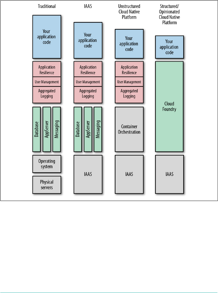
line rises due to increased abstraction. Your responsibility and requirement to config‐
ure various pieces of the software, middleware, and infrastructure stack in support of
your application code diminish as the value line rises. The key is that cloud-native
platforms are designed to do more for you so that you can focus on delivering appli‐
cations with business value.
Figure 1-1. Cloud-native platform evolution
Cloud-Native Platform Concepts
In the Preface, I pointed out that Cloud Foundry’s focus is not so much what a plat‐
form is or what it does, but rather what it enables you to achieve. It has the potential
to make the software build, test, deploy, and scale cycle significantly faster. It removes
many of the hurdles involved in deploying software, making it possible for you to
release software at will.
Specifically, here’s what the Cloud Foundry platform offers:
2 | Chapter 1: The Cloud-Native Platform

Services as a higher level of abstraction above infrastructure
Cloud Foundry provides a self-service mechanism for the on-demand deploy‐
ment of applications bound to an array of provisioned middleware and routing
services. This benefit removes the management overhead of both the middleware
and infrastructure layer from the developer, significantly reducing the
development-to-deployment time.
Containers
Cloud Foundry runs all deployed applications in containers. You can deploy
applications as container images or as standalone apps containerized by Cloud
Foundry. This provides flexibility. Companies already established with Docker
can deploy existing Docker images to Cloud Foundry. However, containerizing
applications on the user’s behalf offers additional productivity and operational
benefits because the resulting container image is built from known and vetted
platform components. This approach allows you to run your vulnerability scans
against your trusted artifacts once per update. From this point, only the applica‐
tion source code requires additional vulnerability scanning on a per deployment
basis. Essentially, there is less to check on a per deployment basis because all of
your supporting artifacts have already been vetted.
Agile and automation
You can use Cloud Foundry as part of a CI/CD pipeline to provision environ‐
ments and services on demand as the application moves through the pipeline to a
production-ready state. This helps satisfy the key Agile requirement of getting
code into the hands of end users when required.
Cultural shift to DevOps
Cross-cutting concerns is a well-understood concept by developers. Adopting
Cloud Foundry is ideally accompanied by a cultural shift to DevOps, meaning
that you need to break down traditional walls, team silos, and ticket-based hand-
offs to get the most benefit from it.
Microservices support
Cloud Foundry supports microservices through providing mechanisms for inte‐
grating and coordinating loosely coupled services. To realize the benefits of
microservices, a platform is required to provide additional supporting capabili‐
ties; for example, Cloud Foundry provides applications with capabilities such as
built-in resilience, application authentication, and aggregated logging.
Cloud-native application support
Cloud Foundry provides a contract against which applications can be developed.
This contract makes doing the right thing simple and will result in better applica‐
tion performance, management, and resilience.
Cloud-Native Platform Concepts | 3

Not all cloud-native platforms are the same. Some are self-built and pieced together
from various components; others are black-boxed and completely proprietary. The
Cloud Foundry cloud-native platform has three defining characteristics: it is struc‐
tured, opinionated, and open. I’ll examine each of these traits in the following sec‐
tions.
The Structured Platform
Within the platform space, two distinct architectural patterns have emerged: struc‐
tured and unstructured:
•Structured platforms provide built-in capabilities and integration points for key
concerns such as enterprise-wide user management, security, and compliance.
With these kinds of platforms, everything you need to run your applications
should be provided in a repeatable way, regardless of what infrastructure you run
on. Cloud Foundry is a perfect example of a structured platform.
•Unstructured platforms have the flexibility to define a bespoke solution at a
granular level. An example of an unstructured platform would involve a “build
your own platform” approach with a mix of cloud-provided services and home‐
grown tools, assembled for an individual company.
Structured platforms focus on simplifying the overall operational model. Rather than
integrating, operating, and maintaining numerous individual components, the plat‐
form operator just deals with the one platform. Structured platforms remove all the
undifferentiated heavy lifting: tasks that must be done—for example, service discov‐
ery or application placement—but that are not directly related to revenue-generating
software.
Although structured platforms are often used for building new cloud-native applica‐
tions, they also support legacy application integration where it makes sense to do so,
allowing for a broader mix of workloads than traditionally anticipated. The struc‐
tured approach provides a much faster “getting started” experience with lower overall
effort required to operate and maintain the environment.
The Opinionated Platform
When you look at successful software, the greatest and most widely adopted technol‐
ogies are incredibly opinionated. What this means is that they are built on, and
adhere to, a set of well-defined principles employing best practices. They are proven
to work in a practical way and reflect how things can and should be done when not
constrained by the baggage of technical debt. Opinions produce contracts to ensure
applications are constrained to do the right thing.
4 | Chapter 1: The Cloud-Native Platform

Platforms are opinionated because they make specific assumptions and optimizations
to remove complexity and pain from the user. Opinionated platforms are designed to
be consistent across environments, with every feature working as designed out of the
box. For example, the Cloud Foundry platform provides the same user experience
when deployed over different IaaS layers and the same developer experience regard‐
less of the application language. Opinionated platforms such as Cloud Foundry can
still be configurable and extended, but not to the extent that the nature of the plat‐
form changes. Platforms should have opinions on how your software is deployed,
run, and scaled, but not where an application is deployed; this means that, with
respect to infrastructure choice, applications should run anywhere.
The Open Platform
Cloud Foundry is an open platform. It is open on three axes:
•It allows a choice of IaaS layer to underpin it (Google Cloud Platform [GCP],
Amazon Web Services [AWS], Microsoft Azure, VMware vSphere, OpenStack,
etc.).
•It allows for a number of different developer frameworks, polyglot languages,
and application services (Ruby, Go, Spring, etc.).
•It is open-sourced under an Apache 2 license and governed by a multi-
organization foundation.
Closed platforms can be proprietary and often focus on a specific problem. They
might support only a single infrastructure, language, or use case. Open platforms
offer choice where it matters.
Summary
Cloud Foundry is an opinionated, structured, and open platform. As such, it is:
•built on, and adheres to, a set of well-defined principles employing best practices.
•constrained to do the right thing for your application, based on defined con‐
tracts.
•consistent across different infrastructure/cloud environments.
•configurable and extendable, but not to the degree that the nature of the platform
changes.
For the developer, Cloud Foundry provides a fast “on rails” development and deploy‐
ment experience. For the operator, it reduces operational effort through providing
built-in capabilities and integration points for key enterprise concerns such as user
management, security, and self-healing.
The Open Platform | 5


CHAPTER 2
Concepts
This chapter explains the core concepts underpinning Cloud Foundry. Understand‐
ing these concepts paints a complete picture of why and how you should use the plat‐
form. These concepts include the need to deal with undifferentiated heavy lifting and
why cloud-based operating systems are essential in protecting your cloud investment.
This chapter also touches on the philosophical perspectives behind Cloud Foundry
with its opinionated do more approach. Operational aspects, including release engi‐
neering through BOSH, and built-in resilience and fault tolerance are also intro‐
duced. Finally, some of the core capabilities of the platform beyond container
orchestration are introduced, including the aggregated streaming of logs and metrics
and the user access and authentication (UAA) management.
Undifferentiated Heavy Lifting
Cloud Foundry is a platform for running applications and one-off tasks. The essence
of Cloud Foundry is to provide companies with the speed, simplicity, and control
they need to develop and deploy applications. It achieves this by undertaking many of
the burdensome boilerplate responsibilities associated with delivering software.
These types of responsibilities are referred to as undifferentiated heavy lifting, tasks
that must be done—for example, container orchestration or application placement—
but that are not directly related to the development of revenue-generating software.
The following are some examples of undifferentiated heavy lifting:
•Provisioning VMs, OSs, middleware, and databases
• Application runtime configuration and memory tuning
• User management and SSO integration
•Load balancing and traffic routing
7

• Centralized log aggregation
• Scaling
• Security auditing
•Providing fault tolerance and resilience
• Service discovery
•Application placement and container creation and orchestration
• Blue/green deployments with the use of canaries
If you do not have a platform to abstract the underlying infrastructure and provide
the aforementioned capabilities, this additional burden of responsibility remains
yours. If you are spending significant time and effort building bespoke environments
for shipping software, refocusing investment back into your core business will pro‐
vide a huge payoff. Cloud Foundry allows enterprises to refocus effort back into the
business by removing as much of the undifferentiated heavy lifting as possible.
The Cloud Operating System
As an application platform, Cloud Foundry is infrastructure-agnostic, sitting on top
of your infrastructure of choice. As depicted in Figure 2-1, Cloud Foundry is effec‐
tively a cloud-based operating system that utilizes cloud-based resources, which are
hidden and abstracted away from the end user. As discussed in Chapter 1, in the
same way that the OS on your phone, tablet, or laptop abstracts the underlying physi‐
cal compute resource, Cloud Foundry abstracts the infrastructure’s compute resource
(specifically virtual storage, networking, RAM, and CPU). The net effect is that Cloud
Foundry serves both as a standard and efficient way to deploy applications and serv‐
ices across different cloud-computing environments. Conversely, if you are stuck
with directly using IaaS–specific APIs, it requires knowledge of the developer pat‐
terns and operations specific to the underlying IaaS technology, frequently resulting
in applications becoming tightly coupled to the underlying infrastructure.
8 | Chapter 2: Concepts
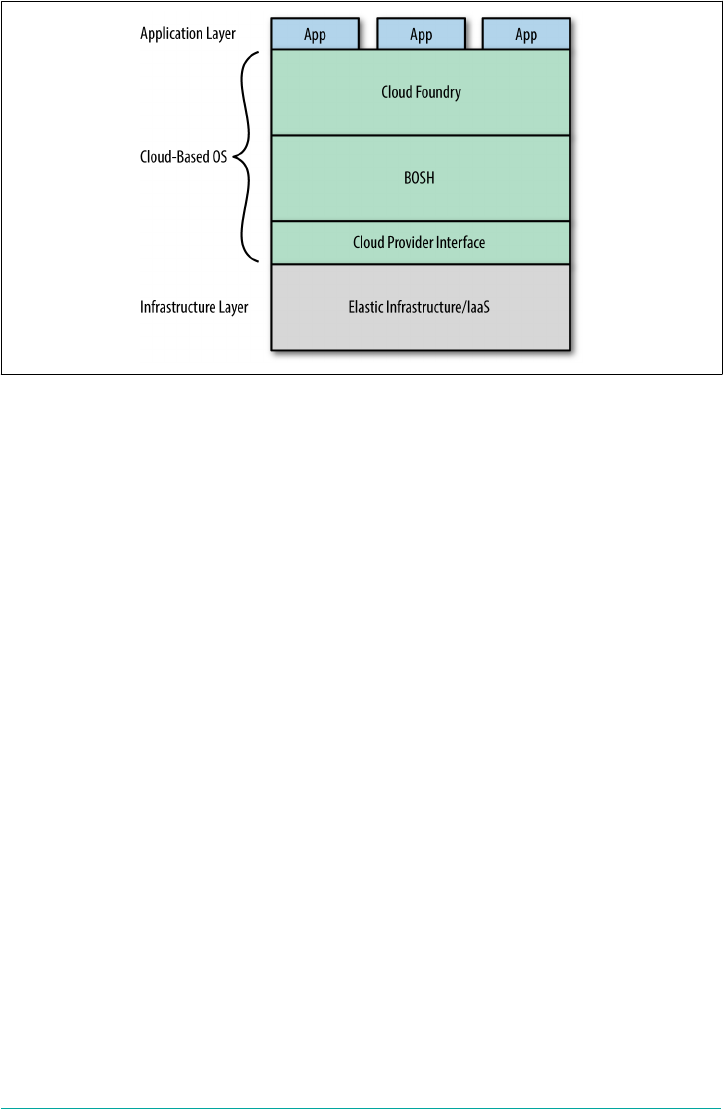
Figure 2-1. Cloud Foundry layers forming a cloud-based OS
Do More
Historically the long pole of application delivery, the part on the critical path that
blocks progress, has been the IT department. This results in a concept I call server
hugging, whereby developers hold on to (and hug) a plethora of VMs just in case they
need them again someday.
Nowadays, businesses no longer need to be constrained by lengthy IT processes or
organizational silos. Cloud Foundry provides a contractual promise to allow busi‐
nesses to move with velocity and establish a developer–feedback loop so that they can
tightly align products to user expectations. With Cloud Foundry, product managers
get their business back and IT engineers can focus on more interesting issues and get
to eat dinner at home.
Platforms are concerned not only with providing environments and middleware for
running applications. For example, Cloud Foundry takes on the responsibility of
keeping applications up and running in the face of failures within the system. It also
provides security, user administration, workload scheduling, and monitoring capabil‐
ities. Onsi Fakhouri, Pivotal’s Vice President of Research and Development, famously
tweeted this haiku:
Here is my source code,
run it on the cloud for me.
I do not care how!
Onsi’s quote captures the essence of Cloud Foundry’s do more capability. Cloud
Foundry is about doing more on behalf of both the developer and operator so that
they can focus on what really differentiates the business. This characteristic is seen all
Do More | 9

throughout the Cloud Foundry ecosystem. You can take a similar approach with
BOSH, Cloud Foundry’s release-engineering system, and state, “Here are my servers,
make them a Cloud Foundry. I do not care how!”
The Application as the Unit of Deployment
Traditionally, deploying application code required provisioning and deploying VMs,
OSs, and middleware to create a development environment for the application to run
in. After that environment was provisioned, it required patching and ongoing main‐
tenance. New environments were then created as the application moved through the
deployment pipeline.
Early incarnations of platforms centered on middleware: defining complex topology
diagrams of application servers, databases, and messaging engines into which you
could drop your application. When this topology diagram (or blueprint) was defined,
you then specified some additional configuration such as IP addresses and ports to
bring the defined topology and applications into existence. Although this was a step
in the right direction, from a developer’s perspective there was still a layer of com‐
plexity that you needed to configure for each deployment.
Cloud Foundry differs from traditional provisioning and orchestration engines in a
fundamental way: it uses middleware and infrastructure directly, allowing stream‐
lined development through self-service environments. Developers can build, deploy,
run, and scale applications on Cloud Foundry without having to be mindful of the
specific underlying infrastructure, middleware, and container implementation.
Cloud Foundry allows the unit of deployment, i.e., what you deploy to run your appli‐
cation, to be isolated to just the application itself. Even though there are some bene‐
fits to encapsulating both your application and dependencies as a precomposed
container image, I still believe it is more secure and more efficient to keep just the
application as the unit of deployment and allow the platform to handle the remaining
concerns. The trade-offs between both approaches are discussed further in Chapter 9;
however, the benefit of Cloud Foundry is that it supports both approaches. Build‐
packs are discussed at length in that chapter, but for now, it is enough to know that
buildpacks provide the framework and runtime support for your applications. A spe‐
cific buildpack is used to package your application with all of its dependencies. The
resulting staged application is referred to as a droplet.
On-boarding developers is easy; they can deploy applications to Cloud Foundry
using existing tool chains with little to no code modification. It enables the developer
to remove the cost and complexity of configuring infrastructure for their applica‐
tions. Using a self-service model, developers can deploy and scale applications
without being directly locked into the IaaS layer.
10 | Chapter 2: Concepts

Because developers no longer need to concern themselves with, for example, which
application container to use, which version of Java, and which memory settings or
garbage-collection (GC) policy to employ, they can simply push their applications to
Cloud Foundry, and the applications run. This allows developers to focus on deliver‐
ing applications that offer business value. Applications can then be bound to a wide
set of backing services that are available on demand.
Units of Deployment
The phrase “the application is the unit of deployment” is used lib‐
erally. Applications as the sole unit of currency has changed with
the emergence of Diego, Cloud Foundry’s new runtime. Cloud
Foundry now supports both applications running as long running
processes (LRPs) and discrete “run once” tasks such as Bash scripts
and Cron-like jobs. Diego LRPs are also referred to as application
instances, or AIs. What you deploy, be it an actual app or just a
script, is not important. The key takeaway is the removal of the
need for deploying additional layers of technology.
Using cf push Command to Deploy
Cloud Foundry provides several ways for a user to interact with it, but the principal
avenue is through its CLI. The most renowned CLI command often referenced by the
Cloud Foundry community is $ cf push.
You use the cf push command to deploy your application. It has demonstrably
improved the deployment experience. From the time you run cf push to the point
when the application is available, Cloud Foundry performs the following tasks:
• Uploads and stores application files
• Examines and stores application metadata
• Stages the application by using a buildpack to create a droplet
•Selects an appropriate execution environment in which to run the droplet
• Starts the AI and streams logs to the Loggregator
This workflow is explored in more depth in Chapter 6.
Staging
Although it is part of the cf push workflow, staging is a core Cloud Foundry con‐
cept. Cloud Foundry allows users to deploy a prebuilt Docker image or an application
artifact (source code or binaries) that has not yet been containerized. When deploy‐
ing an application artifact, Cloud Foundry will stage the application on a machine or
Using cf push Command to Deploy | 11

VM known as a Cell, using everything required to compile and run the apps locally,
including the following:
• The OS stack on which the application runs
•A buildpack containing all languages, libraries, dependencies, and runtime serv‐
ices the app uses
The staging process results in a droplet that the Cell can unpack, compile, and run.
You can then run the resulting droplet (as in the case of a Docker image) repeatedly
over several Cells. The same droplet runs the same app instances over multiple Cells
without incurring the cost of staging every time a new instance is run. This ability
provides deployment speed and confidence that all running instances from the same
droplet are identical.
Self-Service Application Life Cycle
In most traditional scenarios, the application developer and application operator typ‐
ically perform the following:
•Develop an application
• Deploy application services
• Deploy an application and connect (bind) it to application services
• Scale an application, both up and down
•Monitor an application
• Upgrade an application
This application life cycle is in play until the application is decommissioned and
taken offline. Cloud Foundry simplifies the application life cycle by offering self-
service capabilities to the end user. Adopting a self-service approach removes hand-
offs and potentially lengthy delays between teams. For example, the ability to deploy
an application, provision and bind applications to services, scale, monitor, and
upgrade are all offered by a simple call to the platform.
With Cloud Foundry, as mentioned earlier, the application or task itself becomes the
single unit of deployment. Developers just push their applications to Cloud Foundry,
and those applications run. If developers require multiple instances of an application
to be running they can use cf scale to scale the application to N number of AIs.
Cloud Foundry removes the cost and complexity of configuring infrastructure and
middleware per application. Using a self-service model, users can do the following:
• Deploy applications
12 | Chapter 2: Concepts

•Provision and bind additional services, such as messaging engines, caching solu‐
tions, and databases
• Scale applications
•Monitor application health and performance
• Update applications
•Delete applications
Deploying and scaling applications are completely independent operations. This pro‐
vides the flexibility to scale at will, without the cost of having to redeploy the applica‐
tion every time. Users can simply scale an application with a self-service call to the
platform. Through commercial products such as Pivotal Cloud Foundry, you can set
up autoscaling policies for dynamic scaling of applications when they meet certain
configurable thresholds.
Removing the infrastructure, OS, and middleware configuration concerns from
developers allows them to focus all their effort on the application instead of deploy‐
ing and configuring supporting technologies. This keeps the development focus
where it needs to be, on the business logic that generates revenue.
The Twelve-Factor Contract
An architectural style known as cloud-native applications has been established to
describe the design of applications specifically written to run in a cloud environment.
These applications avoid some of the antipatterns that were established in the client-
server era, such as writing data to the local filesystem. Those antipatterns do not work
as well in a cloud environment because, for example, local storage is ephemeral given
that VMs can move between different hosts. The Twelve-Factor App explains the 12
principles underpinning cloud-native applications.
Platforms offer a set of contracts to the applications and services that run on them.
These contracts ensure that applications are constrained to do the right thing. Twelve
Factor can be thought of as the contract between an application and a cloud-native
platform.
There are benefits to adhering to a contract that constrains things correctly. Twitter is
a great example of a constrained platform. You can write only 140 characters, but
that constraint becomes an extremely valuable feature of the platform. You can do a
lot with 140 characters coupled with the rich features surrounding that contract. Sim‐
ilarly, platform contracts are born out of previously tried-and-tested constraints; they
are enabling and make doing the right thing—good developer practices—easy for
developers.
The Twelve-Factor Contract | 13

1The terms VM and machine are used interchangeably because BOSH can deploy to multiple infrastructure
environments ranging from containers to VMs, right down to configuring physical servers.
Release Engineering through BOSH
In addition to developer concerns, the platform provides responsive IT operations,
with full visibility and control over the application life cycle, provisioning, deploy‐
ment, upgrades, and security patches. Several other operational benefits exist, such as
built-in resilience, security, centralized user management, and better insights through
capabilities like aggregated metrics and logging.
Rather than integrating, operating, and maintaining numerous individual compo‐
nents, the platform operator deals only with the platform. Structured platforms han‐
dle all the aforementioned undifferentiated heavy lifting tasks.
The Cloud Foundry repository is structured for use with BOSH. BOSH is an open
source tool chain for release-engineering, deployment, and life cycle management.
Using a YAML (YAML Ain’t Markup Language) deployment manifest, BOSH creates
and deploys (virtual) machines1 on top of the targeted computing infrastructure and
then deploys and runs software (in our case Cloud Foundry and supporting services)
on to those created machines. Many of the benefits to operators are provided through
using BOSH to deploy and manage Cloud Foundry. BOSH is often overlooked as just
another component of Cloud Foundry, but it is the bedrock of Cloud Foundry and a
vital piece of the ecosystem. It performs monitoring, failure recovery, and software
updates with zero-to-minimal downtime. Chapter 10 discusses BOSH at length.
Rather than utilizing a bespoke integration of a variety of tools and techniques that
provide solutions to individual parts of the release-engineering goal, BOSH is
designed to be a single tool covering the entire set of requirements of release engi‐
neering. BOSH enables software deployments to be:
• Automated
• Reproducible
•Scalable
• Monitored with self-healing failure recovery
• Updatable with zero-to-minimal downtime
BOSH translates intent into action via repeatability by always ensuring every provi‐
sioned release is identical and repeatable. This removes the challenge of configuration
drift and removes the sprawl of snowflake servers.
BOSH configures infrastructure through code. By design, BOSH tries to abstract
away the differences between infrastructure platforms (IaaS or physical servers) into
14 | Chapter 2: Concepts

a generalized, cross-platform description of your deployment. This provides the ben‐
efit of being infrastructure agnostic (as far as possible).
BOSH performs monitoring, failure recovery, software updates, and patching with
zero-to-minimal downtime. Without such a release-engineering tool chain, all these
concerns remain the responsibility of the operations team. A lack of automation
exposes the developer to unnecessary risk.
Built-In Resilience and Fault Tolerance
A key feature of Cloud Foundry is its built-in resilience. Cloud Foundry provides
built-in resilience and self-healing based on control theory. Control theory is a branch
of engineering and mathematics that uses feedback loops to control and modify the
behavior of a dynamic system. Resiliency is about ensuring that the actual system
state (the number of running applications, for example) matches the desired state at
all times, even in the event of failures. Resiliency is an essential but often costly com‐
ponent of business continuity.
Cloud Foundry automates the recovery of failed applications, components, and pro‐
cesses. This self-healing removes the recovery burden from the operator, ensuring
speed of recovery. Cloud Foundry, underpinned by BOSH, achieves resiliency and
self-healing through:
•Restarting failed system processes
• Recreating missing or unresponsive VMs
• Deployment of new AIs if an application crashes or becomes unresponsive
•Application striping across availability zones (AZs) to enforce separation of the
underlying infrastructure
•Dynamic routing and load balancing
Cloud Foundry deals with application orchestration and placement focused on even
distribution across the infrastructure. The user should not need to worry about how
the underlying infrastructure runs the application beyond having equal distribution
across different resources (known as availability zones). The fact that multiple copies
of the application are running with built-in resiliency is what matters.
Cloud Foundry provides dynamic load balancing. Application consumers use a route
to access an application; each route is directly bound to one or more applications in
Cloud Foundry. When running multiple instances, it balances the load across the
instances, dynamically updating its routing table. Dead application routes are auto‐
matically pruned from the routing table, with new routes added when they become
available.
Built-In Resilience and Fault Tolerance | 15

Without these capabilities, the operations team is required to continually monitor
and respond to pager alerts from failed apps and invalid routes. By replacing manual
interaction with automated, self-healing software, applications and system compo‐
nents are restored quickly with less risk and downtime. The resiliency concern is sat‐
isfied once, for all applications running on the platform, as opposed to developing
customized monitoring and restart scripts per application. The platform removes the
ongoing cost and associated maintenance of bespoke resiliency solutions.
Self-Healing Processes
Traditional infrastructure as code tools do not check whether provisioned services are
up and running. BOSH has strong opinions on how to create your release, forcing
you to create a monitor script for the process. If a BOSH-deployed component has a
process that dies, the monitor script will try to restart it.
Self-Healing VMs
BOSH has a Health Monitor and Resurrector. The Health Monitor uses status and
life cycle events to monitor the health of VMs. If the Health Monitor detects a prob‐
lem with a VM, it can trigger an alert and invoke the Resurrector. The Resurrector
automatically recreates VMs identified by the Health Monitor as missing or unre‐
sponsive.
Self-Healing Application Instance Count
Cloud Foundry runs the application transparently, taking care of the application life
cycle. If an AI dies for any reason (e.g., because of a bug in the application) or a VM
dies, Cloud Foundry can self-heal by restarting new instances so as to keep the
desired capacity to run AIs. It achieves this by monitoring how many instances of
each application are running. The Cell manages its AIs, tracks started instances, and
broadcasts state messages. When Cloud Foundry detects a discrepancy between the
actual number of running instances versus the desired number of available AIs, it
takes corrective action and initiates the deployment of new AIs. To ensure resiliency
and fault tolerance, you should run multiple AIs for a single application. The AIs will
be distributed across multiple Cells for resiliency.
Resiliency Through Availability Zones
Finally, Cloud Foundry supports the use of availability zones (AZs). As depicted in
Figure 2-2, you can use AZs to enforce separation of the underlying infrastructure.
For example, when running on AWS, you can directly map Cloud Foundry AZs to
different AWS AZs. When running on vCenter, you can map Cloud Foundry AZs to
different vCenter Cluster and resource-pool combinations. Cloud Foundry can then
deploy its components across the AZs. When you deploy multiple AIs, Cloud Foun‐
16 | Chapter 2: Concepts

dry will distribute them evenly across the AZs. If, for example, a rack of servers fails
and brings down an entire AZ, the AIs will still be up and serving traffic in the
remaining AZs.
Figure 2-2. Application resiliency through Cloud Foundry AZs
Aggregated Streaming of Logs and Metrics
Cloud Foundry provides insight into both the application and the underlying plat‐
form through aggregated logging and metrics. The logging system within Cloud
Foundry is known as the Loggregator. It is the inner voice of the system, telling the
operator and developer what is happening. It is used to manage the performance,
health, and scale of running applications and the platform itself, via the following:
•Logs provide visibility into behavior; for example, application logs can be used to
trace through a specific call stack.
•Metrics provide visibility into health; for example, container metrics can include
memory, CPU, and disk-per-app instance.
Insights are obtained through storing and analyzing a continuous stream of aggrega‐
ted, time-ordered events from the output streams of all running processes and back‐
ing services. Application logs are aggregated and streamed to an endpoint via Cloud
Foundry’s Loggregator Firehose. Logs from the Cloud Foundry system components
can also be made available and processed through a separate syslog drain. Cloud
Foundry produces both the application and system logs to provide a holistic view to
the end user.
Figure 2-3 illustrates how application logs and syslogs are separated as streams, in
part to provide isolation and security between the two independent concerns, and in
part due to consumer preferences. Generally speaking, app developers do not want to
wade through component logs to resolve an app-specific issue. Developers can trace
the log flow from the frontend router to the application code from a single log file.
Aggregated Streaming of Logs and Metrics | 17
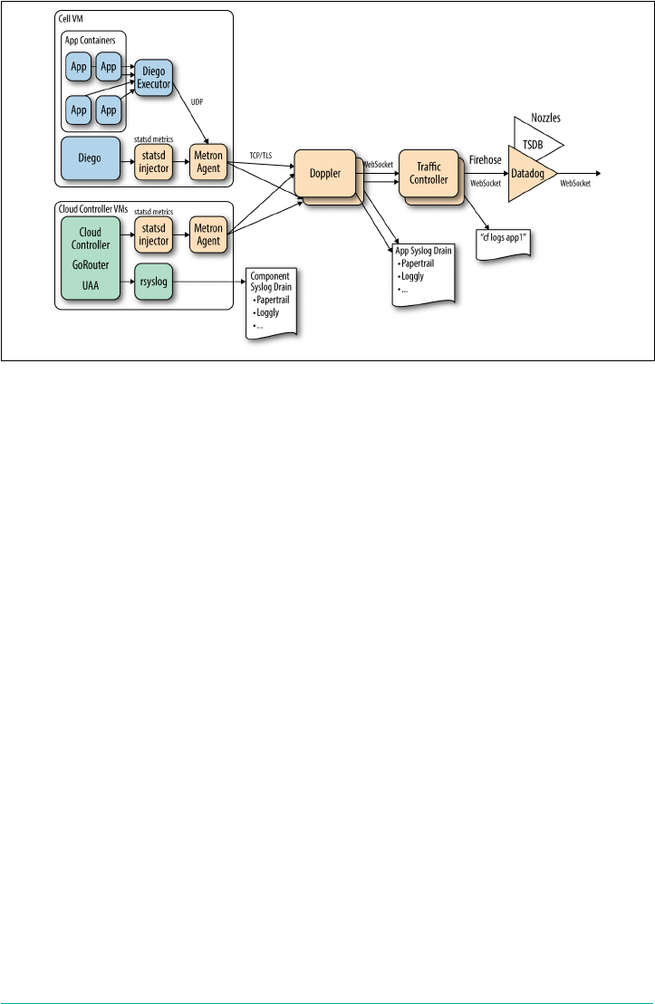
Figure 2-3. The Loggregator system architecture used for aggregating application logs
and metrics
In addition to logs, metrics are gathered and streamed from system components.
Operators can use metrics information to monitor an instance of Cloud Foundry.
Furthermore, Cloud Foundry events show specific events such as when an application
is started or stopped. The benefits of aggregated log, metric, and event streaming
include the following:
• You can stream logs to a single endpoint.
•Streamed logs provide timestamped outputs per application.
•Both application logs and system-component logs are aggregated, simplifying
their consumption.
•Metrics are gathered and streamed from system components.
•Operators can use metrics information to monitor an instance of Cloud Foun‐
dry.
•You can view logs from the command line or drain them into a log management
service such as an ELK stack (Elasticsearch, Logstash, and Kibana), Splunk, or
PCF Metrics.
•Viewing events is useful when debugging problems. For example, it is useful to
be able to correlate an app instance event (like an app crash) to the container’s
specific metrics (high memory prior to crash).
The cost of implementing an aggregated log and metrics-streaming solution involves
bespoke engineering to orchestrate and aggregate the streaming of both syslog and
18 | Chapter 2: Concepts

application logs from every component within a distributed system into a central
server. Using a platform removes the ongoing cost and associated maintenance of
bespoke logging solutions.
Security
For enterprises working with cloud-based infrastructure, security is a top concern.
Usually the security teams have the strongest initial objections to Cloud Foundry
because it works in a way that is generally unprecedented to established enterprise
security teams. However, as soon as these teams understand the strength of Cloud
Foundry’s security posture, my experience is that they become one of your strongest
champions.
Distributed System Security
Cloud Foundry offers significant security benefits over traditional approaches to
deploying applications because it allows you to strengthen your security posture
once, for all applications deployed to the platform. However, securing distributed
systems involves inherent complexity. For example, think about these issues:
•How much effort is required to automatically establish and apply network traffic
rules to isolate components?
•What policies should be applied to automatically limit resources in order to
defend against denial-of-service (DoS) attacks?
•How do you implement role-based access controls (RBAC) with in-built auditing
of system access and actions?
•How do you know which components are potentially affected by a specific vul‐
nerability and require patching?
•How do you safely patch the underlying OS without incurring application down‐
time?
These issues are standard requirements for most systems running in corporate data
centers. The more custom engineering you use, the more you need to secure and
patch that system. Distributed systems increase the security burden because there are
more moving parts, and with the advances in container technology, new challenges
arise, such as “How do you dynamically apply microsegmentation at the container
layer?” Additionally, when it comes to rolling out security patches to update the sys‐
tem, many distributed systems suffer from configuration drift—namely, the lack of
consistency between supposedly identical environments. Therefore, when working
with complex distributed systems (specifically any cloud-based infrastructure), envi‐
ronmental risk factors are intensified.
Security | 19

The Challenge of Configuration Drift
Deployment environments (such as staging, quality assurance, and
production) are often complex and time-consuming to construct
and administer, producing the ongoing challenge of trying to man‐
age configuration drift to maintain consistency between environ‐
ments and VMs. Reproducible consistency through release-
engineering tool chains such as Cloud Foundry’s BOSH addresses
this challenge.
Environmental Risk Factors for Advanced Persistent Threats
Malware known as advanced persistent threats (APTs) needs three risk factors in
order to thrive:
1. Time
2. Leaked or misused credentials
3. Misconfigured and/or unpatched software
Given enough time, APTs can observe, analyze, and learn what is occurring within
your system, storing away key pieces of information at will. If APTs obtain creden‐
tials, they can then further access other systems and data such as important ingress
points into your protected data layer. Finally, unpatched software vulnerabilities pro‐
vide APTs the freedom to further exploit, compromise, and expose your system.
Challenge of Minimal Change
There has been a belief that if enterprises deliver software with velocity, the trade-off
is they must reduce their security posture and increase risk. Therefore, traditionally,
many enterprises have relied on a concept of minimal change to mitigate risk and
reduce velocity. Security teams establish strict and restrictive policies in an attempt to
minimize the injection of new vulnerabilities. This is evident by ticketing systems to
make basic configuration changes to middleware and databases, long-lived transport
layer security (TLS) credentials, static firewall rules, and numerous security policies
to which applications must adhere.
Minimal change becomes compounded by complexity of the environment. Because
machines are difficult to patch and maintain, environmental complexity introduces a
significant lag between the time a vulnerability is discovered and the time a machine
is patched, be it months, or worse, even years in some production enterprise environ‐
ments.
20 | Chapter 2: Concepts

2The three Rs of enterprise security is a phrase coined in an article by Justin Smith, a cloud identity and secu‐
rity expert. I strongly suggest that if you’re interested in enterprise security, you read the full article titled The
Three R’s of Enterprise Security.
The Three Rs of Enterprise Security
IThese combined risk factors provide a perfect ecosystem in which APTs can flour‐
ish, and minimal change creates an environment in which all three factors are likely
to occur. Cloud Foundry inverts the traditional enterprise security model by focusing
on the three Rs of enterprise security: rotate, repave, repair.2"
1. Rotate the credentials frequently so that they are valid only for short periods of
time.
2. Repave (rebuild) servers and applications from a known good state to cut down
on the amount of time an attack can live.
3. Repair vulnerable software as soon as updates are available.
For the three Rs to be effective in minimizing the APT risk factors, you need to
implement them repeatedly at high velocity. For example, data center credentials can
be rotated hourly, servers and applications can be rebuilt several times a day, and
complete vulnerability patching can be achieved within hours of patch availability.
With this paradigm in mind, faster now equates to a safer and stronger security pos‐
ture.
Additional Cloud Foundry Security
Cloud Foundry, along with BOSH and continuous integration (CI) tooling, provides
tooling to make the three Rs’ security posture a reality. Additionally, Cloud Foundry
further protects you from security threats by automatically applying the following
additional security controls to isolate applications and data:
•Manages software-release vulnerability by using new Cloud Foundry releases
created with timely updates to address code issues
•Manages OS vulnerability by using a new OS created with the latest security
patches
•Implements RBACs, applying and enforcing roles and permissions to ensure that
users of the platform can view and affect only the resources to which they have
been granted access
•Secures both code and the configuration of an application within a multitenant
environment
Security | 21

•Deploys each application within its own self-contained and isolated container‐
ized environment
• Prevents possible DoS attacks through resource starvation
•Provides an operator audit trail showing all operator actions applied to the plat‐
form
•Provides a user audit trail recording all relevant API invocations of an applica‐
tion
•Implements network traffic rules (security groups) to prevent system access to
and from external networks, production services, and between internal compo‐
nents
BOSH and the underlying infrastructure expands the security posture further by han‐
dling data-at-rest encryption support through the infrastructure layer, usually by
some device mechanism or filesystem-level support. For example, BOSH can use
AWS EBS (Elastic Block Store) volume encryption for persistent disks.
Because every component within Cloud Foundry is created with the same OS image,
Cloud Foundry eases the burden of rolling out these OS and software-release updates
by using BOSH. BOSH redeploys updated VMs, component by component, to ensure
zero-to-minimal downtime. This ultimately removes patching and updating concerns
from the operator and provides a safer, more resilient way to update Cloud Foundry
while keeping applications running. It is now totally possible to rebuild every VM in
your data center from a known good state, as desired, with zero application down‐
time.
In addition, you can rebuild and redeploy the applications themselves from a known
good release, upon request, with zero downtime. These rebuilding, repairing, and
redeploying capabilities ensure that the patch turnaround time for the entire stack is
as fast and as encompassing as possible, reaching every affected component across
the stack with minimal human intervention. Cadence is limited only by the time it
takes to run the pipeline and commit new code.
In addition to patching, if for any reason a component becomes compromised, you
can instantly recreate it by using a known and clean software release and OS image,
and move the compromised component into a quarantine area for further inspection.
There are additional detailed technical aspects that further improve security; for
example, using namespaces for all containerized processes. I suggest reviewing the
individual components for a more detailed understanding of how components such
as Garden or the UAA help to further increase the security posture.
22 | Chapter 2: Concepts

UAA Management
Role-based access defines who can use the platform and how. Cloud Foundry uses
RBAC, with each role granting permissions to a specific environment the user is tar‐
geting. All collaborators target an environment with their individual user accounts
associated with a role that governs what level and type of access the user has within
that environment. Cloud Foundry’s UAA is the central identity management service
for both users and applications. It supports federated login, Lightweight Directory
Access Protocol (LDAP), Security Assertion Markup Language (SAML), SSO, and
multifactor authentication. UAA is a powerful component for strengthening your
security posture for both user and application authentication. Chapter 15 looks at
UAA in more detail.
Organizations and Spaces
Most developers are familiar with using VMs for development and deployment.
Cloud Foundry is a virtualization layer (underpinned by containers) on top of a vir‐
tualization layer underpinned by VMs. Therefore, users do not have direct access to a
specific machine or VM; rather, they simply access a logical partition of resources to
deploy their apps.
To partition and allocate resources, Cloud Foundry uses logical boundaries known as
Organizations (Orgs) and Spaces. Orgs contain one or more Spaces. Users can belong
to any number of Orgs and/or Spaces, and users can have unique roles and permis‐
sions in each Org or Space to which they belong.
Orgs and Spaces provide the following:
• Logical separation and assignment of Cloud Foundry resources
• Isolation between different teams
•Logical isolation of development, test, staging, and production environments
For some enterprise customers with traditional silos, defining their required Orgs
and Spaces can at first seem complex. Ideally, development teams should have
autonomy to create and manage their own Spaces, as required. For development
teams embracing microservices, the best approach is to organize teams by the big-A
application—meaning a group of related (small-a) applications or services that can
collectively and appropriately be grouped together, often referred to as bulkheading.
Ultimately, you know your business and how your developers work, so use these logi‐
cal structures to provide meaningful working environments and pipelines for your
developers.
UAA Management | 23

Orgs
An Org is the top level of separation. A logical mapping could be to your business
unit, a big-A application, or some other reasonable bounded context. When working
with large enterprises that might have 200 developers in a business unit, I normally
try to shift their thinking to the “Two-Pizza Team” model for application develop‐
ment. However, the actual number of developers within an Org or Space should not
be a contentious point if it maps well to the physical organization and does not
impede development or deployment.
Spaces
Every application and service is scoped to a Cloud Foundry Space. A Space provides a
shared location that a set of users can access for application development, deploy‐
ment, and maintenance. Every Space belongs to one Org. Each Org contains at least
one Space but could contain several, and therefore can contain a broader set of col‐
laborators than a single Space.
Environment Variables for Properties
The cf push command is the user saying to Cloud Foundry, “Here
is my application artifact; run it on the cloud for me. I do not care
how!”
The “I do not care how” needs explaining. There are properties you
should care about, and these properties are configured by environ‐
ment variables. Cloud Foundry uses environment variables to
inform a deployed application about its environment. Environ‐
ment variables include the following:
•How much memory to use
•What routes should be bound to the application
•How many instances of an application should be run
•Additional app-specific environment properties
The Cloud Foundry user can configure all of these properties.
Spaces are more of a developer concern. I believe there should be a limit to the
amount of developers in a Space because there is a requirement for a level of trust due
to the scope of shared resources and exposed environment variables that reside at the
Space level. For the hyper security-conscious who have no trust between application
teams, one Space per application is the only way forward. In reality, a Space for a big-
A application might be more appropriate.
24 | Chapter 2: Concepts

Colocation and Application Interactions
When considering the logical separations of your Cloud Foundry
deployment, namely what Orgs and Spaces to construct, it is
important to consider your application-to-application and
application-to-services interactions. Although this consideration is
more of a microservices consideration, an understanding of appli‐
cation and service boundaries is beneficial in understanding any
colocation requirements. An example of this would be an applica‐
tion needing to access a corporate service in a specific data center
or network. These concerns and their subsequent impacts become
more noticeable at scale. You will need to design, understand, and
document service discovery and app-to-app dependency, and addi‐
tional frameworks such as Spring Cloud can significantly help here.
Resource Allocation
In addition to defining team structures, you can use Orgs and Spaces for assigning
appropriate resources to each team.
Collaborators in an Org share the following:
• Resource quota
• Applications
•Services availability
• Custom domains
Domains Hosts and Routes
To enable traffic from external clients, applications require a specific URL known as a
route. A route is a URL comprised of a domain and an optional host as a prefix. The
host in this context is the portion of the URL referring to the application or applica‐
tions, such as these:
my-app-name is the host prefix
my-business.com is the domain
my-app-name.my-business.com is the route
Route
Application consumers use a route to access an application. Each route is directly
bound to one or more applications in Cloud Foundry. When running multiple
instances, Cloud Foundry automatically load balances application traffic across mul‐
Domains Hosts and Routes | 25

tiple AIs through a component called the GoRouter. Because individual AIs can come
and go for various reasons (scaling, app deletion, app crash), the GoRouter dynami‐
cally updates its routing table. Dead routes are automatically pruned from the routing
table and new routes are added when they become available. Dynamic routing is a
powerful feature. Traditional manual route table maintenance can be slow because it
often requires submitting tickets to update or correct domain name server (DNS) or
load balancer components. Chapter 7 discusses these various routing concepts fur‐
ther.
Domains
Domains provide a namespace from which to create routes. Cloud Foundry uses
domains within routes to direct requests to specific applications. You can also regis‐
ter and use a custom domain, known as an owned domain. Domains are associated
with Orgs and are not directly bound to applications. Domains can be shared, mean‐
ing that they are registered to multiple Orgs, or private, registered to only one Org.
Owned domains are always private.
Context Path–Based Routing
A context path in a URL extends a top-level route with additional context so as to
route the client to either specific application functionality or a different application.
For example, http://my-app-name.my-business.com can be extended to http://my-app-
name.my-business.com/home to direct a client to a homepage.
In the preceding example, your clients can reach the application via my-app-
name.my-business.com. Therefore, if a client targets that route and uses a different
context path, it will still reach only a single application. For example, http://my-app-
name.my-business.com/home and http://my-app-name.my-business.com/somewher
eelse will both be routed by GoRouter to your app my-app-name.
This approach works if all the functionality under the route my-app-name.my-
business.com can be served by a single app. However, when using microservices, there
is a need to have a unified top-level route that can be backed by a number of micro‐
services. Each service uses the same top-level domain but can be individually reached
by different paths in the URL. The microservices collectively serve all supported
paths under the domain my-app-name.my-business.com. With context path–based
routing, you can independently scale those portions of your app that are experiencing
high/low traffic.
26 | Chapter 2: Concepts

Rolling Upgrades and Blue/Green Deployments
As discussed in “Security” on page 19, both the applications running on the platform
and the platform itself allow for rolling upgrades and zero-downtime deployment
through a distributed consensus.
You can update applications running on the platform with zero downtime through a
technique known as blue/green deployments.
Summary
This chapter walked you through the principal concepts of Cloud Foundry. For
example, you should now understand the meaning of a cloud OS, and the importance
of the twelve-factor contract. The primary premise of Cloud Foundry is to enable the
application development-to-deployment process to be as fast as possible. Cloud
Foundry, underpinned by the BOSH release-engineering tool chain, achieves this by
doing more on your behalf. Cloud Foundry provides the following:
•Built-in resiliency through automated recovery and self-healing of failed applica‐
tions, components, and processes
• Built-in resiliency through striping applications across different resources
•Authentication and authorization for both users and applications, with the addi‐
tion of RBAC for users
•Increased security posture with the ability to rotate credentials and repave and
repair components
•The ability to update the platform with zero downtime via rolling upgrades
across the system
•Speed in the deployment of apps with the ability to connect to a number of serv‐
ices via both platform-managed service brokers and services running in your
existing IT infrastructure
•Built-in management and operation of services for your application, such as met‐
rics and log aggregation, monitoring, autoscaling, and performance management
Now that you understand both the concepts and capabilities of Cloud Foundry, you
are ready to learn about the individual components that comprise a Cloud Foundry
deployment.
Rolling Upgrades and Blue/Green Deployments | 27

1The terms VM and machine are used interchangeably because BOSH can leverage and deploy to multiple
infrastructure environments ranging from containers, to VMs, right down to configuring physical servers.
CHAPTER 3
Components
This chapter explores the details of Cloud Foundry components. If you are keen to
begin your journey by deploying Cloud Foundry, you are free to jump ahead to
Chapter 4 and refer to this chapter at a later time.
Cloud Foundry is a distributed system involving several different components. Dis‐
tributed systems balance their processing loads over multiple networked machines.1
They are optimized between efficiency and resiliency against failures. Cloud Foundry
is comprised of a modular distributed architecture with discrete components utilized
for dedicated purposes.
Distributed Systems
As a distributed system, each Cloud Foundry component has a well-defined responsi‐
bility. The different components interact with one another to achieve a common goal.
Distributed systems achieve component interaction through communicating via mes‐
sages and using central data stores for system-wide state coordination. There are sev‐
eral benefits to using a distributed component model, such as the ability to scale a
single component in isolation, or the ability to change one component without
directly affecting another.
It is important for the operator to understand what comprises the Cloud Foundry
distributed system. For example, some components are responsible for system state
and you need to back them up. Other components are responsible for running your
applications, and therefore you most probably want more than one instance of those
29
2System state, along with configuration, is the most critical part of your environment; everything else is just
wiring. Processes can come and go, but your system state and configuration must maintain integrity.
components to remain running to ensure resiliency. Ultimately, understanding these
components and where their boundaries of responsibility lie is vital when it comes to
establishing concerns such as resiliency and disaster recovery.
In this chapter, you will learn about the following:
1. The core components, including their purpose and boundary of responsibility
2. The flow of communication and interaction between components
3. The components responsible for state2
Component Overview
The Cloud Foundry components are covered in detail in the Cloud Foundry docu‐
mentation. The Cloud Foundry code base is being rapidly developed by a growing
open source team of around 250 developers. Any snapshot in time is going to change
almost immediately. This book focuses not on the specific implementations that are
subject to change, but on the purpose and function of each component. The imple‐
mentation details change; the underlying patterns often remain.
We can group by function the components that make up Cloud Foundry into differ‐
ent layers. Table 3-1 lists these layers.
Table 3-1. Cloud Foundry component layers
Layer Compoenents
Routing GoRouter, TCPRouter, and external load balancera
Authentication and user management User Access and Authentication Management
Application life cycle and system state Cloud Controller, Diego’s core components (e.g., BBS and Brain)
App storage and execution blobstore (including app artifacts/droplets and the Application Life-Cycle
Binaries), Diego Cell (Garden, and runC)
Services Service Broker, User Provided Service
Messaging NATS (Network Address Translation) Messaging Bus
Metrics and logging Loggregator (including Doppler and the Firehose)
a The external load balancer is not a Cloud Foundry component; it fronts the traffic coming into Cloud Foundry.
Figure 3-1 provides a visual representation of these components.
30 | Chapter 3: Components
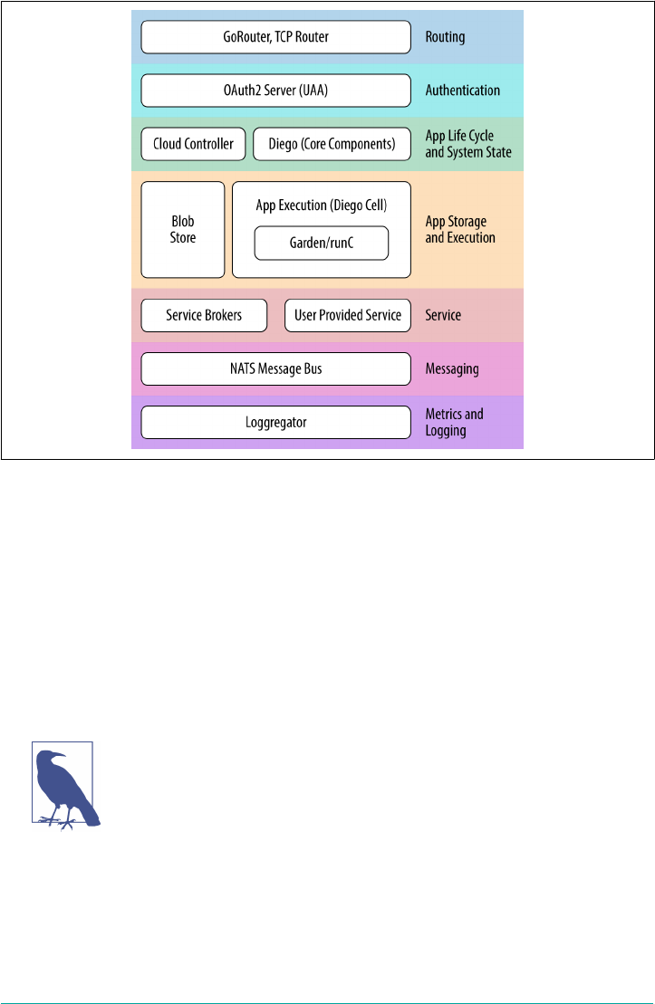
Figure 3-1. Cloud Foundry component layers
To discuss the core components and their role within Cloud Foundry, we will take a
top-down approach beginning with components that handle traffic coming into
Cloud Foundry.
Routing via the Load Balancer and GoRouter
All HTTP-based traffic first enters Cloud Foundry from an external load balancer
fronting Cloud Foundry. The load balancer is primarily used for routing traffic to the
GoRouter.
Load Balancer Preference
The choice of load balancer is according to your preference. Infra‐
structure hosted on AWS often use Amazon’s elastic load balancer
(ELB). On-premises deployments such as those on vSphere or
OpenStack take advantage of existing enterprise load balancers
such as F5’s BIG-IP.
The load balancer can either handle secure socket layer (SSL) decryption and then
route traffic on to the GoRouter, or pass the SSL connection on to the GoRouter for
SSL decryption.
Routing via the Load Balancer and GoRouter | 31

3The GoRouter supports Sticky Session configuration if required.
The GoRouter receives all incoming HTTP traffic from the load balancer. The term
“router” can be misleading to networking engineers who expect routers to implement
specific networking standards. Conceptually, the router should be treated as a reverse
proxy, responsible for centrally managing and routing all incoming HTTP(S) traffic
to the appropriate component. Traffic will typically be passed on to either an applica‐
tion or the Cloud Controller:
•Application users target their desired applications via a dedicated domain. The
GoRouter will route application traffic to the appropriate AI running on a Diego
Cell. If multiple AIs are running, the GoRouter will round-robin traffic across
the AIs to distribute the workload.3
•Cloud Foundry users address the Cloud Controller: Cloud Foundry’s API known
as the CAPI. Some client traffic will go directly from the GoRouter to the UAA;
however, most UAA calls are initiated from the Cloud Controller.
The GoRouter periodically queries Diego, Cloud Foundry’s container runtime sys‐
tem, for information on the location of the Cells and containers on which each appli‐
cation is currently running.
Applications require a route for external traffic to access them. The GoRouter uses a
routing table to keep track of the available applications. Because applications can
have multiple AIs, all with a single route, each route has an associated array of
host:port entries. The host is the Diego Cell machine running the application. The
GoRouter regularly recomputes new routing tables based on the Cell’s IP addresses
and the host-side port numbers for the Cell’s containers.
Routing is an important part of Cloud Foundry. Chapter 7 discusses the GoRouter
and routing in general in greater detail.
User Management and the UAA
As traffic enters Cloud Foundry, it needs to be authenticated. Cloud Foundry’s UAA
service is the central identity management service for managing:
• Cloud Foundry developers
•Application clients/end users
• Applications requiring application-to-application interactions
The UAA is an OAuth2 authorization server, that issues access tokens for client
applications to use when they act on behalf of Cloud Foundry users; for example,
32 | Chapter 3: Components

when they request access to platform resources. The UAA is based on the most up-
to-date security standards like OAuth, OpenID Connect, and System for Cross-
domain Identity Management (SCIM). It authenticates platform users via their Cloud
Foundry credentials. When users register an account with the Cloud Foundry plat‐
form, the UAA acts as the user identity store, retaining user passwords in the UAA
database. The UAA can also act as a SSO service. It has endpoints for managing user
accounts and registering OAuth2 clients as well as various other management func‐
tions. In addition, you can configure the UAA’s user-identity store to either store
user information internally or connect to an external user store through LDAP or
SAML. Here are a couple of examples:
•Users can use LDAP credentials to gain access to the Cloud Foundry platform
instead of registering a separate account.
•Operators can use SAML to connect to an external user store in order to enable
SSO for users who want to access Cloud Foundry.
The UAA has its own database known as the UAADB. Like all databases responsible
for system state, this is a critical component and you must make backups. Chapter 15
looks at the UAA in more detail.
The Cloud Controller
The Cloud Controller exposes Cloud Foundry’s REST API. Users of Cloud Foundry
target the Cloud Controller so that they can interact with the Cloud Foundry API
(CAPI). Clients directly interact with the Cloud Controller for tasks such as these:
• Pushing, staging, running, updating, and retrieving applications
• Pushing, staging, and running discrete one-off tasks
You can interact with the Cloud Controller in the following three ways:
• A scriptable CLI
• Language bindings (currently Java)
• Integration with development tools (IDEs) to ease the deployment process
You can find a detailed overview of the API commands at API Docs. The V3 API
extends the API to also include Tasks in addition to applications LRPs.
The Cloud Controller is responsible for the System State and the Application Life-
Cycle Policy.
The Cloud Controller | 33

System State
The Cloud Controller uses two components for storing state: a blobstore and a data‐
base known as the CCDB.
The Cloud Controller blobstore
To store large binary files such as application artifacts and staged application drop‐
lets, Cloud Foundry’s Cloud Controller uses a blobstore that holds different types of
artifacts:
•Application code packages—unstaged files that represent an application
• Resource files
•Buildpacks
• Droplets and other container images
Resource files are uploaded to the Cloud Controller and then cached in the blobstore
with a unique secure hash algorithm (SHA) so as to be reused without reuploading
the file. Before uploading all the application files, the Cloud Foundry CLI issues a
resource match request to the Cloud Controller to determine if any of the application
files already exist in the resource cache. When the application files are uploaded, the
Cloud Foundry CLI omits files that exist in the resource cache by supplying the result
of the resource-match request. The uploaded application files are combined with the
files from the resource cache to create the complete application package.
Droplets are the result of taking an app package and staging it via a processing build‐
pack to create an executable binary artifact. The blobstore uses FOG so that it can use
abstractions like Amazon Simple Storage Service (Amazon S3) or a mounted network
file system (NFS) for storage.
The CCDB
The Cloud Controller, via its CCDB, also maintains records of the logical hierarchical
structure including available orgs, spaces, apps, services, service instances, user roles,
and more. It maintains users’ information and how their roles map to orgs and
spaces.
The Application Life-Cycle Policy
The Cloud Controller is responsible for the Application Life-Cycle Policy. Conceptu‐
ally, the Cloud Controller is Cloud Foundry’s CPU that drives the other components.
For example, when you use the cf push command to push an application or task to
Cloud Foundry, the Cloud Controller stores the raw application bits in its blobstore,
34 | Chapter 3: Components

4The OCI is an open governance structure for the express purpose of creating open industry standards around
container formats and runtime. For more information, see https://www.opencontainers.org/.
creates a record to track the application metadata in its database, and directs the
other system components to stage and run the application.
The Cloud Controller is application and task centric. It implements all of the object
modeling around running applications (handling permissions, buildpack selection,
service binding, etc.). The Cloud Controller is concerned with policy; for example,
“run two instances of my application,” but the responsibility of orchestration and exe‐
cution has been passed to Diego.
Continuous Delivery Pipelines
Many companies choose to interact with Cloud Foundry through a
continuous delivery pipeline such as Concourse.ci that uses
machines to utilize the CAPI. This approach reduces human error
and offers deployment repeatability.
Application Execution
The components responsible for executing your applications and tasks include Diego,
Garden (a container management API), and an Open Container Initiative (OCI)–
compatible4 backend container implementation (like runC).
Diego
Diego is the container runtime architecture for Cloud Foundry. Whereas the Cloud
Controller is concerned with policy, it is Diego that provides the scheduling, orches‐
tration, and placement of applications and tasks. Diego is designed to keep applica‐
tions available by constantly monitoring their states and reconciling the actual system
state with the expected state by starting and stopping processes as required. Chapter 6
covers Diego at length.
Garden and runC
Garden is a platform-agnostic Go API for container creation and management. Gar‐
den has pluggable backends for different platforms and runtimes, including Linux,
Windows, and runC, an implementation of the OCI specification. Chapter 8 looks at
containers in detail.
Application Execution | 35

Metrics and Logging
As discussed in “Aggregated Streaming of Logs and Metrics” on page 17, system logs
and metrics are continually generated and streamed from every component. In addi‐
tion, AIs should produce logs as a continual stream for each running AI. Cloud
Foundry’s logging system is known as the Loggregator. The Loggregator aggregates
component metrics and application logs into a central location using a Metron agent.
Metron Agent
The Metron agent comes from the Loggregator subsystem and resides on every VM.
It gathers a mix of metrics and log statistics from the Cloud Foundry components; for
example, the Metron agent gathers application logs from the Cloud Foundry Diego
hosts known as Cells. Operators can use the collected component logs and metrics to
monitor a Cloud Foundry deployment. These metrics and logs can be forwarded by a
syslog forwarder onto a syslog drain. It is possible to drain syslogs into multiple con‐
sumers. You can set up as many syslog “sinks” for an application as you want. Each
sink will receive all messages.
Metron has the job of forwarding application logs and component metrics to the
Loggregator subsystem by taking traffic from the various emitter sources (Cells in the
case of apps) and routing that logging traffic to one or more Loggregator compo‐
nents. An instance of the Metron agent runs on each VM in a Cloud Foundry system
and logs are therefore co-located on the emitter sources.
Loggregator
The Loggregator (log aggregator) system continually streams logging and metric
information. The Loggregator’s Firehose provides access to application logs, con‐
tainer metrics (memory, CPU, and disk-per-app instance), some component metrics,
and component counter/HTTP events. If you want to see firsthand the output from
the Loggregator, you can invoke the CF CLI command $ cf logs APP, as demon‐
strated in the following example:
2017-02-14T13:10:32.260-08:00 [RTR/0] [OUT] twicf-signup.cfapps.io -
[2017-02-14T21:10:32.250+0000] "GET /favicon.ico HTTP/1.1" 200 0 946
"https://twicf-signup.cfapps.io/"... "10.10.66.187:26208" "10.10.147
.77:60076" x_forwarded_for:"71.202.60.71" x_forwarded_proto:"https"
vcap_request_id:"2c28e2fe-54f7-48d7-5f0b-aaead5ab5c7c" response_time
:0.009104115 app_id:"ff073944-4d18-4c73-9441-f1a4c4bb4ca3" app_index:"0"
The Firehose does not provide component logs. Component logs are retrieved
through an rsyslog drain.
36 | Chapter 3: Components

Messaging
Most component machines communicate with one another internally through HTTP
and HTTPS protocols. Temporary messages and data are captured in two locations:
•A Consul server stores the longer-lived control data such as component IP
addresses and distributed locks that prevent components from duplicating
actions.
•Diego’s bulletin board system (BBS) stores a real-time view of the system, includ‐
ing the more frequently updated and disposable data such as Cell and application
status, unallocated work, and heartbeat messages.
The Route-Emitter component still uses the NATS messaging system, a lightweight
distributed publish–subscribe message queuing system, to broadcast the latest rout‐
ing tables to the routers.
Additional Components
In addition to the aforementioned core system components, there are other compo‐
nents that comprise the Cloud Foundry ecosystem.
Stacks
A stack is a prebuilt root filesystem (rootfs). Stacks are used along with droplets (the
output of buildpack staging). They provide the container filesystem used for running
applications.
Cells can support more than one stack if configured correctly; however, a Cell must
ensure buildpack and stack compatibility. For example, a Windows “stack” cannot
run on Linux VMs. Therefore, to stage or run a Linux app, a Cell running a Linux
stack must be available (and have free memory).
A Marketplace of On-Demand Services
Applications often depend on additional backing services such as databases, caches,
messaging engines, or third-party APIs. Each Cloud Foundry deployment has the
concept of a marketplace. The Cloud Foundry marketplace is a platform extension
point. It exposes a set of services that are available for developers to use in support of
running applications. Developers do not build applications in isolation. Applications
often require additional middleware services such as data persistence, search, cach‐
ing, graphing, messaging, API management, and more.
The platform operator exposes additional services to the marketplace through service
brokers, route services, and user-provided services. The marketplace provides Cloud
Messaging | 37

Foundry users with the self-service, on-demand provisioning of additional service
instances. The platform operator can expose different service plans to different Cloud
Foundry Orgs. Developers are able to view and create service instances only for ser‐
vice plans that have been configured to be visible for their targeted Org and Space.
You can make service plans public and visible to all, or private to limit service visibil‐
ity.
A service can offer different service plans to provide varying levels of resources or
features for the same service. An example service plan is a database service offering
small, medium, or large plans with differing levels of concurrent connections and
storage sizes. The provisioned service provides a unique set of credentials that can be
used to bind and connect an application to the service.
Services not only enhance applications through providing middleware; they are con‐
cerned with all possible components to enable development teams to move quickly,
including, for example, GitHub, Pivotal Tracker, CI services, and route services. For
example, you can expose to the marketplace any application running on the platform
that offers a service for others to consume. One advantage of this approach is that the
service broker plans can prepopulate datastores with a specific schema or set of data
(such as a sample customer set required for unit testing). Another example could be a
service broker plan to provide specific preconfigured templates for apps.
Service brokers
Developers can provision service instances and then bind those instances to an appli‐
cation via a service broker responsible for providing the service instance.
A service broker interacts with the Cloud Controller to provision a service instance.
Service brokers advertise a catalog of service offerings and service plans (e.g., a single-
node MySQL plan or a clustered multinode MySQL plan). A service broker imple‐
ments the CAPI to provide the user with the following:
• List service offerings
•Provision (create) and deprovision (delete) service instances
• Enable applications to bind to, and unbind from, the service instances
In general, provision reserves service resources (e.g., creates a new VM) and bind
delivers the required information for accessing the resource to an application. The
reserved resource is known, in Cloud Foundry parlance, as a service instance.
The service instance is governed by the broker author. What a service instance repre‐
sents can vary not just by service, but also by plan. For example, an instance could be
a container, a VM, or a new table and user in an existing database. Plans could offer a
single database on a multitenant server, a dedicated datastore cluster, or simply an
account and specific configuration on a running Cloud Foundry application. The key
38 | Chapter 3: Components

concern is that the broker implements the required API to interact with the Cloud
Controller.
User-provided services
In addition to Cloud Foundry-managed service instances, operators can expose exist‐
ing services via user-provided services. This allows established services such as a cus‐
tomer database to be bound to Cloud Foundry applications.
Buildpacks and Docker Images
How do you run applications inside Cloud Foundry? Applications can simply be
pushed through the following CF CLI command:
$ cf push
There are currently two defined artifact types that you can cf push:
•A standalone application
•A prebuilt Docker image (that could contain additional runtime and middleware
dependencies)
You can push standalone applications in both the form of a prebuild artifact such as a
war/jar file or, in some cases, via raw source code such as a link to a Git remote.
Because a standalone application is not already part of a container image, when it is
pushed to Cloud Foundry the buildpack process runs a compile phase. This involves
compiling any source code and packaging the application and runtime dependencies
into an executable container image. The buildpack process is also responsible for
constructing the application runtime environment, deploying the application, and,
finally, starting the required processes.
Buildpacks are a core link in the chain of the Cloud Foundry deployment process if
you are deploying only an application artifact (e.g., JAR, WAR, Ruby, or Go source).
The buildpack automates the following:
•The detection of an application framework
• The application compilation (known in Cloud Foundry terminology as staging)
• Running the application
The officially supported buildpacks are listed at http://docs.cloudfoundry.org/build
packs/index.html. This list includes Ruby, Java (including other JVM-based lan‐
guages), Go, Python, PHP, Node.js, and the binary and staticfile buildpacks.
Numerous additional community buildpacks exist. You can extend buildpacks or
create new ones for specific language, framework, and runtime support. For example,
Additional Components | 39

5NAT is only required if you are using nonroutable addresses.
the reason you might extend the Java buildpack (JBP) is to add support for additional
application servers or a specific monitoring agent.
Buildpacks take your application artifact and containerize it into what Cloud Foun‐
dry calls a droplet. However, if you already have an OCI-compatible container image
such as a Docker image, you can use cf push to move that directly to Cloud Foundry
in order to run it. Containerization is the delivery mechanism for applications. This
is true whether you push an application that Cloud Foundry containerizes into a
droplet, or you push a prebuilt Docker image.
Infrastructure and the Cloud Provider Interface
Cloud Foundry relies on existing cloud-based infrastructure. The underlying infra‐
structure will have implementation-specific details. For example, vSphere’s vCenter
deals with clusters and resource pools, whereas AWS deals with regions and AZs.
There are, however, some fundamental capabilities that need to be available and set
up prior to installing Cloud Foundry:
• Networks and subnets (typically a /22 private network)
• VMs with specified CPU and memory requirements
•Storage for VMs
• File server or blobstore
•DNS, certificates, and wildcard domains
• Load balancer to pass traffic into the GoRouter
• NAT5 for traffic flowing back to the load balancer
Cloud Foundry abstracts away infrastructure-specific implementations through the
use of a cloud provider interface (CPI). Chapter 10 examines this topic further.
The Cloud Foundry GitHub Repository
Cloud Foundry uses the git system on GitHub to version-control all source code,
documentation, and other resources such as buildpacks. Currently, the integrated
Cloud Foundry code base can be located at cf-deployment. To check out Cloud
Foundry code from GitHub, use the master branch because it points to the most
recent stable final release.
40 | Chapter 3: Components

Summary
By design, Cloud Foundry is a distributed system involving several components,
grouped into the following functional layers:
•Routing for handling application and platform user traffic
•Authentication and user management
•Application life cycle and system state through the Cloud Controller and Diego’s
BBS
•Container runtime and app execution through Diego
• Services via the service marketplace
• Messaging
• Metrics and logging
Decoupling Cloud Foundry into a set of services allows each individual function to
grow and evolve as required. Each Cloud Foundry component has a well-defined
responsibility, and the different components interact with one another and share
state in order to achieve a common goal. This loose coupling is advantageous:
•You can scale individual components in isolation
• You can swap and replace components to extend the platform capability
• You can promote a pattern of reuse
Now that you are aware of the components that comprise Cloud Foundry, you are
ready to begin creating a Cloud Foundry instance. Chapter 4 defines the prerequisites
for installing Cloud Foundry.
Summary | 41

CHAPTER 4
Preparing Your Cloud Foundry Environment
This chapter explores the steps you must perform prior to bootstrapping BOSH and
deploying Cloud Foundry. Critically, Cloud Foundry is not a “one size fits all” tech‐
nology, and therefore, you must make some decisions at the outset prior to installing
the platform. It is important that you understand the key concerns and decision
points that define your environment, including:
•Installation steps
• Non-technical considerations
• Cloud Foundry dependencies and integrations
• IaaS and infrastructure design
• Networking design and routing
This chapter assumes that you are familiar with the Cloud Foundry components dis‐
cussed in Chapter 3.
Installation Steps
Following are general steps for deploying Cloud Foundry:
1. Create and configure your IaaS environment, including all the periphery infra‐
structure that Cloud Foundry requires, such as networks, security groups, blob‐
stores, and load balancers.
2. Set up any additional external enterprise services such as LDAP, syslog endpoints
or monitoring, and metrics dashboards.
3. Deploy the BOSH Director.
43

1Deployment and configuration steps are significantly easier to manage if using a CI pipeline such as Con‐
course.ci.
4. Create an IaaS/infrastructure-specific BOSH configuration such as cloud config‐
uration.
5. Create a deployment manifest to deploy Cloud Foundry.
6. Integrate Cloud Foundry with the required enterprise services (via your deploy‐
ment manifest).
7. Deploy Cloud Foundry.1
The rest of this chapter explores the necessary considerations for each step. Before we
dive into those topics, let’s address the non-technical considerations.
Non-technical Considerations
Before addressing the technical points, it is worth establishing two critical things:
• The team structure required for installing Cloud Foundry
• The required deployment topology of Cloud Foundry
These two concerns are especially pertinent when deploying Cloud Foundry for a
large enterprise. Both concerns go hand in hand because the “where and how” of
deploying Cloud Foundry should always be coupled with the team responsible for
operating it.
Team Structure: Platform Operations for the Enterprise
Cloud Foundry is generally deployed either on a team-by-team basis with one instal‐
lation per business unit, or via a central Platform Operations team who deploy and
operate a centralized platform that other DevOps-centric teams can utilize.
In my experience while working with companies helping them to
install and run Cloud Foundry, I came across a decentralized
deployment model only once. For that one company, it worked
well; however, most enterprises choose to establish a centralized
Platform Operations team.
Even with a cultural shift toward DevOps, organizations structure teams in a variety
of different ways. Choose the team structure that works best for you. Whichever var‐
iant you choose, the Platform Operator’s overall responsibility typically includes the
following roles:
44 | Chapter 4: Preparing Your Cloud Foundry Environment

• Networking administrator
• Storage administrator
• System administrator
• IaaS administrator
• Software development
•Security
• QA and performance testing
• Release management
•Project management
These are not necessarily nine exclusive roles; individuals might combine a number
of the preceding capabilities. For example, an IaaS administrator might also have
storage experience. Most of these roles—networking and security, for example—are
more pertinent at the outset when you’re setting up the platform and operational
processes. It is often sufficient just to maintain a regular point of contact for ongoing
expertise in these areas. A point of contact must still be responsive! If it takes a ticket
and three days of waiting to get a network change, your operating model is broken.
If Cloud Foundry is deployed in your data center instead of on a hosted virtual infra‐
structure, the Platform Operations team will need to work closely with the teams
responsible for the physical infrastructure. This is both to help facilitate capacity
planning and because an understanding and appreciation of the hardware capabilities
underpinning the IaaS layer is required to ensure a sufficient level of availability and
scalability. If Cloud Foundry is deployed to a hosted virtual infrastructure such as
GCP, Microsoft Azure, or AWS, your Platform Operations team still needs to work
closely with the teams responsible for networking so as to establish a direct network
connection between the cloud provider and your enterprise.
There is a software development role in the mix because it is necessary to define and
understand the application requirements and best practices based on Twelve-Factor
applications. Additionally, the Platform Operations team needs to appreciate the
application services required to support the cloud-native applications running on the
platform. Developers often have specific requirements for choosing a particular tech‐
nology appropriate for their application. This need can be magnified in a world of
microservices in which each service should be free to use an appropriate backing
technology so that it can grow and evolve independently from other services. The
Platform Operations team should work directly with other business-capability teams
to ensure that they offer a rich and defined portfolio of platform services. You can
host these services directly on the platform, where it makes sense to do so, instead of
being operated and connected adjacent to the platform.
Non-technical Considerations | 45

2All companies I have worked with have adopted separate preproduction and production instances. From a
technical standpoint, if you do not require strict networking segregation, and you size the environment for all
workloads, then separate instances between preproduction and production are not required. However, the
clean separation of concerns between the two environments is appealing for most companies, especially when
considering additional concerns such as performance testing.
Deployment Topology
How many Cloud Foundry instances should you deploy? There are a number of fac‐
tors to consider when addressing this question. For example, ask yourself the follow‐
ing:
•Do you need one instance for the entire company or one instance per organiza‐
tion?
•Should you have one instance for preproduction workloads and a separate
instance for production apps?
•Do you need to isolate applications or data due to regulatory reasons such as
PCI, NIST, or HIPAA compliance?
•Do you need high availability of Cloud Foundry itself (data center-level redun‐
dancy)?
There is no single answer; businesses have different requirements and companies
adopt different approaches. However, the decision can be guided by the following
considerations:
•A single instance, or set of instances (e.g., a sandbox; preproduction and produc‐
tion) for the entire company is a conservative and reasonable starting point. As
you progress with your Cloud Foundry journey, an additional instance or set of
instances per organization might be required if an organization mandates spe‐
cific customizations (e.g., dedicated internal services that must be isolated from
other departments at the network layer).
•Of primary importance, a sandbox environment is always essential for the Plat‐
form Operator to test out new releases without risking developer or production
downtime.
•An instance for pre-production and a separate instance for production might be
required if strict network segregation to backed services (such as a production
database) is mandated.2
•Separate instances for non-regulated and regulated apps might be required if
dealing with industry regulations such as PCI or HIPPA compliance. A new fea‐
ture known as isolation segments might alleviate this requirement over time, as
discussed further in “Isolation Segments” on page 285.
46 | Chapter 4: Preparing Your Cloud Foundry Environment

•Two instances, one in each data center, might be required to allow for data-
center failover or active–active geodispersed application deployments.
Taking the aforementioned points into consideration, for a scenario in which Cloud
Foundry is centrally managed, I tend to see five deployments for a company that has
data centers in two locations (e.g., East and West regions):
•Two environments in a West data center—pre-production and production
instances
•Two environments in an East data center—pre-production and production
instances
•A sandbox environment for the Platform Operator
The importance of the sandbox environment should not be underestimated. Changes
to the Cloud Foundry environment can occur from several aspects, such as the fol‐
lowing:
• Changing or upgrading the network architecture
•Upgrading the IaaS and networking layer
• Upgrading Cloud Foundry
• Upgrading application services
When applying updates across the stack, there is always the potential, no matter how
small, of breaking the underlying infrastructure, the platform itself, or the apps or
services running on the platform. From the Platform Operator’s perspective, both
production and preproduction environments are essentially production systems
requiring 100 percent uptime. Companies strive to avoid both application and devel‐
oper downtime and there is a financial impact if any downtime occurs to either
group. Therefore, it is vital for the Platform Operator to have a safe environment that
can potentially be broken as new changes are tested, without taking developers or
production applications offline. It is worth pointing out that although there is always
a risk when updating software, Cloud Foundry and BOSH impose a unique set of fac‐
tors, such as instance group canaries and rolling deployments, that all help mitigate
risks and deliver exceptionally reliable updates.
Cloud Foundry Dependencies and Integrations
Before you can deploy and operate Cloud Foundry, you must ensure that all prereq‐
uisite dependencies are in place. These dependencies include concerns such as provi‐
sioning the IaaS and configuring a load balancer. Additionally, you can integrate
Cloud Foundry with other enterprise services such as syslog endpoints, SSO solu‐
tions, and metrics dashboards.
Cloud Foundry Dependencies and Integrations | 47

Following are the minimum external dependencies:
•Configured IaaS and infrastructure environment with available administrator
credentials
• Configured networking (subnets and security groups)
•Defined storage policy and an additional NFS- or Amazon S3–compatible blob‐
store (for both the BOSH blobstore and Cloud Foundry blobstore)
• External load balancers set up to point to GoRouter IP addresses
•DNS records set up, including defining appropriate system, app, and any other
required wildcard domains along with SSL certificates
Additional integration considerations based on enterprise services may require the
following:
• SAML, LDAP, or SSO configured for use with Cloud Foundry where required.
•A syslog endpoint such as Splunk or ELK (Elasticsearch, Logstash, and Kibana) is
available to receive component syslog information.
•System monitoring and metrics dashboards such as DataDog set up to receive
system metrics.
•An application performance management (APM) tool such as Dynatrace, New‐
Relic, or AppDynamics set up for receiving application metrics.
This section focuses only on the dependencies and integration
points required for getting started with Cloud Foundry. However,
before installing BOSH and Cloud Foundry, it is still worth consid‐
ering any services and external dependencies with which Cloud
Foundry might need to integrate. This is important because if, for
example, Cloud Foundry requires access to an external production
database, additional considerations such as network access and the
latency of roundtrip requests might arise. Ultimately, where your
vital backing services reside might be the key deciding factor in
where you deploy Cloud Foundry.
IaaS and Infrastructure Design
Before installing Cloud Foundry, you must correctly configure the underpinning
infrastructure.
The first technical decision to make is what IaaS or infrastructure you should use to
underpin Cloud Foundry. Through the use of the BOSH release tool chain, Cloud
Foundry is designed to run on any IaaS provider that has a supported CPI. Refer to
48 | Chapter 4: Preparing Your Cloud Foundry Environment

3An example of such a deployment is documented at the Pivotal blog.
the BOSH documentation for an up-to-date list of supported CPIs. As of this writing,
there are BOSH CPIs for the following infrastructures:
• Google Compute Platform
• AWS
• Azure
•OpenStack
• vSphere’s vCenter
• vSphere’s vCloudAir
•Photon
• RackHD
• Your local machine (for deploying BOSH Lite)
Your infrastructure decision is often made based on the following three factors:
•Does your company desire to have an on-premises (vSphere or OpenStack) or a
cloud-based (AWS, Azure, GCP) infrastructure? What on-premises infrastruc‐
ture management exists today, and what is your desired future state?
• How long will it take to provision new infrastructure (if managed internally)?
• What is the long-term cost model (both capital and operational expenditure)?
With regard to the time to provision new infrastructure, public cloud providers such
as AWS, GCP, or Azure become appealing for many companies because you can
quickly spin up new infrastructure and then scale on demand. I have been on six-
week engagements for which installing the hardware into the company’s data centers
required four weeks. Time lags such as these are painful; thus utilizing public clouds
can accelerate your startup experience. Some companies choose to adopt both a pub‐
lic and private model to provide resiliency through dual deployments.3
From this point on, as a reference architecture, this chapter explores a Cloud Foun‐
dry installation on AWS. I selected AWS as the target IaaS for this book because it is
accessible both to corporations and individuals who might not have access to other
supported IaaS environments.
IaaS and Infrastructure Design | 49

BOSH Lite
If you would like to begin installing Cloud Foundry and using BOSH but do not want
to incur the cost of running several VMs, I suggest using BOSH Lite. BOSH Lite is a
local development environment for BOSH using containers in a Vagrant box. The
BOSH Director that comes with BOSH Lite uses a Garden CPI, which uses containers
to emulate VMs. The usage of containers makes it an excellent choice for local devel‐
opment, testing, and general BOSH exploration because you can deploy the entire cf-
deployment into containers all running on a single VM. This is a great environment
to try Cloud Foundry, but be mindful that because everything is running in a single
VM, it is suitable only for experimentation, not production workloads. BOSH Lite is
discussed further in “BOSH Lite” on page 175.
Designing for Resilience
As discussed in “Built-In Resilience and Fault Tolerance” on page 15, Cloud Foundry
promotes different levels of built-in resilience and fault tolerance. The lowest layer of
resilience within a single installation is achieved through the use of AZs to drive anti‐
affinity of components and applications to physical servers.
Cloud Foundry AZs (assuming they have been configured correctly) ensure that mul‐
tiple instances of Cloud Foundry components and the subsequent apps running on
Cloud Foundry all end up on different physical hosts. An important point here is that
if you desire to use AZs for high availability (HA), you will need a minimum of three
AZs (due to the need to maintain quorum for components that are based on the Raft
consensus algorithm). Chapter 16 offers more information on designing for resil‐
ience.
The Cloud Foundry deployment example discussed in Chapter 5
uses bosh-bootloader and cf-deployment. bosh-bootloader will
configure the infrastructure on your behalf and will try and config‐
ure three AZs by default (assuming the IaaS you deploy to can sup‐
port three distinct regions).
Sizing and Scoping the Infrastructure
Correctly sizing infrastructure for a specific Cloud Foundry installation can be chal‐
lenging, especially if you cannot accurately forecast how many apps are going to be
deployed to the platform. What’s more, this challenge becomes compounded because
a single application might require several instances due to a combination of the fol‐
lowing:
50 | Chapter 4: Preparing Your Cloud Foundry Environment
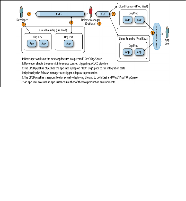
• Running multiple instances for resilience
•Running multiple instances over different spaces throughout the application life
cycle
•Running multiple instances for concurrency performance
For example, as depicted in Figure 4-1, a single AI can often require a minimum of
seven instances when running in an active–active setting:
• Two instances in development (blue and green versions)
• One instance in the test or the CI/CD pipeline
•Four instances in production (two instances in each active–active data center)
Figure 4-1. Typical multiregion, multi-instance deployment with user-interaction flow
In addition, a typical application involves more than one process; for example, it
might have a UI layer, controller/model layer, a service layer, and data layer. You can
quickly begin to see that accurate upfront sizing can become complex as the number
of running instances starts to scale.
Therefore, sizing and capacity planning is generally considered to be a “day two”
concern that should be informed, driven, and actioned via metrics and real data, as
opposed to hypothesis prior to deploying Cloud Foundry. A key advantage is that
Cloud Foundry scales well at every layer, from deploying more AIs to deploying
more Cloud Foundry resources, right down to upgrading the IaaS and the physical
infrastructure underpinning the IaaS.
When sizing infrastructure for Cloud Foundry, I strongly suggest leaving sufficient
headroom for growth. However, there is a danger that by doing this you can end up
with an initial IaaS capacity that drastically exceeds what you actually require. For
IaaS and Infrastructure Design | 51
4These reference architectures and tooling are designed for Pivotal Cloud Foundry. The rationale behind these
resources holds true for all Cloud Foundry deployments with the exception of AI Packs and the Ops Manager
VM, which can be discounted if you are not using Pivotal Cloud Foundry.
this reason, I tend to move away from explicit sizing and focus on general scoping.
Scoping is based on a set of predefined concerns. Through scoping, it is possible to
define the underlying infrastructure, and it becomes easier to be more explicit as to
what resources will be required.
Scoping deployments on AWS is relatively straightforward because you can pick your
desired AWS region, create and configure a new virtual private cloud (VPC) [along
with subnets, security groups, etc.], and then map your Cloud Foundry AZs to the
AWS region AZs. When deploying Cloud Foundry to physical infrastructure, you
need to size your infrastructure in advance. For example, most vSphere customers
have a minimum vSphere cluster configuration of three hosts. Two-host clusters are
not ideal if 50% of the cluster is taken up via vCenter HA demands, and a single-host
cluster is meaningless from a vSphere perspective. vSphere hosts sizes usually contain
256 GB, 384 GB, or 512 GB of RAM. Taking into account the requirement of three
AZs based on three vSphere clusters, this implies that the total provisioned RAM is
2.25 to 4.5 TB, which is often drastically more than the initial requirement. The same
logic holds true for CPU cores.
For an excellent reference point, the Pivotal Professional Services
team has put together two fantastic resources to help structure and
size your infrastructure:4
•For establishing the base architectural design, you can review
the reference architecture.
•For sizing your base architecture for the required workload,
there is a sizing tool—the PCF sizing tool—based on some
fundamental scoping questions.
After you define your architectural footprint and then size the infrastructure based
on your anticipated workload, the next key requirement is to understand the implica‐
tions of your applications operating under peak load. For example, a retail app on a
critical sale day might require more instances to deal with concurrency concerns.
Additional instances might require additional Cell resources. Throughput of traffic to
the additional apps might require additional GoRouters to handle the extra concur‐
rent connections. When designing your routing tier to handle the required load, you
can review the Cloud Foundry routing performance page.
52 | Chapter 4: Preparing Your Cloud Foundry Environment
5Diego is the subsystem responsible for app placement and the container life cycle.
Cell sizing
Cell sizing is of particular importance because Cells run your applications. This is
where most of your expansion will be when your AIs begin to increase. Table 4-1 lists
typical sizing for a Cell.
Table 4-1. Cloud Foundry example Cell configuration
Resource Sizing
AI average RAM 1.5 GB
AI average storage 2 GB
Cell instance type AWS m3.2xlarge (or vSphere eight, 4-core vCPUs)
Cell mem size 64 GB
Cell ephemeral storage size 64 GB
Overcommitting Memory
Overcommitting memory is configurable in BOSH. However, you
need to have a crystal-clear profile of your workloads if you over‐
commit memory because you can run out of memory in cata‐
strophic ways if you calculate this wrong. Memory is relatively
inexpensive, so it is best to avoid this.
A typical three-AZ deployment is often initially set up with six Cells in total: two
Cells per AZ. You can always increase the size of your Cells or add additional Cells at
a later date.
A key consideration when choosing Cell size is that if the Cells are too small and the
average app size too high, you risk wasting space. For example, imagine an 8 GB Cell,
with 2 GB apps. When you take into account headroom for the host OS, you will be
able to fit only three 2 GB apps on a single Cell. This means that you are wasting well
over 1 GB of RAM per Cell; as you replicate this pattern over several Cells, the wasted
RAM begins to accumulate to a significant amount.
Conversely, if your Cells are too large, you risk unnecessary churn if a Cell fails. For
example, imagine a 128 GB Cell hosting two hundred fifty-five 512 MB apps.
Although the app density is great, if for some reason the Cell fails, Cloud Foundry5
will need to subsequently replace 255 apps in one go, in addition to any other work‐
load coming onto the platform. Although this volume of replacement most likely will
be fine, replicating this pattern across several concurrent Cell failures—for example,
due to an AZ failure—can cause unnecessary churn. Even though Cloud Foundry can
cope with a huge amount of churn in replacing applications, but if all of the Cells are
IaaS and Infrastructure Design | 53

running at maximum capacity (as in the scenario stated), rescheduling the apps will
not work until you add additional Cells. However, Cloud Foundry is eventually con‐
sistent. Even for a situation in which Cloud Foundry fails to place the apps, it will
eventually fix itself and reach a consistent state when additional resources are added.
Based on the preceding two illustrations, 32 GB to 64 GB Cells (for an average app
size of between 512 MB and 2 GB) is a good sweet spot to work with.
cf-deployment’s manifest generation capability provides default
Cell sizes that can be reconfigured after you generate the deploy‐
ment manifest.
Instance group replication
HA requirements are discussed in detail in “High Availability Considerations” on
page 263. For deployment of a single Cloud Foundry foundation, you are generally con‐
cerned with defining three AZs and removing single points of failure through
instance group replication.
When using AZs, you can ensure that there are very few (or zero) single points of
failure. In addition to running a multiple Cell instance group as previously described,
you should also run multiple instances of the following:
• MySQL (for BBS, UAA, and CCDBs)
•NATS
• Diego (BBS, Brain, AccessVM, CC-Bridge, Cells)
• Routing (GoRouter, Consul, RouteEmitter)
• Cloud Controller (including the CC-Worker)
• UAA
•Doppler server and Loggregator traffic controller
Strictly speaking, most of the aforementioned instance groups
require only two AZs. Clustered components such as MySQL,
Consul, and etcd require quorum and thus require three AZs. For
simplicity, I recommend replicating all components across three
AZs if you have enough IaaS capacity.
Therefore, a single Cloud Foundry deployment spanning three AZs should have at
least two of the aforementioned components that do not require quorum. As dis‐
cussed previously, any component that uses the Raft consensus algorithm (MySQL,
54 | Chapter 4: Preparing Your Cloud Foundry Environment

Consul, etcd) should have three instances to maintain a quorum. These instance
groups always need an odd number of instances deployed, but you get no additional
benefit from having more than three instances. For the other instance groups in the
list, at least two instances are required to ensure HA and to allow for rolling
upgrades. However, you might want a higher number of instances in order to handle
additional capacity and concurrency.
For example, because the GoRouter is on the critical path for application traffic, it
might be considered necessary to have two GoRouters per AZ to ensure that you can
handle peak traffic if an AZ goes offline. Because the GoRouters load-balance
between all the backend instances, the GoRouter is able to span AZs to reach the
desired AI. Therefore, if two GoRouters can handle peak workload, adding an addi‐
tional instance per AZ is not necessary.
Clock Global remains the only singleton. It is not a critical job. It is used for Cloud
Controller cleanup and BOSH resurrection should be sufficient for this instance.
Beyond that, the only single jobs remaining would be the internal NFS. The NFS can
and should be replaced by an external blobstore such as Amazon S3. Additionally, the
HAProxy and MySQL proxy are singletons by default. Again, you can and should use
an enterprise load balancer, in which case the MySQL proxy can have multiple
instances (e.g., one per AZ) when used in conjunction with an external load balancer.
If you’re using more than one Cloud Foundry AZ, any singleton instance group must
be placed into a specific AZ. Other components that can run with several instances
can and should be balanced across multiple AZs.
bosh-bootloader will try to configure three AZs by default (assum‐
ing that the IaaS to which you deploy will support three distinct
regions). cf-deployment will then deploy multiple instances of cer‐
tain instance groups across the three AZs.
Setting Up an AWS VPC
Each IaaS that you use will have its own unique set of dependencies and configura‐
tion steps. For example, before setting up an AWS VPC, you will need the following:
•An AWS account that can accommodate the minimum resource requirements
for a Cloud Foundry installation.
•The appropriate region selected within your AWS account (this example uses
US-west).
•The AWS CLI installed on your operator machine, configured with user creden‐
tials that have administrative access to your AWS account.
IaaS and Infrastructure Design | 55
6bosh-bootloader will create this key-pair for you.
•Sufficiently high instance limits (or no instance limits) on your AWS account.
Installing Cloud Foundry might require more than the default 20 concurrent
instances.
•A key-pair to use with your Cloud Foundry deployment. This key-pair allows
you to configure SSH access to your instances. The key-pair name should be
uploaded to the NAT instance upon VPC creation.6
•A certificate for your chosen default domain.
If you are deploying a highly distributed Cloud Foundry on AWS,
built for HA, you will need to file a ticket with Amazon to ensure
that your account can launch more than the default 20 instances.
In the ticket, ask for a limit of 50 t2.micro instances and 20 c4.large
instances in the region you are using. You can check the limits on
your account by visiting the EC2 Dashboard on the AWS console;
in the Navigation pane on the left, click Limits.
You can bootstrap VPC setup via bosh-bootloader, as described in “Installing Cloud
Foundry” on page 67. Table 4-2 lists the external IaaS-related dependencies that you
should take into consideration when manually setting up an AWS VPC.
Table 4-2. Cloud Foundry AWS VPC dependencies
Item
Access key ID
AWS secret key
VPC ID
AWS security group name
Region
Key-pair name (used for VM-to-VM communication and SSH)
DNS IP(s)
NTP IP(s)
SSH password (if applicable)
VPC to data center connection
If you are not using bosh-bootloader, there are some excellent instructions on setting
up an AWS IaaS environment ready to install Cloud Foundry at prepare-aws.
Figure 4-2 presents an example of a typical direct VPC setup.
56 | Chapter 4: Preparing Your Cloud Foundry Environment
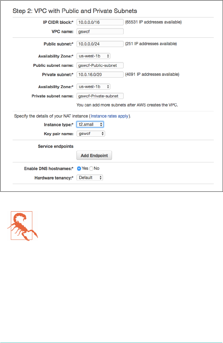
Figure 4-2. Setting up the VPC
A strong word of caution. The Identity and Access Management
(IAM) policy offered by BOSH.io is sufficient to get you started,
but for corporate or production environments, it is highly recom‐
mended you set a very restrictive policy to limit unnecessary user
access. In addition, when setting up the AWS security group
(egress and ingress network rules), it is highly insecure to run any
production environment with 0.0.0.0/0 as the source or to make
any BOSH management ports publicly accessible.
Jumpbox
A jumpbox VM (or Bastian VM) provides layered security because it acts as a single
access point for your control plane. It is the jumpbox that accesses the BOSH Direc‐
tor and subsequent deployed VMs. For operator resilience, there should be more
than one jumpbox. Allowing access through the firewall only to the jumpboxes and
disabling direct access to the other VMs is a common security measure.
IaaS and Infrastructure Design | 57

Using a jumpbox from your VPC to deploy BOSH and Cloud Foundry can help navi‐
gate past network connectivity issues, given that most corporate networks will have
firewall rules preventing SSH connections from a VPC to a local machine.
Instead of using SSH to connect to the jumpbox to run commands, newer CLIs
respect the SOCKS5 protocol. SOCKS5 routes packets between a server and a client
using a proxy server. This means that you can set up an SSH tunnel from your laptop
to the jumpbox, forwarded to a local port. By setting an environment variable prior
to executing the CLI, the CLI will then run through the jumpbox on your worksta‐
tion. This provides the advantage that you do not need to install anything on the
jumpbox, but you have access to the jumpbox’s network space.
You can create a jumpbox by using $bosh create env. There are also tools in the
Cloud Foundry community to help manage, instantiate, and configure your jump‐
box. One such tool is Jumpbox.
Networking Design and Routing
As with all networking, many configurations are possible. The key concern with net‐
working is to design a network topology that suits your business while factoring in
any specific security requirements. The most appropriate network configuration for
Cloud Foundry is established by treating the Cloud Foundry ecosystem as a virtual
appliance. Doing so establishes the expectation that all Cloud Foundry components
are allowed to talk among themselves. Adopting this virtual appliance mindset will
help articulate and shape the networking strategy that could stand in contrast to
more traditional networking policies. Security and networking policies should be in
place and adhered to for sound reasons, not because “that’s the way we’ve always
done it.”
The principal networking best practice is to deploy Cloud Foundry to run on a trus‐
ted, isolated network, typically only accessible via an external SSL terminating load
balancer that fronts Cloud Foundry. Although it is possible to run Cloud Foundry on
any network—for example, where every deployed VM is accessible via its own IP—
nearly all of the projects that I have worked on are deployed into a private network
utilizing NAT for outbound traffic.
Before setting up your VPC, you need to consider the VPC-to-data center connec‐
tion. If you are running your VPC in an isolated manner in which all external calls
use NAT to reach out to your corporate network, the VPC to data center connection
is not important. However, the VPC to data center connection becomes important if
you are treating the VPC as an extension of your corporate network (through capa‐
bilities such as directconnect) because the available network range can have a bearing
on your VPC classless interdomain routings (CIDRs). The important concern in this
scenario is to avoid IP collision with existing resources on the network by defining a
58 | Chapter 4: Preparing Your Cloud Foundry Environment

portion of the existing network that is free and can be strictly reserved for Cloud
Foundry. There are arguments for and against using NAT from the VPC because
some companies desire the components within the Cloud Foundry network to
remain explicitly routable. However, it is worth noting that if you consider the net‐
work as a single address space, you still can use NAT when required, but you cannot
“unNAT” a VPC if your VPC has overlapping addresses with the corporate network.
For each AWS subnet used, you should gather and document the information listed
in Table 4-3. You will use this information in your deployment manifest if you are
creating it from scratch.
Table 4-3. Network dependencies
Network dependencies
AWS network name
VPC subnet ID
Subnet (CIDR range)
Excluded IP ranges
DNS IP(s)
Gateway
A best practice is to co-locate the services in a separate network from Cloud Foundry
and allow a full range of communication (bidirectionally) between the two segments
(the services and Cloud Foundry). You also might choose to have one network per
service and do the same. However, white-listing ports can make the process very
painful, and, for most companies, this extra precaution is regarded as unnecessary.
The general recommendation is to allow full communication among all Cloud Foun‐
dry–managed components at the network-segment level. There is no reason to white-
list ports if you trust all components. This approach is often regarded as entirely
reasonable given that all of the components are under the same management domain.
For a simple installation, the Cloud Foundry documentation provides recommenda‐
tions on basic security group egress and ingress rules.
Using Static IPs
The following Cloud Foundry components (referred to in BOSH parlance as instance
groups) and IaaS components require static IPs or resolution via external DNS:
• Load balancer (static IP for HAProxy, VIP for F5, etc.)
• GoRouter (depending on the IaaS, some CPIs will resolve this for you)
• NATS
•Consul/etcd
Networking Design and Routing | 59

•Database such as a MySQL cluster (relational databse service [RDS] referenced
by DNS)
Static IPs are required for the aforementioned components because they are used by
other downstream instance groups. For example, Consul and etcd, being apex
instance groups, require static IPs; all other instance groups can then be resolved
through external DNS, or internally through Consul’s internal DNS resolution. For
example, the following Cloud Foundry instance groups can have IP resolution via
internal DNS:
•Diego components (BBS, Brain, etc.)
•Cloud Controller
• Cell
• GoRouter (depending on the IaaS, some CPIs will resolve this for you)
• Routing API
• Loggregator
•WebDAV, nfs_server (or S3 blobstore referenced by DNS)
• etcd
Subnets
Network design is dependent on a number of factors. As a minimum, it is recom‐
mended that you create one with a public and private subnet. With a public subnet,
you get an internet GW with no NAT, thus every VM that needs internet access will
require a public IP. With the private network, you can use an NAT gateway or NAT
instance. By default, using bosh-bootloader will provision a management subnet and
then a separate subnet per AZ. This is a basic configuration to get you started. How‐
ever, there is a typical pattern of subnetting your network that has emerged as a com‐
mon practice for production environments (see also Figure 4-3):
• A management subnet for the BOSH Director and or jumpbox
•A dedicated subnet for the core Cloud Foundry components (which also could
contain the BOSH Director)
•A dedicated subnet for the Diego Cells (so as to scale independently as apps
scale)
•A dedicated internet protocol security (IPsec) subnet for services that require the
use of IPSec
• A dedicated subnet for services that do not use IPSec
60 | Chapter 4: Preparing Your Cloud Foundry Environment
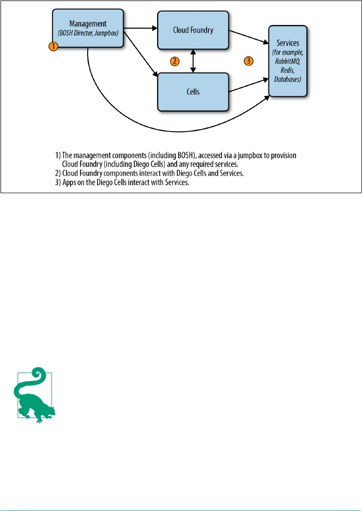
The first three networks can be on an IPSec-enabled network if required, but it is
important to ensure that you have a non-IPSec subnet for services that do not or can‐
not use IPSec.
Figure 4-3. Subnet architecture example
Security Groups
Security group requirements—with respect to egress and ingress rules—are defined
in the Cloud Foundry documentation. It is worth noting that, when setting up the
security group inbound rules, you will define SSH from your current IP. If you are on
a corporate network, your IP will change as you hop on and off it. Therefore, if you
are trying to use $ bosh create-env to update your environment, and you have a
previously created security group policy, you might not have authority to connect to
the Director VM as you try to establish a new connection. After the VM is fully set
up, you can remove the “connect from MyIP” rules for SSH because they are no
longer required.
bosh-bootloader will establish and configure the networking
requirements (static IPs, subnets, security groups) on your behalf,
across your VPC AZs.
Networking Design and Routing | 61

Setting Up the Load Balancer
Application end users access applications via a generic domain such as myapp.com. A
DNS is consulted as part of the path to the application; this is done to route traffic on
to the correct Cloud Foundry installation.
Most Cloud Foundry deployments need more than one instance of the GoRouter for
HA. However, DNS targets a single IP, often referred to as a VIP (virtual IP). Conse‐
quently, you need another device in front of the GoRouter to take requests on that IP
and balance them across the available routers. In addition to balancing traffic, the
load balancer (ELB in the case of AWS) can be used to terminate SSL or it can pass
SSL on to the GoRouter for termination.
bosh-bootloader will create your AWS elastic load balancer and
subsequent security groups.
Setting Up Domains and Certificates
Regardless of the installation approach you choose, your Cloud Foundry installation
will need a registered wildcard domain for its default domain. You will need this reg‐
istered domain when configuring your SSL certificate and Cloud Controller. For
more information, read the AWS documentation on Creating a Server Certificate.
When setting up a single Cloud Foundry deployment, it is recommended that you
have at least two default wildcard domains: a system domain and a separate applica‐
tion domain, as demonstrated here:
•*.system.cf.com
•*.apps.cf.com
The system domain allows Cloud Foundry to know about its internal components
because Cloud Foundry itself runs some of its components as applications; for exam‐
ple, the UAA. Developers use the application domain to access their applications.
If Cloud Foundry had only one combined system and app domain, there would be no
separation of concerns. A developer could register an app domain name that infers it
was a potential system component. This can cause confusion to the Cloud Foundry
operator as to what are system applications and what are developer-deployed applica‐
tions. Even worse, if an app is mapped to an existing system-component route such
as api.mycf.com, the Cloud Foundry environment can become unusable. This is dis‐
cussed in “Scenario Five: Route Collision” on page 241. By enforcing a separation of
system and app domains, it is far more likely that you will avoid this scenario. There‐
62 | Chapter 4: Preparing Your Cloud Foundry Environment

fore, it is recommended that you always have at least one default system and default
app domain per environment.
It is also recommended that you use unique system and application domain as
opposed to deploying Cloud Foundry with a system domain that is in the app’s
domain list. For instance, you should use the preceding example; do not use the fol‐
lowing:
•*.system.apps.cf.com
•*.apps.cf.com
You will need an SSL certificate for your Cloud Foundry domains. This can be a self-
signed certificate, but you should use a self-signed certificate only for testing and
development. A certificate should be obtained from a certificate authority (CA) for
use in production.
A quick and effective way to get started is the AWS Certificate Manager. This allows
you to create SSL certificates (multidomain storage-area network [SAN], wildcard,
etc.) for free if you are using the AWS ELB. This makes it very easy to get the “green
padlock” for Cloud Foundry on AWS environments. After it is authorized, a certifi‐
cate will be issued and stored on the AWS ELB, allowing for secure HTTPS connec‐
tions to your ELB.
You can use bosh-bootloader to generate and upload your AWS key and certificate.
Alternatively, if you want to generate your certificate manually, you can use openssl
as follows:
$ openssl req -sha256 -new -key <YOUR_KEY.pem> -out <YOUR_KEY_csr.pem>
$ openssl x509 -req -days 365 -in <YOUR_KEY_csr.pem> \
-signkey <YOUR_KEY.pem> -out <YOUR_CERT.pem>
If you are not using bosh-bootloader, you will need to add your key manually and
upload the certificate to your VPC, as follows:
$ aws iam upload-server-certificate --server-certificate-name <YOUR_CERT_NAME> \
--certificate-body file://<YOUR_CERT.pem> \
--private-key file://<YOUR_KEY.pem>
One final point: be sure to register your chosen domain name in Route53 by creating
the appropriate record to point to your ELB.
Summary
Cloud Foundry is a complex distributed system that requires forethought prior to
deploying. How you configure and deploy Cloud Foundry becomes even more
important if you intend to use your environment for production applications. Appro‐
priate effort and assessment at the outset can help mitigate challenges such as future
Summary | 63

resource contention or infrastructure and component failure. This chapter explored
both the technical and non-technical topics that require upfront consideration prior
to deploying Cloud Foundry.
Although upfront sizing and architectural assessment is vital, keep in mind that
timely progression toward an end state is always better then stagnation due to indeci‐
sion. The benefit of Cloud Foundry’s rolling-upgrade capability is that it offers you
the freedom to modify your environment at any point in the future.
Now that you are aware of the prerequisites, considerations, and decision points that
are required prior to installing Cloud Foundry, Chapter 5 walks you through a Cloud
Foundry installation.
64 | Chapter 4: Preparing Your Cloud Foundry Environment

CHAPTER 5
Installing and Configuring Cloud Foundry
This chapter explores the steps required for bootstrapping BOSH and installing the
Cloud Foundry BOSH release. The general topic of how to install Cloud Foundry is
nuanced and varied, depending on the approach taken. Nonetheless, there are some
fundamental patterns required to achieve a new deployment of Cloud Foundry, and
the steps for deploying Cloud Foundry are broadly the same regardless of the IaaS
platform or the specific tooling used.
This chapter walks you through setting up Cloud Foundry along with the following
key concerns and decision points:
• Using bosh-bootloader
• Installing Cloud Foundry
•Growing the platform
• Validating platform integrity in production
• Logical environment structure (Orgs and Spaces)
• Deploying an application
This chapter assumes that you are familiar with the Cloud Foundry components dis‐
cussed in Chapter 3. It also assumes that you are familar with the basics of Cloud
Foundry’s release-engineering tool chain, BOSH (a recursive acronym meaning
BOSH outer shell). I will provide you with all of the required BOSH commands for
provisioning Cloud Foundry; however, if you would like a deeper overview of BOSH,
feel free to jump ahead to Chapter 10.
65

1The IaaS environment is created and configured by bosh-bootloader for standard configurations. If you
desire a different configuration, you will need to manually create the IaaS environment.
2Deployment and configuration steps are significantly easier to manage if you’re using a CI pipeline such as
Concourse.ci.
The Canonical Approach to Bootstrapping Cloud Foundry
Until recently, there was no canonical way of getting up and run‐
ning with BOSH and Cloud Foundry. Many open source
approaches exist, such as Stark and Wayne’s genesis. Commercial
products also exist such as Pivotal Cloud Foundry, which make it
easy to install and configure BOSH, Cloud Foundry, and additional
backing services. The Cloud Foundry community has recently
added additional tooling and BOSH functionality to help bootstrap
a Cloud Foundry environment.
Installation Steps
In “Installation Steps” on page 43, I described the prerequisites for installing Cloud
Foundry:
1. Create and configure the IaaS environment (including any networks, security
groups, blobstores, and load balancers).1
2. Set up the required external dependencies; this includes additional enterprise
services (such as LDAP, syslog endpoints, monitoring and metrics dashboards).
After the prerequisites are in place, here is the next set of steps to actually install
Cloud Foundry and BOSH:
1. Deploy the BOSH Director.
2. Create an IaaS/infrastructure-specific BOSH configuration such as cloud config‐
uration.
3. Create a deployment manifest to deploy Cloud Foundry.
4. Integrate Cloud Foundry with the required enterprise services (via the deploy‐
ment manifest).
5. Deploy Cloud Foundry.2
The rest of this chapter explores the necessary considerations for each step.
66 | Chapter 5: Installing and Configuring Cloud Foundry

Installing Cloud Foundry
To install Cloud Foundry, you need an infrastructure (in our case, an AWS VPC) and
a BOSH Director. bosh-bootloader was created to bootstrap both of these concerns.
A single BOSH environment consists of both the Director and the deployments that
it orchestrates. Therefore, to create an empty BOSH environment, we first need a
Director. The Director VM includes all necessary BOSH components that will be
used to manage different IaaS resources.
Bootstrapping just the Director was solved by the BOSH CLI, through:
$ bosh create-env
create-env provides only the Director, there still remains the requirement to provi‐
sion and configure the VPC, subnets, security groups, ELB, databases, and blobstores.
You can install both BOSH and the required IaaS environment using bosh-
bootloader. Bosh-bootloader is a command-line utility for setting up Cloud Foundry
(and Concourse) on an IaaS. Under the hood, bosh-bootloader uses the BOSH CLI to
set up the BOSH Director.
Before using bosh-bootloader, be sure to do the following:
• Create and change into a clean directory by running the following commands:
$ mkdir bosh-bootloader;cd bosh-bootloader
•Download the latest stable release and add it to a directory on your PATH, as in
this example (assuming /usr/local/bin is on your PATH):
$ wget https://github.com/cloudfoundry/bosh-bootloader/releases/
download/v2.3.0/bbl-v2.3.0_osx
$ chmod +x bbl-v2.3.0_osx
$ mv bbl-v2.3.0_osx /usr/local/bin/bbl
•Add the correct inline policy to your AWS user (see the bosh-bootloader reposi‐
tory for details)
•Export any required environment variables (see repo for details), such as the fol‐
lowing:
$ export BBL_AWS_ACCESS_KEY_ID=<YOUR ACCESS KEY>
$ export BBL_AWS_SECRET_ACCESS_KEY=<YOUR SECRET KEY>
$ export BBL_AWS_REGION=<YOUR AWS DEPLOYMENT REGION>
Now you are going to focus on bosh-bootloader:
1. To set up the AWS VPC and deploy the BOSH Director, run the following:
$ bbl up
Installing Cloud Foundry | 67

You should now have a BOSH Director residing in a new VPC with the appro‐
priate subnets, security groups, and NAT in place.
The BOSH team recommends updating your BOSH environ‐
ment frequently to be sure you’re using the latest version of
BOSH. The sequence of steps that follows assumes that you
are using BOSH 2.0.
2. Pull out the Director IP, ca-cert, username, and password from the bbl CLI and
then log in to your BOSH Director. BOSH requires a ca-cert because the BOSH
v2 CLI connects over HTTPS to the Director.
A typical approach is to alias the BOSH environment (Director IP address) and
log in as follows:
$ bosh alias-env my-bosh -e <YOUR-BOSH-IP>
Using environment '<YOUR-BOSH-IP>' as user 'user-********'
$ bosh -e my-bosh --ca-cert <(bbl director-ca-cert) \
login --user $(bbl director-username)
--password $(bbl director-password)
Alternatively, you might find it advantageous to set the Director credentials as
environment variables and log in as follows:
$ export BOSH_CLIENT=$(bbl director-username)
$ export BOSH_CLIENT_SECRET=$(bbl director-password)
$ export BOSH_ENVIRONMENT=$(bbl director-address)
$ export BOSH_CA_CERT=$(bbl director-ca-cert)
# check if the above environment is set up correctly
$ $ bosh env
# At this point you can login to your BOSH Director
$ bosh login
You need only provide the credentials the first time you log in to BOSH.
For any of the aforementioned bbl query commands to work,
you need to run them from the same directory as your bbl-
state.json file. This file is created in the directory where you
first ran bbl up.
3. Create the ELB using the key and certificate you created in “Setting Up Domains
and Certificates” on page 62:
$ bbl create-lbs --type cf --cert <YOUR-cert.pem> --key <YOUR-KEY.pem>
68 | Chapter 5: Installing and Configuring Cloud Foundry

This command updates your bbl-state.json. Save this file in a secure location
such as Lastpass after this step.
Cloud Foundry approaches deploying the platform in an unique way. Open
source software often resides in a single repository and can be distributed as
either a single binary or a set of binaries.
The Cloud Foundry cf-deployment does not ship as a single binary or even a set
of binaries that you first compile then deploy. Instead, cf-deployment is a set of
software packages pulled from other Git repositories. These software packages
are automatically compiled from source as part of the BOSH deployment pro‐
cess.
As part of the deployment process, BOSH sets up separate, temporary VMs to
compile packages and automatically store the results for subsequent distribution.
These VMs are known as compilation VMs.
Before beginning a new installation of Cloud Foundry, be sure to use the latest
stable BOSH v2 CLI obtained from http://bosh.io.
4. BOSH provides a way to capture all OS dependencies as one image, known as a
stemcell (discussed later in “Stemcells” on page 176). Upload the appropriate stem‐
cell for your IaaS environment; for example:
$ bosh -e my-bosh upload-stemcell \
https://bosh.io/d/stemcells/bosh-aws-xen-hvm-ubuntu-trusty-go_agent
5. Deploy Cloud Foundry. You can obtain the canonical manifest for deploying
Cloud Foundry from the cf-deployment Git repository. In time, this repo will
also contain tooling for aiding deployment.
To deploy Cloud Foundry, run the following:
$ bosh -e my-env -d cf deploy cf-deployment/cf-deployment.yml \
--vars-store env-repo/deployment-vars.yml \
-v system_domain=<YOUR-CFDomain.com>
The cf-deployment.yml manifest requires two additional parameter types:
• Environment-specific data; as of this writing, this is just your system domain
• Sensitive configuration information such as credentials
You should propagate all other configurations by using option fields. For addi‐
tional information, see cf-deployment.
To import these datasets, the BOSH CLI currently uses the --vars-store flag.
This flag reads in .yml files and extracts the values present in those files to fill
out the template represented by cf-deployment. The BOSH v2 CLI generates
this .yml file with all of the necessary variables to populate the cf-deployment
manifest. In the command in the previous example, the --vars-store env-
repo/deployment-vars.yml -v system_domain=$SYSTEM_DOMAIN generates a
Installing Cloud Foundry | 69

deployment-vars.yml file based on custom variables such as your Cloud Foun‐
dry system domain. Note that for production deployments, you should use
config-server instead of var-store.
cf-deployment contains all required BOSH releases for
deploying Cloud Foundry; for example:
releases:
- name: capi
url: https://bosh.io/d/github.com/cloudfoundry/
capi-release?v=1.15.0
version: 1.15.0
sha1: 2008137d5bb71e701cedba96cb363e1bfbdebd45
The BOSH CLI will inspect the release URL and then
retrieve and upload releases to the Director’s blobstore.
There is no requirement to explicitly upload a release to the
Director. Instead of linking to a tarball on bosh.io, as in the
example here, you can link to a Git repository that then
links to a release blobstore. This detail is explained further
in “Packaging a Release” on page 199.
6. Use the following command to view your deployed environment:
$ bosh instances --ps #view everything deployed
Figure 5-1 shows the output.
One important point: be sure to register your chosen wildcard
domain names in a DNS such as Route53, and create the
appropriate records to point to your load balancer.
70 | Chapter 5: Installing and Configuring Cloud Foundry
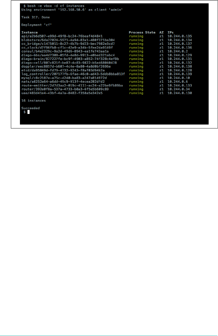
Figure 5-1. Deployed instance groups that comprise Cloud Foundry
7. Target the cf api domain and then log in as follows:
$ cf api api.<YOUR-CFDomain.com> --skip-ssl-validation
8. Log in via cf login. For the administrator username and password, use the fol‐
lowing values from the deployment-vars.yml file:
user:
Pull uaa_scim_users_admin_name out of deployment-vars. This currently
defaults to admin: password:. Pull uaa_scim_users_admin_password out of
deployment-vars.yml. The final deployment should look something like that
shown in Figure 5-2.
Installing Cloud Foundry | 71

Figure 5-2. bbl and cf-deployment topology on AWS spanning two AZs (three AZs are
preferable, but at the time of writing only two AZs are available in us-west)
72 | Chapter 5: Installing and Configuring Cloud Foundry

Changing Stacks
As we discussed in “Stacks” on page 37, a stack is a prebuilt rootfs used along with
droplets to provide the container filesystem used for running applications. The fol‐
lowing Cloud Foundry command lists all the stacks available in a deployment:
$ cf stacks
To change a stack and restage an application, use this command:
$ cf push APPNAME -s STACKNAME
Growing the Platform
bosh-bootloader provides a reasonable, default configuration for getting started with
Cloud Foundry. However, over time, your deployment and platform requirements
are likely to grow in scope and external integration points. You will also need to
upgrade the platform to take advantage of both security updates and new features.
As a distributed platform with many moving parts, Cloud Foundry supports rolling
upgrades, which make it possible for you to make changes to platform configuration
and underlying infrastructure. If you need additional or bigger Cells, you can resize
them and/or increase their number and then simply redeploy Cloud Foundry using
BOSH’s ability to perform rolling upgrades. If you need additional IaaS capacity, you
can grow your infrastructure to support your existing Cloud Foundry deployment.
You can also deploy additional Cloud Foundry environments, as required.
The key is that you must make some important design decisions at the outset, but
you are not locked into a static configuration and are free to grow and develop your
Cloud Foundry environment, as needed.
Validating Platform Integrity in Production
This section discusses how to validate the health and integrity of your production
environment. After you have successfully deployed Cloud Foundry, you should run
the smoke tests and Cloud Foundry acceptance tests (CATS) to ensure that your
environment is working properly. You should also maintain a dedicated sandbox to
test any changes prior to altering any development or production environment.
Start with a Sandbox
If you run business-critical workloads on a production instance of Cloud Foundry,
you should consider using a sandbox or staging environment prior to making any
production platform changes. This approach allows you to test any production apps
in an isolated environment before rolling out the platform changes (be it an infra‐
Changing Stacks | 73

3cf-smoke-tests are part of cf-deployment and will run as a one-off errand.
4cf-acceptance-tests are part of cf-deployment and will run as a one-off errand.
structure upgrade, stemcell change, Cloud Foundry release upgrade, buildpack
change, or service upgrade) to production.
The sandbox environment should mirror the production environment as closely as
possible. It should also contain a representation of the production apps and a mock
up of the production services to ensure that you validate the health of the applica‐
tions running on the platform. An example set of application tests could include the
following:
• Use the cf push command to push the app
•Bind an application to a service(s)
• Start an app
• Target the app on a restful endpoint and validate the response
• Target the app on a restful endpoint to write to a given data service
•Target the app on a restful endpoint to read the written value
• Generate and log a unique string to validate application logging
• Stop an app
• Delete an app
This suite of tests should be designed to exercise the core user-facing functionality,
including the applications interacting with any backing services.
Running these sorts of tests against each Cloud Foundry instance on a CI server with
a metrics dashboard is the desired approach for ease of repeatability. Not only do you
get volume testing for free (e.g., you can easily fill up a buildpack cache that way), you
can publish the dashboard URL to your platform consumers and stakeholders alike.
Tying these tests up to alerting/paging systems is also more efficient than paging peo‐
ple due to IaaS-level failures.
Production Verification Testing
Before making the production environment live, test the behavior of your platform
by running the following:
•cf-smoke-tests3 to ensure core Cloud Foundry functionality is working
•cf-acceptance-tests4 to test Cloud Foundry behavior and component integration
in more detail
74 | Chapter 5: Installing and Configuring Cloud Foundry

5For a current view on what is governed by quota plans, check out the Cloud Foundry documentation on
Creating and Modifying Quota Plans.
•Your own custom acceptance tests against the applications and services you have
written, including any established or customized configuration (this ensures that
the established application behavior does not break)
•External monitoring against your deployed apps
After you make the environment live, it is still important to identify any unintended
behavior changes. Therefore, the ongoing periodic running of your own acceptance
tests in production is absolutely recommended. For example, it is possible that you
might uncover a problem with the underlying infrastructure that can be noticed only
by repeatedly running acceptance tests in production.
Production Configuration Validation
cf-acceptance-tests (CATS) was never designed for live configura‐
tion validation. It is a developer workflow for engineers building
Cloud Foundry to verify that changes have not adversely affected
the platform. As a precheck, CATS is a valuable suite of tests to
run. The Cloud Foundry engineering team is currently working on
a production configuration validation test harness. If, in the mean‐
time, you need ongoing production validation, you can run your
own custom acceptance tests against the applications and services
you have written, including any established or customized configu‐
ration. Due to the way CATS modifies global state across all run‐
ning apps, running CATS against a live production environment is
not recommended.
Logical Environment Structure
Earlier, in “IaaS and Infrastructure Design” on page 48, we described the need to both
design and provision the infrastructure and IaaS layer to support a single Cloud
Foundry foundation. After deploying Cloud Foundry, the next task is to divide the
IaaS resources into logical environments for various teams, products, and users to
utilize. These logical environments within Cloud Foundry are known as Orgs and
Spaces.
As discussed in “Organizations and Spaces” on page 23, Orgs and Spaces provide a
way to group users together for management purposes. All members of an Org share
the same resource quota plan, services availability, and custom domain. Quota plans
are associated with Orgs. A quota will apply to all the activities within a particular
organization.5
Logical Environment Structure | 75

Each Org will have at least one Space but can have multiple Spaces. Every application
and service is scoped to a Space. Spaces provide a shared location for application
development, deployment, and maintenance, and users will have specific Space-
related roles. All members of a Space have access to any application environment
variables configured in the Space. Therefore, the Space members must have a strict
level of trust among one another.
Orgs and Spaces allow you to create a logical multitenant environment within your
Cloud Foundry deployment. They give you a level of abstraction with which you can
define who can do what in a particular environment. They also provide a way of allo‐
cating resources and governing chargeback.
You can define Orgs and Spaces any way that you like. Typically, Orgs are defined
around constructs such as the lines of businesses or particular projects and initiatives.
Spaces are generally defined in a couple of different ways:
•Typically, bigger organizations are broken down into “two-pizza teams,” with
each team owning its own Space. Usually, an individual team is responsible for
developing an isolated component or components such as a specific microser‐
vice.
•When deploying through a pipeline, it is often useful to have a development
space, test space, staging space, and a production space for the applications mov‐
ing into production.
There is no right or wrong way to structure your Orgs and Spaces; an important
point to keep in mind is that you are free to alter your logical Org and Space bound‐
aries at any point.
To begin, you can use the default Org and simply create a Space, as demonstrated
here:
$ cf create-space developer
Creating space developer in org default_org as admin...
OK
Assigning role SpaceManager to user admin in org default_org /
space developer as admin...
OK
Assigning role SpaceDeveloper to user admin in org default_org /
space developer as admin...
OK
You can then target the new developer space:
$ cf target -o "default_org" -s "developer"
76 | Chapter 5: Installing and Configuring Cloud Foundry

Pushing Your First App
You can push many different apps to Cloud Foundry. If you do not have one on
hand, you can download spring-music.
$ git clone https://github.com/scottfrederick/spring-music
$ cd spring-music
The Spring Music repository contains a sample app manifest. An app manifest pro‐
vides an easy way to define and capture any required command-line arguments and
application metadata. This is important because you can source-control the argu‐
ments you used when deploying your app. You do not need to deploy your app with
an app manifest. If you prefer, you can simply provide any required arguments via
the command line, as shown here:
---
applications:
- name: spring-music
memory: 1G
random-route: true
path: build/libs/spring-music.jar
Therefore, to deploy the app, all you need to do is compile the code by
using ./gradlew assemble and then use cf push:
$ ./gradlew assemble
$ cf push
The cf push command should return a URL that you can then use to access your
deployed app.
Summary
This chapter walked you through an end-to-end installation of Cloud Foundry using
cf-deployment and bosh-bootloader. If you followed all the steps, you should have
accomplished the following:
•Deployed the BOSH Director and created IaaS-specific components using bosh-
bootloader
• Deployed a working instance of Cloud Foundry using BOSH and cf-deployment
• Successfully validated platform integrity through CATS smoke tests
• Set up an Org and Space
•Pushed an application
Now that you are up and running with Cloud Foundry, Chapter 6 introduces you to
the underlying concepts and operational aspects of Diego.
Pushing Your First App | 77

CHAPTER 6
Diego
Diego is the container runtime architecture for Cloud Foundry. It is responsible for
managing the scheduling, orchestration, and running of containerized workloads.
Essentially, it is the heart of Cloud Foundry, running your applications and one-off
tasks in containers, hosted on Windows and Linux backends. Most Cloud Foundry
users (e.g., developers) do not interact with Diego directly. Developers interact only
with Cloud Foundry’s API, known as CAPI. However, comprehending the Diego
container runtime is essential for Platform Operators because, as an operator, you are
required to interact with Diego for key considerations such as resilience requirements
and application troubleshooting. Understanding Diego is essential for understanding
how workloads are deployed, run, and managed. This understanding also provides
you with an appreciation of the principles underpinning container orchestration.
This chapter explores Diego’s concepts and components. It explains the purpose of
each Diego service, including how the services interrelate as state changes throughout
the system.
Implementation Changes
It is important to understand the fundamental concepts of the
Diego system. The specific technical implementation is less conse‐
quential because it is subject to change over time. What Diego does
is more important than how it does it.
Why Diego?
Residing at the core of Cloud Foundry, Diego handles the scheduling, running, and
monitoring of tasks and long-running processes (applications) that reside inside
79

managed containers. Diego extends the traditional notion of running applications to
scheduling and running two types of processes:
Task
A process that is guaranteed to be run at most once, with a finite duration. A
Task might be an app-based script or a Cloud Foundry “job”; for example, a stag‐
ing request to build an application droplet.
Long-running process (LRP)
An LRP runs continuously and may have multiple instances. Cloud Foundry dic‐
tates to Diego the desired number of instances for each LRP, encapsulated as
DesiredLRPs. All of these desired instances are run and represented as actual
LRPs known as ActualLRPs. Diego attempts to keep the correct number of
ActualLRPs running in the face of any network partitions, crashes, or other fail‐
ures. ActualLRPs only terminate due to intervention, either by crashing or being
stopped or killed. A typical example of an ActualLRP is an instance of an applica‐
tion running on Cloud Foundry.
Cloud Foundry is no longer solely about the application as a unit of work. The addi‐
tion of running one-off tasks in isolation opens up the platform to a much broader
set of workloads; for example, running Bash scripts or Cron-like jobs to process a
one-off piece of data. Applications can also spawn and run tasks for isolated compu‐
tation. Tasks can also be used for local environmental adjustments to ensure that
applications adhere to service-level agreements (SLAs).
The required scope for what Cloud Foundry can run is ever increasing as more work‐
loads migrate to the platform. Tasks and LRPs, along with the new TCPRouter (dis‐
cussed in “The TCPRouter” on page 134), have opened up the platform to
accommodate a much broader set of workloads. In addition to traditional web-based
applications, you can now consider Cloud Foundry for the following:
•Internet of Things (IoT) applications such as aggregating and processing device
data
• Batch applications
• Applications with application tasks
• Computational numerical modeling
• Reactive streaming applications
•TCP-based applications
By design, Diego is agnostic to preexisting Cloud Foundry components such as the
Cloud Controller. This separation of concerns is compelling. Being agnostic to both
client interaction and runtime implementation has allowed for diverse workloads
80 | Chapter 6: Diego
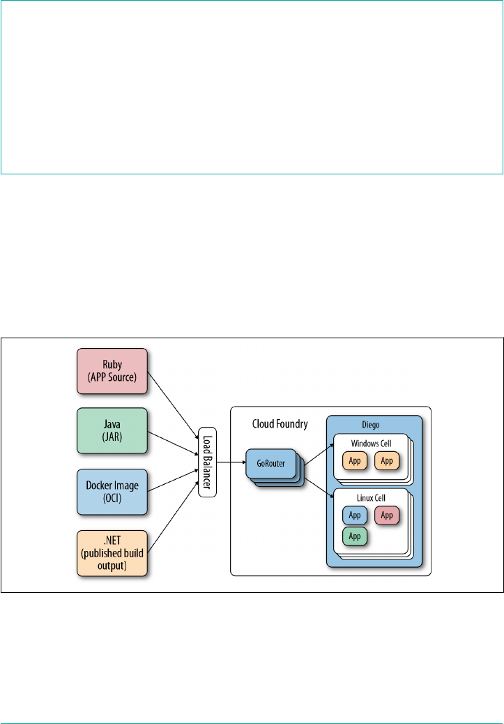
with composable backends. For example, Diego has generalized the way container
image formats are handled; Diego’s container management API is Garden.
The Importance of Container Management
For a container image (such as a Docker image or other OCI–compatible image) to
be instantiated and run as an isolated process, it requires a container-management
layer that can create, run, and manage the container process. The Docker company
provides its own Linux Container manager for running Docker images. Other
container-management technologies also exist, such as rkt and runC. As a more gen‐
eralized container management API, Cloud Foundry uses Garden to support a variety
of container technologies. Garden is discussed further in “Why Garden?” on page 150.
Through Garden, Diego can now support any container image format that the Gar‐
den API supports. Diego still supports the original droplet plus a stack combination
but can now accommodate other image formats; for example, OCI-compatible
images such as Docker or Rocket. In addition, Diego has added support for running
containers on any Garden-based container technology, including Linux and
Windows-based container backends that implement the Garden API. Figure 6-1
illustrates Diego’s ability to support multiple application artifacts and container
image formats.
Figure 6-1. Developer interaction, cf pushing different application artifacts to Cloud
Foundry
Why Diego? | 81

A Brief Overview of How Diego Works
Container scheduling and orchestration is a complex topic. Diego comprises several
components, and each component comprises one or more microservices. Before get‐
ting into detail about these components and services, it is worth taking a moment to
introduce the end-to-end flow of the Diego component interactions. At this point, I
will begin to introduce specific component names for readability. The individual
component responsibilities will be explained in detail in “Diego Components” on
page 97.
At its core, Diego executes a scheduler. Scheduling is a method by which work, speci‐
fied by some means, is assigned to resources that attempt to undertake and complete
that work.
A Tip on Scheduling
Schedulers are responsible for using resources in such a way so as
to allow multiple users to share system resources effectively while
maintaining a targeted quality of service. Scheduling is an intrinsic
part of the execution model of a distributed system. Scheduling
makes it possible to have distributed multitasking spread over dif‐
ferent nodes, with a centralized component responsible for pro‐
cessing. Within OSs, this processing unit is referred to as a CPU.
Within Cloud Foundry, Diego acts as a centralized processing unit
for all scheduling requirements.
Diego clients—in our case, the Cloud Controller (via a bridge component known as
the CC-Bridge)—submit, update, and retrieve Tasks and LRPs to the BBS. The BBS
service is responsible for Diego’s central data store and API. Communication from
the Cloud Controller to the BBS is via a remote procedure call (RPC)–style API
implemented though Google protocol buffers.
The scheduler within Diego is governed by Diego’s Brain component. The Brain’s
orchestration function, known as the Auctioneer service, retrieves information from
the BBS and optimally distributes Tasks and LRPs to the cluster of Diego Cell
machines (typically VMs). The Auctioneer distributes its work via an auction process
that queries Cells for their capacity to handle the work and then sends work to the
Cells. After the Auctioneer assigns work to a Cell, the Cell’s Executor process creates
a Garden container and executes the work encoded in the Task/LRP. This work is
encoded as a generic, platform-independent recipe of composable actions (described
in “Composable Actions” on page 85). Composable actions are the actual actions that
run within a container; for example, a RunAction that runs a process in the con‐
tainer, or a DownloadAction that fetches and extracts an archive into the container.
To assist in setting up the environment for the process running within the container,
82 | Chapter 6: Diego

1These services, along with the concept of domain freshness, are discussed further in “The CC-Bridge” on page
93.
Application Life-Cycle Binaries (e.g., Buildpacks) are downloaded from a file server
that is responsible for providing static assets.
Application Life-Cycle Binaries
Staging is the process that takes an application and composes a
executable binary known as a droplet. Staging is discussed further
in “Staging” on page 159. The process of staging and running an
application is complex and filled with OS and container
implementation-specific requirements. These implementation-
specific concerns have been encapsulated in a collection of binaries
known collectively as the Application Life-Cycle. The Tasks and
LRPs produced by the CC-Bridge download the Application Life-
Cycle Binaries from a blobstore (in Cloud Foundry’s case, the
Cloud Controller blobstore). These Application Life-Cycle Binaries
are helper binaries used to stage, start, and health-check Cloud
Foundry applications. You can read more about Application Life-
Cycle Binaries in “Application Life-Cycle Binaries” on page 112.
Diego ensures that the actual LRP (ActualLRP) state matches the desired LRP (Desir‐
edLRP) state through interaction with its client (the CC-Bridge). Specific services on
the CC-Bridge are responsible for keeping the Cloud Controller and Diego synchron‐
ized, ensuring domain freshness.1
The BBS also provides a real-time representation of the state of the Diego cluster
(including all DesiredLRPs, running ActualLRP instances, and in-flight Tasks). The
Brain’s Converger periodically analyzes snapshots of this representation and corrects
discrepancies, ensuring that Diego is eventually consistent. This is a clear example of
Diego using a closed feedback loop to ensure that its view of the world is accurate.
Self-healing is the first essential feature of resiliency; a closed feedback loop ensures
that eventual consistency continues to match the ever-changing desired state.
Diego sends real-time streaming logs for Tasks/LRPs to the Loggregator system.
Diego also registers its running LRP instances with the GoRouter via the Route-
Emitter, ensuring external web traffic can be routed to the correct container.
Essential Diego Concepts
Before exploring Diego’s architecture and component interaction, you need to be
aware of two fundamental Diego concepts:
Essential Diego Concepts | 83

• Action abstraction
• Composable actions
As work flows through the distributed system, Diego components describe their
actions using different levels of abstraction. Diego can define different abstractions
because the architecture is not bound by a single entity; for example, a single mono‐
lithic component with a static data schema. Rather, Diego consists of distributed
components that each host one or more microservices. Although microservices
architecture is no panacea, if designed correctly for appropriate use cases, microservi‐
ces offer significant advantages by decoupling complex interactions. Diego’s micro‐
services have been composed with a defined boundary and are scoped to a specific
component. Furthermore, Diego establishes well-defined communication flows
between its component services. This is vital for a well designed system.
Components versus Services
Components like the Cell, Brain, and CC-Bridge are all names of VMs where Diego
services are located. The location of those services is mutable, and depending on the
deployment setup, some components can have more than one service residing on
them. When describing the Diego workflow, consider the Diego components as
though they were locations of specific services rather than the actual actors. For
example, it makes sense to talk about distributing work to the Cells because a Cell is
where the container running your workload will reside. However, the Cell does not
actually create the container; it is currently the Rep service that is responsible for ini‐
tiating container creation. Theoretically, the Rep could reside on some other compo‐
nent such as the BBS. Similarly, the Auctioneer is the service responsible for
distributing work; the Brain is just the component VM on which the Auctioneer is
running. In BOSH parlance, components are referred to as instance groups and serv‐
ices are referred to as release jobs.
Action Abstraction
Because each microservice is scoped to a specific Diego component, each service is
free to express its work using its own abstraction. This design is incredibly powerful
because bounded abstractions offer an unprecedented degree of flexibility. Abstrac‐
tion levels move from course high-level abstractions to fine-grained implementations
as work moves through the system. For example, work can begin its journey at the
Cloud Controller as an app, but ultimately all work ends up as a scheduled process
running within a created container. This low-level implementation of a scheduled
process is too specific to be hardwired into every Diego component. If it were hard‐
wired throughout, the distributed system would become incredibly complex for end
84 | Chapter 6: Diego

2The available actions are documented in the Cloud Foundry BBS Release on GitHub.
users and brittle to ongoing change. The abstraction boundaries provides two key
benefits:
• The freedom of a plug-and-play model
• A higher-level concern for Diego clients
Plug-and-play offers the freedom to replace key parts of the system when required,
without refactoring the core services. A great example of this is a pluggable container
implementation. Processes can be run via a Docker image, a droplet plus a stack, or
in a Windows container. The required container implementation (both image format
and container backend) can be plugged into Diego as required without refactoring
the other components.
Moreover, clients of Diego have high-level concerns. Clients should not need to be
concerned with underlying implementation details such as how containers (or, more
specifically, process isolation) are created in order to run their applications. Clients
operate at a much higher level of abstraction, imperatively requesting “run my appli‐
cation.” They are not required to care about any of the underlying implementation
details. This is one of the core benefits of utilizing a platform to drive application
velocity. The more of the undifferentiated heavy lifting you allow the platform to
undertake, the faster your business code will progress.
Composable Actions
At the highest level of abstraction, the work performed by a Task or LRP is expressed
in terms of composable actions, exposed via Diego’s public API. As described earlier,
composable actions are the actual actions that run within a container; for example, a
RunAction that runs a process in the container, or a DownloadAction that fetches
and extracts an archive into the container.
Conceptually each composable action implements a specific instruction. A set of
composable actions can then be used to describe an explicit imperative action, such
as “stage my application” or “run my application.”2 Composable actions are, by and
large, hidden from Cloud Foundry users. Cloud Foundry users generally interact only
with the Cloud Controller. The Cloud Controller (via the CC-Bridge) then interacts
with Diego through Diego’s composable actions. However, even though as a Platform
Operator you do not interact with composable actions directly, it is essential that you
understand the available composable actions when it comes to debugging Cloud
Foundry. For example, the UploadAction might fail due to misconfigured blobstore
credentials, or a TimeoutAction might fail due to a network partition.
Essential Diego Concepts | 85

Composable actions include the following:
1. RunAction runs a process in the container.
2. DownloadAction fetches an archive (.tgz or .zip) and extracts it into the con‐
tainer.
3. UploadAction uploads a single file, in the container, to a URL via POST.
4. ParallelAction runs multiple actions in parallel.
5. CodependentAction runs multiple actions in parallel and will terminate all code‐
pendent actions after any single action exits.
6. SerialAction runs multiple actions in order.
7. EmitProgressAction wraps another action and logs messages when the wrapped
action begins and ends.
8. TimeoutAction fails if the wrapped action does not exit within a time interval.
9. TryAction runs the wrapped action but ignores errors generated by the wrapped
action.
Because composable actions are a high-level Diego abstraction, they describe generic
activity, not how the activity is actually achieved. For example, the UploadAction
describes uploading a single file to a URL; it does not specify that the URL should be
the Cloud Controller’s blobstore. Diego, as a generic execution environment, does
not care about the URL; Cloud Foundry, as a client of Diego, is the entity responsible
for defining that concern. This concept ties back to the action abstraction discussed
previously, allowing Diego to remain as an independently deployable subsystem, free
from specific end-user concerns.
So, how do composable actions relate to the aforementioned Cloud Foundry Tasks
and LRPs? Consider the steps involved when the Cloud Controller issues a run com‐
mand for an already staged application. To bridge the two abstractions, there is a
Cloud Foundry-to-Diego bridge component known as the Cloud Controller Bridge
(CC-Bridge). This essential function is discussed at length in “The CC-Bridge” on
page 93. For now, it is sufficient to know that the CC-Bridge knows how to take the
various resources (e.g., a droplet, metadata ,and blobstore location) that the Cloud
Controller provides, coupled with a desired application message. Then, using these
composable actions, the CC-Bridge directs Diego to build a sequence of composable
actions to run the droplet within the container, injecting the necessary information
provided by the Cloud Controller. For example, the specific composable action
sequence for a run command will be:
•DownLoadAction to download the droplet from the CC blobstore into a speci‐
fied location inside the container.
86 | Chapter 6: Diego
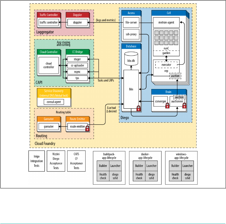
•DownLoadAction to download the set of static plugin (AppLifeCycle) binaries
from a file server into a specified location within the container.
•RunAction to run the start command in the container, with the correct parame‐
ters. RunAction ensures that the container runs the code from the droplet using
the helper (AppLifeCycle) binaries that correctly instantiate the container envi‐
ronment.
Applications are broken into a set of Tasks such as “stage an app” and “run an app.”
All Diego Tasks will finally result in a tree of composable actions to be run within a
container.
Layered Architecture
Diego is comprised of a number of microservices residing on several components.
Diego is best explained by initially referring to the diagram in Figure 6-2.
Figure 6-2. Diego components
Layered Architecture | 87

3You can find more information on Diego online, including the Diego BOSH release repository.
We can group the components broadly, as follows:
•A Cloud Foundry layer of user-facing components (components with which you,
as a platform user, will directly interact)
•The Diego Container Runtime layer (components with which the core Cloud
Foundry components interact)
Each Diego component is a single deployable BOSH machine (known as an instance
group) that can have any number of machine instances. Although there can be multi‐
ple instances of each instance group to allow for HA and horizontal scaling, some
instance groups require a global lock to ensure that only one instance is allowed to
make decisions.
Diego BOSH Releases
As with other Cloud Foundry components, you can deploy and run the Diego BOSH
release as a standalone system. Having the property of being independently deploya‐
ble is powerful. The engineering team responsible for the Diego subsystem has a
smaller view of the distributed system allowing decoupling from other Cloud Foun‐
dry subsystems and faster iterative development. It also means that the release-
engineering team can adopt more holistic granular testing in a heterogeneous
environment of different subsystems. Because each Cloud Foundry subsystem can be
deployed in isolation, more complex upgrade migration paths can now be verified
because older versions of one subsystem, such as the Postgres release, can be
deployed alongside the latest Diego release.3
We will begin exploring Diego by looking at the user-facing Cloud Foundry compo‐
nents that act as a client to Diego, and then move on to the specific Diego compo‐
nents and services.
Interacting with Diego
Cloud Foundry users do not interact with Diego directly; they interact with the Cloud
Foundry user-facing components, which then interact with Diego on the user’s
behalf. Here are the Cloud Foundry user-facing components that work in conjunc‐
tion with Diego:
•CAPI components: the Cloud Foundry API (Cloud Controller and the CC-
Bridge)
88 | Chapter 6: Diego
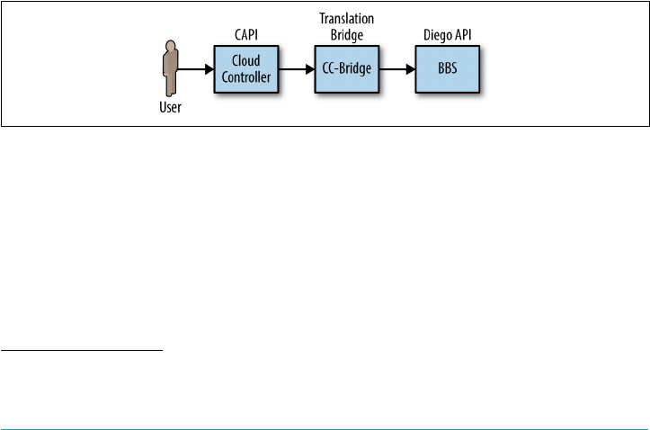
4User management is primarily handled by the User Access and Authentication, which does not directly inter‐
act with Diego but still remains an essential piece of the Cloud Foundry ecosystem.
• The logging system defined by the Loggregator and Metron agents
• Routing (GoRouter, TCPRouter, and the Route-Emitter)
Collectively, these Cloud Foundry components are responsible for the following:
• Application policy
• Uploading application artifacts, droplets, and metadata to a blobstore
•Traffic routing and handling application traffic
• Logging
•User management including end-user interaction via the Cloud Foundry API
commands4
Diego seamlessly hooks into these different Cloud Foundry components to run appli‐
cations and tasks, route traffic to your applications, and allow the retrieval of
required logs. With the exception of the CC-Bridge, these components were dis‐
cussed at length in Chapter 3.
CAPI
Diego Tasks and LRPs are submitted to Diego via a Diego client. In Cloud Foundry’s
case, the Diego client is the CAPI, exposed by the Cloud Controller. Cloud Foundry
users interact with the Cloud Controller through the CAPI. The Cloud Controller
then interacts with Diego’s BBS via the CC-Bridge, a Cloud Foundry-to-Diego trans‐
lation layer. This interaction is depicted in Figure 6-3.
Figure 6-3. API interaction from the platform user through to Diego
The Cloud Controller provides REST API endpoints for Cloud Foundry users to
interact with Cloud Foundry for commands including the following:
•Pushing, staging, running, and updating
• Pushing and running discrete one-off tasks
Interacting with Diego | 89

• Creating users, Orgs, Spaces, Routes, Domains and Services, and so on
• Retrieving application logs
The Cloud Controller (discussed in “The Cloud Controller” on page 33) is concerned
with imperatively dictating policy to Diego, stating “this is what the user desires;
Diego, make it so!”; for example, “run two instances of this application.” Diego is
responsible for orchestrating and executing the required workload. It deals with
orchestration through a more autonomous subsystem at the backend. For example,
Diego deals with the orchestration of the Cells used to fulfill a workload request
through an auction process governed by the Auctioneer.
This design means that the Cloud Controller is not coupled to the execution
machines (now known as Cells) that run your workload. The Cloud Controller does
not talk to Diego directly; instead, it talks only to the translation component, the CC-
Bridge, which translates the Cloud Controller’s app-specific messages to the more
generic Diego language of Tasks and LRPs. The CC-Bridge is discussed in-depth in
“The CC-Bridge” on page 93. As just discussed, this abstraction allows the Cloud
Foundry user to think in terms of apps and tasks, while allowing each Diego service
to express its work in a meaningful abstraction that makes sense to that service.
Staging Workflow
To better understand the Cloud Controller interaction with Diego, we will explore
what happens during a staging request. Exploring staging introduces you to two
Diego components:
• The BBS: Diego’s database that exposes the Diego API.
• Cells: the execution machines responsible for running applications in containers.
These two components are discussed at length later in this chapter. Understanding
the staging process provides you with a clear picture of how Cloud Foundry inter‐
prets the $ cf push and translates it into a running ActualLRP instance. Figure 6-4
provides an overview of the process.
90 | Chapter 6: Diego
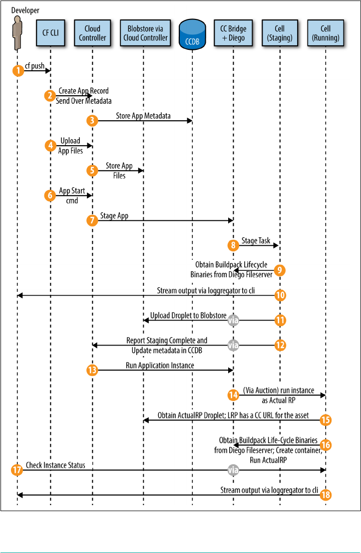
Figure 6-4. Interaction between Cloud Foundry’s Cloud Controller components and
Diego, while staging and running an application
Interacting with Diego | 91

The numbered list that follows corresponds to the callout numbers in Figure 6-4 and
provides an explanation of each stage:
1. A developer/Platform Operator uses the Cloud Foundry command-line tool to
issue a cf push command.
2. The Cloud Foundry command-line tool instructs the Cloud Controller to create
a record for the application and sends over the application metadata (e.g., the
app name, number of instances, and the required buildpack, if specified).
3. The Cloud Controller stores the application metadata in the CCDB.
4. The Cloud Foundry command-line tool uploads the application files (such as
a .jar file) to the Cloud Controller.
5. The Cloud Controller stores the raw application files in the Cloud Controller
blobstore.
6. The Cloud Foundry command-line tool issues an app start command (unless a
no-start argument was specified).
7. Because the app has not already been staged, the Cloud Controller, through the
CC-Bridge, instructs Diego to stage the application.
8. Diego, through an auction process, chooses a Cell for staging and sends the stag‐
ing task to the Cell.
9. The staging Cell downloads the required life-cycle binaries that are hosted on the
Diego file server, and then uses the instructions in the buildpack to run the stag‐
ing task in order to stage the application.
10. The staging Cell streams the output of the staging process (to loggregator) so that
the developer can troubleshoot application staging problems.
11. The staging Cell packages the resulting staged application into a tarball (.tar file)
called a droplet and uploads it to the Cloud Controller blobstore.
12. Diego reports to the Cloud Controller that staging is complete. In addition, it
returns metadata about the application back to the CCDB.
13. The Cloud Controller (via CC-Bridge) issues a run AI command to Diego to run
the staged application.
14. Diego, through an auction process, chooses a Cell to run an LRP instance as an
ActualLRP.
15. The running Cell downloads the application droplet directly from the Cloud
Controller blobstore (the ActualLRP has a Cloud Controller URL for the asset).
16. The running Cell downloads the Application Life-Cycle Binaries hosted by the
Diego file server and uses these binaries to create an appropriate container and
then starts the ActualLRP instance.
92 | Chapter 6: Diego
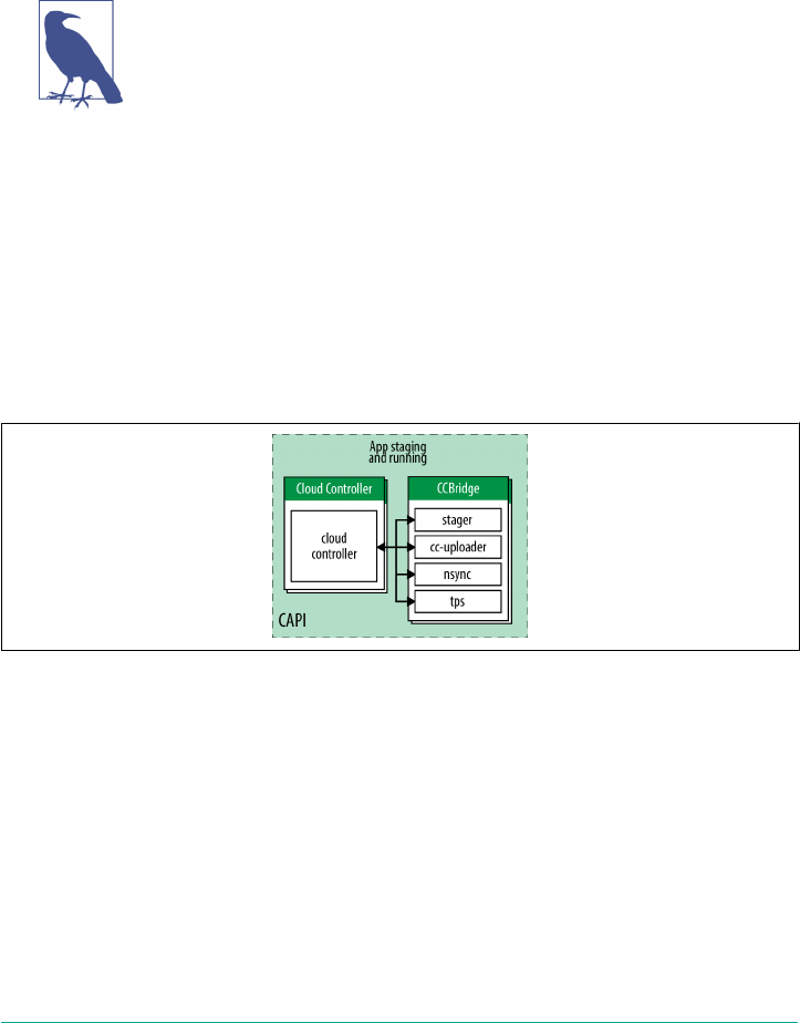
17. Diego reports the status of the application to the Cloud Controller, which peri‐
odically receives the count of running instances and any crash events.
18. The Loggregator log/metric stream goes straight from the Cell to the Loggregator
system (not via the CC-Bridge). The application logs can then be obtained from
the Loggregator through the CF CLI.
Diego Staging
The preceding steps explore only staging and running an app from
Cloud Foundry’s perspective. The steps gloss over the interaction
of the internal Diego services. After exploring the remaining Diego
components and services, we will explore staging an LRP from
Diego’s perspective. Analyzing staging provides a concise way of
detailing how each service interacts, and therefore it is important
for you to understand.
The CC-Bridge
The CC-Bridge (Figure 6-5) is a special component comprised of four microservices.
It is a translation layer designed to interact both with the Cloud Controller and
Diego’s API, which is exposed by Diego’s BBS. The BBS is discussed shortly in “The
BBS” on page 98.
Figure 6-5. The CC-Bridge
The components on the CC-Bridge are essential for establishing domain freshness.
Domain freshness means two things:
1. The actual state reflects the desired state.
2. The desired state is always understood.
Domain freshness is established through a combination of self-healing and closed
feedback loops.
Interacting with Diego | 93

The Future of the CC-Bridge Component
For now, you can think of the CC-Bridge as a translation layer that
converts the Cloud Controller’s domain-specific requests into
Diego’s generic Tasks and LRPs. Eventually, Cloud Foundry’s
Cloud Controller might be modified to communicate directly with
the BBS, making the CC-Bridge redundant. Either way, the func‐
tion of the four services that currently reside on the CC-Bridge will
still be required no matter where they reside.
CC-Bridge services translate the Cloud Controller’s domain-specific requests of stage
and run applications into Diego’s generic language of LRP and Tasks. In other words,
Diego does not explicitly know about applications or staging tasks; instead, it just
knows about a Task or LRP that it has been requested to execute. The CC-Bridge
services include the following:
Stager
The Stager handles staging requests.
CC-Uploader
A file server to serve static assets to the Cloud Controller’s blobstore.
Nsync
This service is responsible for handling domain freshness from the Cloud Con‐
troller to Diego.
TPSThis service is responsible for handling domain freshness from Diego to the
Cloud Controller.
Stager
The Stager handles staging requests from the Cloud Controller. It translates these
requests into generic Tasks and submits the Tasks to Diego’s BBS. The Stager also
instructs the Cells (via BBS Task auctions) to inject the platform-specific Application
Life-Cycle Binary into the Cell to perform the actual staging process. Application
Life-Cycle Binaries provide the logic to build, run, and health-check the application.
(You can read more about them in “Application Life-Cycle Binaries” on page 112.)
After a task is completed (successfully or otherwise), the Stager sends a response to
the Cloud Controller.
CC-Uploader
The CC-Uploader acts as a file server to serve static assets such as droplets and build
artifacts to the Cloud Controller’s blobstore. It mediates staging uploads from the
Cell to the Cloud Controller, translating a simple generic HTTP POST request into
94 | Chapter 6: Diego

the complex correctly formed multipart-form upload request that is required by the
Cloud Controller. Droplet uploads to the CC-Uploader are asynchronous, with the
CC-Uploader polling the Cloud Controller until the asynchronous UploadAction is
completed.
Nsync and TPS
Nsync and TPS are the two components responsible for handling domain freshness,
matching desired and actual state between Diego and the Cloud Controller. They are
effectively two sides of the same coin:
•The Nsync primarily retrieves information from the Cloud Controller. It is the
component responsible for constructing the DesiredLRP that corresponds with
the application request originating from the Cloud Controller.
•The TPS primarily provides feedback information from Diego to the Cloud Con‐
troller.
Both components react to events via their listener process, and will periodically check
state validity via their respective bulker/watcher processes.
Figure 6-6 shows the high-level component interaction between the Cloud Control‐
ler, Diego’s Nsync, and Converger components right through to the Cell. The figure
also illustrates the convergence from a DesiredLRP stored in the BBS to an
ActualLRP running on a Cell.
Figure 6-6. High-level process interaction involving domain freshness, convergence, and
ActualLRP placement into a Cell’s container
Interacting with Diego | 95

Domain Freshness
Diego’s design has built-in resilience for its domain of responsibility—namely, run‐
ning Tasks and LRPs. Diego’s eventual-consistency model periodically compares the
desired state (the set of DesiredLRPs) to the actual state (the set of ActualLRPs) and
takes action to keep the actual and desired state synchronized. To achieve eventual
consistency in a safe way, Diego must ensure that its view of the desired state is com‐
plete and up to date. Consider a rare scenario in which Diego’s database has crashed
and requires repopulating. In this context, Diego correctly knows about the
ActualLRPs but has an invalid view of the DesiredLRPs, so it would be catastrophic
for Diego to shut down all ActualLRPs in a bid to reconcile the actual and desired
state.
To mitigate this effect, it is the Diego client’s responsibility to repeatedly inform
Diego of the desired state. Diego refers to this as the “freshness” of the desired state,
or domain freshness. Diego consumers explicitly mark desired state as fresh on a
domain-by-domain basis. Failing to do so will prevent Diego from taking actions to
ensure eventual consistency (Diego will not stop extra instances if there is no corre‐
sponding desired state). To maintain freshness, the client typically supplies a time-to-
live (TTL) and attempts to bump the freshness of the domain before the TTL expires
(thus verifying that the contents of Diego’s DesiredLRP are up to date). It is possible
to opt out of this by updating the freshness with no TTL so that freshness will never
expire, allowing Diego to always perform all of its eventual-consistency operations.
Only destructive operations, performed during an eventual-consistency convergence
cycle, will override freshness; Diego will continue to start and stop instances when
explicitly instructed to do so.
The Nsync is responsible for keeping Diego “in sync” with the Cloud Controller. It
splits its responsibilities between two independent processes: a bulker and a listener.
Let’s look at each of them:
Nsync-Listener
The Nsync-Listener is a service that responds to DesiredLRP requests from the
Cloud Controller. It actively listens for desired app requests and, upon receiving
a request, either creates or updates the DesiredLRP via a record in the BBS data‐
base. This is the initial mechanism for dictating desired state from the Cloud
Controller to Diego’s BBS.
Nsync-Bulker
The Nsync-Bulker is focused on maintaining the system’s desired state, periodi‐
cally polling the Cloud Controller and Diego’s BBS for all DesiredLRPs to ensure
that the DesiredLRP state known to Diego is up to date. This component pro‐
96 | Chapter 6: Diego

vides a closed feedback loop, ensuring that any change of desired state from the
Cloud Controller is reflected on to Diego.
The process status reporter (TPS) is responsible for reporting Diego’s status; it is
Diego’s “hall monitor.” It splits its responsibilities between two independent pro‐
cesses: listener and watcher submodules. Here’s what each one does:
TPS-Listener
The TPS-Listener provides the Cloud Controller with information about cur‐
rently running ActualLRP instances. It responds to the Cloud Foundry CLI
requests for cf apps and cf app <may-app-name>.
TPS-Watcher
The TPS-Watcher monitors ActualLRP activity for crashes and reports them to
the Cloud Controller.
Logging and Traffic Routing
To conclude our review of the Cloud Foundry layer of user-facing components, let
look at logging.
Diego uses support for streaming logs from applications to Cloud Foundry’s Loggre‐
gator system and provides support for routing traffic to applications via the routing
subsystem. With the combined subsystems—Diego, Loggregator, and the routing
subsystem—we have everything we need to do the following:
• Run any number of applications as a single user
• Route traffic to the LRPs
•Stream logs from the LRPs
The Loggregator aggregates and continually streams log and event data. Diego uses
the Loggregator’s Metron agent to provide real-time streaming of logs for all Tasks
and LRPs in addition to the streaming of logs and metrics for all Diego components.
The routing system routes incoming application traffic to ActualLRPs running within
Garden containers on Diego Cells. (The Loggregator and routing subsystem were dis‐
cussed in Chapter 3.)
Diego Components
At the time of writing, there are four core Diego component machines:
1. BBS (Database)
2. Cell
3. Brain
Diego Components | 97
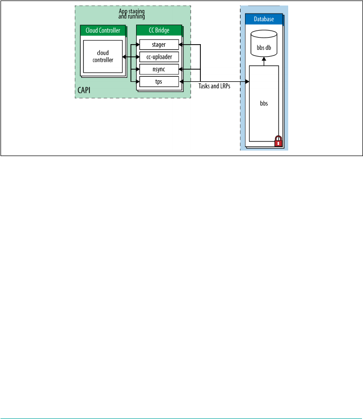
4. Access (an external component)
The functionality provided by these components is broken up into a number of
microservices running on their respective component machines.
The BBS
The BBS manages Diego’s database by maintaining an up-to-date cache of the state of
the Diego cluster including a picture-in-time of all DesiredLRPs, running ActualLRP
instances, and in-flight Tasks. Figure 6-7 provides an overview of the CC–Bridge-to-
BBS interaction.
Figure 6-7. The BBS interaction with the Cloud Controller via the CC-Bridge
The BBS provides Diego’s internal components and external clients with a consistent
API to carry out the following:
1. Query and update the system’s shared state (the state machine)
2. Trigger operations that execute the placement of Tasks and LRPs
3. View the datastore underpinning the state machine
For example, certain operations will cause effects. Consider creating a new LRP in the
system. To achieve this, the CC-Bridge communicates to the BBS API endpoints.
These endpoints will save any required state in the BBS database. If you specify a
DesiredLRP with N instances, the BBS will automatically trigger the required actions
for creating N ActualLRPs. This is the starting point of the state machine. Because
understanding the state machine is important for debugging the platform, we cover it
in more detail in “The Diego State Machine and Workload Life Cycles” on page 107.
Communication to the BBS is achieved through Google protocol buffers (protobufs).
98 | Chapter 6: Diego

Protocol Buffers
Protocol buffers (protobufs) provide an efficient way to marshal
and unmarshal data. They are a language-neutral, platform-
neutral, extensible mechanism for serializing structured data, simi‐
lar in concept to eXtensible Markup Language (XML) but smaller,
faster, and much less verbose.
The Diego API
The BBS provides an RPC-style API for core Diego components (Cell reps and Brain)
and any external clients (SSH proxy, CC-Bridge, Route-Emitter). The BBS endpoint
can be accessed only by Diego clients that reside on the same “private” network; it is
not publicly routable. Diego uses dynamic service discovery between its internal
components. Diego clients (the CC-Bridge) will look up the active IP address of the
BBS using internal service discovery. Here are the main reasons why the Diego end‐
point is not accessible via an external public route through the GoRouter:
•Clients are required to use TLS for communication with the BBS. The GoRouter
is currently not capable of establishing or passing through a TLS connection to
the backend.
•Clients are required to use mutual TLS authentication. To talk to the BBS, the
client must present a certificate signed by a CA that both the client and BBS rec‐
ognize.
The BBS encapsulates access to the backing database and manages data migrations,
encoding, and encryption. The BBS imperatively directs Diego’s Brain to state “here is
a task with a payload, find a Cell to run it.” Diego clients such as the CC-Bridge, the
Brain, and the Cell all communicate with the BBS. The Brain and the Cell are both
described in detail later in this chapter.
State versus Communication
The BBS is focused on data as opposed to communication. Putting state into an even‐
tually consistent store (such as etcd, clustered MySQL, or Consul) is an effective way
to build a distributed system because everything is globally visible. Eventual consis‐
tency is a data problem, not a communication problem. Tools like etcd and Consul,
which operate as a quorum, handle consistency for you.
It is important that Diego does not store inappropriate data in a component designed
for state. For instance, a “start auction” announcement is not a statement of truth; it
is a transient piece of communication representing intent. Therefore, transient infor‐
mation should be communicated by messaging (i.e., NATS or HTTP—although
direct communication over HTTPS is preferred). Communication via messaging is
temporary and, as such, it can be lossy. For Diego auctions, loss is acceptable. Diego
Diego Components | 99

can tolerate loss because of eventual consistency and the closed feedback loops
described earlier.
For visibility into the BBS, you can use a tool called Veritas.
The Converger process
The Converger is a process responsible for keeping work eventually consistent.
Eventual Consistency
Eventual consistency is a consistency model used for maintaining
the integrity of stateful data in a distributed system. To achieve
high availability, a distributed system might have several “copies”
of the data-backing store. Eventual consistency informally guaran‐
tees that, if no new updates are made to a given item of data, even‐
tually all requests for that item will result in the most recently
updated value being returned. To learn more about HA, see “High
Availability Considerations” on page 263.
The Converger is a process that currently resides on the Brain instance group. It is
important to discuss now, because it operates on the BBS periodically and takes
actions to ensure that Diego attains eventual consistency. Should the Cell fail cata‐
strophically, the Converger will automatically move the missing instances to other
Cells. The Converger maintains a lock in the BBS to ensure that only one Converger
performs convergence. This is primarily for performance considerations because
convergence should be idempotent.
The Converger uses the converge methods in the runtime-schema/BBS to ensure
eventual consistency and fault tolerance for Tasks and LRPs. When converging LRPs,
the Converger identifies which actions need to take place to bring the DesiredLRP
state and ActualLRP state into accord. Two actions are possible:
• If an instance is missing, a start auction is sent.
•If an extra instance is identified, a stop message is sent to the Cell hosting the
additional instance.
In addition, the Converger watches for any potentially missed messages. For example,
if a Task has been in the PENDING state for too long, it is possible that the request to
hold an auction for the Task never made it to the Auctioneer. In this case, the Con‐
verger is responsible for resending the auction message. Periodically the Converger
sends aggregate metrics about DesiredLRPs, ActualLRPs, and Tasks to the Loggrega‐
tor.
100 | Chapter 6: Diego
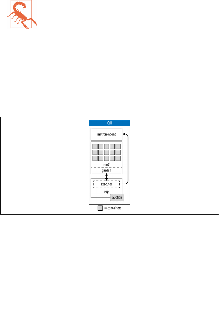
Resilience with RAFT
Whatever the technology used to back the BBS (etcd, Consul, clus‐
tered MySQL), it is likely to be multinode to remove any single
point of failure. If the backing technology is based on the Raft con‐
sensus algorithm, you should always ensure that you have an odd
number of instances (three at a minimum) to maintain a quorum.
Diego Cell Components
Cells are where applications run. The term application is a high-level construct; Cells
are concerned with running desired Tasks and LRPs. Cells are comprised of a num‐
ber of subcomponents (Rep/Executor/Garden; see Figure 6-8) that deal with running
and maintaining Tasks and LRPs. One Cell typically equates to a single VM, as gov‐
erned by the CPI in use. You can scale-out Cells both for load and resilience con‐
cerns.
Figure 6-8. The Cell processes gradient from the Rep to the Executor through to Garden
and its containers
There is a specificity gradient across the Rep, Executor, and Garden. The Rep is con‐
cerned with Tasks and LRPs, and knows the details about their life cycles. The Execu‐
tor knows nothing about Tasks and LRPs but merely knows how to manage a
collection of containers and run the composable actions in these containers. Garden,
in turn, knows nothing about actions and simply provides a concrete implementation
of a platform-specific containerization technology that can run arbitrary commands
in containers.
Rep
The Rep is the Cell’s API endpoint. It represents the Cell and mediates all communi‐
cation between the BBS and Brain—the Rep is the only Cell component that commu‐
Diego Components | 101
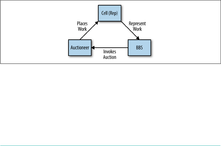
nicates with the BBS. This single point of communication is important to understand;
by using the Rep for all communication back to the Brain and BBS, the other Cell
components can remain implementation independent. The Rep is also free to be
reused across different types of Cells. The Rep is not concerned with specific con‐
tainer implementations; it knows only that the Brain wants something run. This
means that specific container technology implementations can be updated or swap‐
ped out and replaced at will, without forcing additional changes within the wider dis‐
tributed system. The power of this plug-and-play ability should not be
underestimated. It is an essential capability for upgrading the system with zero-
downtime deployments.
Specifically, the Rep does the following (see also Figure 6-9):
•Participates in the Brain’s Auctioneer auctions to bid for Tasks and LRPs. It bids
for work based on criteria such as its capacity to handle work, and then subse‐
quently tries to accept what is assigned.
•Schedules Tasks and LRPs by asking its in-process Executor to create a container
to run generic action recipes in the newly created container.
•Repeatedly maintains the presence of the Cell in the BBS. Should the Cell fail cat‐
astrophically, the BBS will invoke the Brain’s Converger to automatically move
the missing instances to another Cell with availability.
•Ensures that the set of Tasks and ActualLRPs stored in the BBS are synchronized
with the active containers that are present and running on the Cell, thus com‐
pleting the essential feedback loop between the Cell and the BBS.
Figure 6-9. The BBS, auction, and Cell feedback loop
The Cell Rep is responsible for getting the status of a container periodically from
Garden via its in-process Executor and reporting that status to the BBS database.
There is only one Rep running on every Diego Cell.
102 | Chapter 6: Diego

5A conceptual adaption from the earlier container technology LMCTFY, which stands for Let Me Contain
That For You.
Executor
The Executor is a logical process inside the Rep. Its remit is “Let me run that for
you.”5 The Executor still resides in a separate repository, but it is not a separate job; it
is part of the Rep.
The Executor does not know about the Task versus LRP distinction. It is primarily
responsible for implementing the generic Executor “composable actions,” as dis‐
cussed in “Composable Actions” on page 85. Essentially, all of the translation
between the Rep and Garden is encapsulated by the Executor: the Executor is a gate‐
way adapter from the Rep to the Garden interface. The Rep deals with simplistic
specifications (execute this tree of composable actions), and the Executor is in charge
of actually interacting with Garden to, for example, make the ActualLRP via the life
cycle objects. Additionally, the Executor streams Stdout and Stderr to the Metron-
agent running on the Cell. These log streams are then forwarded to the Loggregator.
Garden
Cloud Foundry’s container implementation, Garden, is separated into the API imple‐
mentation and the actual container implementation. This separation between API
and actual containers is similar to how Docker Engine has both an API and a con‐
tainer implementation based on runC.
Garden is a container API. It provides a platform-independent client server to man‐
age Garden-compatible containers such as runC. It is backend agnostic, defining an
interface to be implemented by container-runners (e.g., Garden-Linux, Garden-
Windows, libcontainer, runC). The backend could be anything as long as it under‐
stands requests through the Garden API and is able to translate those requests into
actions.
Container Users
By default, all applications run as the vcap user within the con‐
tainer. This user can be changed with a runAction, the composable
action responsible for running a process in the container. This
composable action allows you to specify, among other settings, the
user. This means Diego’s internal composable actions allow pro‐
cesses to run as any arbitrary user in the container. That said, the
only users that really make sense are distinguished unprivileged
users known as vcap and root. These two users are provided in the
cflinuxfs2 rootfs. For Buildpack-based apps, Cloud Foundry always
specifies the user to be vcap.
Diego Components | 103
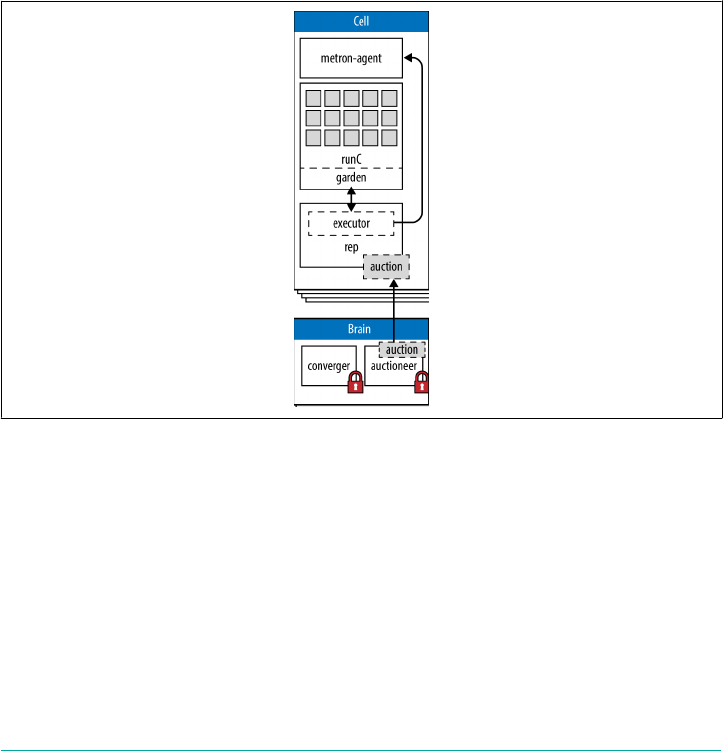
Chapter 8 looks at Garden in greater detail.
The Diego Brain
We have already discussed the Brain’s Converger process. The Brain (Figure 6-10) is
also responsible for running the Auctioneer process. Auctioning is the key compo‐
nent of Diego’s scheduling capability. There are two components in Diego that par‐
ticipate in auctions:
The Auctioneer
Responsible for holding auctions whenever a Task or LRP needs to be scheduled
The Cell’s Rep
Represents a Cell in the auction by making bids for work and, if picked as the
winner, running the Task or LRP
Figure 6-10. The Cell–Brain interaction
104 | Chapter 6: Diego
Horizontal Scaling for Controlling Instance Groups
Each core component (known in BOSH parlance as an instance
group) is deployed on a dedicated machine or VM. There can be
multiple instances of each instance group, allowing for HA and
horizontal scaling.
Some instance groups, such as the Auctioneer, are essentially state‐
less. However, it is still important that only one instance is actively
making decisions. Diego allows for lots of potential running
instances in order to establish HA, but only one Auctioneer can be
in charge at any one period in time. Within a specific instance
group, the instance that is defined as “in charge” is specified by a
global lock. Finding out which specific instance is in charge is
accomplished through an internal service discovery mechanism.
When holding an auction, the Auctioneer communicates with the Cell Reps via
HTTP. The auction process decides where Tasks and ActualLRP instances are run
(remember that a client can dictate that one LRP requires several ActualLRP instan‐
ces for availability). The Auctioneer maintains a lock in the BBS such that only one
Auctioneer may handle auctions at any given time. The BBS determines which Auc‐
tioneer is active from a lock record (effectively the active Auctioneer holding the
lock). When the BBS is at a point at which it wants to assign a payload to a Cell for
execution, the BBS directs the Brain’s Auctioneer by requesting, “here is a task with a
payload, find a Cell to run it.” The Auctioneer asks all of the Reps what they are cur‐
rently running and what their current capacity is. Reps proactively bid for work and
the Auctioneer uses the Reps’ responses to make a placement decision.
Scheduling Algorithms
At the core of Diego is a distributed scheduling algorithm designed
to orchestrate where work should reside. This distribution algo‐
rithm is based on several factors such as existing Cell content and
app size. Other open source schedulers exist, such as Apache
Mesos or Google’s Kubernetes. Diego is optimized specifically for
application and task workloads. The supply–demand relationship
for Diego differs from the likes of Mesos. For Mesos, all worker
Cells report, "I am available to take N pieces of work" and Mesos
decides where the work goes. In Diego, an Auctioneer says, "I have
N pieces of work, who wants them?" Diego’s worker Cells then join
an auction, and the winning Cell of each auctioned-off piece of
work gets that piece of work. Mesos’ approach is supply driven, or
a “reverse-auction,” and Diego’s approach is demand driven.
A classic optimization problem in distributed systems is that there is a small lag
between the time the system realizes it is required to make a decision (e.g., task place‐
Diego Components | 105

ment) and the time when it takes action on that decision. During this lag the input
criteria that the original decision was based upon might have changed. The system
needs to take account of this to optimize its work-placement decisions.
Consequently, there are currently two auction actions for LRPs: LRPStartAuction
and LRPStopAuction. Let’s look at each:
LRPStartAuctions
These occur when LRPs need to be assigned somewhere to run. Essentially, one
of Diego’s Auctioneers is saying, “We need another instance of this app. Who
wants it?”
LRPStopAuctions
These occur when there are too many LRPs instances running for a particular
application. In this case, the Auctioneer is saying, “We have too many instances of
this app at index X. Who wants to remove one?"
The Cell that wins the auction either starts or stops the requested LRP.
Simulations
Diego includes simulations for testing the auction orchestration. Diego values the
tight feedback loops achieved with the auction algorithms. This feedback allows the
engineers to know how Diego internals are working and performing. It is especially
valuable for dealing with order dependency: where “A” must run before “B.” Simulat‐
ing this means it can be tested and reasoned over more quickly.
Simulations can be run either in-process or across multiple processes. Unit tests are
great for isolation and integration tests exercise the traditional usage. Simulation test‐
ing provides an extra layer of performance testing.
The Access VM
The access VM contains the file server and the SSH proxy services.
File server
The file server serves static assets used by various Diego components. In particular, it
provides the Application Life-Cycle Binaries to the Cells.
The SSH proxy
Diego supports SSH access to ActualLRP instances. This feature provides direct
access to the application for tasks such as viewing application logs or inspecting the
state of the container filesystem. The SSH proxy is a stateless routing tier. The pri‐
mary purpose of the SSH proxy is to broker connections between SSH clients and
106 | Chapter 6: Diego

SSH servers running within containers. The SSH proxy is a lightweight SSH daemon
that supports the following:
• Command execution
• Secure file copy via SCP
• Secure file transfer via SFTP
•Local port forwarding
•Interactive shells, providing a simple and scalable way to access containers asso‐
ciated with ActualLRPs
The SSH proxy hosts the user-accessible SSH endpoint so that Cloud Foundry users
can gain SSH access to containers running ActualLRPs. The SSH proxy is responsible
for the following:
• SSH authentication
• Policy enforcement
• Access controls
After a user successfully authenticates with the proxy, the proxy attempts to locate
the target container, creating the SSH session with a daemon running within the con‐
tainer. It effectively creates a “man-in-the-middle” connection with the client, bridg‐
ing two SSH sessions:
• A session from the client to the SSH proxy
•A session from the SSH proxy to the container
After both sessions have been established, the proxy will manage the communication
between the user’s SSH client and the container’s SSH daemon.
The daemon is self-contained and has no dependencies on the container root filesys‐
tem. It is focused on delivering basic access to ActualLRPs running in containers and
is intended to run as an unprivileged process; interactive shells and commands will
run as the daemon user. The daemon supports only one authorized key and is not
intended to support multiple users. The daemon is available on Diego’s file server. As
part of the application life cycle bundle, Cloud Foundry’s LRPs will include a down‐
loadAction to acquire the binary and then a runAction to start it.
The Diego State Machine and Workload Life Cycles
Diego’s semantics provide clients with the ability to state, “Here is my workload: I
want Diego to keep it running forever. I don’t care how.” Diego ensures this request
becomes a reality. If for some reason an ActualLRP crashes, Diego will reconcile
The Diego State Machine and Workload Life Cycles | 107

desired and actual state back to parity. These life cycle concerns are captured by
Diego’s state machine. It is important that you understand the state machine should
you need to debug the system. For example, if you notice many of your ActualLRPs
remain in UNCLAIMED state, it is highly likely that your Cells have reached capacity
and require additional resources.
Stateful and Globally Aware Components
When it comes to state, Diego is comprised of three types of components: stateful
components, stateless components, and stateless globally aware components. To
describe the difference between the three components, consider the differences
between the Cell, the BBS, and the Auctioneer.
A Cell has a global presence, but it is effectively stateless. Cells advertise themselves
over HTTP to the BBS via a service discovery mechanism. They do not provide the
entire picture of their current state; they simply maintain a presence in the BBS via
recording a few static characteristics such as the AZ they reside in and their IP
address. Maintaining a presence in the BBS allows the Auctioneer to contact the Cell
at the recorded location in order to try to place work.
The BBS retains the global state associated with managing the persistence layer. The
BBS also has the responsibility of managing migrations (between data migrations and
schema migrations or API migrations reflected in the schema). For this reason, the
BBS is an essential component to back up.
The Auctioneer is required to be globally aware; it has a global responsibility but is
not directly responsible for system state. When a component has a global responsibil‐
ity, there should only ever be one instance running at any one time.
An understanding of the state machine (see Figure 6-11) and how it relates to the app
and task life cycles is essential for understanding where to begin with debugging a
specific symptom.
108 | Chapter 6: Diego
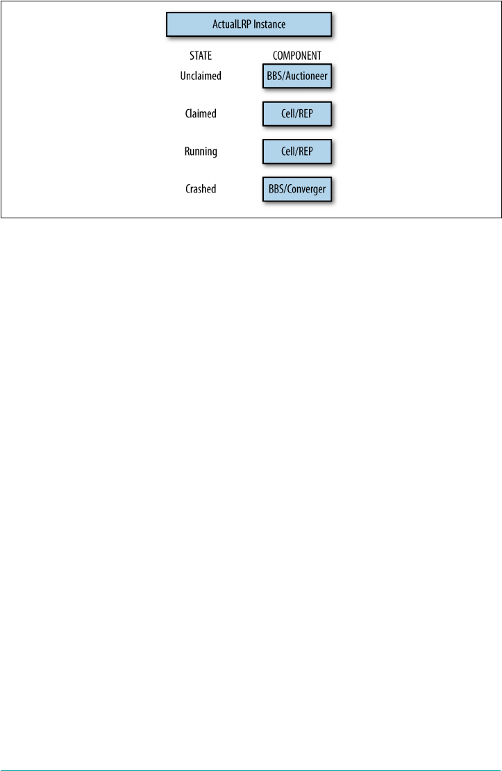
Figure 6-11. Diego’s state machine
The responsibility for state belongs, collectively, to several components. The partition
of ownership within the distributed system is dependent on the task or LRP (app) life
cycle.
The Application Life Cycle
The application life cycle is as follows:
1. When a client expresses the desire to run an application, the request results in
Diego’s Nsync process creating an ActualLRP record.
2. An ActualLRP has a state field (a process globally unique identifier [GUID] with
an index) recorded in the BBS. The ActualLRP begins its life in an UNCLAIMED
state, resulting in the BBS passing it over to the Auctioneer process.
3. Work collectively is batched up and then distributed by the Auctioneer. When
the Auctioneer has a batch of work that requires allocating, it looks up all the
running Cells through service discovery and individually asks each Cell (Rep) for
a current snapshot of its state, including how much capacity the Cell has to
receive extra work. Auction activity is centrally controlled. It is like a team leader
assigning tasks to team members based on their desire for the work and their
capacity to perform it. The batch of work is broken up and distributed appropri‐
ately across the Cells.
4. An auction is performed and the ActualLRP is placed on a Cell. The Cell’s Rep
immediately transfers the ActualLRP state to CLAIMED. If placement is success‐
ful, the LRP is now RUNNING and the Rep now owns this record. If the
ActualLRP cannot be placed (if a Cell is told to do work but cannot run that
work for some reason), it reenters the auction process in an UNCLAIMED state.
The Cell rejects the work and the Auctioneer can retry the work later.
The Diego State Machine and Workload Life Cycles | 109

5. The Cell’s response on whether it has the capacity to do the work should not
block actually starting the work. Therefore, the “perform” request from the Auc‐
tioneer instructs the Cell to try to undertake the work. The Cell then attempts to
reserve capacity within the Executor’s state management, identifying the extra
resource required for the work.
6. The Cell quickly reports success or failure back to the Auctioneer. Upon success,
the Cell then reserves this resource (as quickly as possible) so as not to advertise
reserved resources during future auctions. The Executor is now aware that it has
the responsibility for the reserved work and reports this back to the Rep, which
knows the specifics of the Diego state machine for Tasks and LRPs.
7. Based on the current state that the Executor is reporting to the Rep, the Rep is
then going to make decisions about how to progress workloads through their life
cycles. In general, if anything is in reserved state, the Rep states to the Executor:
"start running that workload.” At that point, the Executor takes the container
specification and creates a container in Garden.
8. The Auctioneer is responsible for the placement of workloads across the entire
cluster of Cells. The Converger is responsible for making sure the desired and
actual workloads are reconciled across the entire cluster of Cells. If the
ActualLRP crashes, it is placed in a CRASHED state and the Rep moves the state
ownership back to the BBS because the ActualLRP is no longer running. When
the Rep undertakes its own local convergence cycle, trying to converge the actual
running states in its Garden containers with its representation within the BBS,
the Rep will discover the ActualLRP CRASHED state. The Rep then looks for the
residual state that might still reside from its management of that ActualLRP.
Even if the container itself is gone, the Executor might still have the container
represented in a virtual state. The virtual state’s “COMPLETED” state informa‐
tion might provide a clue as to why the ActualLRP died (e.g., it may have been
placed in failure mode). The Rep then reports to the BBS that the ActualLRP has
crashed. The BBS will attempt three consecutive restarts and then the restart pol‐
icy will begin to back off exponentially, attempting subsequent restarts after a
delayed period.
9. The Brain’s Converger runs periodically looking for “CRASHED” ActualLRPs.
Based on the number of times it has crashed (which is also retained in the BBS),
the Converger will pass the LRP back to the Auctioneer to resume the
ActualLRP. The Converger deals with the mass of unclaimed LRPs, moving them
to ActualLRPs “CLAIMED” and “RUNNING”. The Converger maps the state
(held in the BBS) on to the desired LRPs. If the BBS desires five instances but the
Rep only reports on four records, the Converger will make the fifth record in the
BBS to kickstart the placement.
10. There is a spectrum of responsibilities that extends from the Converger to the
BBS. Convergence requires a persistence-level convergence, including the
110 | Chapter 6: Diego

required cleanup process. There is also a business-model convergence in which
we can strip away any persistence artifacts and deal with the concepts we are
managing—and Diego ensures that the models of these concepts are in harmony.
The persistence layer always happens in the BBS, but it is triggered by the Con‐
verger running a convergence loop.
Task Life Cycle
Tasks in Diego also undergo a life cycle. This life cycle is encoded in the Task’s state
as follows:
PENDING
When a task is first created, it enters the PENDING state.
CLAIMED
When successfully allocated to a Diego Cell, the Task enters the CLAIMED state
and the Task’s Cell_id is populated.
RUNNING
The Task enters the RUNNING state when the Cell begins to create the container
and run the defined Task action.
COMPLETED
Upon Task completion, the Cell annotates the TaskResponse (failed, failure_rea‐
son, result), and the Task enters the COMPLETED state.
Upon Task completion, it is up to the consumer of Diego to acknowledge and resolve
the completed Task, either via a completion callback or by deleting the Task. To dis‐
cover if a Task is completed, the Diego consumer must either register a comple‐
tion_callback_url or periodically poll the API to fetch the Task in question. When the
Task is being resolved, it first enters the RESOLVING state and is ultimately removed
from Diego. Diego will automatically reap Tasks that remain unresolved after two
minutes.
Additional Components and Concepts
In addition to its core components, Diego also makes use of the following:
• The Route-Emitter
• Consul
• Application Life-Cycle Binaries
Additional Components and Concepts | 111

The Route-Emitter
The Route-Emitter is responsible for registering and unregistering the ActualLRPs
routes with the GoRouter. It monitors DesiredLRP state and ActualLRP state via the
information stored in the BBS. When a change is detected, the Route-Emitter emits
route registration/unregistration messages to the router. It also periodically emits the
entire routing table to the GoRouter. You can read more about routing in Chapter 7.
Consul
Consul is a highly available and distributed service discovery and key-value store.
Diego uses it currently for two reasons:
•It provides dynamic service registration and load balancing via internal DNS res‐
olution.
•It provides a consistent key-value store for maintenance of distributed locks and
component presence. For example, the active Auctioneer holds a distributed lock
to ensure that other Auctioneers do not compete for work. The Cells Rep main‐
tains a global presence in Consul so that Consul can maintain a correct view of
the world. The Converger also maintains a global lock in Consul.
To provide DNS, Consul uses a cluster of services. For services that require DNS res‐
olution, a Consul agent is co-located with the hosting Diego component. The consul-
agent job adds 127.0.0.1 as the first entry in the nameserver list. The consul-agent
that is co-located on the Diego component VM serves DNS for consul-registered
services on 127.0.0.1:53. When Consul tries to resolve an entry, the Consul domain
checks 127.0.0.1 first. This reduces the number of component hops involved in DNS
resolution. Consul allows for effective intercomponent communication.
Other services that expect external DNS resolution also need a reference to the exter‐
nal DNS server to be present in /etc/resolv.conf.
Like all RAFT stores, if Consul loses quorum, it may require manual intervention.
Therefore, a three-Consul-node cluster is required, preferably spanning three AZs. If
you restart a node, when it comes back up, it will begin talking to its peers and replay
the RAFT log to get up to date and synchronized with all the database history. It is
imperative to ensure that a node is fully back up and has rejoined the cluster prior to
taking a second node down; otherwise, when the second node goes offline, you might
lose quorum. BOSH deploys Consul via a rolling upgrade to ensure that each node is
fully available prior to bringing up the next.
Application Life-Cycle Binaries
Diego aims to be platform agnostic. All platform-specific concerns are delegated to
two types of components:
112 | Chapter 6: Diego
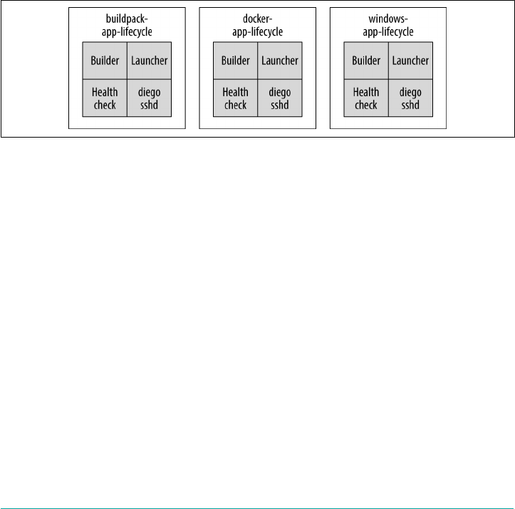
• the Garden backend
• the Application Life-Cycle Binaries
The process of staging and running an application is complex. These concerns are
encapsulated in a set of binaries known collectively as the Application Life-Cycle
Binaries. There are different Application Life-Cycle Binaries depending on the con‐
tainer image (see also Figure 6-12):
•Buildpack-Application Life Cycle implements a traditional buildpack-based life
cycle.
•Docker-Application Life Cycle implements a Docker-based OCI-compatible life
cycle.
•Windows-Application Life Cycle implements a life cycle for .NET applications
on Windows.
Figure 6-12. The Application Life-Cycle Binaries
Each of the aforementioned Application Life Cycles provides a set of binaries that
manage a specific application type. For the Buildpack-Application Life Cycle, there
are three binaries:
•The Builder stages a Cloud Foundry application. The CC-Bridge runs the Builder
as a Task on every staging request. The Builder performs static analysis on the
application code and performs any required preprocessing before the application
is first run.
•The Launcher runs a Cloud Foundry application. The CC-Bridge sets the
Launcher as the Action on the app’s DesiredLRP. The Launcher executes the
user’s start command with the correct system context (working directory, envi‐
ronment variables, etc.).
•The Healthcheck performs a status check of the running ActualLRP from within
the container. The CC-Bridge sets the Healthcheck as the Monitor action on the
app’s DesiredLRP.
Additional Components and Concepts | 113

The Stager Task produced by the CC-Bridge downloads the appropriate Application
Life-Cycle Binaries and runs them to invoke life cycle scripts such as stage, start, and
health-check in the ActualLRP.
This is a pluggable module for running OS-specific components. Because the life
cycle is OS specific, the OS is an explicitly specified field required by the LRP. For
example, the current Linux setting references the cflinuxfs2 rootfs. In addition to the
rootfs, the only other OS-specific component that is explicitly specified is the back‐
end container type.
RunAction and the Launcher Binary
When Diego invokes start-command for an app (ActualLRP), it does so as a RunAc‐
tion. A Task or LRP RunAction invokes a process that resides under the process iden‐
tifier (PID) namespace of the container within which it is invoked. The RunAction
process is not like a simple bash -c "start-command". It is run through the launcher
binary, which adds additional environmental setup for the process before the process
calls exec to spawn bash -c "start-command". The launcher is invoked after the
container is created and is focused on setting up the environment for the start-
command process (e.g., the launcher sets appropriate environmental variables, the
working directory, and all other environment concerns inside the container). This
environment setup is not very extensive; for example, for buildpack apps, it changes
HOME and TMPDIR, puts some per-instance information in VCAP_APPLICA‐
TION, and then sources any scripts the buildpack placed in .profile.d. When the
launcher runs, it uses the exec system call to invoke the start command (and so dis‐
appears). When you review the process tree within the Garden container, you can
observe that after the launcher finishes running and setting up the environment, the
top-level process is init (the first daemon process started when booting the system),
and your applications will be a child of initd.
In addition to the Linux life cycle, Diego also supports a Windows life cycle and a
Docker life cycle. The Docker life cycle (to understand how to stage a Docker image)
is based on metadata from the Cloud Controller, based on what type of app we want
to run. As part of the information for “stage these app bits,” there will be some indica‐
tion of what branching the Stager is required to undertake. The binaries have tried to
ensure that, as much as possible, these specifications are shared.
Putting It All Together
We discussed what happens when staging an application in “Staging Workflow” on
page 90. Specifically, we discussed the following interactions:
•The CLI and the Cloud Controller
114 | Chapter 6: Diego

• The Cloud Controller and CC-Bridge
• The CC-Bridge and Diego, including Diego Cells
Up to this point, we have glossed over the interaction of the internal Diego compo‐
nents. This section discusses the interaction between the Diego components during
staging LRPs. This section assumes you are staging an app using the buildpack Appli‐
cation Life-Cycle Binaries as opposed to pushing a prebuilt OCI-compatible image.
Staging takes application artifacts and buildpacks and produces a binary droplet arti‐
fact coupled with metadata. This metadata can be anything from hosts and route
information to the detected buildpack and the default start command. Essentially,
any information that comes out of the entire buildpack compilation and release pro‐
cess can be encapsulated via the buildpack’s metadata.
The internals of Diego know nothing about buildpacks. The Cloud
Controller, via the Application Life-Cycle Binaries, provides all the
required buildpacks to run in a container. The Cloud Controller
can be conservative on what it downloads; if you specify a build‐
pack (e.g., the JBP), only that buildpack will be downloaded. If no
buildpack is specified, the Cloud Controller will download all
buildpacks. Additionally, individual Cells can cache buildpacks so
that they do not need to be repeatedly downloaded from the Cloud
Controller. Chapter 9 looks at buildpacks in greater detail.
The steps for staging are as follows:
1. The staging process begins with a cf push request from the Cloud Foundry CLI
to the Cloud Controller (CAPI). Diego’s role in the process occurs when the
Cloud Controller instructs Diego (via the CC-Bridge) to stage the application. All
Tasks and LRPs are submitted to the CC-Bridge via Cloud Foundry’s Cloud
Controller. The Cloud Controller begins the staging process by sending a “stage
app bits” request as a task.
2. The CC-Bridge’s Stager picks up and handles the “stage app bits” request. The
Stager constructs a staging message and forwards it to the BBS. Thus, the Stager
represents a transformation function.
3. The first step of the BBS is to store the task information. When the task request is
stored in the BBS, the BBS is responsible for validating it. At this stage the task
request is only stored; no execution of the task has taken place.
4. Diego is now at a point at which it wants to assign a payload (the Task) to a Cell
that is best suited to run it. The BBS determines which of the Brain’s Auctioneers
is active by looking for the Auctioneer that currently holds the lock record. The
BBS communicates to the Auctioneer, directing it to find a Cell to run the Task.
Putting It All Together | 115

5. The Auctioneer optimally distributes Tasks and LRPs to the cluster of Diego
Cells via an auction involving the Cell Reps. The Auctioneer asks all of the Reps
what they are currently running. It uses the Reps’ responses to make a placement
decision. After it selects a Cell, it directs the chosen Cell to run the desired Task.
You can configure it so that this auction is done every time you push an applica‐
tion; however, you can also batch auctions for performance to reduce the auction
overhead.
There is additional scope for sharding this auction process by AZ. It is inappro‐
priate to cache the auction results because state is changing all the time; for
example, a task might complete or an ActualLRP might crash. To look up which
Cells are registered (via their Reps), the Auctioneer communicates with the BBS
to get the shared system state. Reps report to BBS directly to inform BBS of their
current state. When the Auctioneer is aware of the available Reps, it contacts all
Reps directly.
6. The chosen Rep is assigned the Task. After a Task/LRP is assigned to a Cell, that
Cell will try to allocate containers based on its internal accounting. Inside the
Rep, there is a gateway to Garden (the Executor). (We introduced Garden in
“Garden” on page 103 and it is discussed further in Chapter 8.) The Rep runs
Tasks/ActualLRPs by asking its in-process Executor to create a container to run
generic action recipes. The Executor creates a Garden container and executes the
work encoded in the Task/ActualLRP. This work is encoded as a generic,
platform-independent recipe of composable actions (we discussed these in
“Composable Actions” on page 85). If the Cell cannot perform the Task, it
responds to the Auctioneer, announcing that it was unable to run the requested
work. Payloads that are distributed are a batch of Tasks rather than one Task per
request. This approach reduces chatter and allows the Cell to attempt all reques‐
ted tasks and report back any Task it was unable to accomplish.
7. The staging Cell uses the instructions in the buildpack and the staging task to
stage the application. It obtains the buildpack through the buildpack Application
Life-Cycle Binaries via the file server.
8. Assuming that the task completes successfully, the staging task will result in a
droplet, and Garden reports that the container has completed all processes. This
information bubbles up through the Rep and the Task is now marked as being in
a completed state. When a Task is completed it can call back to the BBS using the
callback in the Task request. The callback URL then calls back to the Stager so
that the Stager knows that the task is complete (Stagers are stateless, so the call‐
back will return to any Stager). The callback is the process responsible for
uploading the metadata from Cell to Stager, and the Stager passes the metadata
back to the Cloud Controller.
9. The Cloud Controller also provides information as to where to upload the drop‐
let. The Cell that was responsible for staging the droplet can asynchronously
116 | Chapter 6: Diego

upload the droplet back to the Cloud Controller blobstore. The droplet goes back
to the Cloud Controller blobstore via the Cell’s Executor. The Executor uploads
the droplet to the file server. The file server asynchronously uploads the blob‐
store to the Cloud Controller’s blobstore, regularly polling to find out when the
upload has been completed.
10. Additionally the staging Cell streams the output of the staging process so that the
developer can troubleshoot application staging problems. After this staging pro‐
cess has completed successfully, the Cloud Controller subsequently issues a “run
application droplet command” to Diego to run the staged application.
From a developer’s perspective, you issue a command to Cloud Foundry and Cloud
Foundry will run your app. However, as discussed at the beginning of this chapter, as
work flows through the distributed system, Diego components describe their actions
using different levels of abstraction. Internal interactions between the Cloud Control‐
ler and Diego’s internal components are abstracted away from the developer. They
are, however, important for an operator to understand in order to troubleshoot any
issues.
Summary
Diego is a distributed system that allows you to run and scale N number of applica‐
tions and tasks in containers across a number of Cells. Here are Diego’s major char‐
acteristics and attributes:
•It is responsible for running and monitoring OCI-compatible images, standalone
applications, and tasks deployed to Cloud Foundry.
• It is responsible for container scheduling and orchestration.
•It is agnostic to both client interaction and runtime implementation.
•It ensures applications remain running by reconciling desired state with actual
state through establishing eventual consistency, self-healing, and closed feedback
loops.
•It has a generic execution environment made up of composable actions, and a
composable backend to allow the support of multiple different Windows- and
Linux-based workloads.
When you step back and consider the inherent challenges with any distributed sys‐
tem, the solutions to the consistency and orchestration challenges provided by Diego
are extremely elegant. Diego has been designed to make the container runtime sub‐
system of Cloud Foundry modular and generic. As with all distributed systems,
Diego is complex. There are many moving parts and the communication flows
between them are not trivial. Complexity is fine, however, if it is well defined within
Summary | 117

bounded contexts. The Cloud Foundry team has gone to great lengths to design
explicit boundaries for the Diego services and their interaction flows. Each service is
free to express its work using its own abstraction, and ultimately this allows for a
modular composable plug-and-play system that is easy both to use and operate.
118 | Chapter 6: Diego

CHAPTER 7
Routing Considerations
This chapter looks at Cloud Foundry’s routing mechanisms in more detail. User-
facing apps need to be accessed by a URL, often referred to in Cloud Foundry par‐
lance as a route. End users target the URL for the app that they want to access. The
app then hopefully returns the correct response. However, there is often a lot more
going on behind that simple request–response behavior.
Operators can use routing mechanisms for reasons such as to provide additional
security, ease deployment across a microservices architecture, and avoid downtime
during upgrades through well-established techniques such as deploying canaries and
establishing blue/green deployments. For these reasons, an understanding of Cloud
Foundry’s routing mechanisms along with an appreciation of the routing capabilities
is an important operational concern. Additionally, understanding how different
Cloud Foundry components dynamically handle routing is important for debugging
platform- or app-routing issues.
Routing Primitives
The Cloud Foundry operator deals with the following:
• Routes
• Hostnames
• Domains
• Context paths
•Ports
The Cloud Foundry documentation explores these concepts at length. This chapter
explores the key considerations for establishing routing best practices. We begin with
119

a brief introduction to the terms and then move on to the routing mechanisms and
capabilities.
Routes
To enable traffic from external clients, apps require a specific URL, known as a route.
For example, developers can create a route by mapping the route myapp.shared-cf-
domain.com to the app myapp.
You can construct routes via a combination of the following:
• Domain
• Host
• Port
•Context path
Route construction is explained further in a later section.
Each Cloud Foundry instance can have a single default domain and further addi‐
tional domains that can be shared across organizations (Orgs) in a single Cloud
Foundry instance. Routes are then based on those domains. Routes belong to a Space,
and only apps in the same Space as that route can be mapped to it. A developer of
one Space cannot create or use a route if it already exists in another Space. For this
reason, many developers place app-name-${random-word} in their route to ensure
that their app route is unique during the dev/test phase.
One app, one route, multiple app instances
You can map an individual app to either a single route or, if desired, multiple routes.
Because apps can have multiple app instances (ActualLRPs), all accessed by the single
route, each route has an associated array of host:port entries stored in a routing table
on the GoRouter. Figure 7-1 shows that the host is the Diego Cell machine running
the LRP in a container and the port corresponds to a dedicated host port for that con‐
tainer. The router regularly recomputes new routing tables based on the Cell IP
addresses and the host-side port numbers for the containers, as illustrated in
Figure 7-1. In a cloud-based distributed environment, both desired and actual state
can rapidly change; thus, it is important to dynamically update routes both periodi‐
cally and immediately in response to state changes.
120 | Chapter 7: Routing Considerations
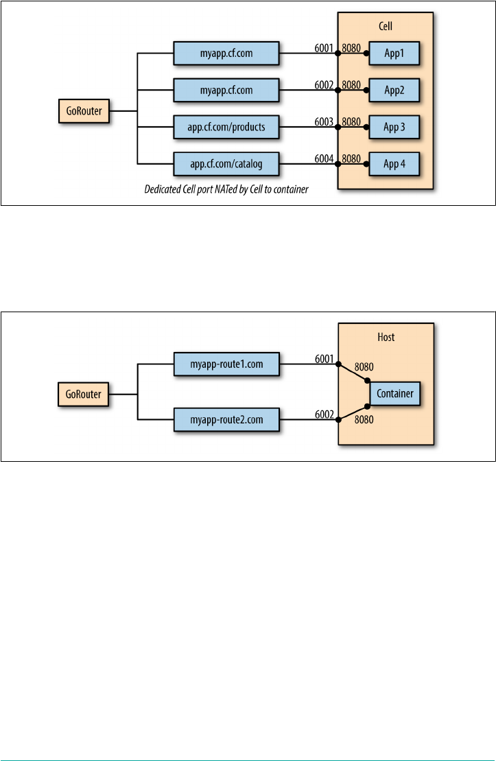
Figure 7-1. Cell-to-container port mapping
One app, multiple routes
You can also map an individual app to multiple routes, granting multiple URLs
access to that app. This capability is illustrated in Figure 7-2.
Figure 7-2. One app mapped to two different routes
Mapping more than one route to an app can be a valuable feature for establishing
techniques such as blue/green deployments. You can read more about blue/green
deployments in the Cloud Foundry Documentation.
Several apps, one route
In addition to being able to map all identical app instances to a single route, as depic‐
ted in Figure 7-3, you can also map independent apps to a single route. This results in
the GoRouter load-balancing requests for the route across all instances of all mapped
apps, as demonstrated in Figure 7-3. This feature is also important for enabling the
use of blue/green and canary deployment strategies. It is also used when dealing with
different apps that must work collectively with a single entry point; for example,
microservices architecture (discussed shortly).
Routing Primitives | 121
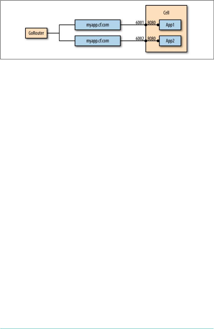
Figure 7-3. Routing mechanism allowing for several apps mapped to the same route
Hostnames
Cloud Foundry provides the option of creating a route with a hostname. A hostname
is a name that can be explicitly used to specify an app, as shown in the following
code:
$ cf create-route my-space shared-domain.com --hostname myapp
This creates the unique route myapp.shared-domain.com comprising the host that is
prepended on to the shared domain.
At this stage, all we have done is reserved the route so that the route is not used in
another Space. The app is only routable by this route after it is mapped to the route,
as in the following:
$ cf mapp-route app-name domain hostname
Note that although this route is created for the Space my-space, the Space is not fea‐
tured in the route name.
Routes created for shared domains must always use a hostname. Alternatively, you
can create a route without a hostname. This approach creates a route for the domain
itself and is permitted for private domains only. You can create private domains as
follows:
$ cf create-route my-space private-domain.com
This example creates a route in the Space my-space from domain private-
domain.com. After configuring your DNS, Cloud Foundry will route requests for
http(s)://private-domain.com or any context path under that URL (e.g., private-
domain.com/app1) to apps that are mapped to that route or context path. Any subdo‐
main (e.g., *foo*.private-domain.com) will fail unless additional routes are
specified for that subdomain and then mapped to a subsequent app.
You can use wildcard routes here as a catch-all (e.g., *.private-domain.com); for
example, to serve a custom 404 page or a specific homepage.
122 | Chapter 7: Routing Considerations

1The enterprise load balancer you use is your choice. Cloud Foundry is not opinionated about the load-
balancing strategy that fronts it.
Domains
Cloud Foundry’s use of the terms domain, shared domain, and private domain differ
from their common use:
• Domains provide a namespace from which to create routes.
•Shared domains are available to users in all Orgs, and every Cloud Foundry
instance requires a single default shared domain.
•Private domains allow users to create routes for privately registered domain
names.
As discussed in “Hostnames” on page 122, by default apps are assigned a route with a
hostname my-app, and the app domain my-app.apps.cf-domain.com, resulting in the
route my-app.apps.cf-domain.com.
The presence of a domain in Cloud Foundry indicates that requests for any route cre‐
ated from that domain will be routed to a specific Cloud Foundry instance. This pro‐
vision requires a DNS to be configured to resolve the domain name to the IP address
of a load balancer that fronts traffic entering Cloud Foundry.1
The recommended practice is to have a wildcard canonical name (CNAME) that you
can use as a base domain for other subdomains. An example of a wildcard CNAME is
*.cf-domain.com.
To use a subdomain of your registered domain name with apps on Cloud Foundry,
configure the subdomain as a CNAME record with your DNS provider, pointing at
any shared domain offered in Cloud Foundry.
When installing Cloud Foundry, it is good practice to have a subsequent system
domain and one or more app domains; for example, system.cf-domain.com for your
system domain, and apps.cf-domain.com for (one of) your app domain(s). Multiple
app domains can be advantageous and are discussed further later.
The system domain allows Cloud Foundry to receive requests for and send commu‐
nication between its internal components (like the UAA and Cloud Controller).
Cloud Foundry itself can run some of its components as apps. For example, a service
broker can deploy an app. The app domain guarantees that requests for routes based
off that domain will go to a specific Cloud Foundry instance.
If we had only one combined system and app domain, there would be no separation
of concerns. A developer could register an app domain name that infers it is a poten‐
tial system component. This can cause confusion to the Cloud Foundry operator with
Routing Primitives | 123

respect to what are system apps and what are developer-deployed apps. Moreover,
mapping an arbitrary app to a system component can cause fundamental system fail‐
ures, as we will explore in “Scenario Five: Route Collision” on page 241. For these rea‐
sons, it is recommended that you always have at least one default system domain and
default app domain per environment.
All system components should register routes that are extensions of the system
domain; for example, login.system.cf-domain.com, uaa.system.cf-domain.com,
doppler.system.cf-domain.com, and api.system.cf-domain.com.
Using Wildcard Domains
For an operator not to have to create a new certificate for every app, Cloud Foundry
depends on wildcard domains. Wildcard SSL certificates (referred to as “certs”) are
extremely beneficial for rapid app development and deployment. You will need to
generate wildcard certificates based on your chosen domains for use in Cloud Foun‐
dry. You can either generate these certificates using your own CA, or through any
other tool for generating certificates, such as Cloud Foundry’s “Generate Self-Signed
Certificate” tool.
Certs are necessary for the platform to operate, but this does not mean that your
external load balancer must use these wildcard domains and/or wildcard certificates.
However, it is worth mentioning that if you do not use wildcard certs at your load
balancer, every time you want to deploy a new app, you will need to set up a new
DNS record and then generate a new certificate for that app and install that cert on
your load balancer. This approach adds time and an additional burden that delays the
velocity of pushing new apps to Cloud Foundry. To put it bluntly, not using wildcard
domains in your TLS certificates violates the entire reason for using Cloud Foundry.
Multiple app domains
There are some advantages to using multiple app domains. For example, an operator
might want to establish a dedicated app domain with a dedicated cert and VIP. If you
issue a certificate for a critical app on a dedicated app domain, and for some reason
that certificate becomes compromised, you have the flexibility of revoking just that
certificate without affecting all of your other apps that are on a different app domain.
Context Path Routing
Context path routing allows for routing to be based not only on the route domain
name (essentially the host header), but also the path specified in the route’s URL. The
GoRouter inspects the URL for additional context paths and, upon discovery, can
then route requests to different apps based on that path. Here are a couple of exam‐
ples:
124 | Chapter 7: Routing Considerations
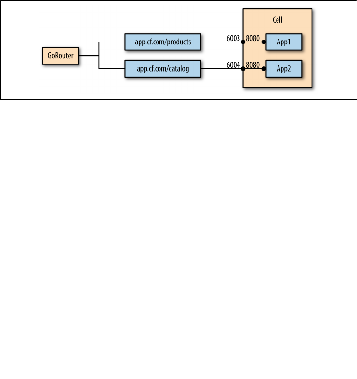
•myapp.mycf-domain.com/foo can be mapped to the foo app.
•myapp.mycf-domain.com/bar can be mapped to the bar app.
This is important when dealing with a microservices architecture. With microservi‐
ces, a single “big-A” apps can be comprised of a suite of smaller microservices apps,
as shown in Figure 7-4. The smaller applications often require the same single top-
level route myapp.mycf-domain.com to offer a single entry point for the user. Context
path routing allows different microservices apps (e.g., foo and bar), all served by the
same parent route, to provide support for different paths in the URL, based on their
unique context path.
With context path-based routing, you can also independently scale up or down those
portions of your big-A app that are being heavily utilized.
Figure 7-4. Routing using a single route and context paths to target a specific app
Routing Components Overview
There are several components involved in the flow of ingress Cloud Foundry traffic.
We can broadly group these as follows:
• Routing tier (load balancer, GoRouter, TCPRouter)
• The control plain and user management (Cloud Controller and UAA)
• The app components (Cells and the SSH proxy)
Figure 7-5 provides a high-level view of the components.
Routing Components Overview | 125
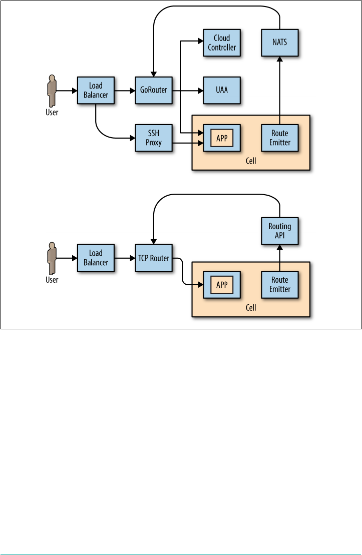
Figure 7-5. Routing components and communication flow
Let’s take a closer look at each of these components:
Load balancer
All HTTP-based traffic first enters Cloud Foundry from an external load bal‐
ancer fronting Cloud Foundry. The load balancer is primarily used for traffic
routing to Cloud Foundry routers.
GoRouter
The GoRouter receives all incoming HTTP(s) traffic from the load balancer. The
GoRouter also receives WebSocket requests and performs the HTTP-to-
WebSocket upgrade to establish a consistent TCP connection to the backend.
TCPRouter
The TCPRouter receives all incoming (non-HTTP) TCP traffic from the load
balancer.
126 | Chapter 7: Routing Considerations

Cloud Controller and the UAA
Operators address the Cloud Controller through Cloud Foundry’s API. As part
of this flow, identity management is provided by the UAA.
Cells and SSH_Proxy
App users target their desired apps via a dedicated hostname and/or domain
combination. The GoRouter will route app traffic to the appropriate app instance
(ActualLRP) running on a Diego Cell. If multiple app instances are running, the
GoRouter will round-robin traffic across the app instances to distribute the
workload. App users can use SSH to the app’s container running on a host Cell
via the SSH proxy service.
Routing Flow
All traffic enters Cloud Foundry from an external load balancer. The load balancer
routes the traffic as follows:
• HTTP/HTTPS and WebSocket traffic to the GoRouter
•(Non-HTTP) TCP traffic to the TCPRouter
App traffic is routed from the routers to the required app. If you’re running multiple
app instances (ActualLRPs), the routers will load-balance the traffic across the run‐
ning ActualLRPs. If an app requires the user to authenticate, you can redirect
requests to the UAA’s login server. Upon authentication, the user is passed back to
the original app. The Cloud Controller provides an example of this behavior.
Platform users target the Cloud Controller. Requests come in from the load balancer
through the GoRouter and hit the CAPI. If the user has yet to log in, requests are
redirected to the UAA for authentication. Upon authentication, the user is redirected
back to the Cloud Controller.
Route-Mapping Flow
When you create a route in the routing table (either directly via Cloud Foundry map-
route command or indirectly via cf push), the Route-Emitter is listening to events
in Diego’s BBS and notices all newly created routes. It takes the route-mapping info
(of Cell host:port) and then dynamically updates the route mapping in the routing
table. Any additional changes—for example, a deleted or moved app—will also result
in the emitter updating the routing table. We discuss route mapping and the Route-
Emitter further in “Routing Table” on page 131.
Routing Flow | 127

Load Balancer Considerations
Although the choice of load balancer is yours to make, there are some specific con‐
siderations required:
•Setting the correct request header fields.
•Determining where to terminate SSL.
•Configuring the load balancer to handle HTTP upgrades to WebSockets (assum‐
ing these requests are then being passed on to the TCPRouter). Ideally, you
should avoid this with the WebSocket upgrade; you should instead use the
GoRouter.
Setting Request Header Fields
When a client connects to a web server through an HTTP proxy or load balancer, it is
possible to identify the originating IP address and the send protocol by setting the X-
Forwarded-For and X-Forwarded-Proto request header fields, respectively. These
headers must be set on the load balancer that fronts the traffic coming into Cloud
Foundry. HTTP traffic passed from the GoRouter to an app will include these head‐
ers. If an app wants to behave differently based on the transport protocol used, it can
inspect the headers to determine whether traffic was received over HTTP or HTTPS.
X-Forwarded-For
X-Forwarded-For (XFF) provides the IP address of the originating client request. For
example, an XFF request header for a client with an IP address of 203.0.56.67 would
be as follows:
X-Forwarded-For: 203.0.56.67
If you did not use XFF, connections through the router would reveal only the origi‐
nating IP address of the router itself, effectively turning the router into an anonymiz‐
ing service and making the detection and prevention of abusive access significantly
more difficult. The usefulness of XFF depends on the GoRouter truthfully reporting
the original host IP address. If your load balancer terminates TLS upstream from the
GoRouter, it must append these headers to the requests forwarded onto the
GoRouter.
X-Forwarded-Proto
X-Forwarded-Proto (XFP) identifies the client protocol (HTTP or HTTPS) used
from the client to connect to the load balancer. The scheme is HTTP if the client
made an insecure request, or HTTPS if the client made a secure request. For example,
128 | Chapter 7: Routing Considerations

an XFP for a request that originated from the client as an HTTPS request would be as
follows:
X-Forwarded-Proto: https
As with most client-server architectures, the GoRouter access logs contain only the
protocol used between the GoRouter and the load balancer; they do not contain the
protocol information used between the client and the load balancer. XFP allows the
router to determine this information. The load balancer stores the protocol used
between the client and the load balancer in the XFP request header and passes the
header along to the router.
XFP is important because you can configure apps to reject insecure requests by
inspecting the header for the HTTP scheme. This header is as important, or even
more so, for system components than for apps. The UAA, for example, will reject all
login attempts if this header is not set.
WebSocket Upgrades
WebSockets is a protocol providing bidirectional communication over a single, long-
lived TCP connection. It is commonly implemented by web clients and servers. Web‐
Sockets are initiated via HTTP as an upgrade request. The GoRouter supports
WebSocket upgrades, holding the TCP connection open with the selected app
instance.
Supporting WebSockets is important because the Firehose (the endpoint of all aggre‐
gated and streamed app logs) is a WebSockets endpoint that streams all event data
originating from a Cloud Foundry deployment. To support WebSockets, operators
must configure their load balancer to pass WebSockets requests through as opaque
TCP connections. WebSockets are also vital for app log streaming, allowing develop‐
ers to view their app logs.
Some load balancers are unable to support listening for both HTTP and TCP traffic
on the same port. Take, for example, ELB offered by AWS. ELB can listen on a port
in either HTTP(s) mode or TCP mode. To pass through a WebSocket request, ELB
must be in TCP mode. However, if ELB is terminating TLS requests on 443 and
appending the XFF and XFP headers, it must be in HTTP mode. Therefore, ELB can‐
not handle WebSockets on the same port. In this scenario, you can do the following:
•Configure your load balancer to listen for WebSocket requests on a nonstandard
port (e.g., 8443) and then forward WebSocket requests to this port in TCP mode
to the GoRouter on port 80 or 443. App clients must make WebSockets upgrade
requests to this port.
Load Balancer Considerations | 129

•Add a second load balancer listening in TCP mode on standard port 80. Config‐
ure DNS with a dedicated hostname for use with WebSockets that resolves to the
new load balancer serving port 80 in TCP mode.
The PROXY Protocol
As just described, WebSockets require a TCP connection; however, when using TCP
mode, load balancers will not add the XFF HTTP protocol headers, so you cannot
identify your clients. Another solution for client identification is to use the Proxy
protocol. This protocol allows your load balancer to add the Proxy protocol header so
that your apps can still identify your clients even when you use TCP mode at the load
balancer.
Another scenario is to terminate TLS with a component that does not support HTTP
and operates only in TCP mode. Therefore, an HTTP connection is then passed on to
the GoRouter.
A point to note is that some load balancers in TCP mode will not give you HTTP
multiplexing and pipelining. This could cause a performance problem unless you
have a content delivery network (CDN) in front.
TLS Termination and IPSec
Although Cloud Foundry is a distributed system, conceptually we can consider it as a
software appliance. It is designed to sit in a dedicated network with defined egress
and ingress firewall rules. For this reason, if the load balancer sits within or on the
edge of the private network, it can handle TLS decryption and then route traffic
unencrypted to the GoRouter.
However, if the load balancer is not dedicated to Cloud Foundry and it is located on a
general-purpose corporate network, it is possible to pass the TLS connection on to
the GoRouter for decryption. To implement this, you must configure your load bal‐
ancer to re-sign the request between the load balancer and the GoRouter using your
wildcard certificate. You will also need to configure the GoRouter with your Cloud
Foundry certificates.
There might be situations in which you require encryption directly back to the app
and data layer. For these scenarios, you can use the additional IPSec BOSH add-on
that provides encrypted traffic between every component machine.
130 | Chapter 7: Routing Considerations

GoRouter Considerations
The GoRouter serves HTTP(S) traffic only. HTTP(S) connections to apps from the
outside world are accepted only on ports 80 or 443. (Protocol upgrade requests for
WebSockets are also acceptable.)
All router logic is contained in a single process. This approach removes unnecessary
latency introduced through interprocess communication. Additionally, with full con‐
trol over every client connection, the router can more easily allow for connection
upgrades to WebSockets and other types of traffic (e.g., HTTP tunneling and proxy‐
ing via HTTP CONNECT).
Routing Table
The router uses a routing table to keep track of available apps. This table contains an
up-to-date list of all the routes to the Cells and containers that are currently running
ActualLRPs. As described earlier, you can map multiple routes to an app and map
multiple apps to a route. The routing table keeps track of this mapping. It provides
the source of truth for all routing, dynamically checking for and pruning dead routes
to avoid 404 errors.
Diego uses its Route-Emitter component to consume event streams from the Diego
Database—the BBS—and then pushes the route updates to the router. Additionally,
the Route-Emitter performs a bulk lookup operation against its database every 20
seconds to fetch all the desired and actual routes.
The GoRouter then recomputes a new routing table based on the IP addresses of each
Cell machine and the host-side port numbers for the Cell’s containers. This ensures
that the routing table information is up to date in the event that an app fails.
Router and Route High Availability
GoRouters should be clustered both for resiliency and for handling a large number of
concurrent client connections.
When GoRouters come on line, they send router.start messages informing Route-
Emitters that they are running. Route-Emitters are monitoring desired and actual
LRP events in the BBS to establish and map routes to app instances. They compute
the routing table and send this table to the GoRouter via NATS at regular intervals.
This ensures that new GoRouters update their routing table and synchronize with
existing GoRouters. Routes will be pruned from the routing table if an app connec‐
tion goes stale. To maintain an active route, the route must be updated by default at
least every two minutes.
GoRouter Considerations | 131

An important implementation consideration for the GoRouter is that because it uses
NATS, it must be brought online after the NATS component in order to function
properly.
Router Instrumentation and Logging
Like the other Cloud Foundry components, the GoRouter provides logging through
its Metron agent. In addition, a /routes endpoint returns the entire routing table as
JSON. Because of the nature of the data present in /routes, the endpoint requires
HTTP basic authentication credentials served on port 8080. These credentials are
obtained from the deployment manifest under the router job:
status:
password: some_password
port: 8080
user: some_user
The credentials can also be obtained from the GoRouter VM at /var/vcap/jobs/
gorouter/config/gorouter.yml.
Each route contains an associated array of host:port entries, which is useful for
debugging:
$ curl -vvv "http://some_user:some_password@127.0.0.1:8080/routes"
In addition to the routing table endpoint, the GoRouter offers a healthcheck end‐
point on /health:
$ curl -v "http://10.0.32.15:8080/health"
This is particularly useful when performing healthchecks from a load balancer. This
endpoint does not require credentials and should be accessed at port 8080. Because
load balancers typically round-robin the GoRouters, by regularly checking the GoR‐
outer health, they can avoid sending traffic to GoRouters that are temporarily not
responding.
You can configure the GoRouter logging levels in the Cloud Foundry deployment
manifest. The meanings of the router’s log levels are as follows:
fatalAn error has occurred that makes the current request unserviceable; for example,
the router cannot bind to its TCP port, or a Cloud Foundry component has pub‐
lished invalid data to the GoRouter.
warn
An unexpected state has occurred. For example, the GoRouter tried to publish
data that could not be encoded as JSON.
132 | Chapter 7: Routing Considerations

info, debug
An expected event has occurred. For example, a new Cloud Foundry component
was registered with the GoRouter, and the GoRouter has begun to prune routes
for stale containers.
Sticky Sessions
For compatible apps, the GoRouter supports sticky sessions (aka session affinity) for
incoming HTTP requests.
When multiple app instances are running, sticky sessions will cause requests from a
particular client to always reach the same app instance. This makes it possible for
apps to store session data specific to a user session. Generally, this approach is not
good practice; however, for some select pieces of data such as discrete and lightweight
user information, it can be a pragmatic approach.
Sticky Sessions
A single app can have several instances running concurrently.
Functional use of the local filesystem is limited to local caching
because filesystems provided to apps are ephemeral unless you use
a filesystem service. By default, changes to the filesystem are not
preserved between app restarts, nor are they synchronized or
shared between multiple app instances.
This means Cloud Foundry does not natively maintain or replicate
HTTP session data across app instances, and all cached session
data will be discarded if the app instance hosting the sticky session
is terminated. If you require session data to be saved, it must be
offloaded to a backing service that offers data persistence.
To support sticky sessions, apps must return a JSESSIONID cookie in their respon‐
ses.
If an app returns a JSESSIONID cookie to a client request, the GoRouter appends an
additional VCAP_ID cookie to the response, which contains a unique identifier for
the app instance. On subsequent client requests, the client provides both the JSES‐
SIONID and VCAP_ID cookies, allowing the GoRouter to forward client requests
back to the same app instance.
If the app instance identified by the VCAP_ID is no longer available, the GoRouter
attempts to route the request to a different instance of the app. If the GoRouter finds
a healthy instance of the app, it initiates a new sticky session.
Sticky Sessions | 133

The TCPRouter
Support for non-HTTP workloads on Cloud Foundry is provided by the TCPRouter.
The TCPRouter allows operators to offer TCP routes to app developers based on res‐
ervable ports.
When pushing an app mapped to a TCP route:
$ cf p myapp -d tcp.mycf-domain.com --random-route
the response from the Cloud Controller includes a port associated with the TCP
route. Client requests to these ports will be routed to apps running on Cloud Foun‐
dry through a layer 4 protocol-agnostic routing tier.
Both HTTP and TCP routes will be directed to the same app port, identified by envi‐
ronment variable $PORT.
The developer experience for TCP routing is similar to previous routing-related
workflows. For example, the developer begins by discovering a domain that supports
TCP routing through cf domains. cf domains will show whether a specific domain
has been enabled for TCP routing by setting up DNS for that domain to point to the
load balancers, and load balancers then pointing to the TCPRouters.
The discovered domain gives a developer an indication that requests for routes cre‐
ated from that domain will be forwarded to apps mapped to that route. It also pro‐
vides a namespace allowing operators to control access for one domain or another.
After you choose your domain, you can then create a route from that domain via the
usual create route and map route commands. However, the cf push experience is
streamlined because the appropriate route will be configured for that app simply by
selecting a TCP domain. For example, to create a TCP route for the app myapp using
the domain tcp-example-domain.com you can run the following:
$ cf push myapp -d tcp-example-domain.com --random-route
TCP routes are different from HTTP routes because they do not use hostnames;
instead, routing decisions are based on a port. For each TCP route, we reserve a port
on the TCPRouter. This requires clients of apps that receive TCP app traffic to sup‐
port these arbitrary ports.
TCP Routing Management Plane
The TCP routing management plane (see Figure 7-5) has similar functionality to the
HTTP routing management plane. There is a Route-Emitter listening to events in
Diego’s BBS. For example, whenever a new app is created or an app is moved or
scaled, the BBS is updated.
134 | Chapter 7: Routing Considerations
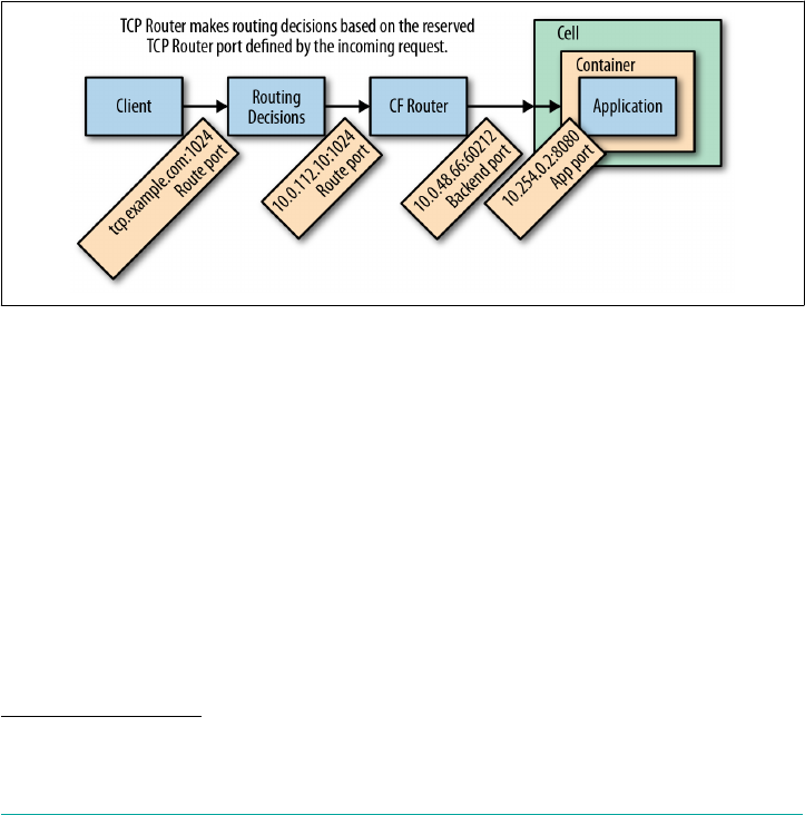
2Make sure your port range accounts for sufficient capacity because every TCP connection will require a dedi‐
cated port from your reserved port range.
The emitter detects these events, constructs the routing table, and then sends this
table on to the routing API. The routing API effectively replaces the need for NATS;
it maintains the routing table and then makes the configuration available across a tier
of TCPRouter instances. Therefore, TCPRouters receive their configuration from the
routing API and not via NATS. Both the TCPRouter and the Route-Emitter receive
their configuration from both periodic bulk fetches and real-time server sent events.
TCP routing introduces some complexity through additional NAT involving differ‐
ent ports at different tiers, as illustrated in Figure 7-6. There is a route port to which
clients send requests. This port is reserved on the TCPRouter when you create a TCP
route. Behind the scenes, the TCPRouter makes a translation between that route port
and the app instances. Containers include app ports (that default to 8080). These
ports are not directly accessible via the TCPRouter, because containers are running in
a Cell providing an additional NAT for the container. Therefore, the ports made
known to the TCPRouter are the Cell ports (the backend port).
Figure 7-6. TCPRouter port mappings from the load balancer through to the app
TCPRouter Configuration Steps
Here are the deployment steps required for configuring TCP routing:
1. Choose a domain name from which developers will create their TCP routes.
2. Configure DNS to point to that domain name via the load balancer.
3. Choose how many TCP routes the platform should support based on the
reserved ports on the TCPRouter.
4. Configure the load balancer to listen on the port range2 and then forward
requests for that port range and domain to the TCPRouters.
The TCPRouter | 135

5. Configure the TCPRouter group within Cloud Foundry with the same port
range.
6. Create a domain associated with that TCPRouter group.
7. Configure a quota to entitle Orgs to create TCP routes.
Route Services
Apps often have additional requirements over and above traditional middleware
components, such as databases, caches, and message buses. The additional app
requirements include tasks such as authentication, or might require a special firewall
or rate limiting. Traditionally, these burdens have been placed on the developer and
app operator to build additional (nonbusiness) capabilities into the app or directly
use and configure some other external capability such as an edge caching appliance.
The route services capability makes it possible for developers to select a specific route
service from the marketplace (in a similar fashion to middleware services) and insert
that service into the app request path. They offer a new point of integration and a
new class of service.
As seen in Figure 7-7, route services give you the ability to dynamically insert a com‐
ponent (in the case of Figure 7-7, Apigee) into the network path as traffic flows to
apps. Traditionally, developers had to file a ticket to get a new load balancer configu‐
ration for additional firewall settings, or IT had to manually insert additional net‐
work components for things like rate limiting. Route services now offer these
additional capabilities dynamically via integration with the router.
136 | Chapter 7: Routing Considerations
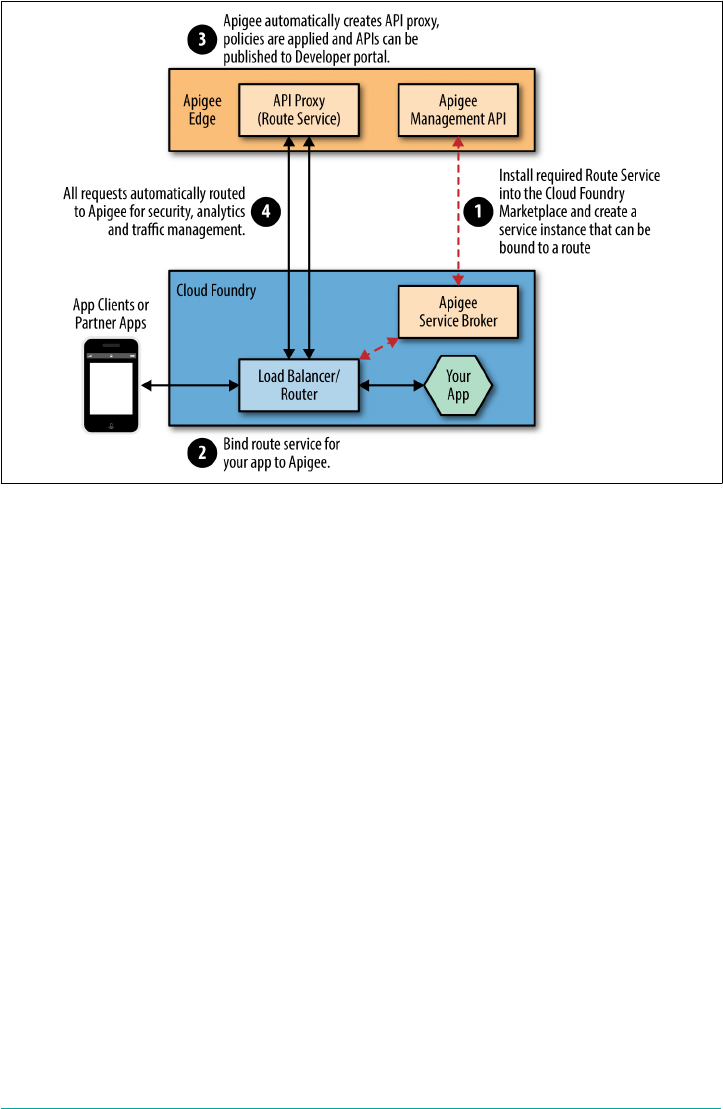
Figure 7-7. The Route Service showing the path of application user traffic to an app,
accessing an API Proxy Service (in this case provided by Apigee)
Unlike middleware marketplace services that are bound to an app, route services are
bound to a route for a specific app. New requests to that app can then be modified via
a route service. Just like the middleware services in the marketplace, the route service
might not necessarily be Cloud Foundry, or BOSH–deployed and managed. For
example, a route service could be the following:
• An app running on Cloud Foundry
• A BOSH-, Puppet-, or Chef-deployed component
• Some other external enterprise service provided by a third party such as Apigee
Route Service Workflow
All requests arrive (1) via the external load balancer, which passes traffic on to the
GoRouter (2). The GoRouter checks for a bound route service for a route, and if no
service exists, it will simply pass traffic on to the appropriate LRP (3). If a route ser‐
vice does exist for the route, the router will then pass that traffic on to the service that
is bound to the route.
Before passing the request on to the service, the router generates an encrypted short-
lived message to include both the requested route and the route service GUID. The
Route Services | 137
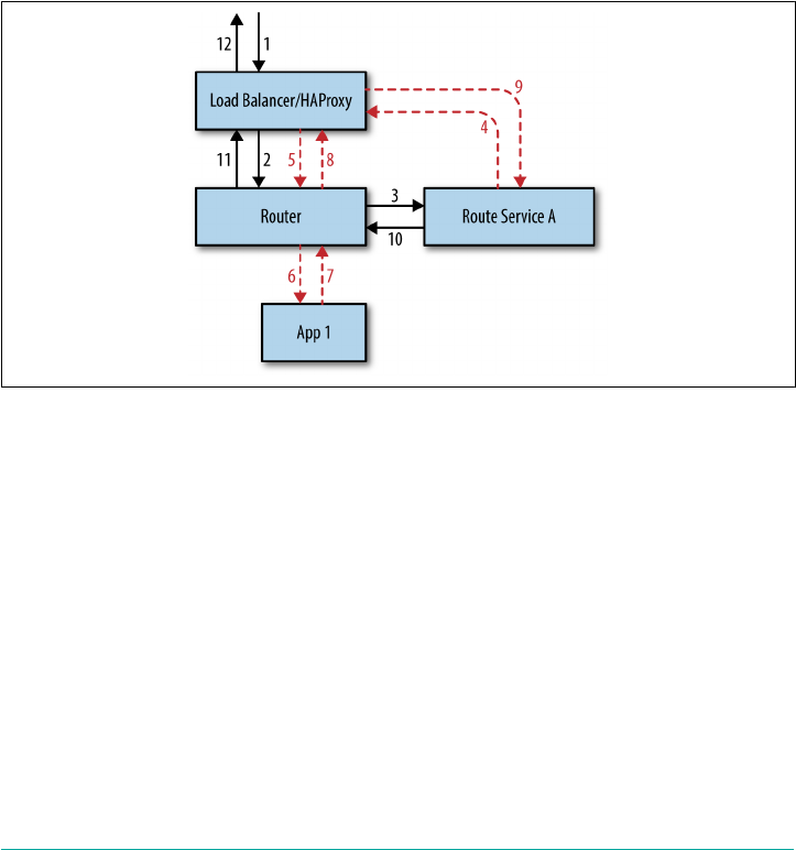
router then appends this message to the request header and forwards the request to
the bound route service. After the specific route service has undertaken its work (e.g.,
header modification or rate limiting) the service can do one of two things:
•Respond directly to the request (e.g., serve an access-denied message if acting as
an app firewall)
•Pass the traffic to the app
The route service passes traffic to the app (4) by resolving via DNS back to the load
balancer (5), then to the router (6), and then to the app. The response traffic then
follows that same flow backward to return a response to the client (7/8/9/10/11/12).
This allows the service to do further modification on the returned response body if
required. Figure 7-8 provides an overview of the architecture.
Figure 7-8. Route service workflow showing the redirection of app traffic to the route
service before being directed back to the app via the load balancer (note that the return
flow retraces the same path in reverse)
Route Service Use Cases
You can consider any use cases that can be on the request path as eligible for a route
service. Here are some examples:
• Gateway use cases such as rate limiting, metering, and caching
•Security use cases such as authentication, authorization, auditing, fraud detec‐
tion, and network sniffing
• Analytics use cases such as monetization, chargeback, and utilization
•Mobile backend as a service (MBaaS) such as push notifications and data services
138 | Chapter 7: Routing Considerations

In line with the rest of Cloud Foundry, the key goal of routing services is to increase
app velocity. Without the developer self-service that route services provide, most
organizations are left with the pain of ticketing systems and extra configuration to
achieve these use-case capabilities.
Summary
The core premise of Cloud Foundry is to allow apps to be deployed with velocity and
operated with ease. The routing abstractions and mechanisms within Cloud Foundry
have been designed and implemented to support that premise:
•Routing is an integral part of deploying and operating apps.
•Cloud Foundry provides a rich set of abstractions and mechanisms for support‐
ing fast deployment, rolling upgrades, and other complicated routing require‐
ments.
•Establishing the most appropriate routing architecture is essential for app secu‐
rity, resiliency, and updatability.
•With the introduction of the TCPRouter and additional route services, the plat‐
form can take on more diverse workloads with broader, more granular routing
requirements.
Summary | 139
CHAPTER 8
Containers, Containers, Containers
Containers, as a concept, is not new technology. However, in recent years, there has
been rapid adoption of new container-based technologies such as Docker, Garden,
and Rocket. Many organizations regard containers as a key enabler for adopting tech‐
nologies such as microservices-based architectures or continuous delivery pipelines.
Therefore, containers have become a critical part of the digital transformation strat‐
egy of most companies.
Some companies I work with establish a mandate to adopt containers but cannot
articulate a specific use case or problem that would be solved by adopting containers.
Others believe containers will help them deploy apps quicker but cannot explain why,
or they believe containers will provide better utilization but have not profiled their
existing infrastructure utilization. The use of container technology absolutely can
provide significant benefits. It is essential to understand how those benefits are
achieved in such a way as to derive the most from container technology.
The Meaning of “Container”
Like the term “platform,” the term container is also overloaded.
This chapter is not about traditional app server containers such as
Tomcat; it is about OS–level containers such as runC.
What Is a Container?
Despite their huge popularity, there still are a lot of misconceptions about containers.
Principally, in the Linux world at least, containers are not a literal entity, they are a
logical construct. Strictly speaking, a container is nothing more than a controlled user
process. Container technology typically takes advantage of OS kernel features to con‐
strain and control various resources, and isolate and secure the relevant container‐
141

ized processes. In addition, the term “container” conflates various concepts, which
adds to the confusion.
Containers have two key elements:
Container Images
These package a repeatable runtime environment (encapsulating your app and
all of its dependencies, including the filesystem) in a format that is self-
describing and portable, allowing for images to be moved between container
hosts. The self-describing nature of container images specifies instructions on
how they should be run, but they are not explicitly self-executable, meaning that
they cannot run without a container management solution and container run‐
time. However, regardless of the container contents, any compliant container
runtime should be able to run the container image without requiring extra
dependencies.
Container management
Often referred to as container engine, the management layer typically uses OS
kernel features (e.g., Linux kernel primitives such as control groups and name‐
spaces) to run a container image in isolation, often within a shared kernel space.
Container-management engines typically expose a management API for user
interaction and utilize a backend container runtime such as runC or runV that is
responsible for building and running an isolated containerized process.
Container Terminology
The challenge in discussing containers is that implementation ter‐
minology can mean different things to different people, and it can
be implementation-specific. I have tried to be as generic as possible
in my description, but it is important to note that different terms
like engine or backend can have meanings relating to a specific
technology implementation.
Container images can be created through a concept of containerization: the notion of
packaging up a filesystem, runtime dependencies, and any other required technology
artifacts to produce a single encapsulated binary image. You can then port these
images around and run them in different container backends via the container API/
management layer. The container backend implementation is host-specific; for
example, the term Linux container is a reference to the Linux technology (originally
based on LXC) for running containerized images. Currently, Linux containers are by
far the most widely adopted container technology. For this reason, the rest of this
chapter focuses on Linux containers to explain the fundamental container concepts.
142 | Chapter 8: Containers, Containers, Containers

1The terms “VM” and “machine” are used interchangeably because containers can run in both environments.
Container Fervor
Why have containers become so popular so quickly? Containers offer three distinct
advantages over traditional VMs:
•Speed and efficiency because they are lightning fast to create
•Greater resource consolidation, especially if you overcommit resources
• App stack portability
Because containers use a slice of a prebuilt machine or VM,1 they are generally regar‐
ded to be significantly faster to create than a new VM. Effectively, to create a new
container, you simply fork and isolate a process.
Containers also allow for a greater degree of resource consolidation because you can
run several container instances in isolation on a single host machine by a single OS
kernel.
In addition, containers have enabled a new era of app-stack portability because apps
and dependencies developed to run in a container backend can easily be packaged
into a single container image (usually containing a tarball with some additional meta‐
data). You can then deploy and run container images in several different environ‐
ments. Container images make it easy to efficiently ship deltas, and therefore moving
whole images between different host machines becomes practical. App-stack porta‐
bility is one of the key reasons why containers have become so popular. Container
images have become a key enabler for trends such as DevOps and CD by enabling
both the app artifacts and all of the related runtime dependencies to migrate
unchanged, as a layered binary image, through a CI pipeline into production. This
has provided a unified approach to delivering software into production as opposed to
the old and defunct “it worked on my machine” approach. Chapter 9 discusses this
unified approach and its various merits in further detail.
Increased deployment efficiency becomes paramount when deploying apps using a
microservices architecture because there are more moving parts and more overall
churn. Container-based infrastructure has therefore become a natural choice for
teams using a microservices architecture.
Containers, as with all technology, are a means to an end. It is not technology itself
that is important; it is how you take advantage of it that is key. For example, we dis‐
cussed using container images to propagate apps through a pipeline and into produc‐
tion. However, the pipeline itself can also effectively use containers. For example, the
Concourse CI controls pipeline inputs so that results are always repeatable. Rather
Container Fervor | 143

than sharing state, every task runs in its own container, thus controlling its own
dependencies. Containers are created and then destroyed every time a task is run,
ensuring repeatability by avoiding build “pollution.” Concourse’s use of containers is
a perfect example of how we can use container technology to provide a clear tangible
benefit over more traditional approaches that experience polluted build-up due to a
pattern of VM reuse.
Linux Containers
Linux containers provide a way of efficiently running an isolated user process. As just
discussed, strictly speaking, Linux containers do not exist in a purely literal sense:
there are no specific Linux kernel container features. Existing kernel features are
combined together to produce the behavior associated with containers, but Linux
containers themselves remain a high-level abstract concept.
The essence of container abstraction is to run processes in an isolated environment.
Linux container technologies use lower Linux primitives and kernel features to pro‐
duce container attributes such as the required process isolation. Other Unix OSs
implement containers at the OS kernel level; for example, BSDJails or Solaris Zones.
How do containers differ from VMs? There are two key elements:
• Where processes are run
•What is actually run
Although the container backend (the runtime) can, technically, be backed by a VM,
traditionally speaking, containers are fundamentally different in concept. A VM vir‐
tualizes the entire machine and then runs the kernel and device drivers that are then
isolated to that VM. This approach provides superb isolation; however, historically,
at least, VMs have been considered relatively slow and expensive to create. Contain‐
ers, on the other hand, all share the same kernel within a host machine, with isolation
achieved by using various kernel features to secure processes from one another. Cre‐
ating a container amounts to forking a process within an existing host machine. This
is orders of magnitude faster than instantiating a traditional VM.
Containers versus VMs
The container versus VM debate is blurring in many ways. Special‐
ized, minimal, single-address-space machine images known as uni‐
kernels allow for fast VM instantiation. You can replace container
backends like runC with VM equivalents such as runV. At the end
of the day, the important concern is not what runs your container‐
ized process, but that your process is being run with the appropri‐
ate isolation guarantees and resource constraints.
144 | Chapter 8: Containers, Containers, Containers

The core Linux primitives and kernel features that produce container attributes
include the following:
• Namespaces to enforce isolation between containers
• Control groups to enforce resource sharing between containers
We look at both of these kernel features in more detail a little later in the chapter. It is
worth keeping in mind that the typical Cloud Foundry developer or operator does
not require a deep understanding of containers, because the Cloud Foundry platform
handles the container creation and orchestration concerns. However, gaining a
deeper understanding is valuable for both the curious and the security-minded oper‐
ator.
Namespaces
Namespaces provide isolation. They offer a way of splitting kernel resources by wrap‐
ping global system resources in an abstraction. The process within a namespace sees
only a subset (its own set) of those kernel resources. This produces the appearance of
the namespaced process having its own isolated instance of the global resource.
Changes to a resource governed by a namespace are visible only to other processes
that are members of that namespace; they cannot be seen by processes outside of the
namespace.
A process can be placed into the following namespaces:
PID
These processes view other processes running inside the same (or a child) name‐
space.
network
These processes have their own isolated view of the network stack.
cgroup
These processes have a virtualized view of their CGroups root directories.
mount
These processes have their own view of the mount table; mounts and unmounts
do not affect processes in other namespaces.
uts/username
These processes have their own hostname and domain name.
ipc
These processes can communicate only with other processes within the same
namespace via system-level IPCs (interprocess communication).
Linux Containers | 145

user
These processes have their own user and group IDs. Host users and groups are
remapped to local users and groups within the user namespace.
Take, for example, the PID namespace. Processes are always structured as a tree with
a single root parent process. A Linux host uses PID 1 for the root process. All the
other processes are eventually parented (or grandparented) by PID 1.
A container’s first process—which might have a PID 123 in the host—will appear as
PID 1 within the container. All other processes in the container are similarly map‐
ped. Processes that are not in the container’s PID namespace do not appear to exist to
the namespaced process. Effectively, both the namespaced process and the host have
different views of the same PID. It is the kernel that provides this mapping.
Upon container creation, a clone of the container process is created within the newly
created namespace. This cloned process becomes PID 1 in the newly created name‐
space. If that process then makes a kernel call asking “what is my Process ID,” the ker‐
nel does the mapping for the process transparently. The process is unaware it is
running within a PID namespace.
As another example, take user namespaces. The host views a user namespaced pro‐
cess with, for example, UID 4000. With user namespaces, the process can ask “what is
my User ID”? If the process is running as root user, the namespaced response from
the kernel will be UID 0 (root). However, the kernel has explicitly mapped the name‐
spaced process such that the process thinks it is root. The host still knows the process
as, for example, UID 4000. If the process attempts to open a file owned by the host
root, the kernel maps the process to UID 4000, checks the UID against the host file‐
system, which is actually mapped to 0, and will then correctly deny the process access
to that host file because of invalid permissions.
The preceding is just an illustration. With the abstraction of con‐
tainers in Cloud Foundry, host files are not even visible to try to
open them. For other container scenarios outside of Cloud Foun‐
dry, there can be, however, some value in joining only a subset of
namespaces. For example, you might join the same network name‐
space to another process but not the mount namespace. This would
allow you to achieve an independent container image that shares
just the network of another container. This approach is known as a
sidecar container.
Security through namespaces
When running processes in a dedicated VM, the responsibility for sharing physical
resources is pushed down to the hypervisor. Containers that run on a single host are
at the mercy of the kernel for security concerns, not an isolated hypervisor. Even
146 | Chapter 8: Containers, Containers, Containers

though container isolation is achieved through namespaces, the namespaces still
share the underlying resource.
Cloud Foundry provides multilayered security for containers. Principally, Garden—
Cloud Foundry’s container creation and management API—does not allow processes
to run as root (the host’s root). Garden can run two types of containers:
•Privileged containers that have some root privileges (useful for testing Garden
itself)
•Unprivileged containers secured as much as possible; for example, processes run‐
ning as pseudo root not host root
For tighter security, Cloud Foundry recommends that everything be run in unprivi‐
leged containers. A buildpack-built app will never run as root; it will always run as
the Cloud Foundry created user vcap. In addition, for buildpack-built apps, Cloud
Foundry uses a trusted secure rootfs provided by the platform. The Cloud Foundry
engineering team has hardened the rootfs to remove exploits that could enable a user
to become root. Building containers from the same known and trusted rootfs
becomes a powerful tool for release engineering, as discussed in “Why BOSH?” on
page 170.
Isolating the use of the root user is not unique to containers; this is generally how
multiuser systems are secured. The next layer of security is containerization itself.
The act of containerization uses Linux namespaces to ensure each container has its
own view of system resources. For example, when it comes to protecting app data,
each container has its own view of its filesystem with no visibility of other containers’
files.
For Linux, conceptually, the kernel is unaware that a process is running in a con‐
tainer. (Remember, there is no actual container, only an isolated process.) Without
the use of namespaces, any non-namespaced kernel call that provides access to a host
resource could allow one process to directly affect another. Namespaces therefore
provide additional security for processes running in a shared kernel.
A point to be aware of is that Docker containers can run as root and, therefore, if not
mitigated, could potentially compromise the underlying host. To address this vulner‐
ability, Cloud Foundry uses a namespaced root for Docker images, so a Docker con‐
tainer still cannot read random memory. Assuming that you have PID and user
namespaces, you should never have the ability to read a random process’s RAM.
Linux Containers | 147

Data Locality
Data is generally regarded to be the principal attack surface as
opposed to simply another app process. Therefore, it is critical to
maintain data isolation between processes. Container technology
uses namespaces to isolate system resources such as filesystem
access. Arguably, containers are still less secure than a dedicated
VM because VMs are not sharing memory at the OS level. The
only way to access another process’s isolated memory would be to
break out of the VM on to the host hypervisor. With containers, if
a file descriptor is left open, because container processes reside in
the same OS, that file descriptor becomes more exposed. For the
Cloud Foundry model, this should not be a major issue, because,
generally speaking, data is not stored on the local filesystem but
rather in a backing service.
CGroups
Namespaces provide containers with an isolated view of the host; however, they are
not responsible for enforcing resource allocation between containers. A Linux kernel
feature known as control groups (CGroups) is used for resource control, accounting,
and isolation (CPU, memory, disk I/O, network, etc.). CGroups enforce fair sharing
of system resources such as CPU and RAM between processes. You can apply
CGroups to a collection of processes; in our case, a namespaced set of container pro‐
cesses.
Disk Quotas
Resource limits (R limits) define things such as how many files can be opened or how
many processes can be run. However, the Linux kernel does not provide any way to
limit disk usage; therefore, disk quotas have been established. Disk quotas were origi‐
nally dependent on quotas based on user IDs. However, because in Docker a process
can be root, that process could create a new user to get around disk quotas, given that
all new users will be provisioned with a new disk. This loophole allows disk usage to
keep growing. As a result, today disk quotas tend to use a layered—copy-on-write—
filesystem for Linux. This allows Linux to scale for the storage that will be available,
with the ability to administer and manage the filesystem with a clean interface and a
clear view of what is being used.
Filesystems
The filesystem image format comes from either a preexisting container image (e.g., if
you use Docker) or it will be Cloud Foundry–created based on available stemcells.
Cloud Foundry–created containers are known as trusted containers because of their
use of a hardened rootfs. Trusted containers use a single-layer filesystem known as a
148 | Chapter 8: Containers, Containers, Containers

stack. The stack works in combination with a buildpack to support apps running in
containers.
A stack is a prebuilt root filesystem (rootfs). Stacks support a spe‐
cific OS; for example, Linux-based filesystems require /usr
and /bin directories at their root. Cloud Foundry app machines
(Diego Cells) can support multiple stacks.
Upon creation, every trusted container uses the same base image (or one of a small
set of base images). The container manager in Cloud Foundry, Garden, can create
multiple containers from its base images. Cloud Foundry uses a layered filesystem. If
every newly created container required a new filesystem, around 700 MB would have
to be copied from the base image. This would take multiple seconds or even minutes,
even on a fast solid-state drive (SSD), and would result in wasted unnecessary stor‐
age. The layered approach amounts to immediately instantiating a filesystem because
it provides a read-only view of the filesystem.
Here’s how it works:
1. On every Cell, there resides a tarball containing the container’s rootfs.
2. When a Cell starts, it untars the rootfs (for argument’s sake, to /var/rootfs).
3. When Garden creates a new container, it takes in a parameter called rootfs (pass‐
ing in /var/rootfs) and imports the contents of that directory into a layered
filesystem graph.
4. For this new container and only this container, Garden then makes a layer on top
of this rootfs; this layer is the resulting filesystem for this container.
5. When a second container is used, it recognizes that the base layer is already in
place, and will create a sibling (a second layer) on the base rootfs for the new
container.
6. The host has a tree structure consisting of a single base rootfs for all containers,
with each container having a layer on top of that base. All containers are there‐
fore siblings of one another.
7. On a write, the container copies that write to a layer above the base image.
8. When the container does a read, it first checks the top level and then goes down
for the read-only content.
Untrusted containers (containers such as Docker that can run as a pseudo root) also
often use a layered filesystem. A Docker container image is slightly more complex
than just a single filesystem. Docker images are constructed from a Dockerfile, a
script containing a set of instructions for building a Docker image very similar to a
vagrant script used for building VMs. Every line in the script becomes a layer stored
Linux Containers | 149

upon the previous layer. The Docker image can then build up multiple filesystem lay‐
ers on top of one another. In addition to the layered filesystem, Docker images usu‐
ally also contain metadata such as environment variables and entry points. Cloud
Foundry must apply a quota to the rootfs to stop users from pushing containers with,
for example, 100 GB of MapReduce data.
Container Implementation in Cloud Foundry
There is currently a degree of confusion and misinformation in the marketplace with
respect to containers. This is largely because, as described earlier in “What Is a Con‐
tainer?” on page 141, the term “container” conflates various concepts. Moreover, the
terminology used to describe container concepts tends to differ based on specific
implementations. For example, when people refer to running containers, what they
are really describing is the running of containers plus a number of other things such
as package management, distribution, networking, and container orchestration. Con‐
tainers are of limited value if considered in isolation because there are additional con‐
cerns surrounding them that must be addressed in order to run production
workloads at scale; for example, container orchestration, clustering, resiliency, and
security.
Cloud Foundry’s container manager, Garden, runs container processes using the
runC backend runtime, which is a CLI tool for spawning and running containers.
When Cloud Foundry uses the Garden API to make a container (running a process
within runC), a couple of additional things happen:
File/volume system management
Containers require a filesystem. Whether that comes from Cloud Foundry’s
rootfs or a Docker image on Docker Hub or some other Docker registry, broadly
speaking, the container engine sets up a volume on disk that a container can use
as its root filesystem. This mechanism provides filesystem isolation. The filesys‐
tem is a path on a disk and Garden imperatively tells the container, “make this
filesystem path the root filesystem of the container.”
Networking
runC has no opinions about the network. The runC API allows Garden to specify
a container that should be run within a network namespace. Therefore, Cloud
Foundry provides additional code that will set up interfaces and assign IPs for
each container so that it can provide each container with its own IP in order for
it to be addressable.
Why Garden?
Garden offers some key advantages when used with Cloud Foundry. First, because
Garden uses runC for the container runtime, it allows both Docker images and
150 | Chapter 8: Containers, Containers, Containers

buildpack-staged containers to be run in Cloud Foundry. Therefore, the use of Gar‐
den does not preclude the use of Docker images.
The primary reason why Garden is the right choice for Cloud Foundry is that good
architecture (especially, complex distributed architecture) must support change. Gar‐
den provides a platform-neutral, lightweight container abstraction so that it can be
backed by multiple backends. Currently, Cloud Foundry Garden supports both a
Linux backend and a Windows backend. This allows Cloud Foundry to support a
wider array of apps. For example, Windows-based .NET apps can run on Cloud
Foundry along with other apps running in Linux containers such as .NET Core, Java,
Go, and Ruby.
The Garden API contains a set of interfaces that each platform-specific backend must
implement. These interfaces contain methods to perform the following actions:
• Create/delete containers
• Apply resource limits to containers
•Open and attach network ports to containers
• Copy files to and from containers
• Run processes within containers, streaming back stdout and stderr data
• Annotate containers with arbitrary metadata
• Snapshot containers for zero-downtime redeploys
In Diego, the Garden API is currently implemented by the following:
•Garden-runC (Garden backed by runC), which provides a Linux-specific imple‐
mentation of a Garden interface.
•Garden-Windows, which provides a Windows-specific implementation of a Gar‐
den interface.
OCI and runC
As discussed earlier in “Linux Containers” on page 144, Linux achieves container-like
behavior through isolation, resource sharing, and resource limits. The first well-
known Linux container implementation was LXC. Both Docker and Cloud Foundry’s
first container manager, Warden, originally used LXC and then built container man‐
agement capability on top. Both Docker and Cloud Foundry have since moved to
employing runC as the technology that spawns and runs the container process.
runC is a reference implementation according to the Open Container Project (OCP),
governed by the OCI. OCI is an open-governance structure for creating open indus‐
try standards around container formats and runtime.
Container Implementation in Cloud Foundry | 151

OCI has standardized backend formats and provided the runC reference implemen‐
tation, which many higher-level systems have now adopted (e.g., Garden and
Docker). runC was established primarily through Docker pulling out the non-
Docker-specific container creation library (libcontainer) for reuse.
Container implementation should not be a concern to the developer, because it is just
an implementation detail. Developers are more productive by focusing on their app,
and Cloud Foundry makes it possible for them to keep their focus on the higher level
of abstraction of apps and tasks. So, with this in mind, why focus on runC, which is a
specific implementation? Why is runC important?
The answer is unification for the good of all! Container fervor is exploding. Various
technologies (such as VMs and containers) are, in some cases, blending together, and
in other cases (such as container orchestration), pulling in opposite directions. In this
complex, emerging, and fast-moving space, standards serve to unite the common
effort around a single goal while leaving enough room for differentiation, depending
on the use case. This promise of containers as a source of lightweight app portability
requires the establishment of certain standards around both format and runtime.
These standards must do the following:
• Not be bound to a specific product, project, or commercial vendor
•Be portable across a wide variety of technologies and IaaS (including OSs, hard‐
ware, CPU architectures, etc.)
The OCI specification defines a bundle. A bundle is JSON that describes the con‐
tainer, stating the following:
•It should have this path as the rootfs.
• It should have this process and be in these namespaces.
It is the bundle that should become truly portable. Users should be able to push this
OCI bundle to any number of OCI-compatible container environments and expect
the container to always run as designed. The debate on the use of a specific container
technology such as Garden versus Docker Engine is less important because both of
these technologies support the same image format and use runC. These technologies
are just an implementation detail that a platform user never sees nor need ever be
concerned about. Most container orchestration tools are increasingly agnostic about
what actually runs the container backend. For example, if you want to swap out runC
for runV—a hypervisor-based runtime for OCI—this should not affect the running
of your OCI container bundle.
152 | Chapter 8: Containers, Containers, Containers

Container Scale
Cloud Foundry is well suited for apps that can scale-out horizontally via process-
based scaling. Cloud Foundry can also accommodate apps that need to scale verti‐
cally to some extent (such as increased memory or disk size); however, this limit is
bound by the size of your containers and ultimately the size of your container host.
One app should not consume all of the available RAM or disk space on a host
machine. Generally speaking, apps that scale memory vertically do so because they
hold some state data in memory. Apps that scale disk space vertically do so because
they write data to a local disk. As a best practice, you should avoid holding excessive
state in memory or writing user data to local disk, or you should look to minimize
these and offload them to a dedicated backing service such as a cache or database
wherever possible.
Container Technologies (and the Orchestration Challenge)
All mainstream container technologies allow you deploy container images (at the
moment, generally in Docker image format, although other standards exist) in a
fairly similar way. Therefore, as mentioned earlier, the key concern is not the stand‐
ardized backend implementation, but the user experience of the container technol‐
ogy.
You should not run containers in isolation. Low-level container technology alone is
insufficient for dealing with scale and production environment concerns. Here are a
few examples:
•If your container dies (along with your production app), who will notice, and
how will it be restarted?
•How can you ensure that your multiple container instances will be equally dis‐
tributed across your VMs and AZs?
•How will you set up and isolate your networks on demand to limit access to spe‐
cific services?
For these reasons, container orchestration, container clustering, and various other
container technologies have been established. As a side effect of the explosive growth
in the container ecosystem over recent years, there is a growing list of container
orchestration tools including Kubernetes, Docker Swarm, Amazon EC2 Container
Service, and Apache Mesos. In addition, some companies still invest in in-house solu‐
tions for container orchestration.
Container orchestration is a vital requirement for running containers at scale.
Orchestration tools handle the spawning and management of the various container
processes within a distributed system. Container orchestration manages the con‐
Container Technologies (and the Orchestration Challenge) | 153

tainer life cycle and allows for additional functions such scheduling or container
restarts. Container services provide a degree of control for the end user to determine
how containers interact with other containers and backing services. Additionally,
orchestration makes it possible for you to group containers into clusters to enable
them to scale to accommodate increased processing loads.
As discussed in Chapter 1 and “Do More” on page 9, Cloud Foundry provides the
additional capabilities required for running containers in production at scale. At its
heart, Cloud Foundry uses Diego as its container orchestration mechanism. (Chap‐
ter 6 reviewed Diego in detail.)
Summary
Containers have become immensely popular in recent years because they offer app
deployment speed and resource efficiency through greater resource consolidation.
They also allow app-stack portability across different environments. All of these ben‐
efits are appealing to DevOps cultures who desire to deliver software with velocity
and avoid the “it worked on my machine” challenge. Containers become even more
critical when working with microservices and CI pipelines for which rapid, repeata‐
ble, lightweight deployment is essential.
The challenge with containers is that because they have only recently become main‐
stream, there has been some confusion in the marketplace as to what container solu‐
tion to adopt and how best to operationalize and orchestrate them in production. The
key to obtaining benefits from containers is to move away from concerns surround‐
ing image format or the backend runtime and ensure that you approach containers at
the right level—namely, the tooling and orchestration that allow you to use running
containers in production at scale.
Here’s how Cloud Foundry supports this approach:
•Garden, a pluggable model for running different container images. Garden ena‐
bles Cloud Foundry to support buildpack apps and Docker apps on Linux (via
the runC backend) and Windows apps (via the Windows backend).
•Diego, which handles the container life cycle and orchestration including sched‐
uling, clustering, networking, and resiliency.
When all is said and done, as impressive as container technology is, containers are
just an implementation detail and not a developer concern. The key consideration in
taking advantage of containers is not the container itself but the user experience of
container orchestration. Removing developer concern from container construction
and refocusing attention back on apps is vital for app velocity. This is where Cloud
Foundry along with its Diego runtime really excels. Chapter 9 looks at Cloud Foun‐
dry’s use of containers through buildpacks and Docker images.
154 | Chapter 8: Containers, Containers, Containers

1Apps in this context refers both to Long-Running Processes and tasks. Conceptually, a task is simply a short-
lived application with finite characteristics and is guaranteed to run at most once.
CHAPTER 9
Buildpacks and Docker
As we explored in Chapter 8, apps1 that have been deployed to Cloud Foundry run as
containerized processes. Cloud Foundry supports running OCI–compatible con‐
tainer images such as Docker as first-class citizens. It also supports running a stand‐
alone app artifact (e.g., .jar file or Ruby app) deployed “as is,” containerizing apps on
the user’s behalf.
Users can deploy a containerized image by using the cf push command. This com‐
mand, along with additional arguments, is used for deploying both standalone apps
and OCI-compatible container images.
When deploying just a standalone app artifact, Cloud Foundry stages your pushed
app by composing a binary artifact known as a droplet. A droplet is an encapsulated
version of your app along with all of the required runtime components and app
dependencies. Cloud Foundry composes this droplet via its buildpack mechanism.
The resulting droplet, combined with a stack (filesystem), is equivalent to a container
image. Cloud Foundry runs this droplet in the same way as any other OCI-
compatible container image: as an isolated containerized process.
When you push an app, Cloud Foundry automatically detects how to run that app
and then invokes the use of Application Life-Cycle Binaries (ALB). The correct set of
ALBs will be installed on the Cell (the Diego machine) where the app needs to run.
For example, if a Docker image is pushed, the Docker ALBs will be used. If your app
requires further compilation via a buildpack, using the buildpack ALBs, Cloud Foun‐
dry will additionally detect which buildpack is required to stage and run the app.
155

The ability to deploy both individual apps and Docker images allows for flexibility.
Companies already extensively using Docker images can deploy their existing Docker
images to Cloud Foundry. Companies that want to keep their focus on just their apps
can use Cloud Foundry to containerize their app artifacts for them. Although Cloud
Foundry supports both approaches, there are trade-offs and benefits to each one.
This chapter explores those trade-offs and benefits. It then further explains the nature
of buildpacks, including a review of their composition, how they work, and how you
can modify them.
Why Buildpacks?
There is an explicit ethos to the buildpack approach. The buildpack model promotes
a clean separation of roles between the Platform Operator, who provides the build‐
pack, and the developer, who produces an app, which then consumes the buildpack
in order to run. For example, the Platform Operator defines the language support
and the dependency resolution (e.g., which versions of Tomcat or OpenJDK are sup‐
ported). The developer is then responsible only for providing the app artifacts. This
separation of concerns is advantageous to both the developer and the app operator.
Generally speaking, developers should not need to be concerned with building con‐
tainers or tweaking middleware internals; their focus should be on the business logic
of their app. By adopting the use of buildpacks, the developers’ focus shifts from
building containers and tinkering with middleware to just providing their app arti‐
fact. This shift aims to remove the undifferentiated heavy lifting of container con‐
struction in order to promote velocity of the app’s business code.
Containerizing apps on the developer’s behalf also offers additional productivity,
security, and operational benefits because you can always build the resulting con‐
tainer image from the same known, vetted, and trusted components. Explicitly, as
you move your app artifact between different Cloud Foundry environments (e.g., the
app is pushed to different spaces as it progresses through different stages of a CI pipe‐
line), the resulting compiled droplet can and should be staged with the same app,
dependencies, and stack. The buildpack configuration facilitates this repeatability.
This leaves only the app source code to require additional vulnerability and security
scanning on every commit.
An additional feature of buildpacks is increased velocity when patching common vul‐
nerabilities and exposures (CVEs) that affect the app. You can update buildpacks to
Cloud Foundry when runtime CVEs emerge. Rather than updating and then rede‐
ploying each container image in turn, the Platform Operator simply updates the
buildpack or runtime dependency once. Cloud Foundry can then restage and rede‐
ploy each app with the latest updates and patches.
156 | Chapter 9: Buildpacks and Docker

Finally, there is a clear benefit to separating the build and run stages. A droplet is
built during the compile phase of the buildpack. Building (staging) the droplet is
done on a new container that is then destroyed after the droplet is created and uploa‐
ded to a blobstore. To run the app, the compiled droplet is then downloaded into a
freshly created container. This separation between staging and running an app means
that build tools do not end up alongside the executed droplet, further reducing the
attack surface of the running app.
Why Docker?
The Docker image format (along with the standard OCI image format) has gained a
huge amount of traction in many companies. There are benefits to encapsulating
your app and all of its dependencies into a single executable image that can be moved
between different environments. An often-cited benefit is that what you run in devel‐
opment is guaranteed to be the same in your production environment because you
are not repeatedly rebuilding the container image per environment. With Cloud
Foundry, every cf push results in a new droplet because you are restaging the appli‐
cation with a buildpack. This means that if your CI pipeline does a cf push to a stag‐
ing environment and then a cf push to a production environment, you will have
created two different droplets albeit with exactly the same components. A single
image removes any doubt that development and production apps could have subtle
differences. For example, with the buildpack approach, if your buildpack dependency
configuration is too broad, there is a small risk that you can update a dependency
during the execution of your pipeline resulting in a subtly different droplet. It is easy
to mitigate this by locking down the buildpack dependency scope through configura‐
tion. Nonetheless, this is an important consideration to be aware of at this point. In
the future, Cloud Foundry will allow droplets to be portable across different environ‐
ments through download/upload mechanisms.
Another benefit of using Docker is that Docker images work well on desktop com‐
puters, allowing for a fast “getting started” experience. For comparison, a full Cloud
Foundry installation on a local box (bosh-lite) requires BOSH skills and therefore
some upfront investment. However, you can obtain a lightweight, easy-to-use, single-
tenant version of Cloud Foundry by using PCFDev.
The trade-off of using Docker images is that more responsibility remains with the
developer who constructs the image. Additionally, there are more components
requiring a package scan on every new code commit. For example, the opaque nature
of Docker images makes detecting and patching CVEs significantly more difficult
than containers constructed and managed by the platform.
Whatever approach you decide on, by design, Cloud Foundry natively supports it.
This leaves the choice down to what best suits your operational requirements.
Why Docker? | 157

App and Dependency Security Scanning
Many companies have already invested heavily in app security
scanning. This includes the app and all of its external build and
runtime dependencies. Therefore, there are some compelling bene‐
fits of using buildpacks to create a droplet for you. From a security
and operational standpoint, it is likely to be more secure to keep
just the app as the unit of deployment and allow the vetted compo‐
nents of the platform to handle all remaining dependencies.
Buildpacks Explained
Buildpacks are an essential component when deploying app artifacts to Cloud Foun‐
dry. Essentially, a buildpack is a directory filesystem that provides the following:
• Detection of an app framework and runtime support
•App compilation (known as staging), including all the required app dependen‐
cies
• Application execution
You can locate buildpacks remotely; for example, on GitHub, accessed via any Git
URL, as in the case of the Java Buildpack. Buildpacks can also reside natively on
Cloud Foundry through a process of being packaged and uploaded for offline use.
You can specify additional buildpack metadata, such as the app name, RAM, service-
binding information, and environment variables, on the command line or in an app
manifest file.
Using an app manifest provides an easy way to handle change control because you
can check manifests into source control. You can see a simple example of an app
manifest in the spring-music repository:
applications:
- name: spring-music
memory: 512M
instances: 1
random-route: true
path: build/libs/spring-music.war
Buildpacks typically examine the user-provided artifacts (applications along with
their manifest and any CF CLI arguments) to determine the following:
• Which dependencies should be downloaded
•How apps and runtime dependencies should be configured
158 | Chapter 9: Buildpacks and Docker

Unlike pushing a Docker image, buildpack-built containerized processes undergo a
process known as staging.
Staging
Buildpacks only make one requirement on the filesystem: it must contain a bin direc‐
tory containing three scripts:
1. Detect
2. Compile
3. Release
Detect, compile, and release are the three life-cycle stages of the buildpack. The three
stages are completely independent and it is not possible to pass variables between
these scripts.
Collectively, the detect, compile, and release stages are known in Cloud Foundry par‐
lance as staging. Staging happens on a new clean container. The output of staging is a
droplet that is uploaded to the Cloud Controller blobstore for later use.
You can write buildpacks in any language. For Ruby-based buildpacks, the buildpack
scripts invoke the following piece of Ruby to ensure that Ruby is passed to the envi‐
ronment to run the scripts:
#!/usr/bin/env ruby
This basically instructs Bash to use the Ruby interpreter when it is executing the
script. Alternatively, if you had a buildpack written in Node.js, the script would pro‐
vide the path to Node.js. For buildpacks written in Bash, you simply invoke the
detect, compile, and release scripts in the buildpack’s bin directory, as shown here:
$ bin/detect <build-dir>
The Java Buildpack
Technically, you can make no assumptions about the environment
in which the three buildpack scripts will run, and so historically
buildpacks were written using Bash. Cloud Foundry ensures that
Ruby will be present, thus the Java buildpack (JBP) has deviated
from the standard buildpacks to be written in Ruby. There is a dif‐
ference in philosophy between the JBP and other buildpacks. With
other buildpacks such as the Ruby buildpack, the ability to handle
things like enterprise proxy servers is handled by setting up a lot of
the environment by hand. The JBP is different. It attempts to han‐
dle as much of this environment configuration for you via the
buildpack components directly.
Staging | 159
For the rest of this chapter, we will use the JBP as a great example of how buildpacks
work.
Detect
Detect is called only if Cloud Foundry does not know which buildpack to run.
Assuming that the user did not specify which buildpack to use at the outset, detect
will be the first script to be run. It is invoked when you push an app to Cloud Foun‐
dry. Cloud Foundry will iterate through all known buildpacks, based on buildpack
ordering, until it finds the first available buildpack that can run the app.
The detect script will not be run if a particular buildpack was specified by the user;
for example:
$ cf push <my_app> -b my-buildpack
Detect is required to return very little. Strictly speaking, detect only needs to return
an exit code (either 0 or some other nonzero integer). The JBP, however, returns a list
of key–value pairs that describe what it is going to do; for example, use Java Version
= Open Jdk JRE 1.8.0_111 and Tomcat = 8.0.38, etc.
System Buildpack Ordering
There are some important considerations when using the detect
script. Because the detect script uses the first available buildpack
that can run the app, it is important to define the correct ordering
of system buildpacks. For example, both the JBP and a TomEE
buildpack could run a WAR file. When you use the cf push com‐
mand without explicitly defining the buildpack, the first buildpack
in the buildpack list is used.
For this reason, it is best practice to always explicitly define your
desired buildpack and to do so using a manifest that you can check
into a source-control repository. With that said, because some
users might still rely on the detect script, both the Cloud Foundry
operator and user should always pay strict attention to buildpack
ordering.
Compile
Compile is responsible for all modification tasks that are required prior to execution.
Compile takes the pushed app and turns it to a state in which it is ready to run.
The /bin/compile script can move files around, change file contents, delete artifacts,
or do anything else required to get the app into a runnable state. For example, in the
case of Java, it downloads Java (Open JDK), Tomcat, JDBC drivers, and so on, and
places all of these dependencies in their required location. If compile needs to recon‐
figure anything, it can reach into your app and, in the example of the JBP, rewrite the
160 | Chapter 9: Buildpacks and Docker

Spring configuration to ensure that everything is properly set up. The compile phase
is when you would make any other modifications such as additional app-specific load
balancer configurations.
The JBP Compile Phase
The workflow for the JBP is subtly different from other buildpacks.
Most other buildpacks will accept app source code. The JBP
requires a precompiled app at the code level; for example, a JAR or
WAR file.
As discussed in “A Marketplace of On-Demand Services” on page 37, an app can
have various services bound to it; for example, database or app monitoring. The com‐
pile script downloads any service agents and puts them in the correct directory. Com‐
pile also reconfigures the app to ensure that the correct database is configured. If cf
push specifies that a specific service should be used, but the service is not available,
the deployment will fail and the app will not be staged.
The JBP has some additional capabilities; for example, the Tomcat configuration con‐
tains some Cloud Foundry–specific values to enable sending logging output to the
Loggregator’s Doppler component.
Release
The release stage provides the execution command to run the droplet. The release
script is part of the droplet and will run as part of staging.
Some buildpacks (such as Java) need to determine how much memory to allocate.
The JBP achieves this by using a program that calculates all required settings, such as
how big the heap should be. You can run the script at the start of the application as
opposed to only during the staging process. This flexibility allows for scaling because
the script will be invoked every time a new instance is instantiated. cf scale can
scale the number of instances and the amount of memory. If you change the amount
of RAM, there is no restaging, but the app will be stopped and restarted with the
required amount of memory specified, based on the specific memory weightings
used.
The rest of the release script sets up variables and the runtime environment. For
example, with Java, environment variables such as JAVA_HOME and JAVA_OPTS (see
Java Options Framework) are set, and then finally, the release script will invoke any
app server scripts such as Catalina.sh to start Tomcat.
Staging | 161

2The use of memory weightings for the memory calculator is in the process of being simplified.
Buildpack Structure
The three aforementioned life-cycle stages (detect, compile, release) are echoed by
the code. The code sits in the <buildpack>/lib directory, all the tests sit in <build‐
pack>/spec, and, in the case of Ruby-based buildpacks, rake is the task executor.
The <buildpack>/config directory contains all the configurations. Components.yml is
the entry point containing a list of all the configurable components.
For example, when looking at the JREs section, we see the following:
jres:
- "JavaBuildpack::Jre::OpenJdkJRE"
# - "JavaBuildpack::Jre::OracleJRE"
# - "JavaBuildpack::Jre::ZuluJRE"
The Oracle JRE is disabled because you need a license from Oracle
to use it.
Here’s the OpenJDK configuration YAML:
jre:
version: 1.8.0_+
repository_root: "{default.repository.root}/openjdk/{platform}/{architecture}"
memory_calculator:
version: 1.+
repository_root: "{default.repository.root}/memory-calculator/{platform}/↵
{architecture}"
memory_sizes:
metaspace: 64m..
permgen: 64m..
memory_heuristics:
heap: 75
metaspace: 10
permgen: 10
stack: 5
native: 10
This specifies the use of Java 8 or above (“above” being denoted via the “+”) and the
repository root where the JRE is located. In addition, it contains the required config‐
uration for the memory calculator app, including the memory weightings.2
162 | Chapter 9: Buildpacks and Docker

Modifying Buildpacks
Cloud Foundry ships with a set of default built-in system buildpacks. To view the
current list of built-in system buildpacks, run the $ cf buildpacks command via the
Cloud Foundry CLI.
If some of the buildpacks require adjustment, in some cases you can override specific
configuration settings.
If your app uses a language or framework that the Cloud Foundry system buildpacks
do not support, you can write your own buildpack or further customize an existing
buildpack. This is a valuable extension point. Operators can, however, choose to dis‐
able custom buildpacks in an entire Cloud Foundry deployment if there is a desire for
uniformity of supported languages and runtime configuration.
After you have created or customized your new buildpack, you can consume the new
buildpack by doing either of the following:
•Specifying the URL of the new repository when pushing Cloud Foundry apps
•Packaging and uploading the new buildpack to Cloud Foundry, making it avail‐
able alongside the existing system buildpacks
For more information on adding a buildpack to Cloud Foundry, go to the Cloud
Foundry documentation page.
Overriding Buildpacks
If you only need to change configuration values such as, in the case of Java, the
default version of Java or the Java memory weightings, you can override the build‐
pack configuration by using environment variables. The name of the overriding envi‐
ronment variable must match the configuration file that you want to override (with
the .yml extension) and it must be prefixed with JBP_CONFIG. The value of the envi‐
ronment variable should be valid inline YAML.
As an example, to change the default version of Java to 7 and adjust the memory heu‐
ristics, you can apply the following environment variable to the app:
$ cf set-env my-application JBP_CONFIG_OPEN_JDK_JRE '[jre: {version: 1.7.0_+},
+ memory_calculator: {memory_heuristics: {heap: 85, stack: 10}}]'
If the key or value contains a special character such as “:”, you will need to escape
them by using double quotes. Here is an example showing how to change the default
repository path for the buildpack:
$ cf set-env my-application JBP_CONFIG_REPOSITORY
+ '[ default_repository_root: "http://repo.example.io" ]'
Modifying Buildpacks | 163

You cannot apply a new configuration using this process: you can only override an
existing configuration. All new configurations require buildpack modifications, as
discussed in “Modifying Buildpacks” on page 163.
The ability to override any configuration in a config.yml file has made simple config‐
uration changes to the JBP very straightforward. You can specify environment vari‐
ables both on the command line or in an app manifest file. You can find more
detailed advice on extending the JBP at https://github.com/cloudfoundry/java-
buildpack/blob/master/docs/extending.md.
Using Custom or Community Buildpacks
It is worth noting that the Cloud Foundry community provides additional external
community buildpacks for use with Cloud Foundry.
You can find a complete list of community buildpacks at https://
github.com/cloudfoundry-community/cf-docs-contrib/wiki/Build
packs.
Forking Buildpacks
You might have a requirement to extend or modify the buildpack; for example,
maybe you need to add an additional custom monitoring agent. The buildpack fea‐
ture supports modification and extension through the use of the Git repository fork‐
ing functionality to create a copy of the buildpack repository. This involves making
any required changes in your copy of the repository. When forking a buildpack, it is
recommended you synchronize subsequent commits from upstream.
Best practice is that if the modifications are generally applicable to the Cloud Foun‐
dry community, you should submit the changes back to Cloud Foundry via a pull
request.
Restaging
After the first cf push, both app files and compiled droplets are retained in the
Cloud Controller’s blobstore. When you use cf scale to scale your app, Cloud
Foundry uses the existing droplet.
From time to time, you might want to restage your app in order to recompile your
droplet; for example, you might want to pick up a new environment variable or a new
app dependency.
The droplet that results from a restage will be completely new. Restage reruns the
buildpack against the existing app files (source, JAR, WAR, etc.) stored in the Cloud
164 | Chapter 9: Buildpacks and Docker

Controller blobstore. The restage process picks up all new buildpack updates and any
new runtime dependencies that the buildpack can accept. For example, if you, the
Platform Operator, have specified the use of Java 8 or above (jre version: 1.8.0_+), the
latest available version of Java 8 will be selected. If a specific version of Java was speci‐
fied (such as jre version: 1.8.0_111), only that version will be selected.
As with cf push, cf restage runs whatever buildpack is associated with the app. By
default, you do not need to specify a buildpack; the platform will run the buildpack
detect script in the order specified by the command system buildpacks. Alterna‐
tively, you can explicitly specify a buildpack name or URL. Diego Cells support
both .git and .zip buildpack URLs.
Packaging and Dependencies
There are different approaches that you can take when accessing a buildpack and its
dependencies. The approach you choose is determined by two concerns:
• How you access the buildpack
• How you access the buildpack dependencies
You can access the buildpack either remotely, via a Git URL, or by packaging and
uploading to Cloud Foundry. You can access buildpack dependencies either by the
buildpack remotely (often referred to as online or remote dependencies) or packaged
along with a packaged buildpack (referred to as offline dependencies).
Given these considerations, there are three standard approaches to consuming build‐
packs:
Online
You access this via a Git URL with both buildpack and dependencies being
pulled from a remote repository.
Minimal-package
This is a packaged version of the buildpack that is as minimal as possible. The
buildpack is uploaded to Cloud Foundry’s blobstore, but it is configured to con‐
nect to the network for all dependencies. This package is about 50 KB in size.
Offline-package
This version of the buildpack is designed to run without network access. It pack‐
ages the latest version of each dependency (as configured in the config directory)
and disables remote_downloads. This package is about 180 MB in size.
Cloud Foundry deployments residing within an enterprise often have limited access
to dependencies due to corporate regulations. Therefore, the second or third options
are generally established within an enterprise setting.
Packaging and Dependencies | 165

With all three approaches, it is recommended that you maintain a local mirror of the
buildpack dependencies hosted by Cloud Foundry on Amazon S3. To clone this
repository, follow the instructions at the Cloud Foundry GitHub repo. With technol‐
ogies such as Artifactory, you can set up a pull-through model that watches the
source blobstore and pulls down any updates onto your local mirror for internal use
only. This approach allows the security team to package-scan all dependencies and
provides the Platform Operators with a level of governance over what dependencies
can be consumed. It also makes it possible for you to run Cloud Foundry without
requiring internet access.
Thus, the decision criterion for these options is one of flexibility versus governance.
The offline-package approach allows for complete control over the buildpack and
dependencies. Packing provides an explicit guarantee of known, vetted, and trusted
dependencies used to deploy the app. The downside is that you will need an addi‐
tional CI pipeline (see the section that follows) to build and upload any buildpack
and dependency changes.
The advantage of the online approach is that it provides the flexibility to make
changes to both the buildpack and the consumption of dependencies without the
need to run the changes through a pipeline. You can mitigate concerns surrounding
control by strict governance of the mirrored dependency repository. For example, if
you want to disable the use of Java 7, you can simply remove it from the repository
and update the buildpack accordingly. If a developer then reconfigures his custom
buildpack to use Java 7, his deployment will fail. Online buildpacks provide the most
flexibility, but without the proper governance, this approach can lead to buildpack
sprawl. This governance is managed in a production environment through the use of
a pipeline to deploy apps. Buildpack sprawl during development is not a bad thing,
provided developers keep in mind the available buildpack options and availability of
app dependencies in the production environment.
Buildpack and Dependency Pipelines
When using the JBP, the approach of using a local mirror for dependencies involves
forking the buildpack and updating the dependency repository. Keeping this mirror
and forked buildpack up-to-date and synchronized with the online buildpack and lat‐
est dependencies is vital to ensure that you are guarding against the latest CVEs. To
this point, it is prudent to set up a pipeline to maintain buildpack concurrency.
You can set up the dependency pipeline flow as follows:
•Trigger weekly updates from an RSS feed of CVEs that pertain to java_buildpack
dependencies (or invoked as soon as a patch is added to the Amazon S3 reposi‐
tory via a pull-down mechanism)
166 | Chapter 9: Buildpacks and Docker

•Use scripts to pull down pertinent items from Cloud Foundry’s Amazon S3
buckets (see the Cloud Foundry GitHub repo)
•Push all new dependencies to the local mirror repository, removing any outdated
or compromised dependencies
You can set up the buildpack pipeline flow for packaging the java_buildpack as fol‐
lows:
• Git clone and pull down the latest version of the java_buildpack repository
•Override the dependency repository to point to your local buildpack repository
(e.g., an Artifactory repository)
• Push the online buildpack to Cloud Foundry
• Build offline buildpack and push offline buildpack to Cloud Foundry
• Restage all affected apps
Note that even if you are using the online-buildpack approach, it is still valuable to
have the offline buildpack available in case there is any downtime of your local repos‐
itory.
Summary
Cloud Foundry supports pushing Docker images and standalone apps and tasks.
Upon pushing an app or task, Cloud Foundry uses a buildpack to containerize and
run your app artifact. Buildpacks are a vital component in the deployment chain
because they are responsible for transforming deployed code into a droplet, which
can then be combined with a stack and executed on a Diego Cell in a container.
Buildpacks enable Cloud Foundry to be truly polyglot and provide an essential exten‐
sion point to Cloud Foundry users. They also facilitate a separation of concerns
between operators who provide the language support and runtime dependencies, and
developers who are then free to keep their focus on just their app code.
Whatever approach you choose, be it deploying a standalone app or a Docker image,
Cloud Foundry supports both as first-class citizens.
Summary | 167
CHAPTER 10
BOSH Concepts
BOSH is a release-engineering tool chain that provides an easy mechanism to ver‐
sion, package, and deploy software. It makes it possible for you to create software
deployments that are both reproducible and scalable. This chapter covers BOSH con‐
cepts and primitives.
BOSH is an open source project originally developed to deploy Cloud Foundry. It is
often overlooked as just another component of Cloud Foundry, but the truth is that
BOSH is the bedrock of Cloud Foundry and an amazing piece of the ecosystem.
BOSH is a recursive acronym that stands for BOSH outer shell. The outer shell refers
to BOSH being a release tool chain that unifies release-engineering, deployment, and
life-cycle management of cloud-based software. To put it simply, the BOSH outer
shell runs Cloud Foundry so that Cloud Foundry can run your apps.
For readability I talk about BOSH deploying to VMs as simply
machines; as is typically the case, however, BOSH can actually
deploy VMs, containers, and in some cases, you can use it to con‐
figure physical servers.
BOSH can provision and deploy software packages either onto a single machine or at
scale over hundreds of machines, with minimal configuration changes. It also per‐
forms monitoring, failure recovery, and software updates with zero-to-minimal
downtime.
Release Engineering
IT operations are tasked with achieving operational stability. Historically, operational
stability was achieved by reducing risk through limiting change. Limiting change is in
169

direct conflict with frequently shipping features. To manage risks involved in fre‐
quent software releases, we use release-engineering tool chains. Release engineering
involves members of the operations team, who are typically concerned with turning
source code into finished software components or products through the following
steps:
•Compilation
• Versioning
• Assembly/packaging
•Deploying
Automating release-engineering concerns through a tool chain reduces deployment
risk, allowing for faster deployments with little to no human interaction.
Release engineering is typically concerned with the compilation, assembly, and deliv‐
ery of source code into finished software components or products. Periodically, these
software components require updating and repackaging in order to fix defects and
provide additional features. After they are updated, the components might require
redeployment over a distributed cluster of servers or repackaging for deployment to
third-party servers.
Release-engineering tool chains are essential because they provide consistent repeata‐
bility. Source code, third-party components, data, and deployment environments of a
software system are integrated and deployed in a repeatable and consistent fashion.
Release-engineering tool chains also provide a historical view to track all changes
made to the deployed system. This provides the ability to audit and identify all com‐
ponents that comprise a particular release. Security teams can easily track the con‐
tents of a particular release and re-create it at will if the need arises. In summary,
consistent repeatability de-risks software releases.
Why BOSH?
Teams operating within a DevOps culture typically deploy their updated software to
their own production environment after all of their tests have passed. The CI pipeline
will often involve a number of different staging and integration environments that
are similarly configured to their production environments. This ensures that updates
run as expected when reaching production. These staging environments are often
complex and time consuming to construct and administer. There is an ongoing chal‐
lenge between trying manage configuration drift and maintaining consistency
between environments.
Tools such as Chef, Puppet, and Salt Stack have become valuable assets to DevOps for
provisioning new environments. Containerization technologies have further enabled
170 | Chapter 10: BOSH Concepts

developers to port their entire stack as a single reusable image as it moves through
the different CI environments. Other tools have also come into the mix. The goal of
versioning, packaging, and deploying software in a reproducible fashion often results
in a bespoke integration of a variety of tools and techniques that provide solutions to
individual parts of the stated goal.
BOSH has been designed to be a single tool covering the entire end-to-end set of
requirements of release engineering. It has been purposefully constructed to address
the four principles of modern release engineering in the following ways:
Identifiability
This is the ability to identify all of the source, tools, environment, and other com‐
ponents that make up a particular release. BOSH achieves identifiability through
the concept of software release. A software release packages up all related artifacts
including source code, binary assets, scripts, and configuration. This enables
users to easily track contents of a particular release. In addition to software relea‐
ses, BOSH provides a way to capture all dependencies as one image, known as a
stemcell.
Reproducibility
This is the ability to integrate source, third-party components, data, and deploy‐
ment externals of a software system in order to guarantee operational stability.
The BOSH tool chain achieves reproducibility through a centralized server,
known as the BOSH Director. The BOSH Director manages software releases, OS
images, persistent data, and system configuration. It provides a clean and repro‐
ducible way of interacting with deployed systems.
Consistency
This encompasses the mission to provide a stable framework for development,
deployment, audit, and accountability for software components. BOSH achieves
consistency through defined workflows that are used throughout both the devel‐
opment and deployment of the software system. The BOSH Director gives users
the ability to view and track all changes made to the deployed system.
Agility
This entails ongoing research into the repercussions of modern software engi‐
neering practices on productivity in the software cycle; in other words, CI. The
BOSH tool chain achieves agility by providing the ability to easily create automa‐
ted releases of complex systems. Furthermore, it allows for subsequent updates
through simple commands. BOSH integrates well with established current trends
of software engineering such as CD and CI technologies.
Why BOSH? | 171
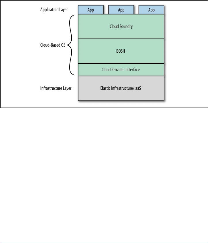
The Cloud Provider Interface
BOSH supports deploying to multiple IaaS providers including VMware’s vSphere,
AWS, GCP, and OpenStack. BOSH achieves its infrastructure-agnostic capabilities by
implementing a cloud provider interface (CPI) for each supported IaaS. The CPI con‐
tains implementations of the necessary verbs that drive the underlying IaaS layer.
These include instructions such as create VM and create disk. You can extend
BOSH support to additional infrastructure providers such as RackHD and Apache
CloudStack by implementing a CPI for the required infrastructure, as demonstrated
in Figure 10-1.
Figure 10-1. The Cloud Foundry infrastructure stack
Infrastructure as Code
BOSH focuses on defining your infrastructure as a piece of code. The traditional
approach with other infrastructure-as-code provisioning tools involve having a pre‐
established set of servers or VMs that are then used for deploying and updating soft‐
ware. More recently, the traditional infrastructure-as-code tools have been extended
with capabilities to preprovision VMs prior to laying down the OS and software com‐
ponents.
The difference between these approaches and BOSH is that BOSH, by design, tries to
abstract away the differences between all of the infrastructure platforms (IaaS or
physical servers) into a generalized cross-platform description of your deployment.
Differences between infrastructures are, where possible, handled by the CPI layer.
The BOSH user works with a manifest, and that manifest will, by and large, be the
same across the different infrastructures to which the BOSH release will be deployed.
172 | Chapter 10: BOSH Concepts

Other powerful provisioning tools such as Terraform or AWS Cloud Formation,
which also provide configuration to instantiate infrastructure, have not abstracted
away infrastructure-specific configuration to the same degree, allowing infrastructure
concerns to bubble up for the end user to handle.
With tools like Terraform, you can set up an entire data center from scratch, if, for
example you are working on AWS, because Terraform knows you will be using AWS
components such as Route53 and ELB. BOSH comes in at a place where all infra‐
structure platforms provide certain levels of abstraction for compute, disk storage,
and some networking. Given those bare-minimum configurations, BOSH will have a
common ground for actually creating VMs, attaching disks, and putting them in the
correct networks. The BOSH user does not need to worry about concerns such as, “If
I am on AWS which AMI should I choose?”
BOSH does not solve every conceivable use case. For example, BOSH does not try to
handle IaaS networking configuration, because this is unique to each IaaS layer.
There is no easy way to abstract away these concerns to a point where you are not
losing required configuration benefits. Abstraction focuses on the common ground
across infrastructure platforms, potentially cutting out features that are unique to a
specific platform. Therefore, picking the right level of abstraction—to be feature-rich
while portable across infrastructure—is the challenge that BOSH aims to address.
BOSH on the Server
Even though BOSH is primarily designed for deployment to IaaS,
there are efforts to allow a hardware provisioning experience
through projects such as Open Crowbar and RackHD.
The other key feature of BOSH is its built-in resiliency. Traditional infrastructure-as-
code provisioning tools do not check whether services are up and running. BOSH has
strong opinions on how to create your release, forcing you to create a monitor script
for every process. If a process dies, the monitor script (Monit for Linux) will restart
the process. In addition, the BOSH Resurrector has the ability to re-create failed or
unresponsive VMs. Upon re-creation, BOSH can deal with remounting persistent
data.
The final key difference is that most other infrastructure-as-code provisioning tools
run a series of package-management commands to build and release their software.
Usually those commands download packages from the internet. This approach might
lead to a nonreproducible environment (the packages have changed in the upstream
repository or are no longer available). BOSH again takes an opinionated view to
always ensure that every provisioned release is identical. A BOSH release has all
dependencies packaged into the release. Therefore, you can deploy an old release
again and again, and BOSH should produce the same results every time.
Infrastructure as Code | 173

The value of BOSH goes beyond configuration management. It is focused on a seam‐
less experience of delivering software and then ensuring that it remains highly avail‐
able and resilient. Simply put, BOSH translates intent into action and then maintains
that state.
Creating a BOSH Environment
A single BOSH environment consists of the Director VM and any deployments it
orchestrates. Before deploying software releases, or, more specifically, BOSH releases,
we first need to deploy the Director. The Director VM includes all necessary BOSH
components that will be used to manage the different IaaS resources such as net‐
works, compute, and disks. You can bootstrap a BOSH Director via bosh-init. You
can find steps for bootstrapping a BOSH environment via $bosh creat-env on
bosh.io.
BOSH Versions
It is recommended that you update your BOSH environment fre‐
quently to stay on the latest version. I have seen spurious deploy‐
ment issues fixed simply by upgrading to a newer version of BOSH,
the latest stemcell, and the latest BOSH CLI.
Both BOSH and Cloud Foundry make extensive use of manifests. This includes man‐
ifests for creating a BOSH environment, release manifests, deployment manifests,
and app manifests for app deployment. Manifests are discussed further in “Under‐
standing YAML Syntax” on page 202. It is important to note that the manifest used to
create the BOSH Director currently currently has some differences from manifests
used for BOSH deployments. You should refer to the bosh.io for a description of
those differences.
Single-Node versus Distributed BOSH
Single-node BOSH is a complete BOSH environment that runs on a single machine.
Although you can deploy BOSH in a distributed fashion, in reality, most deploy‐
ments (including Cloud Foundry) work fine using a single-node BOSH machine.
Even though being on a single machine can be considered a single point of failure, a
single-node BOSH removes network segmentation faults, and it can be protected and
mitigated by the IaaS layer. BOSH downtime does not cause downtime of Cloud
Foundry or the apps running on it. The only real advantage of a multinode (dis‐
tributed) BOSH is that it is easier to update because a single-node BOSH can then be
used to upgrade the distributed BOSH.
174 | Chapter 10: BOSH Concepts

BOSH Lite
Not everyone requires a full-blown deployment for their BOSH release. For example,
if you just want to play around with Cloud Foundry, you might not want to incur the
costs of running anywhere between 10 to 30 VMs on AWS. The solution to running
an easy-to-configure, lightweight version of Cloud Foundry, or any other release, is
BOSH Lite.
BOSH Lite is a prebuilt Vagrant box that includes the BOSH Director. However,
instead of using a traditional IaaS CPI such as AWS, BOSH Lite utilizes a CPI for
Garden. This means that instead of the CPI creating new VMs, the Garden CPI uses
containers to emulate VMs. This makes BOSH Lite an excellent choice for scenarios
such as these:
•General BOSH exploration without investing time and resources to configure an
IaaS
•Getting started with BOSH and Cloud Foundry without incurring significant
IaaS costs
• Development of BOSH releases
• Testing releases locally or as part of a CI/CD pipeline
BOSH Lite is a great environment for trying out Cloud Foundry, but be mindful that
because everything is running on a single VM, it is suitable only for experimentation
and not production workloads.
BOSH Top-Level Primitives
This section covers the BOSH primitives, including the BOSH concepts and compo‐
nents, and how they interact. Before bootstrapping a new BOSH environment, it is
important to be aware of the top-level BOSH primitives that underpin a provisioned
Cloud Foundry environment.
Primitives
Computing languages use primitives to describe the simplest ele‐
ments available in a programming language.
Following are the top-level BOSH primitives:
1. Stemcells
2. Releases
BOSH Top-Level Primitives | 175
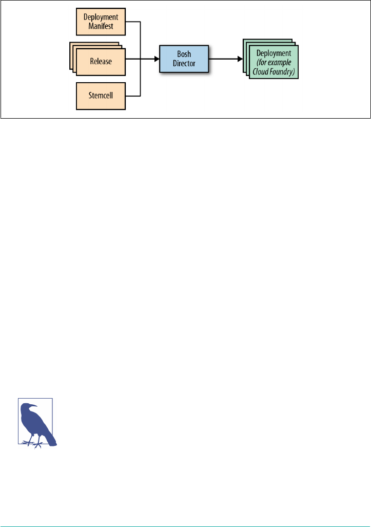
3. Deployments
Figure 10-2 presents an overview of the top-level BOSH primitives.
Figure 10-2. The three BOSH artifacts (deployment manifest, stemcell, and release) that
the BOSH Director uses to create a new deployment (for example, a new Cloud Foun‐
dry instance)
Stemcells
In biology, a stemcell is an undifferentiated (or basic) cell that can differentiate into
several types of specialized cells throughout the body. A BOSH stemcell follows this
same principle; it is a hardened and versioned base OS image wrapped with minimal
IaaS-specific packaging. A common example of stemcell hardening is that SSHD, the
OpenSSH daemon program for SSH, has been reconfigured to support only appro‐
priate cyphers, only allow specific users to log in, and enforce time-out of client con‐
nections. Another example is that all compilers have been removed from the stemcell
to reduce the attack surface. A typical stemcell contains the following:
• A bare-minimum OS skeleton with essential preinstalled common utilities
•Configuration files to securely configure the OS
• A BOSH agent for communication back to the Director
• IaaS-specific packaging and versioning
IaaS Specifics
Certain infrastructures have different packaging schemes (e.g., raw,
qcow, AMI), requiring stemcells to be packaged in a specific way.
For this reason stemcells become infrastructure-specific. The base
OS image is common across all infrastructure types. All installed
packages and libraries should be identical across all stemcells of the
same version.
176 | Chapter 10: BOSH Concepts

1The word “patch” is used indicatively in this context; in reality, machines are not patched—they are re-
created from a new patched stemcell. This approach further strengthens BOSH’s intentional security posture.
All machines created by BOSH are created from stemcells, including the Director
machine itself and any machine subsequently created by the Director.
Stemcells provide clear separation between the base OS and any later-installed soft‐
ware used to specialize the machine. Stemcells are agnostic to what will be installed
on them. They do not contain specific or sensitive information relating to the down‐
stream software used to specialized them, so they can be shared at will with other
BOSH users. Stemcells ultimately become transformed into specialized VMs in the
cluster through BOSH instantiating and installing additional software on them dur‐
ing a BOSH deployment. This specialized downstream software is referred to as a
BOSH release.
This separation of the base OS (stemcells) and specialized downstream software
(BOSH release) is a powerful concept. Stemcells capture a specific base OS image; for
example, Ubuntu Trusty. They are exactly the same and you can use them across dif‐
ferent software deployments and different VM types. Because the same base OS is
reused, it becomes extremely easy to apply versioning changes to the OS; for example,
OS security fixes. This property of generic stemcells makes it possible for BOSH users
to effortlessly switch among different infrastructures without being concerned about
potential differences between OS images. It is similar to Java’s JVM aim of “write
once, run anywhere” for compiled Java code. Because the same base OS is reused
everywhere, it becomes easy to apply versioning changes systematically, to every
deployed OS image. This benefit should not be underestimated; the ability to rapidly
and confidently patch all machines within a distributed system is an extremely pow‐
erful capability.1
Stemcells are distributed as tarballs, and the Cloud Foundry BOSH team is responsi‐
ble for producing and maintaining an official set of stemcells. You can view and
download the most recent and currently supported stemcells at bosh.io.
Releases
BOSH deploys software that has been packaged into a self-contained BOSH release.
A BOSH release is your software, including all configuration and dependencies
required to build and run your software in a reproducible way. A single BOSH release
contains one or more pieces of software that are designed to work in unison. There‐
fore, BOSH becomes an excellent choice for deploying both an individual component
and an entire distributed system.
A release is the software layer placed on top of a stemcell to transform it into a speci‐
alized component. Conceptually, a release is the packaging of your software (code)
BOSH Top-Level Primitives | 177

that you want to deploy. Releases are IaaS-agnostic, which allows for increased porta‐
bility of your software across different IaaS environments. The key point here is that
your BOSH releases and the subsequent deployment of those releases are not locked
into any IaaS layer. This is because IaaS differences are abstracted away by the CPI
layer and the Director’s Cloud Configuration (discussed further in “Cloud Configu‐
ration” on page 180). This decoupling is powerful for your infrastructure strategy.
With the rise of viable alternatives to vSphere and AWS, there is a genuine desire for
portability across different IaaS offerings. For example, using only a small team, Pivo‐
tal moved its hosted version of Cloud Foundry, known as Pivotal Web Services, from
AWS to GCP in a matter of weeks with zero app downtime. This move was possible
only because the Cloud Foundry software release is not tied into the underlying IaaS
layer.
Releases are made up of one or more release jobs, and you can co-locate different
releases during deployment. What you choose to actually deploy is not dictated by
releases; you have the freedom to select which release jobs you would like to deploy
and on which machines those jobs should reside. The anatomy of a release is dis‐
cussed in “Anatomy of a BOSH Release” on page 192. For now, it is important to know
that the release jobs you deploy to a VM form a specific component known as an
instance group. Examples of instance group components are a Diego Cell and Cloud
Foundry’s Cloud Controller. As implied by the name, an instance group can run sev‐
eral instances of the same component; for example, you typically run several Cells
within a Cloud Foundry deployment.
As discussed in Chapter 5, Cloud Foundry is encapsulated by the cf-deployment
BOSH release, located at cf-deployment.
Cloud Foundry Release Structure
The Cloud Foundry BOSH release is structured by the parent cf-
deployment release, which links to a combination of smaller, inde‐
pendent releases (e.g., etcd-release, UAA-release, and diego-
release). The cf-deployment release captures the exact versions
of the specific releases necessary to deploy a full Cloud Foundry
environment.
BOSH is designed for deploying distributed systems such as Cloud Foundry, but you
can use it equally to deploy smaller individual components such as etcd or redis.
Because it can deploy almost any other software that is able to be run on the sup‐
ported infrastructure, it has been used extensively within the Cloud Foundry ecosys‐
tem to deploy a wide variety of services such as databases, message brokers, and
caching technologies. It is worth noting that many popular services such as Rab‐
bitMQ, MySQL, PostgreSQL, and Redis already have existing BOSH releases. Com‐
munity service brokers are located in the Cloudfoundry-community GitHub repo.
178 | Chapter 10: BOSH Concepts
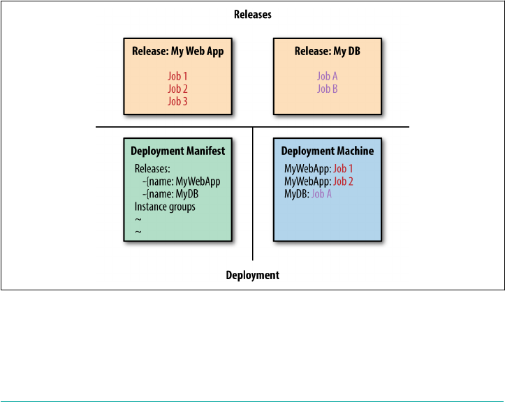
This book does not delve into the detail of creating a new BOSH release; however, it
is valuable to become familiar with release primitives and how releases are composed
in order to understand how cf-deployment is structured and deployed. Understand‐
ing BOSH releases will also come in handy if you want to create additional BOSH
releases for services that back your apps running on Cloud Foundry. Chapter 11 cov‐
ers BOSH releases in detail.
Deployments
BOSH deploys software to the IaaS layer using a deployment manifest, one or more
stemcells, and one or more releases. This is known in BOSH terminology as a BOSH
deployment, which consists of a collection of one or more machines (VMs), as depic‐
ted in Figure 10-3. Machines are built from stemcells and then layered and config‐
ured with specified components from one or more BOSH releases. A BOSH
deployment requires the following:
• The appropriate stemcell(s) for the IaaS of choice
•The releases (software) to deploy
• An IaaS environment (or infrastructure) to which to deploy the release
•A deployment manifest describing the deployment
Figure 10-3. A BOSH deployment
BOSH creates the deployment using ephemeral resources and persistent disks. The
deployment is stable because BOSH can keep your software running by re-creating
BOSH Top-Level Primitives | 179

machines that fail, or restarting failed processes. State stored on the persistent disk
(e.g., database data files) can survive when BOSH re-creates a VM because persistent
disks can be reattached. As just discussed, deployments are portable across different
kinds of cloud infrastructure with minimal changes to the deployment manifest.
The anatomy of a deployment is discussed in Chapter 12.
BOSH 2.0
There are some great features of BOSH 2.0 that significantly reduce the complexity of
deployment manifests. You can use the additional set of BOSH 2.0 features in con‐
junction with the original BOSH constructs.
Cloud Configuration
Previously, deployment manifests included all of the IaaS-specific resource configu‐
rations required for that deployment. To keep BOSH deployments IaaS-agnostic, you
now can configure IaaS resource configuration (networks, resource pools, disk pools,
compilation) in one location at the Director level. Each BOSH deployment can then
reference the predefined IaaS resources by name. You can define the IaaS configura‐
tion in an additional manifest such as iaas.yml, as follows:
compilation:
workers: 6
network: my-network
az: z1
reuse_compilation_vms: true
vm_type: m3.medium
vm_extensions:
- 100GB_ephemeral_disk
azs:
- name: z1
cloud_properties:
availability_zone: us-west-1a
networks:
- name: my-network
type: manual
subnets:
- az: z1
gateway: 10.0.16.1
range: 10.0.16.0/20
reserved:
- 10.0.16.2-10.0.16.3
- 10.0.31.255
static:
- 10.0.31.190-10.0.31.254
cloud_properties:
180 | Chapter 10: BOSH Concepts

subnet: subnet-XXXXXXXX
security_groups:
- sg-XXXXXXXX
vm_types:
- name: m3.medium
cloud_properties:
instance_type: m3.medium
ephemeral_disk:
size: 1024
type: gp2
vm_extensions:
- name: 100GB_ephemeral_disk
cloud_properties:
ephemeral_disk:
size: 102400
type: gp2
- name: router-lb
cloud_properties:
elbs:
- stack-bbl-CFRouter-XXXXXXXX
security_groups:
- sg-XXXXXXXA
- sg-XXXXXXXB
- name: ssh-proxy-lb
cloud_properties:
elbs:
- stack-bbl-CFSSHPro-XXXXXXXX
security_groups:
- sg-XXXXXXXA
- sg-XXXXXXXB
disk_types:
- name: 5GB
disk_size: 5120
cloud_properties:
type: gp2
encrypted: true
The cloud configuration construct provides the flexibility to stipulate IaaS-specific
information once; for example, a small, medium, and large vm-type, which can then
be used by the various different BOSH deployments. The preceding manifest example
specifies information about the following:
• Compilation VM
• AZs
• Networks
•vm_types
BOSH 2.0 | 181

•vm_extensions
•disk_types
The manifest specifies that the compilation VM resides on an AZ named z1 and a
network named my-network. The properties of z1 and my-network are specified in
the respective AZs and networks hashes. The compilation vm_type is specified as
m3.medium with an 100GB_ephemeral_disk vm_extension. Again, the details of
m3.medium and 100GB_ephemeral_disk are specified in the respective vm_types and
vm_extensions hashes. The vm_extensions hash contains additional hashes that
describe the required load balancers, named router-lb and ssh-proxy-lb. Finally,
you can specify any other IaaS component in this manifest such as disk_types. If
that description feels complex, don’t worry, we will walk through the specifics of each
component in a moment.
Because the entire IaaS configuration is now encapsulated in a separate cloud config‐
uration manifest, the deployment manifest is not only simpler, it’s significantly
smaller. In the subsections that follow, we examine each section of the cloud configu‐
ration.
Networks
A BOSH network is an IaaS-agnostic representation of the networking layer. BOSH
expresses networks as a logical view; a BOSH network is the aggregation of all
assigned IaaS subnets. In the manifest, networks provides an array of networks (IaaS
networks and subnets) to be used by deployed jobs.
BOSH Networking and IaaS Networking
The BOSH cloud configuration manifest has only a construct of
networks. The IaaS networking can deal with both networks and
subnets. Therefore, if you run out of IPs, you can simply add addi‐
tional IaaS subnets to the BOSH networks’ array. Second, as dis‐
cussed in “AZs” on page 186, BOSH abstracts the AZ separation.
Some IaaS offerings, such as AWS, do not allow subnets to span
AZs. BOSH deals with this by allowing the operator to specify a
single BOSH network and then add multiple IaaS subnets from dif‐
ferent AZs to that single BOSH network.
Within the cloud configuration manifest, all networking is specified in one global
networking section and then shared by multiple deployments. This provides the
advantage that created VMs are assigned the same IPs. This also makes it easier to
structure subnets, ensuring that they do not overlap. Specifying network information
on a per-deployment manifest basis is significantly more difficult and error prone
because you were required to be mindful of other deployments that might have been
182 | Chapter 10: BOSH Concepts

deployed to the same underlying IaaS network. Now, BOSH guarantees that subnets
will not overlap because it keeps unique IPs all in one table. Therefore, you can even
give multiple BOSH networks the same underlying IaaS subnet, and, still, BOSH will
ensure each new deployment will use only unique IPs.
It is the Director’s responsibility (with the help of the BOSH agent and the IaaS) to
configure each of the instance group’s network. Networking configuration is usually
assigned when the machine is started. You can also apply it when the network config‐
uration changes due to a manifest change for already-running instance groups. Here
is an example of configuring the network:
networks:
- name: my-network
type: manual
subnets:
- az: z1
gateway: 10.0.16.1
range: 10.0.16.0/20
reserved:
- 10.0.16.2-10.0.16.3
- 10.0.31.255
static:
- 10.0.31.190-10.0.31.254
cloud_properties:
subnet: subnet-XXXXXXXX
security_groups:
- sg-XXXXXXXX
The reserved range is used for IPs that will be explicitly used by the network (such as
the gateway VM or DNS). As such, BOSH will not use any IP in a reserved range for
provisioning VMs.
BOSH networking supports automatic and static IP reservation types for manual net‐
works:
Static
The IP is explicitly requested by the Platform Operator in the deployment mani‐
fest.
Automatic
The IP is selected automatically based on the network type.
You can use the static IP range for VMs that require a static IP. Components or VMs
that you need to know about upfront, such as the HA_Proxy or the GoRouter,
require a static IP so that you can point your DNS server to the load balancer and
then point the load balancer at the GoRouter cluster.
If using BOSH links (discussed in “BOSH Links” on page 187), static IPs are not
required for internal-facing BOSH-deployed components. BOSH links will maintain
BOSH 2.0 | 183

the IPs for you, and they do not need to be placed in the manifest. External-facing
components such as a load balancer will still require a static IP.
There are three different BOSH network types:
• Dynamic
• Manual
•VIP
BOSH abstracts the networking away from the Platform Operator. If you are using a
VIP network, you can assign elastic or floating IPs. Manual and dynamic networks
allow you to assign private IPs. For a more detailed explanation about how to config‐
ure these network types, refer to bosh.io for the latest guidance, as implementation
details can change over time.
VM types
VM types is a collection of VM sizes with specific properties. They are created from
the stemcell defined in the deployment manifest. Every VM created from the same
VM type and stemcell will have the same configuration. The Platform Operator can
define an array of VM types each with different VM settings; for example, varying
CPU and RAM to offer small, medium, and large VMs to your deployment. Individ‐
ual deployments no longer need to be concerned with what a small VM means
because it is defined once per Director.
Each instance_group instance defined in the deployment manifest will run on a
dedicated VM, and so the instance_group must reference the required stemcell and
vm-type. This means that each instance group belongs to exactly one vm-type and
stemcell combination.
In addition, there is a cloud_properties definition with which the Platform Opera‐
tor can specify other VM characteristics and IaaS-specific settings that might be
required when creating VMs; for example, vm_extension and disk_type.
A manifest for bosh-init might use the precursor to vm_types known as
resource_pools. Resource pools contain IaaS-specific information about the VMs.
Configuring the disk type
Disks are used for machine storage. Disk types make it possible for you to specify
persistent disks for use with the instance group VMs and compilation VMs (see
“Compilation VMs” on page 186). It is possible to define two different types of storage
solutions: ephemeral and persistent disks. This provides you with the flexibility to use
a more cost-effective storage solution for the ephemeral storage and high-grade stor‐
age for persistent data.
184 | Chapter 10: BOSH Concepts

Consider three different Cloud Foundry instance groups:
• API
• UAA
• etcd
Each instance group has a VM with two mounted ephemeral disk filesystems:
/dev/sda1 with / mounted
/dev/sdb2 with /var/vcap/data mounted
Instance groups that specify a persistent disk (such as persistent_disk: 1024) will
have a third filesystem:
/dev/sdc1 1011416 8136 934688 1% /var/vcap/store
Looking at UAA, which has no persistent disk, you will observe two ephemeral disks
with no var/vcap/store:
df -k
Filesystem 1K-blocks Used Available Use% Mounted on
/dev/sda1 2886304 1293408 1426564 48% /
none 4 0 4 0% /sys/fs/cgroup
udev 498216 4 498212 1% /dev
tmpfs 101760 648 101112 1% /run
none 5120 0 5120 0% /run/lock
none 508784 0 508784 0% /run/shm
none 102400 0 102400 0% /run/user
/dev/sdb2 9182512 478144 8214872 6% /var/vcap/data
tmpfs 1024 16 1008 2% /var/vcap/data/sys/run
/dev/loop0 122835 1583 117321 2% /tmp
Looking at etcd, which does have a persistent disk, we see the addition of /var/
vcap/store:
df -k
Filesystem 1K-blocks Used Available Use% Mounted on
/dev/sda1 2886304 1293640 1426332 48% /
none 4 0 4 0% /sys/fs/cgroup
udev 498216 4 498212 1% /dev
tmpfs 101760 656 101104 1% /run
none 5120 0 5120 0% /run/lock
none 508784 0 508784 0% /run/shm
none 102400 0 102400 0% /run/user
/dev/sdb2 9182512 57524 8635492 1% /var/vcap/data
tmpfs 1024 12 1012 2% /var/vcap/data/sys/run
/dev/loop0 122835 1550 117354 2% /tmp
/dev/sdc1 1011416 8136 934688 1% /var/vcap/store
In addition, one of the CF instance groups might use a blobstore such as a
debian_nfs_server in vSphere or an Amazon S3 bucket in AWS.
BOSH 2.0 | 185

The API instance group has mounted the filesystem /var/vcap/nfs. Data written to
this location actually resides on an NFS blobstore under /var/vcap/store:
bosh_3x78y23hg@25e1aec0-36aa-424b-a70e-eff65b7b5490:~$ df -k
Filesystem 1K-blocks Used Available Use% Mounted on
/dev/sda1 2886304 1296128 1423844 48% /
none 4 0 4 0% /sys/fs/cgroup
udev 498216 4 498212 1% /dev
tmpfs 101760 648 101112 1% /run
none 5120 0 5120 0% /run/lock
none 508784 0 508784 0% /run/shm
none 102400 0 102400 0% /run/user
/dev/sdb2 3057452 360844 2521584 13% /var/vcap/data
tmpfs 1024 12 1012 2% /var/vcap/data/sys
/run
/dev/loop0 122835 1550 117354 2% /tmp
10.129.48.12:/var/vcap/store 103079936 2251776 95568896 3% /var/vcap/nfs
cf-deployment’s manifest-generation capability will automatically
configure the storage for your instance groups. You can reconfig‐
ure these after you generate the deployment manifest.
Compilation VMs
Compilation defines the machine settings for the VMs used to compile any individ‐
ual packages from the release jobs into self-executable binaries, as follows:
compilation:
workers: 6
network: my-network
az: z1
reuse_compilation_vms: true
vm_type: m3.medium
vm_extensions:
- 100GB_ephemeral_disk
It is generally considered fine to reuse compilation VMs as opposed to using a clean
VM for every new compilation. Fewer workers can potentially result in longer
deployments because less work might be done in parallel. However, it is worth noting
that in the case of AWS, the IaaS might be slow to set up VMs compared to the time
it takes to compile packages; thus it might be most performant to have fewer reusable
workers.
AZs
AZs provide resiliency. By striping instances from a single instance group across mul‐
tiple AZs, you ensure availability in the event of a total failure of a single AZ.
186 | Chapter 10: BOSH Concepts

To simplify configuration of AZs, they have been pulled out of the deployment mani‐
fest into their own section. Previously, to stripe a single instance group across multi‐
ple AZs, the Platform Operator had to create multiple resource pools with slightly
different cloud properties and multiple instance groups with slightly different names
(e.g., web_az1, web_az2). This approach introduced extra complexity and repetition
in the deployment manifest.
Since BOSH 2.0, each defined AZ specifies a name and the cloud properties to
include any IaaS-specific properties required for placement information. For exam‐
ple, on AWS, AZs are encapsulated by an AWS availability_zone and on vSphere AZs
might be a vSphere cluster and resource-pool combination.
The subnets of each network must define which AZ they belong to. Each instance
group can be on one or more networks. Because each instance group can span multi‐
ple AZs, there must be a way to determine how to describe a network that spans mul‐
tiple AZs. Most IaaS platforms require a separate subnet per AZ, so BOSH can
abstract that away by defining a network based on multiple subnets from different
AZs.
For deployments that still use resource pools, their cloud properties should only
include VM sizing information such as instance types, RAM, CPUs, etc. When
replacing resource_pools for the newer vm_types, each instance group must specify
the Cloud Foundry AZ in which to reside.
BOSH Links
BOSH links give the Platform Operator a means to configure a deployment involving
multiple VMs, where at least one instance group knows about another; for example, a
web server that depends on a database. Traditionally, operators had to assign static
IPs or DNS names to one job and pass it via properties to the other. This configura‐
tion was error-prone and unnecessary. It was also difficult to automate for the case of
on-demand deployments.
Links provide a solution to this problem and abstract away manual versus dynamic
(DNS-based) networking from the instance groups. Additionally, you can use links to
share other non-networking configurations (job properties) between instance groups.
From the operator’s perspective, introduction of links removes tedious cross-
referencing of IPs and other properties between different BOSH releases and deploy‐
ments.
To take advantage of links in releases, extra metadata needs to be specified by using
the consumes and provides directives. Each release job that needs information about
another release job must specify consumes with the name of the link type it con‐
sumes. Each release job that can satisfy link type must specify provides. BOSH also
has a concept of explicit linking of release jobs. If a link type is provided by only
BOSH 2.0 | 187

one job within a deployment, all release jobs in that deployment that consume links
of that type will be implicitly connected to that provider. You can find more informa‐
tion about BOSH links at https://bosh.io/docs/links.
Orphaned Disks
Orphaned disks provide an additional safety feature because losing persistent data is
never good. If you require a larger disk size, you can modify this in the cloud configu‐
ration manifest (or select a larger instance from the disks listed in the cloud configu‐
ration); BOSH will detach the old disk and reattach the new disk, migrating data
across to the new disk in the process. The challenge here is that if you rename your
instance group (from nameA to nameB), BOSH sees this as a new instance group, as
opposed to an upgraded instance group, and will delete the old instance group (and
old persistent disks) without moving the data on the old disk. To address this valid
but often unintended behavior, when deleting a disk, BOSH keeps old disks around
for five days and will garbage-collect them retroactively. Therefore, if you acciden‐
tally delete a deployment, you can recover your persistent disk after the fact.
Addons
Addons provide the ability for you to add additional releases to BOSH deployments.
This feature is extremely valuable for adding new capabilities to an existing or future
deployment. Addons are especially powerful because they provide the ability for the
operator to define Director-wide policies. For example, additional releases that you
might want to “add on” could include a corporate security module or an IPSec BOSH
release to encrypt communication between all deployed VMs. As a positive side
effect, addons also remove some of the clutter from deployment manifests.
Your BOSH environment might consist of multiple release jobs (e.g., Cloud Foundry
and additional service brokers). There might be requirements to add an additional
release job to all deployed VMs. Instead of modifying the deployment manifest to
add additional release templates and then redeploying, BOSH employs the concept of
runtime-config in the form of BOSH addons. Addons are a new release job that can
be co-located with existing instance groups. When a new bosh deploy is invoked,
BOSH deploys the addons to the defined deployment.
Summary
This chapter covered the concepts of BOSH, the outer shell responsible for provision‐
ing and running Cloud Foundry.
BOSH is a release-engineering tool chain that provides consistent, reproducible, and
identifiable deployments. Consistent repeatability de-risks software releases.
188 | Chapter 10: BOSH Concepts

BOSH is an essential component of the Cloud Foundry ecosystem, and it is impor‐
tant that you understand the role BOSH plays for both deploying and verifying the
health of your Cloud Foundry environment and related services. Specifically, under‐
standing the BOSH top-level primitives of stemcells, releases, and deployment helps
you to understand how Cloud Foundry is deployed.
BOSH is complex, and there is a lot to it. For operators who want to gain a deeper
understanding of BOSH, the next three chapters examine the anatomy of a BOSH
release and deployments, and then we dive deeper into the individual BOSH compo‐
nents and basic BOSH commands.
Summary | 189

CHAPTER 11
BOSH Releases
Chapter 10 introduced BOSH concepts on a high level. For operators who want a
deeper understanding of BOSH releases, this chapter presents an overview of how
releases are structured and packaged.
A BOSH release is your software, including all configuration and dependencies
required to build and run your software in a reproducible way. Gaining an under‐
standing of releases will help you to comprehend how individual components work.
For example, understanding how a release is composed and deployed can help you to
pinpoint where each release job runs. This ability to determine exactly which pro‐
cesses run and where they run is invaluable for debugging.
Release Overview
Releases are self-contained and provide very specific software solely relating to the
purpose of that release. Here’s a simple example provided by bosh.io:
[A] Redis release might include startup and shutdown scripts for Redis-server, a tarball
with Redis source code obtained from the Redis official website, and a few configura‐
tion properties allowing cluster operators to configure that Redis-server.
A release consists of versioned release jobs and packages. A release job describes a
single component that can be run in isolation to do its work. A release package con‐
tains the required dependencies for a specific job. A release exists as a versioned col‐
lection of the following artifacts:
• Configuration properties
• Configuration templates
• Scripts (including startup scripts and shutdown scripts) for the release jobs
•Source code
191

• Binary artifacts
• Anything else required to build and deploy software in a reproducible way
By allowing the separation and layering of releases on top of stemcells, BOSH is able
to version and roll out updated software to the entire cluster on a machine-by-
machine basis. Releases ensure that the same compiled software version is used
repeatedly for every deployment, as opposed to running a package installer such as
apt-get, which can potentially install a different binary every time, depending on
from where you pull binaries. All the required configuration options and scripts for
software deployment are captured and all software dependencies are explicitly recor‐
ded with all changes tracked. Packing enables versioning, tracking, and self-
containment of IaaS—agnostic software releases. This means that you can deploy a
release version without internet access.
Cloud Foundry BOSH Release
Installing Cloud Foundry does not require you to create a new release; you can sim‐
ply deploy a current Cloud Foundry release version. The current canonical Cloud
Foundry deployment is cf-deployment. cf-deployment comprises several individual,
self-contained component releases. This means that each Cloud Foundry component,
such as the UAA, or Diego, or the GoRouter, resides in its own BOSH release. cf-
deployment then draws these releases together via a canonical manifest for deploying
Cloud Foundry. Chapter 12 discusses deployments, including how Cloud Foundry is
deployed.
BOSH Director BOSH Release
The BOSH Director itself is a dedicated BOSH release. To install the BOSH Director,
the $ BOSH create-env command will grab the BOSH Director BOSH release loca‐
ted on GitHub. This BOSH Director BOSH release has some subtle differences from
typical BOSH releases. This chapter focuses on typical BOSH releases, such as Cloud
Foundry.
Anatomy of a BOSH Release
A BOSH release has five release primitives, the most significant being jobs, packages,
src, and blobs. These terms are discussed at length below. A typical release directory
contains:
•A jobs directory that contains job metadata
• A package directory that contains package metadata
•A config, blobs, and src directory
192 | Chapter 11: BOSH Releases

•.dev_builds and .final_builds directories
• Any Git subdirectories
To create a typical release directory with one job and one package, navigate to the
workspace where you want the release to reside. Then, using the BOSH v2 CLI, run
the following:
$ bosh init-release <release_name>
$ cd <release-name>
$ bosh generate-job <job-name>
$ bosh generate-package <package-name>
You can now view the skeleton release directory tree:
$ tree .
.
├── blobs
├── config
│ └── blobs.yml
├── jobs
│ └── job_name
│ ├── monit
│ ├── spec
│ └── templates
├── packages
│ └── package-name
│ └── packaging
└── src
Release Naming
By convention, BOSH uses a lowercase naming convention with
dashes in the release name; for example, cf-deployment. For all
other filenames in the release, BOSH uses underscores; for exam‐
ple, job_name.
Jobs
A release job (or simply job) conceptually describes a single component. You can run
a release job in isolation and it will do its work. The release job can be comprised of
several individual processes (e.g., a master process coupled with a separate worker
process for tasks such as log rotation). A release job might depend on other jobs, and
there may be several steps to instantiate a release job, but the end state should be a
single component that you can start and stop by a single Monit script.
Anatomy of a BOSH Release | 193
Release Jobs and Instance Groups
Release jobs are individual software components that can run in
isolation. An instance group is the deployment unit. A single
instance group represents one or more release jobs to be deployed
to a single VM. An instance group can have several running instan‐
ces (VMs) such as several Diego Cells or several GoRouters.
The BOSH releases for each core Cloud Foundry component (such as the Cloud
Controller or GoRouter) are broken into one or more release jobs. Usually, we do not
append “release” to the release name. Appending release is useful only for descriptive
purposes such as a GitHub repository or when the release is distributed as a .tar file.
You can view a list of the current jobs associated with the deployed instance groups
by running the following command:
$ bosh -e <bosh_env> -d <deployment> instances --ps
Each job has its own directory containing a Monit file, a specification file, and a tem‐
plates directory. A job needs to be able to start and stop its processes. BOSH currently
achieves this by using a control script and Monit.
Control scripts
We use control scripts to configure and control job processes, including commands
such as start and stop. The job’s control script is an embedded Ruby (ERB) tem‐
plate typically named <job_name>ctl.erb (arguably, it should just be called ctl.erb
because it belongs to a specific job and so is already namespaced). It is stored in the
job’s templates directory. By BOSH convention, control scripts should configure the
job to store logs in /var/vcap/sys/log/<job_name>. If a release needs templates other
than the control script, those templates should also reside in the templates directory.
ERB
ERB is a Ruby feature that provides a way to generate text from
templates. The templates combine plain text with Ruby code for
variable substitution and flow control.
When a release is deployed, BOSH transforms the control scripts into files, substitut‐
ing the required variable values (properties), and then replicates these files onto the
subsequent instance group VMs under /var/vcap/jobs/<job_name>.
The /var/vcap Directory Structure
By convention, the /var/vcap directory is used as the parent direc‐
tory to the /sys and /jobs subdirectories.
194 | Chapter 11: BOSH Releases

1The concept is the same for Windows support; however, Windows uses a custom job supervisor with Win‐
dows services instead of Monit, and JSON in place of a ctl script.
Monit
In addition to the ctl.erb template script, a release also requires a controlling and
monitoring process that can start (or restart), monitor, and stop the job processes. In
Linux you do this by using a Monit file (with an equivalent for Windows1) for each
release job. The Monit file has two key responsibilities:
•Specifies the job’s process ID (PID) file
•References all commands (e.g., start and stop) provided by the release job tem‐
plates
The Monit file for a job typically contains the following:
check process <job_name>
with pidfile /var/vcap/sys/run/<job_name>/pid
start program "/var/vcap/jobs/<job_name>/bin/ctl start"
stop program "/var/vcap/jobs/<job_name>/bin/ctl stop"
group vcap
Note that the path to the ctl script is the path that will exist on the deployed instance
group machine.
Specification Templates
Each job has a specification file that defines job metadata (including any additional
templates) and any required job properties like db_password. Here is what the speci‐
fication file lists:
name
The job name
packages
Includes both package dependencies and the packages created by this job
templates
An array of ERB template names and paths
properties
A list of properties required by the job
Anatomy of a BOSH Release | 195

Job Descriptions
Often, specification files will contain a description used to describe
the job. This is not part of BOSH. You can write whatever you
want in the specification file; however, BOSH will consider only
names, packages, templates, and properties.
The job specification file’s templates block contains a list of hashes. The template
name is the key, and the path on the instance group machine’s filesystem is the hash
value.
File paths are always relative to the /var/vcap/jobs/<job_name> directory on the
instance group machine. By convention, these control scripts go in the bin directory.
Therefore, on the instance group machine, bin/ctl becomes /var/vcap/jobs/
<job_name>/bin/ctl.
Templates can be required for things like scripts that set up environment variables.
Any such script is generated via a template, with properties injected in by the Direc‐
tor, which accesses properties set in the deployment manifest. Properties are dis‐
cusssed further in “Properties” on page 207.
Packages
The packages directory contains the dependencies of a specific job. These dependen‐
cies are pulled in from the blobs and src directories. Packages provide BOSH with all
of the information required to prepare the job binaries and job dependencies during
the release-compile phase. A release can contain several jobs, each dependent on their
specified packages.
1. Packages provide source code and dependencies to jobs
2. Src provides packages with the nonbinary files they need
3. Blobs provide packages with the binaries they need (other than binaries that are
checked in to a source code repository)
Figure 11-1 shows the dependency graph for a release job.
196 | Chapter 11: BOSH Releases
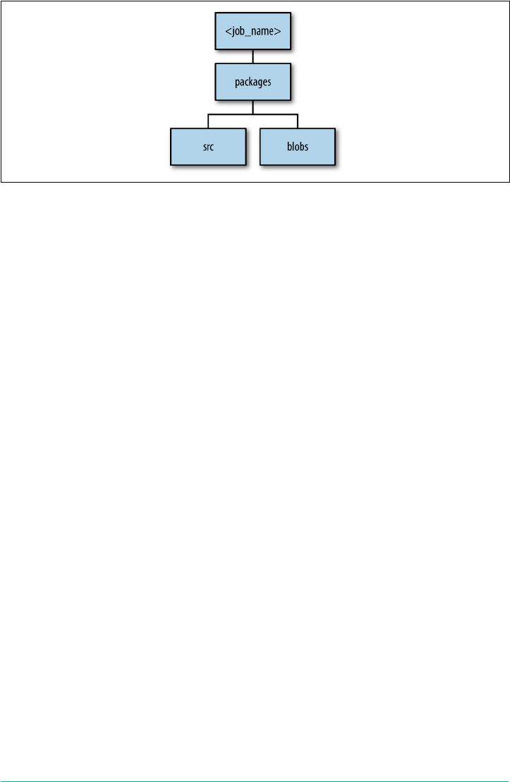
Figure 11-1. Job dependency graph
The packages directory also contains the packaging instructions so that BOSH can
build each of the release job dependencies during the create-release compilation
phase. A BOSH release has two kinds of dependencies: runtime dependencies and
compile-time dependencies.
Runtime dependencies exist when a job depends on a package to run; for example, a
Spring boot app depends on Java, or a Ruby app depends on Ruby. Compile-time
dependencies occur when a package depends on another package at compile time; for
example, Ruby depends on the YAML library to compile.
It is important to note that jobs are self-contained in that jobs can depend only on
packages, not other jobs; however, packages can depend on other packages.
Src, Blobs, and Blobstores
As we just discussed in “Packages” on page 196, src and blobs directories contain the
dependencies pulled in by the packages. The src contains source code that is explicitly
part of the release. Job source code is either copied into the src directory or linked to
it, using a mechanism such as a Git submodule or a Mercurial repository.
Most releases are highly dependent on a source code repository. However, releases
often use blobs, such as .tar files or precompiled third-party libraries. Blob tarballs
can contain both binaries or source code, and they usually contain all external depen‐
dencies. If the tarballs contain source code, the packaging script must define how to
compile that code.
Typically, for components that are not your actual software (e.g., Ruby), you provide
them via blobs. Components that you are responsible for releasing should be pro‐
vided in the most generic form possible, namely source code.
Anatomy of a BOSH Release | 197

Using Source over Binaries
You can compile dependencies from source as opposed to using
prebuilt binaries. Binaries are usually tied to a specific OS architec‐
ture, so something that works on Ubuntu might not work on Cen‐
tos. When you compile from source, you are creating binaries for
the specific stemcell architecture defined in the deployment mani‐
fest.
A lot of source code repositories, for example GitHub, are not suitable for checking
in large blobs. BOSH avoids the requirement to check blobs into a repository in two
ways:
• For a dev release, BOSH uses local copies of blobs.
• For a final release, BOSH uploads blobs to a release blobstore.
For the latter, to deploy a release, the BOSH CLI needs to obtain the required blobs
and then upload those blobs to the Director. Keep in mind that there are two unrela‐
ted blobstores in play here: a Director blobstore that the Director uses, and a release
blobstore that is used only for managing a specific release.
The Director blobstore can reside anywhere the Director can reach it. A release blob‐
store is release-specific; for example, final UAA release saves the final artifacts in a
UAA-specific blobstore.
The CLI has a number of ways to upload the release into the Director blobstore. The
CLI can read the release blobstore location from a GitHub repo and then send the
blobs over to the Director. This method means that the CLI must have access to both
the Director blobstore as well as the release blobstore.
However, the BOSH Director does not require access to a release blobstore, which
means that the Director does not require internet access. An operator can simply
bring a release tarball that has been previously composed from the required blobs
from the release blobstore and then upload that tarball to the Director. This method
means that the tarball has no reference to the original release blobstore, and, as such,
the Director and CLI do not require any access to the release blobstore.
Theoretically, a release can also be constructed from scratch if you can obtain all
dependent blobs, or the release author places blobs in the blobs directory, but it is a
better experience for your release consumers if you package a release for consump‐
tion, as discussed further in “Packaging a Release” on page 199.
All of the information about the release blobstore is recorded via the config directory.
Two files reside in this directory:
198 | Chapter 11: BOSH Releases

2The new BOSH v2.0 CLI has a Git syntax that can clone a Git repository in the background for you by using
the command $ git clone, and then use the specified version of the YAML file to upload the release tarball.
final.yml
This file names the blobstore and specifies its type. Type is either local to the
BOSH Director VM or one of several other types that specify blobstore provid‐
ers, such as a local NFS, or public blobstores such as Amazon S3.
private.yml
This file specifies the blobstore path and secret key for accessing the blobstore.
As such, for security reasons, it should not be checked into a repository.
The config directory also contains an automatically generated blobs.yml file.
Although a local blobstore is convenient for getting started, the resulting releases are
held only locally and cannot be shared beyond the immediate BOSH deployment.
Packaging a Release
BOSH provides two main ways by which you can distribute a release version:
• Package the release in its entirety as a tarball and then store it somewhere.
•Use a Git repo and the releases/<release-name>/release.yml file that points to the
release blobstore.
To upload a release, run the following:
$ bosh -e <env> upload-release <your-release>
This upload-release command accepts different URL schemes. Typically you can
provide an HTTPS URL for the entire tarball, or you can clone the release’s Git repo
into a local directory and then provide, for example, the releases/cf/cf-x.yml. This
<release>.yml file tells the CLI with the information on what the publisher published
for that release version. Specifically, it contains pointers to blobstore objects (pack‐
ages and jobs) that are required for a given release version. These blobs usually reside
either locally (for a development release) or in the release blobstore (for a final
release). From that YAML file, the BOSH CLI is able to create a release tarball that
can be uploaded from the release blobstore to the Director blobstore.2
These blobs are resolved within the .final_builds file, which references the release
blobstore for final jobs and packages (each referenced by one or more releases). For
storing final releases, the config provides the URLs and access credentials to the
release blobstore. Any Git subdirectories provide local Git hooks to pull those subdir‐
ectories in.
Packaging a Release | 199

You might want to create a BOSH release for additional custom Cloud Foundry serv‐
ices. It is important to note that you do not need to create a new release version for
installing Cloud Foundry, because you can use the existing release version. For exam‐
ple, you can simply clone and use a Git URL by invoking $ bosh -c <env> upload-
release releases/cf-x.yml. This has the same behavior as accessing a release
directly from bosh.io. Using bosh.io is completely optional.
Compilation VMs
Some releases might still require further compilation (from source code to binary,
based on the appropriate stemcell). BOSH uses compilation VMs to achieve this.
Compilation brings up the machine or VM, takes the source package, runs a packag‐
ing script, and then produces a compiled package. BOSH then saves these compiled
packages and will then use the compiled packages to deploy the instance group
machines. Compilation VMs were discussed earlier in “Compilation VMs” on page
186.
Summary
A BOSH release does the following:
• Encapsulates all your software in a self-contained way
•Includes all configuration and dependencies required to build and run your soft‐
ware in a reproducible way
•Has five release primitives, the most significant being jobs, packages, src, and
blobs
• Can be versioned, packaged, and distributed
BOSH deploys software to the defined IaaS layer using a deployment manifest, one or
more stemcells, and one or more releases. A BOSH deployment consists of a collec‐
tion of one or more machines or VMs, built from stemcells and then layered and
configured with specified release jobs obtained from software releases.
What you choose to actually deploy is not dictated by releases; you have the freedom
to select which release jobs you would like to deploy and on which instance groups
those jobs should reside. This choice is defined in the deployment manifest. Chap‐
ter 12 looks more closely at BOSH deployments and deployment manifests.
200 | Chapter 11: BOSH Releases

CHAPTER 12
BOSH Deployments
This chapter provides a brief overview of BOSH deployments, including Cloud Foun‐
dry’s deployment manifest. BOSH deploys software to infrastructure (often an IaaS
layer) using a deployment manifest, one or more stemcells, and one or more releases.
As described in Chapter 11, releases exist to package of all your required artifacts.
Releases are then deployed to one or more machines (often VMs) known as instance
groups, via a deployment manifest. A deployment manifest describes how to install
releases. It defines how the various processes (release jobs) that have been packaged
by releases should be distributed and deployed to various instance groups.
There is no direct correlation of release contents and what process runs on an
instance group. This correlation is explicitly defined in the deployment manifest.
Releases are always IaaS-agnostic. A release coupled with a deployment manifest can
also be IaaS-agnostic if written correctly. As of this writing, only stemcells remain
explicitly IaaS format–specific. IaaS format–specific means that certain stemcells can
be reused across the same IaaS format; for example, OpenStack stemcells can be
reused for RackHD, and vSphere stemcells can be reused for vCloudDirector and
VirtualBox. However, where the IaaS format differs, such as between GCP and AWS,
separate stemcells that are specific to each IaaS format are required.
YAML Files
Both BOSH and Cloud Foundry make extensive use of YAML files. This includes the
following:
• Manifests for creating a BOSH Director environment
• Release files that describe release jobs and related blobs
•Deployment manifests
201

• App deployment manifests
• Cloud configuration IaaS information
To read manifests, you need to understand basic YAML syntax. YAML is a human-
readable data serialization standard for programming languages. It is generally con‐
sidered easier for humans to read and write YAML versus other common data
formats like JSON or XML.
You can edit YAML with a regular text editor. If you want to dig deeper into YAML,
you can find further information at http://yaml.org.
Understanding YAML Syntax
BOSH deployment manifests are currently by far the most complex aspect of Cloud
Foundry. The recent work on BOSH 2.0 has made great strides toward simplifying
the deployment manifest. However, for cloud operators, understanding how mani‐
fests are constructed to relay correct information to BOSH is vital. This section uses a
snippet from the Cloud Foundry deployment manifest to walk you through the sali‐
ent points of the YAML structure widely used in deployment manifests.
Many YAML files make extensive use of lists. Lists can contain individual items or
hashes. A hash is represented in a simple key: value form (the colon must be fol‐
lowed by a space). A simple hash could contain a key of “name,” with the value
“java_buildpack.” Most lists in Cloud Foundry contain hashes. All members of a list
are lines beginning at the same indentation level starting with a “- ” (a - and a space):
# A list of buildpacks
install_buildpacks:
- name: java_buildpack
package: buildpack_java
- name: ruby_buildpack
package: buildpack_ruby
- name: nodejs_buildpack
package: buildpack_nodejs
- name: go_buildpack
package: buildpack_go
- name: python_buildpack
package: buildpack_python
- name: php_buildpack
package: buildpack_php
Hash values can contain further hashes or even lists of hashes. The install_build
packs element is itself a hash key that has a value containing a list of nested hashes.
In this case, each nested hash is actually two nested hashes (name and package).
Here’s another more complex example:
202 | Chapter 12: BOSH Deployments

# A list of resource pool hashes: each item is a hash representing a single
# resource pool, uniquely identified by the "name" key
resource_pools:
- name: small_z1
cloud_properties:
instance_type: c3.large
ephemeral_disk:
size: 10_240
type: gp2
availability_zone:
- name: small_z2
cloud_properties:
instance_type: c3.large
ephemeral_disk:
size: 10_240
type: gp2
availability_zone:
The resource_pools key has a value containing a list of two hashes: small_z1 and
small_z2. Let’s explore the first hash element in the list:
- name: small_z1
cloud_properties:
instance_type: c3.large
ephemeral_disk:
size: 10_240
type: gp2
availability_zone: (( meta.zones.z1 ))
This hash has two keys. The first key, name, maps to a unique value that identifies this
resource pool as small_z1. The second key, cloud_properties, is another nested
hash that contains metadata about the specific resource pool. With the exception of
readability, the ordering of the name and cloud_properties keys is not important to
BOSH. Let’s explore the cloud_properties value:
instance_type: c3.large
ephemeral_disk:
size: 10_240
type: gp2
availability_zone:
This nested hash has three keys: instance_type, ephemeral_disk, and availabil
ity_zone. The ephemeral_disk key has a value containing a further two nested
hashes: size and type.
The remainder of this chapter explores the specifics of deployment manifests.
YAML Files | 203

Deployment Manifests
As discussed, deployments are configured and created based on a YAML file called a
deployment manifest (often referred to as simply a manifest). Deployment manifests
provide a way to state, as code, an explicit combination of stemcells, release jobs, and
operator-specified properties. BOSH deployments are deployed to a specific IaaS.
Cloud Configuration
IaaS-specific BOSH concerns are defined in the Director’s cloud
configuration, enabling BOSH deployments to be completely IaaS-
agnostic. IaaS-specific concerns such as network information or
resource pools (including VM type) are configured once per Direc‐
tor. Cloud configuration was discussed in “Cloud Configuration”
on page 180.
Because all the IaaS configuration is now encapsulated in a separate cloud configura‐
tion YAML file, deployment manifests are significantly reduced, defining only con‐
figurations specific to the actual deployment. These configurations include the
following:
1. Deployment name
2. Director universally unique identifier (UUID) (not required with BOSH 2.0)
3. Stemcells
4. Releases
5. Instance groups (VMs)
6. Properties
7. Updates
Director UUID and Deployment Name
The first name in the manifest is the deployment name. This name does not matter.
The BOSH Director UUID is required to ensure that the Platform Operators install a
deployment on the correct director. For example, imagine that you are targeted on
your BOSH production environment, but you want to deploy a development release
to your BOSH test environment. If you forget to retarget BOSH to the test environ‐
ment, the fact that the deployment manifest specifies the BOSH test environment
UUID will cause BOSH to prevent the release from being deployed to the production
environment. The need for specifying UUID in the manifest has been deprecated
with the BOSH CLI v2. The BOSH CLI v2 deals with the aforementioned issue by
204 | Chapter 12: BOSH Deployments

requiring users to explicitly specify the BOSH environment and deployment when
deploying; for example:
$ bosh -e prod -d dep deploy dep-manifest.yml
Release Names
With respect to release names and version (in the deployment manifest releases sec‐
tion), this naming does matter. If you type bosh releases, you will see the releases
uploaded to the Director. However, the name you specify at the release.name should
match the name of the uploaded release. Any version number defined here dictates
the specific release version. You can use the release version for tracking deployed
software.
Stemcell
The stemcell is either picked automatically based on the OS name and version
provided:
stemcells:
- alias: default
os: ubuntu-trusty
version: 3074
Or, you can specify an explicit stemcell name for an exact stemcell match:
stemcells:
- alias: default
name: bosh-aws-xen-hvm-ubuntu-trusty-go_agent
version: 3074
The preferred approach is to pick up the stemcell version based on OS and version
because this allows the manifest to remain IaaS-agnostic. An error will be raised dur‐
ing a deploy if none of the stemcells that have been uploaded to the Director match
the version defined in the deployment manifest.
Instance Groups
The deployment manifest can have one or more instance groups. Instance groups
collectively provide the distributed system as a whole. An instance group is a logical
unit containing the desired components (release jobs) from releases (such as a data‐
base service or a web UI app). Here are the aspects of an instance group:
• They are defined in the deployment manifest by the Platform Operator.
• Each is encapsulated on a separate VM.
• They can have N number of instances.
•They can be comprised of one or more release jobs from one or more releases.
YAML Files | 205

1Note that BOSH errands are different from Cloud Foundry Tasks. Errands are finite tasks run by BOSH on a
machine; Cloud Foundry Tasks are run by Diego in a container on a Cell machine.
•Each represents a discrete functionality (such as that of the Cloud Controller or
the GoRouter).
A deployed instance group exists on N number of machines. Therefore, an instance
group can have multiple deployed instances. Instance groups are based on a defined
stemcell, and they execute either a long-running service or a short-running BOSH
task known as an errand.1 Errands are discussed further in “Errand” on page 216.
The operator who writes the deployment manifest decides which instance groups are
required for a specific deployment. For example, by default a RabbitMQ deployment
has an HAProxy instance group, broker instance group, and server instance group.
For a Cloud Foundry deployment, there are numerous different instance groups.
By convention, the instance group name contains only a descriptive name. They can
then be striped across different AZs through the AZ configuration described in “AZs”
on page 186. The network, vm_type, and persistent_disk_type are defined in the
cloud configuration manifest. You must also specify any additional instance group
properties.
Jobs defines a list of release jobs required to be run on an instance group. Each
instance group must be backed by the software from one or more BOSH releases.
When defining an instance group, the deployment manifest author must specify
which releases make up the component. For example, the cf-deployment manifest
defines, among other things, a UAA instance group. The UAA instance group cur‐
rently specifies five release jobs (consul_agent, uaa, route_registrar, met
ron_agent, and statsd-injector) obtained from four BOSH releases (consul, uaa,
routing, and loggregator). Those four BOSH releases each contain packaged soft‐
ware relevant to the UAA:
- name: uaa
...
jobs:
- name: consul_agent
release: consul
properties:
...
- name: uaa
release: uaa
properties:
...
- name: route_registrar
release: routing
properties:
206 | Chapter 12: BOSH Deployments

...
- name: metron_agent
release: loggregator
properties:
...
- name: statsd-injector
release: loggregator
properties:
...
When you BOSH deploy a release (or releases), BOSH creates one or more instance
group machines. The BOSH Director communicates with the agent on the instance
group machine to execute the commands defined in a control script. The agent cur‐
rently executes these commands by using that control script. The control script for
Linux is currently Monit, an open source process supervision tool (see “Control
scripts” on page 194).
The deployed instance group machine contains a directory tree starting at /var/vcap/
and BOSH places release resources (including compiled code), as defined by the
deployment manifest, under that directory. BOSH also creates four subdirectories:
jobs, packages, src, and blobs. These display on instance group machines as /var/vcap/
jobs, /var/vcap/packages, /var/vcap/src, and /var/vcap/blobs, respectively. These direc‐
tories directly map to the release job directories that were discussed in “Anatomy of a
BOSH Release” on page 192.
Instance groups define the machine’s network, vm_type, and any required static IPs
along with a persistent disk if required. Additionally, release jobs contain property
placeholders, discussed in the section that follows. The deployment manifest author
must provide any required property placeholder values.
Properties
During a BOSH deployment, the BOSH Director creates a new machine for an
instance group, and places the release resources on that machine. During this pro‐
cess, BOSH begins by reviewing the release job’s specification file to see what proper‐
ties are required. The specification file contains default values that are set for the job’s
required properties. The properties section defines the properties that the release job
requires, as defined by the release job in its specification file. Regardless of what
properties are set in the manifest, they will be injected into the job’s machine only if
they are defined in the specification file.
Properties can currently be set at the job level, instance group level, and global level,
as demonstrated here:
instance-groups:
- name: postgres
jobs:
- properties:
YAML Files | 207

#job level (top priority)
properties:
#instance-group level - overrides global properties and overriden by job
properties
properties:
#global level
When BOSH evaluates the release job, job level properties take ultimate prece‐
dence. If no job level property exists, instance-group and global properties are
used, with instance-group properties taking precedence. instance-group level and
global–level properties are being phased out because they can pollute the manifest
with complexity. For example, global level properties can be accidentally picked up
if specified only at the global level and not at the job level. Ideally, the manifest
should specify job property information as close to where it is needed, namely the job
level. Because nothing gets merged into job-level properties, the properties definition
schema remains clean.
BOSH links (discussed in Chapter 10) come into play when you define a property on
one job, such as a password, and another job then requires that property. Instead of
duplicating the property information across the two jobs (and risking repetition con‐
figuration errors), you can use BOSH links to provide this information, as shown in
the following example:
instance-groups:
- name: postgres
jobs:
- properties:
#job level (top priority)
password: ...
- name: app
consumes:
conn: {from postgres}
This removes the need to repeat properties in multiple places. BOSH links do not
replace properties; they simply aid the consumption of properties between jobs.
Update
The update section contains canaries and is important for production environ‐
ments. Canary instances are instances that are updated before other instances. We
use them as a fail-fast mechanism, because any update error in a canary instance will
terminate the deployment.
Because only canaries are affected before the update stops, problem packages or
release jobs are prevented from taking over all instance groups and derailing the
208 | Chapter 12: BOSH Deployments

entire deployment. The update section defines the number of canaries to use during
an update, including the maximum number of canaries to be running at any period
of time:
update:
canaries: 1
canary_watch_time: 30000-1200000
update_watch_time: 5000-1200000
max_in_flight: 5
serial: false
In this example, serial: false means that BOSH will deploy all instance groups at
the same time. serial: true means that BOSH will deploy a single instance group
(the order is based on the order of the instance groups in the deployment manifest)
and will not continue to the next instance group until the current canary has success‐
fully finished. serial: true is safer (and is the default) because sometimes depen‐
dencies exist between instance groups (i.e., the Cloud Controller cannot start if the
Cloud Controller database has not been started).
Theoretically, a “well-constructed” release should support deploying jobs in parallel.
For example, if the Cloud Controller cannot connect to the Cloud Controller data‐
base, the Cloud Controller process will initially fail. However, Monit will try to restart
the Cloud Controller process again, some seconds later, until eventually it succeeds in
connecting to the database.
You can define canary properties both globally and locally. If you specify canary
properties in the global update hash, those properties are applied globally to all
instance groups. You can further override or add canary properties in an update
hash that is local to a specific instance group, as demonstrated here:
update:
canaries: 1
canary_watch_time: 30000-1200000
max_in_flight: 5
serial: false
update_watch_time: 5000-1200000
instance_groups:
- name: consul
...
update:
max_in_flight: 1
serial: true
Credentials
Credentials are commonplace in distributed systems. For example, username and
password credentials are typically used to protect specific endpoints, such as access to
Credentials | 209

a postgres database or a blobstore, and SSH keys serve as a means of identifying your‐
self to an SSH server.
BOSH is responsible for generating required credentials. Credential generation is
backed by a generic API implementation known as config-server, and is currently
implemented by a component known as cred-hub. The deployment manifest speci‐
fies the places where credentials are required using a double parentheses syntax
cred-name. BOSH will then autogenerate and populate those required credentials.
Currently, BOSH supports credential generation for the following:
•RSA key (used for the UAA signing key)
•SSH keys
• Certificate
• Password
BOSH achieves credential generation by using its config-server API. This API
makes it possible for you to extend BOSH to generate different types of credentials
without the need to modify the BOSH Director. With the introduction of the
config-server API, it is now possible to implement automatic credential rotation
for all software deployed by the Director. This strengthens Cloud Foundry’s security
posture significantly.
To use variables generated by BOSH, the manifest must specify where the variables
should be interpolated:
properties:
password: ((postgres_password))
BOSH generates actual values for these credentials and then inserts the real value in
the postgres_password placeholder, just before configuration is sent to individual
instances.
BOSH create-env
When you run $ bosh create-env ... to create the Director, the
CLI has limited ability to generate initial credentials because the
Director is not available. The syntax for specifying credentials in
the manifest and through the CLI is the same.
In the case of the Director, because it is built from a stemcell, it requires a password
for the BOSH agent and SSH keys so that you can connect to the Director VM over
SSH. However, the Director manifest also has a Director SSL certificate, blobstore
password, and so on, all generated by the BOSH CLI. In the BOSH Director’s BOSH
210 | Chapter 12: BOSH Deployments

release repository, you can inspect the bosh.yml deployment manifest and see place‐
holders through the deployment manifest for all the required passwords.
As of this writing, work is being done to allow BOSH to generate and manage as well
as rotate the required credentials for all the releases that BOSH is responsible for
deploying.
Summary
BOSH deploys software to the defined IaaS layer by using a deployment manifest, one
or more stemcells, and one or more releases:
•A BOSH deployment consists of a collection of one or more specialized machines
known as instance groups.
•An instance group is an individual component such as the GoRouter or Cell that
resides on a dedicated machine.
•Instance groups are built from undifferentiated stemcells by layering and config‐
uring specified release jobs that are obtained from one or more BOSH releases.
•The various instance groups and their specified release jobs are defined by a
deployment manifest and deployed by the BOSH Director.
• As implied by the name, each instance group can run several instances.
The Cloud Foundry distributed system as a whole comprises the sum of the deployed
instance groups.
Summary | 211
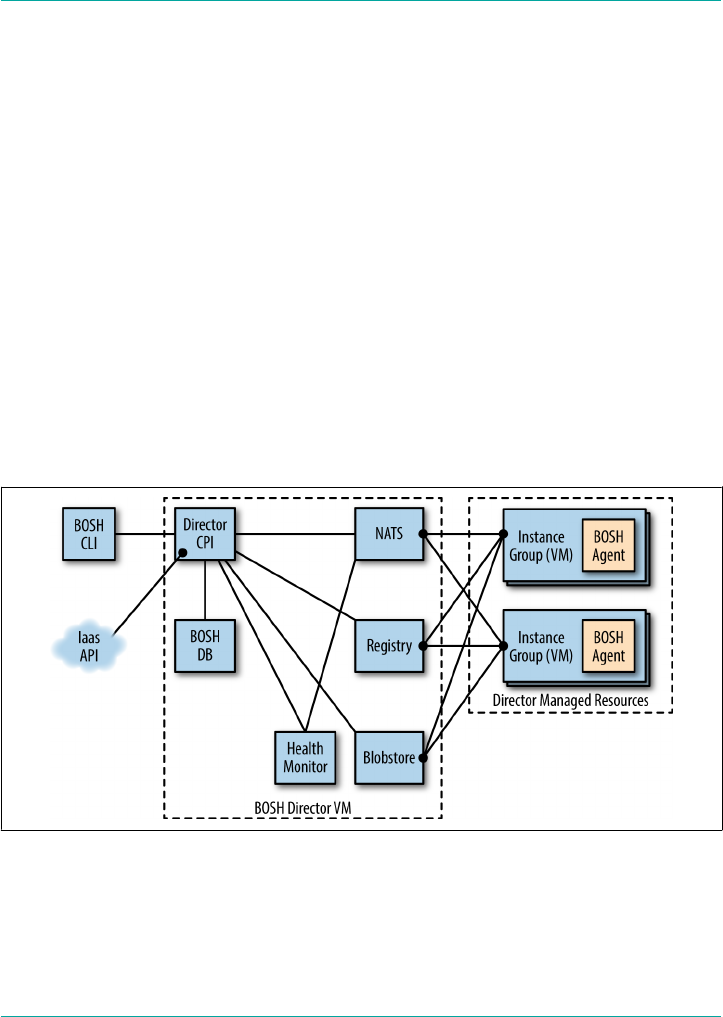
CHAPTER 13
BOSH Components and Commands
For Platform Operators who would like a deeper understanding of how BOSH works,
this chapter explores BOSH’s internal components, including the individual compo‐
nents and terminology that comprise a BOSH environment. It also introduces some
of the fundamental BOSH commands for getting started with BOSH deployments
such as Cloud Foundry.
Figure 13-1 gets the ball rolling by providing a visual tour of the components that
make up the BOSH ecosystem.
Figure 13-1. BOSH components
213

The BOSH Director
Deployments are managed by the BOSH Director, a centralized management and
orchestration server. To deploy a BOSH release, the release is first uploaded to a
BOSH Director along with the appropriate stemcell, and the deployment manifest is
set. Upon deployment, the Director then causes the instance group machines (often
VMs) requested in the manifest to be allocated and stored, forming a deployment. All
interaction with the BOSH Director is through the BOSH CLI.
This is an overview of the process to create a deployment:
1. Create a deployment manifest referencing one or more releases.
2. Through the BOSH CLI, upload stemcells and releases used by the manifest to
the BOSH Director.
3. Direct BOSH to the location of the deployment manifest.
4. Initiate a deployment by using the bosh deploy command to form a deployment
managed by the Director.
A user (or CI/CD pipeline) continues to manage a BOSH deployment through
changes to the deployment manifest. In addition to defining the initial deployment,
the deployment manifest contains all required information for tracking, managing,
and updating the release software layered onto the deployment’s machines. After a
deployment has been installed, the BOSH Director keeps track of all the associated
machines and any attached persistent disks used by the deployment. If the deploy‐
ment manifest is changed and redeployed, old machines are replaced and updated,
but persistent disks are retained and reattached to the newer machines. Updating an
existing deployment is effectively the same procedure as for that of the original
deployment:
1. Update deployment manifest with necessary changes.
2. Upload any new stemcells or releases.
3. Direct BOSH to the location of the deployment manifest.
4. Initiate a deployment by using the bosh deploy command to apply changes to
the deployment.
The Director creates actionable tasks:
• By translating commands sent by the Platform Operator through the BOSH CLI
•From scheduled processes like backups or snapshots
214 | Chapter 13: BOSH Components and Commands

•By self-healing through reconciling expected machine state with actual machine
state
The Director adds these tasks to the Task Queue. Worker processes then take tasks
from the Task Queue to act on them.
Director Blobstore
The Director blobstore is the repository where BOSH stores the uploaded release arti‐
facts and other content. The blobstore stores the source forms of releases and the
compiled images of BOSH releases. An operator uploads a release using the BOSH
CLI, and the Director inserts either the release tarball or release blobs into the blob‐
store. When you deploy a release, BOSH orchestrates the compilation of packages
and stores the result in the blobstore.
Director Task, Queue, and Workers
A task is a basic unit of work performed by the BOSH Director. Tasks include BOSH
commands such as bosh deploy and bosh run errand. You can monitor the task
throughout its life cycle and use the bosh vms command to view its status and logs
whenever required.
The Task Queue is an asynchronous queue used by the Director and workers to man‐
age tasks. The workers then take tasks from the Task Queue and act upon them.
Director Database
The Director uses a database (currently MySQL) to store information about the
desired state of a BOSH deployment. This database includes information about stem‐
cells, releases, and deployments.
Director Registry
When the Director creates or updates a machine, it stores configuration information
for the machine in a Registry so that it can be used during the bootstrapping of the
machine. The Registry is not required on all IaaS offerings; for example, vSphere does
not require it. The Registry is used only for an IaaS that does not allow the machine
metadata to be modified after the machine has started (e.g., AWS and OpenStack).
BOSH Agent
An agent is included on every machine that BOSH deploys. The agent is a single pro‐
cess that runs continuously. It listens for instructions from the Director via messages
(currently sent via NATS). The agent then executes instructions in response to the
messages it receives from the Director.
BOSH Agent | 215

The agent receives job specifications from the Director and uses them to assign a role
or instance group to the machine. These specifications include which packages to
install and how jobs should be configured to create the instance group VM. In
essence, it is the agent that converts undifferentiated stemcells into the specialized
components known as instance groups.
Errand
A BOSH errand is a short-lived BOSH job, defined in a deployment manifest, that the
Platform Operator can run several times after a deploy has finished. Example errands
include the CATS that you should run after every new Cloud Foundry deployment,
and the Cloud Foundry service broker broker-registrar and broker-deregistrar
errands that simplify registering service brokers in a Cloud Foundry deployment.
The Command Line Interface
The CLI is the primary operator interface to BOSH. An operator uses the CLI to
interact with the BOSH Director. The BOSH Director then translates those com‐
mands and performs actions against the underlying cloud infrastructure. The CLI is
typically installed on a machine or VM that can directly communicate with the
Director’s API; for example, an operator’s laptop or a jump box in a data center. The
BOSH CLI is what you use to run BOSH commands. For assistance with BOSH com‐
mands, you can run $ bosh help --all to view the help. We discuss BOSH CLI
commands further in “Basic BOSH Commands” on page 221.
The Cloud Provider Interface
A CPI is an API that the Director uses to interact with an IaaS provider to create and
manage networks, VMs, and disks. A CPI abstracts the cloud infrastructure from the
rest of BOSH, allowing for portability of BOSH releases across different IaaS layers.
You can read more about the CPI in “The Cloud Provider Interface” on page 172.
Health Monitor
The Health Monitor uses status and life cycle events received from BOSH Agents to
monitor the health of machines. If the Health Monitor detects a problem with a
machine, it can send an alert through a notification plug-in, or trigger the Resurrec‐
tor. The Health Monitor works in the following way:
1. The Health Monitor pings the Director for a list of agents.
2. The Health Monitor listens for pings (currently via NATS) from worker agents.
3. The Health Monitor uses the CPI to contact nonresponding agents.
216 | Chapter 13: BOSH Components and Commands

4. If no response is retrieved, it follows retry logic (it instructs the Director to run
the bosh cck command).
Resurrector
If enabled, the Resurrector plug-in automatically re-creates machines identified by
the Health Monitor as missing or unresponsive. It uses the same Director API that
CLI uses.
Message Bus (NATS)
The Director and the agents communicate through a lightweight publish-subscribe
messaging system called NATS. These messages have two purposes:
• To perform the provisioning of instructions to the VMs
•To inform the Health Monitor about changes in the health of monitored pro‐
cesses
You can also use NATS for cross-component communication.
Creating a New VM
To better understand how the BOSH components interact, let’s explore what happens
when a new machine or VM is created. Figure 13-2 depicts the process, and is fol‐
lowed by a description of each of the numbered stages in the figure.
Resurrector | 217
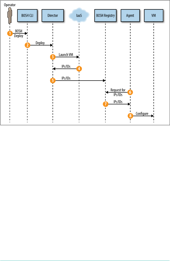
Figure 13-2. BOSH VM creation
1. Through the BOSH CLI, the Platform Operator takes an action such as deploying
Cloud Foundry for the first time or scaling up an existing deployment. These
specific actions require creating a new machine.
2. The BOSH CLI passes the deployment manifest to the Director. The Director
then determines that one or more new machines are needed.
3. The Director uses the CPI to instruct the IaaS to create disks and machines. The
CPI communicates with the IaaS and requests that it create a new machine using
the defined stemcell image.
4. The IaaS provides the Director with information (IP addresses and IDs) that the
BOSH agent requires to configure the VM.
5. The Director updates the BOSH registry with the configuration information for
the machine.
6. The BOSH agent is started. The agent is responsible for all machine configura‐
tion. It requests the configuration information for the machine from the BOSH
registry.
7. The registry responds with IP addresses and IDs.
218 | Chapter 13: BOSH Components and Commands

8. The agent then uses the IP addresses and IDs to configure the machine. As the
machine starts, an init script starts the BOSH agent. An init (short for initializa‐
tion) process is the first process started when the system boots. The BOSH agent
remains continually running on the machine. Ubuntu-based stemcells use Linux
utilities to monitor the BOSH agent using a runsv service containing a run script
that takes over the init jobs and manages the BOSH agent process. Bootstrapping
the BOSH agent deals with all the standard Linux concerns such as creating the
vcap user, starting the SSH daemon, and starting the Monit daemon. The BOSH
agent also deals with creating disks and networking.
As part of the VM configuration in step 8, BOSH will create disks and set up net‐
working for the VM.
Disk Creation
It is possible to define two different types of storage solutions: ephemeral and persis‐
tent disks. These are both in addition to the root machine disk. The distinction
between ephemeral and persistent provides the flexibility to use more cost-effective
storage for temporary storage requirements and persistent storage for long-lived
data.
Within the machine, the BOSH agent checks for the presence of the root disk. By
default, all stemcells have 3 GB of root disk (2.5 GB available after system use). The
BOSH agent partitions a root filesystem on the root disk.
If an instance group is using an ephemeral disk, two partitions are created: one for
swap and one for a tmp space under /var/vcap/data. The creation of the disk depends
on the IaaS and CPI implementation. For vSphere, the Director creates an ephemeral
disk and attaches it to the machine. For AWS and OpenStack, it is the IaaS that cre‐
ates the disk based on the instance type.
If there is no ephemeral disk, the BOSH agent uses the unused root disk space to cre‐
ate the swap and tmp partitions. Although the root partition is usually 3 GB, the real
disk size is often greater, depending on the instance type, so often some unused space
will remain.
Persistent disks are created after the machine has been created. If a persistent disk has
been specified in the instance group, the CPI communicates with the IaaS to create a
persistent disk and then attaches the persistent disk to the required machine. The CPI
communicates with the BOSH agent to inform it about the new disk. The BOSH
agent then looks for that disk, mounts it, and creates the /var/vcap/store for persistent
data.
Disk Creation | 219

Without the Platform Operator cross-checking, the instance group
does not know if the release job requires a persistent disk. For
example, you can deploy a Postgres release job without specifying
in the deployment manifest that the resulting instance group needs
a persistent disk. In that scenario, the release job’s start scripts (not
the agent) creates the /var/vcap/store directory, which will reside
on the ephemeral disk. Be aware that if the release job does require
a persistent disk but no persistent disk was specified by the
instance group, /var/vcap/store will be mounted on the ephemeral
disk.
If /var/vcap/store is mounted on persistent storage, you will not
lose your data if the VM is recycled. If /var/vcap/store is mounted
on ephemeral storage and the machine goes away, you will lose
your data.
Let’s consider three different Cloud Foundry jobs.
Instance groups using an ephemeral disk have a VM with two mounted filesystems;
for example:
/ mounted on the local VM storage /dev/sda1
/var/vcap/data mounted on ephemeral disk /dev/sdb2
Instance groups that specify a persistent disk will have a third filesystem; for example:
/var/vcap/store mounted on /dev/sdc1
You can also mount additional directories. One of the Cloud Foundry jobs is a blob‐
store for an Amazon S3 bucket in AWS. The Cloud Foundry Cloud Controller VM
has an additional remote directory:
/var/vcap/nfs residing on the blobstore server under /var/vcap/store.
Networking Definition
There are three options for setting up networking for the VM:
1. Dynamic
2. Manual
3. VIP
If you have a choice, the recommended approach, as of this writing, is to use manual
networks.
220 | Chapter 13: BOSH Components and Commands

The BOSH CLI v2
There is a new v2 BOSH CLI written in Go. It is designed to be significantly faster
and more stable than the original BOSH CLI that was written in Ruby. Consistency
across different developer environments including Mac OS, Windows, and Linux is
of primary importance.
All of the original CLI behavior remains, and most of the commands are the same,
but the user experience (UX) has changed slightly, making a few of the older com‐
mands redundant. In addition, commands have become hyphenated; for example,
upload release becomes upload-release.
The UX also enforces consistency. For example, you must always specify -e <my-
environment> and -d <my-deployment>. For example, to set the deployment mani‐
fest:
$ bosh -e <my-director-env> -d <my-deployment> deploy <deployment-name.yml>
Specifying the deployment manifest in this manner means that when we invoke other
commands such as BOSH -e <env> cck, you do not need to download manifests; you
need only reference the deployment name. The only time you need a deployment
manifest is when you deploy. This is a significant enhancement to overall usability.
The -d argument is per-deployment context. Commands that are outside of a specific
deployment context, such as the generic cloud-config, do not require the -d argu‐
ment. Here’s an example:
$ bosh -e <env> update-cloud-config ./cloud.yml
Another key difference between the v1 and v2 CLIs is that the new CLI combines
bosh-init functionality with the CLI, as shown here:
$ bosh create-env ...
You can find more information on the BOSH v2 2.0 CLI at the BOSH website.
Basic BOSH Commands
Knowledge of some basic BOSH commands is essential for rudimentary debugging.
As discussed in “BOSH Top-Level Primitives” on page 175, a deployment requires
three key items: a stemcell, release, and deployment manifest.
To view a list of available commands, use the following:
$ bosh -h
Before deploying, you will need to upload a release and stemcell by using the follow‐
ing commands:
The BOSH CLI v2 | 221

$ bosh -e <env> upload-release <release-location>
$ bosh -e <env> upload-stemcell <stemcell-location>
A release file and a stemcell location can be a local file or a remote URI. These two
commands upload these artifacts to BOSH’s blobstore. In addition to uploading a
precompiled release, you can upload a release by uploading a release manifest. When
uploading just the manifest, BOSH fetches the release components from a blobstore
defined in the release.
Before deploying, you can specify the Director IaaS properties through cloud config‐
uration. To apply the cloud configuration to the BOSH Director, use the update-
cloud-config command, as follows:
$ bosh -e <env> update-cloud-config ./cloud.yml
You can retrieve the current cloud configuration from the BOSH Director and save
the output via stdout:
$ bosh -e <my-director-env> cloud-config > cloud.yml
The deployment manifest is not uploaded to BOSH; rather, it is named via the -d
argument. After you have uploaded your stemcell and release, specify the deployment
manifest and deploy via:
$ bosh -e <env> -d <my-dep> deploy <deployment-name>.yml
As mentioned in “Director Task, Queue, and Workers” on page 215, a task is a basic
unit of work performed by the Director. You can view the currently running tasks by
running the following:
$ bosh -e <env> tasks
You can monitor task status throughout its life cycle or retrieve the status of previ‐
ously run tasks:
$ bosh -e <env> task <task-number>
You can retrieve the logs for any previously run or currently running task:
$ bosh -e <env> task <task-number> --debug
If you require more advanced troubleshooting, you can view all of the machines in
the BOSH environment:
$ bosh -e <env> instances
And, you can use SSH to access a specific machine:
$ bosh -e <env> -d <my-dep> ssh <vm-name>
For troubleshooting instance groups, start with this:
$ bosh -e <env> -d <my-dep> cck
222 | Chapter 13: BOSH Components and Commands

CCK (short for Cloud Check) scans for differences between the desired VM state, as
stored in the Director database, and the actual state of the VMs. For each difference
the scan detects, bosh cck offers possible repair and recreate options.
Summary
This chapter provided a basic overview of the BOSH components and essential
BOSH commands. To recap:
•BOSH deployments are managed by the BOSH Director, a centralized manage‐
ment and orchestration server.
• The BOSH Director comprises a number of subcomponents.
•The BOSH Director manages the machines it deploys via a BOSH agent. The
agent residing on BOSH-managed machines is provided by the stemcell.
•Knowledge of some basic BOSH commands is essential for deploying BOSH
releases and for rudimentary debugging.
This chapter concludes our deep dive into the BOSH release-engineering tool chain.
Now that you are familar with some basic BOSH commands, Chapter 14 focuses on
the debugging and logging aspects of running Cloud Foundry.
Summary | 223

CHAPTER 14
Debugging Cloud Foundry
As a topic, debugging is nuanced and complex. Debugging any system is a skill. Due
to the complexity of both the layered software stack and infrastructure underpinning
Cloud Foundry as well as the Cloud Foundry distributed architecture itself, debug‐
ging Cloud Foundry is a huge topic. The topic of debugging the Cloud Foundry dis‐
tributed system deserves an entire book devoted to the subject.
This chapter, although certainly not exhaustive, gives you an introduction to the
basic tools and techniques used for debugging the platform. It focuses on some
unique potential failure scenarios. With each scenario, I will walk you through the
steps, tools, and rationale used to troubleshoot the issue and remedy the situation.
The techniques used in these scenarios are valuable and applicable in helping you
debug numerous failure scenarios.
The failure scenarios explored in this chapter were constructed with the help of Dan
Higham, Principal Engineer and Service Lead at Pivotal. Dan spends his days
troubleshooting Cloud Foundry issues on behalf of client companies, and he is an
authority on the topic of platform debugging.
Cloud Foundry Acceptance Tests
To validate integrity, Cloud Foundry provides a suite of acceptance tests known as
the Cloud Foundry Acceptance Tests, or CATS. You should run these tests after an
initial installation to verify that the integrity of the installation. After you deploy
Cloud Foundry and it passes CATS, you are most of, if not all, the way there. For this
reason, most of this chapter focuses on debugging techniques used to restore a failed
instance group (a BOSH-deployed Cloud Foundry component).
225

Logging
Before you explore debugging-specific failure scenarios, you need to understand how
logging works.
The logging system within Cloud Foundry is known as the Loggregator (a combina‐
tion of log and aggregator). It is the inner voice of the system that informs the opera‐
tor and developer as to what is happening. You use it to manage the performance,
health, and scale of running apps and the platform itself. The Loggregator continually
streams logging and metric information. The Loggregator’s Firehose provides access
to app logs, container metrics (memory, CPU, and disk-per-app instance), some
component metrics, and component counter/HTTP events. It provides the same log
stream you see when you run $ cf logs APP. The Firehose does not provide compo‐
nent logs. You retrieve component logs through an rsyslog drain.
App logs contain information that is often coerced into events; for example, an app
start or app crash event. App logs are streamed to a central location via the Loggre‐
gator. The Loggregator system aggregates this information in a structured, usable
form, via the Firehose.
App Logging Requirements
An app must conform to the logging guidelines of writing logging information to
standard out and standard error. A guidance from 12-Factor App is to never log to
the local filesystem. Doing so could result in logs that can fill up the disk, causing
apps to fail, or the logs might become irretrievable due to the use of an ephemeral
disk.
Writing logs to stdout and stderror does not mean that application code needs to
invoke System.out.println(); rather it is the log configuration that must support
being dumped to stdout. Logging frameworks such as Log4j, slf4j, and many others
allow for runtime injection of log outputs. A more robust approach to logging is to
use a log drain.
If you want to forward app logs to a syslog endpoint, you can create a user-provided
service by using the -l parameter, as shown here:
$ cf create-user-provided-service SERVICE-INSTANCE -l SYSLOG-URL
If apps log directly to syslog or other logging services, you must establish a Cloud
Foundry security group accordingly to expose application access to the endpoint.
You can use the Firehose in different ways. Downstream sinks can use all of the out‐
put of the Firehose. If more specific uses are required, such as a requirement to moni‐
226 | Chapter 14: Debugging Cloud Foundry

tor system internals or a requirement to analyze specific user behavior, you can apply
a specific nozzle to the Firehose.
Nozzles are clients that access the Firehose. As such, they require administrator
access to the Cloud Foundry instance. A nozzle needs to have the doppler.firehose
OAuth scope to be able to connect to the Firehose. Multiple consumers can use a
unique subscription_id to connect to the Firehose endpoint or a pool of consumer
clients can use a common subscription_id. If each consumer uses a different sub
scription_id, each consumer with a unique subscription_id receives the entire
stream and, therefore, all of the messages. If you have multiple consumers with the
same subscription_id, each consumer will receive a portion of the messages. The
portion is roughly the percentage based on the number of consumers with that sub
scription_id; however, the aim is that all data will be distributed evenly among that
subscriber’s client pool. By default, message delivery is “send once, best effort,” there‐
fore, if your consumer is slow at retrieving the messages, Cloud Foundry adds a
warning message to the stream and then might drop some messages.
The Firehose does not contain any system component logs. In general, all the system
logs are collected by the “syslog aggregator”—meaning that they are pulled out of the
rsyslog server on the instance group components. Component/instance group logs
need to be connected to a syslog endpoint via the syslog_daemon configuration in the
Cloud Foundry deployment manifest. If you want only app logs, you can use either
the WebSocket endpoint that has all logs for a given app by $ tail cf logs app
name, or multiple syslog drains.
There is an open source nozzle: firehose-to-syslog. Using this nozzle, you can
drain logs from the Firehose so that you no longer need to bind your app to a syslog
drain. The Firehose-to-syslog applies cf app name, space name, and org name to all
the log messages. In addition to applying to the entire Firehose, it adds info to logs
(which has other implications).
If you require a Loggregator client library, it is worth checking out NOAA. For con‐
figuring system logging, you can review the Cloud Foundry docs.
All Cloud Foundry components use Steno logging. Steno is a lightweight, modular
logging library written specifically to support Cloud Foundry. It is comprised of three
main classes:
Loggers
The main entry points that consume user input and create and forward struc‐
tured records on to configured sinks.
Logging | 227

Sinks
As the ultimate destination for log records, sinks transform structured records
into a strings via formatters and then typically write the transformed string to
another transport.
Formatters
These provide a mechanism for converting structured log records into strings.
You can find more information on Steno at the Cloud Foundry GitHub page.
Typical Failure Scenarios
Typically, you will observe errors for three core reasons:
• Issues with configuration
• Issues with infrastructure
• Release job process failures
The rest of this chapter examines the challenges of these three areas by walking you
through seven distinct failure scenarios.
Configuration Failures
The typical challenges you will face generally occur when you are deploying a soft‐
ware release. Deploying a release requires configuring properties via a manifest. If
you handcraft a deployment manifest, you are likely to encounter configuration (or
rather misconfiguration) issues. As discussed in Chapter 5, there are several ways of
installing Cloud Foundry. Various tools exist, and currently they all involve a level of
complexity. Having a good deployment manifest helps significantly to contend with
this problem. However, during the process of constructing that manifest, it is possible
to introduce configuration errors.
When dealing with configuration errors, many will be caught by BOSH when you
attempt to deploy the misconfigured instance group. For example, if the misconfigu‐
ration is significant enough, specific release jobs might fail and BOSH will be unable
to configure the specific instance group. When BOSH fails to install a specific
instance group (such as a Diego Cell or the GoRouter), it should provide you with
some information as to the nature of the failure; thus, this type of failure is relatively
easy to resolve.
The real challenge comes when your Cloud Foundry deployment actually deploys
successfully but does not behave as you anticipated. Subtle misconfigurations are
more difficult to track down. For example, misconfigured credentials that block spe‐
cific communication flows between two instance groups is challenging because the
228 | Chapter 14: Debugging Cloud Foundry

exhibited behavior (component “A” cannot talk to component “B”) can be caused by
a variety of reasons. Because of this, checking how a component is configured in the
deployment manifest is an important first step in debugging spurious failure scenar‐
ios. If configuration is not the issue, the steps outlined in the failure scenarios that
follow later in the chapter will help.
Infrastructure Failures
Another core reason for platform failure is infrastructure failure. You have only to
look at the recent Amazon S3 outage to see how catastrophic infrastructure outage
can be.
Infrastructure failure could be due to anything from an individual process crash to a
data center–wide SAN failure. Infrastructure failures are often difficult to trouble‐
shoot because they reside in the depths of the software and infrastructure stack that
underpins or supports the platform, such as the network, database, IaaS, and so on.
Understanding how the system is structured and then following a logical set of steps,
such as those outlined in “Scenario Two: Network Address Translation Instance
Deleted (Network Failure)” on page 231, will certainly help.
In addition, it is always worth getting the relevant subject matter expert (SME)
involved. If you have connectivity issues, have your network or load balancer SMEs
involved. If you have an IaaS issue, ensure that your IaaS operator is involved. From
experience, some infrastructure issues exhibit themselves as a platform problem,
whereas in reality they are due to a complex infrastructure configuration issue; for
example, misconfigured network maximum transmission unit (MTU) settings or
high VCPU ready times. Collaboratively working through the issues with the relevant
SME is the most pragmatic approach.
Release Job Process Failure
All BOSH release jobs have their processes managed by a monitoring service. For
Linux, this is currently Monit. Monit is a powerful tool for dealing with sporadic or
random process failures. If a process fails during a deployment, a quick remedy might
be possible via connecting to the failed instance group and, as root user, restarting the
process in the following way:
$ bosh -e <env> -d <dep> ssh <failing_instance_group>
$ sudo su
$ monit summary
$ monit restart <process>
When the failed process is running again, you can then try redeploying the failed
instance group.
Typical Failure Scenarios | 229

Scenario One: The App Is Not Reachable
After you have deployed Cloud Foundry, you might still experience some issues
when pushing an app. This scenario explores how to troubleshoot Diego and a failing
app instance.
For this scenario, I used a basic app called “show-headers”. This is a basic Ruby appli‐
cation that shows the HTML request header information. This scenario assumes that
you use an appropriate app that can respond to HTTP requests.
First, push the app, as follows:
$ cf push show-headers -n duncheaders
When you push an app to Cloud Foundry, upon successful completion of the staging
and running tasks, Cloud Foundry should return information about the running app
including the URLs that you can use to reach it:
urls: duncheaders.cfapps.io
By clicking this URL, you should then be able to reach your application endpoint. If,
for some reason, going to this URL does not return a response from the app, the first
thing to check is whether the route still exists.
The $ cf routes command lists all of the routes within the given space:
# $ cf routes
space host domain path apps
myspace duncheaders cfapps.io show-headers-app
If your route does not exist, it might have been pruned from the GoRouter’s route
table. The reasons for pruning a route from the route table are varied. For example,
the app might have crashed or there might be a network partition between the Cell
running the app and NATS, eventually causing the route to be pruned.
Assuming that there is no problem with the route and the app is still running, the
next step is to review logs via $ cf logs to see if the app is returning a response. The
output of $ cf logs should give you a clear indication as to why you cannot reach
the app. For example, it could be that an app has crashed and Diego cannot restart it
because all Cells are already at capacity.
For basic issues such as a pruned route or a crashed app that Diego cannot restart, $
cf routes and $ cf logs are the most appropriate steps to begin the troubleshoot‐
ing process. For a deeper context of output information, run the command
CF_TRACE=true before the cf cli command, as demonstrated here:
$ CF_TRACE=true cf logs show-headers-app
230 | Chapter 14: Debugging Cloud Foundry

This scenario has provided you with the steps required for diagnosing why you might
not be able to reach a specific app. It is important to note that although a crashed app
is an obvious cause, other issues, such as a pruned route, might actually be the issue.
Scenario Two: Network Address Translation Instance
Deleted (Network Failure)
This scenario is intended to show you how to debug the platform when various CF
CLI commands fail due to infrastructure issues. If you followed the AWS environ‐
ment setup in Chapter 5, the installation used both public and private subnets.
Public networks have an internet gateway (edge router) through
which you can route traffic from the network to the internet. How‐
ever, for a VM to make a connection to another node on the inter‐
net, the VMs require a public IP so that external nodes can route
traffic back. But for VMs on a private network, the private IP is
abstracted via NAT. The NAT VM has the public address and the
NAT then handles the address translation before handing the traf‐
fic on to the internet gateway. Traffic can come into the private
network via a load balancer, but internal VMs cannot forge a con‐
nection to an external node without using the NAT VM.
To force a failure within the infrastructure, I deleted the NAT instance for the private
network. Most private networks will have some kind of NAT gateway so that apps
can create a new connection with the outside world. The recommended way for set‐
ting up a VPC is with both a public and private subnet. The public subnet contains
your jumpbox and management plane, and the private network contains your
deployments.
If the NAT instance or NAT gateway goes offline, the components lose their ability to
forge a new outbound connection because their internal network address cannot be
translated to an externally reachable address. This results in various Cloud Foundry
instance groups failing to communicate properly. Apps can still be reached because
the inbound connection is from an external Cloud Foundry client calling into the
load balancer that fronts the GoRouters. There is nothing in the incoming connec‐
tion from a client to an application that requires NAT.
This test used the previous basic Ruby app. Here are the steps to repeat this exercise:
1. Use $ cf push to push the app.
2. Stop the AWS NAT instance on the private subnet.
3. Run a command that exercises the CAPI.
Scenario Two: Network Address Translation Instance Deleted (Network Failure) | 231

For exercising the API, you can create a new user and set the Org role as follows:
$ cf create-user user@myorg.com password
$ cf set-org-role user@myorg.com my-org PrgManager
The $ set-org-role command should then fail. The reason that this specific com‐
mand fails is because the Cloud Controller is calling back into the UAA via the load
balancer (to verify via the UAA database that the new user has adequate permissions
to be assigned the PrgManager Org role).
Therefore, the Cloud Controller is trying to forge a new outbound connection, which
fails because there is no NAT. A logical first debugging step would be to run the com‐
mand $ cf ssh show-headers to connect to the container running the application.
The SSH-Proxy establishes a “man-in-the-middle” connection between the GoRouter
and the container and so also requires NAT to be working. Therefore, $ cf ssh also
failed. At this point, it should be clear to an operator that because a number of CAPI
commands are failing, there is something fundamentally wrong with the CF CLI.
So how should you debug CF CLI failures? To troubleshoot the $ cf ssh command,
your first step is to view the logs on Diego’s Brain partition by performing the follow‐
ing steps:
1. Using SSH, connect to your jumpbox:
$ ssh -i ./aws-cert.pem jumpbox.com
2. Set the BOSH deployment to your cf-deployment.yml:
$ bosh deployment cf-deployment.yml
3. Run $ bosh ssh and select the diego-brain-partition to view what state the
Brain is in.
4. Once on the Brain, change to the log directory:
$ cd /var/vcap/sys/log
5. Follow the logs via $ tail -f * (or just tail the ssh_proxy log).
6. Back in your workstation terminal, rerun the following:
$ cf ssh my-app
7. Review the log output.
From the output of the log file that follows (taken from the Brain VM at /var/
vcap/sys/log/ssh-proxy.stderr.log), you can see a call to the UAA. As described earlier,
this call to the UAA is to ensure that the user in question is a valid CF user, with cor‐
rect permissions to connect to the app:
{"timestamp":"1468599989.856470823","source":"ssh-proxy","message":↵
"ssh-proxy.cf-authenticate.exchange-access-code-for-token.↵
request-failed","log_level":2,"data":{"error":"Post↵
232 | Chapter 14: Debugging Cloud Foundry

https://uaa.my-cf.com/oauth/token: dial tcp 52.50.20.6:443:↵
i/o timeout","session":"63.1"}}
...
{"timestamp":"1468599996.759604692","source":"ssh-proxy","message":↵
"ssh-proxy.authentication-failed","log_level":2,"data":{"error":↵
"Authentication failed","user":↵
"cf:743e63b9-4343-4179-b0d8-8e67175b091f/0"}}
From here, because components such as the Cloud Controller or the Brain are unable
to call out and back to other components such as the UAA, we can deduce the follow‐
ing:
•Either those target components are offline (something that is easy to check by
using the command $ bosh ... cloud-check or by looking at the status of the
VMs in your IaaS), or
• There is a networking issue causing traffic not to reach the final destination.
In this manufactured scenario, there is a networking issue due to NAT not being
available. Networking and traffic routing issues can be caused by many things, such
as your load balancer configuration, expired or invalid certificates, the MTU configu‐
ration, or invalid security group policies. When you identify a networking-related
issue, if the cause is not obvious after rudimentary debugging, it is worth reaching
out to your networking SME to help you troubleshoot further.
The key takeaway here is that networking- and infrastructure-related issues can man‐
ifest themselves in multiple and sometimes extremely complex ways. For example, in
this scenario, anything within the private network that uses the NAT VM will fail.
Therefore, the failure is manifested across multiple components and several CF CLI
calls. This issue did not just affect apps calling to external services; it also affected
internal processes hair-pinning back into the load balancer. Whenever you observe
several components failing—often for seemingly unspecified or unrelated issues—it is
often an indication of an underlying infrastructure or networking issue.
Networking Tooling
dig and nslookup are valuable tools for assessing how a specific URL resolves. dig
resolves the URL by using the actual nameserver that holds the DNS record, such as
in the following example:
;; ANSWER SECTION:
duncheaders.cfapps.io. 60 IN A 54.86.159.28
duncheaders.cfapps.io. 60 IN A 52.72.73.102
nslookup resolves the URL based on how your machine resolves addresses (e.g.,
resolve.conf):
Scenario Two: Network Address Translation Instance Deleted (Network Failure) | 233

Non-authoritative answer:
Name: duncheaders.cfapps.io
Address: 52.72.73.102
Name: duncheaders.cfapps.io
Address: 54.86.159.28
To connect directly to the SSH server (in place of using cf ssh), you can use netcat:
nc ssh.mycf.com 2222
Scenario Three: Security Group Misconfiguration That
Blocks Ingress Traffic
As discussed in “Scenario Two: Network Address Translation Instance Deleted (Net‐
work Failure)” on page 231, networking issues can trip you up at any point. In that
scenario, you explored a north-south network issue (north-south being the traffic
entering and exiting the network). This scenario reviews east-west traffic (the traffic
between components within a specific network).
AWS employs a construct of security groups. A security group is effectively a layer
above the networking stack that is typically applied to a VM. It acts as a virtual fire‐
wall for your deployed instance groups or VMs, giving you the ability to control the
subnet’s inbound and outbound traffic. Security groups are vital for segregating east-
west network traffic between different subnets. They are used to impose communica‐
tion restrictions from the VM to other components. For example, a VM attached to a
developer-centric security group might not be allowed access to a production data‐
base residing in a services subnet.
However, if you misconfigure security groups, the Cloud Foundry components might
not be able to communicate with each other in the required way. In “Scenario Two:
Network Address Translation Instance Deleted (Network Failure)” on page 231, we
wanted to connect to a container via SSH. When you use SSH to connect to a con‐
tainer, you, as the SSH client, are trying to establish an SSH connection from your
jumpbox residing on the management subnet to the ssh-proxy component residing
in the private Cloud Foundry subnet. The load balancer typically resides in a public
network (either the management network or its own dedicated subnet) and forwards
traffic to the components in the private Cloud Foundry subnet. The load balancer
and jumpbox typically reside in a public subnet because they require an externally
routable IP and direct access and interaction by the Cloud Foundry users or opera‐
tors.
The load balancer and management components should have an applied security
group, configured with specific ingress rules. Table 14-1 lists those ingress firewall
rules that control the traffic to your load balancer.
234 | Chapter 14: Debugging Cloud Foundry
Table 14-1. AWS ELB security group used to define firewall rules to control load balancer
ingress traffic
Type Protocol Port range Source
ALL TCP TCP (6) ALL 10.0.16.0/24 #Allowing ingress from any component on private subnet
ALL UDP UDP (17) ALL 10.0.16.0/24 #Allowing ingress from any component on private subnet
SSH (22) TCP (6) 22 0.0.0.0/0
HTTP (80) TCP (6) 80 0.0.0.0/0
HTTPS (443) TCP (6) 443 0.0.0.0/0
Custom TCP rule TCP (6) 4443 0.0.0.0/0
HTTP* (8080) TCP (6) 8080 0.0.0.0/0
After you have installed Cloud Foundry, you can alter the 0.0.0.0/0 source (allowing
traffic from anywhere) to be more restrictive if you desire finer control over traffic
reaching Cloud Foundry. The ELB security group governs external access to Cloud
Foundry from apps such as the CF CLI and app URLs.
Egress Traffic
A point to note on egress traffic is that most networking teams I
have worked with have no issue allowing all egress traffic to leave
the network to anywhere. Ingress traffic, however, is more tightly
regulated.
In addition, to achieve an SSH connection, the security group applied to the load bal‐
ancer requires the following custom ingress TCP rule:
Port Range 2222 from source 0.0.0.0/0
However, setting this rule on the load balancer security group is not enough. When
running cf ssh my-app, you will still encounter an error opening the SSH connec‐
tion because the load balancer tries to pass on the ssh-connection to the ssh-proxy
instance group. The ssh-proxy instance group resides in the Cloud Foundry subnet.
Therefore, to allow the load balancer to connect to the GoRouter, you must add the
load balancer security group (LBSG) to the ingress of the Cloud Foundry security
group. The Cloud Foundry security group defines the security group policies for the
Cloud Foundry components. Therefore, the security group in which the ssh-proxy
resides requires the additional following custom TCP rule:
Port Range 2222 from source <LOAD-BALANCER-SECURITY GROUP>
Figure 14-1 shows the required traffic flow between the management subnet and the
Cloud Foundry subnet.
Scenario Three: Security Group Misconfiguration That Blocks Ingress Traffic | 235
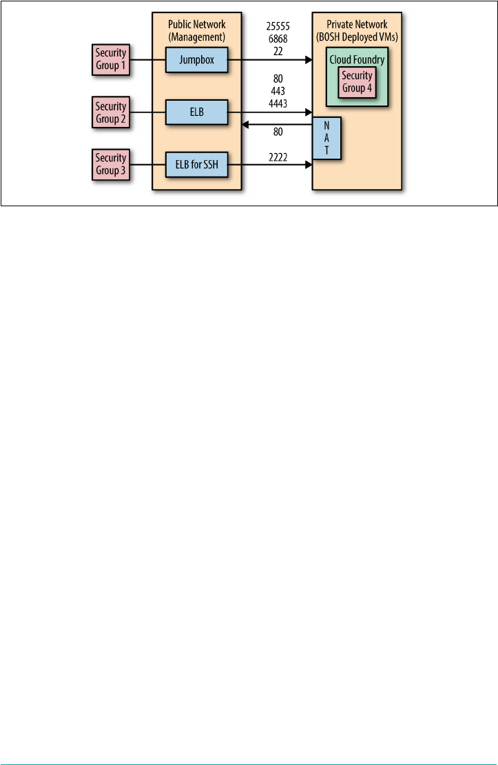
Figure 14-1. Security Group Configuration between the management subnet and the
BOSH/Cloud Foundry subnet
This scenario highlights the importance of establishing the correct networking con‐
figuration to allow for the required east-west component traffic.
Scenario Four: Invoking High Memory Usage That Kills a
Container
As discussed in “CGroups” on page 148, Cloud Foundry uses cgroups to constrain
and limit container resources. Some resources, such as disk usage, will simply be cap‐
ped on exhaustion. This means that you can reach the limit and the container and
app will carry on running. However, even though your app is still running, because
the disk limit cannot be exceeded, any further disk writes will fail. In essence, your
app will still run, but it might not deliver the desired behavior.
Other resource violations, such as memory usage, will cause the container to fail. This
is because the app behavior can be significantly and adversely affected by memory
starvation, and therefore a safer action is to simply shut down the container and flag
the issue. You can track the issue by invoking $ cf events and inspecting the log
output.
It is possible to misconfigure the required memory limits for the container, or worse,
you might have a bug in your app that exposes a memory leak over time. Both of
these events can trigger the destruction of a container. The version of downloader
app in Example 14-1 writes an Ubuntu disk image to a file and then tries to open it,
reading the file into memory, resulting in a significant amount of memory usage
beyond 1 GB.
236 | Chapter 14: Debugging Cloud Foundry
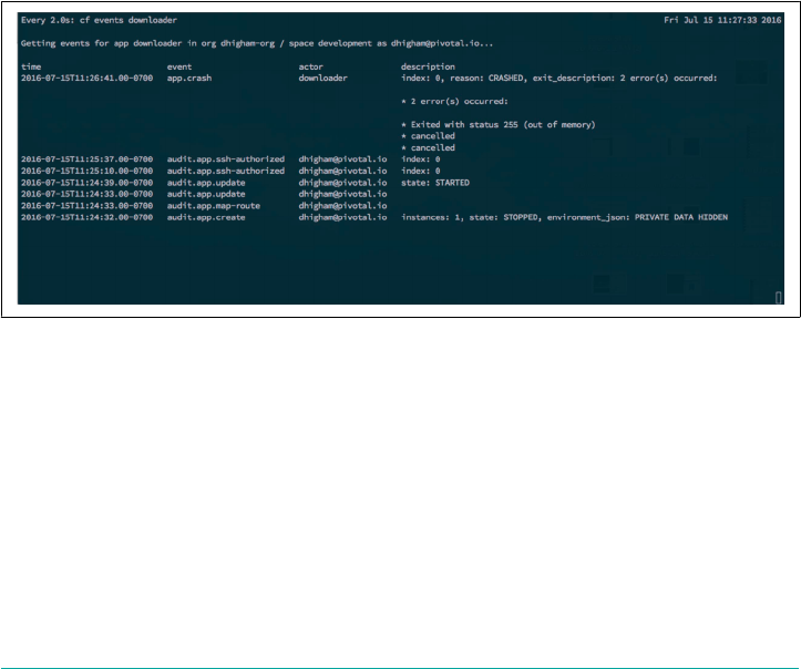
Example 14-1. Write an Ubuntu disk image to a file
#downloader app`
require "open-uri"
run Proc.new { |env|
`wget http://mirror.pnl.gov/releases/16.04/ubuntu-16.04-server-amd64.iso`
file = File.open("ubuntu-16.04-server-amd64.iso", "rb")
contents = file.read
[200, {"Content-Type" => "text/html"}, [contents.length]]
}
On a terminal, use $ cf push to push the app and then, using the command-line tool
watch, monitor app events via the $ cf events command:
$ cf push <downloader>
$ watch cf events <downloader>
Click the app URL to force the iso download and memory usage. You should see the
out-of-memory error depicted in Figure 14-2.
Figure 14-2. Out-of-memory error
For scenarios in which you have an unexpected memory leak or an out-of-memory
event, the first step to debugging them is to open an SSH connection to the container
by using the $ cf ssh command so that you can inspect what is happening:
$ cf ssh downloader
When you’re inside the container, you can follow traditional out-of-memory debug‐
ging techniques such as running a profiling tool or triggering a memory heap dump.
In this case, simply running $ top on the container to monitor memory usage and
using $ wget to view the running process should be sufficient to indicate the issue.
Scenario Four: Invoking High Memory Usage That Kills a Container | 237

However, you might have an additional challenge if you are running several app
instances. If only one instance of the running app is crashing, you will need to target
a specific container. The important question here is how you determine the specific
container exhibiting the issue when running multiple app instances. For example, I
have observed some rare cases in which an app fails only on a specific Cell. In these
scenarios, to reveal what Cell hosts a specific container, I pushed Spring Music.
A typical user scenario is to push two different versions of the same app. Another sce‐
nario might be to troubleshoot a specific instance of a single app running multiple
instances. In either scenario, the troubleshooting steps presented here are the same.
The first instance group you should inspect is the GoRouter. The GoRouter provides
a list of the Cell IP addresses to which it forwards app traffic. From your jumpbox,
run the $ bosh... vms command to discover the IP address of the GoRouter:
$ bosh -e <env> -d <deployment> vms
router is running on *.*.*.* ip address
The IP address of the GoRouter will be used later for querying the router status.
Next, use $ bosh... ssh to connect to the GoRouter:
$ bosh -e <env> -d <deployment> ssh <GoRouterVM>
When on the router, you can query the router status port. To do this, navigate to the
config directory:
$ cd /var/vcap/jobs/gorouter/config
This directory contains the gorouter.yml file, which you can inspect by using the
command-line tool more:
$ more gorouter.yml
At the top of this file, you can view the port number on which the GoRouter is run‐
ning as well as the username and password for the status port:
---
status:
port: 8080
user: router_status
pass: "edf0d4413ed727c6416e"
With this information you can use the curl command to reveal the GoRouter status
port:
$ curl http://<user><pass>@<ROUTER IP ADDRESS>:8080/routes | python -m json.tool
The reason you looked up the GoRouter IP address earlier is because the GoRouter
status does not run on the loopback address, so you need to run the curl command
238 | Chapter 14: Debugging Cloud Foundry

using the actual router IP address. For ease of reading the JSON output from the pre‐
ceding command, you can use a JSON formatter known as JQ. When reviewing the
output, you can clearly see the two cells hosting the Spring Music app:
1:48]
"spring-music-2-precentorial-abnormalcy.paas.high.am": [
{
"address": "10.0.16.27:60014",
"ttl": 0
}
],
"spring-music-dacryagogue-eyebright.paas.high.am": [
{
"address": "10.0.16.25:60024",
"ttl": 0
}
]
This JSON snippet reveals where your app instances are running, including the IP
address of the two Cells (10.0.16.27 and 10.0.16.25) running your two app instances.
The two ports (60014 and 60024) map to the containers running on the Cells. At this
point, you know the Cells that are running your app instances, but you still need to
correlate specific app instances with their respective containers. You can discover the
containers that run your app by using a powerful tool known as Veritas.
Veritas is a CLI for getting at Diego’s truth. Follow the instructions on the Veritas
GitHub page to use it. Veritas commands must include the location of the Diego BBS
server. The BBS is not typically publicly routable, so you will need to run Veritas
from a VM in the same subnet as the Diego Cells. On the private network, you can
find the BBS at https://bbs.service.cf.internal:8889. Diego’s internal DNS resolution
(as of this writing, provided by Consul) will be able to resolve the BBS internal IP
addresses.
Use $ bosh ssh to connect to one of the preceding Cells and then run the following:
$ pushd $HOME
$ wget https://github.com/pivotal-cf-experimental/veritas \
/releases/download/latest/veritas -O ./veritas
$ chmod +x ./veritas
$ echo "export PATH=$PATH:$PWD" > veritas.bash
$ echo "export DROPSONDE_ORIGIN=veritas" >> veritas.bash
$ echo "export DROPSONDE_DESTINATION=localhost:3457" >> veritas.bash
$ ./veritas autodetect >> veritas.bash
$ ./veritas completions >> veritas.bash
$ source veritas.bash
$ popd
Scenario Four: Invoking High Memory Usage That Kills a Container | 239
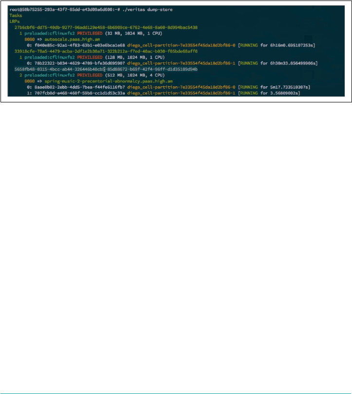
You will need to export the following environment variables to avoid having to spec‐
ify them on every command invocation. For example, the following values configure
these environment variables correctly on a BOSH-deployed Diego Cell VM:
$ export BBS_ENDPOINT=https://bbs.service.cf.internal:8889; \
$ export BBS_CERT_FILE=/var/vcap/jobs/rep/config/certs/bbs/client.crt; \
$ export BBS_KEY_FILE=/var/vcap/jobs/rep/config/certs/bbs/client.key
After running this once, you can simply source ~/veritas.bash when you log in to
the Cell again. Now, you can simply run $ ./veritas dump-store to view all the IDs
of the LRPs and the GUIDs for the processes running on the Cell. The output of this
command queries the BBS database and therefore it will provide information for all
Cells, as shown in Figure 14-3.
Figure 14-3. Veritas dump-store output
The first part of $ top GUID contains the app process GUID. The app GUID is the
same across all instances, but the instance GUID is unique per instance. Because we
scaled the spring-music-2 app to two instances, you can view two instances of the
same app.
You can check the app GUID by running $ cf app springmusic-2 --guid (in this
case, it is 5658fb48-0315-4bcc-ab44-326446b40cb5). By reviewing the output of
$ ./veritas dump-store you can locate the specific app GUID and see exactly what
Cell partition the app is running on. Finally, you can iterate through your instances
via an SSH connection to the container with the CF CLI command:
$ cf shh app -i 0
$ cf shh app -i 1
...
After you’re in the container, you can check what Cell you are on; the preceding
command will show you the specific container ID in which you are running. There
might be times when you do not want to use $ cf ssh because it does not allow root
access. For cases in which you want to edit something that requires root permissions
(e.g., resolve.conf), you need to go into the container via the Cell. Here’s how to do
that:
240 | Chapter 14: Debugging Cloud Foundry

1After this scenario was documented, certain domains and routes are now protected by CAPI to avoid this
potential issue. Nonetheless, because this scenario provides valuable debugging steps, I decided to leave it in.
1. Use $ bosh... ssh to connect to the Cell based on the cell-partition as output
from ./veritas dump-store.
2. Run the following command:
$ sudo su -
3. Change directory:
$ cd /var/vcap/data/garden/depot
4. Review the list of containers running on the Cell:
$ ls -lart
5. Grep the process list searching for the app ID and find the container by using the
following:
$ ps aux | grep <app-id>
This will show the specific container depot ID (e.g., lksdjlkahjs).
Then, you can change the directory into that container:
$ cd /var/vcap/data/garden/depot/lksdjlkahjs
$ ./bin/wsh
$ ./bin/wsh puts you into the container as root. Between the two approaches of dis‐
covering and logging on to a container, it is possible to locate all specific containers
and Cells on which your apps are running. You can then either use $ cf ssh or $
bosh ssh to connect to the container to undertake any further debugging that might
be required.
This scenario has provided you with the various steps and tools to first locate where
your apps are running and then access the specific containers running your apps.
These steps are crucial for app debugging for apps running within the platform.
Scenario Five: Route Collision
This scenario looks at the effects of a route collision due to the system and app
domains being the same. Even though Cloud Foundry allows you to use the same
domain for both system components and apps, it is strongly advised that you have
different domains to separate these concerns. This was discussed in “Setting Up
Domains and Certificates” on page 62. If both sys and app domains are the same, in
theory, a developer could accidentally push an app with the same hostname as a sys‐
tem component, causing catastrophic routing complications.1
Scenario Five: Route Collision | 241

As of this writing, for simplicity, cf-deployment manifest genera‐
tion scripts use only one domain for both system and apps. This is
currently under review.
Creating this scenario allows us to demonstrate how you track down the specific Org
and Space to which a route is mapped. This debugging process can be useful for other
reasons; for example, discovering who else in your business is using a domain that
you would like to use.
Components like the Cloud Controller register their api routes via the Route-
Registrar. We can then register the same api domain for our show-headers app, as
follows:
$ cf push show-headers -n api
When a Cloud Foundry user registers a reserved hostname for his app (e.g.,
api.mycf.com), the GoRouter round-robins between the original Cloud Controller
component and the new app. This scenario will typically be identified by getting
more than one response for the same call. Curl the route information endpoint:
$ CF_TRACE=true curl http://api.mycf.com/v2/info
This shows the round-robin between two different calls: one to the Cloud Controller
and one to the app:
MacBook-Pro:~ user$ curl http://api.mycf.com/v2/info
GATEWAY_INTERFACE: CGI/1.1↵
HTTP_ACCEPT: */*↵
HTTP_CONNECTION: close↵
HTTP_HOST: api.mycf.com↵
HTTP_USER_AGENT: curl/7.43.0↵
HTTP_VERSION: ↵
HTTP/1.1↵
HTTP_X_CF_APPLICATIONID: b4345d46-de57-4606-98fe-839212d52554↵
HTTP_X_CF_INSTANCEID: b455b4b6-946c-445f-5c69-18405f3212fb ↵
HTTP_X_FORWARDED_FOR: 50.53.67.65, 10.0.0.110↵
HTTP_X_FORWARDED_PORT: 80↵
HTTP_X_FORWARDED_PROTO: http↵
HTTP_X_REQUEST_START: 1468619218990↵
HTTP_X_VCAP_REQUEST_ID: f32aece5-d78a-4f88-714f-5c5e9f15a386↵
PATH_INFO: /v2/info↵
QUERY_STRING:
...
USER: vcap↵
VCAP_APPLICATION: {"application_id":"b4345d46-de57-4606-98fe-839212d52554",↵
"application_name":"show-headers","application_uris":["api.mycf.com"],↵
"application_version":↵
"9fea48ca-cb9c-4895-a31b-eb5c83b60841","host":"0.0.0.0",↵
242 | Chapter 14: Debugging Cloud Foundry
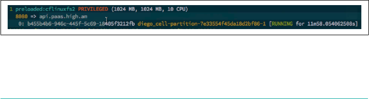
"instance_id":"b455b4b6-946c-445f-5c69-18405f3212fb","instance_index":0,"limits"↵
:{"disk":1024,"fds":16384,"mem":1024},"name":"show-headers",↵
"port":8080,"space_id":"01094679-1d83-4063-ad03-e82b5df05eb1","space_name":↵
"test","uris":["api.paas.high.am"],"users":null,"version":↵
"9fea48ca-cb9c-4895-a31b-eb5c83b60841"}↵
VCAP_SERVICES: {}_: /home/vcap/app/vendor/bundle/ruby/2.2.0/bin/bundle↵
_ORIGINAL_GEM_PATH: /home/vcap/app/vendor/bundle/ruby/2.2.0:↵
MacBook-Pro:~ user$ curl http://api.mycf.com/v2/info
{"name":"","build":"","support":"https://support.pivotal.io", "version":0,↵
"description":"","authorization_endpoint": "https://login.api.mycf.com",↵
"token_endpoint":"https://uaa.api.mycf.com", "min_cli_version":"6.7.0",↵
"min_recommended_cli_version":"6.11.2","api_version":"2.54.0",↵
"app_ssh_endpoint":"ssh.api.mycf.com:2222", "app_ssh_host_key_fingerprint":↵
"ac:2f:c7:96:9f:c3:0c:44:a3:15:bf:3a:8e:89:2c:8e",↵
"app_ssh_oauth_client":"ssh-proxy", "logging_endpoint":↵
"wss://loggregator.api.mycf.com:4443", "doppler_logging_endpoint":↵
"wss://doppler.api.mycf.com:4443"}
From this point on, Cloud Foundry will not function properly because any request
via the CF CLI will typically involve more than one call to the Cloud Controller, and
therefore whenever you come across the rouge app, instead of CAPI, the request will
fail.
So, after discovering this issue, the next step you need to take is to discover the
offending app. Using Veritas as described in “Scenario Four: Invoking High Memory
Usage That Kills a Container” on page 236, you can retrieve the app GUID associated
with the route. If you happen to know the Space where the app is running, you can
verify the app has the conflicting route by using $ cf apps to list all apps residing
within that Space. However, in a larger deployment, it might be more difficult to
track the specific app down by just going to the Spaces. Imagine an enterprise with
several hundred Spaces. In this case, you can use Veritas to find the app associated
with the conflicting route by doing the following:
1. Connect via SSH into the first Cell and follow the Veritas steps as described in
“Scenario Four: Invoking High Memory Usage That Kills a Container” on page
236.
2. Using Veritas, find the app ID that is mapped to the offending route. Figure 14-4
shows an example of this.
Figure 14-4. App ID mapped to the system route api.pass.high.am
Scenario Five: Route Collision | 243

If you simply kill the process by destroying the container, Cloud Foundry will restart
the process. You will need to issue a curl request to delete the app (as cf admin):
$ cf curl -X DELETE /v2/app/<APP GUID>
Make sure that you explicitly address this command to the Cloud Controller. You
might need to run it a couple of times in the scenario we described previously
because the Cloud Controller route was mapped to both the Cloud Controller and a
spurious app. From this point on, Cloud Foundry and the Cloud Controller should
be back to working as designed.
It is often invaluable to be able to pull information from the Cloud Controller. The
Cloud Foundry community has produced some basic scripts for pulling user infor‐
mation from the Cloud Controller, such as report.py. However, for power users,
Cloud Controller has its own dedicated console that you can use for power debug‐
ging. This tool is Interactive Ruby (IRB) for the Cloud Controller, and uses a Ruby
library called pry ruby, a tool for interactive consoles. Here’s how to access it:
1. Connect via SSH to the Cloud Controller.
2. Change the directory as follows:
$ cd /var/vcap/jobs/cloud_controller_ng/bin
3. Run $ ./console.
This is not often referred to, because you can do significant damage to your Cloud
Foundry installation if you use this tool incorrectly. The advantage of using interac‐
tive Ruby is that it supports data access through an exhaustive set of contexts. For
example, typing VCAP::CloudController provides the context for the current scope.
All models within that scope then output with a capital letter. From that scope, you
can then do basic searches. Suppose that you want to repeat the previously described
process of finding an app associated with a specific route. In this example, let’s pick
our previous show_headers route:
1. Run a query against the model as follows:
$ Route.find.(:host => show-headers) # list all known active routes
This displays a specific route ID.
2. Search for the mapping of this route ID to an app:
$ RoutemMpping.find.(:rout_id => <ROUTE ID>)
This displays a specific app ID.
3. Search for the actual app of this app ID:
$ App.find(:id => <APP ID>)
244 | Chapter 14: Debugging Cloud Foundry

This lists the app associated with the app ID that was mapped to the show-
headers route.
4. Set this output to a local variable app:
$ app = App.find(:id => <APP ID>)+++
5. Search this variable for the methods, or a specific method, that can act on it:
$ app.methods.grep /delete/
6. Sure enough, the delete method exists. So calling that method on an app will
delete the app. There is one caveat here: you can only delete the app after you
first delete route mapping:
$ RoutemMpping.find.(:route_id => <ROUTE ID>).delete
Routing is a powerful capability with Cloud Foundry. This scenario has provided you
with the required tools and steps for resolving any routing issues within the platform.
Scenario 6: Release Job Process Failures
As discussed in Chapter 11, BOSH releases are comprised of release jobs. The release
jobs result in processes running on a machine based on how a specific instance group
is configured by the deployment manifest. You can construct a specific instance
group from several release jobs obtained from one or more BOSH releases. Under
certain scenarios, a misconfiguration of the release job properties in the deployment
manifest can result in the job process not starting properly. If the process fails, use
Monit (or an equivalent process monitor), which will first try to restart the process. If
the retries are unsuccessful, Monit will report the failure to the BOSH Director and
the deployment will fail.
Another scenario might be that the process is configured perfectly, but for some rea‐
son, the process still did not start properly, or the process might have run and then
crashed later on. In either case, it is a useful skill to diagnose the instance group com‐
ponent that is failing and then review any specific processes on that instance group
that could be causing that failure. To demonstrate this scenario, we removed the
rootfs file system from the Diego Cell, as illustrated in Figure 14-5.
Scenario 6: Release Job Process Failures | 245
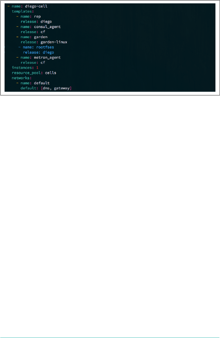
Figure 14-5. Commenting-out Diego rootfs
If you do this and then redeploy Cloud Foundry, you will notice that the deployment
of the Diego Cell instance group fails. To troubleshoot this, you can do the following:
1. Connect via SSH to the failing Cell machine using $ bosh... ssh.
2. Run $ monit summary to view any relevant log files.
Monit provides a view of all the running job processes. Using Monit we can start,
restart, and stop processes. Here, we can see that the Cell’s Rep process is not run‐
ning:
root@3af8d775-12a1-4ac0-ad52-d679950554d6:~# monit summary
The Monit daemon 5.2.5 uptime: 10m
Process 'rep' not monitored
Process 'consul_agent' running
Process 'garden' running
Process 'metron_agent' running
System 'system_localhost' running
Because we have identified an issue with the Cell’s Rep, the next step is to inspect the
Rep’s log:
bosh_vm:/var/vcap/sys/log/rep $ tail -f *
When looking at the Rep’s log, we can clearly see the issue causing the process and,
therefore, the entire deployment to fail:
{"timestamp":"1471029528.793029070","source":"rep","message":↵
"rep.exited-with-failure", "log_level":2,"data":{"error":"Exit trace for group:↵
\ngarden_health_checker exited with error: repository_fetcher: stat file: lstat↵
/var/vcap/packages/rootfs_cflinuxfs2/rootfs:↵
no such file or directory\ncontainer-metrics-reporter↵
246 | Chapter 14: Debugging Cloud Foundry

exited with nil\nhub-closer exited with nil\nmetrics-reporter exited with↵
nil\ndebug-server exited with nil\n"}}
We can see that the log complains that the Rep expects a certain file—/var/vcap/
packages/rootfs_cflinuxfs2/rootfs—and the process fails because no such file or
directory exists. Therefore, when we inspect the Cell instance group in the manifest,
we can quickly identify that the rootfs has been commented out. Adding these two
lines back into the manifest and redeploying Cloud Foundry fixes this issue:
release: garden-linux
# - name: rootfses
# release: diego
This scenario has explored a release job process failure. Although this might look like
a contrived issue, it is entirely reasonable to misconfigure a release job property
within your manifest. These types of misconfiguration result in failed processes and
therefore a failed deployment. Using the steps just described will help you pinpoint
the exact failure, allowing you to remedy the issue.
Scenario 7: Instance Group Failure
Every once in a while, the IaaS underpinning your platform might do something
undesirable, causing a specific VM to die. If BOSH does not bring this VM back for
some reason, your platform can experience issues.
VM Availability
Although BOSH can expertly and reliably bring VMs back, there
are cases where VM resurrection might not happen. An obvious
scenario is when the BOSH Resurrector is deliberately turned off.
A more subtle case might occur when you are using shared infra‐
structure. Between the VM failing and restarting, another VM
could be started by someone else using the IaaS. If the IaaS reaches
capacity from the new non-Cloud Foundry VM, all future VMs
(BOSH-managed and otherwise) will fail until extra capacity is
added. It is always best to run Cloud Foundry in a dedicated envi‐
ronment such as a set of dedicated vCenter Clusters or a dedicated
AWS VPC.
To demonstrate this scenario, we use $ bosh... ssh to connect to the NATS VM
and then run $ monit stop nats to stop the NATS process.
By using Monit to stop the process, it will not report the lack of a running process to
BOSH, because it has been told explicitly that the process should be stopped. If we
then look at the general state of the VMs by using $ bosh... vms, we can see that all
the instance groups that depend on NATS are failing, as depicted in Figure 14-6.
Scenario 7: Instance Group Failure | 247
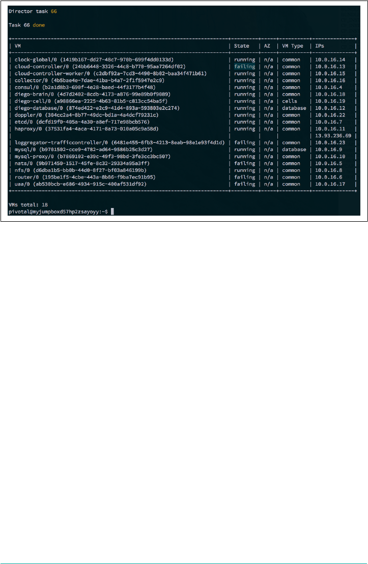
Figure 14-6. Instance groups failing due to failed NATS
A number of instance groups are now failing. This is because all of those components
(Cloud Controller, Loggregator, router, and UAA) depend on NATS. Because we
know that all those VMs depend on NATS and the NATS instance group has no fur‐
ther dependencies, it is tempting to jump straight onto the NATS VM for further
debugging. However, in the interests of investigating a more thorough debugging
path, let’s assume that we do not know the root cause at this time.
You would most likely first detect errant behavior when you run a basic command
against the Cloud Controller, such as $ cf apps. This returns a 503 - service unavail‐
able error because the Cloud Controller process has failed. Therefore, a good starting
point for troubleshooting would be to use $ bosh... ssh to connect to the Cloud
Controller.
When you’re on the VM, use $ sudo -su to become root and then run $ monit sum
mary. This produces the output shown in Figure 14-7.
248 | Chapter 14: Debugging Cloud Foundry
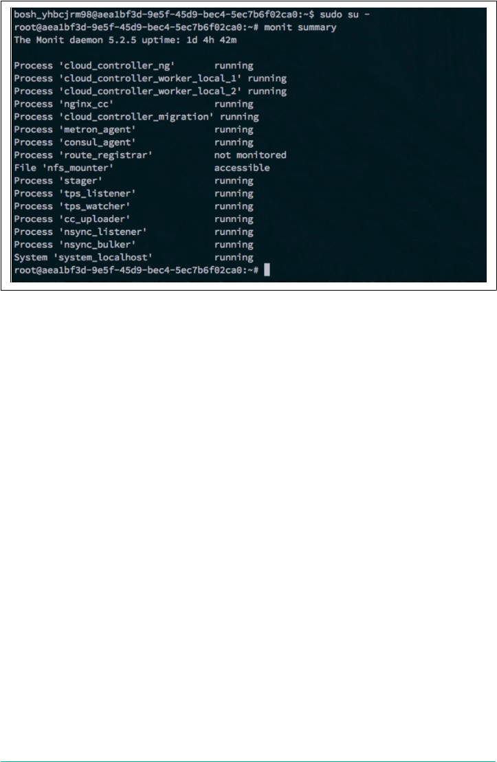
Figure 14-7. route_registrar process stopped due to a failed NATS
This shows us that the route registrar process is failing. The route registrar uses
NATS to register app routes with the GoRouter, so this alone is a clear indication that
something is probably wrong with NATS. However, to clarify this, we can further
inspect the route registrar logs by looking under /var/vcap/sys/log/route_registrar:
root@aea1bf3d-9e5f-45d9-bec4-5ec7b6f02ca0:/var/vcap/sys/log/route_registrar# ↵
tail -f *
{"timestamp":"1471030947.208235741","source":"Route Registrar",↵
"message":"Route Registrar.Exiting with error","log_level":3,"data":↵
{"error":"nats: No servers available for connection","trace":"goroutine 1
For the route_registrar.stdout.log, we can clearly identify the root cause of the
failure residing with the NATS instance group by noticing the following:
"error":"nats: No servers available for connection"
The next step to resolve this issue would be to use $ bosh... ssh to connect to the
NATS instance group and then run $ monit summary. As we saw earlier, this would
show that the NATS process has stopped. Therefore, running $ monit start nats
would restart the NATS process, and BOSH will subsequently restart all the other
failing components on the other instance groups. This will restore Cloud Foundry to
full health.
Scenario 7: Instance Group Failure | 249

This scenario has explored the BOSH’s ability to rectify instance group failures. This
ability to bring back failing deployments is the reason I regard BOSH as the essential
component underpinning the entire Cloud Foundry ecosystem.
Summary
This chapter introduced you to the fundamental troubleshooting, debugging, and
logging techniques required for resolving various issues with both Cloud Foundry
and the underlying infrastructure. Failures within Cloud Foundry typically occur for
one of three core reasons:
•Issues with configuration; for example, misconfigured deployment manifests,
component credentials, or misconfigured infrastructure (including networking
and egress-ingress configuration between subnets)
• Issues with infrastructure failures or resource contention
• Release job process failures and specific app issues
Having an understanding of the flows of communication between the various com‐
ponents within the platform will really help you to pinpoint where to begin resolving
and troubleshooting complex issues. This chapter provided you with a solid intro‐
duction to the essential tools and techniques required to get started. If you require
further help, cf-dev is an active community that can provide you with additional
information and answers to specific Cloud Foundry questions.
250 | Chapter 14: Debugging Cloud Foundry

CHAPTER 15
User Account and Authentication
Management
Role-based access control (RBAC) provides a mechanism for establishing who can
access specific resources (be it an internal service or a user-facing app). The term
“access” refers more broadly to the specific level of authorization a user might have,
allowing her to perform a specific action such as to view or modify a resource.
Cloud Foundry RBAC defines two aspects: who can use the platform, and what those
individuals can use it for. Cloud Foundry employs RBAC via a component known as
the UAA service. The Cloud Foundry UAA is the central identity-management ser‐
vice for platform components, users, and apps.
The UAA has two key modes of operation:
•Secure the Cloud Foundry platform components and API endpoints; for exam‐
ple, the Cloud Controller and Doppler require clients like the Cloud Foundry
CLI to use UAA access tokens when invoking the component’s API
•Provide authentication and access control data for apps running on the platform
that require access to internal services such as the Cloud Controller or any other
external service that requires authentication
The UAA can manage the authentication of users internally, against the UAA’s inter‐
nal user-identity store. Alternatively, you can configure it to connect to external user
stores through identity providers such as Lightweight Directory Access Protocol
(LDAP), Security Assertion Markup Language (SAML), and OpenID Connect
(OIDC). The UAA is based on the latest of security standards like OAuth2, OIDC,
and the System for Cross-Domain Identity Management (SCIM).
251

1Before reading this chapter, an understanding of OAuth2 is required. There is an excellent presentation on
OAuth 2.0 available on YouTube.
There is a lot of online documentation on the UAA that covers how it works and how
to use it. This chapter draws your attention to the high-level concepts and how best
to interact with the UAA. Where appropriate, I provide links to online documenta‐
tion for access to the latest status and information.
Background Information
Before working with the UAA, there is some additional background information you
should be aware of, including an understanding of OAuth 2.0, the UAA documenta‐
tion, and the UAA BOSH release.
OAuth 2.0
The UAA is an OAuth2 server that you can use for centralized identity management.1
OAuth 2.0 is an open authorization protocol designed to allow apps to access each
other’s data. It allows you to create two types of apps:
• One that reads users’ data from other apps, commonly referred to as a client
•One that provides access to users’ data to other apps, commonly referred to as a
resource server, but also represented as a client in the UAA
For example, an app can access specific user data via access to another app; for exam‐
ple, Gmail. The original app achieves this access by asking a user to log in to the orig‐
inal app via Gmail. The user logs in to Gmail, and then is redirected back to the
original app. Now the original app can access the user’s data in Gmail, and call func‐
tions in Gmail on behalf of the user (e.g., querying contact addresses).
OAuth 2.0 relies on an authorization server to provide two factors of authentication
and authorization. The user can be a person trying to authenticate and perform
action via a client app that acts on the user’s behalf or a client app simply acting on its
own. For this reason, a client app is always required, but a real end user is optional.
OAuth2 token generation is via a REST API call and the token used is a JSON web
token (JWT).
UAA Documentation
The UAA is primarily used within Cloud Foundry for securing the Cloud Controller
API, and securing the Loggregator for end-user and client-app access. However, you
252 | Chapter 15: User Account and Authentication Management

can use it for many other tasks that require access and authentication management;
for example, securing the BOSH Director itself or for app access to a specific service.
For a more in-depth look at the UAA, I suggest you begin with the UAA overview.
UAA Release
You can also deploy the UAA as a BOSH release. Like the other components of
Cloud Foundry, it is a standalone repository that is pulled into cf-deployment. The
current release is available on GitHub. The source code for the UAA can also be
found at the Cloud Foundry GitHub.
Breaking out components from cf-release into their own release is a great strategy. It
allows for components such as the UAA to be independently deployable and fosters a
pattern of reuse. The fact that the UAA is packaged into its own independent release
opens up a number of possibilities. For example, BOSH previously had just a single
admin user. However, now that the UAA is packaged as an independent release,
BOSH uses the UAA for its authentication and authorization. You now can manage
BOSH user access via UAA. This provides the capability to plug in an external user
store and potentially have multiple users with different roles for different deploy‐
ments. At the very least, the UAA provides a solid audit trail for the different users
accessing the BOSH Director.
UAA Responsibilities
As mentioned in Preface, the UAA has two key responsibilities within Cloud Foun‐
dry:
• Securing Cloud Foundry components and API endpoints
• Securing service access for apps
Securing Cloud Foundry Components and API Endpoints
You use the UAA to provide access tokens for Cloud Foundry platform components
and API endpoints; for example, the Cloud Controller and Loggregator. All collabo‐
rators target a Cloud Foundry environment with their individual user account.
Accounts are associated with role and grant types that govern what level and type of
access the user has within that environment. Each UAA role grants permission to a
specific resource that an app can target on behalf of the user.
For example, for the purposes of access decisions, user accounts are either “user” or
“admin” types. These user types translate into granted authorities. Using the SCIM
type field from the UAA’s core schema, the granted authorities are either [uaa.user]
UAA Responsibilities | 253

or [uaa.admin,uaa.user], respectively. Resource servers then can choose to use this
information as part of any access decision.
For a user accessing an app, the app will delegate to the UAA, and then the UAA can
delegate this authentication to an external identity provider. Authorization takes
place when the resource server evaluates the scopes, which we know as authorities, in
the access token.
Securing Service Access for Apps
You can use the UAA to provide access tokens for any app running on the platform.
You can configure any OAuth2-aware app to require authentication using the UAA.
In addition to getting an access token for Cloud Foundry apps running on the plat‐
form, the UAA can also be used to authenticate and authorize apps that want to
access an internal service such as the Cloud Controller, the Loggregator, or any other
external service. For example, when using a cf command, such as cf create-org, we
are invoking API endpoints on the Cloud Controller. If you run the command to cre‐
ate a new Org with CF_TRACE=true prepended, you will see the specific API end‐
points that are invoked, as shown in the following example:
$ CF_TRACE=true cf create-org new-org
REQUEST: [2016-12-07T09:48:44-08:00]
POST /v2/organizations HTTP/1.1
REQUEST: [2016-12-07T09:48:44-08:00]
GET /v2/config/feature_flags/set_roles_by_username HTTP/1.1
...
Another concrete example of securing apps is how Pivotal uses and runs the UAA as
a multitenant identity service that is packaged as part of its single sign-on (SSO)
Cloud Foundry service. Each tenant of that service can use the UAA for securing a
group of OAuth-aware apps for access by end users.
App authentication and authorization can be against either the UAA’s internal user-
identity store or an external identity provider such as LDAP, SAML, or OIDC. For an
external identity provider, apps can authenticate against the UAA and then the UAA
can delegate this authentication and authorization to the external identity provider.
An access token is comprised of a set of claims. User claims are specific user informa‐
tion that helps identify additional user attributes; access claims, like the scope claim,
contain a list of authorities used to access and manipulate a specific resource. The
ability to process claim information makes it possible to qualify authorization posi‐
tions. Claims play a vital role, especially when it comes to app security, because all of
254 | Chapter 15: User Account and Authentication Management

the authorization positions (e.g., what services apps can access) are driven by claims.
Claims can also be propagated from an external identity provider.
UAA Architecture and Configuration Within Cloud Foundry
The UAA setup within Cloud Foundry is fairly standard, and you should not need to
deviate too much from the standard templates (assuming that you are following the
standard deployment process as described by cf-deployment and by the Cloud Foun‐
dry documentation. Depending on your IaaS platform, you might need additional
configuration. A key point is that you should always configure your own set of token
keys and SAML certificates.
Instance Groups Governed by the UAA
BOSH-deployed instance groups that are UAA protected, such as the Cloud Control‐
ler, Doppler (part of the Loggregator), or Clock Global, will need to set specific UAA
properties so that the instance group process can accept UAA requests and interact
with the UAA. Typically, the properties required will include the following:
•URL (for accessing the UAA)
• JWT (a JSON web token that asserts some number of claims)
• Clients (a list of the clients with associated scopes and secrets)
• Login (the redirect to the login server)
See the cf-deployment manifest for some concrete examples of instance group UAA
properties. The general structure (or set of properties) will be similar across instance
groups that have their endpoints managed by the UAA; however, the UAA “clients”
list will be instance group–specific.
UAA Instance Groups
The recommended approach is to deploy a cluster of UAA servers (a server being a
single machine running a UAA instance). The cluster should consist of two UAA
instances (or one instance per AZ) for high availability (HA) reasons. The instances
should be split across different AZs.
bosh-bootloader will try to configure three AZs by default (assum‐
ing the IaaS you deploy to will support three distinct regions). cf-
deployment will then deploy multiple instances of the UAA
instance groups across the three AZs.
You can find an example of the UAA instance group in the cf-deployment manifest.
UAA Architecture and Configuration Within Cloud Foundry | 255

UAA Database
The Cloud Foundry deployment requires a UAA database (UAADB). UAA uses a
MySQL database or PostgreSQL. It is recommended that you use a highly available
MySQL solution such as a Galera MariaDB cluster or the highly available RDS solu‐
tion from AWS. The UAA can also run against the p-mysql service, when it is
deployed as a separate release by BOSH. Your MySQL solution should provide both
failover and HA because replicas of the data should be made on every node within
the cluster. A Galera cluster is provided as the default deployment option for the
UAA.
As discussed in Chapter 16, you should make backups of the UAADB regularly to be
able to recover from any cluster outage or damage to the database. This is true for any
critical datastore within Cloud Foundry, and this is discussed further in “Backup and
Restore” on page 272.
You can configure all of the UAA connection parameters via the deployment mani‐
fest. The UAA specification file lists all of the UAADB configurations. You can
review the #Database section for a list of the configurable properties at the Cloud
Foundry GitHub page. However, you should not need to deviate from most of the
defaults apart from the obvious connection base parameters such as IP.
For an example of the UAADB configuration properties, you can review the Cloud
Foundry deployment manifest that you created during the steps in Chapter 5.
UAA Runtime Components
Tomcat is used as the runtime container for the core Java-based UAA web app. Setup
of this environment is BOSH managed via the BOSH deployment of the UAA-
release. As of this writing, this is based on Tomcat 8 and the latest OpenJDK build
packaged by the Java buildpack. All of the JVM settings are configurable in the
deployment manifest (e.g., catalina_opts: "-Xmx768m"); however, it is important to
note that the defaults have been reported as consistently good and should not require
tweaking.
UAA Logging and Metrics
The UAA system logs are written to the UAA component machine in a file named
uaa.log. All of the audit events that are generated for the management and authenti‐
cation operations are written to that log. As with all system components, you can
stream the logs on a secure channel by a syslog forwarder to a syslog endpoint collec‐
tor such as ELK or Splunk. The logs then can be correlated, and you can run reports
for tasks such as audit compliance.
256 | Chapter 15: User Account and Authentication Management

There is a document in GitHub that lists all the standard audit events (such as UAA
requests and responses) that are logged. You can view this document at the Cloud
Foundry GitHub page.
UAA-Produced Metrics
The UAA-produced metrics are under revision. As of this writing,
UAA metrics focus mainly on reporting authentication success and
authentication failure events. You can view the current metrics at
the Cloud Foundry documentation page.
The UAA also supports integration with NewRelic, and all the agent configuration
parameters are exposed in the manifest. NewRelic integration activates automatically
if a valid license is configured in the manifest.
Keys, Tokens, and Certificate Rotation
When a user logs on to Cloud Foundry, she is presented with a UAA token. The
UAA token can be an opaque token or a JWT signed by an RSA key-pair. The signing
keys can be rotated as required. At any given time, the UAA will use only one signing
key, but can use multiple verification keys.
There is a separate certificate and private key when the UAA acts as a SAML service
provider. For every SAML authentication request that the UAA makes, the UAA
must sign those requests with its identity. Therefore, that SAML certificate and pri‐
vate key are also present in the UAA manifest configuration.
Tokens
Tokens must be auditable, irrefutable, and revocable. OAuth 2.0 tokens are REST-
based and easy to implement for developers, and there is polyglot support in com‐
mon and popular frameworks with almost 100 percent feature parity between
languages. Tokens offer open standards with no vendor lock-in.
The token specification in use by the UAA is the JWT with the authentication and
authorization protocol being OAuth 2.0. JWT is an open standard (RFC 7519) JSON
object with a set of claims about current authentication. It is signed with an RSA pri‐
vate key for verification and acceptance. The JSON object becomes a string prepen‐
ded by the signature algorithm. Both the JSON claims object and the token signature
are base64 encoded.
The UAA uses two different tokens: access tokens and OIDC id_token-s.
•Access tokens are purposed for resource access to APIs such as the Cloud Con‐
troller or Doppler.
UAA Architecture and Configuration Within Cloud Foundry | 257

•OpenIDConnectID id_tokens are purposed for an app setting up a user session.
This token captures information (identification) about the client that has already
been authenticated against an external ID provider.
Grant types
A grant type is the way an access token can be requested. Cloud Foundry provides
five different grant types:
client_credentials
Client app requesting a token to represent a client only; no user credentials are
involved.
password
The client uses the user’s credentials, passing them on to the UAA to generate a
token.
implicit
Similar to the password grant but without the requirement for a client password
(secret).
authorization_code
Relies on 302 redirects from the HTTP protocol. It is the most secure grant type
because the client never sees the user’s credentials.
authorization_code using token as authentication
The OAuth token itself is used for authentication.
User Import
One of the key tasks for the Platform Operator is to define the strategy for on-
boarding users. You can onboard them using one of four mechanisms:
•Internal user management in the UAA and credentials managed in the UAA
• External via LDAP—just-in-time provisioning
• External via SAML—just-in-time provisioning
• External via OIDC identity providers—just-in-time provisioning
Essentially, the Platform Operator will need to pick from among the aforementioned
strategies. Internally managed users is a simple way to begin but ultimately most
enterprises require an enterprise-wide userstore, both for security reasons and ease of
use. For this reason, you can also manage users by using one of the three listed exter‐
nal identity providers.
258 | Chapter 15: User Account and Authentication Management

With LDAP, OIDC, and SAML, the UAA manages a “just-in-time provisioning,”
provisioning users on the fly, as required. The best way to onboard users via LDAP or
SAML is through the use of the UAA import tool, which you can find at https://
github.com/pivotalservices/uaaldapimport. This import tool uses a set of APIs, namely
the CC API and UAA API, to provision users with Org and Space access.
Additionally, you can bootstrap users via the manifest, but outside of bootstrapping,
ultimately it is advisable to pick only one of the four strategies.
Roles and Scopes
The Cloud Foundry admin role and UAA scopes can be derived from the previously
listed external group memberships (LDAP, SAML, etc.).
Scopes
OAuth employs the concept of scopes. Scopes are essentially permissions; they allow
roles to be defined. Scopes are added as a named claim, called a scope, in the access
token. Scopes label permissions in a token by using two different names:
scope
When the token represents a client acting on behalf of a user
authorities
When the token represents the client (app) itself
When a resource server receives a request containing a token, the server can make a
decision based on the scope in the token. The resource must validate the token. There
are several ways of doing this, which are discussed in the OAuth 2.0 specification.
Roles
A role grants a specific set of permissions to a resource that can be targeted by an app
on behalf of the user. Within the context of Cloud Foundry, there are two different
sets of roles used to define different permissions:
• Cloud Foundry defines a set of roles relating to Orgs and Spaces.
•The UAA has a set of roles based on the UAA scope that are different from
Cloud Foundry roles. UAA roles (essentially scopes) include cloudcontrol
ler.admin, scim.read, and scim.write. The scopes define the access permis‐
sions for a user, namely what services she can interact with and what she is
allowed to do with that service.
Roles and Scopes | 259

2If your Cloud Foundry instance overrides the properties.uaa.clients.cf property in a stub, you need to
add doppler.firehose to the scope list in the properties.uaa.clients.cf.scope property.
The Cloud Foundry roles must clearly map to a set of UAA roles; for example, a
Cloud Foundry Space Auditor has only read access, but a Cloud Foundry Space
Developer can create new services.
You must set up Cloud Foundry roles via direct interaction with the Cloud Control‐
ler. For this reason, onboarding requires two separate API calls: calls to the UAA and
calls to the Cloud Controller. Therefore, the aforementioned UAA-import tool makes
bulk onboarding significantly easier.
You can map these requirements to a specification file. For more information on
that, go to the Cloud Foundry UAA release GitHub repository.
Separation of role concerns
UAA permissions and scopes managed by the UAA should not be confused with the
Cloud Foundry roles managed by the CAPI.
Cloud Controller roles and permissions
The Cloud Controller governs Orgs and Space roles and responsibilities for a user.
These roles persist in the Cloud Controller database. These roles are managed by the
CAPI through any client of the Cloud Controller—typically through the Cloud Foun‐
dry CLI.
UAA roles and permissions
UAA roles (OAuth scopes) are, essentially, defined roles that allow users access to,
and control of, certain resources. For example, some Cloud Foundry users (e.g., a
space developer) are responsible for Cloud Controller activities such as managing
apps and services. These users would need the cloudcontroller.admin scope. This
gives the user rights on the platform but not permission to manage users. UAA roles
are stored in the UAADB.
Other Cloud Foundry users (i.e., the Platform Operator) are responsible for user
management. For this ability, you need an admin user who is authorized to create
other users. Such a user would need scim.write scope to manage other Cloud Foun‐
dry users.
Additionally, access to the Firehose requires a user with the doppler.firehose scope.
The “cf” UAA client needs permission to grant this custom scope to platform users.
The configuration of the UAA job in Cloud Foundry adds this scope by default.2
260 | Chapter 15: User Account and Authentication Management

You can achieve this separation of duties by creating a new user and associating that
user with the correct scope.
The UAA provides these out-of-the-box roles. However, there is no specific fine-
grained permissions, such as the ability for this user to just manage services. There
are plans to add finer-grained authorization and custom roles, but for most users, the
out-of-the-box roles provide a sufficient level of granularity.
An important point to note is that you can bootstap a predefined default set of CF
users and UAA clients in the deployment manifest.
UAAC and the UAA API
UAA has a command-line utility user management tool called UAAC that can use
the UAA API. It is a Ruby GEM, and you can perform OAuth client management
and user management with it. Initially, most operators will not be required to use the
UAAC tools, given that default UAA users are typically set up with the appropriate
default scopes in the deployment manifest. If additional permissions for other Plat‐
form Operators are required—for example, access to Doppler—you can use the
UAAC to access, inspect, and grant those permissions. There is a standard API docu‐
ment for the UAA API.
Summary
Cloud Foundry’s UAA is the central identity-management service for both platform
users and apps. The UAA is a perfect example of the benefits of designing Cloud
Foundry as a composable distributed architecture because the UAA is its own inde‐
pendent release, and is not tightly coupled with any other component. This decom‐
position has allowed the UAA to be reused for other concerns such as managing
BOSH authentication and authorization user access.
The overall flexibility of the UAA provides benefits for securing the platform compo‐
nents, apps running on the platform, and any backing services. The UAA also ach‐
ieves seamless integration with other enterprise user management technologies,
allowing for the adoption of a single company user management strategy for both
Cloud Foundry and other technologies with your business.
Summary | 261

CHAPTER 16
Designing for Resilience,
Planning for Disaster
Reliability, recoverability, timely error detection, and continuous operations are pri‐
mary characteristics of any high-availability solution. Cloud Foundry, if used cor‐
rectly, can become the central platform for your app development and deployment
activities. As such, the resiliency of the platform is critical to your business continu‐
ity. Preparing for disaster and disruption to Cloud Foundry and the underlying stack
is vital.
You can mitigate and handle failures in three key ways:
• Design for added resiliency and high availability
• Employ backup and restoration mechanisms
•Repeatedly run platform verification tests
This chapter provides you with an overview of Cloud Foundry’s built-in resiliency
capabilities. It then goes on to discuss how you can further expand resiliency. This
chapter also provides you with an overview of some of the available techniques used
for backing up and restoring Cloud Foundry.
High Availability Considerations
Resiliency and high availability go hand in hand. End users do not care how resilient
your system is; they are concerned only about the availability of their app, service, or
functionality. For example, when I am watching Netflix, the last thing on my mind is
that Chaos Monkey can take out a vital component. I care only about watching my
movie. Operators employ resiliency in technical stacks to promote HA. HA is meas‐
ured from the perception of the end user. End users experience frustration, resulting
263

1Cloud Foundry component and app redundancy is covered in “Instance group replication” on page 54.
2HA that is achieved purely through additional redundancy can double the total cost of ownership compared
to a non-HA system.
in a negative perception when the service they want to access is unavailable or unreli‐
able in some fashion. Ultimately, this is what you are guarding against.
Being HA is the degree to which a component is available to a user upon demand. At
its core, HA is primarily achieved simply through the redundant setup of each com‐
ponent such that any single point of failure is avoided.1
Establishing HA is a concern that applies to every layer of the technology stack. For
example, when using replication of components to establish HA, you should see rep‐
lication at every layer of the technology stack, be it multiple Top-of-Rack (ToR)
switches for network availability to a VIP underpinned by a cluster of load balancers
to allow for fast failover of your VIP. Establishing replication only for a single com‐
ponent will typically be insufficient. HA considerations span several components,
and there are different levels of HA that you can attain, because failures can occur
due to a variety of reasons. For example, performance failures due to higher than
expected usage can create the same havoc as the failure of a critical component or a
network outage.2
The different levels of HA are captured and reasoned over through the consideration
of failure boundaries. For example, the lowest level of HA might be your data center
itself. You then need to consider your physical infrastructure and networking layers
followed by your IaaS clusters. You need to think about HA at every single layer.
Designing for HA is essential if your system is required to be continuously opera‐
tional. This means that your Cloud Foundry developer environments must also be
production grade if you require developers to be constantly productive. As an exam‐
ple, I recently worked with a large retail company that estimated that (based on
employee cost per minute) that five minutes of down time could be equated to $1
million in sunk costs.
The key question to ask when making your system resilient is how much HA is
actually required and at what cost. The answer to this question historically has
depended on the appetite for risk coupled with the ability to recover, contrasted
against additional expenses incurred through replicating components.
Understanding the failure boundaries, whether in terms of network, host, cluster,
region, or process, can help shape your HA strategy as it helps you assess specific
risks contrasted against the costs involved in mitigating those risks. For example,
there is a high probability that an individual process or machine can fail, and there‐
fore it is a reasonable and cost-effective approach to run more than one process or
machine. Conversely, the risks of an entire data center going offline may be signifi‐
264 | Chapter 16: Designing for Resilience, Planning for Disaster

cantly small and the costs associated with replicating the data center versus the per‐
ceived risk may likely be too high. Understanding what can fail, the impact of those
failures, and how much it would cost to mitigate those risks is an essential step in
defining your HA strategy.
Within a distributed system such as Cloud Foundry, you must apply special focus to
the intersection and interconnectivity of components so that every failure of an indi‐
vidual component can be bypassed without loss of the overall system functionality.
Cloud Foundry takes a unique approach to providing HA by moving beyond just
replication, although that strategy is still a key focus. Cloud Foundry, coupled with
BOSH, promotes resiliency through self-healing. Self-healing is the ability to recover
from app, process, and component failure through inbuilt error handling and correc‐
tion.
Cloud Foundry addresses HA from the top down, beginning with app availability,
and then moving through the system components to the infrastructure. This is a logi‐
cal way to view HA. Generally speaking, the lower the layer affected, the higher the
overall impact. Failures at the top of the stack, such as a failed process, are potentially
more frequent but easier and less costly to rectify. Failures at the bottom of the stack,
such as a SAN outage, are rare but can be catastrophic to the entire system and even
the data center.
Data Center Availability
Before embarking on a Cloud Foundry HA strategy, there is an
implicit assumption that your data center is set up correctly with
an appropriate level of HA and resiliency for your hardware, stor‐
age, servers, networking, power, and so on.
Extending Cloud Foundry’s Built-In Resiliency
In the previous section, I discussed the requirement for replicating both apps and the
underlying components as a mechanism for establishing HA. Cloud Foundry moves
beyond the simple strategy of replication by establishing resiliency and HA on your
behalf. It achieves built-in resiliency in four key ways, referred to in the Cloud Foun‐
dry community as “the four levels of HA.” An introduction to the four levels of HA
were discussed in “Built-In Resilience and Fault Tolerance” on page 15. They include
the following:
• Restarting failed system processes
• Recreating missing or unresponsive VMs
•Dynamic deployment of new app instances if an app crashes or becomes unre‐
sponsive
Extending Cloud Foundry’s Built-In Resiliency | 265

• App striping across AZs to enforce separation of the underlying infrastructure
Cloud Foundry does more of the resiliency heavy lifting for you by providing self-
healing of apps, processes, and VMs. The four levels of HA provide resiliency within
the boundaries of a single installation. However, if you experience wider data center
failure due to underlying infrastructure issues such as a SAN outage or a load bal‐
ancer VIP cluster becoming unreachable, a single Cloud Foundry deployment could
become temporarily unusable.
Data center outages are extremely rare. However, if you require an additional level of
resiliency to mitigate any potential data center failures, it is possible to run multiple
deployments of Cloud Foundry in different data centers. Whether you run dual
deployments of Cloud Foundry in active–active modes or active–passive modes,
there are some important considerations of which you need to be mindful.
Resiliency Through Multiple Cloud Foundry Deployments
Consider the scenario of running two Cloud Foundry deployments across two differ‐
ent data centers; let’s call them West and East. This could be a preproduction
instance in one data center and a production instance in the other, or two production
deployments running apps and services in an active–active fashion. This configura‐
tion gives you the ability to shut down an entire Cloud Foundry deployment and still
keep your production apps running in the second deployment.
Because you have two data centers, there are at least five required default domains to
cover both the system components and the app domain.
Conceptually, assuming you are not yet using a pipeline, here’s what you have:
1. Developers can push myapp at “cf-west.com”.
2. Developers can push myapp at “cf-east.com”.
3. End-user clients access apps at “mycf.com” .
4. Developers and operators target the system domain api.system.cf-west.com.
5. Developers and operators target the system domain api.system.cf-east.com.
Clearly, the number of domains can further increase with additional environments
(e.g., a production and development instance in each data center).
Traffic will typically first hit a global load balancer (e.g., F5’s Global Traffic Manager
[GTM]) that spans both deployments. Using the global load balancer, the end-user
traffic can be balanced across both active–active environments based on, for example,
geographic location or existing load in the data center. The global load balancer con‐
sults DNS and then routes the traffic to a local data center’s load balancer after it
decides which data center to route the traffic to.
266 | Chapter 16: Designing for Resilience, Planning for Disaster

All domains for all the Cloud Foundry deployments must be registered as a DNS
record so that the global load balancer can route traffic to the correct location. Each
Cloud Foundry deployment should have all five domains defined in its certificate.
This allows the local load balancer to route traffic across to a different data center if,
for some rare reason, the local load balancer is unable to connect to the local Cloud
Foundry deployment.
With this approach, developers who need to target a specific Cloud Foundry installa‐
tion can do so by using the local data center–centric domain. Ideally though, devel‐
opers should not be burdened with the need to deploy to two environments. Instead,
developers should simply check in their code commit and leave the deployment
responsibility to a CI/CD pipeline.
Resiliency Through Pipelines
We discussed in “Why BOSH?” on page 170 the need for environmental consistency
and reproducibility. This is even more pertinent when mirroring environments in
two or more installations. BOSH provides environmental consistency by means of
releases and stemcells, assuming that you have mirrored your deployment configura‐
tion correctly, with only instance-specific concerns such as domains, networks, and
credentials unique to a specific installation.
However, neither Cloud Foundry nor BOSH will ensure that a developer will push an
identical app in the same way, using the same buildpack and dependencies, to two
different Cloud Foundry environments. Therefore, deploying an app to multiple pro‐
duction environments should not be a developer concern; it should be governed by a
CI/CD pipeline such as concourse.ci. The pipeline should handle deploying the app
artifact or Docker OCI image in exactly the same way to both environments, in a
repeatable fashion.
Data Consistency Through Services
One of the biggest challenges with running any app layer technology in an active–
active fashion across two data centers is the data layer underpinning the app. Many
apps will have some requirement to persist data to a backing service such as a data‐
base. The backing data services must maintain consistency between the two data cen‐
ters. This consistency concern is explained by the CAP theorem, which states that it is
impossible for a distributed system to simultaneously provide consistency, availabil‐
ity, and partition tolerance guarantees; at any one time, a distributed system can
ensure only two out of the three requirements.
Maintaining data consistency across different data centers increases the CAP theo‐
rem challenge because of increased latency when trying to propagate data changes
across two separate locations. If you adopt a write-through model across your data
centers, in which you return a confirmation of a successful write only after the write
Extending Cloud Foundry’s Built-In Resiliency | 267

is completed, the end-user experience could be painfully slow. Latency is ultimately
an availability issue, and any additional network latency or extra network hops will
only compound this issue. If you adopt a write-behind model in which you immedi‐
ately return a confirmation of a successful write and then try and propagate the
change after the fact, you risk the two datastores falling out of synchronization, leav‐
ing inconsistent data.
The solution here is to use a local caching layer such as Geode or Cassandra. Using a
distributed data layer that ensures eventual consistency over a wide-area network
(WAN) makes it possible for you to preserve changes locally, allowing a fast response
(and HA) to the end user. In write-behind mode, these technologies can then propa‐
gate the write both to a local backing database and across a WAN to another grid in
your other data center. After the data update is in the second data center, the second
grid can also persist the changes locally. If a conflict does occur, technologies such as
Geode employ various conflict resolution algorithms to ensure that the system is
eventually consistent. Although no eventually consistent system is bulletproof, they
provide a solid solution to the intrinsically challenging problem of data consistency
across a WAN.
HA IaaS Configuration
Establishing the correct infrastructure configuration is essential for establishing HA.
As discussed in “Infrastructure Failures” on page 229, if your infrastructure is either
resource constrained or misconfigured, it can have catastrophic effects on the overall
health of Cloud Foundry and the apps running on it. This section briefly describes
the failure boundaries for AWS, and then explores the failure boundaries for vCenter
in closer detail.
AWS Failure Boundaries
When considering HA, it is important to understand the failure boundaries. For
example, AWS HA failure boundaries (along with their subsequent requirements) are
fairly straightforward: Cloud Foundry AZs map directly to AWS AZs. As you can see
in Figure 16-1, this configuration uses a VPC with three AZs: AZ1, AZ2, and AZ3.
Each AZ has a private, dedicated subnet and the Cloud Foundry components will be
striped across the three AZs.
268 | Chapter 16: Designing for Resilience, Planning for Disaster
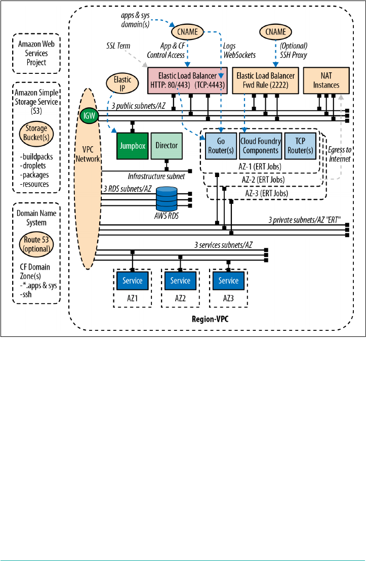
Figure 16-1. AWS Reference Architecture using three AZs to establish HA
Because AWS failure boundaries are so well defined by AZs and private, dedicated
subnets that map one-to-one directly to Cloud Foundry AZs, this configuration is
straighforward and does not require an in-depth analysis.
vCenter Failure Boundaries
This section explores the host configuration for a vCenter cluster. Establishing failure
boundaries for on-premises IaaS is nuanced, and therefore, you are required to
understand more about the underlying host configuration.
You can use vSphere HA in conjunction with the BOSH Resurrector, provided that
the resurrection cadence is different. Using both capabilities can augment the HA
strategy for instance groups in a powerful way. Ideally, for vCenter, a cluster should
have a minimum of two hosts for resiliency, but preferably three. Even though the
vSphere HA can bring back failed VMs, in a complete host failure situation, a single
HA IaaS Configuration | 269
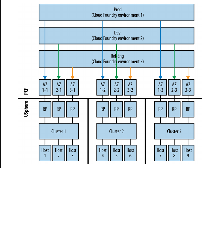
host ESXi cluster would render the cluster inoperable. For that reason, a minimum of
two hosts per cluster (although three is preferable) ensures that you do not lose an
entire AZ if a host server fails.
Therefore, sizing your infrastructure with three Cloud Foundry AZs and three hosts
per cluster will result in a nine-host cluster. Some companies at this point become
concerned that they are oversizing their IaaS. It is important to note that, within a
cluster, you can still use the logical construct of resource pools for sharing infrastruc‐
ture between different Cloud Foundry installations. For example, you can run a
development installation, a production installation, and sandbox, all on the same set
of clusters with isolation and AZs achieved through resource pool and cluster combi‐
nations. This nine-host cluster/resource pool configuration, supporting multiple
Cloud Foundry foundations, is illustrated in Figure 16-2.
Figure 16-2. Using vSphere resource pools to allow multiple Cloud Foundry installa‐
tions to use the same cluster sets
In line with the previous AWS example, Figure 16-3 presents a topology diagram for
the vCenter scenario described, including a sensible networking definition.
270 | Chapter 16: Designing for Resilience, Planning for Disaster
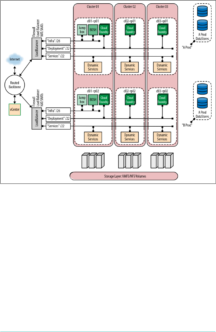
Figure 16-3. An HA Cloud Foundry architecture with two Cloud Foundry deployments
spanning three vCenter clusters
When configuring your capacity for Cloud Foundry, you need to take into considera‐
tion the HA capabilities and effects of the underlying infrastructure. vSphere HA
works in two ways. Primarily there is the reactive action of booting VMs that have
lost a host on which to run. In addition, vSphere also employs a construct known as
admission control.
Admission Control guards capacity and prevents new VMs from being powered on if
it violates the capacity retention policy. This means that you can have a cluster of
hosts that has plenty of spare capacity but will not boot additional VMs because
Admission Control prevents you from eating into capacity you previously specified
as reserved. You can disable Admission Control, but it is usually turned on. A typical
configuration with both Admission Control and vSphere HA turned on often has
each cluster establish one protected host. The default Admission Control policy is
n + 1 host protection so that each cluster effectively loses a host’s worth of capacity.
HA IaaS Configuration | 271

With this configuration, a nine-host environment (three clusters each with three
hosts) will result in only six hosts of capacity.
Cluster Configuration
With the Admission Control and vSphere HA configuration, a
two-host cluster will still establish one protected host. Therefore,
this configuration yields only one host of capacity per cluster. If
you are striving for a higher-utilization model, three hosts is the
preferred option, provided that you have the need for total
capacity.
As with other IaaS technologies, many other configurations are possible. For exam‐
ple, it is totally feasible to configure a three-host cluster with vSphere HA turned on
and Admission Control turned off. This will provide 100 percent capacity available
for VMs but if you lose an entire host, there can well be insufficient capacity to
reboot the lost VMs.
The key takeaway here is that Cloud Foundry is a consolidation play (containers) on
top of a consolidation play (virtualization). Do not cheat yourself at either layer. You
need adequate HA and capacity at every layer (hardware, IaaS, Cloud Foundry) in
order for the platform to function as desired and to protect your workload from fail‐
ures at any layer.
Backup and Restore
From time to time, you might need to completely restore your environment. This
could be due to any of these situations:
•Creating a carbon copy of an existing deployment to create a brand new environ‐
ment
•Maintenance reasons such as swapping out or upgrading your networking,
server, or storage layer
•Recovering from a data center–wide malicious attack that causes a catastrophic
failure
There are several projects that exist to back up and restore Cloud Foundry. Here are a
couple of them:
•cf-converger from Engineer Better
•cfops from Pivotal Services
272 | Chapter 16: Designing for Resilience, Planning for Disaster

The latter is focused on Pivotal Cloud Foundry, but, with the exception of backing up
Pivotal’s Operations Manager configuration, most of the underlying principles (e.g.,
backing up the databases) apply to any Cloud Foundry installation.
To restore your environment, you first need to create a backup of the data layer.
When thinking about Cloud Foundry from a disaster recovery perspective, you need
to forget all of the moving parts—all the processes—and think about the distributed
system as a set of persistent disks holding the following:
• The CCDB
•The UAA database
•The BBS
• The BOSH DB
• The blobstore or NFS server
• Configuration (all deployment manifests, including BOSH itself)
•Any other app-centric persistence layer (e.g., Pivotal Cloud Foundry uses an
additional App Manager database)
The persistence layer is Cloud Foundry from a disaster recovery perspective; every‐
thing else—all of the running processes—can easily be wired back in.
Cloud Foundry Availability
Backing up Cloud Foundry will suspend Cloud Controller writes
for the duration of the backup. This is important because you can‐
not simultaneously write to a database and keep the integrity of the
database backup. Suspending the Cloud Controller writes (thus
effectively taking CAPI offline) will cause your foundation to
become read-only for the duration of the backup. App pushes and
so on will not work during this time, but your existing apps will
still be running and able to accept traffic.
Restoring BOSH
Bringing back BOSH is the first step to recovering any offline Cloud Foundry envi‐
ronment. Therefore, it is vital that you back up the original BOSH manifest (let’s call
it bosh.yml) and take regular snapshots of the BOSH DB or attached BOSH disk.
With your bosh.yml, you can bring your original BOSH back, provided that you have
a snapshot of the disk volume that contains the BOSH DB and blobstore, or you can
use an external DB like MySQL on AWS-RDS and an external blobstore like Amazon
S3. You must, however, bring BOSH back on the original IP as the BOSH worker
nodes. Your BOSH-deployed machines hosting your deployments will have BOSH
agents that are configured to communicate with BOSH on that original IP.
Backup and Restore | 273

It’s best to use an external database like clustered MySQL or AWS-RDS and an exter‐
nal blobstore like Amazon S3. However, if you use BOSH’s internal database, there
are some additional steps required to back up and restore BOSH’s internal database
and blobstore.
For illustrative purposes, when using AWS, you can use the following steps to back
up BOSH’s internal database and blobstore:
1. Using SSH, connect to BOSH: $ ssh -i key vcap@boship
2. Become root: $ su - (use your VM credentials)
3. Run $ monit summary to view all BOSH processes
4. Run $ monit stop all to cleanly stop all BOSH processes
5. Take a snapshot of the BOSH persistent disk volume
Here are the steps to restore BOSH’s internal database and blobstore:
1. Using your original bosh.yml manifest, rebuild BOSH. This creates a new empty
persistent disk.
2. Repeat steps 1 through 4 of the backup procedure. You will need to stop all pro‐
cesses before detaching the persistent disk.
3. Detach the persistent disk (deleting it).
4. Create a new volume from your disk volume snapshot, and then manually attach
the new volume to the BOSH VM.
5. Start all processes again. BOSH will now have the same BOSH UUID (because it
is stored in the database).
Bringing Back Cloud Foundry
After you have successfully restored BOSH, BOSH itself should successfully restore
the Cloud Foundry deployment, assuming that you have used an external and reach‐
able database and blobstore for the other components.
Validating Platform Integrity in Production
This section discusses how to validate the health and integrity of your production
environment. After you have successfully deployed Cloud Foundry, you should run
the smoke tests and CATS to ensure that your environment is working properly. You
should also maintain a dedicated sandbox to try out any changes prior to altering any
development or production environment.
274 | Chapter 16: Designing for Resilience, Planning for Disaster

Start with a Sandbox
If you run business-critical workloads on a production instance of Cloud Foundry,
you should consider using a sandbox/staging environment prior to making any pro‐
duction platform changes. This approach gives you the ability to test any production
apps in an isolated way before rolling out new platform changes (be it an infrastruc‐
ture upgrade, stemcell change, Cloud Foundry release upgrade, buildpack change, or
service upgrade) to production.
The sandbox environment should mirror the production environment as closely as
possible. It should also contain a representation of the production apps and a mock
up of the production services to ensure that you validate the health of the apps run‐
ning on the platform.
Production Verification Testing
To test the behavior of your platform before making the production environment
live, run the following:
•cf-smoke-tests to ensure that core Cloud Foundry functionality is working
•cf-acceptance-tests to test Cloud Foundry behavior and component integra‐
tion in more detail
•Your own custom acceptance tests against the apps and services you have writ‐
ten, including any established or customized configuration, ensuring established
app behavior does not break
• External monitoring against your deployed apps
An example set of app tests could include the following:
1. Use cf push to push the app.
2. Bind the app to a service(s).
3. Start the app.
4. Target the app on a restful endpoint and validate the response.
5. Target the app on a restful endpoint to write to a given data service.
6. Target the app on a restful endpoint to read a written value.
7. Generate and log a unique string to validate app logging.
8. Stop the app.
9. Delete the app.
This set of tests should be designed to exercise the app’s core user-facing functional‐
ity, including the app’s interaction with any backing services.
Validating Platform Integrity in Production | 275

Running these sorts of tests against each Cloud Foundry instance on a CI server with
a metrics dashboard is the desired approach for ease of repeatability. Not only do you
get volume testing for free (e.g., you can easily fill up a buildpack cache that way), you
can publish the dashboard URL to both your platform consumers (namely develop‐
ers) and stakeholders (namely line of business owners) alike. Linking these tests to
alerting/paging systems is also better than paging people due to IaaS-level failures.
After you make the environment live, it is still important to identify any unintended
behavior changes. Therefore, the ongoing periodic running of platform validation
tests in production is absolutely recommended. For example, it is possible that you
may uncover a problem with the underlying infrastructure that can be noticed only
by running your platform validation tests in production.
Summary
This chapter provided you with a core understanding of the issues, decision points,
and built-in capabilities pertaining to platform resiliency.
The key consideration in ensuring that your platform is resilient is understanding the
environmental failure boundaries. When you have established those boundaries and
assessed your appetite for risk versus cost, you will be in a much better position to
design your Cloud Foundry topology for the desired level of HA.
After you have provisioned your Cloud Foundry environment, it is essential to make
regular backups. Backup and restore is not as complex as it might first appear; how‐
ever, making regular backups and, in addition, frequently testing that you can suc‐
cessfully restore your Cloud Foundry environment, should be a part of your ongoing
disaster recovery plan.
Consuming and reacting to system events and logging information will also help
establish resiliency. Using a sandbox/staging environment prior to making any pro‐
duction platform changes provides an additional defense against introducing insta‐
bility to the platform. Finally, you should continue to run your platform tests (smoke
tests, platform and app verification tests, etc.) to ensure that your environment is
working properly. If you do all of this, you will be in much better shape if unforeseen
issues do arise.
276 | Chapter 16: Designing for Resilience, Planning for Disaster
CHAPTER 17
Cloud Foundry Roadmap
As mentioned throughout the early chapters of this book, Cloud Foundry technology
is exceptionally fast moving. Any review of the architecture is just a snapshot in time,
and any future view of the technology is subject to refinement. However, keeping one
eye on the Cloud Foundry roadmap helps to provide a perspective on the emerging
trends that are shaping the IT industry. This chapter explores, at a high level, some of
the recent and soon to emerge features, and some speculation as to where the archi‐
tecture might evolve further.
Roadmap Topics
There is a wiki dedicated to roadmap topics. Roadmaps are gener‐
ally reflected in public Pivotal Tracker projects, with each core
component having its own dedicated project.
v3 API
The third incarnation of the Cloud Foundry API (known as the v3 API) provides a
richer set of building blocks with which you can orchestrate diverse and complex
workflows.
Multiple Droplets per App
With the v2 API, a user (be it a developer or a CI/CD pipeline) can deploy a single
droplet per app, as illustrated in Figure 17-1. There is a direct correlation of one app
name and one app GUID being associated with one droplet.
277
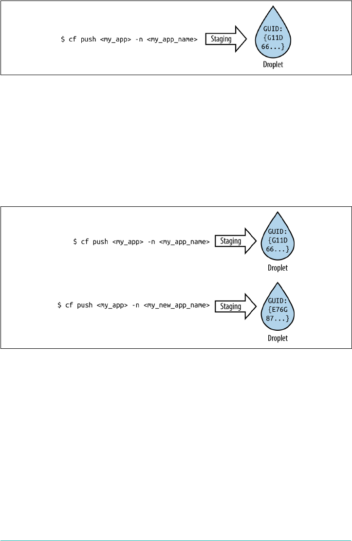
Figure 17-1. Traditional app-to-droplet mapping
For each app, a user can request several running instances. Each app instance will use
the same droplet and will be tagged by the same app GUID. A user can subsequently
push, stage, and run a second version of the same app. From Cloud Foundry’s per‐
spective, the two running apps (version one and version two) are viewed as two com‐
pletely independent apps because they have two different app names and therefore
two different app GUIDs, as depicted in Figure 17-2. It does not matter if the two
apps are binary identical; if they are pushed with different app names, they will have
different droplets, and Cloud Foundry will treat them as different apps.
Figure 17-2. Traditional app-to-droplet mapping with different droplets generated from
the same app artifact
With the v3 API, you can now push more than one version of your app, resulting in
multiple droplets that are all regarded as the same app because they have the same
app name and app GUID, as presented in Figure 17-3. This allows the user to manage
the transition between the different droplet versions natively within Cloud Foundry
in an orchestrated manner.
278 | Chapter 17: Cloud Foundry Roadmap

Figure 17-3. Two app versions mapped to the same droplet version with identical
GUIDs
Currently, when you restage your app with the v2 API, the app instance must be
stopped because new files are uploaded and the app dependencies and artifacts are
replaced during the buildpack compilation phase. With the v2 API, downtime is
mitigated by pushing more than one instance and using rolling blue/green deploy‐
ments. With the v3 API, downtime can be further mitigated by pushing the second
version of the app alongside the first running app instance, without affecting the
already running instance. After you have pushed it, you can restage the second ver‐
sion of your app, again with no impact to the current running app. When the new
version of your app has finished staging and is successfully running, the user can then
choose to instantaneously expose it in place of the original instance.
If you stage and run the new droplet and discover that it does not perform ade‐
quately, you can easily revert to the original droplet because it is still running. This
workflow essentially allows for the native establishment of deployment patterns such
as canaries and blue/green deployments within Cloud Foundry itself, as opposed to
establishing these patterns via a pipeline or route service. Essentially, there are fewer
steps required to achieve the necessary deployment patterns. For example, the map‐
ping of routes between blue and green app versions could become a thing of the past
if Cloud Foundry handles this as a native transition.
The approach of multiple droplets per app has additional implications for managing
logs. With this v3 approach, if the new app is running successfully, because the same
app GUID will be used for both the old and new apps, it becomes much easier to
track the health of the app throughout its entire life cycle because all logs from all
deployed app versions are aggregated into the same stream.
v3 API | 279
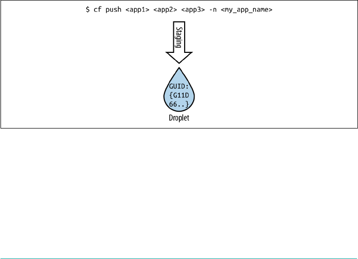
Multiple Apps per Droplet (Process Types)
In addition to multiple droplets per app, the v3 API plans to allow you to have multi‐
ple processes per droplet. This breaks away from the v2 model that allows for only
one app process per droplet. Therefore, the direct correlation of one app name and
one app GUID being associated with one droplet, as described earlier, will be a thing
of the past.
With the v3 API, with one cf push and one stage, you can now have multiple pro‐
cesses (e.g., a web process, worker process, and Cron process) within the same drop‐
let, as shown in Figure 17-4. There is no longer a need to have the separate cf pushes
and three staging events.
After it has been pushed, each app instance contains all three processes, but only one
process is active; there is still only one process running per container. The model
allows for each process to be scaled independently; for example, you might want two
web process instances, four worker process instances, and one Cron process instance.
Each process can have its own defined resources; for example, my worker process
might need double the memory of the web process. A benefit of collating processing
with the same droplet is that all processes have the same app GUID, so they all can be
tracked easily by the same stream in the aggregated log. When moving to a microser‐
vices architecture, this allows the monitoring of your big-A app (the overarching app
that is comprised of smaller services) while still tracking the behavior of each individ‐
ual service.
Figure 17-4. Multiple process-to-one-droplet mapping
Tasks
Tasks allow you to push your app code and then, instead of running your app as an
LRP, run one-off commands. Tasks run at most only once; then, upon exit of the
specified Task, the app will shut down and the container will be destroyed. If the Task
produced a failed result, either Cloud Foundry or the user can detect the failure and
then retry the Task.
280 | Chapter 17: Cloud Foundry Roadmap

Tasks are great for running one-off processes such as Cron-like jobs or database
migrations. Additionally, you could build a service that repeatedly runs your task on,
perhaps, a nightly basis.
If you were trying to orchestrate a database migration, the task workflow might be as
follows:
1. Push your new app version alongside your existing app, as described above, but
leave the new version staged but not running.
2. Invoke your database migration task.
3. Transition the droplet to run the new version of your app and bring your old app
offline.
Tasks provide a huge amount of power for new workflows, especially around han‐
dling batch and computational workflows that involve data processing through pat‐
terns such as pipes and filters.
Diego Scheduling
Advanced features are being added to Diego’s scheduling capability. Two key features
under consideration include Cell rebalancing and a concept of boulder support to
ensure appropriate app distribution.
Cell Rebalancing
Imagine the scenario in which the Cloud Foundry operator provisions two cells (let’s
call them Cell A and Cell B). If a Cloud Foundry user pushes two instances of her
app, Diego will try and deploy an instance of the app to both Cells for resiliency rea‐
sons. Now, if because of some IaaS-related issue Cell B dies, Diego will notice the loss
of the Cell and start a new instance of the app on Cell A. This is good for availability
because both instances of the app are running and handling traffic. However, when
Cell B comes back online, we now have the scenario in which both apps are still run‐
ning on Cell A.
Leaving both apps running on Cell A is not good for resiliency. If Cell A fails, all
instances of the app will need to be re-created simultaneously, causing app downtime
until two new instances are recreated on Cell B.
As of this writing, work is underway to address this scenario so that apps can be
gracefully and slowly migrated back to a resilient distribution across both Cells to
avoid any app downtime if a specific Cell dies (see Figure 17-5). Rebalancing is typi‐
cally a costly processing exercise for the Diego scheduler (the Diego Brain), and so
the algorithm required for this work should be graceful and measured so as to be
transparent to any end-user activity.
Diego Scheduling | 281
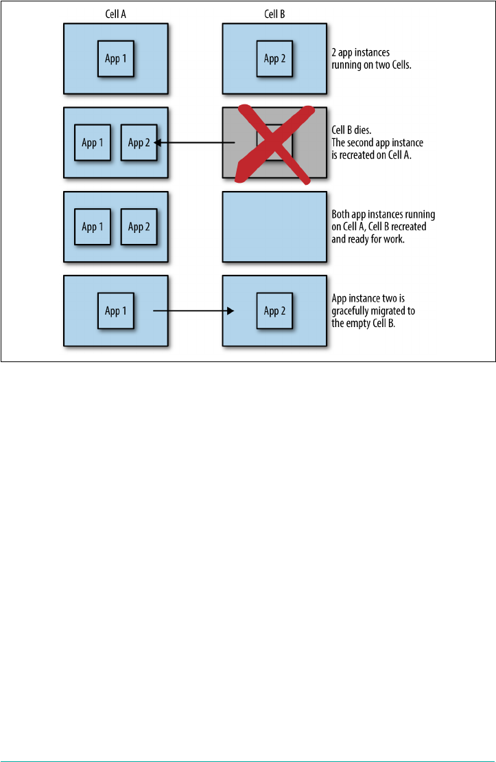
Figure 17-5. Cell rebalancing for a single app with two instances running across two
Cells
Boulders
Consider a scenario in which there are six 32 GB Cells. Each Cell contains lots of
pebble-sized apps (e.g., 512 MB to 2 GB); however, due to the number of apps
deployed, every Cell has only a maximum of 6 GB of RAM remaining. When adding
up all of the available RAM, in theory, there should be enough room for a larger than
average app because there is 36 GB of unused RAM on aggregate across all Cells.
However, if a user wants to push a boulder-sized app of say 10 GB, the cf push com‐
mand will fail because there is no single Cell that can accommodate the new boulder-
sized app. At this point, you are constrained to pushing apps that are less than 6 GB
in size.
For this reason, work is currently being done to relocate some of the smaller pebble-
sized apps, provided that they will not experience downtime, to create enough room
on a single Cell to accommodate the boulder-sized 10 GB app.
282 | Chapter 17: Cloud Foundry Roadmap

Tracing
As of this writing, work is being done to respect and log an HTTP header trace ID. If
an HTTP request/response header trace ID is respected and logged at the GoRouter,
this would allow the app user to reason over the traffic flow. This is valuable both for
the developer and for Cloud Foundry itself, especially when inspecting internal traffic
response times. For example, if a call to the Cloud Controller is slow, inspecting the
trace ID between the Cloud Foundry components will quickly show you where the
bottleneck resides.
Containers
Container management is an essential component of Cloud Foundry. Regardless of
whether you run a Docker Image, app, or Task, the Garden-managed container is
where your workload runs. Work is specifically being added to containers with
respect to network shaping, taking snapshots, networking, and additional traffic resil‐
iency.
Network Shaping
Network shaping of egress and ingress traffic is an important capability that can be
added to Garden. Developers can already add additional route services for traffic
management tasks such as rate limiting. However, the Platform Operator might also
want to impose some additional network quotas around development spaces. For
example, if a developer pushes an app to a development space and then starts to route
a high amount of traffic to that app, Garden could rate-limit the traffic to the app so
as to avoid saturating the network in a way that could disable other, more important
apps.
Container Snapshots
Container snapshots are a valuable feature for security reasons such as quarantine
purposes. Snapshots of the container could also be a valuable technique for additional
debugging.
Container-to-Container Networking
Container-to-container networking is an important topic, and there is work currently
being undertaken to assign a single IP per container as opposed to using a local host
NAT to reach an app. Current thinking on container-to-container traffic is to take
advantage of an overlay network so that an app can communicate with itself or other
apps residing in other containers without having to go via the GoRouter. Additional
app-to-app traffic policies can then be established in order to specify that app A can
communicate directly with app B on a defined port. You can achieve point-to-point
Tracing | 283

routing by using an internal service discovery such as Consul or Eureka. Currently,
when a user provisions a service, it is bound to a single space. For the maximum ben‐
efit of service discovery, your app or service needs to be exposed across multiple
spaces, and work is being undertaken to allow for this.
You can read about the current thinking and proposal on this topic in “A Vision for
the Future of Container Networking on Cloud Foundry”.
Traffic Resiliency
Currently, Cloud Foundry optimizes for consistency over availability. Therefore, the
GoRouter begins pruning routes from the route table after two minutes if it has not
received a heartbeat from the Route Emitter. This is because as time goes on, if the
route is not pruned and there is still no heartbeat, there is an increased possibility
that an intended app request might be routed to a dead app instance.
This preference for consistency above availability can cause unnecessary app down‐
time if a critical component event occurs. For example, consider a scenario in which
all apps are running well, but for some reason the heartbeat messages are not being
received by the GoRouter. In this scenario, it might be preferable to still allow users
to reach the existing apps and not prune the routes because the apps are still running.
However, Diego might be moving or starting new instances of apps, and some of the
running instances might have failed, resulting in the container being destroyed. With
no visibility of the health of the routes, you still require a way to ensure that packets
are not directed to the wrong app.
You can place the GoRouter on an overlay network. This allows the GoRouter to
indicate on the packet encapsulation what app a specific request was intended for.
When the packet lands at a Cell host, if the Cell determines that the packet was not
intended for the apps running on it, the Cell can reject that traffic. This mechanism
allows the Cells to deal with and reject any bad routes in the event that the GoR‐
outer’s route table becomes temporarily stale. This approach makes it possible for
Cloud Foundry to incorporate additional availability while maintaining consistency.
Buildpacks and Staging
Buildpacks are an essential step in the deployment flow when deploying app artifacts.
There are a number of proposed enhancements in this area. Three critical changes
include the use of multiple buildpacks (a parent buildpack that can pull in multiple
child buildpacks), the introduction of post-staging policies, and the isolation of com‐
pilers from running apps.
284 | Chapter 17: Cloud Foundry Roadmap

Multibuildpacks
Buildpack aggregation is a valuable feature that allows you to combine several run‐
times that might be required. For example, if your app is a PHP app but also requires
a Perl module, you can pull in both PHP and Perl runtimes by using a multibuild‐
pack. This alleviates the need for customizing the PHP buildpack to pull in a specific
Perl library.
Post-Staging Policy or Step
An operator might want to define a post-staging policy or step. For example, after
staging is complete, she might want to run a script to package-scan the droplet for
compliance reasons, or to upload the droplet to a corporate repository such as arti‐
factory. Therefore, the addition of this step provides additional control and gover‐
nance over the created droplet artifact.
Compiler-Less Rootfs and Stemcells
If the rootfs and stemcell are compiler-less, all compilers will be excluded from the
resulting container. This reduces the attack surface for all running apps. For example,
because for many scenarios a compiler is required only during the staging process,
Cloud Foundry could use a different rootfs for the staging containers. This is one
approach, but in essence, the objective of making Cloud Foundry more secure by
reducing the attach surface of running apps by removing compilers is extremely val‐
uable.
Isolation Segments
The concept of placement pools has been around for a couple of years under the
guise of several different names (placement pools, isolation zones, elastic clusters).
The objective of isolation segments focuses on the specific isolation of select Cloud
Foundry components (e.g., the Cells, GoRouter, and Loggregator) on to a dedicated
subnet and set of underlying resources so as to provide a dedicated and isolated envi‐
ronment within a Cloud Foundry foundation, without the need to build an entirely
new Cloud Foundry environment.
This feature is especially valuable for apps that are required to be run in a strictly iso‐
lated environment. An example of such a need would be a PCI- or HIPPA-certified
environment. Alternatively, the Cells in the segregated environment might be config‐
ured to be more performant and are therefore more costly to run and should be
reserved for specific apps with demanding memory and CPU characteristics. With
isolation segments, you can establish a segregated environment with, for example,
dedicated Cells, GoRouter, and Loggregator that share a pool containing the remain‐
Isolation Segments | 285

ing Cloud Foundry components (such as the Cloud Controller and other Diego com‐
ponents).
When you deploy your app, you can ensure that it lands on a Cell within your isola‐
tion segments, and all traffic to that app will be routed by the specific isolation seg‐
ment GoRouter. When you deploy an app with no segregation requirements, it will
reside in the default non-isolated environment and will be accessed by the default
GoRouter. This approach allows both segregated and non-segregated apps to reside
within the same Cloud Foundry installation and therefore will reduce both your
overall deployment footprint and ongoing maintenance costs because you can con‐
solidate several environments.
Summary
This chapter has only scratched the surface on what might be coming next. The
premise of Cloud Foundry remains the same: to remove as much of the undifferenti‐
ated heavy lifting as possible so that developers can focus on delivering business value
iteratively with repeated velocity. However, the high-water mark of what Cloud
Foundry can do for you is constantly evolving as new capabilities are always being
added to the platform. The extent of new services and capabilities within Cloud
Foundry is potentially limitless.
In addition, new app frameworks that run on, and can use Cloud Foundry, are
emerging; for example, Spring Cloud Data Flow and Spring Cloud Services. Spring
Cloud Data Flow is a project aimed to simplify development of big data apps. It con‐
tains stream and batch modules existing as Spring Boot–based stream and task
microservices apps. These apps can be autonomously deployed units that can
“natively” run in Cloud Foundry. Spring Cloud Data Flow offers a collection of pat‐
terns and best practices for microservices-based distributed streaming and batch-data
pipelines. This opens Cloud Foundry to new types of workloads and becomes espe‐
cially pertinent when dealing with Internet of Things–based traffic. In essence, it cre‐
ates possibilities for Cloud Foundry not only to be the platform for running your
apps, but an ideal platform to serve as the integration hub for the enterprise.
Established microservices patterns are also emerging through projects such as Spring
Cloud Services, Spring Cloud Netflix, and Spring Cloud Config. Taking advantage of
these battle-tested microservice patterns, and of the libraries that implement them,
can now be as simple as including a few dependencies in your app build file and
applying the appropriate annotation in your source code.
286 | Chapter 17: Cloud Foundry Roadmap

When you step back and review all the recent changes to IT that make technologies
like Cloud Foundry possible, it is clear that the IT industry is experiencing phenom‐
enally exciting times right now. I have learned an enormous amount through work‐
ing on Cloud Foundry, and it is my hope that this book will facilitate your own
journey with it.
Summary | 287

Index
Symbols
$ (command prompt), xxi
$ cf push command, 11, 39, 90
$bosh create env command, 58, 61
12-factor contract, 13, 45, 226
3 Rs of internet security, 21
A
access VM, 106
acknowledgments, xxii
action abstraction, 84
ActualLRPs, 80
Admission Control, 271
Advanced Persistent Threats (APTs), 20
aggregated logging and metrics, 17
Amazon Web Services (AWS)
failure boundaries, 268
increasing default instances, 56
VPC setup, 55
app logs, 226
(see also debugging)
application artifacts
deploying, 39
Diego's support for, 81
storing, 34
application instances (AIs)
failing app instances, 230
instance group failure, 247-250
instance group replication, 54
provisioning/deprovisioning, 38
routes and, 120
self-healing feature, 16
specifying, 12
UAA management, 255
application life cycle
Application Life-Cycle Binaries, 83, 112, 155
Application Life-Cycle Policy, 34
components handling execution, 35
self-healing feature, 16
self-service model, 12
stages of, 109-111
application velocity (see velocity)
applications as units of deployment, 10, 80
Auctioneer service, 82, 104
authentication (see User Access and Authenti‐
cation)
availability zones (AZs), 16, 186
B
backing services, 37
backup and restore, 272
BIG-IP load balancer, 31
blobstore, 34, 197
blue/green deployments, 27
BOSH (see also BOSH 2.0)
basics of, 169
benefits of, 170, 188
bosh-bootloader, 50, 55
Cloud Foundry deployment and, 48, 192
commands, 221
components, 213-223
deployments, 201-211
Diego BOSH releases, 88
environment creation, 174
infrastructure as code focus, 172
instance groups, 84, 105
IPSec release, 130
management port security caution, 57
Index | 289

release engineering through, 14, 169
release jobs, 84, 193
releases, 191-200
restoring, 273
security features in, 21
self-healing features, 15
supported CPIs, 48, 172
top-level primitives, 175-180
deployments, 179
releases, 177
stemcells, 176
UAA release, 253
versions, 174
BOSH 2.0 (see also BOSH)
addons, 188
BOSH links, 187
cloud configuration, 180-187
availability zones (AZs), 186
compilation VMs, 186
disk type configuration, 184
networks, 182
VM types, 184
orphaned disks, 188
BOSH Lite, 50, 175
Boulder support, 282
Brain
Auctioneer service, 82, 104
Cell's Rep, 104
components, 104
role of, 104
scheduling algorithms, 105
simulation testing, 106
buildpacks
advanced features, 284
basics of, 158
benefits of, 156, 167
buildpack and stack compatibility, 37
dependency pipelines, 166
deploying application artifacts, 39
Java buildpacks, 159
modifying, 163-165
packaging and dependencies, 165
staging, 159-161
structure of, 162
system buildpack ordering, 160
bulkheading, 23
Bulletin Board System (BBS)
Converger process, 100
defined, 82
protobuf communications, 99
real-time representation provided by, 83
role of, 98
RPC-style API, 99
state vs. communication focus, 99
bundles, 152
C
caching, 268
canonical name (CNAME), 123
Cassandra, 268
CATS (Cloud Foundry Acceptance Tests), 225,
274
(see also debugging)
CC-Bridge
CC-Uploader, 94
composable actions and, 86
domain freshness and, 93, 95
microservices comprising, 93
Nsync and TPS components, 95-97
purpose of, 83, 94
Stager, 94
Cells
buildpack and stack compatibility, 37
Cell sizing, 53
Cells's Rep, 104
components of, 101
defined, 11
Executor process, 103
Garden container API, 103
rebalancing, 281
Rep endpoint, 101
routing and, 127
certificates
rotating, 257
SSL certificates, 62
cf push command, 11, 24, 34, 155
cf scale command, 12
cf-acceptance-tests (CATS), 75, 274
cf-deployment, 50, 55
Cloud Controller (CAPI)
interaction with Diego, 89
overview of, 33-35
pulling information from, 244
routing to, 32, 127
Cloud Controller database (CCDB), 34
Cloud Foundry
acceptance testing, 225
(see also debugging)
290 | Index

benefits of, xix, 2
deploying, 43, 266
(see also environment setup)
documentation, 30
expanded uses for, 80
factors to consider when running, xvii, 40
GitHub repository, 40
installing, 67
(see also installation)
modular distributed architecture, 29
online resources, xx
platform overview, 5
(see also cloud-native platforms)
prerequisites to learning, xviii
recently released and future features,
277-287
supplemental material, 1, 277
Cloud Provider Interfaces (CPIs), 48, 172, 216
cloud-based operating systems
benefits of, 8
fundamental capabilities needed for, 40
cloud-native applications, 13
cloud-native platforms
benefits of, 1
evolution of, 1
major concepts, 2
open, 5
opinionated, 4
prerequisites to learning, xx
structured vs. unstructured, 4
code examples, obtaining and using, 40
colocation requirements, 25
command line interface (CLI), 216, 221
command prompt ($), xxi
comments and questions, xxii
common vulnerabilities and exposures (CVEs),
156
components
additional
buildpacks and Docker images, 39
infrastructure and Cloud Provider Inter‐
face, 40
marketplace of on-demand services, 37
stacks, 37
for application execution, 35
benefits of distributed systems, 29
Cloud Controller (CAPI), 33-35
load balancer and GoRouter, 31
messaging, 37
for metrics and logging, 36
overview of, 30
user management and UAA, 32
composable actions
actions included, 86
defined, 82
examples of, 85
relationship to Tasks and LRPs, 86
Concourse.ci, 35
configuration drift, 20
configuration failures, 228
Consul, 112
contact information, xxii
containers
advanced features, 283
benefits of, 3, 141, 154
challenges of, 154
container images, 142
container management, 81, 142
container users, 103
creating, 35
defined, 141
elements of, 142
high memory usage failures, 236-241
implementation in Cloud Foundry, 150-153
Linux containers, 144-150
orchestration of, 153
runtime architecture, 79
terminology, 142, 150
trusted containers, 148
context path routing, 124
context path-based routing, 26
continuous delivery pipelines, 35
Continuous Integration/Continuous Deploy‐
ment (CI/CD), 3, 267
Control Groups (CGroups), 148
control theory, 15
Converger process, 100
core concepts and capabilities
aggregated logging and metrics, 17
applications as units of deployment, 10
built-in resilience and fault tolerance, 15,
265
cf push command for deployment, 11
cloud-based OS, 8
dealing with undifferentiated heavy lifting, 7
do more approach, 9
domains hosts and routes, 25
Organizations and Spaces, 23
Index | 291

overview of, 7
release engineering through BOSH, 14
rolling upgrades and blue/green deploy‐
ment, 27
security, 19-23
self-service application life cycle, 12
staging, 11
twelve-factor contract, 13
UAA management, 23
cred-name, 210
credentials, 209-211
D
data consistency, 267
data isolation, 148
debugging
acceptance tests, 225
failure scenarios
configuration failures, 228
core reasons for, 228
infrastructure failures, 229
release job process failures, 229
logging, 226-228
mitigating and handling failures, 263
route collision, 241-245
use cases
app is not reachable, 230
high memory usage, 236-241
instance group failure, 247-250
network failure, 231
release job process failure, 245
security group misconfiguration, 234
dependencies, 47, 165
deployment topology, 46, 266
(see also environment setup)
deployments (BOSH), 179
DesiredLRPs, 80
develop-to-deployment cycle time, 1
DevOps
cultural shift to, 3
team structure, 44
Diego
additional components
Application Life-Cycle Binaries, 112
Consul, 112
Route-Emitter, 112
BOSH releases, 88
components
access VM, 106
Brain, 82, 104-106
Bulletin Board System, 98-100
Cells, 101-104
vs. services, 84
working in conjunction with CF, 88
Diego API, 99
essential concepts, 83-87
action abstraction, 84
composable actions, 85
layered architecture, 87
major characteristics and attributes, 117
overview of, 35, 82-83
process types, 79
purpose of, 79
routing and, 32
scheduling advanced features, 281
separation of concerns, 80
staging steps, 114-117
statefull and globally aware components,
108
support for container image formats, 81
workflow, 88-97
CC-Bridge, 93
Cloud Foundry API, 89
interacting with Diego, 88
logging and traffic routing, 97
staging, 90
workflow life cycles, 107-111
dig, 233
Director VM, 174, 214-215
disaster planning
backup and restore, 272
extending built-in resiliency, 265-268
high availability considerations, 263
high availability IaaS configuration, 268-272
key considerations, 276
platform integrity validation, 274
disk creation, 219
disk quotas, 148
distributed systems
benefits of, 29
distributed data layers, 268
optimization problems, 105
role of Diego in, 84, 117
role of scheduling in, 82
security features in, 19
DNS resolution, 239
do more approach, 9
Docker images
292 | Index

benefits of, 156, 157
cf push command and, 40
container management technologies, 81
domains
canonical name (CNAME), 123
domain freshness, 93, 95-96
multiple app domains, 124
owned, 26
route collision errors, 241-245
separation of concerns, 123
setup, 62
shared and private, 123
subdomains, 123
system domain, 123
wildcard domains, 124
droplets
creating, 40, 83, 155
defined, 10
multiple per app, 277
storing, 34
dynamic load balancing, 15, 31
E
egress traffic, 235
elastic clusters, 285
Elastic Load Balancer (ELB), 31, 129, 234
environment setup
dependencies and integrations, 47
infrastructure design, 48-58
installation steps, 43
key concerns and decisions, 43
networking design and routing, 58-63
non-technical considerations, 44
deployment topology, 46
team structure, 44
environment variables, 24
events, aggregated streaming, 18
eventual consistency, 100
Executor process, 103
F
failure boundaries, 268
failure scenarios
configuration failures, 228
core reasons for, 228
infrastructure failures, 229
mitigating and handling failures, 263
release job process failures, 229
Fakhouri, Onsi, 9
fault tolerance, 15
file server, 106
filesystems, 148
Firehose, 226
G
Garden
advanced features, 283
API and implementation separation, 103
benefits of, 150
implementation, 151
interface actions, 151
Open Container Initiative and runC, 151
overview of, 35
support for container image formats, 81
Geode, 268
GitHub repository, 40
Globally Unique Identifier (GUID), 137
GoRouter
high availability and, 131
instrumentation and logging, 132
interaction with Diego, 83
role in routing, 32, 126, 131
routing table, 131
grant types, 258
H
Health Monitor (BOSH), 16, 216
high availability (HA)
availability zones (AZs) and, 16
considerations for, 263
ensuring, 55
eventual consistency and, 100
IaaS configuration, 268-272
instance groups and, 88, 105
load balancer and, 62
on AWS, 56
high memory usage, 236-241
Higham, Dan, 225
horizontal scaling, 105
hostnames, 122
HTTP multiplexing and pipelining, 130, 283
I
identity-management service (see User Access
and Authentication)
Infrastructure as a Service (IaaS), 1, 201,
268-272
Index | 293

infrastructure as code tools, 16, 172
infrastructure design
BOSH CPIs, 48
factors to consider, 49
jumpbox VMs, 57
resilience, 50
setting up an AWS VPC, 55
sizing and scoping, 50-55
infrastructure failures, 229
installation
canonical approach, 66
changing stacks, 73
growing the platform, 73
installing Cloud Foundry, 67-71
key concerns and decisions, 65
logical environment structure, 75
pushing your first app, 77
steps of, 43, 66
validating platform integrity, 73-75, 274
instance groups, 84, 105, 205, 247-250, 255
integrations, 47
Interactive Ruby (IRB) tools, 244
Internet Gateway (edge routers), 231
internet security, three Rs of, 21
(see also security)
IPSec, 130
isolation segments, 285
J
Java buildpacks (JBP), 159
jumpbox VMs, 57
K
keys, 257
L
Linux Container manager, 81, 144-150
as high-level abstract concept, 144
Control Groups (CGroups), 148
core primitives and kernel features, 145
data locality, 148
disk quotas, 148
filesystems, 148
for Docker images, 81
namespaces, 145
security through namespaces, 146
vs. traditional virtual machines, 144
widespread use of, 142
load balancer
choice of, 31
configuring
PROXY protocol, 130
request header fields, 128, 283
TLS termination and IPSec, 130
WebSocket upgrades, 129
dynamic approach, 15
routing and, 126
setup, 62
local caching layers, 268
logging
aggregated streaming, 17
components for, 36
Diego workflow, 97
process of, 226-228
UAA logging, 256
Loggregator
app log handling, 226
benefits of, 17, 36
duties of, 226
Firehose, 226
interaction with Diego, 83, 97
nozzles, 227
Long Running Processes (LRPs)
Cloud Foundry support for, 11
defined, 80
M
marketplace of on-demand services, 37
memory
high memory usage failures, 236-241
overcommitting, 53
messages, capturing, 37
metrics
aggregated streaming, 17
components for, 36
UAA-produced, 257
Metron agent, 36
microservices, 3
minimal change concept, 20
N
namespaces, 145-147
NATS messaging system
purpose of, 217
router implementation and, 131
Network Address Translation (NAT)., 231
network shaping, 283
294 | Index

networking design
dealing with network failure, 231
dependencies, 59
domains and certificates, 62
internet gateway (edge routers), 231
key concerns and decisions, 58
load balancer setup, 62
networking tooling, 233
security groups, 61
static IPs, 59
subnets, 60
VM options, 220
NOAA, 227
nozzles, 227
nslookup, 233
Nsync, 95-97
O
OAuth 2.0, 252
on-demand services, 37
Open Container Initiative (OCI), 35, 81, 151
open platforms, 5
opinionated platforms, 4
Organizations (Orgs)
benefits of, 23
logical environment structure, 75
orphaned disks, 188
out-of-memory (OOM) errors, 236-241
owned domains, 26
P
packaging, 165
PCFDev, 157
pipelines, 267
placement pools, 285
platform-operations team
platform integrity validation, 274
responsibilities of, xviii
structure of, 44
plug-and-play model, 85
postgres_password, 210
private domains, 123
properties
configurable environment variables, 24
setting, 207
protocol buffers (protobufs), 99
PROXY protocol, 130
Q
questions and comments, xxii
R
Raft consensus algorithm, 101
reference architecture, xx, 52
release engineering, 171
release jobs, 84, 193, 229, 245
releases (BOSH), 177
Rep endpoint, 101
repeatability, 188
report.py, 244
resilience, 15, 50, 101, 263, 284 (see also high
availability)
resource allocation, 25
resource limits (R limits), 148
resource match requests, 34
Resurrector (BOSH), 16, 217, 247
rkt, 81
roadmap topics
buildpacks and staging, 284
containers, 283
Diego scheduling, 281
isolation segments, 285
overview of, 286
tracing, 283
v3 API, 277-281
Role-Based Access Control (RBAC), 23, 251
roles, 259
rolling upgrades, 27
root filesystem (rootfs), 37, 285
root users, 103
Route-Emitter, 112
routing
components overview, 125
Diego workflow, 97
domain hosts and, 25
environment setup, 58-63
load balancer considerations, 128-130
primitives
context path routing, 124
domains, 123
hostnames, 122
routes, 120
route collision, 241-245
route mapping flow, 127
route services, 136-139
routing flow, 127
routing primitives, 119
Index | 295

sticky sessions, 133
TCPRouter, 134-136
uses for, 119
via load balancer and GoRouter, 31,
131-133
RunActions, 114
runC, 35, 81, 86, 150, 151
running containers, 150
S
SAML certificates, 257
sandbox environment, 46, 73, 275
(see also environment setup)
scaling
containers, 153
dynamic, 13
horizontal, 105
scheduling
advanced features, 281
benefits of, 82
defined, 82
scheduled processes, 84
scheduling algorithms, 105
scopes, 259
Secure Shell (SSH)-Proxy services, 106, 127
security
additional in Cloud Foundry, 21
advanced persistent threats (APTs), 20
app and dependency scanning, 158
BOSH management ports, 57
configuration drift and, 20
distributed system security, 19
jumpbox VMs, 57
minimal change concept, 20
networking security groups, 61
security group misconfiguration, 234
three Rs of enterprise security, 21
UAA management, 23, 251-261
self-healing feature, 12, 15
service broker, 38
service instances, 38
session affinity, 133
shared domains, 123
sizing and scoping, 50-55
Cells sizing, 53
instance group replication, 54
snowflake servers, 14
SOCKS5 protocol, 58
Spaces
benefits of, 23
logical environment structure, 75
Spring Cloud, 25
SSL certificates, 62
stacks
changing, 73
defined, 37
staging
advanced features, 284
buildpacks and, 39, 159-161
core concept of, 11
defined, 83
steps of, 114-117
workflow, 90
state machine, 107
static IPs, 59
stemcells, 176, 205, 285
Steno logging, 227
sticky sessions, 133
structured platforms, 4
subdomains, 123
subnets, 60
syslog aggregator, 227
(see also debugging)
system state
components for storing, 34
state machine, 107
T
Tasks
advanced features, 280
examples of, 80
life cycle, 111
TCPRouter, 80, 126, 134-136
teams (see platform-operations team)
testing
cf-acceptance-tests (CATS), 75, 274
production verification testing, 74, 275
three Rs of internet security, 21
time-to-live (TTL), 96
TLS decryption, 130
tokens, 257
TPS, 95-97
tracing, 283
Tracy, Derek, 244
troubleshooting (see debugging)
trusted containers, 148
Twelve-Factor contract, 13, 45, 226
typographical conventions, xx
296 | Index

U
UAADB (UAA database), 256
undifferentiated heavy lifting, 7
unit of deployment, 10 (see also buildpacks)
unstructured platforms, 4
URL resolution, 233
User Access and Authentication (UAA)
architecture and configuration, 255-258
benefits of, 261
BOSH release, 253
documentation, 252
key modes of operation, 251
OAuth 2.0, 252
overview of, 32
responsibilities of, 253
roles and scopes, 259-261
routing and, 32
security features in, 23
UAAC utility, 261
user import, 258
user-provided services, 39
users, onboarding, 258
V
v3 API, 277-281
vcap users, 103
vCenters, 269
velocity
benefits of, xvii
common vulnerabilities and exposures and,
156
security and, 20
verification testing, 74, 275
Veritas, 100, 239
Virtual Private Cloud (VPC), 55
vSphere, 269
W
WebSockets, 129
wildcard domains, 124
workflow (see Diego)
X
X-Forwarded-For (XFF), 128
X-Forwarded-Proto (XFP), 128
Y
YAML (YAML Ain't Markup Language), 14,
201-209
deployment manifests, 204
Director UUID and deployment name, 204
instance groups, 205
properties, 207
release names, 205
stemcells, 205
syntax, 202
updates, 208
used by BOSH, 14
uses for, 201
Index | 297

About the Author
Duncan Winn has been working on Cloud Foundry for Pivotal since that company
formed in 2013. Currently he works on Pivotal’s Platform Architecture Team, help‐
ing companies to install and configure hardened Cloud Foundry environments and
related services to get the most out of Cloud Foundry in an enterprise setting. Prior
to moving to the United States, he was the EMEA Cloud Foundry developer advocate
for Pivotal and ran Pivotal’s Platform Architecture Team in London. He is actively
involved in the Cloud Foundry community blogging, running meetups, and writing
books.
Colophon
The animal on the cover of Cloud Foundry: The Definitive Guide is a black-winged
kite (Elanus caeruleus).
It has distinctive long falcon-like wings with white, gray, and black plumage; its eyes
are forward-facing with red irises. Its wings extend past its tail when perched, often
on roadside wires. To balance itself, it jerks its tail up and down and adjusts its wings.
This kite is recognizable for its habit of hovering over open grasslands. The kite
doesn’t migrate, but makes short distance movements based on weather.
Black-winged kites nest in loose platforms made of twigs. Females spend more energy
constructing the nest than males, and lay 3–4 eggs in them during breeding season.
Both parents incubate the eggs, but the male spends more time foraging for food,
which includes grasshoppers, crickets, other large insects, lizards, and rodents.
Many of the animals on O’Reilly covers are endangered; all of them are important to
the world. To learn more about how you can help, go to animals.oreilly.com.
The cover image is from Lydekker’s Royal Natural History. The cover fonts are URW
Typewriter and Guardian Sans. The text font is Adobe Minion Pro; the heading font
is Adobe Myriad Condensed; and the code font is Dalton Maag’s Ubuntu Mono.
