Disc TN390 5 UHF 900 MHz Tx Codan UT 3 Synthesized Transmitter Discontinued
User Manual: Discontinued Products | LMR & HF Radio | Codan Radio
Open the PDF directly: View PDF ![]() .
.
Page Count: 2
DANIELS
DANIELS
ELECTRONICS LTD.
ELECTRONICS LTD.
TM
TM
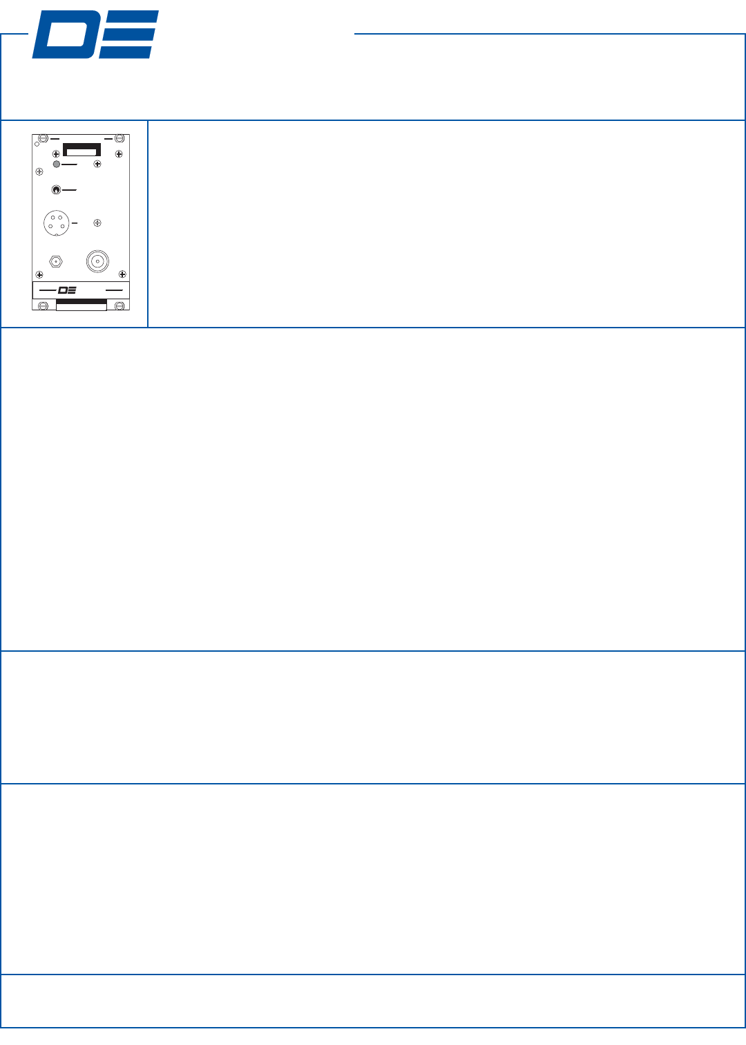
TN390 UT-3/900 UHF 900 MHz Synthesized Transmitter
TX
REFERENCE
INPUT
OFF
KEY TX
MIC
RF OUT
FREQUENCY (MHz)
951.0000
MADE IN CANADA
UT-3/950-SWB3
MADE IN CANADA
MADE IN CANADA
NORM
TRANSMITTER
DANIELS
ELECTRONICS LTD.
Frequency Bands 928 - 935 MHz / 935 - 960 MHz
Channel Spacing 12.5 KHz or 25 KHz
Transmitter Switching Range Unlimited
RF Output Power 0.5 to 3.0 Watts adjustable
Duty Cycle 100% (-40 °C to +60 °C)
Undesired Emissions (Conducted Spurious) < -80 dBc
Undesired Emissions (Conducted Harmonics) < -80 dBc
FM Hum & Noise Ratio (300 Hz - 3.4 KHz) > 40 dB
Carrier Frequency Stability ± 1.0 ppm (-30 °C to +60 °C) (-40 °C to +60 °C optional)
Modulation Type 11K0F3E (FM) or 16K0F3E (FM)
VSWR Protection < 20:1 (All Phase Angles)
Audio Distortion < 2.0% @ 25 °C (< 2.5% @ -40 °C to +60 °C)
Output Impedance 50 Ω (Type N Connector)
Operating Temperature -30 °C to +60 °C (-40 °C to +60 °C optional)
Standby Current < 7 mA
Transmit Current (3.0 W) < 2.00 A
Specifications
MT-3 Radio Systems
The UT-3/900 transmitter is a low power, synthesized FM transmitter capable of operating in 12.5
KHz (narrowband) or 25 kHz (wideband) channels. The UT-3/900 transmitter operates in one of three
frequency bands: 896 to 902 MHz, 928 to 935 MHz, or 935 to 960 MHz. A modular design allows
each of the transmitter’s modules, MT-3 Transmitter Main Board, MT-3 Audio Processor, UT-3/900
Amplifier, and OS-3/900 Synthesizer, to be individually assembled and tested. This facilitates con-
struction, tuning and maintenance as well as troubleshooting procedures. The synthesizer module can
be programmed to have up to 16 channels exclusive to one frequency band.
UT-3/930-SWB300 Low Current Synthesized, 25 KHz Bandwidth, 3.0 W, 928 - 935 MHz
UT-3/930-SNB300 Low Current Synthesized, 12.5 KHz Bandwidth, 3.0 W, 928 - 935 MHz
UT-3/950-SWB300 Low Current Synthesized, 25 KHz Bandwidth, 3.0 W, 935 - 960 MHz
UT-3/950-SNB300 Low Current Synthesized, 12.5 KHz Bandwidth, 3.0 W, 935 - 960 MHz
Models Available
The transmitter is initially aligned at the factory for the frequency stamped on the ‘Factory Set Operating Frequency’ label on
the front panel. For any frequency change, no re-alignment of the transmitter may be required. To align and / or adjust the
transmitter the outer cover needs to be removed, the transmitter needs to be plugged into the subrack via a cable and / or exten-
der card and power must be applied to the system. A 50 Ωdummy load should be connected to the RF output when trans-
mitting.
Transmitter Operating Frequency
Page 1 of 2
43 Erie Street Toll Free Canada & U.S.A. International Internet
Victoria, B.C. Phone: 1-800-664-4066 Phone: 250-382-8268 e-mail: sales@danelec.com
Canada V8V 1P8 Fax: 1-877-750-0004 Fax: 250-382-6139 web: www.danelec.com
TECHNICAL NOTES
TN390 Rev 5-0-0 Nov 06 © Copyright 2006 Daniels Electronics Ltd. All rights reserved.
TThhiisspprroodduucctthhaassbbeeeennddiissccoonnttiinnuueeddaannddiissnnoolloonnggeerrmmaannuuffaaccttuurreeddbbyyDDaanniieellssEElleeccttrroonniiccssLLttdd..
DANIELS
DANIELS
ELECTRONICS LTD.
ELECTRONICS LTD.
TM
TM
TN390 UT-3/900 UHF 900 MHz Synthesized Transmitter
MT-3 Radio Systems
Audio Processor Alignment:
For circuit board version 43-911916 through 43-911923
refer to Technical Note TN130 Audio Processor Tuning
Procedure. For other circuit board versions, refer to the
appropriate manual.
Synthesizer Alignment:
No synthesizer alignment is required.
Amplifier Output Power and Alarm Adjustment:
Adjust R27 fully counterclockwise. Turn R8, the output
power adjustment, to the desired transmitter output power.
Do not exceed 3.0 Watts. The output power alarm is fac-
tory set for a 3 dB loss in forward output power. Terminate
the transmitter with a 3:1 mismatch load. Monitor pin Z26
and slowly turn R27, the antenna VSWR alarm adjustment,
clockwise until pin Z26 goes low.
Transmitter Alignment Procedures
A
A
A
A
B
B
B
B
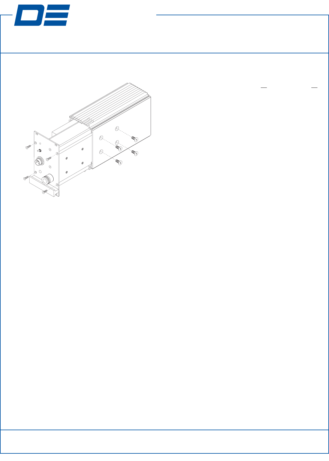
Remove the four front panel screws (A) and four side panel screws (B)
to slide the transmitter outer cover off and expose the Main Board,
Local Oscillator, Audio Processor Board and Amplifier.
Note: For complete alignment procedures, refer to the instruction manual. These notes are for reference only.
Page 2 of 2
43 Erie Street Toll Free Canada & U.S.A. International Internet
Victoria, B.C. Phone: 1-800-664-4066 Phone: 250-382-8268 e-mail: sales@danelec.com
Canada V8V 1P8 Fax: 1-877-750-0004 Fax: 250-382-6139 web: www.danelec.com
TECHNICAL NOTES
TN390 Rev 5-0-0 Nov 06
© Copyright 2006 Daniels Electronics Ltd. All rights reserved.
TThhiisspprroodduucctthhaassbbeeeennddiissccoonnttiinnuueeddaannddiissnnoolloonnggeerrmmaannuuffaaccttuurreeddbbyyDDaanniieellssEElleeccttrroonniiccssLLttdd..
