TN835 1 High Current Power Supplies Codan AC To DC
User Manual: 8. Other | LMR & HF Radio | Codan Radio
Open the PDF directly: View PDF ![]() .
.
Page Count: 2
TN835 Rev 1-1-0 Mar 13
TN835 High Current AC to DC Power Supplies
MT-3/4 Radio Systems
TECHNICAL NOTES
Page 1 of 2
© 2013 Codan Limited All rights reserved.
43 Erie Street
Victoria, B.C.
Canada V8V 1P8
Toll Free Canada & U.S.A.
Phone: 1-800-664-4066
Fax: 1-877-750-0004
International
Phone: 250-382-8268
Fax: 250-382-6139
Internet
Email: LMRsales@codanradio.com
Web: www.codanradio.com
The PSA-12-40-RB-00 and PSA-12-60-RB-00 AC switching power supplies provide a regulated +13.8 Vdc to the
output terminals. The power supplies are 19” rack mountable and include battery revert capability. An input fuse,
electronic current limiting and voltage limiting protection, transient voltage suppressor and thermistor are built into
the unit as standard protection to safeguard the unit from abnormal conditions. The power supply uses active
current sharing technology to distribute the load current among two or three 20 Amp modules. This reduces stress
on individual components and increases reliability.
For remote sensing, status signals are available on the rear of the power supply on a female DB25 connector.
Specifi cations
Input Voltage Range 120 Vac or 220 Vac (Switch Selectable)
Input Frequency Range 50 / 60 Hz
Output Voltage +13.8 Vdc
Output Current 40 Amps continuous @ +13.8 Vdc (+60°C) PSA-12-40-RB-00
60 Amps continuous @ +13.8 Vdc (+60°C) PSA-12-60-RB-00
Operating Temperature -40°C to +60°C continuous duty
Installation
1. Mount the unit to the 19” rack.
2. Select the input voltage by sliding both AC voltage select switches on the rear of the power supply. Be certain that
both switches are on the same voltage setting.
WARNING: Damage to the unit and personal injury might occur if both the AC voltage select switches are
not set on the same voltage setting.
3. Connect the load to the output terminal block connector marked “SYSTEM”, with proper polarities in mind.
Tighten the output terminal block screws to secure the wires.
4. Connect the backup battery (if applicable) to the output terminal block connector marked “BATT”, with proper
polarities in mind. Tighten the output terminal block screws to secure the wires.
5. While the switch is in the OFF position, connect the supplied AC power cord to the AC input socket.
6. Plug the unit into an AC source capable of handling the rated input current (7 Amps or 12 Amps).
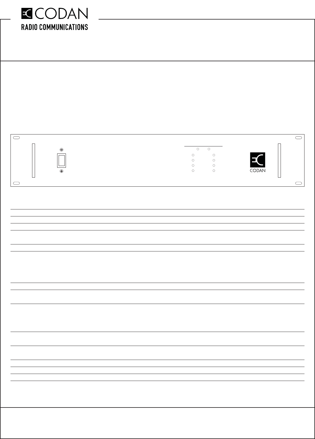
7. Turn the AC switch (located on the front panel) to the ON position to operate the unit.
ON
OFF
SYSTEM STATUS
AC / Input DC / Output
on
on
on
on
off
off
off
off
Module 1
Module 2
Module 3
Module 4
REDUNDANT POWER SUPPLY
TN835 High Current AC to DC Power Supplies
MT-3/4 Radio Systems
TECHNICAL NOTES
TN835 Rev 1-1-0 Mar 13Page 2 of 2 © 2013 Codan Limited All rights reserved.
43 Erie Street
Victoria, B.C.
Canada V8V 1P8
Toll Free Canada & U.S.A.
Phone: 1-800-664-4066
Fax: 1-877-750-0004
International
Phone: 250-382-8268
Fax: 250-382-6139
Internet
Email: LMRsales@codanradio.com
Web: www.codanradio.com
Battery Backup
During normal operation, the power supply provides all of the necessary power to the output while fl oat charging
the battery that is connected at the battery backup output. In the event that the AC power source is interrupted, the
battery will start to supply power to the load through an isolation diode; however, the load voltage will be 0.4 Vdc
lower than the battery voltage. The power resistors used to fl oat charge the battery limit the charging current to a
value based on a 100Ah deep cycle battery.
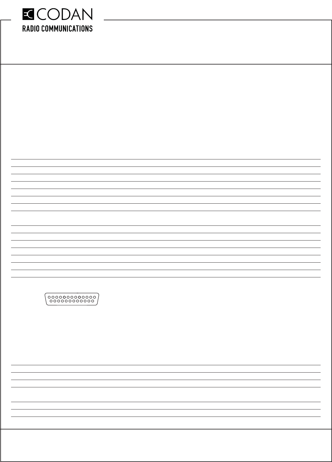
Alarm and Status Signals
For remote monitoring, the power supply is equipped with a female DB25 connector (on the rear of the power supply
behind a protective panel) that outputs various alarm and status signals such as:
Pin Number Pin Description Voltage Out
Pin 1 AC Good signal +15 Vdc if AC Voltage present / 0 Vdc if AC voltage not available
Pin 2 +5 Vdc reference signal +5 Vdc
Pin 3 No connection N/C
Pin 4 Fan Good signal +5 Vdc if both fans are good / 0 Vdc if one or both fans not functioning
Pin 5 No connection N/C
Pin 6 Current signal System current out analog signal (0 Vdc ~ +5 Vdc)
Pin 7 Module 1 Good signal +5 Vdc If Module is Good
0 Vdc If Module is not functioning or not present
Pin 8 Module 2 Good signal
Pin 9 Module 3 Good signal
Pin 10 Module 4 Good signal
Pin 11 No connection N/C
Pin 12 Temp warning signal +5 Vdc if the temperature inside the unit is over 48°C
Pin 13 System VOUT Signal +13.8 Vdc
Pin 14-15 Ground Ground
Figure 1: Pin Layout of the DB25 Connector
LED Status Display
An LED status indicator (located on the front panel) identifi es how many modules are connected on the board and
are working. The display also shows the status of the AC input and the DC output signals.
The green LED status indicator will be lit when:
• AC line voltage is preset
• DC output voltage is present
• Module voltage is present
The yellow LED status indicator will be lit when:
• Module is not present in the slot
• Module is not producing any output
1
13
25 14
