CODING GUIDE SHOWS PONTIS DATA 10 9 13 F65 7 Manual
User Manual: F65-7
Open the PDF directly: View PDF ![]() .
.
Page Count: 115 [warning: Documents this large are best viewed by clicking the View PDF Link!]
FEDERAL and STATE ITEM NUMBER ORDER Page i October 8, 2009
Updates to the Inventory Coding Guide
Item No. Description of Update Date of Update
F108A Removed Virginia Code ‘A’ to be consistent with the Federal
Coding Guide.
3-3-2010
F61 Removed Virginia Codes ‘G’, ‘F’, ‘P’, and ‘C’ to be consistent
with the Federal Coding Guide
3-3-2010
F31 Added 3 new codes per revisions issued by the FHWA on 2-2-
2011
7-10-13
S44 Added 3 new codes per revisions issued by the FHWA on 2-2-
2011
7-10-13
F63 Added 1 new code and revised 1 existing code per revisions
issued by the FHWA on 2-2-2011
7-10-13
F65 Added 1 new code and revised 1 existing code per revisions
issued by the FHWA on 2-2-2011
7-10-13
S48 Notes have been removed to be consistent with IIM-S&B-86 and
the current process in Pontis does not automatically update
items F63 and F65.
7-10-13
F113 Entire section revised - notes and description of codes have
updated to be consistent with FHWA’s 4-27-2001 memo revising
this item in their Coding Guide
10-9-13
FEDERAL and STATE ITEM NUMBER ORDER Page ii October 8, 2009
FEDERAL and STATE ITEM NUMBER ORDER Page iii October 8, 2009
TABLE OF CONTENTS
FEDERAL ITEM 2 - STATE HIGHWAY DEPARTMENT DISTRICT – X (1) ........................................... 1
FEDERAL ITEM 3 - COUNTY (PARISH) CODE – XXX (3) ..................................................................... 1
FEDERAL ITEM 4 - PLACE CODE – XXXXX (5) .................................................................................... 1
FEDERAL ITEM 5 - INVENTORY ROUTE – XXXXXXXXX (9) ............................................................... 1
FEDERAL ITEM 5A - RECORD TYPE – X (1) ......................................................................................... 2
FEDERAL ITEM 5B - ROUTE SIGNING PREFIX - X (1) ......................................................................... 3
FEDERAL ITEM 5C - DESIGNATED LEVEL OF SERVICE - X (1) ........................................................ 3
FEDERAL ITEM 5D - ROUTE NUMBER – XXXXX (5) ............................................................................ 4
FEDERAL ITEM 5E - DIRECTIONAL SUFFIX - X (1) ............................................................................. 4
FEDERAL ITEM 6 - FEATURES INTERSECTED - XXXXXXXXXXXXXXXXXXXXXXXX X (25) ........... 5
FEDERAL ITEM 7 - FACILITY CARRIED BY STRUCTURE - XXXXXXXXXXXXXXXXXX (18) ............. 5
FEDERAL ITEM 8 – STRUCTURE NUMBER - XXXXXXX (7) ................................................................ 6
FEDERAL ITEM 9 - LOCATION - XXXXXXXXXXXXXXXXXXXXXXXXX (25) ........................................ 6
FEDERAL ITEM 10 - INVENTORY ROUTE, MINIMUM VERTICAL CLEARANCE – XX XX (4) ............ 6
FEDERAL ITEM 11 – KILOMETER POINT(MILE POINT) (XXX.XXX MILES) (6) .................................. 7
FEDERAL ITEM 12 – BASE HIGHWAY NETWORK - X (1) ................................................................... 7
FEDERAL ITEM 13 – LRS INVENTORY RTE, SUBROUTE NUMBER – XXXXXXXXXX XX (10) (2) ... 8
FEDERAL ITEM 16 - LATITUDE - XX XX.X (5) ....................................................................................... 8
FEDERAL ITEM 17 - LONGITUDE - XXX XX.X (6) ................................................................................. 9
FEDERAL ITEM 19 - BYPASS, DETOUR LENGTH - XX (2) MILES ...................................................... 9
FEDERAL ITEM 20 - TOLL - X (1) ......................................................................................................... 10
FEDERAL ITEM 21 - MAINTENANCE RESPONSIBILITY - XX (2) ...................................................... 11
FEDERAL ITEM 22 - OWNER - XX (2) .................................................................................................. 11
FEDERAL ITEM 26 - FUNCTIONAL CLASSIFICATION OF INVENTORY ROUTE - XX (2) ............... 12
FEDERAL ITEM 27 - YEAR BUILT - XXXX (4) ...................................................................................... 12
FEDERAL ITEM 28 - LANES ON AND UNDER THE STRUCTURE - XX XX (4) ................................. 13
FEDERAL ITEM 29 - AVERAGE DAILY TRAFFIC - XXXXXX (6) ......................................................... 14
FEDERAL ITEM 30 - YEAR OF AVERAGE DAILY TRAFFIC - XX (2) ................................................... 1
FEDERAL ITEM 31 - DESIGN LOAD - X (1) ........................................................................................... 1
FEDERAL ITEM 32 - APPROACH ROADWAY WIDTH - XXX (3) .......................................................... 1
FEDERAL ITEM 33 - BRIDGE MEDIAN - X (1) ....................................................................................... 3
FEDERAL ITEM 34 - SKEW - XX (2) ....................................................................................................... 4
FEDERAL ITEM 35 - STRUCTURE FLARED - X (1) .............................................................................. 4
FEDERAL ITEM 36 - TRAFFIC SAFETY FEATURES - XXXX (4) .......................................................... 5
FEDERAL ITEM 37 - HISTORICAL SIGNIFICANCE - X (1) ................................................................... 6
FEDERAL ITEM 38 - NAVIGATION CONTROL - X (1) ........................................................................... 7
FEDERAL ITEM 39 - NAVIGATION VERTICAL CLEARANCE - XXX (3) ............................................... 7
FEDERAL ITEM 40 - NAVIGATION HORIZONTAL CLEARANCE - XXXX (4) ....................................... 7
FEDERAL ITEM 41 - OPEN, POSTED, OR CLOSED TO TRAFFIC - X (1) ........................................... 8
FEDERAL ITEM 42 - TYPE OF SERVICE - X X (2) ................................................................................ 9
FEDERAL ITEM 43 - STRUCTURE TYPE, MAIN - XXX (3) ................................................................. 10
FEDERAL ITEM 44 - STRUCTURE TYPE, APPROACH SPANS - XXX (3)......................................... 12
FEDERAL ITEM 45 - NUMBER OF SPANS IN MAIN UNIT - XXX (3) .................................................. 12
FEDERAL ITEM 46 - NUMBER OF APPROACH SPANS - XXXX (4) .................................................. 12
FEDERAL ITEM 47 - INVENTORY ROUTE, TOTAL HORIZONTAL CLEARANCE - XX.X (3) ............ 12
FEDERAL ITEM 48 - LENGTH OF MAXIMUM SPAN - XXXX (4) (FEET) ............................................ 14
FEDERAL ITEM 49 - STRUCTURE LENGTH - XXXXXX (6) (FEET) ................................................... 14
FEDERAL ITEM 50 - CURB OR SIDEWALK WIDTHS - XX.X XX.X (6) (FEET) ................................ 18
FEDERAL ITEM 51 - BRIDGE ROADWAY WIDTH, CURB-TO-CURB - XXX.X (4) ............................. 19
FEDERAL ITEM 52 - DECK WIDTH, OUT-TO-OUT - XXX.X (4) .......................................................... 20
FEDERAL ITEM 53 - MINIMUM VERTICAL CLEARANCE OVER BRIDGE ROADWAY - XX XX (4) . 22
FEDERAL and STATE ITEM NUMBER ORDER Page iv October 8, 2009
FEDERAL ITEM 54 - MINIMUM VERTICAL UNDERCLEARANCE - X XX(feet) XX(inches) (5) ......... 22
FEDERAL ITEM 55 - MINIMUM LATERAL UNDERCLEARANCE ON RIGHT - X XX.X (4) ................ 24
FEDERAL ITEM 56 - MINIMUM LATERAL UNDERCLEARANCE ON LEFT - XX.X (3) ...................... 27
FEDERAL ITEM 58 - DECK - X (1) ........................................................................................................ 28
FEDERAL ITEM 59 - SUPERSTRUCTURE - X (1) ............................................................................... 29
FEDERAL ITEM 60 - SUBSTRUCTURE - X (1) .................................................................................... 29
FEDERAL ITEM 61 - CHANNEL AND CHANNEL PROTECTION - X (1) ............................................. 30
FEDERAL ITEM 62 - CULVERTS - X (1) ............................................................................................... 32
FEDERAL ITEM 63 – METHOD USED TO DETERMINE OPERATING RATING - X (1)..................... 33
FEDERAL ITEM 64 - OPERATING RATING - XXX (3) ......................................................................... 33
FEDERAL ITEM 65 – METHOD USED TO DETERMINE INVENTORY RATING - X (1) ..................... 34
FEDERAL ITEM 66 - INVENTORY RATING - XXX (3) ......................................................................... 35
FEDERAL ITEM 67 - STRUCTURAL EVALUATION - X (1) (CALCULATED) ...................................... 36
FEDERAL ITEM 68 - DECK GEOMETRY - X (1) (CALCULATED) ....................................................... 38
FEDERAL ITEM 69 - UNDERCLEARANCE, VERTICAL & HORIZONTAL - X (1) (CALCULATED) ... 41
FEDERAL ITEM 70 - BRIDGE POSTING - X (1) ................................................................................... 43
FEDERAL ITEM 71 - WATERWAY ADEQUACY - X (1) ....................................................................... 45
FEDERAL ITEM 72 - APPROACH ROADWAY ALIGNMENT - X (1) .................................................... 46
FEDERAL ITEM 75 - TYPE OF WORK - XXX (3) ................................................................................. 47
FEDERAL ITEM 76 - LENGTH OF STRUCTURE IMPROVEMENT - XXXXXX (6) .............................. 49
FEDERAL ITEM 90 - INSPECTION DATE - AUTOMATIC ENTRY (8) ................................................. 51
FEDERAL ITEM 91 - DESIGNATED INSPECTION FREQUENCY - XX (2) ......................................... 51
FEDERAL ITEM 92 - CRITICAL FEATURE INSPECTION - XXX (3) ................................................... 52
FEDERAL ITEM 93 - CRITICAL FEATURE INSPECTION DATE - XXXXXXXXXXXX (12) ................. 53
FEDERAL ITEM 93 (SUPPLEMENTAL) - CRITICAL FEATURE INSPECTOR'S CODE - XXX (3) ..... 53
FEDERAL ITEM 93 (SUPPLEMENTAL) - CRITICAL FEATURE INSPECT - NEXT XXXXXXXX (8) .. 53
FEDERAL ITEM 94 - BRIDGE IMPROVEMENT COST – XXXXXX (6) ................................................ 54
FEDERAL ITEM 95 - ROADWAY IMPROVEMENT COST – XXXXXX (6) ........................................... 55
FEDERAL ITEM 96 - TOTAL PROJECT COST – XXXXXX (6) ............................................................ 55
FEDERAL ITEM 97 - YEAR OF IMPROVEMENT COST ESTIMATE – XXXX (4) ................................ 56
FEDERAL ITEM 98 - BORDER BRIDGE - XXX XX (5) ......................................................................... 56
FEDERAL ITEM 99 - BORDER BRIDGE STRUCTURE NUMBER - XXXXXXXXXXXXXXX (15) ........ 57
FEDERAL ITEM 100 - STRAHNET HIGHWAY DESIGNATION – X (1) ............................................... 57
FEDERAL ITEM 101 - PARALLEL STRUCTURE DESIGNATION – X (1) ........................................... 57
FEDERAL ITEM 102 - DIRECTION OF TRAFFIC – X (1) ..................................................................... 58
FEDERAL ITEM 103 - TEMPORARY STRUCTURE DESIGNATION – X (1) ....................................... 58
FEDERAL ITEM 104 - HIGHWAY SYSTEM OF THE INVENTORY ROUTE – X (1) ........................... 59
FEDERAL ITEM 105 – FEDERAL LANDS HIGHWAY – X (1) .............................................................. 59
FEDERAL ITEM 106 - YEAR RECONSTRUCTED – XXXX (4) ............................................................ 60
FEDERAL ITEM 107 - DECK STRUCTURE TYPE – X (1) ................................................................... 61
FEDERAL ITEM 108 - WEARING SURFACE/PROTECTIVE SYSTEM – X (1) ................................... 61
FEDERAL ITEM 109 - AVERAGE DAILY TRUCK TRAFFIC – XX (2) (PERCENT) ............................. 63
FEDERAL ITEM 110 - DESIGNATED NATIONAL NETWORK – X (1) ................................................ 63
FEDERAL ITEM 111 - PIER OR ABUTMENT PROTECTION (FOR NAVIGATION) – X (1) ................ 63
FEDERAL ITEM 112 - NBIS LENGTH – X (1) ....................................................................................... 64
FEDERAL ITEM 113 - SCOUR CRITICAL BRIDGES – X (1) ............................................................... 67
FEDERAL ITEM 114 - FUTURE AVERAGE DAILY TRAFFIC - XXXXXX (6) ....................................... 70
FEDERAL ITEM 115 - YEAR OF FUTURE AVERAGE DAILY TRAFFIC - XXXX (4) ........................... 70
FEDERAL ITEM 116 - MINIMUM NAVIGATION VERTICAL CLEARANCE, ........................................ 70
STATE ITEM 1 - RESIDENCY CODE - XX ............................................................................................ 71
STATE ITEM 2 - COUNTY OR CITY - XXX ........................................................................................... 71
STATE ITEM 3 - HTRIS STRUCTURE ID - Automatic Entry ................................................................ 71
STATE ITEM 4 - VA STRUCTURE NUMBER - XXXX .......................................................................... 71
STATE ITEM 5 - LANE ON INVENTORY ROUTE - X ........................................................................... 72
FEDERAL and STATE ITEM NUMBER ORDER Page v October 8, 2009
STATE ITEM 6 - BRIDGE NAME - XXXXXXXXXXXXXXXXXXXXXXXXX (25) .................................... 72
STATE ITEM 7 - HTRIS ROUTE ID - XXXXXXXXXXXXXX (14) ........................................................... 72
STATE ITEM 8 - NODE NUMBER - XXXXXX........................................................................................ 74
STATE ITEM 9 - NODE OFFSET - XXX.XXX ........................................................................................ 74
STATE ITEM 10 - ADJACENT COUNTY, CITY - XXX .......................................................................... 74
STATE ITEM 11 - NATIONAL PARK SERVICE STRUCTURE NUMBER - XXXXXXXX ..................... 74
STATE ITEM 12 - SPECIAL USE CODE - XX ....................................................................................... 74
STATE ITEM 13 - ORIGINAL PLAN NUMBER - XXX-XXX ................................................................... 74
STATE ITEM 13 - ORIGINAL STANDARD PLAN NUMBER - XXXXXXXXXXXXXXXX (16) ............... 75
STATE ITEM 14 - RECONSTRUCTION PLAN NUMBER - XXX-XXX .................................................. 75
STATE ITEM 14 - RECONSTRUCTION STANDARD PLAN NO. - XXXXXXXXXXXXXXXX (16) ........ 75
STATE ITEM 15 - MAINTENANCE RESPONSIBILITY - STATE - XXX ............................................... 75
STATE ITEM 18 - EXPANSION JOINTS OR DEVICES - XX ................................................................ 75
STATE ITEM 19 - ABUTMENT/CULVERT MATERIAL & TYPE, FOUNDATION OR PILES - X XX ... 75
STATE ITEM 20 - PIERS TYPE - MAIN - SEE BELOW ........................................................................ 77
STATE ITEM 21 - PIERS TYPE - APPROACH ..................................................................................... 79
STATE ITEM 22 - OPENINGS, NUMBER OF - XX ............................................................................... 79
STATE ITEM 23 - WIDTH OR DIAMETER - XX.X ................................................................................ 79
STATE ITEM 24 - HEIGHT - XX.X ......................................................................................................... 79
STATE ITEM 25 - BARREL LENGTH - XXXX ....................................................................................... 80
STATE ITEM 26 - DEPTH OF FILL - XX ................................................................................................ 80
STATE ITEM 27 - YEAR RECONSTRUCTED - XXXX .......................................................................... 80
STATE ITEM 28 - HORIZONTAL CLEARANCE UNDER ROUTE - LEFT - XX.X ............................... 80
STATE ITEM 29 - HORIZONTAL CLEARANCE UNDER ROUTE – RIGHT (SINGLE) - XX.X ............ 80
STATE ITEM 30 - SCOUR CRITICAL EVALUATION - X ...................................................................... 81
STATE ITEM 31 - SCOUR CRITICAL REMARKS CODE - XX ............................................................. 81
STATE ITEM 32 -DATE DELETED - XX/XX/XX .................................................................................... 82
STATE ITEM 33 - BRIDGE ROADWAY WIDTH - LEFT SIDE - XX.X .................................................. 82
STATE ITEM 34 - BRIDGE ROADWAY WIDTH - RIGHT SIDE - XX.X ................................................ 82
STATE ITEM 35 - WIDTH OF MEDIAN (FT) - XXX ............................................................................... 83
STATE ITEM 36 - MIN. VERT. UNDERCLEARANCE-RIGHT OR SINGLE- X XX(feet) XX(inches) ... 83
STATE ITEM 37 - MINIMUM VERTICAL UNDERCLEARANCE - LEFT - X XX(feet) XX(inches) ....... 83
STATE ITEM 38 - TOTAL REPLACEMENT INDICATOR - X ............................................................... 84
STATE ITEM 39 - TYPE OF CONSTRUCTION - X ............................................................................... 84
STATE ITEM 40 - TYPE OF MODIFICATION - X .................................................................................. 85
STATE ITEM 41 - HBRRP INDICATOR - X ........................................................................................... 85
STATE ITEM 42 - TIDAL INDICATOR - X ............................................................................................. 86
STATE ITEM 44 - DESIGN LOAD - HIGH (STATE) - X ........................................................................ 86
STATE ITEM 45 - RATED CAPACITY, SINGLE UNIT - XX .................................................................. 86
STATE ITEM 46 - RATED CAPACITY, SEMI - XX ................................................................................ 86
STATE ITEM 47 - STRESS LEVEL - X .................................................................................................. 86
STATE ITEM 48 - METHOD OF ANALYSIS - X .................................................................................... 87
STATE ITEM 49A – ANALYSIS PROGRAM NUMBER - XXXXXXXX .................................................. 88
STATE ITEM 49B - ANALYSIS RUN DATE - XX/XX/XX ....................................................................... 88
STATE ITEM 50 - POSTED STATUS (POSTED OR CLOSED BRIDGE - X ....................................... 89
STATE ITEM 51 - POSTED DATE - XX/XX/XX ..................................................................................... 89
STATE ITEM 52 - POSTED CAPACITY - R12-1 - XX ........................................................................... 89
STATE ITEM 53 - POSTED CAPACITY - R12-5 SINGLE UNIT - XX ................................................... 89
STATE ITEM 54 - POSTED CAPACITY - R12-5 SEMI - XX ................................................................. 89
STATE ITEM 55 - POSTED SIGN MAINTENANCE REQUIRED - X .................................................... 90
STATE ITEM 56 - MAINTENANCE REPLACE COST - XXXXXX ......................................................... 90
STATE ITEM 57 - MAINTENANCE REPLACEMENT FUNDING CODE - X ......................................... 90
STATE ITEM 58 – PPMS PROJECT ID NUMBER - XXXXXXXXXXXXXXX......................................... 91
STATE ITEM 59 - MAINTENANCE REPLACEMENT REMARKS CODE - XX ..................................... 91
FEDERAL and STATE ITEM NUMBER ORDER Page vi October 8, 2009
STATE ITEM 60 - REGULAR INSPECTOR'S CODE - XXX ................................................................. 91
STATE ITEM 61 - REGULAR INSPECTION - NEXT - CALCULATED ................................................. 91
STATE ITEM 62 - SPECIAL INSPECTION CLASSIFICATION - X ....................................................... 92
STATE ITEM 63 - SPECIAL EQUIPMENT INDICATOR - X .................................................................. 92
STATE ITEM 64 - SPEC. EQUIPMENT COMMENTS - XXXXXXXXXXXXXXXXXXXXXXXXX (25) .... 92
STATE ITEM 65 - SUFFICIENCY RATING - CALCULATED ................................................................ 92
STATE ITEM 66 - DEFICIENCY POINT - CALCULATED ..................................................................... 92
STATE ITEM 94 - LAST PAINTED DATE - XXXX ................................................................................. 92
STATE ITEM 170 - POSTING SIGN VISIBILITY - X ............................................................................. 92
STATE ITEM 171 – POSTING SIGN LEGIBILTY - X ............................................................................ 93
STATE ITEM 172 - INTERCHANGE SKETCH NUMBER - XXX ........................................................... 93
STATE ITEM 173 - SPECIAL STRUCTURE CODE - XX ...................................................................... 93
STATE ITEM 176 - CRITICAL RECOMMENDATION INDICATOR - X................................................. 93
STATE ITEM 177 - CRITICAL RECOMMENDATION NOTICE DATE - XX/XX/XX .............................. 93
STATE ITEM 178 - CRITICAL RECOMMENDATION ACTION - X ....................................................... 93
STATE ITEM 179 - CRITICAL RECOMMENDATION STATUS CODE - X ........................................... 93
STATE ITEM 180 - CRITICAL RECOMMENDATION ACTION DATE - XX/XX/XX .............................. 93
STATE ITEM 181 - CRITICAL RECOMMENDATION FOLLOW-UP INSPECTION - XX/XX/XX ......... 94
STATE ITEM 182 - CRITICAL RECOMMENDATION REVIEW - DIV - XX/XX/XX ............................... 94
STATE ITEM 183 - CRITICAL RECOMMENDATION REVIEW - FHWA - XX/XX/XX .......................... 94
STATE ITEM 184 - PREVENTIVE MAINTENANCE CODE - X ............................................................ 94
STATE ITEM 185 - VIRGINIA HIGHWAY SYSTEM - X ........................................................................ 94
STATE ITEM 186 - PAINT CLASSIFICATION - XX............................................................................... 95
STATE ITEM 189 - PPMS PROJECT STATUS CODE – XX ................................................................ 95

FEDERAL and STATE ITEM NUMBER ORDER Page 1 October 8, 2009
FEDERAL ITEM 2 - STATE HIGHWAY DEPARTMENT DISTRICT – X (1)
INVENTORY – ID/ADMIN
DISTRICT
TABLE - BRIDGE
The highway agency district (State or Federal) in which the bridge is located shall be represented by a
1-digit code. Existing district numbers shall be used where districts are identified by number. Where
districts are identified by name, a code number shall be assigned based on an alphabetical or
organizational listing of the districts.
1
Bristol District
2
Salem District
3
Lynchburg District
4
Richmond District
5
Hampton Roads District
6
Fredericksburg District
7
Culpeper District
8
Staunton District
A
Northern Virginia District
FEDERAL ITEM 3 - COUNTY (PARISH) CODE – XXX (3)
INVENTORY – ID/ADMIN
COUNTY
TABLE - BRIDGE
Counties shall be identified using the Federal Information Processing Standards (FIPS) codes given in
the current version of the Census of Population and Housing - Geographic Identification Code
Scheme. This information is available online at http://www.census.gov/geo/www/fips/fips55_2k.html
FEDERAL ITEM 4 - PLACE CODE – XXXXX (5)
INVENTORY – ID/ADMIN
PLACECODE
TABLE - BRIDGE
Cities, towns, townships, villages, and other census-designated places shall be identified using the
Federal Information Processing Standards (FIPS) code given in the current version of the Census of
Population and Housing - Geographic Identification Code Scheme. If there is no FIPS code, then
code all zeros. This information is available online at
http://www.census.gov/geo/www/fips/fips55_2k.html
(The Federal length of this field is 5 places XXXXX. When providing our annual report to the federal
government we fill in the missing fields with zeros.)
FEDERAL ITEM 5 - INVENTORY ROUTE – XXXXXXXXX (9)
INVENTORY – ROADS
TABLE - ROADWAY
(See items 5A, 5B, 5C, 5D and 5E below)
The inventory route is a 9-digit code composed of 5 segments.
Segment Description Length
5A Record Type 1 digit
5B Route Signing Prefix 1 digit
5C Designated Level of
Service
1 digit
5D Route Number 5 digits
5E Directional Suffix 1 digit

FEDERAL and STATE ITEM NUMBER ORDER Page 2 October 8, 2009
FEDERAL ITEM 5A - RECORD TYPE – X (1)
INVENTORY – ROADS
ON_UNDER
TABLE - ROADWAY
There are two types of National Bridge Inventory records: "on" and "under." Code the first digit
(leftmost) using one of the following codes:
Code Description
1 Route carried "on" the structure
2 Single route goes "under" the structure
A through Z Multiple routes go "under" the structure
A signifies the first of multiple routes under the structure.
B signifies the second of multiple routes under the structure.
Z signifies 26 routes under the structure.
"On" signifies that the inventory route is carried "on" the structure. Each bridge structure carrying
highway traffic must have a record identified with a type code = 1 (numeric). All of the NBI data items
must be coded, unless specifically excepted, with respect to the structure and the inventory route "on"
it.
"Under" signifies that the inventory route goes "under" the structure. If an inventory route beneath the
structure is on a Federal-aid highway, is a STRAHNET route or connector or is otherwise important, a
record must be coded to identify it. The type code must be 2 or an alphabetic letter A through Z.
Code 2 for a single route under the structure. If 2 or more routes go under a structure on separate
roadways, the code of 2 shall not be used. Code A, B, C, D, etc. consecutively for multiple routes on
separate roadways under the same structure. STRAHNET routes shall be listed first. When this Item
is coded 2 or A through Z, only the following items must be coded: Items 1, 3-11, 16, 17, 19, 20, 26-
30, 42, 43, 47-49, 100-104, 109 and 110. All other items are to remain blank.
Virginia Note: Overlapping under routes (single roadways carrying multiple routes) typically use only
one under record. However, some districts have elected to use a different record for
each route.
It cannot be overemphasized that all route-oriented data must agree with the coding as to whether the
inventory route is "on" or "under" the structure.
Tunnels shall be coded only as an "under" record; that is, they shall not be coded as a structure
carrying highway traffic.
There are situations of a route "under" a structure, where the structure does not carry a highway, but
may carry a railroad, pedestrian traffic, or even a building. These are coded the same as any other
"under" record and no "on" record shall be coded.

FEDERAL and STATE ITEM NUMBER ORDER Page 3 October 8, 2009
FEDERAL ITEM 5B - ROUTE SIGNING PREFIX - X (1)
INVENTORY – ROADS
KIND-HWY
TABLE - ROADWAY
In the second position, identify the route signing prefix for the inventory route using one of the following
codes:
Code
Description
1 Interstate highway
2 U.S. numbered highway
3 State highway
4 County highway Virginia Note: This code shall be used for secondary routes
in any county, including the counties of Arlington and Henrico.
5 City Street
6 Federal lands roads
7 State lands roads
8 Other (include toll roads not otherwise indicated or identified above)
When 2 or more routes are concurrent, the highest class of route will be used. The hierarchy is in the
order listed above.
EDIT CHECK
Item 5B must not equal 1 if Item 104 does not equal 1
EDIT CHECK - Item 5B must not equal 1 if Item 104 does not equal 1.
FEDERAL ITEM 5C - DESIGNATED LEVEL OF SERVICE - X (1)
INVENTORY – ROADS
LEVL_SRVC
TABLE - ROADWAY
In the third position, identify the designated level of service for the inventory route using one of the
following codes:
Code
Description
0 None of the below
1 Mainline Virginia Note: (HOV lanes shall be coded as Mainline)
2 Alternate
3 Bypass
4 Spur
6 Business
7 Ramp, Wye, Connector, etc.
8 Service and/or unclassified frontage road

FEDERAL and STATE ITEM NUMBER ORDER Page 4 October 8, 2009
FEDERAL ITEM 5D - ROUTE NUMBER – XXXXX (5)
INVENTORY – ROADS
ROUTENUM
TABLE - ROADWAY
Code the route number of the inventory route in the next 5 positions. This value shall be right justified
in the field with leading zeros filled in. (See examples listed later.)
If concurrent routes are of the same hierarchy level, denoted by the route signing prefix, the lowest
numbered route shall be coded. Code 00000 for bridges on roads without route numbers.
Virginia Note: Since "Non-Highway On" records have Item 5A coded 2, "Non-Highway On" records
should have Item 5D "Route Number" coded as the route that passes under the
structure.
Virginia Note: A Footbridge, a structure which carries pedestrian traffic over something other than a
highway, will have Item 5A coded 1 and should have Item 5D "Route Number" coded
as the route which passes adjacent to or nearest the structure.
FEDERAL ITEM 5E - DIRECTIONAL SUFFIX - X (1)
INVENTORY – ROADS
DIRSUFFIX
TABLE - ROADWAY
In the last position, code the directional suffix to the route number of the inventory route when it is part
of the route number, using one of the following codes:
Code
Description
0 Not applicable
1 North
2 East
3 South
4 West
In some cases, letters may be used with route numbers and as part of the route numbers and not to
indicate direction. In such cases, the letter should be included in the 5-position route number field.
EXAMPLES: Record Code
Interstate 95, on 1 1 1 00095 0 111000950
Interstate 70S, under 2 1 1 00070 3 211000703
State Highway 104, Spur, under 2 3 4 00104 0 234001040
U.S. 30E Bypass, on 1 2 3 00030 2 123000302
City street, on 1 5 0 00000 0 150000000
Ramp from I-81, under 2 1 7 00081 0 217000810
County Highway 173 on 1 4 1 00173 0 141001730
Interstate 84 under 2 1 1 00084 0 211000840
Interstate 495 on 1 1 1 00495 0 111004950
State Hwy 120 (STRAHNET Rte) under A 3 1 00120 0 A31001200
Alternate State Hwy 130 under B 3 2 00130 0 B32001300
Tunnel on Interstate 70 2 1 1 00070 0 211000700
EDIT CHECK
If Item 5A does not = 1 then Item 28B must be > 00.
If Item 5B = 1 then Item 26 must = 1 or 11 and Item 104 must = 1.

FEDERAL and STATE ITEM NUMBER ORDER Page 5 October 8, 2009
FEDERAL ITEM 6 - FEATURES INTERSECTED - XXXXXXXXXXXXXXXXXXXXXXXX X (25)
INVENTORY – ID/ADMIN
FEATINT
TABLE - BRIDGE
Virginia Note: When Item 5A indicates an “under” record, this item describes the inventory route
and/or features “on” the structure.
This item contains a description of the features intersected by the structure and a critical facility
indicator. When Item 5A indicates an “under” record, this item describes the inventory route and/or
features under the structure. There are 25 digits divided into 2 segments.
Segment
Description Length
6A Feature Intersected 24 digits
6B No Longer Coded (Blank) 1 digit
The information to be recorded for this item in the first 24 digits shall be the name or names of the
features intersected by the structure. When one of the features intersected is another highway, the
signed number or name of the highway shall appear first (leftmost) in the field. The names of any
other features shall follow, separated by a semicolon or a comma. Parentheses shall be used to
provide a second identification of the same feature (see third example). Abbreviations may be used
where necessary, but an effort shall be made to keep them meaningful. The data in this segment shall
be left justified in the first 24 positions without trailing zeros.
EXAMPLES:
I-81, US 51, MILL ROAD
MISSISSIPPI RIVER
SR 42 (POND ROAD)
FEDERAL ITEM 7 - FACILITY CARRIED BY STRUCTURE - XXXXXXXXXXXXXXXXXX (18)
INVENTORY – ID/ADMIN
FACILITY
TABLE - BRIDGE
Virginia Note: When Item 5A indicates an “under” record, this item describes the inventory route
and/or features “under” the structure.
The facility being carried by the structure shall be recorded and coded. This item shall be left justified
without trailing zeros.
EXAMPLES:
US 66
MAIN STREET
COUNTY ROAD 450
C & O RAILROAD (appropriate for "under" record only)
PEDESTRIAN BRIDGE (appropriate for "under" record only)

FEDERAL and STATE ITEM NUMBER ORDER Page 6 October 8, 2009
FEDERAL ITEM 8 – STRUCTURE NUMBER - XXXXXXX (7) SAME AS STATE ITEM 3
INVENTORY – ID/ADMIN
STRUCT_NUM
TABLE - BRIDGE
Virginia Note: The Federal length of this field is XXXXXXXXXXXXXXX (15). When providing our
annual report to the federal government we fill in the missing fields. The first three
digits are the state number 513 and the remaining digits are filled in with zeros.
It is required that the official structure number be recorded. It is not necessary to code this number
according to an arbitrary national standard. Each agency should code the structure number according
to its own internal processing procedures. When recording and coding for this item and following
items, any structure or structures with a closed median should be considered as one structure, not
two. Closed medians may have either mountable or non-mountable curbs or barriers.
The structure number must be unique for each bridge within the State, and once established should
preferably never change for the life of the bridge. If it is essential that structure number(s) must be
changed, all 15 digits are to be filled. For any structure number changes, a complete cross reference
of corresponding "old" and "new" numbers must be provided to the FHWA Bridge Division. The cross
reference shall include both a computer tape or diskette and a printed listing in the FHWA required
format.
The identical structure number must appear on the "on" and all "under" records associated with a
particular structure. (Refer to Item 5 - Inventory Route).
FEDERAL ITEM 9 - LOCATION - XXXXXXXXXXXXXXXXXXXXXXXXX (25)
INVENTORY – ID/ADMIN
LOCATION
TABLE - BRIDGE
This item contains a narrative description of the bridge location. It is recommended that the location
be keyed to a distinguishable feature on any official highway department map such as road junctions
and topographical features. This item shall be left justified without trailing zeros.
EXAMPLES:
6 MI. SW. OF RICHMOND
3.5 I. S. OF JCT. SR 69
FEDERAL ITEM 10 - INVENTORY ROUTE, MINIMUM VERTICAL CLEARANCE – XX XX (4)
INVENTORY – ROADS
VCLRINV
TABLE - ROADWAY
See Virginia Note under Federal Item 54.
Code the minimum vertical clearance over the inventory route identified in Item 5, whether the route is
"on" the structure or "under” the structure. The minimum clearance for a 10-foot width of the
pavement or travel part (See Virginia Notes under Item 54 for definition of where to measure) below of
the roadway where the clearance is the greatest shall be recorded and coded in feet and inches. For
structures having multiple openings, clearances for each opening shall be recorded, but only the
greatest of the “minimum clearances” for the two or more openings shall be coded regardless of the
direction of travel. This would be the practical maximum clearance. When no restriction exists, code
9999. Coding of actual clearances between 100 feet and 300 feet to an exact measurement is
optional.
EDIT CHECK
Last two columns of Item 10 (inches) must be 99 or < = 11.
A warning is issued if Item 10 is coded < 8 feet.

FEDERAL and STATE ITEM NUMBER ORDER Page 7 October 8, 2009
FEDERAL ITEM 11 – KILOMETER POINT(MILE POINT) (XXX.XXX MILES) (6)
INVENTORY – ROADS
KMPOST
TABLE - ROADWAY
Virginia Note: This is an automatic entry.
The linear referencing system (LRS) kilometer/mile point is used to establish the location of the bridge
on the Base Highway Network (see Federal Item 12). It must be from the same LRS Inventory Route
and kilometer/mile point system as reported in the Highway Performance Monitoring System (HPMS).
The kilometer/mile point coded in this item directly relates to Item 13 – LRS Inventory Route, Subroute
Number.
This item must be coded for all structures located on or overpassing the Base Highway Network.
Code a 7-digit number to represent the LRS kilometer/mile point distance in kilometers/mile to the
nearest thousandth. For structures carrying the LRS Inventory Route, code the kilometer/mile point at
the beginning of the structure (i.e. the lowest kilometer/mile point on the bridge). When the LRS
Inventory Route goes under the structure (Item 5A coded 2 or A-Z), then code the kilometer/mile point
on the underpassing route where the structure id first encountered.
Code all zeros in this field for all records where kilometer/mile points are not provided. Kilometer/mile
points may be coded for bridges that are not located on the Base Highway Network, however Item 12
– Base Highway Network shall be coded 0 for these records.
EXAMPLES: Code
Kilometer/mile point is 130.34
0130340
Kilometer/mile point is 9.60
0009600
Virginia Note: The Traffic Engineering Division reports kilometer/mile points to the FHWA with the
beginning kilometer/mile point (0000.000) at the beginning of a route and ignores
county lines as the kilometer/mile points increase i.e. kilometer/mile points do not
‘begin again’ at each county line.
FEDERAL ITEM 12 – BASE HIGHWAY NETWORK - X (1)
INVENTORY – ROADS
ONBASENET
TABLE - ROADWAY
Virginia Note: This is an automatic entry.
This item is to be coded for all records in the inventory. The Base Highway Network includes the
through lane (mainline) portions of the NHS, rural/urban principal arterial system and rural minor
arterial system. Ramps, frontage roads and other roadways are not included in the Base Network.
For the inventory route identified in Federal Item 5 – Inventory Route, indicate whether the inventory
route is on the Base Highway Network or not on that network. Use one of the following codes:
Code Description
0 Inventory Route is not on the Base Network
1 Inventory Route is on the Base Network

FEDERAL and STATE ITEM NUMBER ORDER Page 8 October 8, 2009
FEDERAL ITEM 13 – LRS INVENTORY RTE, SUBROUTE NUMBER – XXXXXXXXXX XX (10) (2)
INVENTORY – ROADS
LRSINVRT
SUBRTNUM
TABLE - ROADWAY
Virginia Note: This is an automatic entry.
If Item 12 - Base Highway Network has been coded 1, the information to be recorded for this item is
inventory route for the State’s linear referencing system (LRS). If Federal Item 12 has been coded 0,
this entire item should be left blank. This item is a 12-digit code composed of 2 segments.
Segment
Description Length
13A LRS Inventory Route 10 digits
13B Subroute Number 2 digits
The LRS inventory route and subroute numbers to be reported in this item must correspond to the
LRS inventory route and subroute numbers reported by the State for the HPMS. The LRS inventory
route number is coded in the ten positions of segment 13A, right justified and zero filled. The subroute
number, if it exists, is coded in the two positions of segment 13B, right justified and zero filled.
The LRS inventory route number can be alphanumeric, but must not contain blanks. The LRS
inventory route number is not necessarily the same as that posted along the roadway, but is a number
used to uniquely identify a route within at least a county and perhaps throughout the State.
The subroute number is a number that uniquely identifies portions of an inventory route sections
where duplicate kilometerpoints occur. These subroute numbers, if they exist, are identified in the
State's HPMS-LRS records. If there is no subroute number, code 00 in this segment.
EXAMPLES: Code
Inventory Route 2775, Subroute Number 0 000000277500
Inventory Route 2775, Subroute Number 3 000000277503
FEDERAL ITEM 16 - LATITUDE - XX XX XX.XX (8)
INVENTORY – ID/ADMIN
LATITUDE
TABLE - BRIDGE
The reason for the increased precision is to facilitate the use of Global Positioning System (GPS) data
directly into this item. The increased precision is not currently mandatory and, if GPS readings are not
available, the current measuring methods and level of precision may continue to be used. The
minimum precision should be to the nearest minute, but the preferred precision is to the nearest
hundredth of a second using GPS methods.
For bridges on STRAHNET and STRAHNET Connector highways and on the NHS, record and code
the latitude of each in degrees, minutes and seconds to the nearest hundredth of a second. The point
of the coordinate may be the beginning of the bridge in the direction of the inventory or any other
consistent point of reference on the bridge that is compatible with the LRS. If the bridge is not on a
STRAHNET highway or the NHS, a code of all zeros is acceptable, but it is preferable to code the
latitude if available.
EXAMPLE: Code
Latitude is 35 degrees 27.3 35273
EDIT CHECK
If Item 100 equals 1 or 2 then Item 16 must be > 00000.

FEDERAL and STATE ITEM NUMBER ORDER Page 9 October 8, 2009
FEDERAL ITEM 17 - LONGITUDE - XXX XX XX.XX (9)
INVENTORY – ID/ADMIN
LONGITUDE
TABLE - BRIDGE
The reason for the increased precision is to facilitate the use of Global Positioning System (GPS) data
directly into this item. The increased precision is not currently mandatory and, if GPS readings are not
available, the current measuring methods and level of precision may continue to be used. The
minimum precision should be to the nearest minute, but the preferred precision is to the nearest
hundredth of a second using GPS methods.
For bridges on STRAHNET and STRAHNET Connector highways and on the NHS, record and code
the latitude of each in degrees, minutes and seconds to the nearest hundredth of a second. The point
of the coordinate may be the beginning of the bridge in the direction of the inventory or any other
consistent point of reference on the bridge that is compatible with the LRS. If the bridge is not on a
STRAHNET highway or the NHS, a code of all zeros is acceptable, but it is preferable to code the
latitude if available.
EXAMPLE: Code
Longitude is 81 degrees 5.8 08105
8
EDIT CHECK
If Item 100 equals 1 or 2 then Item 17 must be > 000000.
FEDERAL ITEM 19 - BYPASS, DETOUR LENGTH - XX (2) MILES
INVENTORY – ROADS
BYPASSLEN
TABLE - ROADWAY
If a ground level bypass is available at the structure site for the inventory route, record and code the
detour length as 00.
If the bridge is one of twin bridges and is not at an interchange, code 01 where the other twin bridge
can be used as a temporary bypass with a reasonable amount of crossover grading. In other cases,
indicate the actual length to the nearest mile of the detour length. The detour length should represent
the total additional travel for a vehicle that would result from closing the bridge. The factor to
consider when determining if a bypass is available at the site is the potential for moving vehicles,
including military vehicles, around the structure. This is particularly true when the structure is in an
interchange. For instance, a bypass likely would be available in the case of diamond interchanges,
interchanges where there are service roads available, or other interchanges where the positioning and
layout of the ramps is such that they could be used without difficulty to get around the structure. Code
99 for 99 mile or more.
The detour route will be established following allowable criteria determined by the governing authority.
(Some authorities will not allow a designated detour over a road or bridge of lesser "quality.")
Virginia Note: The route must not contain structures with a lower posting than the subject bridge and
must be a comparable type of road.
EXAMPLES: Code
One of the bridges of twin bridges 01
A Ground level bypass is available 00
Diamond interchange, structure bypassable 00
Cloverleaf, not bypassable; 8-mile detour 08
FEDERAL and STATE ITEM NUMBER ORDER Page 10 October 8, 2009
Structure over river; 121-mile detour 99
Structure over highway, no interchange, bypassable at ground level 00
Structure on dead end road 99
Bypass Detour Length - Additional travel distance required to go from point A to point B is 4 miles.
Bypass Detour Length - Additional travel distance required to go from point A to point B is 0 miles.
FEDERAL ITEM 20 - TOLL - X (1)
INVENTORY – ROADS
TOLLFAC
TABLE - ROADWAY
This item indicates the toll status of the structure. Interstate toll segments under Secretarial
Agreement (Title 23 - United States Code - Highways Section 129 as amended by 1991 ISTEA and
prior legislation) shall be identified separately. Use one of the following codes:
Code
Description
1 Toll bridge. Tolls are paid specifically to use the structure.
2 On toll road. The structure carries a toll road, that is, tolls are paid to use the facility,
which includes both the highway and the structure.
3 On free road. The structure is toll-free and carries a toll-free highway.
4 On Interstate toll segment under Secretarial Agreement. Structure functions as a
part of the toll segment.
5 Toll bridge is a segment under Secretarial Agreement. Structure is separate
agreement from highway segment.
A
B
Detour Route
3 mi.
3 mi.
8 mi.
Detour Route
B
2 mi.
2 mi.
6 mi.
A

FEDERAL and STATE ITEM NUMBER ORDER Page 11 October 8, 2009
FEDERAL ITEM 21 - MAINTENANCE RESPONSIBILITY - XX (2)
INVENTORY – ID/ADMIN
CUSTODIAN
TABLE - BRIDGE
The actual name(s) of the agency(s) responsible for the maintenance of the structure shall be
recorded on the inspection form. The codes below shall be used to represent the type of agency that
has primary responsibility for maintaining the structure. If more than one agency has equal
maintenance responsibility, code one agency in the hierarchy of State, Federal, county, city, railroad,
and other private.
Code
Description
01
*
State Highway Agency
02
**
County Highway Agency
03
**
Town or Township Highway Agency
04
**
City or Municipal Highway Agency
11
*
State Park, Forest, or Reservation Agency
12
**
Local Park, Forest, or Reservation Agency
21
*
Other State Agencies
25
**
Other Local Agencies
26
Private (other than railroad)
27
Railroad
31
*
State Toll Authority
32
**
Local Toll Authority
60
***
Other Federal Agencies (not listed below)
61
***
Indian Tribal Government
62
***
Bureau of Indian Affairs
63
***
Bureau of Fish and Wildlife
64
***
U.S. Forest Service
66
***
National Park Service
67
***
Tennessee Valley Authority
68
***
Bureau of Land Management
69
***
Bureau of Reclamation
70
***
Corps of Engineers (Civil)
71
***
Corps of Engineers (Military)
72
***
Air Force
73
***
Navy/Marines
74
***
Army
75
***
NASA
76
Metropolitan Washington Airports Service
80
Unknown
Virginia Note: *
Denotes codes which could indicate state responsibility
**
Denotes codes which could indicate municipal responsibility
***
Codes 60 through 71 indicate federal responsibility
FEDERAL ITEM 22 - OWNER - XX (2)
INVENTORY – ID/ADMIN
OWNER
TABLE - BRIDGE
The actual name(s) of the owner(s) of the bridge shall be recorded on the inspection form. The codes
used in Item 21 - Maintenance Responsibility shall be used to represent the type of agency that is the
primary owner of the structure. If more than one agency has equal ownership, code one agency in
hierarchy of State, Federal, county, city, railroad, and other private.

FEDERAL and STATE ITEM NUMBER ORDER Page 12 October 8, 2009
FEDERAL ITEM 26 - FUNCTIONAL CLASSIFICATION OF INVENTORY ROUTE - XX (2)
INVENTORY – ROADS
FUNCCLASS
TABLE - ROADWAY
Virginia Note: This is an automatic entry.
For the inventory route, code the functional classification using one of the following codes:
Code Description Equivalent VDOT
Rural Traffic Engineering Codes
01 Principal Arterial - Interstate 1
02 Principal Arterial - Other 2
06 Minor Arterial 3
07 Major Collector 4
08 Minor Collector 5
09 Local 6
Urban
11 Principal Arterial - Interstate A
12 Principal Arterial - Other Freeways or Expressways B
14 Other Principal Arterial E
16 Minor Arterial H
17 Collector I
19 Local J
The bridge shall be coded rural if not inside a designated urban area. The urban or rural designation
shall be determined by the bridge location and not the character of the roadway.
Virginia Note: Codes of 08, 09 and 19 indicate non-federal aid (off-system) routes. All others are
federal aid (on-system) routes.
EDIT CHECK
If Item 26 = 1 or 11 then Item 5B must = 1 and Item 104 must = 1.
ALSO:
If Item 26 is: Item 104 must be:
01, 02, 11, 12 or 14 1 (NHS Route)
06, 07, 08, 09, 16, 17 or 19 0 (not on NHS Route)
FEDERAL ITEM 27 - YEAR BUILT - XXXX (4)
INVENTORY – ID/ADMIN
YEARBUILT
TABLE - BRIDGE
Record and code the year of construction of the structure. Code all 4 digits of the year in which
construction of the structure was completed. If the year built is unknown, provide a best estimate.
See Item 106 - Year Reconstructed.
EXAMPLES: Code
Construction completed 1956 1956
1892 1892

FEDERAL and STATE ITEM NUMBER ORDER Page 13 October 8, 2009
EDIT CHECK
If Item 106 > 0 then Item 106 must be > Item 27.
First two digits of Item 27 must be 18, 19 or 20.
A review flag occurs if Item 27 is younger than 4 years old or equal to current year and any
one Item 58 through Item 62 or any one Item 67 through Item 72 is < 5 and not N.
A review flag occurs if Item 27 is younger than 4 years old or equal to current year and the
first digit of Item 64 or Item 66 = 1 through 9 and the last two digits of the corresponding
Item are < 20.
FEDERAL ITEM 28 - LANES ON AND UNDER THE STRUCTURE - XX XX (4)
28A 28B
INVENTORY
–
ROADS
INVENTORY – ID/ADMIN
LANES
SUMLANES
TABLE
-
ROADWAY
TABLE
-
BRIDGE
Record and code the number of lanes being carried by the structure and being crossed over by the
structure as a 4-digit number composed of 2 segments. The number of lanes should be right justified
in each segment with leading zeros coded as required.
Segment
Description Length
28A Lanes on the structure 2 digits
28B Lanes under the structure 2 digits
Include all lanes carrying highway traffic (i.e., cars, trucks, buses) that are striped or otherwise
operated as a full width traffic lane for the entire length of the structure or under the structure by the
owning/maintaining authority. This shall include any full width merge lanes and ramp lanes, and shall
be independent of directionality of usage (i.e., a 1-lane bridge carrying 2-directional traffic is still
considered to carry only one lane on the structure). It should be noted here that for the purpose of
evaluating the Deck Geometry - Item 68, any "1-lane" bridge, not coded as a ramp (Item 5C = 7),
which has a Bridge Roadway Width, Curb-to-Curb - Item 51 coded 16 feet (4.9 meters) or greater shall
be evaluated as 2 lanes.
When the inventory route is "on" the bridge (the first digit of Item 5 - Inventory Route is coded 1), the
sum of the total number of lanes on all inventoried routes under the bridge shall be coded. When the
inventory route is "under" the bridge (the first digit of Item 5 - Inventory Route is coded 2 or A through
Z), the number of lanes being identified by that "under" record shall be coded in Item 28B.
When the inventory route is "under" the structure, the obstruction over the inventory route may be
other than a highway bridge (railroad, pedestrian, pipeline, etc.). Code 00 for these cases if there are
no highway lanes on the obstructing structure.
Double deck bridges may be coded as 1 or 2 structures as noted in the examples. Either method is
acceptable, however, all related data must be compatible with the method selected.
*
For the inventory route on the bridge, the first digit of Item - 5 Inventory Route is
coded 1.
EXAMPLES *: Code
1 lane on, 0 lanes under 0100
3 lanes on, 1 lane under 0301
8 lanes on 2-way, 12 lanes under 0812 **
5 lanes on double deck each direction, - 2 lanes under 1002 ***
5 lanes on double deck each direction, - 2 lanes under 0502 ****
Railroad and pedestrian on, 4 lanes under 0004

FEDERAL and STATE ITEM NUMBER ORDER Page 14 October 8, 2009
**
This example has 3 inventory routes under the bridge of 6, 4, and 2 lanes of 2-way
traffic respectively. When coding an "under" record for each of these inventory
routes, the first digit of Item 5 - Inventory Route is coded A, B, and C, and Item 28 is
coded 0806, 0804, and 0802 respectively for the 3 required records.
***
Acceptable if coded as 1 bridge. However, other data such as ADT, curb-to-curb
width, etc., must be for both decks.
****
Acceptable if coded as 2 separate bridges. However, other data such as ADT, curb-
to-curb width, etc., must be for a single deck.
EDIT CHECK
A warning is issued if Item 28A is > 14 feet.
A warning is issued if Item 28A is > 3 and Item 32 is 1.5 times or more than Item 51.
A warning is issued if Item 28A <= 3 and Item 32 is 2.0 times or more than Item 51.
For an under record, If Item 5A does not = 1 then Item 28B must be > 00.
For an under record, If the first two digits of Item 28 are > 00 then the first digit of Item 42
must be 1, 4, 5, 6, 7 or 8.
For an under record, If the first two digits of Item 28 = 00 then the first digit of Item 42 must
be 2, 3, 9 or 0.
FEDERAL ITEM 29 - AVERAGE DAILY TRAFFIC - XXXXXX (6)
INVENTORY – ROADS
ADTTOTAL
TABLE - ROADWAY
Virginia Note: This is an automatic entry.
Code a 6-digit number that shows the average daily traffic volume for the inventory route identified in
Item 5. Make certain the unit's position is coded even if estimates of ADT are determined to tens or
hundreds of vehicles; that is, appropriate trailing zeros shall be coded. The ADT coded should be the
most recent ADT counts available. Included in this item are the trucks referred to in item 109 -
Average Daily Truck Traffic. If the bridge is closed, code the actual ADT from before the closure
occurred.
The ADT must be compatible with the other items coded for the bridge. For example, parallel bridges
with an open median are coded as follows: If Item 28 - Lanes On and Under the Structure and Item 51
- Bridge Roadway Width, Curb-to-Curb are coded for each bridge separately, then the ADT must be
coded for each bridge separately (not the total ADT for the route).
EXAMPLE: Code
Average Daily Traffic 540
000540
15,600
015600
24,000
024000
EDIT CHECK
If Item 29 is > 100 then Item 109 must NOT be blank.
A warning is issued if Item 29 is coded > 200,000.

FEDERAL and STATE ITEM NUMBER ORDER Page 1 October 8, 2009
FEDERAL ITEM 30 - YEAR OF AVERAGE DAILY TRAFFIC - XX (2)
INVENTORY – ROADS
ADTYEAR
TABLE - ROADWAY
Record the year represented by the ADT in Item 29. Code all four digits of the year so recorded.
Virginia Note: This is an automatic entry.
EXAMPLE: Code
Year of ADT is 1994 1994
EDIT CHECK
A warning is issued if Item 30 is greater than 4 years old.
FEDERAL ITEM 31 - DESIGN LOAD - X (1)
APPRAISAL – LOAD RATINGS
DESUGNLOAD
TABLE - BRIDGE
Use the codes below to indicate the live load for which the structure was designed. The numerical
value of the railroad loading should be recorded on the form. Classify any other loading, when
feasible, using the nearest equivalent of the loadings given below.
English Description Metric Description
0 Unknown (describe on recording form)
1 H 10 M 9
2 H 15 M 13.5
3 HS 15 MS 13.5
4 H 20 M 18
5 HS 20 MS 18
6 HS 20+Mod MS 18+Mod
7 Pedestrian Pedestrian
8 Railroad Railroad
9 HS 25 MS 22.5
A HL 93 HL 93
B Greater than HL 93 Greater than HL 93
C Other (describe on recording form)
FEDERAL ITEM 32 - APPROACH ROADWAY WIDTH - XXX (3)
INVENTORY – ROADS
AROADWIDTH
TABLE - ROADWAY
Code to the nearest foot a 3-digit number that represents the normal width of usable roadway
approaching the structure. Usable roadway width will include the width of traffic lanes and the widths
of shoulders where shoulders are defined as follows:
Shoulders must be constructed and normally maintained flush with the adjacent traffic lane,
and must be structurally adequate for all weather and traffic conditions consistent with the
facility carried.
Unstabilized grass or dirt, with no base course, flush with and beside the traffic lane is not to be
considered a shoulder for this item.
For structures with medians of any type and double-decked structures, this item should be coded as
FEDERAL and STATE ITEM NUMBER ORDER Page 2 October 8, 2009
the sum of the usable roadway widths for the approach roadways (i.e., all median widths which do not
qualify as shoulders should not be included in this dimension). When there is a variation between the
approaches at either end of the structure, record and code the most restrictive of the approach
conditions.
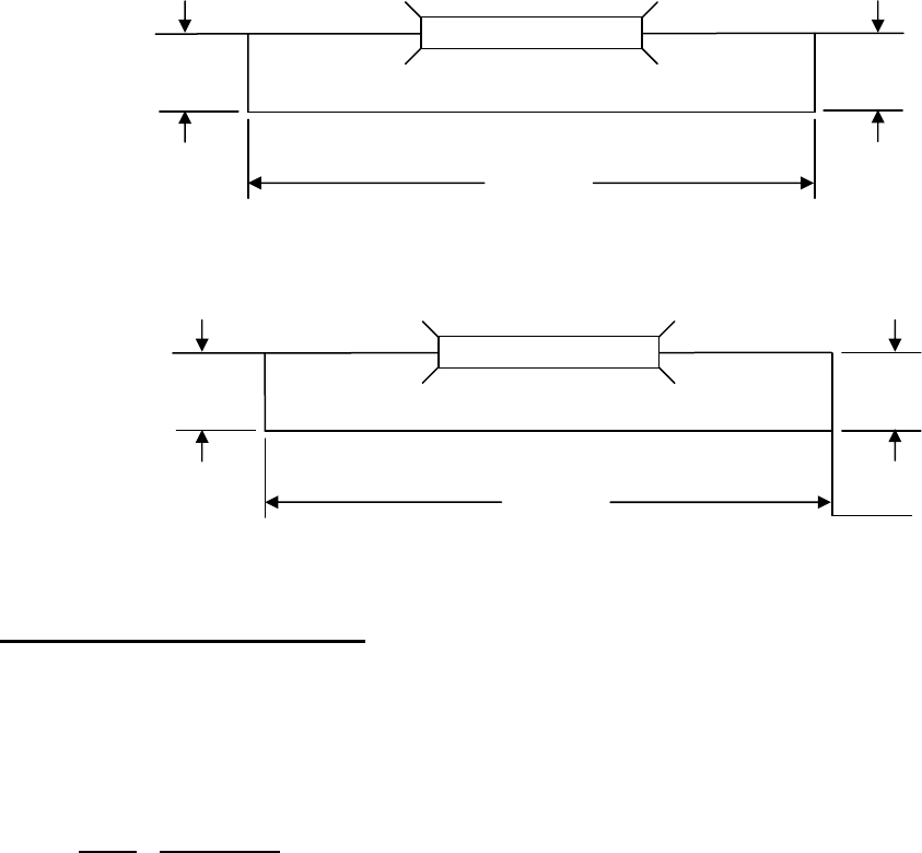
EXAMPLES:
Left Left Median Right Right
Shoulder
Roadway
Shoulders
Roadway
Shoulder
Code
4.0 - - 16 6.0 026
6.0 - - 36 12.0 054
12.0 48 30 48 12.0 150
10.0 24 16 36 10.0 096
The last example above represents the coding method for a structure in which the most restrictive
approach has the cross-section shown below:
Regardless of whether the median is open or closed, the data coded must be compatible with the
other related route and bridge data (i.e., if Item 51 - Bridge Roadway Width, Curb-to-Curb is for traffic
in one direction only, then Items 28, 29, 32, etc. must be for traffic in one direction only).
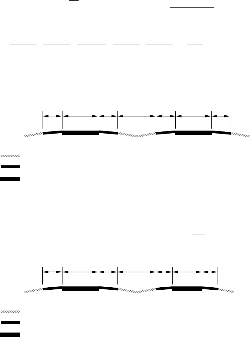
If a ramp is adjacent to the through lanes approaching the structure, it shall be included in the
approach roadway width. The total approach roadway width for the example below is 94 feet (a code
of 094).
EDIT CHECK
A warning is issued if Item 32 is < 8 feet.
A warning is issued if Item 28A is > 3 and Item 32 is 1.5 times or more than Item 51.
A warning is issued if Item 28A <= 3 and Item 32 is 2.0 times or more than Item 51.
8’
10’
36’
8’
varies
24’
10’
-
Median
-
Approach Shoulder
-
Roadway
10’ 10’ varies 48’ 22’ 2’ 2’
-
Median
-
Approach Shoulder
-
Roadway
mainline
ramp
FEDERAL and STATE ITEM NUMBER ORDER Page 3 October 8, 2009
FEDERAL ITEM 33 - BRIDGE MEDIAN - X (1)
INVENTORY – DESIGN
BRIDGEMED
TABLE - BRIDGE
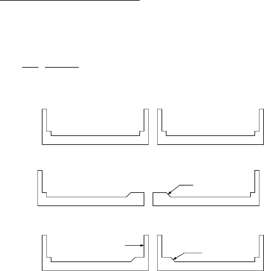
Indicate with a 1-digit code if the median is non-existent, open or closed. The median is closed when
the area between the 2 roadways at the structure is bridged over and is capable of supporting traffic.
All bridges that carry either 1-way traffic or 2-way traffic separated only by a centerline will be coded 0
for no median.
Code
Description
0 No median
1 Open median
2 Closed median (no barrier)
3 Closed median with non-mountable barrier
Open Median
Closed Median
Closed Median with Non-mountable Barrier
Virginia Note: Non-mountable curbs and/or medians will be defined as curbs being greater than 6” in
height.
Mountable
Non-mountable
Mountable

FEDERAL and STATE ITEM NUMBER ORDER Page 4 October 8, 2009
FEDERAL ITEM 34 - SKEW - XX (2)
INVENTORY – DESIGN
SKEW
TABLE - BRIDGE
The skew angle is the angle between the centerline of a pier and a line normal to the roadway
centerline. When plans are available, the skew angle can be taken directly from the plans. If no plans
are available, the angle is to be field measured if possible. Record the skew angle to the nearest
degree. If the skew angle is 0 degrees, it should be so coded. When the structure is on a curve or if
the skew varies for some other reason, the average skew should be recorded, if reasonable.
Otherwise, record 99 to indicate a major variation in skews of substructure units. A 2-digit number
should be coded.
EXAMPLES:
Code
Skew angle 0 degrees
00
10 degrees
10
8 degrees
08
29 degrees
29
FEDERAL ITEM 35 - STRUCTURE FLARED - X (1)
INVENTORY – DESIGN
STRFLARED
TABLE - BRIDGE
Code this item to indicate if the structure is flared (i.e., the width of the structure varies). Generally,
such variance will result from ramps converging with or diverging from the through lanes on the
structure, but there may be other causes. Minor flares at ends of structures should be ignored.
Code
Description
1 Yes, flared
0 No flare

FEDERAL and STATE ITEM NUMBER ORDER Page 5 October 8, 2009
FEDERAL ITEM 36 - TRAFFIC SAFETY FEATURES - XXXX (4)
APPRAISAL – OTHER RATINGS
RAILRATING
TRANSRATIN
ARAILRATIN
AENDRATING
TABLE - INSPEVNT
Bridge inspection shall include the recording of information on the following traffic features so that the
evaluation of their adequacy can be made.
(36A) Bridge railings:
Some factors that affect the proper functioning of bridge railing are height, material,
strength, and geometric features. Railings must be capable of smoothly redirecting
an impacting vehicle. Bridge railings should be evaluated using the current
AASHTO Standard Specifications for Highway Bridges, which calls for railings to
meet specific geometric criteria and to resist specified static loads without
exceeding the allowable stresses in their elements. Bridge railing should be crash
tested per FHWA policy. Railings that meet these criteria and loading conditions
are considered acceptable. Other railings that have been successfully crash
tested are considered acceptable even though they may not meet the static loading
analysis and geometric requirements. Acceptable guidelines for bridge railing
design and testing are also found in the AASHTO Guide Specifications for Bridge
Railings 1989. Additional guidance for testing is found in National Cooperative
Highway Research Program - Report 350 Recommended Procedures for the
Safety Performance Evaluation of Highway Features 1993.
(36B) Transitions:
The transition from approach guardrail to bridge railing requires that the approach
guardrail be firmly attached to the bridge railing. It also requires that the approach
guardrail be gradually stiffened as it comes closer to the bridge railing. The ends
of curbs and safety walks need to be gradually tapered out or shielded.
(36C) Approach guardrail:
The structural adequacy and compatibility of approach guardrail with transition
designs should be determined. Rarely does the need for a barrier stop at the end
of a bridge. Thus, an approach guardrail with adequate length and structural
qualities to shield motorists form the hazards at the bridge site needs to be
installed. In addition to being capable of safely redirecting an impacting vehicle,
the approach guardrail must also facilitate a transition to the bridge railing that will
not cause snagging or pocketing of an impacting vehicle. Acceptable guardrail
design suggestions are contained in the AASHTO Roadside Design Guide and
subsequent FHWA or AASHTO guidelines.
(36D) Approach guardrail ends:
As with guardrail ends in general, the ends of approach guardrails to bridge should
be flared, buried, made breakaway, or shielded. Design treatment of guardrail
ends is given in the AASHTO Roadside Design Guide.

FEDERAL and STATE ITEM NUMBER ORDER Page 6 October 8, 2009
The data collected shall apply only to the route on the bridge. Collision damage or deterioration of the
elements is not considered when coding this item. ‘Traffic Safety Features’ is a 4-digit code composed
of 4 segments.
Segment Description Length
36A Bridge railings 1 digit
36B Transitions 1 digit
36C Approach guardrail 1 digit
36D Approach guardrail ends 1 digit
Virginia Note: The reporting of this feature shall be as follows:
Code Description
0 Inspected feature is in place at all locations and DOES NOT meet currently
acceptable standards at ONE OR MORE locations or inspected feature is not in
place at one or more locations. (See Note Below)
1 Inspected feature is in place at ALL locations and meets currently acceptable
standards at all locations. (See Note Below)
N There is written notice from Traffic Engineering Division that guardrail is not
required. (See Note Below)
NOTE:
For structures on the NHS, national standards are set by regulation. For those
not on the NHS, it shall be the responsibility of the highway agency to set
standards.
CULVERTS
• If the guardrail extends across the fill and all parts of the guardrail are the
same (post spacing, type of rail, etc.) the Bridge Railing and Transition are to
be coded ‘N’ and the Approach Guardrail and End Treatment will be coded ‘1’
or ‘0’ using the criteria shown above.
• If the guardrail is physically attached to the culvert all items will be coded ‘1’ or
‘0’ using the criteria shown above.
EXAMPLE: Code
All feature meet currently acceptable standards except transition 1011
FEDERAL ITEM 37 - HISTORICAL SIGNIFICANCE - X (1)
INVENTORY – CLASSIFICATION
HISTSIGN
TABLE - BRIDGE
The historical significance of a bridge involves a variety of characteristics: the bridge may be a
particularly unique example of the history of engineering; the crossing itself might be significant; the
bridge might be associated with a historical property or area; or historical significance could be derived
from the fact the bridge was associated with significant events or circumstances. Use one of the
following codes:
Code Description
1 Bridge is on the National Register of Historic Places.
2 Bridge is eligible for the National Register of Historic Places.
3 Bridge is possibly eligible for the National Register of Historic Places (requires
further investigation before determination can be made) or bridge is on a State or
local historic register.
4 Historical Significance is not determinable at this time.
5 Bridge is not eligible for the National Register of Historic Places.

FEDERAL and STATE ITEM NUMBER ORDER Page 7 October 8, 2009
FEDERAL ITEM 38 - NAVIGATION CONTROL - X (1)
APPRAISAL – OTHER RATINGS
NAVCNTROL
TABLE - BRIDGE
Indicate for this item whether or not navigation control (a bridge permit for navigation) is required. Use
one of the following codes:
Code Description
N Not applicable, no waterway
0 No navigation control on waterway (bridge permit not required)
1 Navigation control on waterway (bridge permit required)
EDIT CHECK
If Item 38 is = 1 then Item 111 must NOT be blank.
If Item 38 is = 1, then Item 39 must be > 000.
If Item 38 is = 0 or N, then Item 39 must be = 000.
If Item 38 is = 0 or N, then Item 40 must be = 000.
FEDERAL ITEM 39 - NAVIGATION VERTICAL CLEARANCE - XXX (3)
APPRAISAL – OTHER RATINGS
NAVVC
TABLE - BRIDGE
If Item 38 - Navigation Control has been coded 1, record in feet the minimum vertical clearance
imposed at the site as measured above a datum that is specified on a navigation permit issued by a
control agency. The measurement shall be coded as a 3-digit number rounded down to the nearest
foot. This measurement will show the clearance that is allowable for navigational purposes. In the
case of a swing or bascule bridge, the vertical clearance shall be measured with the bridge in the
closed position (i.e., open to vehicular traffic). The vertical clearance of vertical lift bridge shall be
measured with the bridge in the raised or open position. Also, Item 116 - Minimum Navigation Vertical
Clearance Vertical Lift Bridge shall be coded to provide clearance in a closed position. If Item 38 -
Navigation Control has been coded 0 or N, code 000 to indicate not applicable.
EXAMPLES: Code
Measured Vertical Clearance 150.0
150
20.6
020
24.2
024
EDIT CHECK
If Item 38 is = 1, then Item 39 must be > 000.
If Item 38 is = 0 or N, then this Item 39 must be = 000.
A warning is issued if Item 39 is > 250 feet.
FEDERAL ITEM 40 - NAVIGATION HORIZONTAL CLEARANCE - XXXX (4)
APPRAISAL – OTHER RATINGS
NAVHC
TABLE - BRIDGE
If Item 38 - Navigation Control has been coded 1, record the horizontal clearance measurement
imposed at the site that is shown on the navigation permit. This may be less than the structure
geometry allows. If a navigation permit is required but not available, use the minimum horizontal
clearance between fenders, if any, or the clear distance between piers or bents. Code the clearance
as a 4-digit number. Code 0000 if Item 38 - Navigation Control is coded 0 or N.

FEDERAL and STATE ITEM NUMBER ORDER Page 8 October 8, 2009
EXAMPLES: Code
Horizontal Clearance 95 feet
0095
538 feet
0538
1,200 feet
1200
EDIT CHECK
If Item 38 = 1, then this Item 40 must be > 0000.
If Item 38 is = 0 or N, then this Item 40 must be = 000.
A warning is issued if Item 40 is > 1000 feet.
FEDERAL ITEM 41 - OPEN, POSTED, OR CLOSED TO TRAFFIC - X (1)
APPRAISAL – OTHER RATINGS
OPPOSTCL
TABLE - INSPEVNT
This item provides information about the actual operational status of a structure. The field review
could show that a structure is posted, but Item 70 - Bridge Posting may indicate that posting is not
required. This is possible and acceptable coding since Item 70 is based on the operating stress level
and the governing agency's posting procedures may specify posting at some stress level less than the
operating rating. One of the following codes shall be used:
Code Description
A Open, no restriction
B Open, posting recommended but not legally implemented (all signs not in place
or in their correct location)
D Open, would be posted or closed except for temporary shoring, etc. to allow for
unrestricted traffic
E Open, temporary structure in place to carry legal loads while original structure is
closed and awaiting replacement or rehabilitation
G * New structure not yet open to traffic
K * Bridge closed to all traffic
P Posted for load (may include other restrictions such as temporary bridges which
are load posted)
R Posted for other load-capacity restriction (speed, number of vehicles on bridge,
etc.)
* Either of these will cause an ‘*’ to appear in the ‘S’ column on an inquiry list.
EDIT CHECK
If Item 59 = 0 or 1 then Item 41 must = D, E or K.
If Item 60 = 0 or 1 then Item 41 must = D, E or K.
If Item 62 = 0 or 1 then Item 41 must = D, E or K.
If Item 103 = T then Item 41 must = D, E or P.
If Item 41 = E or K then last two digits of Item 64 must = 00.
A warning is issued if any one of Items 41, 58, 59, 60, 62, 67, 68, 69, 70 or 72 is coded 0
and all others are coded >= 2 and Item 42 is NOT = to D, E or K.
A warning is issued if Item 64A = 1 - 6 or 9 and Item 64B = 00 and Item 41 = D or E then
Item 103 must = T.
A warning is issued if Item 41 = B, D, E, P, or R and Item 91 is not less than 24.

FEDERAL and STATE ITEM NUMBER ORDER Page 9 October 8, 2009
FEDERAL ITEM 42 - TYPE OF SERVICE - X X (2)
INVENTORY – ID/ADMIN
SERVTYPON
SERVTYPUND
TABLE - BRIDGE
The type of service on the bridge and under the bridge is indicated by a 2-digit code composed of 2
segments.
Segment
Description Length
42A Type of service on bridge 1 digit
42B Type of service under bridge 1 digit
The first digit indicates the type of service "on" the bridge and shall be coded using one of the
following codes:
Code
Description
1 Highway
2 Railroad
3 Pedestrian – bicycle
4 Highway-railroad
5 Highway-pedestrian
6 Overpass structure at an interchange or second level of multilevel interchange
7 Third level (Interchange)
8 Fourth level (Interchange)
9 Building or plaza
0 Other
The second digit indicates the type of service "under" the bridge and shall be coded using one of the
following codes:
Code
Description
1 Highway, with or without pedestrian
2 Railroad
3 Pedestrian-bicycle
4 Highway-railroad
5 Waterway
6 Highway-waterway
7 Railroad-waterway
8 Highway-waterway-railroad
9 Relief for waterway
0 Other

FEDERAL and STATE ITEM NUMBER ORDER Page 10 October 8, 2009
EDIT CHECK
If Item 28B > 00 then Item 42 must = 1, 4, 6 or 8.
If Item 28B = 00 then Item 42 must = 0, 2, 3, 5, 7 or 9.
If Item 69 is numeric then Item 42 must be 1, 2, 4, 6, 7 or 8.
If Item 71 is numeric then Item 42 must be 5, 6, 7, 8, 9 or 0.
If Item 42B = 5, 6, 7, 8 or 9 then Item 113 must be numeric.
If Item 42B = 1, 2, 3 or 4 then Item 113 must be N.
For an under record, If the first two digits of Item 28 are > 00 then the first digit of Item 42
must be 1, 4, 5, 6, 7 or 8.
For an under record, If the first two digits of Item 28 = 00 then the first digit of Item 42 must
be 2, 3, 9 or 0.
If this Item 28A is = 00 then Item 42A must = 0,2,3 or 9.
FEDERAL ITEM 43 - STRUCTURE TYPE, MAIN - XXX (3)
INVENTORY – DESIGN
MATERIALMAIN
DESIGNMAIN
TABLE - BRIDGE
Record the description on the inspection form and indicate the type of structure for the main span(s)
with a 3-digit code composed of 2 segments.
Segment
Description Length
43A Kind of material and/or design 1 digit
43B Type of design and/or construction 2 digits
The first digit indicates the kind of material and/or design and shall be coded using one of the following
codes:
Code Description
1 Concrete
2 Concrete continuous
3 Steel
4 Steel continuous
5 Prestressed concrete *
6 Prestressed concrete continuous *
7 Wood or Timber
8 Masonry
9 Aluminum, Wrought Iron, or Cast Iron
0 Other
* Post-tensioned concrete should be coded as prestressed concrete.

FEDERAL and STATE ITEM NUMBER ORDER Page 11 October 8, 2009
The second and third digits indicate the predominate type of design and/or type of construction and
shall be coded using one of the following codes:
Code Description
01 Slab
02 Stringer/Multi-beam or Girder
03 Girder and Floorbeam System
04 Tee Beam (See Virginia Note Below)
05 Box beam or Girders - Multiple
06 Box beam or Girders - Single or Spread
07 Frame (except frame culverts)
08 Orthotropic
09 Truss – Deck
10 Truss – Thru
11 Arch – Deck
12 Arch – Thru
13 Suspension
14 Stayed Girder
15 Movable – Lift
16 Movable – Bascule
17 Movable – Swing
18 Tunnel
19 Culvert (includes frame culverts)
20 Mixed types – Applicable only to approach spans (Item 44)
21 Segmental Box Girder
22 Channel Beam
00 Other
EXAMPLE: Code
Timber Through Truss 710
Masonry Culvert 819
Steel Suspension 313
Continuous Concrete Multiple Box Girders 205
Simple Span Concrete Slab 101
Tunnel Rock 018
EDIT CHECK
If Item 51 = 0000 then Item 43B must = 19
If Item 52 = 0000 then Item 43B must = 19
If Item 43B = 19 then Item 58 must = N.
If Item 43B = 19 then Item 59 must = N.
If Item 43B = 19 then Item 60 must = N.
If Item 43B = 19 then Item 62 must be numeric.
If Item 43B = 15 then Item 116 must NOT be blank.
Virginia Note: Not to be used for Prestressed Bulb-T girders. Code Prestressed Bulb-T girders as
502 or 602

FEDERAL and STATE ITEM NUMBER ORDER Page 12 October 8, 2009
FEDERAL ITEM 44 - STRUCTURE TYPE, APPROACH SPANS - XXX (3)
INVENTORY – DESIGN
MATERIALAPPR
DESIGNAAPPR
TABLE - BRIDGE
Indicate with a 3-digit code composed of 2 segments, the type of structure for the approach spans to a
major bridge or for the spans where the structural material is different. The codes are the same as for
Item 43 preceding. However, code 000 if this item is not applicable. Use code 20 (Item 44B) when no
one type of design and/or construction is predominate for the approach units. If the kind of material
(Item 44A) is varied, code the most predominant.
Segment Description Length
44A Kind of material and/or design 1 digit
44B Type of design and/or construction 2 digits
EXAMPLES: Code
Simple prestressed concrete I-beam 502
Continuous concrete T-beam 204
Continuous steel deck truss 409
FEDERAL ITEM 45 - NUMBER OF SPANS IN MAIN UNIT - XXX (3)
INVENTORY – DESIGN
MAINSPANS
TABLE - BRIDGE
Record the number and indicate with a 3-digit number the number of spans in the main or major unit.
This item will include all spans of most bridges, the major unit only of a sizable structure, or a unit of
material or design different from that of the approach spans.
EDIT CHECK
A warning is issued if Item 45 is > 50 feet.
FEDERAL ITEM 46 - NUMBER OF APPROACH SPANS - XXXX (4)
INVENTORY – DESIGN
APPSPANS
TABLE - BRIDGE
Record the number and indicate with a 4-digit number the number of spans in the approach spans to
the major bridge, or the number of spans of material different from that of the major bridge.
EDIT CHECK
A warning is issued if Item 46 is > 50 feet.
FEDERAL ITEM 47 - INVENTORY ROUTE, TOTAL HORIZONTAL CLEARANCE - XX.X (3)
INVENTORY – ROADS
HCLRINV
TABLE - ROADWAY
The total horizontal clearance for the inventory route identified in Item 5 should be measured and
recorded. The clearance should be the available clearance measured between the restrictive features
-- curbs, rails, walls, piers or other structural features limiting the roadway (surface and shoulders).
The measurement should be recorded and coded to the nearest tenth of a foot. When the restriction
is 100 feet or greater, code 999. Flush and mountable medians are not considered to be restrictions.
The purpose of this item is to give the largest available clearance for the movement of wide loads.
This clearance has been identified in 2 ways; use the most applicable:
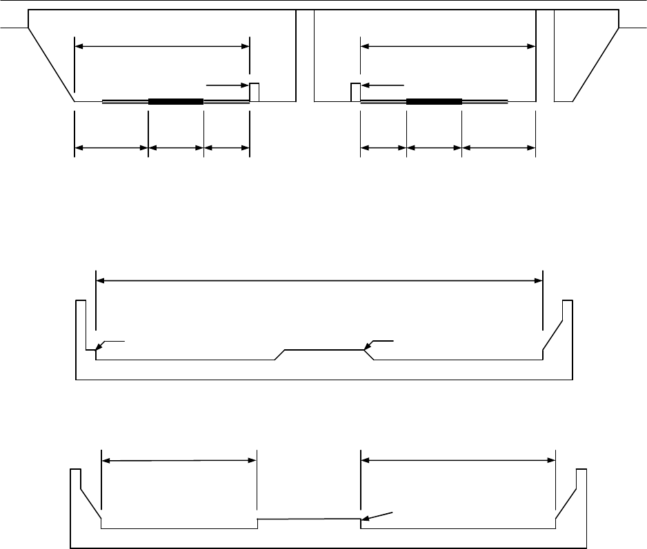
FEDERAL and STATE ITEM NUMBER ORDER Page 13 October 8, 2009
1.
Clear distance between restrictions of the inventory route either “on” or “under” the
structure.
2.
Roadway surface and shoulders – when there are no restrictions.
For a divided facility with a raised or non-mountable median, or an “under” route divided by piers,
record the greater of the restricted widths in either direction, not both directions.
EXAMPLES:
NOTE: IGNORE GUARDRAILS FOR THIS ITEM.
No Median or Flush or Mountable Median
Raised Median or Non-mountable Median
B > A Item 47 = B
Virginia Note: Non-mountable curbs and/or medians will be defined as curbs being greater than 6” in
height.
Clearance A > B Item 47 = A
A
B
29.1’ 18.2’ 24’ 19.3’ 24’ 20.4’
*
*
*
-
Face of a rigid barrier, not face of guardrail.
Item 47
Non
-
mountable Curb
Mountable Median
Non-Mountable Median
A
B

FEDERAL and STATE ITEM NUMBER ORDER Page 14 October 8, 2009
EDIT CHECK
If Item 100 = 1 or 2 then Item 47 must be > 000.
A warning is issued if Item 47 is < 8 feet.
FEDERAL ITEM 48 - LENGTH OF MAXIMUM SPAN - XXXX (4) (FEET)
INVENTORY – DESIGN
MAXSPAN
TABLE - BRIDGE
The length of the maximum span shall be recorded. It shall be noted whether the measurement is
center-to-center of bearing points or clear open distance between piers, bents, or abutments. The
measurement shall be along the centerline of the bridge. For this item, code a 4-digit number to
represent the measurement to the nearest foot.
EXAMPLES: Code
Length of Maximum 50 feet
0050
117 feet
0117
1,050 feet
1050
EDIT CHECK
Item 48 must be <= Item 49.
A warning is issued if Item 48 is > 1000 feet.
FEDERAL ITEM 49 - STRUCTURE LENGTH - XXXXXX (6) (FEET)
INVENTORY – DESIGN
LENGTH
TABLE - BRIDGE
Record and code a 6-digit number to represent the length of the structure to the nearest foot. This
shall be the length of roadway that is supported on the bridge structure. The length should be
measured back to back of backwalls of abutments or from paving notch to paving notch.
Culvert length should be measured along the centerline of roadway regardless of their depth below
grade. Measurement should be made between inside faces of exterior walls. Tunnel length should be
measured along the centerline of the roadway. Be sure to code Item 5A = 2 for all tunnels.
EXAMPLES: Code
Structure Length 50 feet
000050
5,421 feet
005421
333 feet
000333
101,235 feet
101235
EDIT CHECK
Item 48 must be <= Item 49.
If Item 112 = Y then Item 49 must be >= 20
A warning is issued if Item 49 is > 4000 feet.
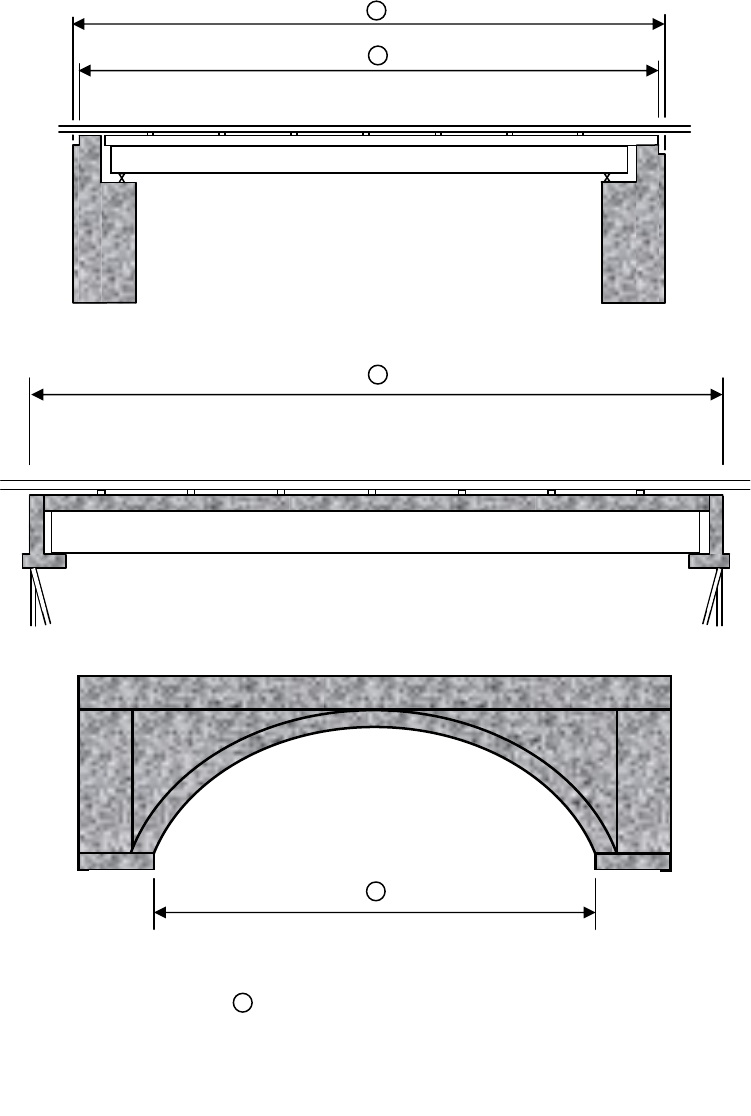
FEDERAL and STATE ITEM NUMBER ORDER Page 15 October 8, 2009
1
1
1
1
Item 49 - Structure Length
1

FEDERAL and STATE ITEM NUMBER ORDER Page 16 October 8, 2009
1
SECTION A
-
A
Centerline Roadway
A A
30º
Item 49 Structure Length = 18’ = 20.78’ Code
cos 30º 000021
1
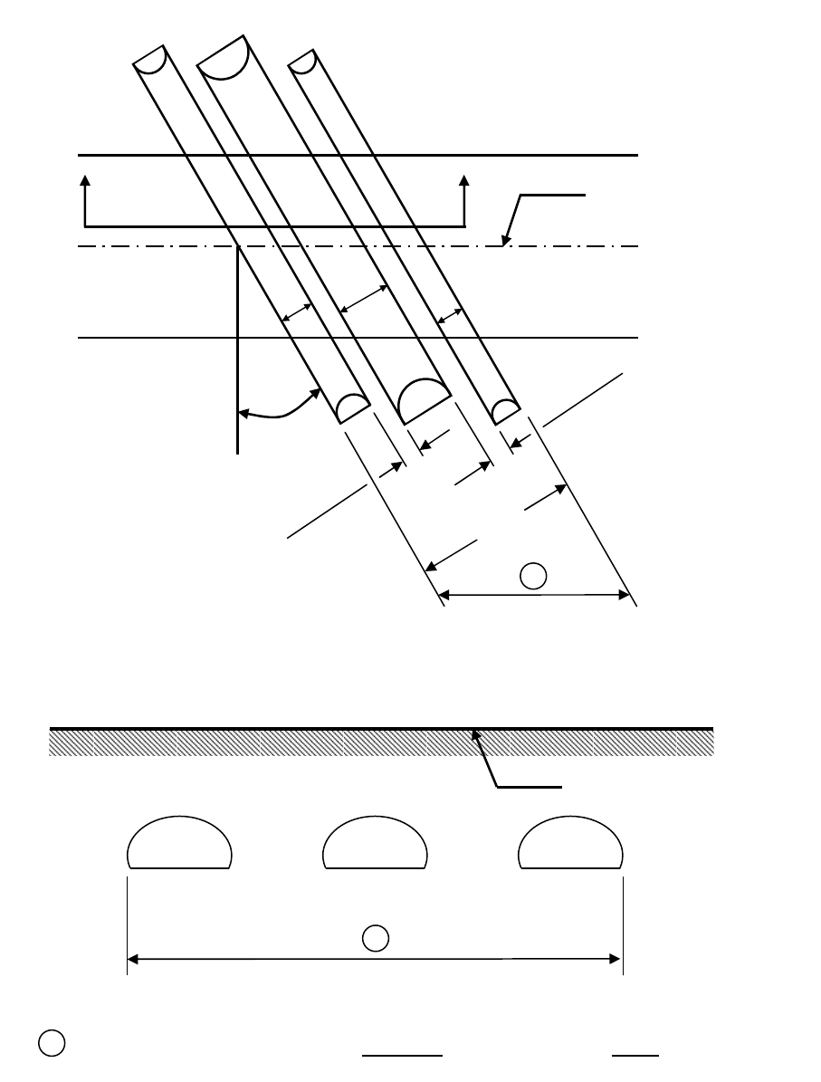
FEDERAL and STATE ITEM NUMBER ORDER Page 17 October 8, 2009
Item 49 Structure Length = 18’ = 20.78’ Code
cos 30
º 000021
SECTION B - B
Centerline Roadway
1
0.5’
0.5’
Centerline Roadway
B B
30º
5’ 7’ 3’
16.0’
1
1
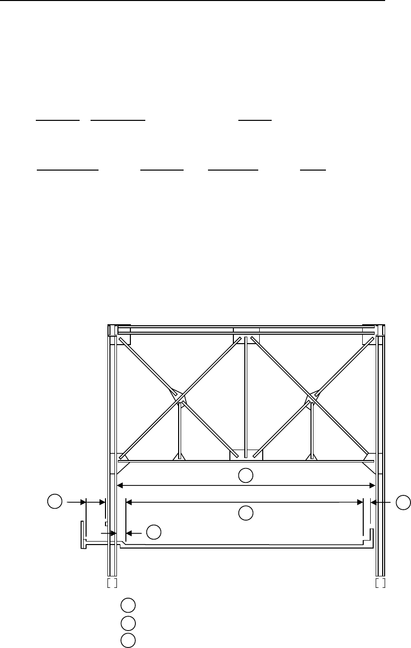
FEDERAL and STATE ITEM NUMBER ORDER Page 18 October 8, 2009
FEDERAL ITEM 50 - CURB OR SIDEWALK WIDTHS - XX.X XX.X (6) (FEET)
INVENTORY – DESIGN
LFTCURBSW
RTCURBSW
TABLE - BRIDGE
Record and code two contiguous 3-digit numbers to represent the widths of the left and right curbs or
sidewalks to nearest tenth of a foot. This is a 6-digit number composed of two segments, with the
leftmost 3 digits representing the left curb or sidewalk and the rightmost 3 digits representing the right
curb or sidewalk. "Left" and "Right" should be determined on the basis of direction of the inventory.
Segment
Description Length
50A Left curb or sidewalk width 3 digits
50B Right curb or sidewalk width 3 digits
EXAMPLES: Left Side Right Side Code
Curb or sidewalk None
8.3'
000083
10.0'
4.1'
100041
8.3'
None
083000
2.1'
11.5'
121115
None
None
000000
0.6'
1.5'
006015
EDIT CHECK
A warning is issued if Item 50A is > 12 feet.
A warning is issued if Item 50B is > 12 feet.
Item 51 – Bridge Roadway Width, Curb to Curb
Item 52 – Deck Width, Out-to-Out
Item 50, Curb or Sidewalk Width
3
1
2
3
3
3
2
1
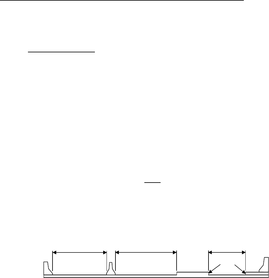
FEDERAL and STATE ITEM NUMBER ORDER Page 19 October 8, 2009
FEDERAL ITEM 51 - BRIDGE ROADWAY WIDTH, CURB-TO-CURB - XXX.X (4)
INVENTORY – ROADS
ROADWIDTH
TABLE - ROADWAY
The information to be recorded is the most restrictive minimum distance between curbs or rails on the
structure roadway. For structures with closed medians and usually for double decked structures,
coded data will be the sum of the most restrictive minimum distances for all roadways carried by the
structure except as noted below. The data recorded for this item must be compatible with other
related route and bridge data (i.e. Items 28, 29, 32, etc.). The measurement should be exclusive of
flared areas for ramps. A 4-digit number should be used to represent the distance to the nearest tenth
of a foot.
Where traffic runs directly on the top slab (or wearing surface) of a culvert-type structure, e.g. an R/C
box without fill, code the actual roadway width (curb-to-curb or rail-to-rail). This will also apply where
the fill is minimal and headwalls or parapets affect the flow of traffic.
Where the roadway is on fill carried across a structure and the headwalls or parapets do not affect the
flow of traffic, code 0000. This is considered proper inasmuch as a filled section simply maintains the
roadway cross-section. However, for sidehill viaduct structures code the actual full curb-to-curb
roadway width. See figure in Federal Coding Guide Appendix D.
NOTE:
Raised or non-mountable medians, open medians, and barrier widths are to be
excluded from the summation along with barrier-protected bicycle and equestrian lanes.
EXAMPLES: Code
Bridge Roadway Width 36.00' wide
0360
66.37' wide
0664
110.13' wide
1101
The last example above would be the coded value for the deck section shown below.
Virginia Note: Non-mountable curbs and/or medians will be defined as curbs being greater than 6” in
height.
(For detail example refer to sketches throughout this section)
EDIT CHECK
Item 51 must be <= Item 52.
If Item 51 = 0000 then Item 43B must = 19
A warning is issued if Item 51 is > 150 feet or < 9 feet and not = 0000.
A warning is issued if Item 28A is > 3 and Item 32 is 1.5 times or more than Item 51.
A warning is issued if Item 28A <= 3 and Item 32 is 2.0 times or more than Item 51.
Non-
Mountable
16.13’
50.00’
44.00’

FEDERAL and STATE ITEM NUMBER ORDER Page 20 October 8, 2009
FEDERAL ITEM 52 - DECK WIDTH, OUT-TO-OUT - XXX.X (4)
INVENTORY – DESIGN
DECKWIDTH
TABLE - BRIDGE
Record and code a 4-digit number to show the out-to-out width to the nearest tenth of a foot. If the
structure is a through structure, the number to be coded will represent the lateral clearance between
superstructure members. The measurement should be exclusive of flared areas for ramps. (For detail
examples refer to Federal Items 50, 51 and 52)
Where traffic runs directly on the top slab (or wearing surface) of the culvert (e.g., an R/C box without
fill) coded the actual width (out-to-out). This will also apply where the fill is minimal and the culvert
headwalls affect the flow of traffic. However, for sidehill viaduct structures code the actual out-to-out
structure width. See figure in Federal Coding Guide Appendix D.
Where the roadway is on a fill carried across a pipe or box culvert and the culvert headwalls do not
affect the flow of traffic, code 0000. This is considered proper inasmuch as a filled section over a
culvert simply maintains the roadway cross-section.
EDIT CHECK
Item 51 must be <= Item 52.
If Item 52 = 0000 then Item 43B must = 19
A warning is issued if Item 52 is > 150 feet or < 9 feet and not = 0000.

FEDERAL and STATE ITEM NUMBER ORDER Page 21 October 8, 2009
2
1
1
2
3
1
2
3
1
2
Mountable Median
2
1c
3 1b
1a
1c 1b
1a 1
=
+
+
1c
1b
1a 1
=
+
+
Non-
Mountable
2
1c 3
1b
1a
2c
1b
varies
1a
2a 2b
1b
1a 1
=
+
2c
2b 2a
2
=
+
+
1
2
3
Item 51 – Bridge Roadway Width, Curb-toCurb
Item 52 – Deck Width, Out-to-Out
Item 50 – Curb or Sidewalk Width

FEDERAL and STATE ITEM NUMBER ORDER Page 22 October 8, 2009
FEDERAL ITEM 53 - MINIMUM VERTICAL CLEARANCE OVER BRIDGE ROADWAY - XX XX (4)
APPRAISAL – OTHER RATINGS
VCLROVER
TABLE - BRIDGE
The information to be recorded for this item is the actual minimum vertical clearance over the bridge
roadway, including shoulders, to any superstructure restriction, rounded down to the nearest inch. For
double decked structures code the minimum, regardless whether it is pertaining to the top or bottom
deck. Coding of actual clearances between 100 feet and 300 feet to an exact measurement is
optional (see Virginia Note below). When no superstructure restriction exists above the bridge
roadway, code 9999. A 4-digit number should be coded to represent feet and inches.
Virginia Note: When no restriction exists above the bridge roadway, or when a restriction is 100 feet
or greater code 9999. The restriction should be measured to any item that creates a
vertical clearance restriction including ancillary structures.
See Virginia Note under Federal Item 54.
EXAMPLES: Code
Minimum Vertical Clearance 17'-3" 1703
75'-11" 7511
No restriction 9999
115'-6" 9999
EDIT CHECK
A warning is issued if Item 53 is < 7 feet.
FEDERAL ITEM 54 - MINIMUM VERTICAL UNDERCLEARANCE - X XX(feet) XX(inches) (5)
APPRAISAL – OTHER RATINGS
REFVUC
VCLRUNDER
TABLE - BRIDGE
Using a 1-digit code and a 4-digit number, record and code the minimum vertical clearance from the
roadway (travel lanes only – See Virginia Notes below) or railroad track beneath the structure to the
underside of the superstructure. (When both a railroad and highway are under the structure, code the
most critical dimension.)
Segment Description Length
54A Reference feature 1 digit
54B Minimum Vertical Underclearance 4 digit
Using one of the codes below, code in the first position, the reference feature from which the
clearance measurement is taken:
Code Description
H Highway beneath structure
R Railroad beneath structure
N Feature not a highway or railroad
In the next 4 positions, code a 4-digit number to represent the minimum vertical clearance from that
feature to the structure. Coding of actual clearances between 100 feet and 300 feet to an exact
measurement is optional. If the feature is not a highway or railroad, code the minimum vertical
clearance 0000.
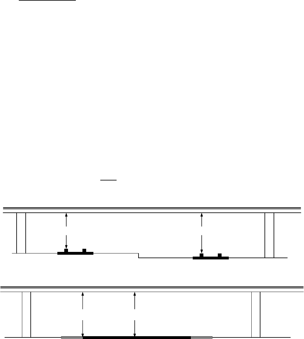
FEDERAL and STATE ITEM NUMBER ORDER Page 23 October 8, 2009
Virginia Note: When a restriction is 100 feet or greater code 9912. For clearances less than or equal
to 25 feet the clearance should be measured and recorded. For clearances between
25 feet and 100 feet the clearance should be measured directly or estimated from the
plans and recorded.
Where to measure
The traveled part of the roadway and/or the travel lane will include the width of traffic
lanes and the widths of shoulders where shoulders are defined as follows:
Shoulders must be constructed and normally maintained flush
with the adjacent traffic lane, and must be structurally adequate
for all weather and traffic conditions consistent with the facility
carried.
Unstabilized grass or dirt, with no base course, flush with and
beside the traffic lane is not to be considered a shoulder.
Therefore, measurements for all vertical clearances should be checked across all
portions of the 'traveled part of the roadway' and/or 'travel lane', as defined above, and
the minimum clearance recorded for the item which is being checked (Federal Item 10,
Federal Item 53, Federal Item 54, State Item 36 and State Item 37). Of course, if edge
of pavement is behind the face of a guardrail then stop at the face of the guardrail.
When on a bridge deck measurements will be checked from face of parapet/railing to
face of parapet/railing. I have checked Manual 90, the 'Recording and Coding Guide
for the Structure Inventory and Appraisal of the Nation's Bridges', the 'Manual for
Condition Evaluation of Bridges' and I have checked with Claude Napier concerning
this. He agrees with this definition and method.
EXAMPLES: Code
River beneath structure N000
Railroad 31'- 3" beneath structure R3103
Highway 34'- 4" beneath structure 3404
EDIT CHECK
A warning is issued if Item 54B is < 7 feet and not = 0000.
31’
–
3”
34’- 6”
34’- 4” 34’- 9”

FEDERAL and STATE ITEM NUMBER ORDER Page 24 October 8, 2009
FEDERAL ITEM 55 - MINIMUM LATERAL UNDERCLEARANCE ON RIGHT - X XX.X (4)
APPRAISAL – OTHER RATINGS
REFHUC
HCLRURT
TABLE - BRIDGE
Using a 1-digit code and a 3-digit number, record and code the minimum lateral underclearance on the
right to the nearest tenth of a foot. When both a railroad and highway are under the structure, code
the most critical dimension (Refer to Item 69 – Underclearances, Horizontal – Table 3B).
Segment
Description Length
55A Reference feature 1 digit
55B Minimum Lateral Underclearance 3 digit
Using one of the codes below, code in the first position the reference feature from which the clearance
measurement is taken:
Code
Description
H Highway beneath structure
R Railroad beneath structure
N Feature not a highway or railroad
In the next 3 positions, code a 3-digit number to represent the minimum lateral underclearance on the
right. The lateral clearance should be measured from the right edge of the roadway (excluding
shoulders) or from the centerline (between rails) of the right-hand track of a railroad to the nearest
substructure unit (pier, abutment, etc.), to a rigid barrier, or to the toe of slope steeper than 3 to 1 (e.g.
1 to 1 or 2 to 1). The clearance measurements to be recorded will be the minimum after measuring
the clearance in both directions of travel. In the case of a dual highway this would mean the outside
clearances of both roadways should be measured and the smaller distance recorded and coded.
If two related features are below the bridge, measure both and record the lesser of the 2. An
explanation should be written as to what was recorded. When the clearance is 99.9 feet or greater,
code 999.
If the feature beneath the structure is not a railroad or highway, code 000 to indicate not applicable.
The presence of ramps and acceleration or turning lanes is not considered in this item; therefore, the
minimum lateral clearance on the right should be measured from the right edge of the through
roadway.
EXAMPLES: Code
Railroad 29.4' centerline to pier R204
Highway 20.2' edge of pavement to pier H202
Creek beneath structure N000
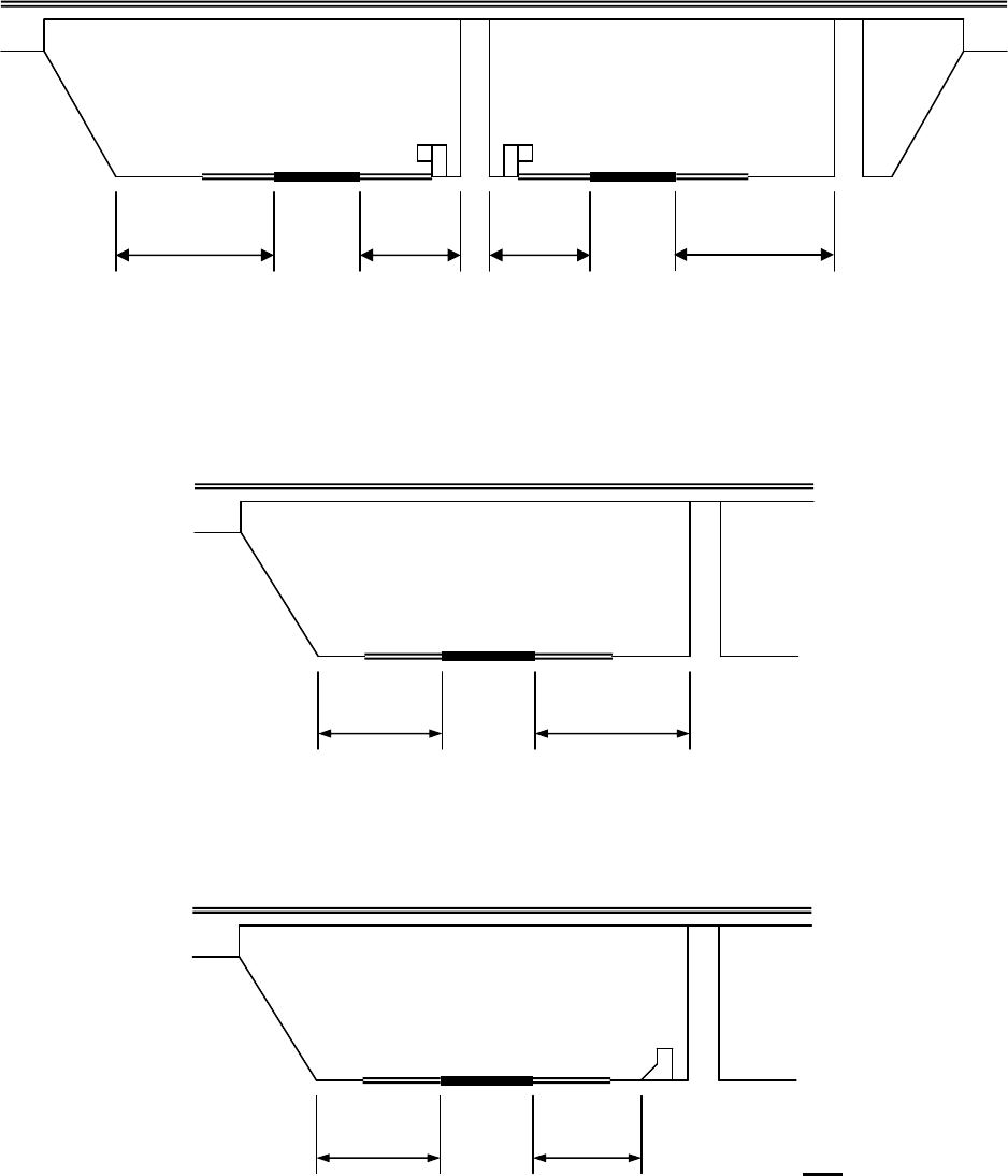
FEDERAL and STATE ITEM NUMBER ORDER Page 25 October 8, 2009
EXAMPLES:
18.2' Left
20.4' Right
NOTE: IGNORE GUARDRAILS FOR THIS ITEM.
-- Left
15.1 Right for 2-way traffic
15.1 Left
20.1 Right for 1-way traffic
-- Left
14.6 Right for 2-way traffic
15.1 Left
14.6 Right for 1-way traffic
2:1 Slope
*
-
Non
-
rigid barrier (examp
le
-
guardrail)
21.1’
18.2’
19.3’
20.4’
* *
2:1 Slope
15.1’ 20.1’
*
* - Rigid barrier
Not guardrail
15.1’ 14.6’
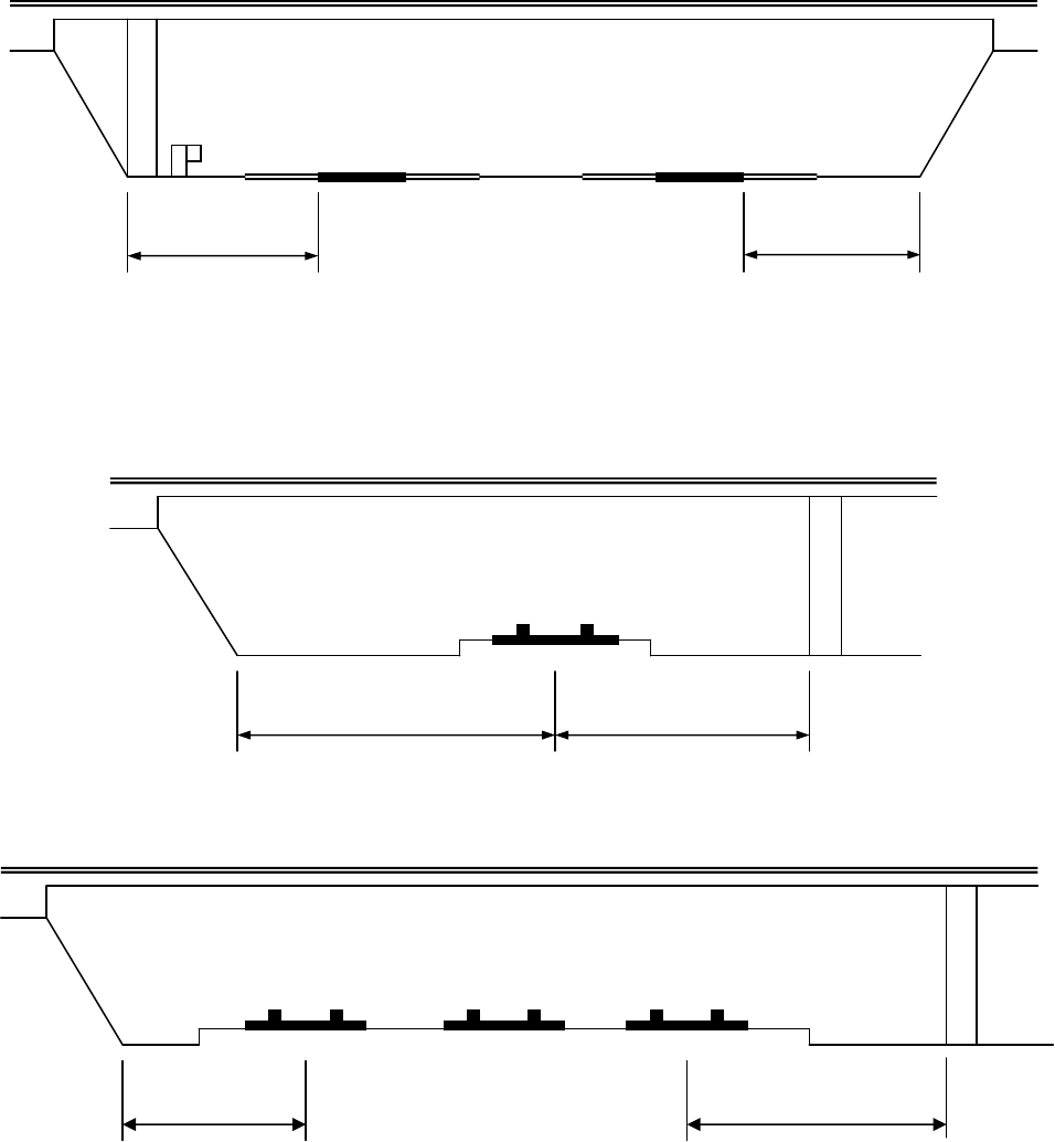
FEDERAL and STATE ITEM NUMBER ORDER Page 26 October 8, 2009
OPEN Left
20.2' Right
NOTE: Instructions state that left would be noted as "Open". Coding should be 99.9
-- Left
20.4' Right
-- Left
20.4' Right
2:1 Slope *
*
-
Non
-
rigid barrier (example
-
guardrail)
20.2’
21.4’
2:1 Slope
30.5’
20.4’
2:1
Slope
20.
4
30.2’

FEDERAL and STATE ITEM NUMBER ORDER Page 27 October 8, 2009
FEDERAL ITEM 56 - MINIMUM LATERAL UNDERCLEARANCE ON LEFT - XX.X (3)
APPRAISAL – OTHER RATINGS
REFHUC
HCLRULT
TABLE - BRIDGE
(code only for divided highway, 1-way streets, and ramps; not applicable to railroads)
Using a 3-digit number, record and code the minimum lateral underclearance on the left (median side
for divided highways) to the nearest tenth of a foot. The lateral clearance should be measured from
the left edge of the roadway (excluding shoulders) to the nearest substructure unit, to a rigid barrier, or
aid the toe of slope steeper than 3 to 1. Refer to examples on page 34 under Item 55 - Minimum
Lateral Underclearance on Right.
In the case of a dual highway, the median side clearances of both roadways should be measured and
the smaller distance recorded and coded. If there is no obstruction in the median area, a notation of
"open" should be recorded and 999 should be coded. For clearance greater than 99.8 feet, code 998.
Code 000 to indicate not applicable.
GENERAL CONDITION RATINGS
In order to promote uniformity between bridge inspectors, these guidelines will be used to rate and
code items 58, 59, 60, 61 and 62.
Condition ratings are used to describe the existing, in-place bridge as compared to the as-built
condition. Evaluation is for the materials related, physical condition of the deck, superstructure and
substructure components of a bridge. The condition evaluation of channels and channel protection
and culverts is also included. Condition codes are properly used when they provide an overall
characterization of the general condition of the entire component being rated. Conversely, they are
improperly used if they attempt to describe localized or nominally occurring instances of deterioration
or disrepair. Correct assignment of a condition code must, therefore, consider both the severity of the
deterioration or disrepair and the extent to which it is widespread throughout the component being
rated.
The load carrying capacity will not be used in evaluating condition items. The fact that a bridge was
designed for less than current legal loads and may be posted shall have no influence upon condition
ratings.
Portions of bridges that are being supported or strengthened by temporary members will be rated
based on their actual condition; that is, the temporary members are not considered in the rating of the
item. (See Item 103 - Temporary Structure Designation for the definition of a temporary bridge.)
Completed bridges not yet opened to traffic, if rated, shall be coded as if open to traffic.
The following general condition ratings shall be used as a guide in evaluating Items 58, 59, 60, 61 and
62:

FEDERAL and STATE ITEM NUMBER ORDER Page 28 October 8, 2009
Code
Description
N NOT APPLICABLE
9 EXCELLENT CONDITION
8 VERY GOOD CONDITION
No problems noted.
7 GOOD CONDITION
Some minor problems.
6 SATISFACTORY CONDITION
Structural elements show some minor deterioration.
5 FAIR CONDITION
All primary structural elements are sound but may have some minor section loss,
cracking, spalling or scour
4 POOR CONDITION
Advanced section loss, deterioration, spalling or scour.
3 SERIOUS CONDITION
Loss of section, deterioration, spalling or scour has seriously affected primary
structural components. Local failures are possible. Fatigue cracks in steel or
shear cracks in concrete may be present.
2 CRITICAL CONDITION
Advanced deterioration of primary structural elements. Fatigue cracks in steel or
shear cracks in concrete may be present or scour may have removed
substructure support. Unless closely monitored it may be necessary to close the
bridge until corrective action is taken.
1 "IMMINENT" FAILURE CONDITION
Major deterioration or section loss present in critical structural components or
obvious vertical or horizontal movement affecting structure stability. Bridge is
closed to traffic but corrective action may put back in light service.
0 FAILED CONDITION
Out of service - beyond corrective action.
FEDERAL ITEM 58 - DECK - X (1)
CONDITION
DKRATING
TABLE - INSPEVNT
This item describes the overall condition rating of the deck. Rate and code the condition in
accordance with the above general condition ratings. Code N for all culverts.
Concrete decks should be inspected for cracking, scaling, spalling, leaching, chloride contamination,
potholing, delamination, and full or partial depth failures. Steel grid decks should be inspected for
broken welds, broken grids, section loss, and growth of filled grids from corrosion. Timber decks
should be inspected for splitting, crushing, fastener failure, and deterioration from rot.
The condition of the wearing surface/protective system, joints, expansion device, curbs, sidewalks,
parapets, fascias, bridge rail, and scuppers shall not be considered in the overall deck evaluation.
However, their condition should be noted on the inspection form.
Decks integral with the superstructure will be rated as a deck only and not how they may influence the
superstructure rating (for example, rigid frame, slab, deck girder or T-beam, void slab, box girder, etc.).
Similarly, the superstructure of an integral deck-type bridge will not influence the deck rating.

FEDERAL and STATE ITEM NUMBER ORDER Page 29 October 8, 2009
EDIT CHECK
If Item 58 is < = 3 then Item 70 must be < 5.
If Item 43B = 19 then Item 58 must = N.
A review flag occurs if Item 27 is younger than 4 years old or equal to current year and
any one Item 58 through Item 62 or any one Item 67 through Item 72 is < 5 and not N.
A warning is issued if any one of Items 41, 58, 59, 60, 62, 67, 68, 69, 70 or 72 is coded 0
and all others are coded >= 2 and Item 42 is NOT = to D, E or K.
FEDERAL ITEM 59 - SUPERSTRUCTURE - X (1)
CONDITION
SUPRATING
TABLE - INSPEVNT
This item describes the physical condition of all structural members. Rate and code the condition in
accordance with the described general condition ratings. Code N for all culverts.
The structural members should be inspected for signs of distress that may include cracking,
deterioration, section loss, and malfunction and misalignment of bearings.
The condition of bearings, joints, paint system, etc. shall not be included in this rating, except in
extreme situations, but should be noted on the inspection form.
On bridges where the deck is integral with the superstructure, the superstructure condition rating may
be affected by the deck condition. The resultant superstructure condition rating may be lower than the
deck condition rating where the girders have deteriorated or been damaged. Fracture critical
components should receive careful attention because failure could lead to collapse of a span or the
bridge.
EDIT CHECK
If Item 59 = 0 or 1 then Item 41 must = D, E or K.
If Item 59 is < = 3 then Item 70 must be < 5.
If Item 43B = 19 then Item 59 must = N.
A review flag occurs if Item 27 is younger than 4 years old or equal to current year and
any one Item 58 through Item 62 or any one Item 67 through Item 72 is < 5 and not N.
A warning is issued if any one of Items 41, 58, 59, 60, 62, 67, 68, 69, 70 or 72 is coded 0
and all others are coded >= 2 and Item 42 is NOT = to D, E or K.
A warning is issued if Item 70 = 5 and Item 59 = 0, 1, 2 or 3.
FEDERAL ITEM 60 - SUBSTRUCTURE - X (1)
CONDITION
SUBRATING
TABLE - INSPEVNT
This item describes the physical condition of piers, abutments, piles, fenders, footings, or other
components. Rate and code the condition in accordance with the previously described general
condition ratings. Code N for all culverts.
All substructure elements should be inspected for visible signs of distress including evidence of
cracking, section loss, settlement, misalignment, scour, collision damage, and corrosion. The rating
given by Item 113 - Scour Critical Bridges, may have a significant effect on Item 60 if scour has
substantially affected the overall condition of the substructure.
The substructure condition rating shall be made independent of the deck and superstructure.
Integral-abutment wingwalls to the first construction or expansion joint shall be included in the
evaluation (i.e. wings poured separately and falling away from the substructure unit will not affect the

FEDERAL and STATE ITEM NUMBER ORDER Page 30 October 8, 2009
condition rating of the substructure). For non-integral superstructure and substructure units, the
substructure shall be considered as the portion below the bearings. For structures where the
substructure and superstructure are integral, the substructure shall be considered as the portion below
the superstructure.
EDIT CHECK
If Item 60 = 0 or 1 then Item 41 must = D, E or K.
If Item 60 is < = 3 then Item 70 must be < 5.
If Item 43B = 19 then Item 60 must = N.
A review flag occurs if Item 27 is younger than 4 years old or equal to current year and any
one Item 58 through Item 62 or any one Item 67 through Item 72 is < 5 and not N.
A warning is issued if any one of Items 41, 58, 59, 60, 62, 67, 68, 69, 70 or 72 is coded 0
and all others are coded >= 2 and Item 42 is NOT = to D, E or K.
A warning is issued if Item 70 = 5 and Item 60 = 0, 1, 2 or 3.
FEDERAL ITEM 61 - CHANNEL AND CHANNEL PROTECTION - X (1)
CONDITION
CHANRATING
TABLE - INSPEVNT
This item describes the physical conditions associated with the flow of water through the bridge such
as stream stability and the condition of the channel, riprap, slope protection, or stream control devices
including spur dikes. The inspector should be particularly concerned with visible signs of excessive
water velocity that may affect undermining of slope protection or footings, erosion of banks, and
realignment of the stream that may result in immediate or potential problems. Accumulation of drift
and debris on the superstructure and substructure should be noted on the inspection form but not
included in the condition rating.

FEDERAL and STATE ITEM NUMBER ORDER Page 31 October 8, 2009
Rate and code the condition in accordance with the previously described general condition ratings and
the following descriptive codes:
Code Description
N Not applicable. Use only when the bridge is not over a waterway.
9 There are no noticeable or noteworthy deficiencies, which affect the condition of
the channel.
8 Banks are protected or well vegetated. River control devices such as spur dikes
and embankment protection are not required or are in a stable condition.
7 Bank protection is in need for minor repairs. River control devices and
embankment protection have a little minor damage. Banks and/or channel have
minor amounts of drift.
6 Bank is beginning to slump. River control devices and embankment protection
have widespread minor damage. There is minor streambed movement evident.
Debris is restricting the waterway slightly.
5 Bank protection is being eroded. River control devices and/or embankment have
major damage. Trees and brush restrict the channel.
4 Bank and embankment protection is severely undermined. River control devices
have severe damage. Large deposits of debris are in the waterway.
3 Bank protection has failed. River control devices have been destroyed.
Streambed aggravation, degradation or lateral movement has change the
waterway to now threaten the bridge and/or approach roadway.
2 The waterway has changed to the extent the bridge is near a state of collapse.
1 Bridge closed because of channel failure. Corrective action may put back in light
service.
0 Bridge closed because of channel failure. Replacement necessary.
EDIT CHECK
If Item 61 is < = 3 then Item 70 must be < 5.
A review flag occurs if Item 27 is younger than 4 years old or equal to current year and
any one Item 58 through Item 62 or any one Item 67 through Item 72 is < 5 and not N.

FEDERAL and STATE ITEM NUMBER ORDER Page 32 October 8, 2009
FEDERAL ITEM 62 - CULVERTS - X (1)
CONDITION
CULVRATING
TABLE - INSPEVNT
This item evaluates the alignment, settlement, joints, structural condition, scour, and other items
associated with culverts. The rating code is intended to be an overall condition evaluation of the
culvert. Integral wingwalls to the first construction or expansion joint shall be included in the
evaluation. For a detailed discussion regarding the inspection and rating of culverts, consult Report
No. FHWA-IP-2, Culvert Inspection Manual, July 1986.
Item 58 - Deck, Item 59 - Superstructure and Item 60 - Substructure shall be coded N for all culverts.
Rate and code the condition in accordance with the previously described general condition ratings and
the following descriptive codes:
Code Description
N Not applicable. Use if structure is not a culvert.
9 No deficiencies.
8 No noticeable or noteworthy deficiencies that affect the condition of the culvert.
Insignificant scrape marks caused by drift.
7 Shrinkage cracks, light scaling, and insignificant spalling which does not expose
reinforcing steel. Insignificant damage caused by drift with no misalignment and
not requiring corrective action. Some minor scouring has occurred near curtain
walls, wingwalls, or pipes. Metal culverts have a smooth symmetrical curvature
with superficial corrosion and no pitting.
6 Deterioration or initial disintegration, minor chloride contamination, cracking with
some leaching, or spalls on concrete or masonry walls and slabs. Local minor
scouring at curtain walls, wingwalls, or pipes. Metal culverts have a smooth
curvature, non-symmetrical shape, significant corrosion or moderate pitting.
5 Moderate to major deterioration or disintegration, extensive cracking and leaching,
or spalls on concrete or masonry walls and slabs. Minor settlement or
misalignment. Noticeable scouring or erosion at curtain walls, wingwalls, or pipes.
Metal culverts have significant distortion and deflection in one section, significant
corrosion or deep pitting.
4 Large spalls, heavy scaling, wide cracks, considerable efflorescence, or opened
construction joint permitting loss of backfill. Considerable settlement or
misalignment. Considerable scouring or erosion at curtain walls, wingwalls or
pipes. Metal culverts have significant distortion and deflection throughout,
extensive corrosion or deep pitting.
3 Any condition described in Code 4 but which is excessive ins cope. Severe
movement or differential settlement of the segments, or loss of fill. Holes may exist
in walls or slabs. Integral wingwalls nearly severed from culvert. Severe scour or
erosion at curtain walls, wingwalls or pipes. Metal culverts have extreme distortion
and deflection in one section, extensive corrosion, or deep pitting with scattered
perforations.
2 Integral wingwalls collapsed, severe settlement of roadway due to loss of fill.
Section of culvert may have failed and can no longer support embankment.
Complete undermining at curtain walls and pipes. Corrective action is required to
maintain traffic. Metal culverts have extreme distortion and deflection throughout
with extensive perforations due to corrosion.
1 Bridge closed. Corrective action may put back in light service.
0 Bridge closed. Replacement necessary.

FEDERAL and STATE ITEM NUMBER ORDER Page 33 October 8, 2009
EDIT CHECK
If Item 62 = 0 or 1 then Item 41 must = D, E or K.
If Item 43B is = 19 then Item 62 must be numeric.
If Item 62 is < = 3 then Item 70 must be < 5.
A review flag occurs if Item 27 is younger than 4 years old or equal to current year and any
one Item 58 through Item 62 or any one Item 67 through Item 72 is < 5 and not N.
A warning is issued if any one of Items 41, 58, 59, 60, 62, 67, 68, 69, 70 or 72 is coded 0
and all others are coded >= 2 and Item 42 is NOT = to D, E or K.
A warning is issued if Item 70 = 5 and Item 62 = 0, 1, 2 or 3.
FEDERAL ITEM 63 – METHOD USED TO DETERMINE OPERATING RATING - X (1)
APPRAISAL - LOADRATING
ORTYPE
TABLE - BRIDGE
(SEE ‘MISC’ FOR HANDLING OF PIPES AND CULVERTS.)
Virginia Note: This is an automatic entry controlled by State Item 48.
Use one of the codes below to indicate which load rating method was used to determine the Operating
Rating coded in Federal Item 64 for this structure.
Code Description
0 Field evaluation and documented engineering judgment
1 Load Factor (LF)
2 Allowable Stress (AS)
3 Load and Resistance Factor (LRFR)
4 Load Testing
5 No rating analysis or evaluation performed
** Please note that the FHWA has added 3 additional codes (6, 7, 8); however, these all are for
reporting using a rating factor and VDOT’s inventory program, Pontis 4.4.4 hotfix, is not able to
accept these values (July 10, 2013).
FEDERAL ITEM 64 - OPERATING RATING - XXX (3)
APPRAISAL - LOADRATING
ORLOAD
TABLE - BRIDGE
This capacity rating, referred to as the operating, will result in the absolute maximum permissible load
level to which the structure may be subjected for the vehicle type used in the rating. Code the
operating rating as a 3-digit code.
(SEE ‘MISC’ FOR HANDLING OF PIPES AND CULVERTS.)
Virginia Note: The newest Federal coding guide uses the only MS loading to determine operating
rating. This is the metric equivalent of the HS loading. We will continue to use the HS
loading to determine the operating rating and will convert these electronically to the MS
equivalent when providing our annual report to the federal government. Since only one
vehicle is now allowed to determine the operating rating we will report the loading as
before and use a leading 0 where the type of vehicle would normally be coded. It
should be emphasized that for HS loading, the total weight in tons of the entire vehicle
should be coded; that is HS20 shall be coded 036 even though the HS20 lane loading

FEDERAL and STATE ITEM NUMBER ORDER Page 34 October 8, 2009
controls and is used to determine the rating. Likewise HS10 shall be coded 018. The
requirement of only using an equivalent HS loading was phased in over a 5-year period.
Therefore, all National Bridge Inventory updates in 1993 were to be report the
operating and inventory ratings in an equivalent HS loading regardless of the loading
used to calculate the ratings.
The AASHTO Manual for Condition Evaluation of Bridges provides a choice of load rating methods,
such as the new load and resistance factor (LRFR) rating method, in addition to the traditional
allowable stress (AS) and load factor (LF) methods. Of the three rating methods, the LF method is the
most suitable for use as a national standard, therefore the FHWA has chosen the LF method as the
standard for computing inventory and operating ratings reported to the NBI. The highway agencies
may, however, elect to use LF, AS or LRFD to establish load limits for purposes of load posting.
If the bridge will not carry a minimum of 3 tons of live load, the operating rating shall be coded '000';
and consistent with the direction of the AASHTO Manual, it shall be closed.
The use or presence of a temporary bridge requires special consideration in coding. In such cases,
since there is no permanent bridge, Items 64 and 66 should be coded as 000 even though the
temporary structure is rated for as much as full legal load.
A bridge shored up or repaired on a temporary basis is considered a temporary bridge and the
inventory and operating rating should be coded as if the temporary shoring were not in place. See
Item 103 - Temporary Structure Designation for definition of a temporary bridge.
EXAMPLES: Code
HS30 054
Temporary bridge 000
Shored-up bridge 003
NOTE: Load capacity without shoring.
Structure under sufficient fill that live load is
insignificant * (according to AASHTO design)
099
Virginia Note: For steel pipes/culverts code method of analysis as ‘L’.
See Virginia charts for pipes/culverts under fill.
* - Insignificant is defined as fill depths greater than 15 feet.
EDIT CHECK
If Item 41 = E or K then last two digits of Item 64 must = 00.
Last two digits of Item 66 must be <= Item 64.
A review flag occurs if Item 27 is younger than 4 years old or equal to current year and
the first digit of Item 64 = 1 through 9 and the last two digits are < 20.
A warning is issued if Item 64A = 1 through 6 or 9 and Item 64B = 00 and Item 41 = D or
E then Item 103 must = T.
FEDERAL ITEM 65 – METHOD USED TO DETERMINE INVENTORY RATING - X (1)
APPRAISAL - LOADRATING
IRTYPE
TABLE - BRIDGE
Virginia Note: This is an automatic entry controlled by State Item 48.
Use one of the codes below to indicate which load rating method was used to determine the Inventory
Rating coded in Federal Item 66 for this structure.

FEDERAL and STATE ITEM NUMBER ORDER Page 35 October 8, 2009
Code Description
0 Field evaluation and documented engineering judgment
1 Load Factor (LF)
2 Allowable Stress (AS)
3 Load and Resistance Factor (LRFR)
4 Load Testing
5 No rating analysis or evaluation performed
** Please note that the FHWA has added 3 additional codes (6, 7, 8); however, these all are for
reporting using a rating factor and VDOT’s inventory program, Pontis 4.4.4 hotfix, is not able to
accept these values (July 10, 2013).
FEDERAL ITEM 66 - INVENTORY RATING - XXX (3)
APPRAISAL - LOADRATING
IRLOAD
TABLE - BRIDGE
This capacity rating, for the vehicle type used in the rating, will result in a load level that can safely
utilize an existing structure for an indefinite period of time. Only the HS loading shall be used to
determine the inventory rating. Code the Inventory Rating as a 3-digit code. The statements and
codes in Item 64 - Operating Rating apply to this item also.
EDIT CHECK
If Item 41 = E or K then last two digits of Item 66 must = 00.
Last two digits of Item 66 must be <= Item 64.
A review flag occurs if Item 27 is younger than 4 years old or equal to current year and the
first digit of Item 66 = 1 through 9 and the last two digits are < 20.
APPRAISAL RATINGS
The items in the Appraisal section are used to evaluate a bridge in relation to the level of service that it
provides on the highway system of which it is a part. The structure will be compared to a new one that
is built to current standards for that particular type of road as further defined in this section except for
Item 72 – Approach Roadway Alignment. See Item 72 for special criteria for that item.
Items 67, 68, 69, 71 and 72 will be coded with a 1-digit code that indicates the appraisal rating for that
item. The ratings and codes are as follows:
Code Description
N Not Applicable
9 Superior to present desirable criteria
8 Equal present desirable criteria
7 Better than present desirable criteria
6 Equal to present desirable criteria
5 Somewhat better than minimum adequacy to tolerate being left in place as is
4 Meets minimum tolerable limits to be left in place as is
3 Basically intolerable requiring high priority of corrective action
2 Basically intolerable requiring high priority of replacement
1 This value of rating code not used
0 Bridge Closed
Tables are provided to evaluate items 67, 68, 69 and 71 and shall be used by all evaluators to code
these items. They have been developed to closely match the descriptions for the appraisal evaluation
codes of 0 to 9. The tables shall be used in all instances to evaluate the item based on the designated

FEDERAL and STATE ITEM NUMBER ORDER Page 36 October 8, 2009
data in the inventory, even if a table does not appear to match the descriptive codes. For unusual
cases where the site data does not exactly agree with the table criteria, use the most appropriate table
to evaluate the item. The code of ‘N’ is not valid for use with Items 67 and 72.
Complete bridges not yet open to traffic, if rated, shall be appraised as if open to traffic. Design
values, for example ADT, shall be used for the evaluation. The data provided will include a code of G
for Item 41 – Structure Open, Posted or Closed to Traffic.
FEDERAL ITEM 67 - STRUCTURAL EVALUATION - X (1) (CALCULATED)
APPRAISAL – OTHER RATINGS
STRRATING
TABLE - INSPEVNT
This item is calculated by the program and need not be coded by the bridge inspector.
The following specifications are used by the program:
For structures other than culverts, the lowest of the codes obtained from Item 59 -
Superstructure, Item 60 - Substructure, or Table 1 is used.
For culverts, the lowest of the codes obtained from Item 62 - Culverts, or Table 1 should
generally be used.
If Item 59, Item 60 or Item 62 is coded 1, then Item 67 is equal to zero (0), regardless of
whether the structure is actually closed. However, if the structure is closed, it does not mean
that this value is zero (0) unless the overall condition and appraisal ratings indicate that a code
of 0 is appropriate.

FEDERAL and STATE ITEM NUMBER ORDER Page 37 October 8, 2009
Table 1. Rating by Comparison of ADT - Item 29
and Inventory Rating - Item 66
Structural
Evaluation
Rating Code
Inventory Rating
Average Daily Traffic (ADT)
0-500 501-5000 >5000
9 >236*
(HS20)**
>236
(HS20)
>236
(HS20)
8 236
(HS20)
236
(HS20)
236
(HS20)
7 231
(HS17)
231
(HS17)
231
(HS17)
6 223
(HS13)
225
(HS14)
227
(HS15)
5 218
(HS10)
220
(HS11)
222
(HS12)
4 212
(HS7)
214
(HS8)
218
(HS10)
3 Inventory rating less than value in rating code of 4 and
requiring corrective action.
2 Inventory rating less than value in rating code of 4 and
requiring replacement.
0 Bridge Closed.
* Coded HS rating load (typical)
** HS Designation (typical)
Table 1 Notes:
1
.
Use the lower rating code for values between those listed in the table.
2
.
The live load used in establishing the Inventory Rating shall be the HS
loading.
3
.
To use Table 1, the Inventory Rating must be the coded HS rating or its
equivalent. If the comparable HS equivalent is not calculated for the
controlling rating, using a factor to determine the HS equivalent is
acceptable even though converting other rating loads to an HS equivalent is
not a constant.
4
.
All bridges with Item 26 - Functional Class coded Interstate, Freeway or
Expressway shall be evaluated using the ADT column of >5000 regardless of
the actual ADT on the bridge.
EDIT CHECK
A review flag occurs if Item 27 is younger than 4 years old or equal to current year and
any one Item 58 through Item 62 or any one Item 67 through Item 72 is < 5 and not N.
A warning is issued if any one of Items 41, 58, 59, 60, 62, 67, 68, 69, 70 or 72 is coded 0
and all others are coded >= 2 and Item 42 is NOT = to D, E or K.

FEDERAL and STATE ITEM NUMBER ORDER Page 38 October 8, 2009
FEDERAL ITEM 68 - DECK GEOMETRY - X (1) (CALCULATED)
APPRAISAL – OTHER RATINGS
DECKGEOM
TABLE - INSPEVNT
This item is calculated by the Program and need not be coded by the bridge inspector.
The overall rating for deck geometry includes two evaluations:
• The curb-to-curb or face-to-face of rail bridge width using Table 2A, B, C, or D and
• The minimum vertical clearance over the bridge roadway using Table 2E.
The lower of the codes obtained from these tables shall be used. When an individual table lists
several deck geometry rating codes for the same roadway width under a specific ADT, use the lower
code. (For example, Table 2A lists deck geometry rating codes 6, 7 and 8 for a 44-foot roadway width
and an ADT of >5000. Use the code of 6.) For values between those listed in the tables, the lower
code is used.
The curb-to-curb or face-to-face of rail dimension shall be taken from Item 51 - Bridge Roadway
Width, Curb-to-Curb. Item 53 - Minimum Vertical Clearance Over Bridge Roadway shall be used to
evaluate the vertical clearance.
The values provide in the tables are for rating purposes only. Current design standards must be used
for structure design or rehabilitation.

FEDERAL and STATE ITEM NUMBER ORDER Page 39 October 8, 2009
Table 2A & 2B. Rating by Comparison of ADT - Item 29 and
Bridge Roadway Width, Curb-to-Curb - Item 51
TABLE 2A TABLE 2B
Deck Geometry
Rating Code
Bridge Roadway Width
2 Lanes; 2 Way Traffic
Bridge Roadway Width
1 Lane; 2-Way Traffic
ADT (Both Directions) ADT (Both Directions)
0-100 101-
400
401-
1000
1001-
2000
2001-
5000 >5000
0-100 >100
9 >32 >36 >40 >44 >44 >44 - -
8 32 36 40 44 44 44 15’-11” -
7 28 32 36 40 44 44 15 -
6 24 28 30 34 40 44 14 -
5 20 24 26 28 34 38 13 -
4 18 20 22 24 28 32
(28*) 12 -
3 16 18 20 22 26 30
(26*) 11 15’-11”
2 Any width less than required for a code of 3 & structure open.
0 Bridge closed.
* Use value in parentheses for bridges longer than 200 feet.
Notes:
1.
Use the lower rating code for values between those listed in the table.
2.
Dimensions are in feet.
3.
For 1 lane of one-way traffic Table 2A is used.
4.
For 3 or more undivided lanes of 2-way traffic, use Table 2C, "Other Multilane Div. Facilities."
5.
Do not use Table 2B for code 9 or codes 8 through 4 inclusive when ADT >100. Single lane
bridges less than 16 feet wide carrying 2-way traffic are always appraised at 3 or below if they
have ADT >100.
6.
One-lane bridges 16 feet and greater in roadway width, which are not ramps, are evaluated
as a 2-lane bridge using Table 2A.
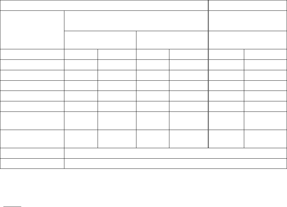
FEDERAL and STATE ITEM NUMBER ORDER Page 40 October 8, 2009
Table 2C & 2D. Rating by Comparison of Number of Lanes - Item 28
and Bridge Roadway Width, Curb-to-Curb - Item 51
TABLE 2C TABLE 2D
Deck Geometry
Rating Code
Bridge Roadway Width
2 or More Lanes Each Direction
Bridge Roadway Width
1-Way Traffic
Interstate and Other
Divided Freeways
Other Multilane
Divided Facilities
Ramps Only
2 Lanes 3 or more 2 Lanes 3 or more 1 Lane 2 or more
9 >42 >12N+24 >42 >12N+18 >26 >12N+12
8 42 12N+24 42 12N+18 26 12N+12
7 40 12N+20 38 12N+15 24 12N+10
6 38 12N+16 36 12N+12 22 12N+8
5 36 12N+14 33 11N+10 20 12N+6
4 34(29)* 11N+12
(11N+7)*
30 11N+6 18 12N+4
3 33(28)* 11N+11
(11N+6)*
27 11N+5 16 12N+2
2 Any width less than required for a code of 3 & structure open.
0 Bridge closed.
* Use value in parentheses for bridges longer than 200 feet.
N = number of lanes of traffic.
Notes
1.
Use the lower rating code for values between those listed in the tables.
2.
Dimensions in feet.
3.
Use Table 2C, Other Multilane Divided Facilities, for 3 or more undivided lanes of 2-way
traffic.
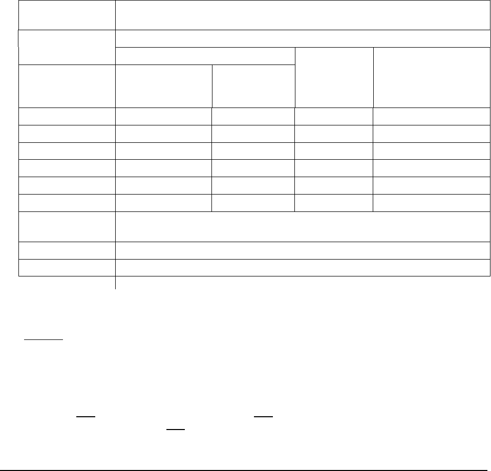
FEDERAL and STATE ITEM NUMBER ORDER Page 41 October 8, 2009
Table 2E. Rating by Comparison of Minimum Vertical Clearance over
Bridge Roadway - Item 53 and Functional Classification - Item 26
Deck Geometry
Rating Code
Minimum Vertical Clearance
Functional Class
Interstate and Other Freeway Other
Principal and
Minor
Arterials
Major and Minor
Collectors and
Locals
All Routes
Except as noted
for Urban Areas
Undesignated
Routes,
Urban Areas*
9 >17'-0" >16'-6" >16'-6" >16'-6"
8 17'-0" 16'-6" 16'-6" 16'-6"
7 16'-9" 15'-6" 15'-6" 15'-6"
6 16'-6" 14'-6" 14'-6" 14'-6"
5 15'-9" 14'-3" 14'-3" 14'-3"
4 15'-0" 14'-0" 14'-0" 14'-0"
3 Vertical clearance less than value in code 4 and requiring corrective
action.
2 Vertical clearance less than value in code 4 and requiring replacement.
0 Bridge Closed
* Use for routes in highly developed urban areas only when there is an alternative Interstate,
freeway or expressway facility with a minimum of 16'- 0" clearance.
NOTES
1 Use the lower rating code for values between those listed in the table.
2. Dimensions are in feet.
EDIT CHECK
A review flag occurs if Item 27 is younger than 4 years old or equal to current year and
any one Item 58 through Item 62 or any one Item 67 through Item 72 is < 5 and not N.
A warning is issued if any one of Items 41, 58, 59, 60, 62, 67, 68, 69, 70 or 72 is coded 0
and all others are coded >= 2 and Item 42 is NOT = to D, E or K.
FEDERAL ITEM 69 - UNDERCLEARANCE, VERTICAL & HORIZONTAL - X (1) (CALCULATED)
APPRAISAL – OTHER RATINGS
UNDERCLR
TABLE - INSPEVNT
This item is calculated by the Program and need not be coded by the bridge inspector.
Vertical and horizontal underclearances are measured from the through roadway to the superstructure
or substructure units, respectively. Code "N" is used unless the bridge is over a highway or railroad.
The vertical underclearance is evaluated using Table 3A. The horizontal underclearance is evaluated
using Table 3B. The lower of the codes obtained from Table 3A and Table 3B is used by the
Edit/Update Program.
Bridges seldom are closed due to deficient underclearances; however, these bridges may be good
candidates for rehabilitation or replacement.
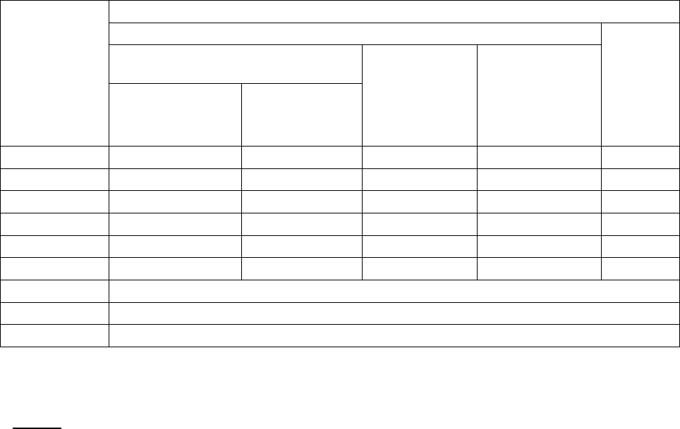
FEDERAL and STATE ITEM NUMBER ORDER Page 42 October 8, 2009
Item 54 - Minimum Vertical Underclearance, Item 55 - Minimum Lateral Underclearance on Right, and
Item 56 - Minimum Lateral Underclearance on Left are used to evaluate this item.
The functional classification used in the table is for the underpassing route. Therefore, the functional
classification is obtained from the record for the route "under" the bridge (see Item 5 - Inventory
Route).
If the underpassing route is not on a Federal-aid system, is not a defense route, or is not otherwise
important, an "under" record may not be available. If no "under" record exits, it is assumed that the
route under the bridge is a major or minor collector or a local road for the purpose of using Tables 3A
and 3B.
Table 3A. Rating by Comparison of Minimum Vertical Underclearance -
Item 54 and Functional Classification of Underpassing Route
Minimum Vertical Clearance
Functional Class
Underclearance
Rating Code Interstate and Other Freeway
Other Principal
and Minor
Arterials
Major and Minor
Collectors and
Locals
Railroad
All Routes Except
as noted for Urban
Areas
Undesignated
Routes, Urban
Areas
9 >17'-0" >16'-6 >16'-6" >16'-6" >23'-0"
8 17'-0" 16'-6" 16'-6" 16'-6" 23'-0"
7 16'-9" 15'-6" 15'-6" 15'-6" 22'-6"
6 16'-6" 14'-6" 14'-6" 14'-6" 22'-0"
5 15'-9" 14'-3" 14'-3" 14'-3" 21'-0"
4 15'-0" 14'-0" 14'-0" 14'-0" 20'-0"
3 Vertical clearance less than value in code 4 and requiring corrective action.
2 Vertical clearance less than value in code 4 and requiring replacement.
0 Bridge Closed.
* Use for routes in highly developed urban areas only when there is an alternative Interstate, freeway or
expressway facility with a minimum of 16'- 0" clearance.
NOTES
1. Use the lower rating code for values between those listed in the table.
2. Dimensions are in feet.
3.
The functional classification of the underpassing route shall be used in the evaluation. If an "under"
record is not coded, the underpassing route shall be considered a major or minor collector or a local
road.
Table 3B. Rating by Comparison of Minimum Lateral
Underclearances Right & Left - Items 55 & 56 and
Functional Classification of Underpassing Route
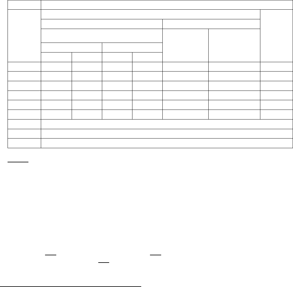
FEDERAL and STATE ITEM NUMBER ORDER Page 43 October 8, 2009
Minimum Lateral Underclearance
Functional Class
1 – Way Traffic 2 – Way Traffic
Under-
clearance
Rating
Code
Principal Arterials
Interstate, Freeways or Expressways Other Principal
and Minor
Arterials
Major and Minor
Collectors and
Locals
Railroad
Main Line Ramp
Left Right Left Right
9 >30 >30 >4 >10 >30 >12 >20
8 30 30 4 10 30 12 20
7 18 21 3 9 21 11 17
6 6 12 2 8 12 10 14
5 5 11 2 6 10 8 11
4 4 10 2 4 8 6 8
3 Vertical clearance less than value in code 4 and requiring corrective action.
2 Vertical clearance less than value in code 4 and requiring replacement.
0 Bridge Closed.
NOTES
1.
Use the lower rating code for values between those listed in the table.
2.
Dimensions are in feet.
3.
When acceleration or deceleration lanes or ramps are provided under 2-Way traffic, use the value from
the right ramp column to determine code.
4.
The functional classification of the underpassing route shall be used in the evaluation. If an "under"
record is not coded, the underpassing route shall be considered a major or minor collector or a local
road.
EDIT CHECK
If Item 69 is numeric then Item 42 must be 1, 2, 4, 6, 7 or 8.
A review flag occurs if Item 27 is younger than 4 years old or equal to current year and
any one Item 58 through Item 62 or any one Item 67 through Item 72 is < 5 and not N.
A warning is issued if any one of Items 41, 58, 59, 60, 62, 67, 68, 69, 70 or 72 is coded 0
and all others are coded >= 2 and Item 42 is NOT = to D, E or K.
FEDERAL ITEM 70 - BRIDGE POSTING - X (1)
APPRAISAL – LOAD RATINGS
POSTING
TABLE - BRIDGE
The National Bridge Inspection Standards require the posting of load limits only if the maximum legal
load configurations in the State exceed the load permitted under the operating rating. If the load
capacity at the operating rating is such that posting is required, this item shall be coded 4 or less. If no
posting is required at the operating rating, this item shall be coded 5.
This item evaluates the load capacity of a bridge in comparison to the State legal load. It differs from
Item 67 - Structural Evaluation in that Item 67 uses Item 66 - Inventory Rating, while the bridge posting
requirement is based on Item 64 - Operating Rating.
Although posting a bridge for load-carrying capacity is required only when the maximum legal load
exceeds the operating rating, highway agencies may choose to post at a lower level. This posting
practice may appear to produce conflicting coding when Item 41 - Structure Open, Posted or Closed to
Traffic is coded to show the bridge as actually posted at the site and Item 70 - Bridge Posting is coded

FEDERAL and STATE ITEM NUMBER ORDER Page 44 October 8, 2009
as bridge posting is not required. Since different criteria are used for coding these 2 items, this coding
is acceptable and correct when the highway agency elects to post at less than the operating rating.
Item 70 shall be coded 4 or less only if the legal load of the State exceeds that permitted under the
operating rating.
The use or presence of a temporary bridge affects the coding. The actual operating rating of the
temporary bridge should be used to determine this item. However the highway agency may choose to
post at a lower level. This also applies to bridges shored up or repaired on a temporary basis.
Code Description
0, 1, 2, 3 or 4 Posting required
5 No posting required
The degree that the operating rating is less than the maximum legal load level may be used to
differentiate between codes. As a guide and for coding purposes only, the following values may be
used to code this item:
Code Relationship of Operating Stress to Legal Load Stress
5 Equal to or above legal loads
4 0.1 - 9.9% below
3 10.0 - 19.9% below
2 20.0 - 29.9% below
1 30.0 - 39.9% below
0 > 39.9% below
Virginia Note: Virginia has elected to post its structures using the loads produced by the Virginia legal
vehicles. These are the three axle - 27-ton vehicle and the 5 axle - 40-ton vehicle. Therefore, for Item
70, we must figure the capacity of the Virginia legal vehicles at the operating stress level and compare
whether the structure would be posted at that level.
Example 1:
The 27-ton Virginia legal vehicle produces a capacity of 23 tons at the operating stress level.
Since this Virginia legal vehicle is a 27-ton vehicle, we compare the 23-ton capacity at the
operating stress level to the 27-ton vehicle, the difference is 4 tons. 4/27 = .148 which is
14.8%, then Item 70 would be coded a 3, since a code of 3 is from 10.0 - 19.9% below legal
loads.
Example 2:
The 27-ton Virginia legal vehicle produces a capacity of 28 tons at operating stress level.
Since this Virginia legal vehicle is a 27 ton vehicle, we compare the 28 ton capacity at the
operating stress level to the 27 ton vehicle, the capacity is above the legal load of 27 tons, then
Item 70 would be coded a 5, since a code of 5 is for capacities at the operating stress level
equal to or above legal loads.
NOTE: The structure used in Example 2 may be posted since Virginia figures the posting capacity at
a stress level below operating stress level for other than concrete spans. The posting capacity
(whatever the posting level) that Virginia uses is not considered in the coding of Item 70. Therefore,
the structure used in Example 2 would still have a coding of 5 for Item 70. In the examples only the
27-ton vehicle was cited, it could be that the 40-ton vehicle would be below legal limit even though the
27-ton vehicle was above legal limit. Therefore, both vehicles must be checked.

FEDERAL and STATE ITEM NUMBER ORDER Page 45 October 8, 2009
EDIT CHECK
If Item 70 is coded < 5 then one of items 58 - 62 must be coded 3 or less. However, keep
in mind that this item uses OPERATING stress to determine posting. That means that
some structures may be posted and yet be coded 5 (since we use a stress less than
operating to determine posting). A review flag occurs if Item 27 is younger than 4 years old
or equal to current year and any one Item 58 through Item 62 or any one Item 67 through
Item 72 is < 5 and not N. A warning is issued if any one of Items 41, 58, 59, 60, 62, 67, 68,
69, 70 or 72 is coded 0 and all others are coded >= 2 and Item 42 is NOT = to D, E or K.
A warning is issued if Item 70 = 5 and Item 59 = 0, 1, 2 or 3.
A warning is issued if Item 70 = 5 and Item 60 = 0, 1, 2 or 3.
A warning is issued if Item 70 = 5 and Item 62 = 0, 1, 2 or 3.
FEDERAL ITEM 71 - WATERWAY ADEQUACY - X (1)
CONDITION
WATERADEQ
TABLE - INSPEVNT
This item appraises the waterway opening with respect to passage of flow through the bridge. The
following codes shall be used in evaluating waterway adequacy (interpolate where appropriate). Site
conditions may warrant somewhat higher or lower ratings than indicated by the table (e.g., flooding of
an urban area due to a restricted bridge opening).
Where overtopping frequency information is available, the descriptions give in the table for chance of
overtopping mean the following:
Remote greater than 100 years
Slight 11 to 100 years
Occasional 3 to 10 years
Frequent less than 3 years
Adjectives describing traffic delay mean the following:
Insignificant
Minor inconvenience. Highway passable in a matter of hours.
Significant
Traffic delay of up to several days.
Severe
Long term delay to traffic with resulting hardship.
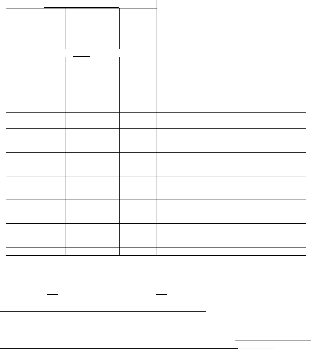
FEDERAL and STATE ITEM NUMBER ORDER Page 46 October 8, 2009
Functional Classification
Description
Principal
Arterials
Interstates,
Freeways, or
Expressways
Other Principal
and Minor
Arterials and
Major Collector
Minor
Collector
s Local
Code
N N N Bridge not over a waterway.
9 9 9
Bridge deck and roadway approaches above
floodwater elevations (high water). Chance of
overtopping is remote.
8 8 8
Bridge deck above roadway approaches.
Slight chance of overtopping roadway
approaches.
6 6 7 Slight chance of overtopping bridge deck and
roadway approaches.
4 5 6
Bridge deck above roadway approaches.
Occasional overtopping of roadway
approaches with insignificant traffic delays.
3 4 5
Bridge deck above roadway approaches.
Occasional overtopping of roadway
approaches with significant traffic delays.
2 3 4
Occasional overtopping of bridge deck and
roadway approaches with significant traffic
delays.
2 2 3
Frequent overtopping of bridge deck and
roadway approaches with significant traffic
delays.
2 2 2
Occasional or frequent overtopping of bridge
deck and roadway approaches with severe
traffic delays.
0 0 0 Bridge closed.
EDIT CHECK
If Item 71 is numeric then Item 42 must be 5, 6, 7, 8, 9 or 0.
A review flag occurs if Item 27 is younger than 4 years old or equal to current year and
any one Item 58 through Item 62 or any one Item 67 through Item 72 is < 5 and not N.
FEDERAL ITEM 72 - APPROACH ROADWAY ALIGNMENT - X (1)
APPRAISAL – OTHER RATINGS
APPRALIGN
TABLE - INSPEVNT
Code the rating based on the adequacy of the approach roadway alignment. This item identifies those
bridges that do not function properly or adequately due to the alignment of the approaches. It is not
intended that the approach roadway alignment be compared to current standards but rather to the
existing highway alignment. This concept differs from other appraisal evaluations. The establishment
of set criteria to be used at all bridge sites is not appropriate for this item. The basic criteria is how the
alignment of the roadway approaches to the bridge relate to the general highway alignment for the
section of highway the bridge is on.

FEDERAL and STATE ITEM NUMBER ORDER Page 47 October 8, 2009
The individual structure shall be rated in accordance with the general appraisal rating guide in lieu of
specific design values. Approach roadway alignment will be rated intolerable (a code of 3 or less) only
if the horizontal or vertical curvature requires a substantial reduction in the vehicle operating speed
from that on the highway section. A very minor speed reduction will be rated a 6, and when a speed
reduction is not required, the appraisal code will be an 8. Additional codes may be selected between
these general values.
For examples, if the highway section requires a substantial speed reduction due to vertical or
horizontal alignment, and the roadway approach to the bridge requires only a very minor additional
speed reduction at the bridge, the appropriate code would be a 6. This concept shall be used at each
bridge site.
Speed reductions necessary because of structure width and not alignment shall not be considered in
evaluating this item.
EDIT CHECK
A review flag occurs if Item 27 is younger than 4 years old or equal to current year and any
one Item 58 through Item 62 or any one Item 67 through Item 72 is < 5 and not N.
A warning is issued if any one of Items 41, 58, 59, 60, 62, 67, 68, 69, 70 or 72 is coded 0
and all others are coded >= 2 and Item 42 is NOT = to D, E or K.
FEDERAL ITEM 75 - TYPE OF WORK - XXX (3)
IN THE UPPER LEFT BESIDE ‘INVENTORY’ USE THE DROP DOWN AND SELECT ‘PROJECT PLAN’
CLICK THE RADIO BUTTON FOR ‘BRIDGES’
CLICK ON THE RADIO BUTTON FOR ‘BRIDGES’
SELECT A STRUCTURE BY SINGLE CLICKING ON THE STRUCTURE
ON THE LEFT CLICK ON ‘NBI PROJECT INFO’
THIS ITEM WILL SHOW IN A POP-UP WINDOW
PROPWORK
WORKBY
TABLE - BRIDGE
The information to be recorded for this item will be the type of work proposed to be accomplished on
the structure to improve it to the point that it will provide the type of service needed and whether the
proposed work is to be done by contract or force account. Code a 3-digit number composed of 2
segments.
Segment Description Length
75A
Type of Work Proposed 2 digit
75B Work Done by 1 digit
This item must be coded for bridges eligible for the Highway Bridge Replacement and Rehabilitation
Program. To be eligible, a bridge must carry highway traffic, be deficient and have a sufficiency rating
of 80.0 or less. This item may be coded for other bridges at the option of the highway agency. Use
one of the following codes to represent the proposed work type, otherwise leave blank:

FEDERAL and STATE ITEM NUMBER ORDER Page 48 October 8, 2009
Code Description
31 Replacement of bridge or other structure because of substandard load carrying
capacity or substandard bridge roadway geometry.
32 Replacement of bridge or other structure because of relocation of road.
33 Widening of existing bridge or other major structure without deck rehabilitation or
replacement; includes culvert lengthening.
34 Widening of existing bridge with deck rehabilitation or replacement.
35 Bridge rehabilitation because of general structure deterioration or inadequate
strength.
36 Bridge deck rehabilitation with only incidental widening.
37 Bridge deck replacement with only incidental widening.
38 Other structural work, including hydraulic replacements.
If segment A is blank, leave segment B blank. Otherwise, the third digit shall be coded using one of
the following codes to indicate whether the proposed work is to be done by contract or by force
account:
Code Description
1 Work to be done by contract
2 Work to be done by owner's forces
EXAMPLES:
Code
311 A bridge is to be replaced by contract because it has deteriorated to the point that
it can no longer carry legal loads. The same code should be used if the bridge is
replaced because it is now too narrow or the original design was too light to
accommodate today's legal loads.
321 A bridge is to be replaced because the roadway must be straightened to eliminate
a dangerous curve. The work will be done by contract.
331 A bridge is to be widened to increase shoulder width or the number of traffic lanes.
Existing deck is in good condition and will be incorporated as is into the new
structure. The work is to be done by contract.
331 A culvert is to be extended by contract to accommodate additional roadway width
as part of a reconstruction contract to improve the safety of the adjacent slopes.
341 A deck is to be rehabilitated and the bridge widened to proved a full 12-foot
shoulder. The existing shoulder is only 7.87 inches wide and an extra line of
girders with appropriate substructure widening must be added. The work will be
done by contract.
352 A bridge superstructure and substructure are to be rehabilitated by State forces to
increase the bridge's load capacity.
361 A bridge deck is to be rehabilitated by contract and a safety curb to be removed
which results in incidental widening of 2 feet.
371 A bridge deck is to be replaced by contract and the deck cantilever overhang
extended 2 feet, which is the maximum that can be done without adding another
line of stringers or girders to the superstructure.
382 A bridge that is no longer needed is to be demolished and an at-grade crossing
built by State forces. (This code could also be use to designate incidental safety
work on a bridge such as bridge-rail upgrading or replacement.)
EDIT CHECK
If Item 75A is > 00 then Item 96 must be > 00000.
If the bridge is structurally deficient and/or functionally obsolete (see appendix for
definitions) and the sufficiency rating is < 80 and Item 5A = 1 then the structure is eligible
for HBRRP funds and Items 75, 76, 94, 95, 96 and 97 must be numeric and > 0.

FEDERAL and STATE ITEM NUMBER ORDER Page 49 October 8, 2009
FEDERAL ITEM 76 - LENGTH OF STRUCTURE IMPROVEMENT - XXXXXX (6)
IN THE UPPER LEFT BESIDE ‘INVENTORY’ USE THE DROP DOWN AND SELECT ‘PROJECT PLAN’
CLICK THE RADIO BUTTON FOR ‘BRIDGES’
CLICK ON THE RADIO BUTTON FOR ‘BRIDGES’
SELECT A STRUCTURE BY SINGLE CLICKING ON THE STRUCTURE
ON THE LEFT CLICK ON ‘NBI PROJECT INFO’
THIS ITEM WILL SHOW IN A POP-UP WINDOW
IMPLEN
TABLE - BRIDGE
Code a 6-digit number that represents the length of the proposed bridge improvement to the nearest
foot. For replacement or rehabilitation of the entire bridge, the length should be back to back of
backwalls of abutments or from pavement notch to pavement notch. For replacement or rehabilitation
of only part of the structure, use the length of the portion to be improved.
This item must be coded for bridges eligible for the Highway Bridge Replacement And Rehabilitation
Program. It may be coded for other bridges at the option of the highway agency.
For culvert improvements, use the proposed length measured along the centerline of the barrel
regardless of the depth below grade. The measurement should be made between the inside faces of
the top parapet or edge-stiffening beam of the top slab.
EXAMPLES: Code
Length of Structure Improvement 250 feet
000250
1,200 feet
001200
12,345 feet
012345
For substructure or channel work only, code the length of superstructure over or supported by, the
substructure or channel.
Typically, a replacement bridge is longer than the existing bridge. Nationwide averages for the
increase in bridge length with replacement as a function of the existing length are given in the
following figures. The length-expansion factors represent data for the years 1981 to 1985. Where
site-specific data is lacking, these factors are suggested for estimating the length of replacement
bridges. For exceedingly long bridges (i.e., 1000 feet or more) the length-expansion factor
approaches 1.0.
(For a detail example of Item 75 refer to the Federal Coding Guide)
EDIT CHECK
If the bridge is structurally deficient and/or functionally obsolete (see appendix for definitions)
and the sufficiency rating is < 80 and Item 5A = 1 then the structure is eligible for HBRRP
funds and Items 75, 76, 94, 95, 96 and 97 must be numeric and > 0.
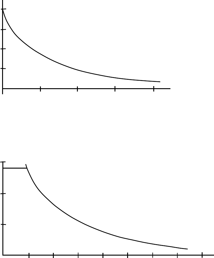
FEDERAL and STATE ITEM NUMBER ORDER Page 50 October 8, 2009
INCREASED LENGTH OF REPLACEMENT BRIDGES
X = EXISTING BRIDGE LENGTH
Y = LENGTH EXPANSION FACTOR
REPLACEMENT BRIDGE LENGTH = EXISTING BRIDGE LENGTH X LENGTH EXPANSION FACTOR
EXISTING BRIDGE LENGTH (FEET)
LENGTH EXPANSION FACTOR
2.0
1.8
1.6
1.4
1.2
20
40
60
80
100
LENGTH EXPANSION FACTOR
EXISTING BRIDGE LENGTH (FEET)
1.2
1.3
100
0 200
300
400
500
600
700
1.1
1.0
800

FEDERAL and STATE ITEM NUMBER ORDER Page 51 October 8, 2009
FEDERAL ITEM 90 - INSPECTION DATE - AUTOMATIC ENTRY (8)
SCHEDULE
INSPDATE
TABLE - INSPEVNT
Record the month and year that the last routine inspection of the structure was performed (note that
this is the way the Feds want us to report this data, it is NOT the way we collect our data). This
inspection date may be different from those recorded in Item 93 - Critical Feature Inspection Date.
Code a 4-digit number to represent the month and year. The number of the month should be coded in
the first 2 digits with leading zeros as required and the last 2 digits of the year coded as the third and
fourth digits of the field.
EXAMPLE: Code
Inspection date November 1986
1186
March 1987
0387
EDIT CHECK
A warning is issued if Item 90 is older than the current date less 36 months.
FEDERAL ITEM 91 - DESIGNATED INSPECTION FREQUENCY - XX (2)
SCHEDULE
BRINSPFREQ
TABLE - INSPEVNT
Code 2 digits to represent the number of months between designated inspections of the structure.
Leading zeros shall be coded. The individual in charge of the inspection program is responsible for
determining the inspection interval. For posted, understrength bridges, this interval should be
substantially less than the 24-month standard. The designated inspection interval could vary form
inspection to inspection depending on the condition of the bridge at the time of inspection.
EXAMPLES:
Code
01 Posted bridge with heavy truck traffic and questionable structural details
which is designated to be inspected each month
24 Bridge is scheduled to be inspected every 24 months
Only the following frequencies are allowed: 0, 1, 2, 3, 4, 5, 6, 7, 8, 9, 10, 11, 12, 24, 48 and 60.
It should be noted that bridges require special non-scheduled inspections after unusual physical
traumas such as floods, earthquakes, fires or collisions. These special inspections may range from a
very brief visual examination to a detailed in-depth evaluation depending upon the nature of the
trauma. For example, when an errant vehicle strikes a substructure unit (pier or abutment), in most
cases only a visual examination of the bridge is necessary. After major collisions or earthquakes, in-
depth inspections may be warranted as directed by the engineer in overall charge of the program.
After and during severe floods, the stability of the substructure of bridges may have to be determined
by probing, underwater sensors or other appropriate measures. Underwater inspection by divers may
be required for some scour critical bridges immediately after floods. See Item 113 - Scour Critical
Bridges.
EDIT CHECK
Item 91 must be between 00 and 48 inclusive.
A warning is issued if Item 91 is > 24 months.
A warning is issued if Item 41 = B, D, E, P, or R and Item 91 is not less than 24.

FEDERAL and STATE ITEM NUMBER ORDER Page 52 October 8, 2009
FEDERAL ITEM 92 - CRITICAL FEATURE INSPECTION - XXX (3)
SCHEDULE
FCINSPFREQ
FCINSPREQ
UWINSPFREQ
UWINSPREQ
OSINSPFREQ
OSINSPREQ
TABLE - INSPEVNT
Virginia Note: The inspection interval for 92C – Other Special Inspections may be as great as 60 months.
Using a series of 3-digits segments, denote critical features that need special inspection or special
emphasis during inspections and the designated in inspection interval in months as determined by the
individual in charge of the inspection program. The designated inspection interval could vary from
inspection to inspection depending on the condition of the bridge at the time of inspection.
Segment Description Length
92A Fracture Critical Details 3 digits
92B Underwater Inspection 3 digits
92C Other Special Inspection 3 digits
For each of 92A, B, and C, code the first digit Y for special inspection or emphasis needed and code N
for not needed. The first digit of 92 A, B, and C must be coded for all structures to designated either a
yes or no answer. Those bridges coded with a Y in Item 92A or B should be the same bridges
contained in the Master Lists of fracture critical and special underwater inspection bridges. In the
second and third digits of each segment, code a 2-digit number to indicate the number of months
between inspections only if the first digit is coded Y. If the first digit is code N, the second and third
digits are left blank.
EXAMPLES: Item
Code
A structure with a 2-girder system being inspected yearly and no
other special inspections are required.
92A Y12
92B N
92C N
A structure where both fracture critical and an underwater
inspection are being performed on a 1-year interval. Other
special inspections are not required.
92A Y12
92B Y12
92C N
A structure has been temporarily shored and is being inspected
on a 6-month interval. Other special inspections are not
required.
92A N
92B N
92C Y06
EDIT CHECK
If Item 92 A, B or C = Y then Item 91 must be < 25.
A warning is issued if the first digit of Item 92A = Y and Item 93A is older than the current
date minus the last two digits of Item 92A in months.
A warning is issued if the first digit of Item 92B = Y and Item 93B is older than the current
date minus the last two digits of Item 92B in months.
A warning is issued if the first digit of Item 92C = Y and Item 93C is older than the current
date minus the last two digits of Item 92C in months.

FEDERAL and STATE ITEM NUMBER ORDER Page 53 October 8, 2009
FEDERAL ITEM 93 - CRITICAL FEATURE INSPECTION DATE - XXXXXXXXXXXX (12)
SCHEDULE
FCLASTINSP
UWLASTINSP
OSLASTINSP
TABLE - INSPEVNT
Code only if the first digit of Item 92A, 92B or 92C is coded Y for yes. Record as a series of 4-digit
code segments, the month and year that the last inspection of the denoted critical feature was
performed.
Segment Description Length
93A Fracture Critical Details 4 digits
93B Underwater Inspection 4 digits
93C Other Special Inspection 4 digits
For each segment of this item, when applicable, code a 4-digit number to represent the month and
year. The number of the month should be coded in the first 2 digits with leading zeros as required and
the last 2 digits of the year coded as the third and fourth digits of the field. If the first digit of any part of
Item 92 is coded N, then the corresponding part of this item shall be blank.
EXAMPLES: Item Code
A structure has fracture critical members that were last inspected in March
1986. It does not require underwater or other special feature inspections.
93A 0386
93B (blank)
93C (blank)
A structure has no fracture critical details, but requires underwater
inspection and has other special features (for example, a temporary
support) for which the State requires special inspection. The last
underwater inspection was done in April 1986 and the last special feature
inspection was done in November 1985.
93A (blank)
93B 0486
93C 1185
EDIT CHECK
A warning is issued if the first digit of Item 92A = Y and Item 93A is older than
the current date minus the last two digits of Item 92A in months.
A warning is issued if the first digit of Item 92B = Y and Item 93B is older than
the current date minus the last two digits of Item 92B in months.
A warning is issued if the first digit of Item 92C = Y and Item 93C is older than
the current date minus the last two digits of Item 92C in months.
FEDERAL ITEM 93 (SUPPLEMENTAL) - CRITICAL FEATURE INSPECTOR'S CODE - XXX (3)
THIS HAS BEEN REPLACED BY THE WAY EACH INSPECTION IS ASSOCIATED WITH THE INSPECTOR SHOWN ON
THE ‘SCHEDULE’ SCREEN
This is the number of the person, county, city or agency performing the Critical Feature Inspection for
this structure. For State Inspectors, this will be the code for the team leader. This is a user-defined
table and will be maintained by Central Office.
FEDERAL ITEM 93 (SUPPLEMENTAL) - CRITICAL FEATURE INSPECT - NEXT XXXXXXXX (8)
THIS HAS BEEN REPLACED BY ‘NEXT DATE’ ON THE ‘SCHEDULE’ SCREEN
This is the date that will be calculated by a program at the time of changes to the inspection data. The
value is determined by adding the frequency to the actual inspection date or by adding the frequency
to the last scheduled date. Format is MM/DD/YYYY.

FEDERAL and STATE ITEM NUMBER ORDER Page 54 October 8, 2009
FEDERAL ITEM 94 - BRIDGE IMPROVEMENT COST – XXXXXX (6)
IN THE UPPER LEFT BESIDE ‘INVENTORY’ USE THE DROP DOWN AND SELECT ‘PROJECT PLAN’
CLICK THE RADIO BUTTON FOR ‘BRIDGES’
CLICK ON THE RADIO BUTTON FOR ‘BRIDGES’
SELECT A STRUCTURE BY SINGLE CLICKING ON THE STRUCTURE
ON THE LEFT CLICK ON ‘NBI PROJECT INFO’
THIS ITEM WILL SHOW IN A POP-UP WINDOW
NBIIMPCOST
TABLE - BRIDGE
Code a 6-digit number to represent the cost of the proposed bridge or major structure improvements in
thousands of dollars. This cost shall include only bridge construction costs, excluding roadway, right
of way, detour, demolitions, preliminary engineering, etc. Code the base year for the cost in Item 97 -
Year of Improvement Cost Estimate. Do not use this item for estimating maintenance costs.
This item must be coded for bridges eligible for the Highway Bridge Replacement and Rehabilitation
Program. It may be coded for other bridges at the option of the highway agency.
EXAMPLES: Code
Bridge Improvement Cost $55,850
000056
250,000
000250
7,451,233
007451
Nationally, the deck area of replaced bridges is averaging 2.2 times the deck area before replacement.
The deck area of rehabilitated bridges is averaging 1.5 times the deck area before rehabilitation.
Widening square foot costs are typically 1.8 times the square foot cost of new bridges with similar
spans. For example, if the average cost of a new bridge were $50 per square foot, the average cost of
the widening area would be $90 per square foot.
Each highway agency is encouraged to use it best available information and established procedures to
determine bridge improvement costs. Ins the absence of these procedures, the highway agency may
wish to use the following procedure as a guide in preparing bridge improvement cost estimates.
Apply a construction unit cost to the proposed bridge area developed by using (1) current State deck
geometry design standards and (2) proposed bridge length from Item 76 - Length of Structure
Improvement.
EDIT CHECK
Item 96 must be > the sum of Item 94 and Item 95.
If Item 97 is not blank then Items 94, 95 and 96 cannot be blank.
If the bridge is structurally deficient and/or functionally obsolete (see appendix for
definitions) and the sufficiency rating is < 80 and Item 5A = 1 then the structure is eligible
for HBRRP funds and Items 75, 76, 94, 95, 96 and 97 must be numeric and > 0.

FEDERAL and STATE ITEM NUMBER ORDER Page 55 October 8, 2009
FEDERAL ITEM 95 - ROADWAY IMPROVEMENT COST – XXXXXX (6)
IN THE UPPER LEFT BESIDE ‘INVENTORY’ USE THE DROP DOWN AND SELECT ‘PROJECT PLAN’
CLICK THE RADIO BUTTON FOR ‘BRIDGES’
CLICK ON THE RADIO BUTTON FOR ‘BRIDGES’
SELECT A STRUCTURE BY SINGLE CLICKING ON THE STRUCTURE
ON THE LEFT CLICK ON ‘NBI PROJECT INFO’
THIS ITEM WILL SHOW IN A POP-UP WINDOW
NBIRWPCOST
TABLE - BRIDGE
Code a 6-digit number to represent the cost of the proposed roadway improvement in thousands of
dollars. This shall include only roadway construction costs, excluding bridge, right-of way, detours,
extensive roadway realignment costs, preliminary engineering, etc. Code the base year for the cost in
Item 97 - Year of Improvement Cost Estimate. Don not use this item for estimating maintenance
costs.
This item must be coded for bridges eligible for the Highway Bridge Replacement and Rehabilitation
Program. It may be coded for other bridges at the option of the highway agency.
In the absence of a procedure for estimating roadway improvement costs, a guide of 10 percent of the
bridge costs is suggested.
EDIT CHECK
Item 96 must be > the sum of Item 94 and Item 95.
If Item 97 is not blank then Items 94, 95 and 96 cannot be blank.
If the bridge is structurally deficient and/or functionally obsolete (see appendix for
definitions) and the sufficiency rating is < 80 and Item 5A = 1 then the structure is eligible
for HBRRP funds and Items 75, 76, 94, 95, 96 and 97 must be numeric and > 0.
FEDERAL ITEM 96 - TOTAL PROJECT COST – XXXXXX (6)
IN THE UPPER LEFT BESIDE ‘INVENTORY’ USE THE DROP DOWN AND SELECT ‘PROJECT PLAN’
CLICK THE RADIO BUTTON FOR ‘BRIDGES’
CLICK ON THE RADIO BUTTON FOR ‘BRIDGES’
SELECT A STRUCTURE BY SINGLE CLICKING ON THE STRUCTURE
ON THE LEFT CLICK ON ‘NBI PROJECT INFO’
THIS ITEM WILL SHOW IN A POP-UP WINDOW
NBITOTPCOST
TABLE - BRIDGE
Code a 6-digit number to represent the total project cost in thousands of dollars, including incidental
costs not included in Items 94 and 95. This item should include all costs normally associated with the
proposed bridge improvement project. The Total Project Cost will therefore usually be greater than
the sum of Items 94 and 95. Code the base year for the cost in Item 97 - Year of Improvement Cost
Estimate. Do not use this item for coding maintenance costs.
This item must be coded for bridges eligible for the Highway Bridge Replacement and Rehabilitation
Program. It may be coded for other bridges at the option of the highway agency.
In the absence of a procedure for estimating the total project cost, a guide of 150 percent of the bridge
cost is suggested.
EDIT CHECK
If Item 75A is > 00 then Item 96 must be > 00000.
Item 96 must be > the sum of Item 94 and Item 95.
If Item 97 is not blank then Items 94, 95 and 96 cannot be blank.
If the bridge is structurally deficient and/or functionally obsolete (see appendix for definitions)
and the sufficiency rating is < 80 and Item 5A = 1 then the structure is eligible for HBRRP
funds and Items 75, 76, 94, 95, 96 and 97 must be numeric and > 0.

FEDERAL and STATE ITEM NUMBER ORDER Page 56 October 8, 2009
FEDERAL ITEM 97 - YEAR OF IMPROVEMENT COST ESTIMATE – XXXX (4)
IN THE UPPER LEFT BESIDE ‘INVENTORY’ USE THE DROP DOWN AND SELECT ‘PROJECT PLAN’
CLICK THE RADIO BUTTON FOR ‘BRIDGES’
CLICK ON THE RADIO BUTTON FOR ‘BRIDGES’
SELECT A STRUCTURE BY SINGLE CLICKING ON THE STRUCTURE
ON THE LEFT CLICK ON ‘NBI PROJECT INFO’
THIS ITEM WILL SHOW IN A POP-UP WINDOW
NBIYRCOST
TABLE - BRIDGE
Record and code the year that the costs of work estimated in Item 94 - Bridge Improvement Cost, Item
95 - Roadway Improvement Cost, and Item 96 - Total Project Cost were based upon. This date and
the data provided for Item 94 through Item 96 must be current; that is, Item 97 shall be no more than
8 years old.
EXAMPLES: Code
Year of Cost Estimate 1994 costs 1994
2000 costs 2000
EDIT CHECK
Item 97 must be no more than eight years old.
If Item 97 is not blank then Items 94, 95 and 96 cannot be blank.
If the bridge is structurally deficient and/or functionally obsolete (see appendix for definitions)
and the sufficiency rating is < 80 and Item 5A = 1 then the structure is eligible for HBRRP
funds and Items 75, 76, 94, 95, 96 and 97 must be numeric and > 0.
FEDERAL ITEM 98 - BORDER BRIDGE - XXX XX (5)
INVENTORY – ID/ADMIN
NSTATECODE
BB_PCT
TABLE - BRIDGE
Use this item to indicate structures crossing borders of States. Code a 5-digit number composed of 2
segments specifying the percent responsibility for improvements to the existing structure when it is on
a border with a neighboring State. Code the first 3 digits with the neighboring State code using State
codes listed in Item 1 - State Code. Code the fourth and fifth digits with the percentage of total deck
area of the existing bridge that the neighboring State is responsible for funding.
Segment
Description Length
98A Neighboring State Code 3 digits
98B Percent Responsibility 2 digits
If a neighboring State codes the structure and accepts 100% of the responsibility, but your State still
codes a record for the structure, then Item 98B in your State’s record should be coded 99 to represent
that your State has no responsibility for the structure.
For the special case of a structure on the border with Canada or Mexico, code the State code value =
CAN or MEX respectively. If structure is not on a border, leave blank.
EXAMPLES:
Code Description
34245 A structure connects your State with New Jersey and New Jersey is
responsible for funding 45 percent of future improvement costs.
MEX00 A structure connects your State with Mexico and Mexico is not responsible
for any funding of future improvement costs.

FEDERAL and STATE ITEM NUMBER ORDER Page 57 October 8, 2009
FEDERAL ITEM 99 - BORDER BRIDGE STRUCTURE NUMBER - XXXXXXXXXXXXXXX (15)
INVENTORY – ID/ADMIN
BB_BRIDGEID
TABLE - BRIDGE
Code the neighboring State's 15 digit National Bridge Inventory structure number for any structure
noted in Item 98 - Border Bridge. This number must match exactly the neighboring State's submitted
NBI structure number. The entire 15-digit field must be accounted for including zeros and blank
spaces whether they are leading, trailing, or embedded in the 15-digit field. If Item 98 is blank, this
item is blank.
In the above example where Mexico (or a neighboring State) has 00% responsibility, and, if there is no
NBI Structure Number in that State’s inventory file, then the entire 15-digit field shall be coded zeroes.
FEDERAL ITEM 100 - STRAHNET HIGHWAY DESIGNATION – X (1)
INVENTORY – ROADS
DEFHWY
TABLE - ROADWAY
This item shall be coded for all records in the inventory. For the purposes of this item, STRAHNET
Connectors are considered included in the term STRAHNET. For the inventory route identified in Item
5, indicate SRAHNET highway conditions using one of the following codes:
Codes Description
0 The inventory route is not a STRAHNET route.
1 The inventory route is on a STRAHNET route.
2 The inventory route is on a Non-Interstate STRAHNET route.
3 The inventory route is on a STRAHNET connector route.
EDIT CHECK
If Item 100 = 1 or 2 then Item 47 must be > 000
If Item 100 equals 1 or 2 then Item 16 must be > 00000.
If Item 100 equals 1 or 2 then Item 17 must be > 00000.
FEDERAL ITEM 101 - PARALLEL STRUCTURE DESIGNATION – X (1)
INVENTORY – CLASSIFICATION
PARALSTRUC
TABLE - BRIDGE
Code this item to indicate situations where separate structures carry the inventory route in opposite
directions of travel over the same features. The lateral distance between structures has no bearing on
the coding of this item.
One of the following codes shall be used:
Code Description
EBL
R
The right structure of parallel bridges carrying the roadway in the direction
of the inventory. (For a STRAHNET highway, this is west to east and
south to north.)
NBL
WBL L The left structure of parallel bridges. This structure carries traffic in the
opposite direction. SBL
N No parallel structure.
EXAMPLE: Code
Structure #1 R
Structure #2 L
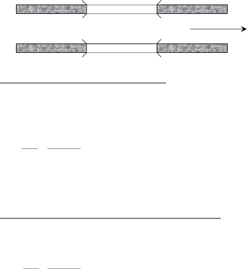
FEDERAL and STATE ITEM NUMBER ORDER Page 58 October 8, 2009
FEDERAL ITEM 102 - DIRECTION OF TRAFFIC – X (1)
INVENTORY – ROADS
TRAFFICDIR
TABLE - ROADWAY
Code the direction of traffic of the inventory route identified in Item 5 as a 1-digit number using one of
the codes below. This item must be compatible with other traffic-related items such as Item 28A
Lanes on the Structure, Item 29 - Average Daily Traffic, Item 47 - Total Horizontal Clearance and Item
51 - Bridge Roadway Width, Curb-to-Curb.
Code Description
0 Highway traffic not carried
1 1-way traffic
2 2-way traffic
3 One lane bridge for 2-way traffic
EDIT CHECK
If this Item 28A is = 01 then Item 102 must = 1 or 3.
FEDERAL ITEM 103 - TEMPORARY STRUCTURE DESIGNATION – X (1)
INVENTORY – CLASSIFICATION
TEMPSTRUC
TABLE - BRIDGE
Code this item to indicate situations where temporary structures or conditions exist. This item should
be blank if not applicable.
Code Description
T Temporary structure(s) or conditions exist.
Temporary structure(s) or conditions are those that are required to facilitate traffic flow. This may
occur either before or during the modification or replacement of a structure found to be deficient. Such
conditions include the following:
1. Bridges shored up, including additional temporary supports.
2. Temporary repairs made to keep a bridge open.
3. Temporary structures, temporary runarounds or bypasses.
4. Other temporary measures, such as barricaded traffic lanes to keep the bridge open.
Any repaired structure or replacement structure that is expected to remain in place without further
project activity, other than maintenance, for a significant period of time shall not be considered
temporary. Under such conditions, that structure, regardless of its type, shall be considered the
minimum adequate to remain in place and evaluated accordingly.
Structure #2
Structure #1
North

FEDERAL and STATE ITEM NUMBER ORDER Page 59 October 8, 2009
If this item is coded T, then all data recorded for the structure shall be for the condition of the structure
without temporary measures, except for the following items which shall be for the temporary structure.
Item Description
10 Inventory Route, Minimum Vertical Clearance
41 Structure Open, Posted, or Closed Traffic
47 Inventory Route, Total Horizontal Clearance
53 Minimum Vertical Clearance Over Bridge Roadway
54 Minimum Vertical Underclearance
55 Minimum Lateral Underclearance on Right
56 Minimum Lateral Underclearance on Left
70 Bridge Posting
EDIT CHECK
If Item 103 = T then Item 41 must = D, E or P.
A warning is issued if Item 64A = 1 through 6 or 9 and Item 64B = 00 and
Item 41 = D or E then Item 103 must = T.
FEDERAL ITEM 104 - HIGHWAY SYSTEM OF THE INVENTORY ROUTE – X (1)
INVENTORY – ROADS
NHS_IND
TABLE - ROADWAY
Virginia Note: THIS DOES NOT DENOTE FEDERAL AID AND NON-FEDERAL AID ROUTES.
This item is to be coded for all records in the inventory. For the inventory route identified in Item 5,
indicate whether the inventory route is on the National Highway System (NHS) or not on that system.
Initially, this code shall reflect an inventory route on the NHS "Interim System" description in Section
1006(a) of the 1991 ISTEA. Upon approval of the NHS by Congress, the coding is to reflect the
approved NHS. Use one of the following codes:
Code Description
0 Inventory Route is not on the NHS
1 Inventory Route is on the NHS
EDIT CHECK
If Item 26 = 1 or 11 then Item 5B must = 1 and Item 104 must = 1.
Item 5B must not equal 1 if Item 104 does not equal 1.
ALSO:
If Item 104 is: Item 26 must be:
1 01, 02, 11, 12 or 14
0 06, 07, 08, 09, 16, 17 or 19
FEDERAL ITEM 105 – FEDERAL LANDS HIGHWAY – X (1)
INVENTORY – ROADS
FEDLANDHWY
TABLE - ROADWAY
Structures owned by State and local jurisdictions on roads that lead to and traverse through federal
lands sometimes require special coded unique identification because they are eligible to receive
funding from the Federal Lands Highway Program. One of the following codes shall be used:

FEDERAL and STATE ITEM NUMBER ORDER Page 60 October 8, 2009
Code Description
0 Not applicable
1 Indian Reservation Road (IRR)
2 Forest Highway (FH)
3 Land Management Highway System (LMHS)
4 Both IRR and FH
5 Both IRR and LMHS
6 Both FH and LMHS
9 Combined IRR, FH, and LMHS
FEDERAL ITEM 106 - YEAR RECONSTRUCTED – XXXX (4)
INVENTORY – ID/ADMIN
YEARRECON
TABLE - BRIDGE
Record and code the year of the most recent reconstruction of the structure. Code all 4 digits of the
latest year in which reconstruction of the structure was completed. If there has been no reconstruction
code 0000.
For a bridge to be defined as reconstructed, the type of work performed, whether or not it meets
current minimum standards, must have been eligible for funding under any of the Federal-aid funding
categories. The eligibility criteria would apply to the work performed regardless of whether all State or
local funds or Federal-aid funds were used.
Some types of eligible work not to be considered as reconstruction are listed:
-
Safety feature replacement or upgrading (for example, bridge rail, approach guardrail
or impact attenuators).
-
Painting of structural steel.
-
Overlay of bridge deck as part of a larger highway surfacing project (for example,
overlay carried across bridge deck for surface uniformity without additional bridge
work).
-
Utility work.
-
Emergency repair to restore structural integrity to the previous status following an
accident.
-
Retrofitting to correct a deficiency that does not substantially alter physical geometry or
increase the load-carrying capacity.
-
Work performed to keep a bridge operational while plans for complete rehabilitation or
replacement are under preparation (for example, adding a substructure element or
extra girder).
EXAMPLE: Code
Reconstruction completed 1970 1970
EDIT CHECK
If Item 106 > 0 then Item 106 must be > Item 27.
A warning is issued if Item 106 is not = 19 or 20.

FEDERAL and STATE ITEM NUMBER ORDER Page 61 October 8, 2009
FEDERAL ITEM 107 - DECK STRUCTURE TYPE – X (1)
INVENTORY – DESIGN
DKDTRUCTYP
TABLE - BRIDGE
Record the type of deck system on the bridge. If more than one type of deck system is on the bridge,
code the most predominate. Code N for a filled culvert or arch with the approach roadway section
carried across the structure. Use one of the following codes:
Virginia Note: Where prestressed box beams have a no overlay or a non-rigid overlay such as
asphalt code this item 9 - Other.
Code
Description
1 Concrete Cast-in-Place
2 Concrete Pre-cast Panels
3 Open Grating
4 Close Grating
5 Steel Plate (includes orthotropic)
6 Corrugated Steel
7 Aluminum
8 Wood or Timber
9 Other (FRP, etc.
N Not Applicable
FEDERAL ITEM 108 - WEARING SURFACE/PROTECTIVE SYSTEM – X (1)
INVENTORY – DESIGN
DKSURFTYPE
DKMEMBTYPE
DKPROTECT
TABLE - BRIDGE
Information on the wearing surface and protective system of the bridge deck shall be coded using a 3-
digit code composed of 3 segments.
Segment
Description Length
108A Type of Wearing Surface 1 digit
108B Type of Membrane 1 digit
108C Deck Protection 1 digit

FEDERAL and STATE ITEM NUMBER ORDER Page 62 October 8, 2009
1st Digit - Type of Wearing Surface (Item 108A):
Code
Description
1 Monolithic Concrete - (concurrently placed with structural deck)
2 Integral Concrete - (separate non-modified layer of concrete added to structural deck)
Virginia Note: Not latex modified, low slump, etc.
3 Latex Concrete or similar additive
4 Low Slump Concrete
5 Epoxy Overlay
6 Bituminous (Asphalt/Surface Treatment)
7 Wood or Timber
8 Gravel
9 Other
0 None (no additional concrete thickness or wearing surface included in bridge deck)
N Not Applicable (applies only to structures with no deck)
2nd Digit - Type of Membrane (Item 108B)
Code
Description
1 Built-up
2 Preformed Fabric
3 Epoxy
8 Unknown
9 Other
0 None
N Not Applicable (applies only to structures with no deck)
3rd Digit - Deck Protection (Item 108C):
Code
Description
1 Epoxy Coated Reinforcing
2 Galvanized Reinforcing
3 Other Coated Reinforcing
4 Cathodic Protection
6 Polymer Impregnated
7 Internally Sealed
8 Unknown
9 Other
0 None
N Not Applicable (applies only to structure with no deck)
Virginia Note: For something to be called a wearing surface, it must be placed separately from the
time the deck is placed. This is the first and most important test. Therefore,
monolithically place concrete (the ½” that designers call a wearing surface) is not a
wearing surface. The following are wearing surfaces: asphaltic concrete overlays,
latex overlays, epoxy overlays or overlays of A-4 concretes. There are others not
mentioned.
Now for some exceptions, remember, for something to be called a wearing surface, it
must be placed separately from the time the deck is placed. However, if an application
is placed separately from the time the deck is placed and if the designer and the
analyzer consider it in the capacity of the structure, it will not be considered an overlay.
Therefore, reinforced A-4 overlays (the concrete placed over prestressed deck panels,
etc.) are not wearing surfaces. They are part of the deck. While this is in conflict with
some of the wording of Manual 90, I believe the above definitions best suit Virginia’s
need for this information and will reduce or eliminate coding disparities. Mr. Claude
Napier of the FHWA approves of this definition.

FEDERAL and STATE ITEM NUMBER ORDER Page 63 October 8, 2009
FEDERAL ITEM 109 - AVERAGE DAILY TRUCK TRAFFIC – XX (2) (PERCENT)
(AUTO ENTRY)
INVENTORY – ROADS
TRUCKPCT
TABLE - ROADWAY
Code a 2-digit percentage that shows the percentage of Item 29 - Average Daily Traffic that is truck
traffic. Do not include vans, pickup trucks and other light delivery trucks in this percentage.
If this information is not available, an estimate that represents the average percentage for the category
of road carried by the bridge may be used. Leave blank if Item 29 - Average Daily Traffic is not greater
than 100.
EXAMPLES: Code
Average Daily Traffic 7% trucks
07
12% trucks
12
EDIT CHECK
If Item 29 is > 100 then Item 109 must NOT be blank.
A warning is issued if Item 109 is > 40.
FEDERAL ITEM 110 - DESIGNATED NATIONAL NETWORK – X (1)
INVENTORY – ROADS
TRUCKNET
TABLE - ROADWAY
The national network for truck includes most of the Interstate System and those portions of the
Federal-Aid Primary System identified in the Code of Federal Regulations (23 CFR 658). The National
network for trucks is available for use by commercial motor vehicles of the dimensions and
configurations described in these regulations. For the Inventory route identified in Item 5, indicate
conditions using one of the following codes:
Code Description
0 The inventory route is not part of the national network for trucks.
1 The inventory route is part of the national network for trucks.
FEDERAL ITEM 111 - PIER OR ABUTMENT PROTECTION (FOR NAVIGATION) – X (1)
APPRAISAL – OTHER RATINGS
PIERPROT
TABLE - INSPEVNT
If Item 38 - Navigation Control has been coded 1 use the codes below to indicate the presence and
adequacy of pier or abutment protection features such as fenders, dolphins, etc. The condition of the
protection devices may be a factor in the overall evaluation of Item 60 - Substructure. If Item 38 -
Navigation Control has been coded 0 or N, leave blank to indicate not applicable.
Code Description
1 Navigation protection not required
2 In place and functioning
3 In place but in a deteriorated condition
4 In place but reevaluation of design suggested
5 None present but reevaluation suggested
Blank Not Applicable
EDIT CHECK
If Item 38 is = 1 then Item 111 must NOT be blank.
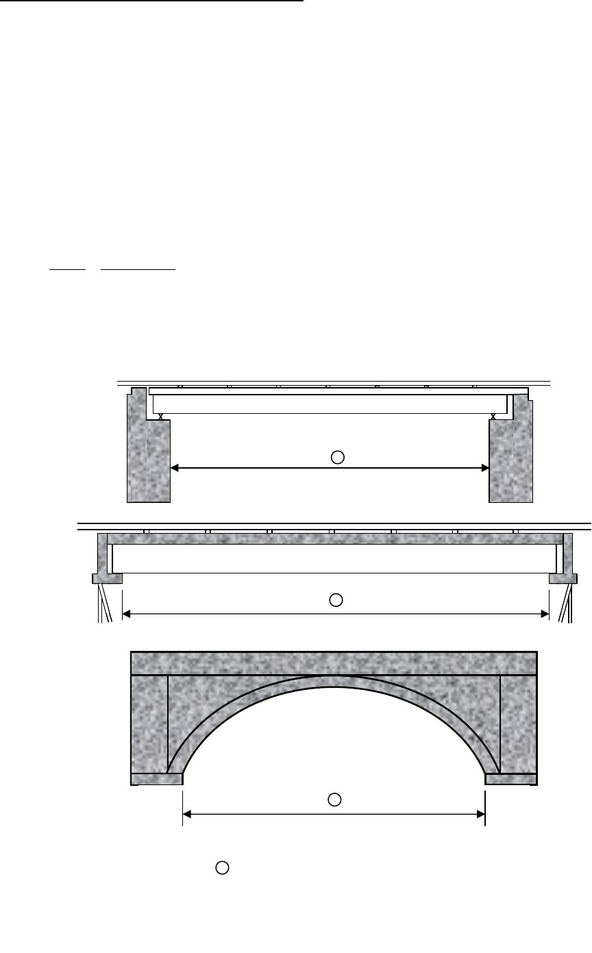
FEDERAL and STATE ITEM NUMBER ORDER Page 64 October 8, 2009
FEDERAL ITEM 112 - NBIS LENGTH – X (1)
INVENTORY – CLASSIFICATION
NBISLEN
TABLE - BRIDGE
Does this structure meet or exceed the minimum length specified to be designated as a bridge for
National Bridge Inspection Standards purposes? The following definition of a bridge is to be used:
A structure including supports erected over a depression or an obstruction, such as water,
highway, or railway, and having a track or passageway for carrying traffic or other moving loads,
and having an opening measured along the center of the roadway of more than
20 feet between undercopings of abutments or spring lines of arches, or extreme ends of
openings for multiple boxes; it may also include multiple pipes, where the clear distance between
openings is less than half of the smaller contiguous opening.
In addition to the above, the structure must carry a highway.
Code
Description
Y Yes
N No
EDIT CHECK
If Item 112 = Y then Item 49 must be >= 20
1
1
1
Item 112 – NBIS Bridge Length
1
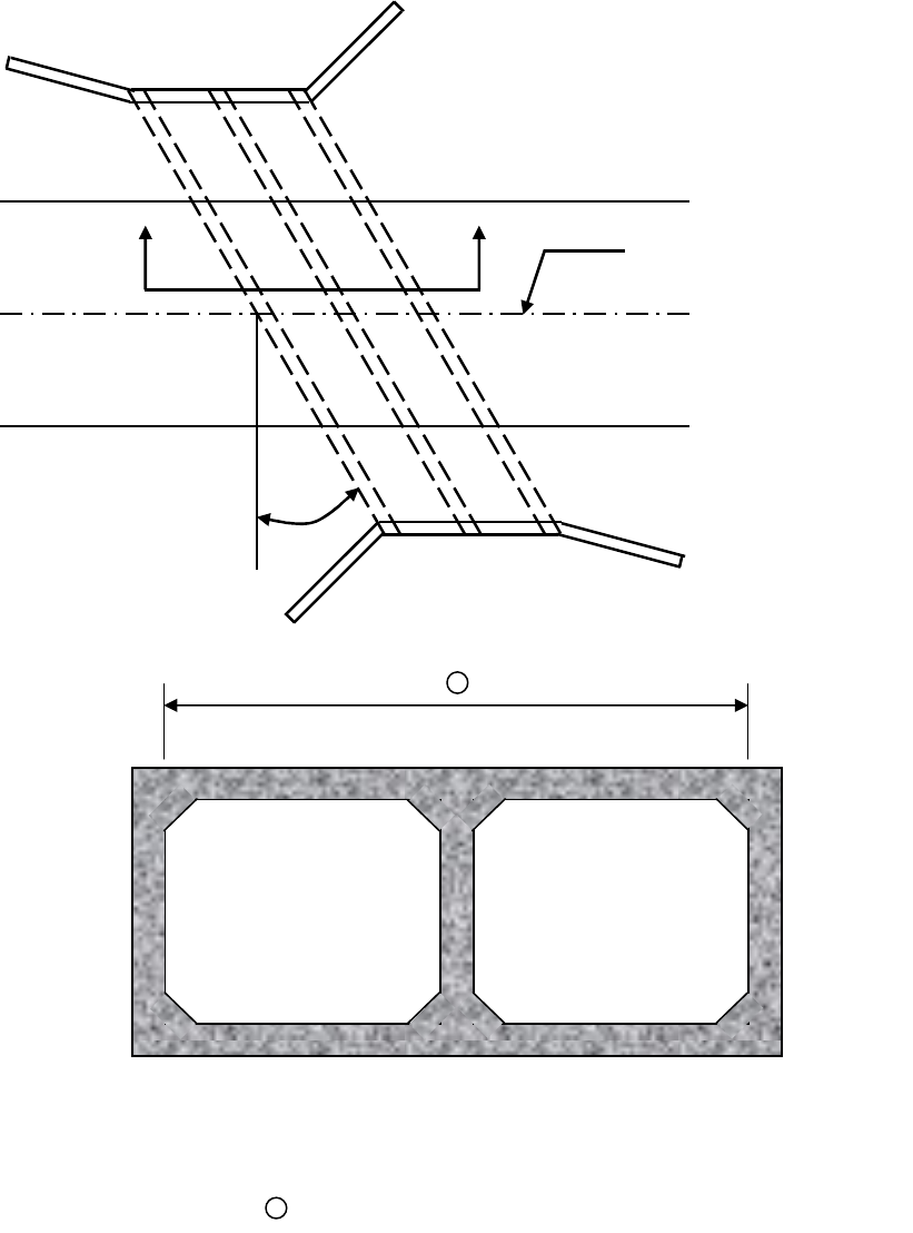
FEDERAL and STATE ITEM NUMBER ORDER Page 65 October 8, 2009
1
SECTION A
-
A
Centerline Roadway
A A
30º
Item 112 – NBIS Bridge Length
1
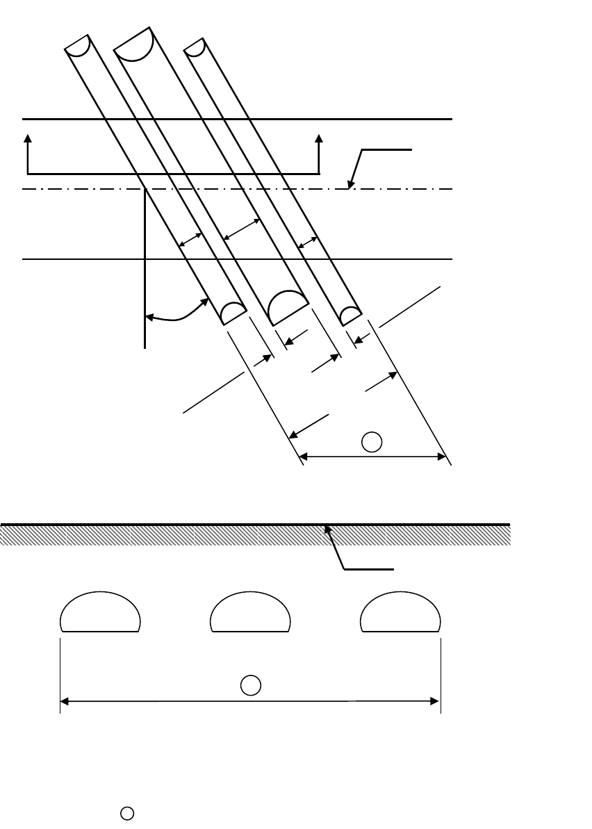
FEDERAL and STATE ITEM NUMBER ORDER Page 66 October 8, 2009
SECTION B - B
Centerline Roadway
1
0.5’
0.5’
Centerline Roadway
B B
30º
5’ 7’ 3’
16.0’
1
Item 112 – NBIS Bridge Length
1

FEDERAL and STATE ITEM NUMBER ORDER Page 67 October 8, 2009
FEDERAL ITEM 113 - SCOUR CRITICAL BRIDGES – X (1)
APPRAISAL – OTHER RATINGS
SCOURCRIT
TABLE - INSPEVNT
Use a single-digit code as indicated below to identify the current status of the bridge regarding its
vulnerability to scour. Evaluations shall be made by hydraulic/geotechnical/structural engineers. Guidance
on conducting a scour evaluation is included in the FHWA Technical Advisory T 5140.23 titled, "Evaluating
Scour at Bridges." Detailed engineering guidance is provided in the Hydraulic Engineering Circular 18 titled
"Evaluating Scour at Bridges." Whenever a rating factor of 2 or below is determined for this item, the rating
factor for Item 60 -- Substructure and other affected items (i.e., load ratings, superstructure rating) should
be revised to be consistent with the severity of observed scour and resultant damage to the bridge. A plan
of action will be developed for each scour critical bridge (see FHWA Technical Advisory T 5140.23, HEC
18 and HEC 23). A scour critical bridge is one with abutment or pier foundation rated as unstable due to (1)
observed scour at the bridge site (rating factor of 2, 1, or 0) or (2) a scour potential as determined from a
scour evaluation study (rating factor of 3). It is assumed that the coding of this item has been based on an
engineering evaluation, which includes consultation of the NBIS field inspection findings.

FEDERAL and STATE ITEM NUMBER ORDER Page 68 October 8, 2009
Code Description
N Bridge not over waterway.
U Bridge with ‘unknown’ foundation that has not been evaluated for scour. Until risk can be
determined, a plan of action should be developed and implemented to reduce the risk to
users from a bridge failure during and immediately after flood events.
T Bridge over ‘tidal’ water that has not been evaluated for scour, but considered low risk.
Bridge will be monitored with regular inspection cycle and with appropriate underwater
inspections until an evaluation is performed. (‘Unknown’ foundations in ‘tidal’ waters should
be coded U.)
9 Bridge foundations (including piles) on dry land well above flood water elevations.
8 Bridge foundations determined to be stable for the assessed or calculated scour condition.
Scour is determined to be above top of footing (Example A) by assessment (i.e., bridge
foundations are on rock formations that have been determined to resist scour within the
service life of the bridge), by calculation or by installation of properly designed
countermeasures (see HEC 23).
7 Countermeasures have been installed to mitigate an existing problem with scour at an
existing bridge to reduce the risk of bridge failure during a flood event. Instructions
contained in a plan of action have been implemented to reduce the risk to users from a
bridge failure during or immediately after a flood event.
6 Scour calculation/evaluation has not been made. (Use only to describe case where bridge
has not yet been evaluated for scour potential.)
5 Bridge foundations determined to be stable for assessed or calculated scour condition.
Scour is determined to be within the limits of footing or piles (Example B) by assessment
(i.e., bridge foundations are on rock formations that have been determined to resist scour
within the service life of the bridge), by calculations or by installation of properly designed
countermeasures (see HEC 23).
4 Bridge foundations determined to be stable for assessed or calculated scour conditions; field
review indicates action is required to protect exposed foundations (see HEC 23).
3 Bridge is scour critical; bridge foundations determined to be unstable for assessed or
calculated scour conditions:
- Scour within limits of footing or piles. (Example B)
- Scour below spread-footing base or pile tips. (Example C)
2 Bridge is scour critical; field review indicates that extensive scour has occurred at bridge
foundations, which are determined to be unstable by:
- a comparison of calculated scour and observed scour during the bridge inspection, or
- an engineering evaluation of the observed scour condition reported by the bridge
inspector in Item 60.
1 Bridge is scour critical; field review indicates that failure of piers/abutments is imminent.
Bridge is closed to traffic. Failure is imminent based on:
- a comparison of calculated and observed scour during the bridge inspection, or
- an engineering evaluation of the observed scour condition reported by the bridge
inspector in Item 60.
0 Bridge is scour critical. Bridge has failed and is closed to traffic.
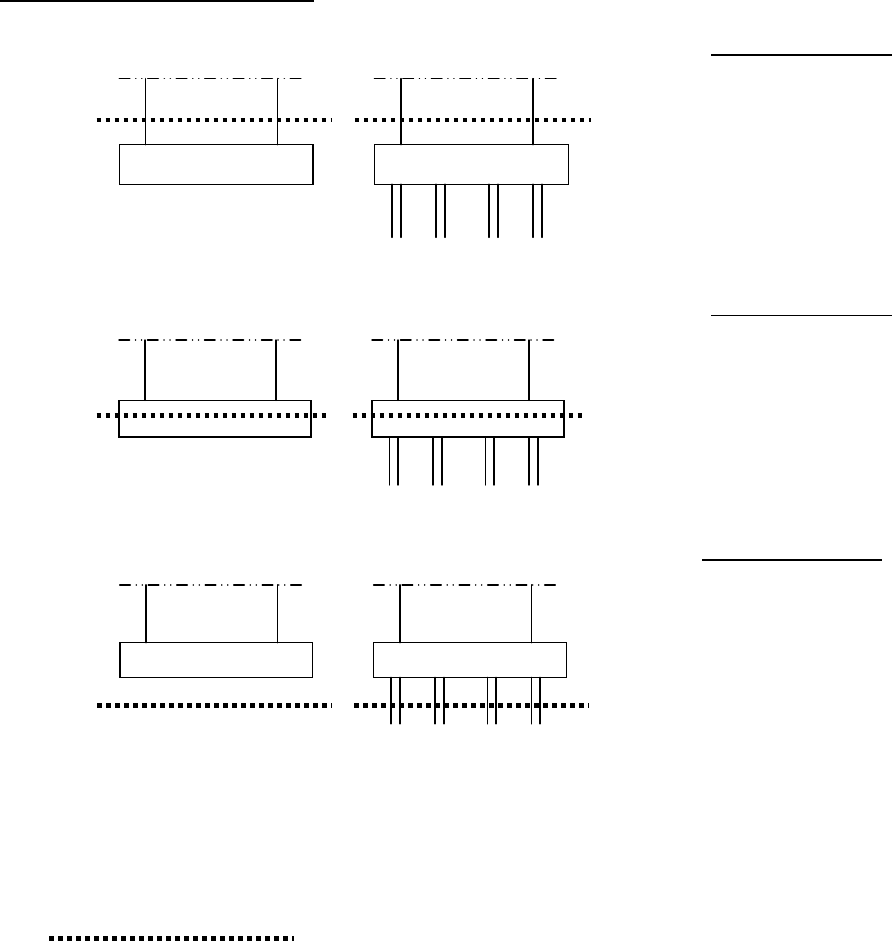
FEDERAL and STATE ITEM NUMBER ORDER Page 69 October 8, 2009
EXAMPLES:
CALCULATED SCOUR DEPTH
A. Above top of Footing.
ACTION NEEDED
None
B. Within limits of footing or piles
ACTION NEEDED
None if scour code = 5
Conduct foundation structural
analysis if scour code = 3 and
foundation has an assessed
scour condition
C. Below pile tips or spread footing base
ACTION NEEDED
Provide for monitoring and
scour countermeasures as
necessary
= Calculated Scour Depth
EDIT CHECK
If Item 42B = 5, 6, 7, 8, or 9 then Item 113 must be numeric.
If Item 42B = 1, 2, 3, or 4 then Item 113 must be N.
SPREAD FOOTING
(NOT FOUNDED IN ROCK)
PILE FOOTING

FEDERAL and STATE ITEM NUMBER ORDER Page 70 October 8, 2009
FEDERAL ITEM 114 - FUTURE AVERAGE DAILY TRAFFIC - XXXXXX (6)
INVENTORY – ROADS
ADTFUTURE
TABLE - ROADWAY
Code for all bridges the forecasted average daily traffic (ADT) for the inventory route identified in Item
5. This shall be projected at least 17 years but no more than 22 years from the year data is submitted
to the NBI. The intent is to provide a basis for a 20-year forecast. This item may be updated anytime,
but must be updated when the forecast falls below the 17-year limit. If planning data is not available,
use the best estimate based on site familiarity.
The future ADT must be compatible with the other items coded for the bridge. For example, parallel
bridges with an open median are coded as follows: if Item 28 - Lanes On and Under the Structure and
Item 51 - Bridge Roadway Width, Curb-to-Curb are coded for each bridge separately, then the future
ADT must be coded for each bridge separately (not the total for the route).
EXAMPLES: Code
Future ADT 540
000540
15,600
015600
240,000
240000
EDIT CHECK
Item 114 must be < or = 4.0 times Item 29 and Item 114 must be > or = 0.4 times Item 29.
A warning is issued if Item 114 is > 200,000.
FEDERAL ITEM 115 - YEAR OF FUTURE AVERAGE DAILY TRAFFIC - XXXX (4)
INVENTORY – ROADS
ADTFUTYEAR
TABLE - ROADWAY
Record and code the year represented by the future ADT in Item 114. The projected year of future
ADT shall be at least 17 years but no more than 22 years from the year of inspection.
EXAMPLE: Code
Year of Future ADT is 2008 08
EDIT CHECK - Item 115 must be >= 17 years and <= 22 years since date of last inspection.
FEDERAL ITEM 116 - MINIMUM NAVIGATION VERTICAL CLEARANCE,
APPRAISAL – OTHER RATINGS VERTICAL LIFT BRIDGE - XXX (3)
LFTBRNAVCL
TABLE - BRIDGE
Record to the nearest foot (rounding down) the minimum vertical clearance imposed at the site as
measured above a datum that is specified on a navigation permit issued by a control agency. Code
this item only for vertical lift bridges in the dropped or closed position, otherwise leave blank.
EXAMPLES: Code
Vertical Clearance 20.6 020
24.2 024
EDIT CHECK - If Item 43B = 15 then Item 116 must NOT be blank.

FEDERAL and STATE ITEM NUMBER ORDER Page 71 October 8, 2009
STATE ITEM 1 - RESIDENCY CODE - XX
AGENCY – BRIDGE
RESID_CODE
TABLE - USERBRDG
This is the number of the Residency in which the structure is geographically located.
STATE ITEM 2 - COUNTY OR CITY - XXX
AGENCY – BRIDGE
CITY_CNTY_CODE
TABLE - USERBRDG
The structures are ordinarily inventoried under the county/city where that structure is geographically
located. (See the County or City Code Tables in the Appendix.)
Structures located in towns or cities with a population over 3,500 are inventoried in that city or town
regardless of the maintenance responsibility.
Structures located in towns with a population under 3,500 which have chosen to maintain their own
street are inventoried in the county in which the town is located and the maintenance responsibility
field should reflect the town code.
If the structure is on a county-county line, county-city line or city-city line, and the maintenance
county/city is on the line, the structure is inventoried under the maintenance county/city.
If the structure is maintained jointly, inventory he structure under the lowest numbered county or city.
If the structure is within a county or city but is maintained by another county or city, inventory the
structure under the county or city where it is geographically located.
STATE ITEM 3 - HTRIS STRUCTURE ID - Automatic Entry
INVENTORY – ID/ADMIN
STRUCT_NUM
TABLE - BRIDGE
SAME AS FEDERAL ITEM 8
This is a unique number assigned when a structure is added to the system. Its purpose is to allow a
structure record to be maintained without limitation of county or structure number. A replacement
structure will be assigned a new Structure ID but may carry the old county and structure number.
History and inspection Data records are linked by the structure ID.
STATE ITEM 4 - VA STRUCTURE NUMBER - XXXX
AGENCY – BRIDGE
VA_STRUC_NO
TABLE - USERBRDG
This is the structure number assigned by the State of Virginia.

FEDERAL and STATE ITEM NUMBER ORDER Page 72 October 8, 2009
STATE ITEM 5 - LANE ON INVENTORY ROUTE - X
AGENCY – ROADWAYS
LANE_ON_RTE
TABLE - USERRWAY
The direction of traffic on the structure according to the Straight Line Diagram shall be used for all
routes including ramps.
Code Description
Blank
Not Applicable
N Northbound
E Eastbound
S Southbound
W Westbound
R Reversible
P Parallel Route
1 Express Northbound
2 Express Eastbound
3 Express Southbound
4 Express Westbound
5 Express Reversible
STATE ITEM 6 – NAME (Previously - BRIDGE NAME) - XXXXXXXXXXXXXXXXXXXXXXXXX (25)
INVENTORY – ID/ADMIN
ROADWAY_NAME
TABLE - ROADWAY
This is the given or assumed name of a bridge. When available this item should be the official name
of a bridge. The unofficial local name of a bridge can also be used. Bridges with “official” names are
those named by the General Assembly or the Commonwealth Transportation Board and can be found
in the booklet titled “Virginia Route Index”. The Traffic Engineering Division prepares this booklet.
STATE ITEM 7 - HTRIS ROUTE ID - XXXXXXXXXXXXXX (14)
AGENCY – ROADWAY
HTRIS_ROUTE_ID
TABLE - USERRWAY
Virginia Note: This is an automatic entry.
This is a unique identification for all roads in the Link/Node Inventory System. It can be sub-defined as
follows:
ROUTE PREFIX
(Positions 1 -4)
ROUTE TYPE
Position 1
A Alternate
B Bypass
C Commercial (Business)
E Extension/Connector
T Truck Route
Y Wye
Blank Not Applicable

FEDERAL and STATE ITEM NUMBER ORDER Page 73 October 8, 2009
CO/CITY/SIGNING
Position 2
O Old
T Temporary
C Under Construction
N First digit of City Code for City Street
N Digit identifying distinct route for Alternate, Bypass, Commercial, or Parallel
Position 3 & 4
IS Interstate
US U. S. Route
SR State Route
FR Frontage Road
Nn Two digits of County
Code
(Use maintenance county for secondary roads and
use jurisdiction county for county roads)
Nn Second and third digits of City Code for City Street
ROUTE NUMBER
(Positions 5-9)
Nnnnn State-assigned number
Nnnnn Off-system Federal Aid No. (requires Co/City Code)
ROUTE SUFFIX
(Positions 10-14)
ROUTE DIRECTION
Position 10
P Parallel Route
N Northbound
E Eastbound
S Southbound
W Westbound
R Reversible
1 Express Northbound
2 Express Eastbound
3 Express Southbound
4 Express Westbound
5 Express Reversible
Blank Not Applicable
SPECIAL FEATURES TYPE
Position 11
D Distributor/Collector
C Channelized Turn Lane
T On-Ramp (To)
F Off-Ramp (From)
I Intersectional Cross-over
R Rest Area
W Weigh Station
Blank Not Applicable
SPECIAL FEATURE NUMBER
Positions 12-14
Nnn State-assigned number (e.g., ramp number)
Blank Not Applicable

FEDERAL and STATE ITEM NUMBER ORDER Page 74 October 8, 2009
STATE ITEM 8 - NODE NUMBER - XXXXXX
AGENCY – ROADWAY
START_NODE_NO
TABLE - USERRWAY
Virginia Note: This is an automatic entry.
This is the node number that begins this link for this route. As a link record is built, the beginning and
ending nodes for the link are identified. A record for each of these nodes must be created at the same
time into this file store.
STATE ITEM 9 - NODE OFFSET - XXX.XXX
AGENCY – ROADWAY
START_NODE_OFFSET
TABLE - USERRWAY
Virginia Note: This is an automatic entry.
This is the distance that the data element is from the begin node.
STATE ITEM 10 - ADJACENT COUNTY, CITY - XXX
AGENCY – BRIDGE
ADJ_CITY_CNTY
TABLE - USERBRDG
If the structure is on a county or city line the code for the county or city adjacent to the structure that is
being inventoried.
STATE ITEM 11 - NATIONAL PARK SERVICE STRUCTURE NUMBER - XXXXXXXX
SINCE THE FHWA INSPECTS THESE BRIDGES AND VDOT HAS NO REPORTING RESPONSIBILITIES, THIS ITEM IS
OBSOLETE.
STATE ITEM 12 - SPECIAL USE CODE - XX
AGENCY – BRIDGE
SPEC_USAGE
TABLE - USERBRDG
This two-digit code is used to supplement the inventory for the special use of a structure. An example
is the structure on coal hauling highways. This is to be a user-defined table controlled by the Districts.
PE
FATIGUE PRONE & ELECTROSLAG WELDS
ES
Electroslag welds (OBSOLETE)
H
Pin & Link Hangers (OBSOLETE)
L
Low Water structures (OBSOLETE)
F
FORESTRY ROUTES
P
FATIGUE PRONE
U
ULTRASONIC INSPECTION REQUIRED
B
CONTRACT TO BE LET FOR BRUSH REMOVAL (NOVA)
C
BARS CHECKED (SALEM)
V
ANALYZED WITH VA LEGAL LOADS (SALEM)
STATE ITEM 13 - ORIGINAL PLAN NUMBER - XXX-XXX
AGENCY – BRIDGE
ORIG_PLAN
TABLE - USERBRDG
Code the original special design plan number for the structure in place. When a structure is built with
multiple standard plans and has a plan number, this field should be coded.

FEDERAL and STATE ITEM NUMBER ORDER Page 75 October 8, 2009
STATE ITEM 13 - ORIGINAL STANDARD PLAN NUMBER - XXXXXXXXXXXXXXXX (16)
AGENCY – BRIDGE
ORIG_STD_PLAN
TABLE - USERBRDG
Code the original standard plan number for the structure in place.
STATE ITEM 14 - RECONSTRUCTION PLAN NUMBER - XXX-XXX
AGENCY – BRIDGE
RECON_PLAN
TABLE - USERBRDG
Code the reconstruction special design plan number for the structure in place. When a structure is
built with multiple standard plans and has a plan number, this field should be coded.
STATE ITEM 14 - RECONSTRUCTION STANDARD PLAN NO. - XXXXXXXXXXXXXXXX (16)
AGENCY – BRIDGE
RECON_STD_PLAN
TABLE - USERBRDG
Code the reconstruction standard plan number for the structure in place. This should be coded when
there is no regular construction plan number.
STATE ITEM 15 - MAINTENANCE RESPONSIBILITY - STATE - XXX
AGENCY – BRIDGE
MAINT_RESP_STATE
TABLE - USERBRDG
This indicates the agency having responsibility for the maintenance of structures in the state. For
state or city maintenance, code the county or city number indicating the maintenance of the structure.
For other state facilities, railroads, Arlington and Henrico counties or other agency maintenance, code
alphabetically according the Agency Responsibility Tables (see rear of this manual).
For an interstate route within a city, code the number of the county that maintains the structure.
Where there is joint maintenance between a city and county, code the county number.
Where there is joint maintenance with and outside agency, code the proper county or city number.
STATE ITEM 18 - EXPANSION JOINTS OR DEVICES - XX
THIS ITEM WAS REPLACED BY PONTIS ELEMENTS
STATE ITEM 19 - ABUTMENT/CULVERT MATERIAL & TYPE, FOUNDATION OR PILES - X XX
AGENCY – BRIDGE
ABUT_A_MATER
ABUT_A_TYPE
ABUT_A _PMATER
ABUT_A_PTYPE
ABUT_B_MATER
ABUT_B_TYPE
ABUT_B_PMATER
ABUT_B_PTYPE
TABLE - USERBRDG
Code for Abutments A & B and Culverts.
(Code culvert foundation material in abutment A.)

FEDERAL and STATE ITEM NUMBER ORDER Page 76 October 8, 2009
Abutment Material and Type
Leave blank for Culverts.
The first position indicates kind of MATERIAL.
CODE
DESCRIPTION
1 Concrete
2 Steel
3 Timber
4 Masonry
0 Other
The second and third positions indicate TYPE of design and/or construction.
CODE
DESCRIPTION
01 Shelf or stub
02 Solid or Gravity
03 Column or Open
04 Curtain Wall
05 Cantilever
06 Bent
07 Cribwall
08 Integral
09 Reinforced Earth, etc.
00 Other
Foundation/Piles Material and Type
The first position indicates the type of/or kind of MATERIAL used for the foundation or piles.
CODE
DESCRIPTION
1 Solid Rock
2 Improved Foundation (Select Aggregate, geo-grid)
3 Firm Material
4 Pre-consolidated Fill
5 Steel
6 Concrete
7 Prestressed Concrete
8 Timber
0 Other

FEDERAL and STATE ITEM NUMBER ORDER Page 77 October 8, 2009
The second and third position indicated spread footing or pile design TYPE.
CODE
DESCRIPTION
01 Spread Footing
02 Piles, Precast or Prefabricated
03 Piles, C-I-P
04 Drilled Shaft
00 Other (used for culverts not on piles.)
3 00 - Unknown
0 00 - Unknown, but likely something other than firm material
STATE ITEM 20 - PIERS TYPE - MAIN - SEE BELOW
AGENCY – BRIDGE
MAIN_PIER_A_NO
MAIN_PIER_B_NO
MAIN_PIER_C_NO
MAIN_PIER_D_NO
MAIN_PIER_E_NO
MAIN_PIER_A_MATER
MAIN_PIER_B_MATER
MAIN_PIER_C_MATER
MAIN_PIER_D_MATER
MAIN_PIER_E_MATER
MAIN_PIER_A_TYPE
MAIN_PIER_B_TYPE
MAIN_PIER_C_TYPE
MAIN_PIER_D_TYPE
MAIN_PIER_E_TYPE
MAIN_PIER_A_PMATER
MAIN_PIER_B_PMATER
MAIN_PIER_C_PMATER
MAIN_PIER_D_PMATER
MAIN_PIER_E_PMATER
MAIN_PIER_A_PTYPE
MAIN_PIER_B_PTYPE
MAIN_PIER_C_PTYPE
MAIN_PIER_D_PTYPE
MAIN_PIER_E_PTYPE
TABLE - USERBRDG
Number - XX
Material and Type - X XX
Foundation/Piles Material and Type - X XX
Pier - Number of
The number of any one type of pier and foundation combination (i.e. one type of pier may be used in
combination with two or more foundations.)
Pier - Material and Type
The first position of this code will indicate kind of MATERIAL.
CODE
DESCRIPTION
1 Concrete
2 Steel
3 Timber
4 Masonry
0 Other

FEDERAL and STATE ITEM NUMBER ORDER Page 78 October 8, 2009
The second and third positions will indicate TYPE of design and/or construction.
CODE
DESCRIPTION
01 Solid
02 Column - single
03 Column - webwall
04 Drilled-In-Caisson
05 Bent - column
06 Bent - pile
07 Single Stem - hammerhead
08 Collision Wall
09 Pivot
10 Bascule
11 Rest Bent
00 Other
Pier Foundation or Piles
The first position indicates the kind of MATERIAL used for piles or for bearing for spread footing.
CODE
DESCRIPTION
1 Solid Rock
2 Improve Foundation (select aggregate, geo-grid)
3 Firm Material
4 Preconsolidated Fill
5 Steel
6 Concrete
7 Prestressed Concrete
8 Timber
0 Other
The second and third positions will indicate the spread footing or piles design TYPE.
CODE
DESCRIPTION
01 Spread Footing
02 Piles, Precast or Prefabricated
03 Piles, C-I-P
04 Drilled Shaft
00 Other

FEDERAL and STATE ITEM NUMBER ORDER Page 79 October 8, 2009
STATE ITEM 21 - PIERS TYPE - APPROACH
AGENCY – BRIDGE
APPR_PIER_A_NO
APPR_PIER_B_NO
APPR_PIER_C_NO
APPR_PIER_D_NO
APPR_PIER_E_NO
APPR_PIER_A_MATER
APPR_PIER_B_MATER
APPR_PIER_C_MATER
APPR_PIER_D_MATER
APPR_PIER_E_MATER
APPR_PIER_A_TYPE
APPR_PIER_B_TYPE
APPR_PIER_C_TYPE
APPR_PIER_D_TYPE
APPR_PIER_E_TYPE
APPR_PIER_A_PMATER
APPR_PIER_B_PMATER
APPR_PIER_C_PMATER
APPR_PIER_D_PMATER
APPR_PIER_E_PMATER
APPR_PIER_A_PTYPE
APPR_PIER_B_PTYPE
APPR_PIER_C_PTYPE
APPR_PIER_D_PTYPE
APPR_PIER_E_PTYPE
TABLE - USERBRDG
- Number = (Code as shown above for Main)
- Material & Type = (Code as shown above for Main)
- Fnd/Piles = (Code as shown above for Main)
STATE ITEM 22 - OPENINGS, NUMBER OF - XX
AGENCY – BRIDGE
DRAIN_OPEN
TABLE - USERBRDG
The number of opening in the given drainage structure or the number of tubes of a tunnel
STATE ITEM 23 - WIDTH OR DIAMETER - XX.X
AGENCY – BRIDGE
DRAIN_WIDTH
TABLE - USERBRDG
Code width or diameter or an opening to the nearest tenth of a foot. For multiple culverts or pipes
having unequal openings, this shall be the width or diameter of the SMALLEST opening.
STATE ITEM 24 - HEIGHT - XX.X
AGENCY – BRIDGE
DRAIN_HT
TABLE - USERBRDG
Design height of an opening to the nearest tenth of a foot. For multiple culverts or non-circular pipes,
this shall be the height of the SMALLEST multiple opening.
For circular openings leave this item blank
.

FEDERAL and STATE ITEM NUMBER ORDER Page 80 October 8, 2009
STATE ITEM 25 - BARREL LENGTH - XXXX
AGENCY – BRIDGE
DRAIN_BARL_LENG
TABLE - USERBRDG
Code total barrel length along the flowline to the nearest foot. When the extension of an existing
structure is of a different size, code the data for the entire portion (all sizes) and note the differences in
the report.
STATE ITEM 26 - DEPTH OF FILL - XX
AGENCY – BRIDGE
DRAIN_DEPTH_FILL
TABLE - USERBRDG
This is the maximum amount of fill above the culvert. Code to the nearest foot.
STATE ITEM 27 - YEAR RECONSTRUCTED - XXXX
AGENCY – BRIDGE
YR_RECON
TABLE - USERBRDG
Code the last year reconstructed for any reconstruction where a plan is involved and the entire
structure is not replaced. This field would be coded whether or not Item 106 is coded.
CODE
DESCRIPTION
1961 Reconstructed in 1961
STATE ITEM 28 - HORIZONTAL CLEARANCE UNDER ROUTE - LEFT - XX.X
STATE ITEM 29 - HORIZONTAL CLEARANCE UNDER ROUTE – RIGHT (SINGLE) - XX.X
AGENCY – ROADWAYS
THEN CLICK ON NEXT ROW AT BOTTOM
HORIZ_UNDER_LEFT
HORIZ_UNDER_RIGHT
TABLE - USERRWAY
The minimum horizontal clearance for passing under the structure should be measured and recorded.
The clearance should be the least available clearance measured between the most restrictive
features -- curbs, rails, walls, or other structural features limiting the roadway (surface and shoulders).
The measurement should be recorded and coded to the nearest tenth of a foot.
The purpose of this item is to determine the width available for the movement of wide loads. This item
will include the roadway surface and shoulders, distance from face of pier or toe of slope or to the face
of guardrail or non-mountable medians (Item 33 - Bridge Median coded 2) whichever is the most
restrictive. See sketch below for further details
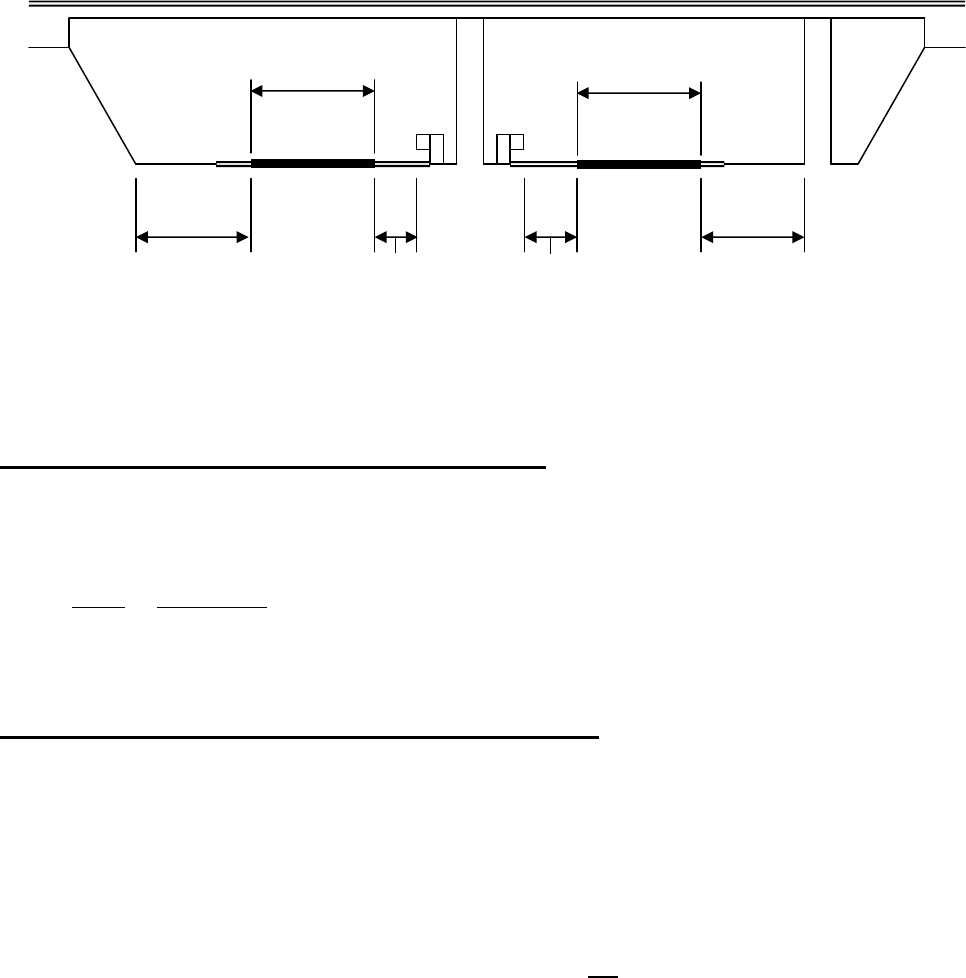
FEDERAL and STATE ITEM NUMBER ORDER Page 81 October 8, 2009
EXAMPLE: (Looking in the direction of increasing milepost)
STATE ITEM 30 - SCOUR CRITICAL EVALUATION - X
AGENCY – BRIDGE
SCOUR_CRIT_IND
TABLE - USERBRDG
This is a single-digit code indicating the need for a Scour Critical Study.
Code Description
Y Study Required
N No Study Required
C Study Complete
STATE ITEM 31 - SCOUR CRITICAL REMARKS CODE - XX
AGENCY – BRIDGE
SCOUR_CRIT_REMRK
TABLE - USERBRDG
The following is the anticipated coding for this item as discussed at a February 1995 bridge scour
workshop. These codes may be used at this time.
This is used to indicate the results/status of the scour study.
EF Indicates that a study by a consultant is required.
ET A full hydraulic and hydrologic analysis has not been completed and temporary
monitoring is being utilized until the study is complete.
FM A full hydraulic and hydrologic analysis has been completed and permanent
monitoring is being utilized as part of the recommendations.
FT A full hydraulic and hydrologic analysis has been completed and temporary
monitoring is being utilized until recommended remedial measures are completed.
Blank Indicates that a study and all remedial measures are completed or if Item 113 is
coded a 6, that the district will complete the analysis.
* - Face of a rigid barrier or face of raised median or face of
non-mountable curb or face of guardrail
State Item 28 = 71.3 State Item 29 = 63.7
24.0’
2:1 Slope
29.1’
18.2’
19.3’
20.4’
* *
24.0’
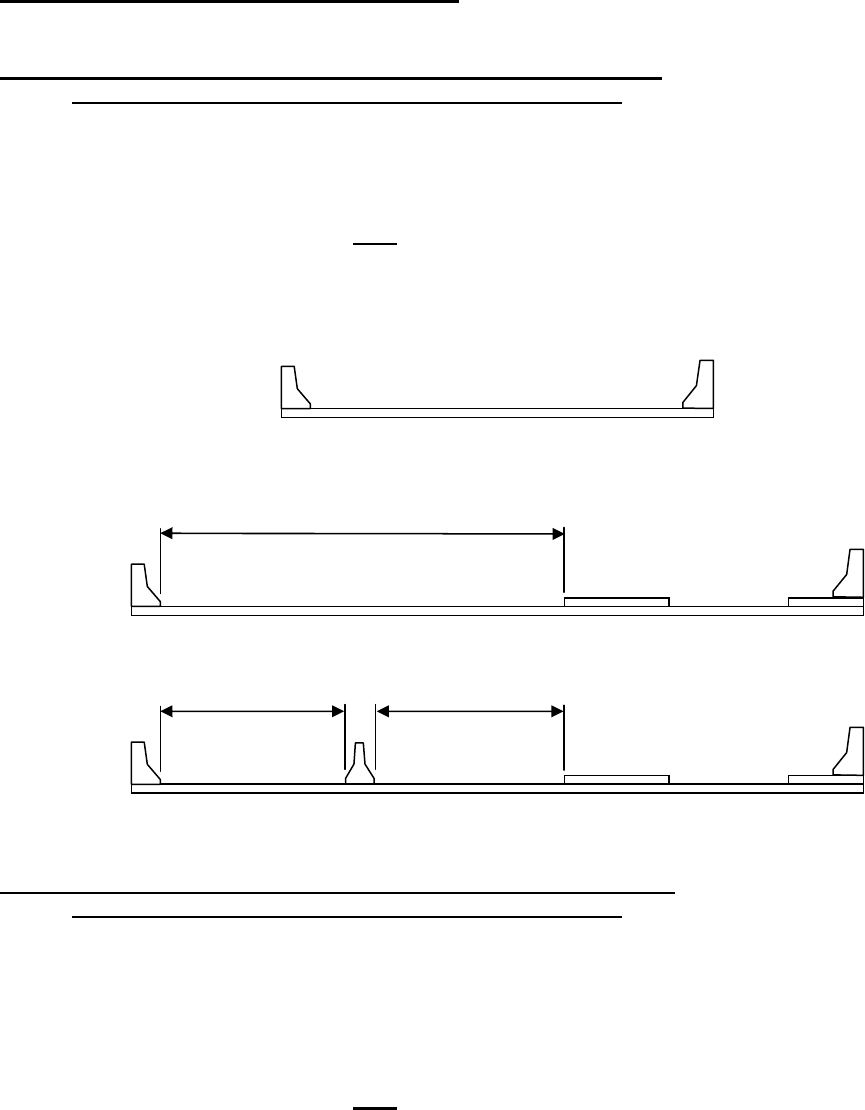
FEDERAL and STATE ITEM NUMBER ORDER Page 82 October 8, 2009
STATE ITEM 32 -DATE DELETED - XX/XX/XX
OBSOLETE FIELD
STATE ITEM 33 - BRIDGE ROADWAY WIDTH - LEFT SIDE - XX.X
MINIMUM CURB-TO-CURB OF MAINLINE ROUTE (FT)
AGENCY – ROADWAYS
WIDTH_ROAD_LEFT
TABLE - USERRWAY
If Federal Item 33 is coded 0 then this item should be 00.0.
If Federal Item 33 is coded 1, 2 or 3 and the median that exists separates a mainline road from a
ramp, bikeway, pedestrian way, etc. only Item 34 will be coded and the measurement will be from
curb-to-curb of the mainline route.
See sketches below.
STATE ITEM 34 - BRIDGE ROADWAY WIDTH - RIGHT SIDE - XX.X
MINIMUM CURB-TO-CURB OF MAINLINE ROUTE (FT)
AGENCY – ROADWAYS
WIDTH_ROAD_RIGHT
TABLE - USERRWAY
If Federal Item 33 is coded 0 then this item should be 00.0. If Federal Item 33 is coded 1, 2 or 3 then
this item must be coded.
If Federal Item 33 is coded 1, 2 or 3 and the median that exists separates a mainline road from a
ramp, bikeway, pedestrian way, etc. only this item will be coded and the measurement will be from
curb-to-curb of the mainline route.
See sketches above.
Item 33 and Item 34 = 00.0
Mainline Route – Where Median is coded 0
ramp, bikeway,
pedestrian way, etc.
Item 33 = 00.0
Item 34 to be this dimension
Mainline Route – Median is coded 1, 2 or 3
Item 34
Item 33
ramp, bikeway,
pedestrian way, etc.
Looking in the Direction of the Mainline Route
Median is coded 1, 2 or 3

FEDERAL and STATE ITEM NUMBER ORDER Page 83 October 8, 2009
STATE ITEM 35 - WIDTH OF MEDIAN (FT) - XXX
AGENCY – ROADWAYS
WIDTH_MEDIAN
TABLE - USERRWAY
Record the measurement in feet. If Federal Item 33 is coded 1, 2 or 3 then this item must be coded. If
Federal Item 33 is coded 0 then this item should be blank.
STATE ITEM 36 - MIN. VERT. UNDERCLEARANCE-RIGHT OR SINGLE- X XX(feet) XX(inches)
AGENCY – ROADWAYS
THEN CLICK ON NEXT ROW AT BOTTOM
VERT_UNDER_RIGHT_CODE
VERT_UNDER_RIGHT
TABLE - USERRWAY
See Virginia Note under Federal Item 54.
Using a 1-digit code and a 4-digit number, record and code the minimum vertical clearance from the
right/single roadway or right/single railroad track beneath the structure to the underside of the
superstructure. (When both a railroad and highway are under the structure, code the most restrictive
dimension.)
Segment
Description Length
36A Reference feature 1 digit
36B Minimum Vertical Underclearance
4 digit
Using one of the codes below, code in the first position, the reference feature from which the
clearance measurement is taken:
Code
Description
H Highway beneath structure
R Railroad beneath structure
N Feature not a highway or railroad
In the next 4 positions, code a 4-digit number to represent the minimum vertical clearance from that
feature to the structure. If the feature is not a highway or railroad, code the minimum vertical
clearance 0000.
STATE ITEM 37 - MINIMUM VERTICAL UNDERCLEARANCE - LEFT - X XX(feet) XX(inches)
AGENCY – ROADWAYS
THEN CLICK ON NEXT ROW AT BOTTOM
VERT_UNDER_LEFT_CODE
VERT_UNDER_LEFT
TABLE - USERRWAY
See Virginia Note under Federal Item 54.
If the feature beneath the structure has more than a single roadway or single railroad then using a 1-
digit code and a 4-digit number, record and code the minimum vertical clearance from the left roadway
or left railroad track beneath the structure to the underside of the superstructure. (When both a
railroad and highway are under the structure, code the most restrictive dimension.)
Segment
Description Length
37A Reference feature 1 digit
37B Minimum Vertical Underclearance
4 digit
Using one of the codes below, code in the first position, the reference feature from which the
clearance measurement is taken:

FEDERAL and STATE ITEM NUMBER ORDER Page 84 October 8, 2009
Code
Description
H Highway beneath structure
R Railroad beneath structure
N Feature not a highway or railroad
In the next 4 positions, code a 4-digit number to represent the minimum vertical clearance from that
feature to the structure. If the feature is not a highway or railroad, code the minimum vertical
clearance 0000.
STATE ITEM 38 - TOTAL REPLACEMENT INDICATOR - X
AGENCY – BRIDGE
REPL_STRUC
TABLE - USERBRDG
Indicates that this structure is a replacement structure. NO PORTION OF THE PREVIOUS
STRUCTURE EXISTS. This field must be coded when a structure is replaced.
Code
Description
Y New structure totally replaces an existing structure.
N New structure does not totally replace an existing structure.
STATE ITEM 39 - TYPE OF CONSTRUCTION - X
AGENCY – BRIDGE
TYPE_CONSTR
TABLE - USERBRDG
Indicates the construction type of the given structure.
Code
Description
B Precast Concrete Box Culvert.
C Culvert or Drainage structure.
D Parking Deck.
F Footbridge (structure which carries only pedestrians over a non-highway)
L Landing Dock or Wharf.
N Any bridge carrying a highway or highway/railroad not covered by another coding.
P Pedestrian Overpass (structure which carries only pedestrians over a highway)
R Railroad
S Scales
T Tunnel (Tunnels shall be coded as under records)
Z Plaza

FEDERAL and STATE ITEM NUMBER ORDER Page 85 October 8, 2009
STATE ITEM 40 - TYPE OF MODIFICATION - X
AGENCY – BRIDGE
TYPE_RECONST
TABLE - USERBRDG
Indicates the last type of modification to the structure.
Code Description
A Altered or remodeled (includes any change to the structure which increases the
original design load capacity or otherwise alters the functional use except for
widening of the bridge roadway deck, also includes all modifications made to
existing culverts or pipes).
D Deck Replacement.
M New Superstructure on existing substructure.
R Repaired Bridge (does not include culverts or pipes).
W Widened Bridge (does not include culverts or pipes).
Blank No modification has been made to structure.
STATE ITEM 41 - HBRRP INDICATOR - X
(HIGHWAY BRIDGE REPLACEMENT/REHABILITATION PROGRAM)
AGENCY – BRIDGE
BRBH_IND
TABLE - USERBRDG
CODE DESCRIPTION
Y Code a ‘Y’ in this field to remove a structure from the HBRRP lists once the
project has been let to contract or started by State Forces.
N
Code an ‘N’ in this field to denote ‘Not Applicable’.
Also, once work has been completed, this field should be changed to ‘N’.
When this field is changed from a ‘Y’ to an ‘N’ Item 106 - YEAR
RECONSTRUCTED (FED. FUNDS) and/or Item S27 YEAR
RECONSTRUCTED (STATE FUNDS) must be coded.
When the state spends money on repairing or rehabilitating a structure, it is not eligible for HBRRP
funds for ten years. However, there is a length of time where a contract is ‘let’ or work has begun and
the ‘Year Reconstructed’ date has not been coded because the work has not been completed.
This field is used to remove from lists of eligible HBRRP structures those structures that are not
eligible for HBRRP money because of ongoing on impending work, but the ‘Year Reconstructed’ date
has not been coded because the work has not been completed. This field must be updated once the
work has been completed.
The date built or the date of reconstruction does NOT cause the ‘*** HBRRP CANDIDATE ***’
indicator to be removed automatically.

FEDERAL and STATE ITEM NUMBER ORDER Page 86 October 8, 2009
STATE ITEM 42 - TIDAL INDICATOR - X
AGENCY – BRIDGE
TIDAL_IND
TABLE - USERBRDG
This is a single-digit code indicating whether the structure crosses tidal water.
Code Description
Y Yes, this is tidal water.
N No, this is not tidal water.
* Does not cross water (May be added when the PDA is placed into service)
STATE ITEM 44 - DESIGN LOAD - HIGH (STATE) - X
AGENCY – BRIDGE
DESIGN_LOAD_HIGH
TABLE - USERBRDG
Code the highest design capacity for a structure that has been widened or otherwise altered so that
different portions have different live-load designs. Use the same codes as Federal Item 31.
STATE ITEM 45 - RATED CAPACITY, SINGLE UNIT - XX
AGENCY – BRIDGE
RATG_CAPAC_SINGLE
TABLE - USERBRDG
Code the rated capacity in gross tons for the Virginia Legal 27 Ton vehicle.
Code Description
07 7 tons
20 20 tons
99 Greater that 100 tons
STATE ITEM 46 - RATED CAPACITY, SEMI - XX
AGENCY – BRIDGE
RATG_CAPAC_SEMI
TABLE - USERBRDG
Code the rated capacity in gross tons for the Virginia Legal 40 Ton Vehicle. See example above.
STATE ITEM 47 - STRESS LEVEL - X
AGENCY – BRIDGE
STRESS_LEVEL
TABLE - USERBRDG
(Inventory, Operating, or Mid-Range). The Stress Level used to determine the rated capacity of the
structure.
Code Description
I Inventory
O Operating
M Mid-Range

FEDERAL and STATE ITEM NUMBER ORDER Page 87 October 8, 2009
STATE ITEM 48 - METHOD OF ANALYSIS - X
AGENCY – BRIDGE
STRESS_METHOD
TABLE - USERBRDG
The Methodology used to calculate the capacity/capacities.
If Federal Item 64 & 66 AND If State Item 45 & 46
Code Figured by Figured by
W Working Stress Working Stress
X Working Stress Load Factor
Y Working Stress Load Resistance Factor
L Load Factor Load Factor
M Load Factor Working Stress
N Load Factor Load Resistance Factor
R Load Resistance Factor Load Resistance Factor
S Load Resistance Factor Working Stress
T Load Resistance Factor Load Factor
A Assumed Assumed
- No Analysis No Analysis
NOTE: Working Stress can still be used for non-NBI structures for Federal Item 64 and Federal Item
66. Culverts with fill greater than 15 feet (i.e. liveload is not a factor and Federal Item 64 and
Federal Item 66 is coded 299) should be coded L.
This item controls the coding of Federal Items 63 and 65.

FEDERAL and STATE ITEM NUMBER ORDER Page 88 October 8, 2009
STATE ITEM 49A – ANALYSIS PROGRAM NUMBER - XXXXXXXX
AGENCY – BRIDGE
BARS_PROG_NO
TABLE - USERBRDG
The ‘Analysis Program Number’ is comprised of the following designator of analysis type, county
number and structure number.
Code the First digit for Analysis Type material:
Code Description
A Structural Steel - OBSOLETE
B Reinforced Concrete – OBSOLETE
C Composite Steel and Concrete – OBSOLETE
D Prestressed Concrete – OBSOLETE
E Composite Prestressed Concrete – OBSOLETE
F Timber – OBSOLETE
G Composite Reinforced Concrete – OBSOLETE
H Truss - OBSOLETE
J STAAD
K Descus
L Brass
M Hand Calculations
N Not enough information known for analysis
P Conspan
R BARS
V Analysis performed by Virtis
X Analysis performed by other method – Check Virtis for more information on
the method used.
Z Analysis performed but deck or substructure controls – Check Virtis for more
information on the method used.
Code Positions 2 - 4 with the county or city number.
Code Positions 5 - 8 with the structure number.
EXAMPLE: The run for a structure number 1009 on Route 60 over Buffalo River in Amherst County
that had been analyzed by Virtis would be coded as: V0051009
Note: While this varies greatly from the previous coding of this item, no changes are necessary on a
particular structure until such time a new analysis is complete for that structure.
STATE ITEM 49B - ANALYSIS RUN DATE - XX/XX/XX
AGENCY – BRIDGE
BARS_RUN_DATE
TABLE - USERBRDG
This is the last date the structure was analyzed by any method.

FEDERAL and STATE ITEM NUMBER ORDER Page 89 October 8, 2009
STATE ITEM 50 - POSTED STATUS (POSTED OR CLOSED BRIDGE - X
AGENCY – BRIDGE
POSTED_STAT
TABLE - USERBRDG
This item provides information about the operational status of a structure.
Code Description
P Permanent Posting but not reported on the M-50 (For structures whose posting
is not the responsibility of the state - i.e. structures inspected and owned by a
municipality)
T 45T structures. Vehicles grossing more than 90
k
may not use the structure.
M Posted Structure reported on the M-50
Blank Not Posted
STATE ITEM 51 - POSTED DATE - XX/XX/XX
AGENCY – BRIDGE
POSTED_DATE
TABLE - USERBRDG
Record the month, day and year that the load posting sign, indicating the most current designated load
capacity, was placed. Code an 8-digit number to represent the month, day and year.
The date should change each time a reevaluation of load capacity requires changing the restriction
signs on a bridge. To the extent possible, this data should represent the actual date that a bridge is
posted or that the posting is removed.
EXAMPLE:
Code Description
11/05/1985 Bridge Posted November 5, 1985
05/16/1986 Bridge Posting removed May 16, 1986
STATE ITEM 52 - POSTED CAPACITY - R12-1 - XX
AGENCY – INSPECTIONS
POST_CAPAC_STD
TABLE - USERINSP
The limiting weight loading for a given structure. This is the gross tonnage posted on a R12-1 Sign for
a standard vehicle.
STATE ITEM 53 - POSTED CAPACITY - R12-5 SINGLE UNIT - XX
AGENCY – INSPECTIONS
POST_CAPAC_SINGLE
TABLE - USERINSP
The limiting weight loading for a given structure. This is the gross tonnage posted on a R12 - 5 Sign
for the 27-ton Virginia vehicle.
STATE ITEM 54 - POSTED CAPACITY - R12-5 SEMI - XX
AGENCY – INSPECTIONS
POST_CAPAC_SEMI
TABLE - USERINSP
The limiting weight loading for a given structure. This is the gross tonnage posted on a R12-5 Sign for
the 40 ton Virginia vehicle.

FEDERAL and STATE ITEM NUMBER ORDER Page 90 October 8, 2009
STATE ITEM 55 - POSTED SIGN MAINTENANCE REQUIRED - X
AGENCY – BRIDGE
POST_REQ
TABLE - USERBRDG
This is a flag indicating that a change has been made in the weight limit and sign maintenance is
needed but has not been done. This will be set to "Y" at the time the M108 is produced. When the
sign maintenance has been performed, the code will change to "C". Otherwise the code will be "N".
Code Description
Y Sign Maintenance Needed
C Sign Maintenance Complete
N No Sign Maintenance Required
STATE ITEM 56 - MAINTENANCE REPLACE COST - XXXXXX
AGENCY – INSPECTIONS
MAINT_REPAIR_COST
TABLE - USERINSP
Code a six-digit number to nearest thousand to represent the maintenance replacement cost required
to satisfy the level of service established by the Maintenance Division. This cost is not included for
structure in the six year improvement program unless the work is required to safely maintain traffic
before the scheduled improvement can be made.
If no repairs are necessary, this field should be filled with zeroes.
STATE ITEM 57 - MAINTENANCE REPLACEMENT FUNDING CODE - X
AGENCY – INSPECTIONS
MAINT_FUND_CODE
TABLE - USERINSP
This is a single-digit code indicating the highway system that funds/maintains the structure.
NOTE: This item should be coded exclusive of State Item 185 Virginia Highway System. For example,
it is possible for a structure to receive Interstate funding and be located on the Secondary
System.
The coding description below will be true for the majority of the structures. A special agreement
between a municipality and the State could affect the source of funding. If you are not aware of a
special agreement, use the codes below.

FEDERAL and STATE ITEM NUMBER ORDER Page 91 October 8, 2009
Code Description
I Interstate Funding Structures on an Interstate, crossing an Interstate or on a
frontage road of an Interstate, regardless of the jurisdiction
in which they reside.
P Primary Funding Structures on a Primary or a frontage road of a Primary that
do not cross an Interstate and are not maintained by a
municipality.
S Secondary Funding Structures on a Secondary that do not cross an Interstate,
are not on the frontage road of an Interstate, are not on the
frontage road of a Primary and are not maintained by a
municipality.
In the counties of Arlington and Henrico, all structures that
are NOT part of an Interstate or Primary system receive
secondary funding.
U
Urban Funding Structures maintained by a municipality and are on a Primary
or on a city street (non-numbered highway) and not crossing
an Interstate.
(See ‘Secondary Funding’ for coding of structures in the
counties of Arlington and Henrico.)
O
Other Structures that do not receive any of the above funding. For
example, structures where maintenance is coded (DGT),
(MWA), (PVT), (TJF), etc.
STATE ITEM 58 – PPMS PROJECT ID NUMBER - XXXXXXXXXXXXXXX
AGENCY – BRIDGE
UPC
TABLE - USERBRDG
This is the identification number the FMSII system assigns to projects. This number is used across the
enterprise to identify projects. It is unique to the project and will never be assigned to any other project.
STATE ITEM 59 - MAINTENANCE REPLACEMENT REMARKS CODE - XX
OBSOLETE
STATE ITEM 60 - REGULAR INSPECTOR'S CODE - XXX
SCHEDULE
INSPNAME
TABLE - USERINSP
This is the inspector number of the person, county, city or agency performing the bridge the regular
inspection for this structure. For State Inspectors, this will be the code for the team leader. This is a
user-defined table and will be maintained by Central Office.
STATE ITEM 61 - REGULAR INSPECTION - NEXT - CALCULATED
SCHEDULE
NEXTINSPEC
TABLE - INSPEVNT
This is the date will be calculated by a program at the time of changes to the inspection data. The
value is determined by adding the frequency to the actual inspection date or by adding the frequency
to the last scheduled date. Format is YY/MM/DD.

FEDERAL and STATE ITEM NUMBER ORDER Page 92 October 8, 2009
STATE ITEM 62 - SPECIAL INSPECTION CLASSIFICATION - X
AGENCY – INSPECTIONS
CRIT_FEAT_CLASS
TABLE - USERINSP
A one-digit code indicating the class of the Interim Inspections required. This user defined table and
will be maintained by the Central Office.
Code Description
1 Pin and Hanger (Redundant) (Obsolete)
2 Scour Monitor or Undermining
3 Vehicular or Drift damage
4 Posted Structure (Obsolete)
5 Concrete Structure (no plans)
6 Temporary Support (Obsolete)
7 Insect Infestation
8 Seam Cracks in Culverts
STATE ITEM 63 - SPECIAL EQUIPMENT INDICATOR - X
AGENCY – BRIDGE
SPEC_EQUIP_LADDER
SPEC_EQUIP_SNOOPER
SPEC_EQUIP_BOAT
SPEC_EQUIP_MANLIFT
SPEC_EQUIP_BUCKET_TRUCK
SPEC_EQUIP_PONTOON
SPEC_EQUIP_SCAFFOLD
SPEC_EQUIP_RIGGIN
SPEC_EQUIP_PLATFORM_TRUCK
TABLE - USERBRDG
This is a flag indicating the need of special equipment to perform the inspection. Value is a "Y" or
blank.
STATE ITEM 64 - SPEC. EQUIPMENT COMMENTS - XXXXXXXXXXXXXXXXXXXXXXXXX (25)
OBSOLETE
STATE ITEM 65 - SUFFICIENCY RATING - CALCULATED
APPRAISAL – OTHER RATINGS
SUFFIC_RATE
TABLE - INSPEVNT
The sufficiency rating is a programmed item as computed by the FHWA formula.
STATE ITEM 66 - DEFICIENCY POINT - CALCULATED
OBSOLETE
STATE ITEM 94 - LAST PAINTED DATE - XXXX
AGENCY - BRIDGE
YR-PAINTED
TABLE - USERBRDG
The year the structure was last painted.
STATE ITEM 170 - POSTING SIGN VISIBILITY - X
AGENCY - INSPECTIONS
POST_SIGN_VIS
TABLE - USERINSP
This field identifies the visibility of the posting sign using G (Good), F (Fair), P (Poor) or C (Critical).

FEDERAL and STATE ITEM NUMBER ORDER Page 93 October 8, 2009
STATE ITEM 171 – POSTING SIGN LEGIBILTY - X
AGENCY - INSPECTIONS
POST_SIGN_LEG
TABLE - USERINSP
This field identifies the legibility of the posting sign using G (Good), F (Fair), P (Poor) or C (Critical).
STATE ITEM 172 - INTERCHANGE SKETCH NUMBER - XXX
AGENCY - BRIDGE
SKETCH_NO
TABLE - USERBRDG
This field identifies the page number of the appropriate schematic sketch of an interchange in which
the structure is located.
STATE ITEM 173 - SPECIAL STRUCTURE CODE - XX
AGENCY - BRIDGE
SPEC_STRUC_CODE
TABLE - INSPEVNT
This code is used to supplement the Federal Structure Types. This code will indicate a special type of
design and/or construction. This is a user define table and will be maintained by the Central Office.
CODE
DESCRIPTION
01 Low water
02 Bailey Bridge
03 Covered bridge
04 Army H 10
05 Stabilized Fill
06 Pin and Hanger (Non Redundant)
07 Pin and Hanger (Redundant)
08 Curved Girder
09 Bebo Arch (NOVA District request)
10 Combination Pin & Hanger and Curved Bridge (NOVA District request)
11 Integral Backwalls (Integral Abutments are coded in State Item 19)
12 Metal culvert with concrete placed in the flowline (Lynchburg District request)
13 Hinge Pin (no link) (Richmond District request)
14 Modified Stabilized Earth (MSE) Walls present
15 Metal Culverts – Asphalt coated
16 Encroachment present
17 Pre-Cast Concrete Slab Span (Staunton District request)
STATE ITEM 176 - CRITICAL RECOMMENDATION INDICATOR - X
OBSOLETE
STATE ITEM 177 - CRITICAL RECOMMENDATION NOTICE DATE - XX/XX/XX
OBSOLETE
STATE ITEM 178 - CRITICAL RECOMMENDATION ACTION - X
OBSOLETE
STATE ITEM 179 - CRITICAL RECOMMENDATION STATUS CODE - X
OBSOLETE
STATE ITEM 180 - CRITICAL RECOMMENDATION ACTION DATE - XX/XX/XX
OBSOLETE
FEDERAL and STATE ITEM NUMBER ORDER Page 94 October 8, 2009
STATE ITEM 181 - CRITICAL RECOMMENDATION FOLLOW-UP INSPECTION - XX/XX/XX
OBSOLETE
STATE ITEM 182 - CRITICAL RECOMMENDATION REVIEW - DIV - XX/XX/XX
OBSOLETE
STATE ITEM 183 - CRITICAL RECOMMENDATION REVIEW - FHWA - XX/XX/XX
OBSOLETE
STATE ITEM 184 - PREVENTIVE MAINTENANCE CODE - X
OBSOLETE
STATE ITEM 185 - VIRGINIA HIGHWAY SYSTEM - X
AGENCY - ROADWAYS
VA_HWY_SYS
TABLE - USERRWAY
This is a single-digit code indicating the highway road system for this structure.
NOTE: This item should be coded exclusive of State Item 57 Maintenance Replacement Funding
Code. It is possible for a structure to be located on the Secondary System and receive
Interstate funding. For example, Route 600 over the interstate will receive interstate funding
even though it carries a secondary system road.
Code Description
I Interstate Road System Structures on an Interstate or on the frontage road of an
Interstate, regardless of the jurisdiction in which they
reside.
P Primary Road System Structures on a Primary or on the frontage road of a
Primary, regardless of the jurisdiction in which they
reside.
S Secondary Road System Structures on a Secondary and may cross an Interstate,
may be on the frontage road of an Interstate or may be
on the frontage road of a Primary. The structure is not
within the limits of a municipality.
U
Urban Road System Structures located within the limits of a municipality and
not on an Interstate or a Primary or on the frontage road
of an Interstate or a Primary. Structures can cross an
Interstate or a Primary and still be part of the Urban
Road System.
(Structures not on an Interstate or Primary and located
in and maintained by the counties of Arlington and
Henrico are considered to be on the urban road system.)
O
Other Structures not on one of the above systems.

FEDERAL and STATE ITEM NUMBER ORDER Page 95 October 8, 2009
STATE ITEM 186 - PAINT CLASSIFICATION - XX
AGENCY - BRIDGE
PAINT_SYS
TABLE - USERBRDG
This item is to be used for coding the type of paint system on the structure.
Code
Description
A Aluminum topcoat with lead primer (old system #1, #2 and #3).
B Color topcoat with lead primer (old system #2, #7, #8 and #50+).
C Mastic topcoat with lead primer (old system #1, #2 and #14).
D Various top coats with zinc rich primer or uncoated zinc rich primer (old system
#4, #6 and system B).
E A588 Steel - not painted (includes those structures where only the bearing
assemblies were painted or galvanized)
F A588 Steel - partially painted (system #4, #6 and systems B, B1 and B2).
G A588 Steel - totally painted (system #4, #6 and systems B, B1 and B2).
H *
Galvanized or Metallized.
I Other or several systems present.
X Non-steel structure (not typically used for concrete structures).
*
Galvanized and metallized structures are handled on the B-7 just like any
other coating would be handled.
STATE ITEM 189 - PPMS PROJECT STATUS CODE – XX
AGENCY - BRIDGE
PROJECT_STATUS_CODE
TABLE - USERBRDG
This is a code that indicates the current status of a project as a whole. See PPMS table 109.
Examples: active, temporarily deferred, indefinitely deferred, advertised, awarded.
