ROSEMOUNT OCX 8800 Comb Manual HAZ REM 200502
User Manual: ROSEMOUNT OCX 8800
Open the PDF directly: View PDF ![]() .
.
Page Count: 152 [warning: Documents this large are best viewed by clicking the View PDF Link!]
- Preface
- Definitions
- Symbols
- Essential Instructions
- Section 1 Description and Specifications
- Section 2 Installation
- Section 3 Configuration and Startup
- Section 4 Using HART Communications
- Section 5 Calibration
- Section 6 Maintenance and Service
- Section 7 Troubleshooting
- Section 8 Replacement Parts
- Appendix A Safety Data
- Appendix B SPA with HART Alarm
- Appendix C Return of Materials
http://www.raihome.com
Instruction Manual
IM-106-880 Original Issue
February 2005
OCX 8800
Oxygen/Combustibles Transmitter
Hazardous Area OCX 8800 Oxygen/Combustibles Analyzer with Remote Electronics

Instruction Manual
IM-106-880 Original Issue
February 2005 OCX 8800
http://www.raihome.com
Table of Contents
Essential Instructions. . . . . . . . . . . . . . . . . . . . . . . . . . . . . . . . . . . . . . . . i
Preface . . . . . . . . . . . . . . . . . . . . . . . . . . . . . . . . . . . . . . . . . . . . . . . . . . ii
Definitions . . . . . . . . . . . . . . . . . . . . . . . . . . . . . . . . . . . . . . . . . . . . . . . . ii
Symbols . . . . . . . . . . . . . . . . . . . . . . . . . . . . . . . . . . . . . . . . . . . . . . . . . . ii
SECTION 1
Description and
Specifications
Component Checklist. . . . . . . . . . . . . . . . . . . . . . . . . . . . . . . . . . . . . . 1-1
System Overview. . . . . . . . . . . . . . . . . . . . . . . . . . . . . . . . . . . . . . . . . 1-1
Specifications. . . . . . . . . . . . . . . . . . . . . . . . . . . . . . . . . . . . . . . . . . . . 1-9
SECTION 2
Installation
Mechanical Installation . . . . . . . . . . . . . . . . . . . . . . . . . . . . . . . . . . . . 2-2
Electrical Installation . . . . . . . . . . . . . . . . . . . . . . . . . . . . . . . . . . . . . . 2-8
Pneumatic Installation . . . . . . . . . . . . . . . . . . . . . . . . . . . . . . . . . . . . 2-14
Initial Startup . . . . . . . . . . . . . . . . . . . . . . . . . . . . . . . . . . . . . . . . . . . 2-20
SECTION 3
Configuration and
Startup
Verify Installation . . . . . . . . . . . . . . . . . . . . . . . . . . . . . . . . . . . . . . . . . 3-1
Initial Power Up . . . . . . . . . . . . . . . . . . . . . . . . . . . . . . . . . . . . . . . . . . 3-3
Set Test Gas Values . . . . . . . . . . . . . . . . . . . . . . . . . . . . . . . . . . . . . . 3-4
OCX 8800 Reset Procedure . . . . . . . . . . . . . . . . . . . . . . . . . . . . . . . . 3-4
SECTION 4
Using HART
Communications
Overview . . . . . . . . . . . . . . . . . . . . . . . . . . . . . . . . . . . . . . . . . . . . . . . 4-1
HART Communicator Signal Connections. . . . . . . . . . . . . . . . . . . . . . 4-1
HART Communicator PC Connections . . . . . . . . . . . . . . . . . . . . . . . . 4-4
HART Menu Tree. . . . . . . . . . . . . . . . . . . . . . . . . . . . . . . . . . . . . . . . . 4-5
D/A Trim Procedures . . . . . . . . . . . . . . . . . . . . . . . . . . . . . . . . . . . . . . 4-9
SECTION 5
Calibration
Overview . . . . . . . . . . . . . . . . . . . . . . . . . . . . . . . . . . . . . . . . . . . . . . . 5-1
Fully Automatic Calibration . . . . . . . . . . . . . . . . . . . . . . . . . . . . . . . . . 5-1
Operator - Initiated Autocalibration . . . . . . . . . . . . . . . . . . . . . . . . . . . 5-3
Manual Calibration. . . . . . . . . . . . . . . . . . . . . . . . . . . . . . . . . . . . . . . . 5-3

Instruction Manual
IM-106-880 Original Issue
February 2005
OCX 8800
TOC-2
SECTION 6
Maintenance and Service
Overview . . . . . . . . . . . . . . . . . . . . . . . . . . . . . . . . . . . . . . . . . . . . . . . 6-1
OCX 8800 Removal and Installation . . . . . . . . . . . . . . . . . . . . . . . . . . 6-1
OCX with Remote Electronics . . . . . . . . . . . . . . . . . . . . . . . . . . . . 6-2
Repair Sensor Housing . . . . . . . . . . . . . . . . . . . . . . . . . . . . . . . . . . . . 6-8
Sensor Housing Disassembly. . . . . . . . . . . . . . . . . . . . . . . . . . . . . 6-8
Sensor Housing Assembly . . . . . . . . . . . . . . . . . . . . . . . . . . . . . . 6-18
Repair Electronics Housing . . . . . . . . . . . . . . . . . . . . . . . . . . . . . . . . 6-28
Electronics Housing Disassembly . . . . . . . . . . . . . . . . . . . . . . . . 6-28
Electronics Housing Assembly . . . . . . . . . . . . . . . . . . . . . . . . . . . 6-30
Replace Tube Fittings . . . . . . . . . . . . . . . . . . . . . . . . . . . . . . . . . . . . 6-34
Remove Tube Fittings . . . . . . . . . . . . . . . . . . . . . . . . . . . . . . . . . 6-34
Install Tube Fittings . . . . . . . . . . . . . . . . . . . . . . . . . . . . . . . . . . . 6-35
SECTION 7
Troubleshooting
Overview . . . . . . . . . . . . . . . . . . . . . . . . . . . . . . . . . . . . . . . . . . . . . . . 7-1
Grounding. . . . . . . . . . . . . . . . . . . . . . . . . . . . . . . . . . . . . . . . . . . . 7-1
Electrical Noise. . . . . . . . . . . . . . . . . . . . . . . . . . . . . . . . . . . . . . . . 7-1
Electrostatic Discharge. . . . . . . . . . . . . . . . . . . . . . . . . . . . . . . . . . 7-1
Total Power Loss . . . . . . . . . . . . . . . . . . . . . . . . . . . . . . . . . . . . . . 7-2
Diagnostic Alarms . . . . . . . . . . . . . . . . . . . . . . . . . . . . . . . . . . . . . . . . 7-2
Fault Isolation . . . . . . . . . . . . . . . . . . . . . . . . . . . . . . . . . . . . . . . . . . . 7-3
Alarm Relay Events . . . . . . . . . . . . . . . . . . . . . . . . . . . . . . . . . . . . . . 7-11
SECTION 8
Replacement Parts
Sensor Housing . . . . . . . . . . . . . . . . . . . . . . . . . . . . . . . . . . . . . . . . . . 8-2
Electronics Housing . . . . . . . . . . . . . . . . . . . . . . . . . . . . . . . . . . . . . . . 8-6
O2 Cell and Heater Strut Assembly. . . . . . . . . . . . . . . . . . . . . . . . . . . 8-9
APPENDIX A
Safety Data
Safety Instructions . . . . . . . . . . . . . . . . . . . . . . . . . . . . . . . . . . . . . . . . A-2
Ceramic Fiber Products Material Safety Data Sheet . . . . . . . . . . . . . A-15
High Pressure Gas Cylinders . . . . . . . . . . . . . . . . . . . . . . . . . . . . . . A-21
Atex Clarification . . . . . . . . . . . . . . . . . . . . . . . . . . . . . . . . . . . . . . . . A-22
APPENDIX B
SPA with HART Alarm
Overview . . . . . . . . . . . . . . . . . . . . . . . . . . . . . . . . . . . . . . . . . . . . . . . B-1
Description. . . . . . . . . . . . . . . . . . . . . . . . . . . . . . . . . . . . . . . . . . . . . . B-1
Installation . . . . . . . . . . . . . . . . . . . . . . . . . . . . . . . . . . . . . . . . . . . . . . B-2
Setup . . . . . . . . . . . . . . . . . . . . . . . . . . . . . . . . . . . . . . . . . . . . . . . . . . B-2
APPENDIX C
Return of Materials
Returning Material . . . . . . . . . . . . . . . . . . . . . . . . . . . . . . . . . . . . . . . .C-1

Instruction Manual
IM-106-880 Original Issue
February 2005 OCX 8800
http://www.raihome.com
OCX 8800
Oxygen/Combustibles Transmitter
ESSENTIAL
INSTRUCTIONS
READ THIS PAGE BEFORE PROCEEDING!
Rosemount Analytical designs, manufactures and tests its products to meet
many national and international standards. Because these instruments are
sophisticated technical products, you MUST properly install, use, and
maintain them to ensure they continue to operate within their normal
specifications. The following instructions MUST be adhered to and integrated
into your safety program when installing, using, and maintaining Rosemount
Analytical products. Failure to follow the proper instructions may cause any
one of the following situations to occur: Loss of life; personal injury; property
damage; damage to this instrument; and warranty invalidation.
•Read all instructions prior to installing, operating, and servicing the
product.
• If you do not understand any of the instructions, contact your
Rosemount Analytical representative for clarification.
•Follow all warnings, cautions, and instructions marked on and
supplied with the product.
•Inform and educate your personnel in the proper installation,
operation, and maintenance of the product.
•Install your equipment as specified in the Installation Instructions
of the appropriate Instruction Manual and per applicable local and
national codes. Connect all products to the proper electrical and
pressure sources.
• To ensure proper performance, use qualified personnel to install,
operate, update, program, and maintain the product.
• When replacement parts are required, ensure that qualified people use
replacement parts specified by Rosemount. Unauthorized parts and
procedures can affect the product's performance, place the safe
operation of your process at risk, and VOID YOUR WARRANTY.
Look-alike substitutions may result in fire, electrical hazards, or
improper operation.
• Ensure that all equipment doors are closed and protective covers
are in place, except when maintenance is being performed by
qualified persons, to prevent electrical shock and personal injury.
The information contained in this document is subject to change without
notice.
If a Model 275/375 Universal HART® Communicator is used with this unit, the software
within the Model 275/375 may require modification. If a software modification is required,
please contact your local Rosemount Analytical Service Group or National Response
Center at 1-800-654-7768.
Instruction Manual
IM-106-880 Original Issue
February 2005
OCX 8800
ii
PREFACE The purpose of this manual is to provide a comprehensive understanding of
the OCX 8800 components, functions, installation, and maintenance.
We recommend that you thoroughly familiarize yourself with the Introduction
and Installation sections before installing your transmitter.
The introduction presents the basic principles of the transmitter along with its
performance characteristics and components. The remaining sections contain
detailed procedures and information necessary to install and service the
transmitter.
Before contacting Rosemount Analytical concerning any questions, first
consult this manual. It describes most situations encountered in your
equipment's operation and details necessary action.
DEFINITIONS The following definitions apply to WARNINGS, CAUTIONS, and NOTES
found throughout this publication.
NOTE
Highlights an essential operating procedure, condition, or statement.
SYMBOLS
NOTE TO USERS
The number in the lower right corner of each illustration in this publication is a
manual illustration number. It is not a part number, and is not related to the
illustration in any technical manner.
Highlights an operation or maintenance procedure, practice, condition, statement, etc. If not
strictly observed, could result in injury, death, or long-term health hazards of personnel.
Highlights an operation or maintenance procedure, practice, condition, statement, etc. If not
strictly observed, could result in damage to or destruction of equipment, or loss of
effectiveness.
: EARTH (GROUND) TERMINAL
: PROTECTIVE CONDUCTOR TERMINAL
: RISK OF ELECTRICAL SHOCK
: WARNING: REFER TO INSTRUCTION BULLETIN

Instruction Manual
IM-106-880 Original Issue
February 2005 OCX 8800
http://www.processanalytic.com
Section 1 Description and Specifications
Component Checklist . . . . . . . . . . . . . . . . . . . . . . . . . . . . . page 1-1
System Overview . . . . . . . . . . . . . . . . . . . . . . . . . . . . . . . . page 1-1
Specifications . . . . . . . . . . . . . . . . . . . . . . . . . . . . . . . . . . . page 1-9
COMPONENT
CHECKLIST
A typical OCX 8800 Oxygen/Combustibles Transmitter package should
contain the items shown in Figure 1-1.
Use the product matrix in Table 1-1 at the end of this section to verify your
order number. The first part of the matrix defines the model. The last part
defines the various options and features of the OCX 8800. Check the model
number against the transmitter features and options, making sure options
specified by this number are on or included with the unit. Use this complete
model number for any correspondence with Rosemount Analytical. A list of
accessories for use with the OCX 8800 is provided in Table 1-2.
SYSTEM OVERVIEW Scope
This Instruction Manual supplies details needed to install, startup, operate,
and maintain the OCX 8800. Signal conditioning electronics outputs separate
4-20 mA signals representing oxygen (O2) and combustibles (COe) values.
This information, plus additional details, can be accessed with the HART
Model 275/375 handheld communicator or Emerson Process Management
AMS software.
System Description
The OCX 8800 is designed to measure oxygen and combustible
concentrations in flue gas temperatures up to 2600°F (1427°C). Electrical
connections, power and communications are made through two 3/4 NPT
ports in the flameproof electronics enclosure using fittings and cables
provided by the customer. Cable installation must meet NEC, IEC and/or
other applicable national or local codes for Class I, Zone 1, Group IIB +H2
T3/T6 permanently mounted equipment. The transmitter is close coupled to
the process and requires minimal sample conditioning requirements.

Instruction Manual
IM-106-880 Original Issue
February 2005
OCX 8800
1-2
Figure 1-1. Typical System Package
1. Instruction Manual
2. HART®Communicator Package (optional)
3. Adapter Plate with Mounting Hardware and Gasket
4. Reference Air and Calibration Set
5. Blowback Hardware (optional)
6. OCX 8800 with Remote Electronics
4
6
1
37390076
2
o
HART Communicator
FISHER-ROSEMOUNT
TM
MAN 4275A00
English
October 1994
35
Analytica
l

Instruction Manual
IM-106-880 Original Issue
February 2005
1-3
OCX 8800
The equipment measures oxygen percentage by reading the voltage
developed across a heated electrochemical cell, which consists of a small
yttria-stabilized, zirconia disc. Both sides of the disc are coated with porous
metal electrodes. When operated at the proper temperature, the millivolt
output of the cell is given by the following Nernst equation:
EMF = KT log10 (P1/P2) + C
Where:
1. P2 is the partial pressure of the oxygen in the measured gas on one side
of the cell.
2. P1 is the partial pressure of the oxygen in the reference air on the
opposite side of the cell.
3. T is the absolute temperature.
4. C is the cell constant.
5. K is an arithmetic constant.
NOTE
For best results, use clean, dry instrument air (20.95% oxygen) as the
reference air.
When the cell is at operating temperature and there are unequal oxygen
concentrations across the cell, oxygen ions will travel from the high oxygen
partial pressure side to the low oxygen partial pressure side of the cell. The
resulting logarithmic output voltage is approximately 50 mV per decade. The
output is proportional to the inverse logarithm of the oxygen concentration.
Therefore, the output signal increases as the oxygen concentration of the
sample gas decreases. This characteristic enables the OCX 8800 to provide
exceptional sensitivity at low oxygen concentrations.
The OCX 8800 measures net oxygen concentration in the presence of all the
products of combustion, including water vapor. Therefore, it may be
considered an analysis on a "wet" basis. In comparison with older methods,
such as the portable apparatus, which provides an analysis on a "dry" gas
basis, the "wet" analysis will, in general, indicate a lower percentage of
oxygen. The difference will be proportional to the water content of the
sampled gas stream.
The OCX 8800 combustibles sensor is a catalytic sensor consisting of two
Resistance Devices (RTD). One RTD is the reference element covered with
an inert coating. The other RTD element is active, coated with a catalyst. As
the sample gases flow by the sensor, the combustible gases oxidize on the
surface of the active element. The oxidation that occurs produces heat and a
temperature rise in the active element. The temperature difference produces
a resistance relationship between the two elements that is directly
proportional to the concentration of combustibles in the sample gases.

Instruction Manual
IM-106-880 Original Issue
February 2005
OCX 8800
1-4
The catalyst is specifically designed to detect carbon monoxide (CO), but the
sensor responds to other combustible gases. The sensor is calibrated using
CO, thus the output should be expressed in terms of CO. However, since the
sensor detects other combustible gases, the output cannot just be labeled
CO. The response of the sensor to other combustible gases gives an output
that is equivalent to the sensor detecting CO. The term COe is used in this
manual to describe the sensor output. This term indicates that the sensor is
calibrated in terms of CO, and that the sensor output is equivalent to CO but
not specific to CO.
Dilution air is provided to the COe sensor to ensure there is adequate oxygen
to fully oxidize any combustible gases regardless of the concentration of
oxygen in the process.
System Configuration
Transmitters are available in four lengths, giving the user the flexibility to use
a penetration appropriate to the size of the stack or duct. The length options
are 18 in. (457 mm), 3 ft (0.91 m), 6 ft (1.83 m), or 9 ft (2.7 m). Probes are
available in three material options, 316L stainless steel, inconel 600, and
ceramic to accommodate higher temperatures.
The electronics are contained in a separate housing from the sensors. The
electronics housing may be mounted up to 150 feet away from the sensor
housing.
The electronics control both sensor temperatures and provide individual 4-20
mA isolated outputs that are proportional to the measured oxygen and
combustibles concentrations. The power supply can accept voltages of 100 to
240 VAC and 50 to 60 Hz. The electronics accepts millivolt signals generated
by the sensors and produces the outputs to be used by remotely connected
devices. The outputs are isolated 4-20 mA linearized currents. Refer to
Section 3, Configuration and Startup for specific instructions upon initial
power up.
System Features
1. The O2 cell output voltage and sensitivity increase as the oxygen
concentration decreases.
2. HART communication is standard. To use the HART capability, you
must have either:
a. HART Model 275/375 Communicator.
b. AMS software for the PC.
3. Oxygen cell and heater/thermocouple assembly are field replaceable.
4. Electronics are automatically configured for line voltages from 100 to
240 VAC.

Instruction Manual
IM-106-880 Original Issue
February 2005
1-5
OCX 8800
5. An operator can calibrate and diagnostically troubleshoot the OCX 8800
using the HART Interface. Each of the OCX 8800's 4-20 mA output lines
transmit an analog signal proportional to oxygen or combustible levels
detected. The HART output is superimposed on the oxygen 4-20 mA
output line only. This information can be accessed through the following:
• Model 275/375 Handheld Communicator - The handheld
communicator requires Device Description (DD) software specific
to the OCX 8800. The DD software will be supplied with many
Model 275/375 units, but can also be programmed into existing
units at most Emerson Process Management service offices.
Refer to Section 4, Using HART Communications, for additional
information.
• Personal Computer (PC) - The use of a personal computer
requires AMS software available from Emerson Process
Management.
• Selected Distributed Control Systems - The use of distributed
control systems requires input/output (I/O) hardware and AMS
software which permit HART communications.
6. Optional Blowback System. The blowback system periodically blows
instrument air back through the sample line filter and out the sample
tube. This clears out particulate and keeps the sample line filter from
clogging.
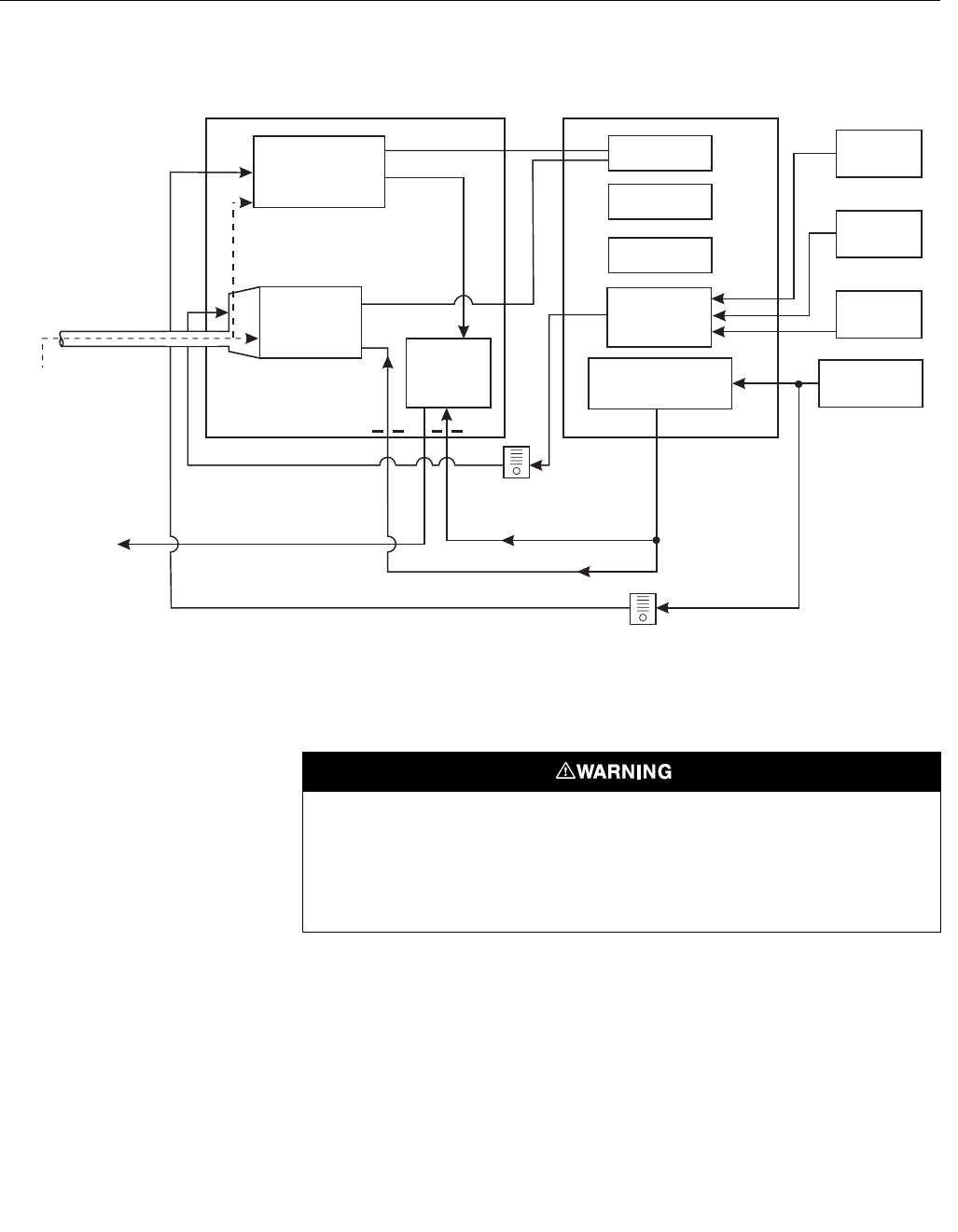
System Operation
Figure 1-2 shows the relationship between the components of the OCX 8800.
The sensors and the electronics are contained in separate housings. The
sensor housing and probe mounts to a duct or process wall so that the probe
protrudes into the flue gas stream. An air powered eductor continuously pulls
samples of the process flue gas through the probe to a chamber in front of the
sensor housing where the sample passes the O2 sensor and continues on to
the COe sensor. Dilution air is provided to the COe sensor and reference air
to the O2 sensor. After the gas sample flows past the O2 sensor and through
the COe sensor, it is drawn through the eductor where it mixes with the
eductor air and exits through exhaust back into the system. The electronics
housing contains the CPU and HART boards which convert the sensor inputs
into 4-20 mA analog output signals. The CPU can also initiate and perform
calibrations. Three test gasses and instrument air can be turned on and off by
solenoids. Test gas flow to the sensors is regulated by a flow meter between
the electronics and sensor housings. Instrument air is separated into eductor
air, reference air, and dilution air. The instrument air solenoid does not allow
air flow until the heaters are up to temperature. This minimizes the amount of
sampled process flue gas being pulled into cold sensors causing
condensation.
Instruction Manual
IM-106-880 Original Issue
February 2005
OCX 8800
1-6
Figure 1-2. System Operation Diagram
Handling the OCX 8800
System Considerations
Prior to installing your OCX 8800, make sure you have all the components
necessary to make the system installation. Ensure all the components are
properly integrated to make the system functional.
Low O
Test Gas
2
COe
Combustibles
Sensor
O
Sensor
2
Eductor
Probe
Exhaust
CPU
HART
Board
Optional
Test Gas
Solenoids
Instrument Air
Solenoid
High O
Test Gas
2
CO
Test Gas
Instrument
Air
Dilution Air
Reference Air
Eductor Air
Flow Meter
50 cc/min.
(
0.1 scfh
)
SENSOR
HOUSING ELECTRONICS
HOUSING
Flow Meter
7 scfh
37390001
Sample
Gas
Power
Supply
It is important that printed circuit boards and integrated circuits are handled only when
adequate antistatic precautions have been taken to prevent possible equipment damage.
The OCX 8800 is designed for industrial application. Treat each component of the system
with care to avoid physical damage. The probe may contain components made from
ceramics, which are susceptible to shock when mishandled.
Instruction Manual
IM-106-880 Original Issue
February 2005
1-7
OCX 8800
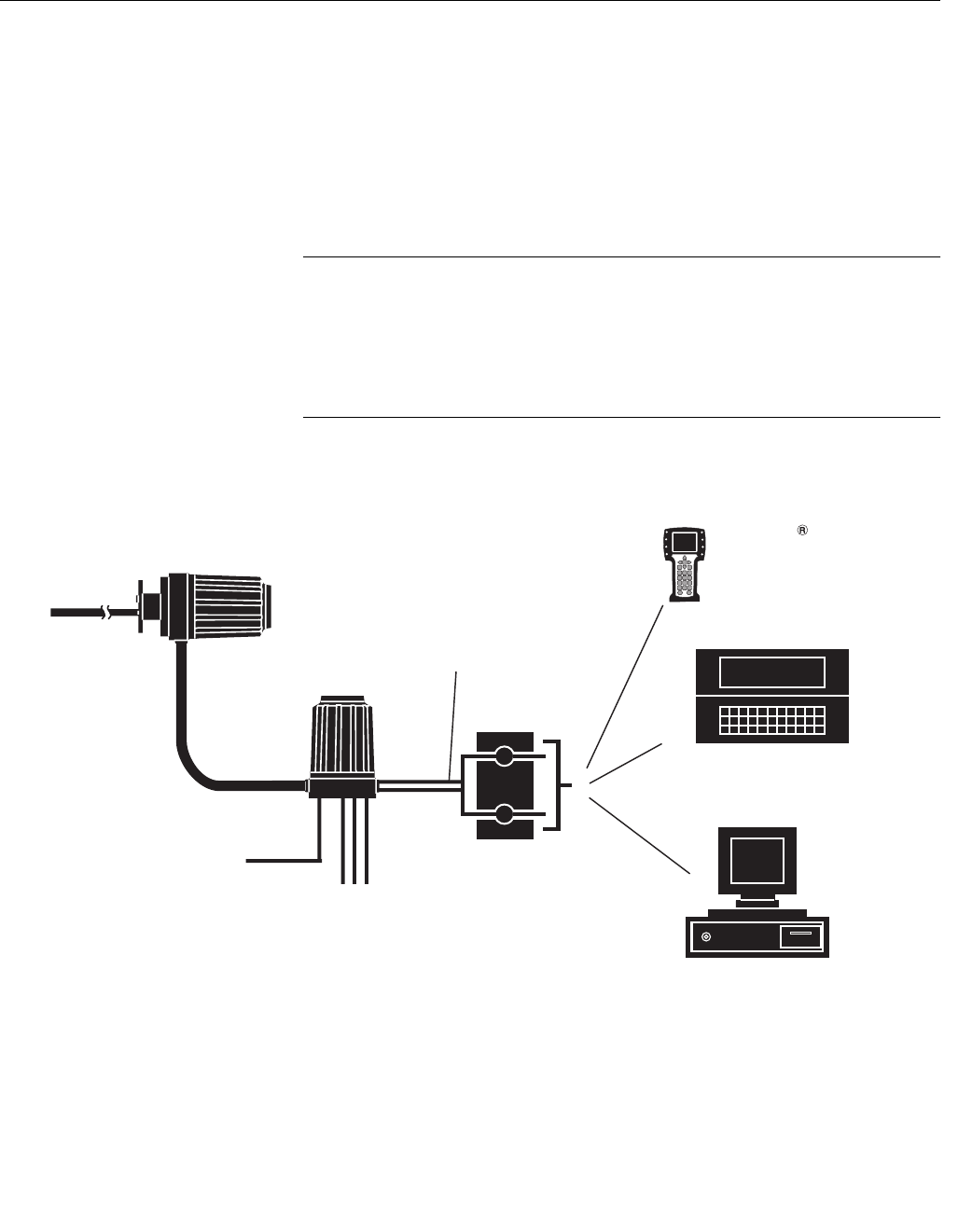
After verifying that you have all the components, select mounting locations
and determine how each component will be placed in terms of available line
voltage, ambient temperatures, environmental considerations, convenience,
and serviceability. Figure 1-3 shows a typical system wiring. Simplified
installations for the OCX 8800 are shown in Figure 1-4.
A source of instrument air is required at the OCX 8800 for reference air,
dilution air, and eductor air. Since the OCX 8800 is equipped with an in-place
calibration feature, provision should be made for connecting test gas tanks to
the OCX 8800 when it is to be calibrated.
NOTE
The electronics module is designed to meet NEMA 4 (IP66) and the electronic
components are rated to temperatures up to 185°F (85°C).
Retain packaging in which the unit arrived from the factory in case any
components are to be shipped to another site. This packaging has been
designed to protect the product.
Figure 1-3. OCX 8800 HART
Connections and AMS Application
37390065
4-20 mA Output
(Twisted Pairs)
Instrument
Air
3 calibration
gas lines by
customer
[300 ft (91 m) max.)
OCX 8800
Sensor Housing
HART
Model 275/375
Handheld
Communicator
Customer’s Laptop
with AMS
Termination in
Control Room
AMS
OCX 8800
Electronics Housing
Instruction Manual
IM-106-880 Original Issue
February 2005
OCX 8800
1-8
Figure 1-4. Typical System
Installation
OCX 8800 with
REMOTE
ELECTRONICS
4-20 mA Outputs
(2 Twisted Pairs)
Heater
Power Cable
[up to 150 ft (46 m)]
Pressure
Regulator
Duct
Stack
Gases
Line Voltage
Signal Cable
[up to 150 ft (46 m)]
37390064
Low O Test Gas
2
High O Test Gas
2
CO Test Gas
Instrument Air
Supply
(Reference Gas)
Test Gas
Flow Meter
Dilution
Air
Flow
Meter

Instruction Manual
IM-106-880 Original Issue
February 2005
1-9
OCX 8800
SPECIFICATIONS Hazardous Area OCX
Specifications
Net O2 Range 0-1% to 0-40% O2, fully field selectable
Combustibles 0-1000 ppm to 0-5%, fully field selectable
Accuracy
Oxygen ± 0.75% of reading or 0.05% O2 (whichever is greater)
Combustibles ± 2% range
System Response to
Tes t G a s
Oxygen 10 sec T90
Combustibles 25 sec T90
Temperature Limits
Process 32° to 2600°F (0° to 1427°C)
Sensors Housing -40° to 212°F (-40° to 100°C), ambient
Electronics Housing -40° to 149°F (-40° to 65°C), ambient
-40° to 185°F (-40° to 85°C), internal - operating temperature of
electronics inside instrument housing, as measured by a HART
communicator or AMS software
Nominal and Approximate
Shipping Weights
18 in. (457 mm)
probe package
54 lbs (20 kg)
3 ft (0.91 m) probe
package
55 lbs (20.5 kg)
6 ft (1.83 m) probe
package
57 lbs (21 kg)
9 ft (2.74 m) probe
package
59 lbs (22 kg)
Mounting and Mounting
Positions
Sensors Housing Flange
Electronics Housing Wall/Pipe
Materials
Probes 316L stainless steel - 1300°F (704°C)
Inconel 600 - 1832°F (1000°C)
Ceramic - 2600°F (1427°C)
Enclosures Low-copper aluminum
Calibration Semi-automatic or automatic
Calibration Gas Mixtures
Recommended
(Ref. test gas bottles
kit #1A99119G04)
0.4% O2, Balance N2
8% O2, Balance N2
1000 ppm CO, Balance Air
Calibration Gas Flow 7 scfh (3.3 l/m)
Reference Air 2 scfh (1 l/m), clean, dry instrument-quality air (20.95% O2),
regulated to 45 psi (310 kPa)
Eductor Air 5 scfh (2.5 l/m), clean, dry, instrument-quality air 20.95% O2),
regulated to 45 psi (310 kPa)
Dilution Air 0.1 scfh (0.5 l/m), clean, dry, instrument-quality air (20.95% O2)
regulated to 45 psi (310 kPa)
Blowback Air (optional) Clean, dry, instrument-quality air (20.95% O2), regulated to 55 psi
(379 kPa)
Table continued on next page
Sensors Housing NEMA 4, IP66 with fitting and pipe on reference exhaust port to
clean, dry atmosphere, two 3/4-14 NPT conduit ports
Instruction Manual
IM-106-880 Original Issue
February 2005
OCX 8800
1-10
NOTE
All static performance characteristics are with operating variables constant. Specifications subject to change
without notice.
Electronics Housing NEMA 4, IP66 with fitting and pipe on reference exhaust port to
clean, dry atmosphere, two 3/4-14 NPT conduit ports
Electrical Noise EN 61326-1, Class A
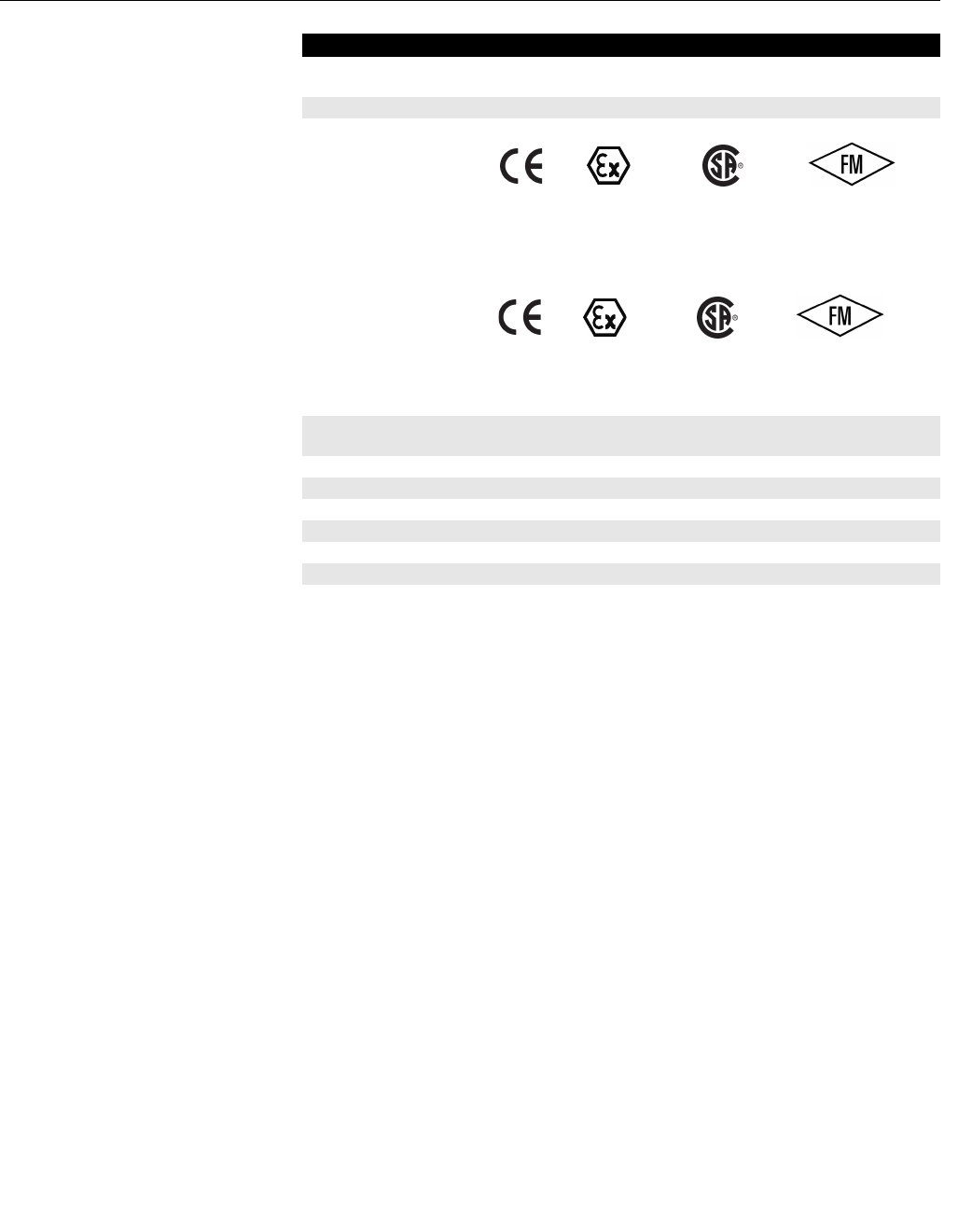
Certifications Sensor Housing
Electronics Housing
Line Voltage Universal 100 to 240 VAC ±10%, 50 to 60 Hz, no switches or
jumpers required, 3/4-14 NPT conduit port
Pollution Degree 2
Over Voltage Category II
Relative Humidity 5 to 95% (non-condensing)
Isolated Output
Oxygen 4-20 mAdc, 950 ohm maximum, with HART capability
Combustibles 4-20 mAdc, 950 ohm maximum
Alarm Alarm output relay - dry contact, form C, 30 mA, 30VDC capacity
Power Consumption 750 W maximum
Specifications
KEMA 04 ATEX 2308
EEx d IIB+H2 T3
0344 II 2 G
2005.1602514
CLASS 1, ZONE 1
Ex d IIB+H2 T3
AEx D IIB+H2 T3
TYPE 4 / IP66
APPROVED
CLASS 1, ZONE 1
AEx D IIB+H2 T3
TYPE 4 / IP66
CUS
2005.1602514
CLASS 1, ZONE 1
Ex d IIB+H2 T6
AEx D IIB+H2 T6
TYPE 4 / IP66
KEMA 04 ATEX 2308
EEx d IIB+H2 T6 IP66
0344 II 2 G
CLASS 1, ZONE 1
AEx D IIB+H2 T3
TYPE 4 / IP66
APPROVED
CUS
Instruction Manual
IM-106-880 Original Issue
February 2005
1-11
OCX 8800
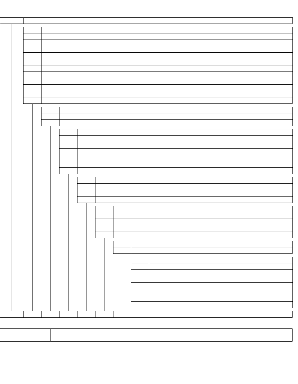
Table 1-1. Product Matrix - Hazardous Area OCX 8800
OCX88C O2/Combustibles Transmitter - Flameproof
Code Probe Length and Material
00 No Probe or Exhaust Tube
11 18 in. (457 mm) 316 SST up to 1300°F (704°C)
21 18 in. (457 mm) Inconel 600 up to 2600°F (1427°C)
31 18 in. (457 mm) Ceramic up to 2600°F (1427°C)
12 3 ft (0.91 m) 316 SST up to 1300°F (704°C)
22 3 ft (0.91 m) Inconel 600 up to 1832°F (1000°C)
32 3 ft (0.91 m) Ceramic up to 2600°F (1427°C)
13 6 ft (1.83 m) 316 SST up to 1300°F (704°C)
23 6 ft (1.83 m) Inconel 600 up to 1832°F (1000°C)
14 9 ft (2.7 m) 316 SST up to 1300°F (704°C)
24 9 ft (2.7 m) Inconel 600 up to 1832°F (1000°C)
Code Probe Mounting Assembly
10 (ANSI 2 in. 150 lb) 6" dia. flange, 4.75" BC with 4 x 0.75" dia. holes
20 (DIN) 185 mm dia. flange, 145 mm BC with 4 x 18 mm dia. holes
Code Mounting Hardware - Stack Side
0 No Adapter Plate (“0” must be chosen under “Mounting Adapter - Probe Side” below)
1 New Installation - Square weld plate with studs
2 Model 218/240 Mounting Plate (with Model 218/240 Shield Removed)
3 Existing Model 218/240 Support Shield
4 Special Mounting (1)
5 Model 132 Adapter Plate
Code Mounting Hardware - Probe Side
0 No Adapter Plate
1 Probe Only (ANSI)
2 Probe Only (DIN)
Code Electronics Housing - Communications
H1 HART Communications(2)
H2 HART Communications with LOI
H3 HART Communications with Calibration Solenoids(2)
H4 HART Communications with LOI and Calibration Solenoids
Code Electronics Mounting
02 Remote Electronics and no cable
Code Accessories
00 None
01 Flow meters & Ref. Air Set
02 In-Situ Filter (Stainless Steel only)
03 In-Situ Filter (SST), Flow meters & Ref. Air Set
11 Flow meters, and Ref. Air Set with Blowback
12 In-Situ Filter (SST) with Blowback
13 In-Situ Filter (SST), Flow meters & Ref. Air Set with Blowback
OCX88C 11 10 1 1 H2 02 02 Example
NOTES:
(1) Provide details of the existing mounting plate as follows:
Plate with studs Bolt circle diameter, number, and arrangement of studs, stud thread, stud height above mounting plate.
Plate without studs Bolt circle diameter, number, and arrangement of holes, thread, depth of stud mounting plate with accessories.
(2) If the LOI is not implemented, remote access and functionality available via HART Communications (Model 275/375 Handheld Communicator)
with Oxygen/Combustibles Device Description (DD) required.

Instruction Manual
IM-106-880 Original Issue
February 2005
OCX 8800
1-12
Table 1-2. Accessories
PART NUMBER DESCRIPTION
1A99119H01 Oxygen test gas bottle; 0.4% O2, balance N2
1A99119H02 Oxygen test gas bottle; 8.0% O2, balance N2
1A 99119H07 CO test gas bottle; 1000 ppm CO, balance air
1A99120H02 Regulator for Oxygen (may need 2)
1A99120H03 Regulator for CO test gas
1A99119G06 Wall mount bracket for test gas bottles
1A99119G05 Test gas regulators kit
1A99119G04 Test gas bottles kit
1A99292H01 Moore Industries SPA for Low O2 Alarm, High COe Alarm,
Calibration Status, and Unit Fail
1A99339H03 Blowback valve, air operated
1A99784H02 375 HART Communicator with 12 Megabyte buffer,
model no. 375HR1EKLU
6A00171G01 Power line filter kit
Instruction Manual
IM-106-880 Original Issue
February 2005 OCX 8800
http://www.processanalytic.com
Section 2 Installation
Mechanical Installation . . . . . . . . . . . . . . . . . . . . . . . . . . . page 2-2
Electrical Installation . . . . . . . . . . . . . . . . . . . . . . . . . . . . . page 2-8
Pneumatic Installation . . . . . . . . . . . . . . . . . . . . . . . . . . . . page 2-14
Initial Startup . . . . . . . . . . . . . . . . . . . . . . . . . . . . . . . . . . . . page 2-20
Before installing this equipment, read the "Safety instructions for the wiring and installation
of this apparatus" in Appendix A: Safety Data. Failure to follow the safety instructions could
result in serious injury or death.
To maintain explosion-proof protection of the OCX 8800 in hazardous areas, all cable entry
devices and blanking elements for unused apertures must be certified flameproof, suitable
for the conditions of use and properly installed.
To maintain explosion-proof protection of the OCX88C in hazardous areas, the sensor
housing must not be mounted to any surface or flange that exceeds 200ºC (392ºF).
To maintain explosion-proof protection of the OCX88C in hazardous areas, the sample
entering the sensor housing must not exceed 200ºC (392ºF).
Instruction Manual
IM-106-880 Original Issue
February 2005
OCX 8800
2-2
MECHANICAL
INSTALLATION
Selecting Location
1. The location of the OCX 8800 in the stack or flue is most important for
maximum accuracy in the oxygen analyzing process. The probe must
be positioned so the gas it measures is representative of the process.
Best results are normally obtained if the transmitter is positioned near
the center of the duct (40-60% insertion). Longer ducts may require
several transmitters since the oxygen and combustibles can vary due to
stratification. A point too near the wall of the duct or the inside radius of
a bend, may not provide a representative sample because of the very
low flow conditions. The sensing point should be selected so the
process gas temperature falls within the range of probe material used.
Figure 2-1 through Figure 2-4 provide mechanical installation
references. The ambient temperature inside the electronics housing
must not exceed 185°F (85°C).
2. Check the flue or stack for holes and air leakage. The presence of this
condition will substantially affect the accuracy of the oxygen and
combustibles readings. Therefore, either make the necessary repairs or
install the transmitter up stream of any leakage.
3. Ensure the area is clear of internal and external obstructions that will
interfere with installation and maintenance access to the unit. Allow
adequate clearance for the removal of the OCX 8800.
Installation
1. Ensure all components are available to install the OCX 8800.
2. The OCX 8800 may be installed intact as it is received.
3. Weld or bolt adapter plate (Figure 2-2) onto the duct.
Do not allow the temperature of the electronics housing to exceed 185°F (85°C) or damage
to the electronics may result.
Whenever a positive stack pressure exists at the installation site, be sure to connect all
pneumatic lines prior to installing the OCX 8800 in the stack or ductwork. Failure to connect
the pneumatic lines can allow the flow of contaminants into the OCX 8800 ports.
Before installing the OCX 8800 into a hot stack or ductwork, make sure that the OCX 8800
is turned on and at normal operating temperature. Exposing a cold OCX transmitter to hot
process gases can cause permanent damage to the equipment.
Instruction Manual
IM-106-880 Original Issue
February 2005
2-3
OCX 8800
4. Use the pipe or wall mounting hardware as shown in Figure 2-3 to
mount the electronics housing. Choose a location not to exceed the
length of the electronics cable ordered.
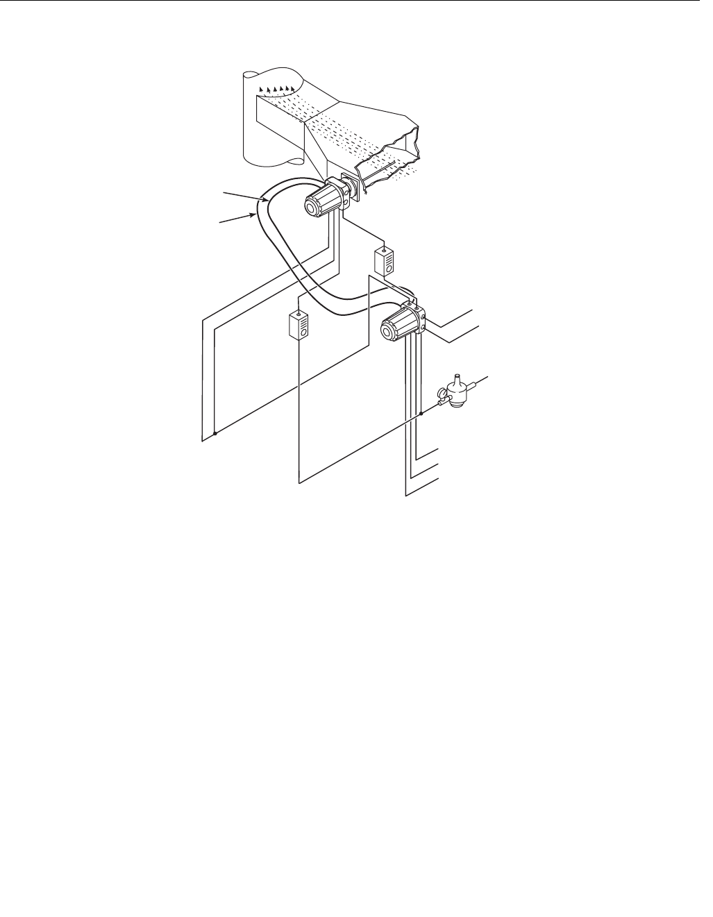
5. Ensure the conduits drop vertically from the OCX 8800 and the conduit
is routed below the level of the conduit ports on the housing to form a
drip loop. Drip loops minimize the possibility that moisture will damage
the electronics (Figure 2-4).
6. Where a positive stack pressure exists at the installation site, connect
all pneumatic lines prior to installing the OCX 8800 in the stack or
ductwork.
NOTE
If process temperatures will exceed 392°F (200°C), use anti-seize compound
on stud threads to ease future removal of the OCX 8800.
7. Insert sample and exhaust tubes through the opening in the mounting
flange and bolt the unit to the flange.
8. If insulation is removed to access the duct for OCX 8800 mounting,
make sure to replace insulation afterward.
Enclosures
The OCX 8800 enclosures are designed to meet ingress conditions of IP66.
Each enclosure cover is threaded to its base and sealed with an o-ring that
isolates the threads from external contaminants.
Each cover is secured by a clip attached to the base that engages the cover
between the ribs of the cover sidewall. The clip is held in place by an Allen
head cap screw and lockwasher mounted in a recess. Cover removal and
installation requires an Allen wrench to loosen and tighten the screw.
Uninsulated stacks or ducts may cause ambient temperatures in the electronics housing to
exceed 185°F (85°C) and damage the electronics.
Instruction Manual
IM-106-880 Original Issue
February 2005
OCX 8800
2-4
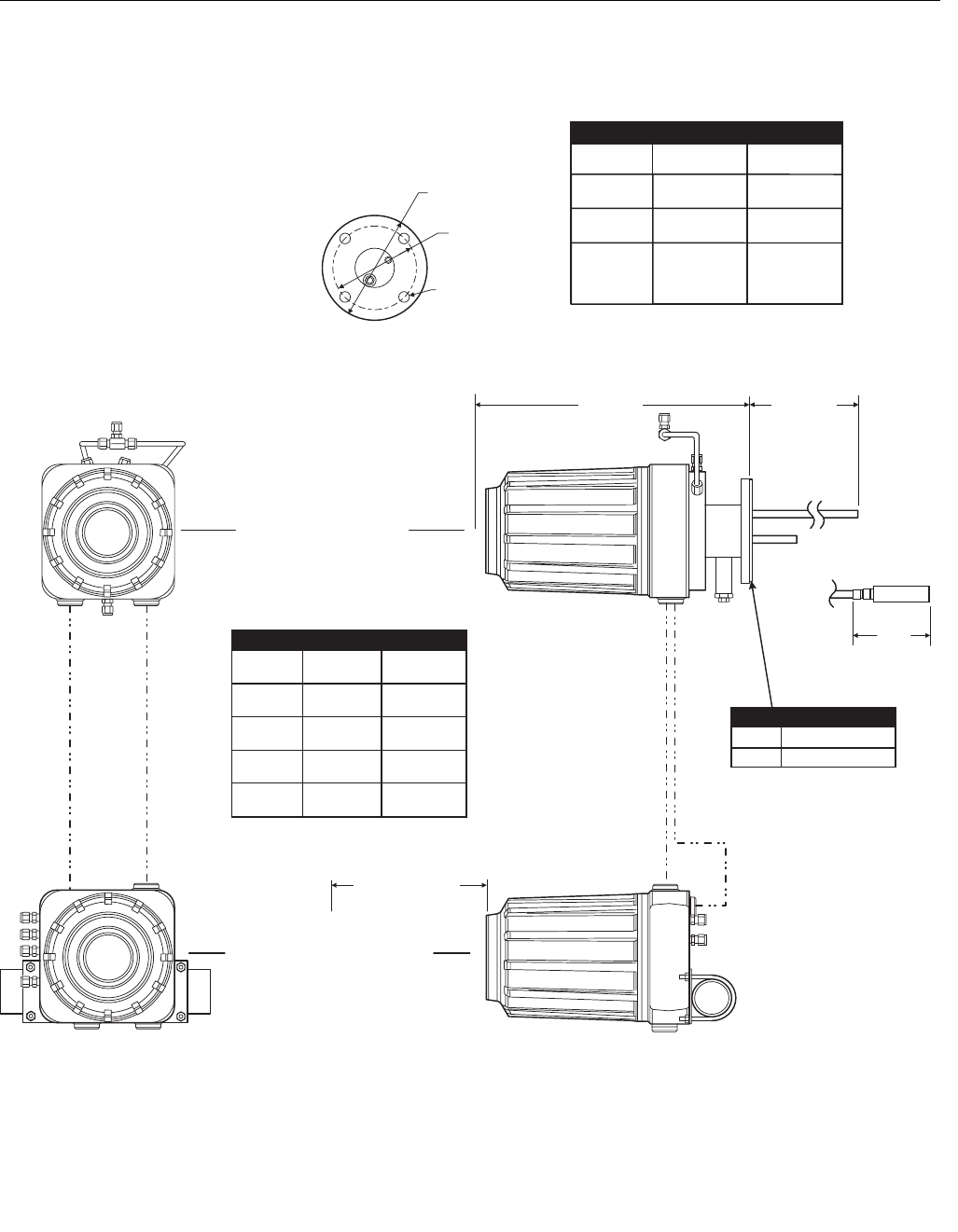
Figure 2-1. Installation, OCX 8800
B.C. Dia.
Removal Envelope
Dim “B”
37390009
Insertion Depth
Dim “A”
Flange Dia.
Hole Dia.
8.3
(211)
Allow 9 in.
(229 mm) for
Cover Removal
See Table 1
Optional
In Situ FIilter
Heater Power Cable
Signal Cable
Heater Power Cable
Signal Cable
ELECTRONICS HOUSING
SENSOR HOUSING
See Table 2
All dimensions are in inches with millimeters in parentheses.
NOTE
Insulate if exposed to adverse weather or extreme temperature
changes, install a protective housing and/or insulation
around the unit. Flange
Dia.
DIN
ANSI 5R10244H025R10244H01
6.00
(152)
Table 1. Mounting Flange
Hole
Dia.
(4) Holes
equally
spaced on
B.C. dia
7.28
(185)
0.75
(19) 0.71
(18)
4.75
(121) 5.71
(145)
Dim "B”
3 ft
9 ft
6 ft
Probe
18 in.
Dim "A”
(2235)
88
(3150)
124
(2743)
108
72
(1829)
(914)
36 (1321)
52
(864)
34
(457)
18
Table 2. Installation/Removal
3535B18H02
3535B45H01
DIN
ANSI
0.06 In. Thick Gasket
Instruction Manual
IM-106-880 Original Issue
February 2005
2-5
OCX 8800
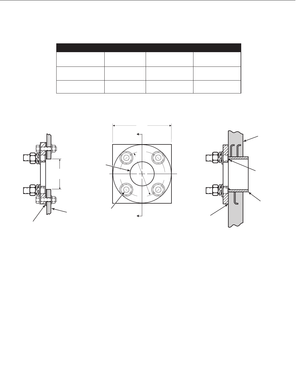
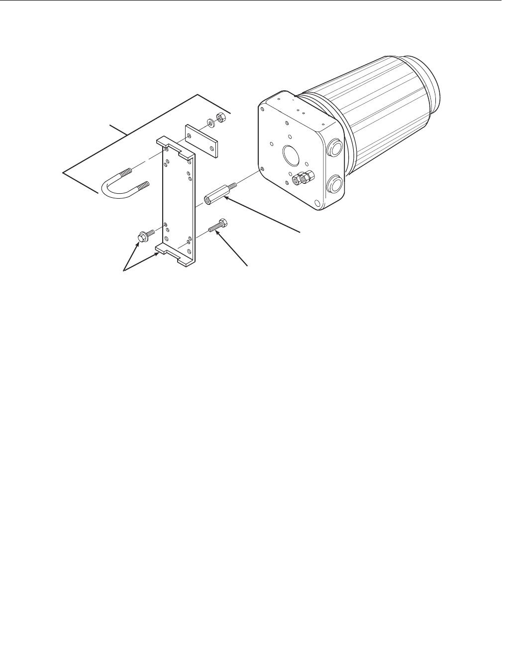
Figure 2-2. Adapter Plate Installation
ANSI
(P/N 4512C34G01)
DIN
(P/N 4512C36G01)
Plate Size "A" Stud Size "B" Bolt Circle
Dia. “C"
6.00
(152) 5/8 -11 UNC - 2A 4.75
(121)
7.50
(191) (M-16 x 2.0 - 6g) 5.71
(145)
*Part numbers for adapter plates include attaching hardware.
D
2.50
(63.5)
Dia.
C
B
NOTE: Dimensions are in inches with millimeters in parentheses.
Only adapter plate is furnished by Rosemount Analytical.
37390010
*Type
Part Number
D
2.50 (63.5)
Dia. min.
Metal Stack
or Duct Wall
Weld or bolt adapter
plate to metal wall.
Joint must be air-tight.
Field weld pipe
to adapter plate
Masonary
Stack Wall
Pipe 3 inch
schedule 40.
Sleeve length
optional.
AA
Section
D-D
Bolt adapter plate to
outside wall surface.
Joint must be air-tight.
Section
D-D
Adapter Plate Kit - Mounting Dimensions
METAL WALL
STACK OR DUCT
CONSTRUCTION
MASONRY WALL
STACK
CONSTRUCTION
Instruction Manual
IM-106-880 Original Issue
February 2005
OCX 8800
2-6
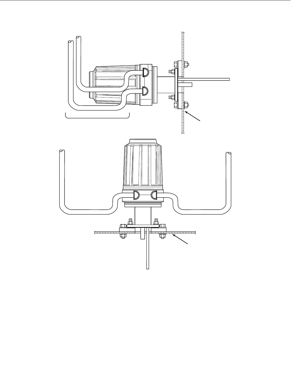
Figure 2-3. Wall or Pipe Mounting
of Electronics Housing
37020021
*Pipe
Mounting
Clamp
Electronics
Housing
*Wall or Pipe
Mounting Bracket
and Screws
1/4-20 UNC x 2 in. M-F Standoffs.
Recommended for rear piping
clearance when wall mounting.
(4 each by customer)
Wall Mounting Bolts
or Lag Screws
(4 each by customer)
* Indicates items are included
in mounting kit P/N 4851B40G01.
Note:
Instruction Manual
IM-106-880 Original Issue
February 2005
2-7
OCX 8800
Figure 2-4. Installation
with Drip Loops
37020004
Conduit Drip Loops Duct Wall
Conduit Drip Loop Conduit Drip Loop
Duct Wall
Instruction Manual
IM-106-880 Original Issue
February 2005
OCX 8800
2-8
ELECTRICAL
INSTALLATION
All wiring must conform to local and national codes. For reference, factory
wired solenoid power connections are shown in Figure 2-5.
Disconnect and lock out power before connecting the unit to the power supply. Failure to
lock out power could result in serious injury or death.
Install all protective equipment covers and safety ground leads after installation. Failure to
install covers and ground leads could result in serious injury or death.
To meet the Safety Requirements of IEC 1010 (EC requirement), and ensure safe operation
of this equipment, connection to the main electrical power supply must be made through a
circuit breaker (min 10 A) in close proximity and marked for this equipment which will
disconnect all current-carrying conductors during a fault situation. This circuit breaker
should also include a mechanically operated isolating switch. If not, then another external
means of disconnecting the supply from the equipment should be located close by. Circuit
breakers or switches must comply with a recognized standard such as IEC 947.
To maintain explosion-proof protection of the OCX 8800 in hazardous areas, all cable entry
devices and blanking elements for unused apertures must be certified flameproof, suitable
for the conditions of use and properly installed.
To maintain explosion-proof protection of the OCX88C in hazardous areas, the sensor
housing must not be mounted to any surface or flange that exceeds 200ºC (392ºF).
To maintain explosion-proof protection of the OCX88C in hazardous areas, the sample
entering the sensor housing must not exceed 200ºC (392ºF).

Instruction Manual
IM-106-880 Original Issue
February 2005
2-9
OCX 8800
NOTE
To maintain proper earth grounding, ensure a positive connection exists
between the sensor housing, the electronics housing, and earth. The
connecting ground wire must be 14 AWG minimum. Refer to Figure 2-5.
NOTE
Line voltage, signal, and relay wiring must be rated for at least 105ºC (221ºF).
Electrical Connections
Electrical connections, power and communications are made to the electronic
enclosure. The connections are made through two 3/4 NPT ports in the
enclosure using fittings and cables provided by the customer. Cable
installation must meet NEC, IEC and/or other applicable national or local
codes for Class I, Zone 1, IIB +H2 T3/T6 permanently mounted equipment.
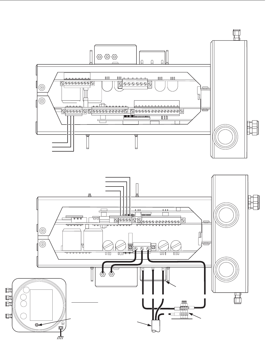
Connect Line Voltage
The OCX 8800 operates on 100 to 240 VAC line voltage at 50 to 60 Hz. The
power supply requires no setup. Connect the line (L wire) to the L terminal,
and the neutral (N wire) to the N terminal on the AC power input terminal
block in the electronics housing. Connect the ground (G wire) to the ground
stud in the electronics housing as shown in Figure 2-5.
Connect 4-20 mA Signals
Connect the 4-20 mA current loop to the 4-20 mA signal output terminals in
the electronics housing as shown in Figure 2-5. Use individual shielded
twisted wire pairs. Terminate the shield at the electronics housing.
O2 4-20 mA Signal
One 4-20 mA signal represents the O2 value. Superimposed on the O2
signal is the HART information accessible through a Model 275/375
Handheld Communicator or AMS software. The O2 signal is at the AOUT 1
terminals.
COe 4-20 mA Signal
Another 4-20 mA signal at the AOUT 2 terminals represents the COe
value. HART information is not available on the COe signal.
Alarm Output Relay
Connect any customer-supplied relay input to the alarm output relay terminal.
Use shielded wire and terminate the shield at the electronics housing. The
alarm output relay terminal is a set of dry, no. 2, form C, contacts with 30 mA,
30 VDC capacity.

Instruction Manual
IM-106-880 Original Issue
February 2005
OCX 8800
2-10
Remote Electronics Connections to Sensor Housing
Make the following connections between the electronics and sensor housings
with the electronics cable ordered with the package (Figure 2-6). Braided
cable is available in lengths up to 150 ft. (46 m).
NOTE
Interconnect wiring shown is for Rosemount Analytical supplied cables. For
customer furnished interconnect wiring or cables, refer to Figure 2-7.
Signal Connections
Connect the electronics housing terminals to the corresponding terminals
in the sensor housing. The twisted wire pairs are numbered on the inner
plastic wrapper. Keep twisted pairs together and match the numbers and
wire colors shown in Figure 2-6.
Heater Power Connections
Use the blue, white, orange black, red, and yellow stranded wires in the
heater power cable to connect power to the three heaters in the sensor
housing. Match the wire colors to the corresponding heater power terminal
blocks in the sensor and electronics housings as shown in Figure 2-6.
Instruction Manual
IM-106-880 Original Issue
February 2005
2-11
OCX 8800
Figure 2-5. Line Voltage, Earth,
and 4-20 mA Connections
37390013
TOP VIEW
(1/2 SIZE)
Ground Stud
Earth Ground
Typical for Electronics and
Sensor Housing
NC
COM
NO
Alarm Output Relay
Terminal Block
#1
AOUT2+
AOUT2 -
AOUT1 -
AOUT1+
O Signal
2
COe Signal
{
{
Ground
Stud
4-20 mA Signal Output
Terminal Block
Power Port
3/4 NPT
Signal Port
3/4 NPT
External Tooth
Lockwasher
#1
G
G
Terminal
Block
N
G
L1
EMI Filter
Customer
Wiring

Instruction Manual
IM-106-880 Original Issue
February 2005
OCX 8800
2-12
Figure 2-6. Electrical Connections Between Remote Electronics and Sensor Housing
37390014
RED
BLK
WHT
GRN
BLK
BLK
BLU
BLK
YEL
BRN
RED
BLK
BLK
ORG
BLK
WHT
T/C CO+
T/C CO-
T/C SB+
T/C SB-
T/C O2+
T/C O2-
O2 CELL+
O2 CELL-
EXC
+
+
-
+
-
EXC-
-
+
-
2
1
1
2
2
1
BLU
ORG
YEL
RED
SHIELD
To
ground
screw
GRN
BLK
WHT
BLK
YEL
RED
BLU
WHT
BLK
BLK
GRN
BLK
BLK
BLK
ORG WHT
RED
BLK
BRN
To ground screw
GRN
ELECTRONICS HOUSING
SENSOR HOUSING
Heater Power Cable
Signal Cable
O Sensor and
Thermocouple
Connector (J5)
2
COe Sensor
and
Cold Junction
Connector (J4)
EXC+
CO ACT+
CO ACT-
CO REF+
CO REF-
CJC+
CJC-
EXC-
O2
HTR
O2
HTR
CO
HTR
SB
CO
REF
CO
ACT
CJC
T/C SB
T/C CO
T/C O2
+
-
+
-
+
-
+
#1
#1 #1
#1
#1
To ground
screw
SHLD
WHT
ORG
BLU
BLK
YEL
RED
Heater Power
Connector (J3)
#1
2HTR SB
1HTR O2
1HTR SB
2HTR CO
1HTR CO
2HTR O2
Instruction Manual
IM-106-880 Original Issue
February 2005
2-13
OCX 8800
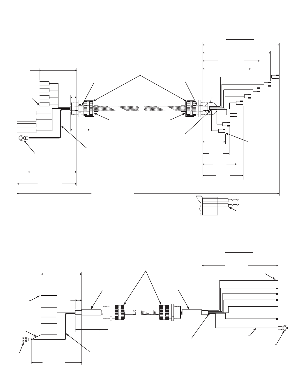
Figure 2-7. Customer-Furnished
Interconnect Wiring or Cables
A
#2
#1
3/4 NPT Hub Size,
Liquid-tight
Strain Relief
Connector
Heat Shrink
Tubing
2” Long
1/2” Size
7.0” Long Teflon Tubing,
0.042” ID (Cut off drain
wire at probe end of
shield).
8 twisted pairs 24 AWG,
stranded, insulated,
tinned copper
conductors, 200 C, 300
volts, with overall braid
of 34 AWG tinned
copper, 90% coverage
and 24 AWG tinned
copper, uninsulated
drain wire.
o
7.25
±0.10
Strip Wire
Ends 3/16”
Typical
7.25 ±0.10
9.25 ±0.10 Overall Cable Length
By Customer
150’ Maximum
3.875
±0.10
4.625
±0.10
5.375
±0.10
6.125
±0.10
6.875 ±0.10
8.625 ±0.10
10.375 ±0.10
12.5 ±0.10
Ferrule,
Uninsulated
2.0 ±0.25
Typical
DETAIL A
Heat Shrink Tubing
1” Long, 3/16” Size
(typical on both ends of wiring)
SIGNAL WIRING OR CABLE
ELECTRONICS END
PROBE END
0.5
Typ.
3/4 NPT Hub Size,
Liquid-tight
Strain Relief
Connectors
Heat Shrink Tubing
2” Long, 1/2” Size
4.25” Long Teflon Tubing,
0.042” ID. (Cut off drain wire
at probe end of shield).
8 Conductors, 16 AWG, Stranded,
200 C, 600 volts.
Braided shield - tinned copper, 90%
coverage with 18 AWG 24 tinned copper,
uninsulated, drain wire.
O
4.0 ±0.10
Stud Size
#10 4.5 ±0.10
5.5 ±0.10
Ferrule, Uninsulated
2.0 ±0.25 Typical
Heat Shrink Tubing
2” Long, 1/2” Size
HEATER WIRING OR CABLE
ELECTRONICS END PROBE END
Green,
16 AWG
0.5
Typ.
Stud Size #6
Green, 16 AWG
Strip Wire
Ends 3/16”
Typical
Heat Shrink
Tubing
2” Long
1/2” Size
See Note See Note
NOTE: For RFI/CE compliance, the connector
must provide 360 degrees of electrical
contact to the cable shield.
Stud Size
#10
37390061
Instruction Manual
IM-106-880 Original Issue
February 2005
OCX 8800
2-14
PNEUMATIC
INSTALLATION
Pneumatic system connections depend on whether reference air set,
calibration solenoids, and/or blowback equipment options are equipped on
your transmitter. Refer to the following paragraphs and select the option that
applies to your transmitter configuration.
Reference Air Set Option (only)
When no options or only the reference air set option is equipped, use the
following procedure to install the pneumatic system components.
1. Refer to Figure 2-8. Connect the reference air set (regulator/filter and
pressure gage) to the instrument air inlet on the electronics housing and
to the inlet side of the dilution air flow meter.
2. Connect the dilution air flow meter output to the dilution air inlet fitting on
the sensor housing.
3. Install an air line between the instrument air outlet fitting on the
electronics housing and the tee fitting on the sensor housing.
.
4. One CO gas and two O2 gases are used to calibrate the OCX 8800:
CO - 1000 ppm or 4%
O2 low gas - 0.4%
O2 high gas - 8%
Connect the output of the test gas sources to the inlet port of the CAL
GAS flow meter. Install an air line between the flow meter outlet port and
the CAL GAS inlet fitting on the sensor housing.
Do not use 100% nitrogen as an O2 low gas. It is suggested that O2 low gas be between
0.4% and 2.0% O2. Do not use gases with hydrocarbon concentrations of more than 40
parts per million. Failure to use proper gases will result in erroneous readings.
Instruction Manual
IM-106-880 Original Issue
February 2005
2-15
OCX 8800
Figure 2-8. Pneumatic
Installation, OCX with Reference
Air Set (without Autocalibration)
37390011
Electronics
Housing
Eductor
Air In
Sensor
Housing
Dilution Air In
Reference Air In
CAL Gas In
CAL Gas
Flow Meter
7 scfh, 20-30 psig
Recommended
Dilution Air
Flow Meter
0.1 scfh
Instrument
Air Supply
Pressure Reguator/Filter
35 psig - General Purpose
45 psig - Hazardous Area
(
(
2-Stage
Regulators
CO
HI O
2
LO O
2
Instrument
Air Out
Instruction Manual
IM-106-880 Original Issue
February 2005
OCX 8800
2-16
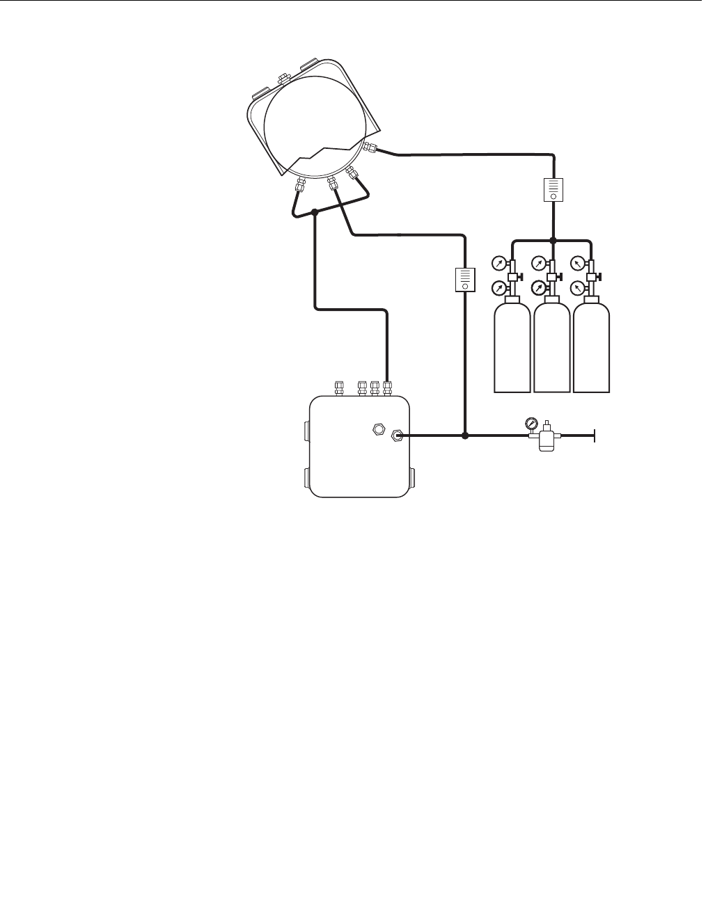
Figure 2-9. Pneumatic
Installation, OCX with Reference
Air Set and Solenoids (with
Autocalibration)
Reference Air Set and Solenoids Option
When the reference air set and test gas solenoids are included with your
OCX 8800, use the following procedure to install the pneumatic system
components.
1. Install the reference air set according to the instructions in Reference Air
Set Option, steps 1 through 3.
2. Refer to Figure 2-9. Connect the O2 low gas source to the CAL GAS LO
O2 inlet fitting on the electronics housing. Install a shutoff valve and
pressure regulator with gage in the O2 low supply line, as shown.
3. Connect the O2 high gas source to the CAL GAS HI O2 inlet fitting.
Install a shutoff valve and pressure regulator with gage in the O2 high
supply line.
Electronics
Housing
Dilution
Air In
Reference
Air In
CAL Gas In
CAL Gas
Flow Meter
7 scfh, 20-30 psig
Recommended
Dilution Air
Flow Meter
0.1 scfh
Instrument
Air Supply
Pressure Regulator/Filter
35 psig - General Purpose
45 psig - Hazardous Area
2-Stage
Regulators
CO
HI O
2
LO O
2
CAL Gas Out
Eductor
Air In
Sensor
Housing
Instrument Air Out
(
(
37390012

Instruction Manual
IM-106-880 Original Issue
February 2005
OCX 8800
2-17
4. Connect the CO high gas to the CAL GAS HI COe inlet fitting. Install a
shutoff valve and pressure regulator with gage in the CO high supply
line.
5. Connect the CAL GAS outlet fitting of the electronics housing to the inlet
port of the CAL GAS flow meter. Install an air line between the flow
meter outlet port and the CAL GAS inlet fitting on the sensor housing.
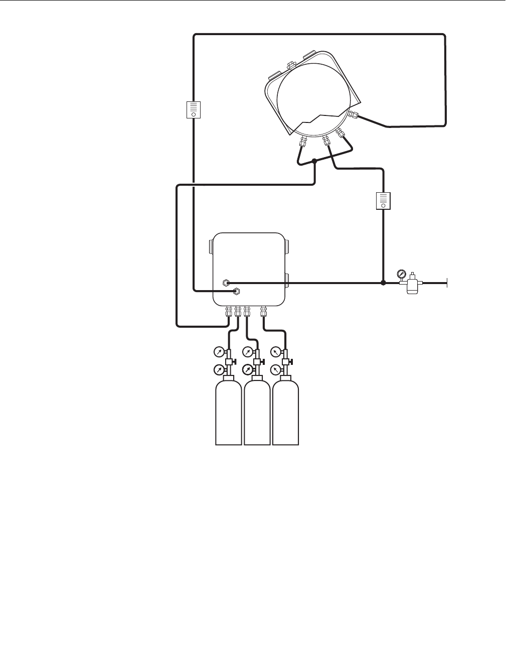
Reference Air Set, Solenoids, and Blowback Option
The blowback system blows instrument air back through the blowback filter
and out the sample tube of the transmitter. This removes built up dirt and
particulate from the filter and sample line. The blowback option is normally
used in systems that have a dirty process stream.
Installing an OCX 8800 with the blowback option requires the addition of air
operated blowback valve, regulator and gage, and check valve.
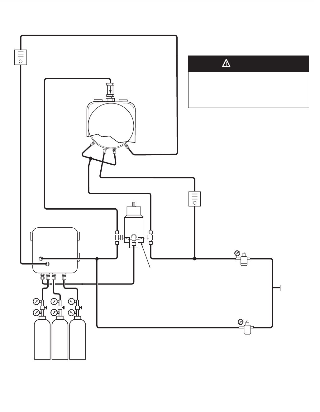
Figure 2-10 shows the piping arrangement for the OCX 8800 with the
blowback and autocalibration options. Figure 2-11 shows the piping
arrangement for the OCX 8800 with the blowback option, but without
autocalibration (without test gas solenoids).
When the reference air set, calibration gas solenoids, and blowback options
are included with your transmitter, use the following procedure to install the
pneumatic system components.
1. Connect the calibration gas sources according to the instructions in the
previous paragraph “Reference Air Set and Solenoids Option”, steps 2
through 5.
2. Connect a clean, dry, instrument-quality supply of air (20.95% O2) to the
35/45 psig and 55 psig pressure regulators. The inlet to the 35/45 psig
regulator accepts a 1/8" NPT fitting. The inlet to the 55 psig regulator
accepts a 1/4" NPT fitting.
3. See the upper leg of the instrument air supply. Connect the output of the
35/45 psi regulator/filter to one port of the normally-closed air-operated
solenoid valve, and to the inlet side of the dilution air flow meter.
4. Connect the dilution air flow meter output to the DILUTION AIR inlet
fitting on the sensor housing.
5. Install an instrument air line between the open port of the normally-open
air-operated solenoid valve and the tee fitting on the sensor housing.
6. Connect the output of the 55 psi regulator/filter to one port of the
normally-open air-operated solenoid valve, and to the instrument air
inlet on the back of the electronics housing.
7. Install an air line between the open port of the normally-closed
air-operated solenoid valve and the check valve inlet fitting on the
sensor housing.
Instruction Manual
IM-106-880 Original Issue
February 2005
OCX 8800
2-18
Figure 2-10. Piping Arrangement,
Blowback with Autocalibration
37390004
Pressure regulator with 1/8” inlet port is factory
set for 35 or 45 psig. Regulator with 1/4” inlet port
is factory set for 55 psig. If regulators are not
installed in correct locations, the OCX 8800 will
not work.
Check Valve
Blowback Valve,
Air Operated
*Normally
Closed
Solenoid
Valve
Electronics
Housing
Eductor Air In
Sensor
Housing
Dilution Air In
Reference Air In
CAL Gas In
Cal Gas
Flow Meter
7 scfh, 20-30 psig
Recommended
Dilution
Air Flow Meter
0.1 scfh
Instrument
Air Supply
Pressure Regulator/Filter
35 psig - General Purpose
45 psig - Hazardous Area
(
(
CAL Gas Out
Instrument Air
Pressure
Regulator/Filter
55 psig
*Normally
Open
Solenoid
Valve
2-Stage
Regulators
CO
HI O
2
LO O
2
CAUTION
NOTE: Wall mount the air-operated blowback
valve on a suitable mounting plate.
*NOTE: During blowback operation, states of
both solenoid valves change.
Instruction Manual
IM-106-880 Original Issue
February 2005
OCX 8800
2-19
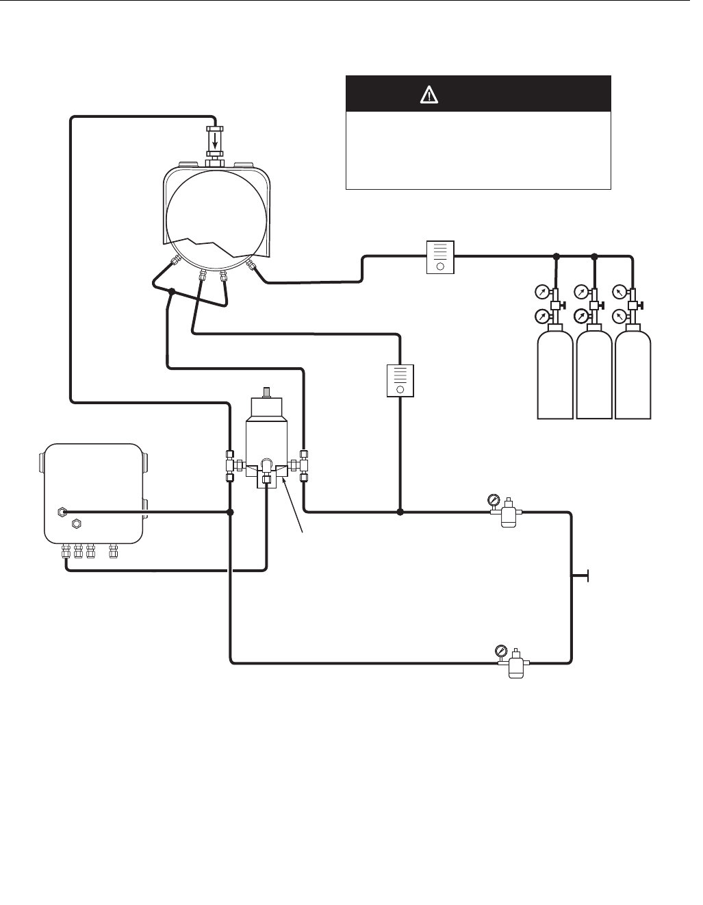
Figure 2-11. Piping Arrangement,
Blowback without Autocalibration
37390005
Check Valve
Blowback Valve,
Air Operated
*Normally
Closed
Solenoid
Valve
*NOTE: During blowback operation, states of
both solenoid valves change.
Electronics
Housing
Eductor Air In
Sensor
Housing
Dilution Air In
Reference Air In
CAL Gas In
Cal Gas Flow Meter
7 scfh, 20-30 psig
Recommended
Dilution
Air Flow Meter
0.1 scfh
Instrument
Air Supply
Pressure Regulator/Filter
35 psig - General Purpose
45 psig - Hazardous Area
(
2-Stage
Regulators
CO
HI O
2
LO O
2
Instrument Air
Pressure
Regulator/Filter
55 psig
*Normally
Open
Solenoid
Valve
Pressure regulator with 1/8” inlet port is factory
set for 35 or 45 psig. Regulator with 1/4” inlet port
is factory set for 55 psig. If regulators are not
installed in correct locations, the OCX 8800 will
not work.
(
NOTE: Wall mount the air-operated blowback
valve on a suitable mounting plate.
CAUTION

Instruction Manual
IM-106-880 Original Issue
February 2005
OCX 8800
2-20
8. Install an air line between the instrument air outlet fitting on the
electronics housing and the control air inlet fitting on the air-operated
solenoid valve.
9. There are three settings that need to be specified to set up the blowback
option. These are the blowback interval, duration, and purge time.
Interval - Length of time between blowback events.
(60 minutes recommended.)
Duration - Length of time blowback air is activated.
(5 seconds recommended.)
Purge - Length of time after blowback is complete before
oxygen/combustibles readings are considered valid.
(Set as required by the application.)
These settings are available through HART from the DEVICE SETUP >
DETAILED SETUP > OUTPUT CONDITIONS > BLOWBACK menu.
INITIAL STARTUP Observe the following Caution and Note. Refer to Section 3: Configuration
and Startup, for OCX 8800 startup information.
NOTE
During outages, and whenever possible, leave OCX 8800 units running to
prevent condensation and premature aging from thermal cycling.
Upon completing installation, make sure that the OCX 8800 is turned on and operating prior
to firing up the combustion process. Damage can result from having a cold OCX 8800
exposed to the process gases.
If ducts will be washed down during outages, make sure to power down the OCX 8800 units
and remove them from the wash area.
Instruction Manual
IM-106-880 Original Issue
February 2005 OCX 8800
http://www.processanalytic.com
Section 3 Configuration and Startup
Verify Installation . . . . . . . . . . . . . . . . . . . . . . . . . . . . . . . . page 3-1
Initial Power Up . . . . . . . . . . . . . . . . . . . . . . . . . . . . . . . . . . page 3-3
Set Test Gas Values . . . . . . . . . . . . . . . . . . . . . . . . . . . . . . page 3-4
OCX 8800 Reset Procedure . . . . . . . . . . . . . . . . . . . . . . . . page 3-4
VERIFY INSTALLATION Ensure the OCX 8800 is installed correctly. Vertify mechanical installation and
all electrical and pneumatic connections. Refer to Section 2, Installation.
NOTE
During outages, and whenever possible, leave all OCX 8800 units running to
prevent condensation and premature aging from thermal cycling.
Install all protective equipment covers and safety ground leads after installation. Failure to
install covers and ground leads could result in serious injury or death.
Make sure that the OCX 8800 is turned on and operating prior to firing up the combustion
process. Damage can result from having a cold OCX 8800 exposed to the process gases.

Instruction Manual
IM-106-880 Original Issue
February 2005
OCX 8800
3-2
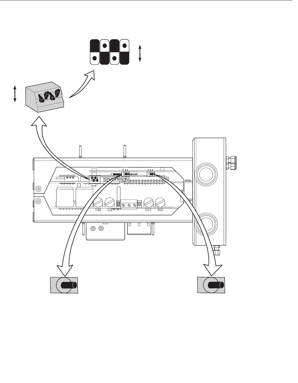
Verify Configuration
There are three switches on the microprocessor board which are user
configurable for the OCX 8800 (Figure 3-1). SW1 determines if the O2 4-20
mA signal is internally or externally powered. SW2 determines if the COe 4-20
mA signal is internally or externally powered. SW3 sets the rail limits for the
O2 and COe 4-20 mA signals and configures the sample line heater control
circuit. All switches are accessible through holes in the electronics box.
Verify that the following switch settings are correct for your OCX 8800
installation:
SW1 The two settings are internally or externally powering the O2 4-20
mA signal. The factory setting is for the O2 4-20 mA signal to be externally
powered.
SW2 The two settings are internally or externally powering the COe 4-20
mA signal. The factory setting is for the COe 4-20 mA signal to be
externally powered.
SW3 The factory sets this switch as follows:
• Position 1 determines the O2 4-20 mA signal rail limit. The settings are
high, 21.1 mA, or low, 3.5 mA. The factory setting is low, 3.5 mA.
• Position 2 determines the COe 4-20 mA signal rail limit. The settings
are high, 21.1 mA, or low, 3.5 mA. The factory setting is high, 21.1 mA.
• Positions 3 and 4 must be set as shown for proper software control of
the device heaters.
Remove power from the OCX 8800 before changing defaults. If defaults are changed under
power, damage to the electronics may occur.
Instruction Manual
IM-106-880 Original Issue
February 2005
3-3
OCX 8800
Figure 3-1. OCX 8800 Defaults
INITIAL POWER UP Allow adequate time (approximately 60 minutes) for the heaters to begin
operation and for the OCX 8800 to reach normal operating temperature on
power up. Normal operating temperature for the O2 cell is 736°C. Normal
operating temperature for the combustibles cell is 300°C. The normal sample
line temperature is 170°C.
1234
Internal:
O 4-20 mA
is Internally
Powered
2
External:
O 4-20 mA
Requires an External
Power Supply
(Default)
2
O 21.1 mA/3.5 mA:
2O 4-20 mA Signal
Rail Limits:
High - 21.1 mA
Low - 3.5 mA
2
COe 4-20 mA Signal
Rail Limits:
High- 21.1 mA
Low - 3.5 mA
COe 21.1 mA/3.5 mA:
1
1
2
2
3
3
4
4
SW3
3.5 mA
Switch
Default Postions
Shown
COe
SW1
SW2
37390026
O2
21.1 mA
Closed
External:
COe 4-20 mA
Requires an External
Power Supply
(Default)
Internal:
COe 4-20 mA
is Internally
Powered
Open
Closed
Open
Open
Closed
Open
Closed

Instruction Manual
IM-106-880 Original Issue
February 2005
OCX 8800
3-4
SET TEST GAS VALUES Use HART/AMS to set test gas values for calibration. Refer to Section 4,
Using HART Communications for more information.
Setting Test Gas Values with HART
1. Use the HART communicator or AMS software to access the HART
menu.
2. From the DETAILED SETUP menu, select O2 CALIB PARAMS.
3. From O2 CALIB PARAMS, select O2 High Gas. Enter the percent O2
used for the high O2 test gas.
4. From O2 CALIB PARAMS, select Low TG. Enter the percent O2 used
for the low O2 test gas.
5. From the DETAILED SETUP menu, select COe CALIB PARAMS.
6. From COe CALIB PARAMS, select COe Test Gas. Enter the CO
concentration (ppm) used for COe test gas.
OCX 8800 RESET
PROCEDURE
Whenever you correct an equipment alarm or fault condition, the OCX 8800
will either revert to normal operation or continue to indicate an alarm status
condition. If the equipment does not revert to normal operation when a fault
condition is cleared, or if instructed to do so in Section 7, Troubleshooting,
use the following procedure to reset the OCX 8800.
OCX Reset with HART
Remove the OCX 8800 from the process loop and recycle power.

Instruction Manual
IM-106-880 Original Issue
February 2005 OCX 8800
http://www.processanalytic.com
Section 4 Using HART Communications
Overview . . . . . . . . . . . . . . . . . . . . . . . . . . . . . . . . . . . . . . . page 4-1
HART Communicator Signal Connections . . . . . . . . . . . . page 4-1
HART Communicator PC Connections . . . . . . . . . . . . . . . page 4-4
HART Menu Tree . . . . . . . . . . . . . . . . . . . . . . . . . . . . . . . . . page 4-5
D/A Trim Procedures . . . . . . . . . . . . . . . . . . . . . . . . . . . . . page 4-9
OVERVIEW The HART communicator is a handheld communications interface device. It
provides a common communications link to all microprocessor-based
instruments that are HART compatible. The handheld communicator contains
an 8 x 21 character liquid crystal display (LCD) and 25 keys. A pocket-sized
manual, included with the HART communicator, details the specific functions
of all the keys.
To interface with the OCX 8800, the HART communicator requires a
termination point along the O2 4-20 mA current loop and a minimum load
resistance of 250 ohms between the communicator and the power supply.
The HART communicator accomplishes its task using a Frequency Shift
Keying (FSK) technique. With the use of FSK, high-frequency digital
communication signals are superimposed on the 4-20 mA oxygen output
signal. The communicator does not disturb the 4-20 mA signal since no net
energy is added to the loop. HART information is not available on the COe
output signal.
The HART communicator may be interfaced with a personal computer (PC),
providing special software has been installed. To connect the HART
communicator to a PC, an interface adapter is required. Refer to the proper
HART communicator documentation in regard to the PC interface option.
HART COMMUNICATOR
SIGNAL CONNECTIONS
The HART communicator can connect to the OCX 8800 oxygen analog output
signal line at any wiring termination in the O2 4-20 mA current loop. There are
two methods of connecting the HART communicator to the signal line. For
applications in which the signal line has a load resistance of 250 ohms or
more, refer to method 1. For applications in which the signal line load
resistance is less than 250 ohms, refer to method 2.
Instruction Manual
IM-106-880 Original Issue
February 2005
OCX 8800
4-2
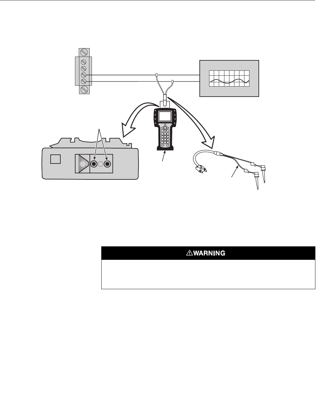
Figure 4-1. Signal Line Connections,
≥ 250 Ohms Load Resistance
Method 1, for Load Resistance ≥ 250 Ohms
Refer to Figure 4-1 and the following steps to connect the HART
communicator to a signal line 250 ohms or more of load resistance.
Using the supplied lead set, connect the HART communicator in parallel to
the OCX 8800. Use any wiring termination points in the oxygen analog output
4-20 mA signal line.
Loop
Connectors
O 4-20 mA Signal Line
2
HART
Communicator
Model 275/375
RL 250Ω
Analog Output Device
HART Communicator
Rear Panel
Lead Set
37390023
4-20 mA Terminal Block in
Electronics Housing
≥
A OUT 1 -
A OUT 1 +
1
Do not make connections to the HART communicator's serial port, 4-20 mA signal lines, or
NiCad recharger jack in an explosive atmosphere. Explosions can result in death or serious
injury.
Instruction Manual
IM-106-880 Original Issue
February 2005
4-3
OCX 8800
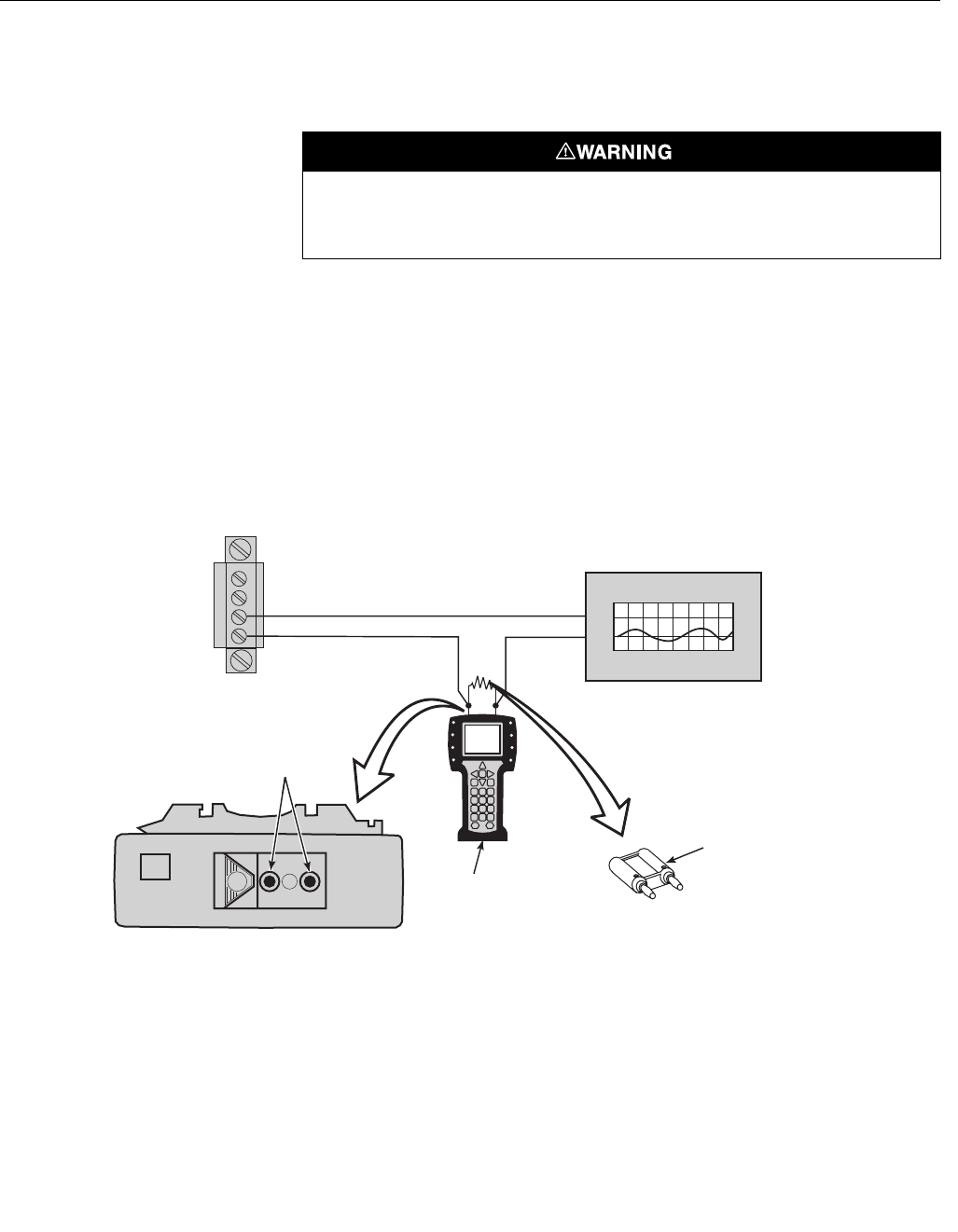
Method 2, for Load Resistance < 250 Ohms
Refer to Figure 4-2 and the following steps to connect the HART
communicator to a signal line with less than 250 ohms load resistance.
1. At a convenient point, break the oxygen analog output 4-20 mA signal
line and install the optional 250 ohm load resistor.
2. Plug the load resistor into the loop connectors (located on the rear panel
of the HART communicator).
Figure 4-2. Signal Line Connections,
< 250 Ohms Load Resistance
Do not make connections to the HART communicator's serial port, 4-20 mA signal lines, or
NiCad recharger jack in an explosive atmosphere. Explosions can result in death or serious
injury.
250 OHM
Load Resistor
(See Note)
37390021
The signal loop must be broken to insert
the optional 250 ohm load resistor.
NOTE:
Loop
Connectors
O 4-20 mA Signal Line
2
HART
Communicator
Model 275/375
RL <250Ω
Analog Output Device
HART Communicator
Rear Panel
4-20 mA Terminal Block in
Electronics Housing
A OUT 1 -
A OUT 1 +
1

Instruction Manual
IM-106-880 Original Issue
February 2005
OCX 8800
4-4
HART COMMUNICATOR
PC CONNECTIONS
There is an option to interface the HART communicator with a personal
computer. Load the designated AMS software into the PC. Then link the
HART communicator to the PC using the interface PC adapter that connects
to the serial port (on the communicator rear panel). Refer to the proper HART
communicator documentation in regard to the PC interface option.
Off-line and On-line Operations
The HART communicator can be operated both off-line and on-line.
Off-line operations are those in which the communicator is not connected to
the OCX 8800. Off-line operations can include interfacing the HART
communicator with a PC. (Refer to applicable HART documentation regarding
HART/PC applications.)
In the on-line mode, the communicator is connected to the oxygen 4-20 mA
analog output signal line. The communicator is connected in parallel to the
OCX 8800 or in parallel to the 250 ohm load resistor.
The opening menu displayed on the LCD is different for on-line and off-line
operations. When powering up a disconnected (off-line) communicator, the
LCD will display the Main Menu. When powering up a connected (on-line)
communicator, the LCD will display the On-line Menu. Refer to the HART
communicator manual for detailed menu information.
Instruction Manual
IM-106-880 Original Issue
February 2005
4-5
OCX 8800
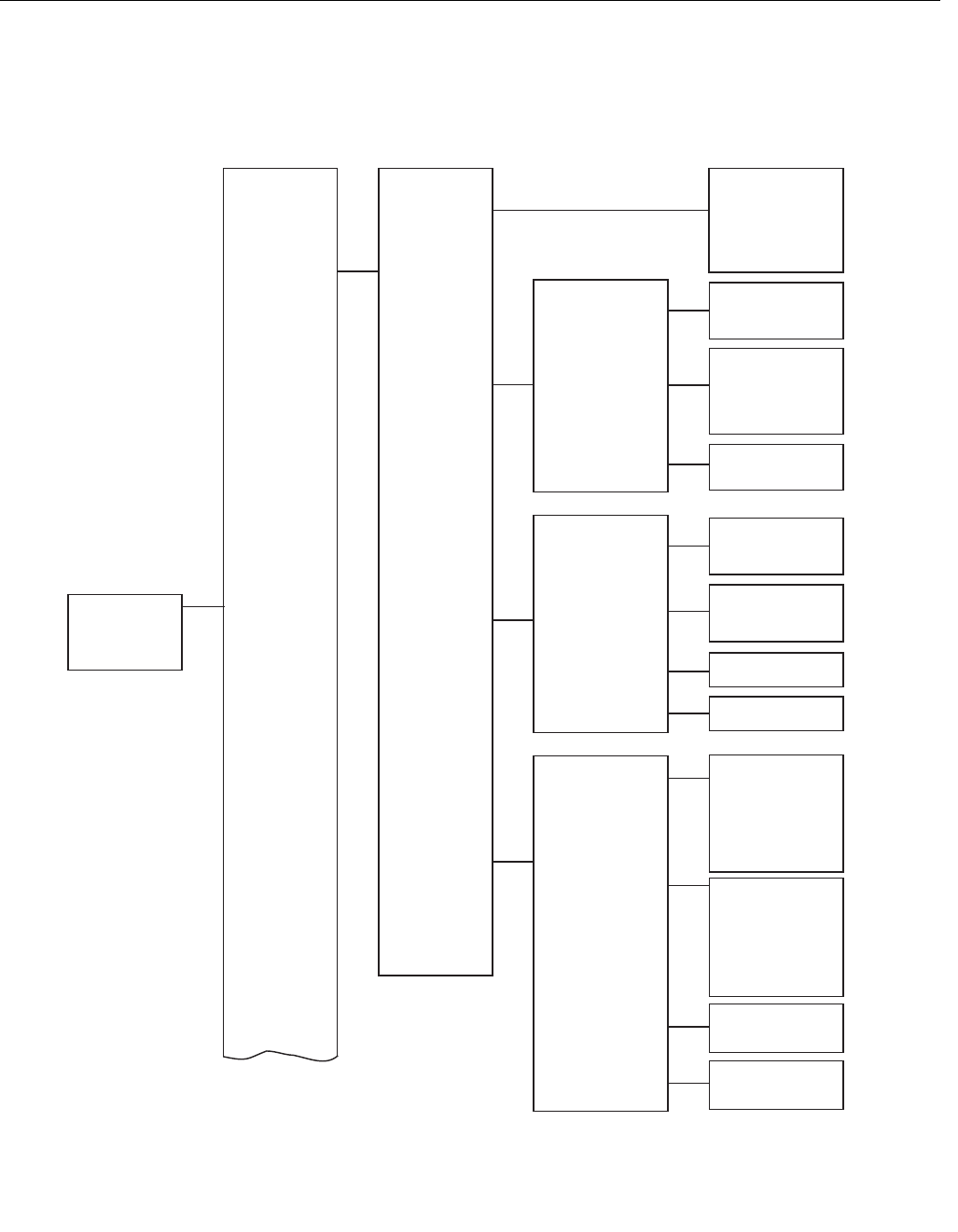
HART MENU TREE This section consists of a menu tree for the HART communicator. This menu
is specific to OCX 8800 applications.
Figure 4-3. HART Menu Tree
(Sheet 1 of 4)
O2
COe
O2 Temp
COe Temp
SB Temp
Brd Temp
CJC Temp
VIEW DEV VARS
PROCESS
VARIABLES
VIEW DEV
RAW VAL
DEVICE SETUP
O2
O2 AO
COe
COe AO
(CONTINUED ON
SHEET 2)
37390038
SV is COe
COe AO
COe AO %
VIEW OUTPUT
VARS
VIEW O2 RAW VAL
VIEW COE RAW VAL
VIEW DEV RAW VAL SB T/C
Brd Temp IC
CJC Temp S
O2 Snsr
O2 T/C
O2 Snsr R
O2 Snsr RS
COe DeltV
COe RefV
COe DeltaR
Coe RefR
COe T/C
RTD Curr
PV-AOUT
4V
TV
SV
PV is O2
O2 AO
O2 AO %
TV is O2 Temp
4V is COe Temp
VIEW DEV
LIMITS
O2
SB TEMP
BOARD TEMP
COE
O2 O2
O2 USL
O2 LSL
SB Temp
SB TC USL
SB TC LSL
O2 TEMP
O2 Temp
O2 T/C USL
O2 T/C LSL
COE COe
COe USL
COe LSL
COE TEMP
COe Temp
COe T/C USL
COe T/C LSL
Brd Temp
Brd TC USL
Brd TC LSL
Instruction Manual
IM-106-880 Original Issue
February 2005
OCX 8800
4-6
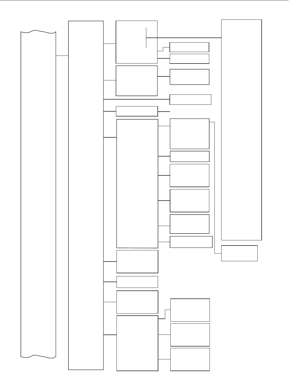
Figure 4-3. HART Menu Tree (Sheet 2 of 4)
DIAG/SERVICE
BCSR0 BCSR3
BCSR1 BCSR4
BCSR2 BCSR5
STATUS
CPLD REGS
D/A TRIM
CAL METHODS
O2OutTracks
COeOutTracks
Cal Step
Cal Time
O2
COe
PERFORM
CAL
CALIBRATE
Cal Step
Cal Time
CAL
STATUS
FAILED CAL
VALUES
Reset O2 CalConsts
Reset COe CalConsts
RESET CAL
CONST
O2 Calibration
COe Calibration
O2 and COe Calib
(CONTINUED FROM
SHEET 1 )
(CONTINUED ON
SHEET 3)
Snsr Housing
Model Number
O2 AO Saturated
COe AO Saturated
O2 AO Fixed
COe AO Fixed
AO fixed
AO saturated
Status group 4
Status group 3
Status group 2
Operate Mode
Status group 6
Status group 5
HW STATUS
Status group 1
LOOP TEST O2 Loop Test
COe Loop Test
O2 D/A Trim
COe D/A Trim
O2 Slope
O2 Const
O2 Snsr R
COe Slope
COe Const
CAL VALUES
Bad O2 Slope
Bad O2 Const
Bad COe Slope
Bad COe Const
PREV CAL
VALUES
Prev O2 Slope
O2 Const
O2 Snsr R
COe Slope
COe Const
Prev
Prev
Prev
Prev
VERIFY CALIB
Verify Calibration
Status
TimeRemain
O2
COe
BlBk State
Blowback
BLOWBACK
MAX TEMP
O2TempMax
COeTempMax
SBTempMax
BrdTempMax
CJCTempMax
O2 Prop
O2 Int
O2 DutyCyc
O2 SetPt
O2 Temp
HEATER PID
O2 PID
COE PID
SB PID
COe Prop
Int
DutyCyc
SetPt
Temp
COe
COe
COe
COe
SB Prop
SB Int
SB DutyCyc
SB SetPt
SB Temp
37390039
Line Freq
Line Volt
PCN Counter
PCD Counter
Status group 4
RTD Current Err
COe Temp Low
COe Temp Hi
COe Temp Very Hi
COe T/C Open
COe T/C Shorted
COe T/C Reversed
SB T/C Reversed
Status group 3
Cal Failed
Cal Warning
SB T/C Open
SB T/C Shorted
SB Temp Low
SB Temp Hi
SB Temp Very Hi
ADC Ref Error
Status group 2
O2 Temp Low
O2 Temp Hi
O2 Snsr Open
O2 Snsr R Hi
EEPRM Chksm Fail
O2 Htr Ramp Rate
COe Htr Ramp Rate
SB Htr Ramp Rate
Status group 6
O2 Slope Error
O2 Constant Error
O2 Cal Failed
COe Slope Error
COe Constant Error
COe Cal Failed
Status group 5
COe Htr Failure
SB Htr Failure
Line Voltage Low
Line Voltage Hi
Htr Relay Failed
Output Board Failure
Status group 1
O2 T/C Open
O2 T/C Shorted
O2 T/C Reversed
ADC Failure
Line Freq Error
O2 Htr Failure
O2 Temp Very Hi
Board Temp Hi
(procedures)
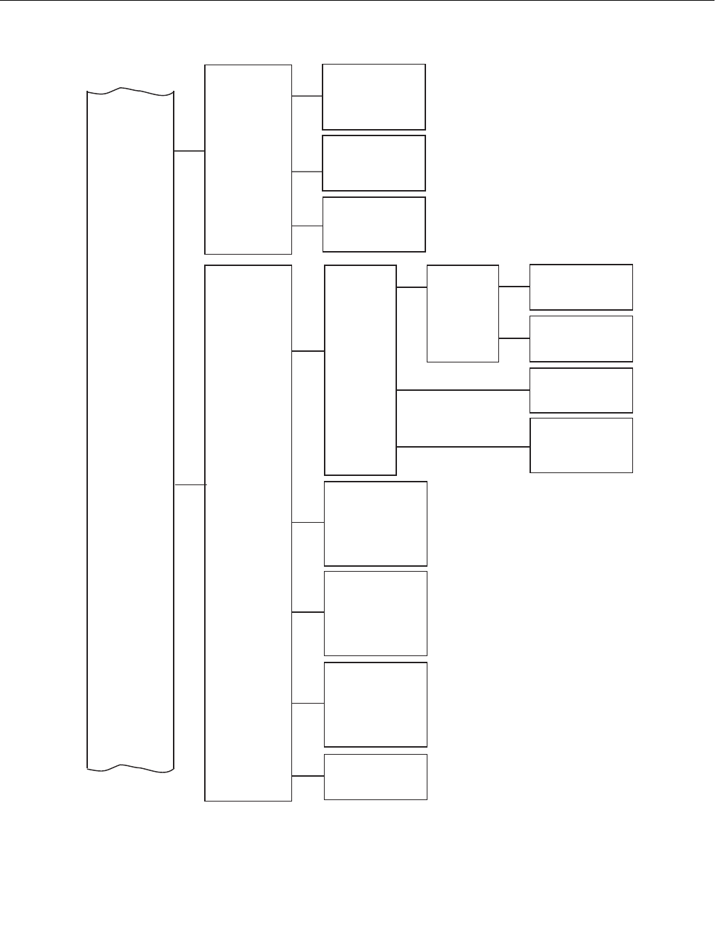
Instruction Manual
IM-106-880 Original Issue
February 2005
4-7
OCX 8800
Figure 4-3. HART Menu Tree
(Sheet 3 of 4)
BASIC SETUP
DEVICE
INFORMATION
DETAILED
SETUP
(CONTINUED FROM
SHEET 2)
37390040
(CONTINUED ON
SHEET 4)
Tag
Poll addr
Dev id
Num req preams
Fld dev rev
OUTPUT
CONDITION
Trig 1 Event
Trig 2 Event
Trig 3 Event
Alarm State
O2 AO Type
O2 URV
O2 LRV
O2 Alarm Level
COe CALIB
PARAMS
BlBk Enabled
BlBk Intrvl
BlBk Period
BlBk PurgeTm
BlBk State
ANALOG
OUTPUT
ALARM
RELAY
DEVICE
PARAMS
LOI
PARAMS
O2 CALIB
PARAMS
BLOWBACK
COe AO Type
COe URV
COe LRV
COe Alarm Level
O2 ANALOG
OUTPUT
COe ANALOG
OUTPUT
O2OutTracks
O2 High Gas
O2 Low Gas
Gas Time
Purge Time
Solenoids
O2 CalIntv
O2NxtCalTm
COeOutTracks
COe Test Gas
Gas Time
Purge Time
Solenoids
COe CalIntv
COeNxtCalTm
COe Slope Warn
O2 Slope
O2 Const
O2 T90
COe Slope
COe Const
COe T90
PCNC Enable
PCDC Enable
User Intface
Luminance
Lockout Time
Revert Time
Date
Descriptor
Message
Final asmbly num
O2 Sensor s/n
COe Sensor s/n
HART
INFORMATION
S/W VERSION
INFO
Version
Chksum
Bld Num
Bld Date
Restart Cntr
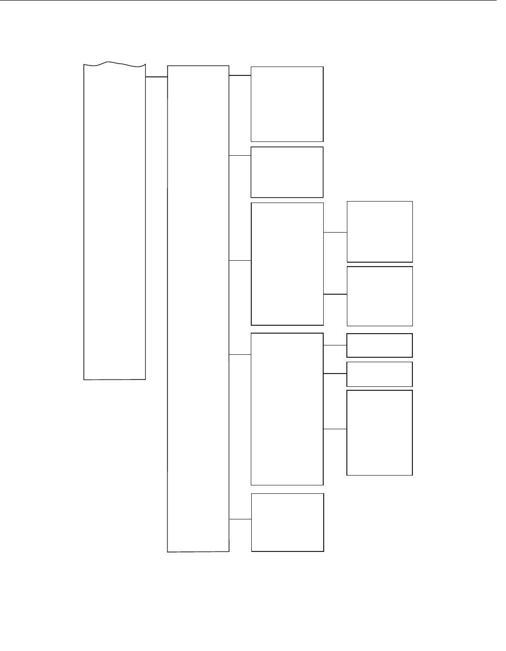
Instruction Manual
IM-106-880 Original Issue
February 2005
OCX 8800
4-8
Figure 4-3. HART Menu Tree
(Sheet 4 of 4)
O2 Slope
O2 Const
O2 T90
COe Slope
COe Const
COe T90
O2 CALIB
O2 DEVICE
CONFIG
REVIEW DEVICE
INFORMATION
HART
INFORMATION
CAL INFO
OUTPUTS
CONFIG
Manufacturer
Model
Date
Descriptor
Message
Final asmbly num
O2 Sensor s/n
COe Sensor s/n
Hardware rev
Software rev
(CONTINUED FROM
SHEET 3)
37390041
Tag
Poll addr
Dev id
Num req preams
Fld dev rev
Universal rev
DEVICE
CONFIG
COE CALIB
O2OutTracks
O2 High Gas
O2 Low Gas
Gas Time
Purge Time
Solenoids
O2 CalIntv
O2NxtCalTm
COeOutTracks
COe Test Gas
Gas Time
Purge Time
Solenoids
COe CalIntv
COeNxtCalTm
COe Slope Warn
COE DEVICE
CONFIG
DEVICE CONFIG
Trig 1 Event
Trig 2 Event
Trig 3 Event
BlBk Enabled
BlBk Intrvl
BlBk Period
BlBk PurgeTm
PCNC Enable
PCDC Enable
Luminance
Lockout Time
Revert Time
O2 URV
O2 LRV
COe URV
COe LRV
O2 AO Type
COe AO Type
O2 Alarm Level
COe Alarm Level

Instruction Manual
IM-106-880 Original Issue
February 2005
4-9
OCX 8800
D/A TRIM PROCEDURES O2 D/A trim procedure using HART/AMS
Use the following procedure to perform the O2 D/A trim procedure using the
HART communicator or AMS. Refer to the HART menu tree, Figure 4-3.
NOTE
To select a menu item, either use the up and down arrow keys to scroll to the
menu item and press the right arrow key or use the number keypad to select
the menu item number.
To return to a preceding menu, press the left arrow key.
1. From the DIAG/SERVICE menu, select D/A TRIM. The HART
communicator displays O2 D/A Trim.
2. Press the right arrow key to start the procedure. (If you wish to exit D/A
Trim with no changes, select ABORT.)
3. The HART communicator displays WARNING: Loop should be
removed from automatic control. Remove the OCX 8800 from any
automatic control loops to avoid a potentially dangerous operating
condition and press OK.
4. Remove the electronics housing cover.
5. Refer to Figure 2-5. Connect a digital multimeter to read the milliamp
output from the O2 D/A coverter circuit. Connect the positive lead to the
AOUT1+ terminal and connect the negative lead to the AOUT1-
terminal. Then, press OK at the HART communicator.
6. The HART communicator displays Setting Fld dev output to 4 mA.
Press OK. Read the O2 millamp output at the digital multimeter. Enter
the reading at the HART communicator and press ENTER. (Select
ABORT to exit without changes).
7. The HART communicator displays Setting Fld dev output to 20 mA.
Press OK. Read the O2 millamp output at the digital multimeter. Enter
the reading at the HART communicator and press ENTER. (Select
ABORT to exit without changes).
8. The HART communicator displays Setting Fld dev output to 4 mA.
Press OK.
9. The HART communicator displays Fld dev output 4.00 mA equal to
reference meter? Using the up or down arrow, select 1 Yes or 2 No
and Press ENTER. If No, the process repeats from step 6.
10. The HART communicator displays Setting Fld dev output to 20 mA.
Press OK.
11. The HART communicator displays Fld dev output 20.00 mA equal to
reference meter? Using the up or down arrow, select 1 Yes or 2 No
and Press ENTER. If No, the process repeats from step 7.
12. The HART communicator displays NOTE: Loop may be returned to
automatic control.

Instruction Manual
IM-106-880 Original Issue
February 2005
OCX 8800
4-10
COe D/A trim procedure using HART/AMS
Use the following procedure to perform the COe D/A trim procedure using the
HART communicator or AMS. Refer to the HART menu tree, Figure 4-3.
NOTE
To select a menu item, either use the up and down arrow keys to scroll to the
menu item and press the right arrow key or use the number keypad to select
the menu item number.
To return to a preceding menu, press the left arrow key.
1. From the DIAG/SERVICE menu, select D/A TRIM. The HART
communicator displays O2 D/A Trim. Press the up or down arrow to
select COe D/A Trim.
2. Press the right arrow key to start the procedure. (If you wish to exit D/A
Trim with no changes, select ABORT.)
3. The HART communicator displays WARNING: Loop should be
removed from automatic control. Remove the OCX 8800 from any
automatic control loops to avoid a potentially dangerous operating
condition and press OK.
4. Remove the electronics housing cover.
5. Refer to Figure 2-5. Connect a digital multimeter to read the milliamp
output from the COe D/A coverter circuit. Connect the positive lead to
the AOUT2+ terminal and connect the negative lead to the AOUT2-
terminal. Then, press OK at the HART communicator.
6. The HART communicator displays Setting Fld dev output to 4 mA.
Press OK. Read the COe millamp output at the digital multimeter. Enter
the reading at the HART communicator and press ENTER. (Select
ABORT to exit without changes).
7. The HART communicator displays Setting Fld dev output to 20 mA.
Press OK. Read the COe millamp output at the digital multimeter. Enter
the reading at the HART communicator and press ENTER. (Select
ABORT to exit without changes).
8. The HART communicator displays Setting Fld dev output to 4 mA.
Press OK.
9. The HART communicator displays Fld dev output 4.00 mA equal to
reference meter? Using the up or down arrow, select 1 Yes or 2 No
and Press ENTER. If No, the process repeats from step 6.
10. The HART communicator displays Setting Fld dev output to 20 mA.
Press OK.
11. The HART communicator displays Fld dev output 20.00 mA equal to
reference meter? Using the up or down arrow, select 1 Yes or 2 No
and Press ENTER. If No, the process repeats from step 7.
12. The HART communicator displays NOTE: Loop may be returned to
automatic control.

Instruction Manual
IM-106-880 Original Issue
February 2005 OCX 8800
http://www.processanalytic.com
Section 5 Calibration
Overview . . . . . . . . . . . . . . . . . . . . . . . . . . . . . . . . . . . . . . . page 5-1
Fully Automatic Calibration . . . . . . . . . . . . . . . . . . . . . . . . page 5-1
Operator - Initiated Autocalibration . . . . . . . . . . . . . . . . . page 5-3
Manual Calibration . . . . . . . . . . . . . . . . . . . . . . . . . . . . . . . page 5-3
OVERVIEW During a calibration, two calibration gases with known O2 concentrations and
one calibration gas with a known COe concentration are applied to the OCX
8800. Slope and constant values are calculated to determine if the OCX 8800
is correctly measuring net concentrations of O2 and combustibles in the
industrial process.
Before calibrating the OCX 8800, verify that the calibration gas parameters
are correct by setting the test gas values used when calibrating the unit. Refer
to Section 3, Configuration and Startup.
There are three calibration methods available to the OCX 8800; automatic,
operator-initiated automatic, and manual. Calibration commands and menus
can be accessed by HART/AMS.
FULLY AUTOMATIC
CALIBRATION
If the OCX 8800 is equipped with calibration solenoids, the unit can be
programmed to automatically calibrate without any operator action. Refer to
the following paragraphs for using HART/AMS to set up the OCX 8800 for
fully automatic calibration.
Autocalibration Setup using HART
NOTE
Automatic calibration is only available on units equipped with calibration
solenoids.
Use the following procedure to specify a time interval (in hours) at which the
OCX 8800 will automatically calibrate.
1. From the DEVICE SETUP screen, select DETAILED SETUP.
2. From the DETAILED SETUP screen, select O2 CALIB PARAMS or
COE CALIB PARAMS.
3. If the unit is equipped with calibration solenoids and timed automatic
calibrations are desired, select Solenoids, then select Yes. Selct No to
disable the calibration solenoids.

Instruction Manual
IM-106-880 Original Issue
February 2005
OCX 8800
5-2
4. Select O2 CalIntrvl (O2 calibration interval) and enter the desired time
in hours between automatic O2 calibrations. Select COE Callintrvl and
enter the desired time between automatic COe calibrations. To disable
automatic calibration for O2 and COe, enter 0 for both CalIntrvl
parameters.
5. If desired, the O2NxtCalTm and the COeNxtCalTm (next calibration
time) parameters can be changed to synchronize a calibration at a
specific day or time.
NOTE
To select a menu item, either use the up and down arrow keys to scroll to the
menu item and press the right arrow key or use the number keypad to select
the menu item number.
To return to a preceding menu, press the left arrow key.
6. From the O2 CALIB PARAMS screen, select CalIntrvl.
7. At the prompt, input a time interval (in hours) at which an automatic O2
calibration will occur and press ENTER.
8. From the DETAILED SETUP screen, select COE CALIB PARAMS.
9. From the COE CALIB PARAMS menu, select CalIntrvl.
10. At the prompt, input a time interval (in hours) at which an automatic COe
calibration will occur and press ENTER.
When setting automatic calibration times, CalIntrvl and NxtCalTm should be set so that O2
and COe are NOT calibrated simultaneously.

Instruction Manual
IM-106-880 Original Issue
February 2005
5-3
OCX 8800
OPERATOR - INITIATED
AUTOCALIBRATION
An operator can initiate an automatic calibration at any time provided that the
unit is equipped with calibration solenoids.
Autocalibration using HART
To initiate an automatic calibration using HART/AMS, perform the following
steps on the HART menu tree. Refer to Section 4, Using HART
Communications, for the HART menu tree.
1. Select DIAG/SERVICE from DEVICE SETUP menu.
2. Select CALIBRATE from the DIAG/SERVICE menu.
3. Select PERFORM CAL from the CALIBRATE menu.
4. Select CAL METHODS from the PERFORM CAL menu.
5. From the CAL METHODS menu, select the type of calibration desired:
O2 Calibration, COe Calibration, or O2 and COe Calibration.
MANUAL CALIBRATION If a unit is not equipped with calibration solenoids, a calibration must be
performed by an operator following prompts from the unit. Refer to the
following paragraphs for manual calibration.
Manual O2 Calibration using HART
To perform a manual O2 calibration using the HART communicator or AMS,
use the following procedure. If necessary, refer to Section 4, Using HART
Communications, for the HART menu tree.
NOTE
To select a menu item, either use the up and down arrow keys to scroll to the
menu item and press the right arrow key or use the number keypad to select
the menu item number.
To return to a preceding menu, press the left arrow key.
1. From the DIAG/SERVICE menu, select CALIBRATION. From the
CALIBRATION menu, select PERFORM CAL.
2. From the PERFORM CAL menu, select CAL METHODS. Select O2
CALIBRATION to start O2 calibration.
3. In the first O2 Calibration screen, a Loop should be removed from
automatic control warning appears. Remove the OCX 8800 from any
automatic control loops to avoid a potentially dangerous operating
condition and press OK.
4. The main Calibration screen should look like the following. Press OK to
continue.
OCX: TAG NAME
STATUS: Idle
TIME REMAIN: 0s
O2: 0.4 %, 85.95mV
OK/NEXT to Select
ABORT/CANCEL to Exit

Instruction Manual
IM-106-880 Original Issue
February 2005
OCX 8800
5-4
5. From the SELECT ACTION screen, select START/NEXT CALSTEP to
continue calibration, select ABORT CAL to abort calibration or EXIT
CAL to exit calibration. Select one item from the list and press ENTER.
OCX: TAG NAME
SELECT ACTION
1. START/NEXT CALSTEP
2. ABORT CAL
3. EXIT CAL
6. When the Calibration Status is at the AppO2Low step, switch on O2
Low Gas. Verify the O2 concentration measured matches the O2 LOW
GAS parameter in the Setup. Press OK when ready.
7. Select Start/Next Cal Step to start applying the O2 Low Gas. The time
to apply the test gas is specified by the Gas Time.
8. The Calibration Status should be automatically changed to FlowO2Low
and then ReadO2Low for a period of time. During this period, if an
attempt is made to go to the next calibration step by pressing OK and
selecting Start/Next Cal Step, you will be prompted with Operator step
command is not accepted at this time. The Next Cal Step command
is not accepted at this time.
9. When ready, Calibration Status will stop at the AppO2Hi. Switch off the
O2 Low Gas and switch on the O2 High Gas. Verify the O2 concentration
measured matches the O2 HIGH GAS parameter in the Setup. Press
OK when ready.
10. Select Start/Next Cal Step to start applying the O2 High Gas. The time
to apply the test gas is specified by the Gas Time.
11. The Calibration Status should be automatically changed to FlowO2Hi
and then ReadO2Hi for a period of time. During this period, if an attempt
is made to go the next calibration step by pressing OK and selecting
Start/Next Cal Step, you will be prompted with Operator step
command is not accepted at this time. The Next Cal Step command
is not accepted at this time.
12. When ready, Calibration Status will stop at STOP GAS. Switch off the
O2 High Gas. Press OK when ready. Select Start/Next Cal Step to start
purging gas. The time to purge gas is specified by the Purge Time.
13. When the Purge step is complete, the Calibration Status will be at IDLE
if the calibration is successful or CAL RECOMMENDED if the
calibration has failed. A Calibration Failed alarm will be set if the
calibration has failed.
14. When calibration is complete. Select Exit Cal to exit the calibration
method.

Instruction Manual
IM-106-880 Original Issue
February 2005
5-5
OCX 8800
Manual COe Calibration using HART
To perform a manual COe calibration using the HART communicator or AMS,
use the following procedure. If necessary, refer to Section 4, Using HART
Communications, for the HART menu tree.
NOTE
To select a menu item, either use the up and down arrow keys to scroll to the
menu item and press the right arrow key or use the number keypad to select
the menu item number.
To return to a preceding menu, press the left arrow key.
1. From the DIAG/SERVICE menu, select CALIBRATION. From the
CALIBRATION menu, select PERFORM CAL.
2. From the PERFORM CAL menu, select CAL METHODS. Select COe
CALIBRATION to start COe calibration.
3. In the first COe Calibration screen, a Loop should be removed from
automatic control warning appears. Remove the OCX 8800 from any
automatic control loops to avoid a potentially dangerous operating
condition and press OK.
4. The main Calibration screen should look like the following. Press OK to
continue.
OCX: TAG NAME
STATUS: Idle
TIME REMAIN: 0s
COe: 0.20 ppm, 0.00 mV
OK/NEXT to Select
ABORT/CANCEL to Exit
5. From the SELECT ACTION screen, select START/NEXT CALSTEP to
continue calibration, select ABORT CAL to abort calibration or EXIT
CAL to exit calibration. Select one item from the list and press ENTER.
OCX: TAG NAME
SELECT ACTION
1. START/NEXT CALSTEP
2. ABORT CAL
3. EXIT CAL
6. The unit samples reference air as the COe Low Gas. The Calibration
Status should automatically change to ReadCOLow for a period of time.
During this period, if an attempt is made to go to the next calibration
step by pressing OK and selecting Start/Next Cal Step, you will be
prompted with Operator step command is not accepted at this time.
The Next Cal Step command is not accepted at this time.
7. When ready, Calibration Status will stop at the AppCOeHi. Switch on
the COe High Gas. Verify the COe concentration measured matches the
COe HIGH GAS parameter in the Setup. Press OK when ready.
8. Select Start/Next Cal Step to start applying the COe High Gas. The
time to apply the test gas is specified by the Gas Time.

Instruction Manual
IM-106-880 Original Issue
February 2005
OCX 8800
5-6
9. The Calibration Status should be automatically changed to FlowCOeHi
and then ReadCOeHi for a period of time. During this period, if an
attempt is made to go the next calibration step by pressing OK and
selecting Start/Next Cal Step, you will be prompted with Operator step
command is not accepted at this time. The Next Cal Step command
is not accepted at this time.
10. When ready, Calibration Status will stop at STOP GAS. Switch off the
COe High Gas. Press OK when ready. Select Start/Next Cal Step to
start purging gas. The time to purge gas is specified by the Purge Time.
11. When the Purge step is complete, the Calibration Status will be at IDLE
if the calibration is successful or CAL RECOMMENDED if the
calibration has failed. A Calibration Failed alarm will be set if the
calibration has failed.
12. When calibration is complete. Select Exit Cal to exit the calibration
method.
Manual O2 and COe Calibration using HART
To perform a manual O2 and COe calibration using the HART communicator
or AMS, use the following procedure. If necessary, refer to Section 4, Using
HART Communications, for the HART menu tree.
NOTE
To select a menu item, either use the up and down arrow keys to scroll to the
menu item and press the right arrow key or use the number keypad to select
the menu item number.
To return to a preceding menu, press the left arrow key.
1. From the DIAG/SERVICE menu, select CALIBRATION. From the
CALIBRATION menu, select PERFORM CAL.
2. From the PERFORM CAL menu, select CAL METHODS. Select 02 &
COe CALIBRATION to start O2 and COe calibration.
3. In the first Calibration screen, a Loop should be removed from
automatic control warning appears. Remove the OCX 8800 from any
automatic control loops to avoid a potentially dangerous operating
condition and press OK.
4. The main Calibration screen should look like the following. Press OK to
continue.
OCX: TAG NAME
STATUS: Idle
TIME REMAIN: 0s
O2: 0.4 %, 85.95mV
COe: 0.20 ppm, 0.00 mV
OK/NEXT to Select
ABORT/CANCEL to Exit

Instruction Manual
IM-106-880 Original Issue
February 2005
5-7
OCX 8800
5. From the SELECT ACTION screen, select START/NEXT CALSTEP to
continue calibration, select ABORT CAL to abort calibration or EXIT
CAL to exit calibration. Select one from the list and press ENTER.
OCX: TAG NAME
SELECT ACTION
1. START/NEXT CALSTEP
2. ABORT CAL
3. EXIT CAL
6. When the Calibration Status is at the AppO2Low step, switch on O2
Low Gas. Verify the O2 concentration measured matches the O2 LOW
GAS parameter in Setup. Press OK when ready.
7. Select Start/Next Cal Step to start applying the O2 Low Gas. The time
to apply the test gas is specified by the Gas Time.
8. The Calibration Status should automatically change to FIowO2Low and
then ReadO2Low for a period of time. During this period, if an attempt
is made to go to the next calibration step by pressing OK and selecting
Start/Next Cal Step, you will be prompted with Operator step
command is not accepted at this time. The Next Cal Step command
is not accepted at this time.
9. When ready, Calibration Status will stop at AppO2Hi. Switch off the O2
Low Gas and switch on the O2 High Gas. Verify the O2 concentration
measured matches the O2 HIGH GAS parameter in Setup. Press OK
when ready.
10. Select Start/Next Cal Step to apply the O2 High Gas. The time to apply
the test gas is specified by the Gas Time.
11. The Calibration Status should automatically change to FlowO2Hi, then
ReadO2Hi, and then ReadCOeLo for a period of time. During this
period, if an attempt is made to go the next calibration step by pressing
OK and selecting Start/Next Cal Step, you will be prompted with
Operator step command is not accepted at this time. The Next Cal
Step command is not accepted at this time.
12. When ready, Calibration Status will stop at AppCOeHi. Switch off the
O2 High Gas and switch on the COe Gas. Verify the COe concentration
measured matches the COe TEST GAS parameter in the Setup. Press
OK when ready.
13. Select Start/Next Cal Step to start applying the COe Gas. The time to
apply the test gas is specified by the Gas Time.
14. The Calibration Status should automatically change to FlowCOeHi and
then ReadCOeHi for a period of time. During this period, if an attempt is
made to go the next calibration step by pressing OK and selecting
Start/Next Cal Step, you will be prompted with Operator step
command is not accepted at this time. The Next Cal Step command
is not accepted at this time.
15. When ready, Calibration Status will stop at STOP GAS. Switch off the
COe gas. Press OK when ready. Select Start/Next Cal Step to start
purging gas. The time to purge gas is specified by Purge Time.

Instruction Manual
IM-106-880 Original Issue
February 2005
OCX 8800
5-8
Instruction Manual
IM-106-880 Original Issue
February 2005 OCX 8800
http://www.raihome.com
Section 6 Maintenance and Service
Overview . . . . . . . . . . . . . . . . . . . . . . . . . . . . . . . . . . . . . . . page 6-1
OCX 8800 Removal and Installation . . . . . . . . . . . . . . . . . page 6-1
Repair Sensor Housing . . . . . . . . . . . . . . . . . . . . . . . . . . . page 6-8
Repair Electronics Housing . . . . . . . . . . . . . . . . . . . . . . . . page 6-28
Replace Tube Fittings . . . . . . . . . . . . . . . . . . . . . . . . . . . . . page 6-34
OVERVIEW This section contains the procedures to maintain and service the OCX 8800.
OCX 8800 REMOVAL
AND INSTALLATION
Use the following procedures to remove or install the OCX 8800.
Install all protective equipment covers and safety ground leads after equipment repair or
service. Failure to install covers and ground leads could result in serious injury or death.
It is recommended that the OCX 8800 be removed from the stack for all service activities.
The unit should be allowed to cool and be taken to a clean work area. Failure to comply may
cause severe burns.
Disconnect and lock out power before working on any electrical components. There may be
voltage up to 264 VAC.
Observe housing classification guidelines prior to removing cover. Failure to observe
classification guidelines may result in serious injury or death.
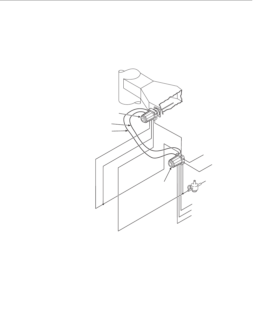
Instruction Manual
IM-106-880 Original Issue
February 2005
OCX 8800
6-2
OCX with
Remote Electronics
Remove Sensor Housing
1. Turn off power to the system.
2. Shut off the test gasses at the cylinders and close the instrument air
valve.
3. Disconnect the calibration gas, reference air, eductor air, and dilution air
lines from the sensor housing, Figure 6-1.
Figure 6-1. OCX with
Remote Electronics
Heater
Power Cable
Low O Test Gas
2
High O Test Gas
2
CO Test Gas
Instrument Air
(Reference Gas)
Test Gas
Reference Air
Dilution Air
Eductor Air
Instrument Air
Duct
Stack
AC Power
Input
Signal Cable
37390044
Sensor
Housing
Electronics
Housing
4-20 mA
Outputs
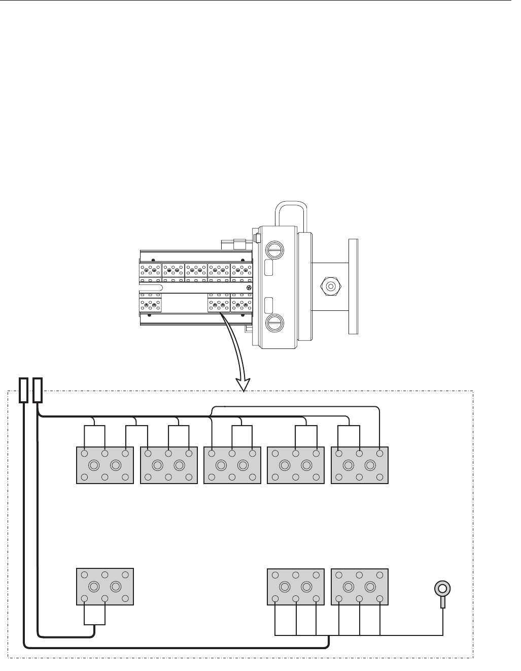
Instruction Manual
IM-106-880 Original Issue
February 2005
6-3
OCX 8800
4. Remove the cover from the sensor housing to expose the sensor
housing terminal blocks, Figure 6-2.
5. Disconnect the signal cable from the O2 and T/C terminal blocks, and
from the CO and CJC terminal blocks.
6. Disconnect the heater power cable from the HTR terminal blocks.
7. If moving the sensor housing to another work site, disconnect and
remove the power and signal cables from the sensor housing.
8. Remove insulation to access the mounting bolts. Unbolt the sensor
housing from the stack and take it to a clean work area.
9. Allow the sensor housing to cool to a comfortable working temperature.
Figure 6-2. Sensor
Housing Terminals
37390028
BLU
ORG
YEL
RED
BLK
WHT
BLK
YEL
RED
BLU
WHT
BLK
BLK
GRN
BLK
BLK
BLK
ORG WHT
RED
BLK
BRN
To
Ground
Screw
GRN
SENSOR HOUSING
Signal Cable
Heater Power Cable
T/C O2
T/C CO
T/C SB
EXC
CJC
CO REF
CO ACT
+
-
+
-
+
-
+
-
+
-
+
-
+
EXC -
O2
HTR SB
2
2
1
-
+
HTR 02
2
1
HTR CO
1
NOTE: Wire colors shown are for cables
supplied by Rosemount Analytical.

Instruction Manual
IM-106-880 Original Issue
February 2005
OCX 8800
6-4
Install Sensor Housing
1. Connect the test gas, reference air, eductor air, and dilution air lines to
the sensor housing.
2. Remove the sensor housing cover.
3. If removed, install the power and signal cables and the customer power
and signal conduits and wiring at the sensor housing.
4. Connect the signal cable to O2 and T/C terminal blocks and to the CO
and CJC terminal blocks, Figure 6-2. Connect the heater power cable to
the HTR terminal blocks.
5. Refer to Figure 6-1 and make sure all test gas lines and electrical
connectors are complete.
6. Install the sensor housing cover.
7. Restore power to the system. Allow OCX to reach normal operating
temperature before installing in a hot process stack.
8. Insert and bolt the sensor housing in the stack and install insulation.
9. Turn on the test gases at the cylinders and open the instrument air
supply valve.
Remove Remote Electronics Housing
1. Turn off power to the system.
2. Shut off the test gases at the cylinders and close the instrument air
supply valve, Figure 6-1.
3. Disconnect the test gas and instrument air lines from the remote
electronics housing.
4. Remove the cover from the electronics housing to expose the
electronics housing terminal blocks, Figure 6-3.
5. Disconnect and remove the power leads from the AC power input
terminal block. Remove the ground lead from the ground stud.
6. Disconnect and remove the O2 and COe signal leads from the 4-20 mA
signal output terminal block.
7. If used, disconnect and remove the external relay leads from the alarm
output relay terminal block.
8. Disconnect the signal cable leads from O2 cell and thermocouple
connector (J4), and from COe and CJC connector (J5), Figure 6-4.
9. Disconnect the heater cable leads from the heater power connector
(J3).
10. If moving the electronics housing to another work site, disconnect and
remove the power and signal cables and customer wiring conduits from
the housing.
11. Remove the remote electronics housing from its mounting and move it
to a suitable work area.
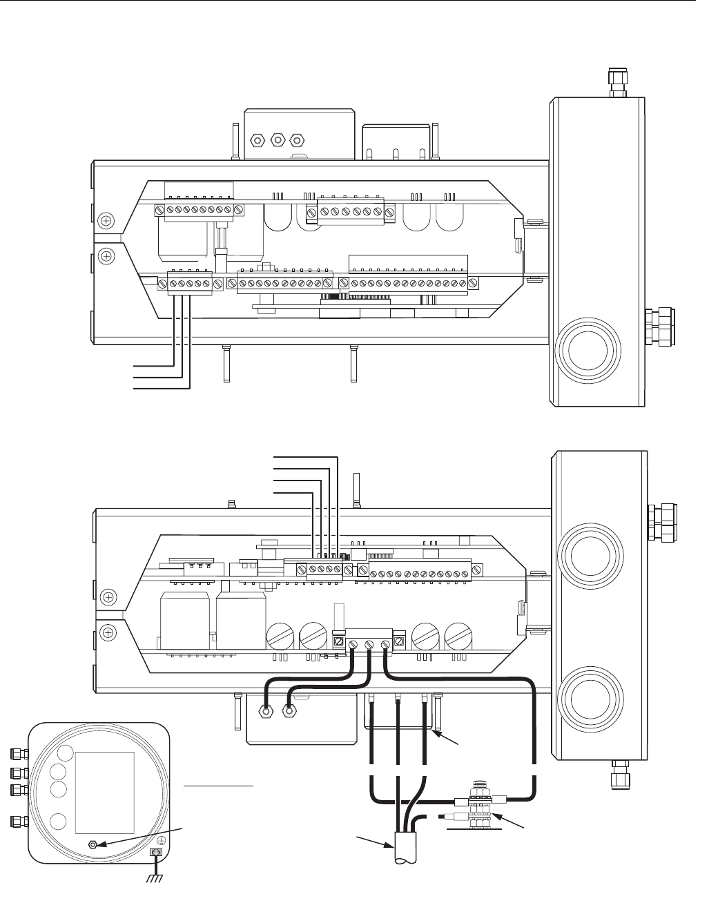
Instruction Manual
IM-106-880 Original Issue
February 2005
6-5
OCX 8800
Figure 6-3. Electronics Housing
Terminal Blocks
37390013
TOP VIEW
(1/2 SIZE)
Ground Stud
Earth Ground
Typical for Electronics and
Sensor Housing
NC
COM
NO
Alarm Output Relay
Terminal Block
#1
AOUT2+
AOUT2 -
AOUT1 -
AOUT1+
O Signal
2
COe Signal
{
{
Ground
Stud
4-20 mA Signal Output
Terminal Block
Power Port
3/4 NPT
Signal Port
3/4 NPT
External Tooth
Lockwasher
#1
G
G
Terminal
Block
N
G
L1
EMI Filter
Customer
Wiring
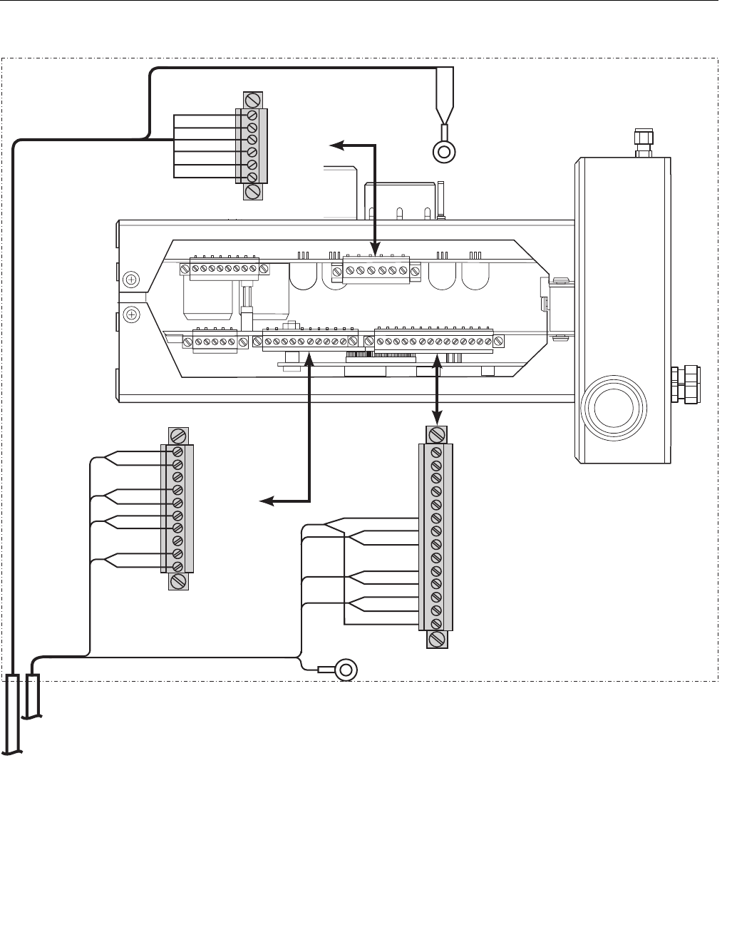
Instruction Manual
IM-106-880 Original Issue
February 2005
OCX 8800
6-6
Figure 6-4. Remote Electronics
Housing Cable Connections
37390016
RED
BLK
WHT
GRN
BLK
BLK
BLU
BLK
YEL
BRN
RED
BLK
BLK
ORG
BLK
WHT
T/C CO+
T/C CO-
T/C SB+
T/C SB-
T/C O2+
T/C O2-
O2 CELL+
O2 CELL-
SHIELD
To
Ground
Screw
GRN
ELECTRONICS HOUSING
O2 Cell
& Thermocouple
Connector (J5)
COe Sensor
& CJC
Connector (J4)
EXC+
CO ACT+
CO ACT-
CO REF+
CO REF-
CJC+
CJC-
EXC-
Heater
Power Cable
Signal Cable
NOTE: Wire colors shown are for cables
supplied by Rosemount Analytical.
1
#1
#1 #1
#1
#1
To Ground
Screw
SHLD
Heater Power
Connector (J3)
#1
2HTR SB
1HTR O2
1HTR SB
2HTR CO
1HTR CO
2HTR O2
WHT
ORG
BLU
BLK
YEL
RED

Instruction Manual
IM-106-880 Original Issue
February 2005
6-7
OCX 8800
Install Remote Electronics Housing
1. Mount remote electronics housing on wall or pipe within distance of
signal and heater cables in use.
2. Remove the electronics housing cover.
3. If removed, install the power and signal cables and the customer power
and signal conduits and wiring at the electronics housing.
4. Connect the signal cable leads to the O2 cell and thermocouple
connector (J4), and to the COe and CJC connector (J5), Figure 6-4.
5. Connect the heater cable leads to the heater power connector (J3).
6. Connect the line (L1 wire) to the L1 terminal, and the neutral (N wire) to
the N terminal on the AC power input terminal block, Figure 6-4.
7. Connect the ground lead to the ground stud. Secure the connection with
two nuts. Attach a separate ground lead (G wire) from the ground stud
to the G terminal on the power input terminal block.
8. If used, connect external relay leads to the alarm output relay terminal.
9. Connect the test gas and instrument air lines to the remote electronics
housing. Connect the calibration gas line and instrument air line to the
remote electronics housing.
10. Refer to Figure 6-1 and Figure 6-4. Make sure all test gas lines and
electrical connections are complete.
11. Install the cover on the electronics housing.
12. Turn on the test gasses at the cylinders and open the instrument air
valve.
13. Restore power to the system.

Instruction Manual
IM-106-880 Original Issue
February 2005
OCX 8800
6-8
REPAIR SENSOR
HOUSING
Use the following procedures to remove damaged components from the OCX
8800 sensor housing and to install new replacement parts. Disassemble the
unit only as needed to replace damaged components. Use the assembly
procedures that apply to install replacement parts and reassemble the unit.
Sensor Housing
Disassembly
Remove Cover and Terminals Insulator
1. Loosen screw (1, Figure 6-5) and slide locking clip (2) away from cover.
Retighten screw (1).
2. With two hands or strap wrench, turn cover (3) counterclockwise to
loosen. Unthread and remove cover.
3. Inspect cover o-ring (4) for wear or damage. Replace cover o-ring if
damaged.
4. Unsnap terminal marking plates (5) and remove terminal insulator (6).
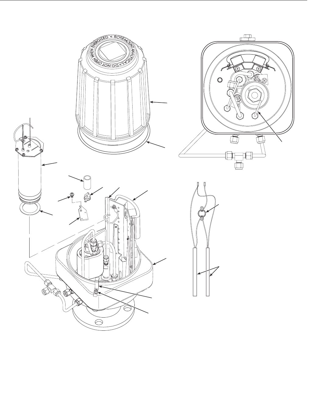
Instruction Manual
IM-106-880 Original Issue
February 2005
6-9
OCX 8800
Figure 6-5. Removal of O2 Cell
and Heater Strut Assembly
56
12
11
14
15
10
9
1
2
4
3
7
8
13
3
7
390066
1. Screw
2. Locking Clip
3. Cover
4. O-ring
5. Marking Plate
6. Terminal Insulator
7. Reference Air Tube
8. Sensor Housing
9. Heater Strut Assembly
10. Gasket
11. Screw
12. Heater Clamp
13. Heater Rod
14. Insulator
15. Thermal Switch
15
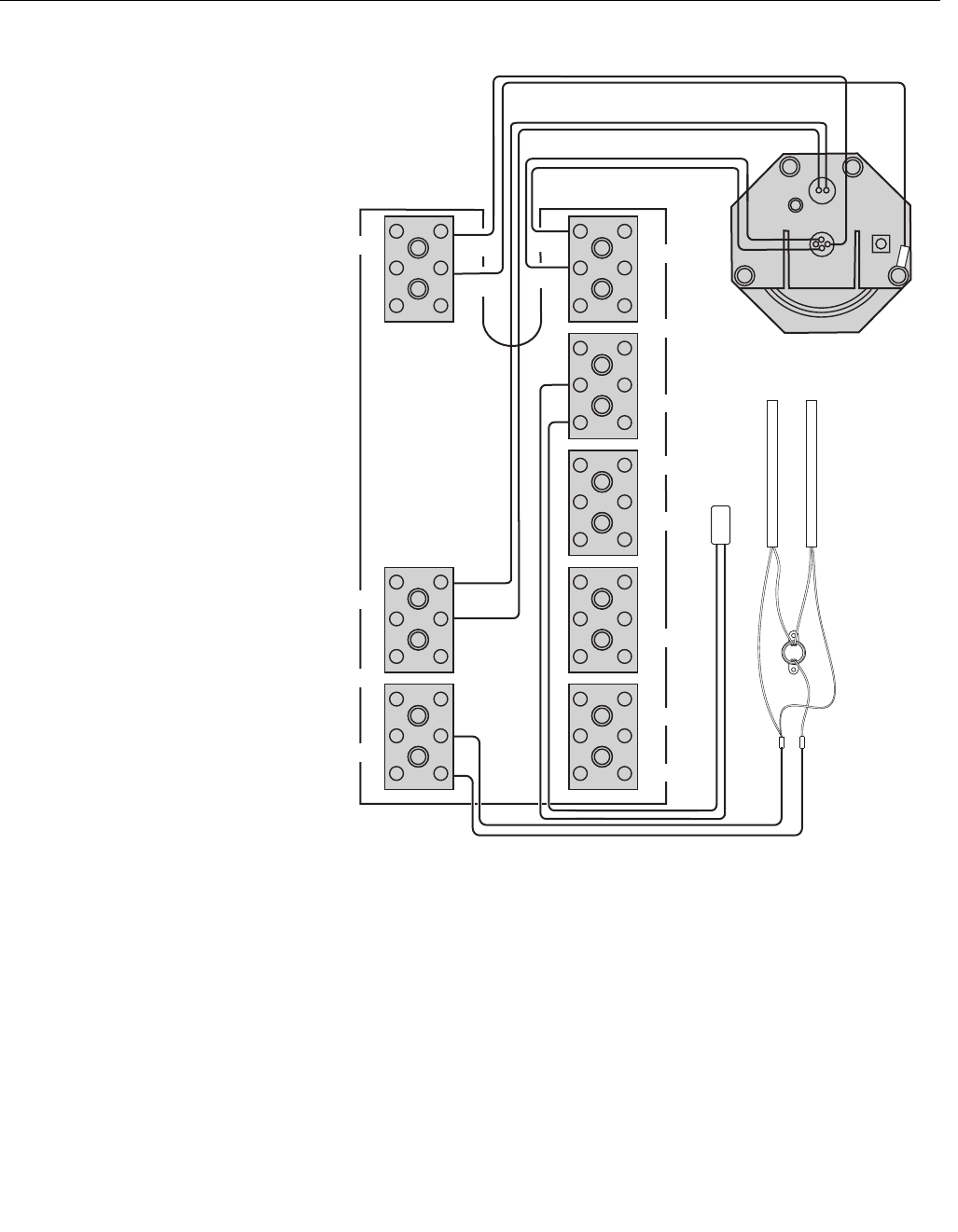
Instruction Manual
IM-106-880 Original Issue
February 2005
OCX 8800
6-10
Figure 6-6. O2 Cell,
Thermocouple, and
Heater Connections
Remove O2 Cell and Heater Strut Assembly
1. Remove reference air tube (7, Figure 6-5) from sensor housing (8).
2. See Figure 6-6. Disconnect and tag O2 heater wires, O2 cell and return
wires, and thermocouple wires at the sensor housing terminals.
3. Remove the O2 cell and heater strut assembly (9, Figure 6-5) from
sensor housing (8). Remove and discard gasket (10).
Remove Sample Block Heater Rods
1. Disconnect sample block heater rod wires from terminal block. Refer to
Figure 6-6.
+ +
++
O2
Thermocouple Wires
ORG
RED
T/C O2
T/C CO
T/C SB
EXC
CJC
O Cell Wires
2
O Heater Wires
2
Return Wire
O Cell and Heater Strut
Assembly
2
CO REF
CO ACT
Sensor Housing Terminals
+
-
HTR 02
HTR SB
2
GRN
2
1
+
-
+
-
+
-
+
-
+
-
+
YEL
-
+
+
37390069
HTR 02
2
1
Sample Block
Heater Rods
Thermal
Switch
HTR CO
1
EXC
-
Sample
Block
Thermo-
couple
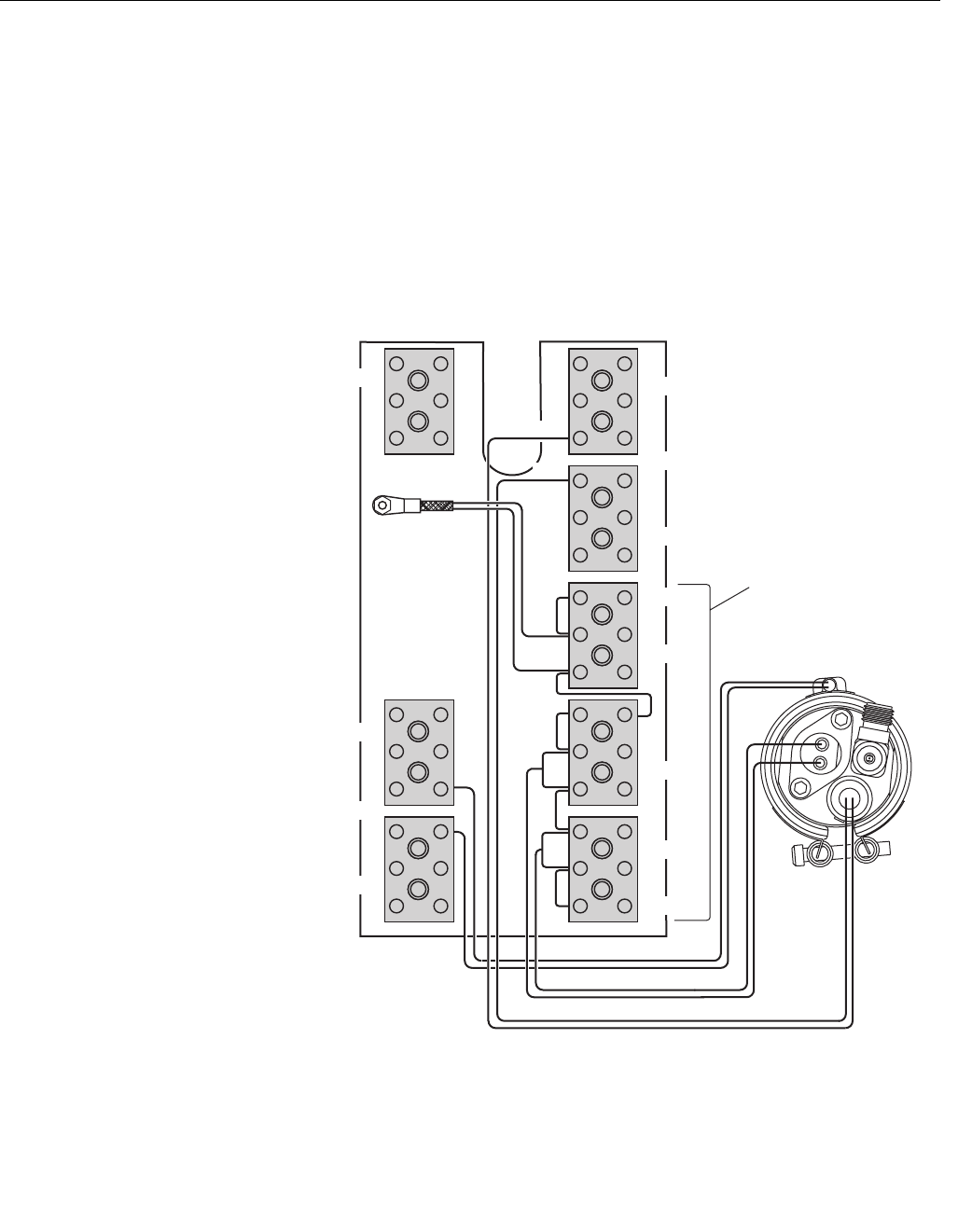
Instruction Manual
IM-106-880 Original Issue
February 2005
6-11
OCX 8800
2. Loosen screws (11, Figure 6-5) and rotate heater clamps (12) to release
heater rods (13). One heater clamp secures each heater rod.
3. Slide sample block heater rods (13) out of housing (8).
4. To replace thermal switch (15), remove insulator (14). Disconnect
heater wires. Unscrew and remove thermal switch.
Remove COe Sensor Assembly
1. Disconnect COe heater, thermocouple, and sensor wires from terminal
blocks. Refer to Figure 6-7.
2. Remove insulator (1, Figure 6-8).
Figure 6-7. COe Sensor,
Thermocouple, and Heater
Connections O2
RED
T/C O2
T/C CO
T/C SB
EXC
CJC
COe Sensor Wires
COe Heater Wires
COe Sensor
Assembly
CO REF
CO ACT
Sensor Housing Terminals
+
-
HTR 02
HTR SB
2
2
1
+
-
+
-
+
-
+
-
+
-
+
YEL
-
+
37390018
HTR 02
2
1
HTR CO
1
WHT BLU
RED RED WHT
COe Thermocouple Wires
-EXC
RED BLU
CJC Sensor NOTE: All wires
at these terminals
are in the CJC
current loop.
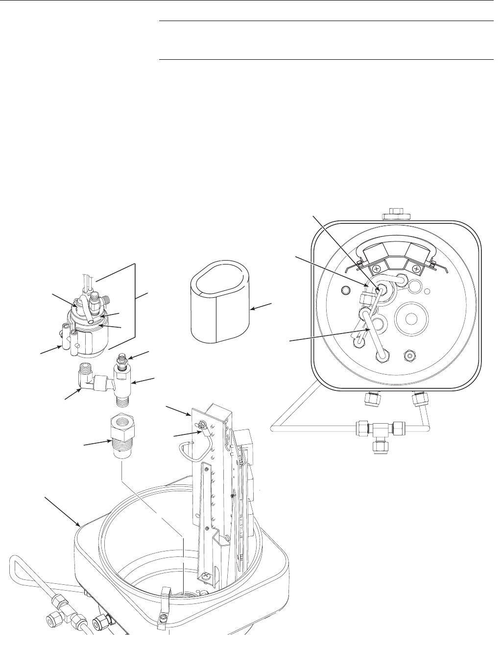
Instruction Manual
IM-106-880 Original Issue
February 2005
OCX 8800
6-12
NOTE
For easier access, you may remove two screws from base of terminal block
mounting (13) and move terminal block assembly out of the way.
3. Remove tubes (2, 3, and 4) from COe sensor assembly (5), eductor
fittings (12 and 15), and sensor housing (7).
4. Unfasten bayonet connector of COe thermocouple (8) and remove
thermocouple.
5. Loosen clamp screw of COe band heater (9) until heater rotaters freely
on sensor holder (11).
Figure 6-8. Removal of
COe Sensor Assembly
1
5
6
7
8
9
10
11
12 13
14
1. Insulator
2. Dilution Air Tube
3. COe Extractive Tube
4. Eductor Air Tube
5. COe Sensor Assembly
6. Eductor
7. Sensor Housing
8. COe Thermocouple
9. Heater Insulator
10. COe Band Heater
11. Sensor Holder
12. Eductor Elbow
13. Terminal Block Mounting
14. Eductor Holder
15. Tube Fitting
16. CJC Sensor
16
2
3
4
15
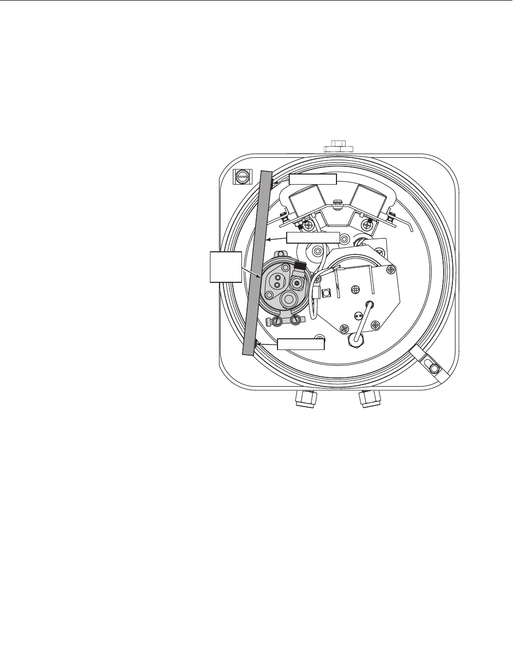
Instruction Manual
IM-106-880 Original Issue
February 2005
6-13
OCX 8800
6. See Figure 6-9. Using straightedge on the sensor holder flat, as shown,
matchmark upper flange of sensor housing to show correct alignment of
sensor holder.
7. With one wrench holding eductor elbow (12, Figure 6-8), and one
wrench on flats of sensor holder (11), unthread and remove COe sensor
assembly (5). Do not allow eductor elbow to turn.
8. Slide band heater (10) and heater insulator (9) from sensor holder (11).
Figure 6-9. Alignment of
COe Sensor Assembly
37390035
Sensor
Holder
Flat
Matchmark
Straightedge
Matchmark
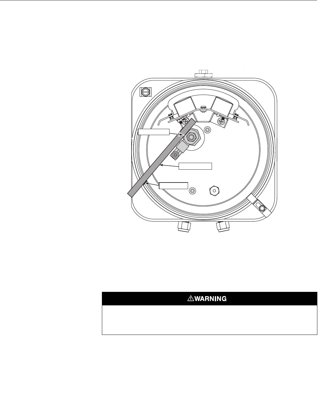
Instruction Manual
IM-106-880 Original Issue
February 2005
OCX 8800
6-14
Remove Eductor
The O2 cell and heater strut assembly (9, Figure 6-5) and the COe sensor
assembly (5, Figure 6-8) must be removed before you start this procedure.
1. Use straightedge to matchmark alignment of eductor flat and elbow, as
shown in Figure 6-10.
Figure 6-10. Eductor Alignment
Matchmarks
2. Unscrew terminal block mounting (13, Figure 6-8). Move terminal block
mounting away from eductor (6).
3. Unscrew eductor holder (14) with eductor (6) and fittings (12 and 15)
from sensor housing (7).
4. Clamp flats of eductor (6) in jaws of bench vise.
5. Use a propane torch to heat the eductor (6) to 450°F (232°C), minimum.
Apply the heat near the screw threads.
6. While heating the eductor (6), use wrench to apply removal torque to
elbow (12), eductor holder (14), or tube fitting (15) until the thread
sealant softens. Remove mating parts (12, 14, and 15).
7. Use MEK or methylene chloride solvent to clean thread sealant residue
from the pipe threads of the mating parts. Refer to applicable MSDS
sheet for solvent handling precautions.
37390036
Eductor Flat
Matchmark
Straightedge
Use heat resistant gloves when removing mating parts from the eductor. The mating parts
are bonded with a thread sealing compound. The compound softens at 450°F (232°C). The
heated parts can cause severe burns.
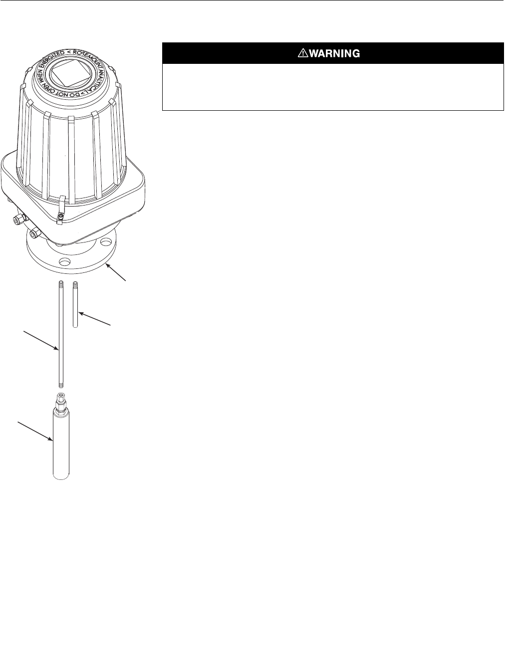
Instruction Manual
IM-106-880 Original Issue
February 2005
6-15
OCX 8800
Figure 6-11. Removal of Sample
and Exhaust Tubes
Remove Sample and Exhaust Tubes
1. Secure the sensor housing (1, Figure 6-11) in soft (plastic, wood, or
brass) vice jaws.
2. Use a propane torch to heat the sample tube (2) or exhaust tube (3) to
450°F (232°C), minimum. Apply the heat near the threaded end of the
tube.
3. While heating the tube, use a pipe wrench to apply removal torque to
part being removed. Apply torque until the pipe thread sealant softens.
Remove and discard the used sample tube (2), exhaust tube (3), or
in-situ filter (4).
4. Use MEK or methylene chloride solvent to clean thread sealant residue
from the internal pipe threads in the housing. Refer to applicable MSDS
sheet for solvent handling precautions.
37390048
1
23
4
1. Sensor Housing
2. Sample Tube
3. Exhaust Tube
4. In Situ Filter
Use heat resistant gloves when removing the probe tube or exhaust tube. The tubes are
bonded with a thread sealing compound. The compound softens at 450°F (232°C). The
heated parts can cause severe burns.
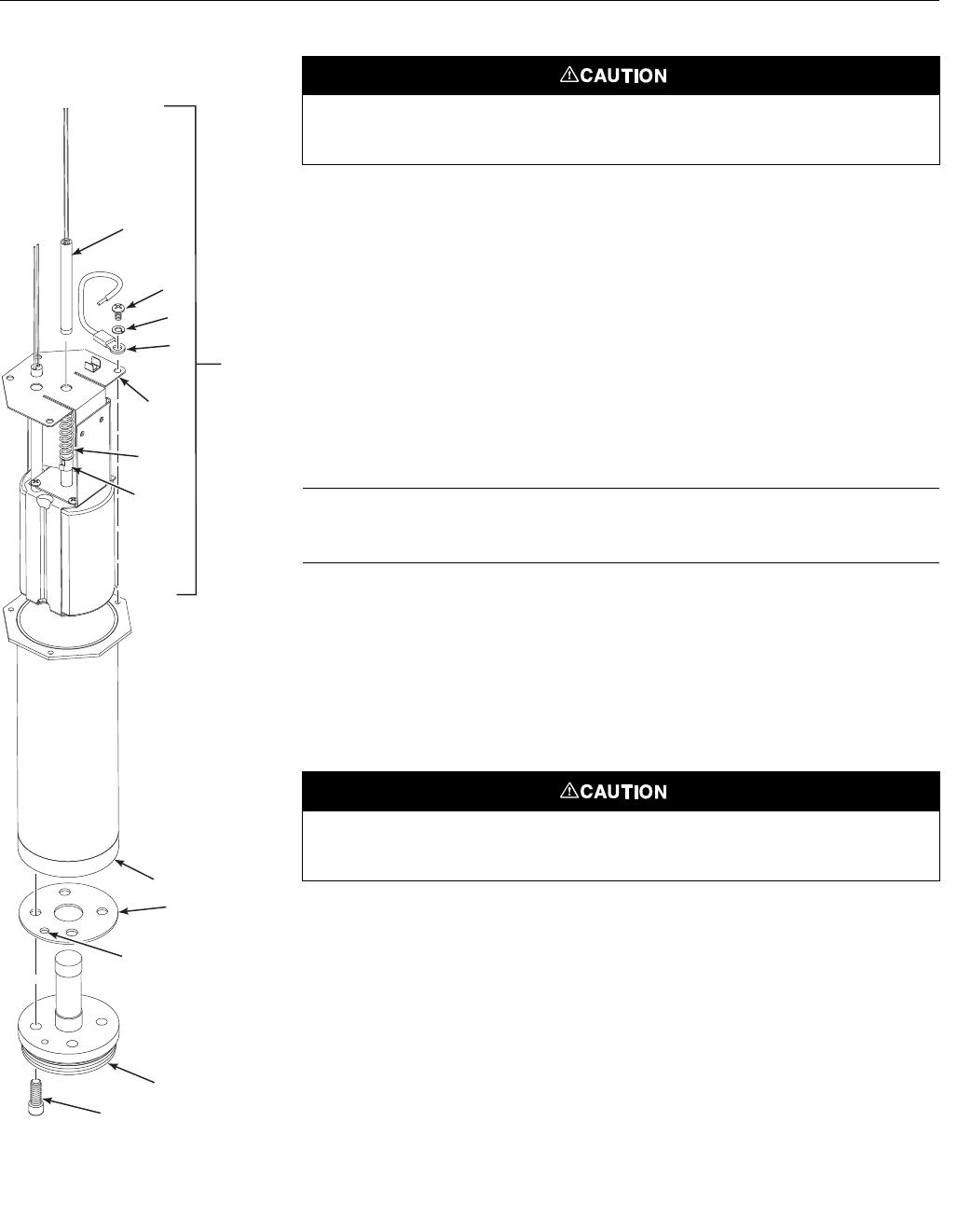
Instruction Manual
IM-106-880 Original Issue
February 2005
OCX 8800
6-16
Figure 6-12. O2 Cell, Heater,
and Thermocouple, Exploded
View
Disassemble O2 Cell and Heater Strut Assembly
Do not attempt to replace the O2 cell until all other possibilities for poor
performance have been considered. If cell replacement is needed, order the
O2 cell replacement kit (Refer to Section 8, Replacement Parts).
The O2 cell replacement kit contains an O2 cell and flange assembly, gaskets,
socket head cap screws, and anti-seize compound. The items are carefully
packaged to preserve precise surface finishes.
Do not remove items from the package until they are ready to be used.
1. Remove the four allen cap screws (1, Figure 6-12) from the O2 cell (2).
Remove the O2 cell. The cell flange has a notch that may be used to
gently pry the flange away from heater tube (3).
NOTE
The pad on the end of contact/thermocouple assembly (4) will sometimes
fuse to the O2 cell (2).
2. If the O2 cell is fused to the contact pad, push the O2 cell back into the
heater tube (against spring pressure) and quickly twist the O2 cell. The
cell and contact pad should separate. If the contact pad stays fused to
the cell, a new contact/thermocouple assembly (4) must be installed.
3. Remove and discard gasket (5). Clean the mating surface of heater
tube (3). Remove burrs and raised surfaces with a block of wood and
crocus cloth.
4. Remove screws (6), lockwashers (7), return wire (8), and heater strut
assembly (9).
5. If replacing contact and thermocouple assembly (4), use a pencil to
mark location of spring clip (10) before removing. Squeeze tabs on
spring clip to remove. Retain spring clip and spring (11); replace if
damaged.
6. While carefully handling new contact and thermocouple assembly (4)
lay old assembly next to new one. Transfer match marks to new
assembly.
7. Carefully guide new contact and thermocouple assembly (4) through
strut bracket (12), spring (11), and spring clip (10) until spring clip
reaches pencil mark.
37390032
10
11
12
4
6
7
89
3
5
2
1
1. Screw
2. O Cell
3. Heater Tube
4. Contact/
Thermocouple
Assembly
5. Gasket
6. Screw
7. Lockwasher
8. Return Wire
9. Heater Strut
Assembly
10. Spring Clip
11. Spring
12. Strut Bracket
2
Test Gas
Passage
Holes
Do not remove the O2 cell unless you are certain it needs to be replaced. Removal may
damage the cell and platinum pad. Remove the O2 cell for cell replacement only.
Use care when handling contact and thermocouple assembly. The ceramic rod in this
assembly is fragile.
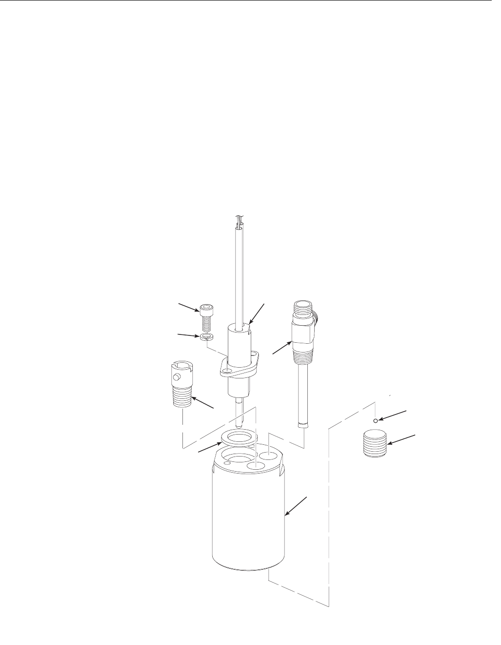
Instruction Manual
IM-106-880 Original Issue
February 2005
6-17
OCX 8800
Disassemble COe Sensor Assembly
1. Carefully remove screws (1, Figure 6-13), lockwashers (2), and COe
sensor (3) from sensor holder (4). Remove and discard gasket (5).
2. If damaged, use the following procedure to remove thermocouple
adaptor (6) from sensor holder (4):
a. Use a propane torch to heat the thermocouple adaptor to 450°F
(232°C), minimum.
b. While heating, use a flat-head screwdriver to apply removal torque.
Apply torque until the pipe thread sealant softens. Remove and
discard the thermocouple adaptor.
c. Use MEK or methylene chloride solvent to clean thread sealant
residue from the internal pipe threads in the sensor holder. Refer to
applicable MSDS sheet for solvent handling precautions.
Figure 6-13. COe Sensor,
Exploded View
37390030
8
9
4
5
6
1
2
3
7
1. Screw
2. Lockwasher
3. COe Sensor
4. Sensor Holder
5. Gasket
6. Thermocouple Adapter
7. Pre-Heater
8. Plug
9. Stainless Steel Balls

Instruction Manual
IM-106-880 Original Issue
February 2005
OCX 8800
6-18
3. If pre-heater (7) is to be removed, clamp flats of sensor holder (4) in vise
jaws with plug (8) pointing up. Remove plug. Unclamp sensor holder
and pour stainless steel balls (9) into a container.
NOTE
Pre-heater should only be removed when pre-heater or sensor holder is
damaged. If removal is not required, leave the pre-heater installed in the
sensor holder.
4. Unthread and remove pre-heater (7).
5. Use a cleaning solvent to thoroughly clean stainless steel balls (9) and
pre-heater chamber in sensor housing (4). Refer to applicable MSDS
sheet for solvent handling precautions.
Sensor Housing
Assembly
Assemble COe Sensor Assembly
1. If pre-heater (7, Figure 6-13) was removed, apply pipe thread sealant
(Loctite #567) to the external pipe threads of pre-heater (7) and plug (8).
Do not apply sealant to the first turn of the pipe threads.
2. Clamp flats of sensor holder (4) in vise jaws with pre-heater port
pointing up.
3. Install and tighten pre-heater (7). Align pre-heater to flat of sensor
holder (4) as shown in Figure 6-14.
4. Invert sensor holder (4, Figure 6-13) in vise and pour stainless steel
balls (9) into plug port. Press down on stainless steel balls and tap
sensor holder with plastic hammer to compact balls in pre-heater
chamber.
5. Install and tighten plug (8).
6. Lubricate and install COe sensor gasket (5). Apply anti-seize compound
to threads of screws (1).
Always remove the stainless steel balls (approximately 200) from sensor holder before
removing or installing pre-heater. Turning pre-heater in the sensor holder with the stainless
steel balls in place will cause permanent damage to the pre-heater.
Always remove the stainless steel balls (approximately 200) from sensor holder before
removing or installing pre-heater. Turning pre-heater in the sensor holder with the stainless
steel balls in place will cause permanent damage to the pre-heater.
Use care when installing the combustibles (COe) sensor. The RTD elements are fragile and
correct alignment in sensor holder is required for proper OCX operation.
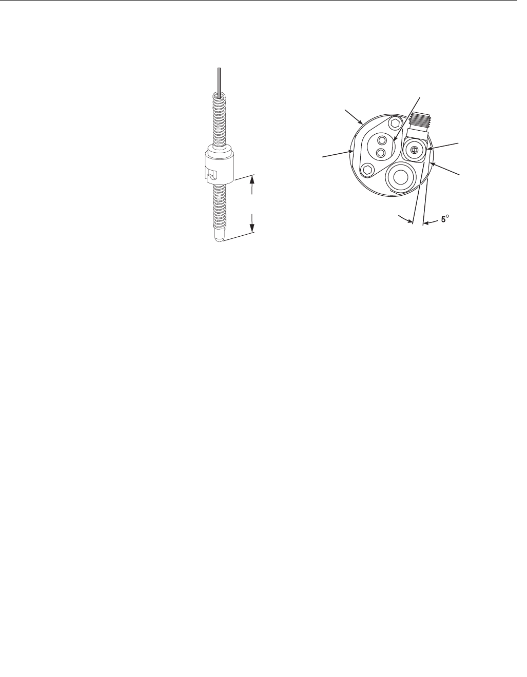
Instruction Manual
IM-106-880 Original Issue
February 2005
6-19
OCX 8800
Figure 6-14. COe Sensor and
Pre-Heater Alignment
7. Install COe sensor (3), lockwashers (2), and screws (1). Rotate flat of
COe sensor (3) to center of sensor holder (4).
8. Align COe sensor flat parallel to sensor holder flat, as shown in
Figure 6-14. Tighten screws (1, Figure 6-13).
9. If replacing thermocouple adaptor (6), apply anti-seize to the pipe
threads. Install and tighten thermocouple adaptor.
Assemble O2 Sensor and Heater Strut Assembly
1. See Figure 6-12. Assemble O2 cell (2), gasket (5), and heater tube (3).
Make sure the test gas passage holes line up with each other in all
components.
2. Apply a small amount of anti-seize compound to the screw threads and
use screws (1) to secure assembly. Torque to 35 in-lbs (4 N·m).
3. Carefully slide O2 heater strut assembly (9) into heater tube (3).
4. Press down on the back plate of strut bracket (12) to ensure spring (11)
tension is present to hold contact pad against O2 cell (2).
5. Secure strut bracket (12) and return wire (8) with four screws (6) and
lockwashers (7). Make sure return wire (8) is tightly fastened. This is the
ground side connection for the O2 cell.
Install Sample and Exhaust Tubes
1. See Figure 6-11. Apply pipe thread sealant (Loctite #567) to the
replacement sample tube (2) or exhaust tube (3) pipe threads. Do not
apply sealant to the first turn of the pipe threads.
2. Thread the sample tube (2) or exhaust tube (3) into the housing (1). Use
a pipe wrench to tighten the tube.
3. If used, install and tighten in-situ filter (4).
37390034
Pre-Heater
Flat
COe
SENSOR ASSEMBLY
TOP VIEW
Sensor
Holder
Flat
COe Sensor
Flat
Sensor
Holder
Flat
Sensor
Holder
2 to 2-1/4 in.
(51 to 57 mm)
THERMOCOUPLE
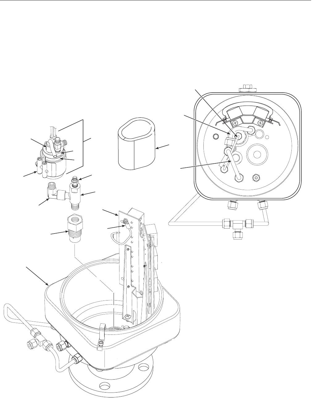
Instruction Manual
IM-106-880 Original Issue
February 2005
OCX 8800
6-20
Install Eductor
If installed, the O2 cell and heater strut assembly (9, Figure 6-5) must be
removed from sensor housing (8), before you install the eductor.
1. Apply pipe thread sealant (Loctite #567) to the external pipe threads of
eductor (6, Figure 6-15). Do not apply sealant to the first turn of the pipe
threads.
Figure 6-15. Installation of
Eductor and COe Sensor
37390047
1
5
6
7
8
9
10
11
12 13
14
1. Insulator
2. Dilution Air Tube
3. COe Extractive Tube
4. Eductor Air Tube
5. COe Sensor Assembly
6. Eductor
7. Sensor Housing
8. COe Thermocouple
9. Heater Insulator
10. COe Band Heater
11. Sensor Holder
12. Eductor Elbow
13. Terminal Block Mounting
14. Eductor Holder
15. Tube Fitting
16. CJC Sensor
16
2
3
4
15
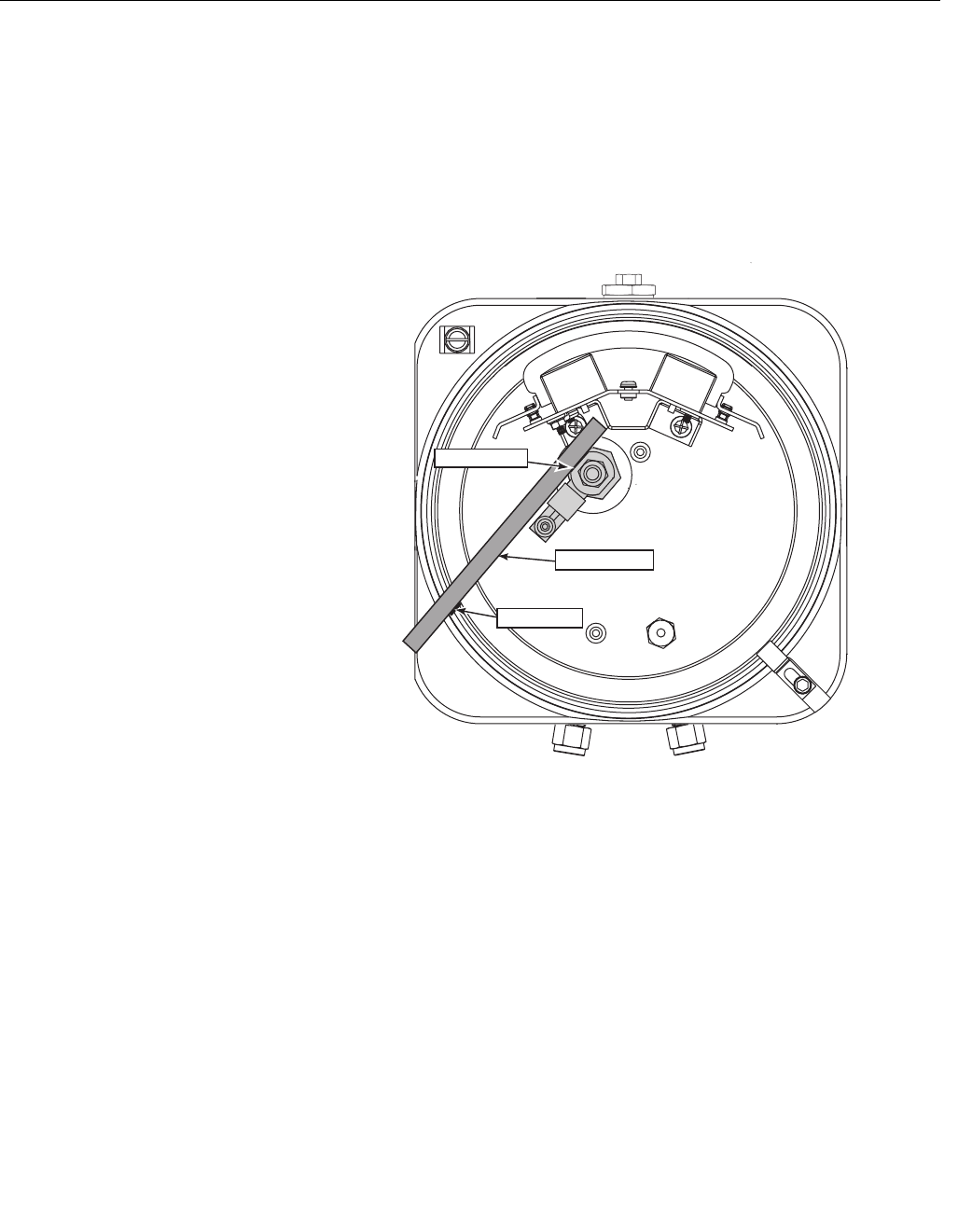
Instruction Manual
IM-106-880 Original Issue
February 2005
6-21
OCX 8800
2. Install and tighten eductor (6) in eductor holder (14).
3. Install and tighten elbow (12) on eductor (6). Male port of elbow must
point up and be in line with long axis of eductor.
4. Apply anti-seize compound to the external pipe threads of eductor
holder (14).
5. Install and tighten eductor holder (14) in sensor housing (7). Align
eductor with matchmarks, as shown in Figure 6-16.
Figure 6-16. COe Sensor
Parts Alignment
37390036
Eductor Flat
Matchmark
Straightedge
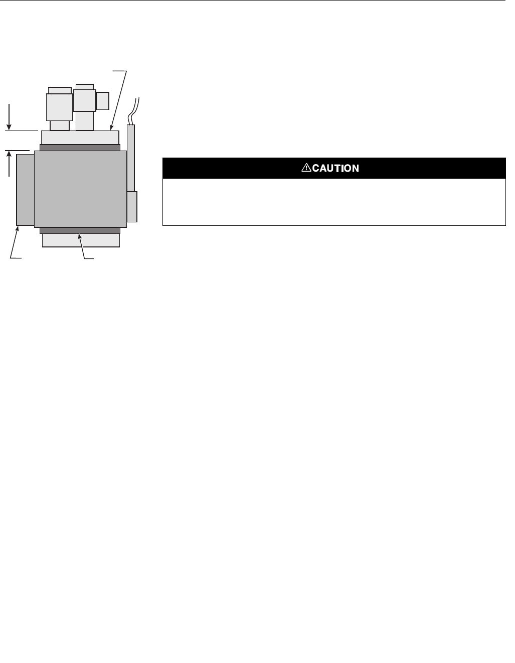
Instruction Manual
IM-106-880 Original Issue
February 2005
OCX 8800
6-22
Install COe Sensor Assembly
Figure 6-17. Band Heater Height 1. Apply pipe thread sealant (Loctite #567) to the exposed pipe threads
of eductor elbow (12, Figure 6-15). Do not apply sealant to the first turn
of the pipe threads.
2. Screw sensor holder (11) onto eductor elbow (12).
3. With wrenches on eductor elbow (12) and on flats of sensor holder (11),
tighten sensor holder. Do not allow eductor elbow to turn.
4. Tighten sensor holder (11) to align outside flat with matchmark on
sensor housing flange, as shown in Figure 6-18.
5. Wrap heater insulator (9) around sensor holder (11). Make sure the
insulator joint lines up with the band gap of the COe band heater (10).
6. Slide COe band heater (10, Figure 6-15) up onto sensor holder (11). Do
not tighten the band heater at this time. Heater must rotate freely around
sensor holder.
7. Check for proper height of COe heater thermocouple (Figure 6-14).
Thread bayonet connector up or down to adjust height.
8. Install and fasten thermocouple (8, Figure 6-15).
9. Position band heater as shown in Figure 6-17 and Figure 6-18 and
tighten band heater clamp screw. The heater insulator (9) end joint must
line up with the band gap of the COe band heater (10).
37390058
0.37 in.
(9,4 mm)
COe Sensor
Band Heater Insulator
The heater insulator prevents current leakage between the band heater and the sensor
holder. Failure to properly install the insulator may cause the device to trip a ground fault
interrupt circuit.
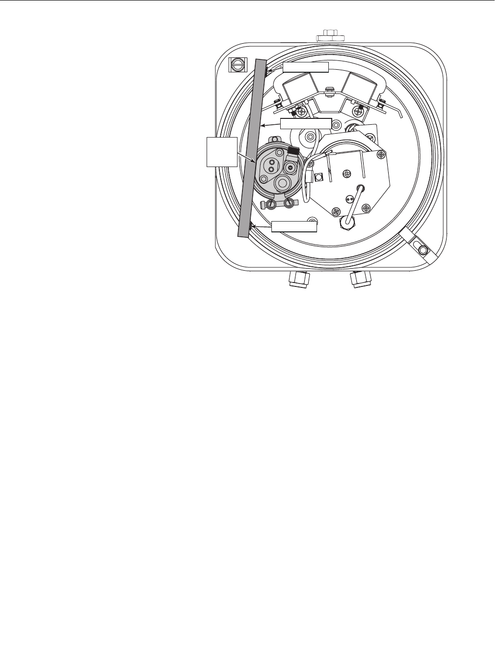
Instruction Manual
IM-106-880 Original Issue
February 2005
6-23
OCX 8800
Figure 6-18. COe Sensor
Holder Alignment
37390035
Sensor
Holder
Flat
Matchmark
Straightedge
Matchmark
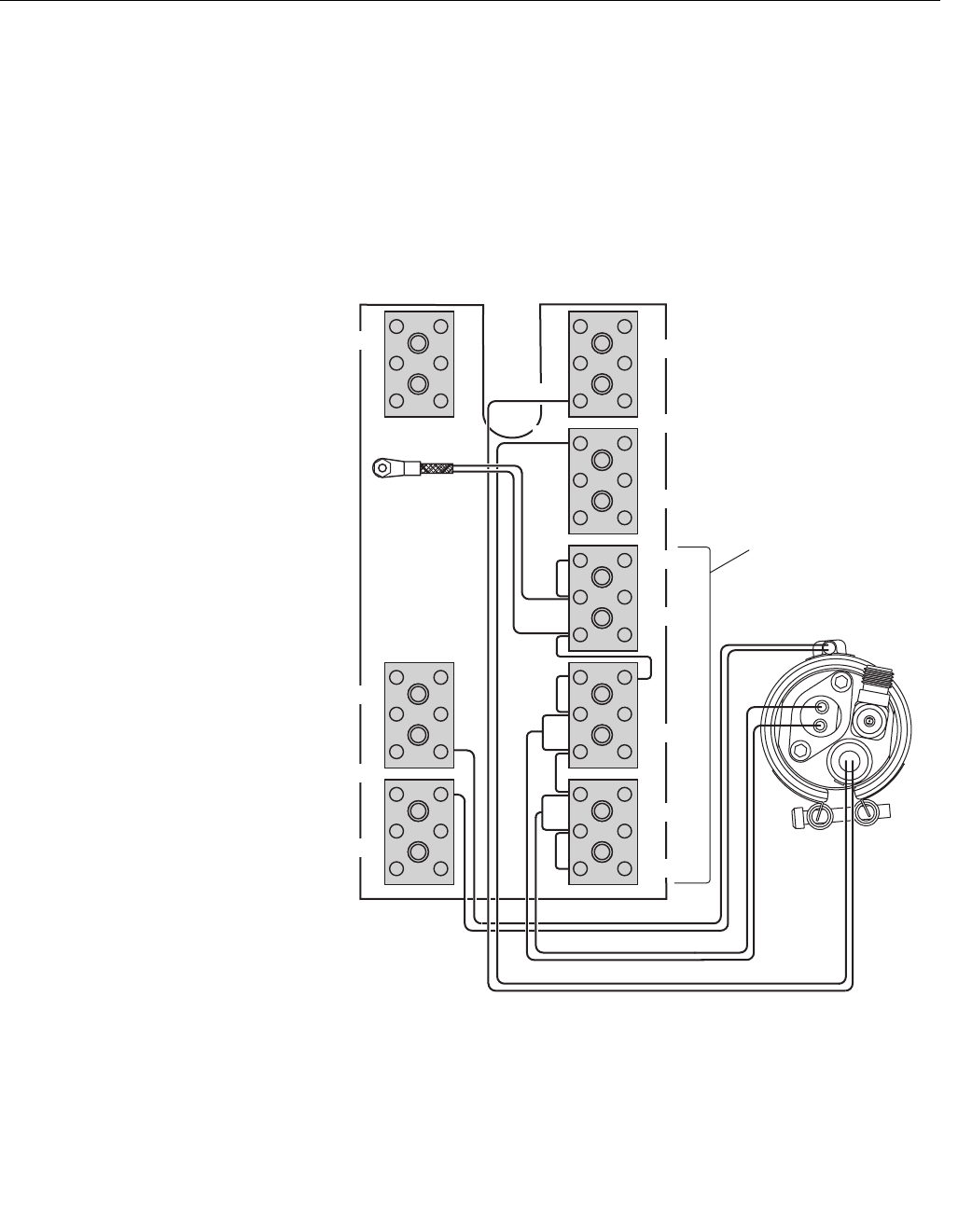
Instruction Manual
IM-106-880 Original Issue
February 2005
OCX 8800
6-24
10. Reconnect the COe sensor, thermocouple, and heater wires at the
sensor housing terminal blocks. Refer to Figure 6-19.
11. Install and fasten the COe insulator (1, Figure 6-15) around COe sensor
assembly (5). All wiring must remain outside of the insulator.
12. If terminal block mounting (13, Figure 6-15) was moved, reinstall with
two base mounting screws.
Figure 6-19. COe Sensor,
Thermocouple, and Heater
Connections
O2
RED
T/C O2
T/C CO
T/C SB
EXC
CJC
COe Sensor Wires
COe Heater Wires
COe Sensor
Assembly
CO REF
CO ACT
Sensor Housing Terminals
+
-
HTR 02
HTR SB
2
2
1
+
-
+
-
+
-
+
-
+
-
+
YEL
-
+
37390018
HTR 02
2
1
HTR CO
1
WHT BLU
RED RED WHT
COe Thermocouple Wires
-EXC
RED BLU
CJC Sensor NOTE: All wires
at these terminals
are in the CJC
current loop.
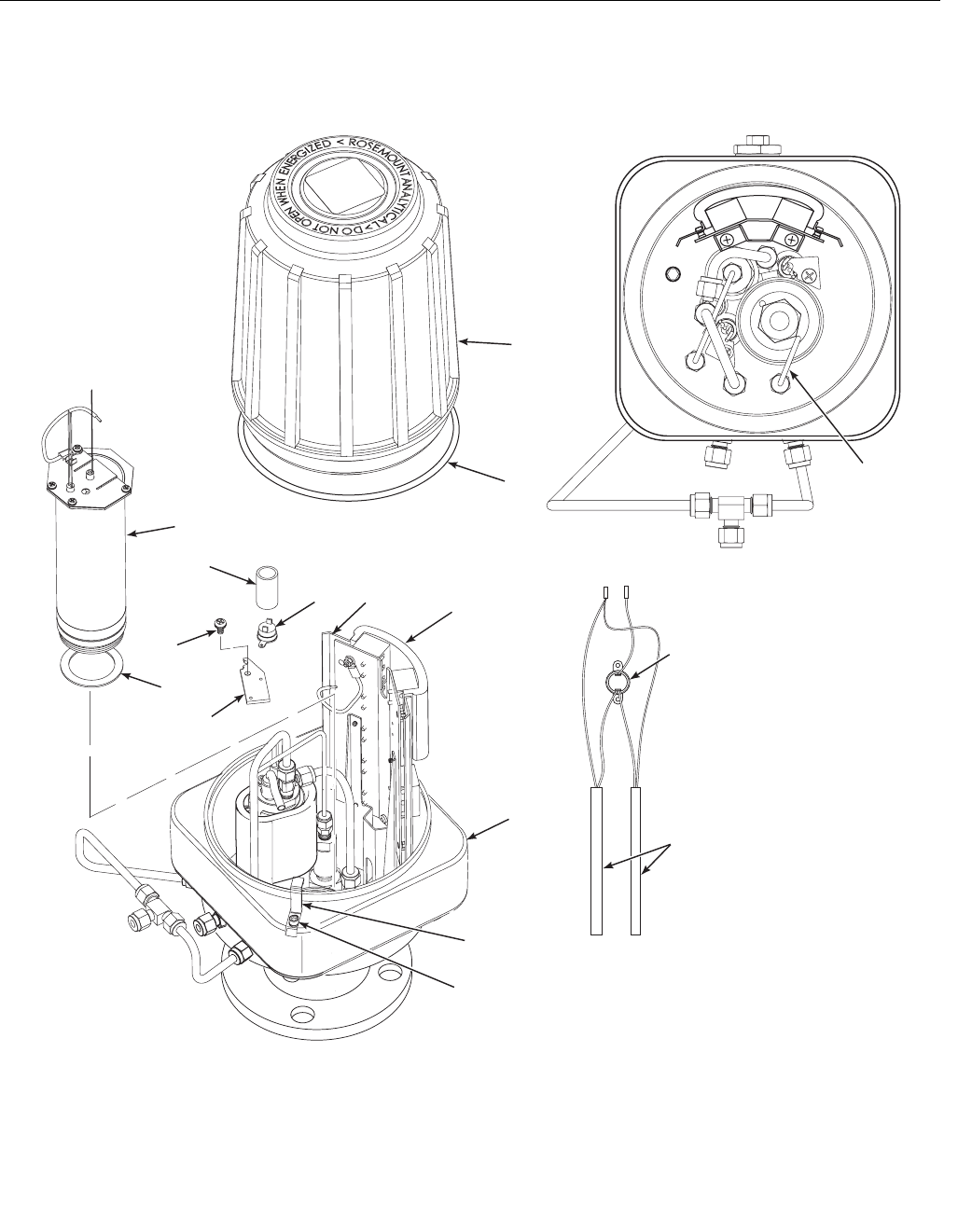
Instruction Manual
IM-106-880 Original Issue
February 2005
6-25
OCX 8800
Figure 6-20. Installation of O2 Cell
and Heater Strut Assembly
Install Sample Block Heater Rods
1. Before installing sample block heater rods (13, Figure 6-20), evenly coat
the heater rods with Watlube heater release agent.
56
12
11
14
15
10
9
1
2
4
3
7
8
13
3
7
390066
1. Screw
2. Locking Clip
3. Cover
4. O-ring
5. Marking Plate
6. Terminal Insulator
7. Reference Air Tube
8. Sensor Housing
9. Heater Strut Assembly
10. Gasket
11. Screw
12. Heater Clamp
13. Heater Rod
14. Insulator
15. Thermal Switch
15
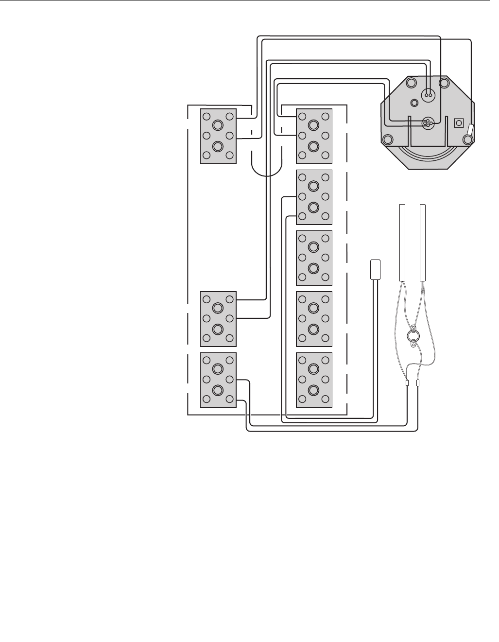
Instruction Manual
IM-106-880 Original Issue
February 2005
OCX 8800
6-26
Figure 6-21. O2 Cell,
Thermocouple, and
Heater Connections
2. If thermal switch (15) was removed, install thermal switch on mating
heater clamp (12), connect wires of heater rods (13), and install
insulator (14).
3. Install the heater rods (13), heater clamps (12), and screws (11).
4. Reconnect the heater rod leads at the sensor housing terminal blocks,
(Figure 6-21).
+ +
++
O2
Thermocouple Wires
ORG
RED
T/C O2
T/C CO
T/C SB
EXC
CJC
OC
ell Wires
2
O Heater Wires
2
Return Wire
O Cell and Heater Strut
Assembly
2
CO REF
CO ACT
Sensor Housing Terminals
+
-
HTR 02
HTR SB
2
GRN
2
1
+
-
+
-
+
-
+
-
+
-
+
YEL
-
+
+
37390069
HTR 02
2
1
Sample Block
Heater Rods
Thermal
Switch
HTR CO
1
EXC
-
Sample
Block
Thermo-
couple
Instruction Manual
IM-106-880 Original Issue
February 2005
6-27
OCX 8800
Install O2 Cell and Heater Strut Assembly
1. Rub a small amount of anti-seize compound on both sides of new
gasket (10, Figure 6-20).
2. Apply anti-seize compound to threads of O2 cell and heater strut
assembly (9) and sensor housing (8).
3. Install O2 cell and heater strut assembly (9) in sensor housing (8). Snug
up, but do not over-tighten the assembly.
4. Reconnect the lead wires from O2 cell, heater, and thermocouple to the
sensor housing terminal blocks. Refer to Figure 6-21.
5. Install reference air tube (7, Figure 6-20) in sensor housing (8). Make
sure that the open end of reference air tube extends into heater tube of
O2 cell and heater strut assembly (9).
Install Terminals Insulator and Cover
1. Install insulator (6, Figure 6-20) over uppermost terminal blocks.
Position one side of insulator against terminal blocks and snap terminal
marking plate (5) to mating stand-off.
2. Position opposite side of insulator (6) and secure with related marking
plate (5).
3. If removed, install cover gasket (4). Screw cover (3) onto sensor
housing (8). Tighten cover firmly.
4. To comply with explosion-proof requirements, the cover gasket (4) must
be compressed. For hazardous area applications, verify that the cover
gasket is compressed.
5. Align locking clip (2) with gap between cover ribs.
6. Loosen screw (1) and slide locking clip (2) fully into gap between cover
ribs. Retighten screw (1).
Sensor Housing Leak Test
1. Install 1/4 NPT cap on dilution air inlet fitting. Install a 1/4 NPT cap on
sample tube (2, Figure 6-11) or plug 1/4 NPT sample inlet port. Capped
or plugged ports must be air tight.
2. If not in place, install exhaust tube (3, Figure 6-11) in exhaust port
according to the instructions provided.
3. Connect a calibrated manometer to the CAL GAS inlet port.
4. Connect and apply clean instrument air at 35 psig (241 kPa gage) to the
instrument air inlet fitting.
5. Observe the manometer reading. The reading should be from 10 to 13
inches, Water Column. Locate and correct leaks if the reading is less
than 10 inches WC.
Stripped threads on the O2 cell and heater strut assembly can allow gas leakage. Gas
leakage can affect the O2 measurements and calibration. Avoid over-tightening the O2 cell
and heater strut assembly .
Instruction Manual
IM-106-880 Original Issue
February 2005
OCX 8800
6-28
REPAIR ELECTRONICS
HOUSING
Use the following procedures to remove damaged components from the OCX
8800 electronics housing and to install new replacement parts. Disassemble
the unit only as needed to replace damaged components. Use the assembly
procedures that apply to install replacement parts and reassemble the unit.
Electronics Housing
Disassembly
Remove Cover
1. See Figure 6-22. Loosen screw (1) and slide locking clip (2) away from
cover (3). Retighten screw (1).
2. With two hands or strap wrench, turn cover (3) counterclockwise to
loosen. Unthread and remove cover.
3. Inspect cover gasket (4) for wear or damage. Replace cover gasket if
damaged.
Remove Flash PROM
1. Locate Flash PROM access port in electronics stack (5, Figure 6-22).
2. Use suitable IC removal tool to remove Flash PROM (6).
Electrostatic discharge (ESD) protection is required to avoid damage to the electronic
circuits.
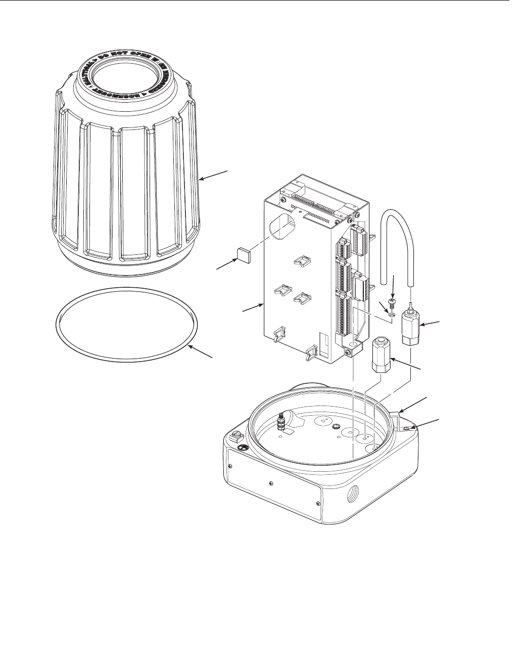
Instruction Manual
IM-106-880 Original Issue
February 2005
6-29
OCX 8800
Figure 6-22. Removal/Installation of
Electronics Housing Components
Remove Electronics Stack
1. Unplug power cable, signal cable, and solenoid lead connectors from
terminals of electronics stack (5, Figure 6-22).
2. Remove two screws (13) and lockwashers (14).
3. Remove electronics stack (5).
37390037
1. Screw
2. Locking Clip
3. Cover
4. O-ring
5. Electronics Stack
6. Flash PROM
7. thru 12. Not used
13. Screw
14. Lockwasher
15. Solenoid Valve (3 way)
16. Solenoid Valve
1
2
3
4
5
613
14
15
16
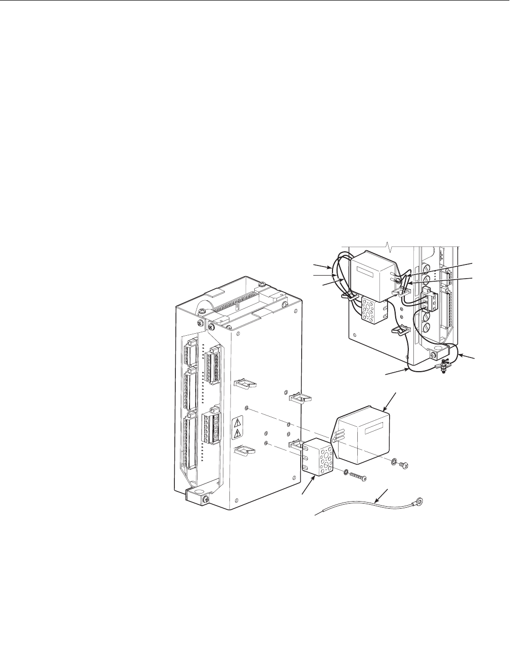
Instruction Manual
IM-106-880 Original Issue
February 2005
OCX 8800
6-30
Remove Solenoid Valves
1. Disconnect solenoid leads from mating terminal connector.
2. Remove top nut of solenoid valve (15 or 16, Figure 6-22).
3. Remove the solenoid coil assembly and washer.
4. Unthread and remove solenoid valve base.
Remove EMI Filter and Terminal Block
1. Disconnect EMI filter wiring (Figure 6-23) at terminal block (3).
2. Disconnect EMI filter wiring at AC power input terminal block on
electronic stack.
3. Unbolt and remove EMI filter (1) from electronic stack.
4. Remove ground wire (2) from terminal block (3).
5. Unbolt and remove terminal block (3) from electronic stack.
Figure 6-23. Removal/
Installation of EMI Filter
Electronics Housing
Assembly
Install EMI Filter and Terminal Block
1. Install replacement EMI filter (1, Figure 6-23) and/or terminal block (3)
on electronic stack.
2. Refer to wiring details in Figure 6-23. Connect EMI filter wiring and
ground wire (2) at terminal block (3).
3. Connect EMI filter wiring at AC power input terminal block on electronic
stack.
1
2
3
37390083
Brown
Blue
Green
Green
Green
Brown
Blue
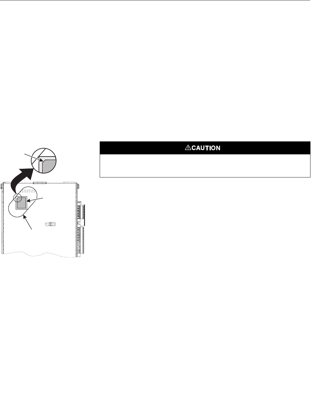
Instruction Manual
IM-106-880 Original Issue
February 2005
6-31
OCX 8800
Install Solenoid Valves
1. Disassemble replacement solenoid valve (15 or 16, Figure 6-22).
2. Install new solenoid valve base. Be careful not to overtighten.
3. Install new washer and solenoid coil assembly and secure with nut.
4. Connect the solenoid leads to the proper terminations on the solenoid
power terminal block (Figure 6-26).
Install Electronics Stack
1. Install electronics stack (5, Figure 6-22) and secure with lockwashers
(14) and screws (13).
2. See Figure 6-25 and Figure 6-26. Reconnect power cable, signal cable,
and solenoid lead connectors to electronics stack terminals.
Figure 6-24. Flash PROM
Alignment
Install Flash PROM
1. Locate Flash PROM access port in electronics stack (5, Figure 6-22).
2. See Figure 6-24. Align Flash PROM (6, Figure 6-22) with mating
receptacle in access port of electronics stack as shown. Flash PROM
corner bevel must be in upper left corner of receptacle.
3. Install Flash PROM (6).
37390060
Flash
PROM
Access
Port
Corner
Bevel
Electrostatic discharge (ESD) protection is required to avoid damage to the electronic
circuits.
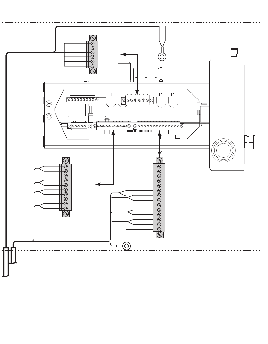
Instruction Manual
IM-106-880 Original Issue
February 2005
OCX 8800
6-32
Figure 6-25. Electronics Housing
Cable Connections
37390016
RED
BLK
WHT
GRN
BLK
BLK
BLU
BLK
YEL
BRN
RED
BLK
BLK
ORG
BLK
WHT
T/C CO+
T/C CO-
T/C SB+
T/C SB-
T/C O2+
T/C O2-
O2 CELL+
O2 CELL-
SHIELD
To
Ground
Screw
GRN
ELECTRONICS HOUSING
O2 Cell
& Thermocouple
Connector (J5)
COe Sensor
& CJC
Connector (J4)
EXC+
CO ACT+
CO ACT-
CO REF+
CO REF-
CJC+
CJC-
EXC-
Heater
Power Cable
Signal Cable
NOTE: Wire colors shown are for cables
supplied by Rosemount Analytical.
1
#1
#1 #1
#1
#1
To Ground
Screw
SHLD
Heater Power
Connector (J3)
#1
2HTR SB
1HTR O2
1HTR SB
2HTR CO
1HTR CO
2HTR O2
WHT
ORG
BLU
BLK
YEL
RED
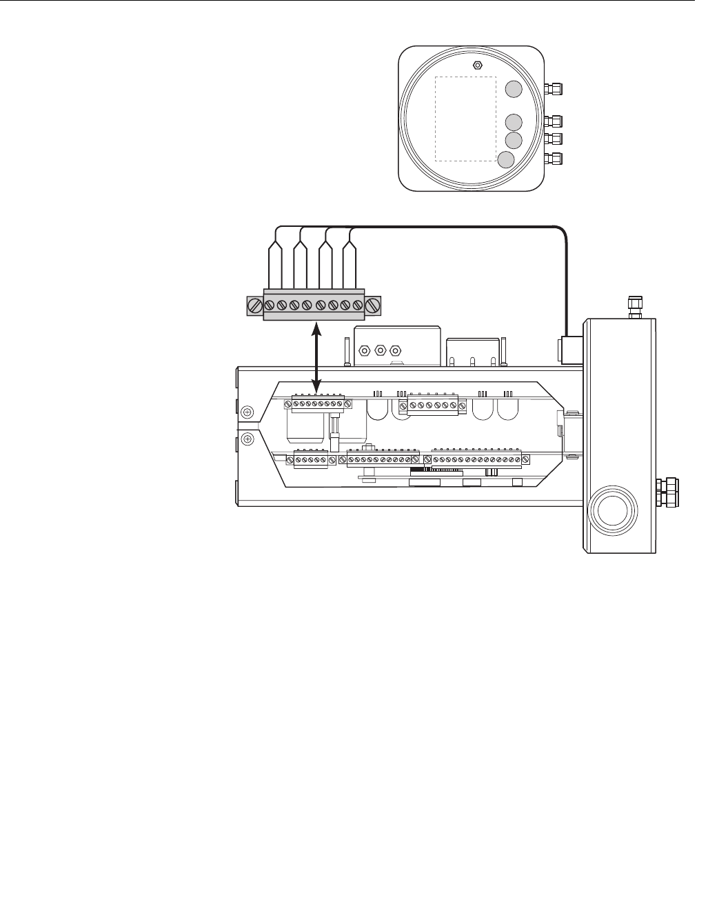
Instruction Manual
IM-106-880 Original Issue
February 2005
6-33
OCX 8800
Figure 6-26. Solenoid
Power Terminals
Install Cover
1. If removed, install cover gasket (4, Figure 6-22). Screw cover (3) onto
electronics housing. Tighten cover firmly. Align locking clip (2) with gap
between cover ribs.
2. To comply with explosion-proof requirements, cover gasket (4) must be
compressed. For hazardous area applications, verify that the cover
gasket is compressed.
3. Loosen screw (1) and slide locking clip (2) fully into gap between cover
ribs. Retighten screw (1).
37390033
Instrument Air
SOL 1
CO Test Gas
High O Test Gas
2
Low O Test Gas
2
SOL 4
SOL 3
SOL 2
TOP VIEW
SOL 4
SOL 3
SOL 2
SOL 1
SOL 3
#1
#1

Instruction Manual
IM-106-880 Original Issue
February 2005
OCX 8800
6-34
REPLACE TUBE
FITTINGS
The OCX transmitter housings have special tube fittings that, if clogged or
damaged, must be replaced with the same type of fitting. The special tube
fittings have alpha or numeric codes etched on the fitting. Unetched tube
fittings are standard 1/4 inch, stainless steel fittings.
‘F’ Type Fitting
The ‘F’ type fitting is a flame arrestor fitting used in all OCX 8800
hazardous area housings. The flame arrestor fitting prohibits spark or
flame conduction from the housing. It requires a thread sealing compound
(Loctite 567) and at least five threads engagement.
‘13’ Type Fitting
This fitting is an eductor drive air fitting for the OCX 8800 hazardous area
housing. This is a 1/8 inch tube fitting with a built-in 0.013 inch restrictor
orifice. It seats in a threaded base port inside the housing.
‘R’ Type Fitting
The ‘R’ type fitting is a reference air line fitting for the general purpose and
hazardous area sensor housings. This is a 1/4 inch tube fitting with a
built-in 0.007 inch restrictor orifice.
Remove Tube Fittings The OCX construction includes pipe thread sealant to seal fittings in all ports
that pass through to an outer wall of the instrument housing base. Use the
following instructions to loosen and remove tube fittings that are secured with
pipe thread sealant.
1. Secure sensor housing (1, Figure 6-27) or electronics housing (2) in soft
(plastic, wood, or brass) vice jaws.
2. To soften the pipe thread sealant, use a propane torch to heat the tube
fitting (3, 4, 5, or 6) to 450°F (232°C), minimum.
3. While heating the tube fitting, use a wrench to apply removal torque until
the pipe thread sealant softens. Remove and discard the used fitting.
4. Use MEK or methylene chloride solvent to clean thread sealant residue
from the internal pipe threads in the housing. Refer to applicable MSDS
sheet for solvent handling precautions.
Use heat resistant gloves when removing a damaged tube fitting. The pipe threads are
bonded with a pipe thread sealant. The thread sealant softens at 450°F (232°C). The
heated parts can cause severe burns.
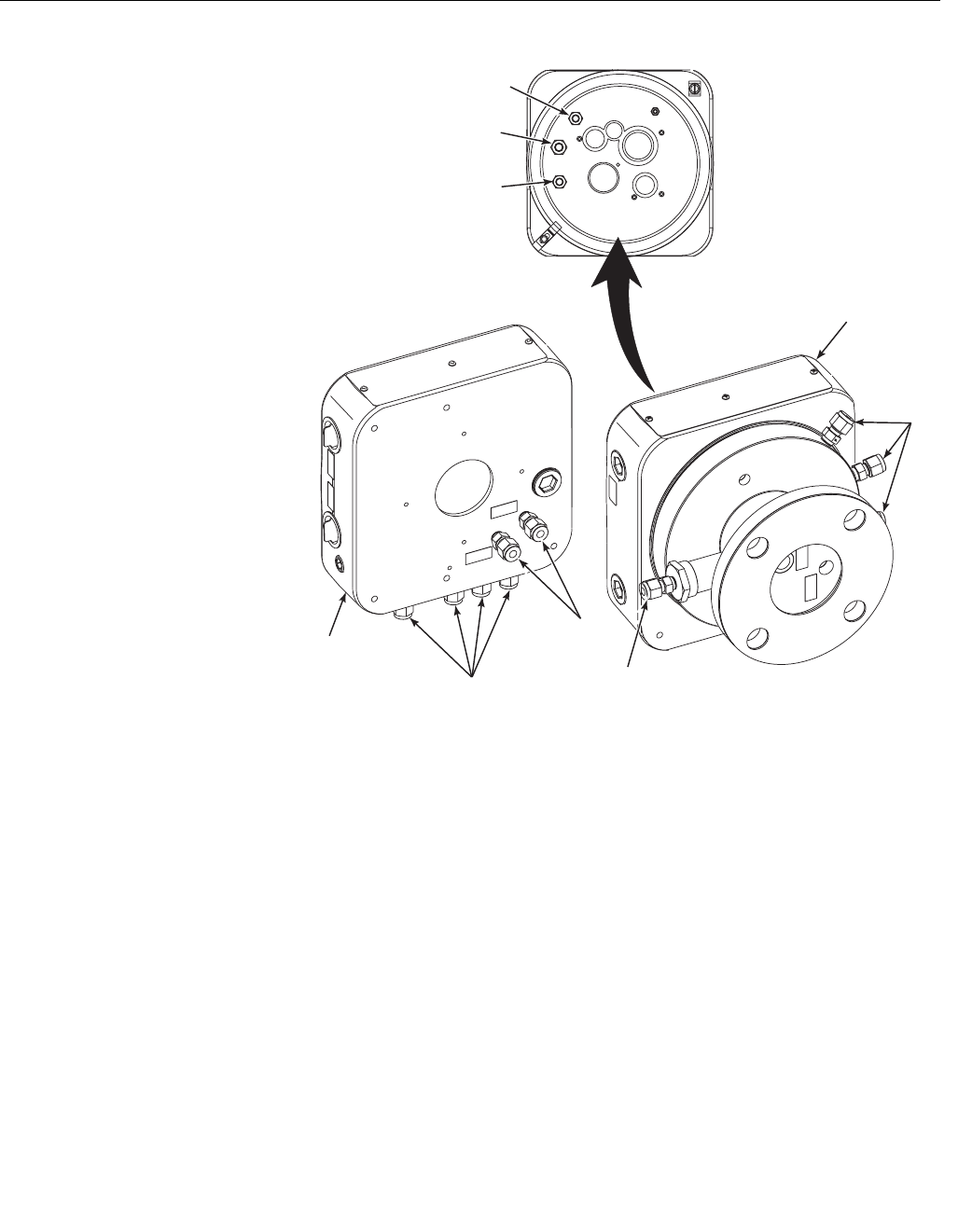
Instruction Manual
IM-106-880 Original Issue
February 2005
6-35
OCX 8800
Figure 6-27. Removal
of Tube Fittings
Install Tube Fittings 1. Verify that the replacement tube fitting is identical to the item removed.
Special fittings are etched with code markings.
2. Apply pipe thread sealant (Loctite #567) to the mating threads of the
tube fitting. Do not apply sealant to the first turn of the external pipe
threads.
3. Install and tighten the tube fitting in the mating port of sensor or
electronics housing.
37390071
5
3
4
3
6
1
1. Sensor Housing
2. Electronics Housing
3. Tube Fitting
4. Tube Fitting (Type 13)
6. Tube Fitting (Type F)
. Tube Fitting (Type R)
5
3
3
2

Instruction Manual
IM-106-880 Original Issue
February 2005
OCX 8800
6-36
Instruction Manual
IM-106-880 Original Issue
February 2005 OCX 8800
http://www.raihome.com
Section 7 Troubleshooting
Overview . . . . . . . . . . . . . . . . . . . . . . . . . . . . . . . . . . . . . . . page 7-1
Diagnostic Alarms . . . . . . . . . . . . . . . . . . . . . . . . . . . . . . . page 7-2
Fault Isolation . . . . . . . . . . . . . . . . . . . . . . . . . . . . . . . . . . . page 7-3
Alarm Relay Events . . . . . . . . . . . . . . . . . . . . . . . . . . . . . . page 7-11
OVERVIEW The troubleshooting section describes how to identify and isolate faults that
may develop in the OCX 8800. When troubleshooting the OCX 8800,
reference the following information.
Grounding It is essential that adequate grounding precautions are taken when installing
the system. Thoroughly check both the probe and electronics to ensure the
grounding quality has not degraded during fault finding. The system provides
facilities for 100% effective grounding and total elimination of ground loops.
Electrical Noise The OCX 8800 has been designed to operate in the type of environment
normally found in a boiler room or control room. Noise suppression circuits
are employed on all field terminations and main inputs. When fault finding,
evaluate the electrical noise being generated in the immediate circuitry of a
faulty system. Ensure all cable shields are connected to earth.
Electrostatic Discharge Electrostatic discharge can damage ICs in the electronics. Before removing or
handling the processor board or the ICs, ensure you are at ground potential.
Install all protective equipment covers and safety ground leads after troubleshooting.
Failure to install covers and ground leads could result in serious injury or death.
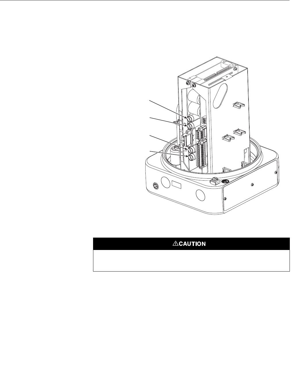
Instruction Manual
IM-106-880 Original Issue
February 2005
OCX 8800
7-2
Total Power Loss In the event that the OCX 8800 will not power up at all, check the incoming
power supply to make sure power is being delivered to the OCX 8800. If the
incoming power supply is good, then check fuses F1 and F6 in the electronics
housing. Refer to Figure 7-1 for fuse locations.
Figure 7-1. Fuse Locations
DIAGNOSTIC ALARMS
The OCX 8800 is equipped with a set of alarm relay contacts on the
microprocessor board in the electronics housing. This set of dry contacts can
be connected to any customer supplied relay device, 30 VDC, 30 mA
maximum. A blocking diode is required on the customers relay coil.
Any fault condition in the OCX 8800 will trip the alarm relay. The optional SPA
with HART programmable alarm indicates LOW O2, HIGH COe, Calibration
Status, and Unit Failure. For more information refer to Appendix B - SPA with
HART Alarm.
F6
Neutral (N)
10 Amp, 250 VAC
F1
Line (L1)
10 Amp, 250 VAC
F3
O2 and COe Heater
4 Amp, 250 VAC
F4
Sample Block Heater
8 Amp, 250 VAC
37390079
Always install a blocking diode on the customers relay coil. Failure to install a blocking diode
may create noise spikes and cause faults in the OCX electronics.

Instruction Manual
IM-106-880 Original Issue
February 2005
7-3
OCX 8800
FAULT ISOLATION Faults in the OCX 8800 Transmitter are indicated by messages displayed on
the HART communicator. Fault indications that can appear are listed in
Table 7-1, Troubleshooting.
If a fault is indicated on the HART communicator, locate the fault indication in
Table 7-1. For each fault listed, there are related Probable Causes and
Recommended Corrective Actions. The Probable Causes are listed in the
order of most probable to least probable. Starting with the most probable
cause, inspect and test the unit to isolate the actual cause, then use the
Recommended Corrective Action listed to correct the problem.
Table 7-1. Troubleshooting
O2 Sensor R High (Oxygen sensor resistance high, > 5000 Ohms)
O2 Sensor Open (Oxygen sensor disconnected)
Probable Cause Recommended Corrective Action
Loose or open O2 cell circuit connection Check O2 cell circuit wires for breaks or loose connections. Repair lead wire break or
loose connections.
O2 cell degraded or failed Check O2 cell impedance by reading the O2 Snsr R value via HART (see Figure 4-3,
sheet 2). If cell impedance is zero, replace O2 cell with cell replacement kit. If cell
impedance is less than 5000 ohms, check for cell housing ground fault. Repair ground
fault. If cell impedance is greater than 5000 ohms and no ground fault is indicated,
replace O2 cell with cell replacement kit.
Ref Current Err (RTD excitation current error)
Probable Cause Recommended Corrective Action
Loose or open lead or circuit wire connection for
COe sensor or CJC sensor current loop
Check all COe and CJC sensor current loop wiring per Figure 7-3 and Figure 6-7.
Correct wiring faults.
COe sensor grounded Check resistance of COe sensor leads to ground per Figure 6-7. Replace COe sensor if
resistance is less than 10M Ohms.
COe sensor failed Check resistance of both COe sensor elements per Figure 6-7. Replace COe sensor if
resistance of sensor element is not between 100 and 250 Ohms.
CJC sensor grounded Check resistance of CJC sensor to ground per Figure 6-7. Replace CJC sensor if
resistance is less than 10M Ohms.
CJC sensor failed Check resistance of CJC sensor per Figure 6-7. Replace CJC sensor if resistance of
sensor is not between 100 and 150 Ohms.
O2 Temp Hi (Oxygen sensor heater temperature high, > 750ºC)
Probable Cause Recommended Corrective Action
High noise in OCX power supply Check power supply for line noise or voltage fluctuations. Install power line filter kit
(PN 6A00171G01) or high quality line filter for input power.
COe Temp Hi (Combustion sensor heater temperature high, 310ºC)
Probable Cause Recommended Corrective Action
High noise in OCX power supply Check power supply for line noise or voltage fluctuations. Install power line filter kit
(PN 6A00171G01) or high quality line filter for input power.
Table continued on next page

Instruction Manual
IM-106-880 Original Issue
February 2005
OCX 8800
7-4
SB Temp Hi (Sample block heater temperature high, > 190ºC)
Probable Cause Recommended Corrective Action
High noise in OCX power supply Check power supply for line noise or voltage fluctuations. Install power line filter kit
(PN 6A00171G01) or high quality line filter for input power.
O2 Temp Very Hi (Oxygen sensor heater over maximum temperature, > 820ºC)
O2 Htr Rmp Rate (Oxygen sensor heater over maximum temperature ramp rate)
Probable Cause Recommended Corrective Action
Incorrect O2 heater wiring Check O2 heater wiring per Figure 7-3 and Figure 6-6. Check the wiring at the heater
and inside the electronics housing. Correct wiring fault. Perform Reset procedure in
Section 3, Configuration and Startup to continue operation.
Incorrect O2 thermocouple wiring Check O2 thermocouple wiring per Figure 7-3 and Figure 6-6. Check the wiring at the
thermocouple and inside the electronics housing. Correct wiring fault. Perform Reset
procedure in Section 3, Configuration and Startup to continue operation.
Electronics package failure Replace electronics package.
COe Temp Very Hi (Combustion sensor heater over maximum temperature, > 400ºC)
COe Htr Rmp Rate (Combustibles sensor heater over maximum temperature ramp rate)
Probable Cause Recommended Corrective Action
Incorrect COe heater wiring Check COe heater wiring per Figure 7-3 and Figure 6-7. Check the wiring at the heater
and inside the electronics housing. Correct wiring fault. Perform Reset procedure in
Section 3, Configuration and Startup to continue operation.
Incorrect COe thermocouple wiring Check COe thermocouple wiring per Figure 7-3 and Figure 6-7. Check the wiring at the
thermocouple and inside the electronics housing. Correct wiring fault. Perform Reset
procedure in Section 3, Configuration and Startup to continue operation.
Electronics package failure Replace electronics package.
SB Temp Very Hi (Sample block heater over maximum temperature, > 260ºC)
SB Htr Rmp Rate (Sample block heater over maximum temperature ramp rate)
Probable Cause Recommended Corrective Action
Incorrect sample block heater wiring Check sample block heater wiring per Figure 7-3 and Figure 6-6. Check the wiring at
the heater and inside the electronics housing. Correct wiring fault. Perform Reset
procedure in Section 3, Configuration and Startup to continue operation.
Incorrect sample block thermocouple wiring Check sample block thermocouple wiring per Figure 7-3 and Figure 6-6. Check the
wiring at the thermocouple and inside the electronics housing. Correct wiring fault.
Perform Reset procedure in Section 3, Configuration and Startup to continue operation.
Electronics package failure Replace electronics package.
O2 TC Open (Oxygen sensor heater thermocouple open)
Probable Cause Recommended Corrective Action
O2 thermocouple or thermocouple circuit open Check O2 thermocouple and circuit wires for breaks or loose connections per Figure 7-3
and Figure 6-6. Repair breaks or loose connections or replace failed thermocouple.
Perform Reset procedure in Section 3, Configuration and Startup to continue operation.
COe TC Open (Combustibles sensor heater thermocouple open)
Probable Cause Recommended Corrective Action
Combustibles sensor thermocouple open Check thermocouple resistance (lead to ground) of reference and active thermocouples
per Figure 7-3 and Figure 6-7. If either thermocouple is open or shorted to ground,
replace combustibles sensor.
Table continued on next page

Instruction Manual
IM-106-880 Original Issue
February 2005
7-5
OCX 8800
SB TC Open (Sample block heater thermocouple open)
Probable Cause Recommended Corrective Action
Sample block thermocouple or thermocouple
circuit open
Check sample block thermocouple and circuit wires for breaks or loose connections per
Figure 7-3 and Figure 6-6. Repair breaks or loose connections or replace failed
thermocouple. Perform Reset procedure in Section 3, Configuration and Startup to
continue operation.
O2 TC Shorted (Oxygen sensor heater thermocouple shorted)
Probable Cause Recommended Corrective Action
O2 thermocouple or thermocouple circuit shorted Check O2 thermocouple and circuit wires for short circuit condition per Figure 7-3 and
Figure 6-6. Repair shorted wiring or replace failed thermocouple. Perform Reset
procedure in Section 3, Configuration and Startup to continue operation.
Slow heatup during cold start Perform Reset procedure in Section 3, Configuration and Startup to continue operation.
If alarm persists, refer to the O2 Htr Failure alarm procedure.
COe TC Shorted (Combustibles sensor heater thermocouple shorted)
Probable Cause Recommended Corrective Action
Combustibles sensor thermocouple shorted Check thermocouple resistance (lead to ground) of reference and active thermocouples
per Figure 7-3 and Figure 6-7. If either thermocouple is open or shorted to ground,
replace combustibles sensor.
Slow heatup during cold start Perform Reset procedure in Section 3, Configuration and Startup to continue operation.
If alarm persists, refer to the COe Htr Failure alarm procedure.
SB TC Shorted (Sample block heater thermocouple shorted)
Probable Cause Recommended Corrective Action
Sample block thermocouple or thermocouple
circuit shorted
Check sample block thermocouple and circuit wires for short circuit condition per
Figure 7-3 and Figure 6-6. Repair shorted wiring or replace failed thermocouple.
Perform Reset procedure in Section 3, Configuration and Startup to continue operation.
Slow heatup during cold start Perform Reset procedure in Section 3, Configuration and Startup to continue operation.
If alarm persists, refer to the SB Htr Failure alarm procedure.
O2 TC Reversed (Oxygen sensor heater thermocouple reversed)
Probable Cause Recommended Corrective Action
O2 thermocouple wires reversed Check O2 thermocouple wiring per Figure 7-3 and Figure 6-6. Check the wiring at the
sensor and inside the electronics housing. Correct reversed-wires fault. Perform Reset
procedure in Section 3, Configuration and Startup to continue operation.
COe TC Reversed (Combustibles sensor block heater thermocouple reversed)
Probable Cause Recommended Corrective Action
Combustibles thermocouple wires reversed Check combustibles thermocouple wiring per Figure 7-3 and Figure 6-7. Check the
wiring at the sensor and inside the electronics housing. Correct reversed-wires fault.
Perform Reset procedure in Section 3, Configuration and Startup to continue operation.
SB TC Reversed (Sample block heater thermocouple reversed)
Probable Cause Recommended Corrective Action
Sample block thermocouple wires reversed Check sample block thermocouple wiring per Figure 7-3 and Figure 6-6. Check the
wiring at the sensor and inside the electronics housing. Correct reversed-wires fault.
Perform Reset procedure in Section 3, Configuration and Startup to continue operation.
Table continued on next page

Instruction Manual
IM-106-880 Original Issue
February 2005
OCX 8800
7-6
ADC Failure (Voltage to digital conversion could not complete)
ADC Ref Error (Voltage to digital conversion not accurate)
Probable Cause Recommended Corrective Action
Incorrect wiring between electronics and sensor
housings
Check all wiring between the electronics and sensor housings per Figure 7-3. Correct
wiring faults.
Electronics package failure Replace electronics package.
O2 Htr Failure (Oxygen sensor heater could not reach final temperature)
Probable Cause Recommended Corrective Action
O2 heater circuit wiring open Check O2 cell heater circuit for broken wire or loose connection per Figure 7-3 and
Figure 6-6. Repair broken wire or loose connection.
O2 heater open Check resistance of O2 heater per Figure 6-6. Normal O2 heater resistance is 62.5
Ohms. Replace O2 heater if heater is open or has a large resistance.
Heater electronics failure Check heater fuse F3 in electronics housing per Figure 7-1. If open, locate and correct
cause of overload. If F3 is not open, or if cause of overload cannot be found, replace
electronics package.
COe Htr Failure (Combustibles sensor heater could not reach final temperature)
Probable Cause Recommended Corrective Action
COe heater circuit wiring open Check COe heater circuit for broken wire or loose connection per Figure 7-3 and
Figure 6-7. Repair broken wire or loose connection.
COe heater open Check resistance of COe heater per Figure 6-7. Normal COe heater resistance is 97.7
Ohms. Replace COe heater if heater is open or has a large resistance.
Heater electronics failure Check heater fuse F3 in electronics housing per Figure 7-1. If open, locate and correct
cause of overload. If F3 is not open, or if cause of overload cannot be found, replace
electronics package.
SB Htr Failure (Sample block heater could not reach final temperature)
Probable Cause Recommended Corrective Action
Sample block heater circuit wiring open Check sample block heater circuit for broken wire or loose connection per Figure 7-3
and Figure 6-6. Repair broken wire or loose connection.
Sample block heater open Check resistance of sample block heater per Figure 6-6. Normal sample block heater
resistance is 36.4 Ohms each (18.2 Ohms with both heaters in parallel). Replace
sample block heater if heater is open or has a large resistance.
Heater electronics failure Check heater fuse F4 in electronics housing per Figure 7-1. If open, locate and correct
cause of overload. If F4 is not open, or if cause of overload cannot be found, replace
electronics package.
Sensor housing exposed to high wind and/or
extreme cold temperatures
If above probable causes are not causing the SB heater failure, install flange insulator
(PN 6P00162H01).
Table continued on next page
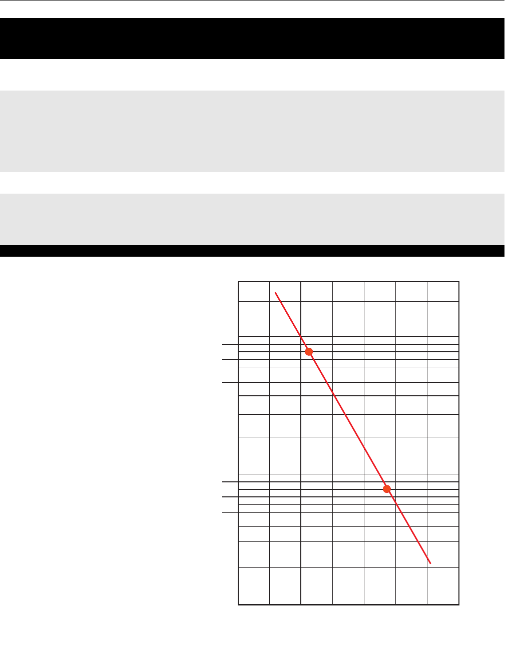
Instruction Manual
IM-106-880 Original Issue
February 2005
7-7
OCX 8800
Figure 7-2. Oxygen and Cell
Output
Cal Warning (Calibration warning)
Cal Failed (Calibration failed)
Probable Cause Recommended Corrective Action
Calibration gas supply low or gas connection
leaking
Check calibration gas supplies and connections. Adjust gas pressure and flow.
Replenish low calibration gas supplies and tighten or repair loose or leaking
connections. When calibration gas supplies are adequate, recalibrate.
O2 cell degraded or failed Check O2 cell impedance by reading the O2 Snsr R value via HART (see Figure 4-3,
sheet 2). If cell impedance is zero, replace O2 cell. If cell impedance is less than 5000
ohms, check for cell housing ground fault. Repair ground fault. If cell impedance is
greater than 5000 ohms and no ground fault is indicated, replace O2 cell.
Flow calibration gas to the O2 cell. Read the cell millivolt output. Plot the cell millivolt
output and the calibration gas O2 concentration on the chart shown in Figure 7-2. If the
plotted values do not fall on the slope line shown in Figure 7-2, replace the O2 cell.
COe sensor degraded Replace COe sensor or increase warning level (SYSTEM, CALIB SETUP, COe Slope
Warn via HART.)
Low sample gas flow in sensor housing due to
flow path plugging
Check the following portions of the flow path for plugging:
• blowback filter
• in-situ filter
• eductor outlet path
Table continued on next page
20
10
8
9
7
5
0.8
0.9
0.7
0.5 0.6
0.4
0.3
0.2
0.1
6
4
3
2
1
-20 0 20 40 60 80 100 120
ANALYZER OUTPUT (MILLIVOLT)
(23)
(73)
37390051
OXYGEN CONCENTRATION (%)

Instruction Manual
IM-106-880 Original Issue
February 2005
OCX 8800
7-8
Board Temp Hi (Electronics temperature maximum exceeded, > 85ºC)
Probable Cause Recommended Corrective Action
Electronics housing exposed to high ambient
temperature
Insulate housing from source of high temperature and/or install cooling fan to remove
heat from housing. Perform Reset procedure in Section 3, Configuration and Startup to
continue operation.
EEPRM Chksm Fail (Non-volatile parameter storage corrupted)
Probable Cause Recommended Corrective Action
Unit powered down during calibration parameter
storage
Perform Reset procedure in Section 3, Configuration and Startup. Recalibrate the OCX
and check/trim analog outputs.
Flash PROM failure Replace electronics package.
O2 Temp Low (Oxygen sensor heater temperature low, < 710ºC)
Probable Cause Recommended Corrective Action
Sensor housing exposed to high wind and/or
extreme cold temperatures
Install sensor housing flange insulator (PN 6P00162H01).
High noise or voltage fluctuations in power
supply
Check power supply for line noise or voltage fluctuations. Install filter power line kit
(PN 6A00171G01) or high quality line filter for input power.
COe Temp Low (Combustion sensor heater temperature low, < 290ºC)
Probable Cause Recommended Corrective Action
Sensor housing exposed to high wind and/or
extreme cold temperatures
Install sensor housing flange insulator (PN 6P00162H01).
High noise or voltage fluctuations in power
supply
Check power supply for line noise or voltage fluctuations. Install power line filter kit
(PN 6A00171G01) or high quality line filter for input power.
SB Temp Low (Sample block heater temperature low, < 150ºC)
Probable Cause Recommended Corrective Action
Sensor housing exposed to high wind and/or
extreme cold temperatures
Install sensor housing flange insulator (PN 6P00162H01).
High noise or voltage fluctuations in power
supply
Check power supply for line noise or voltage fluctuations. Install power line filter kit
(PN 6A00171G01) or high quality line filter for input power.
Line Freq Error (AC power line frequency out of usable range, < 45 Hz or > 66 Hz)
Probable Cause Recommended Corrective Action
High noise or voltage fluctuations in power
supply
Check power supply for line noise or voltage fluctuations. Install power line filter kit
(PN 6A00171G01) or high quality line filter for input power.
AC power line frequency is outside the usable
range of the OCX universal power supply
Correct power supply frequency. AC power line frequency must be between 50 and
60 Hz.
Electronics package failure Check power supply frequency with a calibrated oscilloscope or frequency meter and
compare with line frequency. Replace electronics package if they do not agree within
1 Hz.
Line Voltage Low (AC power line voltage below minimum, < 85 VAC)
Probable Cause Recommended Corrective Action
High noise or voltage fluctuations in power
supply
Check power supply for line noise or voltage fluctuations. Install power line filter kit
(PN 6A00171G01) or high quality line filter for input power.
Electronics package failure Check power supply voltage and compare with line voltage. Replace electronics
package if they do not agree within 5%.
Table continued on next page

Instruction Manual
IM-106-880 Original Issue
February 2005
7-9
OCX 8800
Line Voltage High (AC power line voltage above maximum, > 278 VAC)
Probable Cause Recommended Corrective Action
High noise or voltage fluctuations in power
supply
Check power supply for line noise or voltage fluctuations. Install power line filter kit
(PN 6A00171G01) or high quality line filter for input power.
Electronics package failure Check power supply voltage and compare with line voltage. Replace electronics
package if they do not agree within 5%.
Htr Relay Failed (Heater relay failure)
Probable Cause Recommended Corrective Action
High noise or voltage fluctuations in power
supply
Check power supply for line noise or voltage fluctuations. Install power line filter kit
(PN 6A00171G01) or high quality line filter for input power.
Electronics package failure Replace electronics package.
Out Brd Failure (Output board failure)
Probable Cause Recommended Corrective Action
Electronics package failure Replace electronics package.
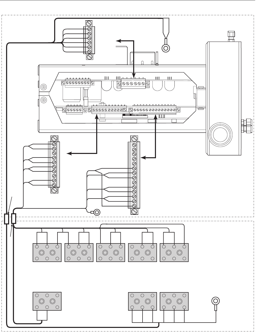
Instruction Manual
IM-106-880 Original Issue
February 2005
OCX 8800
7-10
Figure 7-3. Electrical Connections Between Electronics and Sensor Housing
37390014
RED
BLK
WHT
GRN
BLK
BLK
BLU
BLK
YEL
BRN
RED
BLK
BLK
ORG
BLK
WHT
T/C CO+
T/C CO-
T/C SB+
T/C SB-
T/C O2+
T/C O2-
O2 CELL+
O2 CELL-
EXC
+
+
-
+
-
EXC-
-
+
-
2
1
1
2
2
1
BLU
ORG
YEL
RED
SHIELD
To
ground
screw
GRN
BLK
WHT
BLK
YEL
RED
BLU
WHT
BLK
BLK
GRN
BLK
BLK
BLK
ORG WHT
RED
BLK
BRN
To ground screw
GRN
ELECTRONICS HOUSING
SENSOR HOUSING
Heater Power Cable
Signal Cable
O Sensor and
Thermocouple
Connector (J5)
2
COe Sensor
and
Cold Junction
Connector (J4)
EXC+
CO ACT+
CO ACT-
CO REF+
CO REF-
CJC+
CJC-
EXC-
O2
HTR
O2
HTR
CO
HTR
SB
CO
REF
CO
ACT
CJC
T/C SB
T/C CO
T/C O2
+
-
+
-
+
-
+
#1
#1 #1
#1
#1
To ground
screw
SHLD
WHT
ORG
BLU
BLK
YEL
RED
Heater Power
Connector (J3)
#1
2HTR SB
1HTR O2
1HTR SB
2HTR CO
1HTR CO
2HTR O2

Instruction Manual
IM-106-880 Original Issue
February 2005
7-11
OCX 8800
ALARM RELAY EVENTS The OCX 8800 contains an alarm relay that can be configured to activate on
one of twelve different groups of events. These event groups, and the
conditions that trigger them, are listed in Table 7-2, Alarm Relay Event
Groups.
Table 7-2. Alarm Relay
Event Groups
Alarm Relay Event Alarms/Conditions
In Calibration Calibration in progress
O2 Temperature Error
Oxygen sensor heater temperature low (O2 Temp Low)
Oxygen sensor heater temperature high (O2 Temp Hi,
O2 Temp Very Hi)
RTD excitation current error (Ref Curr Err)
Heater Failure
Oxygen sensor heater could not reach final temperature
(O2 HTR Failure)
Combustibles sensor heater could not reach final temperature
(COe Htr Failure)
Sample Block sensor heater could not reach final temperature
(SB Htr Failure)
O2 Sensor Error Oxygen sensor resistance high (O2 Sensor R High)
Oxygen sensor disconnected (O2 Sensor Open)
Calibration Failure Calibration failed (Cal Failed)
Calibration Warning Calibration warning (Cal Warning)
Board Temperature High Electronics temperature maximum exceeded (Board Temp Hi)
Unit Failure
Any non-recoverable or heater relay off alarm (O2 Temp Hi,
O2 Temp Very Hi, COe Temp Hi, COE Temp Very Hi,
SB Temp Hi, SB Temp Very Hi, O2 Htr Ramp Rate,
COe Htr Rmp Rate, SB Htr Ramp Rate, O2 TC Shorted,
O2 TC Reversed, COe TC Shorted, COe TC Reversed,
SB TC Shorted, SB TC Reversed, ADC Failure,
ADC Ref Error, Board Temp Hi, EEPRM Chksm Fail,
Line Freq Error, Line Voltage Low, Line Voltage Hi,
Htr Relay Failed, Out Brd Fail)
Sample Block
Temperature Error
Sample block heater temperature low (SB Temp Low)
Sample block heater temperature high (SB Temp Hi,
SB Temp Very Hi)
RTD excitation current error (Ref Curr Err)
COe Sensor
Temperature Error
Combustibles sensor heater temperature low (COe Temp Low)
Combustibles sensor heater temperature high (COe Temp Hi,
COe Temp Very Hi)
RTD excitation current error (Ref Curr Err)
Power Input Error
AC power line frequency out of usable range (Line Freq Err)
AC power line voltage below minimum (Line Voltage Low)
AC power line voltage above maximum (Line Voltage Hi)
All Alarms Any alarm

Instruction Manual
IM-106-880 Original Issue
February 2005
OCX 8800
7-12

Instruction Manual
IM-106-880 Original Issue
February 2005 OCX 8800
http://www.processanalytic.com
Section 8 Replacement Parts
Sensor Housing . . . . . . . . . . . . . . . . . . . . . . . . . . . . . . . . . . . . . . . page 8-2
Electronics Housing . . . . . . . . . . . . . . . . . . . . . . . . . . . . . . . . . . . . page 8-6
O2 Cell and Heater Strut Assembly . . . . . . . . . . . . . . . . . . . . . . . page 8-9
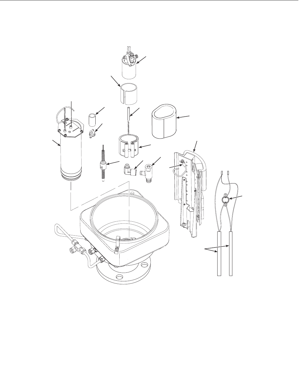
Instruction Manual
IM-106-880 Original Issue
February 2005
OCX 8800
8-2
SENSOR HOUSING
Figure 8-1. Sensor Housing
Components
37390073
1
14
2
15
3
4
5
6
79
16
12
(Requires
item 13 for
assembly)
8
10
11

Instruction Manual
IM-106-880 Original Issue
February 2005
8-3
OCX 8800
Index No. Part Number Description
1 5R10190G02 O2 Cell and Heater Assembly
26P00177H01 Heater Insulator, Mica
3 4851B46G03 Combustibles Sensor Replacement Kit
41A99786H01 Heater Leads Insulator, 11 inches long
5 6P00163H01 COe Insulator
61A99746H02 Band Heater
7 1A99749H01 Thermocouple
81A99747H01 Elbow
9 5R10200H01 Eductor
10 6A00123G01 CJC Sensor (RTD assembly, ring type)
11 6P00155H02 Insulator
12 1A98765H02 Heater Rod
13 1A99520H01 Watlube Heater Release Agent
14 9886A15H01 Thermal Switch Insulator
15 5R10268H02 Thermal Switch
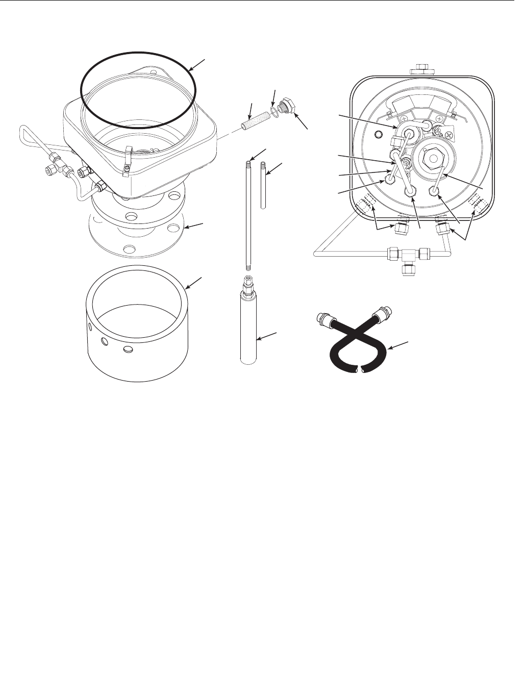
Instruction Manual
IM-106-880 Original Issue
February 2005
OCX 8800
8-4
Figure 8-2. Sensor Housing
Components
37390075
1
12
2
14
16
5
6
7
19
4
3
9
8
15
11, 11A
13
10
18
19

Instruction Manual
IM-106-880 Original Issue
February 2005
8-5
OCX 8800
Index No. Part Number Description
1 1A99089H02 Cover Gasket (O-ring)
25R10246H02 Blowback Filter
31A98448H02 O-ring
45R10247H01 Adaptor
5 5R10183H02 Tube, Sample, 18 in. (457 mm) 316 Stainless steel
5R10183H06 Tube, Sample, 18 in. (457 mm) Inconel 600
5R10227G01 Tube, Sample, 18 in. (457 mm) Ceramic
5R10183H03 Tube, Sample, 3 ft. (0.91 m) 316 Stainless steel
5R10183H07 Tube, Sample, 3 ft. (0.91 m) Inconel 600
5R10227G02 Tube, Sample, 3 ft. (0.91 m) Ceramic
5R10183H04 Tube, Sample, 6 ft. (1.83 m) 316 Stainless steel
5R10183H08 Tube, Sample, 6 ft. (1.83 m) Inconel 600
5R10183H05 Tube, Sample, 9 ft. (2.7 m) 316 Stainless steel
5R10183H09 Tube, Sample, 9 ft. (2.7 m) Inconel 600
6 5R10183H01 Tube, Exhaust
71A68017H02 COe Extractive
8 5R10185H08 Dilution Air Tube
95R10185H03 Eductor Drive Air Tube
10 5R10185H04 Reference Air Tube
11 6A00146G01 Heater Cable Assembly, Remote Electronics, 20 ft (6 m)
6A00146G02 Heater Cable Assembly, Remote Electronics, 40 ft (12 m)
6A00146G03 Heater Cable Assembly, Remote Electronics, 60 ft (18 m)
6A00146G04 Heater Cable Assembly, Remote Electronics, 80 ft (24 m)
6A00146G05 Heater Cable Assembly, Remote Electronics, 100 ft (30 m)
6A00146G06 Heater Cable Assembly, Remote Electronics, 150 ft (45 m)
11A 6A00147G01 Signal Cable Assembly, Remote Electronics, 20 ft (6 m)
6A00147G02 Signal Cable Assembly, Remote Electronics, 40 ft (12 m)
6A00147G03 Signal Cable Assembly, Remote Electronics, 60 ft (18 m)
6A00147G04 Signal Cable Assembly, Remote Electronics, 80 ft (24 m)
6A00147G05 Signal Cable Assembly, Remote Electronics, 100 ft (30 m)
6A00147G06 Signal Cable Assembly, Remote Electronics, 150 ft (45 m)
12 6A00144G01 In-situ Filter Kit
13 6P00162H01 Flange Insulator (optional)
14 3535B18H02 Flange Gasket, ANSI
3535B45H01 Flange Gasket, DIN
15 5R10279G01 Tube Fitting, Type "R"
16 771B870H04 Tube Fitting, Standard
18 5R10279G03 Tube Fitting, Type "13"
19 5R10267G01 Tube Fitting, Flame Arrestor, Type “F”
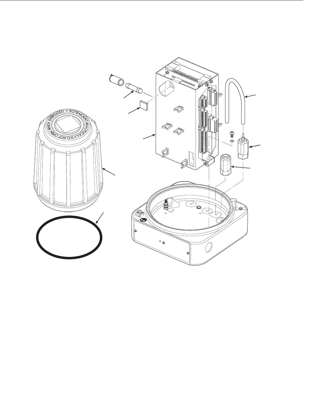
Instruction Manual
IM-106-880 Original Issue
February 2005
OCX 8800
8-6
ELECTRONICS
HOUSING
Figure 8-3. Electronics Housing
Components
37390080
7
1
3
2
5
6
4
8

Instruction Manual
IM-106-880 Original Issue
February 2005
8-7
OCX 8800
Index No. Part Number Description
1 1A97902H01 Hose
21A97905H02 Solenoid Valve, 3-Way
3 1A97905H01 Solenoid Valve, Test Gas
46A00132G01 Electronics Stack, HART
5 Special Order Flash PROM, Programmed
61A97913H06 Fuse (F1 and F6), 10 Amp, 250 VAC
1A99766H01 Fuse (F3), 4 Amp, 250 VAC
1A99766H02 Fuse (F4), 8 Amp, 250 VAC
7 1A99089H02 Cover Gasket (O-ring)
85R10219G01 Cover, Blind
8A 5R10199G01 Cover, Window
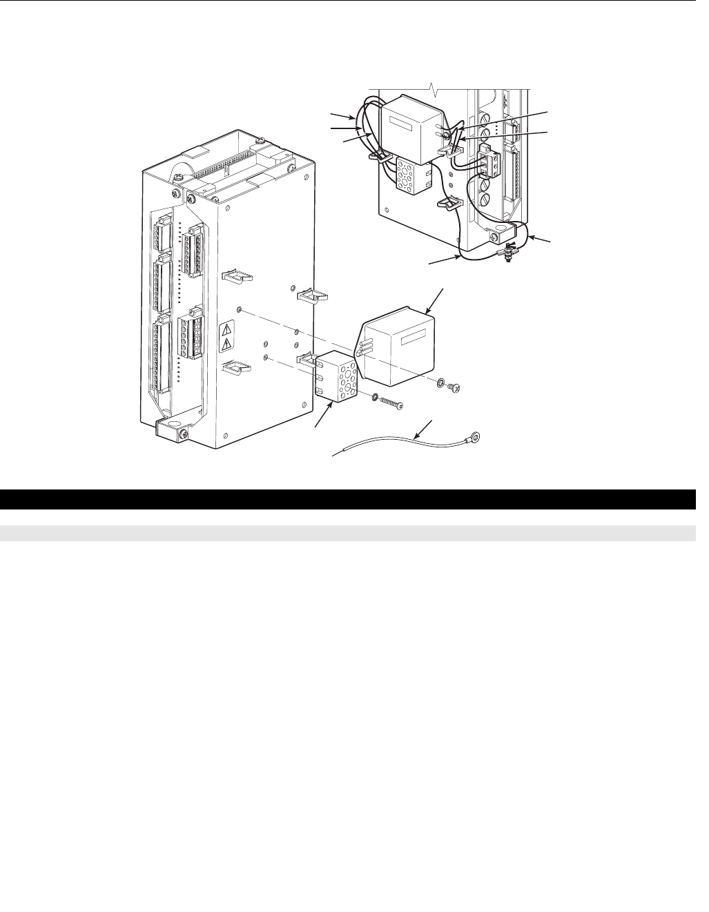
Instruction Manual
IM-106-880 Original Issue
February 2005
OCX 8800
8-8
Figure 8-4. EMI Filter
and Terminal Block
1
2
3
37390083
Brown
Blue
Green
Green
Green
Brown
Blue
Index No. Part Number Description
1 1A98467H01 Filter, EMI
25R10238G01 Ground Wire
3 1A99714H01 Terminal Block
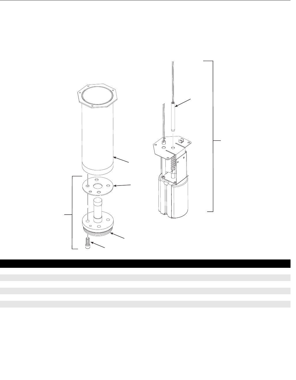
Instruction Manual
IM-106-880 Original Issue
February 2005
8-9
OCX 8800
O2 CELL AND HEATER
STRUT ASSEMBLY
Figure 8-5. O2 Cell and
Heater Strut Assembly
37390055
2
1
3
4
5
6
7
Index No. Part Number Description
1 4851B44G01 Contact and Thermocouple Assembly
25R10211G02 Heater Strut Assembly
3 5R10188G01 Heater Tube
4Ref Gasket (part of O2 Cell Replacement Kit, item 7)
5Ref O
2 Cell (part of O2 Cell Replacement Kit, item 7)
6Ref Screw (part of O2 Cell Replacement Kit, item 7)
7 4851B45G01 O2 Cell Replacement Kit

Instruction Manual
IM-106-880 Original Issue
February 2005
OCX 8800
8-10

Instruction Manual
IM-106-880 Original Issue
February 2005 OCX 8800
http://www.raihome.com
Appendix A Safety Data
Safety Instructions . . . . . . . . . . . . . . . . . . . . . . . . . . . . . . . page A-2
Ceramic Fiber Products Material Safety Data Sheet . . . . page A-15
High Pressure Gas Cylinders . . . . . . . . . . . . . . . . . . . . . . page A-21

Instruction Manual
IM-106-880 Original Issue
February 2005
OCX 8800
A-2
SAFETY INSTRUCTIONS IMPORTANT
SAFETY INSTRUCTIONS FOR THE WIRING
AND INSTALLATION OF THIS APPARATUS
The following safety instructions apply specifically to all EU member
states. They should be strictly adhered to in order to assure compliance
with the Low Voltage Directive. Non-EU states should also comply with
the following unless superseded by local or National Standards.
1. Adequate earth connections should be made to all earthing points,
internal and external, where provided.
2. After installation or troubleshooting, all safety covers and safety grounds
must be replaced. The integrity of all earth terminals must be
maintained at all times.
3. Mains supply cords should comply with the requirements of IEC227 or
IEC245.
4. All wiring shall be suitable for use in an ambient temperature of greater
than 75°C.
5. All cable glands used should be of such internal dimensions as to
provide adequate cable anchorage.
6. To ensure safe operation of this equipment, connection to the mains
supply should only be made through a circuit breaker which will
disconnect all circuits carrying conductors during a fault situation. The
circuit breaker may also include a mechanically operated isolating
switch. If not, then another means of disconnecting the equipment from
the supply must be provided and clearly marked as such. Circuit
breakers or switches must comply with a recognized standard such as
IEC947. All wiring must conform with any local standards.
7. Where equipment or covers are marked with the symbol
to the right, hazardous voltages are likely to be present
beneath. These covers should only be removed when
power is removed from the equipment - and then only
by trained service personnel.
8. Where equipment or covers are marked with the symbol
to the right, there is a danger from hot surfaces beneath.
These covers should only be removed by trained
service personnel when power is removed from the
equipment. Certain surfaces may remain hot to the
touch.
9. Where equipment or covers are marked with the symbol
to the right, refer to the Operator Manual for instructions.
10. All graphical symbols used in this product are from one
or more of the following standards: EN61010-1, IEC417,
and ISO3864.

Instruction Manual
IM-106-880 Original Issue
February 2005
A-3
OCX 8800
BELANGRIJK
Veiligheidsvoorschriften voor de aansluiting en installatie van dit
toestel.
De hierna volgende veiligheidsvoorschriften zijn vooral bedoeld voor de
EU lidstaten. Hier moet aan gehouden worden om de onderworpenheid
aan de Laag Spannings Richtlijn (Low Voltage Directive) te verzekeren.
Niet EU staten zouden deze richtlijnen moeten volgen tenzij zij reeds
achterhaald zouden zijn door plaatselijke of nationale voorschriften.
1. Degelijke aardingsaansluitingen moeten gemaakt worden naar alle
voorziene aardpunten, intern en extern.
2. Na installatie of controle moeten alle veiligheidsdeksels en -aardingen
terug geplaatst worden. Ten alle tijde moet de betrouwbaarheid van de
aarding behouden blijven.
3. Voedingskabels moeten onderworpen zijn aan de IEC227 of de IEC245
voorschriften.
4. Alle bekabeling moet geschikt zijn voor het gebruik in
omgevingstemperaturen, hoger dan 75°C.
5. Alle wartels moeten zo gedimensioneerd zijn dat een degelijke kabel
bevestiging verzekerd is.
6. Om de veilige werking van dit toestel te verzekeren, moet de voeding
door een stroomonderbreker gevoerd worden (min 10A) welke alle
draden van de voeding moet onderbreken. De stroomonderbreker mag
een mechanische schakelaar bevatten. Zoniet moet een andere
mogelijkheid bestaan om de voedingsspanning van het toestel te halen
en ook duidelijk zo zijn aangegeven. Stroomonderbrekers of
schakelaars moeten onderworpen zijn aan een erkende standaard
zoals IEC947.
7. Waar toestellen of deksels aangegeven staan met het
symbool is er meestal hoogspanning aanwezig. Deze
deksels mogen enkel verwijderd worden nadat de
voedingsspanning werd afgelegd en enkel door getraind
onderhoudspersoneel.
8. Waar toestellen of deksels aangegeven staan met het
symbool is er gevaar voor hete oppervlakken. Deze
deksels mogen enkel verwijderd worden door getraind
onderhoudspersoneel nadat de voedingsspanning
verwijderd werd. Sommige oppper-vlakken kunnen 45
minuten later nog steeds heet aanvoelen.
9. Waar toestellen of deksels aangegeven staan met het
symbool gelieve het handboek te raadplegen.
10. Alle grafische symbolen gebruikt in dit produkt, zijn
afkomstig uit een of meer van devolgende standaards:
EN61010-1, IEC417 en ISO3864.
Instruction Manual
IM-106-880 Original Issue
February 2005
OCX 8800
A-4
VIGTIGT
Sikkerhedsinstruktion for tilslutning og installering af dette udstyr.
Følgende sikkerhedsinstruktioner gælder specifikt i alle
EU-medlemslande. Instruktionerne skal nøje følges for overholdelse af
Lavsspændingsdirektivet og bør også følges i ikke EU-lande medmindre
andet er specificeret af lokale eller nationale standarder.
1. Passende jordforbindelser skal tilsluttes alle jordklemmer, interne og
eksterne, hvor disse forefindes.
2. Efter installation eller fejlfinding skal alle sikkerhedsdæksler og
jordforbindelser reetableres.
3. Forsyningskabler skal opfylde krav specificeret i IEC227 eller IEC245.
4. Alle ledningstilslutninger skal være konstrueret til omgivelsestemperatur
højere end 75°C.
5. Alle benyttede kabelforskruninger skal have en intern dimension, så
passende kabelaflastning kan etableres.
6. For opnåelse af sikker drift og betjening skal der skabes beskyttelse
mod indirekte berøring gennem afbryder (min. 10A), som vil afbryde alle
kredsløb med elektriske ledere i fejlsitua-tion. Afbryderen skal indholde
en mekanisk betjent kontakt. Hvis ikke skal anden form for afbryder
mellem forsyning og udstyr benyttes og mærkes som sådan. Afbrydere
eller kontakter skal overholde en kendt standard som IEC947.
7. Hvor udstyr eller dæksler er mærket med dette symbol,
er farlige spændinger normalt forekom-mende bagved.
Disse dæksler bør kun afmonteres, når
forsyningsspændingen er frakoblet - og da kun af
instrueret servicepersonale.
8. Hvor udstyr eller dæksler er mærket med dette symbol,
forefindes meget varme overflader bagved. Disse
dæksler bør kun afmonteres af instrueret
servicepersonale, når forsyningsspænding er frakoblet.
Visse overflader vil stadig være for varme at berøre i op
til 45 minutter efter frakobling.
9. Hvor udstyr eller dæksler er mærket med dette symbol,
se da i betjeningsmanual for instruktion.
10. Alle benyttede grafiske symboler i dette udstyr findes i
én eller flere af følgende standarder:- EN61010-1,
IEC417 & ISO3864.
Instruction Manual
IM-106-880 Original Issue
February 2005
A-5
OCX 8800
BELANGRIJK
Veiligheidsinstructies voor de bedrading en installatie van dit apparaat.
Voor alle EU lidstaten zijn de volgende veiligheidsinstructies van
toepassing. Om aan de geldende richtlijnen voor laagspanning te
voldoen dient men zich hieraan strikt te houden. Ook niet EU lidstaten
dienen zich aan het volgende te houden, tenzij de lokale wetgeving
anders voorschrijft.
1. Alle voorziene interne- en externe aardaansluitingen dienen op
adequate wijze aangesloten te worden.
2. Na installatie, onderhouds- of reparatie werkzaamheden dienen alle
beschermdeksels /kappen en aardingen om reden van veiligheid weer
aangebracht te worden.
3. Voedingskabels dienen te voldoen aan de vereisten van de normen IEC
227 of IEC 245.
4. Alle bedrading dient geschikt te zijn voor gebruik bij een omgevings
temperatuur boven 75°C.
5. Alle gebruikte kabelwartels dienen dusdanige inwendige afmetingen te
hebben dat een adequate verankering van de kabel wordt verkregen.
6. Om een veilige werking van de apparatuur te waarborgen dient de
voeding uitsluitend plaats te vinden via een meerpolige automatische
zekering (min.10A) die alle spanningvoerende geleiders verbreekt
indien een foutconditie optreedt. Deze automatische zekering mag ook
voorzien zijn van een mechanisch bediende schakelaar. Bij het
ontbreken van deze voorziening dient een andere als zodanig duidelijk
aangegeven mogelijkheid aanwezig te zijn om de spanning van de
apparatuur af te schakelen. Zekeringen en schakelaars dienen te
voldoen aan een erkende standaard zoals IEC 947.
7. Waar de apparatuur of de beschermdeksels/kappen
gemarkeerd zijn met het volgende symbool, kunnen
zich hieronder spanning voerende delen bevinden die
gevaar op kunnen leveren. Deze beschermdeksels/
kappen mogen uitsluitend verwijderd worden door
getraind personeel als de spanning is afgeschakeld.
8. Waar de apparatuur of de beschermdeksels/kappen
gemarkeerd zijn met het volgende symbool, kunnen
zich hieronder hete oppervlakken of onderdelen
bevinden. Bepaalde delen kunnen mogelijk na 45 min.
nog te heet zijn om aan te raken.
9. Waar de apparatuur of de beschermdeksels/kappen
gemarkeerd zijn met het volgende symbool, dient men
de bedieningshandleiding te raadplegen.
10. Alle grafische symbolen gebruikt bij dit produkt zijn
volgens een of meer van de volgende standaarden: EN
61010-1, IEC 417 & ISO 3864.
Instruction Manual
IM-106-880 Original Issue
February 2005
OCX 8800
A-6
TÄRKEÄÄ
Turvallisuusohje, jota on noudatettava tämän laitteen asentamisessa ja
kaapeloinnissa.
Seuraavat ohjeet pätevät erityisesti EU:n jäsenvaltioissa. Niitä täytyy
ehdottomasti noudattaa jotta täytettäisiin EU:n matalajännitedirektiivin
(Low Voltage Directive) yhteensopivuus. Myös EU:hun kuulumattomien
valtioiden tulee nou-dattaa tätä ohjetta, elleivät kansalliset standardit
estä sitä.
1. Riittävät maadoituskytkennät on tehtävä kaikkiin maadoituspisteisiin,
sisäisiin ja ulkoisiin.
2. Asennuksen ja vianetsinnän jälkeen on kaikki suojat ja suojamaat
asennettava takaisin pai-koilleen. Maadoitusliittimen kunnollinen
toiminta täytyy aina ylläpitää.
3. Jännitesyöttöjohtimien täytyy täyttää IEC227 ja IEC245 vaatimukset.
4. Kaikkien johdotuksien tulee toimia >75°C lämpötiloissa.
5. Kaikkien läpivientiholkkien sisähalkaisijan täytyy olla sellainen että
kaapeli lukkiutuu kun-nolla kiinni.
6. Turvallisen toiminnan varmistamiseksi täytyy jännitesyöttö varustaa
turvakytkimellä (min 10A), joka kytkee irti kaikki jännitesyöttöjohtimet
vikatilanteessa. Suojaan täytyy myös sisältyä mekaaninen erotuskytkin.
Jos ei, niin jännitesyöttö on pystyttävä katkaisemaan muilla keinoilla ja
merkittävä siten että se tunnistetaan sellaiseksi. Turvakytkimien tai
kat-kaisimien täytyy täyttää IEC947 standardin vaatimukset
näkyvyydestä.
7. Mikäli laite tai kosketussuoja on merkitty tällä merkillä
on merkinnän takana tai alla hengenvaarallisen
suuruinen jännite. Suojaa ei saa poistaa jänniteen
ollessa kytkettynä laitteeseen ja poistamisen saa
suorittaa vain alan asian-tuntija.
8. Mikäli laite tai kosketussuoja on merkitty tällä merkillä
on merkinnän takana tai alla kuuma pinta. Suojan saa
poistaa vain alan asiantuntija kun jännite-syöttö on
katkaistu. Tällainen pinta voi säilyä kosketuskuumana
jopa 45 mi-nuuttia.
9. Mikäli laite tai kosketussuoja on merkitty tällä merkillä
katso lisäohjeita käyt-töohjekirjasta.
10. Kaikki tässä tuotteessa käytetyt graafiset symbolit ovat
yhdestä tai useammasta seuraavis-ta standardeista:
EN61010-1, IEC417 & ISO3864.
Instruction Manual
IM-106-880 Original Issue
February 2005
A-7
OCX 8800
IMPORTANT
Consignes de sécurité concernant le raccordement et l'installation de
cet appareil.
Les consignes de sécurité ci-dessous s'adressent particulièrement à
tous les états membres de la communauté européenne. Elles doivent
être strictement appliquées afin de satisfaire aux directives concernant
la basse tension. Les états non membres de la communauté
européenne doivent également appliquer ces consignes sauf si elles
sont en contradiction avec les standards locaux ou nationaux.
1. Un raccordement adéquat à la terre doit être effectuée à chaque borne
de mise à la terre, interne et externe.
2. Après installation ou dépannage, tous les capots de protection et toutes
les prises de terre doivent être remis en place, toutes les prises de terre
doivent être respectées en permanence.
3. Les câbles d'alimentation électrique doivent être conformes aux normes
IEC227 ou IEC245.
4. Tous les raccordements doivent pouvoir supporter une température
ambiante supérieure à 75°C.
5. Tous les presse-étoupes utilisés doivent avoir un diamètre interne en
rapport avec les câbles afin d'assurer un serrage correct sur ces
derniers.
6. Afin de garantir la sécurité du fonctionnement de cet appareil, le
raccordement à l'alimentation électrique doit être réalisé exclusivement
au travers d'un disjoncteur (minimum 10A.) isolant tous les conducteurs
en cas d'anomalie. Ce disjoncteur doit également pouvoir être actionné
manuellement, de façon mécanique. Dans le cas contraire, un autre
système doit être mis en place afin de pouvoir isoler l'appareil et doit
être signalisé comme tel. Disjoncteurs et interrupteurs doivent être
conformes à une norme reconnue telle IEC947.
7. Lorsque les équipements ou les capots affichent le
symbole suivant, cela signifie que des tensions
dangereuses sont présentes. Ces capots ne doivent
être démontés que lorsque l'alimentation est coupée, et
uniquement par un personnel compétent.
8. Lorsque les équipements ou les capots affichent le
symbole suivant, cela signifie que des surfaces
dangereusement chaudes sont présentes. Ces capots
ne doivent être démontés que lorsque l'alimentation est
coupée, et uniquement par un personnel compétent.
Certaines surfaces peuvent rester chaudes jusqu'à 45
mn.
9. Lorsque les équipements ou les capots affichent le
symbole suivant, se reporter au manuel d'instructions.
10. Tous les symboles graphiques utilisés dans ce produit
sont conformes à un ou plusieurs des standards
suivants: EN61010-1, IEC417 & ISO3864.
Instruction Manual
IM-106-880 Original Issue
February 2005
OCX 8800
A-8
WICHTIG
Sicherheitshinweise für den Anschluß und die Installation dieser
Geräte.
Die folgenden Sicherheitshinweise sind in allen Mitgliederstaaten der
europäischen Gemeinschaft gültig. Sie müssen strickt eingehalten
werden, um der Niederspannungsrichtlinie zu genügen.
Nichtmitgliedsstaaten der europäischen Gemeinschaft sollten die
national gültigen Normen und Richtlinien einhalten.
1. Alle intern und extern vorgesehenen Erdungen der Geräte müssen
ausgeführt werden.
2. Nach Installation, Reparatur oder sonstigen Eingriffen in das Gerät
müssen alle Sicherheitsabdeckungen und Erdungen wieder installiert
werden. Die Funktion aller Erdverbindungen darf zu keinem Zeitpunkt
gestört sein.
3. Die Netzspannungsversorgung muß den Anforderungen der IEC227
oder IEC245 genügen.
4. Alle Verdrahtungen sollten mindestens bis 75°C ihre Funktion dauerhaft
erfüllen.
5. Alle Kabeldurchführungen und Kabelverschraubungen sollten in Ihrer
Dimensionierung so gewählt werden, daß diese eine sichere
Verkabelung des Gerätes ermöglichen.
6. Um eine sichere Funktion des Gerätes zu gewährleisten, muß die
Spannungsversorgung über mindestens 10 A abgesichert sein. Im
Fehlerfall muß dadurch gewährleistet sein, daß die
Spannungsversorgung zum Gerät bzw. zu den Geräten unterbrochen
wird. Ein mechanischer Schutzschalter kann in dieses System integriert
werden. Falls eine derartige Vorrichtung nicht vorhanden ist, muß eine
andere Möglichkeit zur Unterbrechung der Spannungszufuhr
gewährleistet werden mit Hinweisen deutlich gekennzeichnet werden.
Ein solcher Mechanismus zur Spannungsunterbrechung muß mit den
Normen und Richtlinien für die allgemeine Installation von
Elektrogeräten, wie zum Beispiel der IEC947, übereinstimmen.
7. Mit dem Symbol sind Geräte oder Abdeckungen gekennzeichnet, die
eine gefährliche (Netzspannung) Spannung führen. Die Abdeckungen
dürfen nur entfernt werden, wenn die Versorgungsspannung
unterbrochen wurde. Nur geschultes Personal darf an diesen Geräten
Arbeiten ausführen.
8. Mit dem Symbol sind Geräte oder Abdeckungen gekennzeichnet, in
bzw. unter denen heiße Teile vorhanden sind. Die Abdeckungen dürfen
nur entfernt werden, wenn die Versorgungsspannung unterbrochen
wurde. Nur geschultes Personal darf an diesen Geräten Arbeiten
ausführen. Bis 45 Minuten nach dem Unterbrechen der Netzzufuhr
können derartig Teile noch über eine erhöhte Temperatur verfügen.
9. Mit dem Symbol sind Geräte oder Abdeckungen gekennzeichnet, bei
denen vor dem Eingriff die entsprechenden Kapitel im Handbuch
sorgfältig durchgelesen werden müssen.
10. Alle in diesem Gerät verwendeten graphischen Symbole entspringen
einem oder mehreren der nachfolgend aufgeführten Standards:
EN61010-1, IEC417 & ISO3864.
Instruction Manual
IM-106-880 Original Issue
February 2005
A-9
OCX 8800
IMPORTANTE
Norme di sicurezza per il cablaggio e l'installazione dello strumento.
Le seguenti norme di sicurezza si applicano specificatamente agli stati
membri dell'Unione Europea, la cui stretta osservanza è richiesta per
garantire conformità alla Direttiva del Basso Voltaggio. Esse si
applicano anche agli stati non appartenenti all'Unione Europea, salvo
quanto disposto dalle vigenti normative locali o nazionali.
1. Collegamenti di terra idonei devono essere eseguiti per tutti i punti di
messa a terra interni ed esterni, dove previsti.
2. Dopo l'installazione o la localizzazione dei guasti, assicurarsi che tutti i
coperchi di protezione siano stati collocati e le messa a terra siano
collegate. L'integrità di ciscun morsetto di terra deve essere
costantemente garantita.
3. I cavi di alimentazione della rete devono essere secondo disposizioni
IEC227 o IEC245.
4. L'intero impianto elettrico deve essere adatto per uso in ambiente con
temperature superiore a 75°C.
5. Le dimensioni di tutti i connettori dei cavi utilizzati devono essere tali da
consentire un adeguato ancoraggio al cavo.
6. Per garantire un sicuro funzionamento dello strumento il collegamento
alla rete di alimentazione principale dovrà essere eseguita tramite
interruttore automatico (min.10A), in grado di disattivare tutti i conduttori
di circuito in caso di guasto. Tale interruttore dovrà inoltre prevedere un
sezionatore manuale o altro dispositivo di interruzione
dell'alimentazione, chiaramente identificabile. Gli interruttori dovranno
essere conformi agli standard riconosciuti, quali IEC947.
7. Il simbolo riportato sullo strumento o sui coperchi di
protezione indica probabile presenza di elevati voltaggi.
Tali coperchi di protezione devono essere rimossi
esclusivamente da personale qualificato, dopo aver
tolto alimentazione allo strumento.
8. Il simbolo riportato sullo strumento o sui coperchi di
protezione indica rischio di contatto con superfici ad alta
temperatura. Tali coperchi di protezione devono essere
rimossi esclusivamente da personale qualificato, dopo
aver tolto alimentazione allo strumento. Alcune superfici
possono mantenere temperature elevate per oltre 45
minuti.
9. Se lo strumento o il coperchio di protezione riportano il
simbolo, fare riferimento alle istruzioni del manuale
Operatore.
10. Tutti i simboli grafici utilizzati in questo prodotto sono
previsti da uno o più dei seguenti standard: EN61010-1,
IEC417 e ISO3864.
Instruction Manual
IM-106-880 Original Issue
February 2005
OCX 8800
A-10
VIKTIG
Sikkerhetsinstruks for tilkobling og installasjon av dette utstyret.
Følgende sikkerhetsinstruksjoner gjelder spesifikt alle EU medlemsland
og land med i EØS-avtalen. Instruksjonene skal følges nøye slik at
installasjonen blir i henhold til lavspenningsdirektivet. Den bør også
følges i andre land, med mindre annet er spesifisert av lokale- eller
nasjonale standarder.
1. Passende jordforbindelser må tilkobles alle jordingspunkter, interne og
eksterne hvor disse forefinnes.
2. Etter installasjon eller feilsøking skal alle sikkerhetsdeksler og
jordforbindelser reetableres. Jordingsforbindelsene må alltid holdes i
god stand.
3. Kabler fra spenningsforsyning skal oppfylle kravene spesifisert i
IEC227 eller IEC245.
4. Alle ledningsforbindelser skal være konstruert for en
omgivelsestemperatur høyere en 750°C.
5. Alle kabelforskruvninger som benyttes skal ha en indre dimensjon slik
at tilstrekkelig avlastning oppnåes.
6. For å oppnå sikker drift og betjening skal forbindelsen til
spenningsforsyningen bare skje gjennom en strømbryter (minimum
10A) som vil bryte spenningsforsyningen til alle elektriske kretser ved en
feilsituasjon. Strømbryteren kan også inneholde en mekanisk operert
bryter for å isolere instrumentet fra spenningsforsyningen. Dersom det
ikke er en mekanisk operert bryter installert, må det være en annen
måte å isolere utstyret fra spenningsforsyningen, og denne måten må
være tydelig merket. Kretsbrytere eller kontakter skal oppfylle kravene i
en annerkjent standard av typen IEC947 eller tilsvarende.
7. Der hvor utstyr eller deksler er merket med symbol for
farlig spenning, er det sannsynlig at disse er tilstede bak
dekslet. Disse dekslene må bare fjærnes når
spenningsforsyning er frakoblet utstyret, og da bare av
trenet servicepersonell.
8. Der hvor utstyr eller deksler er merket med symbol for
meget varm overflate, er det sannsynlig at disse er
tilstede bak dekslet. Disse dekslene må bare fjærnes
når spenningsforsyning er frakoblet utstyret, og da bare
av trenet servicepersonell. Noen overflater kan være for
varme til å berøres i opp til 45 minutter etter
spenningsforsyning frakoblet.
9. Der hvor utstyret eller deksler er merket med symbol,
vennligst referer til instruksjonsmanualen for instrukser.
10. Alle grafiske symboler brukt i dette produktet er fra en
eller flere av følgende standarder: EN61010-1, IEC417
& ISO3864.

Instruction Manual
IM-106-880 Original Issue
February 2005
A-11
OCX 8800
IMPORTANTE
Instruções de segurança para ligação e instalação deste aparelho.
As seguintes instruções de segurança aplicam-se especificamente a
todos os estados membros da UE. Devem ser observadas rigidamente
por forma a garantir o cumprimento da Directiva sobre Baixa Tensão.
Relativamente aos estados que não pertençam à UE, deverão cumprir
igualmente a referida directiva, exceptuando os casos em que a
legislação local a tiver substituído.
1. Devem ser feitas ligações de terra apropriadas a todos os pontos de
terra, internos ou externos.
2. Após a instalação ou eventual reparação, devem ser recolocadas todas
as tampas de segurança e terras de protecção. Deve manter-se
sempre a integridade de todos os terminais de terra.
3. Os cabos de alimentação eléctrica devem obedecer às exigências das
normas IEC227 ou IEC245.
4. Os cabos e fios utilizados nas ligações eléctricas devem ser adequados
para utilização a uma temperatura ambiente até 75ºC.
5. As dimensões internas dos bucins dos cabos devem ser adequadas a
uma boa fixação dos cabos.
6. Para assegurar um funcionamento seguro deste equipamento, a
ligação ao cabo de alimentação eléctrica deve ser feita através de um
disjuntor (min. 10A) que desligará todos os condutores de circuitos
durante uma avaria. O disjuntor poderá também conter um interruptor
de isolamento accionado manualmente. Caso contrário, deverá ser
instalado qualquer outro meio para desligar o equipamento da energia
eléctrica, devendo ser assinalado convenientemente. Os disjuntores ou
interruptores devem obedecer a uma norma reconhecida, tipo IEC947.
7. Sempre que o equipamento ou as tampas contiverem o
símbolo, é provável a existência de tensões perigosas.
Estas tampas só devem ser retiradas quando a energia
eléctrica tiver sido desligada e por Pessoal da
Assistência devidamente treinado.
8. Sempre que o equipamento ou as tampas contiverem o
símbolo, há perigo de existência de superfícies
quentes. Estas tampas só devem ser retiradas por
Pessoal da Assistência devidamente treinado e depois
de a energia eléctrica ter sido desligada. Algumas
superfícies permanecem quentes até 45 minutos
depois.
9. Sempre que o equipamento ou as tampas contiverem o
símbolo, o Manual de Funcionamento deve ser
consultado para obtenção das necessárias instruções.
10. Todos os símbolos gráficos utilizados neste produto
baseiam-se em uma ou mais das seguintes normas:
EN61010-1, IEC417 e ISO3864.
Instruction Manual
IM-106-880 Original Issue
February 2005
OCX 8800
A-12
IMPORTANTE
Instrucciones de seguridad para el montaje y cableado de este aparato.
Las siguientes instrucciones de seguridad, son de aplicacion especifica
a todos los miembros de la UE y se adjuntaran para cumplir la
normativa europea de baja tension.
1. Se deben preveer conexiones a tierra del equipo, tanto externa como
internamente, en aquellos terminales previstos al efecto.
2. Una vez finalizada las operaciones de mantenimiento del equipo, se
deben volver a colocar las cubiertas de seguridad aasi como los
terminales de tierra. Se debe comprobar la integridad de cada terminal.
3. Los cables de alimentacion electrica cumpliran con las normas IEC 227
o IEC 245.
4. Todo el cableado sera adecuado para una temperatura ambiental de
75ºC.
5. Todos los prensaestopas seran adecuados para una fijacion adecuada
de los cables.
6. Para un manejo seguro del equipo, la alimentacion electrica se realizara
a traves de un interruptor magnetotermico ( min 10 A ), el cual
desconectara la alimentacion electrica al equipo en todas sus fases
durante un fallo. Los interruptores estaran de acuerdo a la norma IEC
947 u otra de reconocido prestigio.
7. Cuando las tapas o el equipo lleve impreso el simbolo
de tension electrica peligrosa, dicho alojamiento
solamente se abrira una vez que se haya interrumpido
la alimentacion electrica al equipo asimismo la
intervencion sera llevada a cabo por personal
entrenado para estas labores.
8. Cuando las tapas o el equipo lleve impreso el simbolo,
hay superficies con alta temperatura, por tanto se abrira
una vez que se haya interrumpido la alimentacion
electrica al equipo por personal entrenado para estas
labores, y al menos se esperara unos 45 minutos para
enfriar las superficies calientes.
9. Cuando el equipo o la tapa lleve impreso el simbolo, se
consultara el manual de instrucciones.
10. Todos los simbolos graficos usados en esta hoja, estan
de acuerdo a las siguientes normas EN61010-1,
IEC417 & ISO 3864.
Instruction Manual
IM-106-880 Original Issue
February 2005
A-13
OCX 8800
VIKTIGT
Säkerhetsföreskrifter för kablage och installation av denna apparat.
Följande säkerhetsföreskrifter är tillämpliga för samtliga
EU-medlemsländer. De skall följas i varje avseende för att
överensstämma med Lågspännings direktivet. Icke EU medlemsländer
skall också följa nedanstående punkter, såvida de inte övergrips av
lokala eller nationella föreskrifter.
1. Tillämplig jordkontakt skall utföras till alla jordade punkter, såväl internt
som externt där så erfordras.
2. Efter installation eller felsökning skall samtliga säkerhetshöljen och
säkerhetsjord återplaceras. Samtliga jordterminaler måste hållas
obrutna hela tiden.
3. Matningsspänningens kabel måste överensstämma med föreskrifterna i
IEC227 eller IEC245.
4. Allt kablage skall vara lämpligt för användning i en
omgivningstemperatur högre än 75ºC.
5. Alla kabelförskruvningar som används skall ha inre dimensioner som
motsvarar adekvat kabelförankring.
6. För att säkerställa säker drift av denna utrustning skall anslutning till
huvudströmmen endast göras genom en säkring (min 10A) som skall
frånkoppla alla strömförande kretsar när något fel uppstår. Säkringen
kan även ha en mekanisk frånskiljare. Om så inte är fallet, måste ett
annat förfarande för att frånskilja utrustningen från strömförsörjning
tillhandahållas och klart framgå genom markering. Säkring eller
omkopplare måste överensstämma med en gällande standard såsom t
ex IEC947.
7. Där utrustning eller hölje är markerad med vidstående
symbol föreliggerisk för livsfarlig spänning i närheten.
Dessa höljen får endast avlägsnas när strömmen ej är
ansluten till utrustningen - och då endast av utbildad
servicepersonal.
8. När utrustning eller hölje är markerad med vidstående
symbol föreligger risk för brännskada vid kontakt med
uppvärmd yta. Dessa höljen får endast avlägsnas av
utbildad servicepersonal, när strömmen kopplats från
utrustningen. Vissa ytor kan vara mycket varma att
vidröra även upp till 45 minuter efter avstängning av
strömmen.
9. När utrustning eller hölje markerats med vidstående
symbol bör instruktionsmanualen studeras för
information.
10. Samtliga grafiska symboler som förekommer i denna
produkt finns angivna i en eller flera av följande
föreskrifter:- EN61010-1, IEC417 & ISO3864.
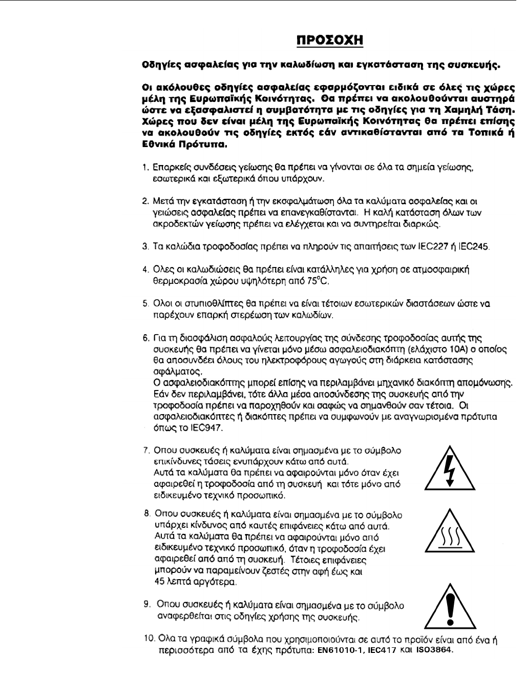
Instruction Manual
IM-106-880 Original Issue
February 2005
OCX 8800
A-14

Instruction Manual
IM-106-880 Original Issue
February 2005
A-15
OCX 8800
CERAMIC FIBER
PRODUCTS MATERIAL
SAFETY DATA SHEET
JULY 1, 1996
SECTION I. IDENTIFICATION
PRODUCT NAME
Ceramic Fiber Heaters, Molded Insulation Modules and Ceramic Fiber
Radiant Heater Panels.
CHEMICAL FAMILY
Vitreous Aluminosilicate Fibers with Silicon Dioxide.
CHEMICAL NAME
N.A.
CHEMICAL FORMULA
N.A.
MANUFACTURER'S NAME AND ADDRESS
Watlow Columbia
2101 Pennsylvania Drive
Columbia, MO 65202
573-814-1300, ext. 5170
573-474-9402
HEALTH HAZARD SUMMARY WARNING
• Possible cancer hazard based on tests with laboratory animals.
• May be irritating to skin, eyes and respiratory tract.
• May be harmful if inhaled.
• Cristobalite (crystalline silica) formed at high temperatures (above
1800ºF) can cause severe respiratory disease.
SECTION II. PHYSICAL DATA
APPEARANCE AND ODOR
Cream to white colored fiber shapes. With or without optional white to gray
granular surface coating and/or optional black surface coating.
SPECIFIC WEIGHT: 12-25 LB./CUBIC FOOT
BOILING POINT: N.A.
VOLATILES (% BY WT.): N.A.
WATER SOLUBILITY: N.A.
SECTION III. HAZARDOUS INGREDIENTS
MATERIAL, QUANTITY, AND THRESHOLD/EXPOSURE LIMIT VALUES
Aluminosilicate (vitreous) 99+ % 1 fiber/cc TWA
CAS. No. 142844-00-06 10 fibers/cc CL
Zirconium Silicate 0-10% 5 mg/cubic meter (TLV)
Black Surface Coating** 0 - 1% 5 mg/cubic meter (TLV)
Armorphous Silica/Silicon Dioxide 0-10% 20 mppcf (6 mg/cubic meter)
PEL (OSHA 1978) 3 gm/cubic meter
(Respirable dust): 10 mg/cubic meter,
Intended TLV (ACGIH 1984-85)
**Composition is a trade secret.

Instruction Manual
IM-106-880 Original Issue
February 2005
OCX 8800
A-16
SECTION IV. FIRE AND EXPLOSION DATA
FLASH POINT: NONE
FLAMMABILITY LIMITS: N.A.
EXTINGUISHING MEDIA
Use extinguishing agent suitable for type of surrounding fire.
UNUSUAL FIRE AND EXPLOSION HAZARDS / SPECIAL FIRE
FIGHTING PROCEDURES
N.A.
SECTION V. HEALTH HAZARD DATA
THRESHOLD LIMIT VALUE
(See Section III)
EFFECTS OF OVER EXPOSURE
• EYE - Avoid contact with eyes. Slightly to moderately irritating. Abrasive
action may cause damage to outer surface of eye.
• INHALATION - May cause respiratory tract irritation. Repeated or
prolonged breathing of particles of respirable size may cause
inflammation of the lung leading to chest pain, difficult breathing,
coughing and possible fibrotic change in the lung (Pneumoconiosis).
Pre-existing medical conditions may be aggravated by exposure:
specifically, bronchial hyper-reactivity and chronic bronchial or lung
disease.
• INGESTION - May cause gastrointestinal disturbances. Symptoms may
include irritation and nausea, vomiting and diarrhea.
• SKIN - Slightly to moderate irritating. May cause irritation and
inflammation due to mechanical reaction to sharp, broken ends of
fibers.
EXPOSURE TO USED CERAMIC FIBER PRODUCT
Product which has been in service at elevated temperatures (greater than
1800ºF/982ºC) may undergo partial conversion to cristobalite, a form of
crystalline silica which can cause severe respiratory disease
(Pneumoconiosis). The amount of cristobalite present will depend on the
temperature and length of time in service. (See Section IX for permissible
exposure levels).
SPECIAL TOXIC EFFECTS
The existing toxicology and epidemiology data bases for RCF's are still
preliminary. Information will be updated as studies are completed and
reviewed. The following is a review of the results to date:
EPIDEMIOLOGY
At this time there are no known published reports demonstrating negative
health outcomes of workers exposed to refractory ceramic fiber (RCF).
Epidemiologic investigations of RCF production workers are ongoing.
1) There is no evidence of any fibrotic lung disease (interstitial fibrosis)
whatsoever on x-ray.
2) There is no evidence of any lung disease among those employees
exposed to RCF that had never smoked.

Instruction Manual
IM-106-880 Original Issue
February 2005
A-17
OCX 8800
3) A statistical "trend" was observed in the exposed population between
the duration of exposure to RCF and a decrease in some measures of
pulmonary function. These observations are clinically insignificant. In
other words, if these observations were made on an individual
employee, the results would be interpreted as being within the normal
range.
4) Pleural plaques (thickening along the chest wall) have been observed
in a small number of employees who had a long duration of
employment. There are several occupational and non-occupational
causes for pleural plaque. It should be noted that plaques are not
"pre-cancer" nor are they associated with any measurable effect on
lung function.
TOXICOLOGY
A number of studies on the health effects of inhalation exposure of rats
and hamsters are available. Rats were exposed to RCF in a series of
life-time nose-only inhalation studies. The animals were exposed to 30,
16, 9, and 3 mg/m3, which corresponds with approximately 200, 150, 75,
and 25 fibers/cc.
Animals exposed to 30 and 16 mg/m3 were observed to have developed a
pleural and parenchymal fibroses; animals exposed to 9 mg/m3 had
developed a mild parenchymal fibrosis; animals exposed to the lowest
dose were found to have the response typically observed any time a
material is inhaled into the deep lung. While a statistically significant
increase in lung tumors was observed following exposure to the highest
dose, there was no excess lung cancers at the other doses. Two rats
exposed to 30 mg/m3 and one rat exposed to 9 mg/m3 developed
masotheliomas.
The International Agency for Research on Cancer (IARC) reviewed the
carcinogenicity data on man-made vitreous fibers (including ceramic fiber,
glasswool, rockwool, and slagwool) in 1987. IARC classified ceramic fiber,
fibrous glasswool and mineral wool (rockwool and slagwool) as possible
human carcinogens (Group 2B).
EMERGENCY FIRST AID PROCEDURES
• EYE CONTACT - Flush eyes immediately with large amounts of water
for approximately 15 minutes. Eye lids should be held away from the
eyeball to insure thorough rinsing. Do not rub eyes. Get medical
attention if irritation persists.
• INHALATION - Remove person from source of exposure and move to
fresh air. Some people may be sensitive to fiber induced irritation of the
respiratory tract. If symptoms such as shortness of breath, coughing,
wheezing or chest pain develop, seek medical attention. If person
experiences continued breathing difficulties, administer oxygen until
medical assistance can be rendered.
• INGESTION - Do not induce vomiting. Get medical attention if irritation
persists.
• SKIN CONTACT - Do not rub or scratch exposed skin. Wash area of
contact thoroughly with soap and water. Using a skin cream or lotion
after washing may be helpful. Get medical attention if irritation persists.

Instruction Manual
IM-106-880 Original Issue
February 2005
OCX 8800
A-18
SECTION VI. REACTIVITY DATA
STABILITY/CONDITIONS TO AVOID
Stable under normal conditions of use.
HAZARDOUS POLYMERIZATION/CONDITIONS TO AVOID
N.A.
INCOMPATIBILITY/MATERIALS TO AVOID
Incompatible with hydrofluoric acid and concentrated alkali.
HAZARDOUS DECOMPOSITION PRODUCTS
N.A.
SECTION VII. SPILL OR LEAK PROCEDURES
STEPS TO BE TAKEN IF MATERIAL IS RELEASED OR SPILLED
Where possible, use vacuum suction with HEPA filters to clean up spilled
material. Use dust suppressant where sweeping if necessary. Avoid clean
up procedure which may result in water pollution. (Observe Special
Protection Information Section VIII.)
WASTE DISPOSAL METHODS
The transportation, treatment, and disposal of this waste material must be
conducted in compliance with all applicable Federal, State, and Local
regulations.
SECTION VIII. SPECIAL PROTECTION INFORMATION
RESPIRATORY PROTECTION
Use NIOSH or MSHA approved equipment when airborne exposure limits
may be exceeded. NIOSH/MSHA approved breathing equipment may be
required for non-routine and emergency use. (See Section IX for suitable
equipment).
Pending the results of long term health effects studies, engineering control
of airborne fibers to the lowest levels attainable is advised.
VENTILATION
Ventilation should be used whenever possible to control or reduce
airborne concentrations of fiber and dust. Carbon monoxide, carbon
dioxide, oxides of nitrogen, reactive hydrocarbons and a small amount of
formaldehyde may accompany binder burn-off during first heat. Use
adequate ventilation or other precautions to eliminate vapors resulting
from binder burn-off. Exposure to burn-off fumes may cause respiratory
tract irritation, bronchial hyper-reactivity and asthmatic response.
SKIN PROTECTION
Wear gloves, hats and full body clothing to prevent skin contact. Use
separate lockers for work clothes to prevent fiber transfer to street clothes.
Wash work clothes separately from other clothing and rinse washing
machine thoroughly after use.
EYE PROTECTION
Wear safety glasses or chemical worker's goggles to prevent eye contact.
Do not wear contact lenses when working with this substance. Have eye
baths readily available where eye contact can occur.

Instruction Manual
IM-106-880 Original Issue
February 2005
A-19
OCX 8800
SECTION IX. SPECIAL PRECAUTIONS
PRECAUTIONS TO BE TAKEN IN HANDLING AND STORING
General cleanliness should be followed.
The Toxicology data indicate that ceramic fiber should be handled with
caution. The handling practices described in this MSDS must be strictly
followed. In particular, when handling refractory ceramic fiber in any
application, special caution should be taken to avoid unnecessary cutting
and tearing of the material to minimize generation of airborne dust.
It is recommended that full body clothing be worn to reduce the potential
for skin irritation. Washable or disposable clothing may be used. Do not
take unwashed work clothing home. Work clothes should be washed
separately from other clothing. Rinse washing machine thoroughly after
use. If clothing is to be laundered by someone else, inform launderer of
proper procedure. Work clothes and street clothes should be kept
separate to prevent contamination.
Product which has been in service at elevated temperatures (greater than
1800ºF/982ºC) may undergo partial conversion to cristobalite, a form of
crystalline silica. This reaction occurs at the furnace lining hot face. As a
consequence, this material becomes more friable; special caution must be
taken to minimize generation of airborne dust. The amount of cristobalite
present will depend on the temperature and length in service.
IARC has recently reviewed the animal, human, and other relevant
experimental data on silica in order to critically evaluate and classify the
cancer causing potential. Based on its review, IARC classified crystalline
silica as a group 2A carcinogen (probable human carcinogen).
The OSHA permissible exposure limit (PEL for cristobalite is 0.05 mg/m3
(respirable dust). The ACGIH threshold limit value (TLV) for cristobalite is
0.05 mg/m3 (respirable dust) (ACGIH 1991-92). Use NIOSH or MSHA
approved equipment when airborne exposure limits may be exceeded.
The minimum respiratory protection recommended for given airborne fiber
or cristobalite concentrations are:
CONCENTRATION
Concentration Personal Protective Equipment
0-1 fiber/cc or 0-0.05 mg/m3 cristobalite (the
OSHA PEL)
Optional disposable dust respirator (e.g. 3M
9970 or equivalent).
Up to 5 fibers/cc or up to 10 times the OSHA
PEL for cristobalite
Half face, air-purifying respirator equipped
with high efficiency particulate air (HEPA)
filter cartridges (e.g. 3M 6000 series with
2040 filter or equivalent).
Up to 25 fibers/cc or 50 times the OSHA PEL
for cristobalite (2.5 mg/m3)
Full face, air-purifying respirator with high
efficiency particulate air (HEPA) filter
cartridges (e.g. 3M 7800S with 7255 filters or
equivalent) or powered air-purifying respirator
(PARR) equipped with HEPA filter cartridges
(e.g. 3M W3265S with W3267 filters or
equivalent).
Greater than 25 fibers/cc or 50 times the
OSHA PEL for cristobalite (2.5 mg/m3)
Full face, positive pressure supplied air
respirator (e.g. 3M 7800S with W9435 hose &
W3196 low pressure regulator kit connected
to clean air supply or equivalent).

Instruction Manual
IM-106-880 Original Issue
February 2005
OCX 8800
A-20
If airborne fiber or cristobalite concentrations are not known, as minimum
protection, use NIOSH/MSHA approved half face, air-purifying respirator
with HEPA filter cartridges.
Insulation surface should be lightly sprayed with water before removal to
suppress airborne dust. As water evaporates during removal, additional
water should be sprayed on surfaces as needed. Only enough water
should be sprayed to suppress dust so that water does not run onto the
floor of the work area. To aid the wetting process, a surfactant can be
used.
After RCF removal is completed, dust-suppressing cleaning methods,
such as wet sweeping or vacuuming, should be used to clean the work
area. If dry vacuuming is used, the vacuum must be equipped with HEPA
filter. Air blowing or dry sweeping should not be used. Dust-suppressing
components can be used to clean up light dust.
Product packaging may contain product residue. Do not reuse except to
reship or return Ceramic Fiber products to the factory.

Instruction Manual
IM-106-880 Original Issue
February 2005
A-21
OCX 8800
HIGH PRESSURE GAS
CYLINDERS
GENERAL PRECAUTIONS FOR HANDLING AND STORING
HIGH PRESSURE GAS CYLINDERS
Edited from selected paragraphs of the
Compressed Gas Association's
"Handbook of Compressed Gases"
published in 1981
Compressed Gas Association
1235 Jefferson Davis Highway
Arlington, Virginia 22202
Used by Permission
1. Never drop cylinders or permit them to strike each other violently.
2. Cylinders may be stored in the open, but in such cases, should be
protected against extremes of weather and, to prevent rusting, from the
dampness of the ground. Cylinders should be stored in the shade when
located in areas where extreme temperatures are prevalent.
3. The valve protection cap should be left on each cylinder until it has been
secured against a wall or bench, or placed in a cylinder stand, and is
ready to be used.
4. Avoid dragging, rolling, or sliding cylinders, even for short distance; they
should be moved by using a suitable hand-truck.
5. Never tamper with safety devices in valves or cylinders.
6. Do not store full and empty cylinders together. Serious suckback can
occur when an empty cylinder is attached to a pressurized system.
7. No part of cylinder should be subjected to a temperature higher than
52°C (125°F). A flame should never be permitted to come in contact
with any part of a compressed gas cylinder.
8. Do not place cylinders where they may become part of an electric
circuit. When electric arc welding, precautions must be taken to prevent
striking an arc against the cylinder.
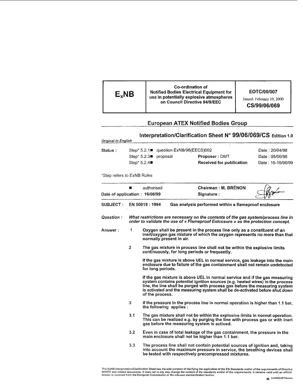
Instruction Manual
IM-106-880 Original Issue
February 2005
OCX 8800
A-22
ATEX CLARIFICATION ATEX COMPLIANT GAS ANALYSIS PERFORMED WITHIN A
FLAMEPROOF ENCLOSURE
Special conditions apply to using a flameproof enclosure analyzer under the
scope of the “European Directive for Equipment used in Explosive
Atmosphere” (Directive 94/9/EEC; ATEX). To stay compliant to the directive
please consider the following clarification sheet released by the European
ATEX Notified Body Group:
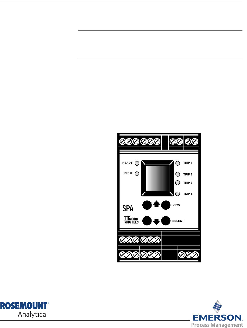
Instruction Manual
IM-106-880 Original Issue
February 2005 OCX 8800
http://www.raihome.com
Appendix B SPA with HART Alarm
Overview . . . . . . . . . . . . . . . . . . . . . . . . . . . . . . . . . . . . . . . page B-1
Description . . . . . . . . . . . . . . . . . . . . . . . . . . . . . . . . . . . . . page B-1
Installation . . . . . . . . . . . . . . . . . . . . . . . . . . . . . . . . . . . . . . page B-2
Setup . . . . . . . . . . . . . . . . . . . . . . . . . . . . . . . . . . . . . . . . . . page B-2
OVERVIEW This section describes the SPA with HART Alarm option for the OCX 8800.
DESCRIPTION The Moore Industries SPA with HART Alarm, Figure B-1, is a 4-wire (line or
mains powered), site-programmable, digital process alarm. It connects to a
standard HART field device, and provides up to four, fully configurable,
contact-closure outputs based on readings of the HART digital data. The four
OCX 8800 alarm outputs recognized by the SPA are Low O2, High COe,
Calibration Status, and OCX Unit Failure.
Figure B-1. SPA with
HART Alarm
37020018
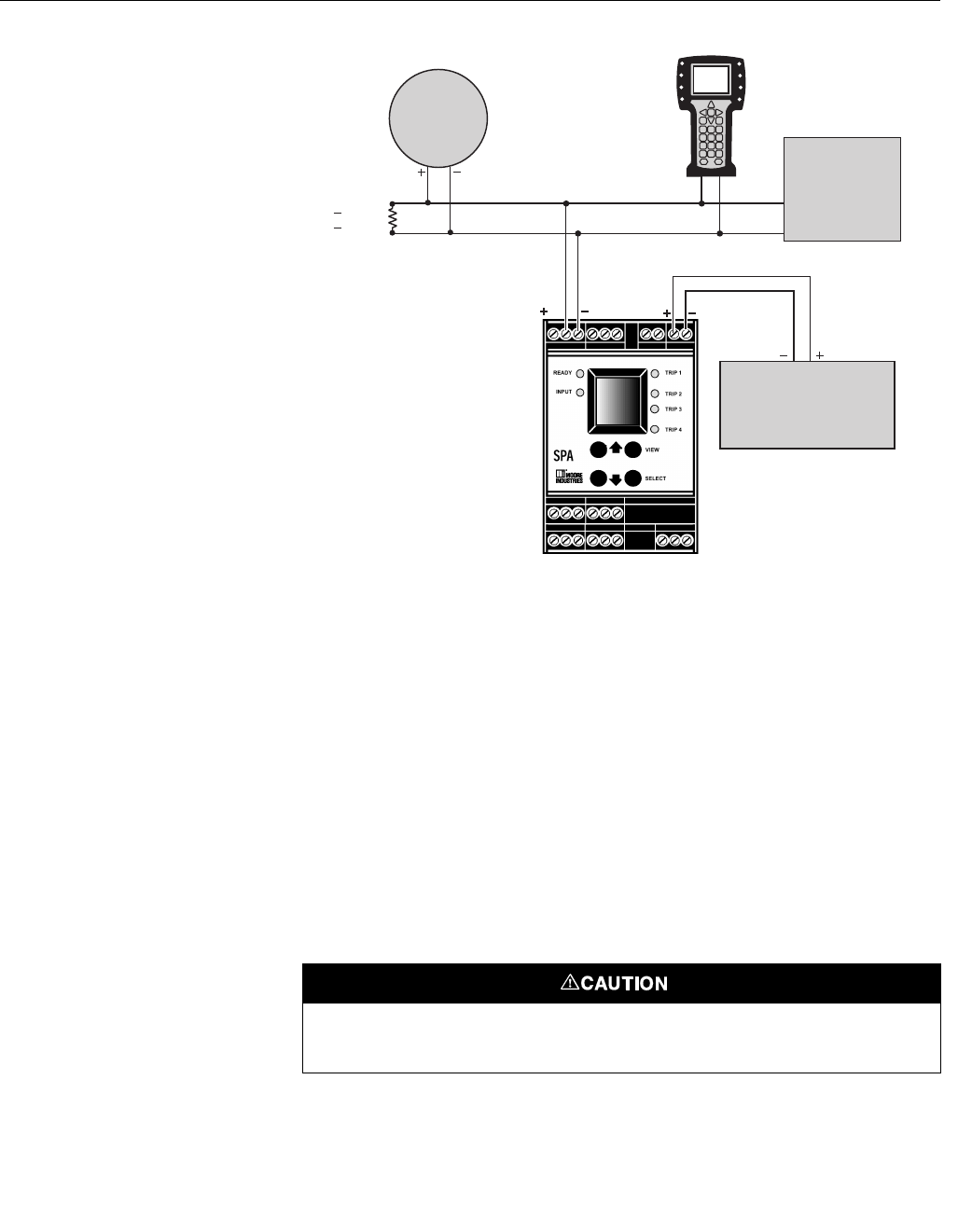
Instruction Manual
IM-106-880 Original Issue
February 2005
OCX 8800
B-2
Figure B-2. OCX 8800 and
SPA Interface Connections
INSTALLATION Refer to Figure B-2 for the typical interface connections for the OCX 8800 and
the SPA with HART alarm. Refer to the Moore Industries SPA user's manual
for additional information concerning SPA installation, setup, and operation.
SETUP Setup of the SPA for communication with the OCX 8800 includes setting
internal jumpers and dip switches and configuring the SPA operating
parameters via a menu-driven selection and calibration procedure.
Jumper and Switch Settings
SPA jumper and switch settings are shown in Figure B-3. If the SPA with
HART was factory-configured by Emerson Process Management for
operation with your OCX 8800, jumper and switch setting adjustments are not
required. However, you may use the following procedure to verify that the
jumper and switch settings are correct. Adjust or verify jumper and switch
settings as follows:
1. Refer to Figure B-3. Turn the SPA over and slide the access cover out.
Before changing any jumper or switch position, take adequate
precautions to avoid an electrostatic discharge.
HART
Model 275/375
Handheld
Communicator
Analog Output
IN IN 4-20 mA
or
0-24 vdc
4-20 mA O Signal Loop
2
37390022
250
950
>
<
RΩ
Ω
OCX 8800
Customers
DCS, PLC,
or
PC with AMS
Software
Event Recorder,
Audible Alarm,
or other
Analog Device
Electrostatic discharge (ESD) protection is required to avoid damage to the SPA electronic
circuits.
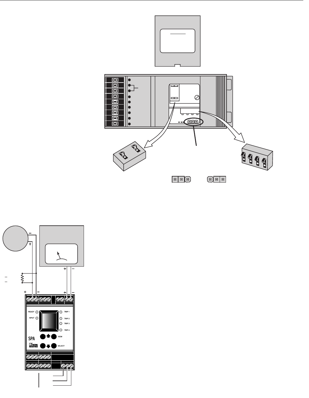
Instruction Manual
IM-106-880 Original Issue
February 2005
B-3
OCX 8800
IN IN
Fluke Model 87
Multimeter
or equivalent
Optional
mA
AC or DC
Power Input
AC
ACC
GND
37390024
250Ω
950Ω
>
<
OCX
8800
Figure B-3. SPA Jumper
and Dip Switch Settings
Figure B-4. SPA Setup for
Calibration
2. Verify that the Password Jumper is set to the OFF position. If the jumper
is in the ON position, reposition the jumper.
3. Check the position of the Failsafe Dip Switches. Position the dip
switches as shown in Figure B-3.
4. Check the position of the Source Current Dip Switches. Position the dip
switches as shown in Figure B-3.
5. Reinstall the SPA access cover.
Configuration/Calibration
Prior to operation, the SPA operating parameters must be configured via a
menu-driven setup procedure. At the end of the configuration procedure, the
SPA analog output signal is calibrated to insure valid communications.
1. See Figure B-4. Connect a calibrated ammeter (Fluke Model 87 or
equivalent, accurate to ±0.025%) to the SPA analog output terminals.
Observe polarity.
2. Connect a 90 to 260 VAC or 22 to 300 VDC power source to the SPA
power terminals. When connecting an AC power source, use the AC
and ACC (AC Common) terminals. For a DC source, use the AC and
Ground terminals.
3. If desired, you can connect the 4 to 20 mA O2 signal wires from the
OCX 8800 analog output terminal block to the SPA Input terminals. (The
OCX must be operational to transmit the O2 signal. Observe polarity.)
Access Cover
37020022
Password
ON Password
OFF
Password
Jumper Pins
Failsafe Dip Switches
(shown in correct position)
(shown in correct position)
Source Current Dip Switches
SPA - Bottom View
NOTICE
REMOVETHIS PANEL
FOR SERVICE ACCESS.
STATIC SENSITIVE.
USE CAUTIONWHEN
CHANGING JUMPERS
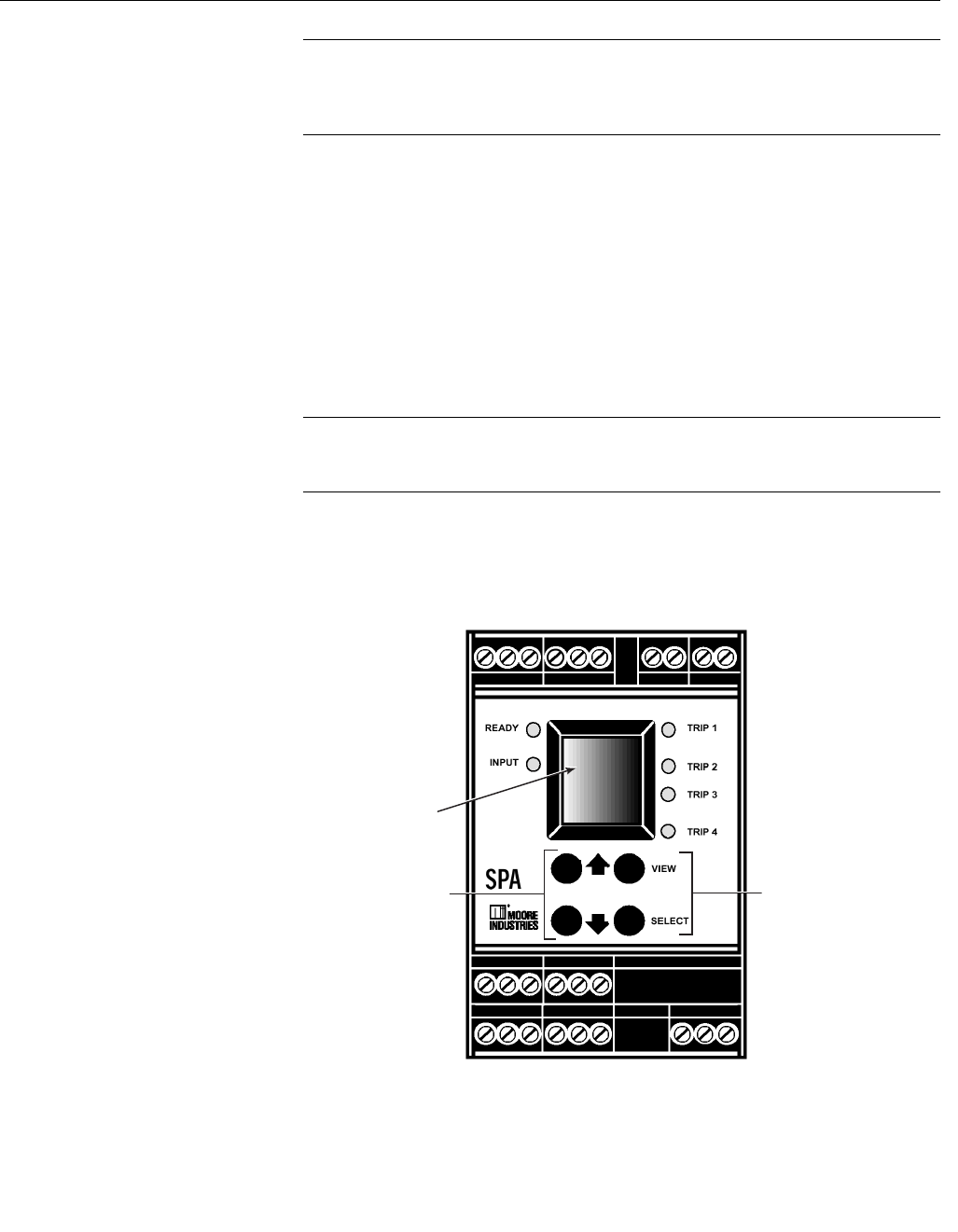
Instruction Manual
IM-106-880 Original Issue
February 2005
OCX 8800
B-4
NOTE
The O2 signal connection is not required for SPA configuration or calibration.
The OCX interface will allow you to observe the O2 signal level when the SPA
configuration procedure is completed.
4. Observe the front panel of the SPA, Figure B-5:
a. A process value display in the SPA display window indicates that the
SPA is operational. Four pushbuttons are located below the display
window.
b. Pressing a left-hand pushbutton scrolls up () or down () through
the SPA command menu, a submenu, or parameter values list.
c. Pressing the VIEW pushbutton displays rail limits and alarm relay
configurations. There are five sequential displays in the VIEW mode.
While in the VIEW mode, the up (), down (), and SELECT
pushbuttons are disabled.
NOTE
In the VIEW mode, you can scroll through and display the output zero and full
scale settings and the alarm relay trip points and configurations.
d. Pressing the SELECT pushbutton selects the displayed menu or
submenu command or selects a displayed parameter variable.
Figure B-5. SPA Front Panel
37020017
SPA
Display
Window
Left-Hand
Pushbuttons
Right-Hand
Pushbuttons

Instruction Manual
IM-106-880 Original Issue
February 2005
B-5
OCX 8800
5. Figure B-6 shows the SPA menu, submenus, and parameter values that
must be selected to configure the SPA for use with the OCX 8800. Use
the following instructions and selections shown to properly configure the
SPA.
a. Press the SELECT pushbutton. Observe the display window on the
SPA front panel. The display window should read SET HART.
b. See the SET HART command in Figure B-6. To the right of the
command window is the SET HART submenu and related parameter
values that must be selected via the front panel pushbuttons on the
SPA.
c. In the submenu views shown:
means press the down pushbutton.
means press the up pushbutton.
means press the SELECT pushbutton one time.
means press the or pushbutton until the desired parameter
value is shown in the SPA window.
d. Proceed through the SPA menu, selecting the menu commands and
parameter values indicated. After completing the sequence in the
first column, go to the top of the second column and continue.
e. To exit the menu, repeatedly press SELECT to display any main
menu command. Then, press or until CONF EXIT is displayed.
Select CONF EXIT.
f. Detailed instructions concerning the configuration menu and the
submenu structure for each main command are provided in the SPA
user's manual.
Instruction Manual
IM-106-880 Original Issue
February 2005
OCX 8800
B-6
Figure B-6. SPA Configuration Menu
for OCX 8800 Communication
37390003
TRIM
OUT
ÜSET MSTR ÜôPRIM
ÜSET FUCT ÜôNRML
ÜNUM VARS Üô02
ÜNUM TRYS Üô03
ÜEXIT HART ÜSGNL SRCE
ÜAOUT SRCE ÜôSV
ÜAL2 SRCE ÜôPV
ÜAL3 SRCE ÜôPV
ÜAL4 SRCE ÜôPV
ÜEXIT SRCE ÜFLT SRCE
êCONF OPTS
ÜSET LINR ÜôLINR OFF
ÜPV SCLE ÜôAUTO
ÜDSPL EGU ÜôCSTM ÜôPPM
(select P, select P, select M)
ÜDSPL SRCE ÜôSV
ÜAL2 SEL ÜAL2 FLT
êSET FAIL ÜFAIL LOW
êEXIT OPTS ÜSET EGU
ÜPV EGU ÜôPCT
ÜSV EGU ÜôCSTM ÜôPPM
(select P, select P, select M)
ÜEXIT EGU ÜSCLE INPT
ÜPV SCLE ÜPV ZERO ô0000 PCT
ÜPV FULL ô25 PCT
ÜSCLE SV ÜSET ZERO ô0000 PPM
ÜSET FULL ô1000 PPM
ÜEXIT SCLE ÜSCLE DSPL
ÜPV DSPL
ÜSET ZERO Üô0000 PCT
ÜSET FULL Üô25 PCT
ÜSV DSPL
ÜSET ZERO Üô0000 PPM
ÜSET FULL Üô1000 PPM
ÜEXIT DSPL ÜSCLE OUT
ÜSET ZERO Üô4.000 MA
ÜSET FULL Üô20.00 MA
ÜEXIT Z/FS
ÜTRIM OUT
ÜTRIM ZERO Üô4.000 MA
ÜTRIM FULL Üô20.00 MA
ÜEXIT TRIM ÜCONF ALRM
SGNL
SRCE
FLT
SRCE
CONF
OPTS
SET
EGU
SCLE
INPT
SET
HART
SCLE
DSPL
SCLE
OUT
CONF
ALRM
SCLE INPT
SCLE DSPL
Refer to
SPA manual
for settings or
êPASS WORD
CONF
EXIT
PASS
WORD
êCONF EXIT
ÜSPA setup complete;
observe process value display.

Instruction Manual
IM-106-880 Original Issue
February 2005 OCX 8800
http://www.raihome.com
Appendix C Return of Materials
RETURNING MATERIAL If factory repair of defective equipment is required, proceed as follows:
1. Secure a return authorization number from a Rosemount Analytical
sales office or representative before returning the equipment.
Equipment must be returned with complete identification in accordance
with Rosemount Analytical instructions or it will not be accepted.
In no event will Emerson Process Management be responsible for
equipment returned without proper authorization and identification.
2. Carefully pack defective unit in a sturdy box with sufficient shock
absorbing material to ensure that no additional damage will occur during
shipping.
3. In a cover letter, describe completely:
a. The symptoms from which it was determined that the equipment is
faulty.
b. The environment in which the equipment has been operating
(housing, weather, vibration, dust, etc.).
c. Site from which equipment was removed.
d. Whether warranty or nonwarranty service is requested.
e. Complete shipping instructions for return of equipment.
f. Reference the return authorization number.
4. Enclose a cover letter and purchase order and ship the defective
equipment according to instructions provided in Rosemount Analytical
Return Authorization, prepaid, to:
Rosemount Analytical Inc.
RMR Department
Daniel Headquarters
11100 Britmore Park Drive
Houston, TX 77041
If warranty service is requested, the defective unit will be carefully inspected
and tested at the factory. If failure was due to conditions listed in the standard
Rosemount Analytical warranty, the defective unit will be repaired or replaced
at Rosemount Analytical's option, and an operating unit will be returned to the
customer in accordance with shipping instructions furnished in the cover
letter.
For equipment no longer under warranty, the equipment will be repaired at the
factory and returned as directed by the purchase order and shipping
instructions.

Instruction Manual
IM-106-880 Original Issue
February 2005
OCX 8800
C-2

Instruction Manual
IM-106-880 Original Issue
February 2005 OCX 8800
http://www.raihome.com
Index
A
Accessories . . . . . . . . . . . . . . 1-12
Alarm Relay Events . . . . . . . . 7-11
Assemble O2 Sensor . . . . . . . 6-19
Autocalibration Setup, HART . . 5-1
Autocalibration, HART . . . . . . . 5-3
B
Band Heater Height . . . . . . . . 6-22
Blowback System . . . . . . 1-5, 2-17
Blowback with
Autocalibration . . . . . . . . . . . 2-18
Blowback without
Autocalibration . . . . . . . . . . . 2-19
C
Cable Connections . . . . . . . . . . 6-6
Cell Output . . . . . . . . . . . . . . . . 7-7
COe Band Heater . . . . . . . . . . 6-14
COe Sensor
Assembly . 6-11, 6-17, 6-18, 6-22
COe Sensor Holder
Alignment . . . . . . . . . . . . . . . 6-23
COe Sensor Parts . . . . . . . . . . 6-21
COe Sensor, Thermocouple,
and Heater Connections . . . 6-24
Combustibles Sensor . . . . . . . . 1-3
Component Checklist . . . . . . . . 1-1
Configuration . . . . . . . . . . . . . . 3-2
D
D/A Trim Procedure . . . . . . . . . 5-8
Defaults . . . . . . . . . . . . . . . . . . . 3-3
Diagnostic Alarms . . . . . . . . . . . 7-2
E
Eductor . . . . . . . . . . . . . 6-14, 6-20
Eductor Holder . . . . . . . . . . . . 6-14
Electrical Noise . . . . . . . . . . . . . 7-1
Electronics Housing
Components . . . . . . . . . . . . . . 8-6
Electronics Housing
Disassembly . . . . . . . . . . . . . 6-28
Electronics Housing
Terminal Blocks . . . . . . . . . . . 6-5
Electrostatic Discharge . . . . . . . 7-1
Essential Instructions . . . . . . . . . . i
F
Factory Repair . . . . . . . . . . . . . .C-1
Fault Indications . . . . . . . . . . . . 7-3
Fault Isolation . . . . . . . . . . . . . . 7-3
Fitting, ‘F’ Type . . . . . . . . . . . . 6-34
Fitting, ‘R’ Type . . . . . . . . . . . . 6-34
Fittng, ‘13’ Type . . . . . . . . . . . . 6-34
Fuse Locations . . . . . . . . . . . . . 7-2
G
Grounding . . . . . . . . . . . . . . . . . 7-1
H
Handling . . . . . . . . . . . . . . . . . . 1-6
HART Communicator . . . . . . . . 4-1
HART Connections . . . . . . . . . . 1-7
HART PC Connections . . . . . . . 4-4
HART Signal Connections . . . . . 4-1
HART Signal Line
Connections . . . . . . . . . . 4-2, 4-3
Hazardous Area OCX 8800 . . 1-11
Heater Strut Assembly . . . . . . 6-19
I
Install Eductor . . . . . . . . . . . . . 6-20
Install Electronics Stack . . . . . 6-31
Install Flash PROM . . . . . . . . . 6-31
Install Remote Electronics . . . . . 6-7
Install Sensor Housing . . . . . . . 6-4
Install Solenoid Valves . . . . . . 6-31
Install Tube Fittings . . . . . . . . . 6-35
Instrument Air . . . . . . . . . . . . . . 1-7
M
Manual Calibration,
HART . . . . . . . . . . . .5-3, 5-5, 5-6
Material Safety Data Sheet . . .A-15
N
Nernst Equation . . . . . . . . . . . . 1-3
O
O2 Cell and Heater
Strut . . . . . . . . . . . . . . 6-25, 6-27
O2 Cell and Heater Strut
Assembly . . . 6-9, 6-10, 6-16, 8-9
O2 Cell Output Voltage . . . . . . .1-4
O2 Cell Replacement Kit . . . . .6-16
O2 Cell, Heater, and
Thermocouple . . . . . . . . . . . .6-16
O2 Cell, Thermocouple, and
Heater Connections . . 6-10, 6-26
OCX with Remote Electronics . .6-2
Operation Diagram . . . . . . . . . .1-6
Oxygen and Cell Output . . . . . .7-7
P
Personal Computer (PC) . . . . . .1-5
Power Up . . . . . . . . . . . . . . . . . .3-3
Pre-Heater . . . . . . . . . . . . . . . .6-18
Pre-Heater Alignment . . . . . . .6-19
Product Matrix . . . . . . . . . . . . . 1-11
R
Reference Air Tube . . . . . . . . .6-10
Removal and Installation . . . . . .6-1
Remove Eductor . . . . . . . . . . .6-14
Remove EEprom . . . . . . . . . . .6-28
Remove Electronics Stack . . . .6-29
Remove Flash PROM . . . . . . .6-28
Remove Remote Electronics . . .6-4
Remove Sensor Housing . . . . . .6-2
Remove Solenoid Valves . . . . .6-30
Remove Tube Fittings . . . . . . .6-34
Repair Sensor Housing . . . . . . .6-8
Replace Tube Fittings . . . . . . .6-34
Reset Procedure . . . . . . . . . . . .3-4
Resistance Devices (RTD) . . . .1-3
Returning Material . . . . . . . . . . C-1
RTD . . . . . . . . . . . . . . . . . . . . . .1-3
S
Sample and Exhaust
Tubes . . . . . . . . . . . . . 6-15, 6-19
Sample Block Heater
Rods . . . . . . . . . . . . . . 6-10, 6-25

Instruction Manual
IM-106-880 Original Issue
February 2005
OCX 8800
Index-2
Selected Distributed
Control Systems . . . . . . . . . . . 1-5
Sensor Housing
Components . . . . . . . . . . 8-2, 8-4
Sensor Housing Disassembly . . 6-8
Sensor Housing Leak Test . . . 6-27
Sensor Housing Terminals . . . . 6-3
Solenoid Power Terminals . . . 6-33
SPA Configuration Menu . . . . . . B-6
SPA Front Panel . . . . . . . . . . . . B-4
SPA Interface Connections . . . . B-2
SPA Setup for Calibration . . . . .B-3
SPA with HART Alarm . . . . . . . .B-1
Specifications . . . . . . . . . . . . . . 1-9
SW1 . . . . . . . . . . . . . . . . . . . . . 3-2
SW2 . . . . . . . . . . . . . . . . . . . . . 3-2
SW3 . . . . . . . . . . . . . . . . . . . . . 3-2
System Configuration . . . . . . . . 1-4
System Description . . . . . . . . . . 1-1
System Features . . . . . . . . . . . . 1-4
System Operation . . . . . . . . . . . 1-5
System Overview . . . . . . . . . . . 1-1
System Package . . . . . . . . . . . . 1-2
T
Terminals Insulator . . . . . . . . .6-27
Test Gas Values . . . . . . . . . . . . .3-4
Thermal Switch . . . . . . . . . . . . 6-11
Total Power Loss . . . . . . . . . . . .7-2
Transmitter Package . . . . . . . . .1-1
Typical System Installation . . . .1-8
Typical System Package . . . . . .1-2
W
Warranty Service . . . . . . . . . . . C-1
WARRANTY
Rosemount Analytical warrants that the equipment manufactured and sold by
it will, upon shipment, be free of defects in workmanship or material. Should
any failure to conform to this warranty become apparent during a period of
one year after the date of shipment, Rosemount Analytical shall, upon prompt
written notice from the purchaser, correct such nonconformity by repair or
replacement, F.O.B. factory of the defective part or parts. Correction in the
manner provided above shall constitute a fulfillment of all liabilities of
Rosemount Analytical with respect to the quality of the equipment.
THE FOREGOING WARRANTY IS EXCLUSIVE AND IN LIEU OF ALL
OTHER WARRANTIES OF QUALITY WHETHER WRITTEN, ORAL, OR
IMPLIED (INCLUDING ANY WARRANTY OF MERCHANTABILITY OF
FITNESS FOR PURPOSE).
The remedy(ies) provided above shall be purchaser's sole remedy(ies) for
any failure of Rosemount Analytical to comply with the warranty provisions,
whether claims by the purchaser are based in contract or in tort (including
negligence).
Rosemount Analytical does not warrant equipment against normal
deterioration due to environment. Factors such as corrosive gases and solid
particulates can be detrimental and can create the need for repair or
replacement as part of normal wear and tear during the warranty period.
Equipment supplied by Rosemount Analytical Inc. but not manufactured by it
will be subject to the same warranty as is extended to Rosemount Analytical
by the original manufacturer.
At the time of installation it is important that the required services are supplied
to the system and that the electronic controller is set up at least to the point
where it is controlling the sensor heater. This will ensure, that should there be
a delay between installation and full commissioning that the sensor being
supplied with ac power and reference air will not be subjected to component
deterioration.
3739
2/05

Emerson Process Management
© 2005 Rosemount Analytical Inc. All rights reserved.
Rosemount Analytical and the Rosemount Analytical logotype are registered trademarks of Rosemount Analytical Inc.
HART is a registered trademark of the HART Communications Foundation.
All other marks are the property of their respective owners.
Instruction Manual
IM-106-880 Original Issue
February 2005
EUROPE, MIDDLE EAST,
AFRICA
Fisher-Rosemount Ltd.
Heath Place
Bognor Regis
West Sussex PO22 9SH
England
T 44-1243-863121
F 44-1243-845354
http://www.raihome.com
LATIN AMERICA
Fisher - Rosemount
Av. das Americas
Rio de Janeiro, RJ
Brazil 22631-003
T 55-21-2431-1882
ASIA - PACIFIC
Fisher-Rosemount
Singapore Private Ltd.
1 Pandan Crescent
Singapore 128461
Republic of Singapore
T +65 6777-8211
F +65 6777-0947
E AP.RMT-Specialist@emersonprocess.com
Fisher-Rosemount GmbH & Co.
Industriestrasse 1
63594 Hasselroth
Germany
T +49 (0) 6055 884-0
F +49 (0) 6055 884-209
E info.de@emersonprocess.com
Rosemount Analytical Inc.
Process Analytic Division
6565P Davis Industrial Parkway
Solon, OH 44139
T (440) 914 1261
F (440) 914 1271
E gas.csc@emersonprocess.com
OCX 8800
