Ez Manuals.com PDF Comdial Unisyn System Manual
User Manual: PDF T E X T F I L E S
Open the PDF directly: View PDF ![]() .
.
Page Count: 130 [warning: Documents this large are best viewed by clicking the View PDF Link!]

iiiZ%is
yn
Telephone System,
System Manual
s publication is applicable to the
following common equipment:
Model TO308 Rev. A and later
Model TO616 Rev. A and later
Model TO3084NT Rev. A and later
Model TO616-INT Rev. A and later
COMDIAL
Made&m
in the USA
n!fI66-112
Table Of Contents
u
Table Of Contents
1.
Introducing The Unisyn System
1
.l
Using This Book l-l
1.2
Using Related Publications
1.3 Getting To Know The Unisyn System
1.4 Understanding The Hardware l-4
1
S
Knowing The General Specifications
1.6 Seeking Technical Assistance l-12
l-2
l-2
l-10
2,
lnstallitw
The Unisyn
2.1
Using Chapter Two
2-
1
2.2 Using The Right Tools 2-l
2.3
Instahing
The Cabinet 2-2
2.4
Connecting The Power 2-4
2.5
Connecting The Lines 2-8
2.6
Connecting The Stations 2-12
2.7
Instalhng
System Options 2-16
2.8
Checking The System 2-25
2.9
Isolating System Failures 2-27
2.10
FCC Rules And Regulations 2-28
8
.
.
.
111
Table Of Contents
IMI64-112
3,
Programming The System
3.1 Using Chapter Three
3-
1
3.2
Understanding
How To
Program
3-
1
3.3 Understanding System Programming
3.4 Master Clearing and System Defaults
4
I
Programming Records
4-I
3.5 ‘Programming The System
3.6 Programming The Lines
3.7 Programming The Stations
3.8 Button Mapping 3-33
3.9
Voice Mail 3-39
3.10 Toll Restriction Programming
3.11
Prog-ramming
Reference Chart
3.12 Feature Code Numbering Plan
5.
System Features
5-1
3-6
3-14
3-19
3-44
3-48
3-49
3-3
3-4
6m
/ndex
6-I
iv

IMI66-112
System Overview
Introducing The Unisyn System-
.:
1. I Using This Book
This manual for the Unisyn telephone system,
IMI66112,
provides step-by-step instructions for installing and
programming the system. We have designed the manual with you, the installer/programmer, in mind, and we have
tried to “walk you through” all of the steps needed to fully install and program the system. If
you,
are unsure about
installing the system, read through this book
~lt
leasr once before you begin any installation.
IMI66-112 contains five chapters, each of which has a unique purpose.
l
Chapter One introduces the Unisyn system and explains how to use this manual
l
Chapter Two covers installation and check-out
.
Chapter Three focuses on programming-perhaps the most important aspect of the installer’s job. The
telephone system is capable of a great deal, but you must program it to meet the user’s needs.
.
Chapter Four contains records for all of your programming decisions.
Use this chapter!
When the time comes
for you to troubleshoot or reprogram the system, you will be glad to have a record of what you have done.
.
Chapter Five lists all of the system’s features and gives brief descriptions of how the features work. We
recommend that you read through this chapter before you do anything. There may be new features you never
knew existed, and of course you want to be positive that the feature you are installing is exactly what the
customer wants.
l-l
System Overview
IMI44-112
1.2 Usina Related Publications
We have not included some information, such as general user information, in this publication, but you can find such
information in the following related publications.
1.2.1
General Information
.
IMI 01-001 Compliance Requirements To FCC Rules and Regulations Part 68 and 15
.
IMI 01-005 Handling Of Electrostatically Sensitive Components
,
1.2.2 User Information
l
GCA 70-293 LCD Speakerphone System User’s Guide
l
GCA70-296
Station User’s Guide
l
GCA70-297 Industry Standard Telephone User’s Guide
1.2.3 Accessory Module Information
.
IMI89-133 Industry Standard Board (TXIST) Installation
.
IMI89-134
Ring Generator (TXRNG) Installation
.
IMI89-135 Message Waiting Board (TXMWG) Installation
.
IMI89-136 Call Metering Board (TXCMX-16, TXCMX-12) Installation
.
IMI89-137 RS232 Board (TX232) Installation
1.2.4 Battery Backup Information
.
IMI89-064 Battery Backup Installation
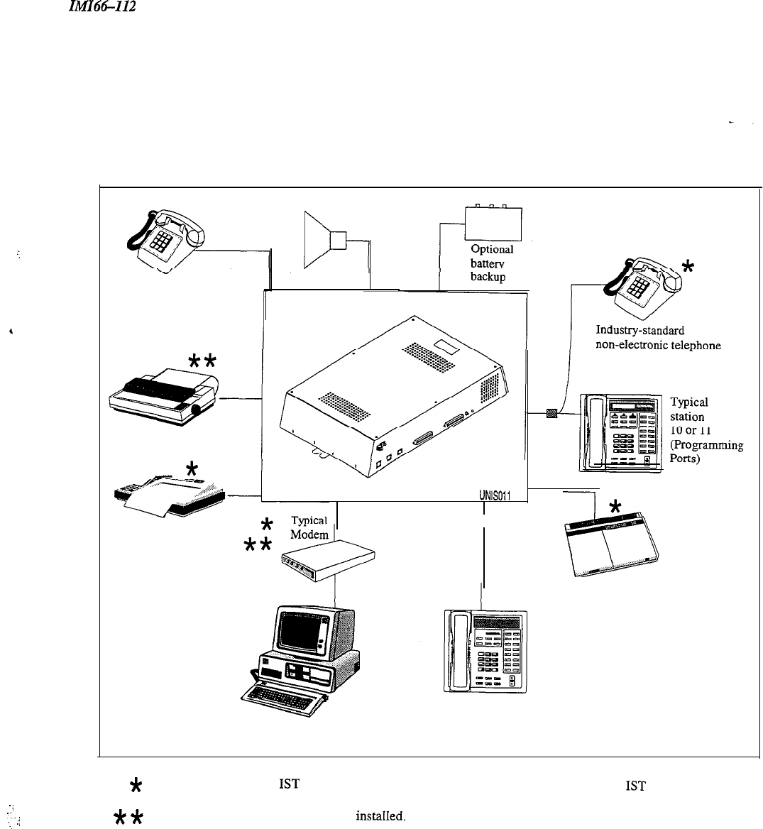
1.3
Getting To Know The System
The Unisyn telephone system provides dozens of different features, and programming options. We have designed
the system so that you, the installer, can customize the operations to fit each customer’s individual telephone needs.
Each system consists of hardware and software. The common equipment cabinet and telephones, for example, are
considered hardware. The software determines what functions you can program into the system.
Figure 1.1
illustrates all of the possible options for the system. For further information on programming, see Chapter 3 of this
manual.
l-2
IMIH-112
System Overview
(,
!
. .
..’
-..
...
.j
Optional PA
Industry-standard
non-electronic telephone
(Power fail interface)
Typical printer
UNISOll
Typical fax machine
Typical
answering
machine
Typical
station
Typical personal computer
(For remote database upload/download)
*
Means YOU must have an
IST
board. (If YOU have TXIST board installed either the bridged
IST
or
stand alone IST can be used for power fail.)
*
*
Means you must have au RS232 board
instahed.
Figure 1.1 System Options
l-3
System Overview
IMI66-112
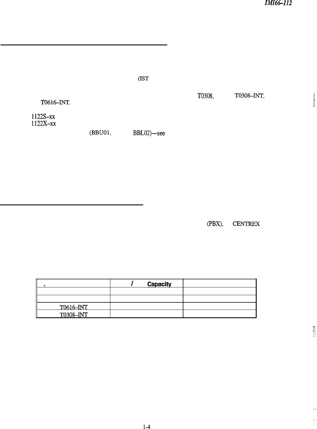
1.4 Understanding The Hardware
Each Unisyn system has the following hardware capabilities:
l
Common Equipment cabinet. Each common equipment unit is full featured for basic operation.
l
Optional Feature Enhancement Circuit Boards (IST Board, Ring Generator, Message Wait Generator, Call
Metering Board, RS232 Board)
l
Telephones. All currently produced Unisyn telephones will work on the TO308, TO616, T0308-INT,
and TO616-INT.
1022%xx
1122s-xx
1122x-xX
l
Optional Battery Backup (BBUOI, BBU02,
BBLM)-see
Section 2.4.2.
1.4. I Knowing The Common Equipment
The common equipment is essentially a special purpose computer system. Common equipment acts as a
communications controller between central office (CO), private branch exchange (PBX), or CENTREX supplied
telephone lines and the proprietary telephone or IST stations. We have designed the common equipment cabinet in a
modem and functional style.
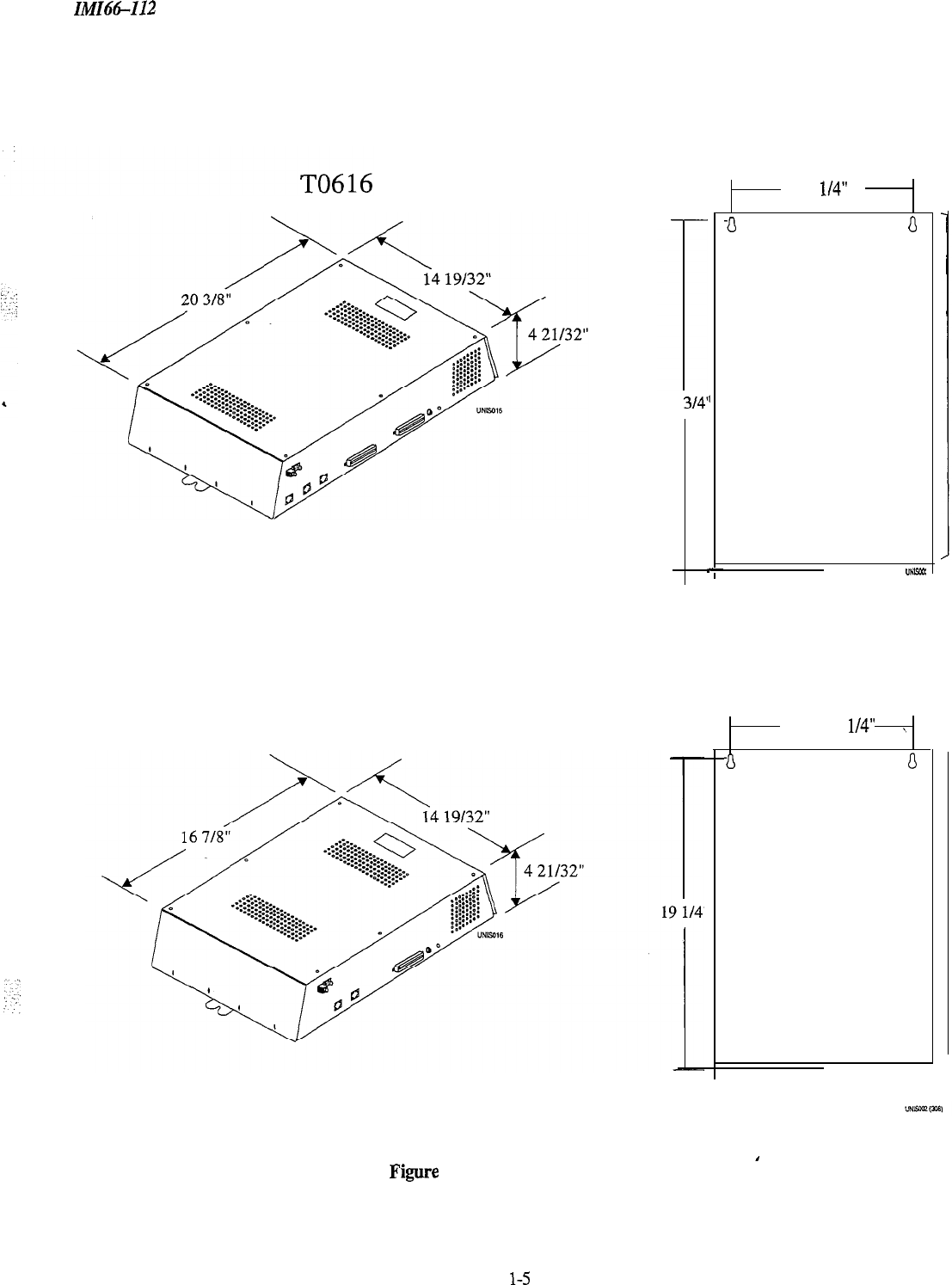
Figure 1.2
shows the four models of the common equipment and their dimensions.
There are four models of the Unisyn common equipment (two for domestic use and two for international use), each
with different station and line capacity.
_
Model Number
CO
/
PBX
CapacrRy
TO616
6
TO308
3
TO616-INT
6
TO308-INT
3
Station Capacity
16
8
16
8
l-4
”
::.
;-
.:
IMICitS-112 System Overview
TO308
23
314’
,
-
12 l/4”
a
0
“NW
12
l/4”
,
a
0
Figure 1.2 Common Equipment Cabinets
l-5
System Overview
IMA%-I12
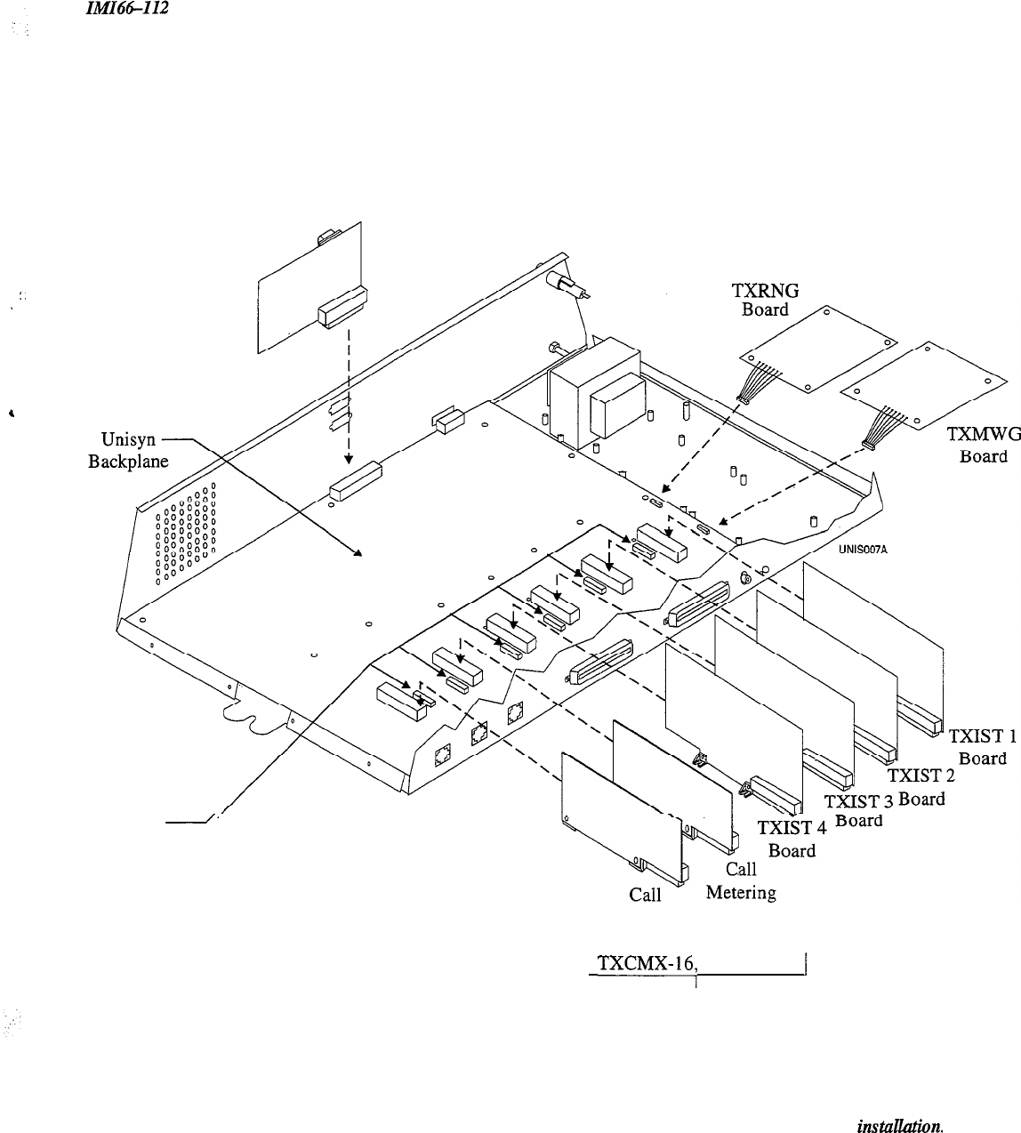
1.4.2 Understanding The Options Boards
You can add any or all of the optional boards into the Unisyn system. The following list describes each board and
its function. Refer to
Figure 1.3
for board installation locations.
l
The Unisyn Industry Standard Telephone (TXIST) Board-makes the
system compatible with IST devices
in addition to proprietary telephones. Adding a TXIST board changes the station ports from proprietary only to
universal ports-universal ports support both proprietary and
/
or IST devices. Each TXIST board converts four
proprietary-only ports to universal ports.
Y
OU
must remove the jumpers next to the corresponding ‘IXJST board
upon installation; the board will not function with the jumpers installed. You must install a TXRNG for IST
::
devices to function. For more information see IMI89-133.
:;
a
l
The Unisyn
Rkg
Generator
(TXRNG) Board-supports the use of industry standard telephones (ISTs) or
other IST devices such as a facsimile machine or modem. The ring generator sends the ring signal that the IST
module (TXIST) needs to ring industry standard devices. You must have a TXRNG if you are using IST
telephones, but you only need one TXRNG no matter how many TXIST boards you install. For more
information see lMI89-134.
l
The Unisyn Message Waiting Generator (TXMWG) Board-also
supports the use of the TXIST board. The
TXMWG generates the message waiting signal that the TXIST board uses to provide message waiting
indication to IST devices. The TXMWG is not required to provide message waiting indication for any
proprietary sets. For more information see lhJI89-135.
l
The Unisyn Call
Metering (TXCMX-16, TXCMX-12) Boards-provide 16 Khz (12
ti
on the
TXCMX-12) transverse call-metering tone detection on three CO lines. When the CO offers call metering
service, the call metering board provides an accurate method of determining the cost of any outside call. You
must remove the jumpers next to the corresponding TXCMX board upon installation; the board will not
function with the jumpers installed. Call metering service normally is not offered in the United States (This
service is only available on TO308-INT, and TO616-lNT). For more information see IMI89-136.
l
The Unisyn Serial Port (TX232)
Board-provides two serial ports for information transfer to and from the
Unisyn system. Use port A for PC Access (defaulting the system, setting the clock, master clearing the system),
or remote-modem programming; use port B for SMDR and Caller ID (Caller ID is a future feature). For more
information see lMI89-137.
NOTE: You must remove the jumpers next to the corresponding TXIST and TXCMX board upon install&on.
The board wiU notfunction with the jumpers installed.
l-6
System Overview
:.
.
,
TX232
Board
TXFNG
*Jumpers
2
Metering
Board 1
Board 2
1
TXCMX-16;
TXCMX-12 1
(International Only)
NOTE: You must remove the jumpers next to the corresponding TXIST and TXCMX
board upon instillation.
The board will not function with the jumpers installed.
Figure 1.3 Optional Boards (TO616 shown)
l-7
System Overview
IMI64-112
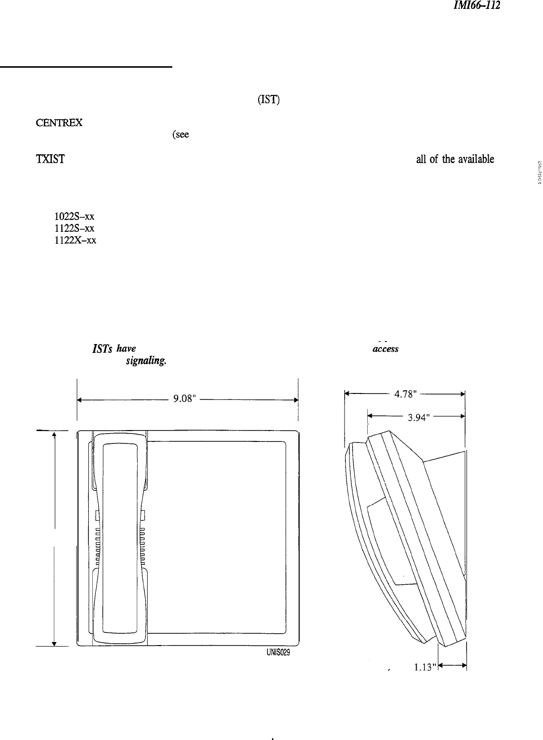
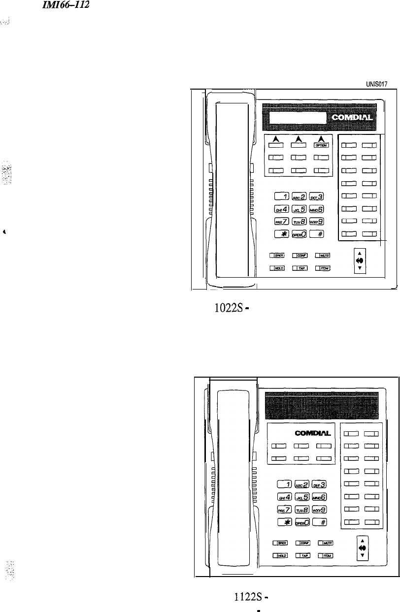
1.4.3 Knowing The Stations
You can install many different types of telephone stations, either proprietary Unisyn electronic
microprocessor-controlled devices, or industry standard, (IST) telephones like the 2500. The stations provide users
with not only multiline pickup but also single button access to features available from the serving CO, PBX, or
CENTREX switch and common equipment. You can program each telephone station to have a unique set of
features and operating parameters
(see
Chapter 3.7). All currently produced Unisyn telephones will work with the
Unisyn system, as will any industry standard telephone, or accessory such as a facsimile machine or modem, (with
‘TM[ST
board).
Figure
1.4 shows a typical station’s mounting dimensions, and figure
1.5 shows all
of
the
av&.d.de
telephones.
You can install all of the following:
.
Proprietary Multiline Unisyn Telephones
1022s-xx
1122s~xx
1122x-xX
l
Industry Standard Telephones-including any Analog Device (facsimile machine, modem)
You must have a TXIST board for IST support.
.
Four-conductor twisted-pair cable (used for multiline station connections).
l
Two-conductor twisted cable (used for single line IST station connections).
NOTE: Any industry-standard device should be fully compatible with a 24 V battery. feed. We also recommend
that
ISTs
have the TAP (Flash) and Positive Disconnectfeatures to have
&cess
to system features
and to
prevent false signuling.
-
8.90”
UNIS0.29
Figure 1.4 Telephone Station Dimensions
l-8 _
IMIN-I12
System Overview
,
UNIS017
If
-4
1
I-
-J,
1022s
-
6-Line LCD Speakerphone
1122s
-
6-Line Speakerphone
1122X
-
6-Line Monitor Telephone
Figure 1.5 Telephone Stations
l-9
System Overview
IiW66-112
1.5
K
nowing The General Specifications
Base Unit
3-Line, 6-Line,
8-Station
16Station
Q-0308, TO308-INT) (TO616, TO616,-INT)
System Capacity
Lines:
3
6
stations:
816
Intercom Paths:
3
6
Proprietary
/
IST stations:
8
lb
Maximum Simultaneous:
Intercom Conversations: 3
6
Power Requirements-Domestic
(Fully loaded system)
AC Power: 117V +/- 10 % 60 H
Z
Single-phase
-
all models
0.4 A 0.8 A
35W
64W
50 VA 80 VA
Heat Dissipation:
120BTU/hr 220BTU/hr
Power Requirements-International
(-INT
models)
(Fully loaded system)
AC Power:
Heat Dissipation:
Dimensions
(approximate)
Common Equipment
Width (inches):
Height(inches):
Depth (inches):
Weight (pounds):
Proprietary Multilme Stations
Footprint (inches):
Weight (pounds):
Station Cable Requirements
Type:
Maximum Length:
Switching Principle:
IST Requirements
12OV/ 220V + 10 %
I
-
14 % Single-phase
-
all models
50/60Hz 50/60Hz
0.4
A(220V
0.3A) 0.8
A(220V
OSA)
35w 64W
50 VA 80 VA
120 Btu
/
h
220Btu/h
14.5 14.5
20.5 24.7
4.7 4.7
19
23
8.9” x 9.08”
2.1
4-wire (2-pair) twisted, non-shielded for multiline telephone,
Zwire
twisted,
non-shielded for IST, using 24 AWG
1000 feet for multiline, 1500 for IST (with 300 Ohm IST device)
Solid-state, space-division analog switching with stored program
control
Only use IST devices that are compatible with 24 V battery ‘service.
Tap (Flash) and Hookswitch Positive Disconnect are recommended features.
l-10
^
:
._
‘:
. .
:
System Overview
IMI64-112
Operating Environment
Temperature:
32
to 122 degrees F (0 to 50 degrees C)
Humidity: Up to 90 percent relative, non-condensing
Terminations
Station: Standard 50-pin female connectors for connection to external distribution field
Line: Standard, 4-conductor mini-jack (USOC 14C)
Station Message Detail Recording Port (Default)
Format:
Parity:
Data Bits:
StopBits:
Baud Rate:
Handshaking:
Serial, pseudo RS-232C
None
8
Cable Length:
Music Interface
Input Level:
Input Impedance:
Connector:
Central Office Limits
Loop Limits:
Cable Insulation
Leakage:
Industry/Regulatory Standards
1
1200
Xon
-Xoff
CTS
/
RTS Available
500 Feet maximum
3 Volts peak-to-peak maximum
Approximately 600 Ohms
RCA phono jack
1,900 Ohms maximum loop DC Resistance
15,000 Ohms minimum
FCC Part 15, Class A
FCC Part 68
DOC
Listed by OSHA-accredited, nationally recognized test laboratory to UL and CSA
safety standards.
EIAITIA-464-A
Memory Retention After Power Loss
70 hours minimum (typically 200 hours)
Clock Retention After Power Loss
Minimum 24 hours
FCC Registration-Number
CVW7WC-12829-KF-E
CVW7WC-16553~MF-E
(Key System) (Hybrid System)
Ringer Equivalence Number
0.4B
Load Number 4.0
Product Codes
3 x 8 System
TO308
6 x 16 System TO616
3 x 8 System (International) TO308-INT
6 x 16 System (International) TO616-INT
Universal IST Board TXIST
Call Metering Board TXCMX-16, TXCMX-12
Ring Generator Board TXRNG
Message Wait Board TXMWG
RS-232 Board TX232
6-line LCD Speakerphone 1022s-xx
I
6-line Speakerphone 1122s~xx
6-line Monitor Telephone 1122x-xX
l-11

System Overview
IMIM-112
1.6
Seeking Technical Assistance
We have designed the Unisysn system and its accompanying manual to be so easy to use that you can install and
program the entire system without any additional assistance. If, however, you should run into a problem in
installation, checkout, or programming that
you
cannot solve, we have a technical support number that you can call
for assistance. This service exists for you to use in
emergency
situations-it is not an alternative to using the
manual. Should you need to call the technical services number, make sure you are on-site with the equipment and a
copy of this manual, opened to the appropriate page. Please don’t call for technical support until you have
thoroughly read through the appropriate section of the manual and tested the problem. For assistance, call the
following number:.
Comdial
Technica
Service staff-l-800-366-8224
7.6.7
Repair Service
If your common equipment or an individual station should need repair after the warranty, you may return the
defective equipment to Comdial. Comdial will, at their option, either repair the equipment or replace it with a
remanufactured unit. There is a fixed charge for a repair. For information on repair charges, please call or write to
the following address:
Comdial
P.O. Box 7266
Charlottesville, VA 22906-7266
Attention: Repair Department
Telephone Number: (800) 8774448 (Outside the United States, call (804) 978-2200)
When returning equipment for repair, pack it carefully to prevent damage. Any damages incurred during shipment
will be the responsibility of the purchaser. Always ship the equipment freight or postage prepaid. The shipping
address for reparations is as follows:
Comdial
1180 Seminole Trail
Charlottesville, VA 22901-2829
Attention: Repair Department
1-12

IMI66-068
./
System Overview
1.6.2 Finding The Fuses
Comdial has included a fuse in the common equipment to protect it against short circuit damage. The fuse
G
located
on the left side of the common equipment cabinet. If you should need to replace a fuse, always replace the fuse with
one of the same value and type; otherwise the equipment could be damaged. Refer to the following list when
replacing a fuse:
.
TO308,l-II308-INT-O.5A, 250V Slow-Blow
.
T0616,
TO6164NT--lA,
250V Slow-Blow
::’
i
:
::
.:
1-13
In!fIM-112 Installing The System
:
,.:
Installing The Unisyn System
2.1 Using This Chapter
2-
1
2.2 Using The Right Tools 2-l
2.3
InstaIXng
The Cabinet
2-2
2.3.1
Mounting The Cabinet
2-2
2.4
Connecting The Power 2-4
2.4.1 Connecting AC Power 2-4
2.4.2 Connecting A Battery Back-up
2.4.3 Grounding The System 2-7
2-6
2.5
Connecting The Lines
2-8
2.5.1 Connecting The Line Jacks
2-
10
2.5.2 Protecting The Lines
2-11
2.6
Connecting The Stations 2-12
2.6.1 Understanding Station Connections
2-12
2.6.2 Understanding Paired Ports Overload Protection 2-12
2.6.3 Connecting The Station Cable Clips 2-12
2.6.4
Connecting A Three Line, Eight Station
Common Equipment Cabinet
2-14
2.6.5
Connecting A Six Line, Sixteen Station
Common Equipment Cabinet
2-15
2.7
InsMing
SystemOptions 2-16
2.7.1 Understanding A Key System or Hybrid System
2-
16
2.7.2 Connecting A Power Failure Station 2-17
2.7.3 Connecting A Common Audible and Auxiliary Station Interface
2- 18
2.7.4
Connecting An External Paging Interface-Station PA Port
220
2.7.5
Connecting An External Paging Interface-Line PA Port
2-21
2.7.6 Connecting A Data Device 2-22
2.7.7 Connecting A Music Interface 2-24
2-i

Installing The System
IMI66-I12
2.8
Checking The System
2-25
2.9
2.8.1
Checking The Installation and Wiring 2-25
2.8.2 Checking The Wiring Resistance to Ground 2-25
-
2.8.3
Powering Up The System And
Doing A General Check
2-25
2.8.4 Checking The DC Voltages to The Station Ports
2-25
2.8.5 Checking The Default Conditions
2-26
2.8.6 Checking The Battery and Battery Charged DC Voltages
2-26
Isolating System Failures
2-27
2.9.1
Checking The System Status Indicator
2-27
2.9.2 Doing A Station Self-test 2-27
2.9.3
Checking Failure Indications
2-27
2.10 Installer
/
User Information-FCC Rules
2-28
2-ii
Installing The Unisyn System
:::.
.,
..:.:
:
,\.:
:
2.
I
Using Chapter Two
Chapter two provides you with a step-by-step procedure for installing the Unisyn System. We have presented the
information in the
most
common
orderfor
instdution
and recommend that you follow the manual when installing.
Always do a pre-installation check to make sure you have the necessary equipment and documentation.
Use the following list as a general guideline for installing the system. This list is by no means the only possible order
for installation.
1.
Unpack the system and read through this manual
2.
Select the correct tools (2.2)
3. Install any option boards into the common
equipment (see corresponding publication(s))
4.
Mount the cabinet in a suitable location (2.3)
5.
Mount the punch-down blocks and any
auxiliary equipment
6. Mount the battery backup, but don’t connect
the battery (2.4.2)
7. Wire earth-ground to Common Equipment (2.4.3)
8. Wire the CO Lines to the Common Equipment
(2.5)
9. Wire-station connector to Common Equipment
(2.6)
10.
Wire the stations to the station connector (2.6)
11. Connect auxiliary equipment-for
example, music interface, or data device (2.7)
12. Inspect all wiring (2.8.1)
13. Check DC resistance of stations and lines to
ground (2.8.2)
14. Power-up system (AC); check green LED (2.8.3)
15. Check DC voltages of stations (2.8.4)
16. Check Battery and Battery Charger DC voltages
(2.8.5)
17. Connect Battery Backup (2.4.2)
18. Master clear the system (3.4)
19. Check default functionality (2.8.6)
20. Program the system
“.
..,
2.2 Using The Right Tools
As
a minimum, the tools and hardware required for installation include the following:
0
Fasteners-wood screws
(*/4
x l-inch round head), toggle bolts, or wall anchors
0
Screwdriver-to match fasteners
0
Electric
drill-
if prepared holes are required
j-J Connecting tool-for fastening wires to a type-66 connector block
[I3
Crimping tool-for 623-type modular plugs
q
Volt-Ohm Meter-for testing power source, CO Lines, and Stations
2-l
Installation
IMI66-112
2.3
/nsta//ing The Cabinet
Before you mount the cabinet, consider the following list in the layout and connection of the telephone system.
It
might be helpful to put a check-mark in each box as you complete that task.
0
Attach the common equipment cabinet vertically to any sturdy flat surface. You may vertically rack-mount the
system.
0
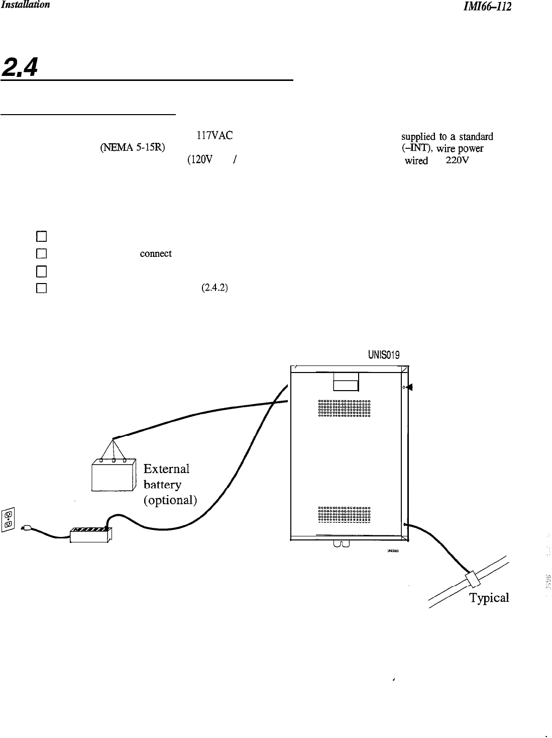
Locate the cabinet within four feet of a proper electrical outlet. The system requires a dedicated 117VAC
15 AMP circuit, with a third-wire ground, supplied to a standard electrical outlet
(NEMA
5- 15R).
0
FCC requirements state that the distance between the common equipment and the TEZLCO/PBX jacks must be
25 feet or less. We recommend that you use a nominal distance of 7 feet.
0
Make sure the mounting location is secure and dry and has adequate ventilation. The temperature range of the
location must be within 32 to 122 degrees F (0 to 50 degrees C), and the relative humidity must be less than 90
percent non-condensing.
0
If the mounting surface is damp or if it is concrete or masonry material, attach a backboard to the mounting
surface to be used for common equipment mounting. Suitable mounting backboards are available commercially
or can be constructed out of
l/2-inch
plywood cut to size.
0
If you choose to install battery backup, install the optional external batteries, cable assembly, common
equipment, and the wiring connections in a dedicated equipment room-except for BBLO2 (as defined in the
NationaZ Electric
Code published by The National Fire Protection Association, Quincy MA, 02269).
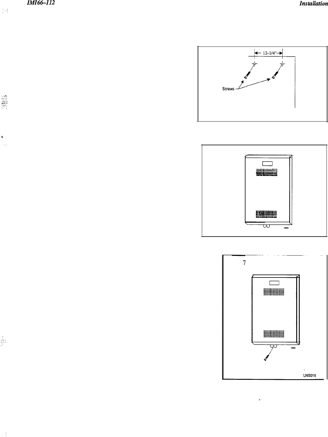
2.3.1 Mounting The Cabinet
1.
Unpack and carefully inspect all equipment for shipping damage. Notify the shipper immediately of any
damages. Verify that the packages contain all parts and accessories needed for proper installation and operation.
2.
If you use a backboard at the mounting location, attach it securely to provide a stable mounting surface for the
equipment.
3.
Mark the locations for the screws on the mounting surface (see step five for the mounting dimensions).
4.
Drill holes in the mounting surface of a proper size to accommodate the hardware being used. If necessary,
prepare these holes with inserts, anchors or other attachment devices as dictated by the type of mounting.
2-2
IMId&
InstaUation
5.
:
“1!
....
‘:
,“:,:
:;-
,:-
:
Insert the two top screws into the mounting surface and
tighten them to within approximately l/&inch of the
surface.
6.
Hang the cabinet on the top screws using the mounting
holes located on the rear of the cabinet. Note that these
holes are elongated with an enlargement at one end.
This feature allows the cabinet to slide down on the
screws to secure the mounting when the cabinet is hung
on them.
7.
Insert and tighten a third screw through the mounting tab
located on the lower edge of the cabinet and into the
mounting surface.
:
:?
:’
.’
Step 5
Step 6
_.“.I...
.
.
.
.
.
I_.“........
-.-^.“-...-
.
.
.
.._.“_.“...
-.-...-
.
.
.
.
.
.
.
..^.I........
.
..“I.““.“...
.
.
.
..“...“._...
.
.
.
..-.“....._
.
..--.......-...
.
.
.
.
.
.
..“-.-...
I......“...“...
Step
7
Figure 2.1 Mounting The Cabinet
2-3
Instullation
IMI66-112
2
I
4
Connecting The Power
2.4. I Connecting AC Power
For a domestic system, use a dedicated 117VAC 15 AMP circuit, with a third-wire ground,
supplied
to
a stand&
electrical outlet (NEMA 5-15R) for the AC power connection. For an international system (-INT), wire
power
supply according to input AC voltage (12OV AC
/
220V AC). International systems default wired for 22OV AC (see
figure
2.3.
Be sure to adhere to the following when connecting the power:
q
A plug-in power line surge protector should be installed between the power cord and the AC outlet
(see 1.5 for surge protector specifications).
0
Do not connect the AC power cord until you have checked the installation.
0
To apply AC power,
COMeCt
the
power cord to the electrical outlet through the power-line surge protector.
0
Do not attach power cord directly to the building surface.
0
Read the sections on battery backup (24.2) and system grounding (2.4.3) before you apply power to the system.
”
Surge
protector
UN6019
/
,
Figure 2.2 AC Power Connections and Grounding
2-4
-Status
indicator
earth
ground
.
Ilwtx-112
TO308
TO616
Domestic 120 VAC
Installation
,.
.:
:
.:
,
T0308-INT
T0616-INT
International 120 VAC
Fuse Holder
Main PWB
T0308-INT
T0616-INT
International 220 VAC
Fuse
Holder
c
I-
-t---
I
Main PWB
Figure 23 Domestic and International Power Connections
2-5
Instulktion IMI66-112
2.4.2 Connecting A Battery Back-Up
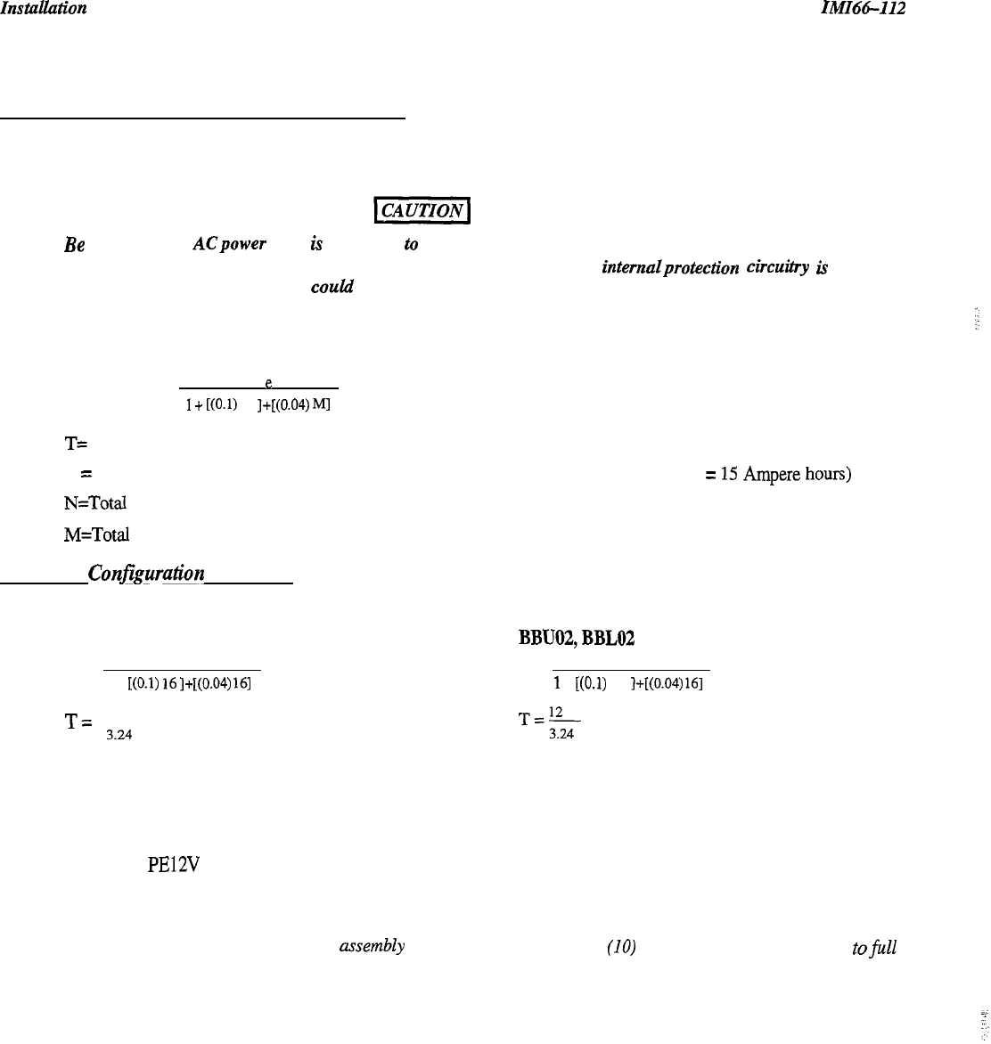
The common equipment provides an interface connector for the connection of an optional external battery assembly.
This assembly is available separately as a kit.
Be
sure that the
ACpower
cord is connected
to
the electrical outlet before connecting the external battery
assembly to the common equipment interface connector; this ensures that internalprotection circuitry is
operating to prevent damage that CoUld result from improper connection.
The optional Comdial model BBUOl, BBU02, BBL02 external battery assembly provides a minimum of one hour of
operation should the AC power to the system be interrupted. To calculate the actual minimum battery back-up time
use the following equation:
T=
(0.8)
e
1
+
[(O.l)
N
]+[(0.04)
M]
T= Back up time in hours for multiline telephones
e = Ampere-hour capacity of batteries (BBUOl, e = 6.5 Ampere hours; BBU02, BBL02, e =
15
Ampere hours)
N=Total Number of Mulitline Stations
M=Total Number of IST Stations
Maximum Conjiguration Examples
The following two equations demonstrate how to calculate the battery backup time for a fully loaded system.
BBUOl
BBU02,BBLOZl
T=
(0.8) 6.5
T=
(0.8) 15
1 +
[(O.l)
16]+[(0.04)
161
1
+
t(O.1)
16
]+[(0.04)
161
T=
5.2
3.24
(1.6 hours of backup time)
T=$
(3.7 hours of backup time)
The BBU02 external battery assembly may include batteries from either of the following suppliers:
.
Model PS-12150 from Power-Sonic Corporation, Redwood City CA, 94032.
.
Model PE12V 15 from GS PORTALAC, City Of Industry CA, 9 1748
During AC operation, the common equipment provides recharging current to maintain the voltage potential of the
external battery assembly at an operational level.
NOTE: The optional external battery
assembly
requires approximately ten (IO) hours to completely recharge tofu11
potential after it has been completely discharged and, in some cases, when initially installed.
2-6
IMI66-112
hlStallatiOTl
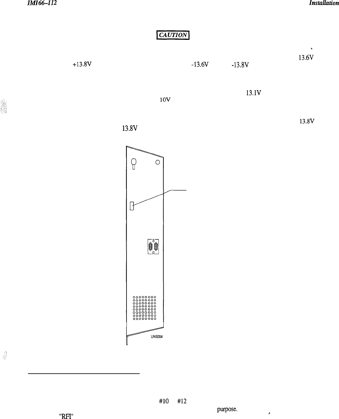
Before installing a battery backup, check that the following voltage measurements are all accurate:
_
l
Correct voltage of battery charger circuit without the batteries connected is as follows: between + 13.6V DC
and +13.8V DC for the positive battery and between -13.6V DC and -13.8V DC for the negative battery
(contact Comdial if the voltage is higher or lower),
l
Nominal voltage of each of the batteries is 12V DC,
l
Each fully charged and disconnected battery should not exceed a voltage of 13.1V DC. A completely
discharged battery may check as low as
1OV
DC,
When the battery backup is installed and the system is powered, check the following:
l
Each fully charged battery connected to the system should have a voltage of less than or equal to 13.8V DC (if
the value is greater than 13.8V DC, contact Comdial).
NOTE: The typical battery service check is every three months.
.
.
.:i
:,:
2.4.3 Grounding The System
7
Out To Battery
Backup
The common equipment cabinet has internal secondary surge protection on all line ports. In order for this protection
to be effective, you
must
connect the cabinet to a reliable earth ground such as a metal cold water pipe or a building
frame ground. The grounding wire
must be
#lO
or #12 insulated, solid copper and separate from the three-wire AC
line cord. the common equipment cabinet has a ground stud for this purpose. In addition, this ground also serves as
an “RFI” ground that reduces the possible effects of radio frequency interference.
’
2-7
Installation
IM66-112
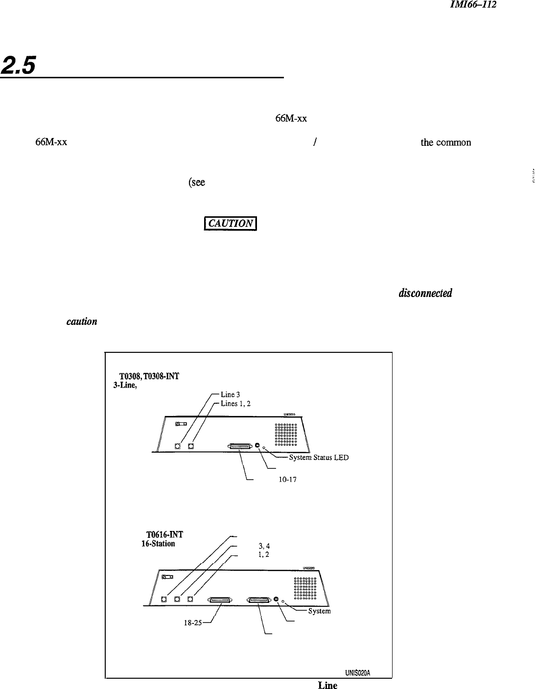
2.5
Connecting The Lines
Once you have mounted the common equipment, it is time to begin connecting the telephone lines.
Connect the common equipment
telephone
line jacks to a Type 66M-xx connector block and then connect that block
to the telephone company’s demarcation point. Individual 4-position modular jacks may be used instead of the type
66M-xx connector. We recommend the use of an external lightning
/
transient protection
between
the
common
equipment and the telephone company line connections (see Section 2.5.2).
The line connections for the common equipment cabinet are standard modular plug/jack connections. Each modular
jack provides termination for two lines
(see
figure
2.4).
Use twisted-pair wiring for the line cord that you route
between the outside line termination and the common equipment termination. Table 2.1 shows the line connection
details for all four of the common equipment base units.
Figures
2.4 and 25 illustrate typical line connections.
Refer to the following list when installing any telephone lines:
I. Never install telephone wiring during a lightning storm
2.
Never install telephone jacks in wet locations unless the jack is specifically designedfor wet locations.
3.
Never touch uninsulated telephone wires or terminals unless the telephone line has been disconnected at the
network interface.
4.
Use caution when installing or modifying telephone lines.
TO308,
T0308-INT
3-Line,
I-Station Unit
L
Music Jack
Station
lo-17
Station 17 Audible Relay Contacts
Common Audible Relay Contacts
T0616,
T0616-INT
C-Line,
164tation
Unit
Lines 5, 6
Lines
3,4
Lines
I,2
Station
18-25l
Status LED
L
Music Jack
Station IO-17
Station 17 Audible Relay Contacts
Common Audible Relay Contacts
UNISOPOA
Figure 2.4 Typical Common Equipment Line Connections
2-8
IMI66-112
I
Instuhtion
T0616,
T0616-INT
Typical Common
RING 2
RING 1
RING 6
Telco/PBX
Connection
-
-
I
4
.INETERMlNATiON
‘TYPE
66M-XX
CONNECTOR BLOCK
OR
. INDIVIDUAL
6POSITION
MODULAR JACKS
UNIS025A
ILL
(-01
n,
co2
T5,
co5
T6,
R6
(-06
.
Figure 2.5 Typical Common Equipment to CO Line Connections
2-9
I?lStUUatiO?l
IMI66-I
I2
25.7
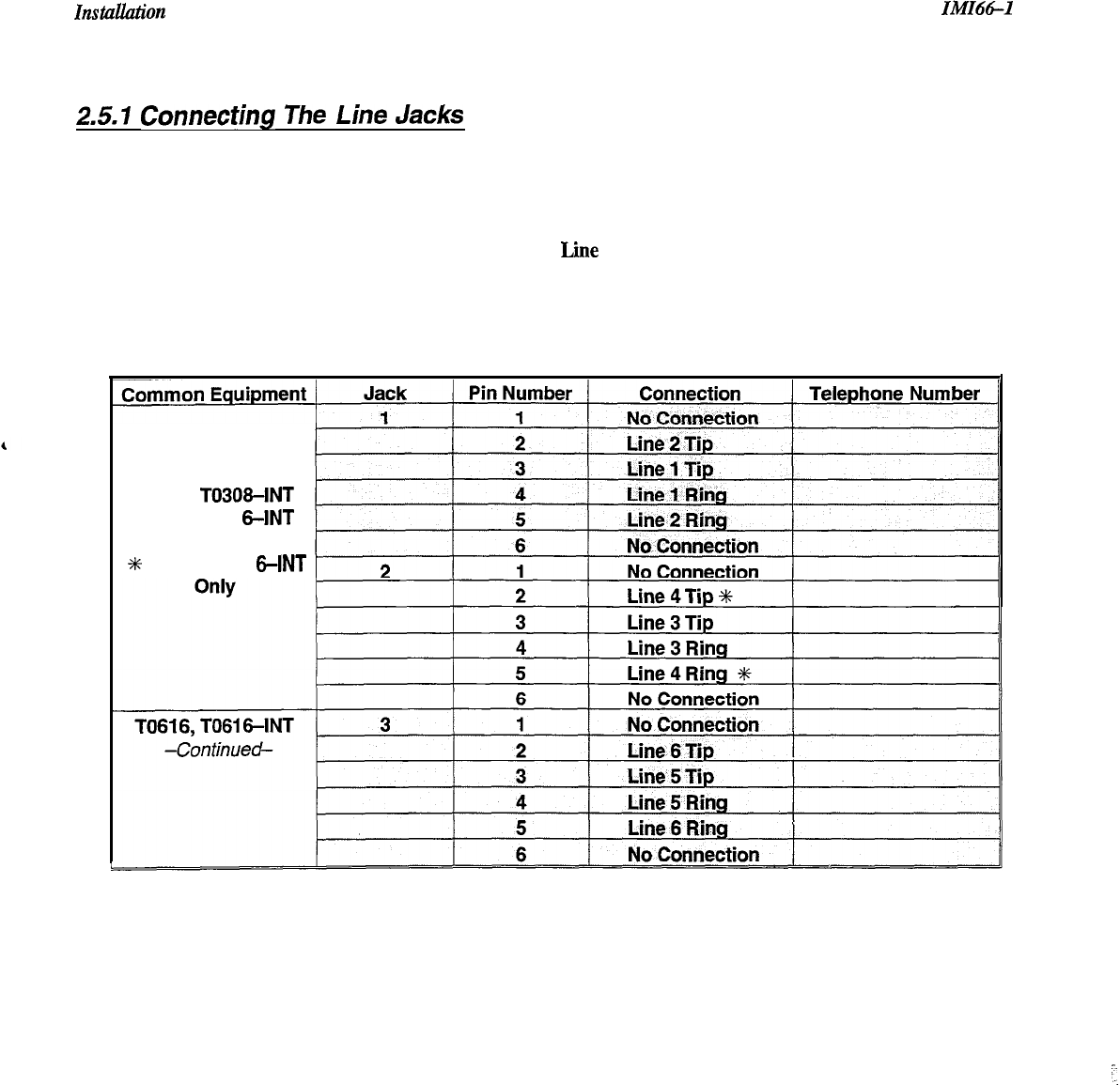
Connecting
The
Line
Jacks
Table 2.1, below, shows the connections for each line on each
common equipment cabinet.
Table 2.1
Lie
Connections
T0308,
T03084NT
TO61 6, TO61
6-INT
5
TO61 6, TO61
6-INT
2-10

IMZ66-112 I?lstullution
2.5.2 Protecting The Lines
Transient voltage spikes, if induced onto CO or CENTREX lines, can travel through the cable and into thecommon
equipment. The telephone company offers basic protection against this condition but it is usually designed to protect
the central office circuits. While this supplied surge protection will also provide some protection to the common
equipment, it should not be relied upon for total protection. To help ensure that external over-voltage surges do not
damage the system, we recommend that you install and properly ground gas discharge tubes, or similar primary
protection devices, on all lines.
2-11
znst4zl&ion
ZMZ6tLZZ2
2=6
Connecting The Stations
Usually, the connections you make between the common equipment and the stations are via type 66M-xx connector
blocks that are cable connected to the common equipment Xl-pin male connector. The maximum total distance
allowed from the common equipment to the stations is 1000 feet for multiline telephones and 1500 feet for industry
standard telephones using #24 gauge, twisted-pair cable.
If spare conductors exist in the cables that are run between the 66M-xx connector blocks and the station jacks, it is a
good practice to connect them to earth ground to help prevent them from inducing radio frequency and/or
AC
interference into the system.
i
The polarity between the individual wires in a particular voice or data pair is not critical; however, do not connect
the voice circuits to the data circuits, and do not connect wires from adjacent stations together.
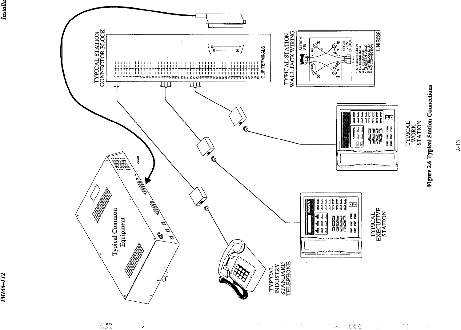
Tables 2.2-2.3 show the station connection details for all four common equipment base units.
Figure 2.6
illustrates typical station connections.
2.6. I Understanding Station Connections
Multiline proprietary stations require connection to both the voice and data pair of a station port (for example, station
10, 11) If you have installed
‘EXIST
card(s), you can also connect an IST device to the mulitline station port
(see Section 1.4.3). Connect an IST device to the voice pair of the station port only.
q
The 6- line, l&station base unit (TO616, TO616INT) has ports 10 through 25
c]
The 3- line, g-station base unit (TO308, TO308-lNT) has ports 10 through 17
2.6.2 Understanding Paired Ports
Overload Protection
Station ports are paired for overload protection. Because of this power pairing, a problem with station ten
may
actually manifest in station 1 l-keep this in mind when you are troubleshooting. The station ports are paired as
follows:
Overload Pairing
10-11
12-13
14-15
16-17
18-19
20-21
22-23
24-25
2.6.3
Connecting The Station Cable Clips
Each cabinet-mounted 50-pin male connector has a retaining clip, which secures the mated connection. The clip
secures the connection by snapping into a slot on the cable-mounted connector. You must pull back the retaining
clip to unsnap it before you can separate the connectors.
2-12
-
;,,i;i;
‘..:-:;Ci’;.
4
InstuUation
IMI64-112
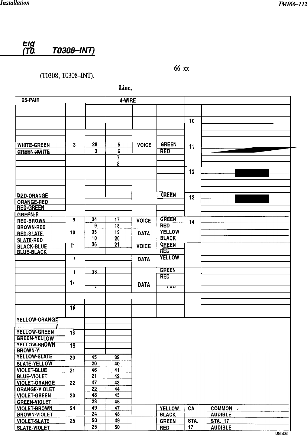
2.6.4 Connecting A Three Line,
Ei ht Station Common Equipment
(T9
0308,
TO308-INT)
Table 2.2, below, shows the color coded connections on a type 66-xx connector block for a three line, eight station
system (TO308, TO308-INT).
Table 2.2 Three Line, Eight Station Common Equipment Connections
25.PAIR
CABLE CONNECTION
S
4-WIRE
CONNECTIONS J-l CONNECTIONS
PIN CLIP
WIRE
WIRE COLOR PAIR NO.
TERM. PAIR COLOR STA. LOCATION
WHITE-BLUE
1
26
1
VOICE
GREEN
I9
BLUE-WHITE
1
2
RED
WHITE-ORANGE 2 27
3DATA
YELLOW
ORANGE-WHITE
24BLACK
iREEN
ii
1
-..--..
.
.
.
.
.
.-
~1ED
WHITE-BROWN 4 29
;
DATA
YELLOW
BROWN-WHITE 4
aBLACK
WHITE-SLATE 5
30
9VOICE
GREEN
SLATE-WHITE 5
10 RED
RED-BLUE 6
31 11 DATA
YELLOW
BLUE-RED 6
12 BLACK
RI
iREEN
ZD-ORANGE
1 7 1 32 1 13
1
VOICE
/d
NGF-RED
I 7 I I4 / RED
RFD-GRFFN
8 33 I
15 DATA
YELLOW
ED
8116
BLACK
”
l2
l3
li iREEN
1
11
22 /
Fl
,cn
15
BLACK-ORANGE 1:
)
137 123
112 1
1
DATA
j
&w
ORANGE-BLACK 24 /
BLACK
BLACK-GREEN 1:
3
’--
38
’--
25 IVOICE
I:
‘rREEN
GREEN-BLACK
13
26
*rn
lirv
16
_
BLACK-BROWN
ll
I
39 27 YELLOW
BROWN-BLACK .
_
14
28
DATA
__
__._
BLACK
BLACK-SLATE
15 40 29 VOICE GREEN
SLATE-BLACK
15
30
RED
17
YELLOW-BLUE
lf
BLUE-YELLOW
YELLOW-ORANGT
ORANGE-YELLOV
5
41 31
’
DATA YELLOW
I16 32
BLACK
,I
E
17 42 33
v
17 34
3
43 35
.ow
18 36
OWN
19
44 37
ELLOW 19 38
UNISOS:
2-14
IMI66-112
Installation
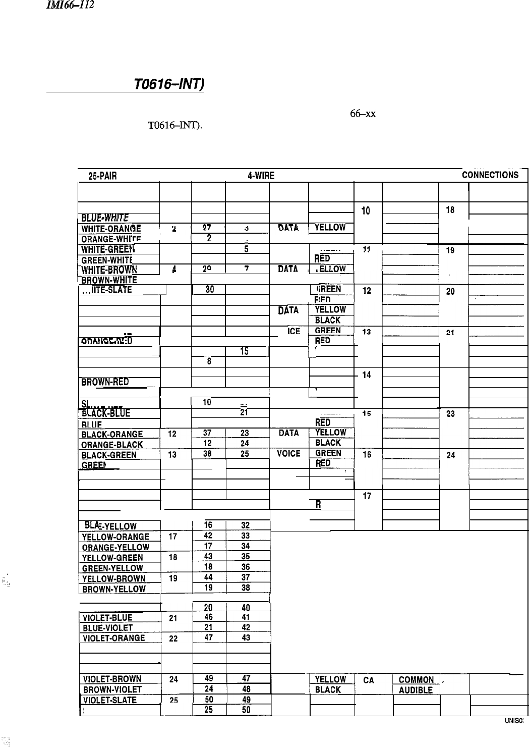
2.6.5 Connecting A Six Line,
Sixteen Station Common Equipment
(T0616,
TO6164NT)
Table 2.3, below, shows the color coded connections on two type
66-xx
connector blocks for a six line, sixteen
station (T0616,
TO616-INTI.
Table 23 Six Line, Sixteen Station
Common
Equipment Connections
25-PAIR
CABLE CONNECTIONS 1
4-WIRE
CONNECTIONS 1J-1
CONNECTIONS
/J-2
CONNECTIONSm
1
PIN
1
CLIP
1 1
WIRE
WIRE COLOR PAIR NO.
TERM. PAIR COLOR STA. LOCATION STA. LOCATION
WHITE-BLUE
1
26
1
VOICE
GREEN
10 18
“LUE-WHITE
1
2RED
. .
..--
--.
..--
n-
.
l....r.
-
l-----
;F
I
“‘ILOW
121
4II
BLACK
;G”l
,t-“llANQ
ORANGE-WHI:
r
WHITE-GREEN
GREEN-WHIT
WHITE-Pnn#.u
RRnWN
I I
,I.
3 28
;
VOICE
GREEN I
1,
I
‘E
36
R
l,&l ”
90
7
nATA
VI
-..-....
,,,,....-WHITE
(
’
1
4 1
a
1 BLACK
WC
IITE-SLATE
pA
5
1
39
I
9
j VOICE
p
.
.
.
.
SLATE-WHITE 5 10
I
Fi
RED-BLUE
6 31
11
DP
BLUE-RED
6 12
RED-ORANGE 732
13
vo
nRANCE.RF
_-
“IIraI.“-
..-
ED
71ii
tT
RED-GREEN
A
8133 1
15
1
DATA
j-’
GREEN-RED
RED-BROWN
BRO\rYN-RED
RECI-SLATE
SI
ATF.RFD
-
YELLOW
-8
16 BLACK
9 34 17
VOICE
GREEN
9
18
RED
-I_I
10 1 35 I 19
j
DATA
c
YELLOW
10
I 20 II BLACK
--.-
..--
I
!I
AC&BLUE
11
36 1
ii
VOICE
GREEN 1
lr;
I
-BLACK
11
122
R
14
22
I-BLACK 13 26,
R
BLACK-BROWN
14 39 27 DATA YELLOW
BROWN-BLACK 14 28 BLACK
BLACK-SLATE
15
40 29
SLATE-BLACK
I1 15 I 30 I
R
S
YELLOW-
41 I 31
VOICE 1 GREEN
17
25
ED
DATA 1 YELLOW
CK
-ORANGE / 17 I 42 I 33 I
~“,
IBLA
.
.
.
.:,
..-:
YELLOW-SLATE
j
20 I 45 1 39
i
SLATE-YELLOW
ORANGE-VIOLET
22 44
VIOLET-GREEN 23 40 45
_
GREEN-VIOLET 23 46
GREEN
STA.
STA. 17
SLATE-VIOLET RED
17 AUDIBLE
UNISO:
2-15
ZnstuUiztion ZMZt%-I12
2.7 Ins falling Sys
tern
Options
‘Ihe Unisyn system offers several options that are not part of the regular installation of the common
equipment.
YOU
may consider an option board or a power failure station connection, for example, as a non-mandatory installation
option. The following is a list of the non-mandatory options:
l
Power Failure Station(s)--Addition power fail stations are available through the use of a I’XIST Board
l
Common Audible Interface
.
Auxiliary Station Interface
.
External Paging Interface-Station PA Port
lExternal Paging Interface-Line Port
l
Data Device (Through the TX232 Module)
l Music Interface
2.7. I
Understanding a Key System /Hybrid System
The Unisyn telephone system automatically assumes the hybrid mode whenever a programmer assigns lines to line
groups (see Section 3.6.5). The hybrid system may have a higher monthly tariff from the telephone company, so the
FCC requires that the installer report the equipment category designation number (KF for key system, MF for hybrid
system) to the telephone company at the time of installation.
2-16
IMI66-112
Instuulztion
;
,
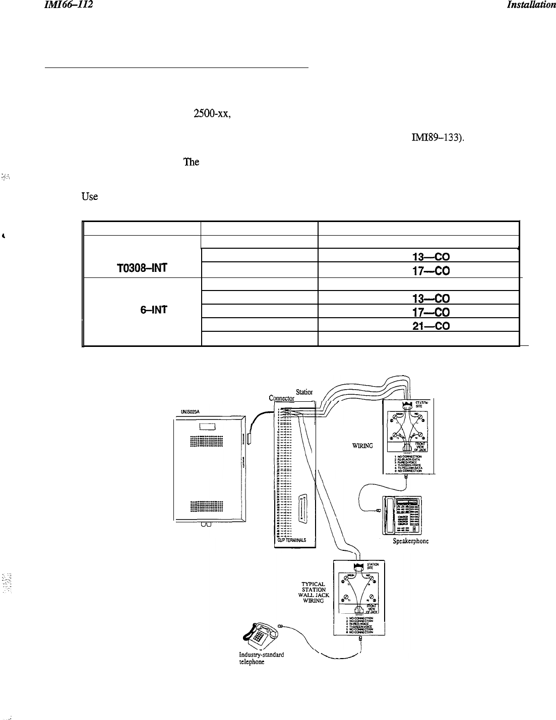
2.7.2 Connecting A Power Failure Station
:ze
.:)
The base system provides a power-fail circuit that connects the voice pair (Tip and Ring) of certain station port(s) to
the line port(s) in the event of a commercial AC power failure. You can connect an industry-standard, single-line
telephone, such as a model 2500-xx, to the appropriate station ports and use those station(s) to provide
communications capability until the AC power to the system is restored. Connect only the voice pair (T and R) to
the IST telephone. Each TXIST board provides an additional power-fail relay (see IMI89-133). If you have
installed TXIST board(s), the regular Station IST device can also serve as the power-fail IST device for the
appropriate station port. The power failure is detailed in
Figure 2.7,
below.
NOTE: When power is interrupted or restored, the powerfail relays will interrupt calls in progress.
Use
the following chart for power-fail reference.
System Configuration
Base System Power Fail Connection
Station IO-CO 1
TO308
T0308-INT
TO61 6
TO61
6-INT
TXIST in Slot 1
TXIST in Slot 2
Base System
TXIST
in Slot 1
TXIST in Slot 2
Station
13-CO
2
Station
17-CO
3
Station
1
O-CO 1, Station 1
I-CO
2
Station
W-CO
3
Station
17-CO
4
TXIST in Slot 3
TXIST in Slot 4 Station
21-CO
5
Station 25-CO 6
Typical
Statior
Cymtor
Block
TYPICAL
STATION
WALL JACK
WlRlNc
LCD
Spcakcrphone
Data LCD Only
Indusuy-standard
t&phone
(Power fail interface)
Figure 2.7 Typical Power Failure Station Connection
2-17

Znstallwion
zM166112
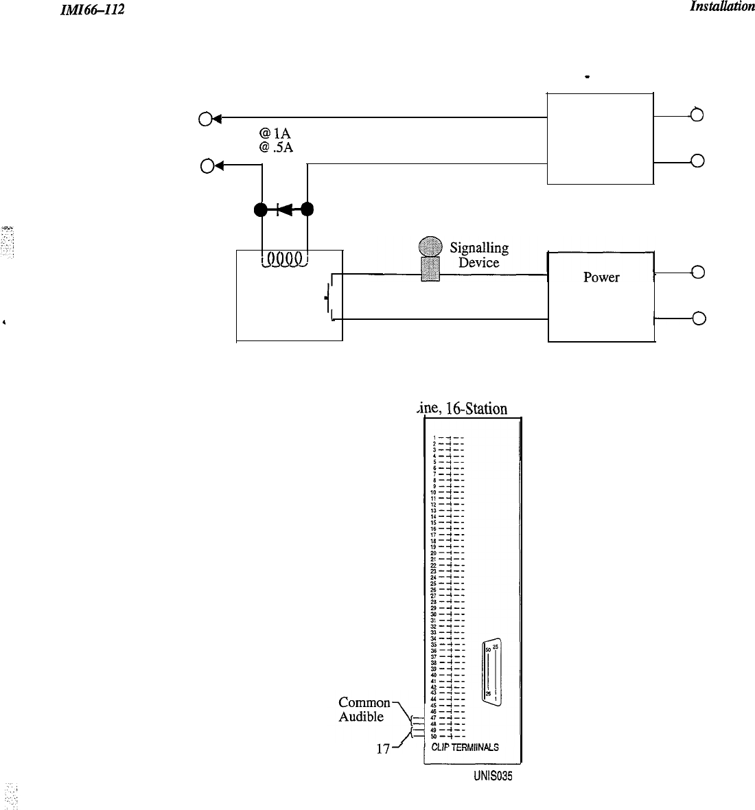
2.7.3 Connecting A Common Audible
And
Auxilraty
Station Interface
You can connect an external audible ringer, such as a loud bell or flashing light, that will operate when the system
receives an outside call. The contact points for this operation are dry, meaning that the external ringer or light must
have its own power supply.
There are two different ways to install an external ring indicator device. The two sets of relay closures with dry
contact points are as follows:
l
One set (common audible) provides a dry-contact relay closure whenever any
ofthe
outside lines, connected to
the common equipment, ring.
l
The other set (station 17 audible) provides a dry-contact relay closure whenever station 17 rings. You must
program the lines that you want to ring on station 17 (station 17 defaults to all lines, and you must remove the
lines that you do not want to ring the external ringer).
These contact closures track the ringing pattern in both cases. The contacts are closed during the
ringing
period and
are open during the silent period.
p?izEq
Do not exceed a load of 1 amp at 24 volts (0.5 amp at 48 volts) on these control terminals.
If
the
load
requirements exceed this limit, connect the
load
through an external she
relay
Do not connect these control
terminals directly to the 117vac line.
Refer to the section 2.7.5 for a discussion on using these terminals in an alternate paging function.
Contact closure connections are located as follows.
l
Clip terminals 47-48 on the station connector jack J-l for Common Audible
.
Clip terminals 49-50 on the station connector jack J-l for Station 17
2-18
IMI66412
Instauution
(Wiring shown with slave relay connection for high current application
-
see caution text)
Common Equipment
m
Power
Common Audible or 24V
@
1A
Max.
Source for
0
ACorDC
Auxiliary Station 48V
@
SA
Max.
Slave Input as
Interface Relay
04
Relay
Required
4~)
Voltage Clamping
Diode Recommended
&QmJ
Slave
Relay
Source for
Signalling
Device
*
ACorDC
Input as
Required
6-L
3-Line, S-Station or
,ine,
16Station
on 31
Station
17l
Audible
LJNIS035
Figure 2.8 Common Audible Auxiliary Interface
2-19

Instullution
2.7.4
Connecting An External Paging
In
tetface-Sta
tion PA
Porf
IMI66-112
You can program any station port, except for station 10, as a PA port. The station port that you choose thell couples
a station voice path to an external paging amplifier. You can configure the external paging amplifier so that an
external music source plays music over the PA. When someone wants to voice-over the music, the station 17
contact disconnects the music source and enables the voice connection. You must use station 17; no other station
port allows voice over. Refer to Chapter 3, section 3.7.19 for more information on programming a PA port. Before
you configure a port as a PA port, consider the following:
l
The audio input connection of the paging amplifier must be isolated with a 600 ohm to 600 ohm audio matching
transformer. Terminate the audio input of the paging amplifier with a 600 ohm (nominal value) resistor.
l
If you program station port 17 as a PA
port,
the Auxiliary Station Interface (station 17 audible) contact points
are automatically re-configured as PA enable terminals. The contact closure now occurs when a user dials the
code for PA station 17. The normal auxiliary station interface function, as discussed in section 2.7.3, is disabled
as long as station 17 is a PA station.
Connect the audio input of an external paging amplifier to the audio pair of the desired station port (refer to Tables
2-2 through 2-3 for station connection details). If the paging amplifier needs to be enabled in order to function,
connect the audio input to station port 17 and the enabling leads according to the following discussion and as
illustrated below.
l
6-line, 16-station (T0616, TO616-lNT) and 3-line, &station
0308,
TO308-INT) base unit: connectors 49-50
on terminal clip
Jl
Station
Connector Block
@J-f--
---.
M--f--
.---.
CLIP
TERMIINALS
UNlSO3
To station port 17
if enable is required
or to any unused
station port if enable
is not required.
600n to 600n
(1:l)
Audio PA Svstem
6OOn
Enable Input
P"
I
/
r----------
1
To station 17
audible terminals
if enable is required.
Figure 2.9 Typical PA
ConnectionCtation
Port
2-20
_.
!
IMI66-112
2.7.5
Connecting An External Paging
Interface-Line Port
Installation
You can program a line port to be an “auxiliary port” external paging device. As an external paging port, the line
port can be used to couple a station voice path to an external paging device. Any station with that line appearance
can use the PA port simply by selecting the line. Users can dial DTMF tones or dial pulses to the external paging
device through the Auxiliary port. If users need to be able to voice-over PA music, you must connect the external
paging device to a station port as described in Section 2.7.4. For more information, see Chapter 3, Section 3.6.7.
when
configuring a line port as a PA port, consider the following:
l
The audio input of an external paging amplifier can be connected to the tip and ring leads of the Auxiliary port
as shown below.
l
You can use DTMF tone select, zone-paging amplifier if desired. If you install this type of amplifier, users
must dial the zone-select code after pressing the paging port line select button.
Program line port as
auxiliary port and connect
PA system to tip and ring
pair of that port.
PA System
0
Audio
Input
0
COlPBX
LINES
LINETERMINATION
‘TYPE
66~.XX
CONNECTOR BLOCK
OR
. INDIVIDUAL B-POSITION
MODULAR JACKS
UNIS025
.
Figure 2.10 Typical PA Connection-Line Port
2-21

Instullation
ZMZ66-112
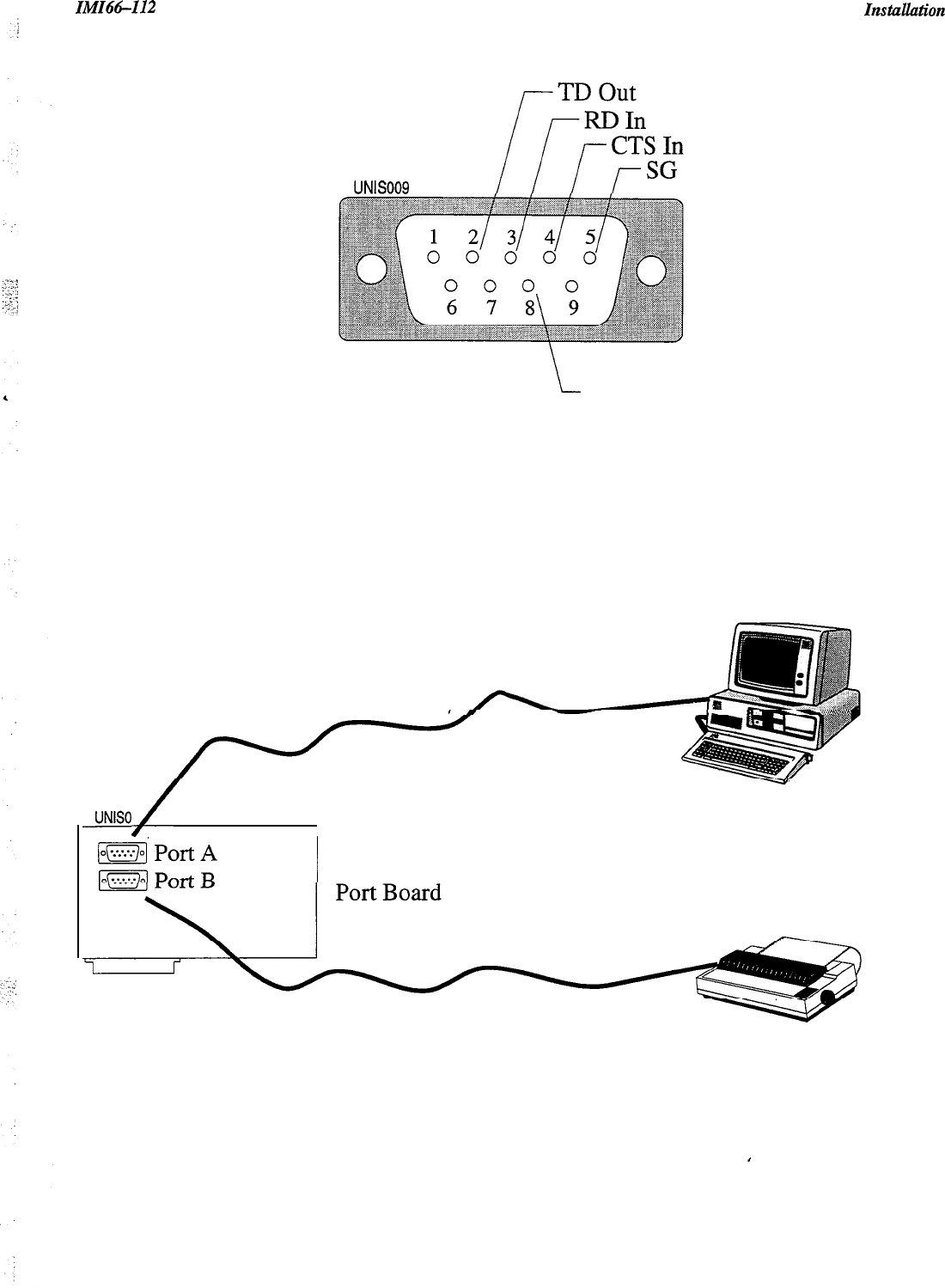
2.7.6 Connecting A Data Device
With the TX232 module, the system provides two RS232 Data Ports for use in connecting a data printer, personal
computer (PC), or modem for remote upload
1
download. Before you connect anything to a data port, consider all of
the following:
l
When you use a personal computer to perform class of service programming, connect it to
RS232
Data Port A (future feature).
l
When you use a serial data printer for SMDR (and Caller ID, future), connect it to the RS232 Data Port B.
l
The distance between the data device and the common equipment can be up to 500 feet in a quiet electrical
environment. Shielded cable may be required at some sites for long runs. For longer distances, a limited
distance modem must be used to relay the data communications between the common equipment and the data
device.
Wiring The Data Device
NOTE: You can use a commercially available straight through 9-pin cable to connect the TX?32 to a standard PC
DB9 serial port.
When preparing a cable for connection to a data device, refer to the manufacturer’s manual for the equipment being
interfaced, and make the following wiring connections:
l
Wire the common equipment RD (data from device to common equipment) connection to the device TD
(transmit data) connection.
l
Wire the common equipment TD (data to device from common equipment) connection to the device RD
(receive data) connection.
l
Wire the common equipment SG (signal ground) connection to the device SG (signal ground) connection.
l
If required for proper operation, wire the common equipment CTS (clear-to-send status from device to common
equipment) connection to the device RTS (request-to-send) connection.
NOTE:
The common equipment requires a positive voltage, with respect to signal ground, in order to send data
Configuring The Data Device
The default data format is as follows. Configure the data device to match this data format for initial operation.
l
8-bit data with 1 stop bit and no parity
l
Baud rate of 1200 baud
--
2-22
IlkfIt%-112 Instuuation
UNlS009
i
RTS Out
Typical DB 9 Connection
RS-232C Non-null Cable
UNISOIO,
,/
Typical Personal Computer
TX232 Serial
SMDR Printer
Figure 2.11 Typical Data Device Connection
2-23
Instuuation IiVlI66-112
2.7.7 Music Interface
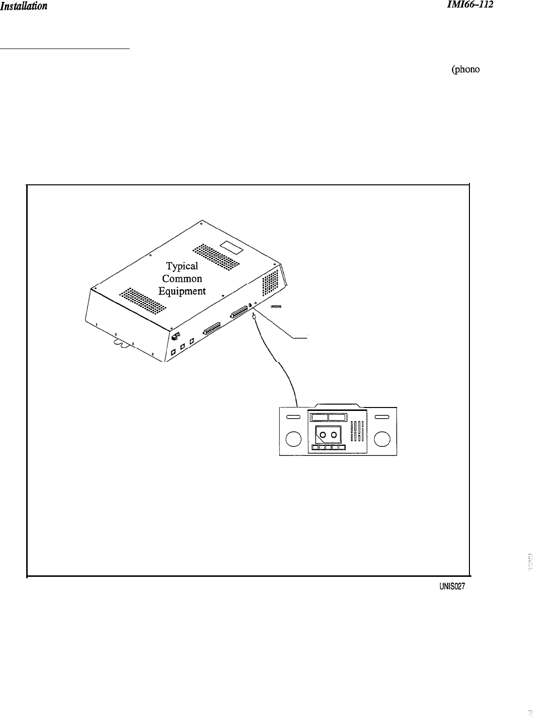
If music is to be part of the system, connect a music source to the common equipment music interface jack (phono
jack) provided for this purpose. The impedance of this input is approximately 600 ohms. Level adjustment of the
music source may be necessary. The system will not support background music at stations with bridged proprietary
and auxiliary devices connected. See Section 3.5.6 for more information.
Music Interface
Music Source
(for music on hold
and background music)
Figure 2.11 Music Interface
2-24
IMI66-112
IilStUUlltiOn
2.6
Checking The System
2.8. I Checking The Installation and Wiring
:
:
Verify that the common equipment is mounted properly and that all wiring is correct. Check all of the following
wiring carefully: the chassis ground wiring, the line port wiring, the station port wiring, the AC wiring, and any
accessory wiring.
Once the basic system is verified as operational, perform the class of service programming as described in Chapter 3.
2.8.2 Checking the Wiring Resistance To Ground
With the system unpowered, check the DC resistance from each individual wire terminal to earth ground. When
Ohm-meter measurements show low
DC
resistance (under 1 Megaohm) disconnect the wire and correct the problem.
2.8.3 Powering-Up The System
And Doing A General Check
Connect the AC power. Check the green light emitting diode (LED) system status indicator. Be sure that it is on
steady. If
it
is off or flashing, refer to Section 2.9, Isolating
System Failures.
2.8.4 Checking The DC Voltages of The Station Ports
Check the common equipment and telephone installation for proper operation by performing the following voltage
measurement.
Make the following voltage measurements at the station connector blocks under the following conditions:
.
Bridging clips installed
.
AC power connected to the common equipment
.
All telephones on-hook
Measure the voltage across each voice pair and across each data pair (See Tables 2.2 and 2.3). The measured voltage
must be as follows:
Unit Under Test 66M-xx Block Meter Lead Polarity Measured Voltage
Connection
Typical Station Voice 1 (Grn)
(+)
+ 24
VDC
+K
I
OVDC
(Repeat for each Voice 2 (Red)
s
station) Data 1
(Yel) (+)
Data 2 (Blk)
w
+ 24
VDC to + 42 VDC
Variant readings can indicate a possible wiring, station, or common equipment problem.
#+
-24 VDC on Universal ports
(TXISTporfs)
0 VDC on Proprietary-only ports.
.
2-25
Instullution
IMIG-112
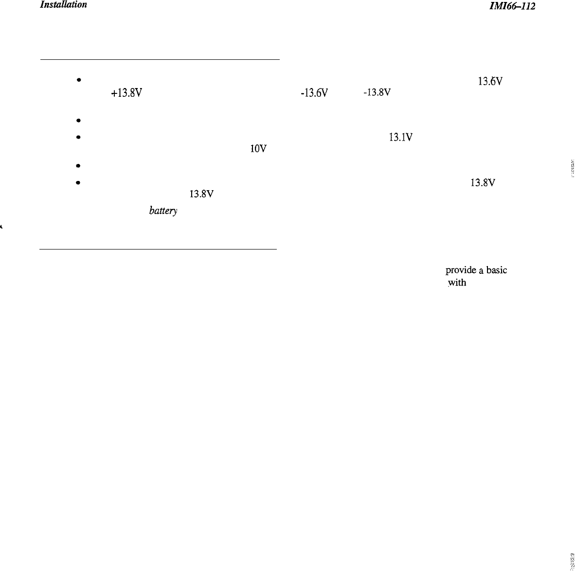
2.8.5 Checking Battery
And Batterv Charuer DC Voltaaes
Correct voltage of battery charger circuit without the batteries connected is as follows: between + 13.6V DC
and +13.8V DC for the positive battery and between -13.6V DC and -13.8V DC for the negative battery
(contact Comdial if the voltage is higher or lower),
Nominal voltage of each of the batteries is 12V DC,
Each fully charged and disconnected battery should not exceed a voltage of 13.1V DC. A completely
discharged battery may check as low as
1OV
DC,
When the battery backup is installed and the system is powered, check the following:
Each fully charged battery connected to the system should have a voltage of less than or equal to 13.8V DC (if
the value is greater than 13.8V DC, contact Comdial).
NOTE: The typical battery service check is every three months.
,
2.8.6 Checking The Default Conditions
The system operating features are set to default conditions at initial power-up. ‘These conditions
provide
a
b&c
operating system with a known set of parameters, and the system should be initially checked out with the default
conditions in place. At any time while the system is operating, default conditions can be reset from station
port 10 or 12. For more information, see Chapter 3, section 3.4.
2-26

I&U66412
2.9
Isolating System Failures
2.9. I Checking The System Status Indicator
“,
.
..-
. .
:
A green LED located on the common equipment cabinet near the music port is the system status indicator.
men
the
system has power, this indicator
SOYS
lit. If the indicator flashes after power-up, it is indicating a processor failure.
Unplug and reconnect the AC power to the power supply and observe the LED indication. If it still shows a flashing
indication, equipment replacement may be necessary.
2.9.2
Doing A Station Self Test
You can self test the multiline stations for proper operation using the following instructions:
1.
Disconnect line cord at station base.
2.
Press and hold the 1 button and reconnect line cord to station connector. Station will automatically perform self
test routine.
NOTE: Active calls to the adjacent port may be dropped when you do a self test.
3.
Release the 1 button as soon as test begins. Sequence of test is as follows:
l
LED Indicators will light in sequence
l
LED Indicators will then turn off
l
Ringer will sound
4.
Replace any station that does not pass the self test.
2.9.3 Checking Failure Indications
If erratic light indications or ring signals occur at a paired station, an open data pair at either station may be the
cause. A station with an erratic data line connection may work properly on a short loop but fail on a long loop.
Stations are paired for overload current protection (2.6.2). If a fault occurs that causes more than 300 milliarnps of
current to-be drawn, the overload paired stations are disabled by circuit action. Disconnect the disabled stations and
reconnect them one at a time to isolate the faulty one.
‘;
.:.
2-27
FCC Information IMI66112
2.10 FCC Rules And Regulations
This electronic key system complies with Federal Communications Commission (FCC) Rules, Part 68. The FCC
registration label on the common equipment contains the FCC registration number, the ringer equivalence number,
the model number, and the serial number or production date of the system.
2. IO. I
Notification To Telephone Company
b
p
I
Unless a telephone-operating company provides and installs the system, the telephone operating company which
provides the lines must be notified before a connection is made to them. The lines (telephone numbers) involved,
the FCC registration number, and the ringer equivalence number must be provided to the telephone company. The
FCC registration number and the ringer equivalence number of this equipment are provided on the label attached to
the common equipment. The user/installer is required to notify the telephone company when final disconnection of
this equipment from the telephone company line occurs.
e
2.10-Z
Compatibility With Telephone Network
When necessary, the telephone operating company provides information on the maximum number of telephones or
ringers that can be connected to one line, as well as any other applicable technical information. The telephone
operating company can temporarily discontinue service and make changes which could affect the operation of this
equipment. They must, however, provide adequate notice, in writing, of any future equipment changes that would
make the system incompatible.
2.10.3 Installation Requirements
Connection of the electronic key system to the telephone lines must be through a universal service order code
(USOC) outlet jack supplied by the telephone operating company. If the installation site does not have the proper
outlet, ask the telephone company business office to install one. The correct outlet jack for this system is either a
type RJ21X or type RJ14C.
2.10.4
Party Lines And Coin Lines
Local telephone company regulations may not permit connections to party lines and coin lines by anyone except the
telephone operating company.
2.10.5
Troubleshooting
If a service problem occurs, first try to determine if the trouble is in the on-site system or in the telephone company
equipment. Disconnect all equipment not owned by the telephone company.
If this corrects the problem, the faulty equipment must not be reconnected to the telephone line until the problem has
been corrected. Any trouble that causes improper operation of the telephone network may require the telephone
company to discontinue service to the trouble site after they notify the user of the reason.
2-28

ZMZ66-112
FCC Information
2.10.6
Repair Authorization
FCC regulations do not permit repair of customer owned equipment by anyone except the manufacturer, their
author&l agent, or others who might be authorized by the FCC. However, routine repairs can be made according
to the maintenance instructions in this publication, provided that all FCC restrictions are obeyed.
2. IO. 7
Radio Frequency Interference
:
4
The electronic key system contains incidental radio frequency generating circuitry and, if not installed and used
properly, may cause interference to radio and television reception. This equipment has been tested and found to
comply with the limits for a Class A computing device pursuant to Subpart J of Part 15 of FCC Rules. These limits
are designed to provide reasonable protection against such interference when operated in a commercial environment.
Operation of this equipment in a residential area may cause interference to radio and television reception; in which
case the user is encouraged to take whatever measures may be required to correct the interference. If this equipment
does cause interference to radio or television reception, which can be determined by turning the equipment off and
on, the user is encouraged to try to correct the interference by one or more of the following measures: Reorient the
television or radio’s receiving antenna, and/or relocate the common equipment, the individual telephone stations, and
the radio or TV with respect to each other. If necessary, the user should consult the manufacturer or an experienced
radio/television technician for additional suggestions. The user may find the following booklet prepared by the
Federal Communications Commission helpful: “How to Identify and Resolve Radio-TV Interference Problems.”
This booklet is available from the Government Printing Office, Washington
DC.
20402. Stock No.
004-000-00345-4.
This digital apparatus does not exceed the (Class A) limits for radio noise emissions from digital apparatus set out in
the Radio Interference Regulations of the Canadian Department of Communications.
Le pre’sent appareil n’emet pas de bruits radioe’lectriques de’passant les limites applicables aux appareils (de la
class A) prescrites dans le Reglement sur le brouillage radioe’lectrique e’dicte’ par le ministe’re des
Communications du Canada
Changes or modifications to this unit not expressly approved by the party
responsible for compliance could void the user’s authority to operate the equipment.
2.10.8
Ringer Equivalence Number,
Load Number
The REN of each line is 0.4B. The FCC requires the installer to determine the total REN for each line, and record it
at the equipment. The Load number is 4.0
2-29

IMI66-112
Programming Contents
Ll
3
Programming Unisyn
3.1
Using
This Chapter
3-
1
3.2
Understanding How To Program
3.3
Understanding System Programming
3.3.1 Using A Telephone To Program
3-3
3.3.2 Master Clearing The System
3-3
3.3.3 Finding The Programming Buttons
3-3
3.4
Master Clearing And System Defaults
3.4.1 Master Clearing 3-4
3.4.2 Defaulting The System 3-4
3.4.3 Defaulting The Lines 3-4
3.4.4 Defaulting The Stations
3-5
3.4.5 Defaulting Button Assignments
3-5
3.4.6 Defaulting Toll Restriction Tables
3-5
3.5
Programming
The System 3-6
3.5.1
3.5.2
3.5.3
3.5.4
3.5.5
3.5.6
3.5.7
3.5.8
3.5.9
3.5.10
3.5.11
3.5.12
3.5.13
3.5.14
3.5.15
Attendant
/
Line Access
Data Baud Rate
3-7
DTMF Dialing Feedback
Exclusive Hold
3-8
Make
/
Break Ratio
3-8
Music On Hold
3-8
System Clock
3-9
System Speed Dial
3-9
3-6
3-7
3-l
3-3
3-4
Tone or Voice Signaling
3-10
Timing Feature-DTMF Extended Tones
3-10
Timing Feature-PA Port
3-11
Timing Feature-Pause Time
3-11
Timing Feature-Recall Flash 3-12
a
Timing Feature-Timed Hold Recall
3-12
Timing Feature-Unanswered Call Transfer Recall
3-i

Programming Contents
IMI6&112
3.6
Programming
The Lines
3-14
3.6.1 Introduction 3-14
3.6.2 Abandoned Hold Release 3-15
3.6.3 Automatic Privacy 3-15
3.6.4 Automatic Privacy Release 3-15
3.6.5 Line Groups 3-16
3.6.6 Line Port Functions-Line Disable
3-
17
3.6.7
Line Port Functions-Auxiliary Lines
3.6.8
Line Port Functions-Central Office Lines
3.6.9 Pulse
/
Tone Switchable-Pulse 3-18
‘3.6.10 Pulse
/
Tone Switchable-Tone 3-18
3-17
3-17
3.7
Programming
The Stations 3-19
3.7.1
3.7.2
3.7.3
3.7.4
3.7.5
3.7.6
3.7.7
3.7.8
3.7.9
3.7.10
3.7.11
3.7.12
3.7.13
3.7.14
3.7.15
3.7.16
3.7.17
3.7.18
3.7.19
3.7.20
3.7.21
3.7.22
3.7.23
3.7.24
3.7.25
3.7.26
3.7.27
3.7.28
3.7.29
3.7.30
Introduction
3-19
Access Denied (Line Access Denied)
All Call and Zone Paging
3-20
All Call and Zone Paging Button
3-20
Automatic Hold
3-21
Automatic Hold for Intercom
3-21
Automatic Privacy
3-22
Automatic Privacy Release
3-22
Call Forwarding On Busy
/
Ring No Answer
Intercom Hunt Group
3-23
3-19
3-23
Call Origination Denied (Line Origination Denied)
3-24
Data Security Port
3-24
Dedicated
ITCM
for Attendant
3-25
Direct
/
Delayed Ringing
3-25
External Paging Interface
3-25
Flexible Ringing Assignment-Direct
/
Delayed Ring
3-26
Flexible Ringing Assignment-Line
/
Station Assignments
3-26
Flexible Ringing Assignment-Night Ringing Mode
3-27
Flexible Ringing Assignment-PA Port
3-27
Flexible Station Numbering
3-28
Headset Interface
3-28
IST Distinctive Ringing 3-28
Idle Line Preference
3-29
Languages
3-29
Personal Ringing Tones
3-30
Port Definition
3-30
Prime Line
/
Prime Group And Prime Intercom
3-31
Message Wait Originate 3-3 1
Ringing Line Preference
3-32
Voice Announce Blocking 3-32 ,.
3-ii

.
.
.,
‘.
In!fI66-112
3.8 Button Mapping
3-33
3.8.1
Automatic Call-back Button
3.8.2
Blank Buttons
3-34
3.8.3
Call Forward Button
3-34
3.8.4
Do Not Disturb Button
3-35
3.8.5
DSS
/
BLF Button
3-35
3.8.6
Line Button
3-36
3.8.7
Line Group Button
3-36
3.8.8
Line Group Queue Button
3.8.9
Dual Intercom Button
3-37
‘3.8.10
Privacy Release Button 3-37
3.8.11
Save Button
3-37
3.8.12
Shift Button
3-38
3.8.13
Voice Announce Block Button
3.8.14
Zone Page
/
All-Call Button
Programming Contents
3-33
3-36
3-38
3-38
3.9
Voice Mail Interface 3-39
3.9.1 Voice Mail Port 3-39
3.9.2 Voice Mail Port
/
Direct Ringing For Attendant
3-40
3.9.3 Voice Mail Port
/
Delayed Ringing For Attendant
3-40
3.9.4 Voice Mail Port
/
Night Ringing For Attendant
3-41
3.9.5
Voice Mail Port-Assign Voice Mail Ports To Hunt Groups 3-41
3.9.6 Automatic Transfer of Voice Mail 3-42
3.9.7 Voice Mail ID Line 3-42
3.9.8 Voice Mail Transfer on Busy 3-43
3.10 Toll Restriction 3-44
3.10.1 Assign Entries To Toll Tables 3-45
3.10.2
Assign Toll Tables To Lines 3-45
3.10.3 Assign Toll Tables To Stations 3-46
3.10.4
Assign Toll Tables To Stations For Night Ringing
3-46
3.10.5
Assign Toll Tables To Stations For Speed Dials
3-47
3.10.6 Toll Restriction Override 3-47
3.11 Programming Reference Chart 3-48
3.12
Feature Code Numbering Plan 3-49
3-iii

IMI66-112
System Programming
Programming The System
-
:
.:
3.1
Using Chapter Three
programming the customer’s new system is the most intricate and important aspect of the installer’s job. The benefit
of the Unisyn system is that you can program every system differently to fit each customer’s individual needs.
Chapter 3 is divided into six programming sections:
l System,
l Lines,
l Stations,
l Button Mapping,
l Voice Mail,
l Toll Restriction.
Each of these sections lists the applicable features in alphabetical order. If you do not know where to find the feature
you need, look in the features chapter, Chapter 5, for a section number (for example, Master Clearing The System is
3.4.1), or look in the index. Each programming step does include a brief explanation of that feature; however, before
you begin programming you should familiarize yourself with
aEZ
of the system’s features, listed in chapter 5, so that
you can be certain that what you are programming is what the customer wants.
NOTE:
Prior to taking any programming action, determine the desired parameters and requirements. Record this
data on the programming reference tables provided in the Records chapter in the back
of
the manual.
3.2
Understanding
How To Program
-:
: :
Once you have selected all of the features
YOU
are going to program into a new system, go to chapter
5, Description
of System Features,
and write down the numbers that correspond to that feature (for example, Master Clearing The
System is 3.4.1). Then locate the feature in chapter
3, Programming The System,
and reread the description to make
sure it is the feature you are looking for. Remember, if you have not already done so you must be in the
configuration mode to do any programming (ITCM X #746
SC>.
When you are finished programming, press SPKR
to end.
3-1

System Programming
IMI66-112
3.2.1
Class of Service Programming
The installer performs the Class of Service Programming when the system is first installed. Any programming
function can be done under this type of programming. Class of service programming includes System, Station, and
Line programmin
g.
The password for COS programming is
*#746*-this
places the system in the configuration
mode. You must program from either station 10 or 12.
,
3.2.2 Administration Programming
Administrators can use administration programming to program all system features except line attributes and the
master clear. Administrators may perform this programming whenever system needs may dictate. The
administration password is
%#236++
3.2.3 Attendant Programming
While all of the system programming is generally done by the installer, there are a few functions that can later be
done by the system attendant. The Attendant programming password is %# plus the number of the feature.
Attendant Programming features are as follows:
l
System clock setting (3.57)
l
System speed dial (3.5.8)
l
Night transfer of ringing (3.7.18)
l
Music on hold (3.5.6)
3-2
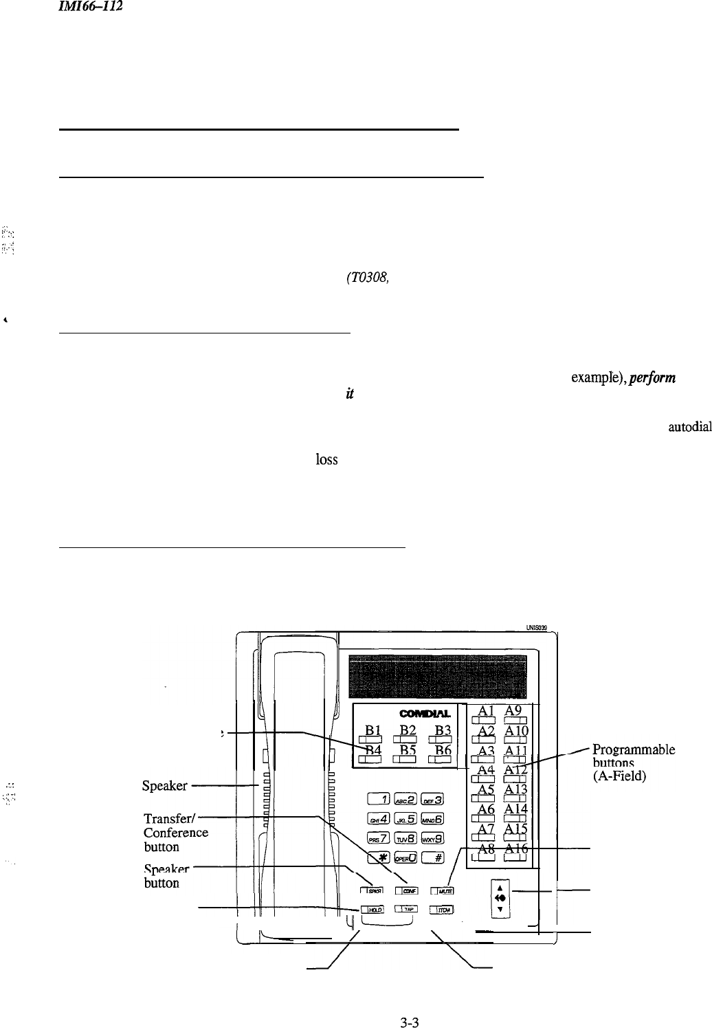
ZMZ66-112
System Programming
3.3 Understanding System
Programming
3.3.1 Using A Telephone To Program The System
.-:
,
i’
:‘:
;;
.-.
:;
:
Perform Class of Service configuration programming from station port 10 or station port 12. The system will not
accept programming commands from any other station port in the system. For best programming results, employ an
LCD speakerphone. While you can install any non-LCD proprietary telephone and use it for programming, visual
feedback of the programming operations will not be available.
NOTE: Do not program a domestic
system
(TO308, TO61 6) with an industry-standard telephone.
3.3.2 Master Clearing The System
After you have completely installed a telephone system for the first time or if a system that you previously installed
has been turned off and taken out of service for a period of time (several weeks, for example),perform
a master
clearprogrammingprocedure before placing
it
into service.
If you plan to perform a master clear procedure,
perform it first before performing
any
other programming procedure. The master clear procedure clears all memory
locations of all data stored there. Master clearing also clears any previously programmed data, such as autodial
numbers and defaults all class-of-service conditions. Therefore, never perform a master clear procedure on an
existing installed system unless data
10~s
and COS default are acceptable. Refer to section 3.4,
Master Clearing and
System Defaults,
for programming details. You can also default certain sections of programming, such as system,
line, station, button mapping, and toll restriction.
3.3.3 Finding The Programming Buttons
The following picture details the telephone’s programming buttons. Refer to this picture if you are unsure about a
button’s location.
7
:.:
,::
7:
:,
Programmable
Buttons
(B-Field)
Message
am
((TlpJ
ilmvl
waiting
I
cl1
L--d
I’
light
/I
/
I
I
Intercom
button
Mute
button
r
Volume
control
Hold
TAP
button button
System Programming
IMI66-112
3.4 Master Clearing
And Svstem Defaults
You can return the entire programming configuration to the factory settings using the master clear procedure. You
can also return the individual system, line, and station class of service configurations to their factory settings using
the system, line, and station default procedures. The operating parameters and class of service values provided by the
factory settings will provide satisfactory performance in a broad range of site applications.
Not only does the master clear procedure return ALL programmed variables to a default state
of
operation, but it
also clears ail currently stored autodial and speed dial numbers.
I
3.4. I Master Clearing
Description:
Returns entire system configuration to factory settings
and clears all stored auto and speed dial numbers.
To
Program:
1.
Press
ITCM
Dial
+k
# 7 4 6
%
“CONFIG. MODE”
2.
Dial
90
“MASTER
CLEAR”
3.
Dial 5
16 8 4
to clear the entire system.
System returns to normal operation mode automatically.
3.4.2 Defaulting The System
Description:
Returns the system configuration features to factory settings.
To Program:
1.
Press ITCM
Dial
+K
#
7 4 6
*
“CONFIG. MODE”
2.
Dial
10
‘SYSTEM DEFAULT”
3.
Press #to default system features.
System returns to configuration mode automatically.
3.4.3 Defaulting The Lines
Description
Returns the line configuration features to factory settings,
To
Program:
1.
Press ITCM Dial
+k
#
7 4 6
+K
“CONFIG. MODE”
2. Dial 30 “LINE DEFAULT”
3.
Press # to default line features.
System returns to configuration mode automatically.
3-4
IMIG-112
System Programming
3.4.4 Defaulting The Stations
Description
Returns the station configuration features to factory settings.
To Program: 1.
2.
3.
4.
Press
ITCM
Dial
+N
#
7 4 6
+k
“CONFIG.
MODE”
Dial
50
“STATION DEFAULT
”
Dial 00 to default station ports system-wide,
-OR-
Select individual station port to be defaulted: Station 10
-
25, Dial
10
-
25 or
press
Al
-
A16
Dial
+i+
for next station to default,
-OR-
Dial
+C
%
for configuration mode or SPKR to quit.
3.4.5
Defaulting Button Assignments
Description:
Returns the button mapping of individual stations to its factory setting.
To Program:
1.
Press ITCM Dial
S
#
7 4 6
%
“CONFIG.
MODE”
2. Dial 56
“BUTTONMAPPING
”
3. Dial 01
‘rBUTTON
DEFAULT
”
4.
Select station ports to be defaulted: Station 10
-
25, Dial
10
-
25
or press
Al
-
Al6
5.
Dial
%
for next button mapping feature,
-OR-
Dial
+C
%+c
for configuration mode or SPKR to quit.
3.4.6 Defaulting Toll Restriction Tables
Description:
The system defaults two toll restriction tables with preprogrammed values and
assigns
them to the lines.
You need only to assign them the stations to put them into effect. The preprogrammed values are as
follows:
Table 1 (deny)
Entry 1 = 1
Entry 2 = 976
Entry3=411
Table 2 (allow)
Entry
l=
1800
Entry2=911
.z’
:
.,.
:.,::I
CT:.
:.
1’
These values will provide satisfactory system performance in a broad range of site applications; however,
they can be changed as needed to meet different toll restriction needs.
To Program:
1.
Press ITCM Dial
+K
#
7 4 6
+K
“CONFIG.
MODE”
2. Dial 70 “DEFAULT TOLL”
_’
I.-
3.
Press # to default toll tables
4.
Dial
+i~
for conf&uration mode or SPKR to quit.
3-5
System Programming
IMI66-112
3.5
Programming The System
Programming the system means that
you
are setting the parameters that will be true system wide. If you are unsure
whether or not you are programming the correct function, check chapter
5, Description
of
System Features,
in the
back of this manual for a full definition of the feature. You should make a record of all your programming
decisions -it will help you keep track of what you have done and will help you troubleshoot any problem that might
arise later. When you need to make a record of the programming configuration, mark the desired requirements in the
system class of service records chart found in Chapter 4.
NOTE: A lighted I&D next to the programming button shows which choice you have selected.. When a single
button provides a toggle
(on/off)
action, the lighted LED indicates the active feature.
The first step in any programming sequence is to enter the base level. Once in this mode, you can dial the feature
code for any desired configuration. Enter the base level with the following procedure: press ITCM then
dial
S#
7 4 6
SC.
When you want to end the programming, press the
SPKR
button to end the programming
procedure and return the system to normal operation.
3.51
Attendant/Line Access
Description:
You can set the system so that the user accesses a line and the attendant in one of two ways:
Dial 9= Attendant
Dial
O=
Line Group 1
-OR-
Dial
O=
Attendant
Dial 9= Line Group 1
Default
=
Dial 0 for Attendant
(Al LED =
OffJ
To Program:
1. Dial 17
“‘SYSTEM FEATURES”
2.
Dial 04
“0
AlTN
9 LINE”
3.
Press Al to toggle between two selections (LED Off = 0 for Attendant)
-OR-
Dial 1 for 9 for Attendant
“9
AlTN
0 LINE”
Dial 2 for 0 for Attendant “0
ATTN 9 LINE”
4.
Press
+K
#+
for configuration mode
3-6
IMI66-112
:
System Programming
3.5.2 Data Baud Rate
Description:
The speed or baud rate of the data bit stream, which carries the SMDR and configuration data between the
system and an external data device, must be programmed to match the requirements of the data device.
NOTE: If you use XMODEM protocol for data transfer between a PC and the common equipment, you must use
a-bit
data. Data transfer can only be done on port A.
DefauU = W8D
IS
1200 (AS, Al6 LED = On)
To Program: 1.
Dial 15
“BAUD RATE”
2.
Dial
1
for data port A
-OR-
Dial 2 for data port B
Choose baud rate.
Dial
01
or Press
Al
“W
nD
nS
I IO”
Dial 02 or Press A2
“W
nD
nS
150”
Dial 03 or Press A3
“W
nD
nS 300”
Dial 04 or Press A4
“W
nD
nS 600”
Dial
05 or Press A5
“W
nD
nS 1200”
Dial 06 or Press A9
“W
nD
nS 2400”
Dial 07 or Press
A10
“W
nD
nS 4800”
Dial
08
or Press
All
“W
nD
nS 9600”
Dial 09 or Press
Al2
“W
nD
nS 19200”
Dial
10
or Press
A8
for 7 data bits and 2 stop bits
“W7D 2S
2~2~2”
Dial
11
or Press
Al6
for 8 data bits and 1 stop bit
“W
80
IS
zzzzz”
3.
4.
Dial
+K
for next data port.
5.
Dial
t
+t+
for configuration mode.
3.5.3
DTMF Dialing Feedback
Description:
You can program either DTMF or monotone feedback during dialing.
Default = Monotone (Al LED = On)
To Program:
1.
Dial 27
“XXXX
FEEDBACK”
2.
Press Al to alternate between monotone and DTMP feedback (Al LED on = monotone feedback)
-OR-
Dial
1
for monotone feedback
“TONE FEEDBACK”
Dial 2 for DTMP feedback
‘DTMF
FEEDBACK”
3.
Press
+K
for configuration mode.
.:
3-7
System Programming ZMZ66-I12
3.5.4
Exclusive Hold
Description:
This feature prevents a telephone user at one station from picking up a call that a user placed on hold at
another station. You can enable or disable it system-wide using this procedure.
Default = Disabled (Al LED =
Ofl
To Program:
1.
Dial 23
“XXXXXXX
EXC
HOLD”
2.
Press
Al
to toggle between enable and disable (LED On = Enable)
-OR-
Dial 1 to enable “ENABLE EXC HOLD
”
Dial 2 to disable
“DISABLE EXC HOLD”
3.
Dial
f
for configuration mode.
,
3.5.5
Make /Break Ratio
Description:
Set the make
!
break ratio for rotary dial signaling to match rotary dial line requirements. You can set the
ratio to two different values: 60/40 or 67133.
Default = 60
/40
(Al LED = Off)
To Program:
1.
Dial 17
“SYSTEM FEATURES”
2. Dial 03
“‘MAKE/BREAKXX/XX”
3.
Press
Al
to toggle between 60/40 and 67/33 ratios (LED Off = 60/40)
-OR-
Dial 1 for
67133
“MAKE/BREAK
67/33”
Dial 2 for
60140
“MAKE/BREAK
60/40”
4.
Dial
+K
+#
for configuration mode.
3.5.6
Music On Hold
Description:
When you connect an external music source to the system, it will provide music to all outside lines that are
placed on hold. You can disable the music using this programming procedure. System attendants also have
access to this feature.
NOTE:
You can enter any attendant programming with the base level entry
of
ITCM % #.
Default = Enabled (Al LED = On)
To Program:
1.
Dial 04
“MOH
XXXXXZX
”
2.
Press
Al
to toggle between enable and disable (LED On = Enabled)
-OR-
Dial 1 to Enable
“MOH
ENABLE”
Dial 2 to Disable
“MOH DISABLE”
3.
Dial
++c
for configuration mode.
3-8

IMI66112
System Programming
3.5.7
System Clock
Description:
The system clock maintains current date and time information. The system provides this information to
LCD speakerphones for display. Set the system time with this feature. The system attendant also-has
access to this feature.
NOTE: You can enter any attendant programming with the base level entry of
ITCM
t
#.
To Program:
1.
Dial 01
“SET
CLOCK
”
LONG FORM
Dial 00
-
99 for yr.
-
Dial 00-23 for hr.
Dial
01
-
12
for mo.
-
Dial 00-59 for min.
Dial
01
-
31
for day
-
Dial #to assign hours and minutes
Dial 00
-
23 for hr.
Dial 00
-
59 for min.
2.
Dial
%
for configuration mode.
3.5.8
System Speed Dial
Description:
You can program a special system-wide list of numbers that all users can use for automatic dialing.
The system attendant can also program the system speed dial numbers.
NOTE: You
can enter any attendant programming with the base level entry of
ITCM
+K
#.
Default = None Assigned
To Program: 1.
2.
3.
4.
Dial 02
‘SYS
SPEED DIAL
”
Dial 01
-
99 for storage location
“m
_.
”
Dial # to clear current entry
‘LINE:
”
Choose line, line group, or intercom to be used with speed dial number “,WW
m
”
Line port l-6 = Dial
01
-
06
or press
Bl-
B6
-OR-
Dial 90 for last line used or prime line
‘PRIME
LINE”
-OR-
Dial
91-
94
for line group
l-4
‘LINE
GROUP I
”
Press ITCM
button for intercom line
“INTERCOM”
Dial number for storage (32 digits max) “XxXxX...
“-
If required, press
HOLD
button to store a
pause. If required, press
TAP
button to store a hookflash
Press
CONF
button to save the number
Repeat steps 2-6 for all speed dial numbers,
-OR-
Press
#+
for configuration mode.
3-9
System Programming ZMZ66-112
3.5.9 Tone or Voice Signaling
Description:
Intercom calls can be tone signaled or voice signaled. Use this programming feature to select the system’s
signaling choice. With either method set as the system’s
fast
choice, the user can choose the other method
as needed by pressing the ITCM key again.
Default = Voice First (Al LED = On)
To Program:
1.
Dial 16
“JBXXX
ANN. FIRST”
2.
Press
Al
to toggle between Voice To Tone. (LED On = voice signaling)
-OR-
Dial
1
for Voice First
“VOICE ANN. FIRST”
Dial 2 for Tone First
“TONE ANN. FIRST”
3.
Dial
f
for configuration mode.
3.5.10
Timing Features-Extended DTMF Tones
Description:
The system can access outside equipment, answering machines or banking computers, for example, that
require DTMF tones that are longer than the standard 80 msec. tone. The system automatically shifts to a
longer tone 10 seconds after the last digit of a number is dialed. A user can shift from one tone length to
the other by pressing the hold button and then reselecting the line.
Default = 80 msec. (Al LED = On)
To Program:
1. Dial26
‘DTMF
DIALNG
XxXx”
2.
Choose DTMF tone length
Press
Al
or dial
1 = 80 rnsec.
Press A2 or dial 2 = 160 msec.
Press A3 or dial 3 = 240 msec.
Press A4 or dial 4 = 320 msec.
Press
A5
or dial 5 = 400 msec.
Press
A9
or dial 6 = 480 msec.
Press
A10
or dial 7 = 560 rnsec.
Press
All
or dial 8 = 720 msec.
Press
Al2
or dial 9 = 880 msec.
Press Al3
or dial 0 = 1040 msec.
3.
Dial
%K
for configuration mode.
3-10

System Programming
3.5.
II
Timing Features-PA Port
Description:
You can set PA
ports
to either timeout of the system for a programmed length of time or to remain on the
system as long as necessary without timing out. The system default is set for no timeout option.
-
Default = No Timeout (Al3 LED = On)
To Program:
1.
Dial 92 “PA
TIMEOUTBY
2.
Choose Timeout length:
Press
Al
or dial
1 = 30 sec.
“PA TIMEOUT 30”
Press A2 or dial 2 = 60 sec.
“PA TIMEOUT 60”
Press A3
or dial 3 = 90 sec.
“PA TIMEOUT 90”
Press A4 or dial 4 = 120 sec.
“PA TIMEOUT 120”
Press A5 or dial 5 = 150 sec.
“PA TIMEOUT
150”
Press A9 or dial 6 = 180 sec.
‘PA
TIMEOUT
180”
Press
A10
or dial 7 = 210 sec.
“PA TIMEOUT
210”
Press
All
or dial 8 = 240 sec.
‘PA
TIMEOUT 240”
Press
Al2
or dial 9 = 300 sec.
“PA TIMEOUT 300”
Press Al3 or dial 0 = No timeout “‘NO
TIMEOUT”
3.
Dial
%
GR
for configuration mode.
3.5.12 Timing Features-Pause Time
Description:
To Program:
During auto dials and speed dials, it is sometimes necessary to delay the sending of digits to give switching
equipment time to prepare for receiving them. A pause is stored for this purpose whenever the user presses
the
HOLD
button. You can set the length of the pause with this programming feature.
Default = 1 sec. (A2 LED = On)
1. Dial13
“‘PAUSE TIME XXX”
2. Select time:
Dial 1 or Press
Al = 0.50 sec.
“PAUSE TIME 0.50
”
Dial 2 or Press A2 = 1 sec.
“PAUSE TIME I
”
Dial 3 or Press A3 = 1.50 sec.
“PAUSE TIME I
.50
”
Dial 4 or Press A4 = 2 sec.
“PAUSE TIME 2”
Dial 5 or Press
A5 = 3 sec.
‘PAUSE TIME 3”
Dial 6 or Press A9 = 5 sec.
“PAUSE TIME 5”
Dial 7 or Press
A10 = 7.50 sec.
“PAUSE TIME 7.50
”
Dial
8
or
Press All =
10 sec.
“PAUSE TIME IO
“
Dial 9 or Press
Al2 = 15 sec.
“‘PAUSE TIME 15”
Dial 0 or Press
Al3 = 20 sec.
“PAUSE TIME 20”
3.
Dial
+K
for configuration mode.
3-l 1
System Programming
IMI66-112
3.5.13
Timing
Features-RecalUFlash
Description:
The system can generate either a line disconnect (recall) or a host system feature access signal (flash)
depending upon the programmed time.
Default = 2 sec. (Al2 LED = On)
To Program:
1.
Dial12
"RECALL/FLSHZXX"
2.
Select time:
Dial 1 or Press
Al = 0.08 sec.
"RECALVFLSHO.08"
Dial 2 or Press A2 = 0.30 sec.
"RECALLlFLSH
0.30"
Dial 3 or Press A3 = 0.50 sec.
"RECALLfFLSHO.50"
7
Dial 4 or Press A4 = 0.60 sec.
"RECAL.UFLSHO.60"
;
Dial 5 or Press A5 = 0.75 sec.
"RECALUFLSH 0.75"
Dial 6 or Press A9 = 0.88 sec.
"RECALL'FLSH
0.88"
Dial 7 or Press
A10 =
1
sec.
"RECALLYFLSHl"
Dial
8
or
Press All = 1.50 sec.
"REC~FLSH1.50"
Dial 9 or Press Al2 = 2 sec.
"RECALLfFLSH2"
Dial 0 or Press Al3 = 3 sec.
"RECALLlFLSH3"
3.
Dial
+k
for configuration mode.
3.5.14 Timing Features-Timed Hold Recall
Description:
After a call has been on hold for a programmed length of time, the system will recall the station that placed
the call on hold. Set the hold recall time with this programming procedure.
Default = 60 sec. (A2 LED = On)
To Program:
1. Dial14
2. Select time:
Dial
1
or Press
Al = 30 sec.
Dial 2 or Press A2 = 60 sec.
Dial 3 or Press A3 = 90
sec.
Dial 4 or Press A4 = 120 sec.
Dial 5 or Press A5 = 180
XC.
Dial 6 or Press A9 = 240 sec.
Dial 7 or Press
A10 = 300 sec.
Dial
8
or Press
All = 360
XC.
Dial 9 or Press Al2 = 420
XC.
Dial 0 or Press Al3 = 0
sec.
3.
Dial
+k
for configuration mode.
"HOLDRECALLXXXX"
"HOLDRECALL30"
"HOLDRECXLL60"
'HoLDRECALL90"
"HOLDRECALL120"
"'HOLDRECALL180"
"HOLDRECALL240"
"HOLDRECALL300"
"HOLDRECALL360"
"HOLDRECALL420"
'HOLDRECALL'O"
3-12
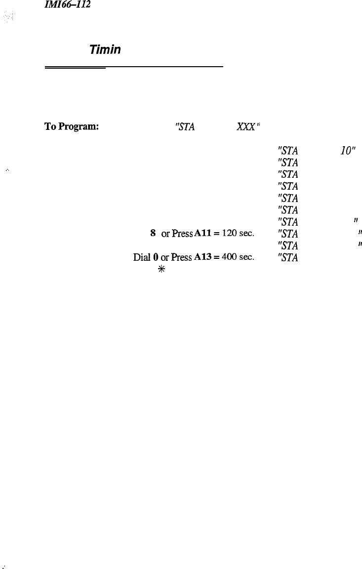
In!fI66-112 System Programming
3.5.15
Timin
Features-Unanswered
Call ransfer Recall Time3
Description:
A transferred call that remains unanswered after a programmed length of time will return to the transferring
station for answering. Set the transfer recall time with this programming procedure.
Default = 20 sec. (A2 LED = On)
.-.
ToProgram:
1.
Dial 11
“STA
XFR RCL
XXX
”
2.
Choose transfer time:
Dial
1
or Press
Al = 10 sec.
Dial 2 or Press A2 = 20 sec.
,
Dial 3 or Press A3 = 25 sec.
Dial 4 or Press A4 = 30 sec.
Dial 5 or Press
A5 = 45 sec.
Dial 6 or Press
A9 = 60 sec.
Dial 7 or Press
A10 = 90 sec.
Dial
8
orPress
All=120sec.
Dial 9 or Press
Al2 =
180 sec.
DialOorPress
A13=4OOsec.
3.
Press
%
for configuration mode.
‘STA
XFR RCL
IO”
‘STA XFR RCL 20”
‘STA XFR RCL 25”
‘STA XFR RCL 30”
‘STA
XFR RCL 45”
‘STA
XFR RCL 60”
‘STA
XFR RCL 90
”
‘STA
XFR RCL 120
”
‘STA
XFR RCL 180
”
‘STA XFR RCL 400”
-.
:
3-13
Line Programming
IMI64-I12
3.6 Programming The Lines
3.6. I In troducfion
You can program the parameters for individual lines by using line class of service programming. The programming
decisions you make, therefore, will only be true for that line and not for the entire telephone system, as is the case for
system configuration. You should keep a record of all programming decisions that you make-it will help you keep
track of what you have done and will help you troubleshoot any problem that might arise later. When you need to
make a record of the programming configuration, mark the desired requirements in the line class of service records
chart located in Chapter 4.
NOTE:
A lighted LED next to the programming button shows which choice you have selected. When a single
button
provides a toggle
(odofl
action, the lighted LED indicates the active feature.
The first step in any programming sequence is to enter the base level. Once in this mode, you can dial the feature
code for any desired configuration. Enter the base level with the following procedure: press ITCM then dial
%# 7 4 6
%.
The last step is to press the
SPKR
button to end the programming procedure and return the system to
normal operation.
To make a line port selection, press a programming button or dial a selection number on the keypad as
follows:
KEYPAD BUTTONS PROG. BUTTONS LINE !
01-06
Bl
-B6
l-6 I
3-14
IMI66-112
Line Programming
3.6.2 Abandoned Hold Release
Description:
To Program:
When a distant party abandons a hold condition and disconnects from a line (hangs up), the central office
sends a positive disconnect signal to the Unisyn telephone system. This signal can be either 50
m,sec.
or
350 msec. Check the signal length from the telephone company and program all of the central office line
ports to match that signal length.
Default = 50 msec. (BI
-
B6 LEDs = On)
1.
Dial
38
“HOLD RELEASE 50
”
2.
Select hold release time for line ports (LED On = 50 msec, LED Off = 350 msec)
Line port l-6 = Dial
01
-
06 or
Press
Bl
-
B6
3.
Dial
%
for configuration mode.
3.6.3 Automatic Privacy
Description:
You can make a line private or non-private. In the private mode, a station has exclusive use of a line
during
a call. Lines are private unless you re-program them and make them non-private.
Default = Privacy
(BI
-
B6
LEDs = Off)
To Program:
1.
Dial
40
‘PRIVACY RELEASE
”
2.
Select line ports to be non-private (LED On = Non Private)
Line port l-6 = Dial
01
-
06
or Press
Bl
-
B6
3.
Dial
%
for configuration mode.
3.6.4 Automatic Privacy Release
Description:
You can arrange for individual stations to automatically release privacy while on certain lines. With this
arrangement, other stations
can
join that particular station whenever it is on the privacy released line.
Default = Privacy (All L.EDs =
Ofl
NOTE: This feature, and all level
54
programming features are toggle on/toggle
08 [fthe
feature defaults
a.~
enabled, dialing the code automatically disables the feature. Similarly,
if
the feature defaults as disabled,
dialing the code automatically enables the feature.
.:
To Program:
1.
Dial 54
“STMLINE
CONFIG.”
2.
Dial 4 “PRIVACY RELEASE”
3.
Select line ports:
4.
5.
6.
Line port l-6 = Dial
01
-
06
or Press
Bl
-
B6
Dial #when all line ports are selected
Select station ports to be programmed: Station
10
-
25,
Dial
10
-
25
or press
Al-Al6
Dial
+K
when all station ports are selected,
-OR-
Dial
t
%
for next station/line feature,
-OR-
Dial
?K
%
%
for configuration mode.
3-15

Line Programming
IMI66-I12
3.6.5 Line Groups
Description:
Group outside lines of the same type together for dial-up outgoing access. Access codes for the line groups
are as follows:
Group
1
=
Dial
9 or
Dial
0(See Section 3.5.1)
Group 2=
Dial
81
Group
3
=
Dial
82
Group
4
=
Dial
83
NOTE:Assigning
lines to groups automatically arranges the system
for
hybrid operation.
Remember, hybrid
5
,L,
operation may incur a higher monthly
tarifs
than the key system operation incurs. Ask the local telephone
;.I
company
for
details.
._
Default = No line groups
(El
-
B6 LEDs
Ofl
To Program:
1.
Dial 35
“ASSIGN LINE GRPS”
2.
Dial 0 for no groups assigned
“NO LINE GROUP”
-OR-
Dial
1
for Line Group 1
“LINE GROUP I
”
Dial 2 for Line Group 2
“‘LINE GROUP 2”
Dial 3 for Line Group 3
“LINE GROUP 3”
Dial 4 for Line Group 4
“LINE GROUP 4”
3.
Select line ports to be assigned (LED On = Lines Assigned)
Line port l-6 = Dial
01
-
06
or Press
Bl
-
B6
4.
Dial
#+
for next group,
-OR-
Dial
%
t
for configuration mode.
NOTE:
To
remove lines from a line group enter 0
for
the line group.
3-16

In!iI66-112 Line Programming
3.6.6 Line Fort Functions-Line Disable
Description:
You can take a line port out of service when necessary (because of defect, for example) using this
programming procedure. Return the line to service with the central office lines programming procedure
(Section 3.6.8).
Default = None disabled
(Bl
-
B6 LEDs
OfjJ
:
:
To Program:
1.
Dial 31 “DISABLE LINES”
2.
Select line ports to be disabled (LED On = Disabled)
Line port 1-6 = Dial
01
-
06
or Press
Bl
-
B6
3.
Dial
+k
for configuration mode.
3.6.7 Line Port Functions-Auxiliary Lines
4
Description:
You can condition a line port to serve as a port for an external paging amplifier, ensuring that the line
cannot be put on hold.
Default = No auxiliary (Bl
-
Bd
LEDs
Off)
To program:
1.
Dial 32 “AUXILIARY LINES”
2.
Select line ports to be assigned (LED On = Assigned)
Line port l-6 = Dial
01
-
06
or Press
Bl
-
B6
3.
Dial
+K
for configuration mode.
3.6.8 Line Port Functions-Central
Office Lines:
Description:
You can condition line
ports
to serve as ports for standard telephone company supplied
central office lines.
Default = All CO (Bl
-
B6 LEDs On)
To program:
1.
Dial 33 “C.O.
LINES”
2.
Select line ports to be assigned (LED On = Assigned)
Line port
l-6
= Dial
01
-
06
or Press
Bl
-
B6
3.
Dial
%
for configuration mode.
3-17
Line Programming
IM166112
3.6.9 Pulse/Tone Switchable-Pulse
Description:
If the installer has connected rotary dial lines to the system, you must condition those line ports as pulse
dial ports.
NOTE:
The user can switch
from
pulse (rotary dial signaling) to tone (dual tone multiple frequency
-
DTMF)
accessing special circuits requiring DTMF tones, such as banking machines, when they need to do so
from
a rotary dial line by dialing
#after
dialing access number.
Default = No pulse
(Bl
-
B6
LEDs
Off)
To Program:
1.
Dial 36
“PULSE
DIAL”
2.
Select pulse dial line ports (LED On = Pulse)
Line port l-6 = Dial
01
-
06
or Press
Bl
-
B6
-OR-
Dial 00 to default all lines to pulse dial
3.
Dial
+#+
for configuration mode.
3.6.10 Pulse/Tone Switchable-Tone
Description:
If the installer has connected tone dial lines to the system, you must condition those line ports as tone dial
ports.
Default
=
Tone
(BI
-
B6
LEDs
On)
To Program:
1.
Dial 37
“TONE
DIAL”
2.
Select tone dial line ports (LED On = Tone)
Line port 1-6 = Dial
01
-
06
or Press
Bl
-
B6
-OR-
Dial 00 to default all lines to tone dial.
3.
Dial
#C
for configuration mode.
.
.
3-18
ZMZ66-112 Station Programming
3.7 Programming The Stations
3.7.1 Introduction
Station programming means that you are programming the functions for one particular station, or port. While it isn’t
necessary, it is a good idea to do station programming after you have done system and line programming. You
should keep a record of programming decisions that you make-it will help you keep track of what you have done
and will help you troubleshoot any problem that might arise later. When you need to make a record of the
programming configuration, mark the desired requirements in the station class of service records chart found at the
back of this manual.
NOTE:
A lighted LED
next to the programming button shows which choice you have selected.
When a single
button provides a
toggle
(ordoff)
action, the lighted LED indicates
the active feature.
The first step in any programming sequence is to enter the base level. Once in this mode, you can dial the feature
code for any desired configuration. Enter the base level with the following procedure: press
ITCM
then dial
##
7 4 6
+i~.
The last step is to press the
SPKR
button to end the programming procedure and return the system to
normal operation.
Make station port selection by dialing a selection number on the keypad or pressing a programming button
as in the following reference chart.
YPAD
RTJITONS
PROCJRAM
Rl
J’TTONS
STATK-lN
PORTS
10-75
Al
-
Al4 10-25
You should program feature 3.7.26, Port Definition, before you do any other station programming.
All
programming for a port is lost when the port is redefined in 3.7.26.
3.7.2
Access Denied (Line Access Denied)
Description:
You can deny access to certain lines at certain stations. When you do this, a station user cannot select a
denied line.
Default = None denied (AU LEDs =
OfJ>
NOTE: This feature and
all level 54 programming features are toggle on/toggle
ofi
If
the feature defaults as
enabled, dialing the code automatically disables the feature. Similarly,
if
the feature
defaults
as disabled,
dialing the code automatically enables the feature.
To Program:
1.
Dial 54
‘STMLINE
CONFIG.
”
2.
Dial
5
‘ACCESS DENY”
3.
Select line ports (LED On = Access Denied) Line port l-6 = Dial 01
-
06 or press
Bl-
B6
4.
Dial # when all line ports are selected
5.
Select station ports (LED On = Feature Assigned): Station 10
-
25, Dial
10
-
25 or
press
Al
-
Al6
6.
Dial
#
when all station ports are selected,
-OR-
Dial
+C
+C
for next
statiotine
feature,
-OR-
Dial
#C
C%
X for configuration mode.
7.
To change setting, repeat procedure and make opposite selection.
3-19
Station
Progranzming
IMI66-I12
3.7.3
All-Call
and Zone Paging
Description:
Telephone users can receive voice announcements through their telephone loudspeakers or through an
external paging amplifier and speaker connected to a PA port. They can transmit these voice
announcements with their telephone handsets. You can arrange the programming so that the users can
make announcements to stations located in certain areas of the site or to all of the stations. You can also
arrange stations to originate but not receive zone pages (or receive but not originate). You cannot send a
page to an IST station.
Default = &Y call to all stations
To Program:
1. Dial 55 “PAGING”
2.
Choose paging assignment
Dial
1
for zone 1 originate
“ORIGINATE ZONE I
“
Dial 2 for zone 2 originate
“ORIGINATE ZONE 2”
Dial 3 for zone 3 originate
“ORIGINATE ZONE 3”
Dial 4 for all-call originate ‘ALL-CALL ORIG.
”
Dial 5 for zone 1 receive
“RECEIVE ZONE I
I’
Dial 6 for zone 2 receive
“RECEIVE ZONE 2”
Dial 7 for zone 3 receive
“RECEIVE ZONE 3”
Dial 8 for all-call receive
“ALL-CALL RECEIVE”
Dial 9 to clear all assigmnents”CLEAR
PAGING”
3.
Select station ports (LED On = Feature Active): Station
10
-
25: Dial 10
-
25 or
press
Al
-
A16
4.
Dial
%
to assign other paging,
-OR-
Dial
+
#
for configuration mode.
5.
To change setting, repeat procedure and make different selection.
3.7.4
All-Call
and Zone Paaina-Button
Description:
If you wish, you can assign a paging button to provide a station with one-button access to the all-call and
zone paging feature. If you have already programmed this feature under 3.8.14, you do not need to
program it again here.
Default = None assigned
To Program:
1.
Dial 56
‘BUlTON
MAPPING
”
2. Dial 09 ‘ASSIGN ZONE”
3.
Select button to be programmed (LED Flash = Paging Button): Press
Al
-
A16,
Bl
-
B6
4.
Dial
1
-
3
for zone 1
-
3
“ASSIGN ZONE X
”
-OR-
Dial 4 for all-call “ASSIGN ALL CALL
”
5.
Select station ports (LED On = Button Assigned To Port): Station 10
-
25, Dial
10
-
25
or press
Al
-
Al6
6.
Dial
+&
for further paging button assignment,
-OR-
Dial
+K
+
for next button mapping feature,
-OR-
Dial
%
+k
X for configuration mode.
.
.
7.
To clear a paging button, dial 5604, press paging button, dial #, and repeat above steps 5 and 6.
3-20
IMI66-112
I
Station Programming
3.7.5
Automatic Hold
Description:
When you enable this feature, the telephone user can automatically place an existing line call on hold when
she or he presses another line button to answer a second call.
Default = Not enabled (AH LBDs =
Off
To Program:
1.
Dial 53 “STATION FEATURES”
2. Dial 11 ‘AUTO HOLD
”
,..
;:
:.
.
.;:,
3.
Select station ports (LED On = Feature Assigned): Station 10
-
25, Dial 10
-
25 or press
Al
-
A16
4.
Dial
+K
for next station feature,
AOR-
Dial
f
#
for configuration mode.
5.
To change setting, repeat procedure and make opposite selection.
3.7.6
Automatic Ho/d For
intercom
Description:
If you want the telephone user to
ASO
have the automatic hold feature when he or she is on an existing
intercom call and presses another intercom button or a line button, take this additional programming action.
Default = Not enabled (All LEDs =
Ofl
To Program:
1.
Dial 53 “STATION FEATURES”
2.
Dial 12
“ITCM
AUTO HOLD”
3.
Select station ports (LED On = Feature Assigned): Station 10
-
25, Dial 10
-
25 or press
Al
-
AI6
4.
Dial
%
for next station feature,
-OR-
Dial
t
#
for configuration mode.
5.
To change setting, repeat procedure and make opposite selection.
3-21

Station Programming ZMZ6W12
3.7.7 Automatic Privacy
Description:
You can make a line private or non-private. In the private mode, a station has exclusive use of a line during
a call. This information is repeated in 3.6.3. You do not need to program this feature again if you have
done so in 3.6.3.
Default = Privacy
(BI
-B6
LEDs =
Ofi
To Program:
1.
Dial
40 “PRIVACY RELEASE
”
2.
Select line ports to be non-private (LED On = Non Private Port)
r-
..:
Line port l-6 = Dial
01
-
06
or Press
Bl
-
B6
:-.
3.
Dial
+K
for configuration mode.
k
4.
To change setting, repeat procedure and make opposite selection.
3.7.8 Automatic
Privacv
Release
Description:
You can arrange for individual stations to automatically release privacy while on certain private lines. With
this arrangement, other stations can join that particular station whenever it is on the line that you have
assigned as a privacy release line (also see 3.8.10, Privacy Release Button).
NOTE: This feature and all level 54 programming features are toggle on/toggle
08
If the feature defaults as
enabled, dialing the code automatically disables the feature. Similarly,
if
the feature defaults as disabled,
dialing the code automatically enables the feature.
Default = Privacy (All LEDs =
On
To Program:
1.
Dial 54
“STMLINE
CONFIG.
”
2. Dial 4 ‘PRIVACY RELEASE“
3.
Select line ports (LED On = Selected Ports) Line port 1-6 = Dial
01
-
06
or Press
Bl
-
B6
4.
Dial # when all line ports are selected.
5.
Select station ports (LED On = Feature Assigned) : Station
10
-
25, Dial
10
-
25
or press Al
-
A16
6.
Dial
t
when all station ports are selected,
-OR-
Dial
+C
G#
for next station/line feature,
-OR-
Dial
+C
C+
C#
for configuration mode.
7.
To change setting, repeat procedure and make opposite selection.
3-22
IMI6&I12
Station Programming
3.7.9 Call Forward On Busy/Ring
-
No Answer
Description:
The system can automatically forward busy and ring-no answer calls. When a user places a call to station
A, for example, that call can be automatically forwarded to any other station associated by intercom hunt
group. Use this feature to arrange for calls to cycle rapidly through such associated stations testing each
one in turn with several rings. You can set stations within the hunt group to ring at different intervals. For
this feature to work, you must program hunt groups (3.7.10).
/,
:-:,
..
,
.-.
:
.“.
.;
-:
.’
,.).
NOTE:
If you enable this feature, also program the system intercom signaling as tone first.
Default = Not enabled (AU LEDs = OjjJ
To Program:
1.
2.
3.
4.
5.
6.
7.
8.
9.
10.
11.
Dial
53 “STATION FEATURES”
Dial 21
“CALL FWD RNA
”
Dial 1
-
9 for 1
-
9 rings before forwarding ‘RING S= X”
Select station ports (LED On = Feature Assigned): Station 10
-
25, Dial
10
-
25
or press
Al
-
Al6
To change setting, repeat procedure and make different selection (0 to cancel)
After you have enabled Call Forward, set tone first intercom signaling by doing the following:
Dial 16
“XXXXXANN.
FIRST”
Press
Al
to toggle from Voice To Tone (LED Off = Tone),
-OR-
Dial 2 for Tone First.
“TONE ANN. FIRST”
Dial
+K
for configuration mode
To change setting, repeat procedure and make opposite selection
Dial
#
for additional station ring assignments,
-OR-
Dial
+
+K
for next station feature,
-OR-
Dial
+K
+K
%
for configuration mode.
3.7.10
Intercom Hunt Group
Description:
You can link stations together to form intercom hunt groups. Calls to a busy station in a hunt group will
search the group for an idle station to ring.
Default = None linked (All LEDs = Ofs)
:
..:
:‘:.
:
.I
To Program:
l-.
Dial
53 “STATION FEATURES”
2.
Dial
18
“ITCh4
HUNT LINK”
3.
Select first linking station: Station 10
-
25, Dial
10
-
25
or press
Al
-
A16
4.
Select second linking station: Station 10
-
25, Dial
10
-
25
or press Al
-
A16
5.
Dial
%
for another link (Example A: 17 to 16, 18 to 16 and 19 to 16; Example B: 16 to 17,
17 to 18, and 18 to 16)
-OR-
Dial
+K
%
for next station feature,
-OR-
Dial
f
#
%
for configuration mode.
6.
Disable link by repeating procedure.
3-23

Station Programming
In@%-I12
3.7. I I
Call Origination Denied
(Line Origination Denied)
Description:
You can deny users of selected stations the ability to originate calls on specified lines. This feature does not
prevent the user from answering incoming calls on these lines.
Default = None denied (AU LBDs = Off)
NOTE: This feature and all level 54 programming features are toggle on/toggle
ofl
the
feature
defaults
m
enabled, dialing the code automatically disables the feature. Similarly,
if
the feature defaults as disabled,
dialing the code automatically enables the feature.
To Program:
1.
Dial 54
“STA/zINE
CONFIG.
”
2. Dial 6 “ORIGINATION DENY”
3.
Select line ports (LED On = Selected Ports)
Line port l-6 = Dial
01
-
06
or press
Bl
-
B6
4.
Dial # when all line ports are selected
5.
Select station ports (LED On = Feature Assigned): Station
10
-
25, Dial 10
-
25 or
press
Al
-
A16
6.
Dial
+I+
when all station ports are selected,
-OR-
Dial
+C
+C
for next station/line feature,
-OR-
Dial
+C
+K
%+G
for configuration mode.
7.
To change setting, repeat procedure and make opposite selection.
3.7.12 Data Security Port
Description:
While port is active on a
cdl,
this feature prevents any incoming tones associated with other system
features from interrupting the call.
Default = None assigned (AU LEDs = Off)
To Program:
1. Dial
53 “STATION FEATURES”
2.
Dial
26 “DATA SECURE PORT”
3.
Select station port (LED On = Feature Assigned): Station 10
-
25, Dial
10
-
25 or
press
Al
-
A16
4.
Dial
+k
for next station feature,
-OR-
Dial
#
+K
for configuration mode.
5.
To change setting, repeat procedure and make opposite selection.
3-24

IMI66-1
I2
_.
;
: :
Station Programming
3.7.13
Dedicated
ITCM
For Attendant
Description:
An intercom link can be reserved for exclusive use by a station. This feature should be used for stations
that process a high rate of calls, usually the attendant.
Default
=
None dedicated (AU LEDs =
O&l
To Program:
1.
Dial
53 “STATION FEATURES”
2.
Dial 17
“‘RESERVE ITCM”
3.
Dial
1-5
for link l-5
(For 308, dial l-2, For 616, dial
l-5)
4.
Select station port (LED On = Feature Assigned): Station 10
-
25, Dial
10
-
25
or press
Al
-
Al6
5.
Dial
%
and repeat steps 3 and 4 to reserve another link
Dial
+&
+&
for next station feature,
-OR-
Dial
%
%
+I+
for configuration mode.
NOTE: When a link is reserved, it reduces the number links
for
other stations use.
3.7.14
Direct/Delayed Ringing
Description:
See Flexible Ringing Assignments for this feature (3.7.16).
3.7.15 External Paging Interface
Description:
A station port can be programmed to interface with an external paging amplifier (PA Port).
Default
=
None assigned (AU LEDs =
Ofi
To Program:
1.
Dial
53 “STATION FE4TURE.S’
2.
Dial
01
“PA PORT”
3.
Select station ports (LED On = Feature Assigned): Station 10
-
25, Dial
10
-
25
or press
Al
-
Al6
4.
Dial
t
for next station feature,
-OR-
Dial X
+i+
for configuration mode.
5.
To change setting, repeat procedure and make opposite selection.
3-25
Station Programming
IM166112
3.7.16
Flexible
Ringin
Assignments-
Direct/Delayed inging
%
Description:
You must program ringing assignments on a per station/per line basis. You can control ringing for every
line that has appearance at a station-assigning immediate, or direct, ringing to some lines and delayed
ringing to others.
Default = Direct ring all lines on stations 10 and 17 (Bl-B6, AI, A8 LEDs = On)
NOTE: This feature and all level 54 programming features are toggle on/toggle
08
If the
enabled, dialing the code automatically disables the feature. Similarly,
if
the feature defaults as disabled,
dialing the code automatically enables the feature.
To Program:
1.
Dial
54
“STUINE
CONFIG.
”
2. Dial 1
“DIRECTRING”
-OR-
Dial 2
“DELAY RING”
3.
Select line ports for ringing (LED On = Selected Ports)
Line port
l-
6= Dial
01
-
06
or press
Bl
-
B6
4.
Dial # when all line ports are selected
5.
Select station ports (LED On = Feature Assigned): Station 10
-
25, Dial
10
-
25 or
press
Al
-
Al6
6.
Dial
+I+
when all station ports are selected,
-OR-
Dial
+k
C%
for next station/line ringing assignment,
-OR-
Dial
+I+
+#
#
for configuration mode.
7.
To change setting, repeat procedure and make opposite selection.
3.7.17 Flexible Ringing Assi
nmen
ts-
Night Ringing-Line/
tation
Assignments
8
Description:
You, or the system attendant, can place the system into the night transfer (of ringing) mode of operation.
While in this mode of operation, the system will activate special line/station ringing assignments. You
must also program 3.7.18.
ilefault
= Night ring all lines on stations IO and 17 (Bl-B6, AI, A8 LEDs = On)
NOTE: This feature and all level 54 programming features are toggle on/toggle ofJ:
If
the feature defaults as
enabled, dialing the code automatically disables the feature. Similarly,
if
the
feature defaults as disabled,
dialing the code automatically enables the feature.
To Program:
1. Dial 54
“‘STALINE
CONFIG”
2. Dial 3
‘NIGHTRING”
3.
Select line ports for night ringing (LED On = Selected Ports)
Line port
l-
6= Dial
01
-
06
or press
Bl
-
B6
4.
Dial # when all line ports are selected
5.
Select station ports (LED On = Feature Assigned): Station 10
-
25, Dial
10
-
25 or
press Al
-
Al6
6.
Dial
C%
when all station ports are selected,
-OR-
Dial
+K
+C
for next station/line feature,
-OR- .
.
Dial
GK
+C
+K
for configuration mode.
7.
To change setting, repeat procedure and make opposite selection.
3-26

IMI66-112
Station Programming
.:
3.7.18
Flexible
Ringin
tdFgnmen
ts-
Night Ringing
/#
Description:
After you have assigned Night Ringing to the stations and lines desired, the attendant must enable the
feature to activate night ringing.
Default = (Al
LED
=
Ofi
NOTE: You can program a speed dial button at the attendant’s telephone with a
?k
#
0
3
string
for
easy
activation.
.“
L
-,
:
To Program:
1.
Dial 03 “NIGHT XFER XXX
”
2.
Press
Al
to toggle between enable and disable (LED On = Enabled)
-OR-
,
Dial 1 to enable “‘NIGHT XFER ON
”
-OR-
Dial 2 to disable”NIGHT
XFER OFF”
3.
Dial
f
for configuration mode.
4.
To change setting, repeat procedure and make opposite selection.
3.7.19
F/;FdedeRinging
Assignments-
Description:
To Program:
You can assign a PA port to a station
port
and then enable that PA port with a particular ringing as&nrnent.
Default = No flexible ring
(All LJ3Ds = Ofs)
1.
Dial
53 “‘STATION FEATURES”
2.
Dial 23 to enable ringing at PA port
“PA RING PORT”
3.
Identify PA port Station 10
-
25, Dial
10
-
25
or press
Al
-
Al6
4.
Dial
+K
for next station/line feature,
-OR-
Dial
C%
X for configuration mode.
3-27
Station Programming
IMI46-112
3.7.20 FIexible Station Numbering
Description:
The system supports a flexible station numbering plan for calling individual stations. You can program
each station port to respond to the dialing of any available number between 10 and 79, 100 and 799, or
1000 and 7999. However, the system will not allow you to assign an extension number conflict such as 15
and 1500.
Default = IO
-
25
To Program:
1.
Dial 52
“ASSIGN EXT. NUM.
‘I
2.
Select station port:
“EXT.
XxXx
”
-
Station 10
-
25 = Dial
10
-
25
or press
Al
-
Al6
3.
Dial new extension number
“EXT. XXXX YYYY
”
NOTE: Extension numbers can be maximum
offour
digits. If an extension number is less than four digits, you must
dial leading zeros before the number. For example: For extension number 15, dial 0015
4.
Select next station number and assign extension number,
-OR-
Dial
+K
for configuration mode.
5.
To change setting, repeat procedure and make opposite selection.
3.7.21 Headset Interface
Description:
A station port can be enabled to allow headset operation through the handset jack. To use the headset, you
must have the handset off of the cradle; use the SPKR button to disconnect a call.
Default = None enabled (All LEDs =
Ofi
To Program:
1.
Dial
53 “STATION FEATURES”
2. Dial 13
‘HEADSETMODE”
3.
Select station ports (LED On = Feature Assigned): Station 10
-
25, Dial
10
-
25
or press
Al
-
Al6
4.
Dial
CK
for next station feature,
-OR-
Dial
%
%
for configuration mode.
5.
To change setting, repeat procedure and make opposite selection.
3.7.22
/ST
Distinctive Ringing
Description:
All IST telephones are defaulted for distinctive ringing on (the normal intercom
ring
cadence-*/z
second
on, r/z second
off,
l/z
second on, 4.5 seconds off
).
You can program IST
telephones to give
an
ouhk
call ring cadence (1.5 seconds on, 4.5 seconds off).
Default = Distinctive Ringing On (Al LED = On)
To Program:
1.
Dial 53 “STATION FEATURES”
2. Dial 33
“DISTRING
ON”
3.
Press Al to toggle between Distinctive Ring on
/
off (LED On = DIST RING ON)
-OR-
Dial
1
to enable
“‘DIST
RING ON”
-OR-
Dial
2
to disable
“DIST RING OFF”
4.
Dial
%
for next station feature,
-OR-
Dial
t
%K
for configuration mode.
5.
To change setting, repeat procedure and make opposite selection.
3-28
IMI6&1 I2
.’
Station Programming
3.7.23 Idle Line Preference
Description:
When you enable idle line preference, a station will automatically connect to any assigned and idle line
when the user takes the station off hook.
Default = None enabled (All
L,EDs
=
OjjI
NOTE:
If
you have already assigned prime ITCM, you must remove it in order to assign Idle Line Preference.
To
Program:
1.
2.
3.
4.
5.
4
6.
7.
Dial 54
‘STA/LINE
CONFIG.
”
Dial 7
“IDLE LINE PREF.
”
Select line ports (LED On = Selected Port)
Line port
l-
6= Dial
01
-
06
or press
Bl
-
B6
Dial # when all line ports are selected
Select station ports (LED On = Feature Assigned): Station 10
-
25, Dial
10
-
25
or press
Al
-
Al6
Dial
+K
when all station ports are selected,
-OR-
Dial
%
+K
for next station/line feature,
-OR-
Dial
+K
%
%
for configuration mode.
To change setting, repeat procedure and make opposite selection.
3.7.24 Languages
Description:
You can program stations to display LCD messages in one of three languages:
1
=
English
2 = French
3 = Spanish
Default = English (Al-Al6 LEDs = On)
To Program:
1. Dial 53
“STATION FEATURES”
2. Dial
38
“LCD LANGUAGES”
3. Select Language
Dial
1
for English
“ENGLISH”
Dial 2 for French
’
‘FRAh’CAIS
”
Dial 3 for Spanish
“ESPANOL”
4.
Select station ports (LED On = Feature Assigned)
5.
Dial
+K
for next language assignment,
-OR-
: Station 10
-
25, Dial
10
-
25
or press
Al
-
Al6
Press
*
+K
for next station feature,
-OR-
Press
+i+
f
+K
for configuration mode.
6.
To change setting, repeat procedure and make different selection.
:
:
3-29
St.&ion
Programming ZMZ66-112
3.7.25 Personal Ringing Tones
Description:
You can program stations to ring in one of four distinctive tones:
1.
509/610 Hz
@
10 Hz warble
2.
763/1016 Hz
@
10 Hz warble
3.
509/610 Hz
@
19 Hz warble
4. 763/1016 Hz
@
19 Hz warble
Default = Tone 1 (Al-Al6 LEDs = On)
To Program:
1.
Dial 53 “STATION FEATURES”
2.
Dial 14 “RINGING
TONE”
3.
Select Ringing Tone
Dial
1
for tone 1
“RINGING TONE
1”
Dial 2 for tone 2
“RINGING TONE 2”
Dial 3 for tone 3
“RINGING TONE 3”
Dial 4 for tone 4
“RINGING TONE 4”
4.
Select station ports (LED On = Feature Assigned) : Station 10
-
25, Dial 10
-
25 or
press
Al
-
A16
5.
Dial
#
for next tone assignment,
-OR-
Press
*
#
for next station feature,
-OR-
Press
+++
%
+I+
for configuration mode.
6.
To change setting, repeat procedure and make different selection.
3.7.26 Port Definition
Description:
You can program a station
port
to accept one of several different types of station
equipment, such
as
the
following:
Multiline
Telephon+Multiline
without LCD
LCD-LCD Speakerphone
Comdial Voice Mail
Default = LCD (AI-Al6 LEDs = On)
IcAuT’orvI
You should program feature Port Definition, before
you
do any other station programming. AU programming for
a port is lost when the port is redefined here.
To Program:
1. Dial 51 “PORT TYPE”
2.
Select port definition
03
(Multiline) ‘MULTILINE”
07 (LCD)
“LCD”
08 (ExecuMail)
“EXECUMAIL”
(Future Feature)
3.
Select all station ports to match definition: Station 10-25, Dial
10-25
or press
Al-Al6
4.
Press
+i+
for next port definition,
-OR-
Press
%
t
for configuration mode.
3-30
Station Programming
3.7.27 Prime Line-Prime Group
And Prime Intercom
Description:
If you assign a group of lines, an intercom line, or one individual line to a particular station for use as its
prime line, the station automatically selects that line for use when the user takes it off-hook. Single line
telephones must have either line groups or intercom already programmed.
Default = Prime Intercom (All LEDs = On)
To Program:
1.
Dial 53 “STATION FEATURES”
2.
Dial 15 “PRIME LINE
”
3a. Assign prime
1ine”PRIME LINE XX”
Line port
l-
6 = Dial
01
-
06
or press
Bl
-
B6
3b. Assign prime group, Dial
51-54
for groups l-4
“‘PRIME LINE GRP X”
3c.
Assign prime intercom, Dial 50 for intercom line
“PRIME INTERCOM”
4.
Select station
ports
(LED On = Feature Assigned): Station 10
-
25, Dial 10
-
25 or press
Al
-
Al6
5.
Dial
%K
for next prime line, group, or intercom assignment,
-OR-
Press
*
X for next station feature,
-OR-
Press
46
++
%
for configuration mode.
6.
To change setting, repeat procedure and make different selection.
3.7.28 Message Wait Originate
Description:
Any station that you program with this feature can control the message waiting light at other stations in the
system. When a station user sees his or her message waiting light on, he or she can press ITCM HOLD to
call the station that activated the light.
Default = Feature enabled (Al-Al6 LEDs = On)
To Program:
1. Dial 53 “STATION FEATURES”
2.
Dial
06
“MSG. WAIT ORIG.
”
3.
Select station ports (LED On = Feature Enabled):
-
Station 10
-
25, Dial
10
-
25
or press
Al
-
Al6
4.
Dial
+K
for next station feature,
-OR-
Dial
+K
f
for configuration mode.
5.
To change setting, repeat procedure and make opposite selection.
3-31
Station Programming
IMI6&I12
3.7.29 Ringing Line Preference
Description:
When you assign this feature to a station, that station will automatically answer a ringing line when its user
goes off-hook. The ringing line shows as an orange LED (only when you have canceled Ringing Line
Preference). IST ports must have ringing line preference assigned.
NOTE: Without Direct Ringing assigned, Ringing Line Preference will only function on transferred calls.
Default = Feature enabled (Al-Al6 LEDs = On)
To Program:
1. Dial
53 “STATION FEATURES”
2.
Dial
09 “RING LINE PREF.
”
3.
Select station ports (LED On = Feature Selected): Station 10
-
25, Dial
10
-
25
or press
Al
-
A16
4.
Dial
+K
for next station feature,
-OR-
Dial
+K
%
for configuration mode.
5.
To change setting, repeat procedure and make opposite selection.
3.7.30
Voice Announce
Blockina
Description:
This feature allows a proprietary station user to block voice signaled intercom calls.
Default = Not assigned (Al-Al6 LEDs =
Ojjj
To Program:
1.
Dial
53 ‘STATION FEATURES”
2. Dial 04 “VOICE BLOCK
”
3.
Select station ports to be programmed: Station 10
-
25, Dial
10
-
25
or press
Al
416
4.
Dial
C%
for next station feature,
-OR-
Dial
%
+I+
for configuration mode.
3-32
IMI66-112
Station Programming
3.8
Button Mapping
(Non-Square System
Configuration)
Description:
You can assign (map) every programmable “A- field” and “B-field” button at each station to be direct
station select (DSS) buttons that provide quick access to system stations, to be special purpose buttons that
:;
provide telephone users one-button access to features, or to be idle buttons that provide autodial locations
,..
‘.,
2‘:
i
I’
;
for the station user. You can also assign B-field buttons to be line select buttons that provide access to
‘.
1
outside lines.
When you map a button at a station port, press the corresponding button on the programming station to
select the button to be mapped. If you must map buttons at a station port while using a programming
,
telephone that does not provide a full complement of buttons, you can dial a
3-digit
code to select the
buttons to be mapped.
Use the following chart for mapping from an IST telephone.
NOTE: Only put line buttons at B-field locations.
Bl
=100
Al =
120
B2
=
101
A2=
118
B3
=102
A3=
116
B4
=
103
A4=
114
B5
=104
A5=
112
B6
=105
A6=
110
A7 =
108
A8 =
121
A9=119
A10
=
117
All
=
115
Al2
=
113
Al3
=
111
Al4
=109
Al5
=122
Al6
=
123
Default:
B
Field
=
Line
Buttons,
A
Field
= DSS Buttons
3.8. I Automatic Call-Back Button
Description:
When a user presses this button after he or she encounters a busy tone, the system will automatically ring
both the called station and the user’s station when the called station becomes idle.
To
Program:
1.
Dial 56
“BUTTON MAPPING”
2. Dial 10 “ASSIGN
CALL
BACK”
3.
Select button to be programmed: Press
Al
-
A16,
Bl
-
B6
4.
Select station ports to be programmed with CALL-BACK button: Station 10
-
25, Dial
10
-
25
or press Al -Al6
5.
Dial
G#
for next auto call-back button assignment,
-OR-
Dial
%
+#+
for next button mapping feature,
-OR-
Dial
+i+
t
#
for configuration mode.
3-33
IMI66-112
3.8.2 Blank Buttons
Description:
Blank those buttons that you want to be speed dial buttons.
NOTE:
When blanking buttons, be sure a previously assigned button is idle (feature not selected by user)
before
you blank it.
To Program:
1.
Dial 56 “‘BUTTON MAPPING”
2. Dial
04
‘BLANIUAUTODIAL.”
3. Select button(s) to be cleared: Press Al
-
A16,
Bl
-
B6
4.
Dial#
5. Select station ports to be programmed with this blank button assignment: Station 10
-
25,
Dial 10
-
25 or press Al-Al6
6. Dial
+K
for further button blanking,
-OR-
Dial
+K
+
for next button mapping feature,
-OR-
Dial
+K
GK
+I+
for configuration mode.
3.8.3 Call Forward Button
Description:
This button provides one-button forwarding of all calls to another extension.
To Program:
1.
Dial 56
“BUITON
MAPPING”
2.
Dial 11
‘ASSIGN
CALL FWD
”
3. Select button to be programmed: Press Al
-
A16,
Bl
-
B6
4. Select station ports to be programmed with a CALL
??WD
button: Station
10
-
25, Dial
10
_
25
or press Al-Al6
5. Dial
%
for next call forward button assignment,
-OR-
Dial
%
+K
for next button mapping feature,
-OR-
Dial
+#+
+K
t
for configuration mode.
3-34

IMI66112
Stfztion
Programming
3.8.4 Do Not Disturb (DND) Button
1:
.
.
:
Description:
Pressing the DND button prevents other stations from ringing the DND station.
To Program:
1.
Dial 56 “BUTTON MAPPING
”
2.
Dial
07
‘ASSIGN DND CODE
”
3.
Select button to be programmed: Press
Al
-
A16,
Bl
-
B6
4.
Select station ports to be programmed with a DND button: Station
10
-
25, Dial 10
-
25 or
press
Al-Al6
5.
Dial
A+
for further DND button assignment,
-OR-
Dial
+K
+K
for next button mapping feature,
-OR-
Dial
+K
%
#
for configuration mode.
3.8.5
DSS/BLF
Button
Description:
DSS buttons provide quick access to system stations ‘and their lights and show the busy status of the
monitored stations.
To Program: 1.
2.
3.
4.
5.
6.
7.
8.
Dial 56
“BUTTON
MAPPING”
Dial 03 “ASSIGN
DSUBLF”
Select button to be programmed: Press
Al
-
A16,
Bl
-
B6,
Select station port to be assigned:
Station 10
-
25, Dial 10
-
25 or press Al-Al6
Repeat steps 3 and 4 until
al1
ports are assigned
Dial #
Select station
ports
to be programmed with this DSS/hutton assignment: Station
10
-
25,
Dial
10
-
25
or press Al
-
Al6
Dial
+K
for further DSS/button assignment,
-OR-
Dial
+K
+E
for next button mapping feature,
-OR-
Dial
%
+#
%
for configuration mode.
3-35
Station Programming
IMI66-I12
3.8,6
Line Button
Description:
Line select buttons provide access to outside lines.
To Program: 1.
Dial 56 ‘BUTTON MAPPING
”
2.
Dial 02 “ASSIGN LINE”
3.
Select button to be programmed:- Press
Bl
-
B6,
4.
Select line ports to be assigned.- Line port
l-
6 = Dial
01
-
06
or Press
Bl
-
B6
5.
Repeat steps 3 and 4 until all lines are assigned
6.
Dial # to finish button mapping
7.
Select station port to be programmed: Station 10
-
25: Dial
10
-
25
or press
Al-A16
8.
Dial
+K
for further line/button assignment,
-OR-
Dial
+
#+
for next button mapping feature,
-OR-
Dial
+i~
+I+
+K
for configuration mode.
3.8.7
Line Group Button
Description:
This button provides one-button access to a line group.
To Program:
1.
Dial 56 “‘BUTTON MAPPING
”
2.
Dial 13
“ASSIGN
LINE
GP”
3.
Select button to be programmed: Press
Al
-
A16,
Bl
-
B6
4.
Dial 1
-
4 for line group 1
-
4
“ASSIGN LINE GP X”
5.
Select station ports to be programmed with GROUP button: Station 10
-
25, Dial 10
-
25 or press
Al-Al6
6.
Dial
%
for next line group button assignment,
-OR-
Dial
+C
+C
for next button mapping feature,
-OR-
Dial X
%
%
for configuration mode.
3.8.8 Line Group Queue Button
Description:
A station user can queue for a busy line by pressing a line group queue button.
To Program:
1.
Dial 56 “BUTTON MAPPING
”
2.
Dial 15 “ASSIGN LINE GP
Q”
3.
Select button to be programmed: Press
Al
-
A16,
Bl
-
B6
4.
Select station ports to be programmed with QUEXJE button: Station 10
-
25, Dial
10
-
25
or press
Al-Al6
5.
Dial
%
for next line group queue button assignment,
-OR-
Dial
+E
+IC
for next button mapping feature,
-OR-
Dial
?i+
%
+I+
for configuration mode.
3-36
IMIH-112
Station Programming
3.8.9 Dual Intercom Button
Description:
You can assign a second intercom button to stations that may make many intercom calls.
To Program:
1.
Dial 56
“‘BUITON
MAPPING
”
2.
Dial 05 “ASSIGN
2ND ITCM
”
3.
Select button to be programmed:- Press
Al
-
A16,
Bl
-
B6
4.
Select station ports to be programmed with a second intercom button: Station 10
-
25, Dial
10
-
25
or press Al-Al6
5.
Dial
+k
for further intercom button assignment,
-OR-
Dial
+&
+K
for next button mapping feature,
-OR-
,
Dial
?-&
+k
+k
for configuration mode.
3.8.10 Privacy Release Button
Description:
A user engaged in a private call can press the privacy button to change a private call into a non-private one.
To Program:
1.
Dial 56
“BUTON
MAPPING
”
2.
Dial 06
‘ASSIGN
PRIVACY
”
3.
Select button to be programmed: Press
Al
-
A16,
Bl
-
B6
4.
Select station ports to be programmed with a PRIVACY button: Station 10
-
25, Dial
10
-
25
or press Al-Al6
5.
Dial
+k
for further privacy release button assignment,
-OR-
Dial
+K
+K
for next button mapping feature,
-OR-
Dial
+K
#
f
for configuration mode.
3.8.11
Save
Button
8,’
Description:
A telephone user
can
press the SAVE button to store the last dialed number for later redid.
To Program:
1.
Dial 56 “BUTTON MAPPING”
2.
Dial OS
“ASSIGN SA VE”
3.
Select button to be programmed: Press
Al
-
A16,
Bl
-
B6
4.
Select station ports to be programmed with a SAVE button: Station 10
-
25, Dial
10
-
25
or press
Al-Al6
5.
Dial
t
for further Save button assignment,
-OR-
Dial
+I+
%
for next button mapping feature,
-OR-
Dial
+I+
f
+k
for configuration mode.
3-37

Station Programming
IMI66-112
3.8.12 Shift Button
Description:
You can use a shift button to access autodial numbers that are programmed under DSS buttons. At default,
the shift button appears at the location of your DSS/BLF button.
To Program:
1.
Dial 56
“‘BUTON
MAPPING
”
2. Dial 18 “ASSIGN
SHIFT"
3.
Select button to be programmed: Press
Al
-
A16,
Bl
-
B6
4.
Select station
ports
to be programmed with a Shift button: Station 10
-
25, Dial 10
-
25 or
press
Al-Al6
5.
Dial
+jC
for next shift button assignment,
-OR-
Dial
M
+I+
for next button mapping feature,
-OR-
Dial
+i+
+iC
+iC
for configuration mode.
3.8.13 Voice Announce Block Button
Description:
Telephone users can block voice announced intercom calls by pressing this button (all call and zone paging
calls are not blocked).
To Program:
1.
Dial 56
“BUTON
MAPPING
“
2.
Dial 14 “ASSIGN VA
B”
3.
Select button to be programmed: Press
Al
-
A16,
Bl
-
B6
4.
Select station ports to be programmed with a Voice Announce Block button: Station 10
-
25,
Dial 10
-
25 or press Al-Al6
5.
Dial
%
for next voice announce block button assignment,
-OR-
Dial
*
+K
for next button mapping feature,
-OR-
Dial
t
t
+I+
for configuration mode.
3.8.14 Zone Page/All-Call Button
Description:
This button will provide a station with one-button access to ah-call and zone paging.
To Program:
1.
Dial 56
‘BUTTON
MAPPING
”
2.
Dial 09 ‘ASSIGN
ZONE”
3.
Select button to be programmed: Press
Al
-
A16,
Bl
-
B6
4.
Dial
1
-
3
for zone 1
-
3 “ASSIGN
ZONE X”
-OR-
Dial 4 for all-call
‘ASSIGN ALL CALL
”
5.
Select station ports to be programmed: Station 10
-
25: Dial
10
-
25,
or press
Al
-
Al6
6.
Dial
+K
for further paging button assignment,
-OR-
Dial
+#
+C
for next button mapping feature,
-OR-
,
Dial
%
+I+
#
for configuration mode.
3-38

. . .
I.:,
:
5..
I
,.‘.
,
.,
,.
;.
IMI66-112
3.9
Voice Mail Interface
+k
Voice Mail
-
-
NOTE: The
+K
denotes that this feature is currently a future feature.
The Unisyn system supports the use of the Comdial proprietary voice mail system. In addition to the required
programming task of identifying the station ports as voice mail ports, there are several other programming
considerations associated with voice mail operation that are optional for use as needed.
NOTE: A lighted LED next to the programming button for the selection shows which choice you have selected.
When a single button provides a toggle
(on/on
action, the lighted LED indicates the active
feature.
The first step in any programming sequence is to enter the base level. Once in this mode, you can dial the feature
code for any desired configuration. Enter the base level with the following procedure: press ITCM then dial
%# 7 4 6 X. The last step is to press the
SPKR
button to end the programming procedure and return the system to
normal operation.
3.9.
I
Voice Mail Port
Description:
To Program:
When you connect the voice mail system to a station port, you must use this programming feature to enable
the station port as a voice mail port.
With its automatic attendant feature, the voice mail system automatically answers any line that is ringing at
a voice mail port. As a default, the system automatically enables ringing line preference for any port that
you have identified as a voice mail port. You must choose a ringing assignment for the lines that you have
assigned to the voice mail ports before the voice mail system can provide the automatic attendant feature.
Default
=
None enabled (All
LEDs
=
Offl
1.
Dial 51 ‘PORT TYPE”
2. Dial
08
“EXECUMAIL”
3.
Select station ports to be programmed: Station 11
-
25, Dial
11
-
25
or press A2
-
Al6
4.
Dial
+
for next feature,
-OR-
Dial
%
%+
for configuration mode.
3-39
Voice Mail
IMI66-I12
3.9.2 Voice Mail Port-Direct Ringing
For Automatic Attendant Operation
Description:
With this feature, the voice mail system automatically answers any line that is ringing at a voice mail port.
You must choose a ringing assignment for the lines that you have assigned to the voice mail ports before
the voice mail system can provide the automatic attendant feature.
Default
=
No direct ring (All
LEDs
=
Off)
To Program: 1. Dial 54
“STA/LINE
CONFIG”
2. Dial 1
‘DIRECTRING”
3.
Select line ports for direct ringing
Line port
l-
6 = Dial 01
-
06 or press
Bl
-
B6
4.
Dial # when all line ports are selected
5.
Select station ports to be programmed: station 1
I-
25, dial
11
-
25
or press A2
-
Al6
6.
Dial
++
when all station ports are selected
7.
Dial
4~
+I+
for configuration mode.
3.9.3 Voice Mail Port-Dela
For Automatic
Atten
J
ed Ringing
ant
Operatron
Description:
You can program the voice mail port to delay ring to the automatic attendant.
Default
=
No delay ring (All
LEDs
=
OjjJ
To Program:
1.
Dial 54
‘STA/LINE
CONFIG.
”
2. Dial 2 ‘DELAYRING
”
3.
Select line ports for delayed ringing
Line port
l-
6 = Dial 01
-
06 or press
Bl
-
B6
4.
Dial # when all line ports are selected
5.
Select station ports to be programmed: station 1
l-
25, Dial
11
-
25
or
press A2
-
A16
6.
Dial
+I+
when all station ports are selected
7.
Dial
+I+
+E
for configuration mode.
3-40
IMI66-112
Voice Mail
!
3.9.4 Voice Mail Port-Night Rin
For Automatic Attendant
8
ing
Deration
Description:
You can program the voice mail port to ring differently in night mode.
Default = No night ring (All LJ3Ds =
Ofi
To Program:
1. Dial 54
“‘STA/LINE
CONFIG”
2.
Dial 3 “NIGHT RING”
3.
Select line ports
Line port
l-
6 = Dial 01
-
06 or press
I31
-
B6
4.
Dial # when all line ports are selected
5.
Select station ports to be programmed: station 11
-
25, Dial
11
-
25
or press A2
-
Al6
6.
Dial
+C
when all station ports are selected
7.
Dial
+K
+&
%
for configuration mode.
3.9.5 Voice Mail Port-Assign Voice Mail
Ports To Hunt
Grow
Description:
To Program:
You must assign all voice mail ports to a circular hunt group to take advantage of that feature’s
multiple-port interface capability. Make a circular hunt group by linking all voice mail ports to one another
and then linking the last voice mail port in the hunt group with the first voice mail port in the hunt group.
For example, with the voice mail system connected to station ports
013,014,015,
and 016, place port 013
in a hunt group and link 014 to it, then place 014 in a hunt group and link 015 to it, then place 015 in a hunt
group and link 016 to it, and finally place 016 in a hunt group and link 013 to it to complete the circle.
With this arrangement, a call will first try to ring at port 013, then try port 014 and so forth until it tries all
four voice mail ports.
Default = None assigned (AU LEDs = Off)
i
.
Dial 53 “STATION FEATURES’
2.
Dial 18
YTCM
HUNT LINK”
3.
Select first linking station: station 11
-
25, Dial
11
-
25 A2
-
Al6
4.
Select second linking station: station 1 1
-
25, Dial
11
-
25 A2
-
Al6
5.
Dial
G+
for another link
-OR-
Dial
+C
+K
for next station feature
-OR-
Dial
+C
#C
%
for configuration mode.
3-41

Voice Mail ZMZ66-112
3.9.6 Automatic Transfer of Voice Mail
Description:
When you include a voice mail system with the Unisyn telephone system, use this programming feature to
arrange for an immediate line transfer without delay from the voice mail system to a station port.
NOTE:
Do not tarn on this feature
if
YOU
tarn on the screen an&or confirm options provided by the voice mail
system.
This is because the immediate transfer will preclude any screen or confirm action that the voice
mail can provide.
Default = Disabled (AI LED =
08
z:
To Program:
1.
Dial 25
“V
MAIL AUTO XFER”
2.
Press
Al
to toggle between enable and disable (LED On = Enable)
-OR-
Dial 1 to enable (Al LED is on)
Dial 2 to disable
3.
Dial
+K
for configuration mode
3.9.7 Voice Mail Line ID
Description:
When you have included the voice mail system with the Unisyn telephone system,
as&q
voice mail
identification (ID) numbers to the lines. A voice mail ID number can contain up to a maximum of six
digits. A voice mail ID number allows the voice mail equipment to identify which line it is answering. The
ID numbers that you assign here must match the ID numbers that you assign when you program the voice
mail equipment.
Default = None assigned
@l-B6
LEDs =
OfJ>
To Program:
1.
Dial 43 “VOICE MAIL LN ID”
2.
Select line port (LED On = Line assigned)
Line port
l-
6 = Dial 01
-
06 or press
Bl
-
B6
3.
Dial # to clear current ID
4.
Dial ID number (6 digit maximum)
5.
Dial
S
for further ID assignment,
-OR-
Dial
%
+k
for configuration mode.
3-42
ZMZ66112
3.9.8 Voice Mail Transfer on Busv
Voice Mail
Description:
To Program:
Normally, the voice mail system automatically routes calls that are made to a busy station to that station’s
voice mail box. Alternately,
you
can arrange for the system to alert the busy station when the voice mail
system is attempting a call transfer to it. You may need to program the attendant station to have this option.
Default = Not enabled (Al-Al6 LEDs = OjjJ
1.
Dial 53 “STATION FEATURES”.
2.
Dial 31 “VMAIL XFR ON
BSY”
3.
Select station ports to be programmed. Station ports
10
-
25, Dial
10
-
25
or press
Al
-
Al6
4.
Dial
*
for next feature,
-OR-
Dial
+I+
++c
for configuration mode.
:
,
:.I
_~...
.2’
:.:
;..,\
‘I.
3-43

Toll
Restriction IMZ66-112
3.
IO
Toll Res friction
Table Confiuuration
In order for toll restriction to take effect, you must perform all of the following functions:
l
Program entries in one or more toll tables
l
Assign toll tables to all appropriate lines.
l
Assign toll tables to all appropriate stations.
>
:..
‘<.
Description:
After you program the toll tables,
you
must assign them to both a line and the station that uses that line
before the system will activate any programmed toll restriction at the station.
1.
Determine the types of dialing restrictions that you wish imposed on the system. Typically, this
includes access codes which result in toll charges, and certain local numbers as desired.
2.
If you wish the restricted dialing codes to be imposed consistently on most or all stations in the system,
list them on one or two tables. If you must allow for a wide variation in the dialing restrictions, spread
the listing out across several tables.
3.
Strategically group the listings on the tables so that a list of restrictions can be applied to a particular
station or group of stations.
4. Designate each table as a DENY table or as an ALLOW table. The system preventi the dialing of
numbers entered in a DENY table. ALLOW tables take precedence over DENY tables. Therefore, an
entry in an allow table will provide an explicit exception to an entry in a DENY table. Note that the
system always pennits the dialing of any number not explicitly denied. Also, note that the system will
not toll restrict system speed dial numbers unless you specify them to be restricted with a separate
programming step.
Example A:
Provide a simple and broad toll restriction format by creating a DENY table with two
entries: ENTRY (1) = 1; ENTRY (2) = 0. This format prevents all long distance and
operator calls.
Example B:
Prevent the dialing of all numbers within the (804) area code while allowing the dialing
of one specific number within that area code by entering 1804 in a DENY table and
18049782200 in an ALLOW table.
5.
Press the
#
button in place of a particular digit to condense a range of numbers into one entry. The
#
character is a “match-anything” digit, and can be included in an entry in either a DENY table or an
ALLOW table.
Example A:
If
327,377,387,
and 397 dialing is to be prohibited, list one entry of 3#7 on a DENY
table to cover them all.
Example B:
Since area codes typically have a 1 or a 0 as a middle digit, prevent long distance calls
to those area codes by entering
l#l#
and
l##O#k
in an DENY table.
6.
Since it is important that emergency numbers never be restricted, always create an allow table with
entries of 911 and 1911 to override any DENY tables that you have created.
7.
If the system is installed behind a PBX, include an access code as part of every table entry.
.
:
NOTE:
The system defaults two toll restriction tables with preprogrammed values and assigns them to the
‘.
:
lines. You need only to assign them the stations to put them into effect. The preprogrammed values are as
follows:
Table 1 = deny Table 2 = allow
Entryl=l
Entry
1
=
1800
Entry 2 = 976
Entry 2 = 911
Entry 3 = 411
These
values
will provide satisfactory system
pelformance
in a broad range
of
site applications; however,
they can be changed as needed to meet different toll restriction needs.
.
3-44

IMI66112
Toll Restriction
3.
IO
Toll Restriction Configuration
NOTE: A lighted LED next to the programming button for the selection shows the choice you have selected. When
a single button provides
a
toggle
(on/ofJ)
action, the lighted LED indicates the active feature.
The first step in any programming sequence is to enter the base level. Once in this mode, you can dial the feature
code for any desired configuration. Enter the base level with the following procedure: press ITCM then dial
%# 7 4 6
SAC.
The last step is to press the
SPKR
button to end the programming procedure and return the system to
normal operation.
You can return the-toll table values to the default state by entering base level, dialing 70#, and pressing SPKR.
NOTE: When you bridge an
IST
telephone across a proprietary station, the system cannot verify toll restriction from
the bridged IST telephone. You
shouti
use caution when installing a bridged system in areas where abuse
could occur. Also note that
ifall
DTMF
receivers are being used it is still possible to get a line and dial
using a non-toll restricted IST telephone.
3.10. I Assign Entries To Toll
Restriction Tables
Description:
Program the entries that you want each toll restriction table to contain.
Default
=
Entries in tables
1,2.
To Program:
1. Dial 71 “TOLL TABLE”
2.
Dial 01
-
16 or Press
Al
-
Al6
for toll table 1
-
16
“XXXXX
TABLE Y”
3.
Dial 5 or Press
Al
to establish an allow toll table (Al LED on = allow) ‘ALLOW TABLE y”
-OR-
Dial 6 or Press A2 to establish a deny toll table (A2 LED on
=
deny)
“DENY TABLE Y
”
4.
Dial
1
-
4
or Press
A9, AlO, All,
or Al2 for entry number
1
-
4
‘!XXXfXX”
5.
Dial # to clear current entry
6.
Dial keypad digits (0
-
9,
#)
to enter numbers “XXXXXX
.._
”
7.
Dial
%
for next entry and repeat steps 4
-
6 until all table restrictions are entered
8.
Dial
#
%
for next table and repeat steps 2
-
7 until all tables are entered
9.
Dial
+K
+K
%
for configuration mode.
3.10.2 Assign Toll Restriction Tables To Lines
Description:
Once you have created a toll restriction table, assign it to the appropriate line(s).
Defauh
=
AU tables assigned to all lines.
To Program:
1.
Dial 72 “ASSIGN TOLL-LINE”
2.
Dial 01
-
16 or Press
Al
-
Al6
for toll table 1
-
16 (LED On = Selected Table)
3.
Dial # to finish entry and display lines
4.
Select line ports
Line port
l-
6 = Dial
01
-
06
or Press
Bl
-
B6
5. Dial
+K
and repeat steps 2-4 for next toll table to line assignment,
’
-OR-
Dial
%
+K
for configuration mode.
3-45
Toll Restriction
3.10.3 Assign Toll Restriction Tables To Stations
IiW6&112
Description:
Assign the toll restriction table to each appropriate station.
Default = None assigned.
To Program:
1.
Dial 73 “ASSIGN TOLL-STA.
”
2.
Dial 01
-
16 for toll tables l-16 to be assigned to station
-OR-
Press
Al
-
Al6
for tables 1-16 (LED On = Selected table)
3.
Dial # to finish entry
4.
Select station ports to be programmed: Station 10
-
25, Dial
10
-
25
or press
Al
-
Al6
5.
Dial
+k
for next toll table to station assignment,
-OR-
Dial
+k
%N
for configuration mode.
3.10.4
Assign
Toll
Restriction Tab/es
To Stations For Night Ringing
Description:
Toll tables assigned with this feature have an effect only when the attendant places the telephone system in
the night ringing mode of operation.
Default = None assigned.
To Program:
1. Dial 74 “ASSIGN
TOLL-NITE”
2.
Dial 01
-
16 for toll tables 1
-
16 to be assigned
-OR-
Press
Al
-
Al6
for tables 1-16 (LED On = Selected table)
3.
Dial # to finish entry
4.
Select station ports to be programmed: Station 10
-
25, Dial
10
-
25
or press
Al
-
Al6
5.
Dial
+k
for next toll table to night answer assignment,
-OR-
Dial
+K
+C
for configuration mode.
3-46
IMI66-112
Toll Restriction
3.10.5 Assign Toll Restriction Tables
To System Speed Dial Calls
Description:
When you enable this feature, the system applies toll restriction tables that you have assigned to a station to
the system speed dial calls that users make from that station.
Default = None assigned.
To Program:
1. Dial 53 “STATION FEATURES”
2.
Dial
05
“SYS SPD TOLL
RST”
3.
Select station
ports
to be programmed: Station
10
-
25, Dial
10
-
25
or press
Al
-
A16
4.
Dial
+C
for next station feature,
-OR-
Dial
*
%
for configuration mode.
3. I 0.6
Toll Restriction 0 verride
Description:
Toll Restriction override allows a user to override any toll restriction that he or she encounters at another
station with their own toll restriction assignments.
Default = Not enabled.
To Program:
1. Dial 53 “STATION FEATURES”
2.
Dial 25 “TOLL R OVERRIDE”
3.
Select station
ports
to be programmed: Station 10
-
25, Dial
10
-
25 or
press
Al
-
A16
4.
Dial four digit TRO code “NNNN”
To remove TRO code, repeat step three and dial #
5.
Repeat steps three and four for next station port,
-OR-
6.
Dial
+K
for next station feature,
-OR-
Dial
+I+
+k
for configuration mode.
3-47
System Programming
IM166112
3.
I I Programming Reference Chart
The following chart lists all of the
Unisp
programming options in their numerical order and provides you with an excellent
reference., You
do not have to program the system in this order.
01
02
03
04
10
11
,12
13
14
151
15,2
16
17,Ol
17,02
17,03
17,04
23
25
26
27
30
31
32
33
35
36
37
38
40
43
47
50,oo
51
52
53,Ol
53,04
53,05
53,06
53,07
53,09
53,ll
53,12
53,13
53,14
53,15
System Clock
System Speed Dial
Night Mode
Music On Hold
System Default
Station Transfer Recall Time
Recall
/
Flash Time
Pause Time
Hold Recall Time
Baud Rate Port A
Baud Rate Port B
Tone or Voice First
CID First Ring %
CID Distribution
%
Make
/
Break Ratio
Attn
/
Line Access
Exclusive Hold
Automatic Transfer of Voice Mail %
Extended DTMF
DTMF Dialing Feedback
Line Default
Line Disable
Auxiliary Lines
CO,
Lines
Line Groups
Pulse Dial
Tone Dial
Abandon Hold Release
Automatic Privacy
Voice Mail ID Line
%
Caller ID Lines
*
Station Default
Port Definition
Station Extension Number
External Paging Interface
Voice Announce Blocking
System Speed Dial Toll Restriction
Message Wait Originate
Thm Dialing
/
IST
Ringing Line Preference
Automatic Hold
Automatic Hold For Intercom
Headset Interface
Personal Ringing Tones
Prime Line
Code # Feature
53,17
53,18
53,21
53,23
53,25
53,26
53,27
53,31
53,33
53,36
53,38
54s
54,2
54,3
54,4
54,5
54,6
54,7
55
56,Ol
56,02
56,03
56,04
56,05
56,06
56,07
56,08
56,09
56,lO
56,ll
56,13
56,14
56,15
56,18
70
71
72
73
74
77,l
77,2
90
92
Dedicated Intercom For Attendant
Intercom Hunt Group
Call Forward on Busy
/
RNA
Flexible Ringing Assignment Of PA Port
Toll Restriction Override
Data Security Port
LCD Display of Call Cost
%
Voice Mail Transfer on Busy
*
IST Distinctive Ringing
Caller ID Stations
*
LCD Languages
Direct Ringing
Delayed Ringing
Night Ringing
Privacy Release
Access Denied
Call Originate Denied
Idle Line Preference
All-Call and Zone Paging
Default Button Mapping
Line Button
DSS Button
Blank Button
Dual Intercom Button
Privacy Button
DND Button
Save Button
Zone page
/
All Call Button
Automatic Call-Back Button
Call Forward Button
Line Group Button
Voice Announce Block Button
Line group Queue Button
Shift Button
Toll Restriction Table Default
Toll Table Entry
Assign Toll Table To Line
Assign Toll Table To Station
Assign Toll Table for Night Ringing
SMDR Cost Reporting %
SMDR Printout
Master Clear
PATimeout
’
.
*
Denotes a future feature.
3-48

IMI66-112
System Programming
3.12 Feature Code Numbering Plan
Feature Dialing Code
All Call Page
Attendant Calling
Automatic Redialing
Background Music
ITCM 87
ITCM 0 (or ITCM 9)
Programmed Button /Interactive Button
lTCM%l
lTCM#l
Automatic Callback
Call Forward
call Pickup
Call Waiting Tone
Activate
Cancel
All Calls
Cancel
Directed
System
Send
Cancel
ITCM, Extension,
%
6
ITCM#6
ITCM
#+
5, Extension
II-CM # 5,
ITCM
+K4,
Extension
II-CM # 4,
ITCM, Extension ,
t
01
Ha%
UP
Do Not Disturb
Ha&free
Answer Inhibit
Hold
Line Group Access
Line Queuing
Message Waiting
Night Transfer
(Attendant Station)
Personal Ringing Tones
Pulse
I
Tone Switching
Redial (Last Dialed Number)
Saved Number Redial
Speed Dial
Toll Restriction Override
Voice Announce Block
Zone Page
Set
Cancel
Set
Cancel
Manual
Exclusive
Group 1
Group 2
Group 3
Group 4
Enable Line
Enable Line Group
Cancel
Set
Cancel From Idle
Retrieve Message
On
Off
Set Tone
14
Use
Store
Station
System
Activate
Block
Unblock
Zone 1
Zone 2
Zone 3
Programmed Button
/
Interactive Button
Programmed Button
/
Interactive Button
MUTE
MUTE
HOLD
HOLD, HOLD
lTCM 9 (or ITCM 0)
ITCM 81
ITCM
82
ITCM 83
HOLD
ITCM (Group code)
t
8
ITCM#8
ITCM
t
3, Extension
ITCM # 3, Extension
ITCM, HOLD (lTCM X 7 from IST)
II-CM
+K
#
03 (Al)
ITCMt#03(Al)
lTCM
%
%
4
(14)
# (While on a line)
#
HOLD, Programmed Button
Programmed Button
1-O
/
Programmed Button
*
01-99
ITCM %K 6, Code
ITCM
+++2
lTCM#2
.
ITCM 84
ITCM 85
lTCM
86
3-49
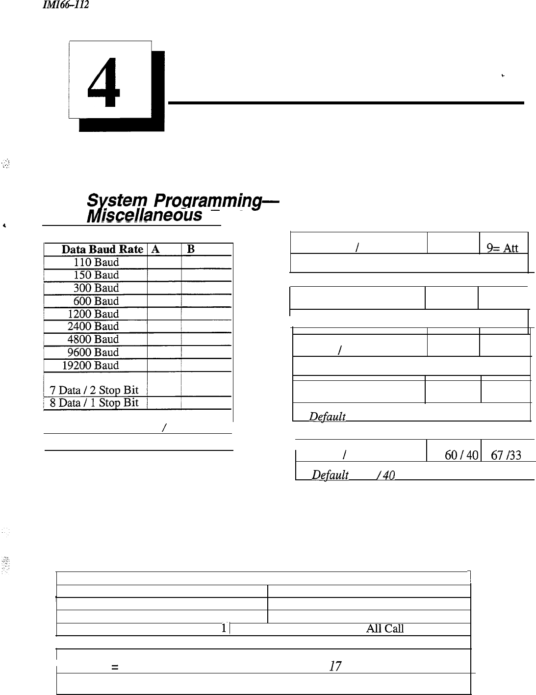
ZMZ66-112
System
Records
.,;.-
:
..;
,
Ll
4
Programming Records
-
4.1
Z$stem
Programming-
iscellaneous Features
Attendant
/
Line Access O=Att
9=Att
Default = 0 For Attendant
Dialing Feedback Mono DTMF /
I
IDefault = Monotone
Tone
/
Voice Signaling Tone Voice
Default = Voice
Exclusive Hold Enable Disable
,
Dgfault
= Disable
)
Default = 1200 Baud 8 Data
/
1 Stop Bits
I
Make
/
Break Ratio
60140
67/33
/
Dgfault
= 60
/40
~
PA Options
Direct Ringing Lines (l-6)
r
Delayed Ringing Lines (l-6)
Night Ringing Lines (l-6)
Zone Paging Enabled 1 Zone
11
Zone 2 1 Zone 3I
AllCall
/Ringing Port Relay Tracking I Station 17 1 Paging Port
.
I
Default
=
No Ringing Lines, All-Call Paging Station
I7
Ringing
4-1
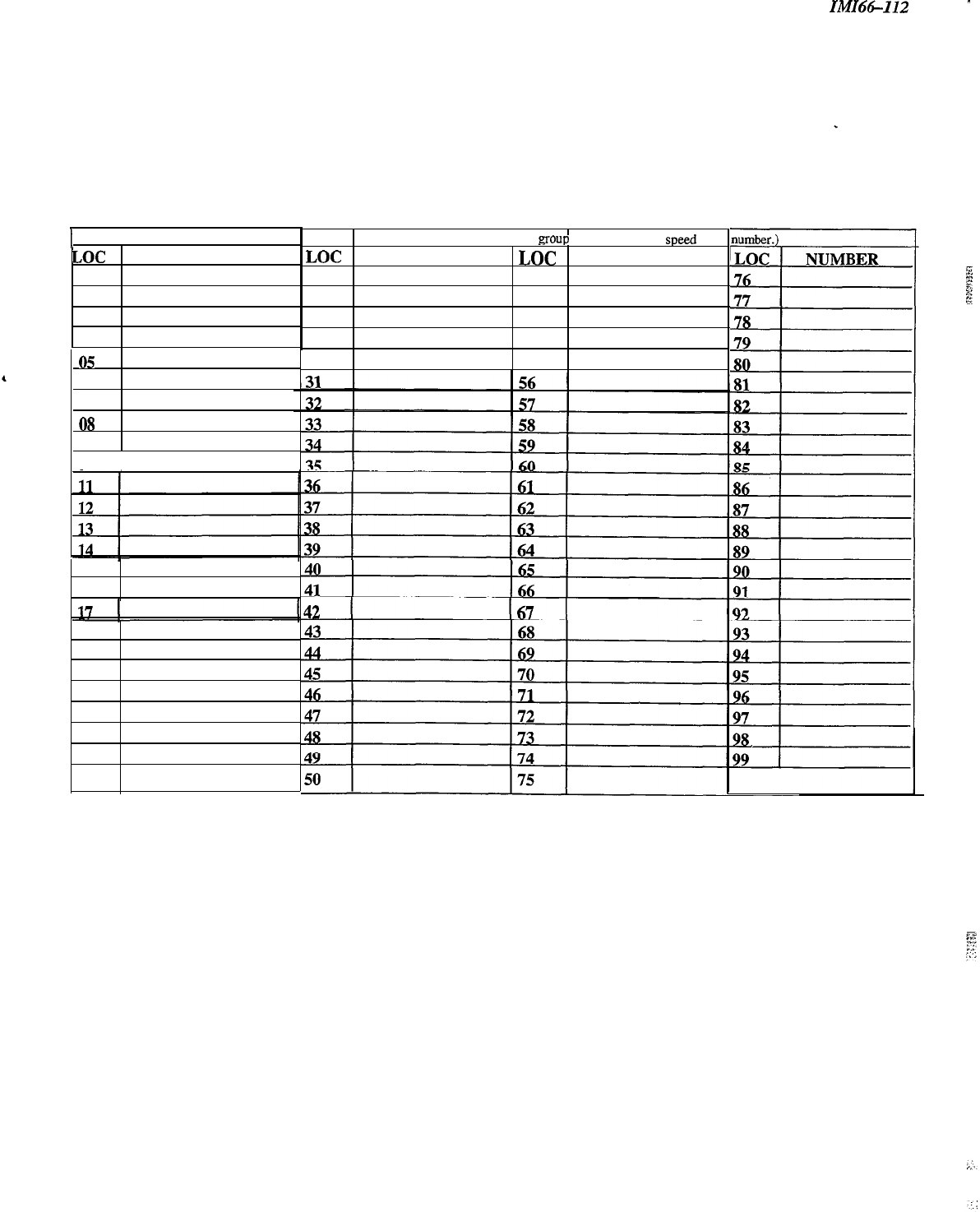
System Records
IMI66-112
-
1
System Speed Dial Record
LOC NUMBER
01
02
03
04
05
06
07
08
09
10 I
15
16
18
19
20
21
22
23
24
25
LOC
3.6
27
28
29
30
(Be sure to record a line or line
group
number with each
speed
dia
NUMBER LOC NUMBER
51
52
53
54
55
4-2
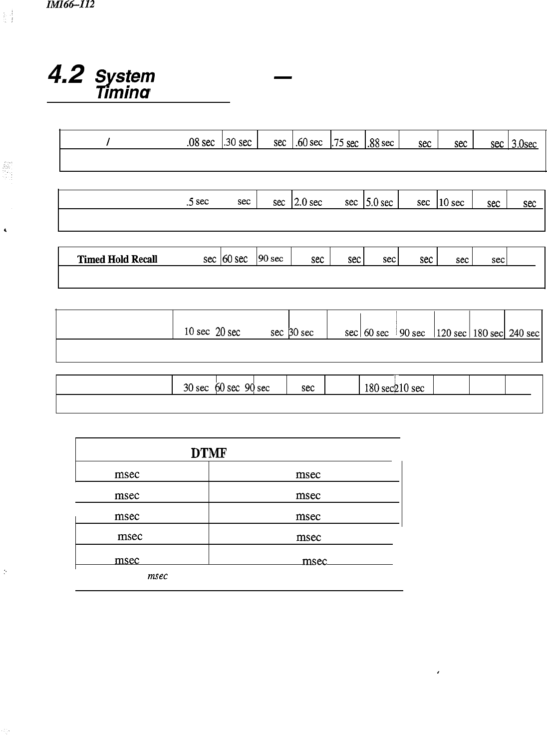
IMI66-112
System Records
4.2
ytem
Programming
-
rmina Features
Recall
/
Flash
Tie
Default = 2 seconds
.08
set
.30
set
SO
set .60
set
.75 see .88
SIX
1.0
set
1.5
set
2.0
set
3.0~~
Pause Time
Default = I second
.5
set
1.0
set
1.5
set
2.0~~
3.0
set
5.0sec 7.5
set
1Osec
15
set
20
set
:.
TimedHoldRecall
Time 30
xc
60 set 9Osec 120 set 180 set 240 set 300 set 360 set 420 set
Never
Default = 60 seconds
Unanswered Call
Transfer Recall Time
I I
IOsec
20s~
25
set
30s~
45
set
Default = 20 seconds
Paging Port Timeout
30s.~
6Osec
90sec
120
set
150sec
180sec
1Osec
i
260sec 300sec None
Default = None
Extended DTMF Tones For Automatic Dialing
80
msec
480
msec
160
msec
560
msec
I
240
msec
720
msec
320
msec
880
msec
400
msec
1040
msec
I
Default = 80 msec
I
I
4-3
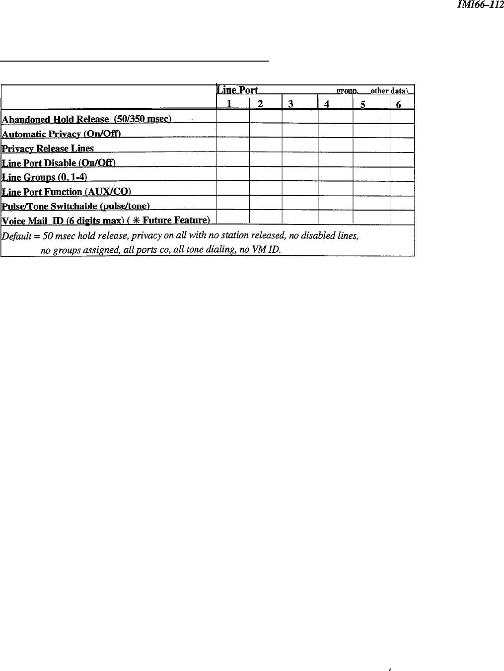
Line Records
IMI66-112
4.4 Line Confiauration Records
Feature
Line
PO&
(Write number. name.
LOUD.
or
otber.data)
III
.
4-4
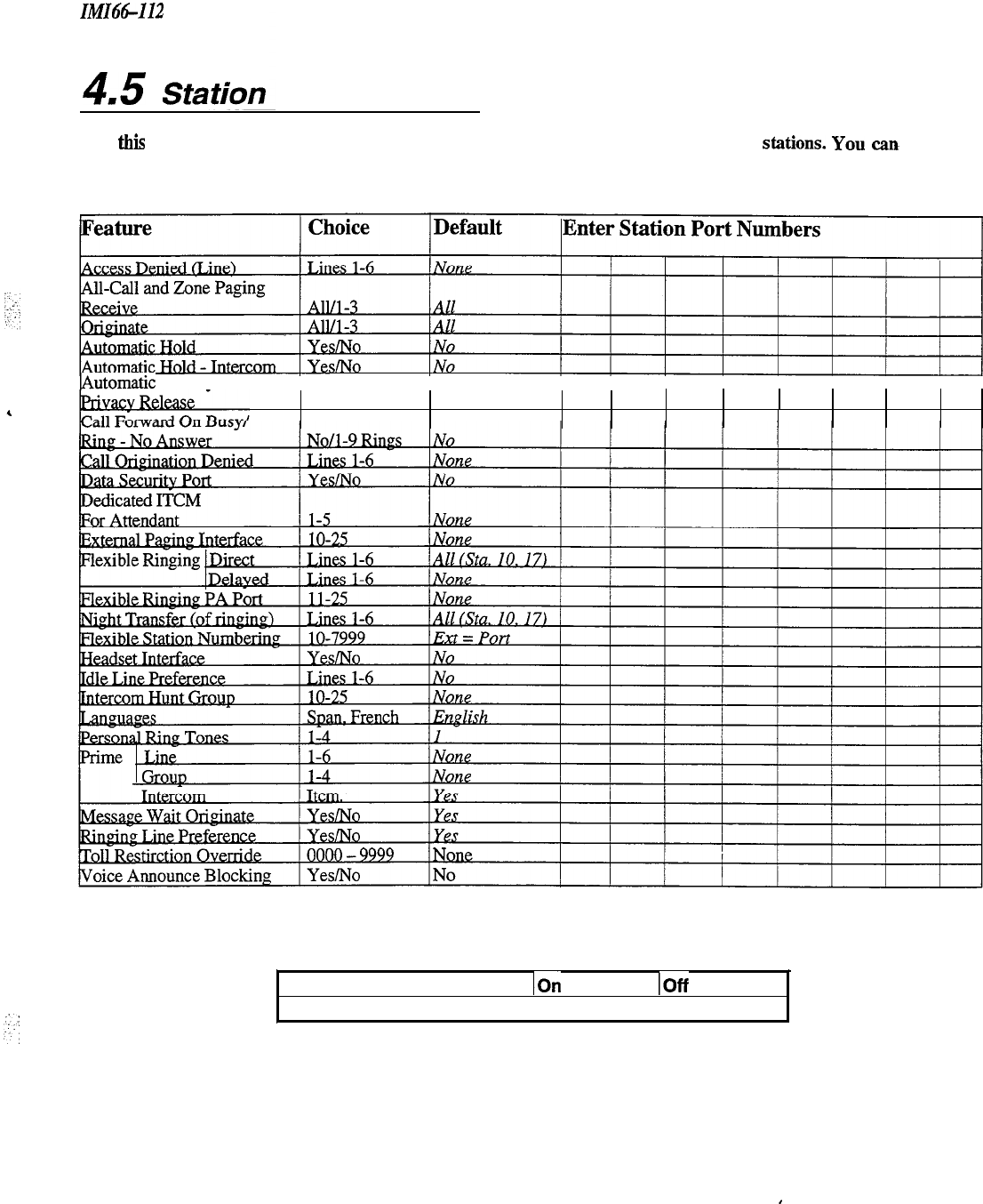
IMI66-112
4.5
Station
Station Records
Configuration
(Use
this
sheet as an individual station record or as a record for a block of like-programmed stations. You
aa
make
copies of this blank sheet as needed to meet the system capacity)
IAutomatic Privacy
IIII I
II I I II
None/l -6
None
IST Distinctive Ringing
IOn
Default = Distincitve Ringing On
IOff
4-5

Station Records
IMI66-112
Station Configuration Records- continued
Station Button Mapping Record
(Complete one record sheet for each station. Copy this blank record sheet as required for additional stations.)
0
6-Line LCD Speakerphone
n
6-Line
Speakerphone
0
6-Line Monitor Telephone
BUllON
DESCRIPTION
BLK Bhnk
Lllll
Snn
DND
PRI
ICZ
SAV
ZPn
AC
ACB
CF
TGn
VAB
TGQ
SHF
Lines
1 . 24
Blalkkns
10
-
57
Do
Noi
Disturb
Privacy Release
Semd
Intercom
save
Zone Page 1
-
3
AIlCall
Page
Atiomatic
Call Back
Call Forward
Line Group
1
.4
Voice Announce
Black
Line Group Queue
Shift
UNIS074
DEFAULTSETTINGS:
308
Bi
=
Line
1
82
=
Line 2
B3=Line3
616
81
q
Line 1
B4=Line4
B2=Line2
85
=
Line 5
B3=Line3
86
= Line 6
Al
=DSSIO
A2=DSSll
A3 = DSS 12
A4 = DSS 13
A5=DSS14
A6=DSS15
A7=DSS16
A8 = DSS 17
Al=DSSlO
A2=DSSll
A3
=
DSS 12
A4=DSS
13
A5
q
DSS 14
A6=
DSS 15
A7=DSS16
A8 = DSS 17
AS=DSS
18
AlO=DSS
19
All
=DSS20
A12=DSS21
Al3 = DSS 22
Al4
=
DSS 23
Al5 = DSS 24
A16=DSS25
‘Shill
button is defaulted at the location of your own DSS button.
4-6
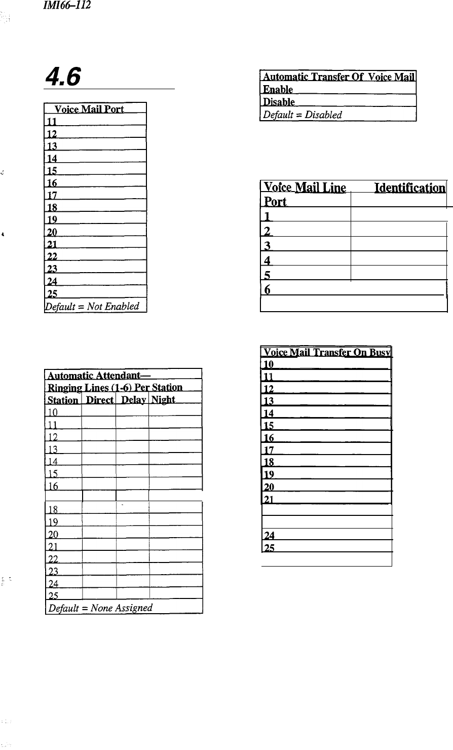
IlvfIt%-112 Station Records
.I
.
4
i
:
:’
:
:
4.6
Voice Mail
.
. . .
once
M&J&g
Port Identlficatlon
Entry
16
I
I
1 Default = No ID Assigned
22
23
Default = Not Enabled
4-7
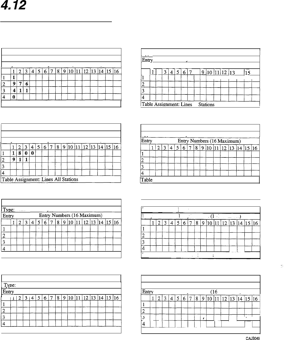
Toll Table Records
ZMZ-66094
412
Toll Restriction
Table Configuration
Toll Restriction Tables
Toll Restriction Table
1
Toll Restriction Table 5
I
Type: Allow Deny X
Entrv Entrv Numbers (16 Maximum)
1
Table Assignment: Lines All Stations
Toll Restriction Table 2
Type: Allow X Deny
Entrv Entrv Numbers (16 Maximum)
Toll Restriction Table
TvDe:
Allow
Denv
3
( Table Assignment: Lines
Stations
Toll Restriction Table 4
1
Tvue:
Allow
,,
Entry
,
Deny
Entry Numbers (16 Maximum)
’
*
[Table Assignment: Lines Stations
1 Type: Allow
Denv
Entry
2
Entry Numbers (16 Maximum)
11
)
213 14 I.5 16
17 18 19 110
111
I12
1IIIlIlllll
II
113
114
115
116
II I I
Toll Restriction Table
Type: Allow
Denv
6
ITable Assignment: Lines Stations
1
Toll Restriction Table 7
I
Type: Allow
Entrv
Deny
Entrv Numbers
Cl
6
Maximum)
III
I
Table Assignment: Lines Stations
Toll Restriction Table 8
Type: Allow
Deny
Entry Entrv Numbers
(16
Maximum)
5llllllllll
11
.
I
11
1 I
4~~~~~)~~~j
11
1 j
11
Table Assignment: Lines Stations
cAJso49
4-8
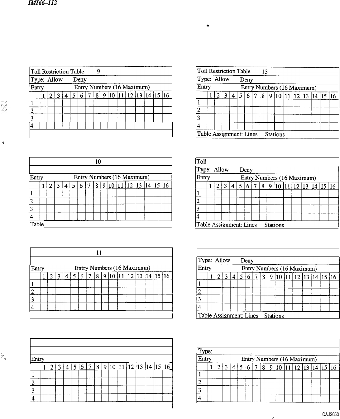
IMI66112
Toll Table Records
Toll Restriction Tables
-
continued
:;e
.-
,,
41II)II/IIIIIIIII
Table Assignment: Lines Stations
Toll Restriction Table 10
Type: Allow
Deny
ITable Assignment: Lines Stations
Toll Restriction Table
11
Type: Allow
Deny
1
Table Assignment: Lines Stations
/
Toll Restriction Table 12
Type: Allow
Deny
Entry
Entry Numbers ( 16 Maximum)
617
~8~9~10~11~12~13~14~15)16
1
Table Assignment: Lines Stations
I
IToll Restriction Table 14
I
1
Toll Restriction Table 15
I
Toll Restriction Table 16
TvDe:
Allow
Denv
I
Table Assignment: Lines Stations
cAJso5o
I
4-9
Toll Table Records IMI-66094
Assign Toll Restriction Tables To Lines
Assim
Toll Restriction Tables To Lines
Port
Tables
,.
.
.
Default = All Tables Assigned To All Ports
Assign Toll Restriction To Stations
Station
Port
10 !
alls
Toll Table Assignments .
NiphtTransfer
16 1
17 I
23 !
Default = None Assigned
4-10
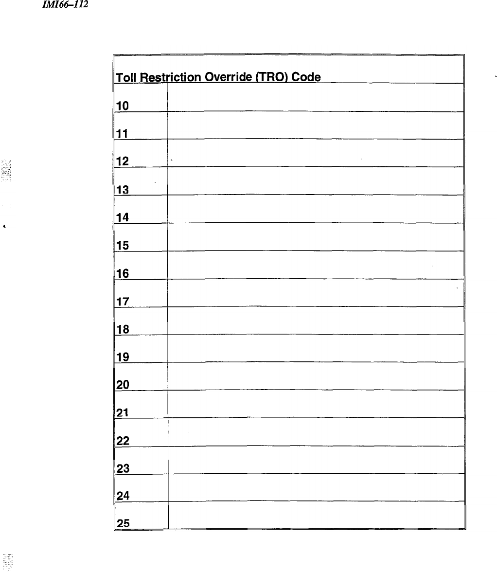
IMI66-112
Toll Table Records
4-11
IMIH-112
Description Of System Features
System Features
A
Abandoned Hold
Release-3.6.2-
When a distant party abandons a Hold condition (hangs up), causing an interruption in the Iine current, the system
drops the line from hold and returns it to service. You can program the time interval between hang-up and line-drop
between either 50 msec. or 350 rnsec. This feature usually depends upon special arrangements that must be made at
the CO end of the connection. The line select indicator will turn off to indicate an idle line after a call on that line
has been abandoned.
Access
Denied-3.7.2-
You can deny access to particular lines at certain stations in the system through system programming. A station user
cannot select a denied line for use. You can program this feature on a per line/per station basis in station class of
service programming.
All-Call Paging-3.7.3,
3.7.”
All-call paging allows all multiline stations to receive announcements through the station speaker at once.
Origination of announcements must be via the station handset. You can program each station to receive and/or
originate all-call page. Also see--Zone
Paging.
All Intercom Links Busy Indication
When all intercom paths are busy, the system causes the intercom light at each station to be on steady. No class of
service programming is required to enable this feature; however, station class of service programming will allow an
intercom link to be reserved for exclusive use by a particular station (3.7.13). IST users will not get ITCM dial tone
if all links are busy.
Area Paging Interface
See-External Paging Interface.
Automatic Call-back
-3.8.1-
When a user encounters a busy tone or a ring-no-answer on an intercom call, he or she can dial a special code (or use
interactive button) that causes the system to automatically ring both the calling and called stations when the called
station becomes idle. No class of service programming is required to enable this feature.
.
5-l

Description Of System Features
IMI66112
Automatic Hold For
Intercom-3.7.6-
If a user selects the second intercom line while a
call
is active on the first intercom line, this feature causes the first
intercom call to be automatically placed on hold.
Automatic
HoM-Transfer
To Intercom (Answer
Hold)-3.7.5-
If the intercom line is selected while an outside line call is active, this system feature causes the outside call to be
automatically placed on hold. No class of service programming is required to enable this feature.
Automatic Hold-Transfer To
Line-X7.5-
When you enable
this
feature, an active line will automatically go on hold when the user presses any line button.
This feature allows a user to move from line to line without having to press the HOLD button to place any current
calls on hold.
Automatic
Privacy-3.6.3,3.7.7-
You can program a line to be private or non-private. In the private mode, a station has exclusive use of the line
during a call, and no other station can access that line unless the user includes the add-on station through the use of
the privacy or add-on conference feature. In the non-private mode, all stations with that line appearance can
gain
access at the same time (sometimes known as common line pickup). Use line class of service programming to make
a line private or non-private. Through station class of service programming, you can make a
line
non-private at a
particular station. Also see-Conference -Add-On
Automatic Privacy
Release-3.6.4,3.7.8-
You
can arrange for individual stations to automatically release privacy while on certain private lines. With this
arrangement, other stations can join that
pticula
station whenever it is on the line that you have assigned as a
privacy release line.
Auxiliary Station Ringer
Interface-2.7.4,2.7.5-
The auxiliary station ringer interface provides “dry-contact” relay closures whenever station
17
rings. The contact
closures track the ringing pattern of station 17 and can control an external signaling device. When you program
station port 17 to function as a PA port, the auxiliary ringer interface relay contacts automatically become
supervisory contacts and close when someone
calls
the PA port. No class of service programming is required. Also
see-Common Audible Ringer
Intelface.
B
Background Music (External Music Source Required)
If the system user provides an external music source, station users can turn on background music at their particular
stations. Users adjust the loudness of the background music with the speaker volume control. The background
music automatically turns off during
calls.
N
O
~1a.s~
of service programming is required to provide this feature. The
system will not support background music with bridged proprietary and auxiliary devices connected. Also
see-Music on Hold
5-2
IMI66-112
Description
Of
System Features
Basic Key Service (la2) Emulation
The system provides all of the basic,
IAZtype,
key service features. These features are as follows: selective line
pickup, common line pickup, multiline pickup, and hold. No special class of service programming is required.
Battery Back-up Interface
-2.4.2-
We have made it possible to attach a Comdial-provided optional battery back-up kit to the common equipment.
Battery back-up gives full uninterrupted system power in case of an AC power loss. The switching and trickle
charge circuitry are in the common equipment, while batteries, chassis, and cable are packaged as a separate option.
When plugged into an active AC power source, the common equipment constantly charges the attached batteries
with a trickle current. Built-in circuitry automatically switches to battery power when AC power is lost. With
batteries at full charge, a fully loaded system will operate for a minimum of one hour without AC power. No class
of service programming is required.
C
4
Call Announce With
Handsflee
Answerback
The internal speaker at each multiline station provides call-announce capability over the intercom link. Users can
make handsfree response to a call-announce. The microphone built into the telephone transmits this response. No
class of service programming is required (Handsfree Answerback not available on 1122X).
Call Forwarding On All Calls
This feature allows a station user to designate another station or the attendant station as the recipient of all calls
normally directed to ring at his or her station. If you have enabled call forwarding when night transfer of ringing is
activated, the system also forwards the night ringing assignment of the station. The system can also forward calls
that have been forwarded once. Therefore, two levels of call forwarding on all calls can occur, first, from station A
to station B and then, from station B to station C. For each intercom call that a station receives while calls are
forwarded, a short tone burst will occur at the forwarding station as a reminder that call forwarding is enabled.
When you designate a programmable button to serve as a call forward button, the associated LED will turn on when
the user presses the button. The LED indicates that the feature is enabled. If you program the call forward button as
a second level to a DSS/BLF button, the LED indication is always reserved for BLF indication. On LCD
speakerphones that are recipients of call forwarding, the display will indicate the extension number or station name
for the station from which an intercom call was forwarded. No class of service programming is required. Also
see-Call Forwarding-Busy Ring No-Answer
,:
.‘.
:
5-3

Description Of System Features
IMIii6-112
Call Forwarding-Busy /Ring-No-Answer-3.7.9,3.X3-
The system can automatically forward busy or ring-no answer calls to a different station for answering. The system
sends these calls to any idle station associated by intercom hunt
group.
Call Pickup-Directed
A station user can dial a code, followed by the extension number of a ringing station, to answer the
ringing
call. No
class of service programming is required.
Call Pickup
If a call rings to any station in the system and another user wishes to answer the call, that user must dial the pickup
code to answer the call.
Call Transfer-Screened
Screened call transfer allows a user to transfer outside calls from one station to another, via the intercom link, in one
of two ways. If both stations have access to the line, they can simply use a common line pickup transfer-the
transferred station merely presses the line button of the incoming call. If the other station does not have access to the
incoming line, transfer can still take place using the system transfer feature. For a screened transfer, a user transfers
a call with a pre-transfer announcement. Users can transfer calls with the CONF button. No class of service
programming is required. Also see-Call Transfer-Unscreened.
Call Transfer-
Unscreened-3.5X-
A user can transfer an active call without being announced. The transferred call camps-on to the other station where
it rings and awaits an answer. The call will automatically ring back to the transferring station after a programmable
recall period. There is no limit as to how many
C&
GUI
be
camped
onto another station. A transferred call will
only ring if the station is idle. The system class of service programming determines the recall time for an
unanswered transferred call.
Call Transfer-
Unscreened (with Automatic Camp-on to Busy Station)
A user can transfer an active call without being announced. The transferred call immediately rings at that station if it
is idle. If a user transfers a call to a busy station, the transferred call automatically camps-on at the busy station. If
the user transfers additional calls to the busy station, the system places those calls in a camp-on queue. When the
user who has received all of the transferred calls hangs up the current call, the first queued transferred call will ring.
This sequence continues until the user has answered all transferred calls. Stations that have line appearance for a
transferred line will show a “my-line” held call status indication for the transferred call. The transferred call will
automatically ring back to the transferring station after a programmable transfer recall period.
Call Waiting Tone
A user can send the call waiting tone to a busy station to indicate that he or she wants to contact the busy station.
Users dial a special code to activate the tone. No class of service programming is required..
Calling Station Identification On BLF
If you have programmed the station number of a calling station into the direct station select/busy lamp field
(DSS/BLF) of a called station, the caller will be identified by a flashing BLF light. The lights also indicate the status
of the DSS telephones: dark = idle, steady-on = in use, flash = calling, and flutter = call back request. No class of
service programming is required for this feature.
Ib!lI66-112
Description Of System Features
Class
Of Service Programming (From Main Station)
Use class of service (COS) programming to configure and assign all system, line, station, and special purpose
operating features. Enter COS programming by dialing an access code over the intercom line. System
administrators can enter COS programming with another code to re-program any system, station, or special purpose
operating feature that may require change at a later date. Line reprogramming ability and defaults are not available
through system administration programming. The system attendant can reprogram certain system-wide features that
require periodic change by entering COS programming with another code provided for this purpose. The station
user can program individual stations for speed dial, and direct station selection (DSS) by entering COS with a code
provided for that purpose. Thus, COS programming is arranged with a hierarchical order from the highest (the
installer) to the lowest (the station user) level. However, only the station user can program the speed dial locations
at his or her telephone.
Perform all class of service (COS) programming from station 10 or 12. Any multiline station combination functions
in this mode and provides visual feedback with the LED associated with the programming button. By employing an
LCD speakerphone, however, the programmer has the benefit of display prompts and verifications to simplify and
clarify the programming procedures. Class of service programming access is as follows:
l
Installer dials: ITCM
*
#
7 4 6
+K
l
Administrator dials: ITCM
%
#
2 3 6
+K
l
Attendant dials: ITCM
+K
#
l
User dials: ITCM
%
%
Common Audible Ringer
Interface-2.7.2-
Connections are available at the common equipment that provide “dry-contact” relay closures whenever an incoming
line rings. These contact closures track the ringing pattern and can be used to control an external signaling device.
When you program station port 17 to be a PA port, the common audible ringer interface contact points automatically
become supervisory contacts that close when someone
calls
the PA port. Also,
see-Auxiliary
Station Ringer
Interface.
Conferencing-Add-on
With this feature, a station operating in a private mode can add another station to an outside call. No class of service
programming is required.
Conferencing-Multiline
This feature allows one multiline station to access two outside lines at the same time resulting in a conference
arrangement. A user can establish conferencing by using the CONF button. Conference transmission levels are not
compensated. No class of service programming is required.
Conferencing-Unsupervised
-.
After a conference between an internal party and two external parties has been established, this feature allows the
internal party to drop out of the conference by dialing a special code. The conference between the two outside
parties continues in an unsupervised condition. No class of service programming is required Also
see-Conferencing
-
Multiline.
There is no unsupervised conferencing on IST stations.
D
Data Baud
Rate-3.5.2-
You must program the speed or baud rate of the data bit stream, which carries the SMDR and configuration data
between the system and an external data device, to match the requirements of the data device.
5-5
Description Of System Features
IMI66-I12
Data
Security-3.7X-
Data security prevents any type of tone (DTMF,
calI
waiting, barge-in, etc.) from interrupting an active
call
on a port
programfned
with the feature. This feature prevents interference to non-voice communications from occurring when
you are using the port as an auxiliary bridged device or a stand-alone IST data port.
Dedicated Intercom for
Attendant-3.7.13-
This programmable feature ensures that an attendant at a principal
call
answering position will always have a free
intercom link to use for announcing the incoming calls to the stations. You can also reserve intercom links for
exclusive use by any particular station in the system.
Defaults-3.6
At initial power-up of the system, the operating features are set to a specific group of operating conditions (default
conditions). The default conditions provide a complete operating system for normal use. You can leave the system
as a defaulted system or reprogram. You can reset the default conditions by system, line, and station class of service
programming. A master clear will default the entire system and erase all stored programmable button information.
Default Toll
Restriction-3.4.6-
The system defaults two toll restriction tables with pre-programmed values and assigns those tables to all lines.
All
you have to do is assign the tables to the stations to put them into effect. You can reprogram the defaulted tables
using the normal programming procedure. Assign toll tables to stations using station class of service programming.
Reprogram toll tables using toll restriction table configuration class of service programming.
Delayed Ringing-3.7.1
6-
You can program delayed ringing assignments for individual stations. You can program a station to provide delayed
ringing on some lines while providing immediate ringing on other lines (delayed ringing occurs on the fourth ring
from the CO). See-Flexible Ringing Assignments.
Designated Programmable Buttons
-3.8-
You can assign station programmable buttons to provide one-button access to a broad range of features. There are
some designated buttons that
YOU
must assign at each station using station class of service programming, but the
station user can assign many others.
Dial 0
/
9 For System
Attendant-3.5.1-
Whenever any station user dials 0 (or 9) on the intercom line, the system signals the attendant station (station 10).
Direct Station Selection (DSS) Programmable
See-Programmable
DSYBLF.
Direct Ringing
See-Flexible Ringing Assignments.
Distinctive
Ringing-3.7.22-
The ringing cadence of an incoming
cdl
is the same as the ringing cadence of the
TELCQ
PEN, or CENTR.EX
system. The ringing cadence of an intercom call presents two tone bursts sounded every four seconds. Class of
service programming is required for IST ports.
Do-Not-Disturb-3.8.6
You can set any station to a do-not-disturb mode (DND) using the designated DND programmable button and
associated indicator (indicator will light when DND is active). While in the DND mode, the station will not ring on
any incoming call nor will it accept an intercom call, however; line appearance and ITCM will flash. A party
making an intercom call to a station set in the DND mode hears a fast busy tone.
.
.
5-6

In!iI66-112 Description Of System Features
Dual
Intercom-3.8.9-
This feature provides two separate intercom lines at the same station. One intercom line is fixed, and a user can
access that intercom line by pressing the ITCM button. You can program the other intercom line, and a user can
access that intercom line by pressing the programmable button selected for that purpose. A user would handle calls
on the intercom lines in much the same manner as he or she would handle outside calls. Special considerations for
dual intercom operation are as follows:
E
Remote call pickup is not available.
Distant party hang-up causes intercom link to drop.
Intercom call to station already busy on intercom rings in subdued fashion and flashes indicator associated with
other intercom button.
With both intercom lines busy, a third intercom call receives a busy signal.
Pressing a DSS button while on an active intercom call will drop the distant party unless the automatic hold
feature is enabled for the intercom line through class of service programming. The hold button can be used,
however, to place an intercom call on hold before selecting the other intercom line for use.
End-to-end Signaling on Intercom
After a user has established an intercom call, the system can continue to send dialing signals (DTh4F tones) through
the intercom path to IST devices. Users can perform this feature from every station in the system, and it can be used
with peripherals such as voice mail equipment. No class of service programming is required.
End-to-end Signaling on Lines
After a user has established an outside call, the system can continue to send dialing signals (DTMF tones) through
the telco network and have them received at the distant end for inward call completion (bank by phone, etc.). This
conventional, off-hook dialing feature can be performed from every station in the system. No class of service
programming is required.
Exclusive Hold
Exclusive hold prohibits a held call from being retrieved by any other station. The exclusive hold condition also
links the held call to the timed hold recall timeout feature. After timeout, audible and visual signaling will occur and
the exclusive hold condition reverts to a normal line hold condition. Default is disabled.
Exclusive Hold System-wide
Enable/Disable-3.5.4-
This feature allows you to turn on or off exclusive hold system-wide.
5-7
Description Of System Features Ih!f.I66-II2
External Paging
Interface-2.7.3,2.7.4,
3.7.I5-
You can program a station port or line port to interface with an external paging amplifier. Users can then access the
paging
amplifier through the station port or directly through the line port from other stations in the system. The user
can dial DTMF tones through the line
port
to provide zone selection if provided by the external
paging
anqlifier.
The line class of service programming arranges a line port for external paging interface, and the station class of
service arranges a station port for external paging interface.
Extended Dual Tone Multiple Frequency (DTMF)-3.5. I
O-
The system can access outside equipment, answering machines, banking computers, voice mail equipment, for
example, that require
DTMF
tones that are longer than the standard 80 maser tone. A shift to a longer tone, of
pre-programmed length, is automatically made
10
seconds after a line is selected or 10 seconds after the last digit of
a number is dialed. A user can shift from one tone length to the other by pressing the hold button and then
re-selecting the line.
F
Flexible Ringing Assignments-3.7.1
6-3.7.20-
You can program ringing assignments on a per station/per line basis for every line that has an appearance at each
station.
Also
see-Delayed Ringing and Night Ringing.
Flexible Ringing Assignments Of PA
Ports-3.7.19-
Stations ports that you program as PA ports can also be programmed for flexible ringing assignments. You can
program any desired lines to direct or delay ring at this port. You can connect a speaker to the voice pair of this port
and when connected, it will sound the ringing that is generated by the system and sent to this port as if it were a
regular station port. Using such an arrangement, the user can determine that certain lines are ringing, such as in a
night transfer of ringing mode, and go to the nearest telephone and answer the call. The most common use for this
arrangement is as a night bell eliminating the need for external equipment as required with the common ringer and
auxiliary ringer interface. You can only program one PA port per system as a ringing PA port. Users cannot use the
speaker for voice response as the path is one-way only.
Flexible Station And Trunk Class Of Service Control
See Line-to-Line Port Reassignment and Station-tcMtation Port Reassignment
Flexible Station Numbering
Plan-3.7.21)-
You can program each station to respond to the dialing of any available number between 10-79, 100-799, or
1000-7999. Also, you can assign any combination of two, three, or four digit extension numbers as long as they do
not conflict. For example:
If
you assign
21
as an extension number, there cannot be any other extension number
assigned that begins with a 21.
Full Button Programmability Of Features
You can make most Unisyn features available at programmable buttons by programming the feature buttons or the
specific access codes necessary for dialing the features. Programmable features include those that can utilize lamp
(on/off) supervision. You can store all feature access codes, except for those requiring T/C button action. You can
also store continuous strings of digits, including ITCM button presses, up to sixteen digits per button.
5-8

IMZ66-112 Description Of System Features
H
Handsflee
Answer Inhibit
A user can press the MUTE button on a multiline station to block all handsfree answerback response. ‘Ihis
arrangement will prevent a station user from monitoring another station site using the monitoring ability of the voice
announce feature. When the user presses the button, all handsfree answerback is disabled thus inhibiting any
off-site monitoring. The mute LED is steady-on to indicate that this feature is active. Any user activity at the
telephone cancels the mute condition. No class of service programming is required. Also see--Mute.
,,
:.
;
:
‘..
Headset
Interface-3.7.21-
You can enable a station port to allow headset operation through the handset. You must program that telephone to
accept the headset.
Hunt Group On
Intercom-3.7.10-
You can assign station ports to intercom hunt groups. When a station that is assigned to a hunt group is busy or is a
ring-no-answer (RNA) a call to that station will ring at the next idle station in the group. A hunt group can be
terminal or circular. A
call
will route down a terminal
group
from the called station until it finds an idle station or
reaches the end of the group. A call will search around a circular group until it encounters an idle station or until all
stations in the circular group are searched. Up to 16 stations can be placed in one hunt group. You can program the
ringing time at any one station.
I
I Hold And I Use Indications
The light associated with a line button provides a visual indication of the status of that line. When a station user has
a line in-use or on-hold at a station, the light indication provided at that station is green or flashing green; the light
indication at the other stations in the system is red or flashing red. No class of service programming is required.
Idle Line Preference
When you program a station for idle line preference, it will automatically connect to the first assigned idle line.
You can program the system on a per station basis to enable idle line preference. When idle line preference is
enabled, taking the handset off-hook will automatically
COMeCt
the station to any assigned line that is idle and has
been arranged for this feature. The user will not have to press the line button. If someone uses this feature in
conjunction with prime line automatic, the user will be given prime line first when going off-hook.
An idle line will
be given if the prime line is in use.
Intercom Call Progress Tones
:
:.:
.-
,..’
Ihe
system marks intercom
call
progress by special tones. A steady tone sounds for dial tone. A one-second-on and
three-seconds-off tone sounds for ring-back. For tone signaled intercom calls, a double-ring burst sounds every four
seconds at a called station and returns to the caller as ring-back. For a voice-signaled intercom call, a single tone
burst sounds at a called station. When a called station is busy on an intercom call, a busy signal of one-half second
on and one-half second off sounds at the calling station. When a station is busy on an outside call, the called station
gets a subdued ring, and the calling station gets a ring back tone. A fast busy tone will be supplied when the called
station is in the do-not-disturb mode.
N
O
class of
service programming is required.
5-9

Description
Of
System Features
IMI66-112
Intercom Line Timeout
Should the intercom line be selected with no dialing or other action taking place, the intercom “times out” after ten
seconds, and returns to an idle state. No class of service programming is required. If no intercom is available on an
IST telephone, the system does not provide an intercom tone until an intercom does become available.
-
L
Languages-3.7.2”
You can program the system to display all LCD prompts in one of three languages: English, Spanish, or French.
Last Number
Rediul
The system provides each station with a last number redial feature. This feature will save 32 digits of the last
outside number dialed. A newly dialed number will always automatically replace a previously dialed number. Upon
command, the system will choose a line and redial the saved number. The system will first choose the prime line if
assigned and idle. If prime line is busy or unavailable, the system will choose any line assigned to idle line
preference. If they too are unavailable, the system will choose the last line used at the station. If it is busy, no
further choice is made. No class of service is required. Also
see-Automatic Pause
Znserth.
LCD Support
The system supports the use of speakerphones having a Liquid Crystal Display (LCD). The LCD speakerphone
ports are identified by station class of service programming.
Line Port Functions-Line
Disable-3.6.6-
You can take a line port out of service when necessary (because of defect, for example) using this programming
procedure. Return the line to service with the central office lines programming step, 3.6.8.
Line Port Functions-Auxiliary
Lines-3.6.7-
You can program a line to serve as a
port
for an external paging amplifier.
See-External
Paging
Znteeace.
Line Port Functions-Central Office
Lines-3.6.8-
You can condition a line port to serve as a
port
for a standard telephone company supplied central office line.
Line Groups-3.6.5,
3.8.7-
You can group outside lines together in up to four different groups. Each group is accessible through a unique
dialing code or is automatically selected with the programmable autodial feature. Grouping can reserve certain lines
for certain clusters of stations as in a tenant-service arrangement or reserve certain lines for access only by
single-line sets. The assignment of line groups frees station buttons normally used for line selection thus making
these buttons available for use with a feature such as a second ITCM key.
Line
Preselection-3.6.5-
A user can manually select a line before lifting the handset (for handsfree dialing) or after the handset is lifted. No
class of service programming is required.
Line Queuing
With the line queuing feature, a user can dial a special code number that will place a station in a queue where it
awaits the availability of a line or line group. When the line is available to it for use, the system automatically
signals the station with five tone bursts . Each station can queue one line at a time. No class of service
programming is required.
5-10
IMI66-112
Description
Of
System Features
M
Manual Hold
A button activated feature at each station will place an outside line on hold. Pressing the HOLD button holds the
call, provides a distinctive flash rate of the line button indicator, and allows the user to access other station features.
‘Ihe holding station or any other station that has access to the line can retrieve the held call. No class of service
programming is required.
Memory Retention Without Batteries
An electronic device sometimes referred to as a “super-cap,” electronically protects the system memory during AC
power failures. The stored program data will remain in memory for a minimum of 70 hours, provided that the
system has been powered continuously for at least 30 minutes prior to the power failure or disconnection. Some
models include a system clock. On those models, the system clock will continue to run and keep time for at least 24
hours after an AC power failure or disconnection. No class of service programming is required.
Message Waiting-3
7.28-
Special feature access codes enable a station user to control the message waiting (MW) light at other stations in the
system. W’hen a user turns on the message waiting at a station, a call can be automaticaIly placed to the station that
turned it on. The message-waiting light automatically turns off when the called party answers.
If a station has a DSS/BLF appearance at another station, the station user can leave a call-back message indication at
that other station. By dialing a special code, the user can activate the BLF light at the called station. This light
indicates that the user’s station has requested a callback. The system automatically turns off the light if a successful
callback is made.
Mixed Station Capacities
See-Port Definition.
Modular Wiring And
Jacks/4-conductor
Wire System
You can completely interconnect the system by employing industry standard
5@pin.
coMe&ors and modular
plug/jack combinations. Station wiring is 4-conductor,twisted-pair cable (2-conductor twisted pair cable for IST)
throughout the system. No class of service programming is required.
Music Interface (External Source
Required)-2.7.6-
We have provided the system with a jack for the
COMdiOn
of a customer-provided ASCAP registered music
source. No class of service programming is required. Also
see-
Background Music
and
Music-On-Hold.
Music-on-Hold
The system provides music to outside lines that are placed on hold if an external music source is connected to the
system. No class of service programming is required. Also
see--Music Interface.
Music-on-hold System-wide
Enable/Disable-3.5.6--
The system provides music to outside lines that are placed on hold if an external music source is connected to the
system. Music-on-hold
can
be disabled system-wide by attendant action.
Also see -Music
Intelface
and
Music-On-Hold.
Mute
Each station has a MUTE button that, when pressed, will mute the handset transmitter (or internal microphone on
speakerphones) to prevent the user’s voice from being heard by the distant party. The mute light comes on to
indicate a muted condition. The button provides push-on/push-off operation. No class of service is required. Mute
is automatically canceled when anyone disconnects by hanging up or pressing the mute key. Also
see-Handsjree
Answer Inhibit.
.
5-11

Description Of System Features
IMIG-112
N
Night
Ringing-3.7.18-
Night transfer is an attendant-controlled feature that transfers the day ringing program of all incoming calls to a
particular station or stations for off-hour or special purpose answering. The night transfer mode can only be
activated from station 10 or 12. Select the individual lines at each station that are to have ringing transferred with
this feature with station class of service programming.
0
On-Hook Dialing
x
‘2
Every multiline station provides manual and/or automatic dialing while the station handset is on-hook. An internal
speaker monitors call progress for completion. (The handset must be taken off-hook to provide the voice link on
non-speakerphone stations.) No class of service programming is required.
Originating Denied-3.7.1
l-
You can deny individual stations the ability to originate calls on certain lines through system programming.
Program the originating denied feature on a per station/per line basis. Originating denied does not prevent a user
from answering a ringing line, retrieving a held call or receiving a transferred call.
P
Pause
Time-3.5.12-
During speed dials, it is sometimes necessary to delay the sending of digits to give switching equipment time to
prepare for receiving those digits. The system stores a pause for this purpose whenever the user presses the HOLD
button. You can program the length of the pause through class of service programming.
PBXICENTmXKO
Compatible
System features and programmable buttons support the requirements of most PBXs, Central Offices, and CENTREX
systems. Numbers, #‘s, Ws, programmable pauses, and flash signals can be made a part of every stored number for
access to host system feature codes. No class of service programming is required. The system supports IST
hookflash for CENTRBX features via access code.
Personalized Ringing
Tone-3.7.25-
This feature allows a station user to choose one of four different ring tones to aid in distinguishing one ringing
station from another.
Pooled Line Access
-3.6.5-
Users can dial a special access code instead of pushing a line button to access one of four different groups of lines.
Single-line telephones do not have line appearances, so a user must use this feature for accessing an outside line for
dialing out. Lines are arranged into groups with the line class of service programming.
Port
Definition-3.7.26-
You can program a station port to accept one of several different types of equipment, such as an LCD speakerphone
or a multiline line telephone.
Power Failure
Transfer-2.7.1-
A power failure line connection is available for connecting industry-standard telephones such as a Comdial model
2500. These power-fail telephones automatically connect directly to certain lines whenever there is an AC power
failure. Normal origination and reception of calls on a power-fail station is possible during the power failure
condition. The power-fail stations will automatically disconnect as soon as power is restored. No class of service
programming is required.
5-12
IMI66-112
Description
Of
System Features
Prime Line
Automatic-3.7.27-
If you program a station for prime line automatic, the system automatically selects the designated outside line,
intercom line, or line group when the user takes the handset off hook. Users may pre-empt prime line pickup by
selecting another line before lifting the handset. If the prime line is ringing, it is automatically answered when the
user lifts the handset.
Privacy Release
-Designated Programmable
Button-3.8.10-
You can program stations to provide a privacy button. If a line is private, a user can press the privacy button to
change it into a non-private one. If the line is non-private, pressing the button will have no effect.
Private Lines (Access Denied)
See -Access Denied.
Programmable
DSS/BLF
(Direct Station Selection/Busy Light Field)
A multiline station user can store one-button, direct station selection (DSS) at any programmable button location to
create a DSS button. When a user presses this button, the system automatically places any active outside call on
hold and then makes an intercom call to that previously stored station number. The visual indicators of the stations
programmed at the button locations form a busy lamp field (BLF). The BLF conveys station status to the user. You
can also program a speed-dial number as a secondary function at every DSS/BLF memory location. No class of
service
is required. Also
see-Tone or Voice Signaling (Intercom).
Programmable Buttons
See-Full Button Programmability
of
Features, Programmable DSS/BLF, and Dedicated Programmable buttons.
Pulse/Tone
Switchuble-3.6.9,3.6.10-
You can program the system on a per-line basis to allow the stations to switch from pulse to
DmF
dialing as
needed. Alternately, you can program the system to only allow tone dialing.
R
Remote Access And Administration
Remote upload and download of the system and SMDR output for printing are both available through serial data
ports. These data ports will
support
X-on
X-off
control codes for terminal control as well as a
DIR
signal for
handshaking. They also have the popular XMODEM protocol so that the system database can be uploaded or
downloaded, error free, from or to a remote computer running software that supports the XMODEM protocol. Use
serial port one for programming and serial port two for SMDR.
Ringing Line
preference-3.7.29-
You can program the system on a per-station basis to provide ringing line preference on all lines programmed for
ringing at the station; ringing line preference activates the yellow lamp.
When you enable ringing line preference at a station, taking it off-hook
aI.ItOm~C~~y
conncxts
it
to
my
oUtsi&
line
that is ringing. If a station also has prime line assigned, the prime line will always be answered first even though it
may be the second line to ring. The ability of a particular station to answer a ringing line with line selection is
enabled by the station class of service programming.
5-13
Description Of System Features
IMI66-112
S
Saved Number
Rediul
This feature enables a button action to save the first 16 digits of the last number manually dialed from the keypad.
The user can
redial
the saved number at a later time. The saved number is permanently available for later use until
the user replaces it with a new number. No class of service programming is required.
Self
Diagnostics-2.9-
Each station can execute a self test when so enabled. This test verifies processor, indicator, and tone functions. No
class of service programming is required. For a self diagnostic, hold down the keypad 1 key when plugging
telephone into the common equipment.
Speakerphone Support
The optional speakerphone (1022S-xx, 1122s~xx) provides handsfree operation of all features, except origination of
call announce; the user must lift the handset for this purpose. No class of service programming is required.
Square /Non-Square
Configuration-3.8-
You can program a system to be square or non-square as desired. In a square system, the line 1 buttons of all
telephone stations select line 1, the line 2 buttons select line 2, etc. In a non-square system, you may assign each line
select button at every station individually to select any line. You can perform button mapping for line appearance on
each station using the station class of service programming.
Station By Station Privacy
See -Automatic Privacy.
Station Message Detail Recording
(SMDR)
The SMDR feature generates a call record for printing as soon as the record is collected by the system. The call
record is presented at the RS-232
port
as an ASCII transmit data in an 80-column format. No class of service
programming is required.
Station Speed Dial
You can program each proprietary station to provide up to 36 speed dial numbers. Station speed dial numbers can be
up to 16 digits in length and can include line or intercom selection, numbers,
#,
SAC,
pauses, and flash signals. The
system stores a pause each time the user presses the HOLD button, and it stores a flash signal each
time
the user
presses the TAP button, No class of service programming is required.
Subdued
Ring&g
When a station is busy on a call and another call comes to the same station, the ringing of the second call will
automatically be subdued to a lower volume. No class of service programming is required.
System
Clock-3.5.7-
The system provides current time and date information, which is displayed on all LCD speakerphones and captured
on SMDR printout.
5-14
IMI64-112
Description Of System Features
System Speed
Dial-3.5.8-
The system provides up to ninety-nine system-wide speed dial numbers. The system speed dial numbers can be up
to 16 digits in length and can include numbers,
#‘s,
%‘s,
pauses, and flash signals. Program system speed dial
numbers at station 10 or 12 for use at every station in the system. No class of service is required.
T
Tap (Flash) /Recall
:
:
.-:.
When host system custom-calling features are available via a hookflash signal, you can program the system
so
that
the TAP (RECALL) button will generate a “flash” signal when a user presses it. When custom calling features are
not available, the TAP (RECALL) button functions as a positive disconnect, or dial tone, recall button. These two
features are mutually exclusive. IST support is feature code activated (future feature).
Tenant Service
You can have one telephone system function for multiple tenants by having flexible line appearance at each station.
You can use button mapping for line appearance on each station using the station class of service programming.
Refer to the discussion
titled: SquareAVon-Square Configuration.
Timed Hold
Recall-3.X14-
After a call has been on hold for a programmed length of time the system will re-call the station that placed the call
on hold.
Toll Restriction (0 And 1)
See the discussion
titled: Toll Restriction (flexible).
Toll Restriction (Flexible)-3.1
O-
You can program toll restriction to prohibit some or all stations from calling a wide range of number combinations.
The restricted numbers are specified on up to 16 tables. The system assigns several broad-range values to two of
these tables and assigns the tables to all lines as a default condition. All you need to do is to default the tables on a
per-station basis to activate the default toll restriction.
In general, toll restriction works as follows:
The programmable tables of restricted numbers contain up to four entries with each entry containing up to 16 digits.
You can program each table of restricted numbers to be an “allow” table or a “deny” table with entries in an “allow”
table overriding entries in a “deny” table. For example, the dialing of l-800-xxx-xxxx numbers can be allowed even
though the dialing of all I-xxx-xxx-xxxx numbers is denied.
The system can store a “match anything” symbol (#) to represent any digit from 1 to 0. Assign the programmed toll
restriction tables to each appropriate station and line. When a user dials an outside call, the system examines the
dialed number and makes a comparison between it and the toll restriction tables. Any tables assigned to BOTH the
station being used and the selected line determine the restrictions to be imposed.
Dialing a restricted number on a restricted line from a restricted station will cause the line to be automatically
disconnected from the station.
Note: On bridged proprietary and IST stations, the system cannot always verify toll restriction
from
the
IST
telephone. You should use caution when installing a bridged telephone in areas where abuse could occur.
5-1.5

Description
Of
System Features
IkfIG-112
Toll Restriction (Night Mode)-3.10.6
You can assign toll restriction tables that will only take effect when the system is in the night transfer of ringing
mode. You can assign these night mode tables to any or all stations in the system . These toll tables work in
addition to any tables that may already be assigned to the station. For example: You can program a station-that has
no other toll restriction table assigned to receive a toll restriction table that will restrict everything but local calls and
will only take effect when the system is placed in the night transfer of ringing mode. Therefore, even though a user
can make toll calls from this station during daytime operation, he or she cannot make toll calls when the attendant
programs the system for nighttime operation using the night transfer of ringing feature.
Note: This night mode
toll restriction
table
assignment
should not be confused with the night
transfer
of ringing
feature.
f
Toll Restriction
Override-3.10.6-
A station user can override a toll restriction at a particular station with his or her own toll restriction table.
.?
Tone Or Voice Signaling (Intercom)
You can program the system as either tone or voice first for the primary intercom The user can activate the alternate
method at his or her station. The system marks intercom call progress by special tone signals. Also
see-Intercom
Call Progress Tones.
Transfer
/
Conference Button
The system provides a fixed
“CONF”
button that gives quick, easy transferring and conferencing. No class of
service programming is required.
Trunk Access Restriction
See-Access Denied.
u
Unanswered Call Transfer Recall
Timing-3.5X-
A transferred call that goes unanswered after a pre-programmed length of time will return to the station that
transferred it. The system will return the
call
to both attendant stations when you have enabled the tandem attendant
feature. When the station uses an LCD speakerphone, the display will show the station number as well as the
line
that is being re-called.
V
Voice Announce
Blocking-3.7.30-
This feature allows the user of multiline stations to block voice announced intercom signaling by dialing a special
code (or using a preprogrammed button).
Z
Zone Paging (Via Station
Speakers)-3.7.3-
Zone paging allows groups of stations to receive announcements through the station speakers. You can enable zone
paging in up to four different zones. Zone paging can be received at a station port that has been programmed as a
PA port and connected to an external loudspeaker.
AGO
see-All-Call Paging (Via Station Speakers).
5-16

Index
-
cl
6
Index
A
Abandoned Hold Release
,
AC Power, Connecting
Access Denied (Line Access Denied)
All Call and Zone Paging
All Call and Zone Paging Button
Assign Entries To Toll Tables
Assign Toll Tables To Lines
Assign Toll Tables To Stations
Assign Toll Tables To Stations For
Night Ringing
Assign Toll Tables To Stations
For Speed Dials
Attendant, Dedicated ITCM for
Attendant
/
Line Access
Automatic Call-back Button
Automatic Hold
Automatic Hold for Intercom
Automatic Privacy, Lines
Automatic Privacy Release, Lines
Automatic Privacy, Stations
Automatic Privacy Release, Stations
Automatic Transfer of Voice Mail
Auxiliary Lines
Auxiliary Station Interface, Connecting
6
Battery Backup, Connecting
Battery and Battery Charged DC Voltages,
Checking The
Baud Rate, Data
Blank Buttons
BLF
/
DSS Button
Book, Using This
Break
/
Make Ratio
3.6.2
2.4.1
3.7.2
3.7.3
3.7.4
3.10.1
3.10.2
3.10.3
3.10.4
3.10.5
3.7.13
3.5.1
3.8.1
3.7.5
3.7.6
3.6.3
3.6.4
3.7.7
3.7.8
3.9.6
3.6.7
2.7.3
2.4.2
2.8.6
3.5.2
3.8.2
3.8.5
1.1
3.5.5
Button Mapping 3.8
Busy /RNA, Call Forward 3.7.9
C
Cable Clips, Station
Cabinet, Installation
Call-back Button, Automatic
Call Forwarding On Busy
/
2.6.3
2.3
38.1
Ring No Answer
Call Forward Button
Call Origination Denied
3.7.9
3.8.3
(Line Origination Denied)
Call Transfer Recall Time, Unanswered
Central Office Lines, Line Port Functions
Checking Failure Indications
Checking The System Status Indicator
Checking The System
Checking The DC Voltages to The
Station Ports
3.7.11
35.15
3.6,8
2.9.3
2.9.1
2.8
2.8.4
Checking the Battery and Battery Charged
DC Voltages
Checking The Default Conditions
Checking The Installation and Wiring
2.8.6
2.8.5
2.8.1
Checking The Wiring Resistance to Ground 2.8.2
Clock, System 3.5.7
Codes, Feature 3.12
Common
Audibie
and Auxiliary Station
Interface, Connecting A2.7.3
Common Equipment, Connecting The 2.6.4,2.6.5
Connecting The Power 2.4
Connecting AC Power 2.4.1
Connecting A Battery Back-up 2.4.2
Connecting The Lines 2.5
Connecting The Line Jacks 2.5.1
Connecting The Station Cable Clips
2.6.3
Connecting A Three Line, Eight Station 2.6.4
6-1

Index
Connecting A Six Line, Sixteen Station
Common Equipment Cabinet 2.6.5
Connecting The Stations 2.6
Connecting A Power Failure Station 2.7.2
Connecting A Common Audible and
Auxiliary Station Interface 2.7.3
Connecting An External Paging
Intet-face-
Station PA Port 2.7.4
Connecting An External Paging
Interface-
Line PA Port 2.7.5
Connecting A Data Device 2.7.6
Connecting A Music Interface 2.7.7
D
,
Data Device, Connecting A
Data Security Port
Data Baud Rate
DC Voltages to The Station Ports,
Checking The
Dedicated ITCM for Attendant
Default Conditions, Checking The
Defaulting The System
Defaulting The Lines
Defaulting The Stations
Defaulting Button Assignments
Defaulting Toll Restriction Tables
Direct
/
Delayed Ringing
Flexible Ringing Assignment-
Direct Ringing For Attendant,
Voice Mail Port/
Delayed Ringing For Attendant,
Voice Mail Port
/
Doing A General Check
Do Not Disturb Button
Doing A Station Self-test
Dual Intercom Button
DSS
/
BLF Button
DTMF Dialing Feedback
DTMF Extended Tones, Timing Feature
2.7.6
3.7.12
3.5.2
2.8.4
3.7.13
2.8.5
3.4.2
3.4.3
3.4.4
3.4.5
3.4.6
3.7.16
3.9.2
3.9.3
2.8.3
3.8.4
2.9.2
3.8.9
3.8.5
3.5.3
3.5.10
E
Exclusive Hold
External Paging Interface-Line PA Port,
Connecting An
3.5.4
2.7.5
External Paging Interface-Station PA Port,
Connecting An 2.7.4
External Paging Interface, Programming 3.7.15
IMI66I
12
F
Failure Indications, Checking
Finding The Programming Buttons
Feature Code Numbering Plan
Flexible Ringing Assignment-
Direct
/
Delayed Ring
Flexible Ringing Assignment-
Line
/
Station Assignments
Flexible Ringing Assignment-
Night Ringing Mode
Flexible Ringing Assignment-
PA Port
Flexible Station Numbering
FCC Rules, Installer
/
User Information
G
General Specifications
1.5
Getting To Know The System
1.3
Grounding The System 2.4.3
Group, ITCM Hunt 3.7.10
Groups, Line 3.6.5
Groups, Line Button 3.8.7
Group, Line Queue Button 3.8.8
H
Hardware, Understanding The
1.4
Headset Interface 3.7.21
Hold, Automatic 3.7.5
Hold for Intercom, Automatic 3.7.6
Hold, Exclusive 3.5.4
Hold Release, Abandoned 3.6.2
How To Program, Understanding 3.2
Hunt Group, ITCM 3.7.10
Hybrid
/
Key System, Understanding A
2.7.1
I
2.9.3
3.3.3
3.12
3.7.16
3.7.17
3.7.18
3.7.19
3.7.20
2.10
Idle Line Preference
Installation and Wiring, Checking The
Installer
/
User Information-FCC Rules
Installing The Cabinet
Installing System Options
Intercom Hunt Group
’
Intercom, Dual Button
IST Distinctive Ringing
ITCM, Dedicated Attendant for
3.7.23
2.8.1
2.10
2.3
2.7
3.7.10
3.8.9
3.7.22
3.7.13
6-2

IA41664 12 Index
J
P
Jacks, Connecting The Line
K
2.5.1
Key /Hybrid System, Understanding A
2.7.1
Knowing The General Specifications
1.5
L
Languages 3.7.24
Lines, Connecting The
2.5
Line Access
I
Attendant
3.5.1
Line Access Denied (Access Denied) 3.7.2
Line Button 3.8.6
Line Disable, Line Port Functions 3.6.6
Line Groups 3.6.5
Line Group Button 3.8.7
Line Group Queue Button 3.8.8
Line Port Functions-Auxiliary Lines
3.6.7
Line Port Functions-Central Office Lines 3.6,8
Line Port Functions-Line Disable
3.6.6
Lines, Programming The 3.6
3.7.19
3.5.11
2.6.2
3.5.12
3.7.25
3.7.26
2.4
2.7.2
M
PA Port, Flexible Ringing Assignment
PA Port, Timing Feature
Paired Ports Overload Protection
Pause Time, Timing Feature
Personal Ringing Tones
Port Definition
Power, Connecting The
Power Failure Station, Connecting A
Powering Up The System And
Isolating System Failures
Pulse
/
Tone Switchable-Pulse
Pulse
/
Tone Switchable-Tone
Privacy, Automatic-Lines
Privacy Release, Automatic-Lines
Privacy,
AutomaticPtations
Privacy Release, Automatic-Stations
Privacy Release Button
Programming Buttons, Finding The
Programming The Lines
Protecting The Lines
Programming The Stations
Programming The System
Programming Reference Chart
Programming The Stations
Prime Line
/
Prime Group And Prime
Intercom
Publications, Finding Related
2.9
3.6.9
3.6.10
3.6.3
3.6.4
3.7.7
3.7.8
3.8.10
3.3.3
3.6
2.5.2
3.7
3.5
3.11
3.7
Make
/
Break Ratio 3.5.5
Master Clearing The System 3.3.2
Master Clearing And System Defaults 3.4
Master Clearing
3.4.1
Message Wait Originate 3.7.28
Mounting The Cabinet
2.3.1
Music On Hold 3.5.6
Music Interface, Connecting A 2.7.7
3.7.27
1.2
R
N
Recall Flash, Timing Feature, 3.5.13
Reference Chart, Programming 3.11
Related Publications, Finding
1.2
Ringing Line Preference 3.7.29
RNA
/
Busy, Call Forward 3.7.9
Night Ringing, Assign Toll Tables To
Stations For
Night Ringing Mode, Flexible
Ringing Assignment
3.10.4
S
3.7.18
0
Options, Installing System
Overload Protection, Understanding
Paired Ports
Override, Toll Restriction
2.7
2.6.2
3.10.6
Save Button
Shift Button
Specifications, Knowing The
SMDR
I
Speed Dial, System
Station Connections, Understanding
3.8.11
3.8.12
1.5
2.7.6
3.5.8
2.6.1
6-3

Index ZM166-112
Stations, Connecting The
Stations, Programming The
System, Checking The
System Clock
System, Defaulting The
System, Grounding The
System, Master Clearing The
System Options, Installing
System Programming, Understanding
System, Programming The
System Speed Dial
System Status Indicator, Checking The
T
Technical Assistance, Seeking
Telephone To Program, Using A
Time, Setting The
Timed Hold Recall, Timing Feature
Timing Feature-DTMF Extended Tones
Timing Feature-PA Port
Timing Feature-Pause Time
Timing Feature-Recall Flash
Timing Feature-Timed Hold Recall
Timing Feature-Unanswered Call
Transfer Recall
Toll Tables, Assign Entries To
Toll Tables To Lines, Assign
Toll Tables To Stations, Assign
Toll Tables To Stations For Night Ringing,
Assign
Toll Tables To Stations For Speed Dials,
Assign
Toll Restriction Override
Toll Restriction
Tools, Using The Right
Tone
/
Pulse Switchable-Pulse
Tone
/
Pulse Switchable-Tone
Tone or Voice Signaling
u
2.6
3.7
2.8
35.7
3.4.2
2.4.3
3.3.2
2.7
3.3
3.5
3.5.8
2.9.1
1.6
3.3.1
3.5.7
3.5.14
35.10
3.5.11
3.5.12
3.5.13
3.5.14
3.5.15
3.10.1
3.10.2
3.10.3
3110.4
3.10.5
3.10.6
3.10
2.2
3.6.9
3.6.10
3.5.9
Unanswered Call Transfer Recall Time
Understanding The Hardware
Understanding How To Program
Understanding A Key System or
Hybrid System
Understanding Station Connections
3.5.15
1.4
3.2
2.7.1
2.6.1
Understanding Paired Ports Overload
Protection
Understanding System Programming
Using Chapter Three
Using Chapter Two
Using The Right Tools
Using Related Publications
Using A Telephone To Program
V
Voice Announce Blocking
Voice Announce Block Button
Voice Mail Interface
Voice Mail Port
Voice Mail Port
/
Direct Ringing
For Attendant
3.7.30
3.813
3.9
3.9.1
3.9.2
Voice Mail Port
/
Delayed
Ringing For Attendant
Voice Mail Port
/
Night Ringing
For Attendant
3.9.3
3.9.4
Voice Mail Port-Assign Voice Mail
Ports To Hunt Groups 3.9.5
Voice Mail ID Line 3.9.7
Voice Mail Transfer on Busy 3.9.8
Voice or Tone Signaling 3.5.9
W
2.6.2
3.3
3.1
-
2.1
2.2
1.2
3.3.1
Wiring and Installation, Checking The
Z
2.8.1
Zone Page
/
All-Call Button 3.8.14
Zone Paging /All Call 3.7.3
64
