Commodore_1960_Monitor Commodore 1960 Monitor
User Manual: Commodore_1960_Monitor
Open the PDF directly: View PDF ![]() .
.
Page Count: 24

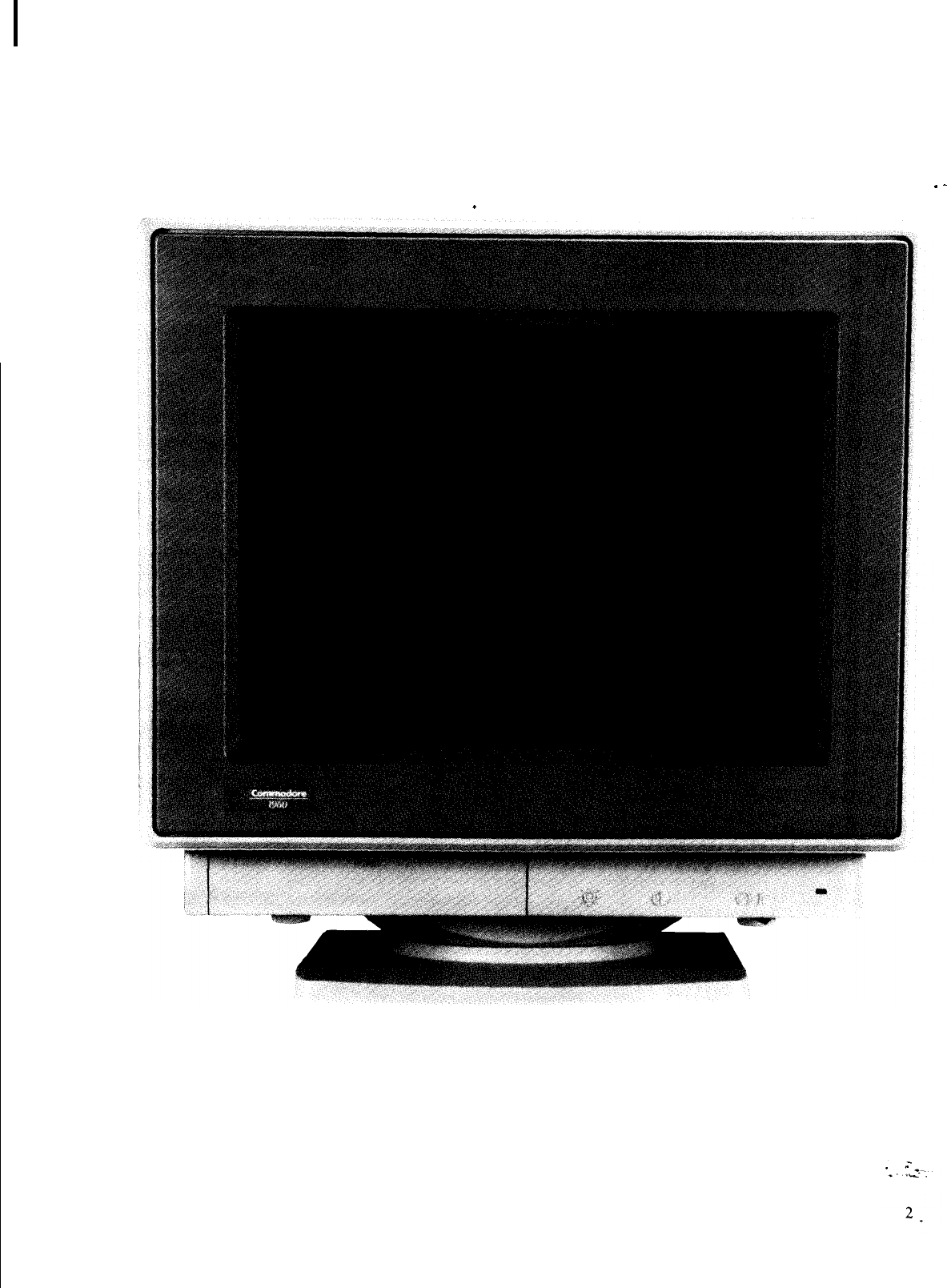
1960
SUPER VGA COLOR MONITOR
JANUARY, 1992 PN-400419-01
1960 SERVICE MANUAL
TABLE OF CONTENTS
.SPECIFICAT!ONS
.............................................................. 1 I.-
.-
SAFETY PRECAUTIONS AND- NOTICES. .....
.i
.................................
.4
ALIGNMENT AND ADJUSTMENT ........................................... ...6
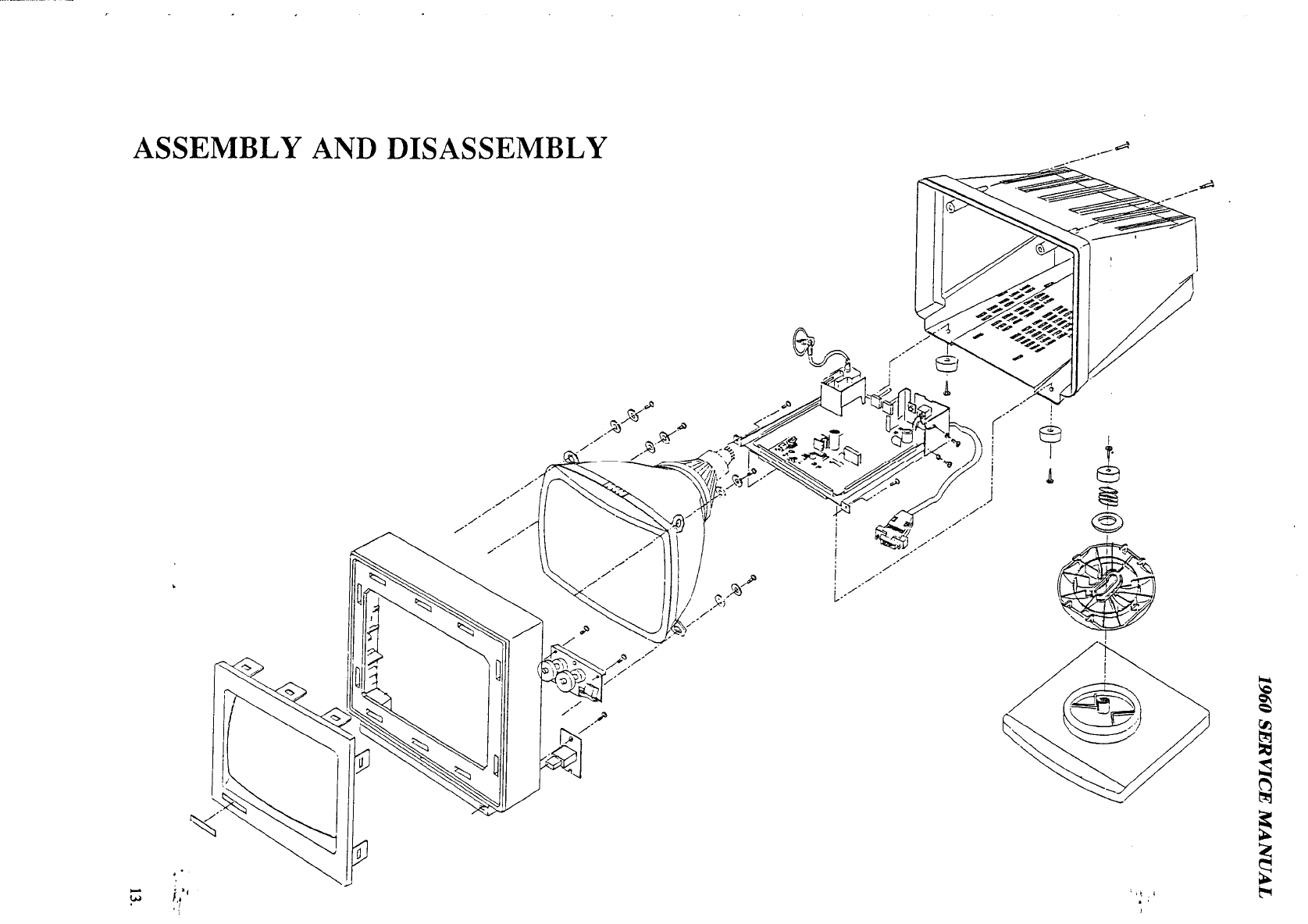
ASSEMBLY AND DISASSEMBLY. ...............................................
13
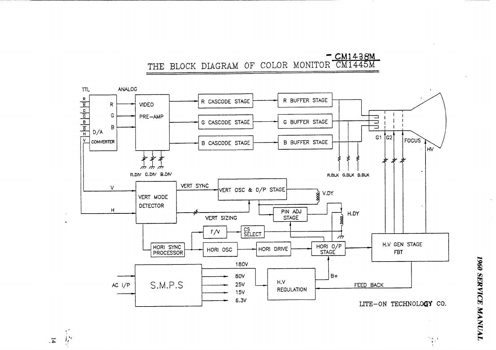
BLOCK DIAGRAM.............................................................l 4
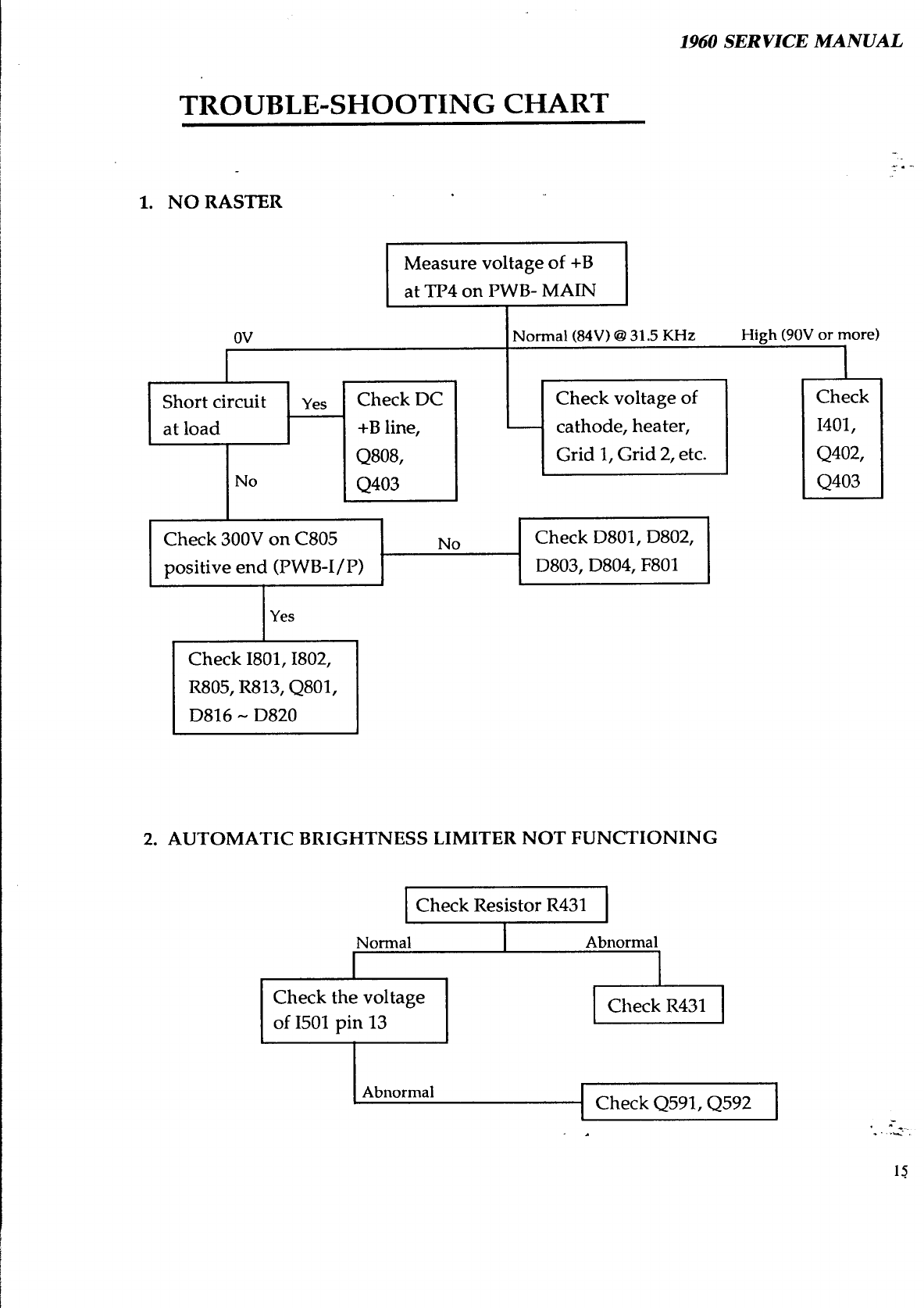
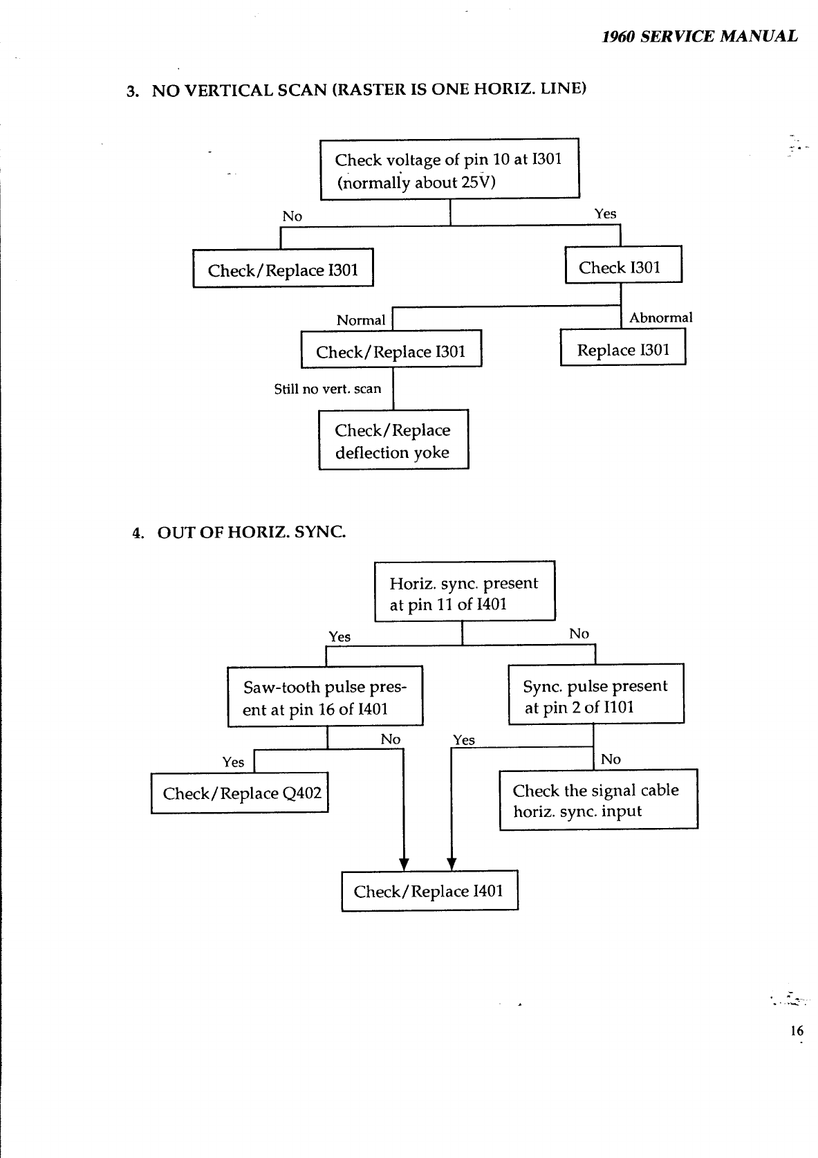
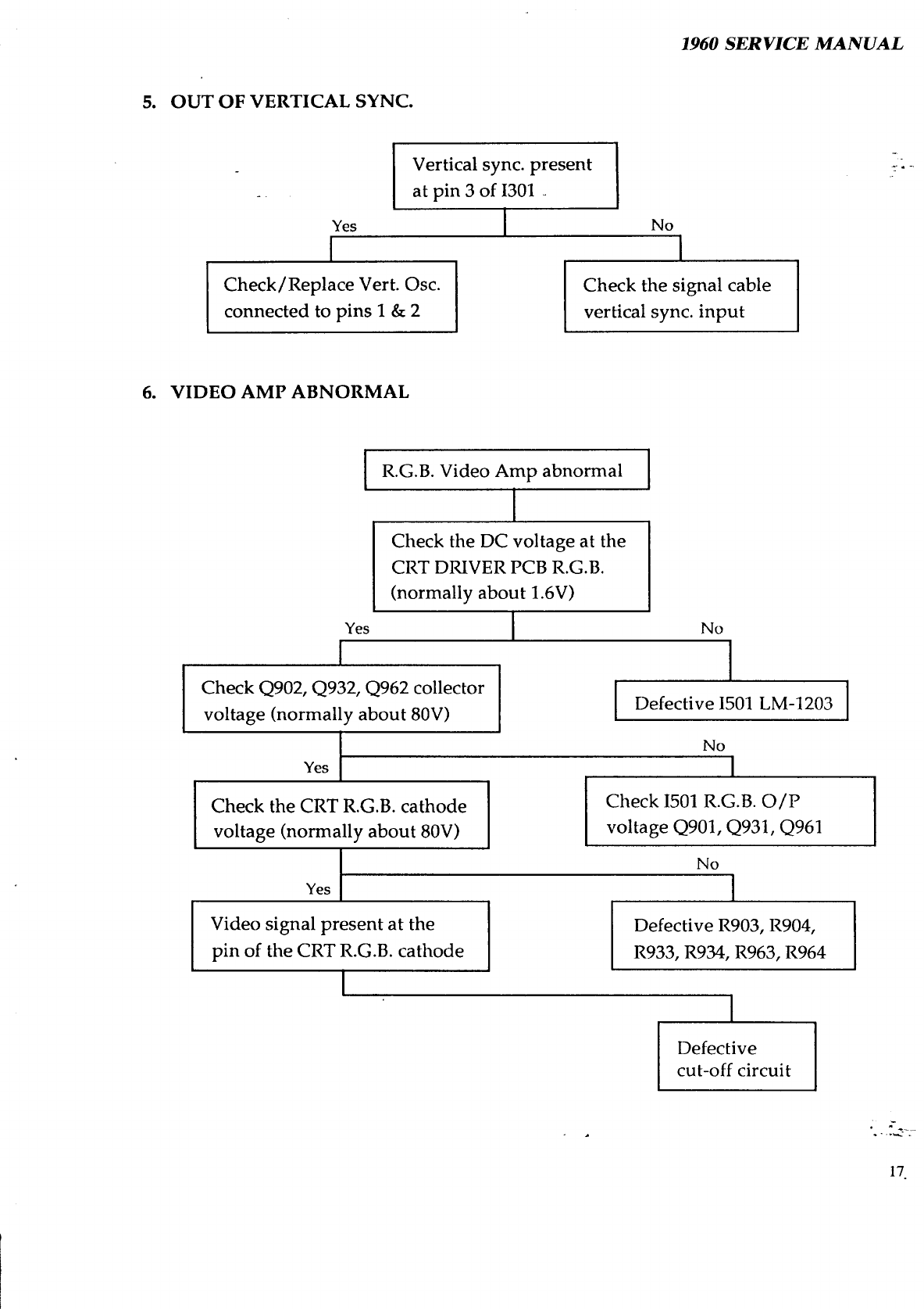
TROUBLESHOOTING
CHART..................................................15
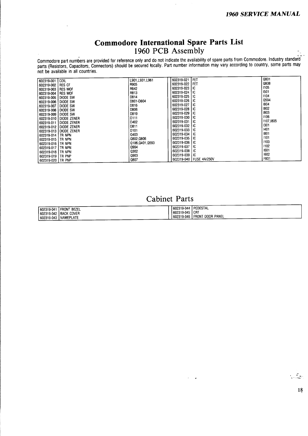
PARTS LIST...................................................................l
8
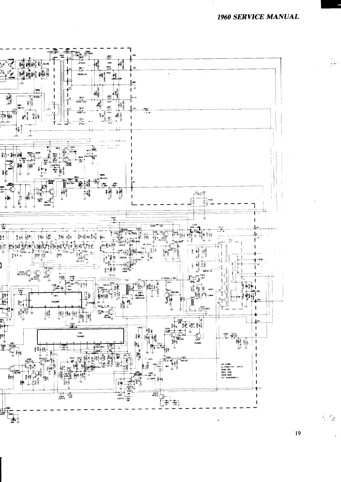
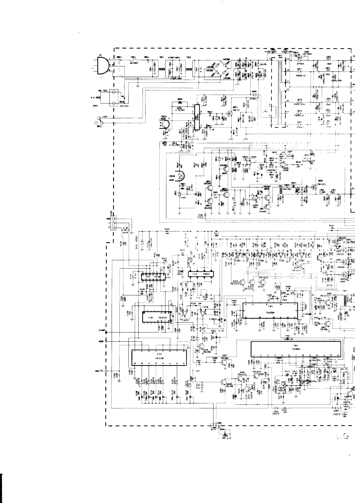
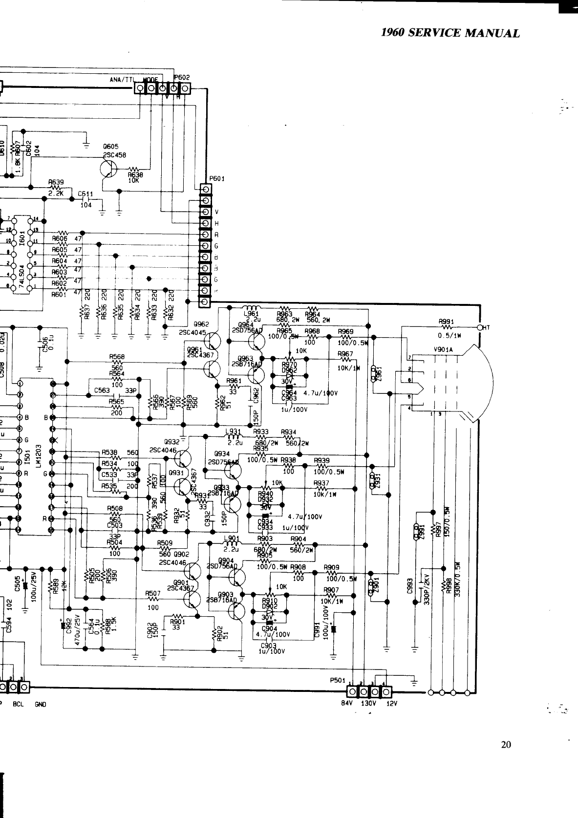
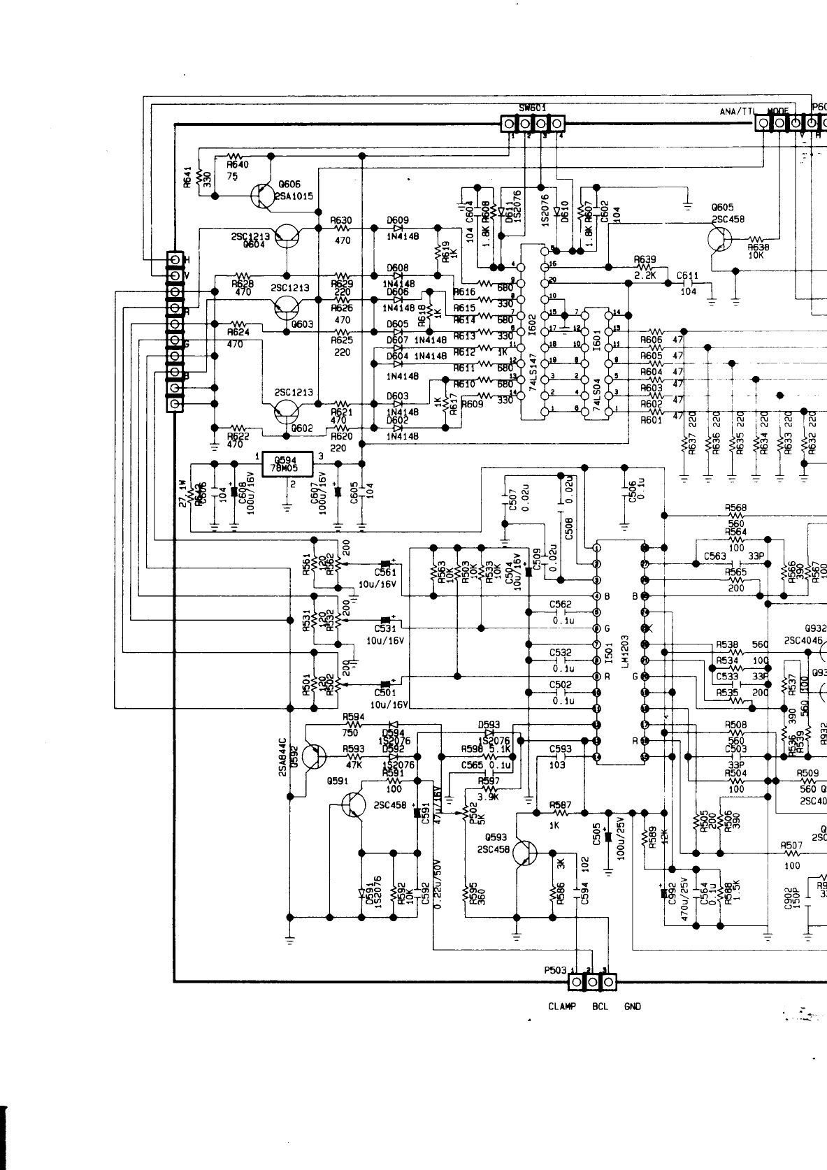
SCHEMATICS ..................................................................
19
,
=*~
*.
-i.
1960 SERVICE MANUAL
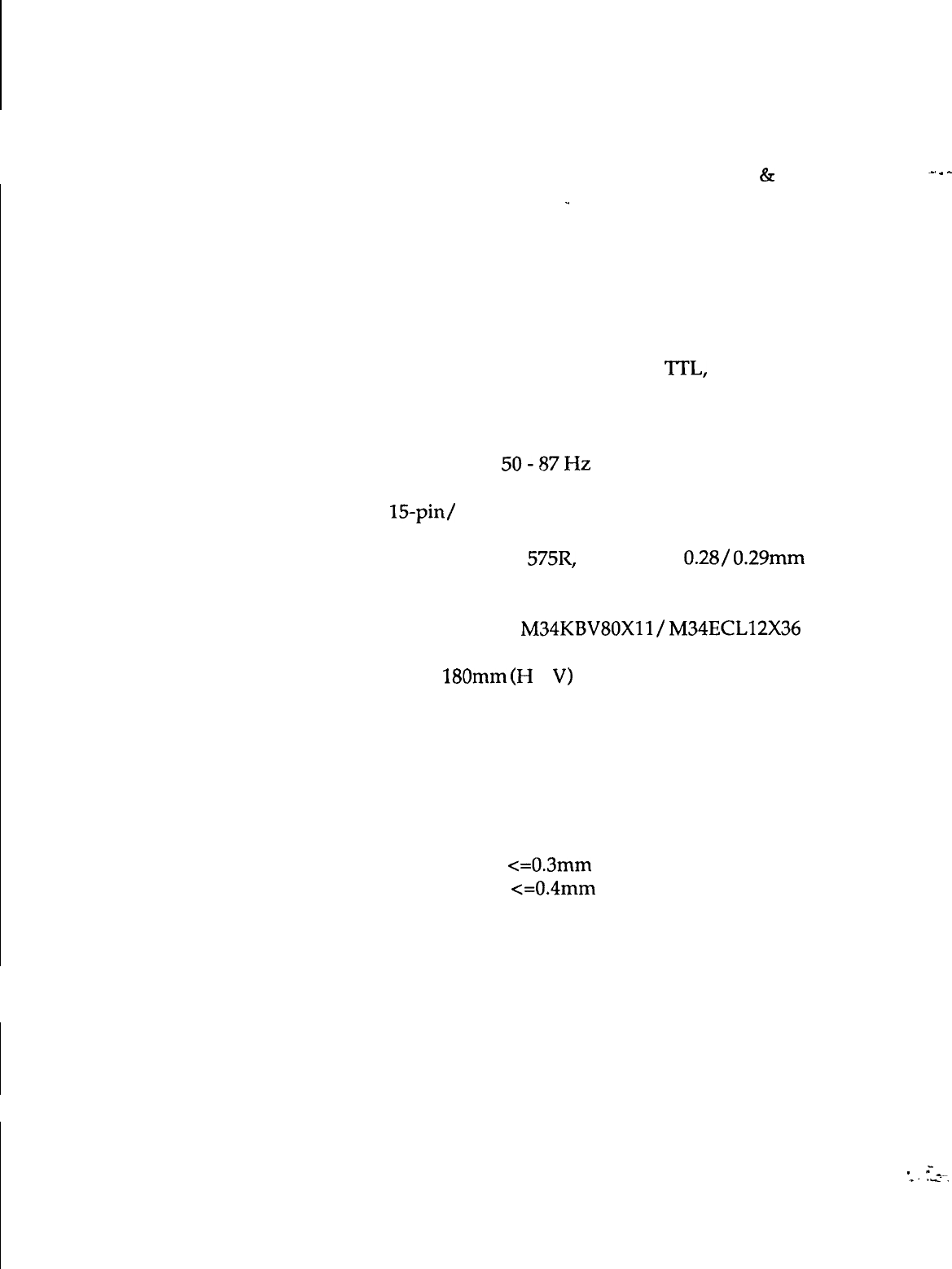
SPECIFICATIONS
Application: A typical data display device for graphics
&
text
PC applications.
-
_.
.
^
Power Input: 80 watts (nominal) AC rated voltage.
Refer to R/C label.
Video Signals:
Analog:
0.7
Vp-p, RGB positive.
Sync. Signals:
Separate Sync: Horiz./Vert.,
‘ITL,
positive or
negative.
Sync. Frequencies: Horizontal: 15.75 to 38 KHz
Vertical:
50-87Hz
Signal Connectors:
15-pin/
9-pin (Analog) D-shell connectors.
Display Tube: 14” 90 degrees,
575R,
29.10 neck, 0.28/ 0.29mm dot
pitch, in-line gun, non-glare screen.
Type number:
M34KBVBOXll/
M34ECL12X36
Display Area:
240 x 180mm
(H
x
V)
Display Colors: Infinite
Display Characters:
80 char. x 60 rows on a 10x10 matrix.
Maximum Resolution:
1024 dots x 768 lines
Misconvergence: Center Area: <=0.3mm
Corner Area: <=0.4mm
User Controls: Power ON/OFF, Brightness, Contrast, Voltage
Selector, Horiz. Phase, Vert. Size, ADD Width,
Mono/ Color Select.
-
=*_
*.
ri.
1
1960 SERVICE MANUAL
.-
.
COMMODORE 1960 SUPER VGA COLOR MONITOR
Service Controls:
1960 SERVICE MANUAL
PWB-1011: R-BKG, G-BKG,
B-BKG
,
R-Bias, G-Bias, B-Bias.
Environmental
Conditions:
Dimensions:
Gross Weight:
PWB-1015:
Gl
Voltage Adjust.,
Pincushion, Horiz. Width, Horiz. Hold 1,
Horiz. Hold 2, Horiz. Phase 1, Horiz. Phase 2,
Vert. Size, Vert. Center, Vert. Linearity,
Vert. Hold, Screen.
Operation: 10 to 35 degrees C ambient.
Storage:
0 to 65 degrees C ambient.
Humidity: 8% to 80% (non-condensing).
Altitude:
up to 7000 ft. above sea-level.
388mm (H) x 370mm (W) x 420mm (D).
14 kgs.
_.
.
-
SIGNAL CABLE PIN CONNECTIONS
Analog:
Pin
Signal
1
Red Signal
2
Green Signal
3
Blue Signal
4
Monitor Sense
Ground to Pin 10
5
Ground
6
Red Return
7
Green Return
TTL:
Pin Signal
1
Ground
2
Red Prime
3
Red Signal
4
Green Signal
5
Blue Signal
Pin Signal
8
Blue Return
9
No Pin
10
Digital Ground
11
Jumper to Pin 10
12
No Pin
13
Horizontal Sync.
14
Vertical Sync.
15
Jumper to Pin 10
Pin
Signal
6
Green Prime
7
Blue Prime
8
H Sync
9
V Sync
1960 SERVICE MANUAL
SAFETY PRECAUTIONS AND NOTICES
SAFETY PRECAUTIONS
_.
.
-
1. Observe all-cautions and safety related notes located inside the monitor cabinet
and on the monitor chassis.
2. Operation of the monitor outside its cabinet or with the cover removed involves
the risk of shock from the monitor power supply. Repair work on the monitor
should not be attempted by anyone who is not thoroughly familiar with all
necessary safety precautions and procedures for working on high voltage
equipment.
3. Do not install, remove, or handle the picture tube in any manner unless shatter-
proof goggles are worn. People not so equipped should be kept at a distance
during handling of the picture tube. Keep the picture tube away from the body
during handling.
4. The picture tube is constructed to limit X-radiation to O.SmR/HR at
300 micro-
amperes anode current. For continued protection, use the recommended
replacement tube only, and adjust the voltages so that the designated maximum
rating at the anode will not be exceeded.
PRODUCT SAFETY NOTICE
Many electrical and mechanical parts in this chassis have been specially inspected
for safety, and the protection afforded by them cannot necessarily be obtained by
using replacement components
ratedfor
higher voltage, wattage etc. Before
replacing any of these components, read the Spare Parts List at the end of this
manual carefully. The use of substitute replacement parts which do not have the
same safety characteristics as those specified in the Spare Parts List may result in
shock, fire, X-radiation or other hazards.
1960 SERVICE MANUAL
SERVICE NOTES
1. When replacing parts or circuit boards, clamp the lead wires around the terminals
before soldering.
_
_.
.
-
2.
When replacing a high wattage resistor
(
>0,5W metal oxide film resistor) in the
circuit board, keep the resistor about 1 cm
(l/2”)
away from the circuit board.
3. Keep wires away from high voltage or high temperature components.
4. Keep wires in their original positions so as to minimize inteference.
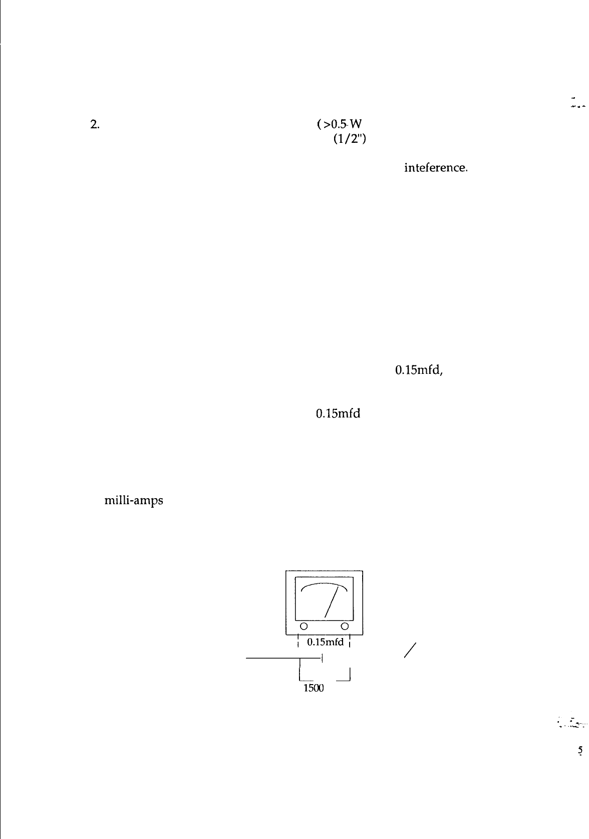
SAFETY TEST
Before returning a serviced monitor to the customer, a thorough safety test must be
performed to verify that the monitor is safe to operate without danger of shock.
Always perform an AC current leakage check on the exposed metallic parts, such as
screw heads, as follows:
1. Plug the AC line cord directly into a rated AC. Do not use a Line Isolation
Transformer during this check).
2. Use an AC voltmeter having at least 5000 ohms per volt sensitivity as follows:
Connect a 1500 ohms 10 watt resistor, paralleled by a
O.l5mfd,
AC type capacitor
between a known good earth ground (such as a water pipe or conduit etc.) and the
exposed metallic part simultaneously. Measure the AC voltage across the
combination of 1500 ohms resistor and
0.15mfd
capacitor.
3. Reverse the AC plug at the AC outlet and repeat the steps for AC voltage
measurements for each exposed metallic part.
4. Voltage measured must not exceed 0.3 volts RMS. This corresponds to 0.2
milli-amps AC. Any value exceeding this limit constitutes a potential shock hazard
and must be corrected immediately.
To good earth ground
To
exposed
\
/
part
I’
‘l---
metallic
l-
_I
1500
ohm
10 watt
1960 SERVICE MANUAL
ALIGNMENT
AND
ADJUSTMENT
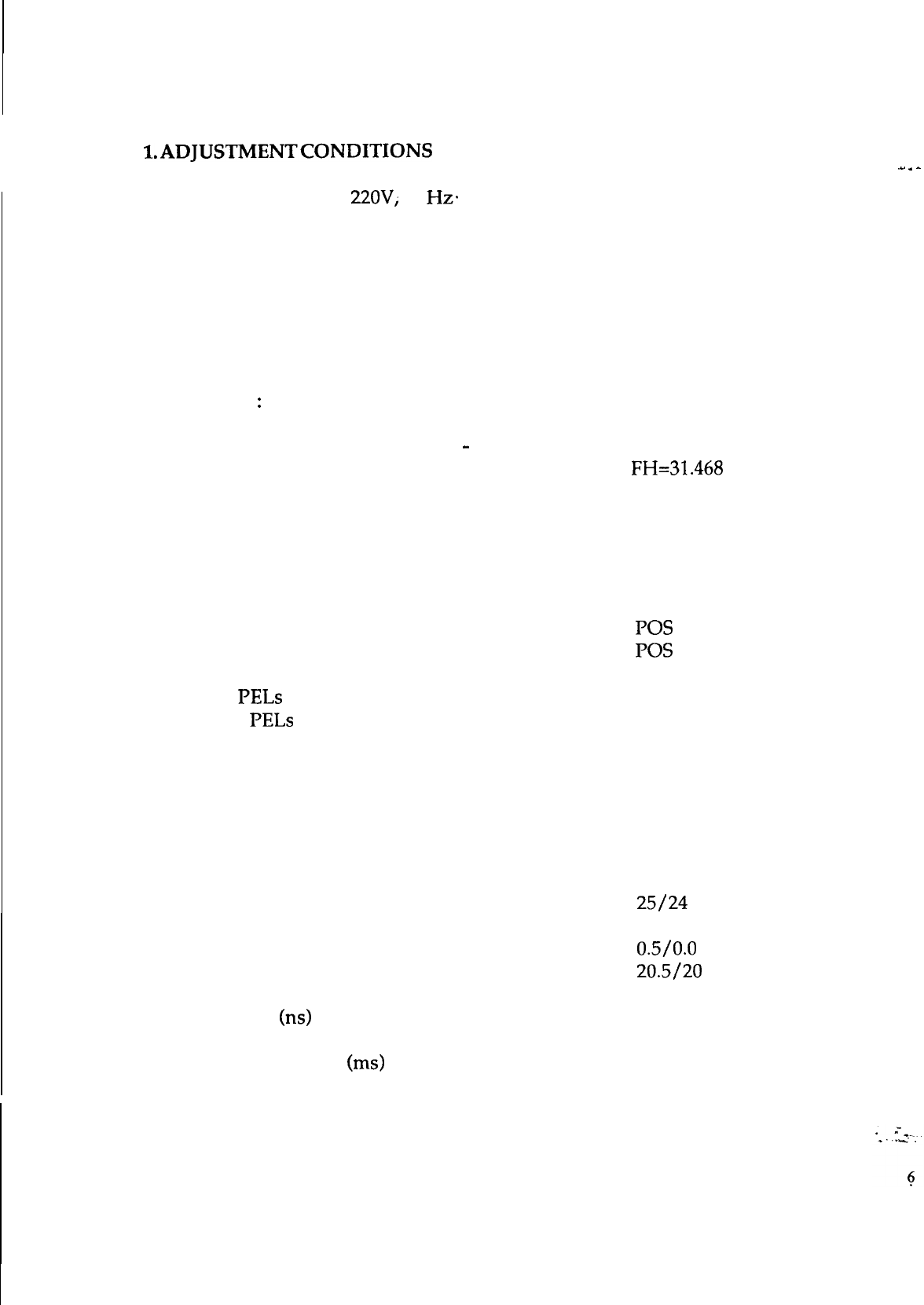
l.ADJUSTMENTCONDITIONS
Power Supply: AC
22OV;
60
Hz+
Warm-up Time: The monitor should be powered on for at least 15 minutes
before any adjustments are made, except for convergence, when 30 minutes
are required.
Signal Input:
1. Video: RGB Analog, 0.7 Vp-p, positive;
RGB TTL positive.
2. Sync.
:
Horiz. and Vert. separated, positive or negative.
3. Scanning Frequencies: FH: 15.75 to 38 KHz/ 15.75 to 45 KHz
FV: 50
-
87 Hz
4. All adjustments should be made using a signal of FH=31.468 KHz,
unless otherwise defined.
2. Parameter list of signal timings generated:
1024x768 Interlaced Mode: (35.52 KHz)
Horiz. Sync. Polarity
Vert. Sync. Polarity
Total PELs per Line
1264
Active PELs per Line
1024
Line Blanking Time (PELs)
240
Line Sync. Pulse Width (PELs)
176
Line Front Porch Width (PELs)
8
Line Back Porch Width (PELs)
56
Total Lines per Frame 817
Active Lines per Frame
768
Fields per Frame
2
Field Blanking Time (E/O Lines) 25/24
Field Sync. Pulse Width (E/O Lines)
4
Field Front Porch Width (E/O Lines) 0.5/0.0
Field Back Porch Width (E/O Lines) 20.5/20
PEL Time
(ns)
22.27
Total Line Time (us) 28.15
Total Frame Time (ms) 23.00
Frame Rate (Hz) 43.48
POS
POS
_.
.
-
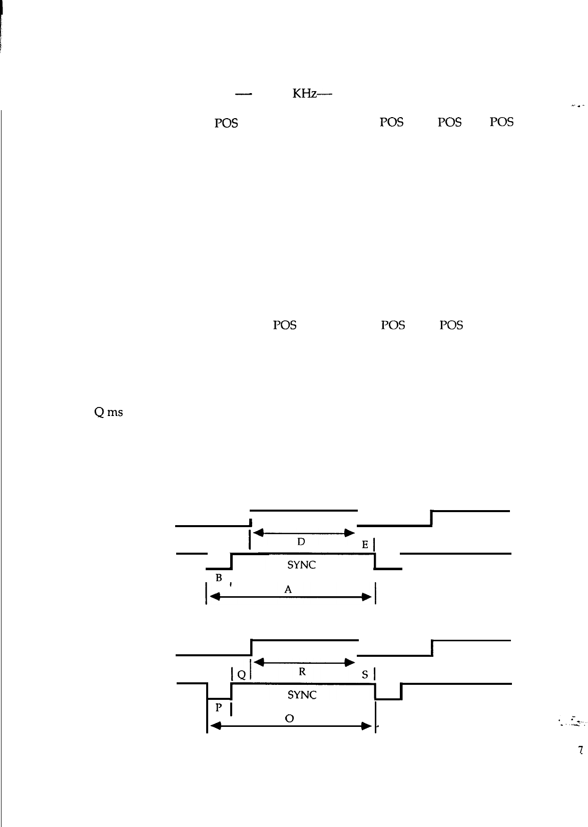
1960 SERVICE MANUAL
Vertical Lines
Horizontal Freq.
Sync. Polarity
A us
B us
c us
D us
E us
Vertical Freq.
Sync. Polarity
Oms
Pms
Qms
Rms
Sms
HORIZONTAL
350
400 480
600
CGA EGA
-
31.468
KHz-
35.52 KHz
POS
31.78
3.81
1.91
25.42
0.64
60 Hz
NEG
14.27
NEG
31.78
3.81
1.91
25.42
NEC
31.78
3.81
1.91
25.42
0.64
60 Hz
NEG
16.68
0.06
1.05
15.25
POS
28.44
2.00
3.66
22.22
POS POS
63.5 45.76
4.50 5.60
7.80
44.50
1.00
39.37
0.64
70 Hz
POS
14.27
0.67
56.25 Hz
POS
17.78
0.06
0.63
17.07
6.70
60 Hz
POS
-0.20
60 Hz
NEG
16.637
16.75
0.06 0.06
1.91 1.11
11.12
12.71
0.19
0.60
2.30 0.08
12.576 16.02
1.18 0.38
0.32
0.03 1.60 0.05
_.
.
-
IVIDEO
I
I
I
C
+-Y---+
I
El
I
I
I
B
I
I
VERTICAL
I
VIDEO
I
I
I
Sl
II
SYNC
I
IJ
I
4
0
1960 SERVICE MANUAL
3.
ADJUSTMENT EQUIPMENT
a. Volt-ohm-A meter (Sanwa FD-750C or equivalent).
b.
3OKV
high voltage probe (HP34111A).
c. Oscilloscope (TEK2235 or equivalent).
-
d. White balance adjuster (Minolta Color Analyzer II).
e. Signal generator (IBM PC with VGA card or equivalent).
f. Screwdriver.
_.
.
-
4.
SWITCHING POWER SUPPLY
-
Regulator Adjustment
(I’WBlOOl)
The regulated B+ control has been preset in the factory and needs no
adjustment. However, if any repairs are made on the equipment, the following
readjustment procedures are recommended.
a. Allow the monitor to warm-up for about 5 minutes.
b. Apply the VGA (31.468 KHz) signal to the monitor.
c. Connect a DC meter to
TPl
(on the main PCB), and adjust VR831 for
86V DC.
d. If a fuse is broken during adjustment, remember to replace it with the exact
same type of fuse.
8
1960 SERVICE MANUAL
5. ALIGNMENT PROCEDURES
A) SYNCRONIZATION ADJUSTMENT
Input Signal: Cross Hatch Pattern.
Connect the DC meter to TP2 and adjust VR128 to obtain the F/V output
for 5.7V.
Adjust H-Hold VR136 until the cross hatch pattern is stable.
B) PICTURE SIZE ADJUSTMENT
Input Signal: Cross Hatch Pattern
Horiz. Width:
480 mode: Adjust
L402
so that the horiz. width of the picture
is 240mm
+/-
3mm
Vert. Height:
350 mode: Adjust
VRlll
so that the vert. height of the picture
is 180mm
+/-
3mm
400 mode: Adjust VR108 so that the vert. height of the picture
is
180mm
+/-
3mm
480 mode: Adjust VRllO so that the vert. height of the picture
is 180mm
+/-
3mm
768 mode: Adjust VR109 so that the vert. height of the picture
is 180mm
+/-
3mm
CGA mode: Adjust VR113 so that the vert. height of the picture
is 180mm
+/-
3mm
EGA mode: Adjust VR115 so that the vert. height of the picture
is 180mm
+/-
3mm
1960 SERVICE MANUAL
C) WHITE BALANCE ADJUSTMENT
Input Signal: Full White Video
-
VGA mode
Drive
VRs:
VR502,
VR532, VR562.
Bias
VRs:
VR910,
VR940,-VR970:
la.
b.
2a.
b.
3a.
b.
4a.
b.
5a.
b.
Set Brightness
&
Contrast to minimum.
First adjust VR940 to its center position.
Then adjust VR970 so that Y = 0.329
and adjust VR910 so that X = 0.313
Set Brightness
&
Contrast to maximum.
Adjust VR532 for 45Vp-p of the G. gun input at the cathode.
Set Brightness to center detent
&
Contrast to 10
Fl.
First adjust VR562 so that Y = 0.329
then adjust VR502 so that X = 0.313
Set Brightness to maximum
&
the G2 voltage just before the raster
appears.
Check the white balance in the VGA mode.
Set Brightness just before the raster disappears.
Repeat steps 2b. to 5b. until the best white balance is obtained.
D)
FOCUS ADJUSTMENT
Input Signal: Dot Test Pattern
1.
Set Brightness
&
Contrast for a normal display.
2.
Adjust the focus control at the high voltage resistor block to obtain the
best focus over the entire display area.
1960 SERVICE MANUAL
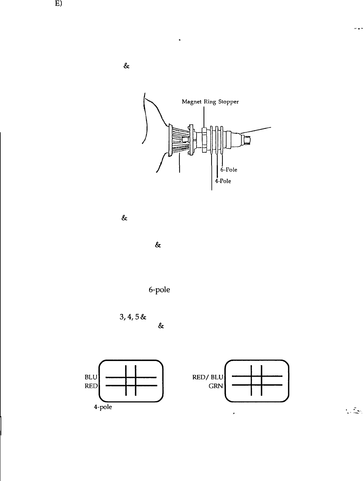
E)
STATIC CONVERGENCE ADJUSTMENT
NB: The monitor should be operated for at least 30 mins. before any
con-vergence adjustments are made.
.
Input Signal: Cross Hatch Pattern
1. Set Brightness
&
Contrast so that a well-defined pattern is obtained.
2. Ensure that the convergence magnets on the CRT are in the
correct position.
,
CRT Neck
deflection Yoke
I
hole
Convergence Magnets
4-Pole
Convergence Magnets
Purity Magnets
3. Turn the 2 tabs of the 4-pole magnets independently to adjust their angles.
Align the red
&
blue vert. lines at the center of the screen.
4. Turn the 2 tabs of the 4-pole magnets simultaneously to keep their angles
constant. Align the red
&
blue horiz. lines at the center of the screen.
5. Turn the 2 tabs of the 6-pole magnets independently to superimpose the
red/blue vert. line on the green one.
6. Turn the 2 tabs of the 6-pole magnets simultaneously to superimpose the
red/blue horiz. line on the green one.
7. Repeat steps
3,4,5
&
6 until the best convergence is obtained.
NB: The 4-pole magnets
&
the 6-pole magnets interact, making dot
movements complex.
BLU RED RED/ BLU GRN
~~[~]
~D%[qq
4-pole
magnets movement 6-pole magnets movement
.
_.
.
-
*
=*_
*.
ri.
11
1960 SERVICE MANUAL
F)
DEGAUSSING
Degaussing is required when poor color purity appears on the screen.
This monitor uses an automatic degaussing circuit that is activated at
power ON. Automatic degaussing will be fully functional within 15
minutes.
_.
.
-
The degaussing effect is confined to the picture tube since the coils are
mounted at the back of the tube. Should any part of the chassis or cabinet
become magnetized, it will be necessary to degauss the affected area with
a manual degaussing coil.
Manual Degaussing
a.
b.
Apply line voltage to the degaussing coil and move it in a rotary
motion over the front, sides, and top of the monitor. The coil should
be kept away from the rear of the monitor to avoid damaging the
magnetic neck components.
Slowly rotate and back the coil away from the monitor to about 6 feet
beyond the point where no effect on the CRT will be noticeable.
For proper degaussing, it is essential that the field be gradually reduced by
moving the coil slowly away from the monitor. The degaussing coil must
never be shut off or disconnected while near the monitor, as this would
introduce a strong field instead of cancelling the effect of the stray fields.
*
=*-.
*.-ri.
12