Chapter 1 Review Questions Computer Networking A Top Down Approach Solution Manual(6th Edition)
User Manual:
Open the PDF directly: View PDF ![]() .
.
Page Count: 154 [warning: Documents this large are best viewed by clicking the View PDF Link!]
Computer Networking: A Top-Down Approach,
6th Edition
Solutions to Review Questions and Problems
Version Date: May 2012
This document contains the solutions to review questions and problems for the 5th
edition of Computer Networking: A Top-Down Approach by Jim Kurose and Keith Ross.
These solutions are being made available to instructors ONLY. Please do NOT copy or
distribute this document to others (even other instructors). Please do not post any
solutions on a publicly-available Web site. We’ll be happy to provide a copy (up-to-date)
of this solution manual ourselves to anyone who asks.
Acknowledgments: Over the years, several students and colleagues have helped us
prepare this solutions manual. Special thanks goes to HongGang Zhang, Rakesh Kumar,
Prithula Dhungel, and Vijay Annapureddy. Also thanks to all the readers who have made
suggestions and corrected errors.
All material © copyright 1996-2012 by J.F. Kurose and K.W. Ross. All rights reserved
Chapter 1 Review Questions
1. There is no difference. Throughout this text, the words “host” and “end system” are
used interchangeably. End systems include PCs, workstations, Web servers, mail
servers, PDAs, Internet-connected game consoles, etc.
2. From Wikipedia: Diplomatic protocol is commonly described as a set of international
courtesy rules. These well-established and time-honored rules have made it easier for
nations and people to live and work together. Part of protocol has always been the
acknowledgment of the hierarchical standing of all present. Protocol rules are based
on the principles of civility.
3. Standards are important for protocols so that people can create networking systems
and products that interoperate.
4. 1. Dial-up modem over telephone line: home; 2. DSL over telephone line: home or
small office; 3. Cable to HFC: home; 4. 100 Mbps switched Ethernet: enterprise; 5.
Wifi (802.11): home and enterprise: 6. 3G and 4G: wide-area wireless.
5. HFC bandwidth is shared among the users. On the downstream channel, all packets
emanate from a single source, namely, the head end. Thus, there are no collisions in
the downstream channel.
6. In most American cities, the current possibilities include: dial-up; DSL; cable
modem; fiber-to-the-home.
7. Ethernet LANs have transmission rates of 10 Mbps, 100 Mbps, 1 Gbps and 10 Gbps.
8. Today, Ethernet most commonly runs over twisted-pair copper wire. It also can run
over fibers optic links.
9. Dial up modems: up to 56 Kbps, bandwidth is dedicated; ADSL: up to 24 Mbps
downstream and 2.5 Mbps upstream, bandwidth is dedicated; HFC, rates up to 42.8
Mbps and upstream rates of up to 30.7 Mbps, bandwidth is shared. FTTH: 2-10Mbps
upload; 10-20 Mbps download; bandwidth is not shared.
10. There are two popular wireless Internet access technologies today:
a) Wifi (802.11) In a wireless LAN, wireless users transmit/receive packets to/from an
base station (i.e., wireless access point) within a radius of few tens of meters. The
base station is typically connected to the wired Internet and thus serves to connect
wireless users to the wired network.
b) 3G and 4G wide-area wireless access networks. In these systems, packets are
transmitted over the same wireless infrastructure used for cellular telephony, with the
base station thus being managed by a telecommunications provider. This provides
wireless access to users within a radius of tens of kilometers of the base station.
11. At time t0 the sending host begins to transmit. At time t1 = L/R1, the sending host
completes transmission and the entire packet is received at the router (no propagation
delay). Because the router has the entire packet at time t1, it can begin to transmit the
packet to the receiving host at time t1. At time t2 = t1 + L/R2, the router completes
transmission and the entire packet is received at the receiving host (again, no
propagation delay). Thus, the end-to-end delay is L/R1 + L/R2.
12. A circuit-switched network can guarantee a certain amount of end-to-end bandwidth
for the duration of a call. Most packet-switched networks today (including the
Internet) cannot make any end-to-end guarantees for bandwidth. FDM requires
sophisticated analog hardware to shift signal into appropriate frequency bands.
13. a) 2 users can be supported because each user requires half of the link bandwidth.
b) Since each user requires 1Mbps when transmitting, if two or fewer users transmit
simultaneously, a maximum of 2Mbps will be required. Since the available
bandwidth of the shared link is 2Mbps, there will be no queuing delay before the
link. Whereas, if three users transmit simultaneously, the bandwidth required
will be 3Mbps which is more than the available bandwidth of the shared link. In
this case, there will be queuing delay before the link.
c) Probability that a given user is transmitting = 0.2
d) Probability that all three users are transmitting simultaneously =
33
31
3
3
pp
= (0.2)3 = 0.008. Since the queue grows when all the users are transmitting, the
fraction of time during which the queue grows (which is equal to the probability
that all three users are transmitting simultaneously) is 0.008.
14. If the two ISPs do not peer with each other, then when they send traffic to each other
they have to send the traffic through a provider ISP (intermediary), to which they
have to pay for carrying the traffic. By peering with each other directly, the two ISPs
can reduce their payments to their provider ISPs. An Internet Exchange Points (IXP)
(typically in a standalone building with its own switches) is a meeting point where
multiple ISPs can connect and/or peer together. An ISP earns its money by charging
each of the the ISPs that connect to the IXP a relatively small fee, which may depend
on the amount of traffic sent to or received from the IXP.
15. Google's private network connects together all its data centers, big and small. Traffic
between the Google data centers passes over its private network rather than over the
public Internet. Many of these data centers are located in, or close to, lower tier ISPs.
Therefore, when Google delivers content to a user, it often can bypass higher tier
ISPs. What motivates content providers to create these networks? First, the content
provider has more control over the user experience, since it has to use few
intermediary ISPs. Second, it can save money by sending less traffic into provider
networks. Third, if ISPs decide to charge more money to highly profitable content
providers (in countries where net neutrality doesn't apply), the content providers can
avoid these extra payments.
16. The delay components are processing delays, transmission delays, propagation
delays, and queuing delays. All of these delays are fixed, except for the queuing
delays, which are variable.
17. a) 1000 km, 1 Mbps, 100 bytes
b) 100 km, 1 Mbps, 100 bytes
18. 10msec; d/s; no; no
19. a) 500 kbps
b) 64 seconds
c) 100kbps; 320 seconds
20. End system A breaks the large file into chunks. It adds header to each chunk, thereby
generating multiple packets from the file. The header in each packet includes the IP
address of the destination (end system B). The packet switch uses the destination IP
address in the packet to determine the outgoing link. Asking which road to take is
analogous to a packet asking which outgoing link it should be forwarded on, given
the packet’s destination address.
21. The maximum emission rate is 500 packets/sec and the maximum transmission rate is
350 packets/sec. The corresponding traffic intensity is 500/350 =1.43 > 1. Loss will
eventually occur for each experiment; but the time when loss first occurs will be
different from one experiment to the next due to the randomness in the emission
process.
22. Five generic tasks are error control, flow control, segmentation and reassembly,
multiplexing, and connection setup. Yes, these tasks can be duplicated at different
layers. For example, error control is often provided at more than one layer.
23. The five layers in the Internet protocol stack are – from top to bottom – the
application layer, the transport layer, the network layer, the link layer, and the
physical layer. The principal responsibilities are outlined in Section 1.5.1.
24. Application-layer message: data which an application wants to send and passed onto
the transport layer; transport-layer segment: generated by the transport layer and
encapsulates application-layer message with transport layer header; network-layer
datagram: encapsulates transport-layer segment with a network-layer header; link-
layer frame: encapsulates network-layer datagram with a link-layer header.
25. Routers process network, link and physical layers (layers 1 through 3). (This is a little
bit of a white lie, as modern routers sometimes act as firewalls or caching
components, and process Transport layer as well.) Link layer switches process link
and physical layers (layers 1 through2). Hosts process all five layers.
26. a) Virus
Requires some form of human interaction to spread. Classic example: E-mail
viruses.
b) Worms
No user replication needed. Worm in infected host scans IP addresses and port
numbers, looking for vulnerable processes to infect.
27. Creation of a botnet requires an attacker to find vulnerability in some application or
system (e.g. exploiting the buffer overflow vulnerability that might exist in an
application). After finding the vulnerability, the attacker needs to scan for hosts that
are vulnerable. The target is basically to compromise a series of systems by
exploiting that particular vulnerability. Any system that is part of the botnet can
automatically scan its environment and propagate by exploiting the vulnerability. An
important property of such botnets is that the originator of the botnet can remotely
control and issue commands to all the nodes in the botnet. Hence, it becomes
possible for the attacker to issue a command to all the nodes, that target a single
node (for example, all nodes in the botnet might be commanded by the attacker to
send a TCP SYN message to the target, which might result in a TCP SYN flood
attack at the target).
28. Trudy can pretend to be Bob to Alice (and vice-versa) and partially or completely
modify the message(s) being sent from Bob to Alice. For example, she can easily
change the phrase “Alice, I owe you $1000” to “Alice, I owe you $10,000”.
Furthermore, Trudy can even drop the packets that are being sent by Bob to Alice
(and vise-versa), even if the packets from Bob to Alice are encrypted.
Chapter 1 Problems
Problem 1
There is no single right answer to this question. Many protocols would do the trick.
Here's a simple answer below:
Messages from ATM machine to Server
Msg name purpose
-------- -------
HELO <userid> Let server know that there is a card in the
ATM machine
ATM card transmits user ID to Server
PASSWD <passwd> User enters PIN, which is sent to server
BALANCE User requests balance
WITHDRAWL <amount> User asks to withdraw money
BYE user all done
Messages from Server to ATM machine (display)
Msg name purpose
-------- -------
PASSWD Ask user for PIN (password)
OK last requested operation (PASSWD, WITHDRAWL)
OK
ERR last requested operation (PASSWD, WITHDRAWL)
in ERROR
AMOUNT <amt> sent in response to BALANCE request
BYE user done, display welcome screen at ATM
Correct operation:
client server
HELO (userid) --------------> (check if valid userid)
<------------- PASSWD
PASSWD <passwd> --------------> (check password)
<------------- OK (password is OK)
BALANCE -------------->
<------------- AMOUNT <amt>
WITHDRAWL <amt> --------------> check if enough $ to cover
withdrawl
<------------- OK
ATM dispenses $
BYE -------------->
<------------- BYE
In situation when there's not enough money:
HELO (userid) --------------> (check if valid userid)
<------------- PASSWD
PASSWD <passwd> --------------> (check password)
<------------- OK (password is OK)
BALANCE -------------->
<------------- AMOUNT <amt>
WITHDRAWL <amt> --------------> check if enough $ to cover
withdrawl
<------------- ERR (not enough funds)
error msg displayed
no $ given out
BYE -------------->
<------------- BYE
Problem 2
At time N*(L/R) the first packet has reached the destination, the second packet is stored
in the last router, the third packet is stored in the next-to-last router, etc. At time N*(L/R)
+ L/R, the second packet has reached the destination, the third packet is stored in the last
router, etc. Continuing with this logic, we see that at time N*(L/R) + (P-1)*(L/R) =
(N+P-1)*(L/R) all packets have reached the destination.
Problem 3
a) A circuit-switched network would be well suited to the application, because the
application involves long sessions with predictable smooth bandwidth requirements.
Since the transmission rate is known and not bursty, bandwidth can be reserved for
each application session without significant waste. In addition, the overhead costs of
setting up and tearing down connections are amortized over the lengthy duration of a
typical application session.
b) In the worst case, all the applications simultaneously transmit over one or more
network links. However, since each link has sufficient bandwidth to handle the sum
of all of the applications' data rates, no congestion (very little queuing) will occur.
Given such generous link capacities, the network does not need congestion control
mechanisms.
Problem 4
a) Between the switch in the upper left and the switch in the upper right we can have 4
connections. Similarly we can have four connections between each of the 3 other
pairs of adjacent switches. Thus, this network can support up to 16 connections.
b) We can 4 connections passing through the switch in the upper-right-hand corner and
another 4 connections passing through the switch in the lower-left-hand corner,
giving a total of 8 connections.
c) Yes. For the connections between A and C, we route two connections through B and
two connections through D. For the connections between B and D, we route two
connections through A and two connections through C. In this manner, there are at
most 4 connections passing through any link.
Problem 5
Tollbooths are 75 km apart, and the cars propagate at 100km/hr. A tollbooth services a
car at a rate of one car every 12 seconds.
a) There are ten cars. It takes 120 seconds, or 2 minutes, for the first tollbooth to service
the 10 cars. Each of these cars has a propagation delay of 45 minutes (travel 75 km)
before arriving at the second tollbooth. Thus, all the cars are lined up before the
second tollbooth after 47 minutes. The whole process repeats itself for traveling
between the second and third tollbooths. It also takes 2 minutes for the third tollbooth
to service the 10 cars. Thus the total delay is 96 minutes.
b) Delay between tollbooths is 8*12 seconds plus 45 minutes, i.e., 46 minutes and 36
seconds. The total delay is twice this amount plus 8*12 seconds, i.e., 94 minutes and
48 seconds.
Problem 6
a)
smdprop /
seconds.
b)
RLdtrans /
seconds.
c)
)//( RLsmd endtoend
seconds.
d) The bit is just leaving Host A.
e) The first bit is in the link and has not reached Host B.
f) The first bit has reached Host B.
g) Want
536105.2
1056
120 8
3
s
R
L
m
km.
Problem 7
Consider the first bit in a packet. Before this bit can be transmitted, all of the bits in the
packet must be generated. This requires
3
1064
856
sec=7msec.
The time required to transmit the packet is
6
102
856
sec=
224
sec.
Propagation delay = 10 msec.
The delay until decoding is
7msec +
224
sec + 10msec = 17.224msec
A similar analysis shows that all bits experience a delay of 17.224 msec.
Problem 8
a) 20 users can be supported.
b)
1.0p
.
c)
n
npp
n
120
1
120
.
d)
20
0
120
1
120
1
n
n
npp
n
.
We use the central limit theorem to approximate this probability. Let
j
X
be independent
random variables such that
pXP j 1
.
P
“21 or more users”
211120
1j
j
XP
9.01.0120
9
9.01.0120
12
21
120
1
120
1
jj
j
j
X
PXP
74.2
286.3
9
ZPZP
997.0
when
Z
is a standard normal r.v. Thus
P
“21 or more users”
003.0
.
Problem 9
a) 10,000
b)
M
Nn
nM
npp
n
M
1
1
Problem 10
The first end system requires L/R1 to transmit the packet onto the first link; the packet
propagates over the first link in d1/s1; the packet switch adds a processing delay of dproc;
after receiving the entire packet, the packet switch connecting the first and the second
link requires L/R2 to transmit the packet onto the second link; the packet propagates over
the second link in d2/s2. Similarly, we can find the delay caused by the second switch and
the third link: L/R3, dproc, and d3/s3.
Adding these five delays gives
dend-end = L/R1 + L/R2 + L/R3 + d1/s1 + d2/s2 + d3/s3+ dproc+ dproc
To answer the second question, we simply plug the values into the equation to get 6 + 6 +
6 + 20+16 + 4 + 3 + 3 = 64 msec.
Problem 11
Because bits are immediately transmitted, the packet switch does not introduce any delay;
in particular, it does not introduce a transmission delay. Thus,
dend-end = L/R + d1/s1 + d2/s2+ d3/s3
For the values in Problem 10, we get 6 + 20 + 16 + 4 = 46 msec.
Problem 12
The arriving packet must first wait for the link to transmit 4.5 *1,500 bytes = 6,750 bytes
or 54,000 bits. Since these bits are transmitted at 2 Mbps, the queuing delay is 27 msec.
Generally, the queuing delay is (nL + (L - x))/R.
Problem 13
a) The queuing delay is 0 for the first transmitted packet, L/R for the second transmitted
packet, and generally, (n-1)L/R for the nth transmitted packet. Thus, the average delay
for the N packets is:
(L/R + 2L/R + ....... + (N-1)L/R)/N
= L/(RN) * (1 + 2 + ..... + (N-1))
= L/(RN) * N(N-1)/2
= LN(N-1)/(2RN)
= (N-1)L/(2R)
Note that here we used the well-known fact:
1 + 2 + ....... + N = N(N+1)/2
b) It takes
RLN /
seconds to transmit the
N
packets. Thus, the buffer is empty when a
each batch of
N
packets arrive. Thus, the average delay of a packet across all batches
is the average delay within one batch, i.e., (N-1)L/2R.

Problem 14
a) The transmission delay is
RL /
. The total delay is
I
RL
R
L
IR
IL
1
/
)1(
b) Let
RLx /
.
Total delay =
ax
x
1
For x=0, the total delay =0; as we increase x, total delay increases, approaching
infinity as x approaches 1/a.
Problem 15
Total delay
aaRaL
RL
I
RL
1
/1
/1
/1
/
1
/
.
Problem 16
The total number of packets in the system includes those in the buffer and the packet that
is being transmitted. So, N=10+1.
Because
daN
, so (10+1)=a*(queuing delay + transmission delay). That is,
11=a*(0.01+1/100)=a*(0.01+0.01). Thus, a=550 packets/sec.
Problem 17
a) There are
Q
nodes (the source host and the
1Q
routers). Let
q
proc
d
denote the
processing delay at the
q
th node. Let
q
R
be the transmission rate of the
q
th link and
let
qq
trans RLd /
. Let
q
prop
d
be the propagation delay across the
q
th link. Then
Q
q
q
prop
q
trans
q
procendtoend dddd
1
.
b) Let
q
queue
d
denote the average queuing delay at node
q
. Then
Q
q
q
queue
q
prop
q
trans
q
procendtoend ddddd
1
.
Problem 18
On linux you can use the command
traceroute www.targethost.com
and in the Windows command prompt you can use
tracert www.targethost.com
In either case, you will get three delay measurements. For those three measurements you
can calculate the mean and standard deviation. Repeat the experiment at different times
of the day and comment on any changes.
Here is an example solution:
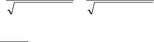
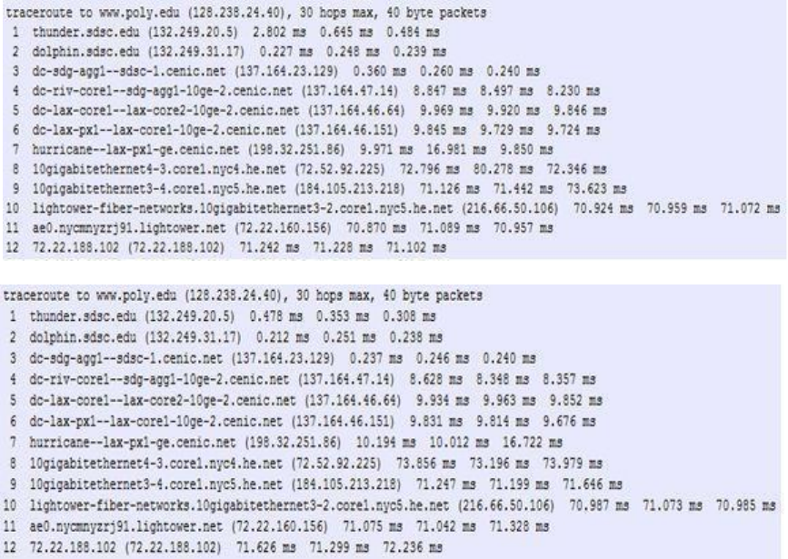
Traceroutes between San Diego Super Computer Center and www.poly.edu
a) The average (mean) of the round-trip delays at each of the three hours is 71.18 ms,
71.38 ms and 71.55 ms, respectively. The standard deviations are 0.075 ms, 0.21 ms,
0.05 ms, respectively.
b) In this example, the traceroutes have 12 routers in the path at each of the three hours.
No, the paths didn’t change during any of the hours.
c) Traceroute packets passed through four ISP networks from source to destination. Yes,
in this experiment the largest delays occurred at peering interfaces between adjacent
ISPs.
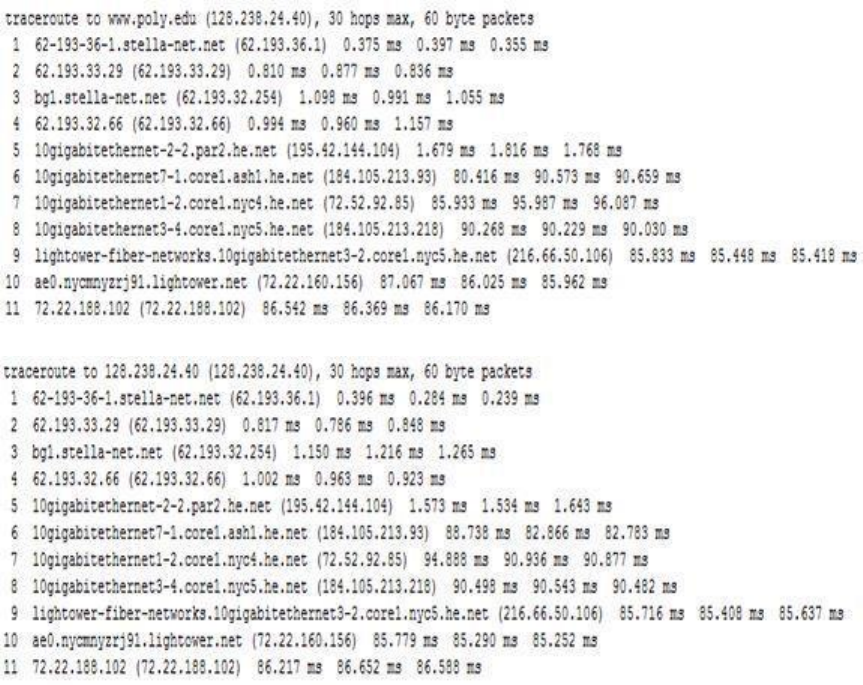
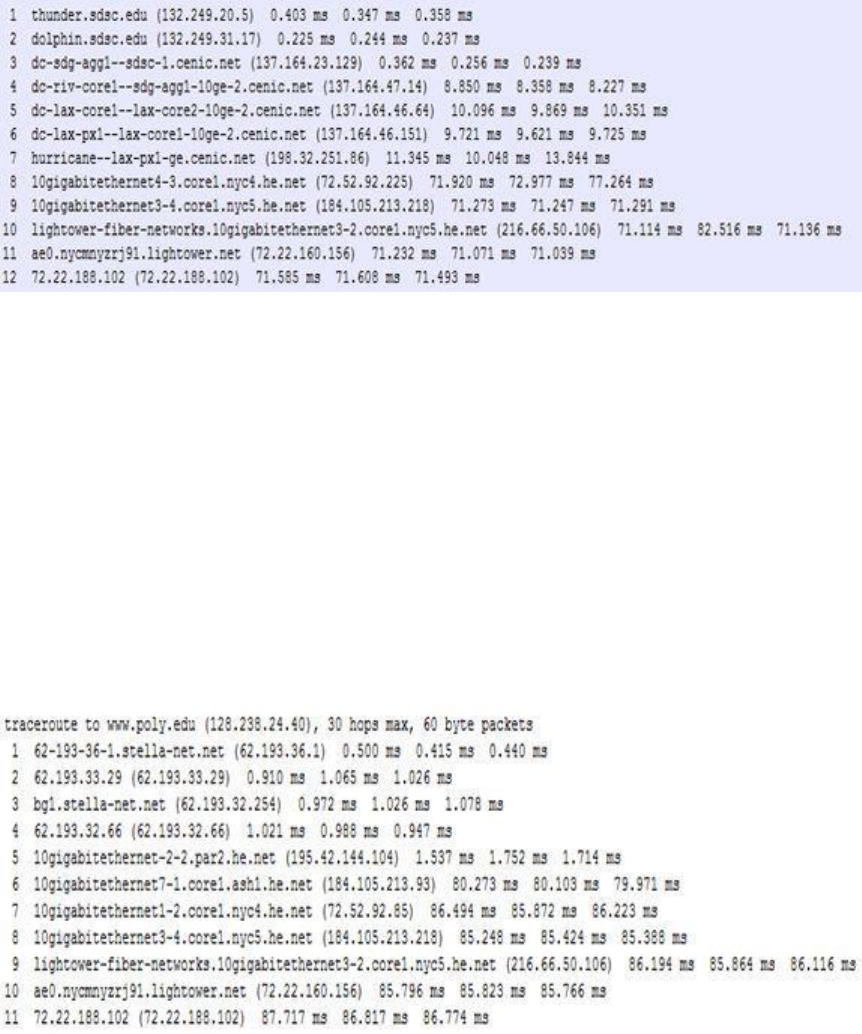
Traceroutes from www.stella-net.net (France) to www.poly.edu (USA).
d) The average round-trip delays at each of the three hours are 87.09 ms, 86.35 ms and
86.48 ms, respectively. The standard deviations are 0.53 ms, 0.18 ms, 0.23 ms,
respectively. In this example, there are 11 routers in the path at each of the three
hours. No, the paths didn’t change during any of the hours. Traceroute packets passed
three ISP networks from source to destination. Yes, in this experiment the largest
delays occurred at peering interfaces between adjacent ISPs.
Problem 19
An example solution:
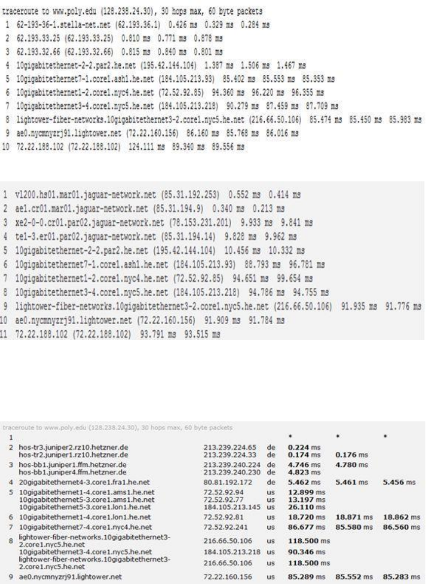
Traceroutes from two different cities in France to New York City in United States
a) In these traceroutes from two different cities in France to the same destination host in
United States, seven links are in common including the transatlantic link.
b) In this example of traceroutes from one city in France and from another city in
Germany to the same host in United States, three links are in common including the
transatlantic link.
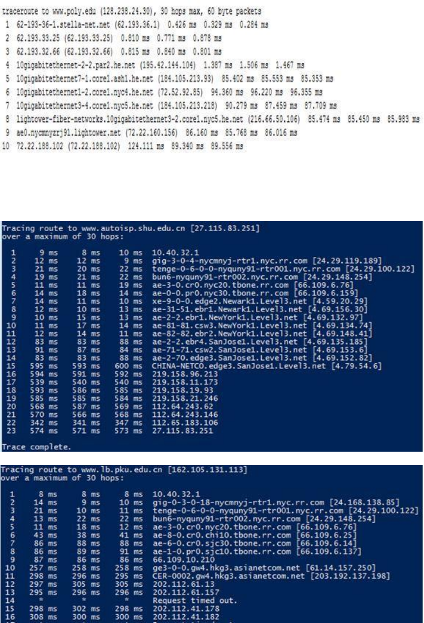
Traceroutes to two different cities in China from same host in United States
c) Five links are common in the two traceroutes. The two traceroutes diverge before
reaching China
Problem 20
Throughput = min{Rs, Rc, R/M}
Problem 21
If only use one path, the max throughput is given by:
}},,,min{,},,,,min{},,,,max{min{ 21
22
2
2
1
11
2
1
1
M
N
MM
NN RRRRRRRRR
.
If use all paths, the max throughput is given by
M
k
k
N
kk RRR
1
21 },,,min{
.
Problem 22
Probability of successfully receiving a packet is: ps= (1-p)N.
The number of transmissions needed to be performed until the packet is successfully
received by the client is a geometric random variable with success probability ps. Thus,
the average number of transmissions needed is given by: 1/ps . Then, the average number
of re-transmissions needed is given by: 1/ps -1.
Problem 23
Let’s call the first packet A and call the second packet B.
a) If the bottleneck link is the first link, then packet B is queued at the first link waiting
for the transmission of packet A. So the packet inter-arrival time at the destination is
simply L/Rs.
b) If the second link is the bottleneck link and both packets are sent back to back, it must
be true that the second packet arrives at the input queue of the second link before the
second link finishes the transmission of the first packet. That is,
L/Rs + L/Rs + dprop < L/Rs + dprop + L/Rc
The left hand side of the above inequality represents the time needed by the second
packet to arrive at the input queue of the second link (the second link has not started
transmitting the second packet yet). The right hand side represents the time needed by
the first packet to finish its transmission onto the second link.
If we send the second packet T seconds later, we will ensure that there is no queuing
delay for the second packet at the second link if we have:
L/Rs + L/Rs + dprop + T >= L/Rs + dprop + L/Rc
Thus, the minimum value of T is L/Rc L/Rs .
Problem 24
40 terabytes = 40 * 1012 * 8 bits. So, if using the dedicated link, it will take 40 * 1012 * 8 /
(100 *106 ) =3200000 seconds = 37 days. But with FedEx overnight delivery, you can
guarantee the data arrives in one day, and it should cost less than $100.
Problem 25
a) 160,000 bits
b) 160,000 bits
c) The bandwidth-delay product of a link is the maximum number of bits that can be in
the link.
d) the width of a bit = length of link / bandwidth-delay product, so 1 bit is 125 meters
long, which is longer than a football field
e) s/R
Problem 26
s/R=20000km, then R=s/20000km= 2.5*108/(2*107)= 12.5 bps
Problem 27
a) 80,000,000 bits
b) 800,000 bits, this is because that the maximum number of bits that will be in the link
at any given time = min(bandwidth delay product, packet size) = 800,000 bits.
c) .25 meters

Problem 28
a) ttrans + tprop = 400 msec + 80 msec = 480 msec.
b) 20 * (ttrans + 2 tprop) = 20*(20 msec + 80 msec) = 2 sec.
c) Breaking up a file takes longer to transmit because each data packet and its
corresponding acknowledgement packet add their own propagation delays.
Problem 29
Recall geostationary satellite is 36,000 kilometers away from earth surface.
a) 150 msec
b) 1,500,000 bits
c) 600,000,000 bits
Problem 30
Let’s suppose the passenger and his/her bags correspond to the data unit arriving to the
top of the protocol stack. When the passenger checks in, his/her bags are checked, and a
tag is attached to the bags and ticket. This is additional information added in the
Baggage layer if Figure 1.20 that allows the Baggage layer to implement the service or
separating the passengers and baggage on the sending side, and then reuniting them
(hopefully!) on the destination side. When a passenger then passes through security and
additional stamp is often added to his/her ticket, indicating that the passenger has passed
through a security check. This information is used to ensure (e.g., by later checks for the
security information) secure transfer of people.
Problem 31
a) Time to send message from source host to first packet switch =
sec4sec
102
108
6
6
With store-and-forward switching, the total time to move message from source host
to destination host =
sec123sec4 hops
b) Time to send 1st packet from source host to first packet switch = .
sec5sec
102
101
6
4m
. Time at which 2nd packet is received at the first switch = time
at which 1st packet is received at the second switch =
sec10sec52 mm
c) Time at which 1st packet is received at the destination host =
sec153sec5 mhopsm
. After this, every 5msec one packet will be received; thus
time at which last (800th) packet is received =
sec01.4sec5*799sec15 mm
. It
can be seen that delay in using message segmentation is significantly less (almost
1/3rd).
d) i. Without message segmentation, if bit errors are not tolerated, if there is a
single bit error, the whole message has to be retransmitted (rather than a single
packet).
ii. Without message segmentation, huge packets (containing HD videos, for
example) are sent into the network. Routers have to accommodate these huge
packets. Smaller packets have to queue behind enormous packets and suffer
unfair delays.
e) i. Packets have to be put in sequence at the destination.
ii. Message segmentation results in many smaller packets. Since header size is
usually the same for all packets regardless of their size, with message
segmentation the total amount of header bytes is more.
Problem 32
Yes, the delays in the applet correspond to the delays in the Problem 31.The propagation
delays affect the overall end-to-end delays both for packet switching and message
switching equally.
Problem 33
There are F/S packets. Each packet is S=80 bits. Time at which the last packet is received
at the first router is
S
F
R
S
80
sec. At this time, the first F/S-2 packets are at the
destination, and the F/S-1 packet is at the second router. The last packet must then be
transmitted by the first router and the second router, with each transmission taking
R
S80
sec. Thus delay in sending the whole file is
)2(
80
S
F
R
S
delay
To calculate the value of S which leads to the minimum delay,
FSdelay
dS
d400
Problem 34
The circuit-switched telephone networks and the Internet are connected together at
"gateways". When a Skype user (connected to the Internet) calls an ordinary telephone, a
circuit is established between a gateway and the telephone user over the circuit switched
network. The skype user's voice is sent in packets over the Internet to the gateway. At the
gateway, the voice signal is reconstructed and then sent over the circuit. In the other
direction, the voice signal is sent over the circuit switched network to the gateway. The
gateway packetizes the voice signal and sends the voice packets to the Skype user.
Chapter 2 Review Questions
1. The Web: HTTP; file transfer: FTP; remote login: Telnet; e-mail: SMTP; BitTorrent
file sharing: BitTorrent protocol
2. Network architecture refers to the organization of the communication process into
layers (e.g., the five-layer Internet architecture). Application architecture, on the other
hand, is designed by an application developer and dictates the broad structure of the
application (e.g., client-server or P2P).
3. The process which initiates the communication is the client; the process that waits to
be contacted is the server.
4. No. In a P2P file-sharing application, the peer that is receiving a file is typically the
client and the peer that is sending the file is typically the server.
5. The IP address of the destination host and the port number of the socket in the
destination process.
6. You would use UDP. With UDP, the transaction can be completed in one roundtrip
time (RTT) - the client sends the transaction request into a UDP socket, and the server
sends the reply back to the client's UDP socket. With TCP, a minimum of two RTTs
are needed - one to set-up the TCP connection, and another for the client to send the
request, and for the server to send back the reply.
7. One such example is remote word processing, for example, with Google docs.
However, because Google docs runs over the Internet (using TCP), timing guarantees
are not provided.
8. a) Reliable data transfer
TCP provides a reliable byte-stream between client and server but UDP does not.
b) A guarantee that a certain value for throughput will be maintained
Neither
c) A guarantee that data will be delivered within a specified amount of time
Neither
d) Confidentiality (via encryption)
Neither
9. SSL operates at the application layer. The SSL socket takes unencrypted data from
the application layer, encrypts it and then passes it to the TCP socket. If the
application developer wants TCP to be enhanced with SSL, she has to include the
SSL code in the application.
10. A protocol uses handshaking if the two communicating entities first exchange control
packets before sending data to each other. SMTP uses handshaking at the application
layer whereas HTTP does not.
11. The applications associated with those protocols require that all application data be
received in the correct order and without gaps. TCP provides this service whereas
UDP does not.
12. When the user first visits the site, the server creates a unique identification number,
creates an entry in its back-end database, and returns this identification number as a
cookie number. This cookie number is stored on the user’s host and is managed by
the browser. During each subsequent visit (and purchase), the browser sends the
cookie number back to the site. Thus the site knows when this user (more precisely,
this browser) is visiting the site.
13. Web caching can bring the desired content “closer” to the user, possibly to the same
LAN to which the user’s host is connected. Web caching can reduce the delay for all
objects, even objects that are not cached, since caching reduces the traffic on links.
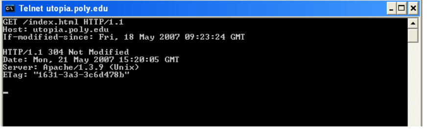
14. Telnet is not available in Windows 7 by default. to make it available, go to Control
Panel, Programs and Features, Turn Windows Features On or Off, Check Telnet
client. To start Telnet, in Windows command prompt, issue the following command
> telnet webserverver 80
where "webserver" is some webserver. After issuing the command, you have
established a TCP connection between your client telnet program and the web server.
Then type in an HTTP GET message. An example is given below:
Since the index.html page in this web server was not modified since Fri, 18 May 2007
09:23:34 GMT, and the above commands were issued on Sat, 19 May 2007, the
server returned "304 Not Modified". Note that the first 4 lines are the GET message
and header lines inputed by the user, and the next 4 lines (starting from HTTP/1.1 304
Not Modified) is the response from the web server.

15. FTP uses two parallel TCP connections, one connection for sending control
information (such as a request to transfer a file) and another connection for actually
transferring the file. Because the control information is not sent over the same
connection that the file is sent over, FTP sends control information out of band.
16. The message is first sent from Alice’s host to her mail server over HTTP. Alice’s
mail server then sends the message to Bob’s mail server over SMTP. Bob then
transfers the message from his mail server to his host over POP3.
17.
Received:
from 65.54.246.203 (EHLO bay0-omc3-s3.bay0.hotmail.com)
(65.54.246.203) by mta419.mail.mud.yahoo.com with SMTP; Sat, 19
May 2007 16:53:51 -0700
Received:
from hotmail.com ([65.55.135.106]) by bay0-omc3-s3.bay0.hotmail.com
with Microsoft SMTPSVC(6.0.3790.2668); Sat, 19 May 2007 16:52:42 -
0700
Received:
from mail pickup service by hotmail.com with Microsoft SMTPSVC; Sat,
19 May 2007 16:52:41 -0700
Message-ID:
<BAY130-F26D9E35BF59E0D18A819AFB9310@phx.gbl>
Received:
from 65.55.135.123 by by130fd.bay130.hotmail.msn.com with HTTP;
Sat, 19 May 2007 23:52:36 GMT
From:
"prithula dhungel" <prithuladhungel@hotmail.com>
To:
prithula@yahoo.com
Bcc:
Subject:
Test mail
Date:
Sat, 19 May 2007 23:52:36 +0000
Mime-Version:
1.0
Content-Type:
Text/html; format=flowed
Return-Path:
prithuladhungel@hotmail.com
Figure: A sample mail message header
Received: This header field indicates the sequence in which the SMTP servers send
and receive the mail message including the respective timestamps.
In this example there are 4 “Received:” header lines. This means the mail message
passed through 5 different SMTP servers before being delivered to the receiver’s mail
box. The last (forth) “Received:” header indicates the mail message flow from the
SMTP server of the sender to the second SMTP server in the chain of servers. The
sender’s SMTP server is at address 65.55.135.123 and the second SMTP server in the
chain is by130fd.bay130.hotmail.msn.com.
The third “Received:” header indicates the mail message flow from the second SMTP
server in the chain to the third server, and so on.
Finally, the first “Received:” header indicates the flow of the mail messages from the
forth SMTP server to the last SMTP server (i.e. the receiver’s mail server) in the
chain.
Message-id: The message has been given this number BAY130-
F26D9E35BF59E0D18A819AFB9310@phx.gbl (by bay0-omc3-
s3.bay0.hotmail.com. Message-id is a unique string assigned by the mail system when
the message is first created.
From: This indicates the email address of the sender of the mail. In the given
example, the sender is “prithuladhungel@hotmail.com”
To: This field indicates the email address of the receiver of the mail. In the example,
the receiver is “prithula@yahoo.com”
Subject: This gives the subject of the mail (if any specified by the sender). In the
example, the subject specified by the sender is “Test mail”
Date: The date and time when the mail was sent by the sender. In the example, the
sender sent the mail on 19th May 2007, at time 23:52:36 GMT.
Mime-version: MIME version used for the mail. In the example, it is 1.0.
Content-type: The type of content in the body of the mail message. In the example, it
is “text/html”.
Return-Path: This specifies the email address to which the mail will be sent if the
receiver of this mail wants to reply to the sender. This is also used by the sender’s
mail server for bouncing back undeliverable mail messages of mailer-daemon error
messages. In the example, the return path is “prithuladhungel@hotmail.com”.
18. With download and delete, after a user retrieves its messages from a POP server, the
messages are deleted. This poses a problem for the nomadic user, who may want to
access the messages from many different machines (office PC, home PC, etc.). In the
download and keep configuration, messages are not deleted after the user retrieves the
messages. This can also be inconvenient, as each time the user retrieves the stored
messages from a new machine, all of non-deleted messages will be transferred to the
new machine (including very old messages).
19. Yes an organization’s mail server and Web server can have the same alias for a host
name. The MX record is used to map the mail server’s host name to its IP address.
20. You should be able to see the sender's IP address for a user with an .edu email
address. But you will not be able to see the sender's IP address if the user uses a gmail
account.
21. It is not necessary that Bob will also provide chunks to Alice. Alice has to be in the
top 4 neighbors of Bob for Bob to send out chunks to her; this might not occur even if
Alice provides chunks to Bob throughout a 30-second interval.
22. Recall that in BitTorrent, a peer picks a random peer and optimistically unchokes the
peer for a short period of time. Therefore, Alice will eventually be optimistically
unchoked by one of her neighbors, during which time she will receive chunks from
that neighbor.
23. The overlay network in a P2P file sharing system consists of the nodes participating
in the file sharing system and the logical links between the nodes. There is a logical
link (an “edge” in graph theory terms) from node A to node B if there is a semi-
permanent TCP connection between A and B. An overlay network does not include
routers.
24. Mesh DHT: The advantage is in order to a route a message to the peer (with ID) that
is closest to the key, only one hop is required; the disadvantage is that each peer must
track all other peers in the DHT. Circular DHT: the advantage is that each peer needs
to track only a few other peers; the disadvantage is that O(N) hops are needed to route
a message to the peer that is closest to the key.
25. a) File Distribution
b) Instant Messaging
c) Video Streaming
d) Distributed Computing
26. With the UDP server, there is no welcoming socket, and all data from different clients
enters the server through this one socket. With the TCP server, there is a welcoming
socket, and each time a client initiates a connection to the server, a new socket is
created. Thus, to support n simultaneous connections, the server would need n+1
sockets.
27. For the TCP application, as soon as the client is executed, it attempts to initiate a TCP
connection with the server. If the TCP server is not running, then the client will fail to
make a connection. For the UDP application, the client does not initiate connections
(or attempt to communicate with the UDP server) immediately upon execution
Chapter 2 Problems
Problem 1
a) F
b) T
c) F
d) F
e) F
Problem 2
Access control commands:
USER, PASS, ACT, CWD, CDUP, SMNT, REIN, QUIT.
Transfer parameter commands:
PORT, PASV, TYPE STRU, MODE.
Service commands:
RETR, STOR, STOU, APPE, ALLO, REST, RNFR, RNTO, ABOR, DELE,
RMD, MRD, PWD, LIST, NLST, SITE, SYST, STAT, HELP, NOOP.
Problem 3
Application layer protocols: DNS and HTTP
Transport layer protocols: UDP for DNS; TCP for HTTP
Problem 4
a) The document request was http://gaia.cs.umass.edu/cs453/index.html. The Host :
field indicates the server's name and /cs453/index.html indicates the file name.
b) The browser is running HTTP version 1.1, as indicated just before the first <cr><lf>
pair.
c) The browser is requesting a persistent connection, as indicated by the Connection:
keep-alive.
d) This is a trick question. This information is not contained in an HTTP message
anywhere. So there is no way to tell this from looking at the exchange of HTTP
messages alone. One would need information from the IP datagrams (that carried the
TCP segment that carried the HTTP GET request) to answer this question.
e) Mozilla/5.0. The browser type information is needed by the server to send different
versions of the same object to different types of browsers.
Problem 5
a) The status code of 200 and the phrase OK indicate that the server was able to locate
the document successfully. The reply was provided on Tuesday, 07 Mar 2008
12:39:45 Greenwich Mean Time.
b) The document index.html was last modified on Saturday 10 Dec 2005 18:27:46
GMT.
c) There are 3874 bytes in the document being returned.
d) The first five bytes of the returned document are : <!doc. The server agreed to a
persistent connection, as indicated by the Connection: Keep-Alive field
Problem 6
a) Persistent connections are discussed in section 8 of RFC 2616 (the real goal of this
question was to get you to retrieve and read an RFC). Sections 8.1.2 and 8.1.2.1 of
the RFC indicate that either the client or the server can indicate to the other that it is
going to close the persistent connection. It does so by including the connection-token
"close" in the Connection-header field of the http request/reply.
b) HTTP does not provide any encryption services.
c) (From RFC 2616) “Clients that use persistent connections should limit the number of
simultaneous connections that they maintain to a given server. A single-user client
SHOULD NOT maintain more than 2 connections with any server or proxy.”
d) Yes. (From RFC 2616) “A client might have started to send a new request at the same
time that the server has decided to close the "idle" connection. From the server's point
of view, the connection is being closed while it was idle, but from the client's point of
view, a request is in progress.”
Problem 7
The total amount of time to get the IP address is
n
RTTRTTRTT
21
.
Once the IP address is known,
O
RTT
elapses to set up the TCP connection and another
O
RTT
elapses to request and receive the small object. The total response time is
no RTTRTTRTTRTT
21
2
Problem 8
a)
oon RTTRTTRTTRTT 282
1
no RTTRTTRTT
1
18
.
b)
oon RTTRTTRTTRTT 222
1
no RTTRTTRTT
1
6
c)
oon RTTRTTRTTRTT 2
1
no RTTRTTRTT
1
3
.
Problem 9
a) The time to transmit an object of size L over a link or rate R is L/R. The average time
is the average size of the object divided by R:
= (850,000 bits)/(15,000,000 bits/sec) = .0567 sec
The traffic intensity on the link is given by
=(16 requests/sec)(.0567 sec/request) =
0.907. Thus, the average access delay is (.0567 sec)/(1 - .907) .6 seconds. The total
average response time is therefore .6 sec + 3 sec = 3.6 sec.
b) The traffic intensity on the access link is reduced by 60% since the 60% of the
requests are satisfied within the institutional network. Thus the average access delay
is (.0567 sec)/[1 – (.4)(.907)] = .089 seconds. The response time is approximately
zero if the request is satisfied by the cache (which happens with probability .6); the
average response time is .089 sec + 3 sec = 3.089 sec for cache misses (which
happens 40% of the time). So the average response time is (.6)(0 sec) + (.4)(3.089
sec) = 1.24 seconds. Thus the average response time is reduced from 3.6 sec to 1.24
sec.
Problem 10
Note that each downloaded object can be completely put into one data packet. Let Tp
denote the one-way propagation delay between the client and the server.
First consider parallel downloads using non-persistent connections. Parallel downloads
would allow 10 connections to share the 150 bits/sec bandwidth, giving each just 15
bits/sec. Thus, the total time needed to receive all objects is given by:
(200/150+Tp + 200/150 +Tp + 200/150+Tp + 100,000/150+ Tp )
+ (200/(150/10)+Tp + 200/(150/10) +Tp + 200/(150/10)+Tp + 100,000/(150/10)+ Tp )
= 7377 + 8*Tp (seconds)
Now consider a persistent HTTP connection. The total time needed is given by:
(200/150+Tp + 200/150 +Tp + 200/150+Tp + 100,000/150+ Tp )
+ 10*(200/150+Tp + 100,000/150+ Tp )
=7351 + 24*Tp (seconds)
Assuming the speed of light is 300*106 m/sec, then Tp=10/(300*106)=0.03 microsec. Tp
is therefore negligible compared with transmission delay.
Thus, we see that persistent HTTP is not significantly faster (less than 1 percent) than the
non-persistent case with parallel download.
Problem 11
a) Yes, because Bob has more connections, he can get a larger share of the link
bandwidth.
b) Yes, Bob still needs to perform parallel downloads; otherwise he will get less
bandwidth than the other four users.
Problem 12
Server.py
from socket import *
serverPort=12000
serverSocket=socket(AF_INET,SOCK_STREAM)
serverSocket.bind(('',serverPort))
serverSocket.listen(1)
connectionSocket, addr = serverSocket.accept()
while 1:
sentence = connectionSocket.recv(1024)
print 'From Server:', sentence, '\n'
serverSocket.close()
Problem 13
The MAIL FROM: in SMTP is a message from the SMTP client that identifies the sender
of the mail message to the SMTP server. The From: on the mail message itself is NOT an
SMTP message, but rather is just a line in the body of the mail message.
Problem 14
SMTP uses a line containing only a period to mark the end of a message body.
HTTP uses “Content-Length header field” to indicate the length of a message body.
No, HTTP cannot use the method used by SMTP, because HTTP message could be
binary data, whereas in SMTP, the message body must be in 7-bit ASCII format.
Problem 15
MTA stands for Mail Transfer Agent. A host sends the message to an MTA. The message
then follows a sequence of MTAs to reach the receiver’s mail reader. We see that this
spam message follows a chain of MTAs. An honest MTA should report where it receives
the message. Notice that in this message, “asusus-4b96 ([58.88.21.177])” does not
report from where it received the email. Since we assume only the originator is
dishonest, so “asusus-4b96 ([58.88.21.177])” must be the originator.
Problem 16
UIDL abbreviates “unique-ID listing”. When a POP3 client issues the UIDL command,
the server responds with the unique message ID for all of the messages present in the
user's mailbox. This command is useful for “download and keep”. By maintaining a file
that lists the messages retrieved during earlier sessions, the client can use the UIDL
command to determine which messages on the server have already been seen.
Problem 17
a) C: dele 1
C: retr 2
S: (blah blah …
S: ………..blah)
S: .
C: dele 2
C: quit
S: +OK POP3 server signing off
b) C: retr 2
S: blah blah …
S: ………..blah
S: .
C: quit
S: +OK POP3 server signing off
c) C: list
S: 1 498
S: 2 912
S: .
C: retr 1
S: blah …..
S: ….blah
S: .
C: retr 2
S: blah blah …
S: ………..blah
S: .
C: quit
S: +OK POP3 server signing off
Problem 18
a) For a given input of domain name (such as ccn.com), IP address or network
administrator name, the whois database can be used to locate the corresponding
registrar, whois server, DNS server, and so on.
b) NS4.YAHOO.COM from www.register.com; NS1.MSFT.NET from ww.register.com
c) Local Domain: www.mindspring.com
Web servers : www.mindspring.com
207.69.189.21, 207.69.189.22,
207.69.189.23, 207.69.189.24,
207.69.189.25, 207.69.189.26, 207.69.189.27,
207.69.189.28
Mail Servers : mx1.mindspring.com (207.69.189.217)
mx2.mindspring.com (207.69.189.218)
mx3.mindspring.com (207.69.189.219)
mx4.mindspring.com (207.69.189.220)
Name Servers: itchy.earthlink.net (207.69.188.196)
scratchy.earthlink.net (207.69.188.197)
www.yahoo.com
Web Servers: www.yahoo.com (216.109.112.135, 66.94.234.13)
Mail Servers: a.mx.mail.yahoo.com (209.191.118.103)
b.mx.mail.yahoo.com (66.196.97.250)
c.mx.mail.yahoo.com (68.142.237.182, 216.39.53.3)
d.mx.mail.yahoo.com (216.39.53.2)
e.mx.mail.yahoo.com (216.39.53.1)
f.mx.mail.yahoo.com (209.191.88.247, 68.142.202.247)
g.mx.mail.yahoo.com (209.191.88.239, 206.190.53.191)
Name Servers: ns1.yahoo.com (66.218.71.63)
ns2.yahoo.com (68.142.255.16)
ns3.yahoo.com (217.12.4.104)
ns4.yahoo.com (68.142.196.63)
ns5.yahoo.com (216.109.116.17)
ns8.yahoo.com (202.165.104.22)
ns9.yahoo.com (202.160.176.146)
www.hotmail.com
Web Servers: www.hotmail.com (64.4.33.7, 64.4.32.7)
Mail Servers: mx1.hotmail.com (65.54.245.8, 65.54.244.8, 65.54.244.136)
mx2.hotmail.com (65.54.244.40, 65.54.244.168, 65.54.245.40)
mx3.hotmail.com (65.54.244.72, 65.54.244.200, 65.54.245.72)
mx4.hotmail.com (65.54.244.232, 65.54.245.104, 65.54.244.104)
Name Servers: ns1.msft.net (207.68.160.190)
ns2.msft.net (65.54.240.126)
ns3.msft.net (213.199.161.77)
ns4.msft.net (207.46.66.126)
ns5.msft.net (65.55.238.126)
d) The yahoo web server has multiple IP addresses
www.yahoo.com (216.109.112.135, 66.94.234.13)
e) The address range for Polytechnic University: 128.238.0.0 – 128.238.255.255
f) An attacker can use the whois database and nslookup tool to determine the IP address
ranges, DNS server addresses, etc., for the target institution.
g) By analyzing the source address of attack packets, the victim can use whois to obtain
information about domain from which the attack is coming and possibly inform the
administrators of the origin domain.
Problem 19
a) The following delegation chain is used for gaia.cs.umass.edu
a.root-servers.net
E.GTLD-SERVERS.NET
ns1.umass.edu(authoritative)
First command:
dig +norecurse @a.root-servers.net any gaia.cs.umass.edu
;; AUTHORITY SECTION:
edu. 172800 IN NS E.GTLD-SERVERS.NET.
edu. 172800 IN NS A.GTLD-SERVERS.NET.
edu. 172800 IN NS G3.NSTLD.COM.
edu. 172800 IN NS D.GTLD-SERVERS.NET.
edu. 172800 IN NS H3.NSTLD.COM.
edu. 172800 IN NS L3.NSTLD.COM.
edu. 172800 IN NS M3.NSTLD.COM.
edu. 172800 IN NS C.GTLD-SERVERS.NET.
Among all returned edu DNS servers, we send a query to the first one.
dig +norecurse @E.GTLD-SERVERS.NET any gaia.cs.umass.edu
umass.edu. 172800 IN NS ns1.umass.edu.
umass.edu. 172800 IN NS ns2.umass.edu.
umass.edu. 172800 IN NS ns3.umass.edu.
Among all three returned authoritative DNS servers, we send a query to the first one.
dig +norecurse @ns1.umass.edu any gaia.cs.umass.edu
gaia.cs.umass.edu. 21600 IN A 128.119.245.12
b) The answer for google.com could be:
a.root-servers.net
E.GTLD-SERVERS.NET
ns1.google.com(authoritative)
Problem 20
We can periodically take a snapshot of the DNS caches in the local DNS servers. The
Web server that appears most frequently in the DNS caches is the most popular server.
This is because if more users are interested in a Web server, then DNS requests for that
server are more frequently sent by users. Thus, that Web server will appear in the DNS
caches more frequently.
For a complete measurement study, see:
Craig E. Wills, Mikhail Mikhailov, Hao Shang
“Inferring Relative Popularity of Internet Applications by Actively Querying DNS
Caches”, in IMC'03, October 2729, 2003, Miami Beach, Florida, USA
Problem 21
Yes, we can use dig to query that Web site in the local DNS server.
For example, “dig cnn.com” will return the query time for finding cnn.com. If cnn.com
was just accessed a couple of seconds ago, an entry for cnn.com is cached in the local
DNS cache, so the query time is 0 msec. Otherwise, the query time is large.
Problem 22
For calculating the minimum distribution time for client-server distribution, we use the
following formula:
Dcs = max {NF/us, F/dmin}
Similarly, for calculating the minimum distribution time for P2P distribution, we use the
following formula:
)}u , NF/(u, F/dmax{F/uD N
1i
ismins
PP
2
Where, F = 15 Gbits = 15 * 1024 Mbits
us = 30 Mbps
dmin = di = 2 Mbps
Note, 300Kbps = 300/1024 Mbps.
Client Server
N
10
100
1000
u
300 Kbps
7680
51200
512000
700 Kbps
7680
51200
512000
2 Mbps
7680
51200
512000
Peer to Peer
N
10
100
1000
u
300 Kbps
7680
25904
47559
700 Kbps
7680
15616
21525
2 Mbps
7680
7680
7680
Problem 23
a) Consider a distribution scheme in which the server sends the file to each client, in
parallel, at a rate of a rate of us/N. Note that this rate is less than each of the client’s
download rate, since by assumption us/N ≤ dmin. Thus each client can also receive at
rate us/N. Since each client receives at rate us/N, the time for each client to receive the
entire file is F/( us/N) = NF/ us. Since all the clients receive the file in NF/ us, the
overall distribution time is also NF/ us.
b) Consider a distribution scheme in which the server sends the file to each client, in
parallel, at a rate of dmin. Note that the aggregate rate, N dmin, is less than the server’s
link rate us, since by assumption us/N ≥ dmin. Since each client receives at rate dmin,
the time for each client to receive the entire file is F/ dmin. Since all the clients receive
the file in this time, the overall distribution time is also F/ dmin.
c) From Section 2.6 we know that
DCS ≥ max {NF/us, F/dmin} (Equation 1)
Suppose that us/N ≤ dmin. Then from Equation 1 we have DCS ≥ NF/us . But from (a)
we have DCS ≤ NF/us . Combining these two gives:
DCS = NF/us when us/N ≤ dmin. (Equation 2)
We can similarly show that:
DCS =F/dmin when us/N ≥ dmin (Equation 3).
Combining Equation 2 and Equation 3 gives the desired result.
Problem 24
a) Define u = u1 + u2 + ….. + uN. By assumption
us <= (us + u)/N Equation 1
Divide the file into N parts, with the ith part having size (ui/u)F. The server transmits
the ith part to peer i at rate ri = (ui/u)us. Note that r1 + r2 + ….. + rN = us, so that the
aggregate server rate does not exceed the link rate of the server. Also have each peer i
forward the bits it receives to each of the N-1 peers at rate ri. The aggregate
forwarding rate by peer i is (N-1)ri. We have
(N-1)ri = (N-1)(usui)/u <= ui,
where the last inequality follows from Equation 1. Thus the aggregate forwarding rate
of peer i is less than its link rate ui.
In this distribution scheme, peer i receives bits at an aggregate rate of
sj
ij
iurr
Thus each peer receives the file in F/us.
b) Again define u = u1 + u2 + ….. + uN. By assumption
us >= (us + u)/N Equation 2
Let ri = ui/(N-1) and
rN+1 = (us – u/(N-1))/N
In this distribution scheme, the file is broken into N+1 parts. The server sends bits
from the ith part to the ith peer (i = 1, …., N) at rate ri. Each peer i forwards the bits
arriving at rate ri to each of the other N-1 peers. Additionally, the server sends bits
from the (N+1) st part at rate rN+1 to each of the N peers. The peers do not forward the
bits from the (N+1)st part.
The aggregate send rate of the server is
r1+ …. + rN + N rN+1 = u/(N-1) + us – u/(N-1) = us
Thus, the server’s send rate does not exceed its link rate. The aggregate send rate of
peer i is
(N-1)ri = ui
Thus, each peer’s send rate does not exceed its link rate.
In this distribution scheme, peer i receives bits at an aggregate rate of
NuuNNuuNujrrr ss
ij
Ni /)(/))1/(()1/(1
Thus each peer receives the file in NF/(us+u).
(For simplicity, we neglected to specify the size of the file part for i = 1, …., N+1.
We now provide that here. Let Δ = (us+u)/N be the distribution time. For i = 1, …, N,
the ith file part is Fi = ri Δ bits. The (N+1)st file part is FN+1 = rN+1 Δ bits. It is
straightforward to show that F1+ ….. + FN+1 = F.)
c) The solution to this part is similar to that of 17 (c). We know from section 2.6 that
u)}, NF/(umax{F/uD ss
PP
2
Combining this with a) and b) gives the desired result.
Problem 25
There are N nodes in the overlay network. There are N(N-1)/2 edges.
Problem 26
Yes. His first claim is possible, as long as there are enough peers staying in the swarm for
a long enough time. Bob can always receive data through optimistic unchoking by other
peers.
His second claim is also true. He can run a client on each host, let each client “free-ride,”
and combine the collected chunks from the different hosts into a single file. He can even
write a small scheduling program to make the different hosts ask for different chunks of
the file. This is actually a kind of Sybil attack in P2P networks.
Problem 27
Peer 3 learns that peer 5 has just left the system, so Peer 3 asks its first successor (Peer 4)
for the identifier of its immediate successor (peer 8). Peer 3 will then make peer 8 its
second successor.
Problem 28
Peer 6 would first send peer 15 a message, saying “what will be peer 6’s predecessor and
successor?” This message gets forwarded through the DHT until it reaches peer 5, who
realizes that it will be 6’s predecessor and that its current successor, peer 8, will become
6’s successor. Next, peer 5 sends this predecessor and successor information back to 6.
Peer 6 can now join the DHT by making peer 8 its successor and by notifying peer 5 that
it should change its immediate successor to 6.
Problem 29
For each key, we first calculate the distances (using d(k,p)) between itself and all peers,
and then store the key in the peer that is closest to the key (that is, with smallest distance
value).
Problem 30
Yes, randomly assigning keys to peers does not consider the underlying network at all, so
it very likely causes mismatches.
Such mismatches may degrade the search performance. For example, consider a logical
path p1 (consisting of only two logical links): ABC, where A and B are neighboring
peers, and B and C are neighboring peers. Suppose that there is another logical path p2
from A to C (consisting of 3 logical links): ADEC.
It might be the case that A and B are very far away physically (and separated by many
routers), and B and C are very far away physically (and separated by many routers). But
it may be the case that A, D, E, and C are all very close physically (and all separated by
few routers). In other words, a shorter logical path may correspond to a much longer
physical path.
Problem 31
a) If you run TCPClient first, then the client will attempt to make a TCP connection with
a non-existent server process. A TCP connection will not be made.
b) UDPClient doesn't establish a TCP connection with the server. Thus, everything
should work fine if you first run UDPClient, then run UDPServer, and then type some
input into the keyboard.
c) If you use different port numbers, then the client will attempt to establish a TCP
connection with the wrong process or a non-existent process. Errors will occur.
Problem 32
In the original program, UDPClient does not specify a port number when it creates the
socket. In this case, the code lets the underlying operating system choose a port number.
With the additional line, when UDPClient is executed, a UDP socket is created with port
number 5432 .
UDPServer needs to know the client port number so that it can send packets back to the
correct client socket. Glancing at UDPServer, we see that the client port number is not
“hard-wired” into the server code; instead, UDPServer determines the client port number
by unraveling the datagram it receives from the client. Thus UDP server will work with
any client port number, including 5432. UDPServer therefore does not need to be
modified.
Before:
Client socket = x (chosen by OS)
Server socket = 9876
After:
Client socket = 5432
Problem 33
Yes, you can configure many browsers to open multiple simultaneous connections to a
Web site. The advantage is that you will you potentially download the file faster. The
disadvantage is that you may be hogging the bandwidth, thereby significantly slowing
down the downloads of other users who are sharing the same physical links.
Problem 34
For an application such as remote login (telnet and ssh), a byte-stream oriented protocol
is very natural since there is no notion of message boundaries in the application. When a
user types a character, we simply drop the character into the TCP connection.
In other applications, we may be sending a series of messages that have inherent
boundaries between them. For example, when one SMTP mail server sends another
SMTP mail server several email messages back to back. Since TCP does not have a
mechanism to indicate the boundaries, the application must add the indications itself, so
that receiving side of the application can distinguish one message from the next. If each
message were instead put into a distinct UDP segment, the receiving end would be able to
distinguish the various messages without any indications added by the sending side of the
application.
Problem 35
To create a web server, we need to run web server software on a host. Many vendors sell
web server software. However, the most popular web server software today is Apache,
which is open source and free. Over the years it has been highly optimized by the open-
source community.
Problem 36
The key is the infohash, the value is an IP address that currently has the file designated by
the infohash.
Chapter 3 Review Questions
1.
a) Call this protocol Simple Transport Protocol (STP). At the sender side, STP accepts
from the sending process a chunk of data not exceeding 1196 bytes, a destination host
address, and a destination port number. STP adds a four-byte header to each chunk
and puts the port number of the destination process in this header. STP then gives the
destination host address and the resulting segment to the network layer. The network
layer delivers the segment to STP at the destination host. STP then examines the port
number in the segment, extracts the data from the segment, and passes the data to the
process identified by the port number.
b) The segment now has two header fields: a source port field and destination port field.
At the sender side, STP accepts a chunk of data not exceeding 1192 bytes, a
destination host address, a source port number, and a destination port number. STP
creates a segment which contains the application data, source port number, and
destination port number. It then gives the segment and the destination host address to
the network layer. After receiving the segment, STP at the receiving host gives the
application process the application data and the source port number.
c) No, the transport layer does not have to do anything in the core; the transport layer
“lives” in the end systems.
2.
1. For sending a letter, the family member is required to give the delegate the letter
itself, the address of the destination house, and the name of the recipient. The
delegate clearly writes the recipient’s name on the top of the letter. The delegate then
puts the letter in an envelope and writes the address of the destination house on the
envelope. The delegate then gives the letter to the planet’s mail service. At the
receiving side, the delegate receives the letter from the mail service, takes the letter
out of the envelope, and takes note of the recipient name written at the top of the
letter. The delegate then gives the letter to the family member with this name.
2. No, the mail service does not have to open the envelope; it only examines the address
on the envelope.
3. Source port number y and destination port number x.
4. An application developer may not want its application to use TCP’s congestion
control, which can throttle the application’s sending rate at times of congestion.
Often, designers of IP telephony and IP videoconference applications choose to run
their applications over UDP because they want to avoid TCP’s congestion control.
Also, some applications do not need the reliable data transfer provided by TCP.
5. Since most firewalls are configured to block UDP traffic, using TCP for video and
voice traffic lets the traffic though the firewalls.
6. Yes. The application developer can put reliable data transfer into the application layer
protocol. This would require a significant amount of work and debugging, however.
7. Yes, both segments will be directed to the same socket. For each received segment, at
the socket interface, the operating system will provide the process with the IP
addresses to determine the origins of the individual segments.
8. For each persistent connection, the Web server creates a separate “connection
socket”. Each connection socket is identified with a four-tuple: (source IP address,
source port number, destination IP address, destination port number). When host C
receives and IP datagram, it examines these four fields in the datagram/segment to
determine to which socket it should pass the payload of the TCP segment. Thus, the
requests from A and B pass through different sockets. The identifier for both of these
sockets has 80 for the destination port; however, the identifiers for these sockets have
different values for source IP addresses. Unlike UDP, when the transport layer passes
a TCP segment’s payload to the application process, it does not specify the source IP
address, as this is implicitly specified by the socket identifier.
9. Sequence numbers are required for a receiver to find out whether an arriving packet
contains new data or is a retransmission.
10. To handle losses in the channel. If the ACK for a transmitted packet is not received
within the duration of the timer for the packet, the packet (or its ACK or NACK) is
assumed to have been lost. Hence, the packet is retransmitted.
11. A timer would still be necessary in the protocol rdt 3.0. If the round trip time is
known then the only advantage will be that, the sender knows for sure that either the
packet or the ACK (or NACK) for the packet has been lost, as compared to the real
scenario, where the ACK (or NACK) might still be on the way to the sender, after the
timer expires. However, to detect the loss, for each packet, a timer of constant
duration will still be necessary at the sender.
12.
a) The packet loss caused a time out after which all the five packets were retransmitted.
b) Loss of an ACK didn’t trigger any retransmission as Go-Back-N uses cumulative
acknowledgements.
c) The sender was unable to send sixth packet as the send window size is fixed to 5.
13.
a) When the packet was lost, the received four packets were buffered the receiver. After
the timeout, sender retransmitted the lost packet and receiver delivered the buffered
packets to application in correct order.
b) Duplicate ACK was sent by the receiver for the lost ACK.
c) The sender was unable to send sixth packet as the send window size is fixed to 5
When a packet was lost, GO-Back-N retransmitted all the packets whereas Selective
Repeat retransmitted the lost packet only. In case of lost acknowledgement, selective
repeat sent a duplicate ACK and as GO-Back-N used cumulative acknowledgment, so
that duplicate ACK was unnecessary.
14. a) false b) false c) true d) false e) true f) false g) false
15. a) 20 bytes b) ack number = 90
16. 3 segments. First segment: seq = 43, ack =80; Second segment: seq = 80, ack = 44;
Third segment; seq = 44, ack = 81
17. R/2
18. False, it is set to half of the current value of the congestion window.
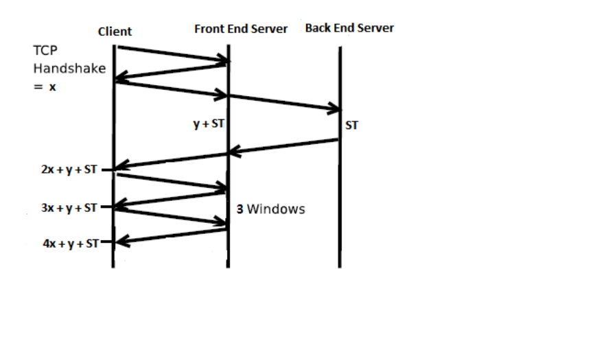
19. Let X = RTTFE, Y = RTTBE and ST = Search time. Consider the following timing
diagram.
TCP packet exchange diagram between a client and a server (Back End) with a proxy
(Front End) between them.
From this diagram we see that the total time is 4X + Y+ ST = 4*RTTFE + RTTBE +
Search time
Chapter 3 Problems
Problem 1
source port
numbers
destination port
numbers
a) A
S
467
23
b) B
S
513
23
c) S
A
23
467
d) S
B
23
513
e) Yes.
f) No.
Problem 2
Suppose the IP addresses of the hosts A, B, and C are a, b, c, respectively. (Note that a, b,
c are distinct.)
To host A: Source port =80, source IP address = b, dest port = 26145, dest IP address = a
To host C, left process: Source port =80, source IP address = b, dest port = 7532, dest IP
address = c
To host C, right process: Source port =80, source IP address = b, dest port = 26145, dest
IP address = c
Problem 3
Note, wrap around if overflow.
10011101
01100110
11001010

01110100
00101110
10011101
One's complement = 1 1 0 1 0 0 0 1.
To detect errors, the receiver adds the four words (the three original words and the
checksum). If the sum contains a zero, the receiver knows there has been an error. All
one-bit errors will be detected, but two-bit errors can be undetected (e.g., if the last digit
of the first word is converted to a 0 and the last digit of the second word is converted to a
1).
Problem 4
a) Adding the two bytes gives 11000001. Taking the one’s complement gives 00111110.
b) Adding the two bytes gives 01000000; the one’s complement gives 10111111.
c) First byte = 01010100; second byte = 01101101.
Problem 5
No, the receiver cannot be absolutely certain that no bit errors have occurred. This is
because of the manner in which the checksum for the packet is calculated. If the
corresponding bits (that would be added together) of two 16-bit words in the packet were
0 and 1 then even if these get flipped to 1 and 0 respectively, the sum still remains the
same. Hence, the 1s complement the receiver calculates will also be the same. This
means the checksum will verify even if there was transmission error.
Problem 6
Suppose the sender is in state “Wait for call 1 from above” and the receiver (the receiver
shown in the homework problem) is in state “Wait for 1 from below.” The sender sends
a packet with sequence number 1, and transitions to “Wait for ACK or NAK 1,” waiting
for an ACK or NAK. Suppose now the receiver receives the packet with sequence
number 1 correctly, sends an ACK, and transitions to state “Wait for 0 from below,”
waiting for a data packet with sequence number 0. However, the ACK is corrupted.
When the rdt2.1 sender gets the corrupted ACK, it resends the packet with sequence
number 1. However, the receiver is waiting for a packet with sequence number 0 and (as
shown in the home work problem) always sends a NAK when it doesn't get a packet with
sequence number 0. Hence the sender will always be sending a packet with sequence
number 1, and the receiver will always be NAKing that packet. Neither will progress
forward from that state.
Problem 7
To best answer this question, consider why we needed sequence numbers in the first
place. We saw that the sender needs sequence numbers so that the receiver can tell if a
data packet is a duplicate of an already received data packet. In the case of ACKs, the
sender does not need this info (i.e., a sequence number on an ACK) to tell detect a
duplicate ACK. A duplicate ACK is obvious to the rdt3.0 receiver, since when it has
received the original ACK it transitioned to the next state. The duplicate ACK is not the
ACK that the sender needs and hence is ignored by the rdt3.0 sender.
Problem 8
The sender side of protocol rdt3.0 differs from the sender side of protocol 2.2 in that
timeouts have been added. We have seen that the introduction of timeouts adds the
possibility of duplicate packets into the sender-to-receiver data stream. However, the
receiver in protocol rdt.2.2 can already handle duplicate packets. (Receiver-side
duplicates in rdt 2.2 would arise if the receiver sent an ACK that was lost, and the sender
then retransmitted the old data). Hence the receiver in protocol rdt2.2 will also work as
the receiver in protocol rdt 3.0.
Problem 9
Suppose the protocol has been in operation for some time. The sender is in state “Wait
for call from above” (top left hand corner) and the receiver is in state “Wait for 0 from
below”. The scenarios for corrupted data and corrupted ACK are shown in Figure 1.
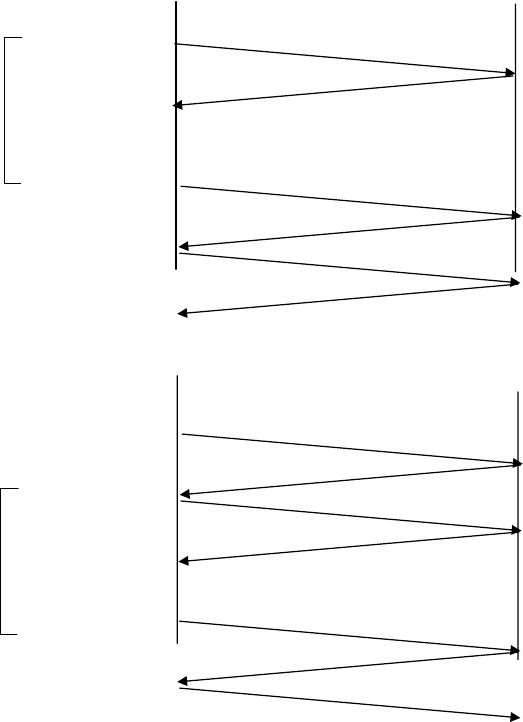
Sender ignores A1
Packet garbled, receiver
resends last ACK (A1)
M0 corrupted
Sender sends M0
Timeout: sender
resends M0
M0
A0
M1
A1
A1
sender sends M0
M0
A0
M1
A1 corrupted
sender sends M1
Ignore ACK
Timeout: sender
resends M1
M1
A1
M0
Corrupted
data
Corrupted
ACK
Figure 1: rdt 3.0 scenarios: corrupted data, corrupted ACK
Problem 10
Here, we add a timer, whose value is greater than the known round-trip propagation
delay. We add a timeout event to the “Wait for ACK or NAK0” and “Wait for ACK or
NAK1” states. If the timeout event occurs, the most recently transmitted packet is
retransmitted. Let us see why this protocol will still work with the rdt2.1 receiver.
Suppose the timeout is caused by a lost data packet, i.e., a packet on the sender-
to-receiver channel. In this case, the receiver never received the previous
transmission and, from the receiver's viewpoint, if the timeout retransmission is
received, it looks exactly the same as if the original transmission is being
received.
Suppose now that an ACK is lost. The receiver will eventually retransmit the
packet on a timeout. But a retransmission is exactly the same action that if an
ACK is garbled. Thus the sender's reaction is the same with a loss, as with a
garbled ACK. The rdt 2.1 receiver can already handle the case of a garbled ACK.
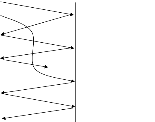
Problem 11
If the sending of this message were removed, the sending and receiving sides would
deadlock, waiting for an event that would never occur. Here’s a scenario:
Sender sends pkt0, enter the “Wait for ACK0 state”, and waits for a packet back
from the receiver
Receiver is in the “Wait for 0 from below” state, and receives a corrupted packet
from the sender. Suppose it does not send anything back, and simply re-enters the
‘wait for 0 from below” state.
Now, the ender is awaiting an ACK of some sort from the receiver, and the receiver is
waiting for a data packet form the sender – a deadlock!
Problem 12
The protocol would still work, since a retransmission would be what would happen if the
packet received with errors has actually been lost (and from the receiver standpoint, it
never knows which of these events, if either, will occur).
To get at the more subtle issue behind this question, one has to allow for premature
timeouts to occur. In this case, if each extra copy of the packet is ACKed and each
received extra ACK causes another extra copy of the current packet to be sent, the
number of times packet
n
is sent will increase without bound as
n
approaches infinity.
Problem 13
M0
M0
M0
M1
M1
A0
A0
A1
A1
old version of M0
accepted!
Problem 14
In a NAK only protocol, the loss of packet x is only detected by the receiver when packet
x+1 is received. That is, the receivers receives x-1 and then x+1, only when x+1 is
received does the receiver realize that x was missed. If there is a long delay between the
transmission of x and the transmission of x+1, then it will be a long time until x can be
recovered, under a NAK only protocol.
On the other hand, if data is being sent often, then recovery under a NAK-only scheme
could happen quickly. Moreover, if errors are infrequent, then NAKs are only
occasionally sent (when needed), and ACK are never sent – a significant reduction in
feedback in the NAK-only case over the ACK-only case.
Problem 15
It takes 12 microseconds (or 0.012 milliseconds) to send a packet, as 1500*8/109=12
microseconds. In order for the sender to be busy 98 percent of the time, we must have
012.30/)012.0(98.0 nutil
or
n
approximately 2451 packets.
Problem 16
Yes. This actually causes the sender to send a number of pipelined data into the channel.
Yes. Here is one potential problem. If data segments are lost in the channel, then the
sender of rdt 3.0 won’t re-send those segments, unless there are some additional
mechanism in the application to recover from loss.
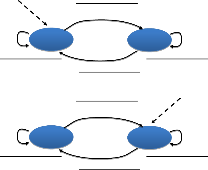
Problem 17
Problem 18
In our solution, the sender will wait until it receives an ACK for a pair of messages
(seqnum and seqnum+1) before moving on to the next pair of messages. Data packets
have a data field and carry a two-bit sequence number. That is, the valid sequence
numbers are 0, 1, 2, and 3. (Note: you should think about why a 1-bit sequence number
space of 0, 1 only would not work in the solution below.) ACK messages carry the
sequence number of the data packet they are acknowledging.
The FSM for the sender and receiver are shown in Figure 2. Note that the sender state
records whether (i) no ACKs have been received for the current pair, (ii) an ACK for
seqnum (only) has been received, or an ACK for seqnum+1 (only) has been received. In
this figure, we assume that the seqnum is initially 0, and that the sender has sent the first
Wait: send
to A
Wait: receive
from A
rdt_send(data)
packet=make_pkt(data)
udt_send(packet)
rdt_receive(packet)
extract(packet,data)
deliver_data(data)
rdt_send(data)
rdt_unable_to_send(data)
rdt_send(data)
Rdt_unable_to_send(data)
B
Wait: send
to B
Wait: receive
from B
rdt_send(data)
packet=make_pkt(data)
udt_send(packet)
rdt_receive(packet)
extract(packet,data)
deliver_data(data)
rdt_send(data)
rdt_unable_to_send(data)
rdt_send(data)
Rdt_unable_to_send(data)
A
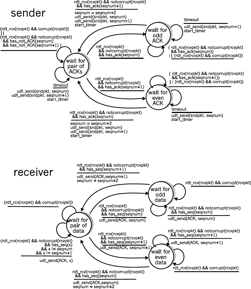
two data messages (to get things going). A timeline trace for the sender and receiver
recovering from a lost packet is shown below:
Figure 2: Sender and receiver for Problem (3.18)
Sender Receiver
make pair (0,1)
send packet 0
Packet 0 drops
send packet 1
receive packet 1
buffer packet 1
send ACK 1
receive ACK 1
(timeout)
resend packet 0
receive packet 0
deliver pair (0,1)
send ACK 0
receive ACK 0
Problem 19
This problem is a variation on the simple stop and wait protocol (rdt3.0). Because the
channel may lose messages and because the sender may resend a message that one of the
receivers has already received (either because of a premature timeout or because the other
receiver has yet to receive the data correctly), sequence numbers are needed. As in
rdt3.0, a 0-bit sequence number will suffice here.
The sender and receiver FSM are shown in Figure 3. In this problem, the sender state
indicates whether the sender has received an ACK from B (only), from C (only) or from
neither C nor B. The receiver state indicates which sequence number the receiver is
waiting for.
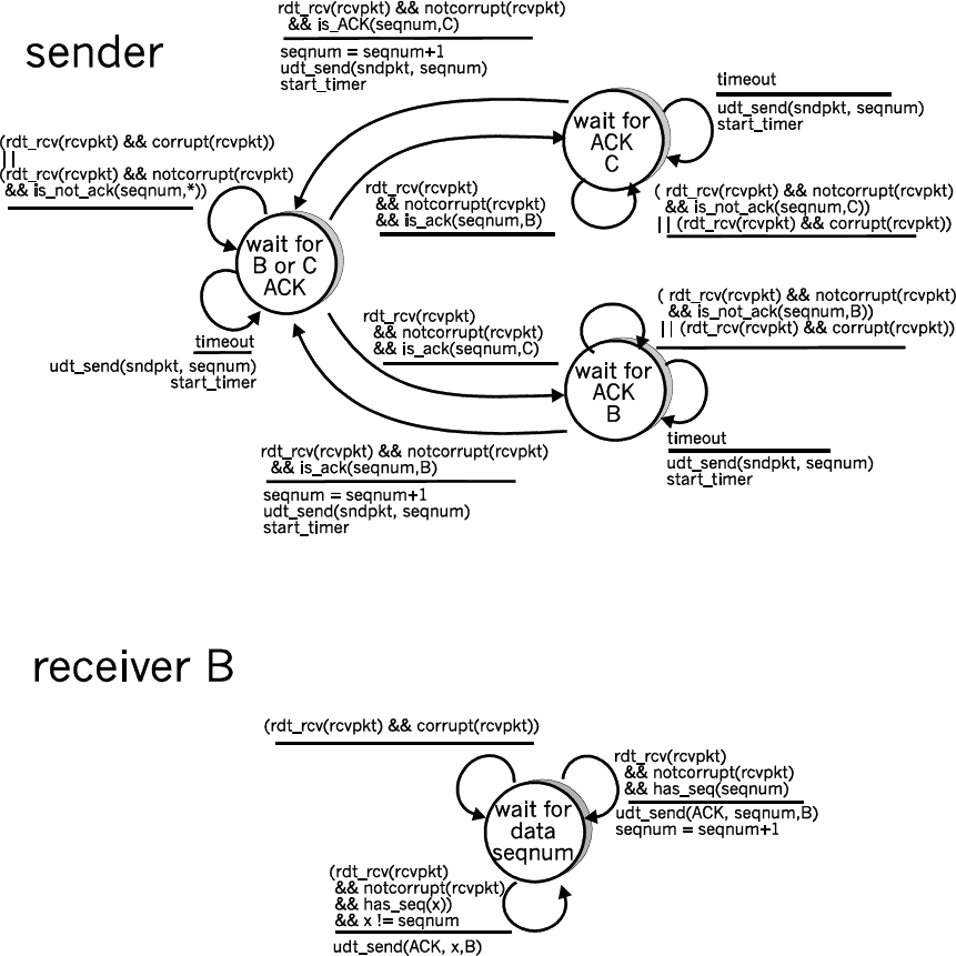
Figure 3. Sender and receiver for Problem 3.19(Problem 19)
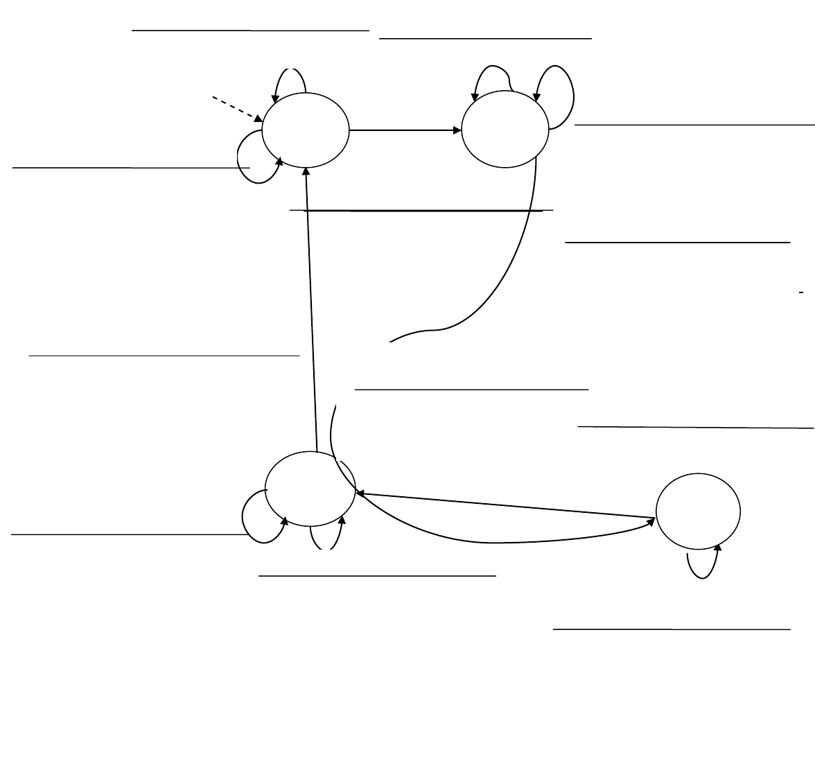
Problem 20
rdt_rcv(rcvpkt)&&from_A(rcvpkt)
Λ
rdt_rcv(rcvpkt)&¬_corrupt(rcvpkt)&&
has_seq0(rcvpkt)&&from_A(rcvpkt)
extract(rcvpkt,data)
deliver_data(data)
sndpkt=make_pkt(ACK, 0, checksum)
udt_send(A,sndpkt)
Wait for
0 from
A
Wait for
1 from
B
rdt_rcv(rcvpkt)&&(corrupt(rcvpkt)
||has_seq0(rcvpkt))&&from_B(rcvpkt)
sndpkt=make_pkt(ACK, 0, checksum)
udt_send(B,sndpkt)
Wait for
0 from
B
rdt_rcv(rcvpkt)&¬_corrupt(rcvpkt)&&ha
s_seq1(rcvpkt)&&from_A(rcvpkt)
extract(rcvpkt,data)
deliver_data(data)
sndpkt=make_pkt(ACK,1,checksum)
udt_send(A,sndpkt)
rdt_rcv(rcvpkt)&&from_A(rcvpkt)
Λ
rdt_rcv(rcvpkt)&¬_corrupt(rcvpkt)&&
has_seq0(rcvpkt)&&from_B(rcvpkt)
extract(rcvpkt,data)
deliver_data(data)
sndpkt=make_pkt(ACK,0,checksum)
udt_send(B,sndpkt)
rdt_rcv(rcvpkt)&&from_B(rcvpkt)
Λ
rdt_rcv(rcvpkt)&¬_corrupt(rcvpkt)
&&has_seq1(rcvpkt)&&from_B(rcvpkt)
extract(rcvpkt,data)
deliver_data(data)
sndpkt=make_pkt(ACK,1,checksum)
udt_send(B,sndpkt)
rdt_rcv(rcvpkt)&&from_B(rcvpkt)
Λ
rdt_rcv(rcvpkt)&&(corrupt(rcvpkt)
||has_seq1(rcvpkt))&&from_B(rcvpkt)
sndpkt=make_pkt(ACK, 1, checksum)
udt_send(B,sndpkt)
rdt_rcv(rcvpkt)&&(corrupt(rcvpkt)
||has_seq1(rcvpkt))&&from_A(rcvpkt)
sndpkt=make_pkt(ACK, 1, checksum)
udt_send(A,sndpkt)
Wait
for 1
from A
rdt_rcv(rcvpkt)&&(corrupt(rcvpkt)
||has_seq0(rcvpkt))&&from_A(rcvpkt)
sndpkt=make_pkt(ACK, 0, checksum)
udt_send(A,sndpkt)
Figure 4: Receiver side FSM for 3.18
Sender
The sender side FSM is exactly same as given in Figure 3.15 in text
Problem 21
Because the A-to-B channel can lose request messages, A will need to timeout and
retransmit its request messages (to be able to recover from loss). Because the channel
delays are variable and unknown, it is possible that A will send duplicate requests (i.e.,
resend a request message that has already been received by B). To be able to detect
duplicate request messages, the protocol will use sequence numbers. A 1-bit sequence
number will suffice for a stop-and-wait type of request/response protocol.
A (the requestor) has 4 states:
“Wait for Request 0 from above.” Here the requestor is waiting for a call from
above to request a unit of data. When it receives a request from above, it sends a
request message, R0, to B, starts a timer and makes a transition to the “Wait for
D0” state. When in the “Wait for Request 0 from above” state, A ignores
anything it receives from B.
“Wait for D0”. Here the requestor is waiting for a D0 data message from B. A
timer is always running in this state. If the timer expires, A sends another R0
message, restarts the timer and remains in this state. If a D0 message is received
from B, A stops the time and transits to the “Wait for Request 1 from above”
state. If A receives a D1 data message while in this state, it is ignored.
“Wait for Request 1 from above.” Here the requestor is again waiting for a call
from above to request a unit of data. When it receives a request from above, it
sends a request message, R1, to B, starts a timer and makes a transition to the
“Wait for D1” state. When in the “Wait for Request 1 from above” state, A
ignores anything it receives from B.
“Wait for D1”. Here the requestor is waiting for a D1 data message from B. A
timer is always running in this state. If the timer expires, A sends another R1
message, restarts the timer and remains in this state. If a D1 message is received
from B, A stops the timer and transits to the “Wait for Request 0 from above”
state. If A receives a D0 data message while in this state, it is ignored.
The data supplier (B) has only two states:
“Send D0.” In this state, B continues to respond to received R0 messages by
sending D0, and then remaining in this state. If B receives a R1 message, then it
knows its D0 message has been received correctly. It thus discards this D0 data
(since it has been received at the other side) and then transits to the “Send D1”
state, where it will use D1 to send the next requested piece of data.
“Send D1.” In this state, B continues to respond to received R1 messages by
sending D1, and then remaining in this state. If B receives a R1 message, then it
knows its D1 message has been received correctly and thus transits to the “Send
D1” state.
Problem 22
a) Here we have a window size of N=3. Suppose the receiver has received packet k-1,
and has ACKed that and all other preceding packets. If all of these ACK's have been
received by sender, then sender's window is [k, k+N-1]. Suppose next that none of
the ACKs have been received at the sender. In this second case, the sender's window
contains k-1 and the N packets up to and including k-1. The sender's window is thus
[k-N,k-1]. By these arguments, the senders window is of size 3 and begins
somewhere in the range [k-N,k].
b) If the receiver is waiting for packet k, then it has received (and ACKed) packet k-1
and the N-1 packets before that. If none of those N ACKs have been yet received by
the sender, then ACK messages with values of [k-N,k-1] may still be propagating
back.Because the sender has sent packets [k-N, k-1], it must be the case that the
sender has already received an ACK for k-N-1. Once the receiver has sent an ACK
for k-N-1 it will never send an ACK that is less that k-N-1. Thus the range of in-
flight ACK values can range from k-N-1 to k-1.
Problem 23
In order to avoid the scenario of Figure 3.27, we want to avoid having the leading edge of
the receiver's window (i.e., the one with the “highest” sequence number) wrap around in
the sequence number space and overlap with the trailing edge (the one with the "lowest"
sequence number in the sender's window). That is, the sequence number space must be
large enough to fit the entire receiver window and the entire sender window without this
overlap condition. So - we need to determine how large a range of sequence numbers can
be covered at any given time by the receiver and sender windows.
Suppose that the lowest-sequence number that the receiver is waiting for is packet m. In
this case, it's window is [m,m+w-1] and it has received (and ACKed) packet m-1 and the
w-1 packets before that, where w is the size of the window. If none of those w ACKs
have been yet received by the sender, then ACK messages with values of [m-w,m-1] may
still be propagating back. If no ACKs with these ACK numbers have been received by
the sender, then the sender's window would be [m-w,m-1].
Thus, the lower edge of the sender's window is m-w, and the leading edge of the
receivers window is m+w-1. In order for the leading edge of the receiver's window to not
overlap with the trailing edge of the sender's window, the sequence number space must
thus be big enough to accommodate 2w sequence numbers. That is, the sequence number
space must be at least twice as large as the window size,
wk 2
.
Problem 24
a) True. Suppose the sender has a window size of 3 and sends packets 1, 2, 3 at
0t
. At
1t
)01( tt
the receiver ACKS 1, 2, 3. At
2t
)12( tt
the sender times out and
resends 1, 2, 3. At
3t
the receiver receives the duplicates and re-acknowledges 1, 2,
3. At
4t
the sender receives the ACKs that the receiver sent at
1t
and advances its
window to 4, 5, 6. At
5t
the sender receives the ACKs 1, 2, 3 the receiver sent at
2t
.
These ACKs are outside its window.
b) True. By essentially the same scenario as in (a).
c) True.
d) True. Note that with a window size of 1, SR, GBN, and the alternating bit protocol
are functionally equivalent. The window size of 1 precludes the possibility of out-of-
order packets (within the window). A cumulative ACK is just an ordinary ACK in
this situation, since it can only refer to the single packet within the window.
Problem 25
a) Consider sending an application message over a transport protocol. With TCP, the
application writes data to the connection send buffer and TCP will grab bytes without
necessarily putting a single message in the TCP segment; TCP may put more or less
than a single message in a segment. UDP, on the other hand, encapsulates in a
segment whatever the application gives it; so that, if the application gives UDP an
application message, this message will be the payload of the UDP segment. Thus,
with UDP, an application has more control of what data is sent in a segment.
b) With TCP, due to flow control and congestion control, there may be significant delay
from the time when an application writes data to its send buffer until when the data is
given to the network layer. UDP does not have delays due to flow control and
congestion control.
Problem 26
There are
2964,294,967,232
possible sequence numbers.
a) The sequence number does not increment by one with each segment. Rather, it
increments by the number of bytes of data sent. So the size of the MSS is irrelevant --
the maximum size file that can be sent from A to B is simply the number of bytes
representable by
Gbytes 4.19232
.
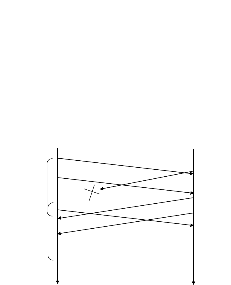
b) The number of segments is
8,012,999
536
232
. 66 bytes of header get added to each
segment giving a total of 528,857,934 bytes of header. The total number of bytes
transmitted is
932 10824.4 4528,857,932
bytes.
Thus it would take 249 seconds to transmit the file over a 155~Mbps link.
Problem 27
a) In the second segment from Host A to B, the sequence number is 207, source port
number is 302 and destination port number is 80.
b) If the first segment arrives before the second, in the acknowledgement of the first
arriving segment, the acknowledgement number is 207, the source port number is 80
and the destination port number is 302.
c) If the second segment arrives before the first segment, in the acknowledgement of the
first arriving segment, the acknowledgement number is 127, indicating that it is still
waiting for bytes 127 and onwards.
d)
Problem 28
Since the link capacity is only 100 Mbps, so host A’s sending rate can be at most
100Mbps. Still, host A sends data into the receive buffer faster than Host B can remove
data from the buffer. The receive buffer fills up at a rate of roughly 40Mbps. When the
buffer is full, Host B signals to Host A to stop sending data by setting RcvWindow = 0.
Host A then stops sending until it receives a TCP segment with RcvWindow > 0. Host A
will thus repeatedly stop and start sending as a function of the RcvWindow values it
Ack = 247
Ack = 247
Seq = 127, 80 bytes
Seq = 127, 80 bytes
Seq = 207, 40 bytes
Ack = 207
Host A
Host B
Timeout
interval
Timeout
interval
receives from Host B. On average, the long-term rate at which Host A sends data to Host
B as part of this connection is no more than 60Mbps.
Problem 29
a) The server uses special initial sequence number (that is obtained from the hash of
source and destination IPs and ports) in order to defend itself against SYN FLOOD
attack.
b) No, the attacker cannot create half-open or fully open connections by simply sending
and ACK packet to the target. Half-open connections are not possible since a server
using SYN cookies does not maintain connection variables and buffers for any
connection before full connections are established. For establishing fully open
connections, an attacker should know the special initial sequence number
corresponding to the (spoofed) source IP address from the attacker. This sequence
number requires the "secret" number that each server uses. Since the attacker does not
know this secret number, she cannot guess the initial sequence number.
c) No, the sever can simply add in a time stamp in computing those initial sequence
numbers and choose a time to live value for those sequence numbers, and discard
expired initial sequence numbers even if the attacker replay them.
Problem 30
a) If timeout values are fixed, then the senders may timeout prematurely. Thus, some
packets are re-transmitted even they are not lost.
b) If timeout values are estimated (like what TCP does), then increasing the buffer size
certainly helps to increase the throughput of that router. But there might be one
potential problem. Queuing delay might be very large, similar to what is shown in
Scenario 1.
Problem 31
TTEstimatedRxxSampleRTTTTEstimatedR )1(
DevRTTyTTEstimatedRSampleRTTyDevRTT )1(
DevRTTTTEstimatedRervalTimeoutInt *4
After obtaining first sampleRTT is
100*875.0106*125.0 TTEstimatedR
ms75.100
.
5*75.075.10010625.0 DevRTT
ms06.5
.
06.5*475.100 ervalTimeoutInt
ms99.120
.
After obtaining second sampleRTT = 120ms:
75.100*875.0120*125.0 TTEstimatedR
ms15.103
.
06.5*75.015.10312025.0 DevRTT
ms8
.
8*415.103 ervalTimeoutInt
ms15.135
.
After obtaining Third sampleRTT = 140ms:
15.103*875.0140*125.0 TTEstimatedR
ms76.107
.
8*75.076.10714025.0 DevRTT
ms06.14
.
06.14*476.107 ervalTimeoutInt
ms164
.
After obtaining fourth sampleRTT = 90ms:
76.107*875.090*125.0 TTEstimatedR
ms54.105
.
06.14*75.054.1059025.0 DevRTT
ms42.14
.
42.14*454.105 ervalTimeoutInt
ms22.163
.
After obtaining fifth sampleRTT = 115ms:
54.105*875.0115*125.0 TTEstimatedR
ms71.106
.
42.14*75.071.10611525.0 DevRTT
ms88.12
.
88.12*471.106 ervalTimeoutInt
ms23.158
.
Problem 32
a)
Denote
)(n
TTEstimatedR
for the estimate after the nth sample.
1
)4( xSampleRTTTTEstimatedR
2
)[1( xSampleRTTx
]])1()[1( 43 SampleRTTxxSampleRTTx

21 )1( xSampleRTTxxSampleRTT
4
3
3
2)1()1( SampleRTTxxSampleRTTx
b)
j
n
j
jn SampleRTTxxTTEstimatedR
1
1
1)( )1(
n
nSampleRTTx 1
)1(
c)
1
)( )1(
1j
j
jSampleRTTx
x
x
TTEstimatedR
1
9.
9
1
j
j
jSampleRTT
The weight given to past samples decays exponentially.
Problem 33
Let’s look at what could wrong if TCP measures SampleRTT for a retransmitted
segment. Suppose the source sends packet P1, the timer for P1 expires, and the source
then sends P2, a new copy of the same packet. Further suppose the source measures
SampleRTT for P2 (the retransmitted packet). Finally suppose that shortly after
transmitting P2 an acknowledgment for P1 arrives. The source will mistakenly take this
acknowledgment as an acknowledgment for P2 and calculate an incorrect value of
SampleRTT.
Let’s look at what could be wrong if TCP measures SampleRTT for a retransmitted
segment. Suppose the source sends packet P1, the timer for P1 expires, and the source
then sends P2, a new copy of the same packet. Further suppose the source measures
SampleRTT for P2 (the retransmitted packet). Finally suppose that shortly after
transmitting P2 an acknowledgment for P1 arrives. The source will mistakenly take this
acknowledgment as an acknowledgment for P2 and calculate an incorrect value of
SampleRTT.
Problem 34
At any given time t, SendBase – 1 is the sequence number of the last byte that the
sender knows has been received correctly, and in order, at the receiver. The actually last
byte received (correctly and in order) at the receiver at time t may be greater if there are
acknowledgements in the pipe. Thus
SendBase–1 LastByteRcvd
Problem 35
When, at time t, the sender receives an acknowledgement with value y, the sender knows
for sure that the receiver has received everything up through y-1. The actual last byte
received (correctly and in order) at the receiver at time t may be greater if y
SendBase or if there are other acknowledgements in the pipe. Thus
y-1 LastByteRvcd
Problem 36
Suppose packets n, n+1, and n+2 are sent, and that packet n is received and ACKed. If
packets n+1 and n+2 are reordered along the end-to-end-path (i.e., are received in the
order n+2, n+1) then the receipt of packet n+2 will generate a duplicate ack for n and
would trigger a retransmission under a policy of waiting only for second duplicate ACK
for retransmission. By waiting for a triple duplicate ACK, it must be the case that two
packets after packet
n
are correctly received, while n+1 was not received. The designers
of the triple duplicate ACK scheme probably felt that waiting for two packets (rather than
1) was the right tradeoff between triggering a quick retransmission when needed, but not
retransmitting prematurely in the face of packet reordering.
Problem 37
a) GoBackN:
A sends 9 segments in total. They are initially sent segments 1, 2, 3, 4, 5 and later re-
sent segments 2, 3, 4, and 5.
B sends 8 ACKs. They are 4 ACKS with sequence number 1, and 4 ACKS with
sequence numbers 2, 3, 4, and 5.
Selective Repeat:
A sends 6 segments in total. They are initially sent segments 1, 2, 3, 4, 5 and later re-
sent segments 2.
B sends 5 ACKs. They are 4 ACKS with sequence number 1, 3, 4, 5. And there is one
ACK with sequence number 2.
TCP:
A sends 6 segments in total. They are initially sent segments 1, 2, 3, 4, 5 and later re-
sent segments 2.
B sends 5 ACKs. They are 4 ACKS with sequence number 2. There is one ACK with
sequence numbers 6. Note that TCP always send an ACK with expected sequence
number.
b) TCP. This is because TCP uses fast retransmit without waiting until time out.
Problem 38
Yes, the sending rate is always roughly cwnd/RTT.
Problem 39
If the arrival rate increases beyond R/2 in Figure 3.46(b), then the total arrival rate to the
queue exceeds the queue’s capacity, resulting in increasing loss as the arrival rate
increases. When the arrival rate equals R/2, 1 out of every three packets that leaves the
queue is a retransmission. With increased loss, even a larger fraction of the packets
leaving the queue will be retransmissions. Given that the maximum departure rate from
the queue for one of the sessions is R/2, and given that a third or more will be
transmissions as the arrival rate increases, the throughput of successfully deliver data can
not increase beyond -out. Following similar reasoning, if half of the packets leaving the
queue are retransmissions, and the maximum rate of output packets per session is R/2,
then the maximum value of -out is (R/2)/2 or R/4.
Problem 40
a) TCP slowstart is operating in the intervals [1,6] and [23,26]
b) TCP congestion avoidance is operating in the intervals [6,16] and [17,22]
c) After the 16th transmission round, packet loss is recognized by a triple duplicate
ACK. If there was a timeout, the congestion window size would have dropped to 1.
d) After the 22nd transmission round, segment loss is detected due to timeout, and hence
the congestion window size is set to 1.
e) The threshold is initially 32, since it is at this window size that slow start stops and
congestion avoidance begins.
f) The threshold is set to half the value of the congestion window when packet loss is
detected. When loss is detected during transmission round 16, the congestion
windows size is 42. Hence the threshold is 21 during the 18th transmission round.
g) The threshold is set to half the value of the congestion window when packet loss is
detected. When loss is detected during transmission round 22, the congestion
windows size is 29. Hence the threshold is 14 (taking lower floor of 14.5) during the
24th transmission round.
h) During the 1st transmission round, packet 1 is sent; packet 2-3 are sent in the 2nd
transmission round; packets 4-7 are sent in the 3rd transmission round; packets 8-15
are sent in the 4th transmission round; packets 16-31 are sent in the 5th transmission
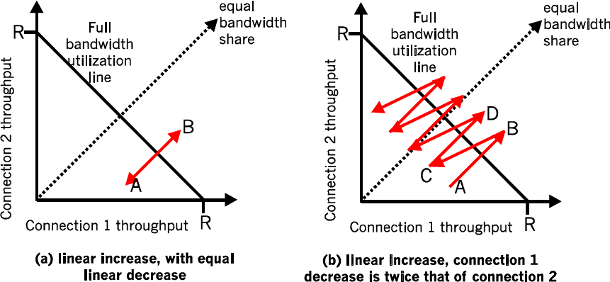
round; packets 32-63 are sent in the 6th transmission round; packets 64 – 96 are sent
in the 7th transmission round. Thus packet 70 is sent in the 7th transmission round.
i) The threshold will be set to half the current value of the congestion window (8) when
the loss occurred and congestion window will be set to the new threshold value + 3
MSS . Thus the new values of the threshold and window will be 4 and 7 respectively.
j) threshold is 21, and congestion window size is 1.
k) round 17, 1 packet; round 18, 2 packets; round 19, 4 packets; round 20, 8 packets;
round 21, 16 packets; round 22, 21 packets. So, the total number is 52.
Problem 41
Refer to Figure 5. In Figure 5(a), the ratio of the linear decrease on loss between
connection 1 and connection 2 is the same - as ratio of the linear increases: unity. In this
case, the throughputs never move off of the AB line segment. In Figure 5(b), the ratio of
the linear decrease on loss between connection 1 and connection 2 is 2:1. That is,
whenever there is a loss, connection 1 decreases its window by twice the amount of
connection 2. We see that eventually, after enough losses, and subsequent increases, that
connection 1's throughput will go to 0, and the full link bandwidth will be allocated to
connection 2.
Figure 5: Lack of TCP convergence with linear increase, linear decrease
Problem 42
If TCP were a stop-and-wait protocol, then the doubling of the time out interval would
suffice as a congestion control mechanism. However, TCP uses pipelining (and is
therefore not a stop-and-wait protocol), which allows the sender to have multiple
outstanding unacknowledged segments. The doubling of the timeout interval does not
prevent a TCP sender from sending a large number of first-time-transmitted packets into
the network, even when the end-to-end path is highly congested. Therefore a congestion-
control mechanism is needed to stem the flow of “data received from the application
above” when there are signs of network congestion.
Problem 43
In this problem, there is no danger in overflowing the receiver since the receiver’s receive
buffer can hold the entire file. Also, because there is no loss and acknowledgements are
returned before timers expire, TCP congestion control does not throttle the sender.
However, the process in host A will not continuously pass data to the socket because the
send buffer will quickly fill up. Once the send buffer becomes full, the process will pass
data at an average rate or R << S.
Problem 44
a) It takes 1 RTT to increase CongWin to 6 MSS; 2 RTTs to increase to 7 MSS; 3 RTTs
to increase to 8 MSS; 4 RTTs to increase to 9 MSS; 5 RTTs to increase to 10 MSS; 6
RTTs to increase to 11 MSS; and 7 RTTs to increase to 12MSS.
b) In the first RTT 5 MSS was sent; in the second RTT 6 MSS was sent; in the third
RTT 7 MSS was sent; in the fourth RTT 8 MSS was sent; in the fifth RTT, 9 MSS
was sent; and in the sixth RTT, 10 MSS was sent. Thus, up to time 6 RTT,
5+6+7+8+9+10 = 45 MSS were sent (and acknowledged). Thus, we can say that the
average throughput up to time 6 RTT was (45 MSS)/(6 RTT) = 7.5 MSS/RTT.
Problem 45
a) The loss rate,
L
, is the ratio of the number of packets lost over the number of packets
sent. In a cycle, 1 packet is lost. The number of packets sent in a cycle is
2/
0
)
2
(1
22
W
n
n
W
W
WW
2/
0
2
1
2
W
n
n
WW
2
)12/(2/
2
1
2
WWWW
4824
22 WWWW
WW 4
3
8
32
Thus the loss rate is
WW
L
4
3
8
3
1
2
b) For
W
large,
WW 4
3
8
32
. Thus
2
3/8 WL
or
L
W3
8
. From the text, we
therefore have
average throughput
RTT
MSS
L 3
8
4
3
LRTT
MSS
22.1
Problem 46
a) Let W denote the max window size measured in segments. Then, W*MSS/RTT =
10Mbps, as packets will be dropped if the maximum sending rate exceeds link
capacity. Thus, we have W*1500*8/0.15=10*10^6, then W is about 125 segments.
b) As congestion window size varies from W/2 to W, then the average window size is
0.75W=94 (ceiling of 93.75) segments. Average throughput is 94*1500*8/0.15
=7.52Mbps.
c) 94/2 *0.15 = 7.05 seconds, as the number of RTTs (that this TCP connections needs
in order to increase its window size from W/2 to W) is given by W/2. Recall the
window size increases by one in each RTT.
Problem 47
Let W denote max window size. Let S denote the buffer size. For simplicity, suppose
TCP sender sends data packets in a round by round fashion, with each round
corresponding to a RTT. If the window size reaches W, then a loss occurs. Then the
sender will cut its congestion window size by half, and waits for the ACKs for W/2
outstanding packets before it starts sending data segments again. In order to make sure
the link always busying sending data, we need to let the link busy sending data in the
period W/(2*C) (this is the time interval where the sender is waiting for the ACKs for the
W/2 outstanding packets). Thus, S/C must be no less than W/(2*C), that is, S>=W/2.
Let Tp denote the one-way propagation delay between the sender and the receiver.
When the window size reaches the minimum W/2 and the buffer is empty, we need to
make sure the link is also busy sending data. Thus, we must have W/2/(2Tp)>=C, thus,
W/2>=C*2Tp.
Thus, S>=C*2Tp.
Problem 48
a) Let W denote the max window size. Then, W*MSS/RTT = 10Gbps, as packets will
be dropped if maximum sending rate reaches link capacity. Thus, we have
W*1500*8/0.15=10*10^9, then W= 125000 segments.
b) As congestion window size varies from W/2 to W, then the average window size is
0.75W=93750 segments. Average throughput is 93750*1500*8/0.1=7.5Gbps.
c) 93750/2 *0.15 /60= 117 minutes. In order to speed up the window increase process,
we can increase the window size by a much larger value, instead of increasing
window size only by one in each RTT. Some protocols are proposed to solve this
problem, such as ScalableTCP or HighSpeed TCP.
Problem 49
As TCP’s average throughput B is given by
LRTT
MSS
B
22.1
, so we know that,
L= (1.22*MSS / (B*RTT) ) 2
Since between two consecutive packet losses, there are 1/L packets sent by the TCP
sender, thus, T=(1/L)*MSS/B. Thus, we find that T=B*RTT2/(1.222*MSS), that is, T is a
function of B.
Problem 50
a) The key difference between C1 and C2 is that C1’s RTT is only half of that of C2.
Thus C1 adjusts its window size after 50 msec, but C2 adjusts its window size after
100 msec. Assume that whenever a loss event happens, C1 receives it after 50msec
and C2 receives it after 100msec. We further have the following simplified model of
TCP. After each RTT, a connection determines if it should increase window size or
not. For C1, we compute the average total sending rate in the link in the previous 50
msec. If that rate exceeds the link capacity, then we assume that C1 detects loss and
reduces its window size. But for C2, we compute the average total sending rate in the
link in the previous 100msec. If that rate exceeds the link capacity, then we assume
that C2 detects loss and reduces its window size. Note that it is possible that the
average sending rate in last 50msec is higher than the link capacity, but the average
sending rate in last 100msec is smaller than or equal to the link capacity, then in this
case, we assume that C1 will experience loss event but C2 will not.
The following table describes the evolution of window sizes and sending rates based
on the above assumptions.
C1
C2
Time
(msec)
Window Size
(num. of
segments sent
in next
50msec)
Average data sending
rate (segments per
second,
=Window/0.05)
Window
Size(num. of
segments
sent in next
100msec)
Average data sending
rate (segments per
second, =Window/0.1)
0
10
200 (in [0-50]msec]
10
100 (in [0-50]msec)

50
5
(decreases
window size
as the avg.
total sending
rate to the
link in last
50msec is
300=
200+100)
100 (in [50-100]msec]
100 (in [50-100]msec)
100
2
(decreases
window size
as the avg.
total sending
rate to the
link in last
50msec is
200=
100+100)
40
5
(decreases
window size
as the avg.
total sending
rate to the
link in last
100msec is
250=
(200+100)/2
+
(100+100)/2)
50
150
1
(decreases
window size
as the avg.
total sending
rate to the
link in last
50msec is
90= (40+50)
20
50
200
1
(no further
decrease, as
window size
is already 1)
20
2
(decreases
window size
as the avg.
total sending
rate to the
link in last
100msec is
80=
(40+20)/2 +
(50+50)/2)
20
250
1
(no further
decrease, as
window size
20
20

is already 1)
300
1
(no further
decrease, as
window size
is already 1)
20
1
(decreases
window size
as the avg.
total sending
rate to the
link in last
100msec is
40=
(20+20)/2 +
(20+20)/2)
10
350
2
40
10
400
1
20
1
10
450
2
40
10
500
1
(decreases
window size
as the avg.
total sending
rate to the
link in last
50msec is
50= (40+10)
20
1
10
550
2
40
10
600
1
20
1
10
650
2
40
10
700
1
20
1
10
750
2
40
10
800
1
20
1
10
850
2
40
10
900
1
20
1
10
950
2
40
10
1000
1
20
1
10
Based on the above table, we find that after 1000 msec, C1’s and C2’s window sizes
are 1 segment each.
b) No. In the long run, C1’s bandwidth share is roughly twice as that of C2’s, because
C1 has shorter RTT, only half of that of C2, so C1 can adjust its window size twice as
fast as C2. If we look at the above table, we can see a cycle every 200msec, e.g. from
850msec to 1000msec, inclusive. Within a cycle, the sending rate of C1 is
(40+20+40+20) = 120, which is thrice as large as the sending of C2 given by
(10+10+10+10) = 40.

Problem 51
a) Similarly as in last problem, we can compute their window sizes over time in the
following table. Both C1 and C2 have the same window size 2 after 2200msec.
C1
C2
Time
(msec)
Window Size
(num. of
segments sent in
next 100msec)
Data sending speed
(segments per second,
=Window/0.1)
Window
Size(num. of
segments sent
in next
100msec)
Data sending speed
(segments per second,
=Window/0.1)
0
15
150 (in [0-100]msec]
10
100 (in [0-100]msec)
100
7
70
5
50
200
3
30
2
20
300
1
10
1
10
400
2
20
2
20
500
1
10
1
10
600
2
20
2
20
700
1
10
1
10
800
2
20
2
20
900
1
10
1
10
1000
2
20
2
20
1100
1
10
1
10
1200
2
20
2
20
1300
1
10
1
10
1400
2
20
2
20
1500
1
10
1
10
1600
2
20
2
20
1700
1
10
1
10
1800
2
20
2
20
1900
1
10
1
10
2000
2
20
2
20
2100
1
10
1
10
2200
2
20
2
20
b) Yes, this is due to the AIMD algorithm of TCP and that both connections have the
same RTT.
c) Yes, this can be seen clearly from the above table. Their max window size is 2.
d) No, this synchronization won’t help to improve link utilization, as these two
connections act as a single connection oscillating between min and max window size.
Thus, the link is not fully utilized (recall we assume this link has no buffer). One
possible way to break the synchronization is to add a finite buffer to the link and
randomly drop packets in the buffer before buffer overflow. This will cause different
connections cut their window sizes at different times. There are many AQM (Active
Queue Management) techniques to do that, such as RED (Random Early Detect), PI
(Proportional and Integral AQM), AVQ (Adaptive Virtual Queue), and REM
(Random Exponential Marking), etc.
Problem 52
Note that W represents the maximum window size.
First we can find the total number of segments sent out during the interval when TCP
changes its window size from W/2 up to and include W. This is given by:
S= W/2 + (W/2)*(1+
) + (W/2)*(1+
)2 + (W/2)*(1+
)3 + … + (W/2)*(1+
)k
We find k=log(1+)2, then S=W*(2
+1)/(2
).
Loss rate L is given by:
L= 1/S = (2
) / (W*(2
+1) ).
The time that TCP takes to increase its window size from W/2 to W is given by:
k*RTT= (log(1+)2) * RTT,
which is clearly independent of TCP’s average throughput.
Note, TCP’s average throughput is given by:
B=MSS * S/((k+1)*RTT) = MSS / (L*(k+1)*RTT).
Note that this is different from TCP which has average throughput:
LRTT
MSS
B
22.1
,
where the square root of L appears in the denominator.
Problem 53
Let’s assume 1500-byte packets and a 100 ms round-trip time. From the TCP throughput
equation
LRTT
MSS
B
22.1
, we have
10 Gbps = 1.22 * (1500*8 bits) / (.1 sec * srqt(L)), or
sqrt(L) = 14640 bits / (10^9 bits) = 0.00001464, or
L = 2.14 * 10^(-10)
Problem 54
An advantage of using the earlier values of cwnd and ssthresh at t2 is that TCP would
not have to go through slow start and congestion avoidance to ramp up to the throughput
value obtained at t1. A disadvantage of using these values is that they may be no longer
accurate. In particular, if the path has become more congested between t1 and t2, the
sender will send a large window’s worth of segments into an already (more) congested
path.
Problem 55
a) The server will send its response to Y.
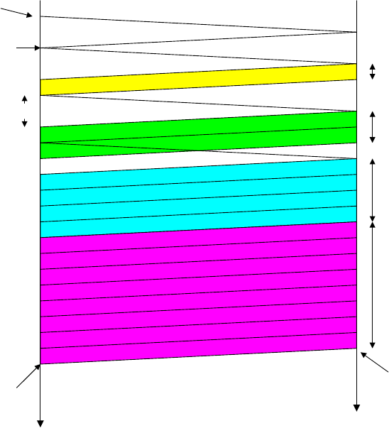
b) The server can be certain that the client is indeed at Y. If it were at some other
address spoofing Y, the SYNACK would have been sent to the address Y, and the
TCP in that host would not send the TCP ACK segment back. Even if the attacker
were to send an appropriately timed TCP ACK segment, it would not know the
correct server sequence number (since the server uses random initial sequence
numbers.)
Problem 56
a) Referring to the figure below, we see that the total delay is
RTT + RTT + S/R + RTT + S/R + RTT + 12S/R = 4RTT + 14 S/R
b) Similarly, the delay in this case is:
RTT+RTT + S/R + RTT + S/R + RTT + S/R + RTT + 8S/R = 5RTT +11 S/R
c) Similarly, the delay in this case is:
RTT + RTT + S/R + RTT + 14 S/R = 3 RTT + 15 S/R
RTT
initiate TCP
connection
request
object first window
= S/R
second window
= 2S/R
third window
= 4S/R
fourth window
= 8S/R
complete
transmission
object
delivered
time at
client
time at
server
Chapter 4 Review Questions
1. A network-layer packet is a datagram. A router forwards a packet based on the
packet’s IP (layer 3) address. A link-layer switch forwards a packet based on the
packet’s MAC (layer 2) address.
2. Datagram-based network layer: forwarding; routing. Additional function of VC-based
network layer: call setup.
3. Forwarding is about moving a packet from a router’s input port to the appropriate
output port. Routing is about determining the end-to-routes between sources and
destinations.
4. Yes, both use forwarding tables. For descriptions of the tables, see Section 4.2.
5. Single packet: guaranteed delivery; guaranteed delivery with guaranteed maximum
delay. Flow of packets: in-order packet delivery; guaranteed minimal bandwidth;
guaranteed maximum jitter. None of these services is provided by the Internet’s
network layer. ATM’s CBR service provides both guaranteed delivery and timing.
ABR does not provide any of these services.
6. Interactive live multimedia applications, such as IP telephony and video conference,
could benefit from ATM CBR’s service, which maintains timing.
7. With the shadow copy, the forwarding lookup is made locally, at each input port,
without invoking the centralized routing processor. Such a decentralized approach
avoids creating a lookup processing bottleneck at a single point within the router.
8. Switching via memory; switching via a bus; switching via an interconnection
network. An interconnection network can forward packets in parallel as long as all the
packets are being forwarded to different output ports.
9. If the rate at which packets arrive to the fabric exceeds switching fabric rate, then
packets will need to queue at the input ports. If this rate mismatch persists, the queues
will get larger and larger and eventually overflow the input port buffers, causing
packet loss. Packet loss can be eliminated if the switching fabric speed is at least n
times as fast as the input line speed, where n is the number of input ports.
10. Assuming input and output line speeds are the same, packet loss can still occur if the
rate at which packets arrive to a single output port exceeds the line speed. If this rate
mismatch persists, the queues will get larger and larger and eventually overflow the
output port buffers, causing packet loss. Note that increasing switch fabric speed
cannot prevent this problem from occurring.

11. HOL blocking: Sometimes the a packet that is first in line at an input port queue
must wait because there is no available buffer space at the output port to which it
wants to be forwarded. When this occurs, all the packets behind the first packet are
blocked, even if their output queues have room to accommodate them. HOL blocking
occurs at the input port.
12. Yes. They have one address for each interface.
13. 11011111 00000001 00000011 00011100.
14. Students will get different correct answers for this question.
15. 8 interfaces; 3 forwarding tables.
16. 50% overhead.
17. The 8-bit protocol field in the IP datagram contains information about which transport
layer protocol the destination host should pass the segment to.
18. Typically the wireless router includes a DHCP server. DHCP is used to assign IP
addresses to the 5 PCs and to the router interface. Yes, the wireless router also uses
NAT as it obtains only one IP address from the ISP.
19. IPv6 has a fixed length header, which does not include most of the options an IPv4
header can include. Even though the IPv6 header contains two 128 bit addresses
(source and destination IP address) the whole header has a fixed length of 40 bytes
only. Several of the fields are similar in spirit. Traffic class, payload length, next
header and hop limit in IPv6 are respectively similar to type of service, datagram
length, upper-layer protocol and time to live in IPv4.
20. Yes, because the entire IPv6 datagram (including header fields) is encapsulated in an
IPv4 datagram.
21. Link state algorithms: Computes the least-cost path between source and destination
using complete, global knowledge about the network. Distance-vector routing: The
calculation of the least-cost path is carried out in an iterative, distributed manner. A
node only knows the neighbor to which it should forward a packet in order to reach
given destination along the least-cost path, and the cost of that path from itself to the
destination.
22. Routers are organized into autonomous systems (ASs). Within an AS, all routers run
the same intra-AS routing protocol. The problem of scale is solved since an router in
an AS need only know about routers within its AS and the subnets that attach to the
AS. To route across ASes, the inter-AS protocol is based on the AS graph and does
not take individual routers into account.
23. No. Each AS has administrative autonomy for routing within an AS.
24. No. The advertisement tells D that it can get to z in 11 hops by way of A. However, D
can already get to z by way of B in 7 hops. Therefore, there is no need to modify the
entry for z in the table. If, on the other hand, the advertisement said that A were only
4 hops away from z by way of C, then D would indeed modify its forwarding table.
25. With OSPF, a router periodically broadcasts routing information to all other routers in
the AS, not just to its neighboring routers. This routing information sent by a router
has one entry for each of the router’s neighbors; the entry gives the distance from the
router to the neighbor. A RIP advertisement sent by a router contains information
about all the networks in the AS, although this information is only sent to its
neighboring routers.
26. “sequence of ASs on the routes”
27. Policy: Among ASs, policy issues dominate. It may well be important that traffic
originating in a given AS not be able to pass through another specific AS. Similarly, a
given AS may want to control what transit traffic it carries between other ASs. Within
an AS, everything is nominally under the same administrative control and thus policy
issues a much less important role in choosing routes with in AS.
Scale: The ability of a routing algorithm and its data structures to scale to handle
routing to/among large numbers of networks is a critical issue in inter-AS routing.
Within an AS, scalability is less of a concern. For one thing, if a single administrative
domain becomes too large, it is always possible to divide it into two ASs and perform
inter-AS routing between the two new ASs.
Performance: Because inter-AS routing is so policy oriented, the quality (for
example, performance) of the routes used is often of secondary concern (that is, a
longer or more costly route that satisfies certain policy criteria may well be taken over
a route that is shorter but does not meet that criteria). Indeed, we saw that among
ASs, there is not even the notion of cost (other than AS hop count) associated with
routes. Within a single AS, however, such policy concerns are of less importance,
allowing routing to focus more on the level of performance realized on a route.
28. ISP C can use the BGP Multi-Exit Descriptor to suggest to ISP B that the preferred
route to ISP D is through the east coast peering point. For example, the east coast
BGP router in ISP C can advertise a route to D with an MED value of 5. The west
coast router in ISP C can advertise a route to D with an MED value of 10. Since a
lower value is preferred, ISP B knows that ISP C wants to receive traffic on the east
coast. In practice, a router can ignore the MED value, and so ISP B can still use hot
potato routing to pass traffic to ISP C destined to ISP D via the west coast peering
point.
29. A subnet is a portion of a larger network; a subnet does not contain a router; its
boundaries are defined by the router and host interfaces. A prefix is the network
portion of a CDIRized address; it is written in the form a.b.c.d/x ; A prefix covers one
or more subnets. When a router advertises a prefix across a BGP session, it includes
with the prefix a number of BGP attributes. In BGP jargon, a prefix along with its
attributes is a BGP route (or simply a route).
30. Routers use the AS-PATH attribute to detect and prevent looping advertisements;
they also use it in choosing among multiple paths to the same prefix. The NEXT-
HOP attribute indicates the IP address of the first router along an advertised path
(outside of the AS receiving the advertisement) to a given prefix. When configuring
its forwarding table, a router uses the NEXT-HOP attribute.
31. A tier-1 ISP B may not to carry transit traffic between two other tier-1 ISPs, say A
and C, with which B has peering agreements. To implement this policy, ISP B would
not advertise to A routes that pass through C; and would not advertise to C routes that
pass through A.
32. N-way unicast has a number of drawbacks, including:
Efficiency: multiple copies of the same packet are sent over the same link for
potentially many links; source must generate multiple copies of same packet
Addressing: the source must discover the address of all the recipients
33. a) uncontrolled flooding: T; controlled flooding: T; spanning-tree: F
b) uncontrolled flooding: T; controlled flooding: F; spanning-tree: F
34. False
35. IGMP is a protocol run only between the host and its first-hop multicast router.
IGMP allows a host to specify (to the first-hop multicast router) the multicast group it
wants to join. It is then up to the multicast router to work with other multicast routers
(i.e., run a multicast routing protocol) to ensure that the data for the host-joined
multicast group is routed to the appropriate last-hop router and from there to the host.
36. In a group-shared tree, all senders send their multicast traffic using the same routing
tree. With source-based tree, the multicast datagrams from a given source are routed
over s specific routing tree constructed for that source; thus each source may have a
different source-based tree and a router may have to keep track of several source-
based trees for a given multicast group.
Chapter 4 Problems
Problem 1
a) With a connection-oriented network, every router failure will involve the routing of
that connection. At a minimum, this will require the router that is “upstream” from
the failed router to establish a new downstream part of the path to the destination
node, with all of the requisite signaling involved in setting up a path. Moreover, all
of the routers on the initial path that are downstream from the failed node must take
down the failed connection, with all of the requisite signaling involved to do this.
With a connectionless datagram network, no signaling is required to either set up a
new downstream path or take down the old downstream path. We have seen,
however, that routing tables will need to be updated (e.g., either via a distance vector
algorithm or a link state algorithm) to take the failed router into account. We have
seen that with distance vector algorithms, this routing table change can sometimes be
localized to the area near the failed router. Thus, a datagram network would be
preferable. Interestingly, the design criteria that the initial ARPAnet be able to
function under stressful conditions was one of the reasons that datagram architecture
was chosen for this Internet ancestor.
b) In order for a router to maintain an available fixed amount of capacity on the path
between the source and destination node for that source-destination pair, it would
need to know the characteristics of the traffic from all sessions passing through that
link. That is, the router must have per-session state in the router. This is possible in a
connection-oriented network, but not with a connectionless network. Thus, a
connection-oriented VC network would be preferable.
c) In this scenario, datagram architecture has more control traffic overhead. This is due
to the various packet headers needed to route the datagrams through the network. But
in VC architecture, once all circuits are set up, they will never change. Thus, the
signaling overhead is negligible over the long run.
Problem 2
a) Maximum number of VCs over a link = 28 = 256.
b) The centralized node could pick any VC number which is free from the set
{0,1,…,28-1}. In this manner, it is not possible that there are fewer VCs in progress
than 256 without there being any common free VC number.
c) Each of the links can independently allocate VC numbers from the set {0,1,…,28-1}.
Thus, a VC will likely have a different VC number for each link along its path. Each
router in the VC’s path must replace the VC number of each arriving packet with the
VC number associated with the outbound link.
Problem 3
For a VC forwarding table, the columns are : Incoming Interface, Incoming VC Number,
Outgoing Interface, Outgoing VC Number. For a datagram forwarding table, the columns
are: Destination Address, Outgoing Interface.
Problem 4
a) Data destined to host H3 is forwarded through interface 3
Destination Address Link Interface
H3 3
b) No, because forwarding rule is only based on destination address.
c) One possible configuration is:
Incoming interface Incoming VC# Outgoing Interface Outgoing VC#
1 12 3 22
2 63 4 18
Note, that the two flows could actually have the same VC numbers.
d) One possible configuration is:
Router B.
Incoming interface Incoming VC# Outgoing Interface Outgoing VC#
1 22 2 24
Router C.
Incoming interface Incoming VC# Outgoing Interface Outgoing VC#
1 18 2 50
Router D.
Incoming interface Incoming VC# Outgoing Interface Outgoing VC#
1 24 3 70
2 50 3 76
Problem 5
a) No VC number can be assigned to the new VC; thus the new VC cannot be
established in the network.
b) Each link has two available VC numbers. There are four links. So the number of
combinations is 24 = 16. One example combination is (10,00,00,10).
Problem 6
In a virtual circuit network, there is an end-to-end connection in the sense that each router
along the path must maintain state for the connection; hence the terminology connection
service. In a connection-oriented transport service over a connectionless network layer,
such as TCP over IP, the end systems maintain connection state; however the routers
have no notion of any connections; hence the terminology connection-oriented service.
Problem 7
a) No, you can only transmit one packet at a time over a shared bus.
b) Yes, as discussed in the text, as long as the two packets use different input busses
and different output busses, they can be forwarded in parallel.
c) No, in this case the two packets would have to be sent over the same output bus at the
same time, which is not possible.
Problem 8
a) (n-1)D
b) (n-1)D
c) 0
Problem 9
The minimal number of time slots needed is 3. The scheduling is as follows.
Slot 1: send X in top input queue, send Y in middle input queue.
Slot 2: send X in middle input queue, send Y in bottom input queue
Slot 3: send Z in bottom input queue.
Largest number of slots is still 3. Actually, based on the assumption that a non-empty
input queue is never idle, we see that the first time slot always consists of sending X in
the top input queue and Y in either middle or bottom input queue, and in the second time
slot, we can always send two more datagram, and the last datagram can be sent in third
time slot.
NOTE: Actually, if the first datagram in the bottom input queue is X, then the worst case
would require 4 time slots.
Problem 10
a) Prefix Match Link Interface
11100000 00 0
11100000 01000000 1
1110000 2
11100001 1 3
otherwise 3
b) Prefix match for first address is 5th entry: link interface 3
Prefix match for second address is 3nd entry: link interface 2
Prefix match for third address is 4th entry: link interface 3
Problem 11
Destination Address Range Link Interface
00000000
through 0
00111111
01000000
through 1
01011111
01100000
through 2
01111111
10000000
through 2
10111111
11000000
through 3
11111111
number of addresses for interface 0 =
6426
number of addresses for interface 1 =
3225
number of addresses for interface 2 =
96326422 56
number of addresses for interface 3 =
6426
Problem 12
Destination Address Range Link Interface
11000000
through (32 addresses) 0
11011111
10000000
through(64 addresses) 1
10111111
11100000
through (32 addresses) 2
11111111
00000000
through (128 addresses) 3
01111111
Problem 13
223.1.17.0/26
223.1.17.128/25
223.1.17.192/28
Problem 14
Destination Address Link Interface
200.23.16/21 0
200.23.24/24 1
200.23.24/21 2
otherwise 3
Problem 15
Destination Address Link Interface
11100000 00 (224.0/10) 0
11100000 01000000 (224.64/16) 1
1110000 (224/8) 2
11100001 1 (225.128/9) 3
otherwise 3

Problem 16
Any IP address in range 128.119.40.128 to 128.119.40.191
Four equal size subnets: 128.119.40.64/28, 128.119.40.80/28, 128.119.40.96/28,
128.119.40.112/28
Problem 17
From 214.97.254/23, possible assignments are
a) Subnet A: 214.97.255/24 (256 addresses)
Subnet B: 214.97.254.0/25 - 214.97.254.0/29 (128-8 = 120 addresses)
Subnet C: 214.97.254.128/25 (128 addresses)
Subnet D: 214.97.254.0/31 (2 addresses)
Subnet E: 214.97.254.2/31 (2 addresses)
Subnet F: 214.97.254.4/30 (4 addresses)
b) To simplify the solution, assume that no datagrams have router interfaces as
ultimate destinations. Also, label D, E, F for the upper-right, bottom, and upper-
left interior subnets, respectively.
Router 1
Longest Prefix Match Outgoing Interface
11010110 01100001 11111111 Subnet A
11010110 01100001 11111110 0000000 Subnet D
11010110 01100001 11111110 000001 Subnet F
Router 2
Longest Prefix Match Outgoing Interface
11010110 01100001 11111111 0000000 Subnet D
11010110 01100001 11111110 0 Subnet B
11010110 01100001 11111110 0000001 Subnet E
Router 3
Longest Prefix Match Outgoing Interface
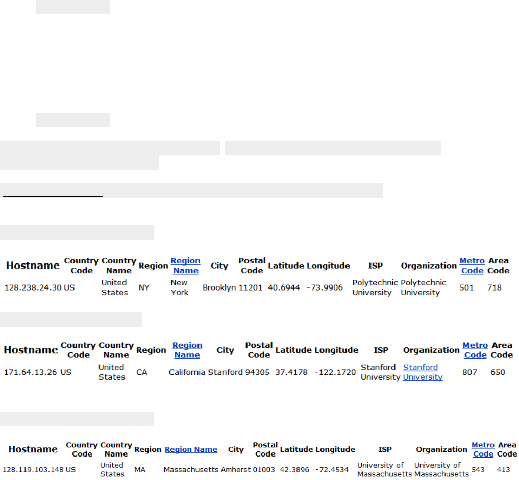
11010110 01100001 11111111 000001 Subnet F
11010110 01100001 11111110 0000001 Subnet E
11010110 01100001 11111110 1 Subnet C
Problem 18
The IP address blocks of Polytechnic Institute of New York University are:
NetRange: 128.238.0.0 - 128.238.255.255
CIDR: 128.238.0.0/16
The IP address blocks Stanford University are:
NetRange: 171.64.0.0 - 171.67.255.255
CIDR: 171.64.0.0/14
The IP address blocks University of Washington are:
NetRange: 140.142.0.0 - 140.142.255.255
CIDR: 140.142.0.0/16
No, the whois services cannot be used to determine with certainty the geographical
location of a specific IP address.
www.maxmind.com is used to determine the locations of the Web servers at Polytechnic
Institute of New York University, Stanford University and University of Washington.
Locations of the Web server at Polytechnic Institute of New York University is
Locations of the Web server Stanford University is
Locations of the Web server at University of Massachusetts is

Problem 19
The maximum size of data field in each fragment = 680 (because there are 20 bytes IP
header). Thus the number of required fragments
4
680
202400
Each fragment will have Identification number 422. Each fragment except the last one
will be of size 700 bytes (including IP header). The last datagram will be of size 360
bytes (including IP header). The offsets of the 4 fragments will be 0, 85, 170, 255. Each
of the first 3 fragments will have flag=1; the last fragment will have flag=0.
Problem 20
MP3 file size = 5 million bytes. Assume the data is carried in TCP segments, with each
TCP segment also having 20 bytes of header. Then each datagram can carry 1500-
40=1460 bytes of the MP3 file
Number of datagrams required
3425
1460
1056
. All but the last datagram will be 1,500
bytes; the last datagram will be 960+40 = 1000 bytes. Note that here there is no
fragmentation – the source host does not create datagrams larger than 1500 bytes, and
these datagrams are smaller than the MTUs of the links.
Problem 21
a) Home addresses: 192.168.1.1, 192.168.1.2, 192.168.1.3 with the router interface
being 192.168.1.4
b)
NAT Translation Table
WAN Side LAN Side
24.34.112.235, 4000 192.168.1.1, 3345
24.34.112.235, 4001 192.168.1.1, 3346
24.34.112.235, 4002 192.168.1.2, 3445
24.34.112.235, 4003 192.168.1.2, 3446
24.34.112.235, 4004 192.168.1.3, 3545
24.34.112.235, 4005 192.168.1.3, 3546
Problem 22
a) Since all IP packets are sent outside, so we can use a packet sniffer to record all IP
packets generated by the hosts behind a NAT. As each host generates a sequence of
IP packets with sequential numbers and a distinct (very likely, as they are randomly
chosen from a large space) initial identification number (ID), we can group IP packets
with consecutive IDs into a cluster. The number of clusters is the number of hosts
behind the NAT.
For more practical algorithms, see the following papers.
“A Technique for Counting NATted Hosts”, by Steven M. Bellovin, appeared in
IMW’02, Nov. 6-8, 2002, Marseille, France.
“Exploiting the IPID field to infer network path and end-system characteristics.”
Weifeng Chen, Yong Huang, Bruno F. Ribeiro, Kyoungwon Suh, Honggang Zhang,
Edmundo de Souza e Silva, Jim Kurose, and Don Towsley.
PAM'05 Workshop, March 31 - April 01, 2005. Boston, MA, USA.
b) However, if those identification numbers are not sequentially assigned but randomly
assigned, the technique suggested in part (a) won’t work, as there won’t be clusters in
sniffed data.
Problem 23
It is not possible to devise such a technique. In order to establish a direct TCP connection
between Arnold and Bernard, either Arnold or Bob must initiate a connection to the
other. But the NATs covering Arnold and Bob drop SYN packets arriving from the WAN
side. Thus neither Arnold nor Bob can initiate a TCP connection to the other if they are
both behind NATs.
Problem 24
y-x-u, y-x-v-u, y-x-w-u, y-x-w-v-u,
y-w-u, y-w-v-u, y-w-x-u, y-w-x-v-u, y-w-v-x-u,
y-z-w-u, y-z-w-v-u, y-z-w-x-u, y-z-w-x-v-u, y-z-w-v-x-u,
Problem 25
x to z:
x-y-z, x-y-w-z,
x-w-z, x-w-y-z,
x-v-w-z, x-v-w-y-z,
x-u-w-z, x-u-w-y-z,
x-u-v-w-z, x-u-v-w-y-z
z to u:
z-w-u,
z-w-v-u, z-w-x-u, z-w-v-x-u, z-w-x-v-u, z-w-y-x-u, z-w-y-x-v-u,
z-y-x-u, z-y-x-v-u, z-y-x-w-u, z-y-x-w-y-u, z-y-x-v-w-u,
z-y-w-v-u, z-y-w-x-u, z-y-w-v-x-u, z-y-w-x-v-u, z-y-w-y-x-u, z-y-w-y-x-v-u
z to w:
z-w, z-y-w, z-y-x-w, z-y-x-v-w, z-y-x-u-w, z-y-x-u-v-w, z-y-x-v-u-w
Problem 26
Step
N’
D(t),p(t)
D(u),p(u)
D(v),p(v)
D(w),p(w)
D(y),p(y)
D(z),p(z)
0
x
∞
∞
3,x
6,x
6,x
8,x
1
xv
7,v
6,v
3,x
6,x
6,x
8,x
2
xvu
7,v
6,v
3,x
6,x
6,x
8,x
3
xvuw
7,v
6,v
3,x
6,x
6,x
8,x
4
xvuwy
7,v
6,v
3,x
6,x
6,x
8,x
5
xvuwyt
7,v
6,v
3,x
6,x
6,x
8,x
6
xvuwytz
7,v
6,v
3,x
6,x
6,x
8,x
Problem 27
a)
Step
N’
D(x), p(x)
D(u),p(u)
D(v),p(v)
D(w),p(w)
D(y),p(y)
D(z),p(z)
0
t
∞
2,t
4,t
∞
7,t
∞
1
tu
∞
2,t
4,t
5,u
7,t
∞
2
tuv
7,v
2,t
4,t
5,u
7,t
∞
3
tuvw
7,v
2,t
4,t
5,u
7,t
∞
4
tuvwx
7,v
2,t
4,t
5,u
7,t
15,x
5
tuvwxy
7,v
2,t
4,t
5,u
7,t
15,x
6
tuvwxyz
7,v
2,t
4,t
5,u
7,t
15,x
b)
Step
N’
D(x), p(x)
D(t),p(t)
D(v),p(v)
D(w),p(w)
D(y),p(y)
D(z),p(z)
u
∞
2,u
3,u
3,u
∞
∞
ut
∞
2,u
3,u
3,u
9,t
∞
utv
6,v
2,u
3,u
3,u
9,t
∞
utvw
6,v
2,u
3,u
3,u
9,t
∞
utvwx
6,v
2,u
3,u
3,u
9,t
14,x
utvwxy
6,v
2,u
3,u
3,u
9,t
14,x
utvwxyz
6,v
2,u
3,u
3,u
9,t
14,x
c)
Step
N’
D(x), p(x)
D(u),p(u)
D(t),pt)
D(w),p(w)
D(y),p(y)
D(z),p(z)
v
3,v
3,v
4,v
4,v
8,v
∞
vx
3,v
3,v
4,v
4,v
8,v
11,x
vxu
3,v
3,v
4,v
4,v
8,v
11,x
vxut
3,v
3,v
4,v
4,v
8,v
11,x
vxutw
3,v
3,v
4,v
4,v
8,v
11,x
vxutwy
3,v
3,v
4,v
4,v
8,v
11,x
vxutwyz
3,v
3,v
4,v
4,v
8,v
11,x
d)
Step
N’
D(x), p(x)
D(u),p(u)
D(v),p(v)
D(t),p(t)
D(y),p(y)
D(z),p(z)
w
6,w
3,w
4,w
∞
∞
∞
wu
6,w
3,w
4,w
5,u
∞
∞
wuv
6,w
3,w
4,w
5,u
12,v
∞
wuvt
6,w
3,w
4,w
5,u
12,v
∞
wuvtx
6,w
3,w
4,w
5,u
12,v
14,x
wuvtxy
6,w
3,w
4,w
5,u
12,v
14,x
wuvtxyz
6,w
3,w
4,w
5,u
12,v
14,x
e)
Step
N’
D(x), p(x)
D(u),p(u)
D(v),p(v)
D(w),p(w)
D(t),p(t)
D(z),p(z)
y
6,y
∞
8,y
∞
7,y
12,y
yx
6,y
∞
8,y
12,x
7,y
12,y
yxt
6,y
9,t
8,y
12,x
7,y
12,y
yxtv
6,y
9,t
8,y
12,x
7,y
12,y
yxtvu
6,y
9,t
8,y
12,x
7,y
12,y
yxtvuw
6,y
9,t
8,y
12,x
7,y
12,y
yxtvuwz
6,y
9,t
8,y
12,x
7,y
12,y
f)
Step
N’
D(x), p(x)
D(u),p(u)
D(v),p(v)
D(w),p(w)
D(y),p(y)
D(t),p(t)
z
8,z
∞
∞
∞
12,z
∞
zx
8,z
∞
11,x
14,x
12,z
∞
zxv
8,z
14,v
11,x
14,x
12,z
15,v
zxvy
8,z
14,v
11,x
14,x
12,z
15,v
zxvyu
8,z
14,v
11,x
14,x
12,z
15,v
zxvyuw
8,z
14,v
11,x
14,x
12,z
15,v
zxvyuwt
8,z
14,v
11,x
14,x
12,z
15,v
Problem 28
Cost to
u v x y z
v ∞ ∞ ∞ ∞ ∞
From x ∞ ∞ ∞ ∞ ∞
z ∞ 6 2 ∞ 0
Cost to
u v x y z
v 1 0 3 ∞ 6
From x ∞ 3 0 3 2
z 7 5 2 5 0
Cost to
u v x y z
v 1 0 3 3 5
From x 4 3 0 3 2
z 6 5 2 5 0
Cost to
u v x y z
v 1 0 3 3 5
From x 4 3 0 3 2
z 6 5 2 5 0
Problem 29
The wording of this question was a bit ambiguous. We meant this to mean, “the number
of iterations from when the algorithm is run for the first time” (that is, assuming the only
information the nodes initially have is the cost to their nearest neighbors). We assume
that the algorithm runs synchronously (that is, in one step, all nodes compute their
distance tables at the same time and then exchange tables).
At each iteration, a node exchanges distance tables with its neighbors. Thus, if you are
node A, and your neighbor is B, all of B's neighbors (which will all be one or two hops
from you) will know the shortest cost path of one or two hops to you after one iteration
(i.e., after B tells them its cost to you).
Let
d
be the “diameter” of the network - the length of the longest path without loops
between any two nodes in the network. Using the reasoning above, after
1d
iterations,
all nodes will know the shortest path cost of
d
or fewer hops to all other nodes. Since
any path with greater than
d
hops will have loops (and thus have a greater cost than that
path with the loops removed), the algorithm will converge in at most
1d
iterations.
ASIDE: if the DV algorithm is run as a result of a change in link costs, there is no a priori
bound on the number of iterations required until convergence unless one also specifies a
bound on link costs.
Problem 30
a) Dx(w) = 2, Dx(y) = 4, Dx(u) = 7
b) First consider what happens if c(x,y) changes. If c(x,y) becomes larger or smaller (as
long as c(x,y) >=1) , the least cost path from x to u will still have cost at least 7. Thus
a change in c(x,y) (if c(x,y)>=1) will not cause x to inform its neighbors of any
changes.
If c(x,y)= <1, then the least cost path now passes through y and has cost +6.
Now consider if c(x,w) changes. If c(x,w) = 1, then the least-cost path to u
continues to pass through w and its cost changes to 5 + ; x will inform its neighbors
of this new cost. If c(x,w) = > 6, then the least cost path now passes through y and
has cost 11; again x will inform its neighbors of this new cost.
c) Any change in link cost c(x,y) (and as long as c(x,y) >=1) will not cause x to inform
its neighbors of a new minimum-cost path to u .
Problem 31
Node x table
Cost to
x y z
x 0 3 4
From y ∞ ∞ ∞
z ∞ ∞ ∞
Cost to
x y z
x 0 3 4
From y 3 0 6
z 4 6 0
Node y table
Cost to
x y z
x ∞ ∞ ∞
From y 3 0 6
z ∞ ∞ ∞
Cost to
x y z
x 0 3 4
From y 3 0 6
z 4 6 0
Node z table
Cost to
x y z
x ∞ ∞ ∞
From y ∞ ∞ ∞
z 4 6 0
Cost to
x y z
x 0 3 4
From y 3 0 6
z 4 6 0
Problem 32
NO, this is because that decreasing link cost won’t cause a loop (caused by the next-hop
relation of between two nodes of that link). Connecting two nodes with a link is
equivalent to decreasing the link weight from infinite to the finite weight.
Problem 33
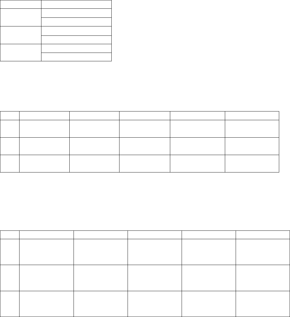
At each step, each updating of a node’s distance vectors is based on the Bellman-Ford
equation, i.e., only decreasing those values in its distance vector. There is no increasing
in values. If no updating, then no message will be sent out. Thus, D(x) is non-increasing.
Since those costs are finite, then eventually distance vectors will be stabilized in finite
steps.
Problem 34
a)
Router z
Informs w, Dz(x)=
Informs y, Dz(x)=6
Router w
Informs y, Dw(x)=
Informs z, Dw(x)=5
Router y
Informs w, Dy(x)=4
Informs z, Dy(x)=4
b) Yes, there will be a count-to-infinity problem. The following table shows the routing
converging process. Assume that at time t0, link cost change happens. At time t1, y
updates its distance vector and informs neighbors w and z. In the following table,
“” stands for “informs”.
time
t0
t1
t2
t3
t4
Z
w, Dz(x)=
No change
w, Dz(x)=
y, Dz(x)=6
y, Dz(x)=11
W
y, Dw(x)=
y, Dw(x)=
No change
z, Dw(x)=5
z, Dw(x)=10
Y
w, Dy(x)=4
w, Dy(x)=9
No change
w, Dy(x)=14
z, Dy(x)=4
z, Dy(x)=
z, Dy(x)=
We see that w, y, z form a loop in their computation of the costs to router x. If we
continue the iterations shown in the above table, then we will see that, at t27, z detects
that its least cost to x is 50, via its direct link with x. At t29, w learns its least cost to x is
51 via z. At t30, y updates its least cost to x to be 52 (via w). Finally, at time t31, no
updating, and the routing is stabilized.
time
t27
t28
t29
t30
t31
Z
w, Dz(x)=50
via w,
y, Dz(x)=50
via y, 55
via z, 50
W
y, Dw(x)=
y, Dw(x)=51
via w,
z, Dw(x)=50
z, Dw(x)=
via y,
via z, 51
Y
w, Dy(x)=53
w, Dy(x)=
via w, 52
z, Dy(x)=
z, Dy(x)= 52
via y, 60
via z, 53
c) cut the link between y and z.
Problem 35
Since full AS path information is available from an AS to a destination in BGP, loop
detection is simple – if a BGP peer receives a route that contains its own AS number in
the AS path, then using that route would result in a loop.
Problem 36
The chosen path is not necessarily the shortest AS-path. Recall that there are many issues
to be considered in the route selection process. It is very likely that a longer loop-free
path is preferred over a shorter loop-free path due to economic reason. For example, an
AS might prefer to send traffic to one neighbor instead of another neighbor with shorter
AS distance.
Problem 37
a) eBGP
b) iBGP
c) eBGP
d) iBGP
Problem 38
a) I1 because this interface begins the least cost path from 1d towards the gateway router
1c.
b) I2. Both routes have equal AS-PATH length but I2 begins the path that has the closest
NEXT-HOP router.
c) I1. I1 begins the path that has the shortest AS-PATH.
Problem 39
One way for C to force B to hand over all of B’s traffic to D on the east coast is for C to
only advertise its route to D via its east coast peering point with C.
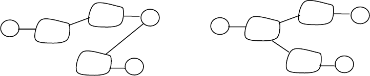
Problem 40
In the above solution, X does not know about the AC link since X does not receive an
advertised route to w or to y that contain the AC link (i.e., X receives no advertisement
containing both AS A and AS C on the path to a destination.
Problem 41
BitTorrent file sharing and Skype P2P applications.
Consider a BitTorrent file sharing network in which peer 1, 2, and 3 are in stub networks
W, X, and Y respectively. Due the mechanism of BitTorrent’s file sharing, it is quire
possible that peer 2 gets data chunks from peer 1 and then forwards those data chunks to
3. This is equivalent to B forwarding data that is finally destined to stub network Y.
Problem 42
A should advise to B two routes, AS-paths A-W and A-V.
A should advise to C only one route, A-V.
C receives AS paths: B-A-W, B-A-V, A-V.
Problem 43
Since Z wants to transit Y's traffic, Z will send route advertisements to Y. In this manner,
when Y has a datagram that is destined to an IP that can be reached through Z, Y will
have the option of sending the datagram through Z. However, if Z advertizes routes to Y,
Y can re-advertize those routes to X. Therefore, in this case, there is nothing Z can do
from preventing traffic from X to transit through Z.
Problem 44
The minimal spanning tree has z connected to y via x at a cost of 14(=8+6).
z connected to v via x at a cost of 11(=8+3);
z connected to u via x and v, at a cost of 14(=8+3+3);
z connected to w via x, v, and u, at a cost of 17(=8+3+3+3).
A
B
C
w
x
y
X’s view of the topology
A
B
C
w
x
y
W’s view of the topology
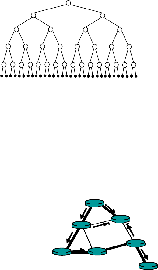
This can be obtained by Prim’s algorithm to grow a minimum spanning tree.
Problem 45
The 32 receives are shown connected to the sender in the binary tree configuration shown
above. With network-layer broadcast, a copy of the message is forwarded over each link
exactly once. There are thus 62 link crossings (2+4+8+16+32). With unicast emulation,
the sender unicasts a copy to each receiver over a path with5 hops. There are thus 160
link crossings (5*32).
A topology in which all receivers are in a line, with the sender at one end of the line, will
have the largest disparity between the cost of network-layer broadcast and unicast
emulation.
Problem 46
Problem 47
A
B
G
D
E
c
F
The thicker shaded lines represent
The shortest path tree from A to all
destination. Other solutions are
possible, but in these solutions, B
can not route to either C or D from A.
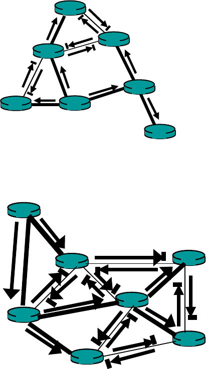
A
B
G
D
E
c
F
Problem 48
Z
y
x
v
t
u
w
Problem 49
The center-based tree for the topology shown in the original figure connects A to C; B to
C; E to C; and F to C (all directly). D connects to C via E, and G connects to C via D, E.
This center-based tree is different from the minimal spanning tree shown in the figure.
Problem 50
The center-based tree for the topology shown in the original figure connects t to v; u to v;
w to v; x to v; and y to v (all directly). And z connected to v via x. This center-based tree
is different from the minimal spanning tree.
Problem 51
Dijkstra’s algorithm for the network below, with node A as the source, results in a least-
unicast-cost path tree of links AC, AB, and BD, with an overall free cost of 20. The
minimum spanning tree contains links AB, BD, and DC, at a cost of 11.
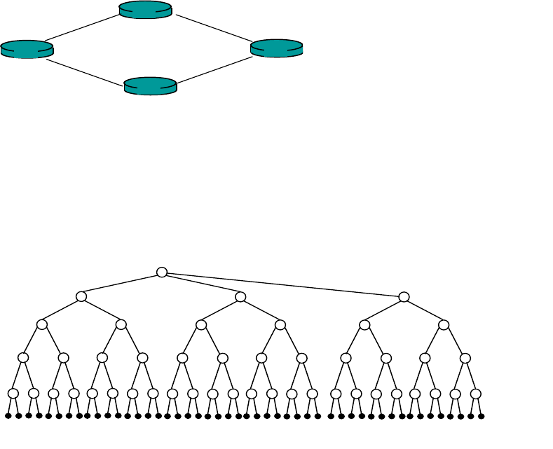
A
B
D
c
10
9
1
1
Problem 52
After 1 step 3 copies are transmitted, after 2 steps 6 copies are transmitted. After 3 steps,
12 copies are transmitted, and so on. After k steps, 3*2k-1 copies will be transmitted in
that step.
3
6
12
24
48
…
Problem 53
The protocol must be built at the application layer. For example, an application may
periodically multicast its identity to all other group members in an application-layer
message.
Problem 54
A simple application-layer protocol that will allow all members to know the identity of
all other members in the group is for each instance of the application to send a multicast
message containing its identity to all other members. This protocol sends message in-
band, since the multicast channel is used to distribute the identification messages as well
as multicast data from the application itself. The use of the in-band signaling makes use
of the existing multicast distribution mechanism, leading to a very simple design.
Problem 55
28432
bits are available for multicast addresses. Thus, the size of the multicast
address space is
28
2N
.
The probability that two groups choose the same address is
928 1073.32
1
N
The probability that 1000 groups all have different addresses is
NNN
N
NNNN 999
1
2
1
1
1
)999()2()1(
1000
Ignoring cross-product terms, this is approximately equal to
998.0
2
1000999
1
99921
1
NN
Chapter 5 Review Questions
1. The transportation mode, e.g., car, bus, train, car.
2. Although each link guarantees that an IP datagram sent over the link will be received
at the other end of the link without errors, it is not guaranteed that IP datagrams will
arrive at the ultimate destination in the proper order. With IP, datagrams in the same
TCP connection can take different routes in the network, and therefore arrive out of
order. TCP is still needed to provide the receiving end of the application the byte
stream in the correct order. Also, IP can lose packets due to routing loops or
equipment failures.
3. Framing: there is also framing in IP and TCP; link access; reliable delivery: there is
also reliable delivery in TCP; flow control: there is also flow control in TCP; error
detection: there is also error detection in IP and TCP; error correction; full duplex:
TCP is also full duplex.
4. There will be a collision in the sense that while a node is transmitting it will start to
receive a packet from the other node.
5. Slotted Aloha: 1, 2 and 4 (slotted ALOHA is only partially decentralized, since it
requires the clocks in all nodes to be synchronized). Token ring: 1, 2, 3, 4.
6. After the 5th collision, the adapter chooses from {0, 1, 2,…, 31}. The probability that
it chooses 4 is 1/32. It waits 204.8 microseconds.
7. In polling, a discussion leader allows only one participant to talk at a time, with each
participant getting a chance to talk in a round-robin fashion. For token ring, there isn’t
a discussion leader, but there is wine glass that the participants take turns holding. A
participant is only allowed to talk if the participant is holding the wine glass.
8. When a node transmits a frame, the node has to wait for the frame to propagate
around the entire ring before the node can release the token. Thus, if L/R is small as
compared to tprop, then the protocol will be inefficient.
9. 248 MAC addresses; 232 IPv4 addresses; 2128 IPv6 addresses.
10. C’s adapter will process the frames, but the adapter will not pass the datagrams up the
protocol stack. If the LAN broadcast address is used, then C’s adapter will both
process the frames and pass the datagrams up the protocol stack.
11. An ARP query is sent in a broadcast frame because the querying host does not which
adapter address corresponds to the IP address in question. For the response, the
sending node knows the adapter address to which the response should be sent, so
there is no need to send a broadcast frame (which would have to be processed by all
the other nodes on the LAN).
12. No it is not possible. Each LAN has its own distinct set of adapters attached to it, with
each adapter having a unique LAN address.
13. The three Ethernet technologies have identical frame structures.
14. 2 (the internal subnet and the external internet)
15. In 802.1Q there is a 12- bit VLAN identifier. Thus 212 = 4,096 VLANs can be
supported.
16. We can string the N switches together. The first and last switch would use one port
for trunking; the middle N-2 switches would use two ports. So the total number of
ports is 2+ 2(N-2) = 2N-2 ports.
Chapter 5 Problems
Problem 1
1 1 1 0 1
0 1 1 0 0
1 0 0 1 0
1 1 0 1 1
1 1 0 0 0
Problem 2
Suppose we begin with the initial two-dimensional parity matrix:
0 0 0 0
1 1 1 1
0 1 0 1
1 0 1 0
With a bit error in row 2, column 3, the parity of row 2 and column 3 is now wrong in the
matrix below:
0 0 0 0
1 1 0 1
0 1 0 1
1 0 1 0
Now suppose there is a bit error in row 2, column 2 and column 3. The parity of row 2 is
now correct! The parity of columns 2 and 3 is wrong, but we can't detect in which rows
the error occurred!
0 0 0 0
1 0 0 1
0 1 0 1
1 0 1 0
The above example shows that a double bit error can be detected (if not corrected).
Problem 3
01001100 01101001
+ 01101110 01101011
------------------------------
10111010 11010100
+ 00100000 01001100
------------------------------
11011011 00100000
+ 01100001 01111001
-----------------------------
00111100 10011010 (overflow, then wrap around)
+ 01100101 01110010
------------------------------
10100010 00001100
The one's complement of the sum is 01011101 11110011
Problem 4
a) To compute the Internet checksum, we add up the values at 16-bit quantities:
00000001 00000010
00000011 00000100
00000101 00000110
00000111 00001000
00001001 00001010
-------------------------
00011001 00011110
The one's complement of the sum is 11100110 11100001.
b) To compute the Internet checksum, we add up the values at 16-bit quantities:
01000010 01000011
01000100 01000101
01000110 01000111
01001000 01001001
01001010 01001011
-------------------------
10011111 10100100
The one's complement of the sum is 01100000 01011011
c) To compute the Internet checksum, we add up the values at 16-bit quantities:
01100010 01100011
01100100 01100101
01100110 01100111
01101000 01101001
01101010 01101011
-------------------------
00000000 00000101
The one's complement of the sum is 11111111 11111010.
Problem 5
If we divide 10011 into 1010101010 0000, we get 1011011100, with a remainder of
R=0100. Note that, G=10011 is CRC-4-ITU standard.
Problem 6
a) we get 1000100011, with a remainder of R=0101.
b) we get 1011111111, with a remainder of R=0001.
c) we get 0101101110, with a remainder of R=0010.
Problem 7
a) Without loss of generality, suppose ith bit is flipped, where 0<= i <= d+r-1 and
assume that the least significant bit is 0th bit.
A single bit error means that the received data is K=D*2r XOR R + 2i. It is clear that
if we divide K by G, then the reminder is not zero. In general, if G contains at least
two 1’s, then a single bit error can always be detected.
b) The key insight here is that G can be divided by 11 (binary number), but any number
of odd-number of 1’s cannot be divided by 11. Thus, a sequence (not necessarily
contiguous) of odd-number bit errors cannot be divided by 11, thus it cannot be
divided by G.
Problem 8
a)
1
)1()(
N
pNppE
21 )1)(1()1()(' NN pNNppNpE
))1()1(()1( 2 NpppN N
N
ppE 1
*0)('
b)
N
N
NNN
NpE
N
NN
1
1
)
1
1(
)
1
1()
1
1(
1
*)(11
1)
1
1(lim
N
N
eN
N
N
1
)
1
1(lim
Thus
e
pE
N
1
*)(lim
Problem 9
)1(2
)1()(
N
pNppE
)3(2)2(2 )1)(1(2)1()(' NN pNNppNpE
))1(2)1(()1( )3(2 NpppN N
12
1
*0)('
N
ppE
)1(2
)
12
1
1(
12
*)(
N
NN
N
pE

ee
pE
N2
11
2
1
*)(lim
Problem 10
a) A’s average throughput is given by pA(1-pB).
Total efficiency is pA(1-pB) + pB(1-pA).
b) A’s throughput is pA(1-pB)=2pB(1-pB)= 2pB- 2(pB)2.
B’s throughput is pB(1-pA)=pB(1-2pB)= pB- 2(pB)2.
Clearly, A’s throughput is not twice as large as B’s.
In order to make pA(1-pB)= 2 pB(1-pA), we need that pA= 2 – (pA / pB).
c) A’s throughput is 2p(1-p)N-1, and any other node has throughput p(1-p)N-2(1-2p).
Problem 11
a) (1 – p(A))4 p(A)
where, p(A) = probability that A succeeds in a slot
p(A) = p(A transmits and B does not and C does not and D does not)
= p(A transmits) p(B does not transmit) p(C does not transmit) p(D does
not transmit)
= p(1 – p) (1 – p)(1-p) = p(1 – p)3
Hence, p(A succeeds for first time in slot 5)
= (1 – p(A))4 p(A) = (1 – p(1 – p)3)4 p(1 – p)3
b) p(A succeeds in slot 4) = p(1-p)3
p(B succeeds in slot 4) = p(1-p)3
p(C succeeds in slot 4) = p(1-p)3
p(D succeeds in slot 4) = p(1-p)3
p(either A or B or C or D succeeds in slot 4) = 4 p(1-p)3
(because these events are mutually exclusive)
c) p(some node succeeds in a slot) = 4 p(1-p)3
p(no node succeeds in a slot) = 1 - 4 p(1-p)3
Hence, p(first success occurs in slot 3) = p(no node succeeds in first 2 slots) p(some
node succeeds in 3rd slot) = (1 - 4 p(1-p)3)2 4 p(1-p)3
d) efficiency = p(success in a slot) =4 p(1-p)3
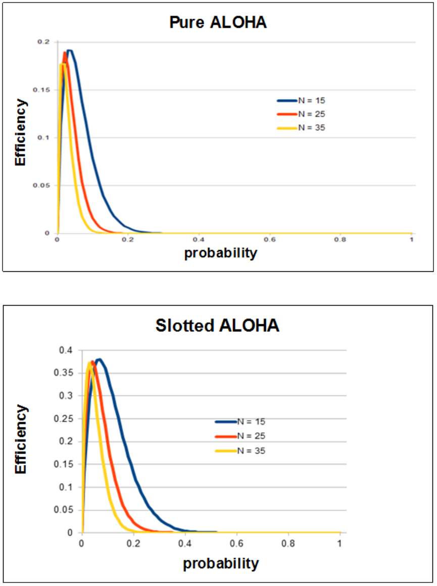
Problem 12
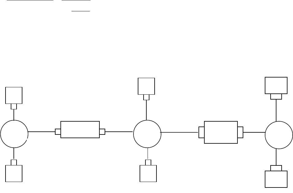
Problem 13
The length of a polling round is
)/( poll
dRQN
.
The number of bits transmitted in a polling round is
NQ
. The maximum throughput
therefore is
Q
Rd
R
dRQN
NQ
poll
poll
1
)/(
Problem 14
a), b) See figure below.
c) 1. Forwarding table in E determines that the datagram should be routed to interface
192.168.3.002.
2. The adapter in E creates and Ethernet packet with Ethernet destination address 88-
88-88-88-88-88.
3. Router 2 receives the packet and extracts the datagram. The forwarding table in
this router indicates that the datagram is to be routed to 198.162.2.002.
4. Router 2 then sends the Ethernet packet with the destination address of 33-33-33-
33-33-33 and source address of 55-55-55-55-55-55 via its interface with IP
address of 198.162.2.003.
5. The process continues until the packet has reached Host B.
192.168.3.003
99-99-99-99-99-99
192.168.3.002
88-88-88-88-88-88
192.168.3.001
77-77-77-77-77-77
192.168.2.003
55-55-55-55-55
192.168.2.001
44-44-44-44-44-44
192.168.2.002
33-33-33-33-33-33
A
B
LAN
Router 1
LAN
C
D
F
192.168.1.001
00-00-00-00-00-00
192.168.1.002
22-22-22-22-22-22
192.168.1.003
11-11-11-11-11-11
E
Router 2
LAN
192.168.2.004
66-66-66-66-66
d) ARP in E must now determine the MAC address of 198.162.3.002. Host E sends out
an ARP query packet within a broadcast Ethernet frame. Router 2 receives the query
packet and sends to Host E an ARP response packet. This ARP response packet is
carried by an Ethernet frame with Ethernet destination address 77-77-77-77-77-77.
Problem 15
a) No. E can check the subnet prefix of Host F’s IP address, and then learn that F is on
the same LAN. Thus, E will not send the packet to the default router R1.
Ethernet frame from E to F:
Source IP = E’s IP address
Destination IP = F’s IP address
Source MAC = E’s MAC address
Destination MAC = F’s MAC address
b) No, because they are not on the same LAN. E can find this out by checking B’s IP
address.
Ethernet frame from E to R1:
Source IP = E’s IP address
Destination IP = B’s IP address
Source MAC = E’s MAC address
Destination MAC = The MAC address of R1’s interface connecting to Subnet 3.
c) Switch S1 will broadcast the Ethernet frame via both its interfaces as the received
ARP frame’s destination address is a broadcast address. And it learns that A resides
on Subnet 1 which is connected to S1 at the interface connecting to Subnet 1. And, S1
will update its forwarding table to include an entry for Host A.
Yes, router R1 also receives this ARP request message, but R1 won’t forward the
message to Subnet 3.
B won’t send ARP query message asking for A’s MAC address, as this address can
be obtained from A’s query message.
Once switch S1 receives B’s response message, it will add an entry for host B in its
forwarding table, and then drop the received frame as destination host A is on the
same interface as host B (i.e., A and B are on the same LAN segment).

Problem 16
Lets call the switch between subnets 2 and 3 S2. That is, router R1 between subnets 2 and
3 is now replaced with switch S2.
a) No. E can check the subnet prefix of Host F’s IP address, and then learn that F is on
the same LAN segment. Thus, E will not send the packet to S2.
Ethernet frame from E to F:
Source IP = E’s IP address
Destination IP = F’s IP address
Source MAC = E’s MAC address
Destination MAC = F’s MAC address
b) Yes, because E would like to find B’s MAC address. In this case, E will send an ARP
query packet with destination MAC address being the broadcast address.
This query packet will be re-broadcast by switch 1, and eventually received by Host
B.
Ethernet frame from E to S2:
Source IP = E’s IP address
Destination IP = B’s IP address
Source MAC = E’s MAC address
Destination MAC = broadcast MAC address: FF-FF-FF-FF-FF-FF.
c) Switch S1 will broadcast the Ethernet frame via both its interfaces as the received
ARP frame’s destination address is a broadcast address. And it learns that A resides
on Subnet 1 which is connected to S1 at the interface connecting to Subnet 1. And, S1
will update its forwarding table to include an entry for Host A.
Yes, router S2 also receives this ARP request message, and S2 will broadcast this
query packet to all its interfaces.
B won’t send ARP query message asking for A’s MAC address, as this address can
be obtained from A’s query message.
Once switch S1 receives B’s response message, it will add an entry for host B in its
forwarding table, and then drop the received frame as destination host A is on the
same interface as host B (i.e., A and B are on the same LAN segment).
Problem 17
Wait for 51,200 bit times. For 10 Mbps, this wait is
12.5
1010
102.51
6
3
bps
bits
msec
For 100 Mbps, the wait is 512
sec.
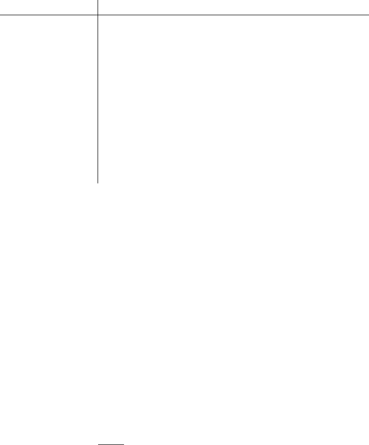
Problem 18
At
0t
A
transmits. At
576t
,
A
would finish transmitting. In the worst case,
B
begins transmitting at time t=324, which is the time right before the first bit of A’s frame
arrives at B. At time t=324+325=649
B
's first bit arrives at
A
. Because 649> 576,
A
finishes transmitting before it detects that B has transmitted. So A incorrectly thinks that
its frame was successfully transmitted without a collision.
Problem 19
Time,
t
Event
0
A
and
B
begin transmission
245
A
and
B
detect collision
293
A
and
B
finish transmitting jam signal
293+245 = 538
538+96=634
B
's last bit arrives at
A
;
A
detects an idle channel
A starts transmitting
293+512 = 805
634+245=879
B returns to Step2
B must sense idle channel for 96 bit times before it
transmits
A’s transmission reaches B
Because
A
's retransmission reaches
B
before
B
's scheduled retransmission time
(805+96),
B
refrains from transmitting while
A
retransmits. Thus
A
and
B
do not
collide. Thus the factor 512 appearing in the exponential backoff algorithm is sufficiently
large.
Problem 20
a) Let
Y
be a random variable denoting the number of slots until a success:
1
)1()(
m
mYP
,
where
is the probability of a success.
This is a geometric distribution, which has mean
/1
. The number of consecutive
wasted slots is
1 YX
that
1
1][][ YEXEx
1
)1(
N
pNp
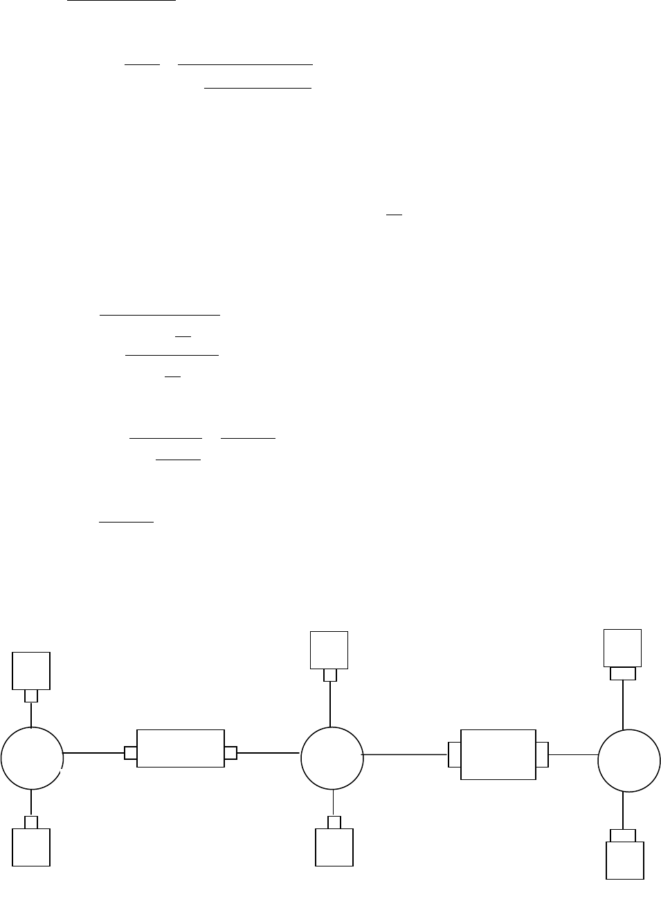
1
1
)1(
)1(1
N
N
pNp
pNp
x
efficiency
1
1
)1(
)1(1
N
N
pNp
pNp
k
k
xk
k
b)
Maximizing efficiency is equivalent to minimizing
x
, which is equivalent to maximizing
. We know from the text that
is maximized at
N
p1
.
c)
efficiency
1
1
)
1
1(
)
1
1(1
N
N
N
N
k
k
N
lim
efficiency
1
/1
/11
ek
k
e
e
k
k
d) Clearly,
1 ek
k
approaches 1 as
k
.
Problem 21
133.333.333.002
88-88-88-88-88-88
133.333.333.001
77-77-77-77-77-77
122.222.222.003
55-55-55-55-55
122.222.222.001
44-44-44-44-44-44
122.222.222.002
33-33-33-33-33-33
A
B
LAN
Router 1
LAN
D
111.111.111.001
00-00-00-00-00-00
111.111.111.002
22-22-22-22-22-22
111.111.111.003
11-11-11-11-11-11
Router 2
LAN
122.222.222.004
66-66-66-66-66
133.333.333.003
99-99-99-99-99-99
C
E
F
i) from A to left router: Source MAC address: 00-00-00-00-00-00
Destination MAC address: 22-22-22-22-22-22
Source IP: 111.111.111.001
Destination IP: 133.333.333.003
ii) from the left router to the right router: Source MAC address: 33-33-33-33-33-33
Destination MAC address: 55-55-55-55-55-55
Source IP: 111.111.111.001
Destination IP: 133.333.333.003
iii) from the right router to F: Source MAC address: 88-88-88-88-88-88
Destination MAC address: 99-99-99-99-99-99
Source IP: 111.111.111.001
Destination IP: 133.333.333.003
Problem 22
i) from A to switch: Source MAC address: 00-00-00-00-00-00
Destination MAC address: 55-55-55-55-55-55
Source IP: 111.111.111.001
Destination IP: 133.333.333.003
ii) from switch to right router: Source MAC address: 00-00-00-00-00-00
Destination MAC address: 55-55-55-55-55-55
Source IP: 111.111.111.001
Destination IP: 133.333.333.003
iii) from right router to F: Source MAC address: 88-88-88-88-88-88
Destination MAC address: 99-99-99-99-99-99
Source IP: 111.111.111.001
Destination IP: 133.333.333.003
Problem 23
If all the 11=9+2 nodes send out data at the maximum possible rate of 100 Mbps, a total
aggregate throughput of 11*100 = 1100 Mbps is possible.
Problem 24
Each departmental hub is a single collision domain that can have a maximum throughput
of 100 Mbps. The links connecting the web server and the mail server has a maximum

throughput of 100 Mbps. Hence, if the three collision domains and the web server and
mail server send out data at their maximum possible rates of 100 Mbps each, a maximum
total aggregate throughput of 500 Mbps can be achieved among the 11 end systems.
Problem 25
All of the 11 end systems will lie in the same collision domain. In this case, the
maximum total aggregate throughput of 100 Mbps is possible among the 11 end sytems.
Problem 26
Action
Switch Table State
Link(s) packet is
forwarded to
Explanation
B sends a
frame to E
Switch learns interface
corresponding to MAC
address of B
A, C, D, E, and F
Since switch table is
empty, so switch
does not know the
interface
corresponding to
MAC address of E
E replies with a
frame to B
Switch learns interface
corresponding to MAC
address of E
B
Since switch already
knows interface
corresponding to
MAC address of B
A sends a
frame to B
Switch learns the
interface corresponding
to MAC address of A
B
Since switch already
knows the interface
corresponding to
MAC address of B
B replies with
a frame to A
Switch table state
remains the same as
before
A
Since switch already
knows the interface
corresponding to
MAC address of A
Problem 27
a) The time required to fill
8L
bits is
.sec
16
sec
10128
8
3m
LL
b) For
,500,1L
the packetization delay is
.sec75.93sec
16
1500 mm

For
,50L
the packetization delay is
.sec125.3sec
16
50 mm
c) Store-and-forward delay
R
L408
For
500,1L
, the delay is
sec4.19sec
10622
4081500
6
For
,50L
store-and-forward delay
sec1
.
d) Store-and-forward delay is small for both cases for typical link speeds. However,
packetization delay for
1500L
is too large for real-time voice applications.
Problem 28
The IP addresses for those three computers (from left to right) in EE department are:
111.111.1.1, 111.111.1.2, 111.111.1.3. The subnet mask is 111.111.1/24.
The IP addresses for those three computers (from left to right) in CS department are:
111.111.2.1, 111.111.2.2, 111.111.2.3. The subnet mask is 111.111.2/24.
The router’s interface card that connects to port 1 can be configured to contain two sub-
interface IP addresses: 111.111.1.0 and 111.111.2.0. The first one is for the subnet of EE
department, and the second one is for the subnet of CS department. Each IP address is
associated with a VLAN ID. Suppose 111.111.1.0 is associated with VLAN 11, and
111.111.2.0 is associated with VLAN 12. This means that each frame that comes from
subnet 111.111.1/24 will be added an 802.1q tag with VLAN ID 11, and each frame that
comes from 111.111.2/24 will be added an 802.1q tag with VLAN ID 12.
Suppose that host A in EE department with IP address 111.111.1.1 would like to send an
IP datagram to host B (111.111.2.1) in CS department. Host A first encapsulates the IP
datagram (destined to 111.111.2.1) into a frame with a destination MAC address equal to
the MAC address of the router’s interface card that connects to port 1 of the switch. Once
the router receives the frame, then it passes it up to IP layer, which decides that the IP
datagram should be forwarded to subnet 111.111.2/24 via sub-interface 111.111.2.0.
Then the router encapsulates the IP datagram into a frame and sends it to port 1. Note that
this frame has an 802.1q tag VLAN ID 12. Once the switch receives the frame port 1, it
knows that this frame is destined to VLAN with ID 12, so the switch will send the frame
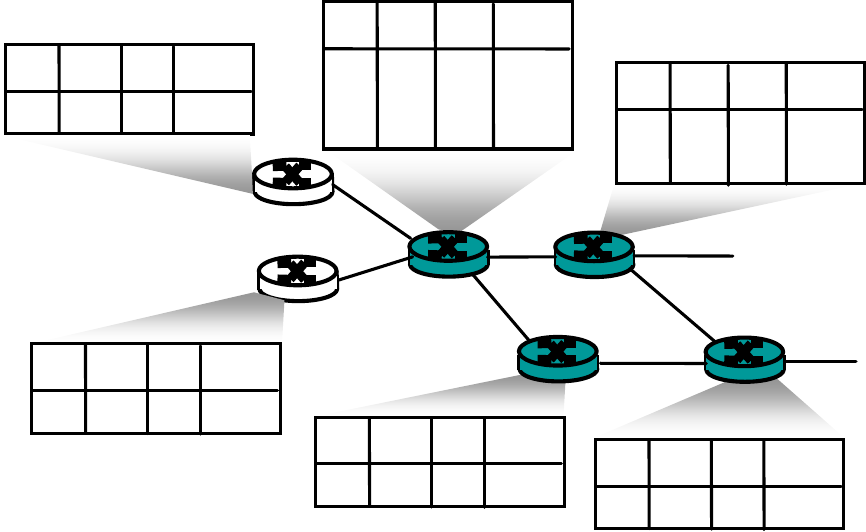
to Host B which is in CS department. Once Host B receives this frame, it will remove the
802.1q tag.
Problem 29
R1
R2
D
R3
R4
R5
0
1
0
0
A
R6
in out out
label label dest inter.
6 - A 0
in out out
label label dest interf.
10 6 A 1
12 9 D 0
in out out
label label dest interf.
7 10 A 0
12 D 0
1
in out out
label label dest interf.
8 6 A 0
0
5 8 A 1
in out out
label label dest interf.
5 A 0
in out out
label label dest interf.
7 A 0
0
0
Problem 30
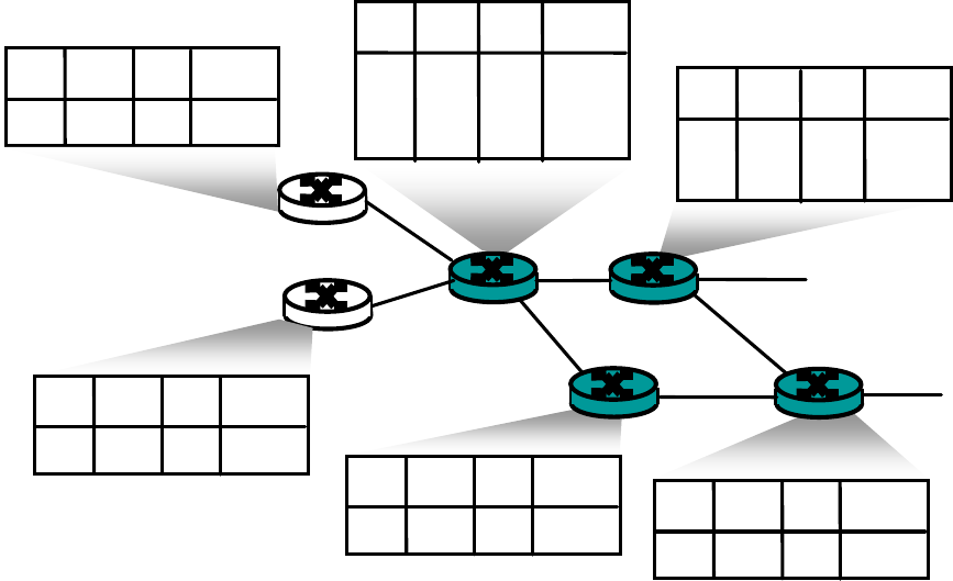
R1
R2
D
R3
R4
R5
1
1
0
0
A
R6
in out out
label label dest inter.
1 12 D 1
in out out
label label dest interf.
12 - D 0
in out out
label label dest interf.
3 12 D 0
1
in out out
label label dest interf.
4 1 D 0
0
2 4 D 1
in out out
label label dest interf.
2 D 0
in out out
label label dest interf.
3 D 0
0
0
Problem 31
(The following description is short, but contains all major key steps and key protocols
involved.)
Your computer first uses DHCP to obtain an IP address. You computer first creates a
special IP datagram destined to 255.255.255.255 in the DHCP server discovery step, and
puts it in a Ethernet frame and broadcast it in the Ethernet. Then following the steps in
the DHCP protocol, you computer is able to get an IP address with a given lease time.
A DHCP server on the Ethernet also gives your computer a list of IP addresses of first-
hop routers, the subnet mask of the subnet where your computer resides, and the
addresses of local DNS servers (if they exist).
Since your computer’s ARP cache is initially empty, your computer will use ARP
protocol to get the MAC addresses of the first-hop router and the local DNS server.
Your computer first will get the IP address of the Web page you would like to download.
If the local DNS server does not have the IP address, then your computer will use DNS
protocol to find the IP address of the Web page.
Once your computer has the IP address of the Web page, then it will send out the HTTP
request via the first-hop router if the Web page does not reside in a local Web server. The
HTTP request message will be segmented and encapsulated into TCP packets, and then
further encapsulated into IP packets, and finally encapsulated into Ethernet frames. Your
computer sends the Ethernet frames destined to the first-hop router. Once the router
receives the frames, it passes them up into IP layer, checks its routing table, and then
sends the packets to the right interface out of all of its interfaces.
Then your IP packets will be routed through the Internet until they reach the Web server.
The server hosting the Web page will send back the Web page to your computer via
HTTP response messages. Those messages will be encapsulated into TCP packets and
then further into IP packets. Those IP packets follow IP routes and finally reach your
first-hop router, and then the router will forward those IP packets to your computer by
encapsulating them into Ethernet frames.
Problem 32
a) Each flow evenly shares a link’s capacity with other flows traversing that link, then the
80 flows crossing the B to access-router 10 Gbps links (as well as the access router to
border router links) will each only receive 10 Gbps / 80 = 125 Mbps
b) In Topology of Figure 5.31, there are four distinct paths between the first and third
tier-2 switches, together providing 40 Gbps for the traffic from racks 1-4 to racks 9-12.
Similarly, there are four links between second and fourth tier-2 switches, together
providing 40 Gbps for the traffic from racks 5-8 to 13-16. Thus the total aggregate
bandwidth is 80 Gbps, and the value per flow rate is 1 Gbps.
c) Now 20 flows will need to share each 1 Gbps bandwidth between pairs of TOR
switches. So the host-to-host bit rate will be 0.5 Gbps.
Problem 33
a) Both email and video application uses the fourth rack for 0.1 percent of the time.
b) Probability that both applications need fourth rack is 0.001*0.001 = 10-6.
c) Suppose the first three racks are for video, the next rack is a shared rack for both
video and email, and the next three racks are for email. Let's assume that the fourth
rack has all the data and software needed for both the email and video applications.
With the topology of Figure 5.31, both applications will have enough intra-bandwidth
as long as both are not simultaneously using the fourth rack. From part b, both are
using the fourth rack for no more than .00001 % of time, which is within the .0001%
requirement.
Chapter 6 Review Questions
1. In infrastructure mode of operation, each wireless host is connected to the larger
network via a base station (access point). If not operating in infrastructure mode, a
network operates in ad-hoc mode. In ad-hoc mode, wireless hosts have no
infrastructure with which to connect. In the absence of such infrastructure, the hosts
themselves must provide for services such as routing, address assignment, DNS-like
name translation, and more.
2. a) Single hop, infrastructure-based
b) Single hop, infrastructure-less
c) Multi-hop, infrastructure-based
d) Multi-hop, infrastructure-less
3. Path loss is due to the attenuation of the electromagnetic signal when it travels
through matter. Multipath propagation results in blurring of the received signal at the
receiver and occurs when portions of the electromagnetic wave reflect off objects and
ground, taking paths of different lengths between a sender and receiver. Interference
from other sources occurs when the other source is also transmitting in the same
frequency range as the wireless network.
4. a) Increasing the transmission power
b) Reducing the transmission rate
5. APs transmit beacon frames. An AP’s beacon frames will be transmitted over one of
the 11 channels. The beacon frames permit nearby wireless stations to discover and
identify the AP.
6. False
7. APs transmit beacon frames. An AP’s beacon frames will be transmitted over one of
the 11 channels. The beacon frames permit nearby wireless stations to discover and
identify the AP.
8. False
9. Each wireless station can set an RTS threshold such that the RTS/CTS sequence is
used only when the data frame to be transmitted is longer than the threshold. This
ensures that RTS/CTS mechanism is used only for large frames.
10. No, there wouldn’t be any advantage. Suppose there are two stations that want to
transmit at the same time, and they both use RTS/CTS. If the RTS frame is as long as
a DATA frames, the channel would be wasted for as long as it would have been
wasted for two colliding DATA frames. Thus, the RTS/CTS exchange is only useful
when the RTS/CTS frames are significantly smaller than the DATA frames.
11. Initially the switch has an entry in its forwarding table which associates the wireless
station with the earlier AP. When the wireless station associates with the new AP, the
new AP creates a frame with the wireless station’s MAC address and broadcasts the
frame. The frame is received by the switch. This forces the switch to update its
forwarding table, so that frames destined to the wireless station are sent via the new
AP.
12. Any ordinary Bluetooth node can be a master node whereas access points in 802.11
networks are special devices (normal wireless devices like laptops cannot be used as
access points).
13. False
14. “Opportunistic Scheduling” refers to matching the physical layer protocol to channel
conditions between the sender and the receiver, and choosing the receivers to which
packets will be sent based on channel condition. This allows the base station to make
best use of the wireless medium.
15. UMTS to GSM and CDMA-2000 to IS-95.
16. No. A node can remain connected to the same access point throughout its connection
to the Internet (hence, not be mobile). A mobile node is the one that changes its point
of attachment into the network over time. Since the user is always accessing the
Internet through the same access point, she is not mobile.
17. A permanent address for a mobile node is its IP address when it is at its home
network. A care-of-address is the one its gets when it is visiting a foreign network.
The COA is assigned by the foreign agent (which can be the edge router in the
foreign network or the mobile node itself).
18. False
19. The home network in GSM maintains a database called the home location register
(HLR), which contains the permanent cell phone number and subscriber profile
information about each of its subscribers. The HLR also contains information about
the current locations of these subscribers. The visited network maintains a database
known as the visitor location register (VLR) that contains an entry for each mobile
user that is currently in the portion of the network served by the VLR. VLR entries
thus come and go as mobile users enter and leave the network.
The edge router in home network in mobile IP is similar to the HLR in GSM and the
edge router in foreign network is similar to the VLR in GSM.
20. Anchor MSC is the MSC visited by the mobile when a call first begins; anchor MSC
thus remains unchanged during the call. Throughout the call’s duration and regardless
of the number of inter-MSC transfers performed by the mobile, the call is routed from
the home MSC to the anchor MSC, and then from the anchor MSC to the visited
MSC where the mobile is currently located.
21. a) Local recovery
b) TCP sender awareness of wireless links
c) Split-connection approaches
Chapter 6 Problems
Problem 1
Output corresponding to bit d1 = [-1,1,-1,1,-1,1,-1,1]
Output corresponding to bit d0 = [1,-1,1,-1,1,-1,1,-1]
Problem 2
Sender 2 output = [1,-1,1,1,1,-1,1,1]; [ 1,-1,1,1,1,-1,1,1]
Problem 3
1
8
1111)1()1(111111)1()1(11
1
2
d
1
8
1111)1()1(111111)1()1(11
2
2
d
Problem 4
Sender 1: (1, 1, 1, -1, 1, -1, -1, -1)
Sender 2: (1, -1, 1, 1, 1, 1, 1, 1)
Problem 5
a) The two APs will typically have different SSIDs and MAC addresses. A wireless
station arriving to the café will associate with one of the SSIDs (that is, one of the
APs). After association, there is a virtual link between the new station and the AP.
Label the APs AP1 and AP2. Suppose the new station associates with AP1. When the
new station sends a frame, it will be addressed to AP1. Although AP2 will also
receive the frame, it will not process the frame because the frame is not addressed to
it. Thus, the two ISPs can work in parallel over the same channel. However, the two
ISPs will be sharing the same wireless bandwidth. If wireless stations in different
ISPs transmit at the same time, there will be a collision. For 802.11b, the maximum
aggregate transmission rate for the two ISPs is 11 Mbps.
b) Now if two wireless stations in different ISPs (and hence different channels) transmit
at the same time, there will not be a collision. Thus, the maximum aggregate
transmission rate for the two ISPs is 22 Mbps for 802.11b.
Problem 6
Suppose that wireless station H1 has 1000 long frames to transmit. (H1 may be an AP
that is forwarding an MP3 to some other wireless station.) Suppose initially H1 is the
only station that wants to transmit, but that while half-way through transmitting its first
frame, H2 wants to transmit a frame. For simplicity, also suppose every station can hear
every other station’s signal (that is, no hidden terminals). Before transmitting, H2 will
sense that the channel is busy, and therefore choose a random backoff value.
Now suppose that after sending its first frame, H1 returns to step 1; that is, it waits a short
period of times (DIFS) and then starts to transmit the second frame. H1’s second frame
will then be transmitted while H2 is stuck in backoff, waiting for an idle channel. Thus,
H1 should get to transmit all of its 1000 frames before H2 has a chance to access the
channel. On the other hand, if H1 goes to step 2 after transmitting a frame, then it too
chooses a random backoff value, thereby giving a fair chance to H2. Thus, fairness was
the rationale behind this design choice.
Problem 7
A frame without data is 32 bytes long. Assuming a transmission rate of 11 Mbps, the time
to transmit a control frame (such as an RTS frame, a CTS frame, or an ACK frame) is
(256 bits)/(11 Mbps) = 23 usec. The time required to transmit the data frame is (8256
bits)/(11 Mbps) = 751
DIFS + RTS + SIFS + CTS + SIFS + FRAME + SIFS + ACK
= DIFS + 3SIFS + (3*23 + 751) usec = DIFS + 3SIFS + 820 usec
Problem 8
a) 1 message/ 2 slots
b) 2 messages/slot
c) 1 message/slot
d) i) 1 message/slot
ii) 2 messages/slot
iii) 2 messages/slot
e) i) 1 message/4 slots
ii) slot 1: Message A B, message D C
slot 2: Ack B A
slot 3: Ack C D
= 2 messages/ 3 slots
iii)
slot 1: Message C D
slot 2: Ack DC, message A B
slot 3: Ack B A
= 2 messages/3 slots
Problem 10
a) 10 Mbps if it only transmits to node A. This solution is not fair since only A is getting
served. By “fair” it means that each of the four nodes should be allotted equal number
of slots.
b) For the fairness requirement such that each node receives an equal amount of data
during each downstream sub-frame, let n1, n2, n3, and n4 respectively represent the
number of slots that A, B, C and D get.
Now,
data transmitted to A in 1 slot = 10t Mbits
(assuming the duration of each slot to be t)
Hence,
Total amount of data transmitted to A (in n1 slots) = 10t n1
Similarly total amounts of data transmitted to B, C, and D equal to 5t n2, 2.5t n3, and
t n4 respectively.
Now, to fulfill the given fairness requirement, we have the following condition:
10t n1 = 5t n2 = 2.5t n3 = t n4
Hence,
n2 = 2 n1
n3 = 4 n1
n4 = 10 n1
Repeat
Now, the total number of slots is N. Hence,
n1+ n2+ n3+ n4 = N
i.e. n1+ 2 n1 + 4 n1 + 10 n1 = N
i.e. n1 = N/17
Hence,
n2 = 2N/17
n3 = 4N/17
n4 = 10N/17
The average transmission rate is given by:
(10t n1+5t n2+ 2.5t n3+t n4)/tN
= (10N/17 + 5 * 2N/17 + 2.5 * 4N/17 + 1 * 10N/17)/N
= 40/17 = 2.35 Mbps
c) Let node A receives twice as much data as nodes B, C, and D during the sub-frame.
Hence,
10tn1 = 2 * 5tn2 = 2 * 2.5tn3 = 2 * tn4
i.e. n2 = n1
n3 = 2n1
n4 = 5n1
Again,
n1 + n2 + n3 + n4 = N
i.e. n 1+ n1 + 2n1 + 5n1 = N
i.e. n1 = N/9
Now, average transmission rate is given by:
(10t n1+5t n2+ 2.5t n3+t n4)/tN
= 25/9 = 2.78 Mbps
Similarly, considering nodes B, C, or D receive twice as much data as any other
nodes, different values for the average transmission rate can be calculated.
Problem 11
a) No. All the routers might not be able to route the datagram immediately. This is
because the Distance Vector algorithm (as well as the inter-AS routing protocols like
BGP) is decentralized and takes some time to terminate. So, during the time when the
algorithm is still running as a result of advertisements from the new foreign network,
some of the routers may not be able to route datagrams destined to the mobile node.
b) Yes. This might happen when one of the nodes has just left a foreign network and
joined a new foreign network. In this situation, the routing entries from the old
foreign network might not have been completely withdrawn when the entries from the
new network are being propagated.
c) The time it takes for a router to learn a path to the mobile node depends on the
number of hops between the router and the edge router of the foreign network for the
node.
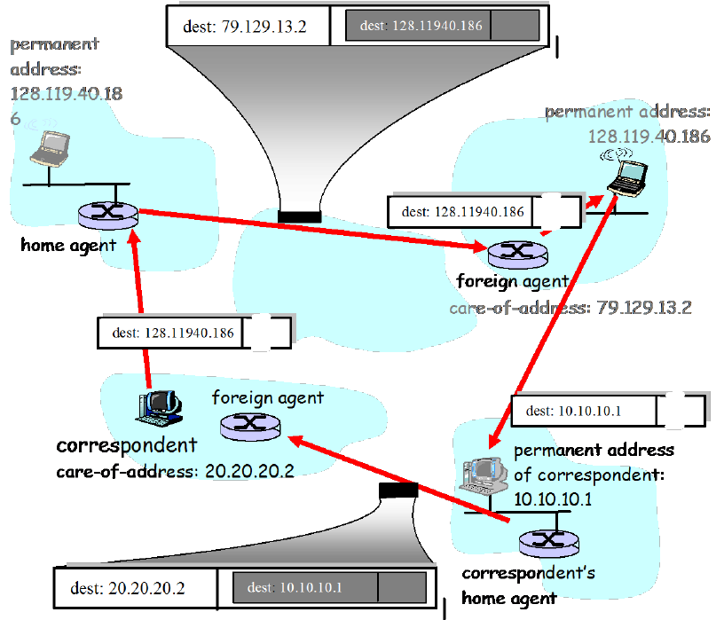
Problem 12
If the correspondent is mobile, then any datagrams destined to the correspondent would
have to pass through the correspondent’s home agent. The foreign agent in the
network being visited would also need to be involved, since it is this foreign agent that
notifies the correspondent’s home agent of the location of the correspondent. Datagrams
received by the correspondent’s home agent would need to be encapsulated/tunneled
between the correspondent’s home agent and foreign agent, (as in the case of the
encapsulated diagram at the top of Figure 6.23.
Problem 13
Because datagrams must be first forward to the home agent, and from there to the mobile,
the delays will generally be longer than via direct routing. Note that it is possible,
however, that the direct delay from the correspondent to the mobile (i.e., if the datagram
is not routed through the home agent) could actually be smaller than the sum of the delay
from the correspondent to the home agent and from there to the mobile. It would depend
on the delays on these various path segments. Note that indirect routing also adds a home
agent processing (e.g., encapsulation) delay.
Problem 14
First, we note that chaining was discussed at the end of section 6.5. In the case of
chaining using indirect routing through a home agent, the following events would
happen:
The mobile node arrives at A, A notifies the home agent that the mobile is now
visiting A and that datagrams to the mobile should now be forwarded to the
specified care-of-address (COA) in A.
The mobile node moves to B. The foreign agent at B must notify the foreign
agent at A that the mobile is no longer resident in A but in fact is resident in B
and has the specified COA in B. From then on, the foreign agent in A will
forward datagrams it receives that are addressed to the mobile’s COA in A to the
mobile’s COA in B.
The mobile node moves to C. The foreign agent at C must notify the foreign
agent at B that the mobile is no longer resident in B but in fact is resident in C and
has the specified COA in C. From then on, the foreign agent in B will forward
datagrams it receives (from the foreign agent in A) that are addressed to the
mobile’s COA in B to the mobile’s COA in C.
Note that when the mobile goes offline (i.e., has no address) or returns to its home
network, the datagram-forwarding state maintained by the foreign agents in A, B and C
must be removed. This teardown must also be done through signaling messages. Note
that the home agent is not aware of the mobile’s mobility beyond A, and that the
correspondent is not at all aware of the mobile’s mobility.
In the case that chaining is not used, the following events would happen:
The mobile node arrives at A, A notifies the home agent that the mobile is now
visiting A and that datagrams to the mobile should now be forwarded to the
specified care-of-address (COA) in A.
The mobile node moves to B. The foreign agent at B must notify the foreign
agent at A and the home agent that the mobile is no longer resident in A but in
fact is resident in B and has the specified COA in B. The foreign agent in A can
remove its state about the mobile, since it is no longer in A. From then on, the
home agent will forward datagrams it receives that are addressed to the mobile’s
COA in B.
The mobile node moves to C. The foreign agent at C must notify the foreign
agent at B and the home agent that the mobile is no longer resident in B but in fact
is resident in C and has the specified COA in C. The foreign agent in B can
remove its state about the mobile, since it is no longer in B. From then on, the
home agent will forward datagrams it receives that are addressed to the mobile’s
COA in C.
When the mobile goes offline or returns to its home network, the datagram-forwarding
state maintained by the foreign agent in C must be removed. This teardown must also be
done through signaling messages. Note that the home agent is always aware of the
mobile’s current foreign network. However, the correspondent is still blissfully unaware
of the mobile’s mobility.
Problem 15
Two mobiles could certainly have the same care-of-address in the same visited network.
Indeed, if the care-of-address is the address of the foreign agent, then this address would
be the same. Once the foreign agent decapsulates the tunneled datagram and determines
the address of the mobile, then separate addresses would need to be used to send the
datagrams separately to their different destinations (mobiles) within the visited network.
Problem 16
If the MSRN is provided to the HLR, then the value of the MSRN must be updated in the
HLR whenever the MSRN changes (e.g., when there is a handoff that requires the MSRN
to change). The advantage of having the MSRN in the HLR is that the value can be
provided quickly, without querying the VLR. By providing the address of the VLR
Rather than the MSRN), there is no need to be refreshing the MSRN in the HLR.
Chapter 7 Review Questions
1.
Bit rate
Bytes transferred in 67
mins
Facebook Frank
40 kbps
20 Mbytes
Martha Music
200 kbps
100 Mbytes
Victor Video
4 Mbps
2 Gbytes
2. Spatial Redundancy: It is the redundancy within a given image. Intuitively, an image
consists of mostly white space has a high degree of redundancy and can be efficiently
compressed without significantly sacrificing image quality.
Temporal Redundancy reflects repetition from image to subsequent image. If, for
example, an image and the subsequent image are exactly the same, there is no reason
to re-encode the subsequent image; it is instead more efficient simply to indicate
during encoding that the subsequent image is exactly the same. If the two images are
very similar, it may be not efficient to indicate how the second image differs from the
first, rather than re-encode the second image.
3. Quantizing a sample into 1024 levels means 10 bits per sample. The resulting rate of
the PCM digital audio signal is 160 Kbps.
4. Streaming stored audio/video: In this class of applications, the underlying medium is
prerecorded video, such as a movie, a television show, or a prerecorded sporting
event. These prerecorded videos are played on servers, and users send requests to the
servers to view the videos on demand. Many internet companies today provide
streaming video, including YouTube, Netflix, and Hulu.
Conversational Voice- and Video-over-IP: Real-time conversational voice over the
Internet is often referred to as Internet telephony, since, from the user’s perspective, it
is similar to the traditional circuit-switched telephone service. It is also commonly
called Voice-over-IP (VOIP).Conversational video is similar except that it includes
the video of the participants as well as their voices. Conversational voice and video
are widely used in the Internet today, with the Internet companies like Skype and
Google Talk boasting hundreds of millions of daily users.
Streaming Live Audio and Video: These applications allow users to receive a live
radio or television transmission over the Internet. Today, thousands of radio and
television stations around the world are broadcasting content over the internet.
5. UDP Streaming: With UDP streaming, the server transmits video at a rate that
matches the client’s video consumption rate by clocking out the video chunks over
UDP at a steady rate.
HTTP Streaming: In HTTP streaming, the video simply stored in an HTTP server as
ordinary file with a specific URL. When a user wants to see the video, the client
establishes a TCP connection with the server and issues an HTTP GET request for
that URL. The server then sends the video file, within an HTTP response message, as
quickly as possible, that is, as quickly as TCP congestion control and flow control
will allow.
Adaptive HTTP Streaming (DASH): In Dynamic Adaptive Streaming over HTTP, the
video is encoded several different versions, with each version having a different bit
rate and, correspondingly, a different quality level. The client dynamically requests
the chunks of video segments of a few seconds in length from the different versions.
When the amount of available bandwidth is high, the client naturally selects chunks
from a high-rate version; and when the available bandwidth is low, it naturally selects
from a low-rate version.
6. The three significant drawbacks of UDP Streaming are:
1. Due to unpredictable and varying amount of available bandwidth between server
and client, constant-rate UDP streaming can fail to provide continuous play out.
2. It requires a media control server, such as an RTSP server, to process client-to-
server interactivity requests and to track client state for each ongoing client
session.
3. Many firewalls are configured to block UDP traffic, preventing users behind
these firewalls from receiving UDP video.
7. No. On the client side, the client application reads bytes from the TCP receive buffer
and places the bytes in the client application buffer.
8. The initial buffering delay is tp = Q/x = 4 seconds.
9. Enter Deep: This philosophy is to enter deep into the access networks of Internet
Service Providers, by deploying server clusters in access ISPs all over the world.
Bring Home: A second design philosophy is to bring the ISP’s home by building
large clusters at a smaller number of key locations and connecting these clusters using
a private high-speed network.
10. Geographically closest cluster selection and real time measurements selection can
find a good cluster with respect to LDNS. IP anycast chooses good cluster with
respect to client itself.
11. Load on the cluster – clients should not be directed to overload clusters.
ISP delivery cost – the clusters may be chosen so that specific ISPs are used to carry
CDN-to-client traffic, taking into account the different cost structures in the
contractual relationships between ISPs and cluster operators.
12. End-to-end delay is the time it takes a packet to travel across the network from source
to destination. Delay jitter is the fluctuation of end-to-end delay from packet to the
next packet.
13. A packet that arrives after its scheduled play out time cannot be played out.
Therefore, from the perspective of the application, the packet has been lost.
14. First scheme: send a redundant encoded chunk after every n chunks; the redundant
chunk is obtained by exclusive OR-ing the n original chunks. Second scheme: send a
lower-resolution low-bit rate scheme along with the original stream. Interleaving does
not increase the bandwidth requirements of a stream.
15. RTP streams in different sessions: different multicast addresses; RTP streams in the
same session: SSRC field; RTP packets are distinguished from RTCP packets by
using distinct port numbers.
16. The role of a SIP registrar is to keep track of the users and their corresponding IP
addresses which they are currently using. Each SIP registrar keeps track of the users
that belong to its domain. It also forwards INVITE messages (for users in its domain)
to the IP address which the user is currently using. In this regard, its role is similar to
that of an authoritative name server in DNS.
17. In non-preemptive priority queuing, the transmission of a packet is not interrupted
once it has begun. In preemptive priority queuing, the transmission of a packet will be
interrupted if a higher priority packet arrives before transmission completes. This
would mean that portions of the packet would be sent into the network as separate
chunks; these chunks would no longer all have the appropriate header fields. For this
reason, preemptive priority queuing is not used.
18. A scheduling discipline that is not work conserving is time division multiplexing,
whereby a rotating frame is partitioned into slots, with each slot exclusively available
to a particular class.
19. FIFO: line at Starbucks. RR: merging traffic (taking 1 vehicle from first lane then 1
from the second, then 1 from the first, and so on). WFQ: ticket counter at airport
providing service to 2 people from first class and 1 from economy, and again 2 from
first class, and so on.

Chapter 7 Problems
Problem 1
a) Client begins playout as soon as first block arrives at t1 and video blocks are to be
played out over the fixed amount of time, d. So it follows that second video block
should be arrived before time t1 + d to be played at right time, third block at
t1 + 2d and so on. We can see from figure that only blocks numbered 1,4,5,6 arrive at
receiver before their playout times.
b) Client begins playout at time t1 + d and video blocks are to be played out over the
fixed amount of time, d. So it follows that second video block should be arrived
before time t1 +2d to be played at right time, third block at t1 + 3d and so on. We can
see from figure that video blocks numbered from 1 to 6 except 7 arrive at receiver
before their playout times.
c) Maximum two video blocks are ever stored in the client buffer. Video blocks
numbered 3 and 4 arrive before t1 + 3d and after t1 + 2d, hence these two blocks are
stored in the client buffer. Video block numbered 5 arrives before time t1 + 4d and
after t1 + 3d, which is stored in the client buffer along with already stored video block
numbered 4.
d) The smallest playout at the client should be t1 + 3d to ensure that every block has
arrived in time.
Problem 2
a) During a playout period, the buffer starts with Q bits and decreases at rate r - x. Thus,
after Q/(r - x) seconds after starting playback the buffer becomes empty. Thus, the
continuous playout period is Q/(r - x) seconds. Once the buffer becomes empty, it fills
at rate x for Q/x seconds, at which time it has Q bits and playback begins. Therefore,
the freezing period is Q/x seconds.
b) Time until buffer has Q bits is Q/x seconds. Time to add additional B - Q bits is (B -
Q)/(x - r) seconds. Thus the time until the application buffer becomes full is
seconds.
Problem 3
a) The server’s average send rate is .
b) This part (b) is an odd question and will be removed from the next edition. After
playing out the first frame, because x(t) < r, the next frame will arrive after the
scheduled playout time of the next frame. Thus playback will freeze after displaying
the first frame.
c) Let q(t) denote the number of bits in the buffer at time t. Playout begins when q(t) =
Q. Let’s assume throughout this problem that HT/2 ≥ Q, so that q(t) = Q by the end of
the first cycle for x(t). We have
.
Therefore, q (t) = Q when t = = tp.
d) At time t = T, q (t) = HT/2 = Q, so that playout begins. If subsequently there is no
freezing, we need q(t + T) > 0 for all t ≥ T, we have
>
With t = nT + ∆, with 0 < ∆ < T, we have from above
=
Which is easily seen to be possible for all 0 < ∆ < T.
e) First consider the [0, T]. We have
for tp ≤ t ≤ T
q (t) is minimized at t = rT/H. It can then be shown that q (rT/H) ≥ 0 if and only if
tp ≥ rT/2H. Furthermore, if tp = rT/2H, proof can be extended to show q (t) > 0 for
all t ≥ T thus, tp < rT/2H and Q = r2T/8H.
f) This is a very challenging problem. Assuming that B is reached before time T, then tf
is solution to
= B.
Problem 4
a) Buffer grows at rate x – r. At time E, (x - r)*E bits are in buffer and are wasted.
b) Let S be the time when the server has transmitted the entire video. If S > E, buffer
grows at rate x – r until time E, so the waste is again (x - r)*E. If S < E, then at time E
there are T – E seconds of video still to be played in buffer. So the waste is r* (T -
E).

Problem 5
a) N*N = N2.
b) N+N = 2N
Problem 6
a)
h160
bytes are sent every 20 msec. Thus the transmission rate is
KbpshKbps
h)4.64(
20
8)160(
b)
IP header: 20 bytes
UDP header: 8 bytes
RTP header: 12 bytes
c) h=40 bytes (a 25% increase in the transmission rate!)
Problem 7
a) Denote
)(n
d
for the estimate after the nth sample.
44
)1( trd
))(1()( 4433
)2( trutrud
))(1()()1()( 443322
)3( trutruutrud
)()1()()1()( 44
2
3322 trutruutru
)3(
11
)4( )1()( dutrud
)()1()()1()()1()( 44
3
33
2
2211 trutruutruutru
b)
)()1()()1(
1
1
)( nn
n
jj
n
j
jn trutruud
c)
)()1(
11
)( jj
j
jtru
u
u
d
)(9.
9
1
1
jj
j
jtr
The weight given to past samples decays exponentially.
Problem 8
a) Denote
)(n
v
for the estimate after the nth sample. Let
jjj tr
.
)1(
4
)1( dv
(=0)
)1(
4
)2(
3
)2( )1( duduv
)2()3(
2
)3( )1( vuduv
)1(
4
2)2(
3
)3(
2)1()1( duduudu
)3()4(
1
)4( )1( vuduv
)2(
3
2)3(
2
)4(
1)1()1( duuduudu
)1(
4
3
)1( du
)2(
3
2)3(
2
)4(
1)1()1( dududu
)1(
4
3
)1( du
b)
)1()1(
1
1
1)( )1()1( duduuv n
njn
j
n
j
jn
Problem 9
a) r1 – t1 + r2 - t2 + …+rn-1-tn-1 = (n-1)dn-1
Substituting this into the expression for dn gives

n
tr
d
n
n
dnn
nn
1
1
b) The delay estimate in part (a) is an average of the delays. It gives equal weight to
recent delays and to “old” delays. The delay estimate in Section 6.3 gives more
weight to recent delays; delays in the distant past have relatively little impact on the
estimate.
Problem 10
The two procedures are very similar. They both use the same formula, thereby resulting
in exponentially decreasing weights for past samples.
One difference is that for estimating average RTT, the time when the data is sent and
when the acknowledgement is received is recorded on the same machine. For the delay
estimate, the two values are recorded on different machines. Thus the sample delay can
actually be negative.
Problem 11
a) The delay of packet 2 is 7 slots. The delay of packet 3 is 9 slots. The delay of packet
4 is 8 slots. The delay of packet 5 is 7 slots. The delay of packet 6 is 9 slots. The
delay of packet 7 is 8 slots. The delay of packet 8 is > 8 slots.
b) Packets 3, 4, 6, 7, and 8 will not be received in time for their playout if playout begins
at t-8.
c) Packets 3 and 6 will not be received in time for their playout if playout begins at t=9.
d) No packets will arrive after their playout time if playout time begins at t=10.
Problem 12
The answers to parts a and b are in the table below:
Packet Number
ri – ti
di
vi
1
7
7
0
2
8
7.10
0.09
3
8
7.19
0.162
4
7
7.17
0.163
5
9
7.35
0.311
6
9
7.52
0.428
7
8
7.57
0.429
8
8
7.61
0.425
Problem 13
a) Both schemes require 25% more bandwidth. The first scheme has a playback delay of
5 packets. The second scheme has a delay of 2 packets.
b) The first scheme will be able to reconstruct the original high-quality audio encoding.
The second scheme will use the low quality audio encoding for the lost packets and
will therefore have lower overall quality.
c) For the first scheme, many of the original packets will be lost and audio quality will
be very poor. For the second scheme, every audio chunk will be available at the
receiver, although only the low quality version will be available for every other
chunk. Audio quality will be acceptable.
Problem 14
a) Each of the other N - 1 participants sends a single audio stream of rate r bps to the
initiator. The initiator combines this stream with its own outgoing stream to create a
stream of rate r. It then sends a copy of the combined stream to each of the N -1 other
participants. The call initiator therefore sends at a total rate of (N-1)r bps, and the
total rate aggregated over all participants is 2(N-1)r bps.
b) As before, each of the other N - 1 participants sends a single video stream of rate r
bps to the initiator. But because the streams are now video, the initiator can no longer
combine them into a single stream. The initiator instead must send each stream it
receives to N - 2 participants. The call initiator therefore sends at a total rate of (N-
1)*(N-1)r bps, and the total rate aggregated over all participants is (N-1)r + (N-1)*(N-
1)r = N (N-1) r bps.
c) N *(N-1)r bps
Problem 15
a) As discussed in Chapter 2, UDP sockets are identified by the two-tuple consisting of
destination IP address and destination port number. So the two packets will indeed
pass through the same socket.
b) Yes, Alice only needs one socket. Bob and Claire will choose different SSRC’s, so
Alice will be able distinguish between the two streams. Another question we could
have asked is: How does Alice’s software know which stream (i.e. SSRC) belongs to
Bob and which stream belongs to Alice? Indeed, Alice’s software may want to
display the sender’s name when the sender is talking. Alice’s software gets the SSRC
to name mapping from the RTCP source description reports.

Problem 16
a) True
b) True
c) No, RTP streams can be sent to/from any port number. See the SIP example in
Section 6.4.3
d) No, typically they are assigned different SSRC values.
e) True
f) False, she is indicating that she wishes to receive GSM audio
g) False, she is indicating that she wishes to receive audio on port 48753
h) True, 5060 for both source and destination port numbers
i) True
j) False, this is a requirement of H.323 and not SIP.
Problem 17
a) One possible sequence is 1 2 1 3 1 2 1 3 1 2 1 3 …
Another possible sequence is 1 1 2 1 1 3 1 1 2 1 1 3 1 1 2 1 1 3 …
b) 1 1 3 1 1 3 1 1 3 1 1 3 …
Problem 18
a)
Packet
Time leaving the queue
Delay
1
0
0
2
1
1
3
2
1
4
3
2
5
5
2
6
4
2
7
6
3
8
7
2
9
8
3
10
9
2
11
10
2
12
11
3
Average Delay
1.91
b)
Packet
Time leaving the queue
Delay
1
0
0
2
2
2
3
1
0

4
6
5
5
4
1
6
7
5
7
3
0
8
9
4
9
5
0
10
10
3
11
8
0
12
11
3
Average Delay
1.91
c)
Packet
Time leaving the queue
Delay
1
0
0
2
2
2
3
4
3
4
1
0
5
3
0
6
6
4
7
5
2
8
7
2
9
9
4
10
11
4
11
8
0
12
10
2
Average Delay
1.91
d)
Packet
Time leaving the queue
Delay
Note
1
0
0
WFQ
2
2
2
WFQ
3
1
0
WFQ
4
5
4
WFQ
5
3
0
WFQ
6
7
5
Idealized WFQ scheduling
7
4
1
WFQ
8
9
4
WFQ
9
6
1
Idealized WFQ scheduling
10
10
3
WFQ
11
8
0
WFQ
12
11
3
WFQ
Average Delay
1.91

e) It can be noticed that the average delay for all four cases is the same (1.91 seconds).
Problem 19
a)
Packet
Time leaving the queue
Delay
1
0
0
2
4
4
3
5
4
4
1
0
5
3
0
6
2
0
7
6
3
8
9
4
9
7
2
10
10
3
11
8
0
12
11
3
Average Delay
1.91
b)
Packet
Time leaving the queue
Delay
1
0
0
2
1
1
3
3
2
4
2
1
5
6
3
6
4
2
7
5
2
8
9
4
9
7
2
10
10
3
11
8
0
12
11
3
Average Delay
1.91
c)
Packet
Time leaving the queue
Delay
1
0
0
2
1
1
3
2
1
4
3
2

5
9
6
6
6
4
7
4
1
8
7
2
9
5
0
10
8
1
11
11
3
12
10
2
Average Delay
1.91
Problem 20
Time Slot
Packets in the queue
Number of tokens in bucket
0
1, 2, 3
2
1
3, 4
1
2
4,5
1
3
5,6
1
4
6
1
5
-
1
6
7, 8
2
7
9, 10
1
8
10
1
Time Slot
Packets in output buffer
0
1, 2
1
3
2
4
3
5
4
6
5
-
6
7, 8
7
9
8
10
Problem 21
Time Slot
Packets in the queue
Number of tokens in bucket
0
1, 2, 3
2
1
3, 4
2
2
5
2
3
6
2
4
-
2
5
-
2
6
7, 8
2
7
9, 10
2
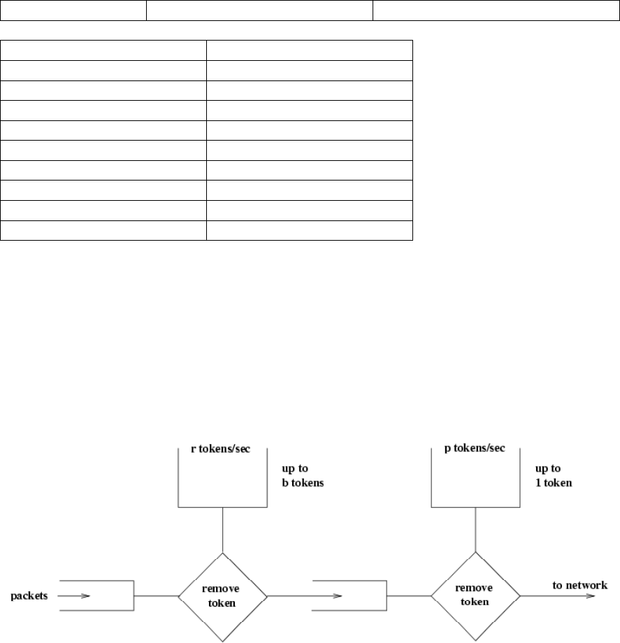
8
-
2
Time Slot
Packets in output buffer
0
1, 2
1
3, 4
2
5
3
6
4
-
5
-
6
7, 8
7
9, 10
8
-
Problem 22
No. The answer still remains the same as in Problem 21.
Problem 23
See figure below. For the second leaky bucket,
.1, bpr
Figure: Solution to problem 26
Problem 24
No.
Problem 25
Let
be a time at which flow 1 traffic starts to accumulate in the queue. We refer to
as the beginning of a flow-1 busy period. Let
t
be another time in the same flow-1
busy period. Let
),(
1tT
be the amount of flow-1 traffic transmitted in the interval
],[ t
.
Clearly,
)(),( 1
1
tR
W
W
tT
j
Let
)(
1tQ
be the amount of flow-1 traffic in the queue at time t. Clearly,
),()()( 1111 tTtrbtQ
)()( 1
11
tR
W
W
trb
j
R
W
W
rtb
j
1
11 )(
Since
R
W
W
r
j
1
1
,
11 )( btQ
. Thus the maximum amount of flow-1 traffic in the queue
is
1
b
. The minimal rate at which this traffic is served is
j
W
RW1
.
Thus, the maximum delay for a flow-1 bit is
.
/max
1
1d
WRW
b
j
Chapter 8 Review Questions
1. Confidentiality is the property that the original plaintext message can not be
determined by an attacker who intercepts the ciphertext-encryption of the original
plaintext message. Message integrity is the property that the receiver can detect
whether the message sent (whether encrypted or not) was altered in transit. The two
are thus different concepts, and one can have one without the other. An encrypted
message that is altered in transmit may still be confidential (the attacker can not
determine the original plaintext) but will not have message integrity if the error is
undetected. Similarly, a message that is altered in transit (and detected) could have
been sent in plaintext and thus would not be confidential.
2. User’s laptop and a web server; (ii) two routers; (iii) two DNS name servers.
3. One important difference between symmetric and public key systems is that in
symmetric key systems both the sender and receiver must know the same (secret) key.
In public key systems, the encryption and decryption keys are distinct. The
encryption key is known by the entire world (including the sender), but the decryption
key is known only by the receiver.
4. In this case, a known plaintext attack is performed. If, somehow, the message
encrypted by the sender was chosen by the attacker, then this would be a chosen-
plaintext attack.
5. An 8-block cipher has 28 possible input blocks. Each mapping is a permutation of the
28 input blocks; so there are 28! possible mappings; so there are 28! possible keys.
6. If each user wants to communicate with N other users, then each pair of users must
have a shared symmetric key. There are N*(N-1)/2 such pairs and thus there are
N*(N-1)/2 keys. With a public key system, each user has a public key which is
known to all, and a private key (which is secret and only known by the user). There
are thus 2N keys in the public key system.
7. a mod n = 23 , b mod n = 4. So (a*b) mod n = 23*4=92
8. 175
9. One requirement of a message digest is that given a message M, it is very difficult to
find another message M’ that has the same message digest and, as a corollary, that
given a message digest value it is difficult to find a message M’’ that has that given
message digest value. We have “message integrity” in the sense that we have
reasonable confidence that given a message M and its signed message digest that the
message was not altered since the message digest was computed and signed. This is
not true of the Internet checksum, where we saw in Figure 7.18 that it easy to find
two messages with the same Internet checksum.
10. No. This is because a hash function is a one-way function. That is, given any hash
value, the original message cannot be recovered (given h such that h=H(m), one
cannot recover m from h).
11. This is scheme is clearly flawed. Trudy, an attacker, can first sniff the communication
and obtain the shared secret s by extracting the last portion of digits from H(m)+s.
Trudy can then masquerade as the sender by creating her own message t and send (t,
H(t)+s).
12. Suppose Bob sends an encrypted document to Alice. To be verifiable, Alice must be
able to convince herself that Bob sent the encrypted document. To be non-forgeable,
Alice must be able to convince herself that only Bob could have sent the encrypted
document (e.g.,, no one else could have guessed a key and encrypted/sent the
document) To be non-reputable, Alice must be able to convince someone else that
only Bob could have sent the document. To illustrate the latter distinction, suppose
Bob and Alice share a secret key, and they are the only ones in the world who know
the key. If Alice receives a document that was encrypted with the key, and knows
that she did not encrypt the document herself, then the document is known to be
verifiable and non-forgeable (assuming a suitably strong encryption system was
used). However, Alice cannot convince someone else that Bob must have sent the
document, since in fact Alice knew the key herself and could have encrypted/sent the
document.
13. A public-key signed message digest is “better” in that one need only encrypt (using
the private key) a short message digest, rather than the entire message. Since public
key encryption with a technique like RSA is expensive, it’s desirable to have to sign
(encrypt) a smaller amount of data than a larger amount of data.
14. This is false. To create the certificate, certifier.com would include a digital signature,
which is a hash of foo.com’s information (including its public key), and signed with
certifier.com’s private key.
15. For a MAC-based scheme, Alice would have to establish a shared key with each
potential recipient. With digital signatures, she uses the same digital signature for
each recipient; the digital signature is created by signing the hash of the message with
her private key. Digital signatures are clearly a better choice here.
16. The purpose of the nonce is to defend against the replay attack.
17. Once in a lifetimes means that the entity sending the nonce will never again use that
value to check whether another entity is “live”.
18. In a man-in-the-middle attack, the attacker puts himself between Alice and Bob,
altering the data sent between them. If Bob and Alice share a secret authentication
key, then any alterations will be detected.
19. Alice provides a digital signature, from which Bob can verify that message came
from Alice. PGP uses digital signatures, not MACs, for message integrity.
20. False. SSL uses implicit sequence numbers.
21. The purpose of the random nonces in the handshake is to defend against the
connection replay attack.
22. True. The IV is always sent in the clear. In SSL, it is sent during the SSL handshake.
23. After the client will generate a pre-master secret (PMS), it will encrypt it with Alice’s
public key, and then send the encrypted PMS to Trudy. Trudy will not be able to
decrypt the PMS, since she does not have Alice’s private key. Thus Trudy will not be
able to determine the shared authentication key. She may instead guess one by
choosing a random key. During the last step of the handshake, she sends to Bob a
MAC of all the handshake messages, using the guessed authentication key. When
Bob receives the MAC, the MAC test will fail, and Bob will end the TCP connection.
24. False. Typically an IPsec SA is first established between Host A and Host B. Then all
packets in the stream use the SA.
25. False. IPsec will increment the sequence number for every packet it sends.
26. False. An IKE SA is used to establish one or more IPsec SAs.
27. 01011100
28. True
29. Filter table and connection table. The connection table keeps track of connections,
allowing for a finer degree of packet filtering.
30. True
31. True
32. If there isn’t a packet filter, than users inside the institution’s network will still be
able to make direct connections to hosts outside the institution’s network. The filter
forces the users to first connect to the application gateway.
33. True
Chapter 8 Problems
Problem 1
The encoding of “This is an easy problem” is “uasi si my cmiw lokngch”.
The decoding of “rmij'u uamu xyj” is “wasn't that fun”.
Problem 2
If Trudy knew that the words “bob” and “alice” appeared in the text, then she would
know the ciphertext for b,o,a,l,i,c,e (since “bob” is the only palindrome in the message,
and “alice” is the only 5-letter word. If Trudy knows the ciphertext for 7 of the letters,
then she only needs to try 19!, rather than 26!, plaintext-ciphertext pairs. The difference
between 19! and 26! is 26*25*24...*20, which is 3315312000, or approximately
.109
Problem 3
Every letter in the alphabet appears in the phrase “The quick fox jumps over the lazy
brown dog.” Given this phrase in a chosen plaintext attack (where the attacker has both
the plain text, and the ciphertext), the Caesar cipher would be broken - the intruder would
know the ciphertext character for every plaintext character. However, the Vigenere
cipher does not alway translate a given plaintext character to the same ciphertext
character each time, and hence a Vigenere cipher would not be immediately broken by
this chosen plaintext attack.
Problem 4
a) The output is equal to 00000101 repeated eight times.
b) The output is equal to 00000101 repeated seven times + 10000101.
c) We have (ARBRCR)R = CBA, where A, B, C are strings, and R means inverse
operation. Thus:
1. For (a), the output is 10100000 repeated eight times;
2. For (b), the output is 10100001 + 10100000 repeated seven times.
Problem 5
a) There are 8 tables. Each table has 28 entries. Each entry has 8 bits.
number of tables * size of each table * size of each entry = 8*28* 8= 214 bits
b) There are 264 entries. Each entry has 64 bits. 271 bits
Problem 6
a) 100100100 ==> 011011011
b) Trudy will know the three block plaintexts are the same.
c) c(i) = KS(m(i) XOR c(i-1))
c(1) = KS(100 XOR 111) = KS (011) = 100
c(2) = KS(100 XOR 100) = KS (000) = 110
c(1) = KS(100 XOR 110) = KS (010) = 101
Problem 7
a) We are given
3p
and
.11q
We thus have
33n
and
.11q
Choose
9e
(it
might be a good idea to give students a hint that 9 is a good value to choose, since the
resulting calculations are less likely to run into numerical stability problems than
other choices for
.e
) since 3 and
20)1(*)1( qp
have no common factors.
Choose
9d
also so that
81*de
and thus
801* de
is exactly divisible by
20. We can now perform the RSA encryption and decryption using
33n
,
9e
and
.9d
letter m m**e ciphertext = m**e mod 33
d 4 262144 25
o 15 38443359375 3
g 7 40353607 19
ciphertext c**d m = c**d mod n letter
25 38146972265625 4 d
3 19683 15 o
19 322687697779 7 g
We first consider each letter as a 5-bit number: 00100, 01111, 00111. Now we
concatenate each letter to get 001000111100111 and encrypt the resulting decimal
number m=4583. The concatenated decimal number m (= 4583) is larger than current
n (= 33). We need m < n. So we use p = 43, q = 107, n = p*q = 4601, z = (p-1)(q-1)
= 4452. e = 61, d = 73
ciphertext = m**e mod 4601
m**e= 21386577601828057804089602156530567188611499869029788733808438
804302864595620613956725840720949764845640956118784875246785033236197
777129730258961756918400292048632806197527785447791567255101894492820
972508185769802881718983
ciphertext = m**e mod 4601 = 402
c**d
= 1283813313619771634195712132539793287643533147482536209328405262793
027158861012392053287249633570967493122280221453815012934241370540204
5814598714979387232141014703227794586499817945633390592
ciphertext = m**e mod 4601 = 4583
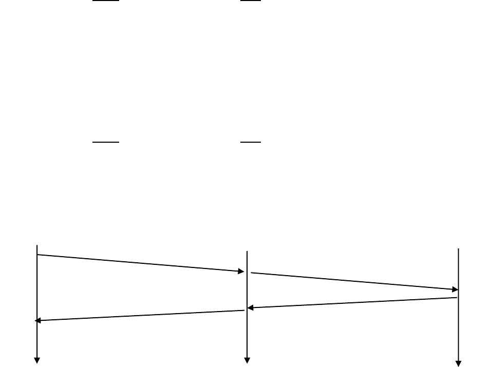
Problem 8
p = 5, q = 11
a) n = p*q = 55, z = (p-1)(q-1) = 40
b) e = 3 is less than n and has no common factors with z.
c) d = 27
d) m = 8, me = 512, Ciphertext c= me mod n = 17
Problem 9
Alice Bob
secrect key: SA SB
public key: TA = (g^SA) mod p TB = (g^SB) mod p
shared key: S = (TB^SA) mod p S' = (TA^SB ) mod p
a) S = (TB^SA ) mod p = ((g^SB mod p)^SA ) mod p = (g^(SBSA )) mod p
= ((g^SA mod p)^SB ) mod p = (TA^SB ) mod p = S'
(b and c) p = 11, g = 2
Alice Bob
secrect key: SA= 5 SB = 12
public key: TA = (g^SA) mod p = 10 TB = (g^SB) mod p = 4
shared key: S = (TB^SA) mod p = 1 S' = (TA^SB ) mod p = 1
d)
The Diffie-Hellman public key encryption algorithm is possible to be attacked by man-in-
the-middle.
1. In this attack, Trudy receives Alice's public value (TA) and sends her own public
value (TT) to Bob.
2. When Bob transmits his public value (TB), Trudy sends her public key to Alice (TT).
3. Trudy and Alice thus agree on one shared key (SAT) and Trudy and Bob agree on
another shared key (SBT).
TA
TT
)
TT
TB
Alice
Trudy
Bob
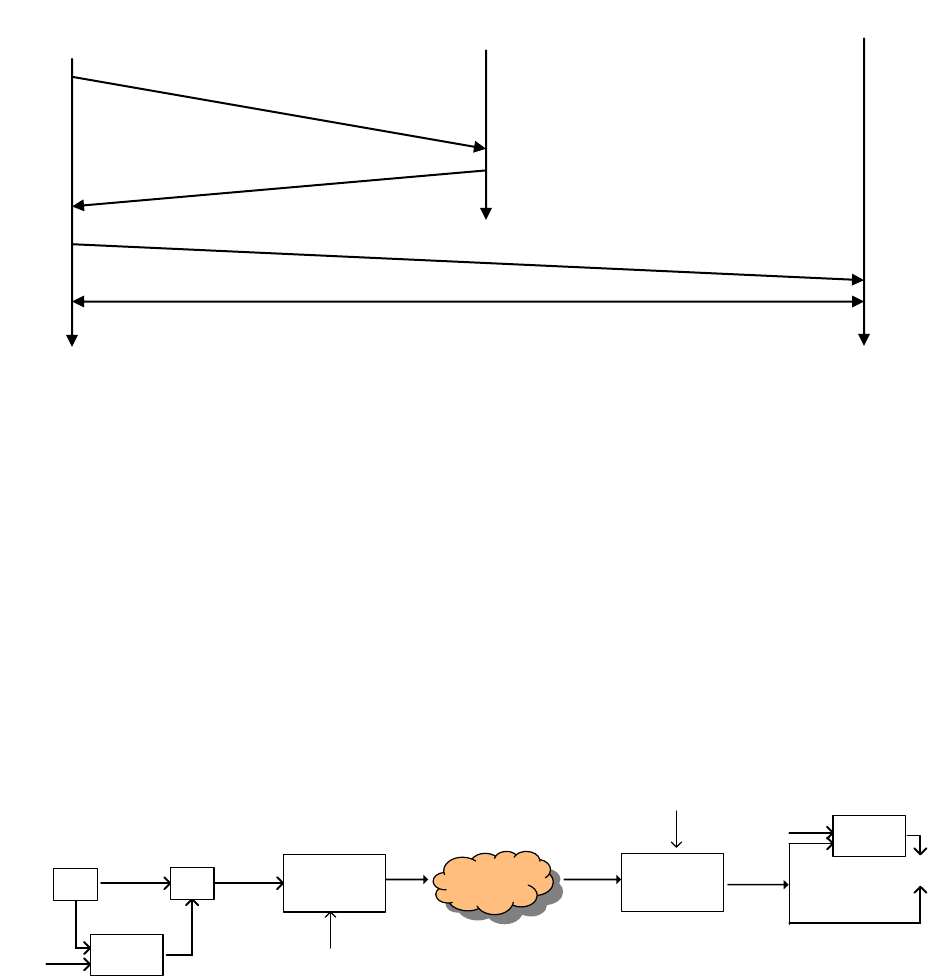
4. After this exchange, Trudy simply decrypts any messages sent out by Alice or Bob by
the public keys SAT and SBT.
Problem 10
Problem 11
The message
I O U 1
9 0 . 9
0 B O B
has the same checksum
Problem 12
Internet
Decription
algorithm
S2
(m,h) m
S1
Compare
(m,h)
H(.)
S1
m+encription
algorithm
S2
KS2 (m,h)
KS2 (m,h) H(.)
Bob and Alice now communicate using the
symmetric session key K
KB-KDC(A, K)
KA-KDC{K, KB-KDC(A, K)}
KA-KDC{A,B}
Alice
KDC
Alice
Bob
Problem 13
The file is broken into blocks of equal size. For each block, calculate the hash (for
example with MD5 or SHA-1). The hashes for all of the blocks are saved in the .torrent
file. Whenever a peer downloads a block, it calculates the hash of this block and
compares it to the hash in the .torrent file. If the two hashes are equal, the block is valid.
Otherwise, the block is bogus, and should be discarded.
Problem 14
Digital signatures require an underlying Public Key Infrastructure (PKI) with certification
authorities. For OSPF, all routers are in a same domain, so the administrator can easily
deploy the symmetric key on each router, without the need of a PKI.
Problem 15
Bob does not know if he is talking to Trudy or Alice initially. Bob and Alice share a
secret key KA-B that is unknown to Trudy. Trudy wants Bob to authenticate her (Trudy)
as Alice. Trudy is going to have Bob authenticate himself, and waits for Bob to start:
1. Bob-to-Trudy: “I am Bob” Commentary: Bob starts to authenticate himself. Bob’s
authentication of himself to the other side then stops for a few steps.
2. Trudy-to-Bob: “I am Alice” Commentary: Trudy starts to authenticate herself as
Alice
3. Bob-to-Trudy: “R” Commentary: Bob responds to step 2 by sending a nonce in
reply. Trudy does not yet know KA-B(R) so she can not yet reply.
4. Trudy-to-Bob: “R” Commentary: Trudy responds to step 1 now continuing Bob’s
authentication, picking as the nonce for Bob to encrypt, the exact same value that
Bob sent her to encrypt in Step 3.
5. Bob-to-Trudy: “KA-B(R)” Bob completes his own authentication of himself to the
other side by encrypting the nonce he was sent in step 4. Trudy now has KA-B(R).
(Note: she does not have, nor need, KA-B
6. Trudy-to-Bob: “KA-B(R)” Trudy completes her authentication, responding to the R
that Bob sent in step 3 above with KA-B(R). Since Trudy has returned the properly
encrypted nonce that Bob send in step 3, Bob thinks Trudy is Alice!
Problem 16
This wouldn't really solve the problem. Just as Bob thinks (incorrectly) that he is
authenticating Alice in the first half of Figure 7.14, so too can Trudy fool Alice into
thinking (incorrectly) that she is authenticating Bob. The root of the problem that neither
Bob nor Alice can tell is the public key they are getting is indeed the public key of Alice
of Bob.
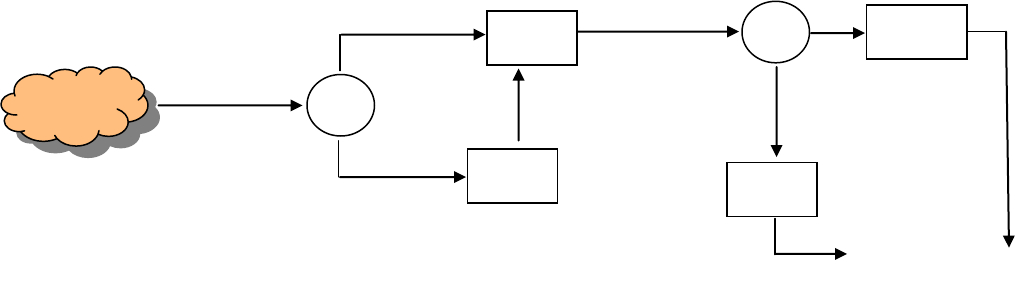
Problem 17
Figure: Operations performed by Bob for confidentiality, integrity, and
authentication
Problem 18
a) No, without a public-private key pair or a pre-shared secret, Bob cannot verify that
Alice created the message.
b) Yes, Alice simply encrypts the message with Bob’s public key and sends the
encrypted message to Bob.
Problem 19
a) Client
b) IP: 216.75.194.220, port: 443
c) 283
d) 3 SSL records
e) Yes, it contains an encrypted master secret
f) First byte: bc; Last byte: 29
g) 6
Problem 20
Again we suppose that SSL does not provide sequence numbers. Suppose that Trudy, a
woman-in-the-middle, deletes a TCP segment. So that Bob doesn’t anything, Trudy needs
to also adjust the sequence numbers in the subsequent packets sent from Alice to Bob,
and the acknowledgment numbers sent from Bob to Alice. The result will be that Bob
will, unknowingly, be missing a packet’s worth of bytes in the byte stream.
Problem 21
No, the bogus packet will fail the integrity check (which uses a shared MAC key).
m
KB+( KS)
KS(m,KA-(H(m))
KB+( KS), KS(m,KA-(H(m)))
-
-
KB-( )
KS
KS( )
-
-
KA+( )
H( )
compare
Internet
Problem 22
a) F
b) T
c) T
d) F
Problem 23
If Trudy does not bother to change the sequence number, R2 will detect the duplicate
when checking the sequence number in the ESP header. If Trudy increments the sequence
number, the packet will fail the integrity check at R2.
Problem 24
a) Since IV = 11, the key stream is 111110100000 ……….
Given, m = 10100000
Hence, ICV = 1010 XOR 0000 = 1010
The three fields will be:
IV: 11
Encrypted message: 10100000 XOR 11111010 = 01011010
Encrypted ICV: 1010 XOR 0000 = 1010
b) The receiver extracts the IV (11) and generates the key stream 111110100000
……….
XORs the encrypted message with the key stream to recover the original message:
01011010 XOR 11111010 = 10100000
XORs the encrypted ICV with the keystream to recover the original ICV:
1010 XOR 0000 = 1010
The receiver then XORs the first 4 bits of recovered message with its last 4 bits:
1010 XOR 0000 = 1010 (which equals the recovered ICV)
c) Since the ICV is calculated as the XOR of first 4 bits of message with last 4 bits of
message, either the 1st bit or the 5th bit of the message has to be flipped for the
received packet to pass the ICV check.
d) For part (a), the encrypted message was 01011010
Flipping the 1st bit gives, 11011010
Trudy XORs this message with the keystream:
11011010 XOR 11111010 = 00100000
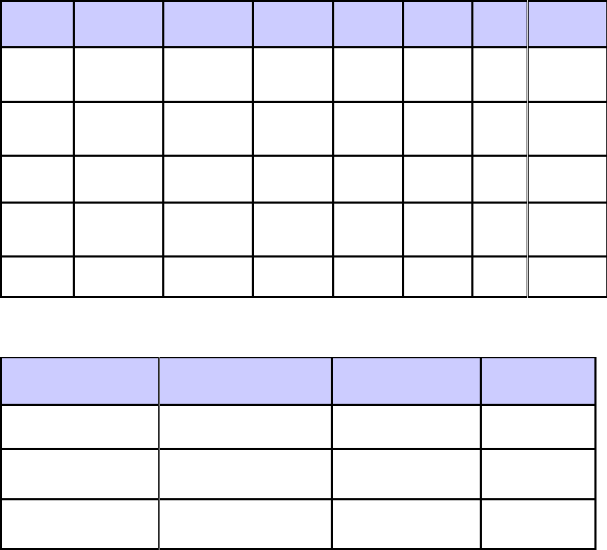
If Trudy flipped the first bit of the encrypted ICV, the ICV value received by the
receiver is 0010
The receiver XORs this value with the keystream to get the ICV:
0010 XOR 0000 = 0010
The receiver now calculates the ICV from the recovered message:
0010 XOR 0000 = 0010 (which equals the recovered ICV and so the received packet
passes the ICV check)
Problem 25
Filter Table:
Action
Source
Address
Dest
address
Protocol
Source
port
Dest
port
Flag
bit
Check
connection
allow
222.22/16
outside of
222.22/16
TCP
> 1023
23
any
allow
outside of
222.22/16
222.22/16
TCP
23
> 1023
ACK
x
Allow
outside of
222.22/16
222.22.0.12
TCP
>1023
80
Any
Allow
222.22.0.12
outside of
222.22/16
TCP
80
>1023
Any
deny
All
all
all
all
all
All
Connection Table:
Source
address
Dest
address
Source
port
Dest
port
222.22.1.7
37.96.87.123
12699
23
222.22.93.2
199.1.205.23
37654
23
222.22.65.143
203.77.240.43
48712
23
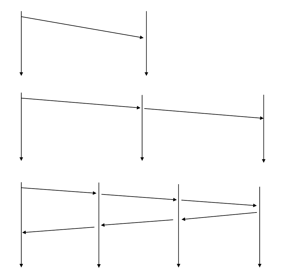
Problem 26
a)
b)
c)
K1+(S1)
Alice
Proxy1
S1( K2+(S2))
Alice
Proxy1
Proxy2
K2+(S2)
S1(S2(req))
Alice
Proxy1
S1(S2(page))
)
Proxy2
S2(req)
page
req
Activist.com
S2(page)
Chapter 9 Review Questions
1. A network manager would like to have network management capabilities when (a) a
component of the network fails, (b) a component of the network is about to fail, and is
acting “flaky” (c) a component of the network has been compromised from a security
standpoint and is attacking the network, e.g., by launching a DOS attack by flooding
the network with packets, (d) traffic levels exceed a certain threshold on a link,
causing packets to be dropped, (e) everything is running smoothly (in order to know
that everything is running smoothly and there are no problems). There are many
additional reasons as well.
2. Performance management, fault management, configuration management, accounting
management, security management.
3. Network management is more narrowly defined, as it focuses on the resources in the
network – monitoring their functions and controlling their operation. These resources
are combined (used) in various ways to implement services. Note that while the
network resources may all be functioning as they should, they may not be sufficient
to implement a service with a given level of performance; this latter concern is an
aspect of service management.
4.
Managing entity: control the collection, processing, analysis, display of network
management information, and is used by the network manager to control the
devices in the network.
Managed device: a piece of network equipment that is under the control of the
managing entity.
Management agent: a software process running on a managed device that
communicated with the managing entity and takes action on the managed device
under the control of the managing entity.
MIB: pieces of information associated with all of the managed objects in a
device.
Network management protocol: runs between the managing entity of the
management agents on the managed devices, allowing the agents to alert the
managing entity to potential problems, and allowing the managing entity to send
commands to the management agents.
5. The SMI is a data-definition language used to defined the pieces of information in an
SNMP MIB.
6. The trap message is sent by the management agent to the managing entity (and
requires no response from the managing entity). A request-response message is sent
by the managing entity, with the response coming back from the management agent.
7. GetRequest, GetNextRequest, GetBulkRequest, SetRequest, InformRequest,
Response, Trap
8. The SNMP engine is the part of an SNMP implementation that handles the
dispatching, processing, authentication, access control, and timeliness of he SNMP
messages. See Figure 8.5.
9. The ASN.1 object identifier tree provides a standard way to name objects.
10. The role of the presentation layer is to allow the sending and receiving of data in a
machine-independent format (i.e., without regard to the particular storage and
architectural conventions of the sender and receiver).
11. The Internet does not have presentation layer. It is up to the implementers of
protocols to make sure that data is sent and received in the desired format.
12. In TLV encoding, each piece of data is tagged with its type, length, and value.
Chapter 9 Problems
Problem 1
Request response mode will generally have more overhead (measured in terms of the
number of messages exchanged) for several reasons. First, each piece of information
received by the manager requires two messages: the poll and the response. Trapping
generates only a single message to the sender. If the manager really only wants to be
notified when a condition occurs, polling has more overhead, since many of the polling
messages may indicate that the waited-for condition has not yet occurred. Trapping
generates a message only when the condition occurs.
Trapping will also immediately notify the manager when an event occurs. With polling,
the manager needs will need to wait for half a polling cycle (on average) between when
the event occurs and the manager discovers (via its poll message) that the event has
occurred.
If a trap message is lost, the managed device will not send another copy. If a poll
message, or its response, is lost the manager would know there has been a lost message
(since the reply never arrives). Hence the manager could repoll, if needed.
Problem 2
Often, the time when network management is most needed is in times of stress, when the
network may be severely congested and packets are being lost. With SNMP running over
TCP, TCP's congestion control would cause SNMP to back-off and stop sending
messages at precisely the time when the network manager needs to send SNMP
messages.
Problem 3
1.3.6.1.2.1.5
Problem 4
Microsoft file formats are under 1.2.840.113556.4 (see section 8.3.2)
Problem 6
If value precedes the length, then there is a chance of misinterpreting length to be part of
the value.
Problem 7
47Michael21 ‘10100101’
Problem 8
47Sridhar 21 ‘10010001’
