Microsoft 030725 CITA PC Maintenance Dimension 8100 Computer Organization Day3
User Manual: Dimension 8100
Open the PDF directly: View PDF ![]() .
.
Page Count: 38

03 07 2 5 CIT A PC M ainte na nc e.ppt 1
The Hong Kong Polytechnic University
Industrial Centre
Computer Organisation
PC Maintenance &
Troubleshooting
Edw ard Cheung
email: icec@polyu.edu.hk
25 July, 2003.
Knowledge Update Course for
Secondary Computer Teachers
03 07 2 5 CIT A PC M ainte na nc e.ppt 2
Basic Computer Maintenance and Troubleshooting Techniques
• Assemble your own computer system
• Installing O/S
• Tweaking BIOS settings
• Advanced chipset features
• Installing hardware
• Awareness of compatibility
Hardware vs hardware
Software vs hardware
Software vs software
• Dual-booting
03 07 2 5 CIT A PC M ainte na nc e.ppt 3
Basic Computer Maintenance
•Power Check
• Disk defragmentation
• System backup
• System fine-tuning
Temporar y files handling
Memory ma nage ment
• Over-clocking
Processor rating
Over-clocking vs over-heating
Fans and cooling systems
03 07 2 5 CIT A PC M ainte na nc e.ppt 4
Basic Troubleshooting Techniques
• Power Supply
• Reboot
• Flash the BIOS
•System recovery
• Virus check
• Release system resources
• System performance enhancement and optimization

03 07 2 5 CIT A PC M ainte na nc e.ppt 5
Modern PC
• Modern PC is a modular design and composed of many
replaceable components. They are sometimes known as
field replaceable units (FRU).
• There are a number of form factors for motherboard and
chassis which limits the expansion capability and the
selection of chipset.
• Chassis selection depends on applications, the number and
type of drive bays, po wer supply and Motherboard
selection.
• Common form factors for motherboards are ATX, LPX,
NLX, WTX & mini-ITX
• The smallest desktop unit is the mini-ITX supported by
VIA only.
http://www.formfactors.org/
http://www.mini-ITX.com
03 07 2 5 CIT A PC M ainte na nc e.ppt 6
•Enclosures
• Power Supply
• Motherboard – mainboard & extension board
• Processor – CPU chip
• DRAM – DRAM modules
• Video System – video graphics adapter
• Sound System – sound card
• Storage Devices – hard disk / floppy disk / CD/DVD
devices
• Communication Adapter – network adapter
• Input Devices – keyboard / mouse / pen input
Components/FRUs of a PC
03 07 2 5 CIT A PC M ainte na nc e.ppt 7
Example – Assemble your own computer system
•Chassis
Material
• Aluminium Alloy vs. Mild
Steel
Secuity
Robustness
Finishing
• Number of drive bays
HDD/FDD
CD Drives
More for SCSI/RAID
• Location of connectors
USB
Firewire
• Ventilation
Nu mber of fans in chassis
• Cable dressing and access ibility
03 07 2 5 CIT A PC M ainte na nc e.ppt 8
Power Supply
• Power supply convert AC power and supply DC power to the
computer system.
• For ordinary PC, power supply should comply with the ATX
requirement on size and pin-out. (not on power rating)
• Watch for proprietary power supply connectors on brand name
products. Read the rating label before connecting power.
E.g. Dell Dimension 8100 P4 2GHz Power supply is not a standard
ATX power supply (use 24-pin connector instead of 20-pin)
Detail connector pin assignment is available at:
• h ttp ://supp ort .ap .dell.c om/ docs /syst ems /ds lees t/techo vu.h tm#dc_pow
er_connector_pin _assignments
Dell Dimension XPS B Series P3 series use 20-pin connector but
with different pin-out.
• h ttp ://supp ort .ap .dell.c om/ docs /syst ems /d ma g/techovu.ht m# dc_ power
_connector_pin_assignments
• New models of Dell have reverted to use the ATX specification.
03 07 2 5 CIT A PC M ainte na nc e.ppt 9
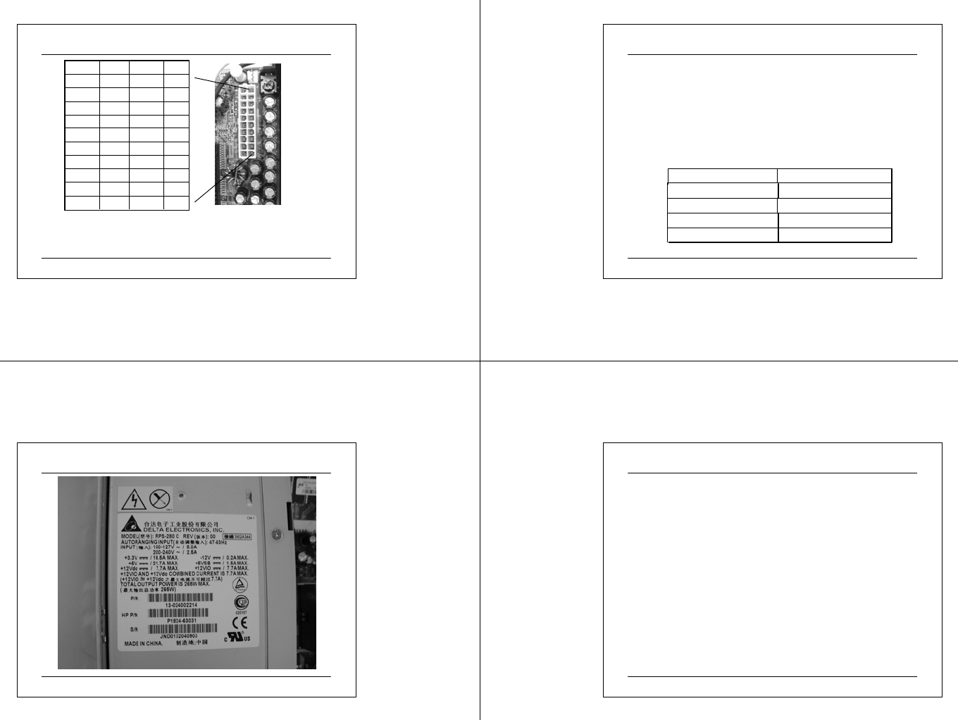
Pin-out of an ATX Power Supply
Pin #Desc.Pin #Desc.
13V3113V3
1012V205V
95VSB195V
8POK18-5V
7COM17COM
65V16COM
5COM15COM
45V14PS-ON
3COM13COM
23V312-12V
This 20-pin ATX pow er connector is used by virtually all current systems w ith ATX,
Micro-ATX and NL X mot herboards
There are tw o additional connectors; 6-pin 5Vn & 3V3 auxiliary pow er connector
(Molex) for >250W pow er supply and 4-pin ATX12V connector for P4 board.
03 07 2 5 CIT A PC M ainte na nc e.ppt 10
Power Requirement for a PC
Selection Criteria
• type of chassis and motherboard
• safety approval markings means that the power supply model has been
follo wing a fabricatio n control procedure and have complied with
national/international standards on electrical and fire safety.
• Usually the manu facturer will ob tain approval from test autho rities such as
Underwriter Laboratory(UL) for USA, Canadian Standard Association (CSA
or C-UL) and European approval such as VDE or TUV from Germany. There
are fail safe mechanisms if the power supply model comply with national /
intern ational s tandards .
400W - 600WServer Chassis
Typical Power Supply Requirements for PC
>300WTower Cases
*Some server power supply may reach 800W
200W – 250WDesktop Cases
130W - 175WBaby Case
Power SupplyCommon Enclosures
03 07 2 5 CIT A PC M ainte na nc e.ppt 11
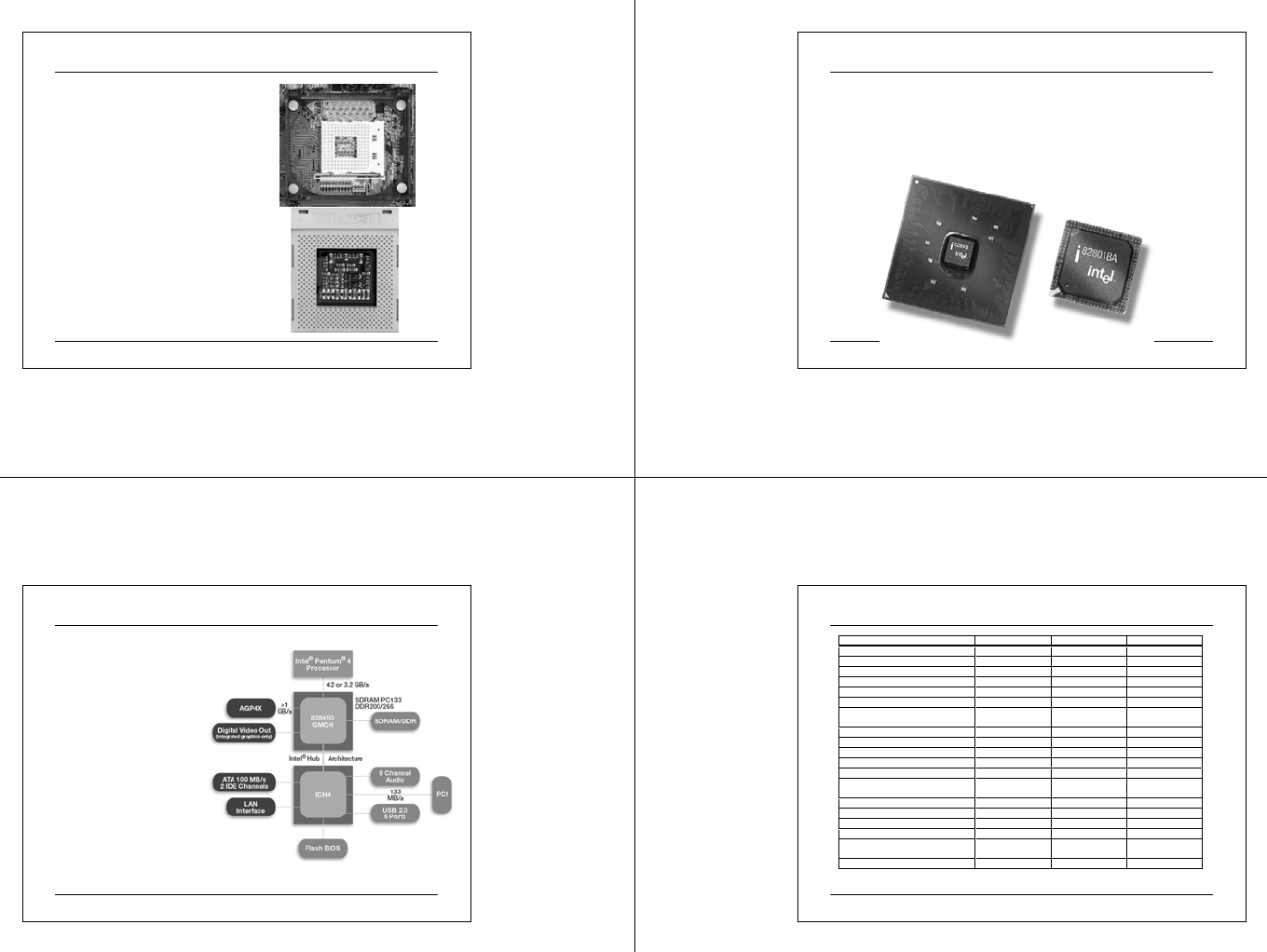
A Typical Power Supply Rating Label
03 07 2 5 CIT A PC M ainte na nc e.ppt 12
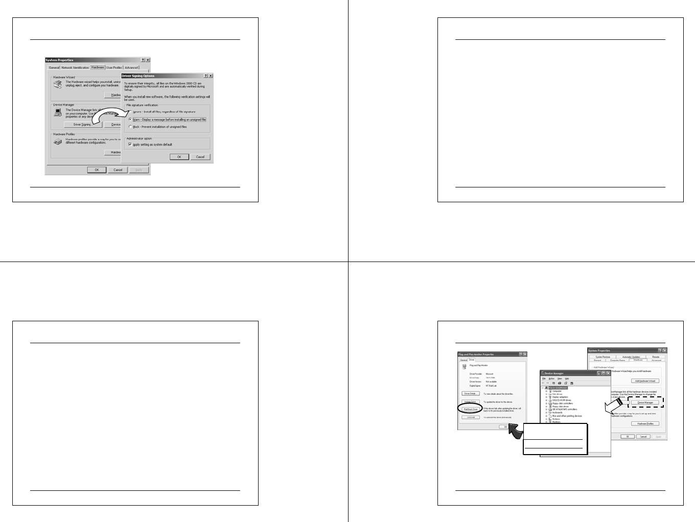
Major Selection Considerations for Motherboard
•Processor
speed and package
• Form factor
Number and type of bus slots
• PCI – 32 vs 64 bit; ISA is fading out
• AGP - match the display controller
• DRAM system
Type and Number of DRAM Slots;DDR, parity
DRAM capacity; can the motherboard support 4GB?
• On board features
Network – Ethernet 10/100/1000
Sound chips
Location and type of Interfaces
• SCSI, serial, USB 2.0, Firewire, etc.
03 07 2 5 CIT A PC M ainte na nc e.ppt 13
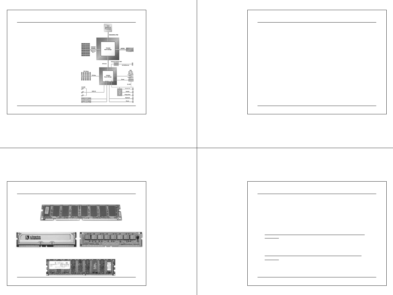
Processor
• Intel Celeron or Pentium 4 or AMD
Duron or Athlon
• Intel has announced Pentium 4
processo r at 3.06GH z on 14/11.
Current model is arou nd 1.8 to 2.4
GHz on 2 speed system bus:-
533 MHz system bus :
• 2.26GHz to 3.06GHz
400 MHz system bus :
• 1.70GHz to 2.60GHz
• The Intel® Pentium® 4 processor
is available in package types OOI
423-pin(400MHz bus, PGA-423
form factor) or FC-PGA2 478-
pin(400/533MHz bus, mPGA -478
form factor).
03 07 2 5 CIT A PC M ainte na nc e.ppt 14
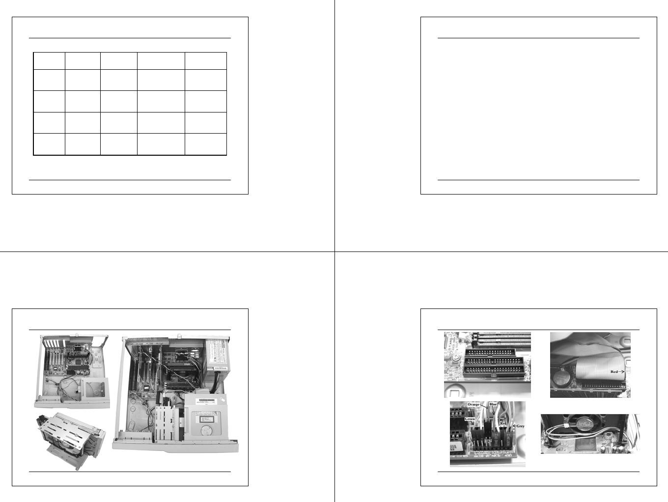
Chipset
• Selection of chipset depends largely on the processor
• Normally is 2 chips per set known as the north bridge and the south bridge
• The 82845G Memory Control Hub (MCH) is packaged in a 593 Flip Chip Ball
Grid Array (FCBGA)
• Some chipset provide on-board graphic adapter. For example, the MCH needs
to balance memory usage between graphics and application for optimal system
performance and video takes up system memory.
03 07 2 5 CIT A PC M ainte na nc e.ppt 15
Intel 845G Chipset Architecture
• Each chipset contains two
main components:
Graphics and Memory
Controller Hub (GMCH)
for the host bridge and
I/O Controller Hub(ICH)
for the I/O subsystem.
The GMCH provides the
processor interface,
system memory interface,
hub interface, and
additional interfaces.
Each GMCH contains an
integrated graphics
controller (IGD). Both the
845G chipset and 845GL
chipset use the 82801DB.
03 07 2 5 CIT A PC M ainte na nc e.ppt 16
Intel 845 Chipset Features
Chipset 845 845E 845G
North Bridge 82845 MCH 82845 MCH 82845 MCH
South Bridge 82801BA ICH2 82801BA ICH2 82801BA ICH2
400 MHz system bus X X X
533 MHz system bus X X
Intel Hub Architecture X X X
Intel Ext reme Graphics Technology X
Inte l Dy namic Vi d eo O utput
Inte rfac e
X
DDR200 or DDR266 SDRAM X X X
PC133 SDRAM X X
AGP interface 4X 4X 4X
LAN connect inte rface X X X
Alert on LAN 1.0 1.0 1.0
USB ports US B 1 .1
( 4 ports )
Hi-Speed USB 2.0
( 6 ports )
Hi-Speed USB 2. 0
( 6 ports )
IDE interface Ultra ATA / 100 Ultra ATA / 100 Ultra ATA / 100
Inte l App li cation Acc eler ator X X X
AC97 Controller X X X
Dual DMA Au dio E ngi nes X
Communications Network Riser
Ca rd
X X X
Low-power sleep mode X X X
03 07 2 5 CIT A PC M ainte na nc e.ppt 17
VIA P4X333 Chipset System Block Diagram
Features:-
• Fo r Int el Pentium 4 processor
400/533MHz FSB
•AGP 2X/4X/8X
• Support up to 3.0GB DR200/266/333
SD RA M
• 8X V-Link 533MB/s high bandwidth
Nort h /So ut h Bridge in t erconnect
• Suppo rt for Advanced
Communicat ions Riser (ACR) Card
St a n dar d
• Int egrat ed 6 channel Surround Sound
AC-97 Audio
• Int egrat ed MC-97 Modem
• Int egrat ed 10 /100 Eth ernet MAC
• Support for ATA 33/66/100/133
• Support for USB 2.0, 6 USB ports,
UHCI compliant
• Advanced power management
capabilities including ACPI/OnNow
03 07 2 5 CIT A PC M ainte na nc e.ppt 18
Memory
•Type
72-pin SIMM - Single in line memory module – obsolete
168-pin DIMM w ith SDRAM Synchronous Dyna mic RA M
chips – fading out
RDRAM RIMM – Rambus Inline Memory Module – fading
out
• Work in pair
• Need terminator in empty slot
184-pin DDR Double Data Rate SDRAM
• This is the main stream
• Capacity
Mother board typica lly has 4 memory s lots (Ta iwan
motherboard) and proprietary system has 2 to 4 memor y
slots.
03 07 2 5 CIT A PC M ainte na nc e.ppt 19
Memory Mod ules
Rambus Memory ( RDRAM ) 184 pin RIMM Module
Double Data Rate RAM ( DDR RAM) 184 pin DIMM Module
Synchronous RAM ( SDRAM ) 168 pin DIMM Module
03 07 2 5 CIT A PC M ainte na nc e.ppt 20
Memory Bandwidth
•Rambus ( RDRAM ) :
Peak Bandwidth = ( Memory Bus Width ) x ( Data Rate ) x
Number of Channels
where
Data Rate = ( Memory Bus Speed x Operations/Clock Cycle )
Each standard RIMM module is 16 bits wide, or 2 Bytes in width
(1 byte = 8 bits ).
•Pe ak bandwi dth for PC800 RIMM Modules ( single me mory
channel)
(2 Bytes) x (800 MHz Data Rate) x 1 channel = 1,600 MB/s or 1.6
GB/s.
•Pe ak bandwi dth for PC800 RIMM Modules ( dual memory
channel)
(2 Bytes) x (800 MHz Data Rate) x 2 channels = 3,200 MB/s or
3.2 GB/s.

03 07 2 5 CIT A PC M ainte na nc e.ppt 21
Memory Bandwidth (cont.)
•Double Data Rate RAM ( DDR RAM ) :
Peak Bandwidth = ( Memory Bus Width ) x ( Data Rate )
where
Data Rate = ( Memory Bus Speed x Operations/Clock Cycle )
Each DIMM module is 64 bits wide, or 8 Bytes in width.
•Peak bandwidth for PC1600 DIMMs Modules
(8 Bytes) x (200 MHz Data Rate) = 1,600 MB/s or 1.6 GB/s
•Peak bandwidth for PC1600 DIMMs Modules
(8 Bytes) x (266 MHz Data Rate) = 2,128 MB/s or 2.1 GB/s
•Peak bandwidth for PC2700 DIMMs Modules
(8 Bytes) x (333 MHz Data Rate) = 2,664 MB/s or 2.7 GB/s
03 07 2 5 CIT A PC M ainte na nc e.ppt 22
Summary of Memory Bandwidth
PC100
SDRAM
PC133
SDRAM
Sin gle -
Channel
PC 80 0
RIMM
Dual-
Channel
PC800
RIMM
PC1600
DDR
PC2100
DDR
PC2700
DDR
800 MB/s 1.1 GB/s 1.6 GB/s 3.2 GB/s 1.6 GB/s 2.1 GB/s 2.7 GB/s
168 pins
DIMM
168 pins
DIMM
184 pins
RIMM
184 pins
RIMM
184 pins
DIMM
184 pins
DIMM
184 pins
DIMM
3.3 V 3.3 V 2.5 V 2.5 V 2.5 V 2.5 V 2.5 V
03 07 2 5 CIT A PC M ainte na nc e.ppt 23
Accelerated Graphics Port
• A high performance interconnect between chipset and the graphics
controller for enhanced graphic performance on 3D applications
• Enable high speed direct access by graphics controller to system
memory where texture maps are stored instead of preloading the
texture data into the video memory of the graphics card.
• Relief the bandwidth constraint and congestion of the PCI bus
(132MB/s)
• AGP Specification 2.0 defines 1x and 2x speed at 3.3V signaling level
and 1x, 2x and 4x speeds at 1.5V signaling level.
• AGP Specification 3.0 defines 4x and 8x at 0.8V signaling level.
• Over 2.1GB/s of peak bandwidth in the new AGP3.0 Specification
(product example RADEON 9700 PRO 09/2002)
03 07 2 5 CIT A PC M ainte na nc e.ppt 24
Comparison of Video Interface
VGA Type PCI AGP 1X AGP 2X AGP 4X AGP 8X
Operating
Voltage 5.0 V 3.3 V 3.3 V 1.5V 0.8V
Bus
Frequency 33 MHz 66 MHz
( X1 )
66 MH z
( X2 )
66MH z
( X4 )
66MHz
( X8 )
Bus 32 bits 32 bits 32 bits 32 bits 32 bits
Transfer
Rate 266 MB / s 266 MB / s 533 MB / s 1066 MB / s 2133 MB /s
Transfer
per clock
cycle
4 Bytes 4 Bytes 8 Bytes 16 Bytes 32 Bytes
03 07 2 5 CIT A PC M ainte na nc e.ppt 25
Video Card Memory Requirements
16MB-32MB8MB-16MB4MB4MB1280x1024
16MB8MB4MB2MB1024x768
8MB4MB2MB1MB800x600
4MB-8MB2MB-4MB1MB1MB640x480
32-bit Colour
(3D)
16-bit Colour
(3D)
24-bit Colour
(2D)
16-bit
Colour (2D)
Reso lution
03 07 2 5 CIT A PC M ainte na nc e.ppt 26
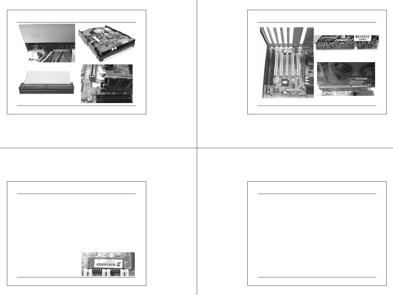
Hardware Installation
• Need a convenient and large table to work on.
• Most computer modules are fabricated in a good quality
environment and hence the connector should fit each other
pretty well. Do not apply brute force to connect/disconnect
FRUs.
• The CPU has many pins and they should fit effortlessly on
ZIF (Zero Insertion Force) socket if the alignment of the
package is good.
• Avoid static electricity discharge by grounding yourself
before touching any component.
• After assembly, the final unit may be heavy.
03 07 2 5 CIT A PC M ainte na nc e.ppt 27
Assemble Your Own System
03 07 2 5 CIT A PC M ainte na nc e.ppt 28
Notes on Assemble Your Own System
03 07 2 5 CIT A PC M ainte na nc e.ppt 29
Notes on Assemble Your Own System ( cont.)
03 07 2 5 CIT A PC M ainte na nc e.ppt 30
AGP 2x Graphics Controller Installation
03 07 2 5 CIT A PC M ainte na nc e.ppt 31
What is a BIOS?
• BIOS stands for Basic Input and Output System. It is sometimes
known as the ROM BIOS or referring as a firmware because it was
originally stored in a Read-Only Memory (ROM) chip on the
motherboard.
• It is the interface layer between the physical hardware layer of the PC
and the OS.
• Modern motherboard uses EEPROM or Flash memory device to store
the code. The BIOS is the first program to run when you turn on your
computer.
• BIOS of a system is specifically designed for a particular hardware. A
BIOS for one system will not operate properly on another unless the
systems are identical in design. The BIOS is like a signature of a
system.
03 07 2 5 CIT A PC M ainte na nc e.ppt 32
“CMOS”
• In addition to the Flash/ROM BIOS, a Real Time Clock (RTC)
chip exist on every PC motherboard. It is designed with CMOS
technology and need a small battery to hold the data after the
computer has been switched off. A Lithium button cell is used to
run the clock and the data is stored in NVRAM. Example Maxim
DS12887A.
• The BIOS uses “CMOS” to store the settings of a PC. Each time
the computer is switched on, BIOS uses the settings in the CMOS
to configure the computer.
• For legacy design, if the battery charge runs too low, the CMOS
c ontents will be lost and POST w ill iss ue a "CMOS inva lid" or
"CMOS checksum invalid" message. User has to replace the
battery. For modern design, the RTC should run for 10 years as
specified by the manufacturer.

03 07 2 5 CIT A PC M ainte na nc e.ppt 33
Function of BIOS
• to initialize system hardware and chipset registers
• to enable basic I/O; keyboard, ports, buses, etc.
• to test the motherboard hardware and other peripherals in a
computer ( Power On Self Test - POST ) .
• bootstrap an operating system
• For legacy system, BIOS help operating systems and
application programs manage PC hardware through a set of
routines called BIOS Run-Time Services or BIOS I/O functions
or BIOS calls. Hence, BIOS isolates the details of a particular
hardware implementation from the operating system or
application software.
03 07 2 5 CIT A PC M ainte na nc e.ppt 34
Who supply the BIOS?
• For PC, there are 3 popular BIOS, Award, Phoenix and American
Megatrends Inc. (AMI). Phoenix purchased Award in late 1998 but
continue to sold Award BIOS products.
http://www.phoenix.com
http://www.ami.com
• There are many BIOS revisions in the service life of a computer.
For example, bug fix and as new peripherals or services become
available. Under normal situation, user don’t need to upgrade BIOS
for every revision unless a new service or I/O is needed.
• Since most BIOSs are contained in Flash, user can program or
upgrade the BIOS using their own PC. In general, the followings
are needed:-
A BIOS programming utility
image of new BIOS
A stable power supply
03 07 2 5 CIT A PC M ainte na nc e.ppt 35
Example - A Good Reason to Upgrade Your BIOS
• Early PCs, those built through 1992-1994, could only
recognize disks with up to 528MB (million bytes) of
storage. As larger disks became available, special
translation programs were needed to utilize the space
beyond the supported maximum. In the early 1990s, as a
result of a general agreement between PC suppliers and
disk companies, the size limit for ATAPI device support
was expanded to 8.4GB. The latest BIOS supports drives
up to 137GB for a 16 head system.
• Recently, disk drive limits were again expanded to
180GB (IBM Deskstar 180GXP series).
• This is a good reason to upgrade your BIOS.
03 07 2 5 CIT A PC M ainte na nc e.ppt 36
BIOS Upgrade Procedure
1. Make a bootable floppy disk or CD.
2. Copy the BIOS programming utility (e.g. flash.exe) and a new BIOS
file (e.g. P4XBSOLI.BIN) onto this diskette.
3. Usually, BIOS updates and flash utility can be downloaded from the
motherboard manufacturer.
4. Read “readme” file and follow instructions.
5. The process is quite straight forward, after rebooting the computer, a
new BIOS will be stored in the Flash memory. Normally, the user
need to load the “optimized default settings” from the new BIOS.
6. In some systems, a jumper is available on the motherboard to protect
accidental overwrite of the EEPROM. The user may need to open the
chassis to enable / disable programming on the motherboard.
7. During the final flash process, power can’t be disconnected and the
process can’t be interrupted. Otherwise the motherboard will not be
able to boot up. Some motherboards has a backup BIOS – dual BIOS;
e.g. Iwill P4ES, Gigabyte GA-8TX, etc. Asus has implemented a
Crash-free BIOS utility to enable restoring new BIOS with a floppy
in her new motherboard P4PE/P4S8X.

03 07 2 5 CIT A PC M ainte na nc e.ppt 37
Typical Menu of a BIOS Set Up Utility
• Standard CMOS Features
• Advanced Chipset Features
• Advanced BIOS Features
• Integrated Peripherals Set
• Power Management Setup
• PnP / PCI Configurations
•PC Health status
• Frequency / Voltage Control
• Load Fail-Safe Settings
• Load Optimized Settings
• Set Supervisor Password
• Set User Password
• Save and Exit Setup
• Exit Without Saving
•Others…
03 07 2 5 CIT A PC M ainte na nc e.ppt 38
Features of a BIOS
• a primitive menu based application – small kernel
• manoeuvre BIOS setting using a few keys; function keys, arrow keys,
page up key, page down key and the escape key
• Standard CMOS Setup Page allow the user to input vital information
of the system. For example, drives, date/time, video and error
handling. It also report the amount of DRAM installed in the system.
• One of the important setting in the Standard CMOS setup page is the
“Halt On” setting. That is, if the system encounters a specified error
during boot-up, it will come to a stop.
• If the system is running out of specs during POST; for example,
overclocking, a “Speed Error” condition would occur and prevent the
system from successfully booting if this is set at “Halt On All Error”.
• The drawback of specifying a “Halt On No Error” setting is that data
corruption can occur as a consequence of incorrect bus speed etc.
03 07 2 5 CIT A PC M ainte na nc e.ppt 39
POST
• POST is an acronym for Power On Self Test. POST is the traditional
name for the routines that the BIOS uses to test and initialize the
devices on the system when the PC is powered on. Its meaning has
changed now to include anything the BIOS does before an operating
system is started.
• Each POST routine is assigned a POST code, a unique number which
is sent to I/O port 080h before the routine is executed. If the computer
hangs during POST, the problem can be located by looking at the last
value written to I/O port 080h. The BIOS will display the POST code
on screen or a POST card can be used to troubleshoot BIOS problem.
• In addition to displaying the POST error code, the BIOS routine will
also write to the speaker for some of the major error and known as the
beep code.
• For example: different beep sequences on the absence of display
adapter, keyboard and memory.
03 07 2 5 CIT A PC M ainte na nc e.ppt 40
Advanced BIOS Features
• Virus Warning (Enabled)
When enabled, the BIOS performs a Pre-Operating System
Check for viruses that could possibly modif y the bootsector
of the HDD. If any modificat ion or sc heduled modificat ion
is encountered, the boot process will come to a halt and the
DOS pr ompt w ill generate the message
•Boot sector is about to be modified, do you wish to continue? Y
/ N.
This BIOS-based virus check is very helpful because it
catches boot sector vir uses and it s hould be ena bled under
norma l operating conditions.

03 07 2 5 CIT A PC M ainte na nc e.ppt 41
Advanced BIOS Features
• CPU Internal Cache (Enabled)
All modern CPUs have at least one level of internal cache
memory (SRAM). The function of the interna l (level 1, L1)
cache is to store data and instructions that have been read
from the main memory and are written back to the cache for
faster access in case they are requested again. Further, read
ahead and stor ing of pre-fetche d data for write allocation
based on the localit y of coherent data is a ls o perf ormed by
the L1 cache
In all cases, this setting should be enabled.
03 07 2 5 CIT A PC M ainte na nc e.ppt 42
Advanced BIOS Features
• External Cache (Enabled)
In Pentium or K6 days (Socket7), the L1 cache was the only
internal cache. In most cases, the L1 cache is 32, 64 or 128 kByte.
As a backup, a secondary, much larger cache was added. In the
Socket7 architecture, the secondary or level 2 (L2) cache was
added to the mainboard in form of designated, fast cache chips
split into data/instruction cache and further the so-called tag RAM.
The data/instruction L2 could vary in size from 512 kB over 1 MB
up to 2 MB of on-board cache in the latest versions of the
SuperSocket7.
The Intel PentiumII was the first CPU to abandon the L2 cache
integrated in the mainboard and instead, employing two 256 kB
cache chips (total of 512 kB) mounted on the backside of the slot1
PCB which gave this particular type of L2 (AMD's Athlon
followed). It is sometimes known as the back-sided cache.
After the introduction of Celeron, Intel started to integrate the L2
cache into the CPU core and all currently made processors have
the L2 cache integrated into the CPU core.
This setting should always be enabled.
03 07 2 5 CIT A PC M ainte na nc e.ppt 43
Advanced BIOS Features
• L2 Cache ECC checking (Enabled)
With integrating the L2 cache into the die, there was some
confus ion re garding the functionality of Error Chec king and
Correction on the L2 cache level. Currently all high-end
microprocessors are using Error Checking and Correction.
The BIOS setting pertain to “CPU L2 Cache ECC” appears
to ha ve no funct ion assigned to it, as recommended by the
motherboard manufacturer. This should be enabled for best
performa nce.
On some motherboar ds, this page a llows the setting of CPU
Vcore voltage and BIO S Update switch and boot devices
03 07 2 5 CIT A PC M ainte na nc e.ppt 44
Advanced BIOS Features
• Boot-Up Floppy Seek (Disabled)
Some older floppy drives have only 40 tracks (360 / 720
kBytes) whereas the new drives have 80 tracks (1.44 / 2.88
MBytes). Enabled means that the system w ill check which
type of dr ive is insta lle d in t he syste m. T h is is mea n ing less if
the system is using new dr ives. It takes up boot t ime a nd
may decrease the life span of the floppy drive because no
diskette is inside the drive while checking. This setting
should be disabled.

03 07 2 5 CIT A PC M ainte na nc e.ppt 45
Advanced BIOS Features
• Gate A20 option (Fast)
It concern with the emulation of the legacy XT system for
addressing memor y system over 1MB. User can dec ide if the
A20 gate can be contr olled by the keyboar d controller or the
motherboard logic. For moder n motherboar d, if this setting
is present in the BIOS, it should always be set to Fast.
Normal: Gate A20 is controlled by keyboard controller
Fast: Gate A20 is controlle d by chipset core logic
03 07 2 5 CIT A PC M ainte na nc e.ppt 46
Advanced BIOS Features
• Video BIOS Shadow (Disabled)
In legacy graphics cards (1 MB video memory), copying the video
BIOS into the system memory could increase the graphics
performance of the system. The only drawback is that the video
BIOS will take up base memory addresses and, thus, possibly
interfere with other devices because of resource overlapping.
For all modern graphics cards, the setting should be disabled
because there is no performance increase and the possibility to
encounter errors because of occupying other necessary system
resources increases.
• System BIOS Shadow (Disabled)
Similar to video BIOS shadowing, after the BIOS is loaded, there
is no reason to shadow it in the main memory for modern OS has
abstracted the BIOS.
03 07 2 5 CIT A PC M ainte na nc e.ppt 47
Advanced Chipset Features
• SDRAM Configuration (By SPD)
SPD means Serial Presence Device, a EEPROM on the
memory module. Set to SPD means that the timing
inf ormation st ored in t he EEPROM on the memory module
will be use d for configuration. Unless for special reason, I
can’t think of a reason to mess with the SDRAM/DRAM
timing.
• Read Around Write (Enabled)
The memory bus can transmit data in one direction at a time.
This means that a write command will interrupt any reads
command or vice versa. The memory controller has a read
around write (RAW) buffer in w hich the write data are
collected and then written as a burst to memory. In addition,
the RAW buffer can act as an additional miniature cache in
that the CPU can read directly out of the buffer without
accessing the main SDRAM.
03 07 2 5 CIT A PC M ainte na nc e.ppt 48
Advanced Chipset Features
•Memory Hole
Severa l Legacy ISA cards require a fixed base memor y
address between 15M and 16M in the system memory. In
order to reserve this space for these cards, a so-called
memory hole has been created, preventing other devices
from occupying this space. Most of these Legacy ISA cards
have become obsolete and thus , it is recommended to disable
the memory hole.

03 07 2 5 CIT A PC M ainte na nc e.ppt 49
Advanced Chipset Features
• PCI-to-DRAM Prefetch (Enabled)
In order to avoid repetitive accesses to the system memory for
retrieving small pieces of data, an entire area of memory can be
prefetched, based on the locality of coherent data. This means that
the data are already in the buffer before they are needed and can be
accessed with very low latency.
• CPU-to-PCI write buffer (Enabled)
When this feature is enabled, up to four data words can be written
to the buffer to be queued to the PCI when it is ready to receive
data. If this feature is disabled, the CPU can only write to the PCI
bus directly and has to wait for the PCI bus to be ready to receive
data. Enabling the buffer can drastically reduce the wait stages
(idle cycles) of the CPU.
• Hence all buffer and cache on bus should be Enabled for
performance.
03 07 2 5 CIT A PC M ainte na nc e.ppt 50
Advanced Chipset Features
• Delayed Transaction / PCI 2.1 support / passive release
(only if ISA cards are present)
ISA cards are running at 25% of the PCI bus speed, that is
8.33MHz on a 16-bit wide bus. The tra nsfer of data from
ISA bus to the system bus is much more slower than that
from the PCI bus and often exceed the PCI latency. If PCI
devices try to access the bus while it is occupied by an ISA
device, the PCI device can write to an integrated 32-bit
buffer within the chipset. The data are temporarily held there
and then written to the bus by passive release.This setting is
applicable when ISA cards are present in the system. Since
most of the ISA cards are gone , this setting will obsolete.
• The main point is to use cache or buffer where possible to
shorten the response time of the system.
03 07 2 5 CIT A PC M ainte na nc e.ppt 51
Advanced Chipset Features
• PnP OS Installed (No)
One of the key limitations of the PC platform is the
restricted number of IRQs. The PCI bus on all mainboards
currently available are capable of IRQ sharing, dynamic
assignment or re negotiating.T his is achieve d by software
emulation (PCI bus IRQ steering). IRQ steering is supported
from W95O SR2.
Since the PnP and IRQ resolution is ha ndle d by the system
OS, one has to turn off the "PnP OS Ins ta lled" in the BIOS.
If the IRQ steering is dia ble d in W indows, IRQ can be
assigne d through BIO S to devices.
03 07 2 5 CIT A PC M ainte na nc e.ppt 52
Interrupts
• When receiving data and cha nge in status from I/O Por ts, two
methods can be used; “Poll” and “Interrupt” the port.
• Polling involves reading the status of the port at fixed
intervals to determine whether any data has been received or a
change of status has occurred. If a event is present, then the
system can transfer its control to a routine to service the port as
re queste d.
• Polling means that the port must wait a nd the system is busy to
poll the port instead of doing meaningful task. Time which
could be used doing other things such as calculation, displa ying
the time, etc. In order to get immediate attention on port request,
a better solution is to use Interrupts. Here, the pr ocessor is
doing nor mal task such as calc ulation or printout, displaying the
time etc. When a I/O Port/Device needs attention as a byte has
been received or status has changed, then the port sends an
Interrupt Request (IRQ) to the processor.

03 07 2 5 CIT A PC M ainte na nc e.ppt 53
Interrupts
• Once the processor receives an Interrupt Request, it
finishes its current instruction, places a few things on the
stack, and executes the appropriate Interrupt Service
Routine (ISR) which can remove the byte from the port
and place it in a buffer. Once the ISR has finished, the
processor returns to where it left off.
• Using this method, the processor doesn't have to waste
time, looking to see if the I/O Device need service. Rather,
the device will interrupt the processor when it needs
attention.
• PC has 15 Hardware IRQ's plus one Non-Maskable IRQ
only.
03 07 2 5 CIT A PC M ainte na nc e.ppt 54
X86 Interrupts and IRQ Assignment for a PC
INT (Hex) IRQ C ommo n Uses
00 - 01 Exception Hand lers -
02 Non-Maskable IRQ
Non-Maskable IRQ (Parity
Errors)
03 - 07 Exception Hand lers -
08 Hard ware IRQ0 S ystem Timer
09 Hardware IRQ1 Keyboard Controller
0A Hard ware IRQ2 S econd IRQ Co ntr olle r
0B Hard ware IRQ3 S erial Port COM2/C OM4
0C Hardware IRQ4 S erial Port COM1/COM3
0D Hard ware IRQ5 R eserved /Sound Card / LPT2
0E Hardware IRQ6 Floppy D isk Controlle r
0F Hard ware IRQ7 P arallel Port LPT1
10 - 6F Software Int errupts -
70 Hardware IRQ8 Real Time Clock
71 Hard ware IRQ9 U nused ( Redir ect ed IRQ2)
72 Hardware IRQ10 Reserved /USB Contr oller
73 Hardware IRQ11 R eserved /Windows Sound Sy stem
74 Har dware IRQ1 2 PS/2 Mouse P ort
75 Hardware IRQ13 Math Coprocessor
76 Hardware IRQ14 HD Controller (Primary)
77 Hardware IRQ15
R eserved / HD Controller
(Secondary)
78 - FF Sof tware Interr upts -
Table 1 : x86 Interrupt Vectors
03 07 2 5 CIT A PC M ainte na nc e.ppt 55
OS Installation
• OS installation is pretty straight forward but it depends on the OS
selection. In PC, the most common OS is Microsoft Windows, others
may choose Linux.
• We must decide how many systems shall be installed on the hard disk
and a hard disk partition plan and a strategy to backup the data and
system such as cater for area to store the Norton Ghost files.
• With today’s large hard disk capacity, it is a good idea to copy the OS
disk onto one of the partition to facilitate installation. A partition is a
physical division of your hard disk. Once a disk has been physically
formatted, it can be divided into separate partitions ( after which
logical formatting is done ).
• The reason for multiple partitions is that to format the disk as one large
partition doesn't provide the best possible data security, or allow the
user to organize files so that they are easy to find or make the most
efficient use of disk space. Sometimes we may want to install more
than one operating system on a disk or set a separate partition for data.
03 07 2 5 CIT A PC M ainte na nc e.ppt 56
File System
• The New Technology File System ( NTFS ) is accessible only through
the Windows NT operating system.
• NTFS is not recommended for use on disks of less than 400 MB
because it uses a significant amount of space for system structures. The
central system structure of the NTFS file system is the master file table
( MFT ). It keeps multiple copies of the critical portion of the master
file table to protect against data loss.
• NTFS uses clusters to store data files, but the size of the cluster is not
dependent on the size of the volume. A cluster size as small as 512
bytes can be specified, regardless of volume size. Using small clusters
reduces the amount of wasted disk space and the amount of file
fragmentation, a condition where files are broken up over many
noncontiguous clusters and which results in slower file access. Thus,
NTFS provides good performance on large drives.
• The NTFS file system also supports hot fixing, through which bad
sec tors are automatic ally detected and marked so that they w ill not be
used.
• Note that W95 and W98 cannot access NTFS file systems. If dual boot
W98 & W2000 is needed, NTFS volume will be invisible in W98.

03 07 2 5 CIT A PC M ainte na nc e.ppt 57
Dual-booting
• Dual boot with Microsoft OS only
FAT16
FAT32
NTFS
• Dual boot with other OS
• Third party boot manager and partitioning product
Partition Magic 8 from PowerQuest
• http://www.powerquest.com
Syste m Comma nder 7 from VCO M
• http://www.v-com.com/product/sc7_ind.html
Rebor n card
03 07 2 5 CIT A PC M ainte na nc e.ppt 58
Peripherals Installation - Device Drivers
• A device driver is a program that controls a particular type of device
that is attached to your computer. There are device drivers for printers,
displays, CD-ROM readers, diskette drives, etc. In an operating
system, many device drivers are built into the product. However, the
user may buy a new type of device that the operating system didn't
anticipate, hence, the user must to install a device driver for the
peripherals to work. A device driver is the interface between the device
and the OS.
• Some Windows programs are known as virtual device drivers. These
programs interface with the Windows Virtual Machine Manager. There
is a virtual device driver for each main hardware device in the system,
including the hard disk drive controller, keyboard, and serial and
parallel ports. Virtual device drivers handle software interrupts from
the system rather than hardware interrupts.
• In Windows operating systems, a device driver usually has a file name
suffix DLL or EXE. A virtual device driver usually has the file suffix
VXD.
03 07 2 5 CIT A PC M ainte na nc e.ppt 59
Aware of Compatibility
• Before purchase peripherals or software, one must check
the operating condition and ensure that a suitable working
environment is available.
• Computers and related product are normally upward
compatible. That is, old peripherals work on new platform
but not the reverse.
For example, BIOS does not support large hard disk.
Solut ion may be to update OS component or update BIOS
component
Sometime , it is cheaper to buy a new platform.
In PC market, anything used for more than 3 years is a
definite gain.
• Check against the platform. It is a difficult task.
03 07 2 5 CIT A PC M ainte na nc e.ppt 60
Hardware / Software Compatibility
• Hardware and software compatibility for Windows 2000 may be
checked at:-
http://www.microsoft.com/windows2000/server/howtobuy/upgradi
ng/compat/default.asp
• A program Compatibility Check List for Windows XP is published as
Q286575 and it is available at:-
http://support.microsoft.com/default.aspx?scid=kb;en-us;286575
Windows XP Application compatibility Info. with toolkit 2.6
• http://www.microsoft.com/windowsxp/appexperience/itpros.asp
• Redhat Hardware Compatibility List is availa ble at:-
http://hardware.redhat.com/hcl/
• Linux Compatibility List
http://www.linux.org/docs/beginner/platforms.html

03 07 2 5 CIT A PC M ainte na nc e.ppt 61
Hardware and Software Compatibi lity
•Example - Minimum Hardware Requirement for Windows 2000
Server
Component
CPU
Me m ory
Display
Accessories
Driver
Network
Component ComponentComponent
133 MHz or Higher
(Up to 2 processors)
133 MHz or Higher
(Up to 4 processors)
133 MHz or Higher
(Up to 8 processors)
64 MB (max. 4GB) 128 MB (max. 4GB) 256 MB (max. 8GB)
Har d Disk 650 MB of free space 1 GB of free space
Video Graphics Array (VGA)
Keyboard, m o use or ot her pointing dev ice
12x or fast er CD-ROM driver an d 3 .5-inch floppy driver
Windows 2000-compatible network adapter cards
03 07 2 5 CIT A PC M ainte na nc e.ppt 62
Hardware Compatibility for OS
• The Windows 2000 Setup program will automatically checks the
hardware and software and reports any potential conflicts. However, to
ensure a successful installation, one should make sure that their
computer hardware is compatible with Windows 2000 Server before
starting the setup process. To do this, verify that the hardware is on the
HCL. The HCL is included in the Windows 2000 Server installation
CD-ROM in the Support folder in Hcl.txt. The HCL lists each hardware
model that has passed the Hardware Compatibility Tests (HCTs). The
list also indicates which devices Windows 2000 Server supports. Testing
is conducted by Windows Hardware Quality Labs (WHQL) and by
some hardware vendors. Installing Windows 2000 Server on a computer
that does not have hardware listed in the HCL might not be successful.
.
03 07 2 5 CIT A PC M ainte na nc e.ppt 63
The Meaning of Hardware Compatibility for an OS
• Companies like Microsoft supports only those devices on
their HCL. If one of the computer's devices is not on the
HCL, it may work just fine. In most cases, drivers are
available from device manufacturer. There are cases that it
does not work.
• Usually, a hardware model is "supported" by the OS
provider if it is listed on their HCL and an approved driver
is used to control that hardware. The term "unsupported"
does not imply anything about the relative quality of
hardware or of third-party drivers. Many unsupported
computers and devices are working correctly. However, it
give a reason to the supporting staff to stop answering
questions for problems specific to any unsupported
hardware or drivers.
03 07 2 5 CIT A PC M ainte na nc e.ppt 64
Compatibility Protection - Driver Signing
• Starting from Windows 2000, Microsoft implemented the
Driver Signing Function. It allows Windows 2000 to notify
users whether or not a driver they are installing has passed
the Microsoft certification process. Driver Signing attaches
an encrypted digital signature to a code file that has passed
the Windows Hardware Quality Labs (WHQL) tests.
• The user has an option to install the driver or not.
• This signing process proved to the user that the driver is
identical to those that has been tested. The good point is, it
also provide security and the user know that the driver file is
valid.
03 07 2 5 CIT A PC M ainte na nc e.ppt 65
Driver Signing Implementation in Win2000
03 07 2 5 CIT A PC M ainte na nc e.ppt 66
Driver Signing in Windows 2000
• Driver Signing allows any one of the three responses from
the user:-
•Ignore
•Allows all files to be installed, whether they've been signed or
not.
•Warn
•Notifies the user if a driver that's being installed hasn't been
signed, and gives the user a chance to say "no" to the installation.
Warn also gives the user the option to install unsigned versions of
a protected driver file.
•Block
•Prevents all unsigned drivers from being installed.
• Windows 2000 comes with the Warn mode set as the
default.
03 07 2 5 CIT A PC M ainte na nc e.ppt 67
A Better Protection - Driver Rollback
• Microsoft take one more step in Windows XP and
implemented the Driver Rollback Service
• Driver Rollback is a system recovery feature that is
available in Windows XP Professional only.
• Driver Rollback enables user to reinstall the last device
driver that was functioning before the installation of the
current device driver.
• This reinstallation enables users to recover from system
problems that result from the installation or update of a
particular driver..
03 07 2 5 CIT A PC M ainte na nc e.ppt 68
Drivers Rollback Implementation in WinXP
•Windows XP will back up drivers that are active and functional. It
will not back up inactive or malfunctioning drivers.
Scan for hardware changes
Pro p ert i es
Update Dri ver …
Disabl e
Unins tall

03 07 2 5 CIT A PC M ainte na nc e.ppt 69
Drivers Rollback Pros and Cons
• Driver Rollback restores only the previous driver of the
specified device, and does not affect other system settings.
User can use this tool if they are not sure if a particular
driver will cause any problem. When problems occurs, user
can revert to the previously installed driver.
• Driver Rollback is available only if a driver has been
updated. If a backed up driver does not exist, a message
will appear on screen to inform the user that a rollback is
not available and offers the user an opportunity to
troubleshoot the driver.
03 07 2 5 CIT A PC M ainte na nc e.ppt 70
Preventive Maintenance
• Improve system availability by maintenance on a regular
schedule and avoid catastrophic downtime.
• Video Display Unit (VDU)
For CRT, keep away from strong or residual electromagnetic
field such as motor, magnets to avoid colour change.
Tur n off the intensity of the display if it is left unatte nde d for
long time or activate the screen saver to avoid memory effect
and the burn out of the phosphor coat ing.
Ens ure the sett ing of the horizonta l scanning fre quency is
above 70Hz to avoid eyes fatigue.
Turn off the VDU when power fluctuation is encountered.
Clean the dust re gularly to avoid flash over.
03 07 2 5 CIT A PC M ainte na nc e.ppt 71
Preventive Maintenance
•PC
Turn off the hard disk and set the system to sleep mode
when not in use.
Clean the heads of the floppy drive, tape drive and t he
CD/DVD device regularly using relevant commercial
available cleaner kits.
Clean and remove the dust accumulations around the
ope nings of the computer chass is.
Inspect and replace input device regularly.
03 07 2 5 CIT A PC M ainte na nc e.ppt 72
Basic Computer Maintenance
• Power check
• Disk Defragmentation
• System Backup
• System fine-tuning
• Temporary files handlling
• Memory management
03 07 2 5 CIT A PC M ainte na nc e.ppt 73
Disk Defragmentation
• OS saves files and folders in the first available space on a
hard disk and not necessarily in an area of contiguous
space. This leads to file and folder fragmentation. When
your hard disk contains a lot of fragmented files and
folders, your computer takes longer to gain access to them
because it requires several additional reads to collect the
various pieces. Creating new files and folders also takes
longer because the available free space on the hard disk is
scattered. Your computer must save a new file or folder in
various locations on the hard disk.
03 07 2 5 CIT A PC M ainte na nc e.ppt 74
Disk Defragmentation
• The process of finding and consolidating fragmented files
and folders is called defragmenting. In Microsoft
Windows, the Disk Defragmenter is used to locate
fragmented files and folders and then defragment them. It
does this by moving the pieces of each file or folder to one
location so that each file or folder occupies a single area of
contiguous space on the hard disk. Consequently, your
system can gain access to and save files and folders more
efficiently. By consolidating files and folders, the Disk
Defragmenter also consolidates free space, making it less
likely that new files will be fragmented. Disk Defragmenter
defragments FAT16, FAT32, and NTFS volumes.
03 07 2 5 CIT A PC M ainte na nc e.ppt 75
Disk Defragmentation
• User can access the Disk Defragmenter through the
Computer Management snap-in or by creating a custom
console containing the Disk Defragmenter snap-in. When
the Disk Defragmenter is selected, the detail window is
split into three areas. You can also access the Disk
Defragmenter snap-in through Windows Explorer or My
Computer by opening the Properties dialog box for the
specific drive.
03 07 2 5 CIT A PC M ainte na nc e.ppt 76
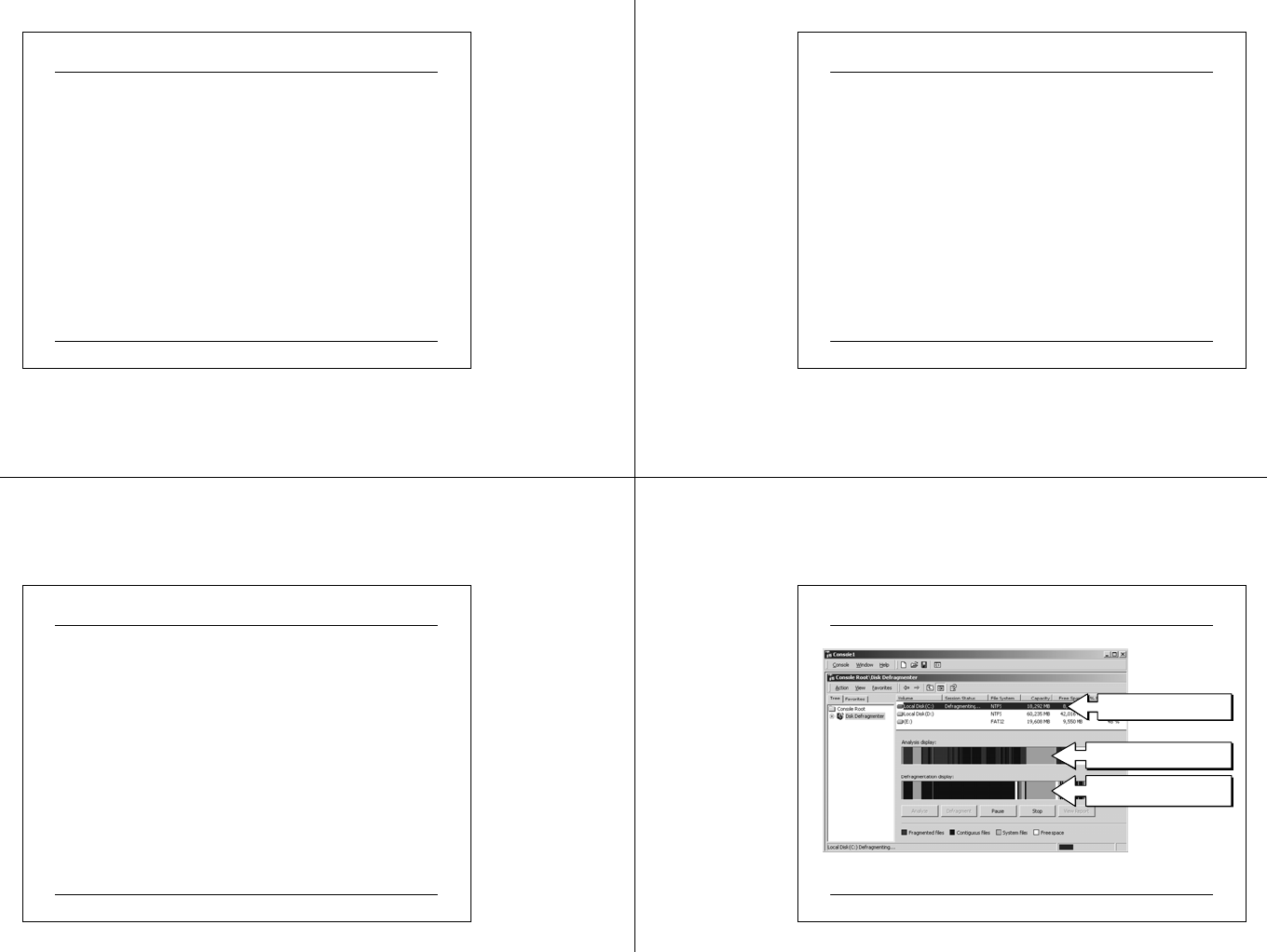
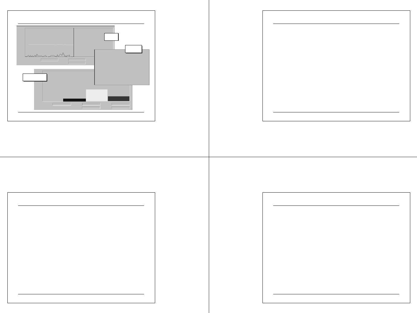
Disk Defragmentation
Select partition to analyze
The partition’s fragme ntation
The partition during and
after de fragmentation
03 07 2 5 CIT A PC M ainte na nc e.ppt 77
Disk Defragmenter Snap-in
• The Disk Defragmenter window has three panes that
provide the following information
The upper portion of the window lists the volumes you can analyze
and defragment.
The middle portion is a graphic representation of how fragmented
the selected volume is.
The lower portion is a dynamic representation of the volume that is
continuously updated during defragmentation.
• The display colors indicate the condition of the volume.
Red indicates fragmented files.
Dark blue indicates contiguous (nonfragmented) files.
White indicates free space on the volume.
Green indicates system files, which Disk Defragmenter cannot
move.
03 07 2 5 CIT A PC M ainte na nc e.ppt 78
Disk Defragmentation
• By comparing the Analysis display band to the Defragmentation display
band during defragmentation and at its conclusion, you can quickly see the
improvement in the volume.
• To analyze or defragment a volume, you can choose one of the options
described in the following table.
DescriptionOption
Click this button to defragment th e dis k. A fter defragmentation, the
Defragmentation display band provides a graphical representation of
the defragmented volume.
Defragment
Click this button to analyze the dis k for fragmentation. After the
analysis, the Analysis display band provides a graphical representation
of ho w fragmented the volume is.
Analyze
03 07 2 5 CIT A PC M ainte na nc e.ppt 79
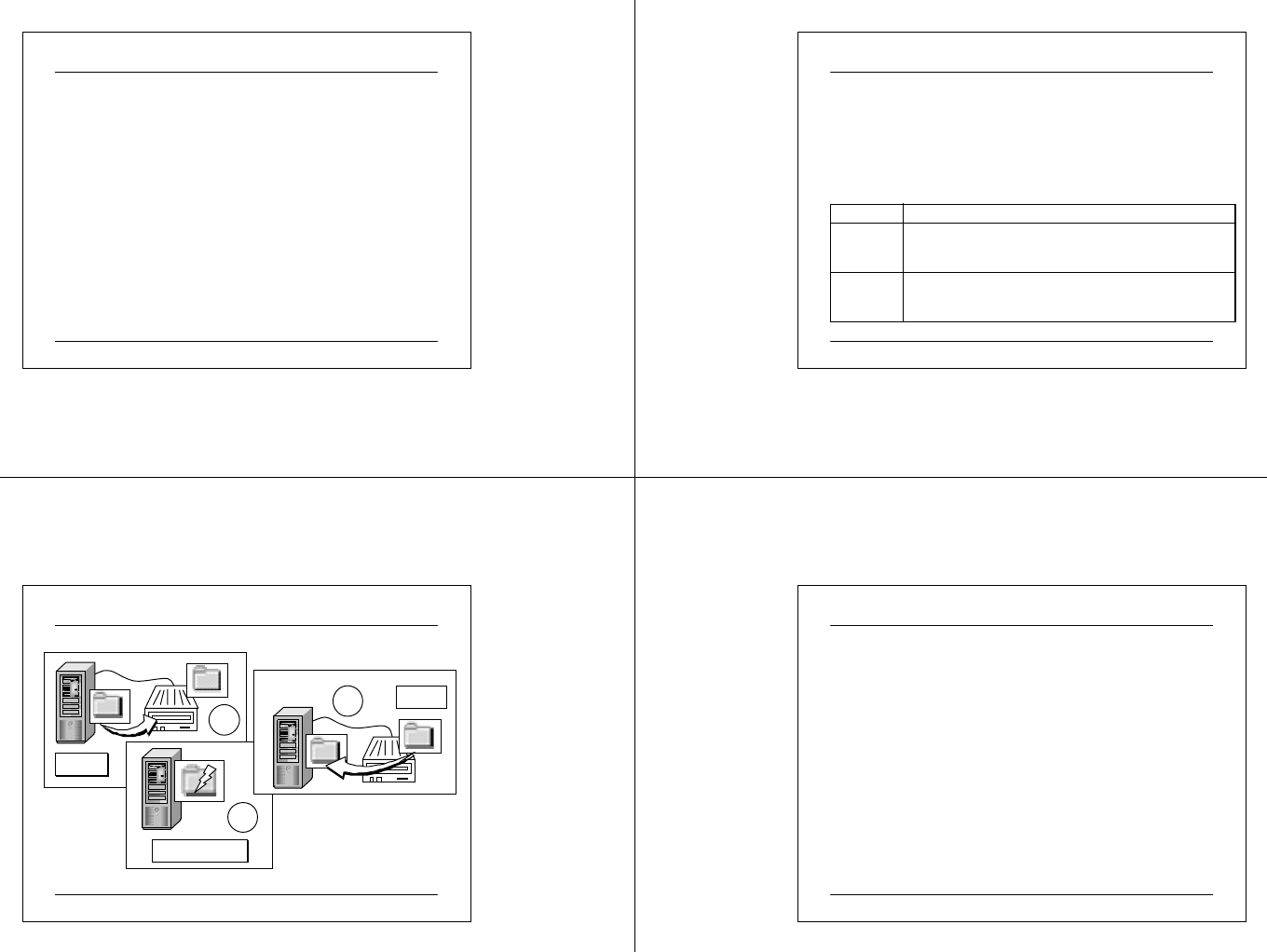
Server
System Backup
Server
Backup
Restore
Data Corruption
Server
3
1
2
03 07 2 5 CIT A PC M ainte na nc e.ppt 80
System Backup
• considerations
system vs. data
cost of Backup
• Backing Up Data
The goal of all backup jobs is to ensure that lost data can be recovered
efficiently and quickly. A backup job is a single process of backing up
data. Regularly backing up data on server hard disks and client
computer hard disks prevents data loss due to disk drive failures,
power outages, virus infections, and other such incidents. If data loss
occurs and you have carefully planned and performed regular backup
jobs, you can restore the lost data, whether the lost data is a single file
or an entire hard disk.
03 07 2 5 CIT A PC M ainte na nc e.ppt 81
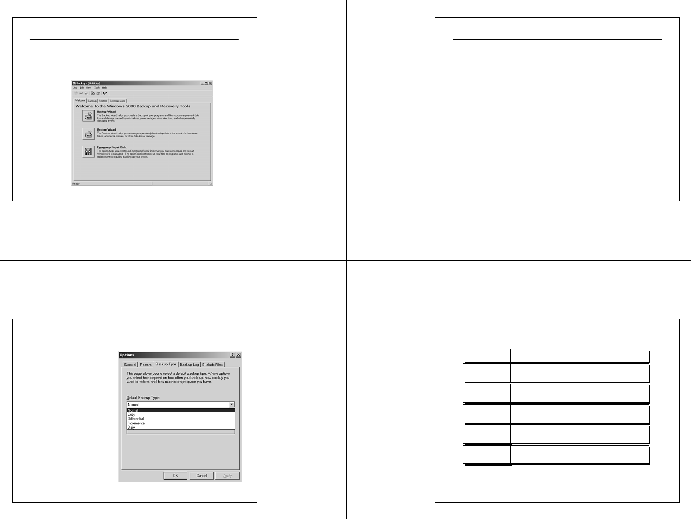
Introducing Windows Backup
• Windows 2000 provides Windows Backup, which is a tool that allows
you to easily back up and restore data. To launch Windows Backup, on
the Start menu, point to Programs, point to Accessories, point to System
Tools, and then click Backup
03 07 2 5 CIT A PC M ainte na nc e.ppt 82
System Backup - Media
•Determine Which Target Media to Use for Storing Backup Data
and their compatibility
Files: User can store the files on a removable media device, such as an
Iomega drive, or on a network location, such as a file server. The file
created contains the files and folders the user have selected to backup.
The file has a .bkf extension. Users can back up their personal data to
a network server.
Ta pe : A tape is more convenient for large backup jobs because of its
high storage capacity. However, tapes have a limited life and can
deteriorate. Be sure to check the tape manufacturer's recommendations
for usage.
User can back up to the following removable media:
03 07 2 5 CIT A PC M ainte na nc e.ppt 83
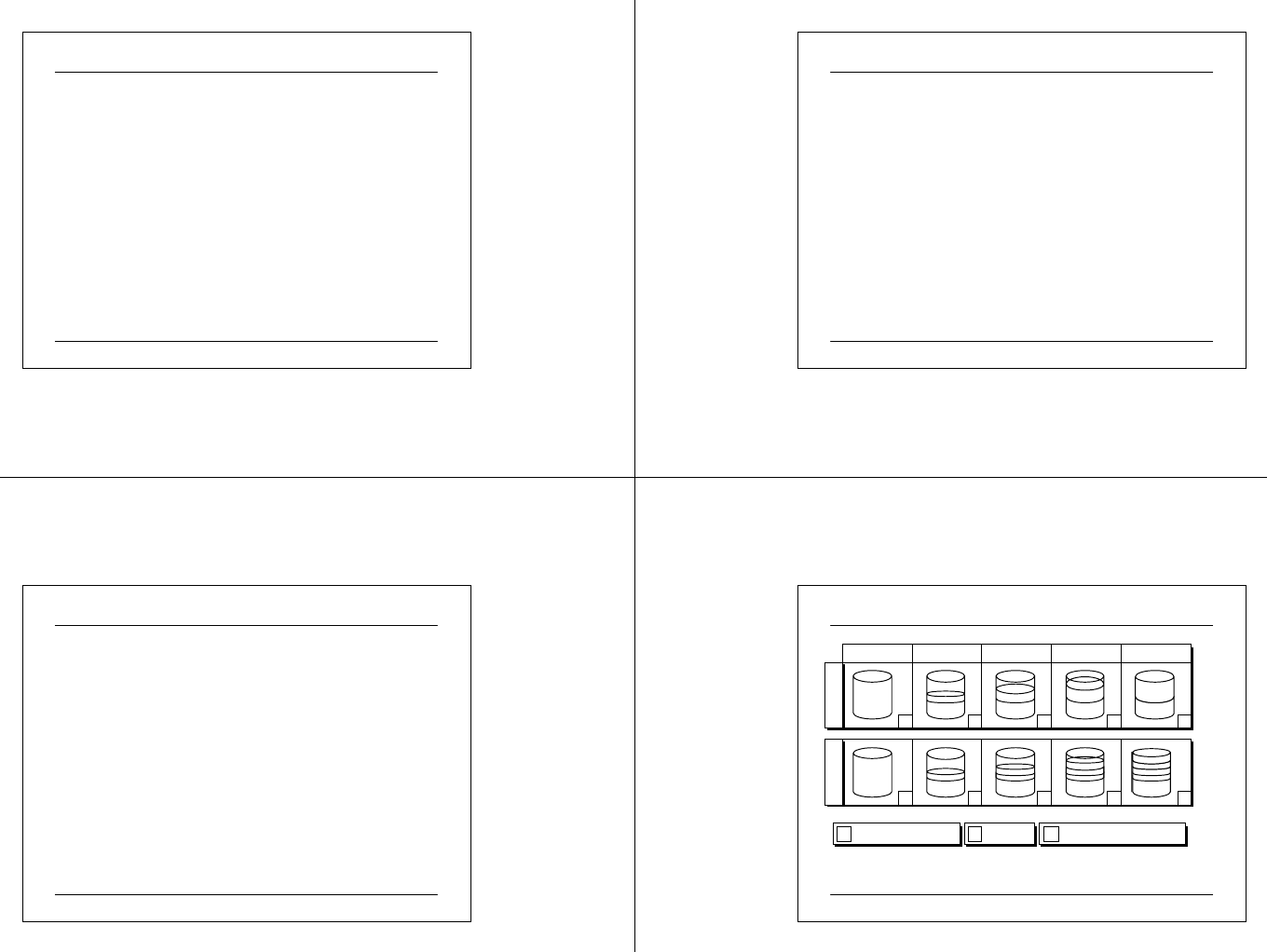
Backup Types
Windows Backup provides
five backup types that
define what data is backed
up: normal, copy,
differential, incr emental,
and daily. You can set the
default backup types on the
Backup Types tab of the
Options dialog box
03 07 2 5 CIT A PC M ainte na nc e.ppt 84
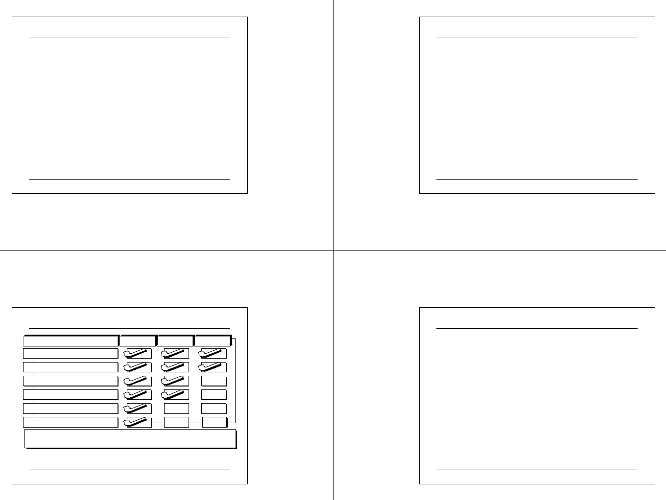
System Backup
Type
Norma l
Backs up
Se lecte d file s an d folde rs
Clears marker
Yes
Copy Se lecte d file s an d folde rs No
Differential Sele cted file s and folde rs th at
changed since the last backup No
Incremental Se le cted files and folde rs that
changed since the last backup Yes
Daily Sele cte d file s and f olders t hat
changed during the day No
03 07 2 5 CIT A PC M ainte na nc e.ppt 85
Backup Types
1. Normal
A normal backup, known as a full backup, all selected files and folders are
backed up. A normal backup does not rely on markers to determine which
files to back up, but it does clear the archive attribute from all files.
Normal backups speed up the restore process because the backup files are
the most current and you do not need to restore multiple backup jobs.
However, they are the most time consuming and require the most storage
capacity of any backup type.
2. Copy
A copy backup, all selected files and folders are backed up. It neither
looks for nor clears markers. If you do not want to clear markers and
affect other backup types, use a copy backup. For example, use a copy
backup between a normal and an incremental backup to create an archival
snapshot of network data.
03 07 2 5 CIT A PC M ainte na nc e.ppt 86
Backup Types
3. Differential
A differential backup, only selected files and folders that have a marker
are backed up. Because a differential backup does not clear markers, if
you did two differential backups in a row on a file, the file would be
backed up each time. This backup type is moderately fast at backing up
and restoring data.
4. Incremental
An incremental backup, only selected files and folders that have a marker
are backed up. An incremental backup clears markers. Because it clears
markers, if you did two incremental backups in a row on a file and
nothing changed in the file, the file would not be backed up the second
time. This backup type is very fast at backing up data and slow at
restoring data.
03 07 2 5 CIT A PC M ainte na nc e.ppt 87
Backup Types
4. Daily
During a daily backup, all selected files and folders that have
changed during the day are backed up. A daily backup neither
looks for nor clears markers. If you want to back up all files and
folders that change during the day without affecting a backup
schedule, use a daily backup.
03 07 2 5 CIT A PC M ainte na nc e.ppt 88
Example of Backup Schedules
Normal (Clears Markers)
NIncremental (Clears Markers)
I
Differential
D
Monda y Tuesday Wednesday Thursday Friday
N D D D D
Example 1
N I I I I
Example 2
03 07 2 5 CIT A PC M ainte na nc e.ppt 89
Configuring File and Folder for Backup
• When a user create a backup job, the following should be
specified:
Drives, Folders, or Files to Back Up
Backup Destination
Path and File Name , or a Ta pe to Use
Backup Options
Description of the Backup Job
Whether the Me dia Contains E xisting Backup Jobs
Advanced Backup O ptions
03 07 2 5 CIT A PC M ainte na nc e.ppt 90
Backing Up System State Data
• You can use Backup to back up the system state data. If the system state
data on a computer has been backed up and that same computer system
fails, you can rebuild the computer with the original Windows 2000
compact disc and the system state data.
• The system state data contains the information to restore the operating
system to its pre-failure state. The system state data includes the
following system components:
•Registry
• Component Services class registration database
• Sys tem startup files
• Certificate Services database
• Active Directory™ directory service
• Sysvol folder
03 07 2 5 CIT A PC M ainte na nc e.ppt 91
Backing Up System State Data
* CS Component Services
** DC A domain controller running Windows 2000 Server
*** Server A computer running Windows 2000 Server that is also a certificate server
Component ProfessionalDC** Server**
CS* Class Registration Database
System Startup Files
Certificate Services Database
Active Directory
Sysvol Folder
Registry
03 07 2 5 CIT A PC M ainte na nc e.ppt 92
Monitoring and Optimizing Performance
Microsoft Windows 2000 includes tools for monitoring system resources.
Task Manager presents a snapshot of programs and processes that are
running on your computer and provides a summary of the computer's
processor and memory usage. System Monitor and Performance Logs and
Alerts provide detailed data about the resources used by specific
components of the operating system and computer. Specifically, these
utilities contains:-
zMonitor event logs to monitor information about system operations.
zTask Manager for monitoring system resources.
zSystem Monitor for monitoring system performance.
zAlerts to notify a user or an administrator when certain system criteria
are met or exceeded.
zCounters are available for monitoring and tune for optimizing
performance.

03 07 2 5 CIT A PC M ainte na nc e.ppt 93
Moni toring Event Logs
• Events are user actions that are recorded based on an Audit
policy, or any significant occurrence as encountered by the
system or in an application.
• Monitoring events helps to identify and track security
events, resource use, or system and application errors.
• 3 types of logs are available on Microsoft Systems
Security events, based on an Audit policy, are
recorded in the security log.
System events automatically configured by Windows
2000 are recorded in the system log.
Applications events determined by the application
developer are recorded in the application log.
03 07 2 5 CIT A PC M ainte na nc e.ppt 94
Event Log Checking as a Security Measure
• After events are recorded in these logs, view and analyze
the logs to detect activities and events that require
administrative consideration.
• Based on your analysis of the logs, one may resolve
security violations, address system problems, or reallocate
resources for better performance.
• You may also need to recommend changes in Audit policy,
audit settings, security settings, application configuration,
or system configuration.
03 07 2 5 CIT A PC M ainte na nc e.ppt 95
Security Event Logs
The security log records security events such as valid and invalid logon
attempts in addition to events related to resource use, such as creating,
opening, or deleting files. An administrator specifies what events are
recorded in the security log. For example, if the administrator has enabled
log on auditing, all attempts to log on to the system are recorded in the
security log. Logs can be used to provide a history of events.
Server
Failed Access
Se cu ri t y Eve n t Log
03 07 2 5 CIT A PC M ainte na nc e.ppt 96
The System Log and The Application Log
•The system log.
This log contains events logged by the Windows 2000 system
components. For example, the failure of a driver or other system
component to load during startup is recorded in the system log.
The event types logged by system components are predetermined
by Windows 2000.
•The application log.
This log contains events logged by applications or programs. For
example, a database program records a file error in the application
log. The program developer decides which events to record. Dr.
Watson application logs are also viewable in this log. Dr. Watson
for Windows 2000 is a program error debugger. When an
application exception (or program error) occurs, Dr. Watson
generates a log file (Drwtsn32.log).
03 07 2 5 CIT A PC M ainte na nc e.ppt 97
Type of System and Application Events
Information
WarningError
There are three types of system and application events: Information,
Warning, and Error. Each event contains detailed information such as the
type of event and the service associated with the event. Event
information can be used to accurately identify the event for taking
appropriate action. System events are generated by Windows 2000 and
recorded in system logs. Application events are generated by
applications and recorded in application logs.
03 07 2 5 CIT A PC M ainte na nc e.ppt 98
Information
Warning
Error
zThe successful operation of an application, driver, or service.
zAn event that is not necessarily significant but may indicate a future
problem with system operations.
zA signif icant problem with system operations, such as loss of data or
loss of functionality.
Classification and Example of Events
03 07 2 5 CIT A PC M ainte na nc e.ppt 99
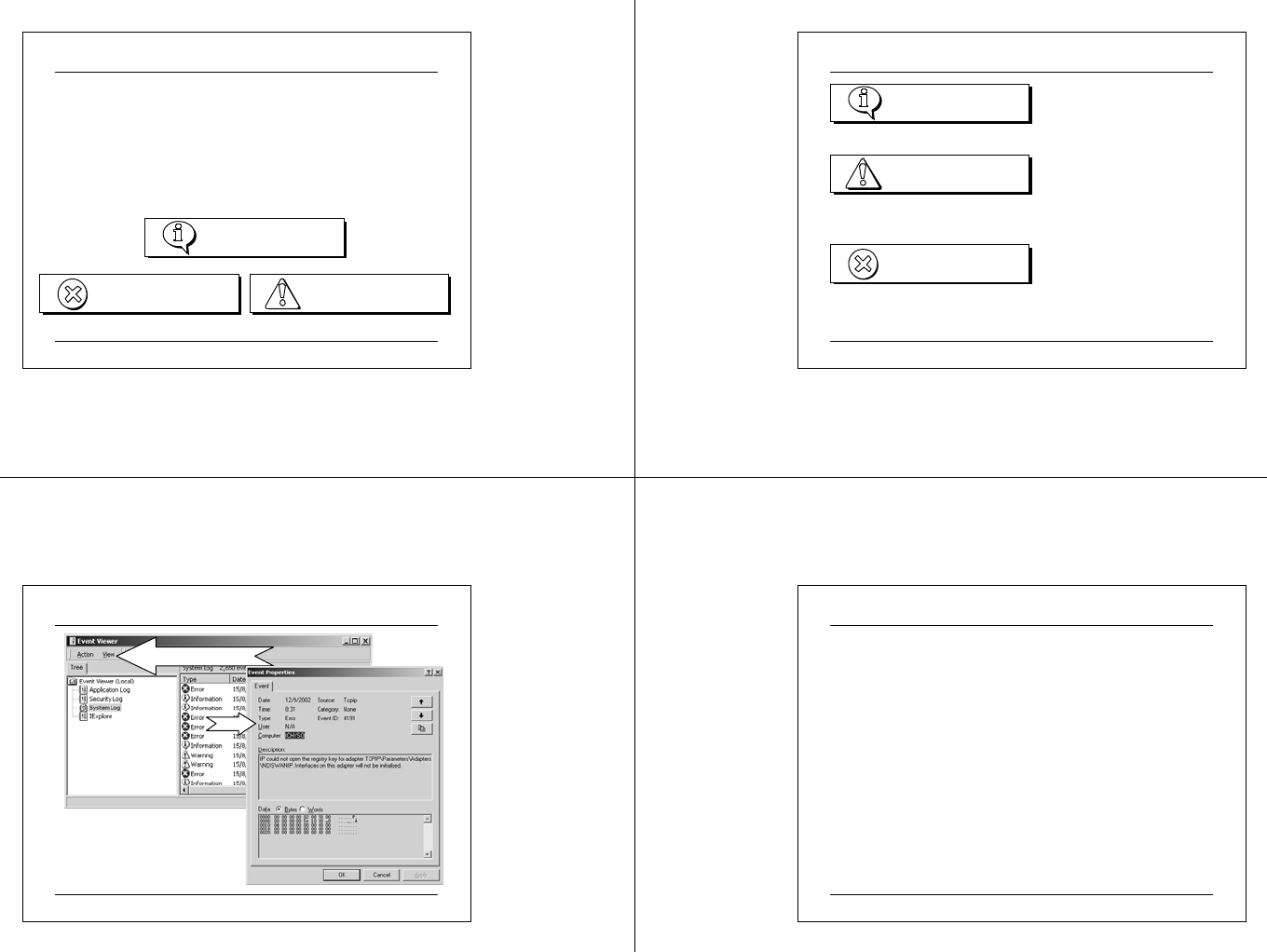
View Event Logs
Search for Events
03 07 2 5 CIT A PC M ainte na nc e.ppt 100
View Event Logs (cont.)
• System and application events are logged in their associated log files
sequentially, from most recent to oldest.
• The log files contain a lot of information about each event that occurs.
• A Event Viewer is provided by the OS to view detailed information
about each event in a log.
• To open Event Viewer, click Start, point to Programs, point to
Administrative Tools, and then click Event Viewer. Select the log
that you want to view in the console tree of Event Viewer. In the
details pane, Event Viewer displays a list of log entries and summary
information for each entry. To view more detailed information about
an event, double-click the event.
• A search function is available for locating specific events.
03 07 2 5 CIT A PC M ainte na nc e.ppt 101
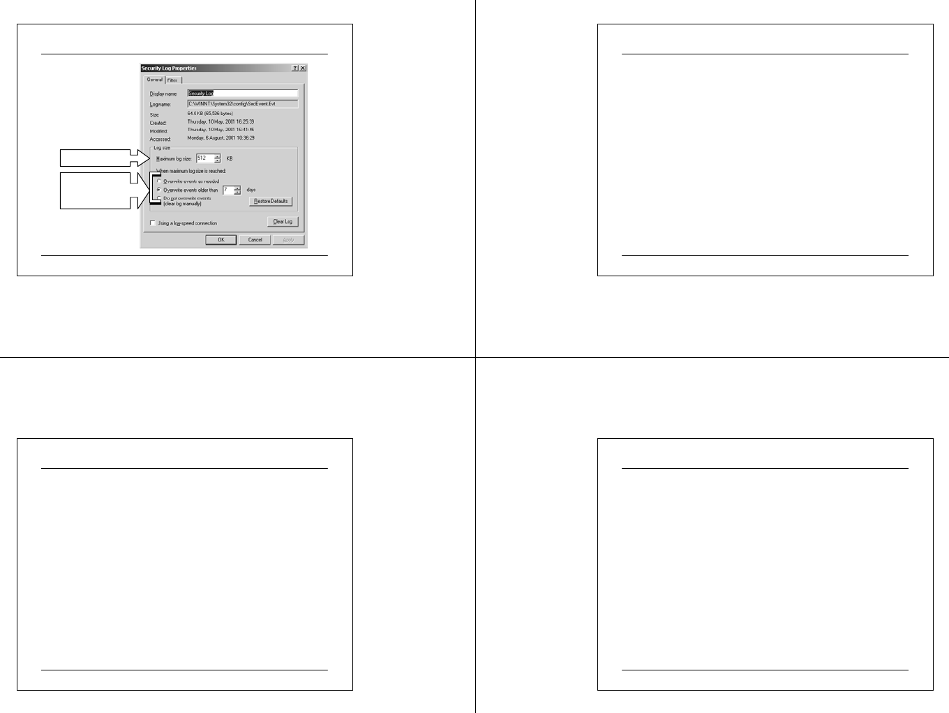
Size of the Log Files
Size Limit
Action to Take
when Limit
Reached
03 07 2 5 CIT A PC M ainte na nc e.ppt 102
Limiting the Size of Log Fi les
• Lim it the size of event logs if hard disk space is a problem and select
a method to overwrite older log event entries with new log entries.
Overwriting older event logs is called event log wrapping.
• When you enable an Event log wrapping option, you lose old entries.
If your security needs are high and you want to keep a history of
events, you can choose to archive old event entries instead of
overwriting them.
• The size of each log, which can range from 64 kilobytes (KB) to 4
gigabytes (GB). The default size is 512 KB.
• The action that Windows 2000 takes when a log is full can be
controlled by configuring the Event log wrapping options
available.
03 07 2 5 CIT A PC M ainte na nc e.ppt 103
Managing Event Logs
• Archive Event Logs to:-
Track trends to determine resource usage
Track unauthorized use of resources
Keep records when required by law
• For convenience, one can export the Log to a File Format
to View in other Application, example:-
Log-file format (.evt )
Text-file format (.txt)
Comma-delimited text-file format (.csv)
• Event Logs can be cleared from the Event Viewer
03 07 2 5 CIT A PC M ainte na nc e.ppt 104
Using Task Manager to Monitor System Resources
• Task Manager provides real-time information about
applications currently running on your system, the
processes and memory usage or other data about those
processes, and statistics on memory and processor
performance.
• For example, you can use Task Manager to identify an
application or process that is using a disproportionate
amount of system resources. In addition, the Task Manager
status bar provides you with measurements of a system or
program activity.
• Task Manager can be used to:-
Monitoring programs
Monitoring processes
Monitoring performance
03 07 2 5 CIT A PC M ainte na nc e.ppt 105
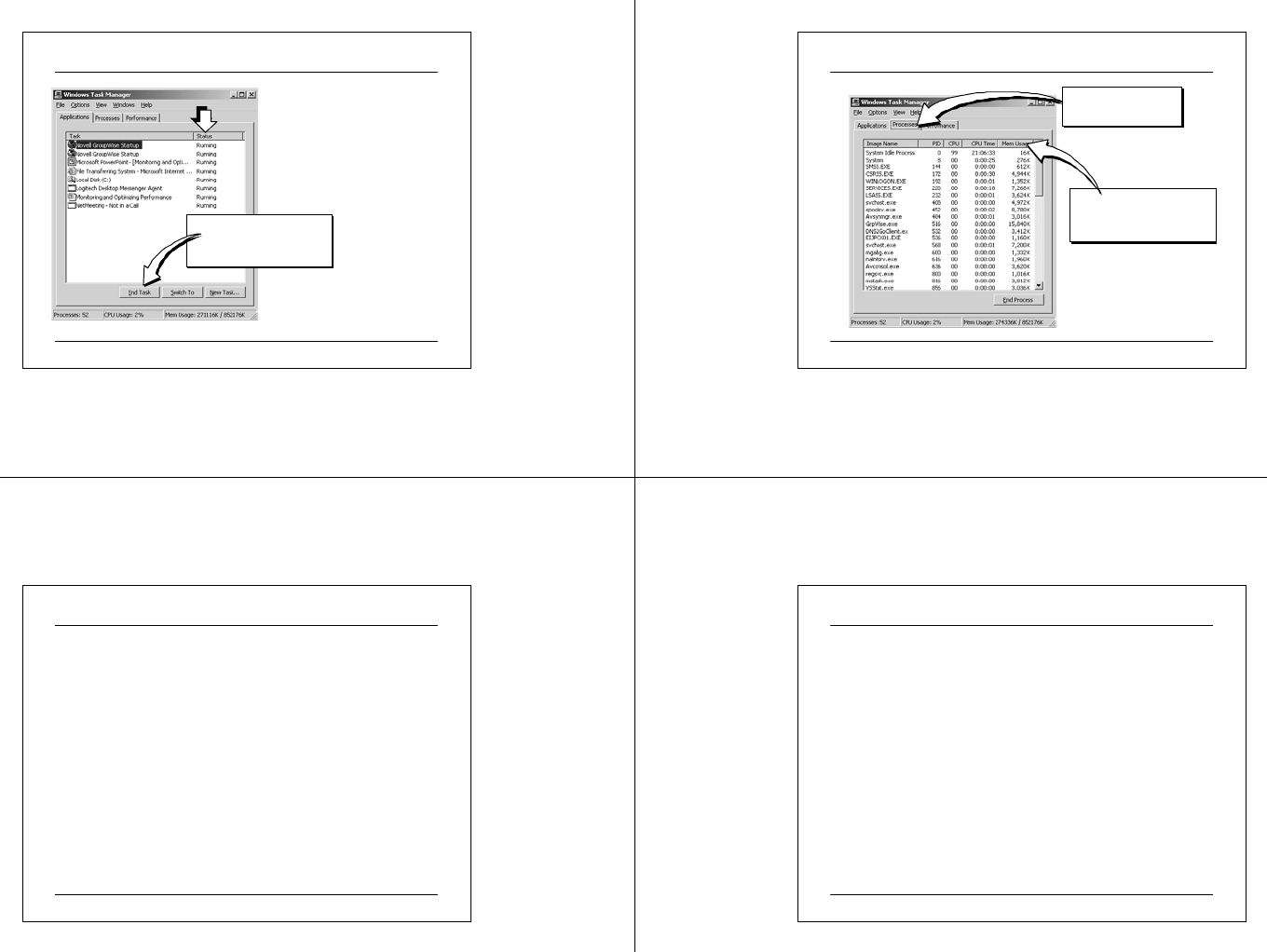
Use the Applications tab of Task
Manager to view the status of
applications running on the
computer and to identify the
process associated with an
application.
In addition, use this tab to shut
down an unresponsive
application.
Moni toring Programs
Click End Ta sk to
shutdown an
unresponsive application
03 07 2 5 CIT A PC M ainte na nc e.ppt 106
Monitoring Process
Click column heading to
sort e ntries in asce nding
or descending order
Sele ct Process
Measures to Display
03 07 2 5 CIT A PC M ainte na nc e.ppt 107
Monitoring Process
The Processes tab can be used to view a list of running
processes and their measures. Measures are measurements of
a process, such as total processor time or the amount of
memory in use. The list that appears on the Processes tab
includes all processes that run in their own address space,
including all applications and system services. Both the user
and the system can initialize a process, but you can only end
a process that is initialized by a user.
03 07 2 5 CIT A PC M ainte na nc e.ppt 108
Process Troubleshooting
• Use the Process tab in Task Manager to identify the
resource use of a program. After you identify the
applications that are using the most processor time, move
some of these applications to another computer to distribute
the workload. Sort column entries ascending or descending
order to identify high usage.
• For example, to identify the high-processor use by an
application, click the CPU column. The first time you click
the column, it sorts the applications in ascending order of
usage. Clicking again sorts the applications in descending
order of CPU usage. You can only sort by one column at a
time.
03 07 2 5 CIT A PC M ainte na nc e.ppt 109
System Performance Monitoring
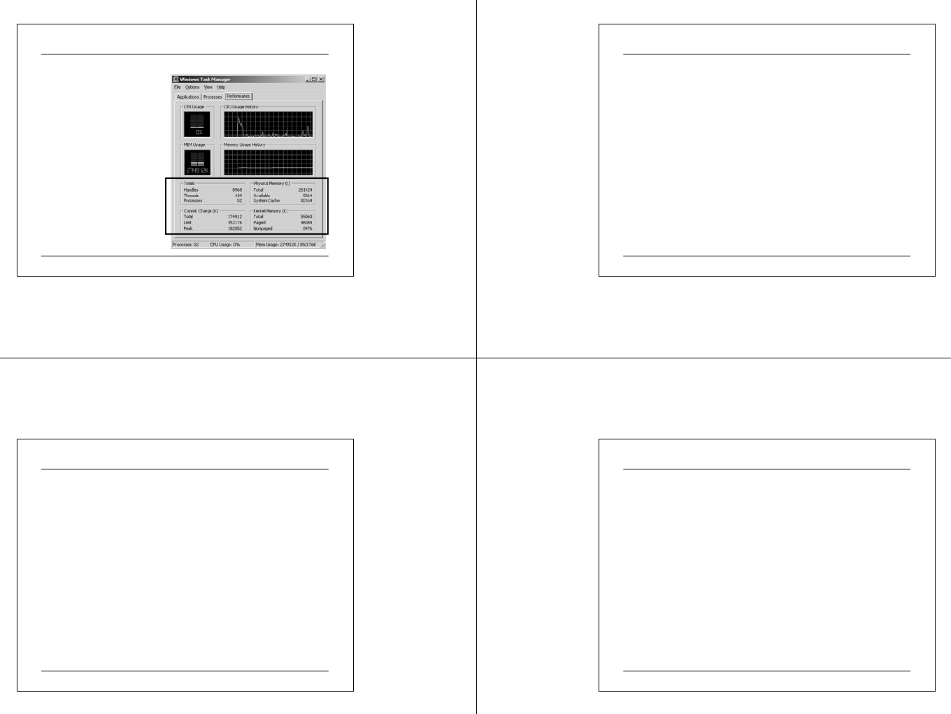
To monitor the current
performance of your
computer, you use the
Performance tab. This tab
displays a dynamic overview
of the computer's current
performance, including a
graph and numeric display of
processor and memory usage.
03 07 2 5 CIT A PC M ainte na nc e.ppt 110
Using Performance Measures to View Processor Time
• Use the Performance tab in Task Manager to identify the amount of
system resources the operating system or an application is using and to
view the percentage of processor time that is being used by the kernel
mode. The kernel is the core of an operating system that manages
memory, files, and peripheral devices; maintains the time and date;
launches applications; and allocates system resources.
• To view the percentage of processor time that is in kernel mode, on the
View menu, click Show Kernel Times.
• The processor time in kernel mode appears in red in the graphs. This is a
measure of the time that applications are using operating system services.
The remaining time, shown in green, is known as user mode. This is a
measure of the time that is spent running threads within the application
code.
03 07 2 5 CIT A PC M ainte na nc e.ppt 111
Using System Monitor to Monitor System Performance
• If you need more detail than that provided by the Task Manager, you
can use System Monitor to obtain more comprehensive information
about your computer or other computers on the network. Use System
Monitor in Performance in Microsoft Management Console (MMC) to
collect and view real-time or logged data about memory, disk,
processor, and network activity. This information can be used to
diagnose how the system and applications are functioning to ensure that
you are optimizing the system. For example, you can determine if your
system is low on disk space.
• System Monitor information can be viewed in graph, histogram (bar
chart), or report form. Graphs, histograms, and reports can be viewed in
a browser and printed when performance data is saved as a Hypertext
Markup Language (HTML) file.
03 07 2 5 CIT A PC M ainte na nc e.ppt 112
Object, Instances and Counters
• Objects In System Monitor Are Major Components or
Subsystems of the Computer System
• Instances Are Multiples of the Same Object
• Counters:
Are Measurements of different aspects of objects
Continually gather data on objects
Provide data on all instances of an object
Can be selected to displayed in System Monitor
03 07 2 5 CIT A PC M ainte na nc e.ppt 113
Object, Instances and Counters
•Objects.
In System Monitor, objects are major components or subsystems of
the computer system. They can be hardware, such as the hard disk, or
software such as a process. There are a fixed number of objects in
Windows 2000.
•Instances.
Instances are multiples of the same object type. For example, if a
system has multiple processors, the Processor object type will have
multip le ins tanc es.
•Counters.
Counters gather data on different aspects of objects. For example, for
the Process object, counters gather data on the processor time and the
user time. Counters are built in to the operating system and
continually capture data, whether it is visible in System Monitor or
not. If an object type has multiple instances, counters track statistics
for each instanc e or the total of all ins tanc es.
03 07 2 5 CIT A PC M ainte na nc e.ppt 114
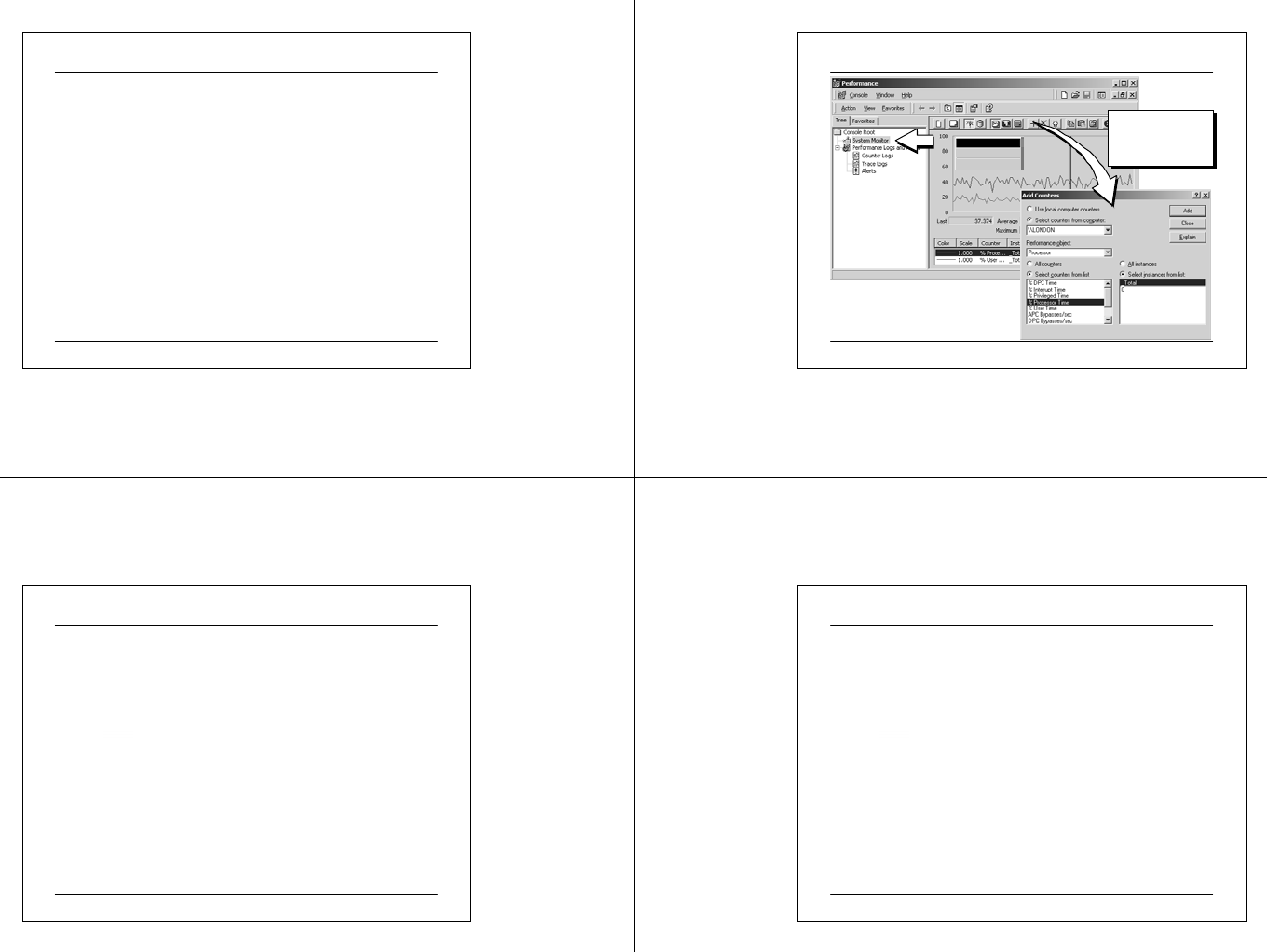
Adding Counters
Add Counters…
Save As…
Properties…
Add counters to
view data in the
graph area
03 07 2 5 CIT A PC M ainte na nc e.ppt 115
Adding Counters
Counters continually gather data on system performance, when
you add counters, you just adding their displays in System
Monitor. This allows you to monitor system performance.
1. Click Start, point to Programs, point to Administrative Tools,
and then click Performance.
When you start Performance for the first time, a blank System
Monitor graph appears.
2. Right-click the System Monitor details pane, and then click Add
Counters.
To add counters in System Monitor, perform the following steps:
03 07 2 5 CIT A PC M ainte na nc e.ppt 116
Adding Counters (cont.)
3. In the Performance object lis t, selec t an object to monitor.
The objects that are available are based on the services and
applications installed on the local computer. You can choose
several counters for each object. The following table describes core
objects in Windows 2000 System Monitor.
4. Click All counters or Select counters from list to choose
individual counters.
5. If an object has instances, click All instances or Select instances
from list to choose individual instances.
6. Click Add, and then click Close to close the Add Counte rs dialog
box.
03 07 2 5 CIT A PC M ainte na nc e.ppt 117
View Counter Data
100
0
20
40
60
80
Last Average
Max imum
4.851
31.000
16.162 Minimum
Duration
0.000
1:40
100
0
20
40
60
80
Last Average
Max imum
1.993
15.000
0.000 Minimum
Duration
\\PHOENIX
LogicalDisk
% Disk Read Time
% Disk Write Time
_Total
0.000
0.000
Memory
Available Bytes 38830080.000
Processor
% Processor Time
_Total
16.162
Report
Chart
Histogram
03 07 2 5 CIT A PC M ainte na nc e.ppt 118
View Counter Data
•Histogram.
•Displays data in a bar chart. This view is useful for
simplifying graphs with multiple counters.
•Report.
•Displays numerical data in columns. This view is useful for
collecting data that you can export into a spreadsheet, such as
Excel.
•Chart.
•Displays data in a line graph. This view is useful for
monitoring real time data or data logged over time.
You can view the data of your counters in real time. Display this data in
three different ways:
03 07 2 5 CIT A PC M ainte na nc e.ppt 119
View Counter Data
• Change and customize display settings by right-clicking the
System Monitor details pane, and then clicking Properties.
• Save performance data as an HTML file, and then open the
HTML file from Microsoft Internet Explorer or another
Web browser. You can also print the data from the browser.
To save data as an HTML file, right-click the details pane
of System Monitor, and then type a file name for the HTML
file.
03 07 2 5 CIT A PC M ainte na nc e.ppt 120
Optimi zing Performance
• Optimize performance so that the operating system and
applications use system resources more efficiently. The
level of system performance that you consider acceptable
when your system is handling a typical workload and
running all required services is its baseline. The baseline
performance is a subjective standard that the user or the
administrator determines based on the typical level of
performance under typical workloads and usage. The
baseline can be the measure used for setting performance
expectations of your system.

03 07 2 5 CIT A PC M ainte na nc e.ppt 121
Optimi zing Performance
• The Performance Optimization Process
• Examining Memory Performance
• Examining Processor Performance
• Examining Disk Performance
• Examining Network Performance
03 07 2 5 CIT A PC M ainte na nc e.ppt 122
The Performance Optimization Process
Take
Corre ctive Action
Analyze
Monitoring Data
Identify Areas
of Unacceptable
Performance
03 07 2 5 CIT A PC M ainte na nc e.ppt 123
The Performance Opti mization Process
• The optimization process helps you to determine what
actions to take to improve system performance in response
to demands on the system. Performance optimization
begins with thoughtful and organized record keeping.
• The performance optimization process includes the
following tasks:-
• Analyzing Monitoring Data.
• Identifying areas of unacceptable performance
• Taking corrective action.
03 07 2 5 CIT A PC M ainte na nc e.ppt 124
The Performance Optimization Process
•Analyzing Monitoring Data.
• Analyzing monitoring data consists of examining counter values that are
reported while the system is performing various operations. During this
process one can determine:
• Which processes are most active and which programs or threads
(if any) are monopolizing a resource.
• Whether the overuse of any hardware resource causes a decrease
in system performance.
• Whether there are residual effect of bottlenecks and other
hardware resources that are underused. For example, if the system
starts to run slower and the hard disk activity increases, this could
indicate a hard drive problem or insufficient RAM to support the
applications and operating system.

03 07 2 5 CIT A PC M ainte na nc e.ppt 125
• Identifying areas of unacceptable performance
• As a result of this analysis, you may find that your system
performs satisfactorily at some times and unsatisfactorily at others.
In general, deciding whether or not performance is acceptable is a
subjective judgment that varies significantly with variations in
user environments. The values you establish as the baselines for
your system are the best basis for comparison. In addition, be
aware that performance varies over time and your monitoring
needs to include different periods of system usage.
• Taking corrective action.
• Depending on the causes of these variations and the degree of
difference, you may choose to take corrective action or to accept
these variations and postpone tuning or upgrading resources to a
later date. In some instances, the corrective action may not have
enough impact to make the change worthwhile.
The Performance Opti mization Process
03 07 2 5 CIT A PC M ainte na nc e.ppt 126
Examining Memory Performance
• Establish a Baseline Range for Normal Values to Help Identify
Trends and Problems
• Use Counters to Examine Memory
Monitor Pages per second
Monitor Available Bytes
• Examine Page Files
Indicates low memory if frequent paging
Check the paging file size
Use counters to monitor the paging file size
03 07 2 5 CIT A PC M ainte na nc e.ppt 127
Examining Memory Performance
• Low memory conditions can slow the operation of
applications and services on your computer and impact
the performance of other resources in your system.
•Es tabli s hi ng a B aseli ne
• Examine your physical memory usage during a
normal workload to establish a baseline for physical
memory usage. The baseline is usually a range of
values within which physical memory usage can
fluctuate and still provide acceptable performance.
Use the baseline to identify trends, such as increasing
physical memory demands over time, or to recognize
problems that arise from a sudden change.
03 07 2 5 CIT A PC M ainte na nc e.ppt 128
Examining Memory Performance
• Examining Paging Files
One of the ways you may become aware of a memory shortage is if your
system is paging frequently.
•Paging
Paging is the process of moving virtual memory back and forth between
physical memory and the disk. When a computer is low on memory,
paging activity increases, therefore, frequent paging indicates a memory
shortage. Increased paging activity causes more work for your disks and
competes with other disk transactions that are being performed. In turn,
the processor is used less or is doing unnecessary work by processing
numerous interrupts due to repeated page faults. (Page faults occur when
the system cannot locate requested code or data in the physical memory
available to the requesting process.) In the end, applications and services
become less responsive.

03 07 2 5 CIT A PC M ainte na nc e.ppt 129
Examining Memory Performance
• Checking the Paging File Size
• To see if a paging file is approaching its upper limit, check the actual
file size and compare this value to the maximum paging file size setting
in System in Control Panel. If these two numbers are close in value,
consider increasing initial paging file size or running fewer programs.
The paging file is located on the disk where you installed the OS -
Windows 2000. To check the size of the paging file, view the file size
shown for Pagefile.sys in Windows Explorer. If disk space is adequate,
you can increase the size of the paging file. The recommended size for
the paging file is equivalent to 1.5 times the amount of RAM available
on your system.
03 07 2 5 CIT A PC M ainte na nc e.ppt 130
Examining Processor Performance
• Use Counters to Examine Processor Performance
• Examine Usage Values for Workstations
High usage can indicate efficient handling
Additional data must be gathered
• Examine Usage Values for Servers
High usage unacceptable
High usage can cause bottlenecks
03 07 2 5 CIT A PC M ainte na nc e.ppt 131
Examining Processor Performance
When you examine processor performance, consider the role
of the computer and the type of work being done. Depending
on what the computer is doing, high processor values could
mean that the system is efficiently handling a heavy workload,
or it could mean that it is struggling to keep up. However, if
more than a few processes are contending for the processor's
time, installing a faster processor may improve throughput.
03 07 2 5 CIT A PC M ainte na nc e.ppt 132
Examining Processor Performance for Workstations
If you are monitoring a workstation that is running Windows
2000, high usage values can mean that the system is efficiently
handling a heavy workload. For example, if the computer is
starting a new process, it may use 100 percent of the
processor's time. Although this type of usage can slow the
performance of other applications on that computer, you need
to gather more data to determine whether the processor load is
keeping other work from being done. If so, you can change the
workload by mo ving the application to a different computer or
changing the current tasks that the computer performs.

03 07 2 5 CIT A PC M ainte na nc e.ppt 133
Examining Processor Performance for Servers
Processor values around 100 percent on a server that is
processing many client requests indicate that processes are
queuing up, waiting for processor time, and causing a
bottleneck. A bottleneck occurs when one subsystem is so
overloaded with work that the other subsystems are not fully
utilized or are idle waiting for the overloaded subsystem to
complete a task. Such a sustained level of processor usage is
unacceptable for a server.
03 07 2 5 CIT A PC M ainte na nc e.ppt 134
Examining Disk Performance
• Monitor Both Physical Disk and Logical Disk Objects to
Examine Performance
• Use Counters to Examine Disk Activity and Determine:
Percentage of unallocated disk space
Size of I/O operations
Speed data moves
Rates bytes transferred
Number of read and writes completed in a second
03 07 2 5 CIT A PC M ainte na nc e.ppt 135
Examining Disk Performance
Monitor disk activity to detect bottlenecks in the disk subsystem so that
you can remove these bottlenecks.
• Monitoring the Physical Disk and Logical Disk Objects
Windows 2000 includes counters that monitor the activity of physical
disks (including removable media drives), as well as logical partitions or
volumes. The Physical Disk object provides counters that report physical
disk activity. The Logical Disk object provides counters that report
statistics for logical disks and storage volumes. System Monitor identifies
physical disks by number starting with 0 and identifies logical disks by
the drive letter.
• Using Performance Monitor
Performance Monitor allows you to monitor the performance of the
network objects on a server.
03 07 2 5 CIT A PC M ainte na nc e.ppt 136
Examining Network Performance
• Using Network Monitor
Use Network Monitor to monitor the network data stream, which
consists of all information transferred over a network at any given time.
The components of Network Monitor that you must install are:
• Network Monitor drivers, which capture the data.
• Network Monitor tools, which allow you to view the data. This
information is divided into smaller parts, called frames or packets.
Because frames are captured from the network, statistics about the
frames are displayed in the Network Monitor Capture window.

03 07 2 5 CIT A PC M ainte na nc e.ppt 137
Various Third Party Performance Meters
•WinBench
http://www.etestinglabs.com/benchmarks/winbench/winbenc
h.asp
• Iometer
http://sourceforge.net/projects/iometer/
• HDTach / CDTach / DVDTach
http://www.tcdlabs.com/hdtech.htm
• HWiNFO32
http://www.hwinfo.com
• A collection from acnc
http://www.acnc.com/benchmarks.html
03 07 2 5 CIT A PC M ainte na nc e.ppt 138
Overclocking
• Overclocking can cause stability problem and overheat the
chip.
• In some P4 motherboard such as the ASUS P4G8X and
P4PE allow the user to adjust the CPU core voltage (25mV
increment) and clock frequency (100MHz – 200MHz at
1MHz step). It also provide a fix frequency for PCI and
AGP bus
http://www.asus.com/mb/socket478/p4g8x-d/overview.htm
• The Pentium Pro, Celeron, and Pentium II/III, AMD K6
processors automatically determine their voltage settings
by controlling the motherboard-based voltage regulator.
That's done through built-in voltage ID (VID) pins.
03 07 2 5 CIT A PC M ainte na nc e.ppt 139
Overclocking by Modifying the Processor Multiplier
Optimal overclocking method because it neither interrupts nor
changes the bus speed on the motherboard. This can be
done by modify the multiplier number in the BIOS or via
jumper settings on the motherboard.
• System stability can be compromised if the maximum
operating frequency of the processor core is exceeded.
• Since Pentium II, both AMD and Intel has been multiplier-
locked to avoid remarking.
For AMD CPU, need soldering/bridging the clock pads to
overclock
03 07 2 5 CIT A PC M ainte na nc e.ppt 140
Overclocking by Modifying FSB Speed
• Front side Bus
• processor to chipset
bus
PCI Bus (33MHz / 66 MHz)
South Bridge
System Bus (800MBps@ 100MHz)
CP U
2GHz
BIOS
RAM
North Bridge
ISA Bus (4.77MBps@4.77MHz / 1 6MBps@ 8MHz)
The difference between CPU speed and
the system bus speed is called the
Multiplier. (e.g. Multiplier=5)
32 / 64
8 / 16
Lo ca l B us
528MBps @ 66MHz AGP
USB, IDE,
Seria l,
Parallel..
64
32 e.g. AG P 2x
32bit /8 x 66 x 2 = 5 28MBps
• Not affected by
processor frequency
loc k
• Affected entire
system

03 07 2 5 CIT A PC M ainte na nc e.ppt 141
Overclocking (cont.)
• Free Intel Processor Frequency ID Utility is available at:-
http://www.intel.com/support/processors/tools/frequencyid/index.h
tm
• Professionals do not recommend overlocking for obvious
reason that overclocking void the processor’s warranty and
can cause a stability problem. Recently, it seems that the
CPU companies is using this as a gimmick to push sales.
• You can try overclocking at your own risk. Please
remember to check the documentation of the motherboard
and processor to find the appropriate settings.
• The Overclocking Database is available at:-
http://www.sysopt.com/ocdatabase.html
03 07 2 5 CIT A PC M ainte na nc e.ppt 142
Overclocking Software
• Hmonitor can be used to monitor the thermal and fan speed
sensors on mainboard.
http://www.hmonitor.com
• WCPUID is a popular bench mark in the overclocking
worl d.
http://www.h-oda.com
• The popular 3DMark
htt p:/ /www.fut ure mark.c o m/
• The popular WinBench and test reports is available at:-
http://www.etestinglabs.com/
• Free PC test tool
http://www.tufftest.com
03 07 2 5 CIT A PC M ainte na nc e.ppt 143
Troubleshooting PC Hardware
• Power On Self Test (POST)
primary line of troubleshoot ing f or hardware problem
• First programme load into the first bank of RAM is the
BIOS
• Error beep code
Different depending on BIOS vendor
AMI/Phoenix
Visual code – use a monitor or POST card
•Other tools
Multimeter / logic probe
Logic analyzer
Oscilloscope
03 07 2 5 CIT A PC M ainte na nc e.ppt 144
Virus
• common types of virus
Boot-sector infecting virus
Progra mme File infecting virus
Trojan horse
Macro Virus
CMOS infecting virus
• F-Secure Anti-Virus for DOS is a freeware for home use,
other versions are 30-day evaluation version
ftp://ftp.f-sercure.com/anti-virus/free/
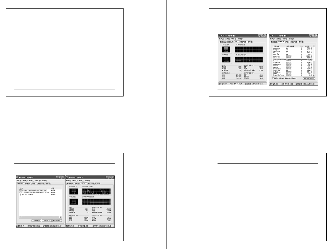
03 07 2 5 CIT A PC M ainte na nc e.ppt 145
Basic Troubleshooting – Examples and Techniques
• Power supply
If fan doesn’t wor k, it ma y be a faulty power supply
•System recovery
Recovery dis ks
Backup
Syste m recovery console in Windows XP
• Virus check and definition file update must be done
regularly and Virus shield must be up at all times.
• Run time problem
Release System Resources with Task Manager
• Flash the BIOS only when system upgrade is required.
• Sometimes it is a good idea to reboot the system to restore
the initial environment.
03 07 2 5 CIT A PC M ainte na nc e.ppt 146
Example – Release System Resources
Symptom:- The pc failed to respond to external command
03 07 2 5 CIT A PC M ainte na nc e.ppt 147
Example – troubleshooting
After the problematic process is removed and the system
returning to normal.
03 07 2 5 CIT A PC M ainte na nc e.ppt 148
Example - System Cannot Boot from Harddisk
• master boot record (MBR) problem
The first sector on a hard disk, which begins the process of
starting the computer. The MBR contains the partition table
for the disk and a small amount of executable code called the
master boot code.
• boot sector problem
A critical disk structure for starting your computer, located
at sector 1 of each volume or floppy disk. It contains
executable code and data that is required by the code,
including information used by the file system to access the
volume. The boot sector is created when you format the
volume.
• Virus or installation of bad driver

03 07 2 5 CIT A PC M ainte na nc e.ppt 149
Reference
1. Mueller, Scott, “Upgrading & Repairing PCs”, 14th
Edition, Que Publishing, 2003.
2. Moulton, Pete, “A+ Certification and PC repair Guide”,
2nd Edition, Prentice Hall PTR, 2002.
3. Loukides, Mike, Musumeci, G., “System Performance
Tuning”, 2nd Edition, O’Reilly, 2002.
4. Bigelow, Stephen, “Troubleshooting, Maintaining &
Repairing PCs”, 5th Edition, Osborne, 2002.
5. Buchanan, Williams & Wilson, Austin, “Advanced PC
Architecture”, Addison Wesley, 2001.
6. Soper, Mark, E., “PC Help Desk in a Book”, Que, 2003.
03 07 2 5 CIT A PC M ainte na nc e.ppt 150
Links
• A few popular PC Bench mark software
• WinBench from PC Magazine
htt p:/ /www.nyq. pcma g.co m/
• WCPUID from Holicho Odas
http://www.h-oda.com/
• Sandra 2003 from SiSoftware
http://www.sisoftware.co.uk/
• http://www.tomshardware.com
• http://www.upgrading and repairingpcs.com
