6309_ConfigurationPerformance_YB_20080417 Black Box Laser Pointer LES421A Configuration And Performance Of IEC 61850 For First Time Users
User Manual: Black Box Laser Pointer LES421A
Open the PDF directly: View PDF ![]() .
.
Page Count: 11
1
Configuration and Performance of IEC 61850
for First-Time Users – UNC Charlotte Senior
Design Project
Youssef Botza, Matthew Shaw, Peter Allen, Mike Staunton, and Dr. Robert Cox,
University of North Carolina at Charlotte
Michael Boughman, Casey Roberts, and William Rominger, Schweitzer Engineering Laboratories, Inc.
Abstract—IEC 61850 was designed to be a substation IED
network and system communications standard rather than just
another communications protocol. The international standard
design allows for the interoperability of many different intelligent
electronic devices (IEDs). Using Ethernet, IEDs are networked
within a substation and across an entire power network. The
University of North Carolina Charlotte senior design group
applied the IEC 61850 standard to a substation integration
project that was first designed using traditional serial communi-
cations methods. The purpose of this project was to offer a
practical comparison between a system of protective relays
communicating protection schemes with serial communications
and hardwired contacts and another using IEC 61850 GOOSE
(Generic Object Oriented Substation Event) messages via
Ethernet. Because this project was an introduction to power
systems for most of the design team, the practical implementation
of incorporating IEC 61850 into a substation integration project
is presented at a beginner’s level.
I. NOMENCLATURE
The following list contains the definitions of abbreviations
that are used in this paper.
AX-S4 MMS IEC 61850 MMS Client Interface Software
COM Component Object Model
DCOM Distributed Component Object Model
DDE Dynamic Data Exchange
GOOSE Generic Object Oriented Substation Event
GUI Graphical User Interface
HMI Human-Machine Interface
IED Intelligent Electronic Device
LAN Local-Area Network
MMS Manufacturing Message Specification
MOE MMS Object Explorer
MTBF Mean Time Between Failures
OLE Object Linking and Embedding
OPC OLE for Process Control
RB Remote Bit
SCADA Supervisory Control and Data Acquisition
SER Sequential Events Recorder
SLC Software Logic Controller
TCP/IP Transmission Control Protocol/Internet
Protocol
WWMMELink Software Application Script That
Concatenates WWMMEItem1 and
WWMMEItem2
II. OVERVIEW OF IEC 61850
IEC 61850 was created to be an internationally standard-
ized method of communication and integration. The standard
is intended to allow IEDs from multiple manufacturers to be
networked to perform protection, monitoring, automation,
metering, and control. IEC 61850 supports all substation
automation functions and the engineering required for imple-
mentation. Unlike earlier standards, the technical approach of
IEC 61850 was premeditated to make it flexible and allow for
future improvements.
An effort to create a communications standard with global
appeal was initiated by an international IEC project group of
about 60 members. In 1995, they created Technical
Committee 57 to produce international standards in the field
of communications between the equipment and systems for
the electric power process, including telecontrol, teleprotec-
tion, and all other telecommunications to control the electric
power system. This committee began creating the communi-
cations standard IEC 61850. The objectives set for the
standard were:
• Develop a standard comprised of multiple protocols
for complete substation communication.
• Define basic services required to transfer data.
• Promote a high level of interoperability between
devices and systems from different manufacturers.
• Create a common method and format for modeling,
describing, and exposing data.
• Standardize configuration file structure and content to
simplify device configuration and methods for sharing
configuration parameters among devices and systems.
The IEC 61850 standard specifies the data transfer methods
and the server processes within the substation; this process is
based on a hierarchical data structure with an object-oriented
approach. The data objects are grouped by functional
constraints to allow information to be communicated with
high-efficiency data transfer. This standard also promotes
interoperability, where multiple IED manufacturers can
communicate over one or several standardized protocols.
Throughout the years, there have been many protocols used
within substations. These protocols are often proprietary with
custom communications links, which can make interopera-
bility between multiple manufacturers’ IEDs difficult. Using
2
IEC 61850 simplifies the interoperation of devices from
different manufacturers.
IEC 61850 differs from most previous communications
methods in its use of object models for device functions and
device components. These models define common data
formats, identifiers, and controls for substation and feeder
devices such as meters, switches, voltage regulators, and
protection relays. The models specify standardized and logical
groups of data for the most common device functions and
allow for significant manufacturer specialization.
III. PROJECT AND SYSTEM OVERVIEW
A student team from University of North Carolina
Charlotte conducted a senior design project that made a
practical comparison between a system of protection relays
using hardwired contacts and serial communications, and one
using IEC 61850 GOOSE messages via Ethernet. The project
system consisted of ten IEDs networked to provide protection,
monitoring, automation, metering, and control of two 138 kV
lines, a 138 kV ring bus, a 12.47 kV feeder, and a transformer.
The team provided a fully automated system with a rugged
computing platform and network switch that provided
SCADA and remote engineering control using LAN access.
The integration of the project resulted in pertinent IED
information displayed on an HMI with a GUI.
The group performed a comparison between IEC 61850
and the traditional methods of wiring microprocessor-based
protective relays. By designing and drafting a complete set of
drawings for each system, they were able to perform both
quantitative and qualitative comparisons against specified
acceptance criteria. The evaluation criteria included speed,
controls, usability, and reliability testing. Because the speed
with which information travels is critical to the performance
of a substation, the speed of IEC 61850 was compared to the
speed of traditional digital serial communications processor
controls and existing serial peer-to-peer communications.
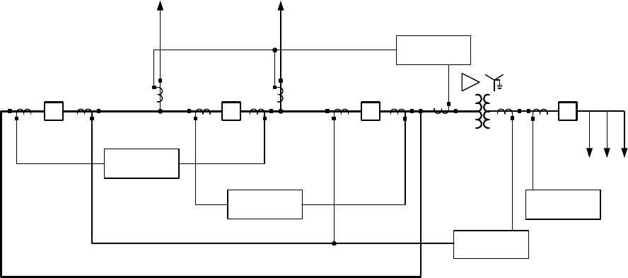
A single-line schematic of this project is shown in Fig. 1. It
includes two lines, a radial feeder, a ring bus, a transformer,
four circuit breakers, and switchgear. The following protection
and monitoring devices are applied in the project’s power
system:
• Line distance protection
• Differential protection
• Transformer protection
• Bus differential protection
• Radial feeder overcurrent protection
• Communications processor
• Computing platform
IV. IMPLEMENTATION OF IEC 61850
Using the described system, pertinent IED information was
output to an HMI created with the Wonderware® software
application. The software runs on a substation-hardened
rugged computing platform with a touchscreen monitor-based
GUI. Using the information selected for the HMI and
associated timestamps at the IED level, the team tested the
speed difference between IEC 61850 communication and the
typical serial connections.
There are two methods of configuring Windows® software
applications to interact with the IEC 61850 protocol drivers
that also run on the Windows operating system on the rugged
computer. These two are DDE and OPC.
DDE offers an easy and flexible method of passing data
from one Windows application to another. Given that
AX-S4 MMS software (see Section IV.A for description of
the software) has the capability to communicate via DDE, this
method was a natural choice because Wonderware has mature
and often-used DDE interfaces as well. This eliminates the
need for a third-party protocol converter and reduces points of
failure. In addition, Microsoft Excel® can be programmed as a
DDE interface to mimic an HMI for testing controls and status
through IEC 61850.
The OPC communications method was based on the OLE,
COM, and DCOM technologies developed by Microsoft for
the Windows operating systems.
Feeder
Protection
Transformer
Protection
Bus Diff
Protection
Feeders
#14000 #13000 #12000 #11000
138 kV Ring Bus
Line and Diff
Protection
Line and Diff
Protection
1200/5
1200/5
1200/5
2000/5
Line 1Line 2
Fig. 1. One-Line Diagram
3
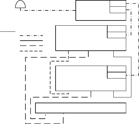
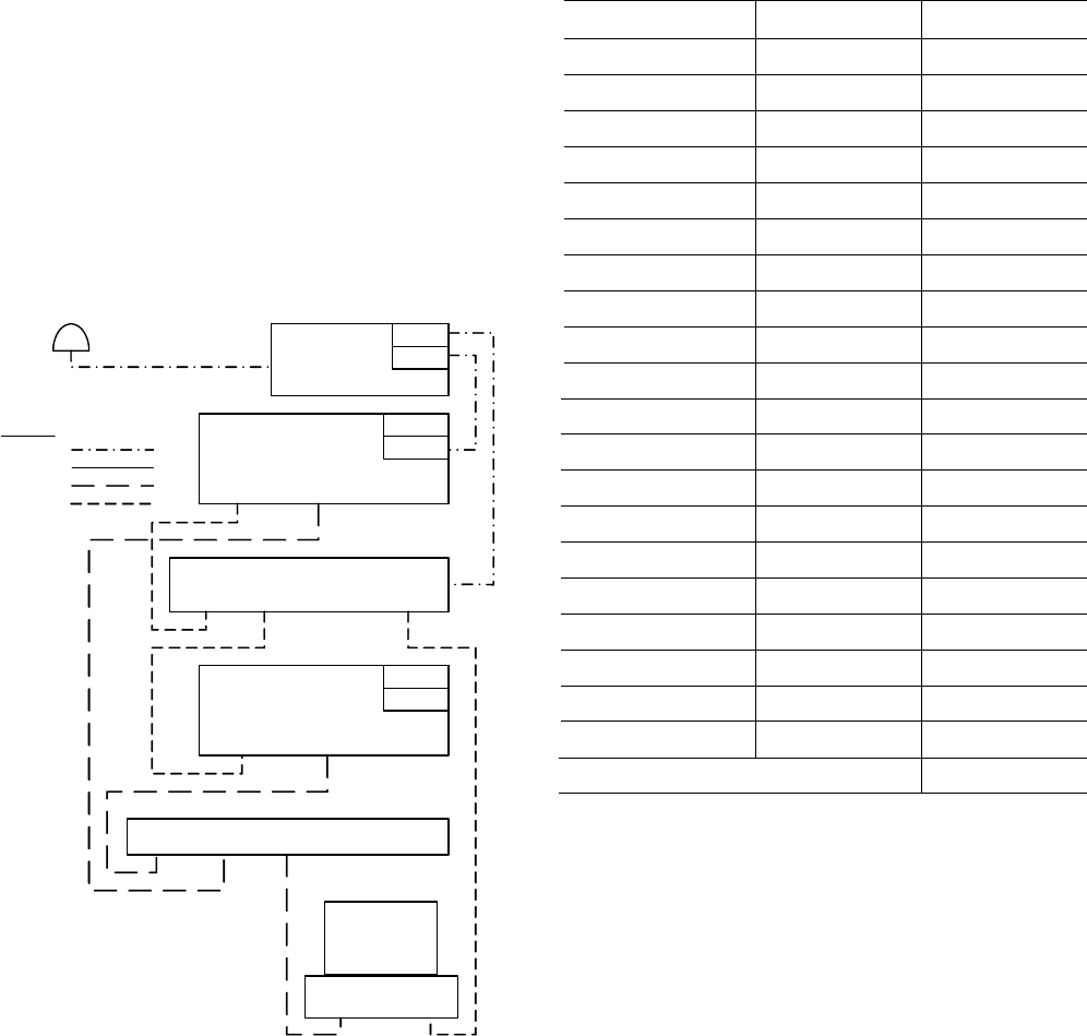
Fig. 2 represents the IEC 61850 process using the two
different communications methods—DDE and OPC. DDE
communication requires fewer individual pieces of software.
The design team selected Wonderware for HMI data and
control using DDE because the team was familiar with it. The
user can select either method for implementation.
IED IEDIED
Switch
AX-S4 MMS
(IEC 61850 Interface)
WWMME Link ReLab OPC
Console
Wonderware®
DDE OPC
ReLab SLC
ClearView
Server
ClearView
Fig. 2. DDE and OPC Control Implementation
A. AX-S4 MMS
AX-S4 MMS is the IEC 61850 interface that acts as a
client to collect data and perform controls and as a server to
provide data. It provides both DDE and OPC interfaces to the
IEC 61850 protocols based on MMS. AX-S4 MMS, with the
capability to communicate both DDE and OPC, provides
many integration options. The software is a server that links
clients such as Wonderware and Excel with MMS devices like
protective relays. AX-S4 MMS provides real-time data in
several ways. Data can be requested via a browser, similar to a
web browser that understands and displays values and
descriptions. One such browser is MMS Object Explorer
(MOE). The same data, or subsets of it, are collected via MMS
reports when data changes or at a fixed update rate to support
an HMI like Wonderware or Excel.
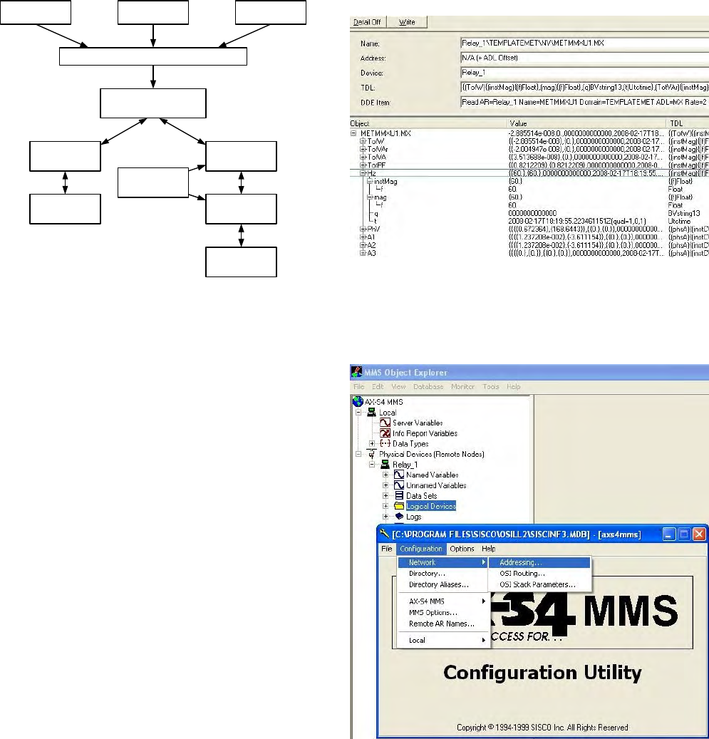
Starting MOE automatically initiates AX-S4 MMS and
other necessary software components to prepare the computer
to act as an MMS client. The MOE is the configuration viewer
of all the physical and logical devices available on the network
and visible to the AX-S4 MMS server. Once MOE is
configured with the device connection information, such as
network IP address, all available device information from each
IED can be viewed in the explorer window. This information
includes the IED’s physical and logical status and analog
values. Instantaneous and dead-band magnitude and angle
values are available for measured analog inputs such as
voltage and current. Instantaneous and dead-band values are
also available for calculated analog values such as watts, vars,
and frequency. Fig. 3 illustrates the ability to see the
individual frequency measurement for a line distance
protection relay. This window also identifies the device name
and DDE item information. The DDE item string information
serves as the data name for interface with software
applications.
Fig. 3. Starting AX-S4 MMS
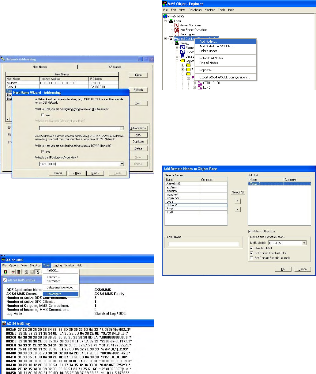
The steps to add an IED to AX-S4 MMS are shown in
Fig. 4. From the Object Explorer window, select Tools >
AX-S4 MMS Configuration Utility. In the Utility window,
select Configuration > Network > Addressing.
Fig. 4. Adding an IED to AX-S4 MMS
4
The Network Addressing window will appear, as shown
in Fig. 5. Confirm that this window identifies Host Names
and select New > Next. From the IED Identifying window
you will “name” the relay. To avoid computing issues with
spaces or dashes, use the underscore character (_). Then select
Next. Select Yes to configure a TCP/IP network, and enter the
IP Address of your host, for example, 192.168.0.90.
Fig. 5. Network Addressing
After entering the IP address, select Next; then select Add
AR Name > Next. In this window, you will see the host name
that you added. Select Next; enter the same name for the
AR Name you are configuring and select Next > Next > Next
> Finish > Finish. At this point, you may close out of the
Network Addressing window and the Configuration Utility
window. Bring up the AX-S4 MMS window, and select Tools
> Reconfigure, as shown in Fig. 6.
Fig. 6. Reconfiguring AX-S4 MMS
This procedure will reconfigure AX-S4 MMS to accept the
new changes or additions to the configuration utility. Viewing
the MMS Object Explorer window, choose from the folder
list on the left side of the screen, right click on Physical
Devices, and select Add Nodes, as shown in Fig. 7.
Fig. 7. Adding Nodes and Updating
Adding the new IEDs through this window will update all
IEDs that have been added to the remote node listing. Select
OK to add the new nodes and complete this process.
From the MMS Object Explorer window, as shown in
Fig. 8, if the IEDs are online with the station LAN, relay
status can be polled, and AX-S4 MMS can implement
controls. The next set of instructions details the steps to test
the controls and status mechanisms using Microsoft Excel.
Fig. 8. Adding Polled Devices
Open a new Excel spreadsheet and start a new Visual
Basic® Editor. Copy the script provided in the appendix into
the Editor window and save. Then click on Button located in
the Forms toolbar and assign the macro script GetFrequency.
Another button can be assigned to a different macro script
SendOutput1.
Using any of the Excel button makers, select a function
name and cell for that button. The cell button will run that
particular function outlined in the Visual Basic script.
B. Wonderware
For this project, Wonderware InTouch® software was used
as an HMI to run the IEC 61850 application. Controls are
administered by issuing the DDE item from AX-S4 MMS
when a particular action is taken in Wonderware. Figs. 9
through 13 show how to set up a pushbutton to administer a
control, such as setting and resetting a remote bit in a relay.
5
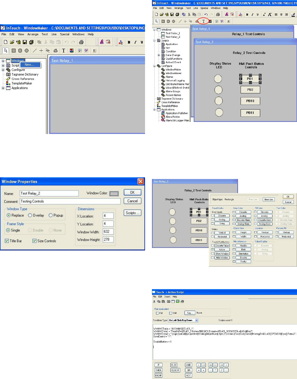
To create a new window after starting a new application in
Wonderware, right click on Windows; then click on New, as
shown in Fig. 9.
Fig. 9. Creating New Window in Wonderware
This action will bring up the Window Properties box, as
shown in Fig. 10, where the appropriate window selections
and naming convention are chosen. The user can populate the
window as desired.
Fig. 10. Window Properties Screen
As seen in Fig. 11, a few simple pushbuttons and status
indicators are chosen. To label the pushbuttons, click on the T
in the toolbar, and place the cursor in the desired box to label
it appropriately. Text can also be typed in the window to label
other actions, like the LED status in the relay.
Fig. 11. Wonderware Draw Object Toolbar
The user must now configure the status indicators and
pushbuttons to operate as desired. As seen in Fig. 12, select
PB1, and choose Action under the Touch Pushbutton
column to configure this particular rectangle as a pushbutton.
In the same way, check Discrete under the Fill Color column
to configure the desired status indicators.
Fig. 12. Configuring Pushbuttons
Fig. 13 shows the field in which to enter the action script.
Fig. 13. Script Activated by Pushbutton
6
The following script sets a remote bit in the relay:
WWMMETopic = “AXS4MMS|Relay_2”;
WWMMEItem1 = “Read AR=Relay_2 Name=RBGGIO1
Domain=Relay_2CON DTDL={(ctlVal)Bool”;
WWMMEItem2 =
“,(origin){(orCat)Byte,(orIdent)OVstring64},(ctlNum)Ub
yte,(T)Utctime,(Test)Bool,(Check)BVstring2}
ADL=CO[SPCSO11[Oper]] Rate=2”;
SendControl = “1”;
DisableButtons = 1;
This script will run a small program WWMMELink that
concatenates WWMMEItem1 and WWMMEItem2 from the
Wonderware script. In Wonderware, every action, status, and
message has a tagname associated with it. This tagname
defines what type of action will be performed as well as where
it should be sent based on its “AccessName” and “Item.” The
item is where the control string would be entered. However, a
tagname item has an 80-character limit and the AX-S4 MMS
control string is more than 90 characters. In order to overcome
this obstacle, the AX-S4 MMS control string is divided into
two sections in the Wonderware script. Then the
WWMMELink program puts the two sections together and
sends the complete control string as required to AX-S4 MMS.
The WWMMELink also has the option to send a pulse, a one,
or a zero.
The WWMMELink proved to be an extremely valuable
tool to allow the HMI to communicate with the relays, making
retrieval of status from the relay much easier. Moreover, the
DDE item from AX-S4 MMS is placed into the item field for
that particular tagname. The following string represents an
item to retrieve frequency from a relay:
RELAY1_1MET/METMMXU1$MX$Hz$instMag
This item is just one example of polling data from a relay.
All other status and indication points are retrieved in this same
way. This item string can be traced in the MMS Object
Explorer that is a GUI for AX-S4 MMS.
Another method of real-time data retrieval is to bundle all
of the data that the HMI requires into a report within the IED.
Once the client, in this case AX-S4 MMS, establishes a
connection with the IED, the report will be sent any time data
change. This will reduce network traffic and assure timely
updates of changes. Both the polling and reporting methods
are frequently used for HMI GUIs, with designers balancing
their functional and performance differences.
V. TESTING
The group also designed and drafted a complete set of
drawings that include ac schematics, dc schematics, one-line
diagrams, communications diagrams, panel layouts, and
wiring diagrams. As mentioned earlier, these drawings
enabled the group to do a quantitative and qualitative compar-
ison between IEC 61850 and the traditional methods of wiring
microprocessor-based protective relays. The evaluation
criteria were speed, controls, usability, and reliability. The
speed with which information can travel is critical to the
performance of a substation. The speed of IEC 61850 was
compared to traditional digital serial communications
processor controls and existing serial peer-to-peer communi-
cations.
One of the IEC 61850 protocols is GOOSE, which is used
for substation events such as commands, alarms, and message
indicators. GOOSE messaging is a key component of
IEC 61850 and allows IEDs to effectively communicate to one
another to accomplish interlocking and integrated protection
schemes. A single GOOSE message that is sent by one IED
can be received and used by several other IEDs. GOOSE takes
advantage of the speed of Ethernet and supports real-time
messaging, which is crucial for accurate event recording.
GOOSE messages are transmitted periodically to increase the
probability of delivery, as well as every time the message
contents change.
A. Relay-to-Relay Communication
When considering how to test the speed of GOOSE
communication, the highest accuracy is required. The project
team decided to use the SER function available in the relays.
The SER data are timestamped to the millisecond.
Communications timing tests between the devices were
completed by analyzing different substation scenarios that are
commonly used in GOOSE messaging. Each test included the
following:
• Hardwired I/O
• Serial peer-to-peer communications protocol
• IEC 61850 GOOSE messaging
Fig. 14 shows the connections of the first test setup.
Relay
Relay
PORT 2
OUT02
OUT01
ALARM
IRIG-B
PORT 5
IN101PORT 2 PORT 5
Antenna 75'
PORT 1 PORT 2
ALARM
IRIG-B
OUT101
Legend
Coax
Copper
Ethernet
Serial
Satellite
Clock
Switch
Fig. 14. First Test Setup
The team assumed that the hardwired I/O would be the
fastest, because there was no communications processing time
in between the relays. However, as demonstrated by these and
other tests performed, the physical detection circuit time takes
longer than the communications message processing time to
verify that an element has changed state.
To accurately test all scenarios, each component of the test
must start from a single relay element to assure that they all
start at the same instant in time. To initiate the test, a

7
pushbutton on the front panel of Relay 1 was programmed to
set a logical latch function, PLT10, inside the relay.
PLT10SET := PUSHBUTTON10_PULSE AND NOT
PLT10 (Actuating the test button sets the logic bit if it is
not already set)
PLT10RESET := PB10_PULSE AND PLT10 (Actuating
the test button resets the logic bit if it is already set)
The latch was programmed to operate a contact output
(OUT101), a logic equation to transmit a serial peer-to-peer
output (TMB1A), and an IEC 61850 communications card
output (CCOUT01).
OUT101 = PLT10
TMB1A = PLT10
CCOUT01 = PLT10†
The initiating latch, the contact output, the serial peer-to-
peer message equation, and the IEC 61850 communications
card output were added to the SER trigger list so that all state
changes would be recorded.
SER1 = PLT10,PLT10,Asserted,Deasserted,N
SER2 = OUT101,OUT101,Asserted,Deasserted,N
SER3 = TMB1A,TMB1A,Asserted,Deasserted,N
SER4 = CCOUT01,CCOUT01,Asserted,Deasserted,N
This information provides the exact time that the relay
asserted each output and the latch.
The contact output and the serial peer-to-peer message
output consistently assert at the same time and within the
same millisecond as the initiating latch along with the
IEC 61850 communications card output. This timing was
consistent each time the communication was tested. In the
receiving relay, elements representing the hardwired contact
input, serial peer-to-peer received message, and IEC 61850
communications card input were programmed into the SER
equation to record the relative time of receipt of the various
signals.
SER1 = IN101,IN101,Asserted,Deasserted,N
SER2 = CCIN001,CCIN001,Asserted,Deasserted,N
SER3 = RMB1A,RMB1A,Asserted,Deasserted,N
To test the speed of the serial peer-to-peer communi-
cations, the speed was set to its maximum of 38400 bps. The
results are shown in Table I.
† CCOUT01 is used because the relay will respond faster than if not using
a CCOUT equation. If the CCOUT equation is not used, the relay polls every
500 milliseconds instead of sending the message as soon as the latch changes
state. This could cause a delay of up to 800 milliseconds in the communica-
tions.
When sending a latched state of 1 with IEC 61850 GOOSE communi-
cation using a CCOUT in the dataset, the relay sends a pulse that asserts and
then deasserts the receiving relay, unlike the serial peer-to-peer and hardwired
schemes where the receiving relay gets asserted and stays asserted. However,
if the CCIN equation is used without the CCOUT, the receiving relay gets
asserted and stays asserted, just like the serial peer-to-peer and the hardwired
schemes.
TABLE I
COMPARISON AT 38400 BPS
38400 Time Difference
Start
LATCH10
Time
RMB1A
Received
Time
IN101
Received
Time
CCIN001
Received
Time
RMB1A IN101 CCIN001
25.637 25.641 25.645 25.641 0.004 0.008 0.004
54.291 54.295 54.3 54.295 0.004 0.009 0.004
47.291 47.295 47.3 47.295 0.004 0.009 0.004
4.393 4.395 4.402 4.395 0.002 0.009 0.005
38.545 38.552 38.554 38.550 0.007 0.009 0.005
23.72 23.725 23.729 23.724 0.005 0.009 0.005
54.795 54.8 54.804 54.799 0.005 0.009 0.005
22.497 22.5 22.501 22.504 0.003 0.009 0.005
54.297 54.3 54.306 54.3 0.003 0.009 0.005
29.074 29.081 29.078 29.081 0.007 0.009 0.005
8.775 8.779 8.783 8.779 0.004 0.008 0.004
43.2 43.204 43.208 43.204 0.004 0.008 0.004
11.827 11.831 11.835 11.831 0.004 0.008 0.004
39.227 39.231 39.235 39.231 0.004 0.008 0.004
10.152 10.156 10.16 10.157 0.004 0.008 0.004
39.729 39.733 39.737 39.733 0.004 0.008 0.004
10.004 10.008 10.012 10.01 0.004 0.008 0.004
38.254 38.258 38.262 38.26 0.004 0.008 0.004
12.306 12.308 12.315 12.312 0.002 0.009 0.004
2.931 2.933 2.94 2.937 0.002 0.009 0.004
Average (Seconds) 0.00400 0.00855 0.00435
At a data transfer rate of 38400 bps, serial peer-to-peer
communication and GOOSE IEC 61850 protocol have about
the same transmission time. Surprisingly, hardwired I/O is the
slowest of the three connections.
The serial peer-to-peer connection was also tested using a
channel speed of 19200 bps. With this change, the serial peer-
to-peer channel speed is 2 milliseconds slower than the
GOOSE messaging speed, as shown in Table II. The speed of
serial peer-to-peer communication is dependent on the data
transfer rate, where as IEC 61850 is not. This is another
advantage of using Ethernet-based communications.
8
TABLE II
COMPARISON AT 19200 BPS
19200 Time Difference
Start
LATCH10
Time
RMB1A
Received
Time
IN101
Received
Time
CCIN002
Received
Time
RMB1A IN101 CCIN001
35.905 35.911 35.913 35.909 0.006 0.008 0.004
11.432 11.438 11.44 11.436 0.006 0.008 0.004
45.732 45.738 45.74 45.736 0.006 0.008 0.004
14.457 14.461 14.465 14.461 0.004 0.008 0.004
50.459 50.465 50.467 50.463 0.006 0.008 0.004
21.259 21.265 21.267 21.263 0.006 0.008 0.004
49.134 49.142 49.142 49.138 0.008 0.008 0.004
10.686 10.69 10.695 10.690 0.004 0.009 0.004
40.613 40.62 40.622 40.618 0.007 0.009 0.005
10.013 10.02 10.022 10.018 0.007 0.009 0.005
Average (Seconds) 0.006 0.0083 0.0042
These tests show that both serial peer-to-peer and
IEC 61850 communications were faster than the hardwired
connection. However, when figuring in reliability, hardwire
I/O is still a good method of communication. If the Ethernet
switch failed, then all protection would be lost in the
IEC 61850 applications, proving that equipment reliability is
crucial for any communication standard.
IEC 61850 does present some advantages when compared
to the serial peer-to-peer protocol. First, the serial peer-to-peer
protocol allows only eight bits to be transmitted in each
direction and GOOSE messages can transmit up to
140 Boolean data elements. However, most interlocking and
protection schemes require the exchange of fewer than eight
bits from each IED. Second, though both can be deployed
directly between two peers using a single cable, it is more
useful to multicast the message to several peers with a
communications switch. For each message type, a
communications switch must be added with each IED
connected to it via a direct link to multicast messages to all
IEDs on the network. The serial switch for the peer-to-peer
serial message adds latency to the message transfer on the
order of 15 milliseconds at 19200 bps. Ethernet switches used
for GOOSE message multicast add a very small latency, less
than 0.2 milliseconds.
Fig. 15 shows the connections of a second test setup with
the serial message communications switch connecting all the
IEDs on the network.
Table III shows the test results with the serial message
communications switch integrated into the communications
scheme. As with the use of an Ethernet switch, the reliability
decreases when adding another device to the system; however,
the serial message communications switch is designed for the
mission critical purpose of multicasting protection data and
has a typical MTBF of about 300 years, contrasted with
Ethernet switches that at best have an MTBF of 23 years.
Further, the peer-to-peer protocol has features to check that
the channels are operational, verify their dependability, and
calculate channel availability. If any channel were to fail,
settings in the relay would activate an alarm. IEC 61850 has
no checking features or bits to set if the channel loses
communication.
When compared with direct relay-to-relay communication,
multicasting through the serial message communications
switch increases the delay; however, this delay is close to one
electrical cycle, which is fast enough for many protection
schemes.
Relay
Relay
Logic Processor
PORT 2
PORT 1 PORT 2
OUT02
OUT01
ALARM
IRIG-B
PORT 5
IN101PORT 2 PORT 5
Antenna 75'
Serial Message Switch
PORT 1 PORT 2
ALARM
IRIG-B
OUT101
Legend
Coax
Copper
Ethernet
Satellite
Clock
Fig. 15. Second Test Setup with Serial Message Switch
TABLE III
COMPARISON AT 19200 BPS WITH LOGIC PROCESSOR
19200 Time Difference
LATCH10 RMB1A RMB1A
22.872 22.887 0.015
12.699 12.714 0.015
39.576 39.591 0.015
1.326 1.343 0.017
29.151 29.168 0.017
49.001 49.016 0.015
6.353 6.368 0.015
25.878 25.893 0.015
41.553 41.566 0.013
19.228 19.241 0.013
Average (Seconds) 0.015
9
B. HMI Controls
Many substations have HMIs that allow the user to look at
a computer screen and have control over the entire substation
with the click of a button. HMIs usually have advanced
graphics with many status indicators and pushbuttons. The
user can have more control, safer operation, and faster
recovery times after outages. The cost of the HMI is justified
by facilitating work and analysis on the substation system.
Fig. 16 shows a setup of an HMI SCADA system with a
Wonderware application to test controls of the relays using
two different communications methods. One method
implements IEC 61850 and the other method applies serial
communication through a communications processor.
HMI
Ethernet Comm 1
PC
Satellite
Clock
Relay
Relay
Communications Processor
PORT 2
PORT 1 PORT 2
OUT02
OUT01
ALARM
IRIG-B
PORT 5
PORT 2 PORT 5
Antenna 75'
Switch
PORT 1 PORT 2
ALARM
IRIG-B
Legend
Coax
Copper
Ethernet
Serial
PORT 14
PORT 3
Fig. 16. Third Test Setup
The basic setup of the two relays consisted of two different
internal IED logic bits referred to as remote bits—RB01 and
RB02. RB01 was sent through the Ethernet with IEC 61850.
RB02 was sent through a serial connection with a
communications processor as an intermediary between the
HMI and as many as 16 relays. Since the times were so
drastically different, the team could easily identify which was
quicker by observing the LEDs on the relay. The test results
were surprising again, as shown in Table IV.
TABLE IV
CONTROLS FROM PC TO RELAY VIA IEC 61850 VS. SERIAL
Serial (RB02) IEC 61850 (RB01) Difference
21.853 24.538 2.685
12.755 15.517 2.762
1.748 4.506 2.758
5.962 8.494 2.532
38.554 40.473 1.919
17.575 20.433 2.858
50.893 52.483 1.59
22.777 25.389 2.612
50.795 52.568 1.773
29.449 31.372 1.923
37.342 39.34 1.998
0.715 3.332 2.617
36.088 38.311 2.223
58.978 61.309 2.331
30.59 33.242 2.652
51.088 53.173 2.085
23.519 26.221 2.702
45.596 48.211 2.615
6.446 9.177 2.731
29.265 31.152 1.887
Average (Seconds) 2.36265
On average, IEC 61850 was almost 2.5 seconds slower
than communication through a serial connection with a
communications processor, as configured in Fig. 16. The
IEC 61850 speed is highly dependent on the script that is
written to send the controls to the AX-S4 MMS server. The
script was written with high consideration toward speed.
However, IEC 61850 significantly lagged the serial
communication due to the much larger message size and
therefore processing overhead.
VI. RELIABILITY
Reliability is always a major concern when adding
anything new to a power system. In these tests, IEC 61850
never missed a protection bit that was sent across the network.
This is not to say there is not one single point of failure. The
switch is a single point of failure, and IEC 61850 GOOSE
does not have an acknowledgement mechanism to confirm to
the publishing IED that the message was received. Instead, the
sending relay will send its bit via multicast messages that are
sent very rapidly at first, and then gradually slowing to a
rhythmic heartbeat update time. The frequent publication right
after the bit changes increases the likelihood that the
information will get through the network to each intended
user. In low-voltage distribution substations, it may be
10
feasible to only use a single, individual IEC 61850 system.
However, in high-voltage transmission systems, the non-
deterministic nature of IEC 61850 protocols suggest it may
still be prudent to use two parallel forms of protection
communications.
VII. CONCLUSION
The ability to draw a comprehensive conclusion on a new
standard of communications protocol is difficult after only one
project. However, IEC 61850 can be compared to serial
communications within a substation as follows:
• Few software applications that support the protocols
exist, and those that do are less mature than their serial
counterparts.
• Fewer integration software tools exist.
• The nature of multiple protocols in one standard and
the use of Ethernet offer more versatility.
The controls from the HMI were a major roadblock in the
completion of the project. Initially, the design group decided
to use OPC as a medium to transmit and receive data.
Receiving data was quite easy; however, trying to implement
controls through a protocol converter proved to be difficult at
best, and in the end unattainable for this team. This issue was
overcome by the following:
• Communicating with DDE directly to AX-S4 MMS.
• Creating an HMI with Excel software.
• Learning Visual Basic script.
• Eliminating Wonderware limitations with Visual
Basic programming.
Although the bulk of the code could be copied into each
HMI script, the code used to transmit data packets over
Ethernet was unique for each relay and each type of control
issued.
The performance of IEC 61850 was not an issue. The
ability for companies to implement systems communicating
IEC 61850 protocols with less engineering effort than
previous methods will be most crucial to its success. Apply
the following to decrease implementation time:
• Software to automate integration.
• Tools to read configuration files and format data to
use the IEC 61850 nomenclature and constructs.
• Clients and servers, such as AX-S4 MMS, tightly
integrated into HMIs and other software applications.
Controlling a system through an HMI with IEC 61850 can
be as easy as integrating a new relay into the system.
However, a simple and cost-effective option is to forgo the
HMI, implement controls through the relay pushbuttons, and
use only the IEC 61850 GOOSE protocol for peer-to-peer
communication. In addition, the speed of GOOSE messaging
proved to be as quick and reliable as any protocol available
today. The ability to utilize TCP/IP protocol is the next logical
step for future integration projects, providing quick and easy
updates through remote terminal units for engineers to receive
updates over any LAN.
VIII. APPENDIX
The script provided here retrieves the status and sends
control to the relays using IEC 61850 through DDE communi-
cation.
‘This script is created to assert RB10 to ‘1’ and then
deassert RB10 to ‘0’ using Excel.
Sub SendOutput1() ‘starting the function
channel_5 = DDEInitiate(“AXS4MMS”, “Relay_1”)
‘setting a channel (any name) to initiate a DDE
communication from Excel to AXS4MMS Relay_1
Application.Worksheets(“Sheet1”).Activate
‘Activating Sheet1 of the Excel application
result = DDERequest(channel_5, “Read AR=Relay_1
Name=RBGGIO1 Domain=Relay_1CON
DTDL={(ctlVal)Bool,(origin){(orCat)Byte,(orIdent)OVst
ring64},(ctlNum)Ubyte,(T)Utctime,(Test)Bool,(Check)B
Vstring2} ADL=CO[SPCSO10[Oper]] Rate=2”)
‘Setting an array called ‘result’(any name) to the
requested data from AXS4MMS through the established
communications channel using “Read + the DDE item
string corresponding to the desired Oper”
Range(“A20:A26”) = result
‘Setting ‘result’ which contains the values of (ctlVal,
orCat, orIdent, ctlNum, T, Test, Check) to Cells in Excel
(for example from A20 to A26)
[A20] = 1 ‘Setting the value of cell A20 to 1
corresponding to ctlVal
[A25] = 0 ‘Setting the value of cell A25 to 0
corresponding to Test because it needs to be a (1 or 0)
instead of (True or False)
DDEPoke channel_5, “Write AR=Relay_1
Name=RBGGIO1 Domain=Relay_1CON
DTDL={(ctlVal)Bool,(origin){(orCat)Byte,(orIdent)OVst
ring64},(ctlNum)Ubyte,(T)Utctime,(Test)Bool,(Check)B
Vstring2} ADL=CO[SPCSO10[Oper]] Rate=2”,
Range(“A20:A26”)
‘Sending a poke command (write) to AXS4MMS
through the set channel, using “Write + the DDE item
string corresponding to the desired Oper”. The values sent
are the ones stored in the corresponding Excel cells A20
to A26. Basically setting RB10 to ‘1’
[A20] = 0 ‘Resetting the value of cell A20 to 0
corresponding to ctlVal (this step is optional, it is just to
reset RB10 to ‘0’)
DDEPoke channel_5, “Write AR=Relay_1
Name=RBGGIO1 Domain=Relay_1CON
DTDL={(ctlVal)Bool,(origin){(orCat)Byte,(orIdent)OVst
ring64},(ctlNum)Ubyte,(T)Utctime,(Test)Bool,(Check)B
Vstring2} ADL=CO[SPCSO10[Oper]] Rate=2”,
Range(“A20:A26”)
‘Sending a poke command (write) to AXS4MMS
through the set channel, using the same DDE item string
to reset RB10 to ‘0’
DDETerminate channel_5 ‘Terminating the
communications channel.
End Sub
11
‘This script is created to assert RB11 to ‘1’ and then
deassert RB11 to ‘0’ using Excel
Sub SendOutput0()
channel_6 = DDEInitiate(“AXS4MMS”, “Relay_1”)
Application.Worksheets(“Sheet1”).Activate
result = DDERequest(channel_6, “Read AR=Relay_1
Name=RBGGIO1 Domain=Relay_1CON
DTDL={(ctlVal)Bool,(origin){(orCat)Byte,(orIdent)OVst
ring64},(ctlNum)Ubyte,(T)Utctime,(Test)Bool,(Check)B
Vstring2} ADL=CO[SPCSO11[Oper]] Rate=2”)
Range(“A27:A33”) = result
[A27] = 1
[A32] = 0
DDEPoke channel_6, “Write AR=Relay_1
Name=RBGGIO1 Domain=Relay_1CON
DTDL={(ctlVal)Bool,(origin){(orCat)Byte,(orIdent)O
Vstring64},(ctlNum)Ubyte,(T)Utctime,(Test)Bool,(Check
)BVstring2} ADL=CO[SPCSO11[Oper]] Rate=2”,
Range(“A27:A33”)
[A27] = 0
DDEPoke channel_6, “Write AR=Relay_1
Name=RBGGIO1 Domain=Relay_1CON
DTDL={(ctlVal)Bool,(origin){(orCat)Byte,(orIdent)OVst
ring64},(ctlNum)Ubyte,(T)Utctime,(Test)Bool,(Check)B
Vstring2} ADL=CO[SPCSO11[Oper]] Rate=2”,
Range(“A27:A33”)
DDETerminate channel_6
End Sub
‘This script is created to bring the value of frequency
from AXS4MMS using Excel
Sub GetFrequency() ‘starting the function
channel_3 = DDEInitiate(“AXS4MMS”, “Relay_1”)
‘Setting a channel (any name) to initiate a DDE
communication from Excel to AXS4MMS Relay_1
Application.Worksheets(“Sheet1”).Activate
‘Activating Sheet1 of the Excel application
fq = DDERequest(channel_3, “Read AR=Relay_1
Name=METMMXU1 Domain=Relay_1MET
DTDL=Float ADL=MX[Hz[instMag[f]]] Rate=2”)
‘Setting a variable called ‘fq’(any name) to the
requested data from AXS4MMS through the established
communications channel using “Read + the DDE item
string corresponding to the desired Oper”
Sheet1.Cells(14, 1) = fq
‘Setting ‘fq’ which contains the value of the frequency
to Cell in Excel (for example A14)
DDETerminate channel_3 ‘Terminating the
communications channel
End Sub’
IX. BIOGRAPHIES
Youssef Botza earned his BS in Electrical Engineering from the University of
North Carolina at Charlotte with honors, where he served as a treasurer for the
IEEE UNC Charlotte Chapter in 2006. Youssef joined Schweitzer
Engineering Laboratories, Inc. as an intern in 2006. In 2007, he was promoted
to an associate protection engineer in the systems and services division. His
responsibilities include design, development, testing, and commissioning of
substation control house systems.
Matthew Shaw holds an AS degree from Catawba Valley Community
College. Currently he attends the University of North Carolina Charlotte,
working toward a BS degree in electrical engineering. Matthew is an active
member of Tau Beta Pi Engineering Honor Society and serves as vice
president of the IEEE Student Chapter. Presently Matthew is working at
Schweitzer Engineering Laboratories, Inc. as an engineering intern, gaining
valuable knowledge in power systems and substation integration.
Peter Allen earned his BS in Electrical Engineering from the University of
North Carolina at Charlotte. In 2006, he was employed by Central Piedmont
Community College as an instructor in their Engineering Technology
department. In 2007, he joined Schweitzer Engineering Laboratories, Inc. as
an intern and was later hired as an associate automation engineer. Peter has
been a member of IEEE since 2005.
William Michael Staunton expects to complete his BS in Electrical
Engineering degree at the University of North Carolina Charlotte in the
summer of 2008. Since 2006, Michael has been an active member of the
North Carolina Society of Engineers. In 2007, he worked as an electrical
design intern at Automation Tooling Systems Carolina, Inc. Currently,
Michael is an intern at Schweitzer Engineering Laboratories, Inc. in the
Charlotte office, working with protection engineers to design and complete
substation protection solutions.
Dr. Robert Cox received his BS, MEng, and PhD degrees from Massachu-
setts Institute of Technology in 2001, 2002, and 2006. He is currently an
assistant professor of electrical and computer engineering at UNC Charlotte.
His research is focused on the design, analysis, and maintenance of electrical
actuators, power-electronic drives, analog instrumentation, and sensors.
Michael Boughman earned his BS in Electrical Engineering from the
University of North Carolina at Charlotte. In 1987, he was employed by Duke
Energy Company, where he worked as a technical specialist. At Duke Energy,
his responsibilities included substation integration/automation design and
implementation. In 1999, he joined Schweitzer Engineering Laboratories, Inc.
(SEL) as an integration application engineer. His responsibilities include
technical support, application assistance, and training for SEL customers.
Casey Roberts earned his BS in Electrical Engineering from the University
of North Carolina at Charlotte. In 2004, he was employed by Duke Power as
an intern in the Fossil/Hydro Generation division. At Duke, his
responsibilities included development of controls and HMI for the overall
plant distributed control system. In 2006, he joined Schweitzer Engineering
Laboratories, Inc. as an automation intern. As of 2007, he was promoted to an
associate automation engineer. His responsibilities include design,
development, testing, and commissioning of SCADA and HMI systems.
Casey has been a member of IEEE since 2007.
William Rominger earned his BS in Electrical Engineering from the North
Carolina State University. In 2003 he was employed by ABB as an intern in
the Protection and Control department. At ABB his responsibilities included
ac and dc schematic design and implementation. In 2006, he joined
Schweitzer Engineering Laboratories, Inc. as an associate protection engineer.
His responsibilities include design, settings calculations and implementation,
testing, commissioning, and customer training. William has been an IEEE
member since 2006.
© 2008 by University of North Carolina Charlotte and
Schweitzer Engineering Laboratories, Inc.
All rights reserved.
20080417 • TP6309-01
