Cisco2811 POE Configuring Cisco 2811 Router With Avaya IP Phones
User Manual: Configuring Cisco 2811 Router with Avaya IP Phones Avaya IP Office Other s - www.telecomuserguides.com
Open the PDF directly: View PDF ![]() .
.
Page Count: 8

JC; Reviewed:
SPOC 9/25/2007 Solution & Interoperability Test Lab Application Notes
©2007 Avaya Inc. All Rights Reserved. 1 of 8
Cisco2811-POE
Avaya Solution & Interoperability Test Lab
Configuring the Cisco 2811 Integrated Services Router
Supporting Power over Ethernet with Avaya
Communication Manager and Avaya IP Telephones – Issue
1.0
Abstract
These Application Notes describe the configuration of the Cisco 2811 Integrated Services
Router and Avaya 1600/4600/9600 Series IP Telephones registered to Avaya Communication
Manager including Avaya Quick Edition IP Telephones with an Avaya G10 PSTN Gateway.
JC; Reviewed:
SPOC 9/25/2007 Solution & Interoperability Test Lab Application Notes
©2007 Avaya Inc. All Rights Reserved. 2 of 8
Cisco2811-POE
1. Introduction
Power over Ethernet (PoE) allows both power and data to be simultaneously carried over
standard Ethernet cables. PoE-enabled Ethernet switches can supply power directly to Ethernet
devices, thereby simplifying installation and removing the need for separate power supplies for
those devices. The IEEE 802.3af standard defines the mechanisms for Power Sourcing
Equipment (PSE), such as PoE-enabled Ethernet switches, to detect, classify, and supply power
to Powered Devices (PDs), such as PoE-enabled IP telephones. The Cisco 2811 Integrated
Service Router, when installed with the EtherSwitch Service Modules with IEEE 802.3af
Support, provides 16 ports with PoE.
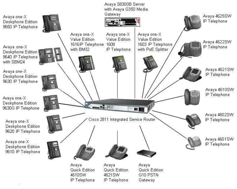
The Avaya product configurations addressed by these Application Notes are shown in Figure 1.
The following Avaya powered devices were covered:
• Avaya one-X DeskPhone Edition IP Telephones : 9610, 9620, 9630, 9630G, 9640 (with
SBM24), 9650
• Avaya 46xx Series IP Telephones: 4601, 4602, 4610, 4621, 4622, 4625
• Avaya one-X Deskphone Value Edition IP Telephones: 1603 with PoE Splitter, 1608,
1616 (with and without BM32 Button Module)
• Avaya Quick Edition: 4610, 4621, and G10 PSTN Gateway
Figure 1: Network Configuration

JC; Reviewed:
SPOC 9/25/2007 Solution & Interoperability Test Lab Application Notes
©2007 Avaya Inc. All Rights Reserved. 3 of 8
Cisco2811-POE
2. Equipment and Software Validated
The following equipment and software were used for the configuration provided:
Equipment Version
Avaya G350 Media Gateway with Avaya
S8300B Server Avaya Communication Manger 4.0.1
(R014x.00.1.731.2)
Avaya one-X Deskphone Edition 9610 IP
Telephone 1.5
Avaya one-X Deskphone Edition 9620 IP
Telephone 1.5
Avaya one-X Deskphone Edition 9630 IP
Telephone 1.5
Avaya one-X Deskphone Edition 9630G IP
Telephone 1.5
Avaya one-X Deskphone Edition 9640 IP
Telephone with SBM24 Button Module 1.5
Avaya one-X Deskphone Edition 9650 IP
Telephone 1.5
Avaya 4601SW IP Telephone 2.3
Avaya 4602+ IP Telephone 2.8
Avaya 4610SW IP Telephone 2.8
Avaya 4621SW IP Telephone 2.8
Avaya 4622SW IP Telephone 2.8
Avaya 4625SW IP Telephone 2.8
Avaya one-X Value Edition 1603 IP
Telephone with PoE Splitter 1.0
Avaya one-X Value Edition 1608 IP
Telephone 1.0
Avaya one-X Value Edition 1616 IP
Telephone with BM32 1.0
Avaya one-X Quick Edition 4610 IP
Telephone 7.2.1958
Avaya one-X Quick Edition 4621 IP
Telephone 7.2.1958
Avaya one-X Quick Edition G10 PSTN
Gateway 7.2.1958
Cisco 2811 Integrated Services Router
- EtherSwitch Service Module with IEEE
802.3af Support (NME-16ES-1G-P)
- Cisco 2811 AC inline power supply
(PWR-2811-AC-IP)
Revision 253.50 SW 12.4(3f)
12.2(25)SEC
-

JC; Reviewed:
SPOC 9/25/2007 Solution & Interoperability Test Lab Application Notes
©2007 Avaya Inc. All Rights Reserved. 4 of 8
Cisco2811-POE
3. Configuration of the Avaya endpoints
There is no configuration requirement on the Avaya endpoints to use PoE. For details on
configuring Avaya Servers, Gateways, or Endpoints, consult the Administrator’s guide [1].
4. IEEE 802.3af PoE Implementation on the Avaya PDs and
Cisco 2811 Integrated Services Router
In June 2003, the IEEE approved a standard for Power over Ethernet that allows a maximum of
15.4 W per PSE port. The maximum power delivered to the device, after cable loss, can be no
more than 12.95W. Optionally, the powered devices can be classified according to the maximum
power the device uses. This optional classification is supported on the Cisco 2811 Integrated
Services Router and Avaya PDs and the appropriate power is allocated to the PD.
The IEEE 802.3af classifications for the PDs are given in Table 1. Note that Class 0 and Class 3
are identical. The reason for this is that Class 0 covers the case where a powered device is
detected but the PSE cannot assign the powered device to Classes 1, 2, or 3.
Class PSE Output Max. Power
0 15.4 W
1 4.0 W
2 7.0 W
3 15.4 W
4 Treat as Class 0
Table 1 – IEEE 802.3af PSE and PD Power Classifications
Table 2 shows the detected class and power allocated from the Cisco 2811 Integrated Services
Router to the Avaya IP Telephones.
Avaya Product Class Power Allocated (Watts)
4601 2 7.0 Watts
4602+ 2 7.0 Watts
4610SW 2 7.0 Watts
4621SW 2 7.0 Watts
4622SW 2 7.0 Watts
4625SW 3 15.4 Watts
9610 2 7.0 Watts
9620 2 7.0 Watts
9630 2 7.0 Watts
9630G 2 7.0 Watts
9640 with SBM24 2 7.0 Watts
9650 2 7.0 Watts
1603 with POE Adapter 2 7.0 Watts
1608 2 7.0 Watts
1616 3 15.4 Watts

JC; Reviewed:
SPOC 9/25/2007 Solution & Interoperability Test Lab Application Notes
©2007 Avaya Inc. All Rights Reserved. 5 of 8
Cisco2811-POE
1616 with BM32 3 15.4 Watts
Quick Edition 4610 2 7.0 Watts
Quick Edition 4621 2 7.0 Watts
Quick Edition G10 0 15.4 Watts
Table 2 – Class and Power Allocation for Avaya IP Telephones
5. Configuring Inline Power on the Cisco 2811 Integrated
Services Router
The Cisco 2811 Integrated Services Router installed with a NME-16ES-1G-P EtherSwitch
Service Module and Cisco 2811 AC inline power supply (PWR-2811-AC-IP) supports 160 Watts
of inline power, which is enough to support Class 2 and some Class 3 PDs on all 16 ports. The
testing associated with these Application Notes did not cover loading of all ports on the PSE.
The ports connecting to the Avaya IP Telephones must be set to the default auto mode in order
to receive power from the router.
To access the router, connect the console cable to the PC’s serial port with the other end
connected to the router’s console port located at the front of the router. Use HyperTerminal to
access the console.
Assign an IP address to the interface associated with the EtherSwitch Service Module and then
open a session to it.
routername#config t
routername#interface gigabitEthernet 1/0
routername#ip address 10.1.20.15 255.255.255.0
routername#no shut
routername#service-module gigabitethernet 1/0 session

JC; Reviewed:
SPOC 9/25/2007 Solution & Interoperability Test Lab Application Notes
©2007 Avaya Inc. All Rights Reserved. 6 of 8
Cisco2811-POE
The power inline of each port is set to auto by default. The command show power inline will
display the inline power configuration and status.
To change the power mode, access the port interface and then use the command power inline
<auto|never|static>. The mode should be set to auto for Avaya IP Telephones to work.
Switch#config t
Switch(config)#interface fastethernet 1/0/5
Switch(config-if)#power inline ?
auto Automatically detect and power inline devices
never Never apply inline power
static High priority inline power interface
Switch(config-if)#
Switch>show power inline
Module Available Used Remaining
(Watts) (Watts) (Watts)
------ --------- -------- ---------
1 160.0 137.2 22.8
Interface Admin Oper Power Device Class Max
(Watts)
--------- ------ ---------- ------- --------- ----- ----
Fa1/0/1 auto on 7.0 Ieee PD 2 7.0
Fa1/0/2 auto on 7.0 Ieee PD 2 7.0
Fa1/0/3 auto on 15.4 Ieee PD 3 15.4
Fa1/0/4 auto on 7.0 Ieee PD 2 7.0
Fa1/0/5 auto on 15.4 Ieee PD 0 15.4
Fa1/0/6 auto on 15.4 Ieee PD 3 15.4
Fa1/0/7 auto on 7.0 Ieee PD 2 7.0
Fa1/0/8 auto on 7.0 Ieee PD 2 7.0
Fa1/0/9 auto on 7.0 Ieee PD 2 7.0
Fa1/0/10 auto on 7.0 Ieee PD 2 7.0
Fa1/0/11 auto on 7.0 Ieee PD 2 7.0
Fa1/0/12 auto on 7.0 Ieee PD 2 7.0
Fa1/0/13 auto on 7.0 Ieee PD 2 7.0
Fa1/0/14 auto on 7.0 Ieee PD 2 7.0
Fa1/0/15 auto on 7.0 Ieee PD 2 7.0
Fa1/0/16 auto on 7.0 Ieee PD 2 7.0
Switch>

JC; Reviewed:
SPOC 9/25/2007 Solution & Interoperability Test Lab Application Notes
©2007 Avaya Inc. All Rights Reserved. 7 of 8
Cisco2811-POE
6. Verification Steps
The following commands can be used verify the proper operation of the Cisco 2811 Integrated
Services Router.
• Connect the Avaya IP Telephones, Avaya Quick Edition IP Telephones and the Avaya
G10 PSTN Gateway to Cisco 2811 Integrated Services Router. Verify the Avaya IP
Telephones can be powered properly.
• Verify that the Avaya IP Telephones can register with Avaya Communication Manager
and calls can be made successfully.
• Use the command show power inline to check the power status of the EtherSwitch
Service Module ports. Verify the power mode is set to auto.
• Reset the router and verify the Avaya IP telephones can be powered up properly.
7. Conclusion
These Application Notes described configuration of the Cisco 2811 Integrated Services Router to
provide power over Ethernet to the Avaya IP Telephones, and the Avaya Quick Edition G10
PSTN Gateway. The Cisco 2811 was able to power all devices tested.
8. Additional References
The Avaya product documentation is available at http://support.avaya.com.
[1] Administrator Guide for Avaya Communication Manager, Release 4.0, Issue 3, February
2007, Document Number 03-300509.
Cisco documentation is available from the Cisco website.

JC; Reviewed:
SPOC 9/25/2007 Solution & Interoperability Test Lab Application Notes
©2007 Avaya Inc. All Rights Reserved. 8 of 8
Cisco2811-POE
©2007 Avaya Inc. All Rights Reserved.
Avaya and the Avaya Logo are trademarks of Avaya Inc. All trademarks identified by ® and
™ are registered trademarks or trademarks, respectively, of Avaya Inc. All other trademarks
are the property of their respective owners. The information provided in these Application
Notes is subject to change without notice. The configurations, technical data, and
recommendations provided in these Application Notes are believed to be accurate and
dependable, but are presented without express or implied warranty. Users are responsible for
their application of any products specified in these Application Notes.
Please e-mail any questions or comments pertaining to these Application Notes along with the
full title name and filename, located in the lower right corner, directly to the Avaya Solution &
Interoperability Test Lab at interoplabnotes@list.avaya.com
