User Guide Rational Rose RealTime Connexis
User Manual:
Open the PDF directly: View PDF ![]() .
.
Page Count: 384 [warning: Documents this large are best viewed by clicking the View PDF Link!]
- User Guide Rational Rose RealTime Connexis
- Preface
- Rational Connexis Overview
- Key Benefits of Connexis
- Connexis Leverages Proven Standards
- Connexis is Tightly Integrated with Rose RealTime
- Connexis Provides Access Transparency
- Connexis Provides Location Transparency
- Connexis is Very Flexible and Easily Configurable
- Connexis Provides Support for Testing Distributed Applications
- Connexis is Designed to be Fault-tolerant and Reliable
- Connexis Terminology and Definitions
- Connexis Application Layers
- The HelloWorld Model
- Using Connexis
- Key Benefits of Connexis
- Using Connexis Model Examples
- Quick Start
- Quick Start Overview
- Iteration 1: Creating the Rose RealTime Model
- Iteration 2: Connexis Enabling our Application
- Step 1: Remove the Connector Between the pingPong Ports
- Step 2: Make Changes to Pong’s pingPong Port
- Step 3: Make Changes to Ping’s pingPong Port
- Step 4: Adding DCS Layer Notification to the Ping and Pong Capsules
- Step 5: Modify Ping’s State Machine to Wait for Connexis
- Step 6: Modify Pong’s State Machine to Wait for Connexis
- Step 7: Modify Ping’s State Machine to Wait for Notify
- Step 8: Add Registration Code to the Ping and Pong Capsules
- Step 9: Add the Connexis Configuration Capsules to Your Model
- Step 10: Create and Configure the Ping Component
- Step 11: Create and Configure the Pong Component
- Step 12: Add Component Dependencies
- Step 13: Build and Execute the Models
- Basic Connexis Development Approach Summary
- Adding Connexis Support to Your Model
- Establishing Connections
- Using the Connexis Locator Service
- Using the Connexis Viewer
- Viewer Architecture
- Adding Viewer Support to a Model
- Adding Metrics Support to a Model
- Starting the Connexis Viewer
- Duplicate CNX Unique Identifiers
- Viewer Main Window
- Viewer Menus
- Explorer Tree View
- Popup Menus
- Creating Processors and Component Instances
- Performing Event Tracing
- Trace Window
- Generating Interaction Diagrams from Trace Output Files
- Log Window
- Displaying the Metrics Collection
- Viewer Tips and Usage Notes
- Using the Connexis Metrics Service
- Registration String Grammar
- Connexis Command Line Options
- Component Instance with Fixed Endpoints (no locator service)
- Component Instance using CDM Endpoint, Locator using CDM
- Component Instance using CDM and CRM Endpoints, Primary Locator using CDM, Backup Locator using CRM
- Component Instance with CDM and CRM, CRM is Preferred Transport
- Miscellaneous Command Line Options
- Connexis Messages, Errors, and Warnings
- Connexis Customization Reference
- Customizing and Porting DCS Libraries
- Using the Transport Integration Framework
- Transport Integration Overview
- DCS Architecture
- Terminology
- Connection Lifecycle
- DCS Threading Model
- Understanding your Transport
- Determine the Name of your Transport and Protocols
- Decide the String Format of the User-specified Address
- Decide How to Validate the Address
- Decide the Transformation of the Address
- Determine the Internal Representation of your Address
- Decide the Format of the Listening Point Information
- Decide if your Transport is Blocking or Non-blocking
- Decide the Recommended Address Resolution Configuration
- Decide How the Transport will Recover from Transport Failures
- Decide How to Audit your Transport
- Decide the Format of your Messages
- Decide Strategy for Listening for Messages
- Integrating your Transport
- Setting up the Model
- Understand the Integrated Transport
- Implementing the RTDTransportAddressFactory Subclass
- Implementing the RTDTransportAddress Subclass
- Implementing the RTDTransportEndpointFactory Subclass
- Implementing the RTDTransportEndpoint Subclass
- Implementing the RTDTransport Subclass
- Building the Transport Integration
- Packaging the Transport Integration
- Using the Transport Integration in Another Model
- Testing the Transport Integration
- TIF Classes
- Comparison of TCP/IP and UDP/IP
- Index

Rational Software Corporation
support@rational.com
http://www.rational.com
User Guide
RATIONAL ROSE® REALTIME CONNEXIS
VERSION: 2002.05.00
PART NUMBER: 800-025101-000
WINDOWS/UNIX
IMPORTANT NOTICE
COPYRIGHT
Copyright ©1993-2001, Rational Software Corporation. All rights reserved.
Part Number: 800-025101-000
Version Number: 2002.05.00
PERMITTED USAGE
THIS DOCUMENT CONTAINS PROPRIETARY INFORMATION WHICH IS THE
PROPERTY OF RATIONAL SOFTWARE CORPORATION (“RATIONAL”) AND IS
FURNISHED FOR THE SOLE PURPOSE OF THE OPERATION AND THE
MAINTENANCE OF PRODUCTS OF RATIONAL. NO PART OF THIS
PUBLICATION IS TO BE USED FOR ANY OTHER PURPOSE, AND IS NOT TO BE
REPRODUCED, COPIED, ADAPTED, DISCLOSED, DISTRIBUTED,
TRANSMITTED, STORED IN A RETRIEVAL SYSTEM OR TRANSLATED INTO
ANY HUMAN OR COMPUTER LANGUAGE, IN ANY FORM, BY ANY MEANS, IN
WHOLE OR IN PART, WITHOUT THE PRIOR EXPRESS WRITTEN CONSENT OF
RATIONAL.
TRADEMARKS
Rational, Rational Software Corporation, Rational the e-development company,
ClearCase, ClearCase Attache, ClearCase MultiSite, ClearDDTS, ClearQuest,
ClearQuest MultiSite, DDTS, Object Testing, Object-Oriented Recording, ObjecTime
& Design, Objectory, PerformanceStudio, ProjectConsole, PureCoverage,
PureDDTS, PureLink, Purify, Purify'd, Quantify, Rational, Rational Apex, Rational
CRC, Rational Rose, Rational Suite, Rational Summit, Rational Visual Test, Requisite,
RequisitePro, RUP, SiteCheck, SoDA, TestFactory, TestFoundation, TestMate, The
Rational Watch, AnalystStudio, ClearGuide, ClearTrack, Connexis, e-Development
Accelerators, ObjecTime, Rational Dashboard, Rational PerformanceArchitect,
Rational Process Workbench, Rational Suite AnalystStudio, Rational Suite
ContentStudio, Rational Suite Enterprise, Rational Suite ManagerStudio, Rational
Unified Process, SiteLoad, TestStudio, VADS, among others, are either trademarks or
registered trademarks of Rational Software Corporation in the United States and/or
in othercountries.All other names are used for identification purposes only, and are
trademarks or registered trademarks of their respective companies.
Microsoft, the Microsoft logo, Active Accessibility, Active Channel, Active Client,
Active Desktop, Active Directory, ActiveMovie, Active Platform, ActiveStore,
ActiveSync, ActiveX, Ask Maxwell, Authenticode, AutoSum, BackOffice, the
BackOffice logo, BizTalk, Bookshelf, Chromeffects, Clearlead, ClearType, CodeView,
Computing Central, DataTips, Developer Studio, Direct3D, DirectAnimation,
DirectDraw, DirectInput, DirectMusic, DirectPlay, DirectShow, DirectSound, DirectX,
DirectXJ, DoubleSpace, DriveSpace, FoxPro, FrontPage, Funstone, IntelliEye, the
IntelliEye logo, IntelliMirror, IntelliSense, J/Direct, JScript, LineShare, Liquid Motion,
the Microsoft eMbedded Visual Tools logo, the Microsoft Internet Explorer logo, the
Microsoft Office Compatible logo, Microsoft Press, the Microsoft Press logo, Microsoft
QuickBasic, MS-DOS, MSDN, Natural, NetMeeting, NetShow, the Office logo, One
Thumb, OpenType, Outlook, PhotoDraw, PivotChart, PivotTable, PowerPoint,
QuickAssembler, QuickShelf, Realmation, RelayOne, Rushmore, SourceSafe,
TipWizard, TrueImage, TutorAssist, V-Chat, VideoFlash, Virtual Basic, the Virtual
Basic logo, Visual C++, Visual FoxPro, Visual InterDev, Visual J++, Visual SourceSafe,
Visual Studio, the Visual Studio logo, Vizact, WebBot, WebPIP, Win32, Win32s, Win64,
Windows, the Windows CE logo, the Windows logo, Windows NT, the Windows Start
logo, and XENIX are trademarks or registered trademarks of Microsoft Corporation in
the United States and other countries.
FLEXlm and GLOBEtrotter are trademarks or registered trademarks of GLOBEtrotter
Software, Inc. Licensee shall not incorporate any GLOBEtrotter software (FLEXlm
libraries and utilities) into any product or application the primary purpose of which is
software license management.
Portions Copyright ©1992-20xx, Summit Software Company. All rights reserved.
PAT E N T
U.S. Patent Nos.5,193,180 and 5,335,344 and 5,535,329 and 5,835,701. Additional
patents pending.
Purify is licensed under Sun Microsystems, Inc., U.S. Patent No. 5,404,499.
GOVERNMENT RIGHTS LEGEND
Use, duplication, or disclosure by the U.S. Government is subject to restrictions set
forth in the applicable Rational Software Corporation license agreement and as
provided in DFARS 277.7202-1(a) and 277.7202-3(a) (1995), DFARS
252.227-7013(c)(1)(ii) (Oct. 1988), FAR 12.212(a) (1995), FAR 52.227-19, or FAR 227-14,
as applicable.
WARRANTY DISCLAIMER
This document and its associated software may be used as stated in the underlying
license agreement. Rational Software Corporation expressly disclaims all other
warranties, express or implied, with respect to the media and software product and its
documentation, including without limitation, the warranties of merchantability or
fitness for a particular purpose or arising from a course of dealing, usage, or trade
practice.

User Guide - Rational Rose RealTime Connexis v
Contents
Preface i
Road Map ii
Related Documentation ii
How to Get Help iii
When contacting Rational technical support iii
Rational web site iii
Other Resources iii
Contacting Rational Technical Publications iv
Contacting Rational Technical Support iv
Chapter 1 Rational Connexis Overview 5
Key Benefits of Connexis 5
Connexis Leverages Proven Standards 6
Connexis is Tightly Integrated with Rose RealTime 6
Connexis Provides Access Transparency 7
Connexis Provides Location Transparency 7
Connexis is Very Flexible and Easily Configurable 8
Connexis Provides Support for Testing Distributed Applications 9
Connexis is Designed to be Fault-tolerant and Reliable 9
Connexis Terminology and Definitions 11

vi User Guide - Rational Rose RealTime Connexis
Connexis Application Layers 13
UML Application 14
Ports in Rose RealTime 14
Distributed Connection Service 16
Transport 16
Locator Service 17
Using the locator 17
The HelloWorld Model 18
Running the HelloWorld Model 18
Additional HelloWorld Models 19
HelloWorldHotStandby 19
HelloWorldLoadSharing 19
HelloWorldOverflowToBackupService 19
HelloWorldRedundantLocator 20
Using Connexis 20
Chapter 2 Using Connexis Model Examples 21
The BasicTest Model 21
The Quick Start Model 22
Quick Start Iteration 1 Model 22
Quick Start Iteration 2 Model 22
The HelloWorld Model 23
Running the HelloWorld Model 23
Additional HelloWorld Models 24
HelloWorldHotStandby 24
HelloWorldLoadSharing 24
HelloWorldOverflowToBackupService 24
HelloWorldRedundantLocator 25
The DCS Performance Model 25
Running the Performance Model 25
Performance model server output 27
Performance model client output 28

User Guide - Rational Rose RealTime Connexis vii
Chapter 3 Quick Start 31
Quick Start Overview 31
Iteration 1: Creating the Rose RealTime Model 35
Step 1: Create a New Model 35
Step 2: Create Packages for the Model 35
Step 3: Create the Ping, Pong, and ContainerCapsules 38
Step 4: Create the PingPong Protocol Class 40
Step 5: Build the Structure of the Model 43
Step 6: Implement the State Machines for Ping and Pong 48
Step 7: Build and Test the Model 53
Iteration 2: Connexis Enabling our Application 59
Step 1: Remove the Connector Between the pingPong Ports 59
Step 2: Make Changes to Pong’s pingPong Port 60
Step 3: Make Changes to Ping’s pingPong Port 61
Step 4: Adding DCS Layer Notification to the Ping and Pong
Capsules 63
Step 5: Modify Ping’s State Machine to Wait for Connexis 64
Step 6: Modify Pong’s State Machine to Wait for Connexis 65
Step 7: Modify Ping’s State Machine to Wait for Notify 66
Step 8: Add Registration Code to the Ping and Pong Capsules 67
Step 9: Add the Connexis Configuration Capsules to Your Model 69
Step 10: Create and Configure the Ping Component 74
Step 11: Create and Configure the Pong Component 75
Step 12: Add Component Dependencies 77
Step 13: Build and Execute the Models 79
Basic Connexis Development Approach Summary 82
Chapter 4 Adding Connexis Support to Your Model 83
Sharing DCS Interfaces 84
Sharing DCS Interfaces into your Model 84
Removing Shared Packages 85

viii User Guide - Rational Rose RealTime Connexis
Configuring Connexis Capsules 85
Manually Integrating Transports Into a Model 88
Configuring a Component for Connexis 90
Verifying Connexis Enabled Components 91
Initializing Your Connexis Capsule 92
Using the RTDInitStatus Protocol 93
Using Fixed Initialization Order 98
Converting Connexis Version 2000.02.10 Models to Connexis
2001A.04.00 Models 99
Verifying Component Compatibility with Connexis Version
2001A.04.00. 103
RTDErrorType Error Reporting 104
Chapter 5 Establishing Connections 107
General Connection Patterns 108
Client/Server 108
Peer to Peer 109
Unwired Port Registration 110
What is Registration? 111
Port API 112
Automatic vs. Application Registration 113
Registration Parameters 115
Name Resolution 118
Connexis Connection Options 118
Local Connections 119
External Explicit Connections 124
External explicit examples 124
Locator Connections 125
Registration Summary 127
Scenario 1: Publisher Registered with the ILS 127
Scenario 2: Publisher Registered with the DCS 128
Scenario 3: Publisher Registered with the Locator 130
Multiple Publishers 131

User Guide - Rational Rose RealTime Connexis ix
Connection Design Heuristics 131
When to Use Replicated Publisher Ports 131
Use of Invokes 132
Use of Broadcast Sends 132
Use of Notification 133
Use of Defers 133
Sending Data 134
Sending Data Classes by Value 134
Chapter 6 Using the Connexis Locator Service 135
Adding Locator Support to a Model 136
Publication and Subscription 136
Publication 136
Subscription 137
Ranking Published Ports 137
Load-sharing of Publishers 138
Examples 138
Locator Dynamics 140
Fully Subscribed Publishers 141
Subscriber Losing Connection to a Publisher 142
Locator Failure 142
Locator Race Condition 144
Unconnected Subscribers 145
Locator Configuration 145
Locator Parameters 145
Locator Parameter Examples 149
Creating your Own Name Service 150
Chapter 7 Using the Connexis Viewer 151
Viewer Architecture 153
Adding Viewer Support to a Model 153
Adding Metrics Support to a Model 154

x User Guide - Rational Rose RealTime Connexis
Starting the Connexis Viewer 155
Duplicate CNX Unique Identifiers 156
Viewer Main Window 156
Viewer Menus 158
File Menu 158
View Menu 158
Tools Menu 159
Windows Menu 161
Help Menu 161
Explorer Tree View 162
Processor Icons 163
Component Instance Icons 163
Filter Icons 164
Component Instance Status 164
Named Services Icons 165
Port Icons 165
Virtual Circuit Icons 166
Object Information Column 167
Popup Menus 168
Session Popup Menu 168
Processor Popup Menu 169
Component Instance Popup Menu 170
Port Reference Popup Menu 173
Virtual Circuit Popup Menu 174
Creating Processors and Component Instances 175
Adding a Processor 175
Changing the Properties of a Processor 176
Removing a Processor 177
Adding a Component Instance 177
Changing the Properties of a Component Instance 180

User Guide - Rational Rose RealTime Connexis xi
Performing Event Tracing 182
Defining a Trace Filter for a Component Instance 182
Setting trace filters 185
Defining a Port Reference Trace 188
Defining a Virtual Circuit Trace 192
Trace Window 194
Component Instance Trace Window 194
Virtual Circuit Trace Window 195
Trace Window Popup Menu 196
Show trace data 197
Define trace 199
Trace active 199
Select in tree 199
Clear 199
Save trace 199
Trace Header Context Menu 201
Generating Interaction Diagrams from Trace Output Files 202
Reporting of error messages 206
Log Window 206
Displaying the Metrics Collection 207
Starting Metrics Collection 208
Using the Metrics Window 208
Summary metrics collection 210
Detailed metrics collection 214
Messages metrics collection 216
Audits metrics collection 219
Engineering metrics collection 221
DCS errors metrics collection 225
Application errors metrics collection 228
Application incompatibility metrics collection 232
Stopping Metrics Collection 234
Saving Collected Metrics 234

xii User Guide - Rational Rose RealTime Connexis
Viewer Tips and Usage Notes 234
Capturing Pre-Viewer Session Messages 234
Error and Warning Tracing 235
Software errors 235
Software warnings 235
Maximizing Viewer Responsiveness 235
Chapter 8 Using the Connexis Metrics Service 237
Obtaining Metrics Data with a Metrics Service 237
Enabling Metrics in the DCS library 238
Adding a Metrics Port 238
Subscribing to the Metrics Service 238
Collecting and Processing Metrics 239
Using Metrics and the Connexis Viewer 243
Chapter 9 Registration String Grammar 245
Registration String Grammar for DCS Registrations 245
Chapter 10 Connexis Command Line Options 247
Component Instance with Fixed Endpoints (no locator service) 247
Component Instance using CDM Endpoint, Locator using CDM 248
Component Instance using CDM and CRM Endpoints, Primary
Locator using CDM, Backup Locator using CRM 249
Component Instance with CDM and CRM, CRM is Preferred Transport
250
Miscellaneous Command Line Options 250
Chapter 11 Connexis Messages, Errors, and Warnings 255
Initialization Messages 255
Initialization Errors 257
Parameter Errors 257

User Guide - Rational Rose RealTime Connexis xiii
Chapter 12 Connexis Customization Reference 261
Engineering Rules Overview 262
Thread Configuration 262
Process view of a Connexis application 263
Default number of threads 264
The application layer 265
DCS and transport Layer 265
Buffer Configuration 266
Overall buffer configuration of a Connexis application 266
Application layer 267
DCS layer 268
Connexis buffer usage 270
Configuring the Number of Virtual Circuits 271
Verifying Connections 272
Handshake audit 272
Connection audit 273
Reset audit 273
Command Line Options Reference 274
Setting Command Line Options 274
System wide 275
DCS options 277
Transporter options 278
Transport specific options 282
CDM 285
Locator 286
Connexis viewer/target agent 287
Chapter 13 Customizing and Porting DCS Libraries 289
Common customizations for the DCS 289
Other resources 290
Operating system capabilities 290
What to do before calling Rational support 290
Porting the DCS to a New Target Configuration 290
Creating a New TargetRTS Library 291
Creating DCS Target Specific Header Files 292
Loading the DCS Model 293
Creating a C++ Library Component 293
Configuring the C++ Library Component Settings 294

xiv User Guide - Rational Rose RealTime Connexis
Configuring the CDR Encode/Decode Functionality 296
Creating a Minimal DCS Library Configuration 296
Building the Library 297
Testing the Port 297
Chapter 14 Using the Transport Integration Framework 299
Transport Integration Overview 300
DCS Architecture 301
Terminology 302
Connection Lifecycle 303
DCS Threading Model 304
Understanding your Transport 305
Determine the Name of your Transport and Protocols 306
Decide the String Format of the User-specified Address 306
Decide How to Validate the Address 306
Decide the Transformation of the Address 307
Determine the Internal Representation of your Address 308
Decide the Format of the Listening Point Information 309
Decide if your Transport is Blocking or Non-blocking 309
Decide the Recommended Address Resolution Configuration 310
Decide How the Transport will Recover from Transport Failures
311
Decide How to Audit your Transport 311
Decide the Format of your Messages 312
Decide Strategy for Listening for Messages 313
Integrating your Transport 315
Setting up the Model 315
Understand the Integrated Transport 316
Implementing the RTDTransportAddressFactory Subclass 316
Implementing the RTDTransportAddress Subclass 317
Implementing the RTDTransportEndpointFactory Subclass 318
Implementing the RTDTransportEndpoint Subclass 319
Implementing the RTDTransport Subclass 320

User Guide - Rational Rose RealTime Connexis xv
Building the Transport Integration 321
Packaging the Transport Integration 321
Using the Transport Integration in Another Model 322
Testing the Transport Integration 322
TIF Classes 322
RTDTransportAddress 325
Constructors 327
RTDTransportEndpointFactory 331
RTDTransportEndpoint 332
Constructor 333
RTDTransport 339
RTDTIF 341
RTDTransportProfile 341
RTDConnexisAPI 348
Appendix A Comparison of TCP/IP and UDP/IP 355
Index 357

xvi User Guide - Rational Rose RealTime Connexis

User Guide - Rational Rose RealTime Connexis i
Preface
This document is organized so that each chapter is as stand-alone as
possible. This section provides a brief overview of the content of each
chapter and several reading paths through the document based on
reader knowledge.
“Rational Connexis Overview” on page 5, provides a brief introduction
to Connexis, the solutions that it provides and its primary features.
“Quick Start” on page 31, provides a simple Connexis tutorial. This
tutorial is also useful for those who are new to Rose RealTime.
“Adding Connexis Support to Your Model” on page 83 describes how to
add Connexis support to your Rose RealTime model.
“Establishing Connections” on page 107, elaborates on the concepts
presented in the Overview chapter. This chapter describes the different
ways of creating connections using Connexis, the syntax for describing
Connexis endpoints and the parameters that can be supplied as part
of registering connection endpoints.
“Using the Connexis Locator Service” on page 135, describes the
Connexis Locator Service and how to configure it to run in a distributed
application.
“Using the Connexis Viewer” on page 151, describes the Connexis
Viewer and how to configure it to view a distributed application.
“Using the Connexis Metrics Service” on page 237 describes how to
collect DCS statistics from within a Rose RealTime executable model.
“Registration String Grammar” on page 245 provides information on
the Backus-Naur Form (BNF) Grammar for the registerSAP and
registerSPP commands.

Preface
ii User Guide - Rational Rose RealTime Connexis
“Connexis Command Line Options” on page 247 provides command
line examples for commonly-used Connexis configurations.
“Connexis Messages, Errors, and Warnings” on page 255 provides
information to assist users in developing and debugging their models.
“Connexis Customization Reference” on page 261, describes the
different configuration options that can be used to customize how
Connexis works.
“Customizing and Porting DCS Libraries” on page 289, describes the
Distributed Connection Service and explains how to customize or port
DCS libraries to a new target environment.
“Using the Transport Integration Framework” on page 299, describes
the Connexis Transport Integration Framework and how to integrate
common or customized transport in a distributed application.
“Comparison of TCP/IP and UDP/IP” on page 355, provides
background information about TCP/IP and UDP/IP.
Road Map
People who are new to Rose RealTime should review the Rose RealTime
documentation followed by the Overview and Quick Start chapters of
this document.
People who are new to Connexis, should read the Overview and Quick
Start chapters before any other part of the manual.
If you are already familiar with Rose RealTime and have a good
understanding of the problems that Connexis solves, you may want to
start with Establishing Connections, and refer to the Overview chapter
only when terms or concepts are unfamiliar to you.
Related Documentation
The following is a list of documentation that is related to the Connexis
product.
■Rose RealTime online Help and user documentation. This
documentation is available online with the Rose RealTime product.
■ISO/IEC 10746-1 ODP Reference Model Part 1. This specification
details the challenges and potential solutions to distributed
computing.

How to Get Help
User Guide - Rational Rose RealTime Connexis iii
How to Get Help
This section describes procedures for interacting with Rational
Software Corporation's technical support services.
When contacting Rational technical support
When contacting technical support for Rose RealTime, please be
prepared to supply the following information:
■Name, telephone number, and company name.
■Product version number (found in the viewer’s Help > About dialog).
■Computer make and model.
■Make and version of the operating system.
■Make and version of development tools (configuration management
program, compiler, linker, RTOS, requirements management
program).
■Your log number (if you are calling about a previously reported
problem).
If your site has a designated, on-site support person, please try to
contact that person before contacting Rational technical support.
Rational web site
You can contact technical support and obtain the latest product
information through our web site at:
http://www.rational.com/products/rosert
Other Resources
■Online Help is available for Rational Rose RealTime.
Select an option from the Help menu
All manuals are available online, either in HTML or PDF format.
To access the online manuals, click Rose RealTime Online Documentation
from the Start menu.
■For more information on training opportunities, see the Rational
University Web site: http://www.rational.com/university.

Preface
iv User Guide - Rational Rose RealTime Connexis
Contacting Rational Technical Publications
To send feedback about documentation for Rational products, please
send e-mail to our Technical Documentation Department at
techpubs@rational.com.
Contacting Rational Technical Support
If you have questions about installing, using, or maintaining this
product, contact Rational Technical Support.
Note: When you contact Rational Technical Support, please be prepared
to supply the following information:
■Your name, telephone number, and company name
■Your computer’s make and model
■Your computer’s operating system and version number
■Product release number and serial number
■Your case ID number (if you are following up on a previously-
reported problem)
Your Location Telephone Fax E-mail
North America (800) 433-5444
(toll free)
(408) 863-4000
Cupertino, CA
(781) 676-2460
Lexington, MA
support@rational.com
Europe, Middle
East, Africa
+31 (0) 20-4546-200
Netherlands
+31 (0) 20-4546-202
Netherlands
support@europe.rational.com
Asia Pacific +61-2-9419-0111
Australia
+61-2-9419-0123
Australia
support@apac.rational.com

User Guide - Rational Rose RealTime Connexis 5
Chapter 1
Rational Connexis Overview
Rational Connexis is a Rational Rose for RealTime add-in product that
provides connectivity for Unified Modeling Language (UML) models.
Connexis is tightly integrated with Rose RealTime and is highly
optimized for event-driven asynchronous systems.
Connexis improves an application’s time to market by eliminating the
need to design, develop, and test a custom Inter-Process
Communications (IPC) mechanism. The use of a Commercial Off The
Shelf (COTS) distribution component, such as Connexis, simplifies and
de-risks the design and deployment of distributed systems.
Key Benefits of Connexis
In addition to the time to market advantage of using Connexis, there
are also several technical advantages to using Connexis. These are
listed below and will be discussed in more detail in the following
sections:
■Connexis Leverages Proven Standards
■Connexis is Tightly Integrated with Rose RealTime
■Connexis Provides Access Transparency
■Connexis Provides Location Transparency
■Connexis is Very Flexible and Easily Configurable
■Connexis Provides Support for Testing Distributed Applications
■Connexis is Designed to be Fault-tolerant and Reliable
Chapter 1 Rational Connexis Overview
6 User Guide - Rational Rose RealTime Connexis
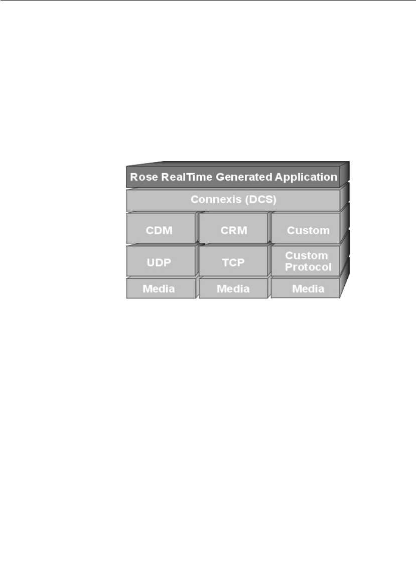
Connexis Leverages Proven Standards
Connexis is built upon current industry-standard technologies.
Connexis supports sending UML-defined data classes between Rose
RealTime models running in different processes and lets you integrate
proven transports using the Connexis Transport Integration
Framework. As shown in Figure 1, Connexis Datagram Messaging
(CDM) is designed on top of UDP and Connexis Reliable Messaging
(CRM) is designed on top of TCP. Connexis also supports custom
messaging transports, allowing your applications to support native
communication protocols to improve service.
Figure 1 Connexis Architecture
Connexis is Tightly Integrated with Rose RealTime
The Connexis product is tightly integrated with Rose RealTime. Adding
Connexis support to a Rose RealTime model simply involves sharing
Connexis packages, adding Connexis capsule roles to the model, and
configuring components for your application. Transports that are
integrated into Connexis are available to the application in the same
manner as standard Connexis transports. Using transports provided
by Connexis and using integrated transports are very similar. Once you
have used one, you can use any other.

Key Benefits of Connexis
User Guide - Rational Rose RealTime Connexis 7
If you know how to use Rose RealTime, learning how to use Connexis
is easy. Connexis ports are unwired ports in your Rose RealTime model
that you register with the Target RSL using a Connexis registration
string. The only concept that is new to a Rose RealTime user is the
format of the Connexis registration string. Once the ports are
registered, sending and receiving messages on them occurs in the
exact same way as it does in a UML model that does not use Connexis.
Connexis Provides Access Transparency
The flexible encoding and decoding strategy that is used by Connexis
allows Connexis to work on different types of hardware environments.
The endian of the target environment is transparent to the executing
application.
Connexis Provides Location Transparency
The Connexis Locator service provides location transparency for a
distributed application. The application uses service names to refer to
the endpoints that are being connected. As a result, the physical
address of these endpoints never has to be revealed to the application.
Locator features are available for services published on integrated
transport addresses. Connexis also supports many different
distribution options which allow the design of the application to be very
flexible.
The following are the most common types of connections supported:
■Local connections
Connexis supports local connections which are optimized to be as
efficient as directly wired ports. The endpoints of the local
connections are registered using service names and Connexis
takes care of binding the endpoints together. Once bound, these
local connections have the same performance characteristics as
two wired ports that have been bound together.
■Explicit endpoint connections
Connexis accepts registrations that use explicit endpoint addresses
in the registration string. This can be used if the application knows
the processor location of the services that it wants to access. In
this way a client can bind to a service using the explicit processor
location and the service name of the desired service.

Chapter 1 Rational Connexis Overview
8 User Guide - Rational Rose RealTime Connexis
■Locator connections
The Connexis Locator service can be used to find a service (given
the service name) anywhere in the distributed application. Once
the Locator has been started, one side of the connection registers
with it as the publisher, and the other side registers as the
subscriber. The Connexis Locator finds the appropriate endpoints,
and feeds them back to the connection service which establishes
the connection.
Connexis is Very Flexible and Easily Configurable
Connexis supports a wide range of configuration options. This enables
the engineering of Connexis to be very flexible and adaptable to
different target environments. Configuration options are available to:
■configure connection audits
■adjust buffer counts and sizes
■adjust thread priorities and stack sizes
■adjust message delivery timing characteristics
The Target Agent, which interfaces to the Connexis Viewer, and the
Connexis Locator Service do not have to be a part of every Connexis
application. If your application does not use the Locator and you do not
need access to the Connexis Viewer, these components can be left out
of the node’s configuration. This helps minimize the size of the
Connexis code that gets linked in your application. For more
information about the Connexis Viewer refer to “Using the Connexis
Viewer” on page 151. For more information on the Connexis Locator
Service refer to “Using the Connexis Locator Service” on page 135.
Connexis allows multiple ports to be registered with the same service
name. This, coupled with the normal Rose RealTime feature of port
multiplicity, enables several simple distribution patterns to be
supported automatically by Connexis. Patterns that are not directly
supported can usually be implemented very easily in Rose RealTime.
Connexis is shipped with full source. The library can be rebuilt if
needed for a custom environment configuration.

Key Benefits of Connexis
User Guide - Rational Rose RealTime Connexis 9
Connexis Provides Support for Testing Distributed Applications
One of the tools that comes with Connexis is the Connexis Viewer. The
Connexis Viewer allows developers to attach to running Connexis
applications and to graphically view connections as they are being
established and taken down. The Viewer provides a minimally-
intrusive tracing mechanism that allows you to trace messages that are
being sent and received by any of the endpoints in a distributed
application. The Viewer also receives messages from integrated
transports and collects metrics information.
The traditional method of testing a distributed Rose RealTime
application is to attach a probe on each end of a virtual circuit to make
sure that the connection has been established. This method of testing
does not scale well. In large systems, it is very difficult to know where
the other end of a virtual circuit is in the model (consider systems with
replicated publishers or multiple publishers with the same name). The
Connexis Viewer simplifies the monitoring of distributed connections.
The Viewer also has the ability to import the deployment diagram from
a Rose RealTime model so that the information about the distributed
application does not have to be entered in two places. The Rose
RealTime target observability feature can also be used to trace message
flow on unwired Connexis ports.
The Connexis installation provides DCS libraries that are compiled
with debugging capabilities for the Connexis Viewer and the Target
Observability feature of Rose RealTime. This library configuration
makes the initial debugging of distributed applications easier. As the
application becomes more mature, consider building a minimal
configuration of the DCS libraries for your target configuration.
Building a minimal configuration is described in “Customizing and
Porting DCS Libraries” on page 289.
Connexis is Designed to be Fault-tolerant and Reliable
Fault tolerance and reliability are paramount to most real-time
systems. Connexis has been designed with these requirements in
mind. The following is a list of the different Connexis features that
enhance the fault tolerance and reliability of Connexis:
■The Locator Service can be run in simplex or duplex mode. A
binary elector is used to determine the health of the primary
locator.

Chapter 1 Rational Connexis Overview
10 User Guide - Rational Rose RealTime Connexis
■Connexis has been designed with true non-blocking behavior. All
potentially blocking system calls are handled by a user-
configurable set of helper threads. Name resolving is an example of
an operation that makes use of helper threads.
■A heart beat style audit is used over the UDP datagram based
connections to detect connection / process / processor failure.
This audit is tunable so that it can be used in a variety of
environments. The audit is highly efficient since it monitors user
messages to collect status information. This allows the explicit “Are
you Alive” messages to be suppressed. When explicit “Are You
Alive” messages are used, the number of such messages sent per
unit of time can be capped to ensure that audits do not overutilize
system resources. When a connection-oriented protocol (such as
TCP) is used, only a very basic, “is the connection alive,” protocol is
used.
■Buffering policies can be configured between the UML
asynchronous messaging controller and the flow-controlled
transport message router. This ensures that your model never
hangs due to a slow or broken transport connection. When the
queue fills up, messages are properly deleted from the system.
■It is easy to build a set of components that meet application
specific requirements for fault-tolerance and reliability. A pair of
generic signals, rtBound and rtUnbound, are supported for all
Rose RealTime and Connexis ports. Notification can be enabled on
a per-port basis and utilized by the application with minimal
additional complexity.
■The underlying “try-forever” algorithm can be overridden by the
application simply by deregistering the unwired port when quality
of service parameters are not met.
■Patterns for distribution can be implemented using Connexis as
the underlying distribution mechanism. For example, a single
publisher can actually hide multiple distributed connections to a
replicated service.
■Resource limits can be placed on publishers of services to limit the
number of subscribers per publisher.
■The allocation of unwired ports to capsules is under the control of
the designer and since the incarnation of capsules onto threads is
also under control of the application, the application can
dynamically control which resources are being used.

Connexis Terminology and Definitions
User Guide - Rational Rose RealTime Connexis 11
■Services can be ranked according to the preferred order of use.
This ranking is done with full, dynamically updated knowledge of
the resource limits. If a given service is full, one of a lower rank will
be used if available.
■Configurable system audits verify that the internal system
connection state matches across the entire system.
Connexis Terminology and Definitions
Table 1 lists and defines Connexis and UML terms and acronyms.
Table 1 Definitions
Term Definition
CDM Connexis Datagram Messaging. A thin layer on top of UDP
that provides additional support for connection auditing
and quality of service parameters.
CRM Connexis Reliable Messaging. A thin layer on top of TCP
that provides additional support for connection auditing
and quality of service parameters.
DCS Distributed Connection Service. This is the key
component used for connecting and managing the
different parties in a connection.
DNS Domain Name System (or Service), an Internet service
that translates domain names into IP addresses. Because
domain names are alphanumeric, they are easier to
remember; however, the Internet is really based on IP
addresses. Every time you use a domain name, a DNS
service must translate the name into the corresponding IP
address. For example, the domain name
www.example.com might translate to 198.105.232.4.
duplex locator
service
Refers to a configuration in which there are two locators.
In normal operation, one locator acts as the active locator
and the other acts as the standby locator. This
configuration is used to prevent a locator from being a
single point of failure.
endpoint An endpoint is an explicit network address used for
finding a peer object. It consists of a protocol followed by a
colon, followed by a protocol-address. For example:
cdm://ipaddress:port.

Chapter 1 Rational Connexis Overview
12 User Guide - Rational Rose RealTime Connexis
ILS Internal Layer Service. This is the connection service that
is built into Rose RealTime. It can only be used for
establishing intra-process connections.
IPC Inter-Process Communication. This is a broad term that
is being used to describe any mechanism that is used to
share information between processes. This could be
something as simple as shared memory or something as
sophisticated as CORBA.
Locator The Connexis Locator Service is a configurable service
that is used to look up the physical location of an object
given a service name for that object.
notification The term used to describe the process of sending a
message to a capsule to inform it when one of its ports
has been connected to, or disconnected from, its peer.
SAP Service Access Point. Term used to describe an unwired
port that is participating in a connection as the
subscriber. The SAP acronym appears in portions of the
Run-time Service Library’s API.
simplex locator
service
Refers to a configuration in which there is only one
locator. This configuration does not provide redundancy.
See also “duplex locator service.”
SPP Service Provisioning Point. Term used to describe an
unwired port that is participating in a connection as the
publisher. The SPP acronym appears in portions of the
Run-time Service Library’s API.
tagged-values Term used to represent the parameters that are being
passed to the Connection Service when registering an
unwired port.
Target RSL Target Run-time System Libraries. These are the libraries
that are compiled into a Rose RealTime model and that
implement the messaging, state walking, and timing
service (among other services) of a Rose RealTime model.
TCP/IP Transmission Control Protocol / Internet Protocol.
Connection-based transport protocol.
Transport The underlying protocol that is being used to pass data
between communicating objects.
Table 1 Definitions
Term Definition

Connexis Application Layers
User Guide - Rational Rose RealTime Connexis 13
Connexis Application Layers
Connexis allows multiple Rose RealTime-generated executables to be
connected in a robust and reliable manner. Executables are networked
by connecting unwired ports across processor boundaries.
The Connexis programming model provides significant value:
■built for real-time - automatic mapping of UML communication
ports onto a high-performance software backplane
■product-ready, but flexible - the software is ready to run as soon as
it has been installed but can be adapted to handle project-specific
requirements
Transport
Integration
Framework (TIF)
A framework that lets 3rd parties (including developers)
add additional transports for use in Connexis Messaging.
UDP User Datagram Protocol. Connectionless transport
protocol.
UML Unified Modeling Language. An industry-standard
modeling language used to model object-oriented software
systems. UML is used by Rose RealTime and Connexis to
model the software that is being built.
unwired port An unwired port is a UML object that can have
connections specified using registration names. These
names can be specified at either design time or run-time.
virtual circuit A virtual circuit is the term used to refer to a connection
that has been established between two endpoints. This
refers to a connection between a single subscriber and a
single publisher.
wired port A wired port is a UML object that can have an explicit
connection (to another wired port) specified at design
time. The connection will be established at system
initialization time or at run-time if the port is contained in
a capsule that is optional or plug-in.
Table 1 Definitions
Term Definition
Chapter 1 Rational Connexis Overview
14 User Guide - Rational Rose RealTime Connexis
■simple-to-use programming model - supports client/server type
name binding and asynchronous messaging
■support for fault tolerance - detects failures and provides a
framework for dealing with faults
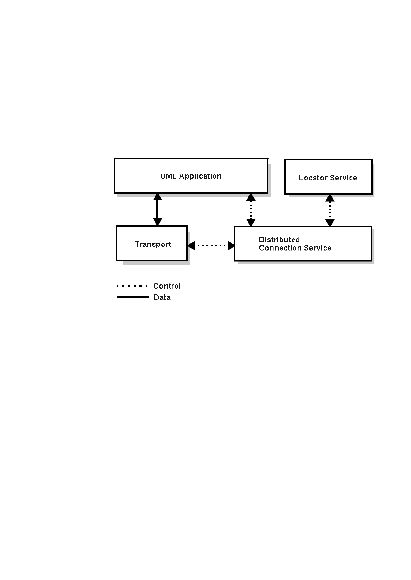
A Rose RealTime application that is using Connexis to implement its
inter-process communication has the high-level architecture shown in
Figure 2. The control paths that are shown, indicate the components
that are involved in registering and deregistering endpoints in the UML
application. All data that is sent between endpoints in a Connexis-
enabled application goes through the Transport component.
Figure 2 High level view of a Connexis enabled application
UML Application
This section presents an overview of how Connexis is used from within
Rose RealTime. For more information on Rose RealTime refer to the
“Rational Rose RealTime Toolset Guide.”
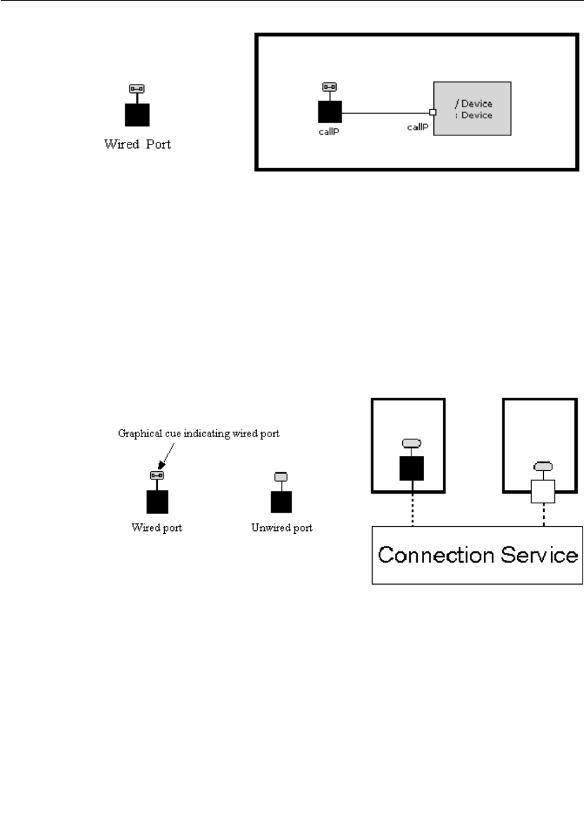
Ports in Rose RealTime
In Rose RealTime, ports are used to send messages between the
capsules in your model. Rose RealTime has several different kinds of
ports. The most common type of port is a wired port as shown in
Figure 3. Wired ports are visibly connected to other wired ports in Rose
RealTime models. Wired ports are represented graphically with two
connected squares in the oval part of the port icon.
Connexis Application Layers
User Guide - Rational Rose RealTime Connexis 15
Figure 3 Connecting wired ports
Another type of port that can be used in Rose RealTime is the unwired
port. Unwired ports are the primary method for establishing Connexis
connections. Once you have created an unwired port, you can specify
the connection service, protocol, and endpoint address that it will use
by registering the port with the Target RSL. This registration can either
be done automatically or through application code. The Connection
Service box in Figure 4 corresponds to the Distributed Connection
Service box in Figure 2. The DCS is one implementation of a
Connection Service.
Figure 4 Connecting unwired ports
A more detailed discussion on the registration process is provided in
“Establishing Connections” on page 107.
Chapter 1 Rational Connexis Overview
16 User Guide - Rational Rose RealTime Connexis
Distributed Connection Service
The Distributed Connection Service (DCS) is the connection service
that is provided with Connexis. It is responsible for maintaining
information about the unwired ports that have been registered with it
by a UML model. The DCS is the part of the system that is responsible
for establishing connections between unwired ports. It does this by
parsing the registration strings that are passed in when an unwired
port registers with the Target RSL.
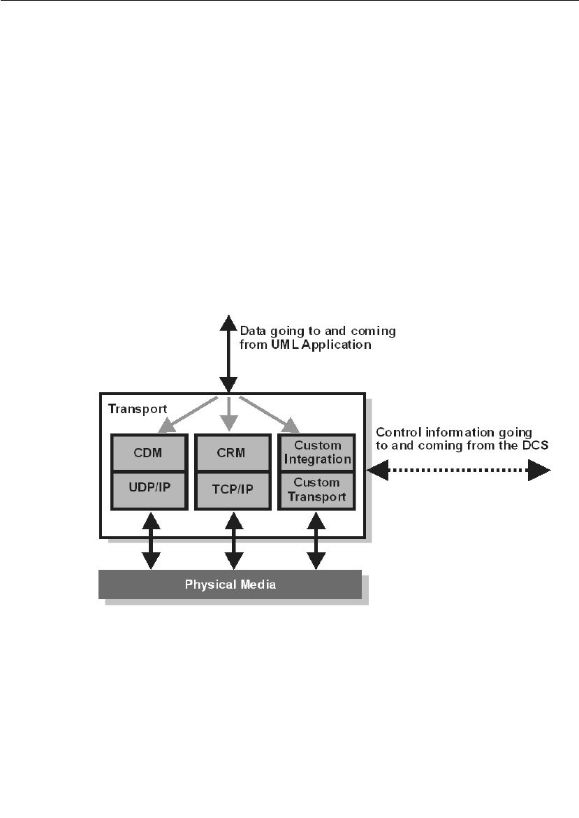
Transport
The Transport is the component that is responsible for sending and
receiving data between processes. It manages any incoming or
outgoing data buffers and encodes and decodes data. A more detailed
break-down of the Transport component is shown in Figure 5.
Figure 5 Inside the Transport component

Connexis Application Layers
User Guide - Rational Rose RealTime Connexis 17
Locator Service
Another key component of a robust distributed system is a fault-
tolerant name service. A name service is used to find the actual
location of a server given a predetermined service name. A well-known
example of a name service is the Domain Naming Service (DNS) that is
widely used on the Internet. The principle function of a name service is
to look up a specific address when it is given a service name. This
isolates the calling application from changes in the physical addressing
of network components. In the Connexis product, the Locator Service
provides the name service functionality.
The Locator Service actually does a bit more than just operate as a
name server. The Locator can be configured to arbitrate between more
than one endpoint that provides the same service and it can also be set
up to run in duplex mode, which allows a backup Locator to
automatically take over when the primary fails.
Using the locator
An endpoint is defined to be the combination of a transport protocol
and the address of a specific port in a distributed application. For
example, cdm://address:port. If an explicit endpoint is provided, then
the client will try to connect to the server at the specified endpoint. If a
complete endpoint is not provided then the Locator is contacted. The
Locator returns an endpoint that is then used by Connexis to choose
the appropriate service provider or peer. The service name by which an
endpoint is referred, is specified as part of the registration of that
endpoint.
The Connexis Locator Service supports both a primary and a backup
locator. In this way, a distributed application can be made more robust
by ensuring that there is no single point of failure in the name server.

Chapter 1 Rational Connexis Overview
18 User Guide - Rational Rose RealTime Connexis
The HelloWorld Model
The HelloWorld model implements a simple distributed model using
Connexis. The model demonstrates the use of the Connexis Locator
Service and how it can be used to easily provide backup service in a
distributed environment.
The model contains two servers, a client, and the Connexis locator
service, each running independently. The servers speak different
languages (either English, or French). Initially, the client is bound to
the server that comes up first. Once bound, the client makes requests
to the server and the server sends back a greeting in the language it
speaks.
If the server to which the client is bound becomes unavailable, the
client is notified of the connection loss, and it rebinds to the backup
server, which starts responding to the client requests in the language
it speaks. For example, if the client is initially bound to the English
server, it will start receiving greetings in English. If you then terminate
the English server (for example, resetting through the RTS panel), the
connection will be lost momentarily, the client will be rebound to the
French server, and the client will start receiving the greetings in
French.
Note: The greetings are output to the DOS window (Windows) and the
RTS Output window (Solaris), which comes up when the client is started.
Running the HelloWorld Model
The model can be run on all supported host platforms. To run the
application, start up the matching (for example, VC++6.0) set of
locator, client, EnglishServer and FrenchServer component instances.
■Keep the DOS (Windows) or RTS Output (Solaris) window for the
client in view. The other DOS or RTS Output windows can be
minimized to reduce screen clutter.
■Run all the component instances from the corresponding RTS
panels.

The HelloWorld Model
User Guide - Rational Rose RealTime Connexis 19
■If you run the EnglishServer first, you should see “Hello World!!!”
appear on the client DOS window repeatedly. At this point, you can
terminate the EnglishServer instance by means of the RTS panel.
The client will receive a connection loss, and will then switch over
to the FrenchServer as soon it is rebound via the locator service.
You should now start to see "Salut le monde!!!" displayed in the
client DOS window.
Additional HelloWorld Models
The following models are extensions of the HelloWorld model. They
provide examples of distributed load-sharing and fault-tolerant
patterns.
HelloWorldHotStandby
A client connects to two servers through a proxy actor, and continually
sends greeting requests. The proxy forwards the message to both
servers, and both of the servers respond back to the proxy, which in
turn relays the message from the active server to the client. If there is
no response from the active server within a specified time period, the
other server becomes active, and starts to handle all the client
requests.
HelloWorldLoadSharing
This model consists of two servers (an English and a French one) that
supply greeting messages for multiple clients. The clients connect to
the servers in a round-robin fashion. For example, if you had four
clients, the first and the third client would connect to one server and
the second and the fourth client would connect to the other server.
HelloWorldOverflowToBackupService
This model contains two servers (an English and a French one). One of
the servers is given a higher rank so that it acts as the primary server.
The clients connect to the primary server until the primary server has
reached its full capacity. Any subsequent clients will connect to the
backup server, which will handle their greeting requests for those
clients.

Chapter 1 Rational Connexis Overview
20 User Guide - Rational Rose RealTime Connexis
HelloWorldRedundantLocator
The model consists of one server, multiple clients, and a primary and
a backup locator. The clients connect to the server using the primary
locator. The server, in turn, provides greeting signals for the clients. If
the primary locator is shut down, all subsequent client-server
connections will be established using the backup locator.
Using Connexis
There are several steps that must be taken to add Connexis support to
a model. These are:
■share the RTDInterface package
■add Connexis component capsule roles to appropriate capsules in
the model
■integrate transport protocols
■configure components for your application
Note: The Connexis configuration dialogs on ports and capsules
allow the user to perform these steps as well.
In addition to these steps, there are also general design rules that must
be followed to ensure that the Connexis components have been
initialized properly before they are used.
Refer to “Adding Connexis Support to Your Model” on page 83 for more
information on Connexis-enabling your application.

User Guide - Rational Rose RealTime Connexis 21
Chapter 2
Using Connexis Model Examples
With Connexis, four model examples are included to accelerate your
learning and proficiency. The list of models are outlined below:
■The BasicTest Model can be used to verify your environment.
■The Quick start Model runs you through an introductory tutorial.
■The HelloWorld Model presents a simple distributed model.
■The Performance Model lets you evaluate the performance of
Connexis-enabled models in your environment.
By default, components in these model examples specify ‘localhost’
(127.0.0.1) as the host machine. If you want to run the model examples
remotely (that is, on a specific processor rather than the one you are
on), you must modify the model examples first.
The BasicTest Model
The BasicTest model implements a very simple client server distributed
system and is intended for use as a simple model to test proper
Connexis installation and operation on any of the Connexis-supported
platforms.
All hosts and target configurations supported with your Connexis
installation are provided.
To run the model on one of the supported configurations listed above,
see “Verifying your installation using BasicTest, in the Release Notes
and Installation Guide for Rational Rose RealTime Professional.

Chapter 2 Using Connexis Model Examples
22 User Guide - Rational Rose RealTime Connexis
The Quick Start Model
The “Rational Connexis User Guide” provides a Quick start tutorial
(chapter 2) to allow you to quickly come up to speed on using Connexis.
The tutorial is composed of three iterations. Iteration 1 takes you
through building a simple ping pong model using Rose RealTime.
Iteration 2 takes you through the steps required to Connexis-enable
the ping pong model and make it distributed.
For your reference, complete, documented models for each iteration
are provided as part of the model examples provided with Connexis.
These examples can be run on all supported host platforms. For
detailed instructions on using the Quick Start model, see “Quick Start”
on page 31.
Quick Start Iteration 1 Model
The PingPong_Iteration1 model is the completed version of the model
developed in Connexis Quick start tutorial (Iteration 1). See “Quick
Start” on page 31 for details.
This model implements a simple ping pong application using Rose
RealTime. This model is used as a starting point for
PingPong_Iteration2 to show the simple steps required to quickly
Connexis-enable an application built using Rose RealTime.
To run the model, compile the PingPongApp component instance
corresponding to your host compiler, and choose run from the item
menu of the component instance under the PingPongProcessor.
Quick Start Iteration 2 Model
The PingPong_Iteration2 model is the completed version of the model
developed in Connexis Quick start tutorial (Iteration 2). See “Quick
Start” on page 31 for details.
This model implements a simple distributed ping pong application
using Rose RealTime and Connexis. It is a Connexis-enabled version of
the model developed in Iteration 1, and demonstrates the simplicity of
distribution using Connexis.

The HelloWorld Model
User Guide - Rational Rose RealTime Connexis 23
To run the model, please compile the Ping and Pong component
instances corresponding to your host compiler, and choose run from
the item menu of the component instances under the
PingPongProcessor.
The HelloWorld Model
The HelloWorld model implements a simple distributed model using
Connexis. The model demonstrates the use of the Connexis Locator
Service and how it can be used to easily provide backup service in a
distributed environment.
The model contains two servers, a client, and the Connexis locator
service, each running independently. The servers speak different
languages (either English, or French). Initially, the client is bound to
the server that comes up first. Once bound, the client makes requests
to the server and the server sends back a greeting in the language it
speaks.
If the server to which the client is bound becomes unavailable, the
client is notified of the connection loss, and it rebinds to the backup
server, which starts responding to the client requests in the language
it speaks. For example, if the client is initially bound to the English
server, it will start receiving greetings in English. If you then terminate
the English server (for example, resetting through the RTS panel), the
connection will be lost momentarily, the client will be rebound to the
French server, and the client will start receiving the greetings in
French.
Note: The greetings are output to the DOS window (Windows) and the
RTS Output window (Solaris), which comes up when the client is started.
Running the HelloWorld Model
The model can be run on all supported host platforms. To run the
application, start up the matching (for example, VC++6.0) set of
locator, client, EnglishServer and FrenchServer component instances.
■Keep the DOS (Windows) or RTS Output (Solaris) window for the
client in view. The other DOS or RTS Output windows can be
minimized to reduce screen clutter.
■Run all the component instances from the corresponding RTS
panels.

Chapter 2 Using Connexis Model Examples
24 User Guide - Rational Rose RealTime Connexis
■If you run the EnglishServer first, you should see “Hello World!!!”
appear on the client DOS window repeatedly. At this point, you can
terminate the EnglishServer instance by means of the RTS panel.
The client will receive a connection loss, and will then switch over
to the FrenchServer as soon it is rebound via the locator service.
You should now start to see "Salut le monde!!!" displayed in the
client DOS window.
Additional HelloWorld Models
The following models are extensions of the HelloWorld model. They
provide examples of distributed load-sharing and fault-tolerant
patterns.
HelloWorldHotStandby
A client connects to two servers through a proxy actor, and continually
sends greeting requests. The proxy forwards the message to both
servers, and both of the servers respond back to the proxy, which in
turn relays the message from the active server to the client. If there is
no response from the active server within a specified time period, the
other server becomes active, and starts to handle all the client
requests.
HelloWorldLoadSharing
This model consists of two servers (an English and a French one) that
supply greeting messages for multiple clients. The clients connect to
the servers in a round-robin fashion. For example, if you had four
clients, the first and the third client would connect to one server and
the second and the fourth client would connect to the other server.
HelloWorldOverflowToBackupService
This model contains two servers (an English and a French one). One of
the servers is given a higher rank so that it acts as the primary server.
The clients connect to the primary server until the primary server has
reached its full capacity. Any subsequent clients will connect to the
backup server, which will handle their greeting requests for those
clients.

The DCS Performance Model
User Guide - Rational Rose RealTime Connexis 25
HelloWorldRedundantLocator
The model consists of one server, multiple clients, and a primary and
a backup locator. The clients connect to the server using the primary
locator. The server, in turn, provides greeting signals for the clients. If
the primary locator is shut down, all subsequent client-server
connections will be established using the backup locator.
The DCS Performance Model
With the DCS Performance Model, you collect performance data for
intra-thread, inter-tread, and inter-processor messaging throughput.
Using this data, you can evaluate message throughput and transport
latency within your environment.
The performance model contains a client capsule and a server capsule
that echo messages between each other. This lets you evaluate the
amount of time required to send messages between capsules.
The model measures performance between capsules in the following
scenarios:
■Client and server on the same thread
■Client and server on different threads
■Client and server in different processes (using the DCS)
The model also provides data that can be used to measure the message
latency using raw socket-based inter-process communication (IPC).
Running the Performance Model
Before compiling the components for the performance model, you must
set the target configuration properties for the components. Once the
components are built, the run-time operations must be configured to
run either the CDM/UDP and CRM/TCP tests.
To run the performance model
1. Set the C++ Compilation Target Services Library properly for the
following components so that they can compile in your
environment:
❑ThroughputClient
❑ThroughputServer

Chapter 2 Using Connexis Model Examples
26 User Guide - Rational Rose RealTime Connexis
All intra-thread, inter-thread, and inter-process tests run within
the ThroughputClientInstance. The ThroughputServerInstance is
used for the IPC tests and the benchmark UDP/TCP tests.
2. Edit the properties of the “inclusion paths” to include the
TargetRTS target specific header files.
For example, if you are running on a VxWorks target, the following
inclusion path must be specified:
$RoseRT_Home/C++/TargetRTS/src/target/TORNADO1
Note: These directories are not normally included in user models.
They have been used in this model to facilitate portability to different
target environments.
3. Set the run-time options for the client’s component instance
according to the following chart:
4. Set the run-time options for the server’s component instance
according to the following chart:
Table 2 Run-time options for the client component
Option Description
-s<server address>:<port> specifies the endpoint of the server and is
used in the client's registration string. (ex.:
-s192.139.252.84:9900).
This parameter must correspond to the
server endpoint specified using -CNXep.
-n<num msgs> specifies the number of messages to be
echoed between the client and server for
each test.
-crm | -cdm specifies which transport is to be tested.
-l<local port> specifies the local port to be used for the
raw TCP/UDP benchmarks.
-r<remote port> specifies the remote port to be used for the
raw TCP/UDP benchmarks. The remote
address is obtained from the endpoint
parameter (-s).

The DCS Performance Model
User Guide - Rational Rose RealTime Connexis 27
5. Run CDM/UDP and CRM/TCP.
Performance model server output
Rational Rose RealTime C++ Target Run Time System
Release 6.30.B.01 (+c)
Copyright (c) 1993-2000 Rational Software
rosert: observability listening at tcp port 30503
*******************************************************************
* Please note: STDIN is turned off. *
* To use the command line, telnet to the above mentioned port. *
* The _output_ of any command will be displayed in _this_ window. *
*******************************************************************
Rational Software Corp. Connexis(tm) - Distributed Connection Service (dcs)
Release 6.30.B.154
Copyright (c) 1999-2000 Rational Software Corporation
dcs: CDM Transport : enabled
dcs: CDM listening at [cdm://192.139.252.171:9900]
dcs: locator service not available
dcs: metric service available
DCS Performance Test Begins
===========================
Client address for benchmark tests: 192.139.252.171
Benchmark tests listening at port: 9800
Benchmark tests connecting to remote port: 8800
Table 3
Option Description
-crm | -cdm specifies which transport is to be tested.
-l<local port> specifies the local port to be used for the
raw TCP/UDP benchmarks.
-CNXep = port
-CNXep = CRM:port
specifies the endpoint where the server is
listening.
-r<remote port> specifies the remote port to be used for the
raw UDP benchmarks.
-a<remote address> specifies the remote address to be used for
the raw UDP benchmarks.

Chapter 2 Using Connexis Model Examples
28 User Guide - Rational Rose RealTime Connexis
Performance model client output
Rational Rose RealTime C++ Target Run Time System
Release 6.30.B.01 (+c)
Copyright (c) 1993-2000 Rational Software
rosert: observability listening at tcp port 30346
*******************************************************************
* Please note: STDIN is turned off. *
* To use the command line, telnet to the above mentioned port. *
* The _output_ of any command will be displayed in _this_ window. *
*******************************************************************
DCS Performance Test Begins
===========================
Number of messages per iteration: 10000
Server address for IPC tests: 192.139.252.171:9900
Benchmark tests listening at port: 8800
Benchmark tests connecting to remote port: 9800
Transport protocol to be tested: cdm
Intra-thread Througput Test
---------------------------
Start time [s:ns]: 984682532:620000000
Finish time [s:ns]: 984682532:700000000
Message size: 16
Messages sent: 10000
Duration [in ms]: 80
Start time [s:ns]: 984682532:700000000
Finish time [s:ns]: 984682532:780000000
Message size: 64
Messages sent: 10000
Duration [in ms]: 80
Start time [s:ns]: 984682532:780000000
Finish time [s:ns]: 984682532:861000000
Message size: 256
Messages sent: 10000
Duration [in ms]: 81
Start time [s:ns]: 984682533:261000000
Finish time [s:ns]: 984682533:351000000
Message size: 1024
Messages sent: 10000
Duration [in ms]: 90
Start time [s:ns]: 984682533:351000000
Finish time [s:ns]: 984682533:501000000
Message size: 4096
Messages sent: 10000
Duration [in ms]: 150
Inter-thread Througput Test
---------------------------

The DCS Performance Model
User Guide - Rational Rose RealTime Connexis 29
Start time [s:ns]: 984682533:501000000
Finish time [s:ns]: 984682533:682000000
Message size: 16
Messages sent: 10000
Duration [in ms]: 181
Start time [s:ns]: 984682533:912000000
Finish time [s:ns]: 984682534:112000000
Message size: 64
Messages sent: 10000
Duration [in ms]: 200
Start time [s:ns]: 984682534:112000000
Finish time [s:ns]: 984682534:303000000
Message size: 256
Messages sent: 10000
Duration [in ms]: 191
Start time [s:ns]: 984682534:513000000
Finish time [s:ns]: 984682534:683000000
Message size: 1024
Messages sent: 10000
Duration [in ms]: 170
Start time [s:ns]: 984682534:693000000
Finish time [s:ns]: 984682534:914000000
Message size: 4096
Messages sent: 10000
Duration [in ms]: 221
Rational Software Corp. Connexis(tm) - Distributed Connection Service (dcs)
Release 6.30.B.154
Copyright (c) 1999-2000 Rational Software Corporation
dcs: CDM Transport : enabled
dcs: CDM listening at [cdm://192.139.252.171:2202]
dcs: locator service not available
dcs: metric service available
Inter-processor Througput Test
------------------------------
Start time [s:ns]: 984682535:134000000
Finish time [s:ns]: 984682536:95000000
Message size: 16
Messages sent: 10000
Duration [in ms]: 961
Start time [s:ns]: 984682536:105000000
Finish time [s:ns]: 984682537:47000000
Message size: 64
Messages sent: 10000
Duration [in ms]: 942

Chapter 2 Using Connexis Model Examples
30 User Guide - Rational Rose RealTime Connexis
Start time [s:ns]: 984682537:57000000
Finish time [s:ns]: 984682538:68000000
Message size: 256
Messages sent: 10000
Duration [in ms]: 1011
Start time [s:ns]: 984682538:78000000
Finish time [s:ns]: 984682539:290000000
Message size: 1024
Messages sent: 10000
Duration [in ms]: 1212
Start time [s:ns]: 984682539:290000000
Finish time [s:ns]: 984682541:152000000
Message size: 4096
Messages sent: 10000
Duration [in ms]: 1862
Inter-process Benchmark Test
----------------------------
Start time [s:ns]: 984682541:173000000
Finish time [s:ns]: 984682541:513000000
Message size: 16
Messages sent: 10000
Duration [in ms]: 340
Start time [s:ns]: 984682541:523000000
Finish time [s:ns]: 984682541:823000000
Message size: 64
Messages sent: 10000
Duration [in ms]: 300
Start time [s:ns]: 984682541:833000000
Finish time [s:ns]: 984682542:144000000
Message size: 256
Messages sent: 10000
Duration [in ms]: 311
Start time [s:ns]: 984682542:144000000
Finish time [s:ns]: 984682542:524000000
Message size: 1024
Messages sent: 10000
Duration [in ms]: 380
Start time [s:ns]: 984682542:534000000
Finish time [s:ns]: 984682543:406000000
Message size: 4096
Messages sent: 10000
Duration [in ms]: 872
TESTS COMPLETE!!!!

User Guide - Rational Rose RealTime Connexis 31
Chapter 3
Quick Start
Connexis is a connection tool that provides robust, transparent
communication between Rational Rose RealTime executable models.
Rational Connexis is integrated with Rational Rose RealTime, which is
a modeling tool that generates executables from UML models.
Connexis improves an application’s time to market by eliminating the
need to design, develop, and test a custom Inter-Process
Communications (IPC) mechanism. The use of a production quality,
Commercial Off The Shelf (COTS) distribution component, such as
Connexis, simplifies and de-risks the design and deployment of
distributed systems.
The Connexis Quick start presented in this chapter takes you through
the general steps that are required to create and execute a Connexis-
enabled application. To follow the steps laid out in this chapter, you
should have:
■Rational Rose RealTime installed on your workstation
■Rational Connexis installed on your workstation
■a general understanding of Rational Rose RealTime and UML
Quick Start Overview
The application to be created is a simple “ping pong” application. The
clients send a ping message to the server, and the server responds with
a pong message. Registration is accomplished using the Locator
Service. The necessary command line options for starting the
applications are also presented.

Chapter 3 Quick Start
32 User Guide - Rational Rose RealTime Connexis
This application is created in three iterations:
■Iteration 1: Creating the Rose RealTime Model - creates the basic
architecture using wired ports to connect the Ping and Pong
capsules. This also involves a third capsule which acts as the
container for the Ping and Pong capsules.
■Iteration 2: Connexis Enabling our Application- makes
modifications so that Ping and Pong communicate through
unwired ports that make use of Connexis connections.
Iteration 1 focuses on creating a simple Rose RealTime model;
therefore, readers who are familiar with Rose RealTime can start with
the solution for Iteration 1, which is found in the examples directory,
$ROSERT_HOME\CONNEXIS\C++\examples. Iteration 2 focuses on
Connexis-enabling the Rose RealTime model.
Note: The package organization of the example models differs slightly
from this tutorial because the examples support multiple platforms;
however, the model elements are the same.
Many of the steps that are presented in these iterations are examples
of good modeling practices. Explanations and the rationale behind
these good modeling practices are presented where appropriate and
are separated from the rest of the text by the heading “Rationale for
....”
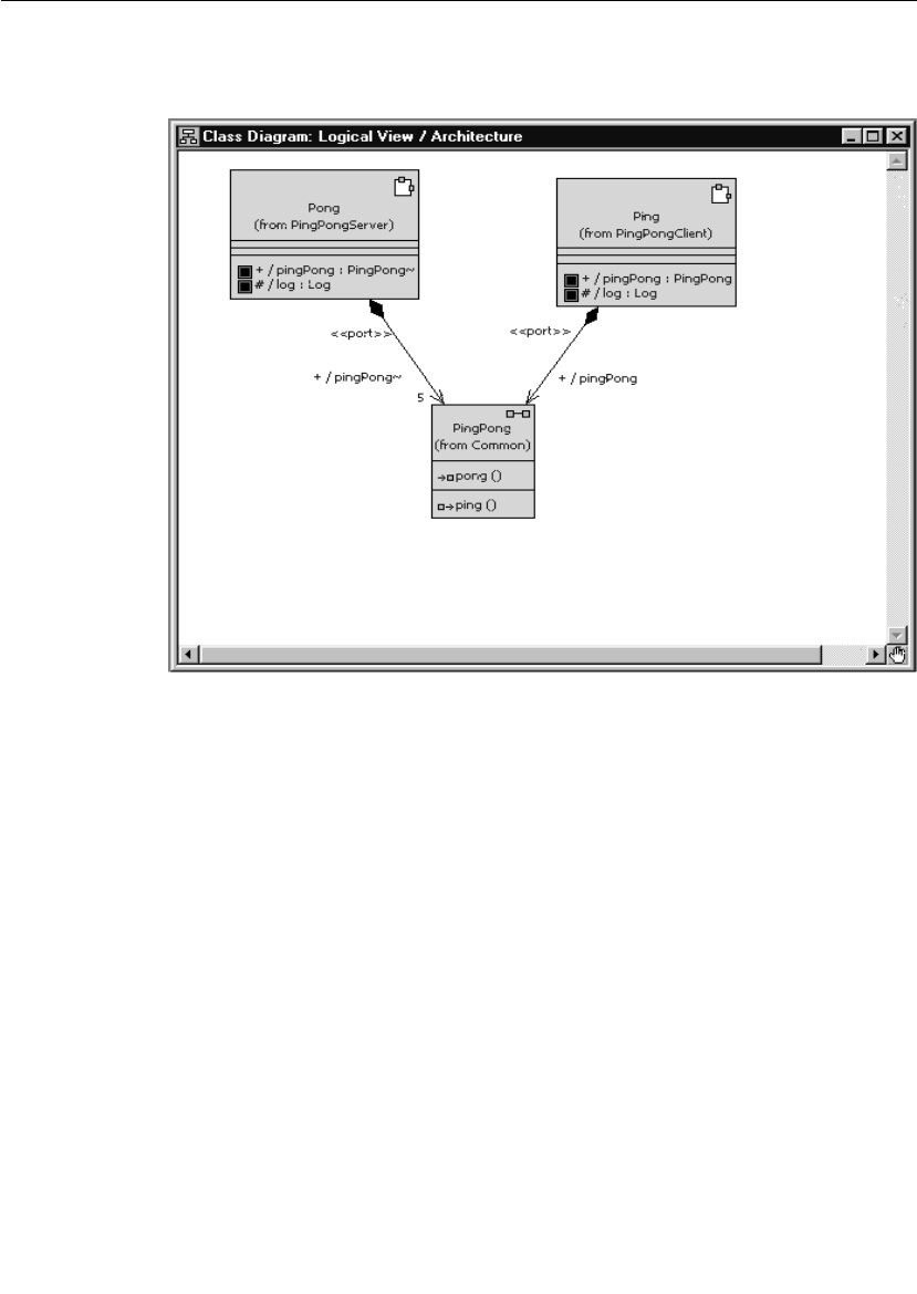
Quick Start Overview
User Guide - Rational Rose RealTime Connexis 33
Figure 6 presents the final architecture of the model that is created in
Iteration 2.
Figure 6 Ping pong application architecture (at the end of Iteration 2)
Even though the ping pong application is very simple it is still
appropriate to present a sequence diagram that documents its
behavior. The sequence diagram, shown in Figure 7, describes the
messages that are sent between the Ping and Pong capsules. The
events illustrated in this sequence diagram are discussed throughout
the remainder of the Quick start.
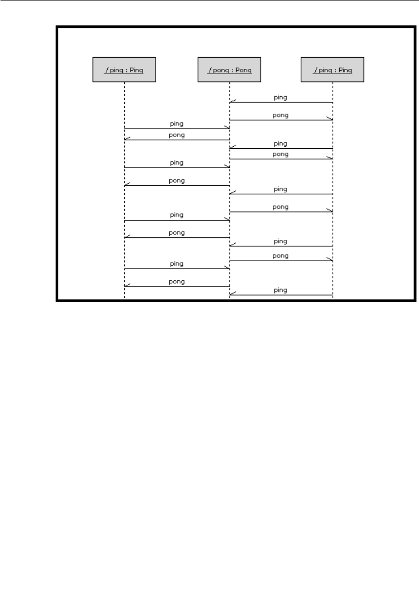
Chapter 3 Quick Start
34 User Guide - Rational Rose RealTime Connexis
Figure 7 Ping Pong application sequence diagram
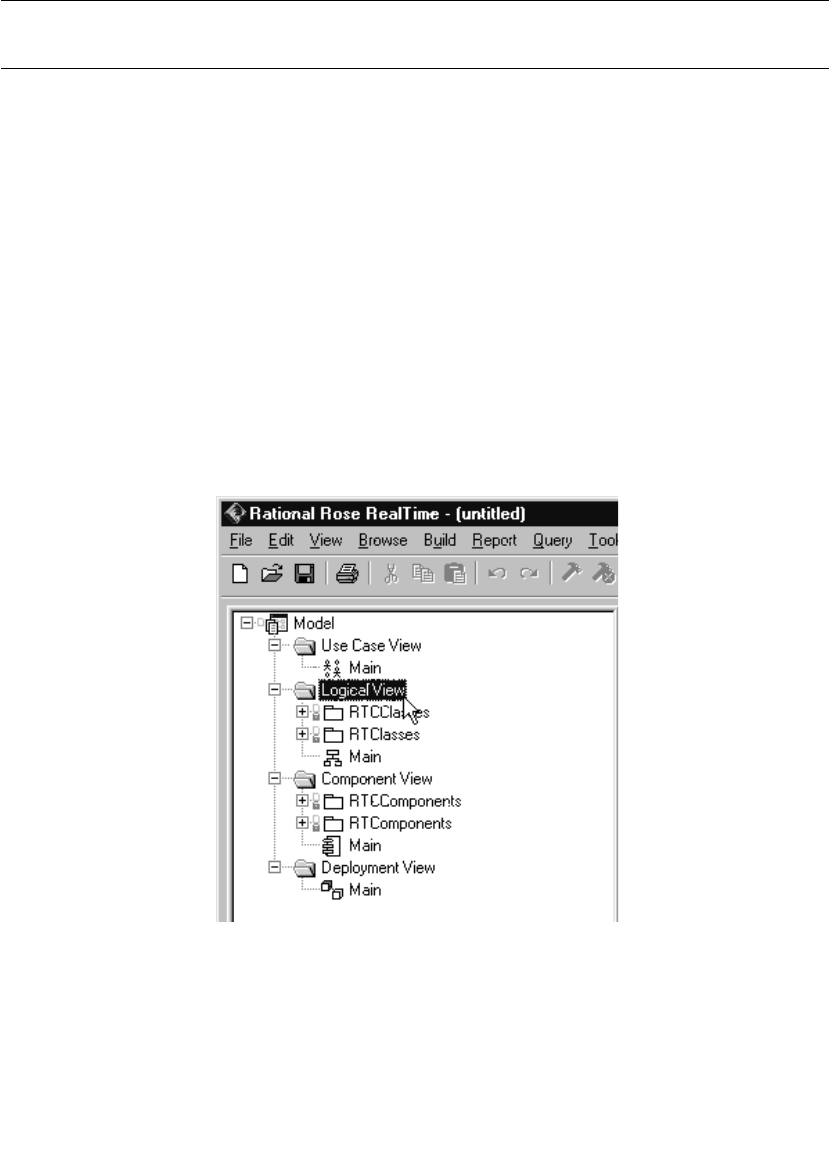
Iteration 1: Creating the Rose RealTime Model
User Guide - Rational Rose RealTime Connexis 35
Iteration 1: Creating the Rose RealTime Model
Iteration 1 focuses on creating the Rose RealTime model that is used
throughout the Quick start.
Step 1: Create a New Model
To create a new model in Rose RealTime:
1. Select File > New.
Step 2: Create Packages for the Model
To create the ping pong client package:
1. Open the pop-up menu on the Logical View package in your Rose
RealTime browser. Do this by right-clicking on the Logical View
package as shown in Figure 8.
Figure 8 Creating packages
2. Select New > Package from the pop-up menu.

Chapter 3 Quick Start
36 User Guide - Rational Rose RealTime Connexis
3. While the default package name is selected, type in
“PingPongClient” to set the name of the new package.
To create the ping pong server package:
Follow the same steps as those listed for “To create the ping pong client
package:” except name the new package “PingPongServer.”
To create the ping pong container package:
Follow the same steps as those listed for “To create the ping pong client
package:” except name the new package “Container.”
To create the ping pong utility package:
Follow the same steps as those listed for “To create the ping pong client
package:”- except name the new package “Common.”
You should now have all of the packages that are required, as shown
in Figure 9.
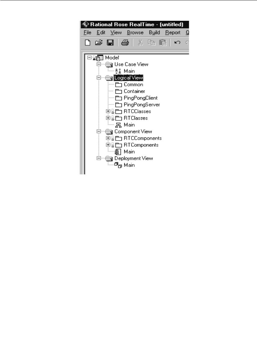
Iteration 1: Creating the Rose RealTime Model
User Guide - Rational Rose RealTime Connexis 37
Figure 9 Created packages
Rationale for creating packages
It is good practice (although not required) to organize all of your Rose
RealTime models into packages. You might think that it is overkill for
a model that is as trivial as this one, but it is good to get in the habit
of doing this, remember small models usually become big models
eventually and it is easier to start off with packages than it is to add
them later.
The main reasons for wanting to organize your models into packages
are:
■ease of understanding and navigation - Packages give you an extra
level of abstraction above what is provided by the classes and
capsules in your model.
■separation of concerns - It is a good way of dividing the work that is
to be done between teams or individuals on teams.

Chapter 3 Quick Start
38 User Guide - Rational Rose RealTime Connexis
■configuration management - Packages are a possible unit of
version control.
■access control - You can define the visibility of classes and
capsules within packages. This makes it possible to control the
access to design elements that are organized into packages.
There are many other reasons for wanting to organize your models into
packages. For more information on this topic, refer to the “Rose
RealTime User’s Guide.”
Step 3: Create the Ping, Pong, and ContainerCapsules
In this application, the Ping capsule fulfills the role of a client. It is
referred to as the client because it only manages a single connection.
The server side of the application is responsible for managing multiple
connections (one for each client it is connected to). The Pong capsule
fulfills the role of the server in this application. The container capsule
contains both the Ping and Pong capsules in Iteration 1 of the
application.
Remember that the application is being built in two iterations; the first
uses wired ports and the second uses Connexis-enabled, non-wired
ports.
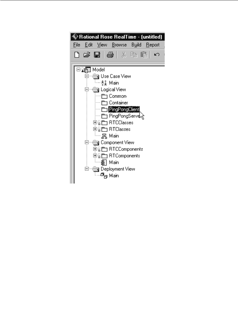
Iteration 1: Creating the Rose RealTime Model
User Guide - Rational Rose RealTime Connexis 39
To create the Ping capsule:
1. Select the PingPongClient package as shown in Figure 10.
Figure 10 Creating a new capsule
2. Open the pop-up menu and select New > Capsule.
3. While the default name of the new capsule is still highlighted, type
in “Ping." This renames the new capsule.
To create the Pong capsule:
To create the Pong capsule, follow the same steps as those listed for “To
create the Ping capsule:” except create the Pong capsule in the
PingPongServer package.
To create the Container capsule:
To create the Container capsule, follow the same steps as those listed
for “To create the Ping capsule:” except create the Container capsule in
the Container package.
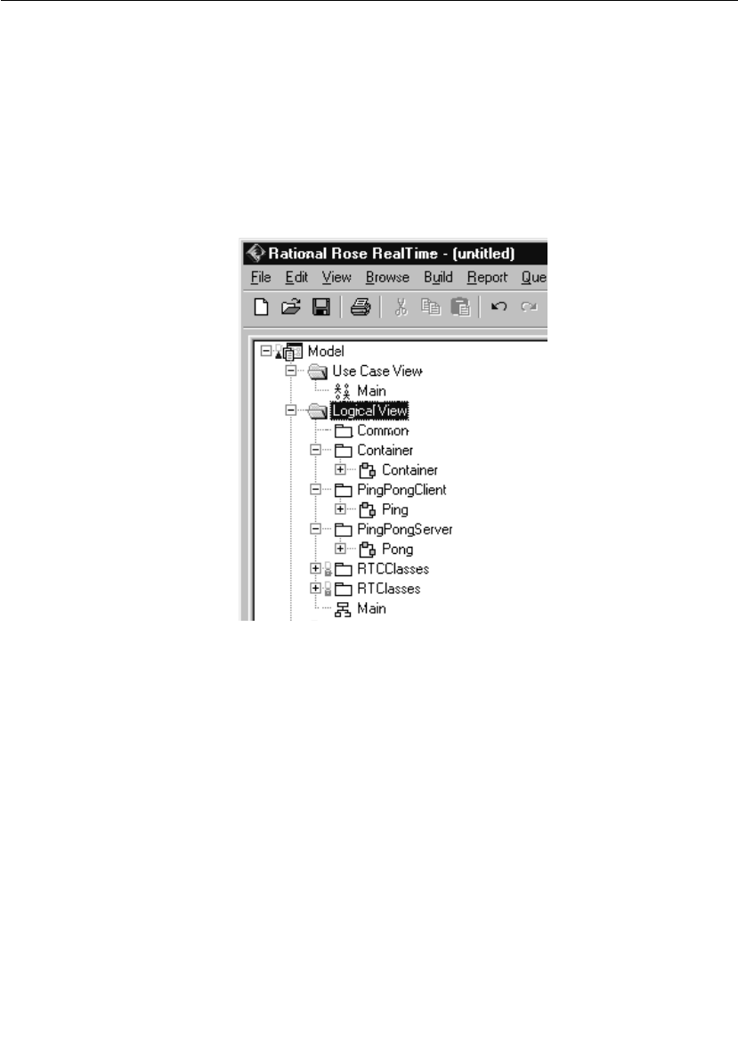
Chapter 3 Quick Start
40 User Guide - Rational Rose RealTime Connexis
The connection topology that is used in this application is an
oversimplification of a real-world distributed application. In real-world
distributed applications, objects would typically take on the role of
client in some communication scenarios and the role of server in
others. Common connection topologies for distributed applications are
discussed in “Establishing Connections” on page 107.
You should now have all of the capsules that are required as shown in
Figure 11.
Figure 11 Created capsules
Step 4: Create the PingPong Protocol Class
In Rose RealTime, capsules communicate with one another through
ports. Ports are defined by a protocol. A protocol is a definition of a set
of incoming signals, along with their associated data types, and a set
of outgoing signals, along with their associated data types.
To create a protocol class:
1. Open the pop-up menu on the Common package by right-clicking
on the Common Package as shown in Figure 12.
2. Select New > Protocol from the pop-up menu.

Iteration 1: Creating the Rose RealTime Model
User Guide - Rational Rose RealTime Connexis 41
3. While the default name of the new protocol is still highlighted, type
in “PingPong." This renames the new protocol.
Figure 12 Creating protocol classes
The PingPong protocol consists of an In Signal called pong, and an Out
Signal called ping. Neither of these signals have data associated with
them.
To add the signals to the protocol class:
1. Open the pop-up menu on the PingPong protocol class.
2. Select Open Specification from the pop-up menu.
3. Select the Signals tab.
4. Open the pop-up menu on the In Signals panel (by right clicking on
the white space below In Signals as shown in Figure 13) and select
Insert. A new signal is added and its default name is highlighted.

Chapter 3 Quick Start
42 User Guide - Rational Rose RealTime Connexis
Figure 13 Protocol specification window
5. While the default name is highlighted, type in “pong." This names
the In Signal pong.
6. Repeat steps 4 and 5 in the Out Signal panel. Name the Out Signal
“ping."
7. Click the OK button.
Rationale for choice of conjugation and signal names
The In Signal is named pong because the protocol is defined from the
perspective of the client. Remember that the client side of the
application is implemented by the Ping capsule. The Ping capsule
sends ping signals and receives pong signals; therefore, the protocol
that is being used should have a pong In Signal and a ping Out Signal.

Iteration 1: Creating the Rose RealTime Model
User Guide - Rational Rose RealTime Connexis 43
The practice of conjugating the server side of a connection is not
required but it is a good way of keeping the naming of ports and
protocols consistent. Conjugating the server side of a connection has
the added benefit of reducing modeling efforts. Ports by default are not
conjugated and there are usually more client ports that server ports.
Step 5: Build the Structure of the Model
As was outlined in the introduction section of this chapter, the first
iteration uses wired ports to connect the Ping and Pong capsules. This
means that a capsule that acts as the container for the Ping and Pong
capsules must be created. This is the capsule that was called
Container.
To create Ping and Pong capsule roles in the Container capsule:
1. Create a new class diagram called “Architecture." This is done by
right-clicking on the Logical View package and selecting New > Class
Diagram from the pop-up menu.
2. Double-click Architecture to open the class diagram.
3. Drag one of each of the Ping, Pong, and Container capsule, from
the browser onto the diagram.
4. Select the Unidirectional Aggregation tool .
5. Create an aggregation relationship between the Container capsule
and the Ping capsule. Do this by clicking and dragging from the
Container capsule to the Ping capsule as shown in Figure 14.
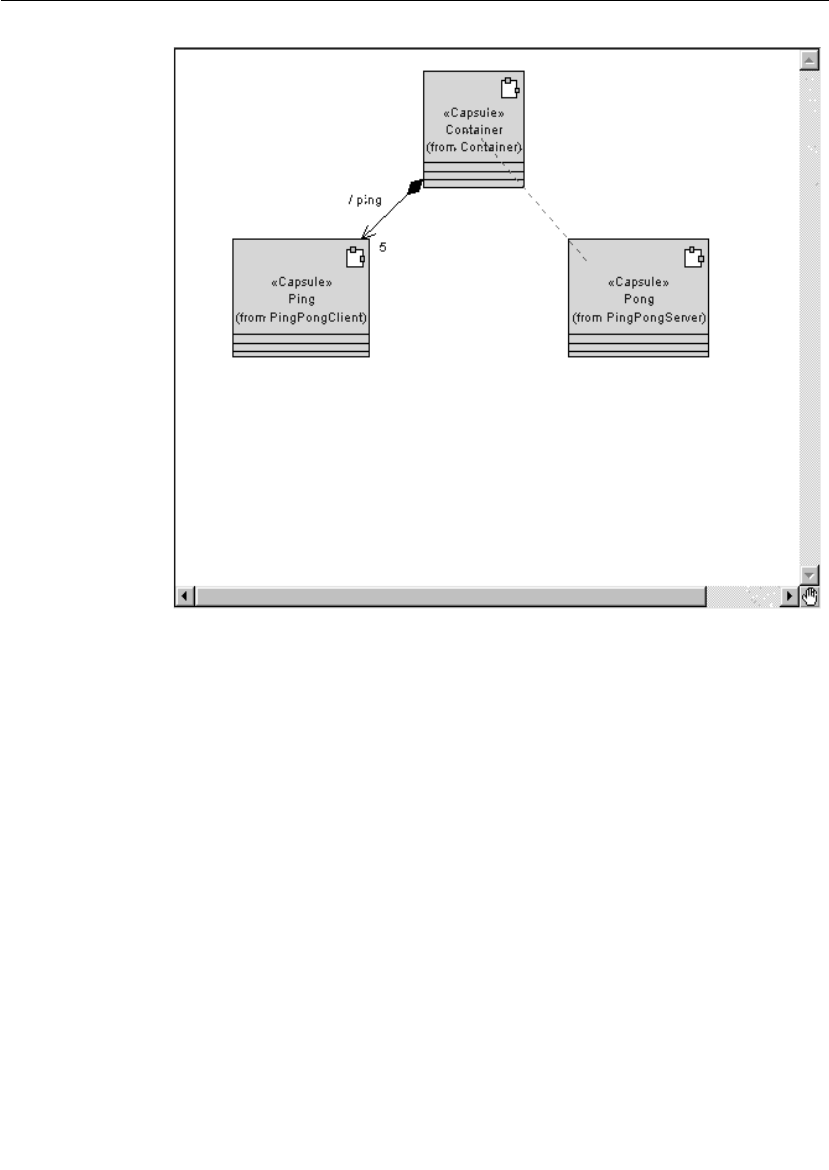
Chapter 3 Quick Start
44 User Guide - Rational Rose RealTime Connexis
Figure 14 Creating aggregations between capsules
6. Repeat step 5 to create an aggregation relationship between the
Container capsule and the Pong capsule.
7. Select the Container/Ping aggregation and open its specification.
Type in the name “ping."
8. Assign a cardinality of 5 to the Container/Ping aggregation.
In a “real” application, the cardinality would be specified using a
constant as opposed to a literal. A literal was used in this example
only for brevity.
9. Click the OK button.
10. Select the Container/Pong aggregation and open its specification.
Type the name “pong."
11. Click the OK button.
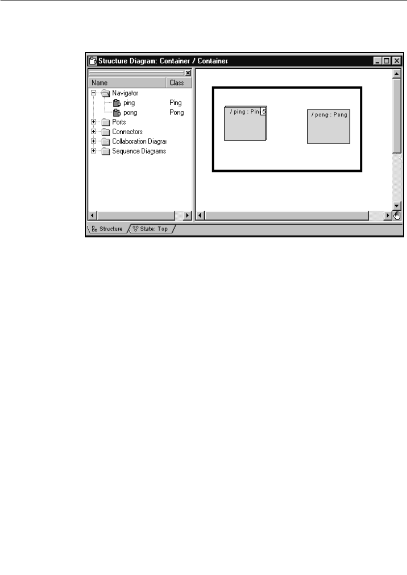
Iteration 1: Creating the Rose RealTime Model
User Guide - Rational Rose RealTime Connexis 45
If you now open the structure diagram of the Container capsule,
you should see a structure similar to what is shown in Figure 15.
Figure 15 Container capsule’s structure diagram
Note: This containment structure could have been created just as easily
from the structure editor of the Container capsule.
To create required ports on Ping and Pong capsules:
1. Drag the PingPong protocol class onto the Architecture class
diagram.
2. Create an aggregation association between the Ping capsule and
the PingPong protocol as shown in Figure 16. Name the association
“pingPong.”
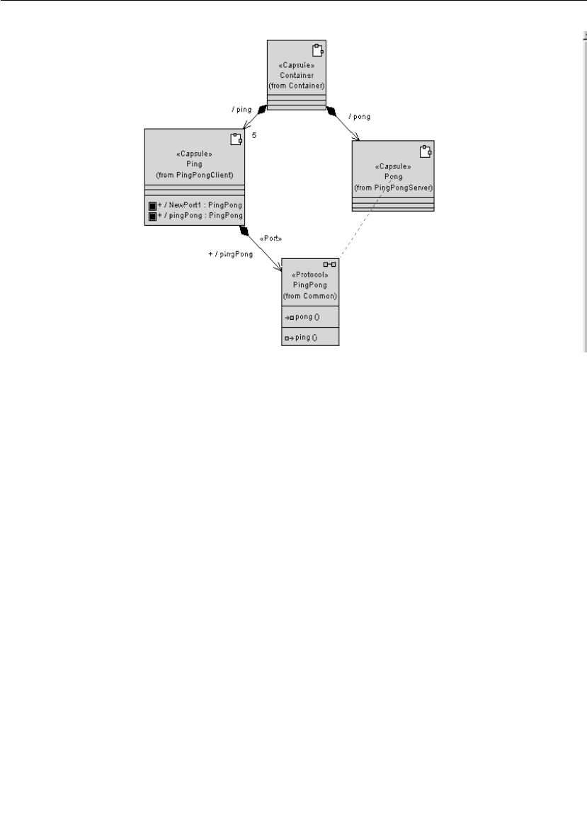
Chapter 3 Quick Start
46 User Guide - Rational Rose RealTime Connexis
Figure 16 Creating ports from a class diagram
3. Create an aggregation association between the Pong capsule and
the PingPong protocol. Name the association “pingPong."
4. Open the specification for the aggregation between the Pong
capsule and the PingPong protocol.
5. Specify a cardinality of 5 and click the Conjugated check box.
6. Click the OK button.
To create a log protocol:
1. Select the Ping capsule.
2. Open its structure diagram.
3. Drag a log protocol onto the structure diagram. Do this by selecting
the log protocol found in the RTClasses package in the Logical View
package.
4. Select the log icon and open its specification.
5. Type in the name “log” and ensure that Protected is enabled.
6. Click the OK button.
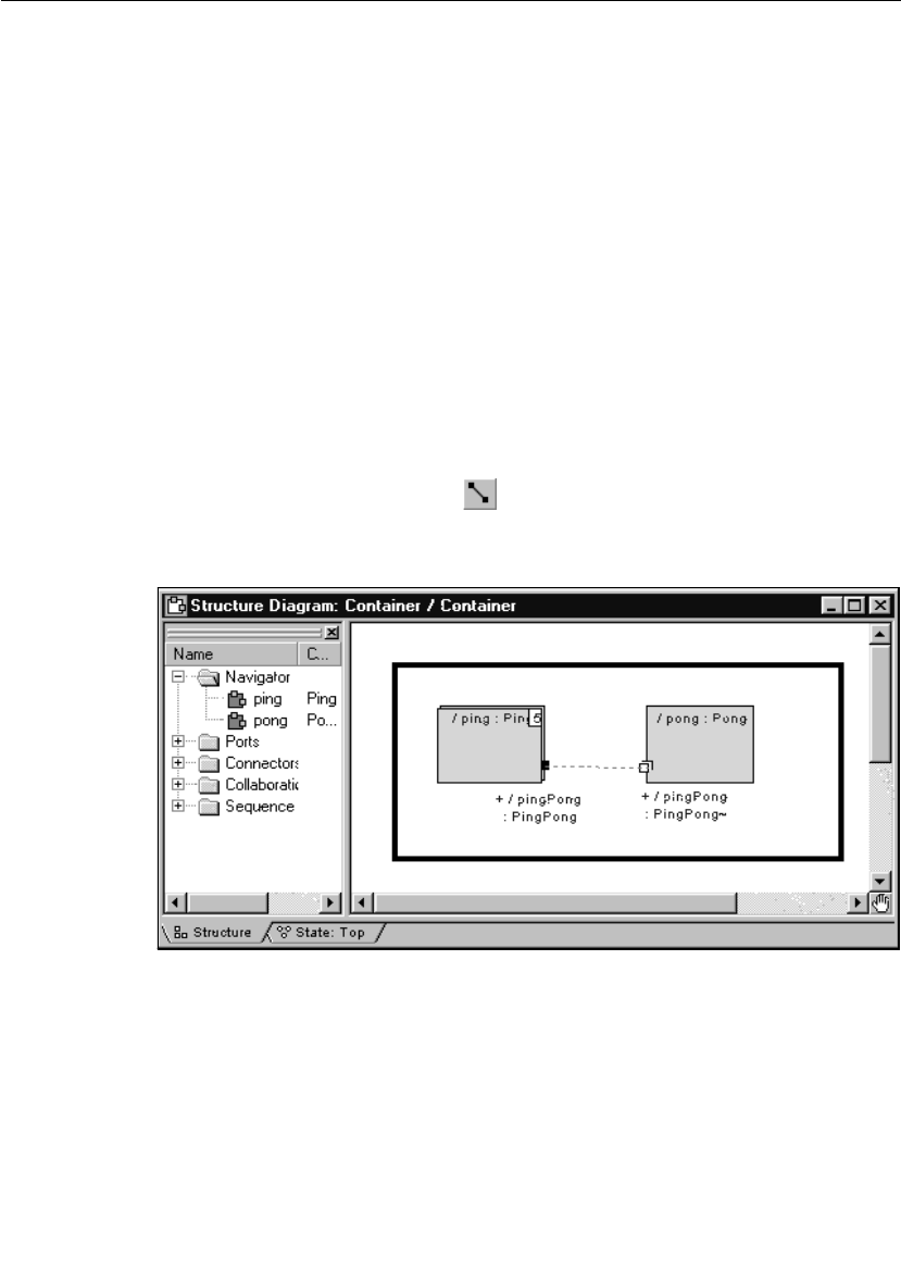
Iteration 1: Creating the Rose RealTime Model
User Guide - Rational Rose RealTime Connexis 47
Rationale for visibility of ports
The log protocol is used to access the logging service that is built into
the Rose RealTime libraries. The logging service is used primarily for
printing messages to standard error during the initial debugging of
models.
The PingPong port is shown in the class diagram because it is
architecturally significant. The log port is shown in the structure
diagram because it is an implementation detail; however, the log port
could have been added to the class diagram, if desired, and the
behavior would be exactly the same.
Repeat steps 1 to 6 for the Pong capsule.
To connect the Ping and Pong capsules:
1. Open the structure editor for the Container capsule by right-
clicking and choosing Open Structure Diagram.
2. Select the Connector tool .
3. Connect the pingPong port on the Ping capsule to the pingPong
port on the Pong capsule as shown in Figure 17.
Figure 17 Creating connectors between ports
The structure for Iteration 1 is now complete. Your class diagram
should look the same as the one shown in Figure 18.
Note: To show the port and log icons, select the capsule and choose
Options > Show Visibility.

Chapter 3 Quick Start
48 User Guide - Rational Rose RealTime Connexis
Figure 18 Completed structure for Iteration 1
Step 6: Implement the State Machines for Ping and Pong
To implement the state machines for the Ping and Pong capsules
perform the steps listed below.
To create Ping’s state machine:
1. Select the Ping capsule.
2. Open the state editor by right-clicking and choosing Open State
Diagram.
3. Select the state tool and drop a state on the diagram. Do this
by clicking the state tool and clicking anywhere on the diagram.
4. Name this state “ready."
5. Select the transition tool and draw the initial transition from
the initial state to the ready state.

Iteration 1: Creating the Rose RealTime Model
User Guide - Rational Rose RealTime Connexis 49
6. Double-click the transition, and select the Actions tab in the
specification editor.
7. Type in the following code, and then click the OK button (see
Figure 19).
pingPong.ping().send();
Figure 19 Adding code to a transition
8. Select the self transition tool and draw a self transition on the
ready state, name this transition “pong." Your diagram should look
similar to Figure 20.
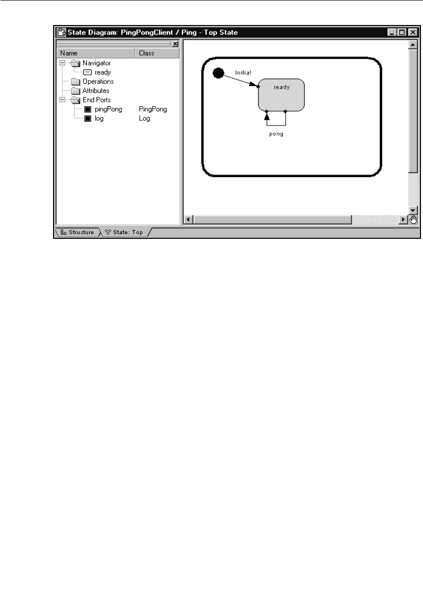
Chapter 3 Quick Start
50 User Guide - Rational Rose RealTime Connexis
Figure 20 Creating states
9. Double-click on the pong transition and select the Actions tab.
10. Type in the following code:
log.log("received a pong");
pingPong.ping().send();
Note: In a real world application, you would not immediately send a
Ping request. You would most likely perform additional processing
where another event would trigger the sending of another Ping
request.
11. Click the Apply button.
12. Select the Triggers tab.
13. Right-click in the control area and select Insert from the pop-up
menu as shown in Figure 21.
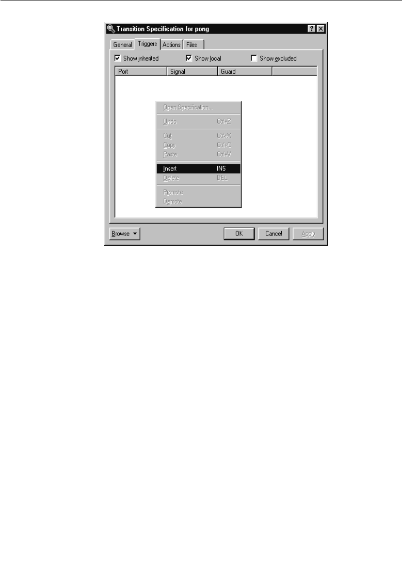
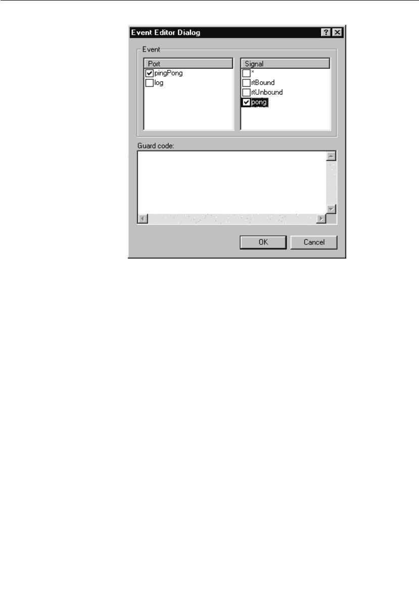
Chapter 3 Quick Start
52 User Guide - Rational Rose RealTime Connexis
Figure 22 Selecting the port and signal
To create Pong’s state machine:
1. Open the state editor for the Pong capsule.
2. Select the state tool and drop a state on the diagram.
3. Name this state “ready."
4. Select the transition tool and draw the initial transition from the
initial state to the ready state.
5. Select the self transition tool and draw a self transition on the
ready state, name this transition “ping."
6. Double-click on the ping transition, and select the Actions tab in the
specification editor.
7. Type in the following code:
log.log("received a ping");
rtport->pong().reply();
8. Click the Apply button.
9. Select the Triggers tab.

Iteration 1: Creating the Rose RealTime Model
User Guide - Rational Rose RealTime Connexis 53
10. Right-click in the control area and select Insert from the pop-up
menu.
11. Select the pingPong port and the ping signal from the resulting
Event Editor dialog and click the OK button.
Step 7: Build and Test the Model
To build and run a model from Rose RealTime, you must first create a
component. Components are used to model the physical elements that
may reside on a node, such as executables, libraries, source files, and
documents. In other words, the component represents the physical
packaging of the logical elements, such as classes and capsules. For
the purposes of this example, the components that are created are
going to represent executables.
Components have an associated top-level capsule. The top-level
capsule defines what parts of the model are contained in the
executable. In this case, the Container capsule should be made the
top-level capsule of the new component.
To create a component:
1. Choose Build > Component Wizard to run the Build Component Wizard.
2. Click Next.
3. Type “PingPongApp” in the component name field as shown in
Figure 23. Ensure that the package is Component View and click
Next.
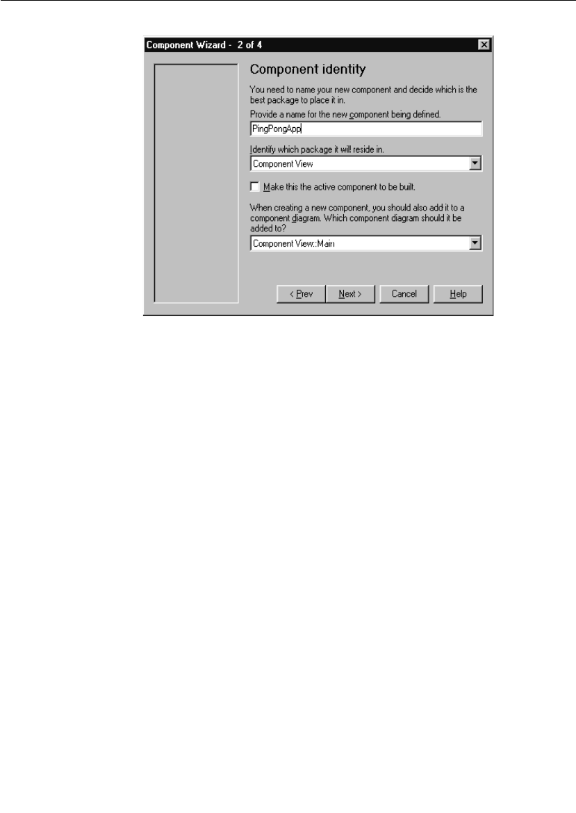

Iteration 1: Creating the Rose RealTime Model
User Guide - Rational Rose RealTime Connexis 55
Figure 24 Setting the top-level capsule - Iteration 1
3. Select the package. In this case, select Container from the drop-
down list.
4. Select the capsule. In this case, select the Container capsule from
the drop-down list
5. Click Next.
6. Click Next.
7. Choose the target configuration as in Figure 25. If your
development configuration is Visual C++ 6.0 in Windows NT, select
NT40T.x86-VisualC++-6.0 and click Next. If your configuration is
different, select the appropriate target.
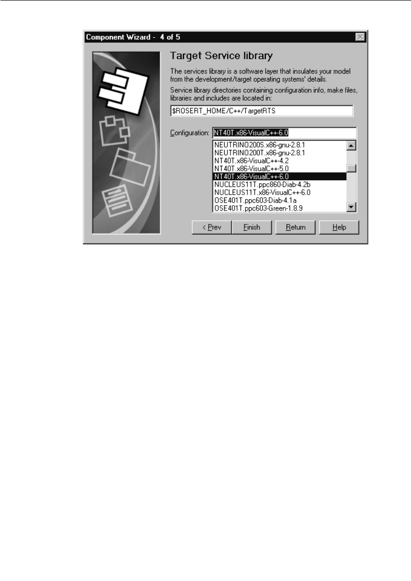
Chapter 3 Quick Start
56 User Guide - Rational Rose RealTime Connexis
Figure 25 Setting the target service library
8. Click Finish and click the OK button.
There are many options that are associated with components. For the
purposes of this example the default values are sufficient.
To create a processor:
To execute the model from within the toolset, you must assign the
component that was created in the last step to a processor. This tells
Rose RealTime to execute the component on a specific machine on your
network. There are many options that can be set for the processor and
for executing a component instance on the processor. The defaults are
sufficient in this case.
To create a processor:
1. Right-click on the Deployment View folder in the Rose RealTime
browser and select New > Processor from the pop-up menu.
2. Name this processor “PingPongProcessor."
3. Drag and drop the PingPongApp component onto the
PingPongProcessor.

Iteration 1: Creating the Rose RealTime Model
User Guide - Rational Rose RealTime Connexis 57
You now should have a PingPongProcessor that contains a
PingPongApp component instance as shown in Figure 26.
Figure 26 Processor and component instance
To build the model:
1. Save the model as "Tutorial_Iteration1."
2. Select the PingPongApp component.
3. Open the pop-up menu and choose Build > Quick Build.
4. Click Add References and Continue.
5. Click the OK button.
Rationale for using Quick Build
In this rapid prototyping example, we allow the tool to inform us about
missing references and add them. In a large, managed application,
references should be carefully managed and added manually to the
component.
Run the PingPong component instance
To run the PingPong application:
1. Right-click on the PingPongAppInstance and select Run from the
pop-up menu. This creates the run-time environment within Rose
RealTime.
2. Select No to “Build the component?” since it is already built.
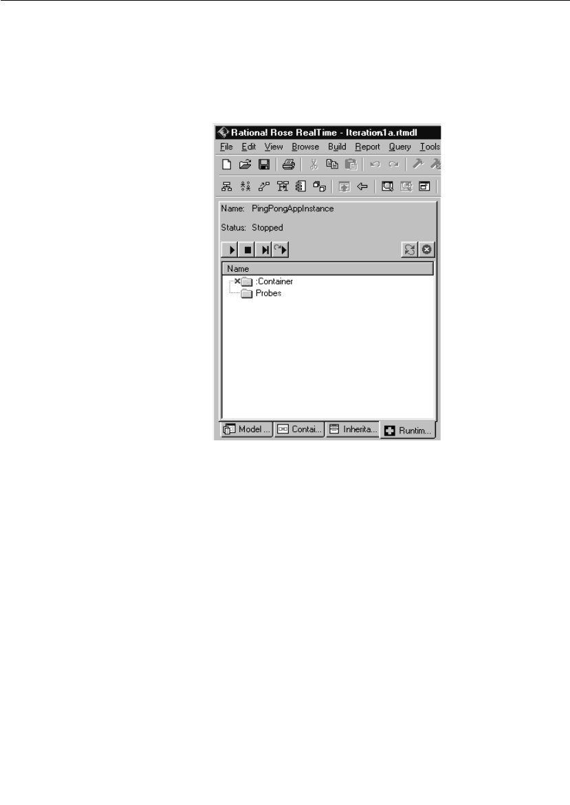
Chapter 3 Quick Start
58 User Guide - Rational Rose RealTime Connexis
The top left hand corner of the Rose RealTime application should
now look something like what is illustrated in Figure 27. A console
window also appears. This window is where the standard output
from the model is displayed. Keep this window visible so that you
can see the output that is being displayed.
Figure 27 Rose RealTime run-time environment
3. Press the Start button to execute the model.
While the PingPongApp is running, you should see messages being
printed to the console window. The Pong capsule receives ping signals
from the Ping capsule and prints “received a ping” each time it does.
Likewise, the Ping capsule receives pong messages from the Pong
capsule and prints “received a pong” each time it does.

Iteration 2: Connexis Enabling our Application
User Guide - Rational Rose RealTime Connexis 59
Because of the way that this model has been designed and the way the
Target RSL message queuing works, this model prints five “received a
ping” messages followed by five “received a pong” messages and
continues doing this until the model is stopped. All messages that are
sent to a capsule are queued in a priority queue. In this model, all five
of the “ping” messages are queued before a “pong” response is
generated. This causes the messages to be output as shown in the
console window.
4. Click the Shutdown button in the Runtime Viewer to stop the
process.
Iteration 2: Connexis Enabling our Application
Connexis manages connections that are established between unwired
ports. Unwired ports are ports whose connections are defined at run-
time. Unlike wired ports, unwired ports cannot have connectors
defined between themselves and other ports. The connections
established between unwired ports can also be removed and
reestablished at run-time.
Since unwired ports are used in Iteration 2, the first thing to do for
Iteration 2 is to remove the wired connections that were created in
Iteration 1 and make the wired pingPong ports unwired.
Step 1: Remove the Connector Between the pingPong Ports
To remove the connector between the pingPong ports:
1. Open the model “Tutorial_Iteration1” that you created in
Iteration 1.
2. Save the model as “Tutorial_Iteration2.”
3. Open the Container capsule’s structure diagram as shown in
Figure 28.
4. Select the connector that is joining the pingPong ports on the Ping
and Pong capsules. Right-click and choose Remove/Exclude to delete
the connector.
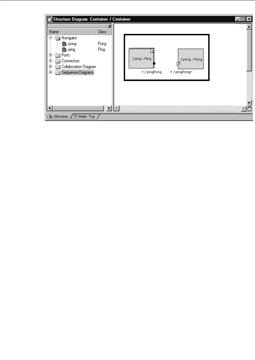
Chapter 3 Quick Start
60 User Guide - Rational Rose RealTime Connexis
Figure 28 Removing the connector between ping and pong
Step 2: Make Changes to Pong’s pingPong Port
To make changes to Pong’s pingPong port:
1. Open the Pong capsule’s structure diagram.
2. Select the pingPong port and open its specification.
3. Uncheck the Wired option as shown in Figure 29.
4. Check the Publish option.
This makes the port externally visible.
5. Since the port is being registered in transition code, the Application
radio button must also be checked.

Iteration 2: Connexis Enabling our Application
User Guide - Rational Rose RealTime Connexis 61
Figure 29 Changing port specifications for Pong
Step 3: Make Changes to Ping’s pingPong Port
To make changes to Ping’t pingPong port:
1. Open the Ping capsule’s structure diagram.
2. Select the pingPong port and open its specification.
3. Uncheck the Wired option as shown in Figure 30.
4. Check the Notification check box.
5. Since the port is being registered in transition code, the Application
radio button must also be checked.
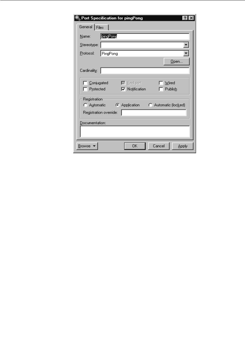
Chapter 3 Quick Start
62 User Guide - Rational Rose RealTime Connexis
Figure 30 Changing port specifications for Ping
The Notification box has been checked so the Ping capsule will be
notified when a connection has been established on the pingPong port.
The Notification box was not checked in the Pong capsule because it
doesn’t really care when connections have been established to its port.
This is because the Pong capsule has published its interface and is just
waiting for others to connect to it. In a more realistic design, the Pong
capsule may be required to keep track of how many clients are
connected at any given time. This would make Pong’s state machine
slightly more complicated.
In the Ping capsule, the notification event will be used. Ping’s state
machine must be changed so that it waits for an rtBound signal to be
received on the pingPong port before sending a Ping message.
Note: The Target RSL sends the rtBound signal as notification that a
connection was established.

Iteration 2: Connexis Enabling our Application
User Guide - Rational Rose RealTime Connexis 63
Step 4: Adding DCS Layer Notification to the Ping and Pong Capsules
To add DCS layer notigication to Ping and Pong capasules:
1. Open the Class Diagram called Architecture you created in the first
iteration.
2. Drag the RTDInitStatus protocol, located in the RTDInterface
package in the Logical View, onto the diagram.
3. Select the Unidirectional Aggregation tool.
4. Create an aggregation association between the Pong capsule and
the RTDInitStatus protocol. Name the association "dcsStatus."
5. Open the specification for the aggregation between the Pong
capsule and the RTDInitStatus protocol.
6. Specify that it is:
a. protected
b. an end port
c. not wired, and
d. notification enabled
7. Specify that the Registration will be handled automatically, and
specify a registration override of “:RTDInitStatus.”
8. Repeat steps 3 through 7 for the Ping capsule.
Before a model attempts to publish or subscribe to services through
Connexis, it should verify that the DCS layer is active and properly
initialized. If not, publication and subscription attempts will fail. The
Connexis capsule will publish the RTDInitStatus service through the
Internal Layer Service when it has completed its initialization. By
subscribing to the service and enabling notification, the model can wait
until it receives notification from Connexis before registering its SAPs
or SPPs.
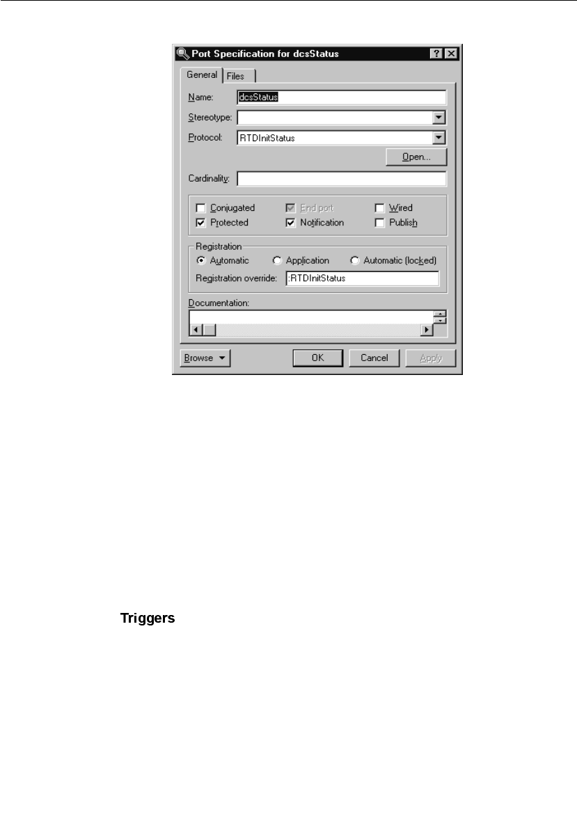
Chapter 3 Quick Start
64 User Guide - Rational Rose RealTime Connexis
Figure 31 Port Specification for dcsStatus
Step 5: Modify Ping’s State Machine to Wait for Connexis
To modify Ping’s state machine to wait for Connexis:
1. Open the state diagram for Ping.
2. Add a new state to the diagram and call it “waitingForDCS.”
3. Delete the Initial transition to the “ready” state.
4. Add a new Initial transition to the “waitingForDCS” state.
5. Add a transition from the “waitingForDCS” state to the “ready”
state. Label this transition “dcsReady.”
6. Open the specification for the “dcsReady” transition and click the
tab.
7. Insert a trigger for the rtBound event on the dcsStatus port. We will
add the action code to subscribe to the service in a later step.
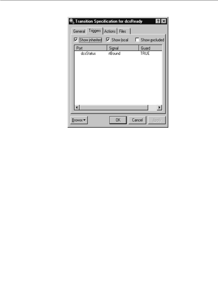
Iteration 2: Connexis Enabling our Application
User Guide - Rational Rose RealTime Connexis 65
Figure 32 Add a transition for dcsStatus
Step 6: Modify Pong’s State Machine to Wait for Connexis
To modify Pong’s state machine to wait for Connexis:
1. Open the state diagram for Pong.
2. Add a new state to the diagram and call it “waitingForDCS.”
3. Delete the Initial transition to the “ready” state.
4. Add a new Initial transition to the “waitingForDCS” state.
5. Add a transition from the “waitingForDCS” state to the “ready”
state. Label this transition “dcsReady.”
6. Open the specification for the “dcsReady” transition and click the
Triggers tab.
7. Insert a trigger for the rtBound event on the dcsStatus port. We will
add the action code to publish the service in a later step.
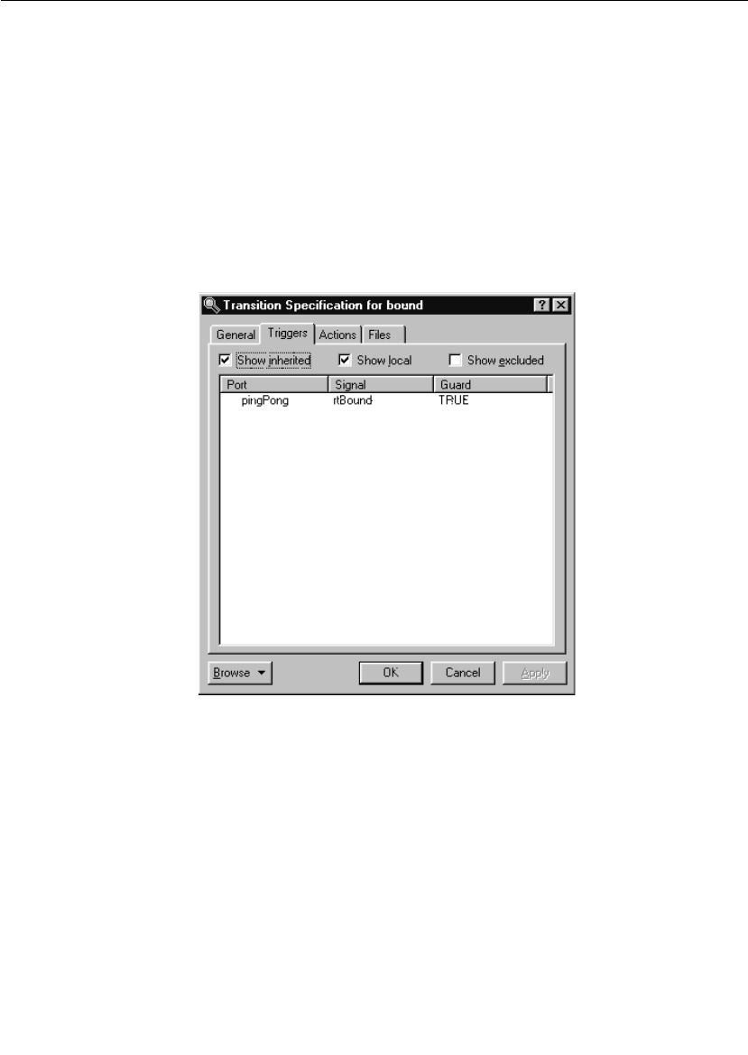
Chapter 3 Quick Start
66 User Guide - Rational Rose RealTime Connexis
Step 7: Modify Ping’s State Machine to Wait for Notify
To modify Ping’s state machine to wait for notify:
1. Open the state diagram for Ping.
2. Add a new state to the diagram and call it “connected."
3. Add a transition between the “ready” state and the “connected”
state. Label this transition “bound."
4. Open the specification for the “bound” transition and click on the
Triggers tab.
5. Insert a trigger for the rtBound event on the pingPong port.
Figure 33 Transition Specification for rtBound
6. Click on the Actions tab and add the following code in the code
editor:
pingPong.ping().send();
7. Move the pong transition from the ready state to the connected
state.
To do this, select the transition and drag both ends of the
transition over onto the Connected state one at a time. Your final
state diagram should be similar to the one shown in Figure 34.
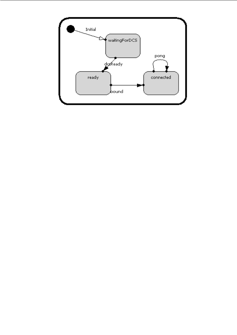
Iteration 2: Connexis Enabling our Application
User Guide - Rational Rose RealTime Connexis 67
Figure 34 Ping’s state diagram
Step 8: Add Registration Code to the Ping and Pong Capsules
Connexis needs to know how to connect the unwired ports in your
model. A client can “lookup” a server in one of three places:
■locally - connect only with current TargetRTS
■explicit address - connect only to the TargetRTS at the specified
address
■locator - connect using the Locator service
In addition to these options, there are also several parameters that can
be passed to Connexis when you register a port. These parameters are
discussed in detail in “Establishing Connections” on page 107.
In this example, the Ping and Pong capsules are going to register with
the Locator service.
The basic syntax for registering a port with the Locator service is:
// for the client side of the connection
registerSAP(“registrationString”);
and
//for the server side of the connection
registerSPP(“registrationString”);

Chapter 3 Quick Start
68 User Guide - Rational Rose RealTime Connexis
The registration string is different depending on which of the three
lookup types you are using (local, explicit address, locator). In this
example, the Locator service is being used, so the form of the
registration string is:
connection_service:/registration_name
The only connection service currently available is the Distributed
Connection Service (DCS) and Connexis Reliable Messaging (CRM).
This leaves us with the following syntax for registering the pingPong
port in the client:
registerSAP(“dcs:/pingpong”);
and the syntax for registering the pingPong port in the server as:
registerSPP(“dcs:/pingpong”);
In this example, the “pingpong” portion of the registration string could
have been any string.
This is the simplest case of registration using the Locator. There are
many parameters that can be supplied to the Locator as part of the
registration string for doing things like setting the transport protocol
that is being used. These parameters are discussed in “Establishing
Connections” on page 107.
To add registration code to the Ping capsule:
1. Open the state diagram for the Ping capsule.
2. Double-click on the dcsReady transition and select the Actions tab
in the resulting dialog.
3. Delete the existing text and enter the following code into the code
window:
if (!pingPong.registerSAP(“dcs:/pingpong”)) {
log.log(“Ping registration failed”);
}
4. Click the OK button.
To add registration code to the Pong capsule:
1. Open the state diagram for the Pong capsule.
2. Double-click on the dcsReady transition and select the Actions tab
in the resulting dialog.

Iteration 2: Connexis Enabling our Application
User Guide - Rational Rose RealTime Connexis 69
3. Enter the following code into the code window:
if (!pingPong.registerSPP(“dcs:/pingpong”)) {
log.log(“Pong registration failed”);
}
4. Click the OK button.
Now all of the model changes that are required have been completed.
The next step is to set up the Connexis environment and create two
new components. One of the components represents the Ping
application and the other the Pong application.
Step 9: Add the Connexis Configuration Capsules to Your Model
The Ping Pong Model requires the Ping and the Pong capsule to include
the DCS capsule roles. We will use the Connexis configuration
interface to add an RTDBase_Agent to Ping and an
RTDBase_Locator_Agent to Pong. (This configuration can also be done
manually).
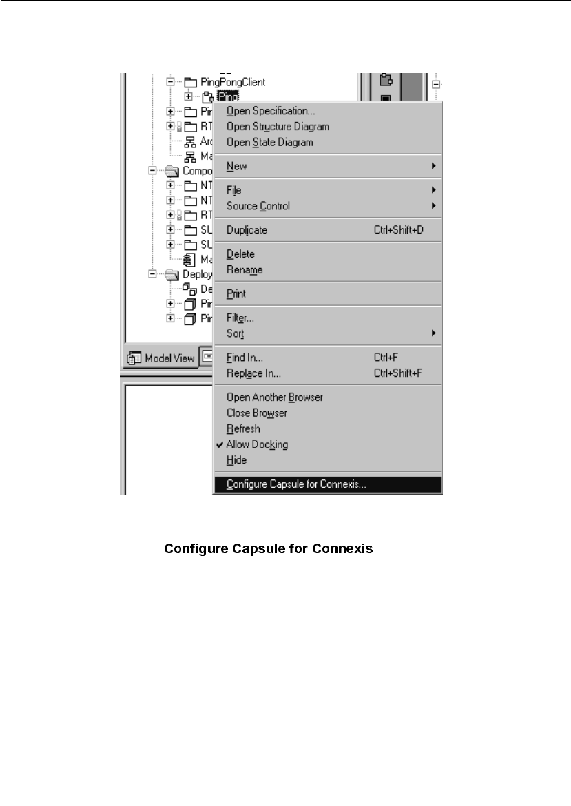
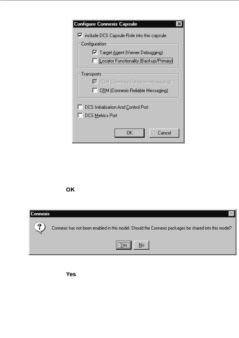
Iteration 2: Connexis Enabling our Application
User Guide - Rational Rose RealTime Connexis 71
Figure 36 Configure Connexis Capsule dialog
3. Select the following options:
a. Include DCS capsule role into this capsule
b. Target Agent (Viewer Debugging)
4. Click .
A dialog, suggesting that “Connexis packages be shared into this
model,” appears.
Figure 37 Sharing Connexis Packages request dialog
5. Click .
You can see that the DCS capsule role has been added by viewing
the Ping capsule structure (see Figure 38, Ping Capsule Structure).

Chapter 3 Quick Start
72 User Guide - Rational Rose RealTime Connexis
Figure 38 Ping Capsule Structure
To configure the Pong Capsule:
1. Right-click the Pong capsule.
2. Select .
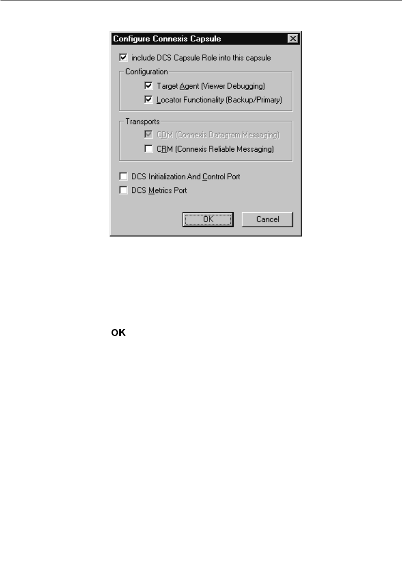
Iteration 2: Connexis Enabling our Application
User Guide - Rational Rose RealTime Connexis 73
The Configure Connexis dialog appears.
Figure 39 Configure Connexis Capsule
3. Select the following options:
a. Include DCS Capsule Role into this capsule
b. Target Agent (Viewer Debugging)
c. Locator Functionality (Backup/Primary)
4. Click .
You can see that the DCS capsule role has been added by viewing the
Pong capsule structure. Since Pong also supports the locator, the class
of the DCS role is RTDBase_Locator_Agent instead of RTDBase_Agent.
Rationale for selecting RTD interfaces
In this configuration, only the Pong (server) capsule can be the locator.
We could use an RTD_Base_Locator_Agent reference in both Ping and
Pong, in which case either capsule could serve as the primary locator.
The locator’s location is determined by the parameters specified in
“Step 13: Build and Execute the Models."
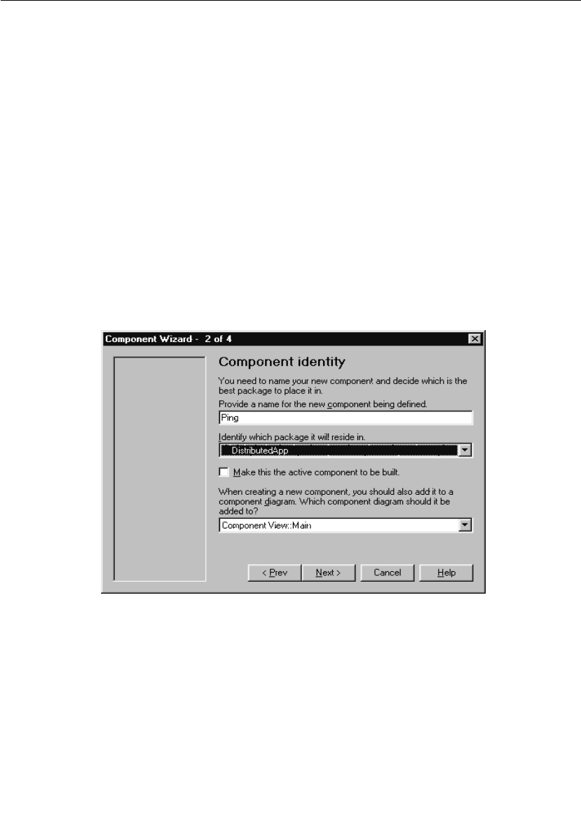
Chapter 3 Quick Start
74 User Guide - Rational Rose RealTime Connexis
For more information about the features provided by the different
RTDInterface capsules, refer to “Adding Connexis Support to Your
Model” on page 83.
Step 10: Create and Configure the Ping Component
Create a component for the Ping application.
To create the Ping component:
1. Select the Component View package.
2. Open the pop-up menu and select New > Package.
3. Name the package “DistributedApp."
4. Choose Build > Component Wizard to run the Build Component Wizard.
5. Click Next.
6. Type “Ping” in the component name field as shown in Figure 40.
Ensure that the package is DistributedApp and click Next.
Figure 40 Setting the component identity - Iteration 2
7. Select C++ and click Next.
8. Click the OK button.
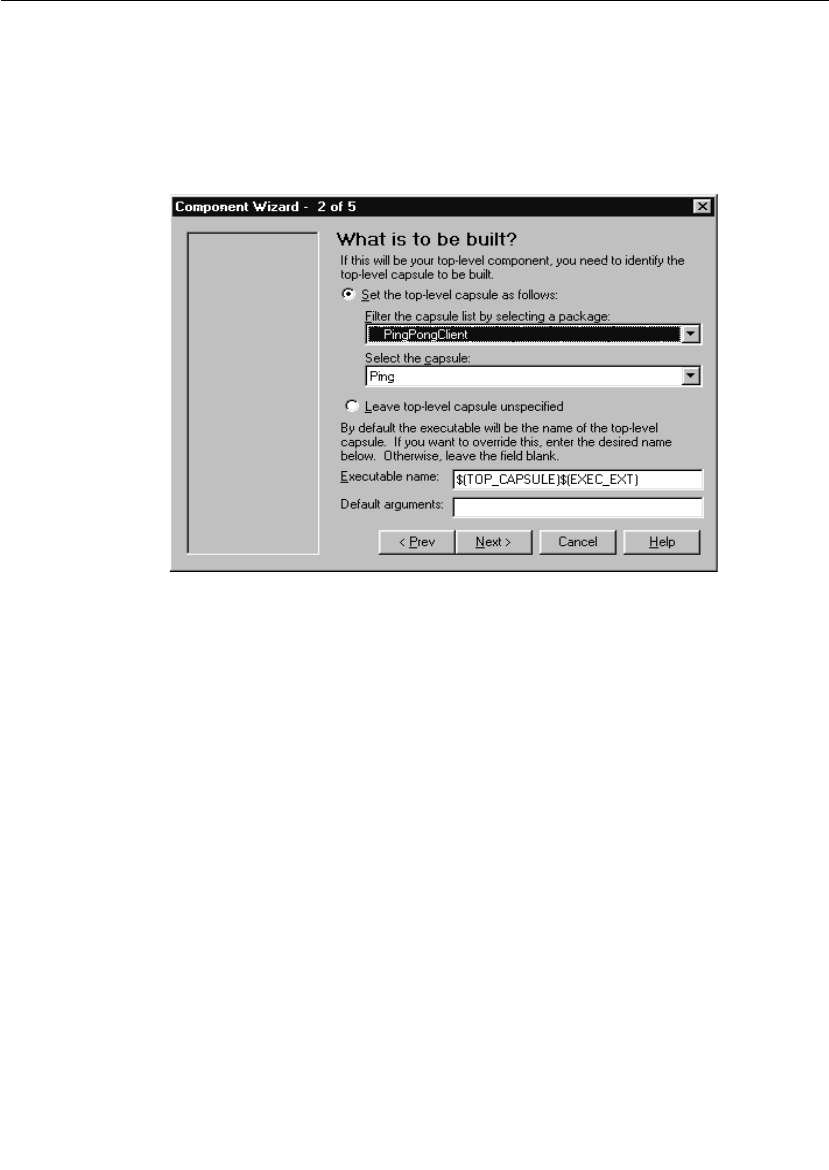
Iteration 2: Connexis Enabling our Application
User Guide - Rational Rose RealTime Connexis 75
To customize the component:
1. Click Next.
2. Click Set the top-level capsule as shown in Figure 41.
a. Select PingPongClient package from the drop-down list.
b. Select Ping as the capsule.
Figure 41 Setting the top-level capsule - Iteration 2
3. Click Next.
4. Click Next.
5. Choose the target configuration.
Use the same target configuration as in “To customize the
component:” on page 54, step 7.
Step 11: Create and Configure the Pong Component
Create a component for the Pong application.
To create the Pong component:
1. Choose Build > Component Wizard to run the Build Component Wizard.
2. Click Next.
3. Type “Pong” in the component name field. Ensure that the package
is DistributedApp and click Next.

Chapter 3 Quick Start
76 User Guide - Rational Rose RealTime Connexis
4. Select C++ and click Next.
5. Click the OK button.
To customize the component:
1. Click Next.
2. Set the top level capsule:
a. Select PingPongServer package from the drop-down list.
b. Select Pong as the capsule.
3. Click Next.
4. Click Next.
5. Choose the target configuration.
Use the same target configuration as in “To customize the
component:” on page 54, step 7.

Iteration 2: Connexis Enabling our Application
User Guide - Rational Rose RealTime Connexis 77
Step 12: Add Component Dependencies
You need to create dependencies between the Ping component and the
Connexis DCS library, and the Pong component and the DCS library.
To add component dependencies:
1. Right-click the Ping Component.
Figure 42 Configuring the Ping Component
2. Select > .
The Component Diagram Selection dialog appears.
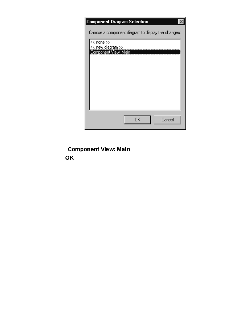
Chapter 3 Quick Start
78 User Guide - Rational Rose RealTime Connexis
Figure 43 Component Diagram Selection dialog
3. Select .
4. Click .
You have created a dependency between the Ping component and
the DCS library.
5. Repeat steps one to four for the Pong component.
The Main diagram in Component View will appear as in Figure 44.
You should now have Ping and Pong components that are ready to be
compiled.
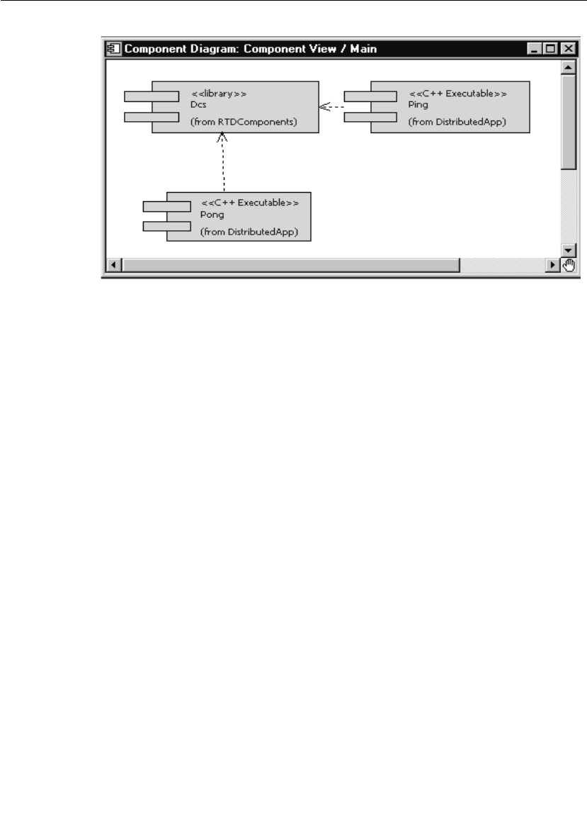
Iteration 2: Connexis Enabling our Application
User Guide - Rational Rose RealTime Connexis 79
Figure 44 Main component view diagram
Step 13: Build and Execute the Models
Now that the components have been created and configured, they must
be built. This is done by right-clicking on the component and selecting
Build from the pop-up menu.
To create a Ping processor and component instance:
1. Create a processor for the Ping component and name it
“PingProcessor."
2. Drag the Ping component onto the PingProcessor to create a
component instance.
3. Select the PingInstance and open its specification.
4. Add the following code to the Parameters field in front of the code
“-obslisten=30468”:
-CNXep=cdm://localhost:7777 -CNXlpep=cdm://localhost:8888
Your final code should appear similar to the line below. Note that
the target observability port number, 30468, will vary from this
example.
-CNXep=cdm://localhost:7777 -CNXlpep=cdm://localhost:8888 -
obslisten=30468
Note: See page 253 for information on using “localhost.”

Chapter 3 Quick Start
80 User Guide - Rational Rose RealTime Connexis
5. Click the OK button.
To create a Pong processor and component instance:
1. Create a processor for the Pong component and name it
“PongProcessor."
2. Drag the Pong component onto the PongProcessor to create a
component instance.
3. Select the PongInstance and open its specification.
4. Add the following code to the Parameters field in front of the code
“-obslisten=30477”:
-CNXep=cdm://localhost:8888 -CNXlp
Your final code should appear similar to the line below. Note that
the target observability port number, 30477, will vary from this
example.
-CNXep=cdm://localhost:8888 -CNXlp -obslisten=30477
5. Click the OK button.
Rationale for the Connexis parameters
The -CNXep= parameter identifies the cdm endpoint at which the
component instance listens. The -CNXlp parameter on the
PongInstance specifies that the PongInstance will act as the primary
locator. The -CNXlpep= parameter informs the PingInstance of the
location of the primary locator. Note that the -CNXep of the
PongInstance is the value of the -CNXlpep of the PingInstance. For
more information about Connexis parameters, refer to “Establishing
Connections” on page 107.
Run the Pong component instance
To run the Pong component instance:
1. Right-click on the PongInstance and select Run from the pop-up
menu.
2. Select No to “Build the component?” since it is already built.
A console window appears.
3. Press the Start button to execute the model.

Iteration 2: Connexis Enabling our Application
User Guide - Rational Rose RealTime Connexis 81
Run the Ping component instance
To run the Ping component instance:
1. Right-click on the PingInstance and select Run from the pop-up
menu.
2. Select No to “Build the component?” since it is already built.
A second console window appears for the Ping component instance.
3. Press the Start button to execute the model.
Note: The ping and pong reports appear in separate console windows.
The two processes are communicating through Connexis.
Optional: Distribute the model
When a model has been Connexis-enabled, it may be distributed by
simply changing the executable parameters.
The hostname "localhost" was used in previous component instance
specifications. Since this has a different meaning on each host, it must
be replaced with the actual hostname. For this example the machine
"angus" will be used for Ping and "bruce" for Pong.
1. Start Rose RealTime running on angus and bruce. Build the Ping
component on angus and the Pong component on bruce if you have
not already done so.
2. On angus, open the PingInstance specification and change the -
CNXep and -CNXlpep parameters to be:
-CNXep=cdm://angus:7777 -CNXlpep=cdm://bruce:8888
3. On bruce, open the PongInstance specification and change the -
CNXep parameter to be:
-CNXep=cdm://bruce:8888
4. Run the PingInstance on angus and the PongInstance on bruce.
Observe the same behavior that you saw in a single-processor
environment.
Note: To keep this exercise simple, Rose RealTime was run on each
of the target processors. In a normal development situation you will
run Rose RealTime on a single host from which all targets are
observed and controlled.

Chapter 3 Quick Start
82 User Guide - Rational Rose RealTime Connexis
Optional: Complete the HelloWorld Tutorial
Once you have completed the Quick Start, proceed to the HelloWorld
tutorial, provided in the Rose RealTime online help. It provides
information on using the Locator and shows you how to work with
rtbound and rtunbound notifications.
Basic Connexis Development Approach Summary
This section outlines the basic steps to follow to distribute your model
using Connexis.
1. Design your Rose RealTime application.
Although it is very easy to repartition your model and distribute it in a
different manner using Connexis, it is still a good idea to consider
distribution when you are doing your up-front designs. The reason for
this is performance. Many of the performance issues that you
encounter in a distributed application are a direct result of not
partitioning your model properly. Remember, intra-thread messages
are faster than inter-thread messages, which are faster than inter-
process messages, which are faster than inter-node messages.
2. Specify the registration strings and connection parameters on your
unwired ports.
If the nature of your application is such that you know the names of
the endpoints that you want to communicate with (either through the
use of an algorithmic mapping or by reading a configuration file), then
explicit endpoint names can be used in the registration strings of the
unwired ports in the model. For more information refer to “External
explicit examples” on page 124.
If this is not the case, you may want to make use of the Locator Service.
In either case, each of the unwired ports in your model must be
registered with an appropriate registration string. Once this has been
completed and the connections are being initialized properly, you can
send and receive messages through Connexis-enabled unwired ports
in the same way as with normal Rose RealTime ports.

User Guide - Rational Rose RealTime Connexis 83
Chapter 4
Adding Connexis Support to Your Model
To add Connexis support to a Rose RealTime model complete the
following sections:
■Sharing DCS Interfaces into your Model
■Configuring Connexis Capsules
■Manually Integrating Transports Into a Model
In addition to these steps, there are also general design rules that must
be followed to ensure that the Connexis component in an application
is initialized properly before it is used (see “Initializing Your Connexis
Capsule” on page 92).
From the perspective of a Rose RealTime model, Connexis is
distributed as a set of Rose RealTime capsules and components. To
make use of Connexis in your Rose RealTime model, you need to share
the appropriate Connexis packages, containing the Connexis capsules
and components.
From a build perspective, Rational Connexis is shipped as an external
library, libDCS. The libDCS library provides support for the CDM and
CRM transports.
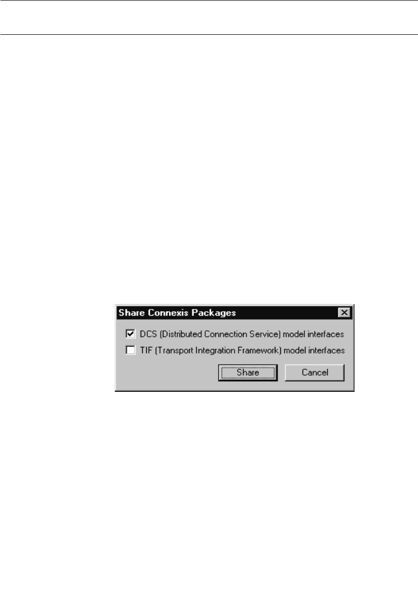
Chapter 4 Adding Connexis Support to Your Model
84 User Guide - Rational Rose RealTime Connexis
Sharing DCS Interfaces
Connexis functionality is defined in a set of packages that must be
shared into your model. There are logical packages containing the
capsules that provide Connexis functionality for your application.
There are also component packages representing the external
Connexis libraries needed to build your application.
Hint: If you want to use the CDM or CRM transport, you only need to
add the Distributed Connection Service (DCS).
Note: You must be able to modify your model, specifically the Logical
View and Component View packages. If your model is under source
control, you need to check out these packages first.
Sharing DCS Interfaces into your Model
In order for your application to make use of the Distributed
Communication Services (DCS), you must share the DCS model
interfaces packages into your model.
To share the Connexis packages:
1. From the Tool s menu, select Connexis > Share Connexis Packages.
The Share Connexis Packages dialog appears.
Figure 45 Share Connexis Packages dialog
2. Select DCS (Distributed Connection Service) model interfaces.
Note: Do not select TIF (Transport Integration Framework) model
interfaces unless you are developing a transport integration (see
“Using the Transport Integration Framework” on page 299).
a. DCS (Distributed Connection Service) model interfaces

Configuring Connexis Capsules
User Guide - Rational Rose RealTime Connexis 85
The DCS model interfaces selection shares the capsules and
components needed to make use of DCS. The RTDInterface
logical package and the RTDComponents component package
are shared into your model.
b. TIF (Transport Integration Framework) model interfaces
Models that make use of DCS do not share this package into the
model. This package is only shared into a model in which a
transport integration is being developed (see “Using the
Transport Integration Framework” on page 299).
3. Click .
Removing Shared Packages
Rose RealTime lets you remove Connexis packages from your model.
To remove Connexis packages:
1. From the menu select Connexis > .
Connexis packages are removed from your model.
Configuring Connexis Capsules
Once the Connexis packages are shared, you must add a capsule role
for one of the Connexis capsules in the RTDInterface package to one
capsule for each component that will use Connexis. It is suggested that
you add one of these capsules as a fixed capsule role in the top-level
capsule in each component. If the capsule or its containing package is
in source control, check the capsule out of source control before
applying the settings.
To add a capsule role in your model:
1. Right-click a capsule in your model or right-click the structure
diagram of a capsule.
2. Select .
The Configure Connexis Capsule dialog appears, containing the
current Connexis settings of the selected capsule, including the
type of Connexis capsule role added to the capsule.

Chapter 4 Adding Connexis Support to Your Model
86 User Guide - Rational Rose RealTime Connexis
Figure 46 Configure Connexis Capsule dialog
3. Check the “include DCS Capsule Role into this capsule” check box
if you want to include the DCS Capsule Role into the selected
capsule. If you do not, proceed to instruction five.

Configuring Connexis Capsules
User Guide - Rational Rose RealTime Connexis 87
4. If you checked the “include the DCS Capsule Role into this
capsule” check box, set the Configuration and Transports options
to your requirements:
5. Select the options that you want to make available to your model.
a. DCS Initialization and Control Port (see “Using the
RTDInitStatus Protocol” on page 93)
b. DCS Metrics Port (see “Using the Connexis Metrics Service” on
page 237)
Once you configure the capsule, the Connexis Component
Configuration tool prompts you to configure the capsules that
reference the Connexis-enabled capsule that you configured.
Depending on the options that you selected in the “Configure Connexis
Capsule” dialog, one of the following capsule roles are included in your
capsule:
Table 4 Configure Connexis Capsule dialog description
Configuration and
Transports Settings
Description
Transport Agent
(Viewer Debugging)
Selecting this option lets you use the Connexis
Viewer to provide debugging support (see“Using
the Connexis Viewer” on page 151). Once you
select this option the CDM transport is enabled. The
Connexis Viewer uses the CDM transport.
Locator Functionality
(Backup Primary)
Selecting this option lets you use the Connexis
Locator that maps endpoint service names to
physical endpoints (see “Locator Connections”
on page 125 and “Using the Connexis Locator
Service” on page 135).
CDM (Connexis
Datagram Messaging)
Selecting this transport lets your component use
the CDM transport.
CRM (Connexis
Reliable Messaging)
Selecting this transport lets your component use
the CRM transport.

Chapter 4 Adding Connexis Support to Your Model
88 User Guide - Rational Rose RealTime Connexis
Manually Integrating Transports Into a Model
This section explains how to integrate transports into your model
without using the Configure Connexis Capsules tool.
For a transport to be available for use in a DCS enabled model, the
transport must first register with DCS, prior to the initialization of
DCS. This constraint also applies to the CDM or CRM transports. The
RTDCdm and RTDCrm classes in the RTDInterface logical package
represent the CDM and CRM transports respectively. The constructors
of each of these classes register their respective transport with DCS. As
Table 5 Configuration Descriptions
Configuration Capsule Description
DCS RTDBase This configuration contains the core
Connexis interfaces. With this
component the Connexis Locator is not
linked in with the executable and the
Connexis Viewer is not used with the
model.
DCS with
Target Agent
RTDBase_Agent This configuration contains the Target
Agent which is the interface between
the executable and the Connexis
Viewer. With this component the Viewer
is used with the model but the Locator
is not linked in with the executable.
DCS with
Locator
RTDBase_Locator This configuration contains the
Connexis Locator. With this
component, the Locator is linked in
with the executable but the Viewer is
not used with the model.
DCS with
Target Agent
and Locator
RTDBase_Locator_
Agent
This configuration contains both the
Locator and the Target Agent. With this
component, the Locator is linked into
the executable and the Connexis
Viewer can be used with the model.

Configuring Connexis Capsules
User Guide - Rational Rose RealTime Connexis 89
a result, an instance of the class must be created prior to the
initialization of the DCS. The easiest way to ensure this is to create an
association (composite aggregation) between the capsule containing
the DCS capsule and the classes that represent the transports to be
integrated.
To register the CDM transport for use in the model, create an
association (composite aggregation) of type RTDCdm on the capsule
containing the RTDBase or RTDBase_Locator capsule. The
RTDBase_Agent and RTDBase_Agent_Locator capsules automatically
register the CDM transport, since the viewer uses the CDM transport.
The constructor for RTDCdm accepts an argument of type bool
indicating whether the CDM transport should listen on the
transporter's thread for incoming messages ("true") or on a separate
thread ("false"). Listening for messages on the transporter's thread can
provide better performance. Only one transport can listen on the
transporter's thread for messages. If the argument supplied to the
constructor is "true" and another transport has already registered with
DCS to listen on the transporter's thread, CDM will listen on a separate
thread.
To register the CRM transport for use in the model, create an
association (or attribute + dependency) of type RTDCrm on the capsule
containing the RTDBase, RTDBase_Locator, RTDBase_Agent and
RTDBase_Agent_Locator capsule. The constructor for RTDCrm
accepts a bool indicating whether the CRM transport should listen on
the transporter's thread for incoming messages ("true") or on a
separate thread ("false"). Listening for messages on the transporter's
thread can provide better performance. Only one transport can listen
on the transporter's thread for messages. If the argument supplied to
the constructor is "true" and another transport has already registered
with DCS to listen on the transporter's thread, the CRM will listen on
a separate thread.
If your model is using additional transports that have been integrated
into DCS, they must also be registered with DCS prior to the
initialization of DCS. The designers that developed the transport
integration will be able to provide information on how to register the
transport.

Chapter 4 Adding Connexis Support to Your Model
90 User Guide - Rational Rose RealTime Connexis
Configuring a Component for Connexis
When you configure a component for Connexis, you create a
component dependency to a DCS library. If a DCS dependency already
exists in the selected component, the Configuration tool notifies you of
the existing dependency.
To configure a Component for Connexis:
1. Right-click a component.
2. Select >
The “Component Diagram Selection” dialog appears.
Note: A DCS capsule role must be in one of the capsules referenced
by the component before you configure the component (see
“Configuring Connexis Capsules” on page 85).
3. Select how you want the changes to be displayed.
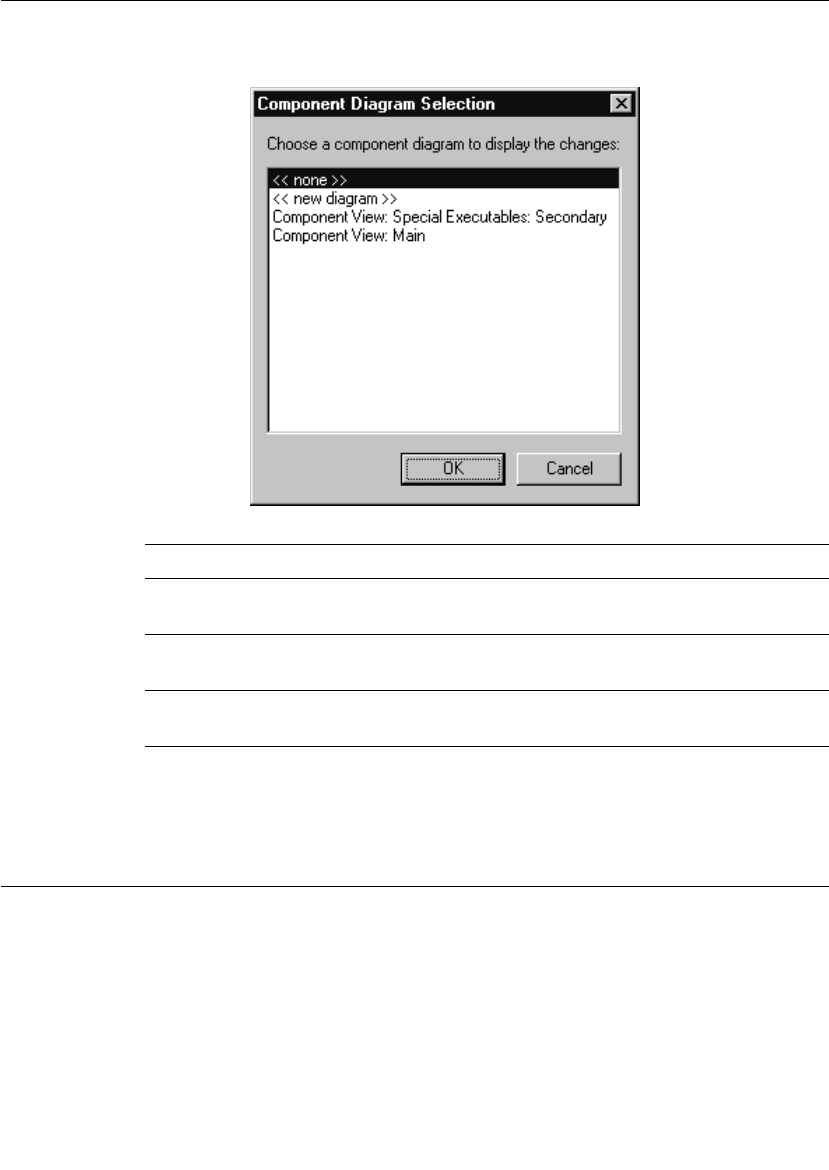
Verifying Connexis Enabled Components
User Guide - Rational Rose RealTime Connexis 91
The dialog lists the display options available for the selected
component.
Note: A component may also be configured from the menu on its view in
a component diagram.
Verifying Connexis Enabled Components
Once you have shared Connexis components in your model, you can
verify the model path and incompatibilities of each component in your
model.
Table 6 Component Diagram Selection options
Options Description
<<none>> creates a component dependency to the DCS
library, without a diagram displaying the changes.
<<new diagram>> creates a new diagram showing the component
dependency to the DCS library.
Existing component
diagram
shows the component dependency to the DCS
library from an existing diagram.
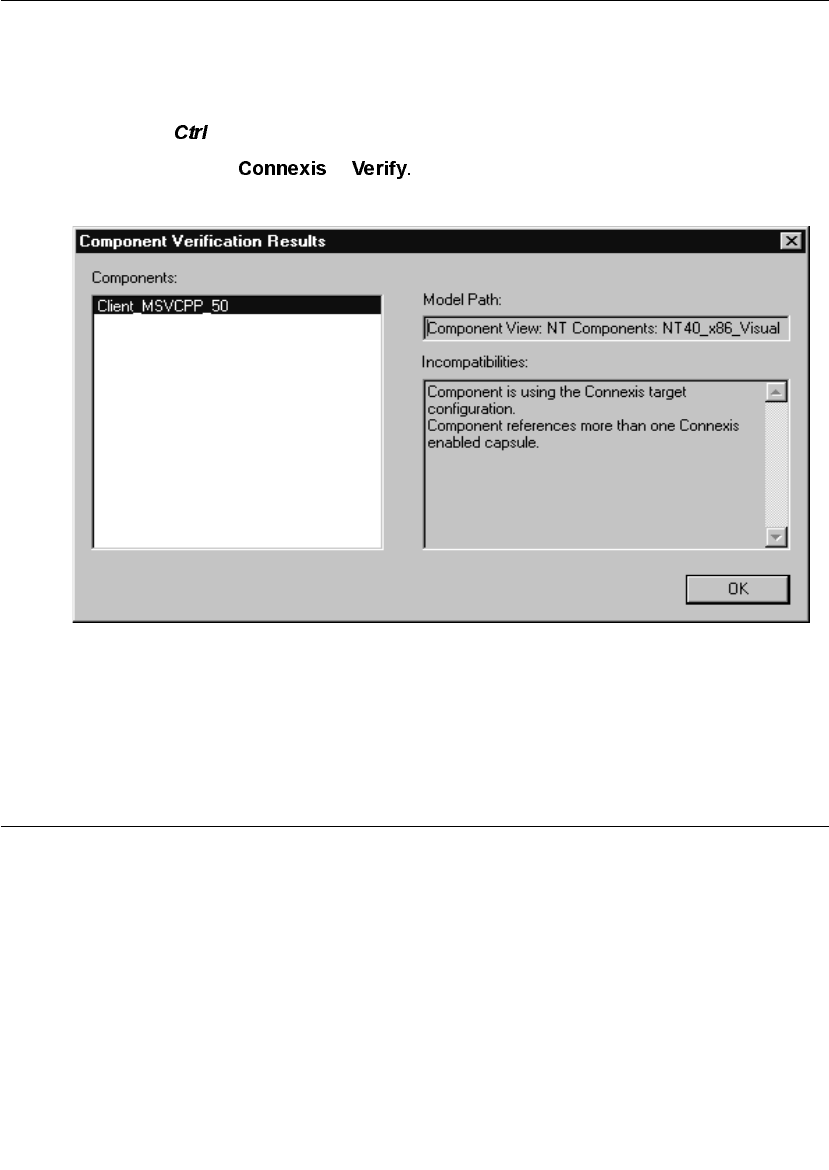
Chapter 4 Adding Connexis Support to Your Model
92 User Guide - Rational Rose RealTime Connexis
To verify a component:
1. Right-click a component.
Note: You can select several components at a time by pressing the
key.
2. Select >
The “Component Verification Results” dialog appears.
Figure 47 Component Verification Results
3. Select a component from the “Components” area.
The “Model Path” information and “Incompatibilities” information
are displayed.
Initializing Your Connexis Capsule
The Connexis capsule that you are using in your application must be
initialized before any ports can be registered with it.
There are two approaches that can be used to make sure that the
Connexis component is initialized before it is used in the application:
■Use the RTDInitStatus protocol. This is the recommended
approach and will work in all configurations.

Initializing Your Connexis Capsule
User Guide - Rational Rose RealTime Connexis 93
■Use fixed initialization order. This approach will work in the most
basic configuration, which is when the Connexis component is
fixed and on the main application thread. This approach will not
work when the Connexis component is created on a different
thread.
Using the RTDInitStatus Protocol
The recommended approach for ensuring the Connexis component is
initialized before use is to subscribe to the RTDInitStatus publisher on
the Connexis component and query DCS as to its status. If the
Connexis component is initialized on a thread other than the main
thread, this approach is required because there is no other way to
ensure the Connexis component is initialized before use.
All of the Connexis components publish a port called RTDInitStatus.
This port realizes the RTDInitStatus protocol. When the component is
fully initialized, it sends an rtBound event on this port. When rtBound
is received the DCS initialization was successful.
All of the capsules that are planning to register ports with the Connexis
component must create a subscriber port that realizes the
RTDInitStatus protocol. This port must be registered as RTDInitStatus
and notification must be turned on. Once the Connexis component has
been initialized, it will send an rtBound event on the RTDInitStatus
port.
The code used to register the subscriber port (if application registration
is used) is as shown below:
rTDInitStatus.registerSAP(“:RTDInitStatus”);
If automatic registration is used, the port must be protected and the
registration override string must be defined as:
:RTDInitStatus
For an example of using the RTDInitStatus protocol, refer to the
HelloWorld model in the examples directory
($ROSERT_HOME/CONNEXIS)/C++/examples.
The RTDInitStatus protocol also defines an interface that provides the
following:
■access to the status of the Target Agent and Locator if present
■query which port the CDM is listening on

Chapter 4 Adding Connexis Support to Your Model
94 User Guide - Rational Rose RealTime Connexis
■access to the DCS Transport thread, and its Virtual Circuit limit
■ability to set the primary and backup locator endpoints
dynamically at run-time
This interface is asynchronous, and is defined in more detail in Table
7 and Table 8. Table 7 summarizes the output signals that can be sent
by the application. Table 8 summarizes the input signals that can be
received by the application.
Table 7 RTDInitStatus Out Signals
Out Signal Description
rtdAgentActive Request for Target Agent activation status.
rtdBackup
Endpoint
Used to set the endpoint of the backup locator. The data
is the endpoint string, in the same format as the CNXlbep
command line argument.
e.g., cdm://localhost:4000, or
tcp://192.139.251.2:5000, etc.
rtdCDMport Request for the value of the CDM port assigned.
rtdDCSrunning No longer supported.
rtdLocator
Available
Request for Locator availability status. If the Locator has
been loaded into the system and properly configured it
will be flagged as available.
rtdPrimary
Endpoint
Used to set the endpoint of the primary locator. The data
is the endpoint string, in the same format as the CNXlpep
command line argument.
e.g., cdm://localhost:4000, or
tcp://192.139.251.2:5000, etc.
rtdTransport
Controller
Request for the Transport handle. This handle is required
for high-performance DCS applications that will be
collocated on the same thread as the Transport.
rtdVClimit Request for internal limit on the number of Virtual
Circuits (VCs). This limit is defined by the version of the
library.

Initializing Your Connexis Capsule
User Guide - Rational Rose RealTime Connexis 95
Table 8 RTDInitStatus In Signals
In Signal Description
rtdAgentActiveReply No longer supported.
rtdBackupEndpoint
Reply
Reply to rtdBackupEndpoint containing the status
of setting the backup locator endpoint, returned as
an int.
int result = *rtdata;
The result is one of the following:
0 - success
1 - failed because this process is the backup locator
2 - failed due to an invalid endpoint string
rtdCDMportReply Reply to rtdCDMport containing the CDM port
assigned, returned as an int. The CDM port is
derived either from the value for CNXep, or from a
free port number.
int cdm_port = *rtdata;
A non-zero value indicates a software failure.
rtdDCSrunningReply Reply to rtdDCSRunning containing the status of
DCS, returned as an int.
int dcs_status = *rtdata;
A non-zero value indicates that DCS is running.

Chapter 4 Adding Connexis Support to Your Model
96 User Guide - Rational Rose RealTime Connexis
rtdLocatorAvailable
Reply
Reply to rtdLocatorAvailable containing availability
status, returned as an int.
int locator_available = *rtdata;
A zero value implies that the locator is NOT properly
configured and the registration of global names will
fail:
port-name.registerSAP("dcs:/service-name") //
will fail
port-name.registerSPP("dcs:/service-name") //
will pass since SPPs can also be connected to locally
and explicitly.
A non-zero value indicates that the Locator is
properly configured though a connection may not
exist at this time to a remote Locator. Registration
of global names will pass.
Possible return values:
1 == Primary Locator running locally (this process),
Backup Locator not configured
2 == Primary Locator running locally (this process),
Backup Locator is remote (CNXlbep)
3 == Backup Locator running locally (this process),
Primary Locator is remote (CNXlpep)
4 == Primary Locator is remote (CNXlpep), Backup
locator not configured
5 == Primary Locator is remote (CNXlpep), Backup
locator is remote (CNXlbep)
Table 8 RTDInitStatus In Signals
In Signal Description

Initializing Your Connexis Capsule
User Guide - Rational Rose RealTime Connexis 97
rtdPrimaryEndpoint
Reply
Reply to rtdPrimaryEndpoint containing the status
of setting the primary locator endpoint, returned as
an int.
int result = *rtdata;
The result is one of the following:
0 - success
1 - failed because this process is the primary locator
2 - failed due to an invalid endpoint string
rtdTransportController
Reply
Reply to rtdTransportController containing the
Transport handle, returned as a (RTController *).
This handle is needed to initialize capsules on the
dcs: Transport thread.
RTController * t_thread = (RTController *)*rtdata;
A null pointer is returned if DCS is not running.
rtdVClimitReply Reply to rtdVClimit containing the VC (virtual
circuit) limit, returned as an int.
int vc_limit = *rtdata;
Table 8 RTDInitStatus In Signals
In Signal Description

Chapter 4 Adding Connexis Support to Your Model
98 User Guide - Rational Rose RealTime Connexis
Using Fixed Initialization Order
If the Connexis component’s capsule role is fixed and is created on the
main application thread, you can ensure that it is initialized before it
is used by other capsules by placing it in the application’s top capsule
and putting the Connexis component’s capsule role at the top of the
initialization order for that capsule.
Note: If the Connexis component’s capsule role is created on a thread
other than the main thread or is optional and on the main thread, this
approach is not guaranteed to work.
To ensure that the Connexis component’s capsule role is initialized
before any capsule roles that register with Connexis:
1. Make the Connexis component’s capsule role fixed and place it in
the top-level capsule of the application.
2. Open the Capsule Specification dialog for the top-level capsule.
3. Select the Capsule Roles tab.
4. Move the Connexis component’s capsule role so that it is in the list
before any capsule roles that register with Connexis. You can do
this by dragging and dropping the appropriate capsule role to the
top of the list of capsule roles. The resulting dialog is shown in
Figure 48.
Note: If you sort the list of capsule roles by clicking on one of the
column headings, you will not be able to determine the initialization
order until you close and reopen the specification dialog.
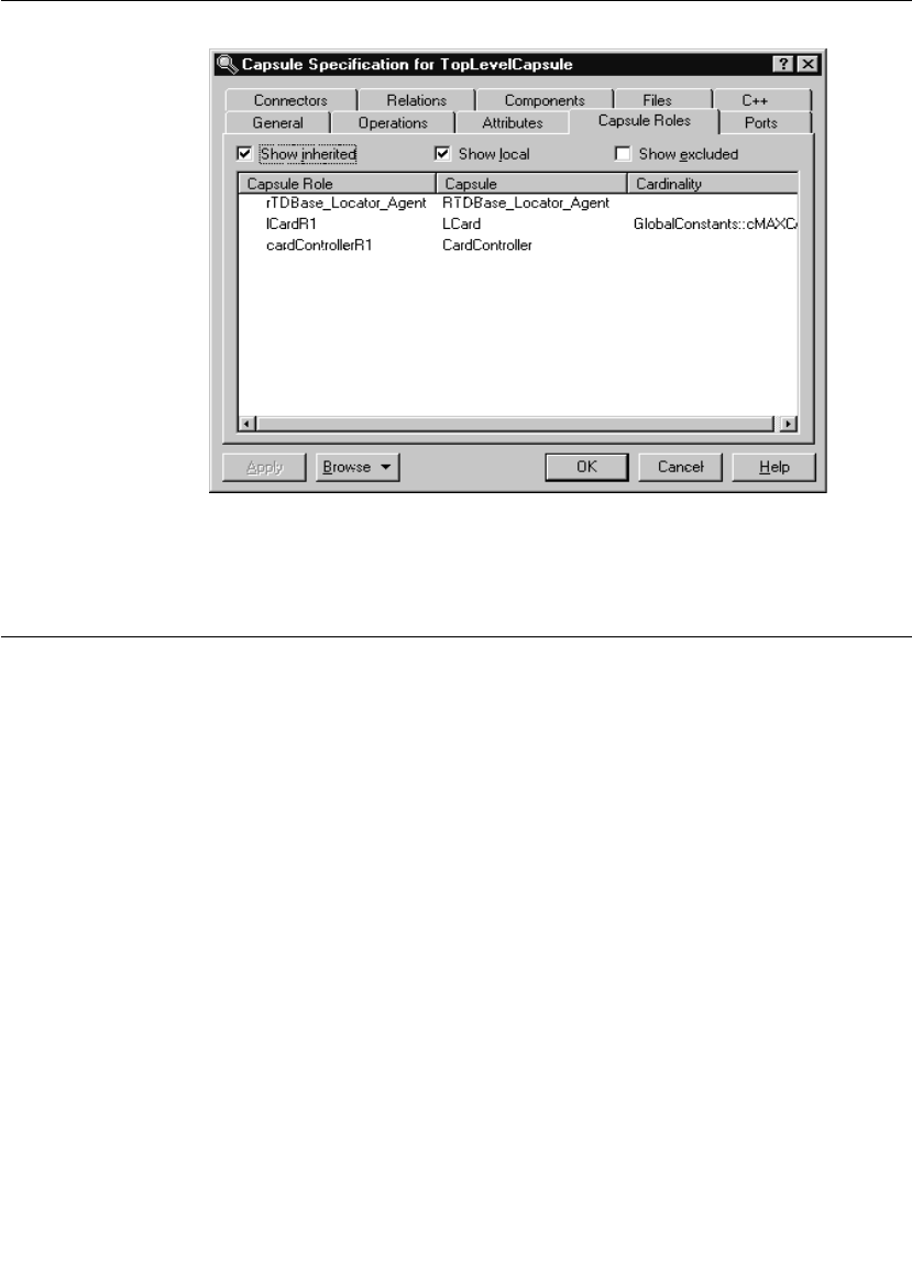
Converting Connexis Version 2000.02.10 Models to Connexis 2001A.04.00 Models
User Guide - Rational Rose RealTime Connexis 99
Figure 48 Capsule Role tab of top-level capsule
Converting Connexis Version 2000.02.10 Models to Connexis
2001A.04.00 Models
If you are using the previous version of Connexis (version 2000.02.10),
the Connexis Model Conversion Tool searches your model, identifying
any incompatibilities, and provides a detailed description, explaining
the changes. Table 9, Model Conversion for Connexis 2000.02.10 to
Connexis 2001A.04.00, explains the changes that are made to your
model during the conversion process.

Chapter 4 Adding Connexis Support to Your Model
100 User Guide - Rational Rose RealTime Connexis
Table 9 Model Conversion for Connexis 2000.02.10 to Connexis
2001A.04.00
Condition Change
RTDXBase,
RTDXBase_Agent,
RTDXBase_Locator,
RTDXBase_Agent_Locator
fixed capsule roles are in
the model
Replaces the capsule roles with the
corresponding RTDBase configuration.
Integrates the CDM transport with the capsules
containing the new RTDBase or
RTDBase_Locator capsule roles.
Integrates the CRM transport into the
containing capsule.
RTDBase,
RTDBase_Locator fixed
capsule roles are in the
model but do not have the
CDM transport as an
attribute.
Integrates the CDM transport using a
composite aggregation relationship into the
capsules containing RTDBase or
RTDBase_Locator capsule roles.
RTDXBase optional
capsule role is in the model
Converts to the RTDBase and integrates the
CRM and CDM transports.
RTDXBase_Agent optional
capsule role is in the model
Converts to RTDBase_Agent and integrates the
CRM transport.
RTDXBase_Locator
optional capsule role is in
the model
Converts to RTDBase_Locator and integrates
the CDM and CRM transports
RTDXBase_Locator_Agent
optional capsule role is in
the model
Converts to RTDBase_Locator_Agent and
integrates the CRM transport.
RTDBase or
RTDBase_Locator optional
capsule role is in the model
Users are notified that the CDM transport is
integrated.
RTDBase_Agent or
RTDBase_Locator_Agent
optional capsule role is in
the model
Searches the model identifying any of the
components that reference a dependency. If a
dependency exists, the CRM transport is
integrated.
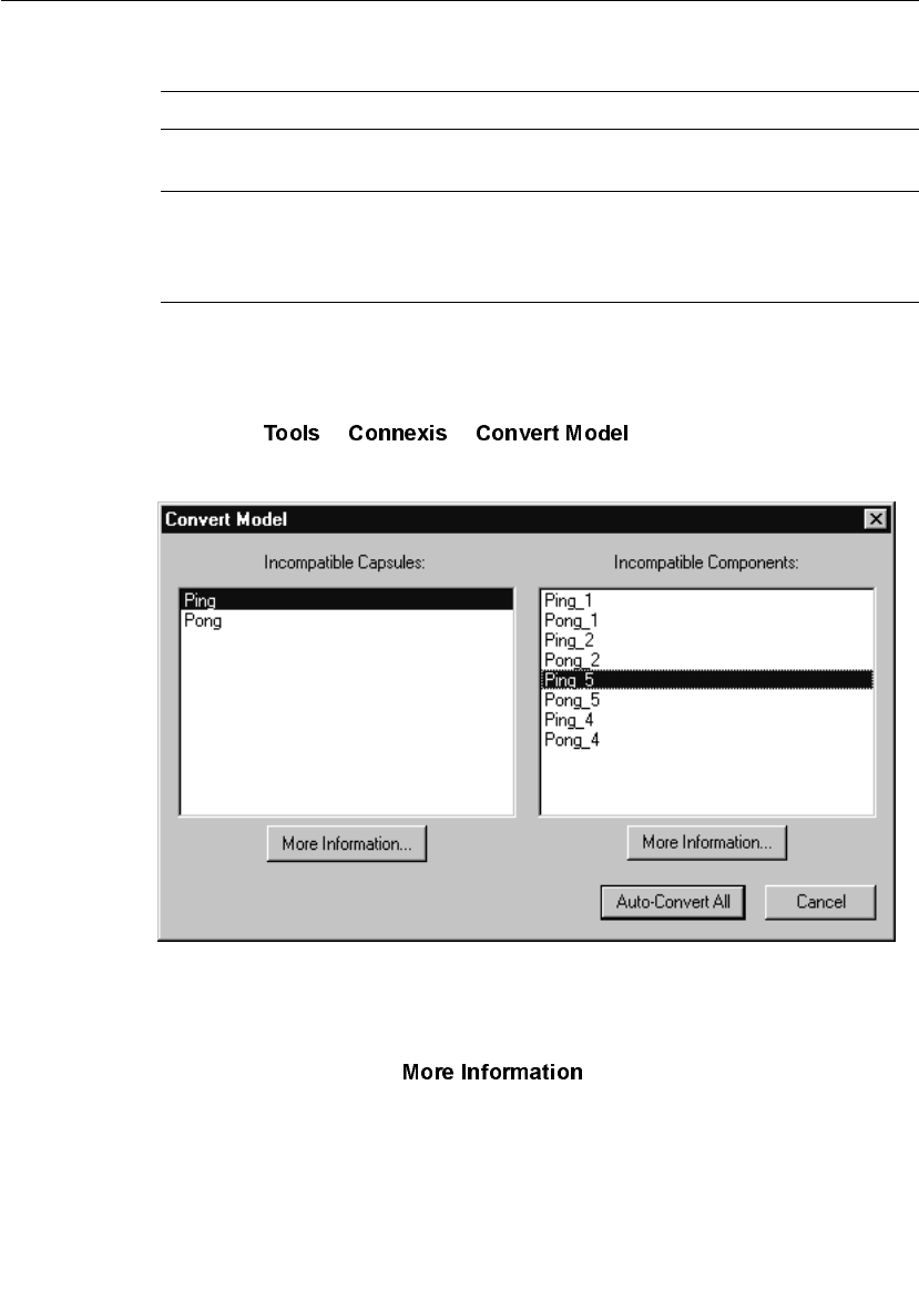
Converting Connexis Version 2000.02.10 Models to Connexis 2001A.04.00 Models
User Guide - Rational Rose RealTime Connexis 101
To convert your model:
1. Open a model that uses the previous version of Connexis (version
2000.02.10).
2. Select > > .
The “Convert Model” dialog appears.
Figure 49 Convert Model dialog
3. View more information about incompatible capsules and
components by selecting the capsule or the component from the
dialog and clicking .
A component depends on a
XDCS library component
Changes the component dependency to use the
DCS library component.
The TargetConfiguration
property of a component
references a -CNX-M or a -
CNX- target configuration
Removes the -CNX- or -CNX-M from the
TargetConfiguration name.
Table 9 Model Conversion for Connexis 2000.02.10 to Connexis
2001A.04.00
Condition Change
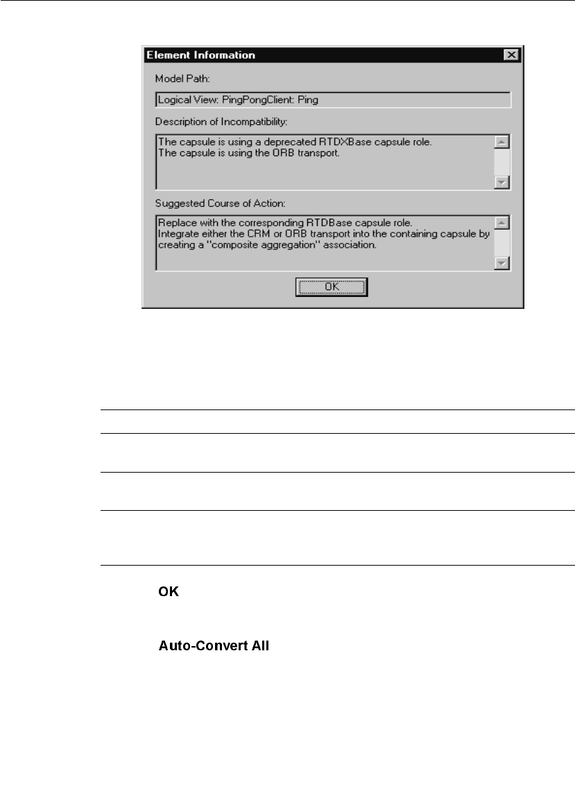
Chapter 4 Adding Connexis Support to Your Model
102 User Guide - Rational Rose RealTime Connexis
The “Element Information” dialog appears.
Figure 50 Element Information dialog
The “Element Information” dialog provides the following
information:
4. Click once you have read the information, and repeat step three
for additional capsules and components that appear in the
“Convert Model” dialog.
5. Click from the “Convert Model” dialog.
Table 10 Element Information dialog chart
Information Heading Description
Model Path Shows the path of the selected capsule or
component.
Description of
Incompatibility
Explains the reason for the incompatibility
between version 2000.02.10 and 2001A.04.00.
Suggested Course of Action Explains how the Conversion tool will make the
capsule or component compatible with
Connexis version 2001A.04.00.
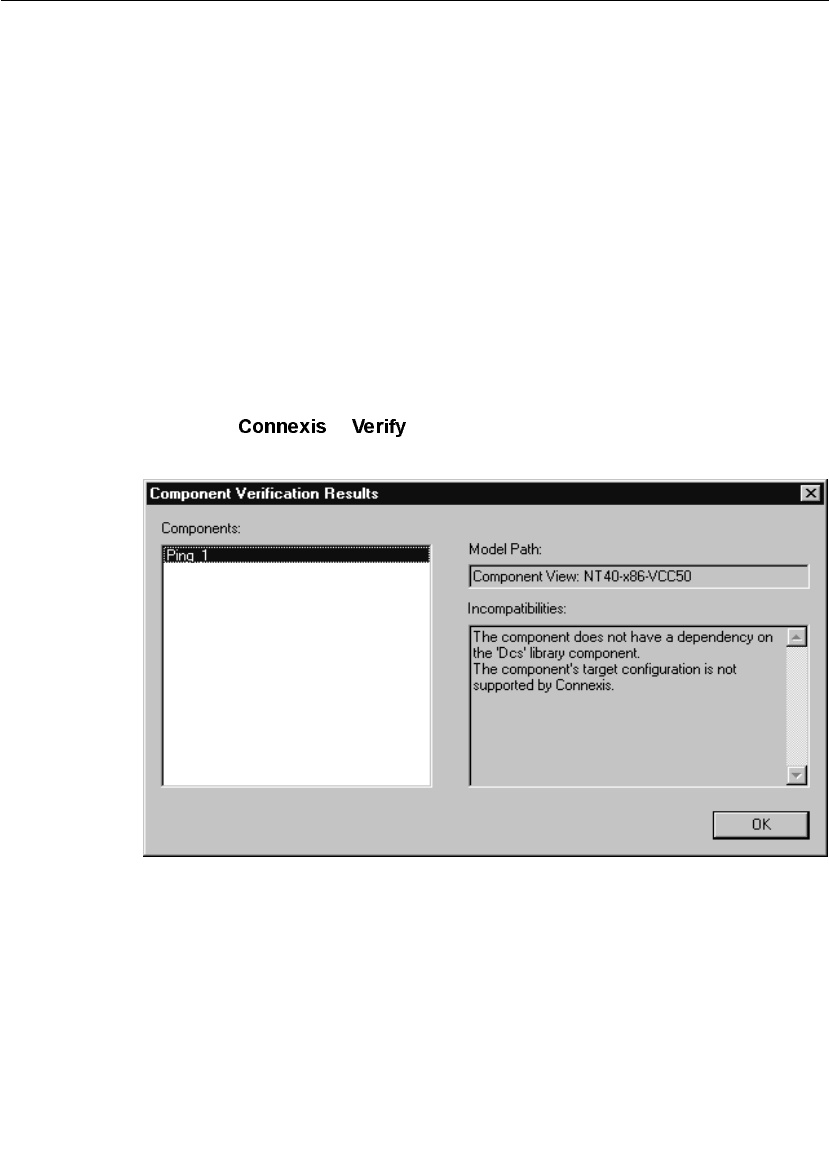
Converting Connexis Version 2000.02.10 Models to Connexis 2001A.04.00 Models
User Guide - Rational Rose RealTime Connexis 103
The Conversion Tool converts the incompatible capsules and
components in your model. As the conversion takes place, the
Conversion Tool may prompt you to confirm some conversion
changes.
Note: Only run the Conversion Tool once. If you run the tool a second
time, the information displayed in the Convert Model dialog may not
be accurate.
Verifying Component Compatibility with Connexis Version 2001A.04.00.
The Component Verification Tool verifies that a component is
compatible with Rational Connexis version 2001A.04.00.
To verify that a component is compatible with version 2001A.04.00:
1. Right-click a component.
2. Select > .
The “Component Verification Results” dialog appears.
Figure 51 Component Verification dialog
3. Select the component from the “Components” area.
The model path and the incompatibilities for the selected
component appear.

Chapter 4 Adding Connexis Support to Your Model
104 User Guide - Rational Rose RealTime Connexis
4. Open the component from the browser and fix the
incompatibilities.
Note: You do not have to close the Component Verification Results
dialog while fixing the incompatibilities.
5. Click .
RTDErrorType Error Reporting
Connexis reports error types that are defined in the enumerated
RTDErrorType class. To access these errors, define an input signal
named rtdError with data type RTDErrorType, in the protocol class of
the port to be registered with DCS. If any of the following errors occur,
the port receives an rtdError message with the error type as data (see
Table 11).
Table 11 RTDErrorType Error Reporting
Output Description
rtdDCSUninitialized = 1 Registration failed because DCS
was not initialized.
rtdZeroReplication = 2 Registration failed because the
replication factor of the port is
zero.
rtdInvalidSyntax = 3 Registration failed because the
registration string was of invalid
syntax.
rtdInvalidTransport = 4 Registration failed because the
specified transport is not
supported by this component.
rtdCircuitUnavailable = 5 Registration failed because no
virtual circuit is currently
available for the remote binding.
rtdLocatorUnavailable = 6 Global registration failed
because no locator is available.

Converting Connexis Version 2000.02.10 Models to Connexis 2001A.04.00 Models
User Guide - Rational Rose RealTime Connexis 105
Note: The last two errors can occur after a successful registration and
bind. For that reason they are sent at Background priority. All other
errors are sent at General priority.
rtdConnectTimeout = 7 Explicit registration failed
because a connection could not
be established with the remote
endpoint.
rtdEndpointUnavailable = 8 A connection cannot be made at
present with the remote
endpoint because it is currently
unavailable.
rtdEndpointInaccessible = 9 A connection can never be made
with the remote endpoint.
Table 11 RTDErrorType Error Reporting
Output Description

User Guide - Rational Rose RealTime Connexis 107
Chapter 5
Establishing Connections
Establishing Connections provides information to help you decide how
you plan to distribute your application and how you can use Connexis
to set up connections:
■General Connection Patterns - provides information about
client/server and peer to peer connection patterns.
■Unwired Port Registration - provides information about
registration, automatic versus application registration, and
registration parameters.
■Name Resolution - describes how Connexis resolves host names.
■Connexis Connection Options - describes how Connexis handles
publisher/subscriber connection patterns. The three methods of
establishing connections: local, explicit endpoint, and Locator
connections are discussed.
■Registration Summary - provides several examples explaining how
to use registration strings successfully.
■Connection Design Heuristics - provides a summary of connection
design principles and how they are handled by Rose RealTime and
Connexis. Replicated publisher ports, invokes, broadcast sends,
notification, defers and sending data between capsules are
discussed.

Chapter 5 Establishing Connections
108 User Guide - Rational Rose RealTime Connexis
General Connection Patterns
In the broadest sense there are two connection patterns that can be
implemented by an application:
■client/server
■peer to peer
These two patterns are not mutually exclusive. A capsule that is
participating in one connection as a client is not limited to that role. It
could be participating as a client in one connection and a server in
another. The same capsule may also be involved in several peer to peer
connections with different capsules.
Client/Server
The client/server pattern is used to describe a connection topology in
which there is a service provider that is capable of providing services
to two or more capsules.
In Figure 52, the ServerCapsule supports three connections on its
clientServer port. Each of the client capsules only supports one. In this
example, the distinction between the server and the client is that the
server publishes its service, and the client subscribes to it. In Rational
Rose RealTime, unwired public and protected ports can each play the
role of the publisher or subscriber.

General Connection Patterns
User Guide - Rational Rose RealTime Connexis 109
Figure 52 Client / server pattern
In scenarios where Automatic registration is used, this is configured by
selecting the Publish checkbox in the Port Specification dialog box. For
more information, refer to the “Rational Rose RealTime Toolset Guide.”
In scenarios where Application registration is used, publishers use the
registerSPP operation and subscribers use the registerSAP operation.
Peer to Peer
With the peer to peer connection pattern, one capsule is connected to
one other capsule and they pass messages back and forth between
each other. Even though the two capsules are peers in the
communication, one of them must be responsible for publishing its
interface and the other for subscribing to the interface.
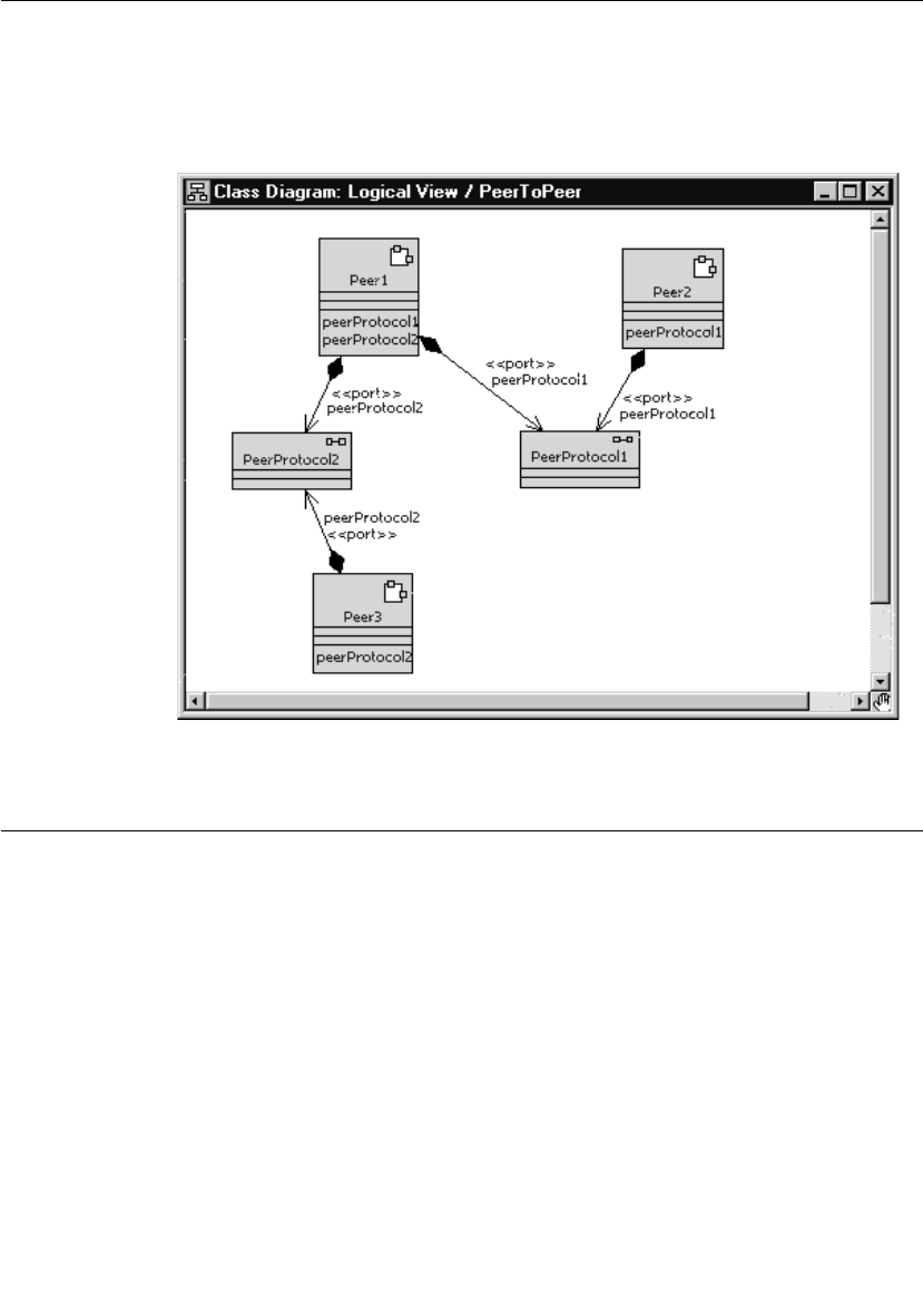
Chapter 5 Establishing Connections
110 User Guide - Rational Rose RealTime Connexis
In Figure 53, Peer1 is connected to both Peer2 and Peer3 in different
connections through different unwired ports. In both of the
connections, one of the capsules must play the role of the publisher
and the other the role of the subscriber.
Figure 53 Peer to peer connection pattern
Unwired Port Registration
There are three ways to establish a connection using Connexis:
■locally - within the same process
■external explicit - between processes, using an explicit endpoint
address
■locator - within the same process or between processes using a
name lookup service
The registration string that is used when the port is registered with the
Target RSL determines which of these methods is used.
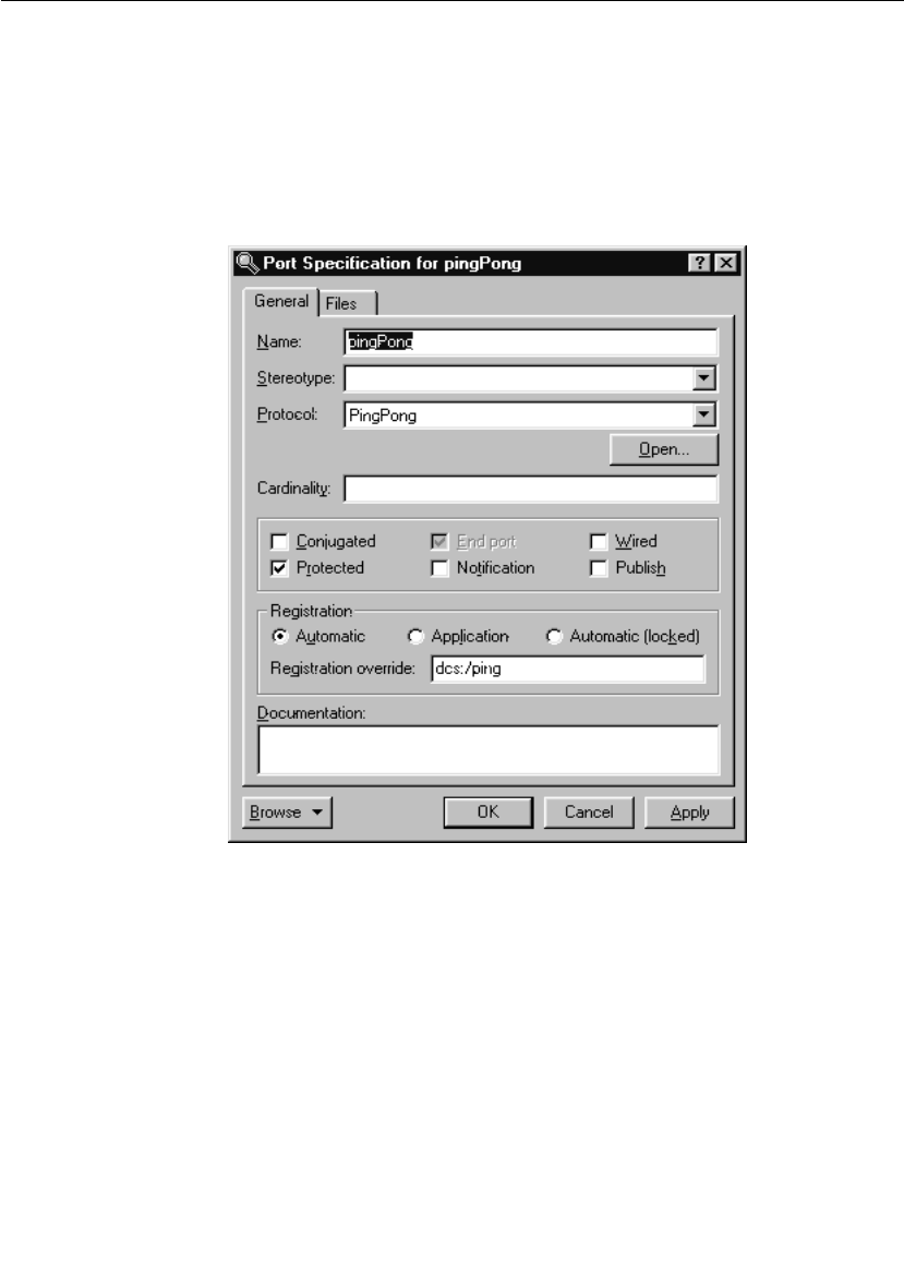
Unwired Port Registration
User Guide - Rational Rose RealTime Connexis 111
What is Registration?
In Rose RealTime, unwired ports must be registered with the Target
RSL. This registration can be accomplished either automatically, or
dynamically through application code. The choice as to which
registration method is to be used is set in the specification dialog for
the unwired port. This setting is illustrated in Figure 54.
Figure 54 Port specification dialog
In Figure 54, the Wired check box is not selected. This means that the
port must be registered using one of the two methods outlined. If the
Automatic registration check box is checked, the port will be registered
automatically using the name provided in the Registration override
field. If no text has been entered into the Registration override field, the
port will be registered under its own name with the ILS. If the Publish

Chapter 5 Establishing Connections
112 User Guide - Rational Rose RealTime Connexis
checkbox is checked, the capsule will publish this interface. If the
Publish checkbox is not checked, the capsule will request to subscribe
to this interface. If the Application registration check box is checked, it
is assumed that the registration of the port will be handled by the
application code. In this case, the Registration override field is ignored.
Port API
To register ports dynamically, you must use the functions that are
provided on the Rose RealTime port objects. The RTProtocol class
implements the concept of a port role in Rose RealTime. At design time,
when you create a port role on a capsule, it corresponds to an instance
of RTProtocol. The API provided by the Rose RealTime port objects to
manage the registration of the ports is implemented on the RTProtocol
class. For more information, refer to the “Rational Rose RealTime
Toolset Guide.”
The RTProtocol class provides the functions required for registration
and deregistration of unwired ports. Each function along with a brief
description of its responsibilities is presented in the following table.
Table 12 RTProtocol interface
Function Description
registerSAP(serviceName : const
char*) : int
Register a subscriber side port with the
connection service using the supplied
serviceName. The connection service is
either the ILS or DCS. Returns a 1 on
success or a 0 on failure.
deregisterSAP( : void) : int Deregisters a previously registered
subscriber side port. Returns a 1 on
success or a 0 on failure.
registerSPP(serviceName : const
char*) : int
Register a publisher side port with the
connection service, using the supplied
serviceName. The connection service is
either the ILS or DCS. Returns a 1 on
success or a 0 on failure.
deregisterSPP( : void) : int Deregisters a previously registered
publisher side port. Returns a 1 on
success or a 0 on failure.
isRegistered( : void) : int Returns a 1 if the port is registered, or a
0 if the port is not registered.

Unwired Port Registration
User Guide - Rational Rose RealTime Connexis 113
Automatic vs. Application Registration
There are two ways to register a port. The first is to specify that the
registration be completed automatically. This instructs the Target RSL
to register the unwired port with the connection service using the name
that was given to the port or with the specified Registration override.
This approach is illustrated in Figure 55.
getRegisteredName( : void ) :
const char*
Returns the service name that was used
to register the current port. If the port is
not registered, a null pointer is returned.
bindingNotification( on_off : int ) :
void
Sets the binding notification of the port to
either on (1) or off (0). This is used to
programmatically set the notification
property of a port.
bindingNotificationRequested( :
void ) : int
Returns 1 if the port has notification
turned on or returns 0 if the port has
notification turned off.
Table 12 RTProtocol interface
Function Description
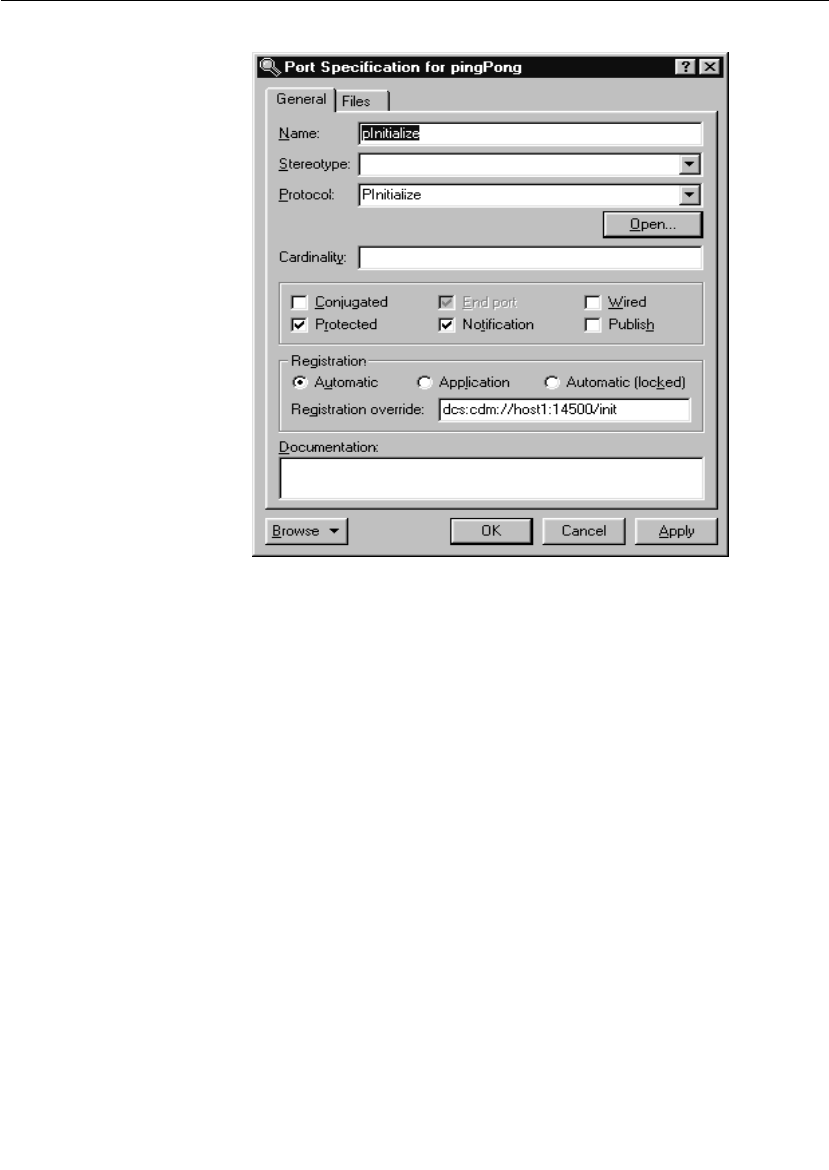
Chapter 5 Establishing Connections
114 User Guide - Rational Rose RealTime Connexis
Figure 55 Automatic port registration
In this case, the port is registered using the string that was provided in
the Registration override field (“dcs:cdm://host1:14500/init”). Since
the Publish checkbox is not checked, it is a subscriber. If no override
had been provided, the port would have been registered using the
port’s name (pInitialize).
The second approach is to specify that the registration be completed by
the application, and to then register the port through application code
using the RTProtocol interface described in “Port API” on page 112. The
port specification for implementing this registration method is shown
in Figure 56.

Unwired Port Registration
User Guide - Rational Rose RealTime Connexis 115
Figure 56 Application port registration
When this registration method is used, a registration string similar to
what is shown in the “Registration override:” field in Figure 55 must be
specified as the argument to the registerSAP() or registerSPP()
RTProtocol API function, somewhere in the state machine of the
capsule. For example, code similar to the following could be written in
the initial transition.
pInitialize.registerSAP(“dcs:cdm://host1:14500/init”);
Registration Parameters
There are often cases where extra information may be required when
registering a port with the connection service. Connexis supports
passing parameters as part of the registration string. These parameters
take the form of tagged-value pairs. The specification string is enclosed
in a pair of delimiters. Each tag-value pair is also enclosed in a pair of
delimiters. For example:

Chapter 5 Establishing Connections
116 User Guide - Rational Rose RealTime Connexis
((tag1,value1)(tag2,value2))
The “(“ and “)” characters are used as tag-value pair delimiters, and
also as delimiters to the entire parameter list. The “,” is used to
separate the tag and the value in a tag-value pair.
Supported parameters
For subscribing, Connexis provides registration options to set the
transport for global registrations and to specify the quality of service
parameters for a connection setup. For publishers, Connexis provides
a registrations option to assign a rank to a publisher. The details of
these registration parameters are outlined in Table 13.

Unwired Port Registration
User Guide - Rational Rose RealTime Connexis 117
Table 13 Supported registration parameters
Parameter Name Description
locator_transport This parameter specifies the transport that is to be used
by the subscriber to connect to a publisher.
Type: string
Possible values: cdm, crm and any integrated
transports
locator_rank This parameter specifies the rank of the publisher that
is being registered. This parameter only works for ports
that are publishers. The higher the number, the higher
the rank.
If the rank is not specified, the default rank is zero.
Type: integer
Possible values: any integer >= 0
connect_retries This parameter specifies the maximum number of times
that DCS attempts to send a connect message to a
remote endpoint to establish a connection. The default,
without the option, is infinity.
The maximum connect timeout interval is equal to (1 +
connect_retries) * CNXdcrd.
If connect_retries equals zero, then the maximum
timeout is therefore CNXdcrd.
If connect_retries equals one, then the maximum
timeout is therefore 2 * CNXdcrd, etc.
If no connect acknowledgment is received within this
timeout interval, a rtdError message with enumerated
data rtdConnectTimeout is sent to the application.
If the transport timeout interval is shorter than the
maximum connect retry interval, a rtdError message
with enumerated data rtdEndpointUnavailable may be
sent to the application instead.

Chapter 5 Establishing Connections
118 User Guide - Rational Rose RealTime Connexis
Registration parameter examples
The first example registers a subscriber port with “cdm” as the
preferred protocol.
port1.registerSAP(“dcs:/service1 ((locator_transport, cdm))”);
This example registers a publisher port with the specified rank.
port2.registerSPP(“dcs:/service1 ((locator_rank, 1))”);
Name Resolution
Whenever an endpoint is registered using a host name instead of an IP
address, Connexis will translate the host name into a valid IP address.
On development workstations this will typically be done through a
Domain Name Service (DNS). Since the call to the DNS is blocking,
Connexis performs this operation using a separate thread, called a
helper thread. The following points describe the algorithm that is used
by Connexis to resolve host names:
1. An attempt is made to resolve the host name.
2. If the host name cannot be resolved, the name resolution will be
retried periodically until it is resolved successfully.
Host names that have been resolved are cached for a number of
seconds. This means that if a resolution request is made for a host
name that had just been looked up, the result from the last lookup will
be returned.
Connexis Connection Options
Connexis is able to handle the connection patterns listed in General
Connection Patterns, as well as other connection topologies common
in distributed systems. It does this using the publisher/subscriber
pattern. With this pattern, every virtual circuit in a Connexis model
has a publisher at one end of the communication channel and a
subscriber at the other end. The publisher publishes its interface with
the connection service (or the locator) and the subscriber subscribes to
that interface.
At the highest level, there are three different ways that connections can
be established using Connexis:
■locally - connect to another object within the same executable

Connexis Connection Options
User Guide - Rational Rose RealTime Connexis 119
■external using an explicit endpoint - connect to an object in
another executable using an explicit endpoint
■using the locator service - connect to an object using the Locator
service to resolve the endpoint address
Local Connections
Rose RealTime has a built-in connection service called the Internal
Layer Service (ILS). The ILS is used to connect unwired ports within the
same executable, or to be more precise, within the same instance of the
Rose RealTime Run-time Service Library (Target RSL).
The ILS establishes the connection between two local unwired ports.
Registering ports locally is the simplest of the three registration types
but it is also the least flexible. When a port is registered with the ILS,
it cannot send or receive messages to or from ports in another
executable model.
In addition to establishing local connections using the ILS, you may
also use Connexis to accomplish the same thing. Using Connexis to
establish local connections has the following advantages:
■Connexis supports multiple publishers with the same registration
name (the ILS does not)
■Connexis allows you to establish loopbacks that can be used to
fully trace the message flow between the connected ports. This can
be very useful for debugging an application.
Local connection examples
This section presents two examples:
■local connection with DCS using automatic registration
■local connection with DCS using application registration
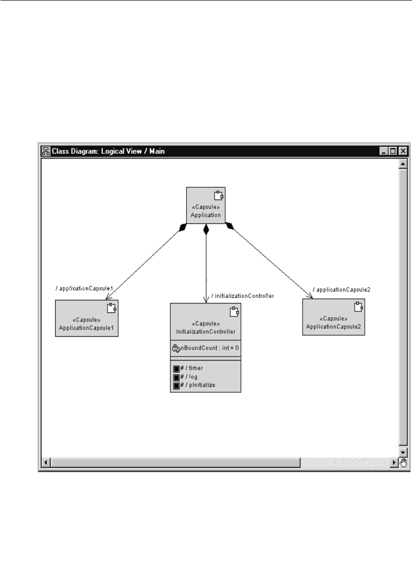
Chapter 5 Establishing Connections
120 User Guide - Rational Rose RealTime Connexis
Example 1: Local connection, ILS, automatic registration and
override
This example illustrates how to register an unwired client side port and
a corresponding server side port using automatic registration.
This example implements a simple initialization controller. The
controller is responsible for making sure that the components of an
application are initialized in a predetermined order.
The structure for the initialization controller is shown in Figure 57.
Figure 57 Class diagram of initialization controller

Connexis Connection Options
User Guide - Rational Rose RealTime Connexis 121
In this structure, the initialization controller capsule requires a
connection to each of the capsules in the application. These
connections are required so that it can send initialization messages to
each of the capsules. If this application exists completely in a single
executable, the initialization controller could connect to each
component through a wired port. This implementation may cause the
following problems:
■The structure is unnecessarily complex as a result of having to
show all of the physical connections between the different
capsules.
■The structure is not as flexible. More effort is required to separate
some of the components out into separate applications.
For these reasons, the pattern is better modeled using unwired ports.
To automatically register the ports in this example for each
initialization port:
1. Select the port and open its specification dialog.
2. Uncheck the Wired option.
3. If the port is being published (that is, server in a client/server
distribution pattern), check the Publish checkbox.
4. Select the Automatic registration option.
5. If notification is being used, check the Notification check box.
6. Type in a DCS Registration string in the Registration override field.
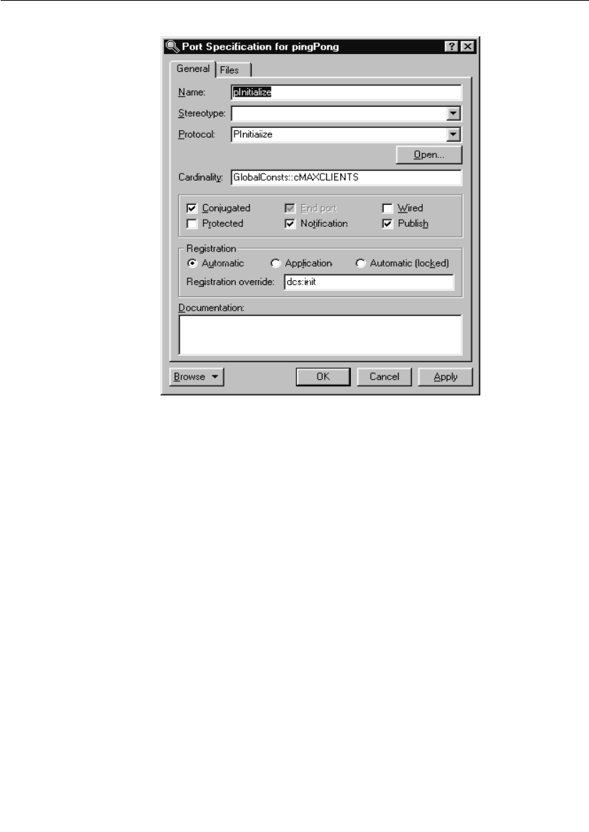
Chapter 5 Establishing Connections
122 User Guide - Rational Rose RealTime Connexis
Figure 58 Specifying automatic registration
As mentioned in the Connexis Quick Start, the convention usually
followed is to conjugate the port that is being published (this would
correspond to the server in the client/server distribution pattern). The
reason for this is twofold:
■By following a convention, the naming of protocols and signals will
be consistent throughout the model.
■It requires fewer steps in a client/server pattern because only the
one server port needs be conjugated (instead of all of the clients).
In this case, the registration name is overridden by entering “dcs:init”
in the Registration override field. This means that this port is registered
with the DCS with the name “init”. Since the Publish option is selected,
the port is published. If nothing is entered in the Registration override
field, the port name, pInitialize, is used and is registered with the ILS.
Automatic registration using the DCS requires registration override;
otherwise, it defaults to the ILS
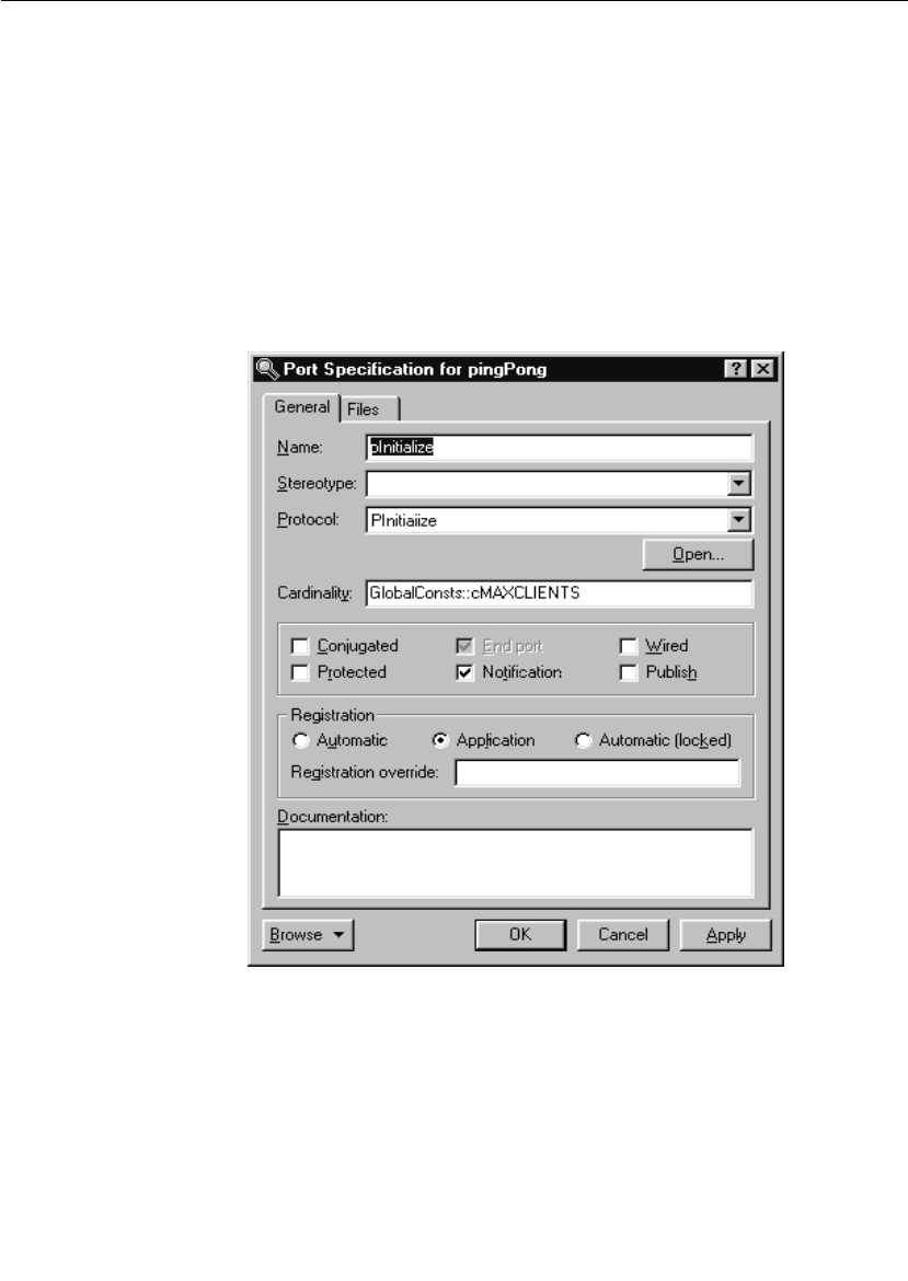
Connexis Connection Options
User Guide - Rational Rose RealTime Connexis 123
If you register your ports with the DCS (instead of the built-in ILS) and
you are making use of the Locator service, you will not have to make
changes to the registration string if one side of the connection is moved
to a different process.
Example 2: Local connection and application registration
This example illustrates registering an unwired client port and a
corresponding server port using application registration. This example
uses the same sample capsules as the previous example. In this case,
the ports are defined as application registration as shown in Figure 59.
Figure 59 Specifying application registration
When a port is registered using application registration, the
Registration override field is ignored and the functions described in the
port API must be used to register the port with the connection service.

Chapter 5 Establishing Connections
124 User Guide - Rational Rose RealTime Connexis
The code required to register the port with the DCS is written as
follows:
pInitialize.registerSPP(“dcs:init”);
The above line of code registers the pInitialize port with the DCS using
the “init” service name.
External Explicit Connections
External explicit connections are connections that:
■are made with capsules that are running in another process, either
on the same processor or a different processor on the network
■the name of the endpoint is known at design time or can be
specified at run-time through a configuration file or command line
argument
Explicit connections are typically used in a fixed network environment
where the network configuration is known and rarely changes.
Using explicit connections is less flexible than making use of a Locator
service, but in cases where the network addresses and endpoint names
are known, it is a smaller (memory wise) and faster approach. The
decision to use either the Locator service or explicit connections
depends mostly on the requirements of the application and the
network configuration that it will be running in.
External explicit examples
With explicit connections, more information must be known by the
applications about the other side of the connection. Each subscriber
must know or be able to find out the explicit endpoint addresses of all
of the other objects that it wants to subscribe to.
Registering the publisher side of the connection is similar to the local
and Locator cases. The connection service and the service name are all
that is required. When starting the publisher component instance, you
usually specify endpoints on which it will be listening.
The subscriber side of the connection is quite a bit different. In this
case, you must know the endpoint address of the publisher and specify
it in the registration string.

Connexis Connection Options
User Guide - Rational Rose RealTime Connexis 125
Queueing of Subscriptions
If a subscriber registers before a transport connection has been
established to the remote endpoint, the DCS repeatedly attempts to
establish a connection to the remote endpoint. If the "conn_retries"
registration option has not been specified in the registration string, the
DCS will try to establish the connection until the port is deregistered.
If a connection to the remote endpoint is established, but the
registration takes place before the service is published at the remote
endpoint, the registration is left pending until a service is published or
the subscribing port is deregistered.
Using the CDM transport protocol
The publisher application would perform the following:
<port_name>.registerSPP(“dcs:myService”);
Assuming that the myService publisher is started on node “host2”, and
is listening on port 45678, the following registration string is used by
the subscriber:
<port_name>.registerSAP(“dcs:cdm://host2:45678/myService”);
This tells Connexis to try to connect to port 45678 on host2 to get to
the desired publisher. The format of the string is defined by the BNF
Registration String Grammar. For more information, see “Registration
String Grammar” on page 245.
For this example to work properly, the application in which the
publisher is running must be started using the following CNXep
command line parameter:
<app_name> -CNXep=45678
Locator Connections
The most flexible way of registering unwired ports is to use the Locator
service. The Locator service maps endpoint service names to physical
endpoints on the network. This enables applications to not be
intimately aware of the network topology, which also means that they
do not have to change when the network topology changes.

Chapter 5 Establishing Connections
126 User Guide - Rational Rose RealTime Connexis
The Connexis Locator is implemented as a Rose RealTime Connexis
component. Unwired ports register (subscribe or publish) themselves
with the Locator instead of the connection service. The Locator is then
responsible for finding the appropriate endpoints and insuring that
they are bound together.
Using the Locator is similar in nature to using local connections, you
register a service name for the port with the Locator and the rest is
handled for you. The key differences between using the Locator and
using local connections are:
■A Locator component (RTDBase_Locator, or
RTDBase_Locator_Agent) must be included in the executables that
are implementing the Locator (either primary or backup).
■The Locator service must be started when the Locator is being
used.
This means that a primary Locator must have been configured
using the -CNXlp configuration option on the Locator process, and
the client processes must be started with the -CNXlpep
configuration option, which specifies the address of the primary
Locator.
■The registration string is slightly different. Instead of using a string
with the syntax, dcs:<service_name> you must use a string with
the syntax, dcs:/<service_name>. This registration string registers
the port with the DCS and with the Locator.
When a subscriber is registered using this registration string
syntax, it first looks for a local publisher to which to connect. If it
finds a local publisher with the service it is looking for, it will
connect to it. If no local publisher is found, it subscribes to the
Locator service.
Locator examples
To register a publisher named QueryState using the Locator, the
following registration string would be used:
port1.registerSPP(“dcs:/QueryState”);
To register a subscriber that subscribes to the same QueryState
service, the following registration string is used:
port2.registerSAP(“dcs:/QueryState”);

Registration Summary
User Guide - Rational Rose RealTime Connexis 127
Note that this example assumes that the applications have been
started using the appropriate command line arguments and the
RTDBase_Locator capsule has been dragged into the application
providing locator services.
Registration Summary
This section presents several registration scenarios and explains what
registrations strings will succeed and fail in each. The important points
to realize about Connexis registration are:
■Ports that are registered with the ILS are registered in a different
namespace than those that are registered with the DCS. This
means that a subscriber port registered as:test1 will not bind with
a publisher registered as dcs:test1.
■Ports that are registered with the Locator are also implicitly
registered with the DCS. This means that they will bind with locally
registered DCS ports and also explicit DCS ports with the same
service name.
■Ports that are registered with the registration string “servicename”
(as opposed to “:servicename” or “dcs:servicename”) share the
same namespace as ports that are registered with the ILS
(“:servicename”). This type of registration is present for backwards
compatibility reasons only, and as a result, is not discussed in this
section.
All of these examples assume that the publisher is replicated, that is,
it can support the number of subscribers that are trying to connect to
it.
Scenario 1: Publisher Registered with the ILS
In this scenario, a publisher (port2) is registered with the ILS and two
subscribers (port1 and port3) attempt to make connections to the
publisher.

Chapter 5 Establishing Connections
128 User Guide - Rational Rose RealTime Connexis
Figure 60 Scenario 1: Registering ports with the ILS
In this scenario, port1 will connect to port2 but port3 will not. This is
because port2 has been registered with the ILS which is only capable
of connecting ports locally. Port2 would also not be capable of receiving
explicit or locator connections from a different process.
Scenario 2: Publisher Registered with the DCS
In this scenario, the publisher is registered with the DCS. Several
subscribers, each registered using different methods, attempt to
establish connections to the subscriber.
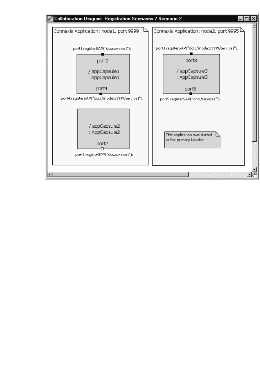
Registration Summary
User Guide - Rational Rose RealTime Connexis 129
Figure 61 Publisher registered with DCS
Note: In this scenario the location of the Locator Service is not relevant
to the outcome of the registrations.
In this scenario, port2 registers with the DCS. Also, port1 connects to
port2 by forming a local DCS connection. Port3 and port4 also connect
because, by registering with the DCS, port2 is capable of receiving both
local DCS connections and explicit connections (whether they are
internal or external). In this scenario, the only registration string that
will not result in a successful connection being established is the one
that is used to register port5. This registration string is looking to the
Locator to resolve the endpoint name. Since port2 did not register with
the Locator, no compatible publisher will be found for port5.
Note: A local DCS connection is an intra-process connection that is using
the DCS instead of the ILS. As with ILS connections, local DCS
connections, once bound, have the same run-time performance as
connections that are bound at design time.
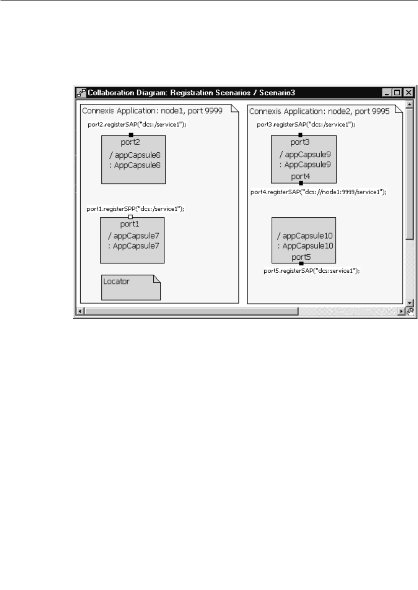
Chapter 5 Establishing Connections
130 User Guide - Rational Rose RealTime Connexis
Scenario 3: Publisher Registered with the Locator
In this scenario, the publisher (port1) registers with the Locator
Service. Several subscribers, each using a different registration string,
attempt to establish connections to the publisher.
Figure 62 Publisher registered with the Locator
Note: In this scenario, the location of the Locator Service is not relevant
to the outcome of the registrations.
In this scenario, the publisher (port1) is registered with the Locator
Service. The interesting aspect of this type of registration is that
registering with the Locator Service implicitly registers the port with
the DCS. This means that subscribers can make explicit (either local
or remote) connections to a publisher that was registered with the
Locator Service. Port2 and port3 will both successfully connect to port1
since they use the Locator. port4 will also connect because it is
specifying the endpoint explicitly. Port5 will not be connected, since it
is registering locally with the DCS.

Connection Design Heuristics
User Guide - Rational Rose RealTime Connexis 131
Multiple Publishers
Unlike the ILS, Connexis supports multiple publishers with the same
registration name. The ILS restricts the naming of unwired ports that
are publishing themselves, so that each published unwired port must
be named uniquely. The port can be replicated but two capsules cannot
have published ports with the same name.
This restriction is removed when using Connexis. Multiple capsules
can have published unwired ports that use the same registration
string. This can be very useful for distributing the load in a distributed
system.
For example, if the application being built has a service provider that
offers a database lookup service, Connexis could be used to distribute
this service between two or more capsules running on separate
processors in the network. This can also be modeled locally without
having to change any code when the distributed version is released.
This can be accomplished by using the Locator service or by reading a
configuration file that contains the endpoints of the different
components.
Connection Design Heuristics
When to Use Replicated Publisher Ports
This is a common design pattern. It is very common in real-time and
non-real-time systems, for a single software element to provide services
to multiple others. A very common example of this is a web server.
When you connect to a website, like www.rational.com, you are
connecting to a server process that is running on the host machine.
The server process is listening on a particular TCP/IP port and when a
request comes in, it spawns a task to handle that particular client
interaction. Multiple clients can connect to www.rational.com at the
same time.
One thing to be careful of when using replicated publishers (or multiple
publishers with the same name) is to make sure that the number of
publishers is appropriate for servicing the number of subscribers. If
the number of subscribers is significantly greater than the number of
publishers thrashing could occur.

Chapter 5 Establishing Connections
132 User Guide - Rational Rose RealTime Connexis
Use of Invokes
Invokes in Rose RealTime are the equivalent of synchronous messages.
Remember that the normal method of communication in a Rose
RealTime model is through asynchronous message sends. In contrast,
invokes are very similar to regular function calls on objects in a system.
The issue that can arise with invokes is that they bypass the normal
message queuing structure that is in place in Rose RealTime. The
calling capsule is blocked until the receiving capsule completes the
transition code that has been called and returns. In addition, the
receiving capsule must know to reply to the invoke.
Rose RealTime invokes cannot be used across thread or processor
boundaries. This means that if invokes are used in a particular
situation, you will not be able to separate the two capsules involved in
that connection into separate threads or processes without changes to
the code. Since Connexis is used specifically to send inter-process
messages, invokes cannot be used with Connexis-enabled
connections.
Use of Broadcast Sends
A broadcast send is a send that is performed on a replicated port
without specifying an index. Broadcast sends result in a message being
sent to each of the capsules that are connected on the other side of the
port.
There are many cases where broadcast sends are a useful and
appropriate technique. For example, when initializing capsules in an
application, it may be necessary to send all of the capsules of a
particular class an initialize message. If the order of the initialize
messages is not important, a broadcast send may be used.
The consequences of using a broadcast send are performance-related.
A broadcast send on a port that has a multiplicity of n results in n
individual message sends. This can impose a significant amount of
overhead on your system, especially in cases where n is large and the
messages are sent between processes.

Connection Design Heuristics
User Guide - Rational Rose RealTime Connexis 133
Use of Notification
Notification is used to instruct the run-time libraries to send a message
on a port whenever the port has been connected or disconnected from
its peer on the other side of the connection. The rtBound message is
sent when a connection is established and the rtUnbound message is
sent when a connection is removed. In general the use of notification
simplifies the job of the developer.
There is one rule that must be followed when notification is being used
on a port: when you deregister the port, and plan to register it again
later, you must wait to receive the rtUnbound event before reregistering
the port.
This is required because the priority of the rtBound message is higher
than that of the rtUnbound message. This means that if you deregister
a port and then immediately register it again, the rtBound message
could arrive first followed by an rtUnbound message. This could result
in an unexpected message or it could cause the capsule to go into an
incorrect state.
Use of Defers
Message deferral is a Rose RealTime feature that allows you to defer
messages that are received when a capsule’s state machine is not ready
to process them. Messages that have been deferred can be recalled at
a later time for processing. Although message deferral is a useful, and
in some cases, a necessary design technique, it does complicate the
state machine design of your model. For this reason, defers should be
used judiciously in Rose RealTime models.
In some cases, defers are used to get around the asynchronous
implementation of a part of the design that is logically sequential. For
example, if you are starting a service by asynchronously requesting an
object from an object factory, you may receive messages destined for
the new object before it has been created and returned by the object
factory. There are two solutions to this problem. The first is to defer the
incoming messages. The second is to request the object synchronously
using an invoke.

Chapter 5 Establishing Connections
134 User Guide - Rational Rose RealTime Connexis
Both of these solutions have trade-offs to consider. If you go the defer
route, the state machine of the capsule becomes more complicated.
There is also a greater probability of maintenance problems because
state machine changes may require additional recalls to be placed in
the code. If this is not done properly, errors may be introduced into the
model.
With the invoke solution, an entirely different set of issues results.
There are no longer any message order issues, and the state machine
is typically cleaner, but the connector that the invoke is being called on
is required to remain in the same thread.
Sending Data
There are many performance issues to consider when sending data
between capsules. The first thing to keep in mind is the relative
performance of different kinds of message sends. In general, the types
of message sends can be listed in order of relative performance (from
fastest to slowest) as in the following list:
1. intra-thread
2. inter-thread
3. inter-process (same node)
4. inter-process (over network)
In addition, messages with little or no data associated with them are
typically faster than messages with a large payload. This would lead
you to believe that it is better to send small messages between
capsules, especially when the messages are sent between processes.
This is true in general but the decision is a little more complicated than
that. The other factor that comes into play is the frequency of the
messages that are being sent. If you are sending small pieces of data
between two capsules hundreds of times a second, it would typically be
faster to buffer this data on the sending side and send a few larger
messages. These are some of the decisions that must be made when
designing a distributed application.
Sending Data Classes by Value
In order to send a data class by value across processes, it must be
marshallable. Refer to the “Data Classes that are Marshallable” in the
Rational Rose RealTime C++ Guide.

User Guide - Rational Rose RealTime Connexis 135
Chapter 6
Using the Connexis Locator Service
The Connexis Locator Service fulfills the role of the name server in a
Connexis application. The Locator does not have to be configured or
used in a Connexis application, but depending on the application’s
requirements, it can be very convenient.
The Connexis Locator Service supports both a primary and a backup
locator. In this way, a distributed application can be made more robust
by ensuring that the name server is not a single point of failure.
By using the Locator, the location of endpoints to which an application
is sending messages can remain totally transparent to the application.
The application uses service names to refer to the endpoints that are
being connected. The physical address of these endpoints never has to
be revealed to the application. This makes creating a network topology
that can be dynamically changed without affecting currently executing
software, much easier than if physical endpoints are used. This
strategy also allows load sharing topologies to be created much more
easily than if physical endpoints are used.
This chapter discusses:
■Adding Locator Support to a Model - describes the capsule roles
required to add Locator service.
■Publication and Subscription - describes how the Locator handles
publishers and subscribers. It provides information about ranking
published ports and load-sharing publishers.

Chapter 6 Using the Connexis Locator Service
136 User Guide - Rational Rose RealTime Connexis
■Locator Dynamics - describes how the Locator operates when a
publisher becomes fully subsribed, a subscriber loses its
connection to a publisher, the primary Locator fails, or a
subscriber is unconnected. It also discusses Locator race
conditions.
■Locator Configuration - describes the Locator configuration
parameters and provides examples of how to start your application
using a primary locator and backup locator.
■Creating your Own Name Service - provides guidelines on using a
custom name service in place of the Connexis Locator.
Adding Locator Support to a Model
To add the Locator to your application you must add a capsule role for
either the RTDBase_Locator or the RTDBase_Locator_Agent capsules
to a capsule in your application. Each node that is going to have a
Locator configured to run with it (either backup or primary) must have
one of these capsule roles contained in it (see “Sharing DCS Interfaces”
on page 84).
The RTDBase_Locator capsule only adds support for the Locator
(primary or backup). The RTDBase_Locator_Agent adds support for
both the Locator and for the Target Agent which is needed to run the
Connexis Viewer.
Publication and Subscription
In Connexis, one endpoint in every distributed connection is the
publisher and the other is the subscriber. The publisher posts (or
publishes) its interface, making it available for another endpoint to
connect to it. The subscriber connects to an endpoint that has been
published. This pattern can be used to implement any kind of
distributed connection topology. For example, client/server, peer to
peer, etc.
Publication
A port is published with the locator by providing its service name and
the endpoints where it can be reached. Multiple ports can be published
with the same server name from the same endpoint, or different
endpoints.

Publication and Subscription
User Guide - Rational Rose RealTime Connexis 137
The registerSPP() port function is used to publish a port. Deregistration
of a published port (using the port’s deregisterSPP() function) causes it
to be unpublished from the locator and severs any connections that are
using that port.
Subscription
A port subscribes to the locator by providing its endpoint and the name
of the service to which it wants to connect. If no port has previously
been published with that service name, the subscription remains
pending. Once one or more ports are published with that service name,
the Locator returns the publisher with the highest rank using the
preferred protocol, to the subscriber endpoint. If the subscriber has
specified a protocol (locator_transport), the highest-ranked publisher
which supports that protocol is returned. The DCS then makes an
explicit registration on behalf of the subscriber port with the returned
publisher.
The registerSAP() port function is used to subscribe a port to a service.
Ranking Published Ports
The Locator supports the ranking of publishers. The default ranking of
published ports is dependent on the following factors:
■the rank that the publisher is given
■the protocol that the publisher is using
The rank of a publisher is specified by the designer through the use of
a registration parameter. For example:
<port_name>.registerSPP(“dcs:/service1 ((locator_rank, 1))”);

Chapter 6 Using the Connexis Locator Service
138 User Guide - Rational Rose RealTime Connexis
When the locator searches for an endpoint to return, it follows this
algorithm. If a subscriber has specified a preferred transport, using the
locator-transport parameter when the SAP is registered, the locator
returns an endpoint published on that transport.
If the subscriber has not specified a preferred transport, but the locator
has been started with the -CNXlpt=<transport> command line
argument, it will return an endpoint published on the transport
specified. This is the case if a publisher exists and if the subscriber has
the transport available. If no endpoint has been found, the locator
returns the first endpoint published on any transport the client has
available. There is no default preferred transport version 2001.03.00 of
Connexis.
In all cases, the locator respects the rank, if any, that the publisher
specified using the locator-rank registration parameter. The highest
ranking endpoint will always be returned. The selection of an endpoint
from among many of the highest rank is arbitrary. The default rank is
zero.
Load-sharing of Publishers
Publishers of equal rank are load-shared among subscribers using a
simple round-robin algorithm. As the publishers are load-shared, the
assignment of a publisher to a subscriber is non-deterministic.
Examples
Ports publish themselves using the registerSPP() function call on an
unwired end port and subscribe to a published port using the
registerSAP() function call on an unwired end port. This section
presents several examples of registration strings that could be used
with these functions to publish or subscribe to interfaces using the
Locator service.
Example 1: Basic Locator registration
Publish:
<port_name>.registerSPP(“dcs:/service1”);
Subscribe:
<port_name>.registerSAP(“dcs:/service1”);

Publication and Subscription
User Guide - Rational Rose RealTime Connexis 139
Example 2: Locator registration using custom ranking
Publish:
<port_name>.registerSPP(“dcs:/service1((locator_rank, 1))”);
Subscribe:
This parameter only applies to the publish side of a
connection.
Example 3: Specifying the protocol
<port_name>.registerSAP(“dcs:/service1((locator_transport,
crm))”);
Notice that in the simple cases (where a custom ranking or protocol is
not being used), the registration string for both the publisher and the
subscriber is the same and neither side of the connection has any
knowledge of the value of the other side’s physical endpoint address.
If a subscriber is registered using the Locator
(registerSAP(“dcs:/service1”)) and no Locator is available (meaning the
application was not launched with a -CNXlp or -CNXlpep parameter),
then the registration will fail. If the same scenario exists for a
publisher, the port will still be registered with the DCS and will be able
to accept local and explicit connections.
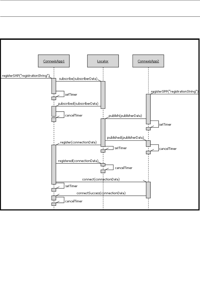
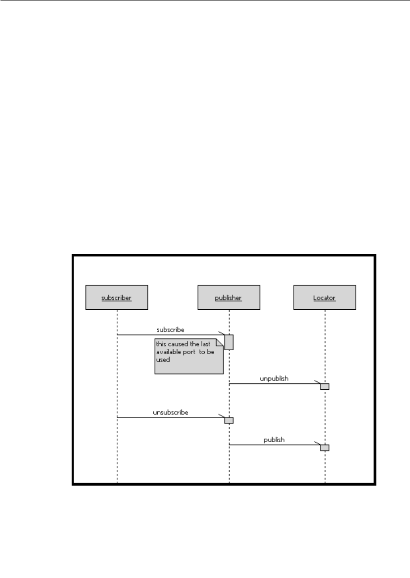
Locator Dynamics
User Guide - Rational Rose RealTime Connexis 141
From the user application perspective, the publication and
subscription is accomplished through the registerSPP() and
registerSAP() function calls on the port objects. The rest of the
messages shown on the sequence diagram in Figure 63 are internal
messages that occur as the result of a registerSAP() or registerSPP()
function call.
The Locator can be configured to execute on any node in the
distributed application. This configuration is accomplished through
command line parameters that are discussed later in this section.
Fully Subscribed Publishers
When a publisher becomes fully subscribed (meaning that all of the
ports on the publisher have been subscribed to), the publisher
unpublishes itself from the locator. At a later time, if a subscriber
deregisters itself from that publisher, the publisher republishes itself
with the locator. This sequence of events is illustrated in the sequence
diagram shown in Figure 64.
Figure 64 Fully subscribed publishers

Chapter 6 Using the Connexis Locator Service
142 User Guide - Rational Rose RealTime Connexis
Subscriber Losing Connection to a Publisher
If a subscriber that has successfully connected to a published endpoint
later loses that connection (through deregistration of the publisher,
failure of the publisher’s host, etc.), and this is detected by the
underlying transport, then the subscriber port is automatically
resubscribed to the locator. If the underlying transport does not
provide this quality of service, then it is up to the user application to
implement a failure detection mechanism in the protocol to detect
messaging failures and reregister as necessary.
One possible solution to this problem is to set up a timer on the
subscriber that periodically sends a message to the publisher. If the
publisher does not respond to this message within a specified amount
of time, the subscriber resubscribes to the service.
Locator Failure
If the primary Locator has been configured with a backup, and the
primary Locator goes down, the backup Locator automatically takes
over the role of primary Locator. When this primary/backup strategy is
used, the primary and backup Locators should be placed on different
nodes in the network. This ensures that there is not a single point of
failure in your distributed application.
Figure 65 illustrates the basic fail-over scenario of a primary/backup
Locator.
The backup continually polls the primary, and restarts the election
protocol should the primary fail to respond. The backup assumes the
role of the primary when the primary continues to fail to respond to the
election protocol. When the backup takes over, it broadcasts a message
to all endpoints stating that it is now the primary locator. The
endpoints acknowledge this and republish all global publisher ports
and pending subscription ports with the newly elected primary Locator.
Should the original primary locator become available again, it assumes
the role of the backup locator.
During the time that it takes for the transition from primary to backup
locator to take place, new publish or subscribe requests will be delayed
until the backup locator takes over.
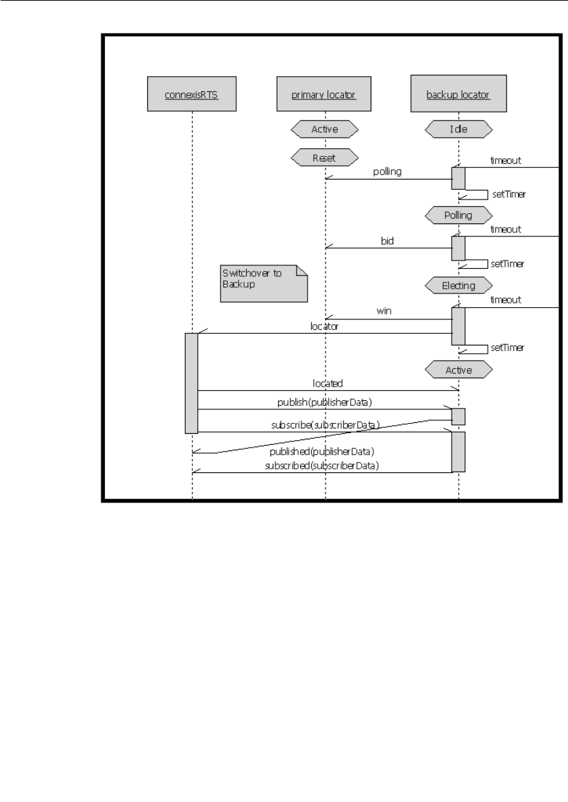
Locator Dynamics
User Guide - Rational Rose RealTime Connexis 143
Figure 65 Primary to backup switchover
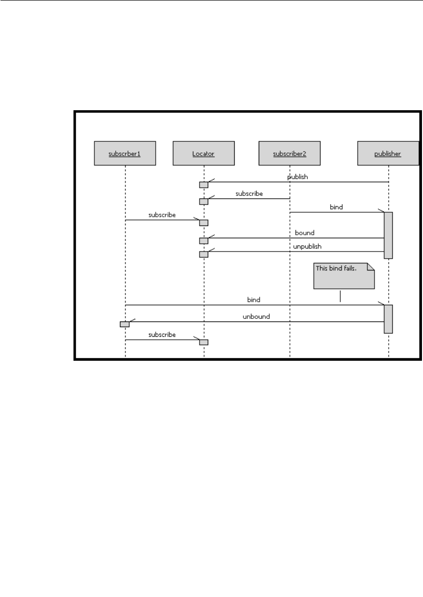
Chapter 6 Using the Connexis Locator Service
144 User Guide - Rational Rose RealTime Connexis
Locator Race Condition
There may be cases where the publisher becomes unavailable in
between the time that its endpoint is received from the locator and the
time when the explicit registration is attempted. One scenario that
would cause this to happen is illustrated in the sequence diagram in
Figure 66.
Figure 66 Locator race condition
In this case, subscriber2 got the endpoint from the locator and bound
to the last available port on the publisher. Meanwhile, subscriber1 got
the endpoint from the locator (before the publisher had unpublished
with the locator), and attempted to bind to it. This bind fails because
there are no ports left on the publisher. This scenario causes
subscriber1 to resubscribe with the Locator.

Locator Configuration
User Guide - Rational Rose RealTime Connexis 145
Unconnected Subscribers
If no unbound publishers are available, the subscriber remains
pending at the locator forever. Deregistration of a subscriber port that
has a pending subscription causes it to be unsubscribed from the
Locator.
Locator Configuration
The Locator service is an optional service that provides subscribers
with an endpoint that will be used on a first-come, first-served basis
when trying to connect to a publisher. The Locator service can be
initialized with both a primary and a backup server.
The initial Connexis release only supports a single backup server. This
limits the level of fault-tolerance to a single processor failure. This is
not a fundamental restriction of the primary/backup approach and
support for multiple backup servers may be added in future releases.
It is possible to operate with a single Locator for test purposes or if
fault-tolerance is not required in the product.
Locator Parameters
There are several configuration options that can be used to set up the
Locator for specific environments. These are listed in Table 14.
Table 14 Locator command line options
Command Line Option Description
CNXlocator_primary
(CNXlp)
Specifies that this process should be made
the primary locator.
Argument Type: none
Default Value: none
CNXlocator_backup
(CNXlb)
Specifies that this process should be made
the backup locator.
Argument Type: none
Default Value: none

Chapter 6 Using the Connexis Locator Service
146 User Guide - Rational Rose RealTime Connexis
CNXlocator_primary_
endpoint (CNXlpep)
Specifies the endpoint of the primary locator
(if this process is not the primary locator).
Argument Type: string
Default Value: none
CNXlocator_backup_
endpoint (CNXlbep)
Specifies the endpoint of the backup locator
(if this process is not the backup locator).
Argument Type: string
Default Value: none
CNXlocator_retry_delay
(CNXlrd)
Specifies the amount of time, in ms, to wait
before retries. The value must be >50.
Argument Type: integer
Default Value: 2000
CNXlocator_audit_delay
(CNXlad)
Specifies the amount of time, in ms, to wait
between audits of the primary and backup
locators. The value must be >50.
Argument Type: integer
Default Value: 2000
CNXlocator_audits_oos
(CNXlao)
Specifies the number of failed audits required
to take the primary locator out of service.
Using the default of 3, the primary locator
would be taken out of service after the third
consecutive audit had failed.
Argument Type: integer
Default Value: 3
CNXlocator_preferred_
transport (CNXlpt)
Specifies that the first protocol to be chosen.
This option can only be set at the primary or
backup locators.
Argument Type: string
Default Value: none
Table 14 Locator command line options
Command Line Option Description

Locator Configuration
User Guide - Rational Rose RealTime Connexis 147
A locator is configured as the primary by starting the application with
the -CNXlp command line option. When the locator starts up it
publishes a port with the DCS. The backup locator will later connect to
this port for the purpose of monitoring the primary locator. If the
primary locator fails, future locator requests will be routed directly to
the backup locator. If a backup is present, the CNXlbep option must
also be specified when the primary is started so that collocated clients
can use the locator if the backup takes over.
A locator is configured as the backup by informing the Connexis library
that the application is acting as the backup locator and by specifying
the explicit endpoint of the primary locator. This is done using the
-CNXlb command line option (to specify that this application is the
backup locator) and the -CNXlpep command line option (to inform
Connexis of the address of the primary locator).
The backup locator subscribes to the port that is published by the
primary locator. The backup uses this port to periodically poll the
primary locator. If the primary fails to respond to the polling messages,
the backup bids to takeover as the primary.
Client Connexis applications in this fault-tolerant configuration must
be configured with the endpoints of both the primary and the backup.
Each Connexis client explicitly subscribes to a port on both the
primary and the backup locators. Registrations are only sent to the
locator which has identified itself as the primary.
Figure 15 outlines the common Locator configurations and the
parameter combinations that are required to support them.

Chapter 6 Using the Connexis Locator Service
148 User Guide - Rational Rose RealTime Connexis
Table 15 Common Locator configurations and required parameters
Configuration Required Options Description
When starting a client that is
collocated with the primary
locator and no backup is being
used.
CNXlp The CNXlp option is required to
establish the process as the primary
locator.
When starting a client that is
collocated with the primary
locator and a backup is being
used.
CNXlp, CNXlbep The CNXlp option is required to
establish the process as the primary
locator.
The CNXlbep options is required so
that the primary locator and the client
know about the backup.
When starting a client that is
collocated with the backup.
CNXlb, CNXlpep The CNXlb option is required to
establish the process as the backup
locator.
The CNXlpep option is required to
inform the backup and the client of
the primary locator.
When starting a client that is
using a primary locator with no
backup.
CNXlpep The CNXlpep option is required to
inform the client of the location of the
primary locator.
When starting a client that is
using a primary locator with a
backup.
CNXlpep, CNXlbep The CNXlpep and CNXlbep options are
required to inform the client of the
location of the primary and the
backup locators respectively.

Locator Configuration
User Guide - Rational Rose RealTime Connexis 149
Locator Parameter Examples
This section presents several examples of starting different
components that are part of a distributed application that is using the
Connexis Locator service.
Example 1: Two node application with no backup locator
To start the application that acts as the primary locator:
<app_name> -CNXep=cdm://host1:9999 -CNXlp
The other application is started using the following command line
syntax:
<app_name> -CNXep=cdm://host2:9991 -CNXlpep=cdm://host1:9999
Example 2: Three node application with primary and backup
locator
To start the application that acts as the primary locator:
<app_name> -CNXep=cdm://host2:9999 -CNXlp -
CNXlbep=cdm://host3:9999
To start the application that will be acting as the backup locator:
<app_name> -CNXep=cdm://host3:9999 -CNXlb -
CNXlpep=cdm://host2:9999
To start the other application:
<app_name> -CNXep=cdm://host2:9991 -CNXlpep=cdm://host2:9999 -
CNXlbep=cdm://host3:9999

Chapter 6 Using the Connexis Locator Service
150 User Guide - Rational Rose RealTime Connexis
Creating your Own Name Service
The Locator service that is provided with Connexis is designed in a very
general fashion. It should satisfy most of the requirements for this type
of service, but there may be cases where a different level of
functionality is required by a specific application. In these cases, it may
be desirable to design and use your own name service instead of using
the Connexis Locator.
If you do this, there are several key differences between the Connexis
Locator and a simple name service that you should be aware of. The
Connexis Locator does more than simply translate a supplied service
name into a physical endpoint. The Connexis Locator also provides the
following features:
■allows for arbitration between several identically named publishers
■performs prioritized endpoint lookup on these publishers based on
rank and protocol priority
■allows pending subscriptions which are automatically connected to
publishers that are registered at a later time
■provides automatic re-subscription when publishers fail
■provides a fault-tolerant (no single point of failure) name service
■provides load-sharing of multiple publishers
A simple name service will typically only do a one-to-one mapping
between an endpoint service name and the endpoint physical address.
If your application does not require the additional features provided by
the Connexis Locator, you may want to create a custom name service.
An example, where this may be desirable, is if all of the nodes in your
distributed application can be determined by some kind of algorithmic
mapping of a service name (for example, “tributaryPort03”) to an
explicit endpoint. Another example, where this may be desirable, is in
a static network environment where all of the endpoint mappings could
be read from a configuration file at system start-up time.
In either of these cases, a Connexis connection could be used by all of
the nodes in the distributed application to connect to a known
“nameservice” port. This “nameservice” port returns an explicit
endpoint given a service name that was passed in to it.

User Guide - Rational Rose RealTime Connexis 151
Chapter 7
Using the Connexis Viewer
Debugging the data flow between embedded component instances in a
distributed network can be a very difficult task. For distributed
systems that have been designed and generated using Rational Rose
RealTime and Rational Connexis, the Connexis Viewer can be used to
provide real-time insight and feedback to aid in the debugging process.
The Connexis Viewer consists of a workstation component that is
provided for user interaction. The workstation component is launched
from within a Rose RealTime session and consists of a target agent
which monitors the DCS port registration process and collects trace
events.
The Connexis Viewer provides the following information about an
executing model:
■the status of unwired end ports that are registered with the DCS
■an indication of which DCS unwired end ports are bound to each-
other
■traces of user data sent from or received at a DCS registered port
■traces of DCS Locator and DCS Transport events -
❑transport connection establishment and failure
❑DCS locator switchover
❑synchronization of naming tables between the active and the
standby DCS locators

Chapter 7 Using the Connexis Viewer
152 User Guide - Rational Rose RealTime Connexis
The circuit tracing functionality provided with the Connexis Viewer
offers features that are similar to the Rose RealTime’s Target
Observability with the following exceptions:
■Traces can be enabled and controlled independently of the Rose
RealTime toolset.
■The output of trace information is handled on a separate (low
priority) thread and is minimally intrusive to the running
application.
Note: The Connexis Viewer can be used at the same time as Rose
RealTime’s Target Observability feature. In fact, the easiest way to
start viewing a distributed model is to launch the different
applications directly from Rose RealTime.
The metrics collecting functionality provided with the Connexis Viewer
lets you control and view the metrics collection results of a component
instance. It provides the following features:
■Controls start and stop function for metrics collection
■Displays metrics data for any registered transports
■Displays aggregate data for all registered transports
■Displays controller metrics
■Saves data in a format that allows for further analysis
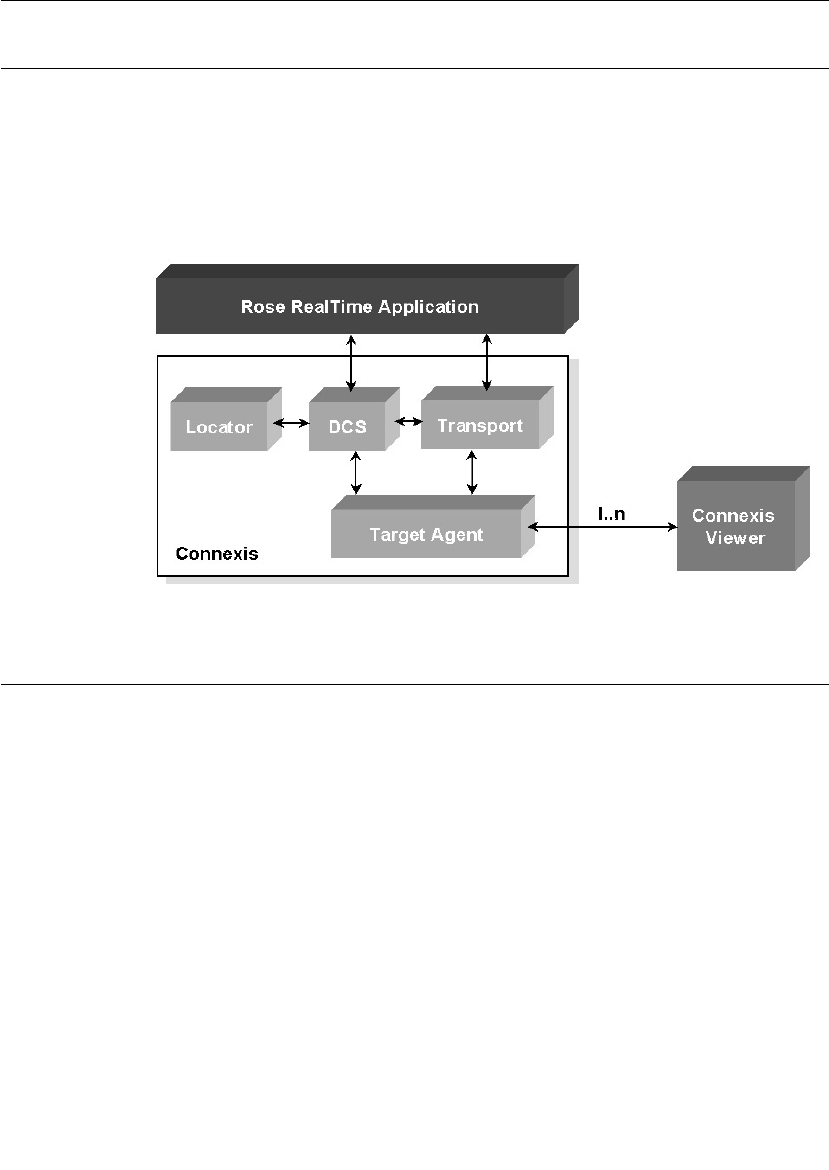
Viewer Architecture
User Guide - Rational Rose RealTime Connexis 153
Viewer Architecture
The Viewer communicates with the executing model through the Target
Agent as shown in Figure 67. The Target Agent component must be
contained in every Rose RealTime executable to which the Viewer
connects. The Target Agent operates on a low priority thread and relays
information about the executing model back to the Viewer where it can
be seen.
Figure 67 High-level architecture
Adding Viewer Support to a Model
To add Viewer support to your application, you must add a capsule role
from the RTDBase_Agent or the RTDBase_Locator_Agent capsule, to a
capsule in your application. Each node requiring Viewer support, must
have one of these capsule roles contained in it.
The RTDBase_Agent capsule only adds support for the Target Agent,
which is needed to run the Connexis Viewer. The
RTDBase_Locator_Agent adds support for both the Target Agent and
the Locator.
For more information on Connexis-enabling a Rose RealTime
application refer to “Adding Connexis Support to Your Model” on
page 83.

Chapter 7 Using the Connexis Viewer
154 User Guide - Rational Rose RealTime Connexis
Before starting the Viewer, there are two command line options that
you should specify for your Rose RealTime component instances:
■CNXep - Used to specify the Connexis endpoint. The Viewer must
know the Connexis endpoint of the executing model to be able to
connect to the running application. This is a required parameter.
■CNXui - Used to specify a unique identifier for the endpoint. If this
option is not specified, Connexis assigns a default identifier for the
endpoint. The default is a hex code and does not easily identify the
endpoint in the Viewer. For this reason, it is recommended that you
define your own unique, descriptive identifier.
If the CNXep option is not specified on the component instance (in Rose
RealTime), you can specify it using the Viewer. The CNXui option can
only be modified in the Viewer on user-defined component instances.
This means that if the component instance was read in from Rose
RealTime, you cannot modify it in the Viewer.
Adding Metrics Support to a Model
Like tracing, metrics gathering is done on the target itself and is
reported to the Viewer. This capability is enabled by default in the DCS
libraries that ship with Connexis, but it can be enabled or disabled
when the DCS library is recompiled by the user. Like tracing, the model
must contain either the RTDBase_Agent or the
RTDBase_Locator_Agent capsule. When the Viewer connects to the
Target Agent in the component instance, it asks if metrics gathering is
enabled on the target. If it is not, a warning message is displayed in the
log of the viewer and no metrics reporting can be done.

Starting the Connexis Viewer
User Guide - Rational Rose RealTime Connexis 155
Starting the Connexis Viewer
You can start the Connexis Viewer from the Rose RealTime main menu,
from a deployment diagram or from a deployment package.
To start the Connexis Viewer from the main menu:
1. Open the Connexis-enabled Rose RealTime model that you want to
view.
2. Select Tools > Connexis Viewer.
If you have a deployment diagram active when you start the Viewer, it
uses the processor and component instances from that diagram. If no
deployment diagram is active, it uses the processors and component
instances in the model.
To start the Connexis Viewer from a deployment diagram or a
deployment diagram icon:
1. Right-click the deployment diagram or the deployment diagram
icon. A popup menu appears.
2. Select from the popup menu. The Connexis Viewer
appears.
The Connexis Viewer uses the processor and component instances
from the deployment diagram icon that you have selected.
To start the Connexis Viewer from a deployment package:
1. Right-click the deployment package. A popup menu appears.
2. Select for the popup menu. The Connexis Viewer
appears.
The Connexis Viewer uses the processor and component instances
from the deployment package.
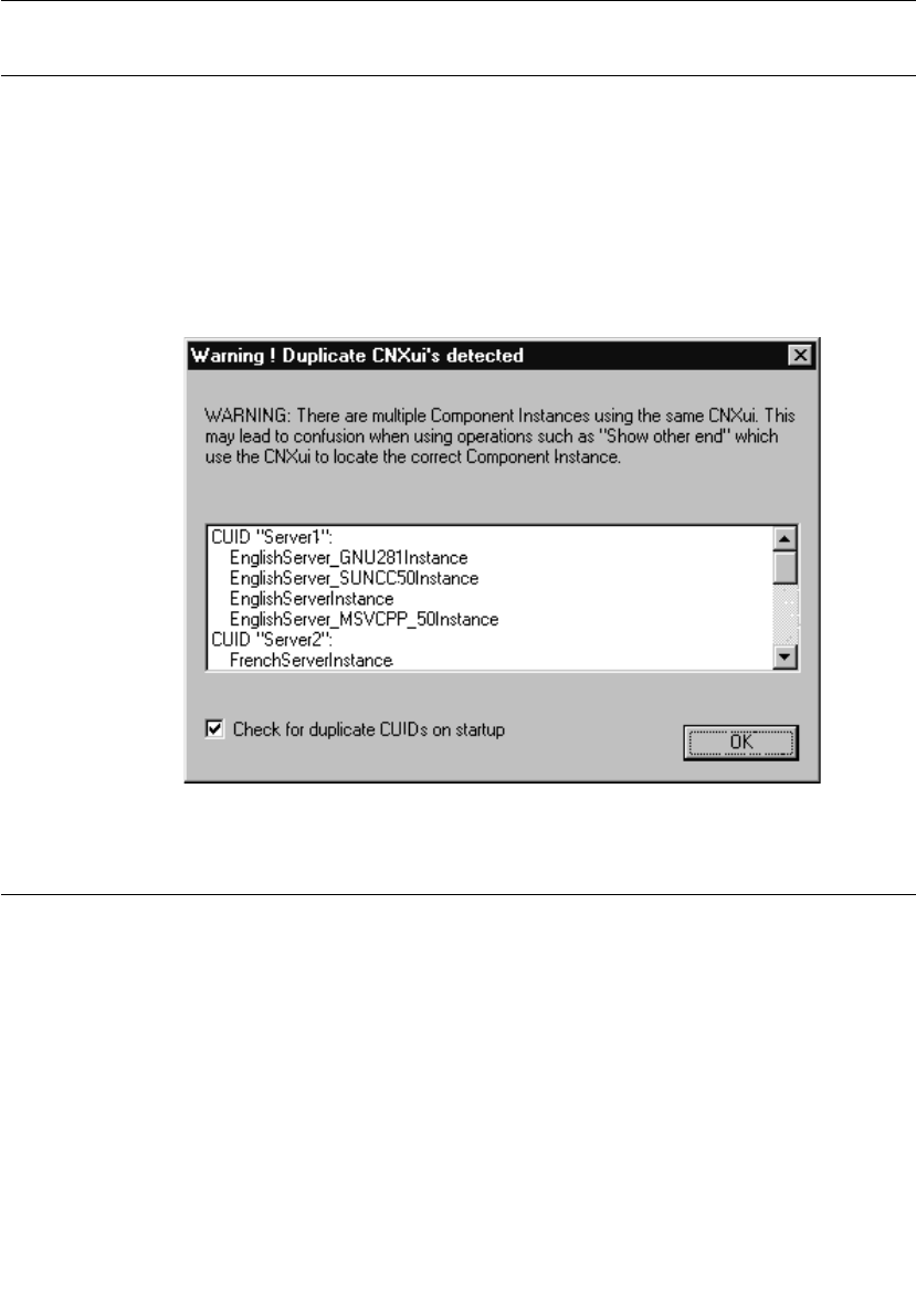
Chapter 7 Using the Connexis Viewer
156 User Guide - Rational Rose RealTime Connexis
Duplicate CNX Unique Identifiers
The Duplicate CNXui dialog box indicates that there are multiple
component instances that use the same CNXui. This may cause
confusing information to be displayed when using Connexis Viewer
features that rely on the CNXui. When this occurs, operations that
involve displaying information about the remote end of a connection
may not function correctly. The recommendation is that CNX unique
identifiers be unique amongst all component instances in the Connexis
Viewer session.
Figure 68 Duplicate CNXuis dialog box
Viewer Main Window
The Viewer main window contains the following:
■Main menu - is used to access application-specific operations
■Tree view - is the main interface to the user and is used to display
and configure information about the executing application as well
as to open trace windows
■Trace pane - is used to manage all of the trace windows that are
currently open
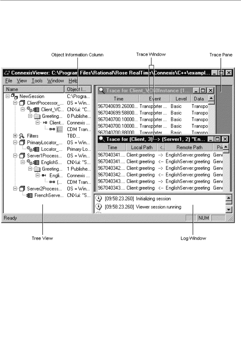
Viewer Main Window
User Guide - Rational Rose RealTime Connexis 157
■Log window - is used to log connection information
■Status bar - is used to display information about the state of the
application
Figure 69 shows the Viewer main window with the HelloWorld model
being viewed.
Figure 69 The Viewer main window

Chapter 7 Using the Connexis Viewer
158 User Guide - Rational Rose RealTime Connexis
Viewer Menus
The main menu, as shown in Figure 70, consists of a File, View, Tools,
Window and Help menu.
Figure 70 Connexis Viewer Main menu
File Menu
Import
Selecting File > Import displays a standard open dialog box that allows
you to import a previously-saved Viewer configuration file.
Use the Import command when you want to view a model in addition to
the one against which you launched the Connexis Viewer. The result of
importing the other model's information is the same as manually
adding each of the model's Processor and component instance
definitions.
Note: Before you import, you must generate the .CVMInfo file for the
model to be imported. This file is generated automatically when you use
the Connexis Viewer with a model.
Exit
Selecting File > Exit exits the application.
View Menu
Status bar
The View menu allows you to toggle the visibility of the Status Bar. A check
mark appears beside the menu item when it is visible.
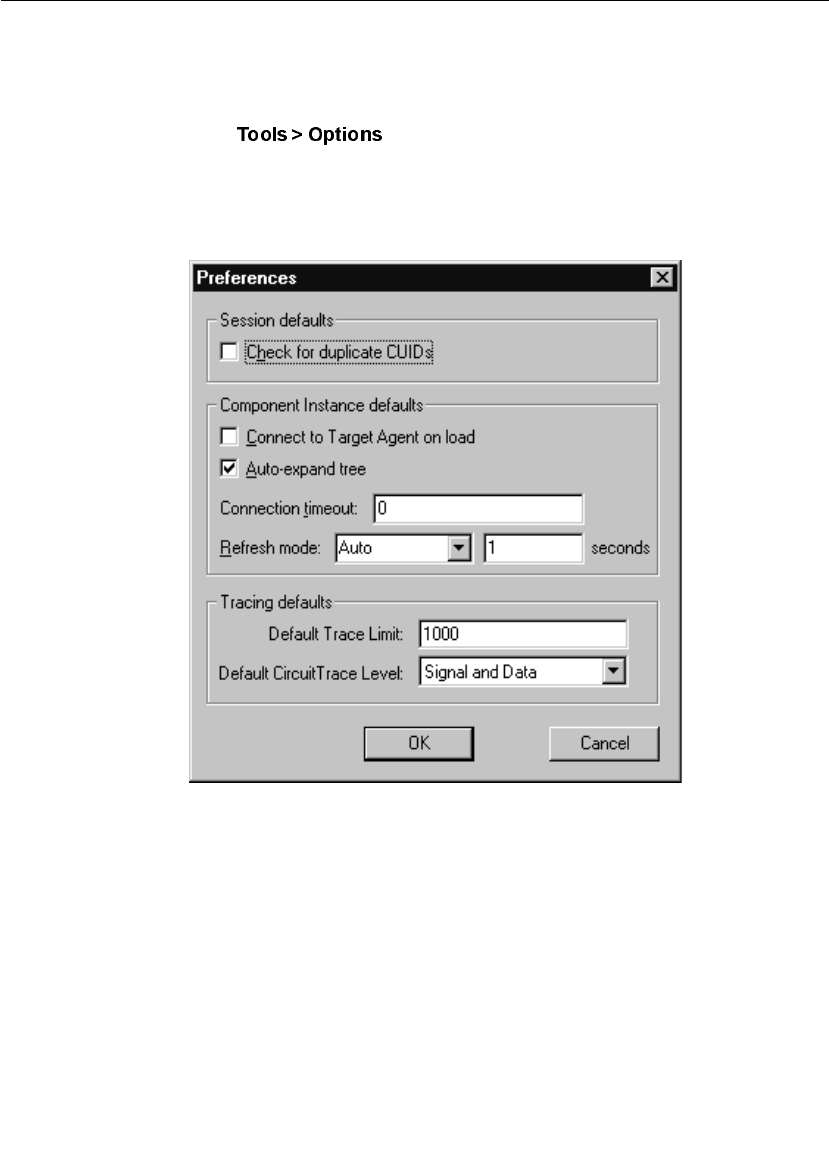
Viewer Menus
User Guide - Rational Rose RealTime Connexis 159
Tools Menu
Options
Selecting displays a “Preferences” dialog (see Figure 71)
that lets you select Session defaults, Component Instance defaults and
Tracing defaults for the Connexis Viewer (see Table 16, “Preference
dialog settings,” on page 160).
Figure 71 Preferences dialog
.

Chapter 7 Using the Connexis Viewer
160 User Guide - Rational Rose RealTime Connexis
Table 16 Preference dialog settings
Option Description
Check for duplicate
CUIDs
Checking this field lets Connexis identify, on
startup, any duplicate CUIDs in a model. This
occurs if you have the same logical CUID value
(specified using the 'CNXui' parameter) for
components that are being deployed on different
configurations.
Connect to target
agents on load
Checking this box lets all new Component
Instances connect to target agents.
Auto-expand Tree Checking this box lets all new Component
Instances function with the Auto-expand tree
feature.
Connection Timeout Typing the number of seconds in this field sets
the timeout period for all new Component
Instances.
Refresh Mode Refresh Mode lets you select the way component
instances are refreshed (Auto, Manual or Timed).
For the Viewer to refresh component instances
automatically, select “Auto” from the list. Select
“Manual” if you want to refresh the component
instance manually or select “Timed” and set your
desired refresh period in seconds.
Trace Limit Setting the value of this field determines the
initial size of the tracing buffer. This specifies the
number of trace events stored for all trace
windows, including Component Instances, Ports
and Circuit traces.
Circuit Trace Level Selecting the level from this list determines the
initial setting (Disabled, Activity, Signal or Signal
and Data) for Port and Circuit tracing. When you
open a trace window onto a Publisher, Subscriber
or Circuit without performing a 'Define...,' the
default trace level is the one defined in this field.

Viewer Menus
User Guide - Rational Rose RealTime Connexis 161
Windows Menu
Tile
Selecting Window > Tile causes all non-iconified Trace windows to be
arranged in a format in which the trace windows do not overlap.
Cascade
Selecting Window > Cascade causes all non-iconified Trace windows to be
arranged in a 'stack' which allows the captions of each window to be
visible.
Trace Windows List
Selecting one of the entries in the Trace Windows List (the numbered
entries) causes that window to become the active Trace Window. The
window is brought to the top, and if it had been previously iconified, it
is restored to its normal state.
Help Menu
Contents
Selecting Help > Contents... launches the main help for Connexis and the
Viewer.
About Connexis Viewer
Selecting Help > About Connexis Viewer, displays the Viewer’s about dialog.
The about dialog contains information about the version of the
Connexis Viewer that is being used and also contains information
about how to contact Connexis support.
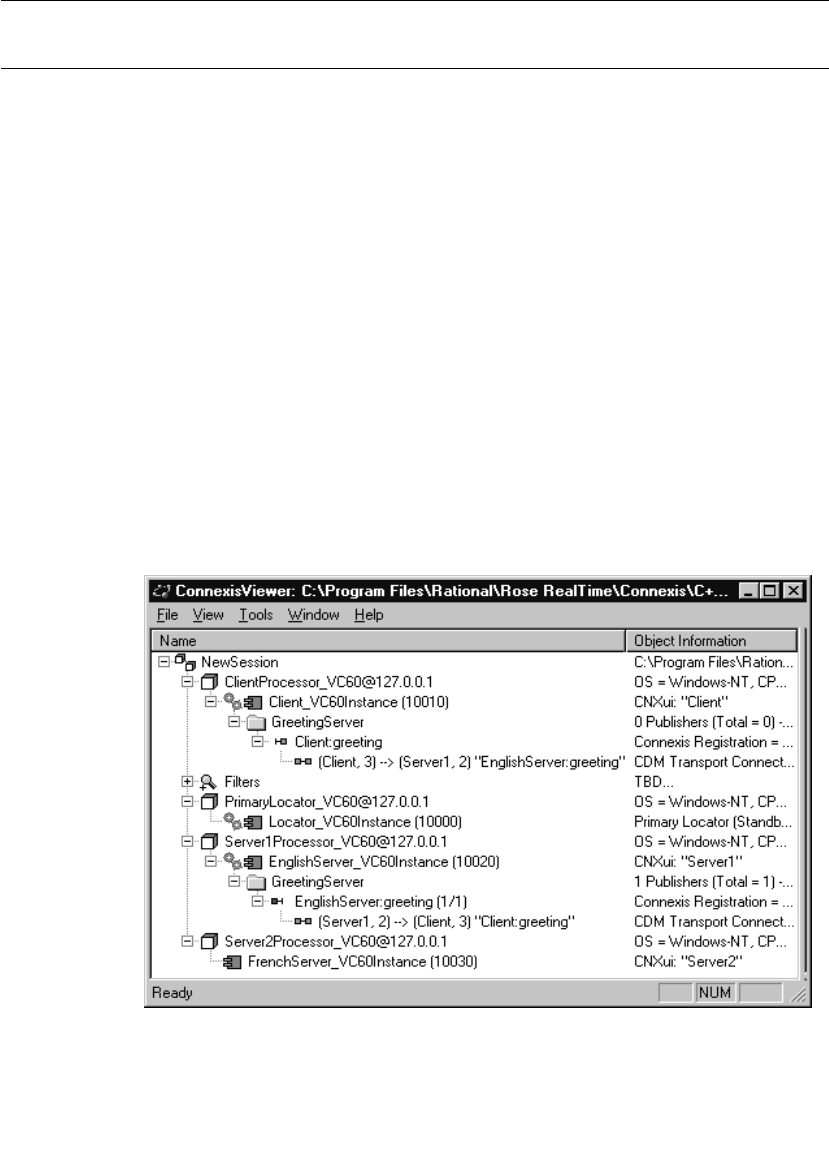
Chapter 7 Using the Connexis Viewer
162 User Guide - Rational Rose RealTime Connexis
Explorer Tree View
The primary way of configuring a Viewer session is through the tree
view. Most of the objects on the tree view have popup menus that allow
you to configure the object and to control the information that is
displayed for the object when the application is executing.
Figure 72 shows the tree view while the HelloWorld model is executing.
Every item in the tree view belongs to the session. The session contains
zero or more processors. Processors contain zero or more component
instances. Component instances contain zero or more named services.
Named services contain zero or more registered end ports and
registered end ports contain zero or more virtual circuit endpoints.
The processor and component instance information can be derived
directly from a Rose RealTime model. The Viewer captures the
information that is contained in the deployment view of the model that
was open when the Viewer was launched. Additionally, you can add
processors and component instances manually inside the Viewer. This
is useful if you also want to monitor Connexis-enabled Rose RealTime
executables that are not contained in the model from which the Viewer
was launched.
Figure 72 The Explorer tree view
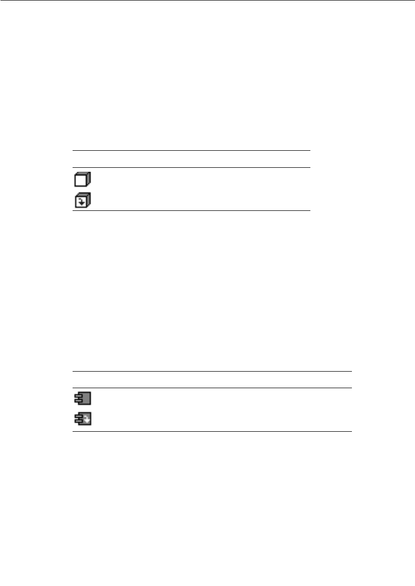
Explorer Tree View
User Guide - Rational Rose RealTime Connexis 163
Processor Icons
Processors that have been added automatically by launching the
Viewer are illustrated using the same processor icon as is used in Rose
RealTime (see the ClientProcessor_VC60@127.0.0.1 processor in
Figure 72 and Table 17). Processors that are added manually in the
Viewer are illustrated using the processor icon with a downward
pointing arrow inside (see the Workstation1@127.0.0.1 processor in
Figure 72 and Table 17). Processors that are added manually will be
reloaded the next time the Viewer is opened from the same model.
Component Instance Icons
Component instances, that have been added automatically by
launching the Viewer, are illustrated using the same component
instance icon as is used in Rose RealTime (refer to the
Client_VC60Instance (10010) component instance in Figure 72).
Component instances that are added manually are illustrated using
the component instance icon with a downward pointing arrow inside
(refer to the TestComponentInstance (9999) component instance in
Figure 72). Component instances that are added manually will be
reloaded the next time the Viewer is opened from the same model.
Table 17 Processor icons
Icons Meaning
automatically-added processor
manually-added processor
Table 18 Component instance icons
Icons Meaning
automatically-added component instances
manually-added component instances

Chapter 7 Using the Connexis Viewer
164 User Guide - Rational Rose RealTime Connexis
Filter Icons
A Filter icon lets you add, select or remove a trace filter specification
from the Explorer tree view. Clicking the plus symbol to the left of the
Filter icon expands the tree and reveals the trace filter specifications
that are available for use. If there are no trace filter specifications
available, right-clicking the Filter icon lets you add a new trace filter
specification. (see“Defining a Trace Filter for a Component Instance” on
page 182).
Figure 73 Filter Icon
Component Instance Status
Component instance status is indicated in the tree view by varying the
gear icon shown in Figure 74.
Figure 74 Gear icon
When a target agent connection is established, the tree refresh mode
(that is, manual, automatic, or timed) is reflected through the gear
spin. Feedback is summarized in Table 19.
When the Viewer has lost contact with the target (red), is manually
disconnected (gray), or is connecting (yellow), there is no feedback for
the refresh mode (since there is no active refresh in these states).
Table 19 Gear spin and status
Icon behavior Meaning
green, continuous spinning Automatic refresh mode
green, intermittent spinning Timed refresh mode
green, with no spin Manual refresh mode

Explorer Tree View
User Guide - Rational Rose RealTime Connexis 165
Named Services Icons
Named services appear in the tree view as folders (see Figure 75) that
are contained in component instances. Named services are identified
using the name that they were registered as with the DCS. Inside each
named service are zero or more registered end ports. The registered end
ports are referred to by the names that they were given in the Rose
RealTime model (this may or may not be the same as the name that
they were registered as), followed by the Rose RealTime model path to
the end port, the number of the end port instance, and the total
number of instances.
Figure 75 Named service icon
Port Icons
Publisher ports appear in the tree view with a red port icon beside them
(refer to the EnglishServer:greeting(1/1) port in Figure 72 and
Table 21). Subscriber ports appear with a yellow port icon if the port is
not bound, or a green port icon if the port is bound.
Table 20 Gear color and status
Icon appearance Meaning
No Gears The Target Agent has not been connected to this
component instance in this Viewer session.
Yellow Gears The user has requested a connection to the Target Agent
but the connection has not yet been established.
Green Gears The Target Agent is connected to the component
instance. If the component instance is in Auto Refresh
mode, the gears will be spinning. (See Table 19)
Red Gears The Viewer has determined that it has lost the
connection with the Target Agent. This is most likely an
indication that the component instance has stopped
running or is hung. The Viewer maintains the last
known state in the tree until the component instance is
Reset.
Gray Gears There is currently no connection established between the
component instance and the Target Agent.

Chapter 7 Using the Connexis Viewer
166 User Guide - Rational Rose RealTime Connexis
Virtual Circuit Icons
The last items that appear on the left hand side of the tree view are the
virtual circuits. Virtual circuits are contained inside of end port objects
in the tree view and appear with a green protocol icon beside them
(refer to (Client, 2) --> (Server1, 2) “EnglishServer:greeting” in Figure 72
and Figure 76).
Figure 76 Virtual circuit icon
Virtual circuits represent the Connexis connections that are currently
established in the running model as of the last time the Viewer was
refreshed. The information that is displayed in the tree view about a
virtual connection contains the following:
■the unique identifier for the local component instance followed by
the virtual circuit ID for that side of the connection
■the unique identifier for the remote component instance followed
by the virtual circuit ID for that side of the connection
■the name and Rose RealTime model path of the end port on the
other side of the connection enclosed in quotation marks
The virtual circuit illustrates why it is important to specify the CNXui
command line option on your component instances. If usable
identifiers had not been used in this model, the Client and Server1
identifiers would have appeared as numbers that were generated by
Connexis.
Table 21 Port icons
Icons Meaning
Publisher port icon
Subscriber port icon
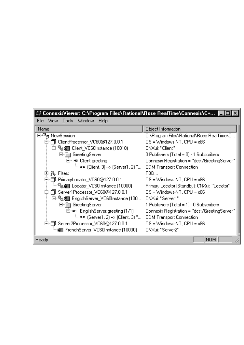
Explorer Tree View
User Guide - Rational Rose RealTime Connexis 167
This would have caused the information for the virtual circuit
contained in the EnglishServer:greeting (1/1) end port in Figure 72 to
be something similar to the following:
(76f95d83,2) --> (76f98e45,2) “Client:greeting”
This information is much more difficult to keep track of when you are
viewing an executing model.
Object Information Column
The Object Information column is on the right-hand side of the tree
view and is shown in Figure 77. It is used to display additional
information about each of the objects in the tree view.
Figure 77 The Object Information column
Table 22 explains what information is displayed in the Object
Information column for each object type.

Chapter 7 Using the Connexis Viewer
168 User Guide - Rational Rose RealTime Connexis
Popup Menus
Most operations in the Connexis Viewer are performed by selecting an
element and using the popup menu. Clicking the right mouse button
on an element in the Explorer Tree View enables you to perform
operations such as adding a processor or component instance, defining
trace parameters, opening a trace window, and so on.
Session Popup Menu
The session object in the tree view has a popup menu associated with
it. This menu is shown in Figure 78. The only option available from this
menu is to add a new processor to the session.
Table 22 Object Information description
Object type Information displayed
Processor Operating system and hardware architecture.
Component
Instance
Connexis Unique Identifier. This displays the string that
was specified using the CNXui command line option. If
the user did not specify an identifier, the Connexis-
generated identifier is not displayed until you connect to
that component instance. This field also displays the
locator configuration and status.
Named service Number of publishers and subscribers that are
currently registered, and in the case of publishers, the
sum of the replication factors of the named service for
the component instance.
Registered end
port
The Connexis Registration string that was used to
register the port.
Virtual circuit This field indicates which transport protocol is used to
establish the connection. This field also indicates the
type of connection that has been established by
Connexis.

Popup Menus
User Guide - Rational Rose RealTime Connexis 169
Figure 78 The session popup menu
Add Processor
The Add Processor command allows you to add a processor to the tree
view. See also “Adding a Processor” on page 175.
Processor Popup Menu
All processors in the tree view have a popup menu associated with
them as shown in Figure 79.
Figure 79 The processor popup menu
Open Specification
The Open Specification command allows you to modify a processor’s
properties. See also “Changing the Properties of a Processor” on
page 176.
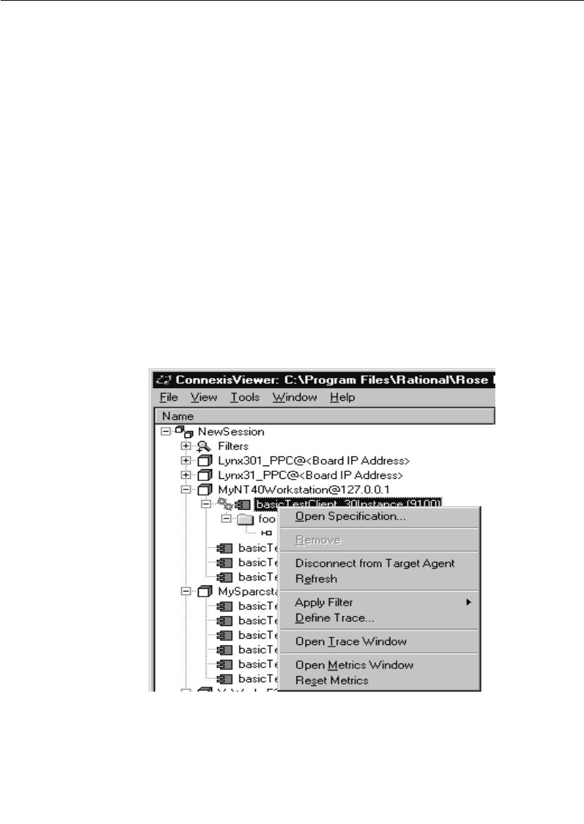
Chapter 7 Using the Connexis Viewer
170 User Guide - Rational Rose RealTime Connexis
Remove
The Remove command allows you to remove a processor that you have
manually added to the model. This command appears grayed out if the
processor was read in from a Rose RealTime model.
Add Component Instance
The Add Component Instance command allows you to add a new component
instance to the tree view. See also “Adding a Component Instance” on
page 177.
Component Instance Popup Menu
The component instance popup menu is context-sensitive and is
shown in Figure 80. Slightly different options will appear in this menu
depending on the state of the component instance. Figure 80 shows
what is displayed if the menu is opened from a component instance
that was read in from a Rose RealTime model and where the Target
Agent has been started on the component during the active session.
Figure 80 The component instance popup menu

Popup Menus
User Guide - Rational Rose RealTime Connexis 171
Open Specification
The Open Specification command allows you to modify a component
instance’s properties. See also “Changing the Properties of a
Component Instance” on page 180.
Remove
The Remove command allows you to remove a component instance that
you have manually added to the model. This command appears grayed
out if the processor was read in from a Rose RealTime model.
Connect to Target Agent on load
The Connect to Target Agent on load command changes context depending
on the current Target State as summarized in Table 23.
Refresh
The Refresh command allows you to manually refresh the information
that is being displayed about the component instance and all of the
objects under it in the tree view. This option is available even if the
Timed or Auto refresh methods are selected for the component
instance. See also “Changing the Properties of a Component Instance”
on page 180.
Table 23 Connect to Target Agent
Target State Command text Action
Not Connected
(Gray gears)
Connect to Target
Agent
Attempts to connect to this
component instance's Target
Agent
Waiting for
Connection
(Yellow gears)
Cancel Target Agent
Connection
Cancels the attempt to connect
Connected
(Green gears)
Disconnect from
Target Agent
Disconnects from the Target
Agent
Disconnected
(Red gears)
Reset Target Agent
Connection
Clears the tree information and
returns to the “Not Connected”
Target state

Chapter 7 Using the Connexis Viewer
172 User Guide - Rational Rose RealTime Connexis
Apply Filter
The Apply Filter command lets you select a previously-defined trace filter
for a component instance. A popup menu appears, listing all available
filters.
Define Trace
The Define Trace command allows you to define trace settings for a
component instance. See also “Defining a Trace Filter for a Component
Instance” on page 182.
Open Trace Window
The command lets you open a trace window from
a component instance. Once the trace window appears, you can right-
click on the window to define or apply a trace filter to the component
instance (see “Trace Window Popup Menu” on page 196).
Open Metrics Window
The command opens a metrics window on the
component instance. The Viewer does not have to be connected to the
component instance, but the component instance must be running for
the metrics connection to work.
Reset Metrics
The command restarts the target metrics counter and
resets the collection and reporting of metrics from the selected
component instance. The component instance must be running for this
menu item to be available.

Popup Menus
User Guide - Rational Rose RealTime Connexis 173
Port Reference Popup Menu
The Port reference popup menu is shown in Figure 81.
Figure 81 The Port Reference popup menu
Define Trace
The Define Trace command allows you to define trace settings for a port
reference. See also “Defining a Port Reference Trace” on page 188.
Open Trace Window
The Open Trace Window command opens a trace window on the port
reference. This trace window uses the filters that were defined in the
Define Trace dialog.
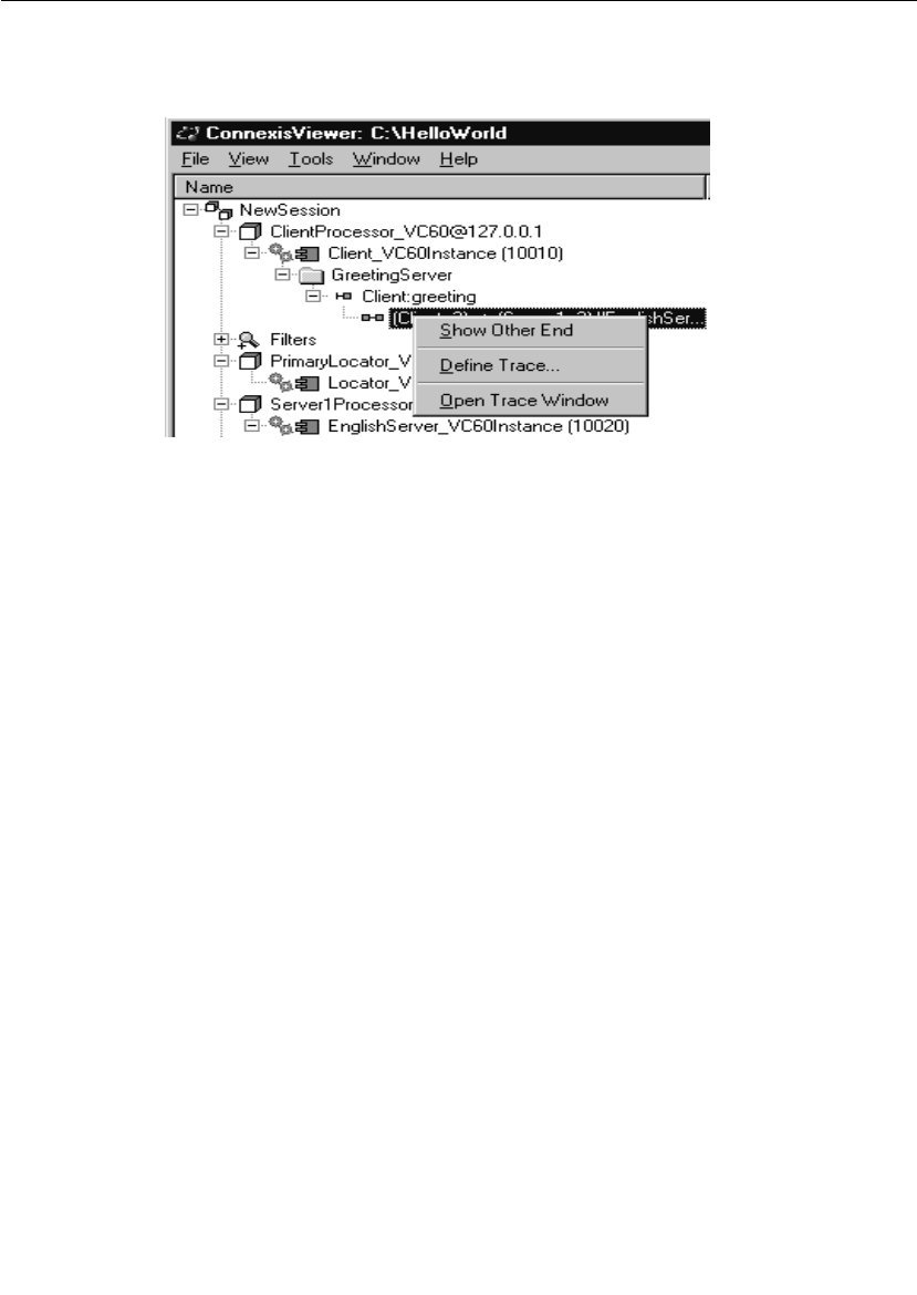
Chapter 7 Using the Connexis Viewer
174 User Guide - Rational Rose RealTime Connexis
Virtual Circuit Popup Menu
The Virtual circuit popup menu is shown in Figure 82.
Figure 82 The virtual circuit popup menu
Show other end
The Show other end command allows you to highlight the virtual circuit
endpoint that is at the other end of the connection.
Define Trace
The Define Trace command allows you to define trace levels for a virtual
circuit. See also “Defining a Virtual Circuit Trace” on page 192.
Open Trace Window
The Open Trace Window menu item opens a trace window on the virtual
circuit. This trace window will use the filters that were defined in the
Define Trace dialog.
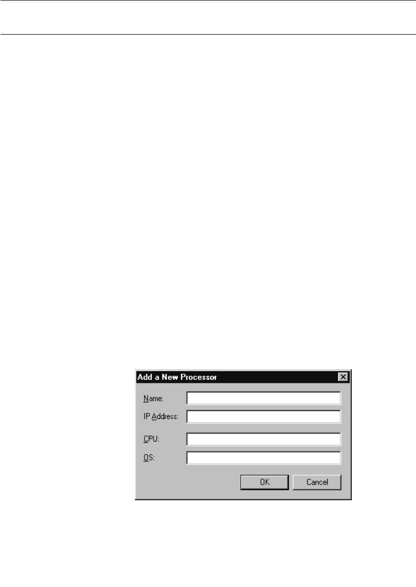
Creating Processors and Component Instances
User Guide - Rational Rose RealTime Connexis 175
Creating Processors and Component Instances
The Connexis Viewer lets you create processors and component
instances that are not part of the current model. This is useful when
you wish to perform traces on distributed systems that are composed
of several models. Using the Import command to import all information
from another model may be undesirable depending on the size and
complexity of the model. The ability to add processors and component
instances from another model allows you to:
■see information for a single component instance in a complex
model without burdening your session with unnecessary
information
■perform a trace when the model for the other component instances
is not available (for example, the model was developed off-site)
New processor and component instances are stored in.CVEInfo file.
Once defined, they will always appear when you open the model.
Adding a Processor
You can add a processor that is not part of the current model to the
tree view.
To add a processor:
1. Select New Session in the tree view.
2. Right-click and select Add Processor from the popup menu.
The dialog shown in Figure 83 appears.
Figure 83 Add Processor dialog
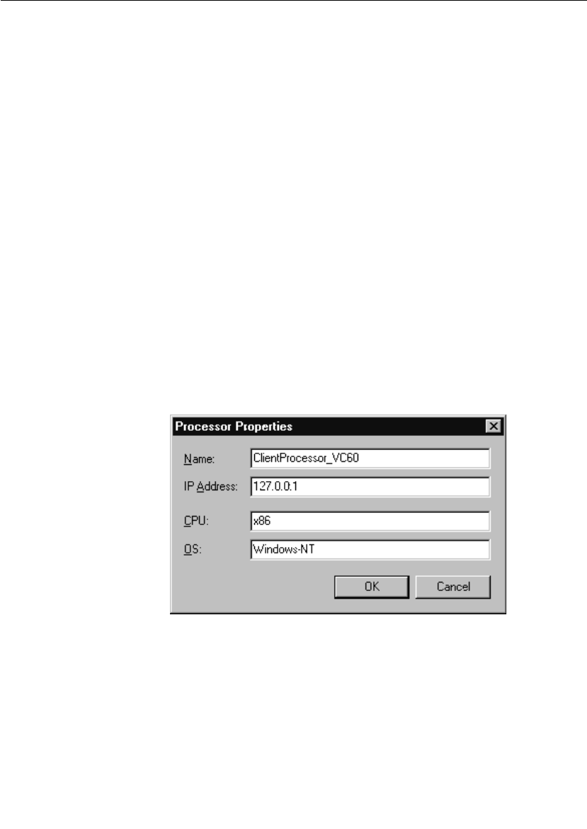
Chapter 7 Using the Connexis Viewer
176 User Guide - Rational Rose RealTime Connexis
3. Enter a processor name.
Note: Letters, numbers, and underscores are permitted in the name.
Spaces are prohibited.
4. Enter the IP address of the processor.
5. Enter the CPU type.
6. Enter the operating system.
7. Click the OK button.
If you need to modify a processor’s properties after you have created it,
see “Changing the Properties of a Processor” on page 176.
Changing the Properties of a Processor
The Connexis Viewer allows you to edit a processor’s properties after
you have created it.
To change a processor’s properties:
1. Select the processor.
2. Right-click and select Open Specification from the popup menu.
The dialog box shown in Figure 84 appears.
Figure 84 Processor Specification dialog
3. Edit the fields as desired.
4. Click the OK button.

Creating Processors and Component Instances
User Guide - Rational Rose RealTime Connexis 177
Removing a Processor
You can remove a processor that you manually added to the model
from the Connexis Viewer. Processors that have been read in from a
Rose RealTime model cannot be removed, and as a result, appear
grayed out on the menu.
To remove a processor:
1. Select the processor.
2. Right-click and select Remove from the popup menu.
Adding a Component Instance
You can add a component instance that is not part of the current model
to the tree view.
To add a component instance:
1. Select the processor to which you want to add a new component
instance.
2. Right-click and select Add Component Instance from the popup menu.
The dialog box shown in Figure 85 appears.
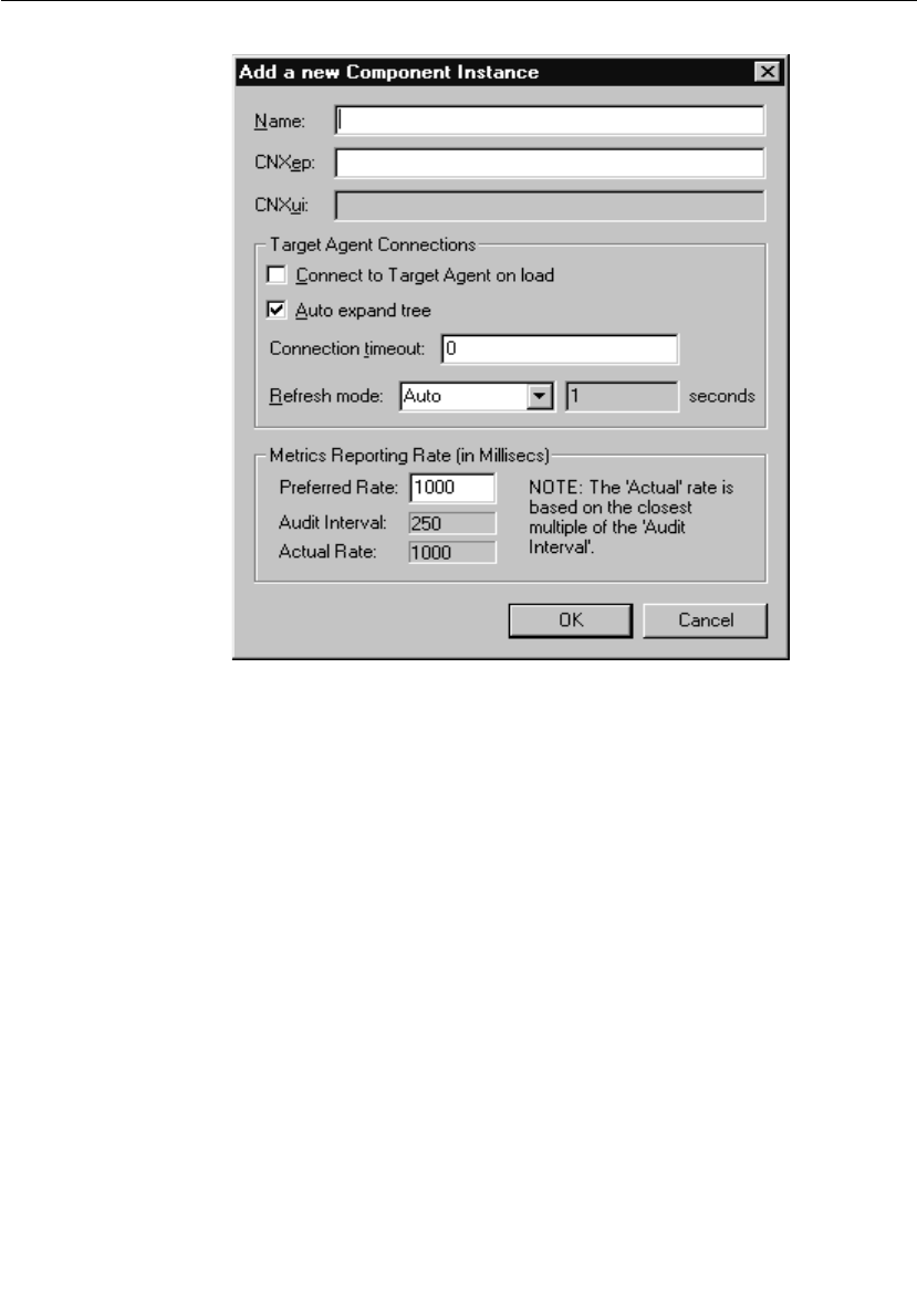
Chapter 7 Using the Connexis Viewer
178 User Guide - Rational Rose RealTime Connexis
Figure 85 Add Component Instance dialog
3. Enter a name for the component instance.
Note: Letters, numbers, and underscores are permitted in the name.
Spaces are prohibited.
4. Enter the CNX endpoint (CNXep). This must be a valid Connexis
endpoint. Specifying just a port number translates into the
endpoint cdm://<IPAddr>:portnumber where <IPAddr> is obtained
from the processor containing this component instance.
5. Enter the CNXui field if you created the component instance
manually.
Note: You cannot edit this field if the component instance was read
in from a Rose RealTime model.
6. Click to enable Connect to Target Agent on load.
When this option is enabled, the Viewer:

Creating Processors and Component Instances
User Guide - Rational Rose RealTime Connexis 179
❑attempts to connect to the component instance’s target agent on
startup
❑automatically attempts to reconnect to a Target Agent when it
becomes 'Disconnected' (that is, unexpectedly loses its
connection). This is useful in situations such as when the target
is reset, rerun, or the communication link between the target
and the Viewer is broken and re-established. All component
instance trace filters established before the reset are
maintained.
If this option is not selected, the Target Agent must be started
manually.
7. Click to enable Auto expand tree.
When this option is enabled, the tree view is automatically
expanded to show new objects underneath the component instance
such as named services, publishers and subscribers, and
connections.
8. Enter a Connection timeout value in seconds.
This is the amount of time that the Viewer will wait for a reply from
the target agent before it assumes the connection has been
terminated. This value is used in two situations:
❑When the Viewer attempts to attach to a target agent, the value
in the connection timeout field is used to decide how long the
Viewer waits for the target agent to handshake with the Viewer.
If the handshake is not received within the specified interval,
the target agent must be reset and another connection attempt
must be initiated. A value of 0 indicates that the Viewer should
wait forever.
❑After the connection has been established (during normal
communication), the value in the connection timeout field is
used to determine how long the Viewer should wait for a
response from the target agent. Once a request for information
is sent by the Viewer to the target agent, the target agent is
expected to reply within the time specified in the connection
timeout field. The target agent is given three attempts to
respond within this interval. If it does not, the Viewer sends it a
status query. If no response is received for the status query
within the connection timeout period, the connection is
assumed to have timed out and the target agent must be reset
and reconnected. If the connection timeout is set to 0, the
default connection timeout period of 30 seconds is used.

Chapter 7 Using the Connexis Viewer
180 User Guide - Rational Rose RealTime Connexis
9. Choose a Refresh mode from the drop-down list:
❑Manual - All refreshes of the data that is displayed in the tree
view must be done by selecting Refresh from the component
instance’s popup menu.
❑Auto - Refreshes the model in real-time. This causes the Viewer
to refresh the display whenever a modification causes the
information that is displayed in the Viewer to change. This
operation may not be desirable for “highly active” models since a
constantly-changing model will cause the tree display to
fluctuate as it attempts to keep up-to-date.
❑Timed - If this option is selected, the refresh will occur every n
seconds where n is the value entered in the seconds field.
10. Enter the rate (milliseconds) at which you want metrics data to be
reported to the Viewer, in the Preferred Rate text box.
If the rate you request is more frequent than the rate at which the
component instance audits its circuits, the rate you request will
not be supported by the component instance. In such a case,
metrics uses the auditing rate of the component instance.
For example, if the component instance "Client" uses the default
audit period of 250 ms, and you set the Preferred Rate to 100 ms,
metrics will be reported at an audit period of 250 ms.
Changing the Properties of a Component Instance
The Connexis Viewer lets you edit a component instance’s properties
after you have created it.
To change a component instance’s properties:
1. Select the component instance you wish to modify.
2. Right-click and select Open Specification.
The dialog box shown in Figure 86 appears.

Creating Processors and Component Instances
User Guide - Rational Rose RealTime Connexis 181
Figure 86 Component Instance Properties dialog
3. Edit the fields as desired.
Note: You cannot edit the CNXep field if the component instance was
read in from a Rose RealTime model. You can only edit this field if the
component instance was created manually.
4. Click the OK button.

Chapter 7 Using the Connexis Viewer
182 User Guide - Rational Rose RealTime Connexis
Performing Event Tracing
The Connexis Viewer lets you perform event tracing on component
instances, port references and virtual circuits.
The options available vary depending on the type of element selected
for tracing and are described in detail in the following sections:
■Defining a Trace Filter for a Component Instance
■Defining a Port Reference Trace
■Defining a Virtual Circuit Trace
Defining a Trace Filter for a Component Instance
Trace filters let you trace messages and event types from a distributed
model. You can define a trace filter from a Component Instance icon or
a Filter icon. Right-clicking either icon lets you access a dialog box that
allows you to set the filter levels for different trace groups and trace
types.
The component instance trace levels that are available for the trace
groups and trace types are:
■Disabled - no tracing for the group/type
■Basic - events that are related to the static operation of a group or
type. This includes start-up events, connect events and shutdown
events
■Operational - events that are related to the dynamic behavior of a
group. This is the trace level that is used to trace data transport
■Advanced - enables all tracing for a group. This is typically very
detailed and includes all events from the other trace levels as well
as audit information
Note: When setting the trace levels for the different types and groups,
keep in mind that the more tracing being performed, the more data is
being sent to the Viewer. This can have a negative impact on the
performance of the executing model.
To define a trace filter from a Component Instance icon:
1. Right-click the Component Instance icon that you want to trace.
2. Select Define Trace from the popup menu.
The Set Component Instance Trace Levels dialog appears.
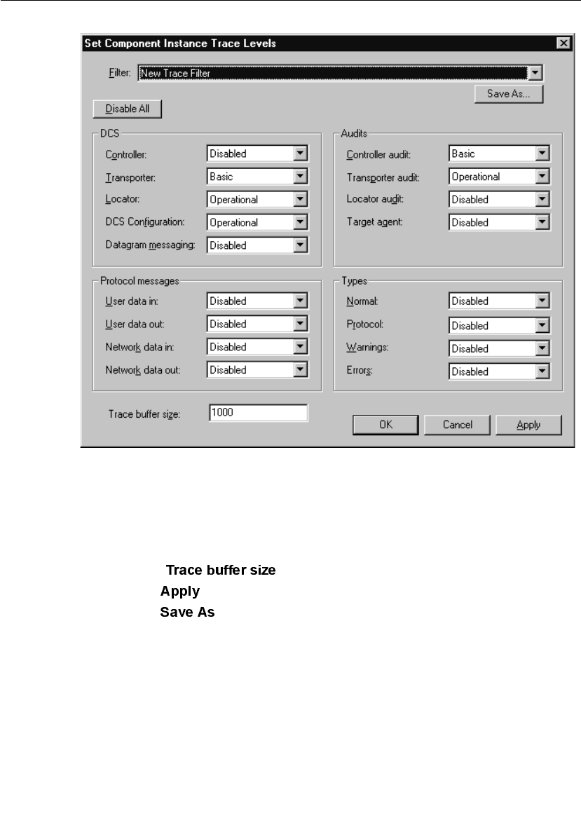
Performing Event Tracing
User Guide - Rational Rose RealTime Connexis 183
Figure 87 Set Component Instance Traces Levels dialog
3. Define the trace filter according to your requirements (see
Table 24, Table 25 and Table 26, for an explanation of the trace
filter options).
4. Type the number of events that you want written to the trace buffer
in the text field.
5. Click to trace the component instance.
6. Click to save your trace options. This is only necessary if
you want to reuse the same trace filter that you have created.

Chapter 7 Using the Connexis Viewer
184 User Guide - Rational Rose RealTime Connexis
To define a trace filter from the Filter icon:
1. Right-click the Filter icon from the Explorer tree view.
2. Select Add Filter.
The Filter Spec Sheet dialog appears.
Figure 88 Filter Spec Sheet dialog
3. Type a descriptive name to identify the filter in the Filter text box.
4. Define the trace filter according to your requirements (see
Table 24, Table 25 and Table 26, for an explanation of the trace
filter options).
5. Click to implement your changes and close the dialog.

Performing Event Tracing
User Guide - Rational Rose RealTime Connexis 185
Setting trace filters
The “Set Component Instance Trace Levels” dialog and the “Filter Spec
Sheet” dialog contain the trace groups and trace types that let you set
your define your trace filter. Trace groups refer to a functional area
where messages can be traced in the distributed model and trace types
refer to event types that can be traced. The settings for the trace groups
and trace types determine what messages are traced in the executing
model.
When connecting to target agents in the minimal configuration, only
error and warning type events for all trace groups are available. A
description of how to configure the following trace groups is explained
in Table 24, Table 25 and Table 26:
■DCS Trace Options
■Audit Trace Options
■Protocol Messages Trace Options

Chapter 7 Using the Connexis Viewer
186 User Guide - Rational Rose RealTime Connexis
Table 24 DCS Trace Options
DCS Tracing Filters Trace Options
Controller Basic
■Controller initialization status
Basic Errors: Failure to initialize the DCS
components (for example, transporter)
Operational
■Subscriber and publisher registration
■Binding and unbinding of end ports
■Connection establishment progress
■Local binding indication
■Transport failure and recovery indications
Operational Warnings: Registration failures due to
configuration (for example, global registration with
no locator configured)
Operational Errors: Subscriber and publisher
registration errors and failures
Advanced
■End port proxy creation and removal
■Auditing of end port proxies
■Viewer/Target Agent service and connection
information queries
Transporter Basic
■Encoder/decoder mismatch between transport
end points
■Data type lookup error
Basic Warnings:
■Local/remote virtual circuit mismatches
■Unknown control messages
Basic Errors:
■Encode/decode errors
■Unknown control messages

Performing Event Tracing
User Guide - Rational Rose RealTime Connexis 187
Operational
■Connection establishment and teardown
Advanced
■An indication that a message was sent over the
wire and the message size in bytes
Locator Basic
■Locator configuration (as primary or basic)
Basic Errors:
■Encode/decode errors
Operational
■Service publish and subscribe events
■Service registration and binding status
Operational Errors:
■Encode/decode errors
Advanced
■Primary and backup locator election process
DCS Configuration Basic
■Used to indicate that user configuration settings
have been overridden
Operational
■Displays the same information as basic
Advanced
■Displays the same information as basic
Datagram Messaging There are currently no trace events defined for
Datagram Messaging.
Table 24 DCS Trace Options
DCS Tracing Filters Trace Options

Chapter 7 Using the Connexis Viewer
188 User Guide - Rational Rose RealTime Connexis
Defining a Port Reference Trace
When performing a trace on a port reference, you can specify where the
messages are traced, set the trace level, and set the buffer size. You can
also refine your trace to use only selected component instances
(identified by the CNXui). This is useful when you want to focus your
trace on a particular component instance that may be experiencing
errors (for example, an encode/decode error).
Table 25 Audit Trace Options
Audit Trace Filters Trace Options
Controller Audit Basic
■None
Operational
■Circuit audit status
■Circuit audit timeouts
■Unbinding of publishers or subscribers as a
result of a circuit audit
Advanced
■Displays same information as Operational
Transporter Audit Basic
■None
Operational
■Transport endpoint failure recovery
Advanced
■Audit messages
Locator Audit There are currently no trace events defined for
Locator Audits.
Target Agent Basic
■None
Operational
■Viewer Operations
Advanced
■Trace filter configuration operations

Performing Event Tracing
User Guide - Rational Rose RealTime Connexis 189
To define a port reference trace:
1. Select the port reference you wish to trace.
2. Right-click and select Define Trace from the popup menu.
The dialog box shown in Figure 89 appears.
Table 26 Protocol Messages Trace Options
Protocol Messages
Trace option
Trace Options
User Data In/Out Basic
■Enables component instance wide tracing of all
circuit data that is injected into the model or
sent by the model. User Data In trace events are
collected after the user’s data has been decoded.
User Data Out trace events are collected before
the user's data has been encoded.
Operational
■Displays same information as basic
Advanced
■Displays same information as basic
Network Data In/Out Basic
■Enables component instance wide tracing of all
circuit data that is received from or sent to the
network. Network Data In trace events are
collected before the data from a user is decoded.
Network Data Out trace events are collected
after the data of a user is encoded.
Operational
■Displays same information as basic
Advanced
■Displays same information as basic
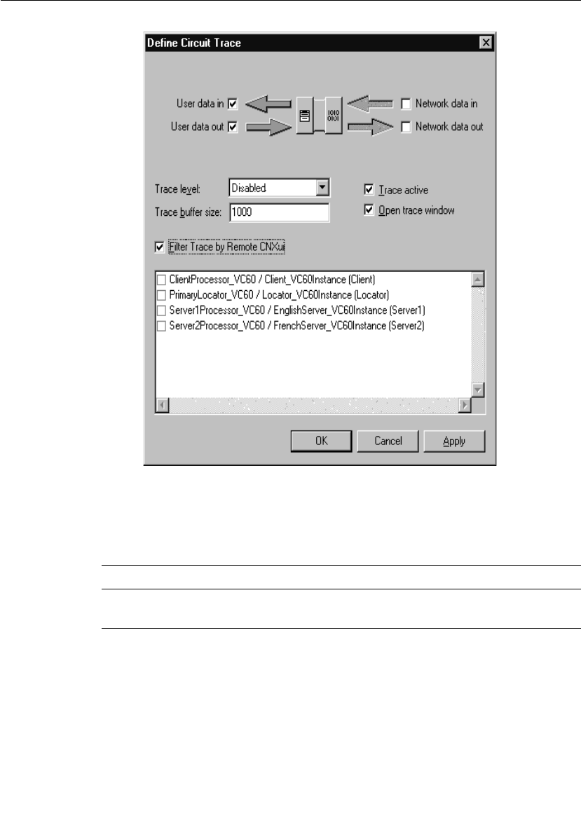
Chapter 7 Using the Connexis Viewer
190 User Guide - Rational Rose RealTime Connexis
Figure 89 Define Trace Dialog (Port reference)
3. Configure the trace reference settings according to Table 27.
Table 27 Trace location settings
Option Description
User data in Causes the tracing of incoming messages to occur after
the message data has been decoded.

Performing Event Tracing
User Guide - Rational Rose RealTime Connexis 191
Figure 90 shows what reference point is used for each of the four
options. If you encounter problems that you think may have been
caused by encoding or decoding, you can use tracing on user and
network data to ensure their accuracy.
Figure 90 User and Network data designations
Any combination of these checkboxes can be selected. Selecting all four
causes the messages to be traced before and after encoding for
outgoing messages, and before and after decoding for incoming
messages.
4. Configure the Trace Level setting according to Table 28.
5. Enter a number to specify the number of events that can be written
to the trace buffer in the Trace buffer size field.
6. Click the Trace Active box to apply the filter settings when you click
Apply or OK.
7. Click the Open Trace Window to open a trace window for this port
reference.
User data out Causes the tracing of outgoing messages to occur before
the message data has been encoded.
Network data in Causes the tracing of incoming messages to occur
before the message data has been decoded.
Network data out Causes the tracing of outgoing messages to occur after
the message data has been encoded.
Table 27 Trace location settings
Option Description

Chapter 7 Using the Connexis Viewer
192 User Guide - Rational Rose RealTime Connexis
8. Click the Filter Trace by Remote CNXui box if you want to specify the
remote component instances to be included in the trace. In the list
box, click on each component instance you wish to include.
Note: When disabled, trace data is gathered for all remote
component instances.
9. Click the OK button.
Defining a Virtual Circuit Trace
When performing a trace on a virtual circuit, you can specify where the
messages are traced, set the trace level, and the buffer size.
To define a virtual circuit trace:
1. Select the virtual circuit you wish to trace.
2. Right-click and select Define Trace from the popup menu.
The dialog box shown in Figure 91 appears.
Table 28 Trace location settings
Option Description
Disabled No tracing will be performed.
Activity Only traces that messages are being sent. The trace
event indicates both the local virtual circuit identifier
and the remote virtual circuit identifier but the actual
signal and message data are not traced.
Signal Only the message signal will be traced.
Signal and data Both the message signal and the message data will be
traced.

Performing Event Tracing
User Guide - Rational Rose RealTime Connexis 193
Figure 91 Define Trace Dialog (Virtual circuit)
3. Configure the trace reference settings according to Table 29.
For information on these trace reference points, refer to Figure 90.
Any combination of these checkboxes can be selected. Selecting all
four causes the messages to be traced before and after encoding for
outgoing messages, and before and after decoding for incoming
messages.
4. Configure the Trace Level setting according to Table 28.
5. Enter a number to specify the number of events that can be written
to the trace buffer in the Trace buffer size field.
Table 29 Trace location settings
Option Description
User data in Causes the tracing of incoming messages to occur after
the message data has been decoded.
User data out Causes the tracing of outgoing messages to occur before
the message data has been encoded.
Network data in Causes the tracing of incoming messages to occur
before the message data has been decoded.
Network data out Causes the tracing of outgoing messages to occur after
the message data has been encoded.

Chapter 7 Using the Connexis Viewer
194 User Guide - Rational Rose RealTime Connexis
6. Click the Trace Active box apply to the filter settings when you click
Apply or OK.
7. Click the Open Trace Window to open a trace window for this virtual
circuit.
8. Click the OK button.
Trace Window
The Trace window presents trace events formatted into columns. The
Trace Window automatically scrolls to show new trace events as they
arrive unless the scroll bar is not at the bottom. To pause scrolling,
click anywhere in the scroll region but the bottom. To resume scrolling,
drag the scroll bar to the bottom of the scroll region.
There are two types of trace windows available in the Connexis Viewer:
■Component instance trace windows.
■Virtual circuit trace windows.
Both types of trace windows provide the same function. They differ in
the type of information that is displayed in them.
Component Instance Trace Window
The component instance trace window is shown in Figure 92. It
contains four fields of information:
■Time - contains a timestamp of when the message was traced.
■Event - this is the trace type for this trace event.
Table 30 Trace location settings
Option Description
Disabled No tracing will be performed.
Activity Only traces that messages are being sent. The trace
event indicates both the local virtual circuit identifier
and the remote virtual circuit identifier but the actual
signal and message data are not traced.
Signal Only the message signal will be traced.
Signal and data Both the message signal and the message data will be
traced.
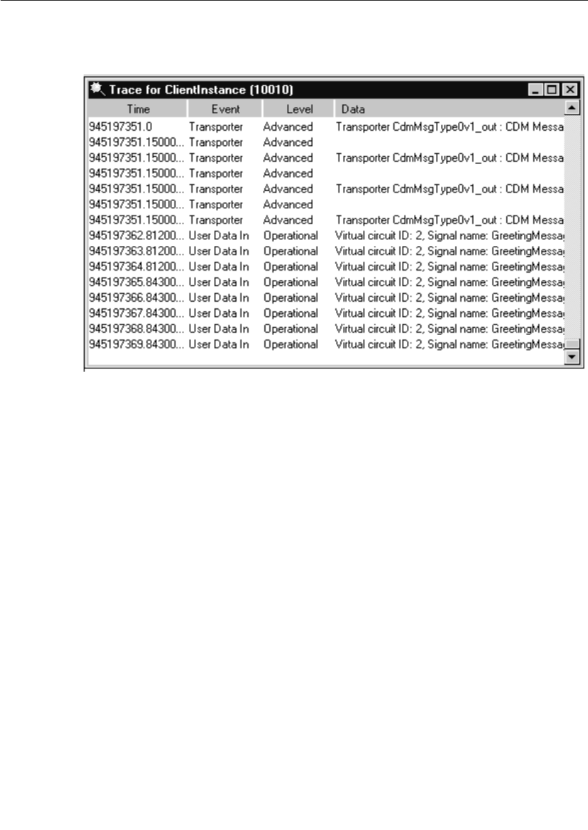
Trace Window
User Guide - Rational Rose RealTime Connexis 195
■Level - this is the level of the trace message.
■Data - this field contains the data that is associated with the trace.
Figure 92 The component instance trace window
Virtual Circuit Trace Window
The virtual circuit trace window is shown in Figure 93. It contains
seven fields of information:
■Time - contains a timestamp of when the message was traced
■Local Path - contains the Rose RealTime model path for the local
side of the virtual circuit
■<-> - contains either a --> or a <-- symbol, indicating the direction
in which the message was sent
■Remote Path - contains the Rose RealTime model path for the far
side of the virtual circuit if the Target Agent is running at the far
end; otherwise, the CNXui and the VCID are displayed
■Priority - corresponds to the message priority
■Signal - contains the message signal name if the Signal or Signal and
data trace level is specified
■Data - contains the message data if the Signal and data trace level is
specified
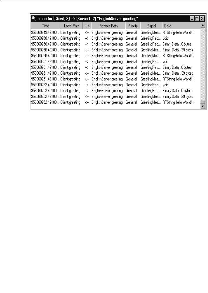
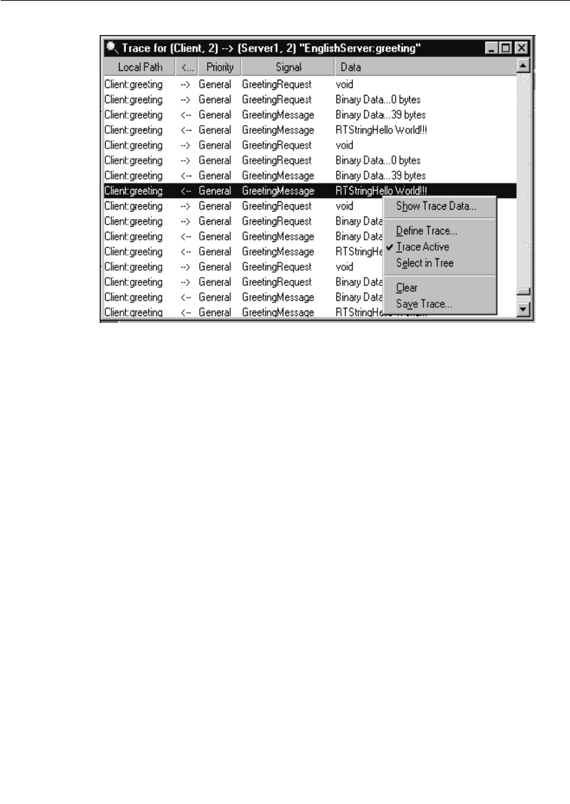
Trace Window
User Guide - Rational Rose RealTime Connexis 197
Figure 94 Trace window popup menu
Show trace data
This opens a trace data window onto the trace data field of the selected
event. The format of this window depends on whether the trace event
is a network or user-side trace event. Figure 95 shows an example of
the Trace Data window for ASCII data. Figure 96 shows an example of
the Trace Data window for binary (network) data.
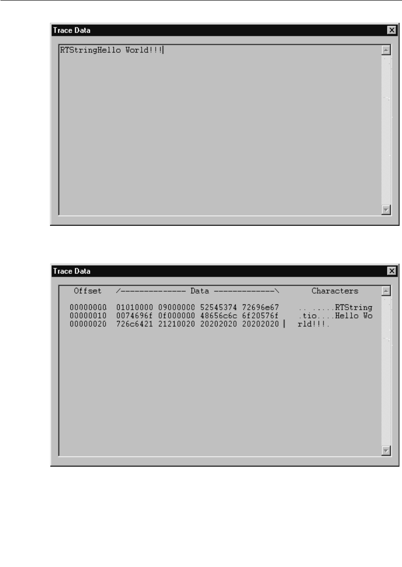
Chapter 7 Using the Connexis Viewer
198 User Guide - Rational Rose RealTime Connexis
Figure 95 The Trace Data Window with ASCII data
Figure 96 The Trace Data Window with binary data

Trace Window
User Guide - Rational Rose RealTime Connexis 199
Define trace
Selecting the Define Trace command opens the Define Trace Levels dialog
box. The content of this dialog box varies depending on the object being
traced. Table 31 lists the types of traces that can be performed in
Connexis and references the figures that display the Define Trace
options.
Trace active
The Trace Active command toggles on and off and is used to select
whether the Trace Data window should capture any new trace events.
If an inactive trace is set to active, it will reuse the values that were set
in the Define Trace dialog box.
Select in tree
Selecting the Select in Tree command causes the object being traced to
become active in the Explorer Tree View.
Clear
Selecting the Clear command clears the contents of the trace window.
Save trace
Selecting the Save Trace command brings up a Save As dialog which
allows you to save the current contents of the Trace window to a file.
There are two available 'formats' of trace output available. They are:
■Comma Delimited Trace (.cdTrace) which produces a simple
comma delimited line for each trace event
■Formatted Trace (.fmtTrace) which produces a (tag : value) multi-
line output for each trace event
Table 31 Types of Traces
Trace Type Figure
Component instance Figure 87, “Set Component Instance
Traces Levels dialog,” on page 183
Port reference Figure 89, “Define Trace Dialog (Port
reference),” on page 190
Virtual circuit Figure 91, “Define Trace Dialog (Virtual
circuit),” on page 193
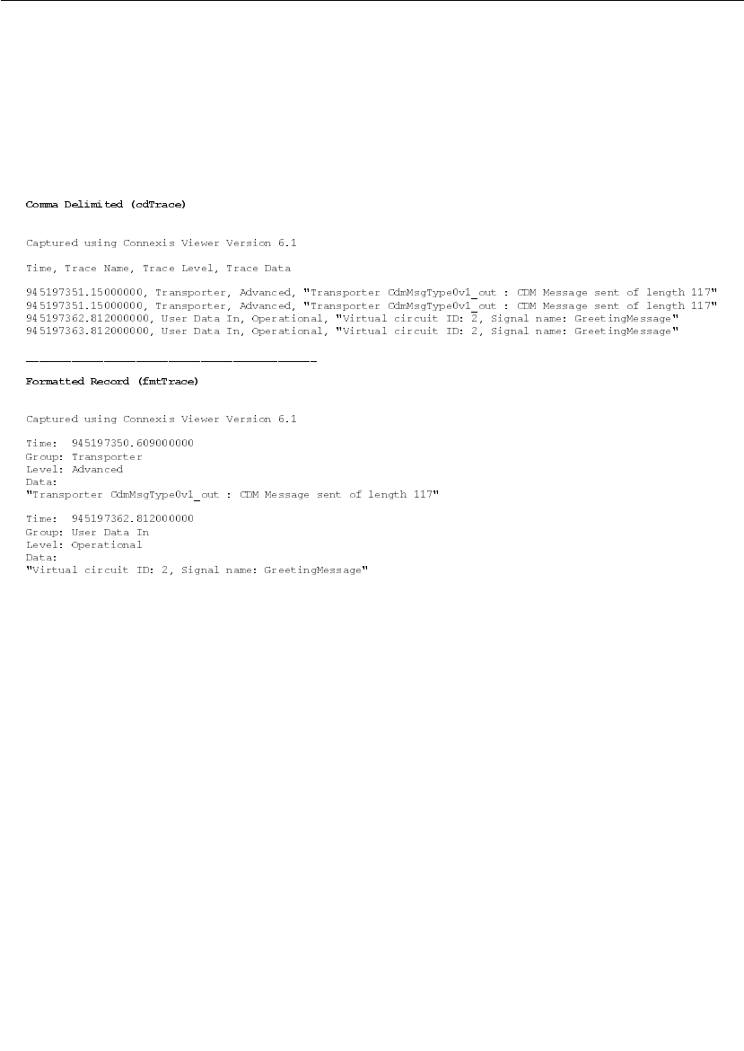
Chapter 7 Using the Connexis Viewer
200 User Guide - Rational Rose RealTime Connexis
Figure 97 shows a sample trace output for a virtual circuit. The top
portion shows the information when Comma Delimited is selected. The
bottom portion shows an example of the output when the Formatted
Trace option is selected.
Figure 97 Sample component trace output - Comma Delimited and
Formatted Record
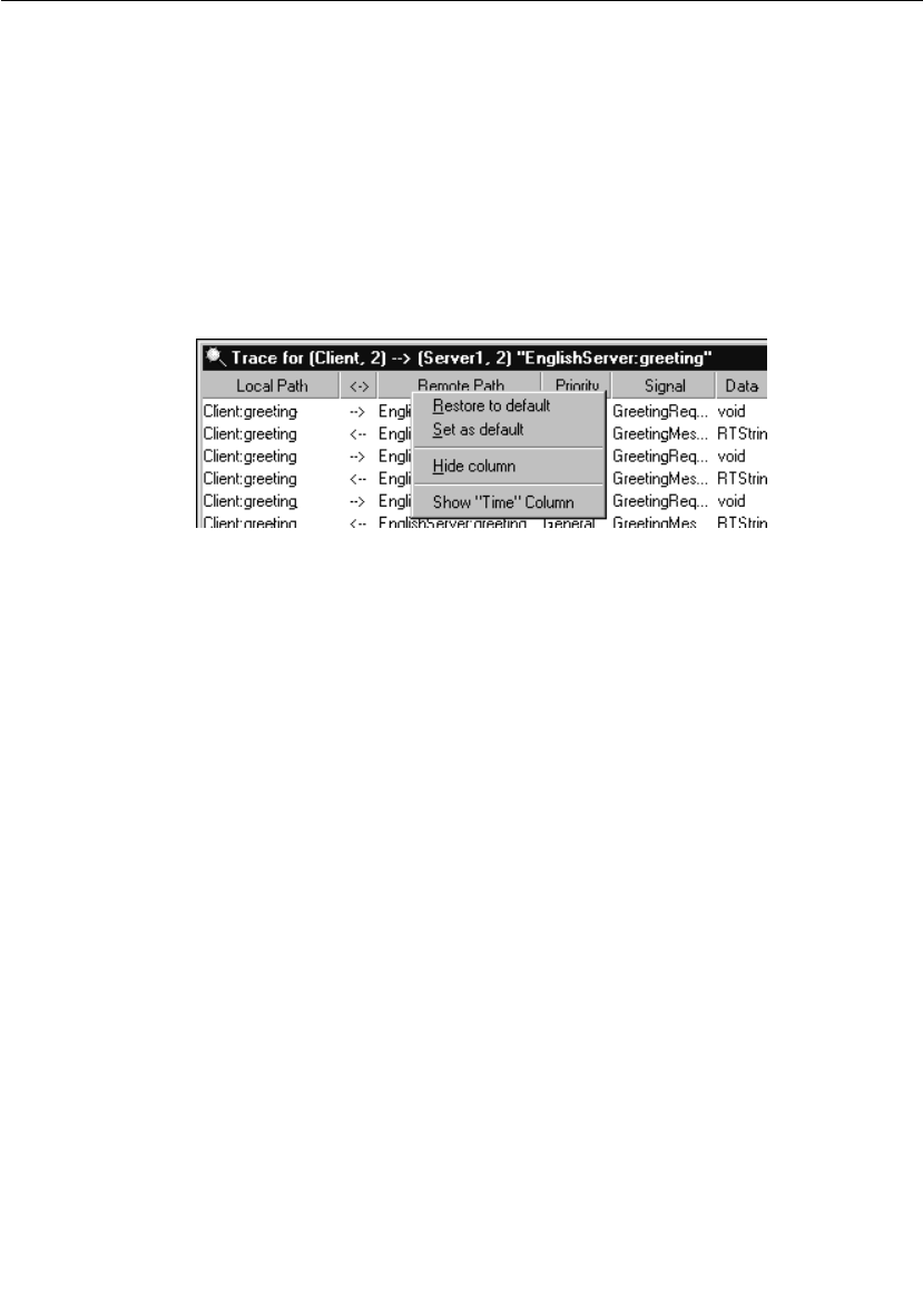
Trace Window
User Guide - Rational Rose RealTime Connexis 201
Trace Header Context Menu
There are times when it is desirable to define a custom layout for the
Trace Window columns. Connexis Viewer allows you to perform these
operations through a context menu that appears when you right-click
on the header control (see Figure 98) of a Trace Window.
When a new Trace Window is opened, it uses the current system
default information to determine the layout of the columns and the size
of the window. If you change the layout of an open Trace Window, this
information is saved and used the next time that the window is opened.
Figure 98 Trace Header Context menu
Selecting the Restore to default entry causes the Trace Window to revert
to the current default layout.
Selecting the Set as default causes the Trace Window's current layout to
become the new 'default' layout. Note that this will not affect windows
that are already open but will cause all newly-opened trace windows to
use this layout (unless they have been previously opened and modified
by the user).
Selecting the Hide column will cause the column the cursor is on to
become hidden (for example, in the image above, the Remote Path
column would become hidden. Note that you cannot hide the Data
column.
At the end of the menu, any currently hidden columns show up in the
format Show “<column name>” Column. Selecting one of these entries
will cause the (previously hidden) column to become visible again. The
column will re-appear at its previously defined width.

Chapter 7 Using the Connexis Viewer
202 User Guide - Rational Rose RealTime Connexis
Generating Interaction Diagrams from Trace Output Files
With Connexis, you can create interaction diagrams from trace output
files, generated from traces on a port reference or a virtual circuit. The
trace output files can be imported into a Rose RealTime model and
rendered into collaboration and sequence diagrams.
Before you generate interaction diagrams, use the Connexis Viewer to
perform an event trace on a port reference (see “Defining a Port
Reference Trace” on page 188) or a virtual circuit (see “Defining a
Virtual Circuit Trace” on page 192) and save the trace output to a file
(see “Save trace” on page 199).
To generate interaction diagrams:
1. Perform an event trace on a port reference or on a virtual circuit.
Ensure that the trace level is set to Signal or Signal and data.
2. Save the event trace information to file. The trace file can be
formatted or comma-delimited.
3. From the tree browser of the Rose RealTime application, right-click
the folder in which you want to save the collaboration and
sequence diagrams that will be generated.
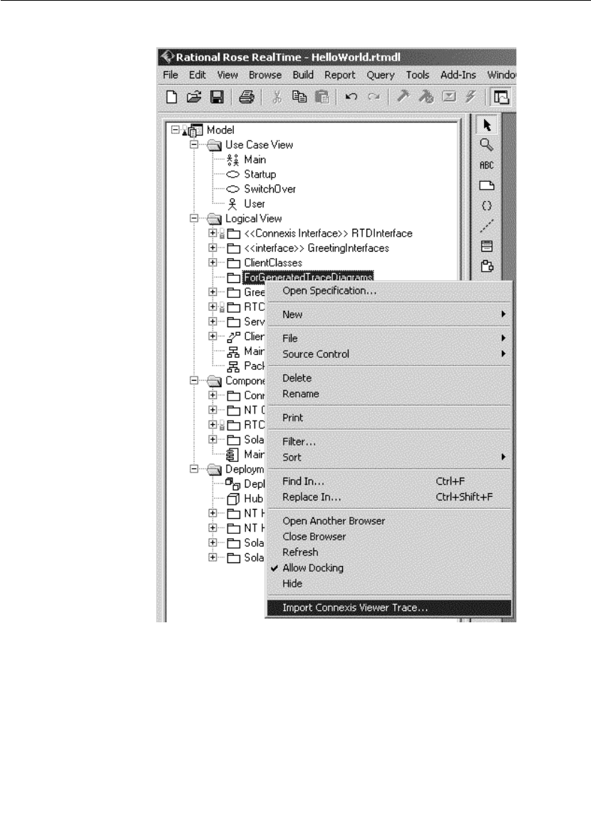
Generating Interaction Diagrams from Trace Output Files
User Guide - Rational Rose RealTime Connexis 203
Figure 99 Tree browser in Rose RealTime
4. Click Import Connexis Viewer Trace.
The Import Interaction Diagram dialog appears.
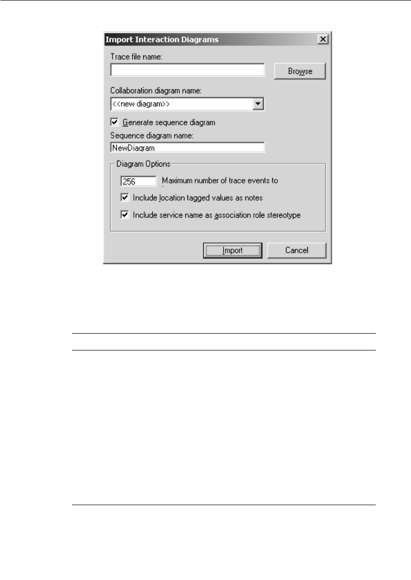
Chapter 7 Using the Connexis Viewer
204 User Guide - Rational Rose RealTime Connexis
Figure 100 Import Interaction Diagrams dialog
5. Complete the Import Interaction Diagrams dialog according to the
following table:
Table 32 Description of Import Interaction Diagrams dialog
Option Description
Trace file name Browse for the trace file that you stored.
This is the file that you will use to
generate your collaboration and
sequence diagrams.
Collaboration diagram
name
Type or select the name of the
collaboration diagram that you want to
generate.
Generate sequence
diagram
If you want to generate a sequence
diagram, ensure that this check box is
checked.
Sequence diagram name Type the name of the sequence diagram
that you want to create.

Generating Interaction Diagrams from Trace Output Files
User Guide - Rational Rose RealTime Connexis 205
6. Click the Import button.
The collaboration diagram and the sequence diagram (if enabled)
are generated. Once the generation process is complete, the
diagrams appear in the display area of Rose RealTime.
Note: If an error message occurs, see Reporting of error messages for
a detailed description of the message.
Maximum number of
trace events to
Type the maximum number of trace
events that you want represented in your
sequence diagrams. A maximum number
of 256 can be selected.
Include location tagged
values as notes
If you want to include location tagged
values as notes on the collaboration
diagram, ensure that this check box is
selected.
Include service name as
association role stereotype
If you want to include the service name
that was used to establish the binding as
the association role’s stereotype, ensure
that this check box is checked.
Table 32 Description of Import Interaction Diagrams dialog
Option Description

Chapter 7 Using the Connexis Viewer
206 User Guide - Rational Rose RealTime Connexis
Reporting of error messages
While generating interaction diagrams, you may receive an error
message that provides feedback about the process. The following chart
lists and explains the error messages:
Log Window
The log window displays the status of the connections in the executing
model.
Each message is preceded by a timestamp in square brackets. This
timestamp indicates the time that the message was received by the
Viewer. Icons indicate the type of message as summarized in Table 33.
A sample log window output is shown in Figure 101.
Error Message Description
Unknown file format The file specified in the Trace file name
text field is not an acceptable file format.
Acceptable file formats are .cdTrace
(comma delimited) or .fmtTrace
(formatted). The file formats with the
.cdTrace and the .fmtTrace extensions,
identify the type of trace file to be
processed.
Unable to process trace
file because it is
incompatible with the
current version of the
toolset add-in
The imported trace file has been
generated by an earlier version of the
Rational Connexis Viewer. The file format
is incompatible with the format accepted
by the toolset add-in. Import trace files
must be generated by Rational Connexis
version 2001A.04.00 or newer.
Invalid file format The user has modified the file or an error
occurred while the Connexis Viewer was
attempting to write the file.
Cannot process more than
256 trace events
An attempt has been made to configure
the tool to import more trace events than
the feature can support.
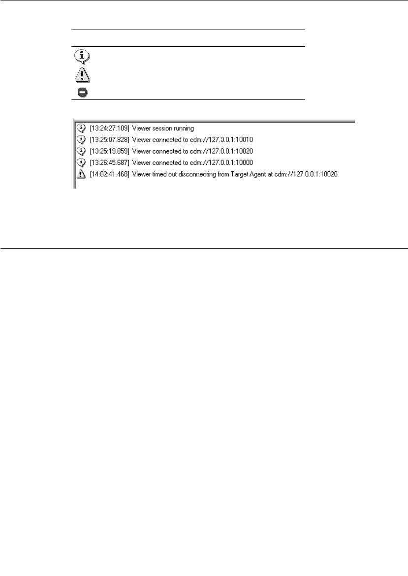
Displaying the Metrics Collection
User Guide - Rational Rose RealTime Connexis 207
Figure 101 The log window
Displaying the Metrics Collection
Metrics is a Connexis Viewer function that lets you start, display and
save statistics collected on a component instance. Once metrics
gathering is enabled on a Connexis library, statistics are collected on
internal run-time operations and registered transports, active in the
model.
A Connexis library that is enabled to gather metrics, collects statistics
on its internal run-time operations and on any registered transport
that are active in the model.
Internal run-time operations include:
■Creating and auditing circuits
■Encoding and decoding messages
■Publishing and subscribing to services
Transport statistics include:
■Totals on the number and the size of message sent and received
■Minimum and maximum sizes of the message payloads
■Number of messages sent with and without data
■Breakdown of application-level versus control message sent
Table 33 Log window icons
Icons Meaning
normal messages
warning messages
error messages

Chapter 7 Using the Connexis Viewer
208 User Guide - Rational Rose RealTime Connexis
Note: All transports supplied with Connexis reports these statistics.
Transports built using the Transport Integration Framework must use
the API supplied by Connexis to gather transport-specific statistics at
run-time. For a complete discussion of this topic, see “Using the
Transport Integration Framework” on page 299.
Starting Metrics Collection
Metrics gathering is designed to have the smallest possible impact on
performance. The Viewer connects to the component instance and
request statistics on a running model that has metrics enabled in the
DCS library, and the CDM transport registered.
When the Viewer connects to the component instance, it sends a
request to start gathering metrics and requests a reporting rate (see
“Adding a Component Instance” on page 177). The component instance
tells the Viewer what reporting rate it supports, describes the
registered transports, and reports statistics at the appropriate interval.
To collect metrics on a component instance:
1. Right-click the component instance on which you want to collect
statistics. A popup window appears.
2. Select from the list. The Metrics window
appears with the name of the component instance in the title bar.
3. Select the tab containing the information that you require (see
“Using the Metrics Window” on page 208).
Using the Metrics Window
The Metrics window displays statistics collected on the internal run-
time operations and registered transports of a component instance.
You can access metrics information from the following window tabs.
Table 34 Metrics Window tabs
Metrics window tabs Description
Summary “Summary metrics collection” on
page 210
Detailed “Detailed metrics collection” on page 214
Messages “Messages metrics collection” on
page 216

Displaying the Metrics Collection
User Guide - Rational Rose RealTime Connexis 209
Audits “Stopping Metrics Collection” on page 234
Engineering “DCS errors metrics collection” on
page 225
DCS Errors “DCS errors metrics collection” on
page 225
App Errors “Application errors metrics collection” on
page 228
App Incompatibility “Application incompatibility metrics
collection” on page 232
Table 34 Metrics Window tabs
Metrics window tabs Description
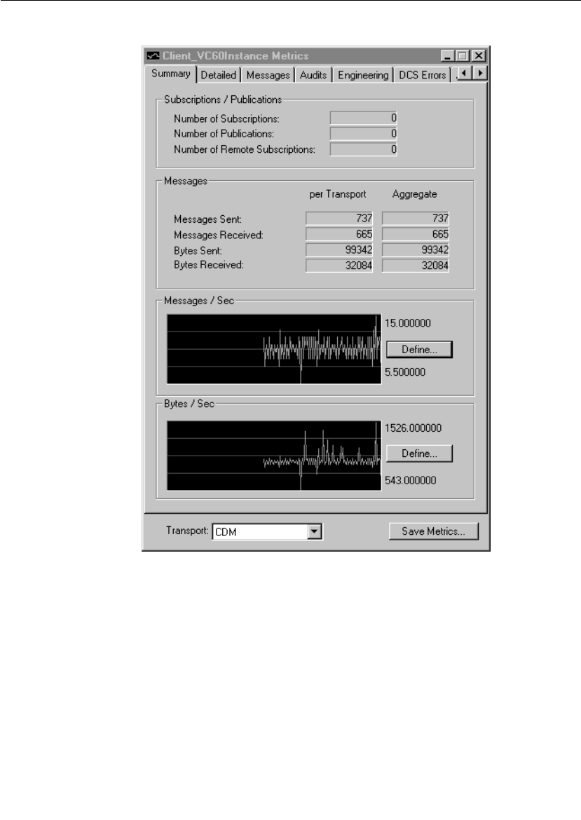
Chapter 7 Using the Connexis Viewer
210 User Guide - Rational Rose RealTime Connexis
Summary metrics collection
Figure 102 Metrics Window: Summary Information
Table 35 Subscriptions/Publications

Displaying the Metrics Collection
User Guide - Rational Rose RealTime Connexis 211
Defining Messages/Sec and Bytes/Sec
From the Summary page of the Metrics dialog, you can set the way
strip chart information is displayed in the Messages/Sec and the
Bytes/Sec area. The Messages/Sec area displays the number of
messages sent from the component instance per second. The
Bytes/Sec area displays the number of bytes sent from the component
instance per second.
Message Type Description
Number of Subscriptions The total number of subscriptions that
have been registered locally, registered
explicitly, registered globally through the
locator, and the number of remote
subscriptions that have been registered to
publications in the Component Instance.
Number of Publications The total number of local and global
publications registrations.
Number of Remote
Subscriptions
The number of registrations from remote
subscriptions.
Table 36 Messages
Message Type Description
Messages Sent Successfully sent user application
messages with signal and data, including
message data. These messages require a
buffer to be send.
Messages Received User application messages with signal
and data received. These messages may
or may not be passed to the application
successfully and the application was
unable to decode the message.
Bytes Sent Total number of bytes sent on the
transport. Includes audit, control and
user messages.
Bytes Received Total number of bytes received on the
transport. Includes audit, control and
user messages.
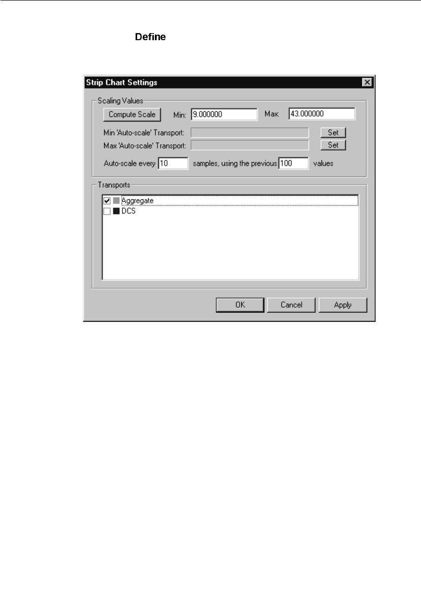
Chapter 7 Using the Connexis Viewer
212 User Guide - Rational Rose RealTime Connexis
To change the way chart settings are presented:
1. Click the button in the Messages/Sec or the Bytes/Sec area.
The “Strip Chart Settings” dialog appears.
Figure 103 Strip Chart Settings dialog

Displaying the Metrics Collection
User Guide - Rational Rose RealTime Connexis 213
Table 37 Strip Chart Settings
Settings Description
Compute Scale Clicking analyses the
strip chart and determines the
minimum and the maximum values.
Note: To manually set the Compute Scale
values without have them overridden, set
to zero.
Min ‘Auto-scale’ Transport Lets you set the transport that you want
the strip chart to use for the minimum
auto-scale value. Before setting the
minimum auto-scale value, select the
transport from the selection
area.
Max ‘Auto-scale’
Transport
Lets you set the transport that you want
the strip chart to use for the maximum
auto-scale value. Before setting the
maximum auto-scale value, select the
transport from the selection
area.
Auto-scale every This sets the number of samples
received from the transport before the
script chart calculates the result and
presents the information.
Using the previous values This sets the number of previous values
that the strip chart uses to calculate the
result.
Transports This area displays the transports
available for use.
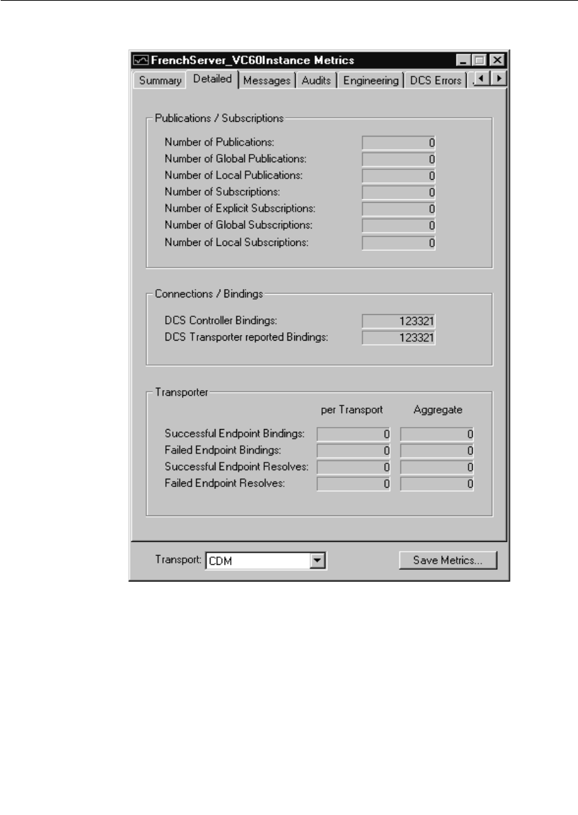
Chapter 7 Using the Connexis Viewer
214 User Guide - Rational Rose RealTime Connexis
Detailed metrics collection
Figure 104 Metrics Window: Detailed Information

Displaying the Metrics Collection
User Guide - Rational Rose RealTime Connexis 215
Table 38 Publications/Subscriptions
Message Type Description
Number of Publications Total number of Publications.
Number of Global
Publications
Total number of global SPP registrations.
Number of Local
Publications
Total number of local SPP registrations.
Number of Subscriptions Total number of Subscriptions.
Number of Explicit
Subscriptions
Total number of explicit SAP
registrations.
Number of Global
Subscriptions
Total number of global SAP registrations.
Number of Local
Subscriptions
Total number of local SAP registrations.
Table 39 Connections/Bindings
Message Type Description
DCS Controller Bindings Total number of SAP/SPP bindings.
DCS Transport reported
Bindings
Number of ports successfully bound. This
includes both SAP and SPP ports. This
count may include duplicate binds if the
underlying transport is lost and control
messages have to be resent.
Table 40 Transporter
Message Type Description
Successful Endpoint
Bindings
Number of successful transport binds.
Failed Endpoint Bindings Number of transport bind failures.
Successful Endpoint
Resolves
Number of addresses resolved
successfully.
Failed Endpoint Resolves Number of address resolve failures.
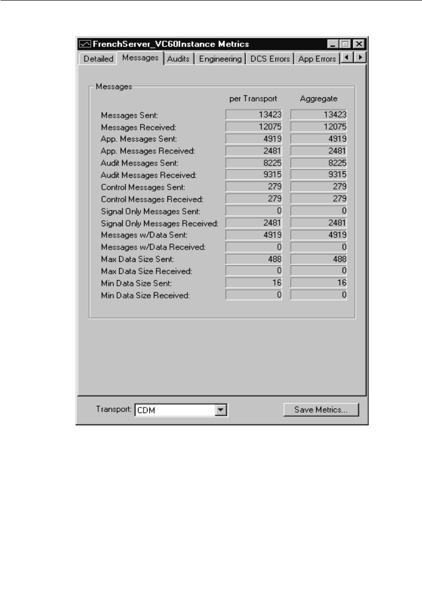
Chapter 7 Using the Connexis Viewer
216 User Guide - Rational Rose RealTime Connexis
Messages metrics collection
Figure 105 Metrics Window: Messages

Displaying the Metrics Collection
User Guide - Rational Rose RealTime Connexis 217
Table 41 Messages
Message Type Description
Messages Sent Connect, register registered, etc.
Messages Received Connect, register registered, etc.
Application Messages
Sent
The total number of message sent by the
application. This count includes those
messages sent with data and with signal
only.
Application Messages
Received
The total number of message received by
the application. This count includes those
messages received with data and with
signal only.
Audit Messages Sent Are You Alive, I Am Alive and You Are Not
Responsive messages sent.
Audit Messages Received Are You Alive, I Am Alive and You Are Not
Responsive messages received.
Control Messages Sent Connect, register registered, etc.
Control Messages
Received
Connect, register registered, etc.
Signal Only Messages
Sent
User application messages consisting
only of a successfully sent signal.
Signal Only Messages
Received
User application messages consisting
only of a signal that was received. These
messages may or may not be passed to
the application successfully (for example,
incompatible with protocol).
Messages with Data Sent Successfully sent user application
messages with signal and data, including
message data. These messages require a
buffer to be send.
Messages with Data
Received
User application messages with signal
and data received. These messages may
or may not be passed to the application
successfully and the application was
unable to decode the message.

Chapter 7 Using the Connexis Viewer
218 User Guide - Rational Rose RealTime Connexis
Maximum Data Size Sent Size of the largest encoded data object
successfully sent. This information in
conjunction with EncodeExceedsMaxSize
helps you engineer the size of the larger
buffers in the buffer pool.
Maximum Data Size
Received
Size of the largest encoded data object
received.
Minimum Data Size Sent Size of the smallest encoded data object
successfully sent. This helps you engineer
what is the size of the smaller buffers
needed in the buffer pool. It also helps
you decide setting of CNXtfms.
Minimum Data Size
Received
Size of the smallest encoded data object
successfully received.
Table 41 Messages
Message Type Description

Displaying the Metrics Collection
User Guide - Rational Rose RealTime Connexis 219
Audits metrics collection
Figure 106 Metrics Window: Audits Information

Chapter 7 Using the Connexis Viewer
220 User Guide - Rational Rose RealTime Connexis
Table 42 Circuits
Message Type Description
Virtual Circuit Audits
Sent
Total number of virtual circuit audits
sent.
Virtual Circuit Audits
Received
Total number of virtual circuit audits
received.
Virtual Circuit Audit
Failures
Total number of virtual circuits removed
due to unacknowledged audits.
Circuit Errors Detected by
Audit
Total number of invalid virtual circuits
removed due to audits.
Table 43 Messages
Message Type Description
Out of Service (Audit
Failure)
Number of times an endpoint went out of
service (CDM did not get IAA responses).
In Service (Audit Failure) Number of times an endpoint went back
into service after an Audit unresponsive
failure.
Audit Resets Detected Number of times an endpoint went out of
service and then back into service after
detecting that the other side has gone
away and come back. Applies to CDM
only.
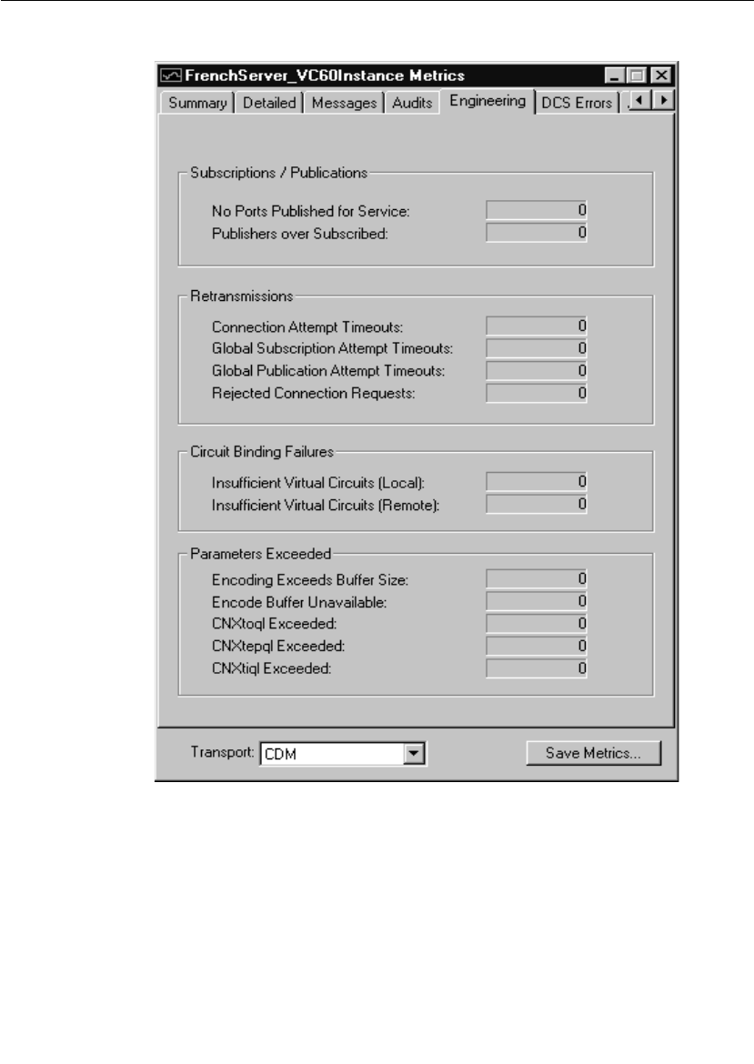
Displaying the Metrics Collection
User Guide - Rational Rose RealTime Connexis 221
Engineering metrics collection
Figure 107 Metrics Window: Engineering Information

Chapter 7 Using the Connexis Viewer
222 User Guide - Rational Rose RealTime Connexis
Table 44 Subscription/Publications
Message Type Description
No Ports Published for
Service
Number of times SAPs could not bind to
an SPP because no SPP was registered for
that service.
Publications over
Subscribed
Number of times SAPs could not bind to
an SPP because the SPPs were all fully
bound.
Table 45 Retransmissions
Message Type Description
Connection Attempt
Timeout
Total number of virtual circuit
establishment retries.
Global Subscription
Attempt Timeout
Total number of global SAP locator
registration retries.
Global Publication
Attempt Timeout
Total number of global SPP locator
registration retries.
Rejected Connection
Requests
The number of times retrying a connect
request resulted in more than one virtual
circuit being setup. The ConnectSuccess
received is rejected, allowing the other
side to terminate the additional circuit.
Table 46 Circuit Binding Failures
Message Type Description
Insufficient Virtual
Circuits (Local)
Total number of times a SAP failed to
register because a free virtual circuit was
not available on the client-side of a
connection.
Insufficient Virtual
Circuits (Remote)
Total number of times a SAP failed to
register because a free virtual circuit was
not available on the server-side of a
connection.

Displaying the Metrics Collection
User Guide - Rational Rose RealTime Connexis 223
Table 47 Parameters Exceeded
Message Type Description
Encoding Exceeds Buffer
Size
Number of times encoding an outgoing
message failed. This occurs because a
large enough buffer is not available. If any
overridden encode function on one of the
classes that describes the type being sent
(i.e. attribute classes) returns 0, this
results in a failure as well. Message is not
sent.
Encode Buffer
Unavailable
Number of times a buffer, of a suitable
size to encode the message, was
unavailable. All messages are encoded to
a buffer before sending. This error may
occur if the message is very large and
there is no buffer available that can
accept the payload. Blocking transports
such as CRM also use this pool to buffer
message sends while the transport is
busy. If the transport becomes
overloaded, message sends are buffered
until there are no further buffers in the
pool. Consider increasing the number of
buffers in the transport pool using the -
CNXtbp parameter. Message is not sent.

Chapter 7 Using the Connexis Viewer
224 User Guide - Rational Rose RealTime Connexis
CNXtoql Exceeded The number of times the output queue
limit is exceeded. Examine the CNXtoql
parameter setting. The setting needed
dependent on CNXtepql and the number
of endpoints in use and number of host
names being resolved (for CDM). If this
only occurs during connection
establishment and you also see the
Connections rejected later, increase the
retry delay. It could be due to retrying
connects before the hostname can be
resolved. If you have a highly replicated
non-published unwired port doing
automatic registration (i.e. a large
number of SAP registrations going on at
once), consider staggering the startup
load on the system. Message is not sent.
CNXtepql Exceeded The number of times the endpoint queue
limit is exceeded. Examine the CNXtepql
parameter setting. The setting needed is
dependent on the maximum number of
messages to be queued for an end point.
If you increase this, examine the CNXtoql
parameter setting as well. If this occurs
during connection establishment, see the
CNXtoqlExceeded description as well.
Message is not sent.
CNXtiql Exceeded The number of times the input queue
limit is exceeded. Examine the CNXtiql
parameter. It can be used to prevent
Connexis from being swamped. Message
is not received.
Table 47 Parameters Exceeded
Message Type Description
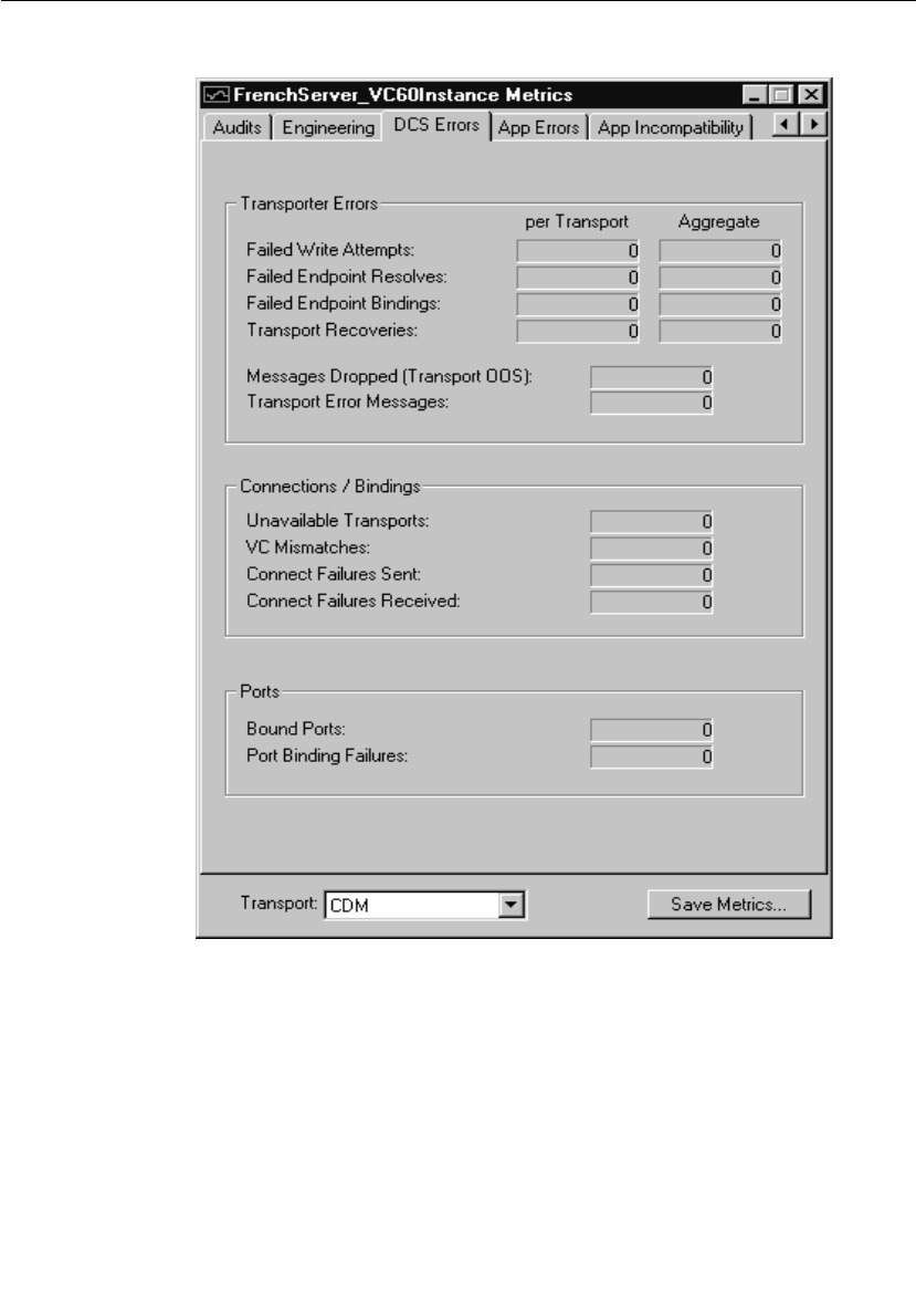
Displaying the Metrics Collection
User Guide - Rational Rose RealTime Connexis 225
DCS errors metrics collection
Figure 108 Metrics Window: DCS Errors Information

Chapter 7 Using the Connexis Viewer
226 User Guide - Rational Rose RealTime Connexis
Table 48 Transport Errors
Message Type Description
Failed Write Attempts Number of times the send of a message
failed on the write (CDM failed on the
write). Message not sent.
Failed Endpoints Resolves Number of host name resolve failures.
Failed Endpoints Bindings Number of transport bind failures.
Transport Recoveries Number of times a transport is brought
back into service after an audit has failed.
Messages Dropped
(Transport OOS)
Number of queued messages sent to an
endpoint after the audit has determined
that it has gone out of service.
Transport Error Messages Number of times the controller sent the
transport error message.
Table 49 Connections/Bindings
Message Type Description
Unavailable Transports The number of times an attempt to use an
unavailable transport was made. Message
is not sent/received.

Displaying the Metrics Collection
User Guide - Rational Rose RealTime Connexis 227
VC Mismatches Number of times the virtual circuit
information contained in a request does
not match the current virtual circuit
setup. Typically occurs during transport
failures or after user applications have
failed and restarted. The SAP or SPP that
was previously being communicated
which is no longer available (may be
participating in another connection or is
released). The Circuit Audit cleans up
these situations. Message not
sent/received.
Connect Failures Sent Number of ConnectFailure responses sent
in response to connect messages received.
No virtual circuit is established. The
reason for failing such a request is due to
no further virtual circuits being available.
Connect Failures Received Number of ConnectFailures received in
response to connect messages sent. A
virtual circuit could not be setup on the
other endpoint.
Table 50 Ports
Message Type Description
Bound Ports Number of ports successfully bound. This
includes both SPP and SAP ports and
may include duplicate binds. For
example, a bind may occur twice for the
same port if dealing with a lost transport
(control messages are re-sent), or if user
data messages over-take control
messages.
Port Binding Failures Number of times binding a port failed.
User messages are not be able to be
exchanged through the port.
Table 49 Connections/Bindings
Message Type Description
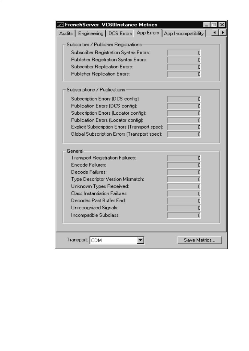
Chapter 7 Using the Connexis Viewer
228 User Guide - Rational Rose RealTime Connexis
Application errors metrics collection
Figure 109 Metrics Window: Application Errors Information

Displaying the Metrics Collection
User Guide - Rational Rose RealTime Connexis 229
Table 51 Subscriber/Publisher Registrations
Message Type Description
Subscriber Registration
Syntax Errors
Number of times a SAP failed to register
because its registration string had invalid
syntax.
Publisher Registration
Syntax Errors
.Number of times a SPP failed to register
because its registration string had invalid
syntax.
Subscriber Replication
Errors
Number of times a SAP failed to register
because its replication factor was zero.
Publisher Replication
Errors
Number of times a SAP failed to register
because its replication factor was zero.
Table 52 Subscription/Publications
Message Type Description
Subscription Errors (DCS
config)
Number of times a SAP failed to register
because DCS was not configured
correctly.
PublicationErrors (DCS
config)
Number of times a SPP failed to register
because DCS was not configured
correctly.
Subscription Errors
(Locator config)
Number of times a SAP failed to register
globally because the locator was not
configured.
Publication Errors
(Locator config)
Number of times a SPP failed to register
globally because the locator was not
configured.
Explicit Subscription
Errors (Transport spec)
Number of times an SAP failed to register
explicitly (for example,
registerSAP(“dcs:<transport>//<host>:<p
ort>/<service>”)) using a transport
protocol because the transport was not
properly configured.
Global Subscription
Errors (Transport spec)
Number of times a SAP failed to register
globally (for example,
registerSAP(“dcs:/<service>”)) using a
transport protocol because the transport
was not properly configured.

Chapter 7 Using the Connexis Viewer
230 User Guide - Rational Rose RealTime Connexis
Table 53 General
Message Type Description
Transport Registration
Failures
The number of times an attempt to use an
unavailable transport was made. Message
is not sent or received.
Encode Failures Number of times the encoding of an
outgoing message failed. This can occur
when there was no buffer large enough to
encode the payload, or the overridden
encode function returned 0. Message is
not sent.
Decode Failures Number of times the decoding of an
incoming message failed.
Type Descriptor Version
Mismatch
Number of times the version of the
sender’s class does not match the version
expected in the receiver. You can specify
the version of a class in its C++
TargetRTS property tab. Only the version
of the class being sent is considered. The
version(s) of its attributes are not.
Message is not received.
Unknown Types Received Number of times the sender’s class is not
known in the receiver’s application. This
can occur if the sender and receiver are in
two different models (different .rtmdl
files). If so, then the protocol and class
being sent must be shared between the
models. This failure can also occur if the
class is not referenced anywhere in the
receiver’s model, and so is not compiled.
Message not received.
Class Instantiation
Failures
The number of times the receiver failed to
create the class to be received. There may
be a problem with the default or
overridden allocation method for the type
descriptor of the class. Message not
received

Displaying the Metrics Collection
User Guide - Rational Rose RealTime Connexis 231
Decodes Past Buffer End Number of times Connexis read past the
end of the encoded data while decoding
an incoming message. Check that the
encode and decode methods in the type
descriptors match exactly on the sender
and receiver side. Message not received
Unrecognized Signals Number of times the signal received is not
recognized as valid on the receiver’s
protocol. Verify that the protocols used in
the sender and receiver are compatible,
and properly conjugated. Message not
received.
Incompatible Classes The number of times the data type
received with a signal is not a compatible
subclass of the type that has been defined
by the protocol. Verify that the protocols
used in the sender and receiver are
compatible and properly conjugated.
Message not received.
Table 53 General
Message Type Description
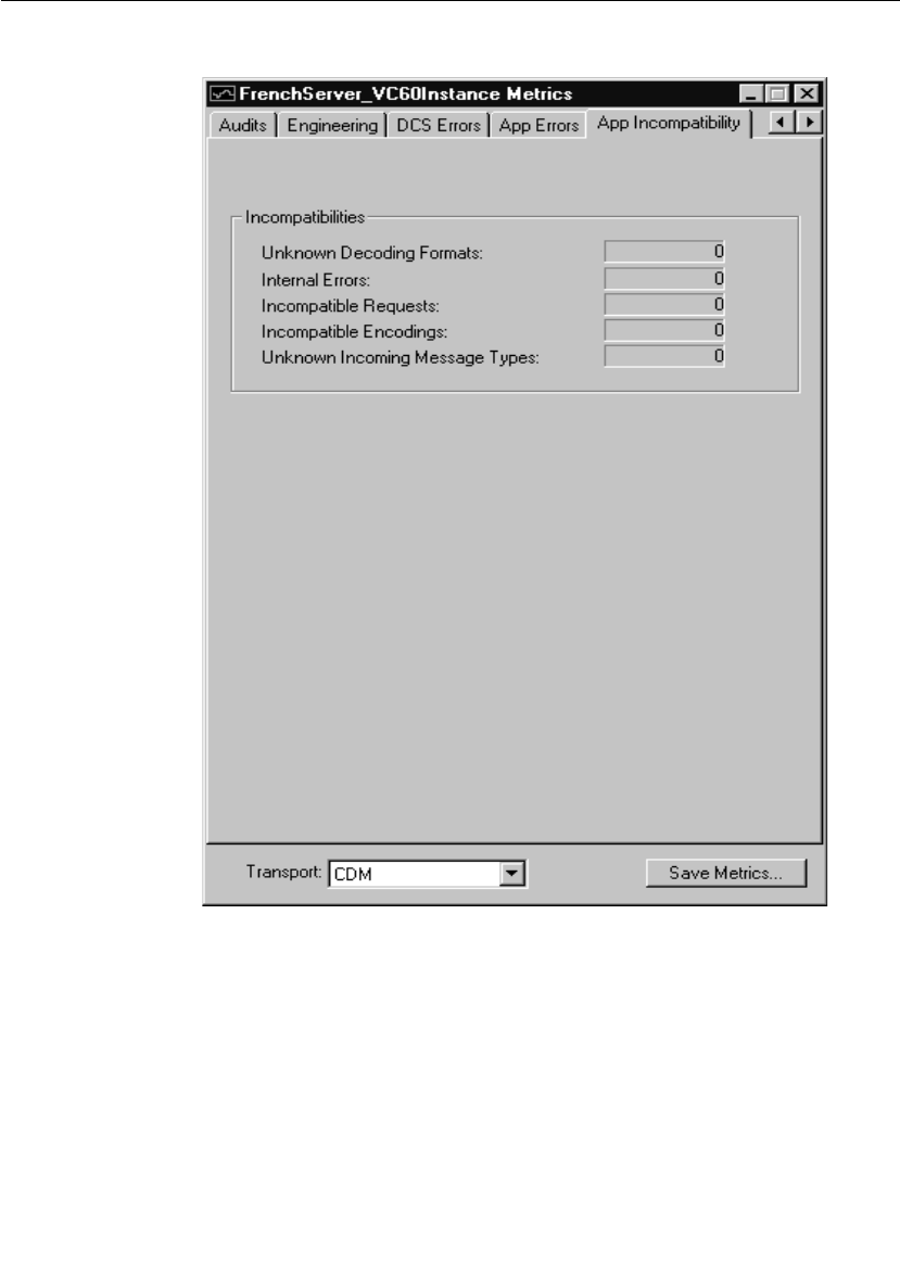
Chapter 7 Using the Connexis Viewer
232 User Guide - Rational Rose RealTime Connexis
Application incompatibility metrics collection
Figure 110 Metrics Window: Application Incompatibility Information

Displaying the Metrics Collection
User Guide - Rational Rose RealTime Connexis 233
Table 54 Incompatibilities
Message Type Description
Unknown Decoding
Formats
Number of times the data received was
encoded in an unknown format.
Internal Errors Number of times Connexis internal
processes cannot process the message
(can be user message or control message).
Message is not sent.
Incompatible Requests Number of times unknown control
messages were received.
This will not happen if all applications are
running with Connexis release 6.1.1.
Future Connexis releases may support
additional control requests not supported
by Connexis 6.1.1. Connexis informs the
message sender so that a common
request interface can be used. See your
user guide for that Connexis release.
Connexis 6.1.1 can not inter-operate with
applications using an earlier Connexis
release. Message is not received.
Incompatible Encoding This will not happen if all applications are
running with Connexis release 6.1.1.
Future Connexis releases may support
enhanced existing encoding formats that
are not supported by Connexis 6.1.1.
Connexis informs the message sender so
that a common version of encoding can be
used. See your user guide for that
Connexis release. Connexis 6.1.1 can not
inter-operate with applications using an
earlier Connexis release. Message is not
received.
Unknown Incoming
Message Types
The number of times the incoming
message was of an unknown type.

Chapter 7 Using the Connexis Viewer
234 User Guide - Rational Rose RealTime Connexis
Stopping Metrics Collection
Closing the metrics collection window stops metrics reporting on the
selected component instance.
To stop collecting Metrics:
1. Click the button on the top right corner of the window.
Saving Collected Metrics
Once you start collecting metrics on a component instance, you could
save the statistics for further analysis. Metrics statistics are saved in a
tab-separated format that can be imported directly into popular
spreadsheet programs.
To save collected metrics:
1. Click the button.
2. Type the name of the file you want to save in the “Save Metrics As”
dialog box. The file is saved as a ComponentInstanceMetrics
(CIMetrics) file. You can open this file a spreadsheet application
like Microsoft Excel or in any text application.
Viewer Tips and Usage Notes
This section provides some tips and usage notes to make it easier to
use the Connexis Viewer:
■Capturing Pre-Viewer Session Messages
■Error and Warning Tracing
■Maximizing Viewer Responsiveness
Capturing Pre-Viewer Session Messages
It is possible to capture traces before a target session is established.
The CNXaas parameter will enable the following trace events:
■controller
■locator
■transporter
■component-wide tracing for all data sent to, and received from, all
unwired DCS ports

Viewer Tips and Usage Notes
User Guide - Rational Rose RealTime Connexis 235
■any errors or warnings
Note: In this mode, only the signal, data, and virtual circuit are
indicated.
Error and Warning Tracing
Connexis Viewer provides capabilities for tracing and filtering software
errors and warnings.
Software errors
Software errors are used to indicate anomalous conditions that prevent
user data from being transported. Software errors are filtered on a
component instance basis, that is, across all functional groups.
There are many causes of software errors. These include:
■Resource depletion, for example, running out of virtual circuits
■Application registration errors, for example, syntax errors in
registration string
■Internal Connexis errors, for example, unexpected message type
processed by a DCS Capsule, initialization errors
■messages being discarded due to type mismatches (on input)
Software warnings
Software warnings are used to indicate conditions that will prevent
Connexis from operating as configured or that can potentially lead to
user data being lost. For example, an unexpected message or an
unknown message type may cause a software warning.
Maximizing Viewer Responsiveness
Under heavy load, you may sometimes notice that the Viewer becomes
unresponsive, that is, right-clicking does not immediately bring up the
context menu. This occurs especially if there are many components
running 'locally', on the same CPU as the Viewer.
To remedy this situation, use the Task Manager to set the Priority of the
Viewer to High as follows:
1. Right click on the Taskbar and select Task Manager.

Chapter 7 Using the Connexis Viewer
236 User Guide - Rational Rose RealTime Connexis
2. In the Processes tab of the Task Manager, right click on the
ConnexisViewer entry.
3. Use the Set Priority menu item to set the Viewer's priority to High.
Note: If the Viewer is still unresponsive, you can try to reduce the
Viewer load by closing trace windows that you do not need to have
open.

User Guide - Rational Rose RealTime Connexis 237
Chapter 8
Using the Connexis Metrics Service
Rational Connexis provides capabilities to collect real-time DCS
metrics information within an executing Rose RealTime model. You can
collect and report metrics on each running component instance. The
DCS performance information that is collected by the DCS metrics
service can be used to tune the DCS command line options.
Metrics services are only available within DCS library components that
have been compiled with metrics collection capabilities enabled. At
run-time, metrics data can be obtained from within a Connexis
enabled model by subscribing to the metrics service. Although you can
subscribe to the metrics service at anytime, you will not be connected
to the metrics service until the service is published within the DCS
layer.
Obtaining Metrics Data with a Metrics Service
The following sections explain how to collect metrics from a Connexis
component instance at runtime.
■Enabling Metrics in the DCS library
■Adding a Metrics Port
■Subscribing to the Metrics Service
■Collecting and Processing Metrics

Chapter 8 Using the Connexis Metrics Service
238 User Guide - Rational Rose RealTime Connexis
Enabling Metrics in the DCS library
The DCS libraries installed with Connexis are metrics-enabled by
default. If you re-build your DCS library, make sure that the metrics
service is enabled. For more information on how to configure your
libraries, see “Customizing and Porting DCS Libraries” on page 289.
Adding a Metrics Port
Before you can interact with the Connexis metrics service, you must
add a metrics port to the capsule in your model. You can add a metrics
port manually or a the Connexis Capsule Configuration Tool.
To add a metrics port manually:
1. Open your model and ensure that the DCS model interface
packages are shared (see “Sharing DCS Interfaces” on page 84).
2. Open the package Logical View::RTDInterface.
3. Drag a port from the RTDMetrics protocol into your model capsule
and make the port non-wired with notification enabled.
To add a metrics port with the Connexis Capsule Configuration Tool:
1. Use the Connexis Capsule Configuration Tool to configure the
newly created port (see “Configuring Connexis Capsules” on
page 85).
The newly created and configured port is used to subscribe to the
metrics service.
Subscribing to the Metrics Service
All of the capsules that are subscribing to the Connexis metrics service
must create a registration port that realizes the RTDMetrics protocol.
The following list defines the syntax used to register the subscriber port
under various circumstances.
■rTDMetrics.registerSAP("dcs:RTDMetrics");
This form is used in detailed code to register the subscriber port to
the metrics service of the local component instance.
Note: There is no "/" in the registration string after the colon.

Obtaining Metrics Data with a Metrics Service
User Guide - Rational Rose RealTime Connexis 239
■rTDMetrics.registerSAP("dcs://<host>:<port>/RTDMetrics");
This form is used in detailed code to register the subscriber port to
the metrics service of another component instance.
■dcs:RTDMetrics
This form is used in the “Registeration Override field of the port
Specification Sheet. It is used to protect the port when automatic
registration is used.
Once the port is bound, you can send the appropriate signals to obtain
metrics data as described in the following section, Collecting and
Processing Metrics.
Collecting and Processing Metrics
To obtain metrics from inside your application, you must subscribe to
the metrics service. This service is accessible through the RTDMetrics
protocol. The interface defined by the the RTDMetrics protocol provides
the following functions:
■Turns on/off gathering of raw metrics data
■Obtains metrics data constantly or periodically
■Clears collected metrics data
This interface is asynchronous, and is defined in more detail in
Table 55 and Table 56. Table 55 summarizes the output signals sent
by the application. Table 56 summarizes the input signals received by
the application.
Table 55 RTDMetrics Out Signals
Signals Description
rtdMetricsCollectOn Sent by the user application to turn
metrics collection on for this session.
rtdMetricsCollectOff Sent by the user application to turn
metrics collection off for this session.

Chapter 8 Using the Connexis Metrics Service
240 User Guide - Rational Rose RealTime Connexis
By default, the DCS does not collect metrics. If you want to collect
metrics during your application (for example, collect metrics on
activities taking place prior to binding to the metrics service and
turning collection on), use command line parameter -CNXm=1. This
will turn on metrics collection when the DCS starts up. This should be
set on the component instance with metrics that you want to collect.
rtdMetricsClear Sent by the user application to clear the
metrics counter values for all metrics
sessions.
rtdMetricsInterval Sent by the user application to set the
time interval at which collected metrics
are sent to this session.
rtdMetricsGet Sent by the user application to request
the collection of metrics to this point.
Table 56 RTDMetrics In Signals
Signals Description
rtdMetricsCollectOnConfirm
rtdMetricsCollectOnFail
Response sent by DCS to the user
application to confirm/deny turning
metrics collection on for this session.
rtdMetricsCollectOffConfirm
rtdMetricsCollectOffFail
Response sent by DCS to the user
application to confirm/deny turning
metrics collection off for this session
rtdMetricsClearConfirm
rtdMetricsClearFail
Response sent by DCS to the user
application to confirm/deny clearing the
metrics storage for all metrics sessions.
rtdMetricsIntervalConfirm
rtdMetricsIntervalFail
Response sent by DCS to the user
application to confirm/deny setting a
time interval at which collected metrics
will be sent to this session.
rtdMetricsGetConfirm
rtdMetricsGetFail
Response sent by DCS to the user
application to confirm/deny request for
the collected metrics data.
Table 55 RTDMetrics Out Signals
Signals Description

Obtaining Metrics Data with a Metrics Service
User Guide - Rational Rose RealTime Connexis 241
The RTDStats and RTDTransportStats classes (see package Logical
View::RTDInterface in your Connexis model) are used to define the
metrics data provided by the metrics service. The following diagrams,
Class diagram of the metrics classes and Class diagram of the metrics
classes illustrate the relationship between the RTDStats and
RTDTransportStats class and displays the corresponding methods and
attributes.
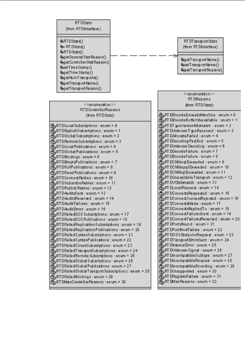
Chapter 8 Using the Connexis Metrics Service
242 User Guide - Rational Rose RealTime Connexis
Figure 111 Class diagram of the metrics classes
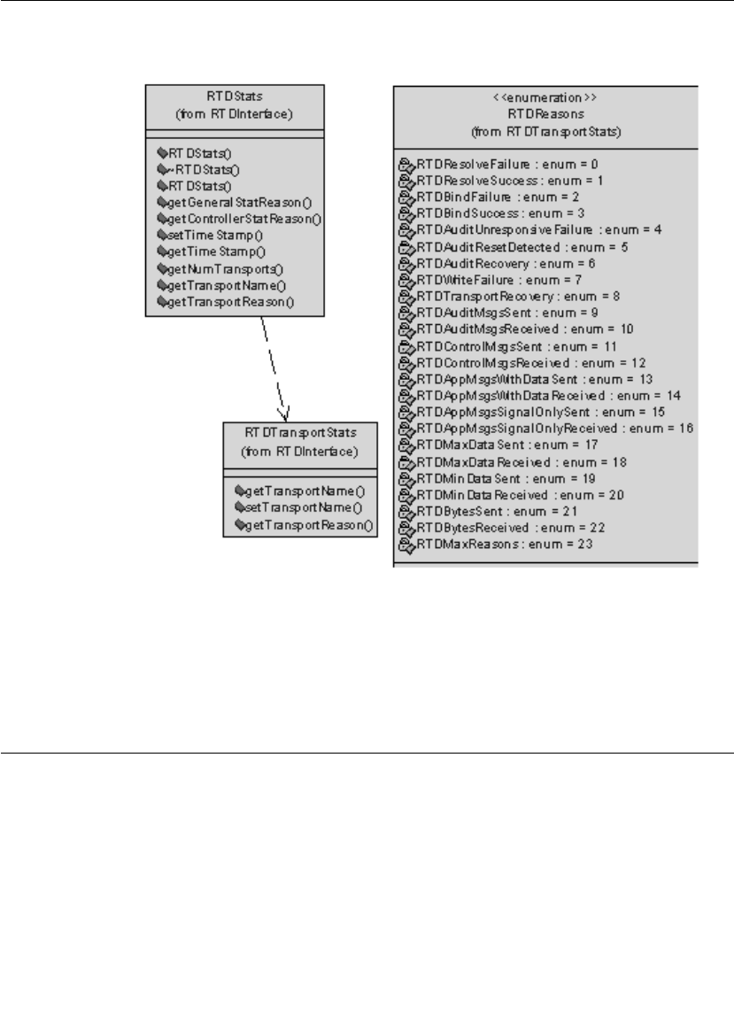
Using Metrics and the Connexis Viewer
User Guide - Rational Rose RealTime Connexis 243
The class diagram Figure 111 continues on Figure 112, showing the
attributes of the RTDTransportStats class.
Figure 112 Class diagram of the metrics classes
Note: An example of the usage of metrics can be seen in the model
metricsCollector in the $RoseRT_Home/CONNEXIS/C++/examples
directory.
Using Metrics and the Connexis Viewer
Another way of obtaining metrics information on a component instance
is by using the Connexis Viewer. Metrics collection is turned on when
the metrics window opens. If you want information on metrics collected
prior to the opening of the metrics window, specify the -CNXm=1
command line argument on the component instance being monitored.
This turns metrics collection on as soon as DCS starts.

Chapter 8 Using the Connexis Metrics Service
244 User Guide - Rational Rose RealTime Connexis
The Viewer can be used at the same time as the metrics service that
you registered. You can obtain metrics data from the metrics service
and from the Viewer.
Note: All the metrics sessions are updated when the metrics counters
are reset from the Viewer or via the port interfaces.

User Guide - Rational Rose RealTime Connexis 245
Chapter 9
Registration String Grammar
Registration String Grammar provides information on the Backus-
Naur Form (BNF) Grammar for the registerSAP and registerSPP
commands.
You can use the grammar below to validate your registration strings
Registration String Grammar for DCS Registrations
<dcs registration string> ::= dcs:[[<endpoint>]/]<service
name>[(<option list>)]
<option list> ::= <option> [ <option list> ]
<option> ::= (locator_rank, integer)
| (locator_transport, transport)
| (connect_retries, integer)
<endpoint> ::= <cdm endpoint> | <custom endpoint>
<cdm endpoint> ::= cdm://<host>:<port>
<crm endpoint> ::= crm://<host>:<port>
<host> ::= host name | ip address
<custom endpoint> ::= <protocol name>://<address>
<service name> ::= <name>
<protocol name> ::= <name>
<address> ::= <restricted string>

Chapter 9 Registration String Grammar
246 User Guide - Rational Rose RealTime Connexis
<port> ::= integer between 0 and 65535
<name> ::= alphanumeric string with optional underscores ("_")
<restricted string> ::= string without
- comma ","
- parenthesis "(" or ")"
- white space

User Guide - Rational Rose RealTime Connexis 247
Chapter 10
Connexis Command Line Options
Command Line Options provides information about commonly-used
combinations for specifying endpoints and locator options. Those
combinations are:
■Component Instance with Fixed Endpoints (no locator service)
■Component Instance using CDM Endpoint, Locator using CDM
■Component Instance using CDM and CRM Endpoints, Primary
Locator using CDM, Backup Locator using CRM
■Component Instance with CDM and CRM, CRM is Preferred
Transport
■Miscellaneous Command Line Options
Component Instance with Fixed Endpoints (no locator service)
How do I configure my Connexis-enabled component instance so
that it is using a single transport for a given component instance?
CDM:
-CNXep=cdm://<host>:<port> (recommended)
For example: -CNXep=cdm://alpha:3000
-OR-
-CNXep=cdm:<port>
For example: -CNXep=cdm:3000

Chapter 10 Connexis Command Line Options
248 User Guide - Rational Rose RealTime Connexis
CRM:
-CNXep=crm://<host>:<port>
For example: -CNXep=crm://alpha:4000
-OR-
-CNXep=CRM://100.200.250.50:4000
Note: You need to specify the corresponding registration string in the
registerSAP and registerSPP in your application.
How do I configure my Connexis-enabled component instance so
that it is using multiple transports for a given component
instance, for example, CDM + CRM and so on?
Note: CDM and CRM can only listen on one port each.
CDM & CRM:
-CNXep=cdm://<host>:<port> -CNXep=crm://<host>:<port>
For example: -CNXep=cdm://beta:10020 -CNXep=crm://beta:12200
Component Instance using CDM Endpoint, Locator using CDM
How do I configure my Connexis-enabled application so that it is
using CDM or CRM for a given component instance and a single
locator using the same transport?
Component instance with the locator:
-CNXep=cdm://<host>:<port> -CNXlp
For example: -CNXep=cdm://gamma:11000 -CNXlp
Component instance using the locator:
In the example below, it is not mandatory to specify the -CNXep
parameter when using CDM (for example, -CNXep=cdm); however, it is
an example of good practice. You must specify this option when using
explicit connections or if you wish to use the Connexis Viewer for
tracing events and debugging.
-CNXep=cdm://<host>:<port1> -CNXlpep=cdm://<locator_host>:<port2>
For example: -CNXep=cdm://theta:12000 -CNXlpep=cdm://gamma:11000

Component Instance using CDM and CRM Endpoints, Primary Locator using CDM,
User Guide - Rational Rose RealTime Connexis 249
Note: For CRM, replace CNXep=cdm with CNXep=crm, and -
CNXlpep=cdm with -CNXlpep=crm in the examples above.
Component Instance using CDM and CRM Endpoints, Primary
Locator using CDM, Backup Locator using CRM
How do I configure my Connexis enabled application so that it is
using multiple transports and primary and backup locators?
Component instance with the primary locator:
-CNXep=cdm://<host>:<port1> -CNXep=crm://<host>:<port2> -CNXlp
-CNXlbep=crm://<backup_loc_host>:<port3>
For example:
-CNXep=cdm://alpha:8000 -CNXep=crm://alpha:8500 -CNXlp
-CNXlbep=crm://beta:9500
Component instance with the backup locator:
-CNXep=cdm://<host>:<port4> -CNXep=crm://<host>:<port3> -CNXlb
-CNXlpep=cdm://<primary_loc_host>:<port1>
For example:
-CNXep=cdm://beta:9000 -CNXep=crm://beta:9500 -CNXlb
-CNXlpep=cdm://alpha:8000
Component instance using the primary and backup locator:
In the example below, it is not mandatory to specify the -CNXep
parameter when using CDM (for example, -CNXep=cdm); however, it is
an example of good practice. You must specify this option when using
explicit connections or if you wish to use the Connexis Viewer for
tracing events and debugging.
-CNXep=cdm://<host>:<port5> -CNXep=crm://<host>:<port6>
-CNXlpep=cdm://<primary_locator_host>:<port1> -CNXlbep
=crm://<backup_loc_host>:<port3>
For example:
-CNXep=cdm://gamma:10000 -CNXep=crm://gamma:10500
-CNXlpep=cdm://alpha:8000 -CNXlbep=crm://beta:9500

Chapter 10 Connexis Command Line Options
250 User Guide - Rational Rose RealTime Connexis
Component Instance with CDM and CRM, CRM is Preferred
Transport
How do I configure my Connexis enabled application so that CRM
is the preferred transport?
To make crm-based connections when other transports are also
available, you can specify CNXlpt=crm at the primary and backup
locators. The default is CNXlpt=cdm.
Component instance with the primary locator:
-CNXep=cdm://<host>:<port1> -CNXep=crm://<host>:<port2>
-CNXlpt=crm -CNXlp -CNXlbep=crm://<backup_loc_host>:<port3>
For example:
-CNXep=cdm://alpha:8000 -CNXep=crm://alpha:8500 -CNXlpt=crm
-CNXlp -CNXlbep=crm://beta:9500
Component instance with the backup locator:
-CNXep=cdm://<host>:<port4> -CNXep=crm://<host>:<port3>
-CNXlpt=crm -CNXlb -CNXlpep=cdm://<primary_loc_host>:<port1>
For example:
-CNXep=cdm://beta:9000 -CNXep=crm://beta:9500 -CNXlpt=crm
-CNXlb -CNXlpep=cdm://alpha:8000
Note: If you wanted an crm-based connection (for example: crm) for a
specific port, you can specify (locator_transport, crm) as part of the
registration string in the RegisterSAP call.
Miscellaneous Command Line Options
Can I specify different encoding, for example, CDR or ASCII, for
different transports?
No. Encoding applies to a component instance, and not per transport
or per end point. As such, it is possible for component instance A to
specify CDR encoding, and component instance B to specify ASCII
encoding. In essence, the two component instances can talk to each
other using two different encoding schemes. Each component instance
can receive either format but send only the configured one.

Miscellaneous Command Line Options
User Guide - Rational Rose RealTime Connexis 251
Each encoding scheme has its advantages and disadvantages. For
example, CDR is faster than ASCII. On the other hand, ASCII is easier
to debug.
To indicate encoding preference, use the following:
CDR:
-CNXtde=2 (this is the default)
ASCII:
-CNXtde=1
For example:
-CNXep=10020 -CNXep=crm://localhost:13000
-CNXlpep=cdm://alpha:10000 -CNXlbep=crm://beta:11000 -CNXtde=1

Chapter 10 Connexis Command Line Options
252 User Guide - Rational Rose RealTime Connexis
When do I need to supply a CNXep?
You need to supply a CNXep when you want to listen at a pre-
determined CDM port, for example:
■when you want to provide a service using the CDM transport, and
clients of your service are not using the locator to resolve your
location. In this case, when you start your component instance
that provides the service, you need to supply the endpoint. That is,
it will be listening at a pre-determined CDM port, for example, -
CNXep=9000. You can then have the clients register for it
specifying the pre-determined location of the service. For example,
consider Application A, which provides service foo, it is started with
a -CNXep=9000 and does registerSPP(dcs:foo). Now another
application B wants to use this service. When B does the
registerSAP, it uses dcs:cdm://<host>:<port>/foo. By having
Application A listen at a pre-determined port (9000), it is easier to
provide that information to Application B, such as via a command
line argument, in a config file, and so on
■when a component instance provides locator services for other
component instances (-CNXlp) which use the CDM protocol. You
want to have it listen at a specific CDM port so that when you start
those other component instances, you will know the port number
to supply in the -CNXlpep and -CNXlbep parameters. You can also
specify "-CNXep”, “-CNXep=0”, “-CNXep=1”. All of these result in a
free port being selected. As well, if the port number you have
provided is non-numeric, or outside the range of 0..65535, it is
ignored and a free port is selected
■when you want to use the Viewer against that component instance

Miscellaneous Command Line Options
User Guide - Rational Rose RealTime Connexis 253
Can I use localhost or 127.0.0.1 for specifying endpoints? Are
there any side effects?
On Windows NT, localhost (defined in
C:\WINNT\system32\drivers\etc\Hosts) is set by default to 127.0.0.1,
and refers to the machine on which the application is executing.
localhost provides a convenient shorthand for referring to the host
machine, while maintaining portability across Windows NT. You can
use localhost in Connexis registration strings locally, that is,
between subscribers and publishers residing on the same Windows NT
machine. You cannot use localhost or 127.0.0.1 for registration
across node boundaries, for example, for registering a subscriber on
VxWorks against a publisher on a Windows NT target.
Explicit SAP registration for CDM with address localhost or 127.0.0.1
(for example, "dcs:cdm://127.0.0.1:12345/foo") always results in a
local loopback connection, regardless of whether or not the CNXtluc
flag is set. It will never result in a direct local bind to the SPP.

User Guide - Rational Rose RealTime Connexis 255
Chapter 11
Connexis Messages, Errors, and
Warnings
Where possible, Connexis provides detailed informational messages,
errors, and warnings to make your development and debugging tasks
easier. Three groups of messages are:
■Initialization Messages
■Initialization Errors
■Parameter Errors
Initialization Messages
The following provides a description of some of the more common
informational messages displayed by Connexis on startup.
Table 57 Connexis informational messages
Output Description
dcs: transport listening at [endpoint]
Note: The transport could be cdm, crm
or your own customized transport.
This is output once the transport
starts up and begins listening at the
endpoint. If it does not appear, your
transport was probably not included.
dcs:CNXcmrs set to [size] CDM maximum receive size specified
was larger than the largest buffer
available. Check your use of CNXtbp.
dcs:CNXtfms set to [size] Transmit first message size was
larger than the largest buffer
available or the max message size.
Check your use of CNXtmts and
CNXtbp.

Chapter 11 Connexis Messages, Errors, and Warnings
256 User Guide - Rational Rose RealTime Connexis
dcs:***** CNX endpoint port not
specified - free port will be selected
*****
Connexis will choose an unused port
on which the CDM transport will
listen.
dcs: target agent enabled Indicates that the target agent is
running. The target agent must be
running if you want to use the
Connexis Viewer.
dcs: locator running as primary Confirmation that the locator was
linked into the executable and is
configured as primary.
dcs: locator running as backup Confirmation that the locator was
linked into the executable and
configured as backup.
dcs: local locator not running (CNXlp
or CNXlb required)
You are using one of
RTDBase_Locator or
RTDBase_Locator_Agent in your
model. The locator was linked into
the executable but has not been
configured.
dcs: locator service not available The locator is not available based on
configuration parameters.
dcs: metric service enabled This indicates that the metrics
service is enabled.
dcs: connecting to primary locator at
[endpoint]
dcs: connecting to backup locator at
[endpoint]
These two lines are output as a pair
and indicate that the primary locator
is remote (CNXlpep) and the backup
locator is remote as well (CNXlbep).
dcs: ***** Parameter [<old parameter
name>] not supported. Please use
[<parameter name>=<value>] *****
Indicates that a parameter that is not
supported with the current release
has been used. When the DCS
encounters a command line
argument that is no longer
supported, the DCS internally
converts the parameter to the new
format and indicates the new usage
to the user.
Table 57 Connexis informational messages
Output Description

Parameter Errors
User Guide - Rational Rose RealTime Connexis 257
Initialization Errors
■The following banner is output in case of initialization failure:
dcs: *********************************************************
dcs: ***** initialization failure - dcs not available *****
dcs: *********************************************************
dcs: ***** banner provided for diagnosis purposes ****
dcs: ***** use CNXd to display configuration *****
dcs: *********************************************************
dcs: !!!!! system failure when initializing the : <step> (<error>) !!!!!
where <step> is one of
❑configuration: problem in parsing parameters
❑target agent: refers to target agent for Viewer
❑transport-capsule: refers to transport router
❑transport-callback: refers to the transport callback thread
(input)
❑transport-helpers: refers to the transport helper thread (output)
❑controller: refers to registration control
❑locator: refers to the Connexis locator service
❑system: any other general error
■CDM failed during initialization - check port number
The error is caused by an inaccurate specification of the CNXep=<port>
command line parameter. Check your CNXep specification.
Technically descriptive error messages have been added at points at
which the initialization of the DCS could fail. These would most likely
only be encountered if the system resources were not sufficient to
handle the demands of the DCS system. Another use would be to
quickly narrow down and pinpoint a startup error while performing a
port of the DCS libraries to another platform.
Parameter Errors
The following errors may be reported in case of a misconfiguration of
the command line parameters.

Chapter 11 Connexis Messages, Errors, and Warnings
258 User Guide - Rational Rose RealTime Connexis
Table 58 Command line parameters misconfiguration errors
Output Description
dcs: ***** multiply defined parameter
[<name>=<value>] ignored *****
The following error is reported if you
try to use a command line parameter
multiple times with a component
instance.
dcs: ***** unknown parameter
[<name>=<value>] ignored *****
The parameter you have specified is
not a valid parameter. This check is
performed for all parameters starting
with CNX. For more information, see
“Command Line Options Reference”
on page 274. You can also output the
list at runtime by specifying CNXhelp
as a command line option.
dcs: ***** CNXendpoint invalid port
[<value>] *****
The port number specified for CNXep
is invalid (non-numeric).
***** CNXendpoint (CNXep) invalid
port [port #] - freeport will be selected
****
The end port specification contains a
syntax error. Connexis will choose
the port on which to listen.
dcs: ***** # of mblks less than # of
buffers in buffer pool *****
The Connexis Transport buffer pool
is not setup properly. Check your use
of CNXtbp.
dcs: ***** Not enough buffers in
buffer pool specified *****
The Connexis Transport buffer pool
is not setup properly. Check your use
of CNXtbp.
dcs: ***** invalid buffer pool specified
*****
The Connexis Transport buffer pool
is not setup properly. Check your use
of CNXtbp.
dcs: ***** CNXcurs = UDP system
receive buffer size must be > max
receive msg size - using target default
*****
UDP buffers are not properly
engineered.
dcs: ***** CNXcuts - UDP system Tx
buffer size smaller than max buffer
size defined in buffer pool - using
system default *****
UDP buffers are not properly
engineered.

Parameter Errors
User Guide - Rational Rose RealTime Connexis 259
dcs: ***** CNXlpep ignored (CNXlp
takes precedence over CNXlpep) *****
You are trying to specify a component
instance as a primary locator, and at
the same time, trying to tell it where
to find the primary locator.
dcs: ***** CNXlb ignored (CNXlp
takes precedence over CNXlb) *****
A component instance can either be a
primary locator or a backup locator
but not both.
dcs: ***** CNXlbep ignored (CNXlb
takes precedence over CNXlbep) *****
You are trying to designate the
component instance as the backup
locator, and at the same time trying
to point it to where the backup
locator is located.
dcs: ***** CNXlp ignored (locator not
present) *****
You are not using RTDBase_Locator
or RTDBase_Locator_Agent in your
model. One of these must be used to
avail the locator capabilities.
dcs: ***** CNXlb ignored (locator not
present) *****
You are not using RTDBase_Locator
or RTDBase_Locator_Agent in your
model. One of these must be used to
avail the locator capabilities.
dcs: ***** CNXlpep missing (CNXlpep
mandatory at backup locator) *****
You must specify a primary locator
for the component instance with the
backup locator.
dcs: ***** CNXlpep missing (CNXlpep
mandatory when using backup
locator) *****
You must specify a primary locator
when using the backup locator
capabilities.
Table 58 Command line parameters misconfiguration errors
Output Description

User Guide - Rational Rose RealTime Connexis 261
Chapter 12
Connexis Customization Reference
Connexis is a general purpose communication tool that can be
customized to suit your needs. To make Connexis as adaptable as
possible, multiple configuration parameters are provided and are
described herein:
■Engineering Rules Overview - outlines the high-level configuration
of the Connexis tool and describes the different components that
can be configured. References are made to the detailed options that
are presented in later sections.
■Command Line Options Reference - details the command line
options that are available for configuring Connexis.
A summary of the parameters, outlining what behavioral aspects are
affected by which parameters, is presented in the Engineering Rules
Overview topic. For example, to find out what parameters can be used
to reduce the memory used by the application, refer to the Engineering
Rules Overview topic.
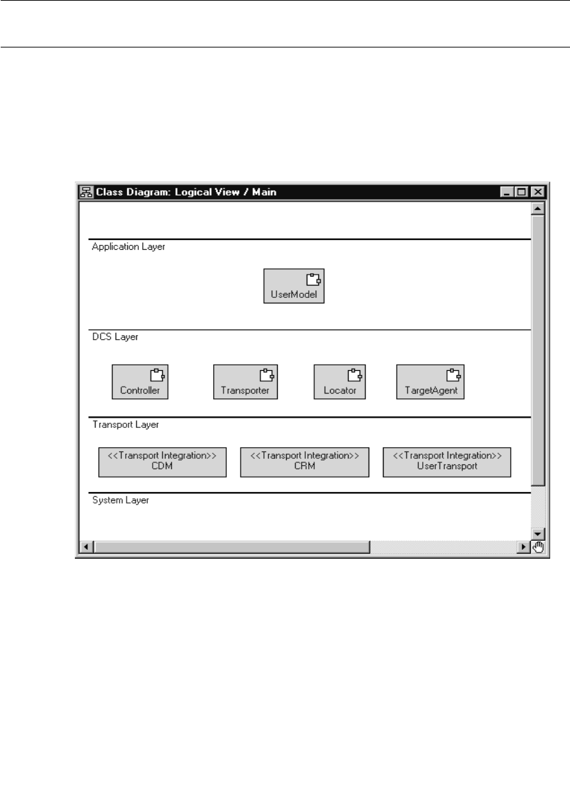
Chapter 12 Connexis Customization Reference
262 User Guide - Rational Rose RealTime Connexis
Engineering Rules Overview
This section presents the high-level design of the Connexis tool and
outlines aspects of the tool that can be configured using the options
that are presented later in this chapter. Figure 113, illustrates the
high-level architecture of a Connexis application. The following
sections detail the aspects of the Connexis design that can be
configured.
Figure 113 DCS high-level design
Thread Configuration
The thread design of your application can have a significant impact on
performance and on the resources that are required by your
application. The following sections describe the thread usage in each
of the layers:

Engineering Rules Overview
User Guide - Rational Rose RealTime Connexis 263
■Process view of a Connexis application
■The application layer
Process view of a Connexis application
This section describes the overall process view of a Connexis
application.
The process view shown in Figure 114 illustrates the thread
configuration for every Connexis component in a distributed
application. If a distributed application had five Connexis components,
each individual node would have a process view similar to that shown
in Figure 114. The Controller_Locator capsule runs on the thread on
which the Connexis capsules that you are using (for example,
RTDBase, RTDBase_Agent, RTDBase_Locator, or
RTDBase_Locator_Agent) are incarnated.
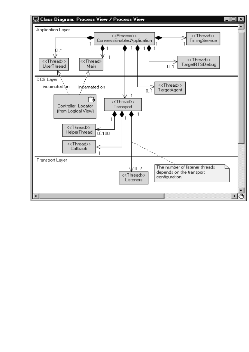
Chapter 12 Connexis Customization Reference
264 User Guide - Rational Rose RealTime Connexis
Figure 114 Connexis process view
Default number of threads
The number of user threads that exist in a particular Connexis
component is determined by the requirements and design of the
component. The number of helper threads associated with the
Transport component is configurable but defaults to five. When the
CDM or CRM transports are enabled, but are not configured to run on
the tread of the transporter, additional threads are incarnated for each
transport.

Engineering Rules Overview
User Guide - Rational Rose RealTime Connexis 265
The application layer
The Application layer consists of the threads that are used by the Rose
RealTime Target RSL and the threads that are part of the design of the
application. This configuration is illustrated in the following class
diagram.
Figure 115 Thread configuration of Application layer
By default, there are only three threads created in a Rose RealTime
model: the TimingService thread, the TargetRSLDebug thread, and the
Main thread. The Main thread is where all application code is executed
by default. The user model may contain any number of user threads.
This is dependent on the design that has been created.
DCS and transport Layer
The thread priorities for the threads in the DCS and Transport layers
can be specified by using the following configuration options:
■Transporter - The priority of the main Transport thread is
configured using the CNXtran_thread_priority (CNXttp) option.
■TargetAgent - The priority of the TargetAgent thread is configured
using the CNXagent_thread_priority (CNXatp) option.
■helper thread priority - The priority of the helper threads is
configured using the CNXtran_helper_thread_priority (CNXthtp)
option. This defaults to a priority that is higher than the transport
thread.

Chapter 12 Connexis Customization Reference
266 User Guide - Rational Rose RealTime Connexis
Note: The “Callback” thread does not run and has no thread priority
associated with it. It is provided so that the transport integration
“callback” operations can send messages to the transporter capsule.
The thread priorities of the built-in transports (ex.: CDM and CRM) can
be configured using the CNXtran_priority (CNXtp) option. When
applicable, user integrated transports are also be configured using the
CNXtran_priority option. If this option is not specified, the default
value is the thread priority of the transporter
(CNXtran_thread_priority).
The DCS Controller and Locator components are on the same thread
and run on the thread that the DCS top-level capsule is incarnated.
The Transport Capsule contains a number of threads that are referred
to as “helper” threads. The helper threads are used to handle any
transport operations that are potentially blocking. The CDM and CRM
transports use the helper threads to resolve host names supplied in
explicit registrations. The CRM transport uses the helper threads when
writing data to an endpoint.
The number of helper threads is configured using the
“CNXtran_helper_threads” command line option. The default value for
this option is 5. The maximum number of helper threads that can be
configured is 100. Setting CNXtht to a number greater than 100 results
in only 100 helper threads being created.
Buffer Configuration
In addition to the threads that are being used by Connexis, there are
areas of the design where buffers are being used. These buffers are
typically being used to buffer data that is either being sent or received
from different processes in the distributed application. The size and
number of many of these buffers is configurable. This section
illustrates Connexis’ buffer usage and details where optimizations can
be made by using configuration options.
Overall buffer configuration of a Connexis application
This section describes the overall buffer usage of a Connexis-enabled
application. Specific options that can be used to configure these
buffers are presented in the following sections. A class diagram
showing the overall buffer usage is presented in Figure 116.

Engineering Rules Overview
User Guide - Rational Rose RealTime Connexis 267
Figure 116 Buffer usage in Connexis application
Application layer
All of the message buffering that occurs in the Application layer is
using the built-in Rose RealTime queuing mechanism. In this queuing
scheme each thread in a Rose RealTime model has a priority queue.
This queue maintains all of the messages that are destined for the
capsules that are running on the thread and that have not been
delivered yet. Connexis does not add any extra buffers in these cases.
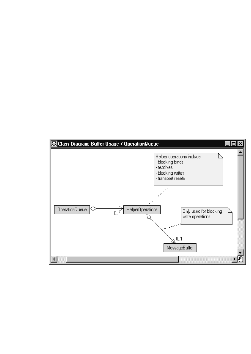
Chapter 12 Connexis Customization Reference
268 User Guide - Rational Rose RealTime Connexis
DCS layer
Most of the messaging that occurs in the DCS layer uses the built-in
Rose RealTime message queues. The Transport capsule also maintains
a transport buffer pool, and an Operation Queue. The transport buffer
queue and the Operation Queue are used to buffer data and control
messages that are being transmitted or received over a transport.
The buffers used for encoding and decoding are obtained from the
buffer pool. The default buffer sizes that are allocated from the buffer
pool for encoding and decoding are configured using the
CNXtran_first_msg_size (CNXtfms) and the
CNXtran_max_transmit_size (CNXtmts) of the transport. In the case of
CDM, a decode buffer is reserved from the buffer pool and its size is
configured using the CNXcdm_message_receive_size (CNXcmrs)
option.
The design of the Operation Queue is illustrated in Figure 117.
Figure 117 Operation Queue design
The Operation Queue is used to buffer transport operations that are
received while an endpoint is binding or being resolved. The size of the
Operation Queue is specified using the CNXtran_out_queue_limit
(CNXtoql).
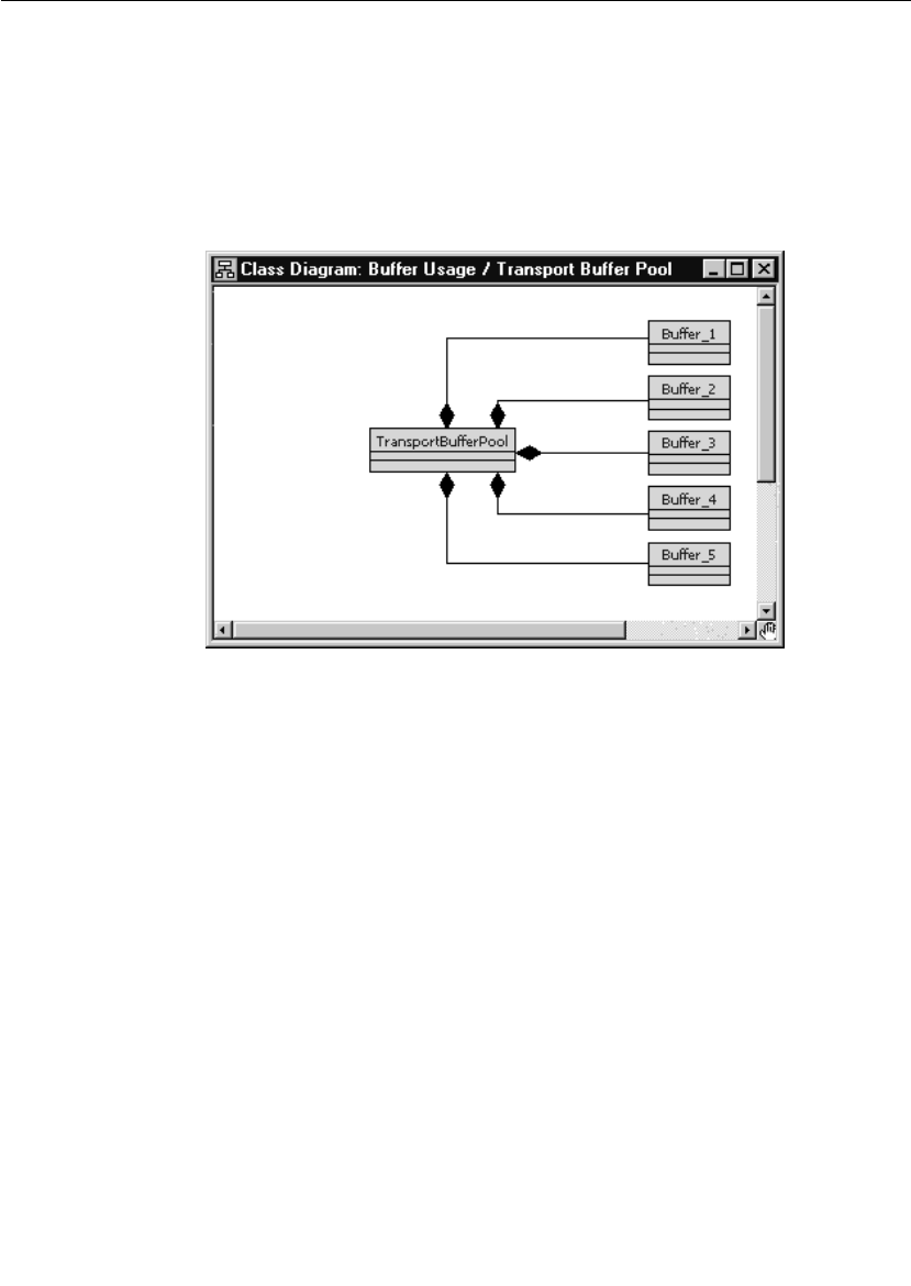
Engineering Rules Overview
User Guide - Rational Rose RealTime Connexis 269
The transport commands that are queued are bind commands, which
do not require a buffer and write commands. Some of the write
commands require message buffers to hold the message payload.
Specifically, if the message has data that is not sent using send scalar,
a message buffer is required. The message buffer is retrieved from the
transport buffer pool. The design of the transport buffer pool is shown
in Figure 118.
Figure 118 Transport Buffer Pool design
The Transport Buffer Pool maintains a set of buffers of varying sizes.
When an transport integration write requires a buffer, the Transport
Integration encodes the data into a buffer that it obtains from the
Transport Buffer Pool. The encode is done in a buffer that most closely
matches the size of the encoded data. This means that the encode is
using a best fit algorithm to find the appropriate buffer.
The size and number of the different buffers in the buffer pool is
configurable using the CNXtran_buffer_pool (CNXtpb) configuration
option. The default value of this option is
64:1,600:10,4200:10,17000:2,32860:2,33000:2. This means that, by
default, the buffer pool creates:
■1, 64 byte buffer
■10, 600 byte buffers
■10, 4200 byte buffers

Chapter 12 Connexis Customization Reference
270 User Guide - Rational Rose RealTime Connexis
■2, 17000 byte buffer
■2, 32860 byte buffer
■2, 33000 byte buffers
If the buffer size is not double word aligned, Connexis rounds up to the
next double word boundary. In addition, each buffer has an overhead
of 24 bytes associated with it due to its buffer control block. This
means that the total amount of memory that is consumed by this
configuration is:
■(64 + 24) x 1 = 88
■(600 + 24) x 10 = 6240
■(4200 + 24) x 10 = 42240
■(17000 + 24) x 2 = 34048
■(32864 + 24) x 2 = 65776
■(33000 + 24) x 2 = 66048
For a total of 214440 bytes.
Connexis buffer usage
This section describes the strategies that are used by CDM Transport
Integration to select buffers from the transport buffer pool for the
different types of messages that can be sent. Table 59presents the
different types of messages that Connexis sends and their
corresponding starting buffer sizes and maximum buffer sizes. Table
59also indicates if the Operation Queue is used for a particular
message type. The general algorithm that is used for all message types
is that Connexis starts by trying to get a buffer that satisfies the criteria
listed in the Starting buffer size column. If a free buffer of that size is
not available, the next largest buffer available is used as long as its size
is not greater than the value listed in the Maximum buffer size column.
If a buffer of that size cannot be found, Connexis looks for a larger
buffer. This continues until the size of the buffer being requested is
greater than the value listed in the Maximum buffer size column.
If your application is only using CDM, configure Connexis according to
the following information:
■There is one decode buffer large enough to hold the biggest
message that your application will receive. Use the CNXcmrs
command line option to configure the receive buffer.

Engineering Rules Overview
User Guide - Rational Rose RealTime Connexis 271
■There is one encode buffer large enough to hold the biggest
message that your application will send. Use the CNXtmts
command line option to configure the transmit buffer.
■There are a number of buffers that are approximately 400 bytes in
size that can be used to hold queued connection requests. This is
only required if host names are being used. If your application uses
IP addresses these buffers are not required.
Configuring the Number of Virtual Circuits
The pre-built Connexis library has a fixed number of virtual circuits
which a Connexis-enabled model can use at run-time. The fixed
number (200) is suitable for most applications and reduces the
memory footprint of the run-time application.
If your application uses more than 200 connections, you must increase
the number of connections, re-build your Connexis library and re-link
your application.
To increase the number of virtual circuits:
1. Open the DCS model
($ROSERT_HOME/CONNEXIS/Model/DCS.rtmdl).
2. Open the specification for the Logical
View::DCSComponents::DCSSysConfig::RTDConstants class.
3. Open the specification for the attribute rtdMaxCircuits.
Table 59 Buffer sizes used by different message types
Message Type Queue
Used?
Starting buffer size Maximum buffer size
CDM Audit No 40 bytes not applicable
CDM data No CNXcmtsa,c CNXcmts
CDM Control No CNXcmtsaCNXcmts
aIf a free buffer that is >= CNXtmts is not available and CNXtfms is < CNXtmts, Connexis
re-attempts to obtain a buffer using the CNXtfms as the starting buffer size.
cConnexis encoding starts with a buffer that is >= the size specified in the Starting buffer
size column. If the encoded data exceeds the buffer size, a buffer twice as large is
obtained (subject to the maximum buffer limit dictated) and the smaller buffer is
released. Encoding continues with this process until a buffer cannot be obtained, or the
encoded size exceeds the maximum encoded data size, or all of the data is encoded.

Chapter 12 Connexis Customization Reference
272 User Guide - Rational Rose RealTime Connexis
4. Change the constant's default value from 200 to a number
appropriate for your requirements.
5. Rebuild the Connexis library from the changed DCS model and link
your application with the newly built library.
Verifying Connections
The Audit functionality verifies that the connection is up and that the
connection is in a state that allows it to go back into service. There are
three types of periodic audits (handshake, connection, and none) and
a reset audit available. The transport can also report when it has failed
and when it has recovered.
With periodic audits the length of the audit period of a connection
depends upon the current state of the connection. It is a function of the
auditISGranularity, the auditOOSGranularity audit configuration
options and the length of the CNXtap. The length of the CNXtap is the
multiple of CNXtap >= the granularity depending on the state.
Handshake audit
This audit determines when a transport has gone out of service. The
handshake audit is usually used when the transport can not notify you
that it has gone out of service through send return code or
asynchronous notification of a failure.
Once a transport goes out of service, messages are sent until it goes
back into service. The audit can be configured so that a re-resolve is
triggered when out of service. If the address was originally unresolved
then it will be reresolved and rebound.
Are You Alive (AYA) messages are sent and I Am Alive (IAA) response
messages are expected in return. A handshake exchanges between two
end points. If piggyBackEnabled is on, messages that are received
count as IAA responses as well. The response must be received before
the next audit period of the connection is over. If it is not received, the
audit period is considered failed. The auditsFailedForOOS identifies
the number of consecutive failed audit periods that may occur before
the connection is considered failed. When a connection has failed
auditsPassedForIS identifies the number of consecutive success audit
periods needed for the connection to resume service. A successful
audit period is one in which an IAA response is received for an AYA
message.

Engineering Rules Overview
User Guide - Rational Rose RealTime Connexis 273
AYA messages are sent only when messages have not been received
from the other side during the last audit period. If messages have been
received, during the period, but no messages were sent, IAA message
are sent. This is an optimization to prevent the other side from having
to send an AYA message in order to trigger this side to send a message.
YANTxEnabled identifies whether You Are Not Responsive (YAN)
messages should be sent when a transport is going out of service.
YANRxForceOOS indicates whether a received YAN message should
trigger the current connection to go out of service. These are useful for
keeping both ends of a connection in sync. It allows one side to notify
the other that it considers the connection to be down, allowing the
other side to release its resources.
Connection audit
Connection audit generates messages during quiet periods, to monitor
the status (up or down) of the transport.
During an audit period, if the connection is in service and no messages
are sent or received, then an IAAnoise audit message is sent. If the
transport is experiencing a failure, the message sends fails and the
connection transitions to out of service. The recovery configuration
defines how to put the transport back into service. When the transport
has failed, the connection audit does not run.
Reset audit
The Reset audit is used primarily in situations where the endpoint goes
up and down faster than the audit can detect. When an application
starts up it assigns itself a unique ID based on the clock and its IP
address. This value is sent in all messages and to all destinations. If
the reset audit is enabled and a message arrives from the sender with
a different ID, it is decided that the sender has failed and has been
restarted. All SPPs are released and all SAPs will rebind to an SPP. To
use the Reset Audit with a connection-oriented transport, the
transport needs to have the ability to release and then re-establish a
connection to the same endpoint. If your network does store and
forward messages, you may not want to use the reset audit either. In a
store and forward network, it is possible old messages turn up with the
old id and result in a working connection being taken down and
restarted unnecessarily.

Chapter 12 Connexis Customization Reference
274 User Guide - Rational Rose RealTime Connexis
A reset audit check takes place when connection establishment
messages are exchanged and when audit messages are exchanged. It
is recommended that you use reset audit with handshake audits.
If your network does store and forward messages, you may not want to
use the reset audit either. In a store and forward network, it is possible
old messages turn up with the old id and result in a working
connection being taken down and restarted unnecessarily.
Command Line Options Reference
There are several areas where the performance and behavior of
Connexis can be modified. The key areas are:
■System wide - options that do not apply to a specific component
■DCS - options that apply to the DCS
■Transporter options that apply to the transporter sub-system and
affect all registered transports.
■Transport specific parameters -options that apply to a particular
transport
■Target RSL - options that apply to the Rose RealTime Target RSL
■Locator - options that apply to the Connexis Locator
■Connexis Viewer / Target Agent - options that apply to the
Connexis Viewer application and its target component
Options applying to each of these components are discussed in the
following tables. Background information that is necessary for making
the design trade-off decisions is also presented. Each set of
configuration parameters is presented in a table format that outlines
the name of the option, the argument type, a description of what the
option does, and a default value.
Setting Command Line Options
The general approach for using all of the mentioned command line
options is to specify them on the command line. If this is not possible
on your target platform, you must set the values of argv and argc using
a supported method.
All of the global command line options that have arguments are set
using the following syntax:

Command Line Options Reference
User Guide - Rational Rose RealTime Connexis 275
<appname> -<command_line_option>=<value>
The transport specific command line options that have arguments are
set using the following syntax:
<appname> -<command_line_option>=<transport name>:<value>
The command line options that do not have arguments are set using
the following syntax:
<appname> -<command_line_option>
Note: The command line options are case sensitive (even on Windows
NT).
System wide
Table 60 lists the options that apply to Connexis as a whole, not to a
specific component.
Table 60 System wide command line options
Command Line
Option
Description
CNXunique_id
| CNXui
This option is used to set a unique identifier for a
Connexis endpoint. If this option is not specified by the
user, Connexis generates a random pattern to use as
the unique identifier.
It is good practice to assign a logical name to the unique
identifier because it makes recognizing the endpoints in
the Viewer easier. For example, -CNXui=service1.
Argument Type: string
Default Value: a random pattern
CNXhelp | CNXh This option causes a brief output of help and default
values for user parameters to be printed to the console.
Argument Type: none
Default Value: none
CNXdump | CNXd This option outputs the final configuration of both the
global and transport specific configuration options once
DCS has been initialized.
Argument Type: none
Default Value: none

Chapter 12 Connexis Customization Reference
276 User Guide - Rational Rose RealTime Connexis
CNXnobanner
| CNXnb
If this option is specified, the Connexis banner is not
displayed on start up.
Argument Type: none
Default Value: none
CNXmetrics |
CNXm
This option allows you to start metrics collection as
soon as DCS starts. This lets you collect metrics on
activities which take place prior to turning metrics on in
the Viewer or programmatically.
Argument Type: bool
Default Value: 0 (false)
CNXpsos_node |
CNXpn
This option only applies to the pSOS operating system.
The pSOS software architecture allows for an
application to be distributed across multiple nodes,
each with a unique ID. This option is used by the DCS
to identify the node ID on which a component instance
is running. The default value assumes that the DCS is
running in a single node configuration.
Argument Type: integer
Default Value: 0
Table 60 System wide command line options
Command Line
Option
Description

Command Line Options Reference
User Guide - Rational Rose RealTime Connexis 277
DCS options
The options contained in Table 61 are related to the DCS controller.
Table 61 DCS command line options
Command Line
Option
Description
CNXdcs_audit_delay
| CNXdad
The minimum time between audits for a given
virtual circuit in milliseconds.
Argument Type: integer
Default Value: 1000
CNXdcs_audit_interval
| CNXdai
Minimum interval between auditing virtual circuits
in seconds.
Argument Type: integer
Default Value: 100
CNXdcs_audit_enabled
| CNXdae
Enables or disables the DCS audit feature. If set to
non-zero the DCS audit is enabled.
Argument Type: BOOL
Default Value: 1
CNXdcs_conn_retry_
delay | CNXdcrd
The retry timeout for transport connect messages.
The transport name is qualified since this option is
transport specific (ex.: -CNXdcrd=cdm:2000).
Time is specified in milliseconds.
Argument Type: integer
Default Value: 5000

Chapter 12 Connexis Customization Reference
278 User Guide - Rational Rose RealTime Connexis
Transporter options
Table 62 describes the command line options that are available for
modifying the global DCS Transporter configuration settings.
CNXdcs_retry_delay |
CNXdrd
The retry timeout for transport control messages.
The transport name must be qualified since this
option is transport specific (ex.: -
CNXdrd=cdm:2000).
Time is specified in milliseconds.
Argument Type: integer
Default Value: 5000
CNXdcs_locator_retry_
delay | CNXdlrd
Specifies the retry delay for locator control
messages. This value is expressed in milliseconds.
Argument Type: integer
Default Value: 5000
Table 62 Transporter global command line options
Command Line Option Description
CNXtran_num_mbks |
CNXtnm
Specifies the number of memory control blocks
that are pre-allocated for the buffer pool of the
transporter. The default value is the number of
memory blocks in the buffer pool, configured
using CNXtran_buffer_pool.
Argument Type: integer
Default Value: sum (CNXtbp)
CNXtran_log_bad_msgs
| CNXtlbm
If set to true, messages with bad types are logged.
Argument Type: BOOL
Default Value: 1 (true)
Table 61 DCS command line options
Command Line
Option
Description

Command Line Options Reference
User Guide - Rational Rose RealTime Connexis 279
CNXtran_default_local_u
se_transport (CNXtdlut)
Configures the default transport used when a
non-explicit subscription resolves locally. This
causes two virtual circuits to be used per local
DCS registration.
Note: Use the Viewer to view local messages. They
are valuable for debugging. Local messages are
not traceable through any other method.
Argument Type: string (transport name)
Default Value: None
CNXtran_local_loopback
_enable (CNXtlle)
Configures the loopback of local connections that
result from an explicit subscription. This causes
two virtual circuits to be used for each local DCS
registration. The syntax is:
-CNXtlle=<transport>:[0 | 1]
An example such as “-CNXtlle=cdm:1,” indicates
that any registration that resolves locally will be
connected through the cdm transport.
Note: Use the Viewer to view local messages. They
are valuable for debugging. Local messages are
not traceable through any other method.
Argument Type: string (transport name)
Default Value: None
CNXtran_thread_priority
| CNXttp
Specifies the priority of the transporter thread.
Argument Type: integer
Default Value: DEFAULT_MAIN_PRIORITY + 1
CNXtran_stack_size
(CNXtss)
Specifies the stack size of the transporter thread.
Argument Type: integer
Default Value: CNXTTP_STACK
Table 62 Transporter global command line options
Command Line Option Description

Chapter 12 Connexis Customization Reference
280 User Guide - Rational Rose RealTime Connexis
CNXtran_default_
encoding | CNXtde
Specifies the default encoding method.
1=ASCII, 2=CDR
Argument Type: integer
Default Value: 2
CNXtran_helper_thread_
priority | CNXthtp
Specifies the helper thread priority.
Argument Type: integer
Default Value: DEFAULT_MAIN_PRIORITY + 2
CNXtran_helper_thread_
stack_size | CNXthtss
Specifies the helper thread stack size.
Argument Type: integer
Default Value: CNXTHTP_STACK
CNXtran_helper_threads
| CNXtht
Specifies the number of helper threads that are
used to buffer data from Connexis. This
corresponds to the maximum number of blocking
calls that can occur against the transport at any
given time plus the number of CDM host name
resolution requests at any given time.
Argument Type: integer
Default Value: 5
CNXtran_out_queue_
limit | CNXtoql
The maximum number of messages allowed in the
Operation queue.
Argument Type: integer
Default Value: 250
CNXtran_endpoint_
queue_limit | CNXtepql
The maximum number of messages that can be
queued per endpoint.
Argument Type: integer
Default Value: 100
Table 62 Transporter global command line options
Command Line Option Description

Command Line Options Reference
User Guide - Rational Rose RealTime Connexis 281
CNXtran_buffer_pool |
CNXtbp
This parameter establishes the number and size
of the buffers that are being managed by the
transport buffer pool. The default specifies that 1,
64 byte buffer, 10, 600 byte buffers, 10, 4200
byte buffers, 2, 17000 byte buffers, 2, 32860 byte
buffers and 2, 33000 bytes buffers be created.
Argument Type: string
Default Value:
64:1,600:10,4200:10,17000:2,32860:2,33000:2
CNXtran_audit_period |
CNXtap
Specifies how often to schedule the audit process.
A value of 0 means that auditing is disabled. This
value is specified in milliseconds
Argument Type: integer
Default Value: 250
CNXtran_audit_
throttle_handshake |
CNXtath
Specifies the maximum number of handshake
audit messages per audit period. This provides
flow control when many connections are being
audited.
Argument Type: integer
Default Value: 10
CNXtran_audit_throttle_
conn | CNXtatc
Specifies the maximum number of connection
audit messages per audit period. This provides
flow control when many connections are being
audited.
Argument Type: integer
Default Value: 10
Table 62 Transporter global command line options
Command Line Option Description

Chapter 12 Connexis Customization Reference
282 User Guide - Rational Rose RealTime Connexis
Transport specific options
Table 62 describes the command line options that are available for
modifying transport specific options.
Table 63 Transport component command line options
Command Line Option Description
CNXendpoint
| CNXep
This option is used to specify the Connexis
endpoint used by the application. A Connexis
endpoint has the syntax: [transport
protocol://][hostname:]port. For example,
cdm://host1:9999.
The CNXep option can be specified once for each
registered transport.
In the case of CDM, if this option is not specified
or is set to 0, Connexis allocates a free port on the
local machine for the CDM transport.
Argument Type: string
Default Value: transport specific
CNXtran_first_msg_size
| CNXtfms
Specifies the first message size to use when
encoding. The default is the smaller of 600 or
CNXtmms.
Argument Type: integer
Default Value: 600 or CNXtmms
CNXtran_max_transmit_
size | CNXtmts
Specifies the maximum transmit message size to
use when encoding. For transports other than
CDM, defaults to the largest buffer in CNXtbp,
after excluding 1 buffer of size CNXtmts and 1
buffer of size CNXcmrs.
The maximum transmit size for the CDM and
CRM transports is limited to 65535 bytes.
Argument Type: string
Default Value: max(CNXtbp)

Command Line Options Reference
User Guide - Rational Rose RealTime Connexis 283
CNXtran_reset_audit_
enabled | CNXtrae
This option (when set) configures the DCS to
detect if a connection has gone down and
recovered before the transport audit could detect
the failure. If this option is true and a reset is
detected, the DCS resets the local circuits so that
their connections can be re-established.
The detection is in part triggered by transport
audits so transport audits must be enabled for
this audit to function.
If you disable CNXtrae you should make sure that
CNXdae is enabled so that failures are detected
by the circuit audit.
Argument Type: BOOL
Default Value: 1 (true)
CNXtran_handshake_co
nn_
audits_is | CNXthcai
Specifies the number of audits that must pass
before the transport can go in-service.
Argument Type: integer
Default Value: 2
CNXtran_handshake_co
nn_
audits_oos | CNXthcao
Specifies the number of handshake audits that
must fail before a transport connection is marked
out-of-service.
(CNXthcao + 1) x CNXtcapo is the amount of time
that the other application would have to be
unresponsive before the connection is marked
out-of-service.
Argument Type: integer
Default Value: 4
Table 63 Transport component command line options
Command Line Option Description

Chapter 12 Connexis Customization Reference
284 User Guide - Rational Rose RealTime Connexis
CNXtran_conn_
audit_period_is |
CNXtcapi
Specifies the audit period to use when the
connection is in-service. This value is represented
in milliseconds. No audit messages are sent when
data is exchanged over the connection in both
directions.
If this option is not a multiple of CNXtap, the
audit period is rounded up to a period that is
divisible by CNXtap.
Argument Type: integer
Default Value: 500
CNXtran_conn_audit_per
iod_oos | CNXtcapo
Specifies the connection audit period to use when
the connection is out-of-service. This value is
represented in milliseconds.
Argument Type: integer
Default Value: 500
CNXtran_resolve_expiry
| CNXtre
Configures the amount of time for which a
resolved endpoint address is valid. Any new
connections established before the expiration
time will use the cached resolved address and will
not reresolved unless there is a transport failure.
This value is represented in seconds.
Argument Type: integer
Default Value: 30
CNXtran_resolve_retry_d
elay | CNXtrre
Configures the retry period for a failed address
resolve operation. The period is specified in
milliseconds.
Argument Type: integer
Default Value: 5000
CNXtran_resolveon_han
dshake_audit_fail |
CNXtrhaf
Configures the DCS to reresolve an endpoint after
this number of failed periods from CNXtcapo, a
handshake audit failure. A value of 1 enables this
functionality.
Argument Type: integer
Default Value: 0 (disabled)
Table 63 Transport component command line options
Command Line Option Description

Command Line Options Reference
User Guide - Rational Rose RealTime Connexis 285
CDM
Table 64 describes the parameters that apply to the CDM transport.
CNXtran_resolve_after_fa
ilure | CNXtraf
Configures the DCS to reresolve a transport
endpoint after a transport failure. A value of 1
enables this functionality.
Argument Type: BOOL
Default Value: 0
CNXtran_bind_retry_dela
y | CNXtbrd
Configures the retry timeout for the endpoint
binding operation of a transport. The timeout
period is specified in milliseconds.
Argument Type: integer
Default Value: 500
CNXtran_priority |
CNXtp
Specifies the transport thread priority.
Argument Type: integer
Default Value: DEFAULT_CNXTTP_PRIORITY + 1
Table 64 CDM command line options
Command Line
Option
Description
CNXcdm_max_rx_size
| CNXcmrs
Maximum CDM receive size. Default to largest
buffer defined in transport buffer pool. This decode
buffer is used exclusively for incoming CDM
messages.
Argument Type: integer
Default Value: max(CNXtbp)
Table 63 Transport component command line options
Command Line Option Description

Chapter 12 Connexis Customization Reference
286 User Guide - Rational Rose RealTime Connexis
Locator
Table 65 describes the options that are available for customizing the
DCS Locator service.
CNXcdm_udp_rx_size
| CNXcurs
The UDP protocol receive buffer size. The default
value is what is defined by the target environment.
Argument Type: integer
Default Value: system
CNXcdm_udp_tx_size
| CNXcuts
The UDP protocol transmit buffer size. The default
value is what is defined by the target environment.
Argument Type: integer
Default Value: system
Table 65 Locator command line options
Command Line Option Description
CNXlocator_primary
| CNXlp
Specifies that this process should be made the
primary locator.
Argument Type: none
Default Value: none
CNXlocator_backup
| CNXlb
Specifies that this process should be made the
backup locator.
Argument Type: none
Default Value: none
CNXlocator_primary_
endpoint | CNXlpep
Specifies the endpoint of the primary locator (if
this process is not the primary locator).
Argument Type: string
Default Value: none
CNXlocator_backup_
endpoint |
CNXlocator_backup_
endpoint
Specifies the endpoint of the backup locator (if
this process is not the backup locator).
Argument Type: string
Default Value: none
Table 64 CDM command line options
Command Line
Option
Description

Command Line Options Reference
User Guide - Rational Rose RealTime Connexis 287
Connexis viewer/target agent
The options listed below apply to the DCS Target Agent component of
the Connexis Viewer. These options are specified in the same way as
other options, namely as command line options to your Connexis-
enabled executable.
These options are used to configure the target agent for optimal use
with the Connexis Viewer.
CNXlocator_retry_delay
| CNXlrd
Specifies the amount of time, in milliseconds, to
wait before retries. The value must be >50.
Argument Type: integer
Default Value: 1000
CNXlocator_audit_delay
| CNXlad
Specifies the amount of time, in milliseconds, to
wait between audits of the Primary locator. This
value must be >50.
Argument Type: integer
Default Value: 2000
CNXlocator_audits_oos
| CNXlao
Specifies the number of failed audits required to
take the primary locator out of service. Using the
default of 3, the primary locator would be taken
out of service after the third consecutive audit
had failed.
Argument Type: integer
Default Value: 3
CNXlocator_preferred_
transport | CNXlpt
Configures the preferred transport to be used for
a binding when the transport is available to both
the publisher and the subscriber. This option can
only be set at the Primary or Backup locators.
Argument Type: string
Default Value: cdm
Table 65 Locator command line options
Command Line Option Description

Chapter 12 Connexis Customization Reference
288 User Guide - Rational Rose RealTime Connexis
Table 66 Connexis Viewer command line options
Command Line Option Description
CNXagent_thread_priority
| CNXatp
Specifies the target agent thread priority.
Argument Type: integer
Default Value: DEFAULT_MAIN_PRIORITY
CNXagent_trace_buffer
_size | CNXatbs
Specifies the target agent trace buffer size in
terms of the number of events that are stored.
Trace events have a fixed size of 32 bytes.
Argument Type: integer
Default Value: 1000
CNXagent_data_block_size
| CNXadbs
Specifies the target agent data block size in
bytes.
Argument Type: integer
Default Value: 32
CNXagent_num_data_
blocks | CNXandb
Specifies the number of data blocks that are
allocated for the target agent.
Argument Type: integer
Default Value: 1000
CNXagent_truncate_user_
data | CNXatud
Specifies the number of bytes to keep before
truncating user data. A value of -1 means that
no truncation is performed.
Argument Type: integer
Default Value: 256
CNXagent_auto_start
| CNXaas
Tells Connexis to automatically start capturing
events. The level can be set between 1 and 5
where 1 corresponds to Basic traces, 3
corresponds to Operational traces and 5
corresponds to Advanced traces. The preferred
level is 3.
For more information, refer to “Defining a Trace
Filter for a Component Instance” on page 182.
Argument Type: integer
Default Value: 0 (disabled)

User Guide - Rational Rose RealTime Connexis 289
Chapter 13
Customizing and Porting DCS Libraries
The Distributed Connection Service (DCS) libraries let you create a
distributed Rose RealTime application. The DCS libraries work with
the TargetRTS, allowing Rose RealTime unwired ports to be bound
across process boundaries.
This chapter describes how to customize or port DCS libraries to a new
target environment. The new target could be a new target
configuration, or an OS or compiler upgrade of a supported DCS target
configuration.
The information in this chapter is specifically designed for software
developers familiar with the target environment to which they are
porting. It assumes that you have significant knowledge and
experience with the development environment, operating system, and
target hardware. It is also assumed that you are familiar with
the”Rational Rose RealTime C++ Porting Guide” and have completed
and tested the TargetRTS port to the new target configuration.
This section also provides guidelines on how to build DCS libraries for
a minimal configuration.
Common customizations for the DCS
The DCS has been designed and implemented using Rose RealTime
and is available in the form of a model. The most common
customizations required are:
■Changing the compilation flags used to build the DCS library
■Updating the compiler version for the target configuration
■Building a minimal configuration of the TargetRTS and DCS
libraries

Chapter 13 Customizing and Porting DCS Libraries
290 User Guide - Rational Rose RealTime Connexis
Other resources
Before customizing a target configuration or starting a port, ensure
that you have the following documents and materials available:
■Rational Rose RealTime C++ Porting Guide
■Compiler documentation
■Simple Rose RealTime example models to verify the TargetRTS port
■Connexis "BasicTest" example model to verify the DCS port
Operating system capabilities
UDP/IP and TCP/IP support are required to support CDM and CRM
transports. While it is possible to complete a port without IP support,
UDP/IP support is required if you need to observe your target using the
Connexis Viewer. IP support is also required for UML-level debugging
using Target Observability feature of Rose RealTime.
What to do before calling Rational support
If you encounter any problems, follow the steps below before calling
Rational support for help regarding a DCS port.
1. Follow the steps outlined in the section "What to do before calling
Rational Support" in the”Rose RealTime C++ Porting Guide.”
2. Verify that the TargetRTS port for the new target configuration is
functional using the Rose RealTime example models.
Porting the DCS to a New Target Configuration
To port the DCS to a new target configuration:
1. Create a TargetRTS library for the new target configuration.
2. Create DCS target specific header files for the new target
configuration.
3. Load the DCS model.
4. Create a new C++ library component for the new target
configuration.
5. Configure and customize the C++ library component settings.
6. Configure the DCS CDR encoding/decoding for the new target
configuration.

Porting the DCS to a New Target Configuration
User Guide - Rational Rose RealTime Connexis 291
7. Build the DCS library for the new target configuration.
8. Test the new target configuration.
Creating a New TargetRTS Library
Follow the steps and instructions described in the “Rational Rose
RealTime C++ Porting Guide” to configure or create a TargetRTS library.
The DCS library for a target platform depends on the TargetRTS for its
target configuration and library settings. The TargetRTS provides
several settings that the user can configure. The TargetRTS
parameters and settings table lists the parameters and the settings
that must be set for the DCS. The “Rational Rose RealTime C++ Porting
Guide” provides a complete description of all the target settings.
Compiler option settings that are common to the TargetRTS libraries,
the DCS libraries, and the user's application should be configured
using the LIBSETCCFLAGS macro in
$RTS_HOME/libset/<libset>/libset.mk.
Compiler option settings that only apply to the TargetRTS libraries
should be set in the LIBSETCCEXTRA macro in
$RTS_HOME/libset/<libset>/libset.mk.
Table 67 TargetRTS parameters and settings
Target Settings Value Descriptions
USE_THREADS 1 The DCS is only available for multi-
threaded applications.
HAVE_INET 1 The DCS requires IP support for the
Connexis Datagram Messaging (CDM) and
the Connexis Reliable Messaging (CRM)
transports.
OBJECT_ENCODE 1 The DCS requires IP support for the
Connexis Datagram Messaging (CDM) and
the Connexis Reliable Messaging (CRM)
transports.
OBJECT_DECODE 1 Required so that a message received over
the wire can be decoded into objects.
RTS_COMPATIBLE 600 Connexis is not available for ObjecTime
Developer and there are no compatibility
issues with v5.2

Chapter 13 Customizing and Porting DCS Libraries
292 User Guide - Rational Rose RealTime Connexis
Compiler option settings that only apply to the DCS libraries should be
configured in the DCS model. Customization of a DCS C++ library
component is described in the section "Configuring the C++ Library
Component Settings."
Creating DCS Target Specific Header Files
Although most of the configuration of the DCS libraries is done within
the DCS model, the DCS thread configurations are configured in the
file $RTS_HOME/target/<target>/RTDcsTarget.h. The file
RTDcsTarget.h contains specific operating system priority definitions
and configuration of the stack size for DCS threads. The
RTDcsTarget.h file also contains the definitions of the maximum and
minimum values of the thread priorities for an operating system. Run-
time argument processing uses these values to validate the run-time
settings or the thread priorities for the DCS threads. The table below
provides a list of constants that must be defined in RTDcsTarget.h.
Table 68 Constant definitions
Constant Description
CNX_PRIORITY_MIN Defines the minimum allowable value for a thread
priority
CNX_PRIORITY_MAX Defines the maximum allowable value for a thread
priority.
CNX_PRIORITY_RAISE The default configuration for the DCS is for the
priority of the helper threads to be higher than the
priority of the transporter thread. The
CNX_PRIORITY_RAISE constant is used to
increment a thread priority. For OS targets in which
the higher priority threads have lower numeric
values, the value of CNX_PRIORITY_RAISE must be
negative.
DEFAULT_CNXTTP_PR
IORITY
Sets the default thread priority for the transporter
thread.
DEFAULT_CNXHTP_P
RIORITY
Sets the default thread priority for the helper
threads. For optimal system performance, the
helper threads should run at a higher priority than
the transporter thread.

Porting the DCS to a New Target Configuration
User Guide - Rational Rose RealTime Connexis 293
Loading the DCS Model
Before you load the DCS model, create new target configuration or
customizations to an existing target configuration within the DCS
model. Load the DCS model into a Rose RealTime session, found in the
$ROSERT_HOME/CONNEXIS/Model directory.
The Component View of the DCS model has packages containing the
C++ library components for the supported DCS configurations. These
packages are named after the target configurations they represent. For
example, the package VXW54-ppc-cygnus-272-960126 represents the
TORNADO2T.ppc-cygnus-2.7.2-960126 target configuration.
Before making any modifications to the target configurations, make a
copy of the DCS model provided with the Connexis installation.
Creating a C++ Library Component
Once the DCS model is loaded, you can modify an existing C++ library
component or create a new one.
If you are modifying an existing target configuration, clone the
TargetRTS with a new name and duplicate the DCS library component.
To clone the TargetRTS:
1. Select the component in the browser.
2. Duplicate the option from its context menu.
DEFAULT_CNXATP_PR
IORITY
Sets the default thread priority for the target agent.
The target agent is designed to be minimally
intrusive to the application and should be running
at a lower priority than the threads of the
application.
CNXTTP_STACK Sets the stack size for the transporter thread.
CNXHTP_STACK Sets the stack size for the helper threads
CNXATP_STACK Sets the stack size for the target agent thread.
Table 68 Constant definitions
Constant Description

Chapter 13 Customizing and Porting DCS Libraries
294 User Guide - Rational Rose RealTime Connexis
If you are creating a new target configuration, duplicate the DCS
library component template provided in the
package. This generic template
component is configured with the following information:
■references to all the DCS Logical View components required to
provide the DCS functionality
■property settings for the library name (the default is
$(LIB_PFX)DCS$(LIB_EXT))
■compilation inclusion paths
■property settings for any component level inclusions
■component dependencies
Configuring the C++ Library Component Settings
The following table describes the component properties that must be
customized.
Table 69 Customizing component properties
Component Property Description
C++ Compilation >
TargetConfiguration
The <target> and <libset> settings of the TargetRTS
configuration that we are building against.
C++ Generation >
CodeGenMakeType
Specify the format of the makefiles to be generated
by the toolset for the code generation phase of the
build. For example, if you are using the GNU make
utility in your environment, this property should be
set to Gnu_make.
C++ Generation >
CodeGenMakeComma
nd
Specifies the name of the make utility to be used by
the toolset for the code generation phase. For
example, gmake.
C++ Compilation >
CompilationMakeType
Specify the format of the makefiles to be generated
by the toolset for compilation phase of the build.
For example, if you are using the GNU make utility
in your environment, this property should be set to
Gnu_make.
C++ Compilation >
CompilationMakeCom
mand
Specifies the name of the make utility to be used by
the toolset for the code compilation phase. For
example, gmake.

Porting the DCS to a New Target Configuration
User Guide - Rational Rose RealTime Connexis 295
C++ Compilation >
CompilationMakeArgu
ments
You must specify RT_SRC_TGT=<target_base>. The
DCS depends on TargetRTS files in the
$RTS_HOME/src/target directory. For example,
RTtcp.h. The RT_SRC_TGT make variable is used to
specify the target base.
C++ Compilation >
CompileArguments
If your component is not compiling, it may be a
result of the RTD_CONNEXIS_BUILD constant not
being set properly. The definition of this constant
can be found in the C++ Compilation" > "Compile
Arguments" field of the component and should be
changed from $(CNX_BUILD_NUM) to a user-
defined integer value. This property is used to
configure the C++ preprocessor macros that
configure certain DCS capabilities.
Viewer tracing is configured on the target using the
RTD_TRACE macro. $(DEFINE_TAG)RTD_TRACE=1
enables tracing. $(DEFINE_TAG)RTD_TRACE=0
disables most traces (except errors and warnings),
$(DEFINE_TAG)RTD_TRACE=2 disables all traces.
The metrics collection and reporting capabilities are
configured using the RTD_STATISTICS macro.
$(DEFINE_TAG)RTD_STATISTICS=1 enables
metrics collection and reporting.
$(DEFINE_TAG)RTD_STATISTICS=0 disables the
metrics collection and reporting.
Additonal macros might be required to configure
the CDR encode/decode capabilities for the target
platform. These capabilties are described in
“Configuring the CDR Encode/Decode
Functionality” on page 296
Note: If your component is not compiling, it could be
a result of the RTD_CONNEXIS_BUILD constant not
being set properly. This constant’s definition can be
found in the component’s “C++ Compilation” >
“Compile Arguments” field and should be changed
from $(CNX_BUILD_NUM) to a user-defined integer.
This property is also used to configure any compiler
option settings that are only required for completion
of the DCS libraries.
Table 69 Customizing component properties
Component Property Description

Chapter 13 Customizing and Porting DCS Libraries
296 User Guide - Rational Rose RealTime Connexis
Configuring the CDR Encode/Decode Functionality
The CDR Encode/Decode functionality could require platform specific
customizations depending on the capabilities of the platform. These
customizations are accomplished by defining C++ preprocessor macros
in the "C++ Compilation > CompileArguments" property of the DCS
library component's specification sheet. The following customizations
are available:
■Overriding the type for use when encoding 64-bit values. The
default behaviour when the RTD_LONGLONG_TYPE macro is not
defined is to encode/decode 64-bit values using the primitive "long
long" type. This customization is required when the compiler does
not provide support for "long long" types. Setting
$(DEFINE_TAG)RTD_LONGLONG_TYPE=0 will use "__int64" type
to encode/decoding 64-bit values. Setting
$(DEFINE_TAG)RTD_LONGLONG_TYPE=1 will cause 64-bit values
to be encoded/decoded using the primitive "double" type.
■Enabling the inclusion of <sys/types.h>. Some platforms require
this inclusion to provide definitions of all the system types. Setting
$(DEFINE_TAG)RTD_INCLUDE_TYPES_IN_RTDPLATFORMCONFI
G enables this capability.
Creating a Minimal DCS Library Configuration
The DCS libraries provided with the Connexis installation are
configured with extensive debugging information and capabilities. As
the application becomes more mature, it may be necessary to
recompile a minimal configuration of both the TargetRTS and DCS
libraries in order to obtain better performance and a smaller memory
footprint for deployment. The Rose for RealTime "C++ Language
Guide" provides a description of how to create a minimal Target RTS
library configuration.
The TargetRTS precompiler settings defined in Table 67,“TargetRTS
parameters and settings” on page 291, must be set to support the DCS
functionality.
Porting the DCS to a New Target Configuration
User Guide - Rational Rose RealTime Connexis 297
Once a minimal Target RTS is configured, built, and tested. The DCS
library corresponding to the TargetRTS library configuration can be
built. For the DCS libraries, it is recommended that the following
preprocessor settings be set for a minimal configuration:
■$(DEFINE_TAG)RTD_TRACE=0
■$(DEFINE_TAG)RTD_STATISTICS=0
These setting are described in Table 69, Customizing component
properties.
Building the Library
Once you build the C++ library component and the
class is configured for the target platform, you can build the
library.
To build the library:
1. Select the component in the browser
2. Select the > option from the context menu.
The library is built into the folder specified in the properties area of the
component ( > ).
Once the library has been built, copy it into the
$ROSERT_HOME/CONNEXIS/C++/lib/<target>.<libset> directory.
Note: If your component is not compiling, it could be a result of the
RTD_CONNEXIS_BUILD constant not being set properly. This constant’s
definition can be found in the component’s “C++ Compilation” > “Compile
Arguments” field and should be changed from $(CNX_BUILD_NUM) to a
user-defined integer.
Testing the Port
Test the DCS library port with the BasicTest model provided as part of
the Connexis installation. This model is available in
$ROSERT_HOME/CONNEXIS/C++/Examples/BasicTest.rtmdl. A
description of the BasicTest model is provided in the “Rational
Connexis Release Notes and Installation Guide.”

User Guide - Rational Rose RealTime Connexis 299
Chapter 14
Using the Transport Integration
Framework
The Rational Connexis Transport Integration Framework (TIF) lets you
add your own proprietary transports or other common transports for
use in Connexis messaging. The TIF is designed to be flexible, allowing
a variety of transports to be integrated. Transports may include
Industry standard transports (UDP/IP, TCP/IP), operating system
specific transports, or your own proprietary transport.
You might want to add your own transports for the following reasons:
■The application requires more real-time predictability than TCP/IP
can provide.
■The application requires more reliability than CDM can provide.
■The application uses an embedded or proprietary protocol.
■TCP/IP is not available on the target system.
TIF lets transport specialists seamlessly integrate transports into
Connexis. TIF is provided as a package of classes that are subclassed
and implemented. The subclasses are packaged into a library and
made available to Connexis-enabled applications. The viewer, locator,
and other Connexis features are fully supported for any transport
integrated into Connexis.

Chapter 14 Using the Transport Integration Framework
300 User Guide - Rational Rose RealTime Connexis
Transport Integration Overview
The following overview identifies the steps in building a Transport
Integration (TI) using the Transport Integration Framework (TIF). The
steps to building a Transport Integration are as follows:
1. Verify that your transport works.
It is import to ensure that your transport works before integrating
it into the DCS using the TIF. It is difficult to test the transport and
integration at the same time.
2. Understand the Transport Integration Framework.
“DCS Architecture” on page 301 describes in detail how the DCS
and the Transport Integration works together to establish
connections and transfer messages between subscribers (SAPs)
and publishers (SPPs).
3. Understand your transport.
This includes the transports properties and how to send and
receive messages over it (see “Understanding your Transport” on
page 305).
4. Implement the transport integration.
Create subclasses and implement the abstract functions of the
following classes:
❑RTDTransport
❑RTDTransportAddress
❑RTDTransportAddressFactory
❑RTDTransportEndpoint
❑RTDTransportEndpointFactory
Create a class (or classes) that provides functionality of the
transport.
5. Package the transport integration.
Create a class (or subclasses) that provide the listening
functionality of the transport.
6. Test the use of the integration of the transport under Connexis.
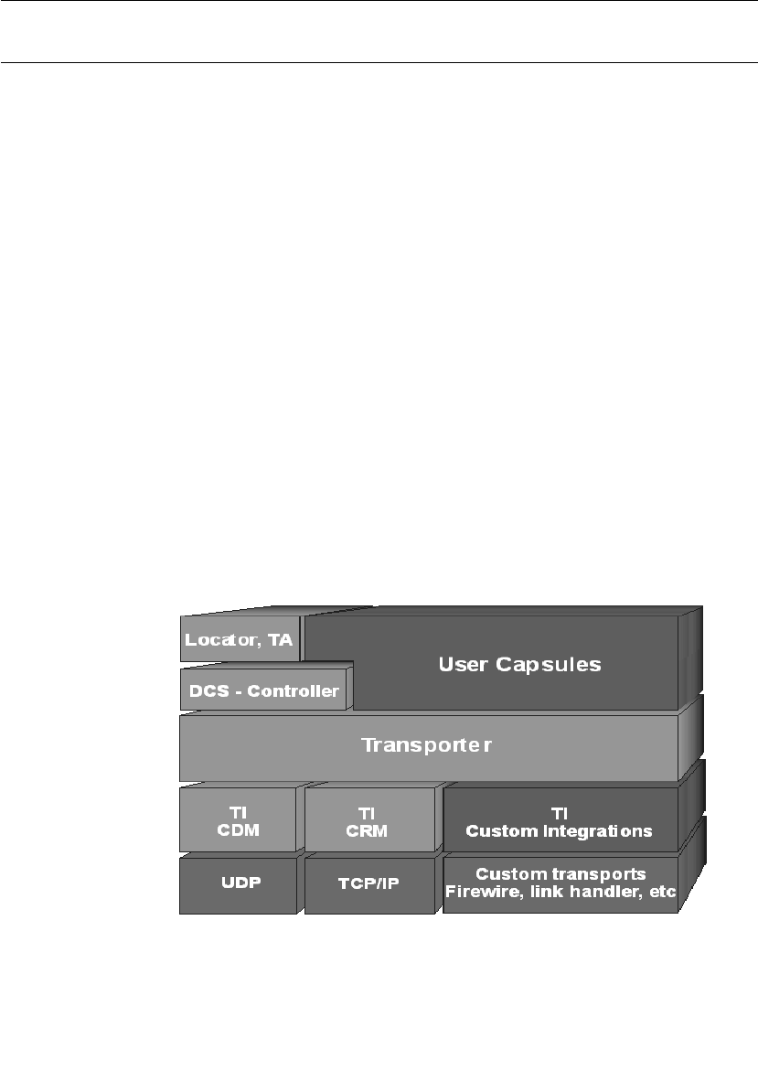
DCS Architecture
User Guide - Rational Rose RealTime Connexis 301
DCS Architecture
The Connexis Transport Integration Framework (TIF) forms the basis
of integration. A Transport Integration (TI) is the actual implementation
of an instance of the TIF. The transports which come with Connexis
(CDM based upon UDP and CRM based upon TCP/IP) have been
integrated using the TIF. Figure 119, “Connexis High-Level Design,” on
page 301, shows how the DCS fits into a DCS-enabled application. The
Locator and Agent, included as part of the DCS, are special
applications that access internal information about connections and
uses of the DCS like a user application. User applications make use of
the DCS when registering and deregistering SAPs and SPPs and when
sending messages between SAPs and SPPs.
The Controller processes the registerSAP, registerSPP, deregisterSAP
and deregisterSPP calls and establishes the virtual circuit between a
SAP and SPP. If necessary a locator is contacted for global
subscriptions and publications.
The transporter is responsible for setting up, auditing, and recovering
connections. It is responsible for routing work requests like binds,
resolves and sends to the appropriate Transport Integration.
The Transport Integration interfaces with the actual transport to
resolve addresses, bind and reset connections, and send or receive
messages.
Figure 119 Connexis High-Level Design

Chapter 14 Using the Transport Integration Framework
302 User Guide - Rational Rose RealTime Connexis
The Table 70, Connexis High-Level Design Chart, identifies what
components of Figure 119 are DCS, Customer or Third-party
components.
Terminology
Throughout this chapter the following terms, defined in Table 71, are
used.
Table 70 Connexis High-Level Design Chart
Connexis
Components
Customer
Components
Third-party
components
locator, TA User Capsules UDP
DCS - Controller TI Custom Integrations TCP/IP
Transporter Custom transports
TI - CDM
TI - CRM
Table 71 Chapter Definitions
Term Definition
Address The location of the component instance.
Endpoint In the context of the Transport Integration
Framework, an endpoint represents a connection
over a transport from one component instance to
another component instance.
Virtual Circuit Represents a logical connection between a
subscriber and a publisher.
Audit Background activity to help monitor the availability
of a transport during periods of inactivity.
Messages Information to exchange between two component
instances.
Audit Messages Messages exchanged between two component
instances in an effort to monitor the endpoint.
Control Messages Messages exchanged between a DCS in different
component instances, regarding a virtual circuit.

Connection Lifecycle
User Guide - Rational Rose RealTime Connexis 303
Connection Lifecycle
When Connexis receives a RegisterSAP request, it resolves the address
and a single endpoint is established from the resolved address. Once
the endpoint is established, it is bound and messages are exchanged
to obtain access to a service (a virtual circuit). Data messages are then
exchanged between the SAP and SPP over the virtual circuit.
Note: Multiple virtual circuits can use the same endpoint and messages
consist of fixed-size control information and data.
Messages sent over the virtual circuit could be Connexis control
messages, Connexis audit messages or SAP/SPP messages. All
messages need to be encoded before they are sent and decoded. The
endpoint is monitored as long as there are established virtual circuits
associated with it. If there is no activity over any of the virtual circuits
the audit activity is triggered. The user is notified of the failure
(rtunbound) of the transport and the recovery (rtbound) of the re-
established connection with the virtual circuit.
Resource cleanup takes place periodically when there are no virtual
circuits making use of an endpoint. In that case the endpoint is
released.
Application Messages Messages exchanged over a virtual circuit (between
a publisher and a subscriber).
Transport Intergration The actual implementation of TIF classes that allow
a transport to be used transparently by a DCS
enabled model.
TIF The set of model interface elements and
documentation that allows transports to be
integrated with the DCS.
Table 71 Chapter Definitions
Term Definition
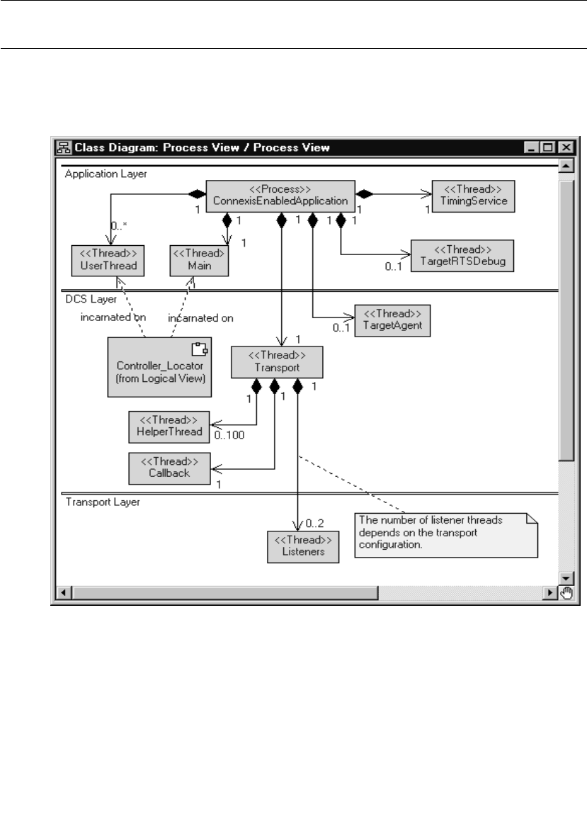
Chapter 14 Using the Transport Integration Framework
304 User Guide - Rational Rose RealTime Connexis
DCS Threading Model
The diagram below illustrates the DCS threading model (see
Figure 120, Connexis Process View). The significant threads from the
Transport Integration point of view are the Transporter thread and the
pool of Helper threads.
Figure 120 Connexis Process View
If an address received in a registerSAP called is unresolved, a request
to resolve it is queued for a helper thread. For blocking transports that
are integrated into the DCS, the bind, send and reset requests take
place on the helper thread. Only one helper thread at a time invokes
these functions for a connection. If the transport is configured as non-

Understanding your Transport
User Guide - Rational Rose RealTime Connexis 305
blocking, these requests are performed on the thread of the DCS
transporter. The Transport Integration, in turn, may create additional
threads for other processing, such as listening for messages.
Alternatively, the wait and wakeup functions of the DCS transporter
can be overridden to perform the "listening" operation for the
transport. In this case, the work is performed on the thread of the
transporter. User capsules can also be incarnated to be run on the
thread of the transporter. The thread of the transporter can be obtained
using the RTDInitStatus protocol. Take care to ensure none of these
user capsules block. For more information on the DCS threading
model, see “Connexis Customization Reference” on page 261.
Understanding your Transport
When you implement the Transport Integration, you must decide how
the transport is to be configured into DCS. You must have the following
information about your transport before you use the TIF:
■“Determine the Name of your Transport and Protocols” on
page 306.
■“Decide the String Format of the User-specified Address” on
page 306.
■“Decide How to Validate the Address” on page 306.
■“Decide the Transformation of the Address” on page 307
■“Determine the Internal Representation of your Address” on
page 308
■“Decide the Format of the Listening Point Information” on
page 309.
■“Decide if your Transport is Blocking or Non-blocking” on
page 309.
■“Decide the Recommended Address Resolution Configuration” on
page 310.
■“Decide How the Transport will Recover from Transport Failures”
on page 311.
■“Decide How to Audit your Transport” on page 311.
■“Decide the Format of your Messages” on page 312.
■“Decide Strategy for Listening for Messages” on page 313.

Chapter 14 Using the Transport Integration Framework
306 User Guide - Rational Rose RealTime Connexis
Determine the Name of your Transport and Protocols
Typically a transport supports only one protocol and has the same
name as the transport. There is the flexibility to register more than one
protocol with a transport.
Note: Transport names and protocols are case insensitive and should
not have embedded blanks or special characters (":" "/" "," ")" "(") in them.
Example:
The CRM transport supports the crm protocol. The CDM transport
supports the cdm protocol.
Decide the String Format of the User-specified Address
When you register an SAP explicitly, you need to supply the address
where the service can be found. The format of the registerSAP
argument for our discussion purposes looks like the following example:
<port reference>.registerSAP("<protocol>://<address>/<service>");
You should have decided on the supported <protocol> before this point
as described in “Determine the Name of your Transport and Protocols”
on page 306. You now need to decide the format for <address>. It could
be a queue name for an OS messaging service, an object name for a
CORBA object, an IP address or the name of a board.
Example:
For the CRM transport, the address takes the form of the following:
<hostname>:<port> or <ip address>:<port>
For example "crm://alpha:9090" or
"crm://192.033.111.222.44:8980"
Decide How to Validate the Address
When you perform a registerSAP call, the registration string supplied
is validated. If the registration string is invalid, the registerSAP call
fails, allowing you to take the necessary action immediately. In order
to assist in the validation of the registration string, a function to
validate the syntax of the string form of the transport address must be
provided. The better the validation, the better the feedback to the user
at registration time.

Understanding your Transport
User Guide - Rational Rose RealTime Connexis 307
Example:
The CRM validation of an address includes verifying:
■A single address is supplied.
■A host name or IP address is supplied.
■A numeric port number is supplied.
■The port is non-zero.
Decide the Transformation of the Address
The address supplied is in a textual string format. It may require that
all or a portion of the string be transformed into an internal transport-
dependent form. A queue name may need to be transformed into an
internal queue ID. An object name may be transformed into an object
reference after looking it up in a naming service. A host name may be
transformed into an IP address. An IP address and port may be
transformed into a socket.
The address can be transformed into an internal form:
■When an instance of the RTDTransportAddress subclass is created
■At resolve time
■At bind time
The results of the transformation during resolve time should be stored
in the RTDTransportAddress subclass. The results of the
transformation done at bind time should be stored in the
RDTTransportEndpoint subclass.
The address should be transformed at resolve time if any of the
following situations apply:
1. If only part of the address needs to be "looked up" or transformed
(for example resolving a host name), it should be performed at
resolve time. The results of the lookup are cached and can be used
by different addresses. For example: crm://alpha:9090 and
crm://alpha:10002 are 2 different addresses. The host name
"alpha" can be looked up once at resolve time and cached for use
by both addresses.

Chapter 14 Using the Transport Integration Framework
308 User Guide - Rational Rose RealTime Connexis
2. If the transport is non-blocking and transformation is blocking, the
look up should take place during resolve time. The resolve takes
place on a separate thread. If the transport is marked as non-
blocking, the bind takes place on the transporter thread being used
to send or receive other messages.
3. If the different unresolved portions of an address can result in the
same resolved value, consider performing the lookup in the resolve
step. For example, if host names "alpha" and "CnxTest" both
resolve to the same result, it is better to perform the lookup during
resolve time, so that "crm://alpha:9000" and
"crm://CnxTest:9000" would result in the same endpoint being
used.
If the transformation is non-blocking and you never need to re-
transform the address after a transport failure, or an audit failure, the
transformation can take place when the RTDTransportAddress
subclass is created.
If none of the above situations apply, the lookup should be done at bind
time. For example a CORBA object name may be looked up only at bind
time.
Example:
For the CRM transport, if a host name is supplied as opposed to an IP
address, the address is considered unresolved. Only the host name
portion of the address needs to be resolved. Because multiple
representations of an address may turn out to be the same address,
the host name lookup will be done as part of the resolve step as
opposed to the bind step. For example: crm://alpha:9000
crm://mymachine:9000 and crm://192.222.222.22:9000 could
resolve the to the same destination. Therefore the resolve is the best
place to look up the host name so that only one endpoint is available
for the same destination. The IP address will be transformed later to a
socket during bind time.
Determine the Internal Representation of your Address
The address supplied by an application is always in a textual string
format. The transport that is integrated requires an address to be
represented in a completely different form.

Understanding your Transport
User Guide - Rational Rose RealTime Connexis 309
Example:
The internal representation of a CRM address uses the RTinet_address
and RTinet_port classes/typedefs. The class also has a host attribute
type of RTString that is used to hold the unresolved host name. The
socket that is created by the connect is part of the internal
representation of the endpoint.
Decide the Format of the Listening Point Information
Review the -CNXep parameter and decide the format of the listening
point information. -CNXep has the form:
-CNXep=<protocol>:<listeningaddress>
Note: It is the transport protocol that is supplied and not the transport
name. If you chose the same value for both, the distinction is irrelevant.
The transport integration is responsible for validating the listening
point information supplied by a user. The endpoint supplied could be
a complete address, or a portion of an address (such as a port number),
or could be completely optional.
Example:
The CRM transport supports the following endpoint format:
-CNXep=[crm[://host]:port]
where host is a host name or IP address of the component instance's
processor.
CRM supports a full address in the same format as used in the
registration string. It also supports just the specification of a port
number. The IP address is determined at startup to be the primary IP
address of the board. If no address was supplied, the primary IP
address and any free port is used as the listening address.
Decide if your Transport is Blocking or Non-blocking
A transport can be considered a blocking transport if it blocks one of
the following operations: bind, send a message or reset.

Chapter 14 Using the Transport Integration Framework
310 User Guide - Rational Rose RealTime Connexis
If the transport is non-blocking, the message send performed is on the
same thread as the transporter, preventing a context switch. If the
transport is blocking, the message is first encoded by the TI on the
transport thread. The message is then queued for the endpoint by the
transporter. The message is later sent by the TI on the helper thread.
If the transport you are integrating is blocking, you must decide the
stack size and priority of the threads (-CNXthts, -CNXthtp). The users
of the transport decide the number of helper threads (-CNXtht), the size
of the buffer pool (-CNXtbp) which holds the encoded messages until
they are sent, the maximum queued messages (-CNXtoql) and the
maximum queued messages per endpoint (-CNXtepql).
Example:
The CRM transport is blocking.
The CDM transport is non-blocking
Decide the Recommended Address Resolution Configuration
When configuring the transport, information on address resolution is
collected. During the configuration process, you need to validate and
set the address expiry and the retry delay periods. See the description
of RTDProfile for more information on the periods. Also, see the
description of the -CNXtre and -CNXtrre parameters (see “Connexis
Customization Reference” on page 261).
Ask yourself how frequently the result of the address resolution
changes during the life of the process. When the resolve fails, is it
possible, if retried later, to be resolved. If so, what is a reasonable time
period to delay?
Example:
For CRM, the resolve step is a host name lookup. It is possible that
during the life of the process that the network topology can change.
This creates the possibility that a host name may resolve to one
location at one point in time, but resolve later to a new location. The
address expiry period can be non-zero. The CRM protocol may be used
in situations where the network topology is known to never (or very
infrequently) change and the user may want to override the settings on
the command line.

Understanding your Transport
User Guide - Rational Rose RealTime Connexis 311
Decide How the Transport will Recover from Transport Failures
During the configuration of the transport, you need to describe how to
recover from transport failures. An endpoint is considered to have had
a transport failure if:
■A bind is unsuccessful (bind function reports RTDFailure).
■A write is unsuccessful (write function reports
RTDTransportFailure).
■The transport notifies the DCS asynchronously that the transport
has failed.
Once an endpoint has suffered a transport failure, the DCS can
attempt to put the endpoint back into service, or it can wait until the
endpoint is accessible again. You can specify how long to delay after a
bind failure. You may also indicate if a transport failure should trigger
the re-resolution of the destination address of the endpoint (if it was
originally unresolved).
Example:
For the CRM transport, the DCS attempts to put the endpoint back into
service. Addresses should be re-resolved since the network topology
can change.
For the CDM transport, transport failures do not happen. The CDM
transport depends upon the handshake audit to determine when an
endpoint is inaccessible.
Decide How to Audit your Transport
The DCS supports two types of periodic audits, Handshake,
Connection or None. See “Configuring the Number of Virtual Circuits”
on page 271, for details on the nature of the audits.
If the transport being integrated already has the ability to detect
failures when the transport is idle, use this functionality instead of the
DCS audit facilities. When the transport detects a failure for an
endpoint, notify the DCS of the failure through the transportFailure or
transportFailureRecovery functions in the DCS API. The API is
provided to the Transport Integration during startup. In the case of this
transport the periodic audit type would be noAudit.

Chapter 14 Using the Transport Integration Framework
312 User Guide - Rational Rose RealTime Connexis
If the transport being integrated can detect failures when messages are
sent, use the Connection audit. The Connection audit results in
messages being sent to endpoint destinations when the application is
not sending or receiving messages on that endpoint.
If the transport being integrated is unreliable and does not detect
failures when writing or receiving messages, use the Handshake audit.
The Handshake audit sends a message that triggers a response from
the other end. If the response is not received, it indicates that the
transport may have failed. When using the Handshake audit, consider
enabling the Reset Audit as well. Do not use the Handshake audit if the
reply to an audit message is received on a different endpoint than the
originating message.
Example:
The CRM transport uses the Connection audit.
The CDM transport uses the Handshake audit and the Reset audit
unless requested it not be used.
Decide the Format of your Messages
There are two major message classes sent by DCS, Audit messages and
Data messages.
An audit message consists of a header of audit-specific information,
and optional data object and information about the data. Data objects
are sent only in rare circumstances.
The Data messages category includes the DCS control messages and
application data messages. A data message consists of a header
structure of data message-specific information, a signal name, a data
object and information about the data. Some of the data messages sent
require that the address of the sender is known on the receiving side.
Depending on the transport and the deployment processor
architecture, messages sent may need to be encoded/decoded. You
may also have additional information that you want to be exchanged
between component instances. You may also want to encrypt or
compress the messages being sent over the transport.

Understanding your Transport
User Guide - Rational Rose RealTime Connexis 313
Example:
For the CRM transport, a common preface header is shared between
the two message categories. This header contains the size of the
message, version information (for future use), message type and
message priority. The message type identifies what follows these 8
bytes (full word alignment).
If the message is an audit message, a second header follows,
containing the audit header information and an offset in the message
to the encoded data object.
If the message is a data message a second header follows, containing
the data header information and an offset in the message to the
encoded data object. A null terminated string containing the signal
name follows the second header.
The attributes of the header are aligned on the appropriate boundaries.
Prior to sending a message, the short and long attributes in the header
are placed in network byte order. The origin of the message never needs
to be sent since it can be determined from the socket on the receiver's
side.
Decide Strategy for Listening for Messages
In the transport integration you need to implement listening
functionality for your transport. The DCS provides a set of functions to
call when a message has been received by the transport. Listening
functionality can be implemented to run on a thread created by the
Transport Integration or in some cases on the DCS Transporter thread.
Does your transport use a callback type mechanism to notify you of
messages received?
For example you register functions to be called. It calls known object
methods (CORBA object). Your listening routine(s) dissect the message
received and call the appropriate DCS API function with the decoded
information. You would not make use of the custom controller.
Does your transport require that you do a blocking wait until a
message arrives?
For example, do you receive on a socket, do a select on a set of sockets,
wait for a message queue signal, etc.? If so, you require a thread that
can wait on the object. The listening routine dissects the message and
calls the appropriate DCS API function with the decoded information.

Chapter 14 Using the Transport Integration Framework
314 User Guide - Rational Rose RealTime Connexis
You can perform the listen operation on the thread of the transport, if
the cases below apply. Otherwise create your own thread on which to
listen. Ideally you want to listen on the thread of the transport to
reduce the number of context switches.
■Does your transport support listening to multiple endpoints at
once?
For example, receive from a UDP socket, or select on a set of
sockets or wait on a queue of incoming messages.
■Are you are able to wake yourself up to do other processing? For
example, you can send yourself a message from another thread or
signal yourself from another thread.
If you want your transport to listen on the DCS transporter thread, set
useCustomController to true and register a wait routine and a wakeup
routine during configuration.
Note: Note only one transport can be configured to listen on the
transporter's thread since there is only one transporter.
You will need to decide which transport listens on the transporter
thread. This should be based on load and performance requirements.
Does your transport require a separate thread to listen on each
individual endpoint from which messages can arrive. For example,
select type functionality is not available. It is recommended that the
RTDEndpoint subclass manages the creation and shutdown of the
listening threads.
Does your transport require you to poll it to see when a message has
arrived?
If so, you can create a thread that periodically polls to see if a message
has arrived. If the CNXtap period is frequent enough for polling, you
must consider placing the polling activity on the DCS transporter
thread by setting useCustomController to true and register implement
a processing routine that checks for new messages.
Refer to the Rational Rose RealTime documentation on the custom
controller to understand how the functionality runs on the DCS
Transporter thread.

Integrating your Transport
User Guide - Rational Rose RealTime Connexis 315
Example:
The CRM transport uses select to listen on a collection of sockets. Only
one thread is needed to listen for messages. Sending the listener a
short control message wakes it up. The CRM transport offers the
flexibility to listen on the DCS Transporter thread or a separate thread,
allowing a different integrated transport to listen on the Transporter
thread. The endpoint notifies the listener when it starts listening on a
particular socket and when to no longer listen on a particular socket.
Integrating your Transport
This section explains how to integrate a transport into the DCS.
Setting up the Model
Preparation:
■Decide the name of your transport.
■Make sure the transport works.
Steps:
1. Create a new model or use an existing model that has your
transport implementation.
2. Share in the RTDTransportIntegrationClasses logical package and
the RTDTIFComponents component package.
These packages contain the classes and library for the Transport
Integration Framework. To share in these packages see “Adding
Connexis Support to Your Model” on page 83.
3. Create a new package to contain your transport integration.
4. Create the new package in a class diagram and subclasses of the
following Integration classes:
❑RTDTransportAddressFactory
❑RTDTransportAddress
❑RTDTransportEndpointFactory
❑RTDTransportEndpoint
❑RTDTransport

Chapter 14 Using the Transport Integration Framework
316 User Guide - Rational Rose RealTime Connexis
Example:
The classes created for the CRM transport are:
■RTDCrmAddressFactory
■RTDCrmAddress
■RTDCrmEndpointFactory
■RTDCrmEndpoint
■RTDCrmTransport
Note: The prefix "RT" for class/capsule names is reserved for Rational
RoseRT. Name your classes appropriately so there are no symbol
conflicts.
Understand the Integrated Transport
Read the section "Understanding Your Transport" and make decisions
on how you want to represent your transport to the DCS.
Implementing the RTDTransportAddressFactory Subclass
To implement the RTDTransport AddressFactory subclass:
1. Review the description of the RTDTransportAddressFactory class.
2. Determine the name of your transport and protocols.
3. Decide the format of the listening point information the user will
supply.
4. Define the implementations of the abstract functions.
a. newTransportAddress(RTDTransportId, const char * const)
b. newTransportAddress(const RTDTransportAddress &)
c. newLocalAddress(const RTDTransportId)
d. releaseTransportAddress(RTDTransportAddress &)
The newTransportAddress and releaseTransportAddress functions
create and release instances of the RTTransportAddress subclass.
The newLocalAddress function creates a RTDTransportAddress
subclass object representing the endpoint on which this process is
listening. The string format of the address (for example, result of the
endpoint() function) is used by the application when publishing SPPs.
It is a good idea to ensure the address supplied is distinct.

Integrating your Transport
User Guide - Rational Rose RealTime Connexis 317
Example:
Typically, the local listening information is supplied by the user in the
-CNXep=<transport protocol>:<listening point information> command
line parameter. This information in turn is supplied to the transport in
the configureTransport call.
In the CRM case, the RTDCrmTransport::startTransport function
processes the -CNXep information supplied by the user and starts the
transport. Once the transport is started, the actual listening point is
known (-CNXep is optional for CRM). The RTDCrmTransport class
makes the listening information available in a public static attribute
(instance of the RTDCrmAddress).
RTDCrmAddressFactory::newLocalAddress returns a copy of this
attribute. This is just one of many possible ways of obtaining access to
the listening point. Choose which works the best for your design.
Implementing the RTDTransportAddress Subclass
To Implement the RTDTransportAddress subclass:
1. Review the description of the RTDTransportAddress class.
2. Decide the string format of the user-specified address.
3. Decide how to validate the address.
4. Decide what is the internal representation of the address of the
transport, if any.
5. Decide the address transformation.
6. Create the necessary attributes/associations needed to contain the
internal representation. You may also want to provide methods for
accessing this information.
7. Define the constructors for the subclass.
The subclass requires 2 constructors, one accepts the transport ID
and a string representation of the address and the other is a copy
constructor.
8. Define the implementations for the abstract functions:
a. unresolvedName
b. resolve
c. setResolved
d. sameResolved

Chapter 14 Using the Transport Integration Framework
318 User Guide - Rational Rose RealTime Connexis
9. Define a function that validates a string representation of the
address.
The definition of the function is as follows:
typedef RTDResult (*RTDAddressValidatorFcn) ( const char *
);
It should return RTDSuccess if the address is valid and
RTDFailure if invalid. In cases of failure, it is possible to generate a
trace event explaining the error found if so desired. The validation
should not be blocking since it can be called from the transporter
thread and the thread on which the RTDBase (or subclass) capsule
was incarnated.
Example:
The CRM transport defines the validation function as a static
function on the RTDCrmAddress class.
10. Define the class destructor as required.
Example:
The RTDCrmAddress class does not allocate any memory. The
default destructor generated by Rational Rose RealTime is
sufficient.
11. Assure that the class is sendable.
The C++ TargetRTS generateDescriptor property should be set to
"True." The attributes added to the subclass need to be of types that
can be sent (for example, your internal classes that have the
generateDescriptor property set to true, Rose RealTime classes such as
RTString or primitive data types such as int). You can also write your
own encode/decode functions.
Implementing the RTDTransportEndpointFactory Subclass
To implement the RTDTransportEndpointFactory subclass:
1. Review the description of the RTDTransportEndpointFactory class.
2. Define the implementation of the following abstract operations:
a. newTransportEndpoint
b. releaseTransportEndpoint

Integrating your Transport
User Guide - Rational Rose RealTime Connexis 319
Implementing the RTDTransportEndpoint Subclass
To implement the RTDTransportEndpoint subclass:
1. Review the description of the RTDTransportEndpoint class.
2. Review the description of the RTDConnexisApi class.
3. Decide if your transport is blocking or non-blocking.
4. Decide the format of your messages.
5. Define the constructors for the subclass.
The subclass requires a constructor that accepts the destination
address (RTDTransportAddress subclass), a unique identifier
(RTDConnectionId) and a pointer to the Connexis API.
6. Define the implementations for the following abstract operations:
a. bind
b. reset
c. sendData
d. queueData
e. sendQueueData
f. sendAudit
g. queueAudit
h. sendQueueAudit
i. reset
The bind and reset methods are called by the DCS. The remaining
functions that are called depend upon whether or not the transport
blocks when binding to an endpoint or sending a message.
If the transport can block when binding or sending messages,
provide full implementation for queueData, sendQueueData,
queueAudit, sendQueueAudit and stubs, sendData and sendAudit.
If the transport does not block when binding or sending messages,
provide full implementations for sendData, sendAudit and stubs,
queueData, sendQueueData, queueAudit, and sendQueueAudit.
Example:
For CRM, full implementation has been provided for all the
RTDCrmEndpoint abstract functions. Since the transport is
configured as blocking, only the queueData, sendQueueData,
queueAudit, and sendQueueAudit functions are called when a
message is sent.

Chapter 14 Using the Transport Integration Framework
320 User Guide - Rational Rose RealTime Connexis
For CDM, full implementation has been provided for all the
RTDCdmEndpoint abstract functions. Since the transport is
configured as non-blocking, only the sendData and sendAudit
functions are called when a message is sent.
7. Define the class destructor as required.
The class destructor should not be blocking. The reset function is
called prior to the release of an endpoint. If the cleanup of an
endpoint is blocking, it takes place in the reset function.
Implementing the RTDTransport Subclass
To implement the RTDTransport subclass:
1. Review the description of the RTDTransport class.
2. Review the description of the RTDTIF class.
3. Review the description of the RTDProfile class.
4. Review the description of the RTDConnexisApi class.
5. Decide the format of the listening point information the user
supplies.
6. Decide the format of your messages.
7. Decide the strategy that you will implement to listen on transport
endpoints.
8. Define the constructor RTDTransport subclass.
The constructor of your transport class registers itself with the
DCS. You may want to accept some additional configuration
information in the parameters of the constructor.
Example:
The constructor of the RTDCrmTransport receives a flag indicating
whether or not it should listen on the thread of the transporter or
create its own thread for listening.
9. Create a wrapper class for the RTDTransport subclass.
User models reference this class. This allows them to transparently
register the transport. It should have a single attribute that is a
pointer to the RTDTransport subclass. The dependency should be
a forward reference in the header and an inclusion in the
implementation. The constructor of the class should create a new
instance of the RTDTransport subclass.
10. Define the implementations for the following abstract operations:

Integrating your Transport
User Guide - Rational Rose RealTime Connexis 321
a. configureTransport
b. startTransport
c. cnxDump
d. cnxHelp
e. shutdownTransport
11. Define the listener functionality required by your transport.
Building the Transport Integration
To build the transport integration:
1. Create a C++ Library Component.
The Reference tab contains the package(s) containing the
Transport Integration classes just implemented. It should not
contain any of the classes in the RTDTransportIntegrationClasses
logical package.
Set any other build information specific to your transport (for
example, the inclusion path for your header files of the transport,
libraries the integration depends on, etc.)
See “Connexis Customization Reference” on page 261 for
information on the compiler flags required to enable metrics
collection and tracing.
2. Create a dependency from your C++ Library Component on the
TransportIntegrationFramework component in the
RTDTIFComponents component package.
3. Build your C++ library component.
The header file generated for the wrapper class and the library built
should be placed in a location available to the models using the
transport.
Packaging the Transport Integration
Now that the Transport Integration library has been built you will want
to try using the transport in a the DCS model. You will need to create
some interfaces in order to make use of the library in another RoseRT
application (refer to the "Generating and Sharing Library Interfaces”
chapter in the Rational Rose RealTime, C++ Reference).

Chapter 14 Using the Transport Integration Framework
322 User Guide - Rational Rose RealTime Connexis
Using the Transport Integration in Another Model
To use the transport integration in another model:
1. Share into the other model the logical and component packages
just created (refer to the "Generating and Sharing Library
Interfaces” chapter in the Rational Rose RealTime, C++ Reference).
2. In the capsule that contains the RTDBase capsule (or a subclass
contained in that capsule), create an association with the type of
your RTDTransport wrapper class.
3. On a component diagram, create a dependency from the executable
component on the Transport Integration external library
component.
4. Prepare documentation that describes the addressing format and
any recommended parameter settings.
Testing the Transport Integration
To test the transport integration:
1. Test your transport integration with a simple model.
Example:
Modify an example model that is known to work (BasicTest) with
CDM or CRM to make use of your transport.
2. Test your Transport Integration as much as possible before
including in a complex application. This might include testing in
the following areas:
a. using the locator with your transport as the preferred transport
(modify HelloConnexis)
b. transport failures and subsequent recovery
c. errors in command line arguments, and registration strings
d. heavy load situations
TIF Classes
The following section describes the Transport Integration Framework
classes that are to be subclassed.

TIF Classes
User Guide - Rational Rose RealTime Connexis 323
RTDTransportAddressFactoryThe purpose of the address factory is to
create and release instances of the RTDTransportAddress subclass.
The functions should be re-entrant since addresses may be created
and released by multiple threads. You can use new and delete to create
the addresses, or you might want to use your own memory
management routines to efficiently create and release addresses. The
four operations that must be implemented in the subclass are:
Function
RTDTransportAddress * newTransportAddress( const RTDTransportId &
addrType, const char * const addr)
Description
This function is responsible for constructing an instance of the
RTDTransportAddress subclass from a string representation of an address.
The type supplied is the one that was assigned to the transport at
configuration time. In the event you have more than one registered
transport sharing the same address factory, you will be able to determine
which transport address subclass to create. The address string supplied
will have been validated previously by the address validation function
supplied for the transport. The string representation supplied will include
the protocol.
Example:
The crm address factory RTDCrmAddressFactory uses new to create
instances of RTDCrmTransportAddress. It receives a string of the form
"crm://<host>:<port>" (ie. "crm:myhost:9000" or
"crm:123.111.11.22:9000"). It will supply the ID and addr values to the
RTDCrmAddress constructor. The cdm address factory performs similar
processing.

Chapter 14 Using the Transport Integration Framework
324 User Guide - Rational Rose RealTime Connexis
Function
RTDTransportAddress * newTransportAddress( const
RTDTransportAddress & address)
Description
This function is responsible for constructing a copy of the transport address
instance supplied. The instance supplied will be the transport specific
subclass of RTDTransportAddress. In the event that you have registered
your factory with more than one transport, the class RTDTransportAddress
has a method transportId() which will return the ID of the transport the
address represents.
Example:
The crm address factory RTDCrmAddressFactory uses the operator new
and the RTDCrmAddress copy constructor to construct a copy of the
address supplied. Because the copy constructor of RTDCrmAddress is
used, the cast address must be of type "const RTDCrmAddress &" prior to
invoking it.
The cdm address factory performs similar processing.

TIF Classes
User Guide - Rational Rose RealTime Connexis 325
RTDTransportAddress
The purpose of RTDTransportAddress is to provide a common string
representation of an address for use in the DCS as well as a transport
dependent representation of the address for use by the transport
integration.
Function
RTDTransportAddress * newLocalAddress( const RTDTransportId & type)
Description
This function is responsible for constructing the RTDTransportAddress
subclass that represents the local endpoint address (for example, the
address at which this component instance can be reached at). Essentially
this is the resolved result of the information supplied via the CNXep
parameter.
This address returned is used to determine whether explicit addresses are
local. The string representation of the address returned is used when
publishing services to the locator. The string format of the address (for
example, the result of the endpoint() function) will be used by the
application when publishing SPPs. It is a good idea to ensure the address
supplied is distinct. The address returned is also used when performing
loopback processing.
Example:
The RTDCrmTransport class creates during startup an instance of
RTDCrmAddress that represents the local listening address. The
newLocalAddress function calls newTransportAddress with the local
listening address to obtain a copy. The cdm address factory performs
equivalent processing.
Function
void releaseAddress( RTDTransportAddress * & address )
Description
The DCS transporter will call this function to release the addresses
provided through the new functions above. This allows you to reclaim
storage allocated for the address.
Example:
The RTDCrmTransport class uses delete to release the RTDCrmAddress
instance. It also sets the address pointer to zero for safety. The cdm address
factory performs equivalent processing.

Chapter 14 Using the Transport Integration Framework
326 User Guide - Rational Rose RealTime Connexis
The class is designed to be sendable and the subclass must also be
designed to be sendable. The class will only be sent within the process
in which it was created, not to other processes therefore the context
information for local, resolved does not need to be re-determined after
a send. It is sent in messages only when conveying the results of the
resolve.
The base class address attributes are:
Attribute
RTDTransportId _transportId
Description
This is the ID assigned to the transport when it was registered. It is typically
used internally to lookup the properties of the transport and for reporting
metrics. This should not need to be updated by the subclass.
Attribute
RTString _endpoint
Description
The string representation of the address supplied. The string is what was
supplied during an explicit sap registration with the "dcs:" prefix removed
and the service name (and preceding "/" removed). This should not need to
be updated by the subclass
Attribute
bool _local
Description
Identifies if this address is equivalent to the listening address of the
component instance. If the address matches the address that the transport
is currently listening on, you should set this flag to true. Often the decision
of whether or not an address is local or not can only be made after the
address is resolved.

TIF Classes
User Guide - Rational Rose RealTime Connexis 327
Constructors
The subclass requires two constructors. One accepts the transport ID
and a string representation of the address and the other is a copy
constructor.
When constructing from a string representation, you can assume the
string has been previously validated. The constructor is expected to
construct the RTDTransportAddress base class with the transport ID
and string.
The constructor should then determine if the address is resolved. If the
address is not resolved, _isResolved and _originalAddressWasResolved
flags should be set to false. The DCS transporter will call the resolve
function from a helper thread or call setResolved later. If the address is
already resolved, the _isResolved and _originalAddressWasResolved
flags should be set to true.
Attribute
bool _valid
Description
Identifies if the address is valid or not.
Attribute
bool _isResolved
Description
Identifies if the address requires resolution or not.
Attribute
bool _originalAddressWasResolved
Description
Identifies if the string address from which the object was constructed was
resolved or not. An address may originally be unresolved and then later
become resolved (_isResolved becomes true). Addresses that were originally
unresolved may be re-resolved during transport recovery (depending on the
transports configuration).

Chapter 14 Using the Transport Integration Framework
328 User Guide - Rational Rose RealTime Connexis
If an address is resolved, it can be determined if the resolved address
is local. A local address is an address that is equivalent to the address
at which the current process is listening.
Example:
In the CRM case, the constructor parses the string supplied and
extracts the IP address if present and the port number. If the address
is resolved, it compares this address against the address that
represents the local address (a public static attribute of
RTDCrmTransport) to determine if it matches the listening address of
the process. The _local flag is set accordingly. For example, if the
application was listening at crm://192.123.012.22:9080 and the
address supplied was "crm://192.123.012.22:9000" the address
resolves to the same machine, but not the same port (not the same
process), so _local would be false.
The copy constructor is expected to construct the base class with a
RTDTransportAddress object reference. It should also copy across any
of the subclass's information. In the CRM case, the IP address and port
information are copied across along with the unresolved host name.
Abstract functions requiring an implementation:
Function
const char * unresolvedName()
Description
If an address may be unresolved, this function must return the unresolved
portion of the address. This value is used during comparisons when
searching the cache for a resolved address, and for finding endpoints
waiting for the result of the resolution. If the unresolved name is a
substring of the _endpoint string, you will find it easiest to store the value
in a separate RTString.
Note: RTString is used so that the class can easily be sent.
Example:
For CRM, if _endpoint was "crm://ahost:9000," "ahost" would be the result.

TIF Classes
User Guide - Rational Rose RealTime Connexis 329
Function
RTDResult resolve()
Description
This function should resolve the unresolved portion of the address and
update the internal representation of the address, determine if the resolved
address is local (for example, the listening point of the component instance)
and set the _isResolved flag. The return value indicates success or failure.
This function will be called on a helper thread and its functionality can be
blocking. The resolve can involves looking up a name in a naming service,
looking up an IP address for a host name, etc. The resolve is expected to
only be concerned with the unresolvedName() portion of the address
supplied during construction.
If the unresolved portion of the address can be successfully resolved, the
resolved address should be further examined to see if it is the same address
that the transport is currently listening on and set the _local flag
accordingly. The _isResolved flag should be set to true and RTDSuccess
returned.
If it can not be resolved, the _isResolved and _local flags should be set to
false and RTDFailure returned. In the failure case, it is strongly
recommended that you generate an informative trace event so the users of
your transport can determine that the address was not resolved.
Re-resolution of the address will be performed after a delay depending on
the interest in the address and your configuration (for example, the
function can be called multiple times in both success and failure
situations). Multiple threads will not call the same function on an instance
of the class.
Example:
For CRM, the host name is looked up to determine the IP address. The
sameAddress function is called with the listening point of the transport (a
static attribute of the RTDCrmTransport class) to determine if it is local or
not. It will return RTDSuccess if it can determine the IP address and
RTDFailure if it fails. The IP address is stored in the RTDCrmAddress class.
When resolving the address, it only looks at the host name and ignores the
port.

Chapter 14 Using the Transport Integration Framework
330 User Guide - Rational Rose RealTime Connexis
Function
void setResolved( const RTDTransportAddress& resolvedAddress)
Description
This function is supplied the results of a resolved address. It should update
the internal representation with the results of the resolution. It must set
the _isResolved flag to true. At this time you should also determine if the
address is local, that is it is the address the transport is listening at, and
set the _local flag accordingly.
Example:
For CRM, the results of resolving a host name is the IP address. In this
function the IP address is only copied. The port number is not copied since
it is not part of the information being resolved. The _isResolved flag is also
set to true. It is determined if the address is local or not by calling the
sameResolved function with the listening point. The listening point is a
static attribute of the RTDCrmTransport class.
Function
RTDResult sameResolved( const RTDTransportAddress& rhs )
Description
This function should compare the internal transport specific representation
of the rhs against this objects internal representation, to see if they are the
same. RTDSuccess is to be returned if the address is the same. RTDFailure
is to be returned if the address is different.
If the transport does not have an internal representation of the address and
only uses the endpoint string with which it was created, the function
should return whether or not the two endpoint strings are equivalent (for
example, the result of sameUnresolved(rhs) ). The DCS only calls this
function if the rhs is the same transport type as the object.
Example:
In the CRM case the IP address and port numbers are compared to see if
they are the same.

TIF Classes
User Guide - Rational Rose RealTime Connexis 331
RTDTransportEndpointFactory
The purpose of the endpoint factory is to create and release instances
of the RTDTransportEndpoint subclass. The functions should be re-
entrant since midpoints may created and released by multiple threads.
You can use new and delete to create the addresses, or you might want
to use your own memory management routines to efficiently create and
release addresses.
The abstract operations that must be implemented in the subclass are:
Function
RTDTransportEndpoint* newTransportEndpoint(const
RTDTransportAddress &, const RTDConnectionId &, const
RTDConnexisAPI *)
Description
This function is responsible for constructing an instance of the
RTDTransportEndpoint subclass. The transport Address and ConnectionId
are required by the underlying RTDTransportEndpoint subclass.
Example:
For CDM, this function will construct a new instance of RTDCdmEndpoint
off of the heap with the information supplied.
For CRM, the function will construct a new instance of RTDCrmEndpoint
off of the heap with the information supplied. Due to the nature of the CRM
transport, a list of endpoints is maintained. Since multiple threads can
create and release a CRM endpoint, the update of the list is protected by a
mutex.

Chapter 14 Using the Transport Integration Framework
332 User Guide - Rational Rose RealTime Connexis
RTDTransportEndpoint
This class is responsible for the binding and resetting the endpoint. It
is also responsible for sending messages.
If the transport profile indicates that the transport is blocking, the
functions will be run on one of the helper threads. Any of the helper
threads may be calling the functions, but only one helper thread at a
time will call the bind and send functions. If it is a non-blocking
transport, the functions will be run on the thread of the transporter.
There are a number of abstract operations that need to be implemented
for this class. When implementing these operations, you should update
the metrics regarding the messages sent and received. Metrics
regarding failed messages are collected by the DCS. You will also want
to use trace macros to log the encoded data sent. Errors and other
events should also be reported using the trace macros to provide
detailed information to the users of the transport. Information logged
with the trace macros is available in the viewer. See “Connexis
Customization Reference” on page 261, for the compiler options
required for collecting metrics and doing tracing.
Function
void releaseEndpoint( RTDTransportEndpoint *& )
Description
This function is responsible for releasing the storage allocated for the
endpoint.
Example:
For CDM, the endpoint was allocated from the heap and will be deleted. The
pointer supplied is set to 0 for safety sake afterward.
In the CRM case, while the DCS is no longer referencing the endpoint, the
CRM listener may still be referencing it. The listener is notified that the
endpoint is no longer of interest and the deletion request is in a sense
deferred until after the listener is no longer referencing the endpoint. The
pointer supplied is still set to 0 for safety sake.

TIF Classes
User Guide - Rational Rose RealTime Connexis 333
The base class address attributes are:
Constructor
The subclass requires a constructor that accepts the destination
address (RTDTransportAddress subclass), a unique identifier
(RTDConnectionId) and a pointer to the Connexis API. The base class
constructor does not require as an argument the API pointer. You may
want to keep the pointer for ease of access to the API. The transport
address may or may not be resolved at construction time. The DCS will
update the address later if unresolved. It will be resolved before bind
and send functions are called. The DCS will also bind the endpoint
prior to sending the initial message. The connection ID is a unique ID
that is supplied to the endpoint for identification purposes. If there is
a need to asynchronously notify the DCS of failures, this connection ID
must be supplied.
Base Class Attribute
RTDConnectionId cid
Description
Unique identifier for the endpoint. The DCS will supply the unique value to
the endpoint factory.
Base Class Attribute
RTDTransportAddress * destination
Description
The address of the component instance the endpoint is to communicate
with.
Base Class Attribute
bool bound
Description
Indication of whether the endpoint is bound or not. The endpoint subclass
is responsible for maintaining this value.

Chapter 14 Using the Transport Integration Framework
334 User Guide - Rational Rose RealTime Connexis
Abstract functions requiring an implementation are as follows:
Function
RTDResult bind()
Description
This function returns the result of the bind. The bind function will be called
before any messages are to be sent by the endpoint. The bind function is
called just once (independent of the number of virtual circuits using the
endpoint). After a transport failure, it will be called after the reset to put the
endpoint back into service. The bound attribute must be updated to reflect
the results of the bind.
Example:
For the CRM transport it will perform a connect to obtain a connection to
the destination identified by the transport address subclass.
For the CDM transport, the bound flag is set to true. There is no bind work
required for the underlying UDP/IP transport.
Function
void reset()
Description
This function will be called to allow the endpoint to reset itself (unbind).
After a reset, the destination address may be updated with a re-resolved
address, the endpoint may be rebound, or the endpoint may be released.
This function can be blocking if the transport has been configured as
blocking. The releaser (destructor) of the subclass should not be blocking.

TIF Classes
User Guide - Rational Rose RealTime Connexis 335
Function
RTDWriteResult sendData(RTDDataHdr &, const char * signal, void * data,
const RTObject_class * type)
Description
This function will be called if the transport is non-blocking to send a
message. The header information is expected to arrive intact at the
destination. The header will indicate the type of data message (whether the
originating address is required), the preferred encoding for the data and
information about the virtual circuit.
Typical processing for this function involves creating a message and
sending it. You can use the RTDMblk and RTDMemPool classes to make
use of buffers setup through the -CNXtbp parameter. Since the transport is
non-blocking you may want to obtain a single buffer during startup and use
it exclusively. Creating the message will involve placing the information to
be sent in your message layout. To encode the data object to be sent, use
the encode API function. You will want to encode the other information in
the message if you are not operating in a homogenous environment. You
can also encrypt or compress the message at this time.
Just prior to sending the message, you should use the trace macros to log
the data being sent. After the message is successfully sent, you should
update the metrics with the information about the message sent. The write
result returned by the function indicates success, transport failure, or
transport failure/recovery.
When transport failure is returned the subscribers (SAPs) registered for the
destination will become unbound. Once the DCS is able to put the endpoint
back into service (for example, a reset, a successful bind), the DCS will re-
establish the virtual circuit for the subscribers. All publishers (SPPs) that
were bound to the destination will become unbound and available for use
by other subscribers.
Transport failure/recovery means that the send of the message failed, but
the transport has been recovered (for example, fail over). For example, if
your transport address syntax supported alternate destinations, when one
address is determined to have failed, the endpoint could fail over to the next
address. The subscribers and publishers will become unbound as in a
Transport failure situation. The DCS will immediately re-establish the
virtual circuits for the subscribers.

Chapter 14 Using the Transport Integration Framework
336 User Guide - Rational Rose RealTime Connexis
Function
RTDResult queueData( RTDDataHdr &, const char * signal, void * data,
const RTObject_class * type, mblk_t *& queueData, unsigned long &
queueDataSize)
Description
This function will be called if the transport is blocking. It is expected to
prepare information to be queued in preparation to be sent later. This
function is expected to encode at a very minimum the data object into a
mblk. The header, signal, and the queue data are maintained in a queue
until it is time to send the data. The function is called from the transporter
thread so it should not block.
The function should return a pointer to the mblk containing the encoded
data and the size of the information in the mblk. If the message is to be
queued to be sent later (for example, a data object successfully encoded),
then RTDSuccess should be returned. Otherwise RTDFailure should be
returned and the message will be dropped.
Example:
The CRM transport calculates the offset in the message at which to place
the encoded data. It then calls the encode API function to encode the data
object. If there is no data (for example, the application is sending just a
signal, or scalar data) to be sent after the encoding, it returns RTDSuccess.
It will obtain an mblk for the header information when it is time to send the
data (CRM optimizes its use of the buffers). If there is data, then the header
information is placed at the start of the mblk.

TIF Classes
User Guide - Rational Rose RealTime Connexis 337
Function
RTDWriteResult sendQueueData( RTDDataHdr &, const char * signal,
mblk_t * queueData, const unsigned long& queueDataSize)
Description
This function will be called if the transport is blocking to send the queued
data. The function is called from one of the helper threads and may block.
The header information, signal and mblk previously created in the queue
data step are supplied. The result indicates success, transport failure,
transport failure/recovery. The caller of the function will free the mblk
passed as an argument.
You will want to encode the other information in the message if you are not
operating in a homogenous environment. You can also encrypt or compress
the message at this time.
Just prior to sending the message, you should use the trace macros to log
the data being sent. After the message is successfully sent, you should
update the metrics with the information about the message sent. The write
result returned by the function indicates success, transport failure, or
transport failure/recovery.
When transport failure is returned the subscribers (SAPs) registered for the
destination will become unbound. After the DCS is able to put the endpoint
back into service (a reset, a successful bind), the DCS will re-establish the
virtual circuit for the subscribers. All publishers (SPPs) that were bound to
the destination will become unbound and available for use by other
subscribers.
Transport failure/recovery means that the send of the message failed, but
the transport has been recovered (fail over). For example, if your transport
address syntax supported alternate destinations, when one address is
determined to have failed, the endpoint could fail over to the next address.
The subscribers and publishers will become unbound as in a Transport
failure situation. The DCS will immediately re-establish the virtual circuits
for the subscribers.
Example:
The CRM Transport creates the message if an mblk containing the message
is not supplied. If an mblk is supplied the message was prepared in the
queueData function. The message is encoded and then sent. The message is
logged using the trace facilities and the metrics are updated.

Chapter 14 Using the Transport Integration Framework
338 User Guide - Rational Rose RealTime Connexis
Function
RTDWriteResult sendAudit(RTDAuditHdr &, void * data, const
RTObject_class * type)
Description
Similar to the sendData function except it is audit information being sent.
The resolved originating address must be available at the destination.
Function
RTDResult queueAudit( RTDAuditHdr &, void * data, const RTObject_class
* type, mblk_t *& queueData, unsigned long & queueDataSize)
Description
Similar the queueData function except it is audit data that is being
prepared to be queued. In most cases (100% if both ends have the same
release of Connexis) no data is ever sent in an audit message.
Function
RTDWriteResult sendQueueAudit( RTDDataHdr &, mblk_t * queueData,
const unsigned long& queueDataSize)
Description
Similar to the sendQueueData except it is for audit messages. Again the
resolve local address is to be known on the other side.

TIF Classes
User Guide - Rational Rose RealTime Connexis 339
RTDTransport
The primary responsibility of this class is to configure, start and
shutdown the transport. When a transport is registered with the DCS,
a pointer to an instance of this class must be supplied.
Function
RTDResult configureProfile( RTDTransportProfile &)
Description
During the DCS setup, this function will be called prior to starting the
transport to obtain additional configuration information. The information
supplied will be pre-populated with information supplied during
registration and from parameter parsing. You can override the information
provided by parameter parsing and can perform any necessary transport
specific validation of the parameter values. If the function returns a
RTDSuccess, the transport will be started.
Example:
The CRM transport saves the parameter information for later use. It then
fills in the profile received with information about the transport. This
includes creating the factory classes.
Function
RTDResult startTransport( const RTDConnexisAPI * )
Description
The purpose of this function is to allow the transport to initialize itself. API
supplied describes the interfaces to use to communicate with the DCS. This
function is called from the transporter thread during startup.
The function should return RTDSuccess or RTDFailure. If the RTDSuccess
is returned, the transport becomes available to the application. If it returns
RTDFailure, the transport will not be considered as started and can not be
used by the application. If the DCS was not able to start the transport, it
will not shut it down.
Example:
For CRM, the listening endpoint information is validated and a socket is
created to listen for incoming connections. Depending on how CRM was
configured a separate thread for the listener will be created or it will run on
thetransporter’s thread.

Chapter 14 Using the Transport Integration Framework
340 User Guide - Rational Rose RealTime Connexis
Function
RTDResult shutdownTransport( )
Description
The DCS transporter will call this function during shutdown. The address
and endpoint subclasses will been released prior to calling this function.
You can not call any of the DCS functions at this point. You are expected to
shutdown your transport cleanly and reclaim its resources. This includes
deleting the RTDTransportAddressFactory and
RTDTransportEndpointFactory objects supplied during configuration.
Function
void cnxDump( )
Description
This function will be called during startup if the end user of the application
has used the -CNXdump command line parameter. This allows you to dump
to the log any of the transport specific parameter setting that will be of use
to the end user. It will be called during the DCS startup after configuration
of the transport has taken place. Use the RTDTransport::log function to put
the messages safely to the log.
Function
void cnxHelp( )
Description
This function will be called during startup if the end user of the application
has used the -CNXhelp command line parameter. This allows you to put to
the long any information specific to using your transport. For example, this
would include information on command line parameters that your
transport supports, format of the CNXep parameter if applicable, etc. Use
the RTDTransport::log function to put the messages safely to the log.

TIF Classes
User Guide - Rational Rose RealTime Connexis 341
RTDTIF
Use this class utility to register the transport.
RTDTransportProfile
This class describes the transport to the DCS. It is initialized with
default values and any of the settings that can be overridden by
command line arguments. An instance of this class is provided during
the configuration of the transport. The attributes include:
Function
RTDResult registerTransport( const char * transportName, int
totalProtocols, char ** protocolList, RTDTransport * transport)
Description
Transports must be registered prior to starting the DCS. That is, prior to
the incarnation of RTDBase or related subclass (RTDBase_Locator,
RTDBase_Agent, RTDBase_Locator_Agent). See the RTDTransportProfile
class description for more information on transportName, totalProtocols
and protocolList. The transport parameter is an instance of the
RTDTransport subclass. During startup, the configure and startup
functions on the transport instance will be called.
Example:
During construction of the RTDCrm class, an instance of the
RTDCrmTransport class is created. The register method on this class is
called to have it register with the DCS. The static method
RTDTIF::registerTransport is called. The user must only create an instance
of the RTDCrm class prior to incarnating RTDBase or a related subclass.
Attribute
char * transportName
Description
The name of the transport supplied during registration
Attribute
int totalProtocols
Description
The number of protocols supported by the transport. This information was
supplied during registration.

Chapter 14 Using the Transport Integration Framework
342 User Guide - Rational Rose RealTime Connexis
Attribute
char * transportProtocols[totalProtocols]
Description
Array of the protocols supported by the transport This information was
supplied during registration.
Attribute
RTDTransportID *transportID
Description
The ID assigned by the DCS to this transport, during the registration
process.
Attribute
RTDTransportEndpointFactory * endpointFactory
Description
An instance of the endpoint factory subclass to be used by the DCS to
create endpoints.
Attribute
RTDTransportAddressFactory * addressFactory
Description
An instance of the address factory subclass to be used by the DCS to create
addresses.
Attribute
int (*RTDAddressValidatorFcn) ( const char * ) addressValidator
Description
Pointer to an address validation function. This will be called to validate the
address supplied in the registerSAP call.

TIF Classes
User Guide - Rational Rose RealTime Connexis 343
Attribute
RTObject_class * addressTypeDescriptor
Description
Pointer to the type descriptor of the RTDTransportAddress subclass. This is
required so that the address can be sent in messages. You should turn the
Generate Descriptor flag on for the RTDTransportAddress subclass,
Rational Rose RealTime creates a type descriptor with the name in the
format:
RTType_<name of your subclass>
Attribute
RTDResolveConfig addressResolutionConfig
Description
Contains information that governs how addresses should be resolved. It will
be initialized with values supplied by the user on the command line. The
fields contained are:
■addressExpiry (-CNXtre) period in seconds. Basically the length of time
the address can be used in subsequent connect requests before
requiring that it be re-resolved. If zero, the address does not expire. It
will be re-resolved though if the transport recovery configuration
dictates it.
■retryDelay (-CNXtrre) period in msecs. Basically the time (rounded up by
a factor of CNXtap) before the address should be re-resolved in the case
where the address resolution failed. If zero, a request to re-resolve the
address will be queued immediately.

Chapter 14 Using the Transport Integration Framework
344 User Guide - Rational Rose RealTime Connexis
Attribute
RTDTransportRecoveryConfig transportRecoveryConfig
Description
Contains information that describes how to recover from transport failures.
It will be initialize with values supplied by the user on the command line.
The fields contained are:
■bindFailureRetryDelay (-CNXtbrd) in msec. Indicates after a bind fails,
how long to delay before re-attempting to put the connection back in
service (by re-resolving or rebinding).
■resolveAfterTransportFailure (-CNXtraf) indicates after a transport
failure whether the address should be re-resolved. This is applicable if
the address was originally unresolved. If the address is re-resolved, it
will also be rebound irrespective of the rebindAfterTransportFailure
setting.
Attribute
transportNotifiesRecovery
Description
After a transport failure, indicates if the transport will notify of a recovery
(after a re-resolve and re-bind as applicable are performed). This allows
them to implement their own transport auditing if ours is not appropriate. If
true the endpoint remains out of service until transport recovery
notification is received. No messages including audit messages will be sent
on the endpoint. If false then the connection goes back into service after a
successful bind. If false and rebindAfterTransportFailure is also false and
the address does not require re-resolving (originally resolved or
resolveAfterTransportFailure is false) then the connection will go
immediately back into service.
Attribute
RTDTransportAuditType periodicAuditType
Description
The type of audit to be performed on a periodic basis. The types of audits
available are handshakeAudit, connectionAudit, or noAudit (requests no
auditting be done). See the Verifying Connections section in the Engineering
chapter for more information on periodic audits.

TIF Classes
User Guide - Rational Rose RealTime Connexis 345
Attribute
RTDHandshakeAuditConfig handshakeAuditConfig
Description
Configuration for the handshake audit. It is ignored if the periodic audit
type is not handshakeAudit. The configuration includes:
■auditISGranularity (-CNXtcapi) Used to determine how many CNXtap
periods constitute an audit period when an endpoint is in service.
■auditOOSGranularity (-CNXtcapo) Used to calculate how many CNXtap
periods constitute an audit period when an endpoint is out of service.
■auditsPassedForIS (-CNXthcai) Number of successful handshakes
needed for an out of service endpoint to go back into service.
■auditsPassedForOOS (-CNXthcao) Number of consecutive failed
handshakes (periods in which an I Am Alive response was not received)
which will trigger an endpoint to transition out of service.
■auditsFailedForReresolve (-CNXtrhaf ) Number of consecutive failed
handshakes after which the destination address of the endpoint should
be re-resolved. If the destination address of the endpoint was originally
resolved, this has no effect.
■YANRxForceOOS Indicates if a YAN (You Are Not responsive) audit
message should transition the endpoint out of service. This is typically
set to true.
■YANTxEnabled Indicates if a YAN (You Are Not responsive) audit
message should be sent when an endpoint transitions out of service.
This is typically set to true.
■piggyBackEnabled - Indicates if user messages should be counted as
activity during an audit period. For efficiency purposes this is typically
on.

Chapter 14 Using the Transport Integration Framework
346 User Guide - Rational Rose RealTime Connexis
Attribute
RTDConnectionAuditConfig connectionAuditConfig
Description
Configuration for the connection audit. It is ignored if the periodic audit
type is not connectionAudit.
The configuration includes:
■auditISGranularity (-CNXtcapi) - Determines how many CNXtap periods
constitute an audit period when an endpoint is in service.
■piggyBackEnabled - Indicates if user messages should be counted as
activity during an audit period. For efficiency purposes this is typically
on.
Attribute
bool useCustomController
Description
Identifies whether the transport integration would like to use a custom
controller. If true, the transport can specify wait and wakeup functions for
the DCS Transporter's peer controller. Using a custom controller allows the
transport integration to perform listening operations on the same thread as
the DCS Transporter thus avoiding a context switch on incoming messages.
Since there is one Transporter capsule (and thread), only one set custom
controller functions can be specified (over all the transports). By default,
useCustomController is true if no other configured transport has indicated
it is using a custom controller. Transports are configured sequentially in
the same order as they are registered. See the Rational Rose RealTime
documentation for further information on Peer Controllers and Custom
Controllers.

TIF Classes
User Guide - Rational Rose RealTime Connexis 347
Attribute
RTDResetAuditConfig resetAuditConfig
Description
Configuration of the reset audit. See the Verifying Connections section in
the Engineering chapter for more information on the reset audit. The
configuration includes:
■enableResetAudit (-CNXtrae) identifies if the reset audit is to be
performed. resolveAfterResetDetected indicates if the address should be
resolved again before placing the connection back in service after a
reset. The address will only be re-resolved if it was originally unresolved
when specified in the registration string. If the address is re-resolved, it
will be rebound afterwards.
■rebindAfterResetDetected identifies if a bind should take place before
putting the connection back into service.
Attribute
bool blockingTransport
Description
Identifies if transport blocks on binds or sending messages. This
determines if the bind/send calls should be performed from the
transporter's thread or by the pool of helper threads.
Attribute
void (*RTDCustomControllerFcn) ( ) customControllerWaitFunction
Description
Wait function to used if using a customController.
Attribute
void (*RTDCustomControllerFcn) ( ) customControllerWakeupFunction
Description
Wakeup function to be used if using a customController.

Chapter 14 Using the Transport Integration Framework
348 User Guide - Rational Rose RealTime Connexis
RTDConnexisAPI
An instance of this class is filled in by the DCS as part of the transport
registration process. A pointer to the instance is supplied to the
transport at initialization time and each time an instance of the
RTDTransportEndpoint subclass is created. It contains the DCS
interfaces available for use by the transport.
Attribute
void (*RTDCustomControllerFcn) ( ) customControllerProcessFunction
Description
Process function to be used if using a customController.
Attribute
RTDTransport * transport
Description
Subclass of the RTDTransport class that will be called to configure, start,
shutdown the transport. This has been set based on the information
supplied during registration.
Attribute
RTDTransportParameters parameters
Description
Contains current parameter settings for configuration information that may
be of interest to the transport. The parameters settings supplied are:
■RTString endpoint - (-CNXep)
■long maxMsgSize - (-CNXtmts)
■short firstMsgSize - (-CNXtfms)
■int threadPriority - (-CNXtp)
Attribute
RTDTransportId transportId
Description
ID assigned to the transport. To be used when reporting metrics.

TIF Classes
User Guide - Rational Rose RealTime Connexis 349
Attribute
RTDResult (*RTDRegisterEndpointFcn) ( RTDTransportEndpoint *)
registerEndpoint
Description
Allows the transport integration to register a endpoint created with the DCS
Transporter. When there is no further interest in the endpoint, it will be
released by the transporter through the transport endpoint factory for the
transport.
Example:
The CRM transport may receive connect requests from other processes.
When the connection is accepted, a socket is created. The socket
information is placed in an endpoint representing the other destination and
registered with the DCS transporter.
The CDM transport does not make use of this function. Initial messages
from other component instances are passed like any other message to the
DCS transporter. The first time the transporter sends a message to the
originating destination, an endpoint will be created for the destination
address via the address factory for the transport.
Attribute
RTDResult (* RTDDataMsgReceiveFcn) ( const RTDMessageStatus status,
const RTDDataHdr &, const char * signal, void ** data, const
RTObject_class * type) dataMsgReceive
Description
When a RTDDataMsg message is received, the Transport Integration should
call this function supplying the data message. It will need to extract the
information from the message and decode the data object sent. If the
decode failed (unknown encoding, etc. It can be conveyed in status). The
other information is equivalent to what was passed on the sendData or
queueData call. The caller of this function is responsible for releasing the
storage for status, header and signal only (not the data and not the type).

Chapter 14 Using the Transport Integration Framework
350 User Guide - Rational Rose RealTime Connexis
Attribute
RTDResult (* RTDDataWithSenderMsgReceiveFcn) ( const
RTDMessageStatus status, const RTDDataHdr &, const char * signal, void
** data, const RTObject_class * type, RTDTransportAddress *)
dataWithSenderMsgReceive
Description
When a RTDDataWithSenderMsg message is received, the Transport
Integration should call this function or the dataWithSenderCidMsgReceive
function supplying the data message along with the resolved address of the
sender. The Transport Integration will need to extract the information from
the message and decode the data object sent. If the decode failed (unknown
encoding, etc. it can be conveyed in status). The other information is
equivalent to what was passed on the sendData or queueData call. The
caller of this function is responsible for releasing the storage for status,
header, signal and transport address (not the data and not the type).
Attribute
RTDResult (* RTDDataWithSenderCidMsgReceiveFcn) ( const
RTDMessageStatus status, const RTDDataHdr &, const char * signal, void
** data, const RTObject_class * type, RTDTransportAddress *, const
RTDConnectionId &) dataWithSenderCidMsgReceive
Description
When a RTDDataWithSenderMsg message is received, the Transport
Integration should call this function or the dataWithSenderMsgReceive
function supplying the data message along with the resolved address of the
sender and the connection ID of the endpoint the message was received on.
The Transport Integration will need to extract the information from the
message and decode the data object sent. If the decode failed (unknown
encoding, etc. it can be conveyed in status). The other information is
equivalent to what was passed on the sendData or queueData call. The
caller of this function is responsible for releasing the storage for status,
header, signal, transport address and connection ID (not the data and not
the type).

TIF Classes
User Guide - Rational Rose RealTime Connexis 351
Attribute
RTDResult (* auditMsgReceiveFcn) ( const RTDMessageStatus, const
RTDAuditHdr &, void **, const RTObject_class *, RTDTransportAddress *)
auditMsgReceive
Description
When an audit message is received, the transport should call this function
(or the auditWithCidMsgReceive function) supplying the audit message and
the resolved address of the sender. The Transport Integration will need to
extract the information from the message and decode the data object sent.
If the decode failed (unknown encoding, etc. it can be conveyed in status).
The other information is equivalent to what was passed on the sendAudit or
queueAudit call. The caller of this function is responsible for releasing the
storage for status, header and transport address not the data and not the
type).
Attribute
RTDResult (* auditWithCidMsgReceiveFcn) ( const RTDMessageStatus,
const RTDAuditHdr &, void **, const RTObject_class *,
RTDTransportAddress *, const RTDConnectionId &)
auditWithCidMsgReceive
Description
When an audit message is received, the transport should call this function
(or the auditMsgReceive function) supplying the audit message, the resolved
address of the sender and the connection ID of the endpoint on which the
message was received. The Transport Integration will need to extract the
information from the message and decode the data object sent. If the
decode failed (unknown encoding, etc. it can be conveyed in status). The
other information is equivalent to what was passed on the sendAudit or
queueAudit call. The caller of this function is responsible for releasing the
storage for status, header and transport address and connection ID (not the
data and not the type).

Chapter 14 Using the Transport Integration Framework
352 User Guide - Rational Rose RealTime Connexis
Attribute
RTDResult (* encodeFcn) (void * unencodedData, const RTObject_class *
dataType, const unsigned char preferredEncoding, unsigned char &
encodingUsed, mblk_t *& mblockOfEncodedData, const unsigned long
offset, unsigned long & encodedDataSize, unsigned long & dataVersion,
const unsigned long firstMsgSize, const unsigned long maxEncodedSize )
encode
Description
This function will encode the "unencodedData" data object of type
"dataType" using the "preferredEncoding". It will return the actual encoding
used in "encodingUsed". This "encodingUsed" information should be
provided in the message sent (we suggest you store the value back in the
header). It will also supply the "dataVersion" (sometimes used to store other
information). This information should be provided in the message sent (we
suggest you store the value back in the header). You may supply a mblk to
encode the data into, or have the encode routine find an appropriately sized
mblk. The encoding will return "mblockOfEncodedData" the mblk in which
the data was encoded along with "encodedDataSize" the size of the encoded
data. "offset" dictates where in the buffer the data should be encoded. This
allows you to reserve room in the mblk for your message header
information. The firstMsgSize and maxEncodedSize identify the initial
buffer size to obtain and the maximum encoded size allowed.
If you use the encode function to encode the data, you must use the decode
function to later decode it (even if the encodedDataSize is zero).
Attribute
RTDMessageStatus (* decodeFcn) (const unsigned char dataFormat,
unsigned char * encodedData, const unsigned long encodedDataSize, const
unsigned long dataVersion, void** decodedData, const RTObject_class **
decodedDataType) decode
Description
This function will decode the "encodedData" data that has been encoded
using "dataFormat" encoding. "dataFormat" corresponds to the
"encodingUsed" value returned by the encode function. "encodedDataSize"
identifies the size of the data. Decode returns "decodedData" (pointer to
data object) and "decodedDataType" (type of object). The return value
indicates the success of decoding the message. It should be passed to the
DCS when supplying the message received.

TIF Classes
User Guide - Rational Rose RealTime Connexis 353
Attribute
void (* RTDTransportNotifyFcn) (const RTDConnectionId &)
transportFailure
Description
This function should be used by the Transport Integration to report
asynchronously a transport failure.
Note: The failures that occur during sends should not use this function. The
return code of the send function reports the failure. The connection ID
supplied identifies the endpoint which failed.
Attribute
void (* RTDTransportNotifyFcn) (const RTDConnectionId &)
transportFailureRecovery
Description
This function should be used by the Transport Integration to report
asynchronously a transport failure and subsequent recovery. Note that
failures and recoveries that occur during sends should not use this
function. The send function's return code reports the failure and recovery.
The purpose is to report the transport failed, but it has been re-established
however there is no guarantee that it is with the same process. The
subscribers (SAPs) and publishers (SPPs) will be unbound. The DCS will re-
establish the virtual circuits for the subscribers.
Attribute
void (* RTDTransportNotifyFcn) (const RTDConnectionId &)
transportRecovery
Description
This function should be used by the Transport Integration to report
asynchronously transport recovery. This function should only be used if the
Transport Integration has been configured with "transportNotifiesRecovery"
as true. The DCS will mark the endpoint as back in service and will re-
establish the virtual circuits for the subscribers.

Chapter 14 Using the Transport Integration Framework
354 User Guide - Rational Rose RealTime Connexis
Attribute
void (* RTDNotifyIncompatibleFcn) (const RTDTransportAddress *)
notifyIncompatibleRequest
Description
This function should be used by Transport Integration to send notification
to the sender that it did not understand the message received (incompatible
Transport Integration message formats). The caller of the function is
responsible for releasing the address. The virtual circuit will be taken out of
service.

User Guide - Rational Rose RealTime Connexis 355
Appendix A
Comparison of TCP/IP and UDP/IP
TCP/IP and UDP/IP are socket based IPC protocols. CRM is based on
TCP/IP and CDM is based on UDP/IP. CRM and CDM reflect the
properties of the underlying transports. Conceptually speaking, socket
based IPC provides an interface similar to that of file I/O. Initially, a
system call is used to create a socket. Internally, each process
maintains a descriptor table, and whenever a socket is created,
internal data structures are created and associated with the
descriptor. The descriptor can then be used to manipulate the
associated socket, just as one would use the file descriptor for
performing file I/O. This hides the complexity of the inter-process
communication by providing a very simple and familiar interface.
Both TCP and UDP have their advantages and disadvantages, and one
or the other may be more suitable to a specific application. The main
characteristics of the socket types are discussed below:
■Transmission Control Protocol (TCP):
TCP uses IP, which provides the packet delivery services. TCP has
the following characteristics:
❑Connection-oriented
❑Reliable
❑Flow-controlled
■User Datagram Protocol (UDP):
UDP is also implemented on top of IP, and exhibits the following
characteristics:
❑Connectionless
❑Unreliable (i.e. no guarantees regarding delivery)

Appendix A Comparison of TCP/IP and UDP/IP
356 User Guide - Rational Rose RealTime Connexis
The main difference between UDP and TCP from an application
perspective is that TCP/IP is connection-oriented and reliable while
UDP is connectionless and unreliable. The fact that TCP/IP is
connection-oriented makes it impractical when you are dealing with a
large number of connections.
For example assume that you were designing an IPC mechanism that
was being used to provide communication between 100 nodes on a
network. Further assume that each of these nodes needed to talk with
every other node. This would result in a grand total of 4950
connections, each with a socket at both ends of the connection, for a
total of 9900 sockets. Each socket requires an input and output buffer.
Typical sizes for send and receive buffers for TCP/IP implementations
range between 2K and 16K. These buffer sizes are configurable, but
this would result in a memory usage across the entire system of:
■2K x 2 buffers x 99 sockets per node x 100 = 40M (for the 2K
buffer)
■16K x 2 buffers x 99 sockets per node x 100 = 317M (for the 16K
buffer)
This would result in per node memory usage of approximately 400K to
3M per node. This may be unacceptable for some embedded
applications.
If UDP were used in this case these memory issues would not exist.
With UDP, there is no acknowledgment of received packets. This
usually means that you have to build the error handling and reliability
specific code into the application.
There are also many cases where the error rate of the UDP connection
is so low that the unreliable nature of UDP is not an issue. For
example, if the network was operating over a backplane, it is quite
common for the bus error rate to be less than the software error rate.
Other examples of situations where UDP may be required (or
preferable) to TCP/IP are:
■UDP must be used if the application uses broadcasting or
multicasting of data packets.
■There are also some implementations of TCP that are very slow in
comparison to UDP.

User Guide - Rational Rose RealTime Connexis 357
Index
A
-a 27
adding
DCS Layer Notification 63
Address
definition 302
internal representation 308
transformation 307
user-specified 306
validation 306
Application layer 267
application layer (Connexis) 265
application layers
Connexis 13
Application Messages
definition 303
Audit
definition 302
Audit Messages
definition 302
B
Backus-Naur Form Grammar 245
binding failures 222
bindingNotification 113
bindingNotificationRequested 113
Bound Ports 227
broadcast
sends 132
buffer
configuration 266
count sizes 8
buffer configuration 266
C
C++ library
building library 297
C++ Library Component
configuring settings 294
creating 293
capsule
configuring for Connexis 85
initializing for Connexis 92
CDM 11, 87
CDM options 285
CDR
configuring encode/decode function-
ality 296
Circuit Binding Failures 222

Index
358 User Guide - Rational Rose RealTime Connexis
CNXep
when to supply 252
CNXtepql Exceeded 224
CNXtiql Exceeded 224
CNXtoql Exceeded 224
command line options
about 247
CNXagent_auto_start 288
CNXagent_data_block_size 288
CNXagent_num_data_blocks 288
CNXagent_thread_priority 265, 288
CNXagent_trace_buffer_size 288
CNXagent_truncate_user_data 288
CNXcdm_max_rx_size 270, 282,
285
CNXcdm_max_tx_size 271, 282
CNXcdm_udp_rx_size 286
CNXcdm_udp_tx_size 286
CNXdcs_audit_delay 277
CNXdcs_audit_enabled 277, 283
CNXdcs_audit_interval 277
CNXdcs_cdm_retry_delay 277
CNXdcs_locator_retry_delay 278
CNXdump 275
CNXendpoint 125, 154, 282
CNXhelp 275
CNXlocator_audit_delay 146, 287
CNXlocator_audits_oos 146, 287
CNXlocator_backup 145, 147, 286
CNXlocator_backup_endpoint 146,
148, 149, 286
CNXlocator_preferred_transport
146, 287
CNXlocator_primary 139, 145, 147,
148, 286
CNXlocator_primary_endpoint 126,
139, 146, 147, 286
CNXlocator_retry_delay 146, 287
CNXnobanner 276
CNXtran_audit_period 281, 284
CNXtran_buffer_pool 269, 281, 282
CNXtran_cdm_audit_throttle 281
CNXtran_cdm_conn_audit_period
283, 284
CNXtran_cdm_conn_audits_is 283
CNXtran_cdm_conn_audits_oos 283
CNXtran_default_encoding 280
CNXtran_endpoint_queue_limit 280
CNXtran_first_msg_size 271, 282
CNXtran_helper_thread_priority
265, 280
CNXtran_helper_threads 266, 280
CNXtran_log_bad_msgs 278
CNXtran_max_msg_size 282
CNXtran_orb_conn_audit_period
284
CNXtran_out_queue_limit 268, 280
CNXtran_reset_audit_enabled 283
CNXtran_thread_priority 265, 279,
285
CNXunique_id 154, 166, 168, 178,
275
command line options (Connexis) 250
compiler version
updating 289
component
configuring for Connexis 90
component instance 56, 57
adding 177
changing properties 180
using CDM and CRM Endpoints 249

Index
User Guide - Rational Rose RealTime Connexis 359
using CDM Endpoint 248
with CDM and CRM 250
with fixed endpoints 247
Component Instance defaults 159
Configuration and Transports Settings 87
configuring
component for Connexis 90
conjugation names 42
Connect Failures Received 227
Connect Failures Sent 227
connect_retries 117
connecting
wired ports 15
Connection audit 273
Connection Lifecycle 303
connection patterns (Connexis) 108
connections
explicit endpoint 124
explicit endpoint (Connexis) 7
local 119, 126
local (Connexis) 7
Locator 125
Locator (Connexis) 8
Connexis
about 5
adding support for 59, 83
application layers 13
automatic versus Application regis-
tration 113
BasicTest Model 21
buffer usage 267, 268, 270
Client/Server pattern 108
command line options 261, 274
components 83, 85, 93
configuring a component 90
configuring capsules 85
connection options 118
connection patterns 108
converting models 99
create packages for a model 35
customization reference 261
datagram messaging 271
definition 11
DCS performance model 25
definitions 11
Development Approach 82
Enabled Components 91
engineering rules 261, 262
errors 255
fault-tolerance 9
initialization rules 93, 98
initializing capsule for 92
key benefits 5, 6, 7, 8
local connections 119
location transparency 7
locator service 17
messages 255
name resolution 118
overview 14
peer to peer pattern 109
ports 14
process view 263, 264, 274
reliability 9
support for distributed applications 9
TCP/IP 355
terminology 11
tutorial 31
UPD/IP 355
using 20
warnings 255
Connexis Datagram Messaging 11, 87
Connexis High-Level Design 301

Index
360 User Guide - Rational Rose RealTime Connexis
Connexis Locator Service 12
Connexis Reliable Messaging 11, 87
Connexis Viewer 9
constructors (Connexis) 327
contacting Rational technical publica-
tions iv
contacting Rational technical support iv
Control Messages
definition 302
Controller 186
Controller Audit 188
creating
New TargetRTS Library 291
CRM 11, 87
-crm 26
CUID 160
D
Datagram Messaging 187
DCS 11, 15, 16, 68, 88, 112, 123, 127,
274
Agent 301
building the library 297
common customizations 289
creating target specific header files
292
definition 11
loadiing DCS model 293
Locator 301
Porting to a New Target Configura-
tion 289
porting to a new target configuration
290
testing the port 297
Threading Model 304
Transporter configuration settings
278
DCS and transport Layer 265
DCS Architecture 301
DCS command line options 277
DCS Configuration 187
DCS Interfaces
sharing 84
sharing into model 84
DCS layer 268
DCS libraries 289
building minimal configuration 289
customizing 289
porting 289
DCS library 289
changing compilation flags 289
enabling metrics 238
DCS Library Configuration 296
DCS library port
testing 297
DCS options 277
DCS Performance Model 25
DCS registration 245
DCS Registrations
string grammar 245
DCS threading model 304
DCS Tracing Filters 186
DCS with Locator 88
DCS with Target Agent 88
DCS with Target Agent and Locator 88
defer
use of 133
Defers 133
deregisterSPP 112

Index
User Guide - Rational Rose RealTime Connexis 361
Distributed Connection Service 11
see DCS 16
distributed Rose RealTime application
289
create 289
DNS 11
documentation feedback iv
Domain Name System 11
duplex locator service 11
E
Encode Buffer Unavailable 223
Encoding Exceeds Buffer Size 223
Endpoint
definition 302
endpoint 11, 82, 110, 118, 124
command line options 247
defined for transport integration 302
definition 11
error reporting RTDErrorType 104
errors
command line paramters 257
initialization errors 257
parameter errors 257
F
Fixed Initialization Order 98
G
getRegisteredName 113
H
Handshake audit 272
I
ILS 12, 112, 119, 123, 127
definition 12
Interaction Diagrams 202
generating 202
Internal Layer Service 12
see ILS
Inter-Process Communication 12
invoke 134
use of 132
Invokes
use of 132
IPC 5, 355
definition 12
isRegistered 112
L
-l 26
Load-sharing of Publishers 138
Locator 12, 187
Locator Audit 188
Locator Dynamics 140
Locator Failure 142
Locator Functionality 87
Locator options 286
Locator Service 8, 9, 31, 68, 82, 88, 110,
118, 123, 124, 126, 127, 135, 136,
138, 140, 141, 142, 144, 145, 147,
149, 150
about 7, 17
adding support for 136
back-up locator 17, 135
command line options 247
configuration 145, 147, 274, 286
definition 12

Index
362 User Guide - Rational Rose RealTime Connexis
failure 142
parameter examples 149
primary locator 9, 126
rank 11, 118, 137
usage scenarios 140, 144, 145
locator service 17
using 17
locator_rank 117
locator_transport 117
M
message
decoding 7, 191, 193
encoding 7, 191, 193, 280
Messages
definition 302
messages
format 312
initialization messages 255
listening strategy 313
Metrics
Connexis Viewer 243
metrics
processing 239
subscribitng to service 238
Metrics Collection
displaying 207
saving 234
starting 208
stopping 234
Metrics Data
obtaining 237
Metrics port
adding 238
metrics port 238
Metrics Service 237
Metrics Support 154
Metrics Window
Application Errors Information 228
Application Incompatibility Informa-
tion 232
Audits Information 219
DCS Errors Information 225
Detailed Information 214
Engineering Information 221
Messages 216
Summary Metrics Collection 210
using 208
minimal DCS Library Configuration
creating 296
Models
HelloWorld 18
Quick start 31
models
converting connexis models 99
multiple publishers 131
N
-n 26
Name Resolution 118
Name Service
creating 150
notification 10, 12, 62, 93, 113, 121
definition 12
rtBound 10, 62, 66, 93, 133
rtUnbound 10, 133
turning on 61, 62
use of 133

Index
User Guide - Rational Rose RealTime Connexis 363
O
Object Information column 167
Operation Queue 268, 280
P
package
rationale for creating 37
sharing external 83
packages
removing shared 85
patterns
Client/Server (Connexis) 108
Peer to Peer 109
port
adding a metrics port 238
API 112, 115
bindingNotification() 113
bindingNotificationRequested()
113
deregisterSAP() 112
deregisterSPP() 112, 137
getRegisteredName() 113
isRegistered() 112
registerSAP() 68, 93, 112, 115,
118, 125, 126, 137, 138,
139, 141
registerSPP() 68, 69, 112, 115,
118, 124, 137, 138, 139,
141
Binding Failures 227
publisher 10, 118, 124, 125, 126, 127,
137, 139, 141
Reference Trace 188
subscriber 93, 110, 112, 118, 124,
126, 127, 136, 137, 139, 141
unwired end port
definition 13
wired end port 14
definition 13
ports
ranking published 137
replicated publisher ports 131
Preferences 159
select Session defaults 159
processor 7, 10, 13, 124
adding 175
changing properties 176
creating 56
removing 177
Protocol Messages Trace option 189
Publication 136
published ports
ranking 137
publishers
fully subscribed 141
load sharing 138
multiple 131
Q
Quick build 57
R
-r 26
race condition
locator 144
Ranking Published Ports 137
Rational technical publications
contacting iv

Index
364 User Guide - Rational Rose RealTime Connexis
Rational technical support
contacting iv
reference tract 188
registerSAP 112
registerSPP 112
registration 15, 17, 31, 67, 68
application 93, 113, 114, 115, 123
automatic 93, 109, 113
parameters 115, 116, 137
example 118
locator_rank 117, 118, 137
locator_transport 117, 118, 139
Publisher Registered with the DCS
128
Publisher Registered with the ILS
127
Publisher Registered with the Locator
130
string 7, 16, 68, 82, 110, 123, 124,
126, 127, 138
string grammar 245
summary 127
unwired port 110, 111
removing
Shared Packages 85
Replicated Publisher Ports 131
Reset audit 273
rtdAgentActive (out signal) 94
rtdAgentActiveReply (in signal) 95
rtdBackup Endpoinp (out signal) 94
RTDBase 263
RTDBase_Agent 88, 263
Viewer requirements 153
RTDBase_Locator 69, 88, 126, 127, 136,
263
RTDBase_Locator_Agent 126, 136, 263
Viewer requirements 153
rtdCDMport (out signal) 94
rtdCDMportReply (in signal) 95
RTDConnexisAPI 348
rtdDCSrunning (out signal) 94
rtdDCSrunningReply (in signal) 95
RTDErrorType Error Reporting 104
RTDInitStatus protocol (Connexis) 93
RTDInterface 20
rtdLocator Available (out signal) 94
rtdLocatorAvailable Reply (in signal) 96
RTDMetrics In Signals 240
RTDMetrics Out Signals 239
rtdPrimary Endpoint (out signal) 94
rtdPrimaryEndpoint Reply (in signal) 97
RTDTIF 341
RTDTransport 339
rtdTransport Controller (out signal) 94
RTDTransport subclass
implementing 320
RTDTransportAddress 325
RTDTransportAddress subclass
implementing 317
RTDTransportAddressFactory subclass
implementing 316
rtdTransportControllerReply (in signal)
97
RTDTransportEndpoint 332
RTDTransportEndpoint subclass
implementing 319
RTDTransportEndpointFactory 331
RTDTransportEndpointFactory subclass
implementing 318
RTDTransportProfile 341
rtdVClimit (out signal) 94

Index
User Guide - Rational Rose RealTime Connexis 365
rtdVClimitReply (in signal) 97
RTProtocol interface 112
S
-s 26
SAP 12
send
broadcast sends 132
data (Connexis) 134
data classes by value 134
sending
data 134
Data Classes by Value 134
Service Access Point 12
Service Provisioning Point 12
Session defaults 159
signal names 42
simplex locator service 12
SPP 12
Subscriber and Publisher Registrations
229
Subscriber Losing Connection to a Pub-
lisher 142
Subscription 137
Subscriptions
queueing 125
T
tagged-values 12
Target Agent 8, 88, 136, 188
Viewer requirements 153
Target Observability 9, 152
Target RSL 12
Target Run-time Service Libraries
see Target RSL
Target Run-time System Libraries 12
TCP 12, 355
TCP/IP 12, 355
thread
configuration (Connexis) 262
threads
configuration 262
DCSAndLocator 263
default number of (Connexis) 264
helper 118
priority 265
main 98, 265
TargetAgent
priority 265
TargetRSLDebug 265
timer 265
transport 265
priority 265
TIF 13, 299
definition 303
TIF Classes 322
RTDConnexisAPI 348
RTDTIF 341
RTDTransport 339
RTDTransportAddress 325
RTDTransportAddressFactory 323
RTDTransportEndpoint 332
RTDTransportEndpointFactory 331
Tools Menu 159
trace
define a 199
generating interaction diagrams from
output files 202
location settings 190

Index
366 User Guide - Rational Rose RealTime Connexis
port reference 188
show data 197
virtual circuit 192
trace filters 185
trace group
Network Data in 191, 193
Network Data out 191, 193
User Data in 190, 193
User Data out 191, 193
trace levels
component instance
advanced 182
basic 182
disabled 182
operational 182
port reference
activity 192
disabled 192
signal 192
signal and data 192
virtual circuit
activity 194
disabled 194
signal 194
signal and data 194
trace limit (Connexis) 160
trace options 186
traces
component instance 182
defining 182
port reference 188
virtual circuit 192
Tracing defaults 159
Transmission Control Protocol 12
Transport 12
auditing 311
blocking/non-blocking 309
integrating 315
understanding 305
transport 10
buffer pool 268, 269, 270
component 14, 16, 274
definition 12
Transport Agent 87
transport and protocols
naming 306
transport buffer pool 269
Transport Errors 226
Transport failures
recovery 311
Transport Integration
building 321
overview 300
packaging 321
significant threads 304
testing 322
using in another model 322
Transport Integration Framework 299
overview 300
Transport Integration Framework (TIF)
13
Transport Intergration
definition 303
transport settings 87
Transport specific options 282
Transporter 186
Transporter Audit 188
Transporter options 278

Index
367 User Guide - Rational Rose RealTime Connexis
transports
manually integrating into model
model
manually integrating trans-
ports (Connexis) 88
type descriptor
Version Mismatch 230
U
UDP 13, 355
UDP/IP 355
UML 5, 6, 7, 10, 11, 13, 14, 16, 31
Unified Modeling Language 13
see UML
unwired port 13
registration 110
User Datagram Protocol 13
see UDP
V
VC Mismatches 227
Viewer 88, 136
adding a component instance 177
adding a processor 175
adding support for 153
architecture 153
changing a component instance’s
properties 180
changing a processor’s properties 176
command line options required 154
component instance 168
configuration 274, 287
creating component instances 175
creating processors 175
defining component instance trace
182
defining port reference trace 188
defining virtual circuit trace 192
duplicate CNX unique identifiers 156
log window 157
main menu 156
main window 156
named service 168
Object Information column 167
processor 168
registered end port 168
removing a processor 177
setting trace buffer size 191, 193
software errors 235
software warnings 235
starting 155
starting from deployment diagram
155
status bar 157
Target Agent
connecting to 171
trace pane 156
tree view 156
Viewer 8
virtual circuit 168
Viewer icons
component instance 163
Named services 165
port icons 165
processor 163
virtual circuit 166

Index
User Guide - Rational Rose RealTime Connexis 368
Viewer menus
File 158
Help 161
View 158
Windows 161
Viewer popup menus
component instance 170
port reference 173
processor 169
session 168
virtual circuit 174
Viewer trace window
component instance 194
virtual circuit 195
Virtual Circuit
definition 302
virtual circuit 9, 13, 118
definition 13
Virtual Circuits 271
VxWorks
inclusion path 26
W
wired port 13
wired ports
connecting (Connexis) 15
