Continental L Head F 163 Etc Overhaul Manual
Continental 4&6 cyl L-Head Engine Overhaul Manual (2006) Continental 4&6 cyl L-Head Engine Overhaul Manual (2006)
C85 Continental-L-Head-F-163-etc-Overhaul-Manual
User Manual: Continental-L-Head-F-163-etc-Overhaul-Manual Continental Engines
Open the PDF directly: View PDF ![]() .
.
Page Count: 91

CONTINENTAL
L-HEAD
OVERHAUL
MANUAL
WISCONSIN
MOTORS, LLC
2020 Fletcher Creek Drive, Memphis, Tennessee 38133
www.wisconsinmotors.com
(800) 932-2858
2006 All Rights Reserved
Wisconsin Motors, LLC

WISCONSIN
MOTORS, LLC
Operation and Maintenance Instructions
CONTINENTAL
L-HEAD ENGINES
FOUR CYLINDER
N56 -- N62
Y69--Y91--Y112
F124-- F135-- F140-- F162-- F163
SIX CYLINDER
F186-- F209-- F226-- F227-- F244-- F245
M271 -- M290-- M330-- M363
B371 -- B427
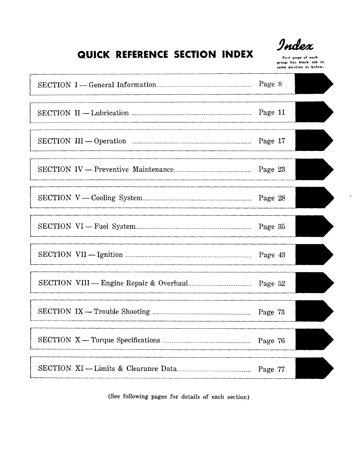
QUICK REFERENCE SECTION INDEX First page of each
group has black tab in
sQme position as below.
SECTION I--General Information ...................................................... Page 8
SECTION II -- Lubrication .................................................................... Page 11
SECTION III--Operation .................................................................... Page 17
SECTION IV--Preventive Maintenance ............................................ Page 23
SECTION V--Cooling System .............................................................. Page 28
SECTION VI.--Fuel System .................................................................. Page 35
SECTION VII--Ignition ........................................................................ Page 43
SECTION VIII--Engine Repair & Overhaul .................................... Page 52
SECTION IX--Trouble Shooting ........................................................ Page 73
SECTION X---Torque Specifications .................................................. Page 76
SECTION XI--Li.mits & Clearance Data .......................................... Page 77
(See following pages for details of each section)
I¥ CONTINENTAL L-HEAD ENGINE MANUAL
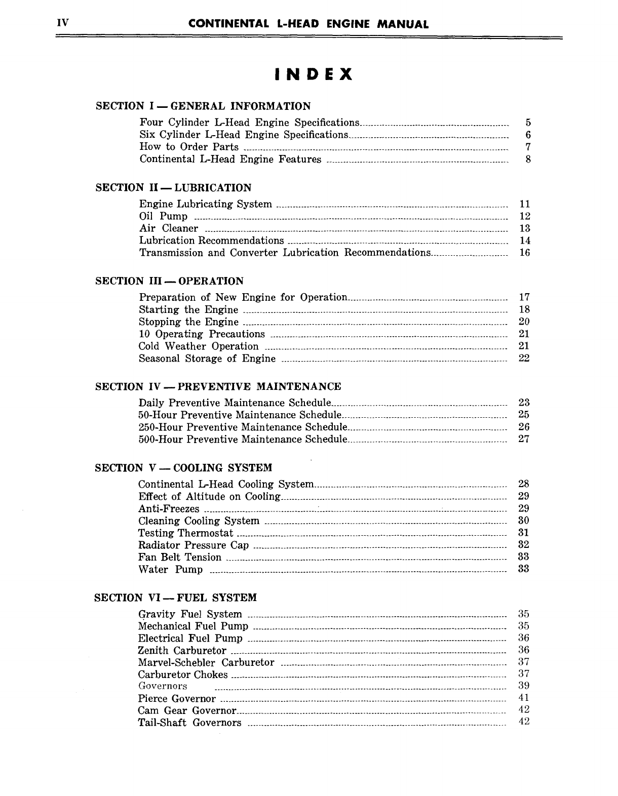
INDEX
SECTION I E GENERAL INFORMATION
Four Cylinder L-Head Engine Specifications ...................................................... 5
Six Cylinder L-Head Engine Specifications .......................................................... 6
How to Order Parts ................................................................................................ 7
Continental L-Head Engine Features .................................................................. 8
SECTION II -- LUBRICATION
Engine Lubricating System .................................................................................... 11
Oil Pump .................................................................................................................. 12
Air Cleaner .............................................................................................................. 13
Lubrication Recommendations ................................................................................ 14
Transmission and Converter Lubrication Recommendations ............................ 16
SECTION III-- OPERATION
Preparation of New Engine for Operation .......................................................... 17
Starting the Engine ................................................................................................ 18
Stopping the Engine ................................................................................................ 20
10 Operating Precautions ...................................................................................... 21
Cold Weather Operation ........................................................................................ 21
Seasonal Storage of Engine .................................................................................. 22
SECTION IV E PREVENTIVE MAINTENANCE
Daily Preventive Maintenance Schedule ................................................................ 23
50-Hour Preventive Maintenance Schedule ............................................................ 25
250-Hour Preventive Maintenance Schedule .......................................................... 26
500-Hour Preventive Maintenance Schedule .......................................................... 27
SECTION V m COOLING SYSTEM
Continental L-Head Cooling System ...................................................................... 28
Effect of Altitude on Cooling .................................................................................. 29
Anti-Freezes ......................................... : ............................................
: ....................... 29
Cleaning Cooling System ........................................................................................ 30
Testing Thermostat .................................................................................................. 31
Radiator Pressure Cap ............................................................................................ 32
Fan Belt Tension ...................................................................................................... 33
Water Pump ............................................................................................................ 33
SECTION VIE FUEL SYSTEM
Gravity Fuel System .............................................................................................. 35
Mechanical Fuel Pump ............................................................................................ 35
Electrical Fuel Pump .............................................................................................. 36
Zenith Carburetor .................................................................................................... 36
Marvel-Schebler Carburetor .................................................................................. 37
Carburetor Chokes .................................................................................................... 37
Governors .......................................................................................................... 39
Pierce Governor ........................................................................................................ 41
Cam Gear Governor ................................................................................................. 42
Tail-Shaft Governors .............................................................................................. 42
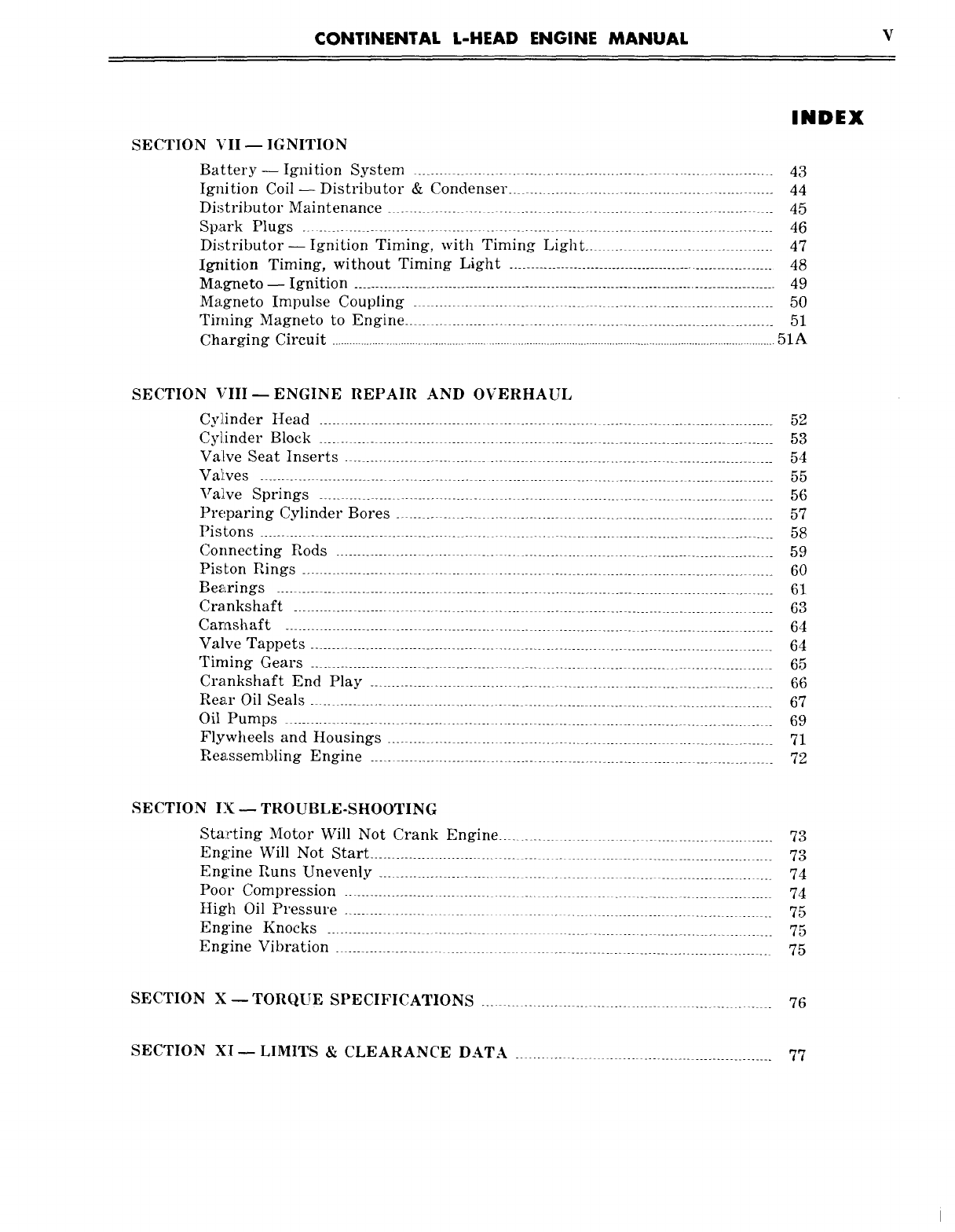
CONTINENTAL L-HEAD ENGINE MANUAL
INDEX
SECTION VII ~ IGNITION
Battery-- Ignition System ................................................................ 43
Ignition Coil- Distributor & Condenser .................................................. 44
Distributor Maintenance ............................................................ 45
Spark Plugs .................................................................................. 46
Distributor--Ignition Timing, with Timing Light .......................... 47
Ig~ition Timing, without Timing Light .............................................................. 48
Magneto -- Ignition ................................................................................................... 49
Magneto Impulse Coupling ........................................................ 50
Timing Magneto to Engine ..................................................................... 51
Charging Circuit ......................................................................................................................................................51A
SECTION VIII--ENGINE REPAIR AND OVERHAUL
Cyi[inder tIead ........................................................................................... 52
Cylinder Block ..................................................................................... 53
Valve Seat Inserts .................................................................................... 54
VaIves .................................................................................................... 55
Valtve Springs ..................................................................................... 56
Preparing Cylinder Bores ......................................................................... 57
Pistons ............................................................................................ 58
Connecting Rods ................................................................................. 59
Piston Rings ............................................................................................... 60
Bearings ................................................................................................ 61
Crankshaft ....................................................................................... 63
Camshaft ..................................................................................................... 64
Valve Tappets ..................................................................................................... 64
Timing Gears ..................................................................................... 65
Crankshaft End Play .......................................................................... 66
Rear Oil Seals .................................................................................... 67
Oil Pumps ............................................................................................ 69
Flywheels and Housings .................................................................... 71
Reassembling Engine ................................................................................. 72
SECTION IX-- TROUBLE-SHOOTING
Starting Motor Will Not Crank Engine .................................................... 73
Engine Will Not Start ................................................................................. 73
Engine Runs Unevenly ........................................................................... 74
Poor Compression .............................................................................. 74
High Oil Pressure .......................................................................... 75
Engine Knocks ...................................................................................... 75
Engine Vibration ................................................................................... 75
SECTION X ~ TORQUE SPECIFICATIONS ............................................ 76
SECTION XI--LIMITS & CLEARANCE DATA ............................................. 77

FORWARD
Good operation and a planned maintenance program as outlined in this
manual are of vital importance in obtaining maximum engine performance, and long
engine life. The instructions on the following pages have been written with this
in mind, to give the operator a better understanding of the various problems which
may arise, and the manner in which these problems can best be solved or avoided.
Procedure in the Preventive Maintenance Section must be set up and
followed by the owner and operator to obtain dependable service and long life from
the engine. Owners and operators are expected to perform these maintenance
procedures as outlined under the daily schedule as well as 50-hr., 250-hr.,
and 5OO-hr. periods WHILE IN THE WARRANTY PERIOD AS WELL AS
DURING THE LIFE OF THE ENGINE.
Warranty service does not include tune-up of the engine such as replacing
spark plugs, distributor points, tappet settings, ignition timing, ignition wiring,
air cleaner service and lubrication and lter maintenance.
The operator is cautioned against the use of any parts, other than Genuine
Wisconsin Motors, LLC Continental Parts for replacement or repair. These
parts have been engineered and tested for their particular job, and the use of any
other parts may result in unsatisfactory performance and short engine life.
Likewise, Wisconsin Motors, LLC Continental distributors and dealers, because
of their close factory relations, can render the best and most efcient service.
THE LIFE OF YOUR ENGINE DEPENDS
ON THE CARE IT RECEIVES.
CONTINENTAL L-HEAD ENGINE MANUAL Page 1
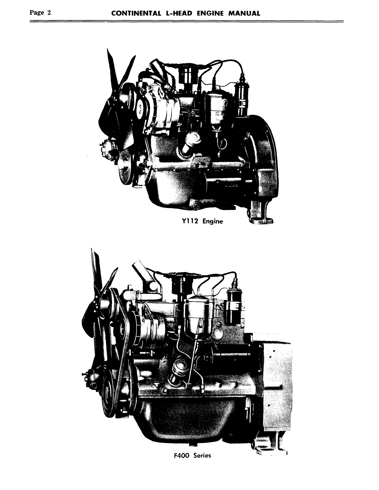
Page 2 CONTINENTAL L-HEAD ENGINE MANUAL
Y112 Engine
F400 Series
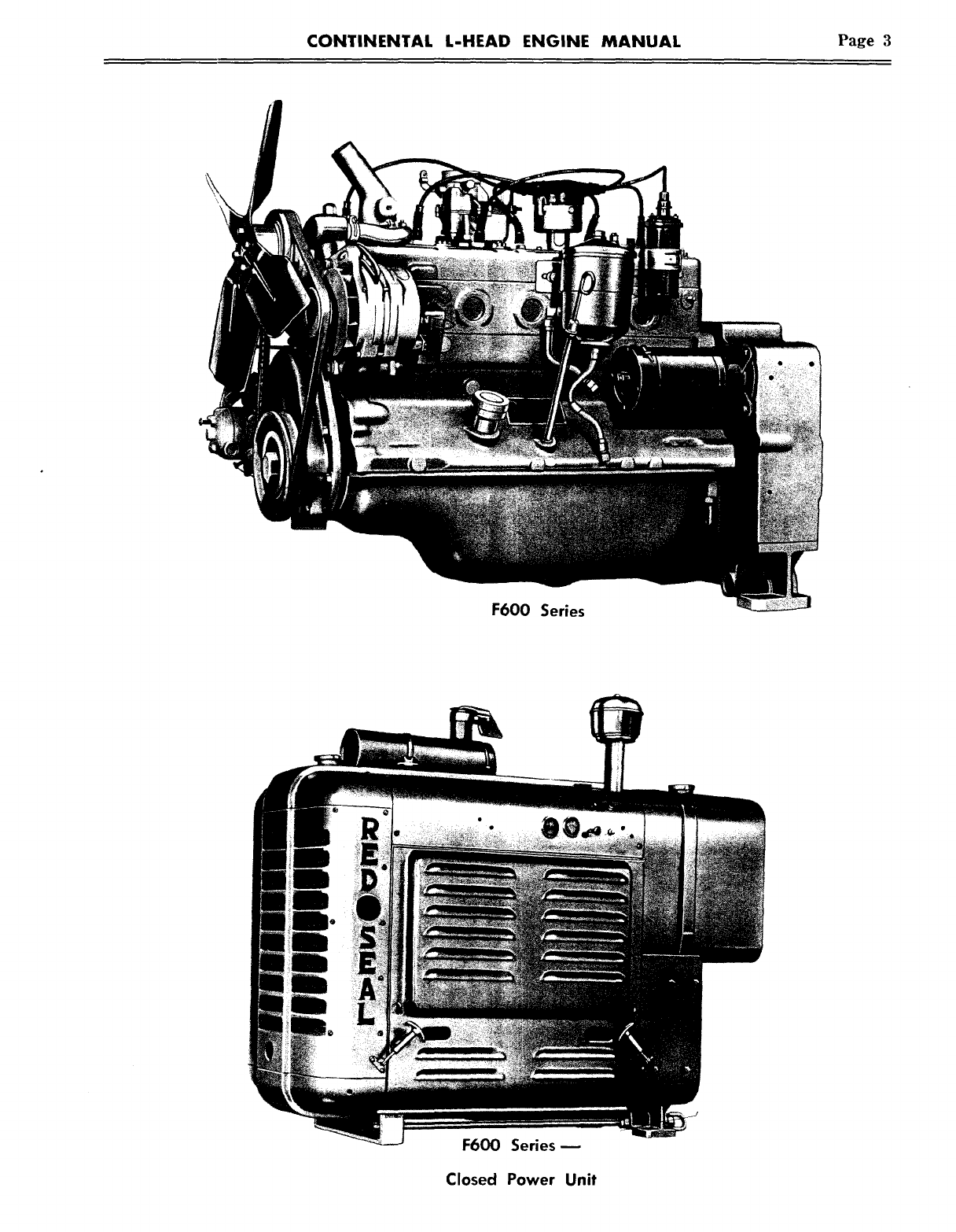
CONTINENTAL L-HEAD ENGINE MANUAL Page 3
F600 Series
F600 Series-
Closed Power Unit
Page 4 CONTINENTAL L-HEAD ENGINE MANUAL
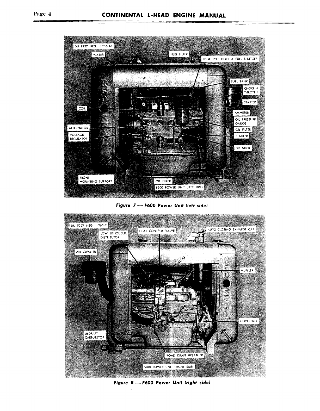
Figure 7 u F600 Power Unit (left side)
Figure 8 ~ F600 Power Unit (right side)
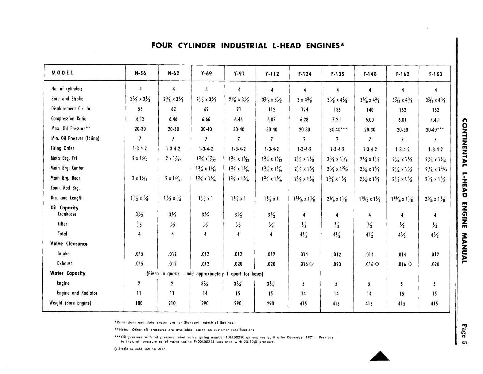
FOUR CYLINDER INDUSTRIAL L-HEAD ENGINES*
MODEL
No. of cylinders
Bore and Stroke
Displacement Cu.
Compression Ratio
Max. Oil Pressure**
Min. Oil Pressure (Idling)
Firing Order
Main Brg. Frt.
Main Brg. Center
Main Brg. Rear
Conn. Rod Brg.
Dia. and Length
N-56
4
2¼ x 3½
6.12
20-30
7
1-3-4-2
2x1~2
N-62
4
2~ x 3~
62
6.46
20-30
7
1-3-4-2
2x1~2
Y-69
4
2~ x 3½
6.66
30-40
7
1-3-4-2
, I~ x 1~e
Y-91
4
2~ x 3½
91
6.46
30-40
7
1-3-4-2
Oil Capacity
Crankcase
Filter
Total
Valve Clearance
Intake
Exhaust
.015
.01 S
.012
.012
3~
½
4
.012
.012
3~
½
4
.012 I
.020
Water Capacity
Engine
Engine and Radiator
Weight (Bare Engine)
(Given approximately 1 quart for hoses)
23~ 3~
11 14 15
180 290 290
in quarts-- add
2
11 I
210 j
Y-112 F-124
3~ x 3~
112
6.07
30-40
7
1-3-4-2
1~44 X 17/116
3½
4
.012
.020
3~
15
290
4
3x4~
124
6.28
20-30
7
1-3-4-2
2¼x1~
2¼ x I~
2¼ x1~
.014
.016 ©
5
14
415
*Dimensions and data shown are for Standard Industrial Engines.
**Note: Other all pressures are available, based on customer specifications.
***OH pressure with oil pressure relief valve spring number 10EL00230 on engines built after December 1971. Previous
to that, all pressure relief valve spring F400LO0223 was used with 20-30~ pressure.
~ StaHc or cold setting .017
F-13S
4
3~ x 4~
135
7.2:1
30-40***
7
1-3-4-2
2~ x 12~
2~ xl~
F-140
4
3~ x 4~
140
6.00
20-30
7
1-3-4-2
2¼x1½
~¼xl~
2¼x1~
F-162
4
3~6 x 4~
162
6.01
20-30
7
1-3-4-2
2¼x1¼
2¼ x1~
2¼xI~
4
½
4~
.012
.020
5
14
415
4
½
4½
.014
.016 ~
5
14
415
.014
.016 o
F-163
4
3~ x 4~
162
7.4:1
30-40***
7
1-3-4-2
2~ xl~
2~ x
2~ x1~
4
½
4~
.012
.020
5
15
415
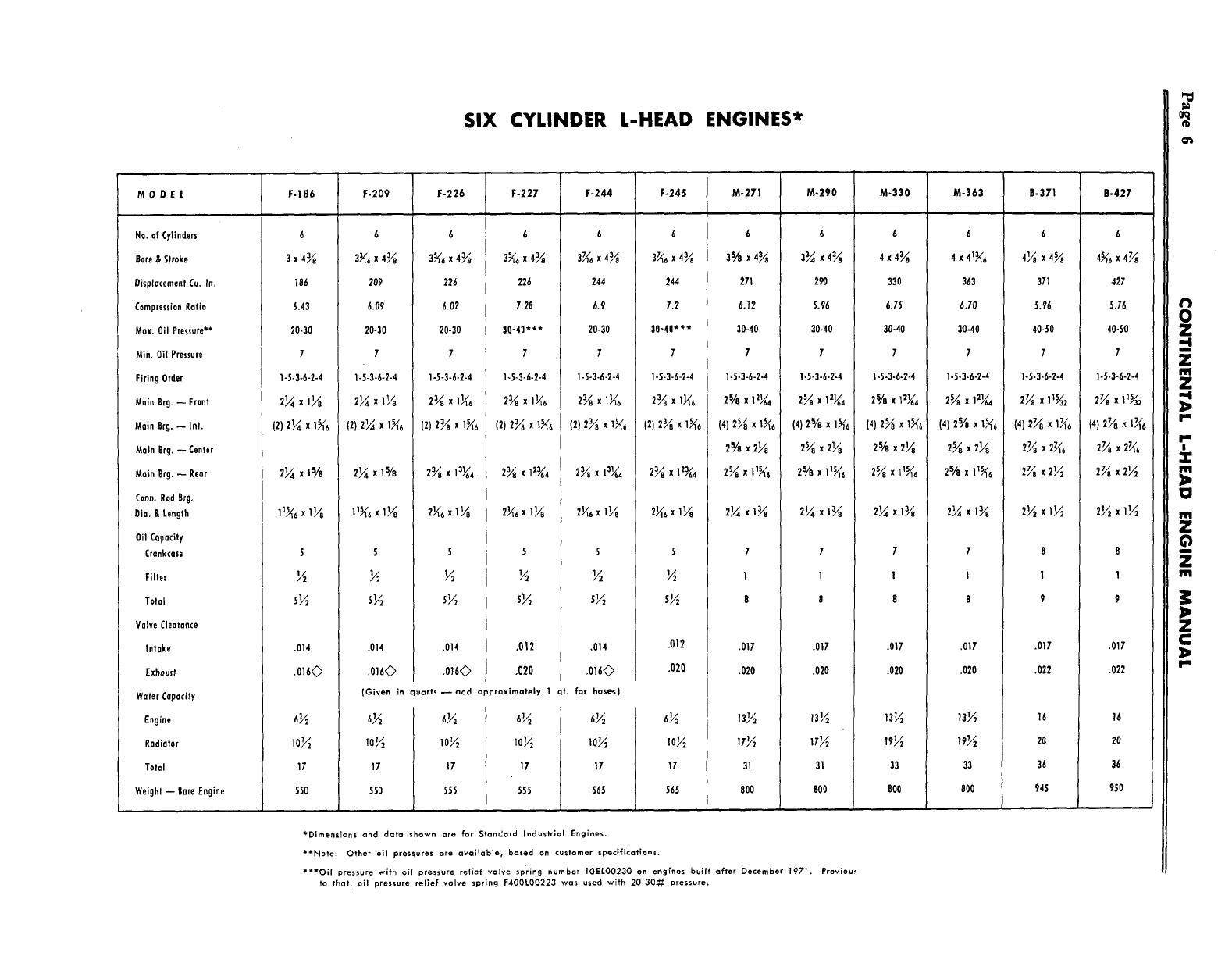
SIX CYLINDER L-HEAD ENGINES*
M 0 D E L F-186 F-209 F-226 F-227 F-244 F-245 M-271 M.290 M-330 M-363 B-371 B-427
Ha. of Cylinders
Born & Strokn
0isplacnment Cu. In.
Compression Ratio
Max. 0il Pressure**
Min. 0H Prnssurn
Firing 0rdnr
Main Rrg.--Front
Main grg. -- Int.
Main Brg.--Center
Main Br
9. --Rear
Conn. Rod Rrg.
Oia. & Length
0il CQpocity
Crankcase
Filter
Total
Valve Clearance
Intake
Exhaust
Water Capacity
Engine
Radiator
Total
Weight--Rare Engine
6
3x4~
6.43
20-30
7
I-5-3-6-2-4
21/4 x 11./~
(2) 2¼ 1~6
5
.014
.016~
6½
10~22
17’
~0
6
3~ x 4~
209
6.09
20-30
7
6
226
6.02
20-30
7
6
3~ x 4~
22~
7.28
’~0-40"**
7
6
244
~.9
20-30
7
6
3~e x 43/e
244
7.2
30-40***
7
6
3~/~ x 43/~e
271
6.12
30-40
7
6
33.3.~ x
290
S.96
30-40
7
6
4x43/e
330
6.75
30-40
7
4 x 41~e
363
6.70
30-40
7
1-5-3-6-2-4
2¼ xl~
(2) 2~ xl~
6
2¼ xl~/~
5
s½
.014
1-5-3-6-2-4
(2) 2~ xI~6
5
½
s½
.014
.016~)
1,5-3-6-2.4
(2)2~ xl~
2~ ~ I~
S
.012
.020
1-5-3-6-2-4
(2) 2~ xl~
2~ X13~4
5
½
s½
,014
.016~
(Given in quarts ~ add approximately qt. for hose,s)
~0½ lo½ 1o½ 10½
17 17 17 17
550 SSS 555 565
1-S-3-6-2-4
(2) 2~ xl~e
2~x~¼
1-5-3-6-2-4
2~ x1~4
(4) 2~ xl~
2%
2~ x~
1-5-3-6-2-4
2~ x12~
(4) 2% x1~6
2~ x2¼
2% xlt~
2¼ x~
1-5-3-6-2-4
2% x1~4
(4) 2~ xl~
2% x2~
2¼ x~
1-5-3-6-2-4
2~ xl~
(4) 2% xl~e
2~ ~2¼
5
½
s½
.012 .017
.020 .020
13½
IT 31
565 800
.017
.020
13½
31
800
.017
.020
13½
33
800
,017
.020
13½
33
800
*Dimensions and data shown are for StanCard Industrial Engines.
~’*Note: Other all pressures are available, based on customer specifications.
~**Oil pressure with all pressur~ relief valve sp~ing number TOELC)O230 on engfnes bu?ft after December 1971. Previou~
to that, oil pressure relief valve spring F4OOLO0223 was used with 20-30-’~: pressure.
6
4~/~ x4S/~
371
5.96
40-50
7
1-S-3-6-2-4
2~ x
(4) 2~
2~ x~6
2~ x2½
.017
.022
16
2G
36
945
6
4~¢~ ~ 4½
427
5.76
40-50
7
1-5-3-6-2-4
2~ x 1~
21~2 x1½
.017
.022
16
20
36
950
Z
C::
CONTINENTAL L-HEAD ENGINE MANUAL Page 7
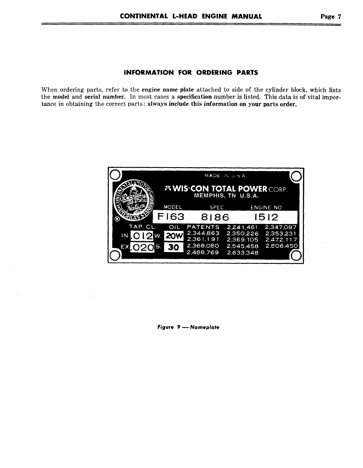
INFORMATION FOR ORDERING PARTS
When ordering’ parts, refer to the engine name plate attached to side of the cylinder block, which lists
the model and serial number. In most cases a specification number is listed. This data is of vital impor-
tance in obtaining the correct parts : always include this information on your parts order.
Figure 9 w Nameplate
Page 8 CONTINENTAL L-HEAD ENGINE MANUAL
SECTION 1
GENERAL INFORMATION
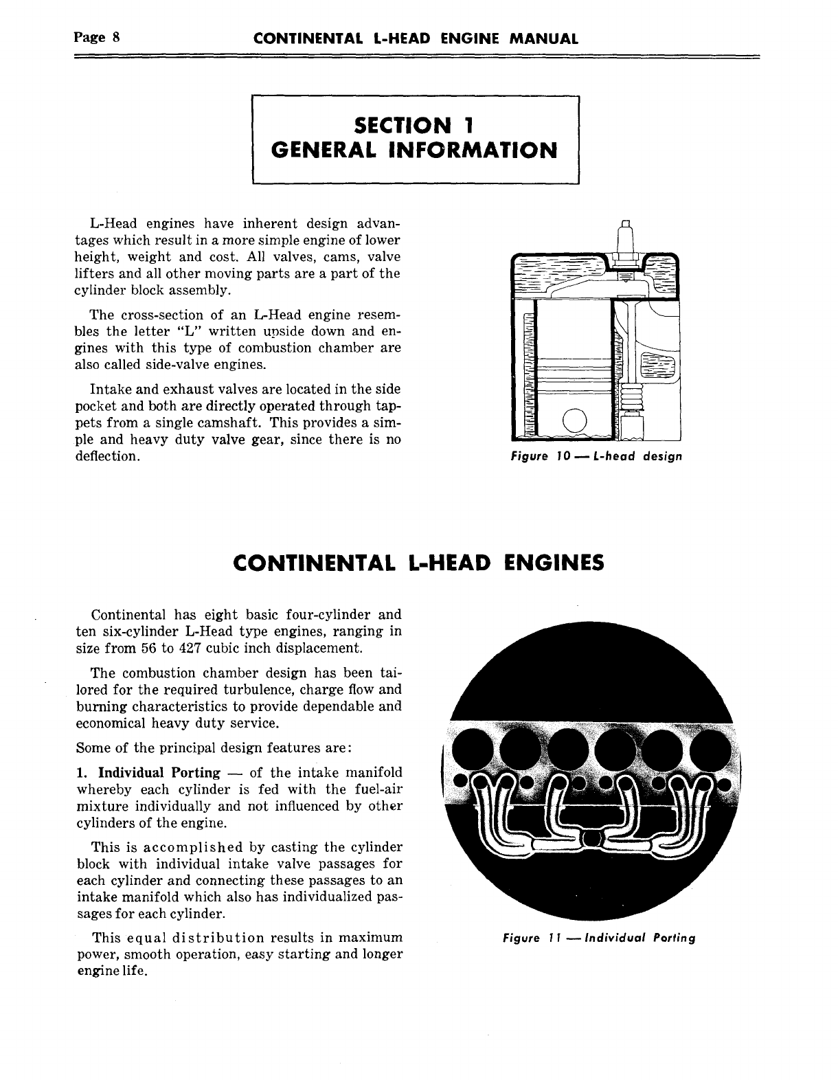
L-Head engines have inherent design advan-
tages which result in a more simple engine of lower
height, weight and cost. All valves, cams, valve
lifters and all other moving parts are a part of the
cylinder block assembly.
The cross-section of an L-Head engine resem-
bles the letter "L" written upside down and en-
gines with this type of combustion chamber are
also called side-valve engines.
Intake and exhaust valves are located in the side
pocket and both are directly operated through tap-
pets from a single camshaft. This provides a sire-
ple and heavy duty valve gear, since there is no
deflection. Figure 10 ~ L-head design
CONTINENTAL L-HEAD ENGINES
Continental has eight basic four-cylinder and
ten six-cylinder L-Head type engines, ranging in
size from 56 to 427 cubic inch displacement.
The combustion chamber design has been tai-
lored for the required turbulence, charge flow and
burning characteristics to provide dependable and
economical heavy duty service.
Some of the principal design features are:
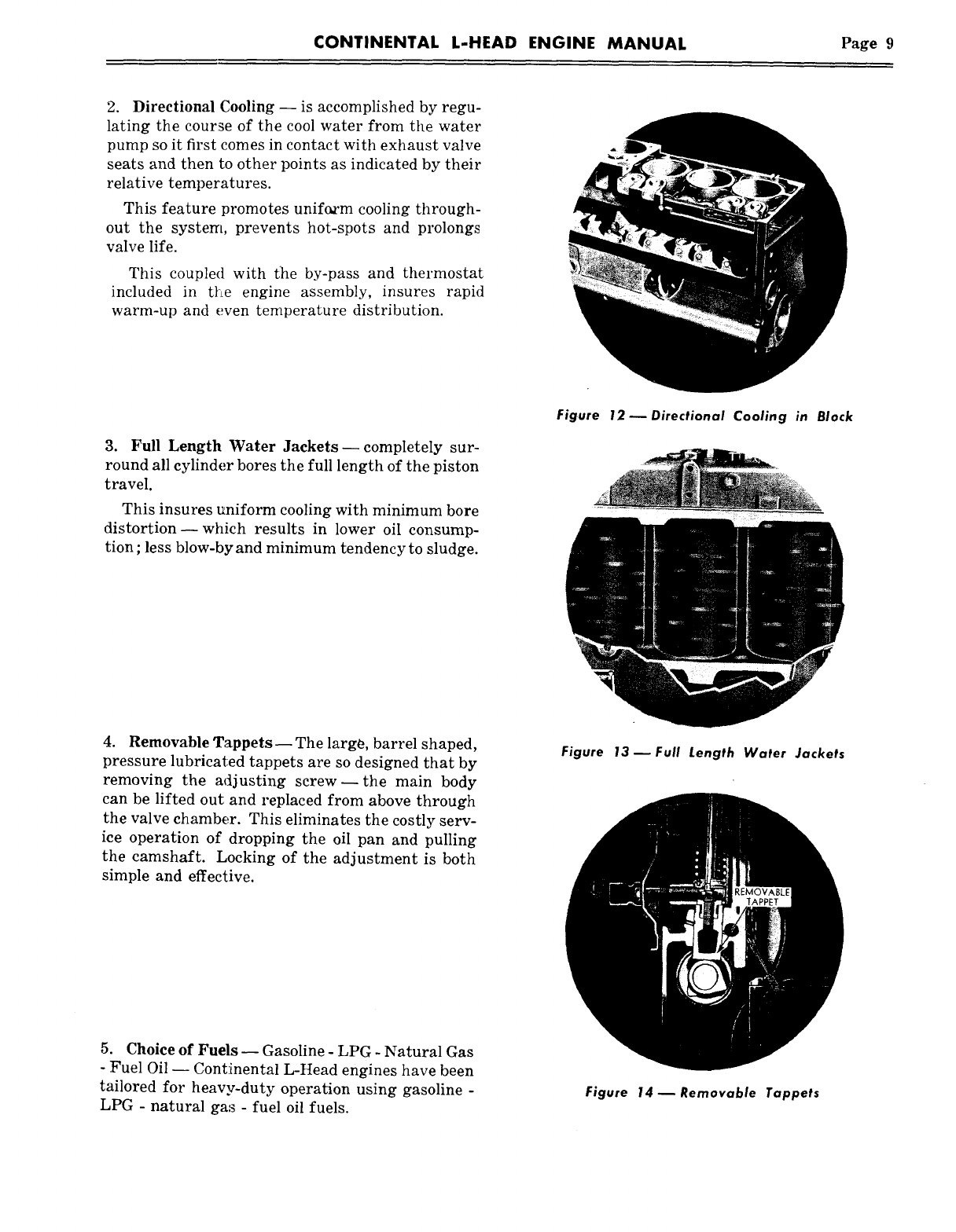
1. Individual Porting -- of the intake manifold
whereby each cylinder is fed with the fuel-air
mixture individually and not influenced by other
cylinders of the engine.
This is accomplished by casting the cylinder
block with individual intake valve passages for
each cylinder and connecting these passages to an
intake manifold which also has individualized pas-
sages for each cylinder.
This equal distribution results in maximum
power, smooth operation, easy starting and longer
engine life.
Figure 1 1 ~ Individual Parting
CONTINENTAL L-HEAD ENGINE MANUAL Page 9
2. Directional Cooling -- is accomplished by regu-
lating the course of the cool water from the water
pump so it first comes in contact with exhaust valve
seats and then to other points as indicated by their
relative temperatures.
This feature promotes unif~m cooling through-
out the system, prevents hot-spots and prolongs
valve life.
This coupled with the by-pass and thermostat
included in tl~e engine assembly, insures rapid
warm-up and even temperature distribution.
3. Full Length Water Jackets- completely sur-
round all cylinder bores the full length of the piston
travel.
This insures uniform cooling with minimum bore
distortion- which results in lower oil consump-
tion ; less blow-by and minimum tendency to sludge.
Figure 12 ~ Directional Cooling in Block
4. Removable Tappets-- The large, barrel shaped,
pressure lubricated tappets are so designed that by
removing the adjusting screw--the main body
can be lifted out and replaced from above through
the valve chamber. This eliminates the costly serv-
ice operation of dropping the oil pan and pulling
the camshaft. Locking of the adjustment is both
simple and effective.
Figure 13 ~ Full Length Water Jackets
5. Choice of Fuels -- Gasoline - LPG - Natural Gas
- Fuel Oil -- Cont:inental L-Head engines have been
tailored for heavy-duty operation using gasoline -
LPG - natural ga~s - fuel oil fuels. Figure 14 ~ Removable Tappets
Page 10 CONTINENTAL L-HEAD ENGINE MANUAL
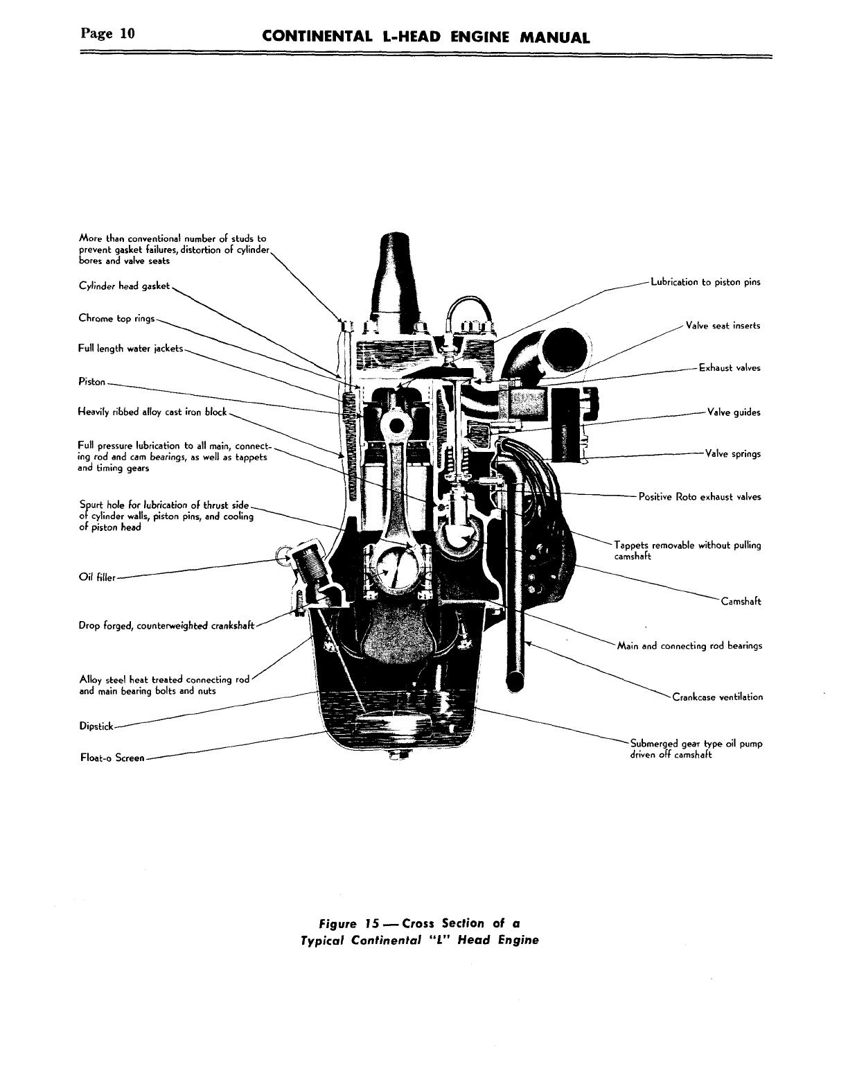
More than conventional number o[ studs to
prevent gasket failures, distortion ol:
bores and valve seats
Cylinder head
Chr,
I:ull length water
Piston ~
Heavily ribbed alloy cast iron
Full pressure lubrication to all main, connect-
;ng rod and cam bearings, as weJl as tappets
and timing gears
Spurt hole ~or I~brication of thrust
otcylinder walls, piston pins, and cooling
ol: piston head
Drop forged, counterwe~ghted crankshaft;
Alloy steel heat treated connecting rod
and main beating bolts and nuts
Dipstick-
~loet-o Screen
piston pins
inserts
Exhaust valves
guides
/abe springs
Positive Roto exhaust valves
removable without pulling
camsha~:
"Main and connecting rod bearings
Crankcase ventilation
Submerged gear b/pe oil pump
driven off camshaft
Figure 15 ~Cross Section of a
Typical Continental "L" Head Engine
CONTINENTAL L-HEAD ENGINE MANUAL Page 11
SECTION II
LUBRICATION
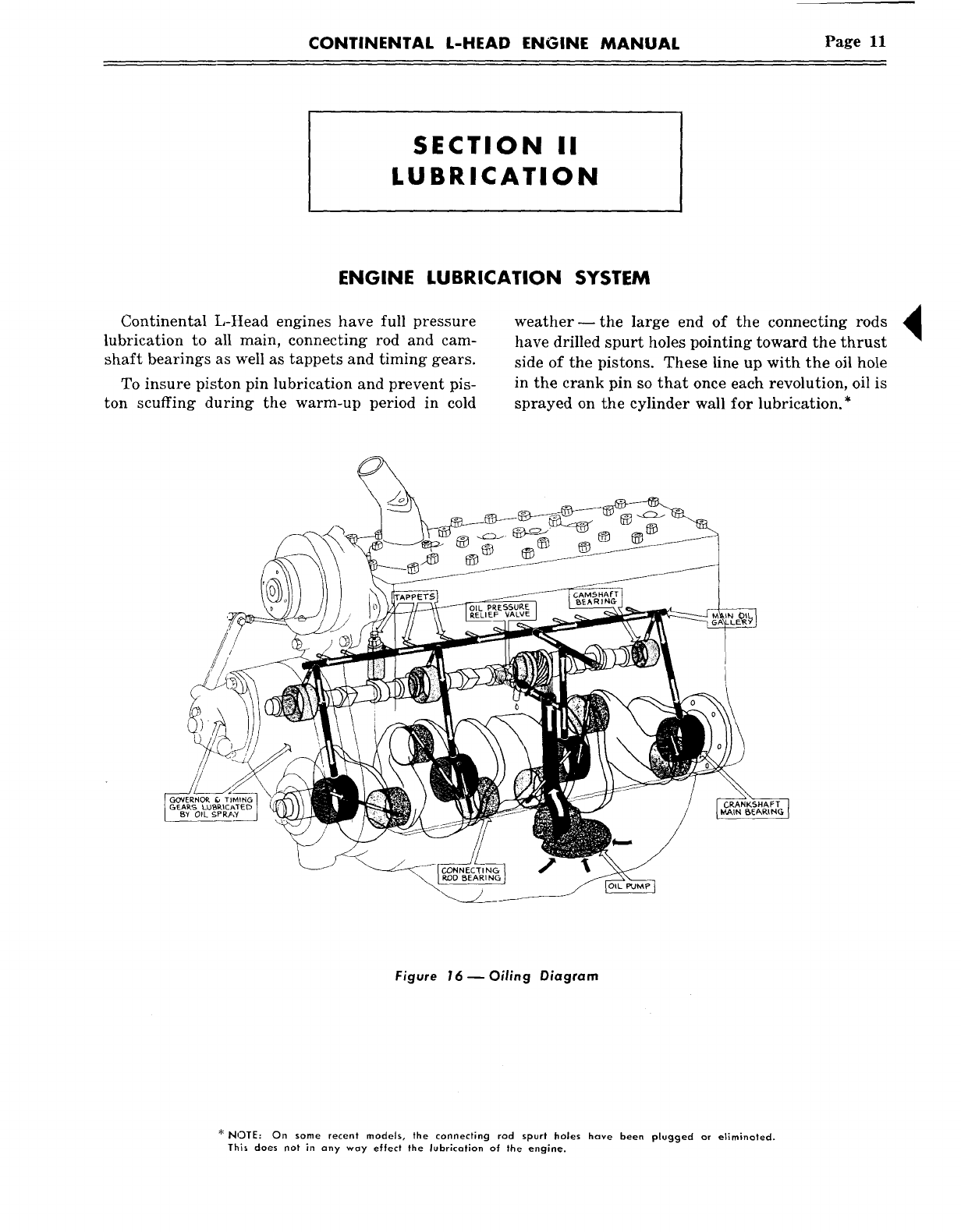
ENGINE LUBRICATION SYSTEM
Continental L-Head engines have full pressure
lubrication to all main, connecting rod and cam-
shaft bearings as well as tappets and timing gears.
To insure piston pin lubrication and prevent pis-
ton scuffing during the warm-up period in cold
weather--the large end of the connecting rods
have drilled spurt holes pointing toward the thrust
side of the pistons. These line up with the oil hole
in the crank pin so that once each revolution, oil is
sprayed on the cylinder wall for lubrication.*
CRANKSHAFT
Figure 16 ~ Oiling Diagram
NOTE: On some recent models, the connecting rod spurt holes have been plugged or eliminated.
This does not in any way effect the lubrication of the engine.
Page 12 CONTINENTAL L-HEAD ENGINE MANUAL
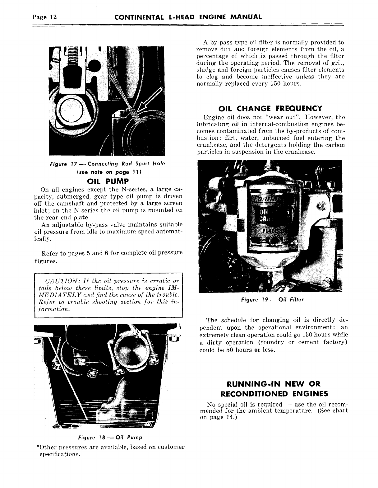
Figure 17--Connecting Rod Spurt Hole
(see note on page 11)
OIL PUMP
On all engines except the N-series, a large ca-
pacity, submerged, gear type oil pump is driven
off the camshaft and protected by a large screen
inlet; on the N-series the oil pump is mounted on
the rear end plate.
An adjustable by-pass valve maintains suitable
oil pressure from idle to maximum speed automat-
ically.
Refer to pages 5 and 6 for complete oil pressure
figures.
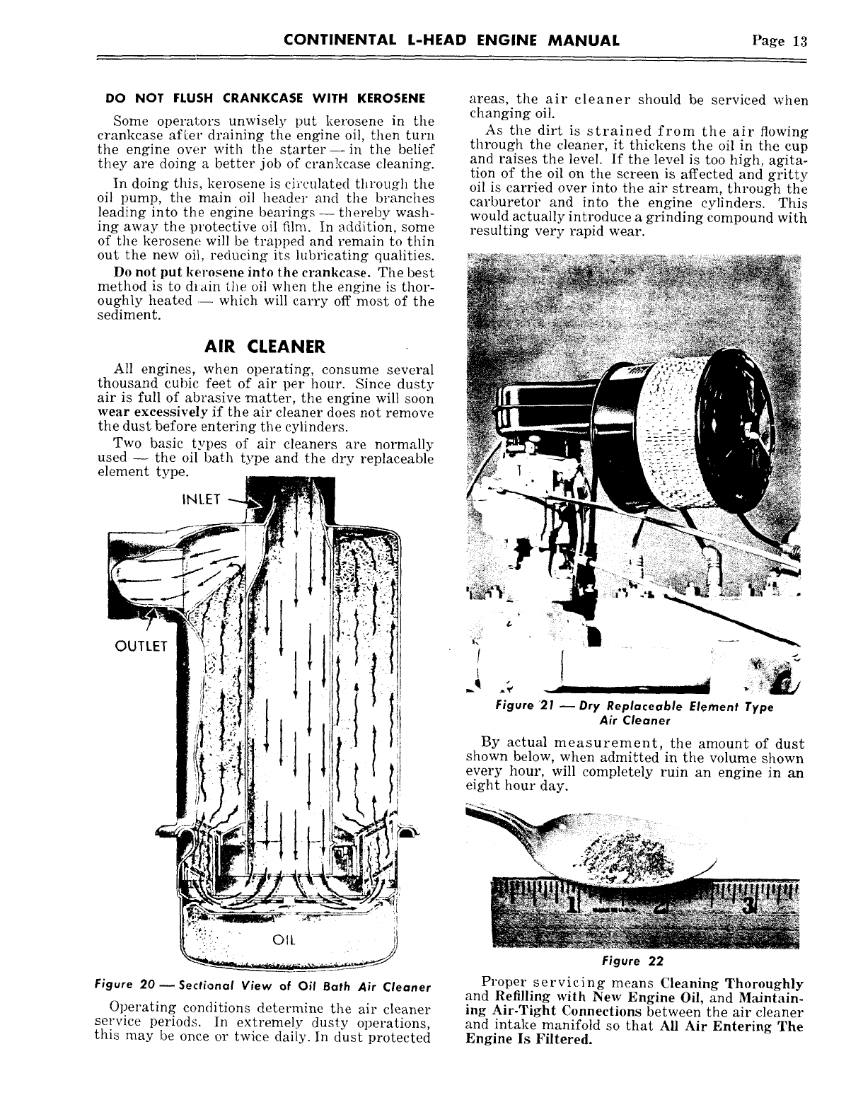
A by-pass type oil filter is normally provided to
remove dirt and foreign elements from the oil, a
percentage of which.is passed through the filter
dm’ing the operating period. The removal of grit,
sludge and foreign particles causes filter elements
to clog and become ineffective unless they are
normally replaced every 150 hours.
OIL CHANGE FREQUENCY
Engine oil does not "wear out". However, the
lubricating oil in internal-combustion engines be-
comes contaminated from the by-products of com-
bustion: dirt, water, unburned fuel entering the
crankcase, and the detergents holding the carbon
particles in suspension in the crankcase.
CAUTION: If the oil pressure is erratic or
falls below these limits, stop the engine IM-
MEDIATELY ~.~d find the cause of the trouble.
Refer to trouble shooting section for this in-
formation.
Figure 19 ~ Oil Filter
The schedule for changing oil is directly de-
pendent upon the operational environment: an
extremely clean operation could go 150 hours while
a dirty operation (foundry or cement factory)
could be 50 hours or less.
RUNNING-IN NEW OR
RECONDITIONED ENGINES
No ~pecial oil is required -- use the oil recom-
mended for the ambient temperature. (See chart
on page 14.)
Figure 18~0il Pump
*Other pressures are available, based on customer
specifications.
CONTINENTAL L-HEAD ENGINE MANUAL Page 13
DO NOT FLUSH CRANKCASE WITH KEROSENE
Some operal:ors un~visely put kerosene in the
crankcase after draining the engine oil, then turn
the engine over with the starter--in the belief
they are doing a better job of crankcase cleaning.
In doing this, kerosene is circulated through the
oil pump, the main oil header and the branches
leading into the engine bearings -- thereby wash-
ing away the protective oil film. In addition, some
of the kerosene will be trapped and remain to thin
out the new oil, reducing its lubricating qualities.
Do not put kerosene into the crankcase. The best
method is to drain the oil when the engine is thor-
oughly heated .-- which will carry off most of the
sediment.
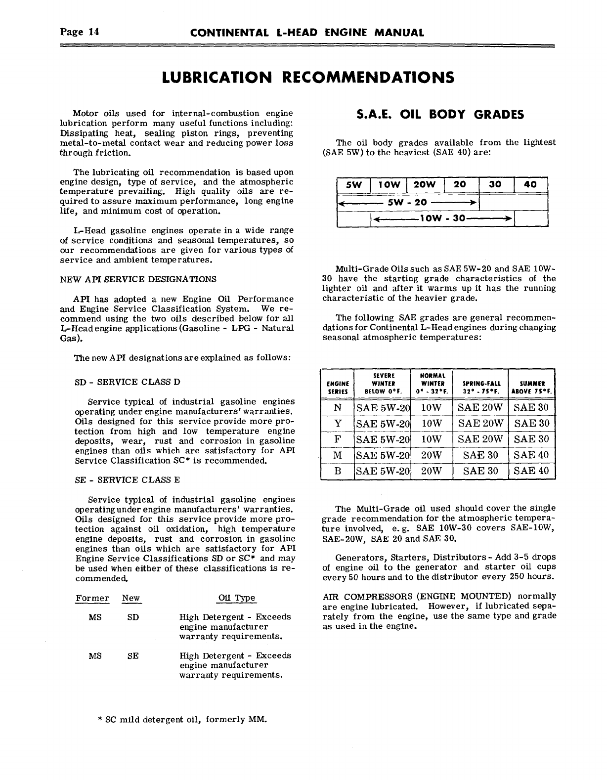
AIR CLEANER
All engines, when operating, consume several
thousand cubic feet of air per hour. Since dusty
air is full of abrasive matter, the engine will soon
wear excessively if the air cleaner does not remove
the dust before entering the cylinders.
Two basic types of air cleaners are normally
used -- the oil bath type and the dry replaceable
element type.
INLET
Figure 20--Sectional View of Oil Bath Air Cleaner
O~?era~ing condRions determine the air cleaner
serwce periods. ~n e×treme]~ dusty operations,
this may be once or twice daily. In dust protected
areas, the air cleaner should be serviced when
changing oil.
As the dirt is strained from the air flowing
through the cleaner, it thickens the oil in the cup
and raises the level. If the level is too high, agita-
tion of the oil on the screen is affected and gritty
oil is carried over into the air stream, through the
carburetor and into the engine cylinders. This
would actually introduce a grinding compound with
resulting very rapid wear.
Figure 21- Dry Replaceable Element Type
Air Cleaner
By actu~! measurement, the amount of dust
shown below, when admitted in the volume shown
every hour, will completely ruin an engine in an
eight hour day.
Figure 22
Proper servicing means Cleaning Thoroughly
and Refilling with New Engine Oil, and Maintain-
ing Air-Tight Connections between the air cleaner
and intake manifold so that All Air Entering The
Engine Is Filtered.
Page 14 CONTINENTAL L-HEAD ENGINE MANUAL
LUBRICATION RECOMMENDATIONS
Motor oils used for internal-combustion engine
lubrication perform many useful functions including:
Dissipating heat, sealing piston rings, preventing
metal-to-metal contact wear and reducing power loss
through friction.
The lubricating oil recommendation is based upon
engine design, type of service, and the atmospheric
temperature prevailing. High quality oils are re-
quired to assure maximum performance, long engine
life, and minimum cost of operation.
L-Head gasoline engines operate in a wide range
of service conditions and seasonal temperatures, so
our recommendations are given for various types Of
service and ambient temperatures.
NEW API SERVICE DESIGNATIONS
API has adopted a new Engine Oil Performance
and Engine Service Classification System. We re-
commend using the two oils described below for all
L-Head engine applications (Gasoline - LPG - Natural
Gas).
The new API designations are explained as follows:
SD - SERVICE CLASS D
Service typical of industrial gasoline engines
operating under engine manufacturers’ warranties.
Oils designed for this service provide more pro-
tection from high and low temperature engine
deposits, wear, rust and corrosion in gasoline
engines than oils which are satisfactory for API
Service Classification SC* is recommended.
SE - SERVICE CLASS E
Service typical of industrial gasoline engines
operating under engine manufacturers’ warranties.
Oils designed for this service provide more pro-
tection against oil oxidation, high temperature
engine deposits, rust and corrosion in gasoline
engines than oils which are satisfactory for API
Engine Service Classifications SD or SC* and may
be used when either of these classifications is re-
commended.
Former New
MS SD
Oil Type
High Detergent - Exceeds
engine manufacturer
warranty requirements.
MS SE High Detergent - Exceeds
engine manufacturer
warranty requirements.
S.A.E. OIL BODY GRADES
The oil body grades available from the lightest
(SAE 5W) to the heaviest (SAE 40)
30 I 40
Multi-Grade Oils such as SAE 5W-20 and SAE 10W-
30 have the starting grade characteristics of the
lighter oil and after it warms up it has the running
characteristic of the heavier grade.
The following SAE grades are general recommen-
dations for Continental L-Head engines during changing
seasonal atmospheric temperatures:
SEVERE
ENGINE WINTER
SERIES BELOW O°F.
N SAE 5W-20
Y SAE 5W-20
F SAE 5W-20
M sAE 5W-20
B SAE 5W-20
NORMAL
WINTER
0o . 32~F.
lOW
lOW
10W
20W
20W
SPRING.FALL
32
° . 75OF.
SAE 20W
SAE 20W
SAE 20W
SAE 30
SAE 30
SUMMER
ABOVE 75°F. i
SAE 30
SAE 30
SAE 3O
SAE 40
SAE 40
The Multi-Grade oil used should cover the single
grade recommendation for the atmospheric tempera-
ture involved, e.g. SAE 10W-30 covers SAE-10W,
SAE-20W, SAE 20 and SAE 30.
Generators, Starters, Distributors-Add 3-5 drops
of engine oil to the generator and starter oil cups
every 50 hours and to the distributor every 250 hours.
AIR COMPRESSORS (ENGINE MOUNTED) normally
are engine lubricated. However, if lubricated sepa-
rately from the engine, use the same type and grade
as used in the engine.
* SC mild detergent oil, formerly MM.
CONTINENTAL L-HEAD ENGINE MANUAL Page 15
Clutches -- Use a high temperature bearing
grease. Do not. over-lubricate.
Conventional Transmissions -- For the greatest
efficiency over the life of the transmission, use a
high quality straight mineral oil. The oil should
be changed sea:sonally.
Use the following proper grades :
Clark
Fuller
Twin Disc
Warner
SUMMER
SAE 90
SAE 140
SAE 4O
SAE .140
WINTER
SAE 90
SAE 90
SAE 40
SAE 90
Torque Converters and Hydraulic or Automatic
Transmissions---These units employ a fluid me-
dium to transmit power which must be very stable
to resist formation of harmful deposits or change
in body in use. The correct fluid must be selected
to obtain maximum efficiency of the transmission.
All fluids should be changed seasonally.
Type "A" Automatic Transmission fluid is most
widely used. There are many widely distributed
brands of this type.
For some models of Twin Disc Clutch Company’s
torque converters, a Special Fluid having a viscos-
ity of 35 Saybolt seconds @ 100° F. is, required --
other models use SAE 10W engine oil. The Special
low viscosity fluid may be obtained from Twin Disc
Clutch Company Dealers. To satisfy the SAE 10W
requirement, we recommend the use of MS type
oils.
Allison Division torque converters and Torqma-
tic transmissions require a type C fluid.
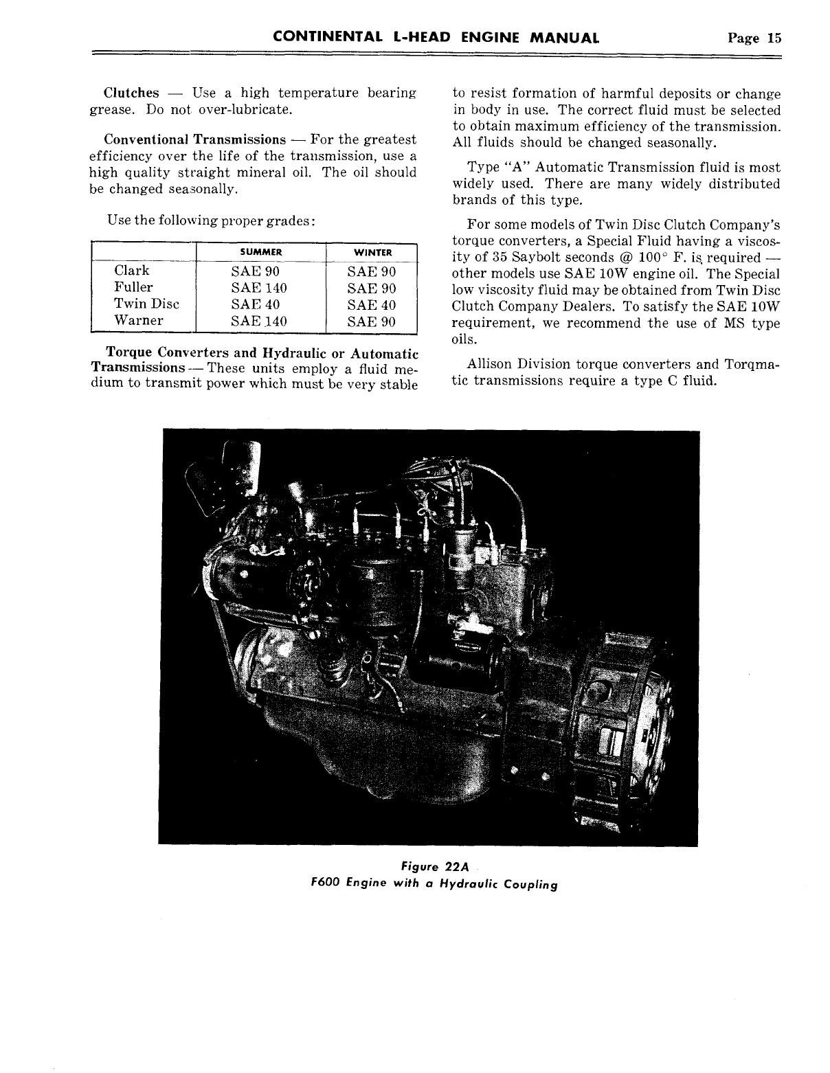
Figure 22A
F600 Engine with a Hydraulic Coupling
Page 16 CONTINENTAL L-HEAD ENGINE MANUAL
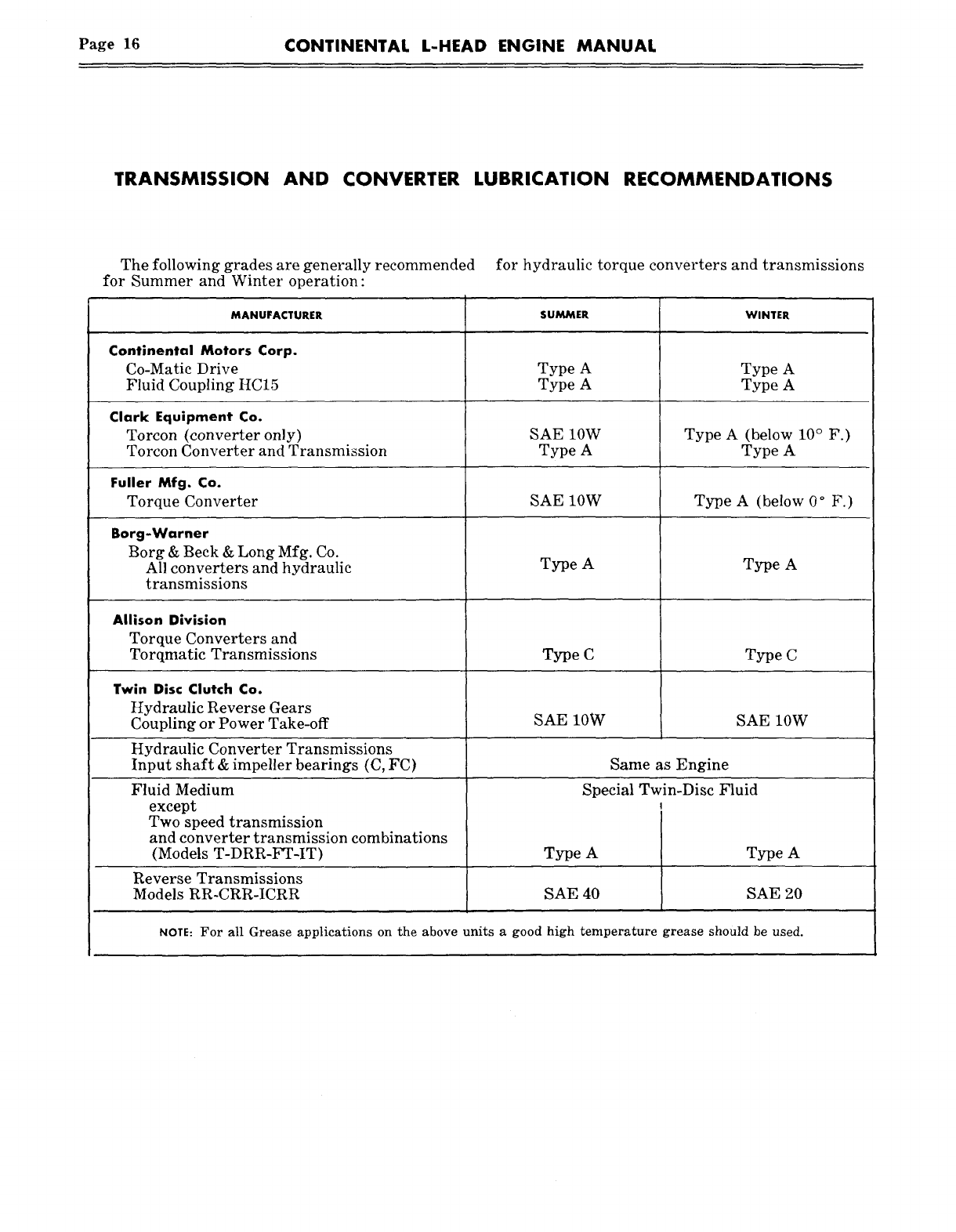
TRANSMISSION AND CONVERTER LUBRICATION RECOMMENDATIONS
The following grades are generally recommended for hydraulic torque converters and transmissions
for Summer and Winter operation:
MANUFACTURER
Continental Motors Corp.
Co-Matic Drive
Fluid Coupling HC15
Clark Equipment Co.
Torcon (converter only)
Torcon Converter and Transmission
Fuller Mfg. Co.
Torque Converter
Borg-Warner
Borg & Beck & Long Mfg. Co.
All converters and hydraulic
transmissions
Allison Division
Torque Converters and
Torqmatic Transmissions
SUMMER
Type A
Type A
SAE 10W
Type A
SAE 10W
Type A
WINTER
Type A
Type A
Fluid Medium
except
Two speed transmission
and converter transmission combinations
(Models T-DRR-FT-IT) Type A Type A
Reverse Transmissions
Models RR-CRR-ICRR SAE 40 SAE 20
NOTE: For all Grease applications on the above units a good high temperature grease should be used.
Type C Type C
Twin Disc Clutch Co.
Hydraulic Reverse Gears
Coupling or Power Take-off SAE 10W SAE 10W
Hydraulic Converter Transmissions
Input shaft & impeller bearings (C, FC) Same as Engine
Special Twin-Disc Fluid
Type A
Type A (below ° F.)
Type A (below 10° F.)
Type A
CONTINENTAL L-HEAD ENGINE MANUAL Page 17
SECTION III
OPERATING INSTRUCTIONS
The person operating the engine naturally as-
sumes responsibility for its care while it is being
operated. This is a very important responsibility
since the care and attention given the engine goes
a long way in determining how long a period it will
operate satisfactorily before having to be shut
down for repairs.
The operating and preventive maintenance in-
structions for the L-Head type engines are simple
and should be followed without deviation.
The entire aim in setting forth these instruc-
tions is to give you the benefit of the knowledge
and experience gained over a long period of col-
laboration between Engineering Research and
Field Service.
PREPARATION OF NEW ENGINE
FOR OPERATION
Before placin~ a new engine in operation, it must
be thoroughly inspected for external damage and
particular attention paid to the following items:
1. Inspect Engine Hold Down Bolts -- To make
certain that they are firmly set.
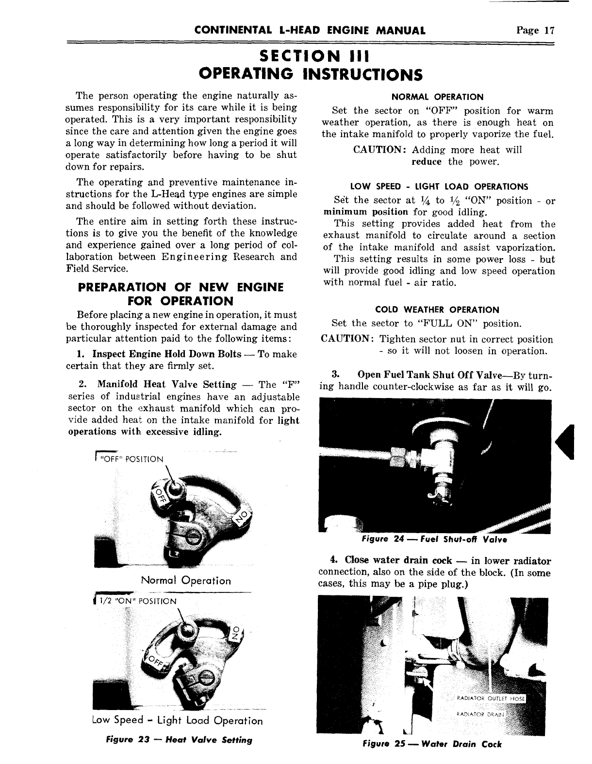
2. Manifold Heat Valve Setting -- The "F"
series of industrial engines have an adjustable
sector on the exhaust manifold which can pro-
vide added hex~ on the intake manifold for light
operations with excessive idling.
~" POSITION
Normal Operation
1/2 "01~1" POSITION
Low Speed- Light Load Operation
Figure 23- Heat Valve Setting
NORMAL OPERATION
Set the sector on "OFF" position for warm
weather operation, as there is enough heat on
the intake manifold to properly vaporize the fuel.
CAUTION: Adding more heat will
reduce the power.
LOW SPEED - LIGHT LOAD OPERATIONS
S6t the sector at 1/~ to 1/2 "ON" position - or
minimum position for good idling.
This setting provides added heat from the
exhaust manifold to circulate around a section
of the intake manifold and assist vaporization.
This setting results in some power loss - but
will provide good idling and low speed operation
with normal fuel - air ratio.
COLD WEATHER OPERATION
Set the sector to "FULL ON" position.
CAUTION: Tighten sector nut in correct position
-so it will not loosen in operation.
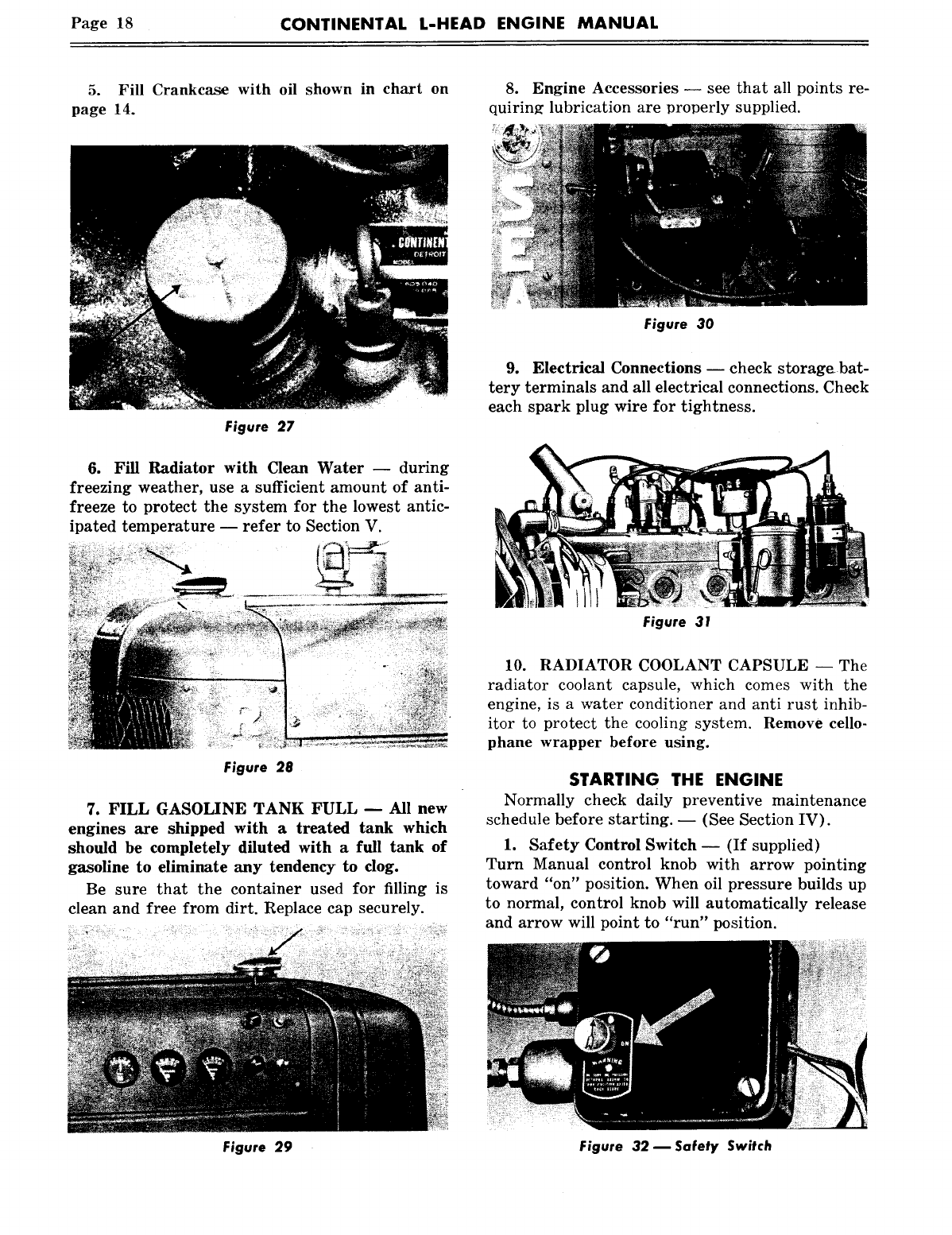
3. Open Fuel Tank Shut Off Valve--By turn-
ing handle counter-clockwise us far as it will go.
Figure 24- Fuel Shut-off Valve
4. Close water drain cock -- in lower radiator
connection, also on the side of the block. (In some
cases, this may be a pipe plug.)
Figure 25 ~ Water Drain Cock
Page 18 CONTINENTAL L-HEAD ENGINE MANUAL
5. Fill Crankcase with oil shown in chart on
page 14.
8. Engine Accessories -- see that all points re-
quiring lubrication are Drol~erly supplied.
Figure 27
6. Fill Radiator with Clean Water -- during
freezing weather, use a sufficient amount of anti-
freeze to protect the system for the lowest antic-
ipated temperature -- refer to Section V.
Figure 28
7. FILL GASOLINE TANK FULL m All new
engines are shipped with a treated tank which
should be completely diluted with a full tank of
gasoline to eliminate any tendency to dog.
Be sure that the container used for filling is
clean and free from dirt. Replace cap securely.
Figure 30
9. Electrical Connections -- check storage bat-
tery terminals and all electrical connections. Check
each spark plug wire for tightness.
Figure 31
10. RADIATOR COOLANT CAPSULE -- The
radiator coolant capsule, which comes with the
engine, is a water conditi.oner and anti rust inhib-
itor to protect the cooling system. Remove cello-
phane wrapper before using.
STARTING THE ENGINE
Normally check daily preventive maintenance
schedule before starting. -- (See Section IV).
1. Safety Control Switch -- (If supplied)
Turn Manual control knob with arrow pointing
toward "on" position. When oil pressure builds up
to normal, control knob will automatically release
and arrow will point to "run" position.
Figure 29 Figure 32 m Safety Switch
CONTINENTAL L-HEAD ENGINE MANUAL Page 19
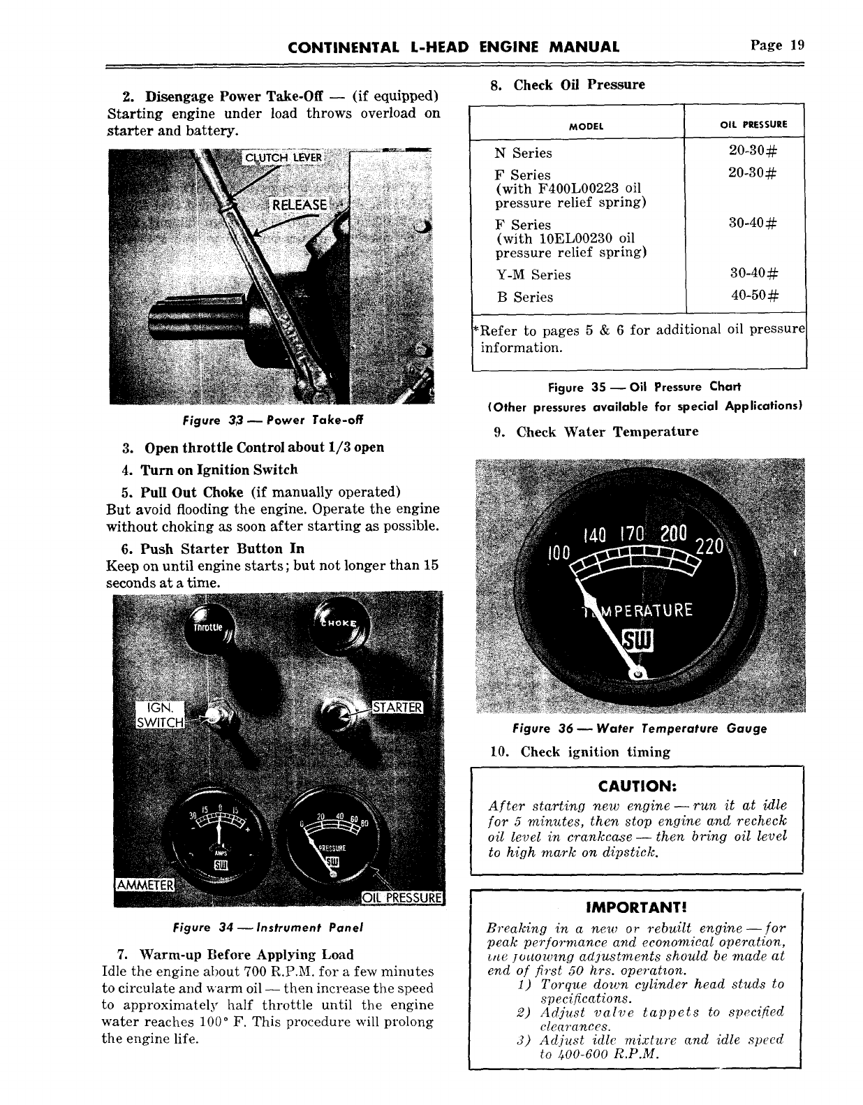
2. Disengage Power Take-Off -- (if equipped)
Starting engine under load throws overload on
starter and battery.
Figure 33 ~ Power Take-off
3. Open throttle Control about 1/3 open
4. Turn on Ignition Switch
5. Pull Out Choke (if manually operated)
But avoid flooding the engine. Operate the engine
without choking as soon after starting as possible.
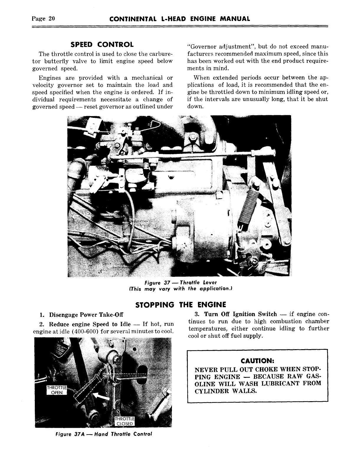
6. Push Starter Button In
Keep on until engine starts ; but not longer than 15
seconds at a time.
8. Check Oil Pressure
MODEL OIL PRESSURE
N Series
F Series
(with F400L00223 oil
pressure relief spring)
F Series
(with 10EL00230 oil
pressure relief spring)
Y-M Series
B Series
30-40¢~
3o-40#
40-50#
~Refer to pages 5 & 6 for additional oil pressure
information.
Figure 35- Oil Pressure Chart
(Other pressures available for special Applications)
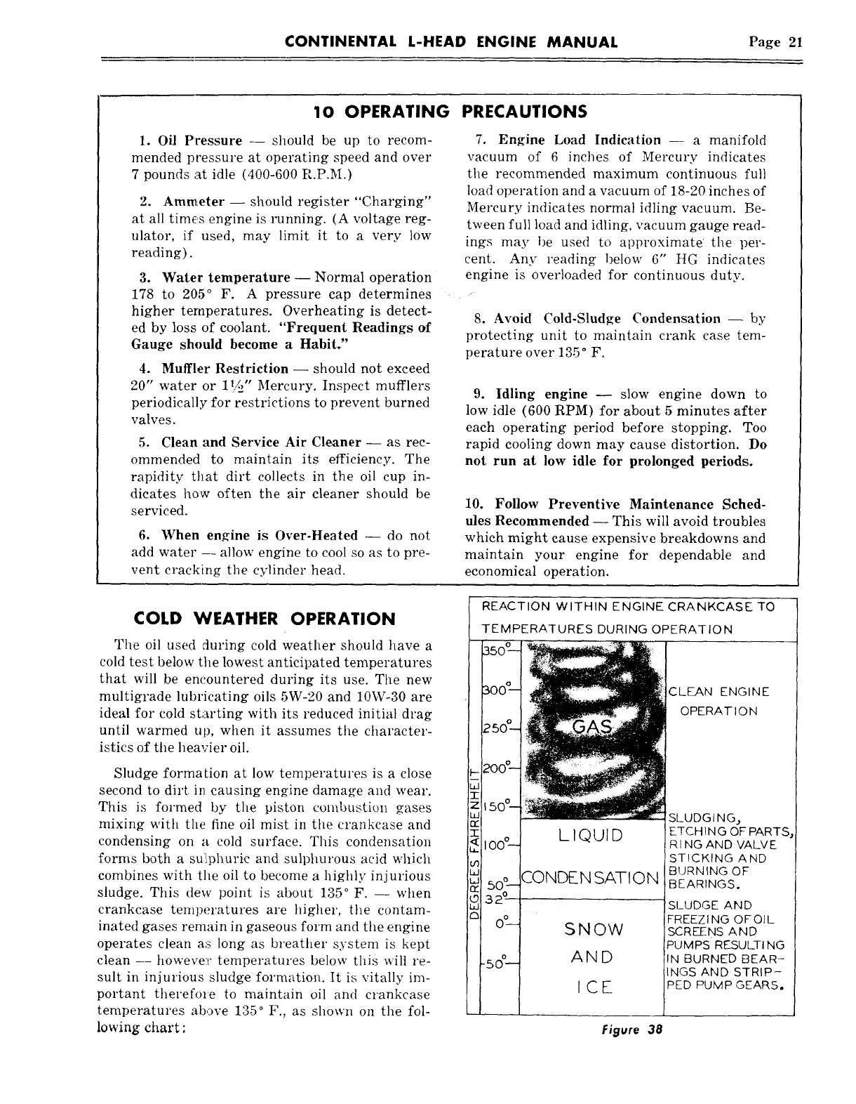
9. Check Water Temperature
Figure 36 w Water Temperature Gauge
10. Check ignition timing
CAUTION:
After starting new engine- run it at izlle
for 5 minutes, then stop engine and recheck
oil level in crankcase- then bring oil level
to high mark on dipstick.
Figure 34--Instrument Panel
7. Warm-up Before Applying Load
Idle the engine about 700 R.P.M. for a few minutes
to circulate and warm oil -- then increase the speed
to approximately half throttle until the engine
water reaches 10/) ° F. This procedure will prolong
the engine life.
IMPORTANT!
Breaking in a new or rebuilt engine--for
peak performance and economical operation,
~ne ]o~towmg adjustments should be made at
end of first 50 hrs. operatzon.
1) Torque down cylinder head studs to
specifications.
2) Adjust valve tappets to specified
clearances.
3) Adjust idle mixture and idle speed
to 400-600 R.P.M.
Page 20 CONTINENTAL L-HEAD ENGINE MANUAL
SPEED CONTROL
The throttle control is used to close the carbure-
tor butterfly valve to limit engine speed below
governed speed.
Engines are provided with a mechanical or
velocity governor set to maintain the load and
speed specified when the engine is ordered. If in-
dividual requirements necessitate a change of
governed speed -- reset governor as outlined under
"Governor adjustment", but do not exceed manu-
facturers recommended maximum speed, since this
has been worked out with the end product require-
ments in mind.
When extended periods occur between the ap-
plications of load, it is recommended that the en-
gine be throttled down to minimum idling speed or,
if the intervals are unusually long, that it be shut
down.
Figure 37 ~ Throttle Lever
(This may vary with the application.)
STOPPING
1. Disengage Power Take-Off
2. Reduce engine Speed to Idle -- If hot, run
engine at idle (400-600) for several minutes to cool.
THE ENGINE
3. Turn Off Ignition Switch -- if engine con-
tinues to run due to high combustion chamber
temperatures, either continue idling to further
cool or shut off fuel supply.
CAUTION:
NEVER PULL OUT CHOKE WHEN STOP-
PING ENGINE -- BECAUSE RAW GAS-
OLINE WILL WASH LUBRICANT FROM
CYLINDER WALLS.
Figure 37A ~ Hand Throttle Control
CONTINENTAL L-HEAD ENGINE MANUAL Page 21
10 OPERATING
1. Oil Pressure -- should be up to recom-
mended pressure at operating speed and over
7 pounds at idle (400-600 R.P.M.)
2. Ammeter -- should register "Charging"
at all times engine is running. (A voltage reg-
ulator, if used, may limit it to a very low
reading).
3. Water temperature -- Normal operation
178 to 205° F. A pressure cap determines
higher temperatures. Overheating is detect-
ed by loss of coolant. "Frequent Readings of
Gauge should become a Habit."
4. Muffler Restriction -- should not exceed
20" water or 1!/.2" Mercury. Inspect mufflers
periodically for restrictions to prevent burned
valves.
5. Clean and Service Air Cleaner -- as rec-
ommended to maintain its efficiency. The
rapidity that dirt collects in the oil cup in-
dicates how often the air cleaner should be
serviced.
6. When engine is Over-Heated -- do not
add water -- allow engine to cool so as to pre-
vent cracking the cylinder head.
PRECAUTIONS
7. Engine Load Indication -- a manifold
vacuum of 6 inches of Mercury indicates
the recommended maximum continuous full
load operation and a vacuum of 18-20 inches of
Mercury indicates normal idling vacuum. Be-
tween full load and idling, vacuum gauge read-
ings may be used to approximate the per-
cent. Any reading below 6" HG indicates
engine is overloaded for continuous duty.
8. Avoid Cold-Sludge Condensation- by
protecting unit to maintain crank case tem-
perature over 135 ° F.
9. Idling engine -- slow engine down to
low idle (600 RPM) for about 5 minutes after
each operating period before stopping. Too
rapid cooling down may cause distortion. Do
not run at low idle for prolonged periods.
10. Follow Preventive Maintenance Sched-
ules Recommended -- This will avoid troubles
which might cause expensive breakdowns and
maintain your engine for dependable and
economical operation.
COLD WEATHER OPERATION
The oil used during cold weather should have a
cold test below the lowest anticipated temperatures
that will be encountered during its use. The new
multigrade lubricating oils 5W-20 and 10W-30 are
ideal for cold starting with its reduced initial drag
until warmed up, when it assumes the character-
istics of the heavier oil.
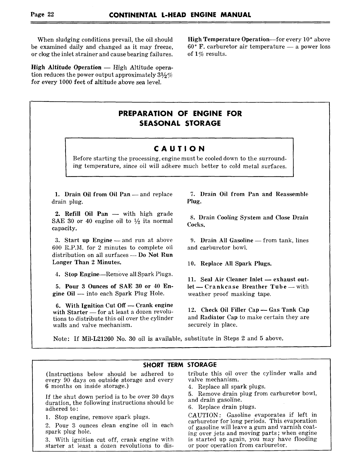
Sludge forma{ion at low temperatures is a close
second to dirt in causing engine damage and wear.
This is formed by the piston combustion gases
mixing with the fine oil mist in the crankcase and
condensing on a cold surface. This condensation
forms both a sui!phuric and sulphurous acid which
combines with the oil to become a highly injurious
sludge. This dew point is about 135° F. -- when
crankcase temperatures are higher, the contam-
inated gases remain in gaseous form and the engine
operates clean as long as breather system is kept
clean -- howeve:t" temperatures below this will re-
sult in injurious sludge formation. It is vitally im-
portant therefore to maintain oil and crankcase
temperatures above 135° F., as shown on the fol-
lowing chart :
REACTION WITHIN ENGINE CRANKCASE TO
TEMPERATURES DURING OPERATION
CLEAN ENGINE
OPERAT I O N
SLUDG I N G..,
:ETCHING OF PARTS
RI NG AND VALVE
STICKING AND
BURNING OF
5ATION BEARINGS.
SLUDGE AND
FREEZING OFOIL
S NOW SCREENS AND
PUMPS RESULTI NG
AN D ~N BURNED BEAR-
INGS AND STRIP-
I C E PED PUMP GEARS.
Figure 38
Page 22 CONTINENTAL L-HEAD ENGINE MANUAL
When sludging conditions prevail, the oil should
be examined daily and changed as it may freeze,
or clog the inlet strainer and cause bearing failures.
High Altitude Operation -- High Altitude opera-
tion reduces the power output approximately 31/~2 %
for every 1000 feet of altitude above sea level.
High Temperature Operation for every 10 ° above
60° F. carburetor air temperature -- a power loss
of 1% results.
PREPARATION OF ENGINE FOR
SEASONAL STORAGE
CAUTION
Before starting the processing, engine must be cooled down to the surround-
ing temperature, since oil will adhere much better to cold metal surfaces.
1. Drain Oil from Oil Pan--and replace
drain plug.
2. Refill Oil Pan -- with high grade
SAE 30 or 40 engine oil to 1/.2 its normal
capacity.
3. Start up Engine--and run at above
600 R.P.M. for 2 minutes to complete oil
distribution on all surfaces -- Do Not Run
Longer Than 2 Minutes.
4. Stop Engine--Rembve all Spark Plugs.
5. Pour 3 Ounces of SAE 30 or 40 En-
gine Oil -- into each Spark Plug Hole.
6. With Ignition Cut Off-- Crank engine
with Starter -- for at least a dozen revolu-
tions to distribute this oil over the cylinder
walls and valve mechanism.
7. Drain Oil from Pan and Reassemble
Plug.
8. Drain Cooling System and Close Drain
Cocks.
9. Drain All Gasoline--from tank, lines
and carburetor bowl.
10. Replace All Spark Plugs.
11. Seal Air Cleaner Inlet m exhaust out-
let- Crankcase Breather Tube-- with
weather proof masking tape.
12. Check Oil Filler Cap--Gas Tank Cap
and Radiator Cap to make certain they are
securely in place.
Note: If Mil-L21260 No. 30 oil is available, substitute in Steps 2 and 5 above.
SHORT TERM
(Instructions below should be adhered to
every 90 days on outside storage and every
6 months on inside storage.)
If the shut down period is to be over 30 days
duration, the following instructions should be
adhered to :
1. Stop engine, remove spark pIugs.
2. Pour 3 ounces clean engine oil in each
spark plug hole.
3. With ignition cut off, crank engine with
starter at least a dozen revolutions to dis-
STORAGE
tribute this oil over the cylinder walls and
valve mechanism.
4. Replace all spark plugs.
5. Remove drain plug from carburetor bowl,
and drain gasoline.
6. Replace drain plugs.
CAUTION: Gasoline evaporates if left in
carburetor for long periods. This evaporation
of gasoline will leave a gum and varnish coat-
ing over jets and moving parts ; when engine
is started up again, you may have flooding
or poor operation from carburetor.
CONTINENTAL L-HEAD ENGINE MANUAL Page 23
SECTION IV
PREVENTIVE MAINTENANCE
In order to obtain maximum efficiency from your
gasoline engine, a definite maintenance program
should be set-up and followed. Haphazard main-
tenance will only lead to faulty engine performance
and shorten engine life.
All moving parts in the engine are subject to
wear; however, wear can be retarded by careful
operation and a planned maintenance program.
In general, gasoline engine operation demands
careful attention to the cleanliness of air, fuel and
oil and maintaining operating temperatures of
180°-200 ° F.
The following pages, covering DAILY, 50-250
and 500 hour maintenance, have been worked out
with our field service division as "Minimum Re-
quirements" to keep your engine in dependable
operating condition.
DALLY
PREVENTIVE MAINTENANCE SCHEDULE
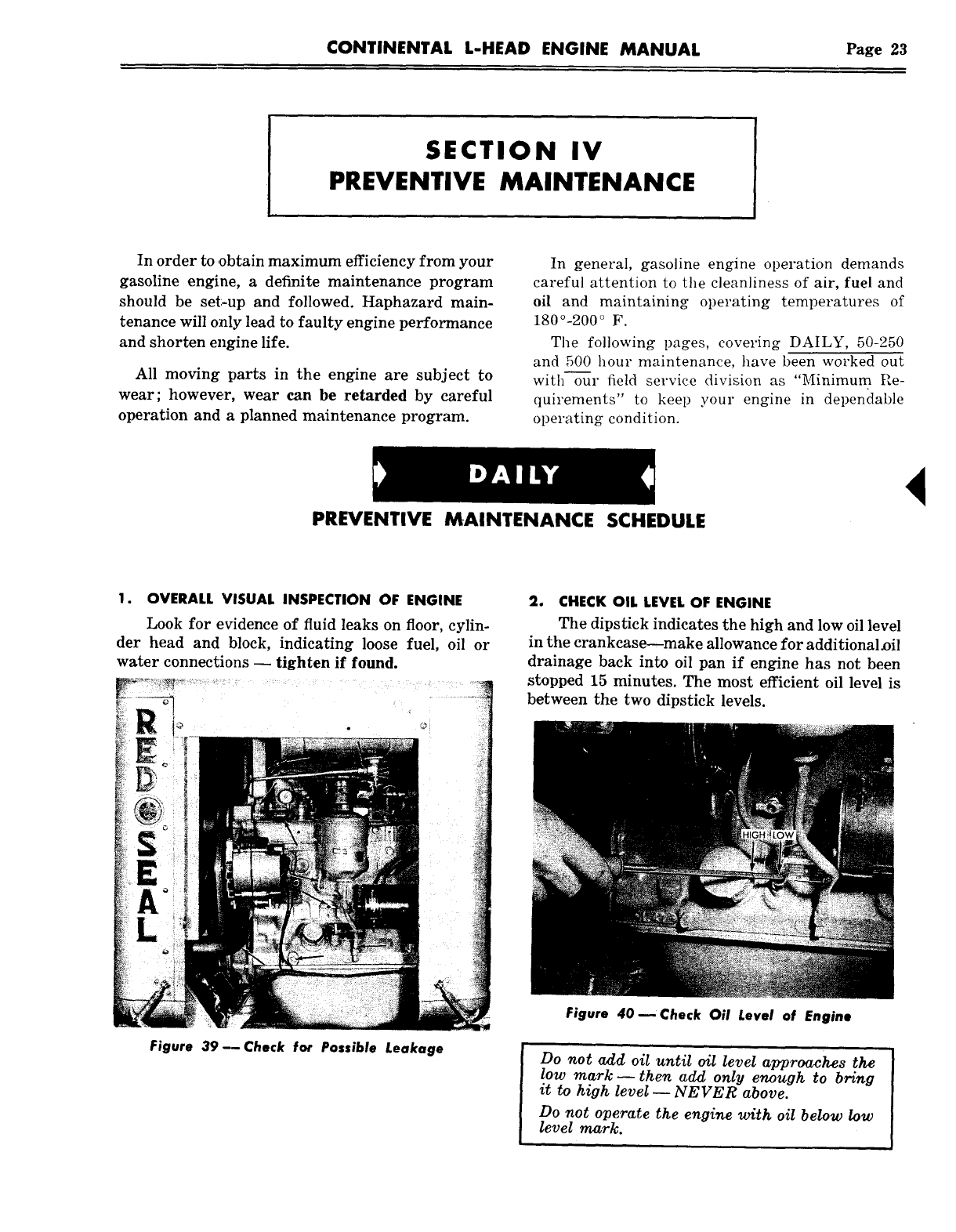
1. OVERALL VISUAL INSPECTION OF ENGINE
Look for evidence of fluid leaks on floor, cylin-
der head and block, indicating loose fuel, oil or
water connections -- tighten if found.
Figure 39--Check for Possible Leakage
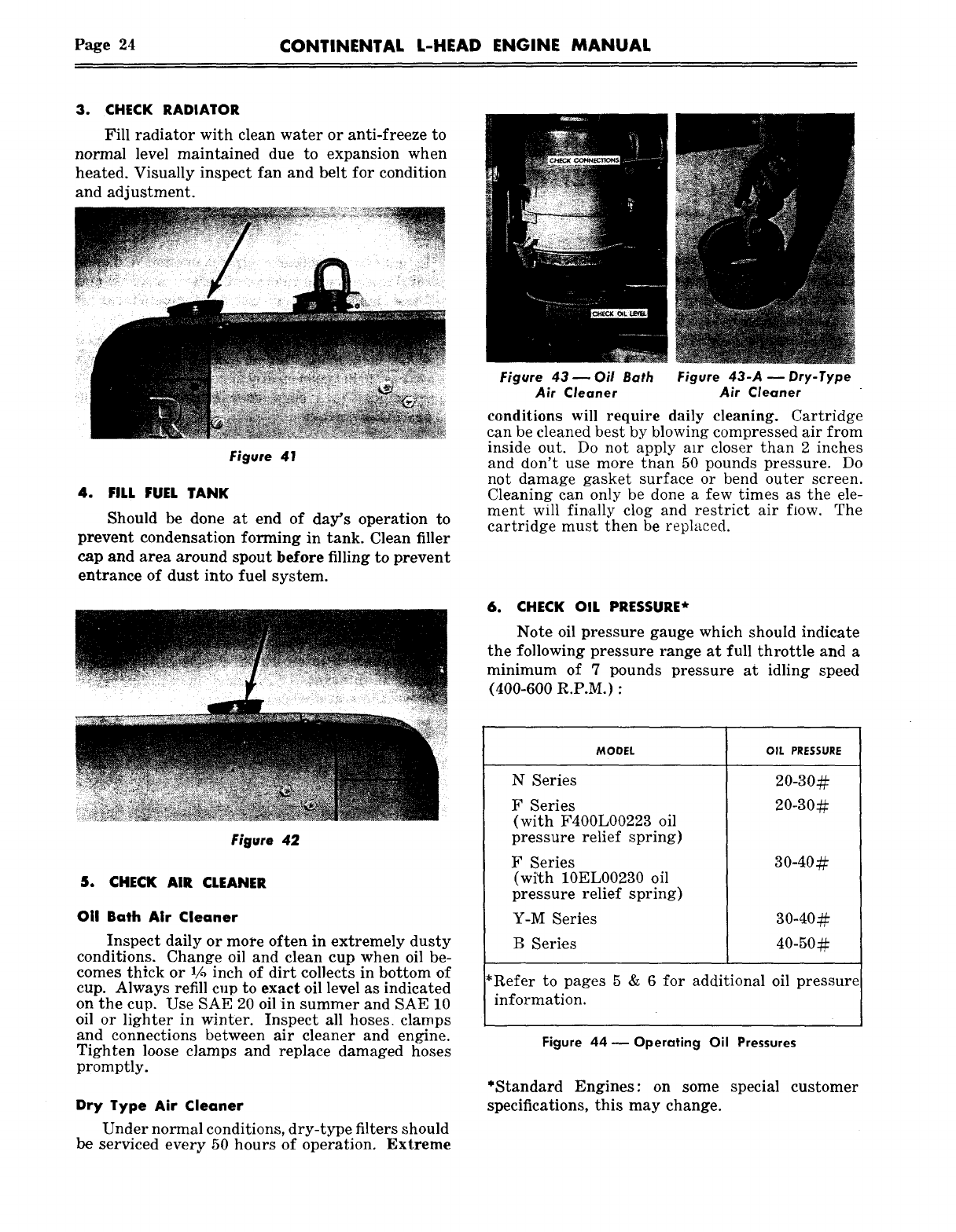
2. CHECK OIL LEVEL OF ENGINE
The dipstick indicates the high and low oil level
in the crankcase~make allowance for additional~il
drainage back into oil pan if engine has not been
stopped 15 minutes. The most efficient oil level is
between the two dipstick levels.
Figure 40 ~Check Oil Level of Engine
Do not add oil until oil level approaches the
low mark- then add only enough to bring
it to high level ~ NEVER above.
Do not operate the engine with oil below low
level mark.
P~ge 24 CONTINENTAL L-HEAD ENGINE MANUAL
3. CHECK RADIATOR
Fill radiator with clean water or anti-freeze to
normal level maintained due to expansion when
heated. Visually inspect fan and belt for condition
and adjustment.
Figure 41
4. FILL FUEL TANK
Should be done at end of day’s operation to
prevent condensation forming in tank. Clean filler
cap and area around spout before filling to prevent
entrance of dust into fuel system.
Figure 42
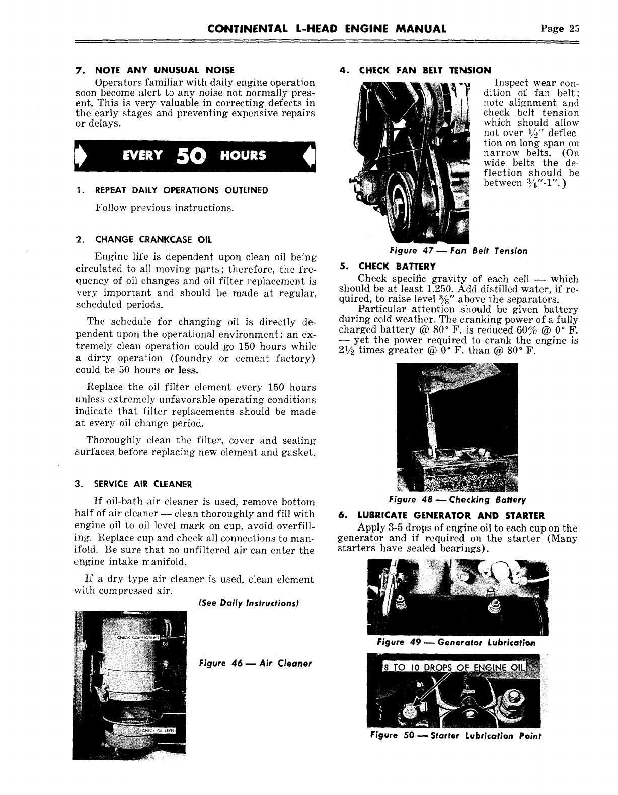
5. CHECK AIR CLEANER
011 Bath Air Cleaner
Inspect daily or more often in extremely dusty
conditions. Change oil and clean cup when oil be-
comes thick or 1/, inch of dirt collects in bottom of
cup. Always refill cu~) to exact oil level as indicated
on the cup. Use SAE 20 oil in summer and SAE 10
oil or lighter in winter. Inspect all hoses, clamps
and connections between air cleaner and engine.
Tighten loose clamps and replace damaged hoses
promptly.
Dry Type Air Cleaner
Under normal conditions, dry-type filters should
be serviced every 50 hours of operation. Extreme
Figure 43--Oil Bath Figure 43-A u Dry-Type
Air Cleaner Air Cleaner
conditions will require daily cleaning. Cartridge
can be cleaned best by blowing compressed air from
inside out. Do not apply air closer than 2 inches
and don’t use more than 50 pounds pressure. Do
not damage gasket surface or bend outer screen.
Cleaning can only be done a few times as the ele-
ment will finally clog and restrict air f~ow. The
cartridge must then be repl~tced.
6. CHECK OIL PRESSURE*
Note oil pressure gauge which should indicate
the following pressure range at full throttle and a
minimum of 7 pounds pressure at idling speed
(400-600 R.P.M.)
MODEL OIL PRESSURE
N Series
F Series
(with F400L00223 oil
pressure relief spring)
F Series
(wi~h 10EL00230 oil
pressure relief spring)
Y-M Series
B Series
30-40¢~
30-4022
40-50¢~
*Refer to pages 5 & 6 for additional oil pressure
information.
Figure 44--Operating Oil Pressures
*Standard Engines: on some special customer
specifications, this may change.
CONTINENTAL L-HEAD ENGINE MANUAL Page 25
7. NOTE ANY UNUSUAL NOISE
Operators familiar with daily engine operation
soon become alert to any noise not normally pres-
ent. This is very valuable in correcting defects in
the early stages and preventing expensive repairs
or delays.
I. REPEAT DALLY OPERATIONS OUTLINED
Follow previous instructions.
2. CHANGE CRANKCASE OIL
Engine life is dependent upon clean oil being
circulated to all moving parts; therefore, the fre-
quency of oil changes and oil filter replacement is
very important and should be made at regular,
scheduled periods.
The schedui!e for changing oil is directly de-
pendent upon the operational environment: an ex-
tremely clean operation could go 150 hours while
a dirty operx!ion (foundry or cement factory)
could be 50 hours or less.
Replace the oil filter element every 150 hours
unless extremely unfavorable operating conditions
indicate that filter replacements should be made
at every oil change period.
Thoroughly clean the filter, cover and sealing
surfaces, before replacing new element and gasket.
CHECK FAN BELT TENSION Inspect wear con-
"~~ dition of fan belt;
note alignment and
check belt tension
which should allow
not over ~" deflec-
tion on long span on
narrow belts. (On
wide belts the de-
flection should be
between ~/_r"-l". )
Figure 47--Fan Belt Tension
5. CHECK BATTERY
Check specific gravity of each cell -- which
should be at least 1.250. Add distilled water, if re-
quired, to raise level ~/8" above the separators.
Particular attention should be given battery
during cold weather. The cranking power of a fully
charged battery @ 80° F. is reduced 60% @ 0° F.
-- yet the power required to crank the engine is
2~/2 times greater @ 0° F. than @ 80° F.
3. SERVICE AIR CLEANER
If oil-bath air cleaner is used, remove bottom
half of air cleaner-- clean thoroughly and fill with
engine oil to oil level mark on cup, avoid overfill-
ing. Replace cup and check all connections to man-
ifold. Be sure that no unfiltered air can enter the
engine intake ~.anifold.
If a dry type air cleaner is used, clean element
with compressed air. (See Daily Instructionsl
Figure 48 ~ Checking Battery
6. LUBRICATE GENERATOR AND STARTER
Apply 3-5 drops of engine oil to each cup on the
generator and if required on the starter (Many
starters have sealed bearings).
Figure 46 ~ Air Cleaner
Figure 49 ~ Generator Lubrication
Figure S0 ~ Starter Lubrication Point

Page 26 CONTINENTAL L-HEAD ENGINE MANUAL
7. LUBRICATE POWER TAKE OFF
Using grease gun, lubricate the clutch throw-
out bearing and output shaft bearing with ap-
proved ball bearing grease.
Operations requiring frequent de-clutching
should be lubricated daily.
4. CLEAN SPARK PLUGS
Clean depressions around plugs before remov-
ing them -- then clean and re-set point gap to
.025 on standard plugs and .035 on resistor plugs.
Install spark plugs (18mm) and tighten
35 ft. Ibs. torque.
Figure 5!
TORQUE DOWN CYLINDER HEAD TO
SPECIFICATIONS IN MANUAL.
ADJUST IDLE MIXTURE AND IDLE SPEED TO
400-600 R. P. M. REPEAT AGAIN AT THE
END OF 500 HOURS
2e
commercial
engine.
REPEAT DALLY AND SO-HOUR SCHEDULES
Follow previous instructions.
CLEAN EXTERIOR OF ENGINE
Use steam if available, otherwise any good
engine cleaner to wash down the
Figure 52
3. CHECK GOVERNOR CONTROL
Clean and lubricate all governor linkage to in-
sure free operation of governor. Free-up any joints
that may be binding or rods or levers that may be
twisted. Check for full throttle opening.
Figure 54
5. CHECK DISTRIBUTOR
Clean distributor cap inside and outside with
solvent without removing wires and blow off with
compressed air -- inspect cap and rotor for cracks.
Examine contact surfaces of points -- replace
if burned or pitted and adjust to .020 gap.
Lubricate distributor cam sparingly.
Check distributor clamp bolts and if found
loose -- retiming the engine is necessary.
Figure 55
6. INSPECT IGNITION WIRES AND CONNECTIONS
Examine ignition wires for breaks in insula-
tion, chafing and loose connections. Replace if
defective.
Figure 53
7
Figure 56
IF DRY REPLACEABLE ELEMENT
AIR CLEANER IS USED, REPLACE
ELEMENT.
CONTINENTAL L-HEAD ENGINE MANUAL Page 27
EVERY 500 HOURS
I. REPEAT DAILY u 50 HOUR AND 250 HOUR
SCHEDULES
2. COOLING SYSTEM
Clean radiator core by blowing out with com-
pressed air.
Inspect radiator mounting.
Inspect water pump and connections for leaks.
Check fan and accessory drive belts.
4. CARBURETOR
Clean exterior and check mounting to manifold.
Adjust carburetor air adjustment for even
running and adjust idle speed to 400-600 R.P.M.
minimum.
..Inspect throttle and choke liflkage for free
operation.
Figure 59 m Carburetor
FUEL PUMP
Clean Filter bowl and screen.
Inspect mounting and gasket.
Check all connections for leaks.
Figure 57
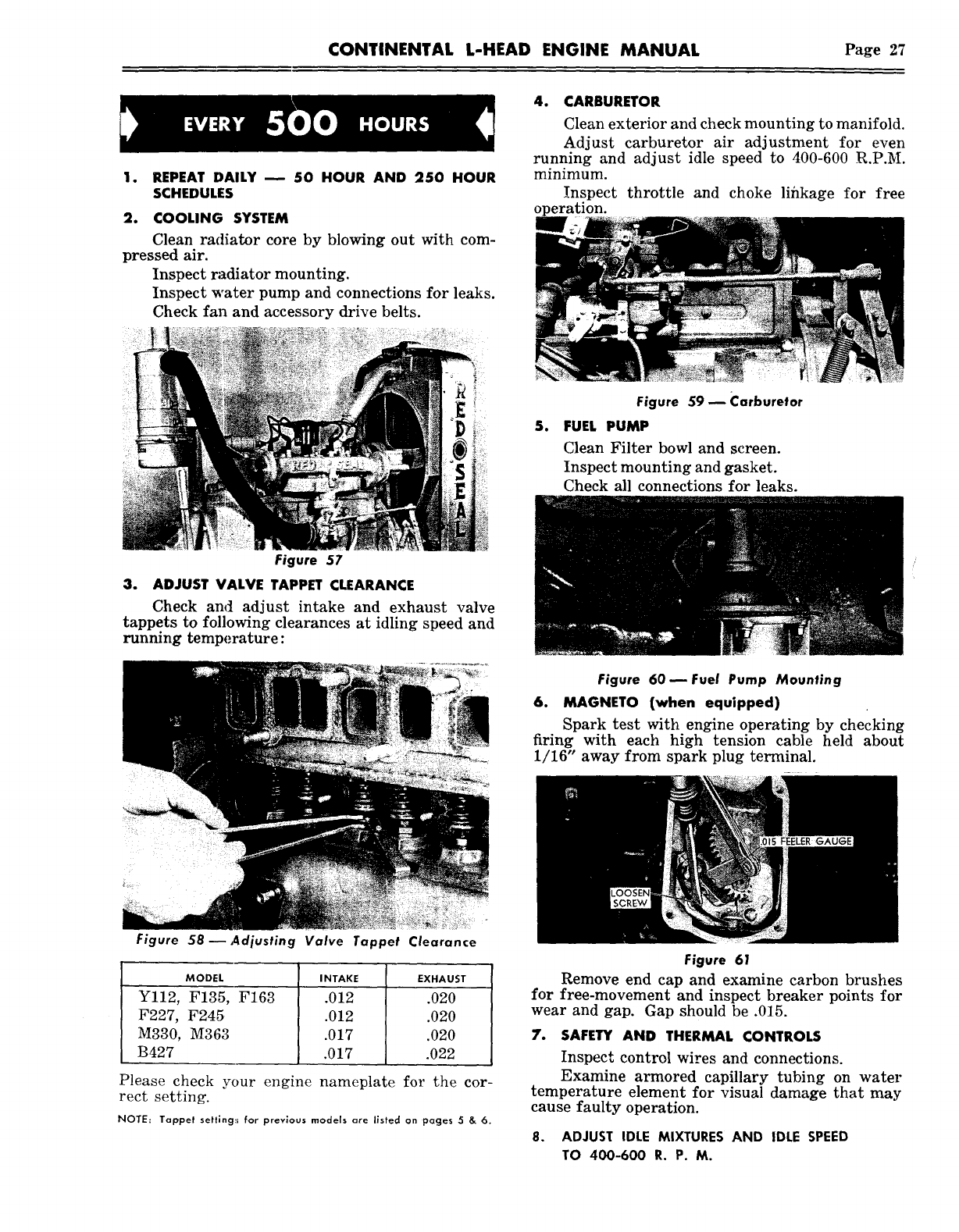
3. ADJUST VALVE TAPPET CLEARANCE
Check and adjust intake and exhaust valve
tappets to following clearances at idling speed and
running temperature:
Figure 60reFuel Pump Mounting
6. MAGNETO (when equipped)
Spark test with engine operating by checking
firing with each high tension cable held about
1/16" away from spark plug terminal.
Figure 58--Adjusting Valve Tappet Clearance
MODEL INTAKE EXHAUST
F227, F245 .012 .020
M330, M363 .017 .020
B427 .017 .022
Please check your engine
rect setting. nameplate for the cor-
NOTE: Tappet settlng:~ for previous models are listed on pages
Figure 61
Remove end cap and examine carbon brushes
for free-movement and inspect breaker points for
wear and gap. Gap should be .015.
7. SAFETY AND THERMAL CONTROLS
Inspec*~ control wires and connections.
Examine armored capillary tubing on water
temperature element for visual damage that may
cause faulty operation.
8. ADJUST IOLE MIXTURES AND IDLE SPEED
TO 400-600 R. P. M.
Page 28 CONTINENTAL L-HEAD ENGINE MANUAL
SECTION V
COOLING SYSTEM
The function of the cooling system is to prevent
the temperatures in the combustion chamber,
which may reach as high as 4000 ° F., from damag-
ing the engine and at the same time keep the op-
crating temperatures within safe limits.
Maintaining the cooling system efficiency is im-
portant, as engine temperatures must be brought
up to and maintained within satisfactory range for
efficient operation; however, must be kept from
overheating, in order to prevent damage to valves,
pistons and bearings.
CONTINENTAL L-HEAD
COOLING SYSTEM
With the exception of some "N" and a few "Y"
engine specifications, all .Continental L-Head en-
gines have the cooling water force-circulated by a
water pump and use a thermostat and by-pass sys-
tem to control the temperature range.
Some of the "N" and a few of the "Y" specifica-
tions circulate the cooling water using the Thermo-
Syphon system -- which requires no water pump
or thermostat -- but circulates the water from the
resulting liquid expansion when heated and con-
traction during cooling.
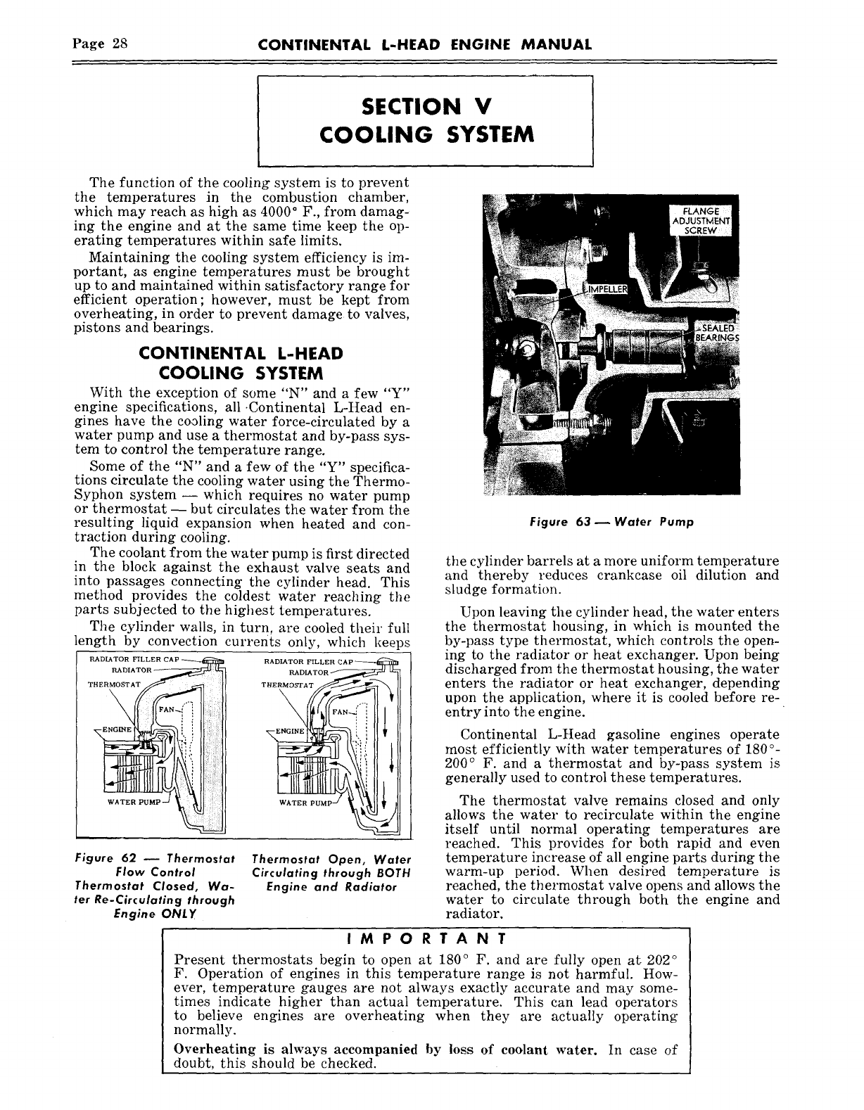
The coolant from the water pump is first directed
in the block against the exhaust valve seats and
into passages connecting the cylinder head. This
method provides the coldest water reaching the
parts subjected to the highest temperatures.
The cylinder walls, in turn, are cooled their full
length by convection currents only, which kee)s
P~DI~TOR FILLER CAP
RADIATOR
~
THERMOSTAT
RADIATOR
ENGINE
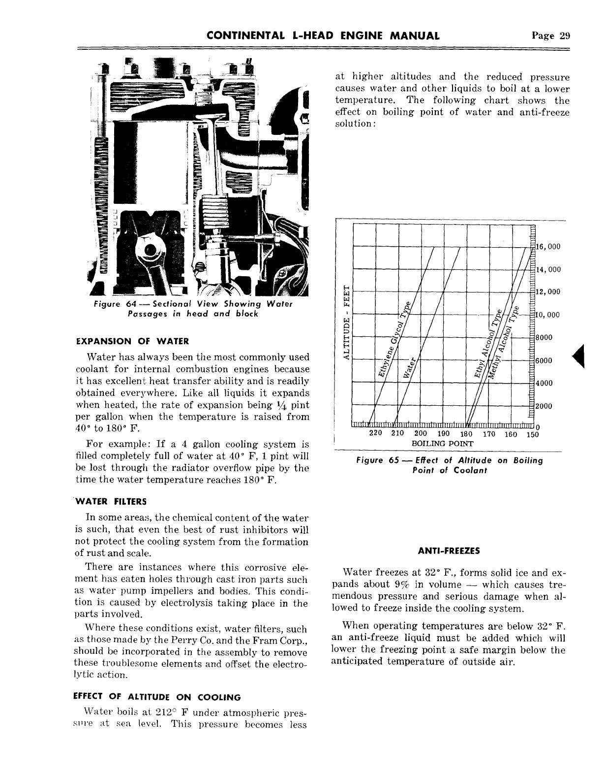
Figure 62 ~ Thermostat
Flow Control
Thermostat Closed, Wa-
ter Re-Circulating through
Engine ONLY
Thermostat Open, Water
Circulating through BOTH
Engine and Radiator
Figure 63 ~ Water Pump
the cylinder barrels at a more uniform temperature
and thereby reduces crankcase oil dilution and
sludge formation.
Upon leaving the cylinder head, the water enters
the thermostat housing, in which is mounted the
by-pass type thermostat, which controls the open-
ing to the radiator or heat exchanger. Upon being
discharged from the thermostat housing, the water
enters the radiator or heat exchanger, depending
upon the application, where it is cooled before re-
entry into the engine.
Continental L-Head gasoline engines operate
most efficiently with water temperatures of 180
°-
200° F. and a thermostat and by-pass system is
generally used to control these temperatures.
The thermostat valve remains closed and only
allows the water to recirculate within the engine
itself until normal operating temperatures are
reached. This provides for both rapid and even
temperature increase of all engine parts during the
warm-up period. When desired temperature is
reached, the thermostat valve opens and allows the
water to circulate through both the engine and
radiator.
IMPORTANT
Present thermostats begin to open at 180° F. and are fully open at 202
°
F. Operation of engines in this temperature range is not harmful. How-
ever, temperature gauges are not always exactly accurate and may some-
times indicate higher than actual temperature. This can lead operators
to believe engines are overheating when they are actually operating
normally.
Overheating is always accompanied by loss of coolant water. In case of
doubt, this should be checked.
CONTINENTAL L-HEAD ENGINE MANUAL Page 29
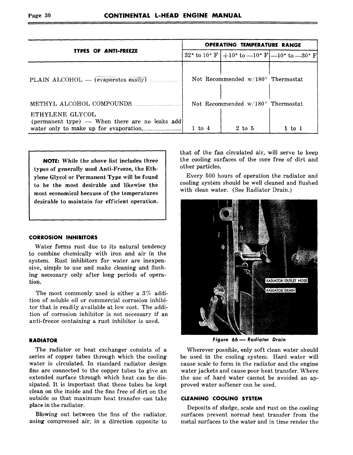
~~ at higher altitudes and the reduced pressure
causes water and other liquids to boil at a lower
~temperature. The following chart shows the
~effect on boiling point of water and anti-freeze
~~solution
16, 000
__.. .
e n - I0~ 000
Water has always been the most commonly used
coolant for internal combustion engines because
it has excellen~ heat transfer ability and is readily /~4000
obtained everywhere. Like all liquids it expands
when heated, the rate of expansion being ~ pint ~~0oo
per gallon when the ~emperature is raised from
40° to 180
° F. ~ 0
~220 210 200 190 180 170 160 150
For example: If a 4 gallon cooling system is BOIL~G PO~
filled completelF full of water at 40° F, 1 pint will Figure 65 ~ Effect of Altitude on Boiling
be lost through the radiator overflow pipe by the Point of Coolant
time the water temperature reaches 180° F.
WATER FILTERS
In some areas, the chemical content of ~he water
is such, that even the best of rust inhibitors will
not protect the cooling system from the formation
of rust and scale.
There are instances where this corrosive ele-
ment has eaten holes through cast iron parts such
as water pump impellers and bodies. This condi-
tion is caused by electrolysis taking place in the
parts involved.
Where these c, onditions exist, water filters, such
as those made by the Perry Co. and the Fram Corp.,
should be incorporated in the assembly to remove
these troublesome elements and offset the electro-
lyric action.
ANTI-FREEZES
Water freezes at 32° F., forms solid ice and ex-
pands about 9% in volume -- which causes tre-
mendous pressure and serious damage when al-
lowed to freeze inside the cooling system.
When operating temperatures are below 32° F.
an anti-freeze liquid must be added which will
lower the freezing point a safe margin below the
anticipated temperature of outside air.
EFFECT OF ALTITUDE ON COOLING
Water boils at: 212° F under atmospheric pres-
s~,re at sea level. This pressure becomes less
Page 30 CONTINENTAL L-HEAD ENGINE MANUAL
OPERATING TEMPERATURE RANGE
TYPES OF ANTI-FREEZE
PLAIN ALCOHOL -- (evaporates da~ily)
METHYL ALCOHOL COMPOUNDS ...........................................
ETHYLENE GLYCOL
(permanent type) -- When ,there are no leaks add
water only to make up for evaporation .........................
32 ° to 10 °F ~-10
°to-10°F
Not Recommended w/180
°
Not Recommended w/180
°
1 to4 2to5
--10 ° to--30 ° F
Thermostat
Thermostat
ltol
NOTE: While the above list includes three
types of generally used Anti-Freeze, the Eth-
ylene Glycol or Permanent Type will be found
to be the most desirable and likewise the
most economical because of the temperatures
desirable to maintain for efficient operation.
that of the fan circulated air, will serve to keep
the cooling surfaces of the core free of dirt and
other particles.
Every 500 hours of operation the radiator and
cooling system should be well cleaned and flushed
with clean water. (See Radiator Drain.)
CORROSION INHIBITORS
Water forms rust due to its natural tendency
to combine chemically with iron and air in the
system. Rust inhibitors for water are inexpen-
sive, simple to use and make cleaning and flush-
ing necessary only after long periods of opera-
tion.
The most commonly used is either a 3 % addi-
tion of soluble oil or commercial corrosion inhibi-
tor that is readily available at low cost. The addi-
tion of corrosion inhibitor is not necessary if an
anti-freeze containing a rust inhibitor is used.
RADIATOR
The radiator or heat exchanger consists of a
series of copper tubes through which the cooling
water is circulated. In standard radiator design
fins are connected to the copper tubes to give an
extended surface through which heat can be dis-
sipated. It is important that these tubes be kept
clean on the inside and the fins free of dirt on the
outside so that maximum heat transfer can take
place in the radiator.
Blowing out between the fins of the radiator,
using compressed air, in a direction opposite to
Figure 66 ~ Radiator Drain
Wherever possible, only soft clean water should
be used in the cooling system. Hard water will
cause scale to form in the radiator and the engine
water jackets and cause poor heat transfer. Where
the use of hard water cannot be avoided an ap-
proved water softener can be used.
CLEANING COOLING SYSTEM
Deposits of sludge, scale and rust on the cooling
surfaces prevent normal heat transfer from the
metal surfaces to the water and in time render the
CONTINENTAL L-HEAD ENGINE MANUAL Page 31
cooling system ineffective to properly maintain
normal operating temperatures. The appearance
of rust in the radiator or coolant is a warning that
the corrosion inhibitor has lost its effectiveness
and should be cleaned before adding fresh coolant.
Dependable cleaning compounds should be used.
Follow the procedure recommended by the sup-
plier. This is of prime importance because differ-
ent cleaners vary in concentration and chemical
compositions. After cleaning and flushing, the
system should be filled with an approved anti-
freeze compound containing a rust and corrosion
inhibitor or water with a corrosion inhibitor.
REVERSE FLOW FLUSHING
Whenever a cooling system is badly rust-clogged
as indicated by overflow loss or abnormally high
operating temperatures, corrective cleaning by re-
verse flow flushing will most effectively remove
the heavy deposits of sludge, rust and scale. The
reverse flow flushing should be performed imme-
diately after draining the cleaning solution and it
is advisable to flush the radiator first, allowing the
engine to cool as much as possible.
Reverse flush the radiator, as follows:
1. Disconnect the hoses at the engine.
2. Put radiator cap on tight.
3. Clamp the flushing gun in the lower hose
with a hose clamp.
CLOSED
HOSE
GUN
AIR
Figure 67--Reverse Flushing Radiator
4. Turn on the water and let it fill the radiator.
5. Apply air pressure gradually, to avoid radi-
ator damage.
6. Shut off the air, again fill the radiator with
water and apply air pressure--repeat until the
flushing stream runs out clear.
7. Clean and inspect radiator cap.
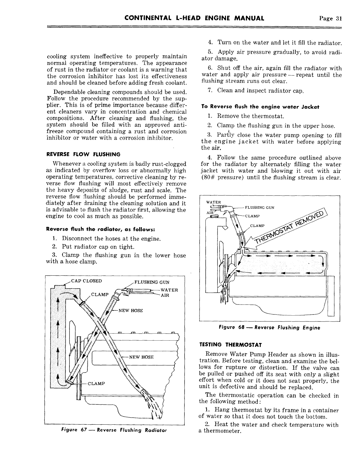
To Reverse flush the engine water Jacket
1. Remove the thermostat.
2. Clamp the flushing gun in the upper hose.
3. Partly close the water pump opening to fill
the engine jacket with water before applying
the air.
4. Follow the same procedure outlined above
for the radiator by alternately filling the water
jacket with water and blowing it out with air
(80# pressure) until the flushing stream is clear.
WATER
~ ~ FLUSHING GUN
Figure 68- Reverse Flushing Engine
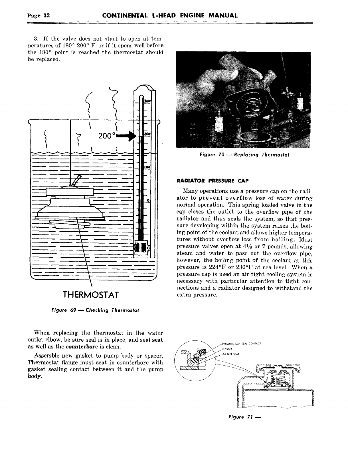
TESTING THERMOSTAT
Remove Water Pump Header as shown in illus-
tration. Before testing, clean and examine the bel-
lows for rupture or distortion. If the valve can
be pulled or pushed off its seat with only a slight
effort when cold or it does not seat properly, the
unit is defective and should be replaced.
The thermostatic operation can be checked in
the following method :
1. Hang thermostat by its frame in a container
of water so that it does not touch the bottom.
2. Heat the water and check temperature with
a thermometer.
Page 32 CONTINENTAL L-HEAD ENGINE MANUAL
3. If the valve does not start to open at tem-
peratures of 180°-200° F. or if it opens well before
the 180° point is reached the thermostat should
be replaced.
THERMOSTAT
Figure 69--Checking Thermostat
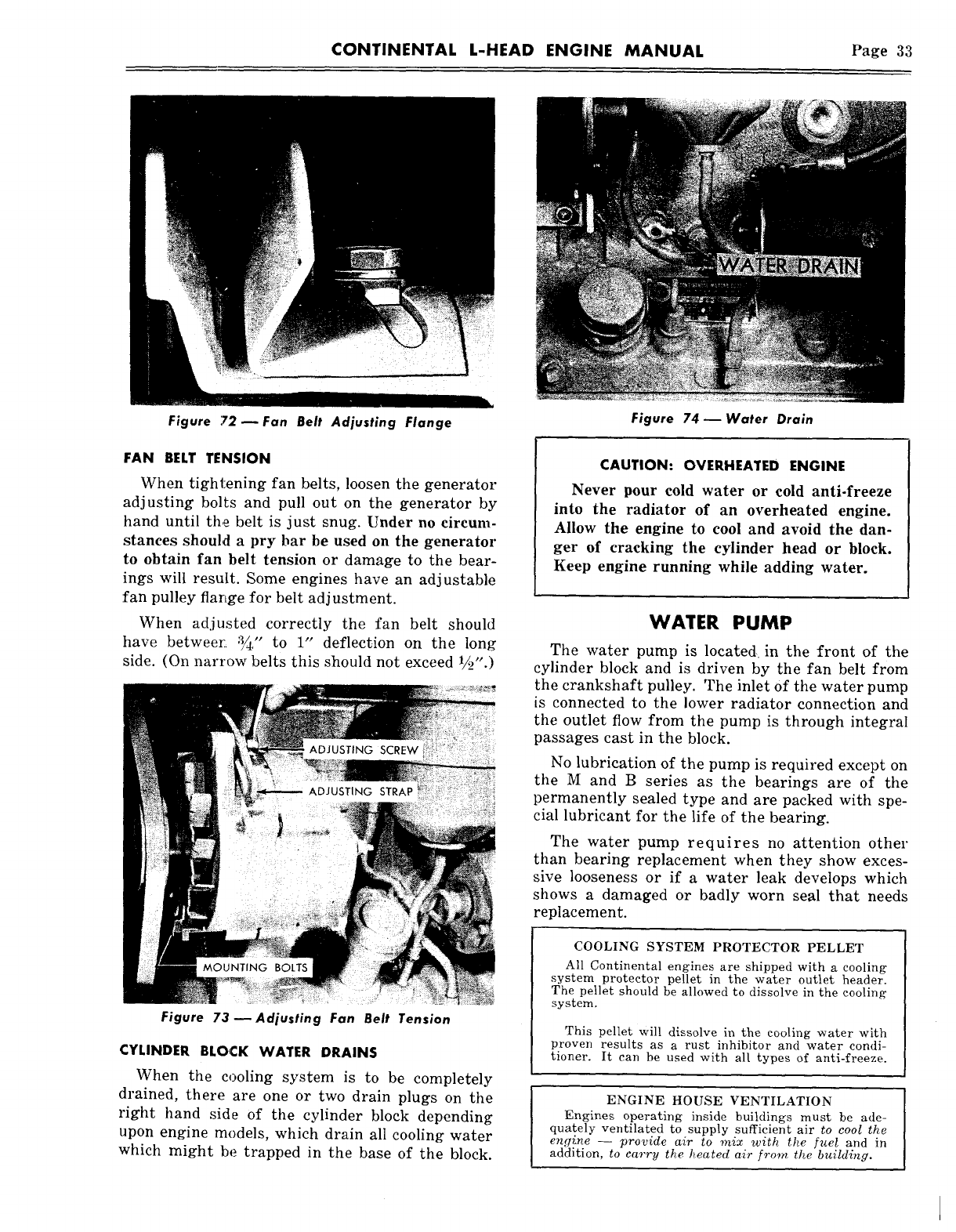
Figure 70 m Replacing Thermostat
RADIATOR PRESSURE CAP
Many operations use a pressure cap on the radi-
ator to prevent overflow loss of water during
normal operation. This spring loaded valve in the
cap closes the outlet to the overflow pipe of the
radiator and thus seals the system, so that pres-
sure developing within the system raises the boil-
ing point of the coolant and allows higher tempera-
tures without overflow loss from boiling. Most
pressure valves open at 41/2 or 7 pounds, allowing
steam and water to pass out the overflow pipe,
however, the. boiling point of the coolant at this
pressure is 224°F or 230°F at sea level. When a
pressure cap is used an air tight cooling system is
necessary with particular attention to tight con-
nections and a~ radiator designed to witl~stand the
extra pressure.
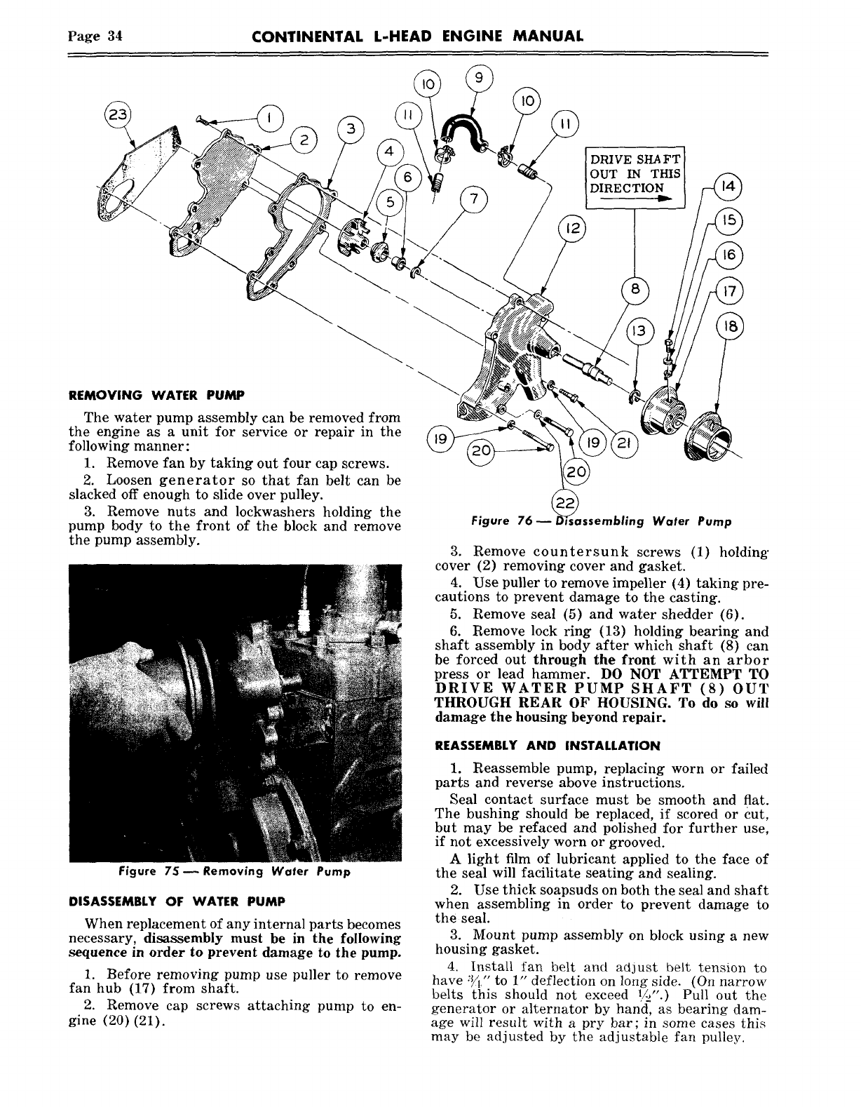
When replacing the thermostat in the water
outlet elbow, be sure seal is in place, and seal seat
as well as the counterbore is clean.
Assemble new gasket to pump body or spacer.
Thermostat flange must seat in counterbore with
gasket sealing contact between it and the pump
body.
PRESSUI~E CAP SEAL CONTACT
GASKET
GASKET SEAT
Figure 71 ~
CONTINENTAL L-HEAD ENGINE MANUAL Page 33
Figure 72 m Fan Belt Adjusting Flange
FAN BELT TENSION
When tightening fan belts, loosen the generator
adjusting bolts and pull out on the generator by
hand until the belt is just snug. Under no circum-
stances should a pry bar be used on the generator
to obtain fan belt tension or damage to the bear-
ings will result. Some engines have an adjustable
fan pulley flarlge for belt adjustment.
When adjusted correctly the fan belt should
have betweer~ :~/4/’ to 1" deflection on the long
side. (On narrow belts this should not exceed
Figure 73--Adjusting Fan Belt Tension
CYLINDER BLOCK WATER DRAINS
When the cooling system is to be completely
drained, there are one or two drain plugs on the
right hand side of the cylinder block depending
upon engine models, which drain all cooling water
which might be trapped in the base of the block.
Figure 74--Water Drain
CAUTION: OVERHEATED ENGINE
Never pour cold water or cold anti-freeze
into the radiator of an overheated engine.
Allow the engine to cool and avoid the dan-
ger of cracking the cylinder head or block.
Keep engine running while adding water.
WATER PUMP
The water pump is located, in the front of the
cylinder block and is driven by the fan belt from
the crankshaft pulley. The inlet of the water pump
is connected to the lower radiator connection and
the outlet flow from the pump is through integral
passages cast in the block.
No lubrication of the pump is required except on
the M and B series as the bearings are of the
permanently sealed type and are packed with spe-
cial lubricant for the life of the bearing.
The water pump requires no attention other
than bearing replacement when they show exces-
sive looseness or if a water leak develops which
shows a damaged or badly worn seal that needs
replacement.
COOLING SYSTEM PROTECTOR PELLET
All Continental engines are shipped with a cooling
system protector pellet in the water outlet header.
The pellet should be allowed to dissolve in the cooling
system.
This pellet will dissolve in the cooling water with
proven results as a rust inhibitor and water condi-
tioner. It can be used with all types of anti-freeze.
ENGINE HOUSE VENTILATION
Engines operating inside buildings must be ade-
qua.rely ventilated to supply sufficient air to cool the
engine -- provide air to mix with the fuel and in
addition, to carry the heated air from the building.
Page 34 CONTINENTAL L-HEAD ENGINE MANUAL
DRIVE SHA FT
OUT IN THIS
DIRECTION
REMOVING WATER PUMP
The water pump assembly can be removed from
the engine as a unit for service or repair in the
following manner:
1. Remove fan by taking out four cap screws.
2. Loosen generator so that fan belt can be
slacked off enough to slide over pulley.
3. Remove nuts and lockwashers holding the
pump body to the front of the block and remove
the pump assembly.
Figure 75--Removing Wafer Pump
DISASSEMBLY OF WATER PUMP
When replacement of any internal parts becomes
necessary, disassembly must be in the following
sequence in order to prevent damage to the pump.
1. Before removing pump use puller to remove
fan hub (17) from shaft.
2. Remove cap screws attaching pump to en-
gine (20) (21).
Figure 76-- fssembling Water Pump
3. Remove countersunk screws (1) holding"
cover (2) removing cover and gasket.
4. Use puller to remove impeller (4) taking pre-
cautions to prevent damage to the casting.
5. Remove seal (5) and water shedder (6).
6. Remove lock ring (13) holding bearing and
shaft assembly in body after which shaft (8) can
be forced out through the front with an arbor
press or lead hammer. DO NOT ATTEMPT TO
DRIVE WATER PUMP SHAFT (8) OUT
THROUGH REAR OF HOUSING. To do so will
damage the housing beyond repair.
REASSEMBLY AND INSTALLATION
1. Reassemble pump, replacing worn or failed
parts and reverse above instructions.
Seal contact surface must be smooth and flat.
The bushing should be replaced, if scored or ~ut,
but may be refaced and polished for further use,
if not excessively worn or grooved.
A light film of lubricant applied to the face of
the seal will facilitate seating and sealing.
2. Use thick soapsuds on both the seal and shaft
when assembling in order to prevent damage to
the seal.
3. Mount pump assembly on block using a new
housing gasket.
4. Install fan belt and adjust be~t tension to
have :~/~," to 1" deflection on long side. (On narrow
belts this should not exceed ~,/~".) Pull out the
generator or alternator by hand, as bearing dam-
age will result with a pry bar; in some cases this
may be adjusted by the adjustable fan pulley.
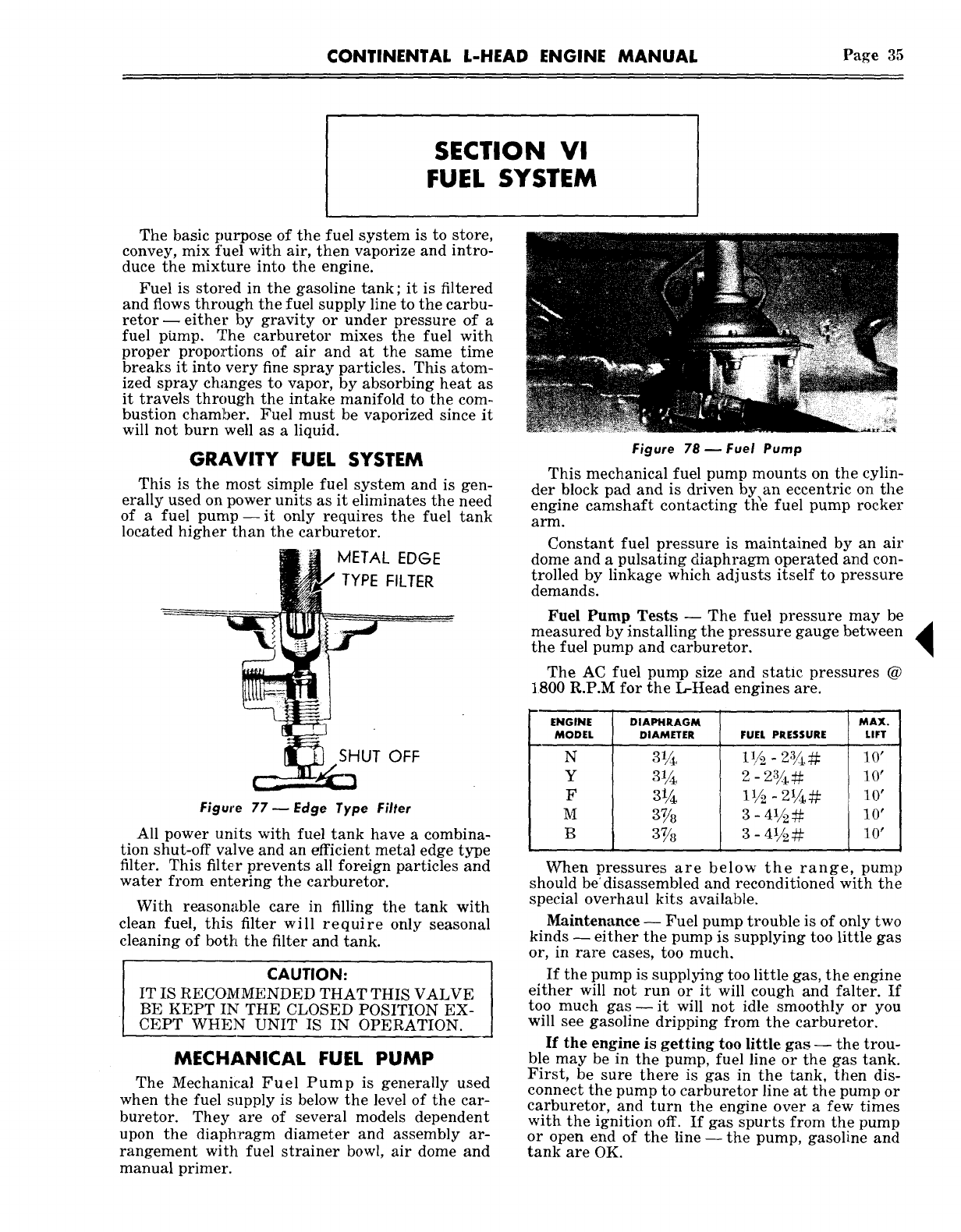
CONTINENTAL L-HEAD ENGINE MANUAL Page 35
SECTION VI
FUEL SYSTEM
The basic purpose of the fuel system is to store,
convey, mix fuel with air, then vaporize and intro-
duce the mixture into the engine.
Fuel is stored in the gasoline tank; it is filtered
and flows through the fuel supply line to the carbu-
retor- either by gravity or under pressure of a
fuel phmp. The carburetor mixes the fuel with
proper proportions of air and at the same time
breaks it into very fine spray particles. This atom-
ized spray changes to vapor, by absorbing heat as
it travels through the intake manifold to the com-
bustion chamber. Fuel must be vaporized since it
will not burn well as a liquid.
GRAVITY FUEL SYSTEM
This is the most simple fuel system and is gen-
erally used on power units as it eliminates the need
of a fuel pump--it only requires the fuel tank
located higher than the carburetor.
I~ .METAL EDGE
TYPE FILTER
Figure 77--Edge Type Filter
All power units with fuel tank have a combina-
tion shut-off valve and an efficient metal edge type
filter. This filter prevents all foreign particles and
water from entering the carburetor.
With reasonable care in filling the tank with
clean fuel, this filter will require only seasonal
cleaning of both the filter and tank.
CAUTION:
IT IS RECOMMENDED THAT THIS VALVE
BE KEPT IN THE CLOSED POSITION EX-
CEPT WHEN UNIT IS IN OPERATION.
MECHANICAL FUEL PUMP
The Mechanic, al Fuel Pump is generally used
when the fuel supply is below the level of the car-
buretor. They are of several models dependent
upon the diaphragm diameter and assembly ar-
rangement with fuel strainer bowl, air dome and
manual primer.
Figure 78 ~ Fuel Pump
This mechanical fuel pump mounts on the cylin-
der block pad and is driven by an eccentric on the
engine camshaft contacting the fuel pump rocker
arm.
Constant fuel pressure is maintained by an air
dome and a pulsating diaphragm operated and con-
trolled by linkage which adjusts itself to pressure
demands.
Fuel Pump Tests -- The fuel pressure may be
measured by installing the pressure gauge between
the fuel pump and carburetor.
The AC fuel pump size and static pressures @
1800 R.P.M for the L-Head engines are.
ENGINE DIAPHRAGM
MODEL DIAMETER FUEL PRESSURE
N
Y
F
M
B
2
~’/2 - 2,2#
3 - 4V2#
MAX.
LIFT
When pressures are below the range, pump
should be’ disassembled and reconditioned with the
special overhaul kits available.
Maintenance -- Fuel pump trouble is of only two
kinds ~ either the pump is supplying too little gas
or, in rare cases, too much.
If the pump is supplying too little gas, the engine
either will not run or it will cough and falter. If
too much gas- it will not idle smoothly or you
will see gasoline dripping from the carburetor,
If the engine is getting too little gas -- the trou-
ble may be in the pump, fuel line or the gas tank.
First, be sure there is gas in the tank, then dis-
connect the pump to carburetor line at the pump or
carburetor, and turn the engine over a few times
with the ignition off. If gas spurts from the pump
or open end of the line--the pump, gasoline and
tank are OK.
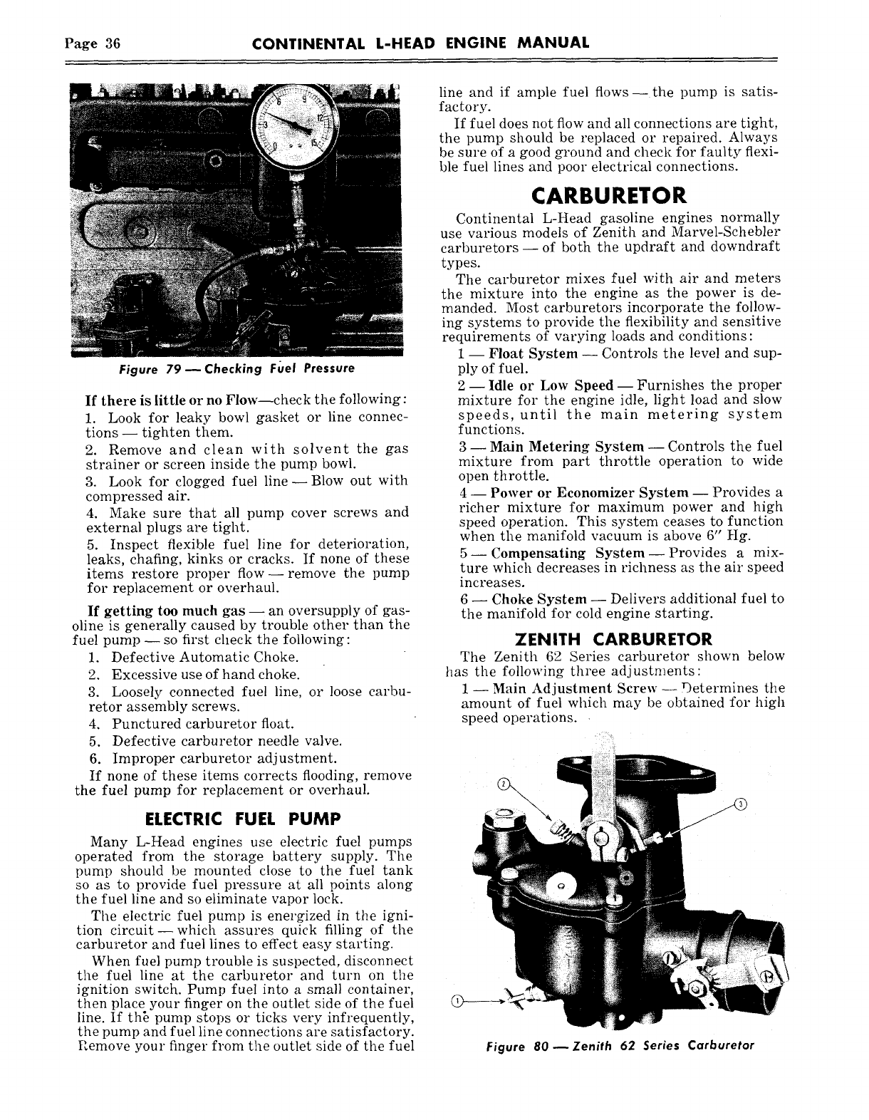
Page 36 CONTINENTAL L-HEAD ENGINE MANUAL
Figure 79 ~ Checking F~el Pressure
If there is little or no Flow--check the following:
1. Look for leaky bowl gasket or line connec-
tions -- tighten them.
2. Remove and clean with solvent the gas
strainer or screen inside the pump bowl.
3. Look for clogged fuel line--Blow out with
compressed air.
4. Make sure that all pump cover screws and
external plugs are tight.
5. Inspect flexible fuel line for deterioration,
leaks, chafing, kinks or cracks. If none of these
items restore proper flow--remove the pump
for replacement or overhaul.
If getting too much gas -- an oversupply of gas-
oline is generally caused by trouble other than the
fuel pump -- so first check the following :
1. Defective Automatic Choke.
2. Excessive use of hand choke.
3. Loosely connected fuel line, or loose carbu-
retor assembly screws.
4. Punctured carburetor float.
5. Defective carburetor needle valve.
6. Improper carburetor adjustment.
If none of these items corrects flooding, remove
the fuel pump for replacement or overhaul.
ELECTRIC FUEL PUMP
Many L-Head engines use electric fuel pumps
operated from the storage battery supply. The
pump should be mounted close to the fuel tank
so as to provide fuel pressure at all points along
the fuel line and so eliminate vapor lock.
The electric fuel pump is energized in the igni-
tion circuit--which assures quick filling of the
carburetor and fuel lines to effect easy starting.
When fuel pump trouble is suspected, disconnect
the fuel line at the carbm’etor and turn on the
ignition switch. Pump fuel into a small container,
then place your finger on the outlet side of the fuel
line. If th~ pump stops or ticks very infrequently,
the pump and fuel line connections are satisfactory.
Remove your finger from the outlet side of the fuel
line and if ample fuel flows--the pump is satis-
factory.
If fuel does not flow and all connections are tight,
the pump should be replaced or repaired. Always
be sm’e of a good ground and check for faulty flexi-
ble fuel lines and poor electrical connections.
CARBURETOR
Continental L-Head gasoline engines normally
use various models of Zenith and Marvel-Schebler
carburetors- of both the updraft and downdraft
types.
The carburetor mixes fuel with air and meters
the mixture into the engine as the power is de-
manded. Most carburetors incorporate the follow-
ing systems to provide the flexibility and sensitive
requirements of varying loads and conditions:
1 -- Float System -- Controls the level and sup-
ply of fuel.
2- Idle or Low Speed- Furnishes the proper
mixture for the engine idle, light load and slow
speeds, until the main metering system
functions.
3- Main Metering System- Controls the fuel
mixture from part throttle operation to wide
open throttle.
4 -- Power or Economizer System -- Provides a
richer mixture for maximum power and high
speed operation. This system ceases to function
when the manifold vacuum is above 6" Hg.
5--Compensating System--Provides a mix-
ture which decreases in richness as the air speed
increases.
6 -- Choke System -- Delivers additional fuel to
the manifold for cold engine starting.
ZENITH CARBURETOR
The Zenith 62 Series carburetor shown below
has the following three adjustments:
1- Main Adjustment Screw--Determines the
amount of fuel which may be obtained for high
speed operations.
Figure 80 ~Zenith 62 Series Carburetor
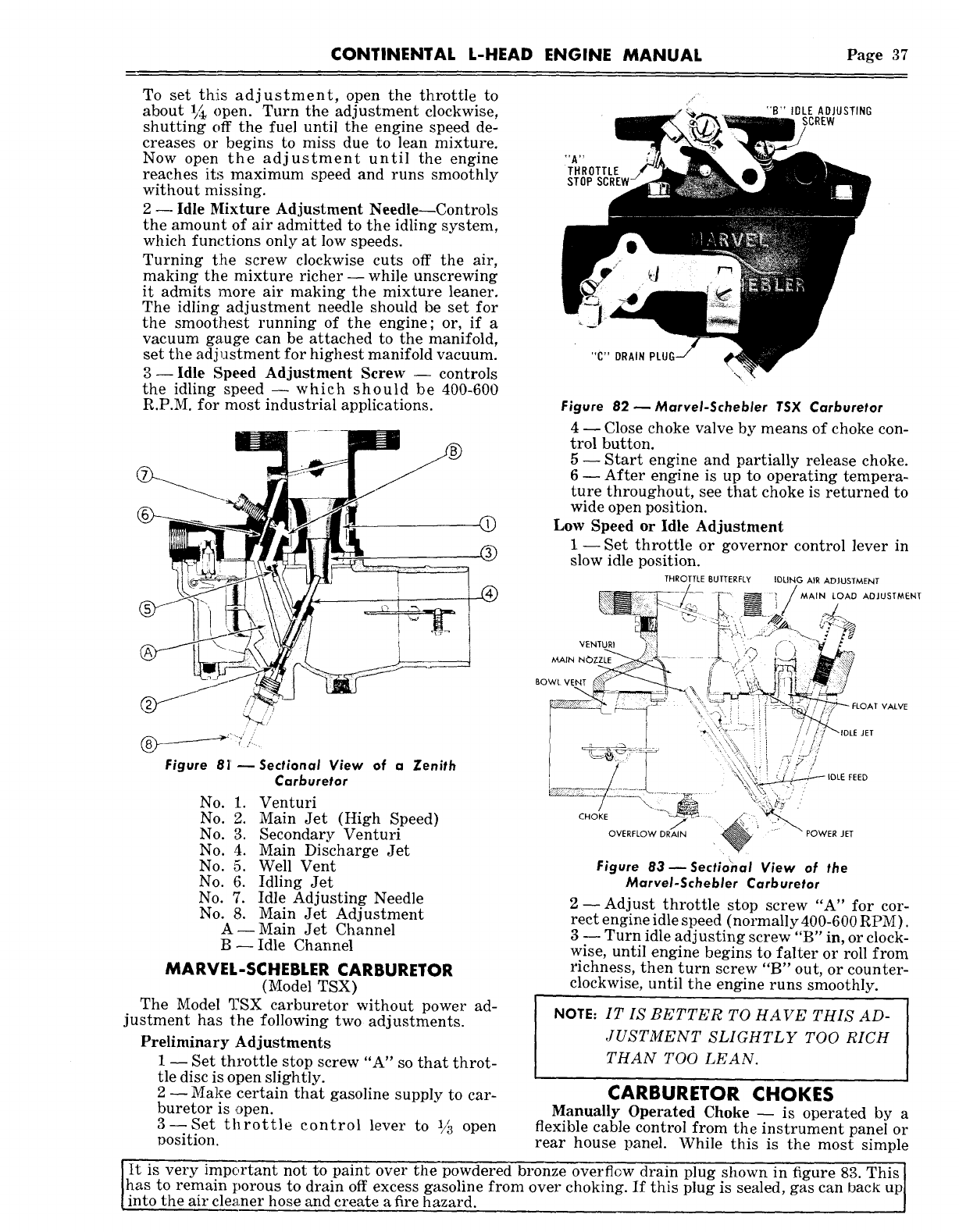
CONTINENTAL L-HEAD ENGINE MANUAL Page 37
To set this adjustment, open the throttle to
about 1/~ open. Turn the adjustment clockwise,
shutting off the fuel until the engine speed de-
creases or begins to miss due to lean mixture.
Now open the adjustment until the engine
reaches its maximum speed and runs smoothly
without missing.
2- Idle Mixture Adjustment Needle--Controls
the amount of air admitted to the idling system,
which functions only at low speeds.
Turning t:he screw clockwise cuts off the air,
making the mixture richer--while unscrewing
it admits more air making the mixture leaner.
The idling adjustment needle should be set for
the smoothest running of the engine; or, if a
vacuum gauge can be attached to the manifold,
set the adj~stment for highest manifold vacuum.
3--Idle Speed Adjustment Screw -- controls
the idling speed -- which should be 400-600
R.P.M. for most industrial applications.
Figure 81’--Sectional View of a Zenith
Carburetor
No. 1. Venturi
No. 2. Main Jet (High Speed)
No. 3. Secondary Venturi
No. 4. Main Discharge Jet
No. 5. Well Vent
No. 6. Idling Jet
No. 7. Idle Adjusting Needle
No. 8. Main Jet Adjustment
A--Main Jet Channel
B -- Idle Channel
MARVEL-SCHEBLER CARBURETOR
(Model TSX)
The Model ~:SX carburetor without power ad-
justment has the following two adjustments.
Preliminary Adjustments
1 -- Set throttle stop screw "A" so that throt-
tle disc is open slightly.
2 --Make certain that gasoline supply to car-
buretor is open.
3--Set throttle control lever to 1/~ open
position.
IDLE ADJUSTING
,SCREW
THROTTLE
STOP
"C" DRAIN
Figure 82 ~MarveI-Schebler TSX Carburetor
4 ~ Close choke valve by means of choke con-
trol button.
5- Start engine and partially release choke.
6- After engine is up to operating tempera~
ture throughout, see that choke is returned to
wide open position.
Low Speed or Idle Adjustment
1- Set throttle or governor control lever in
slow idle position.
THROTTLE BUTTERFLY IDLING AIR ADJUSTMENT
MAIN LOAD ADJUSTMENT
VENTURI
MAIN
VALVE
NOTE:IT IS BETTER TO HAVE THIS AD-
JUSTMENT SLIGHTLY TOO RICH
THAN TOO LEAN.
CARBURETOR CHOKES
Manually Operated Choke ~ is operated by a
flexible cable control from the instrument panel or
rear house panel. While this is the most simple
shown in figure 83. This J
It is very important not to paint over the powdered bronze overflow drain plug is sealed, gas can back upl
Jhas to remain porous to drain off excess gasoline from over choking. If this plug
into the air cleaner hose and create a fire hazard. I
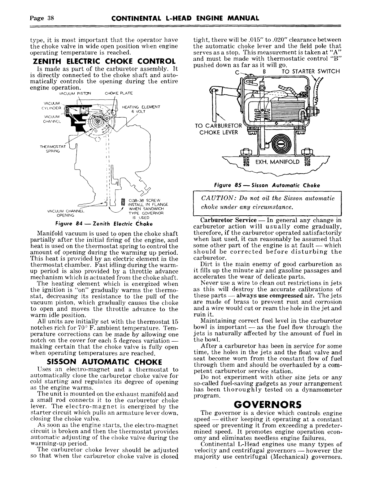
Page 38 CONTINENTAL L-HEAD ENGINE MANUAL
type, it is most important that the operator have
the choke valve in wide open position when engine
operating temperature is reached.
ZENITH ELECTRIC CHOKE CONTROL
Is made as part of the carburetor assembly. It
is directly connected to the choke shaft and auto-
matically controls the opening during the entire
engine operation.
VACUUM PISTON CHOKE PLATE
.~ I~< ~ ~ ~oL~
VACUUM C~NN~L ~ WHEN SANDWICH
TYPE GOVE~OR
OPENING IS USED
Figure 84--Zenith Electric ~hoke
Manifold vacuum is used to open the choke shaft
partially after the initial firing of the engine, and
heat is used on the thermostat spring to control the
amount of opening during the warming up period.
This heat is provided by an electric element in the
thermostat chamber. Fast idling during the warm-
up period is also provided by a throttle advance
mechanism which is actuated from the choke shaft.
The heating element which is energized when
the ignition is "on" gradually warms the thermo-
stat, decreasing its resistance to the pull of the
vacuum piston, which gradually causes the choke
to open and moves the throttle advance to the
warm idle position.
All units are initially set with the thermostat 15
notches rich for 70° F. ambient temperature. Tem-
perature corrections can be made by allowing one
notch on the cover for each 5 degrees variation ~
making certain that the choke valve is fully open
when operating temperatures are reached.
51SSON AUTOMATIC CHOKE
Uses an electro-magnet and a thermostat to
automatically close the carburetor choke valve for
cold starring and regulates its degree of opening
as the engine warms.
The unit is mounted on the exhaust manifold and
a small rod connects it to the carburetor Choke
lever. The electro-magnet is energized by the
starter circuit which pulls an armature lever down,
closing the choke valve.
As soon as the engine starts, the electro-magnet
circuit is broken and H~en the thermostat provides
automatic adjusting of the choke valve during the
warming-up period.
The carburetor choke lever should be adjusted
so that when the carburetor choke valve is closed
tight, there will be .015" to .020" clearance between
the automatic choke lever and the field pole that
serves as a stop. This measurement is taken at "A"
and must be made with thermostatic control "B"
pushed down as far as it will go.
C~-. ~. B TO STARTER SWITCH
Figure 8$--Sisson Automatic Choke
CAUTION: Do not oil the Sisson automatic
choke under any circumstance.
Carburetor Service- In general any change in
carburetor action will usually come gradually,
therefore, if the carburetor operated satisfactorily
when last used, it can reasonably be assumed that
some other part of the engine is at fault- which
should be corrected before disturbing the
carburetor.
Dirt is the main enemy of good carburetion as
it fills up the minute air and gasoline passages and
accelerates the wear of delicate parts.
Never use a wire to clean out restrictions in jets
as this will destroy the accurate calibrations of
these parts -- always use compressed air. The jets
are made of brass to prevent rust and corrosion
and a wire would cut or ream the hole in the jet and
ruin it.
Maintaining correct fuel level in the carburetor
bowl is important--as the fuel flow through the
jets is naturally affected by the amount of fuel in
the bowl.
After a carburetor has been in service for some
time, the holes in the jets and the float valve and
seat become worn from the constant flow of fuel
through them and should be overhauled by a com-
petent carburetor service station.
Do not experiment with other size jets or any
so-called fuel-saving gadgets as your arrangement
has been thoroughly tested on a dynamometer
program. GOVERNORS
The governor is a device which controls engine
speed- either keeping it operating at a constant
speed or preventing it from exceeding a predeter-
mined speed. It promotes engine operation econ-
omy and eliminates needless engine failures.
Continental L-Head engines use many types of
velocity and centrifugal governors -- however the
majority use centrifugal (Mechanical) governors.
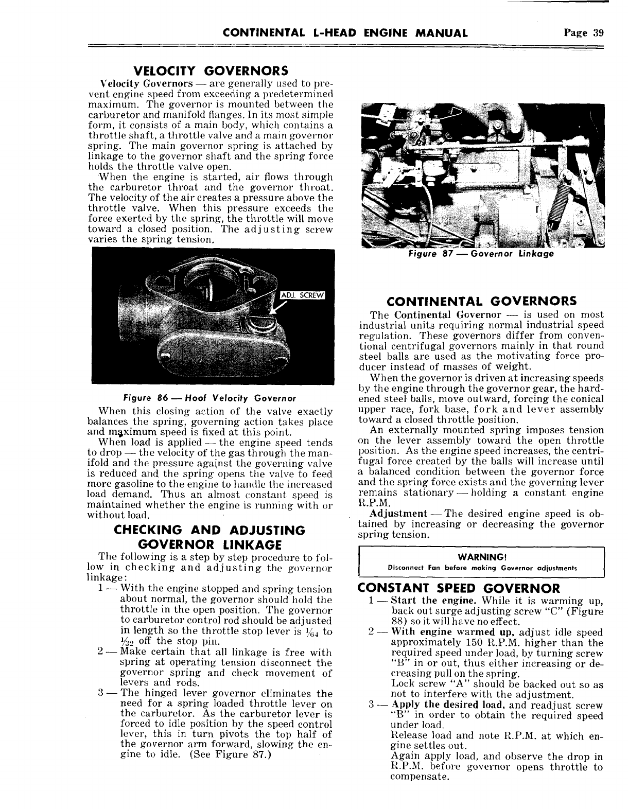
CONTINENTAL L-HEAD ENGINE MANUAL Page 39
VELOCITY GOVERNORS
Velocity Governors -- are generally used to pre-
vent engine speed from exceeding a predetermined
maximum. The governor is mounted between the
carburetor .and manifold flanges, in its most simple
form, it consists of a main body, which contains a
throttle shaft, a throttle valve and a main governor
spring. The main governor spring is attached by
linkage to the governor shaft and the spring force
holds the throttle valve open.
When the engine is started, air flows through
the carburetor throat and the governor throat.
The velocity of the air creates a pressure above the
throttle valve. When this pressure exceeds the
force exerted by the spring, the throttle will move
toward a closed position. The adjusting screw
varies the spring tension.
Figure 87 ~ Governor Linkage
Figure 86 ~ Hoof Velocity Governor
When thi:~ closing action of the valve exactly
balances the spring, governing action takes place
and m~ximum speed is fixed at this point.
When load is applied--the engine speed tends
to drop -- the velocity of the gas through the man-
ifold and the pressure against the governing valve
is reduced and the spring opens the valve to feed
more gasoline to the engine to handle the increased
load demand. Thus an almost constant speed is
maintained whether the engine is runni~g with or
without load.
CHECKING AND ADJUSTING
GOVERNOR LINKAGE
The following is a step by step procedure to fol-
low in checking and adjusting the governor
linkage :
1 -- With the engine stopped and spring tension
about normal, the governor should hold the
throttle in the open position. The governor
to carburetor control rod should be adjusted
in length so the throttle stop lever is ~4 to
½,~ off the stop pin.
2--Make certain that all linkage is free with
spring at operating tension disconnect the
goverrtor spring and check movement of
levers and rods.
3--The hinged lever governor eliminates the
need for a spring loaded throttle lever on
the carburetor. As the carburetor lever is
forced to idle position by the speed control
lever, this in turn pivots the top half of
the governor arm forward, slowing the en-
gine to idle. (See Figure 87.)
CONTINENTAL GOVERNORS
The Continental Governor -- is used on most
industrial units requiring normal industrial speed
regulation. These governors differ from conven-
tional centrifugal governors mainly in that round
steel balls are used as the motivating force pro-
ducer instead of masses of weight.
When the governor is driven at increasing speeds
by the engine through the governor gear, the hard-
ened steel, balls, move outward, forcing the conical
upper race, fork base, fork and lever assembly
toward a closed throttle position.
An externally mounted spring imposes tension
on the lever assembly toward the open throttle
position. As the engine speed increases, the centri-
fugal force created by the balls will increase until
a balanced condition between the governor force
and the spring force exists and the governing lever
remains stationary--holding a constant engine
R.P.M.
Adjustment- The desired engine speed is ob-
tained by increasing or decreasing the governor
spring tension.
WARNING.
I
Disconnect Fan before making Governor adjustments
CONSTANT SPEED GOVERNOR
1- Start the engine. While it is warming up,
back out surge adjusting screw "C" (Figure
88) so it will have no effect.
2- With engine warmed up, adjust idle speed
approximately 150 R.P.M. higher than the
required speed under load, by turning screw
"B" in or out, thus either increasing or de-
creasing pull on the spring.
Lock screw "A" should be backed out so as
not to interfere with the adjustment.
3 -- Apply the desired load, and readjust screw
"B" in order to obtain the required speed
under load.
Release load and note R.P.M. at which en-
gine settles out.
Again apply load, and observe the drop in
R.P.M. before governor opens throttle to
compensate.
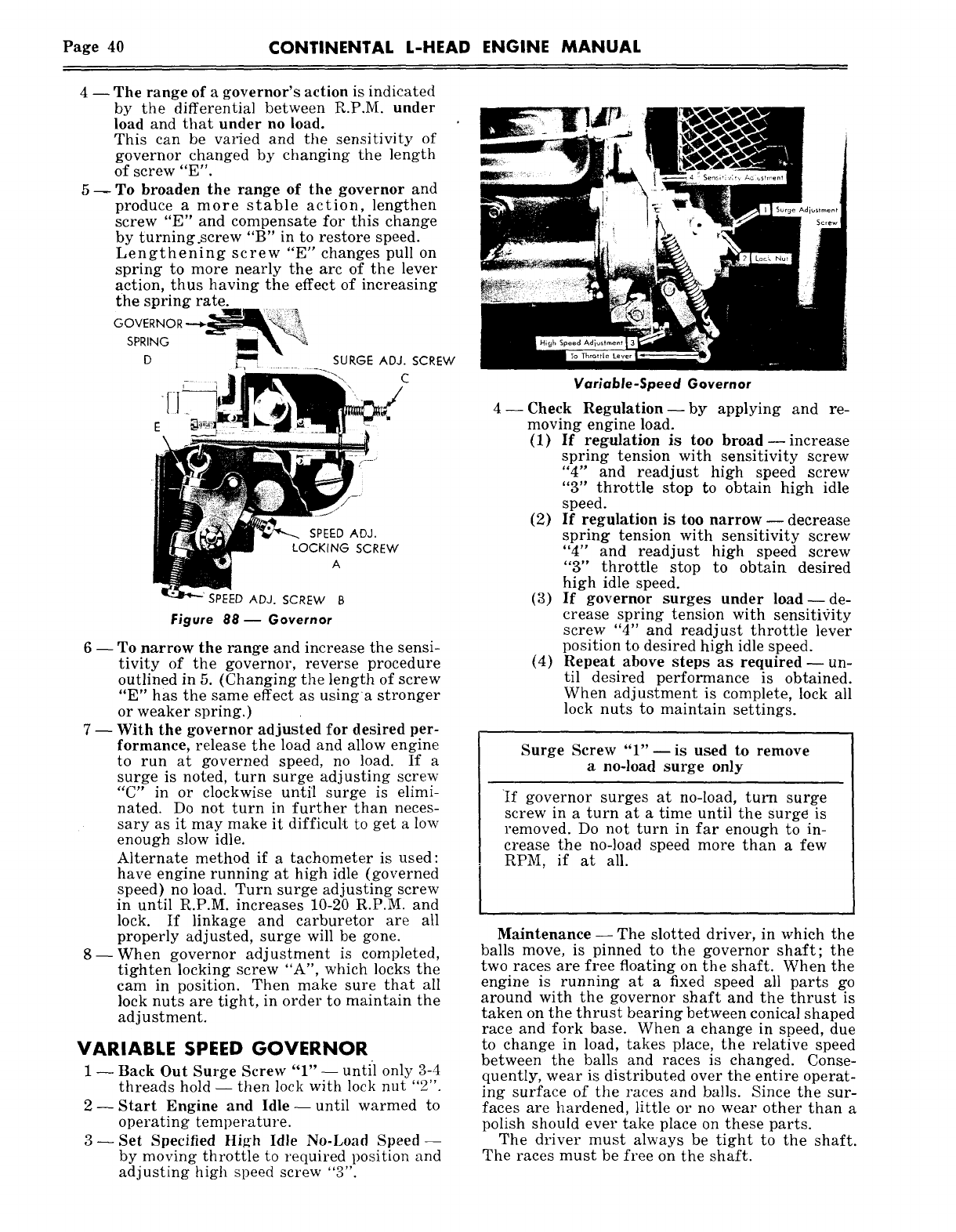
Page 40 CONTINENTAL L-HEAD ENGINE MANUAL
The range of a governor’s action is indicated
by the differential between R.P.M. under
load and that under no load.
This can be rallied and the sensitivity of
governor changed by changing the length
of screw "n".
To broaden the range of the governor and
produce a more stable action, lengthen
screw "E" and compensate for this change
by turning.screw "B" in to restore speed.
Lengthening screw "E" changes pull on
spring to more nearly the arc of the lever
action, thus having the effect of increasing
~he spring rate.
GOVERiX
SPR~NG I~
D ~ SURGE ADJ.SCREW
C
SPEED ADJ.
LOCKING SCREW
A
SPEED ADJ. SCREW B
Figure 88-- Governor
6 -- To narrow the range and increase the sensi-
tivity of the governor, reverse procedure
outlined in 5. (Changing the length of screw
"E" has the same effect as usinga stronger
or weaker spring.)
7 -- With the governor adjusted for desired per-
formance, release the load and allow engine
to run at governed speed, no load. If a
surge is noted, turn surge adjusting screw
"C" in or clockwise un.til surge is elimi-
nated. Do not turn in ~urther than neces-
sary as it may make it difficul.t to get a low
enough slow idle.
Alternate method if a tachometer is used:
have engine running at high idle (governed
speed) no load. Turn surge adjusting screw
in until R.P.M. increases 10-20 R.P.M. and
lock. If linkage and carburetor are all
properly adjusted, surge will be gone.
8--When governor adjustment is completed,
tighten locking screw "A", which locks the
cam in position. Then make sure that all
lock nuts are tight, in order to maintain the
adjustment.
VARIABLE SPEED GOVERNOR
1 -- Back Out Surge Screw "1" -- until only 3-4
threads hold -- then lock with lock nut "2".
2- Start Engine and Idle- until warmed to
operating temperature.
3--Set Specified High Idle No-Load Speed-
by moving throttle to required position and
adjusting high speed screw "3".
Variable-Speed Governor
4- Check Regulation- by applying and re-
moving engine load.
(1) If regulation is too broad -- increase
spring tension with sensitivity screw
"4" and readjust high speed screw
"3" throttle stop to obtain high idle
speed.
(2) If regulation is too narrow -- decrease
spring tension with sensitivity screw
"4" and readjust high speed screw
"3" throttle stop to obtain desired
high idle speed.
(3) If governor surges under load--de-
crease spring tension with sensitivity
screw "4" and readjust throttle lever
position to desired high idle speed.
(4) Repeat above steps as required--un-
til desired performance is obtained.
When adjustment is complete, lock all
lock nuts to maintain settings.
Surge Screw "1"--is used to remove
a no-load surge only
If governor surges at no-load, turn surge
screw in a turn at a time until the surge is
removed. Do not turn in far enough to in-
crease the no-load speed more than a few
RPM, if at all.
Maintenance- The slotted driver, in which the
balls move, is pinned to the governor shaft; the
two races are free floating on the shaft. When the
engine is running at a fixed speed all parts go
around with the governor shaft and the thrust is
taken on the thrust bearing between conical shaped
race and fork base. When a change in speed, due
to change in load, takes place, the relative speed
between the balls and races is changed. Conse-
quently, wear is distributed over the entire operat-
ing surface of the races and balls. Since the sur-
faces are hardened, little or no wear other than a
polish should ever take place on these parts.
The driver must always be tight to the shaft.
The races must be free on the shaft.
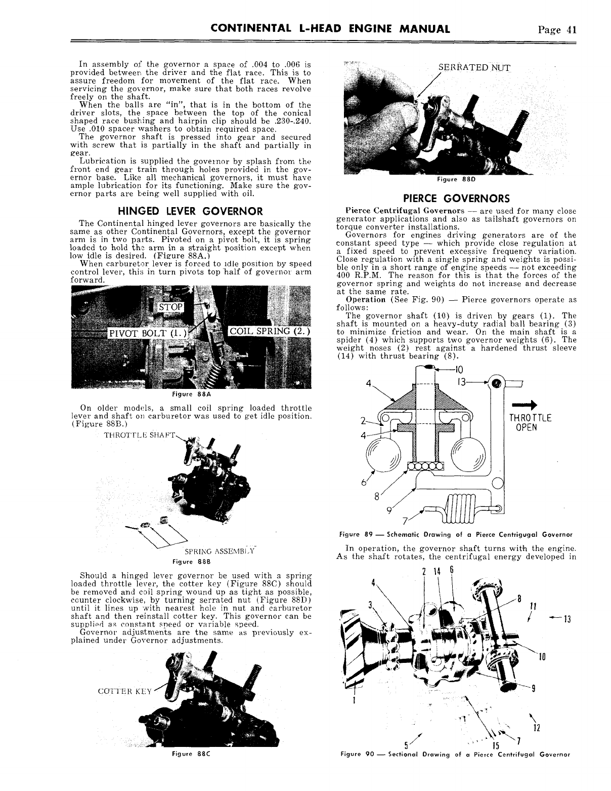
CONTINENTAL L-HEAD ENGINE MANUAL Page 41
In assembly of the governor a space of .004 to .006 is
provided betweer~ the driver and ~he flat race. This is to
assure freedom for movement of the flat race. When
servicing the governor, make sure that both races revolve
freely on the shaft.
When t’he balls are "in", that is in the bottom of the
driver slots, the space between the top of the conical
shaped race bustring and hairpin clip should be .230-.240.
Use .010 spacer washers to obtain required space.
The governor shaft is pressed into gear and secured
with screw that is partially in the shaft and partially in
gear.
Lubrication is supplied the governor by splash from the
front end gear train through holes provided in the gov-
ernor base. Like all mechanical governors, it must have
ample lubrication for its functioning. Make sure the g’ov-
ernor parts are being well supplied with oil.
HINGED LEVER GOVERNOR
The Continental hinged lever governors are basically the
same as other Continental Governors, except the governor
arm is in two parts. Pivoted on a pivot bolt, it is spring
loaded to hold the arm in a straight position except when
low idle is desired. (Figure 88A.)
When carburetor lever is forced to 1die position by speed
control lever, this in turn pivots top half of governor arm
forward.
COIL SPRING (2.)
Figure 88A
On older models, a small coil spring loaded throttle
lever and shaf~ on carburetor was used to get idle position.
(Figure 88B.)
THROTTLE SHAFT-..
SPRING ASSEMBI.Y
Figure 88B
Should a hing.ed lever governor be used with a spring
loaded throttle lever, the cotter key (Figure 88C) should
be removed and c~il spring wound up as tight as possible,
counter clockwise, by turning serrated nut (Figure 88D)
until it lines up with nearest hole in nut and carburetor
shaft and then reinstall cotter key. This governor can be
supl~liod as constant speed or variable saeed.
Governor adjustments are the .same as previously ex-
plained under Governor adjustments.
COTTER KEY
Figure 88C
SERRATED NUT
Figure 880
PIERCE GOVERNORS
Pierce Cet~trifugal G~vernors -- are used for many close
generator applications and also as tailshaft governors on
torque converter installations.
Governors for engines driving generators are of the
constant speed type -- which provide dose regulation at
a fixed speed to prevent exees.sive frequency variation.
Close regulation with a single spring and weights is possi-
ble only in .a short range of engine speeds -- not exceeding
400 R.P.M. The reason for this is that the forces of the
governor spring and weights do not increase and decrease
at the same rate.
Operation (See Fig. 90) -- Pierce governors operate
follows:
The governor shaft (10) is driven By gears (1).
shaft is mounted on a heavy-duty radial bail bearing (3)
to minimize friction and wear. On the main shaft is a
spider (4) which supports two governor weights (6).
weight noses (2) rest against a hardened thrust sleeve
(14) with thrust bearing (8).
THROTTLE
OPEN
.C
Figure 89--Schematic Drawing of a Pierce Centrigugal Governor
In operation, the governor shaft turns with the engine.
As the shaft rotates, the centrifugal energy developed in
214 6
5, ~ ~
Figure 90--Sectional Drawing of a Pierce Centrifugal Governor
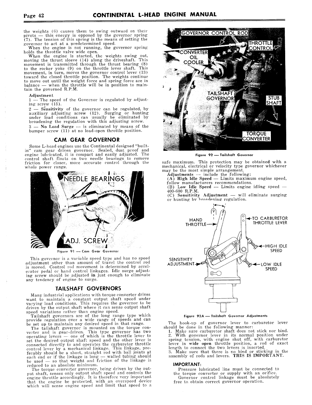
Page 49~ CONTINENTAL L-HEAD ENGINE MANUAL
the weights (6) causes them to swing outward on their
pivots -- this energy is opposed by the governor spring
(7). The tension of this spring is the means of setting the
governor to act at a predetermined speed.
When the engine is not running, the governor spring
holds the throttle valve wide open.
Wken the engine is started, the weights swing out,
moving the thrust sleeve (14) along the driveshaft. This
movement is transmitted through the thrust bearing (8)
to the rocker yoke (9) on the throttle lever shaft. This
movement, in turn, moves the governor control lever (13)
toward the dosed throttle position. The weights continue
to move out until the weight force and spring force are in
balance -- when the throttle will be in position to main-
tain the governed R.P.M.
Adj ustment
1 -- The speed of the Governor is regulated by adjust-
ing screw (15).
2 -- S~nsitivity of the governor can be regulated, by
auxiliary adjusting screw (12). Surging or hunting
under load conditions can usually be eliminated by
broadening the regulation with this adjusting screw.
3 -- No Load Surge -- is eliminated by means of the
bumper screw (11) at no load-open throttle position.
CAM GEAR GOVERNOR
Some L-head engines use the Continental designed "built-
in" cam gear driven governor. Sealed, dust proof and
engine lubricated, it is compact and easily adjusted. The
control shaft floats on two needle bearings to remove
friction for closer, more accurate control through the
whole power range.
|
Figure 91 Cam Gear Governor
This governor is a variahle speed type and has no speed
adjustment other than amount of travel the control rod
is moved. Control rod movement is determined by accel-
erator pedal or hand control linkages. Idle surge adjust-
ing screw should be adjusted in just enough to eliminate
any tendency of engine to surge.
TAILSHAFT GOVERNORS
Many industrial applications with torque converter drives
want to maintain a constant output shaft speed under
varying load conditions. This requires the governor to be
driven by the output shaft where it can sense output shaft
speed variations rather than engine speed.
Taitshaft governors are of the long range type which
provide regulation over a wide range of speeds and can
be set up to maintain any desired speed in that range.
The tailshaft governor is mounted on the torque con-
verter and is gear-driven. This type governor has two
operating levers one of which is the throttle lever to
set the desired output shaft speed and the other lever is
connected directly to and operates the carburetor throttle
control lever by a mechanical linkage. This linkage, pre-
ferably should be a short, straight rod with ball joints at
each end or if the linkage is Ionia" walled tubing should
be used so that weight and friction of the linkage is
reduced to an absolute minimum.
The torque converter governor, being’ driven by the out-
put shaft, senses only output shaft speed and controls the
engine throttle accordingly. It is therefore very important
that the engine be protected, with an overspeed device
which will sense engine speed and limit that speed to a
Figure 92 -- Tailshaft Governor
safe maximum. This protection may be obtained wi’th a
mechanical, electrical or velocity type governor whic’hever
may be the most siraple arrangement.
Adjustments -- include the following:
(A) High Idle Speed -- Limits maximum engine speed,
follow manufacturers recommendations.
(B) Low Idle Speed -- Limits engine idling speed --
400-600 R.P.M.
(C) Sensitivity Adjustment -- will eliminate surging
or hunting bv hrondonin~ regulation.
Figure 92A--Tailshaft Governor Adjustments
The hook-up of governor lever to carburetor lever
should be done in the following manner:
1. Make sure carburetor shaft does not stick nor bind.
2. With governor lever in its normal position under
spring tension, xvith engine shut off, with carburetor
lever in wide open throttle position, a rod of exact
length to connect the two levers is inserted.
3. Make sure l~hat there is no bind or sticking in the
assembly of rods and levers. THIS IS IMPORTANT.
IMPORTANT:
Pressure lubricated line must be connected to
the torque converter or supply with an orifice.
Governor control linkage must be absolutely
free to obtain correct governor operation.
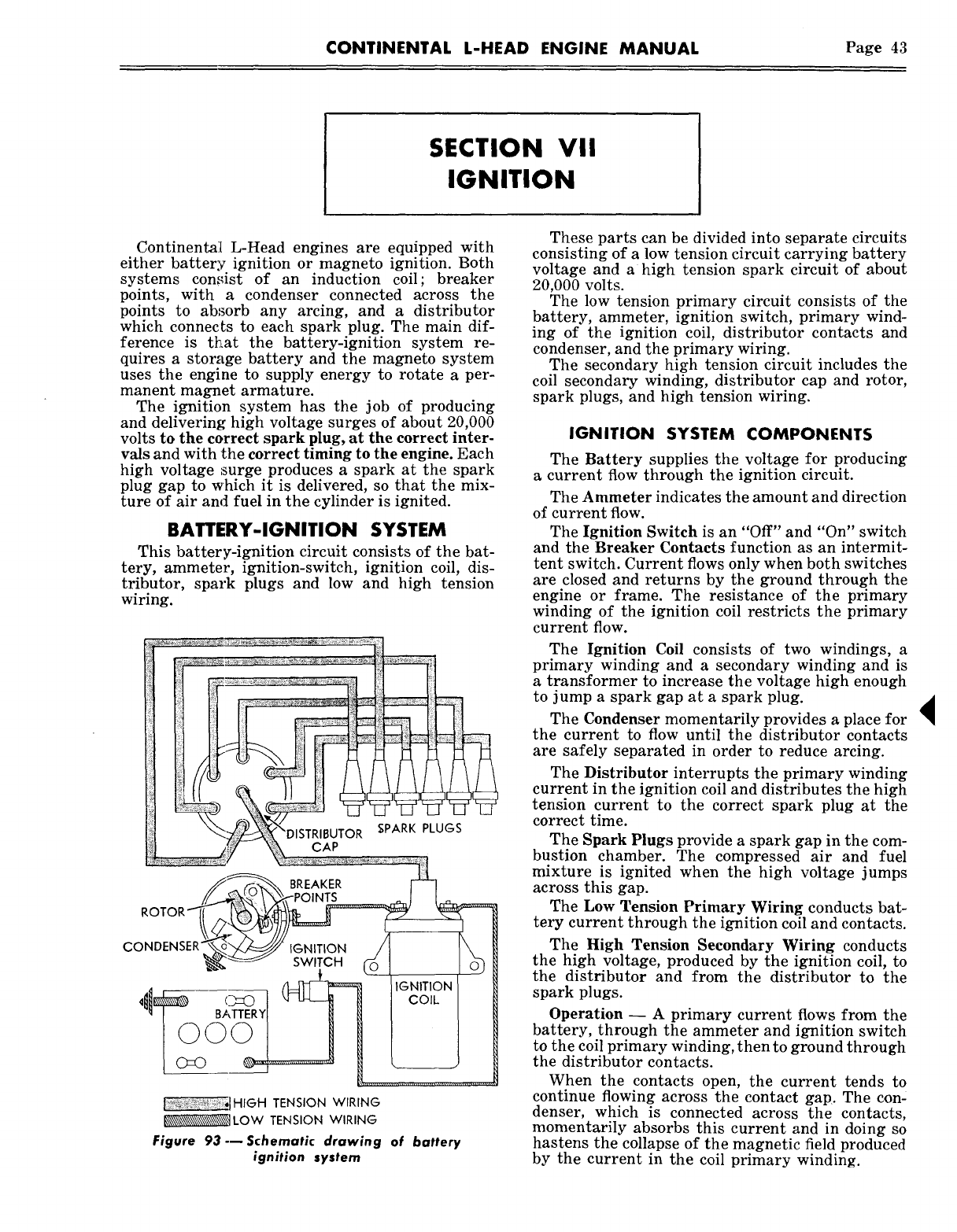
CONTINENTAL L-HEAD ENGINE MANUAL Page 43
SECTION VII
IGNITION
Continental L-Head engines are equipped with
either battery ignition or magneto ignition. Both
systems con!dst of an induction coil; breaker
points, with a condenser connected across the
points to absorb any arcing, and a distributor
which connects to each spark plug. The main dif-
ference is t~at the battery-ignition system re-
quires a storage battery and the magneto system
uses the engine to supply energy to rotate a per-
manent magnet armature.
The ignition system has the job of producing
and delivering high voltage surges of about 20,000
volts to the correct spark plug, at the correct inter-
vals and with the correct timing to the engine. Each
high voltage surge produces a spark at the spark
plug gap to which it is delivered, so that the mix-
ture of air and fuel in the cylinder is ignited.
BATTERY-IGNITION SYSTEM
This battery-ignition circuit consists of the bat-
tery, ammeter, ignition-switch, ignition coil, dis-
tributor, spark plugs and low and high tension
wiring.
CAP
SPARK PLUGS
CO IGNITION
SWITCH
,,~i~tHIGH TENSION WIRING
~LOW TENSION WIRING
Figere 93---Schematic drawing of battery
ignition system
These parts can be divided into separate circuits
consisting of a low tension circuit carrying battery
voltage and a high tension spark circuit of about
20,000 volts.
The low tension primary circuit consists of the
battery, ammeter, ignition switch, primary wind-
ing of the ignition coil, distributor contacts and
condenser, and the primary wiring.
The secondary high tension circuit includes the
coil secondary winding, distributor cap and rotor,
spark plugs, and high tension wiring.
IGNITION SYSTEM COMPONENTS
The Battery supplies the voltage for producing
a current flow through the ignition circuit.
The Ammeter indicates the amount and direction
of current flow.
The Ignition Switch is an "Off" and "On" switch
and the Breaker Contacts function as an intermit-
tent switch. Current flows only when both switches
are closed and returns by the ground through the
engine or frame. The resistance of the primary
winding of the ignition coil restricts the primary
current flow.
The Ignition Coil consists of two windings, a
primary winding and a secondary winding and is
a transformer to increase the voltage high enough
to jump a spark gap at a spark plug.
The Condenser momentarily provides a place for
the current to flow until the distributor contacts
are safely separated in order to reduce arcing.
The Distributor interrupts the primary winding
current in the ignition coil and distributes the high
tension current to the correct spark plug at the
correct time.
The Spark Plugs provide a spark gap in the com-
bustion chamber. The compressed air and fuel
mixture is ignited when the high voltage jumps
across this gap.
The Low Tension Primary Wiring conducts bat-
tery current through the ignition coil and contacts.
The High Tension Secondary Wiring conducts
the high voltage, produced by the ignition coil, to
the distributor and from the distributor to the
spark plugs.
Operation -- A primary current flows from the
battery, through the ammeter and ignition switch
to the coil primary winding, then to ground through
the distributor contacts.
When the contacts open, the current tends to
continue flowing across the contact gap. The con-
denser, which is connected across the contacts,
momentarily absorbs this current and in doing so
hastens the collapse of the magnetic field produced
by the current in the coil primary winding.
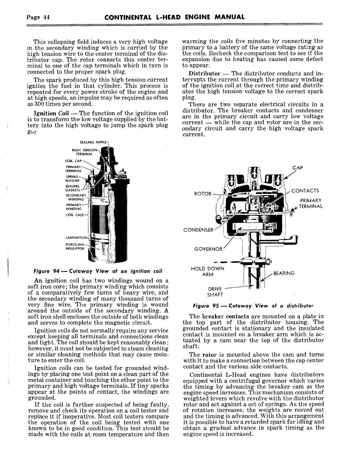
Page 44 CONTINENTAL L-HEAD ENGINE MANUAL
This collapsing field induces a very high voltage
in the secondary winding which is carried by the
high tension wire to the center terminal of the dis-
tributor cap. The rotor connects this center ter-
minal to one of the cap terminals which in turn is
connected to the proper spark plug.
The spark produced by this high tension current
ignites the fuel in that cylinder. This process is
repeated for every power stroke of the engine and
at high speeds, an impulse may be required as often
as 300 times per second.
Ignition Coil -- The function of the ignition coil
is to transform the low voltage supplied by the bat-
tery into the high voltage to jump the spark plug
g~l’
SEALING
HIGH TENSION~
TERMINAL
COIL CAP~.~
PRIMARY~
SEALING ~
GASKETS
SECONDARY
WINDING ~
PRIMARY~ ~ ~ Ill
:’o?’22E_
lAMINATION
PORCELAIN~ !
INSULATOR
Figure 94--Cutaway View of an ignition coil
An ignition coil has two windings wound on a
soft iron core ; the primary winding which consists
of a comparatively few turns of heavy wire, and
the secondary winding of many thousand turns of
very fine wire. The primary winding is wound
around the outside of the secondary winding. A
soft iron shell encloses the outside of both windings
and serves to complete the magnetic circuit.
Ignition coils do not normally require any service
except keeping all terminals and connections clean
and tight. The coil should be kept reasonably clean ;
however, it must not be subjected to steam cleaning
or similar cleaning methods that may cause mois-
ture to enter the coil.
Ignition coils can be tested for grounded wind-
ings by placing one test point on a clean part of the
metal container and touching the other point to the
primary and high voltage terminals. If tiny sparks
appear at the points of contact, the windings are
grounded.
If the coil is further suspected of being faulty,
remove and check its operation on a coil tester and
replace it if inoperative. Most coil testers compare
the operation of the coil being tested with one
known to be in good condition. This test should be
made with the coils at room temperature and then
warming the coils five minutes by connecting the
primary to a battery of the same voltage rating as
the coils. Recheck the comparison test to see if the
expansion due to heating has caused some defect
to appear.
Distributor -- The distributor conducts and in-
terrupts the current through the primary winding
of the ignition coil at the correct time and distrib-
utes the high tension voltage to the correct spark
plug.
There are two separate electrical circuits in a
distributor. The breaker contacts and condenser
are in the primary circuit and carry low voltage
current -- while the cap and rotor are in the sec-
ondary circuit and carry the high voltage spark
current.
ROTOR ~
CONDENSER~
.........
’ HOL~R~OWN
DRIVE
SHAFT
Figure 95--Cutaway View of a distributor
The breaker contacts are mounted on a plate in
the top part of the distributor housing. The
grounded contact is stationary and the insulated
contact is mounted on a breaker arm which is ac-
tuated by a cam near the top of the distributor
shaft.
The rotor is mounted above the cam and turns
with it to make a connection between the cap center
contact and the various side contacts.
Continental L-Head engines have distributors
equipped with a centrifugal governor which varies
the timing by advancing the breaker cam as the
engine speed increases. This mechanism consists of
weighted levers which revolve with the distributor
rotor and act against a set of springs. As the speed
of rotation increases, the weights are moved out
and the timing is advanced. With this arrangement
it is possible to have a retarded spark for idling and
obtain a gradual advance in spark timing as the
engine speed is increased.
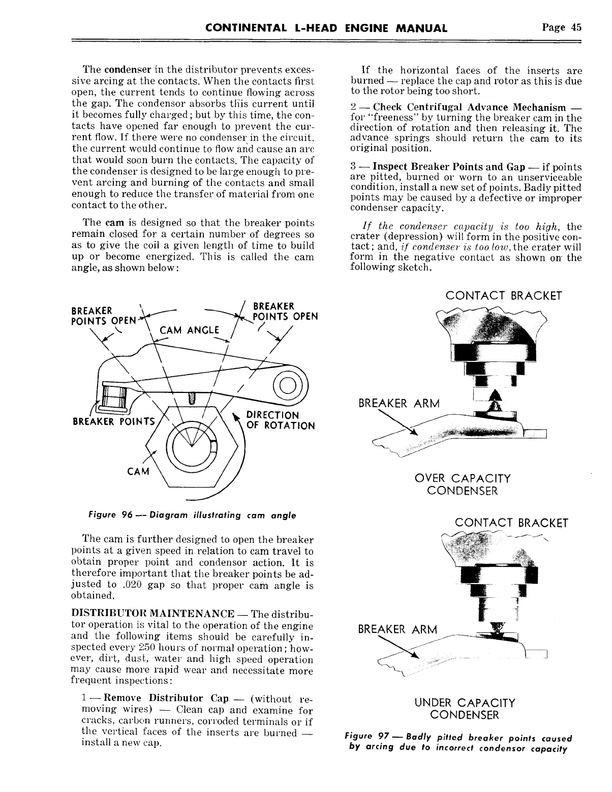
CONTINENTAL L-HEAD ENGINE MANUAL Page 45
The condenser in the distributor prevents exces-
sive arcing at the contacts. When the contacts first
open, the current tends to continue flowing across
the gap. The c.ondensor absorbs tliis current until
it becomes fully charged ; but by this time, the con-
tacts have opened far enough to prevent the cur-
rent flow. If there were no condenser in the circuit,
the current wc.uld continue to flow arid cause an arc
that would soon burn the contacts. The capacity of
the condenser is designed to be large enough to pre-
vent arcing and burning of the contacts and small
enough to reduce the transfer of material from one
contact to the other.
The cam is designed so that the breaker points
remain closed for a certain number of degrees so
as to give the coil a given length of time to build
up or become energized. This is called the cam
angle, as shown below :
CAM \,
Figure 96---Diagram illustrating cam angle
The cam is further designed to open the breaker
points at a giw~n speed in relation to cam travel to
obtain proper poin~ and condensor action. It is
therefore important that the breaker points be ad-
justed to .020 gap so that proper cam angle is
obtained.
DISTRIBUTOR MAINTENANCE -- The distribu-
for operation is vital to the operation of the engine
and the following items should be carefully in-
spected every 250 hours of normal operation ; how-
ever, dirt, dusL water and high speed operation
may cause more rapid wear and necessitate more
frequent inspections :
1--Remove Distributor Cap- (without re-
moving wires) -- Clean cap and examine for
cracks, carbon runners, corroded terminals or if
the vertical faces of the insexts are burned --
install a new cap.
If the horizontal faces of the inserts are
burned -- replace the cap and rotor as this is due
to the rotor being too short.
2- Check Centrifugal Advance Mechanism --
for "freeness" by turning the breaker cam in the
direction of rotation and then releasing it. The
advance springs should return the cam to its
original position.
3 -- Inspect Breaker Points and Gap -- if points
are pitted, burned or worn to an unserviceable
condition, install a new set of points. Badly pitted
points may be caused by a defective or improper
condenser capacity.
If the condenser capacity is too high, the
crater (depression) will form in the positive con-
tact ; and, i/ condenser is too low, the crater will
form in the negative contact as shown on- the
following sketch.
CONTACT BRACKET
BREAKER ARM
OVER CAPACITY
CONDENSER
CONTACT BRACKET
UNDER CAPACITY
CONDENSER
Figure 97 ~ Badly pitted breaker points caused
by arcing due to incorrect condensor capacity
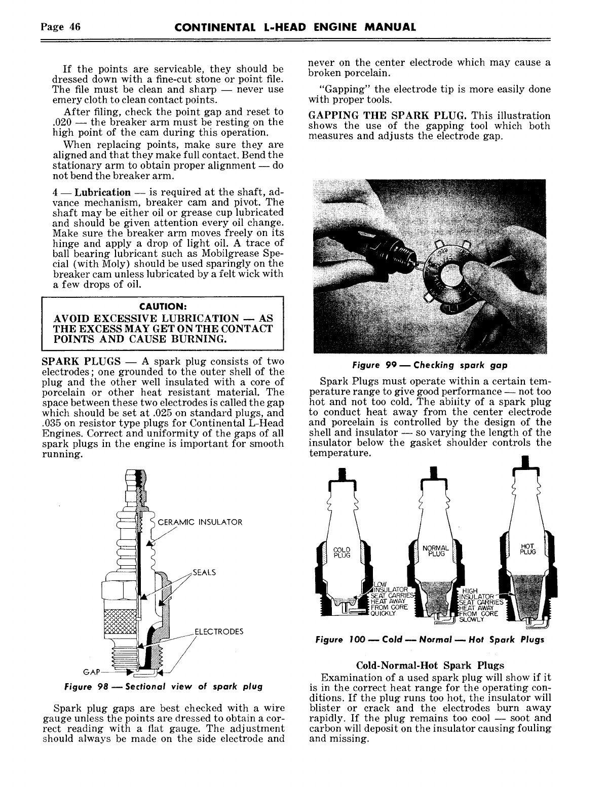
Page 46 CONTINENTAL L-HEAD ENGINE MANUAL
If the points are servicable, they should be
dressed down with a fine-cut stone or point file.
The file must be clean and sharp -- never use
emery cloth to clean contact points.
After filing, check the point gap and reset to
.020 -- the breaker arm must be resting on the
high point of the cam during this operation.
When replacing points, make sure they are
aligned and that they make full contact. Bend the
stationary arm to obtain proper alignment -- do
not bend the breaker arm.
4 -- Lubrication -- is required at the shaft, ad-
vance mechanism, breaker cam and pivot. The
shaft may be either oil or grease cup lubricated
and should be given attention every oil change.
Make sure the breaker arm moves freely on its
hinge and apply a drop of light oil. A trace of
ball bearing lubricant such as Mobilgrease Spe-
cial (with Moly) should be used sparingly on the
breaker cam unless lubricated by a felt wick with
a few drops of oil.
CAUTION:
AVOID EXCESSIVE LUBRICATION -- AS
THE EXCESS MAY GET ON THE CONTACT
POINTS AND CAUSE BURNING.
SPARK PLUGS -- A spark plug consists of two
electrodes; one grounded to the outer shell of the
plug and the other well insulated with a core of
porcelain or other heat resistant material. The
space between these two electrodes is called the gap
which should be set at .025 on standard plugs, and
.035 on resistor type plugs for Continental L-Head
Engines. Correct and uniformity of the gaps of all
spark plugs in the engine is important for smooth
running.
GAP--
CERAMIC INSULATOR
~ -SEALS
LECTRODES
Figure 98 ~ Sectional view of spark plug
Spark plug gaps are best checked with a wire
gauge unless the points are dressed to obtain a cor-
rect reading with a flat gauge. The adjustment
should always be made on the side electrode and
never on the center electrode which may cause a
broken porcelain.
"Gapping" the electrode tip is more easily done
with proper tools.
GAPPING THE SPARK PLUG. This illustration
shows the use of the gapping tool which both
measures and adjusts the electrode gap.
Figure 9Om Checking spark gap
Spark Plugs must operate within a certain tem-
perature range to give good performance -- not too
hot and not too cold. The abidty of a spark plug
to conduct heat away from the center electrode
and porcelain is controlled by the design of the
shell and insulator -- so varying the length of the
insulator below the gasket shoulder controls the
temperature.
COLD
PLUG
HEAT AWAY
FROM OORE HEAT AWAY
FROM CORE
SLOWLY
Figure 100 ~ Cold ~ Normal ~ Hot Spark Plugs
Cold-Normal-Hot Spark Plugs
Examination of a used spark plug will show if it
is in the correct heat range for the operating con-
ditions. If the plug runs too hot, the insulator will
blister or crack and the electrodes burn away
rapidly. If the plug remains too cool -- soot and
carbon will deposit on the insulator causing fouling
and missing.
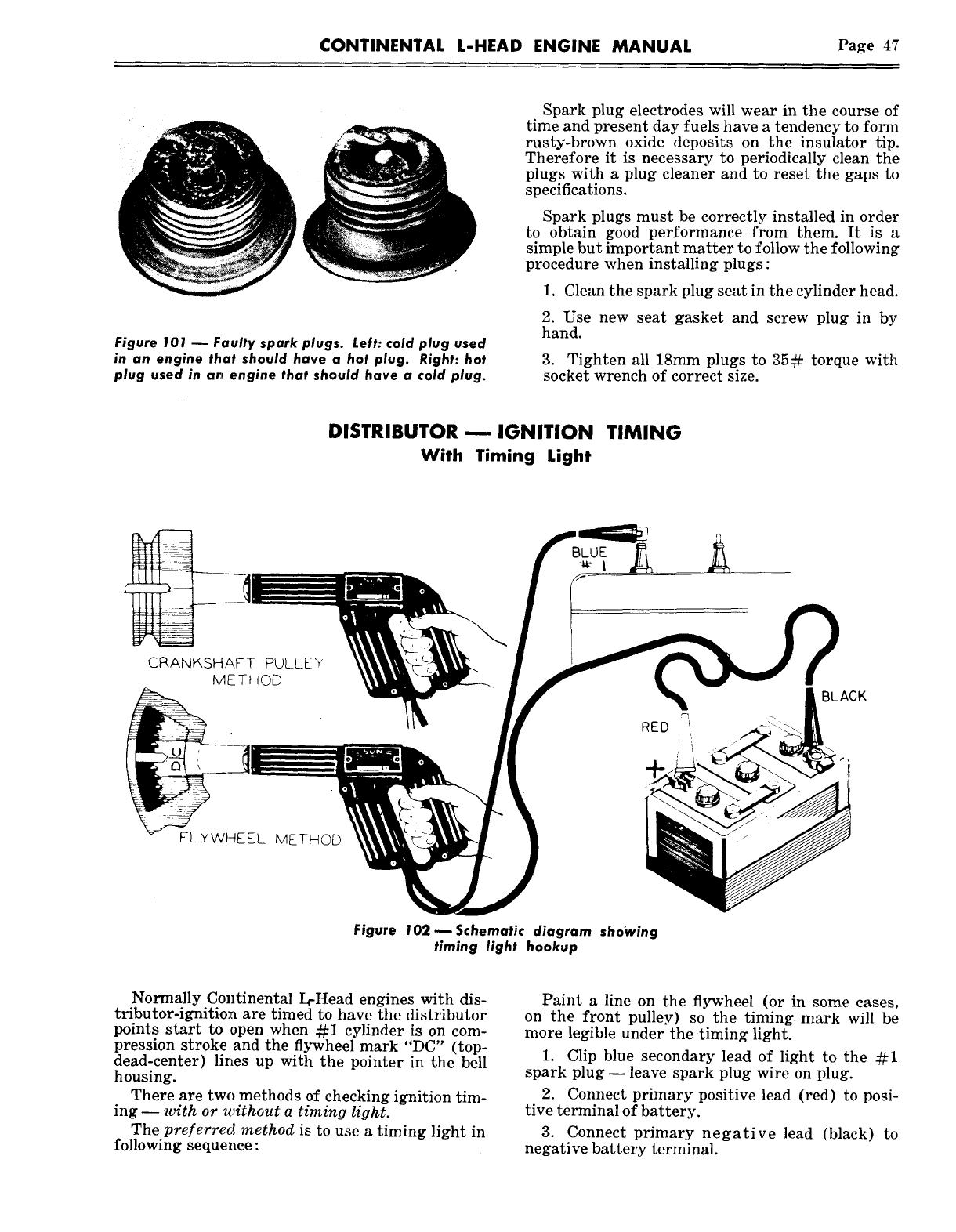
CONTINENTAL L-HEAD ENGINE MANUAL Page 47
Figure 101 ~ Faulty spark plugs. Left: cold plug used
in an engine that should have a hot plug. Right: hot
plug used in ar~ engine that should have a cold plug.
Spark plug electrodes will wear in the course of
time and present day fuels have a tendency to form
rusty-brown oxide deposits on the insulator tip.
Therefore it is necessary to periodically clean the
plugs with & plug cleaner and to reset the gaps to
specifications.
Sp&rk plugs must be correctly installed in order
to obtain good performance from them. It is a
simple but important matter to follow the following
procedure when installing plugs:
1. Clean the spark plug seat in the cylinder head.
2. Use new seat gasket and screw plug in by
hand.
3. Tighten all 18mm plugs to 35¢~ torque with
socket wrench of correct size.
DISTRIBUTOR -- IGNITION TIMING
With Timing Light
C_.RANK, SHAFT PULLEY
METHOD
FLYWHEEL k~lE THOD
BLUE
~ I
RED
Figure 102-- Schematic diagram sho~ving
timing light hookup
Normally Continental L-Head engines with dis-
tributor-ignition are timed to have the distributor
points start to open when ¢~1 cylinder is on com-
pression stroke and the flywheel mark "DC" (top-
dead-center) lines up with the pointer in the bell
housing.
There are two methods of checking ignition tim-
ing -- with or without a timing light.
The preferred method is to use a timing light in
following sequence:
Paint a line on the flywheel (or in some cases,
on the front pulley) so the timing mark will be
more legible under the timing light.
1. Clip blue secondary lead of light to the
spark plug -- leave spark plug wire on plug.
2. Connect primary positive lead (red) to posi-
tive terminal of battery.
3. Connect primary negative lead (black)
negative battery terminal.
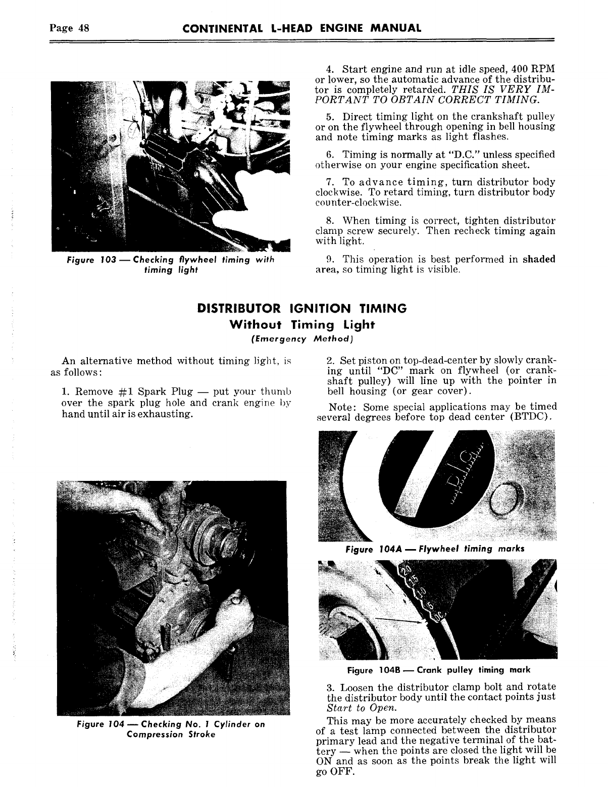
Page 48 CONTINENTAL L-HEAD ENGINE MANUAL
Figure 103 reChecking flywheel timing with
timing light
4. Start engine and run at idle speed, 400 RPM
or lower, so the automatic advance of the distribu-
tor is completely retarded. THIS IS VERY IM-
PORTANT TO OBTAIN CORRECT TIMING.
5. Direct timing light on the crankshaft pulley
or on the flywheel through opening in bell housing
and note timing marks as light flashes.
6. Timing is normally at "D.C." unless specified
otherwise on your engine specification sheet.
7. To advance timing, turn distributor body
clockwise. To retard timing, turn distributor body
cou nter-clockwise.
8. When timing is correct, tighten distributor
clamp screw securely. Then recheck timing again
with light.
9. This operation is best performed in shaded
area, so timing light is visible.
DISTRIBUTOR IGNITION TIMING
Without Timing Light
(Emergency Method)
An alternative method without timing light, is
as follows :
1. Remove ¢~1 Spark Plug -- put your thumb
over the spark plug hole and crank engine by
hand until air is exhausting.
2. Set piston on top-dead-center by slowly crank-
ing until "DC" mark on flywheel (or crank~
shaft pulley) will line up with the pointer in
bell housing (or gear cover).
Note: Some special applications may be timed
several degrees before top dead center (BTDC).
Figure 104 D Checking No. I Cylinder on
Compression Stroke
Figure I04A ~ Flywheel timing marks
Figure 104BDCrank pulley timing mark
3. Loosen the distributor clamp bolt and rotate
the distributor body until the contact points just
Start to Open.
This may be more accurately checked by means
of a test lamp connected between the distributor
primary lead and the negative terminal of the bat-
tery -- when the points are closed the light will be
ON and as soon as the points break the light will
go OFF.
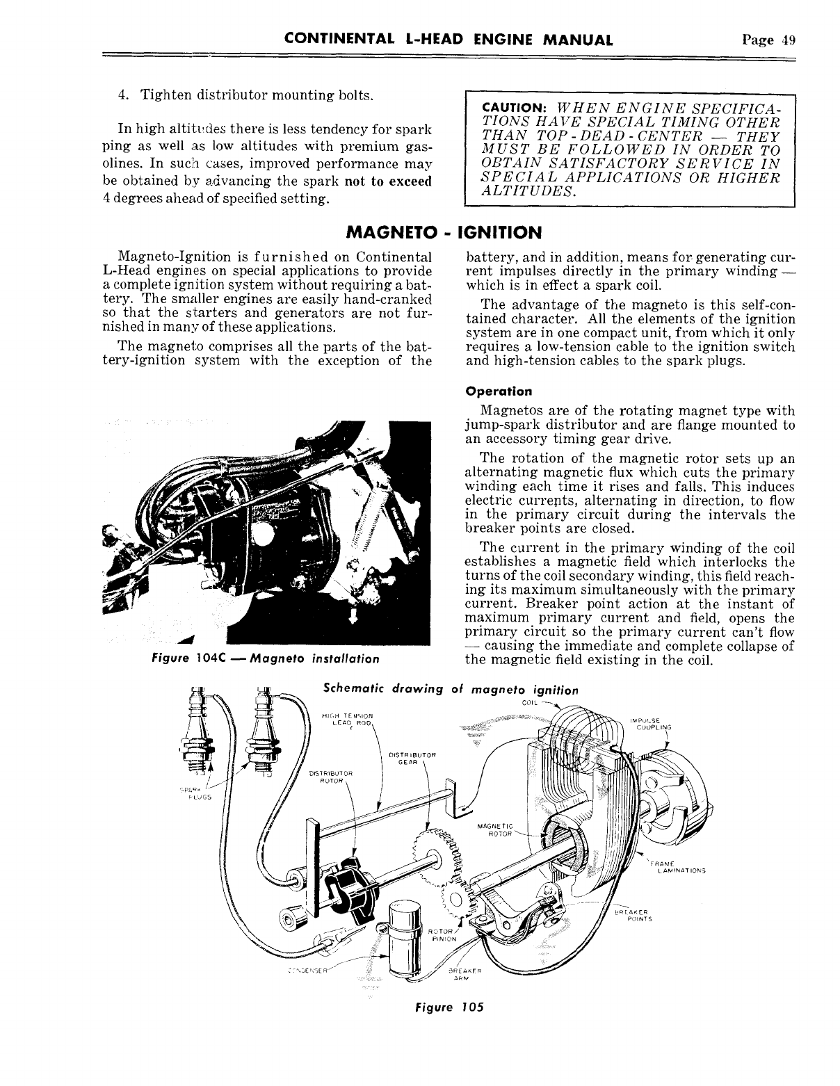
CONTINENTAL L-HEAD ENGINE MANUAL Page 49
4. Tighten distributor mounting bolts.
In high altitt..des there is less tendency for spark
ping as well as low altitudes with premium gas-
olines. In suclh cases, improved performance may
be obtained by s:dvancing the spark not to exceed
4 degrees ahe~td of specified setting.
CAUTION: WHEN ENGINE SPECIFICA-
TIONS HAVE SPECIAL TIMING OTHER
THAN TOP-DEAD- CENTER- THEY
MUST BE FOLLOWED IN ORDER TO
OBTAIN SATISFACTORY SERVICE IN
SPECIAL APPLICATIONS OR HIGHER
ALTITUDES.
MAGNETO - IGNITION
Magneto-Ignition is furnished on Continental
L-Head engines on special applications to provide
a complete ignition system without requiring a bat-
tery. The smaller engines are easily hand-cranked
so that the starters and generators are not fur-
nished in many of these applications.
The magneto comprises all the parts of the bat-
tery-ignition system with the exception of the
battery, and in addition, means for. generating cur-
rent impulses directly in the primary winding--
which is in effect a spark coil.
The advantage of the magneto is this self-con-
tained character. All the elements of the ignition
system are in one compact unit, from which it only
requires a low-tension cable to the ignition switch
and high-tension cables to the spark plugs.
Figure 104C--Magneto installation
Operation
Magnetos are of the rotating magnet type with
jump-spark distributor and are flange mounted to
an accessory timing gear drive.
The rotation of the magnetic rotor sets up an
alternating magnetic flux which cuts the primary
winding each time it rises and falls. This induces
electric curre.nts, alternating in direction, to flow
in the primary circuit during the intervals the
breaker points are closed.
The current in the primary winding of the coil
establishes a magnetic field which interlocks the
turns of the coil secondary winding, this field reach-
ing its maximum simultaneously with the primary
current. Breaker point action at the instant of
maximum primary current and field, opens the
primary circuit so the primary current can’t flow
-- causing the immediate and complete collapse of
the magnetic field existing in the coil.
Schematic drawing of magneto ignition
COIL ~
~ ~ ......................
Figure 105
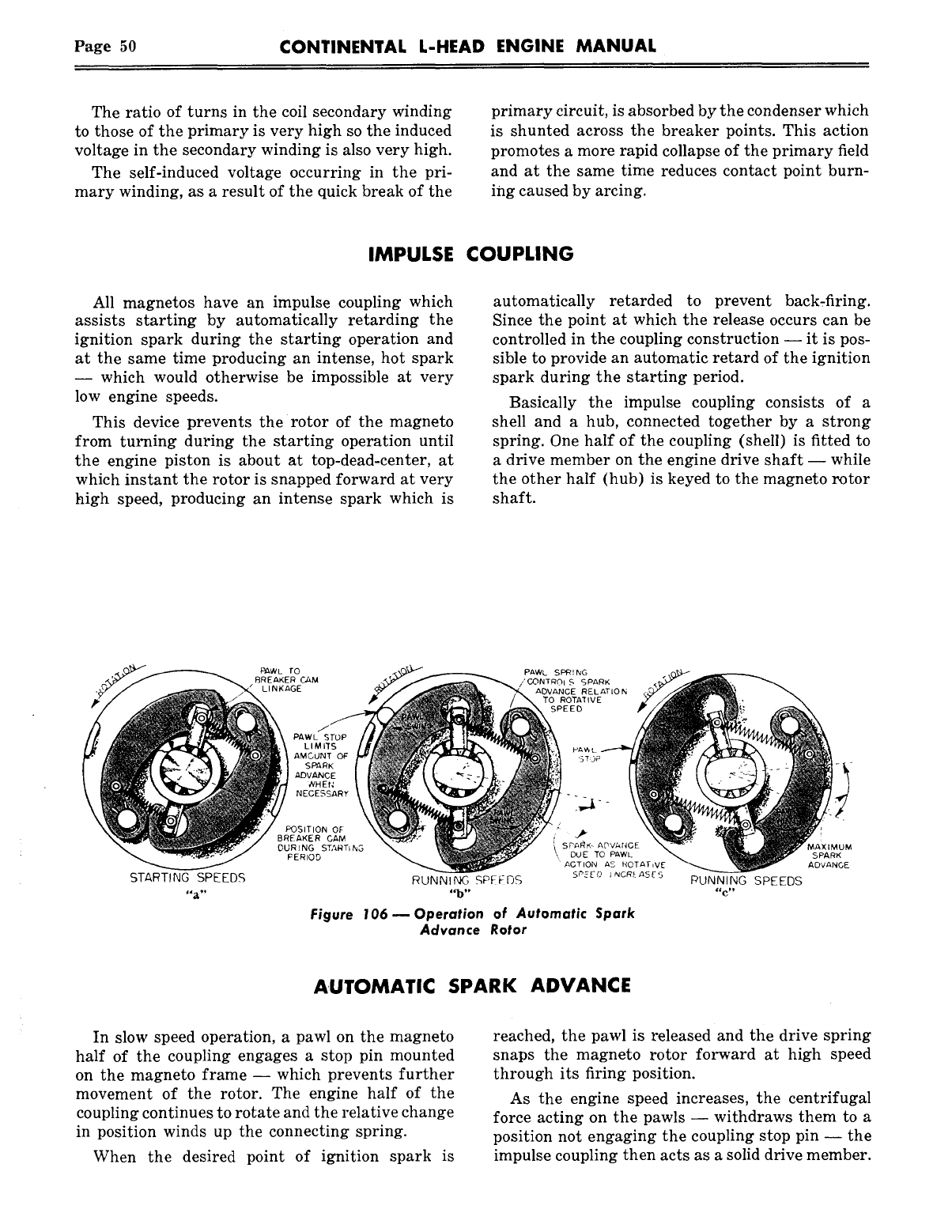
Page 50 CONTINENTAL L-HEAD ENGINE MANUAL
The ratio of turns in the coil secondary winding
to those of the primary is very high so the induced
voltage in the secondary winding is also very high.
The self-induced voltage occurring in the pri-
mary winding, as a result of the quick break of the
primary circuit, is absorbed by the condenser which
is shunted across the breaker points. This action
promotes a more rapid collapse of the primary field
and at the same time reduces contact point burn-
ing caused by arcing.
IMPULSE COUPLING
All magnetos have an impulse coupling which
assists starting by automatically retarding the
ignition spark during the starting operation and
at the same time producing an intense, hot spark
-- which would otherwise be impossible at very
low engine speeds.
This device prevents the rotor of the magneto
from turning during the starting operation until
the engine piston is about at top-dead-center, at
which instant the rotor is snapped forward at very
high speed, producing an intense spark which is
automatically retarded to prevent back~firing.
Since the point at which the release occurs can be
controlled in the coupling construction -- it is pos-
sible to provide an automatic retard of the ignition
spark during the starting period.
Basically the impulse coupling consists of a
shell and a hub, connected together by a strong
spring. One half of the coupling (shell) is fitted
a drive member on the engine drive shaft -- while
the other half (hub) is keyed to the magneto ~otor
shaft.
STARTING SPEEDS
PAWL rO
BREAKER ChM
LINKAGE
PAWL SPRING
/’~ONTRC}I S SPARK
A(~VANCE RELATION
TO ROTATIV E
SPEED
PAWL STOP
L I M I’f S
AMCUNT OF
SPARK
.&DVANC[
WH E f;
NECESSARY
RUNNING SPFFOS
Figure 106 ~ Operation of Automatic Spark
Advance Rotor
AUTOMATIC SPARK ADVANCE
In slow speed operation, a pawl on the magneto
half of the coupling engages a stop pin mounted
on the magneto frame -- which prevents further
movement of the rotor. The engine half of the
coupling continues to rotate and the relative change
in position winds up the connecting spring.
When the desired point of ignition spark is
reached, the pawl is released and the drive spring
snaps the magneto rotor forward at high speed
through its firing position.
As the engine speed increases, the centrifugal
force acting on the pawls -- withdraws them to a
position not engaging the coupling stop pin -- the
impulse coupling then acts as a solid drive member.
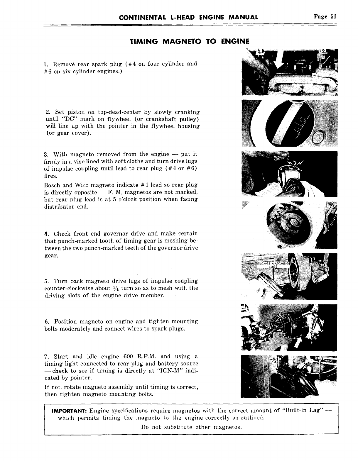
CONTINENTAL L-HEAD ENGINE MANUAL Page 51
TIMING MAGNETO TO ENGINE
1. Remov~ rear spark plug (#4 on four cylinder and
#6 on six cylinder engines.)
2. Set piston on top-dead-center by slowly cranking
until "DC" mark on flywheel (or crankshaft pulley)
will line up with the pointer in the flywheel housing
(or gear cover).
3. With magneto removed from the engine -- put it
firmly in a vise lined with soft cloths and turn drive lugs
of impulse coupling until lead to rear plug (#4 or #6)
fires.
Bosch and Wi,:o magneto indicate # 1 lead so rear plug
is directly opposite -- F. M. magnetos are not marked,
but rear plug lead is at 5 o’clock position when facing
distributor end.
tl. Check front end governor drive and make certain
that punch-marked tooth of timing gear is meshing be-
tween the two punch-marked teeth of the governor drive
gear.
5. Turn back magneto drive lugs of impulse coupling
counter-clockwise about 1/~ turn so as to mesh with the
driving slots of the engine drive member.
6. Position magneto on engine and tighten mounting
bolts moderately and connect wires to spark plugs.
7. Start and idle engine 600 R.P.M. and using a
timing light connected to rear plug and battery source
--check to see; if timing is directly at "IGN-M" indi-
cated by pointer.
If not, rotate magneto assembly until timing is correct,
then tighten magneto mounting bolts.
IMPORTANT: Engine specifications require magnetos with the correct amount of "Built-in Lag" --
which permits timing the magneto to the engine correctly as outlined.
Do not substitute other magnetos.
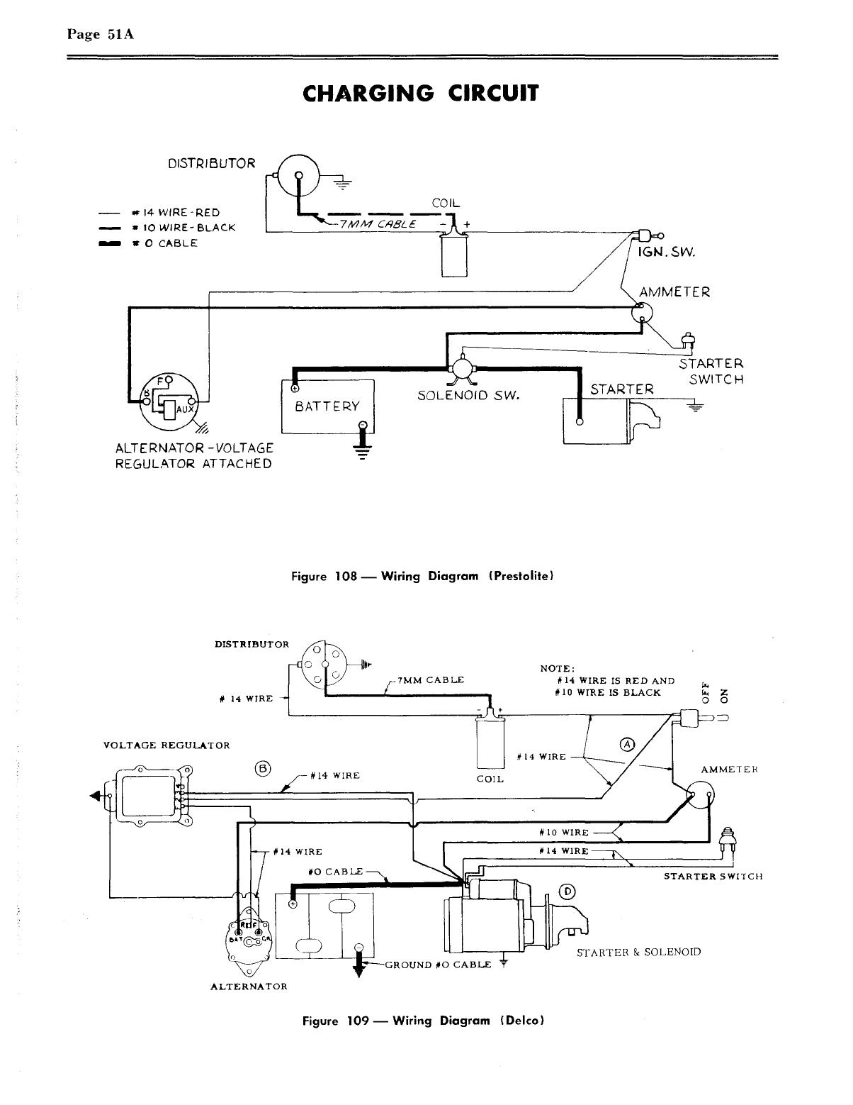
Page 51A
CHARGING CIRCUIT
DISTRIBUTOR
14-WIRE-RED
IO WIRE- BLACK
O CABLE
ALTERNATOR -VOLTAGE
REGULATOR ATTACHED
C~L£
60LEMOID SVv’.
START E P,
SWITCH
Figure 108--Wiring Diagram (Prestolite)
DISTRIBUTOR
# 14 WIRE ~
-7MM CABLE
NOTE:
#14 WIRE IS RED AND
#10 WIRE IS BLACK 0 0
VOLTAGE REGULATOR
-- # 14 WIRE COIL
~
~ARTER ~ SOLENOID
ALTERNATOR
Figure 109--Wiring Diagram (Delco)

The charging circuit consists primarily of a gen-
erator, regulator, battery and wiring. When ana-
lyzing the charging circuit, the components should
be checked in the following order:
I. Wiring
Wiring in the charging circuit should be care-
fully inspected for frayed insulation or other
damage, an.d replace any wiring that is defec-
tive. Also inspect all connections to the gen-
erator, re~:ulator and battery (including all
ground connections), and clean and tighten
as required.
II. Battery
The lead-acid .storage battery, used on auto-
motive and industrial applications, is an elec-
trochemical device for converting chemical
energy into electrical energy.
It has three major functions:
1. It provides a source of curren.t for start-
ing tl~e engine.
2. It acts as a stabilizer to the voltage in
the electrical system.
3. It car~, for a limited time, furnish cur-
rent when the electrical demands of the
unit exceed the output of the generator.
There are ~wo types of batteries with which
we are concerned: The DRY charged and the
WET charged.
The DRY charged is shipped from the fac-
tory with charged plates, and the electrolyte
is added wlhen the battery is ready to be ac-
tivated.
The WET charged battery is shipped from
the factory with the electrolyte already added.
This type must be recharged periodically,
while in storage, to keep it ready for service.
Battery Testing
Visual Test -- The battery should be in-
s, pected visually, checking the level of the
electrolyte and the outside of the battery for
damage and abuse.
Page 51B
The
1.
"In-Vehicle" Light Load Test
First, if the electrolyte level is low, ad~
just it to the proper level by adding
water.
Then place a load in the battery by hold-
ing the starter switch "ON" for three
seconds, or until the engine starts. If
the engine starts, turn off ignition im-
mediately. This removes the surface
charge.
Then, turn the headlights on low-beam.
The headlights must be turned on for
one minute before starting the light load
test and then left on during the test.
If any cell reads 1.95 volts or more and
the diff.erence between the highest and
lowest is less than .05 volt, the battery
is good.
The "Out-of-Vehicle" Light Load Test
This test is conducted in the same way as
the "In-Vehicle" test.
To check the electrical condition of battery
cells :
Place a 150 ampere load on battery for
three seconds, using a high rate load
tester, to remove surface charge.
Then, place a ten ampere load on battery
for one minute before starting the Light
Load Test. The difference in voltage
readings between the individual cells can
be interpreted in the same way as indi-
cared under the "In-Vehicle" Light Load
Test.
Specific Gravity Cell Comparison Test
This test should be used only on batteries
having one-piece cell covers. Measure the
specific gravity of each cell, regardless of
state of charge, and interpret results as fol-
lows :
If the maximum difference between cell
readings is les.s than .050 (50 points) and
the lowest cell reading is 1.200 or above,
the battery is good.
Page 51C
Full Charge Hydrometer Test
This test .is given to fully charged batteries.
If cell readings range between 1.230 and 1.310
specific gravity, the battery is ready for u~e.
NOTE: Add 4 points (.004) to the re.ading
for every 10°F electrolyte temperature above
80°F, and subtract four (4) points for every
10~F electrolyte temperature below 80°F.
Selecting A Replacement Battery
When selecting a replacement battery it
should be noted that battery power shrinks
while the need for engine cranking power
increases
Chart)
with falling temperatures. (See
ENGINE CRANKING
BATTERY POWER TEMPERATURE POWER NEEDED
100 % 80 o 100 ~
68 % 32 o 165 %
46% 0
°250%
30% -20
°350%
Installing Batteries
The following points are important to pro-
perly install a battery:
1. Be sure the battery carrier is clean and
that the new battery rests level when
installed..
2. Tighten the hold-down evenly until snug.
Do not draw down tight enough to dis-
tort or crack battery case.
3. Be .sure the cables are in good condi-
tion and the terminal clamps are clean.
Grease battery terminals lightly before
attaching cable clamps. Make sure the
ground cable is clean and tight at engine
block or frame.
4. Check polarity to be sure battery is not
reversed with respect to the generating
sy,stem.
5. Connect "grounded" terminal of the bat-
tery last to avoid short circuits which
will damage the battery.
Servicing Batteries
The following points are important to pro-
perly service a battery:
o
Check the level of the electrolyte regu-
larly. Add water if necessary but do not
overfill.
Keep the top of the battery clean. When
necessary, wash with baking soda solu-
tion and r.inse with clear water. Do not
allow soda solution to enter cells.
Inspect cables, clamps and hold down
bracket regularly. Replace if necessary.
Use the light load test as your regular
service test to check battery condition.
Check the electrical system if the bat-
tery becomes discharged repeatedly.
CAUTION
Sparks or Flames Near a Battery that
is Being Charged May Ignite Explosive
Gases Causing a Dangerous Explosion.
III. Alternator
The alternator differs from the conven-
tional D.C. shunt generator in that the arma-
ture is the stationary member and is called
the stator; while the field is the rotating
member and is called the rotor. Alternating
current is rectified (changed to direct cur-
rent) by means of diode rectifiers rather than
mechanically with brushes coming into con-
tact with the various segments of the rotating
armature on the generator. With this con-
struction, the higher current values involved
in the armature or stator may be conducted
to the external circuit through fixed leads
and connections rather than through the ro-
tating commutator and brushes as in D.C.
generator. The comparatively small values
of current supplied to the field may be con-
ducted without difficulty through small
brushes and rotating slip rings.
The alternator is somewhat lighter and
more cbmpact in design than the conventional
D.C. generator of comparable electrical size
and is equally as simple to service and test.
Each bearing is prelubricated which elimi-
nates the need for periodic lubrication.
PRECAUTIONS TO BE OBSERVED WHEN
TESTING OR SERVICING THE ALTERNA-
TOR SYSTEM.
Pa~e 51D
1. DI~,CONNECT THE BATTERY, before
connecting or disconnecting test instru-
ments (except voltmeter) or before re-
mo~Ting or replacing any unit or wiring.
Accidental grounding or shorting at the
reg:alator, alternator, ammeter or acces-
sories, will cause severe damage to the
unil:s an.d/or wiring.
2. TO AVOID DAMAGE TO THE REGU-
LATOR, DO NOT, AT ANY TIME,
CONNECT BATTERY TO THE REG-
ULATOR FIELD TERMINAL.
3. THE FIELD CIRCUIT MUST NEVER
BE GROUNDED, ON THIS SYSTEM,
BETWEEN THE ALTERNATOR AND
THE REGULATOR. Grounding of the
field terminal either at the alternator or
regulator will damage the regulator.
4. IF IT IS NECESSARY TO SOLDER
ANY LEAD TO A RECTIFIER LEAD,
use a pair of pliers as a heat dam be-
tween the solder joint and the rectifier.
5. THE ALTERNATOR MUST NOT BE
OPERATED ON OPEN CIRCUIT WITH
THE ROTOR WINDING ENERGIZED.
6. DO NOT ATTEMPT TO POLARIZE
THE ALTERNATOR. No polarization
is required. Any attempt to do so may
resc~lt in damage to the alternator, reg-
lator, or circuits.
7. GROUNDING OF THE ALTERNATOR
OU~?PUT TERMINAL MAY DAMAGE
THE ALTERNATOR AND/OR CIR-
CUIT AND COMPONENTS.
8. REVERSED BATTERY CONNEC-
TIONS MAY DAMAGE THE RECTIFI-
ERS, WIRING OR OTHER COMPON-
ENTS OF THE CHARGING SYSTEM.
Battery polarity should be checked with
a voltmeter before connecting the bat-
tery.
9. IF A BOOSTER BATTERY OR FAST
CHARGER IS USED, ITS POLARITY
MUST BE CONNECTED CORRECTLY
TO PREVENT DAMAGE TO THE
ELECTRICAL SYSTEM COMPON-
ENTS. (POSITIVE TO POSITIVE,
NEGATIVE TO NEGATIVE).
IV. Regulator
Some regulators are fully transistorized
and completely .sealed. These can not be ad-
justed or repaired, and it can be assumed
that this type regulator will outlive the other
components in the charging system.
Other regulators are adjusted and repaired
in accordance with the manufacturer’s in-
structions.
Installation of Regulator for Alternator
To insure proper operation and to protect
the alternator and regulator, the following
steps should be observed during installation.
1. Make sure regulator is of the same volt-
age and polarity as the alternator and
battery.
2. Disconnect battery cable at battery ter-
minal.
Make sure the mounting area of the al-
ternator and regulator base are clean
and make a good tight connection.
Connect alternator in accordance with
the manufacturer’s instructions.
5. Do not flash field or ground terminals
of the regulator.
Reconnect battery cable.
Start engine and observe ammeter. A
"High" charge rate is normal for the
first few minutes, but will decrease as
the regulator warms up.
NOTE : When servicing the charging system, nev-
er remove a unit until tests have shown
it to be defective. Reference always
should be made to the manufacturer’s
maintenance manuals for a complete
trouble shooting story.

Page 52 CONTINENTAL L-HEAD ENGINE MANUAL
SECTION VIII
ENGINE REPAIR AND
OVERHAUL
This section includes instructions for repairs and
overhaul of the component units of Continental
Red Seal L-Head engines.
Provide a clean place to work and clean the en-
gine exterior before you start disassembling --
dirt causes engine failures. Many shop tools have
been developed to save time and assure good work-
manship; these should be included in your equip-
ment.
Use only genuine Red Seal parts in Continental
engines since years of development and testing
have gone into these specifications to assure max-
imum life and performance.
CYLINDER HEAD
The cylinder head is an important part of the
engine assembly since it contains the complete com-
bustion chamber and cored passage for water flow.
Remove the cylinder head in the following
sequence:
1. Drain water from engine and disconnect rad-
iator or heat exchanger outlet hose.
2. Loosen and remove the nuts holding the cylin-
der head to the block.
3. Lift the cylinder head off the engine and carry
to a clean bench for further disassembly.
4. Remove all carbon from combustion areas
using a scraper and wire brush.
5. Clean the cylinder head thoroughly with a
solvent or degreasing solution and blow it off
with air pressure.
6. Make sure that gasket contact surfaces on
the head and block are clean, smooth and flat.
Figure 11 1 m Checking cylinder head flatness
lengthwise.
7. Check out-of-flatness with straight edge and
feeler gauge: maximum permissible is .00075
inches per inch of width or length. Thus, for a
cylinder head 16" long, maximum permissible
lengthwise out-of-flatness is .012". Out-of-flat-
ness should vary gradually and uniformly from
end to end and side to side. Localized depres-
sions or high spots should not exceed .003.
Figure 110 ~ Cleaning carbon from
combustion chamber Figure 112 m Checking cylinder head flatness
crosswise.
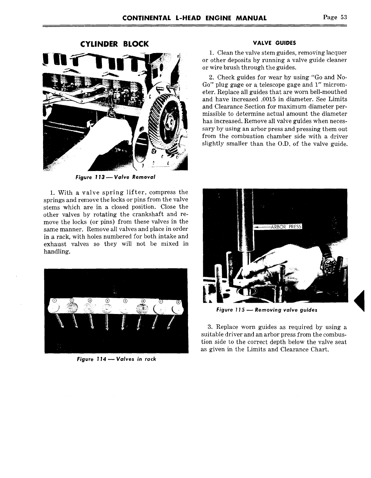
CONTINENTAL L-HEAD ENGINE MANUAL Page 53
CYLINDER BLOCK
Figure 1 13 ~ Valve Removal
1. With a valve spring lifter, compress the
springs and remove the locks or pins from the valve
stems which are in a closed position. Close the
other valves by rotating the crankshaft and re-
move the locks (or pins) from these valves in the
same manner. Remove all valves and place in order
in a rack, with holes numbered for both intake and
exhaust valve:~ so they will not be mixed in
handling.
Figure 114 N Valves in rack
VALVE GUIDES
1. Clean the valve stem guides, removing lacquer
or other deposits by running a valve guide cleaner
or wire brush through the guides.
2. Check guides for wear by using "Go and No-
Go" plug gage or a. telescope gage and 1" microm-
eter. Replace all guides that are worn bell-mouthed
and have increased .0015 in diameter. See Limits
and Clearance Section fol; maximum diameter per-
missible to determine actual amount the diameter
has increased. Remove all valve gtfides when neces-
sary by using an arbor press and pressing them out
from the combustion chamber side with a driver
slightly smaller than the O.D. of the valve guide.
Figure 115 ~ Removing valve guides
3. Replace worn guides as required by using a
suitable driver and an arbor press from the combus-
tion side to the correct depth below the valve seat
as given in the Limits and Clearance Chart.
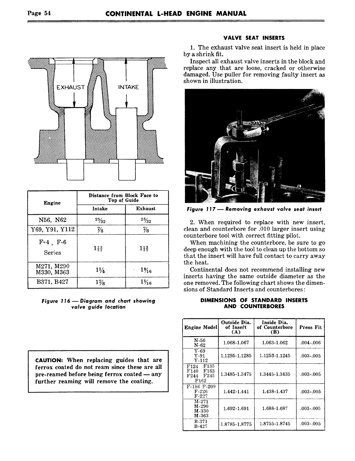
Page 54 CONTINENTAL L-HEAD ENGINE MANUAL
I ~ INTAKE
_
VALVE SEAT INSERTS
1. The exhaust valve seat insert is held in place
by a shrink fit.
Inspect all exhaust valve inserts in the block and
replace any that are loose, cracked or otherwise
damaged. Use puller for removing faulty insert as
shown in illustration.
Engine Distance from Block Face to
Top of Guide
Intake Exhaust
N56, N62 2%2 2%2
Y69, Y91, Yl12 7/8 7/8
F-4 F-6
~eries
M271, M290
M330, M363 11~ 19/16
B371, B427 17/8
Figure 116 m Diagram and chart showing
valve guide location
CAUTION: When replacing guides that are
ferrox coated do not ream since these are all
pre-reamed before being ferrox coated m any
further reaming will remove the coating.
Figure 117 ~ Removing exhaust valve seat insert
2. When required to replace with new insert,
clean and counterbore for .010 larger insert using
counterbore tool with correct fitting pilot.
When machining the counterbore, be sure to go
deep enough with the tool to clean up the bottom so
that the insert will have full contact to carry away
the heat.
Continental does not recommend installing new
inserts having the same outside diameter as the
one removed. The following chart shows the dimen-
sions of Standard Inserts and counterbores :
DIMENSIONS OF STANDARD INSERTS
AND COUNTERBORES
Outside Dia. Inside Dia.
Engine Model of Inse~:t of Counterbore Press Fit
(A) (B)
N-56 1.068-1.067 1.063-1.062 .004-.006
N-62
Y-69
Y-91 1.1295-1.1285 1.1258-1.1245 .003-.005
Y-112
F124 F135
F140 F163
F244 F245 1.3485-1.3475 1.3445-1.3435 .003-.005
F162
F-186 F-209
F-226 1.442-1.441 1.438-1.437 .003-.005
F-227
M-271
M-290 1.692-1.691 1.688-1.687 .003-.005
M-330
M-363
B-371
B-427 1.8785-1.8775 1.8755-1.8745 .003-.005
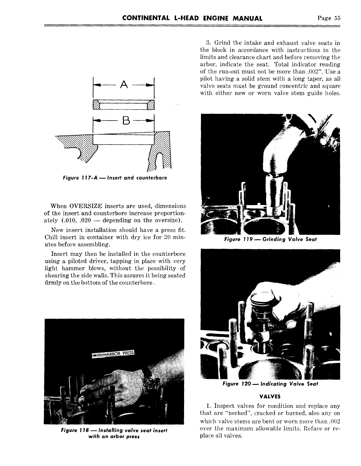
CONTINENTAL L-HEAD ENGINE MANUAL Page 55
Figure 117-A m Insert and counterbore
When OVERSIZE inserts are used, dimensions
of the insert and counterbore increase proportion-
ately (.010, .020 -- depending on the oversize).
New insert installation should have a press fit.
Chill insert in container with dry ice for 20 min-
utes before as,~;embling.
Insert may then be installed in the counterbore
using a piloted driver, tapping in place with very
light hammer blows, without the possibility of
shearing the side walls. This assures it being seated
firmly on the bottom of the counterbore.
3. Grind the intake and exhaust valve seats in
the block in accordance with instructions in the
limits and clearance chart and before removing the
arbor, indicate the seat. Total indicator reading
of the run-out must not be more than .002". Use a
pilot having a solid stem with a long taper, as all
valve seats must be ground concentric and square
with either new or worn valve stem guide holes.
Figure 119 ~ Grinding Valve Seat
Figure 118 ~ Installing valve seat insert
with an arbor press
Figure 120 ~ Indicating Valve Seat
VALVES
1. Inspect valves for condition and replace any
that are "necked", cracked or burned, also any on
which valve stems are bent or worn more than .002
over the maximum allowable limits. Reface or re-
place all valves.
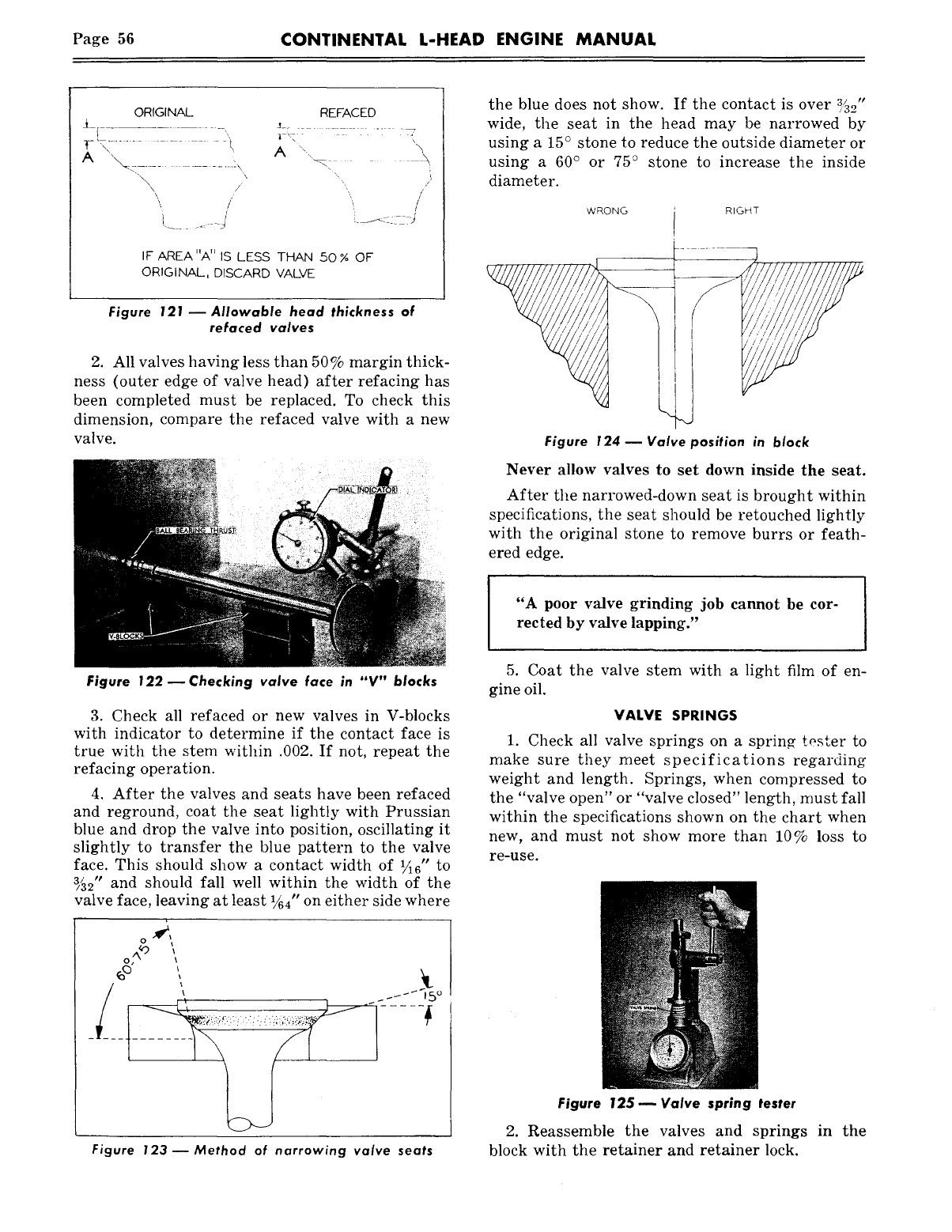
Page 56 CONTINENTAL L-HEAD ENGINE MANUAL
ORIGINAL REFACED
IF AREA UA" IS LESS THAN 50 % OF
ORIGINAL, DISCARD VALVE
Figure 121 ~ Allowable head thickness of
refaced valves
2. All valves having less than 50% margin thick-
ness (outer edge of valve head) after refacing has
been completed must be replaced. To check this
dimension, compare the refaced valve with a new
valve.
the blue does not show. If the contact is over ~5_0"
wide, the seat in the head may be narrowed by
using a 15° stone to reduce the outside diameter or
using a 60° or 75° stone to increase the inside
diameter.
WRONG RIGHT
Figure 124 -- Valve position in block
Never allow valves to set down inside the seat.
After the narrowed-down seat is brought within
specifications, the seat should be retouched lightly
with the original stone to remove burrs or feath-
ered edge.
"A poor valve grinding job cannot be cor-
rected by valve lapping."
Figure 122 ~ Checking valve face in "V" blocks
3. Check all refaced or new valves in V-blocks
with indicator to determine if the contact face is
true with the stem within .002. If not, repeat the
refacing operation.
4. After the valves and seats have been refaced
and reground, coat the seat lightly with Prussian
blue and drop the valve into position, oscillating it
slightly to transfer the blue pattern to the valve
face. This should show a contact width of V16" to
~2" and should fall well within the width of the
valve face, leaving at least 1~4" on either side where
Figure 123--Method of narrowing valve seats
5. Coat the valve stem with a light film of en-
gine oil.
VALVE SPRINGS
1. Check all valve springs on a sprin~ tosser to
make sure they meet specifications regarding
weight and length. Springs, when compressed to
the "valve open" or "valve closed" length, must fall
within the specifications shown on the chart when
new, and must not show more than 10% loss to
re-use.
Figure 125 ~ Valve spring tester
2. Reassemble the valves and springs in the
block with the retainer and retainer lock.
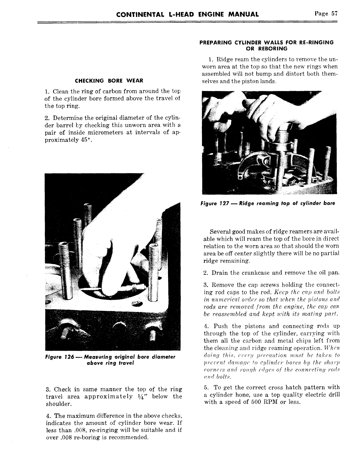
CONTINENTAL L-HEAD ENGINE MANUAL Page 57
CHECKING BORE WEAR
1. Clean the ring of carbon from around the top
of the cylinder bore formed above the travel of
the top ring.
2. Determine the original diameter of the cylin-
der barrel by checking this unworn area with a
pair of inside micrometers at intervals of ap-
proximately 45
°.
PREPARING CYLINDER WALL5 FOR RE-RINGING
OR REBORING
1. Ridge ream the cylinders to remove the un-
worn area at the top so that the new rings when
assembled will not bump and distort both them-
selves and the piston lands.
Figure 127 ~ Ridge reaming top of cylinder bore
Figure 126 m. Measuring original bore diameter
above ring travel
3. Check in same manner the top of the ring
travel area approximately 1~,, below the
shoulder.
4. The maximum difference in the above checks,
indicates the amount of cylinder bore wear. If
less than .008, re-ringing will be suitable and if
over .008 re-boring is recommended.
Several good makes of ridge reamers are avail-
able which will ream the top of the bore in direct
relation to the worn area so that should the worn
area be off center slightly there will be no partial
ridge remaining.
2. Drain the crankcase and remove the oil pan.
3. Remove the cap screws holding the connect-
ing rod caps to the rod. Keep the cap and bolts
in numerical order so that when the pistons and
rods are removed from t~e engine, the cap can
be reassembled and kept with its mating part.
4. Push the pistons and connecting rods up
through the top of the cylinder, carrying with
them all the carbon and metal chips left from
the cleaning and ridge reaming operation. When
doing this. c~’c’r~l precc~ution must bc taken to
prc~’ent da~?~cUle ~o cylinder bores by the st~arp
corners and ?’o~gt~ ~’dgcx of the connecting rod,~
and bolts.
5. To get the correct cross hatch pattern with
a cylinder hone, use a top quality electric drill
with a speed of 500 RPM or less.
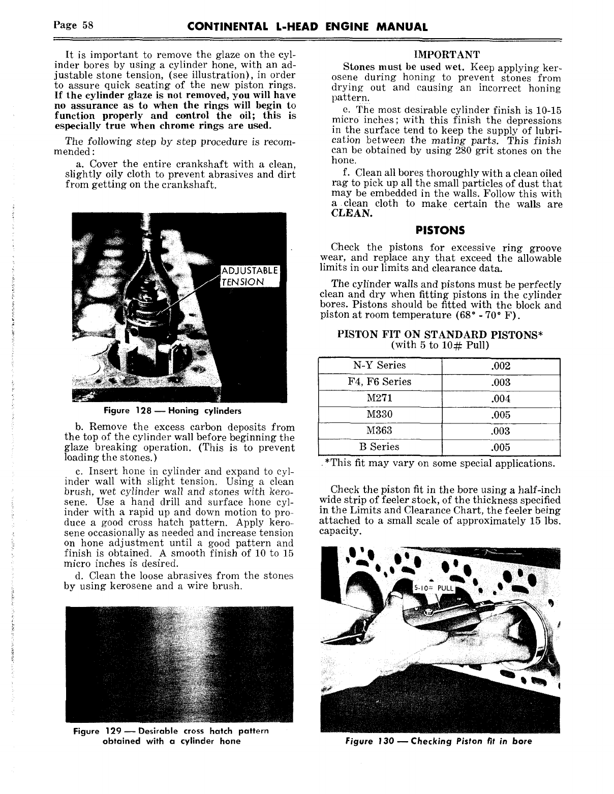
Page 58 CONTINENTAL L-HEAD ENGINE MANUAL
It is important to remove the glaze on the cyl-
inder bores by using a cylinder hone, with an ad-
justable stone tension, (see illustration), in order
to assure quick seating of the new piston rings.
If the cylinder glaze is not removed, you will have
no assurance as to vchen the rings will begin to
function properly and control the oil; this is
especially true when chrome rings are used.
The following step by step procedure is recom-
mended :
a. Cover the entire crankshaft with a clean,
slightly oily cloth to prevent abrasives and dirt
from getting on the crankshaft.
Figure 128mHoning cylinders
b. Remove the excess carbon deposits from
the top of the cylinder wall before beginning the
glaze breaking operation. (This is to prevent
loading the stones.)
c. Insert hone in cylinder and expand to cyl-
inder wall with slight tension. Using a clean
brush, wet cylinder wall and stones with kero-
sene. Use a hand drill and surface hone cyl-
inder with a rapid up and down motion to pro-
duee a good cross hatch pattern. Apply kero-
sene occasionally as needed and increase tension
on hone adjustment until a good pattern and
finish is obtained. A smooth finish of 10 to 15
micro inches is desired.
d. Clean the loose abrasives from the stones
by using kerosene and a wire brush.
IMPORTANT
Stones must be used wet. Keep applying ker-
osene during honing to prevent stones from
drying out and causing an incorrect honing
pattern.
e. The most desirable cylinder finish is 10-15
micro inches; with this finish the depressions
in the surface tend to keep the supply of lubri-
cation between the mating parts. This finish
can be obtained by using 280 grit stones on the
hone.
f. Clean all bores thoroughly with a clean oiled
rag to pick up all the small particles of dust that
may be embedded in the walls. Follow this with
a clean cloth to make certain the walls are
CLEAN.
PISTONS
Check the pistons for excessive ring groove
wear. and replace any that exceed the allowable
limits in our limits and clearance data.
The cylinder walls and pistons must be perfectly
clean and dry when fitting pistons in the cylinder
bores. Pistons should be fitted with the block and
piston at room temperature (68° - 70° F).
PISTON FIT ON STANDARD PISTONS*
(with 5 to 10~: Pull)
N-Y Series .002
F4, F6 Series .003
M271 .004
M330 .005
M363 .003
B Series .005
*This fit may vary on some special applications.
Check the piston fit in the bore using a half-inch
wide strip of feeler stock, of the thickness specified
in the Limits and Clearance Chart, the feeler being
attached to a small scale of approximately 15 lbs.
capacity.
Figure 129 Desirable cross hatch pattern
obtained with a cylinder hone Figure 130 ~ Checking Piston fit in bore
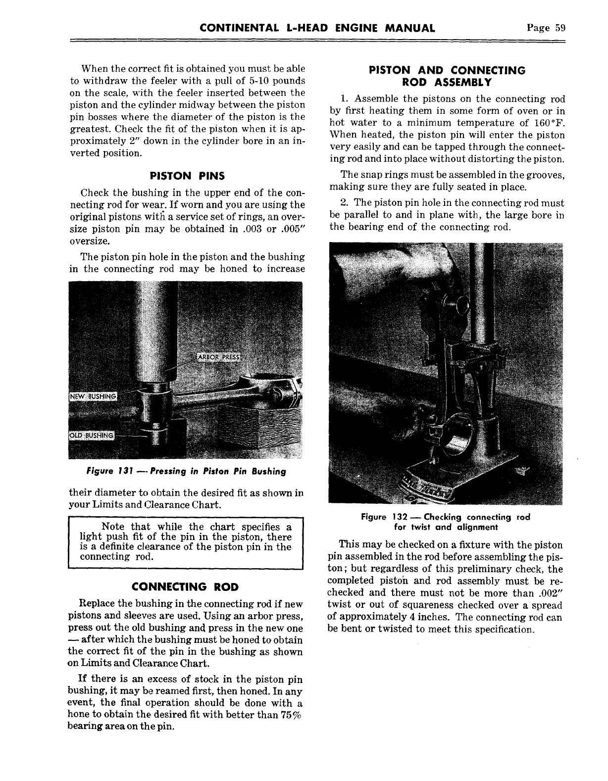
CONTINENTAL L-HEAD ENGINE MANUAL Page 59
When the correct fit is obtained you must be able
to withdraw the feeler with a pull of 5-10 pounds
on the scale, with the feeler inserted between the
piston and the cylinder midway between the piston
pin bosses where the diameter of the piston is the
greatest. Check the fit of the piston when it is ap-
proximately 2" down in the cylinder bore in an in-
verted position.
PISTON PINS
necting rod for wear. If worn and you are using the
original pistons witl~ a service set of rings, an over-
size piston pin may be obtained in .003 or .005"
oversize.
The piston pin hole in the piston and the bushing
in the connecting rod may be honed to increase
PISTON AND CONNECTING
ROD ASSEMBLY
1. Assemble the pistons on the connecting rod
by first heating them in some form of oven or in
hot water to a minimum temperature of 160°F.
When heated, the piston pin will enter the piston
very easily and can be tapped through the connect-
ing rod and into place without distorting the piston.
The snap rings must be assembled in the grooves,
making sure they are fully seated in place.
2. The piston pin hole in the connecting rod must
be parallel to and in plane with, the large bore in
the bearing end of the connecting rod.
Figure 131 ~. Pressing in Piston Pin Bushing
their diameter to obtain the desired fit as shown in
,our Limits and Clearance Chart.
Note that while the chart specifies a
light push fit of the pin in the piston, there
is a definite clearance of the piston pin in the
connecting rod.
CONNECTING ROD
Replace the bushing in the connecting rod if new
pistons and sleeves are used. Using an arbor press,
press out the old bushing and press in the new one
-- after which the bushing must be honed to obtain
the correct fit of the pin in the bushing as shown
on Limits and Clearance Chart.
If there is an excess of stock in the piston pin
bushing, it may be reamed first, then honed. In any
event, the final operation should be done with a
hone to obtain the desired fit with better than 75%
bearing area on the pin.
Figure 132 m Checking connecting rod
for twist and alignment
This may be checked on a fixture with the piston
pin assembled in the rod before assembling the pis-
ton; but regardless of this preliminary check, the
completed pistoh and rod assembly must be re-
checked and there must not be more than .002"
twist or out of squareness checked over a spread
of approximately 4 inches. The connecting rod can
be bent or twisted to meet this specification.
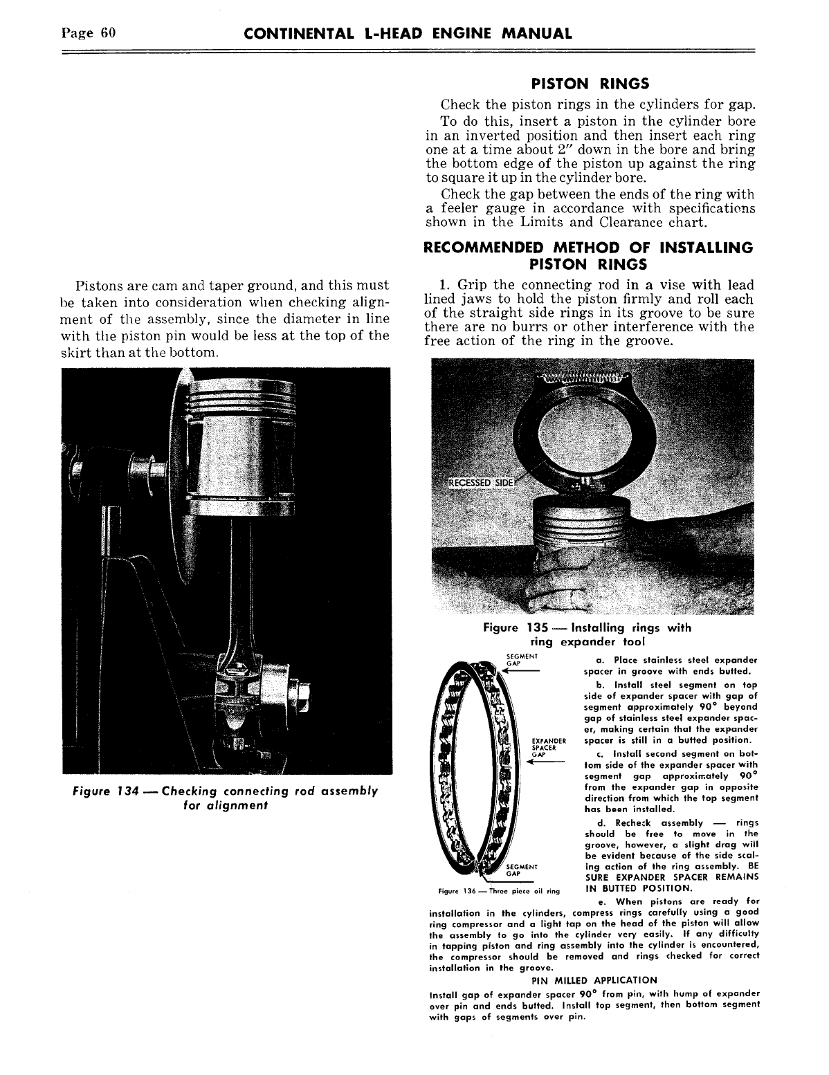
Page 60 CONTINENTAL L-HEAD ENGINE MANUAL
Pistons are cam and taper ground, and this must
be taken into consideration when checking align-
ment of the assembly, since the diameter in line
with the piston pin would be less at the top of the
skirt than at the bottom.
PISTON RINGS
Check the piston rings in the cylinders for gap.
To do this, insert a piston in the cylinder bore
in an inverted position and then insert each ring
one at a time about 2" down in the bore and bring
the bottom edge of the piston up against the ring
to square it up in the cylinder bore.
Check the gap between the ends of the ring with
a feeler gauge in accordance with specificatie, ns
shown in the Limits and Clearance chart.
RECOMMENDED METHOD OF INSTALLING
PISTON RINGS
1. Grip the connecting rod in a vise with lead
lined jaws to hold the piston firmly and roll each
of the straight side rings in its groove to be sure
there are no burrs or other interference with the
free action of the ring in the groove.
Figure 134--Checking connecting rod assembly
for alignment
Figure 135- Installing rings with
ring expander tool
SEGMENT
a~ a. Place stainless steel expander
~ spacer in groove with ends butted.
b. Install steel segment on top
side of expander spacer with gap of
~segment approximately 90° beyond
~gap of stainless steel expander spac-
er, making certain that the expander
spacer is still in a butted position.
c. Install second segment on bot-
lom side of the expander spacer with
segment gap approximately 90
°
from the expander gap in opposite
direction from which the top segment
has been installed.
d. Recheck assembly ~ rings
should be free to move in the
groove, however, a slight drag will
be evident because of the side scal-
ing action of the ring assembly. BE
~SURE EXPANDER SPACER REMAINS
Figure 136--Three piece oil ring IN BUTTED POSITION.
e. When pistons are ready for
installation in the cylinders, compress rings carefully using a good
ring compressor and a light tap on the head of the piston will allow
the assembly to go into the cylinder very easily. If any difficulty
in tapping piston and ring assembly into the cylinder is encountered,
the compressor should be removed and rings checked for correct
installation in the groove.
PIN MILLED APPLICATION
Install gap of expander spacer 90° from pin, with hump of expander
over pin and ends butted. Install top segment, then bottom segment
with gaps of segments over pin.
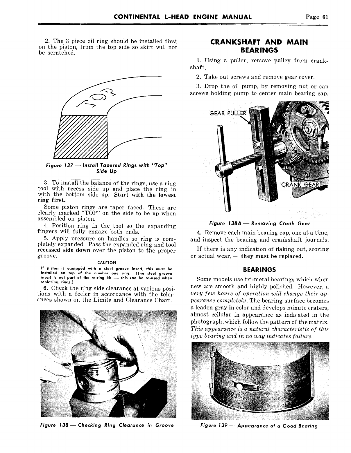
CONTINENTAL L-HEAD ENGINE MANUAL Page 61
2. The 3 piece oil ring should be installed first
on the piston, from the top side so skirt will not
be scratched.
Figure |37--Install Tapered Rings with "Top"
Side Up
3. TO install the balance of the rings, use a ring
tool with recess side up and place the ring in
with the bottom side up. Start with the lowest
ring first.
Some piston rings are taper faced. These are
clearly marked "TOP" on the side to be up when
assembled on piiston.
4. Position ring in the tool so the expanding
fingers will fully engage both ends.
5. Apply pressure on handles so ring is com-
pletely expanded. Pass the expanded ring and tool
recessed side down over the piston to the proper
groove.
CAUTION
if piston is equipped with a steel groove insert, this must be
installed on top of the number one ring. (The steel groove
insert is not part of the re-ring kit ~ this can be re-used when
replacing rings.)
6. Check the ring side clearance at various posi-
tions with a feeler in accordance with the toler-
ances shown on the Limits and Clearance Chart.
Figure 138--Checking Ring Clearance in Groove
CRANKSHAFT AND MAIN
BEARINGS
1. Using a puller, remove pulley from crank-
shaft.
2. Take out screws and remove gear cover.
3. Drop the oil pump, by removing nut or cap
screws holding pump to center main bearing cap.
GEAR PULLER
CRANK GEAR
Figur.e 138A m Removing Crank Gear
4. Remove each main bearing cap, one at a time,
and inspect the bearing and crankshaft journals.
If there is any indication of flaking out, scoring
or actual wear, -- they must be replaced.
BEARINGS
Some models use tri-metal bearings which when
new are smooth and highly polished. However, a
very few hours of operation will change their ap-
pearance completely. The bearing surface becomes
a leaden gray in color and develops minute craters,
almost cellular in appearance as indicated in the
photograph, which follow the pattern of the matrix.
This appearance is a natural characteristic of this
type bearing’ and in no way indicates failure.
Figure 139 ~ Appearance of a Good Bearing
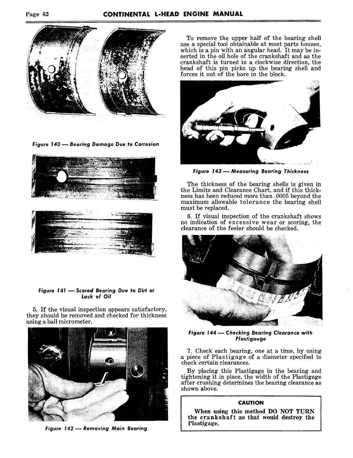
Page 62 CONTINENTAL L-HEAD ENGINE MANUAL
Figure 140 m Bearing Damage Due to Corrosion
Figure 141 --Scored Bearing Due to Dirt or
Lack of Oil
5. If the visual inspection appears satisfactory,
they should be removed and checked for thickness
using a ball micrometer.
Figure 142 ~ Removing Main Bearing
To remove the upper half of the bearing shell
use a special tool obtainable at most parts houses,
which is a pin with an angular head. It may be in-
serted in the oil hole of the crankshaft and as the
crankshaft is turned in a clockwise direction, the
head of this pin picks up the bearing shell and
forces it out of the bore in the block.
Figure 143 ~ Measuring Bearing Thickness
The thickness of the bearing shells is given in
the Limits and Clearance Chart, and if this thick-
ness has been reduced more than .0005 beyond the
maximum allowable tolerance the bearing shell
must be replaced.
6. If visual inspection of the crankshaft shows
no indication of excessive wear or scoring, the
clearance of the feeler should be checked.
Figure 144- Checking Bearing Clearance with
Plastigauge
7. Check each bearing, one at a time, by using
a piece of Plastigage of a diameter specified to
check certain clearances.
By placing this Plastigage in the bearing and
tightening it in place, the width of the Plastigage
after crushing determines the bearing clearance as
shown above.
CAUTION
When using this method DO NOT TURN
the crankshaft as that would destroy the
Plastigage.
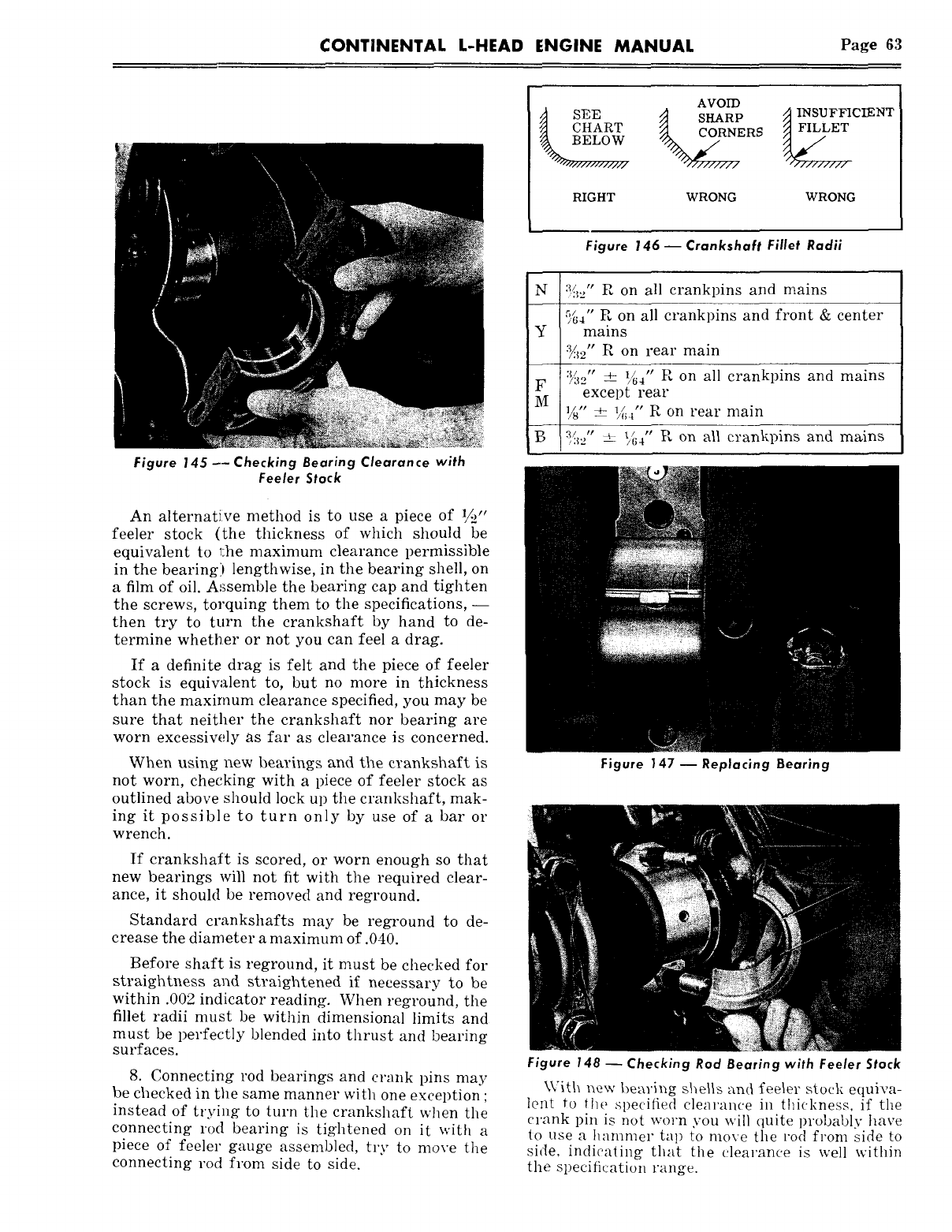
CONTINENTAL L-HEAD ENGINE MANUAL Page 63
AVOID
tS]~E ~ SHARP ~ INSUFFICIENT
CHART ~ERS
B E L 0..
RIGHT WRONG WRONG
Figure 145 -- Checking Bearing Clearance with
Feeler Stock
An alternative method is to use a piece of
feeler stock (the thickness of which should be
equivalent to ~:he maximum clearance permissible
in the bearing) lengthwise, in the bearing shell, on
a film of oil. Assemble the bearing cap and tighten
the screws, torquing them to the specifications, --
then try to turn the crankshaft by hand to de-
termine whetller or not you can feel a drag.
If a definite drag is felt and the piece of feeler
stock is equivalent to, but no more in thickness
than the maximum clearance specified, you may be
sure that neither the crankshaft nor bearing are
worn excessively as far as clearance is concerned.
When using new bearings and the crankshaft is
not worn, checking with a piece of feeler stock as
outlined above should lock up the crankshaft, mak-
ing it possible to turn only by use of a bar or
wrench.
If crankshaft is scored, or worn enough so that
new bearings will not fit with the required clear-
ance, it should be removed and reground.
Standard crankshafts may be reground to de-
crease the diameter a maximum of .040.
Before shaft is reground, it must be checked for
straightness and straightened if necessary to be
within .002 indicator reading. When reground, the
fillet radii must be within dimensional limits and
must be perfectly blended into thrust and bearing
surfaces.
8. Connecting rod bearings and crank pins may
be checked in the same manner with one exception ;
instead of trying to turn the crankshaft when the
connecting rod bearing is tightened on it with a
piece of feeler gauge assembled, try to move the
connecting rod from side to side.
Figure 146 -- Crankshaft Fillet Radii
N ~:/;._," R on all crankpins and mains
%~" R on all crankpins and front & center
Y mains
~2" R on rear main
’~:~’, + ~4 R on all crankpins and mains
FM except rear
Vs" +- ~//~4’’ R on rear main
~- a/ ,, _ ,~ ,, R on all crankpins and mains
’,32 ~- /64
Figure 147--Replacing Bearing
Figure 148 ~ Checking Rod Bearing with Feeler Stock
With new bearing shells and fee~er stock equiva-
le~t to the specified clearance in thickness, if the
crank pin is not worn you will quite probably have
to use a hammer tap to move ~he rod from side to
side, indicating that the clearance is well within
the specification range.
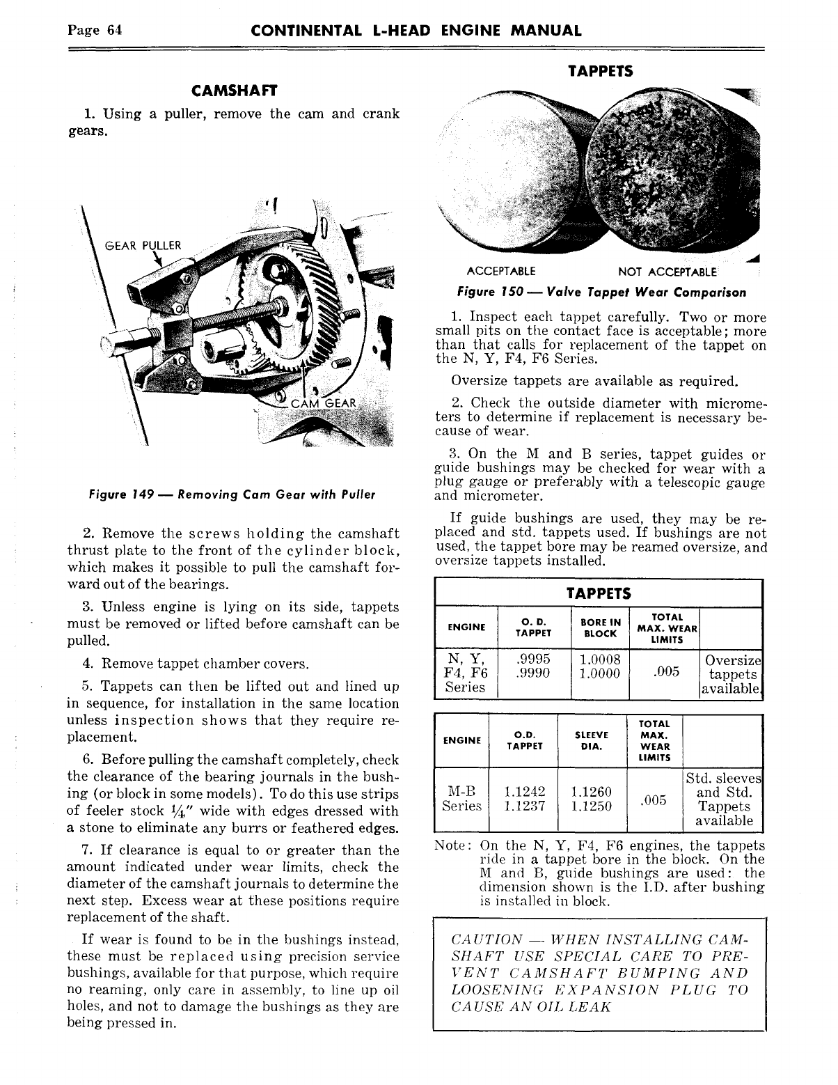
Page 64 CONTINENTAL L-HEAD ENGINE MANUAL
CAMSHAFT
1. Using a puller, remove the cam and crank
gears.
TAPPETS
Figure 149 m Removing Cam Gear with Puller
2. Remove the screws holding the camshaft
thrust plate to the front of the cylinder block,
which makes it possible to pull the camshaft for-
ward out of the bearings.
3. Unless engine is lying on its side, tappets
must be removed or lifted before camshaft can be
pulled.
4. Remove tappet chamber covers.
5. Tappets can then be lifted out and lined up
in sequence, for installation in the same location
unless inspection shows that they require re-
placement.
6. Before pulling the camshaft completely, check
the clearance of the bearing journals in the bush-
ing (or block in some models). To do this use strips
of feeler stock 1/~,, wide with edges dressed with
a stone to eliminate any burrs or feathered edges.
7. If clearance is equal to or greater than the
amount indicated under wear limits, check the
diameter of the camshaft journals to determine the
next step. Excess wear at these positions require
replacement of the shaft.
If wear is found to be in the bushings instead,
these must be replaced using precision service
bushings, available for that purpose, which require
no reaming, only care in assembly, to line up oil
holes, and not to damage the bushings as they are
being pressed in.
ACCEPTABLE NOT ACCEPTABLE
Figure 150 m Valve Tappet Wear Comparison
1. Inspect each tappet carefully. Two o1" more
small pits on the contact face is acceptable; more
than that calls for replacement of the tappet on
the N, Y, F4, F6 Series.
Oversize tappets are available as required.
2. Check the outside diameter with microme-
ters to determine if replacement is necessary be-
cause of wear.
3. On the M and B series, tappet guides or
guide bushings may be checked for wear with a
plug gauge or preferably with a telescopic gauge
and micrometer.
If guide bushings are used, they may be re-
placed and std. tappets used. If bushings are not
used, the tappet bore may be reamed oversize, and
oversize tappets installed.
TAPPETS
TOTAL
O.D. BORE IN
ENGINE MAX. WEAR
TAPPET BLOCK LIMITS
N, Y, .9995 1.0008 Oversize
F4, F6 .9990 1.0000 .005 tappets
Series available,
ENGINE
M-B
Series
O.D. SLEEVE
TAPPET DIA.
1.1242 1.1260
1.1237 1.1250
TOTAL
MAX.
WEAR
LIMITS
.005
Std. sleeves
and Std.
Tappets
available
Note: On the N, Y, F4, F6 engines, the tappets
ride in a tappet bore in the block. On the
M and B, guide bushings are used: the
dimension shown is the I.D. after bushing
is installed in block.
CAUTION -- WHEN INSTALLING CAM-
SHAFT USE SPECIAL CARE TO PRE-
VENT CAMSHAFT BUMPING AND
LOOSENING EXPANSION PLUG TO
CA USE AN OIL LEAK
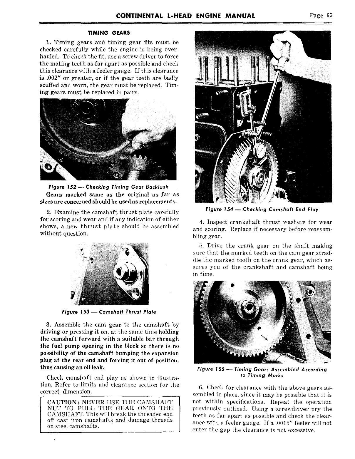
CONTINENTAL L-HEAD ENGINE MANUAL Page 65
TIMING GEARS
i. Timing gears and timing gear fits must be
checked carefully while the engine is being over-
hauled. To check the fit, use a screw driver to force
the mating teeth as far apart as possible and check
this clearance with a feeler gauge. If this clearance
is .002" or greater, or if the gear teeth are badly
scuffed and worm, the gear must be replaced. Tim-
ing gears must be replaced in pairs.
Figure 152 ~-Checking Timing Gear Backlash
Gears marked same as the original as far as
sizes are concerned should be used as replacements.
2. Examine the camshaft thrust plate carefully
for scoring and wear and if any indication of either
shows, a new thrust plate should be assembled
without question.
Figure 153- Camshaft Thrust Plate
3. Assemble the cam gear to the camshaft by
driving or press, ing it on, at the same time holding
the camshaft forward with a suitable bar through
the fuel pump opening in the block so there is no
possibility of the camshaft bumping the expansion
plug at the rear’ end and forcing it out of position,
thus causing an oil leak.
Check camshaft end play as shown in illustra-
tion. Refer to limits and clearance section for the
correct dimension.
CAUTION: NEVER USE THE CAMSHAFT
NUT TO PULL THE GEAR ONTO THE
CAMSHAFT. This will break the threaded end
off cast iron camshafts and damage threads
on steel camshafts.
Figure 154 ~ Checking Camshaft End Play
4. Inspect crankshaft thrust washers for wear
and scoring. Replace if necessary before reassem-
bling gear.
5. Drive the crank gear on the shaft making
s~re that the marked teeth on the cam gear strad-
dle the marked tooth on the crank gear, which as-
sures you of the crankshaft and camshaft being
in time.
Figure 155 ~ Timing Gears Assembled According
to Timing Marks
6. Check for clearance with the above gears as-
sembled in place, since it may be possible that it is
not within specifications. Repeat the operation
previously outlined. Using a screwdriver pry the
teeth as far apart as possible and check the clear-
ance with a feeler gauge. If a .0015" feeler will not
enter the gap the clearance is not excessive.
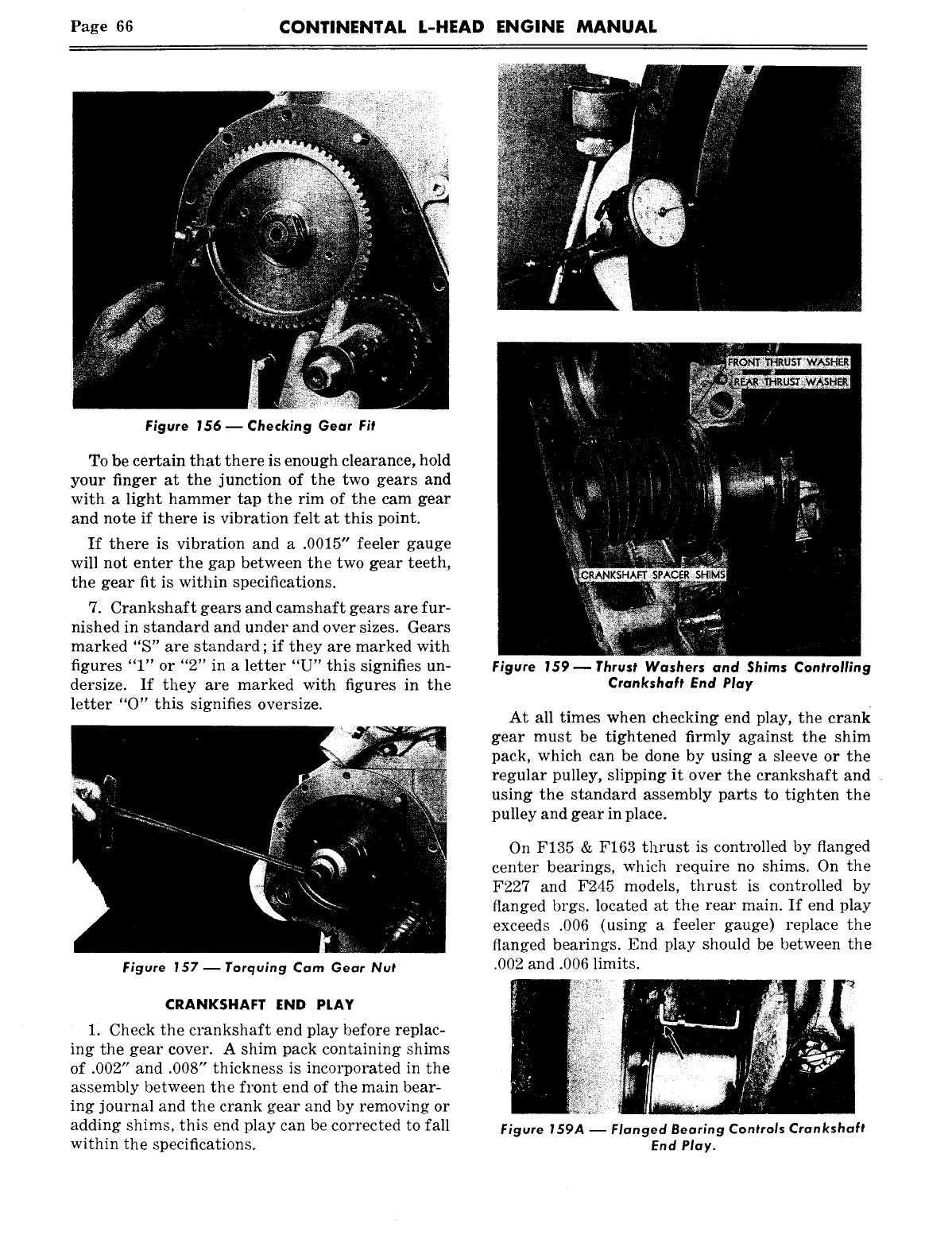
Page 66 CONTINENTAL L-HEAD ENGINE MANUAL
Figure 156 ~ Checking Gear Fit
To be certain that there is enough clearance, hold
your finger at the junction of the two gears and
with a light hammer tap the rim of the cam gear
and note if there is vibration felt at this point.
If there is vibration and a .0015" feeler gauge
will not enter the gap between the two gear teeth,
the gear fit is within specifications.
7. Crankshaft gears and camshaft gears are fur-
nished in standard and under and over sizes. Gears
marked "S" are standard ; if they are marked with
figures "1" or "2" in a letter "U" this signifies un-
dersize. If they are marked with figures in the
letter "0" this signifies oversize.
Figure |57 ~ Torquing Cam Gear Nut
CRANKSHAFT END PLAY
1. Check the crankshaft end play before replac-
ing the gear cover. A shim pack containing shims
of .002" and .008" thickness is incorporated in the
assembly between the front end of the main bear-
ing journal and the crank gear and by removing or
adding shims, this end play can be corrected to fall
within the specifications.
Figure 159--Thrust Washers and Shims Controlling
Crankshaft End Play
At all times when checking end play, the crank
gear must be tightened firmly against the shim
pack, which can be done by using a sleeve or the
regular pulley, slipping it over the crankshaft and
using the standard assembly parts to tighten the
pulley and gear in place.
On F135 & F163 thrust is controlled by flanged
center bearings, which require no shims. On the
F227 and F.2.45 models, thrust is controlled by
flanged brgs. located at the rear main. If end play
exceeds .006 (using a feeler gauge) replace the
flanged bearings. End play should be between the
.002 and .006 limits.
Figure 159A -- Flanged Bearing Controls Crankshaft
End Play.
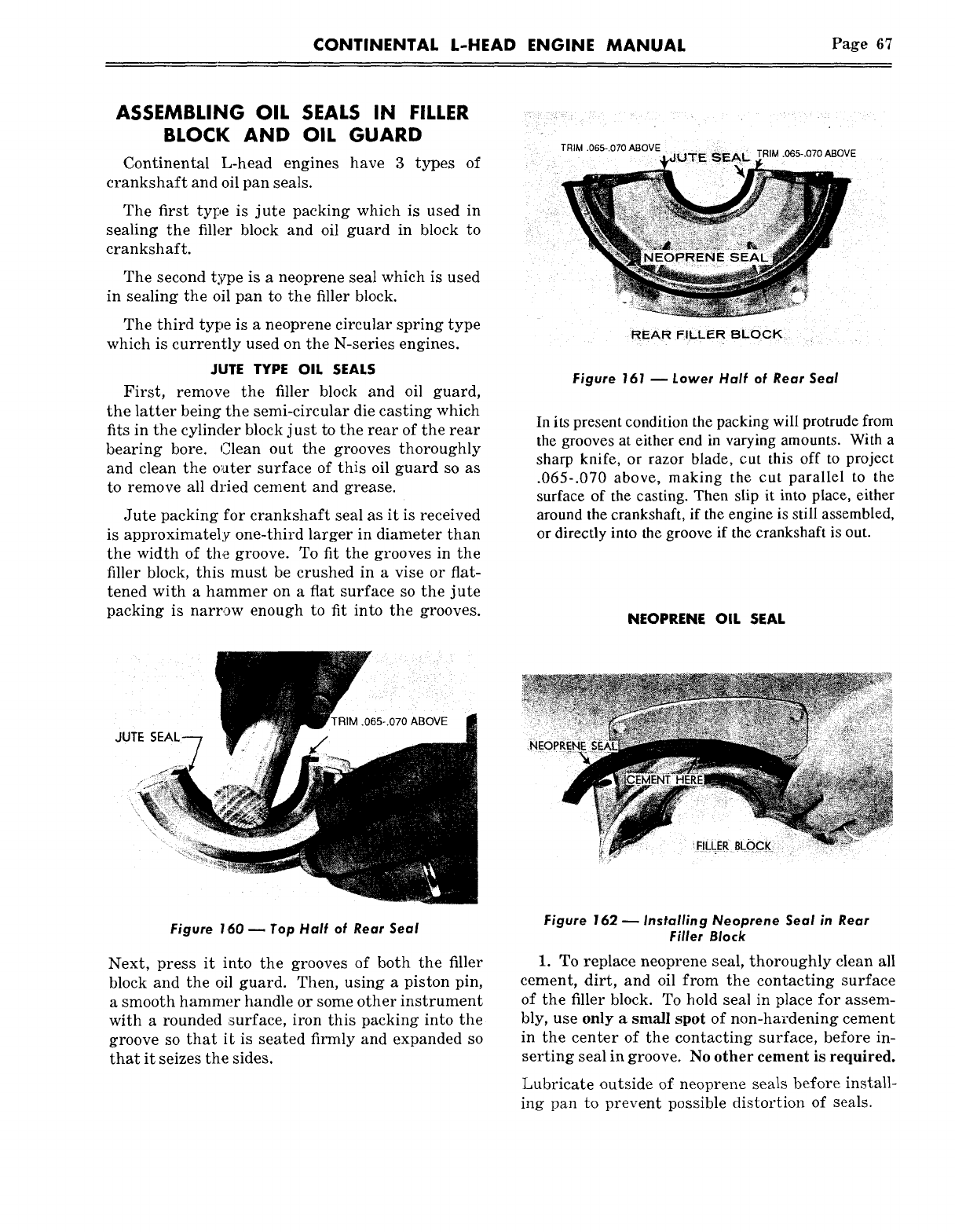
CONTINENTAL L-HEAD ENGINE MANUAL Page 67
ASSEMBLING OIL SEALS IN FILLER
BLOCK AND OIL GUARD
Continental L-head engines have 3 types of
crankshaft and oil pan seals.
The first type is jute packing which is used in
sealing the filler block and oil guard in block to
crankshaft.
The second type is a neoprene seal which is used
in sealing the oil pan to the filler block.
The third type is a neoprene circular spring type
which is currently used on the N-series engines.
JUTE TYPE OIL SEALS
First, remove the filler block and oil guard,
the latter being the semi-circular die casting which
fits in the cylinder block just to the rear of the rear
bearing bore. Clean out the grooves thoroughly
and clean the o~ater surface of this oil guard so as
to remove all dried cement and grease.
Jute packing for crankshaft seal as it is received
is approximately one-third larger in diameter than
the width of the groove. To fit the grooves in the
filler block, this must be crushed in a vise or flat-
tened with a hammer on a flat surface so the jute
packing is narrow enough to fit into the grooves.
TRIM .065-.070 ABOVE TRIM .065-.070 ABOVE
REAR FILLER BLOCK
Figure |61 m Lower Half of Rear Seal
In its present condition the packing will protrude from
the grooves at either end in varying amounts. With a
sharp knife, or razor blade, cut this off to project
.065-.070 above, making the cut parallel to the
surface of the casting. Then slip it into place, either
around the crankshaft, if the engine is still assembled,
or directly into the groove if the crankshaft is out.
NEOPRENE OIL SEAL
JUTE
Figure 160 -- Top Half of Rear Seal
Next, press it into the grooves of both the filler
block and the oil guard. Then, using a piston pin,
a smooth hammer handle or some other instrument
with a rounded ~surface, iron this packing into the
groove so that it is seated firmly and expanded so
that it seizes the sides.
Figure 162 ~ Installing Neoprene Seal in Rear
Filler Block
1. To replace neoprene seal, thoroughly clean all
cement, dirt, and oil from the contacting surface
of the filler block. To hold seal in place for assem-
bly, use only a small spot of non-hardening cement
in the center of the contacting surface, before in-
serting seal in groove. No other cement is required.
Lubricate outside of neoprene seals before install-
ing pan to prevent possible distortion of seals.
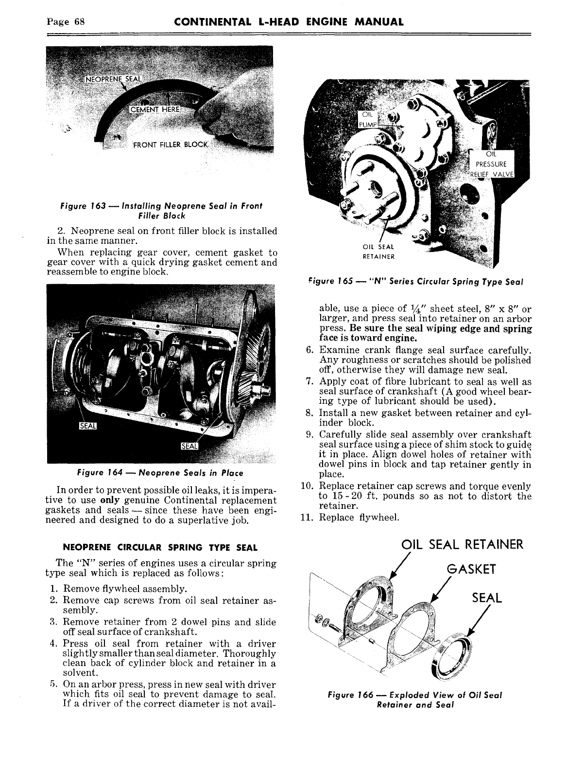
Page 68 CONTINENTAL L-HEAD ENGINE MANUAL
FRONT FILLER BLOCK,
Figure 163 ~ Installing Neoprene Seal in Front
Filler Block
2. Neoprene seal on front filler block is installed
in the same manner.
When replacing gear cover, cement gasket to
gear cover with a quick drying gasket cement and
reassemble to engine block.
Figure 164 ~ Neoprene Seals in Place
In order to prevent possible oil leaks, it is impera-
tive to use only genuine Continental replacement
gaskets and seals--since these have been engi-
neered and designed to do a superlative job.
NEOPRENE CIRCULAR SPRING TYPE SEAL
The "N" series of engines uses a circular spring
type seal which is replaced as follows:
1. Remove flywheel assembly.
2. Remove cap screws from oil seal retainer as-
sembly.
3. Remove retainer from 2 dowel pins and slide
off seal surface of crankshaft.
4. Press oil seal from retainer with a driver
slightly smaller than seal diameter. Thoroughly
clean back of cylinder block and retainer in a
solvent.
5. On an arbor press, press in new seal with driver
which fits oil seal to prevent damage to seal.
If a driver of the correct diameter is not avail-
OIL SEAL
RETAINER
f:igure 165 ~ "N" Series Circular Spring Type Seal
able, use a piece of 1/~,, sheet steel, 8" x 8" or
larger, and press seal into retainer on an arbor
press. Be sure the seal wiping edge and spring
face is toward engine.
6. Examine crank flange seal surface carefully.
Any roughness or scratches should be polished
off, otherwise they will damage new seal.
7. Apply coat of fibre lubricant to seal as well as
seal surface of crankshaft (A good wheel bear-
ing type of lubricant should be used).
8. Install a new gasket between retainer and cyl-
inder block.
9. Carefully slide seal assembly over crankshaft
seal surface using a piece of shim stock to guide
it in place. Align dowel holes of retainer witl~
dowel pins in block and tap retainer gently in
place.
10. Replace retainer cap screws and torque evenly
to 15-20 ft. pounds so as not to distort the
retainer.
11. Replace flywheel.
OIL SEAL RETAINER
GASKET
SEAL
Figure 166 m Exploded View of Oil Seal
Retainer and Seal
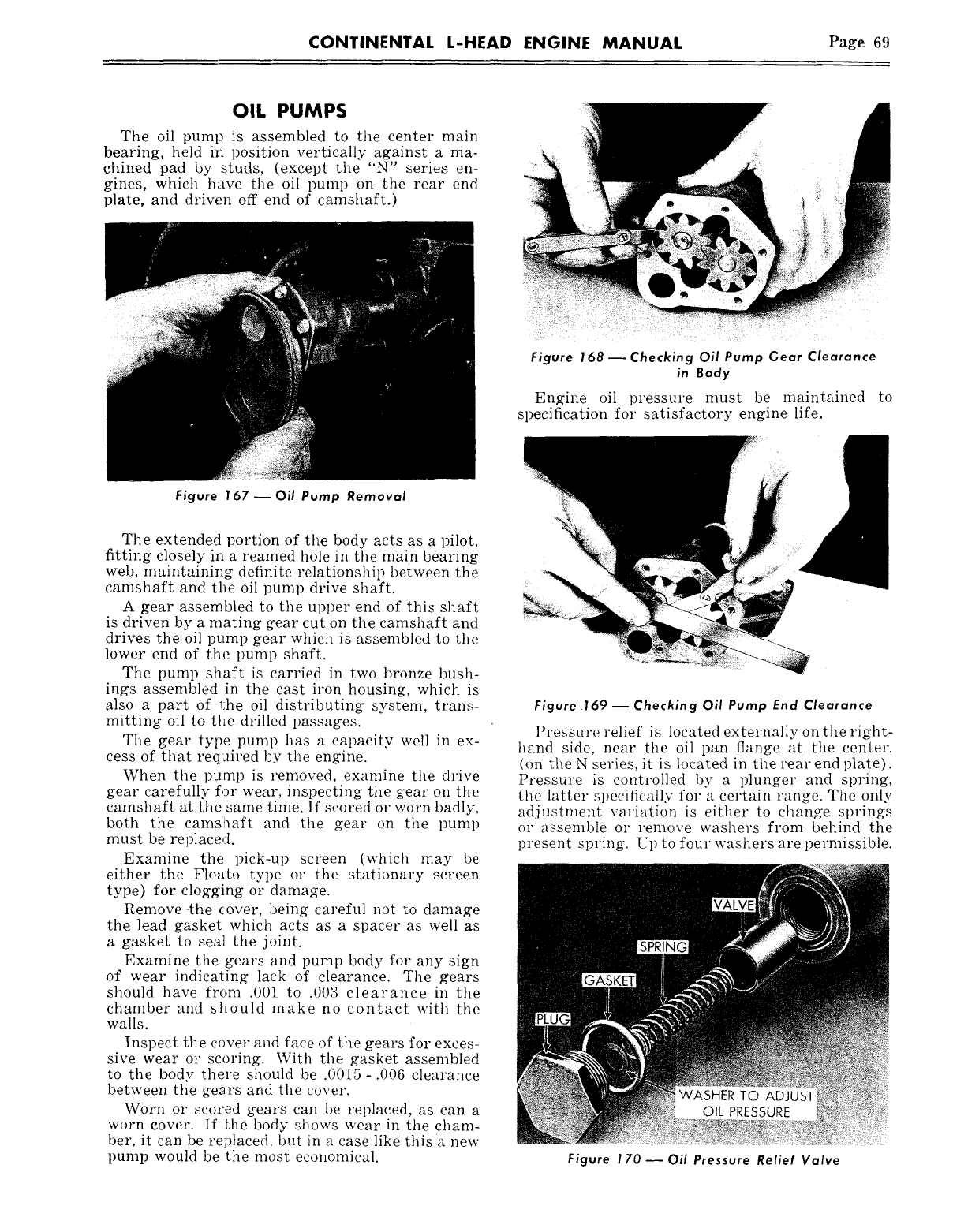
CONTINENTAL L-HEAD ENGINE MANUAL Page 69
OIL PUMPS
The oil pump is assembled to the center main
bearing, held in position vertically against a ma-
chined pad by studs, (except the "N" series en-
gines, which have the oil pump on the rear end
plate, and driven off end of camshaft.)
Figure 168 ~ Checking Oil Pump Gear Clearance
in Body
Engine oil pressure must be maintained to
specification for satisfactory engine life.
Figure 167-- Oil Pump Removal
The extended portion of the body acts as a pilot,
fitting closely ir~ a reamed hole in the main bearing
web, maintainir~g definite l’elationship between the
camshaft and the oil pump drive shaft.
A gear assembled to the upper end of this shaft
is driven by a mating gear cut on the camshaft and
drives the oil pump gear which is assembled to the
lower end of the pump shaft.
The pump shaft is carried in two bronze bush-
ings assembled in the cast iron housing, which is
also a part of the oil distributing system, trans-
mitting oil to the drilled passages.
The gear type pump has a capacity well in ex-
cess of that req:fired by the engine.
When the pump is removed, examine the drive
gear carefully for wear, inspecting the gear on the
camshaft at the same time. If scored or worn badly,
both the camsttaft and the gear on the pump
must be replaced.
Examine the pick-up screen (which may be
either the Floato type or the stationary screen
type) for clogging or damage.
Remove 4he (:over, being careful not to damage
the lead gasket which acts as a spacer as well as
a gasket to seal the joint.
Examine the gears and pump body for any sign
of wear indicating lack of clearance. The gears
should have from .001 to .003 clearance in the
chamber and should make no contact with the
walls.
Inspect the cover and face of the gears for exces-
sive wear or scoring. With the gasket assembled
to the body there should be .0015-.006 clearance
between the gears and the covet’.
Worn or scor.ad gears can be replaced, as can a
worn cover. If ~he body shows wear in the cham-
ber, it can be replaced, but in a case like this a new
pump would be the most economical.
Figure .169 -- Checking Oil Pump End Clearance
Pressure relief is located externally on the right-
hand side, near the oil pan flange at the center.
(on the N series, it is located in the rear end l)late).
Pressure .is controlled by a plunger and spring,
the latter specifically for a certain range. The only
adjustment variation is either to change springs
or assemble or remove washers from behind the
present spring. Up to four washers are permissible.
Figure 170--Oil Pressure Relief Valve
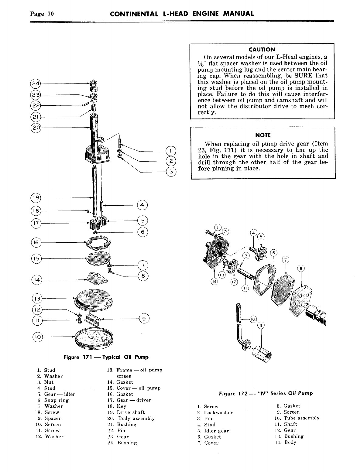
Page 70 CONTINENTAL L-HEAD ENGINE MANUAL
2.
3.
4.
5.
6.
7.
9.
11.
12.
Figure 171--Typical Oil Pump
Stud
Washer
Nut
Stud
Gear- idler
Snap ring
Washer
Screw
Spacer
Screen
Screw
Washer
13. Frame--oil pump
screen
14. Gasket
15. Cover--oil pump
16. Gasket
17. Gear-- driver
18. Key
19. Drive shaft
20. Body assembly
21. Bushing
22. Pin
23. Gear
24. Bushing
CAUTION
On several models of our L-Head engines, a
l/a" flat spacer washer is used between the oil
pump mounting lug and the center main bear-
ing cap. When reassembling, be SURE that
this washer is placed on the oil pump mount-
ing stud before the oil pump is installed in
place. Failure to do this will cause interfer-
ence between oil pump and camshaft and will
not allow the distributor drive to mesh cor-
rectly.
NOTE
When replacing oil pump drive gear (Item
23, Fig. 171) it is necessary to line up the
hole in the gear with the hole in shaft and
drill through the other half of the gear be-
fore pinning in place.
Figure 172- "N" Series Oil Pump
1. Screw
2. Lockwasher
Pin
4. Stud
5. Idler gear
6. Gasket
7. Cover
8. Gasket
9. Screen
10. Tube assembly
11. Shaft
12. Gear
13. Bushing
14. Body
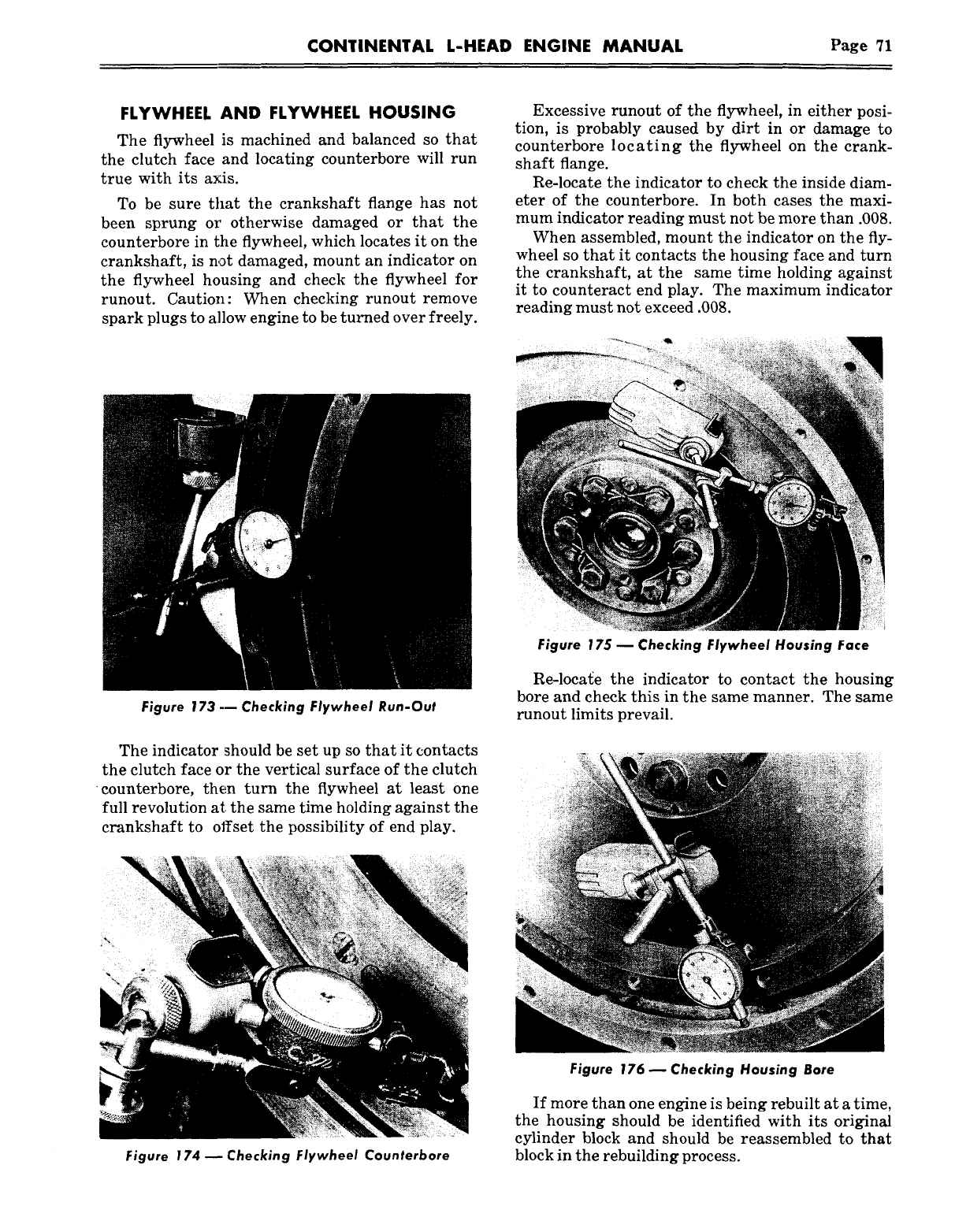
CONTINENTAL L-HEAD ENGINE MANUAL Page 71
FLYWHEEL AND FLYWHEEL HOUSING
The flywheel is machined and balanced so that
the clutch face and locating counterbore will run
true with its axis.
To be sure that the crankshaft flange has not
been sprung or otherwise damaged or that the
counterbore in the flywheel, which locates it on the
crankshaft, is not damaged, mount an indicator on
the flywheel housing and check the flywheel for
runout. Caution: When checking runout remove
spark plugs to allow engine to be turned over freely.
Excessive runout of the flywheel, in either posi-
tion, is probably caused by dirt in or damage to
counterbore locating the flywheel on the crank-
shaft flange.
Re-locate the indicator to check the inside diam-
eter of the counterbore. In both cases the maxi-
mum indicator reading must not be more than .008.
When assembled, mount the indicator on the fly-
wheel so that it contacts the housing face and turn
the crankshaft, at the same time holding against
it to counteract end play. The maximum indicator
reading must not exceed .008.
Figure 173 --- Checking Flywheel Run-Out
The indicator should be set up so that it contacts
the clutch face or the vertical surface of the clutch
¯ counterbore, then turn the flywheel at least one
full revolution at: the same time holding against the
crankshaft to offset the possibility of end play.
Figure 174 ~ Checking Flywheel Counterbore
Figure 175 m Checking Flywheel Housing Face
Re-locage the indicator to contact the housing
bore and check this in the same manner. The same
runout limits prevail.
Figure 176 ~ Checking Housing Bore
If more than one engine is being rebuilt at a time,
the housing should be identified with its original
cylinder block and should be reassembled to that
block in the rebuilding process.
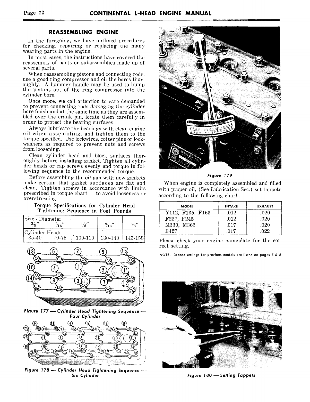
Page 72 CONTINENTAL L-HEAD ENGINE MANUAL
REASSEMBLING ENGINE
In the foregoing, we have outlined procedures
for checking, repairing or replacing tile many
wearing parts in the engine.
In most cases, the instructions have covered the
reassembly of parts or subassemblies made up of
several parts.
When reassembling pistons and connecting rods,
use a good ring compressor and oil the bores thor-
oughly. A hammer handle may be used to bump
the pistons out of the ring compressor into the
cylinder bore.
Once more, we call attention to care demanded
to prevent connecting rods damaging the cylinder
bore finish and at the same time as they are assem-
bled over the crank pin, locate them carefully in
order to protect the bearing surfaces.
Always lub~:icate the bearings with clean engine
oil when assembling, and tighten them to the
torque specified. Uselockwires, cotter pins or lock-
washers as required to prevent nuts and screws
from loosening.
Clean cylinder bead and block surfaces thor-
oughly before installing gasket. Tighten all cylin-
der heads or cap screws evenly and torque in fol-
lowing sequence to the recommended torque.
Before assembling the oil pan with new gaskets
make certain that gasket surfaces are flat and
clean. Tighten screws in accordance with limits
prescribed in torque chart- to avoid looseness or
overstressing.
Torque Specifications for Cylinder Head
Tightening Sequence in Foot Pounds
Size - Diameter
’~" ~,~ ~" ~/~" % ~" ~I"
Cylinder Heads
35-40 70-75 100-110 130-140 145-155
Figure 179
Wben engine is completely assembled and filled
with proper oil, (See Lubrication Sec.) set tappets
according to the following chart:
MODEL
Yl12, F135, F163
F227, F245
M330, M363
B427
Please check your engine
rect setting.
.012 .020
.012 .020
.017 .020
.017 .022
nameplate for the cor-
NOTE: Tappet settings for previous models are listed on pages 5 & 6.
Figure 177 ~ Cylinder Head Tightening Sequence
Four Cylinder
Figure 178~Cylinder Head Tightening Sequence
Six Cylinder Figure 180 ~ Setting Tappets
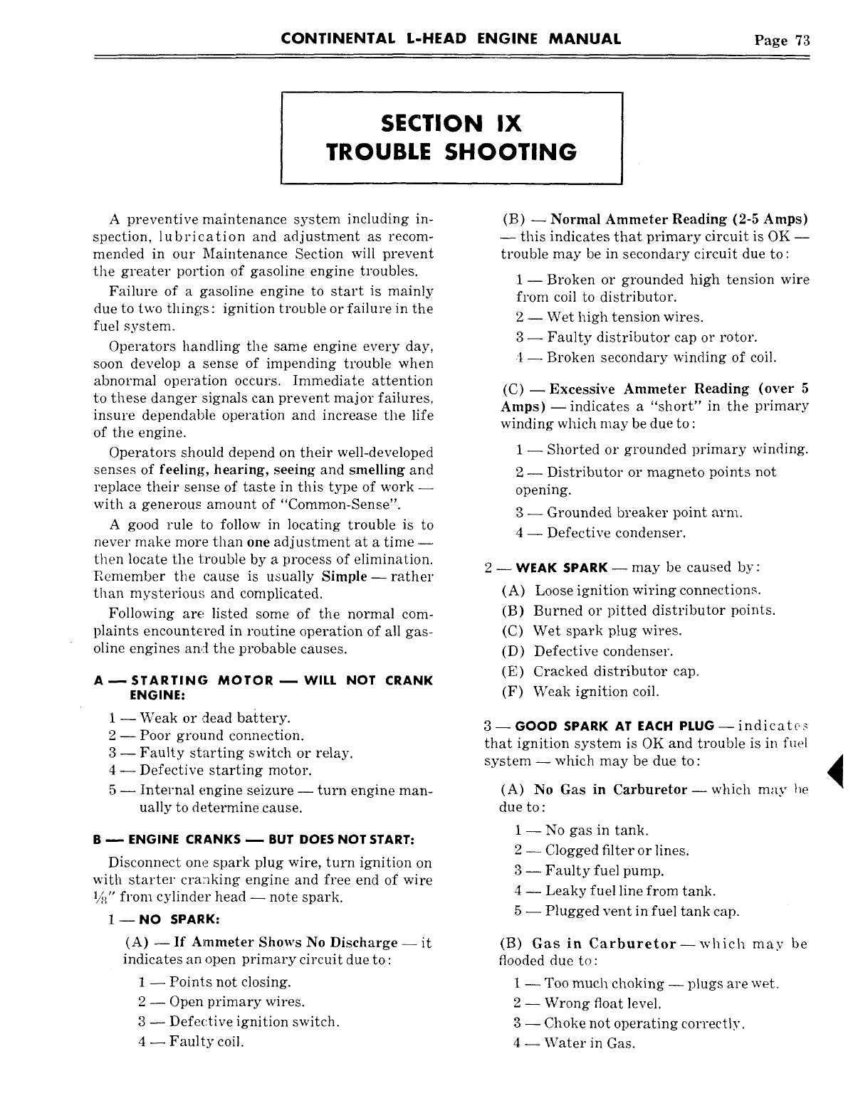
CONTINENTAL L-HEAD ENGINE MANUAL Page 73
SECTION IX
TROUBLE SHOOTING
A preventive maintenance system including in-
spection, lubrication and adjustment as recom-
mended in our Maintenance Section will prevent
the greater portion of gasoline engine troubles.
Failure of a gasoline engine to start is mainly
due to two things : ignition trouble or failure in the
fuel system.
Operators handling the same engine every day,
soon develop a sense of impending trouble when
abnormal operation occurs. Immediate attention
to these danger signals can prevent major failures,
insure dependable operation and increase the life
of the engine.
Operators should depend on their well-developed
senses of feeling, hearing, seeing and smelling and
replace their sense of taste in this type of work --
with a generous amount of "Common-Sense".
A good rule ~o follow in locating trouble is to
never make more than one adjustment at a time --
then locate the trouble by a process of elimination.
Remember the cause is usually Simple--rather
than mysterious and complicated.
Following are listed some of the normal com-
plaints encountered in routine operation of all gas-
oline engines and the probable causes.
A~STARTING MOTOR--WILL NOT CRANK
ENGINE:
1 --Weak or dead battery.
2 -- Poor ground connection.
3 -- Faulty starting switch or relay.
4 -- Defective starting motor.
5 -- Internal engine seizure -- turn engine man-
ually to determine cause.
B ~ ENGINE CRANKS ~ BUT DOES NOT START:
Disconnect one spark plug wire, turn ignition on
with starter cranking engine and free end of wire
1/,(l" from cylinder head -- note spark.
1-- NO SPARK:
(A) -- If Ammeter Shows No Discharge --
indicates an open primary circuit due to :
1-- Points not closing.
2-- Open primary wires.
3-- Defective ignition switch.
4-- Faulty coil.
(B) -- Normal Ammeter Reading (2-5 Amps)
-- this indicates that primary circuit is OK --
trouble may be in secondary circuit due to :
1- Broken or grounded high tension wire
from coil to distributor.
2 -- Wet high tension wires.
3 -- Faulty distributor cap or rotor.
4 --Broken secondary winding of coil.
(C)- Excessive Ammeter Reading (over
Amps)- indicates a "short" in the primary
winding which may be due to :
1 -- Shorted or grounded primary winding.
2 -- Distributor or magneto points not
opening.
3 -- Grounded breaker point arm.
4 -- Defective condenser.
2- WEAK SPARK- may be caused by:
(A) Loose ignition wiring connections.
(B) Burned or pitted distributor points.
(C) Wet spark plug wires.
(D) Defective condenser.
(E) Cracked distributor cap.
(F) Weak ignition coil.
3- GOOD SPARK AT EACH PLUG- indicates
that ignition system is OK and trouble is in fuel
system -- which may be due to :
(A) No Gas in Carburetor--which may
due to :
1-- No gas in tank.
2 -- Clogged filter or lines.
3-- Faulty fuel pump.
4 -- Leaky fuel line from tank.
5 -- Plugged vent in fuel tank cap.
(B) Gas in Carburetor--which may
flooded due to:
1 -- Too much choking -- plugs are wet.
2 -- Wrong float level.
3-- Choke not operating correctly.
4-- Water in Gas.
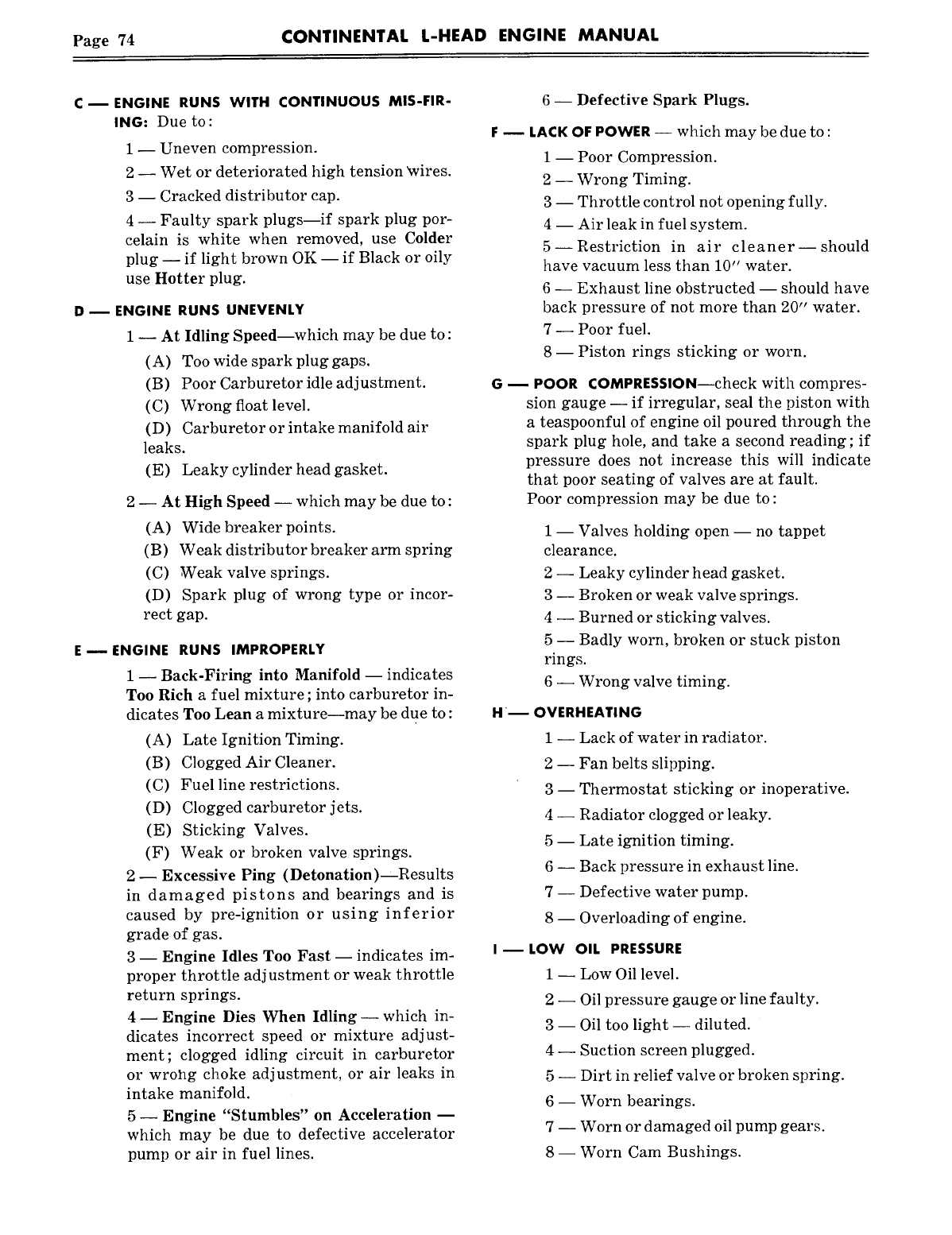
Page 74 CONTINENTAL L-HEAD ENGINE MANUAL
c- ENGINE RUNS WITH CONTINUOUS MIS-FIR-
ING: Due to:
1 -- Uneven compression.
2 -- Wet or deteriorated high tension ~vires.
3 -- Cracked distributor cap.
4 -- Faulty spark plugs--if spark plug por-
celain is white when removed, use Colder
plug -- if light brown OK -- if Black or oily
use Hotter plug.
D ~ ENGINE RUNS UNEVENLY
1 -- At Idling Speed--which may be due to :
(A) Too wide spark plug gaps.
(B) Poor Carburetor idle adjustment.
(C) Wrong float level.
(D) Carburetor or intake manifold air
leaks.
(E) Leaky cylinder head gasket.
2 -- At High Speed -- which may be due to :
(A) Wide breaker points.
(B) Weak distributor breaker arm spring
(C) Weak valve springs.
(D) Spark plug of wrong type or incor-
rect gap.
E m ENGINE RUNS IMPROPERLY
1 -- Back-Firing into Manifold -- indicates
Too Rich a fuel mixture ; into carburetor in-
dicates Too Lean a mixture--may be due to :
(A) Late Ignition Timing.
(B) Clogged Air Cleaner.
(C) Fuel line restrictions.
(D) Clogged carburetor jets.
(E) Sticking Valves.
(F) Weak or broken valve springs.
2-- Excessive Ping (Detonation) Results
in damaged pistons and bearings and is
caused by pre-ignition or using inferior
grade of gas.
3 -- Engine Idles Too Fast -- indicates im-
proper throttle adjustment or weak throttle
return springs.
4 ~ Engine Dies When Idling- which in-
dicates incorrect speed or mixture adjust-
ment; clogged idling circuit in carburetor
or wrol~g choke adjustment, or air leaks in
intake manifold.
5- Engine "Stumbles" on Acceleration m
which may be due to defective accelerator
pump or air in fuel lines.
6 -- Defective Spark Plugs.
LACK OF POWER -- which may be due to :
1 -- Poor Compression.
2 -- Wrong Timing.
3 -- Throttle control not opening fully.
4 -- Air leak in fuel system.
5--Restriction in air cleaner--should
have vacuum less than 10" water.
6 -- Exhaust line obstructed -- should have
back pressure of not more than 20" water.
7 -- Poor fuel.
8- Piston rings sticking or worn.
-- POOR COMPRESSION--check with compres-
sion gauge -- if irregular, seal the piston with
a teaspoonful of engine oil poured through the
spark plug hole, and take a second reading; if
pressure does not increase this will indicate
that poor seating of valves are at fault.
Poor compression may be due to:
1 -- Valves holding open -- no tappet
clearance.
2 -- Leaky cylinder head gasket.
3 -- Broken or weak valve springs.
4 -- Burned or sticking valves.
5 -- Badly worn, broken or stuck piston
rings.
6 -- Wrong valve timing.
~ OVERHEATING
1 -- Lack of water in radiator.
2 -- Fan belts slipping.
3- Thermostat sticking or inoperative.
4 -- Radiator clogged or leaky.
5 -- Late ignition timing.
6 -- Back pressure in exhaust line.
7 -- Defective water pump.
8 -- Overloading of engine.
LOW OIL PRESSURE
1 -- Low Oil level.
3--
4--
5--
6--
7--
81
Oil pressure gauge or line faulty.
Oil too light -- diluted.
Suction screen plugged.
Dirt in relief valve or broken spring.
Worn bearings.
Worn or damaged oil pump gears.
Worn Cam Bushings.
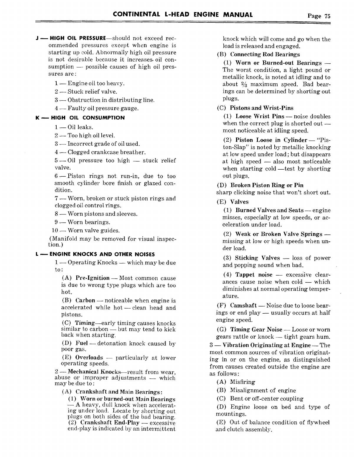
CONTINENTAL L-HEAD ENGINE MANUAL Page 75
J m HIGH OIL PRESSURE--should not exceed rec-
ommended pressures except when engine is
starting up cold. Abnormally high oil pressure
is not desirable because it increases, oil con-
sumption --- possible causes of high oil pres-
sures are :
1 -- Engine oil too heavy.
2 -- Stuck relief valve.
3 -- Obstruction in distributing line.
4 -- Faulty oil pressure gauge.
K ~ HIGH OIL CONSUMPTION
1 -- Oil leaks.
2 -- Too high oil level.
3 -- Incorrect grade of oil used.
4 -- Clog~:ed crankcase breather.
5--Oil pressure too high -- stuck relief
valve.
6--Pisto~a rings not run-in, due to too
smooth cylinder bore finish or glazed con-
dition.
7 -- Worn, broken or stuck piston rings and
clogged oil control rings.
8 -- Worn pistons and sleeves.
9 -- Worn bearings.
10 -- Worn valve guides.
(Manifold may be removed for visual inspec-
tion.)
L m ENGINE KNOCKS AND OTHER NOISES
1 -- Operating Knocks -- which may be due
to:
(A) Pre-Ignition--Most common cause
is due to wrong type plugs which are too
hot.
(B) Carbon -- noticeable when engine
accelerated while hot--clean head and
pistons.
(C) Timing--early timing causes knocks
similar to carbon -- but may tend to kick
back when starting.
(D) Fuel--detonation knock caused
poor gas.
(E) Overloads -- particularly at lower
operating speeds.
2 -- Mechanical Knocks-~result from wear,
abuse or i.mproper adjustments -- which
may be due to :
(A) Crankshaft and Main Bearings:
(1) Worn or burned-out Main Bearings
--A heavy, dull knock when accelerat-
ing urtder load. Locate by shorting out
plugs on both sides of the bad bearing.
(2) Crankshaft End-Play-- excessive
end-play is indicated by an intermittent
knock which will come and go when the
load is released and engaged.
(B) Connecting Rod Bearings
(1) Worn or Burned-out Bearings --
The worst condition, a light pound or
metallic knock, is noted at idling and to
about 2~ maximum speed. Bad bear-
ings can be determined by shorting out
plugs.
(C) Pistons and Wrist-Pins
(1) Loose Wrist Pins--noise doubles
when the correct plug is shorted out --
most noticeable at idling speed.
(2) Piston Loose in Cylinder--"Pis-
ton-Slap" is noted by metallic knocking
at low speed under load ; but disappears
at high speed -- also most noticeable
when starting cold--test by shorting
out plugs.
(D) Broken Piston Ring or Pin
sharp clicking noise that won’t short out.
(E) Valves
(1) Burned Valves and Seats -- engine
misses, especially at low speeds, or ac-
celeration under load.
(2) Weak or Broken Valve Springs --
missing at low or high speeds when un-
der load.
(3) Sticking Valves -- loss of power
and popping sound when bad.
(4) Tappet noise -- excesgive clear-
ances cause noise when cold -- which
diminishes at normal operating temper-
ature.
(F) Camshaft -- Noise due to loose bear-
ings or end play -- usually occurs at half
engine speed.
(G) Timing Gear Noise -- Loose or worn
gears rattle or knock -- tight gears hum.
3 -- Vibration Originating at Engine -- The
most common sources of vibration originat-
ing in or on the engine, as distinguished
from causes created outside the engine are
as follows :
(A) Misfiring
(B) Misalignment of engine
(C) Bent or off-center coupling
(D) Engine loose on bed and type
mountings.
(E) Out of balance condition of flywheel
and clutch assembly.
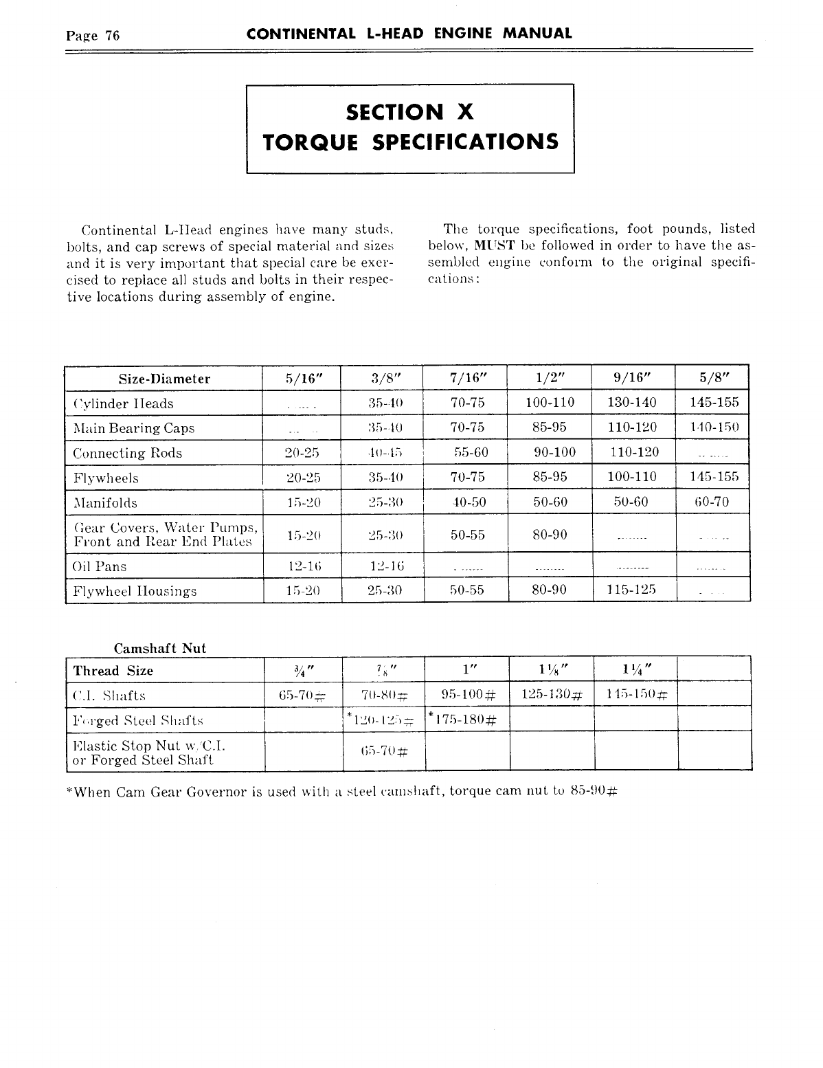
Page 76 CONTINENTAL L-HEAD ENGINE MANUAL
SECTION X
TORQUE SPECIFICATIONS
Continental L-tIead engines have many studs,
bolts, and cap screws of special material and sizes
and it is very important that special care be exer-
cised to replace all studs and bolts in their respec-
tive locations during assembly of engine.
The torque specifications, foot pounds, listed
below, MUST be followed in order to have tile as-
semi)led engine conform to the original specifi-
cations :
Size-Diameter 5/16" 3/8" 7/16" 1/2" 9/16" 5/8"
(:ylinder IIeads ..... 35-.lO 70-75 100-110 130-140 145-155
Main Bearing Caps _. :~5-.10 70-75 85-95 110-120 I d0-150
Connecting Rods 20-25 .lo-.15 55-60 90-100 110-120
Flywheels 20-25 35-40 70-75 85-95 100-110 145-155
Manifolds 15-20 25-3(I 40-50 50-60 50-60 (;0-70
(lear Covers, Water Puml)s,
Front and Rear End Plates 15-20 25-30 50-55 80-90
Oil Pans 12-16 12-16 .............................
Flywheel IIousings 15-20 25-30 50-55 80-90 115-125 _
Camshaft Nut
Thread Size
(;.I. Shafts
l",.rged Steel Shafts
Elastic Stop Nut w.’C.1.
or Forged Steel Shaft
¾" ?h" 1" 1%" 1 ¼"
7()-8()~- 125-130-~. 115-15(Igg
65-7O_# 95-100:~
l, 175-180-~
*When Cam Gear Governor is used with a steel can>haft, torque cam nut to 85-90~
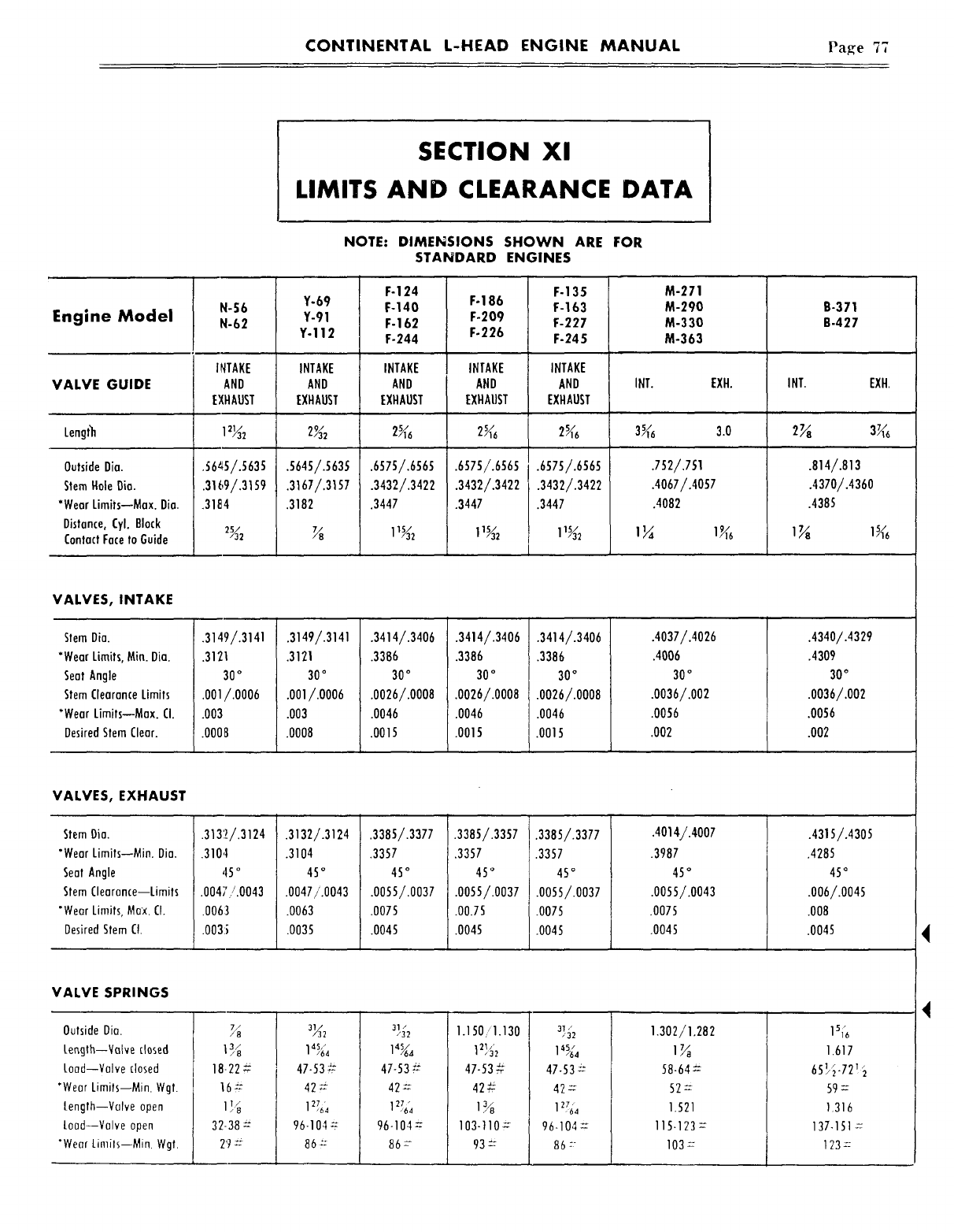
CONTINENTAL L-HEAD ENGINE MANUAL Page 77
SECTION Xl
LIMITS AND CLEARANCE DATA
NOTE: DIMENSIONS SHOWN ARE FOR
STANDARD ENGINES
Engine Model N-S6
N-62
Y-69
Y-91
Y-112
F-124
F-140
F-162
F-244
F-186
F-209
F-226
F-135
F-163
F-227
F-245
M-271
M-290
M-330
M-363
B-371
B-427
INTAKE INTAKE INTAKE INTAKE INTAKE
VALVE GUIDE AND AND AND AND AND INT. EXH. INT. EXH.
EXHAUST EXHAUST EXHAUST EXHAUST EXHAUST
Length 12~2 2~2 2~6 2~6 2~e 3~ 3.0 2~
.56~5/.5635
.31 (,9/.3159
.311~4
.6575/.6565
.3432/.3422
.3447
.6575/.6565
.3432/.3422
.3447
Outside Oia.
Stem Hale Dia.
*Wear Limits--Max. Dia.
Distance, Cyl. Block
Contact Face to Guide
.6575/.6565
.3432/.3422
.3447
.5645/.$63S
.3167/.31S7
.3182
.752/.751
.4067/.4057
.4082
.814/.813
.4370/.4360
.4385
VALVES, INTAKE
Stem Dia.
*Wear Limits, Mia. Oia.
Seat Angle
Stem Clearance Limits
*Wear Limits--Max. CI.
Desired Stem Clear.
.3149/.3141
.3121
30
°
.001/.0006
.003
.0008
.3149/.3141
.3121
30
°
.OOl/.OOO6
.003
.0008
.3414/.3406
.3386
30
°
.0026/.0008
.0046
.0015
.3414/.3406
.3386
30
°
.oo26/.ooo8
.0046
.0015
.3414/.3406
.3386
30
°
.oo26/.ooo8
.0046
.0015
.4037/.4026
.4006
30
°
.0036/.002
.0056
.002
.4340/.4329
.4309
30
°
.0036/.002
.0056
.002
VALVES, EXHAUST
Stem Oio.
"Wear Limits--Min. Dia.
Seat Angle
Stem Clearance--Limits
"Wear Limits, Max. CI.
Desired Stem CI.
VALVE SPRINGS
Outside Dia.
ler~gth--VaNe closed
Load--Valve closed
’Wear Limits--Min. Wgt.
length--Valve open
Load--Valve open
"Wear Limils--Min Wgt.
.3132/.3124
.0047/.0043
.006:3
.003:i
.3132/.3124
.3104
45
°
.0047/.0043
.0063
.0035
.338S/.3377
.3357
4S
°
.0055/.0037
.0075
.0045
.3385/.3357
.3357
4S
o
.0055/.0037
.00.7S
.0045
.3385/.3377
.3357
4S
°
.0055/.0037
.0075
.0045
.4014/.4007
.3987
45
°
.0055/.0043
.0075
.0045
18-22
16 #
32-38
29 ~
47-53#
42 ~
I~
96-104 ~
86 :
31/
/32
47-53~
42=
96-104=
86--
1.150/1.130
47.53
=‘
42#
103-110~
93±=
47-53 ~
42 :
96-104 =
86 ~
1.302/1.282
58-64=
52--
1.521
115-123--
103:
.4315/.4305
.4285
4S
°
.006/.0045
.008
.0045
1.617
6S3~-72!~
59 =
1.316
137-151
123 =
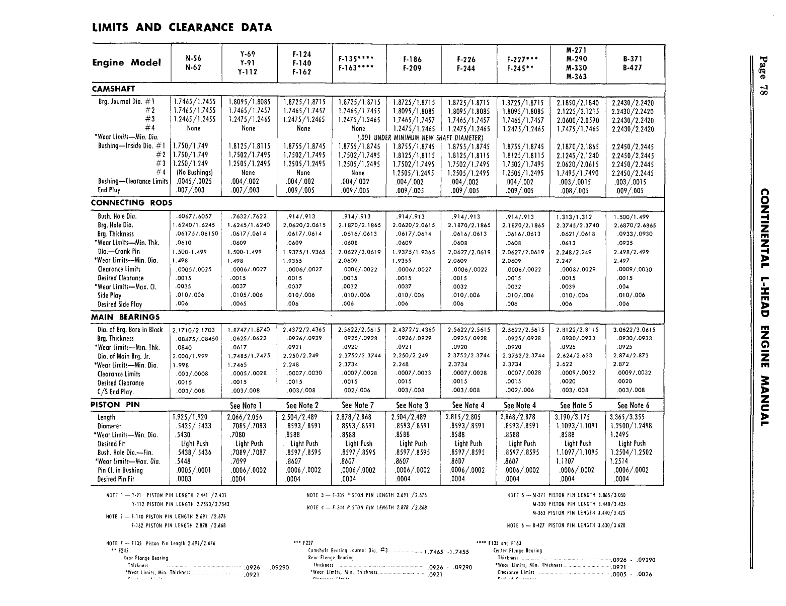
LIMITS AND CLEARANCE DATA
Engine Model N-56
N-62
Y-67
Y-91
Y-112
F-124
F-140
F-162
CAMSHAFT
F-135"*** F-186
F-163"*** F-209 F-226
F-244
M-271
M-290
M-330
M-363
B-371
B-427
Brg. Journal Dia. #I
#2
#3
#4
*Wear Limits--Mb. Dia.
Bushing--inside Dia. #1
#2
#3
Bushing--Clearance Limits
End Play
1.7465/1.7455
1.7465/1.7455
1.2465/1.2455
None
1.750/1.749
1.750/1.749
1.250/1.249
(No Bushings)
.0045/,0025
.007/.003
1,8095/1.8085
1,7465/1.7457
1.2475/1.2465
None
1.8125/1.8115
1.7502/1.7495
1,2505/1.2495
None
.oo4/.oo2
.007/.003
1.8725/1,8715
1.7465/1.7457
1.2475/1.2465
None
1.8755/].8745
t.7502/1.7495
1.2505/1.2495
None
.004/.002
.oo9/.oo5
1.8725/1.8715 1.8725/1.8715 1.8725/1.8715
1.7465/1.7455 1.8095/1.8085 1.8095/1.8085
1.2475/1.2465 1.7465/1.7457 1.7465/1.7457
None 1.2475/1.2465 1.2475/1.2465
/.001 UNDER MINIMUM NEW SHAFT DIAMETER)
1.8755/1.8745 1.8755/1,8745 1.8755/1.8745
1.7502/1.7495 1.8125/1.8115 1.8125/1.8115
1.2505/1.2495 1.7502/1.7495 1.7502/1.7495
None 1.2505/1.2495 1.2505/1.2495
.004/.002 .004/.002 .004/.002
.009/.005 1009/.005 .009/.005
CONNECTING RODS
1.8725/1.8715
1.8095/1.8085
1.7465/1.7457
1.2475/1.2465
1.8755/1.8745
1.8125/t.811S
1.7502/1.7495
1.2505/1.2495
.oo4/.oo2
.009/.005
2.1850/2.1840
2.1225/2.1215
2.0600/2.0590
1.7475/1.7465
2.1870/2.1865
2.1245/2.1240
2.0620/2.0615
1.7495/1.7490
.003/.0015
.oo8/.oo5
2.2430/2.2420
2.2430/2.2420
2.2430/2.2420
2.2430/2.2420
2.2450/2.2445
2.2450/2.2445
2.2450/2.244S
2.2450/2.2445
.003/.00]5
.oo9/.oo5
Bush. Hole I)ia.
Brg. Hole Dia.
Brg. Thickness
*Wear Lirnits--Min. Thk,
Dia.--Crank Pin
"Wear Limits--Min. Dia.
Clearance Limits
Oesired Clearance
*Wear Limits--Max, CI.
Side Play
Desired Side Play
MAIN BEARINGS
.6067/.6057
1.6240/1.6245
,06175/.06150
.0610
.500-1.499
.498
.0005/.0025
.0015
.0035
.010/.006
.006
,7632/.7622
1.6245/1.6240
.0617/.0614
.0609
1,500-1.499
1,498
.0006/.0027
.0015
,0037
,0105/.006
,0065
.914/.913
2.0620/2.0615
.0617/.0614
.0609
1.9375/1.9365
1.9355
.0006/.0027
.0015
.0037
.010/.006
,006
.914/.913
2.1870/2.1865
.0616/.0613
.0608
2.0627/2,0619
2.0609
.0006/.0022
.0015
.0032
.010/.006
.006
.914/.913
2.0620/2.0615
.0617/,0614
.0609
1.9375/1.9365
1.9355
.0006/.0027
.0015
.0037
.010/.006
.006
.914/.913
2.1870/2.1865
.0616/.0613
.0608
2.0627/2.0619
2.0609
.0006/.0022
.gOT5
.0032
.010/.006
.006
.914/.913
2.1870/2.1865
.0616/.0613
.0608
2.0627/2.0619
2.0609
.0006/,0022
.0015
.0032
.010/.006
.006
1.313/1.312
2.3745/2.3740
.0621/.0618
.0613
2.248/2.249
2,247
.0008/.0029
.0015
.0039
.010/.006
.006
1.500/1.499
2.6870/2.6865
.0933/.0930
.0925
2.498/2.499
2.497
.0009/.0030
.0015
.004
.010/.006
.006
Dia. of Brg. Bore in Block
Brg. Thickness
"Wear Limits--Min. Thk.
Dia. of Main Brg. Jr.
*Wear Limits--Min. Dia.
Clearance Limits
Desired Clearance
C/S End Play.
2.1710/2.1703
.08475/.08450
.0840
2.000/1.999
1.998
.003/.0008
.0015
.OO3/.OO8
1.8747/1.8740
.0625/.0622
.0617
1.7485/1.7475
1.7465
.0005/.0028
.0015
.003/.008
2.4372/2.4365
.0926/.0929
.0921
2.250/2.249
2.248
.O007/.003O
.0015
.003/.008
2.5622/2.5615
.0925/.0928
.0920
2.3752/2.3744
2.3734
.0007/.0028
.0015
,002/.006
2.4372/2.4365
.0926/.0929
.0921
2.250/2.249
2.248
.0007/.0033
.0015
.003/.008
2.5622/2.5615
.0925/.0928
.0920
2.3752/2.3744
2.3734
.0007/.0028
.0015
.003/.008
2.5622/2.5615
.0925/.0928
.0920
2.3752/2,3744
2.3734
.0007/.0028
.0015
.002/.006
2.8122/2.8115
.0930/.0933
.0925
2.624/2.623
2.622
.0009/.0032
.0020
.003/.008
3.0622/3.0615
.0930/.0933
.0925
2.874/2.873
2.872
.0009/.0032
.0020
.003/.008
PISTON PIN See Note 1 See Note 2 See Note 7 See Note 3 See Note 4 See Note 4 See Note 5 See Note 6
Length
Diameter
*Wear Limits--Min. Dia.
Desired Fit
Bush. Hole Dia.--Fin.
*Wear Limits--Max. Dia.
Pin CI. in Bushing
Desired Pin Fit
1.925/I.920
.5435/.5433
.5430
Light Push
.5438/.5436
.5448
.ooo5/.OOOl
.0003
2.066/2.056
.7085/.7083
,7080
Light Push
.7089/.7087
.7099
.0006/.0002
.0004
2.504/2.489
.8593/.8591
.8588
. Light Push
.8597/.8595
.8607
.0006/.0002
.0004
2.878/2.868
.8593/.8591
.8588
Light Push
.8597/.8595
.8607
.0006/,0002
.0004
2.504/2.489
.8593/.8591
.8588
Light Push
.8597/,8595
.8607
.ooo6/,ooo2
.0004
2.815/2.805
.8593/.8591
.8588
Light Push
.8597/.8595
.8607
,0006/.0002
.0004
2.868/2.878
.8593/.8591
.8588
Light Push
.8597/.8595
.8607
.0006/.0002
.0004
3.190/3.175
1.1093/1.1091
.8588
Light Push
t.1097/1.1095
1.1107
.0006/.0002
.0004
3.365/3.355
1,2500/1.2498
1.2495
Light Push
1.2504/1.2502
1.2514
.0006/.0002
.0004
NOTE 1 --Y-91 PISTONPIN LENGTH2.441 /2,431
Y.112PISTONPIN LENGTH
2.7553/2.1543
NOTE 2--F-140 PISTONPINLENGTH2.691 /2,676
F-162PISTONPIN LENGTH2,878 /2.~68
NOTE3-- F-209 PISTON PIN LENGTH 2,691 /2676
NOTE4--F-244 PISTON PIN LENGTH 2.878 /2.868
NOTE S--M-27t PISTON PIN LENGTH 3.065/3.050
M-330 PISTON PIN LENGTH 3,440/3.425
M-363 PISTON PIN LENGTH 3.440/3.425
NOTE 6--B-422 PISTON PIN LENGTH 3.630/3.620
NOTE 7--F135 Piston Pin Length 2.691/2.676
** F245
Rear Flange gearing
Thickness .................................... .0926 - .09290
*Wear Limits, Min. Thickness ........................ .0921
*** F227
Camshaft gearing Journal Dia ~-3 ................ ].7465 -1.7455
Bear Flange Bearing
Thickness ......................... .0926 - .09290
*Wear LimHs, Min Thickness ................... .0921
***’ F13S and F163
Center Flange Bearing
Thi(kness .............................................. .0926 - .09290
*Wear Limits, Min Thickness .......................... .0921
Clearance Limits .......................................... :0005 - ,0026
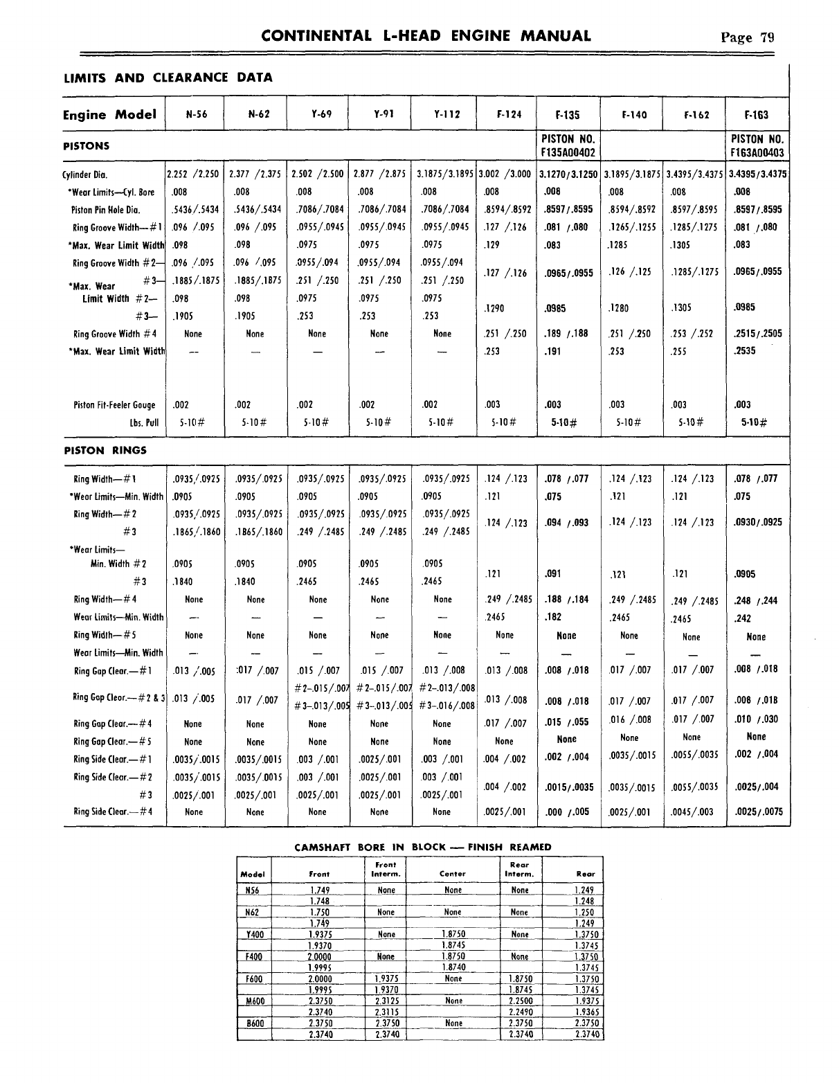
CONTINENTAL L-HEAD ENGINE MANUAL Page 79
LIMITS AND CLEARANCE DATA
Engine Model N-56 N-62 Y-69 Y-91 Y-i12 F-124 F-135 F-140 F-162 F-163
PISTON NO. PISTON NO.
PISTONS F135A00402 F163A00403
:ylinder Dia.
*Wear Limits--Cyl. Bore
Piston Pin Hole Dio.
Ring Groove Width--# 1 :
*Max. Wear Limit Width
Ring Groove Width #2--
*Max. Wear #3--
Limit Width #2--
#3--
Ring Groove Width #4
*Max. Wear Limit Width
Piston Fit-Feeler Gauge
Lbs. Pull
2.252 /2.250
.008
.5436/.5434
.096 /.095
.098
.096 /.095
.1885/.1875
.098
.1905
None
.002
5-1(1#
2.377 /2.37S
.008
.5436/.5434
.o9~ /.o9s
.098
.096 /.095
.i885/.187s
.098
.1905
None
.002
5-10#
2.so2/2.500
.008
.7086/.7084
.0955/.0945 1
.0975
.0955/.094
.251/.2so
.0975
.253
None
.002
5-10#
2.877 /2.875
.008
.7086/.7084
.0955/.0945
.0975
.0955/.094
.251 /.2S0
.0975
.253
None
.002
5-10#
3.1875/3.1895
.008
.7086/.7084
.0955/.0945
.0975
.0955/.094
.251 /.250
.097S
.253
None
.002
S-10#
3.002 /3.000
.008
.8594/.8592
.127 /.126
.129
.127 /.126
.1290
.251 /.250
.253
.003
S-lO#
3.1270/3.1250
.008
.8597/.8595
.081 /.080
.083
.0965/.0955
.0985
.189 /.188
.191
.003
5-10#
3.1895/3.1875
.008
.8594/.8592
.1265/.1255
.1285
.126/.125
.1280
.251 /.250
.253
.003
S-lO#
3.4395/3.4375
.008
.8597/.8595
.1285/,127S
.1305
.1285/.1275
.1305
.2S3 /.252
.255
.003
5-10#
3.4395/3.4375
~06
.8597/.8595
¯ 81 ./.080
.083
.0965/.0955
.0985
.2515/.2505
.2535
PISTON RINGS
Ring Width--# 1
*Wear Limits--Min. Width
Ring Width--# 2
#3
*Wear Limifs--
Min. Width #2
#3
Ring Width-- # 4
Wear Limits--~tin. Width
Ring Width-- # 5
Wear Limits--Min. Width
Ring Gap Clear.--# 1
Ring Gap Clear.--#2 & 3
Ring Gap Clear.--#4
Ring Gap Clear.--# 5
Ring Side Clear.--# 1
Ring Side Clear.--# 2
#3
Ring Side Clear.--#4
.0935,/.0925
.0905
.0935,/.0925
.1865,/.1860
.0905
.1840
None
Nolle
.013 /.005
.013 /.OOS
None
None
.0035/.0015
.0035/’.0015
.0025/.001
None
.0935/.0925
.0905
.0935/.0925
.1865/.1860
.0905
.1840
None
None
:017 /.007
.017 /.007
None
None
.0035/.0015
.0035/.0015
.0025/.001
None
.0935/.0925
.0905
.0935/.0925
.249 /.2485
.0905
.2465
None
None
.015 /.007
#2-.015/.00)
#3-.013/.005
None
None
.003 /.001
.003 /.001
.0025/.001
None
.0935/.0925
.0905
.0935/.0925
.249 /.2485
.0905
.2465
None
None
.OlS /.007
#2-.OlS/.oo:
#3-.o13/.oo
None
None
.0025/.001
.0025/.001
.oo25/.ool
None
Model
N62
Y400
F400
F60Q
M600
8600
CAMSHAFTBORE IN
Front
Front Interm.
1.749 None
1.748
1.750 None
1.749
1.9375 None
1.9370
2.0000 None
1.9995
2.0000 1.9375
1.9995 1.9370
2.3750 2.3125
2.3740 2.3115
2.3750 2.3750
2.3740 2.3740
.0935/.0925
.0905
.0935/.0925
.249 /.2485
.0905
.2465
None
None
.o13 /.oo8
#2-.013/,008
#3-.016/.008
None
None
.003 /.001
.003 /.001
.oo2s/.OOl
None
.124 /.123
.121
.124 /.123
.121
.249 /.2485
.2465
None
.013 /.008
.013 /.008
.0T7 /.007
None
.004 /.002
.oo4/.oo2
.0025/.001
.078 /.077
.075
.094 /.093
.091
.188 /.184
.182
None
.008 /.018
.008 /.018
.015 /.055
None
.002 /.004
.0015/.0035
.000 /.005
.124 /.123
.121
.124 /.123
.121
.249 /.2485
.2465
None
.017 /.007
.017 /.007
.016 /.008
None
.0035/.0015
.0035/.0015
.0025/.001
BLOCK--FINISH REAMED
Rear
Center Interm. Rear
None None 1.249
1.248
None None 1.250
1.249
1.8750 None 1.3750
1.8745 1.3745
1,8750 None 1.3750
1.8740 1.3745
None 1.8750 1.3750
1.8745 1.3745
None 2.2500 1.9375
2.2490 1.9365
None 2.3750 2.3750
2.3740 2.3740
.124 /.123 .078 /.077
.121 .075
.124 /.123 .0930/.0925
.121 .0905
.249 /.2485 .248 /.244
.2465 .242
None None
.017 /.007 .008 /.018
.017 /.007 .008 /.018
.017 /.007 .010 /.030
None None
.0055/.0035 .002 /.004
.0055/.0035 .0025/.004
.0045/.003 .0025/.0075
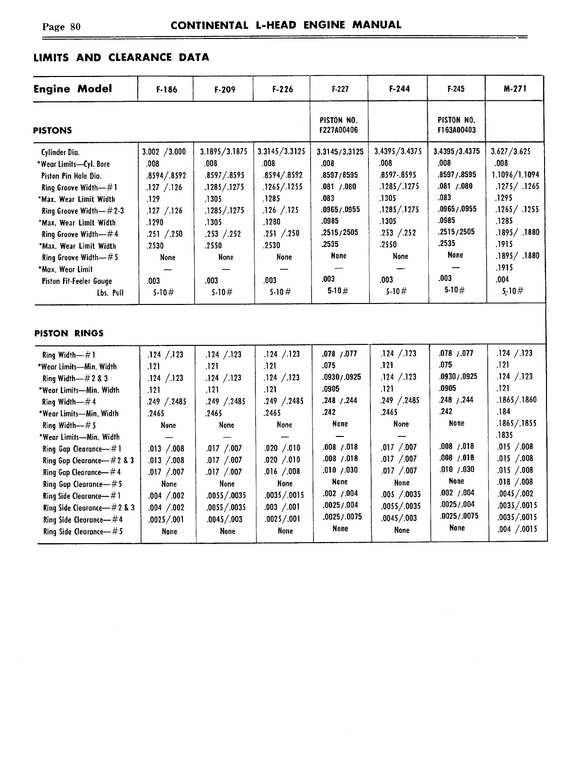
Page 80 CONTINENTAL L-HEAD ENGINE MANUAL
LIMITS AND CLEARANCE DATA
Engine Model F-186 F-209 F-226 F-227 F-244 F-245 M-271
PISTON NO. PISTON NO.
PISTONS F227AO0406 F163AO0403
Cylinder Dia.
*Wear Limits--Cyl. Bore
Piston Pin Hole Dia.
Ring Groove Width--# 1
*Max. Wear Limit Width
Ring Groove Width--#2-3
*Max. Wear Limit Width
Ring Groove Width--#4
*Max. Wear Limit Width
Ring Groove Width--~5
*Max. Wear Limit
Piston Fit-Feeler Gauge
Lbs. Pull
3.002 /3.000
.008
.8594/.8592
¯129
.127 /.126
¯1290
.251 /.250
.2530
None
.003
5-10#
3.1895/3.1875
.008
.8597/.8595
.1285/.1275
.1305
.1285/.1275
.1305
.253 /.252
.2550
None
.003
5-10#
3.3145/3.3125
.008
¯8594/.8592
.1265/.1255
¯1285
.126 /.125
.1280
.251 /.250
.2530
None
.0O3
5-10#
3.3145/3.3125
.008
.8597/8595
.081 /.080
.083
.0965/.0955
.O985
.2515/2505
.2535
None
.003
5.1o#
3.4395/3.4375
.008
.8597-.8595
.1285/.1275
.1305
.1285/.1275
.1305
.253/.252
.2550
None
.003
5-10#
3.4395/3.4375
.008
.8597/.8595
.081 /.080
.083
.0965/.0955
.0985
.2515/2505
.2535
None
.003
5-10#
3.627/3.625
.008
1.1o96/1.1o94
.1275/ .1265
.1295
.1265/ .1255
.1285
.1895/ .1880
.1915
.1895/ .1880
.1915
.004
~-1o#
PISTON RINGS
Ring Width--# 1
*Wear Limits--Min. Width
Ring Width--#2 8, 3
*Wear Limits--Min. Width
Ring Width--#4
*Wear Limits--Min. Width
Ring Width--# 5
*Wear Limits--Min. Width
Ring Gap Clearance--#1
Ring Gap Oearance--#2 & 3
Ring Gap Clearance--#4
Ring Gap Clearance--#5
Ring Side Clearance--# 1
Ring Side Clearance--#2 & 3
Ring Side Clearance--#4
Ring Side Clearance--#5
.124 /.]23
.121
.124 /.123
.121
.249 /.2485
.2465
Nane
.013 /.008
.013 /.008
.017 /.007
None
.004 /.002
.004 /.002
.oo25/.OOl
None
.124 /.123
.121
.124 /.123
.121
.249 /.2485
.2465
None
.o17 /.oo7
.017 /¯007
.017 /.007
None
.0055/.0035
.0055/.0035
.0045/.003
None
.124/.123
.121
.124/.123
.121
.249 /.2485
.2465
None
.O2O /.010
.020 /.010
.016 /.008
None
.oo35/.oo15
.003 /.001
.oo25/.OOl
None
.078 /.077
.075
.0930/.0925
.0905
.248 /.244
.242
None
.008 /.018
.O08 /.018
.010 /.030
None
.002 /.004
.0025/.004
.0025/.0075
None
.124 /.123
.121
.124 /.123
.121
.249 /.2485
.2465
None
.017 /.007
.017 /.007
.017 /.007
None
.005 /.0035
.oo55/.oo35
.0045/.003
None
.078 /.077
.075
.0930/.0925
.0905
.248 /.244
.242
None
.008 /.018
.008 /.018
.010 /.030
Hone
.002 /.004
.0025/.004
.0025/.0075
None
.124 /.123
.121
.124 /.123
.121
.1865/.1860
.184
.1865/.1855
.1835
.015 /.008
.015 /.008
.OlS/.oo8
.o!8/.oo8
.0045/.002
.oo35/.ools
.0035/.0015
.004 /.0015
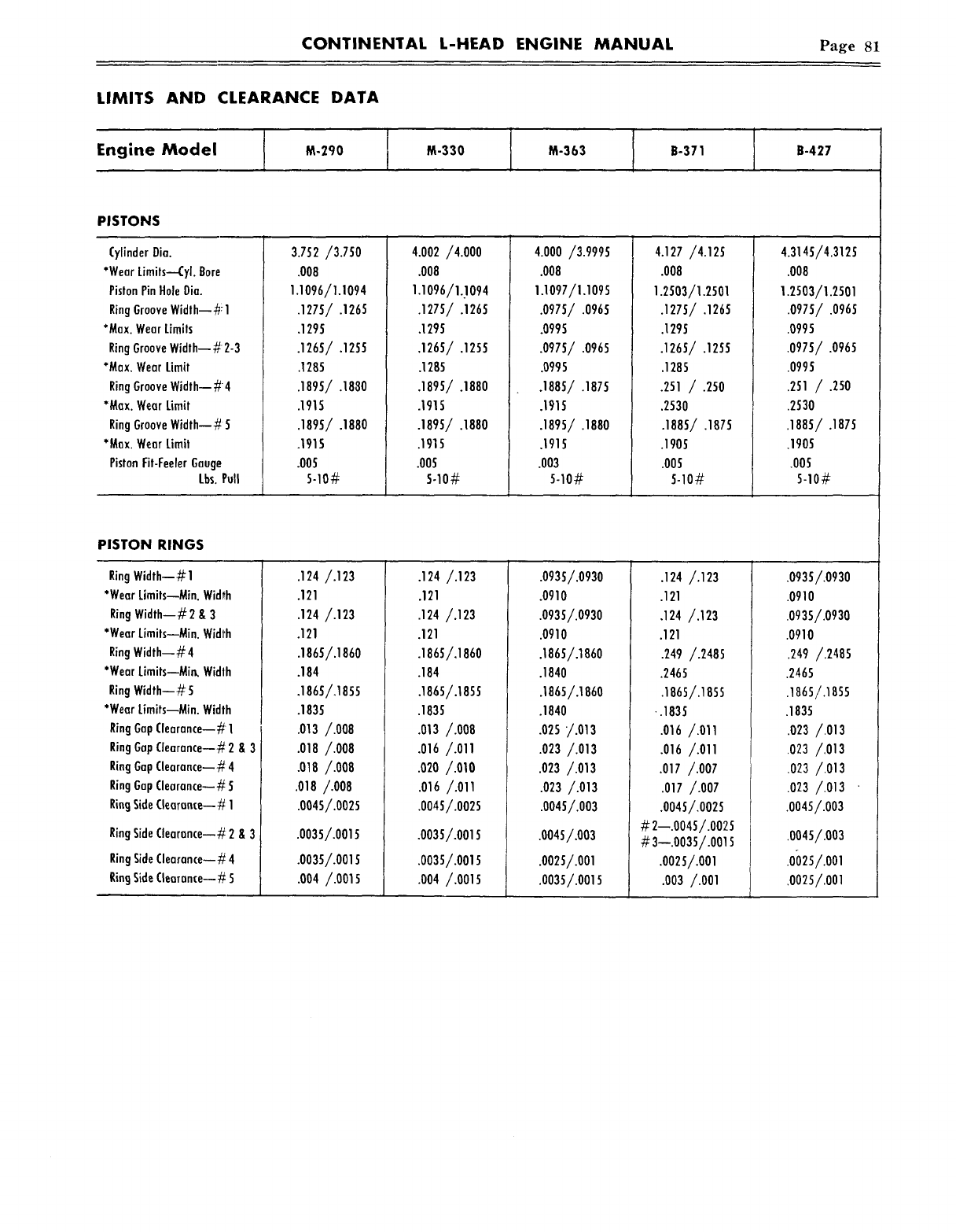
CONTINENTAL L-HEAD ENGINE MANUAL Page 81
LIMITS AND CLEARANCE DATA
IM-330 M-363 B-371 B-427Engine Model M-290 I
PISTONS
Cylinder Dia.
*Wear Limits--Cyl. Bore
Piston Pin Hole Dia.
Ring Groove Width--#1
*Max. Wear Limits
Ring Groove Width--#2-3
*Max. Wear Limit
Ring Groove Width--#4
*Max. Wear Limit
Ring Groove Width--# 5
*Max. Wear Limit
Piston fit-Feeler Gauge
Lbs. Pull
3.752/3.750
.008
1.1096/1.1094
.1275/ .1265
,1295
.1265/ .1255
.1285
,1915
.1895/ .1880
.1915
.005
5-10#
4.002/4.000
.008
1.1096/1.!094
.1275/ .1265
.1295
.1265/ .1255
.1285
.1895/.1880
.1915
.1895/ .1880
.1915
.005
5o10#
4.000 /3.9995
.008
1.1097/I.1095
.0975/.0965
.0995
.0975/ .0965
.0995
.1885/ .1875
.1915
.1895/ .1880
.1915
.003
5-10#
4.127 /4.125
.008
1.2503/1.2501
.1275/ .1265
.1295
.1265/ .1255
.1285
.251 / .250
.2530
.1905
.005
5-10#
4.3145/4.3125
.008
1.2503/1.2501
.0975/ .0965
.0995
.0975/ .0965
.0995
.251 / .250
.2530
.1885/ .1875
.1905
.005
5-10#
PISTON RINGS
Ring Width--# 1
*Wear Limits--Min. Width
Ring Width--# 2 & 3
*Wear Limits--Min. Width
Ring Width--#4
*Wear Limits--Min, Width
Ring Width--#5
*Wear Limits--Min. Width
Ring Gap Clearance--#1
Ring Gap Clearance--# 2
Ring Gap Clearance-- #4
Ring Gap Clearance--# 5
Ring Side Clearance--# 1
Ring Side Clearance--# 2
Ring Side Clearance--# 4
Ring Side Clearance--# 5
&3
&3
.124 /.123
.121
.124 /.123
.121
.1865/.1860
.184
.1865/,1855
.1835
.013/.008
.018/.008
.018/.008
.018/.008
.004s/.0025
.0035/.0015
.0035/.0015
.004/.OOLS
.124 /.123
.121
.124 /.123
.121
.1865/.186o
.184
.1865/.1855
.1835
.o13/.o08
.016 /.011
.020/.OLO
.016 /.011
.0O45/.0025
.oo35/.OOlS
.0035/.0015
.004 /.0015
.0935/.0930
.0910
.0935/.0930
.0910
.1865/.1860
.1840
.1865/.1860
.1840
.025 /.013
.023 /.013
.o23/.o13
.023 /.013
.0045/.003
.0045/.003
.oo25/.OOl
.0035/.0015
.124 /.123
.121
.124 /.123
.121
.249 /.2485
.2465
.1865/.1855
..1835
.o16/.Oll
.016 /.011
.o17/.007
.o17/.oo7
.0045/,0025
#2--.0045/.0025
#3--.0035/.0015
.0025/.001
.oo3/.OOl
.0935/.0930
.0910
.0935/.0930
.0910
.249 /.2485
.2465
.186s/.18ss
.1835
.023 /013
.023 /.013
,023 /.013
.023 /.013
.0045/.003
.oo45/.oo3
.o~25/.OOl
.0025/.001

SERVICE AND PARTS
Available from your Authorized
WISCONSIN
Service Center
SALES OFFICE:
2020 Fletcher Creek Drive, Memphis, Tennessee 38133
Phone: (901) 371-0353 or Toll Free (800) 932-2858
www.wisconsinmotors.com
JUN 2006
X-27053A
! WARNING !
California Proposition 65
The engine exhaust from this product
contains chemicals known to the State of
California to cause cancer, birth defects or
other reproductive harm.
WISCONSIN
MOTORS, LLC
