Core Device Discovery User Guide
User Manual:
Open the PDF directly: View PDF ![]() .
.
Page Count: 7

Modern Robotics, Inc
Core Device Discovery Utility
© Modern Robotics Inc, 2015
Version 1.0.1 October 27, 2015
Page 2 of 7
Core Device Discovery
Application Guide
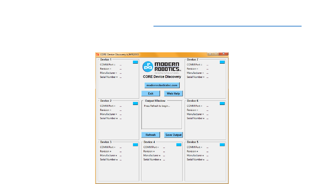
The Core Device Discovery utility allows you to retrieve module information and serial numbers, test
connectivity and most functions of each module from your PC or Mac. Modules that can be tested by this
program are;
Core Servo Controller
Core Motor Controller
Core Legacy Module
Core Device Interface Module
Core Power Distribution Module (Indirectly. This module will not appear as a device.)
It is recommended that the Core Power Distribution module be used in line with the connected controllers
however controllers may be connected directly to your computer as well.
Application Download:
1. Download Core Device Discovery by going to www.modernroboticsinc.com/coredevicediscovery.
2. Extract the contents of the download by right clicking on the zip file and selecting “Extract All…”
3. Double click the executable file to run the application which will display the control page as shown.
Page 3 of 7
Core Power Distribution Module
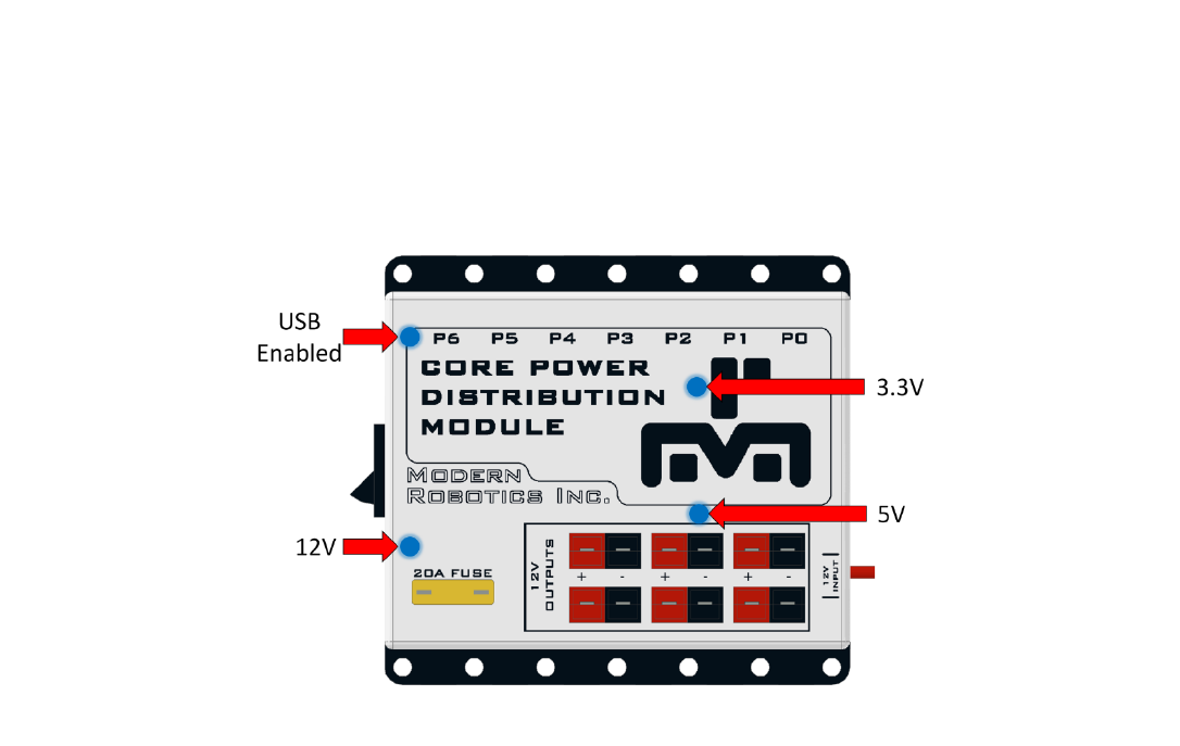
The Core Power Distribution Module is equipped with four LEDs as status indicators. Under normal
operation, all four LED’s should be illuminated after the module is connected to a host phone or
computer.
12V – Indicates 12v supply is connected and the power switch is on.
5V – Indicates 5v power supply is operating and supplying 5v to the USB ports.
3.3V – Indicates 3.3 volt supply to the internal electronics are operating.
USB Enabled – Indicates a host device is connected to the USB input port.
Page 4 of 7
Application Usage / Instructions:
1. If a Core Power Distribution hub is to be used connect this first and wait for your computer to
recognize it as a hub device. Connect modules to your hub or computer and wait for the devices to be
discovered by your computer:
Windows: A popup with "Your Device is Ready to Use" will appear in the bottom right indicating the
device has been assigned a COM port number and is ready for use.
If your computer does not install the drivers, the modules will not be found by the application. To fix
this, go to http://www.ftdichip.com/Drivers/VCP.htm and select the “setup executable” in the
comments column. Installing this driver will allow the modules to talk to the computer.
Mac: In most cases, each device connected will be assigned a "tty" USB COM port within a short time
of connecting. Once this number has been assigned with serial, the device is ready to use.
2. Click the "Refresh" button located in the center of the Core Device Discovery Window to update the
display with the currently connected controllers.
Note: Servo and Motor controllers will not appear as useable devices until 12v has been applied to the
controller 12v input.
3. If this application was referred to you my Modern Robotics Support, select
“Save Output” and email the saved file to support@modernroboticsinc.com.
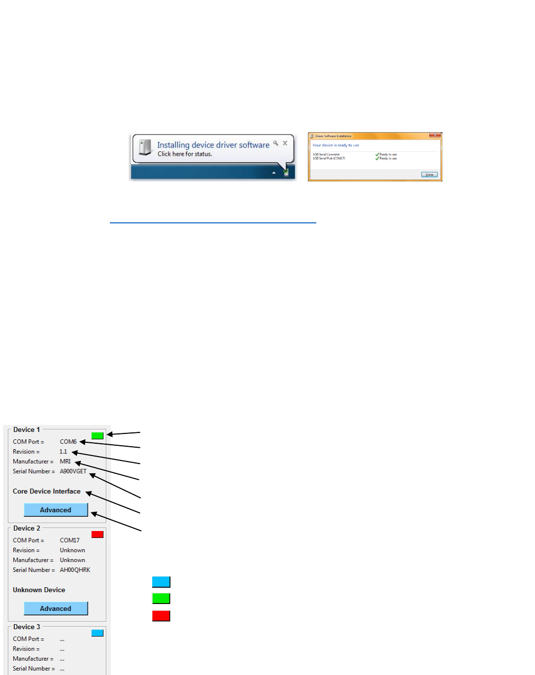
Indicator
COM Port
Revision
Manufacturer
FTDI Serial Number
Device Name
Advanced if Available (see "Advanced Operation" below)
INDICATOR LEGEND:
= No device detected
= Core device found
= Unknown device or Servo/Motor without 12v power
Page 5 of 7
Advanced Operation:
Each successfully connected and recognized Core device will appear with an "Advanced" button option
on their corresponding device window. Clicking this button will open a new GUI window which will allow
you control most operational aspects of the device.
When using the advanced features of each controller, you may see the input fields and buttons change
depending on the controller state and user input. The following legend describes the function and meaning
of each color and state:
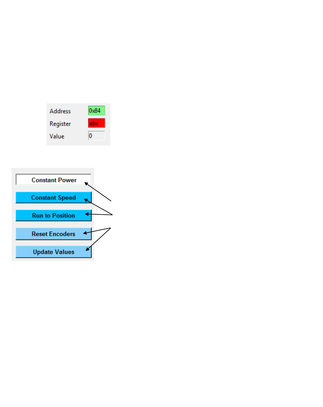
= Input value is good
= Input value is incorrect or out of range
= Input disabled, read only
White button -- selected mode
Dark button -- available mode
Light button -- commands
1. Core Motor Controller
Motors can be controlled in three operation modes and their encoder values displayed. The mode can
be switched using the three buttons labeled Constant Power, Constant Speed, and Run to Position. The
button will appear white when selected indicating the current mode enabled.
* Motor values can range from a power of -100 to 100
* Encoder values can range from -2147483648 to 2147483647
- Pressing <Return> key or "Update Values" will update controller with the user input
- Pressing <Escape> key will set the power of both motors to 0
- Pressing "Reset Encoders" will set motor power and encoder values to 0
- Pressing the <UP> or <DOWN> arrows on the keyboard will adjust the values +/- 5

Page 6 of 7
2. Core Servo Controller
Servos can be enabled or disabled using the selection buttons in the bottom right. The button will
appear white when selected indicating the current mode enabled.
* Servo values can range from 0 - 255 (1.5uS to 2.5uS)
Note: Most servos range from (1.75uS to 2.25uS) and extending the range to the mechanical limits can
cause damage to the servo over time. It is recommended that you find the limits of each servo by
increasing and decreasing the value until the servo "hums" indicating it has hit a mechanical limit and
not exceeding this range in your design.
- Pressing <Return> key or "Update Values" will update controller with the user input
- Pressing the <UP> or <DOWN> arrows on the keyboard will adjust the values +/- 5
3. Core Device Interface
The Core Device Interface has multiple inputs and outputs to be used with Modern Robotics Inc. Core
sensors as well as user created sensors and devices. These functions include onboard indicator LEDs,
Analog input and outputs, Digital input and outputs, I2C communication, and PWM outputs.
Note: The PWM outputs are for sensor design only and not to be used directly with servos as the
power circuitry cannot support the current needed for servo operation.
- The onboard LEDs can be turned on and off using the check boxes in the top left
- PWM output can be controlled using the left frame
* PWM time and period can range from 0 - 65534 uS
* Pressing "PWM Update" will update the controller with the user input
- Analog output can be controlled in the top right frame
* The output mode can be changed for each port using the buttons associated
* Voltage in "Volt" mode can range from -4v to 4v peak
* Voltage in all other modes can range from 0v to 8v peak to peak
* Pressing "Update Analog Out" will update the controller with the user input
- Analog and Digital ports can be read in the bottom right and are auto-updating
* These ports are "floating" when no sensor is connected and all data received on unconnected
ports should be ignored during use
- I2C Address List shows all the discovered I2C addresses connected to the I2C port
* Pressing "Refresh List" will scan for all compatible I2C addresses and display the ones found
and the Device type if it is a MRI branded sensor
- I2C Commands allows you to read and write values to a register on a specific address

Page 7 of 7
* Checking "Poll Read" will continuously update the value field with the contents of the register
selected
* Pressing "READ" will perform a single read transaction to the sensor
* Pressing "WRITE" will perform a single write transaction to the sensor
- Change Address form allows you to modify the address of a specific sensor if allowed
* Only MRI brand I2C sensors support the address change functionality
* When changing the address only one device should be connected at one time to avoid
multiple devices on the same address.
* Pressing the "Change Address" button will change the address of the device and update the
address list to display to ensure the address has been successfully changed
* Addresses can range from (16)0x10 to (254)0xFE and have to be even numbers
4. Core Legacy Module
The Core Legacy Module has six ports for connecting Legacy sensors and controllers. Each port
incorporates 10kHz I2C speed transactions as well as Legacy standard analog input.
* All I2C values can range from 0x00 - 0xFF accordingly
Pressing the "I2C Address" button located in each port form will auto-detect the i2c address of
the device connected.
Checking the box next to "Poll Read" will read the register info and analog values continuously
The Onboard LEDs may be enabled using the check boxes on the left side of the screen
