Cummins DL4 DL5 DL6T Generator Service Manual
900-0336 Onan DL4 DL6 DL6T Genset Generator & Controls Service manual (08-1983) 900-0336 Onan DL4 DL6 DL6T Genset Generator & Controls Service manual (08-1983)
User Manual: Cummins-DL4-DL5-DL6T-Generator-Service-Manual Igor's of metalworking and electrical manuals
Open the PDF directly: View PDF ![]() .
.
Page Count: 67
Caution: This document contains mixed page sizes (8.5 x 11 or 11 x
17), which may affect printing. Please adjust your printer settings
according to the size of each page you wish to print.
Redistribution or publication of this document,
by any means, is strictly prohibited.
Service
Manual
DL4
DL6
DL6U
Generator
and
Controls
900-0336
8-83
(Replaces
900-0336 7/82)
Printed
in
U.S.A
Redistribution or publication of this document,
by any means, is strictly prohibited.
Safety
Precautions
The following symbols in this manual highlight con-
ditions potentially dangerous to service personnel, or
equipment. Read this manual carefully. Know when
these conditions can exist. Then take necessary
steps to protect personnel as well as equipment.
WARN,NG
personal injury.
This symbolis used throughout the
manual to warn of possible serious
This symbol refers to possible
equipment damage.
PROTECT AGAINST MOVING PARTS
Avoid moving parts
of
the unit. Avoid use of loose
jackets, shirts or sleeves due to danger of becoming
caught in moving parts.
Make sure all nuts and 'bolts are secure. Keep power
'
shields and guards in position.
If
you must make adjustments while the unit
is
running, use extreme caution around hot manifolds,
moving parts, etc.
Do not work on this equipment when mentally or
physically fatigued.
GUARD AGAINST ELECTRIC SHOCK
Disconnect electric power before removing protec-
tive shields or touching electrical equipment. Use
rubber insulative mats placed on dry wood platforms
over floors that are metal or concrete when around
.electrical equipment. Do not wear damp clothing
(particularly wet shoes) or allow skin surfaces to be
damp when handling electrical equipment.
Disconnect batteries to prevent accidental engine
start. Jewelry is a good conductor of electricity and
should be removed before working on electrical
equipment.
Use extreine caution when working on electrical
components. High voltages cause injury or death.
Follow all state and local codes.
To
avoid possible
personal injury or equipment damage, a qualified
electrician or an authorized service representative
must perform installation and all service.
EXHAUST
GAS IS
DEADLY!
Exhaust gases contain carbon monoxide, a poisonous gas that might cause
unconsciousness and death. It is an odorless and colorless gas formed during
combustion of hydrocarbon fuels. Symptoms
of
carbon monoxide poisoning
are:
Dizziness Vomiting
Headache Muscular Twitching
'
Weakness and Sleepiness Throbbing in Temples
If you experience any of these symptoms, get
out
into fresh air immediately,
shut down the unit and do not use until it has been inspected.
The best protection against carbon monoxide inhalation is proper installation
and regular, frequent inspections of the complete exhaust system.
If
you notice
a change in the sound or appearance of exhaust system, shut the unit down
immediately and have it inspected and repaired at once by a competent
mechanic.
t
Redistribution or publication of this document,
by any means, is strictly prohibited.
.
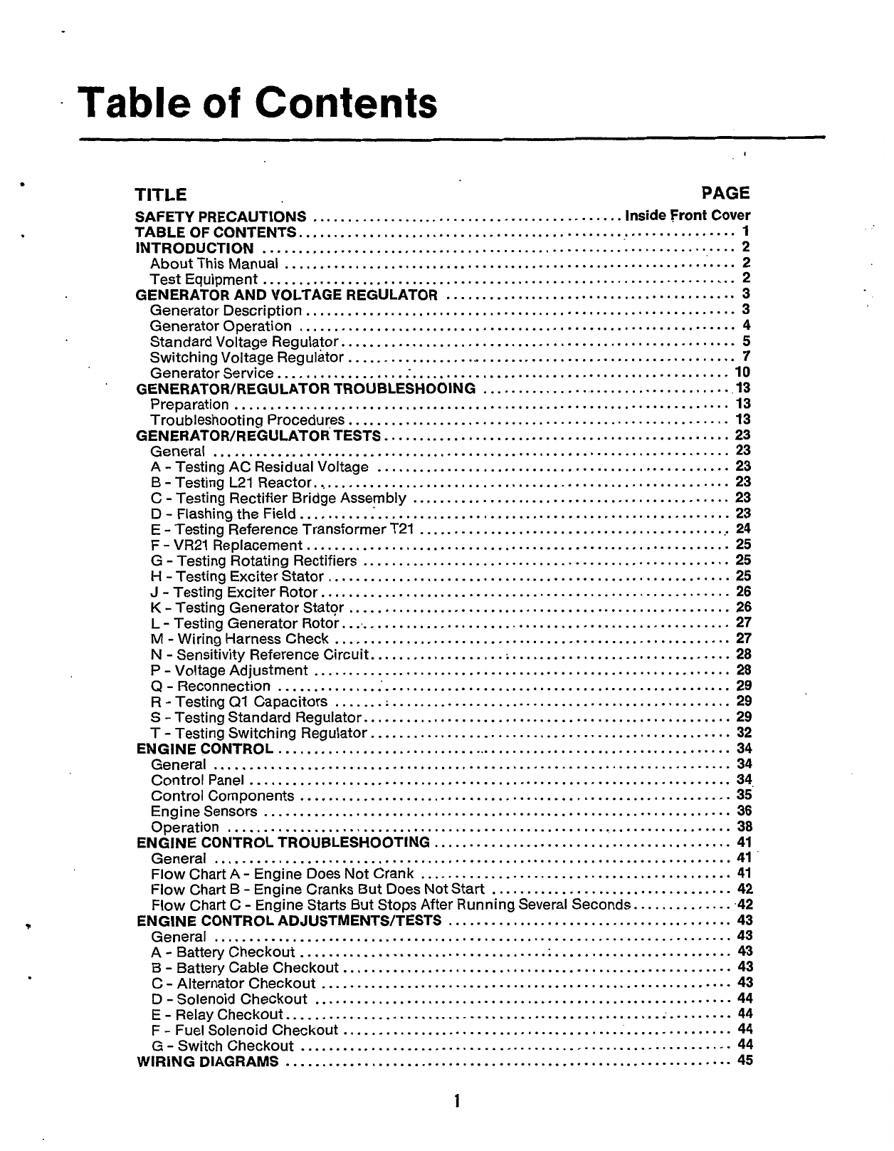
Table
of
Contents
I
.
TITLE
PAGE
SAFETY PRECAUTIONS
............................................
Inside Front Cover
TABLE
OF
CONTENTS
..............................................................
1
INTRODUCTION
...................................................................
2
About This Manual
................................................................
2
Test Equipment
....................................................................
2
GENERATOR AND VOLTAGE REGULATOR
.........................................
3
Generator Description
.............................................................
3
Generator Operation
..............................................................
4
Standard Voltage Regulator
........................................................
5
Switching Voltage Regulator
.......................................................
7
Generator Service
..................
.-.
............................................
10
GENERATOR/REGULATOR TROUBLESHOOING
....................................
13
Preparation
13
Troubleshooting Procedures
......................................................
13
GENERATOR/REGULATOR TESTS
.................................................
23
General
23
A
.
Testing AC Residual Voltage
..................................................
23
B
-
Testing
L21
Reactor
............................................................
23
C
-
Testing Rectifier Bridge Assembly
.............................................
23
D
-
Flashing the Field
..............................................................
23
E
-
Testing Reference Transformer T21
.............................................
24
F
-
VR21 Replacement
............................................................
25
G
-
Testing Rotating Rectifiers
....................................................
25
H
.
Testing Exciter Stator
.........................................................
25
J
-
Testing Exciter Rotor
..........................................................
26
K
-
Testing Generator Stator
......................................................
26
L
.
Testing Generator Rotor
........................................................
27
M
-
Wiring Harness Check
........................................................
27
N
.
Sensitivity Reference Circuit
...................................................
28
P
-
Voltage Adjustment
...........................................................
28
Q
-
Reconnection
.................................................................
29
R
.
Testing
QI
Capacitors
.......
:
................................................
29
S
-
Testing Standard Regulator
....................................................
29
T
-
Testing Switching Regulator
...................................................
32
ENGINE CONTROL
.................................................................
34
General
.........................................................................
34
Control Panel
....................................................................
34
Control Components
.............................................................
35’
Engine Sensors
..................................................................
36
Operation
38
ENGINE CONTROL TROUBLESHOOTING
..........................................
41
General
41
Flow Chart B
-
Engine Cranks But Does Not Start
..................................
42
Flow Chart C
.
Engine Starts But Stops After Running Several Seconds
...............
42
ENGINE CO NTR
0
L AD
J
USTM ENTS/TESTS
........................................
43
General
43
A
-
Battery Checkout
.............................................................
43
B
-
Battery Cable Checkout
.......................................................
43
C
-
Alternator Checkout
..........................................................
43
D
-
Solenoid Checkout
...........................................................
44
E
-
Relay Checkout
...............................................................
44
F
-
Fuel Solenoid Checkout
.......................................................
44
G
-
Switch Checkout
.............................................................
44
......................................................................
.........................................................................
.......................................................................
.........................................................................
Flow Chart A
.
Engine Does Not Crank
............................................
41
.........................................................................
WIRING DIAGRAMS
...............................................................
45
1
Redistribution or publication of this document,
by any means, is strictly prohibited.
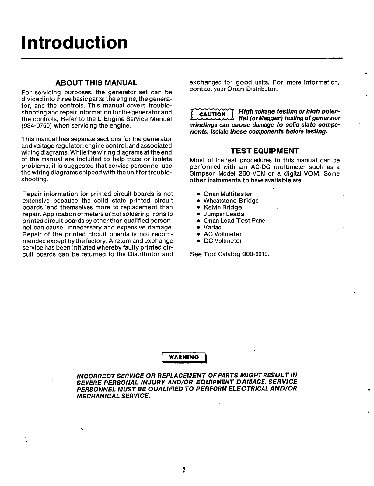
Introduction
ABOUT
THIS
MANUAL
For servicing purposes, the generator set can be
divided into three basic parts: the engine, the genera-
tor, and the controls. This manual covers trouble-
shooting and repair information for the generator and
the controls. Refer to the
L
Engine Service Manual
(934-0750)
when servicing the engine.
This manual has separate sections for the generator
and voltage regulator, engine control, and associated
wiring diagrams. While the wiring diagrams at the end
of the manual are included to help trace or isolate
problems,
it
is suggested that service. personnel use
the wiring diagrams shipped with the unitfortrouble-
shooting.
Repair information for printed circuit boards is not
extensive because the solid state printed circuit
boards lend themselves more to replacement than
repair. Application of meters or hot soldering irons to
printed circuit boards by other than qualified person-
nel can cause unnecessary and expensive damage.
Repair of the printed circuit boards is not recom-
mended except by the factory.
A
return and exchange
service has been initiated whereby faulty printed cir-
cuit boards can be returned to the Distributor and
exchanged for good units. For more information,
contact your Onan Distributor.
High voltage testing or high poten-
tial (or Megger) testing
of
generator
windings can cause damage to solid state compo-
nents. Isolate these components before testing.
TEST
EQUIPMENT
Most of the test procedures
in
this manual can be
performed with
an
AC-DC multimeter such as a
Simpson Model
260
VOM or
a
digital VOM. Some
other instruments
to
have available are:
0
Onan Multitester
0
Wheatstone Bridge
0
Kelvin Bridge
Jumper Leads
0
Onan Load Test Panel
0
Variac
0
AC
Voltmeter
DC Voltmeter
See Tool Catalog
900-0019.
I
WARNING
INCORRECT SERVICE OR REPLACEMENT
OF
PARTS MIGHT RESULT IN
SEVERE PERSONAL INJURY AND/OR EQUIPMENT DAMAGE. SERVICE
PERSONNEL MUST BE QUALIFIED
TO
PERFORM ELECTRICAL AND/OR
MECHA NlCA L SERVICE.
2
Redistribution or publication of this document,
by any means, is strictly prohibited.
Generator
and
.Voltage Regulator
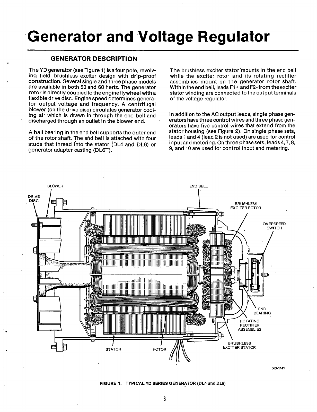
GENERATOR DESCRIPTION
The YD generator (see Figure
1)
is afour pole, revolv-
ing
field, brushless exciter design with drip-proof
construction. Several single and three phase models
are available in both
50
and 60 hertz. The generator
rotor is directly coupled to the engine flywheel with a
flexible drive disc. Engine speed determines genera-
tor output voltage and frequency.
A
centrifugal
blower (on the drive disc) circulates generator cool-
ing
air which is drawn
in
through the end bell and
discharged through an outlet
in
the blower end.
’
A
ball bearing
in
the end bell supports the outer end
of the rotor shaft. The end bell is attached with four
studs that thread into the stator (DL4 and DL6) or
generator adapter casting (DL6T).
C
I
The brushless exciter stator’mounts
in
the end bell
while the exciter rotor and its rotating rectifier
assemblies mount on the generator rotor shaft.
Within theend bell, leads
F1+
and F2-from theexciter
stator winding are connected to the output terminals
of the voltage regulator.
In
addition to the
AC
output leads, single phase gen-
erators have three control wires and three phase gen-
erators have five control wires that extend from the
stator housing (see Figure
2).
On single phase sets,
leads
1
and 4 (lead 2 is not used) are used for control
input and metering. On three,phase sets, leads 4,7,8,
9,
and
10
are used for control input and metering.
BLOWER
END
BELL
BRUSHLESS
EXCITER
ROTOR
FIGURE
1.
TYPICAL
YD
SERIES
GENERATOR
(DL4
and
DL6)
3
XG-1141
Redistribution or publication of this document,
by any means, is strictly prohibited.
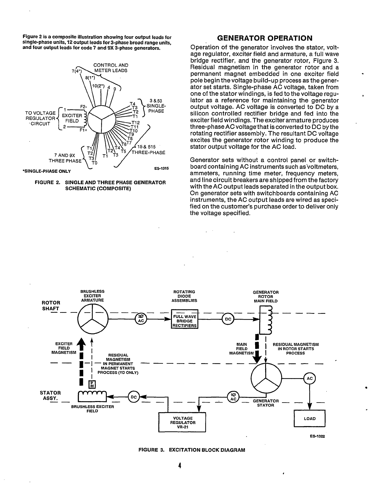
Figure
2
is a composite illustration showing four output leads for
single-phase units,
12
output leads for 3-phase broad range units,
and
four output leads for code
7
and
9X
3-phase generators.
-
CONTROLAND
7bwR
LEADS
L
‘SINGLE-PHASE ONLY ES-1315
FIGURE
2.
SINGLE AND THREE PHASE GENERATOR
SCHEMATIC (COMPOSITE)
GENERATOR OPERATION
Operation
of
the generator involves the stator, volt-
age regulator, exciter field and armature, a full wave
bridge rectifier, and the generator rotor, Figure
3.
Residual magnetism in the generator rotor and a
permanent magnet embedded in one exciter field
pole begin the voltage build-up process as the gener-
ator set starts. Single-phase
AC
voltage, taken from
one
of
the stator windings,
is
fed to the voltage regu-
lator as a reference for maintaining the generator
output voltage.
AC
voltage is converted
to
DC
by
a
silicon controlled rectifier bridge and fed into the
exciter field windings. The exciter armature produces
three-phase
AC
voltagethat is converted to
DC
by the
rotating rectifier assembly. The resultant
DC
voltage
excites the generator rotor winding to produce the
stator output voltage for the
AC
load.
*
Generator sets without
a
control panel
or
switch-
board containing
AC
instruments such as’voltmeters,
ammeters, running time meter, frequency meters,
and line circuit breakers are shipped from the factory
with the
AC
output leads separated in the output box.
On generator sets with switchboards containing
AC
instruments, the
AC
output leads are wired as speci-
fied on the customer’s purchase order
to
deliver only
the voltage specified.
BRUSHLESS ROTATING GENERATOR
EXCITER DIODE ROTOR
ARMATURE ASSEMBLIES MAIN FIELD
----
4
EXCITER
FIELD
MAGNETISM
I
D-
I
--
STATOR
ASSY.
--
t
RESIDUAL
MAGNETISM
MAGNET STARTS
PROCESS (YD ONLY)
-
IN
PERMANENT
MAIN
I
RESIDUALMAGNETISM
FIELD IN ROTOR STARTS
PROCESS
MAGNETISM
---b-
-
GENERATOR
-
-
I
I
BRUSHLESS EXCITER STATOR
FIELD
I
I
VU-21
VOLTAGE
REGULATOR
ES-1322
FIGURE 3. EXCITATION BLOCK DIAGRAM
4
Redistribution or publication of this document,
by any means, is strictly prohibited.
..
-
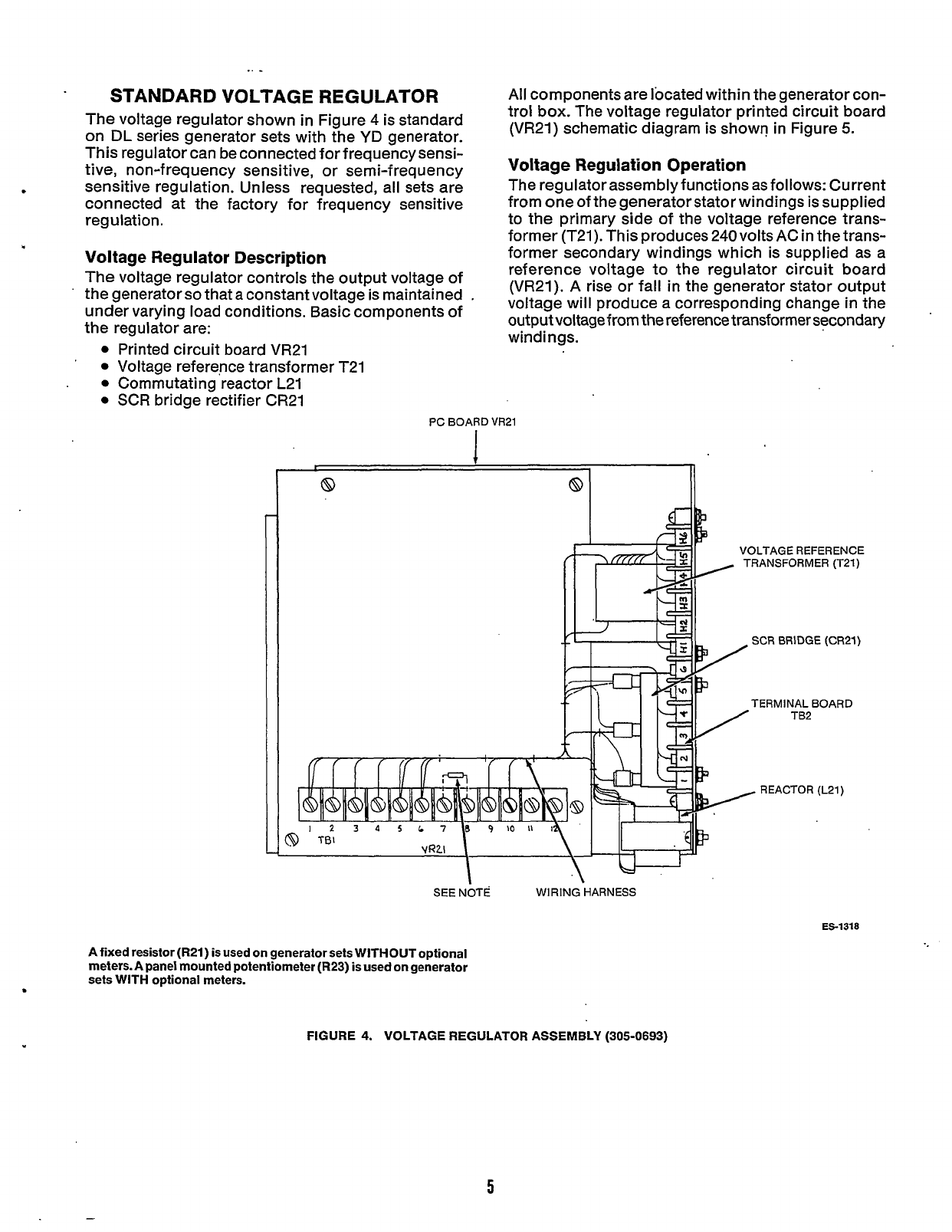
STANDARD VOLTAGE REGULATOR
The voltage regulator shown in Figure
4
is standard
on
DL
series generator sets with the
YD
generator.
This regulator can be connected for frequencysensi-
tive, non-frequency sensitive, or semi-frequency
sensitive regulation. Unless requested, all sets are
connected at the factory for frequency sensitive
regulation.
Voltage Regulator Description
The voltage regulator controls the output voltage of
the generatorso that a constant voltage is maintained
under varying load conditions. Basic components of
the regulator are:
Printed circuit board VR21
Voltage reference transformer T21
Commutating reactor L21
SCR bridge rectifier CR21
All
components are located within the generator con-
trol box. The voltage regulator printed circuit board
(VR21) schematic diagram is shown in Figure
5.
Voltage Regulation Operation
The regulator assembly functions as follows: Current
from one of the generatorstator windings is supplied
to the primary side
of
the voltage reference trans-
former (T21). This produces 240voltsAC in the trans-
former secondary windings which is supplied as a
reference voltage to the regulator circuit board
(VR21).
A
rise or fall in the generator stator output
voltage will produce a corresponding change in the
output voltage from the reference transformer secondary
windings.
PC BOARD
VR21
8
I)
VOLTAGE REFERENCE
TRANSFORMER (T21)
SCR
BRIDGE (CR21)
TERMINAL BOARD
TB2
REACTOR (L21)
SEE NOTE WIRING HARNESS
ES-1318
A fixed resistor
(R21)
is used on generator sets WITHOUT optional
meters.
A
panel mounted potentiometer
(R23)
is used on generator
sets WITH optional meters.
8
FIGURE
4.
VOLTAGE REGULATOR ASSEMBLY
(305-0693)
5
Redistribution or publication of this document,
by any means, is strictly prohibited.
REF.
NO.
C1.14
c2.
c7
c3
c4,.
c12
C5, C8
G6
c11
C13
CR3
CR12
CR13
CR14
F2. F3
1
c1
02
03
.
R1
R2, R3
R4
R5
R6
R7
R8,
R16
R10
R11 R9
Rl2
R13
R14
R15. R27
R17
R18
R20.22
R21
R24
R25. R31
R26
,
R28
TB
1
CR15
K1
R19
Thru
11
29
8.30
PART
DESCRIPTION
Board Assembly, Printed
-
Capacitor
-
47
Mfd. 250 Volt
Capacitor -.22 Mfd, 250 Volt
Capacitor -.47 Mfd, 400 Volt
Capacitor -A7 Mfd, 250 Volt
Capacitor
-
1
Mfd. 100 Volt
Capacitor
-
.33 Mfd, 250 Volt
Capacitor
-
d
Mfd, 400 Volt
Capacitor
-
Electrolytic
Rectifier
-
Silicon
Diode
-
Zener 5.6 Volt
Diode
-
Zener 20 Volt
Diode
-
Zener 18 Volt
Fuse 114 Amp
Integrated Circuit
Transistor
-
Silicon
NPN
Transistor
-
Unijunction
Resistor
-
1/2 Watt, 47-Ohm
Resistor
-
1/2 Watt, 33-Ohm
Resistor
-
2 Watt, 4.7 Meg-Ohm
Resistor
-
Fixed 10 Watt,
Resistor
-
Fixed 15 Watt,
Resistor
-
1/2 Wan, 3.000-Ohm
Resistor
-
112 Watt, 330.000-Ohm
Resistor
-
112 Watt.,51,100-0hm
Resistor
-
Fixed.5 Watt,
Resistor
-
1/2 Watt, 90,900-Ohm
Resistor
-
112 Watt, 10.000-Ohm
Resistor- 1/2 Watt, 220.000-Ohm
Resistor- 1/2Watt, 100.000-Ohm
Resistor, Metal Film
-
1/4
Watt,
11.000-Ohm
Potentiometer-5,WO-Ohrn.
1/2 Watt
.Complete
100 Mfd, 10 Volt
270-Ohm
5.000-Ohm
15.000-Ohm
Resistor
-
1/4 Watt, 28.000-Ohm
Resistor
-
Metal Film
-
1/4 Watt, 5.110-Ohm
Resistor
-
Metal Film
-
114 Watt, 8.870-Ohm
Resistor
-
2 Watt, 10.000-Ohm
:Potentiometer
-
112 Watt.
100,000-Ohm
i
Resistor
-
1/2 Watt .47 Meg-Ohm
'Terminal Block
Diode
-
Zener
-
24 Volt
j
Clip
-
Fuse
'Relay, Magnetic Reed
.,
Resistor
-
2 Watt, 6,800-Ohm
7
I
I
I
!
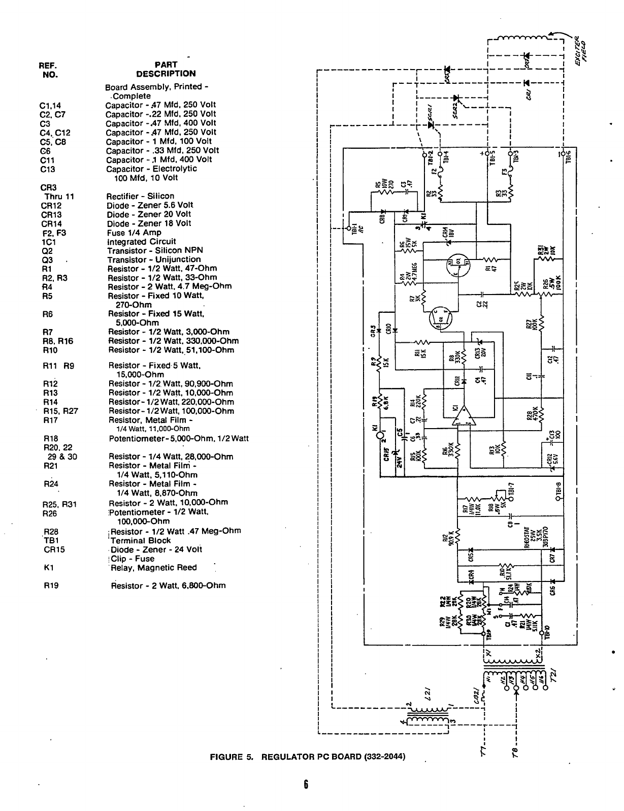
FIGURE
5.
REGULATOR
PC
BOARD
(332-2044)
,
Fc
6
Redistribution or publication of this document,
by any means, is strictly prohibited.
Generator stator current’is also supplied to the com-
mutating reactor (L21). Reactor L21 is achokethat is
used to produce a uniform AC wave. The output ter-
minals of the reactor supply AC current to the AC
input terminals on the rectifier bridge assembly
(CR21).
Rectifier bridge assembly CR21 is made up of two
silicon controlled rectifiers (SCR’s) and three recti-
fier diodes. The generator exciter field is connected
to the DC output terminals
(+
and
-)
on CR21. The
regulator circuit board (VR21) is connected to the
SCR gate terminals (G1 and G2). When a voltage
impulse from the regulator circuit board is applied
to
SCR gate terminals G1 and G2, input AC current from
L21 is rectified to DC current which is then supplied
to the exciter field.
Rectification of AC current to DC current proceeds
until the input AC voltage wave falls to zero. At this
point, rectification of AC to DC stops. As the AC
voltage wave begins to build again, avoltage impulse
is
again applied to the SCR gate terminals G1 and G2
by the regulator circuit board. This initiates a new
rectification cycle.
The voltage of the DC current produced at the output
terminals of CR21
(+
and
-)
is dependent on when the
rectification process begins. If a voltage impulse is
applied to the SCR gate terminals early in the AC
wave cycle, the DC voltage is higher.
If
the voltage
impulse is applied later
in
the AC wave cycle, the DC
voltage is lower.
During operation, the regulator circuit board re-
sponds to changes in the reference voltage supplied
by the voltage transformer.
If
the reference voltage is
low, the circuit board supplies a voltage impulse
to
the SCR gate terminals early in the AC wave cycle.
This raises thevoltage of the DC current produced for
field excitation which results in an increase in the
generator output voltage. If the reference voltage
supplied
to
the regulator circuit board is high, the
circuit board supplies a voltage impulse to the SCR
gate terminals later in the AC wave cycle. This lowers
thevoltage of the DC current produced for field exci-
tation which results
in
a decrease
in
the generator
output voltage. The process of continuously sensing
changes
in
the generator output voltage and adjust-
ing the voltage supplied to the exciter field is how
regulation is achieved.
..
SWITCHING
VOLTAGE
REGULATOR (Optional)
The switching voltage regulator is available as an
option on DL series generator sets. This regulator
can provide frequency sensitive, non-frequency sen-
sitive, or semi-frequency sensitive regulation. All sets
are connected at the factory for frequency sensitive
regulation. Aseparate printed circuit board assembly
is used for each method of regulation.
The switching voltage regulator
is
recommended
when the generator set must power non-linear SCR
loads (usually associated with solid-state
equipment). The voltage sensing circuitry in the
standard regulator tends to overreact to the switch-
ing transients created by SCR loads. This can result
in erratic voltage regulation. The switching regulator
is designed to overcome this limitation.
Voltage Regulator Description
The voltage regulator controls the output voltage
of
the generator
so
that a constant voltage
is
maintained
under varying load conditions. Basic components
of
the regulator are:
Printed circuit board VR21
Voltage reference transformer T21
Commutating reactors L21 and L22
Capacitors C1 (single phase only)
All componentsexcept the C1 capacitors are located
within the control box. When used, the C1 capacitors
are mounted within the generator output box. The
switching voltage regulator assembly is shown
in
Figure
6.
The voltage regulator printed circuit board
(VR21) schematic diagram is shown in Figure
7.
Voltage
..
.
.
Regulator Operation
The regulator assembly functions as follows:
Current from one of the generator stator windings is
supplied to the primary side of the voltage reference
transformer (T21). This produces 240 volts AC in the
transformer secondary windings which is supplied as
a reference voltage to the regulator circuit board
(VR21) A rise or fall in the generatorstator output
will
produce a corresponding change in the output volt-
age from the reference transformer secondary
windings.
7
Redistribution or publication of this document,
by any means, is strictly prohibited.
PC BOARD
VR21
8
1234567831011I~
VRZl
8
TBI
COMMUTATING
REACTORS
(L21
&
L22)
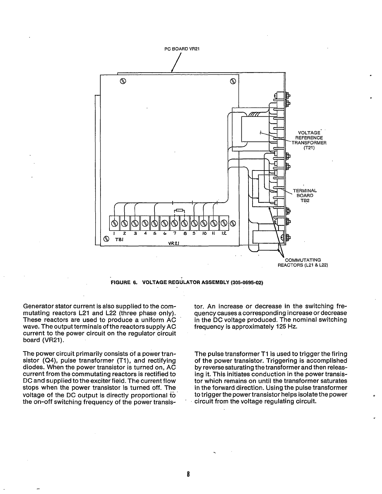
FIGURE
6.
VOLTAGE REGULATOR ASSEMBLY
(305-0695-02)
Generator stator current is also supplied to the com-
mutating reactors
L21
and
L22
(three phase only).
These reactors are used to produce a uniform AC
wave. The output terminals of the reactors supply AC
current to the power circuit on the regulator circuit
board
(VR21).
The power circuit primarily consists of a power tran-
sistor
(Q4),
pulse transformer; (TI), and rectifying
diodes. When the power transistor is turned on, AC
current from the commutating reactors
is
rectified to
DC and supplied to the exciter field. The current flow
stops when
the
power transistor is turned off. The
voltage of the DC output is directly proportional
to'
the on-off switching frequency of the power transis-
'
'
tor. An increase or decrease in the switching fre-
quency causes a corresponding increase or decrease
in the DC voltage produced. The nominal switching
frequency is approximately
125
Hz.
The pulse transformer T1 is used to trigger the firing
of the power transistor. Triggering is accomplished
by reverse saturating the transformer and then releas-
ing
it.
This initiates conduction
in
the power transis-
tor which remains on until the transformer saturates
in the forward direction. Using the pulse transformer
to trigger the power transistor helps isolate the power
circuit from the voltage regulating circuit.
8
Redistribution or publication of this document,
by any means, is strictly prohibited.

w1
VR2
VR1
u3
u2
u1
TB1
T2
T1
R36
R34.35
R33
R32
R30
R29
R28
R24
R22
R20
R19
R18
R17
R15
R14.21
R13
R12
R11
R10
R9
R8
R7, R16
R6
R5
R3,4
R2
R1
Q4
Q3
Ql, 2
K1
CR28
CR9, 15, 22-27
CR3,5
14.16-21
&
29
cdi
,2,4.6,7,a
C15
C14
C13
c11
c10
c9
C7,12
C6,8
c5
c4
c3
c2
c1
Wire Jumpgr,
1"
Diode -Zener
Diode -Zener (5W)
IC
f
12 Volt Regulator
Integrated Circuit
1 C -Timer
Terminal Block
Transformer (1 15/230
V,
50/60
Hz)
Transformer
-
Pulse
Potentiometer (10 K, 1/2W)
Resistor (61.9 K, 1/2W, 1%)
Resistor (28
K,
1/4W, 1%)
Resistor (51.1K. 1/4W, 1%)
Resistor (2.2M. 1/2W,
5%)
Resistor (15K, 5W, 5%)
Resistor (5.1K, 2W,
5%)
Resistor (220K, 1/2W,
5%)
Resistor (330K, 1/2W,
5%)
Resistor (100n 1/2W,
5%)
Resistor (lOK, 5W,
5%)
Resistor (lM, 1/2W,
5%)
Resistor (4.7K, 1/2W,
5%)
Resistor (220K, 1/2W,
5%)
Resistor (100 K, 1/2W,
5%)
Resistor (5.1 K, 1/2W, 5%)
Resistor (1.2 K, 1/2W,
5%)
Resistor (2.7K, 1/2W.
5%)
Resistor (62K, 1/2W,
5%)
Resistor (27K, 1/2W,
5%)
Resistor (68K, 1/2W,
5%)
Resistor (47K. 1/2W,
5%)
Resistor (150
n,
2W,
5%)
Potentiometer (loOK, 1/2W)
Resistor (lOK, 1/2W,
5%)
Resistor (2.2 K. 1/2W,
5%)
Resistor (270
0,
low,
5%)
Power Transistor
-
Silicon (NPN)
Transistor
-
Silicon (NPN High Volt)
Transistor
-
Silicon (PNP)
Relay
Rectifier
-
Fast Recover
Rectifier
-
Silicon
(6A,
800V)
Diode
-
Fast Switching
Rectifier
-
Silicon (lA, 800V)
Capacitor (4000 MFD. 30V)
Capacitor
-
Metalized (.33 MFD, 400 V)
Capacitor
-
Metalized (.001 MFD, 100OV)
Capacitor
-
Metalized (.47 MGD .250V)
Capacitor
-
Metalized
(
1
MFD, 1OOV)
Capacitor
-
Metalized (.l MFD, 1OOV)
Capacitor
-
Metalized (.22 MFD, 630 V)
Capacitor
-
Metalized (.l MFD 250 V)
Capacitor
-
Metalized (1 MFD, 400V)
Capacitor
-
Metalized (.47 MFD, 400V)
Capacitor (10 MFD. 20V)
Capacitor
-
Monolytic (.22 MFD, 50V)
Capacitor
-
Metalized (.047 MFD. 250 V)
1
L-J
FIGURE
7.
REGULATOR
PC
BOARD
(300-2409)
9
Redistribution or publication of this document,
by any means, is strictly prohibited.
The basic regulating circuit performs several func-
tions.
A
voltage sensing circuit samples the generator
terminal voltage by sensing changes in the output
voltage from the reference transformer T21. The AC
output from T21 is rectified to DC and fed to the
sensing side of the error detector circuit (U2). The
error detector compares the sensed voltage with a
constant
DC
zener diode regulated voltage. The dif-
ference is amplified and fed to the control section of a
voltage controlled variable frequency oscillator (UI).
The oscillator responds to changes in thevoltage fed
to its control section by increasing or decreasing the
oscillation frequency. The current pulses produced
by the oscillator are fed to the pulse transformer
which triggers firing of the power transistor.
By
modifying the rate of current pulses fed to the
pulse transformer, the DC field voltage can be con-
trolled. This allows the generator terminal voltage to
be maintained within specified limits.
Several additional circuits are used to improve the
operation and efficiency of the regulating circuit.
However, the basic regulating functions are per-
formed as described.
GENERATOR
SERVICE
The following sections describe the disassembly and
reassembly procedures for the generator.
Accidental starting
of
the set might
I--.
cause severe personal injury or
death. Disconnect the negative battery cable when
repairs are made to the engine, controls, or
generator.
Disassembly
WARNING
1.
Disconnect the negative
(-)
battery cable to pre-
vent accidental starting of the generator set while
servicing
.
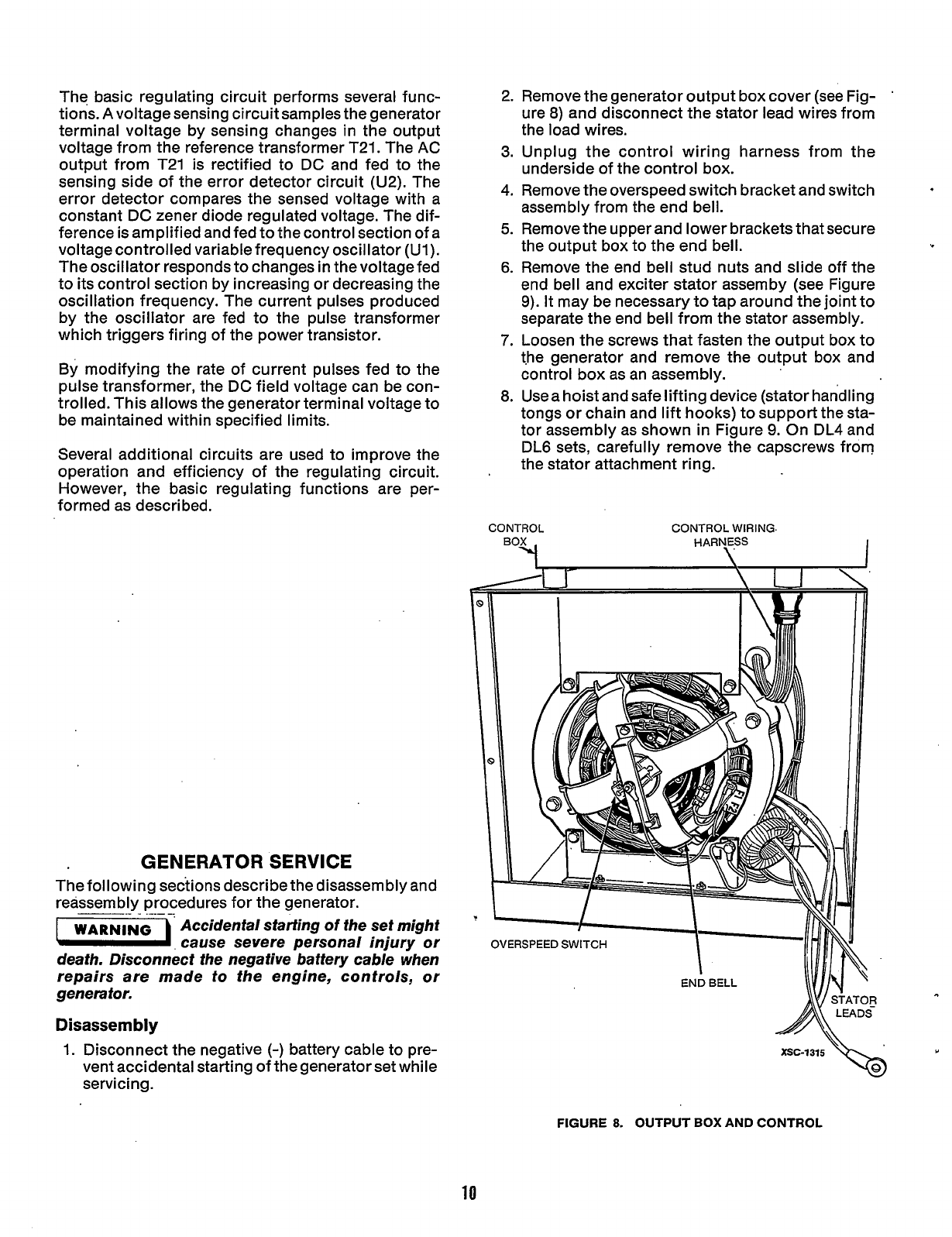
2. Remove the generator output box cover (see Fig-
ure
8)
and disconnect the stator lead wires from
the load wires.
3.
Unplug the control wiring harness from the
underside of the control box.
4. Remove the overspeed switch bracket and switch
assembly from the end bell.
5.
Remove the upper and lower brackets that secure
the output box to the end bell.
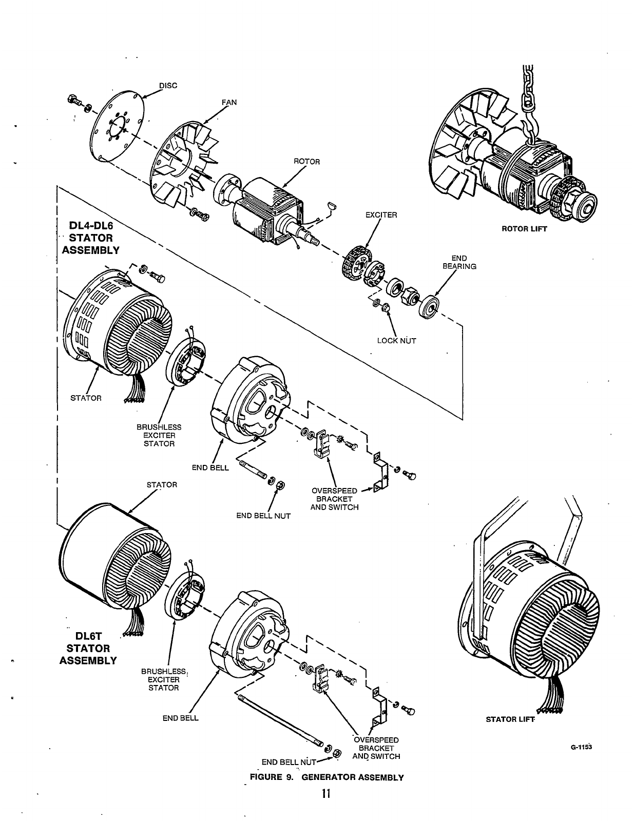
6.
Remove the end bell stud nuts and slide off the
end bell and exciter stator assemby (see Figure
9).
It may be necessary to tap around the joint to
separate the end bell from the stator assembly.
7.
Loosen the screws that fasten the output box to
t.he generator and remove the output box and
control box as an assembly.
8.
Usea hoist and safe lifting device (stator han'dling
tongs or chain and lift hooks) to support the sta-
tor assembly as shown in Figure
9.
On DL4 and
DL6 sets, carefully remove the capscrews from
the stator attachment ring.
'
CONTROL CONTROL WIRING.
HARNESS
\
FIGURE
8.
OUTPUT
BOX
AND CONTROL
10
Redistribution or publication of this document,
by any means, is strictly prohibited.
9.
10.
11.
12.
13.
14.
15.
Remove the stator assembly being careful not to
touch or drag on the rotor. Place stator on its side
in the horizontal position. On DL6T sets, remove
the four end bell studsfrom the generator adapter.
Using a hoist and sling to support the rotor, care-
fully remove the capscrews that attach the drive
disc to the engine flywheel (Figure
9).
Remove the rotor assembly and place
it
on wood
blocks in the horizontal position. The drive disc
and fan should not be resting on anything to
av0i.d possible distortion.
Remove the bolts that hold the drive disc to the
rotor shaft and remove the drive disc and rotor
fan.
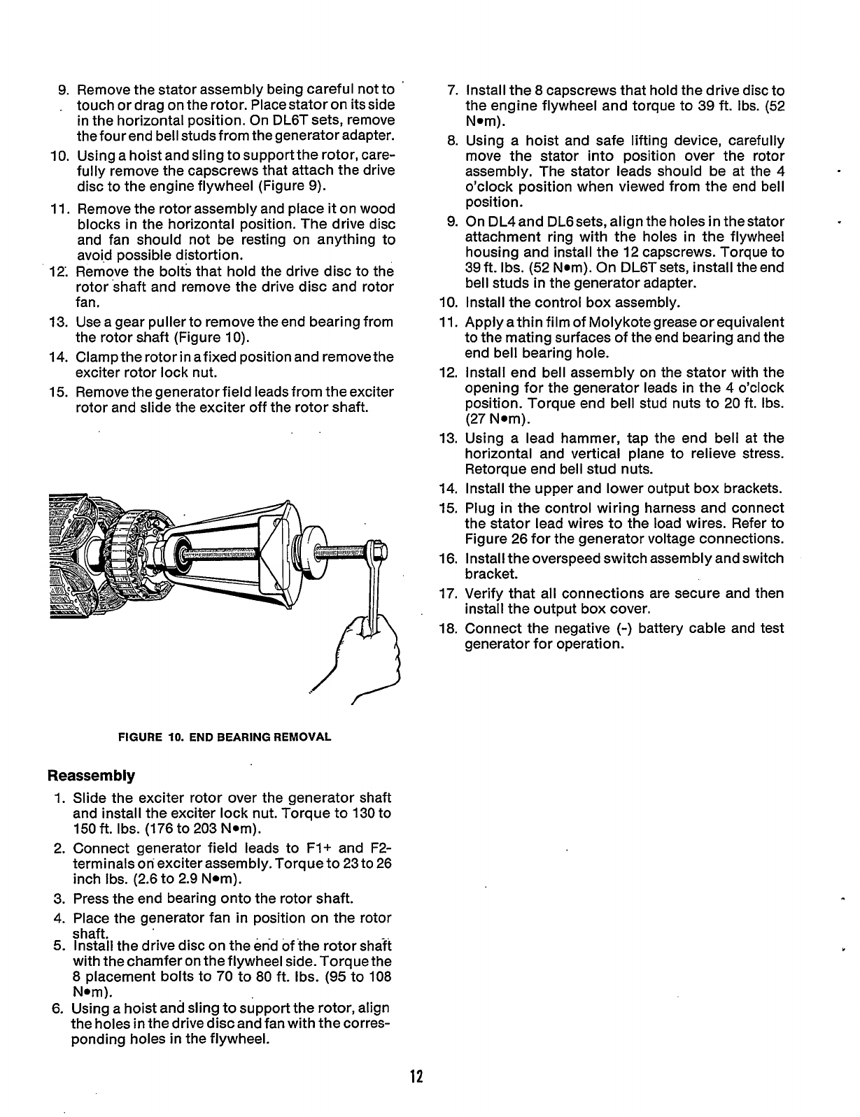
Use a gear puller to remove the end bearing from
the rotor shaft (Figure
IO).
Clamp the rotor in afixed position and remove the
exciter rotor lock nut.
Remove the generator field leads from the exciter
rotor and slide the exciter off the rotor shaft.
..
FIGURE
10.
END
BEARING
REMOVAL
Reassembly
1.
2.
3.
4.
5.
6.
Slide the exciter rotor over the generator shaft
and install the exciter lock nut. Torque to
130
to
150
ft.
Ibs. (176 to
203
Nom).
Connect generator field leads to
F1+
and
F2-
terminals
on
exciter assembly. Torque to
23
to
26
inch Ibs.
(2.6
to
2.9
Nom).
Press the end bearing onto the rotor shaft.
Place the generator fan in position on the rotor
shaft.
Install the drive disc on the end of the rotor shaft
with the chamfer on the flywheel side. Torque the
8
placement bolts to
70
to
80
ft. Ibs.
(95
to
108
Nom).
Using a hoist and sling to support the rotor, align
the holes in the drive disc and fan with the corres-
ponding holes in the flywheel.
7.
Install the
8
capscrews that hold the drive disc to
the engine flywheel and torque to
39
ft. Ibs. (52
Nom).
8.
Using a hoist and safe lifting device, carefully
move the stator into position over the rotor
assembly. The stator leads should be at the 4
o’clock position when viewed from the end bell
position.
9.
On DL4and DL6sets, align the holes in thestator
attachment ring with the holes in the flywheel
housing and install the
12
capscrews. Torque to
39
ft. Ibs.
(52
Nom). On DL6T sets, install the end
bell studs
in
the generator adapter.
10.
Install the control box assembly.
11.
Apply a thin film of Molykotegrease or equivalent
to the mating surfaces of the end bearing and the
end bell bearing hole.
12.
Install end bell assembly on the stator with the
opening for the generator leads in the 4 o’clock
position. Torque end bell stud nuts to
20
ft. Ibs.
(27
Nom).
13.
Using a lead hammer, tap the end bell at the
horizontal and vertical plane to relieve stress.
Retorque end bell stud nuts.
14. Install the upper and lower output box brackets.
15.
Plug in the control wiring harness and connect
the stator lead wires to the load wires. Refer to
Figure 26 for the generator voltage connections.
16.
Install the overspeed switch assembly and switch
bracket.
17.
Verify that all connections are secure and then
install the output box cover.
18.
Connect the negative
(-)
battery cable and test
generator for operation.
12
Redistribution or publication of this document,
by any means, is strictly prohibited.
Generator/Regulator Troubleshooting
PREPARATION
A few simple checks and a proper troubleshooting
procedure can locate the probable source of trouble
and reduce down time.
Check all modifications, repairs, replacements
performed since last satisfactory operation of set
to ensure that connection of generator leads are
correct. A loose wire connection, overlooked
when installing a replacement part could cause
problems. An incorrect connection, an opened
circuit breaker, or a loose connection on printed
circuit board are all potential malfunction areas
to be eliminated by a visual check.
Unless absolutely sure that panel instruments are
accurate, use portable test meters for trouble-
shooting.
0
Visually inspect components on VR21. Look for
dirt, dust, or moisture and cracks in the printed
solder conductors. Burned resistors, arcing
tracks are all identifiable.
Do
not mark on printed circuit
boards with a pencil. Graphite
lines are conductive and can cause leakage or
short circuit between components.
TROUBLESHOOTING PROCEDURES
The information in this section is for both single and
three phase YD generators using the standard UR
type voltage regulator or the optional switching volt-
age regulator. Determine the problem and then refer
to the appropriate Flow Chart (A,
6,
C, D,
or
E)
for the
troubleshooting procedures.
A. NO AC OUTPUT VOLTAGE AT RATED ENGINE
RPM.
B. UNSTABLE OUTPUT VOLTAGE, ENGINE
SPEED STABLE
1800
RPM.
C. OUTPUT VOLTAGE TOO HIGH OR
LOW.
D.
EXCITER FIELD BREAKER TRIPS.
E.
UNBALANCED GENERATOR OUTPUT VOLT-
AGE.
To troubleshoot a problem, start at upper-left corner
of
the chart related to problem, and answer all ques-
tions either YES or NO.
Follow
the chart until the
problem is found, performing referenced Adjustment
and Test procedures following the Flow Charts.
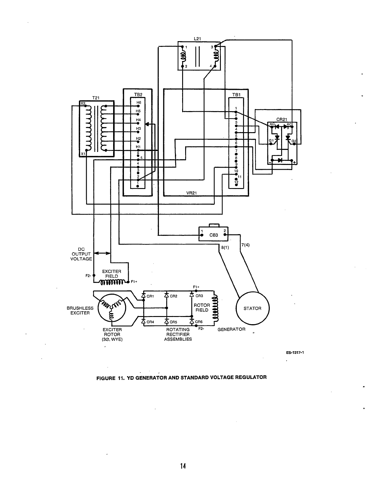
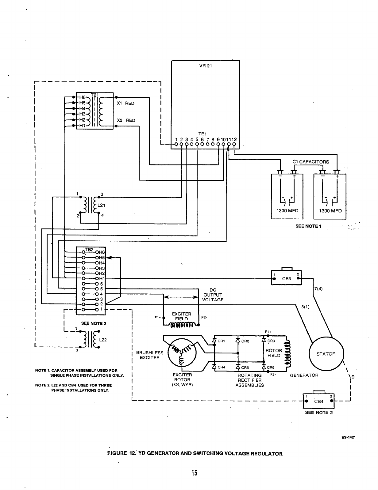
Referenced components in the Flow Charts and
Adjustment and Test procedures can be found on the
electrical schematics (Figure
11
and 12) and on
assembly drawings and wiring diagrams.
13
Redistribution or publication of this document,
by any means, is strictly prohibited.
L
-
DC
OUTPUT
VOLTAGE
F2-
I:
I
4-9
I
,8(,)
7(4)
'I
-I
EXCITER
I
F1+
F1+
\\
..
BRUSHLESS
EXCITER
EXCITER
ROTOR
(30.
WYE) ASSEMBLIES
ES-1377-1
FIGURE
11.
YD GENERATOR AND STANDARD VOLTAGE REGULATOR
14
Redistribution or publication of this document,
by any means, is strictly prohibited.
I
I
I
I
I
I
I
I
I
I
I
I
I
I
I
I
I
I
I
I
I
I
I
I
I
.I
'I
1
I
I
I
r
H2
X2 RED
VU
21
TB1
I
I
112
1
.
...
.. ...
SEENOTE1
.
.
..
.
I
I
SEE
NOTE
2
NOTE
1.
CAPACITOR ASSEMBLY USED
FOR
SINGLE PHASE INSTALLATIONS ONLY.
NOTE
2.
L22 AND
CB4
USED
FOR
THREE
PHASE INSTALLATIONS ONLY.
STATOR
10,
EXCITER
ROTOR
(3v).
WYE)
-
ROTATING
F2-
GENERATOR
R
ECTl
FI
ER
ASSEMBLIES
I
ES-1421
FIGURE
12.'
YD
GENERATOR AND SWITCHING VOLTAGE REGULATOR
15
Redistribution or publication of this document,
by any means, is strictly prohibited.
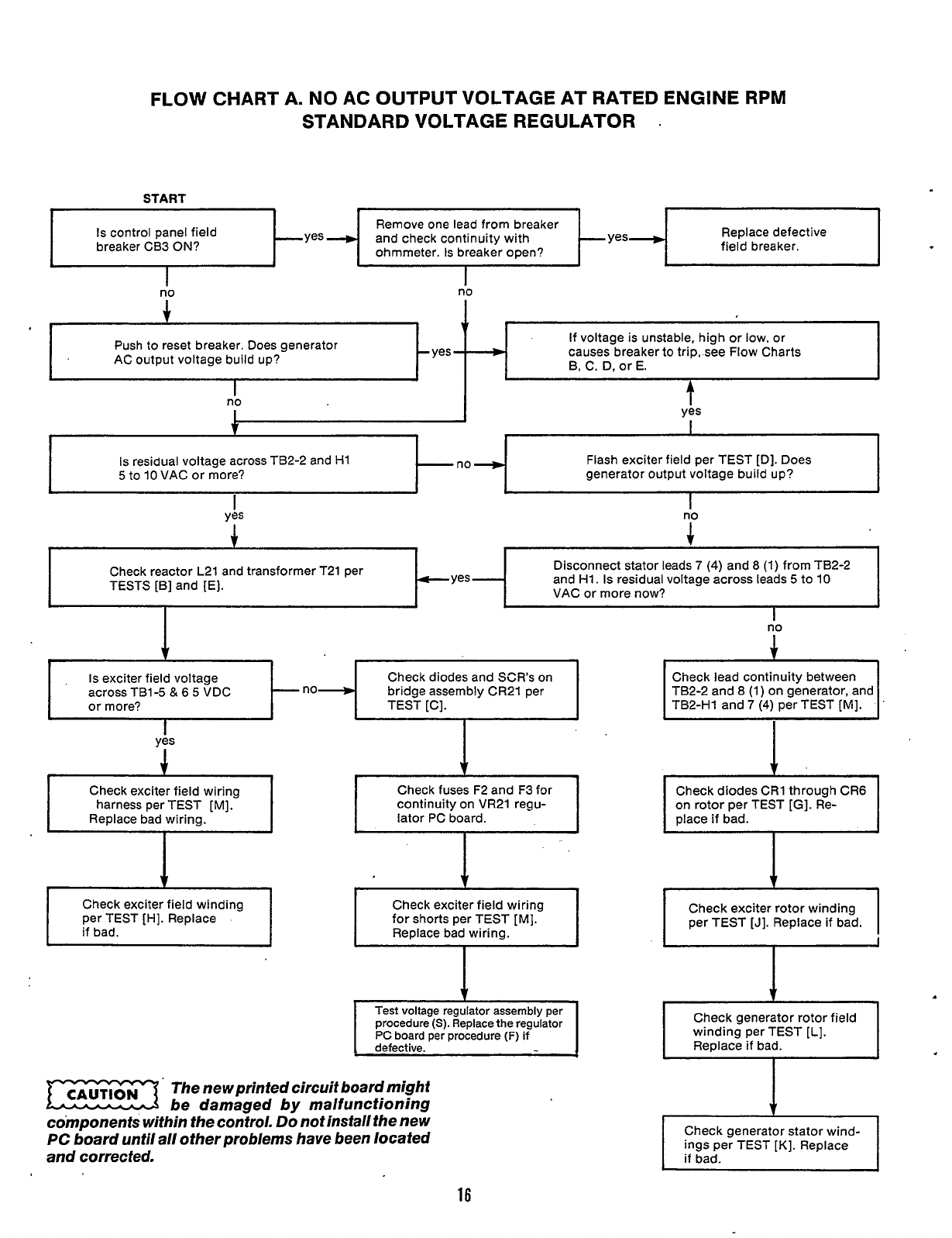
FLOW CHART A. NO AC OUTPUT VOLTAGE AT RATED ENGINE RPM
STANDARD VOLTAGE REGULATOR
.
Test voltage regulator assembly per
procedure
(S).
Replace the regulator
PC
board per procedure
(F)
if
START
Replace defective
field breaker.
ohmmeter.
Is
breaker open?
b
I
Is
control panel field
breaker CB3
ON?
If voltage is unstable, high or
low.
or
causes breaker
to
trip, see Flow Charts
B,
C.
D. or E.
Push
to
reset breaker. Does generator
AC output voltage build up?
Is
residual voltage across TB2-2 and H1
5
to 10 VAC or more? Flash exciter field per TEST [D]. Does
generator output voltage build up?
.
1
Disconnect stator leads
7
(4)
and
8
(1) from TB2-2
and H1.
Is
residual voltage across leads
5
to 10
VAC or more now?
Check reactor
L21
and transformer T21 per
TESTS [B] and [E].
Is
exciter field voltage
across TB1-5
&
6
5
VDC
or
more? TEST [C].
Check diodes and
SCR’s
on
bridge assembly CR21 per
yis
1
1
Check exciter field wiring
harness per TEST [MI.
I
Check fuses F2 and F3 for
continuity on VR21 regu-
lator PC board.
t
i
I
Check exciter field winding
per TEST [HI. Replace
if bad.
The newprinted circuit boardmight
be damaged
by
malfunctioning
co’mponents within the control.
Do
not install the new
PC
board until all other problems have been located
and corrected.
I
no
J.
Check lead continuity between
TB2-2 and
8
(1) on generator, and
I
Check exciter rotor winding
per TEST [J]. Replace if bad.
I
+
Check generator rotor field
winding per TEST
[L].
I
Check generator stator wind-
ings per TEST [K]. Replace
if
bad.
16
Redistribution or publication of this document,
by any means, is strictly prohibited.
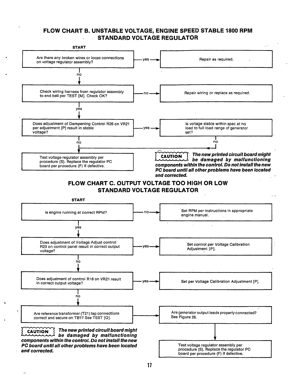
FLOW
CHART
B.
UNSTABLE
VOLTAGE,
ENGINE
SPEED'STABLE
1800
RPM
STANDARD VOLTAGE REGULATOR
--Yes
-
Are there any broken wires or loose connections
on voltage regulator assembly? Repair as required.
I
1
I
I
Check wiring harness from regulator assembly
to end bell per TEST [MI. Check
OK?
-no+ Repair wiring or replace as required.
yes
Test voltage regulator assembly per
procedure
(S).
Replace the regulator PC
board per procedure
(F)
if
defective.
1
Does adjustment of Dampening Control R26 on VR21
per adjustment [PI result in stable
voltage? set?
Is
voltage stable within spec at no
load to full load range
of
generator
--yes
+
be damaged by malfunctioning
components within the control.
Do
not install the new
I
no
I
no
Is
engine running at correct RPM?
-
no----, Set RPM per instructions in appropriate
engine manual.
Does adjustment of control R18 on VR21 result
in correct output voltage?
-
yes----,
I
I
I
yes
Set per Voltage Calibration Adjustment [PI.
I
I
I
Are reference transformer (T21) tap connections
correct and secure on TBl? See TEST
[Q].
Does adjustment of Voltaga
-an
-
-
.
-
I
-
_-
-I
_,I
Are generator output leads properly connected?
b
See Figure 26.
no
-1
Test voltage regulator assembly per
procedure
(S).
Replace the regulator PC
b,oard per procedure (F) if defective.
-
I
.
1
I I
The new printed circuit board might
be damaged by malfunctioning
components within the control.
Do
not install the new
PC board until all other problems have been located
and corrected.
1
17
Redistribution or publication of this document,
by any means, is strictly prohibited.
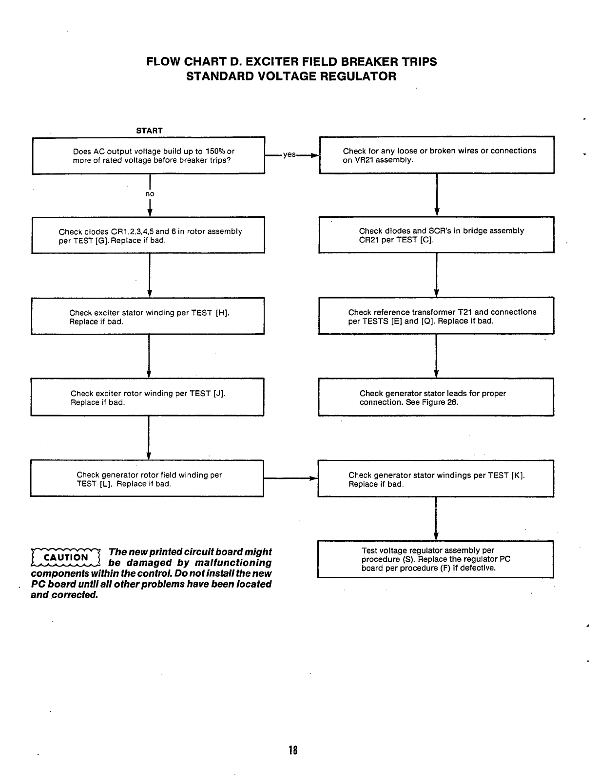
FLOW
CHART
D.
EXCITER
FIELD
BREAKER TRIPS
STANDARD VOLTAGE REGULATOR
I
b
Check generator rotor field winding per
TEST
[L].
Replace
if
bad.
START
1
1
I
1
Check generator stator windings per TEST [K].
Replace
if
bad.
I-
Does AC output voltage build up to 15O0/o0r
more of rated voltage before breaker trips?
kyes-l
Check for any loose or broken wires or connections
on VR21 assembly.
I
I
1
Check exciter stator winding per TEST [HI.
Replace
if
bad.
I
v
I
Check exciter rotor winding per TEST
[J].
Replace
if
bad.
Check diodes and SCR's
in
bridge assembly
CR21 per TEST [C].
I
Check reference transformer T21 and connections
per TESTS [E] and [a]. Replace if bad.
Check generator stator leads for proper
connection. See Figure
26.
I
I
1
1
The new printed circuit board might
be damaged by malfunctioning
components within the control.
Do
not install the new
,
PC
board until all other problems have been located
and corrected.
Test voltage regulator assembly per
procedure
(S).
Replace the regulator PC
board per procedure
(F)
if defective.
18
Redistribution or publication of this document,
by any means, is strictly prohibited.
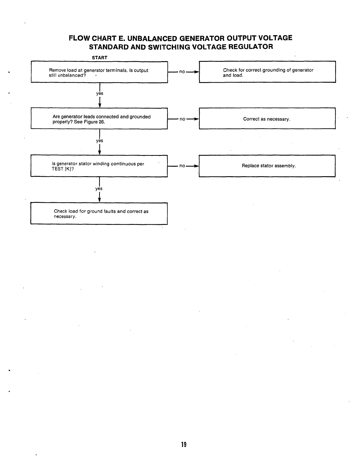
FLOW CHART
E.
UNBALANCED GENERATOR OUTPUT VOLTAGE
STANDARD
AND
SWITCHING VOLTAGE REGULATOR
no
-
Are generator leads connected and grounded
properly? See Figure
26.
START
Remove load at generator terminals. Is output
still unbalanced? and load.
Check for correct grounding
of
generator
yes
Correct as necessary.
1
yes
I
Is
generator stator winding continuous per Replace stator assembly.
Is
generator stator winding continuous per Replace stator assembly.
yis
Check load
for
ground faults and correct as
necessary.
19
Redistribution or publication of this document,
by any means, is strictly prohibited.
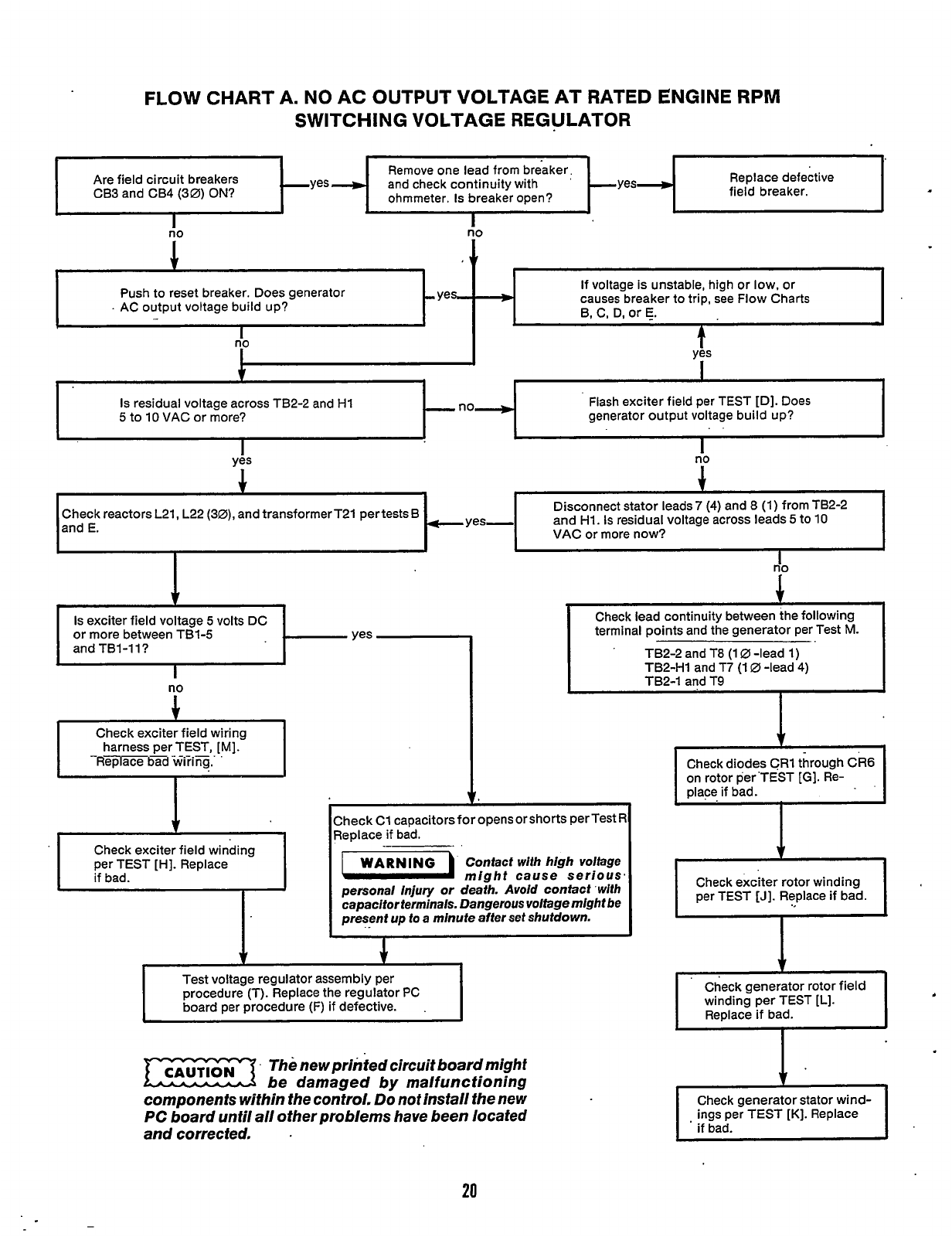
FLOW
CHART A. NO AC OUTPUT VOLTAGE AT RATED ENGINE RPM
SWITCHING VOLTAGE REGULATOR
~
-
-~
Push to reset breaker. Does generator
.
AC output voltage build up?
Replace defective
field breaker.
and check continuity with
Are field circuit breakers
If voltage is unsta
B, C,
D,
or
E.
-yes
*
causes breaker to
J
io
1
I
i"
A
\
ble, high or low. or
trip, see Flow Charts
Check lead continuity between the following
terminal points and the generator per Test
M.
TB2-2 and T8 (1
0
-lead 1)
TB2-H1 and T7 (1
0
-lead
4)
TB2-1 and T9
'
I
Check diodes CR1 through Ck6
on rotor per'TEST
[GI.
Re-
place if bad.
i
I
no
I
Check exciter field winding
per TEST [HI. Replace
if bad.
T
ves
Is
residual voltage across TB2-2 and H1
5
to 10 VAC
or
more? Flash exciter field per TEST [D]. Does
generator output voltage build up?
ti0
I
+
Disconnect stator leads 7
(4)
and
8
(1) from TB2-2
and H1.
Is
residual voltage across leads
5
to 10
VAC
or more now?
-yes-
Check reactors L21, L22
(30),
and transformerT21 pertests B
and E.
I
I
I
I
I
I
Is
exciter field voltage
5
volts DC
or more between TB1-5
and TB1-1 l?
no
1
Check exciter field wiring
harness per TEST,
[MI.
1
I
regulator assembly per
procedure (T). Replace the regulator
PC
board per procedure (F) if defective.
.
Check C1
capacitorsforopensorshorts
perTest
R
Replace if bad.
Contact with high voltage
might cause serious,
personal injury or death. Avoid contact with
capacitor terminals. Dangerous voltage might be
present up to a minute after set shutdown.
1
m.
Thenewprihfed circuit boardmight
be damaged by malfunctioning
components within the control.
Do
not install the new
PC
board until all other problems have been located
and corrected.
1
Check generator rotor field
winding per TEST
[L].
Replace if bad.
Check generator stator wind-
ings per TEST [K]. Replace
if bad.
,
20
Redistribution or publication of this document,
by any means, is strictly prohibited.
c
.no.
+
Check wiring harness from regulator assembly
to end bell per TEST
[MI.
Check OK?
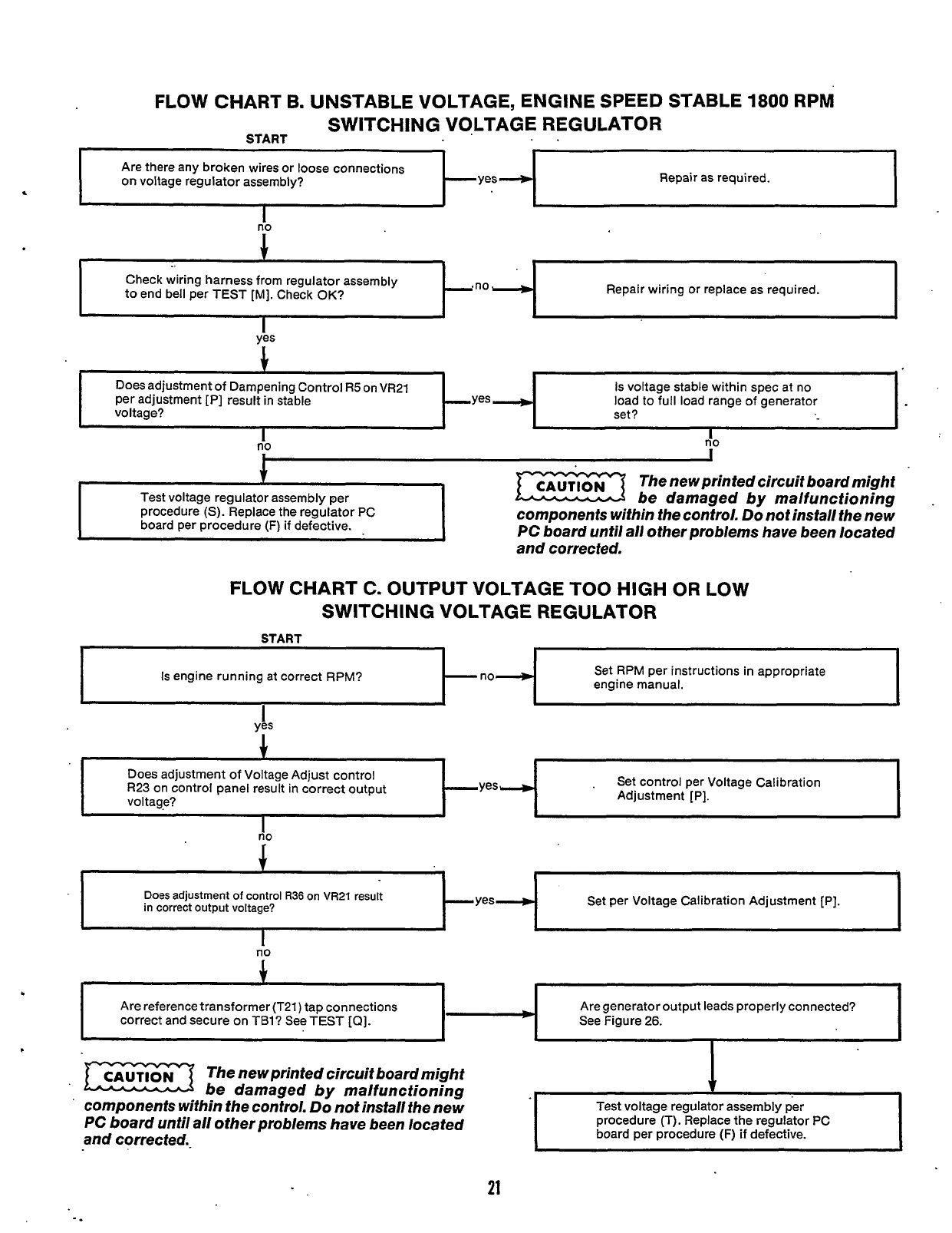
FLOW CHART B. UNSTABLE VOLTAGE, ENGINE SPEED STABLE
1800
RPM
SWITCHING VOLTAGE REGULATOR
START
..
Repair wiring
or
replace as required.
Are there any broken wires or loose connections
on voltage regulator assembly?
Does adjustment of Dampening Control
R5
on VR21
per adjustment [PI result in stable
voltage? -yes
II)
I
Repair as required.
Is voltage stable within spec at no
load to full load range of generator
set?
I
I
Is engine running at correct RPM?
-
no--.)
IiO
Set RPM per instructions in appropriate
engine manual.
-1
-yes
4
Does adjustment
of
control
R36
on
VR21
result
in correct output voltage? Set per Voltage Calibration Adjustment [PI.
Are reference transformer (T21) tap connections
correct and secure on TBl? See TEST
[a].
$.
~~
Test voltage regulator assembly per
procedure
(S).
Replace the regulator PC
board per procedure
(F)
if defective.
*
Are generator output leads properly connected?
See Figure 26.
The new printed circuit boardmight
be damaged by malfunctioning
components within the control.
Do not install the new
PC
board until all other problems have been located
and corrected.
FLOW CHART C. OUTPUT VOLTAGE TOO
HIGH
OR LOW
SWITCH
IN
G VOLTAGE REGULATOR
ge
Latiorailon
no
Does adjustment of Voltage Adjust control
R23
on
control panel result in correct output
voltage?
Set control per Voltal
*"
.'
Adjustment [PI.
I
I
I
I
I
no
The newprinted circuit boardmight
be damaged by malfunctioning
components within the control.
Do
not install the new
PC
board until all other problems have been located
and corrected..
Test voltage regulator assembly per
procedure (T). Replace the regulator PC
board per procedure (F) if defective.
21
Redistribution or publication of this document,
by any means, is strictly prohibited.
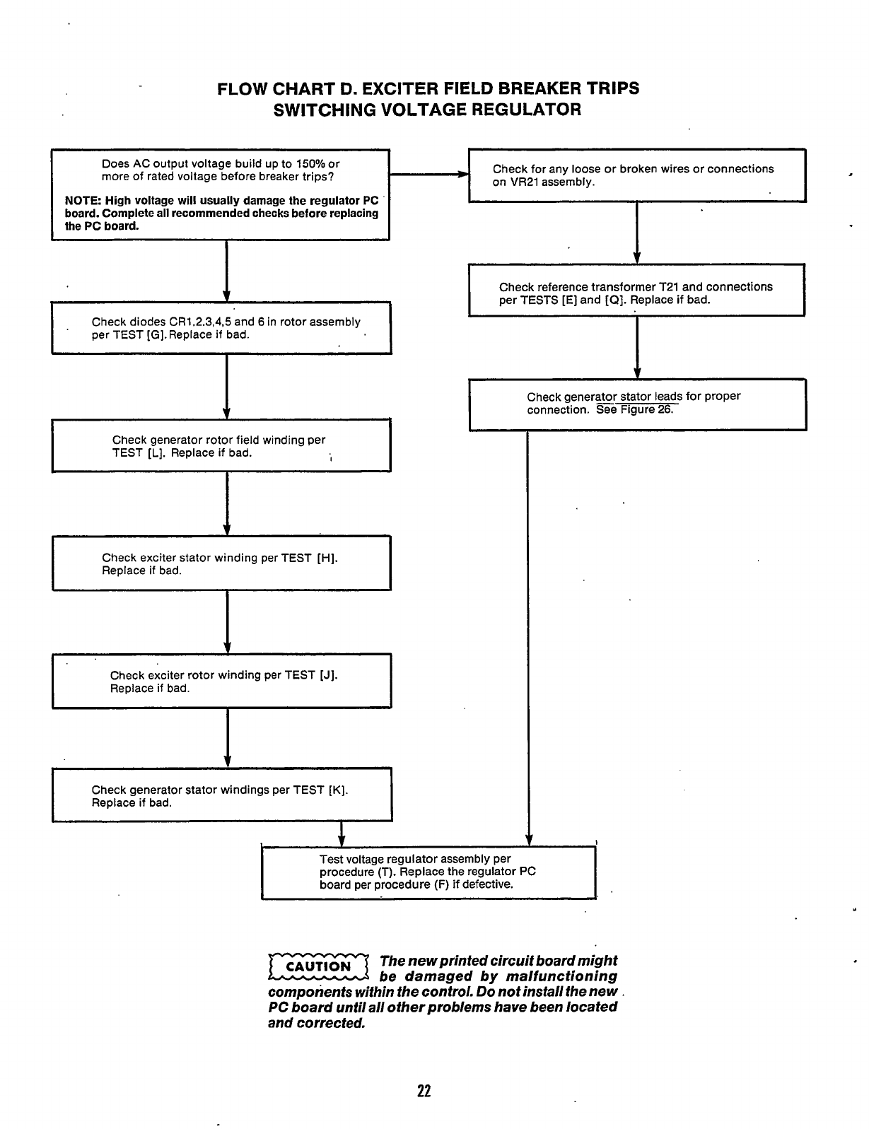
FLOW CHART
D.
EXCITER FIELD BREAKER TRIPS
SWITCHING VOLTAGE REGULATOR
Check for any loose or broken wires or connections
on VR21 assembly.
Does AC output voltage build up
to
150% or
more of rated voltage before breaker trips?
Check generator rotor field winding per
TEST
[L].
Replace if bad.
I
t
Check generator stator windings per TEST
[K].
Replace if bad.
1
Check generator stator leads for proper
connection. See Figure 26.
1'
Test voltage regulator assembly per
procedure (T). Replace the regulator PC
board per procedure
(F)
if defective.
The
newprintedcircuitboardmight
be damaged by malfunctioning
components within the control.
Do
not install the new
PC
board until all other problems have been located
and corrected.
22
Redistribution or publication of this document,
by any means, is strictly prohibited.
Generator/Regulator Tests
'
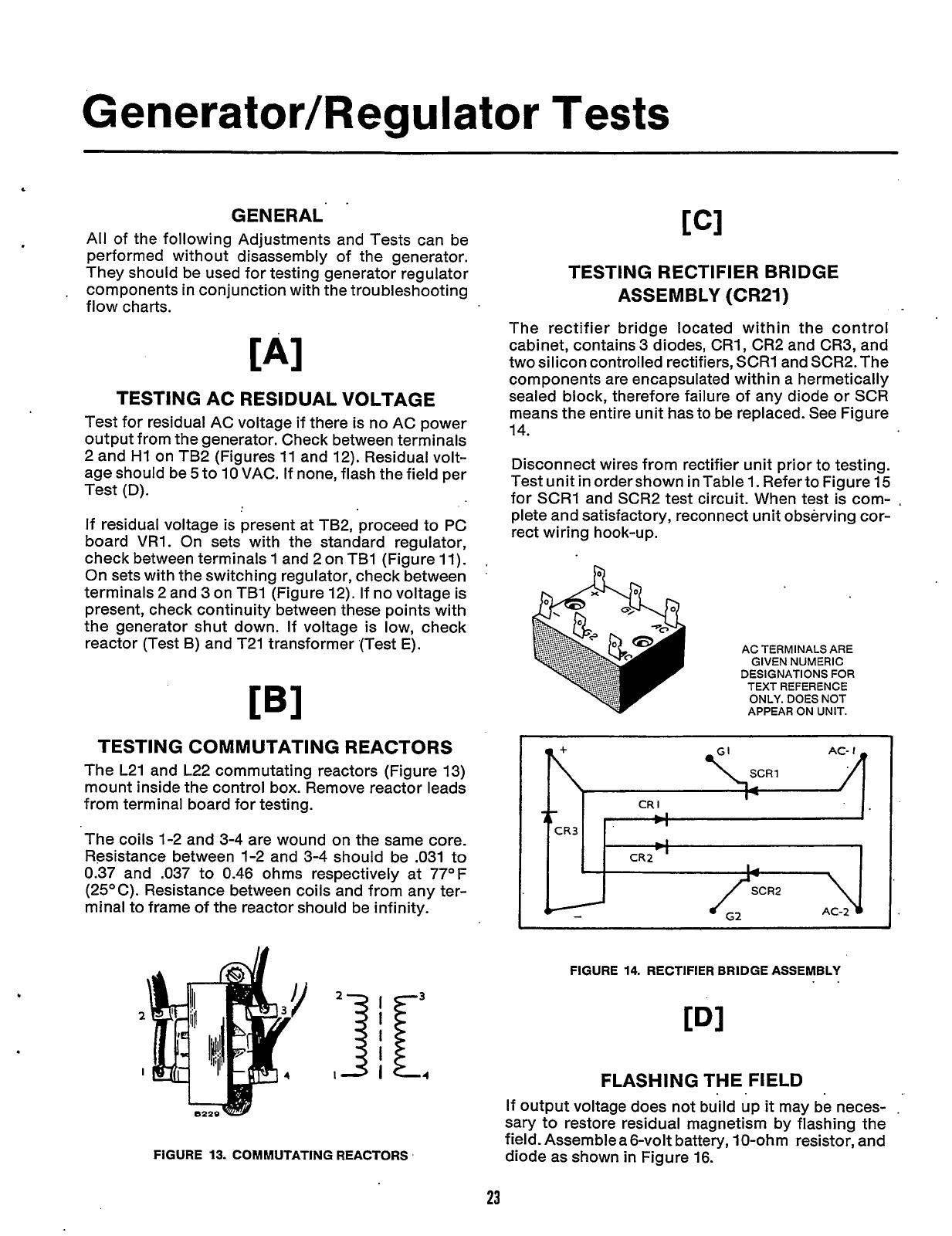
GENERAL'
.
All of the following Adjustments and Tests can be
performed without disassembly of the generator.
They should be used for testing generator regulator
components in conjunction with the troubleshooting
flow charts.
.
[AI
TESTING AC RESIDUAL VOLTAGE
Test for residual AC voltage if there is no AC power
output from the generator. Check between terminals
2 and
HI
on TB2 (Figures
11
and 12). Residual volt-
age should be
5
to
10
VAC. If none, flash the field per
Test (D)
.
If
residual voltage is present at TB2, proceed to PC
board
VRI.
On sets with the standard regulator,
check between terminals
1
and 2 on TBI (Figure
11).
On sets with the switching regulator, check between
terminals 2 and 3 on TBI (Figure 12). If no voltage is
present, check continuity between these points with
the generator shut down. If voltage is low, check
reactor (Test
B)
and T21 transformer (Test
E).
TESTING COMMUTATING REACTORS
The L21 and L22 commutating reactors (Figure 13)
mount inside the control box. Remove reactor leads
from terminal board for testing.
The coils 1-2 and 3-4 are wound on the same core.
Resistance between 1-2 and 3-4 should be .031 to
0.37 and .037
to
0.46 ohms respectively at 77°F
(25OC). Resistance between coils and from any ter-
minal to frame of the reactor should be infinity.
FIGURE
13.
COMMUTATING REACTORS
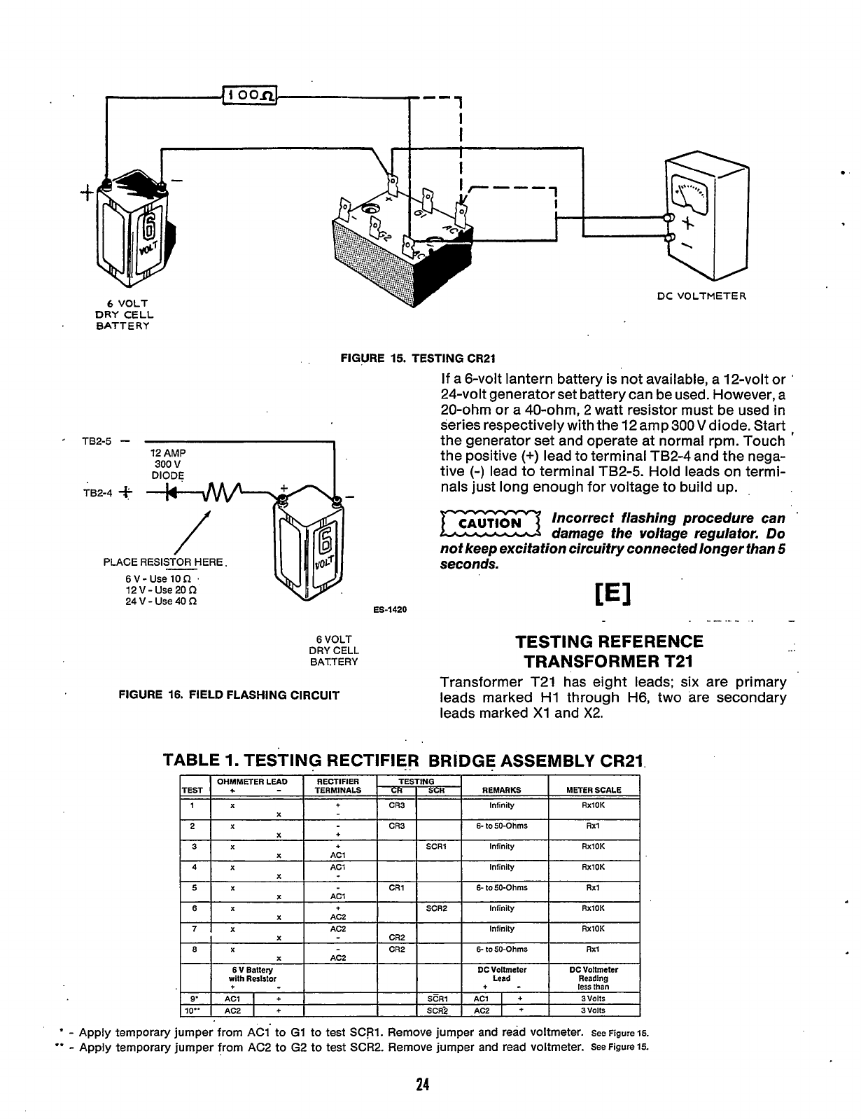
TESTING RECTIFIER BRIDGE
ASSEMBLY (CR21)
The rectifier bridge located within the control
cabinet, contains 3 diodes, CRI, CR2 and CR3, and
two silicon controlled rectifiers, SCRI and SCR2. The
components are encapsulated within a hermetically
sealed block, therefore failure of any diode or SCR
means the entire unit has to be replaced. See Figure
14.
Disconnect wires from rectifier unit prior to testing.
Test unit inordershown inTable1. RefertoFigure15
for SCRI and SCR2 test circuit. When test is com-
,
plete and satisfactory, reconnect unit observing cor-
rect wiring hook-u
p.
AC TERMINALS ARE
GIVEN NUMERIC
DESIGNATIONS FOR
TEXT REFERENCE
ONLY. DOES NOT
APPEAR ON UNIT.
IIL
FIGURE
14.
RECTIFIER BRIDGE ASSEMBLY
CDI
FLASHING THE FIELD
If
output voltage does not build up
it
may be neces-
sary to restore residual magnetism
by
flashing the
field. Assemble a 6-volt battery, IO-ohm resistor, and
diode as shown in Figure 16.
23
Redistribution or publication of this document,
by any means, is strictly prohibited.
--1
I
I
-p
OOR
I
I
6
VOLT
t
r----
t
DC
VOLTMETER
6
VOLT
DRY
CELL
BATTERY
FIGURE 15. TESTING CR21
If a 6-volt lantern battery is not available, a 12-volt or
'
24-volt generator set battery can be used. However, a
20-ohm or a 40-ohm, 2 watt resistor must be used in
series respectively with the 12 amp
300
V
diode. Start
,
the generator set and operate at normal rpm. Touch
the positive
(+)
lead to terminal TB2-4 and the nega-
tive
(-)
lead to terminal TB2-5. Hold leads on termi-
nals just long enough for voltage to build up.
TB2-5
TB2-4
$:
Incorrect flashing procedure can
'
damage the voltage regulator.
Do
not keep excitation circuitry connected longer than
5
-
seconds.
PLACE RESISTOR HERE
6
V
-
Use
10
f2
12
V
-
Use
20
f2
24
V
-
Use
40
f2
---
.-
.
-
ES-1420
6
VOLT
DRY CELL
BATTERY
FIGURE 16. FIELD FLASHING CIRCUIT
TESTING REFERENCE
..
.
TRANSFORMER T21
Transformer T21 has eight leads;
six
are primary
leads marked
HI
through H6, two are secondary
leads marked
X1
and
X2.
TABLE
1.
TESTING RECTIFIER BRIDGE ASSEMBLY CR21
*
-
Apply temporary jumper
from
AC1' to
G1
to test
SCRl.
Remove jumper and read voltmeter.
See Figure 15.
**
-
Apply temporary jumper from AC2 to
G2
to test SCR2. Remove jumper and read voltmeter.
SeeFigure15.
24
Redistribution or publication of this document,
by any means, is strictly prohibited.
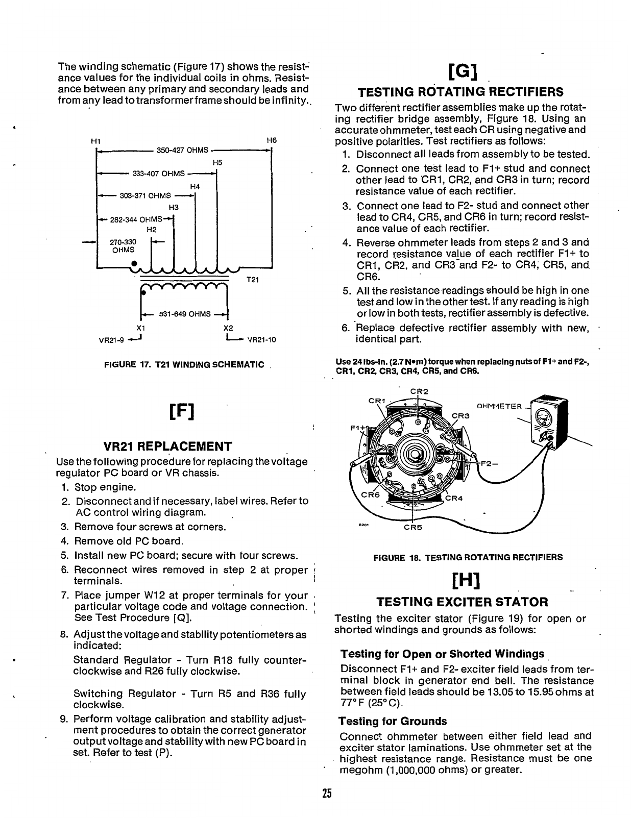
The winding schematic (Figure 17) shows the resist-
ance values for the individual coils
in
ohms. Resist-
ance between any primary and secondary leads and
from any lead to transformerframeshould be infinity..
L
HO
350-427
OHMS
c
333-407
OHMS
c-
303-371
OHMS
-
H3
r
282-344
OKMS1
531-649
OHMS
4
x1
x2
VR21-9
VR21-10
FIGURE 17. T21 WINDING SCHEMATIC
VR21 REPLACEMENT
Use the following procedure for replacing the voltage
regulator PC board or
VR
chassis.
1.
2.
3.
4.
5.
6.
7.
8.
b
9.
Stop engine.
Disconnect and if necessary, label wires. Refer
to
AC control wiring diagram.
Remove four screws at corners.
Remove old PC board.
Install new PC board; secure with four screws.
Reconnect wires removed in step 2 at proper
1
terminals.
1
Place jumper W12 at proper terminals for your
I
particular voltage code and voltage connection.
See Test Procedure
[Q].
Adjust the voltage and stability potentiometers as
indicated:
Standard Regulator
-
Turn R18 fully counter-
clockwise and R26 fully clockwise.
Switching Regulator
-
Turn
R5
and R36 fully
cloc kwise.
Perform voltage calibration and stability adjust-
ment procedures to obtain the correct generator
output voltage and stability with new PC board
in
set. Refer to test (P).
[GI
.
TESTING ROTATING RECTIFIERS
Two different rectifier assemblies make up the rotat-
ing rectifier bridge assembly, Figure 18. Using an
accurate ohmmeter, test each CR using negative and
positive polarities. Test rectifiers as follows:
1.
Disconnect all leads from assembly to be tested.
2. Connect one test lead to F1+ stud and connect
other lead to 'CR1, CR2, and CR3 in turn; record
resistance value of each rectifier.
3. Connect one lead to F2- stud and connect other
lead to CR4,
CR5,
and CR6 in turn; record resist-
ance value of each rectifier.
4. Reverse ohmmeter leads from steps 2 and 3 and
record resistance value of each rectifier
F1+
to
CR1, CR2, and CR3-and F2-
to
CR4; CR5, and
CR6.
5.
All the resistance readings should be high in one
test and low
in
the othertest. If any reading is high
or low in both tests, rectifier assembly is defective.
6. 'Replace defective rectifier assembly with new,
.
identical part.
Use
24 Ibs-in. (2.7
Nom)
torque
when
replacing nuts
of
F1+ and F2-,
CR1, CR2, CR3, CR4, CR5, and CR6.
FIGURE 18. TESTING ROTATING RECTIFIERS
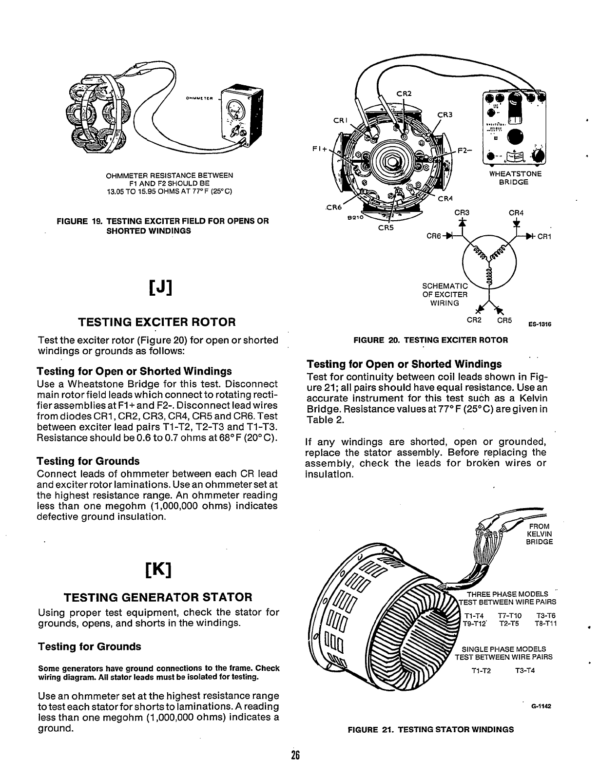
TESTING EXCITER STATOR
Testing the exciter stator (Figure 19) for open or
shorted windings and grounds as follows:
Testing
for
Open
or
Shorted Windings
Disconnect F1+ and F2- exciter field leads from ter-
minal block in generator end bell. The resistance
between field leads should be 13.05 to 15.95 ohms at
77O F (25' C).
Testing
for
Grounds
Connect ohmmeter between either field lead and
exciter stator laminations. Use ohmmeter set at the
highest resistance range. Resistance must be one
megohm (1,000,000 ohms) or greater.
25
Redistribution or publication of this document,
by any means, is strictly prohibited.
OHMMETER RESISTANCE BETWEEN
F1
AND
F2
SHOULD BE
13.05 TO 15.95 OHMS
AT
77°F
(25°C)
FIGURE
19.
TESTING
EXCITER
FIELD
FOR
OPENS
OR
SHORTED WINDINGS
CJI
TESTING EXCITER ROTOR
Test the exciter rotor (Figure 20) for open or shorted
windings or grounds as follows:
Testing for Open or Shorted Windings
Use a Wheatstone Bridge for this test. Disconnect
main rotor field leads which connect to rotating recti-
fier assemblies at
F1+
and F2-. Disconnect lead wires
from diodes CRI, CR2, CR3, CR4, CR5 and
CR6.
Test
between exciter lead pairs TI-T2,
T2-T3
and TI-T3.
Resistance should be
0.6
to
0.7
ohms at
68OF
(20°C).
Testing for Grounds
Connect leads of ohmmeter between each CR lead
and exciter rotor laminations. Usean ohmmeter set at
the highest resistance range. An ohmmeter reading
less than one megohm
(1,000,000
ohms) indicates
defective ground insulation.
TESTING GENERATOR STATOR
Using proper test equipment, check the stator for
grounds, opens, and shorts in the windings.
Testing for Grounds
Some generators have ground connections to the frame. Check
wiring diagram.
All
stator leads must be isolated
for
testing.
Use an ohmmeter set at the highest resistance range
to test each statorforshorts to laminations. A reading
less than one megohm
(1,000,000
ohms) indicates a
ground.
F2-
CR5
f
p-
CR4
CR3
WHEATSTONE
BRIDGE
CR4
*
SCHEMATIC
OF
cR6vcR'
EXCITER
A
CR2
CR5
ES-1316
FIGURE
20.
TESTING EXCITER ROTOR
..
Testing for Open or Shorted Windings
Test for continuity between coil leads shown in Fig-
ure
21;
all pairs should have equal resistance. Use an
accurate instrument for this test such as a Kelvin
Bridge. Resistance values at
77O
F (25OC) are given in
Table 2.
If any windings are shorted, open or grounded,
replace the stator assembly. Before replacing the
assembly, check the leads for broken wires or
insulation.
THREE
PHASE
MODELS
EST BETWEEN WIRE
PAIRS
Tl-T4 T7-Tl0 T3-T6
T9-Tl2' T2-T5 T8-TI1
SINGLE
PHASE
MODELS
EST BETWEEN WIRE
PAIRS
GI142
FIGURE
21.
TESTING STATOR WINDINGS
26
.
Redistribution or publication of this document,
by any means, is strictly prohibited.
L
,
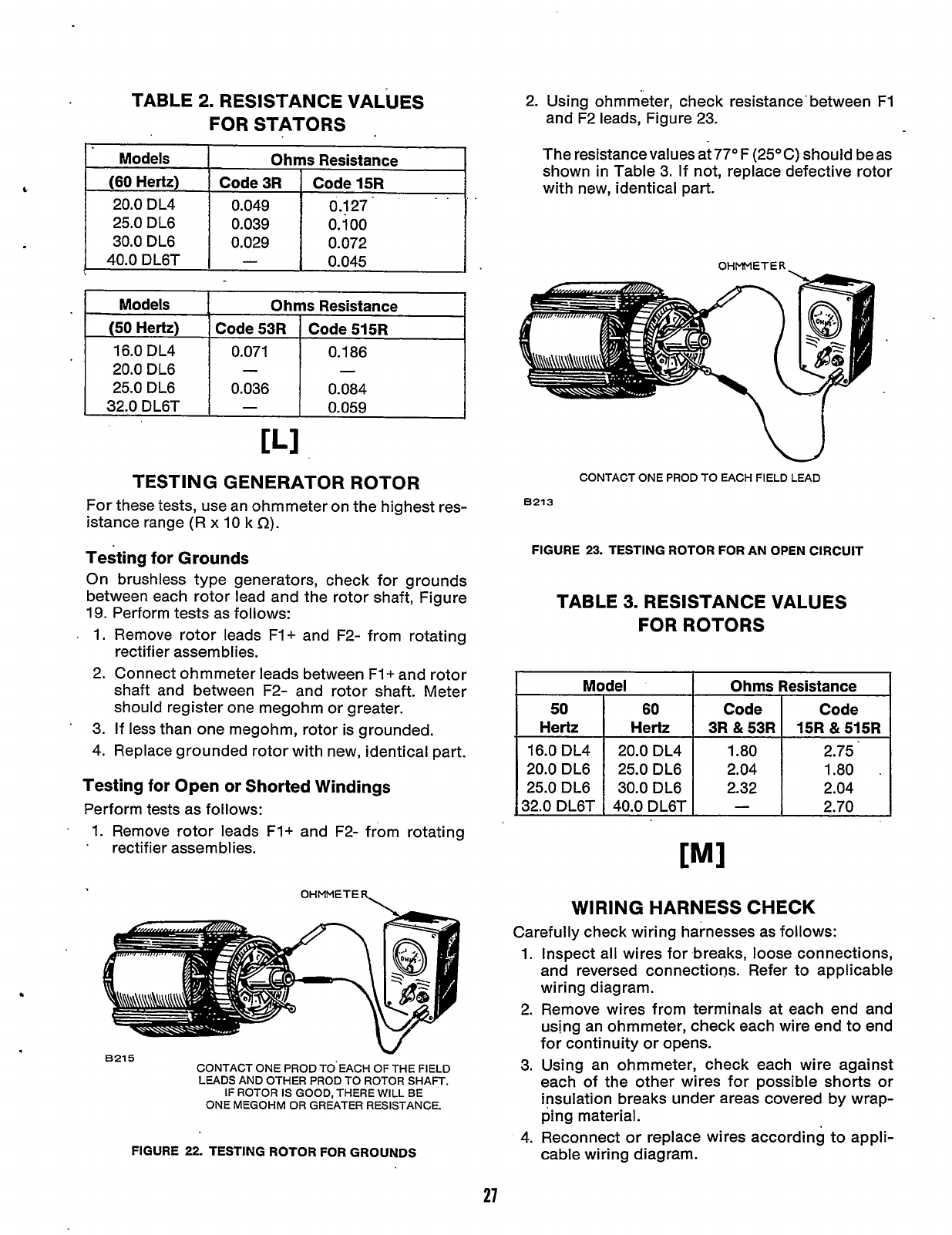
TESTING GENERATOR ROTOR
For these tests, use an ohmmeter on the highest res-
istance range
(R
x
10 k
f2).
Models Ohms Resistance
(60
Hertz) Code 3R Code 15R
20.0 DL4 0.049
0.1
27
.
25.0 DL6 0.039 0.100
30.0 DL6 0.029 0.072
0.045
40.0DL6T
-
Testing for Grounds
On brushless type generators, check for grounds
between each rotor lead and the rotor shaft, Figure
19. Perform tests as follows:
.
1.
Remove rotor leads
Fl+
and
F2-
from rotating
rectifier assemblies.
2.
Connect ohmmeter leads between F1+ and rotor
shaft and between F2- and rotor shaft. Meter
should register one megohm or greater.
3.
If
less
than one megohm, rotor is grounded.
4.
Replace grounded rotor with new, identical part.
'
Models
(50
Hertz)
16.0 DL4
20.0 DL6
25.0 DL6
32.0 DL6T
Testing for Open or Shorted Windings
Perform tests as follows:
1.
Remove rotor leads F1+ and F2- from rotating
.
rectifier assemblies.
Ohms Resistance
Code 53R Code 515R
0.071 0.186
0.036 0.084
-
0.059
- -
\
OHMMETER
Model
50
60
Hertz Hertz
16.0 DL4 20.0 DL4
20.0 DL6 25.0 DL6
25.0 DL6 30.0 DL6
32.0 DL6T 40.0 DL6T
.
Ohms Resistance
Code Code
15R
&
515R
1.80 2.75.
2.04 1.80
.
2.32 2.04
-
2.70
3R
&
53R
W
6215
CONTACT
ONE
PROD
TO'EACH
OF
THE
FIELD
LEADS
AND
OTHER
PROD
TO
ROTOR
SHAFT.
IF
ROTOR
IS
GOOD,
THERE
WILL
BE
ONE
MEGOHM
OR GREATER
RESISTANCE.
FIGURE
22.
TESTING
ROTOR
FOR GROUNDS
2. Using ohmmeter, check resistance'between F1
and F2 leads, Figure 23.
The resistance values at
77OF
(25OC) should be as
shown in Table 3. If not, replace defective rotor
with new, identical part.
OHMMETER.
CONTACT
ONE
PROD
TO
EACH
FIELD
LEAD
8213
FIGURE
23.
TESTING
ROTOR
FOR
AN
OPEN
CIRCUIT
TABLE
3.
RESISTANCE VALUES
FOR ROTORS
WIRING HARNESS CHECK
Carefully check wiring harnesses as follows:
1.
2.
3.
4.
27
Inspect all wires for breaks, loose connections,
and reversed connections. Refer to applicable
wiring diagram.
Remove wires from terminals at each end and
using an ohmmeter, check each wire end to end
for
continuity or opens.
Using an ohmmeter, check each wire against
each of the other wires for possible shorts or
insulation breaks under areas covered by wrap-
ping material.
Reconnect or replace wires according to appli-
cable wiring diagram.
Redistribution or publication of this document,
by any means, is strictly prohibited.
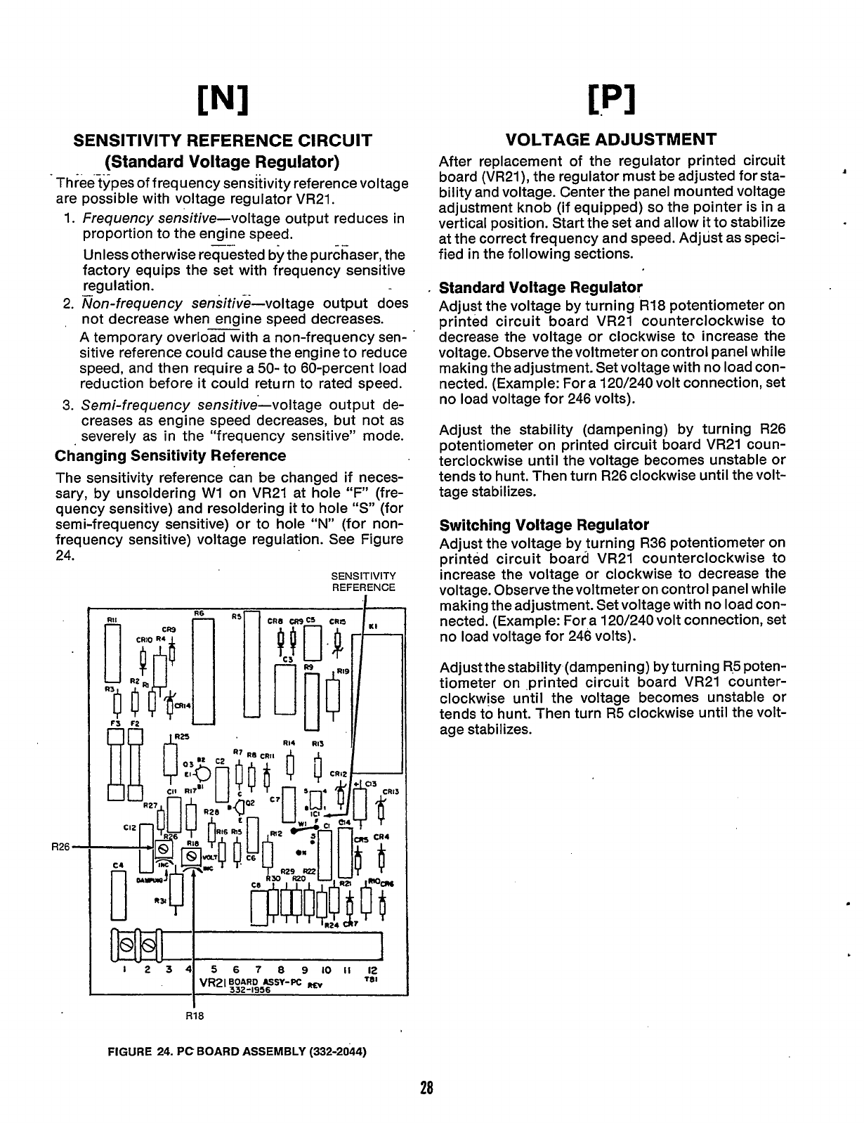
SENSITIVITY REFERENCE CIRCUIT
~
-
(Standard Voltage Regulator)
Three types of frequency sensitivity reference voltage
are possible with voltage regulator VR21.
1. Frequency sensitive-voltage output reduces in
proportion to the engine speed,
Unless otherwise requested by the purchaser, the
factory equips the set with frequency sensitive
regulation.
2.
mon-frequency sensitive-voltage output does
not decrease when engine speed decreases.
A temporary overload with a non-frequency sen-
sitive reference could cause the engine to reduce
speed, and then require a
50-
to 60-percent load
reduction before it could return to rated speed.
3.
Semi-
frequency sensitive-vol tage output de-
creases as engine speed decreases, but not as
severely as in the “frequency sensitive’’ mode.
Changing Sensitivity Reference
The sensitivity reference can be changed if neces-
sary, by unsoldering W1 on VR21 at hole
“F”
(fre-
quency sensitive) and resoldering
it
to hole
“S”
(for
semi-frequency sensitive) or to hole
“N”
(for non-
freauency sensitive) voltage regulation. See Figure
-
24.
R26
-
SENSITIVITY
REFERENCE
VRzlBOARD
USY-PC
332-1956
I
I
R18
VOLTAGE ADJUSTMENT
After replacement of the regulator printed circuit
board (VR21), the regulator must be adjusted for sta-
bility and voltage. Center the panel mounted voltage
adjustment knob (if equipped)
so
the pointer is in a
vertical position. Start the set and allow
it
to stabilize
at the correct frequency and speed. Adjust as speci-
fied in the following sections.
Standard Voltage Regulator
Adjust the voltage by turning R18 potentiometer on
printed circuit board VR21 counterclockwise to
decrease the voltage or clockwise to increase the
voltage. Observe thevoltmeter on control panel while
making the adjustment. Set voltage with no load con-
nected. (Example: For a 120/240 volt connection, set
no load voltage for 246 volts).
Adjust the stability (dampening) by turning R26
potentiometer on printed circuit board VR21 coun-
terclockwise until the voltage becomes unstable or
tends to hunt. Then turn R26 clockwise until the volt-
tage stabilizes.
1
Switching Voltage Regulator
Adjust the voltage by turning R36 potentiometer on
printed circuit board VR21 counterclockwise to
increase the voltage or clockwise to decrease the
voltage. Observe thevoltmeter on control panel while
making the adjustment. Set voltage with no load con-
nected. (Example: For,a 120/240 volt connection, set
no load voltage for 246 volts).
Adjust thestability (dampening) byturning
R5
poten-
tiometer on ,printed circuit board VR21 counter-
clockwise until the voltage becomes unstable or
tends to hunt. Then turn R5 clockwise until the volt-
age stabilizes.
FIGURE 24.
PC
BOARD ASSEMBLY (332-2044)
28
Redistribution or publication of this document,
by any means, is strictly prohibited.
[QI
\
\
\
\
\
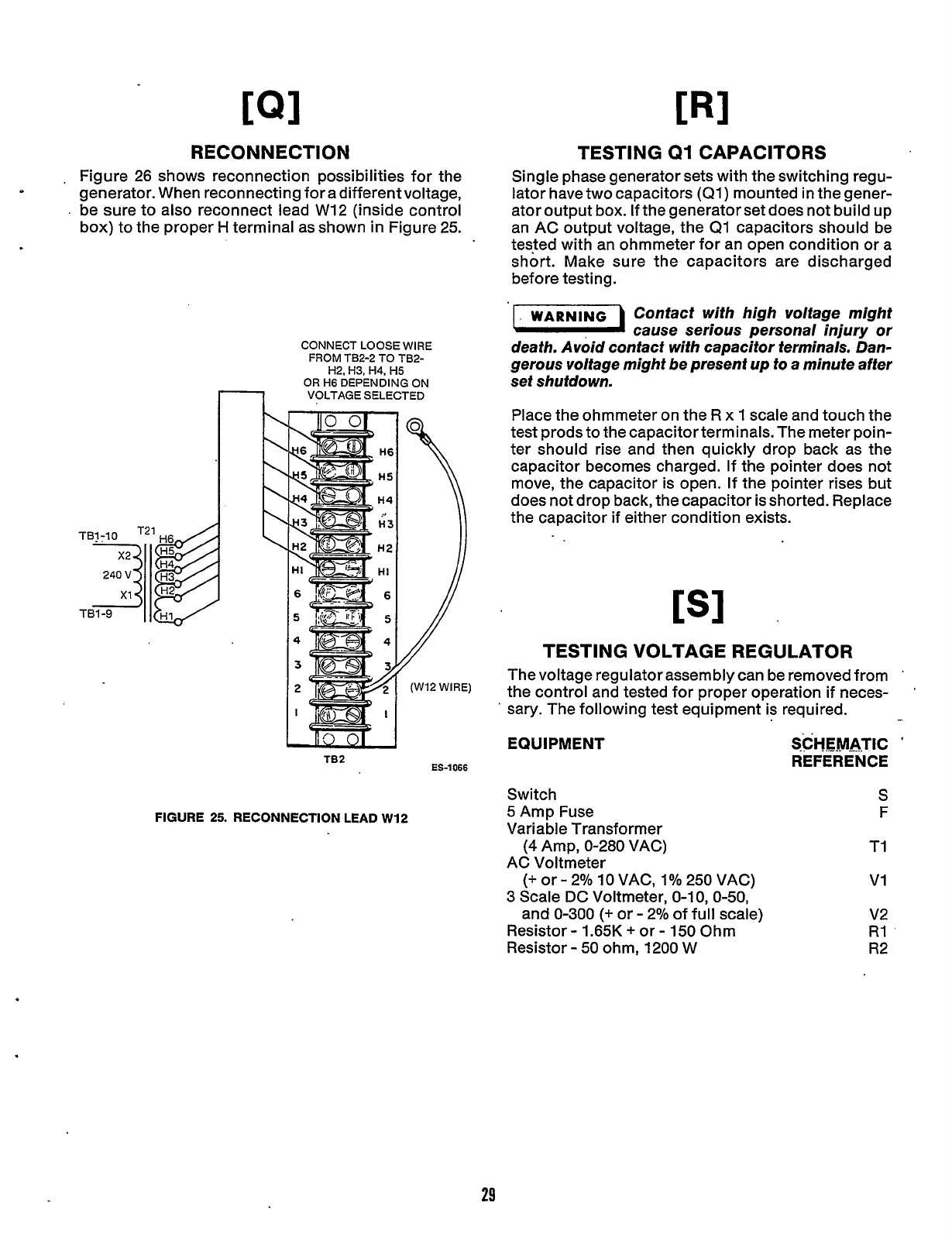
RECONNECT1
ON
.
Figure 26 shows reconnection possibilities for the
generator. When reconnecting for a different voltage,
.
be sure to also reconnect lead W12 (inside control
box) to the proper
H
terminal as shown in Figure 25.
CONNECT LOOSE
WIRE
H2,
H3,
H4,
H5
OR
H6
DEPENDING
ON
VOLTAGE SELECTED
FROM
TB2-2 TO TB2-
TB2
ES-1066
FIGURE
25.
RECONNECTION LEAD
W12
TESTING
Q1
CAPACITORS
Single phase generator sets with the switching regu-
lator have two capacitors
(Ql)
mounted in the gener-
ator output box.
If
the generator set does not build up
an AC output voltage, the
Q1
capacitors should be
tested with an ohmmeter for an open condition or a
short. Make sure the capacitors are discharged
before testing.
WARNING Contact with high voltage might
a
cause serious personal injury or
death. Avoid contact with capacitor terminals. Dan-
gerous voltage might
be
present up to a minute after
set shutdown.
Place the ohmmeter on the
R
x
1
scale and touch the
test prods to the capacitor terminals. The meter poin-
ter should rise and then quickly drop back as the
capacitor becomes charged. If the pointer does not
move, the capacitor is open. If the pointer rises but
does not drop back, the capacitor
is
shorted. Replace
the capacitor
if
either condition exists.
[SI
TESTING VOLTAGE REGULATOR
The voltage regulator assembly can be removed from
the
control and tested for proper operation if neces-
sary. The following test equipment is required.
'
EQUIPMENT
Switch
5
Amp Fuse
Variable Transformer
(4
Amp, 0-280 VAC)
AC Voltmeter
(+
or
-
2%
10
VAC,
1%
250 VAC)
3
Scale DC Voltmeter,
0-1
0,
0-50,
and
0-300
(+
or
-
2% of full scale)
Resistor
-
1.65K
+
or
-
150
Ohm
Resistor
-
50
ohm, 1200 W
SCHEMATIC
*
REFERENCE
S
F
TI
VI
v2
R1
R2
29
Redistribution or publication of this document,
by any means, is strictly prohibited.
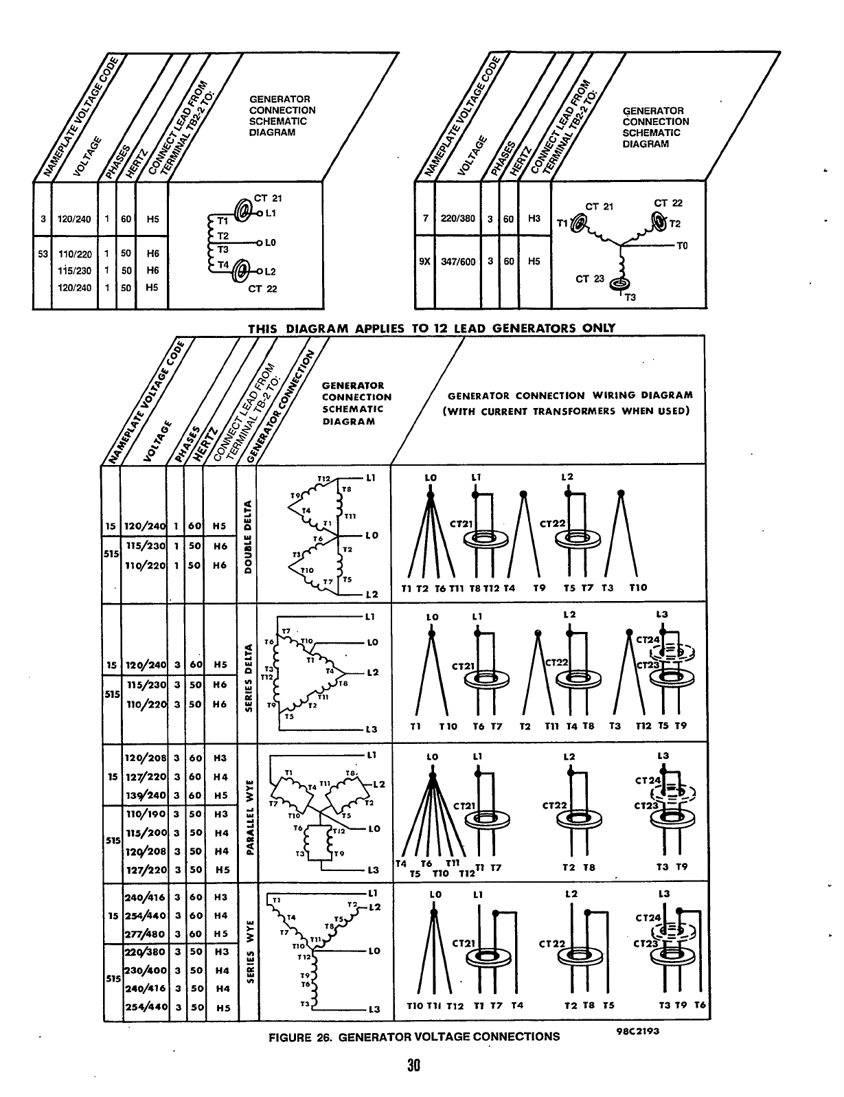
GENERATOR
CONNECTION
SCHEMATIC
DIAGRAM
3 120/240
1
60
H5
53 110/220
1
50
H6
115/230
1
50
H6
&&Y
L2
-
CT 22
DIAGRAM
I
I
I
CT
22
60
H3
60
H5
TI~T;~
a
3
El
,2
11
T2 16111 18T12
14
19 T5
17
T3
110
11
12 13
I,
11
I
LO
W
CI
73
Y
13
11
110
16
17
12
111
14 T8 T3 112 T5 T9
12 13
W
d
-1
a
14 16
111
T2
18
T3 19
15
110
112’’
l7
T319
1
I
T39
l3
I
110111
Tl2
11
17
74 T2
18
15
98C2193
FIGURE
26.
GENERATOR VOLTAGE CONNECTIONS
30
Redistribution or publication of this document,
by any means, is strictly prohibited.
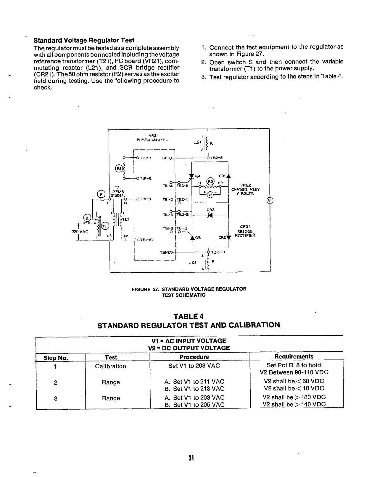
Standard Voltage Regulator Test
The regulator must be tested as acomplete assembly
with all components connected including thevoltage
reference transformer (T21), PC board (VR21), com-
mutating reactor (L21), and SCR bridge rectifier
(CR21).The50 ohm resistor (R2) servesas theexciter
field during testing. Use the following procedure to
check.
:
1.
Connect the test equipment to the regulator as
2. Open switch
S
and then connect
the
variable
3. Test regulator according to the steps in Table
4.
shown in Figure 27.
transformer
(Tl)
to the power supply.
V1= AC INPUT VOLTAGE
V2
=
DC OUTPUT VOLTAGE
1
Calibration Set V1 to 208 VAC Set Pot R18 to hold
V2 Between
90-1
10
VDC
2 Range A. Set
V1
to 21 1 VAC V2 shall be
<
60
VDC
V2
shall
be
<
10
VDC
3 Range A.
Set
V1
to 203 VAC V2 shall be
>
180
VDC
V2 shall be
>
140
VDC
'
Step No. Test Procedure Requirements
B.
Set
V1
to 213 VAC
B.
Set V1 to 205 VAC
EOARD
ASSY-
PC
r----
1
TB2-9
a
Tal-0
I
i
VR22
CHASSIS ASSY
Y
UGLTR
FIGURE
27.
STANDARD VOLTAGE REGULATOR
TEST SCHEMATIC
TABLE
4
STANDARD REGULATOR TEST AND CALIBRATION
31
Redistribution or publication of this document,
by any means, is strictly prohibited.
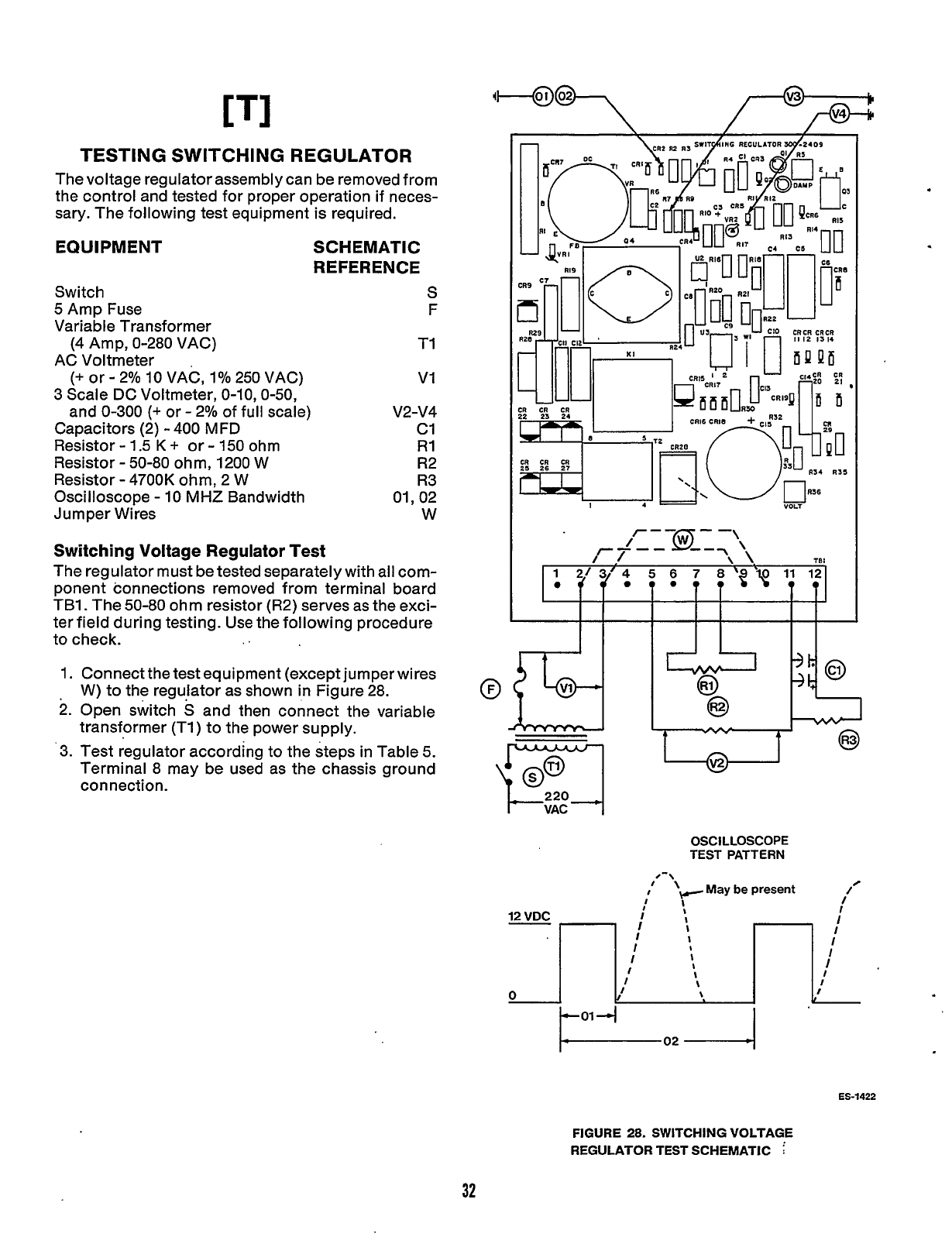
[TI
TESTING SWITCHING
REGULATOR
The voltage regulatorassembly can be removed from
the control and tested for proper operation
if
neces-
sary.
The following test equipment is required.
EQUIPMENT
Switch
5
Amp Fuse
Variable Transformer
(4 Amp, 0-280 VAC)
AC Voltmeter
(+
or
-
2%
10
VAC, 1% 250 VAC)
3 Scale DC Voltmeter,
0-10,0-50,
and
0-300
(e
or
-
2% of full scale)
Capacitors (2)
-
400
MFD
Resistor
-
1.5
K
+
or
-
150
ohm
Resistor
-
50-80
ohm, 1200
W
Resistor
-
4700K
ohm, 2
W
Oscilloscope
-
10
MHZ
Bandwidth
J
um per Wires
SCHEMATIC
REFERENCE
S
F
TI
VI
V2-V4
c1
R1
R2
R3
01,02
W
Switching Voltage Regulator Test
The regulator must be tested separately with all com-
ponent connections removed from terminal board
TB1
.
The 50-80 ohm resistor (R2) serves as the exci-
ter field during testing. Use the following procedure
to check.
..
1.
Connect the test equipment (except jumper wires
W) to the regulator as shown in Figure 28.
2.
Open switch
S
and then connect the variable
transformer (T1
)
to the power supply.
'3.
Test regulator according to the steps in Table
5.
Terminal 8 may be used as the chassis ground
connection.
OSCILLOSCOPE
TEST PATTERN
/-\
'
\
May
be
present
I/
I'Y-
I
ES-1422
FIGURE
28.
SWITCHING VOLTAGE
REGULATOR TEST SCHEMATIC
i
32
Redistribution or publication of this document,
by any means, is strictly prohibited.
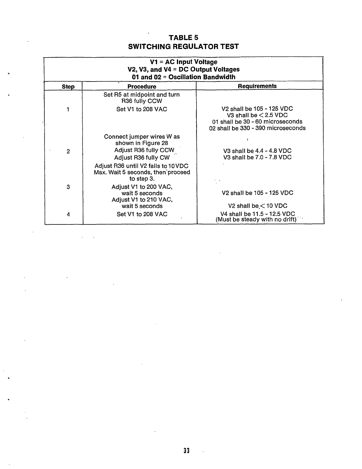
TABLE
5
SWITCHING REGULATOR TEST
V1
=
AC
input Voltage
V2, V3, and
V4
=
DC
Output
Voltages
01
and
02
=
Oscillation Bandwidth
Step
1
2
3
4
Procedure
Set
R5
at midpoint and turn
R36 fully CCW
Set
VI
to 208 VAC
Connect jumper wires W as
shown in Figure 28
Adjust R36 fully CCW
Adjust R36 fully CW
Adjust R36 until V2 falls to10VDC
Max. Wait
5
seconds, then-proceed
to step 3.
Adjust VI to 200 VAC,
wait
5
seconds
Adjust
VI
to
210
VAC,
wait
5
seconds
Set
VI
to 208 VAC
Requirements
V2 shall be
105
-
125
VDC
V3 shall be < 2.5 VDC
01
shall be 30
-
60
microseconds
02
shall be
330
-
390 microseconds
1
V3 shall be 4.4
-
4.8 VDC
V3 shall be
7.0
-
7.8 VDC
V2 shall be
105
-
125
VDC
V2 shall be.<
10
VDC
V4 shall be
11.5
-
12.5
VDC
(Must be steady with no drift)
33
Redistribution or publication of this document,
by any means, is strictly prohibited.
Engine
Control
GENERAL
The engine control system includes all functions that
relate to the operation of the engine. This includes
starting and stopping, instrumentation, monitoring
for fault conditions, and battery charging. This sec-
tion covers how the engine control operates and
where the various components are located.
-.
CONTROL PANEL
The following is a brief description of the two and
'
nine light control panels with the optional AC meters.
Although the AC meters are not part of the engine
control, they are mentioned here in order to providea
complete description of the control panel exterior.
Refer to Figure
29
for the location of each
component.
Gauges/Meters and Switches
Oil
Pressure Gauge:
Indicates engine lubricating oil
pressure. The gauge has a range of
0
to
100
psi
(0
to
700
kPa).
.
Water Temperature Gauge:
Indicates engine coolant
temperature. The gauge is wired to a sensor unit on
the engine and has a range of
100'
to 25OoF,(40" to
121OC).
Battery Charge Rate DC Ammeter:
Indicates battery
charging current. Meter range is
t
30
amperes.
Running Time Meter:
Registers the total number of
hours that the unit has run. Use
it
to keep a record for
periodic servicing. Time is cumulative; meter cannot
be reset.
Frequency Meter (Optional);
Indicates generator
output frequency in hertz.
It
can be used to check
engine speed. (Each hertz equals
30
r/min.)
AC Voltmeter (Optional);
Dual range instrument
indicating AC generator voltage.
AC Ammeter(0ptional):
Dual range instrument indi-
cating AC generator line current.
Tachometer (Optional);
Indicates engine speed in
r/min. The gauge has a range of
0
to
3500
r/min.
'Oil
Temperature Gauge (Optional);
Indicates engine
oil temperature. The gauge has a range of
150"
to
300"
F
(66"
to
149"
C).
Sfarf-Stop-Remote Switch:
Starts and stops the unit
locally, or from a remote location wired to thecontrol
panel.
Pre-Heater Switch:
Provides control for glow plugs
for cold diesel engine starting.
Reset Switch:
Resets engine monitor circuits after an
emergency shutdown. On the optional control panel
the switch is also utilized to verify that the nine lamps
are functioning properly.
Phase Selector Switch (Optional);
Selects phase of
generator to be measured by AC voltmeter and
ammeter.
Voltage Adjustment (Optional):
Provides approx-
imately plus or minus
5
percent adjustment of the
rated voltage.
Circuit Breakers
FieldBreaker:
A
5
ampere breaker provides generator
protection in case of a malfunction.
Control Breaker:
A
7 ampere breaker provides pro-
tection to the control box wiring from
a
short circuit
or overload.
RemofeBreaker:
A7 ampere breaker protects acces-
sory remote controls and wiring from
a
short circuit
or overload.
..
Indicator Lights
The standard control panel has two monitor system
indicator lights.
Run (green)
.'Fault (red)
The green Run light comes on
as
soon as the starter
circuit is opened after unit starting. The red light
indicates an emergency shutdown of the generator
set.
The optional control panel has nine monitor system
indicator lights.
Run (green)
Pre Hi Eng Temp (amber)
Pre Low Oil Pres (amber)
Lo
Eng Temp (red)
Hi Eng Temp (red)
Overcrank (red)
Overspeed (red)
Lo
Oil Pres (red)
Switch Off (flashing red)
High and
Low
Indicator Lights indicate which scale to
use on the._AC voltmeter and ammeter.
Redistribution or publication of this document,
by any means, is strictly prohibited.
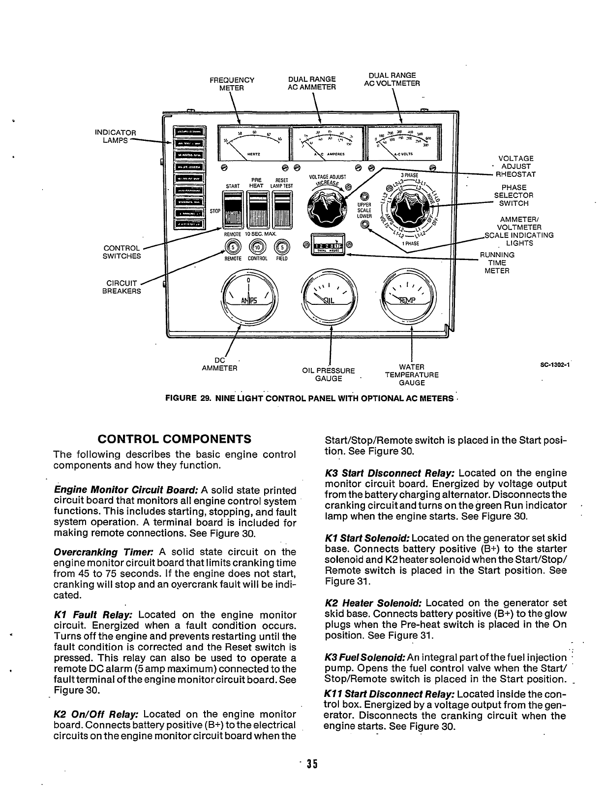
DUAL RANGE
AC VOLTMETER
FREQUENCY DUAL RANGE
METER
AC
AMMETER
1
c
INDICATOR
LAMPS
-
\
\
\
N
0
88
PAE
RESET
START
HEAT
LAUPTEST
VOLTAGE
ADJUST
RHEOSTAT
PHASE
SELECTOR
SWITCH
AMMETER/
VOLTMETER
:ALE INDlCATll
LIGHTS
......
^
/
DC
AMMETER
I
WATER
GAUGE
I
OIL
PRESSURE
GAUGE
.
TEMPERATURE
FIGURE
29.
NINE LIGHT CONTROL PANEL
WITH
OPTIONAL AC METERS
'.
CONTROL COMPONENTS
The following describes the basic engine control
components and how they function.
Engine Monitor Circuit Board:
A solid state printed
circuit board that monitors all engine control system
functions. This includes starting, stopping, and fault
system operation.
A
terminal board is included
for
making remote connections. See Figure
30.
Overcranking Timer:
A solid state circuit on the
engine monitor circuit board that limits cranking time
from
45
to
75
seconds. If the engine does not start,
cranking will stop and an oyercrank fault will be indi-
cated.
K1
Fault Relay:
Located on the engine monitor
circuit. Energized when a fault condition occurs.
Turns off the engine and prevents restarting until the
fault condition is corrected and the Reset switch is
pressed. This relay can also be used to operate a
remote DC alarm
(5
amp maximum) connected to the
fault terminal
of
the engine monitor circuit board. See
Figure
30.
K2
On/Off
Relay:
Located on the engine monitor
board. Connects battery positive
(B+)
to the electrical
circuits on the engine monitor circuit board when the
VG
SC-1302-1
Start/Stop/Remote switch is placed in the Start posi-
tion. See Figure
30.
K3
Sfarf Disconnect Relay:
Located on the engine
monitor circuit board. Energized by voltage output
from the battery charging alternator. Disconnects the
cranking circuit and turns on thegreen Run indicator
lamp when the engine starts. See Figure
30.
K1
Start Solenoid:
Located on the generator set skid
base. Connects battery positive
(B+)
to the starter
solenoid and
K2
heater solenoid when the Start/Stop/
Remote switch is placed
in
the Start position. See
Figure
31.
K2 Heater Solenoid;
Located on the generator set
skid base. Connects battery positive
(B+)
to
the glow
plugs when the Pre-heat switch
is
placed in the On
position. See Figure
31.
K3
FuelSolenoid:
An integral part of the fuel injection
.
pump. Opens the fuel control valve when the Start/
Stop/Remote switch is placed in the Start position.
-
K11
Start Disconnect Relay:
Located inside the con-
trol box. Energized by a voltage output from the gen-
erator. Disconnects the cranking circuit when the
engine starts. See Figure
30.
35
Redistribution or publication of this document,
by any means, is strictly prohibited.
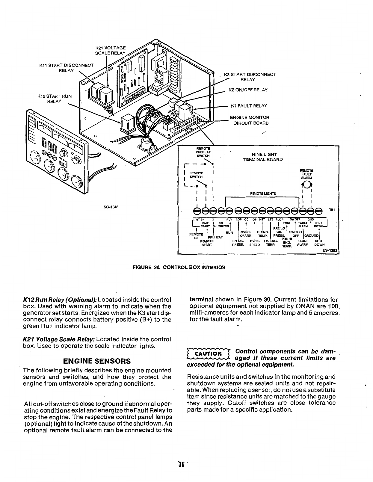
K21
VOLTAGE
K12
START
RUN
SC-1313
.
K3
START
DISCONNECT
RELAY
K2
ON/OFF
RELAY
K1
FAULT
RELAY
ENGINE
MONITOR
'
CIRCUIT
BOARD
/
REMOTE
PREHEAT
SWITCH
,
NINE
LIGHT-
TERMINAL
BOARD
REMOTE
FAULT
ALARM
I
REMOTE
1
II
REMOTE LIGHTS
---
.OP
OC
OS
HE7
LET
PLOP
SWOFF
GND
ICRANK
I
T
irnVlC
e+
IPRAHEAT
-
REM~TE
LO~IL
OV~R-
LO.BNG.
START PRESS. SPEED
TEN
FIGURE
30.
CONTROL
BOX
INTERIOR
'
K72 Run
Relay (Optional):
Located inside the control
box. Used with warning alarm to indicate when the
generator set starts. Energized when the
K3
start dis-
connect relay connects battery positive
(B+)
to the
K27
Voltage Scale Relay:
Located inside the control
terminal shown in Figure
30.
Current limitations for
optional equipment not supplied by
ONAN
are
100
milli-amperes for each indicator lamp and
5
amperes
for the fault alarm.
green Run indicator lamp.
.
..
box. Used to operate the scale indicator lights.
ENGINE
SENSORS
The following briefly describes the enaine mounted
'
Control components can be dam-
.
aged if these current limits are
exceeded
for
the optional equipment.
sensors and switches, and how they protect the
engine from unfavorable operating conditions.
.
All cut-off switches close to ground if abnormal oper-
ating conditions exist and energize the Fault Relay to
stop the engine. The respective control panel lamps
(optional) light to indicatecause of theshutdown. An
optional remote fault alarm can be connected to the
Resistance units and switches in the monitoring and
shutdown systems are sealed units and not repair-
able. When replacing asensor, do not use a substitute
item since resistance units are matched to the gauge
they Supply. Cutoff switches are close tolerance,
Parts made for a specific application.
'3'6
.
Redistribution or publication of this document,
by any means, is strictly prohibited.
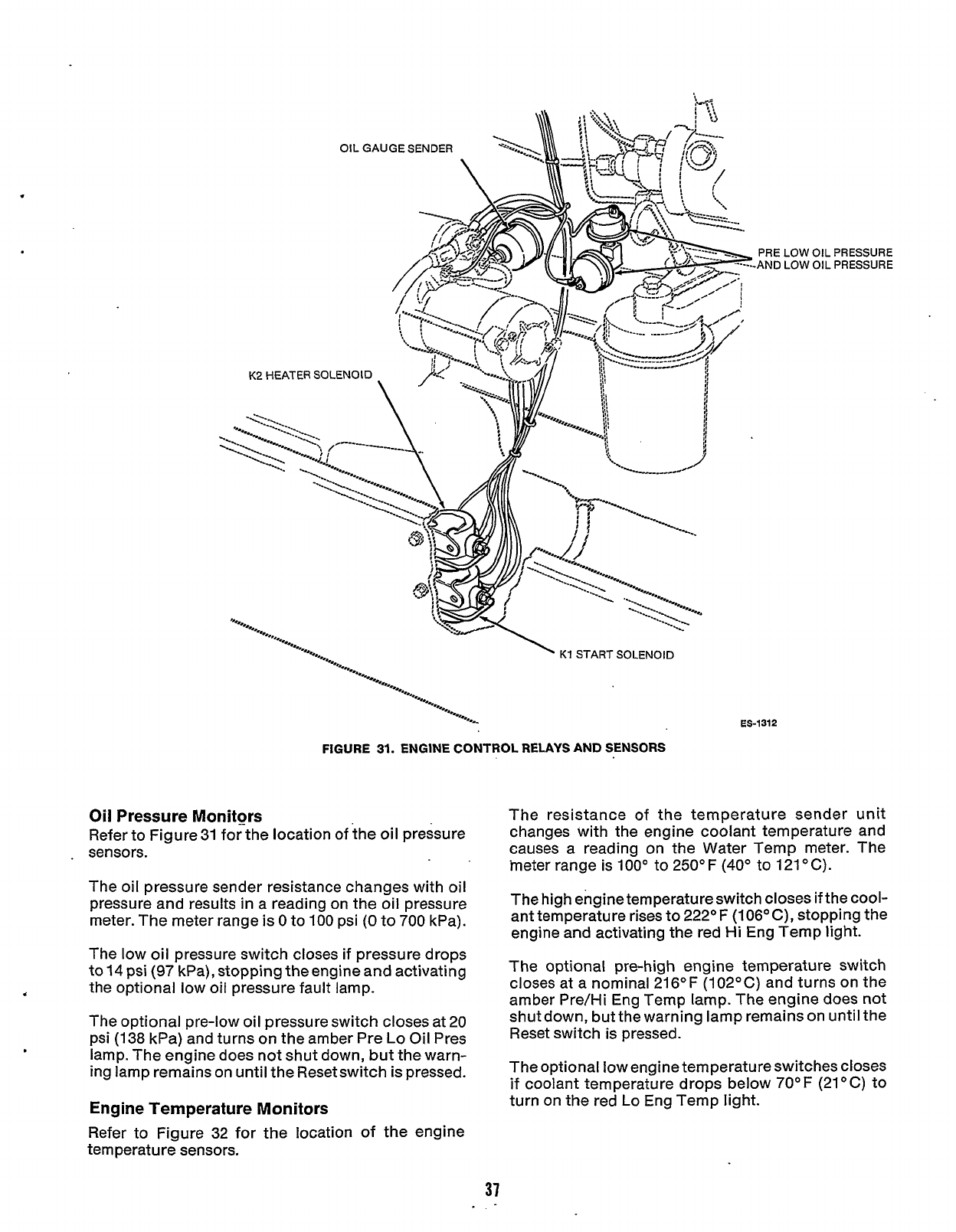
PRE
-AND
K2
HEATER
SOLENOID
*'..,
e..
'%,,
'e...
K1
START SOLENOID
"...,
*..
e...
e..
*....
*..*
*...
'e...
e...
'%..
'e...
"...
%..
*...
ES-1312
FIGURE
31.
ENGINE CONTROL RELAYS AND SENSORS
Oil Pressure Monitors
Refer to Figure
31
for the location of the oil pressure
.
sensors.
The oil pressure sender resistance changes with oil
pressure and results
in
a reading on the oil pressure
meter. The meter range is
0
to
100
psi
(0
to
700
kPa).
The low oil pressure switch closes if pressure drops
to
14
psi
(97
kPa), stopping the engine and activating
,
the optional low oil pressure fault lamp.
The optional pre-low oil pressure switch closes at 20
psi
(138
kPa) and turns on the amber Pre
Lo
Oil Pres
lamp. The engine does not shut down, but the warn-
ing lamp remains on until the Resetswitch is pressed.
Engine Temperature Monitors
Refer to Figure 32 for the location of the engine
tern peratu re sensors.
LOW
OIL
1
LOW
OIL
PRESSURE
PRESSURE
The resistance of the temperature sender unit
changes with the engine coolant temperature and
causes
a
reading on the Water Temp meter. The
.meter range is
100'
to 250'
F
(40'
to 121
O
C).
The high engine temperatureswitch closes if the cool-
ant temperature rises to 222OF (106'C), stopping the
engine and activating the red
Hi
Eng Temp light.
The optional pre-high engine temperature switch
closes at a nominal 216°F (102OC) and turns on the
amber Pre/Hi Eng Temp lamp. The engine does not
shut down, but the warning lamp remains
on
until the
Reset switch is pressed.
The optional low engine temperature switches closes
if coolant temperature drops below
70'F
(21OC) to
turn on the red
Lo
Eng Temp
light.
37
Redistribution or publication of this document,
by any means, is strictly prohibited.
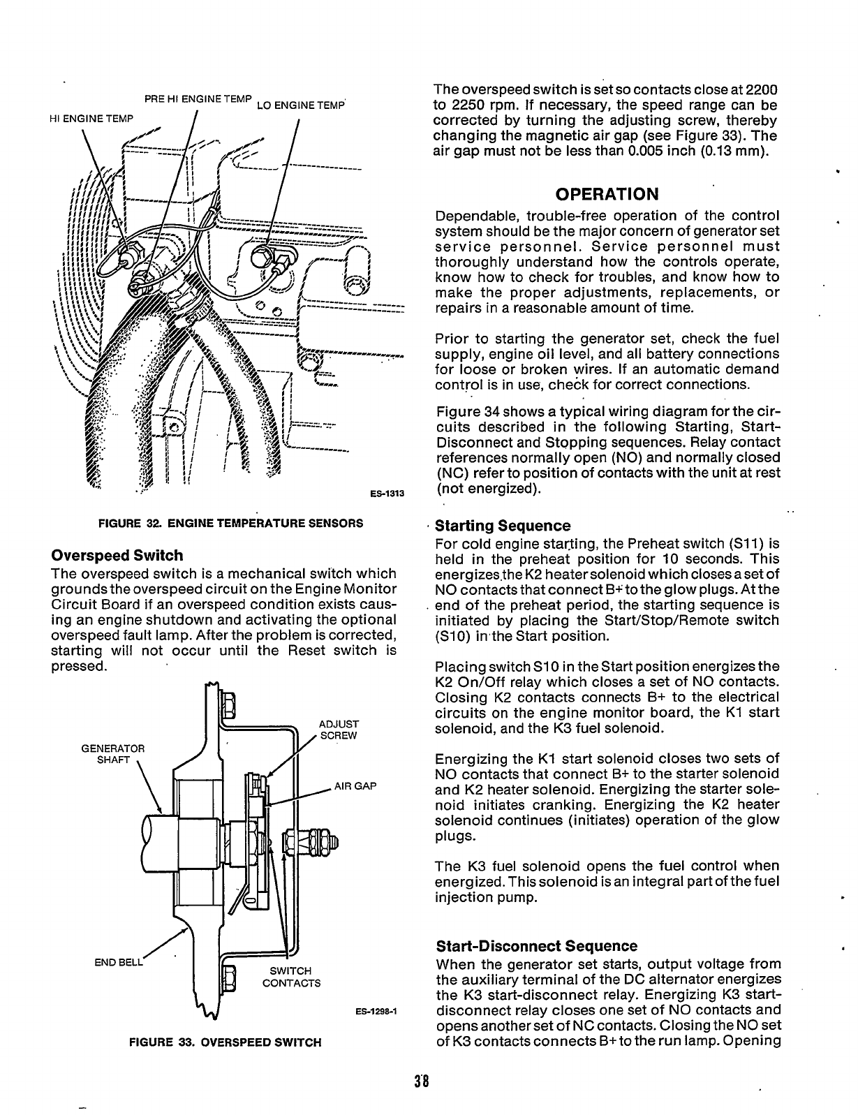
PRE
HI
ENGINE TEMP
LO
ENGINETEM+
HI
ENGINE TEMP
I
I
..r
ES-1313
.,?
'*.
FIGURE
32.
ENGINE TEMPERATURE SENSORS
Overspeed Switch
The overspeed switch is a mechanical switch which
grounds the overspeed circuit on the Engine Monitor
Circuit Board if an overspeed condition exists caus-
ing an engine shutdown and activating the optional
overspeed fault lamp. After the problem is corrected,
starting will not occur until the Reset switch is
pressed.
GENERATOR
v
FIGURE
33.
OVERSPEED
SWITCH
The overspeed switch is set
so
contacts close at 2200
to 2250 rpm. If necessary, the speed range can be
corrected by turning the adjusting screw, thereby
changing the magnetic air gap (see Figure 33). The
air gap must not be less than
0.005
inch (0.13 mm).
OPERATION
Dependable, trouble-free operation of the control
system should be the major concern of generator set
service personnel. Service personnel must
thoroughly understand how the controls operate,
know how to check for troubles, and know how to
make the proper adjustments, replacements, or
repairs in a reasonable amount of time.
Prior to starting the generator set, check the fuel
supply, engine oil level, and all battery connections
for loose or broken wires. If an automatic demand
control is in use, check for correct connections.
Figure 34 shows a typical wiring diagram for the cir-
cuits described
in
the following Starting, Start-
Disconnect and Stopping sequences. Relay contact
references normally open
(NO)
and normally closed
(NC)
refer to position of contacts with the unit at rest
(not energized).
Starting Sequence
For cold engine starjing,
the
Preheat switch (Sll) is
held
in
the preheat position for 10 seconds. This
energizesthe K2 heater solenoid which closes a set of
NO
contacts that connect B+ to the glow plugs. At the
end of the preheat period, the starting sequence is
initiated by placing the Start/Stop/Remote switch
(S10) hthe Start position.
..
Placing switch S10
in
the Start position energizes the
K2 On/Off relay which closes a set of
NO
contacts.
Closing K2 contacts connects B+ to the electrical
circuits on the engine monitor board, the K1 start
solenoid, and the K3 fuel solenoid.
Energizing the K1 start solenoid closes two sets of
NO
contacts that connect
B+
to the starter solenoid
and K2 heater solenoid. Energizing the starter sole-
noid initiates cranking. Energizing the K2 heater
solenoid continues (initiates) operation
of
the glow
The K3 fuel solenoid opens the fuel control when
energized.This solenoid is an integral part of the fuel
injection pump.
plugs.
Start-Disconnect Sequence
When the generator set starts, output voltage from
the auxiliary terminal of the DC alternator energizes
the K3 start-disconnect relay. Energizing K3 start-
disconnect relay closes one set of
NO
contacts and
opens another set of
NC
contacts. Closing the
NO
set
Of
K3 contacts connects B+ to the run lamp. Opening
ES-1298-1
3'8
Redistribution or publication of this document,
by any means, is strictly prohibited.
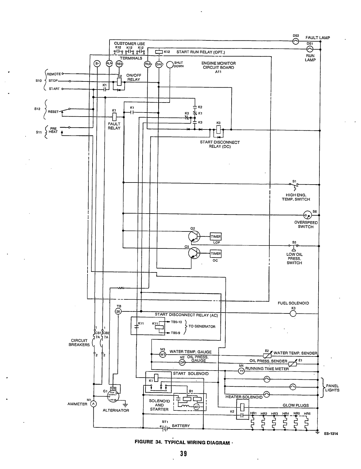
s10
512
s11
CIRCUIT
BREAKERS
M
AMMETER
u
FAULT
RELAY
I
ALTERNATOR
I
47TLil
TIMER
OVERSPEEI
SWITCH
TIMER
F-
LOW
OIL
'
PRESS.
I
SWITCH
I
FUEL SOLENOID
--
--
TB5-9
FIGURE
34.
TYPICAL WIRING DIAGRAM
:
39
PANEL
LIGHTS
ES-1314
Redistribution or publication of this document,
by any means, is strictly prohibited.
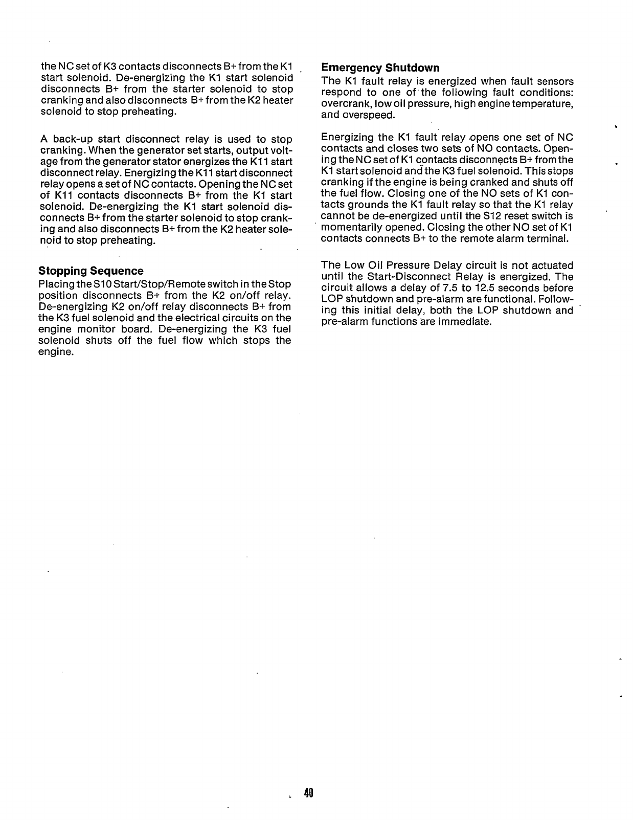
the
NC
set of
K3
contacts disconnects
B+
from the
K1
,
start solenoid. De-energizing the
K1
start solenoid
disconnects
B+
from the starter solenoid to stop
cranking and also disconnects B+from the
K2
heater
solenoid to stop preheating.
A
back-up start disconnect relay
is
used to stop
cranking. When the generator set starts, output volt-
age from the generator stator energizes the
K11
start
disconnect relay. Energizing
the
K11
start disconnect
relay opens a set of NC contacts. Opening the
NC
set
of
K11
contacts disconnects
B+
from the
K1
start
solenoid. De-energizing the
K1
start solenoid
dis-
connects
B+
from the starter solenoid to stop crank-
ing
and also disconnects
B+
from the
K2
heater sole-
noid to stop preheating.
Stopping Sequence
Placing the
S10
Start/Stop/Remote switch
in
the Stop
position disconnects
B+
from the
K2
on/off relay.
De-energizing
K2
on/off relay disconnects
B+
from
the
K3
fuel solenoid and the electrical circuits on the
engine monitor board. De-energizing the
K3
fuel
solenoid
shuts
off the fuel flow which stops the
engine.
Emergency Shutdown
The
K1
fault relay
is
energized when fault sensors
respond to one of'the following fault conditions:
overcrank, low oil pressure,
high
engine temperature,
and overspeed.
Energizing the
K1
fault'relay .opens one
set
of
NC
contacts and closes two sets of
NO
contacts. Open-
ing
the
NC
set of
K1
contacts disconnects
B+
from the
K1
start solenoid andthe
K3
fuel solenoid. This stops
cranking
if
the engine
is
being cranked and
shuts
off
the fuel flow. Closing one of the
NO
sets of
K1
con-
tacts grounds the
K1
fault relay
so
that the
K1
relay
cannot be de-energized
until
the
S12
reset switch
is
momentarily opened. Closing the other
NO
set of
K1
contacts connects
B+
to the remote alarm terminal.
The Low
Oil
Pressure Delay circuit is not actuated
until
the Start-Disconnect Relay
is
energized. The
circuit allows a delay of
7.5
to
12.5
seconds before
LOP shutdown and pre-alarm are functional. Follow-
ing
this initial delay, both the
LOP
shutdown and
pre-alarm functions are immediate.
40
Redistribution or publication of this document,
by any means, is strictly prohibited.
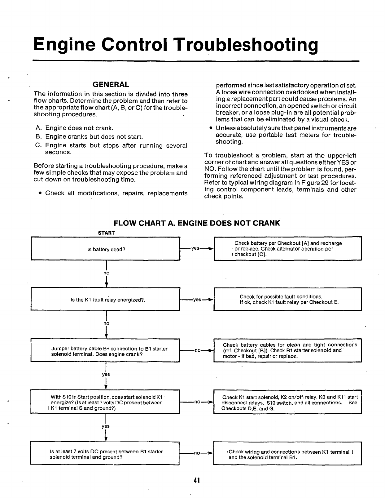
Engine Control Troubleshooting
Is
battery dead? yes+
GENERAL
The information
in
this section is divided into three
flow charts. Determine the problem and then refer to
the appropriate flow chart (A,
B,
or C) for the trouble-
shooting procedures.
Check battery per Checkout
[A]
and recharge
'
or replace. Check alternator operation per
A. Engine does not crank.
B.
Engine cranks but does not start.
C. Engine starts but stops after running several
seconds.
With S10 in Start position, doesstart solenoid K1
'
!
energize?
(Is
at least
7
volts DC present between
I
K1 terminal
S
and ground?)
Before starting a troubleshooting procedure, make a
few simple checks that may expose the problem and
cut down on troubleshooting time.
Check all modifications, repairs, replacements
Check K1 start solenoid, K2 on/off. relay,
K3
and K11 start
-no+ disconnect relays,
SI0
switch, and all connections.. See
Checkouts
D,E,
and
G.
performed since last satisfactory operation of set.
A loose wire connection overlooked when install-
ing a replacement part could cause problems. An
incorrect connection, an opened switch or circuit
breaker, or a loose plug-in are all potential prob-
lems that can be eliminated by a visual check.
Unless absolutelysurethat panel instrumentsare
accurate, use portable test meters for trouble-
shooting.
To
troubleshoot a problem, start at the upper-left
corner of chart and answer all questions eitherYES or
NO.
Follow the chart until the problem is found, per-
forming referenced adjustment or test procedures.
Refer to typical wiring diagram in Figure
29
for locat-
ing control component leads, terminals and other
check points.
Is
at least
7
volts DC present between
B1
starter
solenoid terminal and ground? SCheck wiring and connections between K1 terminal
I
and the solenoid terminal B1.
no
1
Check for possible fault conditions.
If ok, check K1 fault relay per Checkout
E.
Is
the K1 fault relay energized?. yes
4
Check battery cables for clean and tight connections
(ref. Checkout [B]). Check B1 starter solenoid and
motor
-
if
bad, repair
or
replace.
Jumper battery cable B+ connection to B1 starter
solenoid terminal. Does engine crank?
I
1
2
I
41
Redistribution or publication of this document,
by any means, is strictly prohibited.
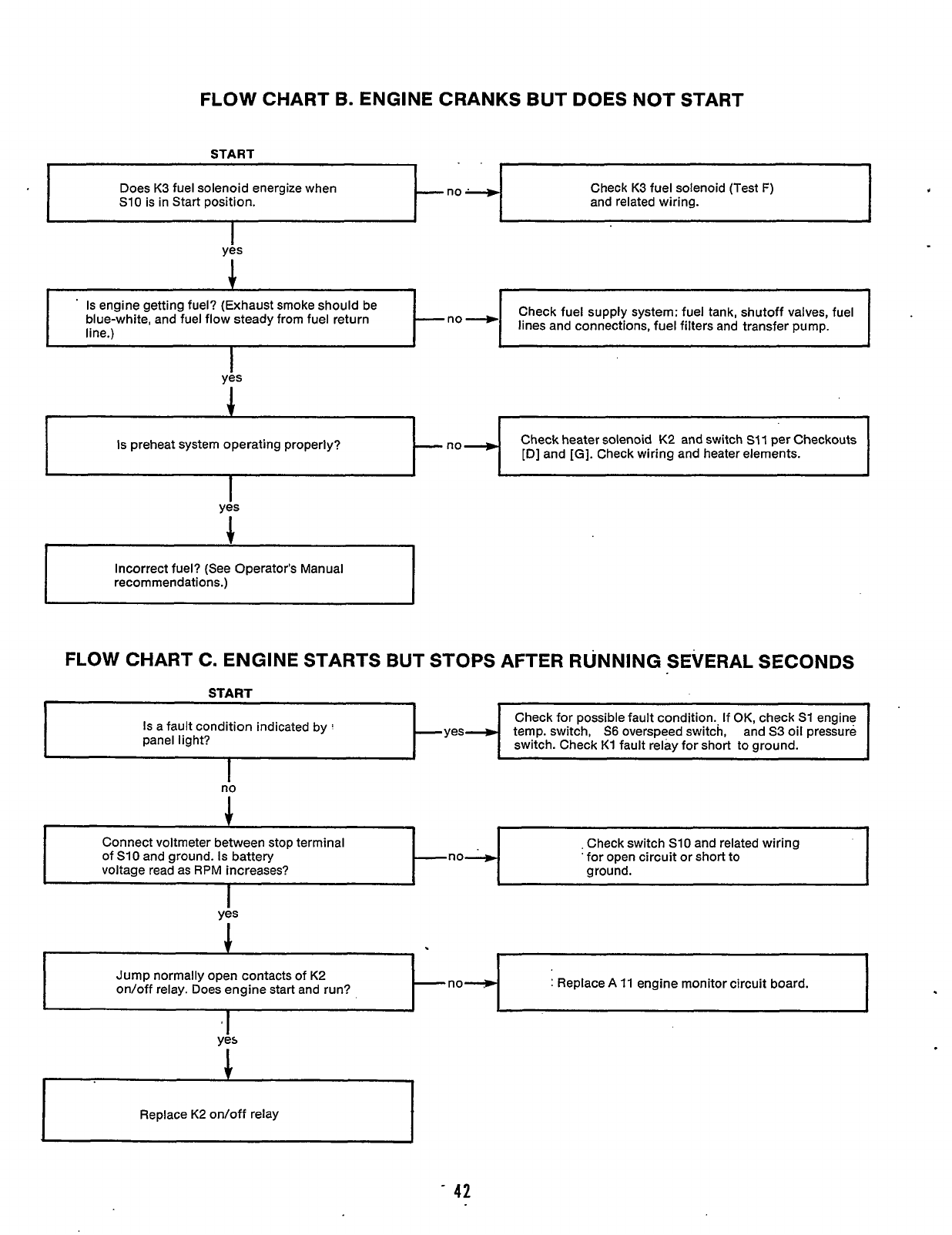
FLOW CHART
B.
ENGINE CRANKS BUT DOES NOT START
..
Does K3 fuel solenoid energize when
S10
is in Start position.
---no-
Check K3 fuel solenoid (Test
F)
and related wiring.
yis
1
Is preheat system operating properly?
-
7
Check fuel supply system: fuel tank, shutoff valves, fuel
lines and connections, fuel filters and transfer pump.
’
Is
engine getting fuel? (Exhaust smoke should be
blue-white, and fuel flow steady from fuel return
line.)
Check heater solenoid K2 and switch
SI1
per Checkouts
[D] and
[GI.
Check wiring and heater elements.
1
I
Check for possible fault condition., If
OK,
check
S1
engine
Is a fault condition indicated by
:
-yes--, temp. switch,
S6
overspeed switch, and S3 oil pressure
switch. Check
K1
fault relay for short to ground.
panel light?
-
~
Connect voltmeter between stop terminal
of
S10
and ground. Is battery
voltage read as
RPM
increases?
yis
1
~ ~ ~~
~~ ~~
,
Check switch
S10
and related wiring
’
for open circuit or short to
ground.
-no----)
I
A
Incorrect fuel? (See Operator’s Manual
recommendations.)
Jump normally open contacts of K2
on/off relay. Does engine start and run? no-
I
I
:
Replace
A
11
engine monitor circuit board.
FLOW CHART C. ENGINE STARTS BUT STOPS AFTER RUNNING SEVERAL SECONDS
START
I
no
‘I
ye5
I
Replace K2 on/off relay
I
42
Redistribution or publication of this document,
by any means, is strictly prohibited.
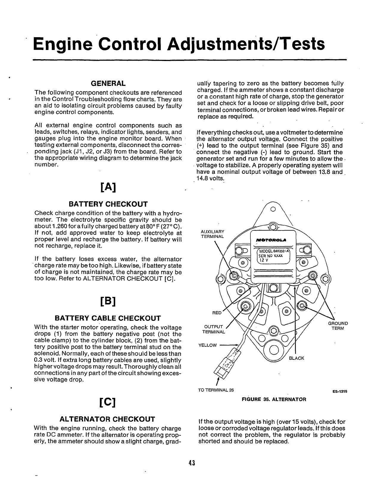
Engine
'Control
AdjustrnentdTests
GENERAL
ually tapering to zero as the battery becomes fully
chaiged. If the ammeter shows a constant discharge
or a constant high rate of charge, stop the generator
set
and
check
for
a
loose
or
slipping
drive
belt,
poor
terminal connections, or broken lead wires. Repair or
replace as required.
The following component checkouts are referenced
in the Control Troubleshooting flow charts. They are
an aid to isolating circuit problems caused by faulty
engine control components.
All external engine control components such as
leads, switches, relays, indicator lights, senders, and
gauges plug into the engine monitor board. When
testing external components, disconnect the corres-
ponding jack
(JI,
J2, or
J3)
from the board. Refer to
the appropriate wiring diagram to determine the jack
number.
If everything checks out, use
a
voltmeterto determine
the alternator output voltage. Connect the positive
(+)
lead to the output terminal (see Figure 35) and
connect the negative
(-)
lead to ground. Start the
generator set and run for a few minutes to allow the
.
.
voltage to stabilize.
A
properly operating system will
have a nominal output voltage of between 13.8 and.
14.8 volts.
TAl
BATTERY CHECKOUT
Check charge condition
of
the battery with a hydro-
meter. The electrolyte specific gravity should be
about 1.260forafullycharged battery at8OoF (27°C).
If not, add approved water to keep electrolyte at
proper level and recharge the battery. If battery will
not recharge, replace
it.
If
the battery loses excess water, the alternator
'
charge rate may be too high. Likewise,
if
battery state
of charge is not maintained, the charge rate may be
too low. Refer to ALTERNATOR CHECKOUT
[C].
BATTERY CABLE CHECKOUT
With the starter motor'operating, check the voltage
drops
(1)
from the battery negative post (not the
cable clamp) to the cylinder block, (2) from the bat-
tery positive post to the battery terminal stud on the
solenoid. Normally, each of theseshould be less than
0.3
volt. If extra long battery cables are used, slightly
higher voltagedrops may result.Thoroughly clean all
connections in any part
of
the circuit showing exces-
sive voltage drop.
ALTERNATOR CHECKOUT
With the engine running, check the battery charge
rate
DC
ammeter.
If
the alternator is operating prop-
erly, the ammeter should show a slight charge, grad-
..
A.
AUXILIARY
MOTOROLA
D
TO
TERMINAL
26
ES-1319
FIGURE
35.
ALTERNATOR
If the output voltage is high (over
15
volts), check for
loose or corroded voltage regulator leads. If this does
not correct the problem, the regulator is probably
shorted and should be replaced.
4.3
Redistribution or publication of this document,
by any means, is strictly prohibited.
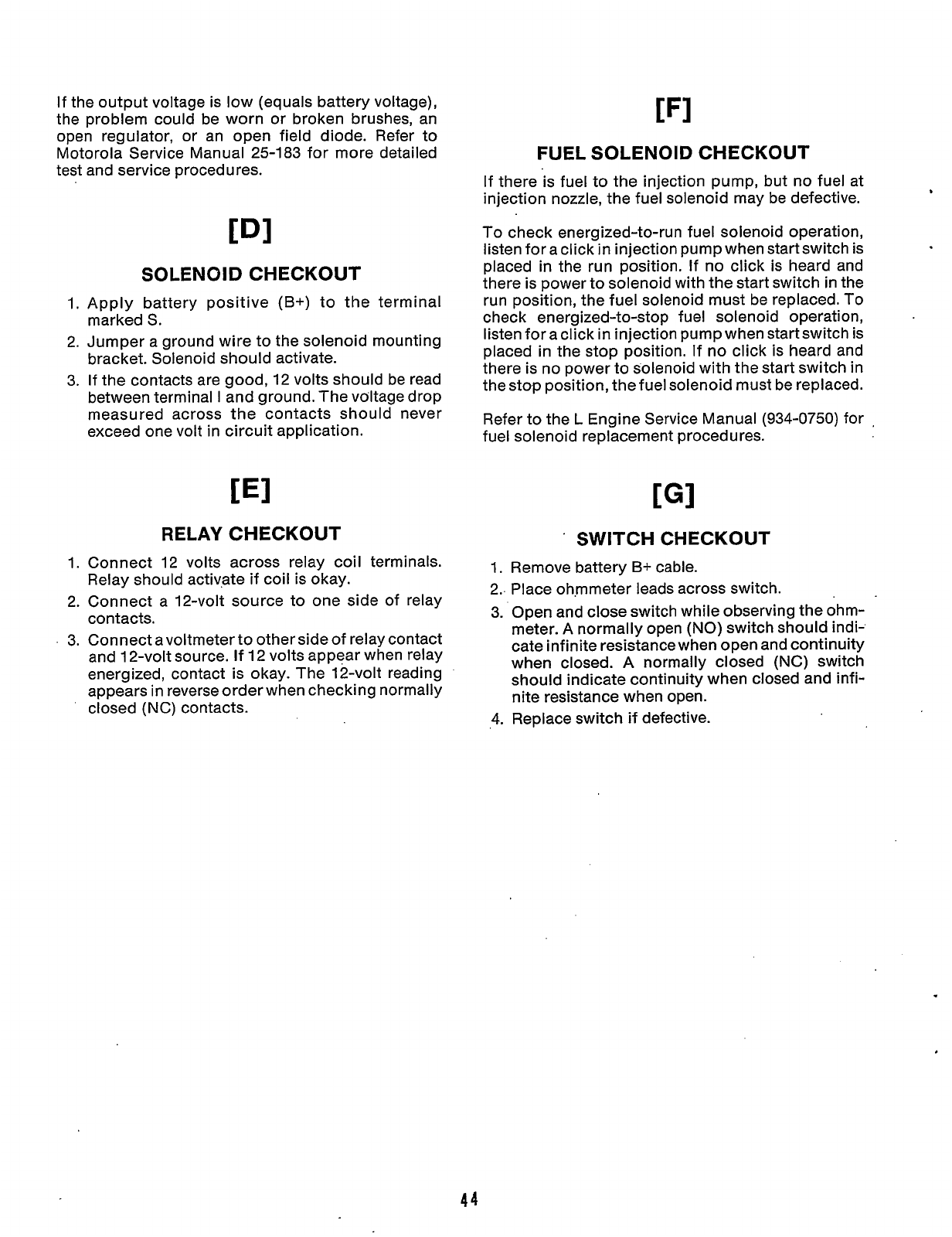
If
the output voltage is low (equals battery voltage),
the problem could be worn or broken brushes, an
open regulator, or an open field diode. Refer to
Motorola Service Manual 25-183 for more detailed
test and service procedures.
SOLENOID CHECKOUT
1. Apply battery positive
(B+)
to the terminal
marked
S.
2. Jumper a ground wire to the solenoid mounting
bracket. Solenoid should activate.
3.
If the contacts are good, 12 volts should be read
between terminal
I
and ground. The voltage drop
measured across the contacts should never
exceed one volt in circuit application.
RELAY CHECKOUT
1. Connect 12 volts across relay coil terminals.
Relay should activate if coil is okay.
2. Connect a 12-volt source to one side of relay
contacts.
.
3. Connect a voltmeter to other side
of
relay contact
and 12-volt source.
If
12 volts appear when relay
energized, contact is okay. The 12-volt reading
appears in reverse order when checking normally
closed (NC) contacts.
FUEL SOLENOID CHECKOUT
If there is fuel to the injection pump, but no fuel at
injection nozzle, the fuel solenoid may be defective.
To check energized-to-run fuel solenoid operation,
listen for a click
in
injection pump when start switch is
placed
in
the run position. If no click is heard and
there is power to solenoid with the start switch in the
run position, the fuel solenoid must be replaced.
To
check energized-to-stop fuel solenoid operation,
listen for a click
in
injection pump when start switch is
placed in the stop position. If no click is heard and
there is no power to solenoid with the start switch in
the stop position, the fuel solenoid must be replaced.
Refer to the
L
Engine Service Manual
(934-0750)
for
,
fuel solenoid replacement procedures.
SWITCH CHECKOUT
1.
Remove battery
B+
cable.
2.. Place ohmmeter leads across switch.
3. Open and close switch while observing the ohm-
meter.
A
normally open
(NO)
switch should indi-
cate infinite resistance when open and continuity
when closed.
A
normally closed
(NC)
switch
should indicate continuity when closed and infi-
nite resistance when open.
4. Replace switch if defective.
44
Redistribution or publication of this document,
by any means, is strictly prohibited.
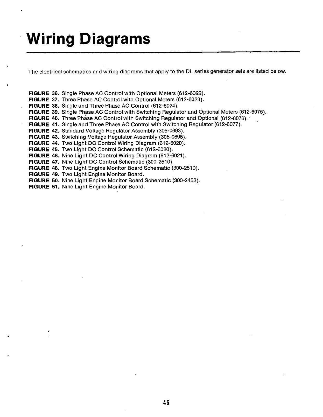
.
Wiring
Diagrams
"
The electrical schematics and wiring diagrams that apply to the DL series generator sets are listed below.
FIGURE 36.
Single Phase AC Control with Optional Meters (612-6022).
FIGURE 37.
Three Phase AC Control with Optional Meters (612-6023).
FIGURE 38.
Single and Three Phase AC Control (612-6024).
FIGURE 39.
Single Phase AC Control with Switching Regulator and Optional Meters (612-6075).
FIGURE 40.
Three Phase AC Control with Switching Regulator and Optional (612-6076).
.
FIGURE 41.
Single and Three Phase AC Control with Switching Regulator (612-6077).
FIGURE
42.
Standard Voltage Regulator Assembly (305-0693).
FIGURE 43.
Switching Voltage Regulator Assembly (305-0695).
FIGURE 44.
Two Light DC Control Wiring Diagram (612-6020).
FIGURE 45.
Two Light DC Control Schematic (612-6020).
FIGURE 46.
Nine Light DC Control Wiring Diagram (612-6021).
FIGURE 47.
Nine Light DC Control Schematic (300-2510).
FIGURE 48.
Two Light Engine Monitor Board Schematic (300-2510).
FIGURE 49.
Two Light Engine Monitor Board.
FIGURE
50.
Nine Light Engine Monitor Board Schematic (300-2453).
FIGURE
51.
Nine Light Engine Monitor Board.
.
'
45
Redistribution or publication of this document,
by any means, is strictly prohibited.
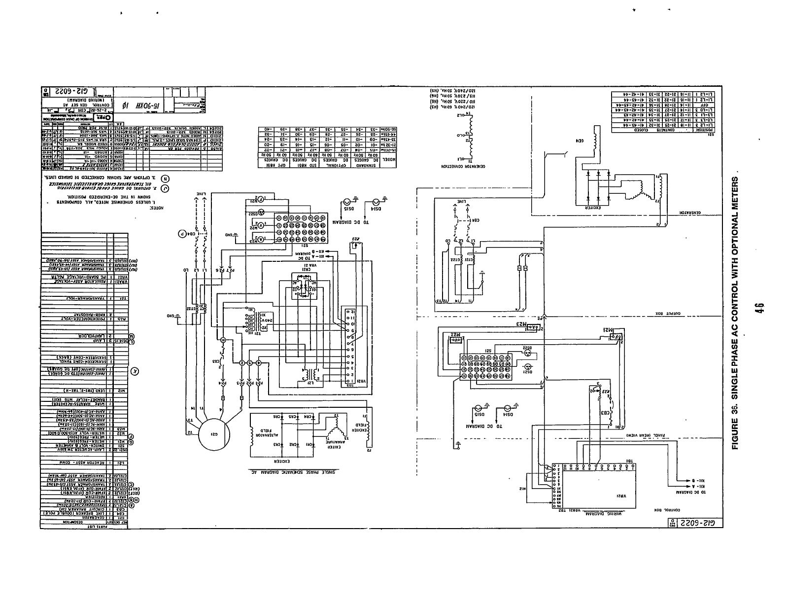
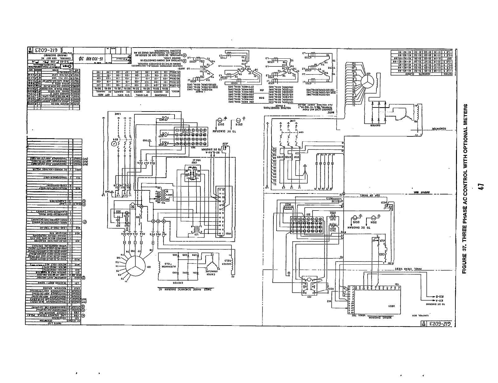
,I==-
-
I.
I
I1
I
Q
3N11
I
.31W
-
--I
-t
YO0
IMlnO
A
0
U
w
2
n
w
w
a
2
I-
&
(3
W
a
3
8
ii
2
Redistribution or publication of this document,
by any means, is strictly prohibited.
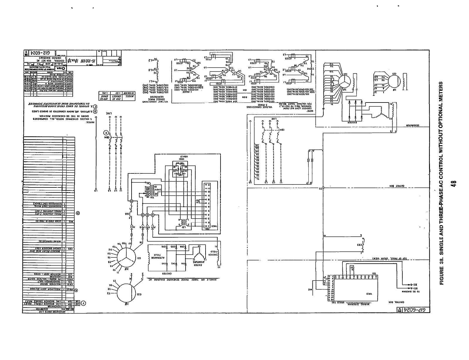
I
I
I
I
I
Ii
I
II
a
I
1-
I’
I1
I
I1
I
3Hll
+
**
I
II
I
I1
I
I1
I
II
oa
i:
1.
?
11
183
1---1---1
#;
(;
I
II
I
II
I
II
I
II
I
I1
I
II
I
II
I
I1
n
1,
21
I],
I1
r-----
I-
I
51
W
a1
2
\
I
I
IIR
II
-I
a
z
0
t
0
I-
3
0
F
.w
u)
2
w
2
I-
a
9
a
Redistribution or publication of this document,
by any means, is strictly prohibited.
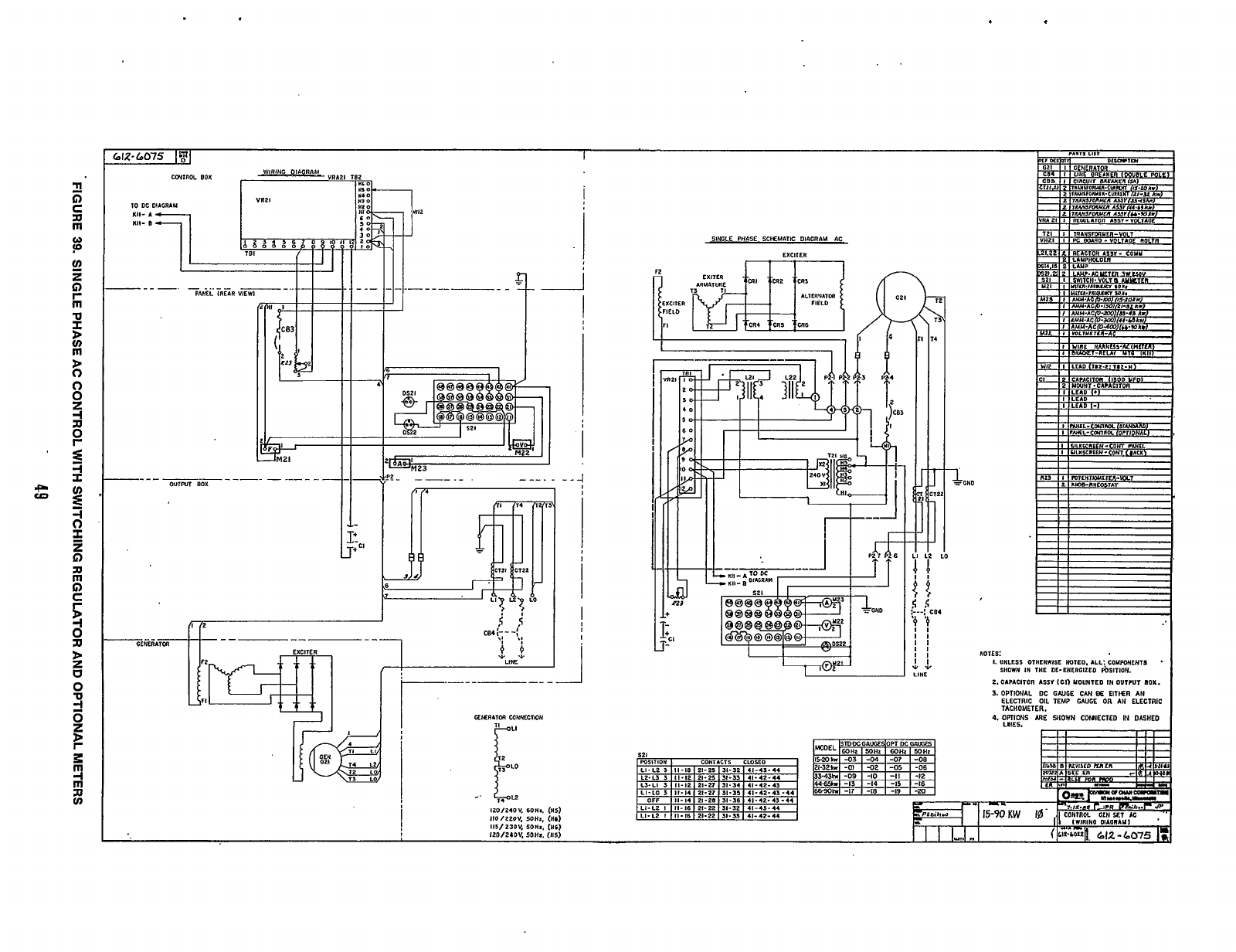
I
I
vi
0'-
i""
SINGLE
PHASE SCKHATH: DIAGRAM AC
EXCllER
1
r
GHD
I
--7
I19
9
0
0
z
-I
a
P
=i
I
'22
LO
I4
2.CAPACllOR
ASS1
ICI)
YOUHTED
IH
OUl?Ul
IOX.
3.
OPTIONAL
DC
GWGE
CAH
OE
EITIER
AN
ELECTRIC
OIL TEMP
WUGE
OR
AH
ELECTRIC
TACHOMETER.
LNES.
Redistribution or publication of this document,
by any means, is strictly prohibited.
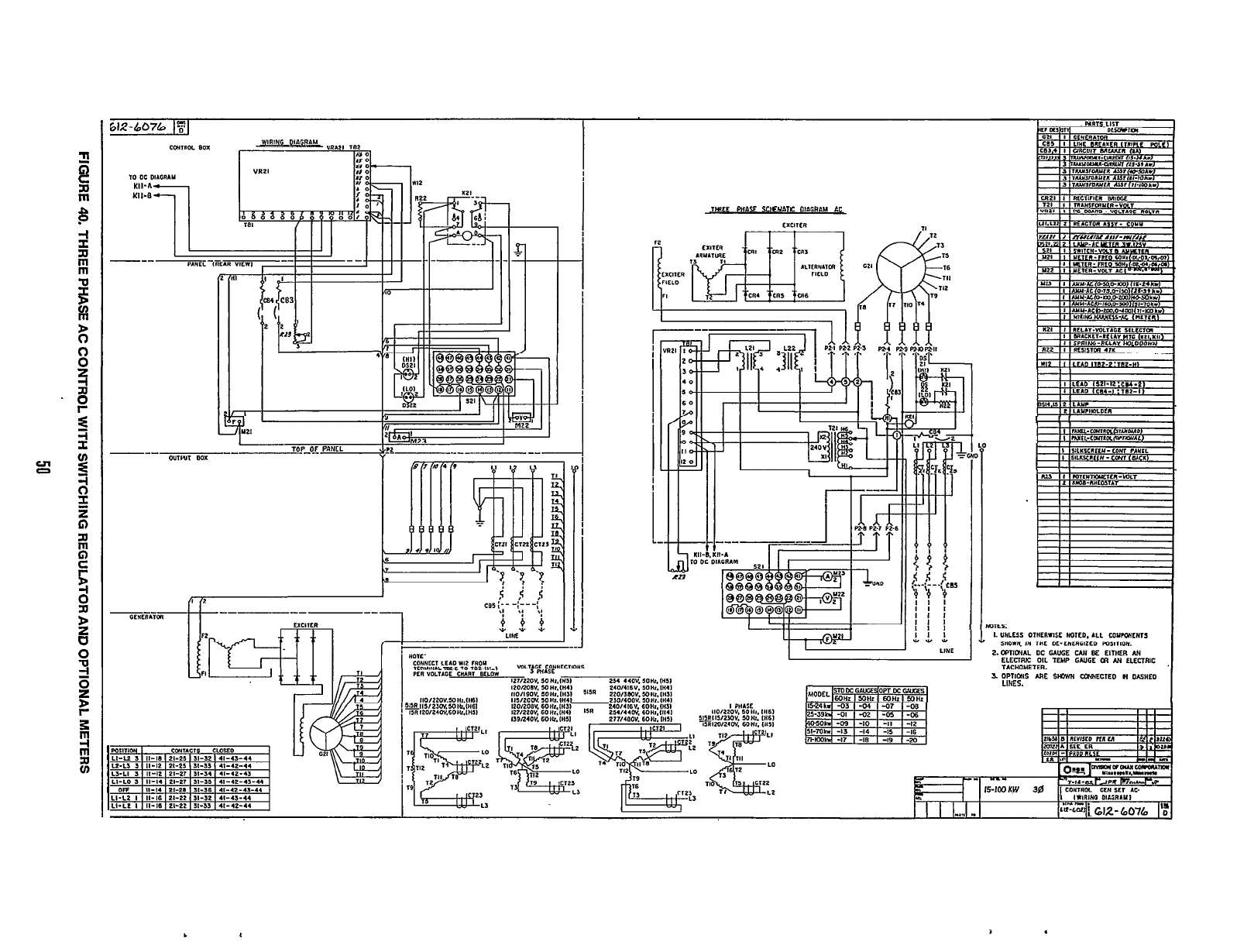
:
C
n
rn
P
P
-I
2
n
rn
m
-u
I
rn
D
0
0
0
2
R
.$
?
P
0
8
2
fr
z
I
lMLE PHAY SCIEMAlC OIAGRAM
IC
I
I
111
I
1
I
!!
I
T
3.
DPIICNS
-E
SYm
WECIED
N
O*SiIED
LINES.
Redistribution or publication of this document,
by any means, is strictly prohibited.
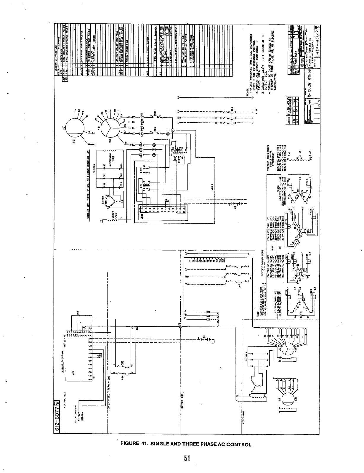
c
..
. .
I
I
I
I
FIGURE
41.
SINGLE AND THREE PHASE AC CONTROL
51
Redistribution or publication of this document,
by any means, is strictly prohibited.
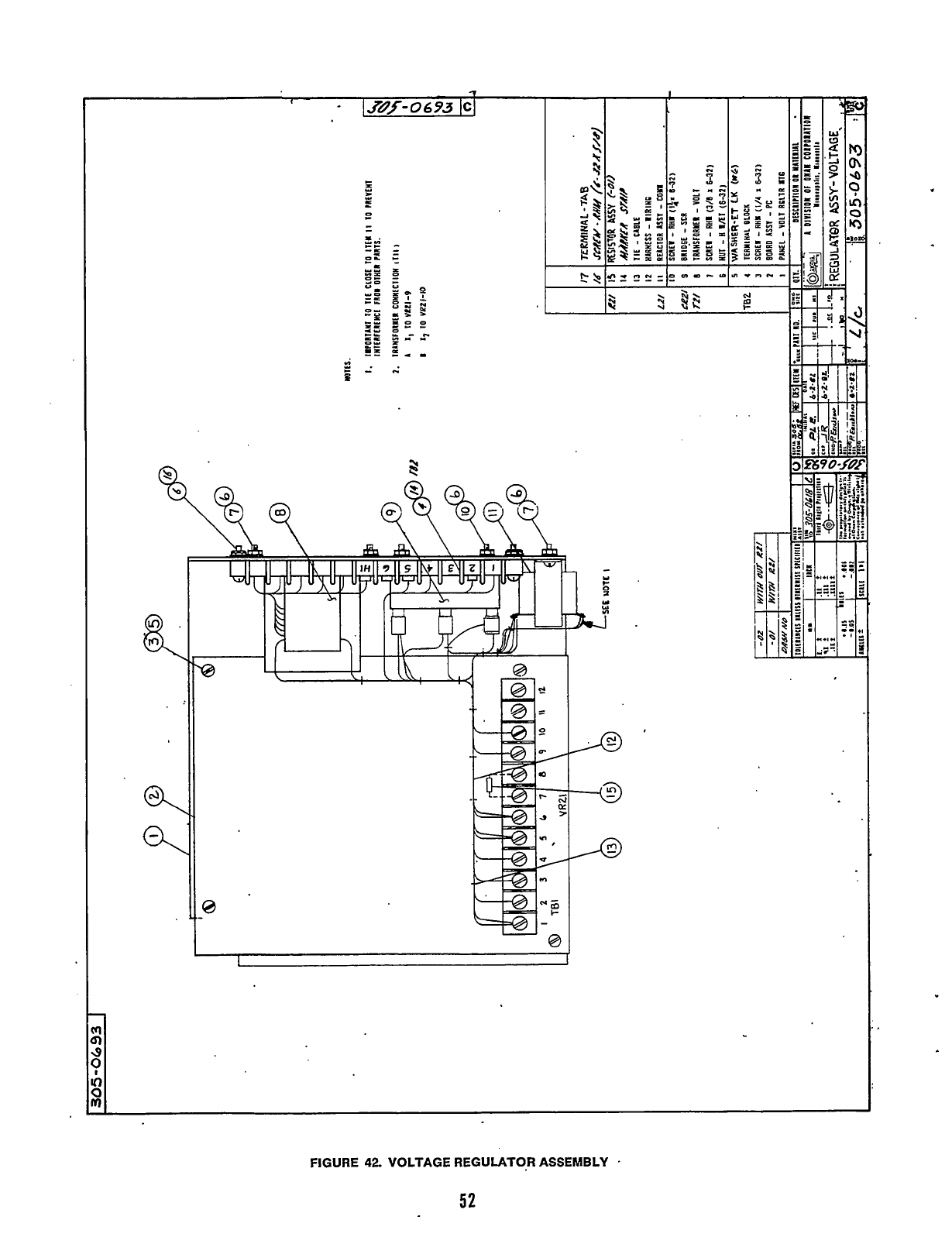
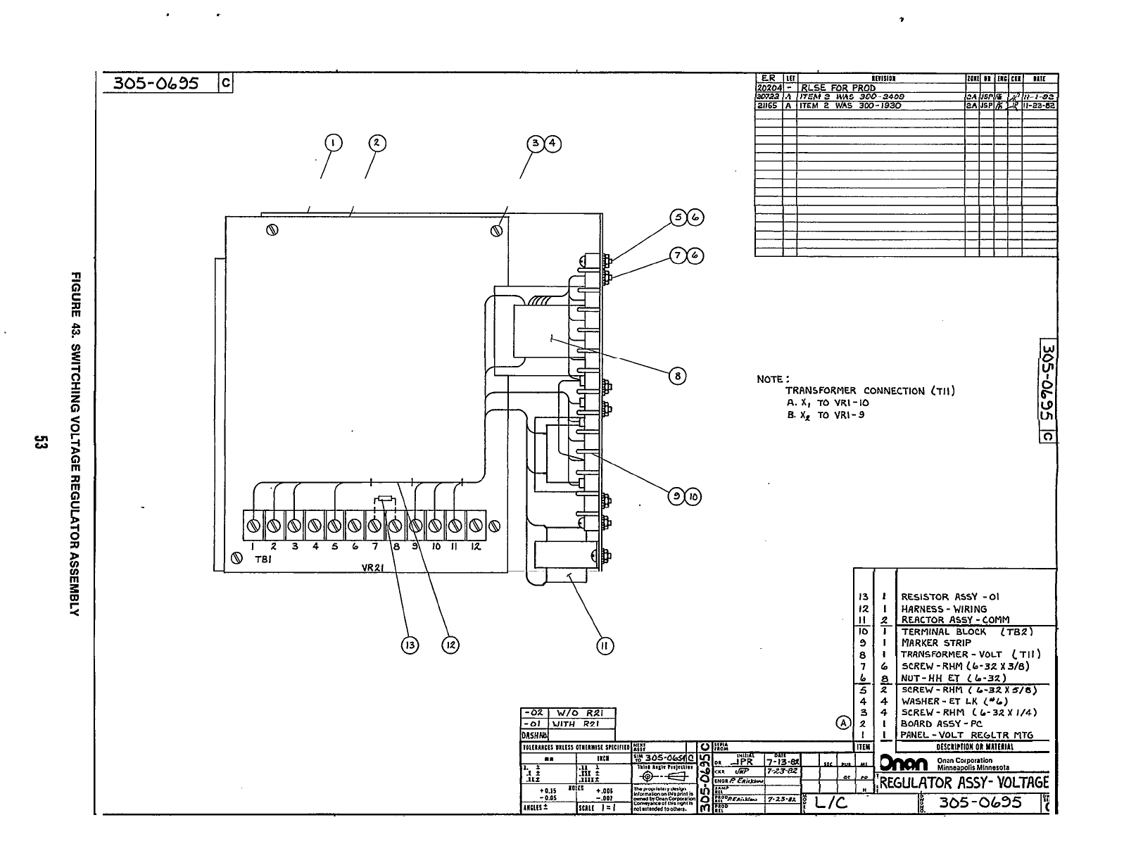
,
.P
P
Po
NOTE
:
TRANSFORMER
CONNECTION
(711)
A.
X,
TO VRI-IO
6.
X,
TO
VRI-9
13
12
IO
9
8
1
!!-
b
5
-
4
3
2
I
I
I
I
I
6
8
2
4
4
I
2
-
RESISTOR ASSY
-01
HARNESS
-
WIRING
RERCTOR ASSY
-
COMM
TERMINAL BLOCK
(78.2)
-.
MARKER STRIP
TRRNSFORMER
-
VOLT
(TI1
)
SCREW
-
RHM
1
b-32
X
3/81
NUT-HH
ET
(6-32)
SCREW
-
RHM
(
L-32
X
S/8)
WASHER
-
ET
LK
("L)
SCREW
-
RHM
c
L-32.
X
1/4)
BOARD ASSY
-
PC
PANEL
-VOLT
REGLTR
MTG
DtSCII?IIDH
OR
YLIt#IIL
I
-
onan
cotpoiation
Minneapolis Minnasola
REGULATOR
ASSY
-
VOLTAGE
Redistribution or publication of this document,
by any means, is strictly prohibited.
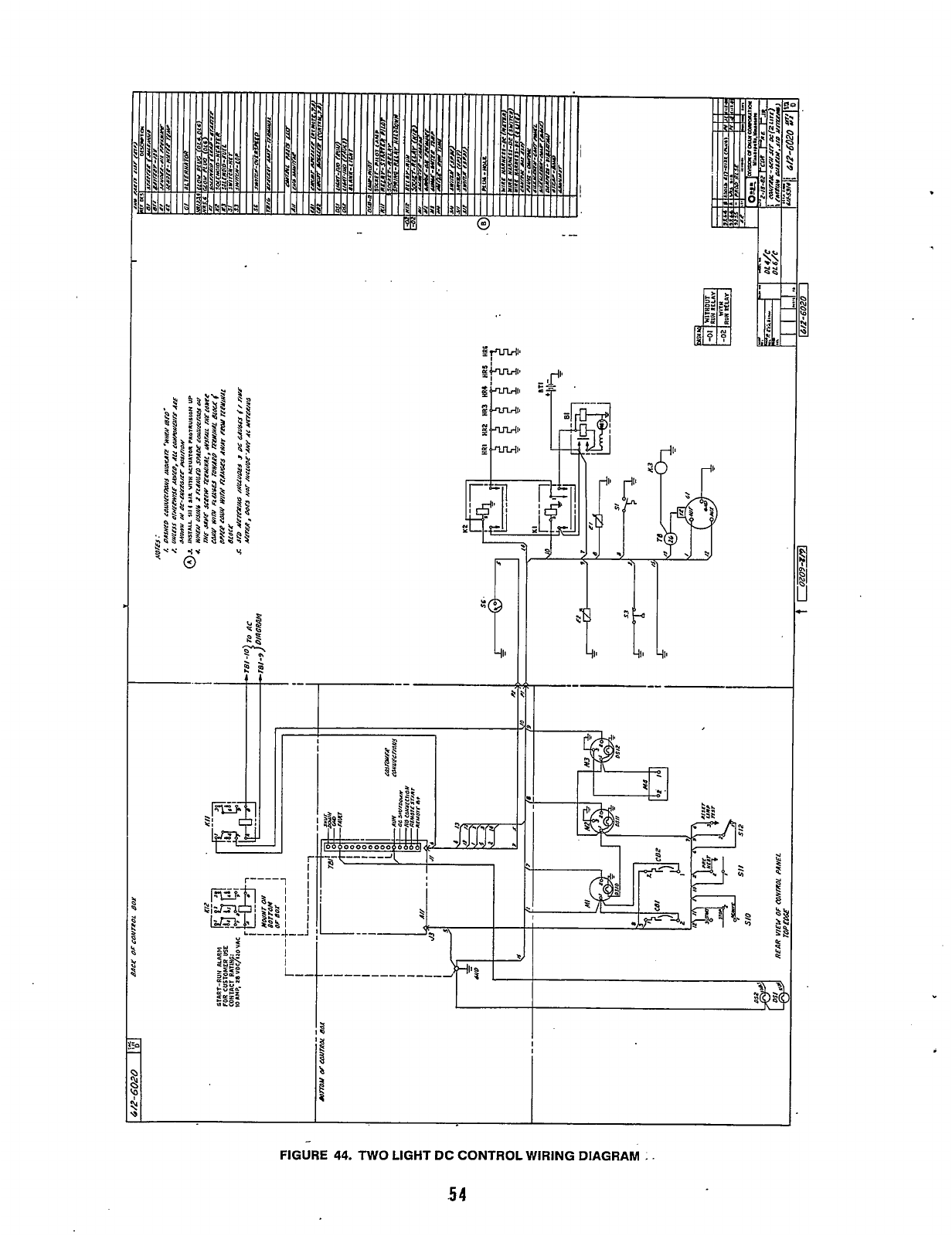
.
f
I
-
FIGURE
44.
TWO
LIGHT
DC CONTROL
WIRING
DIAGRAM
.
.
.5
4
Redistribution or publication of this document,
by any means, is strictly prohibited.
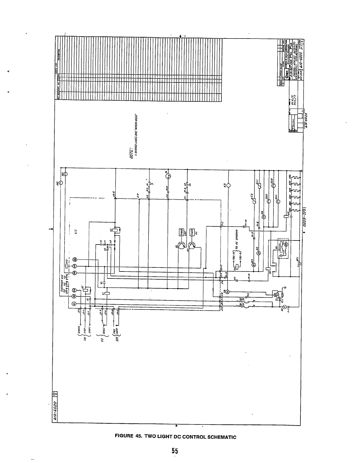
*I
N
.
3
9
c1
--
-
--1
i
!
A
FIGURE
45.
TWO
LIGHT
DC
CONTROL SCHEMATIC
55
Redistribution or publication of this document,
by any means, is strictly prohibited.
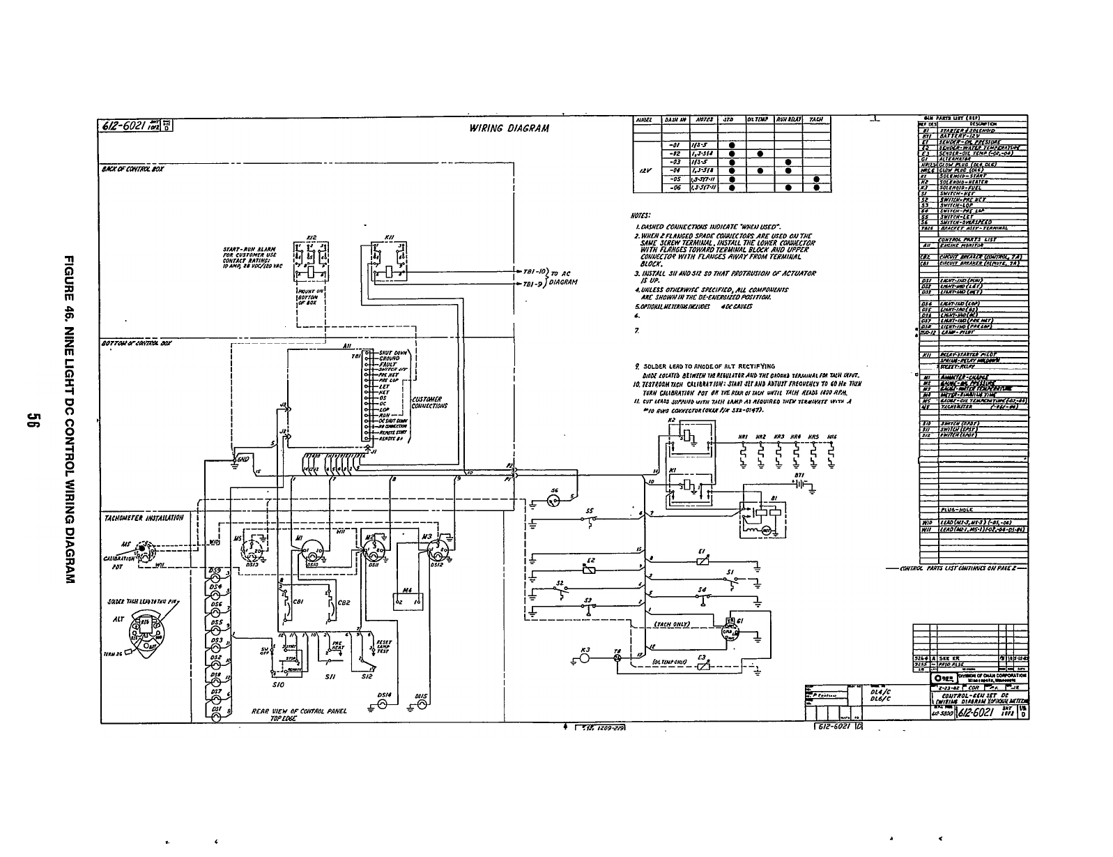
a
P
z
B
I!
SOLDLR
LERDTOANODLOF
RLT
RECTIFYING
I!
I
Redistribution or publication of this document,
by any means, is strictly prohibited.
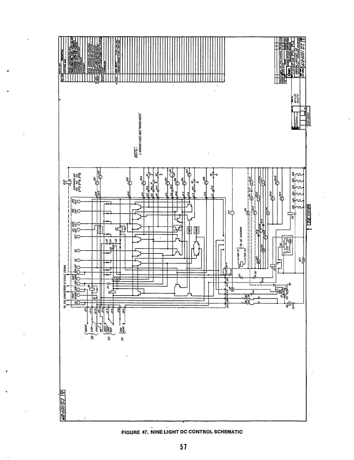
P
5
i
:
FIGURE
47.
NINE LIGHT DC CONTROL SCHEMATIC
57
Redistribution or publication of this document,
by any means, is strictly prohibited.
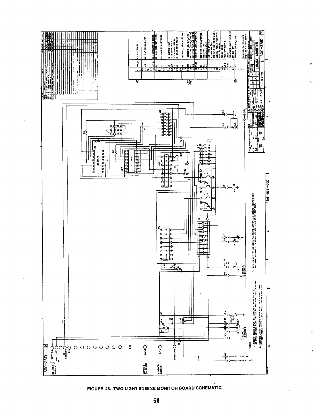
rF
n
"N
p
x
Y-
>
e,
"
FIGURE
48.
TWO
LIGHT
ENGINE MONITOR
BOARD SCHEMATIC
Redistribution or publication of this document,
by any means, is strictly prohibited.
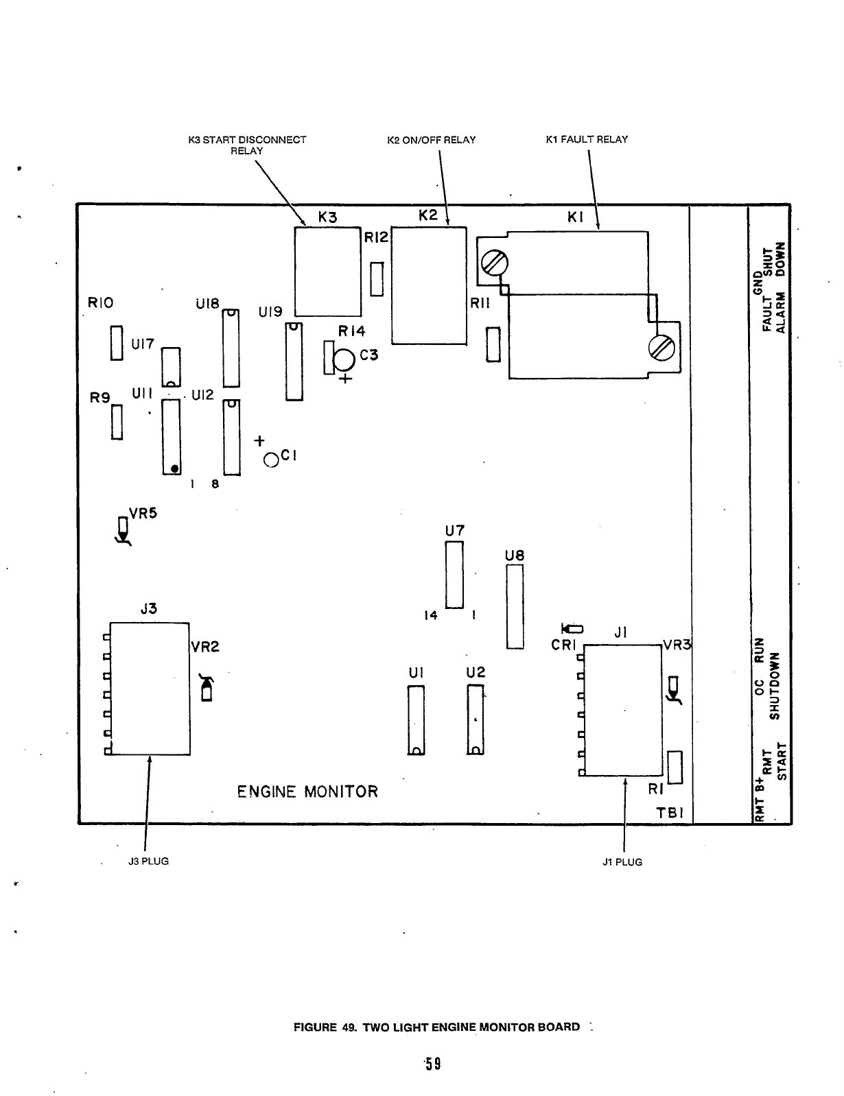
K3
START DISCONNECT
K2
ON/OFF RELAY
K1
FAULT RELAY
RELAY
RIO
1
U17
R9
UI
I
tR5
J3
1
“‘e
18
u’2
lo]
t
u19
I
I
+
+
oc
ENGINE
MONITOR
I
u7
14
I
UI
u2
I
I
U8
JI
CRI
53
PLUG
J1
PLUG
c
FIGURE
49.
TWO
LIGHT ENGINE MONITOR BOARD
I
Redistribution or publication of this document,
by any means, is strictly prohibited.
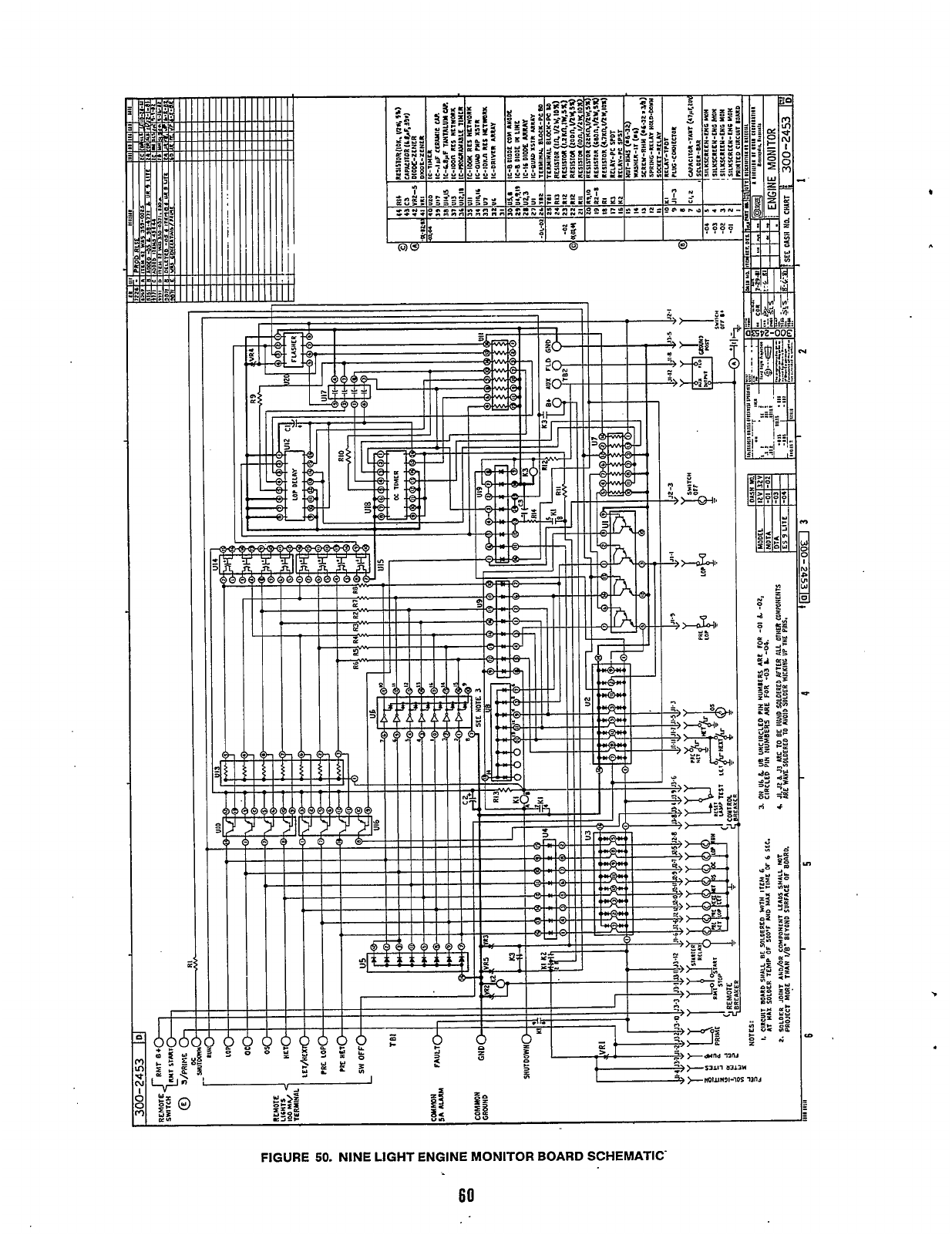
rF
*
FIGURE
50.
NINE LIGHT ENGINE MONITOR BOARD SCHEMATIC
60
Redistribution or publication of this document,
by any means, is strictly prohibited.
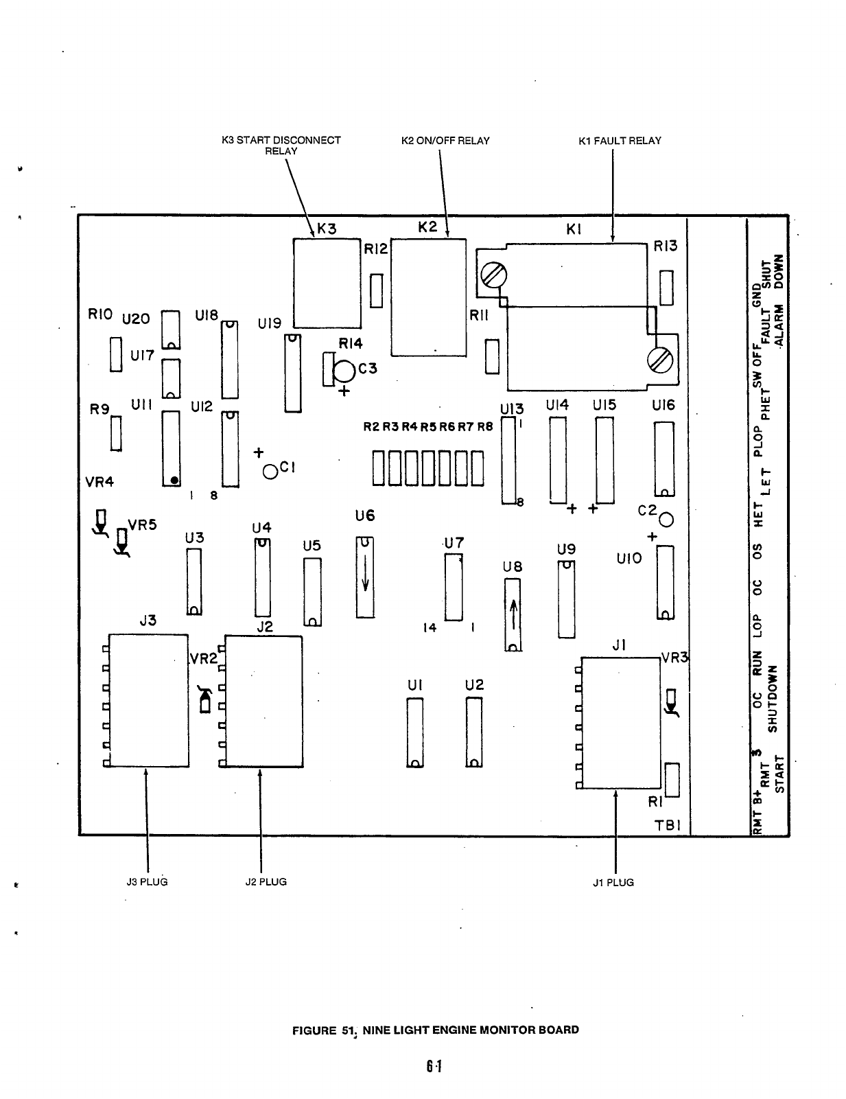
K3
START
R~LA~
DISCONNECT
K2
ON/OFF
,
RELAY
K1
FAU, RELAY
Y
,,i
VR4
18
ut9
r
R12
U
+
OC
I
U13
R2 R3 R4RSRSR7 R8
fl
us
U6
.u
7
14
I
UI
u2
U8
1
U14
U15
Ut6
r[!
++
c20
1
+
FIGURE
51,
NINE LIGHT ENGINE MONITOR BOARD
6.1
Redistribution or publication of this document,
by any means, is strictly prohibited.

L
Redistribution or publication of this document,
by any means, is strictly prohibited.

Redistribution or publication of this document,
by any means, is strictly prohibited.

Onan Corporation
1400
73rd
Avenue
N.E.
Minneapolis,
MN
55432
Telex:
275477
Onan
is
a
registered trademark
of
Onan Corporation
Cummins
is
a
registered trademark
of
Cummins Engine Company
61 2-574-5000
Fax:
612-574-8087
Redistribution or publication of this document,
by any means, is strictly prohibited.
