What Is A Custom Component Components Guide 210 Enu 0
User Manual:
Open the PDF directly: View PDF ![]() .
.
Page Count: 110 [warning: Documents this large are best viewed by clicking the View PDF Link!]
- Contents
- 1 What is a custom component
- 2 Creating custom components
- 2.1 About creating custom components
- 2.2 Exploding components
- 2.3 Example: Exploding an end plate component
- 2.4 Creating a custom component
- 2.5 Custom component types
- 2.6 Example: Creating an end plate connection
- 2.7 Adding a custom component to a model
- 2.8 Example: Adding an end plate connection to a model
- 2.9 Adding a custom part to a model and moving it using direct modification
- 3 Custom component editor
- 4 Variables in custom components
- 5 Examples of modifying custom components
- 5.1 Example: Adding an option to create an object
- 5.2 Example: Determining the bolt group distance from the beam flange
- 5.3 Example: Determining the bolt size and bolt standard
- 5.4 Example: Determining the number of bolt rows
- 5.5 Example: Using construction planes for determining the stiffener position
- 5.6 Example: Replacing sub-components
- 5.7 Example: Using properties files to modify a sub-component
- 5.8 Example: Using user-defined attributes in custom components
- 5.9 Example: Determining the number of handrail posts using a template attribute
- 5.10 Example: Using Excel spreadsheets with custom components
- 6 Modifying the custom component dialog box
- 6.1 Hiding variables in a custom component dialog box
- 6.2 Custom component dialog box file
- 6.3 Custom Component Dialog Editor
- Setting the options for Custom Component Dialog Editor
- Opening a custom component dialog box file in Custom Component Dialog Editor
- Moving items in a custom component dialog box
- Adding an image in a custom component dialog box
- Adding and renaming a tab in a custom component dialog box
- Example: Modifying the dialog box of a stiffener detail
- Example: Adding a list with images in a stiffener dialog box
- Example: Arranging text boxes and labels in a stiffener dialog box
- Example: Dimming unavailable options in a stiffener dialog box
- Preventing modifications of the custom component dialog box
- 7 Managing custom components
- 8 Custom component settings
- 8.1 Custom Component Wizard properties
- 8.2 Default custom component dialog box properties
- 8.3 Plane types
- 8.4 Variables properties
- 8.5 Functions in variable formulas
- Arithmetic operators
- Logical and comparison operators
- Reference functions
- ASCII file as a reference function
- Mathematical functions
- Statistical functions
- Data type conversion functions
- String operations
- Trigonometric functions
- Market size function
- Framing condition functions
- Example: Skew and slope framing conditions
- Example: Ceil and floor statistical functions
- Example: Market size function
- 9 Custom component tips
- 10 Disclaimer
- Index

Tekla Structures
Custom Components Guide
Product version 21.0
March 2015
©2015 Tekla Corporation
Contents
1 What is a custom component...........................................................................5
2 Creating custom components...........................................................................7
2.1 About creating custom components.......................................................................................7
2.2 Exploding components............................................................................................................. 8
2.3 Example: Exploding an end plate component........................................................................8
2.4 Creating a custom component................................................................................................ 9
2.5 Custom component types.......................................................................................................10
2.6 Example: Creating an end plate connection........................................................................12
2.7 Adding a custom component to a model.............................................................................15
2.8 Example: Adding an end plate connection to a model.......................................................15
2.9 Adding a custom part to a model and moving it using direct modification....................16
3 Custom component editor..............................................................................19
3.1 About custom component editor.......................................................................................... 19
3.2 Opening the custom component editor................................................................................20
3.3 Custom component browser..................................................................................................20
3.4 Modifying custom component settings................................................................................21
3.5 Saving a custom component................................................................................................. 22
3.6 Closing the custom component editor................................................................................. 23
4 Variables in custom components................................................................... 24
4.1 About variables.......................................................................................................................24
4.2 Viewing variables....................................................................................................................25
4.3 Distance variables...................................................................................................................25
Creating a distance variable manually...................................................................................................................... 26
Testing a distance variable............................................................................................................................................27
Example: Creating a distance variable to bind an end plate ............................................................................. 28
Automatic distance variables.......................................................................................................................................30
Creating distance variables automatically............................................................................................................... 30
Deleting a distance variable......................................................................................................................................... 31
4.4 Parametric variables...............................................................................................................31
Creating and linking a parametric variable..............................................................................................................32
Example: Creating a parametric variable to set end plate material................................................................. 32
4.5 Reference distance variables.................................................................................................33
Creating a reference distance variable......................................................................................................................34
4.6 Property references................................................................................................................ 35
Copying a property reference.......................................................................................................................................35
2
4.7 Construction planes in custom components........................................................................35
Creating a construction plane in the custom component editor.......................................................................36
5 Examples of modifying custom components................................................ 37
5.1 Example: Adding an option to create an object................................................................. 37
5.2 Example: Determining the bolt group distance from the beam flange............................39
5.3 Example: Determining the bolt size and bolt standard...................................................... 40
5.4 Example: Determining the number of bolt rows.................................................................42
5.5 Example: Using construction planes for determining the stiffener position...................43
5.6 Example: Replacing sub-components...................................................................................46
5.7 Example: Using properties files to modify a sub-component............................................47
5.8 Example: Using user-defined attributes in custom components.......................................48
5.9 Example: Determining the number of handrail posts using a template attribute.......... 50
5.10 Example: Using Excel spreadsheets with custom components.......................................... 54
6 Modifying the custom component dialog box............................................. 55
6.1 Hiding variables in a custom component dialog box..........................................................55
6.2 Custom component dialog box file.......................................................................................56
6.3 Custom Component Dialog Editor.........................................................................................56
Setting the options for Custom Component Dialog Editor..................................................................................57
Opening a custom component dialog box file in Custom Component Dialog Editor...................................57
Moving items in a custom component dialog box.................................................................................................57
Adding an image in a custom component dialog box...........................................................................................58
Adding and renaming a tab in a custom component dialog box.......................................................................58
Example: Modifying the dialog box of a stiffener detail......................................................................................58
Example: Adding a list with images in a stiffener dialog box............................................................................ 59
Example: Arranging text boxes and labels in a stiffener dialog box................................................................ 62
Example: Dimming unavailable options in a stiffener dialog box.....................................................................62
Preventing modifications of the custom component dialog box.......................................................................63
7 Managing custom components......................................................................65
7.1 Exporting custom components..............................................................................................65
7.2 Importing custom components..............................................................................................66
7.3 Protecting custom components with passwords................................................................. 67
7.4 Preventing actions on custom components in Component Catalog..................................68
8 Custom component settings...........................................................................69
8.1 Custom Component Wizard properties.................................................................................69
Type/Notes tab properties............................................................................................................................................. 69
Position tab properties................................................................................................................................................... 70
Advanced tab properties................................................................................................................................................70
Position types....................................................................................................................................................................71
8.2 Default custom component dialog box properties..............................................................73
Default dialog box properties of parts.......................................................................................................................73
Default dialog box properties of connections, details and seams.....................................................................76
8.3 Plane types.............................................................................................................................. 78
Example: Detail component planes............................................................................................................................ 80
3
Example: Connection component planes..................................................................................................................80
Example: Seam component planes.............................................................................................................................81
Example: Part component planes................................................................................................................................82
8.4 Variables properties................................................................................................................82
Value types.........................................................................................................................................................................83
8.5 Functions in variable formulas..............................................................................................86
Arithmetic operators.......................................................................................................................................................87
Logical and comparison operators..............................................................................................................................87
Reference functions........................................................................................................................................................ 88
ASCII file as a reference function............................................................................................................................... 89
Mathematical functions.................................................................................................................................................90
Statistical functions........................................................................................................................................................91
Data type conversion functions...................................................................................................................................92
String operations..............................................................................................................................................................93
Trigonometric functions.................................................................................................................................................94
Market size function.......................................................................................................................................................95
Framing condition functions........................................................................................................................................ 96
Example: Skew and slope framing conditions.........................................................................................................97
Example: Ceil and floor statistical functions...........................................................................................................98
Example: Market size function.................................................................................................................................... 98
9 Custom component tips..................................................................................99
9.1 Tips for creating custom components.................................................................................. 99
9.2 Tips for sharing custom components..................................................................................100
9.3 Existing custom components in a new Tekla Structures version.................................... 101
10 Disclaimer.......................................................................................................102
4
1What is a custom component
Tekla Structures contains a set of tools for defining connections, parts, seams and details,
called custom components. You can create your own custom components.Tekla Structures
creates a dialog box for the custom component and you can customize the dialog box to suit
your needs.
You can then use custom components in the same way as any Tekla Structures system
component.
What is a custom component 5
2Creating custom components
This section explains how to create custom components and add them to a model.
Click the links below to find out more:
About creating custom components on page 7
Exploding components on page 8
Example: Exploding an end plate component on page 8
Creating a custom component on page 9
Custom component types on page 10
Example: Creating an end plate connection on page 12
Adding a custom component to a model on page 15
Example: Adding an end plate connection to a model on page 15
Adding a custom part to a model and moving it using direct modification on page 15
2.1 About creating custom components
You can build custom components either by exploding and modifying an existing component,
or by creating the component objects manually.
You then create a custom component by selecting the objects to include in the custom
component and specifying the information the user needs to input, for example, main part,
secondary parts, or points the user needs to pick. You can add the custom component in a
similar location in the model where the custom component was originally created.
To create an intelligent custom component that automatically adjusts to changes in the
model, you need to modify your custom component in the custom component editor.
Creating custom components on page 7
Creating a custom component on page 9
Adding a custom component to a model on page 15
Custom component editor on page 19
See also
Creating custom components 7About creating custom components
2.2 Exploding components
When you explode a component, the objects in the component will be separated. You can
then remove and modify parts and other objects in the component and use them for creating
a custom component.
To explode a component:
1. Click Detailing --> Component --> Explode component .
2. Select the component to explode.
Tekla Structures separates the objects in the component.
You can now remove and modify the objects separately.
Creating custom components on page 7
Example: Exploding an end plate component on page 8
2.3 Example: Exploding an end plate component
In this example, you will explode an existing end plate component.
To explode an end plate component:
1. Click Detailing --> Component --> Explode component .
2. Select the end plate component.
See also
Creating custom components 8Exploding components
Tekla Structures separates the objects in the component.
You can now modify the properties of the objects as required. Then you can create a custom
connection that is made of the modified end plate component objects.
Creating custom components on page 7
Exploding components on page 8
2.4 Creating a custom component
Before you can create a custom component, you need to create a sample component in the
model containing all the necessary component objects, such as parts, cuts, fittings, bolts, and
so on.
To quickly create a custom component, explode a similar existing component, then
change the component objects to suit your needs.
To create a custom component:
1. Click Detailing --> Component --> Define Custom Component... to open the Custom
Component Wizard.
2. On the Types/Notes tab, select the component type in the Type list.
3. Enter a Name for the component.
4. If needed, modify other properties as required.
For example, you can define the position of a custom connection relative to the main
part.
5. Click Next.
See also
Creating custom components 9Creating a custom component
6. Select the objects that you want to include in the custom component.
7. Click Next.
8. Follow the instructions in the Custom Component Wizard to finish creating the custom
component.
The custom component is added to the Component Catalog.
Creating custom components on page 7
Custom component types on page 10
Example: Creating an end plate connection on page 12
Custom Component Wizard properties on page 69
2.5 Custom component types
You can create four types of custom components.
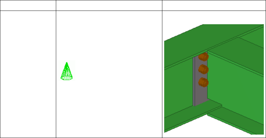
Type Description Examples
Connection Creates connection objects and
connects end(s) of secondary part(s)
to a main part. The main part may be
continuous at the connection point.
Component symbol is green.
End plate and base connections
See also
Creating custom components 10 Custom component types
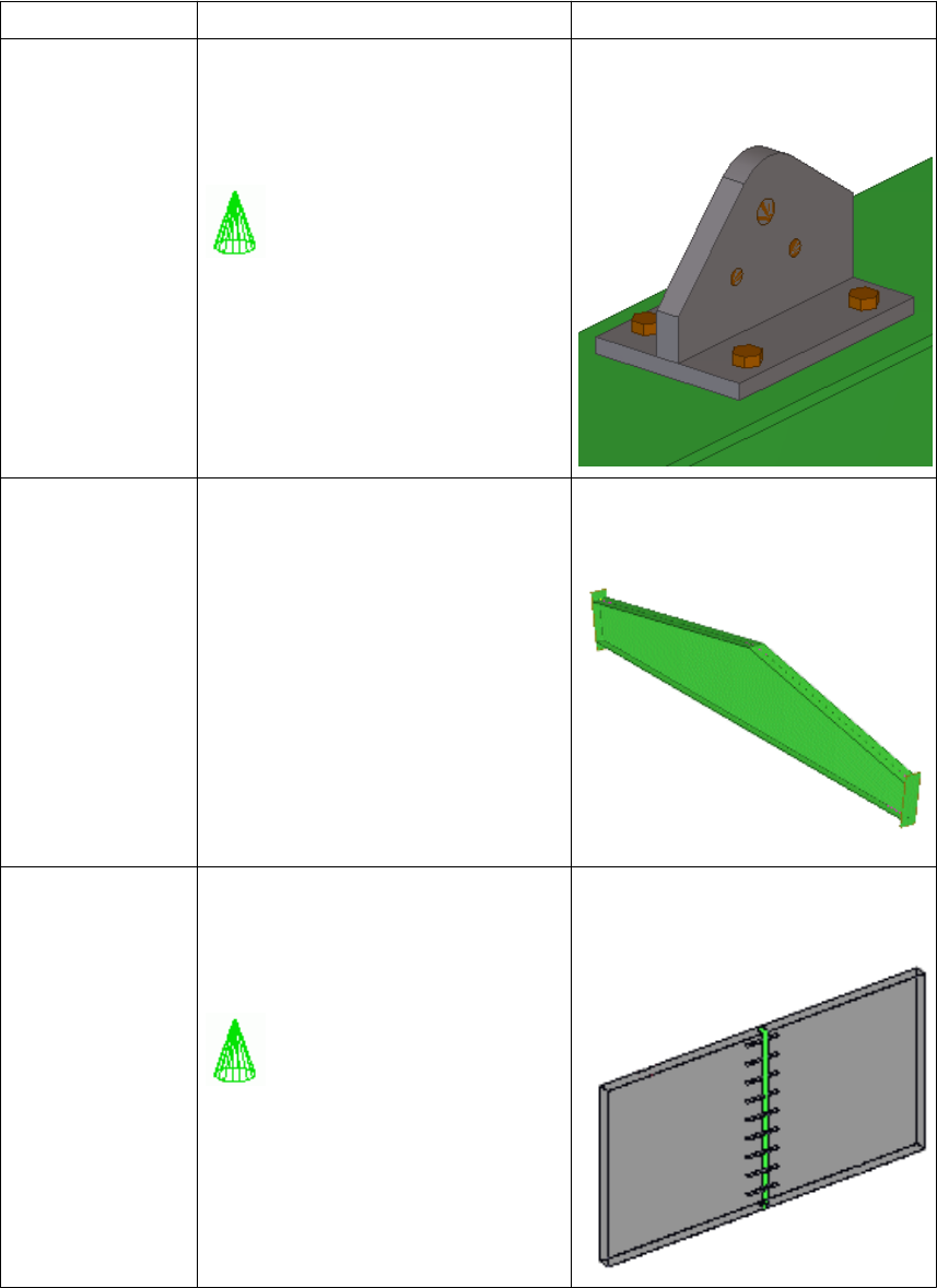
Type Description Examples
Detail Creates detail objects and connects
them to a single part at a picked
location.
Component symbol is green.
Stiffeners, holes, studs, cleats and
lifting brackets
Part Creates a group of objects that may
contain connections and details.
Does not get a component symbol.
Built-up beams, frames and
sandwich panels
Seam Creates seam objects and connects
parts along a line picked with two
points. The parts are usually parallel.
Component symbol is green.
Panel-to-panel seams
Creating custom components on page 7See also
Creating custom components 11 Custom component types
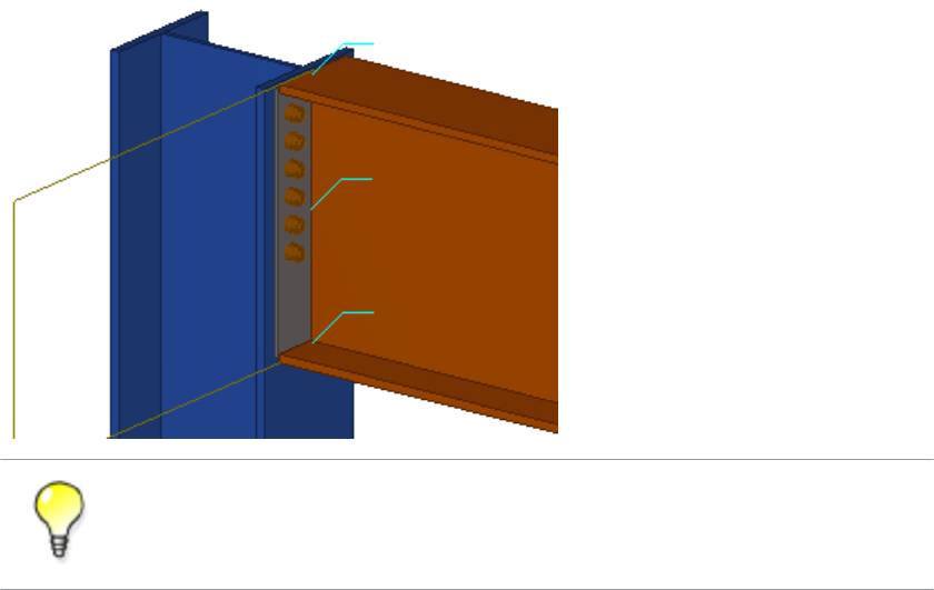
2.6 Example: Creating an end plate connection
In this example, you will create a custom component based on an existing end plate
component that we have exploded.
To explode a component, select the component, right-click and select Explode
Component from the pop-up menu.
To create an end plate connection:
1. Click Detailing --> Component --> Define Custom Component... to open the Custom
Component Wizard.
2. On the Type/Notes tab, set Type to Connection.
3. Enter a Name for the custom component.
Creating custom components 12 Example: Creating an end plate connection
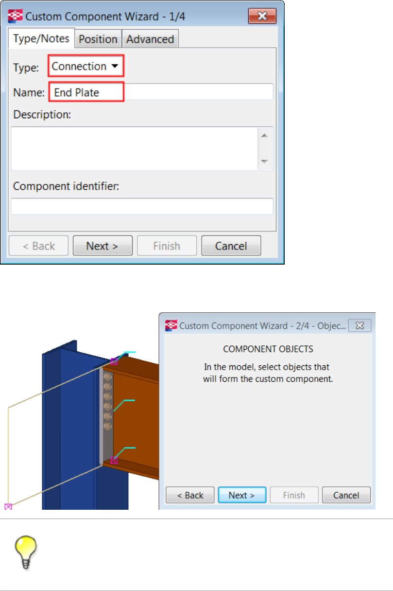
4. Click Next.
5. Select the objects to use in the custom component.
Use area selection (left to right) to select the objects.
Tekla Structures ignores the main part, secondary parts, grids and component
symbols when you are selecting objects to include in the custom component.
6. Click Next.
Creating custom components 13 Example: Creating an end plate connection
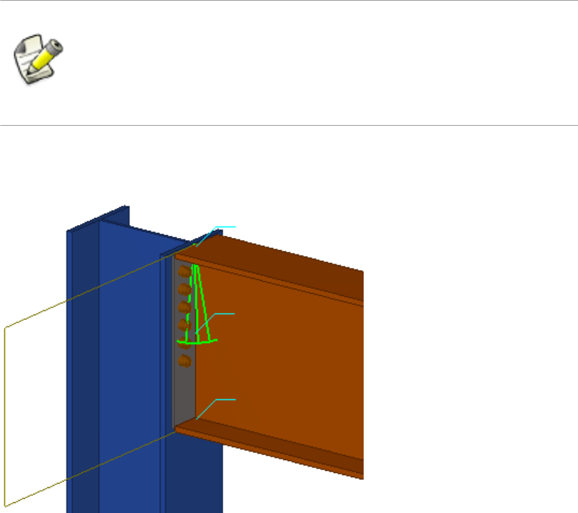
7. Select the column as the main part.
The main part supports the secondary part.
8. Click Next.
9. Select the beam as the secondary part.
The secondary part is supported by the main part.
When you select multiple secondary parts, pay attention to the order of
selection. The custom component will use the same selection order when you
add the component in a model.
The maximum number of secondary parts in a custom component is 30.
10. Click Finish.
Tekla Structures displays a component symbol for the new component.
You have now defined a simple custom component, which you can use in locations
similar to where it was originally created. This component is not intelligent and Tekla
Structures does not adjust dimensions to suit any changes in the model. To make the
custom component intelligent, you need to modify it in the custom component editor.
Creating custom components on page 7
Creating a custom component on page 9
Exploding components on page 8
Custom component editor on page 19
See also
Creating custom components 14 Example: Creating an end plate connection
2.7 Adding a custom component to a model
To add a custom component to a model:
1. Press Ctrl+F to open the Component Catalog.
2. Select Custom in the list to view all custom components in the Component Catalog.
3. Select the custom component you want to add.
4. Follow the instructions on the status bar to add the custom component in the model.
5. If needed, double-click the custom component in the model to modify its properties.
Creating custom components on page 7
Adding a custom part to a model and moving it using direct modification on page 15
2.8 Example: Adding an end plate connection to a model
In this example, you will add a previously created end plate connection to a model. Because
you have not modified the end plate connection to adapt to different situations in the model,
you need to add the custom connection to the similar location where the connection was
created. Otherwise the end plate connection may not work as required.
To add the end plate connection to a model:
1. Press Ctrl + F to open the Component Catalog.
2. Select Custom in the list to view custom components.
3. Select the End Plate custom connection.
Tekla Structures displays instructions on the status bar.
4. Select the column as the main part.
5. Select the beam as the secondary part.
Tekla Structures adds the end plate connection to the model.
Creating custom components on page 7
Example: Creating an end plate connection on page 12
Adding a custom component to a model on page 15
See also
See also
Creating custom components 15 Adding a custom component to a model

2.9 Adding a custom part to a model and moving it using direct
modification
You can use direct modification when you add custom parts to Tekla Structures models. You
can use direct modification also when you modify the location and rotation of the existing
custom parts in the model.
Limitations:
•Direct modification cannot be used to add custom parts to surfaces that have cuts or
edge chamfers. You need to hide the cutting parts and edge chamfer objects from the
view before you add custom parts on cut or chamfered surfaces using direct
modification.
• We do not recommend using direct modification with custom parts that are parametric
and in which the input points define the dimensions of the custom part. The preview is
simplified, based on the default custom part dimensions, and snapping has a different
focus than usually.
To add a custom part to a model using direct modification:
1. Ensure that the Direct modification switch is active.
2. Press Ctrl+F to open the Component Catalog.
3. Select Custom in the list to view all custom components in the Component Catalog.
4. Select the custom part you want to add.
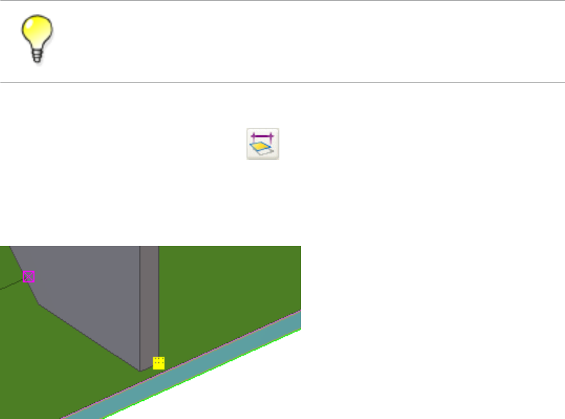
5. Move the mouse pointer over part faces and edges in the model, and see how the custom
part turns over and adjusts to the part faces.
If you are adding a custom part to another part, Tekla Structures shows location
dimensions from the first input point of the custom part to the nearest part faces.
6. If you are adding a custom part that has only one input point, you can rotate the custom
part in 90-degree steps around the work plane y axis by pressing Tab.
7. Depending on the number of the custom part input points, pick one or two points to
place the custom part in the model.
Creating custom components 16 Adding a custom part to a model and moving it using
direct modification
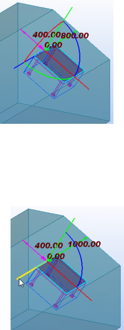
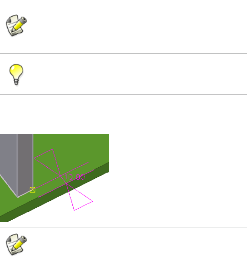
Tekla Structures shows coordinate axes, rotation handles, and location dimensions that
you can use to fine-tune the location and rotation of the custom part.
8. If needed, modify the location and rotation of the custom part.
Do any of the following:
• When you drag a handle, hold down the Shift key to use the snap switches.
By default, the snap switches are off to make it easier to drag the handle to any
location.
• To move the custom part along any of its coordinate axes, drag the relevant axis
handle to a new location.
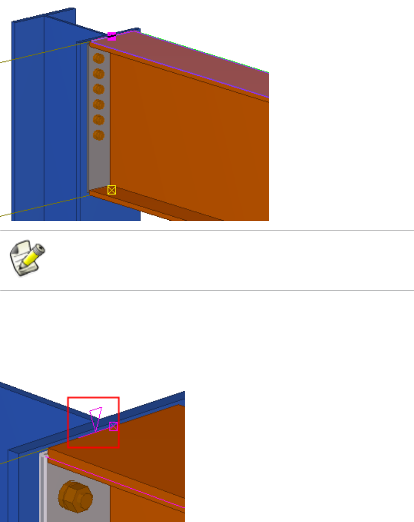
• To rotate the custom part around any of its coordinate axes, drag the relevant
rotation handle to a new location.
Creating custom components 17 Adding a custom part to a model and moving it using
direct modification
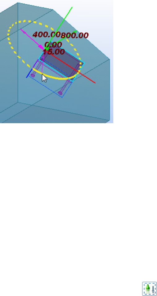
You can also press Tab to rotate the custom part in 90-degree steps in the direction
of the selected rotation handle.
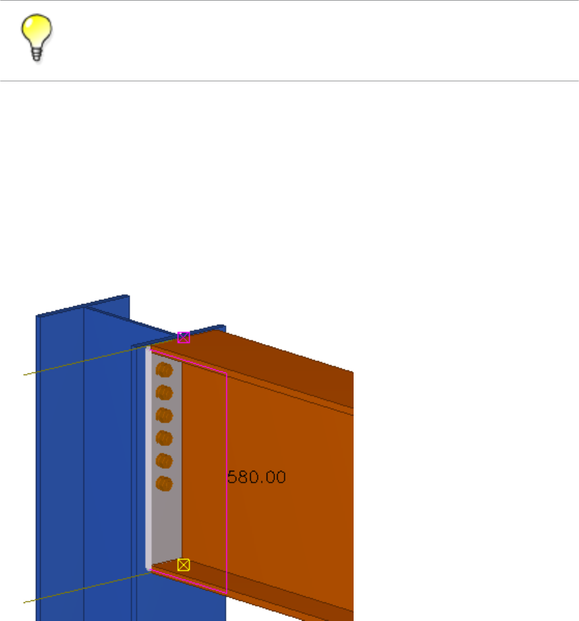
• To change a location dimension, drag the relevant dimension arrowhead to a new
location.
• To move or rotate the custom part by specifying a distance or angle:
1. Select an axis handle, a rotation handle, or a dimension arrowhead.
2. Using the keyboard, enter the value with which you want the dimension to
change.
To start with the negative sign (-), use the numeric keypad.
To enter an absolute value for the dimension, first enter $, then the value.
3. Press Enter, or click OK in the Enter a Numeric Location dialog box.
9. Click the middle mouse button to confirm the location and rotation, and to add the
custom part to the model.
10. If you want to modify an existing custom part in a model:
a. Ensure that the Select components selection switch is active.
b. Select the custom part.
c. Follow the instructions in step 8.
d. To stop modifying, press Esc, or right-click and select Interrup from the pop-up
menu.
Creating custom components on page 7See also
Creating custom components 18 Adding a custom part to a model and moving it using
direct modification
3Custom component editor
This section explains what the custom component editor is.
Click the links below to find out more:
•About custom component editor on page 19
•Opening the custom component editor on page 19
•Custom component browser on page 20
•Modifying custom component settings on page 21
•Saving a custom component on page 22
•Closing the custom component editor on page 22
3.1 About custom component editor
To make a simple custom component intelligent so that it adapts to changes in the model,
you must modify it in the custom component editor. In the custom component editor you can
build dependencies between component objects and model objects. For example, you can
specify that the size of a stiffener depends on the size of the beam. If you change the size of
the beam, the size of the stiffener also changes. You can also add distance variables, for
example, to specify the gap between a plate and a beam.
You can modify only the component objects, not the main or secondary parts, in the custom
component editor.
Custom component editor on page 19
See also
Custom component editor 19 About custom component editor

3.2 Opening the custom component editor
Open the custom component editor to modify custom components and create intelligent
custom components that adjust to changes in the model.
To open the custom component editor:
1. Click Detailing --> Component --> Edit Custom Component .
2. Select the custom component you want to modify.
Custom parts do not have a component symbol. To select custom parts, ensure
that the Select components switch is active.
The custom component editor opens showing the Custom component editor toolbar,
Custom component browser and four views of the custom component.
Custom component editor on page 19
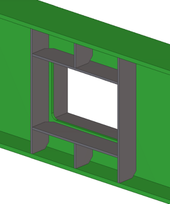
3.3 Custom component browser
The Custom component browser shows the contents of a custom component in a
hierarchical, tree-like structure.
See also
Custom component editor 20 Custom component browser
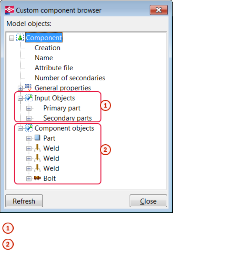
Objects that the custom component is attached to
Objects that the custom component creates
The Custom component browser works with the custom component editor views. When you
select an object in the Custom component browser, Tekla Structures highlights the object in
the views. Select an object in a custom component editor view and Tekla Structures highlight
the object in the Custom component browser.
Custom component editor on page 19
3.4 Modifying custom component settings
You can modify the following custom component settings after you have created a custom
component:
• change the description
• modify the position settings
See also
Custom component editor 21 Modifying custom component settings
• allow multiple instances of connection between parts
To change the settings of a custom component:
1. In the custom component editor, click the Modify custom component settings button
.
2. Modify the settings in the Custom component settings dialog box as required.
3. Click OK.
Custom component editor on page 19
Type/Notes tab properties on page 69
Position tab properties on page 70
Advanced tab properties on page 70
3.5 Saving a custom component
When you have modified a custom component in the custom component editor, you can save
the changes to all copies of the custom component in the model, or save the component with
a new name.
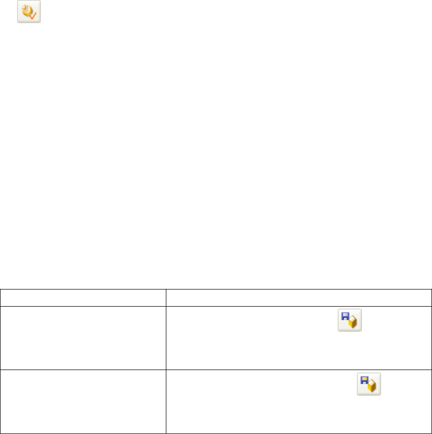
To save a custom component, do one of the following:
To Do this
Save changes in all copies of the
custom component 1. Click the Save component button in the custom
component editor.
2. Click Yes in the Save confirmation dialog box.
Save the component with a new
name 1. Click the Save with new name button in the
custom component editor.
2. Enter a new name for the component.
Custom component editor on page 19
See also
See also
Custom component editor 22 Saving a custom component

3.6 Closing the custom component editor
To close the custom component editor:
1. Click the Close button .
The Close custom component editor message opens.
2. Do one of the following:
• Click Yes to save the changes in the custom component. Tekla Structures applies the
changes to all copies of custom component in the model.
• Click No to close the custom component editor without saving the changes.
Custom component editor on page 19See also
Custom component editor 23 Closing the custom component editor
4Variables in custom components
This section explains what variables are and how they are created in the custom component
editor.
Click the links below to find out more:
•About variables on page 24
•Viewing variables on page 25
•Distance variables on page 25
•Parametric variables on page 31
•Reference distance variables on page 33
•Property references on page 35
•Construction planes in custom components on page 35
4.1 About variables
Variables are properties of a custom component. You can create variables in the custom
component editor, and use them to adapt custom components to changes in your models.
Some of the variables appear in the custom component dialog box, others are hidden and are
only used in calculations.
There are two types of variables:
• Distance variables
• Parametric variables
A distance variable is the distance between two planes, or between a point and a plane. A
distance variable binds parts together, or works as a variable reference distance.
A parametric variable controls all other properties in a custom component, such as name,
material grade and bolt size. Parametric variables are also used in calculations.
Variables in custom components on page 24
Distance variables on page 25
See also
Variables in custom components 24 About variables

Parametric variables on page 31
Variables properties on page 82
Functions in variable formulas on page 86
4.2 Viewing variables
To view the variables:
1. Click the Display variables button on the Custom component editor toolbar.
The Variables dialog box opens.
As the Component parameters category is active by default, the dialog box displays all
variables in the custom component that you are modifying.
2. If you want to see variables in the current model, such as bindings between a part’s end
point and a grid plane, select the Model parameters category on the left of the dialog
box.
Variables in custom components on page 24
4.3 Distance variables
Use distance variables to bind objects to planes so that the custom component can adapt to
changes in the model, such as different main profile shapes and sizes.
You can bind the following objects to a plane:
• construction plane
• reference points of parts (only custom component objects)
• reference points of bolt groups
• chamfers
• part and polygon cut handles
• line cuts
• reference points of reinforcing bars
• reference points of reinforcement meshes and strands
• fittings
Distance variables can be shown or hidden in the custom component dialog box. Show
distance variables when you want to be able to change distance values in the custom
component dialog box. Hide distance variables when you only bind objects to plane.
See also
Variables in custom components 25 Viewing variables
You can create distance variables manually or automatically.
Variables in custom components on page 24
Creating a distance variable manually on page 26
Testing a distance variable on page 27
Example: Creating a distance variable to bind an end plate on page 28
Creating distance variables automatically on page 30
Deleting a distance variable on page 31
Hiding variables in a custom component dialog box on page 55
Creating a distance variable manually
Before you start, ensure that part representation is set to rendered. You can select part
surfaces and available planes only in rendered views.
To create a distance variable:
1. Select the reference points that you want to bind to a plane.
Hold down the Alt key and use area selection (from left to right) to select
multiple reference points.
2. Do one of the following::
• Click the Add fixed distance button on the Custom component editor toolbar.
• Right-click a reference point and select Bind to Plane on the menu.
3. Move the pointer in a custom component editor view to highlight the plane that you
want to bind with the reference points.
See also
Variables in custom components 26 Distance variables
If you cannot highlight the correct plane, change the plane type on the
Custom component editor toolbar.
Boundary and component planes work for most profile types, so try to use
them whenever you can.
Hide parts and their reference lines if they are obscuring the required plane:
Hold down the Shift key, select the part, right-click and select Hide in the list.
4. Click the plane to create the distance variable.
Tekla Structures adds the distance variable in the Variables dialog box and displays a
distance symbol in the custom component editor views.
You can bind one object to a maximum of three planes.
Distance variables on page 25
Plane types on page 77
Example: Creating a distance variable to bind an end plate on page 28
Testing a distance variable
Test the distance variable you created to see changes in the custom component.
To test a distance variable:
1. Double-click the distance symbol in a custom component editor view.
The Distance Properties dialog box opens.
See also
Variables in custom components 27 Distance variables
2. Change Value.
3. Click Modify to see the changes.
You can also test a distance variable in the Variables dialog box by changing the Formula
for the distance variable.
Distance variables on page 25
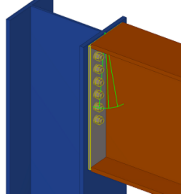
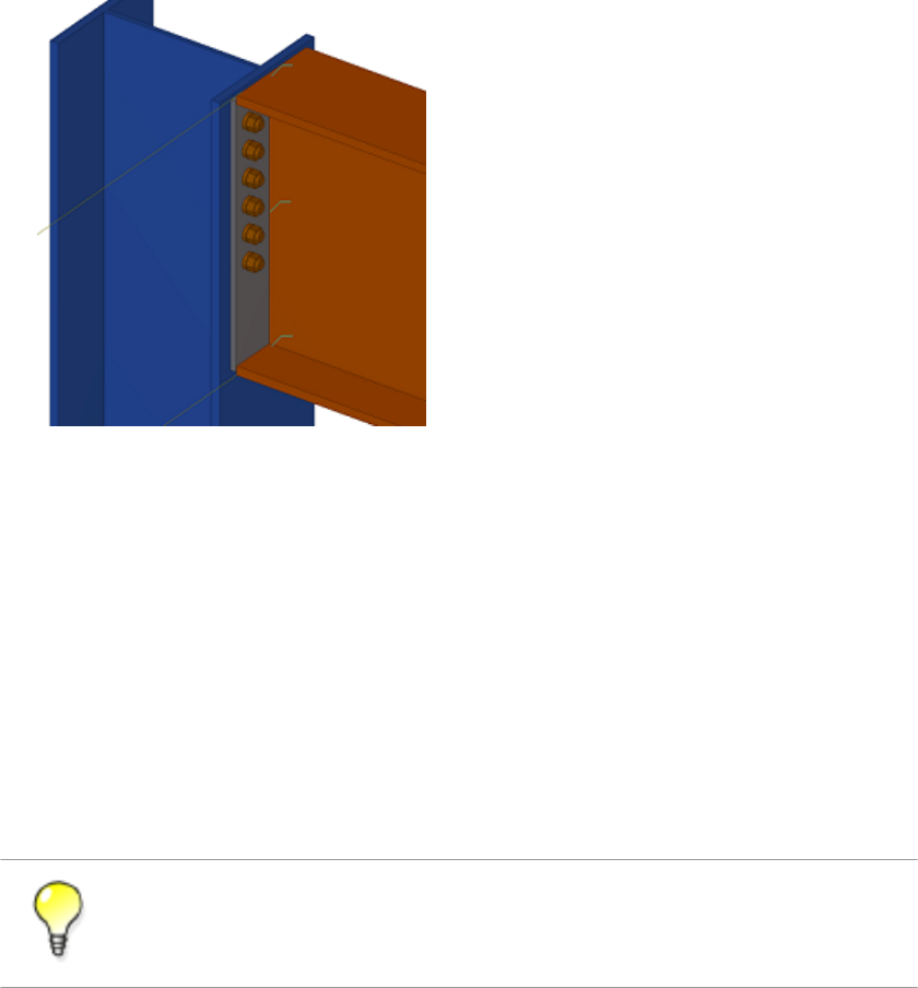
Example: Creating a distance variable to bind an end plate
In this example, you will bind the end plate top to the upper side of the beam.
To bind the end plate top to the upper side of the beam:
1. Select the end plate in a custom component editor view to see the end plate handles.
2. Select the top handle of the end plate.
3. Right-click and select Bind to Plane on the menu.
4. Move the pointer over the upper side of the beam flange to highlight it.
See also
Variables in custom components 28 Distance variables
If you cannot highlight the desired plane, change the plane type on the
Custom component editor toolbar.
Here you use the boundary plane type. If the part profile changes, the boundary plane is
always found.
5. Click the upper side of the beam flange.
A distance symbol appears in the custom component editor views.
6. If needed, give a descriptive name for the distance variable:
a. Open the Variables dialog box.
Variables in custom components 29 Distance variables

b. Change Label in dialog box to Plate Top to Flange Top for the new
distance variable.
If you now change the beam profile, the end plate top follows the upper side of the beam
flange due to the binding.
Distance variables on page 25
Plane types on page 77
Automatic distance variables
You can create distance variable automatically between the picked objects and the main and
the secondary parts of a connection or a detail. Picked objects, or their reference points or
handles, are bound to existing planes if the objects, or their reference points or handles, are
located exactly on the plane. Tekla Structures creates distance variables from a maximum of
three directions to existing planes. Tekla Structures selects planes in the following order:
1. Construction planes
2. Custom components
3. Plane types
Distance variables on page 25
Creating distance variables automatically on page 30
Construction planes in custom components on page 35
Plane types on page 77
Creating distance variables automatically
To create distance variables automatically:
1. Click the Create distances variables automatically button on the Custom
component editor toolbar.
2. Pick an object that has handles.
3. Click the middle mouse button to create distance variables.
4. Check the created variables.
You can see the distance variables in the Variables dialog box and in the custom
component editor views.
You cannot create distance variables automatically for custom parts since they do not have a
main part.
See also
See also
Limitations
Variables in custom components 30 Distance variables

Distance variables on page 25
Automatic distance variables on page 30
Deleting a distance variable
You cannot change an existing distance binding. You need to delete the existing distance
variable and then create a new distance variable to rebind.
To delete a distance variable:
1. Select the distance variable in a custom component editor view.
2. Press Delete.
You can also delete variables in the Variables dialog box by selecting the variable and
clicking the Delete button.
Distance variables on page 25
4.4 Parametric variables
There are two basic ways to use parametric variables:
• Link parametric variables to properties of custom component objects to change the
properties in the custom component dialog box. For example, you can change the object’s
name, material and profile.
• Use parametric variables for calculating values. For example, you can calculate the
position of a stiffener relative to the beam length.
You can decide which parametric variables are shown in the custom component dialog box.
Hide the parametric variables that you use only in calculations and show the variables that
you can use for changing the properties of the custom component.
Variables in custom components on page 24
Creating and linking a parametric variable on page 31
Example: Creating a parametric variable to set end plate material on page 32
Hiding variables in a custom component dialog box on page 55
See also
See also
See also
Variables in custom components 31 Parametric variables
Creating and linking a parametric variable
To create and link a parametric variable:
1. Open the Variables dialog box in the custom component editor.
2. Click the Add button.
A new parametric variable appears in the dialog box.
3. Change Value type for the new variable to match the property you want to link.
For example, change Value type to Material if you link the parametric variable to the
material property of the object.
4. Browse for the object property in the Custom component browser as required.
To find the required object more easily in the Custom component browser,
select the object in a custom component editor view to highlight the object in
the Custom component browser.
5. Right-click the property and select Add Equation.
6. Enter Name of the parametric variable after the equal sign.
The parametric variable is now linked to the object property. To test the parametric
variable, change Value of the variable.
Variables in custom components on page 24
Parametric variables on page 31
Example: Creating a parametric variable to set end plate material on page 32
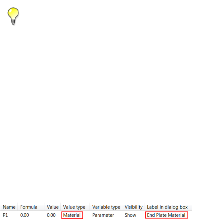
Example: Creating a parametric variable to set end plate material
In this example, you will create a parametric variable and link it to the end plate material.
To create a parametric variable to set the end plate material:
1. Open the Variables dialog box in the custom component editor.
2. Click the Add button.
A new parametric variable appears.
3. Change Value type for the new variable to Material.
4. Enter End Plate Material in Label in dialog box.
5. Open the Custom component browser in the custom component editor.
See also
Variables in custom components 32 Parametric variables
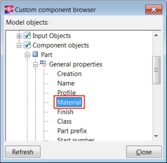
6. Select the end plate in a custom component editor view to highlight the end plate in the
Custom component browser.
7. Browse for the end plate material in the Custom component browser.
8. Right-click Material and select Add Equation.
9. Enter P1 after the equal sign and press Enter.
You have now linked parametric variable P1 to the end plate material.
You can now change the end plate material in the custom component dialog box.
Variables in custom components on page 24
Parametric variables on page 31
Creating and linking a parametric variable on page 31
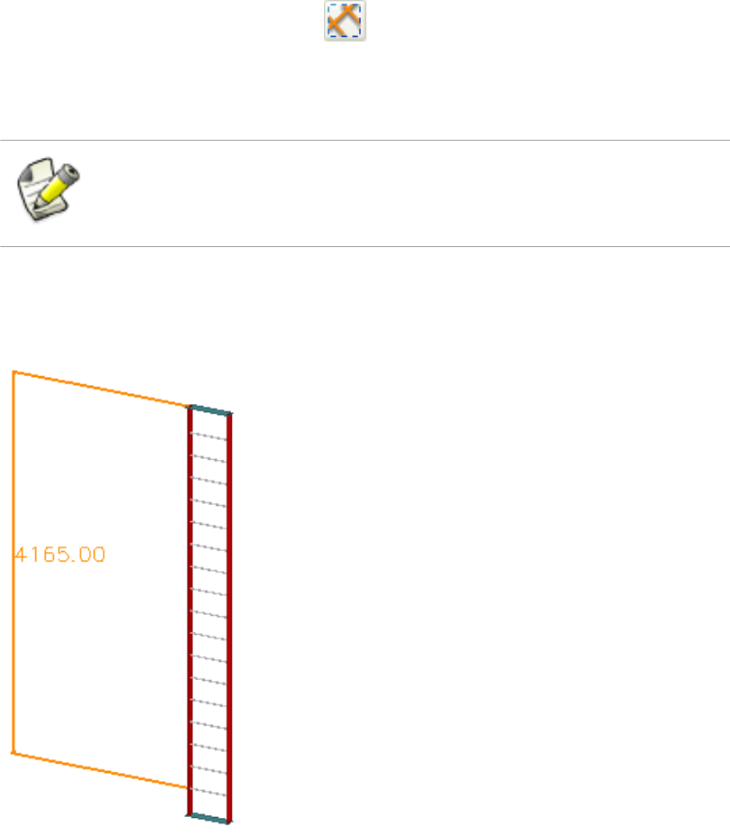
4.5 Reference distance variables
Use reference distances variables to measure the distance between two points or a point and
a plane. You can then use the reference distance variable in calculations, for example, to
determine the spacing of rungs on a ladder.
A reference distance variable changes as you move the objects it refers to. You cannot move
objects by changing their reference distance variables.
See also
Variables in custom components 33 Reference distance variables
Variables in custom components on page 24
Creating a reference distance variable on page 34
Creating a reference distance variable
To create a reference distance variable:
1. Select the reference point that you want to bind to a plane.
2. Click the Add reference distance button on the Custom component editor
toolbar.
3. Move the pointer in a custom component editor view to highlight the plane that you
want to bind with the reference point.
If you cannot highlight the correct plane, change the plane type on the
Custom component editor toolbar.
4. Click the plane to create the reference distance variable.
Tekla Structures adds the reference distance variable in the Variables dialog box and
displays the reference distance with orange color in the custom component editor views.
See also
Variables in custom components 34 Reference distance variables

Variables in custom components on page 24
Reference distance variables on page 33
4.6 Property references
You can copy property references of main and secondary parts and use them to determine
the properties of custom components. The property references are dynamic. If a property later
changes the reference reflects the change. For example, you can use a beam length reference
in variable calculations. If the length changes, the correct value is automatically used in the
calculations.
Variables in custom components on page 24
Copying a property reference on page 35
Copying a property reference
To copy a reference property:
1. Browse for the object property in the Custom component browser as required.
To find the required object more easily in the Custom component browser,
select the object in a custom component editor view to highlight the object in
the Custom component browser.
2. Right-click the property.
3. Select Copy Reference in the list.
4. Paste and use the reference as required.
You can paste the reference to Formula of a variable in the Variables dialog box to use it
in calculation or paste the reference to a custom component object property.
Property references on page 35
Example: Determining the number of bolt rows on page 42
4.7 Construction planes in custom components
You may occasionally need to create your own planes and use them to bind and move groups
of objects.
See also
See also
See also
Variables in custom components 35 Property references

Variables in custom components on page 24
Creating a construction plane in the custom component editor on page 36
Creating a construction plane in the custom component editor
To create a construction plane:
1. Click the Add construction plane button on the Custom component editor
toolbar.
2. Pick four points in a custom component editor view.
3. Click the middle mouse button.
Tekla Structures draws the construction plane.
Variables in custom components on page 24
Construction planes in custom components on page 35
Example: Using construction planes for determining the stiffener position on page 43
See also
See also
Variables in custom components 36 Construction planes in custom components
5Examples of modifying custom
components
This section presents examples on how to modify custom components to make them adapt to
changes in models. The examples are independent from each other.
Click the links below to find out more:
•Example: Adding an option to create an object on page 37
•Example: Determining the bolt group distance from the beam flange on page 38
•Example: Determining the bolt size and bolt standard on page 40
•Example: Determining the number of bolt rows on page 42
•Example: Using construction planes for determining the stiffener position on page 43
•Example: Replacing sub-components on page 46
•Example: Using properties files to modify a sub-component on page 47
•Example: Using user-defined attributes in custom components on page 48
•Example: Determining the number of handrail posts using a template attribute on page
50
•Example: Using Excel spreadsheets with custom components on page 54
5.1 Example: Adding an option to create an object
In this example, you will add an option to select whether or not to create an object in a
custom component.
To add an option to create an object in a custom component:
1. Open the Variables dialog box in the custom component editor.
2. Create a new parametric variable.
3. Modify the parametric variable.
Examples of modifying custom components 37 Example: Adding an option to create an object
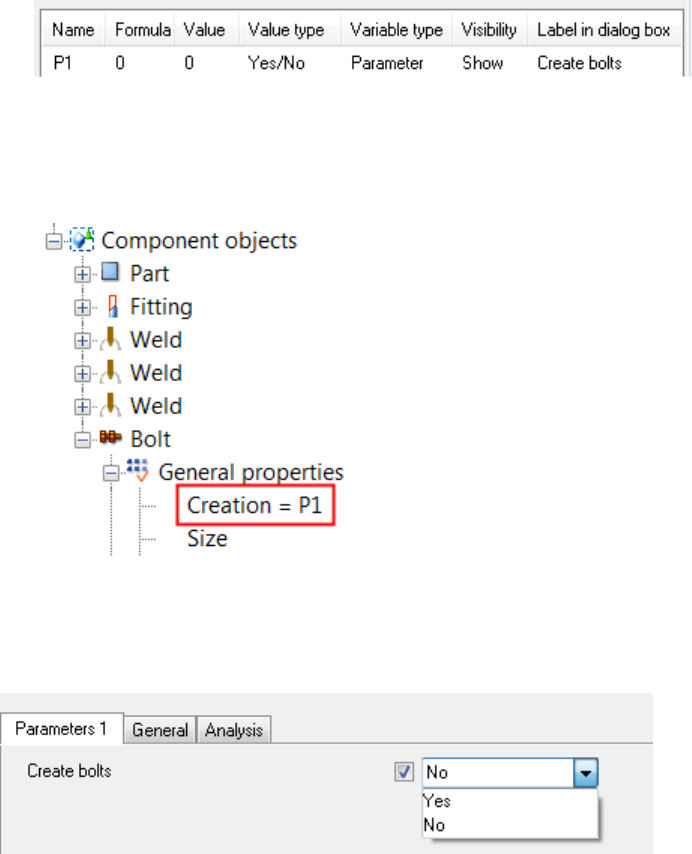
• Change Value type to Yes/No.
• Enter a name in Label in dialog box.
Tekla Structures displays the label in the custom component dialog box.
4. Open the Custom component browser in the custom component editor.
5. Browse for the object in the Custom component browser.
6. Link the Creation property to the parametric variable.
7. Save the custom component.
8. Close the custom component editor.
You now have the option in the custom component dialog box to create the object.
Examples of modifying custom components on page 37
Creating and linking a parametric variable on page 31
Variables properties on page 82
See also
Examples of modifying custom components 38 Example: Determining the bolt group distance from the
beam flange
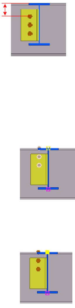
5.2 Example: Determining the bolt group distance from the beam
flange
In this example, you will determine the bolt group distance from the beam flange.
To determine the bolt group distance from the beam flange:
1. Modify the properties of the bolt group.
a. Double-click the bolt group in the custom component editor.
The Bolt Properties dialog box opens.
b. Clear all values under the Offset from area in the Bolt Properties dialog box.
c. Click Modify.
The bolt group moves to the same level with the start point handle of the bolt group.
2. Bind the bolt group to the beam flange.
a. Select the bolt group in the custom component editor.
b. Select the (yellow) top handle.
c. Right-click and select Bind to plane in the list.
d. Select the top flange of the beam.
Examples of modifying custom components 39 Example: Determining the bolt group distance from the
beam flange
A new distance variable appears in the Variables dialog box.
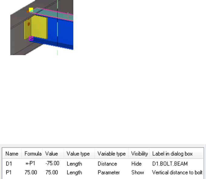
3. Open the Variables dialog box in the custom component editor.
4. Create a new parametric variable.
5. Modify the parametric variable.
a. Enter a distance value in Formula.
b. Enter Vertical distance to bolt in Label in dialog box.
6. Enter =-P1 in Formula to for the distance variable.
7. Save the custom component.
8. Close the custom component editor.
You can now determine the bolt group distance from the beam flange by changing the
Vertical distance to bolt value in the custom component dialog box.
Examples of modifying custom components on page 37
Creating a distance variable manually on page 26
Creating and linking a parametric variable on page 31
Variables properties on page 82
5.3 Example: Determining the bolt size and bolt standard
In this example, you will create two parametric variables to determine bolt size and bolt
standard.
To determine the bolt size and bolt standard:
1. Open the Variables dialog box in the custom component editor.
2. Create two new parametric variables.
3. Modify the first parametric variable.
See also
Examples of modifying custom components 40 Example: Determining the bolt size and bolt standard
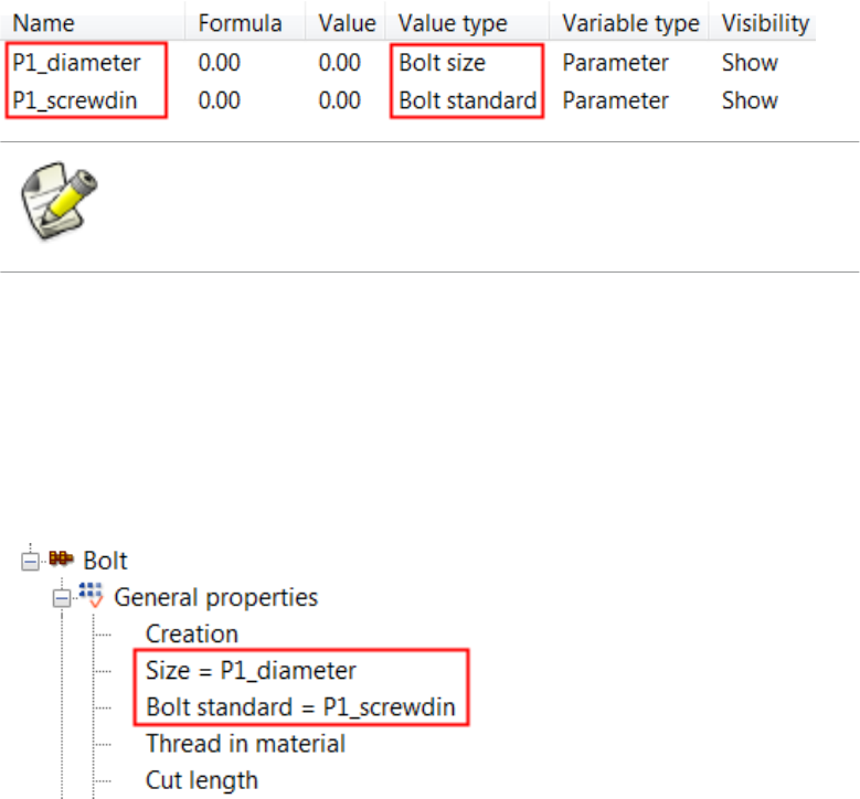
• Change Value type to Bolt size.
Tekla Structures automatically adds the suffix _diameter to the name of the
variables. Do not delete the suffix.
• Enter Bolt Size in Label in dialog box.
4. Modify the second parametric variable.
a. Change Value type to Bolt standard.
Tekla Structures automatically adds the suffix _screwdin to the name of the
variable. Do not delete the suffix.
b. Change the prefix in Name of the second variable so that the prefixes for the two
variables are same.
The bolt size and bolt standard variables must always have the same prefix,
otherwise they do not work.
c. Enter Bolt Standard in Label in dialog box.
5. Open the Custom component browser in the custom component editor.
6. Link the parametric variables to the bolt group properties in the Custom component
browser.
• Link P1_diameter to the Size property.
• Link P1_screwdin to the Bolt standard property.
7. Save the custom component.
8. Close the custom component editor.
You can now determine the bolt size and bolt standard for the custom component in the
custom component dialog box.
Examples of modifying custom components on page 37
See also
Examples of modifying custom components 41 Example: Determining the bolt size and bolt standard
Creating and linking a parametric variable on page 31
Variables properties on page 82
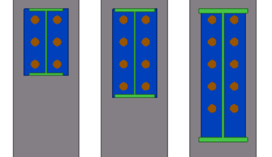
5.4 Example: Determining the number of bolt rows
In this example, you will determine the number of bolt rows based on the beam height. You
will use if statements in calculations.
To determine the number of bolt rows:
1. Open the Variables dialog box in the custom component editor.
2. Create a new parametric variable.
3. Change Value type to Number for the variable.
4. Browse for Height of the beam in the Custom component browser.
5. Right-click Height and select Copy Reference in the list.
6. Enter the following if statement in Formula of the parametric variable:
=if (fP(Height,"ID50B8559A-0000-00FD-3133-353432363133")<
301) then 2 else (if
(fP(Height,"ID50B8559A-0000-00FD-3133-353432363133")>501)
then 4 else 3 endif) endif
fP(Height,"ID50B8559A-0000-00FD-3133-353432363133") is the
beam height reference copied from the Custom component browser.
The variable gets its value in the following way:
• If the beam height is under 301 mm, the value is 2.
• If the beam height is over 501 mm, the value is 4.
• If the beam height is between 300 and 500 mm, the value is 3.
7. Create a new parametric variable.
8. Change Value type of the new variable to Distance list.
Examples of modifying custom components 42 Example: Determining the number of bolt rows
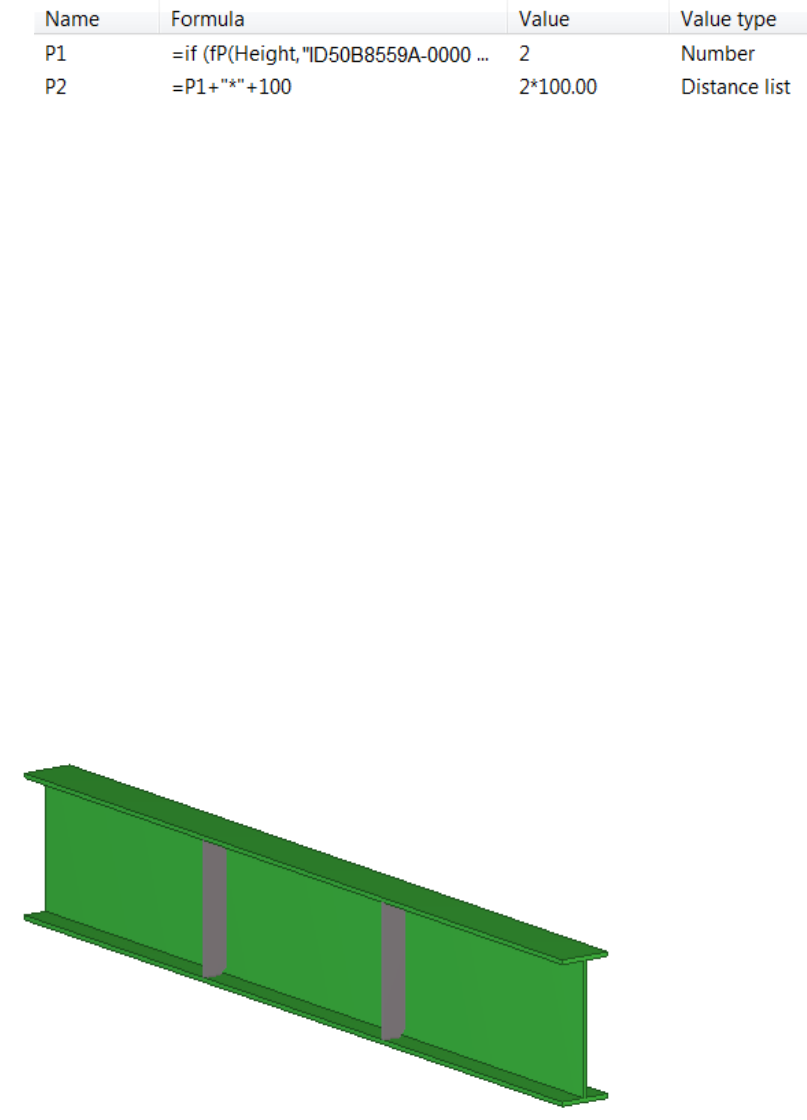
9. Enter =P1+"*"+100 in Formula of the new variable.
In the formula, 100 is the bolt spacing and the P1 value is the number of bolt rows.
10. Browse for Bolt group distance x in Custom component browser.
11. Link variable P2 to Bolt group distance x.
12. Save the custom component.
13. Close the custom component editor.
When you now change the beam height, the number of bolt rows also changes.
Examples of modifying custom components on page 37
Creating and linking a parametric variable on page 31
Property references on page 35
Variables properties on page 82
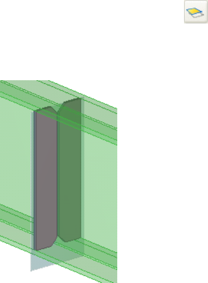
5.5 Example: Using construction planes for determining the
stiffener position
In this example, you will use construction planes for determining the position of the
stiffeners. You will position the stiffeners so that they divide the beam into three equally
long sections.
To position the stiffeners using the construction planes:
1. Open the Variables dialog box in the custom component editor.
See also
Examples of modifying custom components 43 Example: Using construction planes for determining the
stiffener position
2. Create a new parametric variable.
3. Get the GUID of the beam.
a. Click Tools --> Inquire --> Object .
b. Select the beam.
The Inquire Object dialog box opens.
c. Check the GUID of the beam in the Inquire Object dialog box.
4. Modify the parametric variable.
• Enter
=fTpl("LENGTH","ID4C8B5E24-0000-017D-3132-383432313432"
) in Formula.
ID4C8B5E24-0000-017D-3132-383432313432 is the GUID of the beam.
The value of the variable is now the same as the beam length. If you change the
beam length, the value also changes.
• Enter Beam Length in Label in dialog box.
5. Create a new parametric variable.
6. Modify the new parametric variable.
• Enter =P1/3 in Formula.
• Enter 3rd Points in Label in dialog box.
7. Create a construction plane.
a. Click the Add construction plane button on the Custom component editor
toolbar.
b. Pick the points and then click the middle mouse button to create a construction
plane in the center of a stiffener at one end.
Examples of modifying custom components 44 Example: Using construction planes for determining the
stiffener position
8. Bind the stiffener to the construction plane.
a. Select the stiffener.
b. Hold down Alt and use area selection (from left to right) to select all stiffener
handles.
c. Right-click and select Bind to plane.
d. Bind the stiffener handles to the construction plane.
9. Bind the construction plane to the beam end.
a. Select the construction plane.
b. Right-click and select Bind to plane.
c. Bind the construction plane to the beam end.
10. Repeat steps 7 to 9 for the stiffener at the other end.
11. Change Formula to =P2 for the two distance variables that bind the construction planes
to the beam ends.
12. Save the custom component.
Examples of modifying custom components 45 Example: Using construction planes for determining the
stiffener position
13. Close the custom component editor.
When you change the beam length, the position of the stiffeners changes so that the
stiffeners divide the beam into three equally long sections.
Examples of modifying custom components on page 37
Creating and linking a parametric variable on page 31
Creating a construction plane in the custom component editor on page 36
Creating a distance variable manually on page 26
Variables properties on page 82
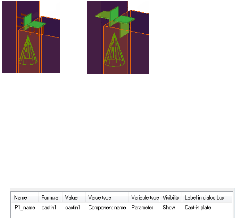
5.6 Example: Replacing sub-components
In this example, you will add an option in the custom component dialog box to replace sub-
components with other sub-components.
To replace sub-components in a custom component:
1. Open the Variables dialog box in the custom component editor.
2. Create a new parametric variable.
3. Modify the parametric variable.
a. Change Value type to Component name.
Tekla Structures automatically adds the suffix _name in the variable name.
Do not delete the suffix.
b. Enter the name of the sub-components in Formula.
c. Enter a descriptive name in Label in dialog box.
See also
Examples of modifying custom components 46 Example: Replacing sub-components
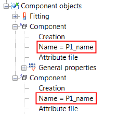
4. Link P1_name to the Name properties of both sub-components.
a. Open the Custom component browser in the custom component editor.
b. Browse for the Name attribute of a sub-component.
c. Right-click Name and select Add Equation.
d. Enter P1_name after the equals sign.
e. Repeat steps 4b to 4d for the other sub-component.
5. Save the custom component.
6. Close the custom component editor.
You can now change the sub-components using the Cast-in-plate option in the custom
component dialog box.
Examples of modifying custom components on page 37
Creating and linking a parametric variable on page 31
Variables properties on page 82
5.7 Example: Using properties files to modify a sub-component
In this example, you will add an option to use properties files to modify a sub-component in
a custom component.
To use properties files to modify a sub-component:
1. Open the Variables dialog box in the custom component editor.
2. Create a new parametric variable.
3. Modify the parametric variable.
See also
Examples of modifying custom components 47 Example: Using properties files to modify a sub-component
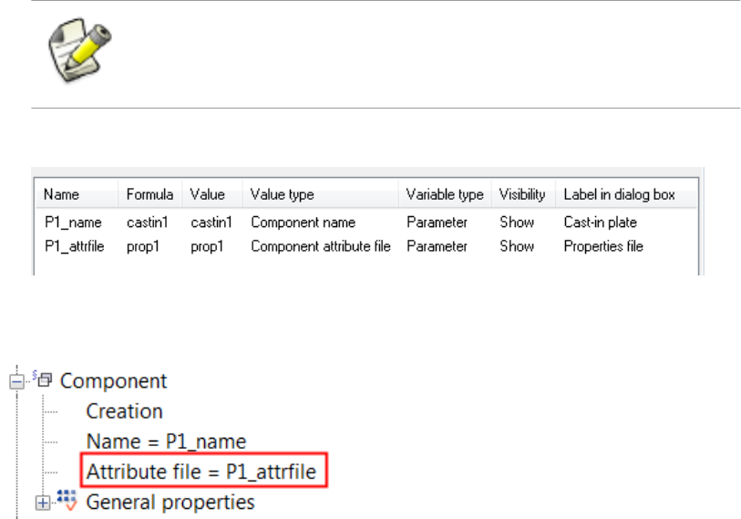
a. Change Value type to Component attribute file.
Tekla Structures automatically adds the suffix _attrfile in the variable name. Do
not delete the suffix.
b. Enter the name of a properties file in Formula.
c. Change Name of the new variable so that the prefix matches with the variable linked
to the component name.
The component name and component attribute file variables must always
have the same prefix, otherwise they do not work.
d. Enter a descriptive name in Label in dialog box.
4. Open the Custom component browser in the custom component editor.
5. Link P1_attrfile to the Attribute file property of the sub-component.
6. Save the custom component.
7. Close the custom component editor.
You can now modify the sub-component using the Properties file option in the custom
component dialog box.
Examples of modifying custom components on page 37
Creating and linking a parametric variable on page 31
Variables properties on page 82
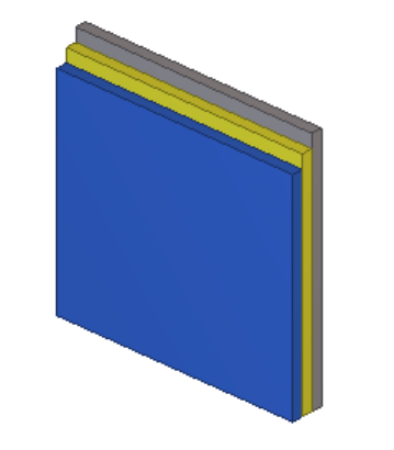
5.8 Example: Using user-defined attributes in custom components
In this example, you will link parametric variables to user-defined attributes of the panels.
You can then use the user-defined attributes in view filters to show or hide the panels.
See also
Examples of modifying custom components 48 Example: Using user-defined attributes in custom
components
To use user-defined attributes in a custom component:
1. Open the Variables dialog box in the custom component editor.
2. Create a new parametric variable.
3. Modify the parametric variable.
• Change Value type to Text.
• Enter Type1 in Formula.
• Enter Panel1 in Label in dialog box.
4. Open the Custom component browser in the custom component editor.
5. Browse for User-defined attributes of the first panel.
You will link P1 to the USER_FIELD_1 attribute. However, the attribute is not visible in
the Custom component browser.
6. Make the user-defined attribute visible in the Custom component browser.
a. Double-click first of the panels.
The panel properties dialog box opens.
b. Click User-defined attributes....
The dialog box for user-defined attributes opens.
c. Go to the Parameters tab.
d. Enter text in the User field 1 box.
e. Click Modify.
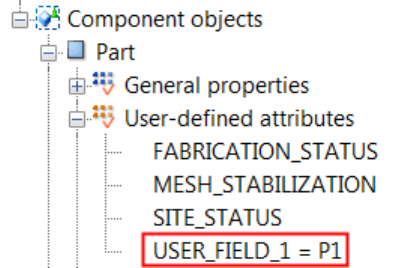
7. Click Refresh in the Custom component browser.
USER_FIELD_1 appears under User-defined attributes in the Custom component
browser.
8. Link P1 to USER_FIELD_1.
Examples of modifying custom components 49 Example: Using user-defined attributes in custom
components
9. Create two new parametric variables and link them to the user-defined attributes of the
other two panels.
10. Save the custom component.
11. Close the custom component editor.
You can now create a view filter and hide or show panels using the User field 1 attribute
and the Formula values you entered for the parametric variables in the filter.
Examples of modifying custom components on page 37
Creating and linking a parametric variable on page 31
Variables properties on page 82
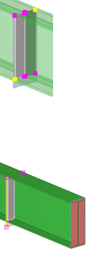
5.9 Example: Determining the number of handrail posts using a
template attribute
In this example, you will use a template attribute to determine the number of handrail posts
based on the beam length. The handrail posts were created at both ends of the beam and one
of them was copied with the Array of objects (29) component.
See also
Examples of modifying custom components 50 Example: Determining the number of handrail posts using a
template attribute
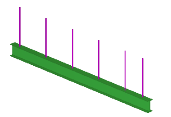
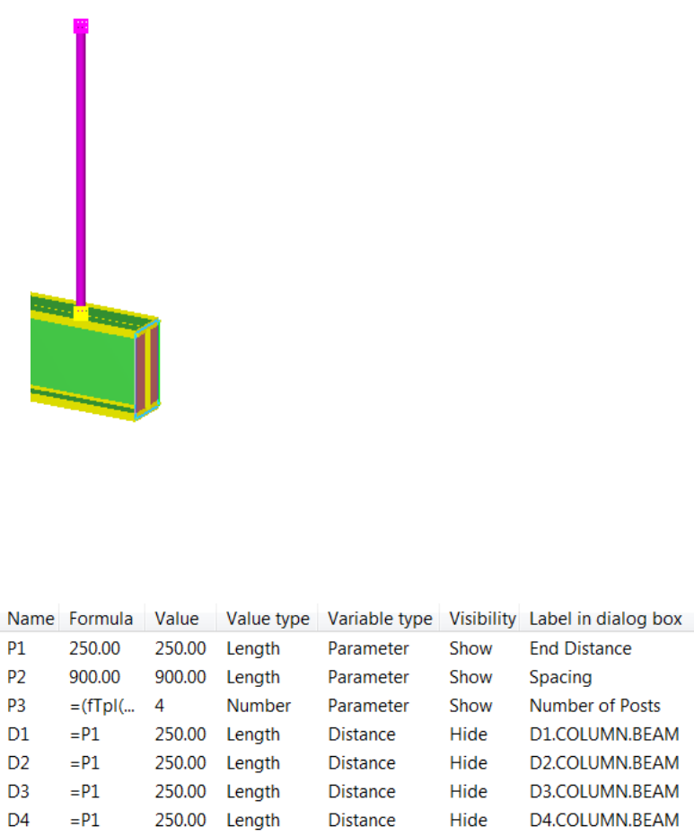
To determine the number of handrail posts:
1. Open the Variables dialog box in the custom component editor.
2. Create three new parametric variables.
3. Modify parametric variable P1.
• Enter 250 in Formula.
• Enter End Distance in Label in dialog box.
4. Modify parametric variable P2.
• Enter 900 in Formula.
• Enter Spacing in Label in dialog box.
5. Modify parametric variable P3.
• Change Value type to Number.
• Enter Number of Posts in Label in dialog box.
6. Inquire the GUID of the beam.
a. Click Tools --> Inquire --> Objects .
b. Select the beam.
The Inquire Object dialog box opens.
c. Check the GUID of the beam in the Inquire Object dialog box.
7. Change Formula of P3 to
=(fTpl("LENGTH","ID50B8559A-0000-010B-3133-353432373038")
-(P1*2))/P2.
Examples of modifying custom components 51 Example: Determining the number of handrail posts using a
template attribute
fTpl("LENGTH","ID50B8559A-0000-010B-3133-353432373038") is
the length template attribute of the beam and
ID50B8559A-0000-010B-3133-353432373038 is the GUID of the beam.
The number of the posts is calculated as follows: first the end distances are subtracted
from the beam length and the result is divided by the post spacing.
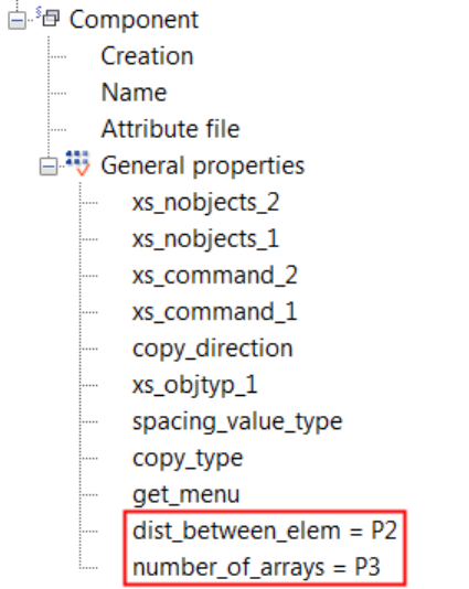
8. Open the Custom component browser in the custom component editor.
9. Link parametric variable P2 and P3 to the properties of Array of objects (29).
10. Bind the first post to the beam end.
a. Select the post in the custom component editor view.
b. Hold down Alt and use area selection (from left to right) to select the post handles.
c. Right-click and select Bind to Plane.
d. Bind the handles to the beam end.
Examples of modifying custom components 52 Example: Determining the number of handrail posts using a
template attribute
11. Bind the last post to the other beam end following the instructions in step 10.
12. Modify all distance variables.
• Change Formula to =P1.
• Change Visibility to Hide.
13. Save the custom component.
14. Close the custom component editor.
You can now change the spacing and the end distance of the handrail posts in the custom
component dialog box. Tekla Structures calculates the number of posts based on the spacing,
end distance and the length of the beam.
Examples of modifying custom components on page 37
Creating and linking a parametric variable on page 31
Creating a distance variable manually on page 26
Variables properties on page 82
See also
Examples of modifying custom components 53 Example: Determining the number of handrail posts using a
template attribute
5.10 Example: Using Excel spreadsheets with custom components
In this example, you will link an Excel spreadsheet to a custom component. For example, you
can use Excel spreadsheets to check connections.
The name of the spreadsheet file must be component_"component_name".xls. For
example, component_stiffener.xls for a custom component named stiffener.
Tekla Structures searches for the spreadsheets in the following locations:
• In the model folder: ..\<model>\exceldesign\
• In the folder defined with the XS_EXTERNAL_EXCEL_DESIGN_PATH advanced
option.
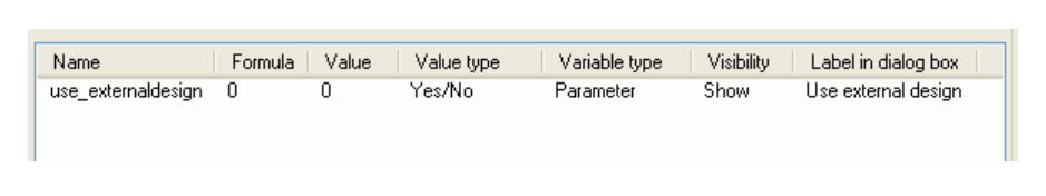
To use Excel spreadsheets with custom components:
1. Open the Variables dialog box in the custom component editor.
2. Create a new parametric variable.
3. Modify the parametric variable.
a. Change Value type to Yes/No.
b. Enter use_externaldesign in Name.
c. Enter Use external design in Label in dialog box.
4. Save the custom component.
5. Close the custom component editor.
The custom component dialog box now contains the Use external design option.
Examples of modifying custom components on page 37
Creating and linking a parametric variable on page 31
Variables properties on page 82
See also
Examples of modifying custom components 54 Example: Using Excel spreadsheets with custom
components
6Modifying the custom component
dialog box
This section explains how to modify the custom component dialog box. For example, you can
decide which variables are visible in the dialog box, and you can add images, tabs and lists to
the dialog box.
Click the links below to find out more:
•Hiding variables in a custom component dialog box on page 55
•Custom component dialog box file on page 55
•Custom Component Dialog Editor on page 56
6.1 Hiding variables in a custom component dialog box
By default, Tekla Structures displays distance variables whose value is more than zero and
parametric variables in the custom component dialog box. You can hide the variables if
required.
To hide a variable in a custom component dialog box:
1. Open the Variables dialog box in the custom component editor.
2. Change Visibility of the variable to Hide.
3. Save the custom component.
4. Close the custom component editor.
Modifying the custom component dialog box on page 55
Viewing variables on page 25
See also
Modifying the custom component dialog box 55 Hiding variables in a custom component dialog box
6.2 Custom component dialog box file
When you create a new custom component, Tekla Structures automatically creates the input
file that defines the custom component dialog box. The input file is located in the
CustomComponentDialogFiles folder under the model folder. The input file has the
same name as the custom component and the file name extension is .inp.
When you modify a custom component, Tekla Structures automatically creates a backup file
of the input file. The backup file has the extension .inp_bak, and it is located in the
CustomComponentDialogFiles folder under the model folder. Tekla Structures
displays a notification when the backup file is created.
Opening a custom component dialog box file in Custom Component Dialog Editor on page
57
Preventing modifications of the custom component dialog box on page 63
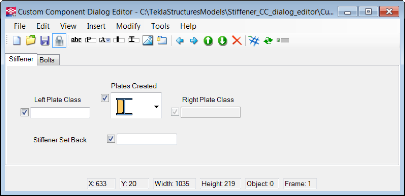
6.3 Custom Component Dialog Editor
Custom Component Dialog Editor is a tool for editing your custom component dialog box.
You can use Custom Component Dialog Editor for adding and arranging dialog box items,
such as images, tabs and lists.
Opening a custom component dialog box file in Custom Component Dialog Editor on page
57
Moving items in a custom component dialog box on page 57
Adding an image in a custom component dialog box on page 57
Adding and renaming a tab in a custom component dialog box on page 58
Example: Modifying the dialog box of a stiffener detail on page 58
See also
See also
Modifying the custom component dialog box 56 Custom Component Dialog Editor

Setting the options for Custom Component Dialog Editor
To set the options for Custom Component Dialog Editor:
1. Click Tools --> Options .
2. Define the options as needed.
By default, the image folder is ..\ProgramData\TeklaStructures
\<version>\Bitmaps. You can revert to the default folder by clicking Default.
3. Click Apply and OK.
Opening a custom component dialog box file in Custom Component
Dialog Editor
To open a custom component dialog box file in Custom Component Dialog Editor:
1. Click Detailing --> Component --> Edit Custom Component Dialog Box .
2. Select the custom component in the model.
The custom component dialog box file opens in Custom Component Dialog Editor.
You can also right-click a custom component in the model or in the Component Catalog
and select Edit Custom Component Dialog Box from the pop-up menu to open the
custom component dialog file for editing.
Custom component dialog box file on page 55
Moving items in a custom component dialog box
To move an item in the custom component dialog box, drag the item to the new position.
You can select multiple items by holding down the Ctrl key and clicking the items,
or by using area selection. You can then drag all the items at once.
You can also use the copy, cut and paste commands. For example, to move items to another
tab, select the items, press Ctrl + X, go to another tab and press Ctrl + V.
See also
Modifying the custom component dialog box 57 Custom Component Dialog Editor
Adding an image in a custom component dialog box
You can add images in a custom component dialog box to make your custom component
easier to use.
To add an image in a custom component dialog box:
1. Click Insert --> Picture .
The Open dialog box opens. It shows the contents of the folder that is set to Image
Folder in Options.
Store all your custom component dialog box images to the image folder.
2. Select the image.
The image must be in the bitmap (.bmp) format.
3. Click Open.
4. Drag the image to the correct position.
Adding and renaming a tab in a custom component dialog box
To add and rename a tab in a custom component dialog box:
1. Click Insert --> Tab Page .
2. Double-click the new tab.
3. Enter a new name and press Enter.
Example: Modifying the dialog box of a stiffener detail
This example shows how to modify the dialog box of a stiffener detail in Custom Component
Dialog Editor to make it easier to adjust the stiffener in the model. The workflow consists of
three tasks:
1. Example: Adding a list with images in a stiffener dialog box on page 59
2. Example: Arranging text boxes and labels in a stiffener dialog box on page 61
3. Example: Dimming unavailable options in a stiffener dialog box on page 62
After completing the tasks, you will have the following improvements in the stiffener dialog
box:
• Creation of stiffener plate is controlled using a list with images.
• Unavailable options are dimmed.
• The list, text boxes and labels are arranged nicely.
Modifying the custom component dialog box 58 Custom Component Dialog Editor
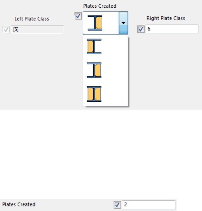
Example: Adding a list with images in a stiffener dialog box
Start by adding a list with images in the stiffener dialog box. This task is phase 1 in the
workflow Example: Modifying the dialog box of a stiffener detail on page 58.
The dialog box of the stiffener has the text box shown below. The user needs to know the
values (0 is left, 1 is right and 2 is both plates) that control the creation of stiffener plates.
You will replace the text box with a list that is easier to use.
To replace the text box with a list in the dialog box:
1. Check the name of the parametric variable that controls the plate creation.
a. Double-click the Plates Created text box in Custom Component Dialog Editor.
The Object Properties dialog box opens.
b. Check Name of the parametric variable in the Object Properties dialog box.
Modifying the custom component dialog box 59 Custom Component Dialog Editor
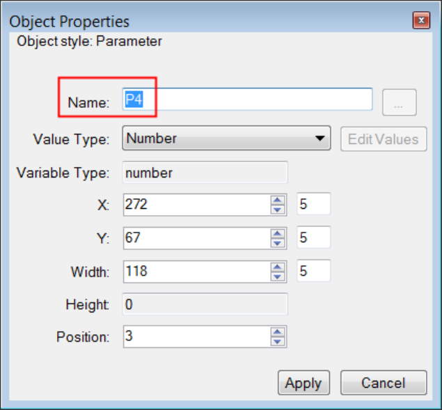
2. Select the text box and press Delete.
3. Add a new attribute (list).
a. Click Insert --> Attribute.
b. Drag the attribute to a suitable location.
4. Double-click the new attribute to edit its properties.
5. Enter P4 as Name for the attribute.
Now the attribute is linked to the parametric variable that controls the plate creation.
6. Click Edit Values to add the list items.
7. Add the image for the left plate.
a. Click Browse Add....
b. Browse to the correct folder.
c. Select a suitable image.
d. Click Open.
8. Add the image for right plate and then for both plates in the same way as for the left
plate.
9. In the Edit Attribute Values dialog box, select the image of both plates and then click
Default to make the attribute the default value.
Modifying the custom component dialog box 60 Custom Component Dialog Editor
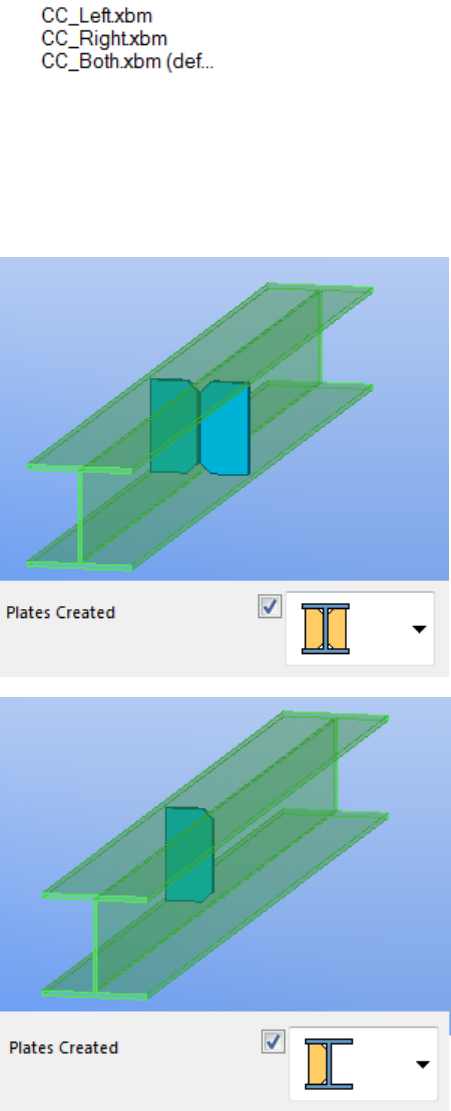
10. Click OK.
11. Click Apply in the Object Properties dialog box.
12. Save changes in Custom Component Dialog Editor.
Now you can select the plates that you want to create more easily.
Modifying the custom component dialog box 61 Custom Component Dialog Editor
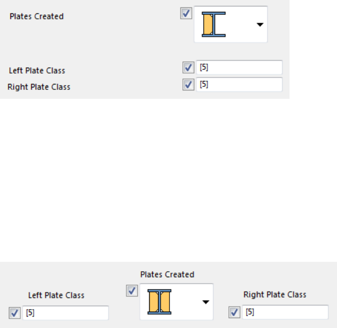
Example: Arranging text boxes and labels in a stiffener dialog box
After adding the list in the stiffener dialog box, you can arrange the text boxes and labels
around the list in the dialog box. This task is phase 2 in the workflow Example: Modifying the
dialog box of a stiffener detail on page 58.
The dialog box looks like the following before the text boxes and labels are arranged:
To arrange the text boxes and labels in the stiffener dialog box:
1. Drag the text box that controls the left plate class to the left side of the list.
2. Drag the Left Plate Class label above the corresponding text box.
3. Drag the text box that controls the right plate class to the right side of the list.
4. Drag the Right Plate Class label above the corresponding text box.
5. Drag the list label above the list.
6. Save the changes.
Now the list, text boxes and labels are arranged nicely.
Moving items in a custom component dialog box on page 57
Example: Dimming unavailable options in a stiffener dialog box
After arranging the text boxes and labels, dim the unavailable options in the stiffener dialog
box. This task is phase 3 in the workflow Example: Modifying the dialog box of a stiffener
detail on page 58.
To dim the unavailable options:
1. Dim the Left Plate Class text box, when only the right stiffener plate is created in the
model.
a. Select the image for the right plate in the Plates Created list.
See also
Modifying the custom component dialog box 62 Custom Component Dialog Editor
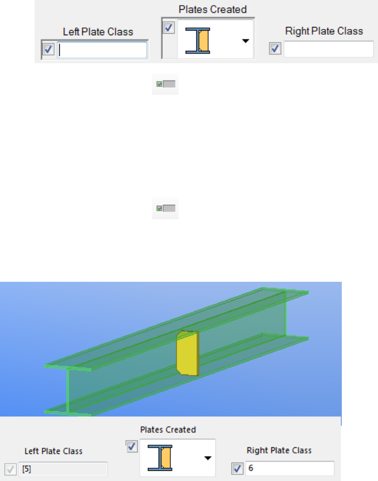
b. Hold down the Ctrl key and select the Left Plate Class text box.
c. Click the Toggle Visibility button.
2. Deselect all dialog box objects.
3. Dim the Right Plate Class text box, when only the left stiffener plate is created in the
model.
a. Select the image for the left plate in the Plates Created list.
b. Hold down the Ctrl key and select the Right Plate Class text box.
c. Click the Toggle Visibility button.
4. Save the changes.
Now the Left Plate Class text box is not available when only the right plate is created and
vice versa.
Preventing modifications of the custom component dialog box
You can lock the dialog box file (.inp) to prevent accidental modifications. If the file is not
locked, and someone else updates the custom component in the custom component editor,
all your modifications to the dialog box will be lost.
Modifying the custom component dialog box 63 Custom Component Dialog Editor

To prevent modifications of the .inp file, click the Lock/Unlock button to the locked state
in Custom Component Dialog Editor.
You can modify the custom component in the custom component editor when the .inp file
is locked, but the .inp file will not be updated. However, you can modify the dialog box in
Custom Component Dialog Editor even if the .inp file is locked.
Custom component dialog box file on page 55
See also
Modifying the custom component dialog box 64 Custom Component Dialog Editor
7Managing custom components
This section explains how to manage custom components. You can export and import custom
components and prevent other users from modifying the custom components.
Click the links below to find out more:
•Exporting custom components on page 65
•Importing custom components on page 66
•Protecting custom components with passwords on page 67
•Preventing actions on custom components in Component Catalog on page 67
7.1 Exporting custom components
You can export custom components to a file, and then import the file to another model. If
the custom component contains sketched cross sections, you need to export both the
sketches and the component.
To export custom components:
1. Press Ctrl + F to open the Component Catalog.
2. Select the custom components in the Component Catalog.
3. Right-click and select Export....
The Export components dialog box opens.
4. Browse for the folder where you want to save the file.
5. Enter a name for the export file in the Selection box.
By default, the file name extension is .uel.
6. Click OK to export the custom components.
Managing custom components 65 Exporting custom components
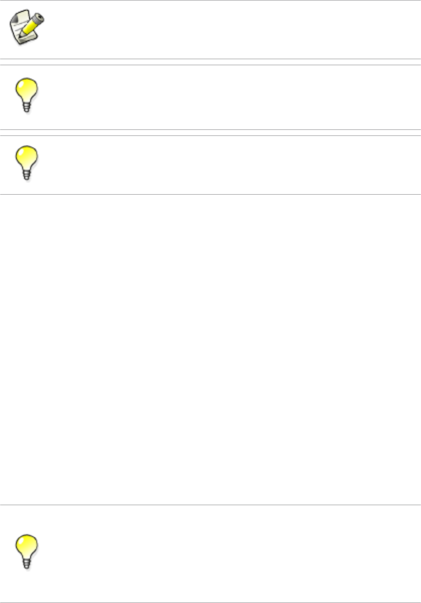
Do not change the name of the .uel file after exporting the custom components.
You can export custom components to separate files by selecting the custom components
in the Component Catalog, right-clicking and selecting Export into separate files on the
menu.
You can also upload custom components to Tekla Warehouse.
Managing custom components on page 65
Importing custom components on page 66
Tips for sharing custom components on page 100
7.2 Importing custom components
To import custom components to a model:
1. Press Ctrl + F to open the Component Catalog.
2. Right-click the component list and select Import....
The Import Components dialog box opens.
3. Browse for the folder that contains the export file.
4. Select the export file.
5. Click OK to import the custom components.
If the custom component contains sketched cross sections, you need to import both the
sketches and the component.
You can import custom components to a new model automatically by using the
XS_UEL_IMPORT_FOLDER advanced option.
Export all custom components to certain folders and refer to these folders in the
XS_UEL_IMPORT_FOLDER advanced option to easily import the custom components
to new models.
See also
Managing custom components 66 Importing custom components
You can also download custom components from Tekla Warehouse.
Managing custom components on page 65
Exporting custom components on page 65
Tips for sharing custom components on page 100
7.3 Protecting custom components with passwords
You can set a password for a custom component to prevent others from modifying the
custom component. You can add password-protected custom components to models as
usual.
To set a password for a custom component
1. Select the custom component in a model.
2. Right-click the custom component and select Edit Custom Component.
The custom component editor opens.
3. Click the Display variables button on the Custom component editor toolbar.
The Variables dialog box opens.
4. Click Add to create a new variable.
5. Enter Password in Name.
6. Enter the desired password in Formula.
7. Save the custom component.
8. Close the custom component editor.
Tekla Structures now asks for the password when you try to open the custom component in
the custom component editor.
Managing custom components on page 65
See also
See also
Managing custom components 67 Protecting custom components with passwords
7.4 Preventing actions on custom components in Component
Catalog
You can prevent the following actions on custom components in the Component Catalog:
• deleting
• importing
• adding to favorites
• adding to search results
• changing image
• editing keywords
• removing from search results
To prevent the actions on custom components in the Component Catalog:
1. Click Files --> Open Model Folder .
2. Right-click the ComponentCatalog.txt file in the model folder.
3. Select Properties on the menu.
The file properties dialog box opens.
4. Select the Read-only check box on the General tab.
5. Click OK.
Managing custom components on page 65
See also
Managing custom components 68 Preventing actions on custom components in Component
Catalog
8Custom component settings
This section provides more information about the various custom component settings, plane
types, variable types and variable functions.
Click the links below to find out more:
•Custom Component Wizard properties on page 69
•Default custom component dialog box properties on page 73
•Plane types on page 77
•Variables properties on page 82
•Functions in variable formulas on page 86
8.1 Custom Component Wizard properties
This section provides more information about the properties in the Custom Component
Wizard.
Click the links below to find out more:
•Type/Notes tab properties on page 69
•Position tab properties on page 70
•Advanced tab properties on page 70
•Position types on page 71
Type/Notes tab properties
The Type/Notes tab contains the following properties:
Custom component settings 69 Custom Component Wizard properties
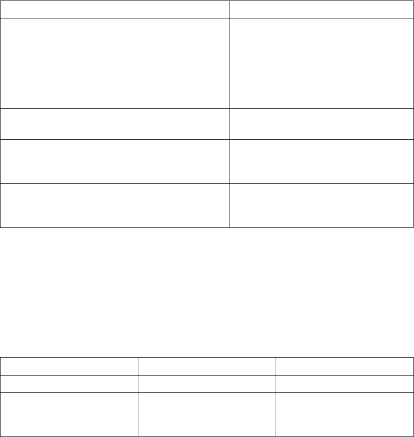
Option Description
Type Select the type of the custom
component.
Type affects how you insert the custom
component in the model. Type also
defines if the custom component
connects to existing parts.
Name A unique name of the custom
component.
Description A short description of the custom
component. Tekla Structures shows the
description in the Component Catalog.
Component identifier To show this in drawings, include Code
in the Connection Mark Properties
dialog box.
Custom Component Wizard properties on page 69
Custom component types on page 10
Position tab properties
The Position tab contains the following properties:
Option Description Note
Up direction Sets the default up direction. Not available for parts.
Position type Position (or origin) of the
component, relative to the
main part.
Not available for details and
parts.
Custom Component Wizard properties on page 69
Position types on page 71
Advanced tab properties
The Advanced tab contains the following properties:
See also
See also
Custom component settings 70 Custom Component Wizard properties

Option Description Note
Detail type Determines on which side of the main part
the component is located. The options are:
•Intermediate detail
Tekla Structures creates all
components on the same side of the
main part
•End detail
Tekla Structures creates all
components on the side of the main
part closest to the details
Only affects asymmetric components.
Only available for details
and seams
Definition point
position in relation to
primary part
Determines the position you pick to create
the detail, relative to the main part.
Only available for details
Definition point
position in relation to
secondary part
Determines where the component is
created, relative to the secondary part.
Only available for
connections and seams
Allow multiple
instances of
connection between
same parts
Select to create many components to the
same main part, in different locations.
Only available for
connections and seams
Exact positions Select to position the seam based on the
positions you pick in the model.
Clear the check box to let Tekla Structures
use automatic seam recognition to
position the seam. This is useful especially
with warped seams.
Only available for seams
Use the center of the
bounding box in
positioning
Select to position the custom part based
on the center of its bounding box (the box
that surrounds the actual part profile).
Only available for parts
Custom Component Wizard properties on page 69
Position types
Position type determines the location of the objects that the custom component creates,
relative to the main part. The options are:
See also
Custom component settings 71 Custom Component Wizard properties
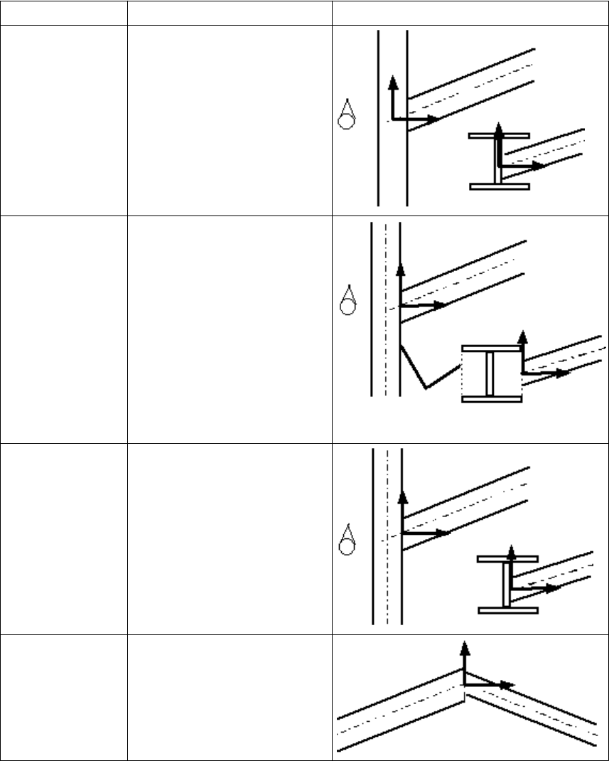
Option Description Example
Middle Where the center lines of the
main and secondary parts
intersect.
Box plane Where the main part box and
the center line of the secondary
part intersect.
Collision plane Where the main part and the
center line of the secondary
part intersect.
Endend plane Where the center line of the
secondary part hits the end of
the main part.
Custom component settings 72 Custom Component Wizard properties
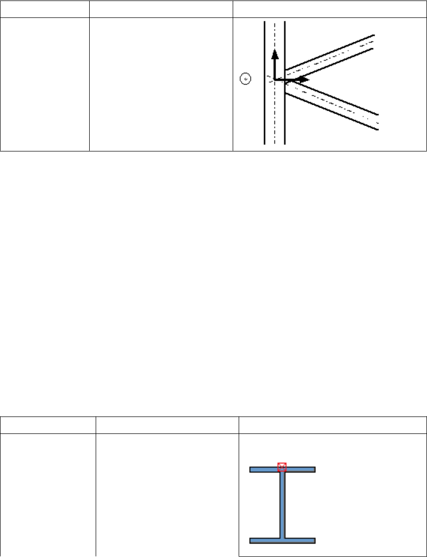
Option Description Example
Gusset plane Where the center lines of the
main part and the first
secondary part intersect. The x
direction is perpendicular to
the center line of the main
part.
Custom Component Wizard properties on page 69
8.2 Default custom component dialog box properties
When you create a custom component, Tekla Structures automatically creates a dialog box
for the component. The dialog box contains the Position tab for parts and the General tab
for connections, details and seams.
Default dialog box properties of connections, details and seams on page 76
Default dialog box properties of parts on page 73
Default dialog box properties of parts
By default, a custom part dialog box contains the Position tab. The Position tab has the
following properties:
Option Description Example
On plane Changes part location on work
plane. Middle
See also
See also
Custom component settings 73 Default custom component dialog box properties
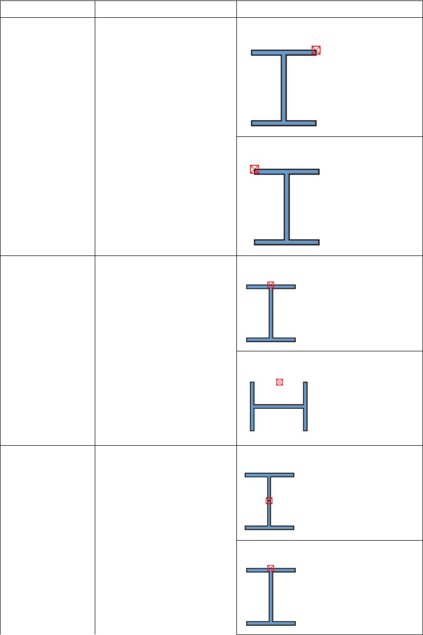
Option Description Example
Right
Left
Rotation Rotates part in steps of 90
degrees. Top and Below
Front and Back
At depth Changes part location
perpendicular to work plane. Middle
Front
Custom component settings 74 Default custom component dialog box properties
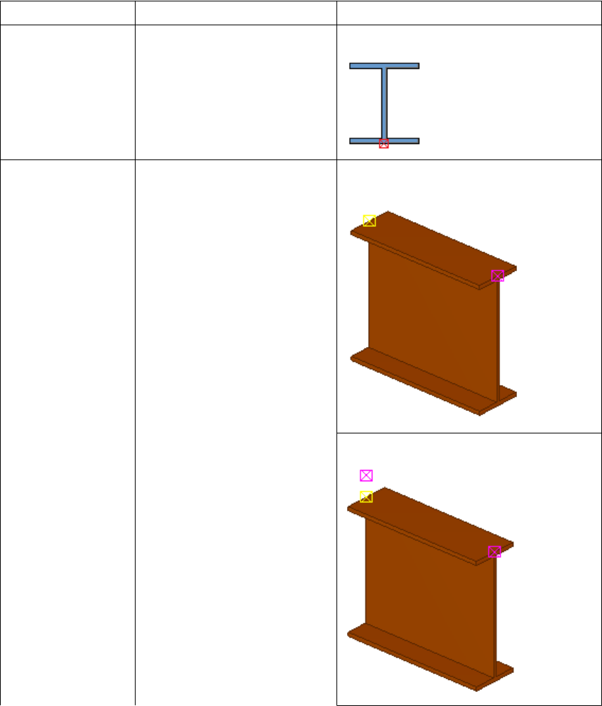
Option Description Example
Behind
Show third handle Sets the third handle of a
nested custom part visible in
the desired direction.
You can bind the third handle
in the desired direction and
thus force the part to follow
the rotation of another part.
None
Above
Custom component settings 75 Default custom component dialog box properties
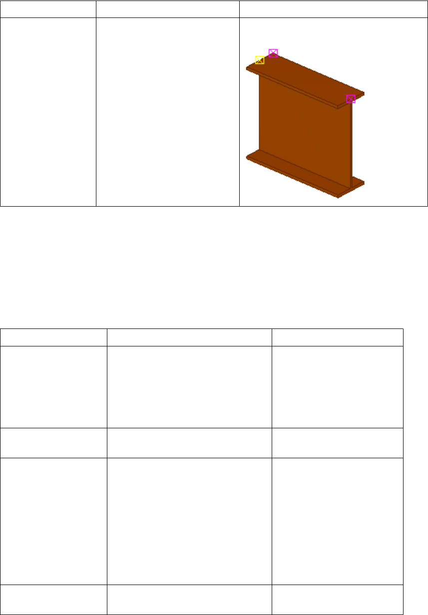
Option Description Example
On the left
Default custom component dialog box properties on page 73
Default dialog box properties of connections, details and seams
By default, a custom component dialog box of connections, details and seams contains the
General tab. The General tab has the following properties:
Option Description Note
Up direction Indicates how the component is
rotated around the secondary part,
relative to the current work plane. If
there are no secondary parts, Tekla
Structures rotates the connection
around the main part.
Position in relation to
primary part The creation point of the component
relative to the main part.
Only available for details.
Position in relation to
secondary part Tekla Structures automatically
places the component according to
the selected option.
Available for seams by
default.
To use this property in
connections, select the
Allow multiple instances of
connection between same
parts check box on the
Advanced tab when you
create the component.
Place to picked
positions Select to place the seam at the
points you pick.
Only available for seams
See also
Custom component settings 76 Default custom component dialog box properties

Option Description Note
Detail type Determines on which side of the
main part the component is located.
The options are:
•Intermediate detail
Tekla Structures creates all
components on the same side of
the main part.
•End detail
Tekla Structures creates all
components on the side of the
main part closest to the details.
Only affects asymmetric
components.
Only available for details
Locked Yes prevents modifying the
properties.
Class The class of the parts that the
custom component creates.
Connection code Identifies the component. You can
display this connection code in
connection marks in drawings.
AutoDefaults rule
group The rule group used for setting the
connection properties.
AutoConnection rule
group The rule group Tekla Structures uses
to select the connection.
Default custom component dialog box properties on page 73See also
Custom component settings 77 Plane types
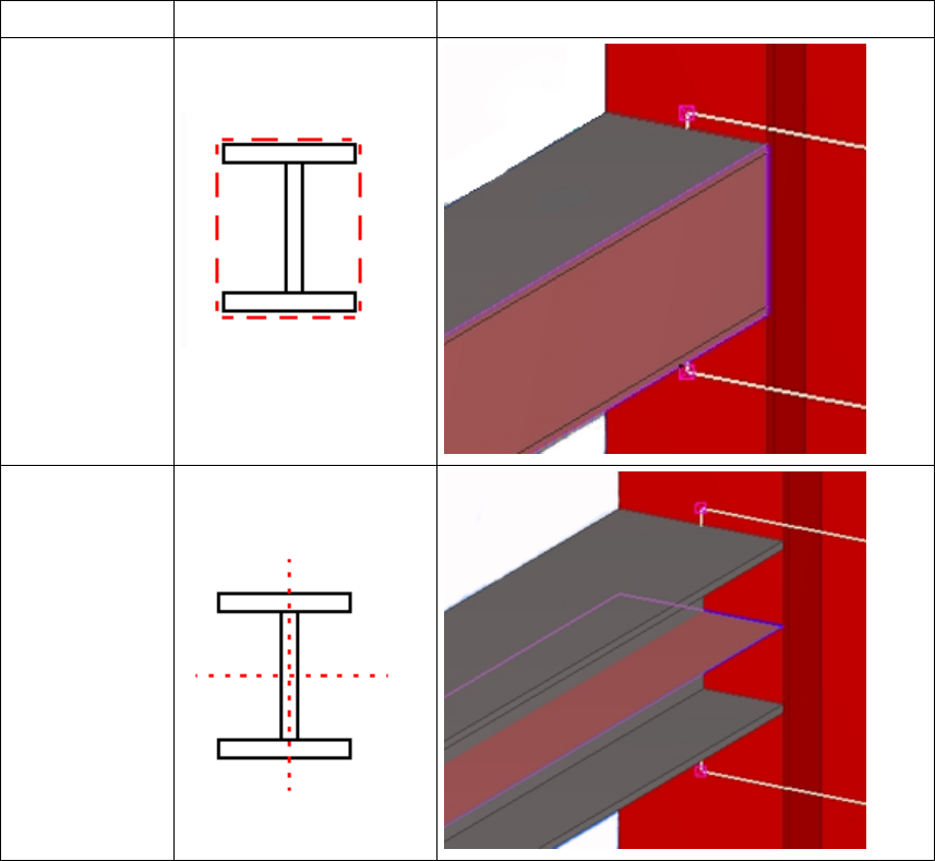
8.3 Plane types
You use planes when you create distance variables. For example, you can bind the reference
point of a plate to the top plane of a beam. You can change the plane type to bind the
reference object to the required plane.
You can bind reference objects to the following planes:
Plane type Description Example
Boundary
planes The edges of a box
surrounding a profile
Center planes The center planes of a
profile
Custom component settings 78 Plane types
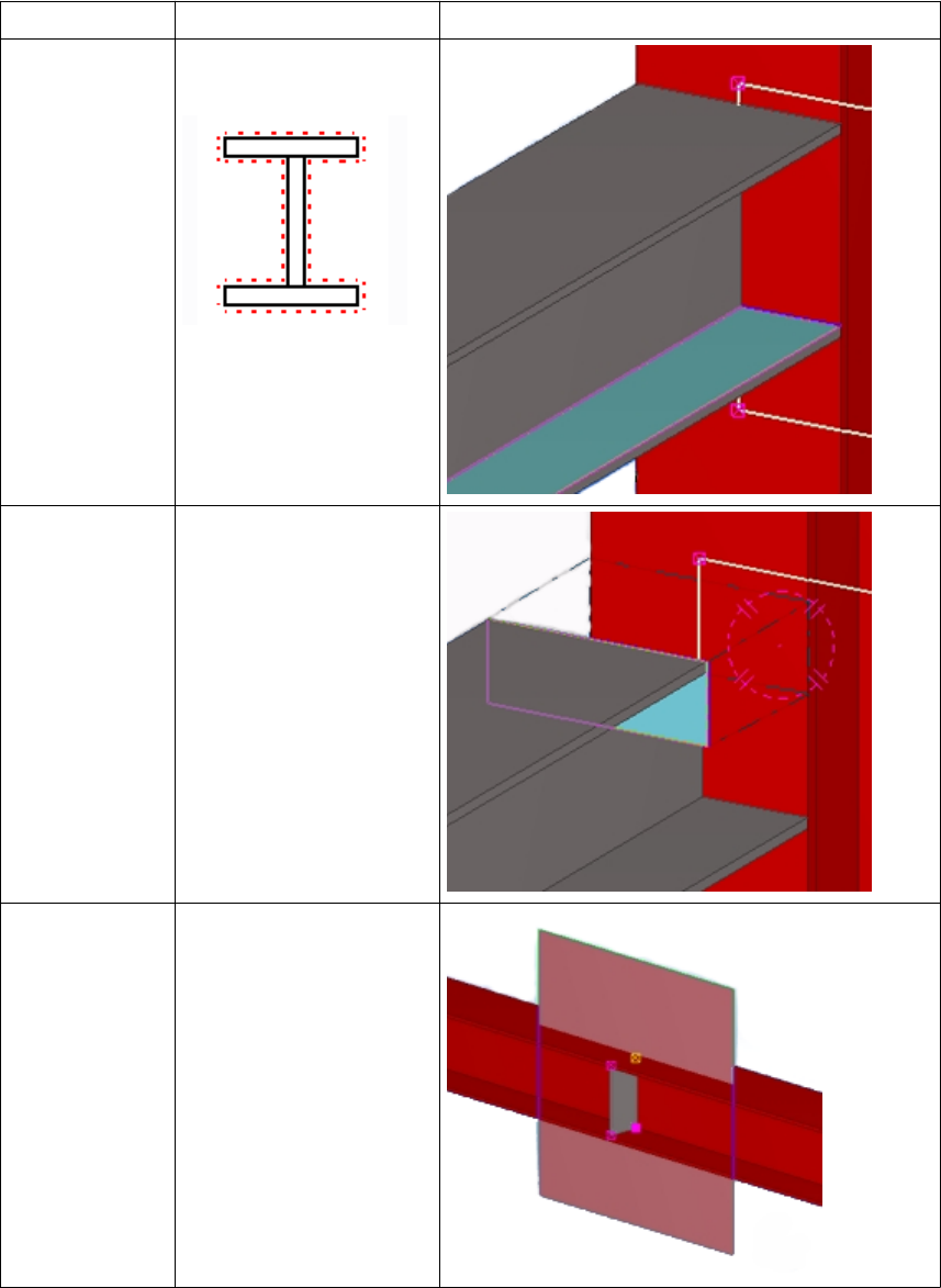
Plane type Description Example
Outline planes The outer and inner
surfaces of a profile
Cut planes If parts contain line, part,
or polygon cuts, this
option selects the cut
surfaces. Fittings cannot
be selected.
Component
planes Depends on the
component type and
Position type of the
custom component.
Custom component settings 79 Plane types
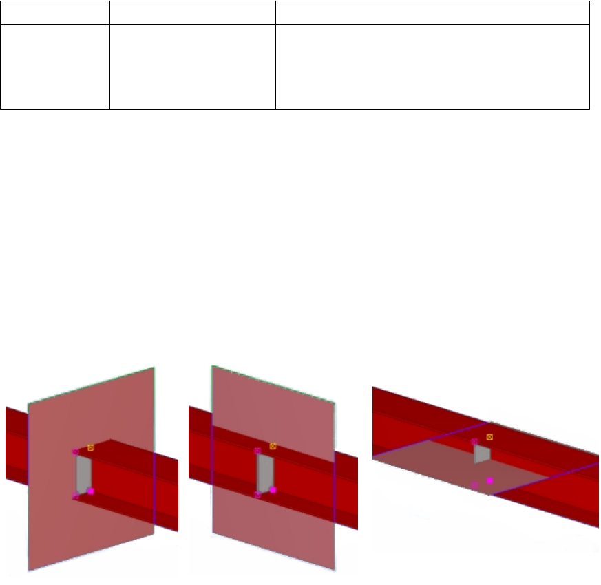
Plane type Description Example
Grid planes Shows grid planes.
This plane type is only
available in models and
sketches.
Creating a distance variable manually on page 26
Example: Detail component planes on page 80
Example: Connection component planes on page 80
Example: Seam component planes on page 81
Example: Part component planes on page 82
Example: Detail component planes
See below for examples of a detail’s component planes.
Plane types on page 77
Example: Connection component planes
See below for examples of a connection’s component planes.
See also
See also
Custom component settings 80 Plane types
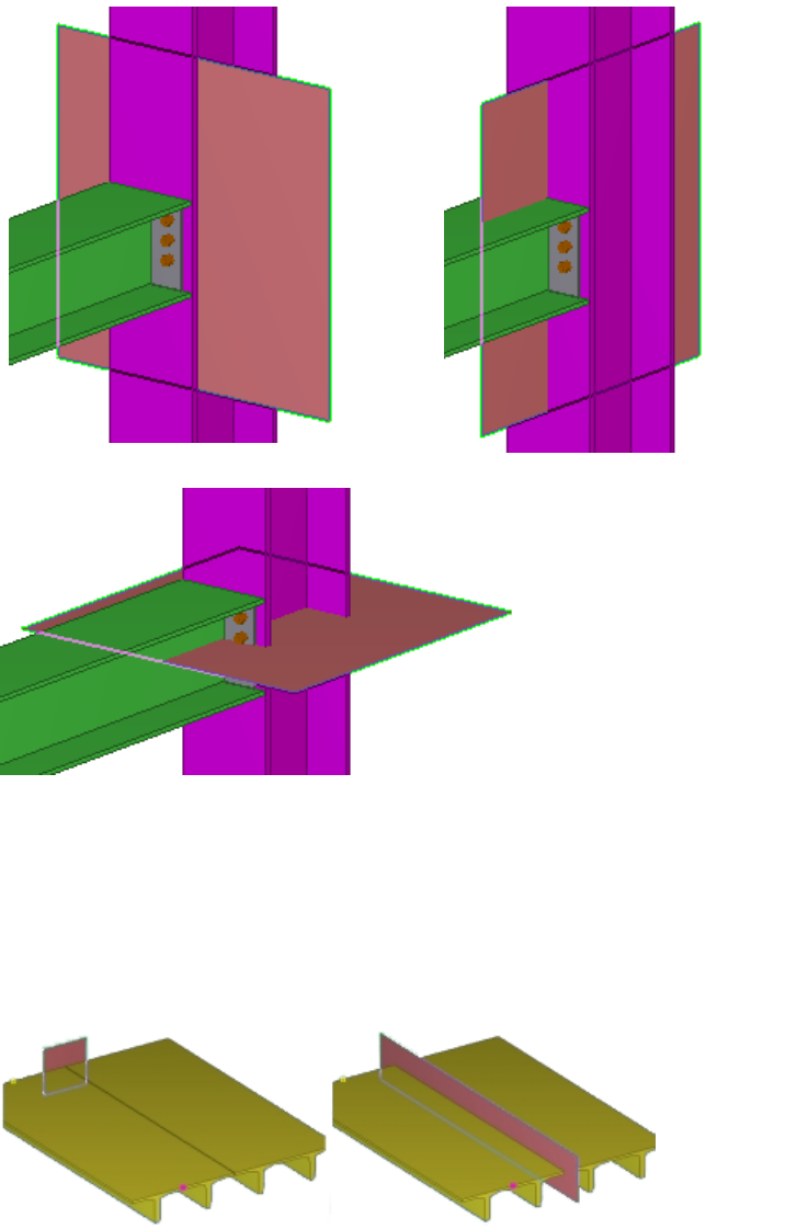
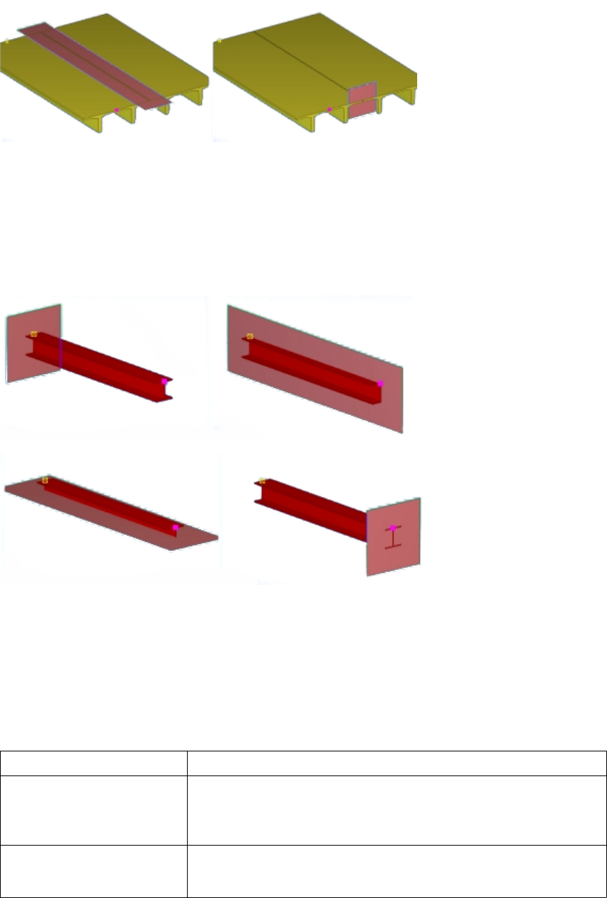
Plane types on page 77
Example: Part component planes
See below for examples of a part’s component planes.
Plane types on page 77
8.4 Variables properties
You can determine the following properties for variables in the Variables dialog box:
Option Description
Name A unique name of a variable. Use this name to refer to the variable
in the custom component editor.
The maximum length is 19 characters.
Formula Can contain a value or a formula.
Formulas begin with =.
See also
See also
Custom component settings 82 Variables properties
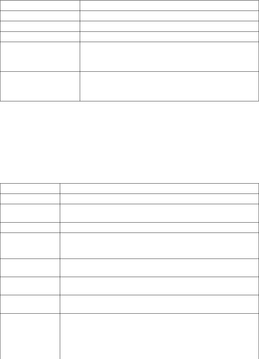
Option Description
Value Shows the current value in Formula.
Value type Determines the type of value that you can enter.
Variable type Distance or parametric variable
Visibility Hide or Show
Set to Show to display the variable in the custom component
dialog box.
Label in dialog box The name of the variable that Tekla Structures displays in the
custom component dialog box.
The maximum length is 30 characters.
Value types on page 83
Variables in custom components on page 24
Value types
The value type determines what kind of value you can enter for the variable. Tekla Structures
has the following value types for variables:
Option Description
Number A whole (integer) number. Use for quantity and multiplier.
Length A decimal (floating point) number. Use for lengths and distances. Length
numbers have unit (mm, inch, etc.) and are rounded to two decimal places.
Text A text (ASCII) string.
Factor A decimal value without a unit. You can set the number of decimals for
the value type in Tools --> Options --> Options... --> Units and
decimals .
Angle A decimal number type for storing angles, stored to one decimal place, in
radians.
Material A data type associated with the material catalog. Use to select material
from the standard material dialog.
Profile A data type associated with the profile catalog. Use to select profile from
the standard profile dialog.
Bolt size
Bolt standard
Data types linked to the bolt catalog. Bolt size works with Bolt standard.
They have fixed naming: Px_diameter and Px_screwdin. Do not
change the fixed name.
To show values for these in the component’s dialog box, x must be the
same for both, for example, P1_diameter and P1_screwdin.
See also
Custom component settings 83 Variables properties
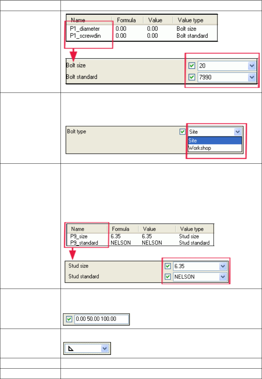
Option Description
Bolt type For determining the bolt type (site/workshop) in the custom component
dialog box. Linked to the Bolt type property of bolts in Custom
component browser.
Stud size
Stud standard
Data types linked to the bolt catalog. Stud size works with Stud standard.
They have fixed naming: Px_size and Px_standard. Do not change
the fixed name.
To show values for these in the component’s dialog box, x must be the
same for both, for example, P9_size and P9_standard.
Distance list Use with options with several length values, such as bolt spacings.
Use space as a separator between the distances.
Weld type A data type for selecting weld type.
Chamfer type A data type for determining the shape of a chamfer.
Welding site A data type for determining the welding place: workshop or building site.
Custom component settings 84 Variables properties
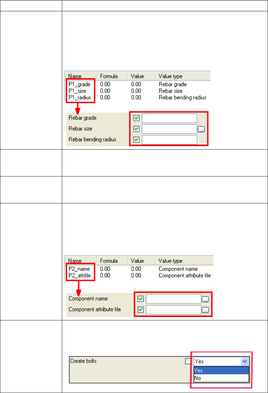
Option Description
Rebar grade
Rebar size
Rebar bending
radius
Data types linked to reinforcement catalog. Rebar grade, Rebar size, and
Rebar bending radius work together. They have fixed naming format:
Px_grade, Px_size, and Px_radius where the x is a number. Do
not change the fixed name.
To show values for these in the component's dialog box, x must be the
same for all, for example, P1_grade, P1_size, and P1_radius.
Reinforcement
mesh For determining meshes in custom components. Linked to the Catalog
name property of reinforcement meshes in the Custom component
browser.
Component name For replacing a sub-component inside a custom component with another
sub-component. Linked to the Name property of objects in the Custom
component browser.
Component
attribute file For setting the properties of a sub-component inside a custom component.
Works with Component name using the format Px_name and
Px_attrfile, where the x is a number. Do not change the fixed name.
To show values for these in the component's dialog box, x must be the
same for both, for example, P2_name and P2_attrfile.
Yes/No For determining whether or not Tekla Structures creates an object in a
custom component. Linked to the Creation property of objects in the
Custom component browser.
Custom component settings 85 Variables properties
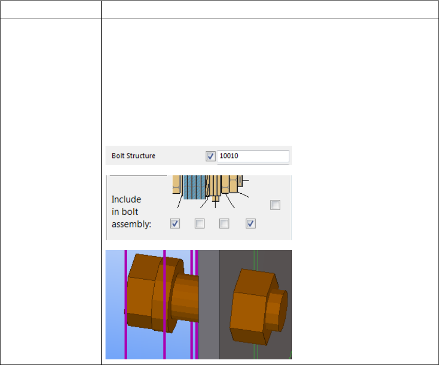
Option Description
Bitmask For defining bolt assembly (nuts and washers) and parts with slotted holes.
Linked to the Bolt structure and Parts with slotted holes properties of
bolts in the Custom component browser.
The value is a five-digit series of ones and zeros. This relates to the check
boxes in the Bolt Properties dialog box. 1 means that a check box is
selected, 0 means that a check box is clear.
In the example below, the value of 10010 means that a bolt with a washer
and a nut is created in the bolt assembly.
Variables properties on page 82
Variables in custom components on page 24
8.5 Functions in variable formulas
This section provides information on the functions that you can use in variable formulas.
Formulas always begin with the equal sign (=).
Click the links below to find out more:
•Arithmetic operators on page 87
•Logical and comparison operators on page 87
•Reference functions on page 88
•ASCII file as a reference function on page 89
•Mathematical functions on page 90
•Statistical functions on page 91
See also
Custom component settings 86 Functions in variable formulas
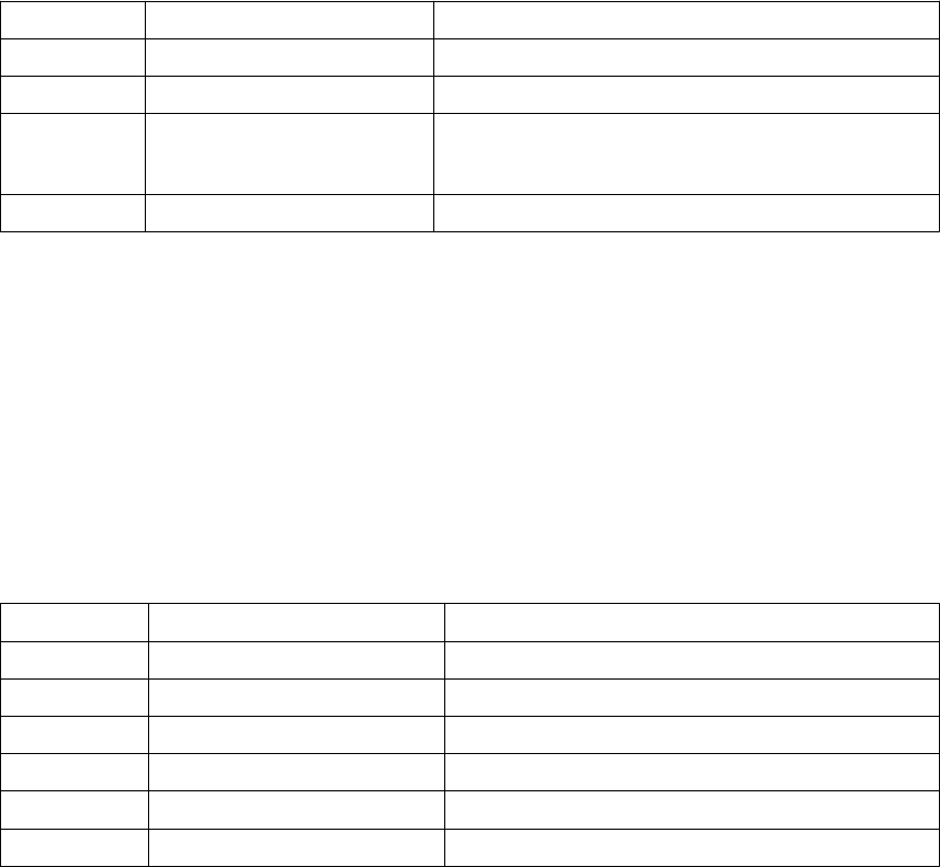
•Data type conversion functions on page 92
•String operations on page 93
•Trigonometric functions on page 94
•Market size function on page 95
•Framing condition functions on page 95
•Example: Skew and slope framing conditions on page 96
•Example: Ceil and floor statistical functions on page 98
Arithmetic operators
You can use the following arithmetic operators in variable formulas:
Operator Description Notes
+ addition Use also to create strings of parameters.
- subtraction
* multiplication Multiplication is faster than division.
=D1*0.5 is faster than =D1/2
/ division
Functions in variable formulas on page 86
Logical and comparison operators
You can use if-then-else statements to test a condition and set the value according to the
result.
=if (D1>200) then 20 else 10 endif
You can also use the following operators inside the if statement:
Operator Description Example
== both sides are equal
!= sides are not equal
< left side is smaller
<= left side is smaller or equal
> right side is smaller
>= right side is smaller or equal
See also
Custom component settings 87 Functions in variable formulas

Operator Description Example
&& logical AND
both conditions must be true
=if (D1==200 && D2<40) then 6
else 0 endif
If D1 is 200 and D2 smaller than 40, the result is
6, otherwise 0.
|| logical OR
only one condition must be
true
=if (D1==200 || D2<40) then 6
else 0 endif
If D1 is 200 or D2 is smaller than 40, the result is
6, otherwise 0.
Functions in variable formulas on page 86
Example: Determining the number of bolt rows on page 42
Reference functions
A reference function refers to the property of another object, such as the plate thickness of a
secondary part. Tekla Structures refers to the object on the system level, so if the object
property changes, so does the reference function value.
Function Description Example
fTpl("template
attribute", "object
GUID")
Returns the value of
template attribute with
given object GUID.
=fTpl("WEIGHT","ID50B855
9A-0000-010B-3133-353432
373038")
returns the weight of an object
whose GUID is
ID50B8559A-0000-010B-3133-353
432373038.
fP("user-defined
attribute", "object
GUID")
Returns the value of user-
defined attribute with given
object GUID.
=fP("comment",
"ID50B8559A-0000-010B-31
33-353432373038")
returns the user-defined attribute
comment of an object whose GUID
is
ID50B8559A-0000-010B-3133-353
432373038.
fValueOf("parameter
")
Returns the value of the
parameter.
If the equation is =P2+"*"+P3,
the result is P2*P3
With =fValueOf("P2")
+"*"+fValueOf("P3"), where
P2=780 and P3=480, the result is
780*480
See also
Custom component settings 88 Functions in variable formulas
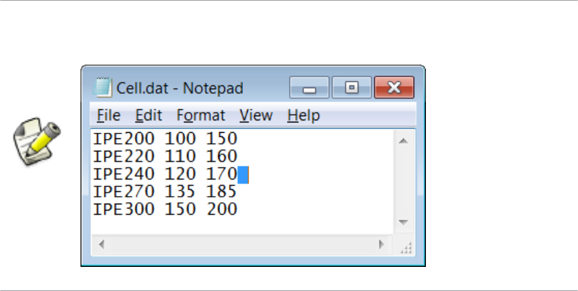
Functions in variable formulas on page 86
Example: Using construction planes for determining the stiffener position on page 43
ASCII file as a reference function
You can refer to ASCII files to get data.
Enter a space at the end of each row in the ASCII file. Otherwise the information is
not read correctly.
Tekla Structures searches for the files as system files in the following order:
1. model
2. ..\TeklaStructuresModels\<model>
\CustomComponentDialogFiles\
3. project (set with advanced option XS_PROJECT)
4. firm (set with advanced option XS_FIRM)
5. system (set with advanced option XS_SYSTEM)
The format for reading files is the following:
fVF("filename", "key_value_of_row", column_number)
• Key value of row is a unique text value.
• Column number is an index starting from 1.
The =fVF("Overlap.dat", "MET-202Z25", 5) function is in Formula in the
Variables dialog box.
The function gets the value 16.0 for profile MET-202Z25, from the Overlap.dat file.
See also
Example
Custom component settings 89 Functions in variable formulas
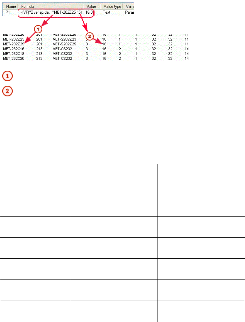
Key value of row (MET-202Z25)
Column number (5)
Functions in variable formulas on page 86
Mathematical functions
You can use the following mathematical functions in variable formulas:
Function Description Example
fabs(parameter) Returns the absolute value of the
parameter =fabs(D1) returns 15
if D1 = -15
exp(power) Returns e raised to the power
e is Euler’s number.
=exp(D1) returns 7.39
if D1 = 2
ln(parameter) Returns natural logarithm of the
parameter (base number e)=ln(P2) returns 2.71
if P2 = 15
log(parameter) Returns the logarithm of the
parameter (base number 10) =log(D1) returns 2
if D1=100
sqrt(parameter) Returns the square root of the
parameter =sqrt(D1) returns 4
if D1 = 16
mod(dividend, divider) Returns the modulo of the
division =mod(D1, 5) returns 1
if D1 = 16
pow(base number, power) Returns the base number raised
to the specified power =pow(D1, D2) returns 9
if D1 = 3 and D2 = 2
See also
Custom component settings 90 Functions in variable formulas
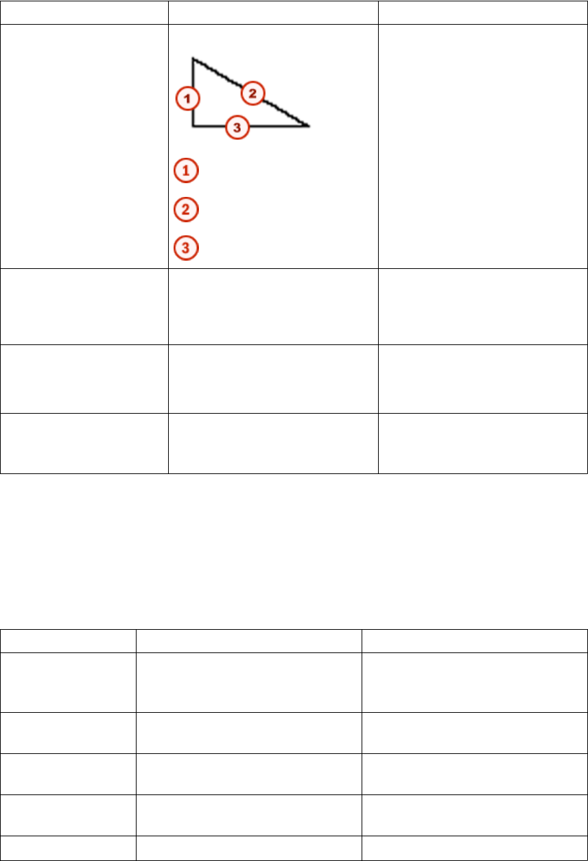
Function Description Example
hypot(side1,side2) Returns the hypotenuse
side1
hypotenuse
side2
=hypot(D1, D2) returns 5
if D1 = 3 and D2 = 4
n!(parameter) Returns the factorial of the
parameter =n!(P2) returns 24
if P2 = 4
(1*2*3*4)
round(parameter,
accuracy)
Returns the parameter rounded
off to the given accuracy =round(P1, 0.1) returns
10.600
if P1 = 10.567
PI Returns the value of pi to 31
decimal places =PI returns
3.1415926535897932384626433
832795
Functions in variable formulas on page 86
Statistical functions
You can use the following statistical functions in variable formulas:
Function Description Example (P1 = 1.4 P2 = 2.3)
ceil() Returns the smallest whole number
greater than or equal to the
parameter
=ceil(P1) returns 2
floor() Returns the largest whole number
less than or equal to the parameter =floor(P1) returns 1
min() Returns the smallest of the
parameters =min(P1, P2) returns 1.4
max() Returns the largest of the
parameters =max(P1, P2) returns 2.3
sum() Sum of the parameters =sum(P1, P2) returns 3.7
See also
Custom component settings 91 Functions in variable formulas
Function Description Example (P1 = 1.4 P2 = 2.3)
sqsum() Sum of the squared parameters:
(parameter1)2 + (parameter2)2 =sqsum(P1, P2) returns 7.25
ave() Average of the parameters =ave(P1, P2) returns 1.85
sqave() Average of the squared parameters =sqave(P1, P2) returns 3.625
Functions in variable formulas on page 86
Example: Ceil and floor statistical functions on page 98
Data type conversion functions
The units depend on the settings in Tools --> Options --> Options --> Units and
decimals .
You can use the following data type conversion functions in variable formulas:
Function Description Example
int() Converts data to integer Useful especially for calculating
profile dimensions:
=int(100.0132222000)
returns 100, if decimals are set to 0
in the Options dialog box
double() Converts data to a double
string() Converts data to string
imp() Converts imperial units
Use this function in calculations
instead of imperial units. You
cannot use imperial units directly in
calculations.
For the following examples, length
unit is set to mm and decimals are
set to 2 in the Options dialog box.
=imp(1,1,1,2) meaning 1 foot
1 1/2 inch returns 342.90 mm
=imp(1,1,2) meaning 1 1/2
inches returns 38.10 mm
=imp(1,2) meaning 1/2 inches
returns 12.70 mm
=imp(1) meaning 1 inch returns
25.40 mm
=3’/3" is not possible, but
=imp(36)/imp(3) is ok
See also
Custom component settings 92 Functions in variable formulas
Function Description Example
vwu(value, unit) Converts the length values and
angle values. The available units are:
• "ft" ("feet", "foot")
• "in" ("inch", "inches")
• "m"
• "cm"
• "mm"
• "rad"
• "deg"
=vwu(4.0,"in") returns 101.60
mm, if length unit is set to mm and
decimals are set to 2 in the Options
dialog box
=vwu(2.0,"rad") returns
114.59 degrees, if angle is set to
degrees and decimals are set to 2 in
the Options dialog box
Functions in variable formulas on page 86
String operations
Strings must be inside quotation marks in variable formulas. For example, to define profile
size PL100*10 with two variables P2 = 100 and P3 = 10, enter the formula as follows:
="PL"+P2+"*"+P3
Tekla Structures handles bolt spacings as strings. To define bolt spacing, set Value
type to Distance list and enter the formula like this:
=P1+" "+P2
This results in 100 200, if P1 = 100 (length) and P2 = 200 (length).
You can use the following string operations in variable formulas:
Operation Description Example (P1 = "PL100*10")
match(parameter1,
parameter2)
Returns 1 if parameters are equal
and 0 if different.
You can also use wildcards *, ?, and
[ ] with the match function.
=match(P1, "PL100*10")
returns 1
Accept all profiles starting with PFC:
=match(P4, "PFC*")
Accept profiles starting with PFC,
and height starts with 2,3,4 or 5:
=match(P4, "PFC[2345]*")
Accept profiles starting with PFC,
heights are 200,300,400 or 500 and
width starts with 7: =match(P4,
"PFC[2345]00?7")
See also
Custom component settings 93 Functions in variable formulas
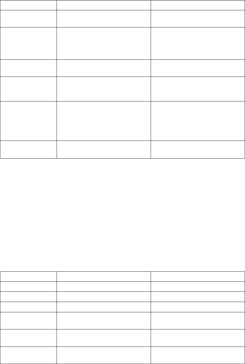
Operation Description Example (P1 = "PL100*10")
length(parameter) Returns the number of characters in
the parameter. =length(P1) returns 8
find(parameter,
string)
Returns the order number (starting
at zero) of the specified string and
-1 if the specified string is not
found from the parameter.
=find(P1, "*") returns 5
getat(parameter, n) Returns the n:th (starting at zero)
character from the parameter. =getat(P1, 1) returns "L"
setat(parameter, n,
character)
Sets the n:th (starting at zero)
character to the specified character
in the parameter.
=setat(P1, 0, "B") returns
"BL100*10"
mid(string, n, x) Returns x characters from the string
starting from n:th (starting at zero)
character. If you leave out the last
argument (x), returns the last part of
the string.
=mid(P1,2,3) returns "100"
reverse(string) Reverses the given string. =reverse(P1) returns
"01*001LP"
Functions in variable formulas on page 86
Trigonometric functions
When you use trigonometric functions in variable formulas, you need to include a prefix to
define the unit. If you do not include a prefix, Tekla Structures uses radians as the default
unit.
• d is degree. For example, sin(d180)
• r is radians (default). For example, sin(r3.14) or sin(3.14)
You can use the following trigonometric functions in variable formulas:
Function Description Example
sin() Returns the sine value =sin(d45) returns 0.71
cos() Returns the cosine value =cos(d45) returns 0.71
tan() Returns the tangent value =tan(d45) returns 1.00
asin() Inverse function of sin(), return
value in radians =asin(d45) returns 0.90
acos() Inverse function of cos(), return
value in radians =acos(d45) returns 0.67
atan() Inverse function of tan(), return
value in radians =atan(d45) returns 0.67
See also
Custom component settings 94 Functions in variable formulas
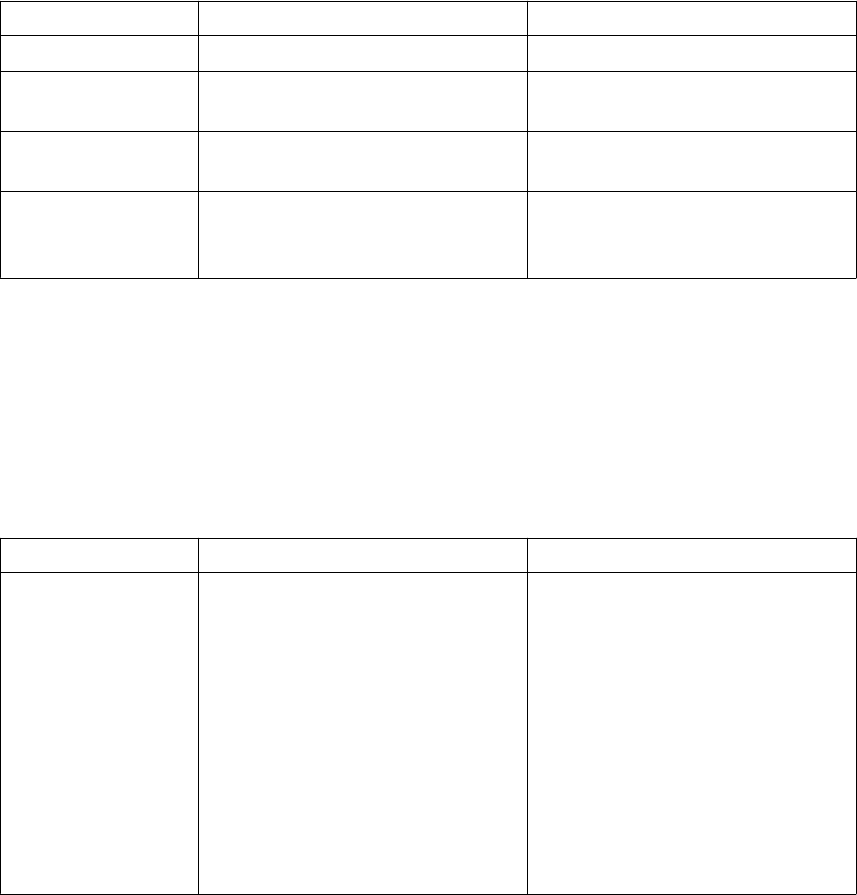
Function Description Example
sinh() Returns the hyperbolical sine value =sinh(d45) returns 0.87
cosh() Returns the hyperbolical cosine
value =cosh(d45) returns 1.32
tanh() Returns the hyperbolical tangent
value =tanh(d45) returns 0.66
atan2() Returns the angle whose tangent is
the quotient of the two numbers.
Return value in radians
=atan2(1,3) returns 0.32
Functions in variable formulas on page 86
Market size function
Use market size in a custom component to select a suitable plate dimension (usually plate
thickness) from the available market sizes. For example, a plate’s thickness should match the
web of a beam.
Function Description Example
fMarketSize(material,
thickness, extrastep)
Returns the next available market
size for the material from the
marketsize.dat file, based on
the thickness you specify.
The file must be in the ..
\environments
\your_environment\profil
folder or the system folder.
For extrastep enter a number to
define the increment to the next
size (default is 0).
=fMarketSize("S235JR",
10, 0)
Functions in variable formulas on page 86
Example: Market size function on page 98
See also
See also
Custom component settings 95 Functions in variable formulas
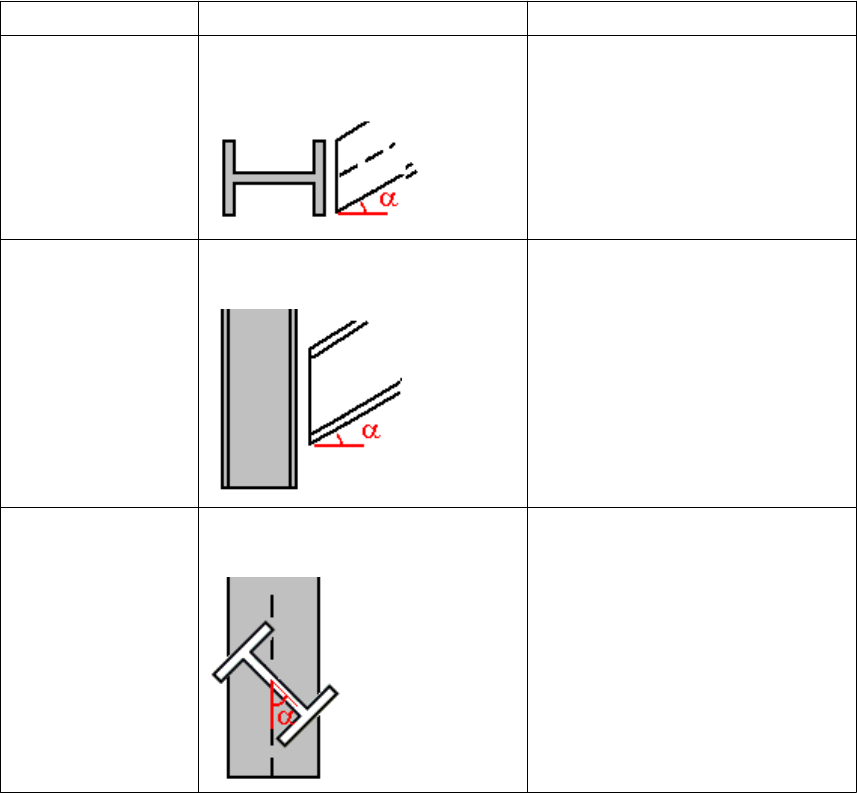
Framing condition functions
Use the following functions return the skew, slope, and cant angle of the secondary beam
relative to the main part (column or beam):
Function Description Example
fAD("skew", GUID) Returns the skewed angle of the
secondary part whose GUID is given.
=fAD("skew","ID50B8559A-
0000-010B-3133-353432373
038") returns 45
ID50B8559A-0000-010B-3133-353
432373038 is the GUID of the
secondary part, which is at a 45
degree angle to the main part.
fAD("slope", GUID) Returns the sloped angle of the
secondary part whose GUID is given.
=fAD("slope","ID50B8559A
-0000-010B-3133-35343237
3038")
fAD("cant", GUID) Returns the cant angle of rotated
secondary part whose GUID is given.
=fAD("cant","ID50B8559A-
0000-010B-3133-353432373
038")
These functions do not return positive and negative slope and skew values. It is not possible
to determine up or down slope and left or right skew with these functions.
Maximum skew angle to return is 45 degrees.
Functions in variable formulas on page 86
Example: Skew and slope framing conditions on page 96
Limitations
See also
Custom component settings 96 Functions in variable formulas
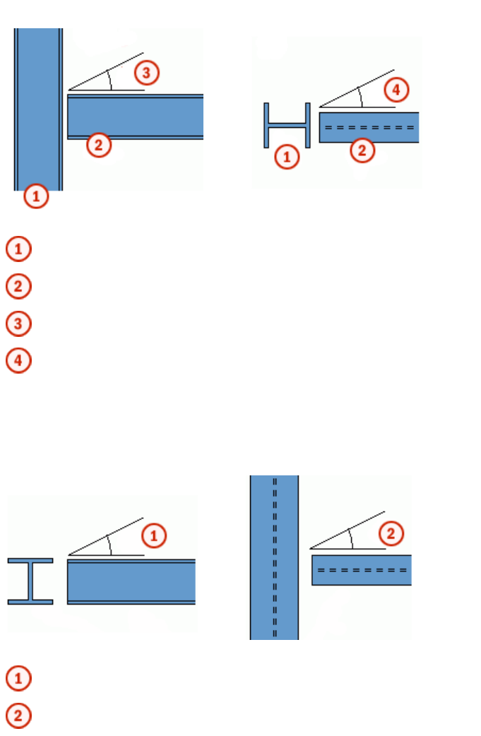
Example: Skew and slope framing conditions
The slope and skew are relative to a beam framing into a column.
Side view Top view
Column
Beam
Slope
Skew
With two beams, the slope is actually the horizontal skew of the beam framing into the other
beam, and the vertical slope of the beam relative to the main is actually the skew angle.
Side view Top view
Skew
Slope
Functions in variable formulas on page 86
Framing condition functions on page 95
See also
Custom component settings 97 Functions in variable formulas
Example: Ceil and floor statistical functions
You have the following parametric variables:
• Beam length: P1 = 3500
• Post spacing: P2 = 450
P1 / P2 = 7.7778
You can use the ceil and floor statistical functions to round the value and then use the
rounded value as the number of beam posts:
•=ceil(P1/P2) returns 8
•=floor(P1/P2) returns 7
Functions in variable formulas on page 86
Statistical functions on page 91
Example: Market size function
You have the following data in marketsize.dat:
S235JR,
6,9,12,16,19,22SS400,1.6,2.3,3.2,4.5,6,9,12,16,19,22,25,28,32,38DEFAULT,
6,9,12,16,19,22,25,28,32,38
The first item in a row is a material grade followed by available plate thicknesses in
millimeters. The DEFAULT line lists the thicknesses available in all other material grades.
With the above data, the function =fMarketSize("S235JR",10,0) would return 12,
and =fMarketSize("S235JR",10,1) would return 16 (one size up).
Market size function on page 95
See also
See also
Custom component settings 98 Functions in variable formulas
9Custom component tips
This section provides useful hints and tips that help you create and use custom components
more efficiently.
Click the links below to find out more:
•Tips for creating custom components on page 99
•Tips for sharing custom components on page 100
•Existing custom components in a new Tekla Structures version on page 101
9.1 Tips for creating custom components
These tips help you in creating useful custom components.
•Enter short, logical names for custom components.
Use the description field to describe the component and explain what it does.
•Create simple components for specific situations.
It is faster and easier to model simple components. They are also much easier to use.
Avoid creating a ’super’ component to use in every possible situation.
•Consider creating a component model.
Use the model to create and test custom components.
•Use the simplest part you can.
For example, if all you need is a rectangular shape, use a rectangular plate, not a contour
plate. Rectangular plates only have two handles, so you only need to create a few
bindings to manipulate them. Contour plates require more because they have four
handles.
Custom component tips 99 Tips for creating custom components
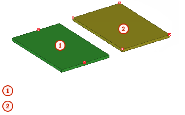
Rectangular plate
Contour plate
•Only model parts as accurately as you need.
If the only part information required is a part mark on the GA drawing and a quantity on
the materials list, create a simple bar or plate. If you later need to include the part in a
detailed view, simply re-model the part more accurately.
•Model embeds as custom parts and include them in components.
Custom component tips on page 99
9.2 Tips for sharing custom components
These tips help you in sharing custom components.
•Use Tekla Warehouse for sharing and storing custom components.
•Store custom components together.
It makes them easy to find and export.
•Provide essential information
If you distribute your component to other users, remember to list the profiles it works
with.
•Use library profiles when possible.
Then you do not have to copy user-defined profiles when you copy the component to
other locations.
•Remember to copy user-defined profile cross sections with your custom component.
Custom component tips on page 99
Managing custom components on page 65
See also
See also
Custom component tips 100 Tips for sharing custom components
9.3 Existing custom components in a new Tekla Structures version
When you start using a new version of Tekla Structures, always check that custom
components created in older versions work correctly in the new version.
When you open custom components created with an older version of Tekla Structures in the
custom component editor, and the new version contains improvements requiring update,
Tekla Structures asks whether you want to update the component. If you do not update the
component, it works in the same manner as in the version where it was originally created,
but you do not gain the benefits of the improvements.
If you choose to update the component, you need to check and sometimes recreate
dimensions depending on the improvements. When you delete a dimension and create a new
one (even with the same name), the equations containing the dimension also need to be
modified, because the dependency created by the equation is lost when a dimension is
deleted. You can recreate the dimensions and modify the equations in the custom component
editor.
Custom component tips on page 99See also
Custom component tips 101 Existing custom components in a new Tekla Structures
version
10Disclaimer
© 2015 Tekla Corporation and its licensors. All rights reserved.
This Software Manual has been developed for use with the referenced Software. Use of the
Software, and use of this Software Manual are governed by a License Agreement. Among
other provisions, the License Agreement sets certain warranties for the Software and this
Manual, disclaims other warranties, limits recoverable damages, defines permitted uses of the
Software, and determines whether you are an authorized user of the Software. All
information set forth in this manual is provided with the warranty set forth in the License
Agreement. Please refer to the License Agreement for important obligations and applicable
limitations and restrictions on your rights. Tekla does not guarantee that the text is free of
technical inaccuracies or typographical errors. Tekla reserves the right to make changes and
additions to this manual due to changes in the software or otherwise.
In addition, this Software Manual is protected by copyright law and by international treaties.
Unauthorized reproduction, display, modification, or distribution of this Manual, or any
portion of it, may result in severe civil and criminal penalties, and will be prosecuted to the
full extent permitted by law.
Tekla, Tekla Structures, Tekla BIMsight, BIMsight, Tedds, Solve, Fastrak and Orion are either
registered trademarks or trademarks of Tekla Corporation in the European Union, the United
States, and/or other countries. More about Tekla trademarks: http://www.tekla.com/tekla-
trademarks. Trimble is a registered trademark or trademark of Trimble Navigation Limited in
the European Union, in the United States and/or other countries. More about Trimble
trademarks: http://www.trimble.com/trademarks.aspx. Other product and company names
mentioned in this Manual are or may be trademarks of their respective owners. By referring
to a third-party product or brand, Tekla does not intend to suggest an affiliation with or
endorsement by such third party and disclaims any such affiliation or endorsement, except
where otherwise expressly stated.
Portions of this software:
D-Cubed 2D DCM © 2010 Siemens Industry Software Limited. All rights reserved.
EPM toolkit © 1995-2004 EPM Technology a.s., Oslo, Norway. All rights reserved.
Open CASCADE Technology © 2001-2014 Open CASCADE SA. All rights reserved.
FLY SDK - CAD SDK © 2012 VisualIntegrity™. All rights reserved.
Teigha © 2003-2014 Open Design Alliance. All rights reserved.
PolyBoolean C++ Library © 2001-2012 Complex A5 Co. Ltd. All rights reserved.
Disclaimer 102 Existing custom components in a new Tekla Structures
version
FlexNet Copyright © 2014 Flexera Software LLC. All Rights Reserved.
This product contains proprietary and confidential technology, information and creative
works owned by Flexera Software LLC and its licensors, if any. Any use, copying, publication,
distribution, display, modification, or transmission of such technology in whole or in part in
any form or by any means without the prior express written permission of Flexera Software
LLC is strictly prohibited. Except where expressly provided by Flexera Software LLC in writing,
possession of this technology shall not be construed to confer any license or rights under any
Flexera Software LLC intellectual property rights, whether by estoppel, implication, or
otherwise.
To see the third party licenses, go to Tekla Structures, click Help --> About and click the
Third party licenses button.
The elements of the software described in this Manual are protected by several patents and
possibly pending patent applications in the European Union and/or other countries. For more
information go to page http://www.tekla.com/tekla-patents.
Disclaimer 103 Existing custom components in a new Tekla Structures
version
Disclaimer 104 Existing custom components in a new Tekla Structures
version
Index
A
acos.......................................................................................94
adding
custom components to models............................. 15
custom parts to models...........................................15
images in custom component dialog box...........57
tab in custom component dialog box..................58
arithmetic operators.........................................................87
ASCII files as reference functions................................ 89
asin........................................................................................94
atan.......................................................................................94
atan2.....................................................................................94
automatic distance variables
about automatic distance variables.....................30
creating........................................................................ 30
ave.........................................................................................91
B
binding objects to planes................................................26
binding to planes
plane types.................................................................. 77
boundary planes................................................................ 77
C
ceil.........................................................................................91
center planes......................................................................77
closing
custom component editor.......................................22
Component Catalog
exporting custom components..............................65
importing custom components..............................66
preventing actions on custom components.......67
component planes.............................................................77
connection examples................................................80
detail examples.......................................................... 80
part examples............................................................. 82
seam examples...........................................................81
components
exploding........................................................................8
connections
custom connections..................................................10
construction planes
creating........................................................................ 36
in custom components.............................................35
copying
property references...................................................35
cos......................................................................................... 94
cosh.......................................................................................94
creating
custom components....................................................9
distance variables automatically.......................... 30
distance variables manually...................................26
parametric variables................................................. 31
reference distance variables...................................34
Custom component browser..........................................20
copying property references...................................35
linking properties to parametric variables......... 31
custom component dialog box file
opening.........................................................................57
custom component dialog box
adding images............................................................ 57
moving items.............................................................. 57
organizing items........................................................ 57
Custom Component Dialog Editor................................56
setting options........................................................... 57
custom component editor.............................................. 19
closing...........................................................................22
opening.........................................................................19
Custom Component Wizard
Advanced tab properties..........................................70
creating custom components...................................9
Position tab properties.............................................70
Position types............................................................. 71
properties.....................................................................69
Type/Notes tab properties.......................................69
custom components
about creating.............................................................. 7
about custom components........................................5
105
adding to models.......................................................15
arithmetic operators.................................................87
ASCII files as reference functions.........................89
automatic distance variables.................................30
connection dialog box properties......................... 76
connections.................................................................10
construction planes...................................................35
copying property references...................................35
creating...........................................................................9
creating construction planes..................................36
creating distance variables automatically......... 30
creating distance variables manually..................26
creating parametric variables................................ 31
creating reference distance variables..................34
data type conversion functions.............................92
default dialog box properties.................................73
deleting distance variables.....................................31
detail dialog box properties....................................76
details........................................................................... 10
dialog box files...........................................................55
distance variables......................................................25
examples of modifying.............................................37
exporting......................................................................65
formulas in variables................................................ 86
framing condition functions...................................95
General tab properties............................................. 76
hiding variables in dialog box................................55
importing..................................................................... 66
inp files.........................................................................55
logical statements.....................................................87
managing.....................................................................65
market size function.................................................95
mathematical functions.......................................... 90
modifying dialog box................................................55
modifying settings.....................................................21
parametric variables................................................. 31
part dialog box properties.......................................73
parts.............................................................................. 10
plane types.................................................................. 77
Position tab properties.............................................73
preventing actions in Component Catalog........ 67
preventing modifications of dialog box..............63
property references...................................................35
protecting with passwords..................................... 67
reference distance variables...................................33
reference functions...................................................88
saving............................................................................22
seam dialog box properties.....................................76
seams............................................................................ 10
settings.........................................................................69
statistical functions..................................................91
string operations........................................................93
testing distance variables....................................... 27
tips.................................................................................99
trigonometric functions...........................................94
types..............................................................................10
value types of variables........................................... 83
variable formulas.......................................................86
variables.......................................................................24
variables properties...................................................82
custom parts
adding to models.......................................................15
modifying.....................................................................15
moving..........................................................................15
cut planes............................................................................77
D
data type conversion functions.....................................92
deleting
distance variables......................................................31
details
custom details............................................................ 10
distance variables
about distance variables..........................................25
creating manually......................................................26
deleting.........................................................................31
testing...........................................................................27
double...................................................................................92
E
editors
Custom Component Dialog Editor........................56
examples
adding custom connection to model...................15
adding list with images in custom component
dialog box....................................................................59
adding list with images in stiffener dialog box59
adding option to create object in custom
component...................................................................37
binding objects to plane..........................................28
ceil and floor statistical functions........................98
connection component planes...............................80
creating custom connection...................................12
106
creating distance variables.....................................28
creating parametric variable..................................32
detail component planes.........................................80
determining bolt group distance from beam
flange............................................................................38
determining bolt size and bolt standard.............40
determining number of bolt rows in custom
component...................................................................42
dimming unavailable options in custom
component dialog box............................................. 62
dimming unavailable options in stiffener dialog
box.................................................................................62
exploding components............................................... 8
market size function.................................................98
modifying custom component dialog box..........58
modifying custom components.............................37
modifying dialog box of stiffener detail............. 58
moving variables in custom component dialog
box.................................................................................61
moving variables in stiffener dialog box............ 61
part component planes............................................82
replacing sub-components in custom
component...................................................................46
seam component planes..........................................81
skew and slope framing conditions......................96
using construction planes in custom component
........................................................................................43
using Excel spreadsheets with custom
components.................................................................54
using properties file in custom component.......47
using template attributes in custom components
........................................................................................50
using user-defined attributes in custom
components.................................................................48
Excel
using with custom components............................54
exp.........................................................................................90
exploding
components...................................................................8
exporting
custom components..................................................65
F
fabs........................................................................................90
fAD.........................................................................................95
find........................................................................................93
floor.......................................................................................91
formulas
arithmetic operators.................................................87
ASCII files as reference functions.........................89
ceil and floor statistical functions example...... 98
data type conversion functions.............................92
framing condition functions...................................95
if statements...............................................................87
in custom components.............................................86
logical statements.....................................................87
market size function.................................................95
mathematical functions.......................................... 90
reference functions...................................................88
skew and slope framing conditions example.....96
statistical functions..................................................91
string operations........................................................93
trigonometric functions...........................................94
framing condition functions..........................................95
G
getat......................................................................................93
grid planes...........................................................................77
H
hiding
variables in custom component dialog box.......55
hypot.....................................................................................90
I
if statements...................................................................... 87
imp........................................................................................ 92
importing
custom components..................................................66
inp files
in custom components.............................................55
int.......................................................................................... 92
L
length................................................................................... 93
linking
parametric variables to object properties.......... 31
ln............................................................................................90
log..........................................................................................90
107
logical statements.............................................................87
M
managing
custom components..................................................65
market size function........................................................ 95
example........................................................................98
match....................................................................................93
mathematical functions..................................................90
max........................................................................................91
mid........................................................................................ 93
min........................................................................................ 91
mod....................................................................................... 90
modifying
custom component settings...................................21
moving
items in a custom component dialog box..........57
N
n!............................................................................................90
O
opening
custom component dialog box file.......................57
custom component editor.......................................19
outline planes.....................................................................77
P
parametric variables
about parametric variables.....................................31
creating........................................................................ 31
linking...........................................................................31
parts
custom parts............................................................... 10
passwords
protecting custom components............................ 67
PI............................................................................................90
plane types..........................................................................77
pow........................................................................................90
properties
Custom Component Wizard....................................69
variables.......................................................................82
R
reference distance variables
about reference distance variables...................... 33
creating........................................................................ 34
reference functions...........................................................88
renaming
tab in custom component dialog box..................58
reverse..................................................................................93
round.................................................................................... 90
S
saving
custom components..................................................22
seams
custom seams.............................................................10
setat......................................................................................93
setting
default options for Custom Component Dialog
Editor.............................................................................57
settings
custom components..................................................69
sin..........................................................................................94
sinh........................................................................................94
sqave.....................................................................................91
sqrt........................................................................................ 90
sqsum....................................................................................91
statistical functions..........................................................91
string.....................................................................................92
string operations............................................................... 93
sum........................................................................................91
T
tan......................................................................................... 94
tanh.......................................................................................94
template attributes
in custom components.............................................88
testing
distance variables......................................................27
tips
creating custom components.................................99
custom components..................................................99
custom components in new Tekla Structures
version........................................................................101
sharing custom components................................100
108
trigonometric functions.................................................. 94
types
custom components..................................................10
U
user-defined attributes
in custom components.............................................88
V
variables
creating distance variables automatically......... 30
creating distance variables manually..................26
creating parametric variables................................ 31
creating reference distance variables..................34
distance variables......................................................25
functions in formulas...............................................86
hiding in custom component dialog box............55
in custom components.............................................24
linking parametric variables...................................31
parametric variables................................................. 31
properties.....................................................................82
reference distance variables...................................33
value types...................................................................83
viewing......................................................................... 25
viewing
variables in custom components.......................... 25
vwu........................................................................................92
109
110
