BassBoost CMoy Headphone Amplifier Operational Guidelines Custom O2 ODAC Soldering Guide
User Manual: Custom O2-ODAC - Soldering Guide
Open the PDF directly: View PDF ![]() .
.
Page Count: 7
Soldering Instructions - Custom O2+ODAC| Document Revision 4 Pg. 1 of 7
Custom O2+ODAC
Soldering Instructions
Preparations
The following components should be omitted during basic assembly:
• R1, R2
• D2, D6
• BT2
The following components should be omitted based on required customization:
• J1 (Power jack)
• J2 (3.5mm input jack)
• J3 (3.5mm headphone jack)
When installing a 1/4" headphone jack, also note that special assembly is required for:
• R10, R11
• C8, C9
Front Power Jack
Install power jack at J1.
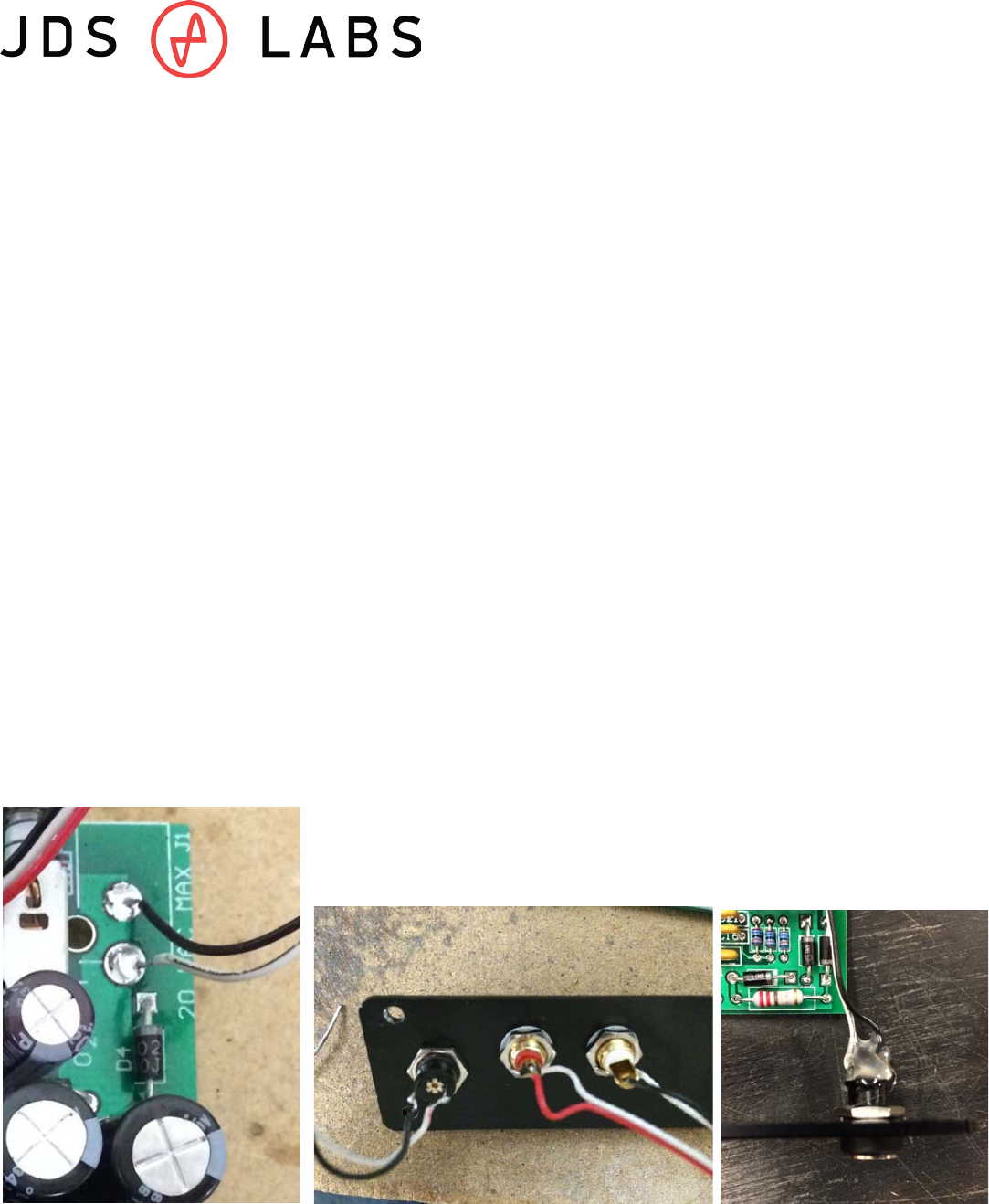
Rear Power Jack
1) Omit J1. Install an "isolated" power jack onto required rear plate. Connect black wire to
longer lead, and white wire to shorter lead. Solder to J1 pins as shown:
2) Apply hot glue to connectors as shown. Let glue dry before installing into case.
Soldering Instructions - Custom O2+ODAC| Document Revision 4 Pg. 2 of 7
Standard Headphone Jack
Install audio jack at J3.
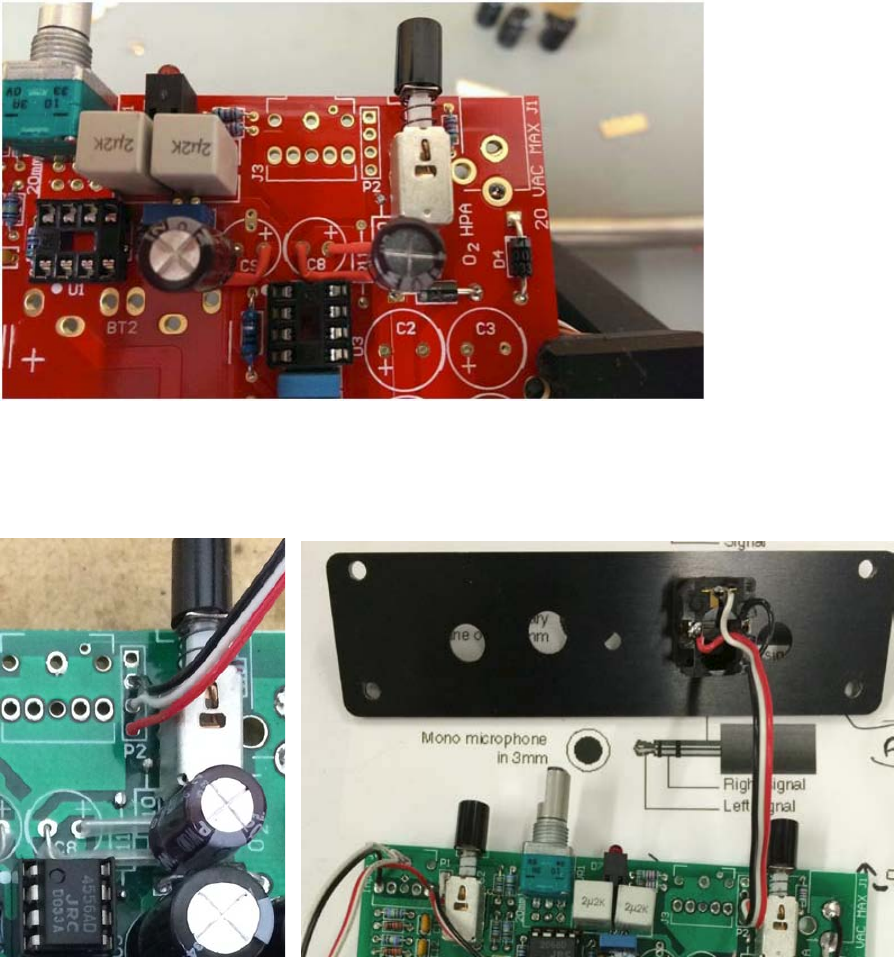
1/4in (6.35mm) Headphone Jack
1. Begin by installing resistors R10 and R11 on the bottom surface of the PCB.
2. Bend leads of capacitors C8 and C9 and cover with heat shrink as shown in Figure 1.
3. Install C8 and C9, then complete remaining assembly of O2+ODAC.
Remember to omit J3.
4. Connect about 3" of wire from Neutrik 1/4in headphone jack to P2. Wire as shown
below (L = White, Red = Right, Black = Ground):
Attach headphone jack to front plate after completing all other assembly. Black nut is
secured by a compression fit. With jack & nut installed on front plate, use table surface
to apply pressure to nut. After nut snaps in place, gently rotate 1/4 turn clockwise.
Soldering Instructions - Custom O2+ODAC| Document Revision 4 Pg. 3 of 7
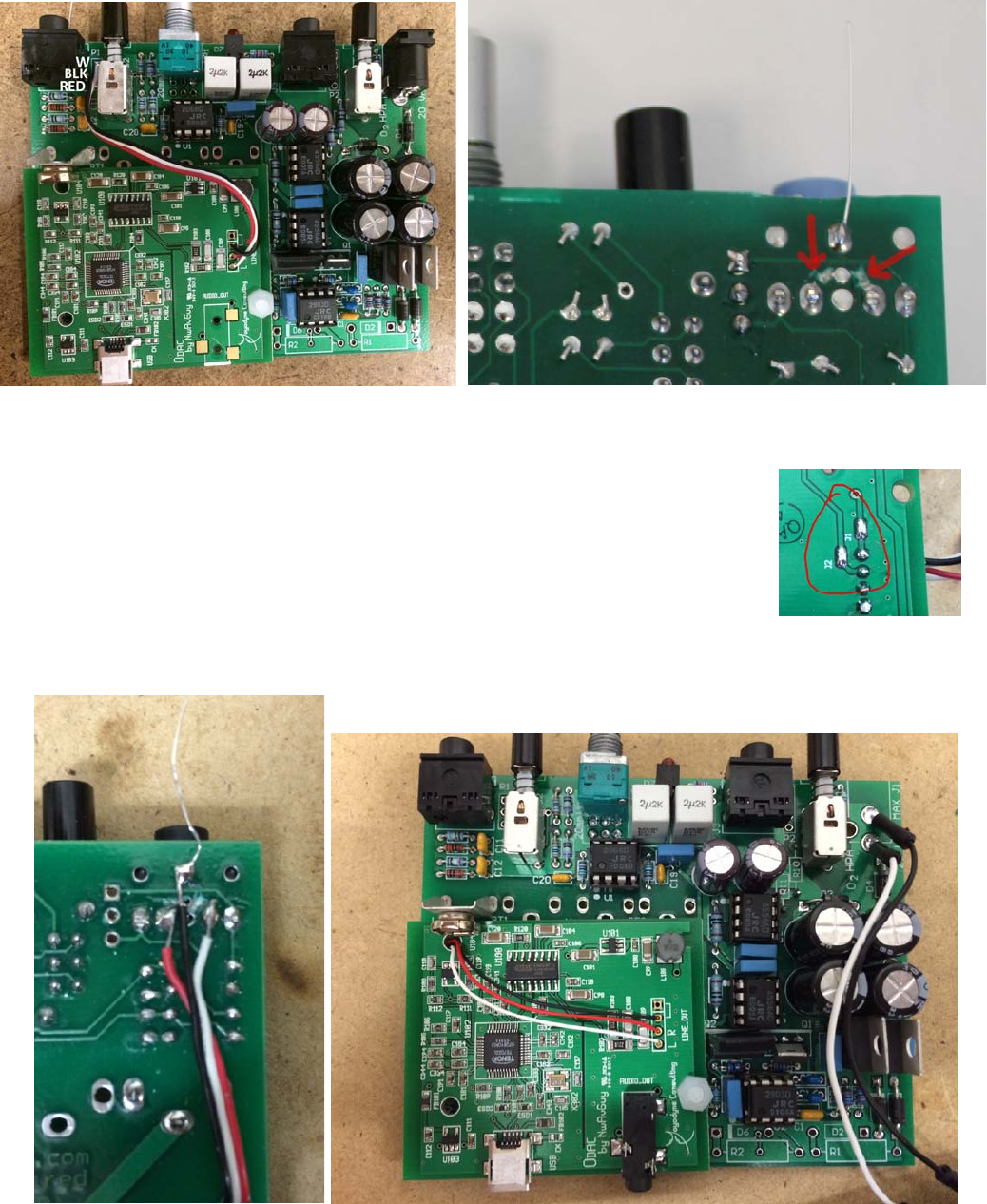
Standard - Shared with 3.5mm input
1. Install audio jack at J2.
2. Wire ODAC's LINE pins to P1 as shown.
3. Using an exacto knife, cut the inner traces beneath J2 (see image at right).
Dedicated 3.5mm DAC line-output
1. Install audio jack at J2.
2. Solder J1 and J2 on bottom of ODAC.
3. Solder 3.5mm jack to ODAC (like Standalone ODAC).
4. Cut inner traces beneath O2 input jack, J2. See page 2.
5. Solder Red/Black/White wire from bottom surface of J2.
Pass wire through holes of O2 and ODAC to solder to LINE OUT. These pins are normally
used for RCA jacks.
Soldering Instructions - Custom O2+ODAC| Document Revision 4 Pg. 4 of 7
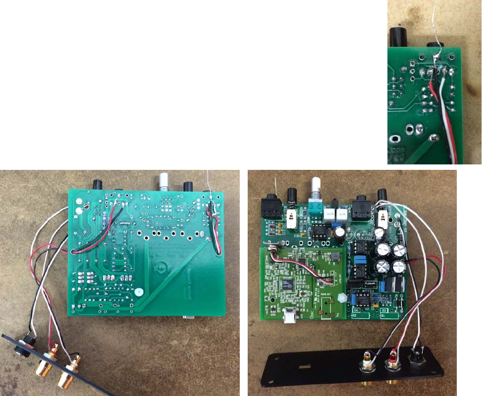
Dedicated RCA DAC line-output
1. Install audio jack at J2.
2. Solder J1 and J2 on bottom of ODAC
3. Mount RCA jacks onto required rear plate using paper washers.
4. Solder about 4" of wire from RCA jacks to ODAC as shown below.
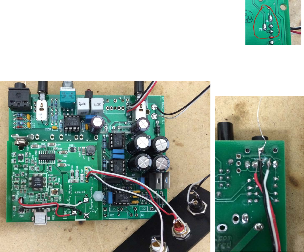
5. Cut inner traces beneath O2 input jack, J2. See page 3 for picture.
6. Solder Red/Black/White wire from bottom surface of J2. Pass wire through holes of O2
and ODAC to solder to AUDIO_OUT as shown:
Soldering Instructions - Custom O2+ODAC| Document Revision 4 Pg. 5 of 7
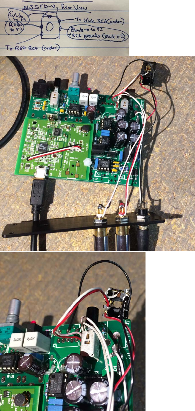
Switched RCA Amplified Output
1. Install audio jack at J2 (on Objective2 input).
2. Mount RCA jacks onto required rear plate using paper washers.
3. Cut inner traces beneath O2 input jack, J2. See page 3 for picture.
4. Solder Red/Black/White wire from bottom surface of J2. Pass wire
through holes of O2 and ODAC to solder to ODAC's L/R/GND holes:
5. Wire RCA jacks directly to Headphone Jack
a. For 3.5mm Headphone Jack
Soldering Instructions - Custom O2+ODAC| Document Revision 4 Pg. 6 of 7
b. For 1/4" Headphone Jack ** Must use Neutrik NJ5FD-V **
Soldering Instructions - Custom O2+ODAC| Document Revision 4 Pg. 7 of 7
Standard Gain
• R17 and R21 = Default = 1 kΩ
• R19 and R23 = Default = 274 Ω
Medium Gain, 1.0 and 3.3x
• R17 and R21 = NONE
• R19 and R23 = 634 Ω
Low Gain, 1.0 and 2.5x
• R17 and R21 = NONE
• R19 and R23 = 1 kΩ (normally R17 and R21)
