Operators Manual PDF Cyber Cycles Standard [Operator's] [English]
User Manual: PDF T E X T F I L E S
Open the PDF directly: View PDF ![]() .
.
Page Count: 37
- Contents
- OPERATORS MANUAL
- SAFETY WARNING
- 1. SPECIFICATIONS
- 2. MAJOR COMPONENTS
- 3. PRECAUTIONS
- 4. INSTALLATION
- 5. How to Play
- 6. ADJUSTMENTS
- 7. MAINTENANCE
- 8. PARTS
- 9. SCHEMATIC

Part No. 90500038
CYBER CYCLES
Operators Manual
IT IS THE RESPONSIBILITY OF THE OPERATOR TO MAINTAIN CUSTOMER SAFETY AT
ALL TIMES, AND IT IS IMPERATIVE THAT THE DETAILS SET OUT IN THIS MANUAL
ARE FOLLOWED PRECISELY.
SAFETY WARNING
In Order to Use This Machine Safely
In order to use this machine safely, be sure to read this Operators Manual carefully
before installation and use of the machine.
Whenever the owner of this machine entrusts disassembly, installation, adjustment,
routine maintenance or trouble shooting to another person, the owner should ensure
that they read the appropriate precautions and relevant sections of this manual before
starting work.
In order that no accidents occur when the machine is in operation, strictly
follow the notes on safety described below. Also, carefully read section 3,
“Precautions”.
Warnings for Operation
NOTE:
Only operate this machine after checking that it has been installed correctly
and in accordance with the manual.
NOTE:
Parts of this machine move during game play, so there are places where the
distance between the stationary section and moveable section changes.
There is a warning sticker that the player must be able to reach the grey
matting of the cycle base with their feet, however if the operator feels that a
customer playing the game is in any danger, he should warn the customer
accordingly.
NOTE:
The warning sticker must always be kept in good condition and replaced if
worn so that the customer can read it clearly.
NOTE:
If there is an error or problem with this machine, operation must be
stopped immediately.
Warnings for Disassembly, Installation, Routine Maintenance and Troubleshooting
DANGER:
Namco Ltd. bears absolutely no responsibility for accidents or injuries
resulting from unauthorized changes to the machine.
DANGER:
Ensure that the machine has been turned OFF before making adjustments
or carrying out maintenance. Also ensure only qualified personnel carry out
maintenance or turn the power ON to this machine.
DANGER:
The power supply and inside the monitor will remain hot and have areas of
high voltage even though the machine has been turned OFF, and there is a
possibility of burns or electric shock. Be careful not to touch these areas.
DANGER:
In order to avoid injuries due to mis-operation, be sure that the voltage of the
power supply is within the prescribed limits. Also to prevent possible electric
shocks due to failure, this machine MUST be fitted with a securely
connected earthed plug.
NOTE:
Do not turn the main power switch ON until the machine has been installed
correctly.
Page 4
1. SPECIFICATIONS
POWER SUPPLY :- 220/240volts AC
MONITOR :- Hantarex 28" Polo with Auto Degauss
COIN ACCEPTOR Mars CashFlow - 4 Channel
DIMENSIONS :-
Assembled 1700(w) x 1970(d) x 2100(h)
Monitor Cabinet 800(w) x 750(d) x 1530(h) ea.
Tower 500(w) x 710(d) x 1800(h)
Bike Assy 910(w) x 1370(d) x 930(h) ea.
Header 1450(w) x 240(d) x 500(h)
WEIGHT :-
Assembled 425kg
Monitor Cabinet 95kg ea.
Tower 80kg
Bike Assy 65kg ea.
Header 25kg
ACCESSORIES :- Keys: (Cash Door) ..................... 2
(Coin Door) ...................... 2
(Service Door) ................. 2
Number Decal Set 1-4 ........................... 2
IEC Mains Lead ..................................... 1
Link Cable ......................................... 1
Operators Manual .................................. 1
Monitor Manual ...................................... 1
Cashflow Data........................................ 1
M8x40 Security Screw - SUS ................ 8
M8x20 Security Screw - SUS ................ 4
M8x16 Security Screw - SUS ................ 8
M8 Flat Washer - SUS ........................... 20
M8 Spring Washer - SUS ...................... 20
M5 Security Wrench .............................. 1
M6 Security Wrench .............................. 1
M8 Security wrench ............................... 1
Page 5
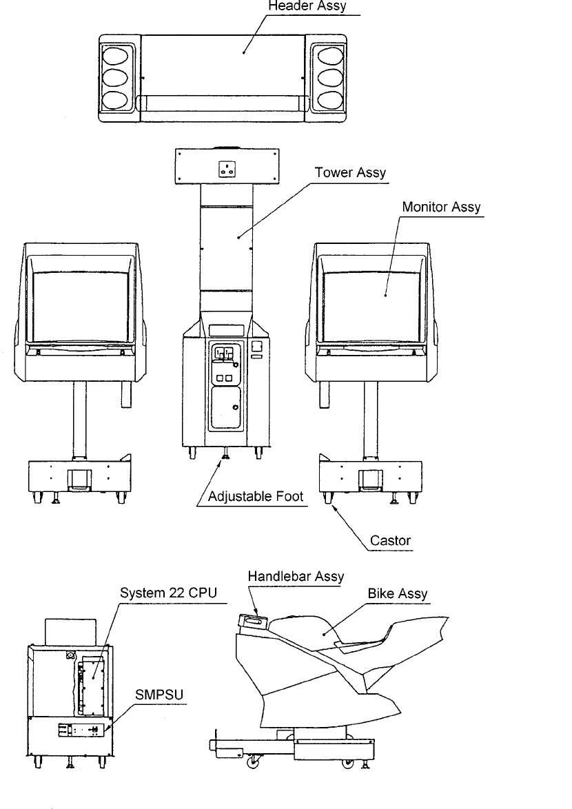
2. MAJOR COMPONENTS
Page 6
3. PRECAUTIONS
Be sure to read this section carefully.
3-1 Notes on Operation
NOTE:
Only operate this machine after checking that it has been installed correctly
and in accordance with the manual.
NOTE:
Parts of this machine move during game play, so there are places where the
distance between the stationary section and moveable section changes.
There is a warning sticker that the player must be able to reach the grey
matting of the bike base with their feet, however if the operator feels that a
customer playing the game is in any danger, he should warn the customer
accordingly.
NOTE:
The warning sticker must always be kept in good condition and replaced if
worn so that the customer can read it clearly.
NOTE:
Ensure customers do not get hurt by leaning or climbing on the cycles. Be
especially careful in the case of young children.
NOTE:
If there is an error or problem with this machine, operation must be
stopped immediately.
Parts of this machine lean to the left and right during game play. In order to
maintain the customer's safety, the operator should strictly follow the
appropriate precautions.
3-2 Cautions When Transporting.
a. Do not subject the game to physical shock when transporting or moving it.
b. Always return the levellers to the UP position before moving the machine, even
for short distances.
c. The main cabinets, bike assemblies, coin assy and header assy must be
separated before moving or shipping.
d. Take care not to rope any moulded (plastic) parts when transporting.
THIS MACHINE IS NOT DESIGNED TO BE MOVED BY FORK LIFT. DO NOT USE
Page 7
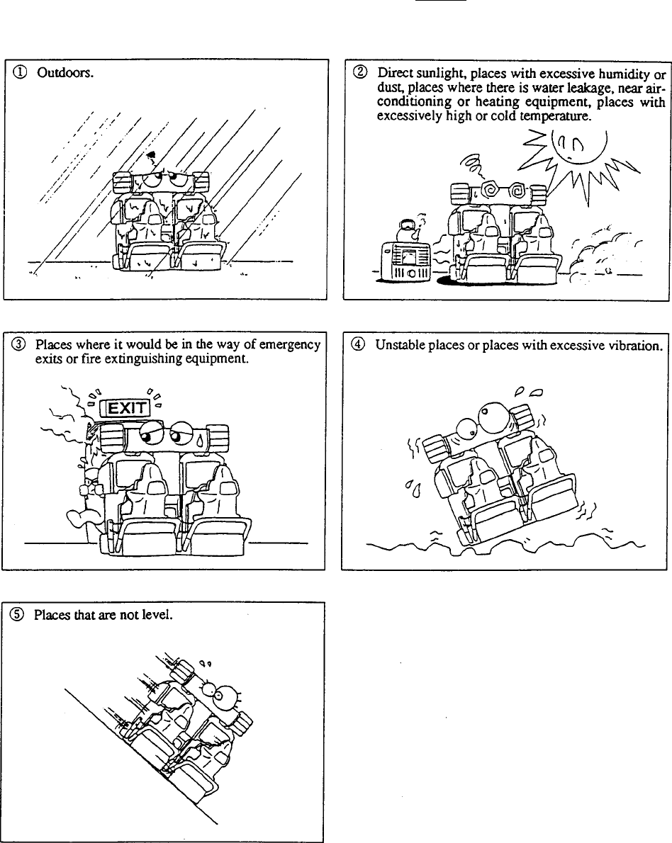
3-3 Cautions When Installing.
1.This machine is designed for indoor use only. Do Not install the machine in the
following places
2. If this machine is installed next to walls or other machines, ensure that there is
plenty of space between them.

Page 8
NOTE:
So that customers are not injured by the movement of the bikes, ensure that
the machines are separated from each other by 200mm and from walls or
other machines by at least 300mm either side, and 600mm from the rear of
the bikes.
NOTE:
In order to gain access to the mains-in connector, ON/OFF switch and link
switches, make sure that the rear of the machine is separated from a wall or
other machine by a distance of at least 500mm or more.

Page 9
3-4 Cautions when Handling.
DANGER
The Mains Voltage to this machine must be within the range of
220v to 240v AC.
DANGER
Be sure that the power is turned OFF when replacing parts and
connecting/disconnecting connectors.
DANGER
To prevent possible electric shocks due to failure, this machine MUST
be fitted with a securely connected earthed plug.
DANGER
The monitor and power supply contain areas of very high voltage. Be
extremely careful when inspecting or making adjustments.
DANGER
When unplugging the game from an electrical outlet, always grasp the
plug, not the mains lead.
NOTES:
•Always return PC Boards to your dealer for repair. Never test the PCB for
continuity with a multimeter or similar device. The PCB contains sensitive devices
which could be damaged or even destroyed by the internal voltage of such test
equipment.
•Adjustments are required after replacing the game PCB, ROM or control pots.
Adjustments should be performed as described in section 7-4, "Adjustments
when Replacing Parts" (page 25).
•After initial installation or if the number of machines linked together changes, it
may be necessary to use the test mode to change the settings and link switch
settings. (Refer to section 6-4, "Linking Two Machines" (page 20).
Page 10
4. INSTALLATION
Note:- The monitor cabinets and tower are supplied already assembled.
The following instructions are for information only.
4-1 Assembling the Monitor and Tower Assemblies
1. Connect the loom connectors between the tower assembly and the monitor
assembly, and place the assemblies together, taking care not to trap any wires.
2. Fit, finger tight, three M8x20 Security Screws, Spring and Flat washers to
connect the tower and monitor base.
3. Fit, finger tight, four M8x20 Security Screws, Spring and Flat washers to connect
the monitor cabinet connector cover to the tower.
4. Tighten fully all the Security Screws. (7off)
5. Repeat above for the other monitor cabinet.
Page 11
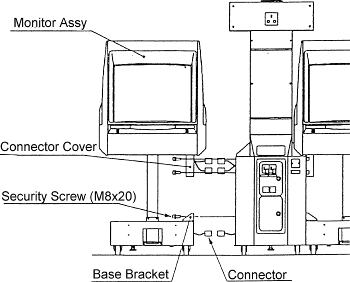
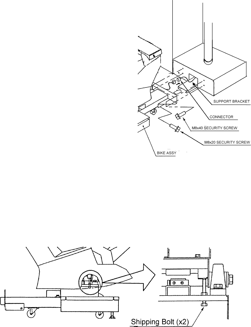
4-2 Connecting the Bike Assemblies to the Cabinets
1. Connect the connectors
between the bike assembly and
cabinet.
2. Place the bike assembly onto
the support bracket and push
the bike against the cabinet
taking care not to trap any
wires.
3. Fit, finger tight, the 4off M8x20
security screws, spring washers
and flat washers, securing the
Bike Assy to the Monitor Base.
4. Fit, finger tight, the 2off M8x20
security screws, spring washers
and flat washers, securing the
Bike assy to the support
bracket.
5. Tighten fully all the security
screws. (6off)
6. Fit the bike number decal to the rear of either side of the bike.
7. Remove the shipping bolts (M8x75) from either side of the bike.
Note:- Retain the shipping bolts in a secure place for re-fitting if the
machine is transported.
Page 12
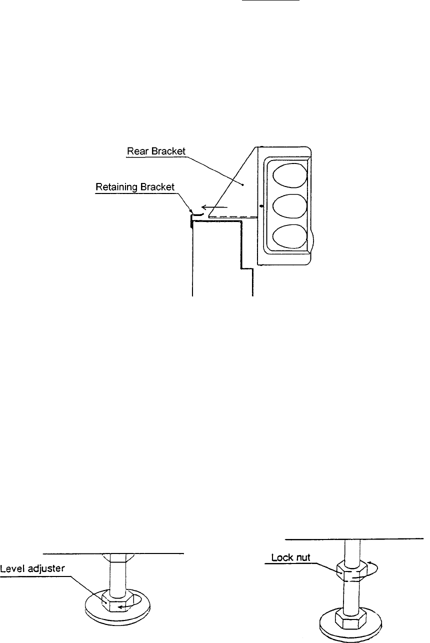
4-3 Fitting the Header Assembly
The Header Assembly is heavy (approx. 25kg), with a forward centre of
gravity, so it is important that at least two people are used to fit or remove
the Header Assembly.
The fitting position of the Header Assembly is very high, and it is important that a
means of reaching the height safely, without stretching, is available. (e.g. steps,
step stools etc.)
1. Place the Header Assembly on to the tower and pass the connectors in to the
tower, slide the header back ensuring that the rear bracket engages fully in to the
retaining brackets.
2. Fit the 8off M8x16 Security Screws, Spring and Flat washers to retain the Header
Assembly to the Tower.
3. Connect the connectors inside the monitor cabinet.
NOTE:-
When the machine is fully assembled and in its final position, lower the 14 level
adjusters, (4 on each monitor cabinet, 2 on the tower and 2 on each bike assy), with a
spanner so that all castors are raised from the floor, and the machine is level.
Tighten the lock nuts with a spanner to ensure that the level adjusters do not move.
Page 13
5. How to Play
This game is linkable so players can compete against each other on the same track,
or compete against computer bikes when playing alone. Two machines can be linked
together allowing up to four players to compete against each other.
The Header Assembly displays the position of each rider and also the leading rider.
Speed is controlled by use of the throttle and brake, and steering is controlled by
leaning the bike left or right.
After the insertion of a coin/s, credit is established to a bike position with the use of the
respective ‘Credit Available’ button. Pressing the flashing ‘View Change’ button,
located on the handle bar assembly, will display the Course Select Screen.
There are two courses available, “GREEN HILL” is a practise course for beginners and
“NEO YOKOHAMA” is an intermediate and advanced course. In a linked game the
course is decided by the majority.
Next select a bike.
Each player can select one of three bikes:-
“ANTHIAS”, for beginners. It corners easily, and its top speed is reduced a little.
“NVR750R”, for intermediate. This bike has good cornering balance, and its top
speed is normal.
“WILD HOG” for advanced. By controlling the special drift, it can cover the course
faster than any of the other bikes, but is more difficult to control.
The first player to enter “Bike Select” is also able to select, by using the throttle, the
music during the game. The title is displayed in the lower left of the screen.
Players can join in a linked game during the link time countdown. This time can be
adjusted in the ‘Game Options’ mode.
If a linked game is in progress but a bike position is available, a player can use this
position as a solo game.
When a player completes the specified number of laps in the given time, they
complete the game. If the countdown timer reaches 00 before completing the specified
number of laps the game is over. At the end of the game, the players ranking, fastest
lap time and total time are displayed.
If a best time is beaten the end of the race will be shown and the player can enter their
initials by leaning the bike to select the letters and pressing ‘View Change’ to enter
them.
With this game it is possible to change the players viewpoint of the game. Each time
the ‘View Change’ button is pressed the view changes between : “Pillion View”,
“Rider’s View”, and “Behind View”.
Page 14
6. ADJUSTMENTS
6-1 Turning on the Power
After the machine has been installed, turn ON the power. The power switch is
located on the rear of the right hand cabinet.
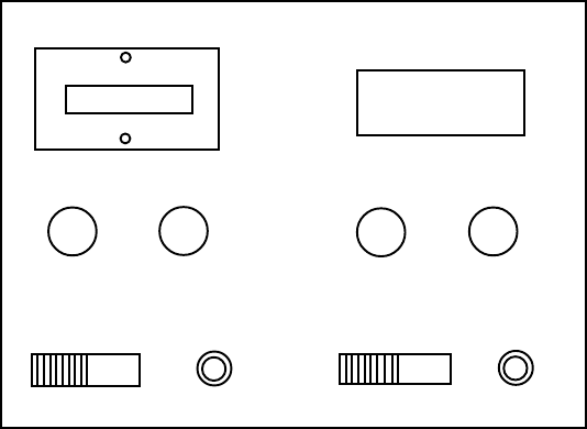
6-2 Adjustment Switches
The Adjustment switches are located inside the coin door.
1. Service Switch.
Press this switch to obtain game credits without incrementing the play meter.
2. Test Switch
Slide the test switch ON to enter test mode.
Test mode allows testing and the changing of game settings. (Refer to section
6-3 "Test Mode" (page 12))
Service Bracket
COIN COUNTER
TEST SERVICE TEST SERVICE
RIGHT PLAYERLEFT PLAYER

Page 15
6-3 Test Mode
1. Open the coin door and slide the test switch "ON". The menu screen will be
displayed on the monitor.
2. Select the test required by leaning the bike left or right. The selected test will
'blink'.
3. Enter the selected test by pressing the 'View Change' push button. Select "EXIT"
to return the "Menu Screen".
4. After testing is completed, ensure that the test switch is returned to the "OFF"
position to return to normal game mode.
The Test Switch must always be in the "OFF" position for normal game mode.
MENU
COIN OPTIONS-------(1)Sets the price of play (See 6-3-1)
GAME OPTIONS-------(2)Sets the game options (See 6-3-2)
I/O TEST ------- (3) Used for testing switches and controls
(See 6-3-3)
SOUND TEST ------- (4) Used for testing sound and setting
volumes (See 6-3-4)
MONITOR TEST ------- (5) Used for adjusting the monitor
ADS TEST ------- (6) Displays accumulated game data
OTHERS ------- (7) Used for testing the PC Boards and for
initializing all of the settings
BANK : CHOOSE
VIEW SW : ENTER
Page 16
6-3-1 Coin Options
1. Select item (1) "COIN
OPTIONS" on the
menu screen to set
the game cost and
related settings.
2. Lean the bike left or
right to select the
required item then
press View Change.
3. Use the Brake to
adjust the settings
UP or the Throttle to
adjust the settings
DOWN, press View
Change to store the
new settings.
4. Select "EXIT" to
return to the menu
screen.
COIN OPTIONS
[ DEFAULT IN GREEN ]
GAME COST
1 COIN 1 CREDIT ------------------------ (a)
FREE PLAY OFF ------------------------ (b)
EXIT
BANK :CHOOSE BRAKE :CHANGE+
VIEW SW :ENTER THROTTLE :CHANGE-
Note :- The price of play on this machine is set within the Cashflow Coin Mech.
Ensure that the Coin Options on the screen are set as shown in the
following table.
METISTNETNOCTESYROTCAF
tsoCemaG)a(9-1elbattes------tiderc1rofderiuqersnioC1
yalPeerF)b(oN/seYON

Page 17
6-3-2 Game Options
1. Select item (2) "GAME OPTIONS" on the menu screen to set the game
options and related settings.
2. Lean the bike left or right to select the required item then press 'View
Change'.
3. Use the Brake to adjust the settings UP or the Throttle to adjust the settings
DOWN. Standard settings are displayed in green.
4. Select "EXIT" and press 'View Change' to return to the menu screen.
GAME OPTIONS
[ DEFAULT IN GREEN ]
GAME DIFFICULTY B --------------- (a)
GAME LAPS
GREEN HILL 3 --------------- (b)
NEO YOKOHAMA 2 --------------- (c)
ENTRY TIME B --------------- (d)
ID NUMBER 1 LINK ON 1 ------- (e), (f)
SEAT COLOUR RED --------------- (g)
LANGUAGE ENGLISH ------------- (h)
SOUND IN ATTRACT ON --------------- (i)
HI SCORE INITIALIZE NO --------------- (j)
EXIT
BANK :CHOOSE BRAKE :CHANGE+
VIEW SW :ENTER THROTTLE :CHANGE-
NOTES
•The game difficulty and number of laps and entry time must be set the
same on all positions that are linked.
•The ID number of the bike furthest left (when facing the front of the
machine) should be set to 1, and the other bikes set to 2, 3, or 4 in order
from left to right. The ID number of the farthest right position should
equal the number of bikes linked.
•Settings other than those described will cause the machine to operate
incorrectly.

Page 18
METINOITPIRCSEDYROTCAF
TES
ytluciffiDemaG)a()drah(Cot)ysae(AB
lliHneerG)b(5-2tes---esruoclliHneerGrofspalforebmuN3
amahokoYoeN)c( 5-1tes---esruocamahokoYoeNrofspalforebmuN2
emiTyrtnE)d()tsetrohs(Cot)tsegnol(AB
rebmuNDI)e( evahsekibdeknilontahtosteS.snoitisopdeknilrofytitnediekibsteS
rebmunemaseht
kniLsyalpsiD)f(
noitamrofnI
stinudeknilforebmun+NOKNIL-wohslliwyalpsiD-dekniLenihcaM
FFOKNIL-wohslliwyalpsiD-elbaCkniLytluaF
1NO-wohslliwyalpsiD-enihcamenoylnO
GN-wohslliwyalpsiD-BCPkniLytluaF
ruoloCtaeS)g( esuniekibforuolocehthctamotteS.ruolocekibehtsteS
egaugnaL)h(enoN,hsilgnE,esenapaJhsilgnE
tcarttAnidnuoS)i(ffO/nOnO
ezilaitinIerocSiH)j(ffO/nOffO
I/O TEST
DIP 4 12345678 ............................(a)
SWITCH TEST ............................(b)
MOTOR TEST ............................(c)
LAMP TEST ............................(d)
EXIT
BANK :CHOOSE
VIEW SW :ENTER
6-3-3 I/O Test
1. Select item (3) "I/O Test" on the menu screen to test the switches or lamps.
2. Lean the bike left or right to select the required item then press View
Change.
3. Select "EXIT" and press 'View Change' to return to the menu screen.
(a) Shows condition of DIP SW 4 on the PCB. In normal operation all switches
are OFF. (If a switch is ON, it will be displayed in red.)
Switch 1 if ON will force the PCB in to Test Mode.
Switch 8 if ON will freeze the picture on the monitor.
(b) Shows if the game is linked.

Page 19
6-3-3-1 Switch Test
1. Select Switch Test from the 'I/O Test' menu. The following screen will
appear on the monitor.
LAMP TEST
ALL LAMPS
RED
YELLOW
BLUE
1
2
3
4
GREEN
VIEW-SW
VIEW-SW: EXIT
SWITCH TEST
TEST SW ON .................(a)
COIN SW ON .................(b)
SERVICE SW ON .................(c)
BANK 00 CENTRE ................(d)
THROTTLE 00 .................(e)
BRAKE 00 .................(f)
VIEW-SW ON .................(g)
BRAKE+THROTTLE: EXIT
2. The word 'ON' will appear next to items a, b, c, and g each time the
respective switch is operated.
When the bike is pushed left, 'CENTRE' will go off and 'OK' appear just
before it reaches the extreme left, '00' will decrease. When the bike is
pushed right, 'CENTRE' will go off and 'OK' appear just before it reaches
the extreme right, '00' will increase.
When the THROTTLE or BRAKE are operated, 'OK' will appear just
before they are fully on, and '00' will increase.
3. Operate the brake and throttle together to exit and return to the 'I/O Test'
menu screen.
6-3-3-2 Motor Test
This test is not used on this machine
6-3-3-3 Lamp Test
1. Select Lamp Test from the “I/O Test” menu. The following screen will
appear on the monitor

Page 20
6-3-4 Sound Test
1. Select item (4) "Sound Test" on the menu screen to test the sound and
speakers.
2. The following screen will appear on the monitor.
2. The lamps will automatically illuminate in turn as indicated on the screen.
3. Press ‘View Change’ to return to the “I/O Test” menu screen.
SOUND TEST
[ DEFAULT IN GREEN ]
VOLUMEFRONT LEFT SP. 55 ------------------- (a)
FRONT RIGHT SP. 55 ------------------- (b)
TANK SP. 50 ------------------- (c)
REQUEST SONG No. 000 ------------------- (d)
MESSAGE ETC. ------------------- (e)
EXIT
BANK :CHOOSE BRAKE :CHANGE+
VIEW SW :ENT/ON,OFF THROTTLE :CHANGE-
3. Select the required item by leaning the bike left or right. The selected item
will ‘blink’.
4. Operating the brake will increase the value setting and operating the throttle
will decrease the value setting. Standard values are displayed in green.
5. Press ‘View Change’ to start or stop a Reqest Song No. sound. (Request
Song No. 3 will generate a stereo sound test.
6. Select “EXIT” and press ‘View Change’ to return to the menu screen.
metInoitpircseDyrotcaF
teS
a tseduoL36-tseteiuQ00------emulovrekaepstfelteS 23
b tseduoL36-tseteiuQ00------emulovrekaepsthgirteS 23
c tseduoL36-tseteiuQ00------emulovrekaepsknatekibteS 23
d000.dnuostnereffidaecudorplliwrebmunhcaE.gnitsetrofdnuostceleS
.tsetoeretsaetareneglliw ---
eemangnossyalpsiD ---

Page 21
6-3-5 Monitor Test
1. Select item (5) “Monitor Test” on the menu screen to set up and adjust the
monitor.
2. On entering monitor test, the following screen will appear on the monitor.
3. Lean the bike to select a test and press ‘View Change’ to enter the test and
to return to “Monitor Menu” from a test.
6-3-6 ADS Data
1. Select item (5) "ADS Data" on the menu screen to view machine history
details.
2. The following screen will appear on the monitor.
ADS
POWER ON 00'00"00 .................. (a)
PLAY TIME 00'00"00 .................. (b)
PLAY TIME AVE 00'00"00 .................. (c)
PLAY NUMBER 0000 .................. (d)
COURSE-VIEW .................. (e)
COURSE-BIKE .................. (f)
COURSE -LINK .................. (g)
COURSE-C. P. .................. (h)
COURSE-P.T. ...................(i)
INITIALIZE ...................(j)
EXIT
BANK :CHOOSE
VIEW-SW :ENTER
MONITOR
GRADATION PATTERN
CROSSHATCH GREEN
CROSSHATCH WHITE
WHITE WINDOW (H)
WHITE WINDOW (M)
WHITE WINDOW (L)
INTERLACE PATTERN
VIEW ANGLE ADJUST (CRT)
VIEW ANGLE ADJUST (PROJECTOR)
FULL WHITE
EXIT
BANK :CHOOSE
VIEW-SW :ENTER
Page 22
metInoitpircseD
nOrewoP)a( dehctiwsneebsahenihcamsdnoces,setunim,sruohniemitlatoT
.no
emiTyalP)b( nineebsahenihcamtahtsdnoces,setunim,sruohniemitlatoT
.yalp
evAemiTyalP)c(.noitarudemagfoemitegarevA
rebmuNyalP)d(.syalpemaglatoT
weiV-esruoC)e(.weivhcaerofemiT
ekiB-esruoC)f( .detcelesneebsahekibasemitforebmuN
kniL-esruoC)g(.deyalpsemagdeknilforebmuN
.P.C-esruoC)h(.revoemagtaesruocehtnonoitisoP
.T.P-esruoC)i( .deyalpneebsahesruochcaeemitlatoT
ezilaitinI)j(.atadllateseR
6-3-7 Others
1. Select item (6) "Others" on the menu screen.
2. On entering 'Others' the following screen will appear on the monitor.
OTHERS
AUTO SETTING ................ (a)
BACK UP MEMORY INITIALIZE ................ (b)
PCB TEST ................ (c)
EXIT
BANK :CHOOSE
VIEW-SW :ENTER
metInoitpircseD
gnitteSotuA)a( .yllacitamotuahctamotstinudeknilllatsujdalliW
ezilaitinIyromeMpUkcaB)b(atadSDAllateseR
tseTBCP)c(BCPemaGehtgnitsetroF
a) If the game is linked, this option allows all linked positions to be set from position
No. 1 bike. If all game and coin options shown on No. 1 screen are correct, select
transmit, then push View Switch. All positions will automatically update to the
displayed options and ID No. All screens will display the Auto Setting screen. Set
each bike colour from each Auto Setting screen.
Note: Any game in play will be lost during Auto Setting transmit.
Page 23
IN OUT
6-4 Linking Two Machines.
Up to two machines (4 bikes) can be linked together.
The machines should be linked as described below.
1) Ensure that the power is “OFF”.
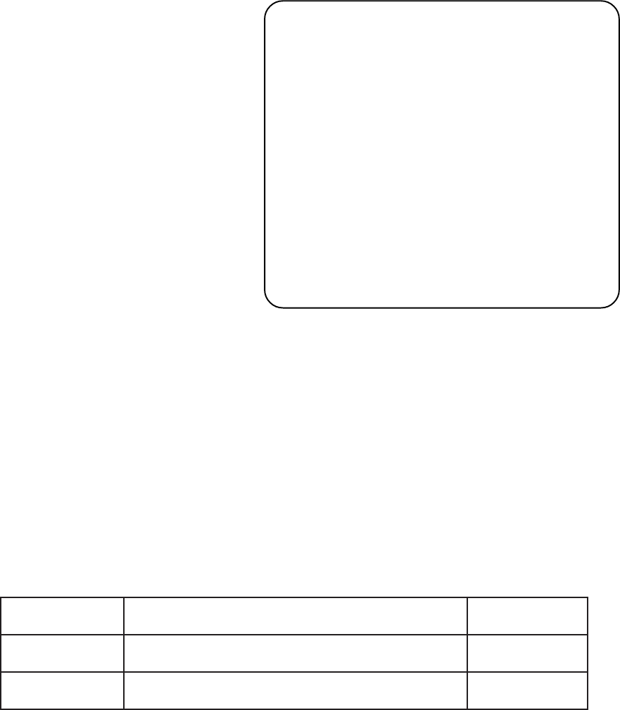
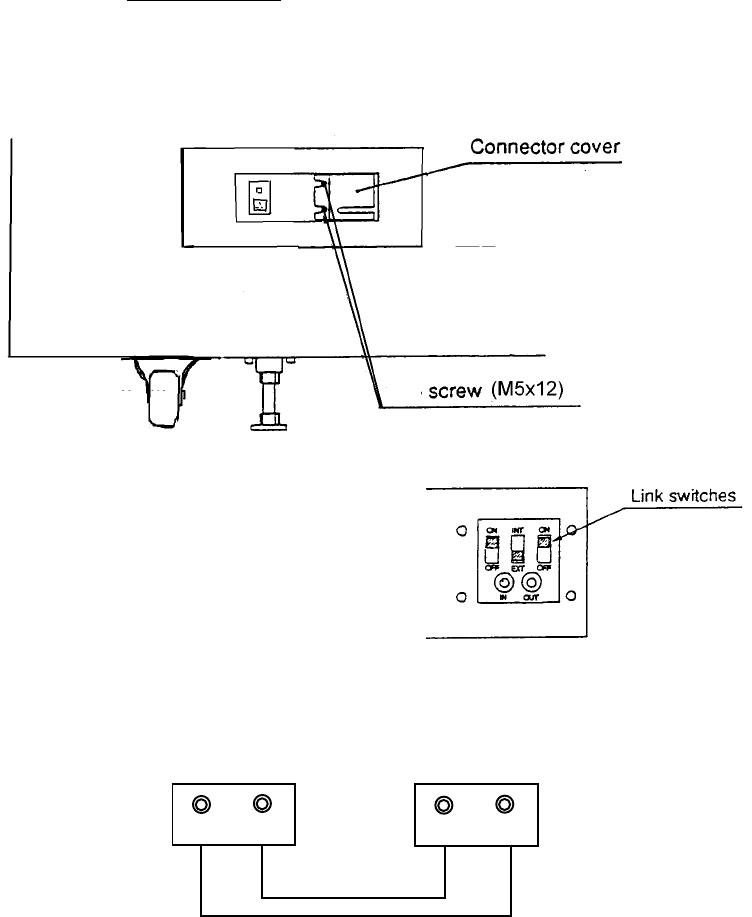
2) Loosen the two screws (M5x12) on the back of the right monitor cabinet, and
remove the connector cover.
3) Set the link switches to “ON” , “EXT”, and
“ON”. (See Diag.)
4) Use the supplied link cable and connect the
machines between “IN” and “OUT” sockets
(See Diag.)
[Examples of Linked Machines]
a) 2 Machines
(2 Seats)
5) Turn the power to each machine “ON”, and set the PCB ID using the test mode.
(Refer to section 6-3-7, “Others” 'Auto Setting' (page 19))
Note: Settings other than those described will cause the machine to operate
incorrectly.
IN OUT
Page 24
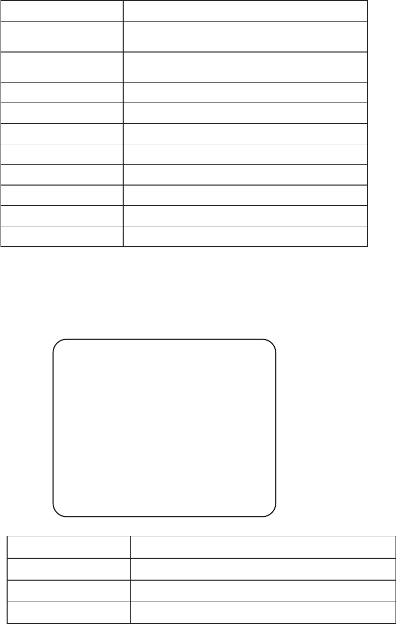
6-4-1 Setting the Link Switches
The link switches are used to set the connection between bikes and machines.
1) Slacken two screws (M5x12) and remove the link
cover.
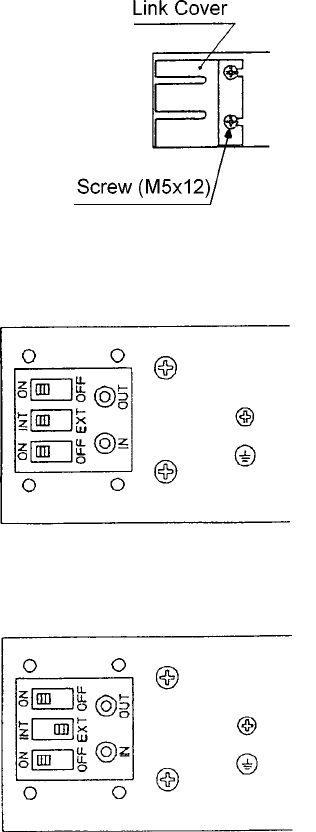
2). Setting only one machine. (2 Bikes)
Set the link switches to “ON”, “INT”, and
“ON”.
Note: Do not use a link cable.
2) Setting two or more machines. (4 Bikes)
Set the link switches to “ON”, “EXT”, and
“ON”.
3) The link procedure is now complete.
4) Setting for faulty PCB.
If the game PCB of only one side is faulty, set the link switch on that side
only to “OFF”
Page 25
7. MAINTENANCE
DANGER: In order to prevent injury or electric shock to service personnel, ensure
that the MAIN POWER IS OFF before attempting any maintenance.
DANGER: Before performing any work not described in this manual, be sure to
contact your distributor to receive instructions or answers to questions.
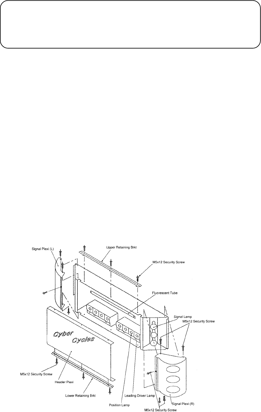
7-1 Replacing the Fluorescent Tube, Position, and Leading Driver Lamps
1) Remove the three security screws (M5x12), and remove the plexi upper retaining
bracket.
2) Remove the three security screws (M5x12), and remove the plexi lower retaining
bracket.
3) Remove the header plexi.
4) Unscrew the defective position lamp and replace.
Warning:- Ensure that the lamp is not hot before touching it.
7-2 Replacing the Signal Lamps
1) After removing the front Plexi as above remove five security screws (M5x12), and
remove the signal plexi L or R.
2) Unscrew the defective lamp and replace.
Warning:- Ensure that the lamp is not hot before touching it.

Page 26
7-3 Handle Bar Assembly
Remove four M5X12 security screws, and remove handle bar assembly cover to gain
access to the throttle and brake controls.
NOTE:- The game must be re-initialized whenever the PCB, ROMS, Throttle, Brake or
Steering controls are replaced.
(See 7-4 "Adjustments when Replacing Parts")
7-3-1 Replacing the Throttle Control Pot
1) Slacken the grub screw
M3X5 securing the
control pot shaft to the
drive gear, and remove
the gear.
2) Replace the control pot
ensuring that the the pot
is replaced in the same
position, and the wires
are replaced to the
correct terminals.
3) Turn the control pot
shaft until the flat is
vertical and to the right,
when looking at the
shaft. Replace the drive
gear ensuring that the
control pot shaft does
not turn and the grub
screw in the drive gear
is on the flat of the shaft
4) Re-tighten the grub
screw M3x5
7-3-2 Replacing the Brake
Control Pot
1) Slacken the grub screw
M3X5 securing the
control pot shaft to the
brake assembly.
2) Replace the control pot
ensuring that the pot is
fitted in the same
position, and the wires are replaced to the correct terminals.
3) When replacing the control pot, ensure that the flat on the control shaft is in
line with the grub screw.
4) Re-tighten the grub screw M3x5.
Page 27
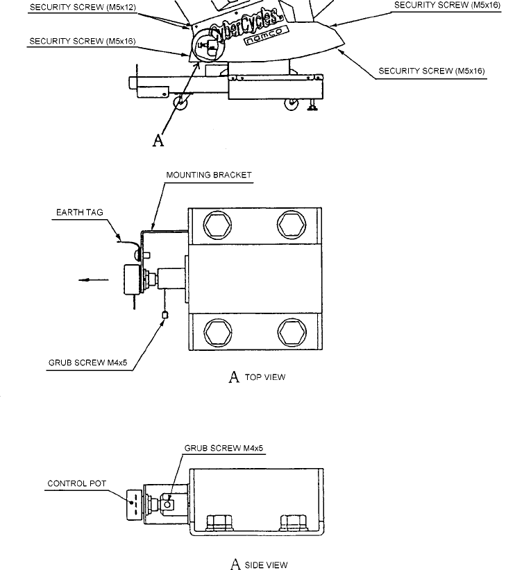
7-3-3 Replacing the Steering Control Pot
1) Remove three security screws (M5X16) and four security screws (M5x12)
from the right hand bike vac-form, and remove the vac-form.
2) Slacken the grub screw (M4x5) to release the control pot shaft.
3) Replace the control pot, ensuring that the pot is replaced in the same
position and the wires are fitted to the correct terminals.
4) Re-tighten the grub screw (M4x5), ensuring that it engages the flat of the
control pot shaft.
5) Refit the bike vac-form, and the security screws (M5x12) (M5x16).
Page 28
7-4 Adjustments When Replacing Parts (Initialization)
The following adjustments must always be carried out after replacing the Game PCB,
ROMS, or Throttle, Brake, and Steering Control Pots.
The game will not operate correctly if these adjustments are not made.
1. Ensure that the Throttle and Brake are fully released and the bike is in its central
upright position.
2. Turn the Test switch on while pressing the Service switch.
3. Adjustment is complete when the screen displays ‘Initialize Completed’.
4. Operate the Brake and Throttle together to return to the “Menu Screen”.
5. Turn the Test switch OFF to return to normal game mode.
Note:- If the ‘View Change’ button is flashing during standby mode, there is a
problem with one of the control pots (Throttle, Brake, or Bank) not being at
zero.
Enter ‘Switch Test’ (See 6-3-3-1 ‘Switch Test’ page 16) to determine which pot
is not at zero and either replace if faulty or reinitialize.
Page 29
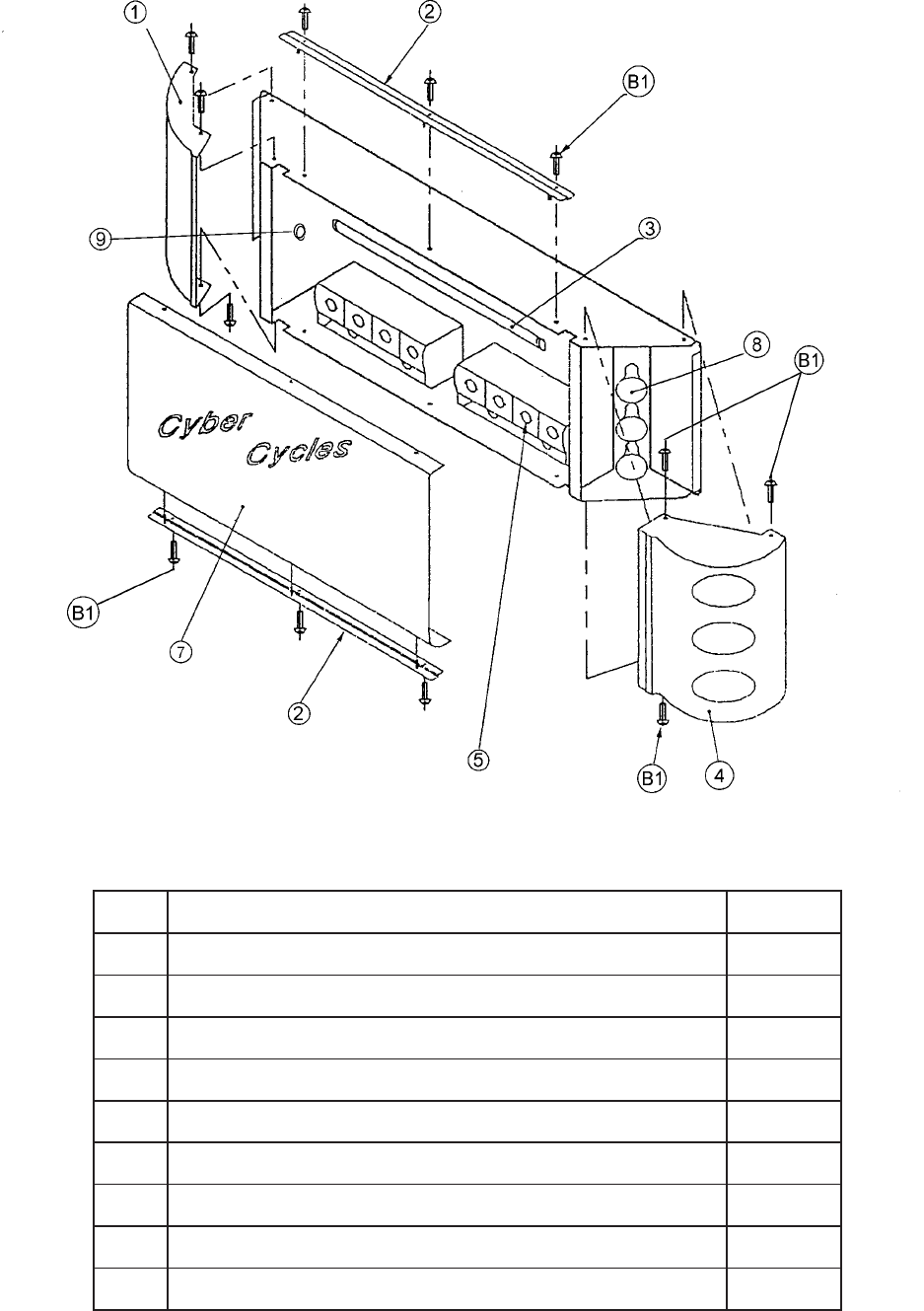
8. PARTS

Page 30
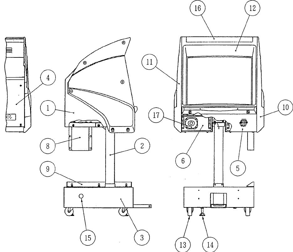
METINOITPIRCSED.oNTRAP
1TENIBACROTINOM 12500054
2TEKCARBDNAEPIPTROPPUSROTINOM 02500054
3HTNILPROTINOM 71500054
4LENAPKCABTENIBACROTINOM 22500054
5ELLIRGREKAEPSDUOL 32500054
6
SHL-TENIBACREKAEPSDUOL 96000173
SHR-TENIBACREKAEPSDUOL 07000173
7ETOMERhtiwROTINOM’OLOP’XERATNAH"82 21000048
8REPPU-TEKCARBTNIOJHTNILPROTINOM 91500054
9REWOL-TEKCARBTNIOJHTNILPROTINOM 81500054
01
DER-SHRMROF-CAVEDISROTINOM 62500054
WOLLEY-SHRMROF-CAVEDISROTINOM 72500054
EULB-SHRMROF-CAVEDISROTINOM 82500054
KCALB-SHRMROF-CAVEDISROTINOM 92500054
11
DER-SHLMROF-CAVEDISROTINOM 03500054
WOLLEY-SHLMROF-CAVEDISROTINOM 13500054
EULB-SHLMROF-CAVEDISROTINOM 23500054
KCALB-SHLMROF-CAVEDISROTINOM 33500054
21MROF-CAVROTINOM 42500054
31mm57ROTSACLEVIWS 50000095
4157x61MTOOFELBATSUJDA 90000052
51
51
mm54-GULPEMOD 90800093
mm54-GNIHSUBYTROHS 45000093
61
61
KCALB-LACEDMROF-CAVROTINOM 84200004
DER-LACEDMROF-CAVROTINOM 94200004
WOLLEY-LACEDMROF-CAVROTINOM 05200004
EULB-LACEDMROF-CAVROTINOM 15200004
Page 31
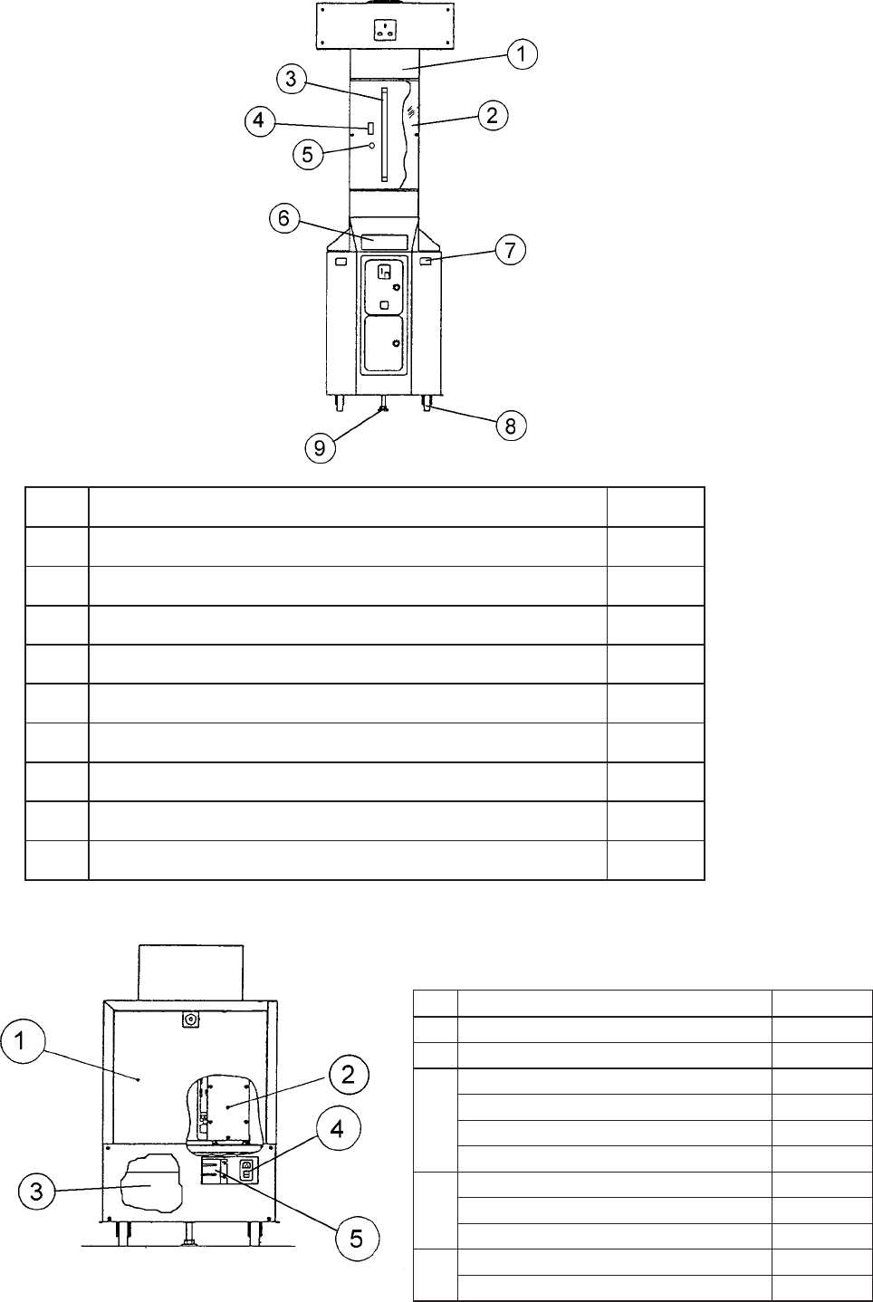
METINOITPIRCSEDoNTRAP
1TEKCARBGNINIATERCILYRCATNORF 53500054
2CILYRCATNORF 93000003
3w51"81EBUTTNECSEROULF 90000546
4w51v042EKOHC 00000336
5RETRATS 00000036
6LACEDYTEFASREWOTNIOC 45200004
7YSSANOTTUBHSUP’TILNEHWELBALIAVATIDERC’ 51200206
8mm57x61MTOOFELBATSUJDA 90000052
9mm57ROTSACLEVIWS 50000095
METINOITPIRCSED.oNTRAP
1ROODECIVRESBCP 74500054
2151V-ELCYCREBYC-YSSABCP BCP-BYCX
3
A5/v21A03/v5USPMS 40000038
1
1
/
4
OLB-OLSA2ESUF" 60500536
1
1
/
4
OLB-OLSA3ESUF" 74500536
1
1
/
4
B/QA2ESUF" 40500536
4
YSSATUPNISNIAMRENFFAHCS 61000066
B/QA5ESUFmm02 10600536
TOOBRENFFAHCS 71000066
5
YSSABCPKNIL BCPKNIL-DAX
TEKCARBREVOCKNIL 05500054
Page 32
METINOITPIRCSED.oNTRAP
1SHL-MROF-CAVTRATSECAR 25400054
2TEKCARBGNINIATERCILYRCAPOT 73500054
3EBUTTNECSERUOLFtf3 31000546
4SHR-MROF-CAVTRATSECAR 35400054
5PMALLLABFLOGttaw5241E 48000046
7CILYRCAPOT 04000003
8PMALDEWREVLISRAERttaw5241E 38000046
9mm05-GNIHSUBYTROHS 15000093
1BWERCSDAEHNOTTUBYTIRUCESSUS61x5M 23000362
Page 33

Page 34
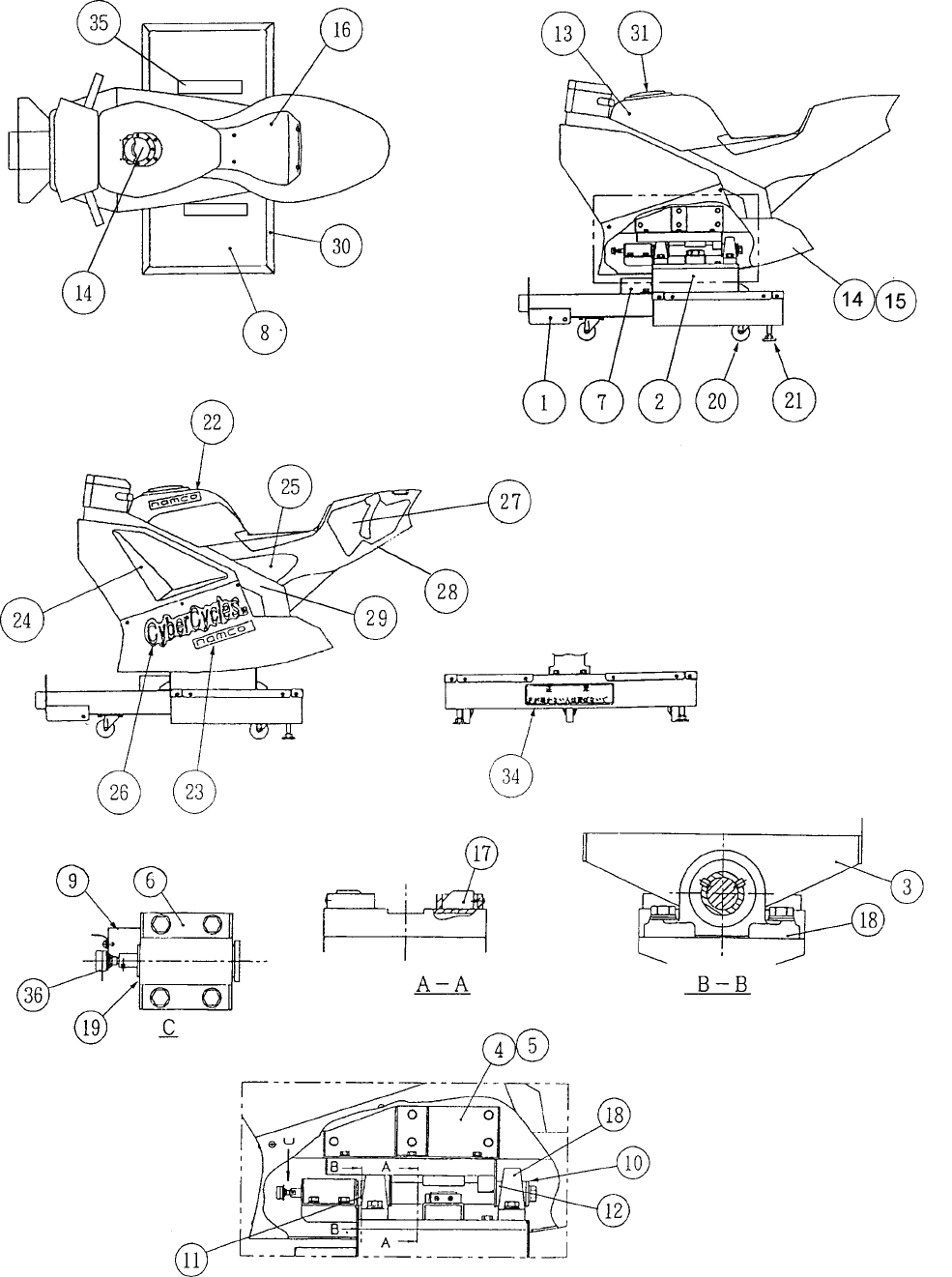
METINOITPIRCSED.oNTRAP
1EMARFESABELCYC 88400054
2YLBMESSAGNITNUOMGNIRAEB 29400054
3ETALPREKCOR 49400054
4SHL-TEKCARBTROPPUSGNIDLUOMYRATOR 51500054
5SHR-TEKCARBTROPPUSGNIDLUOMYRATOR 61500054
6TEKCARBATSOR 79400054
7REVOCROTCENNOC 19400054
8YERG-TAMROOLFAVE 98400054
9TEKCARBRETEMOITNETOP 89400054
01RECAPS 99400054
11RECAPS 59400054
21RECAPS 69400054
31
KCALB-GNIDLUOMYRATOR 10500054
DER-GNIDLUOMYRATOR 20500054
WOLLEY-GNIDLUOMYRATOR 30500054
EULB-GNIDLUOMYRATOR 40500054
41
KCALB-SHRMROF-CAVREWOL 50500054
DER-SHRMROF-CAVREWOL 60500054
WOLLEY-SHRMROF-CAVREWOL 70500054
EULB-SHRMROF-CAVREWOL 80500054
51
KCALB-SHLMROF-CAVREWOL 90500054
DER-SHLMROF-CAVREWOL 01500054
WOLLEY-SHLMROF-CAVREWOL 11500054
EULB-SHLMROF-CAVREWOL 21500054
41REKAEPSw02"‰4 60000026
61MROF-CAVTAES 31500054
71REPMUBEKORTSFODNE 43600388
81702CPU/HYF-GNIRAEBWOLLIP 33600388
91001X72S-RD-GNIRPSATSOR --162-90HEX
262
02mm56ROTSACLEVIWS 20000095
1259x61MTOOFELBATSUJDA 97000388
22GNIDLUOMYRATOR-OGOLOCMAN 83200004
32MROF-CAV-OGOLOCMAN 63200004
42
SHL-TNORFLACEDEKATNIRIA 14200004
SHR-TNORFLACEDEKATNIRIA 24200004
52
SHL-EDISLACEDEKATNIRIA 34200004
SHR-EDISLACEDEKATNIRIA 44200004
62MROFCAVOGOLSELCYCREBYC 73200004
72
SHL-GNIDLUOMYRATORLACEDRAER 93200004
SHR-GNIDLUOMYRATORLACEDRAER 04200004
82EDISREDNURAERLACEDEMORHC 54200004
92
SHL-EDISLACEDEMORHC 64200004
SHR-EDISLACEDEMORHC 74200004
03TEKCARBREVOCTAMROOLF034SUS 094000054
13MROF-CAVPACRELLIF 62600716X
43RAER-REVOCYTEFASESABELCYC 26200004
53SHR/SHL-REVOCYTEFASESABELCYC 36200004
63RETEMOITNETOP 32000800X
Page 35

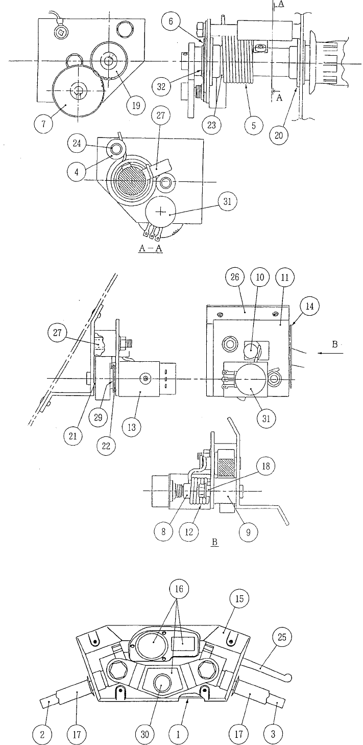
Page 36
METINOITPIRCSED
1ESABELDNAH
2)A(TFAHSPIRG
3)B(TFAHSPIRG
4REPPOTSELTTORHT
5GNIRPSELTTORHT
6ETALPREHSAW
7RAEGELTTORHT
8NIPEKARB
9REPPOTSEKARB
01DORREPPOTS
11ETALPEKARBREPPU
21GNIRPSEKARB
31TEKCARBTOPLORTNOCEKARB
41ETALPEDILS
51REVOCELDNAH
61TESLACED
71PIRGREBBUR
81RECAPSGNIRPS
91RAEGTFAHSPIRG
020102FFL-GNIHSUBEGNALF
125070FFL-GNIHSUBEGNALF
225101FFL-GNIHSUBEGNALF
325202B08-GNIHSUBEGNALF
42RECAPSELTTORHT
52REVELEKARB
62ESABEKARB
72RECAPSEKARB
82NIPELTTORHT
92REHSAWEKARB
03YSSANOTTUBHSUP
13RETEMOITNETOP
23PILC’C’
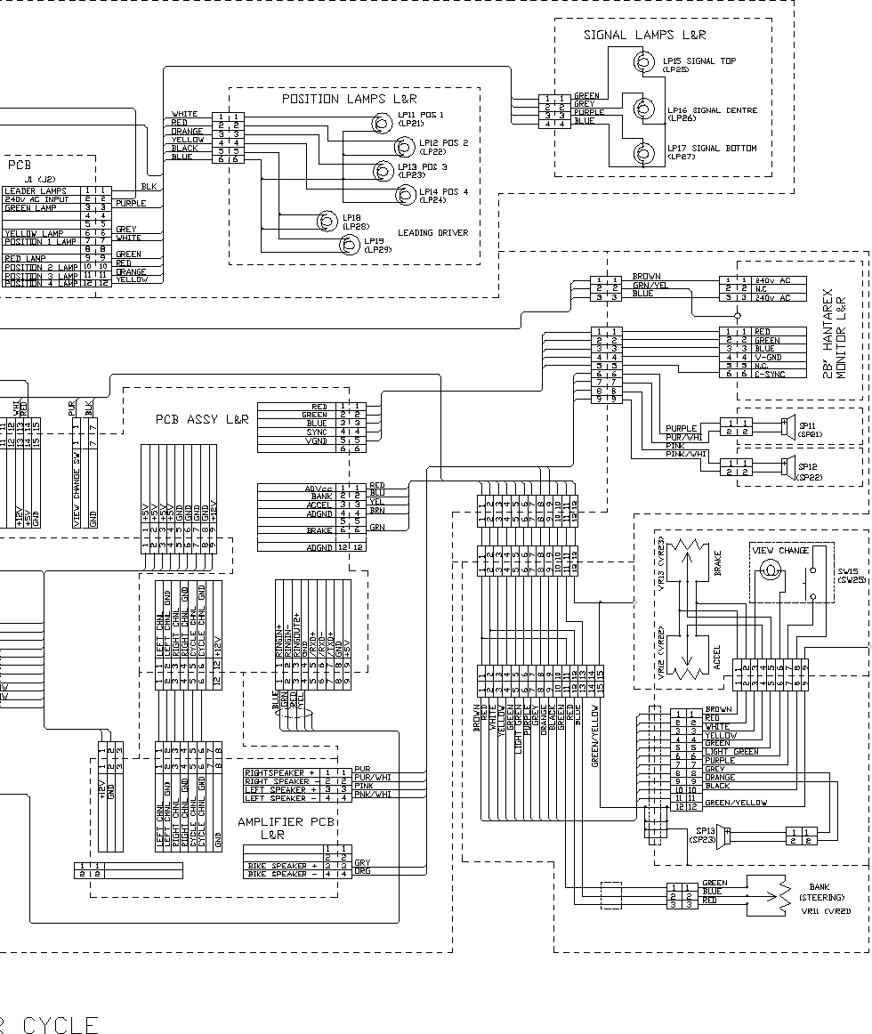
Page37
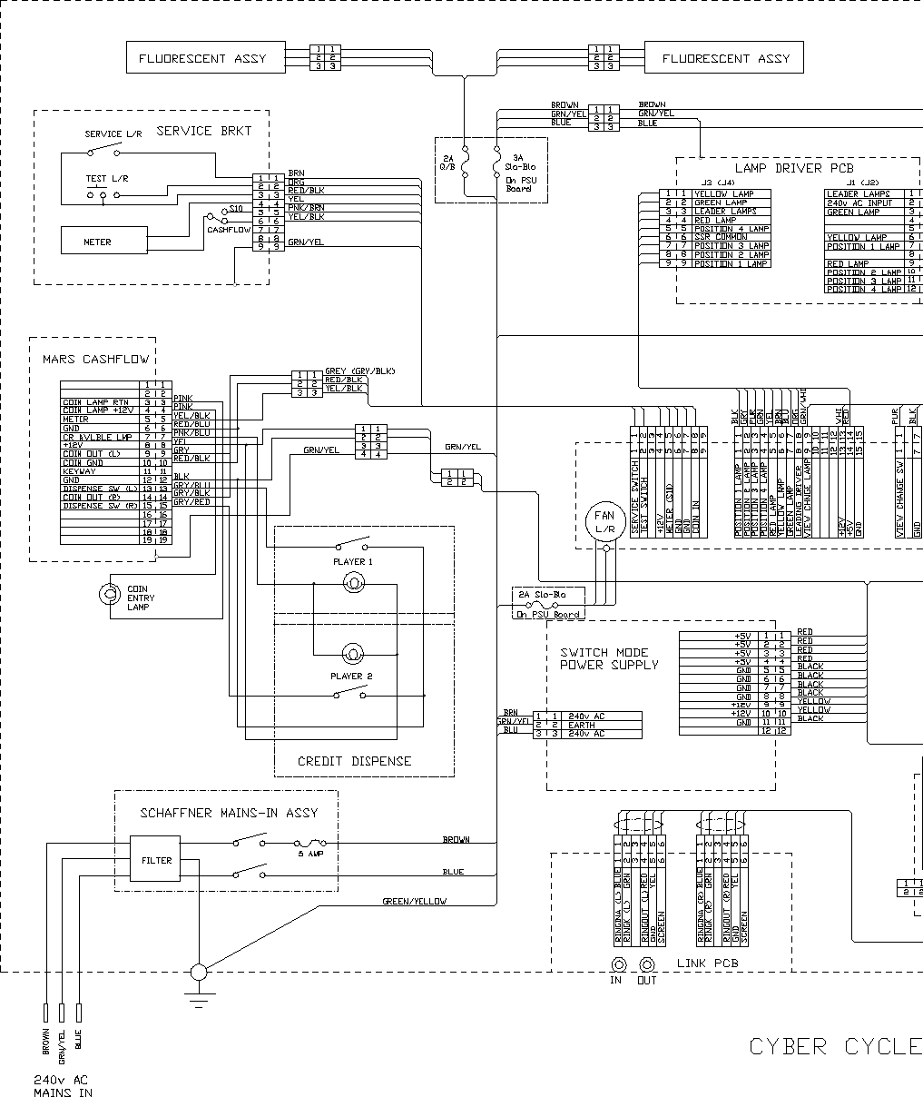
9.SCHEMATIC
Page 38
