48392 SUMITOMO CVR Cyclo Catálogo Motorreductores EEUU Catálogo
User Manual: Cyclo-Catálogo-Motorreductores-EEUU
Open the PDF directly: View PDF ![]() .
.
Page Count: 176 [warning: Documents this large are best viewed by clicking the View PDF Link!]
Cyclo® 6000
CATALOG 04.601.50.007
Gearmotors
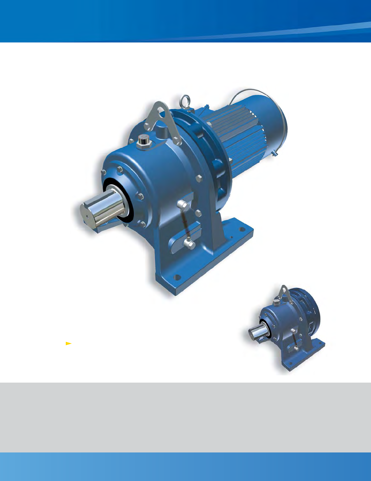
Superior design, powerful performance
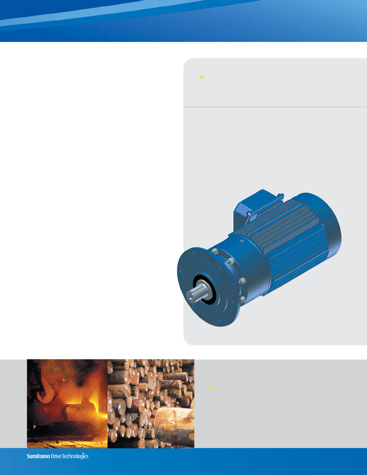
Cyclo® 6000
The Cyclo® 6000 is also available as a Speed Reducer
To request a catalog, or for more information on any of our high quality products,
please visit our Website:
www.smcyclo.com
Table of Contents
1. General Information
2. How to Select a Gearmotor
How to Select. . . . . . . . . . . . . . . . . . . . . . . . . . . . . . . . . . . . . . . . 2.2
AGMA Load Classifications. . . . . . . . . . . . . . . . . . . . . . . . . . . . 2.4
Configure a Model Number (Nomenclature). . . . . . . . . . . 2.6
Housing Styles & Mounting Positions . . . . . . . . . . . . . . . . . 2.8
3. Selection Tables. . . . . . . . . . . . . . . . . . . . . . . . . . . . . . . . . . . 3.1
4. Dimensions. . . . . . . . . . . . . . . . . . . . . . . . . . . . . . . . . . . . . . . . . 4.1
5. Technical Information
Lubrication . . . . . . . . . . . . . . . . . . . . . . . . . . . . . . . . . . . . . . . . . . 5.2
Overhung Load Guidelines . . . . . . . . . . . . . . . . . . . . . . . . . . . 5.6
Axial Load Guidelines . . . . . . . . . . . . . . . . . . . . . . . . . . . . . . . 5.10
Motor . . . . . . . . . . . . . . . . . . . . . . . . . . . . . . . . . . . . . . . . . . . . . . 5.11
Cyclo Food Industry Options . . . . . . . . . . . . . . . . . . . . . . . . 5.24
Slide Rail Dimensions . . . . . . . . . . . . . . . . . . . . . . . . . . . . . . . 5.25
Gearmotors
Cyclo® 6000 boasts an expanded range of standard
sizes and ratings. Use this chart to select a new
Cyclo® 6000 when replacing Cyclo® series 3000 and
4000 models.
CYCLO® Frame Size
Cross Reference
PRIOR SERIES NEW
3000 4000 6000
6060
3075 4075 6065
6070
3085 4085 6075
6080
6085
3090 4090 6090
3095 4095 6095
3097 4097 6095
3100 4100 6100
3105 4105 6105
310H 410H 610H
6110
6115
3110 4110 6120
3115 4115 6125
311H 4125 612H
3140 4130 6130
3145 4135 6135
6140
3155 4145 6145
315H 4155 614H
3160 4160 6160
3165 4165 6165
316H 416H 616H
3170 4170 6170
3175 4175 6175
3180 4180 6180
3185 4185 6185
3190 4190 6190
3195 4195 6195
3205 4205 6205
3215 4215 6215
3225 4225 6225
3235 4235 6235
3245 4245 6245
3255 4255 6255
3265 4265 6265
3275 4275 6275
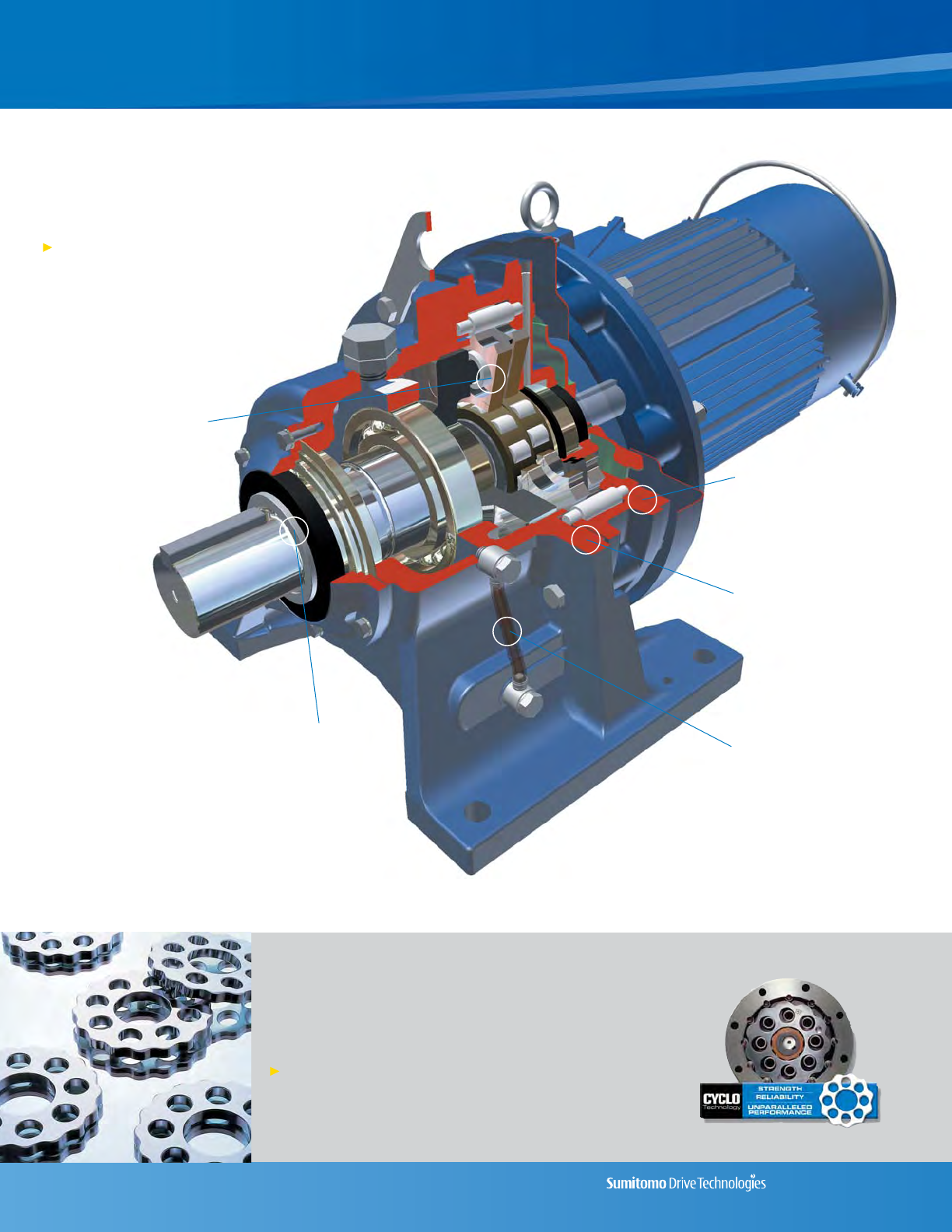
High power density.
All reduction contained
in compact ring gear
housing
Superior seal design
using wear sleeves
and pressure-rated
seals
All rotating components are
fully hardened, vacuum
degassed bearing grade
steel, for consistent, reliable
performance
Unique oil sight gauge for
simple, visible lubrication
indication
1.2 General Information Cyclo® 6000 Series
Unmatched Reliability,
Exceptional Performance
Cyclo® speed reducers and gearmotors are
designed to withstand shock loads
exceeding 500% of their ratings
Cyclo® 6000
Rugged, shock-resistant
cast iron housing.
Optional ductile iron
also available
Wide variety of
inputs available,
including C-Face,
Free-Shaft,
Gearmotor and
Brakemotor
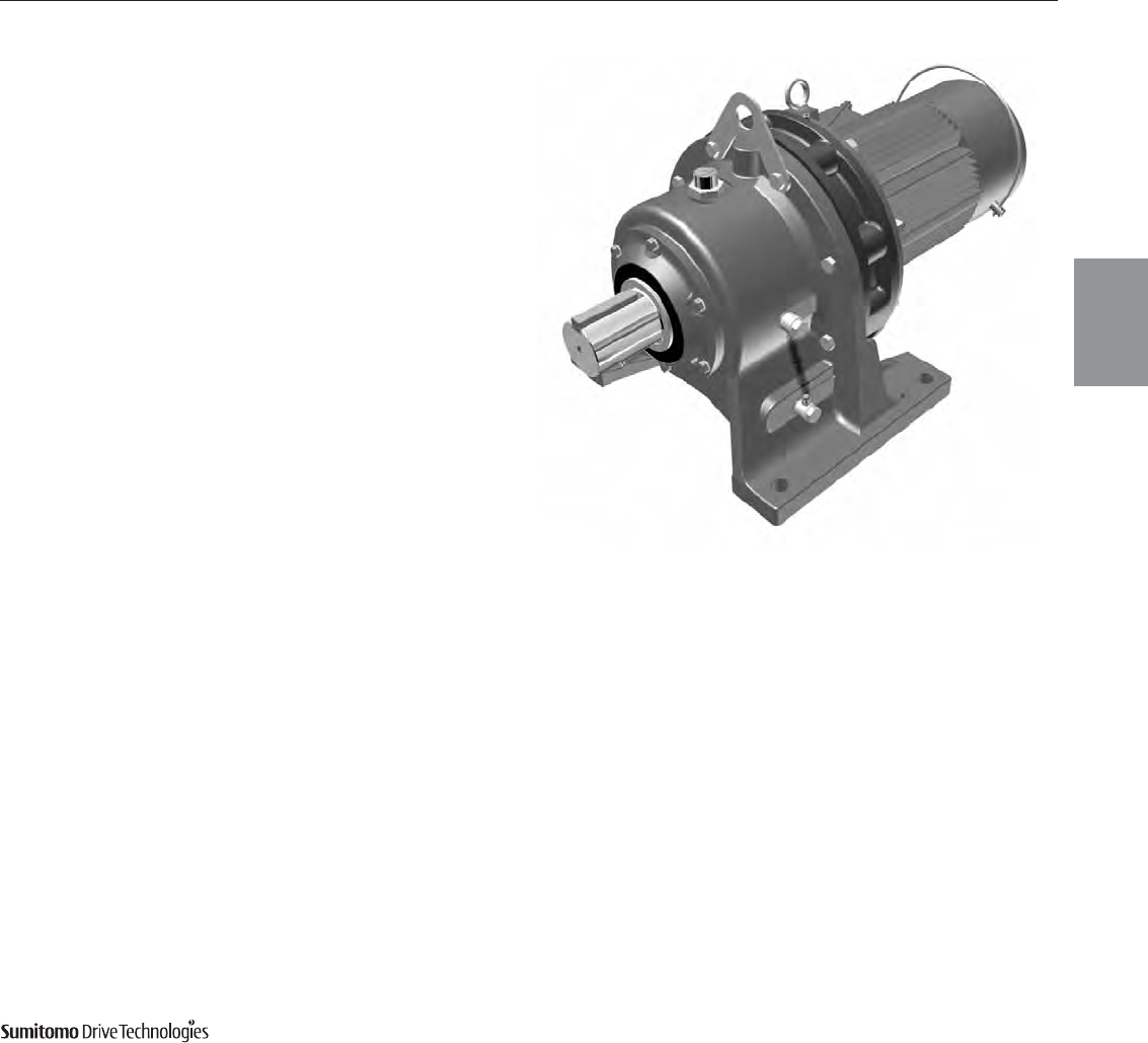
Sumitomo’s Cyclo® 6000 is extremely torque
dense and is available as an inline
gearmotor or speed reducer
• Connection free design
• Rugged forged output shaft
• Direct acting brake option
• Unmatched durability
• Foot and Flange Styles
General Information 1.3
Cyclo® 6000 Series
Applications
• Conveyors • Sawmills and Wood Mills
• Food Machinery • Wastewater Treatment
• Mixers • Steel Mills
• Automotive Plants • Construction Equipment
• Recycling Machines • Paper Mills
• Poultry Plants • Processing Plants
Highly Reliable, Torque Dense
Cycloidal Gearmotors
Product Description
Sumitomo Cyclo®speed reducers and gearmotors are the
premier in-line drives. The revolutionary Cyclo®design provides
quiet, efficient and reliable performance exceeding that of invo-
lute tooth gear designs. The key to Cyclo®'s matchless perform-
ance and reliability is that 67% of the reduction components are in
contact at all times, compared to geared designs that use only
limited tooth contact. Unlike geared designs, the Cyclo®'s reduc-
tion components operate in compression rather than shear, which
results in exceptionally rugged and shock resistant perform-
ance. The Cyclo®technology coupled with innovative product
options and accessories offer the most extensive range of appli-
cation solutions available.
Features & Benefits
•Cycloidal speed reduction technology
~Quiet, efficient and reliable operation with high torque
density and compact size
•Modular design
~Interchangeable cast iron housings in foot, flanged or face
mount configurations
•Universal mounting arrangements
~Available free-shaft, quill hollow shaft, C-face, shovel base,
and top-mount inputs
•Internal components manufactured from hardened,
vacuum-degassed, bearing grade steel
~Minimal vibration, low noise, low backlash and extended
operational life
•The best product warranty
~The 24 month warranty backs up the superb Cyclo®
product reputation
Specifications
Sizes: 23 sizes (5lbs to 5000lbs)
Torque Rating: 55 to 603,000 lb in
HP Rating: .10 to 235 HP
Ratio Range: 3:1 to 119:1 (single)
121:1 to 7569:1 (double)
8041:1 to 658,503:1 (triple)
Mounting: Foot, Flange, Face Mount
Motor Standards: NEMA, IEC, JIS, UL, CSA, CE
1.4 General Information
CYCLO® 6000 Gearmotors
Cyclo® 6000 Series
Product Range (Standard Motor and Reducer Combinations)
Ratio
20
25
30
40
50
60
75
100
125
150
175
11
106
15
77.7
21
55.5
29
40.2
43
27.1
59
19.7
87
13.4
Motor
HP
Output Speed
RPM (60 Hz)
Output Speed
RPM (60 Hz)
212 212 212 212 212 212 400 212 400 212 1325 212 400 1325 4500
65,000 280,000 67,000 390,000 410,000 600,000
104
16.8
121
14.5
143
12.2
165
10.6
195
8.97
231
7.58
273
6.41
319
5.49
377
4.64
473
3.70
559
3.13
649
2.70
731
2.39
841
2.08
1003
1.74
1247
1.40
1479
1.18
1849
.0946
2065
0.847
2537
0.690
3045
0.575
3481
0.503
4437
0.394
5133
0.341
6177
0.283
7569
0.231
Ratio
1/8
1/4
1/3
1/2
3/4
1
1.5
2
3
5
7.5
10
15
20
25
30
40
50
60
Motor
HP
OUTPUT
TORQUE
lb•in
min.
max.
Ratio
Output Speed
RPM (60 Hz)
1/8
1/4
1/3
1/2
3/4
1
1.5
2
3
5
7.5
10
15
20
25
30
40
50
60
75
100
Motor
HP
6
292
8
219
11
159
13
135
15
117
17
103
21
83.3
25
70.0
29
60.3
35
50.0
43
40.7
51
34.3
59
29.7
71
24.6
87
20.1
119
14.7
3
583
5
350
Ratios 3–119 Combinations with 1750 RPM input speed
Ratios 104–7569 Combinations with 1750 RPM input speed
Ratios 11–87
Combinations with 1165 RPM
input speed
Note: Ratios 3 and 5 are planetary.
General Information 1.5
CYCLO® 6000 Gearmotors
Cyclo® 6000 Series
How do I select a Cyclo®gearmotor?
Selection is based on the motor horsepower and/or torque requirements at the output
shaft. The Cyclo®gearmotor has particularly high efficiencies over a wide range of
reduction ratios, which frequently permits the use of reduced input power requirements
(smaller HP motor) without sacrificing output shaft torque. The selection procedures in
this catalog will guide you in choosing the most efficient gearmotor for your applica-
tion.
What information do I need to get started in the selection process?
To select the proper gearmotor for your application, you will need to know:
• Application: type of driven machine
• Hours of operation per day
• Motor horsepower (HP) and speed (RPM)
• Mounting position
If there are any special environmental factors or operation requirements, they must also
be noted. This information will be important in determining the Service Factor of your
application.
What are Service Classes and how are they used?
In general, gearmotors are rated for the specific conditions and operating requirements of
the application by the use of AGMA-defined Service Classes. There are three AGMA
Service Classifications for gearmotors: uniform (I), moderate shock (II) and heavy shock (III)
(pages 2.4-2.5) The Service Classes are used in the product selection process to adjust
for the specific conditions and operating requirements of your application.
What do I do if my application has particularly severe operating conditions?
The standard ratings for Cyclo®are based on 10-hour daily service under conditions of
uniform loads (equivalent to AGMA service Class I). By following the product selection
process, you will determine and apply the Service Factors to compensate for longer
periods of operation and/or severe operating conditions.
How can I be sure that the gearmotor can withstand periodic excessive over-
loads?
Cyclo®Gearmotors provide 500% momentary intermittent shock load capacity.
Planetary gearmotors can accommodate 300% momentary shock loads. For applica-
tions with shock loads greater than 500%, consult an SMA Application Engineer.
What are the standard input speeds?
In general terms, the speeds are 1750 and 1165 RPM. When non-standard input speeds are
used, the horsepower and torque ratings also vary.
What thermal capacity limitations does the Cyclo®have?
The Cyclo®gearmotor, by virtue of its smooth, almost frictionless operation (unlike tra-
ditional helical gears), has a thermal rating that far exceeds its mechanical capacity
and all but eliminates the conventional limitations due to heat under normal ambient
conditions.
What inverter turn-down ratios are available?
A 2:1 ratio is standard with Class F insulation. A 10:1 ratio is available for inverter duty
motors, which use a larger frame than standard motors. A 1000:1 ratio is available in a
C-face configuration.
FAQs
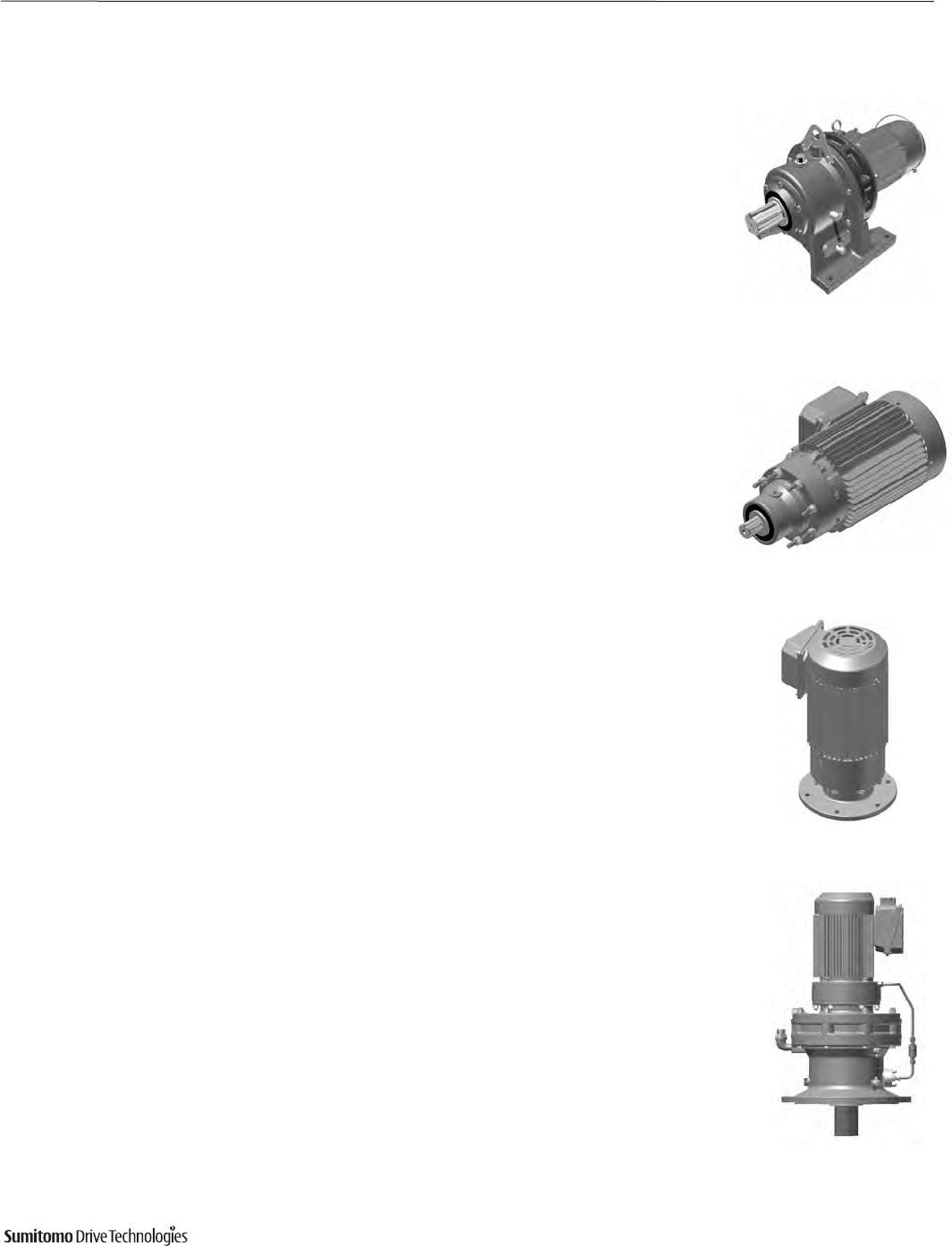
Double Reduction
Single Reduction, V-Flange Mount
Single Reduction, Flange Mount
Single Reduction,
Horizontal Foot Mount
Brakemotor
Common Configurations

1.6 General Information
CYCLO® 6000 Gearmotors
Cyclo® 6000 Series
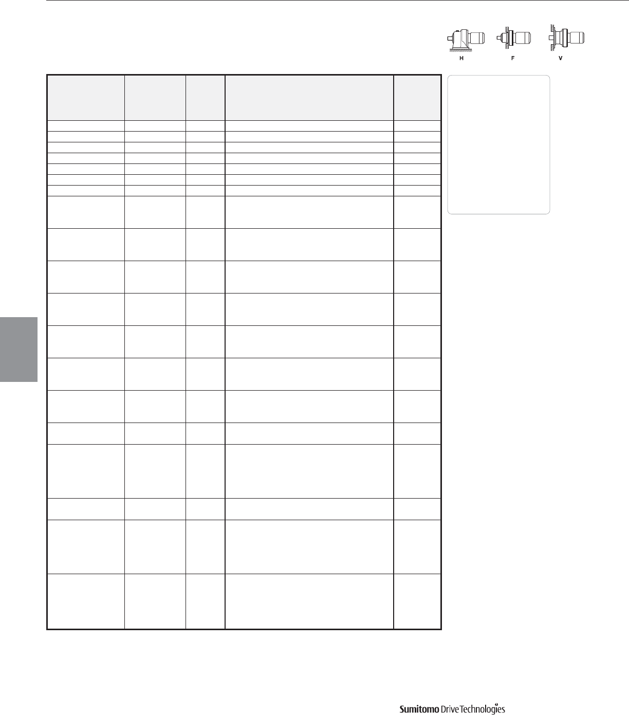
Standard Specifications
Shaft Rotation
On single reduction Cyclo®gearmotors, ratios 3 through 119, the slow speed shaft rotates in a reverse direction to that of the motor shaft.
On double reduction units, ratios 104 through 7569, both the motor and the slow speed shaft rotate in the same direction.
Input Speeds
In general terms, the standard input speeds of single reduction units are 1750 and 1165 RPM. When non-standard input speeds are used, the horse-
power and torque ratings will also vary.
Thermal Capacity
The Cyclo®gearmotor’s smooth, almost frictionless operation all but eliminates the conventional limitations due to heat. In all sizes, Cyclo®gearmotors
have thermal ratings that exceed their mechanical capacity.
Standard Specifications Standard Specifications with Built-In Brake
3-Phase Capacity Range: 1/8 HP ~ 75 HP, 4P 1/8 HP ~ 15 HP, 4P: FB Brake
Integral Motor 20 ~ 75 HP, 6P 20 HP, 4P: CMB Brake
25 HP ~ 40 HP, 4P: ESB Brake
Enclosure: Totally enclosed fan cooled type Totally enclosed fan cooled type
(1/8 HP, 4P Totally enclosed non ventilated) (1/8 HP, 4P Totally enclosed non ventilated)
Power Supply: 230/460 Volts, 60 Hz 230/460 Volts, 60 Hz
575 Volts, 60 Hz 575 Volts, 60 Hz
Insulation: 3/4 ~ 30 HP: Class B 3/4 ~ 20 HP: Class B
40 HP: Class F
Time Rating Continuous Continuous
Standards UL, CE, CSA are available Please consult factory
Note: Dimensions for 575 Volt and CSA units may be different than those specified in Section 4, please consult factory.
Reducer Reduction: Involute crowned tooth profile for ratios 3 and 5:1.
Internal planetary gear mechanism with trochoidal curved tooth profile for ratios 6:1 and higher.
Lubrication: Grease or oil lubricated models available.
Seals: Nitrile material, dual lipped, double output seals available.
Material: Rugged cast iron or ductile housings.
Paint Color: Blue, Munsell color number 6.5PB 3.6/8.2
Note: Ratings listed in Section 3 may be altered if models normally designed for oil lubrication are special ordered for
grease lubrication; please consult factory.
Ambient Installation Location: Indoors (Minimal dust and humidity)
Conditions
Ambient Temperature: 14°~104° F (-10º ~ 40º C)
Ambient Humidity: Under 85%
Elevation: Under 3,281 ft. (1000 meters)
Atmosphere: Well ventilated location, free of corrosive gases, explosive gases, vapors and dust.

CYCLO® 6000 Gearmotors
How to Select 2.1
Cyclo® 6000 Series
How to
Select
How to Select
2
CYCLO® 6000 Gearmotors
2.2 How to Select Cyclo® 6000 Series
How to Select a Gearmotor
How to
Select
Step 1: Collect data about your application
Before starting you need to know the:
• Application (e.g. Conveyor, Mixer, etc.)
• Hours of Operation per day
• Motor Horsepower (HP) and Speed (RPM)
• Desired Output Speed
• Mounting Position and Style
• Overhung or Thrust Loads
• Shaft Dimensions, inch or metric
• Electrical Specifications
Step 2: Select a Frame Size
2A: Find the Load Classification of your application in the
AGMA Load Classification Tables on pages 2.4 and 2.5.
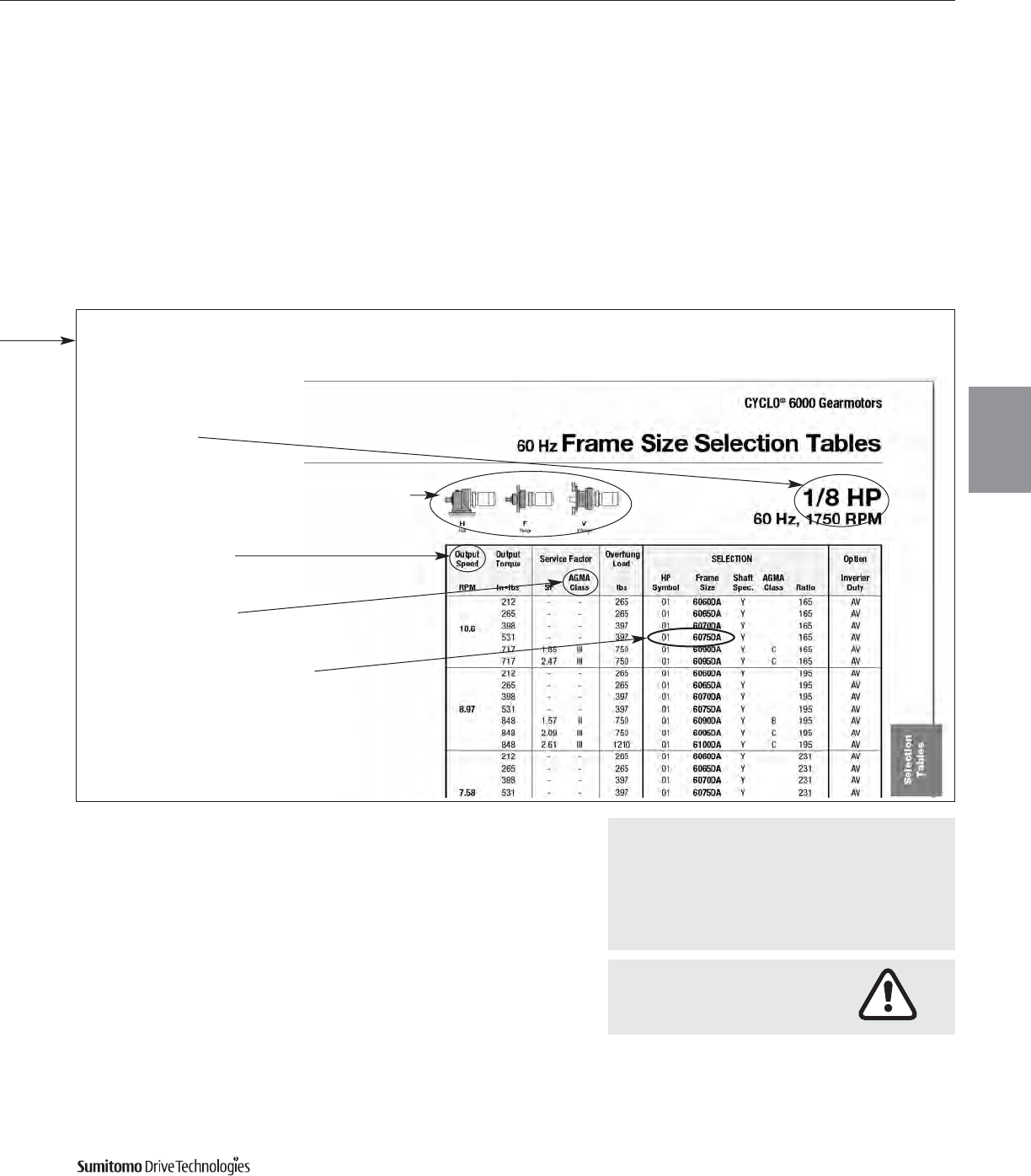
2B: Go to the Gearmotor Selection Table that corresponds
to the desired Motor HP. Find the Output Speed closest
to the desired output speed.
2C: Locate the Service Class in the Gearmotor Selection
Table for your application and select the HP Symbol and
Frame Size SELECTION that matches the HP, Output
Speed, and Service Class.
Step 3: Select a Housing Style
and Mounting Position
Select a housing style and mounting position from chart on
page 2.8.
Step 4: Verify Dimensions
Use the Dimensions information on pages 4.1-4.67 to
verify that the selected Frame Size is appropriate.
Step 5: Choose Options and Modifications
The following options may apply:
Specify Voltage (Consult factory when application requires
575 Volt or CSA unit; dimensions may be different than
those specified in Section 4.)
Inverter Duty
Special Environments
Special Paint
Please see the Cyclo pricelist, or visit our website at
www.smcyclo.com for available modifications.
Step 6: Configure a Model Number
Go to page 2.6 to configure a model number.
Note: You will use the information you gather from the pro-
cedure on this page to Configure a Model Number.
CYCLO® 6000 Gearmotors
How to Select 2.3
Cyclo® 6000 Series How to Select 2.3
How to
Select
If Overhung Load is present,
any Overhung Load must be
checked against the capacity
of the selection.
For special circumstances in selecting a Frame Size such as:
• Overhung Loads
• Axial Loads
Consult Section 5, pages 5.6 – 5.10.
Select a Frame Size
• Housing Style & Mounting Position
• Service Class
• SELECTION Frame Size
and HP Symbol
• Motor HP
• Output Speed
CYCLO® 6000 Gearmotors
2.4 How to Select Cyclo® 6000 Series
AGMA
Tables
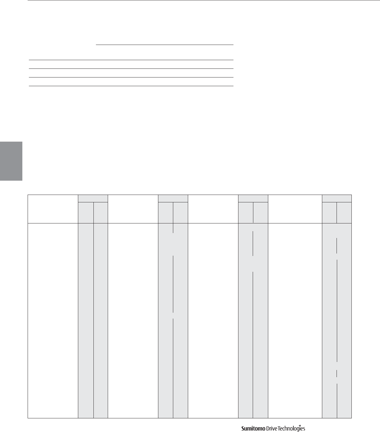
AGMA Load Classifications: Gearmotors
Class I For steady loads not exceeding normal motor rating, 8 to 10 hours a
day. Moderate shock loads where service is intermittent (AGMA Service Factor: 1.0).
Class II For steady loads not exceeding normal motor rating and 24 hours a
day service. Moderate shock loads for 8 hours a day (AGMA Service Factor: 1.4).
Class III For moderate shock loads for 24 hours a day. Heavy shock loads for
8 hours a day (AGMA Service Factor: 2.0).
Up to
10 Hr.
per
day
24
Hr.
per
day
Up to
10 Hr.
per
day
24
Hr.
per
day
Up to
10 Hr.
per
day
24
Hr.
per
day
Up to
10 Hr.
per
day
24
Hr.
per
day
Refer to Factory
Refer to Factory
Refer to Factory
Refer to Factory
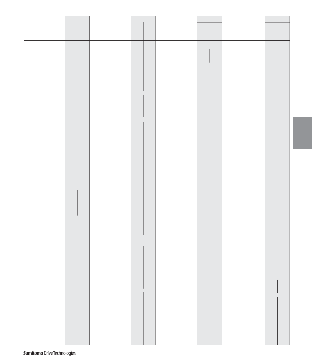
Load Classification by INDUSTRY
Refer to Factory
Refer to Factory
Refer to Factory
Refer to Factory
Refer to Factory
Refer to Factory
Refer to Factory
Refer to Factory
Gearmotor Classification
SERVICE CLASS
UNIFORM MODERATE HEAVY
DURATION OF SERVICE LOAD SHOCK LOAD SHOCK LOAD
Intermittent 3 Hr. per day Class I Class I Class II
Up to 10 Hr. per day Class I Class II Class III
24 Hr. per day Class II Class III —
Class
Application
Brewing & Distilling
Bottling Machinery I II
Brew Kettles, Cont.
Duty – II
Can Filling Machines I II
Cookers–Cont. Duty – II
Mash Tubs–Cont. Duty – II
Scale Hoppers–
Frequent Starts II II
Clay Working Industry
Brick Press III III
Briquette Machines III III
Clay Working
Machinery II II
Pug Mills II II
Distilling (See Brewing)
Dredges
Cable Reels II –
Conveyors II II
Cutter Head Drives III III
Jig Drives III III
Maneuvering Winches II –
Pumps II II
Screen Drives III III
Stackers II II
Utility Winches II –
Food Industry
Beet Slicers II II
Bottlings, Can
Filling Mach. I II
Cereal Cookers I II
Dough Mixers II II
Meat Grinders II II
Class
Application
Lumber Industry
Barkers–
Spindle Feed
Barkers–
Main Drive
Carriage Drive
Conveyors
Burner II III
Main or Heavy Duty II III
Main Log III III
Re-Saw
Merry-Go-Round II III
Slab III III
Transfer II III
Chains–Floor II III
Chains–Green II III
Cut-Off Saws–Chain II III
Cut-Off Saws–Drag II III
Debarking Drums
Feeds–Edger II III
Feeds–Gang III III
Feeds–Trimmer II III
Log Deck III III
Log Hauls–Incline,
Well Type III III
Log Turning Devices III III
Planer Feed II III
Planer Tilting Hoists II III
Rolls–Live–Off
Bearing–Roll Cases III III
Sorting Table II III
Tipple Hoist II III
Transfers–Chain II III
Transfers–Craneway II III
Tray Drives II III
Oil Industry
Chillers II II
Class
Application
Oil Well Pumping
Paraffin Filter Press II II
Rotary Kilns II II
Paper Mills
Agitators (Mixers) II II
Barker–Auxiliaries–
Hyd.
Barker, Mechanical
Barking Drum
Beater & Pulper – II
Bleacher – II
Calenders – II
Calenders–Super – II
Converting Mach.–
Except Cutters–
Platers – II
Conveyors – II
Couch – II
Cutters, Platers – III
Cylinders _II
Dryers – II
Felt Stretchers – II
Felt Whippers – III
Jordans – II
Log Haul – III
Presses – II
Pulp Machine Reels – II
Stock Chests – II
Suction Rolls – II
Washers &
Thickeners – II
Winders – II
Rubber Industry
Mixer III III
Rubber Calender II II
Rubber Mill
(2 or more) II II
Sheeter II II
Class
Application
Tire Building Machines
Tire, Tube Press
Openers
Tubers & Stainers II II
Sewage Disposal
Aerators
Bar Screens I II
Chemical Feeders I II
Collectors I II
Dewatering Screens II II
Grit Collectors I II
Scum Breakers II II
Slow or Rapid Mixers II II
Sludge Collectors I II
Thickeners II II
Vacuum Filters II II
Textile Industry
Batchers II II
Calenders II II
Card Machines II II
Cloth Finishing Machines
(Calenders, Dryers,
Pads, Tenters,
Washers) II II
Dry Cans II II
Dyeing Machinery II II
Knitting Machinery
Looms, Mangles,
Nappers II II
Range Drives
Soapers, Spinners II II
Tenter Frames II II
Winders II II
Yarn Preparatory
Machinery (Cards,
Spinners,
Slashers) II II
Note: Selections without an AGMA Class designation are torque based selections generally used for intermittent service.
Refer to Factory
CYCLO® 6000 Gearmotors
How to Select 2.5
Cyclo® 6000 Series How to Select 2.5
AGMA
Tables
Class
Application
Tray Drives II III
Veneer Lathe Drives
Machine Tools
Bending Roll II II
Notching Press –
Belt Driven
Plate Planer III III
Punch Press –
Gear Driven III III
Tapping Machines III III
Other Machine Tools
Main Drives II II
Auxiliary Drives I II
Metal Mills
Bridle Roll Drives III III
Draw Bench – Carriage III III
Draw Bench –
Main Drive III III
Forming Machines III III
Pinch Dryer & Scrubber
Rolls, Reversing
Slitters II II
Table Conveyors
Non-Reversing II III
Reversing – III
Winding Reels – Strip – III
Wire Drawing &
Flattening Machine II III
Wire Winding Machine II II
Mills, Rotary Type
Ball III III
Cement Kilns
Dryers & Coolers II II
Kilns II II
Pebble III III
Rod III III
Tumbling Barrels III III
Mixers
Concrete Mixers,
Continuous II II
Concrete Mixers,
Intermittent I –
Constant Density I II
Variable Density II II
Oil Industry
Chillers II II
Oil Well Pumping
Paraffin Filter Press II II
Rotary Kilns II II
Paper Mills
Aerators
Agitators (Mixers) II II
Barker Auxiliaries,
Hydraulic
Barker, Mechanical
Barking Drum
Beater & Pulper – III
Bleacher – II
Calenders – II
Calenders – Super – II
Converting Machines,
except Cutters,
Platers – II
Conveyors – II
Conveyors, Log – III
Couch – II
Cutters, Platers – III
Cylinders – II
Dryers – II
Felt Stretcher – II
Felt Whipper – III
Jordans – II
Presses – II
Pulp Machines, Reel – II
Stock Chests – II
Suction Roll – II
Washers and
Thickeners – II
Winders – II
Printing Presses III
24
Hr.
per
day
Up to
10 Hr.
per
day
Load Classification by APPLICATION
Class
Application
Agitators
Pure Liquids I II
Liquids and Solids II II
Liquids – Variable
Density II II
Semi-liquids –
Variable Density II II
Blowers
Centrifugal I II
Lobe II II
Vane I II
Brewing and Distilling
Bottling Machinery I II
Brew Kettles –
Continuous Duty – II
Cookers – Continuous
Duty – II
Mash Tubs –
Continuous Duty – II
Scale Hopper
Frequent Starts II II
Can Filling Machines III
Cane Knives II II
Car Dumpers III –
Car Pullers –
Intermittent Duty I–
Clarifiers III
Classifiers II II
Clay Working
Machinery
Brick Press III III
Briquette Machine III III
Clay Working
Machinery II II
Pug Mill II II
Compressors
Centrifugal I II
Lobe II II
Reciprocating
Multi-Cylinder II II
Single Cylinder III III
Conveyors – Uniformly
Loaded or Fed
Apron I II
Assembly I II
Belt I II
Bucket I II
Chain I II
Flight I II
Oven I II
Screw I II
Conveyors – Heavy Duty
Not Uniformly Fed
Apron II II
Assembly II II
Belt II II
Bucket II II
Chain II II
Flight II II
Live Roll (Package) I II
Oven II II
Reciprocating III III
Screw II II
Shaker III III
Cranes and Hoists
Main Hoists III III
Heavy Duty III III
Medium Duty II II
Reversing II II
Skip Hoists II II
Trolley Drive II II
Bridge Drive II II
Crushers
Ore III III
Stone III III
Dredges
Cable Reels II –
Conveyors II II
Cutter Head Drives III III
24
Hr.
per
day
Class
Application
Jig Drives III III
Maneuvering Winches II –
Pumps II II
Screen Drive III III
Stackers II II
Utility Winches II –
Elevators
Bucket – Uniform Load I II
Bucket – Heavy Load II II
Bucket – Continuous I II
Centrifugal Discharge I II
Escalators I II
Freight I II
Gravity Discharge I II
Man Lifts
Passenger
Service – Hand Lift III –
Fans
Centrifugal II II
Cooling Towers
Induced Draft II II
Forced Draft
Induced Draft II II
Large (Mine, etc.) II II
Large Industrial II II
Light (Small Diameter) I II
Feeders
Apron II II
Belt II II
Disc I II
Reciprocating III III
Screw II II
Food Industry
Beet Slicer II II
Cereal Cooker I II
Dough Mixer II II
Meat Grinders II II
Generators –
(Not Welding) III
Hammer Mills III III
Laundry Washers
Reversing II II
Laundry Tumblers II II
Line Shafts
Heavy Shock Load III III
Moderate
Shock Load II II
Uniform Load I II
Lumber Industry
Barkers – Spindle Feed
Barkers – Main Drive
Carriage Drive
Conveyors – Burner II III
Conveyors – Main or
Heavy Duty II III
Conveyors – Main Log III III
Conveyors –
Merry-Go-Round II III
Conveyors – Slab III III
Conveyors – Transfer II III
Conveyors – Waste II II
Chains – Floor II III
Chains – Green II III
Cut-Off Saws – Chain II III
Cut-Off Saws – Drag II III
Debarking Drums
Feeds – Edger II III
Feeds – Gang III III
Feeds – Trimmer II III
Log Deck III III
Log Hauls – Incline
Well Type III III
Log Turning Devices III III
Planer Feed II III
Planer Tilting Hoists II III
Rolls – Live – Off Brg.
– Roll Cases III III
Sorting Table II III
Tipple Hoist II III
Transfers – Chain II III
Transfers – Craneway II III
Up to
10 Hr.
per
day
24
Hr.
per
day
Up to
10 Hr.
per
day
Class
Application
Pullers
Barge Haul III III
Pumps
Centrifugal I II
Proportioning II II
Reciprocating
Single Acting
3 or more Cylinders II II
Double Acting
2 or more Cylinders II II
Single Acting
1 or 2 Cylinders
Double Acting
Single Cylinder
Rotary – Gear Type I II
– Lobe, Vane I II
Rubber Industry
Mixer III III
Rubber Calender II II
Rubber Mill (2 or more) II II
Sheeter II II
Tire Building Machines
Tire & Tube Press
Openers
Tubers & Strainers II II
Sewage Disposal
Equipment
Aerators
Bar Screens I II
Chemical Feeders I II
Collectors, Circuline
or Straightline I II
Dewatering Screens II II
Grit Collectors I II
Scum Breakers II II
Slow or Rapid Mixers II II
Sludge Collectors I II
Thickeners II II
Vacuum Filters II II
Screens
Air Washing I II
Rotary – Stone
or Gravel II II
Traveling Water
Intake I II
Slab Pushers II II
Steering Gear II II
Stokers III
Textile Industry
Batchers II II
Calenders II II
Card Machines II II
Cloth Finishing Machines
(Washers, Pads,
Tenters)
(Dryers,
Calenders, etc.) II II
Dry Cans II II
Dryers II II
Dyeing Machinery II II
Knitting Machines
(Looms, etc.)
Looms II II
Mangles II II
Nappers II II
Pads II II
Range Drives
Slashers II II
Soapers II II
Spinners II II
Teneter Frames II II
Washers II II
Winders (Other
than Batchers) II II
Yarn Preparatory
Machines (Cards,
Spinners, Slashers,
etc.) II II
Windlass II II
Up to
10 Hr.
per
day
24
Hr.
per
day
Refer to Factory
Refer to Factory
Refer to Factory
Refer to Factory
Refer to Factory
Refer to Factory
Refer to FactoryRefer to Factory
Refer to FactoryRefer to Factory
Refer to FactoryRefer to Factory
Refer to FactoryRefer to Factory
Refer to FactoryRefer to Factory
Refer to FactoryRefer to Factory
Refer to FactoryRefer to Factory
Refer to FactoryRefer to Factory
Refer to FactoryRefer to Factory
Refer to FactoryRefer to Factory
Refer to FactoryRefer to Factory
Refer to FactoryRefer to Factory
Refer to FactoryRefer to Factory
Refer to FactoryRefer to Factory
Refer to FactoryRefer to Factory
CYCLO® 6000 Gearmotors
2.6 How to Select Cyclo® 6000 Series
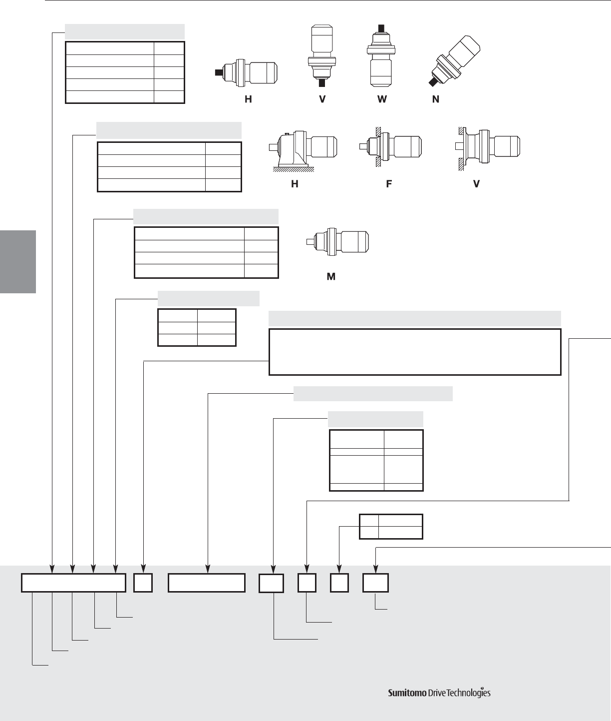
Configure a Model Number
Nomenclature
CHH00
Type Prefix
Foot H
Flange F
V-Flange V
YB
6165
C = Ratios 6:1 and greater (Cyclo Gearmotor product code)
P= Ratios 3:1 and 5:1 (Cyclo 6000 planetary product code)
Output shaft orientation
Mounting style
Input connection
Modification (Special feature)
Frame size
Ratio
Shaft specification
Housing Style
-
-
Foot V FlangeFlange
Input Connection Prefix
None - Integral Gearmotor M
C-Face Adaptor JM
Hollow Input Shaft XM
Input Connection
Type Prefix
Horizontal H
Vertical V
Vertical Up W
Universal Direction N
Output Shaft Orientation
29
Frame Size (from Selection Tables)
Input Shaft Suffix
Metric JIS -
Inch Y
AGMA I YA
AGMA II YB
AGMA III YC
Metric DIN G
Shaft Specifications
B With Brake
No Brake
Prefix
Special S
Standard –
Modification (Special)
10
Motor Capacity Symbol
HP 1/81/41/31/23/411.523457.5101520253040506075100
010203050811H23458101520253040506075100
Symb
HP 20 25 30 40 50 60 75 100 125 150 175
206 256 306 406 506 606 756 1006 1256 1506 1756
Symb
4P
6P
--
Gearmotor specification
CYCLO® 6000 Gearmotors
How to Select 2.7
Cyclo® 6000 Series
Ratio
How to Select 2.7
Nomenclature
Nomenclature
CHHM10 – 6165YB – 29
C– Cyclo 6000 6165 – Frame Size
H– Horizontal O/P YB – Inch Shaft, AGMA Class II
H– Foot Mount 29 – Ratio
M– Gearmotor
Example
Nominal
Total Ratio
Type Suffix
Torque Limiter TL
High Capacity Bearing R1
High Capacity Bearing R2
Ductile Casing
HH Type Ceiling H1
Left Wall H2
Right Wall H3
Low Backlash LB
AF Motor AV
Single Phase Motor SG
Servo Motor SV
DC Motor DV
Gearmotor
Specification
CYCLO® 6000 Gearmotors
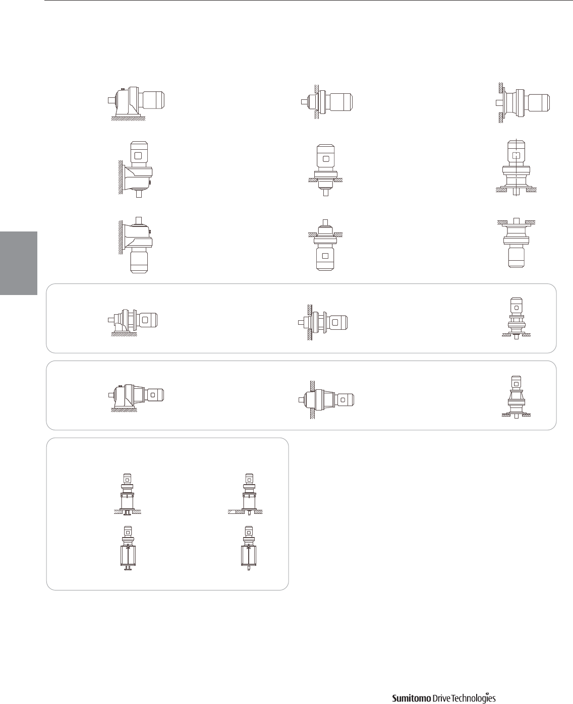
2.8 How to Select Cyclo® 6000 Series
CHHM
(CNHM)
CHFM
(CNFM)
CHVM
(CNVM)
CVVM
(CNVM)
CWVM
(CNVM)
CWFM
(CNFM)
CWHM
(CNHM)
CHHXM
(CNHXM)
CHFXM
(CNFXM)
CVVXM
(CNVXM)
CVVJM
(CNVJM)
CHFJM
(CNFJM)
CHHJM
(CNHJM)
CVHM
(CNHM)
CVFM
(CNFM)
Input Side Hollow Shaft
With Adaptor
Vertical Special Base Mount
C14VM C15VM
C17VM C18VM
Housing Styles & Mounting Positions
Housing &
Mounting
Frame Size Selection Tables 3.1
Selection
Tables
Gearmotors
Cyclo® 6000 Series
Selection Tables
3
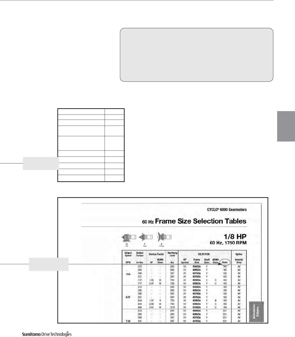
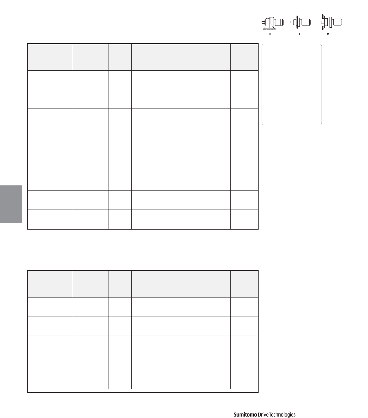
Frame Size Selection Tables 60 Hz
1/8 HP
60 Hz, 1750 RPM
CYCLO® 6000 Gearmotors
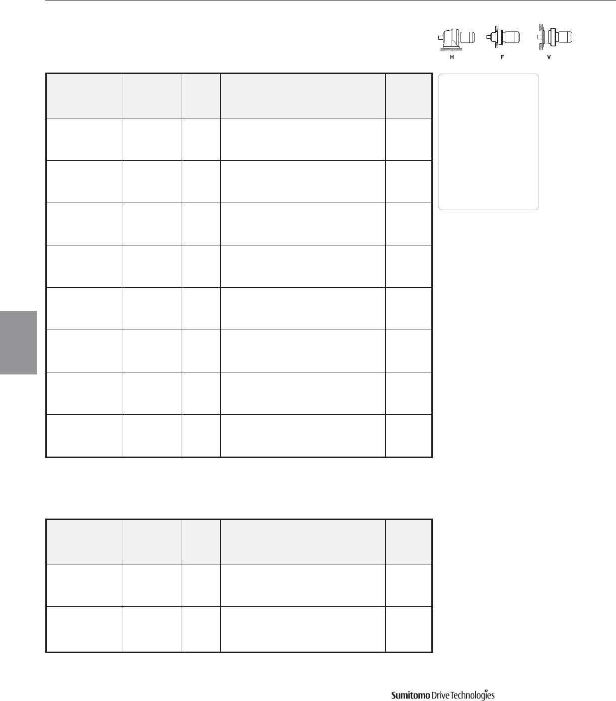
3.2 Frame Size Selection Tables
Output Output Service Factor Overhung SELECTION Option
Speed Torque Load
AGMA HP Frame Shaft AGMA Inverter
RPM In•lbs SF Class lbs Symbol Size Spec. Class Ratio Duty
292 27.5 2.00 III 170 01 6060 YC 6 AV
219 36.7 2.00 III 194 01 6060 YC 8 AV
159 50.4 2.00 III 265 01 6060 YC11 AV
135 59.6 2.00 III 265 01 6060 YC13 AV
117 68.8 2.00 III 265 01 6060 YC15 AV
103 78.0 2.00 III 265 01 6060 YC17 AV
83.3 96.4 2.00 III 265 01 6060 YC21 AV
70.0 115
1.10 I 265 01 6060 YA25 AV
1.66 III 265 01 6065 YC25 AV
2.30 III 397 01 6070 YC25 AV
60.3 133
1.10 I 265 01 6060 YA29 AV
1.66 III 265 01 6065 YC29 AV
2.26 III 397 01 6070 YC29 AV
50.0 160
1.10 I 265 01 6060 YA35 AV
1.43 II 265 01 6065 YB35 AV
2.11 III 397 01 6070 YC35 AV
40.7 197
1.13 I 265 01 6065 YA43 AV
1.70 III 397 01 6070 YC43 AV
2.26 III 397 01 6075 YC43 AV
34.3 234
1.00 I 397 01 6070 YA51 AV
1.43 II 397 01 6075 YB51 AV
1.92 III 575 01 6080 YC51 AV
29.7 271
1.00 I 397 01 6070 YA59 AV
1.36 II 397 01 6075 YB59 AV
1.85 III 575 01 6080 YC59 AV
24.6 326
1.20 I 575 01 6080 YA71 AV
1.87 III 575 01 6085 YC71 AV
2.52 III 750 01 6090 Y C 71 -
20.1 399 1.21 I 575 01 6085 YA87 AV
2.11 III 750 01 6090 Y C 87 -
16.8
212 - - 265 01 6060DA Y 104 AV
265 - - 265 01 6065DA Y 104 AV
398 - - 397 01 6070DA Y 104 AV
452 1.17 I 397 01 6075DA Y A 104 AV
452 2.94 III 750 01 6090DA Y C 104 -
14.7 546 1.25 I 750 01 6090 Y A 119 -
546 1.51 II 750 01 6095 Y B 119 -
14.5
212 - - 265 01 6060DA Y 121 AV
265 - - 256 01 6065DA Y 121 AV
398 - - 397 01 6070DA Y 121 AV
449 - - 397 01 6075DA Y 121 AV
526 2.52 III 750 01 6090DA Y C 121 AV
12.2
212 - - 265 01 6060DA Y 143 AV
265 - - 265 01 6065DA Y 143 AV
398 - - 397 01 6070DA Y 143 AV
531 - - 397 01 6075DA Y 143 AV
621 2.14 III 750 01 6090DA Y C 143 AV
Dimensions Pages
Foot
Mount (H) 4.2–4.29
V-Flange (V) 4.30–4.43
F-Flange (F) 4.44–4.69
Selection
Tables
Gearmotors
Cyclo® 6000 Series
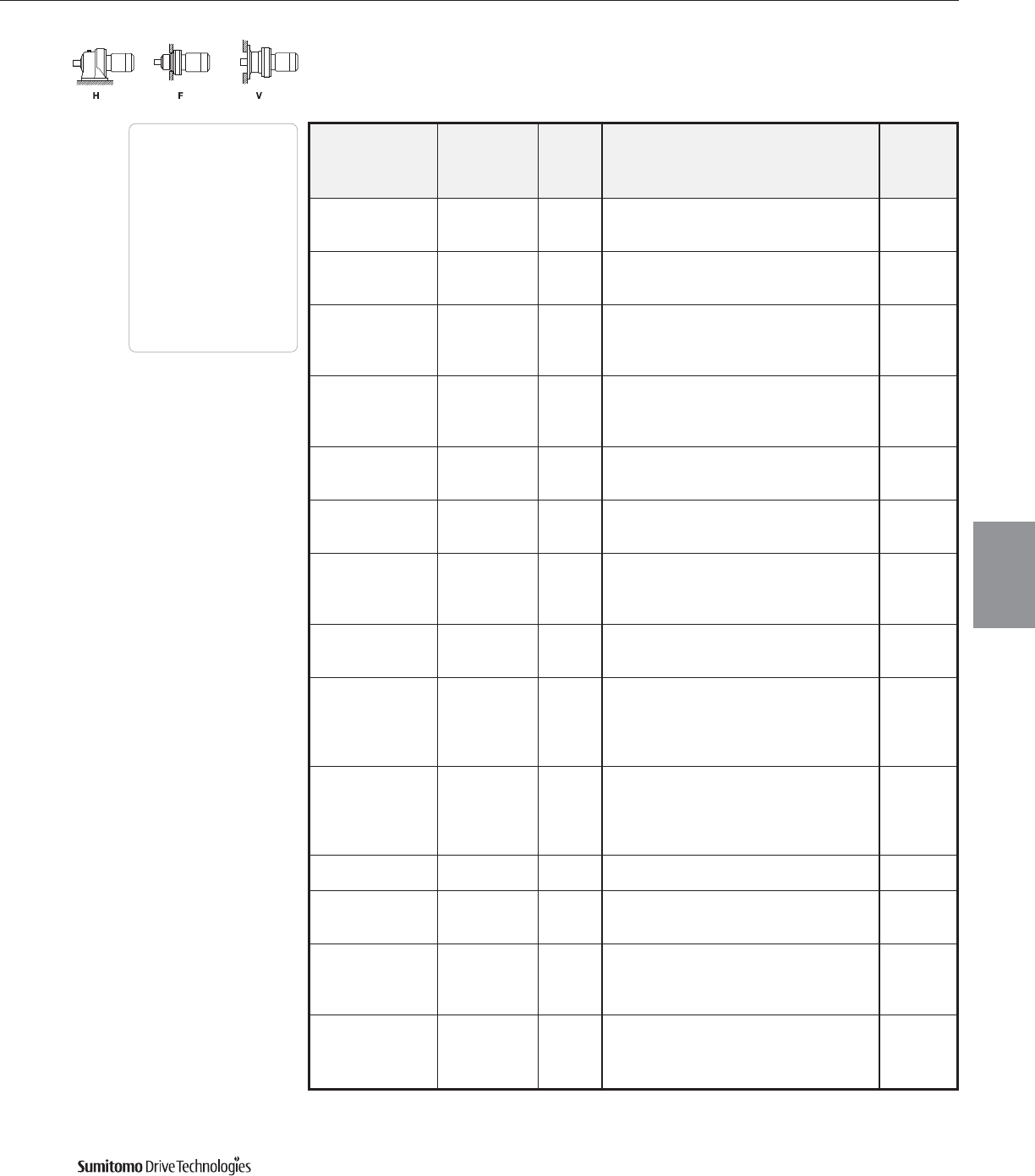
60 Hz Frame Size Selection Tables
1/8 HP
60 Hz, 1750 RPM
CYCLO® 6000 Gearmotors
Frame Size Selection Tables 3.3
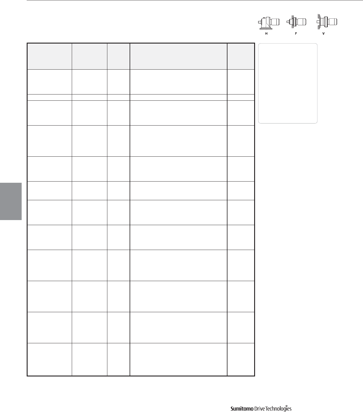
Dimensions Pages
Foot
Mount (H) 4.2–4.29
V-Flange (V) 4.30–4.43
F-Flange (F) 4.44–4.69
Selection
Tables
Gearmotors
Cyclo® 6000 Series
Output Output Service Factor Overhung SELECTION Option
Speed Torque Load
AGMA HP Frame Shaft AGMA Inverter
RPM In•lbs SF Class lbs Symbol Size Spec. Class Ratio Duty
10.6
212 - - 265 01 6060DA Y 165 AV
265 - - 265 01 6065DA Y 165 AV
398 - - 397 01 6070DA Y 165 AV
531 - - 397 01 6075DA Y 165 AV
717 1.85 III 750 01 6090DA Y C 165 AV
717 2.47 III 750 01 6095DA Y C 165 AV
212 - - 265 01 6060DA Y 195 AV
265 - - 265 01 6065DA Y 195 AV
398 - - 397 01 6070DA Y 195 AV
8.97 531 - - 397 01 6075DA Y 195 AV
848 1.57 II 750 01 6090DA Y B 195 AV
848 2.09 III 750 01 6095DA Y C 195 AV
848 2.61 III 1210 01 6100DA Y C 195 AV
212 - - 265 01 6060DA Y 231 AV
265 - - 265 01 6065DA Y 231 AV
398 - - 397 01 6070DA Y 231 AV
7.58 531 - - 397 01 6075DA Y 231 AV
1000 1.32 II 750 01 6090DA Y B 231 AV
1000 1.76 III 750 01 6095DA Y C 231 AV
1000 2.20 III 1210 01 6100DA Y C 231 AV
212 - - 265 01 6060DA Y 273 AV
265 - - 265 01 6065DA Y 273 AV
398 - - 397 01 6070DA Y 273 AV
6.41 531 - - 397 01 6075DA Y 273 AV
1190 1.12 I 750 01 6090DA Y A 273 AV
1190 1.49 II 750 01 6095DA Y B 273 AV
1190 1.86 III 1210 01 6100DA Y C 273 AV
1190 2.24 III 1210 01 6105DA Y C 273 AV
212 - - 265 01 6060DA Y 319 AV
265 - - 265 01 6065DA Y 319 AV
398 - - 397 01 6070DA Y 319 AV
531 - - 397 01 6075DA Y 319 AV
5.49 1330 - - 739 01 6090DA Y 319 AV
1390 1.28 I 736 01 6095DA Y A 319 AV
1390 1.59 II 1210 01 6100DA Y B 319 AV
1390 1.91 III 1210 01 6105DA Y C 319 AV
1390 3.32 III 2200 01 6120DB Y C 319 -
212 - - 265 01 6060DA Y 377 AV
265 - - 265 01 6065DA Y 377 AV
398 - - 397 01 6070DA Y 377 AV
531 - - 397 01 6075DA Y 377 AV
4.64 1330 - - 739 01 6090DA Y 377 AV
1640 1.08 I 725 01 6095DA Y A 377 AV
1640 1.35 II 1210 01 6100DA Y B 377 AV
1640 1.62 III 1210 01 6105DA Y C 377 AV
1640 2.81 III 2200 01 6120DB Y C 377 -
Frame Size Selection Tables 60 Hz
1/8 HP
60 Hz, 1750 RPM
CYCLO® 6000 Gearmotors
3.4 Frame Size Selection Tables
Output Output Service Factor Overhung SELECTION Option
Speed Torque Load
AGMA HP Frame Shaft AGMA Inverter
RPM In•lbs SF Class lbs Symbol Size Spec. Class Ratio Duty
212 - - 265 01 6060DA Y 473 AV
265 - - 265 01 6065DA Y 473 AV
398 - - 397 01 6070DA Y 473 AV
3.70 531 - - 373 01 6075DA Y 473 AV
1330 - - 743 01 6090DA Y 473 AV
1770 - - 723 01 6095DA Y 473 AV
2050 1.29 I 1210 01 6105DA Y A 473 AV
2050 2.26 III 2200 01 6120DB Y C 473 -
212 - - 265 01 6060DA Y 559 AV
265 - - 265 01 6065DA Y 559 AV
398 - - 397 01 6070DA Y 559 AV
531 - - 373 01 6075DA Y 559 AV
3.13 1330 - - 743 01 6090DA Y 559 AV
1770 - - 723 01 6095DA Y 559 AV
2210 - - 1210 01 6100DA Y 559 AV
2430 1.09 I 1210 01 6105DA Y A 559 AV
2430 1.91 III 2200 01 6120DB Y C 559 -
2430 2.29 III 2200 01 6125DB Y C 559 -
398 - - 397 01 6070DA Y 649 AV
508 - - 355 01 6075DA Y 649 AV
1290 - - 741 01 6090DA Y 649 AV
2.70 2210 - - 1210 01 6100DA Y 649 AV
2620 - - 1140 01 6105DA Y 649 AV
2820 1.65 III 2200 01 6120DB Y C 649 -
2820 1.98 III 2200 01 6125DB Y C 649 -
212 - - 265 01 6060DA Y 731 AV
265 - - 265 01 6065DA Y 731 AV
398 - - 397 01 6070DA Y 731 AV
531 - - 373 01 6075DA Y 731 AV
2.39 1330 - - 743 01 6090DA Y 731 AV
1770 - - 723 01 6095DA Y 731 AV
2210 - - 1210 01 6100DA Y 731 AV
2650 - - 1210 01 6105DA Y 731 AV
3180 1.46 II 2200 01 6120DB Y B 731 -
3180 1.75 III 2200 01 6125DB Y C 731 -
212 - - 265 01 6060DA Y 841 AV
265 - - 265 01 6065DA Y 841 AV
398 - - 397 01 6070DA Y 841 AV
531 - - 397 01 6075DA Y 841 AV
2.08 1330 - - 739 01 6090DA Y 841 AV
1770 - - 718 01 6095DA Y 841 AV
2210 - - 1210 01 6100DA Y 841 AV
2650 - - 1210 01 6105DA Y 841 AV
3650 1.26 I 2200 01 6120DB Y A 841 -
3650 1.53 II 2200 01 6125DB Y B 841 -
Dimensions Pages
Foot
Mount (H) 4.2–4.29
V-Flange (V) 4.30–4.43
F-Flange (F) 4.44–4.69
Selection
Tables
Gearmotors
Cyclo® 6000 Series
Output Output Service Factor Overhung SELECTION Option
Speed Torque Load
AGMA HP Frame Shaft AGMA Inverter
RPM In•lbs SF Class lbs Symbol Size Spec. Class Ratio Duty
398 - - 397 01 6070DA Y 1003 AV
508 - - 355 01 6075DA Y 1003 AV
1.74 1290 - - 741 01 6090DA Y 1003 AV
2210 - - 1210 01 6100DA Y 1003 AV
2620 - - 1140 01 6105DA Y 1003 AV
4360 1.28 I 2200 01 6125DB Y A 1003 -
212 - - 265 01 6060DA Y 1247 AV
265 - - 265 01 6065DA Y 1247 AV
398 - - 397 01 6070DA Y 1247 AV
531 - - 373 01 6075DA Y 1247 AV
1.40 1330 - - 743 01 6090DA Y 1247 AV
1770 - - 723 01 6095DA Y 1247 AV
2210 - - 1210 01 6100DA Y 1247 AV
2650 - - 1210 01 6105DA Y 1247 AV
4650 - - 2200 01 6120DB Y 1247 -
5410 1.03 I 2200 01 6125DB Y A 1247 -
1330 - - 743 01 6090DA Y 1479 AV
1710 - - 727 01 6095DA Y 1479 AV
1.18 2210 - - 1210 01 6100DA Y 1479 AV
2650 - - 1070 01 6105DA Y 1479 AV
4650 - - 2200 01 6120DB Y 1479 -
5570 - - 2150 01 6125DB Y 1479 -
212 - - 265 01 6060DA Y 1849 AV
265 - - 265 01 6065DA Y 1849 AV
398 - - 397 01 6070DA Y 1849 AV
531 - - 373 01 6075DA Y 1849 AV
0.946 1330 - - 743 01 6090DA Y 1849 AV
1770 - - 723 01 6095DA Y 1849 AV
2210 - - 1210 01 6100DA Y 1849 AV
2650 - - 1210 01 6105DA Y 1849 AV
4650 - - 2200 01 6120DB Y 1849 -
5570 - - 2200 01 6125DB Y 1849 -
398 - - 397 01 6070DA Y 2065 AV
508 - - 355 01 6075DA Y 2065 AV
1290 - - 741 01 6090DA Y 2065 AV
0.847 2210 - - 1210 01 6100DA Y 2065 AV
2620 - - 1140 01 6105DA Y 2065 AV
4650 - - 2200 01 6120DB Y 2065 -
5570 - - 2200 01 6125DB Y 2065 -
398 - - 397 01 6070DA Y 2537 AV
508 - - 355 01 6075DA Y 2537 AV
1290 - - 741 01 6090DA Y 2537 AV
0.690 2210 - - 1210 01 6100DA Y 2537 AV
2620 - - 1140 01 6105DA Y 2537 AV
4650 - - 2200 01 6120DB Y 2537 -
5570 - - 2200 01 6125DB Y 2537 -
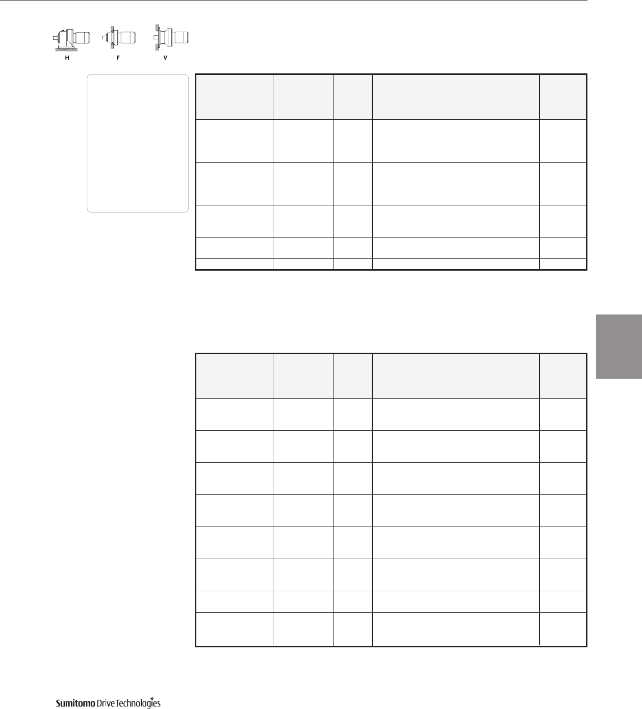
60 Hz Frame Size Selection Tables
1/8 HP
60 Hz, 1750 RPM
CYCLO® 6000 Gearmotors
Frame Size Selection Tables 3.5
Dimensions Pages
Foot
Mount (H) 4.2–4.29
V-Flange (V) 4.30–4.43
F-Flange (F) 4.44–4.69
Selection
Tables
Gearmotors
Cyclo® 6000 Series
Frame Size Selection Tables 60 Hz
1/8 HP
60 Hz, 1750 RPM
CYCLO® 6000 Gearmotors
3.6 Frame Size Selection Tables
Output Output Service Factor Overhung SELECTION Option
Speed Torque Load
AGMA HP Frame Shaft AGMA Inverter
RPM In•lbs SF Class lbs Symbol Size Spec. Class Ratio Duty
1330 - - 743 01 6090DA Y 3045 AV
1700 - - 727 01 6095DA Y 3045 AV
0.575 2210 - - 1210 01 6100DA Y 3045 AV
2650 - - 1070 01 6105DA Y 3045 AV
4650 - - 2200 01 6120DB Y 3045 -
5570 - - 2150 01 6125DB Y 3045 -
1290 - - 741 01 6090DA Y 3481 AV
2210 - - 1210 01 6100DA Y 3481 AV
0.503 2620 - - 1140 01 6105DA Y 3481 AV
4650 - - 2200 01 6120DB Y 3481 -
5570 - - 2200 01 6125DB Y 3481 -
1330 - - 743 01 6090DA Y 4437 AV
1700 - - 727 01 6095DA Y 4437 AV
0.394 2210 - - 1210 01 6100DA Y 4437 AV
2650 - - 1070 01 6105DA Y 4437 AV
4650 - - 2200 01 6120DB Y 4437 -
5570 - - 2150 01 6125DB Y 4437 -
1330 - - 743 01 6090DA Y 5133 AV
1700 - - 727 01 6095DA Y 5133 AV
0.341 2210 - - 1210 01 6100DA Y 5133 AV
2650 - - 1070 01 6105DA Y 5133 AV
4650 - - 2200 01 6120DB Y 5133 -
5570 - - 2150 01 6125DB Y 5133 -
0.283 4650 - - 2200 01 6120DB Y 6177 -
5570 - - 2150 01 6125DB Y 6177 -
0.231 4650 - - 2200 01 6120DB Y 7569 -
5570 - - 2150 01 6125DB Y 7569 -
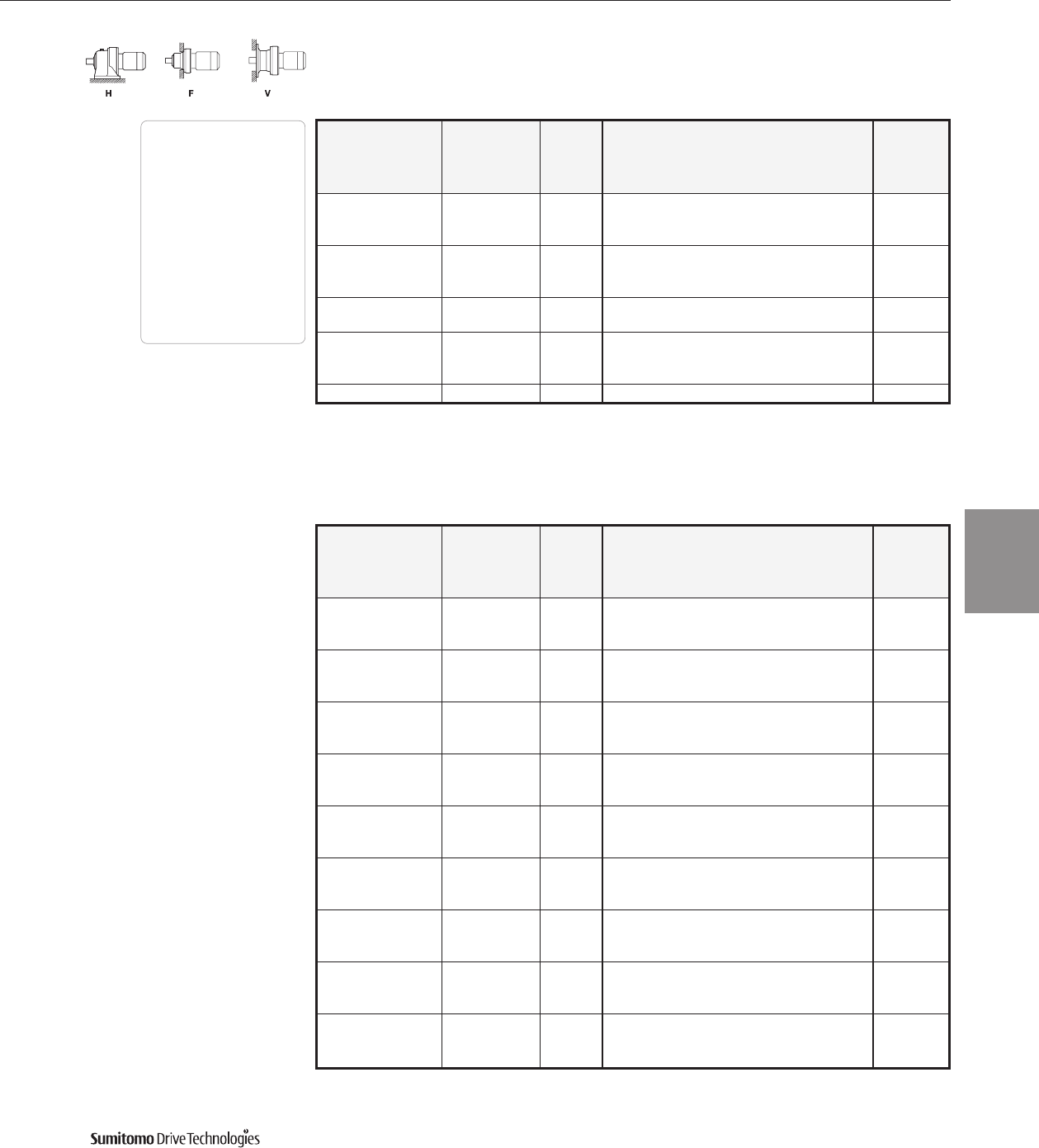
Dimensions Pages
Foot
Mount (H) 4.2–4.29
V-Flange (V) 4.30–4.43
F-Flange (F) 4.44–4.69
Selection
Tables
Gearmotors
Cyclo® 6000 Series
Output Output Service Factor Overhung SELECTION Option
Speed Torque Load
AGMA HP Frame Shaft AGMA Inverter
RPM In•lbs SF Class lbs Symbol Size Spec. Class Ratio Duty
1.00 I 169 02 6060 Y A 6 AV
292 55.0 1.43 II 169 02 6065 Y B 6 AV
1.74 III 294 02 6070 Y C 6 AV
2.04 III 294 02 6075 Y C 6 AV
1.00 I 193 02 6060 Y A 8 AV
219 73.3 1.43 II 193 02 6065 Y B 8 AV
1.74 III 326 02 6070 Y C 8 AV
2.04 III 326 02 6075 Y C 8 AV
1.00 I 263 02 6060 Y A 11 AV
159 101 1.43 II 263 02 6065 Y B 11 AV
1.74 III 366 02 6070 Y C 11 AV
2.04 III 366 02 6075 Y C 11 AV
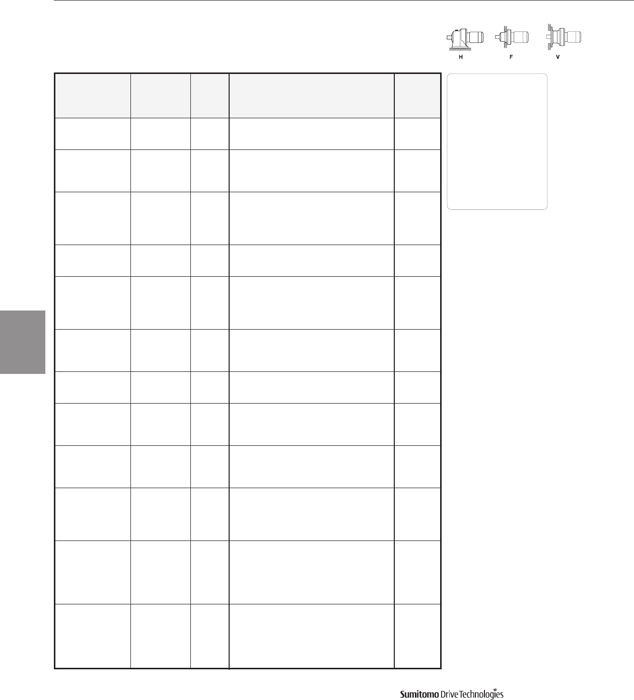
1/4 HP
60 Hz, 1750 RPM

Output Output Service Factor Overhung SELECTION Option
Speed Torque Load
AGMA HP Frame Shaft AGMA Inverter
RPM In•lbs SF Class lbs Symbol Size Spec. Class Ratio Duty
1.00 I 265 02 6060 YA13 AV
135 119 1.43 II 265 02 6065 YB13 AV
1.74 III 386 02 6070 YC13 AV
2.04 III 386 02 6075 YC13 AV
1.00 I 265 02 6060 YA15 AV
117 138 1.43 II 265 02 6065 YB15 AV
1.74 III 388 02 6070 YC15 AV
2.04 III 388 02 6075 YC15 AV
1.00 I 265 02 6060 YA17 AV
103 156 1.43 II 265 02 6065 YB17 AV
1.74 III 397 02 6070 YC17 AV
2.04 III 397 02 6075 YC17 AV
1.17 I 265 02 6065 YA21 AV
83.3 193 1.60 III 397 02 6070 YC21 AV
2.04 III 397 02 6075 YC21 AV
0.83 - 265 02 6065 Y25AV
1.15 I 397 02 6070 YA25 AV
70.0 229 1.47 II 397 02 6075 YB25 AV
1.70 III 573 02 6080 YC25 AV
2.38 III 573 02 6085 YC25 AV
0.83 - 265 02 6065 Y29AV
1.13 I 397 02 6070 YA29 AV
60.3 266 1.43 II 397 02 6075 YB29 AV
1.70 III 575 02 6080 YC29 AV
2.34 III 575 02 6085 YC29 AV
1.06 I 397 02 6070 YA35 AV
1.40 II 397 02 6075 YB35 AV
50.0 321 1.64 III 575 02 6080 YC35 AV
1.86 III 575 02 6085 YC35 AV
3.06 III 750 02 6090 YC35 AV
1.13 I 397 02 6075 YA43 AV
40.7 395 1.47 II 575 02 6085 YB43 AV
2.18 III 750 02 6090 YC43 AV
1.21 I 575 02 6085 YA51 AV
34.3 468 1.66 III 750 02 6090 YC51 AV
2.11 III 750 02 6095 YC51 AV
1.17 I 575 02 6085 YA59 AV
29.7 541 1.55 II 750 02 6090 YB59 AV
1.87 III 750 02 6095 YC59 AV
2.58 III 1210 02 6100 YC59 AV
0.94 - 564 02 6085 Y71AV
24.6 651 1.26 I 750 02 6090 YA71 AV
1.51 II 750 02 6095 YB71 AV
2.18 III 1210 02 6100 YC71 AV
1.06 I 750 02 6090 YA87 AV
20.1 798 1.51 II 750 02 6095 YB87 AV
2.17 III 1210 02 6100 YC87 AV
60 Hz Frame Size Selection Tables
1/4 HP
60 Hz, 1750 RPM
CYCLO® 6000 Gearmotors
Frame Size Selection Tables 3.7
Dimensions Pages
Foot
Mount (H) 4.2–4.29
V-Flange (V) 4.30–4.43
F-Flange (F) 4.44–4.69
Selection
Tables
Gearmotors
Cyclo® 6000 Series

Frame Size Selection Tables 60 Hz
1/4 HP
60 Hz, 1750 RPM
CYCLO® 6000 Gearmotors
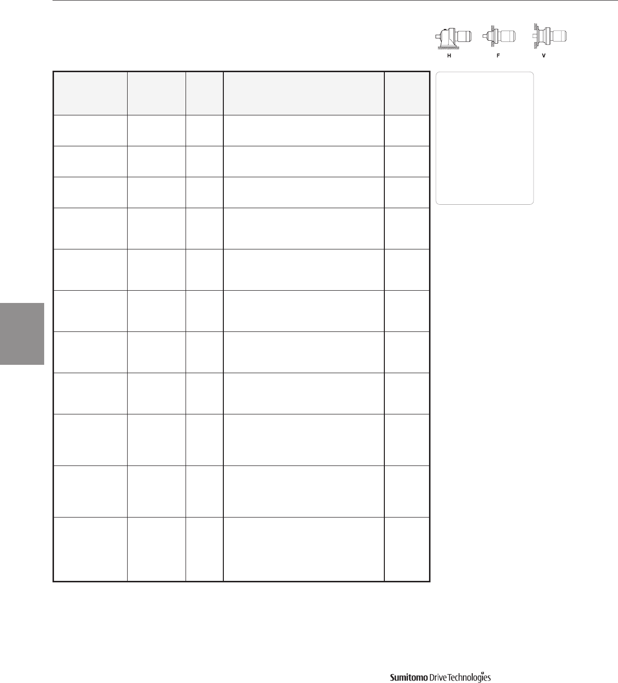
3.8 Frame Size Selection Tables
Output Output Service Factor Overhung SELECTION Option
Speed Torque Load
AGMA HP Frame Shaft AGMA Inverter
RPM In•lbs SF Class lbs Symbol Size Spec. Class Ratio Duty
531 - - 397 02 6075DA Y 104 AV
16.8 902 1.47 II 750 02 6090DA Y B 104 AV
902 1.77 III 750 02 6095DA Y C 104 AV
902 2.15 III 1210 02 6100DA Y C 104 AV
14.7 1090 1.05 I 1210 02 6100 Y A 119 AV
1.43 II 1210 02 6105 Y B 119 AV
1.26 I 750 02 6090DA Y A 121 AV
14.5 1050 1.35 II 750 02 6095DA Y B 121 AV
2.10 III 1210 02 6100DA Y C 121 AV
2.15 III 1210 02 6105DA Y C 121 AV
1.07 I 750 02 6090DA Y A 143 AV
12.2 1240 1.30 II 750 02 6095DA Y B 143 AV
1.78 III 1210 02 6100DA Y C 143 AV
2.14 III 1210 02 6105DA Y C 143 AV
1330 - - 750 02 6090DA Y 165 AV
1430 1.23 I 750 02 6095DA Y A 165 AV
10.6 1430 1.54 II 1210 02 6100DA Y B 165 AV
1430 1.85 III 1210 02 6105DA Y C 165 AV
1430 3.24 III 2200 02 6120DB Y C 165 AV
1330 - - 750 02 6090DA Y 195 AV
1700 1.04 I 750 02 6095DA Y A 195 AV
8.97 1700 1.31 II 1210 02 6100DA Y B 195 AV
1700 1.57 II 1210 02 6105DA Y B 195 AV
1700 2.74 III 2200 02 6120DB Y C 195 AV
1330 - - 750 02 6090DA Y 231 AV
1770 - - 750 02 6095DA Y 231 AV
7.58 2010 1.10 I 1210 02 6100DA Y A 231 AV
2010 1.32 II 1210 02 6105DA Y B 231 AV
2010 2.31 III 2200 02 6120DB Y C 231 AV
1330 - - 750 02 6090DA Y 273 AV
1770 - - 750 02 6095DA Y 273 AV
6.41 2210 - - 1210 02 6100DA Y 273 AV
2370 1.12 I 1210 02 6105DA Y A 273 AV
2370 1.95 III 2200 02 6120DB Y C 273 AV
2370 2.15 III 2200 02 6125DB Y C 273 AV
1770 - - 718 02 6095DA Y 319 AV
2210 - - 1210 02 6100DA Y 319 AV
5.49 2650 - - 1210 02 6105DA Y 319 AV
2770 1.66 III 2200 02 6120DB Y C 319 AV
2770 2.01 III 2200 02 6125DB Y C 319 AV
2770 2.49 III 3300 02 6130DC Y C 319 -
1770 - - 718 02 6095DA Y 377 AV
2210 - - 1210 02 6100DA Y 377 AV
4.64 2650 - - 1210 02 6105DA Y 377 AV
3270 1.40 II 2200 02 6120DB Y B 377 AV
3270 1.70 III 2200 02 6125DB Y C 377 AV
3270 2.11 III 3300 02 6130DC Y C 377 -
Dimensions Pages
Foot
Mount (H) 4.2–4.29
V-Flange (V) 4.30–4.43
F-Flange (F) 4.44–4.69
Selection
Tables
Gearmotors
Cyclo® 6000 Series

Output Output Service Factor Overhung SELECTION Option
Speed Torque Load
AGMA HP Frame Shaft AGMA Inverter
RPM In•lbs SF Class lbs Symbol Size Spec. Class Ratio Duty
2210 - - 1210 02 6100DA Y 473 AV
2650 - - 1210 02 6105DA Y 473 AV
4110 1.13 I 2200 02 6120DB Y A 473 AV
3.70 4110 1.36 II 2200 02 6125DB Y B 473 AV
4110 1.68 III 3300 02 6130DC Y C 473 -
4110 2.02 III 3300 02 6135DC Y C 473 -
4110 2.65 III 3590 02 6140DB Y C 473 AV
2650 - - 1210 02 6105DA Y 559 AV
4650 - - 2200 02 6120DB Y 559 AV
3.13 4860 1.15 I 2200 02 6125DB Y A 559 AV
4860 1.42 II 3300 02 6130DC Y B 559 -
4860 1.71 III 3300 02 6135DC Y C 559 -
4860 2.24 III 3590 02 6140DB Y C 559 AV
4650 - - 2200 02 6120DB Y 649 AV
5650 0.98 - 2200 02 6125DB Y 649 AV
2.70 5650 1.43 II 3300 02 6130DC Y B 649 -
5650 1.65 III 3300 02 6135DC Y C 649 -
5650 2.15 III 3590 02 6145DB Y C 649 AV
4650 - - 2200 02 6120DB Y 731 AV
5570 - - 2200 02 6125DB Y 731 AV
2.39 6350 1.09 I 3300 02 6130DC Y A 731 -
6350 1.31 II 3300 02 6135DC Y B 731 -
6350 1.91 III 3590 02 6145DB Y C 731 AV
4600 - - 2200 02 6120DB Y 841 AV
5570 - - 2200 02 6125DB Y 841 AV
2.08 6900 - - 3300 02 6130DC Y 841 AV
7310 1.14 I 3300 02 6135DC Y A 841 AV
7310 1.48 II 3590 02 6140DB Y B 841 AV
7310 1.66 III 3590 02 6145DB Y C 841 AV
4650 - - 2200 02 6120DB Y 1003 AV
5570 - - 2200 02 6125DB Y 1003 AV
1.74 8070 - - 3300 02 6130DC Y 1003 -
8720 1.07 I 3300 02 6135DC Y A 1003 -
8720 1.39 II 3590 02 6145DB Y B 1003 AV
5570 - - 2200 02 6125DB Y 1247 AV
6900 - - 3300 02 6130DC Y 1247 AV
1.40 8320 - - 3300 02 6135DC Y 1247 AV
10900 1.00 I 3590 02 6140DB Y A 1247 AV
10900 1.12 I 3590 02 6145DB Y A 1247 AV
7500 - - 3300 02 6130DC Y 1479 -
1.18 8660 - - 3300 02 6135DC Y 1479 -
10900 - - 3590 02 6140DB Y 1479 AV
11100 - - 3590 02 6145DB Y 1479 AV
6900 - - 3300 02 6130DC Y 1849 AV
0.946 8320 - - 3300 02 6135DC Y 1849 AV
10900 - - 3590 02 6140DB Y 1849 AV
12100 - - 3530 02 6145DB Y 1849 AV
60 Hz Frame Size Selection Tables
1/4 HP
60 Hz, 1750 RPM
CYCLO® 6000 Gearmotors
Frame Size Selection Tables 3.9
Dimensions Pages
Foot
Mount (H) 4.2–4.29
V-Flange (V) 4.30–4.43
F-Flange (F) 4.44–4.69
Selection
Tables
Gearmotors
Cyclo® 6000 Series
Frame Size Selection Tables 60 Hz
1/4 HP
60 Hz, 1750 RPM
CYCLO® 6000 Gearmotors
3.10 Frame Size Selection Tables
Output Output Service Factor Overhung SELECTION Option
Speed Torque Load
AGMA HP Frame Shaft AGMA Inverter
RPM In•lbs SF Class lbs Symbol Size Spec. Class Ratio Duty
8070 - - 3300 02 6130DC Y 2065 AV
0.847 9290 - - 3300 02 6135DC Y 2065 AV
10900 - - 3590 02 6140DB Y 2065 AV
12100 - - 3590 02 6145DB Y 2065 AV
8070 - - 3300 02 6130DC Y 2537 AV
0.690 9290 - - 3300 02 6135DC Y 2537 AV
10900 - - 3590 02 6140DB Y 2537 AV
12100 - - 3590 02 6145DB Y 2537 AV
7500 - - 3300 02 6130DC Y 3045 AV
0.575 8660 - - 3300 02 6135DC Y 3045 AV
10900 - - 3590 02 6140DB Y 3045 AV
11100 - - 3590 02 6145DB Y 3045 AV
8070 - - 3300 02 6130DC Y 3481 AV
0.503 9290 - - 3300 02 6135DC Y 3481 AV
10900 - - 3590 02 6140DB Y 3481 AV
12100 - - 3590 02 6145DB Y 3481 AV
7500 - - 3300 02 6130DC Y 4437 AV
0.394 8660 - - 3300 02 6135DC Y 4437 AV
10900 - - 3590 02 6140DB Y 4437 AV
11100 - - 3590 02 6145DB Y 4437 AV
7500 - - 3300 02 6130DC Y 5133 AV
0.341 8660 - - 3300 02 6135DC Y 5133 AV
10900 - - 3590 02 6140DB Y 5133 AV
11100 - - 3590 02 6145DB Y 5133 AV
7500 - - 3300 02 6130DC Y 6177 AV
0.283 8660 - - 3300 02 6135DC Y 6177 AV
10900 - - 3590 02 6140DB Y 6177 AV
11100 - - 3590 02 6145DB Y 6177 AV
7500 - - 3300 02 6130DC Y 7569 AV
0.231 8660 - - 3300 02 6135DC Y 7569 AV
10900 - - 3590 02 6140DB Y 7569 AV
11100 - - 3590 02 6145DB Y 7569 AV
Dimensions Pages
Foot
Mount (H) 4.2–4.29
V-Flange (V) 4.30–4.43
F-Flange (F) 4.44–4.69
Selection
Tables
Gearmotors
Cyclo® 6000 Series
1/3 HP
60 Hz, 1750 RPM
Output Output Service Factor Overhung SELECTION Option
Speed Torque Load
AGMA HP Frame Shaft AGMA Inverter
RPM In•lbs SF Class lbs Symbol Size Spec. Class Ratio Duty
1.14 I 168 03 6065 YA 6 AV
292 68.8 1.39 II 294 03 6070 YB 6 AV
1.63 III 294 03 6075 YC 6 AV
2.37 III 406 03 6080 YC 6 AV
1.14 I 192 03 6065 YA 8 AV
219 92.0 1.39 II 326 03 6070 YB 8 AV
1.63 III 326 03 6075 YC 8 AV
2.37 III 442 03 6080 YC 8 AV

60 Hz Frame Size Selection Tables
1/3 HP
60 Hz, 1750 RPM
CYCLO® 6000 Gearmotors
Frame Size Selection Tables 3.11
Output Output Service Factor Overhung SELECTION Option
Speed Torque Load
AGMA HP Frame Shaft AGMA Inverter
RPM In•lbs SF Class lbs Symbol Size Spec. Class Ratio Duty
1.14 I 260 03 6065 YA11 AV
159 127 1.39 II 364 03 6070 YB11 AV
1.63 III 364 03 6075 YC11 AV
2.37 III 489 03 6080 YC11 AV
1.14 I 265 03 6065 YA13 AV
135 149 1.39 II 384 03 6070 YB13 AV
1.63 III 384 03 6075 YC13 AV
2.37 III 525 03 6080 YC13 AV
1.14 I 265 03 6065 YA15 AV
117 172 1.39 II 386 03 6070 YB15 AV
1.63 III 386 03 6075 YC15 AV
2.37 III 543 03 6080 YC15 AV
1.14 I 265 03 6065 YA17 AV
103 195 1.39 II 397 03 6070 YB17 AV
1.63 III 397 03 6075 YC17 AV
2.37 III 570 03 6080 YC17 AV
0.94 - 265 03 6065 Y21AV
83.3 241 1.28 I 397 03 6070 YA21 AV
1.63 III 397 03 6075 YC21 AV
1.91 III 555 03 6080 YC21 AV
1.18 I 397 03 6075 YA25 AV
70.0 287 1.36 II 570 03 6080 YB25 AV
1.90 III 570 03 6085 YC25 AV
1.14 I 397 03 6075 YA29 AV
60.3 333 1.36 II 575 03 6080 YB29 AV
1.87 III 575 03 6085 YC29 AV
1.12 I 397 03 6075 YA35 AV
50.0 402 1.31 II 575 03 6080 YB35 AV
1.48 II 575 03 6085 YB35 AV
2.45 III 750 03 6090 YC35 AV
0.90 - 391 03 6075 Y43AV
40.7 493 1.18 I 575 03 6085 YA43 AV
1.74 III 750 03 6090 YC43 AV
2.41 III 750 03 6095 YC43 AV
0.96 - 575 03 6085 Y51AV
34.3 585 1.33 II 750 03 6090 YB51 AV
1.69 III 750 03 6095 YC51 AV
2.24 III 1210 03 6100 YC51 AV
0.94 - 570 03 6085 Y59AV
29.7 677 1.24 I 750 03 6090 YA59 AV
1.49 II 750 03 6095 YB59 AV
2.06 III 1210 03 6100 YC59 AV
1.20 I 750 03 6095 YA71 AV
24.6 814 1.74 III 1210 03 6100 YC71 AV
2.24 III 1210 03 6105 YC71 AV
1.20 I 750 03 6095 YA87 AV
20.1 1000 1.73 III 1210 03 6100 YC87 AV
2.26 III 1210 03 6105 YC87 AV
Dimensions Pages
Foot
Mount (H) 4.2–4.29
V-Flange (V) 4.30–4.43
F-Flange (F) 4.44–4.69
Selection
Tables
Gearmotors
Cyclo® 6000 Series
Frame Size Selection Tables 60 Hz
1/3 HP
60 Hz, 1750 RPM
CYCLO® 6000 Gearmotors
3.12 Frame Size Selection Tables
Output Output Service Factor Overhung SELECTION Option
Speed Torque Load
AGMA HP Frame Shaft AGMA Inverter
RPM In•lbs SF Class lbs Symbol Size Spec. Class Ratio Duty
1.17 I 750 03 6090DA Y A 104 AV
16.8 1130 1.42 II 750 03 6095DA Y B 104 AV
1.72 III 1210 03 6105DA Y C 104 AV
4.11 III 2200 03 6120DB Y C 104 AV
14.7 1360 1.14 I 1210 03 6105 Y A 119 AV
1.08 I 750 03 6095DA Y A 121 AV
14.5 1320 1.68 III 1210 03 6100DA Y C 121 AV
1.72 III 1210 03 6105DA Y C 121 AV
3.53 III 2200 03 6120DB Y C 121 AV
1330 - - 750 03 6090DA Y 143 AV
1560 1.04 I 750 03 6095DA Y A 143 AV
12.2 1560 1.42 II 1210 03 6100DA Y B 143 AV
1560 1.71 III 1210 03 6105DA Y C 143 AV
1560 2.99 III 2200 03 6120DB Y C 143 AV
0.98 - 750 03 6095DA Y 165 AV
10.6 1800 1.23 I 1210 03 6100DA Y A 165 AV
1.48 II 1210 03 6105DA Y B 165 AV
2.59 III 2200 03 6120DB Y C 165 AV
1770 - - 750 03 6095DA Y 195 AV
8.97 2110 1.25 I 1210 03 6105DA Y A 195 AV
2110 2.19 III 2200 03 6120DB Y C 195 AV
2210 - - 1210 03 6100DA Y 231 AV
7.58 2510 1.06 I 1210 03 6105DA Y A 231 AV
2510 1.84 III 2200 03 6120DB Y C 231 AV
2510 2.22 III 2200 03 6125DB Y C 231 AV
2650 - - 1210 03 6105DA Y 273 AV
6.41 2960 1.56 II 2200 03 6120DB Y B 273 AV
2960 1.88 III 2200 03 6125DB Y C 273 AV
2960 2.33 III 3300 03 6130DC Y C 273 -
2650 - - 1210 03 6105DA Y C 319 AV
3470 1.33 II 2200 03 6120DB Y B 319 AV
5.49 3470 1.61 III 2200 03 6125DB Y C 319 AV
3470 1.99 III 3300 03 6130DC Y C 319 -
3470 2.40 III 3300 03 6135DC Y C 319 -
1.12 I 2200 03 6120DB Y A 377 AV
1.36 II 2200 03 6125DB Y B 377 AV
4.64 4100 1.69 III 3300 03 6130DC Y C 377 -
2.03 III 3300 03 6135DC Y C 377 -
2.66 III 3590 03 6140DB Y C 377 AV
4650 - - 2200 03 6120DB Y 473 AV
5140 1.08 I 2200 03 6125DB Y A 473 AV
3.70 5140 1.34 II 3300 03 6130DC Y B 473 -
5140 1.62 III 3300 03 6135DC Y C 473 -
5140 2.11 III 3590 03 6140DB Y C 473 AV
5570 - - 2200 03 6125DB Y 559 AV
6070 1.14 I 3300 03 6130DC Y A 559 -
3.13 6070 1.37 II 3300 03 6135DC Y B 559 -
6070 1.79 III 3590 03 6140DB Y C 559 AV
6070 2.00 III 3590 03 6145DB Y C 559 AV
Dimensions Pages
Foot
Mount (H) 4.2–4.29
V-Flange (V) 4.30–4.43
F-Flange (F) 4.44–4.69
Selection
Tables
Gearmotors
Cyclo® 6000 Series
60 Hz Frame Size Selection Tables
1/3 HP
60 Hz, 1750 RPM
CYCLO® 6000 Gearmotors
Frame Size Selection Tables 3.13
Output Output Service Factor Overhung SELECTION Option
Speed Torque Load
AGMA HP Frame Shaft AGMA Inverter
RPM In•lbs SF Class lbs Symbol Size Spec. Class Ratio Duty
1.14 I 3300 03 6130DC YA649 -
2.70 7050 1.32 II 3300 03 6135DC YB649 -
1.72 III 3590 03 6145DB YC649 AV
6900 -- 3300 03 6130DC Y 731 -
2.39 7950 1.05 I 3300 03 6135DC YA731 -
7950 1.53 II 3590 03 6145DB YB731 AV
2.08 8320 -- 3300 03 6135DC Y 841 AV
9110 1.21 I 3590 03 6145DB YA841 AV
9290 -- 3300 03 6135DC Y 1003 -
1.74 10900 1.00 I 3590 03 6140DB YA1003 AV
10900 1.11 I 3590 03 6145DB YA1003 AV
1.40 12100 -- 3530 03 6145DB Y 1247 AV
Dimensions Pages
Foot
Mount (H) 4.2–4.29
V-Flange (V) 4.30–4.43
F-Flange (F) 4.44–4.69
Selection
Tables
Gearmotors
Cyclo® 6000 Series
Output Output Service Factor Overhung SELECTION Option
Speed Torque Load
AGMA HP Frame Shaft AGMA Inverter
RPM In•lbs SF Class lbs Symbol Size Spec. Class Ratio Duty
1.02 I 290 05 6075* YA 6 -
292 110 1.48 II 406 05 6080* YB 6 AV
1.95 III 406 05 6085* YC 6 AV
1.02 I 321 05 6075* YA 8 -
219 147 1.48 II 440 05 6080* YB 8 AV
1.95 III 440 05 6085* YC 8 AV
1.02 I 357 05 6075* YA11 -
159 202 1.48 II 485 05 6080* YB11 AV
1.95 III 485 05 6085* YC11 AV
1.02 I 377 05 6075* YA13 -
135 239 1.48 II 521 05 6080* YB13 AV
1.95 III 521 05 6085* YC13 AV
1.02 I 377 05 6075* YA15 -
117 275 1.48 II 539 05 6080* YB15 AV
1.95 III 539 05 6085* YC15 AV
1.02 I 397 05 6075* YA17 -
103 312 1.48 II 564 05 6080* YB17 AV
1.95 III 564 05 6085* YC17 AV
1.02 I 397 05 6075* YA21 -
83.3 385 1.38 II 550 05 6085* YB21 AV
1.90 III 750 05 6090* YC21 AV
1.19 I 566 05 6085* YA25 AV
70.0 458 1.68 III 750 05 6090* YC25 AV
2.17 III 750 05 6095* YC25 AV
1.17 I 575 05 6085* YA29 AV
60.3 532 1.56 II 750 05 6090* YB29 AV
1.96 III 750 05 6095* YC29 AV
1/2 HP
60 Hz, 1750 RPM
Note: *FIDE approved model.
Frame Size Selection Tables 60 Hz
1/2 HP
60 Hz, 1750 RPM
CYCLO® 6000 Gearmotors
3.14 Frame Size Selection Tables
Output Output Service Factor Overhung SELECTION Option
Speed Torque Load
AGMA HP Frame Shaft AGMA Inverter
RPM In•lbs SF Class lbs Symbol Size Spec. Class Ratio Duty
0.93 - 575 05 6085* Y 35 AV
50.0 642 1.53 II 750 05 6090* YB35 AV
1.90 III 750 05 6095* YC35 AV
1.09 I 750 05 6090* YA43 AV
40.7 789 1.51 II 750 05 6095* YB43 AV
1.95 III 1210 05 6100* YC43 AV
1.06 I 750 05 6095* YA51 AV
34.3 938 1.40 II 1210 05 6100* YB51 AV
1.94 III 1210 05 6105* YC51 AV
1.00 I 750 05 6095* YA59 AV
29.7 1080 1.29 I 1210 05 6100* YA59 AV
1.77 III 1210 05 6105* YC59 AV
2.15 III 1710 05 6110* YC59 AV
1.09 I 1210 05 6100* YA71 AV
24.6 1300 1.40 II 1210 05 6105* YB71 AV
1.67 III 1710 05 6110* YC71 AV
1.90 III 1710 05 6115* YC71 AV
1.08 I 1210 05 6100* YA87 AV
20.1 1590 1.41 II 1210 05 6105* YB87 AV
1.65 III 1710 05 6110* YC87 AV
1.90 III 1710 05 6115* YC87 AV
1330 -- 750 05 6090DA Y 104 -
16.8 1600 -- 750 05 6095DA Y 104 -
1800 1.07 I 1210 05 6105DA YA104 -
1800 2.57 III 2200 05 6120DB YC104 AV
1330 -- 750 05 6090DA Y 121 -
14.5 1420 -- 750 05 6095DA Y 121 -
2110 1.07 I 1210 05 6105DA YA121 -
2110 2.21 III 2200 05 6120DB YC121 AV
1620 -- 750 05 6095DA Y 143 -
2210 -- 1210 05 6100DA Y 143 -
12.2 2490 1.07 I 1210 05 6105DA YA143 -
2490 1.87 III 2200 05 6120DB YC143 AV
2490 2.24 III 2200 05 6125DB YC143 AV
2210 -- 1210 05 6100DA Y 165 -
2650 -- 1210 05 6105DA Y 165 -
10.6 2870 1.62 III 2200 05 6120DB YC165 AV
2870 1.94 III 2200 05 6125DB YC165 AV
2870 2.41 III 3300 05 6130DC YC165 -
2210 -- 1210 05 6100DA Y 195 -
2650 -- 1210 05 6105DA Y 195 -
8.97 3390 1.37 II 2200 05 6120DB YB195 AV
3390 1.64 III 2200 05 6125DB YC195 AV
3390 2.04 III 3300 05 6130DC YC195 -
3390 2.45 III 3300 05 6135DC YC195 -
Dimensions Pages
Foot
Mount (H) 4.2–4.29
V-Flange (V) 4.30–4.43
F-Flange (F) 4.44–4.69
Selection
Tables
Gearmotors
Cyclo® 6000 Series
Note: *FIDE approved model.

Output Output Service Factor Overhung SELECTION Option
Speed Torque Load
AGMA HP Frame Shaft AGMA Inverter
RPM In•lbs SF Class lbs Symbol Size Spec. Class Ratio Duty
2650 - - 1210 05 6105DA Y 231 -
4020 1.15 I 2200 05 6120DB Y A 231 AV
7.58 4020 1.39 II 2200 05 6125DB Y B 231 AV
4020 1.72 III 3300 05 6130DC Y C 231 -
4020 2.07 III 3300 05 6135DC Y C 231 -
4020 2.70 III 3590 05 6140DB Y C 231 AV
4620 - - 2200 05 6120DB Y 273 AV
4740 1.18 I 2200 05 6125DB Y A 273 AV
6.41 4740 1.46 II 3300 05 6130DC Y B 273 -
4740 1.75 III 3300 05 6135DC Y C 273 -
4740 2.28 III 3590 05 6140DB Y C 273 AV
4600 - - 2200 05 6120DB Y 319 AV
5550 1.00 I 2200 05 6125DB Y A 319 AV
5.49 5550 1.24 I 3300 05 6130DC Y A 319 -
5550 1.50 II 3300 05 6135DC Y B 319 -
5550 1.95 III 3590 05 6140DB Y C 319 AV
5550 2.19 III 3590 05 6145DB Y C 319 AV
4600 - - 2200 05 6120DB Y 377 AV
5570 - - 2200 05 6125DB Y 377 AV
4.64 6560 1.05 I 3300 05 6130DC Y A 377 -
6560 1.27 I 3300 05 6135DC Y A 377 -
6560 1.66 III 3590 05 6140DB Y C 377 AV
6560 1.85 III 3590 05 6145DB Y C 377 AV
5570 - - 2200 05 6125DB Y 473 AV
6900 - - 3300 05 6130DC Y 473 -
3.70 8220 1.01 I 3300 05 6135DC Y A 473 -
8220 1.32 II 3590 05 6140DB Y B 473 AV
8220 1.47 II 3590 05 6145DB Y B 473 AV
8220 1.87 III 4960 05 6160DC Y C 473 -
6900 - - 3300 05 6130DC Y 559 -
8320 - - 3300 05 6135DC Y 559 -
3.13 9730 1.12 I 3590 05 6140DB Y A 559 AV
9730 1.25 I 3590 05 6145DB Y A 559 AV
9730 1.58 II 4960 05 6160DC Y B 559 -
9730 1.91 III 4960 05 6165DC Y C 559 -
8070 - - 3300 05 6130DC Y 649 -
9290 - - 3300 05 6135DC Y 649 -
2.70 10900 - - 3590 05 6140DB Y 649 AV
11300 1.07 I 3590 05 6145DB Y A 649 AV
11300 1.38 II 4960 05 6160DC Y B 649 -
11300 1.64 III 4960 05 6165DC Y C 649 -
8320 - - 3300 05 6135DC Y 731 AV
10900 - - 3590 05 6140DB Y 731 AV
2.39 12700 0.95 - 3530 05 6145DB Y 731 AV
12700 1.21 I 4960 05 6160DC Y A 731 -
12700 1.46 II 4960 05 6165DC Y B 731 -
12700 1.76 III 6620 05 6170DC Y C 731 -
60 Hz Frame Size Selection Tables
1/2 HP
60 Hz, 1750 RPM
CYCLO® 6000 Gearmotors
Frame Size Selection Tables 3.15
Dimensions Pages
Foot
Mount (H) 4.2–4.29
V-Flange (V) 4.30–4.43
F-Flange (F) 4.44–4.69
Selection
Tables
Gearmotors
Cyclo® 6000 Series
Frame Size Selection Tables 60 Hz
1/2 HP
60 Hz, 1750 RPM
CYCLO® 6000 Gearmotors
3.16 Frame Size Selection Tables
Output Output Service Factor Overhung SELECTION Option
Speed Torque Load
AGMA HP Frame Shaft AGMA Inverter
RPM In•lbs SF Class lbs Symbol Size Spec. Class Ratio Duty
10900 - - 3592 05 6140DB Y 841 AV
12100 - - 3548 05 6145DB Y 841 AV
2.08 14600 1.07 I 4962 05 6160DC Y A 841 -
14600 1.27 I 4962 05 6165DC Y A 841 -
14600 1.53 II 6624 05 6170DC Y B 841 -
14600 1.91 III 6624 05 6175DC Y C 841 -
12100 - - 3592 05 6145DB Y 1003 AV
15600 - - 4962 05 6160DC Y 1003 -
1.74 17400 1.07 I 4962 05 6165DC Y A 1003 -
17400 1.28 I 6624 05 6170DC Y A 1003 -
17400 1.60 III 6624 05 6175DC Y C 1003 -
15400 - - 4962 05 6160DC Y 1247 -
1.40 18600 - - 4962 05 6165DC Y 1247 -
21700 1.03 I 6624 05 6170DC Y A 1247 -
21700 1.29 I 6624 05 6175DC Y A 1247 -
15600 - - 4962 05 6160DC Y 1479 -
1.18 18100 - - 4895 05 6165DC Y 1479 -
22400 - - 6624 05 6170DC Y 1479 -
25800 1.08 I 6624 05 6175DC Y A 1479 -
18600 - - 4962 05 6165DC Y 1849 AV
0.946 22400 - - 6624 05 6170DC Y 1849 AV
27900 - - 6624 05 6175DC Y 1849 AV
0.847 22400 - - 6624 05 6170DC Y 2065 AV
27900 - - 6624 05 6175DC Y 2065 AV
0.690 27900 - - 6624 05 6175DC Y 2537 AV
Dimensions Pages
Foot
Mount (H) 4.2–4.29
V-Flange (V) 4.30–4.43
F-Flange (F) 4.44–4.69
Selection
Tables
Gearmotors
Cyclo® 6000 Series
3/4 HP
60 Hz, 1750 RPM
Output Output Service Factor Overhung SELECTION Option
Speed Torque Load
AGMA HP Frame Shaft AGMA Inverter
RPM In•lbs SF Class lbs Symbol Size Spec. Class Ratio Duty
1.08 I 404 08 6080 YA 6 -
292 151 1.41 II 404 08 6085 YB 6 -
2.09 III 604 08 6090 YC 6 AV
1.08 I 438 08 6080 YA 8 -
219 202 1.41 II 438 08 6085 YB 8 -
2.09 III 671 08 6090 YC 8 AV
1.08 I 483 08 6080 Y A 11 -
159 278 1.41 II 483 08 6085 Y B 11 -
2.09 III 750 08 6090 YC11 AV
1.08 I 519 08 6080 Y A 13 -
135 328 1.41 II 519 08 6085 Y B 13 -
2.09 III 750 08 6090 YC13 AV
1.08 I 534 08 6080 Y A 15 -
117 379 1.41 II 534 08 6085 Y B 15 -
2.09 III 750 08 6090 YC15 AV
60 Hz Frame Size Selection Tables
3/4 HP
60 Hz, 1750 RPM
Output Output Service Factor Overhung SELECTION Option
Speed Torque Load
AGMA HP Frame Shaft AGMA Inverter
RPM In•lbs SF Class lbs Symbol Size Spec. Class Ratio Duty
1.08 I 559 08 6080 Y A 17 -
103 429 1.41 II 559 08 6085 Y B 17 -
2.09 III 750 08 6090 YC17 AV
1.00 I 546 08 6085 Y A 21 -
83.3 530 1.38 II 750 08 6090 YB21 AV
2.76 III 750 08 6095 YC21 AV
0.86 - 559 08 6085 Y25-
70.0 631 1.22 I 750 08 6090 YA25 AV
1.57 II 750 08 6095 YB25 AV
2.31 III 1210 08 6100 YC25 AV
0.85 - 557 08 6085 Y29-
60.3 732 1.14 I 750 08 6090 YA29 AV
1.43 II 750 08 6095 YB29 AV
2.20 III 1210 08 6100 YC29 AV
1.11 I 750 08 6090 YA35 AV
50.0 883 1.38 II 750 08 6095 YB35 AV
1.77 III 1210 08 6100 YC35 AV
1.10 I 750 08 6095 YA43 AV
40.7 1090 1.42 II 1210 08 6100 YB43 AV
1.96 III 1210 08 6105 YC43 AV
1.02 I 1210 08 6100 YA51 AV
34.3 1280 1.41 II 1210 08 6105 YB51 AV
1.72 III 1710 08 6110 YC51 AV
2.02 III 1710 08 6115 YC51 AV
1.29 I 1210 08 6105 YA59 AV
29.7 1490 1.56 II 1710 08 6110 YB59 AV
1.84 III 1710 08 6115 YC59 AV
1.02 I 1210 08 6105 YA71 AV
1.22 I 1710 08 6110 YA71 AV
24.6 1790 1.38 II 1710 08 6115 YB71 AV
1.74 III 2200 08 6120 YC71 AV
2.18 III 2200 08 6125 YC71 AV
1.03 I 1210 08 6105 YA87 AV
1.20 I 1710 08 6110 YA87 AV
20.1 2190 1.38 II 1710 08 6115 YB87 AV
1.72 III 2200 08 6120 YC87 AV
2.05 III 2200 08 6125 YC87 AV
16.8 2490 1.87 III 2200 08 6120DB Y C 104 AV
2.24 III 2200 08 6125DB Y C 104 AV
1.61 III 2200 08 6120DB Y C 121 AV
14.5 2890 1.90 III 2200 08 6125DB Y C 121 AV
2.39 III 3300 08 6130DC Y C 121 -
1.36 II 2200 08 6120DB Y B 143 AV
12.2 3420 1.63 III 2200 08 6125DB Y C 143 AV
2.02 III 3300 08 6130DC Y C 143 -
2.43 III 3300 08 6135DC Y C 143 -
1.18 I 2200 08 6120DB Y A 165 AV
10.6 3950 1.41 II 2200 08 6125DB Y B 165 AV
1.75 III 3300 08 6130DC Y C 165 -
2.11 III 3300 08 6135DC Y C 165 -
CYCLO® 6000 Gearmotors
Frame Size Selection Tables 3.17
Dimensions Pages
Foot
Mount (H) 4.2–4.29
V-Flange (V) 4.30–4.43
F-Flange (F) 4.44–4.69
Selection
Tables
Gearmotors
Cyclo® 6000 Series

Frame Size Selection Tables 60 Hz
3/4 HP
60 Hz, 1750 RPM
CYCLO® 6000 Gearmotors
3.18 Frame Size Selection Tables
Output Output Service Factor Overhung SELECTION Option
Speed Torque Load
AGMA HP Frame Shaft AGMA Inverter
RPM In•lbs SF Class lbs Symbol Size Spec. Class Ratio Duty
4650 - - 2200 08 6120DB Y 195 AV
4660 1.20 I 2200 08 6125DB Y A 195 AV
8.97 4660 1.48 II 3300 08 6130DC Y B 195 AV
4660 1.78 III 3300 08 6135DC Y C 195 AV
4660 2.33 III 3590 08 6140DB Y C 195 AV
4620 - - 2200 08 6120DB Y 231 AV
5520 1.01 I 2200 08 6125DB Y A 231 AV
7.58 5520 1.25 I 3300 08 6130DC Y A 231 -
5520 1.51 II 3300 08 6135DC Y B 231 -
5520 1.96 III 3590 08 6140DB Y C 231 AV
5520 2.14 III 3590 08 6145DB Y C 231 AV
5570 - - 2200 08 6125DB Y 273 AV
6520 1.06 I 3300 08 6130DC Y A 273 AV
6.41 6520 1.28 I 3300 08 6135DC Y A 273 AV
6520 1.67 III 3590 08 6140DB Y C 273 AV
6520 1.82 III 3590 08 6145DB Y C 273 AV
6520 2.39 III 4960 08 6160DC Y C 273 AV
5570 - - 2200 08 6125DB Y 319 AV
6900 - - 3300 08 6130DC Y 319 -
7630 1.09 I 3300 08 6135DC Y A 319 -
5.49 7630 1.42 II 3590 08 6140DB Y B 319 AV
7630 1.59 II 3590 08 6145DB Y B 319 AV
7630 2.04 III 4960 08 6160DC Y C 319 -
7630 2.44 III 4960 08 6165DC Y C 319 -
6900 - - 3300 08 6130DC Y 377 AV
8320 - - 3300 08 6135DC Y 377 AV
9020 1.21 I 3590 08 6140DB Y A 377 AV
4.64 9020 1.35 II 3590 08 6145DB Y B 377 AV
9020 1.72 III 4960 08 6160DC Y C 377 AV
9020 2.06 III 4960 08 6165DC Y C 377 AV
9020 2.48 III 6620 08 6170DC Y C 377 AV
8320 - - 3300 08 6135DC Y 473 -
10900 - - 3590 08 6140DB Y 473 AV
11300 1.07 I 3590 08 6145DB Y A 473 AV
3.70 11300 1.36 II 4960 08 6160DC Y B 473 -
11300 1.64 III 4960 08 6165DC Y C 473 -
11300 1.98 III 6620 08 6170DC Y C 473 -
11300 2.47 III 6620 08 6175DC Y C 473 -
10900 - - 3590 08 6140DB Y 559 AV
12100 - - 3530 08 6145DB Y 559 AV
3.13 13400 1.15 I 4960 08 6160DC Y A 559 AV
13400 1.39 II 4960 08 6165DC Y B 559 AV
13400 1.68 III 6620 08 6170DC Y C 559 AV
13400 2.09 III 6620 08 6175DC Y C 559 AV
12100 - - 3590 08 6145DB Y 649 AV
15600 - - 4960 08 6160DC Y 649 -
2.70 15500 1.20 I 4960 08 6165DC Y A 649 -
15500 1.44 II 6620 08 6170DC Y B 649 -
15500 1.80 III 6620 08 6175DC Y C 649 -
Dimensions Pages
Foot
Mount (H) 4.2–4.29
V-Flange (V) 4.30–4.43
F-Flange (F) 4.44–4.69
Selection
Tables
Gearmotors
Cyclo® 6000 Series
60 Hz Frame Size Selection Tables
3/4 HP
60 Hz, 1750 RPM
CYCLO® 6000 Gearmotors
Frame Size Selection Tables 3.19
Output Output Service Factor Overhung SELECTION Option
Speed Torque Load
AGMA HP Frame Shaft AGMA Inverter
RPM In•lbs SF Class lbs Symbol Size Spec. Class Ratio Duty
15400 -- 4960 08 6160DC Y 731 AV
2.39 17400 1.06 I 4960 08 6165DC YA731 AV
17400 1.28 I 6620 08 6170DC YA731 AV
17400 1.60 III 6620 08 6175DC YC731 AV
15600 -- 4960 08 6160DC Y 841 AV
2.08 18600 -- 4960 08 6165DC Y 841 AV
20100 1.11 I 6620 08 6170DC YA841 AV
20100 1.39 II 6620 08 6175DC YB841 AV
18600 -- 4960 08 6165DC Y 1003 AV
1.74 22400 -- 6620 08 6170DC Y 1003 AV
24000 1.16 I 6620 08 6175DC YA1003 AV
1.40 22400 -- 6620 08 6170DC Y 1247 AV
27900 -- 6620 08 6175DC Y 1247 AV
1.18 27900 -- 6620 08 6175DC Y 1479 AV
Dimensions Pages
Foot
Mount (H) 4.2–4.29
V-Flange (V) 4.30–4.43
F-Flange (F) 4.44–4.69
Selection
Tables
Gearmotors
Cyclo® 6000 Series
Output Output Service Factor Overhung SELECTION Option
Speed Torque Load
AGMA HP Frame Shaft AGMA Inverter
RPM In•lbs SF Class lbs Symbol Size Spec. Class Ratio Duty
1.04 I 402 1 6085* YA 6 -
292 206 1.53 II 599 1 6090* YB 6 AV
2.03 III 599 1 6095* YC 6 AV
1.04 I 433 1 6085* YA 8 -
219 275 1.53 II 669 1 6090* YB 8 AV
2.03 III 669 1 6095* YC 8 AV
1.04 I 478 1 6085* YA11 -
159 379 1.53 II 750 1 6090* YB11 AV
2.03 III 750 1 6095* YC11 AV
1.04 I 512 1 6085* YA13 -
135 447 1.53 II 750 1 6090* YB13 AV
2.03 III 750 1 6095* YC13 AV
1.04 I 528 1 6085* YA15 -
117 516 1.53 II 750 1 6090* YB15 AV
2.03 III 750 1 6095* YC15 AV
1.04 I 552 1 6085* YA17 -
103 585 1.53 II 750 1 6090* YB17 AV
2.03 III 750 1 6095* YC17 AV
83.3 723 1.01 I 750 1 6090* YA21 AV
2.03 III 750 1 6095* YC21 AV
1.15 I 750 1 6095* YA25 AV
70.0 860 1.69 III 1210 1 6100* YC25 AV
2.23 III 1210 1 6105* YC25 AV
1 HP
60 Hz, 1750 RPM
Note: *FIDE approved model.
Frame Size Selection Tables 60 Hz
1HP
60 Hz, 1750 RPM
CYCLO® 6000 Gearmotors
3.20 Frame Size Selection Tables
Output Output Service Factor Overhung SELECTION Option
Speed Torque Load
AGMA HP Frame Shaft AGMA Inverter
RPM In•lbs SF Class lbs Symbol Size Spec. Class Ratio Duty
1.05 I 750 1 6095* YA29 AV
60.3 1000 1.61 III 1210 1 6100* YC29 AV
2.12 III 1210 1 6105* YC29 AV
1.01 I 748 1 6095* YA35 AV
50.0 1200 1.30 II 1210 1 6100* YB35 AV
1.60 III 1210 1 6105* YC35 AV
2.00 III 1680 1 6110* YC35 AV
0.80 - 736 1 6095* Y 43 AV
1.04 I 1210 1 6100* YA43 AV
40.7 1480 1.44 II 1210 1 6105* YB43 AV
1.73 III 1710 1 6110* YC43 AV
2.03 III 1710 1 6115* YC43 AV
1.03 I 1210 1 6105* YA51 AV
34.3 1750 1.48 II 1710 1 6115* YB51 AV
2.29 III 2200 1 6120* YC51 AV
0.94 - 1210 1 6105* Y 59 AV
1.15 I 1710 1 6110* YA59 AV
29.7 2030 1.35 II 1710 1 6115* YB59 AV
1.73 III 2200 1 6120* YC59 AV
2.16 III 2200 1 6125* YC59 AV
1.01 I 1710 1 6115* YA71 AV
24.6 2440 1.28 I 2200 1 6120* YA71 AV
1.60 III 2200 1 6125* YC71 AV
2.44 III 2940 1 6130* YC71 AV
1.01 I 1710 1 6115* YA87 AV
20.1 2990 1.51 II 2200 1 6125* YB87 AV
1.89 III 3190 1 6130* YC87 AV
1.37 II 2200 1 6120DB YB104 AV
16.8 3390 1.64 III 2200 1 6125DB YC104 AV
2.04 III 3300 1 6130DC YC104 AV
2.45 III 3300 1 6135DC YC104 AV
1.18 I 2200 1 6120DB YA121 AV
14.5 3950 1.40 II 2200 1 6125DB YB121 AV
1.75 III 3300 1 6130DC YC121 AV
2.11 III 3300 1 6135DC YC121 AV
4650 -- 2200 1 6120DB Y 143 AV
4660 1.20 I 2200 1 6125DB YA143 AV
12.2 4660 1.48 II 3300 1 6130DC YB143 AV
4660 1.78 III 3300 1 6135DC YC143 AV
4660 2.13 III 3590 1 6140DB YC143 AV
4650 -- 2200 1 6120DB Y 165 AV
5380 1.04 I 2200 1 6125DB YA165 AV
10.6 5380 1.28 I 3300 1 6130DC YA165 AV
5380 1.55 II 3300 1 6135DC YB165 AV
5380 2.02 III 3590 1 6140DB YC165 AV
5380 2.13 III 3590 1 6145DB YC165 AV
5570 -- 2200 1 6125DB Y 195 AV
6350 1.09 I 3300 1 6130DC YA195 AV
8.97 6350 1.31 II 3300 1 6135DC YB195 AV
6350 1.71 III 3590 1 6140DB YC195 AV
6350 1.89 III 3590 1 6145DB YC195 AV
6350 2.45 III 4960 1 6160DC YC195 AV
Dimensions Pages
Foot
Mount (H) 4.2–4.29
V-Flange (V) 4.30–4.43
F-Flange (F) 4.44–4.69
Selection
Tables
Gearmotors
Cyclo® 6000 Series
Note: *FIDE approved model.
60 Hz Frame Size Selection Tables
1 HP
60 Hz, 1750 RPM
Output Output Service Factor Overhung SELECTION Option
Speed Torque Load
AGMA HP Frame Shaft AGMA Inverter
RPM In•lbs SF Class lbs Symbol Size Spec. Class Ratio Duty
5570 - - 2200 1 6125DB Y 231 AV
6900 - - 3300 1 6130DC Y 231 AV
7530 1.10 I 3300 1 6135DC Y A 231 AV
7.58 7530 1.44 II 3590 1 6140DB Y B 231 AV
7530 1.57 II 3590 1 6145DB Y B 231 AV
7530 2.07 III 4960 1 6160DC Y C 231 AV
7530 2.47 III 4960 1 6165DC Y C 231 AV
6900 - - 3300 1 6130DC Y 273 AV
8320 - - 3300 1 6135DC Y 273 AV
8940 1.22 I 3590 1 6140DB Y A 273 AV
6.41 8940 1.33 II 3590 1 6145DB Y B 273 AV
8940 1.75 III 4960 1 6160DC Y C 273 AV
8940 2.09 III 4960 1 6165DC Y C 273 AV
8940 2.50 III 6620 1 6170DC Y C 273 AV
8320 - - 3300 1 6135DC Y 319 AV
10400 1.04 I 3590 1 6140DB Y A 319 AV
5.49 10400 1.17 I 3590 1 6145DB Y A 319 AV
10400 1.49 II 4960 1 6160DC Y B 319 AV
10400 1.79 III 4960 1 6165DC Y C 319 AV
10400 2.14 III 6620 1 6170DC Y C 319 AV
10900 - - 3590 1 6140DB Y 377 AV
12300 0.99 - 3530 1 6145DB Y 377 AV
4.64 12300 1.27 I 4960 1 6160DC Y A 377 AV
12300 1.51 II 4960 1 6165DC Y B 377 AV
12300 1.82 III 6620 1 6170DC Y C 377 AV
12300 2.27 III 6620 1 6175DC Y C 377 AV
12100 - - 3530 1 6145DB Y 473 AV
15400 1.00 I 4960 1 6160DC Y A 473 AV
3.70 15400 1.21 I 4960 1 6165DC Y A 473 AV
15400 1.45 II 6620 1 6170DC Y B 473 AV
15400 1.81 III 6620 1 6175DC Y C 473 AV
15400 2.33 III 9360 1 6180DB Y C 473 -
15400 - - 4960 1 6160DC Y 559 AV
18200 1.02 I 4960 1 6165DC Y A 559 AV
3.13 18200 1.23 I 6620 1 6170DC Y A 559 AV
18200 1.53 II 6620 1 6175DC Y B 559 AV
18200 1.97 III 9360 1 6180DB Y C 559 -
18200 2.43 III 9360 1 6185DB Y C 559 -
18600 - - 4960 1 6165DC Y 649 AV
21100 1.06 I 6620 1 6170DC Y A 649 AV
2.70 21100 1.32 II 6620 1 6175DC Y B 649 AV
21100 1.69 III 9360 1 6180DB Y C 649 -
21100 2.09 III 9360 1 6185DB Y C 649 -
21100 2.67 III 13200 1 6190DA Y C 649 AV
18600 - - 4960 1 6165DC Y 731 AV
22400 - - 6620 1 6170DC Y 731 AV
2.39 23800 1.17 I 6620 1 6175DC Y A 731 AV
23800 1.51 II 9360 1 6180DB Y B 731 -
23800 1.86 III 9360 1 6185DB Y C 731 -
23800 2.37 III 13200 1 6190DA Y C 731 AV
CYCLO® 6000 Gearmotors
Frame Size Selection Tables 3.21
Dimensions Pages
Foot
Mount (H) 4.2–4.29
V-Flange (V) 4.30–4.43
F-Flange (F) 4.44–4.69
Selection
Tables
Gearmotors
Cyclo® 6000 Series
Frame Size Selection Tables 60 Hz
1 HP
60 Hz, 1750 RPM
CYCLO® 6000 Gearmotors
3.22 Frame Size Selection Tables
Output Output Service Factor Overhung SELECTION Option
Speed Torque Load
AGMA HP Frame Shaft AGMA Inverter
RPM In•lbs SF Class lbs Symbol Size Spec. Class Ratio Duty
22400 - - 6620 1 6170DC Y 841 AV
27400 1.02 I 6620 1 6175DC Y A 841 AV
2.08 27400 1.31 II 9360 1 6180DB Y B 841 AV
27400 1.61 III 9360 1 6185DB Y C 841 AV
27400 2.06 III 13200 1 6190DA Y C 841 AV
27400 2.57 III 13200 1 6195DA Y C 841 AV
27900 - - 6620 1 6175DC Y 1003 AV
32600 1.10 I 9360 1 6180DB Y A 1003 -
1.74 32600 1.35 II 9360 1 6185DB Y B 1003 -
32600 1.73 III 13200 1 6190DA Y C 1003 AV
32600 2.15 III 13200 1 6195DA Y C 1003 AV
35900 - - 9360 1 6180DB Y 1247 AV
1.40 40600 1.09 I 9360 1 6185DB Y A 1247 AV
40600 1.39 II 13200 1 6190DA Y B 1247 AV
40600 1.73 III 13200 1 6195DA Y C 1247 AV
35900 - - 9360 1 6180DB Y 1479 -
1.18 44200 - - 9360 1 6185DB Y 1479 -
48200 1.17 I 13200 1 6190DA Y A 1479 AV
48200 1.46 II 13200 1 6195DA Y B 1479 AV
44200 - - 9360 1 6185DB Y 1849 AV
0.946 56500 - - 13200 1 6190DA Y 1849 AV
60300 1.17 I 13200 1 6195DA Y A 1849 AV
44200 - - 9340 1 6185DB Y 2065 AV
0.847 56500 - - 13200 1 6190DA Y 2065 AV
67300 1.05 I 13100 1 6195DA Y A 2065 AV
56500 - - 13200 1 6190DA Y 2537 AV
0.690 70400 - - 13000 1 6195DA Y 2537 AV
82700 1.00 I 18900 1 6205DA Y A 2537 AV
56500 - - 13200 1 6190DA Y 3045 AV
0.575 70400 - - 13100 1 6195DA Y 3045 AV
77500 - - 18900 1 6205DA Y 3045 AV
56500 - - 13200 1 6190DA Y 3481 AV
0.503 70400 - - 13000 1 6195DA Y 3481 AV
82300 - - 18900 1 6205DA Y 3481 AV
56500 - - 13200 1 6190DA Y 4437 AV
0.394 70400 - - 13100 1 6195DA Y 4437 AV
77500 - - 18900 1 6205DA Y 4437 AV
56500 - - 13200 1 6190DA Y 5133 AV
0.341 70400 - - 13100 1 6195DA Y 5133 AV
82300 - - 18900 1 6205DA Y 5133 AV
56500 - - 13200 1 6190DA Y 6177 AV
0.283 70400 - - 13100 1 6195DA Y 6177 AV
77500 - - 18900 1 6205DA Y 6177 AV
56500 - - 13200 1 6190DA Y 7569 AV
0.231 70400 - - 13100 1 6195DA Y 7569 AV
77500 - - 18900 1 6205DA Y 7569 AV
Dimensions Pages
Foot
Mount (H) 4.2–4.29
V-Flange (V) 4.30–4.43
F-Flange (F) 4.44–4.69
Selection
Tables
Gearmotors
Cyclo® 6000 Series

Output Output Service Factor Overhung SELECTION Option
Speed Torque Load
AGMA HP Frame Shaft AGMA Inverter
RPM In•lbs SF Class lbs Symbol Size Spec. Class Ratio Duty
583 151 2.14 III 687 1H 6100 YC 3 AV
350 253 2.14 III 813 1H 6100 YC 5 AV
1.05 I 595 1H 6090 YA 6 -
292 303 1.38 II 595 1H 6095 YB 6 -
2.14 III 876 1H 6100 YC 6 AV
1.05 I 662 1H 6090 YA 8 -
219 403 1.38 II 662 1H 6095 YB 8 -
2.14 III 977 1H 6100 YC 8 AV
1.05 I 750 1H 6090 Y A 11 -
159 555 1.38 II 750 1H 6095 Y B 11 -
2.14 III 1110 1H 6100 YC11 AV
1.05 I 750 1H 6090 Y A 13 -
135 656 1.38 II 750 1H 6095 Y B 13 -
2.14 III 1150 1H 6100 YC13 AV
1.05 I 750 1H 6090 Y A 15 -
117 757 1.38 II 750 1H 6095 Y B 15 -
2.14 III 1210 1H 6100 YC15 AV
1.05 I 750 1H 6090 Y A 17 -
103 857 1.38 II 750 1H 6095 Y B 17 -
1.81 III 1210 1H 6100 YC17 AV
1.38 II 750 1H 6095 Y B 21 -
83.3 1060 1.75 III 1210 1H 6100 YC21 AV
2.13 III 1210 1H 6105 YC21 AV
1.15 I 1210 1H 6100 YA25 AV
70.0 1270 1.52 II 1210 1H 6105 YB25 AV
1.74 III 1520 1H 6110 YC25 AV
2.02 III 1520 1H 6115 YC25 AV
1.10 I 1210 1H 6100 YA29 AV
60.3 1460 1.45 II 1210 1H 6105 YB29 AV
1.73 III 1560 1H 6110 YC29 AV
2.02 III 1560 1H 6115 YC29 AV
1.09 I 1210 1H 6105 YA35 AV
50.0 1770 1.36 II 1670 1H 6110 YB35 AV
1.65 III 1670 1H 6115 YC35 AV
2.26 III 2020 1H 6120 YC35 AV
0.98 - 1210 1H 6105 Y43AV
1.18 I 1710 1H 6110 YA43 AV
40.7 2170 1.38 II 1710 1H 6115 YB43 AV
1.74 III 2150 1H 6120 YC43 AV
2.16 III 2150 1H 6125 YC43 AV
1.01 I 1710 1H 6115 YA51 AV
34.3 2570 1.56 II 2200 1H 6120 YB51 AV
2.07 III 2200 1H 6125 YC51 AV
0.92 - 1710 1H 6115 Y59AV
29.7 2970 1.18 I 2200 1H 6120 YA59 AV
1.47 II 2200 1H 6125 YB59 AV
1.99 III 2760 1H 6130 YC59 AV
60 Hz Frame Size Selection Tables
1.5 HP
60 Hz, 1750 RPM
CYCLO® 6000 Gearmotors
Frame Size Selection Tables 3.23
Dimensions Pages
Foot
Mount (H) 4.2–4.29
V-Flange (V) 4.30–4.43
F-Flange (F) 4.44–4.69
Selection
Tables
Gearmotors
Cyclo® 6000 Series
Frame Size Selection Tables 60 Hz
1.5 HP
60 Hz, 1750 RPM
CYCLO® 6000 Gearmotors
3.24 Frame Size Selection Tables
Output Output Service Factor Overhung SELECTION Option
Speed Torque Load
AGMA HP Frame Shaft AGMA Inverter
RPM In•lbs SF Class lbs Symbol Size Spec. Class Ratio Duty
1.09 I 2200 1H 6125 YA71 AV
24.6 3580 1.66 III 2940 1H 6130 YC71 AV
1.97 III 2940 1H 6135 YC71 AV
1.03 I 2200 1H 6125 YA87 AV
20.1 4390 1.29 I 3170 1H 6130 YA87 AV
1.74 III 3170 1H 6135 YC87 AV
1.80 III 3590 1H 6140 YC87 AV
4650 - - 2200 1H 6120DB Y 104 -
16.8 4970 1.12 I 2200 1H 6125DB Y A 104 -
4970 1.39 II 3300 1H 6130DC Y B 104 AV
4970 1.67 III 3300 1H 6135DC Y C 104 AV
4650 - - 2200 1H 6120DB Y 121 -
5500 - - 2200 1H 6125DB Y 121 -
14.5 5790 1.19 I 3300 1H 6130DC Y A 121 AV
5790 1.44 II 3300 1H 6135DC Y B 121 AV
5790 1.45 II 3590 1H 6140DB Y B 121 -
5790 2.68 III 4960 1H 6160DC Y C 121 AV
5570 - - 2200 1H 6125DB Y 143 -
6840 1.01 I 3300 1H 6130DC Y A 143 AV
12.2 6840 1.22 I 3300 1H 6135DC Y A 143 AV
6840 1.45 II 3590 1H 6140DB Y B 143 -
6840 2.27 III 4960 1H 6160DC Y C 143 AV
5570 - - 2200 1H 6125DB Y 165 -
6900 - - 3300 1H 6130DC Y 165 AV
7880 1.05 I 3300 1H 6135DC Y A 165 AV
10.6 7880 1.38 II 3590 1H 6140DB Y B 165 -
7880 1.45 II 3590 1H 6145DB Y B 165 -
7880 1.97 III 4960 1H 6160DC Y C 165 AV
7880 2.36 III 4960 1H 6165DC Y C 165 AV
6900 - - 3300 1H 6130DC Y 195 AV
8320 - - 3300 1H 6135DC Y 195 AV
9290 1.17 I 3590 1H 6140DB Y A 195 -
8.97 9290 1.29 I 3590 1H 6145DB Y A 195 -
9290 1.68 III 4960 1H 6160DC Y C 195 AV
9290 1.99 III 4960 1H 6165DC Y C 195 AV
9290 2.40 III 6620 1H 6170DC Y C 195 AV
8320 - - 3300 1H 6135DC Y 231 AV
10900 - - 3590 1H 6140DB Y 231 -
11100 1.07 I 3590 1H 6145DB Y A 231 -
7.58 11100 1.41 II 4960 1H 6160DC Y B 231 AV
11100 1.68 III 4960 1H 6165DC Y C 231 AV
11100 2.03 III 6620 1H 6170DC Y C 231 AV
11100 2.52 III 6620 1H 6175DC Y C 231 AV
10900 - - 3590 1H 6140DB Y 273 -
11900 - - 3590 1H 6145DB Y 273 -
6.41 13000 1.20 I 4960 1H 6160DC Y A 273 AV
13000 1.42 II 4960 1H 6165DC Y B 273 AV
13000 1.72 III 6620 1H 6170DC Y C 273 AV
13000 2.14 III 6620 1H 6175DC Y C 273 AV
Dimensions Pages
Foot
Mount (H) 4.2–4.29
V-Flange (V) 4.30–4.43
F-Flange (F) 4.44–4.69
Selection
Tables
Gearmotors
Cyclo® 6000 Series
60 Hz Frame Size Selection Tables
1.5 HP
60 Hz, 1750 RPM
Output Output Service Factor Overhung SELECTION Option
Speed Torque Load
AGMA HP Frame Shaft AGMA Inverter
RPM In•lbs SF Class lbs Symbol Size Spec. Class Ratio Duty
10900 - - 3590 1H 6140DB Y 319 -
12100 - - 3550 1H 6145DB Y 319 -
15200 1.02 I 4960 1H 6160DC Y A 319 AV
5.49 15200 1.22 I 4960 1H 6165DC Y A 319 AV
15200 1.47 II 6620 1H 6170DC Y B 319 AV
15200 1.83 III 6620 1H 6175DC Y C 319 AV
15200 2.35 III 9360 1H 6180DB Y C 319 -
15600 - - 4960 1H 6160DC Y 377 AV
18000 1.03 I 4960 1H 6165DC Y A 377 AV
4.64 18000 1.24 I 6620 1H 6170DC Y A 377 AV
18000 1.54 II 6620 1H 6175DC Y B 377 AV
18000 1.99 III 9360 1H 6180DB Y C 377 -
18000 2.45 III 9360 1H 6185DB Y C 377 -
18600 - - 4960 1H 6165DC Y 473 AV
22400 - - 6620 1H 6170DC Y 473 AV
3.70 22700 1.23 I 6620 1H 6175DC Y A 473 AV
22700 1.59 II 9360 1H 6180DB Y B 473 -
22700 1.96 III 9360 1H 6185DB Y C 473 -
22700 2.50 III 13200 1H 6190DA Y C 473 AV
18600 - - 4960 1H 6165DC Y 559 AV
22400 - - 6620 1H 6170DC Y 559 AV
3.13 26700 1.04 I 6620 1H 6175DC Y A 559 AV
26700 1.34 II 9360 1H 6180DB Y B 559 -
26700 1.66 III 9360 1H 6185DB Y C 559 -
26700 2.11 III 13200 1H 6190DA Y C 559 AV
22400 - - 6620 1H 6170DC Y 649 AV
27900 - - 6620 1H 6175DC Y 649 AV
2.70 31100 1.15 I 9360 1H 6180DB Y A 649 -
31100 1.43 II 9360 1H 6185DB Y B 649 -
31100 1.82 III 13200 1H 6190DA Y C 649 AV
31100 2.27 III 13200 1H 6195DA Y C 649 AV
27900 - - 6620 1H 6175DC Y 731 AV
34900 1.03 I 9360 1H 6180DB Y A 731 AV
2.39 34900 1.27 I 9360 1H 6185DB Y A 731 AV
34900 1.62 III 13200 1H 6190DA Y C 731 AV
34900 2.02 III 13200 1H 6195DA Y C 731 AV
27900 - - 6620 1H 6175DC Y 841 AV
35800 - - 9360 1H 6180DB Y 841 AV
2.08 40200 1.10 I 9360 1H 6185DB Y A 841 AV
40200 1.40 II 13200 1H 6190DA Y B 841 AV
40200 1.75 III 13200 1H 6195DA Y C 841 AV
35800 - - 9360 1H 6180DB Y 1003 AV
1.74 44200 - - 9340 1H 6185DB Y 1003 AV
48000 1.18 I 13200 1H 6190DA Y A 1003 AV
48000 1.47 II 13200 1H 6195DA Y B 1003 AV
44200 - - 9360 1H 6185DB Y 1247 AV
1.40 56500 - - 13200 1H 6190DA Y 1247 AV
59600 1.18 I 13200 1H 6195DA Y A 1247 AV
CYCLO® 6000 Gearmotors
Frame Size Selection Tables 3.25
Dimensions Pages
Foot
Mount (H) 4.2–4.29
V-Flange (V) 4.30–4.43
F-Flange (F) 4.44–4.69
Selection
Tables
Gearmotors
Cyclo® 6000 Series
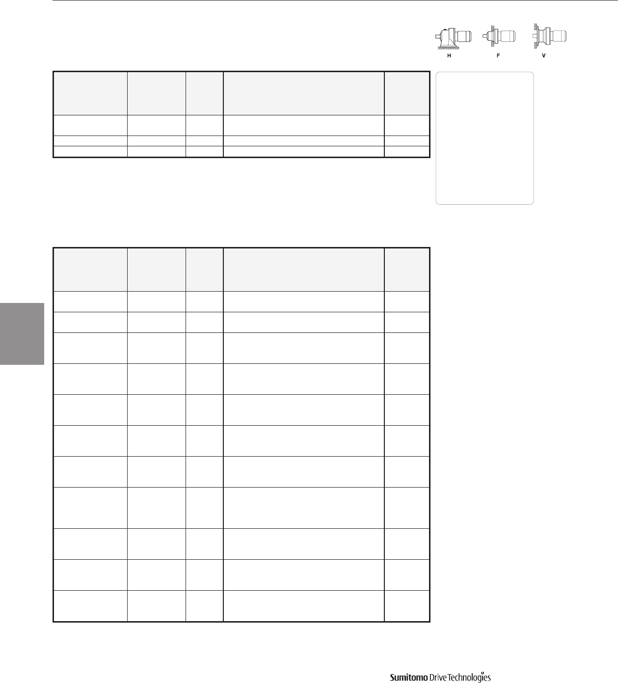
Frame Size Selection Tables 60 Hz
1.5 HP
60 Hz, 1750 RPM
CYCLO® 6000 Gearmotors
3.26 Frame Size Selection Tables
Output Output Service Factor Overhung SELECTION Option
Speed Torque Load
AGMA HP Frame Shaft AGMA Inverter
RPM In•lbs SF Class lbs Symbol Size Spec. Class Ratio Duty
1.18 56500 -- 13200 1H 6190DA Y 1479 AV
70700 1.00 I 13100 1H 6195DA YA1479 AV
0.946 70400 -- 13200 1H 6195DA Y 1849 AV
0.847 70400 -- 13000 1H 6195DA Y 2065 AV
Dimensions Pages
Foot
Mount (H) 4.2–4.29
V-Flange (V) 4.30–4.43
F-Flange (F) 4.44–4.69
Selection
Tables
Gearmotors
Cyclo® 6000 Series
Output Output Service Factor Overhung SELECTION Option
Speed Torque Load
AGMA HP Frame Shaft AGMA Inverter
RPM In•lbs SF Class lbs Symbol Size Spec. Class Ratio Duty
583 207 1.57 II 687 2 6100* YB 3 AV
2.12 III 680 2 6105* YC 3 AV
350 344 1.57 II 813 2 6100* YB 5 AV
2.12 III 806 2 6105* YC 5 AV
1.01 I 591 2 6095* YA 6 -
292 413 1.57 II 871 2 6100* YB 6 AV
2.12 III 871 2 6105* YC 6 AV
1.01 I 656 2 6095* YA 8 -
219 550 1.57 II 972 2 6100* YB 8 AV
2.12 III 972 2 6105* YC 8 AV
1.01 I 741 2 6095* YA11 -
159 757 1.57 II 1100 2 6100* YB11 AV
2.12 III 1100 2 6105* YC11 AV
1.01 I 741 2 6095* YA13 -
135 894 1.57 II 1150 2 6100* YB13 AV
2.12 III 1150 2 6105* YC13 AV
1.01 I 736 2 6095* YA15 -
117 1040 1.57 II 1210 2 6100* YB15 AV
2.12 III 1210 2 6105* YC15 AV
1.01 I 739 2 6095* YA17 -
103 1170 1.33 II 1210 2 6100* YB17 AV
1.64 III 1210 2 6105* YC17 AV
2.12 III 1400 2 6110* YC17 AV
1.01 I 732 2 6095* YA21 -
83.3 1440 1.56 II 1210 2 6105* YB21 AV
1.81 III 1490 2 6110* YC21 AV
1.11 I 1210 2 6105* YA25 AV
70.0 1720 1.48 II 1510 2 6115* YB25 AV
2.06 III 1830 2 6120* YC25 AV
1.06 I 1210 2 6105* YA29 AV
60.3 2000 1.48 II 1550 2 6115* YB29 AV
1.99 III 1900 2 6120* YC29 AV
2 HP
60 Hz, 1750 RPM
Note: *FIDE approved model.
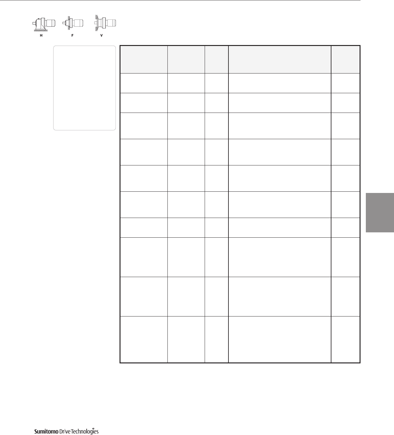
60 Hz Frame Size Selection Tables
2 HP
60 Hz, 1750 RPM
Output Output Service Factor Overhung SELECTION Option
Speed Torque Load
AGMA HP Frame Shaft AGMA Inverter
RPM In•lbs SF Class lbs Symbol Size Spec. Class Ratio Duty
1.21 I 1650 2 6115* YA35 AV
50.0 2410 1.66 III 2010 2 6120* YC35 AV
2.12 III 2010 2 6125* YC35 AV
1.01 I 1710 2 6115* YA43 AV
40.7 2960 1.59 II 2140 2 6125* YB43 AV
1.99 III 2510 2 6130* YC43 AV
1.15 I 2200 2 6120* YA51 AV
34.3 3510 1.52 II 2200 2 6125* YB51 AV
1.95 III 2630 2 6135* YC51 AV
2.29 III 3590 2 6140* YC51 AV
1.08 I 2200 2 6125* YA59 AV
29.7 4060 1.46 II 2740 2 6130* YB59 AV
1.68 III 2740 2 6135* YC59 AV
1.97 III 3590 2 6140* YC59 AV
1.22 I 2900 2 6130* YA71 AV
24.6 4880 1.45 II 2900 2 6135* YB71 AV
1.62 III 3590 2 6140* YC71 AV
2.02 III 3590 2 6145* YC71 AV
1.27 I 3120 2 6135* YA87 AV
20.1 5990 1.32 II 3590 2 6140* YB87 AV
1.65 III 3590 2 6145* YC87 AV
2.31 III 4960 2 6160* YC87 AV
5570 -- 2200 2 6125DB Y 104 -
16.8 6780 1.23 I 3300 2 6135DC YA104 AV
6780 2.30 III 4960 2 6160DC YC104 AV
6900 -- 3300 2 6130DC Y 121 AV
7880 1.05 I 3300 2 6135DC YA121 AV
14.5 7880 1.07 I 3590 2 6140DB YA121 -
7880 1.45 II 3590 2 6145DB YB121 -
7880 1.97 III 4960 2 6160DC YC121 AV
7880 2.36 III 4960 2 6165DC YC121 AV
6900 -- 3300 2 6130DC Y 143 AV
8320 -- 3300 2 6135DC Y 143 AV
12.2 9290 1.07 I 3590 2 6140DB YA143 -
9290 1.67 III 4960 2 6160DC YC143 AV
9290 1.99 III 4960 2 6165DC YC143 AV
9290 2.41 III 6620 2 6170DC YC143 AV
8320 -- 3300 2 6135DC Y 165 AV
10800 1.01 I 3590 2 6140DB YA165 -
10800 1.07 I 3590 2 6145DB YA165 -
10.6 10800 1.44 II 4960 2 6160DC YB165 AV
10800 1.73 III 4960 2 6165DC YC165 AV
10800 2.08 III 6620 2 6170DC YC165 AV
10800 2.58 III 6620 2 6175DC YC165 AV
CYCLO® 6000 Gearmotors
Frame Size Selection Tables 3.27
Dimensions Pages
Foot
Mount (H) 4.2–4.29
V-Flange (V) 4.30–4.43
F-Flange (F) 4.44–4.69
Selection
Tables
Gearmotors
Cyclo® 6000 Series
Note: *FIDE approved model.
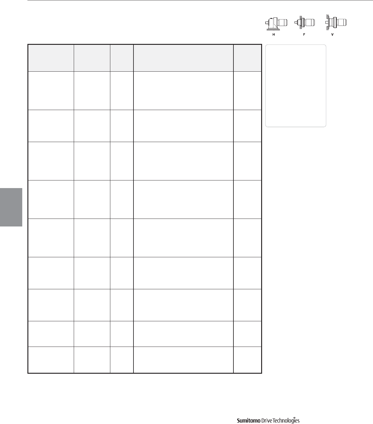
Frame Size Selection Tables 60 Hz
2 HP
60 Hz, 1750 RPM
CYCLO® 6000 Gearmotors
3.28 Frame Size Selection Tables
Output Output Service Factor Overhung SELECTION Option
Speed Torque Load
AGMA HP Frame Shaft AGMA Inverter
RPM In•lbs SF Class lbs Symbol Size Spec. Class Ratio Duty
10900 - - 3590 2 6140DB Y 195 -
12000 - - 3590 2 6145DB Y 195 -
8.97 12700 1.22 I 4960 2 6160DC Y A 195 AV
12700 1.46 II 4960 2 6165DC Y B 195 AV
12700 1.76 III 6620 2 6170DC Y C 195 AV
12700 2.19 III 6620 2 6175DC Y C 195 AV
11900 - - 3590 2 6145DB Y 231 -
15000 1.24 I 4960 2 6165DC Y A 231 AV
7.58 15000 1.49 II 6620 2 6170DC Y B 231 AV
15000 1.85 III 6620 2 6175DC Y C 231 AV
15000 2.38 III 9360 2 6180DB Y C 231 -
15600 - - 4960 2 6160DC Y 273 AV
17800 1.04 I 4960 2 6165DC Y A 273 AV
6.41 17800 1.26 I 6620 2 6170DC Y A 273 AV
17800 1.57 II 6620 2 6175DC Y B 273 AV
17800 2.01 III 9360 2 6180DB Y C 273 AV
17800 2.49 III 9360 2 6185DB Y C 273 AV
15600 - - 4960 2 6160DC Y 319 AV
18600 - - 4960 2 6165DC Y 319 AV
5.49 20800 1.08 I 6620 2 6170DC Y A 319 AV
20800 1.34 II 6620 2 6175DC Y B 319 AV
20800 1.72 III 9360 2 6180DB Y C 319 -
20800 2.13 III 9360 2 6185DB Y C 319 -
18600 - - 4960 2 6165DC Y 377 AV
22400 - - 6620 2 6170DC Y 377 AV
4.64 24600 1.13 I 6620 2 6175DC Y A 377 AV
24600 1.46 II 9360 2 6180DB Y B 377 AV
24600 1.80 III 9360 2 6185DB Y C 377 AV
24600 2.30 III 13200 2 6190DA Y C 377 AV
27900 - - 6620 2 6175DC Y 473 AV
30800 1.17 I 9360 2 6180DB Y A 473 -
3.70 30800 1.43 II 9360 2 6185DB Y B 473 -
30800 1.83 III 13200 2 6190DA Y C 473 AV
30800 2.28 III 13200 2 6195DA Y C 473 AV
27900 - - 6620 2 6175DC Y 559 AV
35900 - - 9360 2 6180DB Y 559 AV
3.13 36500 1.21 I 9360 2 6185DB Y A 559 AV
36500 1.55 II 13200 2 6190DA Y B 559 AV
36500 1.93 III 13200 2 6195DA Y C 559 AV
35800 - - 9360 2 6180DB Y 649 -
2.70 42300 1.05 I 9360 2 6185DB Y A 649 -
42300 1.33 II 13200 2 6190DA Y B 649 AV
42300 1.66 III 13200 2 6195DA Y C 649 AV
35900 - - 9360 2 6180DB Y 731 AV
2.39 44200 - - 9360 2 6185DB Y 731 AV
47700 1.18 I 13200 2 6190DA Y A 731 AV
47700 1.48 II 13200 2 6195DA Y B 731 AV
Dimensions Pages
Foot
Mount (H) 4.2–4.29
V-Flange (V) 4.30–4.43
F-Flange (F) 4.44–4.69
Selection
Tables
Gearmotors
Cyclo® 6000 Series
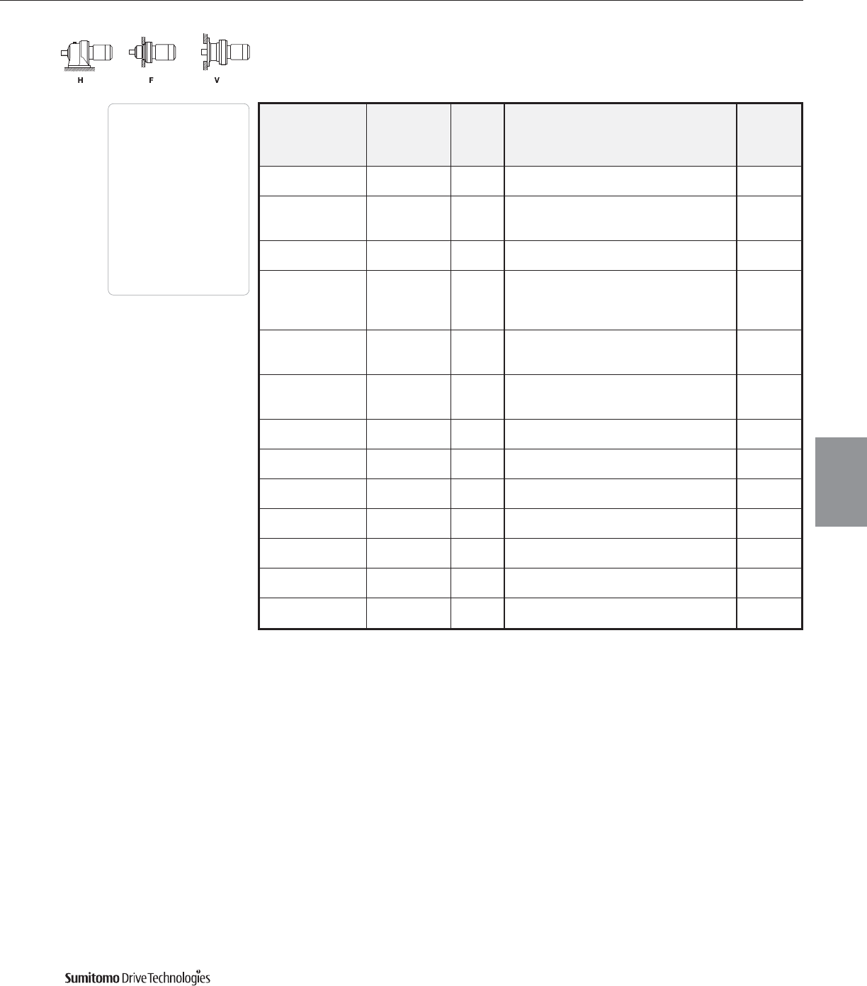
60 Hz Frame Size Selection Tables
2 HP
60 Hz, 1750 RPM
CYCLO® 6000 Gearmotors
Frame Size Selection Tables 3.29
Output Output Service Factor Overhung SELECTION Option
Speed Torque Load
AGMA HP Frame Shaft AGMA Inverter
RPM In•lbs SF Class lbs Symbol Size Spec. Class Ratio Duty
2.08 44200 - - 9360 2 6185DB Y 841 AV
54900 1.28 I 13200 2 6195DA Y A 841 AV
56500 - - 13200 2 6190DA Y 1003 AV
1.74 65400 1.08 I 13100 2 6195DA Y A 1003 AV
65400 1.26 I 18900 2 6205DB Y A 1003 AV
1.40 70400 - - 13200 2 6195DA Y 1247 AV
81300 1.01 I 18900 2 6205DB Y A 1247 AV
74000 - - 18900 2 6205DA Y 1479 AV
1.18 77500 - - 18900 2 6205DB Y 1479 AV
96400 1.03 I 23400 2 6215DA Y A 1479 AV
96400 1.39 II 32600 2 6225DA Y B 1479 AV
82300 - - 18900 2 6205DA Y 1849 AV
0.946 112000 - - 23400 2 6215DA Y 1849 AV
120000 1.17 I 32600 2 6225DA Y A 1849 AV
82300 - - 18900 2 6205DA Y 2065 AV
0.847 112000 - - 23400 2 6215DA Y 2065 AV
134000 1.04 I 32600 2 6225DA Y A 2065 AV
0.690 112000 - - 23400 2 6215DA Y 2537 AV
141000 - - 32600 2 6225DA Y 2537 AV
0.575 100000 - - 23400 2 6215DA Y 3045 AV
134000 - - 32600 2 6225DA Y 3045 AV
0.503 112000 - - 23400 2 6215DA Y 3481 AV
141000 - - 32600 2 6225DA Y 3481 AV
0.394 100000 - - 23400 2 6215DA Y 4437 AV
134000 - - 32600 2 6225DA Y 4437 AV
0.341 112000 - - 23400 2 6215DA Y 5133 AV
141000 - - 32600 2 6225DA Y 5133 AV
0.283 100000 - - 23400 2 6215DA Y 6177 AV
134000 - - 32600 2 6225DA Y 6177 AV
0.231 100000 - - 23400 2 6215DA Y 7569 AV
134000 - - 32600 2 6225DA Y 7569 AV
Dimensions Pages
Foot
Mount (H) 4.2–4.29
V-Flange (V) 4.30–4.43
F-Flange (F) 4.44–4.69
Selection
Tables
Gearmotors
Cyclo® 6000 Series
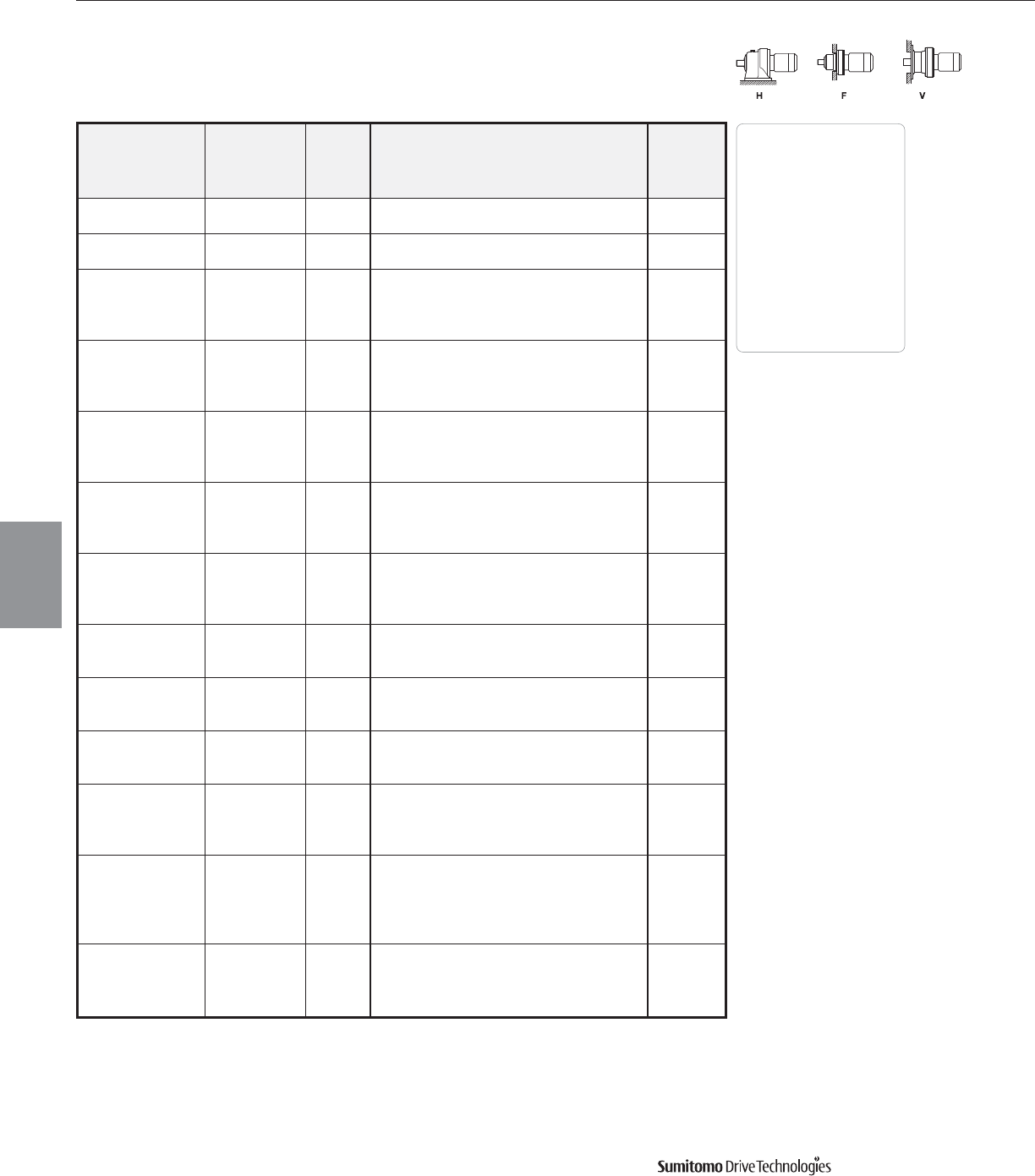
Frame Size Selection Tables 60 Hz
3 HP
60 Hz, 1750 RPM
CYCLO® 6000 Gearmotors
3.30 Frame Size Selection Tables
Output Output Service Factor Overhung SELECTION Option
Speed Torque Load
AGMA HP Frame Shaft AGMA Inverter
RPM In•lbs SF Class lbs Symbol Size Spec. Class Ratio Duty
583 303 1.07 I 687 3 6100 YA 3 -
1.45 II 680 3 6105 YB 3 -
350 505 1.07 I 813 3 6100 YA 5 -
1.45 II 806 3 6105 YB 5 -
1.07 I 867 3 6100 YA 6 -
292 605 1.45 II 867 3 6105 YB 6 -
1.61 III 981 3 6110 YC 6 AV
1.78 III 981 3 6115 YC 6 AV
1.07 I 965 3 6100 YA 8 -
219 807 1.45 II 965 3 6105 YB 8 -
1.61 III 1090 3 6110 YC 8 AV
1.78 III 1090 3 6115 YC 8 AV
1.07 I 1090 3 6100 Y A 11 -
159 1110 1.45 II 1090 3 6105 Y B 11 -
1.61 III 1250 3 6110 YC11 AV
1.78 III 1250 3 6115 YC11 AV
1.07 I 1140 3 6100 Y A 13 -
135 1310 1.45 II 1140 3 6105 Y B 13 -
1.61 III 1290 3 6110 YC13 AV
1.77 III 1290 3 6115 YC13 AV
1.07 I 1200 3 6100 Y A 15 -
117 1510 1.45 II 1200 3 6105 Y B 15 -
1.61 III 1370 3 6110 YC15 AV
1.77 III 1370 3 6115 YC15 AV
1.12 I 1210 3 6105 Y A 17 -
103 1720 1.45 II 1390 3 6110 YB17 AV
1.77 III 1390 3 6115 YC17 AV
1.06 I 1210 3 6105 Y A 21 -
83.3 2120 1.41 II 1470 3 6115 YB21 AV
1.80 III 1730 3 6120 YC21 AV
1.01 I 1490 3 6115 YA25 AV
70.0 2520 1.40 II 1810 3 6120 YB25 AV
1.80 III 1810 3 6125 YC25 AV
1.01 I 1530 3 6115 YA29 AV
60.3 2930 1.36 II 1880 3 6120 YB29 AV
1.71 III 1880 3 6125 YC29 AV
2.04 III 2210 3 6130 YC29 AV
0.82 - 1620 3 6115 Y35AV
1.13 I 1980 3 6120 YA35 AV
50.0 3530 1.45 II 1980 3 6125 YB35 AV
1.69 III 2310 3 6130 YC35 AV
1.93 III 2310 3 6135 YC35 AV
1.08 I 2110 3 6125 YA43 AV
40.7 4340 1.36 II 2490 3 6130 YB43 AV
1.71 III 2490 3 6135 YC43 AV
1.79 III 3570 3 6140 YC43 AV
Dimensions Pages
Foot
Mount (H) 4.2–4.29
V-Flange (V) 4.30–4.43
F-Flange (F) 4.44–4.69
Selection
Tables
Gearmotors
Cyclo® 6000 Series

60 Hz Frame Size Selection Tables
3 HP
60 Hz, 1750 RPM
CYCLO® 6000 Gearmotors
Frame Size Selection Tables 3.31
Output Output Service Factor Overhung SELECTION Option
Speed Torque Load
AGMA HP Frame Shaft AGMA Inverter
RPM In•lbs SF Class lbs Symbol Size Spec. Class Ratio Duty
1.04 I 2190 3 6125 YA51 AV
1.33 II 2580 3 6135 YB51 AV
34.3 5150 1.56 II 3590 3 6140 YB51 AV
1.92 III 3590 3 6145 YC51 AV
2.61 III 4510 3 6160 YC51 AV
1.15 I 2720 3 6135 YA59 AV
29.7 5950 1.34 II 3590 3 6140 YB59 AV
1.66 III 3590 3 6145 YC59 AV
2.01 III 4960 3 6160 YC59 AV
0.98 - 2870 3 6135 Y71AV
1.10 I 3590 3 6140 YA71 AV
24.6 7170 1.38 II 3590 3 6145 YB71 AV
1.58 II 4960 3 6160 YB71 AV
2.57 III 4960 3 6165 YC71 AV
1.13 I 3590 3 6145 YA87 AV
20.1 8780 1.58 II 4960 3 6160 YB87 AV
1.77 III 4960 3 6165 YC87 AV
6900 - - 3300 3 6130DC Y 104 -
8320 - - 3300 3 6135DC Y 104 -
16.8 9910 1.57 II 4960 3 6160DC Y B 104 AV
9910 1.87 III 4960 3 6165DC Y C 104 AV
9910 2.25 III 6600 3 6170DC Y C 104 AV
8320 - - 3300 3 6135DC Y 121 -
11600 1.34 II 4960 3 6160DC Y B 121 AV
14.5 11600 1.60 III 4960 3 6165DC Y C 121 AV
11600 1.94 III 6620 3 6170DC Y C 121 AV
11600 2.41 III 6620 3 6175DC Y C 121 AV
1.14 I 4960 3 6160DC Y A 143 AV
1.36 II 4960 3 6165DC Y B 143 AV
12.2 13700 1.63 III 6620 3 6170DC Y C 143 AV
2.04 III 6620 3 6175DC Y C 143 AV
2.63 III 9360 3 6180DB Y C 143 AV
15600 - - 4960 3 6160DC Y 165 AV
15700 1.18 I 4960 3 6165DC Y A 165 AV
10.6 15700 1.42 II 6620 3 6170DC Y B 165 AV
15700 1.77 III 6620 3 6175DC Y C 165 AV
15700 2.28 III 9360 3 6180DB Y C 165 AV
15600 - - 4960 3 6160DC Y 195 AV
18700 1.00 I 4960 3 6165DC Y A 195 AV
8.97 18700 1.50 II 6620 3 6175DC Y B 195 AV
18700 1.93 III 9360 3 6180DB Y C 195 AV
18700 2.34 III 9360 3 6185DB Y C 195 AV
15600 - - 4960 3 6160DC Y 231 AV
18600 - - 4960 3 6165DC Y 231 AV
7.58 22100 1.26 I 6620 3 6175DC Y A 231 AV
22100 1.62 III 9360 3 6180DB Y C 231 AV
22100 2.00 III 9360 3 6185DB Y C 231 AV
22100 2.56 III 13200 3 6190DA Y C 231 AV
Dimensions Pages
Foot
Mount (H) 4.2–4.29
V-Flange (V) 4.30–4.43
F-Flange (F) 4.44–4.69
Selection
Tables
Gearmotors
Cyclo® 6000 Series

Frame Size Selection Tables 60 Hz
3 HP
60 Hz, 1750 RPM
CYCLO® 6000 Gearmotors
3.32 Frame Size Selection Tables
Output Output Service Factor Overhung SELECTION Option
Speed Torque Load
AGMA HP Frame Shaft AGMA Inverter
RPM In•lbs SF Class lbs Symbol Size Spec. Class Ratio Duty
18600 - - 4960 3 6165DC Y 273 AV
22400 - - 6620 3 6170DC Y 273 AV
6.41 26100 1.07 I 6620 3 6175DC Y A 273 AV
26100 1.37 II 9360 3 6180DB Y B 273 AV
26100 1.69 III 9360 3 6185DB Y C 273 AV
26100 2.16 III 13200 3 6190DA Y C 273 AV
22400 - - 6620 3 6170DC Y 319 AV
27900 - - 6620 3 6175DC Y 319 AV
5.49 30500 1.17 I 9360 3 6180DB Y A 319 AV
30500 1.45 II 9360 3 6185DB Y B 319 AV
30500 1.85 III 13200 3 6190DA Y C 319 AV
30500 2.31 III 13200 3 6195DA Y C 319 AV
27900 - - 6620 3 6175DC Y 377 AV
35800 - - 9360 3 6180DB Y 377 AV
4.64 36000 1.23 I 9360 3 6185DB Y A 377 AV
36000 1.57 II 13200 3 6190DA Y B 377 AV
36000 1.95 III 13200 3 6195DA Y C 377 AV
36000 2.27 III 18900 3 6205DB Y C 377 AV
35900 - - 9360 3 6180DB Y 473 AV
45200 0.98 - 9360 3 6185DB Y 473 AV
3.70 45200 1.25 I 13200 3 6190DA Y A 473 AV
45200 1.56 II 13200 3 6195DA Y B 473 AV
45200 1.82 III 18900 3 6205DB Y C 473 AV
45200 2.48 III 23400 3 6215DA Y C 473 AV
44200 - - 9360 3 6185DB Y 559 AV
53400 1.06 I 13200 3 6190DA Y A 559 AV
3.13 53400 1.32 II 13200 3 6195DA Y B 559 AV
53400 2.09 III 23400 3 6215DA Y C 559 AV
53400 2.65 III 32600 3 6225DA Y C 559 AV
44200 - - 9340 3 6185DB Y 649 AV
56500 - - 13200 3 6190DA Y 649 AV
2.70 62000 1.14 I 13100 3 6195DA Y A 649 AV
62000 1.33 II 18900 3 6205DB Y B 649 AV
62000 1.80 III 23400 3 6215DA Y C 649 AV
62000 2.26 III 32600 3 6225DA Y C 649 AV
56500 - - 13200 3 6190DA Y 731 AV
69900 1.01 I 13200 3 6195DA Y A 731 AV
2.39 69900 1.18 I 18900 3 6205DB Y A 731 AV
69900 1.60 III 23400 3 6215DA Y C 731 AV
69900 2.03 III 32600 3 6225DA Y C 731 AV
69900 2.60 III 40200 3 6235DA Y C 731 AV
56500 - - 13200 3 6190DA Y 841 AV
70400 - - 13200 3 6195DA Y 841 AV
80400 1.02 I 18900 3 6205DA Y A 841 AV
2.08 80400 1.39 II 23400 3 6215DA Y B 841 AV
80400 1.65 III 32600 3 6225DA Y C 841 AV
80400 2.08 III 40200 3 6235DA Y C 841 AV
80400 2.84 III 46700 3 6245DA Y C 841 AV
Dimensions Pages
Foot
Mount (H) 4.2–4.29
V-Flange (V) 4.30–4.43
F-Flange (F) 4.44–4.69
Selection
Tables
Gearmotors
Cyclo® 6000 Series
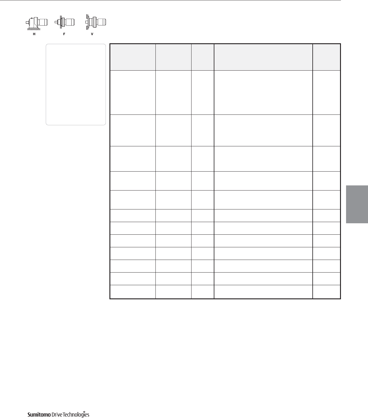
60 Hz Frame Size Selection Tables
3 HP
60 Hz, 1750 RPM
CYCLO® 6000 Gearmotors
Frame Size Selection Tables 3.33
Output Output Service Factor Overhung SELECTION Option
Speed Torque Load
AGMA HP Frame Shaft AGMA Inverter
RPM In•lbs SF Class lbs Symbol Size Spec. Class Ratio Duty
70400 - - 13000 3 6195DA Y 1003 AV
80200 - - 18900 3 6205DA Y 1003 AV
82300 - - 18900 3 6205DB Y 1003 AV
1.74 95600 1.17 I 23400 3 6215DA Y A 1003 AV
95600 1.46 II 32600 3 6225DA Y B 1003 AV
95600 1.89 III 40200 3 6235DA Y C 1003 -
95600 2.38 III 46700 3 6245DA Y C 1003 -
82300 - - 18900 3 6205DA Y 1247 AV
112000 - - 23400 3 6215DA Y 1247 AV
1.40 119000 1.19 I 32600 3 6225DA Y A 1247 AV
119000 1.52 II 40200 3 6235DA Y B 1247 AV
119000 1.91 III 46700 3 6245DA Y C 1247 AV
100000 - - 23400 3 6215DA Y 1479 AV
1.18 134000 - - 32600 3 6225DA Y 1479 AV
142000 1.07 I 40200 3 6235DA Y A 1479 -
142000 1.42 II 46700 3 6245DA Y B 1479 -
142000 - - 32600 3 6225DA Y 1849 AV
0.946 177000 1.03 I 40200 3 6235DA Y A 1849 AV
177000 1.29 I 46700 3 6245DA Y A 1849 AV
141000 - - 32600 3 6225DA Y 2065 AV
0.847 181000 - - 40200 3 6235DA Y 2065 AV
197000 1.16 I 46700 3 6245DA Y A 2065 AV
0.690 181000 - - 40200 3 6235DA Y 2537 AV
228000 - - 46700 3 6245DA Y 2537 AV
0.575 152000 - - 40200 3 6235DA Y 3045 AV
200000 - - 46700 3 6245DA Y 3045 AV
0.503 181000 - - 40200 3 6235DA Y 3481 AV
228000 - - 46700 3 6245DA Y 3481 AV
0.394 152000 - - 40200 3 6235DA Y 4437 AV
200000 - - 46700 3 6245DA Y 4437 AV
0.341 181000 - - 40200 3 6235DA Y 5133 AV
228000 - - 46700 3 6245DA Y 5133 AV
0.283 152000 - - 40200 3 6235DA Y 6177 AV
200000 - - 46700 3 6245DA Y 6177 AV
0.231 152000 - - 40200 3 6235DA Y 7569 AV
200000 - - 46700 3 6245DA Y 7569 AV
Dimensions Pages
Foot
Mount (H) 4.2–4.29
V-Flange (V) 4.30–4.43
F-Flange (F) 4.44–4.69
Selection
Tables
Gearmotors
Cyclo® 6000 Series
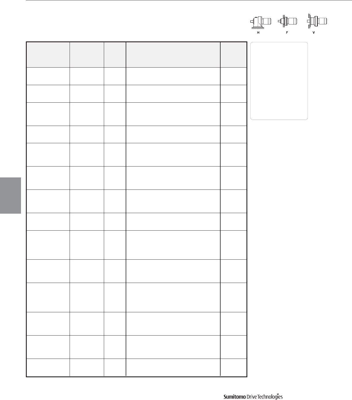
Frame Size Selection Tables 60 Hz
5 HP
60 Hz, 1750 RPM
CYCLO® 6000 Gearmotors
3.34 Frame Size Selection Tables
Output Output Service Factor Overhung SELECTION Option
Speed Torque Load
AGMA HP Frame Shaft AGMA Inverter
RPM In•lbs SF Class lbs Symbol Size Spec. Class Ratio Duty
1.37 II 867 5 6120 YB 3 AV
583 510 1.57 II 862 5 6125 YB 3 AV
2.52 III 997 5 6130 YC 3 AV
1.37 II 1027 5 6120 YB 5 AV
350 850 1.57 II 1020 5 6125 YB 5 AV
2.52 III 1181 5 6130 YC 5 AV
1.06 I 970 5 6115 YA 6 -
292 1020 1.37 II 1100 5 6120 YB 6 AV
1.57 II 1100 5 6125 YB 6 AV
2.54 III 1260 5 6130 YC 6 AV
1.06 I 1080 5 6115 YA 8 -
219 1350 1.37 II 1230 5 6120 YB 8 AV
1.88 III 1230 5 6125 YC 8 AV
1.06 I 1230 5 6115 Y A 11 -
159 1870 1.37 II 1390 5 6120 YB11 AV
1.60 III 1390 5 6125 YC11 AV
2.54 III 1640 5 6130 YC11 AV
1.05 I 1270 5 6115 Y A 13 -
135 2200 1.37 II 1440 5 6120 YB13 AV
1.60 III 1440 5 6125 YC13 AV
2.54 III 1710 5 6130 YC13 AV
1.05 I 1340 5 6115 Y A 15 -
117 2550 1.37 II 1540 5 6120 YB15 AV
1.60 III 1540 5 6125 YC15 AV
2.10 III 1740 5 6130 YC15 AV
1.05 I 1360 5 6115 Y A 17 -
103 2880 1.53 II 1550 5 6125 YB17 AV
1.96 III 1870 5 6130 YC17 AV
0.84 - 1430 5 6115 Y21-
1.07 I 1690 5 6120 YA21 AV
83.3 3570 1.32 II 1700 5 6125 YB21 AV
1.66 III 2000 5 6130 YC21 AV
2.04 III 2000 5 6135 YC21 AV
1.07 I 1770 5 6125 YA25 AV
70.0 4250 1.39 II 2040 5 6130 YB25 AV
1.61 III 2070 5 6135 YC25 AV
1.86 III 3100 5 6140 YC25 AV
1.02 I 1840 5 6125 YA29 AV
1.21 I 2180 5 6130 YA29 AV
60.3 4920 1.53 II 2180 5 6135 YB29 AV
1.61 III 3190 5 6140 YC29 AV
2.04 III 3190 5 6145 YC29 AV
1.15 I 2290 5 6135 YA35 AV
50.0 5940 1.41 II 3390 5 6140 YB35 AV
2.04 III 3390 5 6145 YC35 AV
2.61 III 4020 5 6160 YC35 AV
1.02 I 2450 5 6135 YA43 AV
40.7 7300 1.46 II 3550 5 6145 YB43 AV
2.01 III 4310 5 6160 YC43 AV
2.14 III 4310 5 6165 YC43 AV
1.14 I 3590 5 6145 YA51 AV
34.3 8650 1.55 II 4470 5 6160 YB51 AV
2.04 III 4470 5 6165 YC51 AV
Dimensions Pages
Foot
Mount (H) 4.2–4.29
V-Flange (V) 4.30–4.43
F-Flange (F) 4.44–4.69
Selection
Tables
Gearmotors
Cyclo® 6000 Series

60 Hz Frame Size Selection Tables
5 HP
60 Hz, 1750 RPM
CYCLO® 6000 Gearmotors
Frame Size Selection Tables 3.35
Output Output Service Factor Overhung SELECTION Option
Speed Torque Load
AGMA HP Frame Shaft AGMA Inverter
RPM In•lbs SF Class lbs Symbol Size Spec. Class Ratio Duty
1.19 I 4960 5 6160 YA59 AV
29.7 10000 1.55 II 4960 5 6165 YB59 AV
1.93 III 5320 5 6170 YC59 AV
0.94 - 4920 5 6160 Y71AV
24.6 12000 1.53 II 4920 5 6165 YB71 AV
1.60 III 5610 5 6170 YC71 AV
1.93 III 5610 5 6175 YC71 AV
1.05 I 4890 5 6165 YA87 AV
20.1 14800 1.52 II 6020 5 6175 YB87 AV
1.93 III 8130 5 6180 Y C 87 -
15600 - - 4960 5 6160DC Y 104 AV
16700 1.11 I 4960 5 6165DC Y A 104 AV
16.8 16700 1.34 II 6510 5 6170DC Y B 104 AV
16700 1.67 III 6510 5 6175DC Y C 104 AV
16700 2.15 III 8640 5 6180DB Y C 104 AV
18600 - - 4960 5 6165DC Y 121 AV
19500 1.15 I 6620 5 6170DC Y A 121 AV
14.5 19500 1.43 II 6620 5 6175DC Y B 121 AV
19500 1.85 III 9210 5 6180DB Y C 121 AV
19500 2.19 III 9210 5 6185DB Y C 121 AV
22400 - - 6620 5 6170DC Y 143 AV
23000 1.21 I 6620 5 6175DC Y A 143 AV
12.2 23000 1.56 II 9360 5 6180DB Y B 143 AV
23000 1.89 III 9360 5 6185DB Y C 143 AV
23000 2.46 III 13200 5 6190DB Y C 143 AV
22400 - - 6620 5 6170DC Y 165 AV
26500 1.05 I 6620 5 6175DC Y A 165 AV
10.6 26500 1.35 II 9360 5 6180DB Y B 165 AV
26500 1.64 III 9360 5 6185DB Y C 165 AV
26500 1.69 III 13200 5 6190DA Y C 165 AV
26500 2.13 III 13200 5 6190DB Y C 165 AV
27900 - - 6620 5 6175DC Y 195 AV
31300 1.15 I 9360 5 6180DB Y A 195 AV
8.97 31300 1.39 II 9360 5 6185DB Y B 195 AV
31300 1.69 III 13200 5 6190DA Y C 195 AV
31300 2.23 III 13200 5 6195DB Y C 195 AV
35800 - - 9360 5 6180DB Y 231 AV
37200 1.19 I 9360 5 6185DB Y A 231 AV
7.58 37200 1.52 II 13200 5 6190DA Y B 231 AV
37200 1.69 III 13200 5 6195DA Y C 231 AV
37200 2.21 III 18900 5 6205DB Y C 231 AV
35800 - - 9360 5 6180DB Y 273 AV
43900 1.01 I 9360 5 6185DB Y A 273 AV
6.41 43900 1.29 I 13200 5 6190DA Y A 273 AV
43900 1.60 III 13200 5 6195DA Y C 273 AV
43900 2.52 III 23400 5 6215DA Y C 273 AV
44200 - - 9360 5 6185DB Y 319 AV
51300 1.10 I 13200 5 6190DA Y A 319 AV
5.49 51300 1.37 II 13200 5 6195DA Y B 319 AV
51300 1.59 II 18900 5 6205DB Y B 319 AV
51300 2.18 III 23400 5 6215DA Y C 319 AV
Dimensions Pages
Foot
Mount (H) 4.2–4.29
V-Flange (V) 4.30–4.43
F-Flange (F) 4.44–4.69
Selection
Tables
Gearmotors
Cyclo® 6000 Series
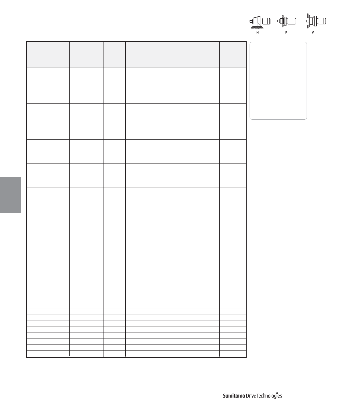
Frame Size Selection Tables 60 Hz
5 HP
60 Hz, 1750 RPM
CYCLO® 6000 Gearmotors
3.36 Frame Size Selection Tables
Output Output Service Factor Overhung SELECTION Option
Speed Torque Load
AGMA HP Frame Shaft AGMA Inverter
RPM In•lbs SF Class lbs Symbol Size Spec. Class Ratio Duty
56500 - - 13200 5 6190DA Y 377 AV
60600 1.16 I 13200 5 6195DA Y A 377 AV
4.64 60600 1.17 I 18900 5 6205DA Y A 377 AV
60600 1.35 II 18900 5 6205DB Y B 377 AV
60600 1.85 III 23400 5 6215DA Y C 377 AV
60600 2.20 III 32600 5 6225DA Y C 377 AV
70400 - - 13200 5 6195DB Y 473 AV
76100 0.90 - 18900 5 6205DA Y 473 AV
3.70 76100 1.08 I 18900 5 6205DB Y A 473 AV
76100 1.47 II 23400 5 6215DA Y B 473 AV
76100 1.86 III 32600 5 6225DA Y C 473 AV
76100 2.38 III 40200 5 6235DA Y C 473 -
1.25 I 23400 5 6215DA Y A 559 AV
3.13 90200 1.58 II 32600 5 6225DA Y B 559 AV
2.02 III 40200 5 6235DA Y C 559 -
2.54 III 46700 5 6245DA Y C 559 -
1.07 I 23400 5 6215DA Y A 649 AV
2.70 104000 1.35 II 32600 5 6225DA Y B 649 AV
1.74 III 40200 5 6235DA Y C 649 -
2.19 III 46700 5 6245DA Y C 649 -
112000 - - 23400 5 6215DA Y 731 AV
118000 1.20 I 32600 5 6225DA Y A 731 AV
2.39 118000 1.54 II 40200 5 6235DA Y B 731 AV
118000 1.94 III 46700 5 6245DA Y C 731 AV
118000 2.60 III 57900 5 6255DA Y C 731 -
112000 - - 23400 5 6215DA Y 841 AV
135000 0.98 - 32600 5 6225DA Y 841 AV
2.08 135000 1.24 I 40200 5 6235DA Y A 841 AV
135000 1.69 III 46700 5 6245DA Y C 841 AV
135000 2.13 III 57900 5 6255DA Y C 841 -
141000 - - 32600 5 6225DA Y 1003 AV
1.74 161000 1.12 I 40200 5 6235DA Y A 1003 AV
161000 1.42 II 46700 5 6245DA Y B 1003 AV
161000 1.89 III 57900 5 6255DA Y C 1003 -
181000 - - 40200 5 6235DA Y 1247 AV
1.40 201000 1.14 I 46700 5 6245DA Y A 1247 AV
201000 1.52 II 57900 5 6255DA Y B 1247 -
1.18 200000 - - 46700 5 6245DA Y 1479 AV
238000 1.15 I 57900 5 6255DA Y A 1479 -
0.946 297000 1.03 I 57900 5 6255DA Y A 1849 AV
0.847 305000 - - 57900 5 6255DA Y 2065 -
0.690 305000 - - 57900 5 6255DA Y 2537 AV
0.575 274000 - - 57900 5 6255DA Y 3045 -
0.503 305000 - - 57900 5 6255DA Y 3481 AV
0.394 274000 - - 57900 5 6255DA Y 4437 AV
0.341 305000 - - 57900 5 6255DA Y 5133 AV
0.283 274000 - - 57900 5 6255DA Y 6177 AV
0.231 274000 - - 57900 5 6255DA Y 7569 AV
Dimensions Pages
Foot
Mount (H) 4.2–4.29
V-Flange (V) 4.30–4.43
F-Flange (F) 4.44–4.69
Selection
Tables
Gearmotors
Cyclo® 6000 Series
60 Hz Frame Size Selection Tables
7.5 HP
60 Hz, 1750 RPM
CYCLO® 6000 Gearmotors
Frame Size Selection Tables 3.37
Output Output Service Factor Overhung SELECTION Option
Speed Torque Load
AGMA HP Frame Shaft AGMA Inverter
RPM In•lbs SF Class lbs Symbol Size Spec. Class Ratio Duty
1.06 I 862 8 6125 YA 3 -
583 758 1.71 III 997 8 6130 YC 3 AV
2.05 III 983 8 6135 YC 3 AV
1.06 I 1020 8 6125 YA 5 -
350 1265 1.71 III 1180 8 6130 YC 5 AV
2.05 III 1166 8 6135 YC 5 AV
1.06 I 1090 8 6125 YA 6 -
292 1510 1.71 III 1280 8 6130 YC 6 AV
2.05 III 1280 8 6135 YC 6 AV
1.26 I 1210 8 6125 YA 8 -
219 2020 1.71 III 1430 8 6130 YC 8 AV
2.05 III 1430 8 6135 YC 8 AV
1.08 I 1370 8 6125 Y A 11 -
159 2780 1.71 III 1630 8 6130 YC11 AV
2.05 III 1630 8 6135 YC11 AV
1.08 I 1410 8 6125 Y A 13 -
135 3280 1.71 III 1690 8 6130 YC13 AV
2.05 III 1690 8 6135 YC13 AV
1.08 I 1510 8 6125 Y A 15 -
117 3790 1.41 II 1720 8 6130 YB15 AV
1.63 III 1720 8 6135 YC15 AV
2.18 III 2650 8 6140 YC15 AV
1.03 I 1520 8 6125 Y A 17 -
103 4290 1.51 II 1850 8 6135 YB17 AV
1.84 III 2760 8 6140 YC17 AV
0.89 - 1660 8 6125 Y21-
1.12 I 1970 8 6130 YA21 AV
83.3 5300 1.37 II 1970 8 6135 YB21 AV
1.57 II 2940 8 6140 YB21 AV
2.00 III 2940 8 6145 YC21 AV
2.35 III 3460 8 6160 YC21 AV
1.08 I 2040 8 6135 YA25 AV
70.0 6310 1.44 II 3100 8 6145 YB25 AV
1.79 III 3610 8 6160 YC25 AV
1.03 I 2130 8 6135 YA29 AV
1.08 I 3170 8 6140 YA29 AV
60.3 7320 1.37 II 3170 8 6145 YB29 AV
1.91 III 3770 8 6160 YC29 AV
2.07 III 3770 8 6165 YC29 AV
0.95 - 3370 8 6140 Y35AV
1.37 II 3370 8 6145 YB35 AV
50.0 8830 1.76 III 4000 8 6160 YC35 AV
2.07 III 4000 8 6165 YC35 AV
2.18 III 4540 8 6170 YC35 AV
0.98 - 3500 8 6145 Y43AV
1.35 II 4240 8 6160 YB43 AV
40.7 10900 1.44 II 4240 8 6165 YB43 AV
1.77 III 4830 8 6170 YC43 AV
2.05 III 4830 8 6175 YC43 AV
Dimensions Pages
Foot
Mount (H) 4.2–4.29
V-Flange (V) 4.30–4.43
F-Flange (F) 4.44–4.69
Selection
Tables
Gearmotors
Cyclo® 6000 Series
Frame Size Selection Tables 60 Hz
7.5 HP
60 Hz, 1750 RPM
CYCLO® 6000 Gearmotors
3.38 Frame Size Selection Tables
Output Output Service Factor Overhung SELECTION Option
Speed Torque Load
AGMA HP Frame Shaft AGMA Inverter
RPM In•lbs SF Class lbs Symbol Size Spec. Class Ratio Duty
1.05 I 4400 8 6160 YA51 AV
34.3 12800 1.37 II 4400 8 6165 YB51 AV
1.53 II 5030 8 6170 YB51 AV
2.05 III 5030 8 6175 YC51 AV
1.05 I 4870 8 6165 YA59 AV
29.7 14900 1.51 II 5250 8 6175 YB59 AV
1.77 III 7050 8 6180 YC59 AV
1.03 I 4850 8 6165 YA71 AV
24.6 17900 1.30 II 5550 8 6175 YB71 AV
1.60 III 7500 8 6180 YC71 AV
1.78 III 7500 8 6185 YC71 AV
1.02 I 5930 8 6175 YA87 AV
20.1 21900 1.56 II 8060 8 6185 YB87 AV
2.15 III 11300 8 6190 Y C 87 -
18600 - - 4960 8 6165DC Y 104 -
22400 - - 6420 8 6170DC Y 104 -
16.8 24900 1.12 I 6400 8 6175DC Y A 104 -
24900 1.45 II 8580 8 6180DB Y B 104 AV
24900 1.74 III 8580 8 6185DB Y C 104 AV
24900 2.17 III 12000 8 6190DB Y C 104 AV
22400 - - 6620 8 6170DC Y 121 -
28900 0.96 - 6620 8 6175DC Y 121 -
14.5 28900 1.24 I 9120 8 6180DB Y A 121 AV
28900 1.47 II 9120 8 6185DB Y B 121 AV
28900 1.95 III 12800 8 6190DB Y C 121 AV
28900 2.17 III 12800 8 6195DB Y C 121 AV
27900 - - 6620 8 6175DC Y 143 -
12.2 34200 1.27 I 9360 8 6185DB Y A 143 AV
34200 1.65 III 13200 8 6190DB Y C 143 AV
34200 1.97 III 13200 8 6195DB Y C 143 AV
27900 - - 6620 8 6175DC Y 165 -
35900 - - 9360 8 6180DB Y 165 AV
39500 1.10 I 9360 8 6185DB Y A 165 AV
10.6 39500 1.14 I 13200 8 6190DA Y A 165 -
39500 1.43 II 13200 8 6190DB Y B 165 AV
39500 1.77 III 13200 8 6195DB Y C 165 AV
39500 2.08 III 18900 8 6205DB Y C 165 AV
39500 2.74 III 23400 8 6215DA Y C 165 AV
35900 - - 9360 8 6180DB Y 195 AV
43500 - - 9360 8 6185DB Y 195 AV
8.97 46600 1.14 I 13200 8 6190DA Y A 195 -
46600 1.50 II 13200 8 6195DB Y B 195 AV
46600 1.76 III 18900 8 6205DB Y C 195 AV
46600 2.17 III 23400 8 6215DA Y C 195 AV
44200 - - 9360 8 6185DB Y 231 AV
55200 1.14 I 13200 8 6195DA Y A 231 -
7.58 55200 1.28 I 13200 8 6195DB Y A 231 AV
55200 1.49 II 18900 8 6205DB Y B 231 AV
55200 2.00 III 23400 8 6215DA Y C 231 AV
55200 2.17 III 29600 8 6225DA Y C 231 AV
Dimensions Pages
Foot
Mount (H) 4.2–4.29
V-Flange (V) 4.30–4.43
F-Flange (F) 4.44–4.69
Selection
Tables
Gearmotors
Cyclo® 6000 Series
60 Hz Frame Size Selection Tables
7.5 HP
60 Hz, 1750 RPM
Output Output Service Factor Overhung SELECTION Option
Speed Torque Load
AGMA HP Frame Shaft AGMA Inverter
RPM In•lbs SF Class lbs Symbol Size Spec. Class Ratio Duty
44200 - - 9360 8 6185DB Y 273 AV
56500 - - 13200 8 6190DA Y 273 -
65200 1.08 I 13200 8 6195DA Y A 273 -
6.41 65200 1.26 I 18900 8 6205DB Y A 273 AV
65200 1.70 III 23400 8 6215DA Y C 273 AV
65200 2.01 III 31000 8 6225DA Y C 273 AV
65200 2.56 III 38600 8 6235DA Y C 273 AV
56500 - - 13200 8 6190DA Y 319 -
70400 - - 13200 8 6195DA Y 319 -
5.49 76300 1.07 I 18900 8 6205DB Y A 319 AV
76300 1.47 II 23400 8 6215DA Y B 319 AV
76300 1.75 III 32100 8 6225DA Y C 319 AV
76300 2.19 III 40200 8 6235DA Y C 319 AV
70400 - - 13200 8 6195DA Y 377 -
71000 - - 18900 8 6205DA Y 377 -
4.64 90200 1.24 I 23400 8 6215DA Y A 377 AV
90200 1.47 II 32600 8 6225DA Y B 377 AV
90200 1.86 III 40200 8 6235DA Y C 377 AV
90200 2.53 III 46700 8 6245DA Y C 377 AV
0.98 - 23400 8 6215DA Y 473 AV
1.25 I 32600 8 6225DA Y A 473 AV
3.70 113000 1.60 III 40200 8 6235DA Y C 473 AV
2.02 III 46700 8 6245DA Y C 473 AV
2.70 III 57900 8 6255DA Y C 473 -
112000 - - 23400 8 6215DA Y 559 AV
134000 1.06 I 32600 8 6225DA Y A 559 AV
3.13 134000 1.36 II 40200 8 6235DA Y B 559 AV
134000 1.71 III 46700 8 6245DA Y C 559 AV
134000 2.28 III 57900 8 6255DA Y C 559 -
112000 - - 23400 8 6215DA Y 649 AV
141000 - - 32600 8 6225DA Y 649 AV
2.70 155000 1.17 I 40200 8 6235DA Y A 649 AV
155000 1.47 II 46700 8 6245DA Y B 649 AV
155000 1.97 III 57900 8 6255DA Y C 649 -
155000 2.62 III 62000 8 6265DA Y C 649 -
142000 - - 32600 8 6225DA Y 731 AV
174000 1.04 I 40200 8 6235DA Y A 731 AV
2.39 174000 1.31 II 46700 8 6245DA Y B 731 AV
174000 1.75 III 57900 8 6255DA Y C 731 -
174000 2.33 III 62000 8 6265DA Y C 731 -
167000 - - 40200 8 6235DA Y 841 AV
2.08 201000 1.14 I 46700 8 6245DA Y A 841 AV
201000 1.43 II 57900 8 6255DA Y B 841 AV
201000 2.02 III 62000 8 6265DA Y C 841 -
181000 - - 40200 8 6235DA Y 1003 AV
1.74 240000 0.95 - 46700 8 6245DA Y 1003 AV
240000 1.27 I 57900 8 6255DA Y A 1003 -
240000 1.70 III 62000 8 6265DA Y C 1003 -
CYCLO® 6000 Gearmotors
Frame Size Selection Tables 3.39
Dimensions Pages
Foot
Mount (H) 4.2–4.29
V-Flange (V) 4.30–4.43
F-Flange (F) 4.44–4.69
Selection
Tables
Gearmotors
Cyclo® 6000 Series
Frame Size Selection Tables 60 Hz
7.5 HP
60 Hz, 1750 RPM
CYCLO® 6000 Gearmotors
3.40 Frame Size Selection Tables
Output Output Service Factor Overhung SELECTION Option
Speed Torque Load
AGMA HP Frame Shaft AGMA Inverter
RPM In•lbs SF Class lbs Symbol Size Spec. Class Ratio Duty
228000 - - 46700 8 6245DA Y 1247 AV
1.40 298000 1.02 I 57900 8 6255DA Y A 1247 AV
298000 1.37 II 62000 8 6265DA Y B 1247 -
1.18 274000 - - 57900 8 6255DA Y 1479 -
354000 1.10 I 62000 8 6265DA Y A 1479 -
0.946 305000 - - 57900 8 6255DA Y 1849 AV
407000 - - 62000 8 6265DA Y 1849 -
0.847 407000 - - 62000 8 6265DA Y 2065 -
0.690 407000 - - 62000 8 6265DA Y 2537 -
0.575 389000 - - 62000 8 6265DA Y 3045 -
0.503 407000 - - 62000 8 6265DA Y 3481 -
0.394 389000 - - 62000 8 6265DA Y 4437 -
0.341 407000 - - 62000 8 6265DA Y 5133 -
0.283 389000 - - 62000 8 6265DA Y 6177 -
0.231 389000 - - 62000 8 6265DA Y 7569 -
Dimensions Pages
Foot
Mount (H) 4.2–4.29
V-Flange (V) 4.30–4.43
F-Flange (F) 4.44–4.69
Selection
Tables
Gearmotors
Cyclo® 6000 Series
10 HP
60 Hz, 1750 RPM
Output Output Service Factor Overhung SELECTION Option
Speed Torque Load
AGMA HP Frame Shaft AGMA Inverter
RPM In•lbs SF Class lbs Symbol Size Spec. Class Ratio Duty
1.25 I 997 10 6130 YA 3 AV
583 1035 1.51 II 983 10 6135 YB 3 AV
1.73 III 1560 10 6140 YC 3 AV
2.01 III 1550 10 6145 YC 3 AV
1.25 I 1180 10 6130 YA 5 AV
350 1725 1.51 II 1166 10 6135 YB 5 AV
1.73 III 1850 10 6140 YC 5 AV
2.01 III 1840 10 6145 YC 5 AV
1.25 I 1270 10 6130 YA 6 AV
292 2060 1.51 II 1270 10 6135 YB 6 AV
1.73 III 1980 10 6140 YC 6 AV
2.01 III 1980 10 6145 YC 6 AV
1.25 I 1410 10 6130 YA 8 AV
219 2750 1.51 II 1410 10 6135 YB 8 AV
1.73 III 2200 10 6140 YC 8 AV
2.01 III 2200 10 6145 YC 8 AV
1.25 I 1610 10 6130 YA11 AV
159 3790 1.51 II 1610 10 6135 YB11 AV
1.73 III 2470 10 6140 YC11 AV
2.01 III 2470 10 6145 YC11 AV
1.25 I 1670 10 6130 YA13 AV
135 4470 1.51 II 1670 10 6135 YB13 AV
1.73 III 2510 10 6140 YC13 AV
2.01 III 2510 10 6145 YC13 AV
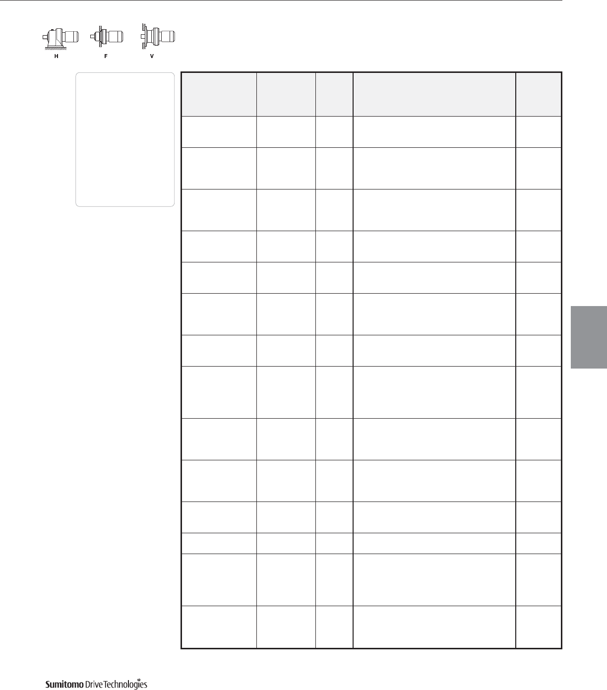
60 Hz Frame Size Selection Tables
10 HP
60 Hz, 1750 RPM
CYCLO® 6000 Gearmotors
Frame Size Selection Tables 3.41
Output Output Service Factor Overhung SELECTION Option
Speed Torque Load
AGMA HP Frame Shaft AGMA Inverter
RPM In•lbs SF Class lbs Symbol Size Spec. Class Ratio Duty
1.20 I 1700 10 6135 YA15 AV
117 5160 1.60 III 2630 10 6140 YC15 AV
2.01 III 2630 10 6145 YC15 AV
1.11 I 1820 10 6135 YA17 AV
103 5850 1.35 II 2740 10 6140 YB17 AV
1.60 III 2740 10 6145 YC17 AV
1.75 III 3210 10 6160 YC17 AV
1.00 I 1930 10 6135 YA21 AV
83.3 7230 1.47 II 2940 10 6145 YB21 AV
1.72 III 3440 10 6160 YC21 AV
2.15 III 3440 10 6165 YC21 AV
1.05 I 3080 10 6145 YA25 AV
70.0 8600 1.31 II 3570 10 6160 YB25 AV
2.01 III 3570 10 6165 YC25 AV
1.00 I 3140 10 6145 YA29 AV
60.3 10000 1.52 II 3730 10 6165 YB29 AV
1.91 III 4240 10 6170 YC29 AV
1.00 I 3350 10 6145 YA35 AV
50.0 12000 1.52 II 3930 10 6165 YB35 AV
1.60 III 4490 10 6170 YC35 AV
2.01 III 4490 10 6175 YC35 AV
1.05 I 4180 10 6165 YA43 AV
40.7 14800 1.51 II 4780 10 6175 YB43 AV
2.01 III 6490 10 6180 YC43 AV
1.00 I 4330 10 6165 YA51 AV
1.12 I 4960 10 6170 YA51 AV
34.3 17500 1.51 II 4960 10 6175 YB51 AV
1.60 III 6710 10 6180 YC51 AV
2.01 III 6710 10 6185 YC51 AV
1.11 I 5190 10 6175 YA59 AV
29.7 20300 1.30 II 7010 10 6180 YB59 AV
1.60 III 7010 10 6185 YC59 AV
2.04 III 9880 10 6190 Y C 59 -
0.95 - 5460 10 6175 Y71AV
24.6 24400 1.17 I 7430 10 6180 YA71 AV
1.31 II 7430 10 6185 YB71 AV
1.80 III 10500 10 6190 Y C 71 -
1.15 I 7990 10 6185 YA87 AV
20.1 29900 1.57 II 11300 10 6190 Y B 87 -
1.81 III 11300 10 6195 Y C 87 -
16.8 33900 1.28 I 8490 10 6185DB Y A 104 AV
1.59 II 11900 10 6195DB Y B 104 AV
35900 - - 9050 10 6180DB Y 121 AV
39500 1.08 I 9000 10 6185DB Y A 121 AV
14.5 39500 1.43 II 12700 10 6190DB Y B 121 AV
39500 1.59 II 12700 10 6195DB Y B 121 AV
39500 2.55 III 22900 10 6215DB Y C 121 AV
35900 - - 9360 10 6180DB Y 143 AV
12.2 43400 - - 9360 10 6185DB Y 143 AV
46600 1.21 I 13200 10 6190DB Y A 143 AV
46600 1.45 II 13200 10 6195DB Y B 143 AV
Dimensions Pages
Foot
Mount (H) 4.2–4.29
V-Flange (V) 4.30–4.43
F-Flange (F) 4.44–4.69
Selection
Tables
Gearmotors
Cyclo® 6000 Series

Frame Size Selection Tables 60 Hz
10 HP
60 Hz, 1750 RPM
CYCLO® 6000 Gearmotors
3.42 Frame Size Selection Tables
Output Output Service Factor Overhung SELECTION Option
Speed Torque Load
AGMA HP Frame Shaft AGMA Inverter
RPM In•lbs SF Class lbs Symbol Size Spec. Class Ratio Duty
43500 - - 9360 10 6185DB Y 165 AV
53800 1.05 I 13200 10 6190DB Y A 165 AV
10.6 53800 1.30 II 13200 10 6195DB Y B 165 AV
53800 1.59 II 23400 10 6215DA Y B 165 AV
53800 2.00 III 23400 10 6215DB Y C 165 AV
53800 2.38 III 26300 10 6225DB Y C 165 -
56500 - - 13200 10 6190DB Y 195 AV
63500 1.10 I 13200 10 6195DB Y A 195 AV
8.97 63500 1.29 I 18900 10 6205DB Y A 195 AV
63500 1.59 II 23400 10 6215DA Y B 195 AV
63500 2.02 III 27600 10 6225DB Y C 195 -
63500 2.73 III 34400 10 6235DA Y C 195 AV
56500 - - 13200 10 6190DB Y 231 AV
70400 - - 13200 10 6195DB Y 231 AV
7.58 75300 1.09 I 18900 10 6205DB Y A 231 AV
75300 1.47 II 23400 10 6215DA Y B 231 AV
75300 1.59 II 29400 10 6225DA Y B 231 AV
75300 2.22 III 36800 10 6235DA Y C 231 AV
70400 - - 13200 10 6195DB Y 273 AV
82000 - - 18900 10 6205DB Y 273 AV
6.41 89400 1.24 I 23400 10 6215DA Y A 273 AV
89400 1.47 II 30800 10 6225DA Y B 273 AV
89400 1.88 III 38600 10 6235DA Y C 273 AV
89400 2.57 III 42900 10 6245DA Y C 273 AV
1.08 I 23400 10 6215DA Y A 319 AV
5.49 104000 1.28 I 32100 10 6225DA Y A 319 AV
1.61 III 40200 10 6235DA Y C 319 AV
2.20 III 44700 10 6245DA Y C 319 AV
112000 - - 23400 10 6215DA Y 377 AV
123000 1.08 I 32600 10 6225DA Y A 377 AV
4.64 123000 1.36 II 40200 10 6235DA Y B 377 AV
123000 1.86 III 46700 10 6245DA Y C 377 AV
123000 2.34 III 57700 10 6255DA Y C 377 -
142000 - - 32600 10 6225DA Y 473 AV
154000 1.18 I 40200 10 6235DA Y A 473 AV
3.70 154000 1.48 II 46700 10 6245DA Y B 473 AV
154000 1.98 III 57900 10 6255DA Y C 473 -
154000 2.64 III 62000 10 6265DA Y C 473 -
142000 - - 32600 10 6225DA Y 559 AV
182000 1.00 I 40200 10 6235DA Y A 559 AV
3.13 182000 1.25 I 46700 10 6245DA Y A 559 AV
182000 1.68 III 57900 10 6255DA Y C 559 -
182000 2.23 III 62000 10 6265DA Y C 559 -
181000 - - 40200 10 6235DA Y 649 AV
211000 1.08 I 46700 10 6245DA Y A 649 AV
2.70 211000 1.44 II 57900 10 6255DA Y B 649 -
211000 1.92 III 62000 10 6265DA Y C 649 -
211000 2.85 III 55700 10 6275DA Y C 649 -
Dimensions Pages
Foot
Mount (H) 4.2–4.29
V-Flange (V) 4.30–4.43
F-Flange (F) 4.44–4.69
Selection
Tables
Gearmotors
Cyclo® 6000 Series
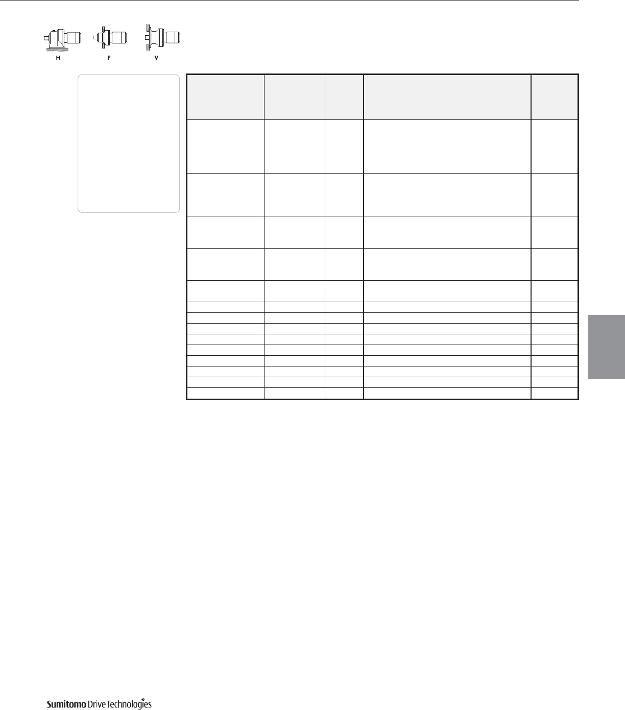
60 Hz Frame Size Selection Tables
10 HP
60 Hz, 1750 RPM
CYCLO® 6000 Gearmotors
Frame Size Selection Tables 3.43
Output Output Service Factor Overhung SELECTION Option
Speed Torque Load
AGMA HP Frame Shaft AGMA Inverter
RPM In•lbs SF Class lbs Symbol Size Spec. Class Ratio Duty
181000 - - 40200 10 6235DA Y 731 AV
228000 - - 46700 10 6245DA Y 731 AV
2.39 238000 1.28 I 57900 10 6255DA Y A 731 AV
238000 1.71 III 62000 10 6265DA Y C 731 -
238000 2.53 III 55700 10 6275DA Y C 731 -
228000 - - 46700 10 6245DA Y 841 AV
2.08 274000 1.05 I 57900 10 6255DA Y A 841 AV
274000 1.48 II 62000 10 6265DA Y B 841 -
274000 2.20 III 55700 10 6275DA Y C 841 -
305000 - - 57900 10 6255DA Y 1003 AV
1.74 326000 1.25 I 62000 10 6265DA Y A 1003 -
326000 1.85 III 55700 10 6275DA Y C 1003 -
305000 - - 57900 10 6255DA Y 1247 AV
1.40 406000 1.00 I 62000 10 6265DA Y A 1247 -
406000 1.48 II 55700 10 6275DA Y B 1247 -
1.18 389000 - - 62000 10 6265DA Y 1479 -
482000 1.25 I 55700 10 6275DA Y A 1479 -
0.946 603000 1.00 I 55700 10 6275DA Y A 1849 -
0.847 603000 - - 55700 10 6275DA Y 2065 -
0.690 603000 - - 55700 10 6275DA Y 2537 -
0.575 603000 - - 55000 10 6275DA Y 3045 -
0.503 603000 - - 55700 10 6275DA Y 3481 -
0.394 603000 - - 55000 10 6275DA Y 4437 -
0.341 603000 - - 55000 10 6275DA Y 5133 -
0.283 603000 - - 55000 10 6275DA Y 6177 -
0.231 603000 - - 55000 10 6275DA Y 7569 -
Dimensions Pages
Foot
Mount (H) 4.2–4.29
V-Flange (V) 4.30–4.43
F-Flange (F) 4.44–4.69
Selection
Tables
Gearmotors
Cyclo® 6000 Series
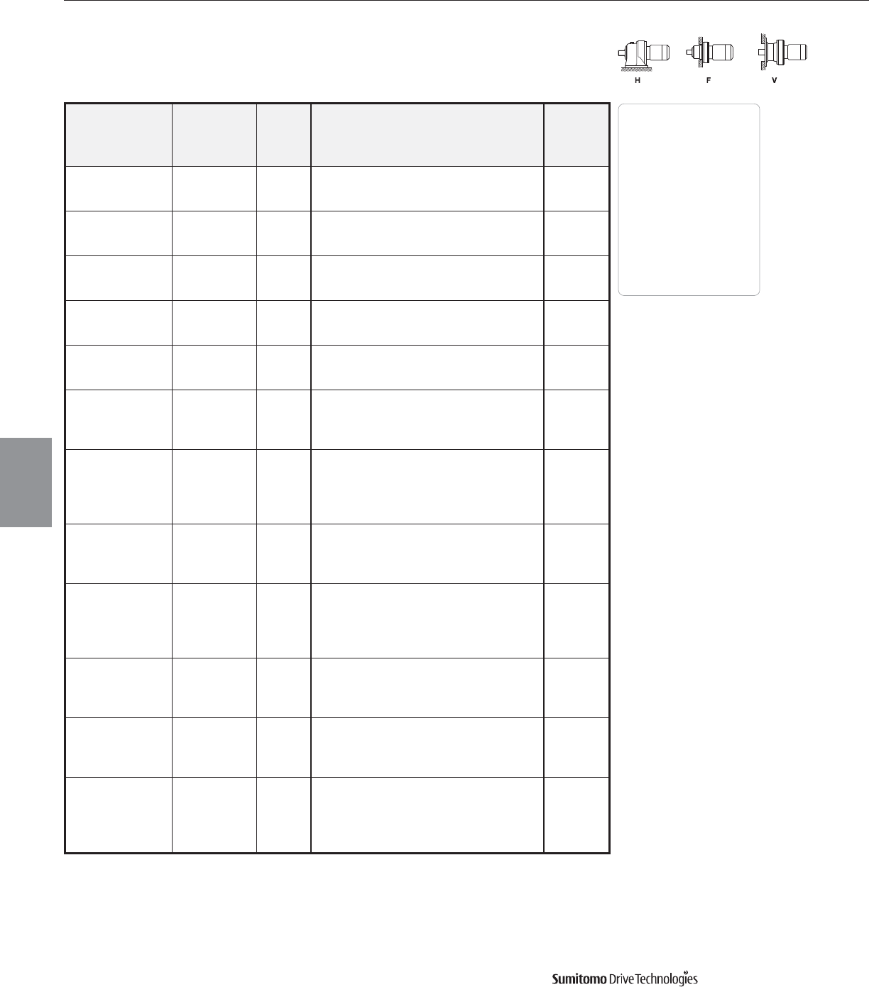
Frame Size Selection Tables 60 Hz
15 HP
60 Hz, 1750 RPM
CYCLO® 6000 Gearmotors
3.44 Frame Size Selection Tables
Output Output Service Factor Overhung SELECTION Option
Speed Torque Load
AGMA HP Frame Shaft AGMA Inverter
RPM In•lbs SF Class lbs Symbol Size Spec. Class Ratio Duty[1]
1.03 I 983 15 6135 YA 3 AV
583 1510 1.37 II 1550 15 6145 Y B 3 AV[H]
1.85 III 1700 15 6160 Y C 3 AV[H]
1.03 I 1166 15 6135 YA 5 AV
350 2530 1.37 II 1840 15 6145 Y B 5 AV[H]
1.85 III 2020 15 6160 Y C 5 AV[H]
1.03 I 1240 15 6135 YA 6 AV
292 3030 1.37 II 1970 15 6145 Y B 6 AV[H]
1.85 III 2190 15 6160 Y C 6 AV[H]
1.03 I 1380 15 6135 YA 8 AV
219 4030 1.37 II 2180 15 6145 Y B 8 AV[H]
1.79 III 2450 15 6160 Y C 8 AV[H]
1.03 I 1570 15 6135 YA11 AV
159 5550 1.37 II 2450 15 6145 Y B 11 AV[H]
1.79 III 2760 15 6160 Y C 11 AV[H]
1.03 I 1630 15 6135 YA13 AV
135 6560 1.18 I 2490 15 6140 Y A 13 AV[H]
1.37 II 2490 15 6145 Y B 13 AV[H]
1.79 III 2900 15 6160 Y C 13 AV[H]
0.82 - 1650 15 6135 Y15AV
1.09 I 2600 15 6140 Y A 15 AV[H]
117 7570 1.37 II 2600 15 6145 Y B 15 AV[H]
1.70 III 3050 15 6160 Y C 15 AV[H]
2.05 III 3050 15 6165 Y C 15 AV[H]
1.09 I 2720 15 6145 Y A 17 AV[H]
103 8570 1.19 I 3170 15 6160 Y A 17 AV[H]
1.71 III 3170 15 6165 Y C 17 AV[H]
1.79 III 3590 15 6170 YC17 AV
1.00 I 2900 15 6145 Y A 21 AV[H]
1.17 I 3370 15 6160 Y A 21 AV[H]
83.3 10600 1.46 II 3370 15 6165 Y B 21 AV[H]
1.77 III 3860 15 6170 YC21 AV
2.19 III 3860 15 6175 YC21 AV
0.90 - 3530 15 6160 Y 25 AV[H]
70.0 12700 1.37 II 3530 15 6165 Y B 25 AV[H]
1.44 II 4000 15 6170 YB25 AV
1.77 III 4000 15 6175 YC25 AV
1.04 I 3660 15 6165 Y A 29 AV[H]
60.3 14600 1.30 II 4200 15 6170 YB29 AV
1.71 III 4200 15 6175 YC29 AV
1.77 III 5640 15 6180 YC29 AV
1.04 I 3840 15 6165 Y A 35 AV[H]
1.09 I 4420 15 6170 YA35 AV
50.0 17700 1.37 II 4420 15 6175 YB35 AV
1.71 III 5990 15 6180 YC35 AV
2.05 III 5990 15 6185 YC35 AV
Dimensions Pages
Foot
Mount (H) 4.2–4.29
V-Flange (V) 4.30–4.43
F-Flange (F) 4.44–4.69
Selection
Tables
Gearmotors
Cyclo® 6000 Series
Note: [1] [H] indicates a high center height unit.
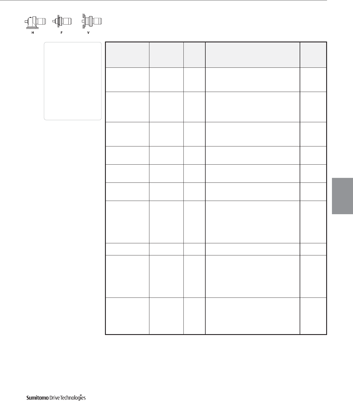
Output Output Service Factor Overhung SELECTION Option
Speed Torque Load
AGMA HP Frame Shaft AGMA Inverter
RPM In•lbs SF Class lbs Symbol Size Spec. Class Ratio Duty
1.03 I 4690 15 6175 YA43 AV
40.7 21700 1.37 II 6420 15 6180 YB43 AV
1.71 III 6420 15 6185 YC43 AV
1.90 III 9000 15 6190 YC43 AV
1.03 I 4870 15 6175 YA51 AV
1.09 I 6650 15 6180 YA51 AV
34.3 25700 1.37 II 6650 15 6185 YB51 AV
1.65 III 9410 15 6190 YC51 AV
1.90 III 9410 15 6195 YC51 AV
1.09 I 6940 15 6185 YA59 AV
29.7 29700 1.39 II 9810 15 6190 YB59 AV
1.71 III 9810 15 6195 YC59 AV
2.05 III 17900 15 6205 Y C 59 -
0.89 - 7340 15 6185 Y71AV
24.6 35800 1.23 I 10400 15 6190 YA71 AV
1.42 II 10400 15 6195 YB71 AV
1.24 I 11200 15 6195 YA87 AV
20.1 43900 1.45 II 18900 15 6205 Y B 87 -
1.95 III 20500 15 6215 Y C 87 -
35900 - - 8460 15 6180DB Y 104 AV
16.8 43400 - - 8370 15 6185DB Y 104 AV
49700 1.08 I 11800 15 6195DB Y A 104 AV
42600 - - 8980 15 6185DB Y 121 AV
56500 - - 12600 15 6190DB Y 121 AV
57900 1.08 I 12600 15 6195DB Y A 121 AV
14.5 57900 1.08 I 18900 15 6205DB Y A 121 AV
57900 1.74 III 22900 15 6215DB Y C 121 AV
57900 2.06 III 24200 15 6225DB Y C 121 -
57900 2.31 III 30300 15 6235DA Y C 121 AV
12.2 56500 - - 13100 15 6190DB Y 143 AV
68400 0.98 - 13000 15 6195DB Y 143 AV
56500 - - 13200 15 6190DB Y 165 AV
70000 - - 13100 15 6195DB Y 165 AV
78800 1.04 I 18900 15 6205DB Y A 165 AV
10.6 78800 1.08 I 23400 15 6215DA Y A 165 AV
78800 1.37 II 23400 15 6215DB Y B 165 AV
78800 1.62 III 26300 15 6225DB Y C 165 -
78800 2.20 III 32600 15 6235DA Y C 165 AV
70000 - - 13100 15 6195DB Y 195 AV
82000 - - 18900 15 6205DB Y 195 AV
8.97 92900 1.08 I 23400 15 6215DA Y A 195 AV
92900 1.37 II 27400 15 6225DB Y B 195 -
92900 1.86 III 34100 15 6235DA Y C 195 AV
92900 2.17 III 38200 15 6245DA Y C 195 AV
60 Hz Frame Size Selection Tables
15 HP
60 Hz, 1750 RPM
CYCLO® 6000 Gearmotors
Frame Size Selection Tables 3.45
Dimensions Pages
Foot
Mount (H) 4.2–4.29
V-Flange (V) 4.30–4.43
F-Flange (F) 4.44–4.69
Selection
Tables
Gearmotors
Cyclo® 6000 Series
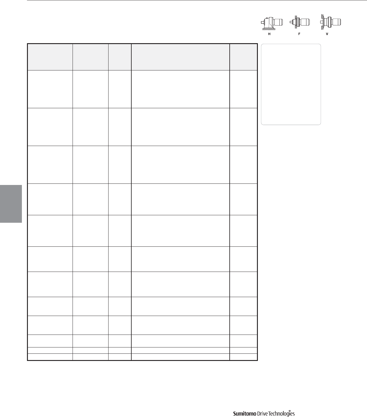
Frame Size Selection Tables 60 Hz
15 HP
60 Hz, 1750 RPM
CYCLO® 6000 Gearmotors
3.46 Frame Size Selection Tables
Output Output Service Factor Overhung SELECTION Option
Speed Torque Load
AGMA HP Frame Shaft AGMA Inverter
RPM In•lbs SF Class lbs Symbol Size Spec. Class Ratio Duty
82000 - - 18900 15 6205DB Y 231 AV
111000 1.00 I 23400 15 6215DA Y A 231 AV
7.58 111000 1.18 I 29200 15 6225DB Y A 231 -
111000 1.51 II 36600 15 6235DA Y B 231 AV
111000 2.07 III 40600 15 6245DA Y C 231 AV
111000 2.48 III 49600 15 6255DA Y C 231 -
111000 - - 23400 15 6215DA Y 273 AV
130000 1.00 I 30800 15 6225DA Y A 273 AV
6.41 130000 1.28 I 38400 15 6235DA Y A 273 AV
130000 1.75 III 42700 15 6245DA Y C 273 AV
130000 2.10 III 52100 15 6255DA Y C 273 -
130000 3.12 III 62000 15 6265DA Y C 273 -
112000 - - 23400 15 6215DA Y 319 AV
133000 - - 31900 15 6225DA Y 319 AV
5.49 152000 1.10 I 39700 15 6235DA Y A 319 AV
152000 1.50 II 44500 15 6245DA Y B 319 AV
152000 1.88 III 54800 15 6255DA Y C 319 -
152000 2.67 III 62000 15 6265DA Y C 319 -
133000 - - 32600 15 6225DA Y 377 AV
167000 - - 40200 15 6235DA Y 377 AV
4.64 180000 1.27 I 46700 15 6245DA Y A 377 AV
180000 1.59 II 57500 15 6255DA Y B 377 -
180000 2.26 III 62000 15 6265DA Y C 377 -
181000 - - 40200 15 6235DA Y 473 AV
227000 1.01 I 46700 15 6245DA Y A 473 AV
3.70 227000 1.35 II 57900 15 6255DA Y B 473 -
227000 1.80 III 62000 15 6265DA Y C 473 -
227000 2.67 III 55700 15 6275DA Y C 473 -
228000 - - 46700 15 6245DA Y 559 AV
3.13 267000 1.14 I 57900 15 6255DA Y A 559 -
267000 1.52 II 62000 15 6265DA Y B 559 -
267000 2.26 III 55700 15 6275DA Y C 559 -
228000 - - 46700 15 6245DA Y 649 AV
2.70 311000 0.98 - 57900 15 6255DA Y 649 -
311000 1.31 II 62000 15 6265DA Y B 649 -
311000 1.95 III 55700 15 6275DA Y C 649 -
305000 - - 57900 15 6255DA Y 731 AV
2.39 349000 1.16 I 62000 15 6265DA Y A 731 -
349000 1.73 III 55700 15 6275DA Y C 731 -
288000 - - 57900 15 6255DA Y 841 AV
2.08 402000 1.01 I 62000 15 6265DA Y A 841 -
402000 1.50 II 55700 15 6275DA Y B 841 -
1.74 407000 - - 62000 15 6265DA Y 1003 -
480000 1.26 I 55700 15 6275DA Y A 1003 -
1.40 596000 1.01 I 55700 15 6275DA Y A 1247 -
1.18 603000 - - 55000 15 6275DA Y 1479 -
Dimensions Pages
Foot
Mount (H) 4.2–4.29
V-Flange (V) 4.30–4.43
F-Flange (F) 4.44–4.69
Selection
Tables
Gearmotors
Cyclo® 6000 Series

Output Output Service Factor Overhung SELECTION Option
Speed Torque Load
AGMA HP Frame Shaft AGMA Inverter
RPM In•lbs SF Class lbs Symbol Size Spec. Class Ratio Duty
1.01 I 1550 20 614H YA 3 -
583 2070 1.35 II 1700 20 6160 YB 3 AV
1.61 III 1688 20 616H YC 3 AV
1.84 III 1908 20 6170 YC 3 AV
1.01 I 1840 20 614H YA 5 -
350 3440 1.35 II 2020 20 6160 YB 5 AV
1.61 III 2000 20 616H YC 5 AV
1.84 III 2260 20 6170 YC 5 AV
1.01 I 1960 20 614H YA 6 -
292 4130 1.35 II 2170 20 6160 YB 6 AV
1.61 III 2170 20 616H YC 6 AV
1.84 III 2450 20 6170 YC 6 -
1.01 I 2170 20 614H YA 8 -
219 5500 1.31 II 2420 20 6160 YB 8 AV
1.61 III 2420 20 616H YC 8 AV
1.84 III 2720 20 6170 YC 8 -
1.01 I 2420 20 614H Y A 11 -
159 7570 1.31 II 2740 20 6160 YB11 AV
1.61 III 2740 20 616H YC11 AV
1.84 III 3120 20 6170 YC11 AV
1.01 I 2470 20 614H Y A 13 -
135 8940 1.51 II 2850 20 616H YB13 AV
1.82 III 3260 20 6170 YC13 AV
1.01 I 2580 20 614H Y A 15 -
1.25 I 3030 20 6160 YA15 AV
117 10400 1.51 II 3030 20 616H YB15 AV
1.70 III 3410 20 6170 YC15 AV
2.01 III 3410 20 6175 YC15 AV
0.80 - 2690 20 614H Y17-
1.25 I 3120 20 616H YA17 AV
103 11700 1.31 II 3550 20 6170 YB17 AV
1.61 III 3550 20 6175 YC17 AV
2.04 III 4800 20 6180 YC17 AV
1.07 I 3320 20 616H YA21 AV
83.3 14400 1.30 II 3820 20 6170 YB21 AV
1.61 III 3820 20 6175 YC21 AV
2.00 III 5140 20 6180 YC21 AV
1.01 I 3460 20 616H YA25 AV
1.05 I 3930 20 6170 YA25 AV
70.0 17200 1.30 II 3930 20 6175 YB25 AV
1.61 III 5340 20 6180 YC25 AV
2.01 III 5340 20 6185 YC25 AV
1.25 I 4130 20 6175 YA29 AV
60.3 20000 1.30 II 5590 20 6180 YB29 AV
1.61 III 5590 20 6185 YC29 AV
2.05 III 7900 20 6190 YC29 AV
60 Hz Frame Size Selection Tables
20 HP
60 Hz, 1750 RPM
CYCLO® 6000 Gearmotors
Frame Size Selection Tables 3.47
Dimensions Pages
Foot
Mount (H) 4.2–4.29
V-Flange (V) 4.30–4.43
F-Flange (F) 4.44–4.69
Selection
Tables
Gearmotors
Cyclo® 6000 Series
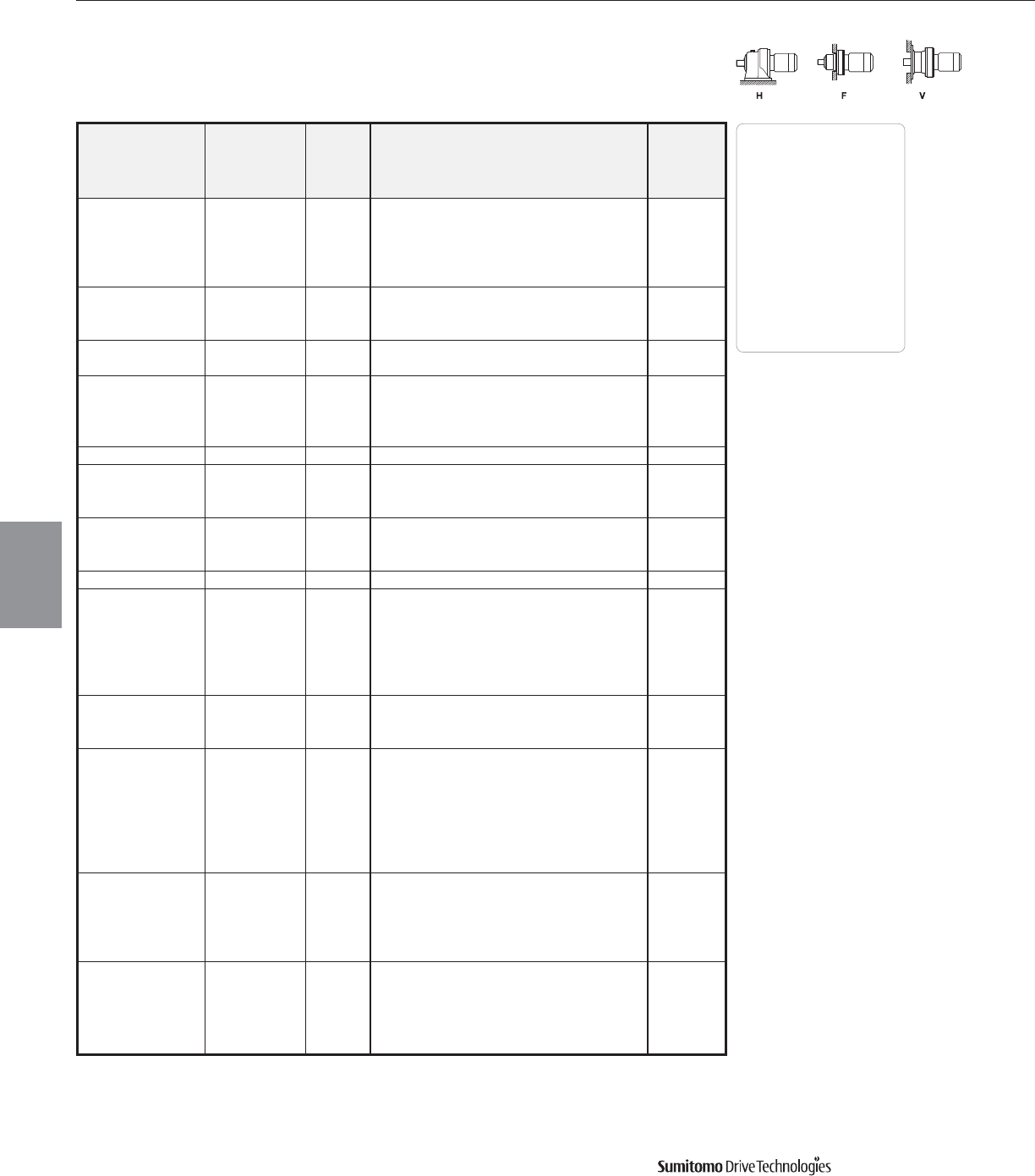
Frame Size Selection Tables 60 Hz
20 HP
60 Hz, 1750 RPM
CYCLO® 6000 Gearmotors
3.48 Frame Size Selection Tables
Output Output Service Factor Overhung SELECTION Option
Speed Torque Load
AGMA HP Frame Shaft AGMA Inverter
RPM In•lbs SF Class lbs Symbol[1] Size Spec. Class Ratio Duty
1.01 I 4360 20 6175 YA35 AV
1.25 I 5950 20 6180 YA35 AV
50.0 24100 1.51 II 5950 20 6185 YB35 AV
1.62 III 8330 20 6190 YC35 AV
2.01 III 8330 20 6195 YC35 AV
1.25 I 6350 20 6185 YA43 AV
40.7 29600 1.39 II 8960 20 6190 YB43 AV
2.01 III 8960 20 6195 YC43 AV
34.3 35100 1.01 I 6560 20 6185 YA51 AV
1.39 II 9320 20 6195 YB51 AV
0.80 - 6830 20 6185 Y59AV
29.7 40600 1.25 I 9740 20 6195 YA59 AV
1.51 II 17900 20 6205 Y B 59 -
2.51 III 18300 20 6215 Y C 59 -
24.6 48800 1.04 I 10300 20 6195 YA71 AV
0.91 - 11000 20 6195 Y87AV
20.1 59900 1.06 I 18900 20 6205 YA87 AV
1.43 II 20400 20 6215 Y B 87 -
1.30 II 18900 206 6205 Y B 59 -
19.7 61000 1.83 III 20500 206 6215 Y C 59 -
2.22 III 21800 206 6225 Y C 59 -
16.8 67800 0.80 - 11800 20 6195DB Y 104 -
62700 - - 12500 20 6195DB Y 121 -
78800 0.80 - 18900 20 6205DB Y 121 -
14.5 78800 1.28 I 22700 20 6215DB Y A 121 AV
78800 1.52 II 23800 20 6225DB Y B 121 AV
78800 1.69 III 30300 20 6235DA Y C 121 AV
78800 2.30 III 33700 20 6245DB Y C 121 -
1.48 II 24200 206 6225 Y B 87 -
13.4 90200 1.60 III 30300 206 6235 Y C 87 -
2.14 III 33900 206 6245 Y C 87 -
82000 - - 18900 20 6205DB Y 165 -
108000 0.80 - 23400 20 6215DA Y 165 -
108000 1.00 I 23400 20 6215DB Y A 165 AV
10.6 108000 1.19 I 25800 20 6225DB Y A 165 AV
108000 1.61 III 32300 20 6235DA Y C 165 AV
108000 1.69 III 36100 20 6245DA Y C 165 AV
108000 2.16 III 36100 20 6245DB Y C 165 -
101000 - - 23400 20 6215DA Y 195 -
127000 1.01 I 27400 20 6225DB Y A 195 AV
8.97 127000 1.37 II 33900 20 6235DA Y B 195 AV
127000 1.59 II 37900 20 6245DA Y B 195 AV
127000 2.12 III 46500 20 6255DA Y C 195 AV
119000 - - 29200 20 6225DA Y 231 -
150000 1.11 I 36400 20 6235DA Y A 231 AV
7.58 150000 1.52 II 40400 20 6245DA Y B 231 AV
150000 1.82 III 49400 20 6255DA Y C 231 AV
150000 2.70 III 60400 20 6265DA Y C 231 -
Dimensions Pages
Foot
Mount (H) 4.2–4.29
V-Flange (V) 4.30–4.43
F-Flange (F) 4.44–4.69
Selection
Tables
Gearmotors
Cyclo® 6000 Series
Note: [1] HP symbol ending in 6indicates a six-pole, 1165 RPM motor.
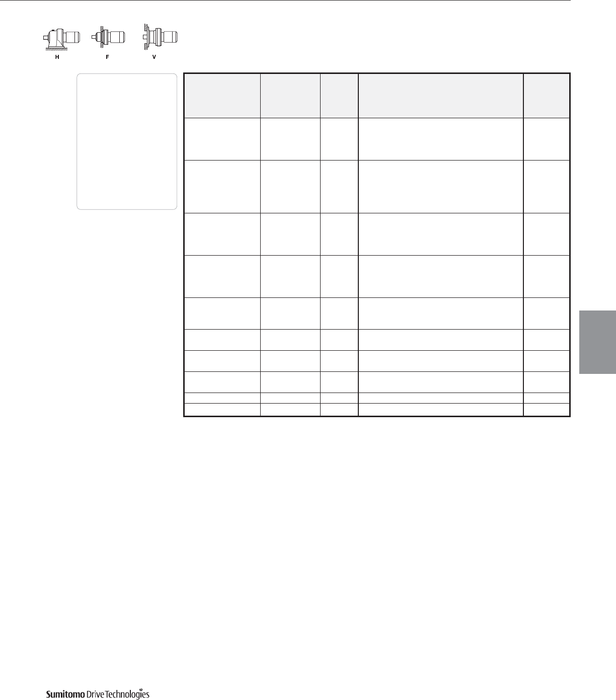
60 Hz Frame Size Selection Tables
20 HP
60 Hz, 1750 RPM
CYCLO® 6000 Gearmotors
Frame Size Selection Tables 3.49
Output Output Service Factor Overhung SELECTION Option
Speed Torque Load
AGMA HP Frame Shaft AGMA Inverter
RPM In•lbs SF Class lbs Symbol Size Spec. Class Ratio Duty
167000 - - 38200 20 6235DA Y 273 AV
6.41 178000 1.28 I 42400 20 6245DA Y A 273 AV
178000 1.54 II 51400 20 6255DA Y B 273 AV
178000 2.29 III 62000 20 6265DA Y C 273 -
167000 - - 39700 20 6235DA Y 319 AV
208000 1.10 I 44200 20 6245DA Y A 319 AV
5.49 208000 1.38 II 54600 20 6255DA Y B 319 AV
208000 1.96 III 62000 20 6265DA Y C 319 -
208000 2.90 III 55700 20 6275DA Y C 319 -
228000 - - 46500 20 6245DA Y 377 AV
4.64 246000 1.17 I 57300 20 6255DA Y A 377 AV
246000 1.66 III 62000 20 6265DA Y C 377 -
246000 2.46 III 55700 20 6275DA Y C 377 -
228000 - - 46700 20 6245DA Y 473 AV
3.70 308000 0.98 - 57900 20 6255DA Y 473 AV
308000 1.32 II 62000 20 6265DA Y B 473 -
308000 1.96 III 55700 20 6275DA Y C 473 -
305000 - - 57900 20 6255DA Y 559 AV
3.13 365000 1.12 I 62000 20 6265DA Y A 559 -
365000 1.66 III 55700 20 6275DA Y C 559 -
2.70 423000 0.96 - 62000 20 6265DA Y 649 -
1.43 II 55700 20 6275DA Y B 649 -
2.39 407000 - - 62000 20 6265DA Y 731 -
477000 1.27 I 55700 20 6275DA Y A 731 -
2.08 407000 - - 62000 20 6265DA Y 841 AV
549000 1.10 I 55700 20 6275DA Y A 841 AV
1.74 603000 - - 55700 20 6275DA Y 1003 -
1.40 603000 - - 55700 20 6275DA Y 1247 AV
Dimensions Pages
Foot
Mount (H) 4.2–4.29
V-Flange (V) 4.30–4.43
F-Flange (F) 4.44–4.69
Selection
Tables
Gearmotors
Cyclo® 6000 Series

Frame Size Selection Tables 60 Hz
25 HP
60 Hz, 1750 RPM
CYCLO® 6000 Gearmotors
3.50 Frame Size Selection Tables
Output Output Service Factor Overhung SELECTION Option
Speed Torque Load
AGMA HP Frame Shaft AGMA Inverter
RPM In•lbs SF Class lbs Symbol Size Spec. Class Ratio Duty
1.10 I 1700 25 6160 YA 3 -
583 2549 1.30 II 1688 25 6165 YB 3 -
1.63 III 1908 25 6175 YB 3 AV
1.10 I 2020 25 6160 YA 5 -
350 4248 1.30 II 2000 25 6165 YB 5 -
1.63 III 2260 25 6175 YB 5 AV
1.10 I 2150 25 6160 YA 6 -
292 5090 1.30 II 2150 25 616H YB 6 -
1.63 III 2450 25 6175 YC 6 AV
1.06 I 2400 25 6160 YA 8 -
219 6790 1.30 II 2400 25 616H YB 8 -
1.63 III 2690 25 6175 YC 8 AV
1.06 I 2720 25 6160 Y A 11 -
159 9380 1.30 II 2720 25 616H Y B 11 -
1.63 III 3100 25 6175 YC11 AV
1.90 III 4130 25 6180 YC11 AV
1.22 I 2830 25 616H Y A 13 -
135 11100 1.48 II 3210 25 6170 YB13 AV
1.63 III 3210 25 6175 YC13 AV
1.90 III 4290 25 6180 YC13 AV
1.22 I 2990 25 616H Y A 15 -
117 12700 1.38 II 3370 25 6170 YB15 AV
1.63 III 3370 25 6175 YC15 AV
1.75 III 4540 25 6180 YC15 AV
1.02 I 3050 25 616H Y A 17 -
103 14400 1.30 II 3500 25 6175 YB17 AV
1.65 III 4780 25 6180 YC17 AV
2.11 III 4780 25 6185 YC17 AV
1.05 I 3770 25 6170 YA21 AV
83.3 17800 1.30 II 3770 25 6175 YB21 AV
1.62 III 5120 25 6180 YC21 AV
2.11 III 5120 25 6185 YC21 AV
1.05 I 3880 25 6175 YA25 AV
70.0 21200 1.30 II 5320 25 6180 YB25 AV
1.63 III 5320 25 6185 YC25 AV
1.90 III 7480 25 6190 YC25 AV
1.02 I 4060 25 6175 YA29 AV
1.05 I 5550 25 6180 YA29 AV
60.3 24600 1.30 II 5550 25 6185 YB29 AV
1.66 III 7860 25 6190 YC29 AV
2.04 III 7860 25 6195 YC29 AV
1.22 I 5910 25 6185 YA35 AV
50.0 29700 1.31 II 8290 25 6190 YB35 AV
1.63 III 8290 25 6195 YC35 AV
1.02 I 6290 25 6185 YA43 AV
1.13 I 8890 25 6190 YA43 AV
40.7 36500 1.63 III 8890 25 6195 YC43 AV
1.72 III 16400 25 6205 Y C 43 -
2.44 III 16800 25 6215 Y C 43 -
Dimensions Pages
Foot
Mount (H) 4.2–4.29
V-Flange (V) 4.30–4.43
F-Flange (F) 4.44–4.69
Selection
Tables
Gearmotors
Cyclo® 6000 Series

60 Hz Frame Size Selection Tables
25 HP
60 Hz, 1750 RPM
Output Output Service Factor Overhung SELECTION Option
Speed Torque Load
AGMA HP Frame Shaft AGMA Inverter
RPM In•lbs SF Class lbs Symbol[1] Size Spec. Class Ratio Duty
34.3 43300 0.82 - 6490 25 6185 Y51AV
1.13 I 9270 25 6195 YA51 AV
1.02 I 9680 25 6195 YA59 AV
29.7 50100 1.22 I 17800 25 6205 Y A 59 -
2.04 III 18200 25 6215 Y C 59 -
1.24 I 10100 256 6195 Y A 43 -
27.1 54800 1.50 II 16300 256 6205 Y B 43 -
2.04 III 18900 256 6215 Y C 43 -
2.58 III 20000 256 6225 Y C 43 -
24.6 60300 0.84 - 10200 25 6195 Y71AV
20.1 73800 1.16 I 20300 25 6215 Y A 87 -
1.44 II 21600 25 6225 Y B 87 -
1.49 II 20500 256 6215 Y B 59 -
19.7 75200 1.80 III 21700 256 6225 Y C 59 -
2.04 III 26900 256 6235 Y C 59 -
1.03 I 22700 25 6215DB Y A 121 -
1.22 I 24000 25 6225DB Y A 121 AV
14.5 97300 1.37 II 30100 25 6235DA Y B 121 -
1.86 III 33200 25 6245DB Y C 121 AV
2.50 III 41300 25 6255DB Y C 121 -
1.20 I 24200 256 6225 Y A 87 -
13.4 111000 1.30 II 30100 256 6235 YB87 AV
1.74 III 33900 256 6245 Y C 87 -
2.32 III 41800 256 6255 Y C 87 -
0.97 - 25800 25 6225DB Y 165 AV
1.31 II 32300 25 6235DA Y B 165 -
10.6 133000 1.31 II 32300 25 6235DB Y B 165 AV
1.37 II 36100 25 6245DA Y B 165 -
2.08 III 44200 25 6255DB Y C 165 -
2.74 III 53900 25 6265DA Y C 165 -
1.11 I 33900 25 6235DA Y A 195 -
1.11 I 33900 25 6235DB Y A 195 AV
8.97 157000 1.29 I 37900 25 6245DA Y A 195 -
1.48 II 37900 25 6245DB Y B 195 AV
1.72 III 46500 25 6255DA Y C 195 AV
2.47 III 56600 25 6265DA Y C 195 -
167000 - - 36400 25 6235DA Y 231 -
7.58 186000 1.23 I 40400 25 6245DB Y A 231 AV
186000 1.48 II 48900 25 6255DA Y B 231 AV
186000 2.19 III 60400 25 6265DA Y C 231 -
1.04 I 42200 25 6245DA Y A 273 -
6.41 219000 1.04 I 42200 25 6245DB Y A 273 AV
1.25 I 51600 25 6255DA Y A 273 AV
1.85 III 62000 25 6265DA Y C 273 -
228000 - - 44000 25 6245DA Y 319 -
5.49 257000 1.12 I 54300 25 6255DA Y A 319 AV
257000 1.59 II 62000 25 6265DA Y B 319 -
257000 2.35 III 55700 25 6275DA Y C 319 -
CYCLO® 6000 Gearmotors
Frame Size Selection Tables 3.51
Dimensions Pages
Foot
Mount (H) 4.2–4.29
V-Flange (V) 4.30–4.43
F-Flange (F) 4.44–4.69
Selection
Tables
Gearmotors
Cyclo® 6000 Series
Note: [1] HP symbol ending in 6indicates a six-pole, 1165 RPM motor.
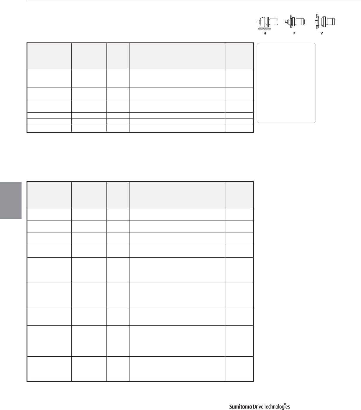
Frame Size Selection Tables 60 Hz
25 HP
60 Hz, 1750 RPM
CYCLO® 6000 Gearmotors
3.52 Frame Size Selection Tables
Output Output Service Factor Overhung SELECTION Option
Speed Torque Load
AGMA HP Frame Shaft AGMA Inverter
RPM In•lbs SF Class lbs Symbol Size Spec. Class Ratio Duty
288000 - - 57000 25 6255DA Y 377 AV
4.64 303000 1.34 II 62000 25 6265DA Y B 377 -
303000 1.99 III 55700 25 6275DA Y C 377 -
3.70 380000 1.07 I 62000 25 6265DA Y A 473 -
1.59 II 55700 25 6275DA Y B 473 -
3.13 407000 - - 62000 25 6265DA Y 559 -
449000 1.34 II 55700 25 6275DA Y B 559 -
2.70 522000 1.16 I 55700 25 6275DA Y A 649 -
2.39 588000 1.03 I 55700 25 6275DA Y A 731 -
2.08 603000 - - 55700 25 6275DA Y 841 AV
Dimensions Pages
Foot
Mount (H) 4.2–4.29
V-Flange (V) 4.30–4.43
F-Flange (F) 4.44–4.69
Selection
Tables
Gearmotors
Cyclo® 6000 Series
30 HP
60 Hz, 1750 RPM
Output Output Service Factor Overhung SELECTION Option
Speed Torque Load
AGMA HP Frame Shaft AGMA Inverter
RPM In•lbs SF Class lbs Symbol Size Spec. Class Ratio Duty
583 3030 1.10 I 1688 30 6165 YC 3 -
1.37 II 1908 30 6175 YC 3 AV
350 5050 1.10 I 2000 30 6165 YC 5 -
1.37 II 2260 30 6175 YC 5 AV
292 6050 1.10 I 2140 30 616H YA 6 -
1.37 II 2420 30 6175 YB 6 -
219 8070 1.10 I 2380 30 616H YA 8 -
1.37 II 2670 30 6175 YB 8 -
1.10 I 2670 30 616H Y A 11 -
159 11100 1.37 II 3080 30 6175 YB11 AV
1.60 III 4110 30 6180 YC11 AV
1.77 III 4110 30 6185 YC11 AV
1.03 I 2780 30 616H Y A 13 -
135 13100 1.37 II 3190 30 6175 YB13 AV
1.60 III 4290 30 6180 YC13 AV
1.77 III 4290 30 6185 YC13 AV
1.03 I 2940 30 616H Y A 15 -
117 15100 1.37 II 3320 30 6175 YB15 AV
1.77 III 4510 30 6185 YC15 AV
0.86 - 3010 30 616H Y17-
1.10 I 3460 30 6175 YA17 AV
103 17200 1.39 II 4760 30 6180 YB17 AV
1.77 III 4760 30 6185 YC17 AV
1.86 III 6650 30 6190 Y C 17 -
1.10 I 3730 30 6175 YA21 AV
83.3 21200 1.36 II 5100 30 6180 YB21 AV
1.77 III 5100 30 6185 YC21 AV
1.86 III 7140 30 6190 YC21 AV

60 Hz Frame Size Selection Tables
30 HP
60 Hz, 1750 RPM
Output Output Service Factor Overhung SELECTION Option
Speed Torque Load
AGMA HP Frame Shaft AGMA Inverter
RPM In•lbs SF Class lbs Symbol[1] Size Spec. Class Ratio Duty
0.89 - 3820 30 6175 Y25AV
1.10 I 5280 30 6180 YA25 AV
70.0 25200 1.37 II 5280 30 6185 YB25 AV
1.60 III 7450 30 6190 YC25 AV
1.84 III 7450 30 6195 YC25 AV
1.10 I 5500 30 6185 YA29 AV
60.3 29300 1.40 II 7840 30 6190 YB29 AV
1.72 III 7840 30 6195 YC29 AV
2.08 III 14600 30 6205 Y C 29 -
50.0 35300 1.03 I 5840 30 6185 YA35 AV
1.37 II 8240 30 6195 YB35 AV
0.86 - 6200 30 6185 Y43AV
0.95 - 8850 30 6190 Y43AV
40.7 43400 1.37 II 8850 30 6195 YB43 AV
1.45 II 16400 30 6205 Y B 43 -
2.05 III 16700 30 6215 Y C 43 -
34.3 51500 0.95 - 9210 30 6195 Y51AV
0.86 - 9610 30 6195 Y59AV
29.7 59500 1.03 I 17800 30 6205 YA59 AV
1.71 III 18100 30 6215 Y C 59 -
2.05 III 19200 30 6225 Y C 59 -
1.26 I 18400 306 6205 Y A 43 -
27.1 65200 1.72 III 18800 306 6215 Y C 43 -
2.17 III 20000 306 6225 Y C 43 -
20.1 87800 1.21 I 21500 30 6225 YA87 AV
1.25 I 20400 306 6215 Y A 59 -
19.7 89400 1.51 II 21600 306 6225 Y B 59 -
2.55 III 30100 306 6245 Y C 59 -
101000 - - 22700 30 6215DB Y 121 -
116000 1.03 I 23800 30 6225DB Y A 121 AV
14.5 116000 1.43 II 30100 30 6235DB Y B 121 AV
116000 1.57 II 33500 30 6245DB Y B 121 AV
116000 2.10 III 41100 30 6255DB Y C 121 -
116000 2.31 III 50300 30 6265DA Y C 121 -
1.09 I 30100 306 6235 Y A 87 -
13.4 132000 1.46 II 33700 306 6245 Y B 87 -
1.95 III 41500 306 6255 Y C 87 -
1.10 I 32100 30 6235DA Y A 165 -
10.6 157000 1.47 II 35900 30 6245DB Y B 165 AV
1.75 III 44000 30 6255DB Y C 165 -
2.31 III 53900 30 6265DA Y C 165 -
173000 - - 33700 30 6235DB Y 195 AV
8.97 187000 1.24 I 37700 30 6245DB Y A 195 AV
187000 1.48 II 45800 30 6255DB Y B 195 -
187000 2.08 III 56600 30 6265DA Y C 195 -
1.03 I 40200 30 6245DB Y A 231 AV
7.58 221000 1.24 I 49200 30 6255DA Y A 231 AV
1.84 III 60200 30 6265DA Y C 231 -
CYCLO® 6000 Gearmotors
Frame Size Selection Tables 3.53
Dimensions Pages
Foot
Mount (H) 4.2–4.29
V-Flange (V) 4.30–4.43
F-Flange (F) 4.44–4.69
Selection
Tables
Gearmotors
Cyclo® 6000 Series
Note: [1] HP symbol ending in 6indicates a six-pole, 1165 RPM motor.
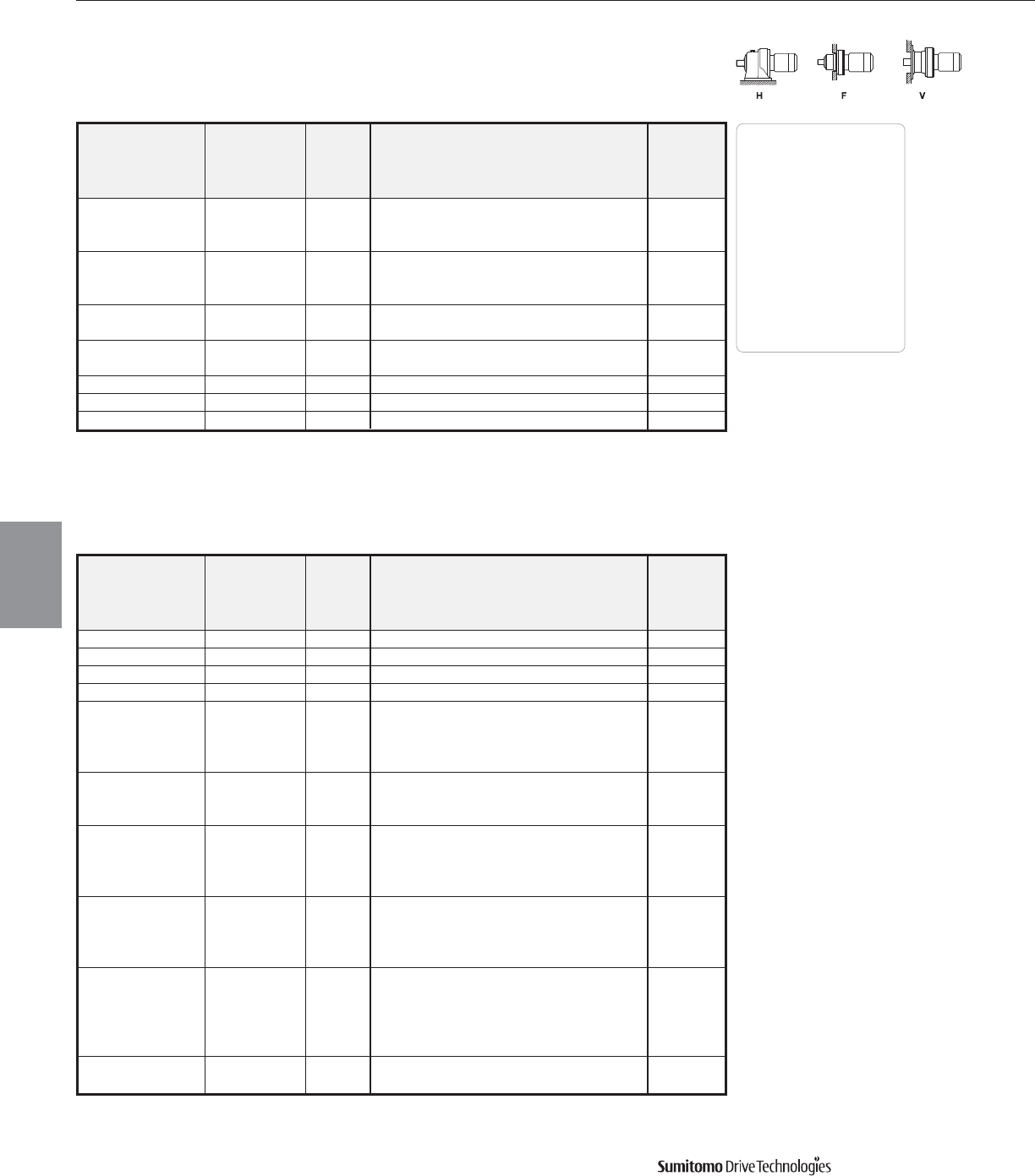
Frame Size Selection Tables 60 Hz
30 HP
60 Hz, 1750 RPM
CYCLO® 6000 Gearmotors
3.54 Frame Size Selection Tables
Output Output Service Factor Overhung SELECTION Option
Speed Torque Load
AGMA HP Frame Shaft AGMA Inverter
RPM In•lbs SF Class lbs Symbol Size Spec. Class Ratio Duty
228000 - - 42200 30 6245DB Y 273 AV
6.41 261000 1.05 I 51400 30 6255DA Y A 273 AV
261000 1.56 II 62000 30 6265DA Y B 273 -
288000 - - 54100 30 6255DB Y 319 -
5.49 305000 1.33 II 62000 30 6265DA Y B 319 -
305000 1.98 III 55700 30 6275DA Y C 319 -
4.64 360000 1.13 I 62000 30 6265DA Y A 377 -
1.67 III 55700 30 6275DA Y C 377 -
3.70 407000 - - 62000 30 6265DA Y 473 -
452000 1.33 II 55700 30 6275DA Y B 473 -
3.13 534000 1.13 I 55700 30 6275DA Y A 559 -
2.70 620000 0.97 - 55700 30 6275DA Y 649 -
2.39 603000 - - 55700 30 6275DA Y 731 -
Dimensions Pages
Foot
Mount (H) 4.2–4.29
V-Flange (V) 4.30–4.43
F-Flange (F) 4.44–4.69
Selection
Tables
Gearmotors
Cyclo® 6000 Series
40 HP
60 Hz, 1750 RPM
Output Output Service Factor Overhung SELECTION Option
Speed Torque Load
AGMA HP Frame Shaft AGMA Inverter
RPM In•lbs SF Class lbs Symbol Size Spec. Class Ratio Duty
583 4130 1.00 I 1908 40 6175 YA 3 -
350 6890 1.00 I 2260 40 6175 YA 5 -
292 8260 1.00 I 2400 40 6175 YA 6 -
219 11000 1.00 I 2630 40 6175 YA 8 -
1.00 I 3010 40 6175 Y A 11 -
159 15100 1.30 II 4090 40 6185 YB11 AV
1.60 III 5730 40 6195 Y C 11 -
1.99 III 11100 40 6205 Y C 11 -
1.00 I 3120 40 6175 Y A 13 -
135 17900 1.30 II 4220 40 6185 YB13 AV
1.60 III 5950 40 6195 YC13 AV
1.00 I 3230 40 6175 Y A 15 -
117 20600 1.30 II 4450 40 6185 YB15 AV
1.60 III 6240 40 6195 YC15 AV
1.99 III 11900 40 6205 Y C 15 -
0.80 - 3350 40 6175 Y17-
103 23400 1.02 I 4670 40 6180 YA17 AV
1.30 II 4670 40 6185 YB17 AV
1.60 III 6580 40 6195 YC17 AV
1.00 I 5030 40 6180 YA21 AV
1.30 II 5030 40 6185 YB21 AV
83.3 28900 1.37 II 7070 40 6190 YB21 AV
1.60 III 7070 40 6195 YC21 AV
1.97 III 13300 40 6205 Y C 21 -
70.0 34400 1.00 I 5190 40 6185 YA25 AV
1.35 II 7390 40 6195 YB25 AV
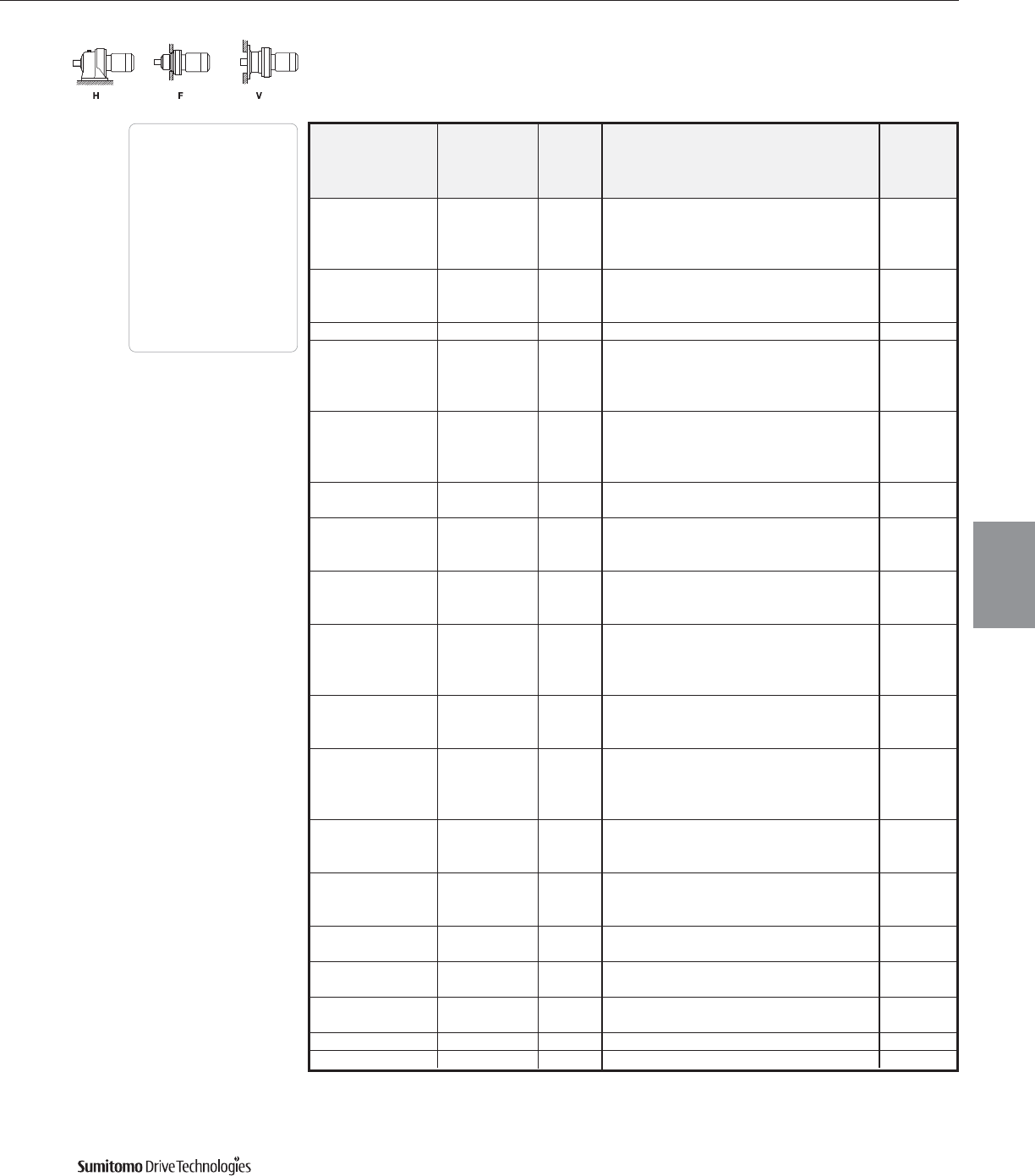
60 Hz Frame Size Selection Tables
40 HP
60 Hz, 1750 RPM
CYCLO® 6000 Gearmotors
Frame Size Selection Tables 3.55
Dimensions Pages
Foot
Mount (H) 4.2–4.29
V-Flange (V) 4.30–4.43
F-Flange (F) 4.44–4.69
Selection
Tables
Gearmotors
Cyclo® 6000 Series
Output Output Service Factor Overhung SELECTION Option
Speed Torque Load
AGMA HP Frame Shaft AGMA Inverter
RPM In•lbs SF Class lbs Symbol[1] Size Spec. Class Ratio Duty
0.80 - 5390 40 6185 Y29AV
60.3 39900 1.26 I 7750 40 6195 YA29 AV
1.52 II 14500 40 6205 Y B 29 -
1.95 III 14800 40 6215 Y C 29 -
1.30 II 8040 406 6190 YB21 AV
55.5 43400 1.60 III 8040 406 6195 YC21 AV
2.51 III 15300 406 6215 Y C 21 -
50.0 48100 1.00 I 8150 40 6195 YA35 AV
1.17 I 8690 406 6195 Y A 29 -
40.2 60000 1.32 II 16300 406 6205 Y B 29 -
1.87 III 16600 406 6215 Y C 29 -
2.22 III 17600 406 6225 Y C 29 -
1.00 I 8730 40 6195 YA43 AV
40.7 59200 1.06 I 16300 40 6205 YA43 AV
1.51 II 16600 40 6215 Y B 43 -
1.88 III 17600 40 6225 Y C 43 -
29.7 81200 1.26 I 18000 40 6215 YA59 AV
1.51 II 19100 40 6225 Y B 59 -
1.26 I 18700 406 6215 Y A 43 -
27.1 88500 1.59 II 19800 406 6225 Y B 43 -
2.51 III 27600 406 6245 Y C 43 -
1.26 I 26700 406 6235 YA59 AV
19.7 122000 1.87 III 30100 406 6245 Y C 59 -
2.16 III 36800 406 6255 Y C 59 -
119000 - - 23800 40 6225DB Y 121 -
14.5 157000 1.05 I 29900 40 6235DB Y A 121 AV
157000 1.54 II 40900 40 6255DB Y B 121 -
157000 1.69 III 50100 40 6265DA Y C 121 -
1.07 I 33500 406 6245 Y A 87 -
13.4 180000 1.43 II 41300 406 6255 Y B 87 -
1.78 III 50500 406 6265 Y C 87 -
173000 - - 32100 40 6235DB Y 165 AV
10.6 215000 1.08 I 35700 40 6245DB Y A 165 AV
215000 1.28 I 43800 40 6255DB Y A 165 -
215000 1.69 III 53700 40 6265DA Y C 165 -
232000 - - 37500 40 6245DB Y 195 AV
8.97 254000 1.06 I 46000 40 6255DA Y A 195 -
254000 1.52 II 56400 40 6265DA Y B 195 AV
228000 - - 40200 40 6245DB Y 231 AV
7.58 274000 - - 48900 40 6255DB Y 231 -
301000 1.35 II 59900 40 6265DA Y B 231 -
6.41 274000 - - 51400 40 6255DB Y 273 AV
356000 1.14 I 62000 40 6265DA Y A 273 AV
5.49 416000 0.98 - 62000 40 6265DA Y 319 -
1.45 II 55700 40 6275DA Y B 319 -
4.64 407000 - - 62000 40 6265DA Y 377 AV
491000 1.23 I 55700 40 6275DA Y A 377 AV
3.70 617000 0.98 - 55700 40 6275DA Y 473 -
3.13 603000 - - 55700 40 6275DA Y 559 AV
Note: [1] HP symbol ending in 6indicates a six-pole, 1165 RPM motor.
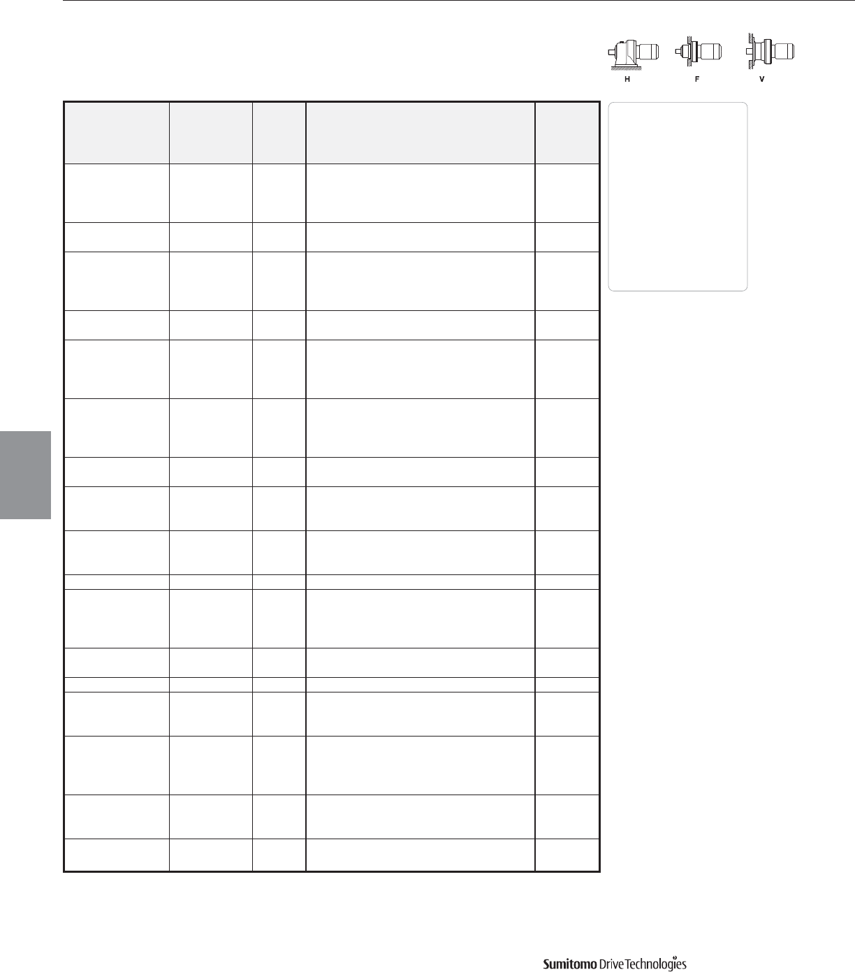
Frame Size Selection Tables 60 Hz
50 HP
60 Hz, 1750 RPM
CYCLO® 6000 Gearmotors
3.56 Frame Size Selection Tables
Output Output Service Factor Overhung SELECTION Option
Speed Torque Load
AGMA HP Frame Shaft AGMA Inverter
RPM In•lbs SF Class lbs Symbol[1] Size Spec. Class Ratio Duty
1.05 I 4040 50 6185 Y A 11 -
159 18700 1.30 II 5700 50 6195 YB11 AV
1.61 III 11100 50 6205 Y C 11 -
2.04 III 11200 50 6215 Y C 11 -
135 22000 1.05 I 4180 50 6185 Y A 13 -
1.30 II 5930 50 6195 YB13 AV
1.05 I 4380 50 6185 Y A 15 -
117 25500 1.30 II 6220 50 6195 YB15 AV
1.61 III 11900 50 6205 Y C 15 -
2.04 III 12000 50 6215 Y C 15 -
103 28800 1.05 I 4600 50 6185 Y A 17 -
1.30 II 6530 50 6195 YB17 AV
1.05 I 4960 50 6185 Y A 21 -
83.3 35700 1.30 II 7030 50 6195 YB21 AV
1.60 III 13300 50 6205 Y C 21 -
2.04 III 13600 50 6215 Y C 21 -
1.11 I 7030 506 6190 YA15 AV
77.7 38200 1.30 II 7030 506 6195 YB15 AV
1.61 III 13400 506 6205 Y C 15 -
2.04 III 13500 506 6215 Y C 15 -
70.0 42500 0.81 - 5100 50 6185 Y25-
1.09 I 7340 50 6195 YA25 AV
1.02 I 7680 50 6195 YA29 AV
60.3 49200 1.58 II 14800 50 6215 Y B 29 -
2.04 III 15600 50 6225 Y C 29 -
1.30 II 7970 506 6195 Y B 21 -
55.5 53500 2.04 III 15300 506 6215 Y C 21 -
2.45 III 16100 506 6225 Y C 21 -
50.0 59400 0.81 - 8060 50 6195 Y35AV
1.07 I 16200 506 6205 Y A 29 -
40.2 74000 1.51 II 16500 506 6215 Y B 29 -
1.80 III 17500 506 6225 Y C 29 -
2.04 III 22000 506 6235 Y C 29 -
40.7 73000 1.22 I 16600 50 6215 YA43 AV
1.53 II 17600 50 6225 Y B 43 -
29.7 100000 1.22 I 19000 50 6225 YA59 AV
1.29 I 19700 506 6225 Y A 43 -
27.1 110000 1.47 II 24200 506 6235 YB43 AV
2.04 III 27400 506 6245 Y C 43 -
1.02 I 26700 506 6235 Y A 59 -
19.7 150000 1.52 II 29900 506 6245 Y B 59 -
1.75 III 36800 506 6255 Y C 59 -
2.55 III 45100 506 6265 Y C 59 -
165000 - - 29900 50 6235DB Y 121 -
14.5 181000 - - 33200 50 6245DB Y 121 -
195000 1.25 I 40600 50 6255DB Y A 121 AV
13.4 222000 1.16 I 41100 506 6255 Y A 87 -
1.44 II 50300 506 6265 Y B 87 -
Dimensions Pages
Foot
Mount (H) 4.2–4.29
V-Flange (V) 4.30–4.43
F-Flange (F) 4.44–4.69
Selection
Tables
Gearmotors
Cyclo® 6000 Series
Note: [1] HP symbol ending in 6indicates a six-pole, 1165 RPM motor.
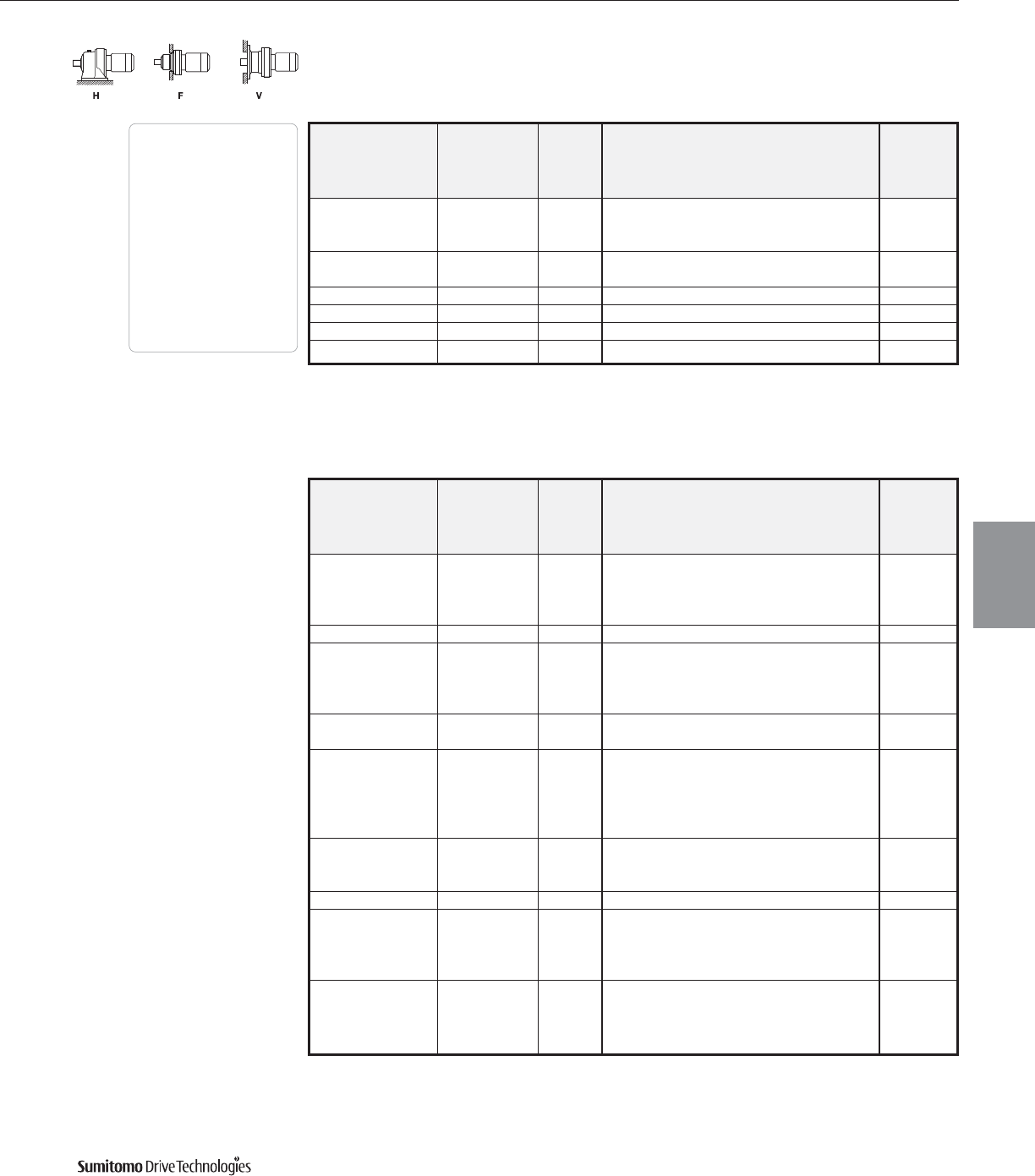
60 Hz Frame Size Selection Tables
50 HP
60 Hz, 1750 RPM
CYCLO® 6000 Gearmotors
Frame Size Selection Tables 3.57
Output Output Service Factor Overhung SELECTION Option
Speed Torque Load
AGMA HP Frame Shaft AGMA Inverter
RPM In•lbs SF Class lbs Symbol Size Spec. Class Ratio Duty
232000 - - 35500 50 6245DB Y 165 -
10.6 265000 1.04 I 43600 50 6255DB Y A 165 AV
265000 1.37 II 53400 50 6265DA Y B 165 AV
8.97 276000 - - 45800 50 6255DB Y 195 AV
313000 1.23 I 56100 50 6265DA Y A 195 AV
7.58 372000 1.10 I 59700 50 6265DA Y A 231 AV
6.41 407000 - - 62000 50 6265DA Y 273 AV
5.49 513000 1.18 I 55700 50 6275DA Y A 319 AV
4.64 606000 1.00 I 55700 50 6275DA Y A 377 AV
Dimensions Pages
Foot
Mount (H) 4.2–4.29
V-Flange (V) 4.30–4.43
F-Flange (F) 4.44–4.69
Selection
Tables
Gearmotors
Cyclo® 6000 Series
Note: [1] HP symbol ending in 6indicates a six-pole, 1165 RPM motor.
60 HP
60 Hz, 1750 RPM
Output Output Service Factor Overhung SELECTION Option
Speed Torque Load
AGMA HP Frame Shaft AGMA Inverter
RPM In•lbs SF Class lbs Symbol[1] Size Spec. Class Ratio Duty
1.07 I 5680 60 6195 Y A 11 -
159 22700 1.33 II 11000 60 6205 Y B 11 -
1.67 III 11200 60 6215 Y C 11 -
2.21 III 11900 60 6225 Y C 11 -
135 26800 1.07 I 5880 60 6195 Y A 13 -
1.07 I 6150 60 6195 Y A 15 -
117 31000 1.33 II 11900 60 6205 Y B 15 -
1.67 III 12000 60 6215 Y C 15 -
2.21 III 12800 60 6225 Y C 15 -
103 35100 0.87 - 4540 60 6185 Y17-
1.07 I 6490 60 6195 Y A 17 -
0.87 - 4870 60 6185 Y21-
1.07 I 6980 60 6195 Y A 21 -
83.3 43400 1.32 II 13200 60 6205 Y B 21 -
1.67 III 13500 60 6215 Y C 21 -
2.09 III 14300 60 6225 Y C 21 -
1.33 II 13300 606 6205 Y B 15 -
77.7 46500 1.67 III 13500 606 6215 Y C 15 -
2.21 III 14400 606 6225 Y C 15 -
70.0 51600 0.90 - 7270 60 6195 Y25-
0.84 - 7610 60 6195 Y29-
60.3 59900 1.02 I 14400 60 6205 Y A 29 -
1.30 II 14700 60 6215 Y B 29 -
1.67 III 15600 60 6225 Y C 29 -
1.22 I 14900 606 6205 Y A 21 -
55.5 65100 1.67 III 15200 606 6215 Y C 21 -
2.01 III 16100 606 6225 Y C 21 -
2.17 III 20100 606 6235 Y C 21 -
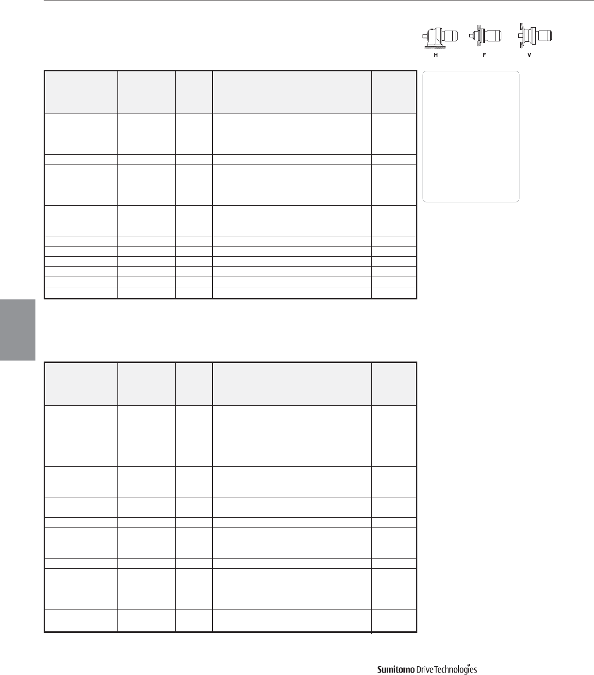
Frame Size Selection Tables 60 Hz
60 HP
60 Hz, 1750 RPM
CYCLO® 6000 Gearmotors
3.58 Frame Size Selection Tables
Output Output Service Factor Overhung SELECTION Option
Speed Torque Load
AGMA HP Frame Shaft AGMA Inverter
RPM In•lbs SF Class lbs Symbol[1] Size Spec. Class Ratio Duty
1.24 I 16400 606 6215 Y A 29 -
40.2 90200 1.48 II 17200 606 6225 Y B 29 -
1.67 III 21900 606 6235 Y C 29 -
2.09 III 24500 606 6245 Y C 29 -
40.7 88500 1.00 I 16500 60 6215 Y A 43 -
1.21 I 24200 606 6235 Y A 43 -
27.1 134000 1.67 III 27400 606 6245 Y C 43 -
1.98 III 33700 606 6255 Y C 43 -
2.51 III 41300 606 6265 Y C 43 -
1.25 I 29600 606 6245 Y A 59 -
19.7 183000 1.44 II 36100 606 6255 Y B 59 -
2.09 III 44900 606 6265 Y C 59 -
14.5 236000 1.03 I 40400 60 6255DB Y A 121 -
13.4 270000 1.19 I 50100 606 6265 Y A 87 -
10.6 323000 1.13 I 53200 60 6265DA Y A 165 -
8.97 381000 1.01 I 55700 60 6265DA Y A 195 -
7.58 407000 - - 59500 60 6265DA Y 231 -
5.49 624000 0.97 - 55700 60 6275DA Y 319 -
Dimensions Pages
Foot
Mount (H) 4.2–4.29
V-Flange (V) 4.30–4.43
F-Flange (F) 4.44–4.69
Selection
Tables
Gearmotors
Cyclo® 6000 Series
75 HP
60 Hz, 1750 RPM
Output Output Service Factor Overhung SELECTION Option
Speed Torque Load
AGMA HP Frame Shaft AGMA Inverter
RPM In•lbs SF Class lbs Symbol[1] Size Spec. Class Ratio Duty
1.09 I 11000 75 6205 Y A 11 -
159 27800 1.37 II 11200 75 6215 Y B 11 -
1.81 III 11800 75 6225 Y C 11 -
1.09 I 11800 75 6205 Y A 15 -
117 37900 1.37 II 12000 75 6215 Y B 15 -
1.81 III 12800 75 6225 Y C 15 -
1.08 I 13200 75 6205 Y A 21 -
83.3 53000 1.37 II 13500 75 6215 Y B 21 -
1.71 III 14200 75 6225 Y C 21 -
60.3 73200 1.06 I 14600 75 6215 Y A 29 -
1.37 II 15500 75 6225 Y B 29 -
55.5 79500 1.77 III 20000 756 6235 Y C 21 -
1.37 II 21600 756 6235 Y B 29 -
40.2 110000 1.71 III 24200 756 6245 Y C 29 -
2.15 III 30100 756 6255 Y C 29 -
40.7 109000 1.03 I 17400 75 6225 Y A 43 -
0.99 - 24200 756 6235 Y43-
27.1 163000 1.37 II 27200 756 6245 Y B 43 -
1.62 III 33500 756 6255 Y C 43 -
2.05 III 41100 756 6265 Y C 43 -
19.7 224000 1.18 I 36400 756 6255 Y A 59 -
1.71 III 44700 756 6265 Y C 59 -
Note: [1] HP symbol ending in 6indicates a six-pole, 1165 RPM motor.
Dimensions 4.1
Dimensions
Gearmotors
Dimensions shown are for reference only and are subject to change without notice, unless certified.
Certified prints are available after receipt of an order; consult factory.
Cyclo® 6000 Series
Dimensions
4
Dimensions for 575 Volt and CSA units may be different than
those specified in this section, please consult factory.
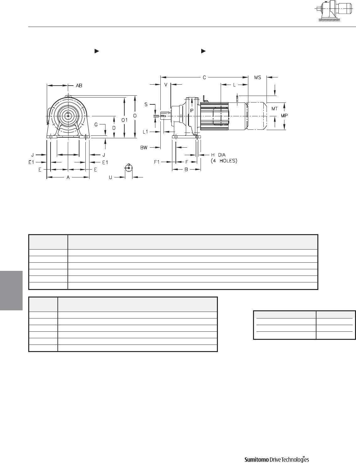
CYCLO® 6000 Gearmotors
Dimensions Integral Foot Mount
Single Reduction
CNHM-6060/5Y 610HY, PHHM-6100/5Y 610HY
4.2 Dimensions
Dimensions
Gearmotors
All dimensions are in inches
Model Low Speed Shaft
CNHM, PHHM
U* V S L1 Key
6060/5Y 0.500 0.98 10-32UNF 0.63 1/8 X 1/8 X 0.79
6070/5Y 0.750 1.18 12-28UNF 0.63 3/16 X 3/16 X 1.06
6080/5Y 0.875 1.38 12-28UNF 0.63 3/16 X 3/16 X 1.18
6090/5Y 1.125 1.38 5/16-18UNC 0.79 1/4 X 1/4 X 1.18
6100/5Y 1.125 1.38 5/16-18UNC 0.79 1/4 X 1/4 X 1.18
610HY 1.125 1.38 5/16-18UNC 0.79 1/4 X 1/4 X 1.18
Shaft Nominal Diameter (inches) Tolerances (inches)
0.500 (1/2) through 0.625 (5/8) +0.0000/-0.0004
0.750 (3/4) through 1.125 (1 1/8) +0.0000/-0.0005
1.250 (1 1/4) through 1.875 (1 7/8) +0.0000/-0.0006
*Shaft Tolerances
Model A B D E E1 F F1 G H J P BW
CNHM, PHHM
6060/5Y 5.67 3.31 3.15 2.36 0.47 2.36 0.47 0.39 0.35 1.38 4.33 1.61
6070/5Y 5.67 3.31 3.15 2.36 0.47 2.36 0.47 0.39 0.35 1.38 4.33 1.85
6080/5Y 5.67 3.90 3.54 2.36 0.47 2.95 0.47 0.51 0.35 1.46 5.28 2.05
6090/5Y 7.09 5.31 3.94 2.95 0.59 3.54 0.59 0.47 0.43 1.57 5.91 2.36
6100/5Y 7.09 5.31 3.94 2.95 0.59 3.54 0.59 0.47 0.43 1.57 5.91 2.36
610HY 7.09 5.31 4.72 2.95 0.59 3.54 0.59 0.47 0.43 1.77 5.91 2.36
Dimensions shown are for reference only and are subject to change without notice, unless certified.
Certified prints are available after receipt of an order; consult factory.
Cyclo® 6000 Series
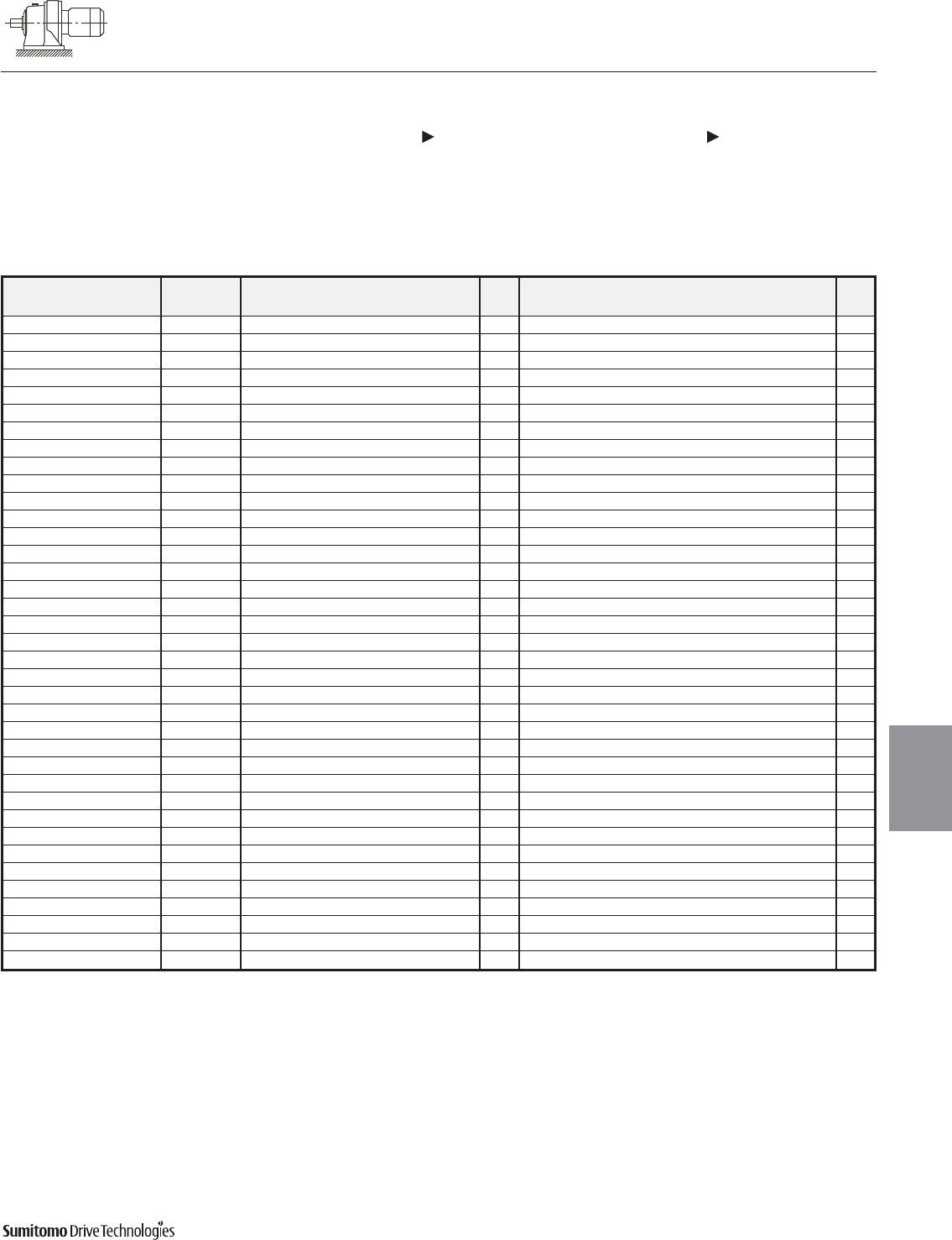
CYCLO® 6000 Gearmotors
Dimensions Integral Foot Mount
Single Reduction
CNHM-6060/5Y 610HY, PHHM-6100/5Y 610HY (cont.)
Dimensions 4.3
Dimensions
Gearmotors
All dimensions are in inches
Model Motor Without Brake Appx With Brake Appx
HP Pole C O O1 AB L MP Wt (lb) C O O1 AB L MP MS MT Wt (lb)
CNHM01-6060/5Y 1/8 4 8.90 - 5.59 5.04 1.38 4.69 13 10.28 - 5.59 5.04 2.76 4.88 1.93 - 15
CNHM02-6060/5Y 1/4 4 10.55 - 5.59 5.04 2.32 4.88 15 11.81 - 5.59 5.04 3.58 4.88 2.40 - 18
CNHM03-6060/5Y 1/3 4 10.55 - 5.59 5.04 2.32 4.88 15 11.81 - 5.59 5.04 3.58 4.88 2.40 - 18
CNHM01-6070/5Y 1/8 4 9.13 - 5.59 5.04 1.38 4.69 13 10.51 - 5.59 5.04 2.76 4.88 1.93 - 15
CNHM02-6070/5Y 1/4 4 10.79 - 5.59 5.04 2.32 4.88 15 12.05 - 5.59 5.04 3.58 4.88 2.40 - 18
CNHM03-6070/5Y 1/3 4 10.79 - 5.59 5.04 2.32 4.88 15 12.05 - 5.59 5.04 3.58 4.88 2.40 - 18
CNHM05-6070/5Y 1/2 4 11.57 - 5.59 5.04 2.32 4.88 18 12.83 - 5.59 5.04 3.58 4.88 2.40 - 20
CNHM01-6080/5Y 1/8 4 10.16 - 6.18 5.04 1.38 4.69 20 11.54 - 6.18 5.04 2.76 4.88 1.93 - 22
CNHM02-6080/5Y 1/4 4 11.81 - 6.18 5.04 2.32 4.88 22 13.07 - 6.18 5.04 3.58 4.88 2.40 - 24
CNHM03-6080/5Y 1/3 4 11.81 - 6.18 5.04 2.32 4.88 22 13.07 - 6.18 5.04 3.58 4.88 2.40 - 24
CNHM05-6080/5Y 1/2 4 12.60 - 6.18 5.04 2.32 4.88 26 13.86 - 6.18 5.04 3.58 4.88 2.40 - 29
CNHM08-6080/5Y 3/4 4 14.21 7.99 - 5.63 3.82 5.83 35 15.91 7.99 - 5.63 5.51 5.83 3.66 4.17 37
CNHM1-6080/5Y 1 4 14.21 7.99 - 5.63 3.82 5.83 35 15.91 7.99 - 5.63 5.51 5.83 3.66 4.17 37
CNHM01-6090/5Y 1/8 4 10.87 - 6.89 5.04 1.38 4.69 24 12.24 - 6.89 5.04 2.76 4.88 1.93 - 29
CNHM02-6090/5Y 1/4 4 12.52 - 6.89 5.04 2.32 4.88 26 13.78 - 6.89 5.04 3.58 4.88 2.40 - 31
CNHM03-6090/5Y 1/3 4 12.52 - 6.89 5.04 2.32 4.88 26 13.78 - 6.89 5.04 3.58 4.88 2.40 - 31
CNHM05-6090/5Y 1/2 4 13.31 - 6.89 5.04 2.32 4.88 29 14.57 - 6.89 5.04 3.58 4.88 2.40 - 33
CNHM08-6090/5Y 3/4 4 14.92 8.39 - 5.63 3.82 5.83 37 16.61 8.39 - 5.63 5.51 5.83 3.66 4.17 44
CNHM1-6090/5Y 1 4 14.92 8.39 - 5.63 3.82 5.83 37 16.61 8.39 - 5.63 5.51 5.83 3.66 4.17 44
CNHM1H-6090/5Y 1.5 4 16.22 8.66 - 5.83 3.94 6.30 44 18.66 8.66 - 5.83 6.38 6.30 4.53 4.49 55
CNHM2-6090/5Y 2 4 16.22 8.66 - 5.83 3.94 6.30 44 18.66 8.66 - 5.83 6.38 6.30 4.53 4.49 55
CNHM02-6100/5Y 1/4 4 13.07 8.15 - 5.04 2.32 4.88 37 14.33 8.15 - 5.04 3.58 4.88 2.40 - 42
CNHM03-6100/5Y 1/3 4 13.07 8.15 - 5.04 2.32 4.88 37 14.33 8.15 - 5.04 3.58 4.88 2.40 - 42
CNHM05-6100/5Y 1/2 4 13.86 8.15 - 5.04 2.32 4.88 40 15.12 8.15 - 5.04 3.58 4.88 2.40 - 44
CNHM08-6100/5Y 3/4 4 15.47 8.39 - 5.63 3.82 5.83 49 17.17 8.39 - 5.63 5.51 5.83 3.66 4.17 55
CNHM1-6100/5Y 1 4 15.47 8.39 - 5.63 3.82 5.83 49 17.17 8.39 - 5.63 5.51 5.83 3.66 4.17 55
CNHM/PHHM1H-6100/5Y 1.5 4 16.77 8.66 - 5.83 3.94 6.30 57 19.21 8.66 - 5.83 6.38 6.30 4.53 4.49 68
CNHM/PHHM2-6100/5Y 2 4 16.77 8.66 - 5.83 3.94 6.30 57 19.21 8.66 - 5.83 6.38 6.30 4.53 4.49 68
CNHM/PHHM3-6100/5Y 3 4 17.56 8.90 - 6.10 4.13 6.81 66 20.04 8.90 - 6.10 6.61 6.81 4.76 4.88 79
CNHM02-610HY 1/4 4 13.07 8.94 - 5.04 2.32 4.88 40 14.33 8.94 - 5.04 3.58 4.88 2.40 - 44
CNHM03-610HY 1/3 4 13.07 8.94 - 5.04 2.32 4.88 40 14.33 8.94 - 5.04 3.58 4.88 2.40 - 44
CNHM05-610HY 1/2 4 13.86 8.94 - 5.04 2.32 4.88 42 15.12 8.94 - 5.04 3.58 4.88 2.40 - 46
CNHM08-610HY 3/4 4 15.47 9.17 - 5.63 3.82 5.83 51 17.17 9.17 - 5.63 5.51 5.83 3.66 4.17 57
CNHM1-610HY 1 4 15.47 9.17 - 5.63 3.82 5.83 51 17.17 9.17 - 5.63 5.51 5.83 3.66 4.17 57
CNHM1H-610HY 1.5 4 16.77 9.45 - 5.83 3.94 6.30 60 19.21 9.45 - 5.83 6.38 6.30 4.53 4.49 71
CNHM/PHHM2-610HY 2 4 16.77 9.45 - 5.83 3.94 6.30 60 19.21 9.45 - 5.83 6.38 6.30 4.53 4.49 71
CNHM/PHHM3-610HY 3 4 17.56 9.69 - 6.10 4.13 6.81 68 20.04 9.69 - 6.10 6.61 6.81 4.76 4.88 82
Dimensions shown are for reference only and are subject to change without notice, unless certified.
Certified prints are available after receipt of an order; consult factory.
Cyclo® 6000 Series
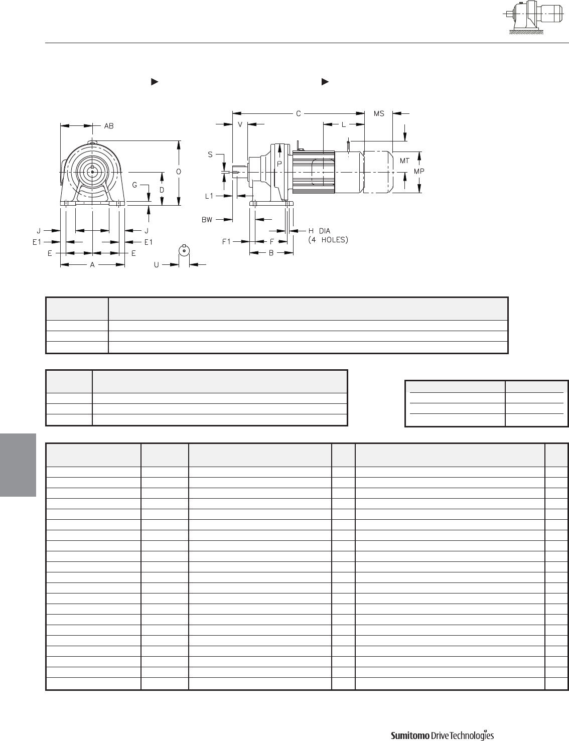
CYCLO® 6000 Gearmotors
Dimensions Integral Foot Mount
Single Reduction
CNHM-6110/5Y 612HY, PHHM-6120/5Y 612HY
4.4 Dimensions
Dimensions
Gearmotors
All dimensions are in inches
Model Low Speed Shaft
CNHM, PHHM
U* V S L1 Key
6110/5Y 1.250 1.77 5/16-18UNC 0.79 1/4 X 1/4 X 1.46
6120/5Y 1.500 2.17 5/16-18UNC 0.79 3/8 X 3/8 X 1.77
612HY 1.500 2.17 5/16-18UNC 0.79 3/8 X 3/8 X 1.77
Shaft Nominal Diameter (inches) Tolerances (inches)
0.500 (1/2) through 0.625 (5/8) +0.0000/-0.0004
0.750 (3/4) through 1.125 (1 1/8) +0.0000/-0.0005
1.250 (1 1/4) through 1.875 (1 7/8) +0.0000/-0.0006
*Shaft Tolerances
Model Motor Without Brake Appx With Brake Appx
HP Pole C O AB L MP Wt (lb) C O AB L MP MS MT Wt (lb)
CNHM05-6110/5Y 1/2 4 14.29 9.29 5.04 2.32 4.88 42 15.51 9.29 5.04 3.58 4.88 2.40 - 44
CNHM08-6110/5Y 3/4 4 15.87 9.29 5.63 3.82 5.83 49 17.80 9.29 5.63 5.51 5.83 3.66 4.17 55
CNHM1-6110/5Y 1 4 15.87 9.29 5.63 3.82 5.83 49 17.80 9.29 5.63 5.51 5.83 3.66 4.17 55
CNHM1H-6110/5Y 1.5 4 17.17 9.45 5.83 3.94 6.30 55 19.41 9.45 5.83 6.38 6.30 4.53 4.49 66
CNHM2-6110/5Y 2 4 17.17 9.45 5.83 3.94 6.30 55 19.41 9.45 5.83 6.38 6.30 4.53 4.49 66
CNHM3-6110/5Y 3 4 17.95 9.69 6.10 4.13 6.81 64 20.43 9.69 6.10 6.61 6.81 4.76 4.88 77
CNHM5-6110/5Y 5 4 19.33 10.47 6.54 5.00 8.35 86 22.17 10.47 6.54 7.83 8.35 5.20 6.18 108
CNHM08-6120/5Y 3/4 4 16.65 9.17 5.63 3.82 5.83 68 18.35 9.17 5.63 5.51 5.83 3.66 4.17 75
CNHM1-6120/5Y 1 4 16.65 9.17 5.63 3.82 5.83 68 18.35 9.17 5.63 5.51 5.83 3.66 4.17 75
CNHM1H-6120/5Y 1.5 4 17.95 9.45 5.83 3.94 6.30 77 20.39 9.45 5.83 6.38 6.30 4.53 4.49 88
CNHM2-6120/5Y 2 4 17.95 9.45 5.83 3.94 6.30 77 20.39 9.45 5.83 6.38 6.30 4.53 4.49 88
CNHM3-6120/5Y 3 4 18.74 9.69 6.10 4.13 6.81 86 21.22 9.69 6.10 6.61 6.81 4.76 4.88 101
CNHM/PHHM5-6120/5Y 5 4 19.65 10.47 6.54 5.00 8.35 108 22.48 10.47 6.54 7.83 8.35 5.20 6.18 130
CNHM/PHHM8-6120/5Y 7.5 4 21.38 10.47 6.54 5.00 8.35 123 24.21 10.47 6.54 7.83 8.35 5.20 6.18 146
CNHM08-612HY 3/4 4 16.65 9.96 5.63 3.82 5.83 71 18.35 9.96 5.63 5.51 5.83 3.66 4.17 77
CNHM1-612HY 1 4 16.65 9.96 5.63 3.82 5.83 71 18.35 9.96 5.63 5.51 5.83 3.66 4.17 77
CNHM1H-612HY 1.5 4 17.95 10.24 5.83 3.94 6.30 79 20.39 10.24 5.83 6.38 6.30 4.53 4.49 90
CNHM2-612HY 2 4 17.95 10.24 5.83 3.94 6.30 79 20.39 10.24 5.83 6.38 6.30 4.53 4.49 90
CNHM3-612HY 3 4 18.74 10.47 6.10 4.13 6.81 88 21.22 10.47 6.10 6.61 6.81 4.76 4.88 104
CNHM/PHHM5-612HY 5 4 19.65 11.26 6.54 5.00 8.35 110 22.48 11.26 6.54 7.83 8.35 5.20 6.18 132
CNHM/PHHM8-612HY 7.5 4 21.38 11.26 6.54 5.00 8.35 126 24.21 11.26 6.54 7.83 8.35 5.20 6.18 148
Model A B D E E1 F F1 G H J P BW
CNHM, PHHM
6110/5Y 7.09 5.31 4.724 2.95 0.59 3.54 0.59 0.47 0.43 1.77 6.38 2.76
6120/5Y 9.06 6.10 4.724 3.74 0.79 4.53 0.79 0.59 0.55 2.17 8.03 3.23
612HY 9.06 6.10 5.512 3.74 0.79 4.53 0.79 0.59 0.55 2.36 8.03 3.23
Dimensions shown are for reference only and are subject to change without notice, unless certified.
Certified prints are available after receipt of an order; consult factory.
Cyclo® 6000 Series
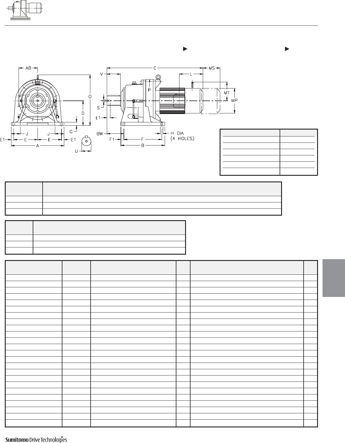
CYCLO® 6000 Gearmotors
Dimensions Integral Foot Mount
Single Reduction
CHHM-6130/5Y 614HY, PHHM-6130/5Y 614HY
Dimensions 4.5
Dimensions
Gearmotors
All dimensions are in inches
Dimensions shown are for reference only and are subject to change without notice, unless certified.
Certified prints are available after receipt of an order; consult factory.
Cyclo® 6000 Series
Model Low Speed Shaft
CHHM, PHHM
U* V S L1 Key
6130/5Y 1.875 2.76 3/8-16UNC 0.71 1/2 X 1/2 X 2.16
6140/5Y 1.875 3.54 3/8-16UNC 0.71 1/2 X 1/2 X 2.95
614HY 1.875 3.54 3/8-16UNC 0.71 1/2 X 1/2 X 2.95
Shaft Nominal Diameter (inches) Tolerances (inches)
0.500 (1/2) through 0.625 (5/8) +0.0000/-0.0004
0.750 (3/4) through 1.125 (1 1/8) +0.0000/-0.0005
1.250 (1 1/4) through 1.875 (1 7/8) +0.0000/-0.0006
2.000 (2) through 3.125 (3 1/8) +0.0000/-0.0007
3.250 (3 1/4) through 4.625 (4 5/8) +0.0000/-0.0009
4.750 (4 3/4) through 7.000 (7) +0.0000/-0.0010
*Shaft Tolerances
Model Motor Without Brake Appx With Brake Appx
HP Pole C O AB L MP Wt (lb) C O AB L MP MS MT Wt (lb)
CHHM1-6130/5Y 1 4 18.78 10.43 5.63 3.82 5.83 110 20.47 10.43 5.63 5.51 5.83 3.66 4.17 117
CHHM1H-6130/5Y 1.5 4 20.08 10.55 5.83 3.94 6.30 119 22.52 10.55 5.83 6.38 6.30 4.53 4.49 130
CHHM2-6130/5Y 2 4 20.08 10.55 5.83 3.94 6.30 119 22.52 10.55 5.83 6.38 6.30 4.53 4.49 130
CHHM3-6130/5Y 3 4 20.87 10.79 6.10 4.13 6.81 126 23.35 10.79 6.10 6.61 6.81 4.76 4.88 141
CHHM5-6130/5Y 5 4 21.77 11.65 6.54 5.00 8.35 148 24.61 11.65 6.54 7.83 8.35 5.20 6.18 170
CHHM/PHHM8-6130/5Y 7.5 4 23.50 11.65 6.54 5.00 8.35 163 26.34 11.65 6.54 7.83 8.35 5.20 6.18 185
CHHM/PHHM10-6130/5Y 10 4 24.41 12.72 8.31 5.63 9.88 196 28.15 12.72 8.31 9.37 9.88 6.69 7.17 236
CHHM/PHHM15-6130/5Y 15 4 26.77 12.72 8.31 5.63 9.88 227 30.51 12.72 8.31 9.37 9.88 6.69 7.17 265
CHHM1H-6140/5Y 1.5 4 20.87 10.55 5.83 3.94 6.30 121 23.31 10.55 5.83 6.38 6.30 4.53 4.49 132
CHHM2-6140/5Y 2 4 20.87 10.55 5.83 3.94 6.30 121 23.31 10.55 5.83 6.38 6.30 4.53 4.49 132
CHHM3-6140/5Y 3 4 21.65 10.79 6.10 4.13 6.81 128 24.13 10.79 6.10 6.61 6.81 4.76 4.88 143
CHHM5-6140/5Y 5 4 22.56 11.65 6.54 5.00 8.35 150 25.39 11.65 6.54 7.83 8.35 5.20 6.18 172
CHHM8-6140/5Y 7.5 4 24.29 11.65 6.54 5.00 8.35 165 27.13 11.65 6.54 7.83 8.35 5.20 6.18 187
CHHM/PHHM10-6140/5Y 10 4 25.20 12.72 8.31 5.63 9.88 198 28.94 12.72 8.31 9.37 9.88 6.69 7.17 238
CHHM/PHHM15-6140/5Y 15 4 27.56 12.72 8.31 5.63 9.88 227 31.30 12.72 8.31 9.37 9.88 6.69 7.17 267
CHHM/PHHM20-6140/5Y[1
]20 4 31.10 14.09 9.13 11.61 12.76 342 34.65 14.09 9.13 15.16 12.76 8.66 - 415
CHHM1H-614HY 1.5 4 20.87 10.94 5.83 3.94 6.30 126 23.31 10.94 5.83 6.38 6.30 4.53 4.49 137
CHHM2-614HY 2 4 20.87 10.94 5.83 3.94 6.30 126 23.31 10.94 5.83 6.38 6.30 4.53 4.49 137
CHHM3-614HY 3 4 21.65 11.18 6.10 4.13 6.81 132 24.13 11.18 6.10 6.61 6.81 4.76 4.88 148
CHHM5-614HY 5 4 22.56 12.05 6.54 5.00 8.35 154 25.39 12.05 6.54 7.83 8.35 5.20 6.18 176
CHHM8-614HY 7.5 4 24.29 12.05 6.54 5.00 8.35 170 27.13 12.05 6.54 7.83 8.35 5.20 6.18 192
CHHM/PHHM10-614HY 10 4 25.20 13.11 8.31 5.63 9.88 203 28.94 13.11 8.31 9.37 9.88 6.69 7.17 243
CHHM/PHHM15-614HY 15 4 27.56 13.11 8.31 5.63 9.88 234 31.30 13.11 8.31 9.37 9.88 6.69 7.17 273
CHHM/PHHM20-614HY[1
]20 4 31.10 14.49 9.13 11.61 12.76 348 34.65 14.49 9.13 15.16 12.76 8.66 - 421
Model A B D E E1 F F1 G H J P BW
CHHM, PHHM
6130/5Y 12.99 7.68 5.906 5.71 0.79 5.71 0.98 0.87 0.71 2.56 9.06 3.94
6140/5Y 12.99 7.68 5.906 5.71 0.79 5.71 0.98 0.87 0.71 2.56 9.06 4.72
614HY 12.99 7.68 6.299 5.71 0.79 5.71 0.98 0.87 0.71 2.76 9.06 4.72
Note: [1] Motor frame extends below the unit base.
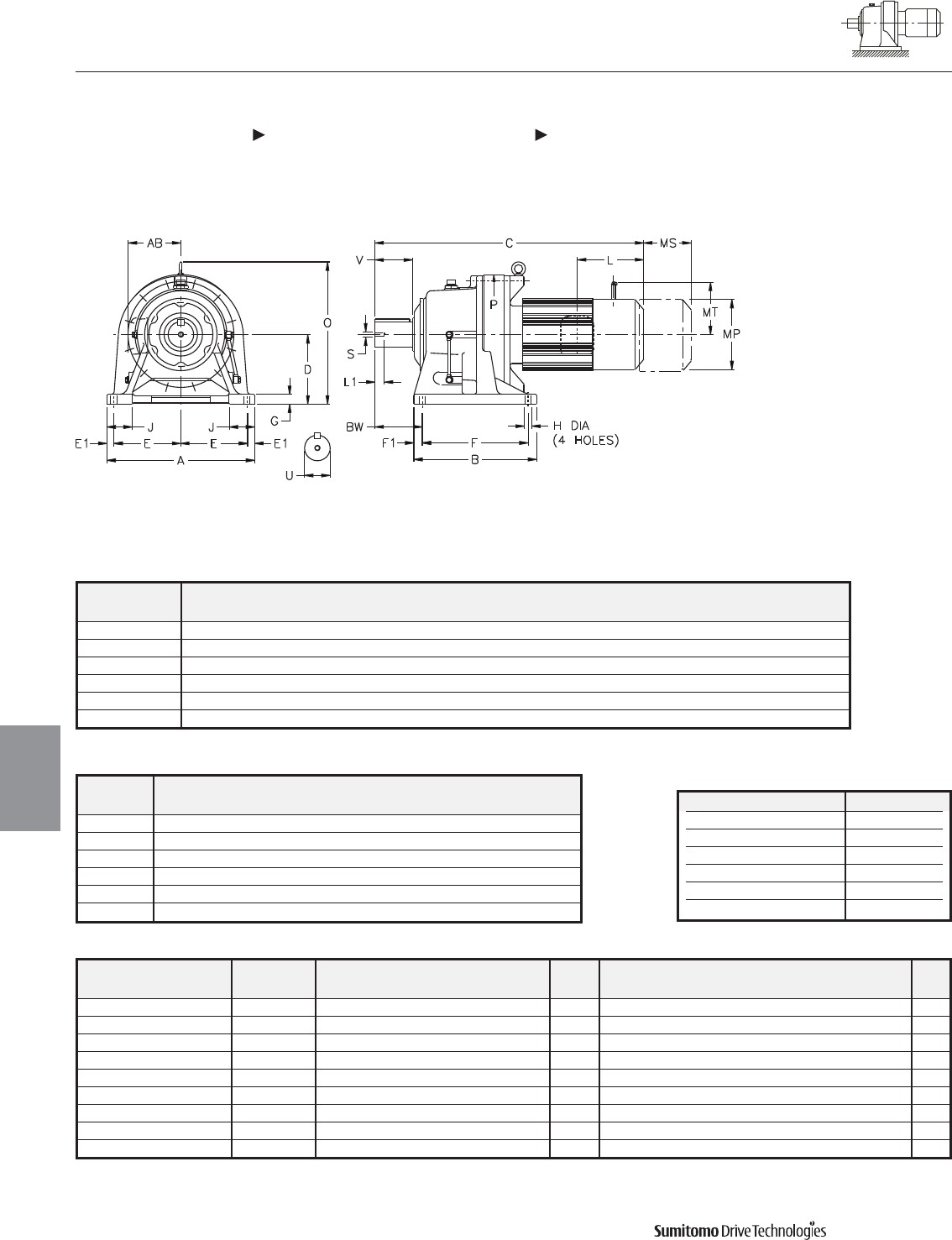
CYCLO® 6000 Gearmotors
Dimensions Integral Foot Mount
Single Reduction
CHHM-6160/5Y 6205Y, PHHM-6160/5Y 6170/5Y
4.6 Dimensions
Dimensions
Gearmotors
All dimensions are in inches
Model Low Speed Shaft
CHHM, PHHM
U* V S L1 Key
6160/5Y 2.250 3.54 3/8-16UNC 0.71 1/2 X 1/2 X 2.95
616HY 2.250 3.54 3/8-16UNC 0.71 1/2 X 1/2 X 2.95
6170/5Y 2.750 3.54 1/2-13UNC 0.94 5/8 X 5/8 X 3.15
6180/5Y 3.125 4.33 1/2-13UNC 0.94 3/4 X 3/4 X 3.74
6190/5Y 3.625 5.31 3/4-10UNC 1.34 7/8 X 7/8 X 4.92
6205Y 3.875 6.50 3/4-10UNC 1.34 1 X 1 X 6.50
Shaft Nominal Diameter (inches) Tolerances (inches)
0.500 (1/2) through 0.625 (5/8) +0.0000/-0.0004
0.750 (3/4) through 1.125 (1 1/8) +0.0000/-0.0005
1.250 (1 1/4) through 1.875 (1 7/8) +0.0000/-0.0006
2.000 (2) through 3.125 (3 1/8) +0.0000/-0.0007
3.250 (3 1/4) through 4.625 (4 5/8) +0.0000/-0.0009
4.750 (4 3/4) through 7.000 (7) +0.0000/-0.0010
*Shaft Tolerances
Dimensions shown are for reference only and are subject to change without notice, unless certified.
Certified prints are available after receipt of an order; consult factory.
Cyclo® 6000 Series
Model A B D E E1 F F1 G H J P BW
CHHM, PHHM
6160/5Y 16.14 9.37 6.299 7.28 0.79 5.91 1.73 0.98 0.71 2.95 12.52 5.47
616HY 16.14 9.37 7.874 7.28 0.79 5.91 1.73 0.98 0.71 3.15 12.52 5.47
6170/5Y 16.93 13.19 7.874 7.48 0.98 10.83 1.18 1.18 0.87 3.15 14.25 4.92
6180/5Y 18.50 14.96 8.661 8.27 0.98 12.60 1.18 1.18 0.87 3.35 15.35 5.71
6190/5Y 20.87 17.32 9.843 9.45 0.98 14.96 1.18 1.38 1.02 3.54 17.76 6.69
6205Y 20.87 17.32 9.843 8.66 1.77 14.17 1.57 1.38 1.02 3.94 18.54 8.46
Model Motor Without Brake Appx With Brake Appx
HP Pole C O AB L MP Wt (lb) C O AB L MP MS MT Wt (lb)
CHHM2-6160/5Y 2 4 22.95 12.20 5.83 3.94 6.30 205 25.39 12.20 5.83 6.38 6.30 4.53 4.49 216
CHHM3-6160/5Y 3 4 23.54 12.20 6.10 4.13 6.81 212 26.02 12.20 6.10 6.61 6.81 4.76 4.88 225
CHHM5-6160/5Y 5 4 24.45 12.20 6.54 5.00 8.35 232 27.28 12.20 6.54 7.83 8.35 5.20 6.18 254
CHHM8-6160/5Y 7.5 4 26.18 12.20 6.54 5.00 8.35 247 29.02 12.20 6.54 7.83 8.35 5.20 6.18 269
CHHM10-6160/5Y 10 4 27.28 13.11 8.31 5.63 9.88 282 31.02 13.11 8.31 9.37 9.88 6.69 7.17 320
CHHM/PHHM15-6160/5Y 15 4 29.65 13.11 8.31 5.63 9.88 313 33.39 13.11 8.31 9.37 9.88 6.69 7.17 351
CHHM/PHHM20-6160/5Y[1
]20 4 32.99 14.49 9.13 11.61 12.76 430 36.54 14.49 9.13 15.16 12.76 8.66 - 503
CHHM/PHHM25-6160/5Y[1
]25 4 36.73 14.49 11.69 13.39 15.51 589 45.00 14.49 11.69 21.65 15.51 14.45 - 701
CHHM/PHHM30-6160/5Y[1
]30 4 36.73 14.49 11.69 13.39 15.51 589 45.00 14.49 11.69 21.65 15.51 14.45 - 701
Note: [1] Motor frame extends below the unit base.
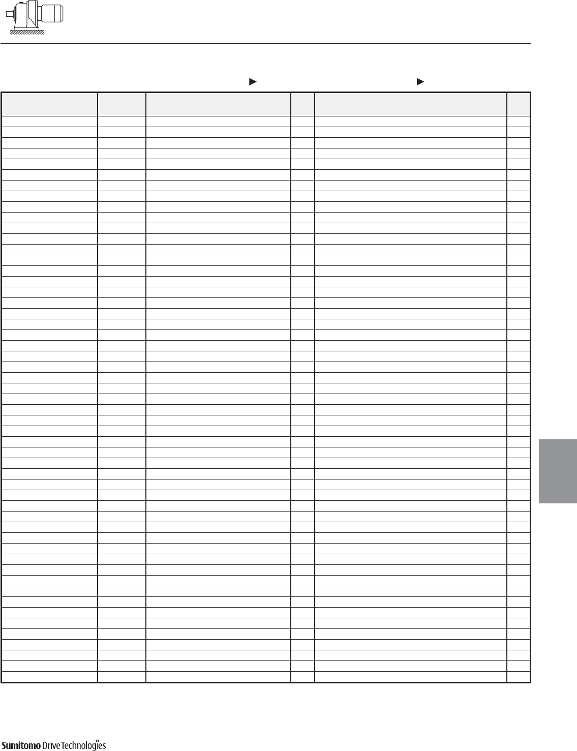
CYCLO® 6000 Gearmotors
Dimensions Integral Foot Mount
Single Reduction
CHHM-6160/5 6205Y, PHHM-6160/5Y 6170/5Y (cont.)
Dimensions 4.7
Dimensions
Gearmotors
All dimensions are in inches
Dimensions shown are for reference only and are subject to change without notice, unless certified.
Certified prints are available after receipt of an order; consult factory.
Cyclo® 6000 Series
Model Motor Without Brake Appx With Brake Appx
HP Pole C O AB L MP Wt (lb) C O AB L MP MS MT Wt (lb)
CHHM2-616HY 2 4 22.95 13.78 5.83 3.94 6.30 216 25.39 13.78 5.83 6.38 6.30 4.53 4.49 227
CHHM3-616HY 3 4 23.54 13.78 6.10 4.13 6.81 223 26.02 13.78 6.10 6.61 6.81 4.76 4.88 236
CHHM5-616HY 5 4 24.45 13.78 6.54 5.00 8.35 243 27.28 13.78 6.54 7.83 8.35 5.20 6.18 265
CHHM8-616HY 7.5 4 26.18 13.78 6.54 5.00 8.35 258 29.02 13.78 6.54 7.83 8.35 5.20 6.18 280
CHHM10-616HY 10 4 27.28 14.69 8.31 5.63 9.88 293 31.02 14.69 8.31 9.37 9.88 6.69 7.17 331
CHHM15-616HY 15 4 29.65 14.69 8.31 5.63 9.88 324 33.39 14.69 8.31 9.37 9.88 6.69 7.17 362
CHHM/PHHM20-616HY 20 4 32.99 16.06 9.13 11.61 12.76 441 36.54 16.06 9.13 15.16 12.76 8.66 - 514
CHHM/PHHM25-616HY 25 4 36.73 16.06 11.69 13.39 15.51 600 45.00 16.06 11.69 21.65 15.51 14.45 - 712
CHHM/PHHM30-616HY 30 4 36.73 16.06 11.69 13.39 15.51 600 45.00 16.06 11.69 21.65 15.51 14.45 - 712
CHHM5-6170/5Y 5 4 26.77 15.87 6.54 5.00 8.35 322 29.61 15.87 6.54 7.83 8.35 5.20 6.18 344
CHHM8-6170/5Y 7.5 4 28.50 15.87 6.54 5.00 8.35 337 31.34 15.87 6.54 7.83 8.35 5.20 6.18 359
CHHM10-6170/5Y 10 4 29.21 15.87 8.31 5.63 9.88 370 32.95 15.87 8.31 9.37 9.88 6.69 7.17 410
CHHM15-6170/5Y 15 4 31.57 15.87 8.31 5.63 9.88 401 35.31 15.87 8.31 9.37 9.88 6.69 7.17 441
CHHM/PHHM20-6170/5Y 20 4 34.72 16.26 9.13 11.61 12.76 520 38.27 16.26 9.13 15.16 12.76 8.66 - 593
CHHM/PHHM25-6170/5Y 25 4 38.46 16.81 11.69 13.39 15.51 670 46.73 16.81 11.69 21.65 15.51 14.45 - 783
CHHM/PHHM30-6170/5Y 30 4 38.46 16.81 11.69 13.39 15.51 670 46.73 16.81 11.69 21.65 15.51 14.45 - 783
CHHM/PHHM40-6170/5Y 40 4 38.46 16.85 11.69 13.39 15.51 708 46.73 16.81 11.69 21.65 15.51 14.57 - 803
CHHM5-6180/5Y 5 4 28.23 17.24 6.54 5.00 8.35 404 31.06 17.24 6.54 7.83 8.35 5.20 6.18 426
CHHM8-6180/5Y 7.5 4 29.96 17.24 6.54 5.00 8.35 421 32.80 17.24 6.54 7.83 8.35 5.20 6.18 443
CHHM10-6180/5Y 10 4 30.67 17.24 8.31 5.63 9.88 454 34.41 17.24 8.31 9.37 9.88 6.69 7.17 494
CHHM15-6180/5Y 15 4 33.03 17.24 8.31 5.63 9.88 485 36.77 17.24 8.31 9.37 9.88 6.69 7.17 525
CHHM20-6180/5Y 20 4 36.18 17.24 9.13 11.61 12.76 617 39.72 17.24 9.13 15.16 12.76 8.66 - 679
CHHM25-6180/5Y 25 4 39.92 17.64 11.69 13.39 15.51 754 48.19 17.64 11.69 21.65 15.51 14.45 - 867
CHHM30-6180/5Y 30 4 39.92 17.64 11.69 13.39 15.51 754 48.19 17.64 11.69 21.65 15.51 14.45 - 867
CHHM40-6180/5Y 40 4 39.92 17.64 11.69 13.39 15.51 792 48.19 17.64 11.69 21.65 15.51 14.57 - 886
CHHM50-6180/5Y 50 4 44.45 18.94 11.69 16.93 15.51 897 52.91 18.94 11.69 25.39 15.51 17.52 - 1111
CHHM60-6180/5Y 60 4 44.45 18.94 11.69 16.93 15.51 897 52.91 18.94 11.69 25.39 15.51 17.52 - 1111
CHHM8-6190/5Y 7.5 4 33.74 20.12 6.54 5.00 8.35 584 36.57 20.12 6.54 7.83 8.35 5.20 6.18 606
CHHM10-6190/5Y 10 4 34.25 20.12 8.31 5.63 9.88 613 37.99 20.12 8.31 9.37 9.88 6.69 7.17 653
CHHM15-6190/5Y 15 4 36.61 20.12 8.31 5.63 9.88 644 40.35 20.12 8.31 9.37 9.88 6.69 7.17 684
CHHM20-6190/5Y 20 4 39.17 18.39 9.13 11.61 12.76 761 42.72 18.39 9.13 15.16 12.76 8.66 - 836
CHHM25-6190/5Y 25 4 42.91 20.12 11.69 13.39 15.51 919 51.18 20.12 11.69 21.65 15.51 14.45 - 1019
CHHM256-6190/5Y 25 6 42.91 20.12 11.69 13.39 15.51 953 51.18 20.12 11.69 21.65 15.51 14.45 - 1047
CHHM30-6190/5Y 30 4 42.91 20.12 11.69 13.39 15.51 919 51.18 20.12 11.69 21.65 15.51 14.45 - 1019
CHHM40-6190/5Y 40 4 42.91 20.12 11.69 13.39 15.51 953 51.18 20.12 11.69 21.65 15.51 14.57 - 1047
CHHM406-6190/5Y 40 6 47.44 20.12 11.69 16.93 15.51 1036 55.91 20.12 11.69 25.39 15.51 17.52 - 1250
CHHM50-6190/5Y 50 4 47.44 20.12 11.69 16.93 15.51 1036 55.91 20.12 11.69 25.39 15.51 17.52 - 1250
CHHM506-6190/5Y 50 6 47.44 20.12 11.69 16.93 15.51 1036 55.91 20.12 11.69 25.39 15.51 17.52 - 1250
CHHM60-6190/5Y 60 4 47.44 20.12 11.69 16.93 15.51 1036 55.91 20.12 11.69 25.39 15.51 17.52 - 1250
CHHM15-6205Y 15 4 38.27 20.87 8.31 5.63 9.88 690 42.01 20.87 8.31 9.37 9.88 6.69 7.17 730
CHHM20-6205Y 20 4 41.02 20.87 9.13 11.61 12.76 809 44.57 20.87 9.13 15.16 12.76 8.66 - 886
CHHM206-6205Y 20 6 44.37 20.87 11.69 13.39 15.51 966 52.64 20.87 11.69 21.65 15.51 14.45 - 1065
CHHM25-6205Y 25 4 44.37 20.87 11.69 13.39 15.51 966 52.64 20.87 11.69 21.65 15.51 14.45 - 1065
CHHM256-6205Y 25 6 44.37 20.87 11.69 13.39 15.51 966 52.64 20.87 11.69 21.65 15.51 14.45 - 1065
CHHM30-6205Y 30 4 44.37 20.87 11.69 13.39 15.51 966 52.64 20.87 11.69 21.65 15.51 14.45 - 1065
CHHM306-6205Y 30 6 44.37 20.87 11.69 13.39 15.51 994 52.64 20.87 11.69 21.65 15.51 14.57 - 1094
CHHM40-6205Y 40 4 44.37 20.87 11.69 13.39 15.51 994 52.64 20.87 11.69 21.65 15.51 14.57 - 1094
CHHM406-6205Y 40 6 48.90 20.87 11.69 16.93 15.51 1078 57.36 20.87 11.69 25.39 15.51 17.52 - 1286
CHHM50-6205Y 50 4 48.90 20.87 11.69 16.93 15.51 1078 57.36 20.87 11.69 25.39 15.51 17.52 - 1286
CHHM506-6205Y 50 6 48.90 20.87 11.69 16.93 15.51 1078 57.36 20.87 11.69 25.39 15.51 17.52 - 1286
CHHM60-6205Y 60 4 48.90 20.87 11.69 16.93 15.51 1078 57.36 20.87 11.69 25.39 15.51 17.52 - 1286
CHHM606-6205Y 60 6 51.06 22.64 16.22 18.31 19.06 1283 - - - - - - - -
CHHM75-6205Y 75 4 51.06 22.64 16.22 18.31 19.06 1283 - - - - - - - -
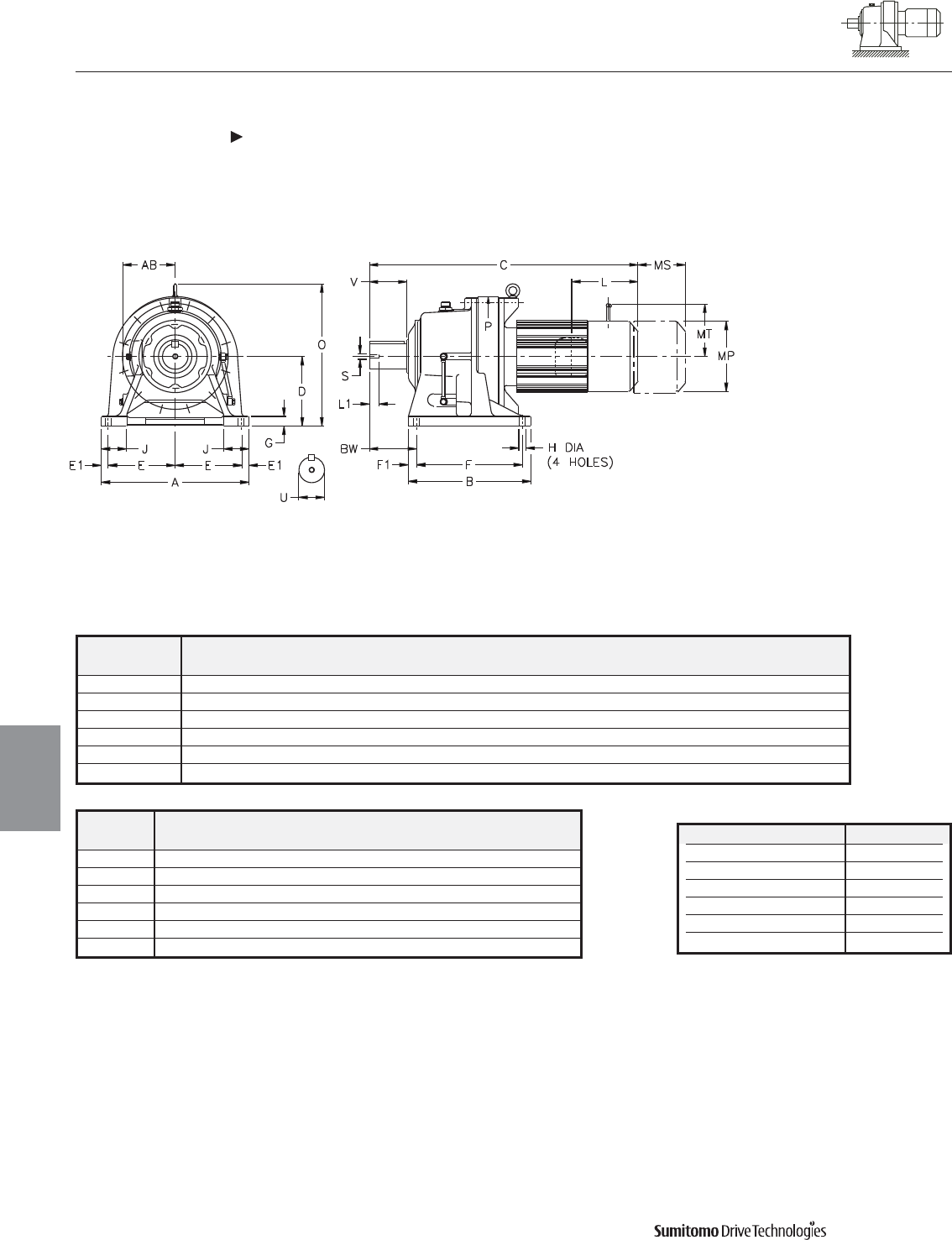
CYCLO® 6000 Gearmotors
Dimensions Integral Foot Mount
Single Reduction
CHHM-6215Y 6265Y
4.8 Dimensions
Dimensions
Gearmotors
All dimensions are in inches
Model Low Speed Shaft
CHHM
U* V S L1 Key
6215Y 4.250 6.50 3/4-10UNC 1.34 1 X 1 X 6.50
6225Y 4.625 6.50 3/4-10UNC 1.34 1-1/4 X 7/8 X 6.5
6235Y 5.000 7.87 1-8UNC 1.61 1-1/4 X 7/8 X 7.87
6245Y 5.500 7.87 1-8UNC 1.61 1-1/4 X 7/8 X 7.87
6255Y 6.250 9.45 1-1/4-7UNC 1.93 1-1/2 X 1 X 9.45
6265Y 6.625 11.81 1-1/4-7UNC 1.93 1-3/4 X 1-1/4 X 11.8
Shaft Nominal Diameter (inches) Tolerances (inches)
0.500 (1/2) through 0.625 (5/8) +0.0000/-0.0004
0.750 (3/4) through 1.125 (1 1/8) +0.0000/-0.0005
1.250 (1 1/4) through 1.875 (1 7/8) +0.0000/-0.0006
2.000 (2) through 3.125 (3 1/8) +0.0000/-0.0007
3.250 (3 1/4) through 4.625 (4 5/8) +0.0000/-0.0009
4.750 (4 3/4) through 7.000 (7) +0.0000/-0.0010
*Shaft Tolerances
Dimensions shown are for reference only and are subject to change without notice, unless certified.
Certified prints are available after receipt of an order; consult factory.
Cyclo® 6000 Series
Model A B D E E1 F F1 G H J P BW
CHHM
6215Y 22.83 18.70 10.433 9.45 1.97 15.55 1.57 1.57 1.02 4.33 19.96 8.27
6225Y 24.41 20.47 11.024 10.63 1.57 16.54 1.97 1.57 1.30 4.53 21.61 9.06
6235Y 26.38 22.05 11.811 11.42 1.77 18.11 1.97 1.77 1.30 4.72 23.27 10.24
6245Y 28.35 22.83 13.189 12.40 1.77 18.90 1.97 1.77 1.54 5.04 25.08 10.35
6255Y 30.71 24.80 14.764 13.19 2.17 20.47 2.17 1.97 1.54 5.51 27.68 12.60
6265Y 34.65 27.56 15.748 15.16 2.17 23.23 2.17 2.17 1.77 6.30 30.39 15.35
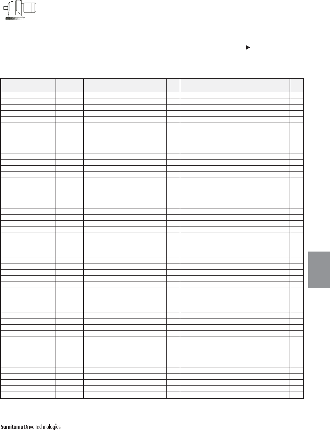
CYCLO® 6000 Gearmotors
Dimensions Integral Foot Mount
Single Reduction
CHHM-6215Y 6265Y (cont.)
Dimensions 4.9
Dimensions
Gearmotors
All dimensions are in inches
Dimensions shown are for reference only and are subject to change without notice, unless certified.
Certified prints are available after receipt of an order; consult factory.
Cyclo® 6000 Series
Model Motor Without Brake Appx With Brake Appx
HP Pole C O AB L MP Wt (lb) C O AB L MP MS MT Wt (lb)
CHHM15-6215Y 15 4 39.21 22.64 8.31 5.63 9.88 871 42.95 22.64 8.31 9.37 9.88 6.69 7.17 911
CHHM20-6215Y 20 4 41.97 22.64 9.13 11.61 12.76 992 45.51 22.64 9.13 15.16 12.76 8.66 - 1067
CHHM206-6215Y 20 6 45.31 22.64 11.69 13.39 15.51 1136 53.58 22.64 11.69 21.65 15.51 14.45 - 1235
CHHM25-6215Y 25 4 45.31 22.64 11.69 13.39 15.51 1136 53.58 22.64 11.69 21.65 15.51 14.45 - 1235
CHHM256-6215Y 25 6 45.31 22.64 11.69 13.39 15.51 1164 53.58 22.64 11.69 21.65 15.51 14.45 - 1263
CHHM30-6215Y 30 4 45.31 22.64 11.69 13.39 15.51 1136 53.58 22.64 11.69 21.65 15.51 14.45 - 1235
CHHM306-6215Y 30 6 45.31 22.64 11.69 13.39 15.51 1164 53.58 22.64 11.69 21.65 15.51 14.57 - 1263
CHHM40-6215Y 40 4 45.31 22.64 11.69 13.39 15.51 1164 53.58 22.64 11.69 21.65 15.51 14.57 - 1263
CHHM406-6215Y 40 6 49.84 22.64 11.69 16.93 15.51 1248 58.31 22.64 11.69 25.39 15.51 17.52 - 1458
CHHM50-6215Y 50 4 49.84 22.64 11.69 16.93 15.51 1248 58.31 22.64 11.69 25.39 15.51 17.52 - 1458
CHHM506-6215Y 50 6 49.84 22.64 11.69 16.93 15.51 1248 58.31 22.64 11.69 25.39 15.51 17.52 - 1458
CHHM60-6215Y 60 4 49.84 22.64 11.69 16.93 15.51 1248 58.31 22.64 11.69 25.39 15.51 17.52 - 1458
CHHM606-6215Y 60 6 52.01 22.64 16.22 18.31 19.06 1491 - - - - - - - -
CHHM75-6215Y 75 4 52.01 22.64 16.22 18.31 19.06 1491 - - - - - - - -
CHHM206-6225Y 20 6 46.89 24.02 11.69 13.39 15.51 1323 55.16 24.02 11.69 21.65 15.51 14.45 - 1422
CHHM25-6225Y 25 4 46.89 24.02 11.69 13.39 15.51 1323 55.16 24.02 11.69 21.65 15.51 14.45 - 1422
CHHM256-6225Y 25 6 46.89 24.02 11.69 13.39 15.51 1352 55.16 24.02 11.69 21.65 15.51 14.45 - 1451
CHHM30-6225Y 30 4 46.89 24.02 11.69 13.39 15.51 1323 55.16 24.02 11.69 21.65 15.51 14.45 - 1422
CHHM306-6225Y 30 6 46.89 24.02 11.69 13.39 15.51 1352 55.16 24.02 11.69 21.65 15.51 14.57 - 1451
CHHM40-6225Y 40 4 46.89 24.02 11.69 13.39 15.51 1352 55.16 24.02 11.69 21.65 15.51 14.57 - 1451
CHHM406-6225Y 40 6 51.42 24.02 11.69 16.93 15.51 1435 59.88 24.02 11.69 25.39 15.51 17.52 - 1645
CHHM50-6225Y 50 4 51.42 24.02 11.69 16.93 15.51 1435 59.88 24.02 11.69 25.39 15.51 17.52 - 1645
CHHM506-6225Y 50 6 51.42 24.02 11.69 16.93 15.51 1435 59.88 24.02 11.69 25.39 15.51 17.52 - 1645
CHHM60-6225Y 60 4 51.42 24.02 11.69 16.93 15.51 1435 59.88 24.02 11.69 25.39 15.51 17.52 - 1645
CHHM606-6225Y 60 6 53.58 24.02 16.22 18.31 19.06 1654 - - - - - - - -
CHHM75-6225Y 75 4 53.58 24.02 16.22 18.31 19.06 1654 - - - - - - - -
CHHM206-6235Y 20 6 49.33 26.26 11.69 13.39 15.51 1539 57.60 26.26 11.69 21.65 15.51 14.45 - 1607
CHHM256-6235Y 25 6 49.33 26.26 11.69 13.39 15.51 1539 57.60 26.26 11.69 21.65 15.51 14.45 - 1638
CHHM306-6235Y 30 6 49.33 26.26 11.69 13.39 15.51 1539 57.60 26.26 11.69 21.65 15.51 14.57 - 1638
CHHM406-6235Y 40 6 53.86 26.26 11.69 16.93 15.51 1641 62.32 26.26 11.69 25.39 15.51 17.52 - 1835
CHHM506-6235Y 50 6 53.86 26.26 11.69 16.93 15.51 1641 62.32 26.26 11.69 25.39 15.51 17.52 - 1835
CHHM606-6235Y 60 6 56.02 26.26 16.22 18.31 19.06 1837 - - - - - - - -
CHHM756-6235Y 75 6 59.17 26.26 16.22 19.88 19.09 1956 - - - - - - - -
CHHM206-6245Y 20 6 50.47 28.70 11.69 13.39 15.51 1806 58.74 28.70 11.69 21.65 15.51 14.45 - 1879
CHHM256-6245Y 25 6 50.47 28.70 11.69 13.39 15.51 1806 58.74 28.70 11.69 21.65 15.51 14.45 - 1910
CHHM306-6245Y 30 6 50.47 28.70 11.69 13.39 15.51 1806 58.74 28.70 11.69 21.65 15.51 14.57 - 1910
CHHM406-6245Y 40 6 55.00 28.70 11.69 16.93 15.51 1907 63.46 28.70 11.69 25.39 15.51 17.52 - 2101
CHHM506-6245Y 50 6 55.00 28.70 11.69 16.93 15.51 1907 63.46 28.70 11.69 25.39 15.51 17.52 - 2101
CHHM606-6245Y 60 6 57.17 28.70 16.22 18.31 19.06 2108 - - - - - - - -
CHHM756-6245Y 75 6 60.31 28.70 16.22 19.88 19.09 2216 - - - - - - - -
CHHM256-6255Y 25 6 55.12 32.09 11.69 13.39 15.51 2536 63.39 32.09 11.69 21.65 15.51 14.45 - 2639
CHHM306-6255Y 30 6 55.12 32.09 11.69 13.39 15.51 2536 63.39 32.09 11.69 21.65 15.51 14.57 - 2639
CHHM406-6255Y 40 6 59.65 32.09 11.69 16.93 15.51 2635 68.11 32.09 11.69 25.39 15.51 17.52 - 2829
CHHM506-6255Y 50 6 59.65 32.09 11.69 16.93 15.51 2635 68.11 32.09 11.69 25.39 15.51 17.52 - 2829
CHHM606-6255Y 60 6 61.81 32.09 16.22 18.31 19.06 2811 - - - - - - - -
CHHM756-6255Y 75 6 64.96 32.09 16.22 19.88 19.09 2933 - - - - - - - -
CHHM406-6265Y 40 6 64.25 34.41 11.69 16.93 15.51 3175 72.72 34.41 11.69 25.39 15.51 17.52 - 3369
CHHM506-6265Y 50 6 64.25 34.41 11.69 16.93 15.51 3175 72.72 34.41 11.69 25.39 15.51 17.52 - 3369
CHHM606-6265Y 60 6 66.42 34.41 16.22 18.31 19.06 3385 - - - - - - - -
CHHM756-6265Y 75 6 69.56 34.41 16.22 19.88 19.06 3493 - - - - - - - -
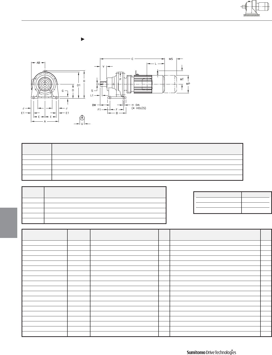
CYCLO® 6000 Gearmotors
Dimensions Integral Foot Mount
Double Reduction
CNHM-6060/5DAY 6120/5DBY
4.10 Dimensions
Dimensions
Gearmotors
All dimensions are in inches
Model Low Speed Shaft
CNHM
U* V S L1 Key
6060/5DAY 0.500 0.98 0.63 10-32UNF 1/8 X 1/8 X .79
6070/5DAY 0.750 1.18 0.63 12-28UNF 3/16 X 3/16 X 1.06
6090/5DAY 1.125 1.38 0.79 5/16-18UNC 1/4 X 1/4 X 1.18
6100/5DAY 1.125 1.38 0.79 5/16-18UNC 1/4 X 1/4 X 1.18
6120/5DBY 1.500 2.17 0.79 5/16-18UNC 3/8 X 3/8 X 1.77
Shaft Nominal Diameter (inches) Tolerances (inches)
0.500 (1/2) through 0.625 (5/8) +0.0000/-0.0004
0.750 (3/4) through 1.125 (1 1/8) +0.0000/-0.0005
1.250 (1 1/4) through 1.875 (1 7/8) +0.0000/-0.0006
*Shaft Tolerances
Model Motor Without Brake Appx With Brake Appx
HP Pole C O O1 AB L MP Wt (lb) C O O1 AB L MP MS MT Wt (lb)
CNHM01-6060/5DAY 1/8 4 10.20 - 5.59 5.04 1.38 4.69 18 11.57 - 5.59 5.04 2.76 4.88 1.93 - 20
CNHM01-6070/5DAY 1/8 4 10.43 - 5.59 5.04 1.38 4.69 18 11.81 - 5.59 5.04 2.76 4.88 1.93 - 20
CNHM02-6070/5DAY 1/4 4 12.09 - 5.59 5.04 2.32 4.88 20 13.35 - 5.59 5.04 3.58 4.88 2.40 - 22
CNHM01-6090/5DAY 1/8 4 12.76 8.15 - 5.04 1.38 4.69 35 14.13 8.15 - 5.04 2.76 4.88 1.93 - 37
CNHM02-6090/5DAY 1/4 4 14.41 8.15 - 5.04 2.32 4.88 37 15.67 8.15 - 5.04 3.58 4.88 2.40 - 40
CNHM03-6090/5DAY 1/3 4 14.41 8.15 - 5.04 2.32 4.88 37 15.67 8.15 - 5.04 3.58 4.88 2.40 - 40
CNHM05-6090/5DAY 1/2 4 15.20 8.15 - 5.04 2.32 4.88 40 16.46 8.15 - 5.04 3.58 4.88 2.40 - 42
CNHM01-6100/5DAY 1/8 4 13.31 8.15 - 5.04 1.38 4.69 40 14.69 8.15 - 5.04 2.76 4.88 1.93 - 42
CNHM02-6100/5DAY 1/4 4 14.96 8.15 - 5.04 2.32 4.88 42 16.22 8.15 - 5.04 3.58 4.88 2.40 - 44
CNHM03-6100/5DAY 1/3 4 14.96 8.15 - 5.04 2.32 4.88 42 16.22 8.15 - 5.04 3.58 4.88 2.40 - 44
CNHM05-6100/5DAY 1/2 4 15.75 8.15 - 5.04 2.32 4.88 44 17.01 8.15 - 5.04 3.58 4.88 2.40 - 46
CNHM01-6120/5DBY 1/8 4 15.20 10.12 - 5.04 1.38 4.69 71 16.57 10.12 - 5.04 2.76 4.88 1.93 - 75
CNHM03-6120/5DBY 1/4 4 16.85 10.12 - 5.04 2.32 4.88 73 18.62 10.12 - 5.04 3.58 4.88 2.40 - 77
CNHM03-6120/5DBY 1/3 4 16.85 10.12 - 5.04 2.32 4.88 73 18.62 10.12 - 5.04 3.58 4.88 2.40 - 77
CNHM05-6120/5DBY 1/2 4 17.64 10.12 - 5.04 2.32 4.88 75 18.62 10.12 - 5.04 3.58 4.88 2.40 - 79
CNHM08-6120/5DBY 3/4 4 19.25 10.12 - 5.63 3.82 5.83 84 20.94 10.12 - 5.63 5.51 5.83 3.66 4.17 90
CNHM1-6120/5DBY 1 4 19.25 10.12 - 5.63 3.82 5.83 84 20.94 10.12 - 5.63 5.51 5.83 3.66 4.17 90
CNHM1H-6120/5DBY 1.5 4 20.31 10.12 - 5.83 3.94 6.30 90 22.76 10.12 - 5.83 6.38 6.30 4.53 4.49 101
CNHM2-6120/5DBY 2 4 20.31 10.12 - 5.83 3.94 6.30 90 22.76 10.12 - 5.83 6.38 6.30 4.53 4.49 101
Dimensions shown are for reference only and are subject to change without notice, unless certified.
Certified prints are available after receipt of an order; consult factory.
Cyclo® 6000 Series
Model A B D E E1 F F1 G H J P BW
CNHM
6060/5DAY 5.67 3.31 3.150 2.36 0.47 2.36 0.47 0.39 0.35 1.38 4.33 1.61
6070/5DAY 5.67 3.31 3.150 2.36 0.47 2.36 0.47 0.39 0.35 1.38 4.33 1.85
6090/5DAY 7.09 5.31 3.937 2.95 0.59 3.54 0.59 0.47 0.43 1.57 5.91 2.36
6100/5DAY 7.09 5.31 3.937 2.95 0.59 3.54 0.59 0.47 0.43 1.57 5.91 2.36
6120/5DBY 9.06 6.10 4.724 3.74 0.79 4.53 0.79 0.59 0.55 2.17 8.03 3.23
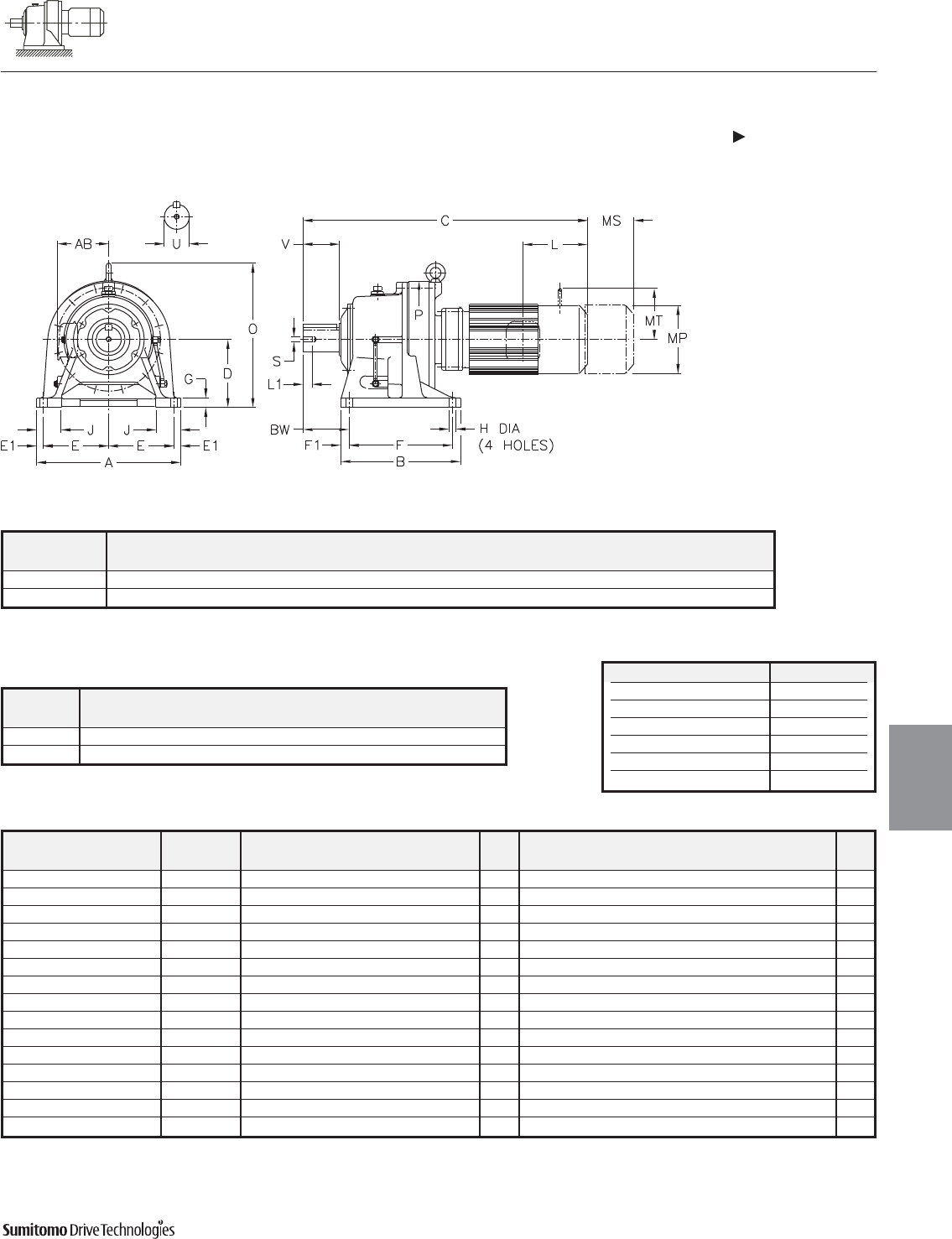
CYCLO® 6000 Gearmotors
Dimensions Integral Foot Mount
Double Reduction
CHHM-6130/5DCY 6140/5DBY
Dimensions 4.11
Dimensions
Gearmotors
All dimensions are in inches
Dimensions shown are for reference only and are subject to change without notice, unless certified.
Certified prints are available after receipt of an order; consult factory.
Cyclo® 6000 Series
Model Motor Without Brake Appx With Brake Appx
HP Pole C O AB L MP Wt (lb) C O AB L MP MS MT Wt (lb)
CHHM02-6130/5DCY 1/4 4 19.41 11.81 5.04 2.32 4.88 110 20.67 11.81 5.04 3.58 4.88 2.40 - 115
CHHM03-6130/5DCY 1/3 4 19.41 11.81 5.04 2.32 4.88 110 20.67 11.81 5.04 3.58 4.88 2.40 - 115
CHHM05-6130/5DCY 1/2 4 20.20 11.81 5.04 2.32 4.88 112 21.46 11.81 5.04 3.58 4.88 2.40 - 117
CHHM08-6130/5DCY 3/4 4 21.81 10.35 5.63 3.82 5.83 121 23.50 10.35 5.63 5.51 5.83 3.66 4.17 128
CHHM1-6130/5DCY 1 4 21.81 10.35 5.63 3.82 5.83 121 23.50 10.35 5.63 5.51 5.83 3.66 4.17 128
CHHM1H-6130/5DCY 1.5 4 23.11 10.63 5.83 3.94 6.30 130 25.55 10.63 5.83 6.38 6.30 4.53 4.49 141
CHHM2-6130/5DCY 2 4 23.11 10.63 5.83 3.94 6.30 130 25.55 10.63 5.83 6.38 6.30 4.53 4.49 141
CHHM3-6130/5DCY 3 4 23.90 10.87 6.10 4.13 6.81 139 26.38 10.87 6.10 6.61 6.81 4.76 4.88 152
CHHM02-6140/5DBY 1/4 4 19.65 11.81 5.04 2.32 4.88 106 20.91 11.81 5.04 3.58 4.88 2.40 - 110
CHHM03-6140/5DBY 1/3 4 19.65 11.81 5.04 2.32 4.88 106 20.91 11.81 5.04 3.58 4.88 2.40 - 110
CHHM05-6140/5DBY 1/2 4 20.43 11.81 5.04 2.32 4.88 108 21.69 11.81 5.04 3.58 4.88 2.40 - 112
CHHM08-6140/5DBY 3/4 4 22.05 10.35 5.63 3.82 5.83 117 23.74 10.35 5.63 5.51 5.83 3.66 4.17 123
CHHM1-6140/5DBY 1 4 22.05 10.35 5.63 3.82 5.83 117 23.74 10.35 5.63 5.51 5.83 3.66 4.17 123
CHHM1H-6140/5DBY 1.5 4 23.35 10.63 5.83 3.94 6.30 123 25.79 10.63 5.83 6.38 6.30 4.53 4.49 135
CHHM2-6140/5DBY 2 4 23.35 10.63 5.83 3.94 6.30 123 25.79 10.63 5.83 6.38 6.30 4.53 4.49 135
Model Low Speed Shaft
CHHM
U* V S L1 Key
6130/5DCY 1.875 2.76 3/8-16UNC 0.71 1/2 X 1/2 X 2.16
6140/5DBY 1.875 3.54 3/8-16UNC 0.71 1/2 X 1/2 X 2.95
Shaft Nominal Diameter (inches) Tolerances (inches)
0.500 (1/2) through 0.625 (5/8) +0.0000/-0.0004
0.750 (3/4) through 1.125 (1 1/8) +0.0000/-0.0005
1.250 (1 1/4) through 1.875 (1 7/8) +0.0000/-0.0006
2.000 (2) through 3.125 (3 1/8) +0.0000/-0.0007
3.250 (3 1/4) through 4.625 (4 5/8) +0.0000/-0.0009
4.750 (4 3/4) through 7.000 (7) +0.0000/-0.0010
*Shaft Tolerances
Model A B D E E1 F F1 G H J P BW
CHHM
6130/5DCY 12.99 7.68 5.906 5.71 0.79 5.71 0.98 0.87 0.71 2.56 9.06 3.94
6140/5DBY 12.99 7.68 5.906 5.71 0.79 5.71 0.98 0.87 0.71 2.56 9.06 4.72

CYCLO® 6000 Gearmotors
Dimensions Integral Foot Mount
Double Reduction
CHHM-6160/5DCY 6190/5DBY
4.12 Dimensions
Dimensions
Gearmotors
All dimensions are in inches
Model Low Speed Shaft
CHHM
U* V S L1 Key
6160/5DCY 2.250 3.54 3/8-16UNC 0.71 1/2 X 1/2 X 2.95
6170/5DCY 2.750 3.54 1/2-13UNC 0.94 5/8 X 5/8 X 3.15
6180/5DBY 3.125 4.33 1/2-13UNC 0.94 3/4 X 3/4 X 3.74
6190/5DAY 3.625 5.31 3/4-10UNC 1.34 7/8 X 7/8 X 4.92
6190/5DBY 3.625 5.31 3/4-10UNC 1.34 7/8 X 7/8 X 4.92
Shaft Nominal Diameter (inches) Tolerances (inches)
0.500 (1/2) through 0.625 (5/8) +0.0000/-0.0004
0.750 (3/4) through 1.125 (1 1/8) +0.0000/-0.0005
1.250 (1 1/4) through 1.875 (1 7/8) +0.0000/-0.0006
2.000 (2) through 3.125 (3 1/8) +0.0000/-0.0007
3.250 (3 1/4) through 4.625 (4 5/8) +0.0000/-0.0009
4.750 (4 3/4) through 7.000 (7) +0.0000/-0.0010
*Shaft Tolerances
Model A B D E E1 F F1 G H J P BW
CHHM
6160/5DCY 16.14 9.37 6.299 7.28 0.79 5.91 1.73 0.98 0.71 2.95 11.81 5.47
6170/5DCY 16.93 13.19 7.874 7.48 0.98 10.83 1.18 1.18 0.87 3.15 13.39 4.92
6180/5DBY 18.50 14.96 8.661 8.27 0.98 12.60 1.18 1.18 0.87 3.35 14.57 5.71
6190/5DAY 20.87 17.32 9.843 9.45 0.98 14.96 1.18 1.38 1.02 3.54 16.93 6.69
6190/5DBY 20.87 17.32 9.843 9.45 0.98 14.96 1.18 1.38 1.02 3.54 16.93 6.69
Dimensions shown are for reference only and are subject to change without notice, unless certified.
Certified prints are available after receipt of an order; consult factory.
Cyclo® 6000 Series
CYCLO® 6000 Gearmotors
Dimensions Integral Foot Mount
Double Reduction
CHHM-6160/5DCY 6190/5DBY (cont.)
Dimensions 4.13
Dimensions
Gearmotors
All dimensions are in inches
Model Motor Without Brake Appx With Brake Appx
HP Pole C O AB L MP Wt (lb) C O AB L MP MS MT Wt (lb)
CHHM05-6160/5DCY 1/2 4 23.07 13.74 5.04 2.32 4.88 216 24.49 13.74 5.04 3.58 4.88 2.40 - 221
CHHM08-6160/5DCY 3/4 4 24.65 13.74 5.63 3.82 5.83 225 26.34 13.74 5.63 5.51 5.83 3.66 4.17 232
CHHM1-6160/5DCY 1 4 24.65 13.74 5.63 3.82 5.83 225 26.34 13.74 5.63 5.51 5.83 3.66 4.17 232
CHHM1H-6160/5DCY 1.5 4 25.94 13.74 5.83 3.94 6.30 234 28.39 13.74 5.83 6.38 6.30 4.53 4.49 245
CHHM2-6160/5DCY 2 4 25.94 13.74 5.83 3.94 6.30 234 28.39 13.74 5.83 6.38 6.30 4.53 4.49 245
CHHM3-6160/5DCY 3 4 26.73 13.74 6.10 4.13 6.81 243 29.21 13.74 6.10 6.61 6.81 4.76 4.88 258
CHHM5-6160/5DCY 5 4 27.64 13.74 6.54 5.00 8.35 265 30.47 13.74 6.54 7.83 8.35 5.20 6.18 287
CHHM8-6160/5DCY 7.5 4 29.37 13.74 6.54 5.00 8.35 280 32.20 13.74 6.54 7.83 8.35 5.20 6.18 302
CHHM05-6170/5DCY 1/2 4 24.92 16.38 5.04 2.32 4.88 291 26.34 16.38 5.04 3.58 4.88 2.40 - 295
CHHM08-6170/5DCY 3/4 4 26.50 16.38 5.63 3.82 5.83 300 28.19 16.38 5.63 5.51 5.83 3.66 4.17 306
CHHM1-6170/5DCY 1 4 26.50 16.38 5.63 3.82 5.83 300 28.19 16.38 5.63 5.51 5.83 3.66 4.17 306
CHHM1H-6170/5DCY 1.5 4 27.80 16.38 5.83 3.94 6.30 309 30.24 16.38 5.83 6.38 6.30 4.53 4.49 320
CHHM2-6170/5DCY 2 4 27.80 16.38 5.83 3.94 6.30 309 30.24 16.38 5.83 6.38 6.30 4.53 4.49 320
CHHM3-6170/5DCY 3 4 28.58 16.38 6.10 4.13 6.81 318 31.06 16.38 6.10 6.61 6.81 4.76 4.88 333
CHHM5-6170/5DCY 5 4 29.49 16.38 6.54 5.00 8.35 340 32.32 16.38 6.54 7.83 8.35 5.20 6.18 362
CHHM8-6170/5DCY 7.5 4 31.22 16.38 6.54 5.00 8.35 355 34.06 16.38 6.54 7.83 8.35 5.20 6.18 377
CHHM1-6180/5DBY 1 4 28.86 17.76 5.63 3.82 5.83 417 30.55 17.76 5.63 5.51 5.83 3.66 4.17 423
CHHM1H-6180/5DBY 1.5 4 30.16 17.76 5.83 3.94 6.30 426 32.60 17.76 5.83 6.38 6.30 4.53 4.49 437
CHHM2-6180/5DBY 2 4 30.16 17.76 5.83 3.94 6.30 426 32.60 17.76 5.83 6.38 6.30 4.53 4.49 437
CHHM3-6180/5DBY 3 4 30.94 17.76 6.10 4.13 6.81 432 33.43 17.76 6.10 6.61 6.81 4.76 4.88 448
CHHM5-6180/5DBY 5 4 31.85 17.76 6.54 5.00 8.35 454 34.69 17.76 6.54 7.83 8.35 5.20 6.18 476
CHHM8-6180/5DBY 7.5 4 33.58 17.76 6.54 5.00 8.35 470 36.42 17.76 6.54 7.83 8.35 5.20 6.18 492
CHHM10-6180/5DBY 10 4 34.49 17.76 8.31 5.63 9.88 503 38.23 17.76 8.31 9.37 9.88 6.69 7.17 542
CHHM15-6180/5DBY 15 4 36.85 17.76 8.31 5.63 9.88 534 40.59 17.76 8.31 9.37 9.88 6.69 7.17 573
CHHM1-6190/5DAY 1 4 31.22 20.91 5.63 3.82 5.83 549 32.91 20.91 5.63 5.51 5.83 3.66 4.17 556
CHHM1H-6190/5DAY 1.5 4 32.52 20.91 5.83 3.94 6.30 558 34.96 20.91 5.83 6.38 6.30 4.53 4.49 569
CHHM2-6190/5DAY 2 4 32.52 20.91 5.83 3.94 6.30 558 34.96 20.91 5.83 6.38 6.30 4.53 4.49 569
CHHM3-6190/5DAY 3 4 33.31 20.91 6.10 4.13 6.81 567 35.79 20.91 6.10 6.61 6.81 4.76 4.88 582
CHHM5-6190/5DAY 5 4 34.21 20.91 6.54 5.00 8.35 589 37.05 20.91 6.54 7.83 8.35 5.20 6.18 611
CHHM8-6190/5DAY 7.5 4 35.94 20.91 6.54 5.00 8.35 604 38.78 20.91 6.54 7.83 8.35 5.20 6.18 626
CHHM5-6195DBY 5 4 34.84 20.91 6.54 5.00 8.35 604 37.68 20.91 6.54 7.83 8.35 5.20 6.18 626
CHHM8-6195DBY 7.5 4 36.57 20.91 6.54 5.00 8.35 620 39.41 20.91 6.54 7.83 8.35 5.20 6.18 642
CHHM10-6195DBY 10 4 37.48 20.91 8.31 5.63 9.88 653 41.22 20.91 8.31 9.37 9.88 6.69 7.17 692
CHHM15-6195DBY 15 4 39.84 20.91 8.31 5.63 9.88 684 43.58 20.91 8.31 9.37 9.88 6.69 7.17 723
CHHM20-6195DBY 20 4 43.39 20.91 9.13 11.61 12.76 798 46.93 20.91 9.13 15.16 12.76 8.66 - 871
Dimensions shown are for reference only and are subject to change without notice, unless certified.
Certified prints are available after receipt of an order; consult factory.
Cyclo® 6000 Series
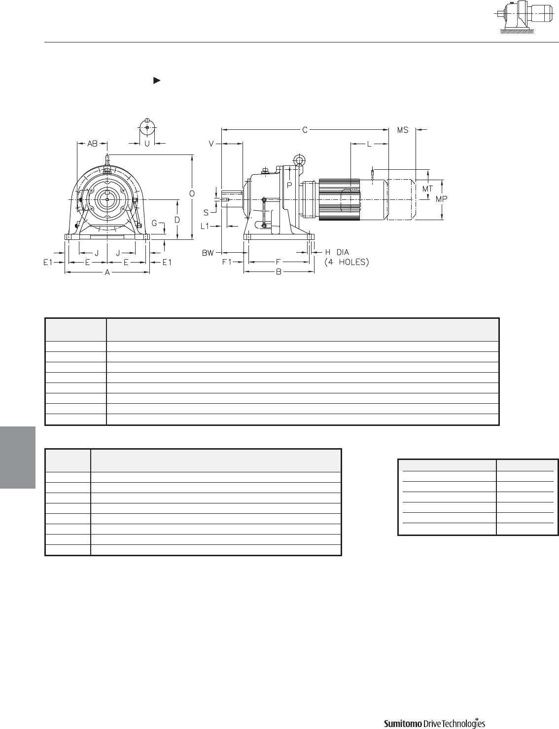
CYCLO® 6000 Gearmotors
Dimensions Integral Foot Mount
Double Reduction
CHHM-6205DAY 6235DBY
4.14 Dimensions
Dimensions
Gearmotors
All dimensions are in inches
Model Low Speed Shaft
CHHM
U* V S L1 Key
6205DAY 3.875 6.50 3/4-10UNC 1.34 1 X 1 X 6.50
6205DBY 3.875 6.50 3/4-10UNC 1.34 1 X 1 X 6.50
6215DAY 4.250 6.50 3/4-10UNC 1.34 1 X 1 X 6.50
6215DBY 4.250 6.50 3/4-10UNC 1.34 1 X 1 X 6.50
6225DAY 4.625 6.50 3/4-10UNC 1.34 1-1/4 X 7/8 X 6.5
6225DBY 4.625 6.50 3/4-10UNC 1.34 1-1/4 X 7/8 X 6.5
6235DAY 5.000 7.87 1-8UNC 1.61 1-1/4 X 7/8 X 7.87
6235DBY 5.000 7.87 1-8UNC 1.61 1-1/4 X 7/8 X 7.87
Shaft Nominal Diameter (inches) Tolerances (inches)
0.500 (1/2) through 0.625 (5/8) +0.0000/-0.0004
0.750 (3/4) through 1.125 (1 1/8) +0.0000/-0.0005
1.250 (1 1/4) through 1.875 (1 7/8) +0.0000/-0.0006
2.000 (2) through 3.125 (3 1/8) +0.0000/-0.0007
3.250 (3 1/4) through 4.625 (4 5/8) +0.0000/-0.0009
4.750 (4 3/4) through 7.000 (7) +0.0000/-0.0010
*Shaft Tolerances
Dimensions shown are for reference only and are subject to change without notice, unless certified.
Certified prints are available after receipt of an order; consult factory.
Cyclo® 6000 Series
Model A B D E E1 F F1 G H J P BW
CHHM
6205DAY 20.87 17.32 9.843 8.66 1.77 14.17 1.57 1.38 1.02 3.94 17.64 8.46
6205DBY 20.87 17.32 9.843 8.66 1.77 14.17 1.57 1.38 1.02 3.94 17.64 8.46
6215DAY 22.83 18.70 10.433 9.45 1.97 15.55 1.57 1.57 1.02 4.33 19.09 8.27
6215DBY 22.83 18.70 10.433 9.45 1.97 15.55 1.57 1.57 1.02 4.33 19.09 8.27
6225DAY 24.41 20.47 11.024 10.63 1.57 16.54 1.97 1.57 1.30 4.53 20.71 9.06
6225DBY 24.41 20.47 11.024 10.63 1.57 16.54 1.97 1.57 1.30 4.53 20.71 9.06
6235DAY 26.38 22.05 11.811 11.42 1.77 18.11 1.97 1.77 1.30 4.72 22.13 10.24
6235DBY 26.38 22.05 11.811 11.42 1.77 18.11 1.97 1.77 1.30 4.72 22.13 10.24
CYCLO® 6000 Gearmotors
Dimensions Integral Foot Mount
Double Reduction
CHHM-6205DAY 6235DBY (cont.)
Dimensions 4.15
Dimensions
Gearmotors
All dimensions are in inches
Dimensions shown are for reference only and are subject to change without notice, unless certified.
Certified prints are available after receipt of an order; consult factory.
Cyclo® 6000 Series
Model Motor Without Brake Appx With Brake Appx
HP Pole C O AB L MP Wt (lb) C O AB L MP MS MT Wt (lb)
CHHM1-6205DAY 1 4 32.83 20.87 5.63 3.82 5.83 591 34.53 20.87 5.63 5.51 5.83 3.66 4.17 598
CHHM2-6205DAY 2 4 34.13 20.87 5.83 3.94 6.30 600 36.57 20.87 5.83 6.38 6.30 4.53 4.49 611
CHHM3-6205DAY 3 4 34.92 20.87 6.10 4.13 6.81 609 37.36 20.87 6.10 6.61 6.81 4.76 4.88 624
CHHM5-6205DAY 5 4 35.83 20.87 6.54 5.00 8.35 631 38.66 20.87 6.54 7.83 8.35 5.20 6.18 653
CHHM8-6205DAY 7.5 4 37.56 20.87 6.54 5.00 8.35 646 40.39 20.87 6.54 7.83 8.35 5.20 6.18 668
CHHM2-6205DBY 2 4 35.19 20.87 5.83 3.94 6.30 626 37.67 20.87 5.83 6.38 6.30 4.53 4.49 637
CHHM3-6205DBY 3 4 35.98 20.87 6.10 4.13 6.81 635 38.46 20.87 6.10 6.61 6.81 4.76 4.88 650
CHHM5-6205DBY 5 4 36.89 20.87 6.54 5.00 8.35 657 39.72 20.87 6.54 7.83 8.35 5.20 6.18 679
CHHM8-6205DBY 7.5 4 38.62 20.87 6.54 5.00 8.35 673 41.46 20.87 6.54 7.83 8.35 5.20 6.18 695
CHHM10-6205DBY 10 4 39.53 20.87 8.31 5.63 9.88 706 43.27 20.87 8.31 9.37 9.88 6.69 7.17 745
CHHM15-6205DBY 15 4 41.89 20.87 8.31 5.63 9.88 734 45.63 20.87 8.31 9.37 9.88 6.69 7.17 774
CHHM20-6205DBY 20 4 45.43 20.87 9.13 11.61 12.76 849 48.58 20.87 9.13 15.16 12.76 8.66 - 919
CHHM2-6215DAY 2 4 36.22 22.64 5.83 3.94 6.30 807 38.66 22.64 5.83 6.38 6.30 4.53 4.49 818
CHHM3-6215DAY 3 4 37.01 22.64 6.10 4.13 6.81 814 39.49 22.64 6.10 6.61 6.81 4.76 4.88 829
CHHM5-6215DAY 5 4 37.91 22.64 6.54 5.00 8.35 836 40.75 22.64 6.54 7.83 8.35 5.20 6.18 858
CHHM8-6215DAY 7.5 4 39.65 22.64 6.54 5.00 8.35 851 42.48 22.64 6.54 7.83 8.35 5.20 6.18 873
CHHM10-6215DAY 10 4 40.55 22.64 8.31 5.63 9.88 884 44.29 22.64 8.31 9.37 9.88 6.69 7.17 924
CHHM15-6215DAY 15 4 42.91 22.64 8.31 5.63 9.88 913 46.65 22.64 8.31 9.37 9.88 6.69 7.17 953
CHHM20-6215DAY 20 4 46.46 22.64 9.13 11.61 12.76 1028 50.00 22.64 9.13 15.16 12.76 8.66 - 1100
CHHM10-6215DBY 10 4 41.73 22.64 8.31 5.63 9.88 928 45.47 22.64 8.31 9.37 9.88 6.69 7.17 966
CHHM15-6215DBY 15 4 44.09 22.64 8.31 5.63 9.88 959 47.83 22.64 8.31 9.37 9.88 6.69 7.17 997
CHHM20-6215DBY 20 4 47.44 22.64 9.13 11.61 12.76 1076 50.98 22.64 9.13 15.16 12.76 8.66 - 1149
CHHM25-6215DBY 25 4 51.18 22.64 11.69 13.39 15.51 1233 59.45 22.64 11.69 21.65 15.51 14.45 - 1345
CHHM30-6215DBY 30 4 51.18 22.64 11.69 13.39 15.51 1233 59.45 22.64 11.69 21.65 15.51 14.45 - 1345
CHHM2-6225DAY 2 4 37.87 24.02 5.83 3.94 6.30 970 40.31 24.02 5.83 6.38 6.30 4.53 4.49 981
CHHM3-6225DAY 3 4 38.66 24.02 6.10 4.13 6.81 977 41.14 24.02 6.10 6.61 6.81 4.76 4.88 992
CHHM5-6225DAY 5 4 39.57 24.02 6.54 5.00 8.35 999 42.40 24.02 6.54 7.83 8.35 5.20 6.18 1021
CHHM8-6225DAY 7.5 4 41.30 24.02 6.54 5.00 8.35 1014 44.13 24.02 6.54 7.83 8.35 5.20 6.18 1036
CHHM10-6225DAY 10 4 42.20 24.02 8.31 5.63 9.88 1047 45.94 24.02 8.31 9.37 9.88 6.69 7.17 1087
CHHM15-6225DAY 15 4 44.57 24.02 8.31 5.63 9.88 1078 48.31 24.02 8.31 9.37 9.88 6.69 7.17 1118
CHHM20-6225DAY 20 4 48.11 24.02 9.13 11.61 12.76 1193 51.65 24.02 9.13 15.16 12.76 8.66 - 1266
CHHM10-6225DBY 10 4 44.29 24.02 8.31 5.63 9.88 1147 48.03 24.02 8.31 9.37 9.88 6.69 7.17 1186
CHHM15-6225DBY 15 4 46.65 24.02 8.31 5.63 9.88 1177 50.39 24.02 8.31 9.37 9.88 6.69 7.17 1217
CHHM20-6225DBY 20 4 49.80 24.02 9.13 11.61 12.76 1297 53.35 24.02 9.13 15.16 12.76 8.66 - 1369
CHHM25-6225DBY 25 4 53.54 24.02 11.69 13.39 15.51 1446 61.81 24.02 11.69 21.65 15.51 14.45 - 1559
CHHM30-6225DBY 30 4 53.54 24.02 11.69 13.39 15.51 1446 61.81 24.02 11.69 21.65 15.51 14.45 - 1559
CHHM40-6225DBY 40 4 53.54 24.02 11.69 13.39 15.51 1484 61.81 24.02 11.69 21.65 15.51 14.57 - 1596
CHHM3-6235DAY 3 4 42.05 26.26 6.10 4.13 6.81 1235 44.53 26.26 6.10 6.61 6.81 4.76 4.88 1248
CHHM5-6235DAY 5 4 42.95 26.26 6.54 5.00 8.35 1255 45.79 26.26 6.54 7.83 8.35 5.20 6.18 1277
CHHM8-6235DAY 7.5 4 44.69 26.26 6.54 5.00 8.35 1270 47.52 26.26 6.54 7.83 8.35 5.20 6.18 1292
CHHM10-6235DAY 10 4 45.79 26.26 8.31 5.63 9.88 1305 49.53 26.26 8.31 9.37 9.88 6.69 7.17 1343
CHHM15-6235DAY 15 4 48.15 26.26 8.31 5.63 9.88 1336 51.89 26.26 8.31 9.37 9.88 6.69 7.17 1374
CHHM20-6235DAY 20 4 51.50 26.26 9.13 11.61 12.76 1453 55.04 26.26 9.13 15.16 12.76 8.66 - 1526
CHHM25-6235DAY 25 4 55.24 26.26 11.69 13.39 15.51 1614 63.50 26.26 11.69 21.65 15.51 14.45 - 1727
CHHM30-6235DAY 30 4 55.24 26.26 11.69 13.39 15.51 1614 63.50 26.26 11.69 21.65 15.51 14.45 - 1727
CHHM25-6235DBY 25 4 56.10 26.26 11.69 13.39 15.51 1675 64.37 26.26 11.69 21.65 15.51 14.57 - 1770
CHHM30-6235DBY 30 4 56.10 26.26 11.69 13.39 15.51 1675 64.37 26.26 11.69 21.65 15.51 14.57 - 1770
CHHM40-6235DBY 40 4 56.10 26.26 11.69 13.39 15.51 1713 64.37 26.26 11.69 21.65 15.51 14.57 - 1808
CHHM50-6235DBY 50 4 60.63 26.26 11.69 16.93 15.51 1797 69.09 26.26 11.69 25.39 15.51 17.52 - 2011
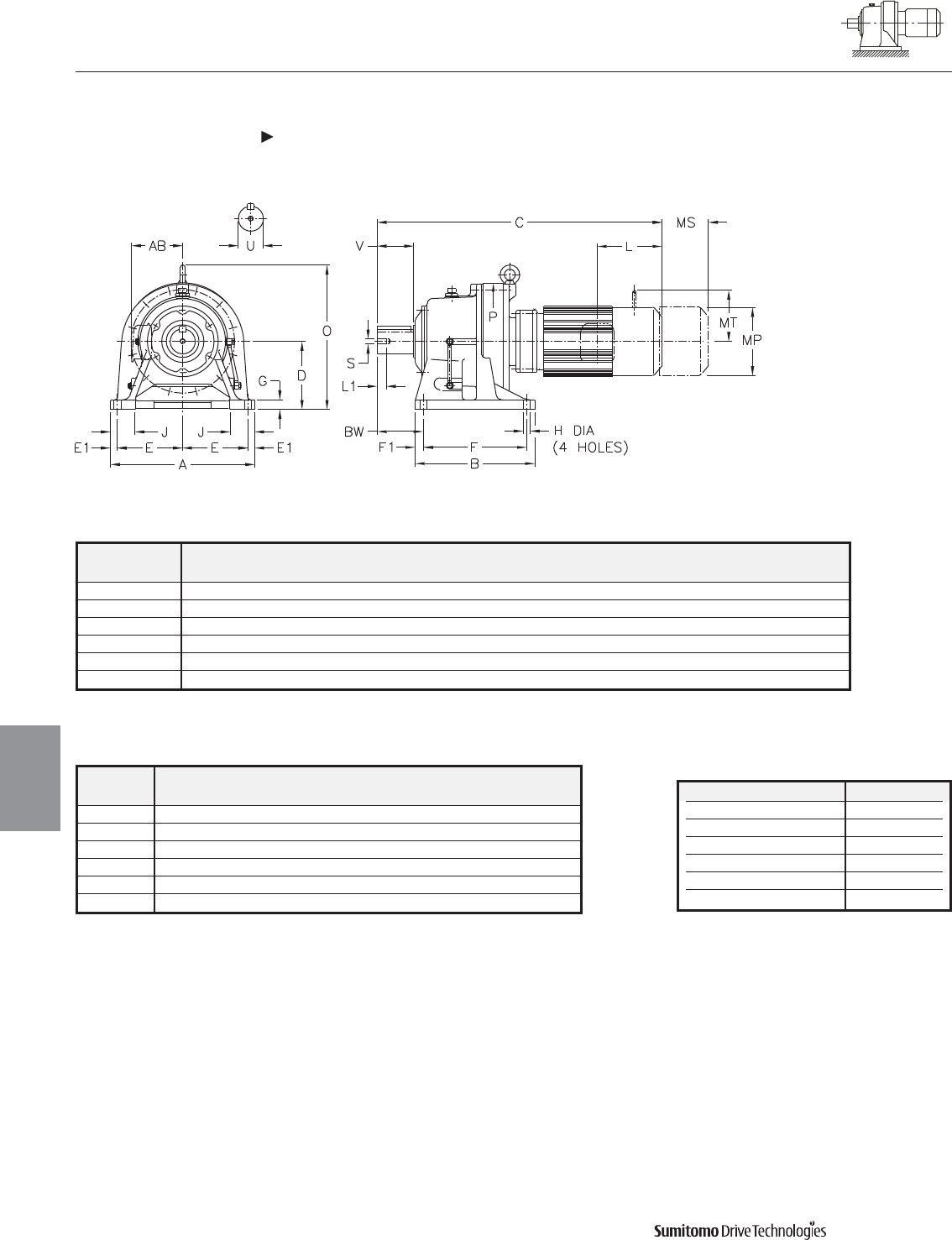
CYCLO® 6000 Gearmotors
Dimensions Integral Foot Mount
Double Reduction
CHHM-6245DAY 6275DAY
4.16 Dimensions
Dimensions
Gearmotors
All dimensions are in inches
Model Low Speed Shaft
CHHM
U* V S L1 Key
6245DAY 5.500 7.87 1-8UNC 1.61 1-1/4 X 7/8 X 7.87
6245DBY 5.500 7.87 1-8UNC 1.61 1-1/4 X 7/8 X 7.87
6255DAY 6.250 9.45 1-1/4-7UNC 1.93 1-1/2 X 1 X 9.45
6255DBY 6.250 9.45 1-1/4-7UNC 1.93 1-1/2 X 1 X 9.45
6265DAY 6.625 11.81 1-1/4-7UNC 1.93 1-3/4 X 1-1/4 X 11.8
6275DAY 7.000 13.00 1-1/4-7UNC 2.05 1-3/4 X 1-1/4 X 13
Shaft Nominal Diameter (inches) Tolerances (inches)
0.500 (1/2) through 0.625 (5/8) +0.0000/-0.0004
0.750 (3/4) through 1.125 (1 1/8) +0.0000/-0.0005
1.250 (1 1/4) through 1.875 (1 7/8) +0.0000/-0.0006
2.000 (2) through 3.125 (3 1/8) +0.0000/-0.0007
3.250 (3 1/4) through 4.625 (4 5/8) +0.0000/-0.0009
4.750 (4 3/4) through 7.000 (7) +0.0000/-0.0010
*Shaft Tolerances
Model A B D E E1 F F1 G H J P BW
CHHM
6245DAY 28.35 22.83 13.189 12.40 1.77 18.90 1.97 1.77 1.54 5.04 24.17 10.35
6245DBY 28.35 22.83 13.189 12.40 1.77 18.90 1.97 1.77 1.54 5.04 24.17 10.35
6255DAY 30.71 24.80 14.764 13.19 2.17 20.47 2.17 1.97 1.54 5.51 26.38 12.60
6255DBY 30.71 24.80 14.764 13.19 2.17 20.47 2.17 1.97 1.54 5.51 26.38 12.60
6265DAY 34.65 27.56 15.748 15.16 2.17 23.23 2.17 2.17 1.77 6.30 28.98 15.35
6275DAY 45.67 40.94 21.260 20.67 2.17 16.54 3.94 2.36 1.77 7.87 37.40 19.09
Dimensions shown are for reference only and are subject to change without notice, unless certified.
Certified prints are available after receipt of an order; consult factory.
Cyclo® 6000 Series

CYCLO® 6000 Gearmotors
Dimensions Integral Foot Mount
Double Reduction
CHHM-6245DAY 6275DAY (cont.)
Dimensions 4.17
Dimensions
Gearmotors
All dimensions are in inches
Model Motor Without Brake Appx With Brake Appx
HP Pole C O AB L MP Wt (lb) C O AB L MP MS MT Wt (lb)
CHHM3-6245DAY 3 4 43.54 28.70 6.10 4.13 6.81 1475 46.02 28.70 6.10 6.61 6.81 4.76 4.88 1488
CHHM5-6245DAY 5 4 44.45 28.70 6.54 5.00 8.35 1495 47.28 28.70 6.54 7.83 8.35 5.20 6.18 1517
CHHM8-6245DAY 7.5 4 46.18 28.70 6.54 5.00 8.35 1510 49.02 28.70 6.54 7.83 8.35 5.20 6.18 1532
CHHM10-6245DAY 10 4 47.28 28.70 8.31 5.63 9.88 1546 51.02 28.70 8.31 9.37 9.88 6.69 7.17 1583
CHHM15-6245DAY 15 4 49.65 28.70 8.31 5.63 9.88 1577 53.39 28.70 8.31 9.37 9.88 6.69 7.17 1614
CHHM20-6245DAY 20 4 52.99 28.70 9.13 11.61 12.76 1693 56.54 28.70 9.13 15.16 12.76 8.66 - 1766
CHHM25-6245DAY 25 4 56.73 28.70 11.69 13.39 15.51 1841 65.00 28.70 11.69 21.65 15.51 14.45 - 1954
CHHM20-6245DBY 20 4 53.82 28.70 9.13 11.61 12.76 1762 57.36 28.70 9.13 15.16 12.76 8.66 - 1824
CHHM25-6245DBY 25 4 57.56 28.70 11.69 13.39 15.51 1899 65.83 28.70 11.69 21.65 15.51 14.45 - 2011
CHHM30-6245DBY 30 4 57.56 28.70 11.69 13.39 15.51 1899 65.83 28.70 11.69 21.65 15.51 14.45 - 2011
CHHM40-6245DBY 40 4 57.56 28.70 11.69 13.39 15.51 1936 65.83 28.70 11.69 21.65 15.51 14.57 - 2031
CHHM50-6245DBY 50 4 62.09 28.70 11.69 16.93 15.51 2051 70.55 28.70 11.69 25.39 15.51 17.52 - 2265
CHHM5-6255DAY 5 4 50.55 32.09 6.54 5.00 8.35 2271 53.39 32.09 6.54 7.83 8.35 5.20 6.18 2293
CHHM8-6255DAY 7.5 4 52.28 32.09 6.54 5.00 8.35 2293 55.12 32.09 6.54 7.83 8.35 5.20 6.18 2315
CHHM10-6255DAY 10 4 52.99 32.09 8.31 5.63 9.88 2326 56.73 32.09 8.31 9.37 9.88 6.69 7.17 2359
CHHM15-6255DAY 15 4 55.35 32.09 8.31 5.63 9.88 2359 59.09 32.09 8.31 9.37 9.88 6.69 7.17 2392
CHHM20-6255DAY 20 4 58.50 32.09 9.13 11.61 12.76 2470 62.05 32.09 9.13 15.16 12.76 8.66 - 2547
CHHM25-6255DAY 25 4 62.24 32.09 11.69 13.39 15.51 2624 70.51 32.09 11.69 21.65 15.51 14.45 - 2736
CHHM30-6255DAY 30 4 62.24 32.09 11.69 13.39 15.51 2624 70.51 32.09 11.69 21.65 15.51 14.45 - 2736
CHHM40-6255DAY 40 4 62.24 32.09 11.69 13.39 15.51 2668 70.51 32.09 11.69 21.65 15.51 14.57 - 2763
CHHM25-6255DBY 25 4 63.11 32.09 11.69 13.39 15.51 2789 71.38 32.09 11.69 21.65 15.51 14.45 - 2902
CHHM30-6255DBY 30 4 63.11 32.09 11.69 13.39 15.51 2789 71.38 32.09 11.69 21.65 15.51 14.45 - 2902
CHHM40-6255DBY 40 4 63.11 32.09 11.69 13.39 15.51 2822 71.38 32.09 11.69 21.65 15.51 14.57 - 2917
CHHM50-6255DBY 50 4 67.64 32.09 11.69 16.93 15.51 2906 75.91 32.09 11.69 25.39 15.51 17.52 - 3120
CHHM60-6255DBY 60 4 67.64 32.09 11.69 16.93 15.51 2906 75.91 32.09 11.69 25.39 15.51 17.52 - 3120
CHHM8-6265DAY 7.5 4 58.27 34.41 6.54 5.00 8.35 3010 61.10 34.41 6.54 7.83 8.35 5.20 6.18 3032
CHHM10-6265DAY 10 4 58.78 34.41 8.31 5.63 9.88 3043 62.52 34.41 8.31 9.37 9.88 6.69 7.17 3087
CHHM15-6265DAY 15 4 61.14 34.41 8.31 5.63 9.88 3076 64.88 34.41 8.31 9.37 9.88 6.69 7.17 3109
CHHM20-6265DAY 20 4 63.70 34.41 9.13 11.61 12.76 3186 67.24 34.41 9.13 15.16 12.76 8.66 - 3263
CHHM25-6265DAY 25 4 67.44 34.41 11.69 13.39 15.51 3352 75.71 34.41 11.69 21.65 15.51 14.45 - 3451
CHHM30-6265DAY 30 4 67.44 34.41 11.69 13.39 15.51 3352 75.71 34.41 11.69 21.65 15.51 14.45 - 3451
CHHM40-6265DAY 40 4 67.44 34.41 11.69 13.39 15.51 3385 75.71 34.41 11.69 21.65 15.51 14.57 - 3479
CHHM50-6265DAY 50 4 71.97 34.41 11.69 16.93 15.51 3462 80.43 34.41 11.69 25.39 15.51 17.52 - 3676
CHHM60-6265DAY 60 4 71.97 34.41 11.69 16.93 15.51 3462 80.43 34.41 11.69 25.39 15.51 17.52 - 3676
CHHM10-6275DAY 10 4 69.06 45.71 8.31 5.63 9.88 5546 72.80 45.71 8.31 9.37 9.88 6.69 7.17 5590
CHHM15-6275DAY 15 4 71.42 45.71 8.31 5.63 9.88 5579 75.16 45.71 8.31 9.37 9.88 6.69 7.17 5612
CHHM20-6275DAY 20 4 73.98 45.71 9.13 11.61 12.76 5689 77.52 45.71 9.13 15.16 12.76 8.66 - 5766
CHHM25-6275DAY 25 4 77.72 45.71 11.69 13.39 15.51 5854 85.98 45.71 11.69 21.65 15.51 14.45 - 5954
CHHM30-6275DAY 30 4 77.72 45.71 11.69 13.39 15.51 5854 85.98 45.71 11.69 21.65 15.51 14.45 - 5954
CHHM40-6275DAY 40 4 77.72 45.71 11.69 13.39 15.51 5887 85.98 45.71 11.69 21.65 15.51 14.57 - 5982
CHHM50-6275DAY 50 4 82.24 45.71 11.69 16.93 15.51 5971 90.71 45.71 11.69 25.39 15.51 17.52 - 6185
CHHM60-6275DAY 60 4 82.24 45.71 11.69 16.93 15.51 5971 90.71 45.71 11.69 25.39 15.51 17.52 - 6185
Dimensions shown are for reference only and are subject to change without notice, unless certified.
Certified prints are available after receipt of an order; consult factory.
Cyclo® 6000 Series
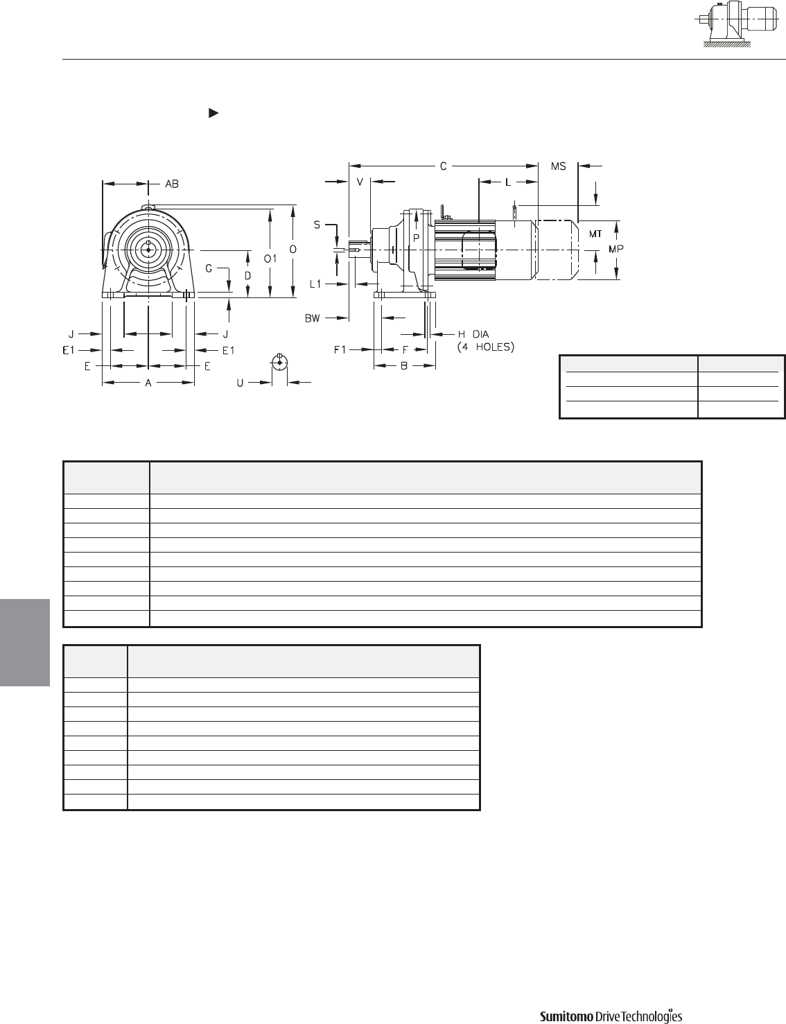
CYCLO® 6000 Gearmotors
Dimensions Inverter Duty, Integral Foot Mount
Single Reduction
CNHM-6060/5Y 612HY-AV
4.18 Dimensions
Dimensions
Gearmotors
All dimensions are in inches
Model Low Speed Shaft
CNHM
U* V S L1 Key
6060/5Y 0.500 0.98 10-32UNF 0.63 1/8 X 1/8 X .79
6070/5Y 0.750 1.18 12-28UNF 0.63 3/16 X 3/16 X 1.06
6080/5Y 0.875 1.38 12-28UNF 0.63 3/16 X 3/16 X 1.18
6090/5Y 1.125 1.38 5/16-18UNC 0.79 1/4 X 1/4 X 1.18
6100/5Y 1.125 1.38 5/16-18UNC 0.79 1/4 X 1/4 X 1.18
610HY 1.125 1.38 5/16-18UNC 0.79 1/4 X 1/4 X 1.18
6110/5Y 1.250 1.77 5/16-18UNC 0.79 1/4 X 1/4 X 1.46
6120/5Y 1.500 2.17 5/16-18UNC 0.79 3/8 X 3/8 X 1.77
612HY 1.500 2.17 5/16-18UNC 0.79 3/8 X 3/8 X 1.77
Shaft Nominal Diameter (inches) Tolerances (inches)
0.500 (1/2) through 0.625 (5/8) +0.0000/-0.0004
0.750 (3/4) through 1.125 (1 1/8) +0.0000/-0.0005
1.250 (1 1/4) through 1.875 (1 7/8) +0.0000/-0.0006
*Shaft Tolerances
Model A B D E E1 F F1 G H J P BW
CNHM
6060/5Y 5.67 3.31 3.150 2.36 0.47 2.36 0.47 0.39 0.35 1.38 4.33 1.61
6070/5Y 5.67 3.31 3.150 2.36 0.47 2.36 0.47 0.39 0.35 1.38 4.33 1.85
6080/5Y 5.67 3.90 3.543 2.36 0.47 2.95 0.47 0.51 0.35 1.46 5.28 2.05
6090/5Y 7.09 5.31 3.937 2.95 0.59 3.54 0.59 0.47 0.43 1.57 5.91 2.36
6100/5Y 7.09 5.31 3.937 2.95 0.59 3.54 0.59 0.47 0.43 1.57 5.91 2.36
610HY 7.09 5.31 4.724 2.95 0.59 3.54 0.59 0.47 0.43 1.77 5.91 2.36
6110/5Y 7.09 5.31 4.724 2.95 0.59 3.54 0.59 0.47 0.43 1.77 6.38 2.76
6120/5Y 9.06 6.10 4.724 3.74 0.79 4.53 0.79 0.59 0.55 2.17 8.03 3.23
612HY 9.06 6.10 5.512 3.74 0.79 4.53 0.79 0.59 0.55 2.36 8.03 3.23
Dimensions shown are for reference only and are subject to change without notice, unless certified.
Certified prints are available after receipt of an order; consult factory.
Cyclo® 6000 Series
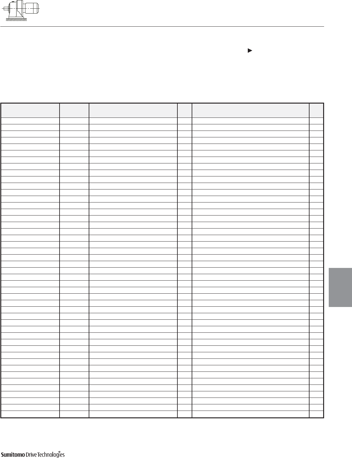
CYCLO® 6000 Gearmotors
Dimensions Inverter Duty, Integral Foot Mount
Single Reduction
CNHM-6060/5Y 612HY-AV (cont.)
Dimensions 4.19
Dimensions
Gearmotors
All dimensions are in inches
Model Motor Without Brake Appx With Brake Appx
HP Pole C O O1 AB L MP Wt (lb) C O O1 AB L MP MS MT Wt (lb)
CNHM01-6060/5Y-AV 1/8 4 10.55 - 5.59 5.04 2.32 4.88 15 11.81 - 5.59 5.04 3.58 4.88 2.40 - 18
CNHM02-6060/5Y-AV 1/4 4 11.34 - 5.59 5.04 2.32 4.88 18 12.83 - 5.59 5.04 3.58 4.88 2.40 - 20
CNHM01-6070/5Y-AV 1/8 4 10.79 - 5.59 5.04 2.32 4.88 15 12.05 - 5.59 5.04 3.58 4.88 2.40 - 18
CNHM02-6070/5Y-AV 1/4 4 11.57 - 5.59 5.04 2.32 4.88 18 12.83 - 5.59 5.04 3.58 4.88 2.40 - 20
CNHM03-6070/5Y-AV 1/3 4 11.57 - 5.59 5.04 2.32 4.88 18 12.83 - 5.59 5.04 3.58 4.88 2.40 - 20
CNHM01-6080/5Y-AV 1/8 4 11.81 - 6.18 5.04 2.32 4.88 22 13.07 - 6.18 5.04 3.58 4.88 2.40 - 24
CNHM02-6080/5Y-AV 1/4 4 12.60 - 6.18 5.04 2.32 4.88 26 13.86 - 6.18 5.04 3.58 4.88 2.40 - 29
CNHM03-6080/5Y-AV 1/3 4 12.60 - 6.18 5.04 2.32 4.88 26 13.86 - 6.18 5.04 3.58 4.88 2.40 - 29
CNHM05-6080/5Y-AV 1/2 4 14.21 7.99 - 5.63 3.82 5.83 35 15.91 7.99 - 5.63 5.51 5.83 3.66 4.17 37
CNHM02-6090/5Y-AV 1/4 4 13.31 - 6.89 5.04 2.32 4.88 29 14.57 - 6.89 5.04 3.58 4.88 2.40 - 33
CNHM03-6090/5Y-AV 1/3 4 13.31 - 6.89 5.04 2.32 4.88 29 14.57 - 6.89 5.04 3.58 4.88 2.40 - 33
CNHM05-6090/5Y-AV 1/2 4 14.92 8.39 - 5.63 3.82 5.83 37 16.61 8.39 - 5.63 5.51 5.83 3.66 4.17 44
CNHM08-6090/5Y-AV 3/4 4 16.22 8.66 - 5.83 3.94 6.30 44 18.66 8.66 - 5.83 6.38 6.30 4.53 4.49 55
CNHM1-6090/5Y-AV 1 4 16.22 8.66 - 5.83 3.94 6.30 44 18.66 8.66 - 5.83 6.38 6.30 4.53 4.49 55
CNHM02-6100/5Y-AV 1/4 4 13.86 8.15 - 5.04 2.32 4.88 40 15.12 8.15 - 5.04 3.58 4.88 2.40 - 44
CNHM03-6100/5Y-AV 1/3 4 13.86 8.15 - 5.04 2.32 4.88 40 15.12 8.15 - 5.04 3.58 4.88 2.40 - 44
CNHM05-6100/5Y-AV 1/2 4 15.47 8.39 - 5.63 3.82 5.83 49 17.17 8.39 - 5.63 5.51 5.83 3.66 4.17 55
CNHM08-6100/5Y-AV 3/4 4 16.77 8.66 - 5.83 3.94 6.30 57 19.21 8.66 - 5.83 6.38 6.30 4.53 4.49 68
CNHM1-6100/5Y-AV 1 4 16.77 8.66 - 5.83 3.94 6.30 57 19.21 8.66 - 5.83 6.38 6.30 4.53 4.49 68
CNHM1H-6100/5Y-AV 1.5 4 17.56 8.90 - 6.10 4.13 6.81 66 20.04 8.90 - 6.10 6.61 6.81 4.76 4.88 79
CNHM2-6100/5Y-AV 2 4 17.56 8.90 - 6.10 4.13 6.81 66 20.04 8.90 - 6.10 6.61 6.81 4.76 4.88 79
CNHM02-610HY-AV 1/4 4 13.86 8.94 - 5.04 2.32 4.88 42 15.12 8.94 - 5.04 3.58 4.88 2.40 - 46
CNHM03-610HY-AV 1/3 4 13.86 8.94 - 5.04 2.32 4.88 42 15.12 8.94 - 5.04 3.58 4.88 2.40 - 46
CNHM05-610HY-AV 1/2 4 15.47 9.17 - 5.63 3.82 5.83 51 17.17 9.17 - 5.63 5.51 5.83 3.66 4.17 57
CNHM08-610HY-AV 3/4 4 16.77 9.45 - 5.83 3.94 6.30 60 19.21 9.45 - 5.83 6.38 6.30 4.53 4.49 71
CNHM1-610HY-AV 1 4 16.77 9.45 - 5.83 3.94 6.30 60 19.21 9.45 - 5.83 6.38 6.30 4.53 4.49 71
CNHM1H-610HY-AV 1.5 4 17.56 9.69 - 6.10 4.13 6.81 68 20.04 9.69 - 6.10 6.61 6.81 4.76 4.88 82
CNHM2-610HY-AV 2 4 17.56 9.69 - 6.10 4.13 6.81 68 20.04 9.69 - 6.10 6.61 6.81 4.76 4.88 82
CNHM05-6110/5Y-AV 1/2 4 15.87 9.29 - 5.63 3.82 5.83 49 17.80 9.29 - 5.63 5.51 5.83 3.66 4.17 55
CNHM08-6110/5Y-AV 3/4 4 17.17 9.45 - 5.83 3.94 6.30 55 19.41 9.45 - 5.83 6.38 6.30 4.53 4.49 66
CNHM1-6110/5Y-AV 1 4 17.17 9.45 - 5.83 3.94 6.30 55 19.41 9.45 - 5.83 6.38 6.30 4.53 4.49 66
CNHM1H-6110/5Y-AV 1.5 4 17.95 9.69 - 6.10 4.13 6.81 64 20.43 9.69 - 6.10 6.61 6.81 4.76 4.88 77
CNHM2-6110/5Y-AV 2 4 17.95 9.69 - 6.10 4.13 6.81 64 20.43 9.69 - 6.10 6.61 6.81 4.76 4.88 77
CNHM3-6110/5Y-AV 3 4 19.33 10.47 - 6.54 5.00 8.35 86 22.17 10.47 - 6.54 7.83 8.35 5.20 6.18 108
CNHM08-6120/5Y-AV 3/4 4 17.95 9.45 - 5.83 3.94 6.30 77 20.39 9.45 - 5.83 6.38 6.30 4.53 4.49 88
CNHM1-6120/5Y-AV 1 4 17.95 9.45 - 5.83 3.94 6.30 77 20.39 9.45 - 5.83 6.38 6.30 4.53 4.49 88
CNHM1H-6120/5Y-AV 1.5 4 18.74 9.69 - 6.10 4.13 6.81 86 21.22 9.69 - 6.10 6.61 6.81 4.76 4.88 101
CNHM2-6120/5Y-AV 2 4 18.74 9.69 - 6.10 4.13 6.81 86 21.22 9.69 - 6.10 6.61 6.81 4.76 4.88 101
CNHM3-6120/5Y-AV 3 4 19.65 10.47 - 6.54 5.00 8.35 108 22.48 10.47 - 6.54 7.83 8.35 5.20 6.18 130
CNHM5-6120/5Y-AV 5 4 21.38 10.47 - 6.54 5.00 8.35 123 24.21 10.47 - 6.54 7.83 8.35 5.20 6.18 146
CNHM08-612HY-AV 3/4 4 17.95 10.24 - 5.83 3.94 6.30 79 20.39 10.24 - 5.83 6.38 6.30 4.53 4.49 90
CNHM1-612HY-AV 1 4 17.95 10.24 - 5.83 3.94 6.30 79 20.39 10.24 - 5.83 6.38 6.30 4.53 4.49 90
CNHM1H-612HY-AV 1.5 4 18.74 10.47 - 6.10 4.13 6.81 88 21.22 10.47 - 6.10 6.61 6.81 4.76 4.88 104
CNHM2-612HY-AV 2 4 18.74 10.47 - 6.10 4.13 6.81 88 21.22 10.47 - 6.10 6.61 6.81 4.76 4.88 104
CNHM3-612HY-AV 3 4 19.65 11.26 - 6.54 5.00 8.35 110 22.48 11.26 - 6.54 7.83 8.35 5.20 6.18 132
CNHM5-612HY-AV 5 4 21.38 11.26 - 6.54 5.00 8.35 126 24.21 11.26 - 6.54 7.83 8.35 5.20 6.18 148
Dimensions shown are for reference only and are subject to change without notice, unless certified.
Certified prints are available after receipt of an order; consult factory.
Cyclo® 6000 Series
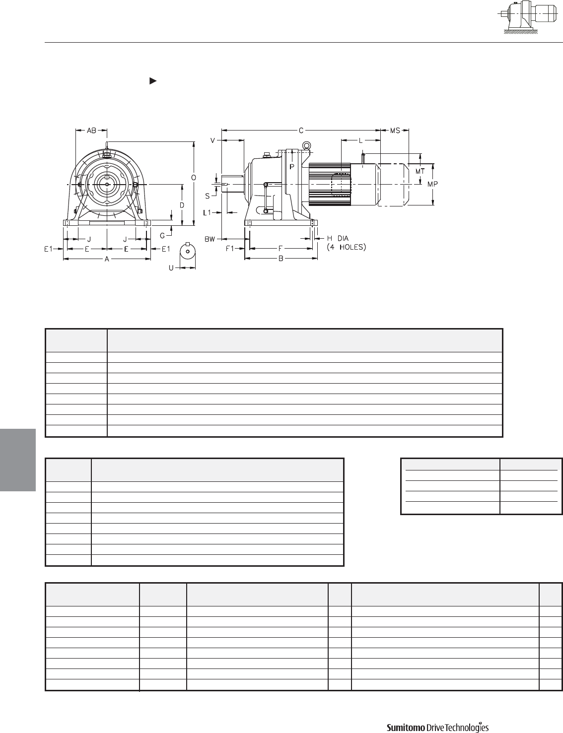
CYCLO® 6000 Gearmotors
Dimensions Inverter Duty, Integral Foot Mount
Single Reduction
CHHM-6130/5Y 6190/5Y-AV
4.20 Dimensions
Dimensions
Gearmotors
All dimensions are in inches
Model Low Speed Shaft
CHHM
U* V S L1 Key
6130/5Y 1.875 2.76 3/8-16UNC 0.71 1/2 X 1/2 X 2.16
6140/5Y 1.875 3.54 3/8-16UNC 0.71 1/2 X 1/2 X 2.95
614HY 1.875 3.54 3/8-16UNC 0.71 1/2 X 1/2 X 2.95
6160/5Y 2.250 3.54 3/8-16UNC 0.71 1/2 X 1/2 X 2.95
616HY 2.250 3.54 3/8-16UNC 0.71 1/2 X 1/2 X 2.95
6170/5Y 2.750 3.54 1/2-13UNC 0.94 5/8 X 5/8 X 3.15
6180/5Y 3.125 4.33 1/2-13UNC 0.94 3/4 X 3/4 X 3.74
6190/5Y 3.625 5.31 3/4-10UNC 1.34 7/8 X 7/8 X 4.92
Shaft Nominal Diameter (inches) Tolerances (inches)
1.250 (1 1/4) through 1.875 (1 7/8) +0.0000/-0.0006
2.000 (2) through 3.125 (3 1/8) +0.0000/-0.0007
3.250 (3 1/4) through 4.625 (4 5/8) +0.0000/-0.0009
4.750 (4 3/4) through 7.000 (7) +0.0000/-0.0010
*Shaft Tolerances
Dimensions shown are for reference only and are subject to change without notice, unless certified.
Certified prints are available after receipt of an order; consult factory.
Cyclo® 6000 Series
Model A B D E E1 F F1 G H J P BW
CHHM
6130/5Y 12.99 7.68 5.906 5.71 0.79 5.71 0.98 0.87 0.71 2.56 9.06 3.94
6140/5Y 12.99 7.68 5.906 5.71 0.79 5.71 0.98 0.87 0.71 2.56 9.06 4.72
614HY 12.99 7.68 6.299 5.71 0.79 5.71 0.98 0.87 0.71 2.76 9.06 4.72
6160/5Y 16.14 9.37 6.299 7.28 0.79 5.91 1.73 0.98 0.71 2.95 11.81 5.47
616HY 16.14 9.37 7.874 7.28 0.79 5.91 1.73 0.98 0.71 3.15 11.81 5.47
6170/5Y 16.93 13.19 7.874 7.48 0.98 10.83 1.18 1.18 0.87 3.15 13.39 4.92
6180/5Y 18.50 14.96 8.661 8.27 0.98 12.60 1.18 1.18 0.87 3.35 14.57 5.71
6190/5Y 20.87 17.32 9.843 9.45 0.98 14.96 1.18 1.38 1.02 3.54 16.93 6.69
Model Motor Without Brake Appx With Brake Appx
HP Pole C O AB L MP Wt (lb) C O AB L MP MS MT Wt (lb)
CHHM1-6130/5Y-AV 1 4 20.08 10.55 5.83 3.94 6.30 119 22.52 10.55 5.83 6.38 6.30 4.53 4.49 130
CHHM1H-6130/5Y-AV 1.5 4 20.87 10.79 6.10 4.13 6.81 126 23.35 10.79 6.10 6.61 6.81 4.76 4.88 141
CHHM2-6130/5Y-AV 2 4 20.87 10.79 6.10 4.13 6.81 126 23.35 10.79 6.10 6.61 6.81 4.76 4.88 141
CHHM3-6130/5Y-AV 3 4 21.77 11.65 6.54 5.00 8.35 148 24.61 11.65 6.54 7.83 8.35 5.20 6.18 170
CHHM5-6130/5Y-AV 5 4 23.50 11.65 6.54 5.00 8.35 163 26.34 11.65 6.54 7.83 8.35 5.20 6.18 185
CHHM8-6130/5Y-AV 7.5 4 24.41 12.72 8.31 5.63 9.88 196 28.15 12.72 8.31 9.37 9.88 6.69 7.17 236
CHHM10-6130/5Y-AV 10 4 26.77 12.72 8.31 5.63 9.88 227 30.51 12.72 8.31 9.37 9.88 6.69 7.17 265
CHHM15-6130/5Y-AV[1
]15 4 31.10 14.09 9.13 11.61 12.76 340 34.65 12.64 9.13 15.16 12.76 8.66 - 412
Note: [1] Motor frame extends below the unit base.
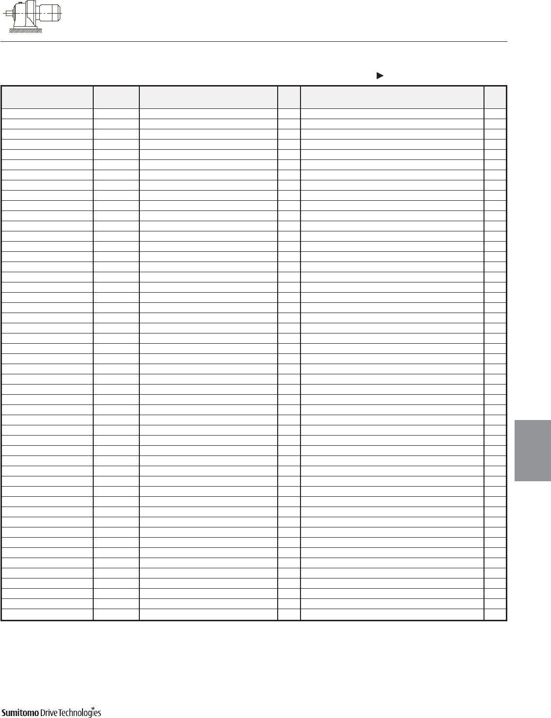
CYCLO® 6000 Gearmotors
Dimensions Inverter Duty, Integral Foot Mount
Single Reduction
CHHM-6130/5Y 6190/5Y-AV (cont.)
Dimensions 4.21
Dimensions
Gearmotors
All dimensions are in inches
Dimensions shown are for reference only and are subject to change without notice, unless certified.
Certified prints are available after receipt of an order; consult factory.
Cyclo® 6000 Series
Model Motor Without Brake Appx With Brake Appx
HP Pole C O AB L MP Wt (lb) C O AB L MP MS MT Wt (lb)
CHHM1H-6140/5Y-AV 1.5 4 21.65 10.79 6.10 4.13 6.81 128 24.13 10.79 6.10 6.61 6.81 4.76 4.88 143
CHHM2-6140/5Y-AV 2 4 21.65 10.79 6.10 4.13 6.81 128 24.13 10.79 6.10 6.61 6.81 4.76 4.88 143
CHHM3-6140/5Y-AV 3 4 22.56 11.65 6.54 5.00 8.35 150 25.39 11.65 6.54 7.83 8.35 5.20 6.18 172
CHHM5-6140/5Y-AV 5 4 24.29 11.65 6.54 5.00 8.35 165 27.13 11.65 6.54 7.83 8.35 5.20 6.18 187
CHHM8-6140/5Y-AV 7.5 4 25.20 12.72 8.31 5.63 9.88 198 28.94 12.72 8.31 9.37 9.88 6.69 7.17 238
CHHM10-6140/5Y-AV 10 4 27.56 12.72 8.31 5.63 9.88 227 31.30 12.72 8.31 9.37 9.88 6.69 7.17 267
CHHM15-6140/5Y-AV[1
]15 4 31.10 14.09 9.13 11.61 12.76 342 34.65 12.64 9.13 15.16 12.76 8.66 - 415
CHHM1H-614HY-AV 1.5 4 21.65 11.18 6.10 4.13 6.81 132 24.13 11.18 6.10 6.61 6.81 4.76 4.88 148
CHHM2-614HY-AV 2 4 21.65 11.18 6.10 4.13 6.81 132 24.13 11.18 6.10 6.61 6.81 4.76 4.88 148
CHHM3-614HY-AV 3 4 22.56 12.05 6.54 5.00 8.35 154 25.39 12.05 6.54 7.83 8.35 5.20 6.18 176
CHHM5-614HY-AV 5 4 24.29 12.05 6.54 5.00 8.35 170 27.13 12.05 6.54 7.83 8.35 5.20 6.18 192
CHHM8-614HY-AV 7.5 4 25.20 13.11 8.31 5.63 9.88 203 28.94 13.11 8.31 9.37 9.88 6.69 7.17 243
CHHM10-614HY-AV 10 4 27.56 13.11 8.31 5.63 9.88 234 31.30 13.11 8.31 9.37 9.88 6.69 7.17 273
CHHM15-614HY-AV[1
]15 4 31.10 14.49 9.13 11.61 12.76 348 34.65 13.03 9.13 15.16 12.76 8.66 - 421
CHHM2-6160/5Y-AV 2 4 23.54 12.20 6.10 4.13 6.81 212 26.02 12.20 6.10 6.61 6.81 4.76 4.88 225
CHHM3-6160/5Y-AV 3 4 24.45 12.20 6.54 5.00 8.35 232 27.28 12.20 6.54 7.83 8.35 5.20 6.18 254
CHHM5-6160/5Y-AV 5 4 26.18 12.20 6.54 5.00 8.35 247 29.02 12.20 6.54 7.83 8.35 5.20 6.18 269
CHHM8-6160/5Y-AV 7.5 4 27.28 13.11 8.31 5.63 9.88 282 31.02 13.11 8.31 9.37 9.88 6.69 7.17 320
CHHM10-6160/5Y-AV 10 4 29.65 13.11 8.31 5.63 9.88 313 33.39 13.11 8.31 9.37 9.88 6.69 7.17 351
CHHM15-6160/5Y-AV[1
]15 4 32.99 14.49 9.13 11.61 12.76 430 36.54 14.49 9.13 15.16 12.76 8.66 - 503
CHHM20-6160/5Y-AV[1
]20 4 36.73 14.49 11.69 13.39 15.51 589 45.00 14.49 11.69 21.65 15.51 14.45 - 701
CHHM2-616HY-AV 2 4 23.54 13.78 6.10 4.13 6.81 223 26.02 13.78 6.10 6.61 6.81 4.76 4.88 236
CHHM3-616HY-AV 3 4 24.45 13.78 6.54 5.00 8.35 243 27.28 13.78 6.54 7.83 8.35 5.20 6.18 265
CHHM5-616HY-AV 5 4 26.18 13.78 6.54 5.00 8.35 258 29.02 13.78 6.54 7.83 8.35 5.20 6.18 280
CHHM8-616HY-AV 7.5 4 27.28 14.69 8.31 5.63 9.88 293 31.02 14.69 8.31 9.37 9.88 6.69 7.17 331
CHHM10-616HY-AV 10 4 29.65 14.69 8.31 5.63 9.88 324 33.39 14.69 8.31 9.37 9.88 6.69 7.17 362
CHHM15-616HY-AV 15 4 32.99 16.06 9.13 11.61 12.76 441 36.54 16.06 9.13 15.16 12.76 8.66 - 514
CHHM20-616HY-AV 20 4 36.73 16.06 11.69 13.39 15.51 600 45.00 16.06 11.69 21.65 15.51 14.45 - 712
CHHM5-6170/5Y-AV 5 4 28.50 15.87 6.54 5.00 8.35 337 31.34 15.87 6.54 7.83 8.35 5.20 6.18 359
CHHM8-6170/5Y-AV 7.5 4 29.21 15.87 8.31 5.63 9.88 370 32.95 15.87 8.31 9.37 9.88 6.69 7.17 410
CHHM10-6170/5Y-AV 10 4 31.57 15.87 8.31 5.63 9.88 401 35.31 15.87 8.31 9.37 9.88 6.69 7.17 441
CHHM15-6170/5Y-AV 15 4 34.72 16.26 9.13 11.61 12.76 520 38.27 16.26 9.13 15.16 12.76 8.66 - 593
CHHM20-6170/5Y-AV 20 4 38.46 16.81 11.69 13.39 15.51 670 46.73 16.81 11.69 21.65 15.51 14.45 - 783
CHHM25-6170/5Y-AV 25 4 38.46 16.85 11.69 13.39 15.51 708 46.73 16.81 11.69 21.65 15.51 14.57 - 803
CHHM30-6170/5Y-AV 30 4 38.46 16.85 11.69 13.39 15.51 708 46.73 16.81 11.69 21.65 15.51 14.57 - 803
CHHM8-6180/5Y-AV 7.5 4 30.67 17.24 8.31 5.63 9.88 454 34.41 17.24 8.31 9.37 9.88 6.69 7.17 494
CHHM10-6180/5Y-AV 10 4 33.03 17.24 8.31 5.63 9.88 485 36.77 17.24 8.31 9.37 9.88 6.69 7.17 525
CHHM15-6180/5Y-AV 15 4 36.18 17.24 9.13 11.61 12.76 617 39.72 17.24 9.13 15.16 12.76 8.66 - 679
CHHM20-6180/5Y-AV 20 4 39.92 17.64 11.69 13.39 15.51 754 48.19 17.64 11.69 21.65 15.51 14.45 - 867
CHHM25-6180/5Y-AV 25 4 39.92 17.64 11.69 13.39 15.51 792 48.19 17.64 11.69 21.65 15.51 14.57 - 886
CHHM30-6180/5Y-AV 30 4 39.92 17.64 11.69 13.39 15.51 792 48.19 17.64 11.69 21.65 15.51 14.57 - 886
CHHM40-6180/5Y-AV 40 4 44.45 18.94 11.69 18.11 15.51 897 52.91 18.94 11.69 21.65 15.51 11.61 - 1111
CHHM15-6190/5Y-AV 15 4 39.17 18.39 9.13 11.61 12.76 761 42.72 18.39 9.13 15.16 12.76 8.66 - 836
CHHM20-6190/5Y-AV 20 4 42.91 20.12 11.69 13.39 15.51 919 51.18 20.12 11.69 21.65 15.51 14.45 - 1019
CHHM25-6190/5Y-AV 25 4 42.91 20.12 11.69 13.39 15.51 953 51.18 20.12 11.69 21.65 15.51 14.57 - 1047
CHHM30-6190/5Y-AV 30 4 42.91 20.12 11.69 13.39 15.51 953 51.18 20.12 11.69 21.65 15.51 14.57 - 1047
CHHM40-6190/5Y-AV 40 4 47.44 20.12 11.69 18.11 15.51 1036 55.91 20.12 11.69 21.65 15.51 11.61 - 1250
CHHM406-6190/5Y-AV[2] 40 6 48.62 20.12 11.69 18.11 15.51 1041 - - - - - - - -
CHHM50-6190/5Y-AV 50 4 47.44 20.12 11.69 18.11 15.51 1036 55.91 20.12 11.69 28.03 15.51 11.61 - 1250
CHHM506-6190/5Y-AV[2] 50 6 49.80 20.12 11.69 18.11 19.06 1230 - - - - - - - -
Note: [1] Motor frame extends below the unit base.
[2] Air over design.
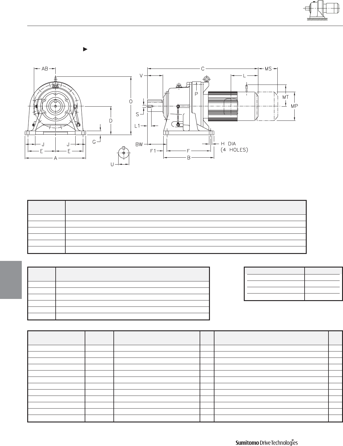
CYCLO® 6000 Gearmotors
Dimensions Inverter Duty, Integral Foot Mount
Single Reduction
CHHM-6205Y 6255Y-AV
4.22 Dimensions
Dimensions
Gearmotors
All dimensions are in inches
Model Low Speed Shaft
CHHM
U* V S L1 Key
6205Y 3.875 6.50 3/4-10UNC 1.34 1 X 1 X 6.50
6215Y 4.250 6.50 3/4-10UNC 1.34 1 X 1 X 6.50
6225Y 4.625 6.50 3/4-10UNC 1.34 1-1/4 X 7/8 X 6.5
6235Y 5.000 7.87 1-8UNC 1.61 1-1/4 X 7/8 X 7.87
6245Y 5.500 7.87 1-8UNC 1.61 1-1/4 X 7/8 X 7.87
6255Y 6.250 9.45 1-1/4-7UNC 1.93 1-1/2 X 1 X 9.45
Shaft Nominal Diameter (inches) Tolerances (inches)
1.250 (1 1/4) through 1.875 (1 7/8) +0.0000/-0.0006
2.000 (2) through 3.125 (3 1/8) +0.0000/-0.0007
3.250 (3 1/4) through 4.625 (4 5/8) +0.0000/-0.0009
4.750 (4 3/4) through 7.000 (7) +0.0000/-0.0010
*Shaft Tolerances
Model Motor Without Brake Appx With Brake Appx
HP Pole C O AB L MP Wt (lb) C O AB L MP MS MT Wt (lb)
CHHM20-6205Y-AV 20 4 44.37 20.87 11.69 13.39 15.51 966 50.87 20.87 11.69 21.65 15.51 14.45 - 1065
CHHM30-6205Y-AV 30 4 44.37 20.87 11.69 13.39 15.51 994 50.87 20.87 11.69 21.65 15.51 14.45 - 1087
CHHM40-6205Y-AV [1] 40 4 50.08 20.87 11.69 18.11 15.51 1082 60.00 20.87 11.69 26.57 15.51 17.52 - 1287
CHHM20-6215Y-AV 20 4 45.31 22.64 11.69 13.39 15.51 1135 51.81 22.64 11.69 21.65 15.51 14.45 - 1235
CHHM40-6215Y-AV [1] 40 4 51.02 22.64 11.69 18.11 15.51 1252 60.94 22.64 11.69 26.57 15.51 17.52 - 1459
CHHM406-6215Y-AV [1] 40 6 51.02 22.64 11.69 18.11 15.51 1252 60.94 22.64 11.69 26.57 15.51 17.52 - 1459
CHHM50-6215Y-AV [1] 50 4 51.02 22.64 11.69 18.11 15.51 1252 60.94 22.64 11.69 26.57 15.51 17.52 - 1459
CHHM30-6225Y-AV 30 4 46.89 24.02 11.69 13.39 15.51 1351 55.16 24.02 11.69 21.65 15.51 14.45 - 1451
CHHM50-6225Y-AV [1] 50 4 52.6 24.02 11.69 18.11 15.51 1440 62.52 24.02 11.69 26.57 15.51 17.52 - 1647
CHHM406-6235Y-AV [1] 40 6 55.04 26.26 11.69 18.11 15.51 1645 64.96 26.26 11.69 26.57 15.51 17.52 - 1836
CHHM506-6245Y-AV [1] 50 6 58.35 28.7 11.69 18.11 19.06 2121 - - - - - - - -
CHHM506-6255Y-AV [1] 50 6 62.99 32.09 11.69 18.11 19.06 2824 - - - - - - - -
Model A B D E E1 F F1 G H J P BW
CHHM
6205Y 20.87 17.32 9.843 8.66 1.77 14.17 1.57 1.38 1.02 3.94 18.54 8.46
6215Y 22.83 18.70 10.433 9.45 1.97 15.55 1.57 1.57 1.02 4.33 19.09 8.27
6225Y 24.41 20.47 11.024 10.63 1.57 16.54 1.97 1.57 1.30 4.53 20.71 9.06
6235Y 26.38 22.05 11.811 11.42 1.77 18.11 1.97 1.77 1.30 4.72 22.13 10.24
6245Y 28.35 22.83 13.189 12.40 1.77 18.90 1.97 1.77 1.54 5.04 25.08 10.35
6255Y 30.71 24.80 14.764 13.19 2.17 20.47 2.17 1.97 1.54 5.51 27.68 12.60
Dimensions shown are for reference only and are subject to change without notice, unless certified.
Certified prints are available after receipt of an order; consult factory.
Cyclo® 6000 Series
Note: [1] Motor frame extends below the unit base.
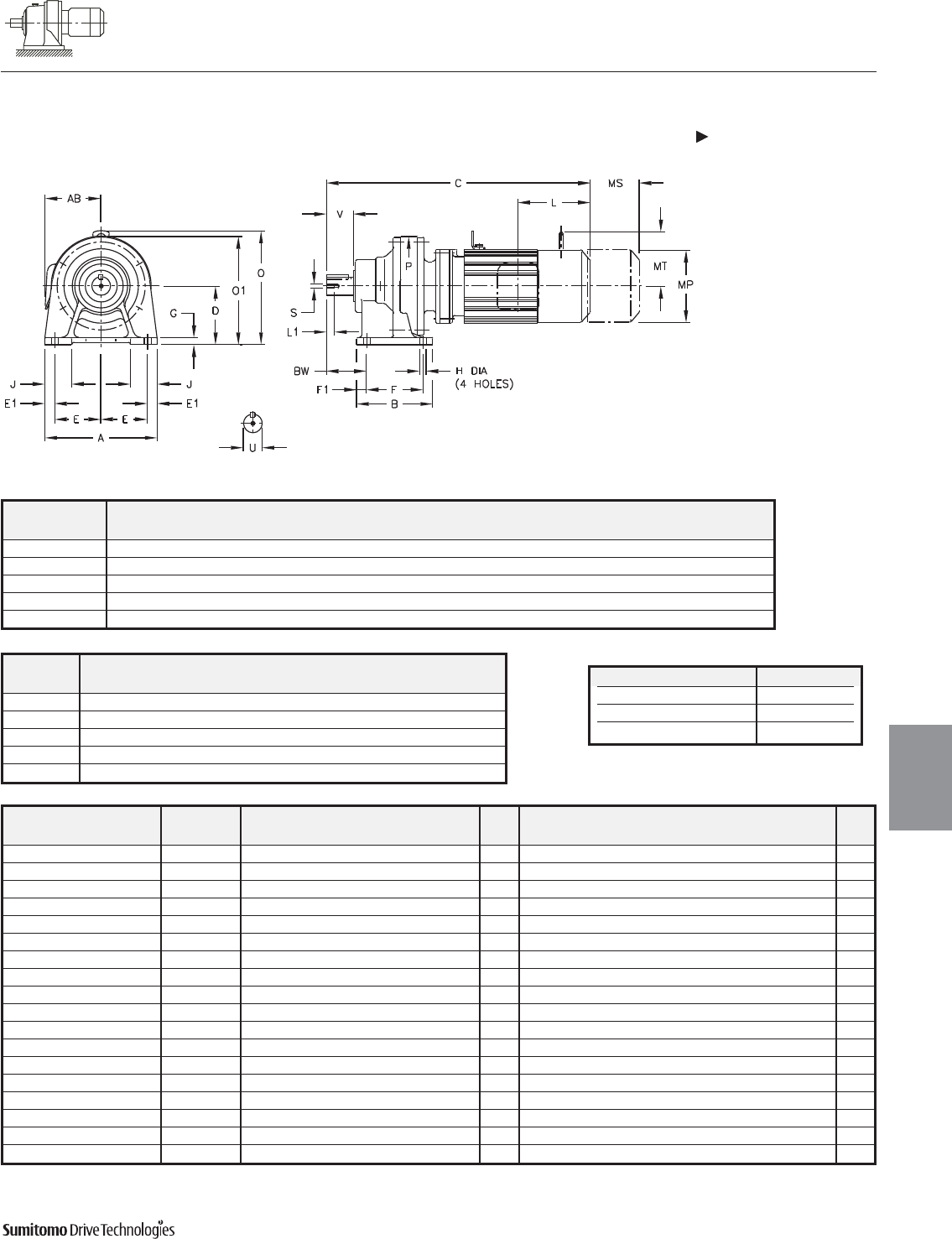
CYCLO® 6000 Gearmotors
Dimensions Inverter Duty, Integral Foot Mount
Double Reduction
CNHM-6060/5DAY 6120/5DBY-AV
Dimensions 4.23
Dimensions
Gearmotors
All dimensions are in inches
Model Motor Without Brake Appx With Brake Appx
HP Pole C O O1 AB L MP Wt (lb) C O O1 AB L MP MS MT Wt (lb)
CNHM01-6060/5DAY-AV 1/8 4 11.85 - 5.59 5.04 2.32 4.88 20 13.11 - 5.59 5.04 3.58 4.88 2.40 - 22
CNHM01-6070/5DAY-AV 1/8 4 12.09 - 5.59 5.04 2.32 4.88 20 13.35 - 5.59 5.04 3.58 4.88 2.40 - 22
CNHM02-6070/5DAY-AV 1/4 4 12.87 - 5.59 5.04 2.32 4.88 22 14.13 - 5.59 5.04 3.58 4.88 2.40 - 24
CNHM01-6090/5DAY-AV 1/8 4 14.41 8.15 - 5.04 2.32 4.88 37 15.67 8.15 - 5.04 3.58 4.88 2.40 - 40
CNHM02-6090/5DAY-AV 1/4 4 15.20 8.15 - 5.04 2.32 4.88 40 16.46 8.15 - 5.04 3.58 4.88 2.40 - 42
CNHM03-6090/5DAY-AV 1/3 4 15.20 8.15 - 5.04 2.32 4.88 40 16.46 8.15 - 5.04 3.58 4.88 2.40 - 42
CNHM05-6090/5DAY-AV 1/2 4 16.81 8.15 - 5.63 3.82 5.83 51 18.50 8.15 - 5.63 5.51 5.83 3.66 4.17 53
CNHM01-6100/5DAY-AV 1/8 4 14.96 8.15 - 5.04 2.32 4.88 42 16.22 8.15 - 5.04 3.58 4.88 2.40 - 44
CNHM02-6100/5DAY-AV 1/4 4 15.75 8.15 - 5.04 2.32 4.88 44 17.01 8.15 - 5.04 3.58 4.88 2.40 - 46
CNHM03-6100/5DAY-AV 1/3 4 15.75 8.15 - 5.04 2.32 4.88 44 17.01 8.15 - 5.04 3.58 4.88 2.40 - 46
CNHM05-6100/5DAY-AV 1/2 4 17.36 8.15 - 5.63 3.82 5.83 53 19.06 8.15 - 5.63 5.51 5.83 3.66 4.17 57
CNHM02-6120/5DBY-AV 1/4 4 17.64 10.12 - 5.04 2.32 4.88 75 18.90 10.12 - 5.04 3.58 4.88 2.40 - 79
CNHM03-6120/5DBY-AV 1/3 4 17.64 10.12 - 5.04 2.32 4.88 75 18.90 10.12 - 5.04 3.58 4.88 2.40 - 79
CNHM05-6120/5DBY-AV 1/2 4 19.25 10.12 - 5.63 3.82 5.83 84 20.94 10.12 - 5.63 5.51 5.83 3.66 4.17 90
CNHM08-6120/5DBY-AV 3/4 4 20.31 10.12 - 5.83 3.94 6.30 90 22.76 10.12 - 5.83 6.38 6.30 4.53 4.49 101
CNHM1-6120/5DBY-AV 1 4 20.31 10.12 - 5.83 3.94 6.30 90 22.76 10.12 - 5.83 6.38 6.30 4.53 4.49 101
CNHM1H-6120/5DBY-AV 1.5 4 21.34 10.12 - 6.10 4.13 8.35 99 23.82 10.12 - 6.10 6.61 8.35 4.76 4.88 112
CNHM2-6120/5DBY-AV 2 4 21.34 10.12 - 6.10 4.13 8.35 99 23.82 10.12 - 6.10 6.61 8.35 4.76 4.88 112
Dimensions shown are for reference only and are subject to change without notice, unless certified.
Certified prints are available after receipt of an order; consult factory.
Cyclo® 6000 Series
Model Low Speed Shaft
CNHM
U* V S L1 Key
6060/5DAY 0.500 0.98 10-32UNF 0.63 1/8 X 1/8 X .79
6070/5DAY 0.750 1.18 12-28UNF 0.63 3/16 X 3/16 X 1.06
6090/5DAY 1.125 1.38 5/16-18UNC 0.79 1/4 X 1/4 X 1.18
6100/5DAY 1.125 1.38 5/16-18UNC 0.79 1/4 X 1/4 X 1.18
6120/5DBY 1.500 2.17 5/16-18UNC 0.79 3/8 X 3/8 X 1.77
Shaft Nominal Diameter (inches) Tolerances (inches)
0.500 (1/2) through 0.625 (5/8) +0.0000/-0.0004
0.750 (3/4) through 1.125 (1 1/8) +0.0000/-0.0005
1.250 (1 1/4) through 1.875 (1 7/8) +0.0000/-0.0006
*Shaft Tolerances
Model A B D E E1 F F1 G H J P BW
CNHM
6060/5DAY 5.67 3.31 3.150 2.36 0.47 2.36 0.47 0.39 0.35 1.38 4.33 1.61
6070/5DAY 5.67 3.31 3.150 2.36 0.47 2.36 0.47 0.39 0.35 1.38 4.33 1.85
6090/5DAY 7.09 5.31 3.937 2.95 0.59 3.54 0.59 0.47 0.43 1.57 5.91 2.36
6100/5DAY 7.09 5.31 3.937 2.95 0.59 3.54 0.59 0.47 0.43 1.57 5.91 2.36
6120/5DBY 9.06 6.10 4.724 3.74 0.79 4.53 0.79 0.59 0.55 2.17 8.03 3.23
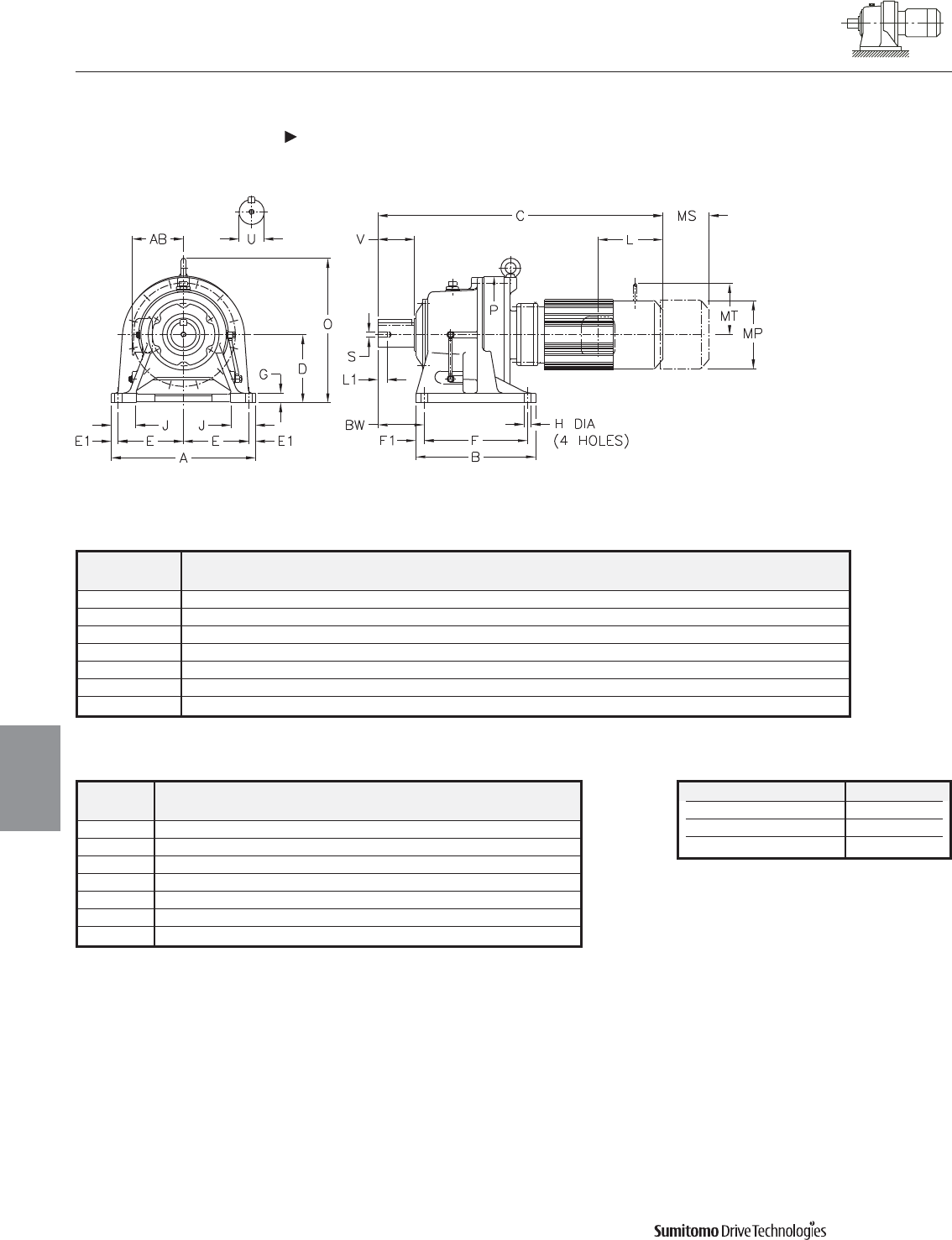
CYCLO® 6000 Gearmotors
Dimensions Inverter Duty, Integral Foot Mount
Double Reduction
CHHM-6130/5DCY 6190/5DBY-AV
4.24 Dimensions
Dimensions
Gearmotors
All dimensions are in inches
Model Low Speed Shaft
CHHM
U* V S L1 Key
6130/5DCY 1.875 2.76 3/8-16UNC 0.71 1/2 X 1/2 X 2.16
6140/5DBY 1.875 3.54 3/8-16UNC 0.71 1/2 X 1/2 X 2.95
6160/5DCY 2.250 3.54 3/8-16UNC 0.71 1/2 X 1/2 X 2.95
6170/5DCY 2.750 3.54 1/2-13UNC 0.94 5/8 X 5/8 X 3.15
6180/5DBY 3.125 4.33 1/2-13UNC 0.94 3/4 X 3/4 X 3.74
6190/5DAY 3.625 5.31 3/4-10UNC 1.34 7/8 X 7/8 X 4.92
6190/5DBY 3.625 5.31 3/4-10UNC 1.34 7/8 X 7/8 X 4.92
Shaft Nominal Diameter (inches) Tolerances (inches)
1.250 (1 1/4) through 1.875 (1 7/8) +0.0000/-0.0006
2.000 (2) through 3.125 (3 1/8) +0.0000/-0.0007
3.250 (3 1/4) through 4.625 (4 5/8) +0.0000/-0.0009
*Shaft Tolerances
Model A B D E E1 F F1 G H J P BW
CHHM
6130/5DCY 12.99 7.68 5.906 5.71 0.79 5.71 0.98 0.87 0.71 2.56 9.06 3.94
6140/5DBY 12.99 7.68 5.906 5.71 0.79 5.71 0.98 0.87 0.71 2.56 9.06 4.72
6160/5DCY 16.14 9.37 6.299 7.28 0.79 5.91 1.73 0.98 0.71 2.95 11.81 5.47
6170/5DCY 16.93 13.19 7.874 7.48 0.98 10.83 1.18 1.18 0.87 3.15 13.39 4.92
6180/5DBY 18.50 14.96 8.661 8.27 0.98 12.60 1.18 1.18 0.87 3.35 14.57 5.71
6190/5DAY 20.87 17.32 9.843 9.45 0.98 14.96 1.18 1.38 1.02 3.54 16.93 6.69
6190/5DBY 20.87 17.32 9.843 9.45 0.98 14.96 1.18 1.38 1.02 3.54 16.93 6.69
Dimensions shown are for reference only and are subject to change without notice, unless certified.
Certified prints are available after receipt of an order; consult factory.
Cyclo® 6000 Series

CYCLO® 6000 Gearmotors
Dimensions Inverter Duty, Integral Foot Mount
Double Reduction
CHHM-6130/5DCY 6190/5DBY-AV (cont.)
Dimensions 4.25
Dimensions
Gearmotors
All dimensions are in inches
Model Motor Without Brake Appx With Brake Appx
HP Pole C O AB L MP Wt (lb) C O AB L MP MS MT Wt (lb)
CHHM02-6130/5DCY-AV 1/4 4 20.20 11.81 5.04 2.32 4.88 112 21.46 11.81 5.04 3.58 4.88 2.40 - 117
CHHM03-6130/5DCY-AV 1/3 4 20.20 11.81 5.04 2.32 4.88 112 21.46 11.81 5.04 3.58 4.88 2.40 - 117
CHHM05-6130/5DCY-AV 1/2 4 21.81 10.35 5.63 3.82 5.83 121 23.50 10.35 5.63 5.51 5.83 3.66 4.17 128
CHHM08-6130/5DCY-AV 3/4 4 23.11 10.63 5.83 3.94 6.30 130 25.55 10.63 5.83 6.38 6.30 4.53 4.49 141
CHHM1-6130/5DCY-AV 1 4 23.11 10.63 5.83 3.94 6.30 130 25.55 10.63 5.83 6.38 6.30 4.53 4.49 141
CHHM1H-6130/5DCY-AV 1.5 4 23.90 10.87 6.10 4.13 6.81 139 26.38 10.87 6.10 6.61 6.81 4.76 4.88 152
CHHM2-6130/5DCY-AV 2 4 23.90 10.87 6.10 4.13 6.81 139 26.38 10.87 6.10 6.61 6.81 4.76 4.88 152
CHHM02-6140/5DBY-AV 1/4 4 20.43 11.81 5.04 2.32 4.88 108 21.69 11.81 5.04 3.58 4.88 2.40 - 112
CHHM03-6140/5DBY-AV 1/3 4 20.43 11.81 5.04 2.32 4.88 108 21.69 11.81 5.04 3.58 4.88 2.40 - 112
CHHM05-6140/5DBY-AV 1/2 4 22.05 10.35 5.63 3.82 5.83 117 23.74 10.35 5.63 5.51 5.83 3.66 4.17 123
CHHM08-6140/5DBY-AV 3/4 4 23.35 10.63 5.83 3.94 6.30 123 25.79 10.63 5.83 6.38 6.30 4.53 4.49 135
CHHM1-6140/5DBY-AV 1 4 23.35 10.63 5.83 3.94 6.30 123 25.79 10.63 5.83 6.38 6.30 4.53 4.49 135
CHHM05-6160/5DCY-AV 1/2 4 24.65 13.74 5.63 3.82 5.83 225 26.34 13.74 5.63 5.51 5.83 3.66 4.17 232
CHHM08-6160/5DCY-AV 3/4 4 25.94 13.74 5.83 3.94 6.30 234 28.39 13.74 5.83 6.38 6.30 4.53 4.49 245
CHHM1-6160/5DCY-AV 1 4 25.94 13.74 5.83 3.94 6.30 234 28.39 13.74 5.83 6.38 6.30 4.53 4.49 245
CHHM1H-6160/5DCY-AV 1.5 4 26.73 13.74 6.10 4.13 6.81 243 29.21 13.74 6.10 6.61 6.81 4.76 4.88 258
CHHM2-6160/5DCY-AV 2 4 26.73 13.74 6.10 4.13 6.81 243 29.21 13.74 6.10 6.61 6.81 4.76 4.88 258
CHHM3-6160/5DCY-AV 3 4 27.64 13.74 6.54 5.00 8.35 265 30.47 13.74 6.54 7.83 8.35 5.20 6.18 287
CHHM5-6160/5DCY-AV 5 4 29.37 13.74 8.31 5.63 8.35 280 32.20 13.74 8.31 9.37 8.35 6.69 7.17 302
CHHM05-6170/5DCY-AV 1/2 4 26.50 16.38 5.63 3.82 5.83 300 28.19 16.38 5.63 5.51 5.83 3.66 4.17 306
CHHM08-6170/5DCY-AV 3/4 4 27.80 16.38 5.83 3.94 6.30 309 30.24 16.38 5.83 6.38 6.30 4.53 4.49 320
CHHM1-6170/5DCY-AV 1 4 27.80 16.38 5.83 3.94 6.30 309 30.24 16.38 5.83 6.38 6.30 4.53 4.49 320
CHHM1H-6170/5DCY-AV 1.5 4 28.58 16.38 6.10 4.13 6.81 318 31.06 16.38 6.10 6.61 6.81 4.76 4.88 333
CHHM2-6170/5DCY-AV 2 4 28.58 16.38 6.10 4.13 6.81 318 31.06 16.38 6.10 6.61 6.81 4.76 4.88 333
CHHM3-6170/5DCY-AV 3 4 29.49 16.38 6.54 5.00 8.35 340 32.32 16.38 6.54 7.83 8.35 5.20 6.18 362
CHHM5-6170/5DCY-AV 5 4 31.22 16.38 8.31 5.63 8.35 355 34.06 16.38 8.31 9.37 8.35 6.69 7.17 377
CHHM1-6180/5DBY-AV 1 4 30.16 17.76 5.83 3.94 6.30 426 32.60 17.76 5.83 6.38 6.30 4.53 4.49 437
CHHM1H-6180/5DBY-AV 1.5 4 30.94 17.76 6.10 4.13 6.81 432 33.43 17.76 6.10 6.61 6.81 4.76 4.88 448
CHHM2-6180/5DBY-AV 2 4 30.94 17.76 6.10 4.13 6.81 432 33.43 17.76 6.10 6.61 6.81 4.76 4.88 448
CHHM3-6180/5DBY-AV 3 4 31.85 17.76 6.54 5.00 8.35 454 34.69 17.76 6.54 7.83 8.35 5.20 6.18 476
CHHM5-6180/5DBY-AV 5 4 33.58 17.76 6.54 5.00 8.35 470 36.42 17.76 6.54 7.83 8.35 5.20 6.18 492
CHHM8-6180/5DBY-AV 7.5 4 34.49 17.76 8.31 5.63 9.88 503 38.23 17.76 8.31 9.37 9.88 6.69 7.17 542
CHHM10-6180/5DBY-AV 10 4 36.85 17.76 8.31 5.63 9.88 534 40.59 17.76 8.31 9.37 9.88 6.69 7.17 573
CHHM15-6180/5DBY-AV 15 4 40.39 17.76 9.13 11.61 12.76 651 44.53 17.76 9.13 15.16 12.76 8.66 - 739
CHHM1-6190/5DAY-AV 1 4 32.52 20.91 5.83 3.94 6.30 558 34.96 20.91 5.83 6.38 6.30 4.53 4.49 569
CHHM1H-6190/5DAY-AV 1.5 4 33.31 20.91 6.10 4.13 6.81 567 35.79 20.91 6.10 6.61 6.81 4.76 4.88 582
CHHM2-6190/5DAY-AV 2 4 33.31 20.91 6.10 4.13 6.81 567 35.79 20.91 6.10 6.61 6.81 4.76 4.88 582
CHHM3-6190/5DAY-AV 3 4 34.21 20.91 6.54 5.00 8.35 589 37.05 20.91 6.54 7.83 8.35 5.20 6.18 611
CHHM5-6190/5DAY-AV 5 4 35.94 20.91 6.54 5.00 8.35 604 38.78 20.91 6.54 7.83 8.35 5.20 6.18 626
CHHM5-6190/5DBY-AV 5 4 36.57 20.91 6.54 5.00 8.35 620 39.41 20.91 6.54 7.83 8.35 5.20 6.18 642
CHHM8-6190/5DBY-AV 7.5 4 37.48 20.91 8.31 5.63 9.88 653 41.22 20.91 8.31 9.37 9.88 6.69 7.17 692
CHHM10-6190/5DBY-AV 10 4 39.84 20.91 8.31 5.63 9.88 684 43.58 20.91 8.31 9.37 9.88 6.69 7.17 723
CHHM15-6190/5DBY-AV 15 4 43.39 20.91 9.13 11.61 12.76 798 46.93 20.91 9.13 15.16 12.76 8.66 - 871
Dimensions shown are for reference only and are subject to change without notice, unless certified.
Certified prints are available after receipt of an order; consult factory.
Cyclo® 6000 Series

CYCLO® 6000 Gearmotors
Dimensions Inverter Duty, Integral Foot Mount
Double Reduction
CHHM-6205DAY 6225DBY-AV
4.26 Dimensions
Dimensions
Gearmotors
All dimensions are in inches
Model Low Speed Shaft
CHHM
U* V S L1 Key
6205DAY 3.875 6.50 3/4-10UNC 1.34 1 X 1 X 6.50
6205DBY 3.875 6.50 3/4-10UNC 1.34 1 X 1 X 6.50
6215DAY 4.250 6.50 3/4-10UNC 1.34 1 X 1 X 6.50
6215DBY 4.250 6.50 3/4-10UNC 1.34 1 X 1 X 6.50
6225DAY 4.625 6.50 3/4-10UNC 1.34 1-1/4 X 7/8 X 6.5
6225DBY 4.625 6.50 3/4-10UNC 1.34 1-1/4 X 7/8 X 6.5
Shaft Nominal Diameter (inches) Tolerances (inches)
2.000 (2) through 3.125 (3 1/8) +0.0000/-0.0007
3.250 (3 1/4) through 4.625 (4 5/8) +0.0000/-0.0009
4.750 (4 3/4) through 7.000 (7) +0.0000/-0.0010
*Shaft Tolerances
Dimensions shown are for reference only and are subject to change without notice, unless certified.
Certified prints are available after receipt of an order; consult factory.
Cyclo® 6000 Series
Model A B D E E1 F F1 G H J P BW
CHHM
6205DAY 20.87 17.32 9.843 8.66 1.77 14.17 1.57 1.38 1.02 3.94 17.64 8.46
6205DBY 20.87 17.32 9.843 8.66 1.77 14.17 1.57 1.38 1.02 3.94 17.64 8.46
6215DAY 22.83 18.70 10.433 9.45 1.97 15.55 1.57 1.57 1.02 4.33 19.09 8.27
6215DBY 22.83 18.70 10.433 9.45 1.97 15.55 1.57 1.57 1.02 4.33 19.09 8.27
6225DAY 24.41 20.47 11.024 10.63 1.57 16.54 1.97 1.57 1.30 4.53 20.71 9.06
6225DBY 24.41 20.47 11.024 10.63 1.57 16.54 1.97 1.57 1.30 4.53 20.71 9.06
CYCLO® 6000 Gearmotors
Dimensions Inverter Duty, Integral Foot Mount
Double Reduction
CHHM-6205DAY 6225DBY-AV (cont.)
Dimensions 4.27
Dimensions
Gearmotors
All dimensions are in inches
Dimensions shown are for reference only and are subject to change without notice, unless certified.
Certified prints are available after receipt of an order; consult factory.
Cyclo® 6000 Series
Model Motor Without Brake Appx With Brake Appx
HP Pole C O AB L MP Wt (lb) C O AB L MP MS MT Wt (lb)
CHHM1-6205DAY-AV 1 4 34.13 20.87 5.83 3.94 6.30 600 36.57 20.87 5.83 6.38 6.30 4.53 4.49 611
CHHM2-6205DAY-AV 2 4 34.92 20.87 6.10 4.13 6.81 609 37.36 20.87 6.10 6.61 6.81 4.76 4.88 624
CHHM3-6205DAY-AV 3 4 35.83 20.87 6.54 5.00 8.35 631 38.66 20.87 6.54 7.83 8.35 5.20 6.18 653
CHHM5-6205DAY-AV 5 4 37.56 20.87 6.54 5.00 8.35 646 40.39 20.87 6.54 7.83 8.35 5.20 6.18 668
CHHM3-6205DBY-AV 3 4 36.89 20.87 6.54 5.00 8.35 657 39.72 20.87 6.54 7.83 8.35 5.20 6.18 679
CHHM5-6205DBY-AV 5 4 38.62 20.87 6.54 5.00 8.35 673 41.46 20.87 6.54 7.83 8.35 5.20 6.18 695
CHHM8-6205DBY-AV 7.5 4 39.53 20.87 8.31 5.63 9.88 706 43.27 20.87 8.31 9.37 9.88 6.69 7.17 745
CHHM10-6205DBY-AV 10 4 41.89 20.87 8.31 5.63 9.88 734 45.63 20.87 8.31 9.37 9.88 6.69 7.17 774
CHHM15-6205DBY-AV 15 4 45.43 20.87 9.13 11.61 12.76 849 48.58 20.87 9.13 15.16 12.76 8.66 - 919
CHHM2-6215DAY-AV 2 4 37.01 22.64 6.10 4.13 6.81 814 39.49 22.64 6.10 6.61 6.81 4.76 4.88 829
CHHM3-6215DAY-AV 3 4 37.91 22.64 6.54 5.00 8.35 836 40.75 22.64 6.54 7.83 8.35 5.20 6.18 858
CHHM5-6215DAY-AV 5 4 39.65 22.64 6.54 5.00 8.35 851 42.48 22.64 6.54 7.83 8.35 5.20 6.18 873
CHHM8-6215DAY-AV 7.5 4 40.55 22.64 8.31 5.63 9.88 884 44.29 22.64 8.31 9.37 9.88 6.69 7.17 924
CHHM10-6215DAY-AV 10 4 42.91 22.64 8.31 5.63 9.88 913 46.65 22.64 8.31 9.37 9.88 6.69 7.17 953
CHHM15-6215DAY-AV 15 4 46.46 22.64 9.13 11.61 12.76 1028 50.00 22.64 9.13 15.16 12.76 8.66 - 1100
CHHM10-6215DBY-AV 10 4 44.09 22.64 8.31 5.63 9.88 959 47.83 22.64 8.31 9.37 9.88 6.69 7.17 997
CHHM15-6215DBY-AV 15 4 47.44 22.64 9.13 11.61 12.76 1076 50.98 22.64 9.13 15.16 12.76 8.66 - 1149
CHHM20-6215DBY-AV 20 4 51.18 22.64 11.69 13.39 15.51 1233 59.45 22.64 11.69 21.65 15.51 14.45 - 1345
CHHM2-6225DAY-AV 2 4 38.66 24.02 6.10 4.13 6.81 977 41.14 24.02 6.10 6.61 6.81 4.76 4.88 992
CHHM3-6225DAY-AV 3 4 39.57 24.02 6.54 5.00 8.35 999 42.40 24.02 6.54 7.83 8.35 5.20 6.18 1021
CHHM5-6225DAY-AV 5 4 41.30 24.02 6.54 5.00 8.35 1014 44.13 24.02 6.54 7.83 8.35 5.20 6.18 1036
CHHM8-6225DAY-AV 7.5 4 42.20 24.02 8.31 5.63 9.88 1047 45.94 24.02 8.31 9.37 9.88 6.69 7.17 1087
CHHM10-6225DAY-AV 10 4 44.57 24.02 8.31 5.63 9.88 1078 48.31 24.02 8.31 9.37 9.88 6.69 7.17 1118
CHHM15-6225DAY-AV 15 4 48.11 24.02 9.13 11.61 12.76 1193 51.65 24.02 9.13 15.16 12.76 8.66 - 1266
CHHM20-6225DBY-AV 20 4 53.54 24.02 11.69 13.39 15.51 1446 61.81 24.02 11.69 21.65 15.51 14.45 - 1559
CHHM25-6225DBY-AV 25 4 53.54 24.02 11.69 13.39 15.51 1446 61.81 24.02 11.69 21.65 15.51 14.45 - 1559
CHHM30-6225DBY-AV 30 4 53.54 24.02 11.69 13.39 15.51 1484 61.81 24.02 11.69 21.65 15.51 14.57 - 1596

CYCLO® 6000 Gearmotors
Dimensions Inverter Duty, Integral Foot Mount
Double Reduction
CHHM-6235DAY 6275DAY-AV
4.28 Dimensions
Dimensions
Gearmotors
All dimensions are in inches
Model Low Speed Shaft
CHHM
U* V S L1 Key
6235DAY 5.000 7.87 1-8UNC 1.61 1-1/4 X 7/8 X 7.87
6235DBY 5.000 7.87 1-8UNC 1.61 1-1/4 X 7/8 X 7.87
6245DAY 5.500 7.87 1-8UNC 1.61 1-1/4 X 7/8 X 7.87
6245DBY 5.500 7.87 1-8UNC 1.61 1-1/4 X 7/8 X 7.87
6255DAY 6.250 9.45 1-1/4-7UNC 1.93 1-1/2 X 1 X 9.45
6255DBY 6.250 9.45 1-1/4-7UNC 1.93 1-1/2 X 1 X 9.45
6265DAY 6.625 11.81 1-1/4-7UNC 1.93 1-3/4 X 1-1/4 X 11.8
6275DAY 7.000 13.00 1-1/4-7UNC 2.05 1-3/4 X 1-1/4 X 13
Shaft Nominal Diameter (inches) Tolerances (inches)
2.000 (2) through 3.125 (3 1/8) +0.0000/-0.0007
3.250 (3 1/4) through 4.625 (4 5/8) +0.0000/-0.0009
4.750 (4 3/4) through 7.000 (7) +0.0000/-0.0010
*Shaft Tolerances
Model A B D E E1 F F1 G H J P BW
CHHM
6235DAY 26.38 22.05 11.811 11.42 1.77 18.11 1.97 1.77 1.30 4.72 22.13 10.24
6235DBY 26.38 22.05 11.811 11.42 1.77 18.11 1.97 1.77 1.30 4.72 22.13 10.24
6245DAY 28.35 22.83 13.189 12.40 1.77 18.90 1.97 1.77 1.54 5.04 24.17 10.35
6245DBY 28.35 22.83 13.189 12.40 1.77 18.90 1.97 1.77 1.54 5.04 24.17 10.35
6255DAY 30.71 24.80 14.764 13.19 2.17 20.47 2.17 1.97 1.54 5.51 26.38 12.60
6255DBY 30.71 24.80 14.764 13.19 2.17 20.47 2.17 1.97 1.54 5.51 26.38 12.60
6265DAY 34.65 27.56 15.748 15.16 2.17 23.23 2.17 2.17 1.77 6.30 28.98 15.35
6275DAY 45.67 40.94 21.260 20.67 2.17 16.54 3.94 2.36 1.77 7.87 37.40 19.09
Dimensions shown are for reference only and are subject to change without notice, unless certified.
Certified prints are available after receipt of an order; consult factory.
Cyclo® 6000 Series
CYCLO® 6000 Gearmotors
Dimensions Inverter Duty, Integral Foot Mount
Double Reduction
CHHM-6235DAY 6275DAY-AV (cont.)
Dimensions 4.29
Dimensions
Gearmotors
All dimensions are in inches
Model Motor Without Brake Appx With Brake Appx
HP Pole C O AB L MP Wt (lb) C O AB L MP MS MT Wt (lb)
CHHM3-6235DAY-AV 3 4 42.95 26.26 6.54 5.00 8.35 1255 45.79 26.26 6.54 7.83 8.35 5.20 6.18 1277
CHHM5-6235DAY-AV 5 4 44.69 26.26 6.54 5.00 8.35 1270 47.52 26.26 6.54 7.83 8.35 5.20 6.18 1292
CHHM8-6235DAY-AV 7.5 4 45.79 26.26 8.31 5.63 9.88 1305 49.53 26.26 8.31 9.37 9.88 6.69 7.17 1343
CHHM10-6235DAY-AV 10 4 48.15 26.26 8.31 5.63 9.88 1336 51.89 26.26 8.31 9.37 9.88 6.69 7.17 1374
CHHM15-6235DAY-AV 15 4 51.50 26.26 9.13 11.61 12.76 1453 55.04 26.26 9.13 15.16 12.76 8.66 - 1526
CHHM20-6235DAY-AV 20 4 55.24 26.26 11.69 13.39 15.51 1614 63.50 26.26 11.69 21.65 15.51 14.45 - 1727
CHHM25-6235DAY-AV 25 4 55.24 26.26 11.69 13.39 15.51 1614 63.50 26.26 11.69 21.65 15.51 14.45 - 1727
CHHM40-6235DBY-AV 40 4 60.63 26.26 11.69 18.11 15.51 1797 69.09 26.26 11.69 25.39 15.51 17.52 - 2011
CHHM3-6245DAY-AV 3 4 44.45 28.70 6.54 5.00 8.35 1495 47.28 28.70 6.54 7.83 8.35 5.20 6.18 1517
CHHM5-6245DAY-AV 5 4 46.18 28.70 6.54 5.00 8.35 1510 49.02 28.70 6.54 7.83 8.35 5.20 6.18 1532
CHHM8-6245DAY-AV 7.5 4 47.28 28.70 8.31 5.63 9.88 1546 51.02 28.70 8.31 9.37 9.88 6.69 7.17 1583
CHHM10-6245DAY-AV 10 4 49.65 28.70 8.31 5.63 9.88 1577 53.39 28.70 8.31 9.37 9.88 6.69 7.17 1614
CHHM15-6245DAY-AV 15 4 52.99 28.70 9.13 11.61 12.76 1693 56.54 28.70 9.13 15.16 12.76 8.66 - 1766
CHHM20-6245DAY-AV 20 4 56.73 28.70 11.69 13.39 15.51 1841 65.00 28.70 11.69 21.65 15.51 14.45 - 1954
CHHM25-6245DAY-AV 25 4 56.73 28.70 11.69 13.39 15.51 1841 65.00 28.70 11.69 21.65 15.51 14.45 - 1954
CHHM20-6245DBY-AV 20 4 57.56 28.70 11.69 13.39 15.51 1899 65.83 28.70 11.69 21.65 15.51 14.45 - 2011
CHHM30-6245DBY-AV 30 4 57.56 28.70 11.69 13.39 15.51 1936 65.83 28.70 11.69 21.65 15.51 14.57 - 2031
CHHM40-6245DBY-AV 40 4 62.09 28.70 11.69 18.11 15.51 2051 70.55 28.70 11.69 28.03 15.51 17.52 - 2265
CHHM5-6255DAY-AV 5 4 52.28 32.09 6.54 5.00 8.35 2293 55.12 32.09 6.54 9.37 8.35 5.20 6.18 2315
CHHM8-6255DAY-AV 7.5 4 52.99 32.09 8.31 5.63 9.88 2326 56.73 32.09 8.31 9.37 9.88 6.69 7.17 2359
CHHM10-6255DAY-AV 10 4 55.35 32.09 8.31 5.63 9.88 2359 59.09 32.09 8.31 9.37 9.88 6.69 7.17 2392
CHHM15-6255DAY-AV 15 4 58.50 32.09 9.13 11.61 12.76 2470 62.05 32.09 9.13 15.16 12.76 8.66 - 2547
CHHM20-6255DAY-AV 20 4 62.24 32.09 11.69 13.39 15.51 2624 70.51 32.09 11.69 21.65 15.51 14.45 - 2736
CHHM25-6255DAY-AV 25 4 62.24 32.09 11.69 13.39 15.51 2624 70.51 32.09 11.69 21.65 15.51 14.45 - 2736
CHHM30-6255DAY-AV 30 4 62.24 32.09 11.69 13.39 15.51 2668 70.51 32.09 11.69 21.65 15.51 14.57 - 2763
CHHM25-6255DBY-AV 25 4 63.11 32.09 11.69 13.39 15.51 2789 71.38 32.09 11.69 21.65 15.51 14.45 - 2902
CHHM30-6255DBY-AV 30 4 63.11 32.09 11.69 13.39 15.51 2822 71.38 32.09 11.69 21.65 15.51 14.57 - 2917
CHHM40-6255DBY-AV 40 4 67.64 32.09 11.69 18.11 15.51 2906 75.91 32.09 11.69 28.03 15.51 17.52 - 3120
CHHM50-6255DBY-AV 50 4 67.64 32.09 11.69 18.11 15.51 2906 75.91 32.09 11.69 28.03 15.51 - - 3120
CHHM8-6265DAY-AV 7.5 4 58.78 34.41 8.31 5.63 9.88 3043 62.52 34.41 8.31 9.37 9.88 6.69 7.17 3087
CHHM10-6265DAY-AV 10 4 61.14 34.41 8.31 5.63 9.88 3076 64.88 34.41 8.31 9.37 9.88 6.69 7.17 3109
CHHM15-6265DAY-AV 15 4 63.70 34.41 9.13 11.61 12.76 3186 67.24 34.41 9.13 15.16 12.76 8.66 - 3263
CHHM20-6265DAY-AV 20 4 67.44 34.41 11.69 13.39 15.51 3352 75.71 34.41 11.69 21.65 15.51 14.45 - 3451
CHHM25-6265DAY-AV 25 4 67.44 34.41 11.69 13.39 15.51 3352 75.71 34.41 11.69 21.65 15.51 14.45 - 3451
CHHM30-6265DAY-AV 30 4 67.44 34.41 11.69 13.39 15.51 3385 75.71 34.41 11.69 21.65 15.51 14.57 - 3479
CHHM40-6265DAY-AV 40 4 71.97 34.41 11.69 18.11 15.51 3462 80.43 34.41 11.69 28.03 15.51 17.52 - 3676
CHHM50-6265DAY-AV 50 4 71.97 34.41 11.69 18.11 15.51 3462 80.43 34.41 11.69 28.03 15.51 - - 3676
CHHM10-6275DAY-AV 10 4 71.42 45.71 8.31 5.63 9.88 5579 75.16 45.71 8.31 9.37 9.88 6.69 7.17 5612
CHHM15-6275DAY-AV 15 4 73.98 45.71 9.13 11.61 12.76 5689 77.52 45.71 9.13 15.16 12.76 8.66 - 5766
CHHM20-6275DAY-AV 20 4 77.72 45.71 11.69 13.39 15.51 5854 85.98 45.71 11.69 21.65 15.51 14.45 - 5954
CHHM25-6275DAY-AV 25 4 77.72 45.71 11.69 13.39 15.51 5854 85.98 45.71 11.69 21.65 15.51 14.45 - 5954
CHHM30-6275DAY-AV 30 4 77.72 45.71 11.69 13.39 15.51 5887 85.98 45.71 11.69 21.65 15.51 14.57 - 5982
CHHM40-6275DAY-AV 40 4 82.24 45.71 11.69 18.11 15.51 5971 90.71 45.71 11.69 28.03 15.51 17.52 - 6185
CHHM50-6275DAY-AV 50 4 82.24 45.71 11.69 18.11 15.51 5971 90.71 45.71 11.69 28.03 15.51 - - 6185
Dimensions shown are for reference only and are subject to change without notice, unless certified.
Certified prints are available after receipt of an order; consult factory.
Cyclo® 6000 Series
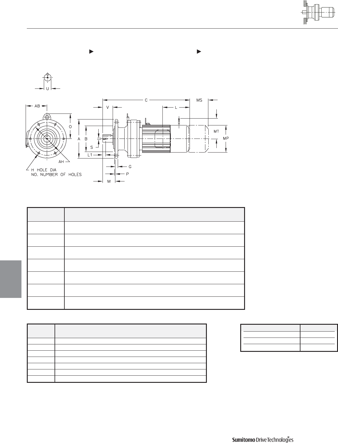
Model ABGHNO
.
MOPAH
CNVM, PHVM
6060/5Y 4.72 3.1484 0.31 0.35 6 1.34 - 0.12 4.02
3.1466
6070/5Y 6.30 4.3293 0.35 0.43 4 1.65 - 0.12 5.28
4.3272
6080/5Y 6.30 4.3293 0.35 0.43 4 1.89 - 0.12 5.28
4.3272
6090/5Y 6.30 4.3293 0.35 0.43 4 1.89 4.21 0.12 5.28
4.3272
6100/5Y 6.30 4.3293 0.35 0.43 4 1.89 4.21 0.12 5.28
4.3272
6110/5Y 8.27 5.5101 0.43 0.43 6 2.28 4.57 0.16 7.09
5.5076
6120/5Y 8.27 5.5101 0.51 0.43 6 2.72 5.39 0.16 7.09
5.5076
CYCLO® 6000 Gearmotors
Dimensions Integral V-Flange Mount
Single Reduction
CNVM-6060/5Y 6120/5Y, PHVM-6100/5Y 6120/5Y
4.30 Dimensions
Dimensions
Gearmotors
All dimensions are in inches
Model Low Speed Shaft
CNVM, PHVM
U* V S L1 Key
6060/5Y 0.500 0.98 10-32UNF 0.63 1/8 X 1/8 X 0.79
6070/5Y 0.750 1.18 12-28UNF 0.63 3/16 X 3/16 X 1.06
6080/5Y 0.875 1.38 12-28UNF 0.63 3/16 X 3/16 X 1.18
6090/5Y 1.125 1.38 5/16-18UNC 0.79 1/4 X 1/4 X 1.18
6100/5Y 1.125 1.38 5/16-18UNC 0.79 1/4 X 1/4 X 1.18
6110/5Y 1.250 1.77 5/16-18UNC 0.79 1/4 X 1/4 X 1.46
6120/5Y 1.500 2.17 5/16-18UNC 0.79 3/8 X 3/8 X 1.77
Shaft Nominal Diameter (inches) Tolerances (inches)
0.500 (1/2) through 0.625 (5/8) +0.0000/-0.0004
0.750 (3/4) through 1.125 (1 1/8) +0.0000/-0.0005
1.250 (1 1/4) through 1.875 (1 7/8) +0.0000/-0.0006
*Shaft Tolerances
Dimensions shown are for reference only and are subject to change without notice, unless certified.
Certified prints are available after receipt of an order; consult factory.
Cyclo® 6000 Series

CYCLO® 6000 Gearmotors
Dimensions Integral V-Flange Mount
Single Reduction
CNVM-6060/5Y 6120/5Y, PHVM-6100/5Y 6120/5Y (cont.)
Dimensions 4.31
Dimensions
Gearmotors
All dimensions are in inches
Dimensions shown are for reference only and are subject to change without notice, unless certified.
Certified prints are available after receipt of an order; consult factory.
Cyclo® 6000 Series
Model Motor Without Brake Appx With Brake Appx
HP Pole C AB L MP Wt (lb) C AB L MP MS MT Wt (lb)
CNVM01-6060/5Y 1/8 4 8.90 5.04 1.38 4.69 13 10.28 5.04 2.76 4.88 1.93 - 18
CNVM02-6060/5Y 1/4 4 10.55 5.04 2.32 4.88 15 11.81 5.04 3.58 4.88 2.40 - 20
CNVM03-6060/5Y 1/3 4 10.55 5.04 2.32 4.88 18 11.81 5.04 3.58 4.88 2.40 - 20
CNVM01-6070/5Y 1/8 4 9.13 5.04 1.38 4.69 18 10.51 5.04 2.76 4.88 1.93 - 20
CNVM02-6070/5Y 1/4 4 10.79 5.04 2.32 4.88 20 12.05 5.04 3.58 4.88 2.40 - 22
CNVM03-6070/5Y 1/3 4 10.79 5.04 2.32 4.88 20 12.05 5.04 3.58 4.88 2.40 - 22
CNVM05-6070/5Y 1/2 4 11.57 5.04 2.32 4.88 22 12.83 5.04 3.58 4.88 2.40 - 24
CNVM01-6080/5Y 1/8 4 10.16 5.04 1.38 4.69 24 11.54 5.04 2.76 4.88 1.93 - 26
CNVM02-6080/5Y 1/4 4 11.81 5.04 2.32 4.88 26 13.07 5.04 3.58 4.88 2.40 - 29
CNVM03-6080/5Y 1/3 4 11.81 5.04 2.32 4.88 26 13.07 5.04 3.58 4.88 2.40 - 29
CNVM05-6080/5Y 1/2 4 12.60 5.04 2.32 4.88 31 13.86 5.04 3.58 4.88 2.40 - 33
CNVM08-6080/5Y 3/4 4 14.21 5.63 3.82 5.83 40 15.91 5.63 5.51 5.83 3.66 4.17 42
CNVM1-6080/5Y 1 4 14.21 5.63 3.82 5.83 40 15.91 5.63 5.51 5.83 3.66 4.17 42
CNVM01-6090/5Y 1/8 4 10.87 5.04 1.38 4.69 26 12.24 5.04 2.76 4.88 1.93 - 31
CNVM02-6090/5Y 1/4 4 12.52 5.04 2.32 4.88 29 13.78 5.04 3.58 4.88 2.40 - 33
CNVM03-6090/5Y 1/3 4 12.52 5.04 2.32 4.88 29 13.78 5.04 3.58 4.88 2.40 - 33
CNVM05-6090/5Y 1/2 4 13.31 5.04 2.32 4.88 31 14.57 5.04 3.58 4.88 2.40 - 35
CNVM08-6090/5Y 3/4 4 14.92 5.63 3.82 5.83 40 16.61 5.63 5.51 5.83 3.66 4.17 46
CNVM1-6090/5Y 1 4 14.92 5.63 3.82 5.83 40 16.61 5.63 5.51 5.83 3.66 4.17 46
CNVM1H-6090/5Y 1.5 4 16.22 5.83 3.94 6.30 46 18.66 5.83 6.38 6.30 4.53 4.49 57
CNVM2-6090/5Y 2 4 16.22 5.83 3.94 6.30 46 18.66 5.83 6.38 6.30 4.53 4.49 57
CNVM02-6100/5Y 1/4 4 13.07 5.04 2.32 4.88 33 14.33 5.04 3.58 4.88 2.40 - 37
CNVM03-6100/5Y 1/3 4 13.07 5.04 2.32 4.88 33 14.33 5.04 3.58 4.88 2.40 - 37
CNVM05-6100/5Y 1/2 4 13.86 5.04 2.32 4.88 35 15.12 5.04 3.58 4.88 2.40 - 40
CNVM08-6100/5Y 3/4 4 15.47 5.63 3.82 5.83 44 17.17 5.63 5.51 5.83 3.66 4.17 51
CNVM1-6100/5Y 1 4 15.47 5.63 3.82 5.83 44 17.17 5.63 5.51 5.83 3.66 4.17 51
CNVM/PHVM1H-6100/5Y 1.5 4 16.77 5.83 3.94 6.30 53 19.21 5.83 6.38 6.30 4.53 4.49 64
CNVM/PHVM2-6100/5Y 2 4 16.77 5.83 3.94 6.30 53 19.21 5.83 6.38 6.30 4.53 4.49 64
CNVM/PHVM3-6100/5Y 3 4 17.56 6.10 4.13 6.81 62 20.04 6.10 6.61 6.81 4.76 4.88 75
CNVM05-6110/5Y 1/2 4 14.29 5.04 2.32 4.88 40 15.51 5.04 3.58 4.88 2.40 - 44
CNVM08-6110/5Y 3/4 4 15.87 5.63 3.82 5.83 46 17.80 5.63 5.51 5.83 3.66 4.17 53
CNVM1-6110/5Y 1 4 15.87 5.63 3.82 5.83 46 17.80 5.63 5.51 5.83 3.66 4.17 53
CNVM1H-6110/5Y 1.5 4 17.17 5.83 3.94 6.30 53 19.41 5.83 6.38 6.30 4.53 4.49 64
CNVM2-6110/5Y 2 4 17.17 5.83 3.94 6.30 53 19.41 5.83 6.38 6.30 4.53 4.49 64
CNVM3-6110/5Y 3 4 17.95 6.10 4.13 6.81 62 20.43 6.10 6.61 6.81 4.76 4.88 75
CNVM5-6110/5Y 5 4 19.33 6.54 5.00 8.35 84 22.17 6.54 7.83 8.35 5.20 6.18 106
CNVM08-6120/5Y 3/4 4 16.65 5.63 3.82 5.83 66 18.35 5.63 5.51 5.83 3.66 4.17 73
CNVM1-6120/5Y 1 4 16.65 5.63 3.82 5.83 66 18.35 5.63 5.51 5.83 3.66 4.17 73
CNVM1H-6120/5Y 1.5 4 17.95 5.83 3.94 6.30 75 20.39 5.83 6.38 6.30 4.53 4.49 86
CNVM2-6120/5Y 2 4 17.95 5.83 3.94 6.30 75 20.39 5.83 6.38 6.30 4.53 4.49 86
CNVM3-6120/5Y 3 4 18.74 6.10 4.13 6.81 84 21.22 6.10 6.61 6.81 4.76 4.88 99
CNVM/PHVM5-6120/5Y 5 4 19.65 6.54 5.00 8.35 106 22.48 6.54 7.83 8.35 5.20 6.18 128
CNVM/PHVM8-6120/5Y 7.5 4 21.38 6.54 5.00 8.35 121 24.21 6.54 7.83 8.35 5.20 6.18 143
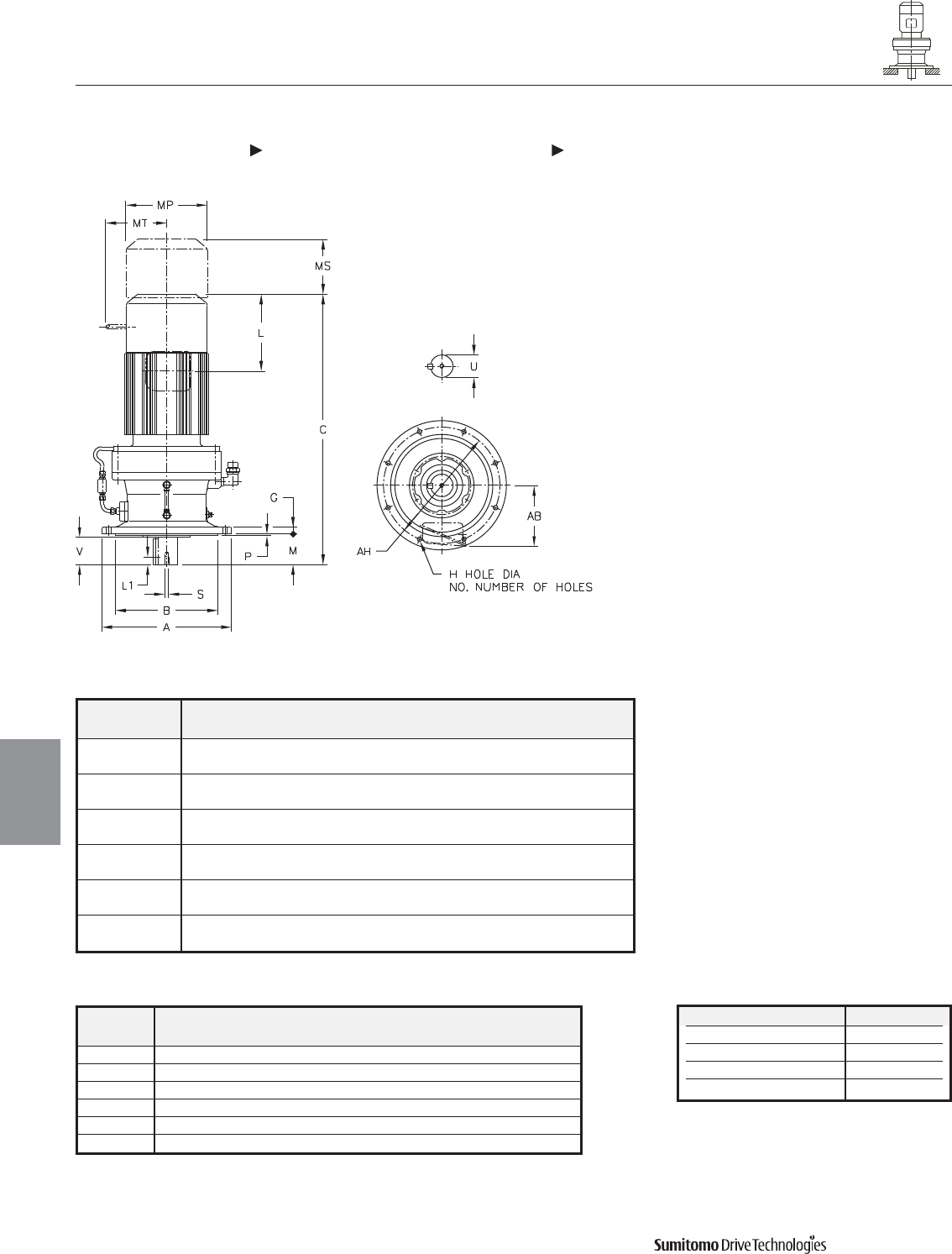
Model ABGH
NO.
MPAH
CVVM, PVVM
6130/5Y 10.24 7.8720 0.59 0.43 6 2.99 0.16 9.06
7.8692
6140/5Y 10.24 7.8720 0.59 0.43 6 3.78 0.16 9.06
7.8692
6160/5Y 13.39 10.6277 0.79 0.43 6 3.50 0.16 12.20
10.6245
6170/5Y 15.75 12.4385 0.87 0.55 8 3.70 0.20 14.17
12.4350
6180/5Y 16.93 13.5802 0.87 0.71 8 4.33 0.20 15.35
13.5767
6190/5Y 19.29 15.7456 1.18 0.71 12 5.71 0.24 17.72
15.7421
CYCLO® 6000 Gearmotors
Dimensions Integral Vertical V-Flange Mount
Single Reduction
CVVM-6130/5Y 6190/5Y, PVVM-6130/5Y 6170/5Y
4.32 Dimensions
Dimensions
Gearmotors
All dimensions are in inches
Model Low Speed Shaft
CVVM, PVVM
U* V S L1 Key
6130/5Y 1.875 2.40 3/8-16UNC 0.71 1/2 X 1/2 X 2.16
6140/5Y 1.875 3.19 3/8-16UNC 0.71 1/2 X 1/2 X 2.95
6160/5Y 2.250 3.15 3/8-16UNC 0.71 1/2 X 1/2 X 2.95
6170/5Y 2.750 3.31 1/2-13UNC 0.94 5/8 X 5/8 X 3.15
6180/5Y 3.125 3.94 1/2-13UNC 0.94 3/4 X 3/4 X 3.74
6190/5Y 3.625 4.92 3/4-10UNC 1.34 7/8 X 7/8 X 4.92
Shaft Nominal Diameter (inches) Tolerances (inches)
1.250 (1 1/4) through 1.875 (1 7/8) +0.0000/-0.0006
2.000 (2) through 3.125 (3 1/8) +0.0000/-0.0007
3.250 (3 1/4) through 4.625 (4 5/8) +0.0000/-0.0009
4.750 (4 3/4) through 7.000 (7) +0.0000/-0.0010
*Shaft Tolerances
Dimensions shown are for reference only and are subject to change without notice, unless certified.
Certified prints are available after receipt of an order; consult factory.
Cyclo® 6000 Series
Model Motor Without Brake Appx With Brake Appx
HP Pole C AB L MP Wt (lb) C AB L MP MS MT Wt (lb)
CVVM1-6130/5Y 1 4 18.78 5.63 3.82 5.83 110 20.47 5.63 5.51 5.83 3.66 4.17 117
CVVM1H-6130/5Y 1.5 4 20.08 5.83 3.94 6.30 119 22.52 5.83 6.38 6.30 4.53 4.49 130
CVVM2-6130/5Y 2 4 20.08 5.83 3.94 6.30 119 22.52 5.83 6.38 6.30 4.53 4.49 130
CVVM3-6130/5Y 3 4 20.87 6.10 4.13 6.81 126 23.35 6.10 6.61 6.81 4.76 4.88 141
CVVM5-6130/5Y 5 4 21.77 6.54 5.00 8.35 148 24.61 6.54 7.83 8.35 5.20 6.18 170
CVVM/PVVM8-6130/5Y 7.5 4 23.50 6.54 5.00 8.35 163 26.34 6.54 7.83 8.35 5.20 6.18 185
CVVM/PVVM10-6130/5Y 10 4 24.41 8.31 5.63 9.88 196 28.15 8.31 9.37 9.88 6.69 7.17 236
CVVM15-6130/5Y 15 4 26.77 8.31 5.63 9.88 227 30.51 8.31 9.37 9.88 6.69 7.17 265
CVVM1H-6140/5Y 1.5 4 20.87 5.83 3.94 6.30 121 23.31 5.83 6.38 6.30 4.53 4.49 132
CVVM2-6140/5Y 2 4 20.87 5.83 3.94 6.30 121 23.31 5.83 6.38 6.30 4.53 4.49 132
CVVM3-6140/5Y 3 4 21.65 6.10 4.13 6.81 128 24.13 6.10 6.61 6.81 4.76 4.88 143
CVVM5-6140/5Y 5 4 22.56 6.54 5.00 8.35 150 25.39 6.54 7.83 8.35 5.20 6.18 172
CVVM8-6140/5Y 7.5 4 24.29 6.54 5.00 8.35 165 27.13 6.54 7.83 8.35 5.20 6.18 187
CVVM/PVVM10-6140/5Y 10 4 25.20 8.31 5.63 9.88 198 28.94 8.31 9.37 9.88 6.69 7.17 238
CVVM/PVVM15-6140/5Y 15 4 27.56 8.31 5.63 9.88 227 31.30 8.31 9.37 9.88 6.69 7.17 267
CVVM20-6140/5Y 20 4 31.10 9.13 11.61 12.76 342 34.65 9.13 15.16 12.76 8.66 - 415
CVVM2-6160/5Y 2 4 22.95 5.83 3.94 6.30 194 25.39 5.83 6.38 6.30 4.53 4.49 205
CVVM3-6160/5Y 3 4 23.54 6.10 4.13 6.81 201 26.02 6.10 6.61 6.81 4.76 4.88 214
CVVM5-6160/5Y 5 4 24.45 6.54 5.00 8.35 221 27.28 6.54 7.83 8.35 5.20 6.18 243
CVVM8-6160/5Y 7.5 4 26.18 6.54 5.00 8.35 236 29.02 6.54 7.83 8.35 5.20 6.18 258
CVVM10-6160/5Y 10 4 27.28 8.31 5.63 9.88 271 31.02 8.31 9.37 9.88 6.69 7.17 309
CVVM/PVVM15-6160/5Y 15 4 29.65 8.31 5.63 9.88 302 33.39 8.31 9.37 9.88 6.69 7.17 340
CVVM/PVVM20-6160/5Y 20 4 32.99 9.13 11.61 12.76 419 36.54 9.13 15.16 12.76 8.66 - 492
CVVM/PVVM25-6160/5Y 25 4 36.73 11.69 13.39 15.51 578 45.00 11.69 21.65 15.51 14.45 - 690
CVVM30-6160/5Y 30 4 36.73 11.69 13.39 15.51 578 45.00 11.69 21.65 15.51 14.45 - 690
CVVM5-6170/5Y 5 4 26.77 6.54 5.00 8.35 315 29.61 6.54 7.83 8.35 5.20 6.18 337
CVVM8-6170/5Y 7.5 4 28.50 6.54 5.00 8.35 331 31.34 6.54 7.83 8.35 5.20 6.18 353
CVVM10-6170/5Y 10 4 29.21 8.31 5.63 9.88 364 32.95 8.31 9.37 9.88 6.69 7.17 404
CVVM15-6170/5Y 15 4 31.57 8.31 5.63 9.88 395 35.31 8.31 9.37 9.88 6.69 7.17 434
CVVM/PVVM20-6170/5Y 20 4 34.72 9.13 11.61 12.76 514 38.27 9.13 15.16 12.76 8.66 - 587
CVVM/PVVM25-6170/5Y 25 4 38.46 11.69 13.39 15.51 664 46.73 11.69 21.65 15.51 14.45 - 776
CVVM/PVVM30-6170/5Y 30 4 38.46 11.69 13.39 15.51 664 46.73 11.69 21.65 15.51 14.45 - 776
CVVM40-6170/5Y 40 4 38.46 11.69 13.39 15.51 701 46.73 11.69 21.65 15.51 14.57 - 796
CVVM5-6180/5Y 5 4 28.23 6.54 5.00 8.35 373 31.06 6.54 7.83 8.35 5.20 6.18 395
CVVM8-6180/5Y 7.5 4 29.96 6.54 5.00 8.35 390 32.80 6.54 7.83 8.35 5.20 6.18 412
CVVM10-6180/5Y 10 4 30.67 8.31 5.63 9.88 423 34.41 8.31 9.37 9.88 6.69 7.17 463
CVVM15-6180/5Y 15 4 33.03 8.31 5.63 9.88 454 36.77 8.31 9.37 9.88 6.69 7.17 494
CVVM20-6180/5Y 20 4 36.18 9.13 11.61 12.76 587 39.72 9.13 15.16 12.76 8.66 - 648
CVVM25-6180/5Y 25 4 39.92 11.69 13.39 15.51 723 48.19 11.69 21.65 15.51 14.45 - 836
CVVM30-6180/5Y 30 4 39.92 11.69 13.39 15.51 723 48.19 11.69 21.65 15.51 14.45 - 836
CVVM40-6180/5Y 40 4 39.92 11.69 13.39 15.51 761 48.19 11.69 21.65 15.51 14.57 - 856
CVVM50-6180/5Y 50 4 44.45 11.69 16.93 15.51 867 52.91 11.69 25.39 15.51 17.52 - 1080
CVVM60-6180/5Y 60 4 44.45 11.69 16.93 15.51 867 52.91 11.69 25.39 15.51 17.52 - 1080
CVVM8-6190/5Y 7.5 4 33.74 6.54 5.00 8.35 549 36.57 6.54 7.83 8.35 5.20 6.18 571
CVVM10-6190/5Y 10 4 34.25 8.31 5.63 9.88 578 37.99 8.31 9.37 9.88 6.69 7.17 617
CVVM15-6190/5Y 15 4 36.61 8.31 5.63 9.88 609 40.35 8.31 9.37 9.88 6.69 7.17 648
CVVM20-6190/5Y 20 4 39.17 9.13 11.61 12.76 725 42.72 9.13 15.16 12.76 8.66 - 800
CVVM25-6190/5Y 25 4 42.91 11.69 13.39 15.51 884 51.18 11.69 21.65 15.51 14.45 - 983
CVVM256-6190/5Y 25 6 42.91 11.69 13.39 15.51 884 51.18 11.69 21.65 15.51 14.45 - 979
CVVM30-6190/5Y 30 4 42.91 11.69 13.39 15.51 884 51.18 11.69 21.65 15.51 14.45 - 983
CVVM40-6190/5Y 40 4 42.91 11.69 13.39 15.51 917 51.18 11.69 21.65 15.51 14.45 - 979
CVVM406-6190/5Y 40 6 47.44 11.69 16.93 15.51 1001 55.91 11.69 25.39 15.51 17.52 - 1215
CVVM50-6190/5Y 50 4 47.44 11.69 16.93 15.51 1001 55.91 11.69 25.39 15.51 17.52 - 1215
CVVM506-6190/5Y 50 6 47.44 11.69 16.93 15.51 1001 55.91 11.69 25.39 15.51 17.52 - 1215
CVVM60-6190/5Y 60 4 47.44 11.69 16.93 15.51 1001 55.91 11.69 25.39 15.51 17.52 - 1215
CYCLO® 6000 Gearmotors
Dimensions Integral Vertical V-Flange Mount
Single Reduction
CVVM-6130/5Y 6190/5Y, PVVM-6130/5Y 6170/5Y (cont.)
Dimensions 4.33
Dimensions
Gearmotors
All dimensions are in inches
Dimensions shown are for reference only and are subject to change without notice, unless certified.
Certified prints are available after receipt of an order; consult factory.
Cyclo® 6000 Series
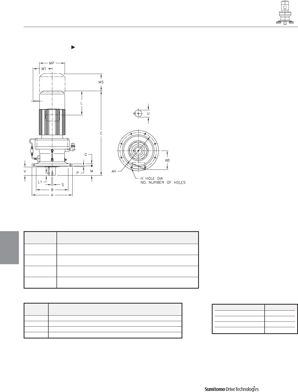
Model ABGH
NO.
MPAH
CVVM
6205Y 17.91 13.9739 1.18 0.87 8 8.03 0.20 15.94
13.9704
6215Y 19.29 15.3519 1.38 0.94 8 7.99 0.28 17.32
15.3484
6225Y 21.06 16.3359 1.38 1.06 8 8.27 0.39 18.70
16.3321
6235Y 22.44 17.7139 1.57 1.06 8 9.84 0.39 20.08
17.7100
CYCLO® 6000 Gearmotors
Dimensions Integral Vertical V-Flange Mount
Single Reduction
CVVM-6205Y 6235Y
4.34 Dimensions
Dimensions
Gearmotors
All dimensions are in inches
Model Low Speed Shaft
CVVM
U* V S L1 Key
6205Y 3.875 6.50 3/4-10UNC 1.34 1 X 1 X 6.50
6215Y 4.250 6.50 3/4-10UNC 1.34 1 X 1 X 6.50
6225Y 4.625 6.50 3/4-10UNC 1.34 1-1/4 X 7/8 X 6.50
6235Y 5.000 7.87 1-8UNC 1.61 1-1/4 X 7/8 X 7.87
Shaft Nominal Diameter (inches) Tolerances (inches)
1.250 (1 1/4) through 1.875 (1 7/8) +0.0000/-0.0006
2.000 (2) through 3.125 (3 1/8) +0.0000/-0.0007
3.250 (3 1/4) through 4.625 (4 5/8) +0.0000/-0.0009
4.750 (4 3/4) through 7.000 (7) +0.0000/-0.0010
*Shaft Tolerances
Dimensions shown are for reference only and are subject to change without notice, unless certified.
Certified prints are available after receipt of an order; consult factory.
Cyclo® 6000 Series
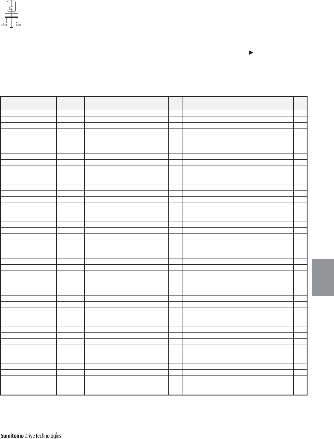
CYCLO® 6000 Gearmotors
Dimensions Integral Vertical V-Flange Mount
Single Reduction
CVVM-6205Y 6235Y (cont.)
Dimensions 4.35
Dimensions
Gearmotors
All dimensions are in inches
Model Motor Without Brake Appx With Brake Appx
HP Pole C AB L MP Wt (lb) C AB L MP MS MT Wt (lb)
CVVM15-6205Y 15 4 38.27 8.31 5.63 9.88 657 42.01 8.31 9.37 9.88 6.69 7.17 697
CVVM20-6205Y 20 4 41.02 9.13 11.61 12.76 776 44.57 9.13 15.16 12.76 8.66 - 853
CVVM206-6205Y 20 6 44.37 11.69 13.39 15.51 933 52.64 11.69 21.65 15.51 14.45 - 1032
CVVM25-6205Y 25 4 44.37 11.69 13.39 15.51 933 52.64 11.69 21.65 15.51 14.45 - 1032
CVVM30-6205Y 30 4 44.37 11.69 13.39 15.51 933 52.64 11.69 21.65 15.51 14.45 - 1032
CVVM306-6205Y 30 6 44.37 11.69 13.39 15.51 961 52.64 11.69 21.65 15.51 14.57 - 1061
CVVM40-6205Y 40 4 44.37 11.69 13.39 15.51 961 52.64 11.69 21.65 15.51 14.57 - 1061
CVVM406-6205Y 40 6 48.90 11.69 16.93 15.51 1045 57.36 11.69 25.39 15.51 17.52 - 1252
CVVM50-6205Y 50 4 48.90 11.69 16.93 15.51 1045 57.36 11.69 25.39 15.51 17.52 - 1252
CVVM506-6205Y 50 6 48.90 11.69 16.93 15.51 1045 57.36 11.69 25.39 15.51 17.52 - 1252
CVVM60-6205Y 60 4 48.90 11.69 16.93 15.51 1045 57.36 11.69 25.39 15.51 17.52 - 1252
CVVM606-6205Y 60 6 51.06 16.22 18.31 19.06 1250 - - - - - - -
CVVM75-6205Y 75 4 51.06 16.22 18.31 19.06 1250 - - - - - - -
CVVM15-6215Y 15 4 39.21 8.31 5.63 9.88 829 42.95 8.31 9.37 9.88 6.69 7.17 869
CVVM20-6215Y 20 4 41.97 9.13 11.61 12.76 950 45.51 9.13 15.16 12.76 8.66 - 1025
CVVM206-6215Y 20 6 45.31 11.69 13.39 15.51 1094 53.58 11.69 21.65 15.51 14.45 - 1193
CVVM25-6215Y 25 4 45.31 11.69 13.39 15.51 1094 53.58 11.69 21.65 15.51 14.45 - 1193
CVVM256-6215Y 25 6 45.31 11.69 13.39 15.51 1122 53.58 11.69 21.65 15.51 14.45 - 1222
CVVM30-6215Y 30 4 45.31 11.69 13.39 15.51 1094 53.58 11.69 21.65 15.51 14.45 - 1193
CVVM306-6215Y 30 6 45.31 11.69 13.39 15.51 1122 53.58 11.69 21.65 15.51 14.57 - 1222
CVVM40-6215Y 40 4 45.31 11.69 13.39 15.51 1122 53.58 11.69 21.65 15.51 14.57 - 1222
CVVM406-6215Y 40 6 49.84 11.69 16.93 15.51 1244 58.31 11.69 25.39 15.51 17.52 - 1453
CVVM50-6215Y 50 4 49.84 11.69 16.93 15.51 1244 58.31 11.69 25.39 15.51 17.52 - 1453
CVVM506-6215Y 50 6 49.84 11.69 16.93 15.51 1244 58.31 11.69 25.39 15.51 17.52 - 1453
CVVM60-6215Y 60 4 49.84 11.69 16.93 15.51 1244 58.31 11.69 25.39 15.51 17.52 - 1453
CVVM606-6215Y 60 6 52.01 16.22 18.31 19.06 1449 - - - - - - -
CVVM75-6215Y 75 4 52.01 16.22 18.31 19.06 1449 - - - - - - -
CVVM206-6225Y 20 6 46.89 11.69 13.39 15.51 1297 55.16 11.69 21.65 15.51 14.45 - 1396
CVVM25-6225Y 25 4 46.89 11.69 13.39 15.51 1297 55.16 11.69 21.65 15.51 14.45 - 1396
CVVM256-6225Y 25 6 46.89 11.69 13.39 15.51 1325 55.16 11.69 21.65 15.51 14.45 - 1424
CVVM30-6225Y 30 4 46.89 11.69 13.39 15.51 1297 55.16 11.69 21.65 15.51 14.45 - 1396
CVVM306-6225Y 30 6 46.89 11.69 13.39 15.51 1325 55.16 11.69 21.65 15.51 14.57 - 1424
CVVM40-6225Y 40 4 46.89 11.69 13.39 15.51 1325 55.16 11.69 21.65 15.51 14.57 - 1424
CVVM406-6225Y 40 6 51.42 11.69 16.93 15.51 1444 59.88 11.69 25.39 15.51 17.52 - 1654
CVVM50-6225Y 50 4 51.42 11.69 16.93 15.51 1444 59.88 11.69 25.39 15.51 17.52 - 1654
CVVM506-6225Y 50 6 51.42 11.69 16.93 15.51 1444 59.88 11.69 25.39 15.51 17.52 - 1654
CVVM60-6225Y 60 4 51.42 11.69 16.93 15.51 1444 59.88 11.69 25.39 15.51 17.52 - 1654
CVVM606-6225Y 60 6 53.58 16.22 18.31 19.06 1627 - - - - - - -
CVVM75-6225Y 75 4 53.58 16.22 18.31 19.06 1627 - - - - - - -
CVVM206-6235Y 20 6 49.33 11.69 13.39 15.51 1429 57.60 11.69 21.65 15.51 14.45 - 1497
CVVM256-6235Y 25 6 49.33 11.69 13.39 15.51 1429 57.60 11.69 21.65 15.51 14.45 - 1528
CVVM306-6235Y 30 6 49.33 11.69 13.39 15.51 1429 57.60 11.69 21.65 15.51 14.57 - 1528
CVVM406-6235Y 40 6 53.86 11.69 16.93 15.51 1530 62.32 11.69 25.39 15.51 17.52 - 1724
CVVM506-6235Y 50 6 53.86 11.69 16.93 15.51 1530 62.32 11.69 25.39 15.51 17.52 - 1724
CVVM606-6235Y 60 6 56.02 16.22 18.31 19.06 1727 - - - - - - -
CVVM756-6235Y 75 6 59.17 16.22 19.88 19.09 1846 - - - - - - -
Dimensions shown are for reference only and are subject to change without notice, unless certified.
Certified prints are available after receipt of an order; consult factory.
Cyclo® 6000 Series
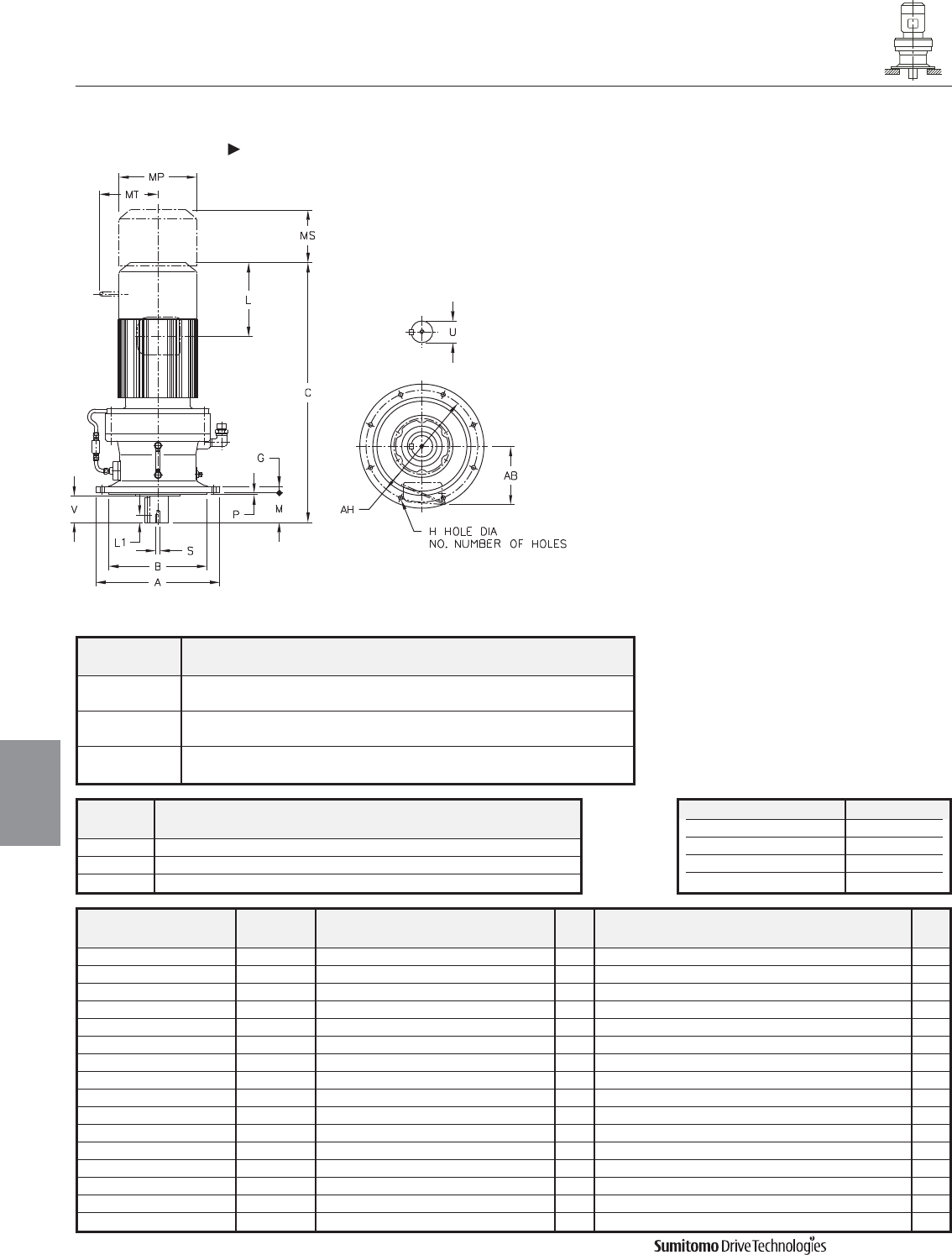
Model Motor Without Brake Appx With Brake Appx
HP Pole C AB L MP Wt (lb) C AB L MP MS MT Wt (lb)
CVVM206-6245Y 20 6 50.47 11.69 13.39 15.51 1663 58.74 11.69 21.65 15.51 14.45 - 1735
CVVM256-6245Y 25 6 50.47 11.69 13.39 15.51 1663 58.74 11.69 21.65 15.51 14.45 - 1766
CVVM306-6245Y 30 6 50.47 11.69 13.39 15.51 1663 58.74 11.69 21.65 15.51 14.57 - 1766
CVVM406-6245Y 40 6 55.00 11.69 16.93 15.51 1764 63.46 11.69 25.39 15.51 17.52 - 1958
CVVM506-6245Y 50 6 55.00 11.69 16.93 15.51 1764 63.46 11.69 25.39 15.51 17.52 - 1958
CVVM606-6245Y 60 6 57.17 16.22 18.31 19.06 1965 - - - - - - -
CVVM756-6245Y 75 6 60.31 16.22 19.88 19.09 2073 - - - - - - -
CVVM256-6255Y 25 6 55.12 11.69 13.39 15.51 2293 67.91 11.69 21.65 15.51 14.45 - 2496
CVVM306-6255Y 30 6 55.12 11.69 13.39 15.51 2293 67.91 11.69 21.65 15.51 14.57 - 2496
CVVM406-6255Y 40 6 59.65 11.69 16.93 15.51 2392 68.11 11.69 25.39 15.51 17.52 - 2586
CVVM506-6255Y 50 6 59.65 11.69 16.93 15.51 2392 68.11 11.69 25.39 15.51 17.52 - 2586
CVVM606-6255Y 60 6 61.81 16.22 18.31 19.06 2569 - - - - - - -
CVVM756-6255Y 75 6 64.96 16.22 19.88 19.09 2690 - - - - - - -
CVVM406-6265Y 40 6 64.25 11.69 16.93 15.51 3065 72.72 11.69 25.39 15.51 17.52 - 3259
CVVM506-6265Y 50 6 64.25 11.69 16.93 15.51 3065 72.72 11.69 25.39 15.51 17.52 - 3259
CVVM606-6265Y 60 6 66.42 16.22 18.31 19.06 3274 - - - - - - -
Model ABGH
NO.
MPAH
CVVM
6245Y 25.00 19.0918 1.57 1.30 8 9.84 0.39 22.05
19.0880
6255Y 26.97 21.0600 1.77 1.30 8 11.61 0.39 24.02
21.0557
6265Y 29.53 22.4380 1.97 1.54 8 14.17 0.39 25.98
22.4336
CYCLO® 6000 Gearmotors
Dimensions Integral Vertical V-Flange Mount
Single Reduction
CVVM-6245Y 6265Y
4.36 Dimensions
Dimensions
Gearmotors
All dimensions are in inches
Model Low Speed Shaft
CVVM
U* V S L1 Key
6245Y 5.500 7.87 1-8UNC 1.61 1-1/4 X 7/8 X 7.87
6255Y 6.250 9.45 1-1/4-7UNC 1.93 1-1/2 X 1 X 9.45
6265Y 6.625 11.81 1-1/4-7UNC 1.93 1-3/4 X 1-1/4 X 11.8
Shaft Nominal Diameter (inches) Tolerances (inches)
1.250 (1 1/4) through 1.875 (1 7/8) +0.0000/-0.0006
2.000 (2) through 3.125 (3 1/8) +0.0000/-0.0007
3.250 (3 1/4) through 4.625 (4 5/8) +0.0000/-0.0009
4.750 (4 3/4) through 7.000 (7) +0.0000/-0.0010
*Shaft Tolerances
Dimensions shown are for reference only and are subject to change without notice, unless certified.
Certified prints are available after receipt of an order; consult factory.
Cyclo® 6000 Series
CYCLO® 6000 Gearmotors
Dimensions Integral Universal V-Flange Mount
Double Reduction
CNVM-6060/5DAY 6120/5DBY
Dimensions 4.37
Dimensions
Gearmotors
All dimensions are in inches
Model Low Speed Shaft
CNVM
U* V S L1 Key
6060/5DAY 0.500 0.98 10-32UNF 0.63 1/8 X 1/8 X 0.79
6070/5DAY 0.750 1.18 12-28UNF 0.63 3/16 X 3/16 X 1.06
6090/5DAY 1.125 1.38 5/16-18UNC 0.79 1/4 X 1/4 X 1.18
6100/5DAY 1.125 1.38 5/16-18UNC 0.79 1/4 X 1/4 X 1.18
6120/5DBY 1.500 2.17 5/16-18UNC 0.79 3/8 X 3/8 X 1.77
Model ABGH
NO.
MOPAH
CNVM
6060/5DAY 4.72 3.1484 0.31 0.35 6 1.34 - 0.12 4.02
3.1466
6070/5DAY 6.30 4.3293 0.35 0.43 4 1.65 - 0.12 5.28
4.3272
6090/5DAY 6.30 4.3293 0.35 0.43 4 1.89 4.21 0.12 5.28
4.3272
6100/5DAY 6.30 4.3293 0.35 0.43 4 1.89 4.21 0.12 5.28
4.3272
6120/5DBY 8.27 5.5101 0.51 0.43 6 2.72 5.39 0.16 7.09
5.5076
Dimensions shown are for reference only and are subject to change without notice, unless certified.
Certified prints are available after receipt of an order; consult factory.
Cyclo® 6000 Series
Model Motor Without Brake Appx With Brake Appx
HP Pole C AB L MP Wt (lb) C AB L MP MS MT Wt (lb)
CNVM01-6060/5DAY 1/8 4 10.20 5.04 1.38 4.69 18 11.57 5.04 2.76 4.88 1.93 - 24
CNVM01-6070/5DAY 1/8 4 10.43 5.04 1.38 4.69 18 11.81 5.04 2.76 4.88 1.93 - 24
CNVM02-6070/5DAY 1/4 4 12.09 5.04 2.32 4.88 20 13.35 5.04 3.58 4.88 2.40 - 26
CNVM01-6090/5DAY 1/8 4 12.76 5.04 1.38 4.69 33 14.13 50.59 2.76 4.88 1.93 - 35
CNVM02-6090/5DAY 1/4 4 14.41 5.04 2.32 4.88 35 15.67 5.04 3.58 4.88 2.40 - 37
CNVM03-6090/5DAY 1/3 4 14.41 5.04 2.32 4.88 35 15.67 5.04 3.58 4.88 2.40 - 37
CNVM05-6090/5DAY 1/2 4 15.20 5.04 2.32 4.88 37 16.46 5.04 3.58 4.88 2.40 - 40
CNVM01-6100/5DAY 1/8 4 13.31 5.04 1.38 4.69 35 14.69 5.04 2.76 4.88 1.93 - 37
CNVM02-6100/5DAY 1/4 4 14.96 5.04 2.32 4.88 37 16.22 5.04 3.58 4.88 2.40 - 40
CNVM03-6100/5DAY 1/3 4 14.96 5.04 2.32 4.88 37 16.22 5.04 3.58 4.88 2.40 - 40
CNVM05-6100/5DAY 1/2 4 15.75 5.04 2.32 4.88 40 17.01 5.04 3.58 4.88 2.40 - 42
CNVM01-6120/5DBY 1/8 4 15.20 5.04 1.38 4.69 68 16.57 5.04 2.76 4.88 1.93 - 73
CNVM03-6120/5DBY 1/3 4 16.85 5.04 2.32 4.88 71 18.62 5.04 3.58 4.88 2.40 - 75
CNVM05-6120/5DBY 1/2 4 17.64 5.04 2.32 4.88 73 18.62 5.04 3.58 4.88 2.40 - 77
CNVM08-6120/5DBY 3/4 4 19.25 5.63 3.82 5.83 82 20.94 5.63 5.51 5.83 3.66 4.17 88
CNVM1-6120/5DBY 1 4 19.25 5.63 3.82 5.83 82 20.94 5.63 5.51 5.83 3.66 4.17 88
CNVM1H-6120/5DBY 1.5 4 20.31 5.83 3.94 6.30 90 22.76 5.83 6.38 6.30 4.53 4.49 101
CNVM2-6120/5DBY 2 4 20.31 5.83 3.94 6.30 90 22.76 5.83 6.38 6.30 4.53 4.49 101
Shaft Nominal Diameter (inches) Tolerances (inches)
0.500 (1/2) through 0.625 (5/8) +0.0000/-0.0004
0.750 (3/4) through 1.125 (1 1/8) +0.0000/-0.0005
1.250 (1 1/4) through 1.875 (1 7/8) +0.0000/-0.0006
*Shaft Tolerances
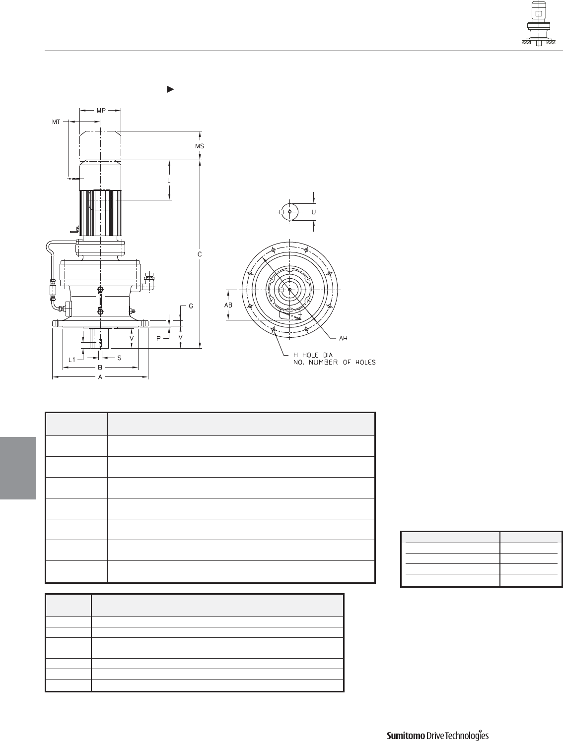
Model ABGH
NO.
MPAH
CVVM
6130/5DCY 10.24 7.8720 0.59 0.43 6 2.99 0.16 9.06
7.8692
6140/5DBY 10.24 7.8720 0.59 0.43 6 3.78 0.16 9.06
7.8692
6160/5DCY 13.39 10.6277 0.79 0.43 6 3.50 0.16 12.20
10.6245
6170/5DCY 15.75 12.4385 0.87 0.55 8 3.70 0.20 14.17
12.4350
6180/5DBY 16.93 13.5802 0.87 0.71 8 4.33 0.20 15.35
13.5767
6190/5DAY 19.29 15.7456 1.18 0.71 12 5.71 0.24 17.72
15.7421
6190/5DBY 19.29 15.7456 1.18 0.71 12 5.71 0.24 17.72
15.7421
CYCLO® 6000 Gearmotors
Dimensions Integral Vertical V-Flange Mount
Double Reduction
CVVM-6130/5DCY 6190/5DBY
4.38 Dimensions
Dimensions
Gearmotors
All dimensions are in inches
Model Low Speed Shaft
CVVM
U* V S L1 Key
6130/5DCY 1.875 2.40 3/8-16UNC 0.71 1/2 X 1/2 X 2.16
6140/5DBY 1.875 3.19 3/8-16UNC 0.71 1/2 X 1/2 X 2.95
6160/5DCY 2.250 3.15 3/8-16UNC 0.71 1/2 X 1/2 X 2.95
6170/5DCY 2.750 3.31 1/2-13UNC 0.94 5/8 X 5/8 X 3.15
6180/5DBY 3.125 3.94 1/2-13UNC 0.94 3/4 X 3/4 X 3.74
6190/5DAY 3.625 4.92 3/4-10UNC 1.34 7/8 X 7/8 X 4.92
6190/5DBY 3.625 4.92 3/4-10UNC 1.34 7/8 X 7/8 X 4.92
Shaft Nominal Diameter (inches) Tolerances (inches)
1.250 (1 1/4) through 1.875 (1 7/8) +0.0000/-0.0006
2.000 (2) through 3.125 (3 1/8) +0.0000/-0.0007
3.250 (3 1/4) through 4.625 (4 5/8) +0.0000/-0.0009
4.750 (4 3/4) through 7.000 (7) +0.0000/-0.0010
*Shaft Tolerances
Dimensions shown are for reference only and are subject to change without notice, unless certified.
Certified prints are available after receipt of an order; consult factory.
Cyclo® 6000 Series
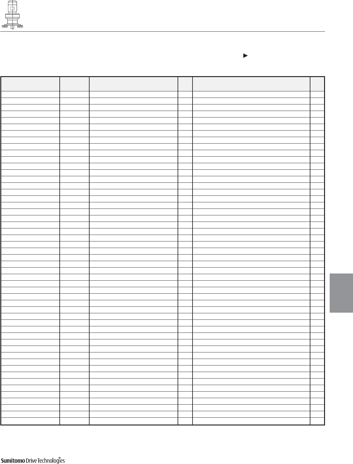
Model Motor Without Brake Appx With Brake Appx
HP Pole C AB L MP Wt (lb) C AB L MP MS MT Wt (lb)
CVVM02-6130/5DCY 1/4 4 19.41 5.04 2.32 4.88 110 20.67 5.04 3.58 4.88 2.40 - 115
CVVM03-6130/5DCY 1/3 4 19.41 5.04 2.32 4.88 110 20.67 5.04 3.58 4.88 2.40 - 115
CVVM05-6130/5DCY 1/2 4 20.20 5.04 2.32 4.88 112 21.46 5.04 3.58 4.88 2.40 - 117
CVVM08-6130/5DCY 3/4 4 21.81 5.63 3.82 5.83 121 23.50 5.63 5.51 5.83 3.66 4.17 117
CVVM1-6130/5DCY 1 4 21.81 5.63 3.82 5.83 121 23.50 5.63 5.51 5.83 3.66 4.17 128
CVVM1H-6130/5DCY 1.5 4 23.11 5.83 3.94 6.30 130 25.55 5.83 6.38 6.30 4.53 4.49 141
CVVM2-6130/5DCY 2 4 23.11 5.83 3.94 6.30 130 25.55 5.83 6.38 6.30 4.53 4.49 141
CVVM3-6130/5DCY 3 4 23.90 6.10 4.13 6.81 139 26.38 6.10 6.61 6.81 4.76 4.88 152
CVVM01-6140/5DBY 1/8 4 17.99 5.04 1.38 4.69 101 19.37 5.04 2.76 4.88 1.93 - 106
CVVM02-6140/5[DBY 1/4 4 19.65 5.04 2.32 4.88 104 20.91 5.04 3.58 4.88 2.40 - 108
CVVM03-6140/5DBY 1/3 4 19.65 5.04 2.32 4.88 104 20.91 5.04 3.58 4.88 2.40 - 108
CVVM05-6140/5DBY 1/2 4 20.43 5.04 2.32 4.88 106 21.69 5.04 3.58 4.88 2.40 - 110
CVVM08-6140/5DBY 3/4 4 22.05 5.63 3.82 5.83 115 23.74 5.63 5.51 5.83 3.66 4.17 121
CVVM1-6140/5DBY 1 4 22.05 5.63 3.82 5.83 115 23.74 5.63 5.51 5.83 3.66 4.17 121
CVVM1H-6140/5DBY 1.5 4 23.35 5.83 3.94 6.30 123 25.79 5.83 6.38 6.30 4.53 4.49 135
CVVM2-6140/5DBY 2 4 23.35 5.83 3.94 6.30 123 25.79 5.83 6.38 6.30 4.53 4.49 135
CVVM05-6160/5DCY 1/2 4 26.73 5.04 4.13 6.81 234 29.21 5.04 6.61 6.81 4.76 4.88 249
CVVM08-6160/5DCY 3/4 4 23.07 5.63 2.32 4.88 207 24.49 5.63 3.58 4.88 2.40 - 212
CVVM1-6160/5DCY 1 4 24.65 5.63 3.82 5.83 216 26.34 5.63 5.51 5.83 3.66 4.17 223
CVVM1H-6160/5DCY 1.5 4 24.65 5.83 3.82 5.83 216 26.34 5.83 5.51 5.83 3.66 4.17 223
CVVM2-6160/5DCY 2 4 25.94 5.83 3.94 6.30 225 28.39 5.83 6.38 6.30 4.53 4.49 236
CVVM3-6160/5DCY 3 4 25.94 6.10 3.94 6.30 225 28.39 6.10 6.38 6.30 4.53 4.49 236
CVVM5-6160/5DCY 5 4 27.64 6.54 5.00 8.35 256 30.47 6.54 7.83 8.35 5.20 6.18 278
CVVM8-6160/5DCY 7.5 4 29.37 6.54 5.00 8.35 278 32.20 6.54 7.83 8.35 5.20 6.18 300
CVVM05-6170/5DCY 1/2 4 24.92 5.04 2.32 4.88 284 26.34 5.04 3.58 4.88 2.40 - 289
CVVM08-6170/5DCY 3/4 4 26.50 5.63 3.82 5.83 293 28.19 5.63 5.51 5.83 3.66 4.17 300
CVVM1-6170/5DCY 1 4 26.50 5.63 3.82 5.83 293 28.19 5.63 5.51 5.83 3.66 4.17 300
CVVM1H-6170/5DCY 1.5 4 27.80 5.83 3.94 6.30 302 30.24 5.83 6.38 6.30 4.53 4.49 313
CVVM2-6170/5DCY 2 4 27.80 5.83 3.94 6.30 302 30.24 5.83 6.38 6.30 4.53 4.49 313
CVVM3-6170/5DCY 3 4 28.58 6.10 4.13 6.81 311 31.06 6.10 6.61 6.81 4.76 4.88 326
CVVM5-6170/5DCY 5 4 29.49 6.54 5.00 8.35 333 32.32 6.54 7.83 8.35 5.20 6.18 355
CVVM8-6170/5DCY 7.5 4 31.22 6.54 5.00 8.35 355 34.06 6.54 7.83 8.35 5.20 6.18 377
CVVM1-6180/5DBY 1 4 28.86 5.63 3.82 5.83 386 30.55 5.63 5.51 5.83 3.66 4.17 392
CVVM1H-6180/5DBY 1.5 4 30.16 5.83 3.94 6.30 395 32.60 5.83 6.38 6.30 4.53 4.49 406
CVVM2-6180/5DBY 2 4 30.16 5.83 3.94 6.30 395 32.60 5.83 6.38 6.30 4.53 4.49 406
CVVM3-6180/5DBY 3 4 30.94 6.10 4.13 6.81 401 33.43 6.10 6.61 6.81 4.76 4.88 417
CVVM5-6180/5DBY 5 4 31.85 6.54 5.00 8.35 423 34.69 6.54 7.83 8.35 5.20 6.18 445
CVVM8-6180/5DBY 7.5 4 33.58 6.54 5.00 8.35 439 36.42 6.54 7.83 8.35 5.20 6.18 461
CVVM10-6180/5DBY 10 4 34.49 8.31 5.63 9.88 472 38.23 8.31 9.37 9.88 6.69 7.17 512
CVVM15-6180/5DBY 15 4 36.85 8.31 5.63 9.88 503 40.59 8.31 9.37 9.88 6.69 7.17 542
CVVM1-6190/5DAY 1 4 31.22 5.63 3.82 5.83 523 32.91 5.63 5.51 5.83 3.66 4.17 529
CVVM1H-6190/5DAY 1.5 4 32.52 5.83 3.94 6.30 531 34.96 5.83 6.38 6.30 4.53 4.49 542
CVVM2-6190/5DAY 2 4 32.52 5.83 3.94 6.30 531 34.96 5.83 6.38 6.30 4.53 4.49 542
CVVM3-6190/5DAY 3 4 33.31 6.10 4.13 6.81 540 35.79 6.10 6.61 6.81 4.76 4.88 556
CVVM5-6190/5DAY 5 4 34.21 6.54 5.00 8.35 562 37.05 6.54 7.83 8.35 5.20 6.18 584
CVVM8-6190/5DAY 7.5 4 35.94 6.54 5.00 8.35 578 38.78 6.54 7.83 8.35 5.20 6.18 600
CVVM5-6195DBY 5 4 34.84 6.54 5.00 8.35 578 37.68 6.54 7.83 8.35 5.20 6.18 600
CVVM8-6195DBY 7.5 4 36.57 6.54 5.00 8.35 593 39.41 6.54 7.83 8.35 5.20 6.18 615
CVVM10-6195DBY 10 4 37.48 8.31 5.63 9.88 626 41.22 8.31 9.37 9.88 6.69 7.17 666
CVVM15-6195DBY 15 4 39.84 8.31 5.63 9.88 657 43.58 8.31 9.37 9.88 6.69 7.17 697
CVVM20-6195DBY 20 4 43.39 9.13 11.61 12.76 772 46.93 9.13 15.16 12.76 8.66 - 845
CYCLO® 6000 Gearmotors
Dimensions Integral Vertical V-Flange Mount
Double Reduction
CVVM-6130/5DCY 6190/5DBY (cont.)
Dimensions 4.39
Dimensions
Gearmotors
All dimensions are in inches
Dimensions shown are for reference only and are subject to change without notice, unless certified.
Certified prints are available after receipt of an order; consult factory.
Cyclo® 6000 Series
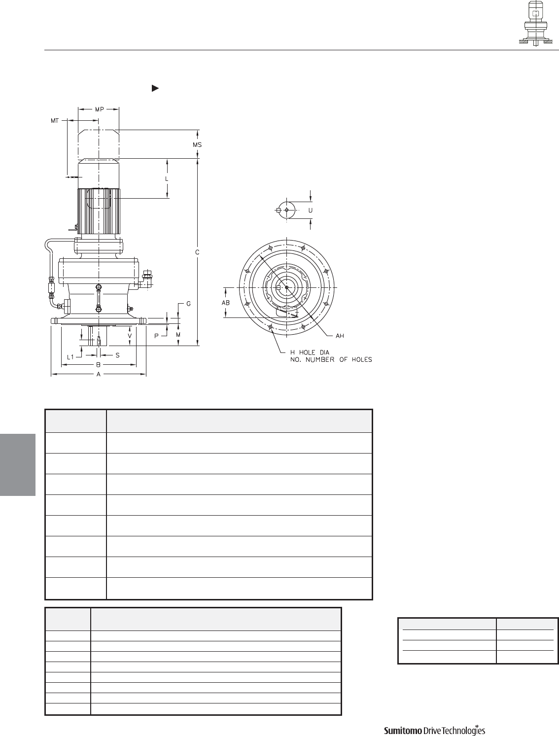
Model ABGH
NO.
MPAH
CVVM
6205DAY 17.91 13.9739 1.18 0.87 8 8.03 0.20 15.94
13.9704
6205DBY 17.91 13.9739 1.18 0.87 8 8.03 0.20 15.94
13.9704
6215DAY 19.29 15.3519 1.38 0.94 8 7.99 0.28 17.32
15.3484
6215DBY 19.29 15.3519 1.38 0.94 8 7.99 0.28 17.32
15.3484
6225DAY 21.06 16.3359 1.38 1.06 8 8.27 0.39 18.70
16.3321
6225DBY 21.06 16.3359 1.38 1.06 8 8.27 0.39 18.70
16.3321
6235DAY 22.44 17.7139 1.57 1.06 8 9.84 0.39 20.08
17.7100
6235DBY 22.44 17.7139 1.57 1.06 8 9.84 0.39 20.08
17.7100
CYCLO® 6000 Gearmotors
Dimensions Integral Vertical V-Flange Mount
Double Reduction
CVVM-6205DAY 6235DBY
4.40 Dimensions
Dimensions
Gearmotors
All dimensions are in inches
Model Low Speed Shaft
CVVM
U* V S L1 Key
6205DAY 3.875 6.50 3/4-10UNC 1.34 1 X 1 X 6.50
6205DBY 3.875 6.50 3/4-10UNC 1.34 1 X 1 X 6.50
6215DAY 4.250 6.50 3/4-10UNC 1.34 1 X 1 X 6.50
6215DBY 4.250 6.50 3/4-10UNC 1.34 1 X 1 X 6.50
6225DAY 4.625 6.50 3/4-10UNC 1.34 1-1/4 X 7/8 X 6.5
6225DBY 4.625 6.50 3/4-10UNC 1.34 1-1/4 X 7/8 X 6.5
6235DAY 5.000 7.87 1-8UNC 1.61 1-1/4 X 7/8 X 7.87
6235DBY 5.000 7.87 1-8UNC 1.61 1-1/4 X 7/8 X 7.87
Shaft Nominal Diameter (inches) Tolerances (inches)
2.000 (2) through 3.125 (3 1/8) +0.0000/-0.0007
3.250 (3 1/4) through 4.625 (4 5/8) +0.0000/-0.0009
4.750 (4 3/4) through 7.000 (7) +0.0000/-0.0010
*Shaft Tolerances
Dimensions shown are for reference only and are subject to change without notice, unless certified.
Certified prints are available after receipt of an order; consult factory.
Cyclo® 6000 Series
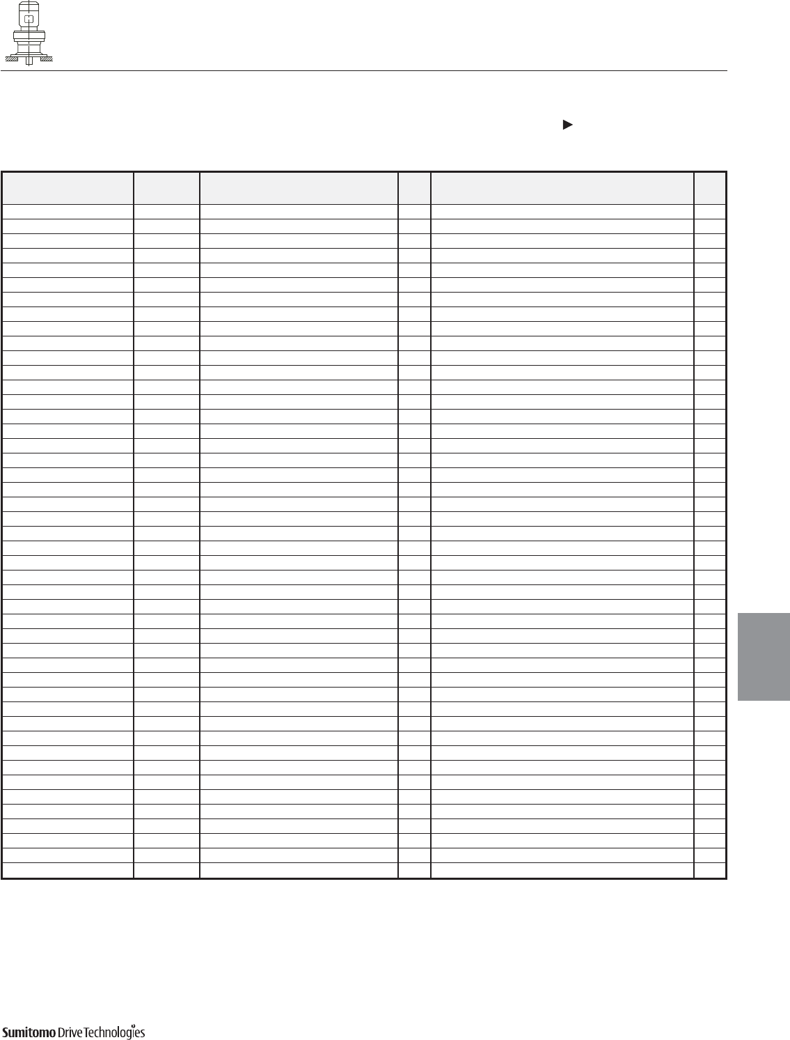
Model Motor Without Brake Appx With Brake Appx
HP PoleC AB L MP Wt (lb) C AB L MP MS MT Wt (lb)
CVVM1-6205DAY 1 4 32.83 5.63 3.82 5.83 558 34.53 5.63 5.51 5.83 3.66 4.17 564
CVVM2-6205DAY 2 4 34.13 5.83 3.94 6.30 567 36.57 5.83 6.38 6.30 4.53 4.49 578
CVVM3-6205DAY 3 4 34.92 6.10 4.13 6.81 576 37.36 6.10 6.61 6.81 4.76 4.88 591
CVVM5-6205DAY 5 4 35.83 6.54 5.00 8.35 598 38.66 6.54 7.83 8.35 5.20 6.18 620
CVVM8-6205DAY 7.5 4 37.56 6.54 5.00 8.35 613 40.39 6.54 7.83 8.35 5.20 6.18 635
CVVM3-6205DBY 3 4 35.98 6.10 4.13 6.81 602 38.46 6.10 6.61 6.81 4.76 4.88 617
CVVM5-6205DBY 5 4 36.89 6.54 5.00 8.35 624 39.72 6.54 7.83 8.35 5.20 6.18 662
CVVM8-6205DBY 7.5 4 38.62 6.54 5.00 8.35 639 41.46 6.54 7.83 8.35 5.20 6.18 712
CVVM10-6205DBY 10 4 39.53 8.31 5.63 9.88 673 43.27 8.31 9.37 9.88 6.69 7.17 763
CVVM15-6205DBY 15 4 41.89 8.31 5.63 9.88 703 45.63 8.31 9.37 9.88 6.69 7.17 794
CVVM20-6205DBY 20 4 45.43 9.13 11.61 12.76 818 48.58 9.13 15.16 12.76 8.66 - 942
CVVM2-6215DAY 2 4 36.22 5.83 3.94 6.30 728 38.66 5.83 6.38 6.30 4.53 4.49 739
CVVM3-6215DAY 3 4 37.01 6.10 4.13 6.81 734 39.49 6.10 6.61 6.81 4.76 4.88 750
CVVM5-6215DAY 5 4 37.91 6.54 5.00 8.35 756 40.75 6.54 7.83 8.35 5.20 6.18 778
CVVM8-6215DAY 7.5 4 39.65 6.54 5.00 8.35 772 42.48 6.54 7.83 8.35 5.20 6.18 794
CVVM10-6215DAY 10 4 40.55 8.31 5.63 9.88 805 44.29 8.31 9.37 9.88 6.69 7.17 845
CVVM15-6215DAY 15 4 42.91 8.31 5.63 9.88 836 46.65 8.31 9.37 9.88 6.69 7.17 875
CVVM20-6215DAY 20 4 46.46 9.13 11.61 12.76 950 50.00 9.13 15.16 12.76 8.66 - 1023
CVVM10-6215DBY 10 4 41.73 8.31 5.63 9.88 880 45.47 8.31 9.37 9.88 6.69 7.17 917
CVVM15-6215DBY 15 4 44.09 8.31 5.63 9.88 911 47.83 8.31 9.37 9.88 6.69 7.17 948
CVVM20-6215DBY 20 4 47.44 9.13 11.61 12.76 1028 50.98 9.13 15.16 12.76 8.66 - 1100
CVVM25-6215DBY 25 4 51.18 11.69 13.39 15.51 1186 59.45 11.69 21.65 15.51 14.45 - 1283
CVVM30-6215DBY 30 4 51.18 11.69 13.39 15.51 1186 59.45 11.69 21.65 15.51 14.45 - 1283
CVVM2-6225DAY 2 4 37.87 5.83 3.94 6.30 924 40.31 5.83 6.38 6.30 4.53 4.49 935
CVVM3-6225DAY 3 4 38.66 6.10 4.13 6.81 931 41.14 6.10 6.61 6.81 4.76 4.88 946
CVVM5-6225DAY 5 4 39.57 6.54 5.00 8.35 953 42.40 6.54 7.83 8.35 5.20 6.18 975
CVVM8-6225DAY 7.5 4 41.30 6.54 5.00 8.35 968 44.13 6.54 7.83 8.35 5.20 6.18 990
CVVM10-6225DAY 10 4 42.20 8.31 5.63 9.88 1001 45.94 8.31 9.37 9.88 6.69 7.17 1041
CVVM15-6225DAY 15 4 44.57 8.31 5.63 9.88 1032 48.31 8.31 9.37 9.88 6.69 7.17 1069
CVVM20-6225DAY 20 4 48.11 9.13 11.61 12.76 1147 51.65 9.13 15.16 12.76 8.66 - 1217
CVVM10-6225DBY 10 4 44.29 8.31 5.63 9.88 1103 48.03 8.31 9.37 9.88 6.69 7.17 1142
CVVM15-6225DBY 15 4 46.65 8.31 5.63 9.88 1133 50.39 8.31 9.37 9.88 6.69 7.17 1173
CVVM20-6225DBY 20 4 49.80 9.13 11.61 12.76 1252 53.35 9.13 15.16 12.76 8.66 - 1325
CVVM25-6225DBY 25 4 53.54 11.69 13.39 15.51 1446 61.81 11.69 21.65 15.51 14.45 - 1499
CVVM30-6225DBY 30 4 53.54 11.69 13.39 15.51 1446 61.81 11.69 21.65 15.51 14.45 - 1499
CVVM40-6225DBY 40 4 53.54 11.69 13.39 15.51 1484 61.81 11.69 21.65 15.51 14.57 - 1579
CVVM3-6235DAY 3 4 42.09 6.10 4.13 6.81 1151 44.53 6.10 6.61 6.81 4.76 4.88 1164
CVVM5-6235DAY 5 4 42.95 6.54 5.00 8.35 1171 45.79 6.54 7.83 8.35 5.20 6.18 1193
CVVM8-6235DAY 7.5 4 44.69 6.54 5.00 8.35 1186 47.52 6.54 7.83 8.35 5.20 6.18 1208
CVVM10-6235DAY 10 4 45.79 8.31 5.63 9.88 1222 49.53 8.31 9.37 9.88 6.69 7.17 1259
CVVM15-6235DAY 15 4 48.15 8.31 5.63 9.88 1252 51.89 8.31 9.37 9.88 6.69 7.17 1290
CVVM20-6235DAY 20 4 51.54 9.13 11.61 12.76 1369 55.04 9.13 15.16 12.76 8.66 - 1442
CVVM25-6235DAY 25 4 55.24 11.69 13.39 15.51 1528 63.50 11.69 21.65 15.51 14.45 - 1625
CVVM30-6235DAY 30 4 55.24 11.69 13.39 15.51 1528 63.50 11.69 21.65 15.51 14.45 - 1625
CVVM40-6235DBY 40 4 56.10 11.69 13.39 15.51 1629 64.37 11.69 21.65 15.51 14.57 - 1724
CVVM50-6235DBY 50 4 60.63 11.69 16.93 15.51 1735 69.09 11.69 25.39 15.51 17.52 - 1949
CYCLO® 6000 Gearmotors
Dimensions Integral Vertical V-Flange Mount
Double Reduction
CVVM-6205DAY 6235DBY (cont.)
Dimensions 4.41
Dimensions
Gearmotors
All dimensions are in inches
Dimensions shown are for reference only and are subject to change without notice, unless certified.
Certified prints are available after receipt of an order; consult factory.
Cyclo® 6000 Series
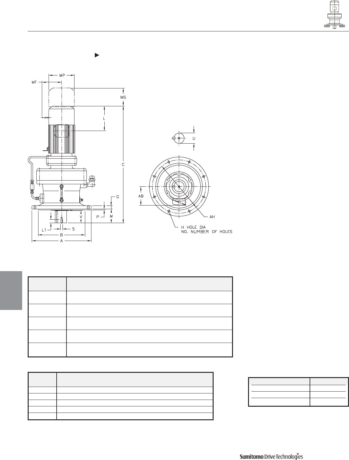
Model ABGH
NO.
MPAH
CVVM
6245DBY 25.00 19.0918 1.57 1.30 8 9.84 0.39 22.05
19.0880
6255DAY 26.97 21.0600 1.77 1.30 8 11.61 0.39 24.02
21.0557
6255DBY 26.97 21.0600 1.77 1.30 8 11.61 0.39 24.02
21.0557
6265DAY 29.53 22.4380 1.97 1.54 8 14.17 0.39 25.98
22.4336
6275DAY 45.67 35.4297 2.36 1.54 8 13.98 0.39 40.16
35.4242
CYCLO® 6000 Gearmotors
Dimensions Integral Vertical V-Flange Mount
Double Reduction
CVVM-6245DAY 6275DAY
4.42 Dimensions
Dimensions
Gearmotors
All dimensions are in inches
Model Low Speed Shaft
CVVM
U* V S L1 Key
6245DBY 5.500 7.87 1-8UNC 1.61 1-1/4 X 7/8 X 7.87
6255DAY 6.250 9.45 1-1/4-7UNC 1.93 1-1/2 X 1 X 9.45
6255DBY 6.250 9.45 1-1/4-7UNC 1.93 1-1/2 X 1 X 9.45
6265DAY 6.625 11.81 1-1/4-7UNC 1.93 1-3/4 X 1-1/4 X 11.8
6275DAY 7.000 12.60 1-1/4-7UNC 2.05 1-3/4 X 1-1/4 X 13
Shaft Nominal Diameter (inches) Tolerances (inches)
2.000 (2) through 3.125 (3 1/8) +0.0000/-0.0007
3.250 (3 1/4) through 4.625 (4 5/8) +0.0000/-0.0009
4.750 (4 3/4) through 7.000 (7) +0.0000/-0.0010
*Shaft Tolerances
Dimensions shown are for reference only and are subject to change without notice, unless certified.
Certified prints are available after receipt of an order; consult factory.
Cyclo® 6000 Series
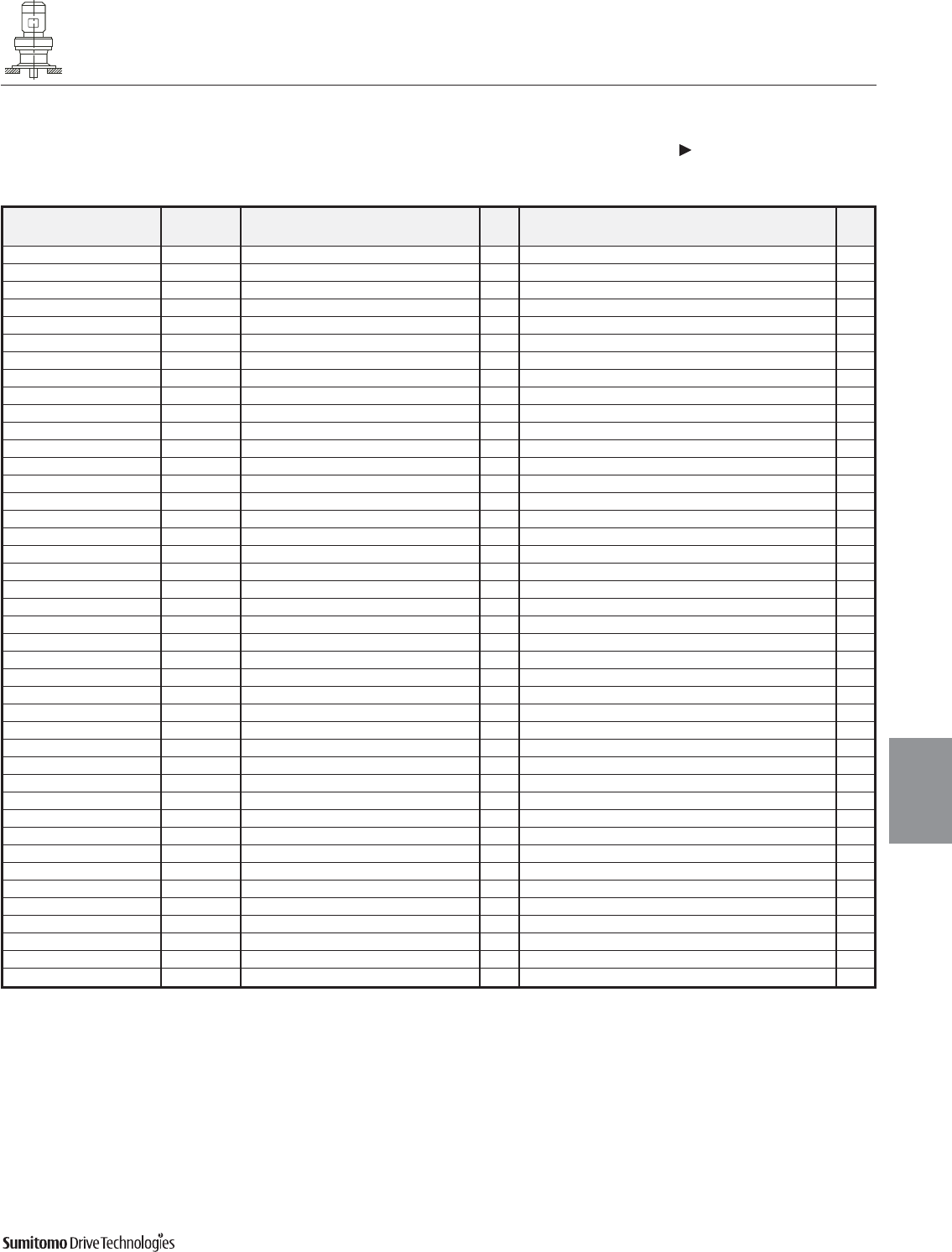
CYCLO® 6000 Gearmotors
Dimensions Integral Vertical V-Flange Mount
Double Reduction
CVVM-6245DAY 6275DAY (cont.)
Dimensions 4.43
Dimensions
Gearmotors
All dimensions are in inches
Dimensions shown are for reference only and are subject to change without notice, unless certified.
Certified prints are available after receipt of an order; consult factory.
Cyclo® 6000 Series
Model Motor Without Brake Appx With Brake Appx
HP Pole C AB L MP Wt (lb) C AB L MP MS MT Wt (lb)
CVVM3-6245DAY 3 4 43.54 6.10 4.13 6.81 1358 46.02 6.10 6.61 6.81 4.76 4.88 1372
CVVM5-6245DAY 5 4 44.45 6.54 5.00 8.35 1378 47.28 6.54 7.83 8.35 5.20 6.18 1400
CVVM8-6245DAY 7.5 4 46.18 6.54 5.00 8.35 1394 49.02 6.54 7.83 8.35 5.20 6.18 1416
CVVM10-6245DAY 10 4 47.28 8.31 5.63 9.88 1429 51.02 8.31 9.37 9.88 6.69 7.17 1466
CVVM15-6245DAY 15 4 49.65 8.31 5.63 9.88 1460 53.39 8.31 9.37 9.88 6.69 7.17 1497
CVVM20-6245DAY 20 4 52.99 9.13 11.61 12.76 1577 56.54 9.13 15.16 12.76 8.66 - 1649
CVVM25-6245DAY 25 4 56.73 11.69 13.39 15.51 1735 65.00 11.69 21.65 15.51 14.45 - 1852
CVVM30-6245DAY 30 4 56.73 11.69 13.39 15.51 1735 65.00 11.69 21.65 15.51 14.45 - 1852
CVVM20-6245DBY 20 4 53.82 9.13 11.61 12.76 1652 57.36 9.13 15.16 12.76 8.66 - 1713
CVVM30-6245DBY 30 4 57.56 11.69 13.39 15.51 1788 65.83 11.69 21.65 15.51 14.45 - 1901
CVVM40-6245DBY 40 4 57.56 11.69 13.39 15.51 1826 65.83 11.69 21.65 15.51 14.57 - 1921
CVVM50-6245DBY 50 4 62.09 11.69 16.93 15.51 1932 70.55 11.69 25.39 15.51 17.52 - 2145
CVVM5-6255DAY 5 4 50.55 6.54 5.00 8.35 2086 53.39 6.54 7.83 8.35 5.20 6.18 2108
CVVM8-6255DAY 7.5 4 52.28 6.54 5.00 8.35 2101 55.12 6.54 7.83 8.35 5.20 6.18 2123
CVVM10-6255DAY 10 4 52.99 8.31 5.63 9.88 2134 56.73 8.31 9.37 9.88 6.69 7.17 2168
CVVM15-6255DAY 15 4 55.35 8.31 5.63 9.88 2165 59.09 8.31 9.37 9.88 6.69 7.17 2198
CVVM20-6255DAY 20 4 58.50 9.13 11.61 12.76 2293 62.05 9.13 15.16 12.76 8.66 - 2370
CVVM25-6255DAY 25 4 62.24 11.69 13.39 15.51 2437 70.51 11.69 21.65 15.51 14.45 - 2549
CVVM30-6255DAY 30 4 62.24 11.69 13.39 15.51 2437 70.51 11.69 21.65 15.51 14.45 - 2549
CVVM40-6255DAY 40 4 62.24 11.69 13.39 15.51 2478 70.51 11.69 21.65 15.51 14.57 - 2573
CVVM25-6255DBY 25 4 63.11 11.69 13.39 15.51 2602 71.38 11.69 21.65 15.51 14.45 - 2714
CVVM30-6255DBY 30 4 63.11 11.69 13.39 15.51 2602 71.38 11.69 21.65 15.51 14.45 - 2714
CVVM40-6255DBY 40 4 63.11 11.69 13.39 15.51 2635 71.38 11.69 21.65 15.51 14.57 - 2730
CVVM50-6255DBY 50 4 67.64 11.69 16.93 15.51 2719 75.91 11.69 25.39 15.51 17.52 - 2933
CVVM60-6255DBY 60 4 67.64 11.69 16.93 15.51 2719 75.91 11.69 25.39 15.51 17.52 - 2933
CVVM8-6265DAY 7.5 4 58.27 6.54 5.00 8.35 2855 61.10 6.54 7.83 8.35 5.20 6.18 2878
CVVM10-6265DAY 10 4 58.78 8.31 5.63 9.88 2884 62.52 8.31 9.37 9.88 6.69 7.17 2928
CVVM15-6265DAY 15 4 61.14 8.31 5.63 9.88 2922 64.88 8.31 9.37 9.88 6.69 7.17 2955
CVVM20-6265DAY 20 4 63.70 9.13 11.61 12.76 3032 67.24 9.13 15.16 12.76 8.66 - 3109
CVVM25-6265DAY 25 4 67.44 11.69 13.39 15.51 3197 75.71 11.69 21.65 15.51 14.45 - 3296
CVVM30-6265DAY 30 4 67.44 11.69 13.39 15.51 3197 75.71 11.69 21.65 15.51 14.45 - 3296
CVVM40-6265DAY 40 4 67.44 11.69 13.39 15.51 3230 75.71 11.69 21.65 15.51 14.57 - 3325
CVVM50-6265DAY 50 4 71.97 11.69 16.93 15.51 3308 80.43 11.69 25.39 15.51 17.52 - 3513
CVVM60-6265DAY 60 4 71.97 11.69 16.93 15.51 3308 80.43 11.69 25.39 15.51 17.52 - 3513
CVVM10-6275DAY 10 4 69.06 8.31 5.63 9.88 5938 72.80 8.31 9.37 9.88 6.69 7.17 5982
CVVM15-6275DAY 15 4 71.42 8.31 5.63 9.88 5969 75.16 8.31 9.37 9.88 6.69 7.17 6002
CVVM20-6275DAY 20 4 73.98 9.13 11.61 12.76 6086 77.52 9.13 15.16 12.76 8.66 - 6163
CVVM25-6275DAY 25 4 77.72 11.69 13.39 15.51 6251 85.98 11.69 21.65 15.51 14.45 - 6350
CVVM30-6275DAY 30 4 77.72 11.69 13.39 15.51 6251 85.98 11.69 21.65 15.51 14.45 - 6350
CVVM40-6275DAY 40 4 77.72 11.69 13.39 15.51 6284 85.98 11.69 21.65 15.51 14.57 - 6379
CVVM50-6275DAY 50 4 82.24 11.69 16.93 15.51 6361 90.71 11.69 25.39 15.51 17.52 - 6566
CVVM60-6275DAY 60 4 82.24 11.69 16.93 15.51 6361 90.71 11.69 25.39 15.51 17.52 - 6566
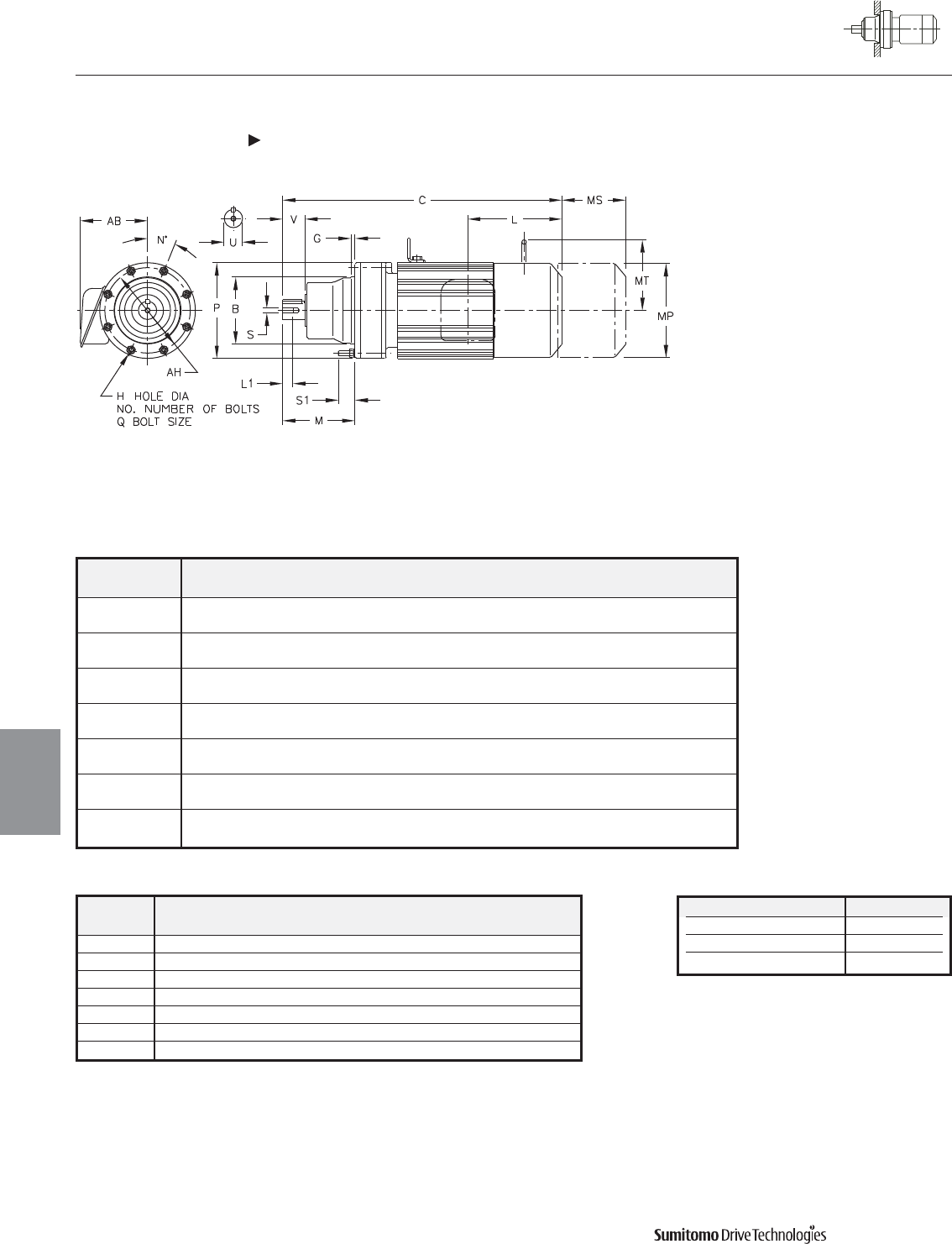
Model BGH
NO.
MN P QS1AH
CNFM
6060/5Y 3.1492 0.16 0.26 6 2.68 60 4.33 M6 0.83 3.86
3.1485
6070/5Y 3.1492 0.16 0.26 6 2.91 60 4.33 M6 0.83 3.86
3.1485
6080/5Y 3.7397 0.20 0.35 8 3.58 22.5 5.28 M8 1.06 4.65
3.7388
6090/5Y 4.1334 0.24 0.35 8 4.49 22.5 5.91 M8 1.14 5.28
4.1325
6100/5Y 4.1334 0.24 0.35 8 4.49 22.5 5.91 M8 1.10 5.28
4.1325
6110/5Y 4.5271 0.24 0.35 8 4.65 22.5 6.38 M8 1.02 5.75
4.5262
6120/5Y 5.5113 0.55 0.43 6 5.47 60 8.03 M10 1.30 7.09
5.5103
CYCLO® 6000 Gearmotors
Dimensions Integral F-Flange Mount
Single Reduction
CNFM-6060/5Y 6120/5Y
4.44 Dimensions
Dimensions
Gearmotors
All dimensions are in inches
Model Low Speed Shaft
CNFM
U* V S L1 Key
6060/5Y 0.500 0.98 10-32UNF 0.63 1/8 X 1/8 X .79
6070/5Y 0.750 1.18 12-28UNF 0.63 3/16 X 3/16 X 1.06
6080/5Y 0.875 1.38 12-28UNF 0.63 3/16 X 3/16 X 1.18
6090/5Y 1.125 1.38 5/16-18UNC 0.79 1/4 X 1/4 X 1.18
6100/5Y 1.125 1.38 5/16-18UNC 0.79 1/4 X 1/4 X 1.18
6110/5Y 1.250 1.77 5/16-18UNC 0.79 1/4 X 1/4 X 1.46
6120/5Y 1.500 2.17 5/16-18UNC 0.79 3/8 X 3/8 X 1.77
Shaft Nominal Diameter (inches) Tolerances (inches)
0.500 (1/2) through 0.625 (5/8) +0.0000/-0.0004
0.750 (3/4) through 1.125 (1 1/8) +0.0000/-0.0005
1.250 (1 1/4) through 1.875 (1 7/8) +0.0000/-0.0006
*Shaft Tolerances
Dimensions shown are for reference only and are subject to change without notice, unless certified.
Certified prints are available after receipt of an order; consult factory.
Cyclo® 6000 Series
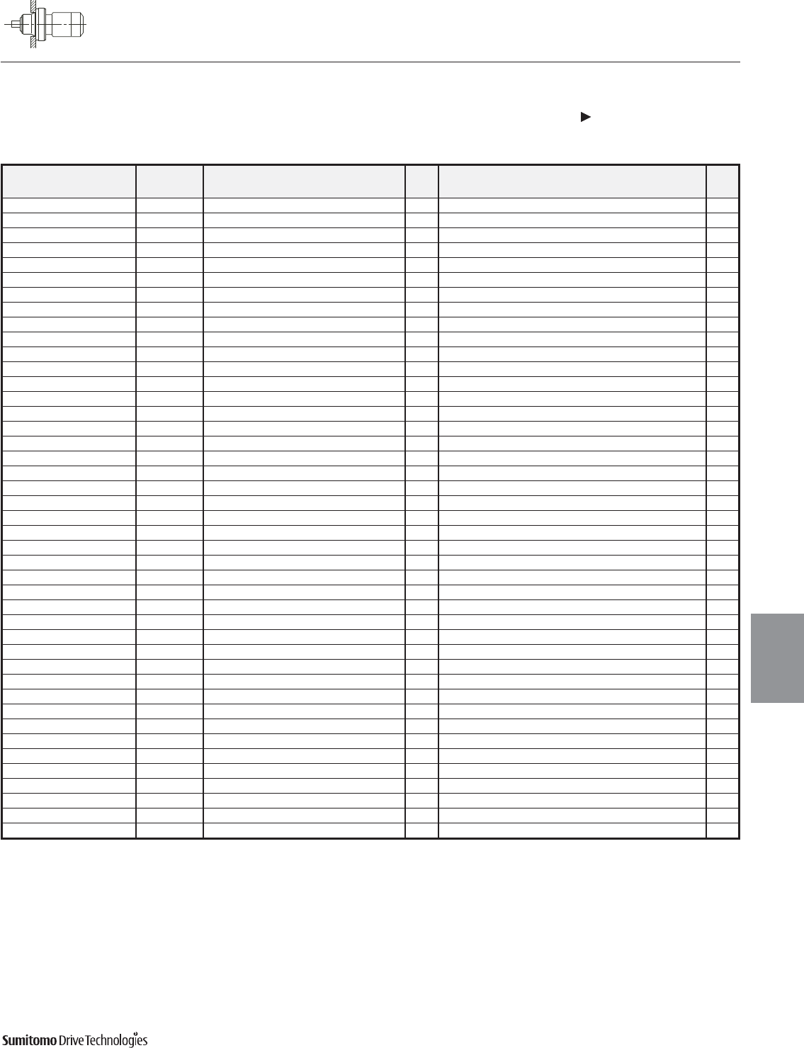
CYCLO® 6000 Gearmotors
Dimensions Integral F-Flange Mount
Single Reduction
CNFM-6060/5Y 6120/5Y (cont.)
Dimensions 4.45
Dimensions
Gearmotors
All dimensions are in inches
Dimensions shown are for reference only and are subject to change without notice, unless certified.
Certified prints are available after receipt of an order; consult factory.
Cyclo® 6000 Series
Model Motor Without Brake Appx With Brake Appx
HP Pole C AB L MP Wt (lb) C AB L MP MS MT Wt (lb)
CNFM01-6060/5Y 1/8 4 8.90 5.04 1.38 4.69 12 10.28 5.04 2.76 4.88 1.93 - 15
CNFM02-6060/5Y 1/4 4 10.55 5.04 2.32 4.88 14 11.81 5.04 3.58 4.88 2.40 - 18
CNFM03-6060/5Y 1/3 4 10.55 5.04 2.32 4.88 14 11.81 5.04 3.58 4.88 2.40 - 18
CNFM01-6070/5Y 1/8 4 9.13 5.04 1.38 4.69 14 10.51 5.04 2.76 4.88 1.93 - 17
CNFM02-6070/5Y 1/4 4 10.79 5.04 2.32 4.88 17 12.05 5.04 3.58 4.88 2.40 - 19
CNFM03-6070/5Y 1/3 4 10.79 5.04 2.32 4.88 17 12.05 5.04 3.58 4.88 2.40 - 19
CNFM05-6070/5Y 1/2 4 11.57 5.04 2.32 4.88 19 12.83 5.04 3.58 4.88 2.40 - 21
CNFM01-6080/5Y 1/8 4 10.16 5.04 1.38 4.69 20 11.54 5.04 2.76 4.88 1.93 - 22
CNFM02-6080/5Y 1/4 4 11.81 5.04 2.32 4.88 22 13.07 5.04 3.58 4.88 2.40 - 24
CNFM03-6080/5Y 1/3 4 11.81 5.04 2.32 4.88 22 13.07 5.04 3.58 4.88 2.40 - 24
CNFM05-6080/5Y 1/2 4 12.60 5.04 2.32 4.88 26 13.86 5.04 3.58 4.88 2.40 - 29
CNFM08-6080/5Y 3/4 4 14.21 5.63 3.82 5.83 35 15.91 5.63 5.51 5.83 3.66 4.17 37
CNFM1-6080/5Y 1 4 14.21 5.63 3.82 5.83 35 15.91 5.63 5.51 5.83 3.66 4.17 37
CNFM01-6090/5Y 1/8 4 10.87 5.04 1.38 4.69 22 12.24 5.04 2.76 4.88 1.93 - 26
CNFM02-6090/5Y 1/4 4 12.52 5.04 2.32 4.88 24 13.78 5.04 3.58 4.88 2.40 - 29
CNFM03-6090/5Y 1/3 4 12.52 5.04 2.32 4.88 24 13.78 5.04 3.58 4.88 2.40 - 29
CNFM05-6090/5Y 1/2 4 13.31 5.04 2.32 4.88 26 14.57 5.04 3.58 4.88 2.40 - 31
CNFM08-6090/5Y 3/4 4 14.92 5.63 3.82 5.83 35 16.61 5.63 5.51 5.83 3.66 4.17 40
CNFM1-6090/5Y 1 4 14.92 5.63 3.82 5.83 35 16.61 5.63 5.51 5.83 3.66 4.17 40
CNFM1H-6090/5Y 1.5 4 16.22 5.83 3.94 6.30 44 18.66 5.83 6.38 6.30 4.53 4.49 53
CNFM2-6090/5Y 2 4 16.22 5.83 3.94 6.30 44 18.66 5.83 6.38 6.30 4.53 4.49 53
CNFM02-6100/5Y 1/4 4 13.07 5.04 2.32 4.88 29 14.33 5.04 3.58 4.88 2.40 - 33
CNFM03-6100/5Y 1/3 4 13.07 5.04 2.32 4.88 29 14.33 5.04 3.58 4.88 2.40 - 33
CNFM05-6100/5Y 1/2 4 13.86 5.04 2.32 4.88 31 15.12 5.04 3.58 4.88 2.40 - 35
CNFM08-6100/5Y 3/4 4 15.47 5.63 3.82 5.83 40 17.17 5.63 5.51 5.83 3.66 4.17 46
CNFM1-6100/5Y 1 4 15.47 5.63 3.82 5.83 40 17.17 5.63 5.51 5.83 3.66 4.17 46
CNFM1H-6100/5Y 1.5 4 16.77 5.83 3.94 6.30 49 19.21 5.83 6.38 6.30 4.53 4.49 60
CNFM2-6100/5Y 2 4 16.77 5.83 3.94 6.30 49 19.21 5.83 6.38 6.30 4.53 4.49 60
CNFM3-6100/5Y 3 4 17.56 6.10 4.13 6.81 57 20.04 6.10 6.61 6.81 4.76 4.88 71
CNFM05-6110/5Y 1/2 4 14.29 3.35 2.32 4.88 36 15.51 3.35 3.58 4.88 2.40 - 38
CNFM08-6110/5Y 3/4 4 15.87 5.63 3.82 5.83 40 17.80 5.63 5.51 5.83 3.66 4.17 49
CNFM1-6110/5Y 1 4 15.87 5.63 3.82 5.83 42 17.80 5.63 5.51 5.83 3.66 4.17 49
CNFM1H-6110/5Y 1.5 4 17.17 5.83 3.94 6.30 49 19.41 5.83 6.38 6.30 4.53 4.49 60
CNFM2-6110/5Y 2 4 17.17 5.83 3.94 6.30 49 19.41 5.83 6.38 6.30 4.53 4.49 60
CNFM3-6110/5Y 3 4 17.95 6.10 4.13 6.81 58 20.43 6.10 6.61 6.81 4.76 4.88 71
CNFM5-6110/5Y 5 4 19.33 5.79 5.00 8.35 80 22.17 5.79 7.83 8.35 5.20 6.18 102
CNFM08-6120/5Y 3/4 4 16.65 5.63 3.82 5.83 60 18.35 5.63 5.51 5.83 3.66 4.17 66
CNFM1-6120/5Y 1 4 16.65 5.63 3.82 5.83 60 18.35 5.63 5.51 5.83 3.66 4.17 66
CNFM1H-6120/5Y 1.5 4 17.95 5.83 3.94 6.30 68 20.39 5.83 6.38 6.30 4.53 4.49 79
CNFM2-6120/5Y 2 4 17.95 5.83 3.94 6.30 68 20.39 5.83 6.38 6.30 4.53 4.49 79
CNFM3-6120/5Y 3 4 18.74 6.10 4.13 6.81 77 21.22 6.10 6.61 6.81 4.76 4.88 93
CNFM5-6120/5Y 5 4 19.65 6.54 5.00 8.35 99 22.48 6.54 7.83 8.35 5.20 6.18 121
CNFM8-6120/5Y 7.5 4 21.38 6.54 5.00 8.35 115 24.21 6.54 7.83 8.35 5.20 6.18 137
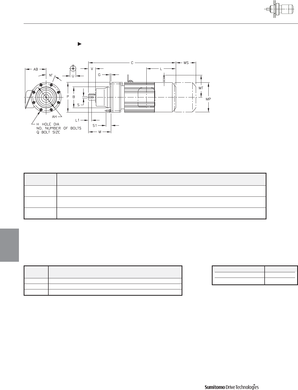
Model BGH
NO.
MN O P QS1AHX
CHFM
6130/5Y 6.4955 0.63 0.43 6 7.01 60 5.91 9.06 M10 1.22 8.07 8.19
6.4945
6140/5Y 6.4955 0.63 0.43 6 7.80 60 5.91 9.06 M10 1.22 8.07 8.19
6.4945
6160/5Y 7.8734 0.39 0.55 6 8.74 30 7.44 11.81 M12 1.38 10.63 8.98
7.8723
CYCLO® 6000 Gearmotors
Dimensions Integral F-Flange Mount
Single Reduction
CHFM-6130/5Y 6160/5Y
4.46 Dimensions
Dimensions
Gearmotors
All dimensions are in inches
Model Low Speed Shaft
CHFM
U* V S L1 Key
6130/5Y 1.875 2.76 0.71 3/8-16UNC 1/2 X 1/2 X 2.16
6140/5Y 1.875 3.54 0.71 3/8-16UNC 1/2 X 1/2 X 2.95
6160/5Y 2.250 3.54 0.71 3/8-16UNC 1/2 X 1/2 X 2.95
Shaft Nominal Diameter (inches) Tolerances (inches)
1.250 (1 1/4) through 1.875 (1 7/8) +0.0000/-0.0006
2.000 (2) through 3.125 (3 1/8) +0.0000/-0.0007
*Shaft Tolerances
Dimensions shown are for reference only and are subject to change without notice, unless certified.
Certified prints are available after receipt of an order; consult factory.
Cyclo® 6000 Series
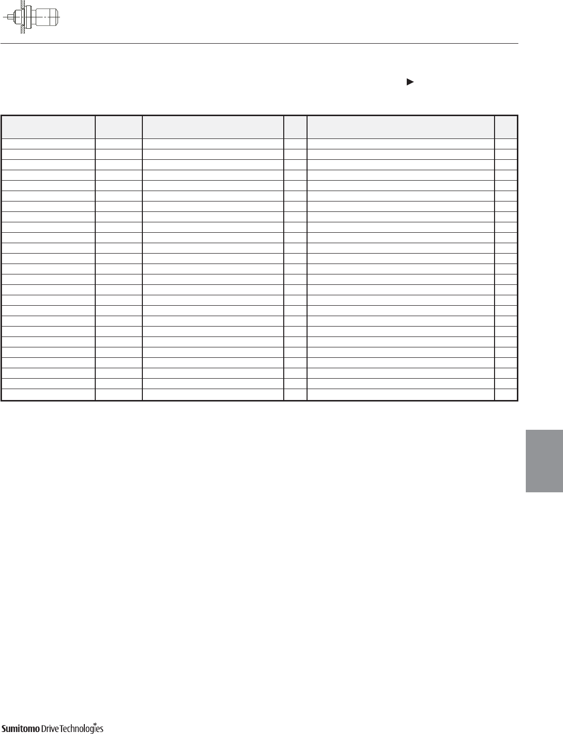
CYCLO® 6000 Gearmotors
Dimensions Integral F-Flange Mount
Single Reduction
CHFM-6130/5Y 6160/5Y (cont.)
Dimensions 4.47
Dimensions
Gearmotors
All dimensions are in inches
Dimensions shown are for reference only and are subject to change without notice, unless certified.
Certified prints are available after receipt of an order; consult factory.
Cyclo® 6000 Series
Model Motor Without Brake Appx With Brake Appx
HP Pole C AB L MP Wt (lb) C AB L MP MS MT Wt (lb)
CHFM1-6130/5Y 1 4 18.78 5.63 3.82 5.83 95 20.47 5.63 5.51 5.83 3.66 4.17 106
CHFM1H-6130/5Y 1.5 4 20.08 5.83 3.94 6.30 104 22.52 5.83 6.38 6.30 4.53 4.49 115
CHFM2-6130/5Y 2 4 20.08 5.83 3.94 6.30 104 22.52 5.83 6.38 6.30 4.53 4.49 115
CHFM3-6130/5Y 3 4 20.87 6.10 4.13 6.81 110 23.35 6.10 6.61 6.81 4.76 4.88 126
CHFM5-6130/5Y 5 4 21.77 6.54 5.00 8.35 132 24.61 6.54 7.83 8.35 5.20 6.18 154
CHFM8-6130/5Y 7.5 4 23.50 6.54 5.00 8.35 148 26.34 6.54 7.83 8.35 5.20 6.18 170
CHFM10-6130/5Y 10 4 24.41 8.31 5.63 9.88 181 28.15 8.31 9.37 9.88 6.69 7.17 221
CHFM15-6130/5Y 15 4 26.77 8.31 5.63 9.88 212 30.51 8.31 9.37 9.88 6.69 7.17 251
CHFM1H-6140/5Y 1.5 4 20.87 5.83 3.94 6.30 106 23.31 5.83 6.38 6.30 4.53 4.49 117
CHFM2-6140/5Y 2 4 20.87 5.83 3.94 6.30 106 23.31 5.83 6.38 6.30 4.53 4.49 117
CHFM3-6140/5Y 3 4 21.65 6.10 4.13 6.81 112 24.13 6.10 6.61 6.81 4.76 4.88 128
CHFM5-6140/5Y 5 4 22.56 6.54 5.00 8.35 135 25.39 6.54 7.83 8.35 5.20 6.18 157
CHFM8-6140/5Y 7.5 4 24.29 6.54 5.00 8.35 150 27.13 6.54 7.83 8.35 5.20 6.18 172
CHFM10-6140/5Y 10 4 25.20 8.31 5.63 9.88 183 28.94 8.31 9.37 9.88 6.69 7.17 223
CHFM15-6140/5Y 15 4 27.56 8.31 5.63 9.88 214 31.30 8.31 9.37 9.88 6.69 7.17 254
CHFM20-6140/5Y 20 4 31.10 9.13 11.61 12.76 329 34.65 9.13 15.16 12.76 8.66 - 401
CHFM2-6160/5Y 2 4 22.95 5.83 3.94 6.30 165 25.39 5.83 6.38 6.30 4.53 4.49 176
CHFM3-6160/5Y 3 4 23.54 6.10 4.13 6.81 172 26.02 6.10 6.61 6.81 4.76 4.88 185
CHFM5-6160/5Y 5 4 24.45 6.54 5.00 8.35 192 27.28 6.54 7.83 8.35 5.20 6.18 214
CHFM8-6160/5Y 7.5 4 26.18 6.54 5.00 8.35 207 29.02 6.54 7.83 8.35 5.20 6.18 229
CHFM10-6160/5Y 10 4 27.28 8.31 5.63 9.88 243 31.02 8.31 9.37 9.88 6.69 7.17 280
CHFM15-6160/5Y 15 4 29.65 8.31 5.63 9.88 273 33.39 8.31 9.37 9.88 6.69 7.17 311
CHFM20-6160/5Y 20 4 32.99 9.13 11.61 12.76 390 36.54 9.13 15.16 12.76 8.66 - 463
CHFM25-6160/5Y 25 4 36.73 11.69 13.39 15.51 549 45.00 11.69 21.65 15.51 14.45 - 662
CHFM30-6160/5Y 30 4 36.73 11.69 13.39 15.51 549 45.00 11.69 21.65 15.51 14.45 - 662
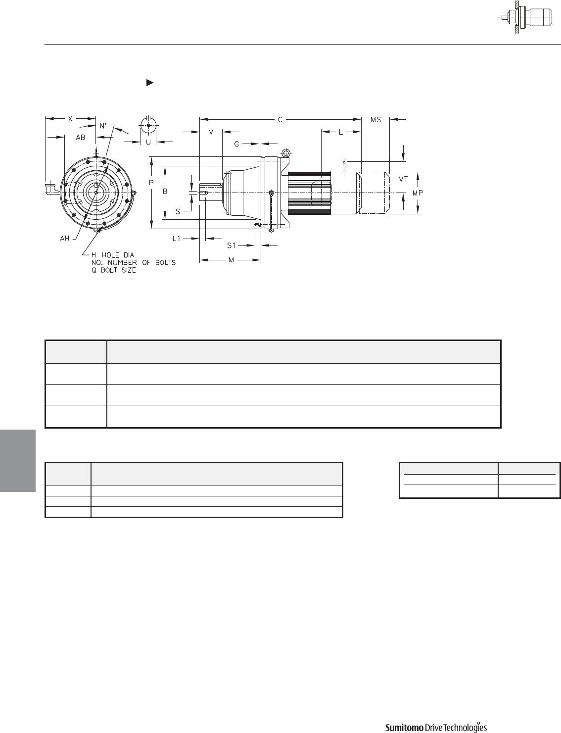
Model BGH
NO.
MN O P QS1AHX
CHFM
6170/5Y 9.8419 0.47 0.55 8 10.31 22.5 8.50 13.39 M12 1.61 11.81 9.57
9.8408
6180/5Y 11.0230 0.47 0.55 8 11.77 22.5 9.09 14.57 M12 1.50 12.99 10.16
11.0217
6190/5Y 12.5977 0.39 0.55 12 14.37 15 11.06 16.93 M12 1.61 14.96 11.22
12.5963
CYCLO® 6000 Gearmotors
Dimensions Integral F-Flange Mount
Single Reduction
CHFM-6170/5Y 6190/5Y
4.48 Dimensions
Dimensions
Gearmotors
All dimensions are in inches
Model Low Speed Shaft
CHFM
U* V S L1 Key
6170/5Y 2.750 3.54 0.94 1/2-13UNC 5/8 X 5/8 X 3.15
6180/5Y 3.125 4.33 0.94 1/2-13UNC 3/4 X 3/4 X 3.74
6190/5Y 3.625 5.31 1.34 3/4-10UNC 7/8 X 7/8 X 4.92
Shaft Nominal Diameter (inches) Tolerances (inches)
2.000 (2) through 3.125 (3 1/8) +0.0000/-0.0007
3.250 (3 1/4) through 4.625 (4 5/8) +0.0000/-0.0009
*Shaft Tolerances
Dimensions shown are for reference only and are subject to change without notice, unless certified.
Certified prints are available after receipt of an order; consult factory.
Cyclo® 6000 Series
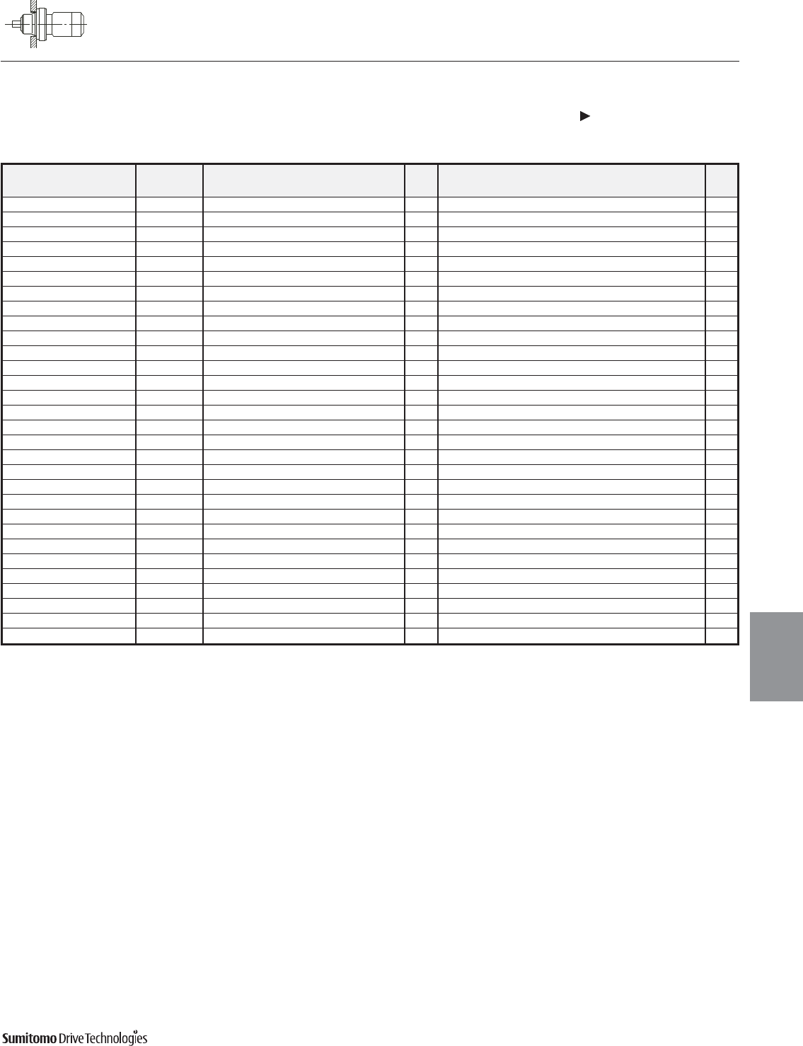
CYCLO® 6000 Gearmotors
Dimensions Integral F-Flange Mount
Single Reduction
CHFM-6170/5Y 6190/5Y (cont.)
Dimensions 4.49
Dimensions
Gearmotors
All dimensions are in inches
Model Motor Without Brake Appx With Brake Appx
HP Pole C AB L MP Wt (lb) C AB L MP MS MT Wt (lb)
CHFM5-6170/5Y 5 4 26.77 6.54 5.00 8.35 260 29.61 6.69 7.83 8.35 5.20 6.18 282
CHFM8-6170/5Y 7.5 4 28.50 6.54 5.00 8.35 276 31.34 6.69 7.83 8.35 5.20 6.18 298
CHFM10-6170/5Y 10 4 29.21 8.31 5.63 9.88 309 32.95 7.40 9.37 9.88 6.69 7.17 348
CHFM15-6170/5Y 15 4 31.57 8.31 5.63 9.88 340 35.31 7.40 9.37 9.88 6.69 7.17 379
CHFM20-6170/5Y 20 4 34.72 9.13 11.61 12.76 459 38.27 9.13 15.16 12.76 8.66 - 531
CHFM25-6170/5Y 25 4 38.46 11.69 13.39 15.51 609 46.73 11.69 21.65 15.51 14.45 - 721
CHFM30-6170/5Y 30 4 38.46 11.69 13.39 15.51 609 46.73 11.69 21.65 15.51 14.45 - 721
CHFM40-6170/5Y 40 4 38.46 11.69 13.39 15.51 646 46.73 11.69 21.65 15.51 14.45 - 741
CHFM5-6180/5Y 5 4 28.23 6.54 5.00 8.35 326 31.06 6.69 7.83 8.35 5.20 6.18 348
CHFM8-6180/5Y 7.5 4 29.96 6.54 5.00 8.35 344 32.80 6.69 7.83 8.35 5.20 6.18 366
CHFM10-6180/5Y 10 4 30.67 8.31 5.63 9.88 377 34.41 7.40 9.37 9.88 6.69 7.17 417
CHFM15-6180/5Y 15 4 33.03 8.31 5.63 9.88 408 36.77 7.40 9.37 9.88 6.69 7.17 448
CHFM20-6180/5Y 20 4 36.18 9.13 11.61 12.76 540 39.72 9.13 15.16 12.76 8.66 - 602
CHFM25-6180/5Y 25 4 39.92 11.69 13.39 15.51 677 48.19 11.69 21.65 15.51 14.45 - 789
CHFM30-6180/5Y 30 4 39.92 11.69 13.39 15.51 677 48.19 11.69 21.65 15.51 14.45 - 789
CHFM40-6180/5Y 40 4 39.92 11.69 13.39 15.51 714 48.19 11.69 21.65 15.51 14.45 - 809
CHFM50-6180/5Y 50 4 44.45 11.69 16.93 15.51 820 52.91 11.69 25.39 15.51 17.52 - 1034
CHFM60-6180/5Y 60 4 44.45 11.69 16.93 15.51 820 52.91 11.69 25.39 15.51 17.52 - 1034
CHFM8-6190/5Y 7.5 4 33.74 6.54 5.00 8.35 476 36.57 6.69 7.83 8.35 5.20 6.18 498
CHFM10-6190/5Y 10 4 34.25 8.31 5.63 9.88 505 37.99 7.40 9.37 9.88 6.69 7.17 545
CHFM15-6190/5Y 15 4 36.61 8.31 5.63 9.88 536 40.35 7.40 9.37 9.88 6.69 7.17 576
CHFM20-6190/5Y 20 4 39.17 9.13 11.61 12.76 653 42.72 9.13 15.16 12.76 8.66 - 728
CHFM25-6190/5Y 25 4 42.91 11.69 13.39 15.51 811 51.18 11.69 21.65 15.51 14.45 - 911
CHFM256-6190/5Y 25 6 42.91 11.69 13.39 15.51 845 51.18 11.69 21.65 15.51 14.45 - 939
CHFM30-6190/5Y 30 4 42.91 11.69 13.39 15.51 811 51.18 11.69 21.65 15.51 14.45 - 911
CHFM40-6190/5Y 40 4 42.91 11.69 13.39 15.51 845 51.18 11.69 21.65 15.51 14.45 - 939
CHFM406-6190/5Y 40 6 47.44 11.69 16.93 15.51 928 55.91 11.69 25.39 15.51 5.20 - 1142
CHFM50-6190/5Y 50 4 47.44 11.69 16.93 15.51 928 55.91 11.69 25.39 15.51 17.52 - 1142
CHFM506-6190/5Y 50 6 47.44 11.69 16.93 15.51 928 55.91 11.69 25.39 15.51 17.52 - 1142
CHFM60-6190/5Y 60 4 47.44 11.69 16.93 15.51 928 55.91 11.69 25.39 15.51 17.52 - 1142
Dimensions shown are for reference only and are subject to change without notice, unless certified.
Certified prints are available after receipt of an order; consult factory.
Cyclo® 6000 Series
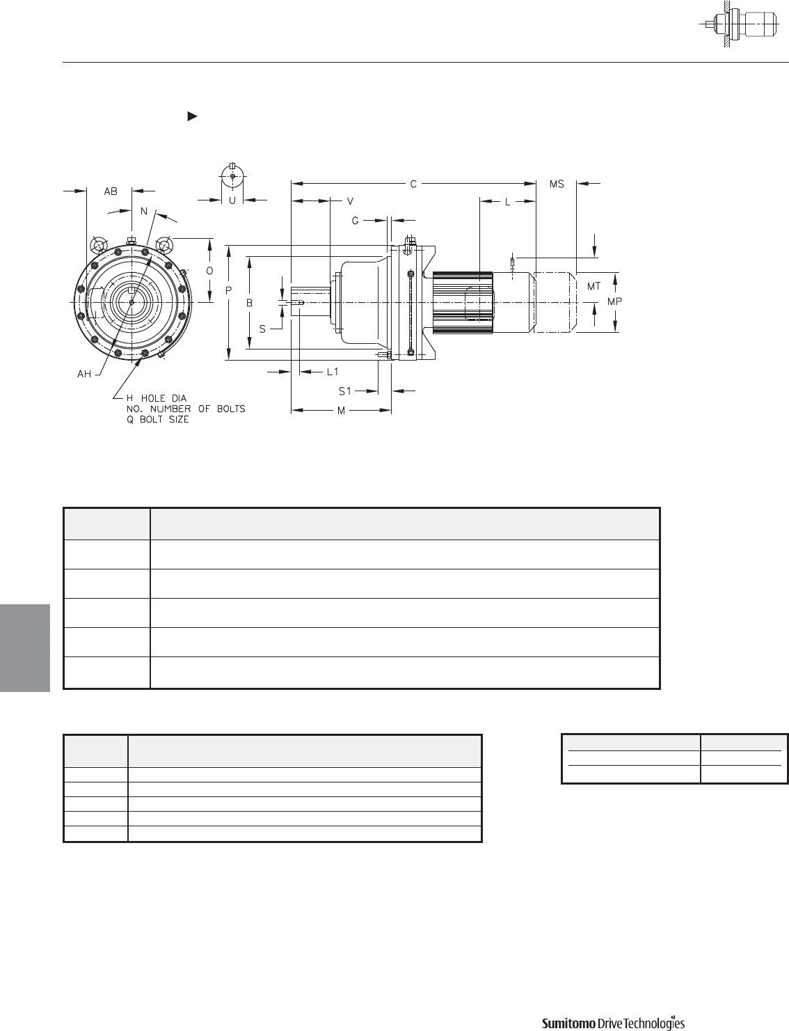
Model BGH
NO.
MN O P QS1AH
CHFM
6205Y 14.1725 0.79 0.71 12 16.14 15 11.14 17.64 M16 2.20 15.94
14.1711
6215Y 15.3536 0.79 0.81 12 16.65 15 12.28 19.09 M18 2.20 17.32
15.3522
6225Y 16.5346 0.79 0.87 12 17.87 15 13.11 20.71 M20 2.52 18.70
16.5331
6235Y 17.9126 0.79 0.87 12 19.88 15 13.82 22.13 M20 2.56 20.08
17.9110
6245Y 19.6843 0.98 1.06 12 20.83 15 15.55 24.17 M24 2.56 22.05
19.6827
CYCLO® 6000 Gearmotors
Dimensions Integral F-Flange Mount
Single Reduction
CHFM-6205Y 6245Y
4.50 Dimensions
Dimensions
Gearmotors
All dimensions are in inches
Model Low Speed Shaft
CHFM
U* V S L1 Key
6205Y 3.875 6.50 3/4-10UNC 1.34 1 X 1 X 6.50
6215Y 4.250 6.50 3/4-10UNC 1.34 1 X 1 X 6.50
6225Y 4.625 6.50 3/4-10UNC 1.34 1-1/4 X 7/8 X 6.50
6235Y 5.000 7.87 1-8UNC 1.61 1-1/4 X 7/8 X 7.87
6245Y 5.500 7.87 1-8UNC 1.61 1-1/4 X 7/8 X 7.87
Shaft Nominal Diameter (inches) Tolerances (inches)
3.250 (3 1/4) through 4.625 (4 5/8) +0.0000/-0.0009
4.750 (4 3/4) through 7.000 (7) +0.0000/-0.0010
*Shaft Tolerances
Dimensions shown are for reference only and are subject to change without notice, unless certified.
Certified prints are available after receipt of an order; consult factory.
Cyclo® 6000 Series
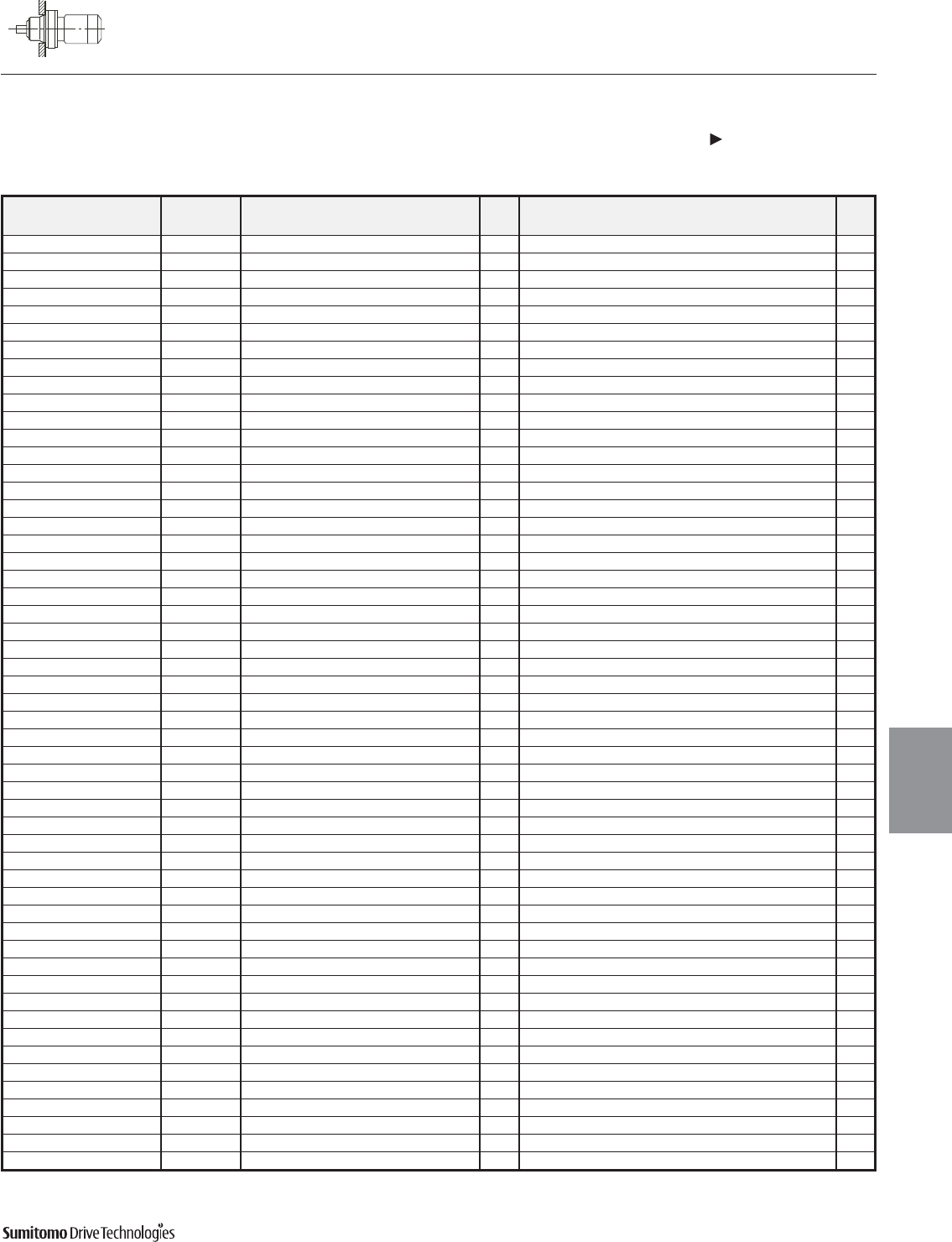
CYCLO® 6000 Gearmotors
Dimensions Integral F-Flange Mount
Single Reduction
CHFM-6205Y 6245Y (cont.)
Dimensions 4.51
Dimensions
Gearmotors
All dimensions are in inches
Model Motor Without Brake Appx With Brake Appx
HP Pole C AB L MP Wt (lb) C AB L MP MS MT Wt (lb)
CHFM15-6205Y 15 4 38.27 8.31 5.63 9.88 593 42.01 8.31 9.37 9.88 6.69 7.17 633
CHFM20-6205Y 20 4 41.02 9.13 11.61 12.76 712 44.57 9.13 15.16 12.76 8.66 - 789
CHFM206-6205Y 20 6 44.37 11.69 13.39 15.51 869 52.64 11.69 21.65 15.51 14.45 - 968
CHFM25-6205Y 25 4 44.37 11.69 13.39 15.51 869 52.64 11.69 21.65 15.51 14.45 - 968
CHFM30-6205Y 30 4 44.37 11.69 13.39 15.51 869 52.64 11.69 21.65 15.51 14.45 - 968
CHFM306-6205Y 30 6 44.37 11.69 13.39 15.51 897 52.64 11.69 21.65 15.51 14.57 - 997
CHFM40-6205Y 40 4 44.37 11.69 13.39 15.51 897 52.64 11.69 21.65 15.51 14.57 - 997
CHFM406-6205Y 40 6 48.90 11.69 16.93 15.51 981 57.36 11.69 25.39 15.51 17.52 - 1188
CHFM50-6205Y 50 4 48.90 11.69 16.93 15.51 981 57.36 11.69 25.39 15.51 17.52 - 1188
CHFM506-6205Y 50 6 48.90 11.69 16.93 15.51 981 57.36 11.69 25.39 15.51 17.52 - 1188
CHFM60-6205Y 60 4 48.90 11.69 16.93 15.51 981 57.36 11.69 25.39 15.51 17.52 - 1188
CHFM606-6205Y 60 6 51.06 16.22 18.31 19.06 1186 - - - - - - -
CHFM75-6205Y 75 4 51.06 16.22 18.31 19.06 1186 - - - - - - -
CHFM15-6215Y 15 4 39.21 8.31 5.63 9.88 770 42.95 8.31 9.37 9.88 6.69 7.17 809
CHFM20-6215Y 20 4 41.97 9.13 11.61 12.76 891 45.51 9.13 15.16 12.76 8.66 - 966
CHFM206-6215Y 20 6 45.31 11.69 13.39 15.51 1034 53.58 11.69 21.65 15.51 14.45 - 1133
CHFM25-6215Y 25 4 45.31 11.69 13.39 15.51 1034 53.58 11.69 21.65 15.51 14.45 - 1133
CHFM256-6215Y 25 6 45.31 11.69 13.39 15.51 1063 53.58 11.69 21.65 15.51 14.45 - 1162
CHFM30-6215Y 30 4 45.31 11.69 13.39 15.51 1034 53.58 11.69 21.65 15.51 14.45 - 1133
CHFM306-6215Y 30 6 45.31 11.69 13.39 15.51 1063 53.58 11.69 21.65 15.51 14.57 - 1162
CHFM40-6215Y 40 4 45.31 11.69 13.39 15.51 1063 53.58 11.69 21.65 15.51 14.57 - 1162
CHFM406-6215Y 40 6 49.84 11.69 16.93 15.51 1147 58.31 11.69 25.39 15.51 17.52 - 1356
CHFM50-6215Y 50 4 49.84 11.69 16.93 15.51 1147 58.31 11.69 25.39 15.51 17.52 - 1356
CHFM506-6215Y 50 6 49.84 11.69 16.93 15.51 1147 58.31 11.69 25.39 15.51 17.52 - 1356
CHFM60-6215Y 60 4 49.84 11.69 16.93 15.51 1147 58.31 11.69 25.39 15.51 17.52 - 1356
CHFM606-6215Y 60 6 52.01 16.22 18.31 19.06 1389 - - - - - - -
CHFM75-6215Y 75 4 52.01 16.22 18.31 19.06 1389 - - - - - - -
CHFM206-6225Y 20 6 46.89 11.69 13.39 15.51 1184 55.16 11.69 21.65 15.51 14.45 - 1283
CHFM25-6225Y 25 4 46.89 11.69 13.39 15.51 1184 55.16 11.69 21.65 15.51 14.45 - 1283
CHFM256-6225Y 25 6 46.89 11.69 13.39 15.51 1213 55.16 11.69 21.65 15.51 14.45 - 1312
CHFM30-6225Y 30 4 46.89 11.69 13.39 15.51 1184 55.16 11.69 21.65 15.51 14.45 - 1283
CHFM306-6225Y 30 6 46.89 11.69 13.39 15.51 1213 55.16 11.69 21.65 15.51 14.57 - 1312
CHFM40-6225Y 40 4 46.89 11.69 13.39 15.51 1213 55.16 11.69 21.65 15.51 14.57 - 1312
CHFM406-6225Y 40 6 51.42 11.69 16.93 15.51 1297 59.88 11.69 25.39 15.51 17.52 - 1506
CHFM50-6225Y 50 4 51.42 11.69 16.93 15.51 1297 59.88 11.69 25.39 15.51 17.52 - 1506
CHFM506-6225Y 50 6 51.42 11.69 16.93 15.51 1297 59.88 11.69 25.39 15.51 17.52 - 1506
CHFM60-6225Y 60 4 51.42 11.69 16.93 15.51 1297 59.88 11.69 25.39 15.51 17.52 - 1506
CHFM606-6225Y 60 6 53.58 16.22 18.31 19.06 1515 - - - - - - -
CHFM75-6225Y 75 4 53.58 16.22 18.31 19.06 1515 - - - - - - -
CHFM206-6235Y 20 6 49.33 11.69 13.39 15.51 1372 57.60 11.69 21.65 15.51 14.45 - 1440
CHFM256-6235Y 25 6 49.33 11.69 13.39 15.51 1372 57.60 11.69 21.65 15.51 14.45 - 1471
CHFM306-6235Y 30 6 49.33 11.69 13.39 15.51 1372 57.60 11.69 21.65 15.51 14.57 - 1471
CHFM406-6235Y 40 6 53.86 11.69 16.93 15.51 1473 62.32 11.69 25.39 15.51 17.52 - 1667
CHFM506-6235Y 50 6 53.86 11.69 16.93 15.51 1473 62.32 11.69 25.39 15.51 17.52 - 1667
CHFM606-6235Y 60 6 56.02 16.22 18.31 19.06 1669 - - - - - - -
CHFM756-6235Y 75 6 59.17 16.22 19.88 19.09 1788 - - - - - - -
CHFM206-6245Y 20 6 50.47 11.69 13.39 15.51 1636 58.74 11.69 21.65 15.51 14.45 - 1709
CHFM256-6245Y 25 6 50.47 11.69 13.39 15.51 1636 58.74 11.69 21.65 15.51 14.45 - 1740
CHFM306-6245Y 30 6 50.47 11.69 13.39 15.51 1636 58.74 11.69 21.65 15.51 14.57 - 1740
CHFM406-6245Y 40 6 55.00 11.69 16.93 15.51 1738 63.46 11.69 25.39 15.51 17.52 - 1932
CHFM506-6245Y 50 6 55.00 11.69 16.93 15.51 1738 63.46 11.69 25.39 15.51 17.52 - 1932
CHFM606-6245Y 60 6 57.17 16.22 18.31 19.06 1938 - - - - - - -
CHFM756-6245Y 75 6 60.31 16.22 19.88 19.09 2046 - - - - - - -
Dimensions shown are for reference only and are subject to change without notice, unless certified.
Certified prints are available after receipt of an order; consult factory.
Cyclo® 6000 Series
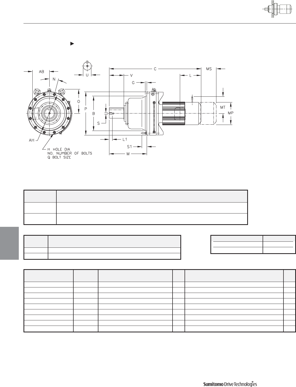
Model BGH
NO.
MN O P QS1AH
CHFM
6255Y 21.2590 1.18 1.06 12 24.25 15 15.20 26.38 M24 3.58 24.02
21.2562
6265Y 22.4401 1.57 1.34 12 28.03 15 17.83 28.98 M30 3.35 25.98
22.4373
CYCLO® 6000 Gearmotors
Dimensions Integral F-Flange Mount
Single Reduction
CHFM-6255Y 6265Y
4.52 Dimensions
Dimensions
Gearmotors
All dimensions are in inches
Model Low Speed Shaft
CHFM
U* V S L1 Key
6255Y 6.250 9.45 1-1/4-7UNC 1.93 1-1/2 X 1 X 9.45
6265Y 6.625 11.81 1-1/4-7UNC 1.93 1-3/4 X 1-1/4 X 11.8
Shaft Nominal Diameter (inches) Tolerances (inches)
3.250 (3 1/4) through 4.625 (4 5/8) +0.0000/-0.0009
4.750 (4 3/4) through 7.000 (7) +0.0000/-0.0010
*Shaft Tolerances
Dimensions shown are for reference only and are subject to change without notice, unless certified.
Certified prints are available after receipt of an order; consult factory.
Cyclo® 6000 Series
Model Motor Without Brake Appx With Brake Appx
HP Pole C AB L MP Wt (lb) C AB L MP MS MT Wt (lb)
CHFM256-6255Y 25 6 55.12 11.69 13.39 15.51 2176 63.39 11.69 21.65 15.51 14.45 - 2280
CHFM306-6255Y 30 6 55.12 11.69 13.39 15.51 2176 63.39 11.69 21.65 15.51 14.57 - 2280
CHFM406-6255Y 40 6 59.65 11.69 16.93 15.51 2276 68.11 11.69 25.39 15.51 17.52 - 2470
CHFM506-6255Y 50 6 59.65 11.69 16.93 15.51 2276 68.11 11.69 25.39 15.51 17.52 - 2470
CHFM606-6255Y 60 6 61.81 16.22 18.31 19.06 2452 - - - - - - -
CHFM756-6255Y 75 6 64.96 16.22 19.88 19.09 2573 - - - - - - -
CHFM406-6265Y 40 6 64.25 11.69 16.93 15.51 2800 72.72 11.69 25.39 15.51 17.52 - 2994
CHFM506-6265Y 50 6 64.25 11.69 16.93 15.51 2800 72.72 11.69 25.39 15.51 17.52 - 2994
CHFM606-6265Y 60 6 66.42 16.22 18.31 19.06 3010 - - - - - - -
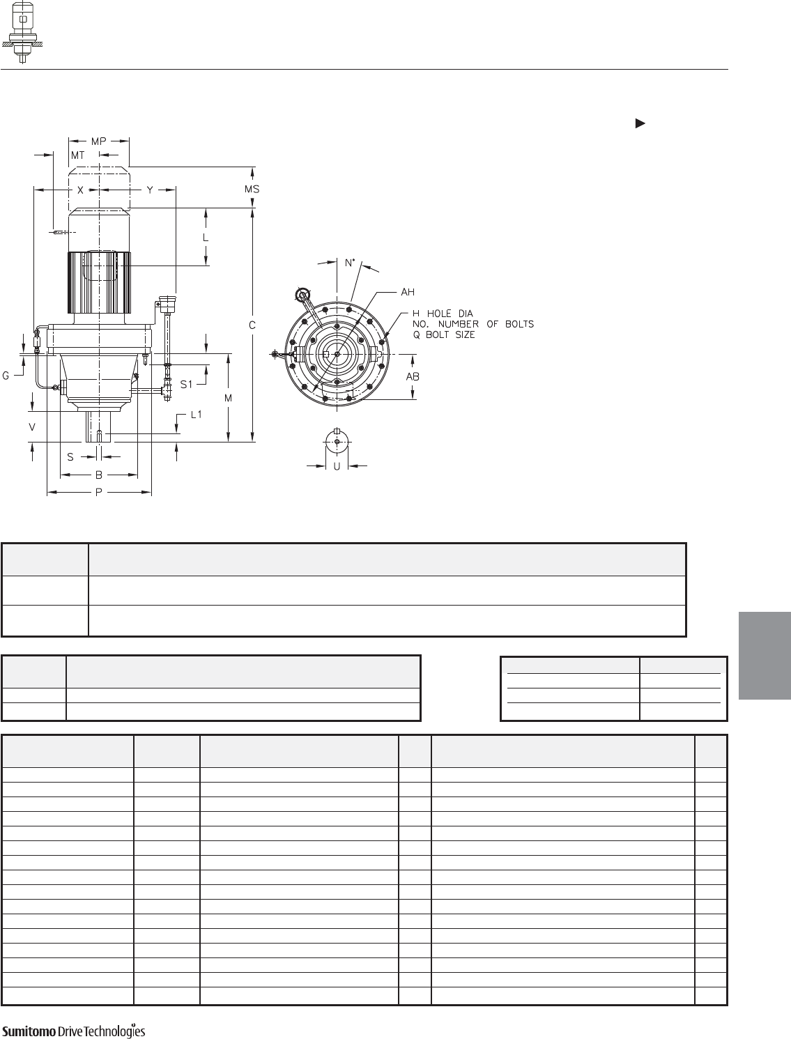
CYCLO® 6000 Gearmotors
Dimensions Integral Vertical F-Flange Mount
Single Reduction
CVFM-6130/5Y 6140/5Y
Dimensions 4.53
Dimensions
Gearmotors
All dimensions are in inches
Model Low Speed Shaft
CVFM
U* V S L1 Key
6130/5Y 1.875 2.40 3/8-16UNC 0.71 1/2 X 1/2 X 2.16
6140/5Y 1.875 3.19 3/8-16UNC 0.71 1/2 X 1/2 X 2.95
Model BCGH
NO.
MNPQS1AHXY
CVFM
6130/5Y 6.4955 12.64 0.63 0.43 6 7.01 60 9.06 M10 1.22 8.07 5.98 8.23
6.4945
6140/5Y 6.4955 13.43 0.63 0.43 6 7.80 60 9.06 M10 1.22 8.07 5.98 8.23
6.4945
Dimensions shown are for reference only and are subject to change without notice, unless certified.
Certified prints are available after receipt of an order; consult factory.
Cyclo® 6000 Series
Model Motor Without Brake Appx With Brake Appx
HP Pole C AB L MP Wt (lb) C AB L MP MS MT Wt (lb)
CVFM1-6130/5Y 1 4 18.78 5.63 3.82 5.83 95 20.47 5.63 5.51 5.83 3.66 4.17 106
CVFM1H-6130/5Y 1.5 4 20.08 5.83 3.94 6.30 104 22.52 5.83 6.38 6.30 4.53 4.49 115
CVFM2-6130/5Y 2 4 20.08 5.83 3.94 6.30 104 22.52 5.83 6.38 6.30 4.53 4.49 115
CVFM3-6130/5Y 3 4 20.87 6.10 4.13 6.81 110 23.35 6.10 6.61 6.81 4.76 4.88 126
CVFM5-6130/5Y 5 4 21.77 6.54 5.00 8.35 132 24.61 6.54 7.83 8.35 5.20 6.18 154
CVFM8-6130/5Y 7.5 4 23.50 6.54 5.00 8.35 148 26.34 6.54 7.83 8.35 5.20 6.18 170
CVFM10-6130/5Y 10 4 24.41 8.31 5.63 9.88 181 28.15 8.31 9.37 9.88 6.69 7.17 221
CVFM15-6130/5Y 15 4 26.77 8.31 5.63 9.88 212 30.51 8.31 9.37 9.88 6.69 7.17 251
CVFM1H-6140/5Y 1.5 4 20.87 5.83 3.94 6.30 106 23.31 5.83 6.38 6.30 4.53 4.49 117
CVFM2-6140/5Y 2 4 20.87 5.83 3.94 6.30 106 23.31 5.83 6.38 6.30 4.53 4.49 117
CVFM3-6140/5Y 3 4 21.65 6.10 4.13 6.81 112 24.13 6.10 6.61 6.81 4.76 4.88 128
CVFM5-6140/5Y 5 4 22.56 6.54 5.00 8.35 135 25.39 6.54 7.83 8.35 5.20 6.18 157
CVFM8-6140/5Y 7.5 4 24.29 6.54 5.00 8.35 150 27.13 6.54 7.83 8.35 5.20 6.18 172
CVFM10-6140/5Y 10 4 25.20 8.31 5.63 9.88 183 28.94 8.31 9.37 9.88 6.69 7.17 223
CVFM15-6140/5Y 15 4 27.56 8.31 5.63 9.88 214 31.30 8.31 9.37 9.88 6.69 7.17 254
CVFM20-6140/5Y 20 4 31.10 9.13 11.61 12.76 329 34.65 9.13 15.16 12.76 8.66 - 401
Shaft Nominal Diameter (inches) Tolerances (inches)
1.250 (1 1/4) through 1.875 (1 7/8) +0.0000/-0.0006
2.000 (2) through 3.125 (3 1/8) +0.0000/-0.0007
3.250 (3 1/4) through 4.625 (4 5/8) +0.0000/-0.0009
*Shaft Tolerances
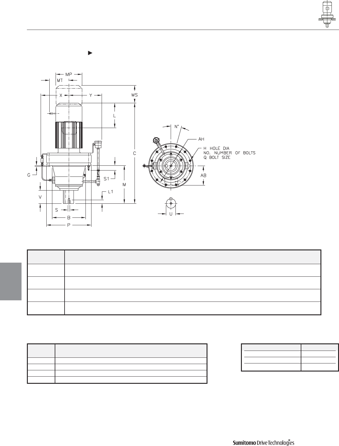
Model BCGH
NO.
MNPQS1AHXY
CVFM
6160/5Y 7.8734 16.26 0.39 0.55 6 8.74 30 11.81 M12 1.38 10.63 8.54 9.06
7.8723
6170/5Y 9.8419 18.78 0.47 0.55 8 10.31 22.5 13.39 M12 1.61 11.81 8.74 10.24
9.8408
6180/5Y 11.0230 20.75 0.47 0.55 8 11.77 22.5 14.57 M12 1.50 12.99 9.33 10.24
11.0217
6190/5Y 12.5977 24.41 0.39 0.55 12 14.37 15 16.93 M12 1.61 14.96 10.43 10.24
12.5963
CYCLO® 6000 Gearmotors
Dimensions Integral Vertical F-Flange Mount
Single Reduction
CVFM-6160/5Y 6190/5Y
4.54 Dimensions
Dimensions
Gearmotors
All dimensions are in inches
Model Low Speed Shaft
CVFM
U* V S L1 Key
6160/5Y 2.250 3.15 3/8-16UNC 0.71 1/2 X 1/2 X 2.95
6170/5Y 2.750 3.31 1/2-13UNC 0.94 5/8 X 5/8 X 3.15
6180/5Y 3.125 3.94 1/2-13UNC 0.94 3/4 X 3/4 X 3.74
6190/5Y 3.625 4.92 3/4-10UNC 1.34 7/8 X 7/8 X 4.92
Shaft Nominal Diameter (inches) Tolerances (inches)
1.250 (1 1/4) through 1.875 (1 7/8) +0.0000/-0.0006
2.000 (2) through 3.125 (3 1/8) +0.0000/-0.0007
3.250 (3 1/4) through 4.625 (4 5/8) +0.0000/-0.0009
*Shaft Tolerances
Dimensions shown are for reference only and are subject to change without notice, unless certified.
Certified prints are available after receipt of an order; consult factory.
Cyclo® 6000 Series
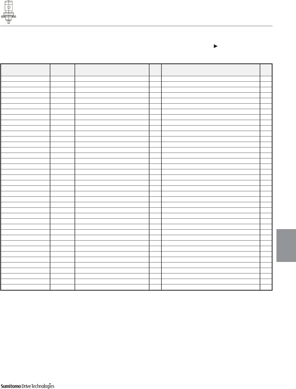
CYCLO® 6000 Gearmotors
Dimensions Integral Vertical F-Flange Mount
Single Reduction
CVFM-6160/5Y 6190/5Y (cont.)
Dimensions 4.55
Dimensions
Gearmotors
All dimensions are in inches
Model Motor Without Brake Appx With Brake Appx
HP Pole C AB L MP Wt (lb) C AB L MP MS MT Wt (lb)
CVFM2-6160/5Y 2 4 22.95 5.83 3.94 6.30 165 25.39 5.83 6.38 6.30 4.53 4.49 176
CVFM3-6160/5Y 3 4 23.54 6.10 4.13 6.81 172 26.02 6.10 6.61 6.81 4.76 4.88 185
CVFM5-6160/5Y 5 4 24.45 6.54 5.00 8.35 192 27.28 6.54 7.83 8.35 5.20 6.18 214
CVFM8-6160/5Y 7.5 4 26.18 6.54 5.00 8.35 207 29.02 6.54 7.83 8.35 5.20 6.18 229
CVFM10-6160/5Y 10 4 27.28 8.31 5.63 9.88 243 31.02 8.31 9.37 9.88 6.69 7.17 280
CVFM15-6160/5Y 15 4 29.65 8.31 5.63 9.88 273 33.39 8.31 9.37 9.88 6.69 7.17 311
CVFM20-6160/5Y 20 4 32.99 9.13 11.61 12.76 390 36.54 9.13 15.16 12.76 8.66 - 463
CVFM25-6160/5Y 25 4 36.73 11.69 13.39 15.51 549 45.00 11.69 21.65 15.51 14.45 - 662
CVFM30-6160/5Y 30 4 36.73 11.69 13.39 15.51 549 45.00 11.69 21.65 15.51 14.45 - 662
CVFM5-6170/5Y 5 4 26.77 6.54 5.00 8.35 260 29.61 6.54 7.83 8.35 5.20 6.18 282
CVFM8-6170/5Y 7.5 4 28.50 6.54 5.00 8.35 276 31.34 6.54 7.83 8.35 5.20 6.18 298
CVFM10-6170/5Y 10 4 29.21 8.31 5.63 9.88 309 32.95 8.31 9.37 9.88 6.69 7.17 348
CVFM15-6170/5Y 15 4 31.57 8.31 5.63 9.88 340 35.31 8.31 9.37 9.88 6.69 7.17 379
CVFM20-6170/5Y 20 4 34.72 9.13 11.61 12.76 459 38.27 9.13 15.16 12.76 8.66 - 531
CVFM25-6170/5Y 25 4 38.46 11.69 13.39 15.51 609 46.73 11.69 21.65 15.51 14.45 - 721
CVFM30-6170/5Y 30 4 38.46 11.69 13.39 15.51 609 46.73 11.69 21.65 15.51 14.45 - 721
CVFM40-6170/5Y 40 4 38.46 11.69 13.39 15.51 646 46.73 11.69 21.65 15.51 14.57 - 741
CVFM5-6180/5Y 5 4 28.23 6.54 5.00 8.35 326 31.06 6.54 7.83 8.35 5.20 6.18 348
CVFM8-6180/5Y 7.5 4 29.96 6.54 5.00 8.35 344 32.80 6.54 7.83 8.35 5.20 6.18 366
CVFM10-6180/5Y 10 4 30.67 8.31 5.63 9.88 377 34.41 8.31 9.37 9.88 6.69 7.17 417
CVFM15-6180/5Y 15 4 33.03 8.31 5.63 9.88 408 36.77 8.31 9.37 9.88 6.69 7.17 448
CVFM20-6180/5Y 20 4 36.18 9.13 11.61 12.76 540 39.72 9.13 15.16 12.76 8.66 - 602
CVFM25-6180/5Y 25 4 39.92 11.69 13.39 15.51 677 48.19 11.69 21.65 15.51 14.45 - 789
CVFM30-6180/5Y 30 4 39.92 11.69 13.39 15.51 677 48.19 11.69 21.65 15.51 14.45 - 789
CVFM40-6180/5Y 40 4 39.92 11.69 13.39 15.51 714 48.19 11.69 21.65 15.51 14.57 - 809
CVFM50-6180/5Y 50 4 44.45 11.69 16.93 15.51 820 52.91 11.69 25.39 15.51 17.52 - 1034
CVFM60-6180/5Y 60 4 44.45 11.69 16.93 15.51 820 52.91 11.69 25.39 15.51 17.52 - 1034
CVFM8-6190/5Y 7.5 4 33.74 6.54 5.00 8.35 476 36.57 6.54 7.83 8.35 5.20 6.18 498
CVFM10-6190/5Y 10 4 34.25 8.31 5.63 9.88 505 37.99 8.31 9.37 9.88 6.69 7.17 545
CVFM15-6190/5Y 15 4 36.61 8.31 5.63 9.88 536 40.35 8.31 9.37 9.88 6.69 7.17 576
CVFM20-6190/5Y 20 4 39.17 9.13 11.61 12.76 653 42.72 9.13 15.16 12.76 8.66 - 728
CVFM25-6190/5Y 25 4 42.91 11.69 13.39 15.51 811 51.18 11.69 21.65 15.51 14.45 - 911
CVFM256-6190/5Y 25 6 42.91 11.69 13.39 15.51 845 51.18 11.69 21.65 15.51 14.45 - 939
CVFM30-6190/5Y 30 4 42.91 11.69 13.39 15.51 811 51.18 11.69 21.65 15.51 14.45 - 911
CVFM40-6190/5Y 40 4 42.91 11.69 13.39 15.51 845 51.18 11.69 21.65 15.51 14.45 - 939
CVFM406-6190/5Y 40 6 47.44 11.69 16.93 15.51 928 55.91 11.69 25.39 15.51 17.52 - 1142
CVFM50-6190/5Y 50 4 47.44 11.69 16.93 15.51 928 55.91 11.69 25.39 15.51 17.52 - 1142
CVFM506-6190/5Y 50 6 47.44 11.69 16.93 15.51 928 55.91 11.69 25.39 15.51 17.52 - 1142
CVFM60-6190/5Y 60 4 47.44 11.69 16.93 15.51 928 55.91 11.69 25.39 15.51 17.52 - 1142
Dimensions shown are for reference only and are subject to change without notice, unless certified.
Certified prints are available after receipt of an order; consult factory.
Cyclo® 6000 Series
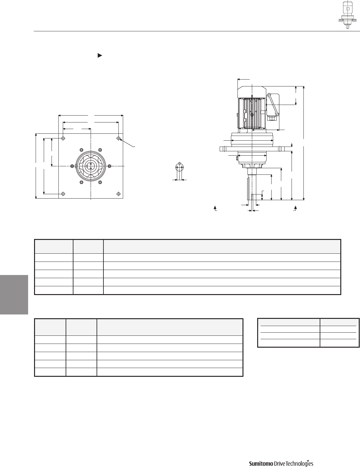
CYCLO® 6000 Gearmotors
Dimensions Integral Vertical F-Flange Mount, Overhead Drive
Single Reduction
CVFM-6130/5Y 6180/5Y
4.56 Dimensions
Dimensions
Gearmotors
Dimensions shown are for reference only and are subject to change without notice, unless certified.
Certified prints are available after receipt of an order; consult factory.
Cyclo® 6000 Series
All dimensions are in inches
Shaft Nominal Diameter (inches) Tolerances (inches)
1.250 (1 1/4) through 1.875 (1 7/8) +0.0000/-0.0006
2.000 (2) through 3.125 (3 1/8) +0.0000/-0.0007
3.250 (3 1/4) through 4.625 (4 5/8) +0.0000/-0.0009
*Shaft Tolerances
Model
CVFM
Model
DVX A B C F G H M P
6130/5Y 35DVX 12.50 6.14 16.02 10.50 0.88 0.56 9.50 9.06
6140/5Y 40DVX 14.00 6.14 17.15 12.00 1.00 0.69 10.50 9.06
6160/5Y 50DVX 16.00 7.68 18.22 14.00 0.98 0.81 10.50 11.81
6170/5Y 60DVX 19.50 9.45 24.56 17.00 1.57 0.94 15.50 13.39
6180/5Y 70DVX 22.00 12.99 26.03 19.00 1.75 1.12 15.50 14.57
Model
CVFM
Model
DVX
Low Speed Shaft
T U V V1 S L1 Key
6130/5Y 35DVX 0.38 1.6250 4.50 5.76 5/16-18UNC 1.00 3/8 X 3/8 X 3.70
6140/5Y 40DVX 0.50 1.6875 5.50 6.89 3/8-16UNC 1.00 3/8 X 3/8 X 4.69
6160/5Y 50DVX 0.75 2.1875 5.50 - 3/8-16UNC 1.00 1/2 X 1/2 X 5.24
6170/5Y 60DVX 0.75 2.4375 7.50 - 3/8-16UNC 1.00 5/8 X 5/8 X 6.50
6180/5Y 70DVX 1.00 2.9375 7.50 9.22 3/8-16UNC 1.00 3/4 X 3/4 X 6.50
VIEW Y-Y
AF
F/2
F/2
F
A
H (4 HOLES)
MP
L
AB
P
B
G
L1
US
VV1
M
C
YY
l
T T
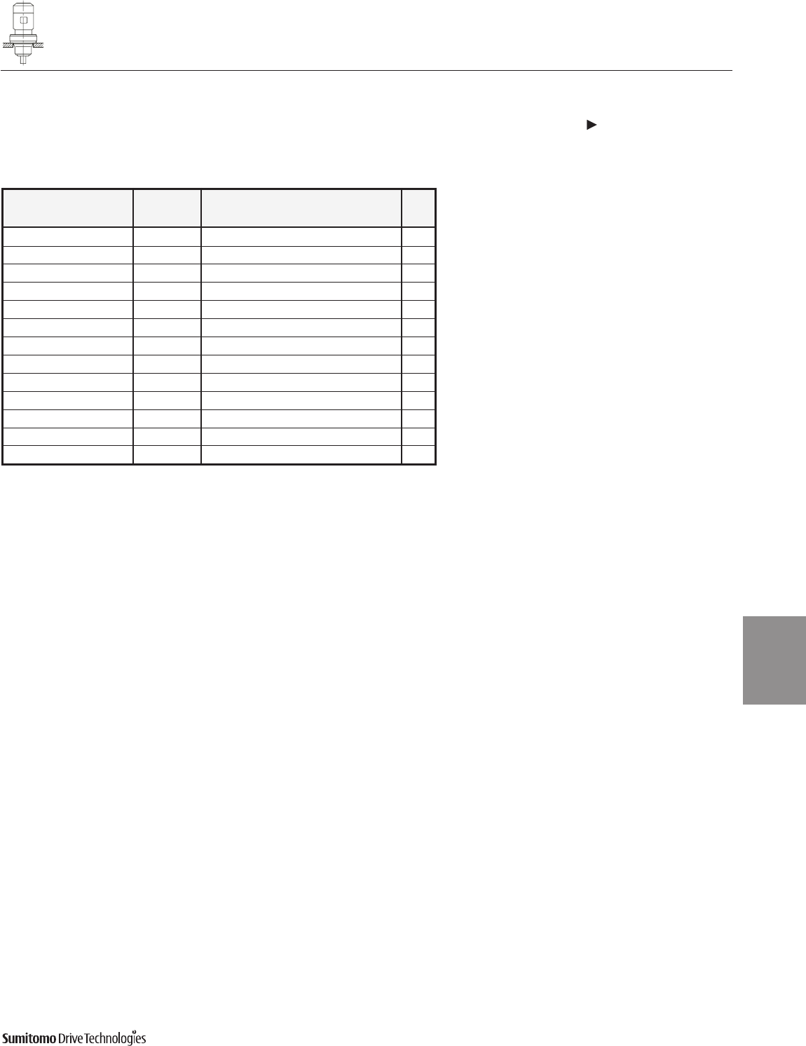
CYCLO® 6000 Gearmotors
Dimensions Integral Vertical F-Flange Mount, Overhead Drive
Single Reduction
CVFM-6130/5Y 6180/5 (cont.)
Dimensions 4.57
Dimensions
Gearmotors
Dimensions shown are for reference only and are subject to change without notice, unless certified.
Certified prints are available after receipt of an order; consult factory.
Cyclo®6000 Series
All dimensions are in inches
Model Motor Without Brake Appx
HP Pole C AB L MP Wt (lb)
CVFM1-6130/5Y 1 4 22.16 5.63 3.82 5.83 136
CVFM1H-6130/5Y 1.5 4 23.46 5.83 3.94 6.30 145
CVFM2-6130/5Y 2 4 23.46 5.83 3.94 6.30 145
CVFM1H-6140/5Y 1.5 4 24.59 5.83 3.94 6.30 163
CVFM2-6140/5Y 2 4 24.59 5.83 3.94 6.30 163
CVFM2-6160/5Y 2 4 24.91 5.83 3.94 6.30 238
CVFM3-6160/5Y 3 4 25.50 6.10 4.13 6.81 245
CVFM5-6160/5Y 5 4 26.41 6.54 5.00 8.35 265
CVFM5-6170/5Y 5 4 32.55 6.54 5.00 8.35 435
CVFM8-6170/5Y 7.5 4 34.28 6.54 5.00 8.35 451
CVFM5-6180/5Y 5 4 33.51 6.54 5.00 8.35 577
CVFM8-6180/5Y 7.5 4 35.24 6.54 5.00 8.35 595
CVFM10-6180/5Y 10 4 35.95 8.31 5.63 9.88 628
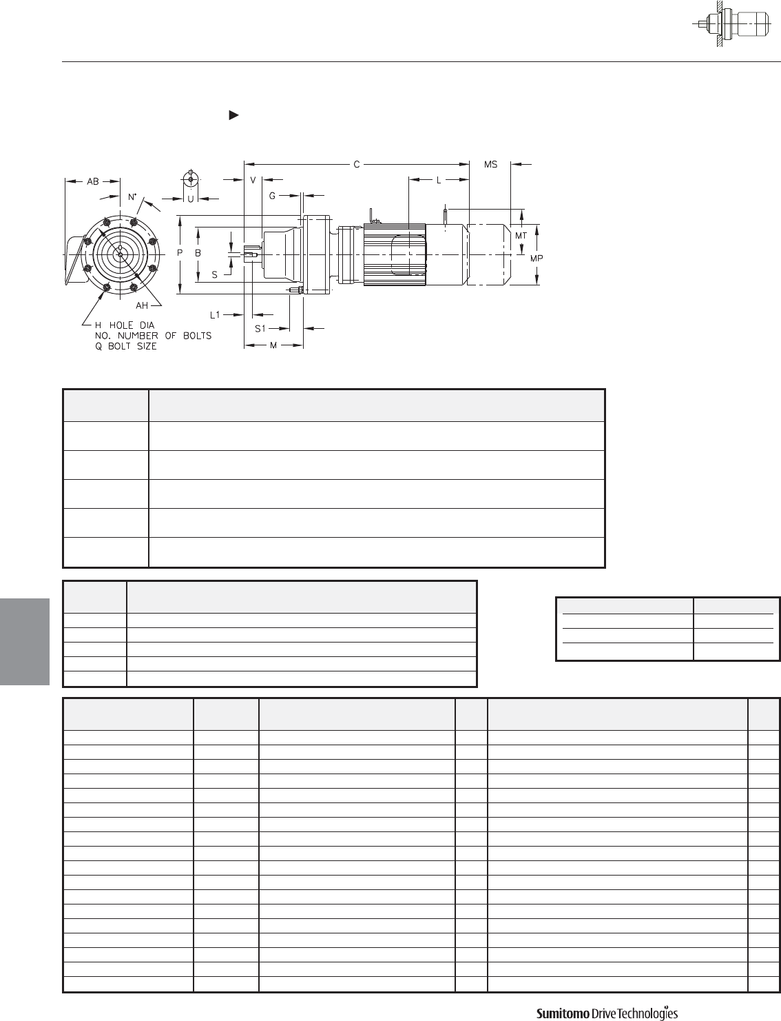
Model BGH
NO.
MN P QS1AH
CNFM
6060/5DAY 3.1492 0.16 0.26 6 2.68 60 4.33 M6 0.83 3.86
3.1485
6070/5DAY 3.1492 0.16 0.26 6 2.91 60 4.33 M6 0.83 3.86
3.1485
6090/5DAY 4.1334 0.24 0.35 8 4.49 22.5 5.91 M8 1.14 5.28
4.1325
6100/5DAY 4.1334 0.24 0.35 8 4.49 22.5 5.91 M8 1.10 5.28
4.1325
6120/5DBY 5.5113 0.55 0.43 6 5.47 60 8.03 M10 1.30 7.09
5.5103
Model Motor Without Brake Appx With Brake Appx
HP Pole C AB L MP Wt (lb) C AB L MP MS MT Wt (lb)
CNFM01-6060/5DAY 1/8 4 10.20 5.04 1.38 4.69 15 11.57 5.04 4.88 4.88 - 0.33 19
CNFM01-6070/5DAY 1/8 4 10.43 5.04 1.38 4.69 18 11.81 5.04 4.88 4.88 - 0.37 21
CNFM02-6070/5DAY 1/4 4 12.09 5.04 2.32 4.88 20 13.35 5.04 4.88 4.88 - 0.43 24
CNFM01-6090/5DAY 1/8 4 12.76 5.04 1.38 4.69 29 14.13 5.04 4.88 4.88 - 0.55 31
CNFM02-6090/5DAY 1/4 4 14.41 5.04 2.32 4.88 31 15.67 5.04 4.88 4.88 - 0.59 33
CNFM03-6090/5DAY 1/3 4 14.41 5.04 2.32 4.88 31 15.67 5.04 4.88 4.88 - 0.59 33
CNFM05-6090/5DAY 1/2 4 15.20 5.04 2.32 4.88 33 16.46 5.04 4.88 4.88 - 0.63 35
CNFM01-6100/5DAY 1/8 4 13.31 5.04 1.38 4.69 31 14.69 5.04 4.88 4.88 - 0.59 33
CNFM02-6100/5DAY 1/4 4 14.96 5.04 2.32 4.88 33 16.22 5.04 4.88 4.88 - 0.63 35
CNFM03-6100/5DAY 1/3 4 14.96 5.04 2.32 4.88 33 16.22 5.04 4.88 4.88 - 0.63 35
CNFM05-6100/5DAY 1/2 4 15.75 5.04 2.32 4.88 35 17.01 5.04 4.88 4.88 - 0.67 37
CNFM01-6120/5DBY 1/8 4 15.20 5.04 1.38 4.69 62 16.57 5.04 4.88 4.88 - 1.18 66
CNFM03-6120/5DBY 1/3 4 16.85 5.04 2.32 4.88 64 18.62 5.04 4.88 4.88 - 1.22 68
CNFM05-6120/5DBY 1/2 4 17.64 5.04 2.32 4.88 66 18.62 5.04 4.88 4.88 - 1.26 71
CNFM08-6120/5DBY 3/4 4 19.25 5.63 3.82 5.83 75 20.94 5.63 5.83 5.83 4.17 1.46 82
CNFM1-6120/5DBY 1 4 19.25 5.63 3.82 5.83 75 20.94 5.63 5.83 5.83 4.17 1.46 82
CNFM1H-6120/5DBY 1.5 4 20.31 5.83 3.94 6.30 84 22.76 5.83 6.30 6.30 4.49 1.69 95
CNFM2-6120/5DBY 2 4 20.31 5.83 3.94 6.30 84 22.76 5.83 6.30 6.30 4.49 1.69 95
CYCLO® 6000 Gearmotors
Dimensions Integral F-Flange Mount
Double Reduction
CNFM-6060/5DAY 6120/5DBY
4.58 Dimensions
Dimensions
Gearmotors
All dimensions are in inches
Model Low Speed Shaft
CNFM
U* V S L1 Key
6060/5DAY 0.500 0.98 0.63 10-32UNF 1/8 X 1/8 X .79
6070/5DAY 0.750 1.18 0.63 12-28UNF 3/16 X 3/16 X 1.06
6090/5DAY 1.125 1.38 0.79 5/16-18UNC 1/4 X 1/4 X 1.18
6100/5DAY 1.125 1.38 0.79 5/16-18UNC 1/4 X 1/4 X 1.18
6120/5DBY 1.500 2.17 0.79 5/16-18UNC 3/8 X 3/8 X 1.77
Shaft Nominal Diameter (inches) Tolerances (inches)
0.500 (1/2) through 0.625 (5/8) +0.0000/-0.0004
0.750 (3/4) through 1.125 (1 1/8) +0.0000/-0.0005
1.250 (1 1/4) through 1.875 (1 7/8) +0.0000/-0.0006
*Shaft Tolerances
Dimensions shown are for reference only and are subject to change without notice, unless certified.
Certified prints are available after receipt of an order; consult factory.
Cyclo® 6000 Series
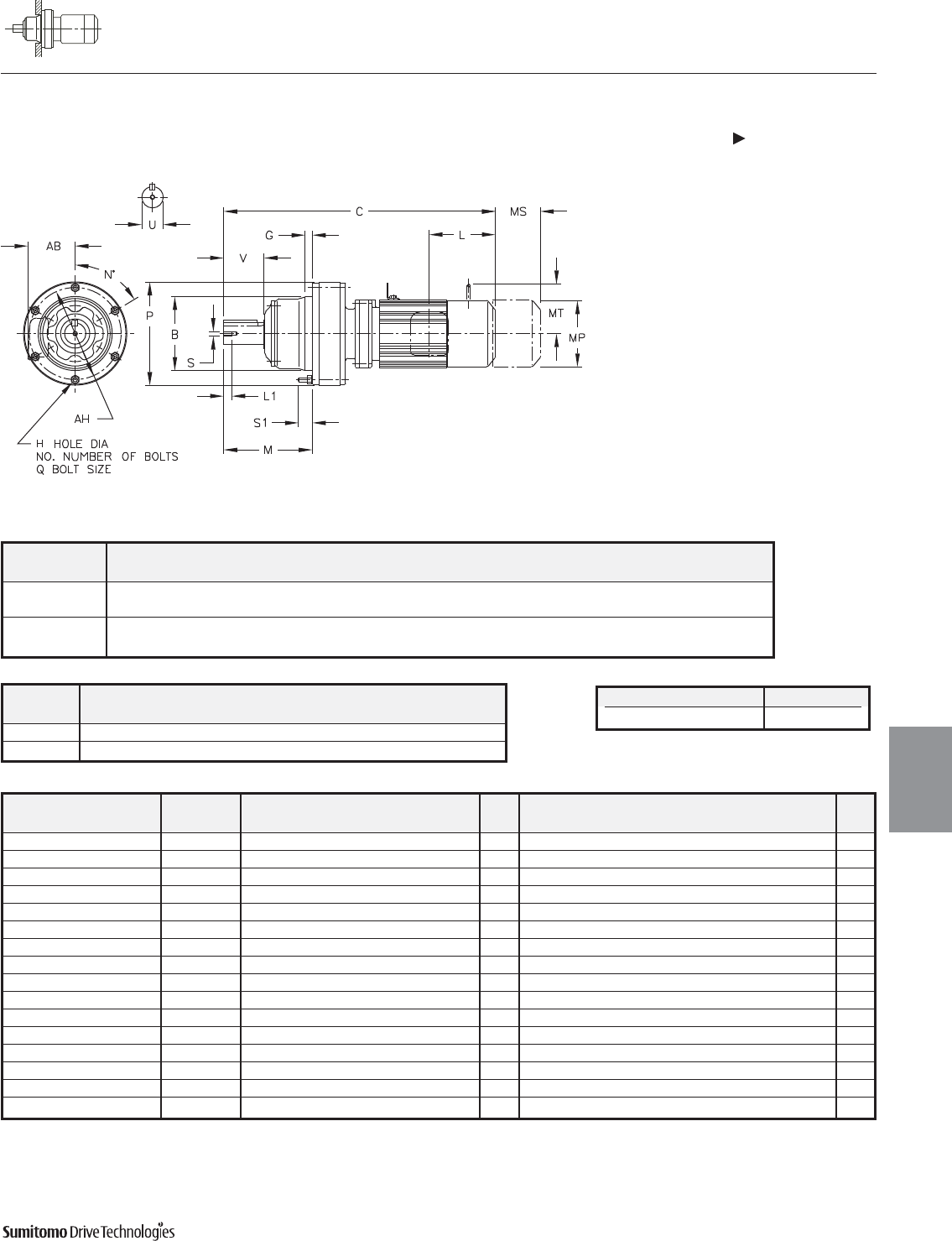
CYCLO® 6000 Gearmotors
Dimensions Integral F-Flange Mount
Double Reduction
CHFM-6130/5DCY 6140/5DBY
Dimensions 4.59
Dimensions
Gearmotors
All dimensions are in inches
Model BCGH
NO.
MNOPQS1AH
CHFM
6130/5DCY 6.4955 14.53 0.63 0.43 6 7.01 60 5.91 9.06 M10 1.22 8.07
6.4945
6140/5DBY 6.4955 15.08 0.63 0.43 6 7.80 60 5.91 9.06 M10 1.22 8.07
6.4945
Model Motor Without Brake Appx With Brake Appx
HP Pole C AB L MP Wt (lb) C AB L MP MS MT Wt (lb)
CHFM02-6130/5DCY 1/4 4 19.41 5.04 2.32 4.88 95 20.67 5.04 3.58 4.88 2.40 - 99
CHFM03-6130/5DCY 1/3 4 19.41 5.04 2.32 4.88 95 20.67 5.04 3.58 4.88 2.40 - 99
CHFM05-6130/5DCY 1/2 4 20.20 5.04 2.32 4.88 97 21.46 5.04 3.58 4.88 2.40 - 101
CHFM08-6130/5DCY 3/4 4 21.81 5.63 3.82 5.83 106 23.50 5.63 5.51 5.83 3.66 4.17 112
CHFM1-6130/5DCY 1 4 21.81 5.63 3.82 5.83 106 23.50 5.63 5.51 5.83 3.66 4.17 112
CHFM1H-6130/5DCY 1.5 4 23.11 5.83 3.94 6.30 115 25.55 5.83 6.38 6.30 4.53 4.49 126
CHFM2-6130/5DCY 2 4 23.11 5.83 3.94 6.30 115 25.55 5.83 6.38 6.30 4.53 4.49 126
CHFM3-6130/5DCY 3 4 23.90 6.10 4.13 6.81 123 26.38 6.10 6.61 6.81 4.76 4.88 137
CHFM01-6140/5DBY 1/8 4 17.99 5.04 1.38 4.69 88 19.37 5.04 2.76 4.88 1.93 - 93
CHFM02-6140/5DBY 1/4 4 19.65 5.04 2.32 4.88 90 20.91 5.04 3.58 4.88 2.40 - 95
CHFM03-6140/5DBY 1/3 4 19.65 5.04 2.32 4.88 90 20.91 5.04 3.58 4.88 2.40 - 95
CHFM05-6140/5DBY 1/2 4 20.43 5.04 2.32 4.88 93 21.69 5.04 3.58 4.88 2.40 - 101
CHFM08-6140/5DBY 3/4 4 22.05 5.63 3.82 5.83 101 23.74 5.63 5.51 5.83 3.66 4.17 108
CHFM1-6140/5DBY 1 4 22.05 5.63 3.82 5.83 101 23.74 5.63 5.51 5.83 3.66 4.17 108
CHFM1H-6140/5DBY 1.5 4 23.35 5.83 3.94 6.30 110 25.79 5.83 6.38 6.30 4.53 4.49 117
CHFM2-6140/5DBY 2 4 23.35 5.83 3.94 6.30 110 25.79 5.83 6.38 6.30 4.53 4.49 117
Dimensions shown are for reference only and are subject to change without notice, unless certified.
Certified prints are available after receipt of an order; consult factory.
Cyclo® 6000 Series
Model Low Speed Shaft
CHFM
U* V S L1 Key
6130/5DCY 1.875 2.76 0.71 3/8-16UNC 1/2 X 1/2 X 2.16
6140/5DBY 1.875 3.54 0.71 3/8-16UNC 1/2 X 1/2 X 2.95
Shaft Nominal Diameter (inches) Tolerances (inches)
1.250 (1 1/4) through 1.875 (1 7/8) +0.0000/-0.0006
*Shaft Tolerances
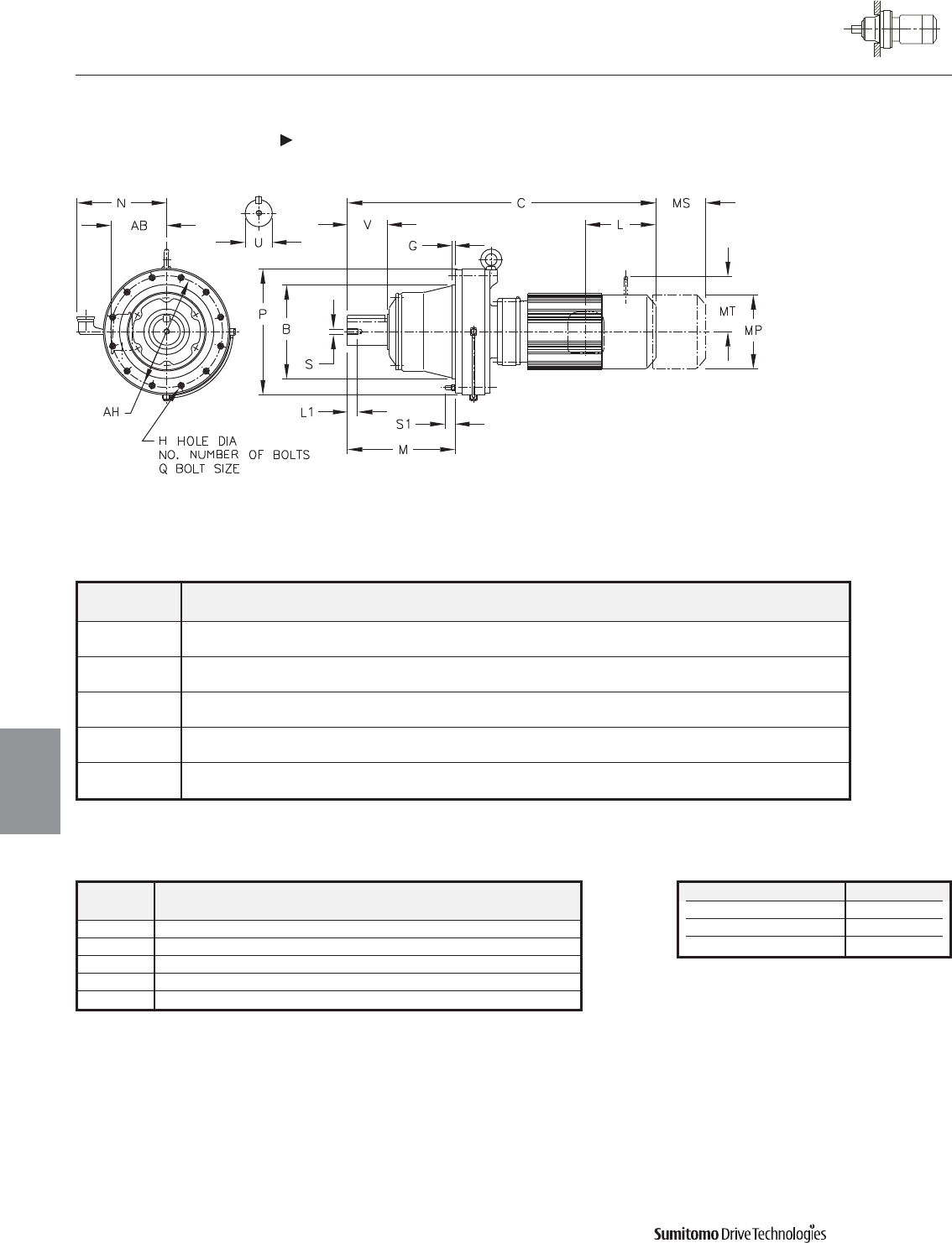
Model BGH
NO.
MN O P QS1AHX
CHFM
6160/5DCY 7.8734 0.39 0.55 6 8.74 30 7.44 11.81 M12 1.38 10.63 8.98
7.8723
6170/5DCY 9.8419 0.47 0.55 8 10.31 22.5 8.50 13.39 M12 1.61 11.81 9.57
9.8408
6180/5DBY 11.0230 0.47 0.55 8 11.77 22.5 9.09 14.57 M12 1.50 12.99 10.16
11.0217
6190/5DAY 12.5977 0.39 0.55 12 14.37 15 11.06 16.93 M12 1.61 14.96 11.22
12.5963
6190/5DBY 12.5977 0.39 0.55 12 14.37 15 11.06 16.93 M12 1.61 14.96 11.22
12.5963
CYCLO® 6000 Gearmotors
Dimensions Integral F-Flange Mount
Double Reduction
CHFM-6160/5DCY 6190/5DBY
4.60 Dimensions
Dimensions
Gearmotors
All dimensions are in inches
Model Low Speed Shaft
CHFM
U* V S L1 Key
6160/5DCY 2.250 3.54 3/8-16UNC 0.71 1/2 X 1/2 X 2.95
6170/5DCY 2.750 3.54 1/2-13UNC 0.94 5/8 X 5/8 X 3.15
6180/5DBY 3.125 4.33 1/2-13UNC 0.94 3/4 X 3/4 X 3.74
6190/5DAY 3.625 5.31 3/4-10UNC 1.34 7/8 X 7/8 X 4.92
6190/5DBY 3.625 5.31 3/4-10UNC 1.34 7/8 X 7/8 X 4.92
Shaft Nominal Diameter (inches) Tolerances (inches)
2.000 (2) through 3.125 (3 1/8) +0.0000/-0.0007
3.250 (3 1/4) through 4.625 (4 5/8) +0.0000/-0.0009
4.750 (4 3/4) through 7.000 (7) +0.0000/-0.0010
*Shaft Tolerances
Dimensions shown are for reference only and are subject to change without notice, unless certified.
Certified prints are available after receipt of an order; consult factory.
Cyclo® 6000 Series
CYCLO® 6000 Gearmotors
Dimensions Integral F-Flange Mount
Double Reduction
CHFM-6160/5DCY 6190/5DBY (cont.)
Dimensions 4.61
Dimensions
Gearmotors
All dimensions are in inches
Model Motor Without Brake Appx With Brake Appx
HP Pole C AB L MP Wt (lb) C AB L MP MS MT Wt (lb)
CHFM05-6160/5DCY 1/2 4 23.07 5.04 2.32 4.88 176 24.49 5.04 3.58 4.88 2.40 - 181
CHFM08-6160/5DCY 3/4 4 24.65 5.63 3.82 5.83 185 26.34 5.63 5.51 5.83 3.66 4.17 192
CHFM1-6160/5DCY 1 4 24.65 5.63 3.82 5.83 185 26.34 5.63 5.51 5.83 3.66 4.17 192
CHFM1H-6160/5DCY 1.5 4 25.94 5.83 3.94 6.30 194 28.39 5.83 6.38 6.30 4.53 4.49 205
CHFM2-6160/5DCY 2 4 25.94 5.83 3.94 6.30 194 28.39 5.83 6.38 6.30 4.53 4.49 205
CHFM3-6160/5DCY 3 4 26.73 6.10 2.32 6.81 203 29.21 6.10 3.58 6.81 2.40 - 218
CHFM5-6160/5DCY 5 4 27.64 6.54 5.00 8.35 225 30.47 6.54 7.83 8.35 5.20 6.18 247
CHFM8-6160/5DCY 7.5 4 29.37 6.54 5.00 8.35 240 32.20 6.54 7.83 8.35 5.20 6.18 262
CHFM05-6170/5DCY 1/2 4 24.92 5.04 2.32 4.88 229 26.34 5.04 3.58 4.88 2.40 - 234
CHFM08-6170/5DCY 3/4 4 26.50 5.63 3.82 5.83 238 28.19 5.63 5.51 5.83 3.66 4.17 245
CHFM1-6170/5DCY 1 4 26.50 5.63 3.82 5.83 238 28.19 5.63 5.51 5.83 3.66 4.17 245
CHFM1H-6170/5DCY 1.5 4 27.80 5.83 3.94 6.30 247 30.24 5.83 6.38 6.30 4.53 4.49 258
CHFM2-6170/5DCY 2 4 27.80 5.83 3.94 6.30 247 30.24 5.83 6.38 6.30 4.53 4.49 258
CHFM3-6170/5DCY 3 4 28.58 6.10 2.32 6.81 256 31.06 6.10 3.58 6.81 2.40 - 271
CHFM5-6170/5DCY 5 4 29.49 6.54 5.00 8.35 278 32.32 6.54 7.83 8.35 5.20 6.18 300
CHFM8-6170/5DCY 7.5 4 31.22 6.54 5.00 8.35 293 34.06 6.54 7.83 8.35 5.20 6.18 315
CHFM1-6180/5DBY 1 4 28.86 5.63 3.82 5.83 340 30.55 5.63 5.51 5.83 3.66 4.17 346
CHFM1H-6180/5DBY 1.5 4 30.16 5.83 3.94 6.30 348 32.60 5.83 6.38 6.30 4.53 4.49 359
CHFM2-6180/5DBY 2 4 30.16 5.83 3.94 6.30 348 32.60 5.83 6.38 6.30 4.53 4.49 359
CHFM3-6180/5DBY 3 4 30.94 6.10 2.32 6.81 355 33.43 6.10 3.58 6.81 2.40 - 370
CHFM5-6180/5DBY 5 4 31.85 6.54 5.00 8.35 377 34.69 6.54 7.83 8.35 5.20 6.18 399
CHFM8-6180/5DBY 7.5 4 33.58 6.54 5.00 8.35 392 36.42 6.54 7.83 8.35 5.20 6.18 415
CHFM10-6180/5DBY 10 4 34.49 8.31 5.63 9.88 426 38.23 8.31 9.37 9.88 6.69 7.17 465
CHFM15-6180/5DBY 15 4 36.85 8.31 5.63 9.88 456 40.59 8.31 9.37 9.88 6.69 7.17 496
CHFM1-6190/5DAY 1 4 31.22 5.63 3.82 5.83 441 32.91 5.63 5.51 5.83 3.66 4.17 448
CHFM1H-6190/5DAY 1.5 4 32.52 5.83 3.94 6.30 450 34.96 5.83 6.38 6.30 4.53 4.49 461
CHFM2-6190/5DAY 2 4 32.52 5.83 3.94 6.30 450 34.96 5.83 6.38 6.30 4.53 4.49 461
CHFM3-6190/5DAY 3 4 33.31 6.10 2.32 6.81 459 35.79 6.10 3.58 6.81 2.40 - 474
CHFM5-6190/5DAY 5 4 34.21 6.54 5.00 8.35 481 37.05 6.54 7.83 8.35 5.20 6.18 503
CHFM8-6190/5DAY 7.5 4 35.94 6.54 5.00 8.35 496 38.78 6.54 7.83 8.35 5.20 6.18 518
CHFM5-6190/5DBY 5 4 34.84 6.54 5.00 8.35 496 37.68 6.54 7.83 8.35 5.20 6.18 518
CHFM8-6190/5DBY 7.5 4 36.57 6.54 5.00 8.35 512 39.41 6.54 7.83 8.35 5.20 6.18 534
CHFM10-6190/5DBY 10 4 37.48 8.31 5.63 9.88 545 41.22 8.31 9.37 9.88 6.69 7.17 584
CHFM15-6190/5DBY 15 4 39.84 8.31 5.63 9.88 576 43.58 8.31 9.37 9.88 6.69 7.17 615
CHFM20-6190/5DBY 20 4 43.39 9.13 11.61 12.76 690 46.93 9.13 15.16 12.76 8.66 - 763
Dimensions shown are for reference only and are subject to change without notice, unless certified.
Certified prints are available after receipt of an order; consult factory.
Cyclo® 6000 Series
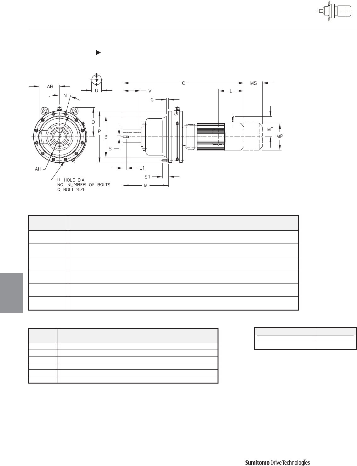
Model BGH
NO.
MN O P QS1AH
CHFM
6205DAY 14.1725 0.79 0.71 12 16.14 15 11.14 17.64 M16 2.20 15.94
14.1711
6205DBY 14.1725 0.79 0.71 12 16.14 15 11.14 17.64 M16 2.20 15.94
14.1711
6215DAY 15.3536 0.79 0.81 12 16.65 15 12.28 19.09 M18 2.20 17.32
15.3522
6215DBY 15.3536 0.79 0.81 12 16.65 15 12.28 19.09 M18 2.20 17.32
15.3522
6225DAY 16.5346 0.79 0.87 12 17.87 15 13.11 20.71 M20 2.52 18.70
16.5331
6225DBY 16.5346 0.79 0.87 12 17.87 15 13.11 20.71 M20 2.52 18.70
16.5331
CYCLO® 6000 Gearmotors
Dimensions Integral F-Flange Mount
Double Reduction
CHFM-6205DAY 6225DBY
4.62 Dimensions
Dimensions
Gearmotors
All dimensions are in inches
Model Low Speed Shaft
CHFM
U* V S L1 Key
6205DAY 3.875 6.50 3/4-10UNC 1.34 1 X 1 X 6.50
6205DBY 3.875 6.50 3/4-10UNC 1.34 1 X 1 X 6.50
6215DAY 4.250 6.50 3/4-10UNC 1.34 1 X 1 X 6.50
6215DBY 4.250 6.50 3/4-10UNC 1.34 1 X 1 X 6.50
6225DAY 4.625 6.50 3/4-10UNC 1.34 1-1/4 X 7/8 X 6.50
6225DBY 4.625 6.50 3/4-10UNC 1.34 1-1/4 X 7/8 X 6.50
Shaft Nominal Diameter (inches) Tolerances (inches)
3.250 (3 1/4) through 4.625 (4 5/8) +0.0000/-0.0009
4.750 (4 3/4) through 7.000 (7) +0.0000/-0.0010
*Shaft Tolerances
Dimensions shown are for reference only and are subject to change without notice, unless certified.
Certified prints are available after receipt of an order; consult factory.
Cyclo® 6000 Series

CYCLO® 6000 Gearmotors
Dimensions Integral F-Flange Mount
Double Reduction
CHFM-6205DAY 6225DBY (cont.)
Dimensions 4.63
Dimensions
Gearmotors
All dimensions are in inches
Model Motor Without Brake Appx With Brake Appx
HP Pole C AB L MP Wt (lb) C AB L MP MS MT Wt (lb)
CHFM1-6205DAY 1 4 32.83 5.63 3.82 5.83 494 34.53 5.63 5.51 5.83 3.66 4.17 501
CHFM2-6205DAY 2 4 34.13 5.83 3.94 6.30 503 36.57 5.83 6.38 6.30 4.53 4.49 514
CHFM3-6205DAY 3 4 34.92 6.10 2.32 6.81 512 37.36 6.10 3.58 6.81 2.40 - 527
CHFM5-6205DAY 5 4 35.83 6.54 5.00 8.35 534 38.66 6.54 7.83 8.35 5.20 6.18 556
CHFM8-6205DAY 7.5 4 37.56 6.54 5.00 8.35 549 40.39 6.54 7.83 8.35 5.20 6.18 571
CHFM3-6205DB 3 4 35.98 6.10 2.32 6.81 538 38.46 6.10 3.58 6.81 2.40 - 553
CHFM5-6205DB 5 4 36.89 6.54 5.00 8.35 560 39.72 6.54 7.83 8.35 5.20 6.18 582
CHFM8-6205DB 7.5 4 38.62 6.54 5.00 8.35 576 41.46 6.54 7.83 8.35 5.20 6.18 598
CHFM10-6205DB 10 4 39.53 8.31 5.63 9.88 609 43.27 8.31 9.37 9.88 6.69 7.17 648
CHFM15-6205DB 15 4 41.89 8.31 5.63 9.88 637 45.63 8.31 9.37 9.88 6.69 7.17 677
CHFM20-6205DB 20 4 45.43 9.13 11.61 12.76 752 48.58 9.13 15.16 12.76 8.66 - 822
CHFM2-6215DAY 2 4 36.22 5.83 3.94 6.30 706 38.66 5.83 6.38 6.30 4.53 4.49 717
CHFM3-6215DAY 3 4 37.01 6.10 2.32 6.81 712 39.49 6.10 3.58 6.81 2.40 - 728
CHFM5-6215DAY 5 4 37.91 6.54 5.00 8.35 734 40.75 6.54 7.83 8.35 5.20 6.18 756
CHFM8-6215DAY 7.5 4 39.65 6.54 5.00 8.35 750 42.48 6.54 7.83 8.35 5.20 6.18 772
CHFM10-6215DAY 10 4 40.55 8.31 5.63 9.88 783 44.29 8.31 9.37 9.88 6.69 7.17 822
CHFM15-6215DAY 15 4 42.91 8.31 5.63 9.88 811 46.65 8.31 9.37 9.88 6.69 7.17 851
CHFM20-6215DAY 20 4 46.46 9.13 11.61 12.76 926 50.00 9.13 15.16 12.76 8.66 - 999
CHFM10-6215DBY 10 4 41.73 8.31 5.63 9.88 827 45.47 8.31 9.37 9.88 6.69 7.17 864
CHFM15-6215DBY 15 4 44.09 8.31 5.63 9.88 858 47.83 8.31 9.37 9.88 6.69 7.17 895
CHFM20-6215DBY 20 4 47.44 9.13 11.61 12.76 975 50.98 9.13 15.16 12.76 8.66 - 1047
CHFM25-6215DBY 25 4 51.18 11.69 13.39 15.51 1131 59.45 11.69 21.65 15.51 14.45 - 1244
CHFM30-6215DBY 30 4 51.18 11.69 13.39 15.51 1131 59.45 11.69 21.65 15.51 14.45 - 1244
CHFM2-6225DAY 2 4 37.87 5.83 3.94 6.30 831 40.31 5.83 6.38 6.30 4.53 4.49 842
CHFM3-6225DAY 3 4 38.66 6.10 2.32 6.81 838 41.14 6.10 3.58 6.81 2.40 - 853
CHFM5-6225DAY 5 4 39.57 6.54 5.00 8.35 860 42.40 6.54 7.83 8.35 5.20 6.18 882
CHFM8-6225DAY 7.5 4 41.30 6.54 5.00 8.35 875 44.13 6.54 7.83 8.35 5.20 6.18 897
CHFM10-6225DAY 10 4 42.20 8.31 5.63 9.88 908 45.94 8.31 9.37 9.88 6.69 7.17 948
CHFM15-6225DAY 15 4 44.57 8.31 5.63 9.88 939 48.31 8.31 9.37 9.88 6.69 7.17 979
CHFM20-6225DAY 20 4 48.11 9.13 11.61 12.76 1054 51.65 9.13 15.16 12.76 8.66 - 1127
CHFM10-6225DBY 10 4 44.29 8.31 5.63 9.88 1008 48.03 8.31 9.37 9.88 6.69 7.17 1047
CHFM15-6225DBY 15 4 46.65 8.31 5.63 9.88 1039 50.39 8.31 9.37 9.88 6.69 7.17 1078
CHFM20-6225DBY 20 4 49.80 9.13 11.61 12.76 1158 53.35 9.13 15.16 12.76 8.66 - 1230
CHFM25-6225DBY 25 4 53.54 11.69 13.39 15.51 1308 61.81 11.69 21.65 15.51 14.45 - 1420
CHFM30-6225DBY 30 4 53.54 11.69 13.39 15.51 1308 61.81 11.69 21.65 15.51 14.45 - 1420
CHFM40-6225DBY 40 4 53.54 11.69 13.39 15.51 1345 61.81 11.69 21.65 15.51 14.57 - 1458
Dimensions shown are for reference only and are subject to change without notice, unless certified.
Certified prints are available after receipt of an order; consult factory.
Cyclo® 6000 Series
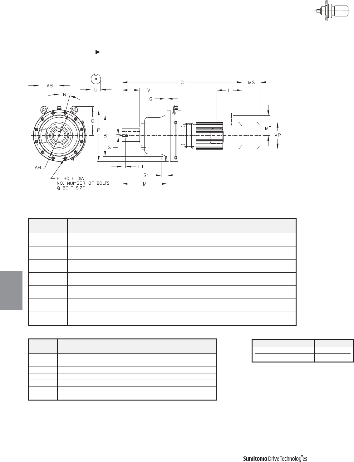
Model BGH
NO.
MN O P QS1AH
CHFM
6235DAY 17.9126 0.79 0.87 12 19.88 15 13.82 22.17 M20 2.56 20.08
17.9110
6235DBY 17.9126 0.79 0.87 12 19.88 15 13.82 22.13 M20 2.56 20.08
17.9110
6245DAY 19.6843 0.98 1.06 12 20.83 15 15.55 24.17 M24 2.56 22.05
19.6827
6245DBY 19.6843 0.98 1.06 12 20.83 15 15.55 24.17 M24 2.56 22.05
19.6827
6255DAY 21.2590 1.18 1.06 12 24.25 15 15.20 26.38 M24 3.58 24.02
21.2572
6255DBY 21.2590 1.18 1.06 12 24.25 15 15.20 26.38 M24 3.58 24.02
21.2572
6265DAY 22.4401 1.57 1.34 12 28.03 15 17.83 28.98 M30 3.35 25.98
22.4383
CYCLO® 6000 Gearmotors
Dimensions Integral F-Flange Mount
Double Reduction
CHFM-6235DAY 6265DAY
4.64 Dimensions
Dimensions
Gearmotors
All dimensions are in inches
Model Low Speed Shaft
CHFM
U* V S L1 Key
6235DAY 5.000 7.87 1-8UNC 1.61 1-1/4 X 7/8 X 7.87
6235DBY 5.000 7.87 1-8UNC 1.61 1-1/4 X 7/8 X 7.87
6245DAY 5.500 7.87 1-8UNC 1.61 1-1/4 X 7/8 X 7.87
6245DBY 5.500 7.87 1-8UNC 1.61 1-1/4 X 7/8 X 7.87
6255DAY 6.250 9.45 1-1/4-7UNC 1.93 1-1/2 X 1 X 9.45
6255DBY 6.250 9.45 1-1/4-7UNC 1.93 1-1/2 X 1 X 9.45
6265DAY 6.625 11.81 1-1/4-7UNC 1.93 1-3/4 X 1-1/4 X 11.81
Shaft Nominal Diameter (inches) Tolerances (inches)
3.250 (3 1/4) through 4.625 (4 5/8) +0.0000/-0.0009
4.750 (4 3/4) through 7.000 (7) +0.0000/-0.0010
*Shaft Tolerances
Dimensions shown are for reference only and are subject to change without notice, unless certified.
Certified prints are available after receipt of an order; consult factory.
Cyclo® 6000 Series

CYCLO® 6000 Gearmotors
Dimensions Integral F-Flange Mount
Double Reduction
CHFM-6235DAY 6265DAY (cont.)
Dimensions 4.65
Dimensions
Gearmotors
All dimensions are in inches
Dimensions shown are for reference only and are subject to change without notice, unless certified.
Certified prints are available after receipt of an order; consult factory.
Cyclo® 6000 Series
Model Motor Without Brake Appx With Brake Appx
HP Pole C AB L MP Wt (lb) C AB L MP MS MT Wt (lb)
CHFM3-6235DAY 3 4 42.05 6.10 2.32 6.81 1067 44.53 6.10 3.58 6.81 2.40 - 1080
CHFM5-6235DAY 5 4 42.95 6.54 5.00 8.35 1087 45.79 6.54 7.83 8.35 5.20 6.18 1109
CHFM8-6235DAY 7.5 4 44.69 6.54 5.00 8.35 1103 47.52 6.54 7.83 8.35 5.20 6.18 1125
CHFM10-6235DAY 10 4 45.79 8.31 5.63 9.88 1138 49.53 8.31 9.37 9.88 6.69 7.17 1175
CHFM15-6235DAY 15 4 48.15 8.31 5.63 9.88 1169 51.89 8.31 9.37 9.88 6.69 7.17 1206
CHFM20-6235DAY 20 4 51.50 9.13 11.61 12.76 1286 55.04 9.13 15.16 12.76 8.66 - 1358
CHFM25-6235DAY 25 4 55.24 11.69 13.39 15.51 1446 63.50 11.69 21.65 15.51 14.45 - 1559
CHFM30-6235DAY 30 4 55.24 11.69 13.39 15.51 1446 63.50 11.69 21.65 15.51 14.45 - 1559
CHFM40-6235DBY 40 4 56.10 11.69 13.39 15.51 1555 64.37 11.69 21.65 15.51 14.57 - 1649
CHFM50-6235DBY 50 4 60.63 11.69 16.93 15.51 1638 69.09 11.69 25.39 15.51 17.52 - 1852
CHFM3-6245DAY 3 4 43.54 6.10 2.32 6.81 1305 46.02 6.10 3.58 6.81 2.40 - 1319
CHFM5-6245DAY 5 4 44.45 6.54 5.00 8.35 1325 47.28 6.54 7.83 8.35 5.20 6.18 1347
CHFM8-6245DAY 7.5 4 46.18 6.54 5.00 8.35 1341 49.02 6.54 7.83 8.35 5.20 6.18 1363
CHFM10-6245DAY 10 4 47.28 8.31 5.63 9.88 1376 51.02 8.31 9.37 9.88 6.69 7.17 1413
CHFM15-6245DAY 15 4 49.65 8.31 5.63 9.88 1407 53.39 8.31 9.37 9.88 6.69 7.17 1444
CHFM20-6245DAY 20 4 52.99 9.13 11.61 12.76 1524 56.54 9.13 15.16 12.76 8.66 - 1596
CHFM25-6245DAY 25 4 56.73 11.69 13.39 15.51 1671 65.00 11.69 21.65 15.51 14.45 - 1784
CHFM30-6245DAY 30 4 56.73 11.69 13.39 15.51 1671 65.00 11.69 21.65 15.51 14.45 - 1784
CHFM20-6245DBY 20 4 53.82 9.13 11.61 12.76 1592 57.36 9.13 15.16 12.76 8.66 - 1654
CHFM30-6245DBY 30 4 57.56 11.69 13.39 15.51 1729 65.83 11.69 21.65 15.51 14.45 - 1841
CHFM40-6245DBY 40 4 57.56 11.69 13.39 15.51 1766 65.83 11.69 21.65 15.51 14.57 - 1861
CHFM50-6245DBY 50 4 62.09 11.69 16.93 15.51 1848 70.55 11.69 25.39 15.51 17.52 - 2062
CHFM5-6255DAY 5 4 50.55 6.54 5.00 8.35 1912 53.39 6.54 7.83 8.35 5.20 6.18 1934
CHFM8-6255DAY 7.5 4 52.28 6.54 5.00 8.35 1934 55.12 6.54 7.83 8.35 5.20 6.18 1956
CHFM10-6255DAY 10 4 52.99 8.31 5.63 9.88 1967 56.73 8.31 9.37 9.88 6.69 7.17 2000
CHFM15-6255DAY 15 4 55.35 8.31 5.63 9.88 2000 59.09 8.31 9.37 9.88 6.69 7.17 2033
CHFM20-6255DAY 20 4 58.50 9.13 11.61 12.76 2110 62.05 9.13 15.16 12.76 8.66 - 2187
CHFM25-6255DAY 25 4 62.24 11.69 13.39 15.51 2265 70.51 11.69 21.65 15.51 14.45 - 2377
CHFM30-6255DAY 30 4 62.24 11.69 13.39 15.51 2265 70.51 11.69 21.65 15.51 14.45 - 2377
CHFM40-6255DAY 40 4 62.24 11.69 13.39 15.51 2309 70.51 11.69 21.65 15.51 14.57 - 2403
CHFM25-6255DBY 25 4 63.11 11.69 13.39 15.51 2430 71.38 11.69 21.65 15.51 14.45 - 2542
CHFM30-6255DBY 30 4 63.11 11.69 13.39 15.51 2430 71.38 11.69 21.65 15.51 14.45 - 2542
CHFM40-6255DBY 40 4 63.11 11.69 13.39 15.51 2463 71.38 11.69 21.65 15.51 14.57 - 2558
CHFM50-6255DBY 50 4 67.64 11.69 16.93 15.51 2545 75.91 11.69 25.39 15.51 17.52 - 2758
CHFM60-6255DBY 60 4 67.64 11.69 16.93 15.51 2545 75.91 11.69 25.39 15.51 17.52 - 2758
CHFM8-6265DAY 7.5 4 58.27 6.54 5.00 8.35 2635 61.10 6.54 7.83 8.35 5.20 6.18 2657
CHFM10-6265DAY 10 4 58.78 8.31 5.63 9.88 2668 62.52 8.31 9.37 9.88 6.69 7.17 2712
CHFM15-6265DAY 15 4 61.14 8.31 5.63 9.88 2701 64.88 8.31 9.37 9.88 6.69 7.17 2734
CHFM20-6265DAY 20 4 63.70 9.13 11.61 12.76 2811 67.24 9.13 15.16 12.76 8.66 - 2889
CHFM25-6265DAY 25 4 67.44 11.69 13.39 15.51 2977 75.71 11.69 21.65 15.51 14.45 - 3076
CHFM30-6265DAY 30 4 67.44 11.69 13.39 15.51 2977 75.71 11.69 21.65 15.51 14.45 - 3076
CHFM40-6265DAY 40 4 67.44 11.69 13.39 15.51 3010 75.71 11.69 21.65 15.51 14.57 - 3105
CHFM50-6265DAY 50 4 71.97 11.69 16.93 15.51 3087 80.43 11.69 25.39 15.51 17.52 - 3301
CHFM60-6265DAY 60 4 71.97 11.69 16.93 15.51 3087 80.43 11.69 25.39 15.51 17.52 - 3301
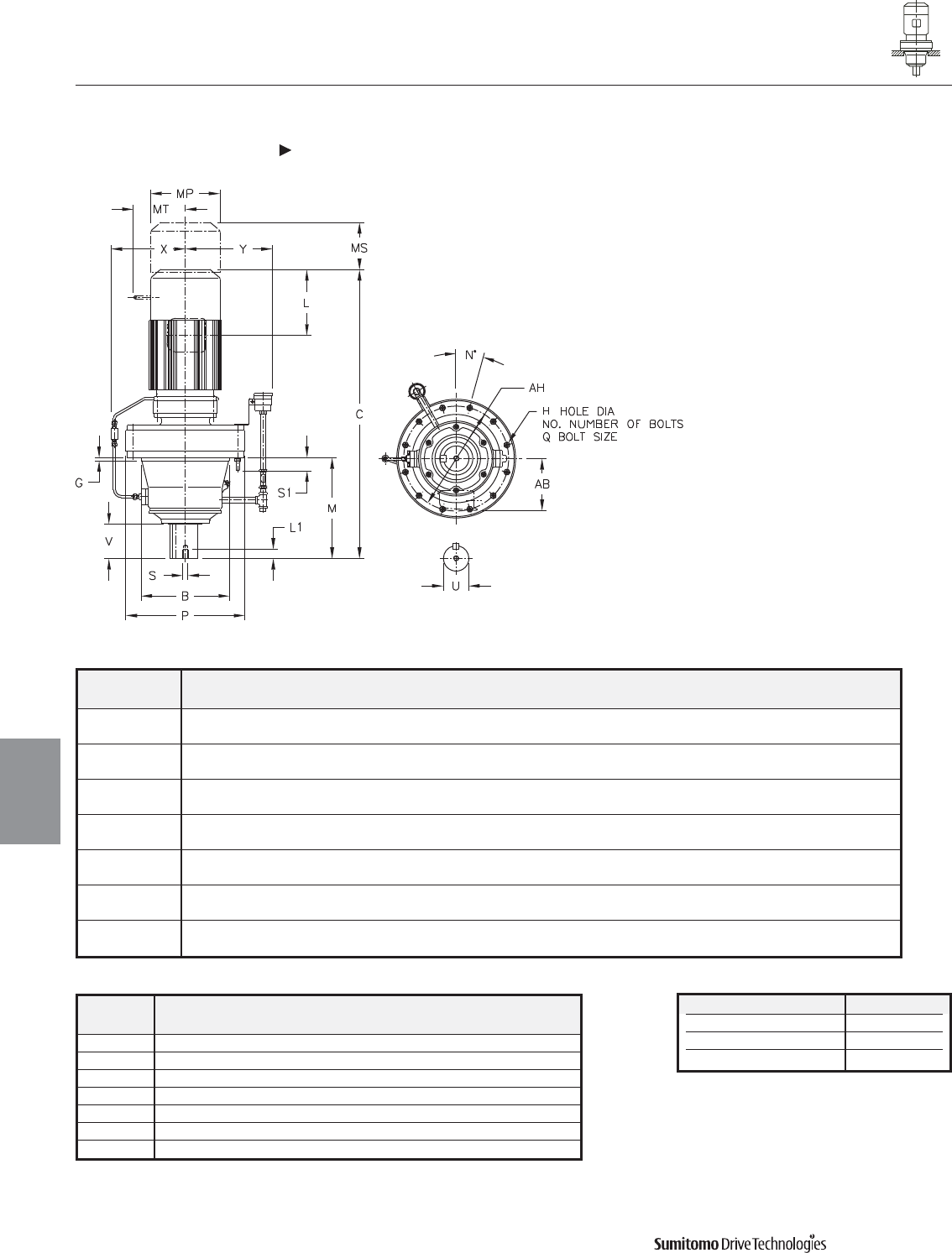
Model BCGH
NO.
MNPQS1AHXY
CVFM
6130/5DCY 6.4955 14.53 0.63 0.43 6 7.01 60 9.06 M10 1.22 8.07 - -
6.4945
6140/5DBY 6.4955 15.08 0.63 0.43 6 7.80 60 9.06 M10 1.22 8.07 - -
6.4945
6160/5DCY 7.8734 18.19 0.39 0.55 6 8.74 30 11.81 M12 1.38 10.63 7.72 9.06
7.8723
6170/5DCY 9.8419 20.04 0.47 0.55 8 10.31 22.50 13.39 M12 1.61 11.81 8.58 10.24
9.8408
6180/5DBY 11.0230 22.72 0.47 0.55 8 11.77 22.50 14.57 M12 1.50 12.99 9.17 10.24
11.0217
6190/5DAY 12.5977 24.76 0.39 0.55 12 14.37 15 16.93 M12 1.61 14.96 10.04 10.24
12.5963
6190/5DBY 12.5977 25.71 0.39 0.55 12 14.37 15 16.93 M12 1.61 14.96 10.04 10.24
12.5963
CYCLO® 6000 Gearmotors
Dimensions Integral Vertical F-Flange Mount
Double Reduction
CVFM-6130/5DCY 6190/5DBY
4.66 Dimensions
Dimensions
Gearmotors
All dimensions are in inches
Model Low Speed Shaft
CVFM
U* V S L1 Key
6130/5DCY 1.875 2.40 3/8-16UNC 0.71 1/2 X 1/2 X 2.16
6140/5DBY 1.875 3.19 3/8-16UNC 0.71 1/2 X 1/2 X 2.95
6160/5DCY 2.250 3.15 3/8-16UNC 0.71 1/2 X 1/2 X 2.95
6170/5DCY 2.750 3.31 1/2-13UNC 0.94 5/8 X 5/8 X 3.15
6180/5DBY 3.125 3.94 1/2-13UNC 0.94 3/4 X 3/4 X 3.74
6190/5DAY 3.625 4.92 3/4-10UNC 1.34 7/8 X 7/8 X 4.92
6190/5DBY 3.625 4.92 3/4-10UNC 1.34 7/8 X 7/8 X 4.92
Shaft Nominal Diameter (inches) Tolerances (inches)
1.250 (1 1/4) through 1.875 (1 7/8) +0.0000/-0.0006
2.000 (2) through 3.125 (3 1/8) +0.0000/-0.0007
3.250 (3 1/4) through 4.625 (4 5/8) +0.0000/-0.0009
*Shaft Tolerances
Dimensions shown are for reference only and are subject to change without notice, unless certified.
Certified prints are available after receipt of an order; consult factory.
Cyclo® 6000 Series
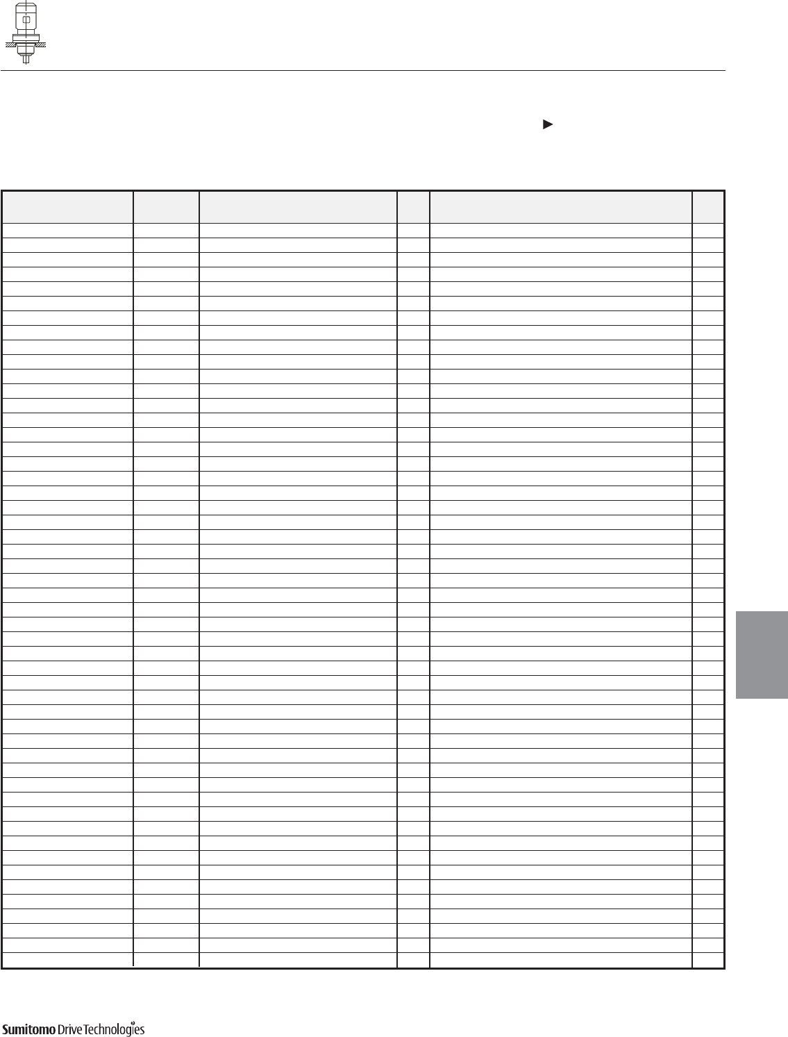
CYCLO® 6000 Gearmotors
Dimensions Integral Vertical F-Flange Mount
Double Reduction
CVFM-6130/5DCY 6190/5DBY (cont.)
Dimensions 4.67
Dimensions
Gearmotors
All dimensions are in inches
Dimensions shown are for reference only and are subject to change without notice, unless certified.
Certified prints are available after receipt of an order; consult factory.
Cyclo® 6000 Series
Model Motor Without Brake Appx With Brake Appx
HP Pole C AB L MP Wt (lb) C AB L MP MS MT Wt (lb)
CVFM02-6130/5DCY 1/4 4 19.41 5.04 2.32 4.88 95 20.67 5.04 3.58 4.88 2.40 - 99
CVFM03-6130/5DCY 1/3 4 19.41 5.04 2.32 4.88 95 20.67 5.04 3.58 4.88 2.40 - 99
CVFM05-6130/5DCY 1/2 4 20.20 5.04 2.32 4.88 97 21.46 5.04 3.58 4.88 2.40 - 101
CVFM08-6130/5DCY 3/4 4 21.81 5.63 3.82 5.83 106 23.50 5.63 5.51 5.83 3.66 4.17 112
CVFM1-6130/5DCY 1 4 21.81 5.63 3.82 5.83 106 23.50 5.63 5.51 5.83 3.66 4.17 112
CVFM1H-6130/5DCY 1.5 4 23.11 5.83 3.94 6.30 115 25.55 5.83 6.38 6.30 4.53 4.49 126
CVFM2-6130/5DCY 2 4 23.11 5.83 3.94 6.30 115 25.55 5.83 6.38 6.30 4.53 4.49 126
CVFM3-6130/5DCY 3 4 23.90 6.10 4.13 6.81 123 26.38 6.10 6.61 6.81 4.76 4.88 137
CVFM01-6140/5DBY 1/8 4 17.99 5.04 1.38 4.69 88 19.37 5.04 2.76 4.88 1.93 - 93
CVFM02-6140/5DBY 1/4 4 19.65 5.04 2.32 4.88 90 20.91 5.04 3.58 4.88 2.40 - 95
CVFM03-6140/5DBY 1/3 4 19.65 5.04 2.32 4.88 90 20.91 5.04 3.58 4.88 2.40 - 95
CVFM05-6140/5DBY 1/2 4 20.43 5.04 2.32 4.88 93 21.69 5.04 3.58 4.88 2.40 - 101
CVFM08-6140/5DBY 3/4 4 22.05 5.63 3.82 5.83 101 23.74 5.63 5.51 5.83 3.66 4.17 108
CVFM1-6140/5DBY 1 4 22.05 5.63 3.82 5.83 101 23.74 5.63 5.51 5.83 3.66 4.17 108
CVFM1H-6140/5DBY 1.5 4 23.35 5.83 3.94 6.30 110 25.79 5.83 6.38 6.30 4.53 4.49 117
CVFM2-6140/5DBY 2 4 23.35 5.83 3.94 6.30 110 25.79 5.83 6.38 6.30 4.53 4.49 117
CVFM05-6160/5DCY 1/2 4 23.07 5.04 2.32 4.88 176 24.49 5.04 3.58 4.88 2.40 - 181
CVFM08-6160/5DCY 3/4 4 24.65 5.63 3.82 5.83 185 26.34 5.63 5.51 5.83 3.66 4.17 192
CVFM1-6160/5DCY 1 4 24.65 5.63 3.82 5.83 185 26.34 5.63 5.51 5.83 3.66 4.17 192
CVFM1H-6160/5DCY 1.5 4 25.94 5.83 3.94 6.30 194 28.39 5.83 6.38 6.30 4.53 4.49 205
CVFM2-6160/5DCY 2 4 25.94 5.83 3.94 6.30 194 28.39 5.83 6.38 6.30 4.53 4.49 205
CVFM3-6160/5DCY 3 4 26.73 6.10 4.13 6.81 203 29.21 6.10 6.61 6.81 4.76 4.88 218
CVFM5-6160/5DCY 5 4 27.64 6.54 5.00 8.35 225 30.47 6.54 7.83 8.35 5.20 6.18 247
CVFM8-6160/5DCY 7.5 4 29.37 6.54 5.00 8.35 240 32.20 6.54 7.83 8.35 5.20 6.18 262
CVFM05-6170/5DCY 1/2 4 24.92 5.04 2.32 4.88 229 26.34 5.04 3.58 4.88 2.40 - 234
CVFM08-6170/5DCY 3/4 4 26.50 5.63 3.82 5.83 238 28.19 5.63 5.51 5.83 3.66 4.17 245
CVFM1-6170/5DCY 1 4 26.50 5.63 3.82 5.83 238 28.19 5.63 5.51 5.83 3.66 4.17 245
CVFM1H-6170/5DCY 1.5 4 27.80 5.83 3.94 6.30 247 30.24 5.83 6.38 6.30 4.53 4.49 258
CVFM2-6170/5DCY 2 4 27.80 5.83 3.94 6.30 247 30.24 5.83 6.38 6.30 4.53 4.49 258
CVFM3-6170/5DCY 3 4 28.58 6.10 4.13 6.81 256 31.06 6.10 6.61 6.81 4.76 4.88 271
CVFM5-6170/5DCY 5 4 29.49 6.54 5.00 8.35 278 32.32 6.54 7.83 8.35 5.20 6.18 300
CVFM8-6170/5DCY 7.5 4 31.22 6.54 5.00 8.35 293 34.06 6.54 7.83 8.35 5.20 6.18 315
CVFM1-6180/5DBY 1 4 28.86 5.63 3.82 5.83 340 30.55 5.63 5.51 5.83 3.66 4.17 346
CVFM1H-6180/5DBY 1.5 4 30.16 5.83 3.94 6.30 348 32.60 5.83 6.38 6.30 4.53 4.49 359
CVFM2-6180/5DBY 2 4 30.16 5.83 3.94 6.30 348 32.60 5.83 6.38 6.30 4.53 4.49 359
CVFM3-6180/5DBY 3 4 30.94 6.10 4.13 6.81 355 33.43 6.10 6.61 6.81 4.76 4.88 370
CVFM5-6180/5DBY 5 4 31.85 6.54 5.00 8.35 377 34.69 6.54 7.83 8.35 5.20 6.18 399
CVFM8-6180/5DBY 7.5 4 33.58 6.54 5.00 8.35 392 36.42 6.54 7.83 8.35 5.20 6.18 415
CVFM10-6180/5DBY 10 4 34.49 8.31 5.63 9.88 426 38.23 8.31 9.37 9.88 6.69 7.17 465
CVFM15-6180/5DBY 15 4 36.85 8.31 5.63 9.88 456 40.59 8.31 9.37 9.88 6.69 7.17 496
CVFM1-6190/5DAY 1 4 31.22 5.63 3.82 5.83 441 32.91 5.63 5.51 5.83 3.66 4.17 448
CVFM1H-6190/5DAY 1.5 4 32.52 5.83 3.94 6.30 450 34.96 5.83 6.38 6.30 4.53 4.49 461
CVFM2-6190/5DAY 2 4 32.52 5.83 3.94 6.30 450 34.96 5.83 6.38 6.30 4.53 4.49 461
CVFM3-6190/5DAY 3 4 33.31 6.10 4.13 6.81 459 35.79 6.10 6.61 6.81 4.76 4.88 474
CVFM5-6190/5DAY 5 4 34.21 6.54 5.00 8.35 481 37.05 6.54 7.83 8.35 5.20 6.18 503
CVFM8-6190/5DAY 7.5 4 35.94 6.54 5.00 8.35 496 38.78 6.54 7.83 8.35 5.20 6.18 518
CVFM5-6190/5DBY 5 4 34.84 6.54 5.00 8.35 496 37.68 6.54 7.83 8.35 5.20 6.18 518
CVFM8-6190/5DBY 7.5 4 36.57 6.54 5.00 8.35 512 39.41 6.54 7.83 8.35 5.20 6.18 534
CVFM10-6190/5DBY 10 4 37.48 8.31 5.63 9.88 545 41.22 8.31 9.37 9.88 6.69 7.17 584
CVFM15-6190/5DBY 15 4 39.84 8.31 5.63 9.88 576 43.58 8.31 9.37 9.88 6.69 7.17 615
CVFM20-6190/5DBY 20 4 43.39 9.13 11.61 12.76 690 46.93 9.13 15.16 12.76 8.66 - 763
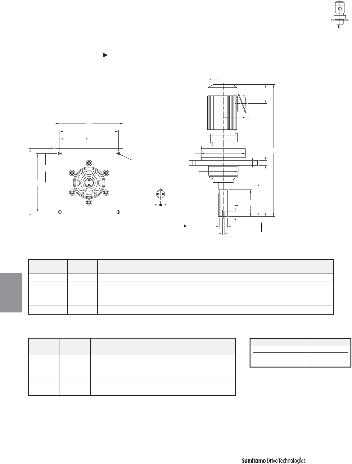
4.68 Dimensions Dimensions shown are for reference only and are subject to change without notice, unless certified.
Certified prints are available after receipt of an order; consult factory.
Cyclo® 6000 Series
CYCLO® 6000 Gearmotors
Dimensions
Gearmotors
Dimensions Integral Vertical F-Flange Mount, Overhead Drive
Double Reduction
CVFM-6130/5DCY 6180/5DBY
All dimensions are in inches
M
G
U
VV1
B
P
MP
AB
C
Y Y
A F
A
F
H (4 HOLES)
VIEW Y-Y
F/2
F/2
T T
L
L1
S
Model
CVFM
Model
DVX A B C F G H M P
6130/5DCY 35DVX 12.50 6.14 17.91 10.50 0.88 0.56 9.50 9.06
6140/5DBY 40DVX 14.00 6.14 18.80 12.00 1.00 0.43 10.50 9.06
6160/5DCY 50DVX 16.00 7.68 20.15 14.00 0.98 0.81 10.50 11.81
6170/5DCY 60DVX 19.50 9.45 25.82 17.00 1.57 0.94 15.50 13.39
6180/5DBY 70DVX 22.00 12.99 28.00 19.00 1.75 1.12 15.50 14.57
Model
CVFM
Model
DVX
Low Speed Shaft
T U V V1 SL1 Key
6130/5DCY 35DVX 0.38 1.6250 4.50 5.76 5/16-18UNC 1.00 3/8 X 3/8 X 3.70
6140/5DBY 40DVX 0.50 1.6875 5.50 6.89 3/8-16UNC 1.00 3/8 X 3/8 X 4.69
6160/5DCY 50DVX 0.75 2.1875 5.50 - 3/8-16UNC 1.00 1/2 X 1/2 X 5.24
6170/5DCY 60DVX 0.75 2.4375 7.50 - 3/8-16UNC 1.00 5/8 X 5/8 X 6.50
6180/5DBY 70DVX 1.00 2.9375 7.50 9.22 3/8-16UNC 1.00 3/4 X 3/4 X 6.50
Shaft Nominal Diameter (inches) Tolerances (inches)
1.250 (1 1/4) through 1.875 (1 7/8) +0.0000/-0.0006
2.000 (2) through 3.125 (3 1/8) +0.0000/-0.0007
3.250 (3 1/4) through 4.625 (4 5/8) +0.0000/-0.0009
*Shaft Tolerances
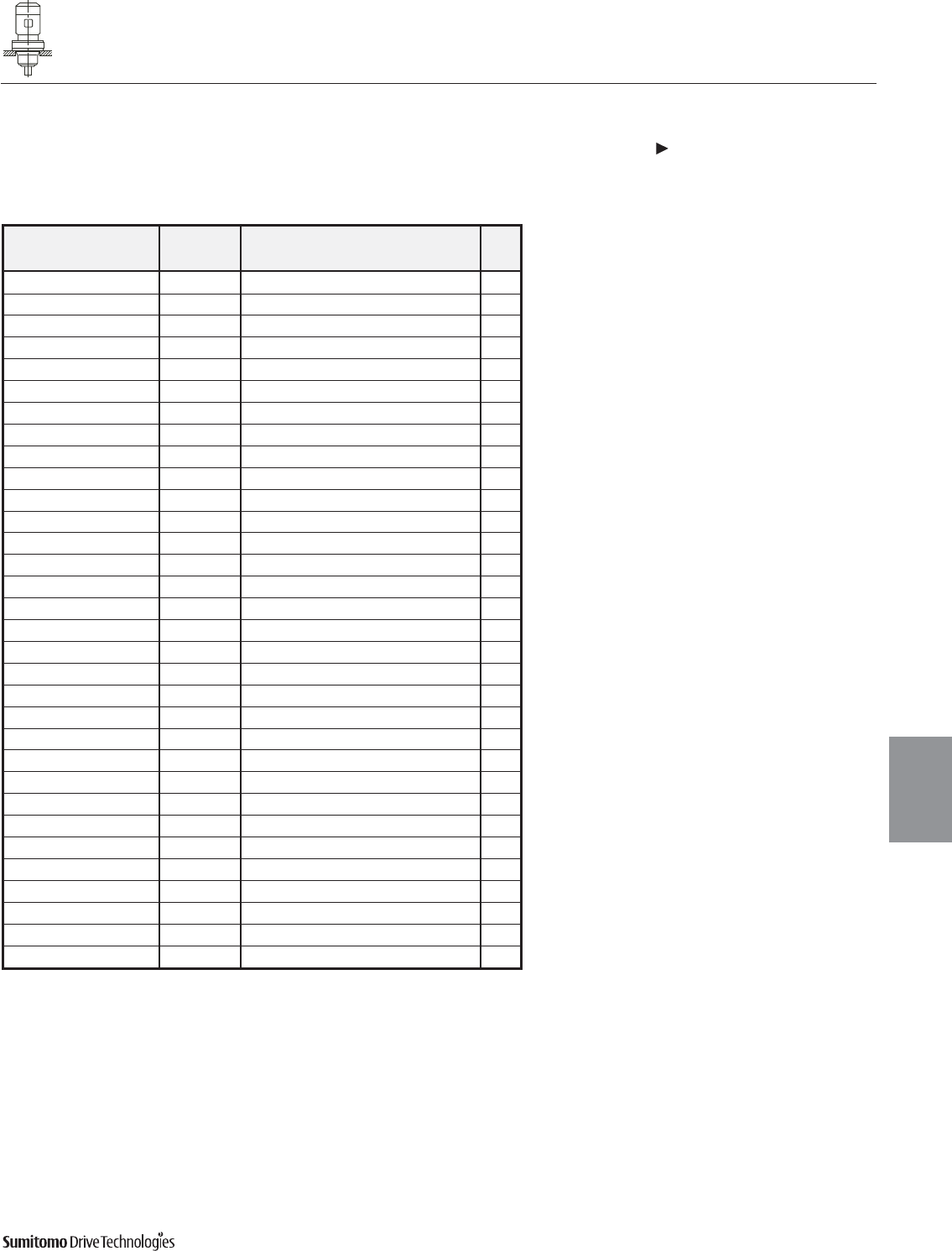
Dimensions 4.69
Dimensions shown are for reference only and are subject to change without notice, unless certified.
Certified prints are available after receipt of an order; consult factory.
Cyclo® 6000 Series
CYCLO® 6000 Gearmotors
Dimensions
Gearmotors
Dimensions Integral Vertical F-Flange Mount, Overhead Drive
Double Reduction
CVFM-6130/5DCY 6180/5DBY (cont.)
All dimensions are in inches
All dimensions are in inches
Model Motor Without Brake Appx
HP Pole C AB L MP Wt (lb)
CVFM05-6130/5DCY 1/2 4 23.58 5.04 2.32 4.88 138
CVFM08-6130/5DCY 3/4 4 25.19 5.63 3.82 5.83 147
CVFM1-6130/5DCY 1 4 25.19 5.63 3.82 5.83 147
CVFM1H-6130/5DCY 1.5 4 26.49 5.83 3.94 6.30 156
CVFM2-6130/5DCY 2 4 26.49 5.83 3.94 6.30 156
CVFM05-6140/5DBY 1/2 4 24.15 5.04 2.32 4.88 150
CVFM08-6140/5DBY 3/4 4 25.74 5.63 3.82 5.83 158
CVFM1-6140/5DBY 1 4 25.74 5.63 3.82 5.83 158
CVFM1H-6140/5DBY 1.5 4 27.07 5.83 3.94 6.30 167
CVFM2-6140/5DBY 2 4 27.07 5.83 3.94 6.30 167
CVFM05-6160/5DCY 1/2 4 25.03 5.04 2.32 4.88 249
CVFM08-6160/5DCY 3/4 4 26.61 5.63 3.82 5.83 258
CVFM1-6160/5DCY 1 4 26.61 5.63 3.82 5.83 258
CVFM1H-6160/5DCY 1.5 4 27.90 5.83 3.94 6.30 267
CVFM2-6160/5DCY 2 4 27.90 5.83 3.94 6.30 267
CVFM3-6160/5DCY 3 4 28.69 6.10 4.13 6.81 276
CVFM5-6160/5DCY 5 4 29.60 6.54 5.00 8.35 298
CVFM05-6170/5DCY 1/2 4 30.70 5.04 2.32 4.88 404
CVFM08-6170/5DCY 3/4 4 32.28 5.63 3.82 5.83 413
CVFM1-6170/5DCY 1 4 32.28 5.63 3.82 5.83 413
CVFM1H-6170/5DCY 1.5 4 33.58 5.83 3.94 6.30 422
CVFM2-6170/5DCY 2 4 33.58 5.83 3.94 6.30 422
CVFM3-6170/5DCY 3 4 34.36 6.10 4.13 6.81 431
CVFM5-6170/5DCY 5 4 35.27 6.54 5.00 8.35 453
CVFM8-6170/5DCY 7.5 4 37.00 6.54 5.00 8.35 468
CVFM1-6180/5DBY 1 4 34.14 5.63 3.82 5.83 591
CVFM1H-6180/5DBY 1.5 4 35.44 5.83 3.94 6.30 599
CVFM2-6180/5DBY 2 4 35.44 5.83 3.94 6.30 599
CVFM3-6180/5DBY 3 4 36.22 6.10 4.13 6.81 606
CVFM5-6180/5DBY 5 4 37.13 6.54 5.00 8.35 628
CVFM8-6180/5DBY 7.5 4 38.86 6.54 5.00 8.35 643
CVFM10-6180/5DBY 10 4 39.77 8.31 5.63 9.88 677
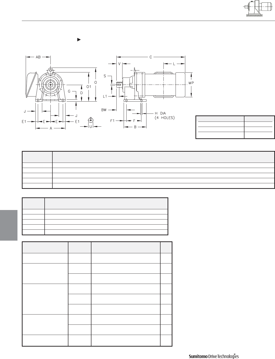
CYCLO® 6000 Gearmotors
Dimensions Single Phase, Integral Foot Mount
Single Reduction
CNHM-6065Y-SG 6120/5Y-SG
4.70 Dimensions
Dimensions
Gearmotors
All dimensions are in inches
Model ABDEE1FF1GHJ OO1PBW
CNHM
6065Y-SG 5.67 3.31 3.15 2.36 0.47 2.36 0.47 0.39 0.35 1.38 - 5.31 4.33 1.61
6075Y-SG 5.67 3.31 3.15 2.36 0.47 2.36 0.47 0.39 0.35 1.38 - 5.31 4.33 1.85
6090/5Y-SG 7.09 5.31 3.94 2.95 0.59 3.54 0.59 0.47 0.43 1.57 - 6.89 5.91 2.36
6100/5Y-SG 7.09 5.31 3.94 2.95 0.59 3.54 0.59 0.47 0.43 1.57 8.15 - 5.91 2.36
6120/5Y-SG 9.06 6.10 4.72 3.74 0.79 4.53 0.79 0.59 0.55 2.17 10.12 - 8.03 3.23
Model Low Speed Shaft
CNHM
U* V S L1 Key
6065Y-SG 0.500 0.98 10-32UNF 0.63 1/8 X 1/8 X 0.79
6075Y-SG 0.750 1.18 12-28UNF 0.63 3/16 X 3/16 X 1.06
6090/5Y-SG 1.125 1.38 5/16-18UNC 0.79 1/4 X 1/4 X 1.18
6100/5Y-SG 1.125 1.38 5/16-18UNC 0.79 1/4 X 1/4 X 1.18
6120/5Y-SG 1.500 2.17 5/16-18UNC 0.79 3/8 X 3/8 X 1.77
Shaft Nominal Diameter (inches) Tolerances (inches)
0.500 (1/2) through 0.625 (5/8) +0.0000/-0.0004
0.750 (3/4) through 1.125 (1 1/8) +0.0000/-0.0005
1.250 (1 1/4) through 1.875 (1 7/8) +0.0000/-0.0006
*Shaft Tolerances
Dimensions shown are for reference only and are subject to change without notice, unless certified.
Certified prints are available after receipt of an order; consult factory.
Cyclo® 6000 Series
Model Motor CMPAB
Appx.
CNHM HP Wt (lb)
6065Y-SG 1/8 13.42 6.02 5.79 30
1/4
1/8 13.66 6.02 5.79 32
6075Y-SG 1/4
1/3 15.08 6.02 5.79 36
1/2
1/8 15.79 6.02 5.79 46
1/4
6090/5Y-SG 1/3 17.20 6.02 5.79 52
1/2
3/4 17.25 7.83 6.38 66
1
1/3 17.76 6.02 5.79 52
6100/5Y-SG 1/2
3/4 17.80 7.83 6.50 66
1
6120/5Y-SG 3/4 18.63 7.83 6.50 94
1
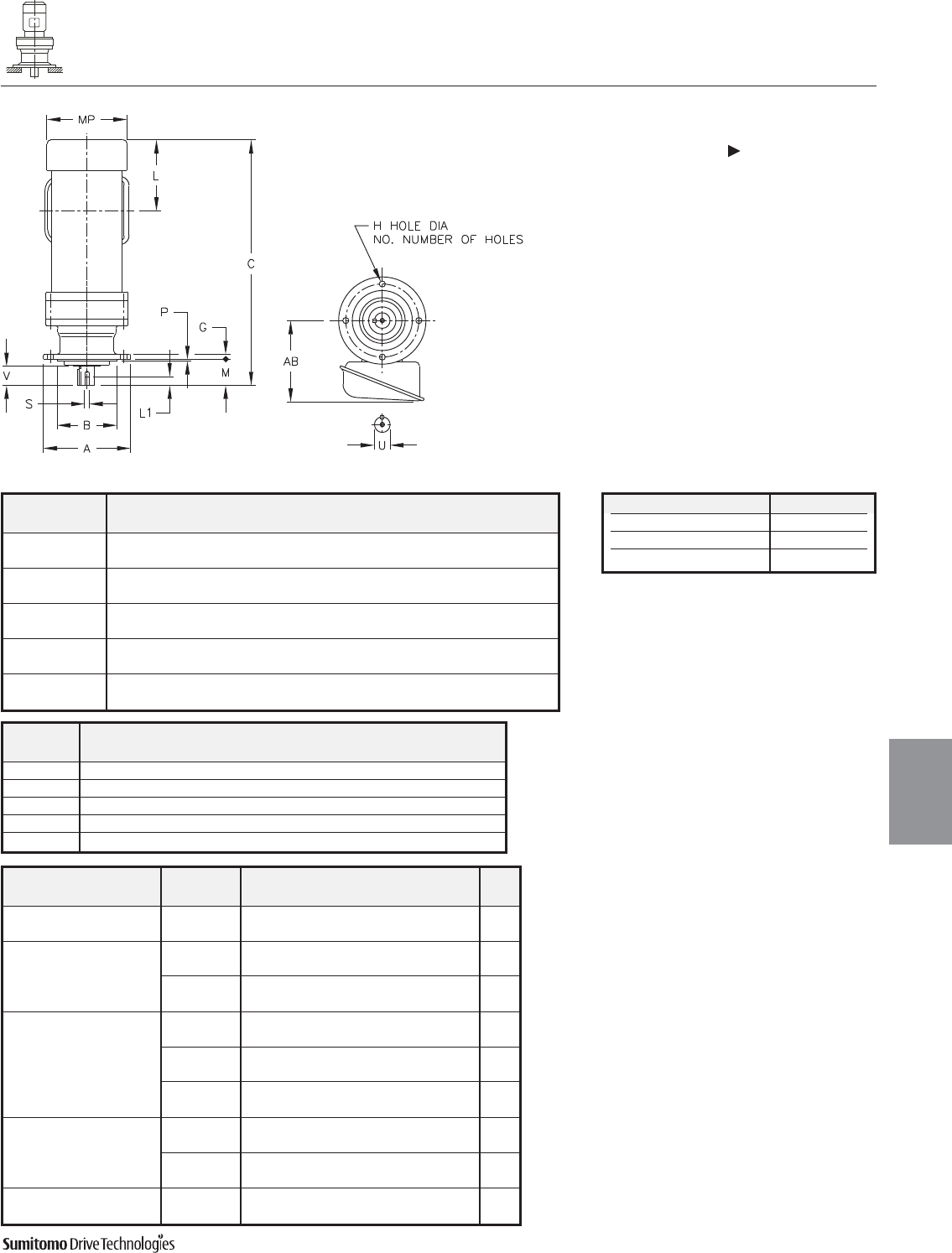
CYCLO® 6000 Gearmotors
Dimensions Single Phase, Integral Universal V-Flange
Single Reduction
CNVM-6065Y-SG 6120/5Y-SG
Dimensions 4.71
Dimensions
Gearmotors
All dimensions are in inches
Model ABGH
NO.
MPAH
CNVM
6065Y-SG 4.72 3.1484 0.31 0.35 6 1.34 0.12 4.02
3.1466
6075Y-SG 6.30 4.3293 0.35 0.43 4 1.65 0.12 5.28
4.3272
6090/5Y-SG 6.30 4.3293 0.35 0.43 4 1.89 0.12 5.28
4.3272
6100/5Y-SG 6.30 4.3293 0.35 0.43 4 1.89 0.12 5.28
4.3272
6120/5Y-SG 8.27 5.5101 0.51 0.43 6 2.72 0.16 7.09
5.5076
Dimensions shown are for reference only and are subject to change without notice, unless certified.
Certified prints are available after receipt of an order; consult factory.
Cyclo® 6000 Series
Model Low Speed Shaft
CNVM
U* V S L1 Key
6065Y-SG 0.500 0.98 10-32UNF 0.63 1/8 X 1/8 X 0.79
6075Y-SG 0.750 1.18 12-28UNF 0.63 3/16 X 3/16 X 1.06
6090/5Y-SG 1.125 1.38 5/16-18UNC 0.79 1/4 X 1/4 X 1.18
6100/5Y-SG 1.125 1.38 5/16-18UNC 0.79 1/4 X 1/4 X 1.18
6120/5Y-SG 1.500 2.17 5/16-18UNC 0.79 3/8 X 3/8 X 1.77
Shaft Nominal Diameter (inches) Tolerances (inches)
0.500 (1/2) through 0.625 (5/8) +0.0000/-0.0004
0.750 (3/4) through 1.125 (1 1/8) +0.0000/-0.0005
1.250 (1 1/4) through 1.875 (1 7/8) +0.0000/-0.0006
*Shaft Tolerances
Model Motor CMPAB
Appx.
CNVM HP Wt (lb)
6065YA-SG 1/8 13.42 6.02 5.79 27
1/4
1/8 13.66 6.02 5.79 31
6075YA-SG 1/4
1/3 15.08 6.02 5.79 36
1/2
1/8 15.79 6.02 5.79 41
1/4
6090/5YA-SG 1/3 17.20 6.02 5.79 48
1/2
3/4 17.25 7.83 6.38 67
1
1/3 17.76 6.02 5.79 55
6100/5YA-SG 1/2
3/4 17.80 7.83 6.50 74
1
6120/5YA-SG 3/4 18.63 7.83 6.50 94
1

CYCLO® 6000 Gearmotors
4.72 Dimensions Cyclo® 6000 Series
This page intentionally left blank.

CYCLO® 6000 Gearmotors
Technical Information 5.1
Technical
Information
Cyclo® 6000 Series
Technical Information
5
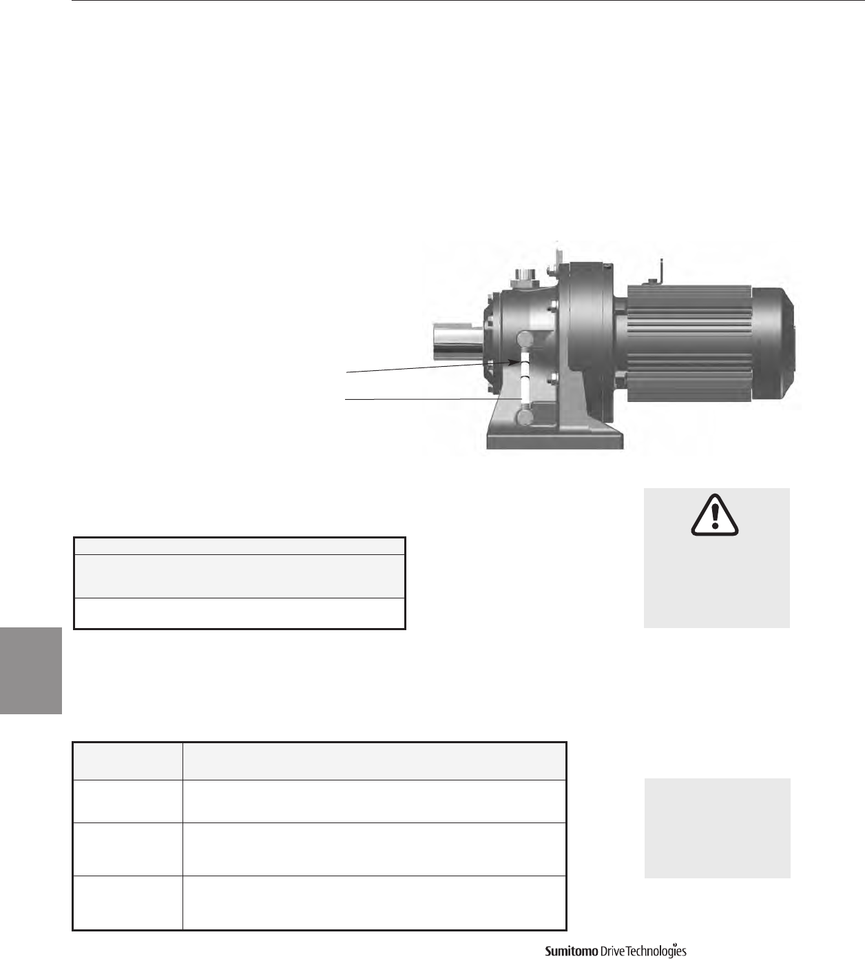
CYCLO® 6000 Gearmotors
5.2 Technical Information
Lubrication
Cyclo® 6000 Series
Lubrication
Approved Oils
Oil lubricated gearmotors must be filled with oil prior to operation.
Fill the gearmotor to the correct level with the recommended oil.
For use in winter or relatively low ambi-
ent temperatures, use the lower vis-
cosity oil specified for each ambient
temperature range.
For consistent use in ambient temper-
atures outside of the range 32°F to
104°F (0°C to 40°C), consult factory.
Ambient Temperature Cyclo®Planetary
°F °C ExxonMobil Shell Oil
14 to 122 -10 to 50 Exxon Unirex N2 Grease Shell Alvania®EP
(NLGI Grade #2) (NLGI Grade #0)
Approved Greases
Grease lubricated gearmotors are filled with grease prior to shipment and
are ready for installation and operation. This information is provided for
maintenance purposes.
When the Cyclo®gearmotor will be
used under widely fluctuating
temperatures or ambient temperatures
(other than those listed here) or any
other special conditions, consult the
factory.
Oil Fill Level
Oil Sight Gauge
Cyclo®Gearmotors are either Grease lubricated or Oil lubricated.
Refer to pages 5.3 and 5.4 to determine the unit lubrication type.
•Grease lubricated gearmotors are filled with grease prior to
shipment and are ready for installation and operation
•Oil lubricated gearmotors must be filled with the proper
amount of approved oil before installation and operation
•Lubrication methods (grease or oil) are specified for
Cyclo®driven at standard input speed.
NOTE: Some models normally designed for
oil lubrication may be specially ordered
for grease lubrication; please consult factory.
Ambient Temperature ChevronTexaco Exxon Oil Mobil Oil Shell Oil BP Oil
°F °C
14 to 41° -10 to 5 EP Gear
Compound 68
Spartan EP
68
Mobilgear 600 XP 68
(ISO VG 68)
Omala S2 G
68
Energol
GR-XP 68
32 to 95° 0 to 35
EP Gear
Compound
100, 150
Spartan
EP100
EP150
Mobilgear
600 XP 100, 150
(ISO VG 100, 150)
Omala S2 G
100, 150
Energol
GR-XP 100
GR-XP 150
86 to 122° 30 to 5
EP Gear
Compound
220, 320, 460
Spartan
EP 220
EP320
EP 460
Mobilgear
600 XP 220,
320, 460
(ISO VG 220, 320, 460)
Omala S2 G
220, 320
460
Energol
GR-XP 220
GR-XP 320
GR-XP 460
CYCLO® 6000 Gearmotors
Technical Information 5.3
Lubrication
Cyclo® 6000 Series
Frame Size Reduction Ratio
104 121 143 165 195 231 273 319 377 473 559 649 731 841 1003 1015 1247 1479 1849 2065 2537 3045 3481 4437 5133 6177 7569
6060DA, 6065DA
6070DA, 6075DA
2537
6090DA, 6095DA
5133
6100DA, 6105DA Maintenance Free Grease
6120DA, 6120DB
6125DA, 6125DB
6130DA, 6135DA
6130DB, 6135DB
6130DC, 6135DC Grease
6140DA, 6140DB, 6140DC
6145DA, 6145DB, 6145DC
6160DA, 6165DA
6160DB, 6165DB
6170DA, 6175DA
6170DB, 6175DB
6180DA. 6185DA
6160DC, 6165DC
6170DC, 6175DC
6180DB. 6185DB
6190DA, 6195DA
6190DB, 6195DB
6205DA, 6205DB
165
6215DA, 6215DB
121
Oil
6225DA, 6225DB
6235DA, 6235DB
6245DA, 6245DB
6255DA, 6255DB
6265DA
6275DA
377
HORIZONTAL Mounted Gearmotor • SINGLE Reduction • Frame Sizes 6060 to 6275
HORIZONTAL Mounted Gearmotor • DOUBLE Reduction • Frame Sizes 6060DA to 6275DA
Lubrication continued
Frame Size Reduction Ratio
3 5 6 8 11 13 15 17 21 25 29 35 43 51 59 71 87 119
6060, 6065
6070, 6075 59
6080. 6085 87
6090, 6095 Grease Maintenance Free Grease
6100, 6105, 610H
6110, 6115
6120, 6125, 612H
6130, 6135
6140, 6145, 614H
6160, 6165, 616H
6170, 6175 Oil
6180, 6185
6190, 6195
6205
6215
6225
6235
6245
6255
6265
6275
CYCLO® 6000 Gearmotors
5.4 Technical Information
Lubrication
Cyclo® 6000 Series
Lubrication continued
VERTICAL Mounted Gearmotor • SINGLE Reduction • Frame Sizes 6060 to 6275
VERTICAL Mounted Gearmotor • DOUBLE Reduction • Frame Sizes 6060DA to 6275DA
Frame Size Reduction Ratio
104 121 143 165 195 231 273 319 377 473 559 649 731 841 1003 1015 1247 1479 1849 2065 2537 3045 3481 4437 5133 6177 7569
6060DA, 6065DA
6070DA, 6075DA
2537
6090DA, 6095DA
5133
6100DA, 6105DA Maintenance Free Grease
6120DA, 6120DB
6125DA, 6125DB
6130DA, 6125DA
6130DB, 6135DB
6130DC, 6135DC Grease
6140DA, 6140DB, 6140DC
6145DA, 6145DB, 6145DC
6160DA, 6165DA
6160DB, 6165DB
6170DA, 6175DA
6170DB, 6175DB
6180DA, 6185DA
6160DC, 6165DC
473
6170DC, 6175DC
841
6180DB, 6185DB
1015
6190DA, 6195DA
2065
6190DB, 6195DB
6205DA, 6205DB
1849
6215DA, 6215DB
121
Forced Oil
2537
6225DA, 6225DB
6235DA, 6235DB
6245DA, 6245DB
6255DA, 6255DB
6265DA
6275DA 377
Frame Size Reduction Ratio
3 5 6 8 11 13 15 17 21 25 29 35 43 51 59 71 87 119
6060, 6065
6070, 6075 59
6080. 6085 87
6090, 6095 Maintenance Free Grease
6100, 6105
6110, 6115
6120, 6125
6130, 6135 Oil
6140, 6145
6160, 6165
6170, 6175 Forced Oil
6180, 6185
6190, 6195
6205
6215
6225
6235
6245
6255
6265
6275
Grease
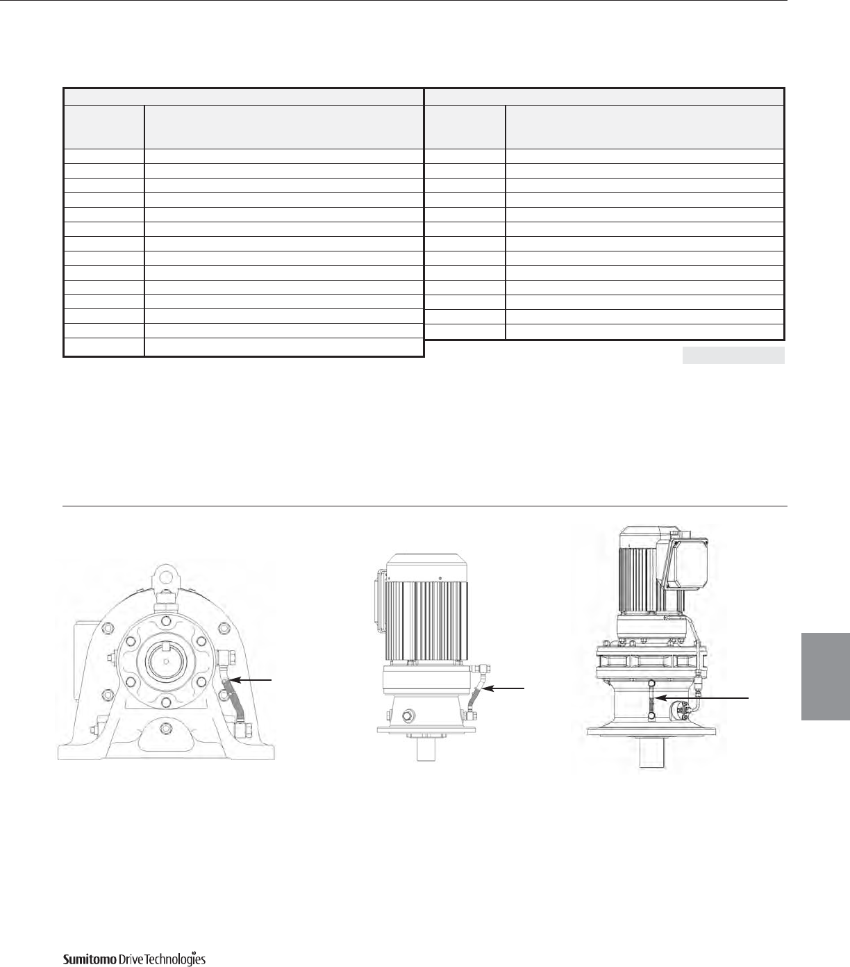
CYCLO® 6000 Gearmotors
Technical Information 5.5
Lubrication
Cyclo® 6000 Series
Lubrication continued
Single Reduction
Mounting Configuration
Frame Size Horizontal[1] Vertical[1]
U.S. gal. U.S. gal.
6130, 6135 0.18 0.29
6140, 6145, 614H 0.18 0.29
6160, 6165, 616H 0.37 0.26
6170, 6175 0.50 0.50
6180, 6185 0.66 0.53
6190, 6195 1.1 0.71
6205 1.5 1.5
6215 2.2 2.0
6225 2.6 2.6
6235 4.0 3.2
6245 4.2 4.0
6255 5.5 11.1
6265 7.7 13.5
6275 14.8 (15.9)
Double Reduction
Mounting Configuration
Frame Size Horizontal[1] Vertical[1]
U.S. gal. U.S. gal.
6160DC, 6165DC 0.40 0.26
6170DC, 6175DC 0.63 0.50
6180DB, 6185DB 0.92 0.53
6190DA, 6195DA 1.5 0.71
6190DB, 6195DB 1.6 0.71
6205DA, 6205DB 1.6 2.9
6215DA, 6215DB 2.6 3.7
6225DA, 6225DB 2.9 4.8
6235DA, 6235DB 4.5 6.1
6245DA, 6245DB 4.8 7.7
6255DA, 6255DB 6.1 11.1
6265DA 8.5 13.5
6275DA 15.9 (15.9)
Oil Fill Quantities
( ) With trochoid pump
Oil Fill Level
Horizontal Vertical
Sizes 6130/5 and 6140/5 only
Note: [1] Please consult factory for oil quantities when the reducer is mounted in any other position or angle
Vertical
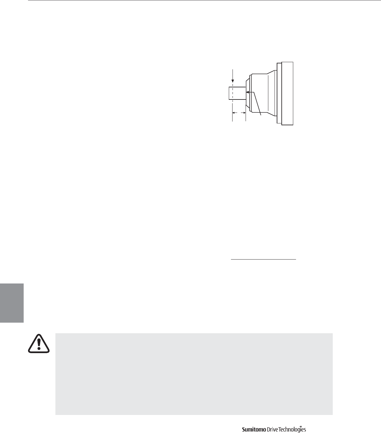
How to Calculate Overhung Load (OHL)
Step 1. Measure distance X from gearmotor collar surface
to the centerline of the OHL.
Step 2. Determine Lf (Load Location Factor) for your chosen Frame Size,
using Load Location Factor Table on the next page.
Step 3. Determine Cf (Connection Factor) and Sf (Shock Factor) from the tables below:
Step 4. Apply Lf, Cf and Sf to the formula to calculate the OHL.
EXAMPLE: Known HP = Power Transmitted by shaft (HP)
Known D = Pitch Diameter of sprocket (inches)
Known N = Shaft Speed (RPM)
Step 5. Refer back to the Frame Size Selection Tables (pp. 3.1–3.32) to determine maximum
allowable OHL capacity for the selected Frame Size.
If the calculated OHL does not exceed the OHL capacity (from Selection Table),
the selected Frame Size is acceptable.
If the calculated OHL exceeds the OHL capacity, there are two standard options that
can increase the OHL capacity of a reducer:
• High Capacity Bearings Option–R1 (Table on pg. 5.8)
• Ductile Iron Housing & High Capacity Bearings Option–R2 (Table on pg. 5.9)
If neither of these options adequately increase the OHL capacity:
1. Choose the next larger Frame Size, or
2. Move the OHL closer to the collar surface, or
3. Decrease the OHL by increasing the pitch diameter of the connecting drive.
Be sure to recalculate and verify the OHL capacity for the new frame size.
CYCLO® 6000 Gearmotors
5.6 Technical Information
Overhung
Loads
Cyclo® 6000 Series
Overhung Loads • Slow Speed Shaft
Overhung Loads are loads that act perpendicular to the gearmotor shaft. Each gearmotor has a maximum allowable overhung
load (OHL) capacity, which is shown in the Frame Size Selection Tables for each gearmotor. In applications with an OHL, it is criti-
cal that the OHL is calculated and that the chosen gearmotor is adequately sized for the maximum OHL.
Centerline of Load
X
Collar
Surface
Load Connection Factor (Cf)
CONNECTION TYPE FACTOR
General Purpose Chain 1.0
Machined Gear or Synchronous Belt 1.25
V-Belt 1.5
Flat Belt 2.5
Service Factor (Sf)
DEGREE OF SHOCK FACTOR
Steady Loads 1.0
Moderate Shock 1.3
Heavy Shock 1.6
126,000 x HP X Lf X Cf X Sf = Calculated OHL
D X N
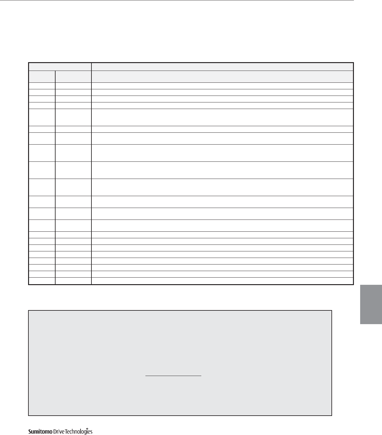
CYCLO® 6000 Gearmotors
Technical Information 5.7
Overhung
Loads
Cyclo® 6000 Series
Overhung Loads, Slow Speed Shaft continued
Load Location Factors (Lf), Slow Speed Shaft
EXAMPLE
A uniformly loaded belt conveyor requiring 5 HP is to be driven 8 hours/day by a Cyclo®gearmotor, size 6135, ratio 29:1, 60 RPM output using a 9.84
pitch diameter sprocket on the slow speed shaft. Centerline of the load (X) is 1.5 from the collar surface.
Procedure: 1. Calculate the overhung load with Cf = 1.0 (from Step 3, pg. 5.6), Lf = 1.08 (from Step 3, pg. 5.6).
Overhung Load = 126,000 x 5 x 1.0 x 1.08 x 1.0 = 1152 lbs.
9.84 x 60
2. In the Selection Tables (pages 3.1–3.58), check the overhung load capacity of the 6135, 29:1 with the 1750 RPM input speed.
Allowable Overhung Load for the 6135 is 2125 lbs. Since the allowable overhung load of the 6135 is larger than the calculated
overhung load of 1152 lbs., the application is satisfactory.
Frame Size X (inches)
Single Double
1/4 1/2 3/4 1 1 1/4 1 1/2 1 3/4 2 2 1/2 3 3 1/2 4 4 1/2 5 6 7 8 9 10 11
Reduction Reduction
6060, 6065 6060DA, 6065DA 0.86 1.08 1.49 — — — — — — — — — — — — — — — — —
6070, 6075 6070DA, 6075DA 0.85 0.96 1.23 1.61 — — — — — — — — — — — — — — — —
6080, 6085 — 0.83 0.91 1.01 1.30 1.63 — — — — — — — — — — — — — — —
6090, 6095 6090DA, 6095DA 0.88 0.95 1.10 1.40 1.73 — — — — — — — — — — — — — — —
6100
6105 6100DA, 6105DA 0.88 0.95 1.10 1.40 1.73 — — — — — — — — — — — — — — —
610H
6110, 6115 — 0.80 0.87 0.95 1.02 1.12 1.30 1.51 — — — — — — — — — — — — —
6120, 6125 6120DA, 6120DB — 0.85 0.91 0.98 1.14 1.36 1.57 — — — — — — — — — — — — —
612H 6125DA, 6125DB
6130DA, 6130DB
6130 6135 6130DC, 6135DA — — 0.86 0.92 0.97 1.08 1.24 1.40 1.72 — — — — — — — — — — —
6135DB, 6135DC
6140 6140DA, 6140DB
6145 6140DC, 6145DA — — — 0.74 0.82 0.91 0.99 1.12 1.37 1.62 1.88 — — — — — — — — —
614H 6145DB, 6145DC
6160 6160DA, 6160DB
6165 6160DC, 6165DA — — — 0.87 0.91 0.95 1.00 1.13 1.39 1.67 1.94 — — — — — — — — —
616H 6165DB, 6165DC
6170 6170DA, 6170DB
6175 6170DC, 6175DA — — — 0.89 0.93 0.96 1.00 1.13 1.39 1.67 1.94 — — — — — — — — —
6180 6180DA, 6180DB — — — 0.85 0.88 0.92 0.95 0.99 1.15 1.37 1.58 — — — — — — — — —
6185 6185DA, 6185DB
6190 6190DA, 6190DB — — — — 0.86 0.88 0.91 0.93 0.99 1.13 1.30 1.48 1.67 — — — — — — —
6195 6195DA, 6195DB
6205 6205DA, 6205DB — — — — — — 0.74 0.78 0.86 0.95 1.04 1.13 1.22 1.31 1.49 — — — — —
6215 6215DA, 6215DB — — — — — — 0.73 0.78 0.86 0.95 1.04 1.14 1.23 1.32 1.50 — — — — —
6225 6225DA, 6225DB — — — — — — 0.88 0.90 0.94 0.98 1.02 1.06 1.10 1.14 1.23 — — — — —
6235 6235DA, 6235DB — — — — — — 0.84 0.85 0.89 0.93 0.97 1.00 1.04 1.08 1.16 1.23 — — — —
6245 6245DA, 6245DB — — — — — — 0.84 0.86 0.90 0.93 0.97 1.00 1.04 1.08 1.15 1.22 — — — —
6255 6255DA, 6255DB — — — — — — — 0.83 0.86 0.89 0.93 0.95 0.99 1.02 1.08 1.21 1.38 1.54 — —
6265 6265DA — — — — — — — — — 0.84 0.88 0.90 0.93 0.95 1.02 1.16 1.31 1.47 1.64 1.80
6275 6275DA — — — — — — — — — — 0.71 0.76 0.80 0.85 0.95 1.08 1.23 1.37 1.52 1.67
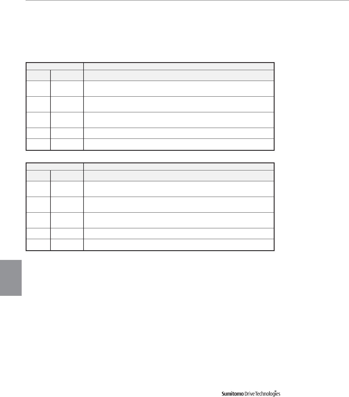
CYCLO® 6000 Gearmotors
5.8 Technical Information
Overhung
Loads
Cyclo® 6000 Series
Frame Size Output Shaft Speed (RPM)
Single Double 10 & Below 15 20 25 30 35 40 50
Reduction Reduction
6130DA, 6130DB
6130, 6135 6130DC, 6135DA 3305 3305 3305 3305 3305 3305 3305 3305
6135DB, 6135DC
6160 6160DA, 6160DB
6165 6160DC, 6165DA 4969 4969 4969 4969 4969 4969 4969 4969
616H 6165DB, 6165DC
6170 6170DA, 6170DB
6175 6170DC, 6175DA 6632 6632 6632 6632 6632 6632 6632 6632
6175DB, 6175DC
6180 6180DA, 6180DB 9375 9375 9375 9375 9375 9375 9375 9375
6185 6185DA, 6185DB
6190 6190DA, 6190DB 13264 13264 13264 13264 13264 13264 13264 12410
6195 6195DA, 6195DB
Frame Size Output Shaft Speed (RPM)
Single Double 60 80 100 125 150 200 250 300
Reduction Reduction
6130DA, 6130DB
6130, 6135 6130DC, 6135DA 3305 3170 3035 2833 2675 2451 2293 2172
6135DB, 6135DC
6160 6160DA, 6160DB
6165 6160DC, 6165DA 4969 4969 4856 4519 4272 3934 3665 3462
616H 6165DB, 6165DC
6170 6170DA, 6170DB
6175 6170DC, 6175DA 6632 6632 6587 6160 5823 5351 4991 4744
6175DB, 6175DC
6180 6180DA, 6180DB 9375 9285 8678 8138 7689 7059 — —
6185 6185DA, 6185DB
6190 6190DA, 6190DB 11915 10612 9892 9218 8611 7801 — —
6195 6195DA, 6195DB
High Capacity Bearings Option
Type R1
Slow Speed Shaft Overhung Load Capacity (lbs.)
Overhung Loads, Slow Speed Shaft continued
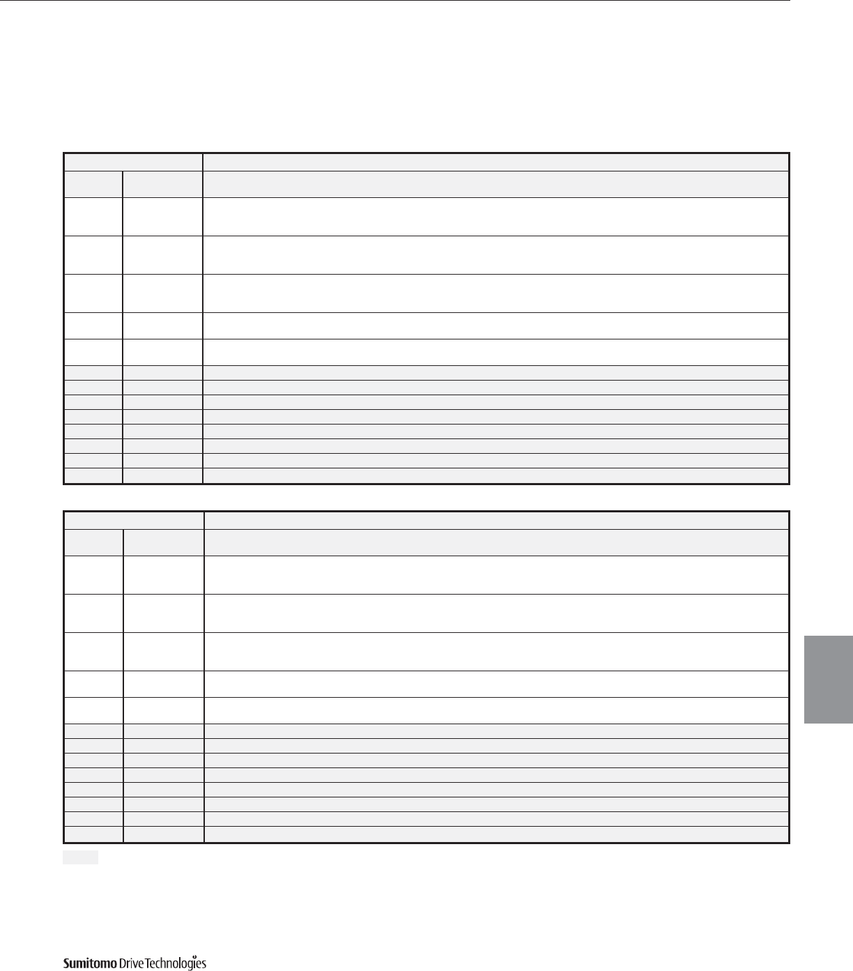
CYCLO® 6000 Gearmotors
Technical Information 5.9
Overhung
Loads
Cyclo® 6000 Series
Ductile Iron Housing and High Capacity Bearings Option
Type R2
Slow Speed Shaft Overhung Load Capacity (lbs.)
Overhung Loads, Slow Speed Shaft continued
Indicates ductile iron housing and high capacity bearing is standard
Frame Size Output Shaft Speed (RPM)
Single Double 4 & Below 5 6 8 10 15 20 25 30 35
Reduction Reduction
6130DA, 6130DB
6130, 6135 6130DC, 6135DA 5396 5396 5396 5396 5396 5351 4901 4586 4339 4137
6135DB, 6135DC
6160 6160DA, 6160DB
6165 6160DC, 6165DA 7554 7554 7554 7554 7554 7554 7554 7487 7082 6767
616H 6165DB, 6165DC
6170 6170DA, 6170DB
6175 6170DC, 6175DA 10319 10319 10319 10319 10319 10319 10319 10184 9645 9195
6175DB, 6175DC
6180 6180DA, 6180DB 12522 12522 12522 12522 12522 12522 12522 12522 12522 12140
6185 6185DA, 6185DB
6190 6190DA, 6190DB 16142 16142 16142 16142 16142 16142 16142 16142 15580 14861
6195 6195DA, 6195DB
6205 6205DA, 6205DB 21987 21987 21987 21987 21987 20031 18390 17199 16277 15535
6215 6215DA, 6215DB 29860 28327 26754 24505 22932 20346 18660 17446 16524 15760
6225 6225DA, 6225DB 36196 35072 33273 30351 28327 25180 23156 21650 20479 19559
6235 6235DA, 6235DB 41142 41142 41142 38219 35746 31700 29002 27203 25629 24505
6245 6245DA, 6245DB 50135 46987 44514 40692 37995 33723 31025 29002 27428 26079
6255 6255DA, 6255DB 61601 58004 54856 50360 47212 41592 38219 35746 33948 32374
6265 6265DA 63624 63624 63624 60701 56879 50360 46088 42941 40692 39119
6275 6275DA 61151 61151 61151 61151 61151 61151 61151 61151 61151 —
Frame Size Output Shaft Speed (RPM)
Single Double 40 50 60 80 100 125 150 200 250 300
Reduction Reduction
6130DA, 6130DB
6130, 6135 6130DC, 6135DA 4002 3710 3507 3237 3035 2833 2675 2451 2293 2172
6135DB, 6135DC
6160 6160DA, 6160DB
6165 6160DC, 6165DA 6497 6070 5755 5283 4946 4609 4362 4024 3732 3462
616H 6165DB, 6165DC
6170 6170DA, 6170DB
6175 6170DC, 6175DA 8835 8273 7824 7172 6722 6272 5935 5463 4991 4744
6175DB, 6175DC
6180 6180DA, 6180DB 11668 10904 10319 9465 8858 8296 7846 7194 — —
6185 6185DA, 6185DB
6190 6190DA, 6190DB 14276 13354 12657 11601 10859 10139 9622 8835 — —
6195 6195DA, 6195DB
6205 6205DA, 6205DB 14928 13961 13219 12140 11353 10589 10027 9218 — —
6215 6215DA, 6215DB 15153 14164 13399 12320 11533 10769 10207 9353 — —
6225 6225DA, 6225DB 18772 17558 16637 15265 14276 13354 12657 11578 — —
6235 6235DA, 6235DB 23606 22055 20886 19177 17941 16749 — — — —
6245 6245DA, 6245DB 25180 23606 22235 20414 19087 17851 — — — —
6255 6255DA, 6255DB 31250 29002 27653 25180 23606 22100 — — — —
6265 6265DA 37320 35072 33273 30351 28327 26529 — — — —
6275 6275DA ——————————
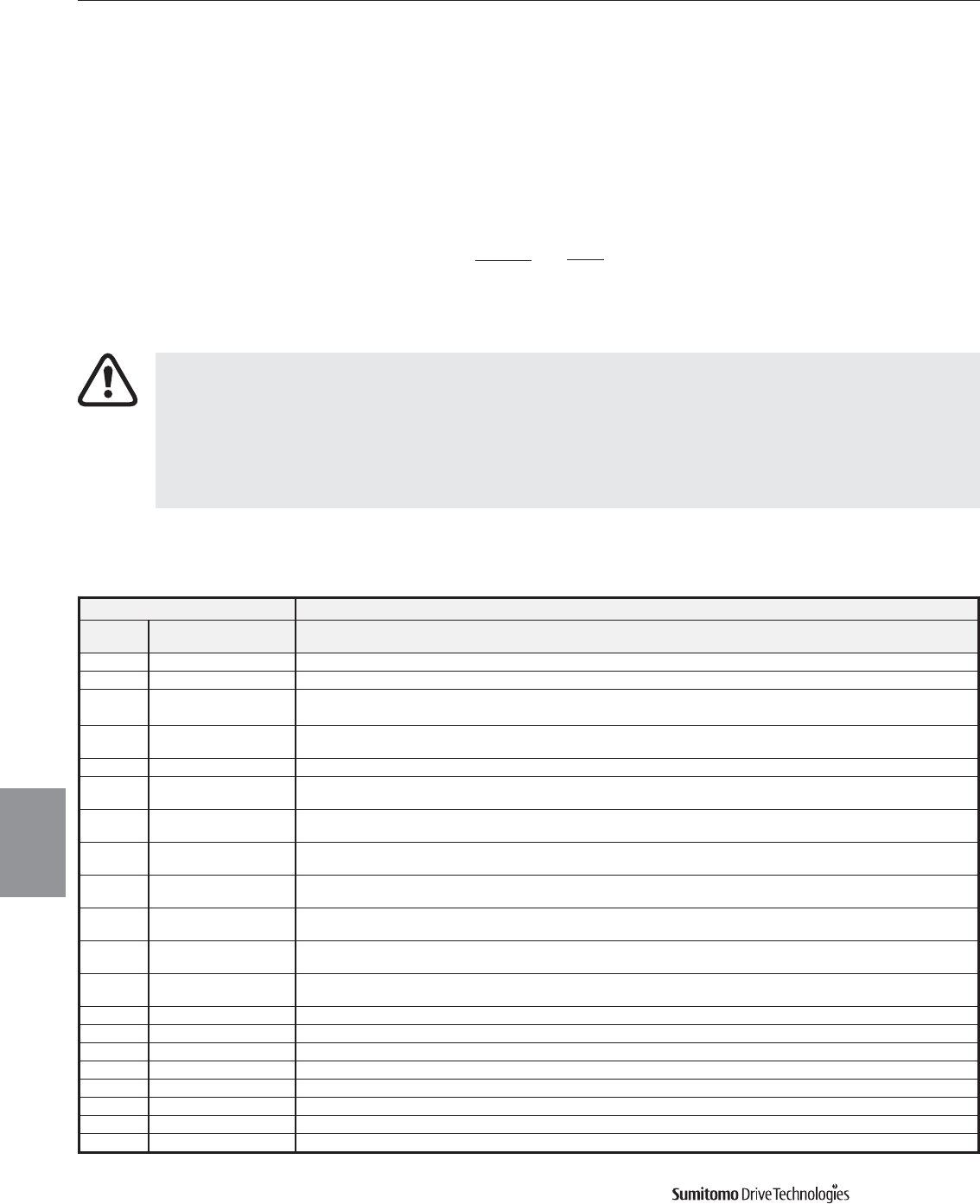
CYCLO® 6000 Gearmotors
5.10 Technical Information
Axial
Loads
Cyclo® 6000 Series
Axial Loads
Frame Size Output Shaft Speed (RPM)
Single Double ~10 15 20 25 30 35 40 50 60 80 100 125 150 200 250 300
Reduction Reduction
6060 6065 6060DA 6065DA 66 66 66 66 66 66 66 66 66 66 66 66 66 66 66 66
6070 6075 6070DA 6075DA 176 176 176 176 176 176 176 176 176 176 176 176 176 176 176 176
6080 6085 — 221 221 221 221 221 221 221 221 221 221 221 221 221 221 221 221
6090 6095 6090DA 6095DA 221 221 221 221 221 221 221 221 221 221 221 221 221 221 221 221
6100 6105 6100DA 6105DA 330 330 330 330 330 330 330 330 330 330 330 330 330 330 330 330
610H
6110 6115 — 330 330 330 330 330 330 330 330 330 330 330 330 330 330 330 330
6120 6125 6120DA 6120DB 661 661 661 661 661 661 661 661 661 661 661 661 661 623 562 537
612H 6125DA 6125DB
6130 6135 6130DA 6130DB 6130DC 881 881 881 881 881 881 881 881 881 881 881 881 881 881 881 881
6135DA 6135DB 6135DC
6140 6145 6140DA 6140DB 6140DC 1214 1214 1214 1214 1214 1214 1214 1214 1214 1176 1093 1025 982 866 825 776
614H 6145DA 6145DB 6145DC
6160 6165 6160DA 6160DB 6160DC 1545 1545 1545 1545 1545 1545 1545 1545 1545 1545 1545 1545 1545 1416 1281 1146
616H 6165DA 6165DB 6165DC
6170 6175 6170DA 6170DB 6170DC 2205 2205 2205 2205 2205 2205 2205 2205 2205 2205 2205 2176 2028 1819 1648 1547
6175DA 6175DB 6175DC
6180 6185 6180DA 6180DB 3080 3080 3080 3080 3080 3080 3080 3080 3080 3080 3080 2945 2810 2473 — —
6185DA 6185DB
6190 6195 6190DA 6190DB 4406 4406 4406 4406 4406 4406 4406 4406 4406 4406 4406 4159 3934 3462 — —
6195DA 6195DB
6205 6205DA 6205DB 5958 5283 4744 4406 4182 4069 3979 3754 3530 3192 2968 2878 2765 2540 — —
6215 6215DA 6215DB 6183 5508 4969 4631 4406 4182 4069 3867 3642 3305 3080 2968 2878 2653 — —
6225 6225DA 6225DB 6610 5755 5216 4879 4631 4406 4204 3957 3754 3440 3237 3058 2945 2720 — —
6235 6235DA 6235DB 7936 7059 6385 5958 5621 5283 5081 4744 4519 4182 3979 3754 — — — —
6245 6245DA 6245DB 8386 7599 6947 6475 6138 5868 5643 5283 5013 4721 4474 4294 — — — —
6255 6255DA 6255DB 10814 9690 8858 8296 7891 7554 7262 6835 6407 6025 5733 5441 — — — —
6265 6265DA 11691 11691 11466 10679 10072 9622 9353 8746 8386 7824 7419 6992 — — — —
6275 6275DA 13242 13242 13242 13242 13242 13242 13242 13242 — — — — — — — —
Axial Load Capacity, Slow Speed Shaft (lbs.)
How to Calculate Axial Loads
When axial and overhung loads are combined
to act on the Slow Speed Shaft, this formula
is used to determine if the combined loading
is acceptable for the selected Cyclo®gearmotor.
Pr = Actual Overhung Load
Lf = Load Location Factor
Pro = Allowable Overhung Load
Pa = Actual Axial Load (lbs.)
Pao = Allowable Axial Load (lbs.)
Cf = Coupling Factor
Sf = Service Factor
Pr • Lf + Pa • Cf • Sf ≤ 1
Pro Pao
If the calculated loads exceed the limits shown in Slow Speed Shaft Axial Load Capacity Table below:
1. Decrease the OHL by moving the load closer to the shaft collar or by increasing the pitch
diameter of the connecting device,
or
2. Select the next larger frame size. Repeat the Axial Load calculation to verify the selection.
Axial Loads are loads that act parallel to the gearmotor shaft. Each
gearmotor has a maximum allowable axial load capacity, which is shown
in table below. When the maximum allowable axial load exceeds
the
capacity shown in the table, the next larger frame size should be chosen.
()
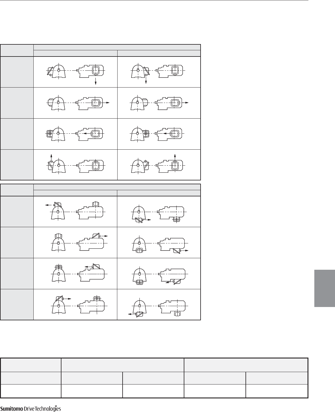
CYCLO® 6000 Gearmotors
Technical Information 5.11
Motor
Cyclo® 6000 Series
Horizontal Mounting Configuration Vertical Mounting Configuration
(Horizontal Slow Speed Shaft) (Vertical Slow Speed Shaft Down)
Standard Motor Brake Motor Standard Motor Brake Motor
3 Phase AF Motor 3 Phase AF Moto 3 Phase 3 Phase
Terminal Box Mounting Position Left Side Left Side Left Side Left Side Left Side Left Side
Cable Port Direction B B B B A A
Mounting Direction of Terminal Box
The terminal box mounting direction can be changed in units of 90˚;
specify the direction according to the table below when placing an order.
Motor
Cable port
direction
Type A
(N3A)
Terminal box mounting position (As viewed from output shaft with motor being horizontal) [1]
Left side (N33) Right side (N34)
Type B
(N3B)
Type C
(N3C)
Type D
(N3D)
Cable port
direction
Type A
(N3A)
Terminal box mounting position (As viewed from output shaft with motor being horizontal) [1]
Top (N35) Bottom (N36)
Type B
(N3B)
Type C
(N3C)
Type D
(N3D)
Standard Position of Terminal Box and Direction of Lead Wires
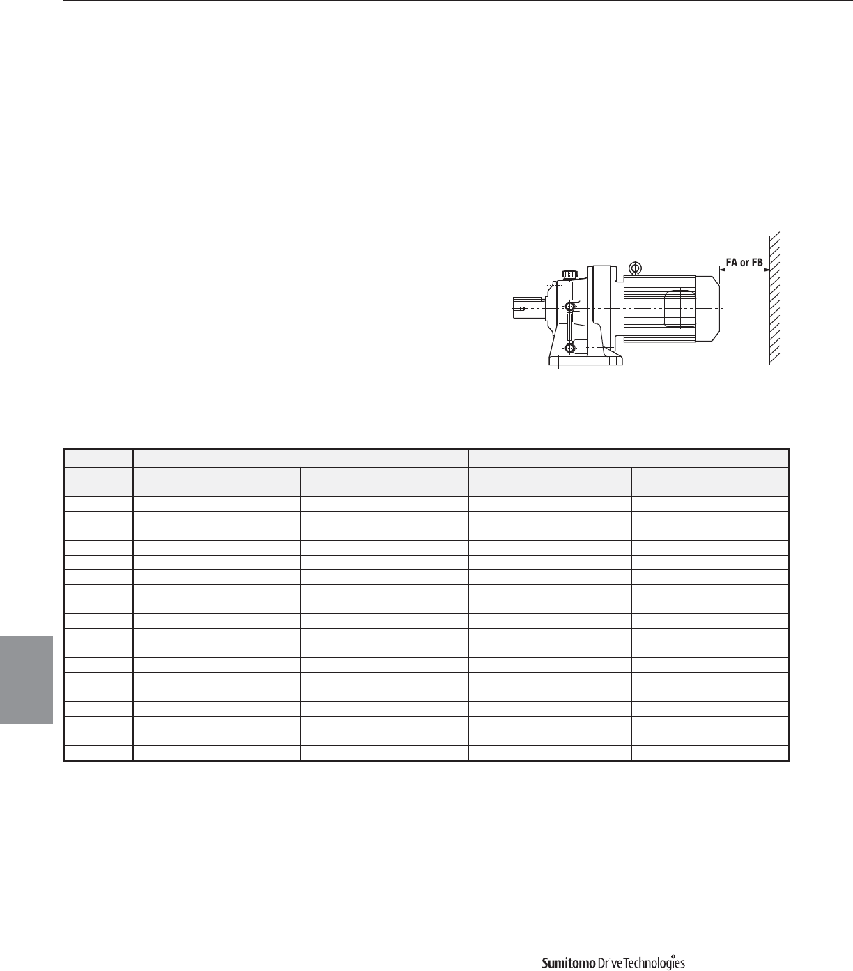
CYCLO® 6000 Gearmotors
5.12 Technical Information
Motor
Cyclo® 6000 Series
Motor Standard Motor Brake Motor
HP (kW) 3 Phase Inverter Duty 3 Phase Inverter Duty
x Pole FA FB FA FB FA FB FA FB
1/8(0.1) x 4 - - 1.9 (48) 0.8 (20) 2.0 (49) - 2.5 (61) 0.8 (20)
1/4(0.2) x 4 1.9 (48) 0.8 (20) 1.9 (48) 0.8 (20) 2.5 (61) 0.8 (20) 2.5 (61) 0.8 (20)
1/3(0.25) x 4 1.9 (48) 0.8 (20) 1.9 (48) 0.8 (20) 2.5 (61) 0.8 (20) 2.5 (61) 0.8 (20)
1/2(0.4) x 4 1.9 (48) 0.8 (20) 2.0 (49) 0.8 (20) 2.5 (61) 0.8 (20) 3.7 (93) 0.8 (20)
3/4(0.55) x 4 2.0 (49) 0.8 (20) 2.1 (52) 0.8 (20) 3.7 (93) 0.8 (20) 4.6 (115) 0.8 (20)
1(0.75) x 4 2.0 (49) 0.8 (20) 2.1 (52) 0.8 (20) 3.7 (93) 0.8 (20) 4.6 (115) 0.8 (20)
1.5(1.1) x 4 2.1 (52) 0.8 (20) 2.2 (56) 0.8 (20) 4.6 (115) 0.8 (20) 5.2 (132) 0.8 (20)
2(1.5) x 4 2.1 (52) 0.8 (20) 2.2 (56) 0.8 (20) 4.6 (115) 0.8 (20) 5.2 (132) 0.8 (20)
3(2.2) x 4 2.2 (56) 0.8 (20) 2.4 (60) 0.8 (20) 5.2 (132) 0.8 (20) 5.2 (132) 0.8 (20)
5(3.7) x 4 2.4 (60) 0.8 (20) 2.4 (60) 0.8 (20) 5.2 (132) 0.8 (20) 5.2 (132) 0.8 (20)
7.5(5.5) x 4 2.4 (60) 0.8 (20) 3.0 (75) 1.0 (25) 5.2 (132) 0.8 (20) 6.7 (170) 1.0 (25)
10(7.5) x 4 3.0 (75) 1.0 (25) 3.0 (75) 1.0 (25) 6.7 (170) 1.0 (25) 6.7 (170) 1.0 (25)
15(11) x 4 3.0 (75) 1.0 (25) 5.2 (130) 1.2 (30) 6.7 (170) 1.0 (25) 8.7 (220) 1.2 (30)
20(15) x 4 5.2 (130) 1.2 (30) 6.2 (155) 1.2 (30) 8.7 (220) 1.2 (30) 14.5 (367) 1.2 (30)
25(18.5) x 4 6.2 (155) 1.2 (30) 6.7 (170) 1.2 (30) 14.5 (367) 1.2 (30) 14.6 (370) 1.2 (30)
30(22) x 4 6.2 (155) 1.2 (30) 6.7 (170) 1.2 (30) 14.5 (367) 1.2 (30) 14.6 (370) 1.2 (30)
40(30) x 4 6.7 (170) 1.2 (30) 5.6 (140) 1.2 (30) 14.6 (370) 1.2 (30) 11.7 (295) 1.2 (30)
50(37) x 4 9.1 (230) 1.2 (30) 5.6 (140) 1.2 (30) 17.6 (445) 1.2 (30) 11.7 (295) 1.2 (30)
Motor Cover Mounting Specifications
Refer to dimension FA or FB when designing the mounting space into which the gearmotor is to fit.
Dimension FA: The space necessary to remove the fan cover or brake cover without removing
the motor from the equipment.
Dimension FB: Minimum space required for adequate ventilation.
Notes:
1. It is necessary to remove the gearmotor from the equipment when removing the fan or brake cover.
2. AF (Inverter) motors of 40 HP (30kW) or greater are of a different ventilation type.
Motor continued
Space Requirements
Units: inches (mm)
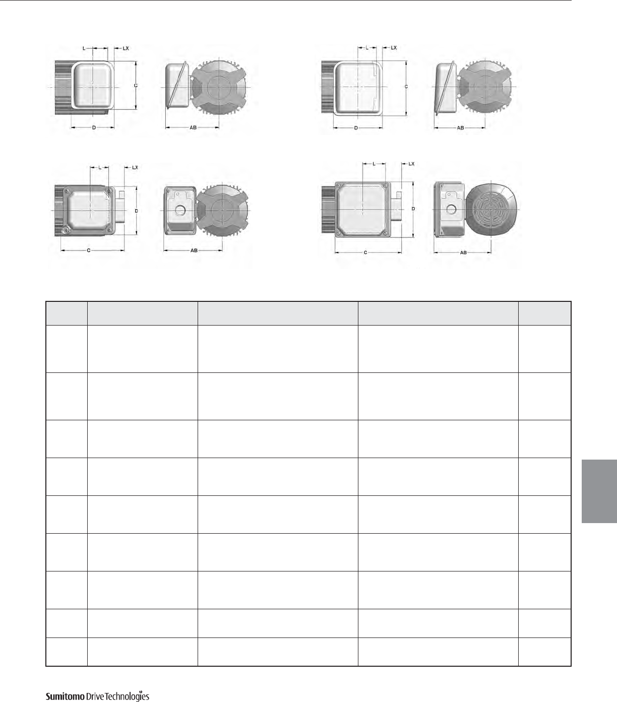
CYCLO® 6000 Gearmotors
Technical Information 5.13
Motor
Cyclo® 6000 Series
Motor continued
Conduit Box Dimensions
Figure 5.22 Non-UL Indoor Duty Figure 5.23 UL Indoor Duty
Figure 5.24 Non-UL & UL Washdown Duty Figure 5.25 Global
Table 5.24 Terminal Box Mounting Centers
Units: inches
Frame
Size Duty Rating Without Brake With Brake Conduit
Opening
AB C D L LX AB C D L LX
V-63S
Non-UL Indoor Duty 4.13 3.78 3.35
1.38
.30 5.20 5.67 4.80
2.76
– 0.90 dia
UL Indoor Duty 5.20 5.67 4.80 1.02 5.20 5.67 4.80 – 0.90 dia
Non-UL & UL Washdown Duty 5.00 5.16 3.94 1.58 5.00 5.16 3.94 0.20 PF 1/2
Global 5.04 5.91 4.92 2.05 5.04 5.91 4.92 0.67 NPT 1/2
Small Global 4.45 4.41 4.09 0.80 4.45 4.41 4.09 – NPT 1/2
V-63M
V-71M
VA-63S
VA-63M
Non-UL Indoor Duty 4.13 3.78 3.35
2.34
– 5.20 5.67 4.80
3.58
– 0.90 dia
UL Indoor Duty 5.20 5.67 4.80 .06 5.20 5.67 4.80 – 0.90 dia
Non-UL & UL Washdown Duty 5.00 5.16 3.94 0.62 5.00 5.16 3.94 – PF 1/2
Global 5.04 5.91 4.92 1.09 5.04 5.91 4.92 – NPT 1/2
Small Global 4.45 4.41 4.09 – 4.45 4.41 4.09 NPT 1/2
V-80S
V-80M
VA-71M
Non-UL Indoor Duty 4.69 3.78 3.35
3.82
– 5.79 5.67 4.80
5.53
– 0.90 dia
UL Indoor Duty 5.79 5.67 4.80 – 5.79 5.67 4.80 – 0.90 dia
Non-UL & UL Washdown Duty 5.55 5.16 3.94 – 5.55 5.16 3.94 – PF 3/4
Global 5.63 5.91 4.92 – 5.63 5.91 4.92 – NPT 3/4
V-90S
V-90L
VA-80S
VA-80M
Non-UL Indoor Duty 4.88 3.78 3.35
3.98
– 5.98 5.67 4.80
6.42
– 0.90 dia
UL Indoor Duty 5.98 5.67 4.80 – 5.98 5.67 4.80 – 0.90 dia
Non-UL & UL Washdown Duty 5.75 5.16 3.94 – 5.75 5.16 3.94 – PF 3/4
Global 5.83 5.91 4.92 – 5.83 5.91 4.92 – NPT 3/4
V-100L
VA-90S
VA-90L
Non-UL Indoor Duty 5.16 3.78 3.35
4.17
– 6.26 5.67 4.80
6.65
– 0.90 dia
UL Indoor Duty 6.26 5.67 4.80 – 6.26 5.67 4.80 – 0.90 dia
Non-UL & UL Washdown Duty 6.02 5.16 3.94 – 6.02 5.16 3.94 – PF 3/4
Global 6.10 5.91 4.92 – 6.10 5.91 4.92 – NPT 3/4
V-112M
VA-100L
Non-UL Indoor Duty 5.80 4.41 3.94
5.00
– 6.69 5.67 4.80
7.83
– 0.90 dia
UL Indoor Duty 6.69 5.67 4.80 – 6.69 5.67 4.80 – 0.90 dia*
Non-UL & UL Washdown Duty 7.20 6.02 4.84 – 7.20 6.02 4.84 – PF 3/4
Global 6.54 5.91 4.92 – 6.54 5.91 4.92 – NPT 3/4
V-132S
VA-112M
Non-UL Indoor Duty 5.80 4.41 3.94
5.00
– 6.69 5.67 4.80
7.83
– 0.90 dia
UL Indoor Duty 6.69 5.67 4.80 – 6.69 5.67 4.80 – 0.90 dia*
Non-UL & UL Washdown Duty 7.20 6.02 4.84 – 7.20 6.02 4.84 – PF 1
Global 6.54 5.91 4.92 – 6.54 5.91 4.92 – NPT 1
F-132M
FA-132S
UL Indoor Duty 7.40 5.44 4.80
5.63
– 7.40 5.44 4.80
9.37
– 1.69 dia
Non-UL & UL Washdown Duty 8.74 7.37 6.06 – 8.74 7.37 6.06 – PF 1
Global 8.31 7.83 6.69 – 8.31 7.83 6.69 – NPT 1
F-160M
FA132M
UL Indoor Duty 7.40 5.44 4.80
5.63
– 7.40 5.44 4.80
9.37
– 1.69 dia
Non-UL & UL Washdown Duty 8.74 7.37 6.06 – 8.74 7.37 6.06 – PF 1-1/4
Global 8.31 7.83 6.69 – 8.31 7.83 6.69 – NPT 1
*1.38 dia. may be found for some of these sizes
CYCLO® 6000 Gearmotors
5.14 Technical Information
Motor
Motor continued
Standard Motor Data
Three Phase, 230/460V, 60Hz, 1800 RPM Synchronous Speed, TEFC
Three Phase, 230/460V, 60Hz, 1200 RPM Synchronous Speed, TEFC
Note: ** 1/8 HP is TENV.
Single Phase, 115/230V, 60Hz, 1800 RPM, Synchronous Speed, TEFC
HP Frame
Size
Full Load Current (A) Starting Breakdown Power NEMA Inertia WR2
lb•in2
Rated
RPM
Torque
in•lbs
Full Load No Load Starting Torque Torque Efficiency Factor Code
230V 460V % of FL % of FL (% of FL) (% of FL) % % Letter
1/8** V-63S 1730 4.55 0.66 0.33 86.1% 424% 326% 308% 63.3% 60.0% K 1.11
1/4 V-63M 1730 9.10 1.12 0.56 79.6% 464% 300% 287% 69.2% 65.1% K 1.71
1/3 V-63M 1700 12.2 1.24 0.62 72.0% 419% 237% 226% 70.1% 72.0% G 1.71
1/2 V-71M 1750 18.0 2.15 1.08 77.7% 456% 295% 276% 71.5% 65.4% J 2.22
3/4 V-80S 1720 27.5 2.47 1.24 68.4% 500% 266% 261% 76.5% 73.1% H 3.45
1 V-80M 1740 36.2 3.38 1.69 69.8% 521% 278% 303% 76.9% 72.4% H 4.10
1.5 V-90S 1720 54.9 4.66 2.33 64.4% 614% 273% 290% 79.8% 74.3% J 6.32
2 V-90L 1740 72.4 6.07 3.04 61.6% 606% 263% 275% 81.9% 75.8% J 7.28
3 V-100L 1730 109 8.5 4.25 57.2% 645% 277% 311% 83.9% 77.4% J 11.4
5 V-112M 1730 182 13.1 6.55 47.8% 702% 278% 293% 85.8% 82.7% J 29.0
7.5 V-132S 1710 276 18.2 9.08 32.4% 661% 223% 252% 86.2% 88.3% H 39.0
10 F-132M 1750 360 23.7 11.9 27.8% 620% 212% 228% 88.9% 89.7% G 91.6
15 F-160M 1750 540 34.1 17.1 27.6% 677% 248% 258% 90.1% 90.0% G 128
20 G-160L 1750 720 45.7 22.9 22.3% 595% 222% 220% 90.8% 90.7% F 307
25 F-180MG 1770 890 58.0 29.0 36.1% 917% 361% 328% 92.0% 86.9% K 769
30 F-180MG 1760 1090 67.8 33.9 30.5% 785% 303% 275% 92.1% 88.5% J 769
40 F-180L 1760 1430 93.3 46.7 31.4% 755% 310% 274% 92.2% 87.6% H 854
50 F-200L 1760 1790 113 56.7 30.5% 800% 340% 286% 92.6% 88.5% J 1050
60 F-200L 1740 2170 137 68.7 28.5% 793% 344% 282% 92.4% 89.0% J 1170
75 F-225S 1760 2680 166 83 28.6% 758% 277% 282% 92.4% 90.0% H 2310
HP Frame
Size
Full Load Current (A) Starting Breakdown Power NEMA Inertia WR2
lb•in2
Rated
RPM
Torque
in•lbs
Full Load No Load Starting Torque Torque Efficiency Factor Code
230V 460V % of FL % of FL % of FL % of FL % % Letter
20 F-180MG 1180 1070 48.4 24.2 39.5% 748% 273% 306% 92.3% 84.3% J 1090
25 F-180L 1180 1330 58.5 29.3 35.4% 704% 261% 286% 91.7% 86.6% J 1240
30 F-180L 1180 1600 71 35.6 39.1% 713% 273% 297% 92.0% 84.4% H 1240
40 F-200L 1180 2130 95.4 47.7 36.3% 738% 318% 305% 92.6% 85.4% H 1620
50 F-200L 1170 2690 119 59.6 39.1% 776% 348% 327% 92.8% 84.1% J 2050
60 F-225S 1180 3200 141 70.4 33.4% 683% 290% 267% 92.8% 86.6% H 3420
75 F-250S 1170 4040 170 85 31.4% 672% 289% 259% 93.0% 87.0% G 4030
Cyclo® 6000 Series
HP Frame
Size
Full Load Current (A) Starting Breakdown Power Inertia WR2
lb•in2
Rated
RPM
Torque
in•lbs
Full Load No Load Starting Torque Torque Efficiency Factor
115V 230V % of FL % of FL % of FL % of FL % %
1/8 TS-71S 1730 4.52 3.56 1.88 91.3% 475% 468% 582% 42.2% 54.1% 5.13
1/4 TS-71S 1680 9.37 4.8 2.4 67.7% 352% 225% 280% 49.9% 69.6% 5.13
1/3 TS-71 1745 12.0 6.4 3.2 75.3% 525% 378% 368% 58.1% 58.2% 7.69
1/2 TS-71 1720 18.3 7.8 3.9 61.8% 431% 252% 245% 61.7% 68.8% 7.69
3/4 TS-90 1730 27.3 10.4 5.2 71.3% 590% 395% 465% 71.4% 68.1% 20.5
1TS-90 1700 37.0 12.4 6.2 59.8% 495% 290% 340% 69.4% 77.1% 20.5
CYCLO® 6000 Gearmotors
Technical Information 5.15
Lubrication
Cyclo® 6000 Series
Motor
Dimensions for units with CSA approved motors may
be different than those specified in Section 4.
Please consult factory for details.
CSA Approved Motor Data
EPACT/EEV Efficiency Motors
Three Phase, 230/460V, 60Hz, 1800 RPM Synchronous Speed, TEFC
Three Phase, 230/460V, 60Hz, 1800 RPM Synchronous Speed, TEFC
HP Frame
Size
Full Load Current (A) Starting Breakdown Power NEMA Inertia WR2
lb•in2
Rated
RPM
Torque
in•lbs
Full Load No Load Starting Torque Torque Efficiency Factor Code
230V 460V % of FL % of FL % of FL % of FL % % Letter
1/8** V-63S 1720 4.58 0.71 0.35 91.4% 457% 378% 393% 65.5% 54.1% M 1.11
1/4 V-63M 1730 9.10 1.20 0.60 86.0% 450% 309% 343% 69.4% 60.1% K 1.71
1/3 V-63M 1710 12.2 1.30 0.65 79.4% 415% 244% 272% 71.3% 67.5% H 1.71
1/2 V-71M 1700 18.5 2.10 1.10 81.0% 481% 343% 331% 75.2% 63.1% K 2.22
3/4 V-80S 1700 27.8 2.60 1.30 70.8% 515% 263% 272% 75.4% 71.4% H 3.45
1 V-80M 1700 37.0 3.60 1.80 75.6% 572% 341% 315% 78.0% 66.9% K 4.10
HP Frame
Size
Full Load Current (A) Starting Breakdown Power NEMA Inertia WR2
lb•in2
Rated
RPM
Torque
in•lbs
Full Load No Load Starting Torque Torque Efficiency Factor Code
230V 460V % of FL % of FL % of FL % of FL % % Letter
1VA-80M 1740 36.2 3.2 1.6 70.0% 700% 320% 379% 84.5% 68.2% K 7.28
1.5 VA-90S 1740 54.3 4.6 2.3 64.6% 678% 319% 364% 85.7% 71.1% K 11.4
2VA-90L 1730 72.8 5.8 2.9 60.3% 717% 271% 306% 86.6% 74.9% K 11.4
3 VA-100L 1750 108 8.1 4.1 56.9% 879% 310% 406% 89.1% 76.4% L 29.0
5 VA-112M 1740 181 12.7 6.4 45.1% 781% 302% 330% 89.5% 81.6% J 39.0
7.5 FA-132S 1750 270 18.5 9.2 46.6% 801% 309% 345% 90.7% 82.5% J 91.6
10 FA-132M 1750 360 24.5 12.2 38.9% 828% 284% 303% 90.4% 85.1% K 128
15 G-160L 1770 534 35.9 18.0 41.8% 928% 335% 335% 92.9% 82.7% K 307
20 G-160L 1770 712 48.7 24.3 41.6% 984% 351% 354% 92.8% 83.5% L 307
25 F-180L 1780 885 61.0 30.4 40.1% 803% 336% 305% 92.4% 82.7% J 854
30 F-180L 1780 1060 71.0 35.4 34.5% 689% 282% 256% 92.4% 84.5% H 854
40 F-200L 1780 1420 98.0 49.1 38.3% 740% 288% 279% 93.4% 82.1% J 1050
50 F-200L 1780 1770 116 58.0 30.6% 683% 203% 250% 93.2% 85.5% H 1050
Motor continued
Note: ** 1/8 HP is TENV.
Motor
CYCLO® 6000 Gearmotors
5.16 Technical Information Cyclo® 6000 Series
Dimensions for units with CSA approved motors may
be different than those specified in Section 4.
Please consult factory for details.
CSA Approved Motor Data continued
EPACT/EEV Efficiency Motors
Three Phase, 575V, 60Hz, 1800 RPM Synchronous Speed, TEFC
Three Phase, 575V, 60Hz, 1800 RPM Synchronous Speed, TEFC
HP Frame
Size
Full Load Current (A) Starting Breakdown Power NEMA Inertia WR2
lb•in2
Rated
RPM
Torque
in•lbs
Full No Load Starting Torque Torque Efficiency Factor Code
Load % of FL % of FL % of FL % of FL % % Letter
1/8** V-63S 1720 4.58 0.28 91.8% 464% 376% 391% 65.3% 54.1% M 1.11
1/4 V-63M 1730 9.10 0.48 85.4% 458% 316% 340% 69.4% 60.3% K 1.71
1/3 V-63M 1710 12.2 0.52 78.8% 423% 250% 270% 71.3% 67.4% H 1.71
1/2 V-71M 1700 18.5 0.79 75.8% 468% 309% 300% 75.8% 67.4% J 2.22
3/4 V-80S 1700 27.8 1.00 74.0% 530% 260% 268% 75.1% 71.6% H 3.45
1 V-80M 1700 37.0 1.30 65.4% 508% 252% 256% 78.1% 74.9% H 4.10
HP Frame
Size
Full Load Current (A) Starting Breakdown Power NEMA Inertia WR2
lb•in2
Rated
RPM
Torque
in•lbs
Full No Load Starting Torque Torque Efficiency Factor Code
Load % of FL % of FL % of FL % of FL % % Letter
1VA-80M 1740 36.2 1.3 66.5% 685% 320% 379% 84.8% 68.2% K 7.28
1.5 VA-90S 1740 54.3 1.8 62.2% 689% 319% 364% 85.7% 71.1% K 11.4
2VA-90L 1730 72.8 2.4 56.7% 692% 326% 371% 86.1% 73.6% K 11.4
3 VA-100L 1750 108 3.3 53.9% 833% 354% 417% 87.9% 78.5% L 29.0
5 VA-112M 1740 181 5.2 45.6% 769% 295% 346% 88.7% 81.7% J 39.0
7.5 FA-132S 1750 270 7.5 45.2% 709% 288% 331% 89.9% 83.6% H 91.6
10 FA-132M 1760 358 9.7 39.5% 849% 314% 340% 91.5% 84.5% K 128
15 G-160L 1770 534 14.7 41.5% 925% 338% 338% 92.8% 82.7% L 307
20 G-160L 1770 712 19.2 38.5% 927% 327% 330% 93.0% 84.5% K 307
25 F-180L 1780 885 24.5 38.8% 776% 330% 285% 92.7% 82.9% J 854
30 F-180L 1780 1060 28.9 32.9% 657% 275% 237% 92.5% 84.5% H 854
40 F-200L 1780 1420 38.8 37.9% 714% 283% 274% 93.5% 83.0% H 1050
50 F-200L 1770 1780 46.1 31.7% 685% 203% 250% 93.8% 85.8% G 1050
Motor continued
Note: ** 1/8 HP is TENV.
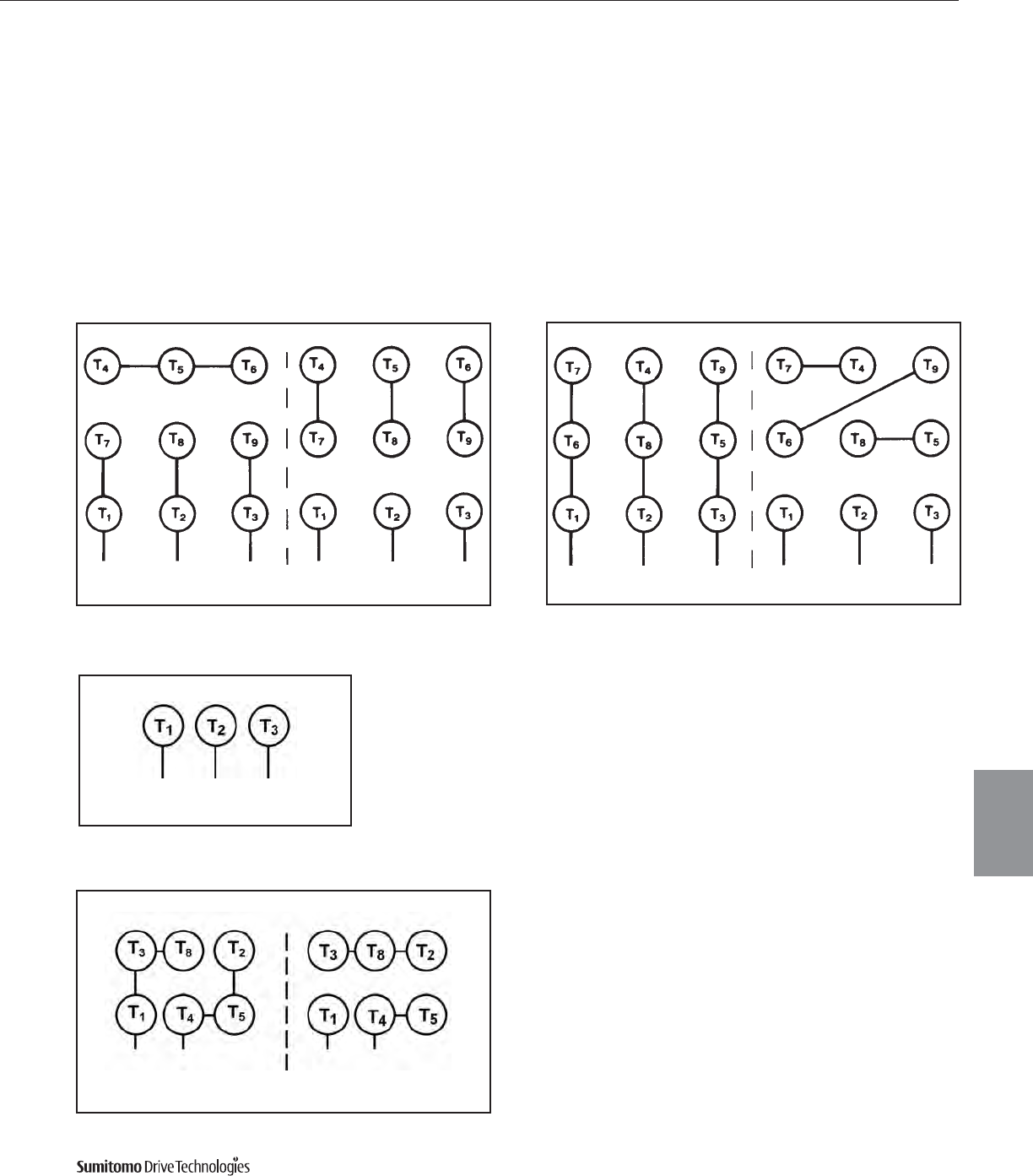
Motor continued
Standard Wiring Diagrams
Illustrated below are the wiring diagrams for our standard motors, for
additional information please refer to the motor name plate. Due to
changes in design features, this diagram may not always agree with
that on the motor. If different, the motor diagram found inside the
conduit box cover is correct.
3-Phase Motors (230/460 V)
Single Phase Motors
WYE-Connected (5 HP and smaller) DELTA-Connected (7.5 HP and larger)
Line 208/230V 60Hz Line 460V 60Hz Line 208/230V 60Hz Line 460V 60Hz
Line 115V Line 230V or 208V
CYCLO® 6000 Gearmotors
Technical Information 5.17
Motor
Cyclo® 6000 Series
Line 575V 60Hz
Three Phase Motors (575V)
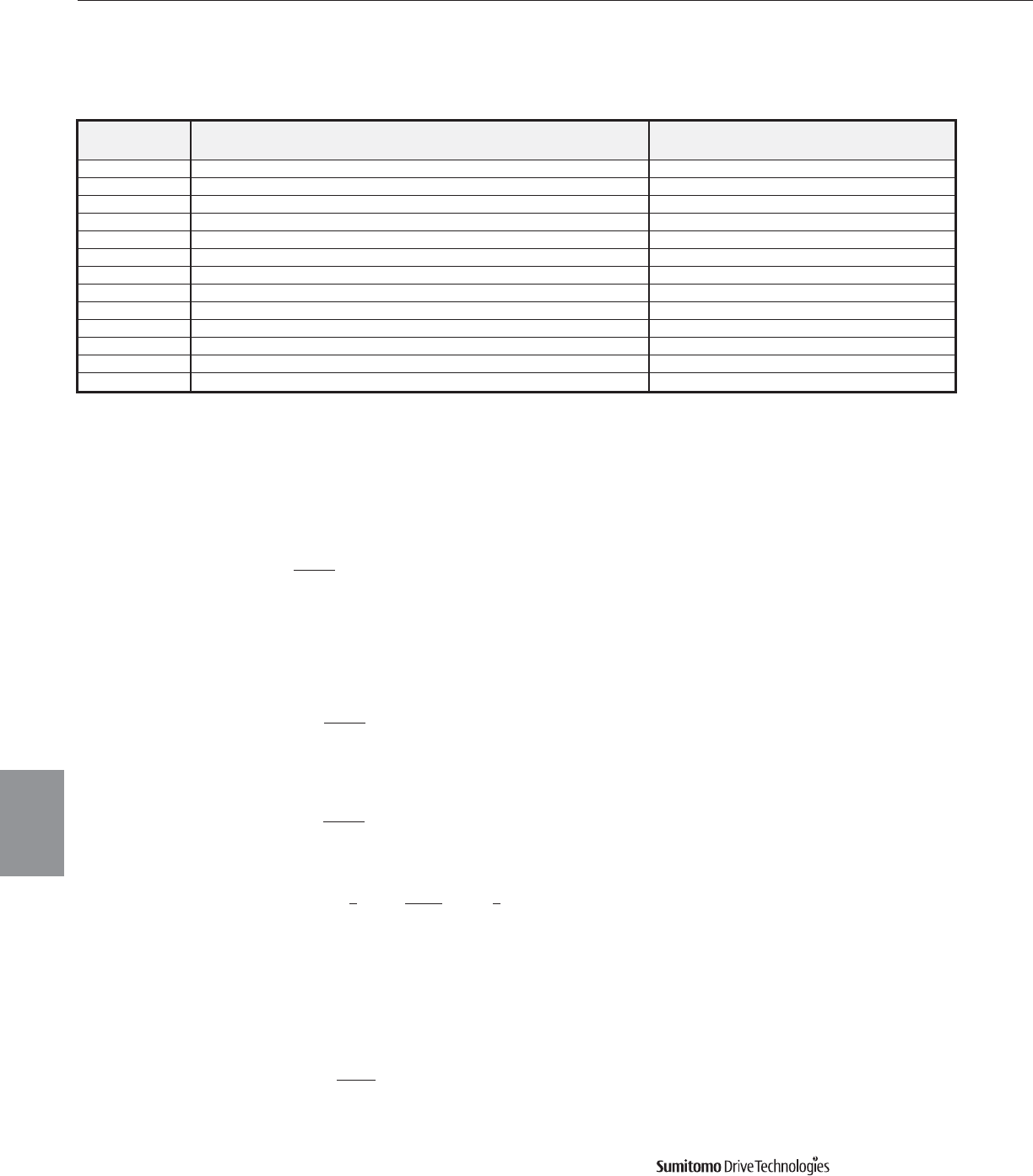
CYCLO® 6000 Gearmotors
5.18 Technical Information Cyclo® 6000 Series
Motor
Motor Allowable C x Z Motor Moment of Inertia lb•in2
Power HP 35% ED[1] 35%~50% ED[1] 50~80% ED[1] 80~100% ED[1] Standard with Brake
1/8 3200 3000 2000 1200 1.11 1.20
1/4 2200 2800 2800 2500 1.71 1.88
1/3 2200 2800 2800 2500 1.71 1.88
1/2 1800 2200 1500 1500 2.22 2.31)
3/4 1800 2200 1500 1500 3.45 3.79
1 1400 1400 800 500 4.10 4.44
1.5 1400 1400 800 500 6.32 7.11
2 1200 1200 500 400 7.28 8.03
3 1000 900 400 200 11.4 12.8
5 800 800 800 700 29.0 32.7
7.5 300 300 200 150 39.0 42.7
10 400 350 300 300 91.6 104
15 200 200 150 150 128 140
Motor continued
The calculated C x Z value (steps 1 – 3 outlined below) should be less than the allow-
able value listed in Motor Thermal Rating table above.
1. Obtain the C value:
IM= Moment of Inertia of Motor.
IL= Total Moment of Inertia of Load as seen from the motor.
2. Obtain the Z value (number of starts per hour):
(a) Assume that one operating period consists of “on-time” ta (sec.), “off-time” tb (sec.) and
the motor is started nr (times/sec.).
(b) When inching, ni (times/cycle) is included in 1 cycle (ta + tb), the number of inching
times per hour Zi, is then included in the number of starts.
(c) Calculate Z by adding Zr to Zi.
3. Calculate C multiplied by Z:
Use the value of C obtained in step (1) and Z from step (2)
4. Obtain the duty cycle %ED and check with Motor Thermal Rating table above.
Motor Thermal Rating (C x Z)
Note: [1] % ED = duty cycle.
C = IM+ IL
IM
Zr = 3600nr (times/hour)
ta + tb
Zi = 3600ni (times/hour)
ta + tb
Z = Zr + 1 Zi = 3600 • nr + 1 ni (times/hour)
2 ta + tb 2
%ED = ta x 100 ta = on-time
ta + tb tb = off-time
()
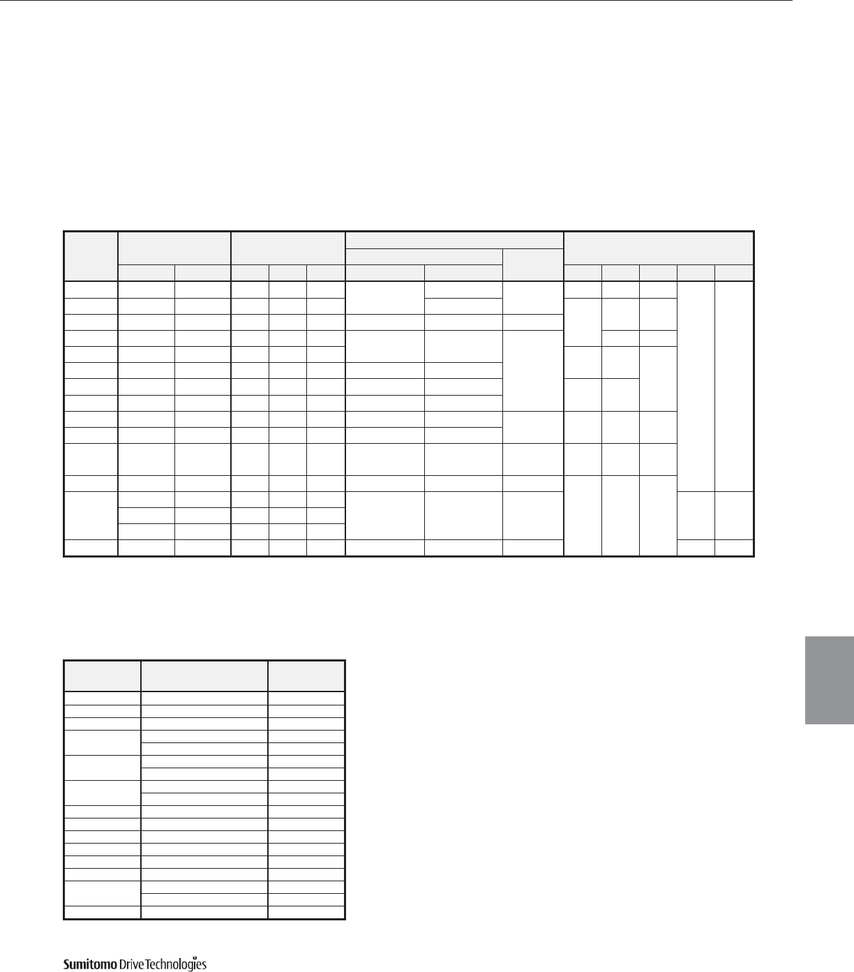
CYCLO® 6000 Gearmotors
Technical Information 5.19
Motor
Cyclo® 6000 Series
Motor continued
Brakemotor Characteristics
The brakemotor on Cyclo®gearmotors operates with direct current supplied by a dual voltage rectifier for 230/460V, or single voltage
rectifier/power module for other noted voltages. Rectifier or power module is mounted in the motor conduit box.
When used for outdoor installations, our standard brakemotor must be protected with some type of covering. Such type of coverings
are available from the factory, please inquire when ordering.
Note: Advise the factory when ordering if you require larger or smaller brake torque than those shown as standard in the
Brakemotor Characteristics table below.
Brake Characteristics
Standard Brake Models
Brake
Model
Motor Capacity [1]
(HP x 4P)
Braking Torque
(ft-lbs)
Braking Delay Time (sec) Standard Brake Current
(AC Amps)
Normal Braking Action Fast Braking
Action
Standard AF-Motor Min. Std. Max. Standard Wiring Inverter Wiring[2] 230VAC 460VAC 575VAC 200VAC 220VAC
FB-01A 1/8 – 0.24 0.7 0.96 0.15 ~ 0.2 –0.015 ~ 0.02 0.06 0.04 0.03
– –
FB-02A 1/4, 1/3 1/8 0.48 1.4 1.9 0.8 ~ 0.12
0.1 0.06 0.07
FB-05A 1/2 1/4, 1/3 0.96 2.9 2.9 0.1 ~ 0.15 0.03 ~ 0.07 0.01 ~ 0.015
FB-1D 3/4, 1 1/2 1.9 5.8 7.7 0.2 ~ 0.3 0.1 ~ 0.15
0.01 ~ 0.02
0.1 0.1
FB-2D 1.5, 2 3/4, 1 3.6 11 14 0.2 0.2
0.2
FB-3D 31.5, 2 5.3 16 21 0.3 ~ 0.4 0.15 ~ 0.2
FB-5B 5 3 9 27 36 0.4 ~ 0.5 0.2 ~ 0.25 0.3 0.3
FB-8B 7.5 5 13 40 55 0.3 ~ 0.4 0.1 ~ 0.15
FB-10B 10 7.5 18 54 72 0.7 ~ 0.8 0.25 ~ 0.3 0.03 ~ 0.04 0.5 0.5 0.4
FB-15B 15 10 27 80 108 0.5 ~ 0.6 0.15 ~ 0.2
CMB-20 20 15 58 72 72 0.6 ~ 0.8 (other)
0.4 ~ 0.5 (460V)
0.3 ~ 0.35 (other)
0.1 ~ 0.15 (460V) 0.1 ~ 0.15 1.6 1.8 1.4
FB-20[3] 20 15 40 110 160 1.7 ~ 1.8 0.65 ~ 0.75 0.03 ~ 0.06
–––FB-30[3]
25 20 40 140 160
1.4 ~ 1.5 0.45 ~ 0.55 0.03 ~ 0.06 1.4/0.7[4] 1.6/0.8[4]
30 – 40 160 160
40 30 40 160 160
ESB250[3] 50 40 – 180 – – – 0.065 1.6/0.8[4] 1.8/0.9[4]
Brake
Model
Motor
Frame Sizes
Inertia WR2
lb-in2
FB-01A V-63S 1.20
FB-02A V-63M, VA-63S 1.88
FB-05A V-71M, VA-63M 2.31
FB-1D V-80S 3.79
V-80M, VA-71M 4.44
FB-2D V-90S, VA-80S 7.11
V-90L, VA-80M 8.03
FB-3D VA-90S 10.4
V-100L, VA-90L 12.7
FB-5B V-112M, VA-100L 32.7
FB-8B V-132S, VA-112M 42.7
FB-10B F-132M, FA-132S 104
FB-15B F-160M, FA-132M 140
CMB-20 G-160L 454
FB-20 G-160L 366
FB-30 F-180MG 830
F-180L 895
ESB-250 F-200L 1100
Combination Table with Brakemotor Inertia
Notes: [1] May not apply to CSA Approved motors. Identify applicable brake model to motor frame size in Combination table below.
[2] Also applies to wiring where brake is powered separately from the motor leads.
[3] Available only with power module rated for use at 200VAC or 220VAC.
[4] 2 brake current values shown. First excitation current on initial power up. Second is holding current.
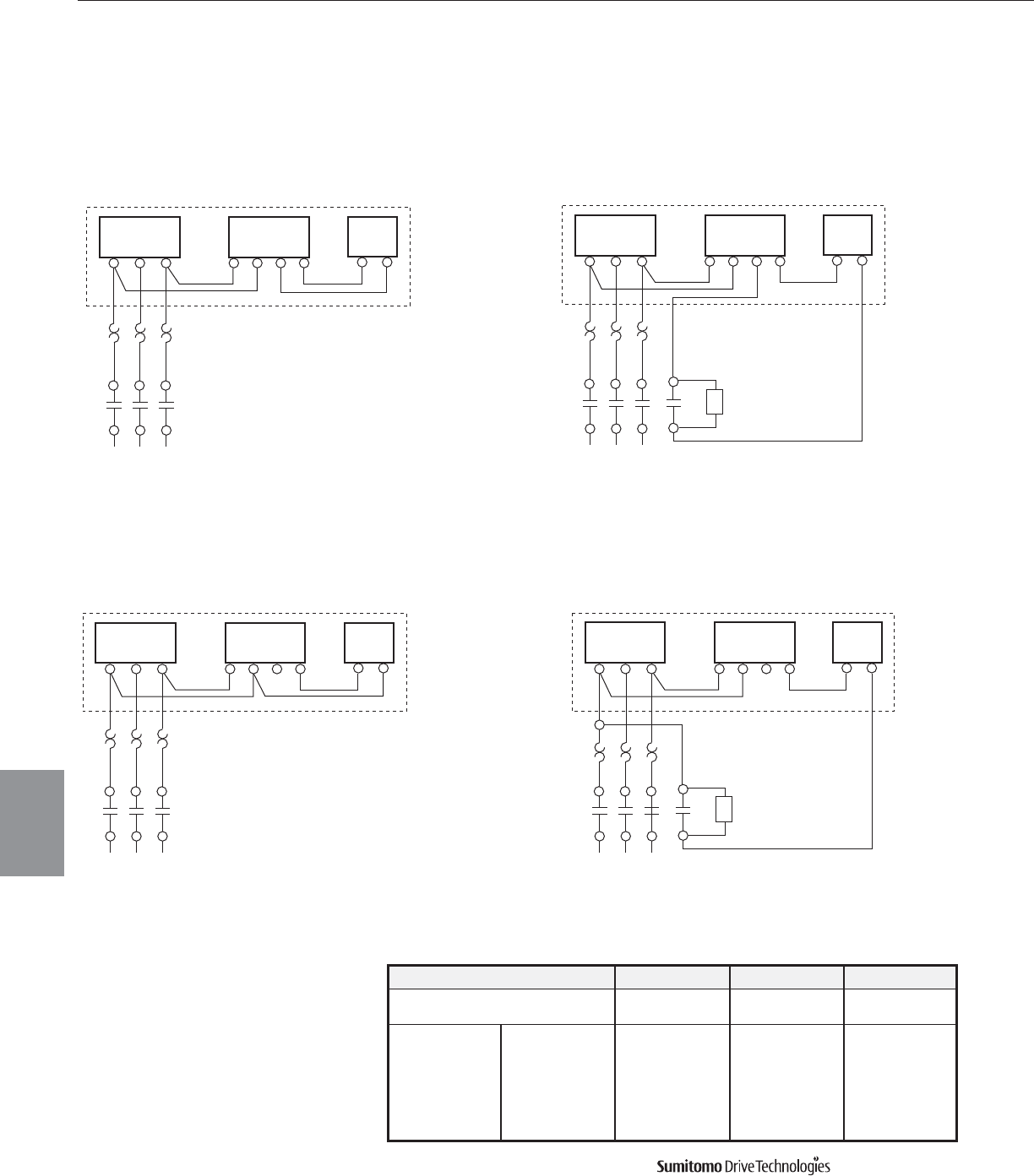
CYCLO® 6000 Gearmotors
5.20 Technical Information Cyclo® 6000 Series
Motor
Motor Brakemotor, Standard Wiring
Brake
MN
Furnished by Sumitomo
OLR
MC
Line 230V
Motor
T2T1 T3
Rectifier
21 3 4
VR
Brake
MN
Furnished by Sumitomo
OLR
MC
Line 460V
Motor
T2T1 T3
Rectifier
21 3 4
Brake
M N
Furnished by Sumitomo
OLR
MC
Line 460V
Motor
T2T1 T3
Rectifier
21 3 4
VR
Brake
MN
Furnished by Sumitomo
OLR
MC
Line 230V
Motor
T2T1 T3
Rectifier
21 3 4
Figure 5-1 Normal Brake Action, 230V, 575V Figure 5-2 Fast Brake Action, 230V
Figure 5-3 Normal Brake Action, 460V Figure 5-4 Fast Brake Action, 460V, 575V
Models FB-01A through FB-15B
Standard Wiring Connection, Dual Voltage
Varistor Specifications Table
MC: Electromagnetic Relay
MCB: Magnetic Circuit Breaker
OLR: Overload or Thermal Relay
VR: Varistor (protective device)[1]
Note: [1] Refer to Varisitor Specifications Table
Operating Voltage 190-230V 380-460V 575V
Varistor Rated Voltage AC260-300V AC510V AC604V
Varistor Voltage 430-470V 820V 1000V
FB01A, 02A Over 0.4W Over 0.4W Over 0.4W
FB-05A Over 0.4W Over 0.4W Over 0.4W
Rated Watt FB-1D Over 0.6W Over 0.6W Over 0.4W
FB-2D, 3D Over 1.5W Over 1.5W Over 0.6W
FB-5B, 8B Over 1.5W Over 1.5W Over 1.5W
FB10B, 15B Over 1.5W Over 1.5W Over 1.5W
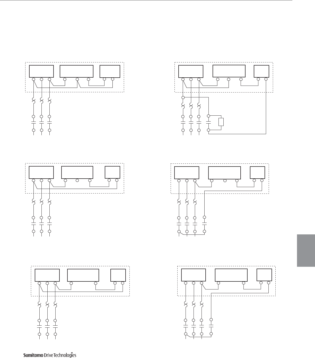
CYCLO® 6000 Gearmotors
Technical Information 5.21
Cyclo® 6000 Series
Motor Brakemotor Standard Wiring continued
Brake
M N
Furnished by Sumitomo
OLR
MC
Line 208/230V
Motor
T2 T3
Rectifier
CA B
R
Brake
MN
Furnished by Sumitomo
OLR
MC
Line 460V
Motor
T2T1 T3
Rectifier
CA B
Brake
MN
Furnished by Sumitomo
OLR
MC
Line 460V
Motor
T2T1 T3
Rectifier
CA B
Brake
MN
Furnished by Sumitomo
OLR
MC
Line 208/230V
Motor
T2T1 T3
Rectifier
CA B
Figure 5-5 Normal Brake Action, 230V Figure 5-6 Fast Brake Action, 230V
Figure 5-7 Normal Brake Action, 460V Figure 5-8 Fast Brake Action, 460V
Models CMB-20
Motor
Brake
M N
Furnished by Sumitomo
OLR
MC
Line 575V
Motor
T2T1 T3
Rectifier
A B
Figure 5-9 Normal Brake Action, 575V
Brake
M N
Furnished by Sumitomo
OLR
MC
Line 575V
Motor
T2T1 T3
Rectifier
A B
Figure 5-10 Fast Brake Action, 575V
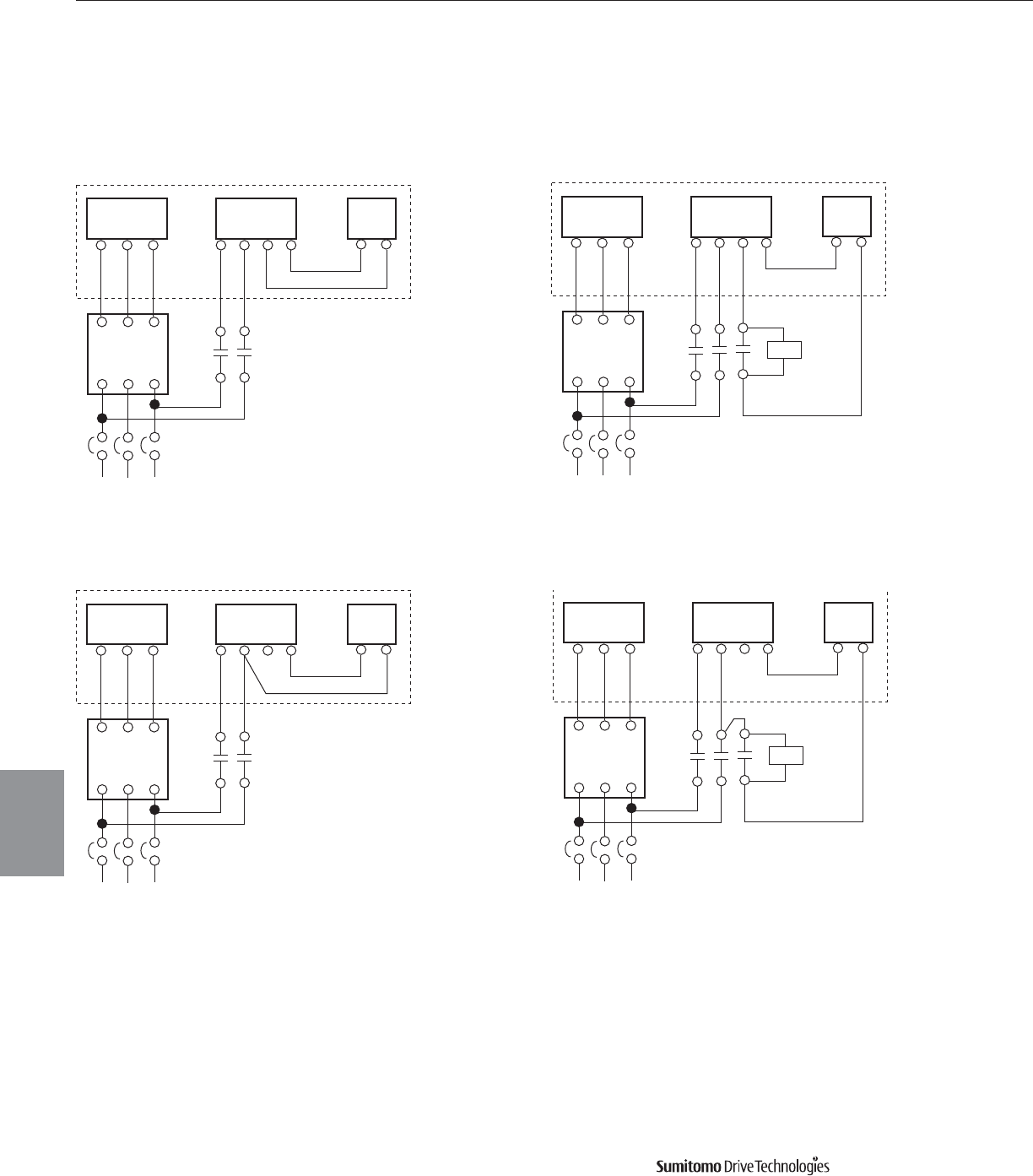
CYCLO® 6000 Gearmotors
5.22 Technical Information Cyclo® 6000 Series
Motor
Motor
T2T1 T3
Rectifier
2134
Brake
MN
MC
Line 230V
Furnished by
Sumitomo
Inverter
T2T1 T3
L2L1 L3
VR
Motor
T2T1 T3
Rectifier
2134
Brake
MN
MC
Line 460V
Furnished by
Sumitomo
Inverter
T2T1 T3
L2L1 L3
Motor
T2T1 T3
Rectifier
2134
Brake
MN
MC
Line 460V
Furnished by
Sumitomo
Inverter
T2T1 T3
L2L1 L3
VR
Motor
T2T1 T3
Rectifier
2134
Brake
MN
MC
Line 230V
Furnished by
Sumitomo
Inverter
T2T1 T3
L2L1 L3
Figure 5-11 Normal Brake Action, 230V, 575V Figure 5-12 Fast Brake Action, 230V, 575V
Figure 5-13 Normal Brake Action, 460V Figure 5-14 Fast Brake Action, 460V
MC: Electromagnetic Relay
MCB: Magnetic Circuit Breaker
VR: Varistor (protective device)[1]
Note: [1] Refer to Varsitor Specifications Table on pg. 5.20
FB Brake (1/8 to 15 HP) with Inverter
Motor Brakemotor, Standard Wiring continued
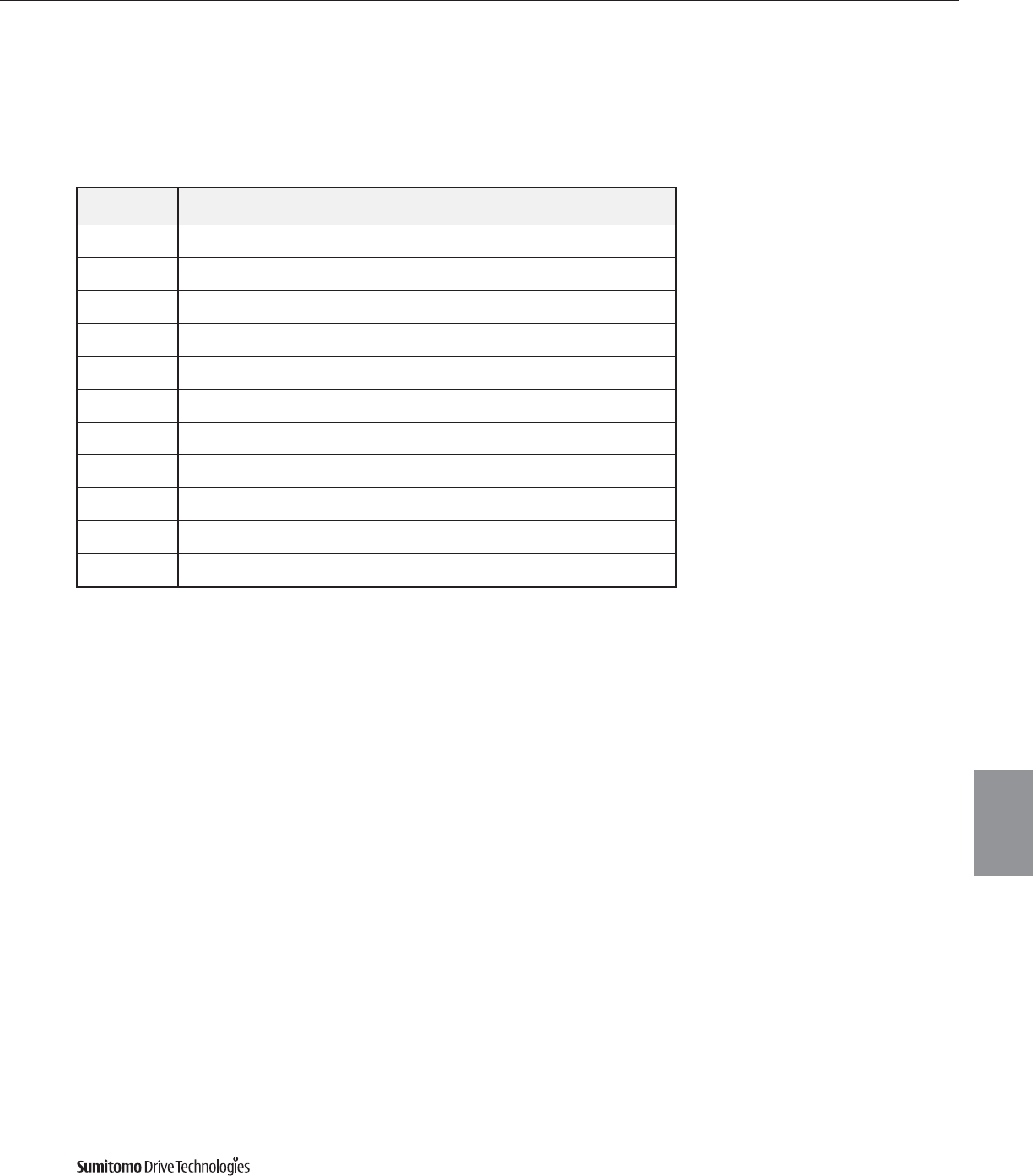
CYCLO® 6000 Gearmotors
Technical Information 5.23
Cyclo® 6000 Series
Rectifier Data
Motor continued
Motor
Brake Type Motor (HP X P) Rectifier Model
230V/460V
Rectifier P. N.
Number
Rectifier Model
575V
Rectifier P. N.
Number
FB-01A 1/8 x 4 25FW - 4FB3 EW107WW-01 10F-6FB3 EW104WW-01
FB-02A 1/4 x 4
1/3 x 4 25FW - 4FB3 EW107WW-01 10F-6FB3 EW104WW-01
FB-05A 1/2 x 4 25FW - 4FB3 EW107WW-01 10F-6FB3 EW104WW-01
FB-1D 3/4 x 4
1 x 4 25FW - 4FB3 EW107WW-01 10F-6FB3 EW104WW-01
FB-2D 1.5 x 4
1 x 4 25FW - 4FB3 EW107WW-01 10F-6FB3 EW104WW-01
FB-3D 3 x 4 25FW - 4FB3 EW107WW-01 10F-6FB3 EW104WW-01
FB-5B 5 x 4 25FW - 4FB3 EW107WW-01 10F-6FB3 EW104WW-01
FB-8B 7.5 x 4 25FW - 4FB3 EW107WW-01 10F-6FB3 EW104WW-01
FB-10B 10 x 4 25FW - 4FB3 EW107WW-01 10F-6FB3 EW104WW-01
FB-15B 15 x 4 25FW - 4FB3 EW107WW-01 10F-6FB3 EW104WW-01
CMB-20 20 x 4 SB25F-3HS DN937WW-G01 SB25-6H DN934WW-G01
Brake Rectifier
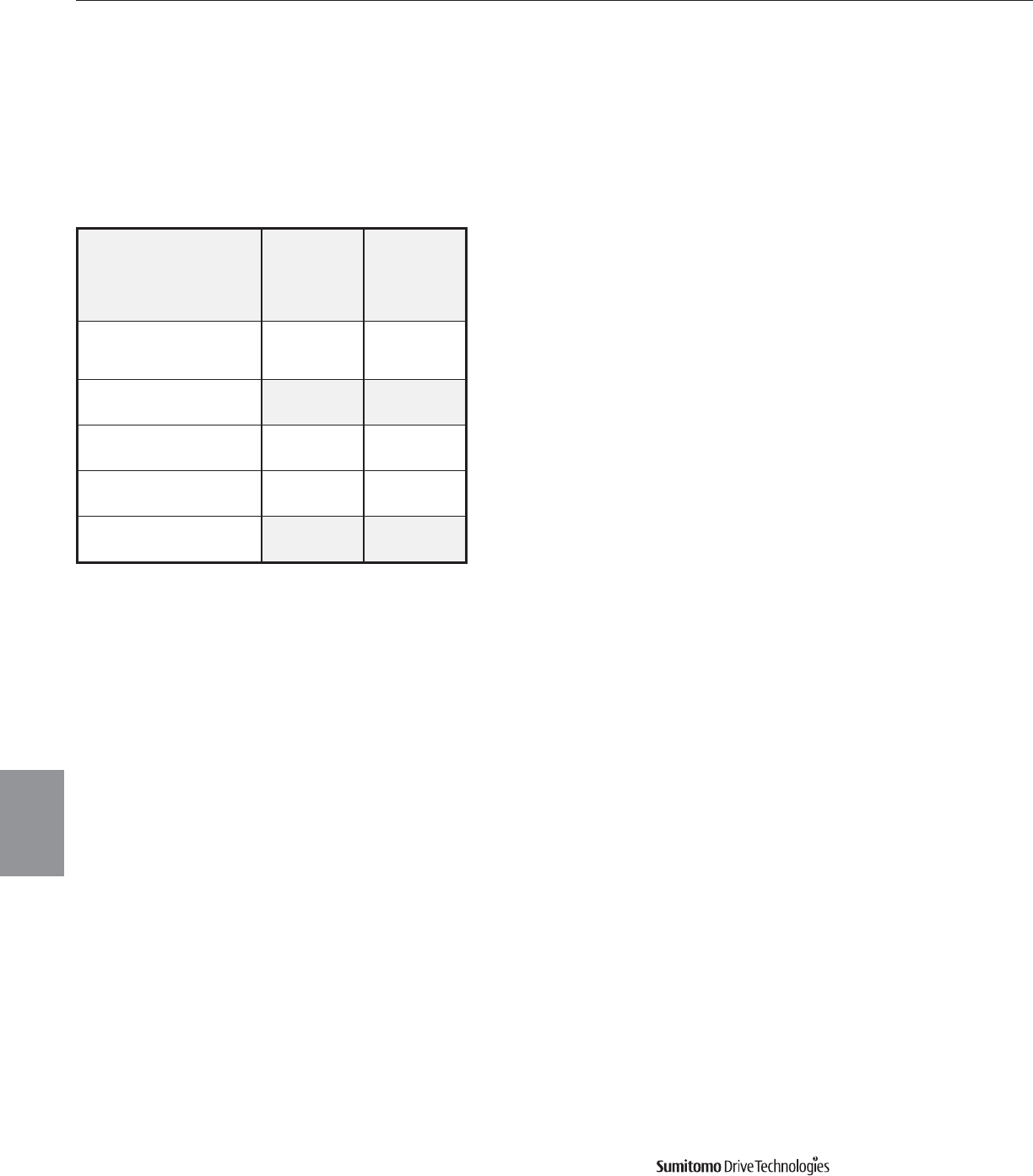
CYCLO® 6000 Gearmotors
5.24 Technical Information
Food Industry
Option
Cyclo® 6000 Series
Four food-grade packages are available for use in machinery where there in incidental food contact.
The following optional packages are available for Cyclo©frame sizes 6060 through 6165.
When ordering, chose the Special Specification Code (SSC) that meets your requirements to obtain
the features listed below.
Feature SSC-YBA1
Food Grade
SSC-YBA2
Food Grade &
Washdown
IP55
Washdown Air
Breather
(Oil Lubricated units only)
FDA Approved
Paint
Antimicrobial
Oil Seal
NSF H1
Lubricant
Less Lifting Lug
Cyclo Food Industry Option Packages
Available Food Industry Option Packages
(Cyclo©frame sizes 6060-6165 only)
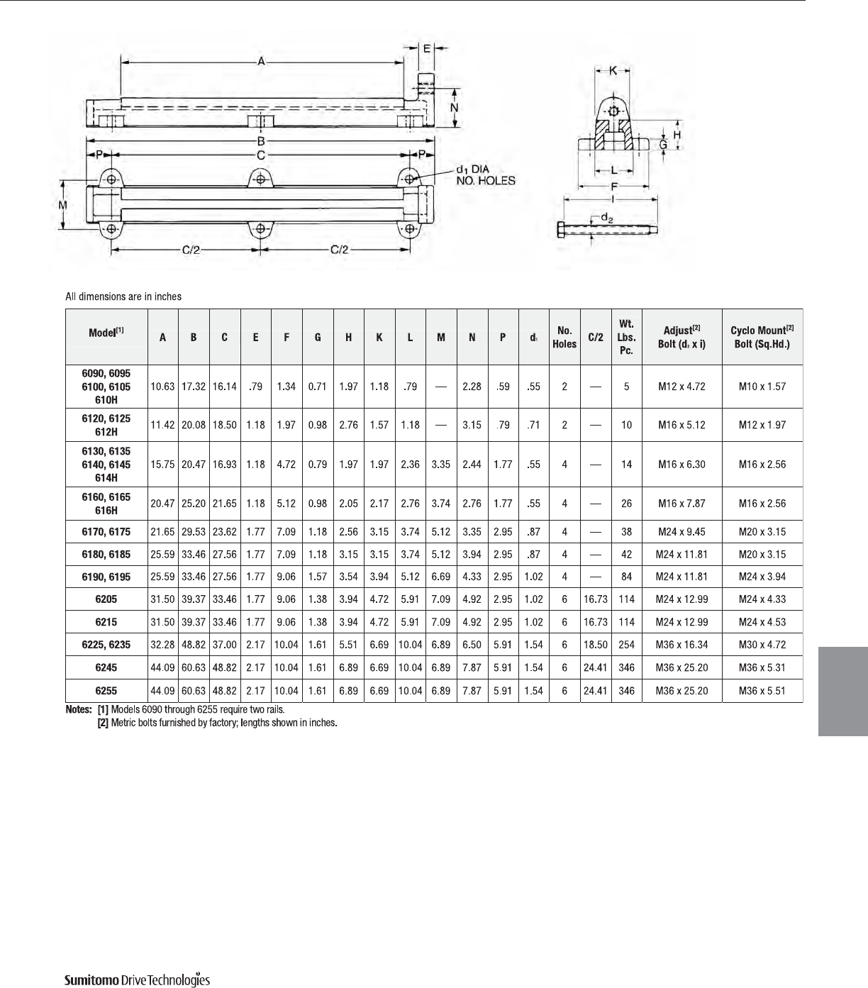
CYCLO® 6000 Gearmotors
Technical Information 5.25
Slide Rail
Dimensions
Cyclo® 6000 Series
CYCLO® 6000 Gearmotors
Slide Rail Dimensions

CYCLO® 6000 Gearmotors
5.26 Technical Information Cyclo® 6000 Series
Warranty
Sumitomo warrants that its Cyclo® Speed Reducers and Cyclo® Gear Motors will deliver their continuous catalog
ratings and up to 500% intermittent SHOCK LOAD CAPACITY, provided they are properly installed, maintained
and operated within the limits of speed, torque or other load conditions under which they were sold. Sumitomo
further states that Cyclo® Speed Reducers and Cyclo® Gear Motors are warranted to be free of defects in material
or workmanship for a period of two years from the date of shipment. Sumitomo assumes no liability beyond
product repair or replacement under this limited warranty.
For construction purposes, be sure to obtain certified dimension sheets or drawings. Although we take every
precaution to include accurate data in our catalog, we cannot guarantee such accuracy. If performance guarantees
are required, they should be obtained in writing from the factory. Full consideration will be given to such
requests when complete details are given of the proposed installation.

CYCLO® 6000 Gearmotors
Technical Information 5.27
Cyclo® 6000 Series
Notes

CYCLO® 6000 Gearmotors
5.28 Technical Information Cyclo® 6000 Series
Notes
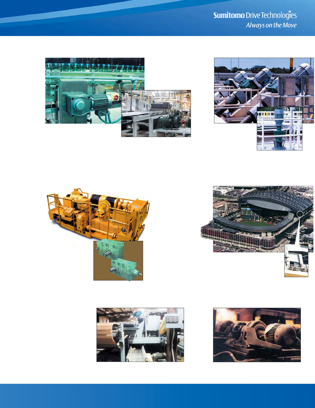
Steel hypoid gear technology,
maintenance-free grease lubrication
and a compact modular housing
makes the Hyponic® an efficient performer
in the food industry. A 15-hp Beier mechanical variable speed drive
with electric remote control provides
an adjustable, steady speed range
for this 350-ft. oven band conveyor.
Bottling/Baking Water Treatment
Material Handling Custom Designs
Wood Products
Steel
Cyclo® mixer drives are a key compo-
nent of this award-winning water
treatment facility in Hillsborough
County, Florida.
Each of these
Sumitomo Paramax®
speed reducers helps
pump up to 13 million
gallons a day at this
state-of-the-art waste-
water treatment facility
in the City of Clearwater,
Florida.
In less than 20 minutes,
96 Sumitomo Cyclo® Bevel Buddybox
gearmotors help retract
the 13,000-ton roof on Seattle’s
new Safeco Field .
The Sumitomo gearmotors, on eight travel
truck assemblies, turn 128 36” wheels.
Once flooring is side-matched, it is inspected for defects. This
conveyor, driven by Sumitomo Cyclo® drives, carries defective
material to the hammer mill.
Sumitomo Cyclo® drives are an inte-
gral part of this manufacturing
plant which produces 150,000 board
feet of unfinished strip and plank
hardwood flooring each week. After molten steel is formed in the five-strand continuous caster
at this steel mill, it is conveyed by Sumitomo Cyclo® drives on the
auto-torch conveyors where the steel is cut into billets.
Sumitomo Paramax® reducers
provide quiet, reliable operation
for both the hoist and trolley
drive systems in this 35-ton
capacity DC Trolley Hoist used
for heavy-duty coil handling
service.

Sumitomo Machinery Corporation of
America
Headquarters & Manufacturing
4200 Holland Boulevard
Chesapeake, VA 23323
Tel: 757-485-3355 • 1-800-SMCYCLO
Fax: 757-485-7490
www.smcyclo.com
E-mail: customercare@suminet.com
World Headquarters
Japan
Sumitomo Heavy Industries, Ltd.
Power Transmission & Controls Group
Thinkpark Tower, 1-1, Osaki 2-chome,
Shinagawa-Ku, Tokyo 141-6025 Japan
Tel: 011-813-6737-2511 • Fax: 011-813-6866-5160
For Worldwide contact information:
www.sumitomodrive.com
U.S. Sales and Support
Mid-West
Sumitomo Machinery Corporation of America
175 West Lake Drive
Glendale Heights, IL 60139
Tel: 630-752-0200 • 1-800-SMCYCLO
Fax: 630-752-0208
West
Sumitomo Machinery Corporation of America
2375 Railroad Street
Corona, CA 92880-5411
Tel: 951-340-4100 • 1-800-SMCYCLO
Fax: 951-340-4108
Canada
Toronto (East)
SM-Cyclo of Canada, Ltd.
1045 South Service Road, West
Oakville, Ontario, Canada L6L 6K3
Tel: 905-469-1050 • Fax: 905-469-1055
Vancouver (West)
SM-Cyclo of Canada, Ltd.
740 Chester Road, Annacis Island, Delta
B.C., Canada V3M 6J1
Tel: 604-525-5403 • Fax: 604-525-0879
Montreal
SM-Cyclo of Canada, Ltd.
2862 Blvd. Daniel-Johnson
Laval, Quebec, Canada H7P 5Z7
Tel: 450-686-8808 • Fax: 450-686-8800
Mexico
Monterrey
SM-Cyclo de Mexico, S.A. de C.V.
Calle “C” No. 506A
Parque Industrial Almacentro
Apodaca, N.L., Mexico 66600
Tel: 011-52-81-8144-5130 • Fax: 011-52-81-8369-3699
Mexico City
SM-Cyclo de Mexico S.A. de C.V.
Privada Ceylan No. 59-B Bis
Colonia Industrial Vallejo
Delegacion Azcapotzalco, DF Mexico 02300
Tel: 011-52-55-5368-7172 • Fax: 011-52-55-5368-6699
Guadalajara
SM-Cyclo de Mexico S.A. de C.V.
Unidad Privativa No. 4
Alamo Tecno Park
Tlaqepapue, JAL CP 44490
Tel: 011-52-33-3675-43-69 • Fax: 011-52-33-3675-4418
Brazil
SM Cyclo Redutores do Brasil Ltda.
Av. Fagundes Filho, 191
Ed. Houston Office Center–c j. H123
CEP: 04304-010–São Paulo, Brazil
Tel: 011-55-11-5585-3600 • Fax: 011-55-11-5585-9990
Chile
Santiago
SM Cyclo de Chile Ltda.
San Pablo 3507
Comuna de Quinta Normal - Santiago, Chile
Tel: 011-562-892-7000 • Fax: 011-562-892-7001
Antofagasta
SM Cyclo de Chile Ltda.
Calle 8, Manzana N2, Sitio 1
Sector La Negra, Antofagasta, Chile
Tel: 011-565-556-1611 • Fax: 011-565-556-1616
Concepción
SM Cyclo de Chile Ltda.
Camino a Coronel Km 10, #5580, Modulo 3-A
Comuna: San Pedro de la Paz - Concepción, Chile
Tel: 011-41-246-98-06/07 • Fax: 011-41-246-98-08
Argentina
SM-Cyclo de Argentina SA
Manuel Montes de Oca 6719
B1606 BMG, Munro
Buenos Aires, Argentina
Tel: 011-54-11-4765-5332 • Fax: 011-54-11-4765-5517
Europe
Austria
Belgium
France
Germany
Italy
Spain
Sweden
United Kingdom
Asia
China
Hong Kong
Indonesia
Korea
Malaysia
Philippines
Singapore
Taiwan
Thailand
Vietnam
Other Locations
Australia
India
New Zealand
WORLDWIDE LOCATIONS
Catalog 04.601.50.007; Supersedes Catalog 04.601.50.006
©2011 Sumitomo Machinery Corporation of America Printed in USA
