Cypress USB Serial Configuration Utility User Guide
User Manual:
Open the PDF directly: View PDF ![]() .
.
Page Count: 46


Copyrights
Cypress USB-Serial Configuration Utility User Guide, Doc. No. 001-86781 Rev. *D 2
Copyrights
© Cypress Semiconductor Corporation, 2014-2015. The information contained herein is subject to change without notice.
Cypress Semiconductor Corporation assumes no responsibility for the use of any circuitry other than circuitry embodied in a
Cypress product. Nor does it convey or imply any license under patent or other rights. Cypress products are not warranted
nor intended to be used for medical, life support, life saving, critical control or safety applications, unless pursuant to an
express written agreement with Cypress. Furthermore, Cypress does not authorize its products for use as critical
components in life-support systems where a malfunction or failure may reasonably be expected to result in significant injury
to the user. The inclusion of Cypress products in life-support systems application implies that the manufacturer assumes all
risk of such use and in doing so indemnifies Cypress against all charges.
Trademarks
PSoC Designer™, and Programmable System-on-Chip™ are trademarks and PSoC® is a registered trademark of Cypress
Semiconductor Corp. All other trademarks or registered trademarks referenced herein are property of the respective
corporations.
Source Code
Any Source Code (software and/or firmware) is owned by Cypress Semiconductor Corporation (Cypress) and is protected
by and subject to worldwide patent protection (United States and foreign), United States copyright laws and international
treaty provisions. Cypress hereby grants to licensee a personal, non-exclusive, non-transferable license to copy, use,
modify, create derivative works of, and compile the Cypress Source Code and derivative works for the sole purpose of
creating custom software and or firmware in support of licensee product to be used only in conjunction with a Cypress
integrated circuit as specified in the applicable agreement. Any reproduction, modification, translation, compilation, or
representation of this Source Code except as specified above is prohibited without the express written permission of
Cypress.
Disclaimer
CYPRESS MAKES NO WARRANTY OF ANY KIND, EXPRESS OR IMPLIED, WITH REGARD TO THIS MATERIAL,
INCLUDING, BUT NOT LIMITED TO, THE IMPLIED WARRANTIES OF MERCHANTABILITY AND FITNESS FOR A
PARTICULAR PURPOSE. Cypress reserves the right to make changes without further notice to the materials described
herein. Cypress does not assume any liability arising out of the application or use of any product or circuit described herein.
Cypress does not authorize its products for use as critical components in life-support systems where a malfunction or failure
may reasonably be expected to result in significant injury to the user. The inclusion of Cypress’ product in a life-support
systems application implies that the manufacturer assumes all risk of such use and in doing so indemnifies Cypress against
all charges.
Use may be limited by and subject to the applicable Cypress software license agreement.

Cypress USB-Serial Configuration Utility User Guide, Doc. No. 001-86781 Rev. *D 3
Contents
Contents
1. Introduction .................................................................................................................................................................... 4
1.1 Software Requirements ......................................................................................................................................... 4
2. Cypress USB-Serial Configuration Utility .................................................................................................................... 5
2.1 Start Page .............................................................................................................................................................. 5
2.2 Select Target ......................................................................................................................................................... 5
2.2.1 Select Device ............................................................................................................................................ 5
2.2.2 Device Information .................................................................................................................................... 6
2.2.3 Connect to Target ..................................................................................................................................... 6
2.3 Device Configuration ............................................................................................................................................. 6
2.3.1 USB Descriptor and System Configuration ............................................................................................... 7
2.3.2 Serial Configuration Block (SCB) Configuration ...................................................................................... 13
2.3.3 Device GPIOs ......................................................................................................................................... 23
2.3.4 CapSense®/BCD/GPIO Configuration ..................................................................................................... 23
2.3.5 Program Device ...................................................................................................................................... 32
2.3.6 Save Configuration ................................................................................................................................. 32
2.3.7 Open Device Configuration ..................................................................................................................... 32
2.3.8 Batch Program ........................................................................................................................................ 32
2.3.9 Restore Default Settings ......................................................................................................................... 36
2.3.10 Cycle Port ............................................................................................................................................... 36
2.3.11 Reset Device .......................................................................................................................................... 36
2.3.12 Disconnect .............................................................................................................................................. 36
3. Appendix ...................................................................................................................................................................... 37
3.1 Driver Binding for USB-Serial Devices with Custom VID/PID .............................................................................. 37
3.1.1 Driver INF File Changes ......................................................................................................................... 37
3.1.2 Master Interface Number of USB-Serial Device Configuration ............................................................... 40
3.2 Default Value for Various Configurable Fields ..................................................................................................... 41
3.2.1 CY7C65213 / CY7C65213A ................................................................................................................... 41
3.2.2 CY7C65215 / CY7C65215A ................................................................................................................... 42
3.2.3 CY7C65211 / CY7C65211A ................................................................................................................... 44
Cypress USB-Serial Configuration Utility User Guide, Doc. No. 001-86781 Rev. *D 4
1. Introduction
The Cypress USB-Serial Configuration Utility provides an easy-to-use graphical interface to configure manufacturing settings and
options for Cypress USB-Serial devices. With this utility, you can connect to USB-Serial devices, modify the configuration settings,
and program the configuration to the device.
This user guide describes the USB-Serial Configuration Utility features and how to use the utility to configure a supported device.
The current version of the utility supports configuring the Cypress USB-Serial device part numbers listed in Table 1-1.
Table 1-1. Supported USB-Serial Devices
#
Part Number
Description
1
CY7C65211-24LTXI
USB-Serial (Single Channel)
4
CY7C65211A-24LTXI
USB-Serial (Single Channel)
3
CY7C65213-32LTXI
USB-UART LP (QFN Package)
4
CY7C65213A-32LTXI
USB-UART LP (QFN Package)
5
CY7C65213-28PVXI
USB-UART LP (SSOP Package)
6
CY7C65213A-28VXI
USB-UART LP (SSOP Package)
7
CY7C65215-32LTXI
USB-Serial (Dual Channel)
8
CY7C65215A-32LTXI
USB-Serial (Dual Channel)
1.1 Software Requirements
Table 1-2 lists the software prerequisites needed to run the configuration utility.
Table 1-2. Software Requirements
#
Software
Version
1.
Operating System
Microsoft Windows XP or later
2.
.NET Framework
.NET Framework 3.5 SP1 or later
3.
Runtime Libraries
Microsoft VC++ 2008 SP1 runtime re-distributable
Note 1: Microsoft.NET framework 3.5SP1 can be downloaded and installed from Microsoft website. The link to the installable on
Microsoft’s website is: http://www.microsoft.com/en-us/download/details.aspx?id=22.
Note 2: Microsoft VC++ 2008 runtime re-distributable is packaged along with USB-Serial SDK for Windows. The re-distributable can
be located under the ‘<sdk_install_path>\prerequisite’ directory. The package can also be downloaded and installed
from the Microsoft website. The link to the installable is: http://www.microsoft.com/en-us/download/details.aspx?id=11895.
Cypress USB-Serial Configuration Utility User Guide, Doc. No. 001-86781 Rev. *D 5
2. Cypress USB-Serial Configuration Utility
Run USB-Serial Configuration Utility.exe from Start>All Programs>Cypress>Cypress USB-Serial Configuration Utility to launch
the configuration utility. On start-up, the utility comes up with two active tabs— Start Page and Select Target. These tabs are
always visible and you can navigate between these tabs at any time during the configuration session.
After you connect to an attached Cypress USB-Serial device (from the Select Target tab), the utility opens a third tab (Device tab)
for the part number of the device selected. This tab allows you to view and configure the device settings.
Note: The exact name of the third tab will be the device part number. The device part numbers are listed in Table 1-1. Throughout
the document, this tab will be referred to as the Device tab.
2.1 Start Page
This tab provides a brief description about Cypress USB-Serial products.
2.2 Select Target
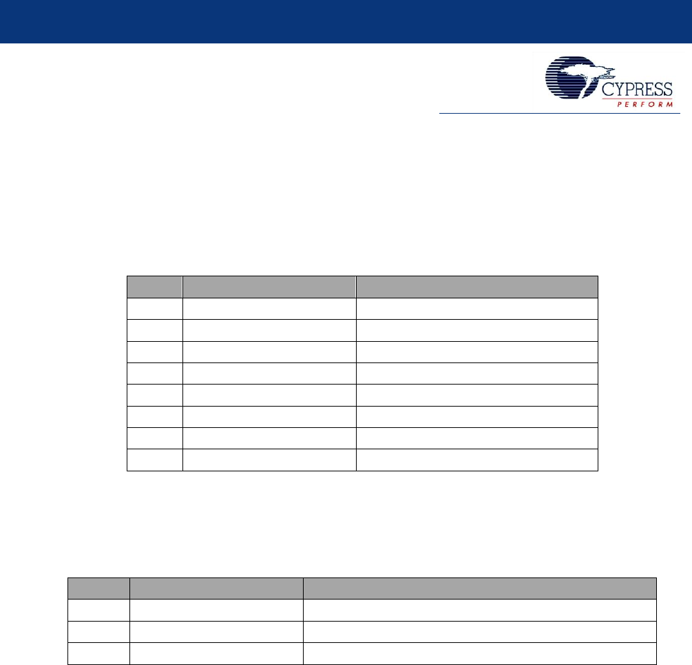
This tab displays all the USB-Serial devices attached to the machine. Figure 2-1 shows the Select Target tab of the utility. The
utility lists all the USB-Serial device interfaces that bind to the Cypress cyusb3.sys driver.
Figure 2-1: Select Target
2.2.1 Select Device
The Select Device drop-down list box lists all the USB-Serial devices attached to the machine. The device, which is to be
configured, should be selected from this list.
Cypress USB-Serial Configuration Utility
Cypress USB-Serial Configuration Utility User Guide, Doc. No. 001-86781 Rev. *D 6
2.2.2 Device Information
The Device Information section displays information about the currently selected device (see Table 2-1).
Table 2-1. Device Information
#
Property
Remarks
1.
Vendor ID (VID)
Vendor ID in 2-byte HEX format
2.
Product ID (PID)
Product ID in 2-byte HEX format
3.
Device name
Device-friendly name. This name comes from the device driver INF file
4.
Manufacturer
Device manufacturer name
5.
Product
Product name
6.
Serial number
Device serial number
7.
Version
Device firmware version
8.
Windows device instance ID
Windows-assigned device instance ID
2.2.3 Connect to Target
2.2.3.1 Connect
After you select the required device from the Select Device field, click Connect to establish connection with the device. On
successful connection, the utility opens the Device tab.
2.3 Device Configuration
This tab allows viewing and modifying the device configuration settings. From this tab, the target device can be programmed with
the modified configuration settings.
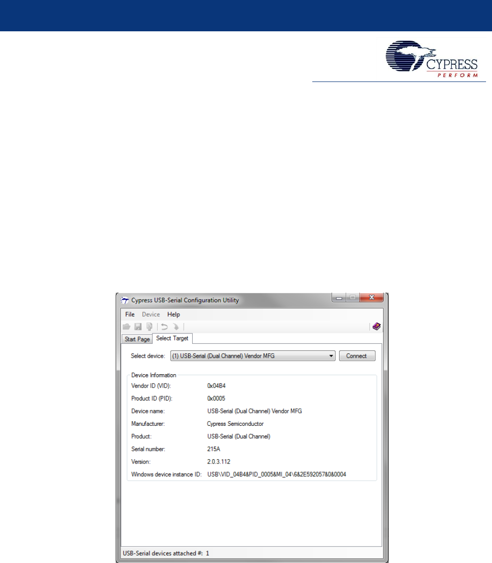
Figure 2-2: USB Configuration Settings
Cypress USB-Serial Configuration Utility
Cypress USB-Serial Configuration Utility User Guide, Doc. No. 001-86781 Rev. *D 7
The following device configuration settings can be viewed and modified:
1. USB Descriptors and system-level settings
2. Serial Configuration Block (SCB)
3. CapSense®/BCD/GPIO
2.3.1 USB Descriptor and System Configuration
The USB tab (see Figure 2-2) displays some of the device USB descriptor values. The USB configuration and system settings are
categorized into four groups:
1. Basic
2. Power
3. String Descriptor
4. System
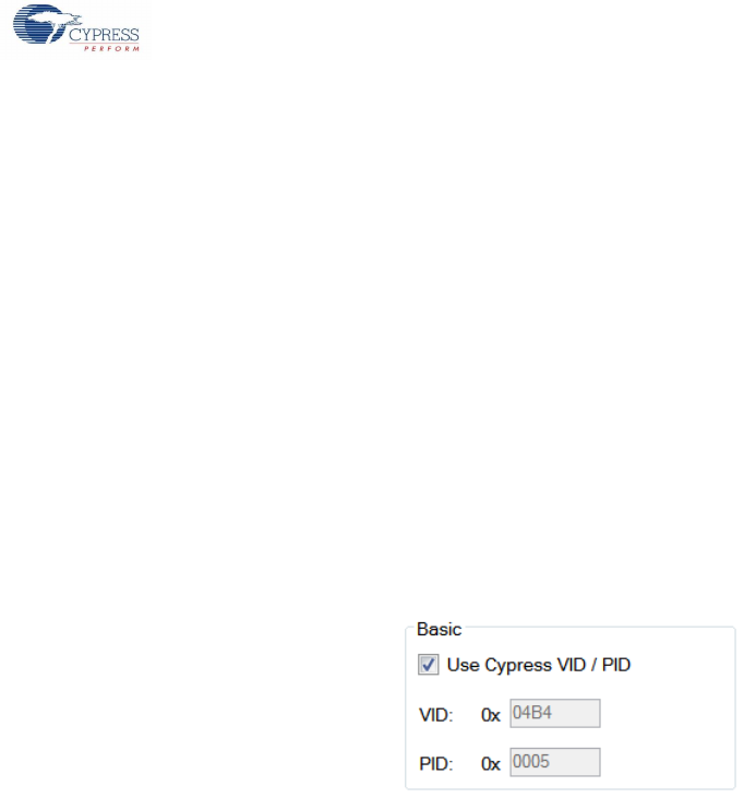
2.3.1.1 Basic
The basic descriptor settings include the device Vendor ID (VID) and Product ID (PID) values. The device can be configured to
either use the default Cypress-provided VID and PID combination or to use a custom VID and PID combination (see Figure 2-3).
Figure 2-3: USB - Basic Settings
2.3.1.1.1 Vendor ID (VID)
This field accepts a 2-byte hexadecimal value. This field cannot be left empty and the value cannot be zero.
2.3.1.1.2 Product ID (PID)
This field accepts a 2-byte hexadecimal value. This field cannot be left empty and the value cannot be zero.
2.3.1.1.3 Use Cypress VID/PID
Select this option to use the default Cypress VID and PID combination for the current SCB settings. When you select this option, the
VID and PID fields are not editable. The major advantage of using this option is that the default drivers shipped with the product can
be used directly without any modification.
Table 2-2 captures the Cypress-provided PID for USB-Serial devices based on the device configuration.

Cypress USB-Serial Configuration Utility
Cypress USB-Serial Configuration Utility User Guide, Doc. No. 001-86781 Rev. *D 8
Table 2-2: Cypress USB-Serial Device PIDs
#
Part Number
SCB 0
SCB 1
PID
Mode
Protocol
Mode
Protocol
1.
CY7C65211-24LTXI
UART
CDC
NA
NA
0x0002
UART/ SPI
Vendor / PHDC
NA
NA
0x0004
I2C
Vendor
NA
NA
0x0004
2.
CY7C65211A-24LTXI
UART
CDC
NA
NA
0x0002
UART/ SPI
Vendor / PHDC /
CDC
NA
NA
0x0004
I2C
Vendor / CDC
NA
NA
0x0004
3.
CY7C65213-32LTXI
Or
CY7C65213-28PVXI
Or
CY7C65213A-28VXI
Or
CY7C65213A-32LTXI
UART
CDC
NA
NA
0x0003
UART
Vendor / PHDC
NA
NA
0x0006
4.
CY7C65215-32LTXI
UART
CDC
UART
CDC
0x0005
UART
CDC
UART / SPI / I2C /
JTAG
Vendor / PHDC
0x0007
UART / SPI
Vendor / PHDC
UART
CDC
0x0009
I2C
Vendor
UART
CDC
0x0009
UART / SPI
Vendor / PHDC
UART / SPI
Vendor / PHDC
0x000A
I2C / JTAG
Vendor
0x000A
I2C
Vendor
UART / SPI
Vendor / PHDC
0x000A
I2C / JTAG
Vendor
0x000A
5.
CY7C65215A-32LTXI
UART
CDC
UART
CDC
0x0005
UART
CDC
UART / SPI / I2C
Vendor / PHDC /
CDC
0x0007
UART / SPI
Vendor / PHDC /
CDC
UART
CDC
0x0009
I2C
Vendor / CDC
UART
CDC
0x0009
UART / SPI
Vendor / PHDC /
CDC
UART / SPI
Vendor / PHDC /
CDC
0x000A
I2C
Vendor / CDC
0x000A
I2C
Vendor / CDC
UART / SPI
Vendor / PHDC /
CDC
0x000A
I2C
Vendor / CDC
0x000A
CDC: CDC device referred in this document is a UART device that follows USB Standard Communication Device Class
Specification. And, this device binds to a Virtual COM port driver for the supported operating system.
Vendor: Vendor operational mode device doesn’t follow any USB standard class specification. They are custom or vendor USB
class devices that follow custom data transfer protocol. USB to (SPI or I2C or JTAG) Bridge is always configured as Vendor Device.
UART can also be a vendor device and in this mode, UART device doesn’t bind to Virtual COM port driver. Instead, the UART
device will bind to cypress generic USB driver or vendor mode driver in the supported Operating System.
Cypress USB-Serial Configuration Utility
Cypress USB-Serial Configuration Utility User Guide, Doc. No. 001-86781 Rev. *D 9
PHDC: Device that follow Personal Healthcare Device Class Specification is referred as PHDC devices. USB Serial Bridge supports
PHDC USB to UART and PHDC USB to SPI Bridge. PHDC device binds to generic USB device driver otherwise called as vendor
mode driver.
Figure 2-4: USB - Use Custom VID/PID
To use a custom VID and PID for your device, uncheck the ‘Use Cypress VID / PID’ option. On unchecking this option, the VID field
becomes editable. Enter the required VID (other than Cypress VID [0x04B4]) and hit the <Tab> or <Enter> key to enable the PID
field. Refer to the Driver Binding for USB-Serial Devices with Custom VID/PID section for binding the driver to USB-Serial devices
with custom VID/PID.
2.3.1.2 Power Settings
The utility allows for configuring the USB power settings of your device. Figure 2-5 shows the configurable USB power settings.
Figure 2-5: USB - Power Settings
2.3.1.2.1 Power Mode
The device power mode can be set to either self-powered or bus-powered. The default value for this field is ‘Bus powered’.
2.3.1.2.2 bMaxPower (mA)
This field allows setting the maximum power the device drains from the USB bus. The value is in units of mA. The default value for
this field is 100 mA. This field cannot be zero when the device power mode is set to ‘Bus Powered’. USB specification has say on
the maximum current drawn from a USB port. And, hence this field can be up to 500 mA Max.
2.3.1.2.3 Remote Wake-up/Suspend Configuration
Click the Configure button (shown in Figure 2-5) to open the Remote Wake-up & Suspend configuration editor. Figure 2-6 shows
the ‘Remote Wake-up & Suspend Editor’ for CY7C65211-24LTXI and CY7C65215-32LTXI devices.
Figure 2-6: Remote Wake-up & Suspend Editor
2.3.1.2.3.1 Remote Wake-up
Select the Remote wake-up Enable option to enable GPIO remote wake-up for the device. The editor also provides an option to
invert the polarity of the remote wake-up GPIO line. The remote wake-up GPIO line for the device is fixed. Refer to the device
datasheet for the exact remote wake-up GPIO pin.
Cypress USB-Serial Configuration Utility
Cypress USB-Serial Configuration Utility User Guide, Doc. No. 001-86781 Rev. *D 10
2.3.1.2.3.2 Suspend
Select the Suspend Enable option to enable the GPIO suspend notification for your device. The editor also provides an option to
invert the polarity of the suspend line. The suspend wake-up line is fixed for CY7C65211-24LTXI and CY7C65215-32LTXI devices.
Refer to the respective device datasheets for the exact suspend GPIO pin. For theCY7C65213-32LTXIor CY7C65213-28PVXI
devices, the suspend GPIO is configurable. That is, one of the available GPIOs can be configured as the suspend line. Figure 2-7
shows the ‘Suspend & Remote Wake-up editor’ for the CY7C65213-32LTXI or CY7C65213-28PVXI device.
Figure 2-7: CY7C65213-32LTXI or CY7C65213-28PVXI Suspend & Remote Wake-up Editor
2.3.1.2.3.3 Power#
Select a GPIO from the Power# drop-down list to enable power notification. To disable this option, select Not enabled from the
drop-down list.
2.3.1.3 String Descriptors
This utility allows configuration of the following USB string descriptors for the device:
1. Manufacturer string
2. Product string
3. Serial Number string
Figure 2-8 shows the default USB string descriptor configuration settings for the CY7C65215-32LTXI device.
Figure 2-8: USB String Descriptors
2.3.1.3.1 Manufacturer string
Enter the manufacturer string to be used for the device in this field. The text field accepts up to 32 Unicode characters.
Default value: Cypress Semiconductor
Cypress USB-Serial Configuration Utility
Cypress USB-Serial Configuration Utility User Guide, Doc. No. 001-86781 Rev. *D 11
2.3.1.3.2 Product string
Enter the product string to be used for the device in this field. The text field accepts up to 32 Unicode characters. Table 2-3 lists the
default values for all the supported devices.
Table 2-3. Default Product Strings
#
Part Number
Default value
1
CY7C65211-24LTXI
USB-Serial (Single Channel)
2
CY7C65211A-24LTXI
USB-Serial (Single Channel)
3
CY7C65213-32LTXI
USB-UART LP
4
CY7C65213A-32LTXI
USB-UART LP
5
CY7C65213-28PVXI
USB-UART LP
6
CY7C65213A-28VXI
USB-UART LP
7
CY7C65215-32LTXI
USB-Serial (Dual Channel)
8
CY7C65215A-32LTXI
USB-Serial (Dual Channel)
2.3.1.3.3 Serial number
To enter a serial number for the device, select the ‘Serial Number’ checkbox field. On selecting the checkbox, the serial number text
box field becomes editable. Enter the required serial number for the device in this textbox field. The text field accepts up to 32
Unicode characters. If the device does not need a serial number, uncheck the checkbox.
Currently we can use only ‘alpha numeric’ combinations, special characters and spaces are not allowed.
Default value: NULL (No serial number)
2.3.1.4 System settings
The utility supports configuring three other system-level settings shown in Figure 2-9.
Figure 2-9: Other system settings
2.3.1.4.1 VBUS Voltage is 3.3 V
This option needs to be checked if the VBUS line is supplied with 3.3 V and unchecked if the VBUS line is supplied with 5 V.
Checking this option results in the USB regulator being bypassed. By default, this option is unchecked. A warning message pops up
in the utility (see Figure 2-10) when this option is checked.
Figure 2-10: Bypass USB Regulator Warning
Cypress USB-Serial Configuration Utility
Cypress USB-Serial Configuration Utility User Guide, Doc. No. 001-86781 Rev. *D 12
2.3.1.4.2 VDD is less than 2 V
This option needs to be checked only if the VDD is less than 2 V. This option results in bypassing the system regulator. Bypassing
the regulator and supplying more than 2 V may damage the device. Not bypassing when the VDD is less than 2 V may result in
device reset. By default, this option is unchecked. A warning message pops up in the utility (see Figure 2-11) when this option is
checked.
Figure 2-11: Bypass System Regulator Warning
2.3.1.4.3 Enable Manufacturing Interface
The utility provides an option to include an additional interface for the device. This additional interface can act as the manufacturing
mode interface for re-programming the device. The manufacturing interface must bind to the Cypress Vendor Class driver
(CyUsb3.sys) for the utility to connect to the device. This interface can be disabled if not required. A warning message pops up in
the utility (see Figure 2-12) when this option is unchecked.
Caution: Disabling this interface may prevent you from re-programming the device in the future.
Figure 2-12: Disable Manufacturing Interface Warning
By default, this option is enabled.
2.3.1.4.4 I/O Level
The device allows setting the GPIO logic to be used. The device supports logic levels CMOS and LVTTL. The default is CMOS
logic. LVTTL logic supports device input level only. Changing the I/O Level to LVTTL will pop a caution message box as shown in
Figure 2-12a.
Caution: Device Input logic supports LVTTL levels but the output level from the device is always CMOS.
Figure 2-12a: Device Support for LVTTL - Warning

Cypress USB-Serial Configuration Utility
Cypress USB-Serial Configuration Utility User Guide, Doc. No. 001-86781 Rev. *D 13
2.3.1.4.5 I/O Mode
The device allows slowing the GPIO edge transitions up to 5X for EMI considerations. Setting the I/O mode to slow reduces the
transitions by up to 5 times. The default value is fast mode.
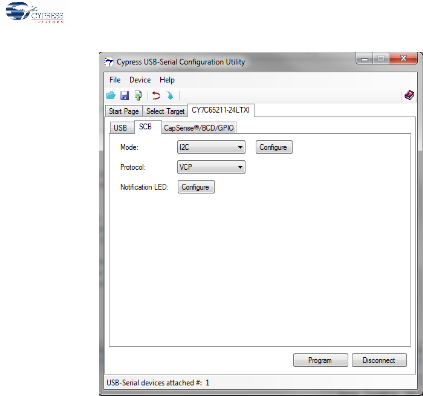
2.3.2 Serial Configuration Block (SCB) Configuration
The utility allows configuration of the following SCB parameters:
Operation mode
USB-SCB protocol
Notification LED
2.3.2.1 SCBs in USB-Serial Devices
The number of SCBs and the available configuration options for the SCBs depend on the device part number. Table 2-4 captures
the number of SCBs present in the USB-Serial device parts.
Table 2-4: Device SCB Count
#
Part Number
SCB Count
1
CY7C65211-24LTXI
1
2
CY7C65211A-24LTXI
1
3
CY7C65213-32LTXI
1
4
CY7C65213A-32LTXI
1
5
CY7C65213A-28VXI
1
6
CY7C65213-28PVXI
1
7
CY7C65215-32LTXI
2
8
CY7C65215A-32LTXI
2
The following sections capture the configurable options available for these devices.
2.3.2.1.1 USB-Serial (Single Channel) [Part Number: CY7C65211-24LTXI and
CY7C65211A-24LTXI]
The USB-Serial (Single Channel) device, as the name suggests, has only one SCB (SCB0). The SCB supports the following modes
of operation:
1. UART
2. I2C (Master / Slave)
3. SPI (Master / Slave)
2.3.2.1.2 USB-UART LP [Part Number: CY7C65213-32LTXI, CY7C65213-28PVXI,
CY7C65213A-32LTXI and CY7C65213A-28VXI]
The USB-UART LP device, similar to the USB-Serial (Single Channel) device, has only one SCB (SCB0). The SCB in this device is
pre-configured to a 8-pin UART. The device does not support other operational modes.
2.3.2.1.3 USB-Serial (Dual Channel) [Part Number: CY7C65215-32LTXI and
CY7C65215A-32LTXI]
The USB-Serial (Dual Channel) device has two SCBs (SCB 0 and SCB 1). Both SCB0 and SCB1 support the following operation
modes:
1. UART
2. I2C (Master / Slave)
3. SPI (Master / Slave)
Cypress USB-Serial Configuration Utility
Cypress USB-Serial Configuration Utility User Guide, Doc. No. 001-86781 Rev. *D 14
In addition to these operation modes, SCB1 also supports JTAG mode. If needed, SCB1 can also be disabled to free up SCB
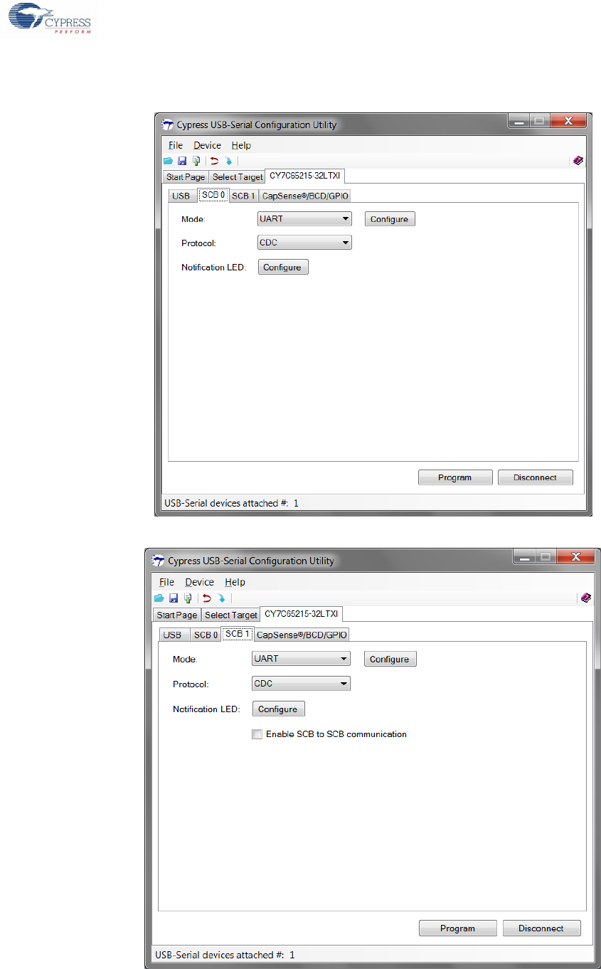
GPIOs to be used for Cypress CapSense®. Figure 2-13 and Figure 2-14 show the default configuration for SCB0 and SCB1.
Figure 2-13: SCB 0 Configuration
Figure 2-14: SCB 1 Configuration
Cypress USB-Serial Configuration Utility
Cypress USB-Serial Configuration Utility User Guide, Doc. No. 001-86781 Rev. *D 15
2.3.2.2 Select SCB Operation Mode
The Mode drop-down combo box lists all the supported SCB operation modes. Select the required operation mode from this list.
Most of these modes provide additional configuration settings. These mode-specific configurations can be edited by clicking the
Configure button.
The following sections describe the configurable options available for each of the supported SCB modes.
2.3.2.3 Enable SCB-SCB Mode
This is only valid for the USB-Serial (dual-channel) device and for firmware version 1.x. The device allows for
transferring data from one SCB to another when the USB is not connected. This mode is available only in the self-
powered use case where the two serial peripherals can do data transfers with each other. In this mode, only the
following SCB configurations are supported:
SPI slave to UART – When one of the SCB is acting as an SPI slave and another as UART, and the data received by the SPI
slave is being transmitted over UART. In this case, the data received from the UART shall also be transmitted over the SPI
slave interface.
SPI slave to SPI slave – When both SCBs are configured as SPI slave interface, data received on one is transmitted on the
other and vice versa.
UART to SPI master – When one of the SCB is configured as UART and another as SPI master, data received by the UART
interface shall be transmitted over SPI master interface. When this happens, the data received on the SPI master interface
shall also be transmitted out on the UART interface.
UART to UART – When both SCBs are configured as UART, the data received on one is transmitted on the other and vice
versa.
2.3.2.3.1 UART Mode
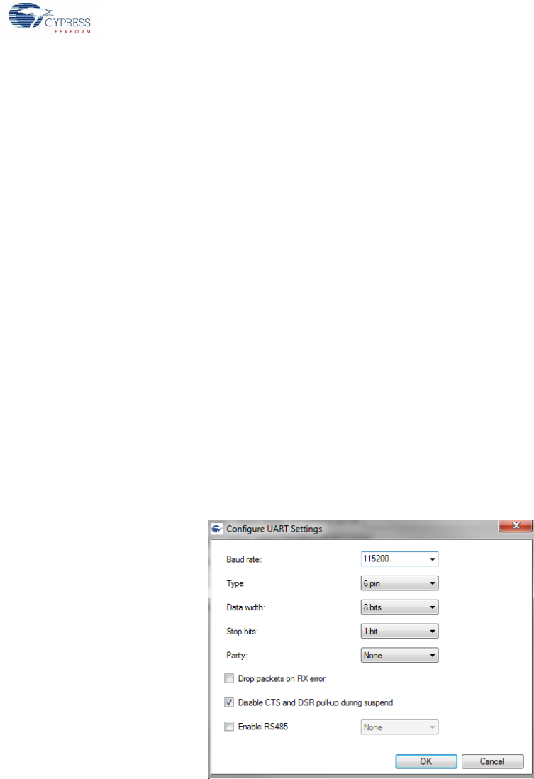
Select UART from the Mode drop-down list, and then click the Configure button to open the UART settings editor. Figure 2-15
shows the UART configuration settings.
Figure 2-15. UART Configuration
The UART operation mode supports the following configurable settings:
1. Baud Rate
2. Type
3. Data Width
4. Stop Bits
5. Parity
6. Drop packets on RX error
7. Disable CTS, DSR and DCD pull-up / pull-down during suspend
8. Enable RS485

Cypress USB-Serial Configuration Utility
Cypress USB-Serial Configuration Utility User Guide, Doc. No. 001-86781 Rev. *D 16
2.3.2.3.1.1 Baud Rate
Select the required baud rate from the standard baud rates listed in the combo box or enter a custom baud rate. The UART
supports a baud rate in the range 100 to 3000000.
The default value is 115200
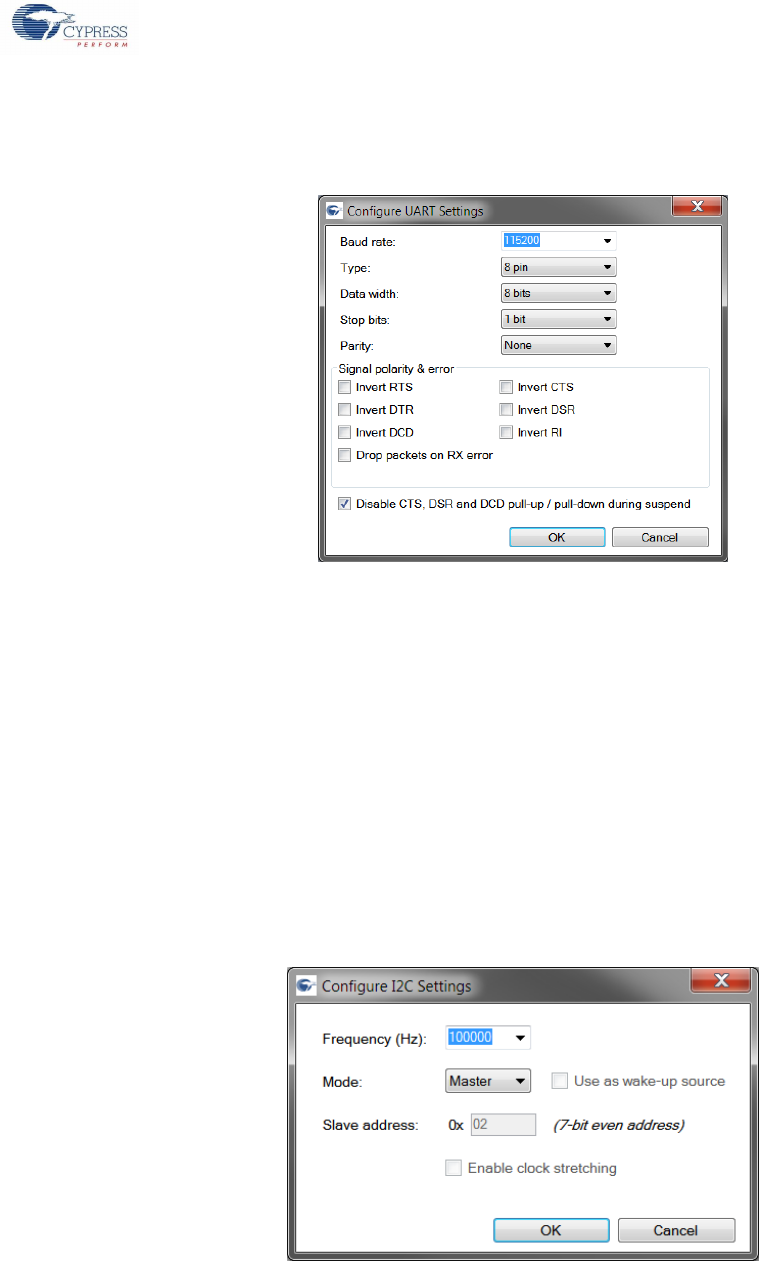
2.3.2.3.1.2 Type
The UART can be configured to one of the following types:
2-pin (2-pin UART: Only RX and TX lines)
4-pin (4-pin UART: RX, TX, RTS and CTS lines)
6-pin (6-pin UART: RX, TX, RTS, CTS, DSR and DTR lines)
8-pin (8-pin UART: RX, TX, RTS, CTS, DSR, DTR, DCD and RI lines)
The default value is 2-pin.
For the USB-UART LP device, the UART is pre-configured to 8-pin UART with RX, TX, RTS, CTS, DSR, DTR, DCD, and RI lines.
2.3.2.3.1.3 Data Width
The UART data width can be set to one of the following two options:
7 bits
8 bits
The default value is 8 bits.
2.3.2.3.1.4 Stop Bits
The number of UART stop bits can be set to one of the following options:
1 bit
2 bits
The default value is 1 bit.
2.3.2.3.1.5 Parity
The UART parity can be set to one of the following options:
None
Odd
Even
Mark
Space
The default value is None.
2.3.2.3.1.6 Drop packets on RX Error
This option can be selected to drop the data packets when there is a receive error. By default, this option is unchecked.
2.3.2.3.1.7 Disable CTS, DSR and DCD Pull-up/Pull-down During Suspend
In order to save power, the device disables the internal pull-up / pull-down resistors on the CTS, DSR and DCD GPIO lines during
suspend state. Uncheck this option to retain the internal resistors.
2.3.2.3.1.8 Enable RS485
This option can be selected to enable the RS485 feature. User can configure a GPIO for this. By default, this will be disabled.
Note: This feature will be enabled only for the CY7C6521xA parts.
Cypress USB-Serial Configuration Utility
Cypress USB-Serial Configuration Utility User Guide, Doc. No. 001-86781 Rev. *D 17
2.3.2.3.1.9 Invert Signal Polarity
The USB-UART LP device supports inverting the polarity of the UART signals. The polarity of all the UART lines, except the RX and
TX lines, can be inverted. Figure 2-16 shows the UART configuration editor for the USB-UART LP device.
Figure 2-16: USB-UART LP UART Configuration
This feature is not available in the USB-Serial (single-channel) and USB-Serial (dual-channel) devices.
2.3.2.3.2 I2C Mode
Select I2C from the Mode drop-down list, and then click the Configure button to open the I2C settings editor. Figure 2-17 and
Figure 2-18 show the I2C Master and Slave mode configuration settings.
The I2C operation mode supports the following configurable settings:
Frequency
Mode
Slave Address (Slave mode only)
Use as wake-up source(Slave mode only)
Enable Clock Stretching(Slave mode only)
Figure 2-17: I2C Master Configuration
Cypress USB-Serial Configuration Utility
Cypress USB-Serial Configuration Utility User Guide, Doc. No. 001-86781 Rev. *D 18
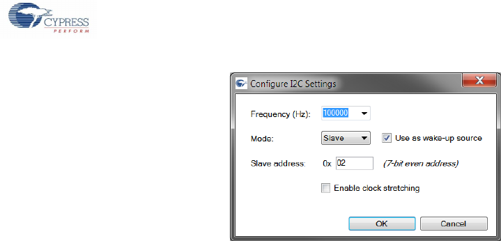
Figure 2-18. I2C Slave Configuration
2.3.2.3.2.1 Frequency (Hz)
Select the required frequency from the frequencies listed in the combo box or enter a custom frequency in Hz. The I2C supports
frequency in the range 1000 (1 KHz) to 4,00,000 (400 KHz). In the slave mode operation, the frequency should be greater than or
equal to other masters on the bus.
The default value is 100 KHz.
2.3.2.3.2.2 Mode
The I2C operation mode can be set to either Master or Slave. By default, the I2C is configured to operate in the master mode.
2.3.2.3.2.3 Slave Address
This field allows for setting the 7-bit I2C slave address in the hexadecimal format. The device supports only even numbers for the
slave address. Although based on the I2C specification, the valid 7-bit address ranges from 0x08 to 0x77, the utility does not restrict
you from setting any even number address in the range 0x02 to 0x7F. The address limitation is only on the slave mode operation
and the master can be used to access all the 7-bit address space.
2.3.2.3.2.4 Use as Wake-up Source
The utility supports using I2C, configured in the slave mode, as a host remote wake-up source. Select this option to use it as a
remote wake-up source.
2.3.2.3.2.5 Enable Clock Stretching
This option allows the device to emulate flow control. When this option is set, the clock is stretched (held low) until the buffer is
available.
2.3.2.3.2.6 VCP Mode for I2C Slave
On setting the I2C as slave, we can configure the device as VCP. This is nothing but a Vendor mode with PID 0x0033. Figure 2-19
shows the configuration settings.
Cypress USB-Serial Configuration Utility
Cypress USB-Serial Configuration Utility User Guide, Doc. No. 001-86781 Rev. *D 19
Figure 2-19. I2C slave VCP Configuration
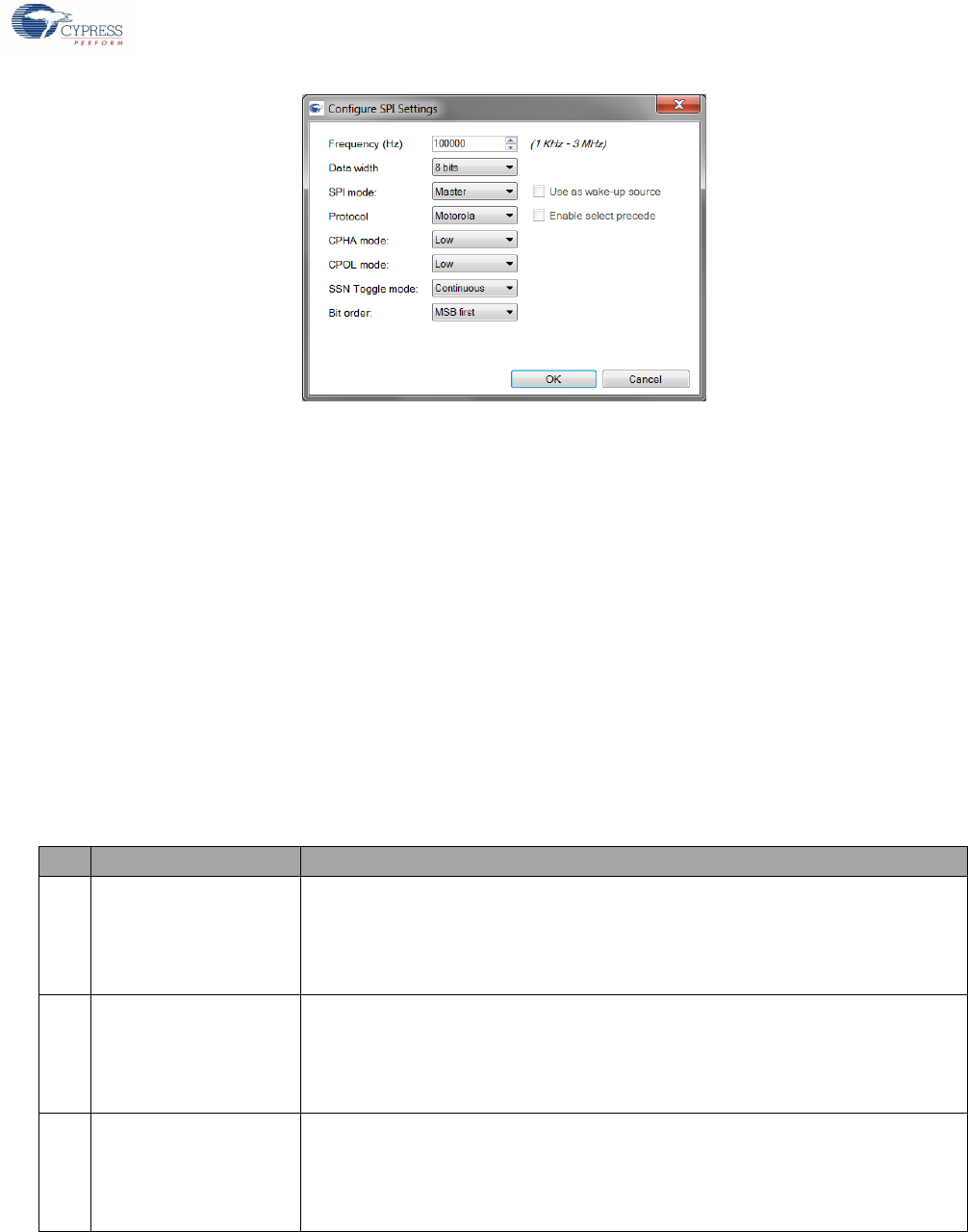
2.3.2.3.3 SPI Mode
Select SPI from the Mode drop-down list, and then click Configure to open the SPI settings editor. Figure 2-20 shows the SPI
configuration settings.
The SPI function mode supports the following configurable settings:
Frequency
Data width
Protocol
SPI mode
SSN Toggle mode
Bit Order
CPHA & CPOL mode
Enable Select Precede
Use as wake-up source (Slave mode only)
Cypress USB-Serial Configuration Utility
Cypress USB-Serial Configuration Utility User Guide, Doc. No. 001-86781 Rev. *D 20
Figure 2-20: SPI Configuration
2.3.2.3.3.1 Frequency
This field allows setting of the SPI operating frequency in Hz. The SPI mode supports operating frequencies in the range 1 KHz to
3 MHz (1000 to 3000000). In the slave mode operation, the slave should be clocked at a higher or same frequency as that of the
master.
The default frequency is 1000Hz (1 KHz).
2.3.2.3.3.2 Data width
The SPI data width can be set to one of the values in the drop-down list. SPI supports data width in the range 4 bits to 16 bits. By
default, the data width is set to 8 bits.
2.3.2.3.3.3 Protocol
SPI can be configured to operate in one of the following protocols.
Motorola
Texas Instruments (TI)
National Semiconductor (NS)
Table 2-5 briefly describes each of the supported protocols.
Table 2-5. SPI Supported Protocols
#
Mode
Description
1.
Motorola
In Master mode,
1. When not transmitting data (SELECT line is inactive), SCLK is stable at CPOL
2. When there is no data to transmit (TX FIFO is empty), SELECT line is inactive
In Slave mode,
1. When not selected, SCLK is ignored (SCLK can be either stable or clocking)
2.
TI (supports only mode 1)
In Master mode,
1. When not transmitting data, SCLK is stable at ‘0’
2. When there is no data to transmit (TX FIFO is empty), SELECT line is inactive
In Slave mode,
1. When not selected, SCLK is ignored (SCLK can be either stable or clocking)
3.
NS (supports only mode 0)
In Master mode,
1. When not transmitting data, SCLK is stable at ‘0’
2. When there is no data to transmit (TX FIFO is empty), SELECT line is inactive
In Slave mode,
1. When not selected, SCLK is ignored (SCLK can be either stable or clocking)
The default mode is Motorola.

Cypress USB-Serial Configuration Utility
Cypress USB-Serial Configuration Utility User Guide, Doc. No. 001-86781 Rev. *D 21
2.3.2.3.3.4 SPI Mode
The SPI can be configured to operate as either master or slave. By default, the operating mode is set to Master.
2.3.2.3.3.5 SSN Toggle Mode
The SSN toggle mode can be configured to either Frame or Continuous. Table 2-6 describes these options.
Table 2-6. SSN Toggle Modes
#
Toggle Mode
Description
1.
Frame
Individual data frame transfers are always separated by slave de-selection. Independent of
the availability of TX FIFO data frames, data frames are sent out with slave de-selection.
2.
Continuous
Individual data frame transfers are not necessarily separated by slave de-selection (as
indicated by the SELECT line). If the TX FIFO has multiple data frames, data frames are sent
out without slave de-selection.
This field is used for master mode configuration. The Slave mode supports both continuous and frame mode data transfers.
The default value is Continuous.
2.3.2.3.3.6 Bit Order
You can set the SPI data transfer bit order to one of the following options:
LSB first
MSB first
The default value is MSB first.
2.3.2.3.3.7 CPHA and CPOL Modes
CPHA stands for Clock Phase and CPOL stands for Clock Polarity. You can set the CPOL and CPHA values to either Low or High
from the drop-down list. Table 2-7 describes the clock polarity values.
Table 2-7. SPI CPOL Values
#
CPOL
Description
1.
Low
SCLK is ‘0’ when not transmitting data
2.
High
SCLK is ‘1’ (high) when not transmitting data
The CPHA and CPOL fields combine to form the four modes supported by the Motorola protocol. Table 2-8 captures the four
Motorola modes:
Table 2-8. SPI Motorola Modes
#
Mode
CPOL
CPHA
Description
1.
Mode 0
Low
Low
Data is captured on the rising edge of SCLK and data is propagated on the
falling edge of SCLK
2.
Mode 1
Low
High
Data is captured on the falling edge of SCLK and data is propagate on the
rising edge of SCLK
3.
Mode 2
High
Low
Data is captured on the falling edge of SCLK and data is propagated on the
rising edge of SCLK
4.
Mode 3
High
High
Data is captured on the rising edge of SCLK and data is propagated in the
falling edge of SCLK
The CPHA and CPOL fields are available only when the SPI protocol is set to Motorola. By default, the CPOL and CPHA values are
set to Low.
Cypress USB-Serial Configuration Utility
Cypress USB-Serial Configuration Utility User Guide, Doc. No. 001-86781 Rev. *D 22
2.3.2.3.3.8 Enable Select Precede
This field is available only when the SPI protocol is set to the Texas Instruments (TI) mode. Table 2-9 describes the behavior when
this field is enabled or disabled.
Table 2-9. SPI Select Precede
#
Options
Description
1.
Enabled (checked)
Data frame start indication pulse on the SELECT line precedes the transfer of the first data frame bit
2.
Disabled (unchecked)
Data frame start indication pulse on the SELECT coincides with the transfer of the first data frame bit
2.3.2.3.3.9 Use as Wake-up Source
The device supports using the SPI slave as a host remote wake-up source. Select this option (see Figure 2-21) to use SPI as a
remote wake-up source.
Figure 2-21: Use SPI as Remote Wake-Up Source
2.3.2.3.4 JTAG Mode
Select JTAG from the Mode drop-down list to configure SCB to operate as JTAG. This mode has pre-configured, but not
configurable, settings.
Note: CY7C65215A does not support JTAG Mode.
2.3.2.4 USB-SCB Protocol
After selecting the SCB operation mode, select the USB-SCB protocol. Each mode supports a fixed set of protocols. The Protocol
drop-down box lists all the supported protocols.
Table 2-10 provides the protocols supported by each of the SCB operation modes.
Table 2-10. USB-SCB Protocols
#
Modes
Supported Protocols
1.
Disabled
Disabled
2.
UART
CDC, PHDC, Vendor
3.
I2C
Vendor, CDC, VCP
4,
SPI
PHDC, Vendor, CDC
5.
JTAG
Vendor
Cypress USB-Serial Configuration Utility
Cypress USB-Serial Configuration Utility User Guide, Doc. No. 001-86781 Rev. *D 23
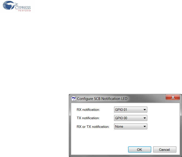
2.3.2.5 Configure SCB Activity Notification
The USB-Serial devices support three types of notification
1. Drive a GPIO on USB transmit
2. Drive a GPIO on USB receive
3. Drive a GPIO on both USB transmit and receive (SCB: TX&RX LED)
The device can simultaneously support all three notifications. Therefore, for a particular SCB, the device can be configured for more
than one notification.
Figure 2-22 shows the SCB notification configuration editor. To enable a notification, select a GPIO from the respective GPIO drop-
down list. To disable a notification, select None from the drop-down list.
Figure 2-22: Notify SCB Activity Configuration Editor
The device supports individual notification for each of the SCBs in the device. Notification can be configured for either one of the
SCBs or both the SCBs or none.
2.3.3 Device GPIOs
USB-Serial devices have a pool of configurable GPIOs. The number of GPIOs varies from one device part to another. Refer to the
device datasheet to get the available GPIO count for your device.
Each SCB uses GPIOs from this GPIO pool. The number of required GPIOs varies from one SCB configuration to another. Refer to
the device datasheet for more information on what GPIOs are used for your SCB configuration.
After the required GPIOs are consumed for the SCB configuration, the device may still be left with some unused / free GPIOs in the
device GPIO pool. These free GPIOs can be used for other features supported by the device.
Note: The device datasheet maps the GPIO numbers to the corresponding device physical pin.
2.3.4 CapSense®/BCD/GPIO Configuration
The CapSense®/BCD/GPIO tab allows configuration of the system-level settings of the device. The following settings can be
configured
1. Cypress CapSense®
2. GPIO Drive Modes
3. Battery Charging Detect (BCD)
2.3.4.1 Cypress CapSense®
Capacitance sensing systems can be used in many applications in place of conventional buttons, switches, and other controls, even
in applications that are exposed to rain or water. Such applications include automotive, outdoor equipment, ATMs, public access
systems, portable devices such as cell phones and PDAs, and kitchen and bathroom applications.
To understand the basics of capacitive touch sensing and to learn the key design considerations and layout best practices, read the
document, Getting Started with CapSense.
Cypress USB-Serial Configuration Utility
Cypress USB-Serial Configuration Utility User Guide, Doc. No. 001-86781 Rev. *D 24
USB-Serial (Single Channel) and USB-Serial (Dual Channel) devices support up to eight CapSense buttons depending on the free
GPIOs. The device supports only single-button detection. The CapSense output is indicated over binary coded output GPIO lines.
LED based indication (ON/OFF) is also provided as output. The CapSense®/BCD/GPIO tab of the utility allows configuration of
CapSense in the device.
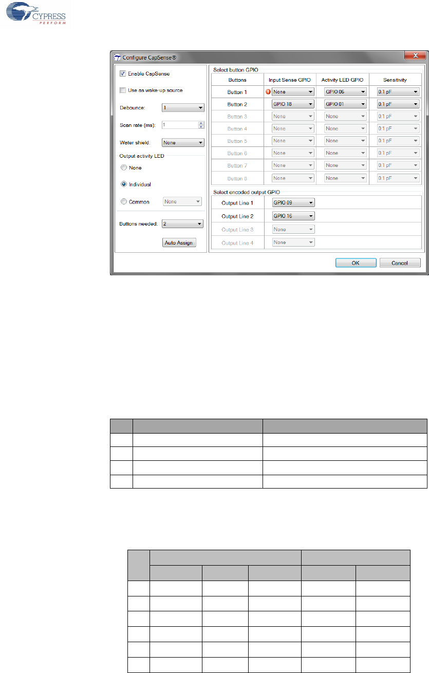
Figure 2-23: CapSense Configuration & Validation
2.3.4.1.1 CapSense Configuration
To configure CapSense on the device, click the CapSense Configure button to launch the CapSense Configuration editor (see
Figure 2-24).
Figure 2-24: CapSense Configuration Editor
Cypress USB-Serial Configuration Utility
Cypress USB-Serial Configuration Utility User Guide, Doc. No. 001-86781 Rev. *D 25
2.3.4.1.1.1 Enable CapSense
To enable CapSense in the device, select Enable from the CapSense drop-down list. This enables the CapSense block in the
device and other configuration options in the editor (see Figure 2-25).
Figure 2-25: Enable CapSense
2.3.4.1.1.2 Debounce
The Debounce value defines the number of scan cycles that a button needs to be in pressed state for the device to detect and
report the button press status. For example, if the debounce value is set to two, the device reports a button press status only when it
detects the button press for two continuous scan cycles.
Debounce ensures that a high-frequency, high-amplitude noise does not cause false detection of a pressed button. The debounce
value can be set to any value between 1 and 5. By default, the debounce value is set to ‘1’.
2.3.4.1.1.3 Scan Rate
The scan rate is the delay (in ms) between two button scans. For example, if the device has three CapSense buttons and the scan
rate is set to 2 ms, each button will be scanned once in every 6 ms.
Scan rate can be set to any value between 1 ms and 100 ms. By default, the scan rate is set to 1 ms.
2.3.4.1.1.4 Water Shield
The device can be configured to suppress the influence of water on the CapSense system. Select the GPIO to be used as
WaterShield I/O from the drop-down list. This GPIO will be used to compensate for the influence of water drops on the sensor at the
hardware level.
2.3.4.1.1.5 Activity LED Selection
The device supports the following activity notifications for CapSense buttons:
1. None
2. Individual
3. Common
Cypress USB-Serial Configuration Utility
Cypress USB-Serial Configuration Utility User Guide, Doc. No. 001-86781 Rev. *D 26
Figure 2-26: Activity LED
Activity LED selection affects the maximum number of CapSense buttons that can be configured. Therefore, select the required
notification before selecting the required CapSense buttons.
2.3.4.1.1.6 None
To disable the notification for the CapSense button, select the None radio button from the Activity LED group. In this configuration,
there will no LED notification for the CapSense button pressed state.
2.3.4.1.1.7 Individual
Select the Individual radio button to get an individual notification LED for each of the selected CapSense buttons.
2.3.4.1.1.8 Common
Select the Common radio button to get a single notification LED for all the selected CapSense buttons. When this option is
selected, you can choose the GPIO to be used for notification from the drop-down list.
2.3.4.1.1.9 Select CapSense Buttons
CapSense uses GPIOs from the device pool (refer to the Device GPIOs section). The number of CapSense buttons that can be
selected for configuration depends on the availability of the GPIOs. The USB-Serial devices can support a maximum of eight
CapSense buttons.
Select the number of CapSense buttons required from the Buttons needed drop-down list. After selecting the number of CapSense
buttons required, configure the GPIOs to be used for sensing the CapSense buttons, activity LEDs (based on the selection made
under the Activity LED Selection section), and the encoded output lines.
2.3.4.1.1.10 CapSense GPIO Assignment
GPIOs can be either manually selected from the drop-down list or click the Auto Assign button to automatically assign the GPIOs.
All fields which require a GPIO to be assigned are marked with an error icon as shown in Figure 2-27.
Figure 2-27: Unassigned CapSense Fields
Cypress USB-Serial Configuration Utility
Cypress USB-Serial Configuration Utility User Guide, Doc. No. 001-86781 Rev. *D 27
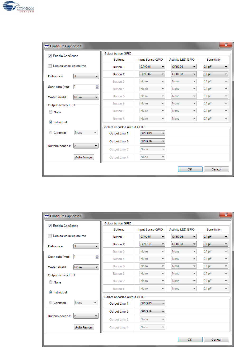
On clicking the Auto Assign button, the utility automatically assigns the GPIOs from the available free pool, as shown in
Figure 2-28.
Figure 2-28: Auto Assign GPIOs
The Auto Assign feature also works with partial GPIO assignments. Select GPIOs for some of the required fields and then click
Auto Assign. The utility will populate the remaining fields with the available GPIOs.
Figure 2-29: Modify Automatic GPIO Assignments
The utility enables modification of the auto-assigned pins. In Figure 2-29, the Input GPIO assignment for Button 2 is modified from
GPIO 07 to GPIO 18.
Cypress USB-Serial Configuration Utility
Cypress USB-Serial Configuration Utility User Guide, Doc. No. 001-86781 Rev. *D 28
Figure 2-30: CapSense GPIO Re-assignment
The utility also allows re-assigning an already selected GPIO for another field. In Figure 2-30, GPIO 01 is re-assigned to Button 2
Activity LED GPIO from Button 1 Input GPIO. Note the error icon next to the Button 1 Input GPIO field after re-assignment.
2.3.4.1.1.11 Sensitivity
The utility allows configuration of the individual button sensitivity in terms of finger capacitance. The sensitivity can be set to any
value between 0.1pF and 0.4pF from the drop-down list. By default, the sensitivity of all the buttons is set to 0.1 pF.
2.3.4.1.1.12 Encoded output GPIO
The number of encoded output GPIO lines required, depends on the number of CapSense buttons selected. Table 2-11 captures
the number of output GPIOs required for the selected CapSense buttons.
Table 2-11: Encoded Output GPIO Count
#
# of CapSense Buttons
# of Output GPIOs Required
1.
1
1
2.
2 to 3
2
3.
4 to 7
3
4
8
4
The encoded GPIO lines indicate the button press status as binary coded output. For example, consider a design with three
CapSense buttons B1, B2 and B3. The design would require two encoded output GPIOs O1 and O2.
Table 2-12 illustrates the mapping between the button press state and the output GPIO states.
Table 2-12: Encoded Output GPIO State
#
CapSense Buttons Pressed
Output GPIOs state
B1
B2
B3
O1
O2
1
NO
NO
NO
Drive 0
Drive 0
2
YES
NO
NO
Drive 0
Drive 1
3
NO
YES
NO
Drive 1
Drive 0
4
NO
NO
YES
Drive 1
Drive 1
5
YES
NO
YES
Drive 0
Drive 1
6
YES
YES
YES
Drive 0
Drive 1
The device supports only single button detection. When multiple buttons are pressed at the same time, the lowest button number
will be indicated.

Cypress USB-Serial Configuration Utility
Cypress USB-Serial Configuration Utility User Guide, Doc. No. 001-86781 Rev. *D 29
2.3.4.1.2 CapSense Validation
The utility allows validating the behavior of the configured CapSense buttons by plotting a graph of the CapSense parameters in
real-time. Follow these steps to begin the CapSense validation:
1. Configure the CapSense from the ‘CapSense Configuration Editor’, as discussed in CapSense Configuration section.
2. Program the configuration (see Program Device section)
3. Reset the device for the programmed configuration to take effect
4. Connect to the device again and navigate to the CapSense®/BCD/GPIO sub-tab under the Device tab
5. Click Launch to launch the ‘CapSense Validation’ window
The utility monitors and plots the following CapSense parameters:
Raw Count: Button capacitance is converted into a count value by the CapSense algorithm. The unprocessed count value is
referred to as raw count. Processing of the raw count results in ON/OFF states for the button
Baseline: The baseline is an estimate of the average sensor count level when the sensor is in the OFF state. The baseline
provides a reference level for the ON/OFF comparison.
Difference Count: Subtracting the baseline level from the raw count produces the difference count that is used in the ON/OFF
decision process. The actual baseline is dynamically adjusted by the user module to compensate for environmental changes
through a process called baseline update.
Finger Threshold: Threshold value used by the CapSense algorithm to identify button status changes. If the difference count
us increasing and exceeds the level of finger threshold, then the button state changes from OFF to ON. If the difference count
is decreasing and drops below the level of finger threshold, then the button state changes from ON to OFF
Noise Threshold: If the difference count is below the noise threshold, then the baseline is updated
Signal-to-Noise Ratio (SNR): Ratio of difference count to noise threshold
The CapSense validation window supports two modes of validation:
Button Specific Validation
Parameter Specific Validation
2.3.4.1.2.1 Button-Specific Validation
In this validation mode, the utility plots the CapSense parameter values for a selected button. The utility allows you to choose the
button for which the utility needs to collect real-time data. To load this validation mode, select the Button Specific Validation
option from the Select View drop-down list and then click Load view.
Select Button
After the utility loads the validation view, select the button for which the utility needs to collect data. By default, the first CapSense
button is selected and the utility collects data for Button 1. The Select Button drop-down lists all the buttons configured in the
device. The utility allows changing the button to view at any time during the validation process.
Button Status
The Button Status, located to the right of the validation window, indicates the current status of the selected button.
Select Graph
For the selected button, the utility allows selecting from three different graphs to view the CapSense parameters.
Raw Count Vs. Baseline: The utility plots the raw count values against the baseline values for the selected button
Difference Count Vs. Finger Threshold: Plots the difference count values for the selected button against the finger threshold
Signal to Noise Ratio (SNR): Plots the SNR calculated for the selected button
The utility allows changing the graph at any time during the validation process.
Cypress USB-Serial Configuration Utility
Cypress USB-Serial Configuration Utility User Guide, Doc. No. 001-86781 Rev. *D 30
2.3.4.1.2.2 Parameter-Specific Validation
In this mode, the utility monitors and plots the selected CapSense parameter for all the configured buttons. You can select the
CapSense parameter for which the utility needs to collect real-time data. To load this validation mode, select
Parameter Specific Validation from the Select View drop-down list and then click the Load view button.
Select Parameter
After the utility loads the validation view, select the parameter to monitor from the Select Parameter drop-down list. The utility
allows selecting one of the following CapSense parameters:
Raw Count
Difference Count
SNR
Monitor Buttons
This section of the utility displays all the configured buttons in the device. For the selected parameter, the utility allows selection of
the buttons to be viewed or hidden by checking or unchecking the checkbox.
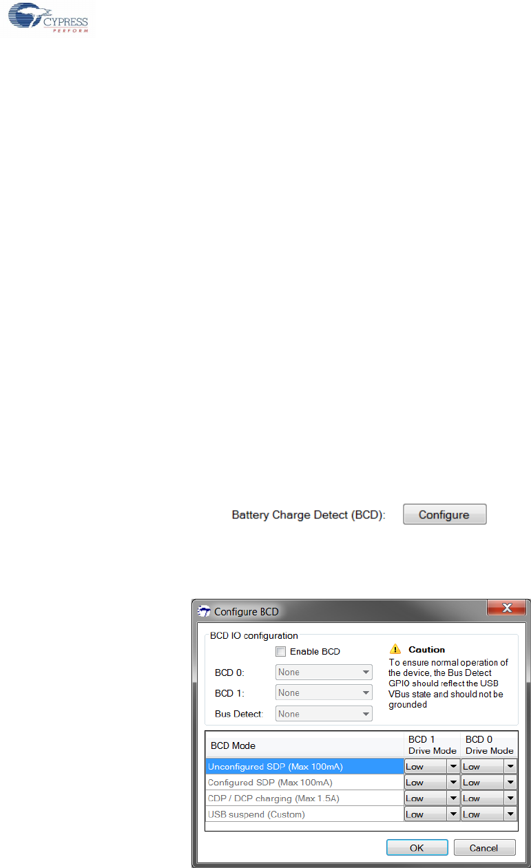
2.3.4.2 Battery Charging Detect (BCD)
The device supports battery charger detection based on the Battery Charging Specification, version 1.2. The device does not
support ID pin-based (ACA) detection. The detection output is indicated to the external processor / PMIC through the configured
GPIO lines (BCD0 and BCD1). The external processor is expected to handle GPIO signaling for configuring the power management
circuitry to initiate battery charging. The charger detection is useful only when the device functions in the self-power mode where
there is a battery available for the device to charge. While using BCD, the VBUS must be routed to BUS_DETECT GPIO line
through resistor dividers so that the voltage on the line never exceeds 5 V. This shall be used for detecting connect / disconnect.
To launch the BCD configuration editor, click the BCD Configure button as shown in Figure 2-31.
Figure 2-31: Open BCD Configuration
The editor (shown in Figure 2-32) allows selection of GPIOs for the BCD pins and sets the BCD pin drive state for each of the
different battery detection modes.
Figure 2-32: BCD Configuration Editor
Cypress USB-Serial Configuration Utility
Cypress USB-Serial Configuration Utility User Guide, Doc. No. 001-86781 Rev. *D 31
2.3.4.2.1 Enable BCD
Select the Enable BCD checkbox to enable BCD for the device.
2.3.4.2.2 Assign BCD GPIOs
On enabling BCD, the ‘BCD0’, ‘BCD1’, and ‘Bus Detect’ fields become editable. BCD requires these fields to be assigned a GPIO.
Select the required GPIO from the drop-down list.
2.3.4.2.3 Charging Mode Indication
The utility allows configuration of the BCD0 and BCD1 line drive mode to indicate the charging state. The BCD0 and BCD1 drive
state for the charging states may vary from one PMIC to another. The utility allows the flexibility to configure the BCD feature to
match the PMIC used in the system.
The utility allows configuration of the following charging states:
Unconfigured SDP state (up to 100 mA)
Configured SDP state (up to 500 mA or whatever is set in the Current Draw field)
DCP / CDP charging (up to 1.5 A)
Not charging (USB bus suspended)
These four states can be represented by the BCD0 and BCD1 lines using the BCD drive mode options. If the PMIC supports only
two current limits (500mA and 1.5A), then only the BCD0 line needs to be connected to the PMIC. The BCD1 line shall be ignored
and shall not be connected to the PMIC. The polarity of BCD0 and BCD1 can be configured to match the PMIC settings.
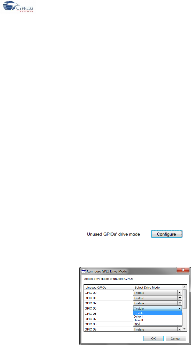
2.3.4.3 GPIO Drive Modes
After configuring the main features of the device, the remaining free GPIOs of the device can be configured to one of the following
drive modes:
1. Drive 0 – Drives the GPIO low on startup
2. Drive 1 – Drives the GPIO high on startup
3. Input – Configures the GPIO as input on startup
4. Tristate – Configures the GPIO in tri-state on startup.
Click on the Drive Mode Configure button (see Figure 2-33) to open the Drive Mode configuration editor.
Figure 2-33: Open Drive Mode Configuration
The configuration editor (see Figure 2-34) lists all the remaining free GPIOs in the device. Select the drive mode for each of these
GPIOs from the drop-down list. By default, the free GPIOs are configured as Tristate.
Figure 2-34: GPIO Drive Mode Editor
Refer to the device datasheet and the Cypress USB-Serial API guide on the functionalities supported by the GPIOs.

Cypress USB-Serial Configuration Utility
Cypress USB-Serial Configuration Utility User Guide, Doc. No. 001-86781 Rev. *D 32
2.3.5 Program Device
The device configuration changes made in the utility do not update the configuration until the device is programmed
with the new settings. To program the device, click Program at the bottom of the Device tab. The device can also be
programmed from the Device menu (Device > Program Device) or by clicking the Program Device button ( ) in the
toolbar.
2.3.6 Save Configuration
The utility allows saving the current device configuration settings to a configuration file. The saved configuration file
can be loaded whenever required. In addition, the batch programming feature (described in Batch Program section) of
the utility uses this configuration file as input.
Follow these steps to save the current settings:
1. In the File menu, click Save to open the Save Configuration dialog
2. This is a regular Windows Save dialog. Choose the location on disk to export the configuration and give a name for the
configuration file
3. Click Save to save the configuration. The configuration file will be saved with the extension ‘.cyusb’
The configuration can also be saved by clicking the Save button ( ) on the toolbar.
2.3.7 Open Device Configuration
The utility allows loading the device configuration from two sources:
Target device
Configuration file
2.3.7.1 Open Configuration from Device
The utility allows loading the current configuration in the connected device. To do this, select
File > Open Configuration from > Device’. The utility then attempts to read the configuration from the device. If
successful, the device configuration settings in the Device tab are updated. On failure to correctly read the settings, the
current settings in the Device tab will be unmodified. The configuration in the connected device can also be loaded by
clicking the Open Configuration from Device button ( ) on the toolbar.
This option can be used to review the current configuration of the device.
2.3.7.2 Open Configuration from File
The utility allows loading a saved configuration from configuration file (refer to Save Configuration section) on disk.
Follow these steps to load the configuration from disk:
1. Select File > Open Configuration from > Disk… to open the Open Configuration dialog
2. This is a regular Windows File Open dialog. Navigate to the location where the configuration file is stored and select the
configuration file (*.cyusb)
3. Click Open to load the configuration.
The configuration file can also be loaded by clicking the Open Configuration from Disk button ( ) on the toolbar.
On successful loading, the configuration settings in the Device tab are updated. If the configuration file is corrupted or
invalid, the current configurations are unmodified.
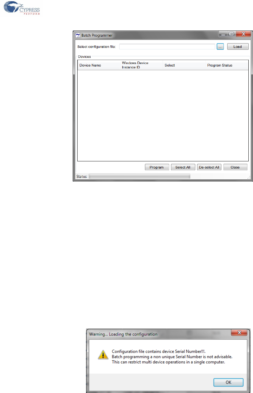
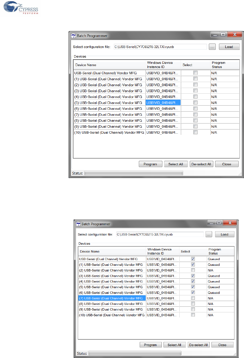
2.3.8 Batch Program
When there are multiple devices to be programmed with the same configuration, the utility provides an option to program these
devices in batch mode. The Batch Programmer (see Figure 2-35) allows programming one or more devices connected to the
machine with the click of a button.
Cypress USB-Serial Configuration Utility
Cypress USB-Serial Configuration Utility User Guide, Doc. No. 001-86781 Rev. *D 33
Figure 2-35: Batch Programmer
Follow these steps to program the devices in the batch mode:
1. The Batch Programmer uses the saved configuration file. If the configuration settings are not saved yet, follow the steps
mentioned in Save Configuration section.
2. After a saved configuration file is available, select File>Batch Program to launch the Batch Programmer.
3. In the Batch Programmer dialog, select the configuration file to be used for programming by clicking on the ellipses (…)
button.
4. On clicking the ellipses button, the utility opens the Open Configuration dialog (similar to the one described in Open
Configuration from File section). Select the configuration from the disk and click Open.
5. Click Load to load the configuration file.
6. In case the loaded configuration file has a serial number and this serial number presence can lead to the possibility of
having multiple devices programmed with the same serial number. Default Windows Operating System does not accept
multiple USB devices with same serial number in the same PC. To avoid this scenario, a warning message Box (see
Figure 2-36a) is popped up to alert the user about a potential risk of programming same serial number to multiple devices.
User still can use the batch programmer to program multiple devices with same serial number, provided the user
understands that this isn’t a usage scenario issue.
Figure 2-36a: Serial Number Presence Warning Message Box.
7. On successfully loading, the utility searches for the attached devices and lists the devices, which support the selected
configuration, in the Devices table (see Figure 2-37). The Devices table allows viewing some of the basic details of the
device such as ‘Device Name’ and ‘Windows Device Instance ID’.
Cypress USB-Serial Configuration Utility
Cypress USB-Serial Configuration Utility User Guide, Doc. No. 001-86781 Rev. *D 34
Figure 2-37: Load Configuration File
8. The utility allows selecting the devices to be programmed by checking the checkbox corresponding to the device of
interest. The utility also allows selecting all the devices simultaneously by clicking the Select All button. All the selected
devices are added to the programming queue as indicated by the Program Status field of the device, as shown in
Figure 2-38.
Figure 2-38: Devices Queued for Programming
9. A device can be removed from the programming queue by unchecking the checkbox. To remove all the devices from the
queue, click on the De-select All button.
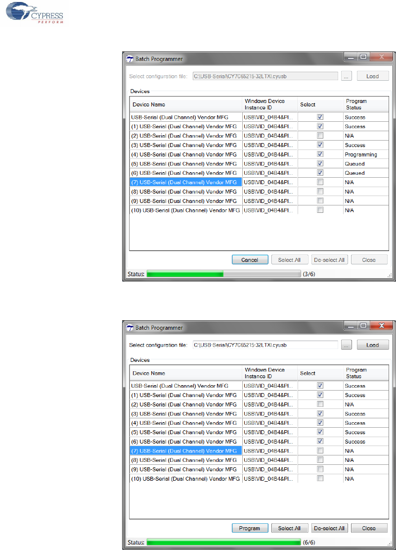
10. After choosing the devices to be programmed, click Program to start the batch programming. The utility starts to program
the devices sequentially in the order listed in the Device table. The progress bar and the Program Status field in the Device
table are updated to notify the progress (see Figure 2-39).
Cypress USB-Serial Configuration Utility
Cypress USB-Serial Configuration Utility User Guide, Doc. No. 001-86781 Rev. *D 35
Figure 2-39: Batch Programming In-progress
Figure 2-40: Batch Programming Completed
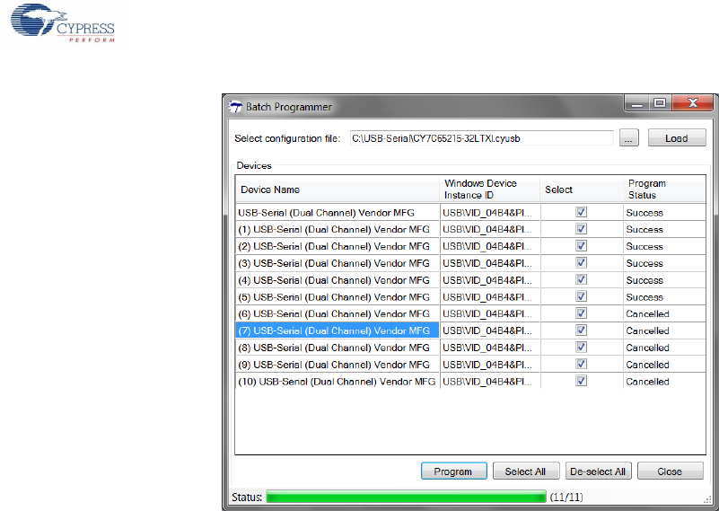
11. The utility allows cancelling or stopping the batch programming by clicking the Cancel button. The utility stops the
programming process after completing the current device. The status of all devices, which were cancelled are indicated as
Cancelled in the Program Status field.
Cypress USB-Serial Configuration Utility
Cypress USB-Serial Configuration Utility User Guide, Doc. No. 001-86781 Rev. *D 36
Figure 2-41: Batch Programming Cancelled
12. Click Close to exit the Batch Programmer and return to the main utility window.
2.3.9 Restore Default Settings
To restore the silicon default settings in the utility, select Restore Default Settings from the File menu. The default settings for the
fields are captured in the respective device datasheets.
2.3.10 Cycle Port
To power cycle the host port to which the device is connected, select Cycle Port from the Device menu. The device will re-
enumerate after the power cycle.
2.3.11 Reset Device
The USB-Serial device needs to be reset after programming the configuration for the new configuration to take effect. To trigger a
software reset of the device, select Reset Device from the Device menu.
2.3.12 Disconnect
The utility allows connecting to only one device at a time. To connect to another device that is attached to the machine, the utility
needs to disconnect from the current device.
To disconnect from the connected device, click the Disconnect button at the bottom of the Device tab. The device can also be
disconnected by selecting Disconnect from the ‘Device’ menu (Device > Disconnect).
Cypress USB-Serial Configuration Utility User Guide, Doc. No. 001-86781 Rev. *D 37
3. Appendix
3.1 Driver Binding for USB-Serial Devices with Custom VID/PID
The Cypress-provided drivers, out-of-the-box, can bind to USB-Serial devices using the Cypress-provided VID/PID provided in
Table 2-2. The customer can also choose to use a custom VID/PID for their USB-Serial device. In this case, customers can decide
to either use the Cypress driver or the custom driver for their devices.
The following sections discuss how to use Cypress drivers for USB-Serial devices with a custom VID/PID. Using custom drivers for
USB-Serial devices is outside the scope of this document.
3.1.1 Driver INF File Changes
The driver INF file contains the entries for all the devices supported by the driver. The operating system can bind a driver to a
device only if the driver INF file contains information about the device. Therefore, to use the Cypress driver with a custom VID/PID,
the driver INF file must be modified to include references to the new VID/PID.
Note: The Microsoft WHQL certification becomes void when INF is modified. Therefore, the customer must make sure to get the
driver WHQL tested and certified from Microsoft for the new VID/PID.
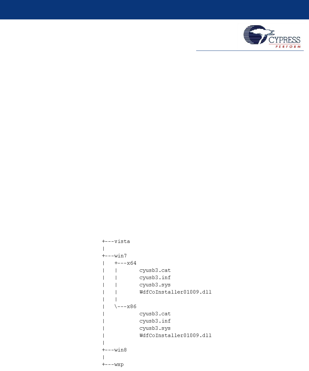
3.1.1.1 Modifying Cypress Generic USB 3.0 Driver INF
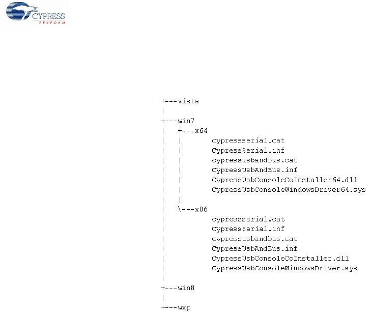
The Cypress generic USB 3.0 driver (cysub3.sys) is packaged along the USB-Serial SDK and can be located on the disk at
<install_path>/driver/cyusb3/bin, where <install_path> is the location where the SDK is installed.
Figure 3-1 shows the driver directory structure under the bin directory.
Figure 3-1: Cypress Generic USB 3.0 Driver Directory Structure
Appendix
Cypress USB-Serial Configuration Utility User Guide, Doc. No. 001-86781 Rev. *D 38
Follow these steps to modify the INF file to use Cypress generic USB 3.0 driver with custom VID/PID:
1. Open the cyusb3.inf file located in thewin7\x86 directory (see Figure 3-1) in a text editor like Notepad.
2. Scroll down in the text editor until the section [Device.NT] is visible.
3. The [Device.NT] section contains entries for all the devices supported by the driver. Add an entry for the new device in the
following format:
%VID_XXXX&PID_YYYY&MI_ZZ.DeviceDesc%=CyUsb3, USB\ VID_XXXX&PID_YYYY&MI_ZZ
Where,
XXXX – Device Vendor ID (VID) in hexadecimal
YYYY – Device Product ID (PID) in hexadecimal
ZZ – Master Interface Number in hexadecimal
4. Copy the entry created in step 3 and paste it under the sections [Device.NTx86] and [Device.NTamd64]
5. Scroll down in the text editor until the[String] section is visible
6. Under the [String]section add an entry in the following format:
VID_XXXX&PID_YYYY&MI_ZZ.DeviceDesc=”<Device Friendly Name>”
Where,
XXXX – Device Vendor ID (VID) in hexadecimal
YYYY – Device Product ID (PID) in hexadecimal
ZZ – Master Interface Number in hexadecimal (refer to the Master Interface Number of USB-Serial Device Configuration
section)
<Device Friendly Name> -- String to be used by the OS for the device in the Device Manager (as highlighted in
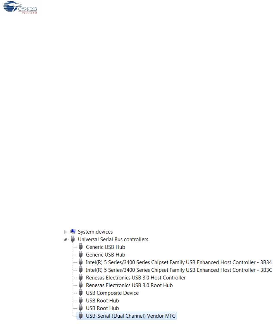
Figure 3-2).
7. The values of XXXX, YYYY, and ZZ should match with value mentioned in step 3.
Figure 3-2: Device Friendly Name for Cypress Generic USB 3.0 Devices
8. Repeat steps 2 to 6 for all device interfaces, which needs to bind to the Cypress Generic USB 3.0 driver
9. Repeat steps 2 to 7 for all the cyusb3.inf files located under the <install_path>/driver/cyusb3/bin directory.
Appendix
Cypress USB-Serial Configuration Utility User Guide, Doc. No. 001-86781 Rev. *D 39
3.1.1.2 Modifying Cypress CDC Driver INF
The Cypress CDC driver (CypressUsbConsoleWindowsDriver.sys) is packaged along the USB-Serial SDK and can be located on
the disk at <install_path>/driver/cyusbserial/bin, where <install_path> is the location where the SDK is installed.
Figure 3-3: Cypress CDC Driver Directory Structure
Figure 3-3 shows the driver directory structure under the bin directory.
Follow these steps to modify the INF file to use the Cypress CDC driver with a custom VID/PID:
1. Open the CypressUsbAndBus.inf file located in win7\x86 directory (as shown in Figure 3-3) in a text editor like Notepad.
2. Scroll down in the text editor until section [Cypress] is visible. For INF files under x64 directory this will be
[Cypress.NTamd64]
3. [Cypress] or [Cypress.NTamd64] section contains entries for all the devices supported by the driver. Add an entry for the
new device in the format
%VID_XXXX&PID_YYYY&MI_ZZ.DeviceDesc%=CypressUsb, USB\ VID_XXXX&PID_YYYY&MI_ZZ
Use the followingformat for the INF files under the x64 directory:
%VID_XXXX&PID_YYYY&MI_ZZ.DeviceDesc%=CypressUsb.NTamd64, USB\ VID_XXXX&PID_YYYY&MI_ZZ
Where,
XXXX – Device Vendor ID (VID) in hexadecimal
YYYY – Device Product ID (PID) in hexadecimal
ZZ – Master Interface Number in hexadecimal (refer to the Master Interface Number of USB-Serial Device
Configuration section)
4. Then, scroll down in the text editor until the [String] section is visible
5. Under the [String] section, add an entry in the following format:
VID_XXXX&PID_YYYY&MI_ZZ.DeviceDesc=”<Device Friendly Name>”
Where,
XXXX – Device Vendor ID (VID) in hexadecimal
YYYY – Device Product ID (PID) in hexadecimal
ZZ – Master Interface Number in hexadecimal
<Device Friendly Name> -- String to be used by the OS for the device in the Device Manager (as highlighted in Figure 3-4).
6. The values of XXXX, YYYY, and ZZ should match with value mentioned in step 3.

Appendix
Cypress USB-Serial Configuration Utility User Guide, Doc. No. 001-86781 Rev. *D 40
Figure 3-4: Device Friendly Name for Cypress CDC Device
7. Repeat steps 2 to 5 for all device interfaces that must bind to the Cypress CDC driver
8. Repeat steps 2 to 6 for all the CypressUsbAndBus.inf files located under the
<install_path>/driver/cyusbserial/bin directory
3.1.2 Master Interface Number of USB-Serial Device Configuration
Table 3-1 provides the Master Interface number (MI #) for the various USB-Serial device configuration combinations.
Table 3-1: Master Interface Numbers for USB-Serial Devices
#
Part Number
SCB 0
SCB 1
MFG Interface
MI #
Mode
Protocol
MI #
Mode
Protocol
MI #
1
CY7C65211-24LTXI
UART
CDC
00
NA
NA
NA
02
UART/ SPI/
I2C
Vendor /
PHDC
00
NA
NA
NA
01
2
CY7C65211A-24LTXI
UART
CDC
00
NA
NA
NA
02
UART/ SPI/
I2C
Vendor /
PHDC /
CDC
00
NA
NA
NA
01
3
CY7C65213-32LTXI
Or
CY7C65213-28PVXI
Or
CY7C65213A-28VXI
Or
CY7C65213A-32LTXI
UART
CDC
00
NA
NA
NA
02
UART
Vendor /
PHDC
00
NA
NA
NA
01
4
CY7C65215-32LTXI
UART
CDC
00
UART
CDC
02
04
UART
CDC
00
UART / SPI
/ I2C /
JTAG
Vendor /
PHDC
02
03
UART / SPI /
I2C
Vendor /
PHDC
00
UART
CDC
01
03
UART / SPI /
I2C
Vendor /
PHDC
00
UART / SPI
/ I2C /
JTAG
Vendor /
PHDC
01
02
5
CY7C65215A-32LTXI
UART
CDC
00
UART
CDC
02
04
UART
CDC
00
UART / SPI
/ I2C
Vendor /
PHDC /
CDC
02
03
UART / SPI /
I2C
Vendor /
PHDC /
CDC
00
UART
CDC
01
03
UART / SPI /
I2C
Vendor /
PHDC /
CDC
00
UART / SPI
/ I2C
Vendor /
PHDC /
CDC
01
02

Cypress USB-Serial Configuration Utility User Guide, Doc. No. 001-86781 Rev. *D 41
3.2 Default Value for Various Configurable Fields
Out of the box default values for each configurable parameter is consolidated in the following table. Refer to the part specific table.
3.2.1 CY7C65213 / CY7C65213A
Sl. No
Parameter
Default Value
Brief Description
USB Configuration
1
VID
0x04B4
2-byte value VID in hex.
2
PID
See Table 2-2
2-byte cypress PID value in hex.
3
Power Mode
Bus Powered
Is the device Bus Powered or Self Powered?
4
bMaxPower
100 mA
USB Specification has say on the maximum current drawn by a
device. So, the value can be between 1 mA to 500 mA.
5
RI#, Sleep# and Power#
Enabled
Remote Wake up, Suspend and Power Enable. Sleep and Power
Enable needs GPIO. GPIO
6
Manufacturing String
Cypress Semiconductor
32 characters string descriptor.
7
Product String
USB-UART LP
32 characters string descriptor.
8
Serial Number
NULL
32 character space for Unique Serial Number.
9
Vcc voltage is 3.3 V
Disabled
Check this option to bypass the voltage regulator in the silicon.
Otherwise you expect to supply 5 V to silicon Vcc.
10
VCCIO voltage less than 2.0 V
Disabled
Enable / disable the voltage regulator for VCC-IO. Enable this option
only when you supply VCCIO with less than 2 volts.
11
Enable Manufacturing
Interface
Enabled
This option enables additional Manufacturing Interface for device
configuration downloads.
12
I/O Level
CMOS
GPIO Logic level selection (CMOS or LVTTL)
13
I/O Mode
Fast
Configures the GPIO edge transition time. Slower transition rate
reduces EMI. This parameter has two static settings Fast/Slow.
UART Configuration (CDC Mode or Vendor Mode or PHDC Mode)
Sl. No
Parameter
Default Value
Brief Description
14
Baud Rate
115200 Bauds
Normally, UART baud rate is driven by host software and hence this
value is expected to change dynamically. This default value is the
startup baud rate value for the hardware UART module.
15
Type
8 Pins
UART type can be 2, 4, 6, or 8 pin module. Lesser the UART pin,
higher the GPIO pins.
16
Data Width
8 bits
UART data width can be 7 or 8 bits value.
17
Stop bits
1 bit
Number of STOP bits needed to complete a UART transaction. 1bit or
2 bit are the available options.
Sl. No
Parameter
Default Value
Brief Description
18
Parity
NONE
UART Parity bit can be NONE, ODD, EVEN, SPACE or MARK.
19
Signal Polarity & Error
Polarity Inversion and data
drop on receive errors is
Disabled.
Invert polarity on any of signals such as RTS, CTS, DTR, DSR, DCD
and RI is disabled by default.
UART Rx module (receive pin) can receive errors such as Frame
error, Parity error, Break errors or overrun errors. The user has the
option to keep or drop the data byte associate to the error? By default,
there is no data drop happens on error.
20
Disable CTS & RTS internal
pull-up during suspend
Enabled
Disabling internal pull up on CTS & RTS pins will reduce current
consumption during suspend state.
BCD and GPIOs

Appendix
Cypress USB-Serial Configuration Utility User Guide, Doc. No. 001-86781 Rev. *D 42
Sl. No
Parameter
Default Value
Brief Description
21
Battery Charger Detection
Functionality
DISABLED
Enabling the BCD functionality needed three free GPIO.
22
GPIO 0
TXLED
GPIO 1
RXLED
GPIO 2
TRISTATE
GPIO 3
POWER#
GPIO 4
SLEEP#
GPIO 5
TRISTATE
GPIO 6
TRISTATE
GPIO 7
TRISTATE
3.2.2 CY7C65215 / CY7C65215A
Sl. No
Parameter
Default Value
Brief Description
USB Configuration
1
VID
0x04B4
2-byte value VID in hex.
2
PID
See Table 2-2
2-byte cypress PID value in hex.
3
Power Mode
Bus Powered
Is the device Bus Powered or Self Powered?
4
bMaxPower
100 mA
USB Specification has say on the maximum current drawn by
a device. So, the value can be between 1 mA to 500 mA.
5
RI# and Sleep#
Enabled.
Remote Wake up and Suspend.
6
Manufacturing String
Cypress Semiconductor
32 characters string descriptor.
7
Product String
USB-Serial (Dual Channel)
32 characters string descriptor.
8
Serial Number
NULL
32 character space for Unique Serial Number.
9
Vcc voltage is 3.3 V
Disabled
Check this option to bypass the voltage regulator in the silicon.
Otherwise you expect to supply 5 V to silicon Vcc.
10
VCCIO voltage less than 2.0v
Disabled
Enable / disable the voltage regulator for VCC-IO. Enable this
option only when you supply VCCIO with less than 2 V.
11
Enable Manufacturing
Interface
Enabled.
This option enables additional Manufacturing Interface for
device configuration downloads.
12
I/O Level
CMOS
GPIO Logic level selection (CMOS or LVTTL)
13
I/O Mode
Fast
Configures the GPIO edge transition time. Slower transition
rate reduces EMI. This parameter has two static settings
Fast/Slow.
UART Configuration (CDC Mode or Vendor Mode or PHDC Mode)
Sl. No
Parameter
Default Value
Brief Description
14
Baud Rate
115200 Bauds
Normally, UART baud rate is driven by host software and hence
this value is expected to change dynamically. This default value
is the startup baud rate value for the hardware UART module.
15
Type
6 Pins
UART type can be 2, 4, or 6 module. Lesser the UART pin,
higher the GPIO pins.
16
Data Width
8 bits
UART data width can be 7 or 8 bits value.
17
Stop bits
1 bit
Number of STOP bits needed to complete a UART transaction.
1bit or 2 bits are the available options.

Appendix
Cypress USB-Serial Configuration Utility User Guide, Doc. No. 001-86781 Rev. *D 43
Sl. No
Parameter
Default Value
Brief Description
18
Parity
NONE
UART Parity bit can be NONE, ODD, EVEN, SPACE or MARK.
19
Drop Packets on RX Error
DISABLED
UART Rx module (receive pin) can receive errors such as Frame
error, Parity error, Break errors or overrun errors. The user has
the option to keep or drop the data byte associate to the error?
By default, there is no data drop happens on error.
20
Disable CTS & RTS internal
pull-up during suspend
Enabled
Disabling internal pull up on CTS & RTS pins will reduce current
consumption during suspend state.
21
Enable RS485
Disabled
To enable RS485 we need at-least one free GPIO.
SPI Configuration (Vendor Mode or PHDC Mode)
Sl. No
Parameter
Default Value
Brief Description
22
Frequency (Hz)
100,000
This default value is the startup clock frequency value for the
hardware SPI module. This value can be dynamically changed
from host application.
23
Data Width
8 bits
SPI data width can be from 4 bits to 16 bits value.
24
SPI Mode
Master
Master or Slave operational mode settings.
25
Protocol
Motorola
SPI data transfer protocol definition. Motorola, TI and NS are
possible options. Refer to the Protocol section for more
information.
26
CPHA mode
Low
Clock Phase definitions. Refer to the CPHA and CPOL Modes
section for more information.
27
CPOL Mode
Low
Clock Polarity definitions. Refer to the CPHA and CPOL Modes
section for more information.
28
SSN Toggle Mode
Continuous
Data frame separation handling through slave de-selection. Refer
to the SSN Toggle Mode section for more information.
29
Bit Order
MSB First
Bit ordering meant LSB first or MSB first setting. By default its
MSB first.
I2C Configuration. (Vendor Mode)
30
Frequency (Hz)
100,000
This default value for startup I2C clock frequency. This value can
be dynamically changed from host application.
31
Mode
Master
I2C Master or I2C Slave
32
Slave Address
0x02
Enabled in slave mode. 7 bit even address are expected here.
33
Enable Clock Stretching
Disabled
Enabled in slave mode. This functionality will hold the clock line
low till the time input buffer become available.
34
Use as wake-up source
Disabled
Enabled in slave mode. This functionality is used to wake the
USB host from sleep.
CapSense, BCD and GPIOs
Sl. No
Parameter
Default Value
Brief Description
35
Enable / Disable CapSense
DISABLED
Based on the configuration few GPIOs are needed to enable this
functionality.
36
Battery Charger Detection
Functionality
DISABLED
Enabling the BCD functionality needed three free GPIO.
37
GPIO 0
TXLED
GPIO 1
RXLED
GPIO 6
POWER#
GPIO 7
TRISTATE
GPIO 16
TRISTATE
GPIO 17
TRISTATE

Appendix
Cypress USB-Serial Configuration Utility User Guide, Doc. No. 001-86781 Rev. *D 44
Sl. No
Parameter
Default Value
Brief Description
GPIO 18
TRISTATE
3.2.3 CY7C65211 / CY7C65211A
Sl. No
Parameter
Default Value
Brief Description
USB Configuration
1
VID
0x04B4
2-byte value VID in hex.
2
PID
See Table 2-2
2-byte cypress PID value in hex.
3
Power Mode
Bus Powered
Is the device Bus Powered or Self Powered?
4
bMaxPower
100 mA
USB Specification has say on the maximum current drawn
by a device. So, the value can be between 1 mA to 500 mA.
5
RI# and Sleep#
Enabled.
Remote Wake up and Suspend.
6
Manufacturing String
Cypress Semiconductor
32 characters string descriptor.
7
Product String
USB-Serial (Single
Channel)
32 characters string descriptor.
8
Serial Number
NULL
32 character space for Unique Serial Number.
9
Vcc voltage is 3.3 V
Disabled
Check this option to bypass the voltage regulator in the
silicon. Otherwise you expect to supply 5 V to silicon Vcc.
10
VCCIO voltage less than 2.0 V
Disabled
Enable / disable the voltage regulator for VCC-IO. Enable
this option only when you supply VCCIO with less than 2 V.
11
Enable Manufacturing Interface
Enabled
This option enables additional Manufacturing Interface for
device configuration downloads.
12
I/O Level
CMOS
GPIO Logic level selection (CMOS or LVTTL)
13
I/O Mode
Fast
Configures the GPIO edge transition time. Slower transition
rate reduces EMI. This parameter has two static settings
Fast/Slow.
UART Configuration (CDC Mode or Vendor Mode or PHDC Mode)
Sl. No
Parameter
Default Value
Brief Description
14
Baud Rate
115200 Bauds
Normally, UART baud rate is driven by host software and
hence this value is expected to change dynamically. This
default value is the startup baud rate value for the hardware
UART module.
15
Type
8 Pins
UART type can be 2, 4, 6, or 8 pin module. Lesser the
UART pin, higher the GPIO pins.
16
Data Width
8 bits
UART data width can be 7 or 8 bits value.
17
Stop bits
1 bit
Number of STOP bits needed to complete a UART
transaction. 1 or 2 bits available options.
18
Parity
NONE
UART Parity bit can be NONE, ODD, EVEN, SPACE or
MARK.
19
Drop Packets on RX Error
DISABLED
UART Rx module (receive pin) can receive errors such as
Frame error, Parity error, Break errors or overrun errors.
The user has the option to keep or drop the data byte
associate to the error? By default, there is no data drop
happens on error.
20
Disable CTS & RTS internal pull-up
during suspend
Enabled
Disabling internal pull up on CTS & RTS pins will reduce
current consumption during suspend state.
21
Enable RS485
Disabled
To enable RS485 we need at-least one free GPIO.
SPI Configuration (Vendor Mode or PHDC Mode)

Appendix
Cypress USB-Serial Configuration Utility User Guide, Doc. No. 001-86781 Rev. *D 45
Sl. No
Parameter
Default Value
Brief Description
Sl. No
Parameter
Default Value
Brief Description
22
Frequency (Hz)
100,000
This default value is the startup clock frequency value for
the hardware SPI module. This value can be dynamically
changed from host application.
23
Data Width
8 bits
SPI data width can be from 4 bits to 16 bits value.
24
SPI Mode
Master
Master or Slave operational mode settings.
25
Protocol
Motorola
SPI data transfer protocol definition. Motorola, TI and NS
are possible options. Refer to the Protocol section for more
information.
26
CPHA mode
Low
Clock Phase definitions. Refer to the CPHA and CPOL
Modes section for more information.
27
CPOL Mode
Low
Clock Polarity definitions. Refer to the CPHA and CPOL
Modes section for more information.
28
SSN Toggle Mode
Continuous
Data frame separation handling through slave de-selection.
Refer to the SSN Toggle Mode section for more
information.
29
Bit Order
MSB First
Bit ordering meant LSB first or MSB first setting. By default
its MSB first.
I2C Configuration (Vendor Mode)
30
Frequency (Hz)
100,000
This default value for startup I2C clock frequency. This
value can be dynamically changed from host application.
31
Mode
Master
I2C Master or I2C Slave
32
Slave Address
0x02
Enabled in slave mode. 7 bit even address are expected
here.
33
Enable Clock Stretching
Disabled
Enabled in slave mode. This functionality will hold the clock
line low till the time input buffer become available.
34
Use as wake-up source
Disabled
Enabled in slave mode. This functionality is used to wake
the USB host from sleep.
CapSense, BCD and GPIOs
Sl. No
Parameter
Default Value
Brief Description
35
Enable / Disable CapSense
DISABLED
Based on the configuration few GPIOs are needed to
enable this functionality.
36
Battery Charger Detection
Functionality
DISABLED
Enabling the BCD functionality needed three free GPIO.
37
GPIO 0
TXLED
GPIO 1
RXLED
GPIO 8
TRISTATE
GPIO 9
TRISTATE
GPIO 10
TRISTATE
GPIO 11
POWER#

Cypress USB-Serial Configuration Utility User Guide, Doc. No. 001-86781 Rev. *D 46
Revision History
Document History
Document Title: Cypress USB-Serial Configuration Utility 2.0 User Guide
Document Number: 001-86781
Revision
ECN
Orig. of Change
Submission Date
Description of Change
**
3944703
BAAM
03/26/2013
New document
*A
4103549
BAAM
08/23/2013
Added new sections on CapSense and BCD configuration
Added a new section on batch programming
Restructured section 2.3 to match the configuration utility
usage flow
Added an appendix on binding drivers to USB-Serial
devices with custom VID/PID
*B
4257858
JEGA
01/23/2014
Added new device CY7C65213-28PVXI.
Added new warning message for LVTTL logic.
Added default value table reference for all the supported
parts.
Format changes need to represent device classification
data.
*C
4822131
MKRS
08/06/2015
Updated the document title.
Added Enable RS485.
Added VCP Mode for I2C Slave.
Update the Note in Enable RS485.
Updated Table 1-1, Table 2-2, Table 2-3, Table 2-4 and
Table 3-1.
Updated Cypress USB-Serial Configuration Utility.
Updated Appendix.
Added Figure 2-15, Figure 2-16 and Figure 2-19.
*D
4891105
MKRS
08/20/2015
Updated Figure 2-1.
