DA 42 AFM Rev. 4 DA42_Diamond Twin_Flight Manual DA42 Diamond Twin Flight
User Manual: DA42_Diamond-Twin_FlightManual
Open the PDF directly: View PDF ![]() .
.
Page Count: 332 [warning: Documents this large are best viewed by clicking the View PDF Link!]
- FRONT MATTER
- 1 GENERAL
- 2 OPERATING LIMITATIONS
- 2.1 Introduction
- 2.2 Airspeed
- 2.3 Airspeed Indicator Markings
- 2.4 Power-Plant Limitations
- 2.5 Engine Instrument Markings
- 2.6 Warning, Caution and Advisory Alerts
- 2.7 Mass (Weight)
- 2.8 Center of Gravity
- 2.9 Approved Maneuvers
- 2.10 Maneuvering Load Factors
- 2.11 Operating Altitude
- 2.12 Flight Crew
- 2.13 Kinds of Operation
- 2.14 Fuel
- 2.15 Limitation Placards
- 2.16 Other Limitations
- 3 EMERGENCY PROCEDURES
- 3.1 Introduction
- 3.2 Airplane-Related G1000 Warnings
- 3.3 G1000 System Warnings
- 3.4 G1000 Failures
- 3.5 One Engine Inoperative Procedures
- 3.5.1 Detecting the Inoperative Engine
- 3.5.2 Engine Troubleshooting
- 3.5.3 Engine Securing (Feathering) Procedure
- 3.5.4 Unfeathering & Restarting the Engine in Flight
- 3.5.5 Engine Failure During Take-off
- 3.5.6 Engine Failures in Flight
- 3.5.7 Landing with one Engine Inoperative
- 3.5.8 Go-around / Balked Landing with one Engine Inpoerative
- 3.5.9 Flight with One Engine Inoperative
- 3.6 Landing Gear System Failures
- 3.7 Failures in the Electrical System
- 3.8 Smoke and Fire
- 3.9 Other Emergencies
- 4A NORMAL OPERATING PROCEDURES
- 4A.1 Introduction
- 4A.3 Advisory Alerts on the G1000
- 4A.4 Flight Characteristics
- 4A.5 Daily Check
- 4A.6 Checklists for Normal Operating Procedures
- 4A.6.1 Pre-Flight Inspection
- 4A.6.2 Before Starting Engine
- 4A.6.3 Starting Engine
- 4A.6.4 Before Taxiing
- 4A.6.5 Taxiing
- 4A.6.6 Before Take-off
- 4A.6.7 Take-off
- 4A.6.8 Climb
- 4A.6.9 Cruise
- 4A.6.10 Descent
- 4A.6.11 Approach & Landing
- 4A.6.12 Go-around
- 4A.6.13 After Landing
- 4A.6.14 Shut-down
- 4A.6.15 Parking
- 4A.6.16 Exit Airplane
- 4A.6.17 Post Flight Inspection
- 4A.6.18 Flight in Rain
- 4A.6.19 Refueling
- 4A.6.20 Flight at High Altitude
- 4B ABNORMAL OPERATING PROCEDURES
- 4B.1 Precautionary Landing
- 4B.2 Canopy in Cooling Gap Position
- 4B.3 Engine Instrument Indications outside of Green Range on the G1000
- 4B.4 Caution-Alerts on the G1000
- 4B.4.1 Cautions/General
- 4B.4.2 L/R ECU A FAIL
- 4B.4.3 L/R ECU B FAIL
- 4B.4.4 L/R FUEL LOW
- 4B.4.5 Low Voltage Caution (LOW VOLTS)
- 4B.4.6 L/R ALTN FAIL
- 4B.4.7 L/R COOL LVL
- 4B.4.8 PITOT FAIL / HT OFF
- 4B.4.9 STALL HT FAIL / OFF
- 4B.4.10 L/R Fuel Transfer Fail (if Aux. Tanks Are Installed)
- 4B.4.11 L/R Auxiliary Fuel Tank Empty (if Aux. Tanks Installed)
- 4B.4.12 STICK LIMIT
- 4B.4.13 RAIM UNAVAIL
- 4B.4.14 AHRS ALIGNING - Keep Wings Level
- 4B.5 Failures in Flap Operating System
- 4B.6 Failures in Hydraulic System
- 4B.7 Starting Engine with External Power
- 5 PERFORMANCE
- 5.1 Introduction
- 5.2 Use of the Performance Tables and Diagrams
- 5.3 Performance Tables and Diagrams
- 5.3.1 Airspeed Calibration
- 5.3.2 Fuel Flow Diagram
- 5.3.3 International Standard Atmosphere
- 5.3.4 Stalling Speeds
- 5.3.5 Wind Components
- 5.3.6 Take-off Distance
- 5.3.7 Climb Performance - Take-off Climb
- 5.3.8 Climb Performance - Cruise Climb
- 5.3.9 One Engine Inoperative Climb Performance
- 5.3.10 Cruising (True Airspeed TAS)
- 5.3.11 Landing Distance
- 5.3.12 Gradient of Climb on Go-around
- 5.3.13 Approved Noise Data
- 6 MASS AND BALANCE
- 7 DESCRIPTION OF THE AIRPLANE AND ITS SYSTEMS
- 7.1 Introduction
- 7.2 Airframe
- 7.3 Flight Controls
- 7.4 Instrument Panel
- 7.5 Landing Gear
- 7.6 Seats and Safety Harnesses
- 7.7 Baggage Compartment
- 7.8 Canopy, Rear Door, and Cabin Interior
- 7.9 Power Plant
- 7.10 Electrical System
- 7.11 Pitot-Static System
- 7.12 Stall Warning System
- 7.13 Garmin G1000 Integrated Avionics System
- 8 AIRPLANE HANDLING, CARE AND MAINTENANCE
- 9 SUPPLEMENTS

Introduction DA 42 AFM
Page 0 - 0a Rev. 3 15-Oct-2005 Doc. # 7.01.05-E
Intentionally left blank.

DA 42 AFM Introduction
Doc. # 7.01.05-E Rev. 3 15-Oct-2005 Page 0 - 1
FOREWORD
We congratulate you on the acquisition of your new DIAMOND DA 42 Twin Star.
Skillful operation of an airplane increases both safety and the enjoyment of flying. Please
take the time therefore, to familiarize yourself with your new DIAMOND DA 42.
This airplane may only be operated in accordance with the procedures and operating
limitations of this Airplane Flight Manual.
Before this airplane is operated for the first time, the pilot must familiarize himself with
the complete contents of this Airplane Flight Manual.
In the event that you have obtained your DIAMOND DA 42 second-hand, please let us
know your address, so that we can supply you with the publications necessary for the
safe operation of your airplane.
This document is protected by copyright. All associated rights, in particular those of
translation, reprinting, radio transmission, reproduction by photo-mechanical or similar
means and storing in data processing facilities, in whole or part, are reserved.
Copyright © by: DIAMOND AIRCRAFT INDUSTRIES GMBH
N.A. Otto-Strasse 5
A-2700 Wiener Neustadt, Austria
Phone : +43-2622-26700
Fax : +43-2622-26780
E-Mail : office@diamond-air.at

Introduction DA 42 AFM
Page 0 - 2 Rev. 3 15-Oct-2005 Doc. # 7.01.05-E
0.1 APPROVAL
%
The content of approved chapters is approved by EASA. All other content is approved
%
by DAI under the authority of EASA DOA No. EASA.21J.052 in accordance with Part 21.
%
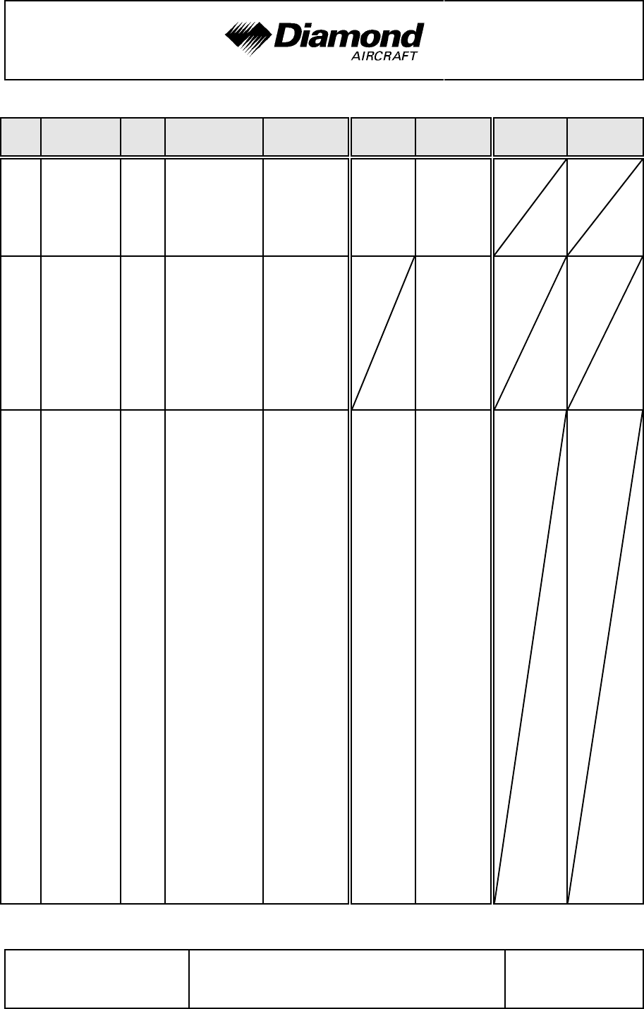
0.2 RECORD OF REVISIONS
All revisions of this manual, with the exception of -
• Temporary Revisions,
• updates of the modification level (Section 1.1),
• updated mass and balance information (Section 6.3),
• updates of the Equipment Inventory (Section 6.5), and
• updates of the List of Supplements (Section 9.2)
must be recorded in the following table.
The new or amended text is indicated by a vertical black line at the left hand side of the
revised page, with the revision number and date appearing at the bottom of the page.
If pages are revised which contain information valid for your particular serial number
(modification level of the airplane, weighing data, Equipment Inventory, List of
Supplements), then this information must be transferred to the new pages in hand-writing.
The cover pages of Temporary Revisions, if applicable, are inserted behind the cover
%
page of this manual; the following pages of the Temporary Revision are inserted in front
%
of the corresponding pages of this AFM. Temporary Revisions are used to provide
%
information on systems or equipment until the next 'permanent' Revision of the Airplane
Flight Manual. When a 'permanent' Revision covers a Mandatory or Optional Design
Change Advisory (MÄM or OÄM), then the corresponding Temporary Revision is
superseded. Example: Revision 3 covers OÄM 42-053, therefore the Temporary Revision
%
TR-OÄM-42-053 is superseded by the 'permanent' Revision 3.
%
DA 42 AFM Introduction
Doc. # 7.01.05-E Rev. 4 30-Nov-2005 Page 0 - 3
Rev.
No. Reason Chap-
ter Page(s) Date of
Revision Approval Verification Date
Inserted Signature
1
IFR
certification;
corrections
all all except cover
page 1 Dec 2004 2005-196
[Ing.
Andreas
Winkler for
ACG]
2
MÄM 42-034
(elevator
stop);
OÄM 42-060
(T&B
coordinat.);
Take-off
diagrams
0
4A
4B
5
6
7
0-3, 0-5,
0-7, 0-8, 0-9
4A-9
4B-25
5-11, 5-12
6-18
7-7
28 Jan 2005
[10 Feb
2005
Dipl.-Ing.
(FH)
Manfred
Reichel
for DAI]
3
FAA
Certification
MÄM 42-
-062, -070/a,
-079, -080,
-091, -101,
-111/b
(TR-MÄM-
42-111/a),
-115
OÄM 42-
-053, -056,
-057, -059,
-079
Corrections
all all 15 Oct 2005
[25 Oct
%
2005
%
Ing.
%
Andreas
%
Winkler for
%
ACG]
%
%
%

DA 42 AFM Introduction
Doc. # 7.01.05-E Rev. 4 30-Nov-2005 Page 0 - 5
0.3 LIST OF EFFECTIVE PAGES
Ch. Page Date
0
0-0
0-0a
0-1
0-2
0-3
0-4
0-5
0-6
0-7
0-8
0-9
0-10
0-11
0-12
29-Apr-2004
15-Oct-2005
15-Oct-2005
15-Oct-2005
30-Nov-2005
%
30-Nov-2005
%
30-Nov-2005
%
30-Nov-2005
%
30-Nov-2005
%
30-Nov-2005
%
30-Nov-2005
%
30-Nov-2005
%
15-Oct-2005
15-Oct-2005
1
1-1
1-2
1-3
1-4
1-5
1-6
1-7
1-8
1-9
1-10
1-11
1-12
1-13
1-14
1-15
1-16
1-17
1-18
1-19
1-20
1-21
1-22
15-Oct-2005
30-Nov-2005
%
15-Oct-2005
15-Oct-2005
15-Oct-2005
15-Oct-2005
15-Oct-2005
15-Oct-2005
15-Oct-2005
15-Oct-2005
30-Nov-2005
%
15-Oct-2005
15-Oct-2005
15-Oct-2005
15-Oct-2005
15-Oct-2005
15-Oct-2005
15-Oct-2005
15-Oct-2005
15-Oct-2005
15-Oct-2005
15-Oct-2005
Ch. Page Date
2
2-1
2-2
appr. 2-3
appr. 2-4
appr. 2-5
appr. 2-6
appr. 2-7
appr. 2-8
appr. 2-9
appr. 2-10
appr. 2-11
appr. 2-12
appr. 2-13
appr. 2-14
appr. 2-15
appr. 2-16
appr. 2-17
appr. 2-18
appr. 2-19
appr. 2-20
appr. 2-21
appr. 2-22
appr. 2-23
appr. 2-24
appr. 2-25
appr. 2-26
appr. 2-27
appr. 2-28
appr. 2-29
appr. 2-30
appr. 2-31
appr. 2-32
15-Oct-2005
30-Nov-2005
%
15-Oct-2005
30-Nov-2005
%
15-Oct-2005
15-Oct-2005
30-Nov-2005
%
30-Nov-2005
%
15-Oct-2005
30-Nov-2005
%
15-Oct-2005
15-Oct-2005
15-Oct-2005
30-Nov-2005
%
30-Nov-2005
%
15-Oct-2005
15-Oct-2005
30-Nov-2005
%
15-Oct-2005
15-Oct-2005
30-Nov-2005
%
30-Nov-2005
%
30-Nov-2005
%
15-Oct-2005
%
15-Oct-2005
%
30-Nov-2005
%
30-Nov-2005
%
15-Oct-2005
%
15-Oct-2005
%
15-Oct-2005
%
15-Oct-2005
%
30-Nov-2005
%

Introduction DA 42 AFM
Page 0 - 6 Rev. 4 30-Nov-2005 Doc. # 7.01.05-E
Ch. Page Date
3
3-1
3-2
3-3
3-4
3-5
3-6
3-7
3-8
3-9
3-10
3-11
3-12
3-13
3-14
3-15
3-16
3-17
3-18
3-19
3-20
3-21
3-22
3-23
3-24
3-25
3-26
3-27
3-28
3-29
3-30
15-Oct-2005
15-Oct-2005
15-Oct-2005
15-Oct-2005
15-Oct-2005
15-Oct-2005
15-Oct-2005
15-Oct-2005
15-Oct-2005
15-Oct-2005
15-Oct-2005
15-Oct-2005
15-Oct-2005
15-Oct-2005
15-Oct-2005
15-Oct-2005
15-Oct-2005
15-Oct-2005
15-Oct-2005
15-Oct-2005
15-Oct-2005
15-Oct-2005
15-Oct-2005
15-Oct-2005
15-Oct-2005
15-Oct-2005
15-Oct-2005
15-Oct-2005
15-Oct-2005
30-Nov-2005
%
Ch. Page Date
3
3-31
3-32
3-33
3-34
3-35
3-36
3-37
3-38
3-39
3-40
3-41
3-42
3-43
3-44
3-45
3-46
3-47
3-48
3-49
3-50
3-51
3-52
3-53
3-54
3-55
3-56
30-Nov-2005
%
30-Nov-2005
%
15-Oct-2005
15-Oct-2005
15-Oct-2005
15-Oct-2005
15-Oct-2005
30-Nov-2005
%
15-Oct-2005
15-Oct-2005
15-Oct-2005
15-Oct-2005
15-Oct-2005
15-Oct-2005
15-Oct-2005
15-Oct-2005
15-Oct-2005
15-Oct-2005
15-Oct-2005
15-Oct-2005
15-Oct-2005
15-Oct-2005
15-Oct-2005
15-Oct-2005
15-Oct-2005
15-Oct-2005

DA 42 AFM Introduction
Doc. # 7.01.05-E Rev. 4 30-Nov-2005 Page 0 - 7
Ch. Page Date
4A
4A-1
4A-2
4A-3
4A-4
4A-5
4A-6
4A-7
4A-8
4A-9
4A-10
4A-11
4A-12
4A-13
4A-14
4A-15
4A-16
4A-17
4A-18
4A-19
4A-20
4A-21
4A-22
4A-23
4A-24
4A-25
4A-26
4A-27
4A-28
4A-29
4A-30
4A-31
4A-32
4A-33
4A-34
4A-35
4A-36
4A-37
4A-38
4A-39
%
4A-40
%
30-Nov-2005
%
30-Nov-2005
%
30-Nov-2005
%
30-Nov-2005
%
30-Nov-2005
%
30-Nov-2005
%
30-Nov-2005
%
30-Nov-2005
%
30-Nov-2005
%
30-Nov-2005
%
30-Nov-2005
%
30-Nov-2005
%
30-Nov-2005
%
30-Nov-2005
%
30-Nov-2005
%
30-Nov-2005
%
30-Nov-2005
%
30-Nov-2005
%
30-Nov-2005
%
30-Nov-2005
%
30-Nov-2005
%
30-Nov-2005
%
30-Nov-2005
%
30-Nov-2005
%
30-Nov-2005
%
30-Nov-2005
%
30-Nov-2005
%
30-Nov-2005
%
30-Nov-2005
%
30-Nov-2005
%
30-Nov-2005
%
30-Nov-2005
%
30-Nov-2005
%
30-Nov-2005
%
30-Nov-2005
%
30-Nov-2005
%
30-Nov-2005
%
30-Nov-2005
%
30-Nov-2005
%
30-Nov-2005
%
Ch. Page Date
4B
4B-1
4B-2
4B-3
4B-4
4B-5
4B-6
4B-7
4B-8
4B-9
4B-10
4B-11
4B-12
4B-13
4B-14
4B-15
4B-16
4B-17
4B-18
4B-19
4B-20
4B-21
4B-22
4B-23
4B-24
4B-25
4B-26
4B-27
4B-28
4B-29
4B-30
4B-31
4B-32
4B-33
%
4B-34
%
15-Oct-2005
30-Nov-2005
%
15-Oct-2005
15-Oct-2005
15-Oct-2005
15-Oct-2005
15-Oct-2005
15-Oct-2005
15-Oct-2005
15-Oct-2005
15-Oct-2005
15-Oct-2005
30-Nov-2005
%
15-Oct-2005
15-Oct-2005
15-Oct-2005
15-Oct-2005
15-Oct-2005
15-Oct-2005
15-Oct-2005
15-Oct-2005
15-Oct-2005
15-Oct-2005
15-Oct-2005
30-Nov-2005
%
15-Oct-2005
30-Nov-2005
%
15-Oct-2005
15-Oct-2005
30-Nov-2005
%
30-Nov-2005
%
30-Nov-2005
%
30-Nov-2005
%
30-Nov-2005
%

Introduction DA 42 AFM
Page 0 - 8 Rev. 4 30-Nov-2005 Doc. # 7.01.05-E
Ch. Page Date
5
5-1
%
5-2
%
5-3
%
5-4
%
5-5
%
5-6
%
5-7
%
5-8
%
5-9
%
5-10
%
5-11
%
5-12
%
5-13
%
5-14
%
5-15
%
5-16
%
5-17
%
5-18
%
5-19
%
5-20
%
5-21
%
5-22
%
5-23
%
5-24
%
5-25
%
5-26
%
5-27
%
5-28
%
5-29
%
5-30
%
5-31
%
5-32
%
5-33
%
5-34
%
30-Nov-2005
%
30-Nov-2005
%
30-Nov-2005
%
30-Nov-2005
%
30-Nov-2005
%
30-Nov-2005
%
30-Nov-2005
%
30-Nov-2005
%
30-Nov-2005
%
30-Nov-2005
%
30-Nov-2005
%
30-Nov-2005
%
30-Nov-2005
%
30-Nov-2005
%
30-Nov-2005
%
30-Nov-2005
%
30-Nov-2005
%
30-Nov-2005
%
30-Nov-2005
%
30-Nov-2005
%
30-Nov-2005
%
30-Nov-2005
%
30-Nov-2005
%
30-Nov-2005
%
30-Nov-2005
%
30-Nov-2005
%
30-Nov-2005
%
30-Nov-2005
%
30-Nov-2005
%
30-Nov-2005
%
30-Nov-2005
%
30-Nov-2005
%
30-Nov-2005
%
30-Nov-2005
%
%
Ch. Page Date
6
6-1
6-2
6-3
6-4
6-5
6-6
6-7
6-8
6-9
6-10
6-11
6-12
6-13
6-14
6-15
6-16
6-17
6-18
6-19
6-20
15-Oct-2005
15-Oct-2005
15-Oct-2005
15-Oct-2005
30-Nov-2005
%
15-Oct-2005
15-Oct-2005
30-Nov-2005
%
15-Oct-2005
30-Nov-2005
%
30-Nov-2005
%
30-Nov-2005
%
30-Nov-2005
%
30-Nov-2005
%
15-Oct-2005
30-Nov-2005
%
15-Oct-2005
15-Oct-2005
15-Oct-2005
30-Nov-2005
%

DA 42 AFM Introduction
Doc. # 7.01.05-E Rev. 4 30-Nov-2005 Page 0 - 9
Ch. Page Date
7
7-1
7-2
7-3
7-4
7-5
7-6
7-7
7-8
7-9
7-10
7-11
7-12
7-13
7-14
7-15
7-16
7-17
7-18
7-19
7-20
7-21
7-22
7-23
7-24
7-25
7-26
7-27
7-28
7-29
7-30
7-31
7-32
7-33
7-34
7-35
7-36
7-37
30-Nov-2005
%
30-Nov-2005
%
15-Oct-2005
15-Oct-2005
15-Oct-2005
15-Oct-2005
15-Oct-2005
15-Oct-2005
15-Oct-2005
15-Oct-2005
15-Oct-2005
15-Oct-2005
15-Oct-2005
15-Oct-2005
15-Oct-2005
15-Oct-2005
15-Oct-2005
15-Oct-2005
15-Oct-2005
15-Oct-2005
15-Oct-2005
15-Oct-2005
15-Oct-2005
15-Oct-2005
15-Oct-2005
15-Oct-2005
15-Oct-2005
15-Oct-2005
15-Oct-2005
15-Oct-2005
15-Oct-2005
15-Oct-2005
15-Oct-2005
15-Oct-2005
15-Oct-2005
15-Oct-2005
15-Oct-2005
Ch. Page Date
7
7-38
7-39
7-40
7-41
7-42
7-43
7-44
7-45
7-46
7-47
7-48
7-49
7-50
7-51
7-52
7-53
7-54
7-55
7-56
7-57
7-58
7-59
7-60
7-61
7-62
7-63
7-64
7-65
%
7-66
%
%
15-Oct-2005
15-Oct-2005
30-Nov-2005
%
30-Nov-2005
%
30-Nov-2005
%
30-Nov-2005
%
30-Nov-2005
%
30-Nov-2005
%
30-Nov-2005
%
30-Nov-2005
%
30-Nov-2005
%
30-Nov-2005
%
30-Nov-2005
%
30-Nov-2005
%
30-Nov-2005
%
30-Nov-2005
%
30-Nov-2005
%
30-Nov-2005
%
30-Nov-2005
%
30-Nov-2005
%
30-Nov-2005
%
30-Nov-2005
%
30-Nov-2005
%
30-Nov-2005
%
30-Nov-2005
%
30-Nov-2005
%
30-Nov-2005
%
30-Nov-2005
%
30-Nov-2005
%

Introduction DA 42 AFM
Page 0 - 10 Rev. 4 30-Nov-2005 Doc. # 7.01.05-E
Ch. Page Date
8
8-1
8-2
8-3
8-4
8-5
8-6
8-7
8-8
8-9
8-10
8-11
8-12
15-Oct-2005
15-Oct-2005
15-Oct-2005
30-Nov-2005
%
15-Oct-2005
15-Oct-2005
15-Oct-2005
15-Oct-2005
15-Oct-2005
15-Oct-2005
15-Oct-2005
30-Nov-2005
%
99-1
9-2 15-Oct-2005
%
30-Nov-2005
%

DA 42 AFM Introduction
Doc. # 7.01.05-E Rev. 3 15-Oct-2005 Page 0 - 11
0.4 TABLE OF CONTENTS
Chapter
GENERAL
(a non-approved chapter) .......................................... 1
OPERATING LIMITATIONS
(an approved chapter) ............................................. 2
EMERGENCY PROCEDURES
(a non-approved chapter) .......................................... 3
NORMAL OPERATING PROCEDURES
(a non-approved chapter) ......................................... 4A
ABNORMAL OPERATING PROCEDURES
(a non-approved chapter) ......................................... 4B
PERFORMANCE
(a non-approved chapter) .......................................... 5
MASS AND BALANCE / EQUIPMENT LIST
(a non-approved chapter) .......................................... 6
DESCRIPTION OF THE AIRPLANE AND ITS SYSTEMS
(a non-approved chapter) .......................................... 7
AIRPLANE HANDLING, CARE AND MAINTENANCE
(a non-approved chapter) .......................................... 8
SUPPLEMENTS ................................................... 9

Introduction DA 42 AFM
Page 0 - 12 Rev. 3 15-Oct-2005 Doc. # 7.01.05-E
Intentionally left blank.

DA 42 AFM General
Doc. No. 7.01.05-E Rev. 3 15-Oct-2005 Page 1 - 1
CHAPTER 1
GENERAL
Page
1.1 INTRODUCTION .......................................1-2
1.2 CERTIFICATION BASIS ..................................1-3
1.3 WARNINGS, CAUTIONS AND NOTES ......................1-4
1.4 DIMENSIONS ..........................................1-5
1.5 DEFINITIONS AND ABBREVIATIONS .......................1-7
1.6 UNITS OF MEASUREMENT .............................1-15
1.6.1 CONVERSION FACTORS ..........................1-15
1.6.2 CONVERSION CHART LITERS / US GALLONS .........1-17
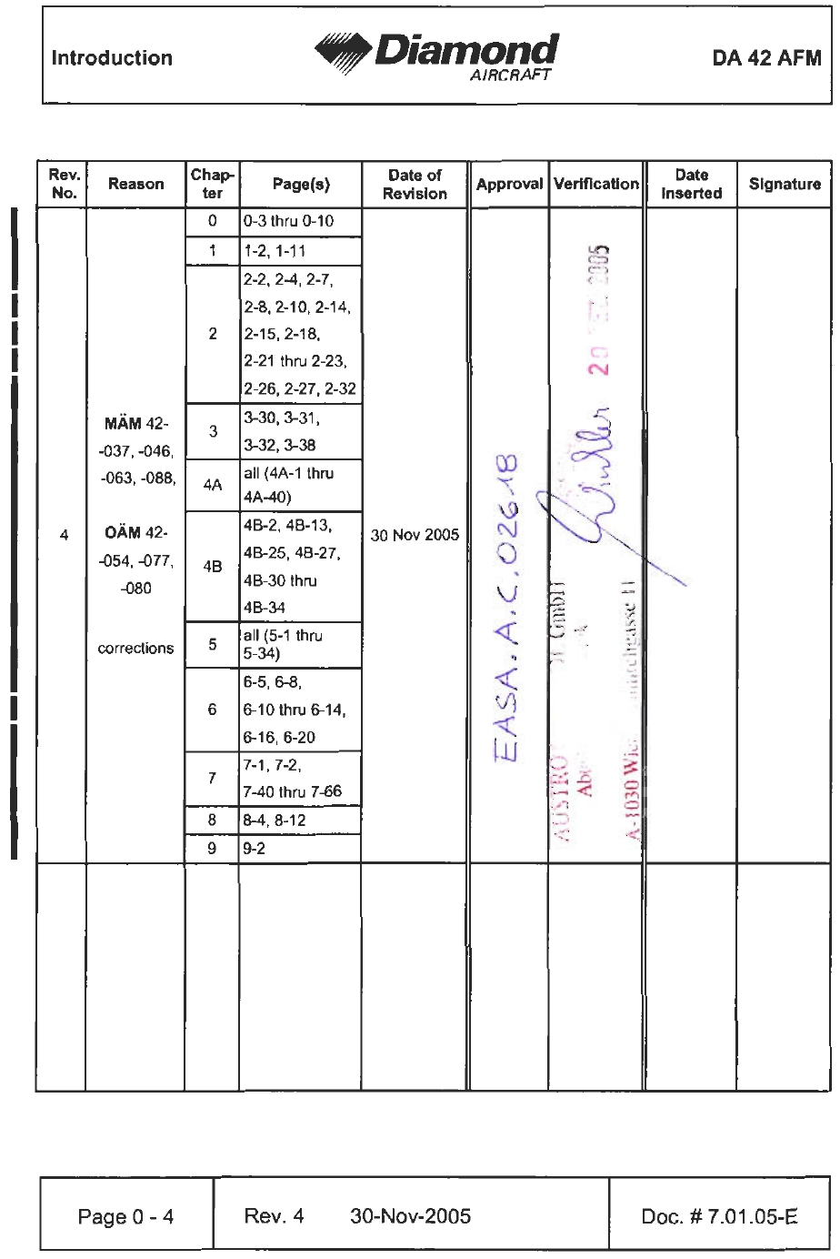
1.7 THREE-VIEW DRAWING................................1-18
1.8 G1000 AVIONICS SYSTEM ..............................1-19
1.9 SOURCE DOCUMENTATION ............................1-20
1.9.1 ENGINE ........................................1-20
1.9.2 PROPELLER ....................................1-21
1.9.3 AVIONICS SYSTEM ...............................1-21

General DA 42 AFM
Page 1 - 2 Rev. 4 30-Nov-2005 Doc. No. 7.01.05-E
1.1 INTRODUCTION
This Airplane Flight Manual has been prepared in order to provide pilots and instructors
with all the information required for the safe and efficient operation of the airplane.
The Airplane Flight Manual includes all the data which must be made available to the pilot
according to the JAR-23 requirement. Beyond this, it contains further data and operating
instructions which, in the manufacturer’s opinion, could be of value to the pilot.
This Airplane Flight Manual is valid for all serial numbers. Equipment and modification
level (design details) of the airplane may vary from serial number to serial number.
Therefore, some of the information contained in this manual is applicable depending on
the respective equipment and modification level. The exact equipment of your serial
number is recorded in the Equipment Inventory in Section 6.5. The modification level is
recorded in the following table (as far as necessary for this manual).
Modification Source Installed
New Engine Instrument Markings MÄM 42-101 9 yes 9 no
Increased Take-Off Mass
'
MÄM 42-088
'
9 yes 9 no
Use of Diesel fuel
'
MÄM 42-037
'
9 yes 9 no
Ice Protection System OÄM 42-053 9 yes 9 no
Ice Protection System
'
(Known Icing)
'
OÄM 42-054
'
9 yes 9 no
Auxiliary Fuel Tanks OÄM 42-056 9 yes 9 no
Removable Fuselage Nose Cone
'
OÄM 42-077
'
9 yes 9 no
9 yes 9 no
9 yes 9 no

DA 42 AFM General
Doc. No. 7.01.05-E Rev. 3 15-Oct-2005 Page 1 - 3
This Airplane Flight Manual must be kept on board the airplane at all times. Its designated
place is the side bag of the forward left seat. The designated place for the Garmin G1000
Cockpit Reference Guide is the bag on the rear side of the forward left seat.
CAUTION
The DA 42 is a twin engine airplane. When the operating
limitations and maintenance requirements are complied with,
it has the high degree of reliability which is required by the
certification basis. Nevertheless, an engine failure is not
completely impossible. For this reason it is highly recom-
mended for flights during the night, on top, under IMC, or
above terrain which is unsuitable for a landing, to select flight
times and flight routes such that reduced performance in case
of single engine operation does not constitute a risk.
1.2 CERTIFICATION BASIS
The certification basis is JAR-23, published on 11-Mar-1994, including Amdt. 1, and
additional requirements as laid down in CRI A-01.

General DA 42 AFM
Page 1 - 4 Rev. 3 15-Oct-2005 Doc. No. 7.01.05-E
1.3 WARNINGS, CAUTIONS AND NOTES
Special statements in the Airplane Flight Manual concerning the safety or operation of
the airplane are highlighted by being prefixed by one of the following terms:
WARNING
means that the non-observation of the corresponding
procedure leads to an immediate or important degradation
in flight safety.
CAUTION
means that the non-observation of the corresponding
procedure leads to a minor or to a more or less long term
degradation in flight safety.
NOTE
draws the attention to any special item not directly related to
safety but which is important or unusual.

DA 42 AFM General
Doc. No. 7.01.05-E Rev. 3 15-Oct-2005 Page 1 - 5
1.4 DIMENSIONS
NOTE
All dimensions shown below are approximate.
Overall dimensions
Span : 13.42 m 44 ft
Length : 8.56 m 28 ft 1 in
Height : 2.49 m 8 ft 2 in
Wing
Airfoil : Wortmann FX 63-137/20 - W4
Wing Area : 16.29 m² 175.3 sq.ft.
Mean aerodynamic chord : 1.271 m 4 ft 2 in
Aspect ratio : 11.06
Dihedral : 5°
Leading edge sweep : 1°
Aileron
Area (total, left + right) : 0.66 m² 7.1 sq.ft.

General DA 42 AFM
Page 1 - 6 Rev. 3 15-Oct-2005 Doc. No. 7.01.05-E
Wing flaps
Area (total, left + right) : 2.18 m² 23.4 sq.ft.
Horizontal tail
Area : 2.35 m225.3 sq.ft.
Elevator area : 0.66 m² 7.1 sq.ft.
Angle of incidence : -1.1° relative to longitudinal axis of airplane
'
Vertical tail
Area : 2.43 m² 26.2 sq.ft.
Rudder area : 0.78 m² 8.4 sq.ft.
Landing gear
Track : 2.95 m (9 ft 8 in)
Wheelbase : 1.735 m (5 ft 8 in)
Nose wheel : 5.00-5; 10 PR, 120 mph
Main wheel : 15x6.0-6; 6 PR, 120 mph

DA 42 AFM General
Doc. No. 7.01.05-E Rev. 3 15-Oct-2005 Page 1 - 7
1.5 DEFINITIONS AND ABBREVIATIONS
(a) Airspeeds
CAS: Calibrated Airspeed. Indicated airspeed, corrected for installation and instrument
errors. CAS equals TAS at standard atmospheric conditions (ISA) at MSL.
KCAS: CAS in knots.
KIAS: IAS in knots.
IAS: Indicated Airspeed as shown on an airspeed indicator.
TAS: True Airspeed. The speed of the airplane relative to the air. TAS is CAS
corrected for errors due to altitude and temperature.
vA: Maneuvering Speed. Full or abrupt control surface movement is not permissible
above this speed.
vFE: Maximum Flaps Extended Speed. This speed must not be exceeded with the
given flap setting.
vLO: Maximum Landing Gear Operating Speed. This speed may not be exceeded
during the extension or retraction of the landing gear.
vLE: Maximum Landing Gear Extended Speed. This speed may not be exceeded
if the landing gear is extended.
vMC: Minimum Control Speed. Minimum speed necessary to be able to control the
airplane in case of one engine inoperative.
vNE: Never Exceed Speed in smooth air. This speed must not be exceeded in any
operation.

General DA 42 AFM
Page 1 - 8 Rev. 3 15-Oct-2005 Doc. No. 7.01.05-E
vNO: Maximum Structural Cruising Speed. This speed may be exceeded only in
smooth air, and then only with caution.
vS: Stalling Speed, or the minimum continuous speed at which the airplane is still
controllable in the given configuration.
vS0: Stalling Speed, or the minimum continuous speed at which the airplane is still
controllable in the landing configuration.
vS1: Stalling Speed, or the minimum continuous speed at which the airplane is still
controllable with flaps and landing gear retracted.
vSSE: Minimum Control Speed for Schooling. Minimum speed necessary in case of
one engine intentionally inoperative / idle (training purposes).
vx: Best Angle-of-Climb Speed.
vy: Best Rate-of-Climb Speed.
vYSE: Best Rate of-Climb Speed for one engine inoperative.
(b) Meteorological terms
ISA: International Standard Atmosphere. Conditions at which air is identified
as an ideal dry gas. The temperature at mean sea level is 15 °C (59 °F),
air pressure at MSL is 1013.25 hPa (29.92 inHg); the temperature
gradient up to the altitude at which the temperature reaches -56.5 °C
(-69.7 °F) is -0.0065 °C/m (-0.00357 °F/ft), and above this 0 °C/m (0 °F/ft).
MSL: Mean Sea Level.
OAT: Outside Air Temperature.

DA 42 AFM General
Doc. No. 7.01.05-E Rev. 3 15-Oct-2005 Page 1 - 9
QNH: Theoretical atmospheric pressure at MSL, calculated from the elevation
of the measuring point above MSL and the actual atmospheric pressure
at the measuring point.
Density Altitude:
Altitude in ISA conditions at which the air density is equal to the current
air density.
Indicated Pressure Altitude:
Altitude reading with altimeter set to 1013.25 hPa (29.92 inHg).
Pressure Altitude:
Altitude indicated by a barometric altimeter, which is set to 1013.25 hPa
(29.92 inHg). The Pressure Altitude is the Indicated Pressure Altitude
corrected for installation and instrument errors.
In this Airplane Flight Manual altimeter instrument errors are regarded
as zero.
Wind: The wind speeds which are shown as variables in the diagrams in this
manual should be regarded as headwind or tailwind components of the
measured wind.
(c) Flight performance and flight planning
Demonstrated Crosswind Component:
The speed of the crosswind component at which adequate maneuverabil-
ity for take-off and landing has been demonstrated during type
certification.
MET: Weather, weather advice.
NAV: Navigation, route planning.
RoC: Rate of Climb.

General DA 42 AFM
Page 1 - 10 Rev. 3 15-Oct-2005 Doc. No. 7.01.05-E
(d) Mass and balance
CG: Center of Gravity, also called 'center of mass'. Imaginary point in which
the airplane mass is assumed to be concentrated for mass and balance
calculations. Its distance from the Datum Plane is equal to the Center
of Gravity Moment Arm.
Center of Gravity Moment Arm:
The Moment Arm which is obtained if one divides the sum of the individual
moments of the airplane by its total mass.
Center of Gravity Limits:
The Center of Gravity range within which the airplane, at a given mass,
must be operated.
DP: Datum Plane; an imaginary vertical plane from which all horizontal
distances for center of gravity calculations are measured.
Empty Mass: The mass of the airplane including unusable fuel, all operating
consumables and the maximum quantity of oil.
Maximum Take-off Mass:
The maximum permissible mass for take-off.
Maximum Landing Mass:
The highest mass for landing conditions at the maximum descent velocity.
This velocity was used in the strength calculations to determine the
landing gear loads during a particularly hard landing.
Moment Arm: The horizontal distance from the Datum Plane to the Center of Gravity
of a component.
Moment: The mass of a component multiplied by its moment arm.

DA 42 AFM General
Doc. No. 7.01.05-E Rev. 4 30-Nov-2005 Page 1 - 11
Usable Fuel: The quantity of fuel available for flight planning.
Unusable Fuel: The quantity of fuel remaining in the tank which cannot be used for flight.
Useful Load: The difference between take-off mass and empty mass.
(e) Engine
ECU: Engine Control Unit
FADEC: Full Authority Digital Engine Control
RPM: Revolutions per minute (rotational speed of the propeller)
Engine starting fuel temperature: Above this fuel temperature the engine may be
'
started.
'
Take-off fuel temperature: Above this fuel temperature take-off power setting
'
is permitted.
'
(f) Designation of the circuit breakers on the instrument panel
LH MAIN BUS:
COM1 COM Radio No. 1
GPS/NAV1 Global Positioning System and NAV Receiver No. 1
XPDR Transponder
ENG INST Engine Instruments
PITOT Pitot Heating System
XFR PUMP/DE-ICE Fuel Transfer Pump / De-Icing System
TAXI/MAP/ACL Taxi-, Map-, Anti Collision Light
FLOOD/OXY Flood Light / Oxygen System
PFD Primary Flight Display
ADC Air Data Computer
AHRS Attitude Heading Reference System
GEAR WRN/ELEV. LIMIT Landing Gear Annunciation / Variable Elevator Stop
GEAR Landing Gear Control

General DA 42 AFM
Page 1 - 12 Rev. 3 15-Oct-2005 Doc. No. 7.01.05-E
RH MAIN BUS:
MFD Multi Function Display
AH Artificial Horizon
STALL WRN Stall Warning System
FLAP Flap System
LDG LT/START Landing Light / Start
INST LT/ NAV LT Instrument-, Navigation (Position) Light
AV/CDU/FAN Avionic-, CDU-Cooling Fans
AVIONIC BUS Avionic Bus
AV CONT./AP. WRN. Avionic Control / Autopilot Warning
AVIONICS BUS:
COM2 COM Radio No. 2
GPS/NAV2 Global Positioning System and NAV Receiver No. 2
AUDIO Audio Panel
AUTO PILOT Auto Pilot System
DATA LINK Data Link System GDL 49
Wx 500 Stormscope
ADF Automatic Direction Finder
DME Distance Measuring Equipment
Wx RDR Weather Radar
LH ENG ECU BUS:
ECU BUS LH ECU Bus
ECU B LH ECU B
ECU A LH ECU A

DA 42 AFM General
Doc. No. 7.01.05-E Rev. 3 15-Oct-2005 Page 1 - 13
LH BUS:
ALT.LH LH Alternator
BATT Battery
RH BUS:
BATT Battery
ALT.RH RH Alternator
RH ENG ECU BUS:
ECU BUS RH ECU Bus
ECU B RH ECU B
ECU A RH ECU A
(g) Equipment
ELT: Emergency Locator Transmitter
(h) Design Change Advisories
MÄM: Mandatory Design Change Advisory
OÄM: Optional Design Change Advisory

General DA 42 AFM
Page 1 - 14 Rev. 3 15-Oct-2005 Doc. No. 7.01.05-E
(i) Miscellaneous
ACG: Austro Control GmbH (formerly BAZ, Federal Office of Civil Aviation)
ATC: Air Traffic Control
CFRP: Carbon Fiber Reinforced Plastic
EASA: European Aviation Safety Agency
EPU: External Power Unit
GIA: Garmin Integrated Avionics
GFRP: Glass Fiber Reinforced Plastic
JAR: Joint Aviation Requirements
JC/VP: Joint Certification/Validation Procedure
PCA: Primary Certification Authority

DA 42 AFM General
Doc. No. 7.01.05-E Rev. 3 15-Oct-2005 Page 1 - 15
1.6 UNITS OF MEASUREMENT
1.6.1 CONVERSION FACTORS
Dimension SI-Units US Units Conversion
Length [mm] millimeters
[m] meters
[km] kilometers
[in] inches
[ft] feet
[NM] nautical
miles
[mm] / 25.4 = [in]
[m] / 0.3048 = [ft]
[km] / 1.852 = [NM]
Volume [l] liters [US gal] US gallons
[qts] US quarts
[l] / 3.7854 = [US gal]
[l] / 0.9464 = [qts]
Speed [km/h] kilometers
per hour
[m/s] meters per
second
[kts] knots
[mph] miles per
hour
[fpm] feet per
minute
[km/h] / 1.852 = [kts]
[km/h] / 1.609 = [mph]
[m/s] x 196.85 = [fpm]
Speed of
rotation [RPM] revolutions per minute --
Mass [kg] kilograms [lb] pounds [kg] x 2.2046 = [lb]
Force,
weight [N] newtons [lbf] pounds
force [N] x 0.2248 = [lbf]
Pressure [hPa] hecto-
pascals
[mbar] millibars
[bar] bars
[inHg] inches of
mercury
[psi] pounds per
square inch
[hPa] = [mbar]
[hPa] / 33.86 = [inHg]
[bar] x 14.504 = [psi]
Tempera-
ture [°C] degrees
Celsius [°F] degrees
Fahrenheit [°C]x1.8 + 32 = [°F]
([°F] - 32)/1.8 = [°C]

General DA 42 AFM
Dimension SI-Units US Units Conversion
Page 1 - 16 Rev. 3 15-Oct-2005 Doc. No. 7.01.05-E
Intensity of
electric
current
[A] ampères --
Electric
charge
(battery
capacity)
[Ah] ampère-hours
--
Electric
potential [V] volts --
Time [sec] seconds --

DA 42 AFM General
Doc. No. 7.01.05-E Rev. 3 15-Oct-2005 Page 1 - 17
1.6.2 CONVERSION CHART LITERS / US GALLONS
Liters US Gallons US Gallons Liters
5 1.3 1 3.8
10 2.6 2 7.6
15 4.0 4 15.1
20 5.3 6 22.7
25 6.6 8 30.3
30 7.9 10 37.9
35 9.2 12 45.4
40 10.6 14 53.0
45 11.9 16 60.6
50 13.2 18 68.1
60 15.9 20 75.7
70 18.5 22 83.3
80 21.1 24 90.9
90 23.8 26 98.4
100 26.4 28 106.0
110 29.1 30 113.6
120 31.7 32 121.1
130 34.3 34 128.7
140 37.0 36 136.3
150 39.6 38 143.8
160 42.3 40 151.4
170 44.9 45 170.3
180 47.6 50 189.3
General DA 42 AFM
Page 1 - 18 Rev. 3 15-Oct-2005 Doc. No. 7.01.05-E
1.7 THREE-VIEW DRAWING

DA 42 AFM General
Doc. No. 7.01.05-E Rev. 3 15-Oct-2005 Page 1 - 19
1.8 G1000 AVIONICS SYSTEM
1. The G1000 Integrated Avionics System is a fully integrated flight, engine,
communication, navigation and surveillance instrumentation system. The system
consists of a Primary Flight Display (PFD), Multi-Function Display (MFD), audio panel,
Air Data Computer (ADC), Attitude and Heading Reference System (AHRS), engine
sensors and processing unit (GEA), and integrated avionics (GIA) containing VHF
communications, VHF navigation, and GPS (Global Positioning System).
2. The primary function of the PFD is to provide attitude, heading, air data, navigation,
and alerting information to the pilot. The PFD may also be used for flight planning.
The primary function of the MFD is to provide engine information, mapping, terrain
information, and for flight planning. The audio panel is used for selection of radios for
transmitting and listening, intercom functions, and marker beacon functions.
3. The primary function of the VHF Communication portion of the G1000 is to enable
external radio communication. The primary function of the VOR/ILS Receiver portion
of the equipment is to receive and demodulate VOR, Localizer, and Glide Slope signals.
The primary function of the GPS portion of the system is to acquire signals from the
GPS satellites, recover orbital data, make range and Doppler measurements, and
process this information in real-time to obtain the user's position, velocity, and time.
4. Provided a Garmin G1000 GPS receiver is receiving adequate usable signals, it has
been demonstrated capable of and has been shown to meet the accuracy specifications
for:
(a) VFR/IFR enroute, oceanic, terminal, and non-precision instrument approach (GPS,
Loran-C, VOR, VOR-DME, TACAN, NDB, NDB-DME, RNAV) operation within the
U.S. National Airspace System in accordance with AC 20-138A.

General DA 42 AFM
Page 1 - 20 Rev. 3 15-Oct-2005 Doc. No. 7.01.05-E
(b) RNAV (GPS) Approaches - The G1000 GPS meets the requirements of AC
20-138(A) for GPS based RNAV approaches. This includes RNAV approaches
labeled as RNAV (GPS), provided GPS sensor data is valid.
(c) The systems meets RNP5 airspace (BRNAV) requirements of AC 90-96 and in
accordance with AC 20-138A, EASA AMC 20-4, and FAA Order 8110.60 for oceanic
and remote airspace operations, provided it is receiving usable navigation
information from the GPS receiver.
Navigation is accomplished using the WGS-84 (NAD-83) coordinate reference datum.
GPS navigation data is based upon use of only the GPS operated by the United States
of America.
1.9 SOURCE DOCUMENTATION
This section lists documents, manuals and other literature that were used as sources for
the Airplane Flight Manual, and indicates the respective publisher. However, only the
information given in the Airplane Flight Manual is valid.
1.9.1 ENGINE
Address: Thielert Aircraft Engines GmbH
Platanenstrasse 14
D-09350 Lichtenstein
GERMANY
Phone: +49-37204-696-90
Fax: +49-37204-696-50
Website: www.thielert.com
Documents: TAE 125-01 Operation and Maintenance Manual
Doc. No.: OM-02-01, Version 2/7

DA 42 AFM General
Doc. No. 7.01.05-E Rev. 3 15-Oct-2005 Page 1 - 21
1.9.2 PROPELLER
Address: mt-propeller
Airport Straubing Wallmühle
D-94348 Atting
GERMANY
Phone: +49-9429-9409-0
E-mail: sales@mt-propeller.com
Website: www.mt-propeller.de
Documents: E-124, Operation and Installation Manual
Hydraulically controlled variable pitch propeller
MTV -5, -6, -9, -11, -12, -14, -15, -16, -21, -22, -25
1.9.3 AVIONICS SYSTEM
Address: Garmin International, Inc.
1200 East 151st Street
Olathe, Kansas 66062
USA
Phone: +1-(913)-3978200
Fax: +1-(913)-3978282
Website: www.garmin.com
Documents: G1000 Cockpit Reference Guide
P/N 190-00406-00, Sept. 2004

General DA 42 AFM
Page 1 - 22 Rev. 3 15-Oct-2005 Doc. No. 7.01.05-E
Intentionally left blank.

DA 42 AFM Operating Limitations
Doc. No. 7.01.05-E Rev. 3 15-Oct-2005 Page 2 - 1
CHAPTER 2
OPERATING LIMITATIONS
Page
2.1 INTRODUCTION .......................................2-3
2.2 AIRSPEED ............................................2-4
2.3 AIRSPEED INDICATOR MARKINGS ........................2-5
2.4 POWER-PLANT LIMITATIONS ............................2-6
2.5 ENGINE INSTRUMENT MARKINGS ........................2-9
2.6 WARNING, CAUTION AND ADVISORY ALERTS .............2-10
2.6.1 WARNING, CAUTION AND ADVISORY
ALERTS ON THE G1000 ...........................2-10
2.6.2 OTHER WARNING ALERTS ........................2-13
2.7 MASS (WEIGHT) ......................................2-14
2.8 CENTER OF GRAVITY .................................2-15
2.9 APPROVED MANEUVERS ..............................2-16
2.10 MANEUVERING LOAD FACTORS ........................2-17
2.11 OPERATING ALTITUDE ................................2-18
2.12 FLIGHT CREW ........................................2-18
2.13 KINDS OF OPERATION.................................2-18
2.14 FUEL................................................2-21
2.15 LIMITATION PLACARDS ................................2-22

Operating Limitations DA 42 AFM
Page 2 - 2 Rev. 4 30-Nov-2005 Doc. No. 7.01.05-E
2.16 OTHER LIMITATIONS ................................. 2-26
2.16.1 FUEL TEMPERATURE ........................... 2-26
2.16.2 BATTERY CHARGE ............................. 2-26
2.16.3 EMERGENCY SWITCH .......................... 2-27
'
2.16.4 DOOR LOCKING DEVICE ........................ 2-27
'
2.16.5 ELECTRONIC EQUIPMENT....................... 2-27
2.16.6 GARMIN G1000 AVIONICS SYSTEM ............... 2-28
2.16.7 SMOKING ..................................... 2-32
2.16.8 GROUND OPERATION .......................... 2-32

DA 42 AFM Operating Limitations
Doc. No. 7.01.05-E Rev. 3 15-Oct-2005 Page 2 - 3
2.1 INTRODUCTION
Chapter 2 of this Airplane Flight Manual provides operating limitations, instrument markings
and placards necessary for the safe operation of the airplane, its power-plants, standard
systems and standard equipment.
The limitations included in this Chapter are approved.
WARNING
Operation of the airplane outside of the approved operating
limitations is not permissible.

Operating Limitations DA 42 AFM
Page 2 - 4 Rev. 4 30-Nov-2005 Doc. No. 7.01.05-E
2.2 AIRSPEED
Airspeed IAS Remarks
vAManeuvering
speed above 1542 kg
'
(3400 lb)
'
126 KIAS
'
Do not make full or abrupt
control surface movement
above this speed.
up to 1542 kg
'
(3400 lb)
'
120 KIAS
'
vFE Max. flaps
extended
speed
LDG 111 KIAS Do not exceed these
speeds with the given flap
setting.
APP 137 KIAS
vLO Max. landing
gear operating
speed
Extension vLOE
194 KIAS Do not operate the landing
gear above this speed.
Retraction vLOR
156 KIAS
vLE Max. landing gear extended
speed 194 KIAS Do not exceed this speed
with the landing gear
extended.
vMCA Minimum control speed airborne 68 KIAS With one engine
inoperative, keep airspeed
above this limit.
vNO Max. structural cruising speed 155 KIAS Do not exceed this speed
except in smooth air, and
then only with caution.
vNE Never exceed speed in smooth
air 194 KIAS Do not exceed this speed
in any operation.

DA 42 AFM Operating Limitations
Doc. No. 7.01.05-E Rev. 3 15-Oct-2005 Page 2 - 5
2.3 AIRSPEED INDICATOR MARKINGS
Marking KIAS Significance
White arc 56 - 111 KIAS Operating range with flaps fully extended.
Green arc 62 - 155 KIAS Normal operating range.
Yellow arc 155 - 194 KIAS ‘Caution’ range - “Only in smooth air”.
Blue radial 82 KIAS Best rate of climb speed, single engine.
Red radial 68 KIAS Minimum control speed, single engine.
Red radial 194 KIAS Maximum speed for all operations - vNE.

Operating Limitations DA 42 AFM
Page 2 - 6 Rev. 3 15-Oct-2005 Doc. No. 7.01.05-E
2.4 POWER-PLANT LIMITATIONS
a) Number of engines : 2
b) Engine manufacturer : Thielert Aircraft Engines
c) Engine designation : TAE 125-01 Centurion 1.7
(P/N see Equipment List in Chapter 6)
d) RPM limitations (shown as propeller RPM)
Maximum : 2300 RPM
Maximum overspeed : 2500 RPM (max. 20 sec.)
e) Engine power
Max. take-off power : 99 kW (135 DIN-hp) at 2300 RPM (100 % load)
Max. continuous power : 99 kW (135 DIN-hp) at 2300 RPM (100 % load)
f) Fuel temperature
Minimum : -30 °C
Maximum : 75 °C
g) Oil pressure (indicated values are corrected for pressure altitude)
Minimum : 1.0 bar
Maximum : 6.5 bar
h) Oil quantity (per engine)
Minimum : 4.5 liters (appr. 4.8 US qts)
Maximum : 6.0 liters (appr. 6.3 US qts)
Maximum oil consumption : 0.1 liters/hr (appr. 0.1 US qts/hr)
i) Oil temperature
Minimum : -32 °C
Maximum : 140 °C
j) Gearbox temperature
Maximum : 120 °C

DA 42 AFM Operating Limitations
Doc. No. 7.01.05-E Rev. 4 30-Nov-2005 Page 2 - 7
k) Coolant temperature
Minimum : -32 °C
Maximum : 105 °C
l) Voltage
Minimum : 24.1 V
Maximum : 32.0 V
m) Amperage
Maximum : 60 A
n) Propeller manufacturer : mt-Propeller
o) Propeller designation : MTV-6-A-C-F/CF 187-129
p) Propeller diameter : 187 cm (6 ft 2 in)
q) Prop. pitch angle (@ 0.75 R) : 12° ±0.2° (low pitch)
15° ±1° (start lock position)
81° ±1° (feathered position)
r) Approved fuel grades : see Section 2.14 - FUEL
s) Oil specification : SHELL HELIX ULTRA 5W30 synthetic API SL/CF
SHELL HELIX ULTRA 5W40 synthetic API SL/CF
AERO SHELL OIL Diesel 10W-40
t) Gearbox oil (propeller gearbox) : SHELL EP 75W90 API GL-4
u) Coolant : Water / Cooler protection (BASF Glysantin Protect
'
Plus/G48) 1/1. The freezing point of the coolant
'
is -36 °C (-32.8 °F).
'

Operating Limitations DA 42 AFM
Page 2 - 8 Rev. 4 30-Nov-2005 Doc. No. 7.01.05-E
CAUTION
If the coolant or gearbox oil level is low, the reason must be
determined and the problem must be corrected by authorized
personnel.
v) Maximum restart altitude : 6000 ft
w) Restart airspeed : 80 to 120 KIAS
'

DA 42 AFM Operating Limitations
Doc. No. 7.01.05-E Rev. 3 15-Oct-2005 Page 2 - 9
2.5 ENGINE INSTRUMENT MARKINGS
Engine instrument markings and their color code significance are shown in the table below:
Indi-
cation Red
arc/bar
=
lower
prohibited
range
Yellow
arc/bar
=
caution
range
Green
arc/bar
=
normal
operating
range
Yellow
arc/bar
=
caution
range
Red
arc/bar
=
upper
prohibited
range
RPM -- -- up to
2300 RPM above
2300 RPM
Oil
pressure below
1.0 bar 1.0 to 2.3 bar 2.3 to 5.2 bar 5.2 to 6.5 bar above
6.5 bar
Oil
temp. below
-32 °C -32 to 50 °C 50 to 125 °C 1
50 to 130 °C 2
'
125 to 140 °C 1
131 to 140 °C 2
'
above
140 °C
Coolant
temp. below
-32 °C -32 to 60 °C 60 to 96 °C 1
60 to 101 °C 2
'
96 to 105 °C 1
102 to 105 °C 2
'
above
105 °C
Gearbox
temp. -- -- up to 115 °C 115 to 120 °C above
120 °C
Load -- -- 0 to 100 % -- --
Fuel
temp. below
-30 °C -30 to -22 °C 1
-30 to +4 °C 2
'
-22 to 70 °C 1
+5 to 69 °C 2
'
70 to 75 °C above
75 °C
Ammeter -- -- up to 60 A -- above
60 A
Volt-
meter below
24.1 V 24.1 to 25 V 25 to 30 V 30 to 32 V above
32 V
Fuel qty. 0 US gal -- 0 to 25
US gal -- --
1) MÄM 42-101 not implemented
'
2) MÄM 42-101 implemented (refer to Section 1.1)
'

Operating Limitations DA 42 AFM
Page 2 - 10 Rev. 4 30-Nov-2005 Doc. No. 7.01.05-E
2.6 WARNING, CAUTION AND ADVISORY ALERTS
2.6.1 WARNING, CAUTION AND ADVISORY ALERTS ON THE G1000
NOTE
The alerts described in the following are displayed on the
Garmin G1000. Section 7.10 includes a detailed description
of the alerts.
The following tables show the color and significance of the warning, caution and advisory
alerts lights on the G1000.
Color and significance of the warning alerts on the G1000
Warning alerts
(red) Meaning / Cause
WARNING One of the Warnings listed below is being indicated.
L/R ENG TEMP Left / Right engine coolant temperature is in the upper red
range (too high / > 105 °C).
L/R OIL TEMP Left / Right engine oil temperature is in the upper red range
(too high / >140 °C).
'
L/R OIL PRES Left / Right engine oil pressure is in the lower red range
(too low / < 1.0 bar).
FUEL TEMP Left / Right fuel temperature is in the upper red range (too
high / > 75 °C)
L/R GBOX TEMP Left / Right engine gearbox temperature is in the upper red
range (too high / > 120 °C).
L/R ALTN AMPS Left / Right engine alternator output is in the upper red range
(too high / > 60 amps).

DA 42 AFM Operating Limitations
Warning alerts
(red) Meaning / Cause
Doc. No. 7.01.05-E Rev. 3 15-Oct-2005 Page 2 - 11
L/R ENG FIRE Left / Right engine fire detected.
L/R STARTER Left / Right engine starter is engaged.
DOOR OPEN Front and/or rear canopy and/or baggage door are/is not
closed and locked.
POSN ERROR G1000 will no longer provide GPS based navigational
guidance.
ATTITUDE FAIL The display system is not receiving attitude reference
information from the AHRS.
AIRSPEED FAIL The display system is not receiving airspeed input from the
air data computer.
ALTITUDE FAIL The display system is not receiving altitude input from the air
data computer.
VERT SPEED
FAIL The display system is not receiving vertical speed input from
the air data computer.
HDG The display system is not receiving valid heading input from
the AHRS.
WARN RAIM position warning. The nav deviation bar is removed.

Operating Limitations DA 42 AFM
Page 2 - 12 Rev. 3 15-Oct-2005 Doc. No. 7.01.05-E
Color and significance of the caution alerts on the G1000
Caution-alerts
(amber) Meaning / Cause
L/R ECU A FAIL
* A fault has occurred in the left / right engine ECU A (one
'
reset of minor faults is possible)
'
or
'
* ECU A is being tested during FADEC-test procedure
'
during the 'before take- off check.'
'
L/R ECU B FAIL
* A fault has occurred in the left / right engine ECU B (one
'
reset of minor faults is possible)
'
or
'
* ECU B is being tested during FADEC-test procedure
'
during the 'before take- off check.'
'
L/R FUEL LOW Left / Right engine main tank fuel quantity is low.
L/R ALTN FAIL Left / Right engine alternator has failed.
L/R VOLTS LOW Left / Right engine bus voltage is too low (< 25 volts).
L/R COOL LVL Left / Right engine coolant level is low.
PITOT FAIL Pitot heat has failed.
PITOT HT OFF Pitot heat is OFF.
STALL HT FAIL Stall warning heat has failed.
STALL HT OFF Stall warning heat is OFF.
STICK LIMIT Control stick limiting system (variable elevator stop) has
failed.
INTEG RAIM not
available RAIM (Receiver Autonomous Integrity Monitor) is not
available.
AHRS ALIGN:
Keep Wings
Level
The AHRS (Attitude and Heading Reference System) is
aligning.
L/R AUX FUEL E
'
'
Left / Right auxiliary fuel tank empty (if installed).
'

DA 42 AFM Operating Limitations
Doc. No. 7.01.05-E Rev. 3 15-Oct-2005 Page 2 - 13
Color and significance of the advisory alerts on the G1000
advisory alerts
(white) Meaning / Cause
L/R GLOW ON Left / Right engine glow plug active.
L/R FUEL XFER Fuel transfer from auxiliary to main tank is in progress.
PFD FAN FAIL Cooling fan for the PFD is inoperative.
MFD FAN FAIL Cooling fan for the MFD is inoperative.
'
GIA FAN FAIL Cooling fan for the GIAs is inoperative.
2.6.2 OTHER WARNING ALERTS
Warning alerts on the instrument panel
GEAR UNSAFE
WARNING LIGHT
(red)
Illuminates if the landing gear is neither in the final up or
down & locked position.
Audible warning alerts
GEAR
RETRACTED
CHIME TONE
(repeating)
Resounds if the landing gear is retracted while the flaps
move into position LDG or when the throttle is placed in a
position below 25%.

Operating Limitations DA 42 AFM
Page 2 - 14 Rev. 4 30-Nov-2005 Doc. No. 7.01.05-E
2.7 MASS (WEIGHT)
Value Mass (Weight)
'
Minimum flight mass 1250 kg 2756 lb
Maximum take-off mass MÄM 42-088 not carried out 1700 kg 3748 lb
'
MÄM 42-088 carried out
'
1785 kg
'
3935 lb
'
Maximum zero fuel mass 1650 kg 3638 lb
Maximum landing mass (see NOTE below)
'
1700 kg 3748 lb
Max. load in nose baggage compartment
(in fuselage nose) 30 kg 66 lb
Max. load in cockpit baggage compartment
(behind rear seats) 45 kg 100 lb
Max. load in baggage extension
(behind cockpit baggage compartment) 18 kg 40 lb
Max. load, cockpit baggage compartment and baggage
extension together 45 kg 100 lb
WARNING
Exceeding the mass limits will lead to overstressing of the
airplane as well as to degradation of flight characteristics and
flight performance.
NOTE
In some countries the beginning of a flight is defined by
starting the powerplant. In those countries a ramp mass of
maximal MTOM + 8 kg (MTOM + 18 lb) is approved. At the
'
time of lift-off the maximum permitted take-off mass must not
be exceeded.
NOTE
'
If MÄM 42-088 is carried out, a landing with a mass between
'
1700 kg (3748 lb) and 1785 kg (3935 lb) is admissible. It
'
constitutes an abnormal operating procedure. A "Hard
'
Landing Check" is only required after a hard landing,
'
regardless of the actual landing mass.
'

DA 42 AFM Operating Limitations
Doc. No. 7.01.05-E Rev. 4 30-Nov-2005 Page 2 - 15
2.8 CENTER OF GRAVITY
Datum Plane
The Datum Plane (DP) is a plane which is normal to the airplane’s longitudinal axis and
in front of the airplane as seen from the direction of flight. The airplane’s longitudinal axis
is parallel with the floor of the nose baggage compartment. When the floor of the nose
baggage compartment is aligned horizontally, the Datum Plane is vertical. The Datum
Plane is located 2.196 meters (86.46 in) forward of the most forward point of the root rib
on the stub wing (refer to figure in Section 6.2).
Center of gravity limitations
The center of gravity (CG position) for flight conditions must be between the following
limits:
Most forward flight CG:
2.35 m (92.52 in) aft of Datum Plane at 1250 kg (2756 lb)
'
2.35 m (92.52 in) aft of Datum Plane at 1468 kg (3236 lb)
'
2.40 m (94.49 in) aft of Datum Plane at max. take-off mass (see Section 2.7)
'
linear variation in between
'
Most rearward flight CG:
2.42 m (95.28 in) aft of Datum Plane at 1250 kg (2756 lb)
'
2.49 m (98.03 in) aft of Datum Plane at 1600 kg (3527 lb)
'
2.49 m (98.03 in) aft of Datum Plane at max. take-off mass (see Section 2.7)
'
linear variation in between
'
Refer to Section 6.4.4 for a graphical illustration of the CG limitations.
WARNING
Exceeding the center of gravity limitations reduces the
controllability and stability of the airplane.

Operating Limitations DA 42 AFM
Page 2 - 16 Rev. 3 15-Oct-2005 Doc. No. 7.01.05-E
2.9 APPROVED MANEUVERS
The airplane is certified in the Normal Category in accordance with JAR-23.
Approved maneuvers
1) all normal flight maneuvers;
2) stalling (with the exception of dynamic stalling); and
3) Lazy Eights, Chandelles, as well as steep turns and similar maneuvers, in which
an angle of bank of not more than 60° is attained.
CAUTION
Aerobatics, spinning and flight maneuvers with more than 60°
of bank are not permitted in the Normal Category. Stalling
with asymmetric power or one engine inoperative is not
permitted.

DA 42 AFM Operating Limitations
Doc. No. 7.01.05-E Rev. 3 15-Oct-2005 Page 2 - 17
2.10 MANEUVERING LOAD FACTORS
at vAat vNE with flaps in APP
or LDG position
Positive 3.8 3.8 2.0
Negative -1.52 0
WARNING
Exceeding the maximum structural load factors will lead to
overstressing of the airplane.
CAUTION
Exceeding the maximum powerplant load factors and time
limits listed below will lead to a L/R OIL PRES warning.
load factor time limit
-0.2 5 seconds
-0.3 4 seconds
-0.4 3 seconds
-0.5 2 seconds

Operating Limitations DA 42 AFM
Page 2 - 18 Rev. 4 30-Nov-2005 Doc. No. 7.01.05-E
2.11 OPERATING ALTITUDE
The maximum operating altitude is 18,000 ft (5,486 m) pressure altitude.
2.12 FLIGHT CREW
Minimum crew : 1 (one person)
Maximum number of occupants : 4 (four persons)
2.13 KINDS OF OPERATION
Provided that national operational requirements are met, the following kinds of operation
are approved:
• daytime flights according to Visual Flight Rules (VFR)
• with the appropriate equipment: night flights according to Visual Flight Rules (VFR)
• with the appropriate equipment: flights according to Instrument Flight Rules (IFR)
• take-off and landing on paved surfaces
• take-off and landing on grass surfaces
'
• If OÄM 42-054 is carried out: flight into known or forecast icing conditions. Refer
'
to Supplement S03, latest revision.
'
Flights into known thunderstorms are prohibited.
Minimum operational equipment (serviceable)
The following table lists the minimum serviceable equipment required by JAR-23. Additional
minimum equipment for the intended operation may be required by national operating
rules and also depends on the route to be flown.
NOTE
Many of the items of minimum equipment listed in the
following table are integrated in the G1000.

DA 42 AFM Operating Limitations
Doc. No. 7.01.05-E Rev. 3 15-Oct-2005 Page 2 - 19
for daytime VFR
flights in addition
for night VFR flights in addition
for IFR flights
Flight &
naviga-
tion
instru-
ments
*
*
*
*
airspeed indicator
(on G1000 PFD or
backup)
altimeter (on G1000
PFD or backup)
magnetic compass
1 headset, used by
pilot in command
*
*
*
*
*
*
*
*
vertical speed
indicator (VSI)
attitude gyro
(artificial horizon; on
G1000 PFD or
backup)
turn & bank indicator
directional gyro
VHF radio (COM)
with speaker and
microphone
VOR receiver
transponder
(XPDR), mode A
and mode C
GPS receiver (part
of G1000)
*
*
*
*
*
*
second airspeed
indicator (both, on
G1000 PFD and
backup)
second altimeter
(both, on G1000
PFD and backup)
second attitude gyro
(both, on G1000
PFD and backup)
second VHF radio
(COM)
VOR-LOC-GP
receiver
second GPS
receiver (part of
G1000)
engine
instru-
ments
*
*
*
*
*
*
*
*
*
fuel qty. (2x)
oil press. (2x)
oil temp. (2x)
coolant temp. (2x)
coolant level
indicator (2x)
gearbox temp. (2x)
load (2x)
prop. RPM (2x)
fuel temp. left & right
tank
*
*
ammeter
voltmeter

Operating Limitations DA 42 AFM
for daytime VFR
flights in addition
for night VFR flights in addition
for IFR flights
Page 2 - 20 Rev. 3 15-Oct-2005 Doc. No. 7.01.05-E
lighting *
*
*
*
*
*
position lights
strobe lights (anti
collision lights)
landing light
instrument lighting
flood light
flashlight
other
opera-
tional
mini-
mum
equip-
ment
*
*
*
*
*
stall warning system
variable elevator
stop
alternate means for
fuel quantity
indication (see
Section 7.9)
safety belts for each
occupied seat
Airplane Flight
Manual
*
*
Pitot heating system
alternate static valve
* emergency battery
(for backup attitude
gyro and flood light)
NOTE
A list of approved equipment can be found in Chapter 6.

DA 42 AFM Operating Limitations
Doc. No. 7.01.05-E Rev. 4 30-Nov-2005 Page 2 - 21
2.14 FUEL
Approved fuel grades : JET A-1 (ASTM 1655)
: only if MÄM 42-037 is carried out: Diesel (EN590)
'
CAUTION
'
Limitations for operation in the following countries:
'
Malaysia: JET A-1 (ASTM 1655) only. Use of Diesel
'
fuel is NOT approved.
'
CAUTION
'
If the airplane is operated with Diesel fuel or a blend of Diesel
'
fuel with JET A-1, the use of the auxiliary tanks, if installed
'
(OÄM 42-056), is not permitted.
'
CAUTION
'
Additional temperature limitations must be observed if the
'
airplane is operated with Diesel fuel or blends of Diesel fuel
'
with Jet A-1. Refer to Section 2.16.1.
'
NOTE
'
Use only uncontaminated fuel from reliable sources.
'
Main Tanks Auxiliary Tanks
(if installed) Total
US gal liters US gal liters US gal liters
Total fuel quantity 2 x 26.0 2 x 98.4 2 x 13.7 2 x 52.0 2 x 39.7 2 x 150.4
Usable fuel 2 x 25.0 2 x 94.6 2 x 13.2 2 x 50.0 2 x 38.2 2 x 144.6
Max. permissible
difference LH/RH 5.0 18.9

Operating Limitations DA 42 AFM
Page 2 - 22 Rev. 4 30-Nov-2005 Doc. No. 7.01.05-E
LANDING GEAR
vLE / vLOE = 194 KIAS
vLOR = 156 KIAS
EMERGENCY
Gear Extension
Max. 156 KIAS
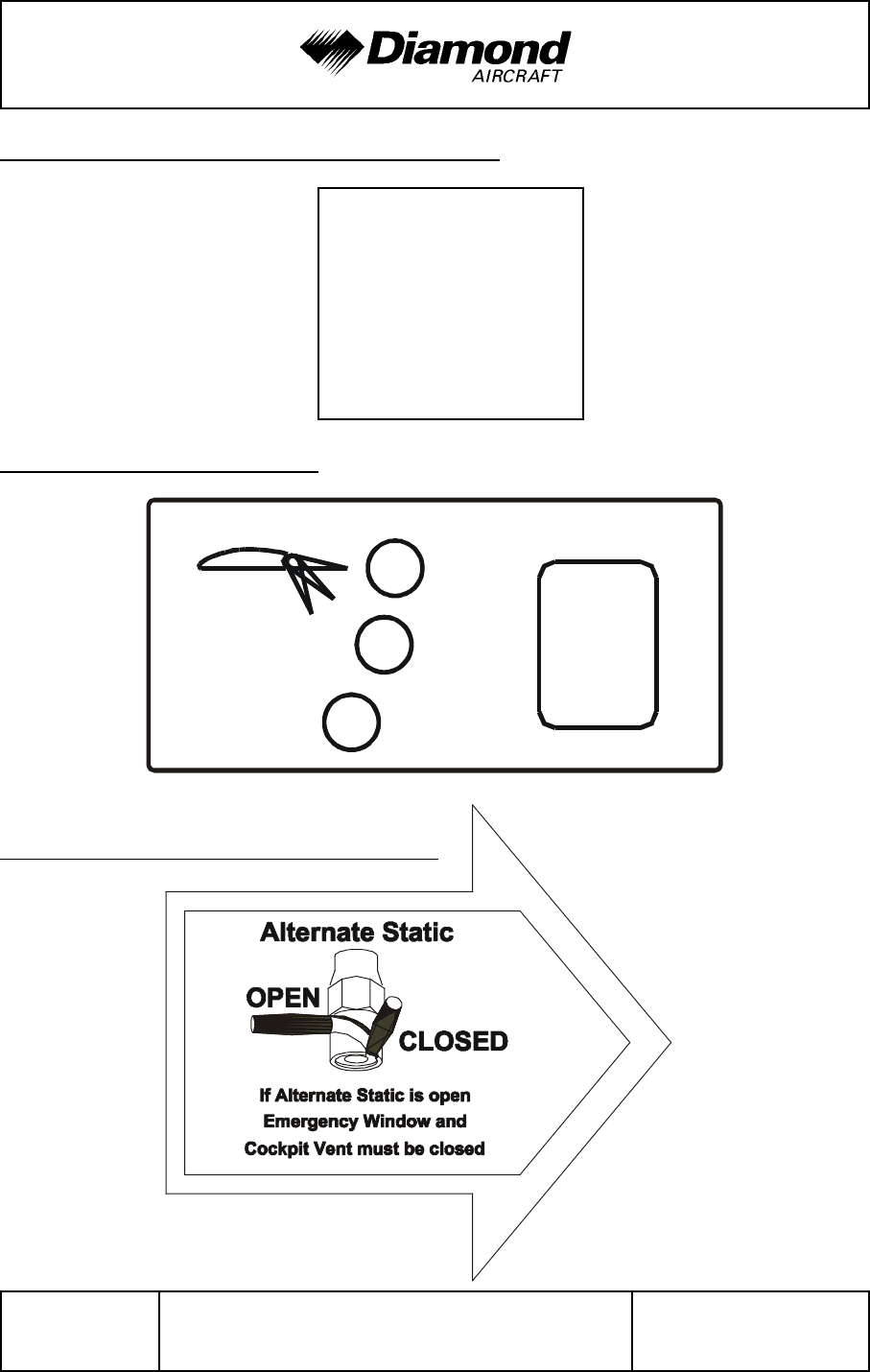
2.15 LIMITATION PLACARDS
All limitation placards are shown below. A list of all placards is included in the Airplane
Maintenance Manual (Doc. No. 7.02.01), Chapter 11.
On the instrument panel:
MÄM 42-088 or
OÄM 42-054 or
both
incorporated:
THIS AIRPLANE MAY ONLY BE OPERATED IN ACCORDANCE WITH THE AIRPLANE'FLIGHT MANUAL IN THE “NORMAL” CATEGORY. PROVIDED THAT NATIONAL'OPERATIONAL REQUIREMENTS ARE MET AND THE APPROPRIATE EQUIPMENT'IS INSTALLED AND OPERATIONAL, THIS AIRPLANE IS APPROVED FOR THE'FOLLOWING KINDS OF OPERATION: DAY VFR, NIGHT VFR AND IFR, AND FLIGHT'INTO KNOWN OR FORECAST ICING CONDITIONS. ALL AEROBATIC MANEUVERS'INCLUDING SPINNING ARE PROHIBITED. FOR FURTHER OPERATIONAL LIMITATIONS'REFER TO THE AIRPLANE FLIGHT MANUAL.'
MANEUVERING SPEED:'
VA = 126 KIAS (ABOVE 1542 KG / 3400 LB)'VA = 120 KIAS (UP TO 1542 KG / 3400 LB)'
neither
MÄM 42-088 nor
OÄM 42-054
incorporated:
THIS AIRPLANE MAY ONLY BE OPERATED IN ACCORDANCE WITH THE AIRPLANE
FLIGHT MANUAL. IT CAN BE OPERATED IN THE “NORMAL” CATEGORY IN NON-ICING
CONDITIONS. PROVIDED THAT NATIONAL OPERATIONAL REQUIREMENTS ARE MET
AND THE APPROPRIATE EQUIPMENT IS INSTALLED, THIS AIRPLANE IS APPROVED
FOR THE FOLLOWING KIND OF OPERATION: DAY VFR, NIGHT VFR AND IFR. ALL
AEROBATIC MANEUVERS INCLUDING SPINNING ARE PROHIBITED. FOR FURTHER
OPERATIONAL LIMITATIONS REFER TO THE AIRPLANE FLIGHT MANUAL.
MANEUVERING SPEED:
VA = 124 KIAS (ABOVE 1468 UP TO 1700 KG / ABOVE 3236 UP TO 3748 LB)
VA = 121 KIAS (1250 TO 1468 KG / 2756 TO 3236 LB)
On the Emergency Landing Gear Extension Lever:

DA 42 AFM Operating Limitations
Doc. No. 7.01.05-E Rev. 4 30-Nov-2005 Page 2 - 23
Diesel Fuel or
Unknown Fuel Blend:
Below -5 /C:
No engine start permitted.
Below +5 /C:
No take-off permitted.
max. usable
fuel: 2 x 25 US gal
max. difference LH/RH
tank: 5 US gal
max. usable fuel
main tank:
2 x 25 US gal
auxiliary tank:
2 x 13 US gal
max. difference LH/RH
main tank: 5 US gal
WARNING
APPROVED FUEL
JET-A1
or see Airplane Flight Manual
On the instrument panel, next to the fuel quantity indication:
(a) Standard Tank: (b) Auxiliary Tank (if installed):
if MÄM 42-037 is carried out, on the Garmin G1000 MFD next to the fuel temperature
'
indication:'
'
'
'
'
(a) Next to each of the two fuel filler necks;
(b) in addition next to each of the two auxiliary fuel filler necks (if installed):
Operating Limitations DA 42 AFM
Page 2 - 24 Rev. 3 15-Oct-2005 Doc. No. 7.01.05-E
OIL
'
Shell Helix Ultra
5W30 synth.
API SL/CF
or see AFM
UP
Flaps
APP
137 KIAS
LDG
111 KIAS
In each cowling, on the door for the oil filler neck:
'
'
'
'
'
'
'
Next to the flap selector switch:
In the cockpit, on the left fuselage sidewall:
DA 42 AFM Operating Limitations
Doc. No. 7.01.05-E Rev. 3 15-Oct-2005 Page 2 - 25
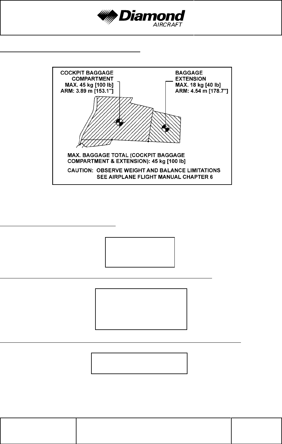
Next to the cockpit baggage compartment:
In the nose baggage compartment:
Beside the door locking device installed in the passengers' door:
On the right hand side of the instrument panel above the circuit breakers:
Max. Baggage:
30 kg [66 lb]
EMERGENCY EXIT:
The keylock must be
unlocked during flight
______ NO SMOKING ______

Operating Limitations DA 42 AFM
Page 2 - 26 Rev. 4 30-Nov-2005 Doc. No. 7.01.05-E
2.16 OTHER LIMITATIONS
2.16.1 FUEL TEMPERATURE
JET A-1: from -30 °C to +75 °C (from -22 °F to +167 °F).
'
NOTE
'
Operation with Diesel fuel, or blends of Diesel fuel with Jet
'
fuel, is only approved when MÄM 42-037 is carried out.
'
Diesel fuel: engine starting fuel temperature ........... min. -5 °C (+23 °F)
'
take-off fuel temperature ................min. +5 °C (+41 °F)
'
maximum fuel temperature................ +75 °C (+167 °F)
'
Fuel blends or unknown fuel grade:
'
engine starting fuel temperature ........... min. -5 °C (+23 °F)
'
take-off fuel temperature ................min. +5 °C (+41 °F)
'
maximum fuel temperature................ +75 °C (+167 °F)
'
2.16.2 BATTERY CHARGE
Taking off for a Night VFR or IFR flight with an empty battery is not permitted.
The use of an external power supply for engine starting with an empty airplane battery
is also not permitted if the subsequent flight is intended to be a Night VFR or IFR flight.
In this case the airplane battery must first be charged.

DA 42 AFM Operating Limitations
Doc. No. 7.01.05-E Rev. 4 30-Nov-2005 Page 2 - 27
2.16.3 EMERGENCY SWITCH
IFR flights are not permitted when the seal on the emergency switch is broken.
2.16.4 DOOR LOCKING DEVICE
The canopy and the passenger door must not be blocked by the key lock during operation
of the airplane.
2.16.5 ELECTRONIC EQUIPMENT
The use and switching on of electronic equipment other than that which is part of the
equipment of the airplane is not permitted, as it could lead to interference with the
airplane’s avionics.
Examples of undesirable items of equipment are:
- Mobile phones
- Remote radio controls
- Video screens employing CRT's
- Minidisc recorders in record mode
This list is not exhaustive.
The use of laptop computers, including those with CD-ROM drives, CD and minidisc players
in the replay mode, cassette players and video cameras is permitted. All this equipment
however should be switched off for take-off and landing.

Operating Limitations DA 42 AFM
Page 2 - 28 Rev. 3 15-Oct-2005 Doc. No. 7.01.05-E
2.16.6 GARMIN G1000 AVIONICS SYSTEM
1. The Garmin G1000 Cockpit Reference Guide, P/N 190-00406-00, dated September
2004 or later appropriate revision must be immediately available to the flight crew.
'
2. If MÄM-42-101 has been implemented (refer to Section 1.1), the G1000 must utilize
'
the software Garmin P/N: 010-00370-11, or later approved software in accordance
'
with the mandatory service bulletin DAI MSB 42-008, latest version.
'
Software Part Number Approved
Version Function
System
'
for approved version see DAI MSB 42-008, latest version
'
010-00370-( )
'
'
Manifest
'
006-B0093-( )
'
'
GPS1, GPS2
006-B0172-( )
'
'
GTX1-GIA1, GTX1-GIA2
006-B0190-( )
'
'
GIA1, GIA2
006-B0193-( )
'
'
GEA1-GIA1; GEA1-GIA2
006-B0203-( )
'
'
GMA1-GIA1, GMA1-GAI2
006-B0223-( )
'
'
GRS1-GIA1, GRS1-GIA2
006-B0224-( )
'
'
GMU1
006-B0319-( )
'
'
PFD1, MFD1
006-B0328-( )
'
'
006-B0329-( )
'
'
006-C0048-( )
'
'
GMU1 FPGA
006-C0049-( )
'
'
GRS1 FPGA
006-C0055-( )
'
'
GDC1 FPGA
006-D0159-( )
'
'
GRS1 MV DB
006-D0202-( )
'
'
006-B0261-( )
'
'
GDC1-GIA1
006-B0081-( )
'
'
COM1, COM2
006-B0083-( )
'
'
GS1, GS2
006-B0082-( )
'
'
NAV1, NAV2

DA 42 AFM Operating Limitations
Doc. No. 7.01.05-E Rev. 3 15-Oct-2005 Page 2 - 29
NOTE
The database version is displayed on the MFD power-up page
immediately after system power-up and must be
acknowledged. The remaining system software versions can
be verified on the AUX group sub-page 5, "AUX - SYSTEM
STATUS".
3. IFR enroute, oceanic and terminal navigation predicated upon the G1000 GPS Receiver
is prohibited unless the pilot verifies the currency of the database or verifies each
selected waypoint for accuracy by reference to current approved data.
4. Instrument approach navigation predicated upon the G1000 GPS Receiver must be
accomplished in accordance with approved instrument approach procedures that are
retrieved from the GPS equipment database. The GPS equipment database must
incorporate the current update cycle.
NOTE
Not all published approaches are in the FMS database. The
pilot must ensure that the planned approach is in the
database.
(a) Instrument approaches utilizing the GPS receiver must be conducted in the
approach mode and Receiver Autonomous Integrity Monitoring (RAIM) must
be available at the Final Approach Fix.

Operating Limitations DA 42 AFM
Page 2 - 30 Rev. 3 15-Oct-2005 Doc. No. 7.01.05-E
(b) Accomplishment of ILS, LOC, LOC-BC, LDA, SDF, MLS or any other type of
approach not approved for GPS overlay with the G1000 GPS receiver is not
authorized.
(c) Use of the G1000 VOR/ILS receiver to fly approaches not approved for GPS
require VOR/ILS navigation data to be present on the display.
(d) When an alternate airport is required by the applicable operating rules, it must
be served by an approach based on other than GPS or Loran-C navigation, the
airplane must have the operational equipment capable of using that navigation
aid, and the required navigation aid must be operational.
(e) VNAV information may be utilized for advisory information only. Use of VNAV
information for Instrument Approach Procedures does not guarantee step-down
fix altitude protection, or arrival at approach minimums in normal position to land.
(f) RNAV (GPS) approaches must be conducted utilizing the GPS sensor.
(g) RNP RNAV operations are not authorized, except as noted in Chapter 1 of this
AFM.
5. If not previously defined, the following default settings must be made in the "SYSTEM
SETUP" menu of the G1000 prior to operation (refer to Pilot's Guide for procedure if
necessary):
(a) DIS, SPD : nm, kt (sets navigation units to "nautical miles" and "knots")
(b) ALT, VS : ft, fpm (sets altitude units to "feet" and "feet per minute")
(c) MAP DATUM : WGS 84 (sets map datum to WGS-84, see note below)
(d) POSITION : deg-min (sets navigation grid units to decimal minutes)

DA 42 AFM Operating Limitations
Doc. No. 7.01.05-E Rev. 3 15-Oct-2005 Page 2 - 31
NOTE
In some areas, datums other than WGS-84 or NAD-83 may
be used. If the G1000 is authorized for use by the appropriate
Airworthiness Authority, the required geodetic datum must be
set in the G1000 prior to its use for navigation.
6. Operation is prohibited north of 70° N and south of 70° S latitudes. In addition, operation
is prohibited in the following two regions:
(a) north of 65° N between 75° W and 120° W longitude, and
(b) south of 55° S between 120° E and 165° E longitude.
7. CDI sequencing of the ILS must be set to MANUAL for instrument approaches
conducted with the autopilot coupled. If the CDI source is changed when the autopilot
is engaged in NAV mode, the autopilot lateral mode will revert to ROLL ATTITUDE
mode and NAV mode must be manually reselected by the pilot.
8. The fuel quantity, fuel required, and fuel remaining functions on the Fuel Page
(displayed when pushing the FUEL button as shown in Section 7.13) of the FMS are
supplemental information only and must be verified by the flight crew.
9. The pilot's altimeter is the primary altitude reference during all operations using advisory
vertical navigation (VNAV) information.

Operating Limitations DA 42 AFM
Page 2 - 32 Rev. 4 30-Nov-2005 Doc. No. 7.01.05-E
2.16.7 SMOKING
Smoking in the airplane is not permitted.
2.16.8 GROUND OPERATION
Take-Off and landing has been demonstrated on hard paved surfaces (asphalt, concrete,
etc.) and grass runways.
'

DA 42 AFM Emergency
Procedures
Doc. No. 7.01.05-E Rev. 3 15-Oct-2005 Page 3 - 1
CHAPTER 3
EMERGENCY PROCEDURES
Page
3.1 INTRODUCTION .......................................3-4
3.1.1 GENERAL........................................3-4
3.1.2 CERTAIN AIRSPEEDS IN EMERGENCIES ..............3-5
3.1.3 SELECTING EMERGENCY FREQUENCY ..............3-5
3.2 AIRPLANE-RELATED G1000 WARNINGS ...................3-6
3.2.1 WARNINGS / GENERAL ............................3-6
3.2.2 L/R ENG TEMP....................................3-6
3.2.3 L/R OIL TEMP ....................................3-7
3.2.4 L/R OIL PRES.....................................3-7
3.2.5 L/R GBOX TEMP ..................................3-8
3.2.6 L/R FUEL TEMP ...................................3-8
3.2.7 L/R ALTN AMPS...................................3-9
3.2.8 L/R ENG FIRE ....................................3-9
3.2.9 L/R STARTER....................................3-10
3.2.10 DOOR OPEN....................................3-10
3.3 G1000 SYSTEM WARNINGS .............................3-11
3.3.1 RED X..........................................3-11
3.3.2 POSN ERROR ...................................3-11
3.3.3 ATTITUDE FAIL ..................................3-11
3.3.4 AIRSPEED FAIL ..................................3-11
3.3.5 ALTITUDE FAIL ..................................3-12
3.3.6 VERT SPEED FAIL ................................3-12
3.3.7 HDG ...........................................3-12
3.3.8 WARN..........................................3-12

Emergency
Procedures DA 42 AFM
Page 3 - 2 Rev. 3 15-Oct-2005 Doc. No. 7.01.05-E
3.4 G1000 FAILURES ..................................... 3-13
3.4.1 NAVIGATION INFORMATION FAILURE .............. 3-13
3.4.2 PFD OR MFD DISPLAY FAILURE ................... 3-13
3.4.3 AHRS FAILURE ................................. 3-13
3.4.4 AIR DATA COMPUTER (ADC) FAILURE .............. 3-14
3.4.5 ERRONEOUS OR LOSS OF ENGINE
AND FUEL DISPLAYS ............................ 3-14
3.4.6 ERRONEOUS OR LOSS OF
WARNING/CAUTION ANNUNCIATORS .............. 3-15
3.5 ONE ENGINE INOPERATIVE PROCEDURES ............... 3-16
3.5.1 DETECTING THE INOPERATIVE ENGINE ............ 3-16
3.5.2 ENGINE TROUBLESHOOTING ..................... 3-17
3.5.3 ENGINE SECURING (FEATHERING) PROCEDURE .... 3-20
3.5.4 UNFEATHERING & RESTARTING
THE ENGINE IN FLIGHT .......................... 3-21
3.5.5 ENGINE FAILURE DURING TAKEOFF ............... 3-23
3.5.6 ENGINE FAILURES IN FLIGHT ..................... 3-26
3.5.7 LANDING WITH ONE ENGINE INOPERATIVE ......... 3-30
3.5.8 GO-AROUND / BALKED LANDING
WITH ONE ENGINE INOPERATIVE ................. 3-32
3.5.9 FLIGHT WITH ONE ENGINE INOPERATIVE........... 3-34
3.6 LANDING GEAR SYSTEM FAILURES ..................... 3-35
3.6.1 LANDING GEAR UNSAFE WARNING ................ 3-35
3.6.2 MANUAL EXTENSION OF THE LANDING GEAR ....... 3-37
3.6.3 LANDING WITH GEAR UP ......................... 3-39
3.6.4 LANDING WITH A DEFECTIVE TIRE
ON THE MAIN LANDING GEAR .................... 3-40
3.6.5 LANDING WITH DEFECTIVE BRAKES ............... 3-41

DA 42 AFM Emergency
Procedures
Doc. No. 7.01.05-E Rev. 3 15-Oct-2005 Page 3 - 3
3.7 FAILURES IN THE ELECTRICAL SYSTEM ..................3-42
3.7.1 COMPLETE FAILURE OF THE ELECTRICAL SYSTEM . . . 3-42
3.7.2 HIGH CURRENT .................................3-43
3.7.3 STARTER MALFUNCTION .........................3-43
3.8 SMOKE AND FIRE .....................................3-44
3.8.1 ENGINE FIRE ON GROUND ........................3-44
3.8.2 ENGINE FIRE DURING TAKE-OFF ...................3-44
3.8.3 ENGINE FIRE IN FLIGHT...........................3-45
3.8.4 ELECTRICAL FIRE ON GROUND ....................3-46
3.8.5 ELECTRICAL FIRE IN FLIGHT ......................3-47
3.9 OTHER EMERGENCIES ................................3-48
3.9.1 SUSPICION OF CARBON MONOXIDE
CONTAMINATION IN THE CABIN ...................3-48
3.9.2 UNLOCKED DOORS ..............................3-49
3.9.3 DEFECTIVE PROPELLER RPM REGULATING SYSTEM . . 3-50
3.9.4 UNINTENTIONAL FLIGHT INTO ICING................3-52
3.9.5 FUEL SUPPLY FAILURE ...........................3-53
3.9.6 RECOVERY FROM AN UNINTENTIONAL SPIN .........3-54
3.9.7 EMERGENCY DESCENT...........................3-56
3.9.8 EMERGENCY EXIT ...............................3-56
NOTE
Procedures for uncritical system faults are given in Chapter
4B - ABNORMAL OPERATING PROCEDURES.

Emergency
Procedures DA 42 AFM
Page 3 - 4 Rev. 3 15-Oct-2005 Doc. No. 7.01.05-E
3.1 INTRODUCTION
3.1.1 GENERAL
This chapter contains checklists as well as the description of recommended procedures
to be followed in the event of an emergency. Engine failure or other airplane-related
emergencies are most unlikely to occur if the prescribed procedures for pre-flight checks
and airplane maintenance are followed.
If, nonetheless, an emergency does arise, the guidelines given in this chapter should be
followed and applied in order to clear the problem.
As it is impossible to foresee all kinds of emergencies and cover them in this Airplane
Flight Manual, a thorough understanding of the airplane by the pilot is, in addition to his
knowledge and experience, an essential factor in the solution of any problems which may
arise.
WARNING
In each emergency, control over the flight attitude and the
preparation of a possible emergency landing have priority
over attempts to solve the current problem ("first fly the
aircraft"). Prior to the flight the pilot must consider the
suitability of the terrain for an emergency landing for each
phase of the flight. For a safe flight the pilot must constantly
keep a safe minimum flight altitude. Solutions for various
adverse scenarios should be thought over in advance. This
should prevent a situation where the pilot is faced with an
emergency he cannot handle calmly and with determination.

DA 42 AFM Emergency
Procedures
Doc. No. 7.01.05-E Rev. 3 15-Oct-2005 Page 3 - 5
3.1.2 CERTAIN AIRSPEEDS IN EMERGENCIES
Event
One engine inoperative minimum
control speed (Air) vmCA 68 KIAS
One engine inoperative speed for
best rate of climb vYSE 82 KIAS
3.1.3 SELECTING EMERGENCY FREQUENCY
In an in-flight emergency, depressing and holding the Com transfer button ȼ on the
G1000 for 2 seconds will tune the emergency frequency of 121.500 MHz. If the display
is available, it will also show it in the "Active" frequency window.

Emergency
Procedures DA 42 AFM
Page 3 - 6 Rev. 3 15-Oct-2005 Doc. No. 7.01.05-E
3.2 AIRPLANE-RELATED G1000 WARNINGS
3.2.1 WARNINGS / GENERAL
"Warning" means that the non-observation of the corresponding procedure leads to an
'
immediate or important degradation in flight safety. The warning text is displayed in red
'
color. A warning chime tone of 1.5 seconds duration will sound and repeat without delay
'
until the alarm is acknowledged by the crew.
'
3.2.2 L/R ENG TEMP
L/R ENG TEMP Left / Right engine coolant temperature is in the upper
red range (too high / above 105 °C)
Coolant temperatures above the limit value of 105 °C can lead to a total loss of power
due to engine failure.
Proceed according to:
4B.3.2 COOLANT TEMPERATURE

DA 42 AFM Emergency
Procedures
Doc. No. 7.01.05-E Rev. 3 15-Oct-2005 Page 3 - 7
3.2.3 L/R OIL TEMP
L/R OIL TEMP Left / Right engine oil temperature is in the upper red
range (too high / above 140 °C).
Oil temperatures above the limit value of 140 °C can lead to a total loss of power due
to engine failure.
Proceed according to:
4B.3.3 OIL TEMPERATURE
3.2.4 L/R OIL PRES
L/R OIL PRES Left / Right engine oil pressure is in the lower red
range (too low / below 1 bar).
Oil pressures below the limit value of 1 bar can lead to a total loss of power due to engine
failure.
Proceed according to:
4B.3.4 OIL PRESSURE

Emergency
Procedures DA 42 AFM
Page 3 - 8 Rev. 3 15-Oct-2005 Doc. No. 7.01.05-E
3.2.5 L/R GBOX TEMP
L/R GBOX TEMP Left / Right engine gearbox temperature is in the
upper red range (too high / above 120 °C).
Gearbox temperatures above the limit value of 120 °C can lead to a total loss of power
due to engine failure.
Proceed according to:
4B.3.5 GEARBOX TEMPERATURE
3.2.6 L/R FUEL TEMP
L/R FUEL TEMP Left / Right fuel temperature is in the upper red range
(too high / above 75 °C).
Fuel temperatures above the limit value of 75 °C can lead to a noticeable reduction of the
high pressure pump efficiency.
Proceed according to:
4B.3.6 FUEL TEMPERATURE

DA 42 AFM Emergency
Procedures
Doc. No. 7.01.05-E Rev. 3 15-Oct-2005 Page 3 - 9
3.2.7 L/R ALTN AMPS
L/R ALTN AMPS Left / Right engine alternator output is in the upper red
range (too high / above 60 amps).
Proceed according to:
3.7.2 HIGH CURRENT
'
3.2.8 L/R ENG FIRE
L/R ENG FIRE Left / Right engine fire detected
Engine fire can lead to a total loss of power due to engine failure as well as severe
structural damage:
Proceed according to the following procedures as applicable:
3.8.1 ENGINE FIRE ON GROUND
'
3.8.2 ENGINE FIRE DURING TAKE-OFF
'
3.8.3 ENGINE FIRE IN FLIGHT
'

Emergency
Procedures DA 42 AFM
Page 3 - 10 Rev. 3 15-Oct-2005 Doc. No. 7.01.05-E
3.2.9 L/R STARTER
L/R STARTER Left / Right engine starter is engaged
Proceed according to:
3.7.3 STARTER MALFUNCTION
3.2.10 DOOR OPEN
DOOR OPEN Front and/or rear canopy and/or baggage door are/is
not closed and locked.
Proceed according to:
3.9.2 UNLOCKED DOORS
'

DA 42 AFM Emergency
Procedures
Doc. No. 7.01.05-E Rev. 3 15-Oct-2005 Page 3 - 11
3.3 G1000 SYSTEM WARNINGS
3.3.1 RED X
A red X through any display field, such as COM frequencies, NAV frequencies, or engine
data, indicates that display field is not receiving valid data.
3.3.2 POSN ERROR
POSN ERROR The system will flag and no longer provide GPS based
navigational guidance.
Revert to the G1000 VOR/ILS receivers or an alternate means of navigation other than
the G1000 GPS receivers.
3.3.3 ATTITUDE FAIL
ATTITUDE FAIL The display system is not receiving attitude reference
information from the AHRS; accompanied by the
removal of sky/ground presentation and a red X over
the attitude area.
Revert to the standby attitude indicator.
3.3.4 AIRSPEED FAIL
AIRSPEED FAIL The display system is not receiving airspeed input
from the air data computer; accompanied by a red X
through the airspeed display.
Revert to the standby airspeed indicator.

Emergency
Procedures DA 42 AFM
Page 3 - 12 Rev. 3 15-Oct-2005 Doc. No. 7.01.05-E
3.3.5 ALTITUDE FAIL
ALTITUDE FAIL The display system is not receiving altitude input from
the air data computer; accompanied by a red X
through the altimeter display.
Revert to the standby altimeter.
3.3.6 VERT SPEED FAIL
VERT SPEED FAIL The display system is not receiving vertical speed
input from the air data computer; accompanied by a
red X through the vertical speed display.
Determine vertical speed based on the change of altitude information.
3.3.7 HDG
HDG The display system is not receiving valid heading input
from the AHRS; accompanied by a red X through the
digital heading display.
Revert to the emergency compass.
3.3.8 WARN
WARN RAIM position warning - nav deviation bar removed.
1. CDI softkey .......................... switch to VOR/LOC

DA 42 AFM Emergency
Procedures
Doc. No. 7.01.05-E Rev. 3 15-Oct-2005 Page 3 - 13
3.4 G1000 FAILURES
3.4.1 NAVIGATION INFORMATION FAILURE
If Garmin G1000 GPS navigation information is not available or invalid, utilize remaining
operational navigation equipment as required.
3.4.2 PFD OR MFD DISPLAY FAILURE
1. DISPLAY BACKUP button on audio panel . . PUSH
3.4.3 AHRS FAILURE
NOTE
A failure of the Attitude and Heading Reference System
(AHRS) is indicated by a removal of the sky/ground
presentation and a red X and a yellow "AHRS FAILURE"
shown on the PFD. The digital heading presentation will be
replaced with a yellow "HDG" and the compass rose digits will
be removed. The course pointer will indicate straight up and
course may be set using the digital window.
1. Use standby attitude indicator, emergency compass and Navigation Map
2. Course ............................. set using digital window

Emergency
Procedures DA 42 AFM
Page 3 - 14 Rev. 3 15-Oct-2005 Doc. No. 7.01.05-E
3.4.4 AIR DATA COMPUTER (ADC) FAILURE
NOTE
Complete loss of the Air Data Computer is indicated by a red
X and yellow text over the airspeed, altimeter, vertical speed,
TAS and OAT displays. Some FMS functions, such as true
airspeed and wind calculations, will also be lost.
1. Use standby airspeed indicator and altimeter.
3.4.5 ERRONEOUS OR LOSS OF ENGINE AND FUEL DISPLAYS
NOTE
Loss of an engine parameter is indicated by a red X through
the data field. Erroneous information may be identified by
indications which do not agree with other system information.
Erroneous indications may be determined by comparing a
display with other displays and other system information.
1. Set power based on throttle lever position, engine noise and speed.
2. Monitor other indications to determine the health of the engine.
3. Use known power settings and Section 5.3.2 of AFM for approximate fuel flow
values.
4. Use other system information, such as annunciator messages, GPS fuel quantity
and flow, to safely complete the flight.

DA 42 AFM Emergency
Procedures
Doc. No. 7.01.05-E Rev. 3 15-Oct-2005 Page 3 - 15
3.4.6 ERRONEOUS OR LOSS OF WARNING/CAUTION ANNUNCIATORS
NOTE
Loss of an annunciator may be indicated when engine or fuel
displays show an abnormal or emergency situation and the
annunciator is not present. An erroneous annunciator may be
identified when an annunciator appears which does not agree
with other displays or system information.
1. If an annunciator appears, treat it as if the condition exists. Refer to Chapter 3 -
EMERGENCY PROCEDURES or Chapter 4B - ABNORMAL OPERATING PRO-
CEDURES.
2. If a display indicates an abnormal condition but no annunciator is present, use
other system information, such as engine displays, GPS fuel quantity and flow, to
determine if the condition exists. If it cannot be determined that the condition
does not exist, treat the situation as if the condition exists. Refer to Chapter 3 -
EMERGENCY PROCEDURES or Chapter 4B - ABNORMAL OPERATING PRO-
CEDURES.

Emergency
Procedures DA 42 AFM
Page 3 - 16 Rev. 3 15-Oct-2005 Doc. No. 7.01.05-E
3.5 ONE ENGINE INOPERATIVE PROCEDURES
WARNING
In certain combinations of airplane weight, configuration,
ambient conditions, speed and pilot skill, negative climb
performance may result. Refer to Chapter 5, PERFORMANCE
for one engine inoperative performance data.
In any event the sudden application of power during one-
engine inoperative operation makes the control of the airplane
more difficult.
3.5.1 DETECTING THE INOPERATIVE ENGINE
NOTE
One engine inoperative means an asymmetric loss of thrust,
resulting in uncommanded yaw and roll in direction of the so-
called "dead" engine (with coordinated controls). To handle
this situation it is vital to maintain directional control by mainly
rudder and additional aileron input. The following mnemonic
can help to identify the failed engine:
"Dead foot - dead engine"
This means that, once directional control is re-established,
the pilot can feel the control force on the foot pushing the
rudder-pedal on the side of the operative engine, while the
foot on the side of the failed engine feels no force. Further,
the engine instruments can help to analyze the situation.

DA 42 AFM Emergency
Procedures
Doc. No. 7.01.05-E Rev. 3 15-Oct-2005 Page 3 - 17
3.5.2 ENGINE TROUBLESHOOTING
WARNING
Control over the flight attitude has priority over attempts to
solve the current problem ("first fly the aircraft").
NOTE
'
With respect to handling and performance, the left hand
'
engine (pilots view) is considered the "critical" engine.
'
Depending on the situation the following attempts can be made to restore engine power
prior to securing the engine:
CAUTION
Once the engine has been shut down for longer than 30
seconds, it can only be restarted below 6000 ft pressure
altitude. Proceed in accordance with 3.5.4 - UNFEATHERING
& RESTARTING THE ENGINE IN FLIGHT.
1. POWER lever ........................ IDLE
'
NOTE
If the loss of power was due to unintentional setting of the
power lever, you may adjust the friction lock and continue your
flight.
2. If in icing conditions ................... alternate air ON
CONTINUED

Emergency
Procedures DA 42 AFM
Page 3 - 18 Rev. 3 15-Oct-2005 Doc. No. 7.01.05-E
3. Fuel quantity ......................... check
NOTE
In case of low fuel quantity in the affected engine‘s fuel tank
you may feed it from the other engine's fuel tank by setting
the affected engine's fuel selector to CROSSFEED.
4. Fuel selector ......................... check ON / CROSSFEED if
required
NOTE
If the loss of power was due to unintentional setting of the fuel
selector to the OFF position you may continue your flight but
have the proper function of the restrainer locks checked prior
to next flight.
5. ECU SWAP.......................... ECU B
NOTE
If the swap to ECU B has restored engine power land as soon
as possible. If selecting ECU B does not solve the problem,
switch back to AUTOMATIC in order to maintain the engine
control system redundancy.
6. Circuit breakers....................... check / reset if necessary
CONTINUED

DA 42 AFM Emergency
Procedures
Doc. No. 7.01.05-E Rev. 3 15-Oct-2005 Page 3 - 19
NOTE
If resetting the circuit breakers has restored engine power land
as soon as possible.
If the engine power could not be restored by following the procedure of this section prepare
for 3.5.6 - ENGINE FAILURES IN FLIGHT and land as soon as possible.
END OF CHECKLIST

Emergency
Procedures DA 42 AFM
Page 3 - 20 Rev. 3 15-Oct-2005 Doc. No. 7.01.05-E
3.5.3 ENGINE SECURING (FEATHERING) PROCEDURE
Depending on the situation attempts can be made to restore engine power prior to securing
the engine (see Section 3.5.2 ENGINE TROUBLESHOOTING).
Shut down and feathering of the affected engine:
1. Inoperative engine ..................... identify & verify
2. ENGINE MASTER inoperative engine ..... OFF
CAUTION
Do not shut down an engine with the fuel selector valve. The
high pressure fuel pump can otherwise be damaged.
Securing the feathered engine:
3. Alternator inoperative engine ............ OFF
4. Fuel selector inoperative engine .......... OFF
NOTE
The remaining fuel in the tank of the failed engine can be used
for the remaining engine, to extend range and maintain lateral
balance, by setting its fuel selector in the CROSSFEED
position.
If one of the power levers is set to low settings the landing
gear warning horn is activated. Set the power lever of the
secured engine forward as required to mute the warning horn.
END OF CHECKLIST

DA 42 AFM Emergency
Procedures
Doc. No. 7.01.05-E Rev. 3 15-Oct-2005 Page 3 - 21
3.5.4 UNFEATHERING & RESTARTING THE ENGINE IN FLIGHT
NOTE
Restarting the engine in flight is possible at altitudes below
6000 ft pressure altitude.
1. Airspeed ............................ 80 KIAS to 120 KIAS
2. POWER lever affected engine ........... IDLE
'
3. FUEL SELECTOR affected engine ........ check ON
4. ALTERNATE AIR ..................... as required
5. ENGINE MASTER affected engine ........ ON
CAUTION
The propeller starts windmilling at airspeeds of 80 KIAS and
above. To avoid propeller overspeeds shortly after
unfeathering and restarting maintain airspeeds below
120 KIAS.
6. Starter affected engine ................. engage / if propeller does
not start windmilling by itself
CAUTION
Do not engage the starter if the propeller is windmilling! This
might damage the starter.
CONTINUED

Emergency
Procedures DA 42 AFM
Page 3 - 22 Rev. 3 15-Oct-2005 Doc. No. 7.01.05-E
In case of a failed restart you may, depending on the situation, proceed with
3.5.2 - ENGINE TROUBLESHOOTING.
CAUTION
After the engine has started, the Power lever should be set
to a moderate power setting, until engine temperatures have
reached the green range.
7. Alternator ........................... ON / if engine power has been
restored
END OF CHECKLIST

DA 42 AFM Emergency
Procedures
Doc. No. 7.01.05-E Rev. 3 15-Oct-2005 Page 3 - 23
3.5.5 ENGINE FAILURE DURING TAKEOFF
a) Engine failure during ground roll
- abort takeoff
1. POWER lever ........................ IDLE / BOTH
2. Rudder ............................. maintain directional control
3. Brakes ............................. as required
CAUTION
If sufficient time is remaining, the risk of fire in the event of
a collision with obstacles can be reduced as follows:
4. ENGINE MASTER .................... both OFF
5. FUEL SELECTOR .................... both OFF
6. ELECT. MASTER ..................... OFF
END OF CHECKLIST

Emergency
Procedures DA 42 AFM
Page 3 - 24 Rev. 3 15-Oct-2005 Doc. No. 7.01.05-E
b) Engine Failure after lift-off
If landing gear is still extended and the remaining runway / surface is adequate:
- abort the takeoff & land straight ahead, turning to avoid obstacles
If the remaining runway / surface is inadequate:
- decide whether to abort or to continue the take-off
Continued takeoff:
WARNING
A continued take-off is not recommended if the steady rate
of climb according to Section 5.3.9 ONE ENGINE
INOPERATIVE CLIMB performance is less than 3.3 %. Under
certain combinations of ambient conditions, such as
turbulence, crosswinds and wind shear as well as pilot skill
the resulting climb performance may nevertheless be
insufficient to continue the take-off successfully. Therefore
a continued take-off with a failed engine has to be avoided
if at all possible.
1. Power lever .......................... MAX
2. Rudder ............................. maintain directional control
3. Airspeed ............................ vYSE 82 KIAS / as required
4. Landing Gear ........................ UP to achieve a positive ROC
5. FLAPS.............................. check UP
CONTINUED

DA 42 AFM Emergency
Procedures
Doc. No. 7.01.05-E Rev. 3 15-Oct-2005 Page 3 - 25
6. Engine ............................. secure according to
3.5.3 - ENGINE SECURING
(FEATHERING) PROCEDURE
Continue according to Section 3.5.9 - FLIGHT WITH ONE ENGINE INOPERATIVE and
land as soon as possible according to 3.5.7 - LANDING WITH ONE ENGINE
INOPERATIVE.
If the situation allows, you may climb to a safe altitude for troubleshooting (3.5.2 - ENGINE
TROUBLESHOOTING) in order to try to restore engine power.
END OF CHECKLIST

Emergency
Procedures DA 42 AFM
Page 3 - 26 Rev. 3 15-Oct-2005 Doc. No. 7.01.05-E
3.5.6 ENGINE FAILURES IN FLIGHT
(a) Engine Failure during Initial Climb at Airspeeds below vmCA 68 KIAS
WARNING
As the climb is a flight condition which is associated with high
power settings, airspeeds lower than vmCA 68 KIAS should be
avoided as a sudden engine failure can lead to loss of control.
In this case it is very important to reduce the asymmetry in
thrust to regain directional control.
1. Rudder ............................. apply for directional control
2. Power levers ......................... retard as required to maintain
directional control
3. Airspeed ............................ vYSE 82 KIAS / above vmCA 68
KIAS as required
4. Operative engine ...................... increase power as required if
directional control has been
re-established
CONTINUED

DA 42 AFM Emergency
Procedures
Doc. No. 7.01.05-E Rev. 3 15-Oct-2005 Page 3 - 27
Establish minimum / zero sideslip condition. (approx. half ball towards good engine;
3° to 5° bank)
5. Inoperative engine .................... Secure according to 3.5.3 -
ENGINE SECURING
(FEATHERING) PROCEDURE
Continue according to Section 3.5.9 - FLIGHT WITH ONE ENGINE INOPERATIVE and
land as soon as possible according to Section 3.5.7 - LANDING WITH ONE ENGINE
INOPERATIVE.
If the situation allows, you may climb to a safe altitude for troubleshooting (3.5.2 - ENGINE
TROUBLESHOOTING) in order to try to restore engine power.
END OF CHECKLIST

Emergency
Procedures DA 42 AFM
Page 3 - 28 Rev. 3 15-Oct-2005 Doc. No. 7.01.05-E
(b) Engine Failure during Initial Climb at Airspeeds above vmCA 68 KIAS
1. Rudder ............................. maintain directional control
2. Airspeed ............................ v
YSE 82 KIAS/ above vmCA 68
KIAS as required
3. Operative engine ...................... increase power as required if
directional control has been
established
Establish minimum / zero sideslip condition. (approx. half ball towards good engine;
3° to 5° bank)
4. Inoperative engine ..................... Secure according to 3.5.3 -
ENGINE SECURING
(FEATHERING) PROCEDURE
Continue according to Section 3.5.9 - FLIGHT WITH ONE ENGINE INOPERATIVE and
land as soon as possible according to Section 3.5.7 - LANDING WITH ONE ENGINE
INOPERATIVE.
If the situation allows, you may climb to a safe altitude for troubleshooting (3.5.2 - ENGINE
TROUBLESHOOTING) in order to try to restore engine power.
END OF CHECKLIST

DA 42 AFM Emergency
Procedures
Doc. No. 7.01.05-E Rev. 3 15-Oct-2005 Page 3 - 29
(c) Engine Failure during Flight
1. Rudder ............................. maintain directional control
2. Airspeed ............................ as required /
above vmCA 68 KIAS
3. Operative engine ..................... increase power as required if
directional control has been
established
Establish minimum / zero sideslip condition. (approx. half ball towards good engine;
3° to 5° bank)
4. Inoperative engine .................... Secure according to 3.5.3
ENGINE SECURING
(FEATHERING) PROCEDURE
Continue according to Section 3.5.9 - FLIGHT WITH ONE ENGINE INOPERATIVE and
land as soon as possible according to Section 3.5.7 - LANDING WITH ONE ENGINE
INOPERATIVE.
If the situation allows, you may climb to a safe altitude for troubleshooting (3.5.2 - ENGINE
TROUBLESHOOTING) in order to try to restore engine power.
END OF CHECKLIST

Emergency
Procedures DA 42 AFM
Page 3 - 30 Rev. 4 30-Nov-2005 Doc. No. 7.01.05-E
3.5.7 LANDING WITH ONE ENGINE INOPERATIVE
Preparation:
1. Safety harnesses ..................... check fastened & tightened
2. Landing light ......................... as required
3. Gear warning horn .................... check function
Operative engine:
4. Fuel Selector......................... check ON / CROSSFEED as
required
Inoperative engine:
5. Engine.............................. check secured (feathered)
according to 3.5.3 - ENGINE
SECURING & FEATHERING
PROCEDURE
not before being certain of "making the field“:
6. Airspeed ............................ reduce to operate landing
gear
7. Landing Gear ........................ DOWN, check 3 green
8. Trim................................ as required
9. Airspeed ............................ reduce as required
10.FLAPS.............................. as required
11. Final approach speed
at 1700 kg (3748 lb) ................... 85 KIAS (v
REF/FLAPS UP)
'
82 KIAS (vREF/FLAPS APP)
76 KIAS (vREF/FLAPS LDG)
CONTINUED

DA 42 AFM Emergency
Procedures
Doc. No. 7.01.05-E Rev. 4 30-Nov-2005 Page 3 - 31
at 1785 kg (3935 lb) ................... 86 KIAS (v
REF/FLAPS UP)
'
82 KIAS (vREF/FLAPS APP)
'
78 KIAS (vREF/FLAPS LDG)
'
WARNING
One-engine inoperative approaches for landing with flap
settings of more than flaps UP are not recommended unless
a safe landing is assured („Making the field“). Higher flap
settings increase the loss of altitude during the transition to
a one engine inoperative go-around / balked landing.
12.POWER lever ........................ as required
13.Trim ............................... as required / directional trim to
neutral
NOTE
Higher approach speeds result in a significantly longer landing
distance during flare.
CAUTION
In conditions such as (e.g.) strong wind, danger of wind shear
or turbulence a higher approach speed should be selected.
- Perform normal touchdown and deceleration on ground.
CONTINUED

Emergency
Procedures DA 42 AFM
Page 3 - 32 Rev. 4 30-Nov-2005 Doc. No. 7.01.05-E
If the approach to land is not successful you may consider:
3.5.8 GO-AROUND / BALKED LANDING WITH ONE ENGINE INOPERATIVE
CAUTION
The go-around / balked landing is not recommended to be
'
initiated below a minimum of 800 ft above ground.
'
For performance data with one engine inoperative and flaps
'
and gear UP refer to 5.3.9 ONE ENGINE INOPERATIVE
'
CLIMB PERFORMANCE.
'
Under certain combinations of ambient conditions, such as
turbulence, cross wind and windshear, as well as pilot skill,
the resulting climb performance may nevertheless be
insufficient for a successful go-around / balked landing.
14.POWER lever ........................ MAX / as required
15. Rudder ............................. maintain directional control
16. Airspeed ............................ vYSE = 82 KIAS / as required
17. Landing Gear ........................ UP / retract
18.FLAPS.............................. UP
-Establish minimum sideslip and manoeuver for a new attempt to land. Repeat from
step 1 of this section.
CONTINUED

DA 42 AFM Emergency
Procedures
Doc. No. 7.01.05-E Rev. 3 15-Oct-2005 Page 3 - 33
If a positive rate of climb cannot be established:
- Land so as to keep clear of obstacles with the landing gear extended.
If time allows the following steps can reduce the risk of fire in an event of collision with
obstacles after touchdown:
19.ENGINE MASTER .................... both OFF
20.FUEL SELECTOR .................... both OFF
21.ELECT. MASTER ..................... OFF
END OF CHECKLIST

Emergency
Procedures DA 42 AFM
Page 3 - 34 Rev. 3 15-Oct-2005 Doc. No. 7.01.05-E
3.5.9 FLIGHT WITH ONE ENGINE INOPERATIVE
CAUTION
Even if a positive flight performance can be established with
one engine inoperative, land as soon as practicable at the next
suitable airfield / airport.
1. Airspeed ............................ above vmCA 68 KIAS to
maintain directional control
2. Remaining engine ..................... monitor engine instruments
continuously
3. Fuel quantity ......................... monitor continuously
4. FUEL SELECTOR..................... Remaining engine / set
CROSSFEED or ON so as to
keep fuel quantity laterally
balanced
NOTE
If the Fuel Selector is set on CROSSFEED, the engine will
be supplied with fuel from the main tank on the opposite side.
This will extend range and helps to keep the wings laterally
balanced (see 2.14 FUEL).
Land as soon as possible according to Section 3.5.7 - LANDING WITH ONE ENGINE
INOPERATIVE.
If the situation allows, you may climb to a safe altitude for troubleshooting (3.5.2 - ENGINE
TROUBLESHOOTING) in order to try to restore engine power.
END OF CHECKLIST

DA 42 AFM Emergency
Procedures
Doc. No. 7.01.05-E Rev. 3 15-Oct-2005 Page 3 - 35
3.6 LANDING GEAR SYSTEM FAILURES
3.6.1 LANDING GEAR UNSAFE WARNING
NOTE
The landing gear unsafe warning light illuminates if the landing
gear is neither in the final up or down & locked position.
Illumination of this light is therefore normal during transit.
If the light remains on for longer than 20 seconds during landing gear retraction / extension:
1. Airspeed ............................ check below v
LOR 156 KIAS
2. Gear selector ........................ re-cycle if continued illumination
occurs
If the landing gear cannot be extended to the down & locked position or red light does
not extinguish:
- Continue with 3.6.2 MANUAL EXTENSION OF THE LANDING GEAR.
NOTE
If the landing gear cannot be retracted to the final up position
you may continue the flight with the landing gear extended
in the down&locked position. Consider for higher aerodynamic
drag, resulting in degraded flight performance, increased fuel
consumption and decreased range.

Emergency
Procedures DA 42 AFM
Page 3 - 36 Rev. 3 15-Oct-2005 Doc. No. 7.01.05-E
With the landing gear extended and at aft CG-locations, with
flaps up and full power applied, the aircraft will easily recover
from sideslip if the trim is set to neutral (normal procedure).
Otherwise it may require corrective action with a moderate
amount of rudder input.
In cold ambient temperatures it may help to reduce the
airspeed below 110 KIAS for landing gear operation.
END OF CHECKLIST

DA 42 AFM Emergency
Procedures
Doc. No. 7.01.05-E Rev. 3 15-Oct-2005 Page 3 - 37
3.6.2 MANUAL EXTENSION OF THE LANDING GEAR
NOTE
In case of a failure of the electrical pump, which is driving the
landing gear actuators, the landing gear can be extended
manually at speeds up to 156 KIAS. The manual extension
of the landing gear may take up to 20 seconds.
The following checks shall be completed before extending the landing gear manually:
1. Gear indicator lights ................... test / push test button
2. ELECT. MASTER .................... check ON
3. Bus voltage.......................... check in normal range
4. Circuit breaker ....................... check in / reset if necessary
CONTINUED

Emergency
Procedures DA 42 AFM
Page 3 - 38 Rev. 4 30-Nov-2005 Doc. No. 7.01.05-E
Manual landing gear extension procedure:
5. Gear selector ........................ select DOWN
6. Manual gear extension handle ........... pull out
NOTE
The landing gear should now extend by gravity and relief of
hydraulic pressure from the system. If one or more landing
gear indicator lights do not indicate the gear down & locked
after completion of the manual extension procedure steps 1 -
6 reduce airspeed below 110 KIAS and apply moderate yawing
and pitching to bring the landing gear into the locked position.
7. Gear indicator lights ................... check 3 green lights
NOTE
'
If the landing gear is correctly extended and locked, as
'
indicated by the 3 green lights, the red light is illuminated
'
additionally if the GEAR circuit breaker is pulled.
'
If the landing gear cannot be extended to the down & locked position continue
according to 3.6.3 LANDING WITH GEAR UP.
END OF CHECKLIST

DA 42 AFM Emergency
Procedures
Doc. No. 7.01.05-E Rev. 3 15-Oct-2005 Page 3 - 39
3.6.3 LANDING WITH GEAR UP
NOTE
This procedure applies if the landing gear is completely
retracted.
1. Approach ........................... with power at normal approach
airspeeds and flap settings
2. POWER lever ....................... IDLE / just before
touchdown
If the time / situation allows, the following steps can help to reduce the risk of fire:
3. ENGINE MASTER .................... both OFF
4. FUEL SELECTOR .................... both OFF
5. ELECT. MASTER ..................... OFF
Touchdown:
6. Touchdown ......................... Contact surface with minimum
airspeed
7. On ground .......................... Maintain directional control with
rudder as long as possible so as
to avoid collision with obstacles
END OF CHECKLIST

Emergency
Procedures DA 42 AFM
Page 3 - 40 Rev. 3 15-Oct-2005 Doc. No. 7.01.05-E
3.6.4 LANDING WITH A DEFECTIVE TIRE ON THE MAIN LANDING GEAR
CAUTION
A defective (e.g. burst) tire is not usually easy to detect. The
damage normally occurs during take-off or landing, and is
hardly noticeable during fast taxiing. It is only during the roll-
out after landing or at lower taxiing speeds that a tendency
to swerve occurs. Rapid and determined action is then
required.
1. Advise ATC.
2. Land the airplane at the edge of the runway that is located on the side of the intact
tire, so that changes in direction which must be expected during roll-out due to the
braking action of the defective tire can be corrected on the runway.
3. Land with one wing low. The wing on the side of the intact tire should be held low.
4. Direction should be maintained using the rudder. This should be supported by use
of the brake. It is possible that the brake must be applied strongly - if necessary
to the point where the wheel locks. The wide track of the landing gear will prevent
the airplane from tipping over a wide speed range. There is no pronounced tendency
to tip even when skidding.
END OF CHECKLIST

DA 42 AFM Emergency
Procedures
Doc. No. 7.01.05-E Rev. 3 15-Oct-2005 Page 3 - 41
3.6.5 LANDING WITH DEFECTIVE BRAKES
Consider the greater rolling distance.
Safety harness ........................... check fastened and tightened
CAUTION
If sufficient time is remaining, the risk of fire in the event of
a collision can be reduced as follows after a safe touch-down:
ENGINE MASTER ............. both OFF
FUEL SELECTOR ............. both OFF
ELECT. MASTER .............. OFF
END OF CHECKLIST

Emergency
Procedures DA 42 AFM
Page 3 - 42 Rev. 3 15-Oct-2005 Doc. No. 7.01.05-E
3.7 FAILURES IN THE ELECTRICAL SYSTEM
3.7.1 COMPLETE FAILURE OF THE ELECTRICAL SYSTEM
1. Circuit breakers....................... check if all OK (pressed in)
if there is still no electrical power available:
2. EMERGENCY SWITCH ................ ON
3. Flood light, if necessary ................ ON
4. POWER ............................ set based on lever positions
and engine noise
5. Prepare landing with flaps in the given position. Refer to 4B.5 - FAILURES IN
FLAP OPERATING SYSTEM.
6. Land on the nearest suitable airfield.
WARNING
Engine stoppage may occur, depending on the failure mode.
NOTE
The landing gear uplock is no longer ensured. The landing
gear may slowly extend.
The landing gear can be extended manually according to 3.6.2
MANUAL EXTENSION OF THE LANDING GEAR.
NOTE
The backup artificial horizon and the flood light will have
electrical power for at least 1.5 hours.
Make use of the stand-by airspeed indicator and altimeter. Engine power can be set via
visual reference of the power lever position.
END OF CHECKLIST

DA 42 AFM Emergency
Procedures
Doc. No. 7.01.05-E Rev. 3 15-Oct-2005 Page 3 - 43
3.7.2 HIGH CURRENT
If high current is indicated on the G1000:
1. Circuit breakers ...................... check
2. Reduce electric load to minimum required for continued safe flight.
3. Land on the nearest suitable airfield.
END OF CHECKLIST
3.7.3 STARTER MALFUNCTION
If the starter does not disengage from the engine after starting (starter engaged warning
(STARTER ENGD) on the G1000 annunciator field remains illuminated after the engine
has started):
1. POWER lever affected engine ........... IDLE
2. ENGINE MASTER affected engine ........ OFF
3. ELECT. MASTER ..................... OFF
Terminate flight preparation!
END OF CHECKLIST

Emergency
Procedures DA 42 AFM
Page 3 - 44 Rev. 3 15-Oct-2005 Doc. No. 7.01.05-E
3.8 SMOKE AND FIRE
3.8.1 ENGINE FIRE ON GROUND
1. ENGINE MASTER .................... both OFF
2. FUEL SELECTOR..................... both OFF
3. ELECT. MASTER ..................... OFF
after standstill:
4. Canopy ............................. open
5. Airplane............................. evacuate immediately
END OF CHECKLIST
3.8.2 ENGINE FIRE DURING TAKE-OFF
Proceed according to 3.5.5 - ENGINE FAILURES DURING TAKEOFF
'
1. Cabin heat & Defrost ................... OFF
CAUTION
In case of extreme smoke development, the front canopy may
be unlatched during flight. This allows it to partially open, in
order to improve ventilation. The canopy will remain open in
this position. Flight characteristics will not be affected
significantly.
END OF CHECKLIST

DA 42 AFM Emergency
Procedures
Doc. No. 7.01.05-E Rev. 3 15-Oct-2005 Page 3 - 45
3.8.3 ENGINE FIRE IN FLIGHT
1. Cabin heat & Defrost .................. OFF
Proceed according to 3.5.6 ENGINE FAILURES IN FLIGHT and shut down the engine
according to 3.5.3 ENGINE SECURING (FEATHERING) PROCEDURE.
CAUTION
In case of extreme smoke development, the front canopy may
be unlatched during flight. This allows it to partially open, in
order to improve ventilation. The canopy will remain open in
this position. Flight characteristics will not be affected
significantly.
END OF CHECKLIST

Emergency
Procedures DA 42 AFM
Page 3 - 46 Rev. 3 15-Oct-2005 Doc. No. 7.01.05-E
3.8.4 ELECTRICAL FIRE ON GROUND
1. ELECT. MASTER ..................... OFF
if the engine is running:
2. POWER lever ........................ both IDLE
3. ENGINE MASTER .................... both OFF
4. FUEL SELECTOR..................... both OFF
when the engine has stopped / after standstill:
5. Canopy ............................. open
6. Airplane............................. evacuate immediately
END OF CHECKLIST

DA 42 AFM Emergency
Procedures
Doc. No. 7.01.05-E Rev. 3 15-Oct-2005 Page 3 - 47
3.8.5 ELECTRICAL FIRE IN FLIGHT
1. EMERGENCY SWITCH ................ ON, if installed
2. AVIONIC MASTER.................... OFF
3. ELECT. MASTER ..................... OFF
4. Cabin heat & Defrost .................. OFF
5. Emergency windows ................... open if required
6. Land at the next suitable airfield
CAUTION
Switching OFF the ELECTRIC MASTER will lead to total
failure of all electronic and electric equipment. The attitude
gyro (artificial horizon) and the directional gyro, if installed,
will also be affected.
However, by switching the EMERGENCY switch ON, the
emergency battery will supply power to the stand-by attitude
gyro (artificial horizon) and the flood light.
In case of extreme smoke development, the front canopy may
be unlatched during flight. This allows it to be partially opened,
in order to improve ventilation. The canopy will remain open
in this position. Flight characteristics will not be affected
significantly.
The maximum demonstrated airspeed for emergency opening
the front canopy in flight is 120 KIAS. Do not exceed 120
KIAS.
END OF CHECKLIST

Emergency
Procedures DA 42 AFM
Page 3 - 48 Rev. 3 15-Oct-2005 Doc. No. 7.01.05-E
3.9 OTHER EMERGENCIES
3.9.1 SUSPICION OF CARBON MONOXIDE CONTAMINATION IN THE CABIN
Carbon monoxide (CO) is a gas which is developed during the combustion process. It
is poisonous and without smell. Increased concentration of carbon monoxide gas can be
fatal. The occurrence of CO in the cabin is possible only due to a defect. If a smell similar
to exhaust gases is noticed in the cabin, the following measures should be taken:
1. Cabin heat & Defrost ................... OFF
2. Ventilation ........................... open
3. Emergency windows ................... open
4. Forward canopy ...................... unlatch, push up and lock in
"cooling-gap“ position
CAUTION
The maximum demonstrated airspeed for emergency opening
the front canopy in flight is 120 KIAS. Do not exceed 120
KIAS.
END OF CHECKLIST

DA 42 AFM Emergency
Procedures
Doc. No. 7.01.05-E Rev. 3 15-Oct-2005 Page 3 - 49
3.9.2 UNLOCKED DOORS
1. Airspeed ............................ reduce
2. Canopy ............................. check visually if closed
3. Rear passenger door .................. check visually if closed
4. Front baggage doors .................. check visually if closed
WARNING
Never unlock the rear passenger door during flight. It may
break away.
5. If it is not possible to lock the canopy or the rear passenger door, or if one or
both of the front baggage doors are open, land on the nearest suitable airfield.
END OF CHECKLIST

Emergency
Procedures DA 42 AFM
Page 3 - 50 Rev. 3 15-Oct-2005 Doc. No. 7.01.05-E
3.9.3 DEFECTIVE PROPELLER RPM REGULATING SYSTEM
CAUTION
The power lever should be moved slowly, in order to avoid
over-speeding and excessively rapid RPM changes. The light
wooden propeller blades produce more rapid RPM changes
than metal blades.
WARNING
In case of a malfunction of the engine control unit it is possible
that the propeller blades will remain in the position of highest
pitch. In this case the reduced engine performance should be
taken into consideration.
(a) Oscillating RPM
1. POWER setting....................... change
if the problem does not clear:
2. ECU SWAP.......................... ECU B
NOTE
If the problem does not clear itself, switch back to AUTO and
land on the nearest suitable airfield.
CONTINUED

DA 42 AFM Emergency
Procedures
Doc. No. 7.01.05-E Rev. 3 15-Oct-2005 Page 3 - 51
(b) Propeller overspeed
NOTE
This procedure applies for continued propeller overspeed due
to a malfunction in the propeller constant speed unit or a
engine control unit malfunction.
1. POWER setting ...................... reduce as required
if the problem does not clear:
2. ECU SWAP ......................... ECU B
CAUTION
If the problem does not clear itself, switch back to AUTO and
land on the nearest suitable airfield. Prepare for engine
malfunction according to 3.5.6 ENGINE FAILURES IN FLIGHT
'
END OF CHECKLIST

Emergency
Procedures DA 42 AFM
Page 3 - 52 Rev. 3 15-Oct-2005 Doc. No. 7.01.05-E
3.9.4 UNINTENTIONAL FLIGHT INTO ICING
1. Leave the icing area (by changing altitude or turning back, in order to reach
zones with a higher ambient temperature).
2. PITOT HEAT......................... ON
3. Cabin heat & Defrost ................... ON
4. POWER lever ........................ increase power, in order to
prevent ice build-up on the
propeller blades, apply power
changes periodically.
5. ALTERNATE AIR ..................... OPEN
6. Emergency windows ................... open if required
CAUTION
Ice build-up increases the stalling speed.
7. ATC................................ advise if an emergency is
expected
CAUTION
If the Pitot heating fails:
Alternate static valve ............ OPEN
Emergency windows ............ close
END OF CHECKLIST

DA 42 AFM Emergency
Procedures
Doc. No. 7.01.05-E Rev. 3 15-Oct-2005 Page 3 - 53
3.9.5 FUEL SUPPLY FAILURE
1. FUEL SELECTOR .................... CROSSFEED /
affected engine
WARNING
When the high pressure fuel pump of the engine takes in air
an inspection of the pump is necessary prior to next flight.
2. Fuel quantity ......................... monitor
END OF CHECKLIST

Emergency
Procedures DA 42 AFM
Page 3 - 54 Rev. 3 15-Oct-2005 Doc. No. 7.01.05-E
3.9.6 RECOVERY FROM AN UNINTENTIONAL SPIN
CAUTION
Spin recovery has NOT been shown during certification as
it is NOT required for this airplane category. The given
recovery method is based on general experience!
CAUTION
Intentional spins are prohibited in this airplane. In the event
a spin is encountered unintentionally, immediate recovery
actions must be taken.
Single-engine stalling is not permitted.
CAUTION
Steps 1 to 4 must be carried out immediately and
simultaneously.
1. POWER lever ........................ IDLE
2. Rudder ............................. full deflection against
direction of spin
3. Elevator (control stick).................. fully forward
4. Ailerons ............................. neutral
5. FLAPS.............................. UP
CONTINUED

DA 42 AFM Emergency
Procedures
Doc. No. 7.01.05-E Rev. 3 15-Oct-2005 Page 3 - 55
when rotation has stopped:
6. Rudder ............................. neutral
7. Elevator (control stick) ................. pull carefully
8. Return the airplane from a descending into a normal flight attitude. Do not
exceed the 'never exceed speed', vNE = 194 KIAS.
END OF CHECKLIST

Emergency
Procedures DA 42 AFM
Page 3 - 56 Rev. 3 15-Oct-2005 Doc. No. 7.01.05-E
3.9.7 EMERGENCY DESCENT
1. FLAPS.............................. UP
2. Gear ............................... DOWN
3. POWER lever ........................ IDLE
4. Airspeed ............................ as required
WARNING
Max. structural cruising speed ........v
NO = 155 KIAS.
Never exceed speed in smooth air ....v
NE = 194 KIAS.
END OF CHECKLIST
3.9.8 EMERGENCY EXIT
In case of a roll over of the airplane on ground, the rear side door can be used as exit.
For this purpose unlock the front hinge of the rear side door. The function is displayed
on a placard beside the hinge.

DA 42 AFM Normal Operating
Procedures
Doc. No. 7.01.05-E Rev. 4 30-Nov-2005 Page 4A - 1
CHAPTER 4A
NORMAL OPERATING PROCEDURES
Page
4A.1 INTRODUCTION ..................................... 4A-3
4A.2 AIRSPEEDS FOR NORMAL OPERATING PROCEDURES .... 4A-3
4A.3 ADVISORY ALERTS ON THE G1000 ..................... 4A-5
%
4A.3.1 ADVISORY / GENERAL.......................... 4A-5
%
4A.3.2 L/R GLOW ON ................................. 4A-5
%
4A.3.3 L/R FUEL XFER ................................ 4A-5
%
4A.3.4 PFD/MFD/GIA FAN FAIL ......................... 4A-5
%
4A.4 FLIGHT CHARACTERISTICS ........................... 4A-6
%
4A.5 DAILY CHECK ....................................... 4A-7
%
4A.6 CHECKLISTS FOR NORMAL OPERATING PROCEDURES . . . 4A-7
%
4A.6.1 PRE-FLIGHT INSPECTION ....................... 4A-7
%
4A.6.2 BEFORE STARTING ENGINE.................... 4A-19
%
4A.6.3 STARTING ENGINE............................ 4A-21
%
4A.6.4 BEFORE TAXIING ............................. 4A-23
%
4A.6.5 TAXIING ..................................... 4A-24
%
4A.6.6 BEFORE TAKE-OFF ........................... 4A-25
%
4A.6.7 TAKE-OFF ................................... 4A-30
%
4A.6.8 CLIMB ...................................... 4A-32
%
4A.6.9 CRUISE ..................................... 4A-33
%
4A.6.10 DESCENT .................................. 4A-34
%
4A.6.11 APPROACH & LANDING ....................... 4A-35
%
4A.6.12 GO-AROUND ................................ 4A-36
%
4A.6.13 AFTER LANDING............................. 4A-36
%

Normal Operating
Procedures DA 42 AFM
Page 4A - 2 Rev. 4 30-Nov-2005 Doc. No. 7.01.05-E
4A.6.14 SHUT-DOWN ................................ 4A-37
%
4A.6.15 PARKING ................................... 4A-38
%
4A.6.16 EXIT AIRPLANE .............................. 4A-38
%
4A.6.17 POST FLIGHT INSPECTION .................... 4A-38
%
4A.6.18 FLIGHT IN RAIN.............................. 4A-38
%
4A.6.19 REFUELING ................................. 4A-39
%
4A.6.20 FLIGHT AT HIGH ALTITUDE .................... 4A-40
%

DA 42 AFM Normal Operating
Procedures
Doc. No. 7.01.05-E Rev. 4 30-Nov-2005 Page 4A - 3
4A.1 INTRODUCTION
Chapter 4A contains checklists and describes procedures for the normal operation of the
airplane.
NOTE
Readability of the G1000 PFD and MFD displays may be
degraded when wearing polarized sunglasses.
4A.2 AIRSPEEDS FOR NORMAL OPERATING PROCEDURES
FLAPS
%
%
up to 1700 kg
%
%
%
above 1700 kg1
%
(above 3748 lb)
%
%
Airspeed for rotation (take-off run, vR)UP
%
min. 70 KIAS
%
min. 72 KIAS
%
Airspeed for take-off climb
(best rate-of-climb speed vY)UP
%
min. 77 KIAS
%
min. 79 KIAS
%
Airspeed for best angle of climb2
%
UP
%
77 KIAS
%
79 KIAS
%
Airspeed for cruise climb UP
%
min. 85 KIAS
%
min. 86 KIAS
%
Reference landing approach speed UP
%
85 KIAS
%
86 KIAS
%
APP
%
min. 82 KIAS
%
82 KIAS
%
Final approach speed LDG
%
min. 76 KIAS
%
min. 78 KIAS
%
Minimum speed during go-around UP
%
min. 82 KIAS
%
min. 82 KIAS
%
Max. structural cruising speed
Do not exceed this speed except in
smooth air, and then only with
caution.
UP
%
155 KIAS
%
155 KIAS
%
1), 2) see NOTES on next page
%

Normal Operating
Procedures DA 42 AFM
Page 4A - 4 Rev. 4 30-Nov-2005 Doc. No. 7.01.05-E
NOTE
%
If MÄM 42-088 is carried out, a landing with a mass between
%
1700 kg (3748 lb) and 1785 kg (3935 lb) is admissible. It
%
constitutes an abnormal operating procedure. A "Hard
%
Landing Check" is only required after a hard landing,
%
regardless of the actual landing mass.
%
NOTE
vx is always less than vy. For the DA 42 however, the actual
value of vx would be below the minimum safe speed. The
minimum airspeed for best angle of climb was therefore raised
to the value of vy.

DA 42 AFM Normal Operating
Procedures
Doc. No. 7.01.05-E Rev. 4 30-Nov-2005 Page 4A - 5
4A.3 ADVISORY ALERTS ON THE G1000
The G1000 provides the following advisory-alerts on the PFD in the alert area:
4A.3.1 ADVISORY / GENERAL
CHARACTERISTICS White color coded text
4A.3.2 L/R GLOW ON
L/R GLOW ON Left / Right engine glow plug active
4A.3.3 L/R FUEL XFER
L/R FUEL XFER Fuel transfer from auxiliary to main tank is in progress (if
aux. tanks are installed)
4A.3.4 PFD/MFD/GIA FAN FAIL
PFD FAN FAIL Cooling Fan for the PFD is inoperative
MFD FAN FAIL Cooling Fan for the MFD is inoperative
GIA FAN FAIL Cooling Fan for the GIA is inoperative
The flight may be continued, but maintenance action is required after landing.

Normal Operating
Procedures DA 42 AFM
Page 4A - 6 Rev. 4 30-Nov-2005 Doc. No. 7.01.05-E
4A.4 FLIGHT CHARACTERISTICS
The DA 42 is to be flown with "the feet on the pedals“, meaning that coordinated flight
in all phases and configurations shall be supported by dedicated use of the rudder and
ailerons together.
With the landing gear extended and at aft CG-locations, with flaps up and full power
applied, the airplane will easily recover from sideslip if the trim is set to neutral (normal
procedure), otherwise it may require corrective action with a moderate amount of rudder
input.

DA 42 AFM Normal Operating
Procedures
Doc. No. 7.01.05-E Rev. 4 30-Nov-2005 Page 4A - 7
4A.5 DAILY CHECK
Before the first flight of a day it must be ensured that the following functions are operable
without failure.
* On-condition check of the canopy, the side door and the baggage compartment doors
for cracks and major scratches.
* On-condition check of the hinges for the canopy, the side door and the baggage
compartment doors.
* Visual inspection of the locking bolts for proper movement with no backlash.
* Tire inflation pressure check (main wheels: 4.5 bar/65 psi, nose wheel: 6.0 bar/87 psi).
* Visual inspection of both spinners and their attachment.
* If OÄM-42-077 (Removable Fuselage Nose Cone) is implemented: %
Check fuselage nose cone for improper fit and loose attachment screws.%
4A.6 CHECKLISTS FOR NORMAL OPERATING PROCEDURES
4A.6.1 PRE-FLIGHT INSPECTION
I. Cabin check
Preparation:
a) Parking brake ........................ set ON
b) MET, NAV, Mass & Balance............. flight planning completed
c) Airplane documents ................... complete and up-to-date
d) Front canopy & rear door ............... clean, undamaged,
check locking mechanism
function
e) Baggage ............................ stowed and secured
f) Foreign objects ....................... check
CONTINUED

Normal Operating
Procedures DA 42 AFM
Page 4A - 8 Rev. 4 30-Nov-2005 Doc. No. 7.01.05-E
Center console:
a) FUEL SELECTOR..................... check ON
b) POWER Lever........................ check condition, freedom of
movement and full travel /
adjust friction, set IDLE
Below instrument panel in front of left seat:
a) ALTERNATE STATIC SOURCE .......... check CLOSED
b) MANUAL GEAR EXTENSION HANDLE . . . check pushed in
c) ALTERNATE AIR ..................... check CLOSED
On the instrument panel:
a) ALTERNATOR ....................... check ON
b) ECU SWAP.......................... check AUTOMATIC
c) PITOT HEAT......................... check OFF
d) ENGINE MASTER .................... check both OFF
e) START KEY ......................... check key is pulled out
f) ELECT. MASTER ..................... check OFF
g) AVIONIC MASTER .................... check OFF
h) GEAR SELECTOR .................... check DOWN
i) FLAP SELECTOR..................... check UP
j) Circuit breakers....................... set in (if one has been pulled,
check reason)
k) All electrical equipment ................. OFF
l) EMERGENCY SWITCH ................ check OFF & guarded
m) ELT ................................ armed
CONTINUED

DA 42 AFM Normal Operating
Procedures
Doc. No. 7.01.05-E Rev. 4 30-Nov-2005 Page 4A - 9
Check procedure:
a) ELECT. MASTER ..................... ON
CAUTION
When switching the ELECT. MASTER ON, the electrically
driven hydraulic gear pump may activate itself for 5 to 20
seconds in order to restore the system pressure. Should the
pump continue to operate continuously or periodically,
terminate flight. There is a malfunction in the landing gear
system.
b) Fuel quantity ......................... check indication, verify using
%
alternate means (see Section
%
7.9.5)
%
c) Position lights, strobe lights (ACL) ........ check for correct function
CAUTION
Do not look directly into the anti collision lights.
d) Landing / Taxi light .................... check for correct function
e) Stall warning / stall heat / Pitot heat ....... check
f) Gear warning /
Fire detector TEST BUTTON ............ PUSH, check aural alert / fire
detection warning and aural alert
CAUTION
If the aural alert or the warning on the PFD does not appear,
terminate flight. Unscheduled maintenance is necessary.
CONTINUED

Normal Operating
Procedures DA 42 AFM
Page 4A - 10 Rev. 4 30-Nov-2005 Doc. No. 7.01.05-E
g) Control stick ......................... pull fully aft / hold at backstop
h) FLAPS.............................. set LDG position
i) POWER Lever........................ set MAX
j) Variable elevator backstop .............. check function / control stick must
move slightly forward during
power lever forward movement
k) POWER Lever........................ set IDLE
l) Variable elevator backstop .............. check function / control stick must
regain full movement during
power lever retraction
m) FLAPS.............................. set UP position
CAUTION
The proper function of the variable elevator backstop is
indispensable for the safety of flight, as the handling qualities
during power-on stalls are degraded significantly. For more
details see Chapter 7. AIRPLANE DESCRIPTION AND
SYSTEMS.
If the variable elevator backstop does not function properly,
terminate flight.
n) ELECT. MASTER ..................... OFF
o) Flight controls ........................ check free & correct movement
up to full deflection
p) Trims............................... check free & correct movement
up to full deflection
END OF CHECKLIST

DA 42 AFM Normal Operating
Procedures
Doc. No. 7.01.05-E Rev. 4 30-Nov-2005 Page 4A - 11
II. Walk-around check, visual inspection
CAUTION
A visual inspection means: examination for damage, cracks,
delamination, excessive play, load transmission, correct
attachment and general condition. In addition control surfaces
should be checked for freedom of movement.
CAUTION
In low ambient temperatures the airplane must be completely
cleared of ice, snow and similar accumulations. For approved
de-icing fluids refer to Section 8.6 - DE-ICING.
CAUTION
Prior to flight, remove such items as control surfaces gust
lock, Pitot cover, tow bar, etc.
1. Left main landing gear:
a) Landing gear strut & lock ............... visual inspection, sufficient height
(typical visible length of bare
piston: at least 4 cm/1.6")
b) Down & Uplock switches (3x) ............ visual inspection
c) Wear, tread depth of tire ................ visual inspection
d) Tire, wheel, brake ..................... visual inspection
e) Brake line connection .................. check for leaks
f) Slip marks........................... visual inspection
g) Chocks ............................. remove
h) Landing gear door ..................... visual inspection
CONTINUED

Normal Operating
Procedures DA 42 AFM
Page 4A - 12 Rev. 4 30-Nov-2005 Doc. No. 7.01.05-E
2. Left engine nacelle:
a) 3 air inlets / 2 air outlets ................ clear
b) Engine oil level ....................... check dipstick (inspection hole in
the upper cowling)
c) Gearbox oil level ...................... check visually (inspection hole in
the lower cowling)
d) Cowling ............................. visual inspection
e) Gascolator / air inlet ................... drain off to check for water and
sediment (drain until no water
comes out) / clear
f) Venting pipe ......................... check for blockage
g) Exhaust ............................. visual inspection
WARNING
The exhaust can cause burns when hot.
h) Propeller ............................ visual inspection
WARNING
Never move the propeller by hand while the ENGINE
MASTER switch is ON! Also do not move the propeller by
hand while the ENGINE MASTER is OFF immediately after
operation (remaining pressure in the injection system rail).
Serious personal injury may result.
CONTINUED

DA 42 AFM Normal Operating
Procedures
Doc. No. 7.01.05-E Rev. 4 30-Nov-2005 Page 4A - 13
i) Nacelle underside ..................... check for excessive
contamination particularly by oil,
fuel, and other fluids
j) Auxiliary tank vent outlet on lower surface . . visual inspection
k) Auxiliary tank drain .................... drain off to check for water and
sediment (drain until no water
comes out) / visual inspection
l) Auxiliary tank filler ..................... visual inspection, tank filler closed
3. Left wing:
a) Entire wing surface .................... visual inspection
b) Tank air outlet on lower surface .......... visual inspection
c) Tank drain / tank air inlet ............... drain off to check for water and
sediment (drain until no water
comes out) / visual inspection
d) Openings on lower surface .............. check for foreign objects and for
traces of fuel (if tank is full, fuel
may spill over through the tank
vent)
e) Stall warn device...................... visual inspection
f) Tank filler ........................... visual inspection, check closed
%
g) Pitot probe .......................... clean, orifices clear, cover
removed, no deformation
h) Wing tip............................. visual inspection
i) Static dischargers ..................... visual inspection
CONTINUED

Normal Operating
Procedures DA 42 AFM
Page 4A - 14 Rev. 4 30-Nov-2005 Doc. No. 7.01.05-E
j) Position light, strobe light (ACL) .......... visual inspection
k) Tie-down ............................ check, clear
l) Aileron and linkage .................... visual inspection
m) Aileron hinges and safety pin ............ visual inspection
n) Foreign objects in aileron paddle ......... visual inspection
o) Flap and linkage ...................... visual inspection
p) Flap hinges and safety pin .............. visual inspection
q) Nacelle underside fuel cooler air in- & outlet . check clear
r) Step................................ visual inspection
4. Fuselage, left side, underside:
a) Canopy, left side ...................... visual inspection
b) Rear cabin door & window .............. visual inspection
c) Fuselage skin ........................ visual inspection
d) Antennas ............................ visual inspection
e) Fuselage ............................ check for contamination
(hydraulic fluid)
5. Empennage:
a) Stabilizers and control surfaces,
elevator tips.......................... visual inspection
b) Hinges .............................. visual inspection
c) Elevator trim tab ...................... visual inspection, check safetying
d) Rudder trim tab ....................... visual inspection, check safetying
e) Tie-down ............................ check, clear
f) Tail skid and lower fin .................. visual inspection
g) Static dischargers ..................... visual inspection
CONTINUED

DA 42 AFM Normal Operating
Procedures
Doc. No. 7.01.05-E Rev. 4 30-Nov-2005 Page 4A - 15
6. Fuselage, right side:
a) Fuselage skin ........................ visual inspection
b) Rear window ......................... visual inspection
c) Canopy, right side ..................... visual inspection
7. Right Main Landing Gear:
a) Landing gear strut & lock ............... visual inspection, sufficient height
(typical visible length of bare
piston: at least 4 cm/1.6")
b) Down & Uplock switches (3x) ............ visual inspection
c) Wear, tread depth of tire ................ visual inspection
d) Tire, wheel, brake ..................... visual inspection
e) Brake line connection .................. check for leaks
f) Slip marks........................... visual inspection
g) Chocks ............................. remove
h) Landing gear door ..................... visual inspection
8. Right wing:
a) Entire wing surface .................... visual inspection
b) Tank air outlet on lower surface .......... visual inspection
c) Tank drain / tank air inlet ............... drain off to check for water and
sediment (drain until no water
comes out) / visual inspection
d) Openings on lower surface .............. check for foreign objects and for
traces of fuel (if tank is full, fuel
may spill over through the tank
vent)
CONTINUED

Normal Operating
Procedures DA 42 AFM
Page 4A - 16 Rev. 4 30-Nov-2005 Doc. No. 7.01.05-E
e) Tank filler ........................... visual inspection, check closed
%
f) Pitot probe........................... clean, orifices clear, cover
removed, no deformation
g) Wing tip ............................. visual inspection
h) Static dischargers ..................... visual inspection
i) Position light, strobe light (ACL) .......... visual inspection
j) Tie-down ............................ check, clear
k) Aileron and linkage .................... visual inspection
l) Aileron hinges and safety pin ............ visual inspection
m) Foreign objects in aileron paddle ......... visual inspection
n) Flap and linkage ...................... visual inspection
o) Flap hinges and safety pin .............. visual inspection
p) Nacelle underside fuel cooler air in- & outlet . check clear
q) Step................................ visual inspection
r) Cabin vent air inlet .................... check clear
9. Right engine nacelle:
a) 3 air inlets / 2 air outlets ................ clear
b) Engine oil level ....................... check dipstick (inspection hole in
the upper cowling)
c) Gearbox oil level ...................... check visually (inspection hole in
the lower cowling)
d) Cowling ............................. visual inspection
CONTINUED

DA 42 AFM Normal Operating
Procedures
Doc. No. 7.01.05-E Rev. 4 30-Nov-2005 Page 4A - 17
e) Gascolator / air inlet ................... drain off to check for water and
sediment (drain until no water
comes out) / clear
f) Venting pipe ......................... check for blockage
g) Exhaust ............................. visual inspection
WARNING
The exhaust can cause burns when hot.
h) Propeller ............................ visual inspection
WARNING
Never move the propeller by hand while the ENGINE
MASTER switch is ON! Also do not move the propeller by
hand while the ENGINE MASTER is OFF immediately after
operation (remaining pressure in the injection system rail).
Serious personal injury may result.
i) Nacelle underside ..................... check for excessive
contamination particularly by oil,
fuel, and other fluids
j) Auxiliary tank vent outlet on lower surface . . visual inspection
k) Auxiliary tank drain .................... drain off to check for water and
sediment (drain until no water
comes out) / visual inspection
l) Auxiliary tank filler ..................... visual inspection, tank filler closed
CONTINUED

Normal Operating
Procedures DA 42 AFM
Page 4A - 18 Rev. 4 30-Nov-2005 Doc. No. 7.01.05-E
10. Front fuselage and nose landing gear:
a) Left and right front baggage door ......... visual inspection, closed & locked
b) Nose landing gear strut ................. visual inspection, sufficient height
(typical visible length of bare
piston: at least 15 cm/5.9")
c) Down & Uplock switches................ visual inspection
d) Wear, tread depth of tire ................ check
e) Slip marks ........................... visual inspection
f) Gear door and linkage .................. visual inspection
g) Chocks ............................. remove
h) OAT sensor.......................... check
i) EPU connector ....................... check
j) Tow bar ............................. remove
END OF CHECKLIST

DA 42 AFM Normal Operating
Procedures
Doc. No. 7.01.05-E Rev. 4 30-Nov-2005 Page 4A - 19
4A.6.2 BEFORE STARTING ENGINE
1. Pre-flight inspection ................... complete
2. Passengers ......................... instructed
NOTE
Ensure all the passengers have been fully briefed on the use
of the seat belts, doors and emergency exits and the ban on
smoking.
3. Rear door ........................... closed and locked
CAUTION
When operating the canopy, pilots/operators must ensure that
there are no obstructions between the canopy and the mating
frame, for example seat belts, clothing, etc. When operating
the locking handle do NOT apply undue force.
A slight downward pressure on the canopy may be required
to ease the handle operation.
4. Front canopy ......................... Position 1 or 2 (“cooling gap”)
5. Rudder pedals ....................... adjusted and locked
6. Safety harnesses ..................... all on and fastened
7. POWER lever ........................ check IDLE
8. Parking brake ........................ set
9. AVIONIC MASTER ................... check OFF
10. GEAR selector ....................... check DOWN
11.ECU SWAP ......................... check AUTOMATIC
12.ALTERNATORS ...................... check ON
13.ELECT. MASTER ..................... ON
CONTINUED
%

Normal Operating
Procedures DA 42 AFM
Page 4A - 20 Rev. 4 30-Nov-2005 Doc. No. 7.01.05-E
CAUTION
When switching the ELECT. MASTER ON, the electrically
driven hydraulic gear pump may activate itself for 5 to 20
seconds in order to restore the system pressure. Should the
pump continue to operate continuously or periodically,
terminate flight preparation. There is a malfunction in the
landing gear system.
14. G1000 .............................. wait until power-up completed.
Press ENT on MFD to
acknowledge.
NOTE
The engine instruments are only available on the MFD after
item 14 has been completed.
15.Fuel temperature...................... check
%
WARNING
%
If Diesel fuel or a blend of Diesel fuel with Jet A-1 is used
%
(approved only if MÄM 42-037 is carried out), or if the fuel
%
grade is unknown, the engine must not be started if the fuel
%
temperature indication prior to operation is below -5 °C
%
(+23 °F).
%
Operation with a fuel temperature below -5 °C (+23 °F) is not
%
permitted, as safe operation of the engine under those
%
conditions cannot be ensured and the engine can stop.
%
NOTE
%
Make sure which fuel grade is being used (see Section 7.9.5).
%
If it is not possible to determine the fuel grade, the Diesel fuel
%
temperature limitations must be observed.
%
END OF CHECKLIST

DA 42 AFM Normal Operating
Procedures
Doc. No. 7.01.05-E Rev. 4 30-Nov-2005 Page 4A - 21
4A.6.3 STARTING ENGINE
1. Strobe lights (ACL) .................... ON
2. ENGINE MASTER .................... ON (L / R)
NOTE
It is recommended to start the LH engine (pilot side) first. If
required by operational reasons, the RH engine can also be
started first.
3. Annunciations ........................ check „L/R ENGINE GLOW“ ON
4. Annunciations / Engine / System Page ..... check OK / normal range
WARNING
Before starting the engine the pilot must ensure that the
propeller area is free, and no persons can be endangered.
After the L/R ENGINE GLOW indication is extinguished:
5. START KEY ......................... START L/R as required / release
when engine has started
CONTINUED

Normal Operating
Procedures DA 42 AFM
Page 4A - 22 Rev. 4 30-Nov-2005 Doc. No. 7.01.05-E
CAUTION
Do not overheat the starter motor. Do not operate the starter
motor for more than 10 seconds. After operating the starter
motor, let it cool off for 20 seconds. After 6 attempts to start
the engine, let the starter cool off for half an hour.
If the „L/R STARTER“ annunciation does not extinguish after
the engine has started and the START KEY has been
released, set the ENGINE MASTER to OFF and investigate
the problem.
6. Annunciations / Engine / System Page ..... check OK / normal range
7. Annunciations / Starter ................. check OFF
8. Annunciations / Oil pressure ............. check OK
WARNING
If the oil pressure has not moved from the red range within
3 seconds after starting, set the ENGINE MASTER switch
to OFF and investigate problem. When starting the cold
engine, the oil pressure can be as high as 6.5 bar for a
maximum of 20 seconds.
7. Circuit breakers....................... check all in / as required
8. Idle RPM ............................ check, 900 ±20 RPM
Repeat with opposite engine.
9. Warm up ............................ IDLE for 2 minutes /
thereafter 1400 RPM
END OF CHECKLIST

DA 42 AFM Normal Operating
Procedures
Doc. No. 7.01.05-E Rev. 4 30-Nov-2005 Page 4A - 23
4A.6.4 BEFORE TAXIING
1. AVIONIC MASTER.................... ON
2. Electrical equipment ................... ON as required
3. Flight instruments and avionics .......... set as required
4. Flood light ........................... ON, test function, as
required
5. Pitot and stall warn heating .............. ON, check annunciation
6. Pitot and stall warn heating .............. OFF
7. Strobe lights (ACL's) ................... check ON
8. Position lights, landing and taxi lights ...... as required
CAUTION
When taxiing at close range to other aircraft, or during night
flight in clouds, fog or haze, the strobe lights should be
switched OFF. The position lights must always be switched
ON during night flight.
END OF CHECKLIST

Normal Operating
Procedures DA 42 AFM
Page 4A - 24 Rev. 4 30-Nov-2005 Doc. No. 7.01.05-E
4A.6.5 TAXIING
1. Parking brake ........................ release
2. Brakes.............................. test on moving off
3. Nose wheel steering ................... check for proper function
4. Flight instrumentation and avionics ........ check for correct indications
5. FUEL SELECTOR..................... CROSSFEED (LH/RH)
CAUTION
The fuel crossfeed function can be tested simultaneously with
both engines. Proper function can be tested by running the
engines for approx. 30 seconds with crossfeed selected. The
operation of both engines with both fuel selectors in crossfeed
position, other than for this test, is prohibited.
6. FUEL SELECTOR .................... ON (LH/RH)
CAUTION
When taxiing on a poor surface select the lowest possible
RPM to avoid damage to the propeller from stones or similar
items.
END OF CHECKLIST

DA 42 AFM Normal Operating
Procedures
Doc. No. 7.01.05-E Rev. 4 30-Nov-2005 Page 4A - 25
4A.6.6 BEFORE TAKE-OFF
1. Position airplane into wind if possible.
2. Parking brake ........................ set
3. Safety harnesses ..................... on and fastened
4. Rear door ........................... check closed and locked
CAUTION
When operating the canopy, pilots/operators must ensure that
there are no obstructions between the canopy and the mating
frame, for example seat belts, clothing, etc. When operating
the locking handle do NOT apply undue force.
A slight downward pressure on the canopy may be required
to ease the handle operation.
5. Front canopy ......................... closed and locked
6. Front baggage doors .................. closed (visual check)
7. Door warning (DOOR) ................. check no indication
8. Annunciations / Engine / System Page ..... check OK / normal range
(except pressure may be in the
yellow range with a warm engine
and power lever at IDLE)
9. Circuit breakers ...................... check pressed in
10. Longitudinal Trim ..................... set T/O
11.FUEL SELECTOR .................... check ON (LH/RH)
12. Directional Trim ....................... neutral
13.FLAPS ............................. check function & indicator /
set UP
14.Flight controls ........................ unrestricted free movement,
correct sense
CONTINUED

Normal Operating
Procedures DA 42 AFM
Page 4A - 26 Rev. 4 30-Nov-2005 Doc. No. 7.01.05-E
NOTE
The following test sequence can be executed for both engines
simultaneously, or in sequence.
FADEC test sequence:
CAUTION
If the „L/R ECU A/B FAIL“ do not illuminate and extinguish
during the test sequence there is a malfunction in the engine
control system. Terminate flight preparation.
The whole test procedure must be completed without any
error. In case of an error terminate flight preparation, even
when the engine seems to run smoothly after the test
procedure.
1. Power lever .......................... IDLE
2. ECU TEST BUTTON................... press and hold
CONTINUED

DA 42 AFM Normal Operating
Procedures
Doc. No. 7.01.05-E Rev. 4 30-Nov-2005 Page 4A - 27
Annunciations in the following sequence:
3. ECU A/B FAIL LIGHTS................. ON
4. Propeller RPM ....................... increase
5. ECU A/B FAIL LIGHTS ................ OFF
6. ECU B FAIL LIGHT.................... ON
7. Propeller RPM ....................... decrease / increase
8. ECU B FAIL LIGHT.................... OFF
9. ECU A FAIL LIGHT.................... ON
10. Propeller RPM ....................... decrease / increase
11. ECU A FAIL LIGHT ................... OFF
12. Propeller RPM ....................... decrease to idle
Test sequence completed.
CAUTION
When switching from one ECU to the other a slight shake of
the engine may occur. In case of longer dropouts of the
engine, or if the engine stops during the test, terminate flight
preparation.
13.ECU TEST BUTTON .................. release
14.ECU SWAP ......................... ECU B
15.Engine ............................. check running without a change
16.ECU SWAP ......................... AUTOMATIC
NOTE
When switching from one ECU to the other a slight shake of
the engine may occur.
CONTINUED

Normal Operating
Procedures DA 42 AFM
Page 4A - 28 Rev. 4 30-Nov-2005 Doc. No. 7.01.05-E
CAUTION
Running the engine with the ECU SWAP on ECU B, other
than for this test or in an emergency is prohibited. The
engines control system redundancy is only given with the
ECU SWAP set on AUTO.
17. Pitot heating ......................... ON, if required
18. Landing light ......................... ON, if required
Available power check:
1. POWER lever ........................ MAX for 10 seconds
2. Annunciations ........................ check OK / normal range
3. Instruments .......................... check within normal range
3. RPM ............................... stabilizes at 2240 to 2300 RPM
4. LOAD indication ...................... stabilizes at 90 to 100 %
5. POWER lever ........................ IDLE
CAUTION
Under high temperature and high altitude conditions, load
indications below 90 % are possible. If the engine does not
stabilize at the target RPM of 2240 to 2300 RPM terminate
flight preparation.
6. Engine instruments .................... check in green range (except oil
%
pressure may be in yellow range
%
with a warm engine and power
%
lever at IDLE, and fuel temp may
%
be in the low yellow range if the
%
airplane is operated with JET A-1)
%
CONTINUED
%

DA 42 AFM Normal Operating
Procedures
Doc. No. 7.01.05-E Rev. 4 30-Nov-2005 Page 4A - 29
WARNING
%
If the airplane is operated with Diesel fuel or a blend of Diesel
%
fuel with JET A-1 (only approved if MÄM 42-037 is carried
%
out), or if the fuel grade is unknown, the fuel temperature must
%
be in the green range before take-off.
%
END OF CHECKLIST

Normal Operating
Procedures DA 42 AFM
Page 4A - 30 Rev. 4 30-Nov-2005 Doc. No. 7.01.05-E
4A.6.7 TAKE-OFF
1. Transponder ......................... as required
2. POWER lever ........................ MAX
NOTE
The proper and symmetric performance of the engines at
MAX should be checked early during the take-off run, so that
the take-off can be aborted if necessary.
3. Elevator............................. neutral
4. Rudder ............................. maintain direction
NOTE
In strong crosswinds steering can be augmented by use of
the toe brakes. It should be noted, however, that this method
increases the take-off roll, and should not generally be used.
5. Nose wheel lift-off:
up to 1700 kg (3748 lb) ............... v
R minimum 70 KIAS
%
above 1700 kg (3748 lb) .............. v
R minimum 72 KIAS
%
6. Airspeed for initial climb:
up to 1700 kg (3748 lb) ............... Minimum 77 KIAS, recommended
%
82 KIAS (vySE) when clear of
%
obstacles.
%
above 1700 kg (3748 lb) .............. Minimum 79 KIAS, recommended
%
82 KIAS (vySE) when clear of
%
obstacles.
%
CONTINUED

DA 42 AFM Normal Operating
Procedures
Doc. No. 7.01.05-E Rev. 4 30-Nov-2005 Page 4A - 31
when safe climb is established:
7. LANDING GEAR...................... apply brakes; UP,
check unsafe light off
NOTE
To avoid damage and excessive wear of the main landing
gear wheels, firmly apply brakes before selecting gear up.
END OF CHECKLIST

Normal Operating
Procedures DA 42 AFM
Page 4A - 32 Rev. 4 30-Nov-2005 Doc. No. 7.01.05-E
4A.6.8 CLIMB
Initial climb check
1. Landing light ......................... OFF / as required
2. Landing Gear ........................ check UP
3. FLAPS.............................. check UP
4. Airspeed:
up to 1700 kg (3748 lb) ............... 77 KIAS (best rate-of-climb)
%
85 KIAS / as required for en-route
%
(cruise) climb
%
above 1700 kg (3748 lb) .............. 79 KIAS (best rate-of-climb)
%
86 KIAS / as required for en-route
%
(cruise) climb
%
5. POWER lever ........................ MAX
6. Trim................................ as required (ball centered)
7. Annunciations / Engine / System Page ..... monitor
CAUTION
If the oil temperature and/or coolant temperature reaches the
yellow range during climb, flight should be continued with the
airspeed increased by 10 kts and power reduced by 10 %
(reduced climb rate) for better engine cooling.
END OF CHECKLIST

DA 42 AFM Normal Operating
Procedures
Doc. No. 7.01.05-E Rev. 4 30-Nov-2005 Page 4A - 33
4A.6.9 CRUISE
1. POWER lever ........................ performance as required
NOTE
The engine manufacturer recommends a cruise power setting
of 70 %.
2. Trim ............................... as required
3. Annunciations / Engine / System Page ..... monitor
END OF CHECKLIST
Use of the Auxiliary fuel tanks (if installed)
The auxiliary fuel tanks are optional equipment (OÄM 42-056).
CAUTION
When operating the FUEL TRANSFER LH/RH switch, make
sure not to exceed the fuel imbalance limitations given in
Section 2.14.
To avoid additional imbalance in the auxiliary tanks both
FUEL TRANSFER switches must be operated simultaneously.
1. Transfer the first half of the auxiliary fuel:
As soon as the fuel quantity in each main fuel tank is 17 US gal or less, set both FUEL
TRANSFER switches to ON until the main tanks are full again.
Monitor the fuel quantity indicator to verify that fuel is transferred properly. (approx.
1 US gal per minute). If no fuel is transferred, proceed according to Section 4B.4.10
L/R FUEL XFER FAIL.
CONTINUED

Normal Operating
Procedures DA 42 AFM
Page 4A - 34 Rev. 4 30-Nov-2005 Doc. No. 7.01.05-E
2. Transfer the second half of the auxiliary fuel:
Repeat the procedure described above.
NOTE
Transfer the fuel from the auxiliary tanks to the main tanks
as soon as possible. The fuel in the auxiliary tanks must be
transferred to the main tanks to become available for the
current flight mission.
END OF CHECKLIST
4A.6.10 DESCENT
1. POWER lever ........................ as required
2. Airspeed ............................ as required
3. Trim................................ as required
4. Annunciations / Engine / System Page ..... monitor
END OF CHECKLIST

DA 42 AFM Normal Operating
Procedures
Doc. No. 7.01.05-E Rev. 4 30-Nov-2005 Page 4A - 35
4A.6.11 APPROACH & LANDING
NOTE
%
If the landing mass exceeds 1700 kg (3748 lb), the landing
%
constitutes an abnormal operating procedure. Refer to Section
%
4B.8.
%
Approach:
1. Safety harnesses ..................... check fastened & tightened
2. Controls ............................ no interference by foreign objects
3. Landing light ......................... as required
4. Gear warning horn .................... check function
5. Fuel Selector ........................ check ON
6. LANDING GEAR...................... DOWN, check 3 green
7. Parking brake ........................ check released
8. Trim ............................... as required, directional trim
neutral
Before landing:
9. Airspeed ............................ min. 82 KIAS with FLAPS APP
min. 85 KIAS with FLAPS UP
%
10.FLAPS ............................. as required
11.POWER lever ........................ as required
12.Trim ............................... as required, directional trim
neutral
13. Final Approach speed .................. min. 76 KIAS with FLAPS LDG
NOTE
Higher approach speeds result in a significantly longer landing
distance during flare.
CAUTION
In conditions such as (e.g.) strong wind, danger of wind shear
or turbulence a higher approach speed should be selected.
END OF CHECKLIST

Normal Operating
Procedures DA 42 AFM
Page 4A - 36 Rev. 4 30-Nov-2005 Doc. No. 7.01.05-E
4A.6.12 GO-AROUND
1. POWER lever ........................ MAX
2. Airspeed ............................ min. 82 KIAS
3. FLAPS.............................. position APP
when a positive rate of climb is established:
4. Landing Gear ........................ UP, check unsafe light off
5. FLAPS.............................. retract, position UP
END OF CHECKLIST
4A.6.13 AFTER LANDING
1. POWER lever ....................... IDLE
2. Brakes ............................. as required
3. Transponder ........................ OFF / STBY
4. Pitot heating ......................... OFF
5. Avionics ............................ as required
6. Lights .............................. as required
7. FLAPS ............................. UP
END OF CHECKLIST

DA 42 AFM Normal Operating
Procedures
Doc. No. 7.01.05-E Rev. 4 30-Nov-2005 Page 4A - 37
4A.6.14 SHUT-DOWN
1. Parking brake ........................ set
2. POWER lever ........................ IDLE for 2 minutes
3. Engine / System Page ................. check
4. ELT................................ check not transmitting on
121.5 MHz
5. AVIONIC MASTER.................... OFF
6. Electrical consumers................... OFF
7. ENGINE MASTER .................... OFF
8. Anti-collision lights (ACL) ............... OFF
9. ELECT. MASTER ..................... OFF
CAUTION
Before shut-down the engine must run for at least 2 minutes
with the power lever at IDLE to avoid heat damage of the
turbo charger.
CAUTION
Do not shut down an engine with the fuel selector valve. The
high pressure fuel pump can otherwise be damaged.
END OF CHECKLIST

Normal Operating
Procedures DA 42 AFM
Page 4A - 38 Rev. 4 30-Nov-2005 Doc. No. 7.01.05-E
4A.6.15 PARKING
1. Parking brake ........................ release, use chocks
2. Airplane............................. moor, if unsupervised for
extended period
3. PITOT probe ......................... cover
END OF CHECKLIST
4A.6.16 EXIT AIRPLANE
Exit the airplane to the aft on designated areas on the inner wing section LH or RH.
4A.6.17 POST FLIGHT INSPECTION
1. Record any problem found in flight and during the post-flight check in the log
book.
2. Park the airplane.
3. If necessary, moor the airplane.
4A.6.18 FLIGHT IN RAIN
NOTE
Performance deteriorates in rain; this applies particularly to
the take-off distance and to the maximum horizontal speed.
The effect on the flight characteristics is minimal. Flight
through very heavy rain should be avoided because of the
associated visibility problems.

DA 42 AFM Normal Operating
Procedures
Doc. No. 7.01.05-E Rev. 4 30-Nov-2005 Page 4A - 39
4A.6.19 REFUELING
CAUTION
Before refueling, the airplane must be connected to electrical
ground. Grounding points: unpainted areas on steps, left and
right. Refer to Section 2.14 for approved fuel grades.
NOTE
%
If the airplane is operated with Diesel fuel (only approved if
%
MÄM 42-037 is carried out), additional temperature limitations
%
(refer to Section 2.16.1) must be observed.
%
If JET A-1 is used, make sure that no Diesel fuel is remaining
%
in the tanks, neither in the left nor in the right tank (see fuel
%
grade, Section 7.9.5). Otherwise the temperature limitations
%
for Diesel fuel operation must be observed.
%
Refueling of the Auxiliary Tanks (if installed)
CAUTION
If the auxiliary tanks are used, then both tanks must be
refueled to the maximum level. Only then the pilot has proper
information concerning the fuel quantity in the auxiliary tanks.
If the auxiliary tanks are not in use, make sure that they are
empty (refer to Section 6.4).
CAUTION
%
If the airplane is operated with Diesel fuel or a blend of Diesel
%
fuel with JET A-1 (only approved if MÄM 42-037 is carried
%
out), the use of the auxiliary tanks is not permitted.
%

Normal Operating
Procedures DA 42 AFM
Page 4A - 40 Rev. 4 30-Nov-2005 Doc. No. 7.01.05-E
4A.6.20 FLIGHT AT HIGH ALTITUDE
At high altitudes the provision of oxygen for the occupants is necessary. Legal
requirements for the provision of oxygen should be adhered to.
Also see Section 2.11 - OPERATING ALTITUDE.

DA 42 AFM Abnormal Operating
Procedures
Doc. No. 7.01.05-E Rev. 3 15-Oct-2005 Page 4B - 1
CHAPTER 4B
ABNORMAL OPERATING PROCEDURES
Page
4B.1 PRECAUTIONARY LANDING ........................... 4B-3
4B.2 CANOPY IN COOLING GAP POSITION ................... 4B-5
4B.3 ENGINE INSTRUMENT INDICATIONS OUTSIDE
OF GREEN RANGE ON THE G1000 ...................... 4B-5
4B.3.1 RPM ......................................... 4B-5
4B.3.2 COOLANT TEMPERATURE ...................... 4B-6
4B.3.3 OIL TEMPERATURE ............................ 4B-8
4B.3.4 OIL PRESSURE............................... 4B-10
4B.3.5 GEARBOX TEMPERATURE ..................... 4B-12
4B.3.6 FUEL TEMPERATURE ......................... 4B-13
4B.3.7 VOLTAGE ................................... 4B-14
4B.4 CAUTION-ALERTS ON THE G1000 ..................... 4B-15
4B.4.1 CAUTIONS / GENERAL......................... 4B-15
4B.4.2 L/R ECU A FAIL ............................... 4B-16
4B.4.3 L/R ECU B FAIL ............................... 4B-17
4B.4.4 L/R FUEL LOW................................ 4B-18
4B.4.5 LOW VOLTAGE CAUTION (LOW VOLTS) .......... 4B-19
4B.4.6 L/R ALTN FAIL ................................ 4B-20
4B.4.7 L/R COOL LVL ................................ 4B-21
4B.4.8 PITOT FAIL / HT OFF .......................... 4B-22
4B.4.9 STALL HT FAIL / OFF .......................... 4B-23
4B.4.10 L/R FUEL TRANSFER FAIL
'
(IF AUX. TANKS ARE INSTALLED) .............. 4B-24
'
4B.4.11 L/R AUXILIARY FUEL TANK EMPTY
'
(IF AUX. TANKS INSTALLED)................... 4B-24
'

Abnormal Operating
Procedures DA 42 AFM
Page 4B - 2 Rev. 4 30-Nov-2005 Doc. No. 7.01.05-E
4B.4.12 STICK LIMIT ................................. 4B-25
4B.4.13 RAIM UNAVAIL ............................... 4B-26
4B.4.14 AHRS ALIGNING - KEEP WINGS LEVEL .......... 4B-26
4B.5 FAILURES IN FLAP OPERATING SYSTEM ............... 4B-27
4B.6 FAILURES IN HYDRAULIC SYSTEM ..................... 4B-28
4B.6.1 CONTINUOUS HYDRAULIC PUMP OPERATION..... 4B-28
4B.6.2 HYDRAULIC PUMP FAILURE .................... 4B-28
4B.7 STARTING ENGINE WITH EXTERNAL POWER............ 4B-29
4B.7.1 BEFORE STARTING ENGINE .................... 4B-29
4B.7.2 STARTING ENGINE ............................ 4B-31
4B.8 LANDING WITH HIGH LANDING MASS .................. 4B-33'

DA 42 AFM Abnormal Operating
Procedures
Doc. No. 7.01.05-E Rev. 3 15-Oct-2005 Page 4B - 3
4B.1 PRECAUTIONARY LANDING
NOTE
A landing of this type is only necessary when there is a
reasonable suspicion that due to operational factors such as
fuel shortage, weather conditions, etc. the possibility of
endangering the airplane and its occupants by continuing the
flight cannot be excluded. The pilot is required to decide
whether or not a controlled landing in a field represents a
lower risk than the attempt to reach the target airfield under
all circumstances.
NOTE
If no level landing area is available, a landing on an upward
slope should be sought.
1. Select appropriate landing area.
2. Consider wind.
3. Approach:
If possible, the landing area should be overflown at a suitable height in order to
recognize obstacles. The degree of offset at each part of the circuit will allow the
wind speed and direction to be assessed.
4. ATC ............................... advise
Perform procedures according to Normal Procedures 4A.6.11
APPROACH & LANDING.
5. Touchdown .......................... with the lowest possible airspeed
CONTINUED

Abnormal Operating
Procedures DA 42 AFM
Page 4B - 4 Rev. 3 15-Oct-2005 Doc. No. 7.01.05-E
CAUTION
If sufficient time is remaining, the risk of fire in the event of
a collision with obstacles can be reduced as follows after a
safe touch-down:
- ENGINE MASTER............ both OFF
- FUEL SELECTOR ........... both OFF
- ELECT. MASTER ............ OFF
END OF CHECKLIST

DA 42 AFM Abnormal Operating
Procedures
Doc. No. 7.01.05-E Rev. 3 15-Oct-2005 Page 4B - 5
4B.2 CANOPY IN COOLING GAP POSITION
CAUTION
If take-off was inadvertently done with the canopy in the
Cooling Gap position, do not attempt to close the canopy in
flight. Land the airplane and close the canopy on ground.
4B.3 ENGINE INSTRUMENT INDICATIONS OUTSIDE OF GREEN
RANGE ON THE G1000
4B.3.1 RPM
High RPM
1. Reduce power of affected engine.
2. Keep RPM within the green range using the power lever.
If the above mentioned measures do not solve the problem, refer to 3.9.3 DEFECTIVE
PROPELLER RPM REGULATING SYSTEM
3. Land at the nearest suitable airfield.
END OF CHECKLIST

Abnormal Operating
Procedures DA 42 AFM
Page 4B - 6 Rev. 3 15-Oct-2005 Doc. No. 7.01.05-E
4B.3.2 COOLANT TEMPERATURE
(a) High coolant temperature
- Check G1000 for L/R COOL LVL caution message (low coolant level)
L/R COOL LVL caution message not displayed:
during climb:
- Reduce power on affected engine by 10 % or more as required.
- Increase airspeed by 10 KIAS or more as required.
- If the coolant temperature does not reach the green range within 60 seconds,
reduce power on affected engine as far as possible and increase airspeed.
during cruise:
- Reduce power on affected engine.
- Increase airspeed.
- Check coolant temperature in green range.
CAUTION
If high coolant temperature is indicated and the L/R COOL
LVL caution message is not displayed, it can be assumed that
there is no technical defect in the cooling system and that the
above mentioned procedure can decrease the temperature(s).
This might not be the case if the coolant temperature does
not return to the green range. In this case perform a
precautionary landing on the nearest suitable airfield. Prepare
for an engine failure in accordance with 3.5.6 - ENGINE
FAILURES IN FLIGHT.
CONTINUED

DA 42 AFM Abnormal Operating
Procedures
Doc. No. 7.01.05-E Rev. 3 15-Oct-2005 Page 4B - 7
L/R COOL LVL caution message displayed:
- Reduce power on affected engine.
- Expect loss of coolant.
WARNING
A further increase in coolant temperature must be expected.
Prepare for an engine failure in accordance with 3.5.6 -
ENGINE FAILURES IN FLIGHT.
(b) Low coolant temperature
- Check G1000 for L/R COOL LVL caution message (low coolant level)
NOTE
During an extended descent from high altitudes with a low
power setting coolant temperature may decrease. In this case
an increase in power and a decrease in airspeed can help.
L/R COOL LVL caution message displayed:
- Reduce power on affected engine.
- Expect loss of coolant.
WARNING
A further decrease in coolant temperature must be expected.
Prepare for an engine failure in accordance with 3.5.6 -
ENGINE FAILURES IN FLIGHT.
END OF CHECKLIST

Abnormal Operating
Procedures DA 42 AFM
Page 4B - 8 Rev. 3 15-Oct-2005 Doc. No. 7.01.05-E
4B.3.3 OIL TEMPERATURE
(a) High oil temperature
- Check oil pressure.
if the oil pressure is outside of the green range (lower limit):
- Reduce power on affected engine.
- Expect loss of engine oil.
WARNING
A further increase in oil temperature must be expected.
Prepare for an engine failure in accordance with 3.5.6 -
ENGINE FAILURES IN FLIGHT.
if the oil pressure is within the green range:
- Reduce power on affected engine.
- Increase airspeed.
CAUTION
If high oil temperature is announced and the oil pressure
indication is within the green range, it can be assumed that
there is no technical defect in the engine oil system and that
the above mentioned procedure can decrease the
temperature(s). This might not be the case if the oil
temperature does not return to the green range. In this case
perform a precautionary landing on the nearest suitable
airfield. Prepare for an engine failure in accordance with 3.5.6
- ENGINE FAILURES IN FLIGHT.
CONTINUED

DA 42 AFM Abnormal Operating
Procedures
Doc. No. 7.01.05-E Rev. 3 15-Oct-2005 Page 4B - 9
(b) Low oil temperature
NOTE
During an extended descent from high altitudes with a low
power setting oil temperature may decrease. In this case an
increase in power can help.
- Increase power.
- Reduce airspeed.
END OF CHECKLIST

Abnormal Operating
Procedures DA 42 AFM
Page 4B - 10 Rev. 3 15-Oct-2005 Doc. No. 7.01.05-E
4B.3.4 OIL PRESSURE
(a) High oil pressure
- Check oil temperature.
- Check coolant temperature.
if the temperatures are within the green range:
- Expect false oil pressure indication. Keep monitoring temperatures.
if the temperatures are outside of the green range:
- Reduce power on affected engine.
WARNING
Land at the nearest suitable airfield. Prepare for an engine
failure in accordance with 3.5.6 - ENGINE FAILURES IN
FLIGHT.
CAUTION
When starting a cold engine, the oil pressure can be as high
as 6.5 bar for a maximum of 20 seconds.
CONTINUED

DA 42 AFM Abnormal Operating
Procedures
Doc. No. 7.01.05-E Rev. 3 15-Oct-2005 Page 4B - 11
(b) Low oil pressure
- Reduce power on affected engine.
- Expect loss of oil.
WARNING
Land at the nearest suitable airfield. Prepare for an engine
failure in accordance with 3.5.6 - ENGINE FAILURES IN
FLIGHT.
END OF CHECKLIST

Abnormal Operating
Procedures DA 42 AFM
Page 4B - 12 Rev. 3 15-Oct-2005 Doc. No. 7.01.05-E
4B.3.5 GEARBOX TEMPERATURE
High gearbox temperature
- Reduce power on affected engine.
- Increase airspeed.
CAUTION
At high ambient temperature conditions and / or at low
airspeeds with high power settings, it can be assumed that
there is no technical defect in the gearbox and that the above
mentioned procedure will decrease the temperature(s). This
might not be the case if the gearbox temperature does not
return to the green range. In this case perform a precaution-
ary landing on the nearest suitable airfield. Prepare for an
engine failure in accordance with 3.5.6 - ENGINE FAILURES
IN FLIGHT.
END OF CHECKLIST

DA 42 AFM Abnormal Operating
Procedures
Doc. No. 7.01.05-E Rev. 4 30-Nov-2005 Page 4B - 13
4B.3.6 FUEL TEMPERATURE
(a) High fuel temperature
- Reduce power on affected engine.
- Increase airspeed.
CAUTION
At high ambient temperature conditions and / or at low
airspeeds with high power settings and low fuel quantities,
it can be assumed that the above mentioned procedure will
decrease the temperature(s). If the fuel temperature does not
return to the green range, perform a precautionary landing
on the nearest suitable airfield.
NOTE
'
Increased fuel temperature can occur when the fuel quantity
'
in the main tank is low. If the auxiliary tank is installed the fuel
'
temperature can be decreased by transferring fuel from the
'
auxiliary to the main tank.
'
(b) Low fuel temperature
- Increase power on affected engine.
- Reduce airspeed.
CAUTION
At low ambient temperature conditions and / or at high
airspeeds with low power settings, it can be assumed that
the above mentioned procedure will increase the tempera-
ture(s). If the fuel temperature does not return to the green
range perform a precautionary landing on the nearest suitable
airfield. Prepare for an engine failure in accordance with
3.5.6 - ENGINE FAILURES IN FLIGHT.

Abnormal Operating
Procedures DA 42 AFM
Page 4B - 14 Rev. 3 15-Oct-2005 Doc. No. 7.01.05-E
4B.3.7 VOLTAGE
(a) Low voltage indication on the ground
1. Circuit breakers....................... check
2. POWER lever ........................ increase RPM
if LOW VOLTAGE CAUTION (LOW VOLTS / 4B.4.5) is still indicated on the G1000:
terminate flight preparation.
(b) Low voltage during flight
1. Circuit breakers....................... check
2. Electrical equipment ................... OFF if not needed
if LOW VOLTAGE CAUTION (LOW VOLTS / 4B.4.5) is still indicated on the G1000:
follow procedure in 4B.4.6 - L/R ALTN FAIL
END OF CHECKLIST

DA 42 AFM Abnormal Operating
Procedures
Doc. No. 7.01.05-E Rev. 3 15-Oct-2005 Page 4B - 15
4B.4 CAUTION-ALERTS ON THE G1000
The G1000 provides the following CAUTION-alerts on the PFD in the ALERT area.
4B.4.1 CAUTIONS / GENERAL
CHARACTERISTICS * amber color coded text
* Single warning chime tone of 1.5 seconds duration

Abnormal Operating
Procedures DA 42 AFM
Page 4B - 16 Rev. 3 15-Oct-2005 Doc. No. 7.01.05-E
4B.4.2 L/R ECU A FAIL
L/R ECU A FAIL * Left / Right engine ECU A has failed
or
* is being tested during FADEC test procedure before
take-off check.
(a) 'ECU A' caution on the ground
- Terminate flight preparation.
(b) 'ECU A' caution during flight
NOTE
'
In case of a failure in the electronic ECU (Engine Control Unit)
'A' the system automatically switches to ECU 'B'.
1. Press the ECU TEST button for more than 2 seconds to reset the caution
message.
If the ECU A caution message re-appears, or cannot be reset:
'
2. Land on the nearest suitable airfield.
'
3. The engine must be serviced after landing.
'
'
If the ECU A caution message can be reset:
'
2. Continue flight.
'
3. The engine must be serviced after landing.
'
END OF CHECKLIST

DA 42 AFM Abnormal Operating
Procedures
Doc. No. 7.01.05-E Rev. 3 15-Oct-2005 Page 4B - 17
4B.4.3 L/R ECU B FAIL
L/R ECU B FAIL * Left / Right engine ECU B has failed
or
* is being tested during FADEC test procedure before
take-off check.
(a) 'ECU B' caution on the ground
- Terminate flight preparation.
(b) 'ECU B' caution during flight
1. Press the ECU TEST button for more than 2 seconds to reset the caution
message.
If the ECU B caution message re-appears, or cannot be reset:
'
2. Land on the nearest suitable airfield.
'
3. The engine must be serviced after landing.
'
'
If the ECU B caution message can be reset:
'
2. Continue flight.
'
3. The engine must be serviced after landing.
'
END OF CHECKLIST

Abnormal Operating
Procedures DA 42 AFM
Page 4B - 18 Rev. 3 15-Oct-2005 Doc. No. 7.01.05-E
4B.4.4 L/R FUEL LOW
L/R FUEL LOW
'
Left / Right engine main tank fuel quantity is low.
'
1. Fuel quantity ......................... check
CAUTION
As soon as the amount of usable fuel in the main tank is low,
a caution message is displayed. The indication is calibrated
for straight and level flight. The caution message may be
triggered during turns which are flown with slip, or while
taxiing in curves.
if fuel quantities of LH & RH engines show remarkable different fuel quantities in flight:
- Expect loss of fuel on side with lower indication.
- Use crossfeed function to ensure fuel supply.
2. FUEL SELECTOR..................... crossfeed (engine with LOW
FUEL indication)
END OF CHECKLIST

DA 42 AFM Abnormal Operating
Procedures
Doc. No. 7.01.05-E Rev. 3 15-Oct-2005 Page 4B - 19
4B.4.5 LOW VOLTAGE CAUTION (LOW VOLTS)
L/R VOLTS LOW Left / Right engine bus voltage is too low (less than
25 volts)
Possible reasons are:
- A fault in the power supply.
- RPM too low.
Continue with 4B.3.7 VOLTAGE.
CAUTION
If both Low Voltage indications are ON, expect failure of both
Alternators and follow 4B.4.6 L/R ALTN FAIL.
END OF CHECKLIST

Abnormal Operating
Procedures DA 42 AFM
Page 4B - 20 Rev. 3 15-Oct-2005 Doc. No. 7.01.05-E
4B.4.6 L/R ALTN FAIL
L/R ALTN FAIL Left / Right engine alternator has failed.
(a) One alternator failed
1. ALTERNATOR ....................... OFF / affected side
2. Bus voltage .......................... monitor
3. Electrical consumers................... reduce as practicable
END OF CHECKLIST
(b) Both alternators failed
WARNING
If both alternators fail at the same time, reduce all electrical
equipment to a minimum. Expect battery power to last 30
minutes and land the airplane as soon as possible. Expect
engine stoppage after this period of time.
1. Avionics Master....................... OFF
2. LH/RH Alternator...................... OFF
3. XPDR .............................. STBY
4. LANDING GEAR...................... down, when down and locked pull
Emergency Release
5. Stall/Pitot heat ........................ OFF
6. All lights............................. OFF
END OF CHECKLIST

DA 42 AFM Abnormal Operating
Procedures
Doc. No. 7.01.05-E Rev. 3 15-Oct-2005 Page 4B - 21
4B.4.7 L/R COOL LVL
L/R COOL LVL Left / Right engine coolant level is low.
A low coolant caution-alert may indicate a loss of coolant. This will subsequently lead
to decreased engine cooling capability / loss of engine power due to engine failure.
1. Annunciations / Engine instruments ....... monitor
See 4B.3.2 COOLANT TEMPERATURE.
NOTE
The indication is calibrated for straight and level flight. The
caution message may be triggered during turns which are
flown with slip, or while taxiing in curves.
END OF CHECKLIST

Abnormal Operating
Procedures DA 42 AFM
Page 4B - 22 Rev. 3 15-Oct-2005 Doc. No. 7.01.05-E
4B.4.8 PITOT FAIL / HT OFF
PITOT FAIL Pitot heating system has failed.
PITOT HT OFF Pitot heating system is OFF.
1. PITOT HEAT......................... check ON / as required
NOTE
The Pitot heating caution message is displayed when the Pitot
heating is switched OFF, or when there is a failure of the Pitot
heating system. Prolonged operation of the Pitot heating on
the ground can also cause the Pitot heating caution message
to be displayed. In this case it indicates the activation of the
thermal switch, which prevents overheating of the Pitot
heating system on the ground. This is a normal function of
the system. After a cooling period, the heating system will be
switched on again automatically.
if in icing conditions:
2. Expect loss of static instruments.
3. Open Alternate Static.
4. Leave icing zone / refer to 3.9.4 - UNINTENTIONAL FLIGHT INTO ICING
END OF CHECKLIST

DA 42 AFM Abnormal Operating
Procedures
Doc. No. 7.01.05-E Rev. 3 15-Oct-2005 Page 4B - 23
4B.4.9 STALL HT FAIL / OFF
STALL HT FAIL Stall warning heat has failed.
STALL HT OFF Stall warning heat is OFF.
1. PITOT HEAT ........................ check ON / as required
NOTE
The STALL HT OFF caution message is displayed when the
Pitot heating is switched OFF, or STALL HT FAIL when there
is a failure of the stall warning heating system. Prolonged
operation of the stall warning heating on the ground can also
cause the stall warning heating failed caution message to be
displayed. In this case it indicates the activation of the thermal
switch, which prevents overheating of the stall warning
heating system on the ground. This is a normal function of
the system. After a cooling period, the heating system will be
switched on again automatically.
if in icing conditions:
2. Expect loss of acoustic stall warning.
3. Leave icing zone / See 3.9.4 UNINTENTIONAL FLIGHT INTO ICING
END OF CHECKLIST

Abnormal Operating
Procedures DA 42 AFM
Page 4B - 24 Rev. 3 15-Oct-2005 Doc. No. 7.01.05-E
4B.4.10 L/R FUEL TRANSFER FAIL (IF AUX. TANKS ARE INSTALLED)
'
If the fuel quantity in a main tank does not increase during fuel transfer:
'
1. Switch OFF both fuel transfer pumps.
'
'
CAUTION
'
An imbalance in the auxiliary tanks is approved when the
'
imbalance in the main tanks is less than 1 US gal (3.8 liters).
'
2. Check fuel imbalance in the main tanks; use crossfeed function to keep the LH
'
and RH main tank imbalance within the permissible limit of 1 US gal (3.8 liters).
'
3. Switch the remaining fuel pump ON.
'
4. Use crossfeed function to keep the LH and RH main tank imbalance within the
'
permissible limit of 1 US gal (3.8 liters).
'
END OF CHECKLIST
4B.4.11 L/R AUXILIARY FUEL TANK EMPTY (IF AUX. TANKS INSTALLED)
'
'
L/R AUX FUEL E Left / Right auxiliary fuel tank empty (displayed only
'
when FUEL TRANSFER pump is ON)
'
The auxiliary tank empty caution message indicates an empty auxiliary fuel tank while
'
the fuel pump is switched ON.
'
'
1. L/R auxiliary fuel pump ................. OFF
'
'
END OF CHECKLIST
'
'

DA 42 AFM Abnormal Operating
Procedures
Doc. No. 7.01.05-E Rev. 4 30-Nov-2005 Page 4B - 25
4B.4.12 STICK LIMIT
STICK LIMIT Control stick limiting system (variable elevator stop) has
failed.
The variable elevator backstop is activated depending on the position of the power levers
and the position of the flap selector switch. The system has two failure modes which can
be identified as follows:
(a) Both power levers are in a position for a power setting of more than approximately
20 % LOAD, and the FLAP selector switch is in LDG position:
CAUTION
The variable elevator backstop is inoperative. In case of
stalling with "power-on" the handling qualities and stall-
characteristics are degraded significantly.
Do not stall the airplane in any configuration.
(b) At least one power lever is in a position for a power setting of less than approximately
20 % LOAD, or the FLAP selector switch is not in LDG position:
CAUTION
The variable elevator backstop is active all the time, reducing
the maximum elevator "pull"-deflection. This results in
reduced elevator capacity. In this case it is important to
maintain the required minimum vREF during the approach for
'
landing, especially at loading conditions with forward locations
of the center of gravity.
up to 1700 kg (3748 lb) .......... v
REF = 76 KIAS
'
above 1700 kg (3748 lb) ......... v
REF = 78 KIAS
'
(see Section 4B.8)
'

Abnormal Operating
Procedures DA 42 AFM
Page 4B - 26 Rev. 3 15-Oct-2005 Doc. No. 7.01.05-E
4B.4.13 RAIM UNAVAIL
'
INTEG
RAIM not available RAIM (Receiver Autonomous Integrity Monitor) is not
available.
(a) Enroute, oceanic, terminal, or initial approach phase of flight
If the "RAIM UNAVAIL" annunciation is displayed in the enroute, oceanic, terminal, or
initial approach phase of flight, continue to navigate using the GPS equipment or revert
to an alternate means of navigation other than the G1000 GPS receiver appropriate to
the route and phase of flight. When continuing to use GPS navigation, position must be
verified every 15 minutes using the G1000 VOR/ILS receiver or another IFR-approved
navigation system.
(b) Final approach
If the "RAIM UNAVAIL" annunciation is displayed while on the final approach segment,
GPS based navigation will continue for up to 5 minutes with approach CDI sensitivity (0.3
nautical miles). After 5 minutes the system will flag and no longer provide course guidance
with approach sensitivity. Missed approach course guidance may still be available with
1 nautical mile CDI sensitivity and integrity by executing the missed approach.
4B.4.14 AHRS ALIGNING - KEEP WINGS LEVEL
AHRS ALIGN:
Keep Wings
Level
The AHRS (Attitude and Heading Reference System) is
aligning.
Keep wings level using standby attitude indicator.

DA 42 AFM Abnormal Operating
Procedures
Doc. No. 7.01.05-E Rev. 4 30-Nov-2005 Page 4B - 27
4B.5 FAILURES IN FLAP OPERATING SYSTEM
Failure in position indication or function
1. FLAPS position ....................... check visually
2. Airspeed ............................ keep in white sector
(max. 111 KIAS)
3. FLAPS switch ........................ re-check all positions
Modified approach procedure depending on the available flap setting
(a) Only UP available:
Airspeed
up to 1700 kg (3748 lb) ............... min. 85 KIAS
'
above 1700 kg (3748 lb) .............. min. 86 KIAS (see Section 4B.8)
'
Land at a flat approach angle, use power lever to control airplane speed and
rate of descent.
(b) Only APP available:
Airspeed ............................ min. 82 KIAS
Land at a flat approach angle, use power lever to control airplane speed and
rate of descent.
(c) Only LDG available:
Perform normal landing.

Abnormal Operating
Procedures DA 42 AFM
Page 4B - 28 Rev. 3 15-Oct-2005 Doc. No. 7.01.05-E
4B.6 FAILURES IN HYDRAULIC SYSTEM
4B.6.1 CONTINUOUS HYDRAULIC PUMP OPERATION
1. Landing gear indication lights ............ check
2. Prepare for manual landing gear extension. Refer to Section 3.6.2 - MANUAL
EXTENSION OF THE LANDING GEAR.
NOTE
The landing gear might extend as the hydraulic system
pressure decreases. Consider for higher aerodynamic drag,
resulting in degraded flight performance, increased fuel
consumption and decreased range.
Unscheduled maintenance action is required after landing.
4B.6.2 HYDRAULIC PUMP FAILURE
1. Landing gear indication lights ............ check
2. Prepare for manual landing gear extension. Refer to Section 3.6.2 - MANUAL
EXTENSION OF THE LANDING GEAR.
NOTE
The landing gear might extend as the hydraulic system
pressure decreases. Consider for higher aerodynamic drag,
resulting in degraded flight performance, increased fuel
consumption and decreased range.
Unscheduled maintenance action is required after landing.

DA 42 AFM Abnormal Operating
Procedures
Doc. No. 7.01.05-E Rev. 3 15-Oct-2005 Page 4B - 29
4B.7 STARTING ENGINE WITH EXTERNAL POWER
'
4B.7.1 BEFORE STARTING ENGINE
'
1. Pre-flight inspection ................... complete
'
2. Passengers ......................... instructed
'
NOTE
'
Ensure all the passengers have been fully briefed on the use
'
of the seat belts, doors and emergency exits and the ban on
'
smoking.
'
3. Rear door ........................... closed and locked
'
4. Front canopy ......................... Position 1 or 2 (“cooling gap”)
'
5. Rudder pedals ....................... adjusted and locked
'
6. Safety harnesses ..................... all on and fastened
'
7. POWER lever ........................ check IDLE
'
8. Parking brake ........................ set
'
9. AVIONIC MASTER ................... check OFF
'
10. GEAR selector ....................... check DOWN
'
11.ECU SWAP ......................... check AUTOMATIC
'
12.ALTERNATORS ...................... check ON
'
13.ELECT. MASTER ..................... check OFF
'
14.ENGINE MASTER .................... check OFF
'
15.PROPELLER ........................ check clear
'
16.External power ....................... connect
'
'
'
CONTINUED
'
'

Abnormal Operating
Procedures DA 42 AFM
Page 4B - 30 Rev. 4 30-Nov-2005 Doc. No. 7.01.05-E
CAUTION
When switching the External Power Unit ON, the electrically
driven hydraulic gear pump may activate itself for 5 to 20
seconds in order to restore the system pressure. Should the
pump continue to operate continuously or periodically,
terminate flight. There is a malfunction in the landing gear
system.
NOTE
When switching the External Power Unit ON, all electrical
equipment, connected to the LH and RH main busses is
powered.
17. G1000 .............................. wait until power-up completed.
'
Press ENT on MFD to
'
acknowledge.
'
NOTE
The engine instruments are only available on the MFD after
item 17 has been completed.
END OF CHECKLIST

DA 42 AFM Abnormal Operating
Procedures
Doc. No. 7.01.05-E Rev. 4 30-Nov-2005 Page 4B - 31
4B.7.2 STARTING ENGINE
1. Strobe lights (ACL) .................... ON
2. ELECT. MASTER ..................... ON
'
3. ENGINE MASTER .................... ON (L / R)
'
NOTE
It is recommended to start the LH engine (pilot side). If
required by operational reasons, the RH engine can also be
started.
4. Annunciations ........................ check „L/R ENGINE GLOW“ ON
'
5. Annunciations / Engine / System Page ..... check OK / normal range
'
WARNING
Before starting the engine the pilot must ensure that the
propeller area is free, and no persons can be endangered.
After the L/R ENGINE GLOW indication is extinguished:
6. START KEY ......................... START L/R as required / release
'
when engine has started
CONTINUED

Abnormal Operating
Procedures DA 42 AFM
Page 4B - 32 Rev. 4 30-Nov-2005 Doc. No. 7.01.05-E
CAUTION
Do not overheat the starter motor. Do not operate the starter
motor for more than 10 seconds. After operating the starter
motor, let it cool off for 20 seconds. After 6 attempts to start
the engine, let the starter cool off for half an hour.
If the „L/R STARTER“ annunciation does not extinguish after
the engine has started and the START KEY has been
released, set the ENGINE MASTER to OFF and investigate
the problem.
7. Annunciations / Engine / System Page ..... check OK / normal range
'
8. Annunciations / Starter ................. check OFF
'
9. Annunciations / Oil pressure ............. check OK
'
WARNING
If the oil pressure has not moved from the red range within
3 seconds after starting, set the ENGINE MASTER switch
to OFF and investigate problem. When starting the cold
engine, the oil pressure can be as high as 6.5 bar for a
maximum of 20 seconds.
10.Circuit breakers....................... check all in / as required
'
11.Idle RPM ............................ check, 900 ±20 RPM
'
12.External Power ....................... disconnect
'
13. Opposite engine ...................... Start with normal procedure
'
14.Warm up ............................ IDLE for 2 minutes /
'
thereafter 1400 RPM
END OF CHECKLIST

DA 42 AFM Abnormal Operating
Procedures
Doc. No. 7.01.05-E Rev. 4 30-Nov-2005 Page 4B - 33
4B.8 LANDING WITH HIGH LANDING MASS
'
CAUTION
'
Damage of the landing gear can result from a hard landing
'
with a flight mass above the maximum landing mass.
'
NOTE
'
If MÄM 42-088 is carried out, a landing with a mass between
'
1700 kg (3748 lb) and 1785 kg (3935 lb) is admissible. It
'
constitutes an abnormal operating procedure. A "Hard
'
Landing Check" is only required after a hard landing,
'
regardless of the actual landing mass. Refer to Section
'
4A.6.11 for landings with a mass up to 1700 kg (3748 lb).
'
'
Perform landing approach according to Section 4A.6.11, but maintain an increased
'
airspeed during final landing approach.
'
'
Approach speed .......................... min. 82 KIAS with FLAPS APP
'
min. 86 KIAS with FLAPS UP
'
Final approach speed ...................... min. 78 KIAS with FLAPS LDG
'
'
Minimum speed on go-around ............... 82 KIAS
'

Abnormal Operating
Procedures DA 42 AFM
Page 4B - 34 Rev. 4 30-Nov-2005 Doc. No. 7.01.05-E
Intentionally left blank.
'

DA 42 AFM Performance
Doc. No. 7.01.05-E Rev. 4 30-Nov-2005 Page 5 - 1
CHAPTER 5
PERFORMANCE
Page
5.1 INTRODUCTION .......................................5-2
5.2 USE OF THE PERFORMANCE TABLES AND DIAGRAMS ......5-2
5.3 PERFORMANCE TABLES AND DIAGRAMS..................5-3
5.3.1 AIRSPEED CALIBRATION ...........................5-3
5.3.2 FUEL FLOW DIAGRAM .............................5-6
5.3.3 INTERNATIONAL STANDARD ATMOSPHERE...........5-7
5.3.4 STALLING SPEEDS ................................5-8
5.3.5 WIND COMPONENTS ..............................5-9
5.3.6 TAKE-OFF DISTANCE .............................5-10
5.3.7 CLIMB PERFORMANCE - TAKE-OFF CLIMB ...........5-16
'
5.3.8 CLIMB PERFORMANCE - CRUISE CLIMB .............5-19
'
5.3.9 ONE ENGINE INOPERATIVE CLIMB PERFORMANCE . . . 5-22
'
5.3.10 CRUISING (TRUE AIRSPEED TAS) .................5-25
'
5.3.11 LANDING DISTANCE.............................5-27
'
5.3.12 GRADIENT OF CLIMB ON GO-AROUND .............5-33
'
5.3.13 APPROVED NOISE DATA .........................5-34
'

Performance DA 42 AFM
Page 5 - 2 Rev. 4 30-Nov-2005 Doc. No. 7.01.05-E
5.1 INTRODUCTION
The performance tables and diagrams on the following pages are presented so that, on
the one hand, you can see what performance you can expect from your airplane, while
on the other they allow comprehensive and sufficiently accurate flight planning. The values
in the tables and the diagrams were obtained in the framework of the flight trials using
an airplane and power-plant in good condition, and corrected to the conditions of the
International Standard Atmosphere (ISA = 15 EC / 59 °F and 1013.25 hPa / 29.92 inHg
at sea level).
The performance diagrams do not take into account variations in pilot experience or a
poorly maintained airplane. The performances given can be attained if the procedures
quoted in this manual are applied, and the airplane has been well maintained.
5.2 USE OF THE PERFORMANCE TABLES AND DIAGRAMS
In order to illustrate the influence of a number of different variables, the performance data
is reproduced in the form of tables or diagrams. These contain sufficiently detailed
information so that conservative values can be selected and used for the determination
of adequate performance data for the planned flight.
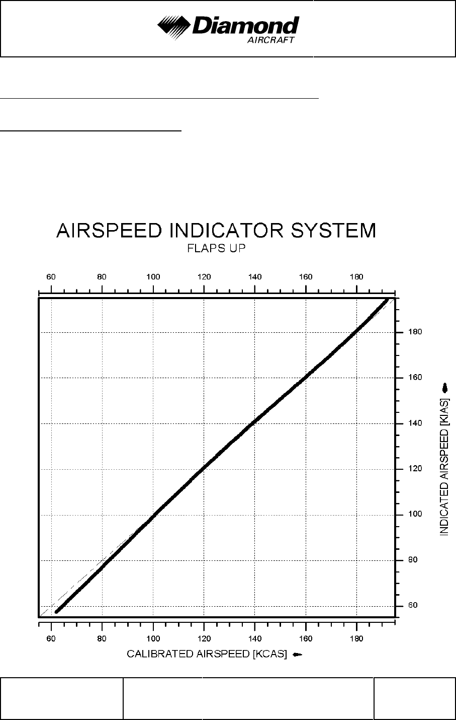
DA 42 AFM Performance
Doc. No. 7.01.05-E Rev. 4 30-Nov-2005 Page 5 - 3
5.3 PERFORMANCE TABLES AND DIAGRAMS
5.3.1 AIRSPEED CALIBRATION
NOTE
The position of the landing gear (extended/retracted) has no
influence on the airspeed indicator system.
'
'
'
'
'
'
'
'
'
'
'
'
'
'
'
'
'
'
'
'
'
'
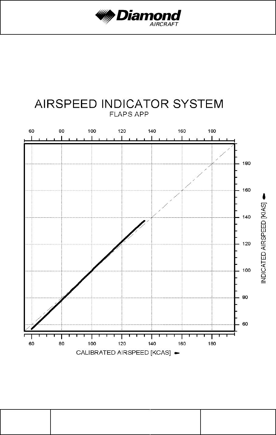
Performance DA 42 AFM
Page 5 - 4 Rev. 4 30-Nov-2005 Doc. No. 7.01.05-E
'
'
'
'
'
'
'
'
'
'
'
'
'
'
'
'
'
'
'
'
'
'
'
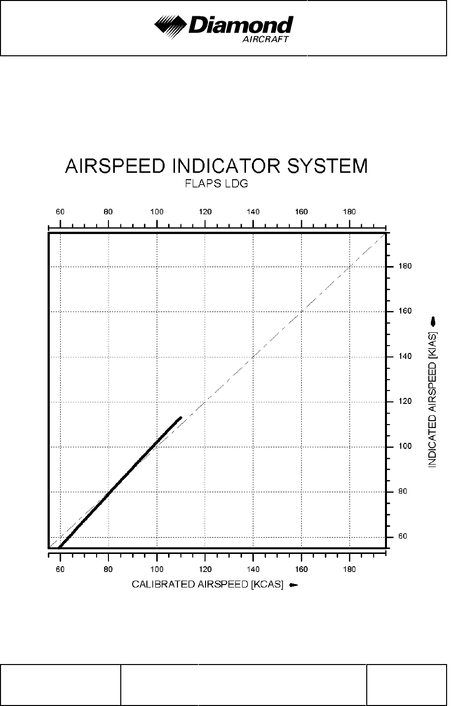
DA 42 AFM Performance
Doc. No. 7.01.05-E Rev. 4 30-Nov-2005 Page 5 - 5
'
'
'
'
'
'
'
'
'
'
'
'
'
'
'
'
'
'
'
'
'
'
'
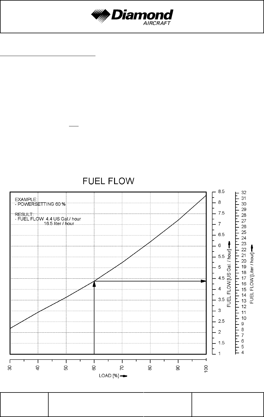
Performance DA 42 AFM
Page 5 - 6 Rev. 4 30-Nov-2005 Doc. No. 7.01.05-E
5.3.2 FUEL FLOW DIAGRAM
CAUTION
The diagram shows the fuel flow per hour for one engine.
NOTE
The fuel calculations on the FUEL CALC portion of the G1000
MFD do not use the airplane's fuel quantity indicators. The
values shown are numbers which are calculated from the last
fuel quantity update done by the pilot and actual fuel flow
data. Therefore, the endurance and range data is for
information only, and must not be used for flight planning.
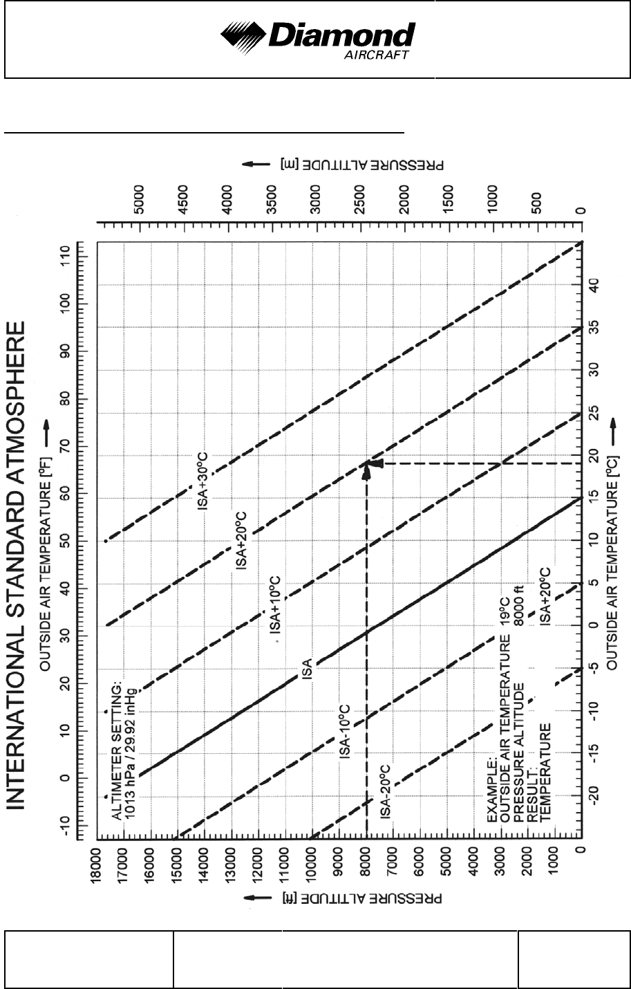
DA 42 AFM Performance
Doc. No. 7.01.05-E Rev. 4 30-Nov-2005 Page 5 - 7
5.3.3 INTERNATIONAL STANDARD ATMOSPHERE
Performance DA 42 AFM
Page 5 - 8 Rev. 4 30-Nov-2005 Doc. No. 7.01.05-E
5.3.4 STALLING SPEEDS
CAUTION
The calculated stalling speeds may be higher than the
maximum approved / limiting flap-extended and / or
maneuvering airspeeds.
Stalling speeds at various flight masses
'
Airspeeds in KIAS at idle power:
'
1400 kg (3086 lb)
'
Bank Angle
Gear Flaps 0° 30° 45° 60°
UP UP 56
'
60
'
68
'
83
'
DOWN APP 53
'
58
'
65
'
78
'
DOWN LDG 49
'
53
'
61
'
75
'
1700 kg (3748 lb) Bank Angle
Gear Flaps 0° 30° 45° 60°
UP UP 62
'
67 76
'
92
'
DOWN APP 59
'
64
'
72
'
87
'
DOWN LDG 55
'
60 68 84
'
if MÄM 42-088 is carried out:
'
'
1785 kg (3935 lb)
'
Bank Angle
'
Gear
'
Flaps
'
0°
'
30°
'
45°
'
60°
'
UP
'
UP
'
64
'
69
'
78
'
95
'
DOWN
'
APP
'
61
'
66
'
74
'
90
'
DOWN
'
LDG
'
57
'
62
'
70
'
86
'
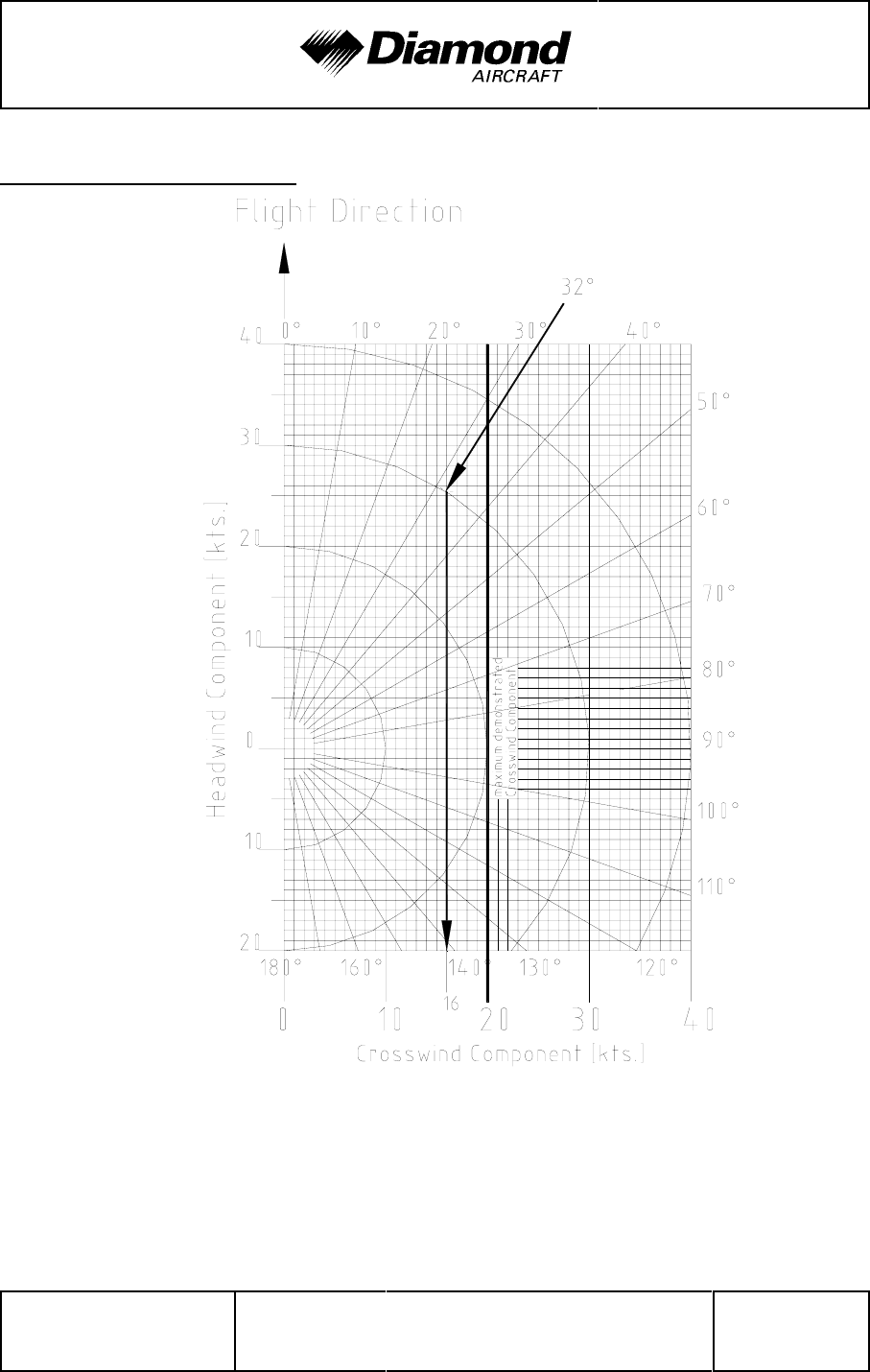
DA 42 AFM Performance
Doc. No. 7.01.05-E Rev. 4 30-Nov-2005 Page 5 - 9
5.3.5 WIND COMPONENTS
Example: Flight direction : 360°
Wind : 32°/30 kts
Result: Crosswind component : 16 kts
Max. demonstrated crosswind component : 20 kts

Performance DA 42 AFM
Page 5 - 10 Rev. 4 30-Nov-2005 Doc. No. 7.01.05-E
5.3.6 TAKE-OFF DISTANCE
Conditions:
- Power lever ......................... both MAX @ 2300 RPM
- Flaps .............................. UP
- Nose wheel lift-off
up to 1700 kg (3748 lb) .............. @ v
R = 70 KIAS
'
above 1700 kg (3748 lb) ............. @ v
R = 72 KIAS
'
- Airspeed for initial climb
up to 1700 kg (3748 lb) ............. 77 KIAS
'
above 1700 kg (3748 lb) ............. 79 KIAS
'
- Runway ............................ level, hard paved surface
(concrete, asphalt, etc.)
values for ISA and MSL, at 1700 kg (3748 lb)
Take-off distance over a 50 ft (15 m) obstacle 530 m (1739 ft)
'
Take-off ground roll 348 m (1142 ft)
'
if MÄM 42-088 is carried out:
'
values for ISA and MSL, at 1785 kg (3935 lb)
'
Take-off distance over a 50 ft (15 m) obstacle
'
691 m (2267 ft)
'
Take-off ground roll
'
427 m (1401 ft)
'
WARNING
For a safe take-off the available runway length must be at
least equal to the take-off distance over a 50 ft (15 m)
obstacle.

DA 42 AFM Performance
Doc. No. 7.01.05-E Rev. 4 30-Nov-2005 Page 5 - 11
WARNING
'
Poor maintenance condition of the airplane, deviation from
'
the given procedures, uneven runway, as well as unfavorable
'
external factors (high temperature, rain, unfavorable wind
'
conditions, including cross-wind) will increase the take-off
'
distance.
'
CAUTION
'
The figures in the following NOTE are typical values. On wet
'
ground or wet soft grass covered runways the take-off roll
'
may become significantly longer than stated below. In any
'
case the pilot must allow for the condition of the runway to
'
ensure a safe take-off.
'
NOTE
'
For take-off from dry, short-cut grass covered runways, the
'
following corrections must be taken into account, compared
'
to paved runways (typical values, see CAUTION above):
'
- grass up to 5 cm (2 in) long: 10 % increase in take-off roll.
'
- grass 5 to 10 cm (2 to 4 in) long: 15 % increase in take-
'
off roll.
'
- grass longer than 10 cm (4 in): at least 25 % increase
'
in take-off roll.
'
- on grass longer than 25 cm (10 in), a take-off should
'
not be attempted.
'
NOTE
'
For wet grass, an additional 10 % increase in take-off roll
'
must be expected.
'
NOTE
'
An uphill slope of 2 % (2 m per 100 m or 2 ft per 100 ft)
'
results in an increase in the take-off distance of approximately
'
10 %. The effect on the take-off roll can be greater.
'
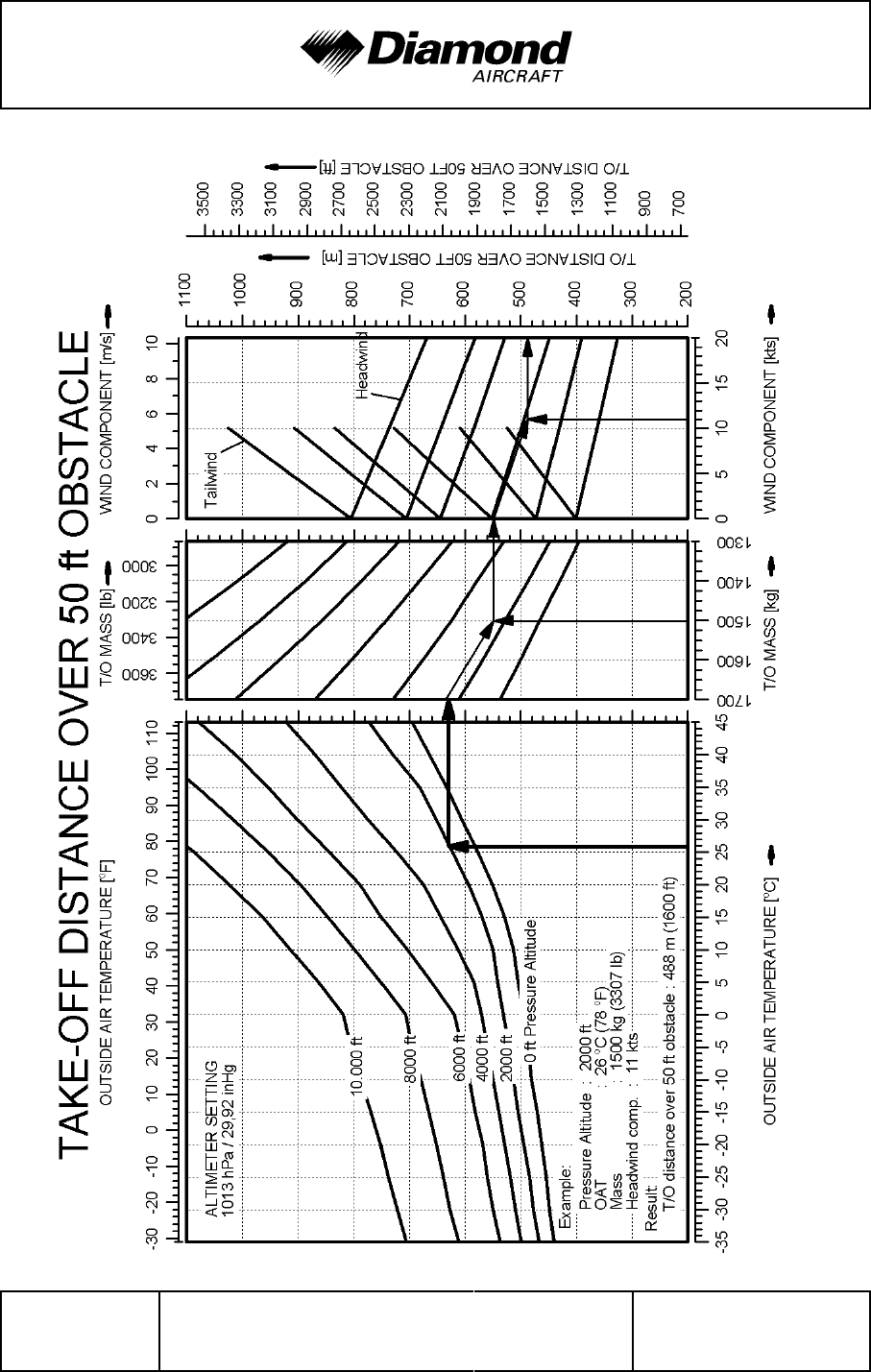
Performance DA 42 AFM
Page 5 - 12 Rev. 4 30-Nov-2005 Doc. No. 7.01.05-E
Conditions: Flaps: UP, Power: both MAX @ 2300 RPM, vR: 70 KIAS, Airspeed: 77 KIAS, Runway: hard, paved
'
'
'
'
'
'
'
'
'
'
'
'
'
'
'
'
'
'
'
'
'
'
'
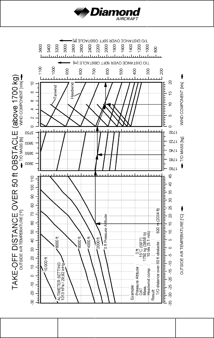
DA 42 AFM Performance
Doc. No. 7.01.05-E Rev. 4 30-Nov-2005 Page 5 - 13
Conditions: Flaps: UP, Power: both MAX @ 2300 RPM, vR: 72 KIAS, Airspeed: 79 KIAS, Runway: hard, paved
'
'
'
'
'
'
'
'
'
'
'
'
'
'
'
'
'
'
'
'
'
'
'
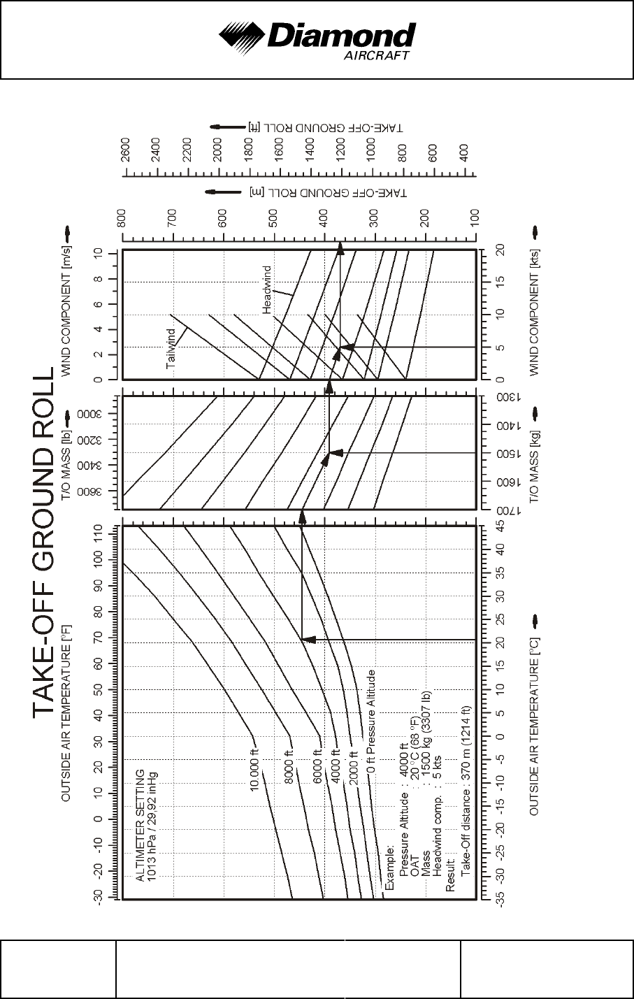
Performance DA 42 AFM
Page 5 - 14 Rev. 4 30-Nov-2005 Doc. No. 7.01.05-E
Conditions: Flaps: UP, Power: both MAX @ 2300 RPM, vR: 70 KIAS, Airspeed: 77 KIAS, Runway: hard, paved
'
'
'
'
'
'
'
'
'
'
'
'
'
'
'
'
'
'
'
'
'
'
'
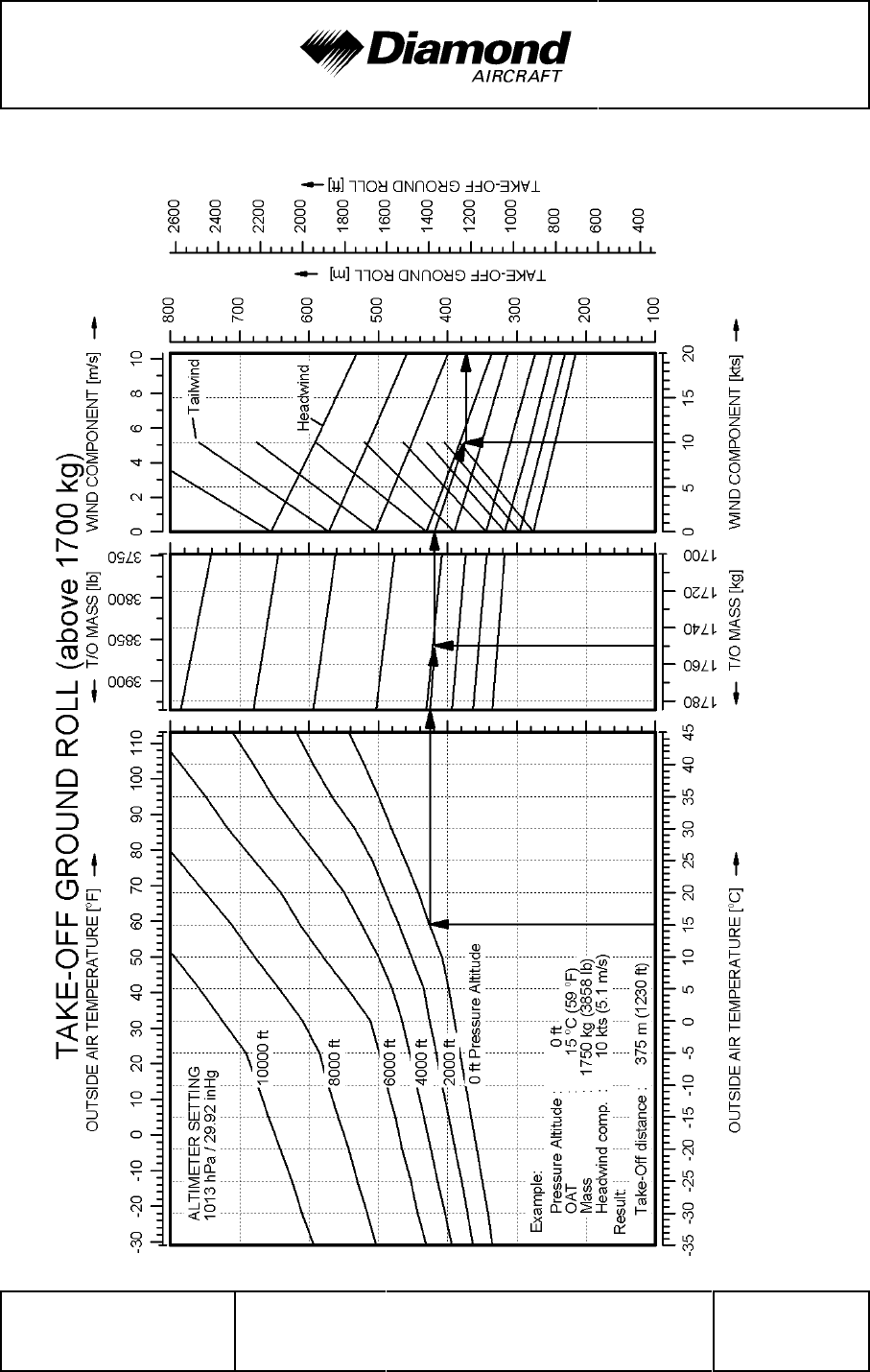
DA 42 AFM Performance
Doc. No. 7.01.05-E Rev. 4 30-Nov-2005 Page 5 - 15
Conditions: Flaps: UP, Power: both MAX @ 2300 RPM, vR: 72 KIAS, Airspeed: 79 KIAS, Runway: hard, paved
'
'
'
'
'
'
'
'
'
'
'
'
'
'
'
'
'
'
'
'
'
'
'

Performance DA 42 AFM
Page 5 - 16 Rev. 4 30-Nov-2005 Doc. No. 7.01.05-E
Gradient ROC fpm
TAS KTAS
[%] []
[]
.
=⋅
095
Gradient ROC m s
TAS KTAS
[%] [/]
[]
=⋅
190
5.3.7 CLIMB PERFORMANCE - TAKE-OFF CLIMB
Conditions:
- Power lever ......................... both MAX @ 2300 RPM
- Flaps .............................. UP
- Landing Gear ........................ retracted
- Airspeed
up to 1700 kg (3748 lb) .............. 77 KIAS
'
above 1700 kg (3748 lb) ............. 79 KIAS
'
NOTE
The charts on the following pages show the rate of climb. The
'
gradient of climb cannot easily be determined with a chart,
but it can be calculated using the following formulae:
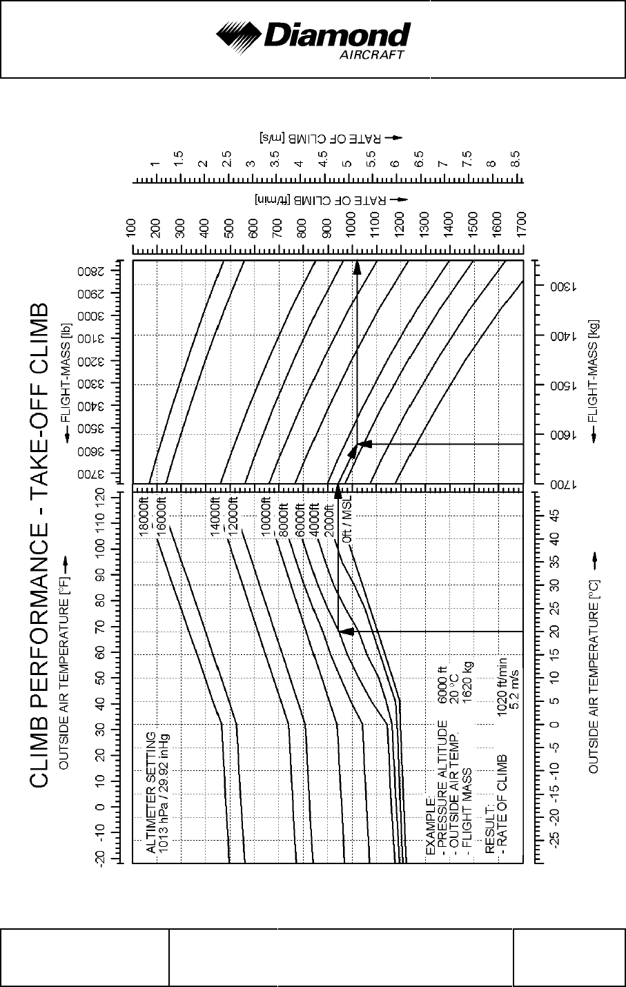
DA 42 AFM Performance
Doc. No. 7.01.05-E Rev. 4 30-Nov-2005 Page 5 - 17
Conditions: Flaps: UP, Power: both MAX @ 2300 RPM, Landing gear: retracted, Airspeed: 77 KIAS
'
'
'
'
'
'
'
'
'
'
'
'
'
'
'
'
'
'
'
'
'
'
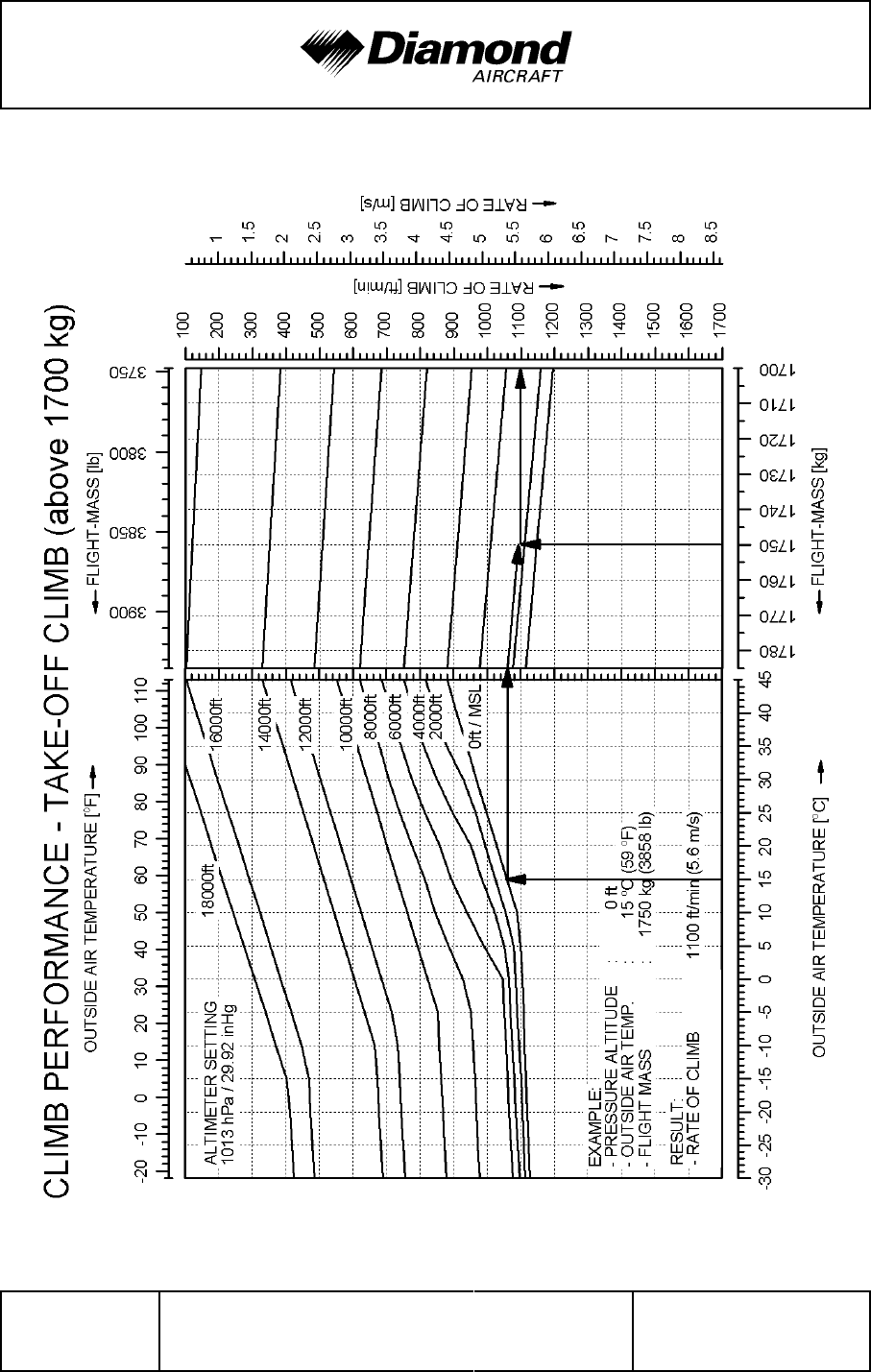
Performance DA 42 AFM
Page 5 - 18 Rev. 4 30-Nov-2005 Doc. No. 7.01.05-E
Conditions: Flaps: UP, Power: both MAX @ 2300 RPM, Landing gear: retracted, Airspeed: 79 KIAS
'
'
'
'
'
'
'
'
'
'
'
'
'
'
'
'
'
'
'
'
'

DA 42 AFM Performance
Doc. No. 7.01.05-E Rev. 4 30-Nov-2005 Page 5 - 19
Gradient ROC m s
TAS KTAS
[%] [/]
[]
=⋅
190
Gradient ROC fpm
TAS KTAS
[%] []
[]
.
=⋅
095
5.3.8 CLIMB PERFORMANCE - CRUISE CLIMB
Conditions:
- Power lever ......................... both MAX @ 2300 RPM
- Flaps .............................. UP
- Airspeed
up to 1700 kg (3748 lb) .............. 85 KIAS
'
above 1700 kg (3748 lb) ............. 86 KIAS
'
NOTE
The graphs on the following pages show the rate of climb.
'
The gradient of climb cannot easily be determined with a
graph, but it can be calculated using the following formulae:
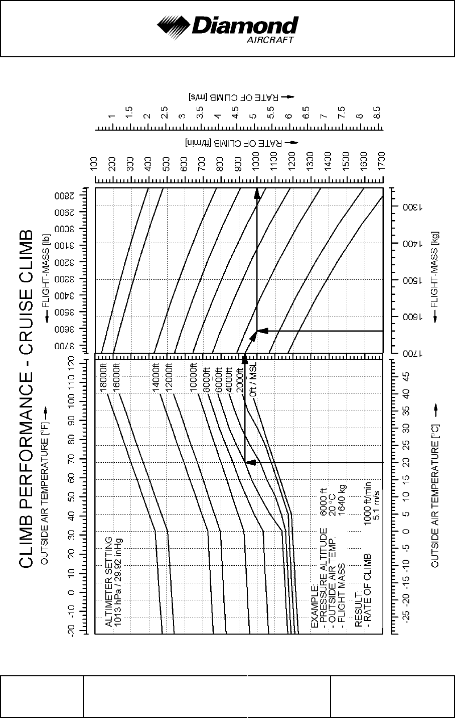
Performance DA 42 AFM
Page 5 - 20 Rev. 4 30-Nov-2005 Doc. No. 7.01.05-E
Conditions: Flaps: UP, Power: both MAX @ 2300 RPM, Airspeed: 85 KIAS
'
'
'
'
'
'
'
'
'
'
'
'
'
'
'
'
'
'
'
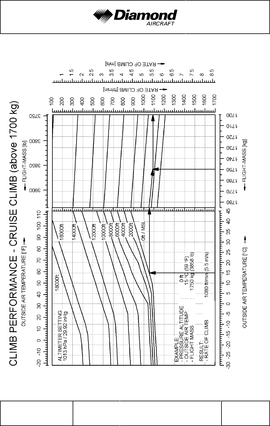
DA 42 AFM Performance
Doc. No. 7.01.05-E Rev. 4 30-Nov-2005 Page 5 - 21
Conditions: Flaps: UP, Power: both MAX @ 2300 RPM, Airspeed: 86 KIAS
'
'
'
'
'
'
'
'
'
'
'
'
'
'
'
'
'
'
'

Performance DA 42 AFM
Page 5 - 22 Rev. 4 30-Nov-2005 Doc. No. 7.01.05-E
Gradient ROC fpm
TAS KTAS
[%] []
[]
.
=⋅
095
Gradient ROC m s
TAS KTAS
[%] [/]
[]
=⋅
190
5.3.9 ONE ENGINE INOPERATIVE CLIMB PERFORMANCE
Conditions:
- Remaining Engine (RH) ................ MAX @ 2300 RPM
- Dead Engine ........................ feathered and secured
- Flaps .............................. UP
- Airspeed ............................ 82 KIAS
- Landing Gear ........................ retracted
- Zero Sideslip ........................ established
NOTE
With respect to handling and performance, the left hand
engine (pilots view) is considered the "critical" engine.
NOTE
The graphs on the following pages show the rate of climb.
'
The gradient of climb cannot easily be determined with a
graph, but it can be calculated using the following formulae:
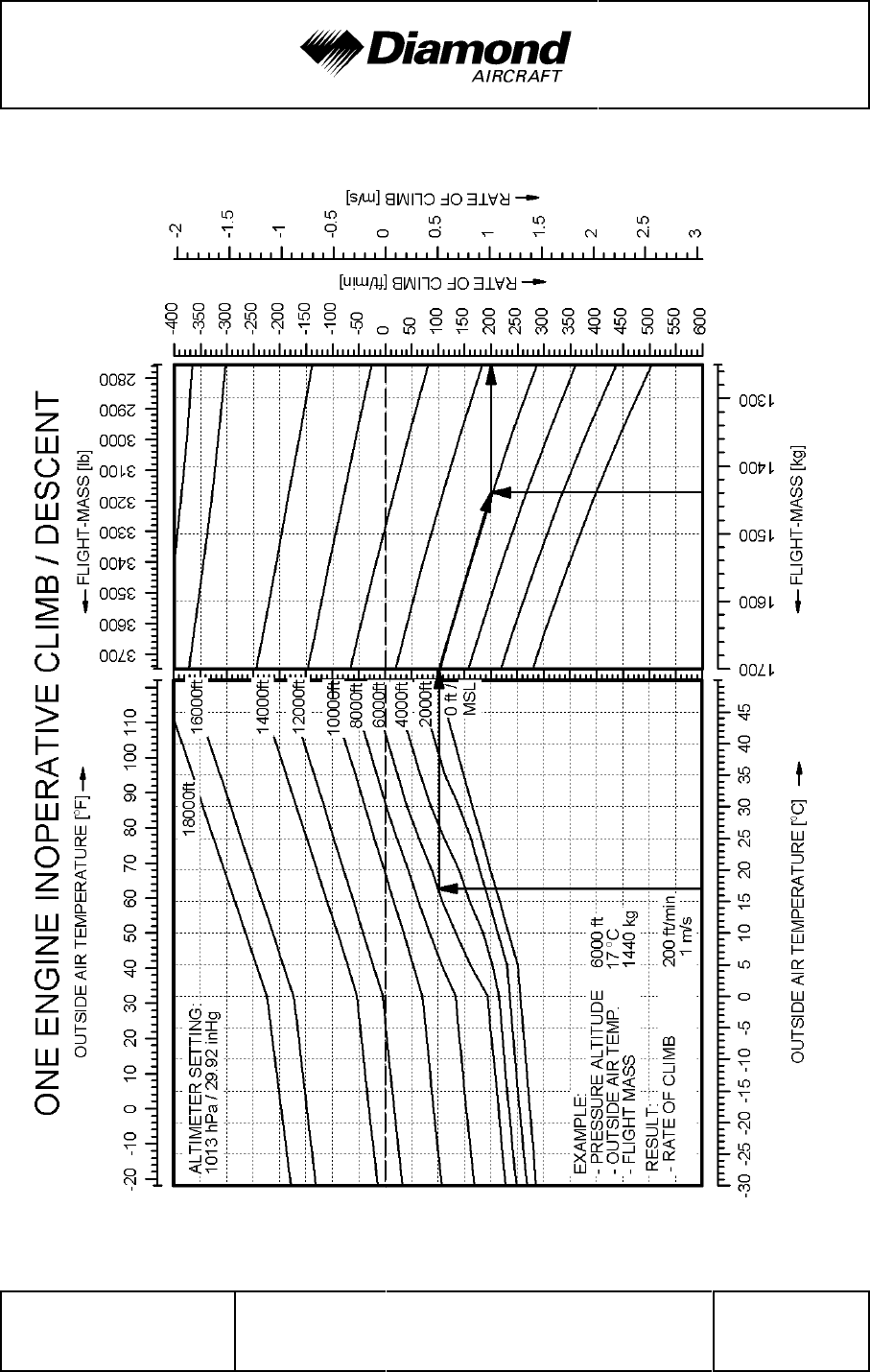
DA 42 AFM Performance
Doc. No. 7.01.05-E Rev. 4 30-Nov-2005 Page 5 - 23
Conditions: Flaps: UP, Power: remaining engine MAX @ 2300 RPM / Dead engine: feathered+secured, Airspeed: 82 KIAS
'
'
'
'
'
'
'
'
'
'
'
'
'
'
'
'
'
'
'
'
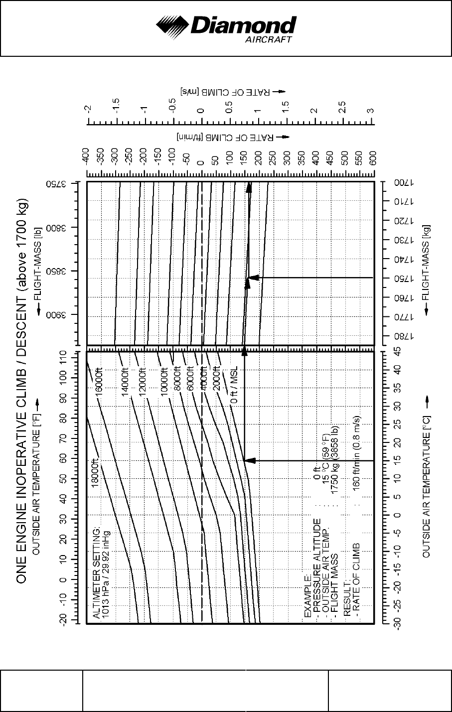
Performance DA 42 AFM
Page 5 - 24 Rev. 4 30-Nov-2005 Doc. No. 7.01.05-E
Conditions: Flaps: UP, Power: remaining engine MAX @ 2300 RPM / Dead engine: feathered+secured, Airspeed: 82 KIAS
'
'
'
'
'
'
'
'
'
'
'
'
'
'
'
'
'
'
'
'
'

DA 42 AFM Performance
Doc. No. 7.01.05-E Rev. 4 30-Nov-2005 Page 5 - 25
5.3.10 CRUISING (TRUE AIRSPEED TAS)
Conditions:
- Engines ............................ all operating
- Power lever ......................... as required to adjust selected
displayed LOAD [%]
- Flaps .............................. UP
- Landing Gear ....................... retracted
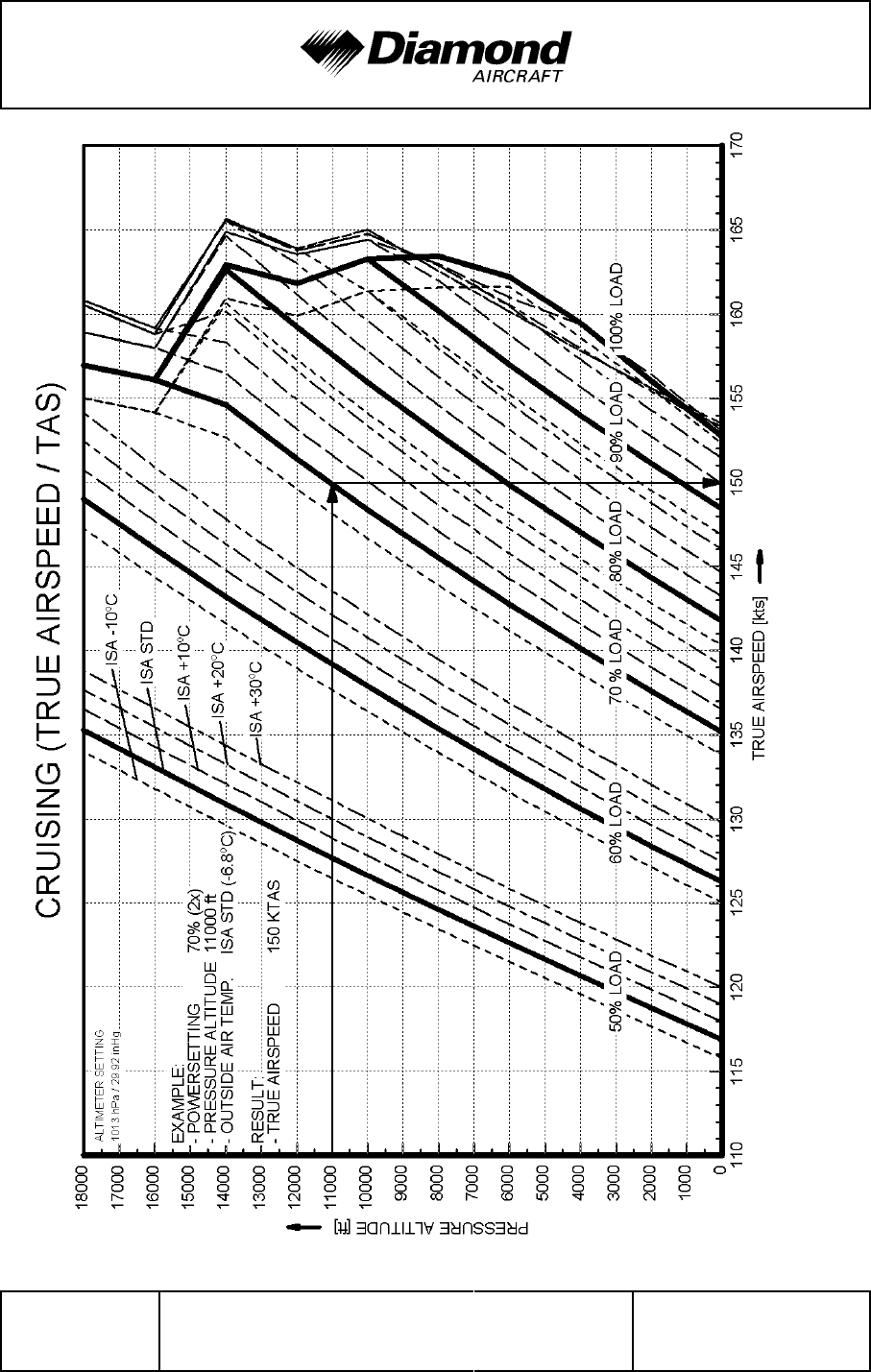
Performance DA 42 AFM
Page 5 - 26 Rev. 4 30-Nov-2005 Doc. No. 7.01.05-E
Conditions: Engines: all operating, Power: as required to adjust selected LOAD [%], Flaps: UP, Landing Gear: retracted
'
'
'
'
'
'
'
'
'
'
'
'
'
'
'
'
'
'
'

DA 42 AFM Performance
Doc. No. 7.01.05-E Rev. 4 30-Nov-2005 Page 5 - 27
5.3.11 LANDING DISTANCE
Conditions: - Power lever ............... both IDLE
- Flaps .................... LDG
- Runway .................. level, asphalt surface, dry
values for ISA and MSL, at 1700 kg (3748 lb), approach speed 76 KIAS
'
Landing distance over a 50 ft (15 m) obstacle 572 m (1877 ft)
Ground roll 323 m (1060 ft)
NOTE
'
If MÄM 42-088 is carried out, a landing with a mass between
'
1700 kg (3748 lb) and 1785 kg (3935 lb) is admissible. It
'
constitutes an abnormal operating procedure.
'
values for ISA and MSL, at 1785 kg (3935 lb), approach speed 78 KIAS
'
Landing distance over a 50 ft (15 m) obstacle
'
710 m (2329 ft)
'
Ground roll
'
397 m (1302 ft)
'
WARNING
For a safe landing the available runway length must be at
least equal to the landing distance over a 50 ft (15 m)
obstacle.

Performance DA 42 AFM
Page 5 - 28 Rev. 4 30-Nov-2005 Doc. No. 7.01.05-E
WARNING
'
Poor maintenance condition of the airplane, deviation from
'
the given procedures, uneven runway, as well as unfavorable
'
external factors (high temperature, rain, unfavorable wind
'
conditions, including cross-wind) will increase the landing
'
distance.
'
CAUTION
'
The figures in the following NOTE are typical values. On wet
'
ground or wet soft grass covered runways the landing
'
distance may become significantly longer than stated below.
'
In any case the pilot must allow for the condition of the runway
'
to ensure a safe landing.
'
NOTE
'
For landings on dry, short-cut grass covered runways, the
'
following corrections must be taken into account, compared
'
to paved runways (typical values, see CAUTION above):
'
- grass up to 5 cm (2 in) long: 5 % increase in landing roll.
'
- grass 5 to 10 cm (2 to 4 in) long: 15 % increase in landing
'
roll.
'
- grass longer than 10 cm (4 in): at least 25 % increase in
'
landing roll.
'
NOTE
'
For wet grass, an additional 10 % increase in landing roll must
'
be expected.
'
NOTE
'
A downhill slope of 2 % (2 m per 100 m or 2 ft per 100 ft)
'
results in an increase in the landing distance of approximately
'
10 %. The effect on the landing roll can be greater.
'
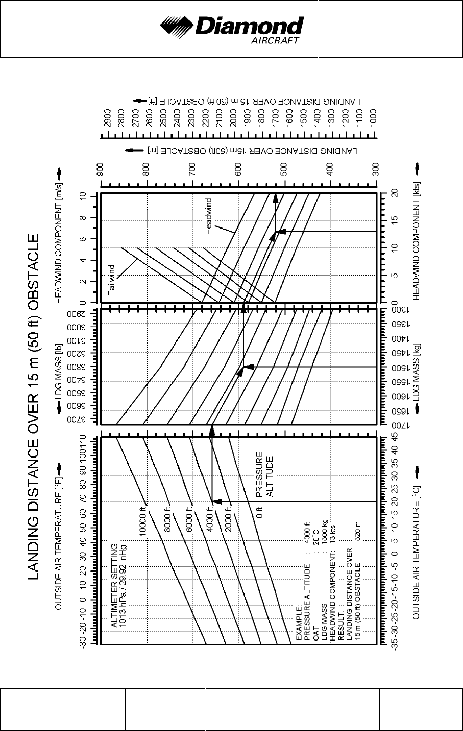
DA 42 AFM Performance
Doc. No. 7.01.05-E Rev. 4 30-Nov-2005 Page 5 - 29
Conditions: Flaps: LDG, Power: both IDLE, Runway: level and hard, dry surface, Approach Speed: 76 KIAS
'
'
'
'
'
'
'
'
'
'
'
'
'
'
'
'
'
'
'
'
'
'
'
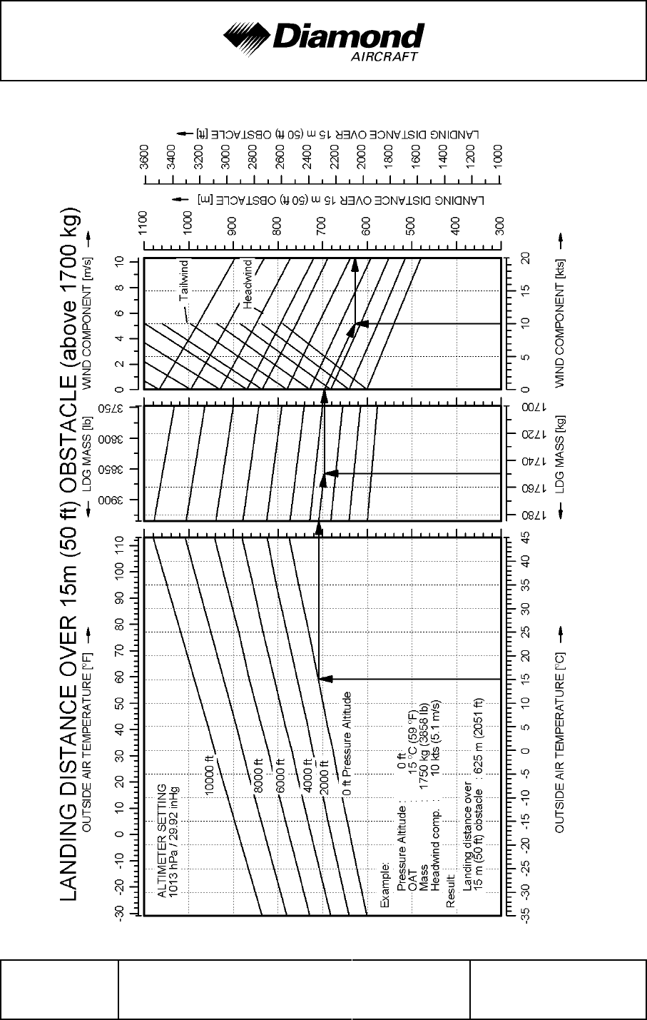
Performance DA 42 AFM
Page 5 - 30 Rev. 4 30-Nov-2005 Doc. No. 7.01.05-E
Conditions: Flaps: LDG, Power : both IDLE, Runway: level and hard, dry surface, Approach Speed: 78 KIAS
'
'
'
'
'
'
'
'
'
'
'
'
'
'
'
'
'
'
'
'
'
'
'
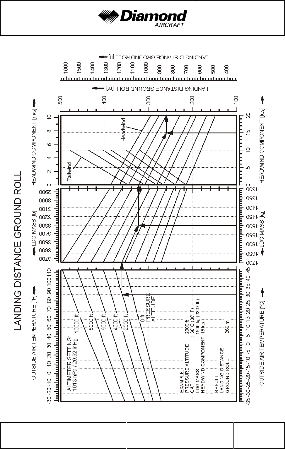
DA 42 AFM Performance
Doc. No. 7.01.05-E Rev. 4 30-Nov-2005 Page 5 - 31
Conditions: Flaps: LDG, Power: both IDLE, Runway: level and hard, dry surface, Approach Speed: 76 KIAS
'
'
'
'
'
'
'
'
'
'
'
'
'
'
'
'
'
'
'
'
'
'
'
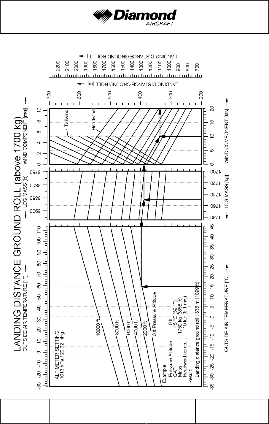
Performance DA 42 AFM
Page 5 - 32 Rev. 4 30-Nov-2005 Doc. No. 7.01.05-E
Conditions: Flaps: LDG, Power: both IDLE, Runway: level and hard, dry surface, Approach Speed: 78 KIAS
'
'
'
'
'
'
'
'
'
'
'
'
'
'
'
'
'
'
'
'
'
'
'
DA 42 AFM Performance
Doc. No. 7.01.05-E Rev. 4 30-Nov-2005 Page 5 - 33
5.3.12 GRADIENT OF CLIMB ON GO-AROUND
Conditions:
'
- Power lever ......................... both MAX @ 2300 RPM
- Flaps .............................. LDG
- Landing gear ........................ extended
- Airspeed:
up to 1700 kg (3748 lb) .............. 76 KIAS
'
above 1700 kg (3748 lb) ............. 78 KIAS
'
value for ISA and MSL, at 1700 kg (3748 lb)
'
constant gradient of climb
'
5.25 % (equals 3.0° climb angle) or 400 ft/min
'
NOTE
'
If MÄM 42-088 is carried out, a landing with a mass between
'
1700 kg (3748 lb) and 1785 kg (3935 lb) is admissible. It
'
constitutes an abnormal operating procedure.
'
value for ISA and MSL, at 1785 kg (3935 lb)
'
constant gradient of climb
'
4.30 % (equals 2.5° climb angle) or 340 ft/min
'

Performance DA 42 AFM
Page 5 - 34 Rev. 4 30-Nov-2005 Doc. No. 7.01.05-E
5.3.13 APPROVED NOISE DATA
Max. flight mass 1700 kg (3748 lb)
'
ICAO Annex 16 Chapter X, App. 6 ............ 75.2 dB(A)
JAR-36 Subpart C ......................... 75.2 dB(A)
Max. flight mass 1785 kg (3935 lb), if MÄM 42-088 is carried out
'
ICAO Annex 16 Chapter X, App. 6 ............ 76.8 dB(A)
'
JAR-36 Subpart C ......................... 76.8 dB(A)
'

DA 42 AFM Mass and Balance
Doc. No. 7.01.05-E Rev. 3 15-Oct-2005 Page 6 - 1
CHAPTER 6
MASS AND BALANCE
Page
6.1 INTRODUCTION .......................................6-2
6.2 DATUM PLANE ........................................6-3
6.3 MASS AND BALANCE REPORT ...........................6-4
6.4 FLIGHT MASS AND CENTER OF GRAVITY ..................6-6
6.4.1 MOMENT ARMS...................................6-8
6.4.2 LOADING DIAGRAM ...............................6-9
6.4.3 CALCULATION OF LOADING CONDITION.............6-10
6.4.4 PERMISSIBLE CENTER OF GRAVITY RANGE .........6-12
6.4.5 PERMISSIBLE MOMENT RANGE ....................6-14
6.5 EQUIPMENT LIST AND EQUIPMENT INVENTORY ...........6-15

Mass and Balance DA 42 AFM
Page 6 - 2 Rev. 3 15-Oct-2005 Doc. No. 7.01.05-E
6.1 INTRODUCTION
In order to achieve the performance and flight characteristics described in this Airplane
Flight Manual and for safe flight operation, the airplane must be operated within the
permissible mass and balance envelope.
The pilot is responsible for adhering to the permissible values for loading and center of
gravity (CG). In this, he should note the movement of the CG due to fuel consumption.
The permissible CG range during flight is given in Chapter 2.
The procedure for determining the flight mass CG position is described in this chapter.
Additionally a comprehensive list of the equipment approved for this airplane exists
(Equipment List) with a list of the equipment installed when the airplane was weighed
(Equipment Inventory).
Before the airplane is delivered, the empty mass and the corresponding CG position are
determined and entered in Section 6.3 MASS AND BALANCE REPORT.
NOTE
Following equipment changes the new empty mass and the
corresponding CG position must be determined by calculation
or by weighing.
Following repairs or repainting the new empty mass and the
corresponding CG position must be determined by weighing.
Empty mass, empty mass CG position, and the empty mass
moment must be certified in the Mass and Balance Report
by authorized personnel.
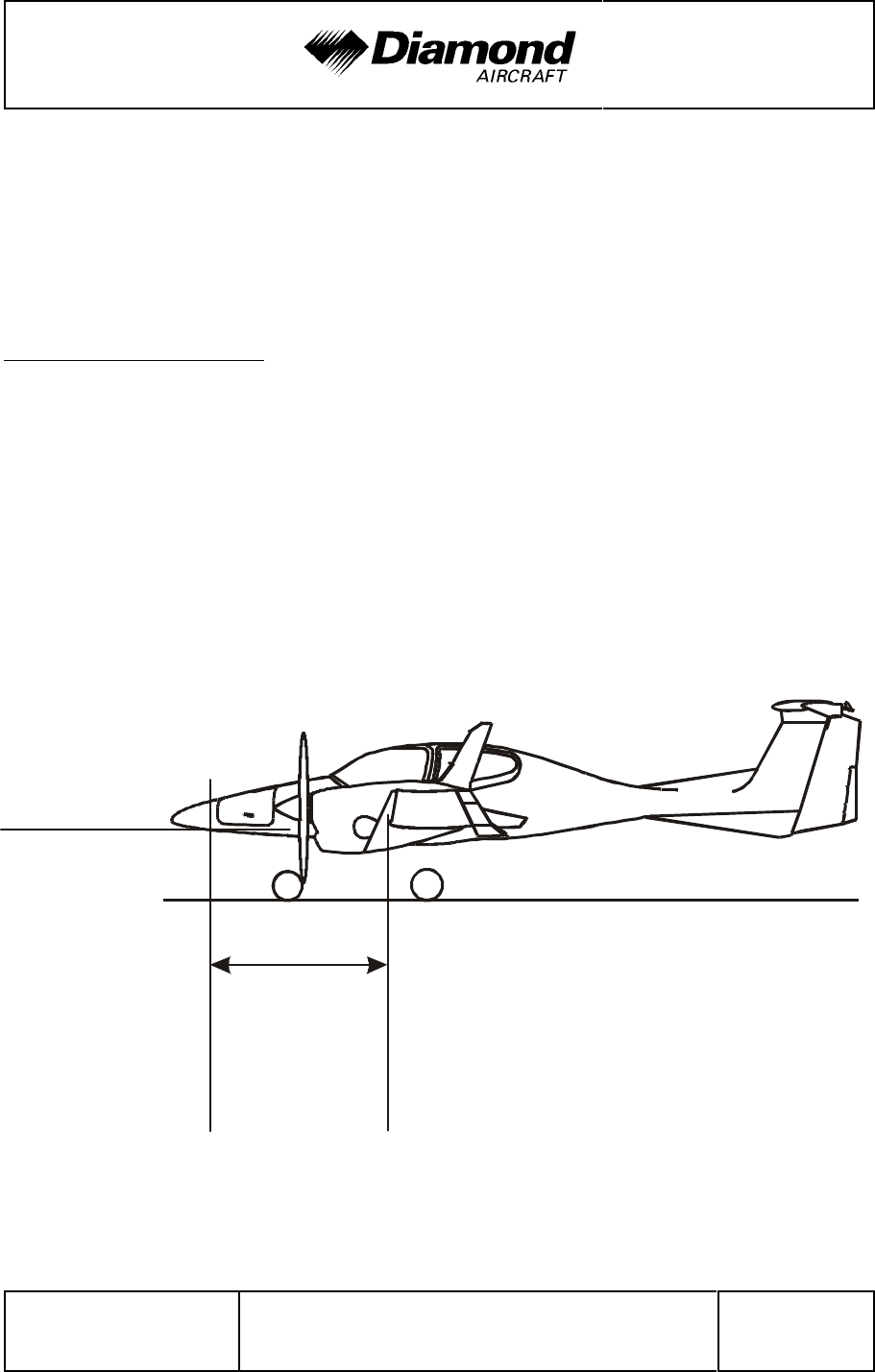
DA 42 AFM Mass and Balance
Doc. No. 7.01.05-E Rev. 3 15-Oct-2005 Page 6 - 3
2196 mm
floor of
nose baggage
compartment
horizontal
(86.46 in)
Datum
Plane
Root Rib
on Stub Wing
NOTE
Refer to Section 1.6 UNITS OF MEASUREMENT for
conversion of SI units to US units and vice versa.
6.2 DATUM PLANE
The Datum Plane (DP) is a plane which is normal to the airplane’s longitudinal axis and
in front of the airplane as seen from the direction of flight. The airplane’s longitudinal axis
is parallel with the floor of the nose baggage compartment. When the floor of the nose
baggage compartment is aligned horizontally, the Datum Plane is vertical. The Datum
Plane is located 2.196 meters (86.46 in) forward of the most forward point of the root rib
on the stub wing.

Mass and Balance DA 42 AFM
Page 6 - 4 Rev. 3 15-Oct-2005 Doc. No. 7.01.05-E
6.3 MASS AND BALANCE REPORT
The empty mass and the corresponding CG position established before delivery are the
first entries in the Mass and Balance Report. Every change in permanently installed
equipment, and every repair to the airplane which affects the empty mass or the empty
mass CG must be recorded in the Mass and Balance Report.
For the calculation of flight mass and corresponding CG position (or moment), the current
empty mass and the corresponding CG position (or moment) in accordance with the Mass
and Balance Report must always be used.
Condition of the airplane for establishing the empty mass:
- Equipment as per Equipment Inventory (see Section 6.5)
- Including the following operating fluids:
'
brake fluid
hydraulic fluid (for the retractable gear)
'
engine oil (2 x 6.0 liters = 2 x 6.3 qts)
coolant (2 x 6.0 liters = 2 x 6.3 qts)
gearbox oil (2 x 0.9 liters = 2 x 0.95 qts)
unusable fuel in main fuel tanks (2 x 1.0 US gal = 2 x 3.8 liters)
'
unusable fuel in auxiliary fuel tanks (if installed, 2 x 0.5 US gal = 2 x 1.9 liters)
'
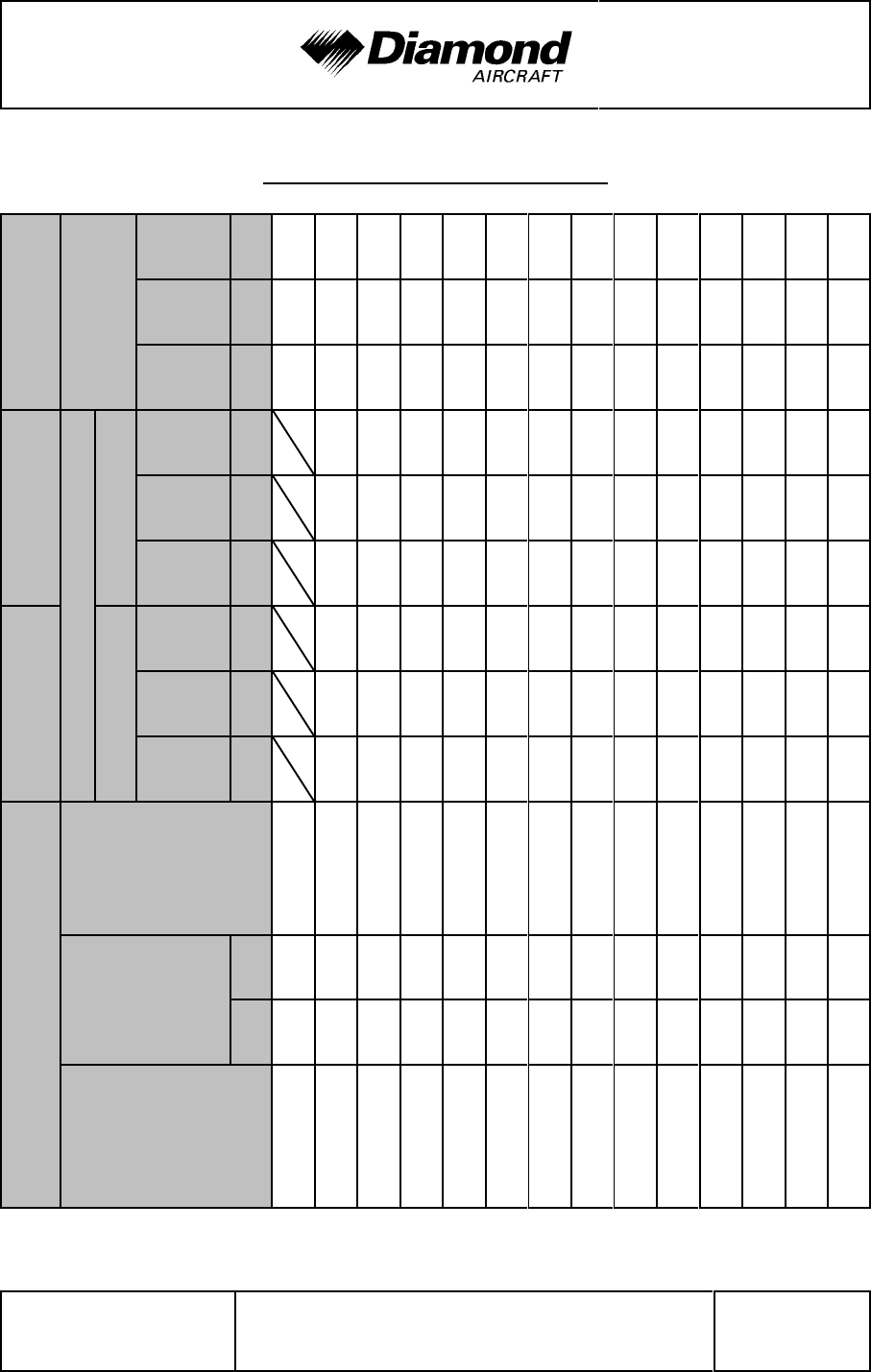
DA 42 AFM Mass and Balance
Doc. No. 7.01.05-E Rev. 4 30-Nov-2005 Page 6 - 5
MASS AND BALANCE REPORT
'
Page No.:
'
'
Current empty
mass
'
Mo-
ment
'
''''''''
'''''
'
''
'
Mo-
ment
Arm
'
''''''''
'''''
'
'
'
'
Mass
'
''''''''
'''''
'
'
Registration:
'
Changes in mass
'
'
'
Subtraction (-)
'
'
Mo-
ment
'
''''''''
'''''
'
'''
'
Mo-
ment
Arm
'
''''''''
'''''
'
'
'
'
'
Mass
'
''''''''
'''''
'
'
Serial No.:
'
'
'
Addition (+)
'
'
Mo-
ment
'
''''''''
'''''
'
'''
'
Mo-
ment
Arm
'
''''''''
'''''
'
'
'
'
'
Mass
'
''''''''
'''''
'
'
DA 42
''
Description
of part or
Modification
Upon delivery
'
'''''''
'''''
'
'
'
Entry No.:
'
OUT
''''''''
'''''
'
'
'
'
IN
''''''''
'''''
'
'
'
Date
''''''''
'''''
'

Mass and Balance DA 42 AFM
Page 6 - 6 Rev. 3 15-Oct-2005 Doc. No. 7.01.05-E
6.4 FLIGHT MASS AND CENTER OF GRAVITY
The following information enables you to operate your DA 42 within the permissible mass
and balance limits. For the calculation of the flight mass and the corresponding CG position
the following tables and diagrams are required:
6.4.1 MOMENT ARMS
6.4.2 LOADING DIAGRAM
6.4.3 CALCULATION OF LOADING CONDITION
6.4.4 PERMISSIBLE CENTER OF GRAVITY RANGE
6.4.5 PERMISSIBLE MOMENT RANGE
The diagrams should be used as follows:
1. Take the empty mass and the empty mass moment of your airplane from the Mass
and Balance Report, and enter the figures in the appropriate boxes under the column
marked ‘Your DA 42' in Table 6.4.3 - 'CALCULATION OF LOADING CONDITION'.
2. Read the fuel quantity indicators to determine the fuel quantity in the main fuel tanks.
'
3. Determine the fuel quantity in the auxiliary fuel tanks (if installed).
'
To verify an empty auxiliary fuel tank, set the ELECT. MASTER switch and the FUEL
'
TRANSFER switch to ON and check the PFD for the L/R AUX FUEL E caution
'
message.
'
To verify a full auxiliary fuel tank open the auxiliary fuel tank filler and check fuel level.
'
If the auxiliary fuel tank quantity is in between empty and full, the exact quantity cannot
'
be determined. If possible transfer all fuel to the main fuel tank by setting the ELECT.
'
MASTER switch and the FUEL TRANSFER switch to ON until the L/R AUX FUEL E
'
caution message appears on the PFD. During this procedure ground power must be
'
used or at least one engine must be running. The fuel transfer will take a maximum
'
of 10 minutes.
'

DA 42 AFM Mass and Balance
Doc. No. 7.01.05-E Rev. 3 15-Oct-2005 Page 6 - 7
CAUTION
'
If the auxiliary tanks are in use, both tanks must be refueled
'
to the maximum level to provide proper information for the
'
pilot about the fuel quantity in the auxiliary fuel tanks.
'
If the auxiliary tanks are not in use, the pilot must ensure that
'
they are empty.
'
4. Multiply the individual masses by the moment arms quoted to obtain the moment for
'
every item of loading and enter these moments in the appropriate boxes in Table
6.4.3 - 'CALCULATION OF LOADING CONDITION'.
5. Add up the masses and moments in the respective columns. The CG position is
'
calculated by dividing the total moment by the total mass (using row 8 for the condition
'
with empty fuel tanks, and row 11 for the pre take-off condition). The resulting CG
'
position must be inside the limits.
As an illustration the total mass and the CG position are entered on Diagram 6.4.4 -
'PERMISSIBLE CENTER OF GRAVITY RANGE'. This checks graphically that the
current configuration of the airplane is within the permissible range.
6. Graphical method:
'
Diagram 6.4.2 - 'LOADING DIAGRAM' is used to determine the moments. The masses
and moments for the individual items of loading are added. Then Diagram 6.4.5 -
'PERMISSIBLE MOMENT RANGE' is used to check whether the total moment
associated with the total mass is in the permissible range.
The result found with the graphical method is however inaccurate. In doubtful cases
the result must be verified using the exact method given above.

Mass and Balance DA 42 AFM
Page 6 - 8 Rev. 4 30-Nov-2005 Doc. No. 7.01.05-E
6.4.1 MOMENT ARMS
The most important lever arms aft of the Datum Plane:
Item Lever Arm
[m] [in]
Occupants on front seats 2.30 90.6
Occupants on rear seats 3.25 128.0
Fuel in main tanks 2.63 103.5
in auxiliary tanks 3.20 126.0
De-Icing Fluid (if equipment installed,
'
OÄM 42-053 or OÄM 42-054)
'
1.00
'
39.4
'
Baggage in
Compartments
nose 0.60 23.6
cockpit 3.89 153.1
extension 4.54 178.7
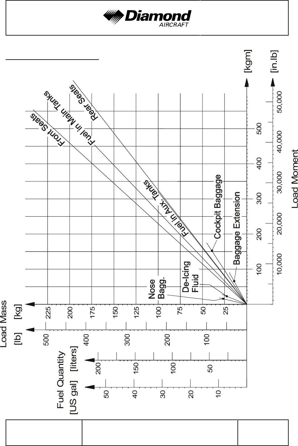
DA 42 AFM Mass and Balance
Doc. No. 7.01.05-E Rev. 3 15-Oct-2005 Page 6 - 9
6.4.2 LOADING DIAGRAM
'
'
'
'
'
'
'
'
'
'
'
'
'
'
'
'
'
'
'
'
'
'
'
'
'
'
'
'
'

Mass and Balance DA 42 AFM
Page 6 - 10 Rev. 4 30-Nov-2005 Doc. No. 7.01.05-E
6.4.3 CALCULATION OF LOADING CONDITION
NOTE
If the optional de-icing system (OÄM 42-053 or OÄM 42-054)
'
is installed, the following must be observed:
The consumption of fuel causes a forward movement of the
CG. The consumption of de-icing fluid causes a rearward
movement of the CG. Depending on the fuel flow and de-icing
fluid flow, the overall movement of the CG can be a forward
or a rearward movement. In order to cover all possible cases,
the following table must be completed twice: with (as shown
in the example) and without considering the on-board de-icing
fluid. All four CG positions (fuel tank full/empty, de-icing fluid
tank full/empty) must fall into the permitted area.
1. Complete the form on the next page.
2. Divide the total moments from rows 8 and 11 by the related total mass to obtain the
CG positions.
In our example: empty tanks: 3625.1 kgm / 1527.5 kg = 2.373 m
'
314,656 in.lb / 3368 lb = 93.43 in
'
full tanks: 4312.1 kgm / 1770.5 kg = 2.436 m
'
374,295 in.lb / 3904 lb = 95.87 in
'
3. Locate the values in the diagram in Section 6.4.4 'PERMISSIBLE CENTER OF
GRAVITY RANGE'. If the CG positions and related masses fall into the permitted area,
the loading condition is allowable.
Our example shows allowable loading conditions (for 1785 kg take-off mass, i.e., MÄM
'
42-088 carried out).
'

DA 42 AFM Mass and Balance
Doc. No. 7.01.05-E Rev. 4 30-Nov-2005 Page 6 - 11
CALCULATION OF
LOADING CONDITION
DA 42 (Example) Your DA 42
Mass
[kg]
[lb]
Moment
[kgm]
[in.lb]
Mass
[kg]
[lb]
Moment
[kgm]
[in.lb]
1. Empty mass (from Mass and
Balance Report) 1250
'
2756
'
2937.5
'
254,965
'
2. Front seats
Lever arm: 2.30 m (90.6 in) 160
353 368.0
31,982
'
3. Rear seats
Lever arm: 3.25 m (128.0 in) 70
154 227.5
19,712
'
4. Nose baggage compt.
Lever arm: 0.60 m (23.6 in) 5
11 3.0
260
5. Cockpit baggage compt.
Lever arm: 3.89 m (153.1 in) 10
22 38.9
3,368
'
6. Baggage extension
Lever arm: 4.54 m (178.7 in) 5
11 22.7
1,966
7. De-icing fluid (if installed; see
NOTE on previous page)
(1.1 kg/liter) (9.2 lb/US gal)
Lever arm: 1.00 m (39.4 in)
27.5
61
27.5
2,403
'
8. Total mass & total moment
with empty fuel tanks
(Total of 1.-7.)
1527.5
'
3368
'
3625.1
'
314,656
'
9. Usable fuel, main tanks
(0.84 kg/liter) (7.01 lb/US gal)
Lever arm: 2.63 m (103.5 in)
159
351 418.2
36,329
'
10. Usable fuel, auxiliary tanks (if
installed; OÄM 42-056)
'
(0.84 kg/liter) (7.01 lb/US gal)
Lever arm: 3.20 m (126.0 in)
84
185 268.8
23,310
'
11. Total mass & total moment
with fuel & de-icing fluid
(Total of 8. through 10.)
1770.5
'
3904
'
4312.1
'
374,295
'
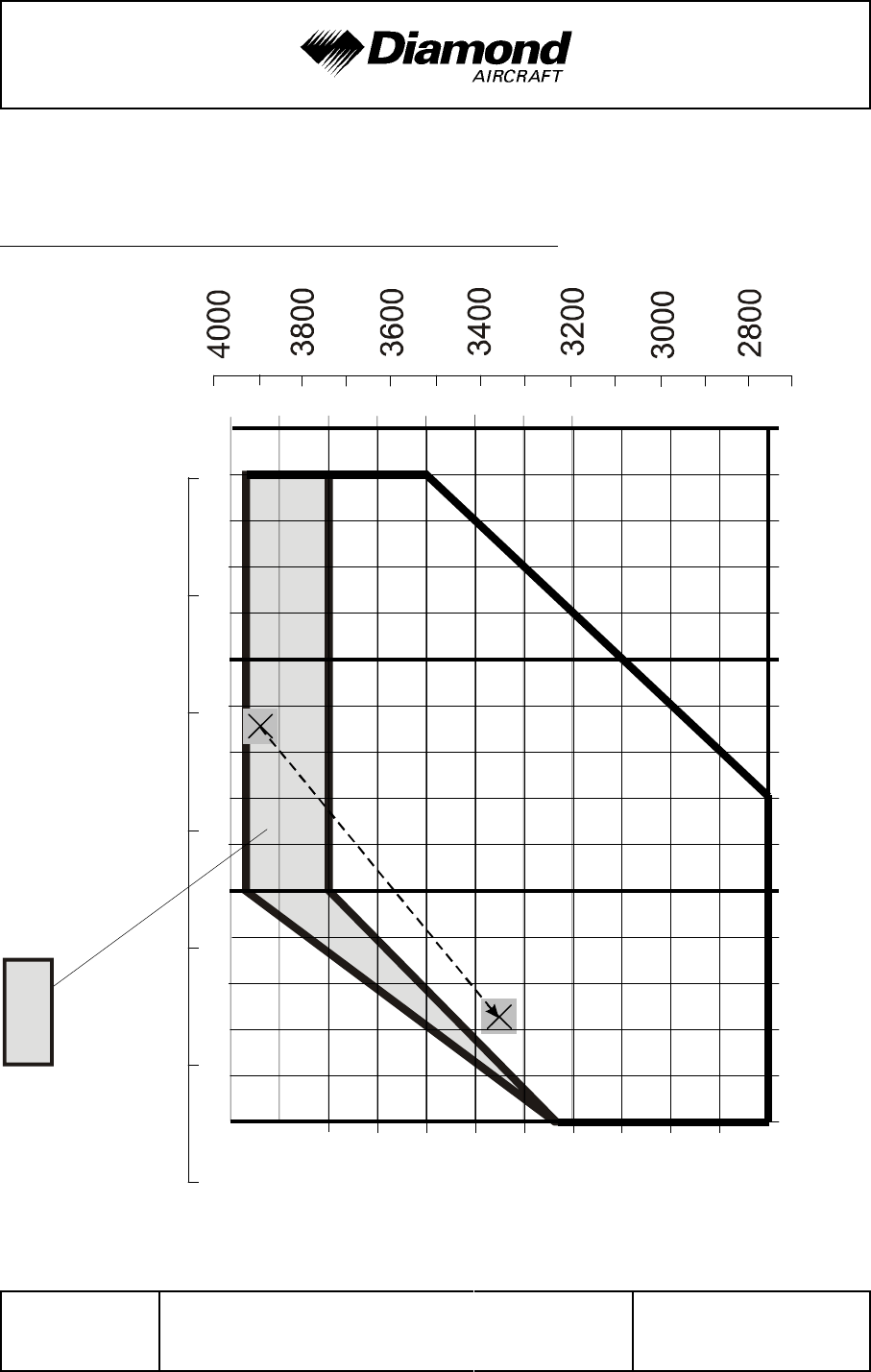
Mass and Balance DA 42 AFM
Page 6 - 12 Rev. 4 30-Nov-2005 Doc. No. 7.01.05-E
Flight Mass [kg]
1250
1300
1350
1400
1450
1500
1550
1600
1650
1700
1750
1800
Center of Gravity Position [m]
2.35 2.40 2.45 2.50
Flight
Mass
[lb]
Center of Gravity Position [in]
9695949392 97 98
shaded area only for 1785 kg (3935 lb)
max. take-off mass (MÄM 42-088 carried out)
The CG's shown in the following diagrams are those from the example in Section 6.4.3
'CALCULATION OF LOADING CONDITION', rows 8 and 11.
6.4.4 PERMISSIBLE CENTER OF GRAVITY RANGE
'
'
'
'
'
'
'
'
'
'
'
'
'
'
'
'
'
'
'
'
'
'
'
'
'
'

DA 42 AFM Mass and Balance
Doc. No. 7.01.05-E Rev. 4 30-Nov-2005 Page 6 - 13
The flight CG position must be within the following limits:
Most forward flight CG:
2.35 m (92.52 in) aft of Datum Plane at 1250 kg (2756 lb)
'
2.35 m (92.52 in) aft of Datum Plane at 1468 kg (3236 lb)
'
2.40 m (94.49 in) aft of Datum Plane at max. take-off mass (see Section 2.7)
'
linear variation in between
'
Most rearward flight CG:
2.42 m (95.28 in) aft of Datum Plane at 1250 kg (2756 lb)
'
2.49 m (98.03 in) aft of Datum Plane at 1600 kg (3527 lb)
'
2.49 m (98.03 in) aft of Datum Plane at max. take-off mass (see Section 2.7)
'
linear variation in between
'
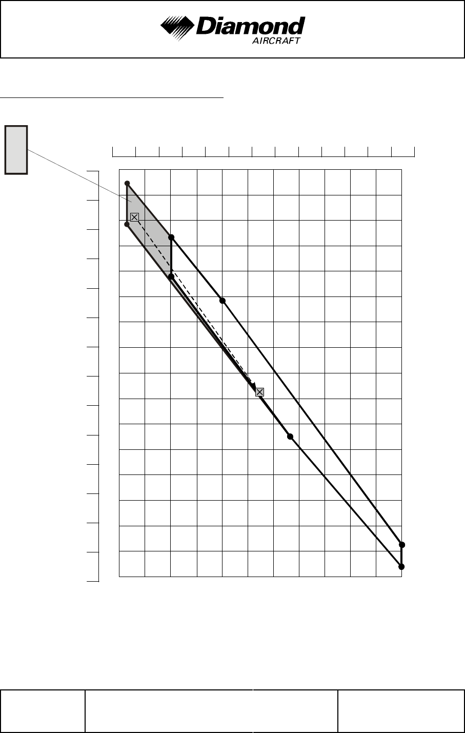
Mass and Balance DA 42 AFM
Page 6 - 14 Rev. 4 30-Nov-2005 Doc. No. 7.01.05-E
1250
1300
1350
1400
1450
1500
1550
1600
1650
1700
1750
1800
2800
3000
3200
3400
3600
3800
4000
4300
4400
4500
4200
4100
4000
3900
3800
3700
3600
3500
3400
3300
3200
3100
3000
2900
Flight Mass [kg]
Flight Mass [lb]
Flight Mass Moment [kg m]
Flight Mass Moment [in lb]
260,000
280,000
300,000
320,000
340,000
360,000
380,000
shaded area only for 1785 kg (3935 lb)
max. take-off mass (MÄM 42-088 carried out)
6.4.5 PERMISSIBLE MOMENT RANGE
'
'
'
'
'
'
'
'
'
'
'
'
'
'
'
'
'
'
'
'
'
'
'
'
'
The flight mass moments shown in the diagram are those from the example in Table 6.4.3
(a) 'CALCULATION OF LOADING CONDITION', rows 8 and 11.

DA 42 AFM Mass and Balance
Doc. No. 7.01.05-E Rev. 3 15-Oct-2005 Page 6 - 15
6.5 EQUIPMENT LIST AND EQUIPMENT INVENTORY
All equipment that is approved for installation in the DA 42 is shown in the Equipment
List below.
NOTE
'
The equipment listed below cannot be installed in any
'
arbitrary combination. The airplane manufacturer must be
'
contacted before removing or installing equipment, with the
'
exception of replacing a unit by an identical unit.
'
The items of equipment installed in your particular airplane are indicated in the appropriate
column. The set of items marked as 'installed' constitutes the Equipment Inventory.
Airplane Serial No.: Registration: Date:
Description Type Part No. Manufacturer S/N inst‘d
AVIONICS COOLING
Avionics Cooling Fan SAFE 328 305 467-00 Sandia Aerospace
PFD Cooling Fan SAFE 128 305 468-00 Sandia Aerospace
MFD Cooling Fan SAFE 128 305 468-00 Sandia Aerospace
AUTOPILOT SYSTEM KAP 140
Flight Computer KC 140 065-00176-7904 Bendix/King
Pitch servo KS 270 C 065-00178-2500 Bendix/King
Pitch servo mount KM 275 065-00030-0000 Bendix/King
Roll servo KS 271 C 065-00179-0500
'
Bendix/King
Roll servo mount KM 275 065-00030-0000 Bendix/King
Trim servo KS 272 C 065-00180-3500 Bendix/King
Trim servo mount KM 277 065-00041-0000 Bendix/King
Configuration module KCM 100 071-00073-5000 Bendix/King
Sonalert SC 628 Mallory
Control stick DA4-2213-12-90 Diamond Aircraft
CWS switch 031-00514-0000 Bendix/King
AP-Disc switch 031-00428-0000 Bendix/King
Trim switch assy 200-09187-0000 Bendix/King
ELECTRICAL POWER
Main Battery G-243 (CB24-11M) Gill (Concorde)
Excitation Battery (2 pcs.) LC-R121R3PU Panasonic

Mass and Balance DA 42 AFM
Airplane Serial No.: Registration: Date:
Description Type Part No. Manufacturer S/N inst‘d
Page 6 - 16 Rev. 4 30-Nov-2005 Doc. No. 7.01.05-E
Emergency Battery D60-2560-91-00 Diamond Aircraft
External Power Connector DA4-2443-10-00 Diamond Aircraft
LH Alternator 02-7150-55110R2 Thielert
RH Alternator 02-7150-55110R2 Thielert
LH Alternator Regulator 02-7150-55112R2 Thielert
RH Alternator Regulator 02-7150-55112R2 Thielert
EQUIPMENT
Safety belt, pilot 5-01-1C5710-LH 918 Schroth
Safety belt, copilot 5-01-1C0710-RH 918 Schroth
Safety belt, LH pax 5-01-1B5710 918 Schroth
Safety belt, RH pax 5-01-1B0710 918 Schroth
ELT unit C406-1 453-5002- Artex
ELT unit
'
ME406
'
453-6603-
'
Artex
'
ELT remote switch 345-6196-04 Artex
ELT ant+enna 110-338 Artex
Buzzer 130-4004 Artex
SAFETY EQUIPMENT
Fire extinguisher HAL 1 AIR Total
First aid kit
FLIGHT CONTROLS
Flaps actuator assy 43055 Krutz
Lift detector C-99701-1 Safe Flight Instr.
Stall warning buzzer SC Series SC 628 ND Mallory
Variable elevator stop D60-2733-12-00 Diamond Aircraft
HYDRAULIC
Motor pump unit X11-0001-00- Hydraulik Mayer
Hydraulic fluid tank X11-0002-00- Hydraulik Mayer
Hydraulic control unit X11-0003-00- Hydraulik Mayer
High pressure filter X11-0004-00- Hydraulik Mayer
Hydraulic pressure accumulator X11-0005-00- Hydraulik Mayer
MLG hydraulic cylinder X11-0006-00- Hydraulik Mayer
MLG hydraulic cylinder X11-0006-00- Hydraulik Mayer
NLG hydraulic cylinder X11-0006-00- Hydraulik Mayer
Brake master cylinder 2x 10-54A Cleveland
Parking valve 60-5B Cleveland
Brake assembly 30-239A Cleveland
DA 42 AFM Mass and Balance
Doc. No. 7.01.05-E Rev. 3 15-Oct-2005 Page 6 - 17
Airplane Serial No.: Registration: Date:
Description Type Part No. Manufacturer S/N inst‘d
INDICATING / REC. SYSTEM
Primary Flight Display (PFD) GDU 1040 011-00972-02 Garmin
Multi Function Display (MFD) GDU 1040 011-00972-02 Garmin
LANDING GEAR
Main landing gear LH D60-3217-11-00 Diamond Aircraft
Main landing gear RH D60-3217-12-00 Diamond Aircraft
Nose landing gear D60-3223-10-00 Diamond Aircraft
LDG Gear Warning SC Series SC 628 NDP Mallory
LIGHTS
Map/Reading light assy crew W1461.0.010 Rivoret
Cabin Light W1461.0.010 Rivoret
Strobe/Pos. light assy LH A600-PR-D-28 01-0790006-05 Whelen
Strobe/Pos. light assy RH A600-PG-D-28 01-0790006-07 Whelen
Strobe light power supply LH/RH A490ATS-CF-14/28 01-0770062-05 Whelen
Taxi light Xenon D1S Aero Vision Int.
Taxi light power supply XV1-28 Aero Vision Int.
Landing light Xenon D1S Aero Vision Int.
Landing light power supply XV1-28 Aero Vision Int.
Glareshield lamp assy DA4-3311-10-02 Diamond Aircraft
Glareshield light inverter APVL328-4-1-L-5QF Quantaflex
Placards inverter APVL328-4-1-L-15QF Quantaflex

Mass and Balance DA 42 AFM
Page 6 - 18 Rev. 3 15-Oct-2005 Doc. No. 7.01.05-E
Airplane Serial No.: Registration: Date:
Description Type Part No. Manufacturer S/N inst‘d
COMMUNICATION / NAVIGATION
COMM #1 antenna DMC63-1/A DM
COMM #2 antenna DMC63-2 DM
Audio Panel / Marker / ICS GMA 1347 011-00809-00 Rev. 3 Garmin
Headset, pilot Echelon 100 Telex
Headset, copilot Echelon 100 Telex
Headset, LH pax Echelon 100 Telex
Headset, RH pax Echelon 100 Telex
Speaker FRS8 / 4 Ohms Visaton
Handmic 100 TRA 62800-001 Telex
Pitot/Static probe, heated
'
'
DAI-9034-57-00
'
Diamond Aircraft
'
''
Pitot/Static probe, heated
'
AN5814-2
'
PST-305
'
Aeroinstruments
'''
Alternate static valve DA4-3111-51-00 Diamond Aircraft
Backup Altimeter 5934PD-3 Untied Instruments
Backup airspeed indicator 8030 8030-B.864 United Instruments
Backup artificial horizon 4300 4300-206 Mid Continent Instr.
Magnetic compass PG2C-28V SIRS Navigation
Turn & Bank indicator 1394T100-(12RZ) Mid Continent Instr.
Turn & Bank indicator 1394T100-(12RA) Mid Continent Instr.
OAT probe GTP 59
'
011-00978-00
'
Garmin
Digital Air Data System GDC 74A 011-00882-00 Rev. 6 Garmin
Integrated Avionics #1 GIA 63 011-00781-01 Garmin
Integrated Avionics #2 GIA 63 011-00781-01 Garmin
Transponder GTX 33 011-00779-00 Rev. C Garmin
Attitude / Heading Reference System GRS 77 011-00868-00 Rev. 4 Garmin
Attitude / Heading Reference System
'
GRS 77
'
011-00868-10
'
Garmin
'
Magnetometer GMU 44 011-00870-00 Rev. 4 Garmin
VOR/LOC/GS antenna CI 157P Comant
dual VOR / dual GS duplexer CI 1125 Comant
Transponder antenna KA 60 071-01591-0001 Bendix/King
Marker antenna CI 102 Comant
GPS #1 antenna GA 56 010-10040-01 Garmin
GPS #2 antenna GA 56 010-10040-01 Garmin
DME KN 63 066-1070-01 Bendix/King
DME antenna KA 60 071-01591-0001 Bendix/King
ADF receiver
'
RA 3502-(01)
'
0505.757-912
'
Becker
'
ADF / RMI converter
'
AC 3504-(01)
'
0856.010-912
'
Becker
'
ADF antenna
'
AN 3500
'
0832.601-912
'
Becker
'
Stormscope
'
WX-500
'
805-11500-001
'
L-3(Goodrich)
'
Stormscope antenna
'
NY-163
'
805-10930-001
'
L-3 (Goodrich)
'
DA 42 AFM Mass and Balance
Doc. No. 7.01.05-E Rev. 3 15-Oct-2005 Page 6 - 19
Airplane Serial No.: Registration: Date:
Description Type Part No. Manufacturer S/N inst‘d
ENGINE
LH Engine TAE-125-01 125-01-(017)-( ) Thielert
RH Engine TAE-125-01 125-01-(017)-( ) Thielert
LH ENGINE CONTROL UNIT ECU 02-7610-55003R(*) Thielert
ECU Firmware 02-7610-55101R( )* Thielert
ECU Mapping 50-7610-55107R( )* Thielert
RH ENGINE CONTROL UNIT ECU 02-7610-55003R(*) Thielert
ECU Firmware 02-7610-55101R( )* Thielert
ECU Mapping 50-7610-55107R( )* Thielert
ENGINE STARTING
Glow Power Control Unit LH/RH 02-7150-55005R1 Thielert
Starter LH/RH 02-8010-13210R1 Thielert
ENGINE FIRE WARNING
LH overheat detector X 2003-2 Control Products, Inc.
RH overheat detector X 2003-2 Control Products, Inc.
ENGINE INDICATING
Engine / Airframe Unit GEA 71 011-00831-00 Rev. 6 Garmin
PROPELLER
Propeller LH MTV-6-A-C-F/CF187-129 mt-propeller
Propeller RH MTV-6-A-C-F/CF187-129 mt-propeller
Unfeathering accumulator X11-0007-00-00 Hydraulik Mayer
Unfeathering accumulator X11-0007-00-00 Hydraulik Mayer
AIRPLANE FLIGHT MANUAL Doc. No. 7.01.05-E Diamond Aircraft
FUEL TANK SYSTEM
Fuel probe assy., LH inboard D60-2817-13-00 Diamond Aircraft
Fuel probe assy., RH inboard D60-2817-13-00 Diamond Aircraft
Fuel probe assy., LH outboard D60-2817-14-00 Diamond Aircraft
Fuel probe assy., RH outboard D60-2817-14-00 Diamond Aircraft
Alternate means for fuel qty. D60-2817-90-00 Diamond Aircraft
AUX FUEL SYSTEM
''''''
LH auxiliary fuel pump
''
5100-09
'
Dukes
'''
LH auxiliary fuel pump
''
5100-09
'
Dukes
'''

Mass and Balance DA 42 AFM
Airplane Serial No.: Registration: Date:
Description Type Part No. Manufacturer S/N inst‘d
Page 6 - 20 Rev. 4 30-Nov-2005 Doc. No. 7.01.05-E
ICE PROTECTION SYSTEM
porous panel, outer wing, LH 12102-21 CAV Aerospace
porous panel, outer wing, RH 12102-22 CAV Aerospace
porous panel, center wing, LH 12102-23 CAV Aerospace
porous panel, center wing, RH 12102-24 CAV Aerospace
porous panel, horizontal tail, LH 12102-25 CAV Aerospace
porous panel, horizontal tail, RH 12102-26 CAV Aerospace
porous panel, vertical tail 12102-27 CAV Aerospace
inlet strainer 12121-02 CAV Aerospace
'
spray bar 12124-10 CAV Aerospace
'
metering pump 1 9513A-386 CAV Aerospace
metering pump 2 9513A-386 CAV Aerospace
de-icing fluid tank D60-3013-24-50 Diamond Aircraft
'
filter F908 CAV Aerospace
'
filter F908 CAV Aerospace
'
solenoid valve FV158H-28V CAV Aerospace
solenoid valve FV158H-28V CAV Aerospace
high pressure switch P041ED850 CAV Aerospace
proportioning unit, nacelle, LH PU300DW142 CAV Aerospace
proportioning unit, nacelle, RH PU300DW142 CAV Aerospace
tail bracket assembly 12132-03 CAV Aerospace
windshield pump 1 WP209A CAV Aerospace
windshield pump 2 WP209A CAV Aerospace
de-ice control box DAI-9030-00-01 Diamond Aircraft
'
* Refer to Service Information SI 42.003 for approved ECU firmware and mapping.
Place:____________ Date: ____________ Signature: ____________

DA 42 AFM Airplane Description
Doc. No. 7.01.05-E Rev. 4 30-Nov-2005 Page 7 - 1
CHAPTER 7
DESCRIPTION OF THE AIRPLANE
AND ITS SYSTEMS
Page
7.1 INTRODUCTION .......................................7-3
7.2 AIRFRAME ............................................7-3
7.3 FLIGHT CONTROLS ....................................7-4
7.4 INSTRUMENT PANEL ..................................7-10
7.5 LANDING GEAR.......................................7-13
7.6 SEATS AND SAFETY HARNESSES .......................7-19
7.7 BAGGAGE COMPARTMENT.............................7-19
7.8 CANOPY, REAR DOOR, AND CABIN INTERIOR .............7-20
7.9 POWER PLANT .......................................7-22
7.9.1 ENGINES, GENERAL..............................7-22
7.9.2 PROPELLER ....................................7-23
7.9.3 OPERATING CONTROLS ..........................7-26
7.9.4 ENGINE INSTRUMENTS ...........................7-30
7.9.5 FUEL SYSTEM ...................................7-32
7.9.6 COOLING SYSTEM ...............................7-43
'
7.9.7 OIL SYSTEMS ...................................7-44
'
7.9.8 TURBO-CHARGER SYSTEM ........................7-45
'
7.9.9 FIRE DETECTION SYSTEM ........................7-46
'
7.10 ELECTRICAL SYSTEM .................................7-47
'
7.10.1 GENERAL......................................7-48
'
7.10.2 ENGINE CONTROL UNIT / ECU ....................7-53
'
7.10.3 WARNING, CAUTION AND ADVISORY MESSAGES ....7-55
'

Airplane Description DA 42 AFM
Page 7 - 2 Rev. 4 30-Nov-2005 Doc. No. 7.01.05-E
7.11 PITOT-STATIC SYSTEM ............................... 7-61
'
7.12 STALL WARNING SYSTEM ............................. 7-61
'
7.13 GARMIN G1000 INTEGRATED AVIONICS SYSTEM ......... 7-62
'
7.13.1 GENERAL ..................................... 7-62
'
7.13.2 PRIMARY FLIGHT DISPLAY (PFD) ................. 7-63
'
7.13.3 MULTI-FUNCTION DISPLAY (MFD) ................. 7-65
'
7.13.4 AUDIO PANEL ................................. 7-66
'
7.13.5 ATTITUDE AND HEADING
REFERENCE SYSTEM (AHRS) .................... 7-66
'
7.13.6 AIR DATA COMPUTER (ADC) ..................... 7-66
'

DA 42 AFM Airplane Description
Doc. No. 7.01.05-E Rev. 3 15-Oct-2005 Page 7 - 3
7.1 INTRODUCTION
Chapter 7 contains a description of the airplane and its systems, together with operating
instructions.
For details about optional equipment see Chapter 9.
7.2 AIRFRAME
Fuselage
The CFRP fuselage is of semi monocoque molded construction. The center wing is
attached to the fuselage with bolts. The two main spars and both nacelles are part of the
center wing. The two main spars are CFRP items. The engine compartment in each nacelle
is separated from the other structure with a firewall. The fire protection on the firewall is
of a special fire-resistant matting, which is covered on the engine side by stainless steel
cladding.
Wings
The wings have a front and rear spar; each wing has a top shell and a bottom shell; The
whole wing is ‘fail-safe‘ design. The wings, as well as the ailerons and flaps, are made
of GFRP/CFRP, and are principally of sandwich construction. An aluminum fuel tank is
installed in each of the wings.
Empennage
The airplane has a ‘T’ tail of GFRP/CFRP semi monocoque construction. Both the
stabilizers have twin spars. Rudder and elevator are of sandwich construction.

Airplane Description DA 42 AFM
Page 7 - 4 Rev. 3 15-Oct-2005 Doc. No. 7.01.05-E
7.3 FLIGHT CONTROLS
The ailerons, elevator and wing flaps are operated through control rods, while the rudder
is controlled by cables. The flaps are electrically operated. Elevator forces can be balanced
by a trim tab on the elevator, which is operated by a Bowden cable. Rudder forces can
be balanced by a trim tab on the rudder, which is also operated by a Bowden cable.
Ailerons
Construction: GFRP/CFRP composite sandwich.
Hinges: There are 4 hinges, which are hinge pins mounted in an aluminum
bracket. They are secured in position by a roll pin. The absence of this
roll pin can lead to the loss of the hinge pin and a consequent loss of flight
safety.
Operation: A rod-end bearing is screwed into a steel push rod and locked by means
of a jam nut which has locking varnish applied to it. Damage to this
varnish can indicate a twisting and thus a change to the adjustment. The
connection between the rod-end bearing and the control horn is a bolt,
the nut of which is likewise sealed with locking varnish.
The aluminum control horn is attached to the aileron with 3 screws.

DA 42 AFM Airplane Description
Doc. No. 7.01.05-E Rev. 3 15-Oct-2005 Page 7 - 5
Flaps
The flaps are a two piece construction. The inner part of the flap is mounted to the center
wing and the outer part to the wing. Both parts are connected to each other with a form
fit connection.
Construction: GFRP/CFRP composite sandwich.
Hinges: There are 6 hinges at the outer part and 4 hinges at the inner part of the
flap. These hinges are hinge pins mounted in an aluminum bracket. They
are secured in position by a roll pin. The absence of this roll pin can lead
to the loss of the hinge pin and a consequent loss of flight safety.
Operation: Each part is connected with a flap control horn to the push rods of the
flap control system. A rod-end bearing is screwed into a steel push rod
and locked by means of a jam nut which has locking varnish applied to
it. Damage to this varnish can indicate a twisting and thus a change to
the adjustment. The connection between the rod-end bearing and the
control horn is a bolt, the nut of which is likewise sealed with locking
varnish.
Each flap control horn is attached to the flap part with 3 screws.
The flaps are driven by an electric motor and have 3 settings:
- Cruise (UP), totally retracted
- Approach (APP), and
- Landing (LDG).

Airplane Description DA 42 AFM
Page 7 - 6 Rev. 3 15-Oct-2005 Doc. No. 7.01.05-E
The flaps are operated by means of a 3-position flap selector switch on the instrument
panel. The positions of the switch correspond to the positions of the flaps, the Cruise
position of the switch being at the top. If the switch is moved to another position, the flaps
continue to travel automatically until they have reached the position selected on the switch.
The UP and LDG positions are additionally protected by a limit switch to guard against
over-running the end positions.
The electrical flap drive has an automatic circuit breaker which can also be operated
manually.
Flap position indicator:
The current flap position is indicated by means of three lights beside the flap selector
switch.
When the upper light (green) is illuminated, the flaps are in the Cruise position (UP);
when the center light (white) is illuminated, the flaps are in Approach position (APP);
when the lower light (white) is illuminated, the flaps are in Landing position (LDG).
When two lights are illuminated simultaneously, the flaps are between the two indicated
positions. This is the case only when the flaps are in transition.

DA 42 AFM Airplane Description
Doc. No. 7.01.05-E Rev. 3 15-Oct-2005 Page 7 - 7
Elevator
Construction: GFRP sandwich.
Hinges: 5 hinges.
Operation: Steel push-rods;
Two of the bellcrank bearings are accessible for visual inspection next
to the lower hinge of the rudder. The elevator horn and its bearing, as
well as the connection to the push-rod, can be visually inspected at the
upper end of the rudder.
Variable elevator stop
The DA 42 is equipped with an electrically operated actuator that limits the elevator-up
travel to 13° as soon as the power setting of both engines exceeds approximately 20 %
(approach power setting) and the flap selector switch is set to LDG. This is 2.5° less than
'
the 15.5° full deflection.
The linear actuator acts as a movable stop and is controlled by three switches, one for
each power lever and one for the flap selector. When the power of one engine is reduced
'
below approximately 20 %, or the flap selector is not in the LDG position, full elevator
deflection is regained.
An amber annunciation (CAUTION) on the G1000 display is provided to inform the pilot
in case a malfunction occurs. The annunciation illuminates when the variable stop should
be in place and is actually not activated (power on condition) or should be retracted and
actually limits the elevator travel (power off condition).

Airplane Description DA 42 AFM
Page 7 - 8 Rev. 3 15-Oct-2005 Doc. No. 7.01.05-E
Rudder
Construction: GFRP sandwich.
Hinges: Upper hinge: One bolt.
Lower hinge: Bearing bracket including rudder stops, held by 4 screws
to the rear web of the vertical stabilizer. The mating part on the rudder
is a bracket which is attached to the rudder by 2 bolts. The bolts and nuts
are accessible to visual inspection.
Operation: Steel cables, the eyes of which are connected to the bolts on the bracket.

DA 42 AFM Airplane Description
Doc. No. 7.01.05-E Rev. 3 15-Oct-2005 Page 7 - 9
Elevator Trim
The trim control is a black wheel in the center console to the rear of the power lever. To
guard against over-rotating, the trim wheel incorporates a friction device. A mark on the
wheel shows the take-off (T/O) position.
Turn wheel to the front = nose down
Turn wheel to the rear = nose up
Rudder Trim
The trim control is a black wheel in the center console below the instrument panel. A mark
on the wheel shows the center position and the direction of movement.
Turn wheel to the right = right turn
Turn wheel to the left = left turn
Pedal Adjustment
NOTE
The pedals may only be adjusted on the ground!
The pedals are unlocked by pulling the black handle which is located behind the rear
attachment.
Forward adjustment:
Whilst keeping the handle pulled, push the pedals forward with your feet. Release the
handle and allow the pedals to lock into place.
Rearward adjustment:
Using the unlocking handle, pull the pedals back to the desired position. Release the
handle and push the pedals forward with your feet until they lock into place.
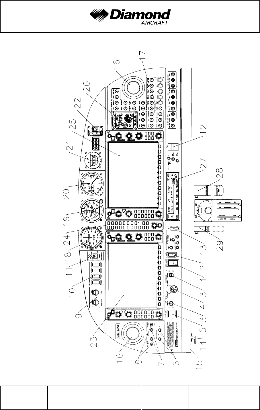
Airplane Description DA 42 AFM
Page 7 - 10 Rev. 3 15-Oct-2005 Doc. No. 7.01.05-E
7.4 INSTRUMENT PANEL

DA 42 AFM Airplane Description
Doc. No. 7.01.05-E Rev. 3 15-Oct-2005 Page 7 - 11
Major instruments and controls
1 Electric Master switch 16 Ventilation nozzles
2 Avionic Master switch 17 Circuit breakers*
3 Engine Master switches 18 Backup airspeed indicator
4 Start switch 19 Backup artificial horizon
5 Pitot-/Stall Warning-Heat switch 20 Backup altimeter
6 Alternator switches 21 Emergency compass
7 ECU Test buttons 22 ELT control unit
8 ECU Swap switches 23 Primary Flight Display (PFD)
9 Rotary buttons for instrument
lighting and flood light 24 Audio amplifier / Intercom / Marker
beacon receiver
10 Light switches 25 Multi Function Display (MFD)
11 Emergency switch 26 Oxygen system control unit
12 Flap selector switch 27 Autopilot control unit
13 Landing gear switch 28 Alt air lever
14 Alternate static valve 29 Landing gear emergency
extension lever
15 Microphone socket
*) Designations and abbreviations used to identify the circuit breakers are explained in
Section 1.5 DEFINITIONS AND ABBREVIATIONS.
NOTE
The figure on previous page shows the typical DA 42
installation position for the equipment. The actual installation
may vary due to the approved equipment version (e.g., there
is no oxygen system approved at present).

Airplane Description DA 42 AFM
Page 7 - 12 Rev. 3 15-Oct-2005 Doc. No. 7.01.05-E
Cockpit ventilation
Ventilation in the front is provided by spherical ventilation nozzles (16) in the instrument
panel. Furthermore there are spherical nozzles in the roll bar on the left and right side
next to the front seats as well as on the central console above the passengers’ heads.
The spherical nozzles are opened and closed by twisting.

DA 42 AFM Airplane Description
Doc. No. 7.01.05-E Rev. 3 15-Oct-2005 Page 7 - 13
7.5 LANDING GEAR
The landing gear is a fully retractable, hydraulically operated, tricycle landing gear. Struts
for the landing gear are air-oil assemblies.
The hydraulic pressure for the landing gear operation is provided by an electrically powered
hydraulic pump, which is activated by a pressure switch, when the required pressure is
too low. Electrically actuated hydraulic valves, which are operated with the gear selector
switch, provide the required hydraulic pressure for the movement of the landing gear.
The gear selector switch is located on the instrument panel. The switch must be pulled
out before it is moved to “UP” or “DOWN” position. Gear extension normally takes 6-10
seconds.
When the landing gear is retracted, the main wheels retract inboard into the center wing
and the nose wheel retracts forward into the nose section. Hydraulic pressure on the
actuators keeps the landing gear in the retracted position. A pressurized gas container
acts as an accumulator which keeps the system pressure constant by replacing the volume
lost due to the normal actuator leakages. This prevents a permanent starting of the
hydraulic pump in flight.
Springs assist the hydraulic system in gear extension and locking the gear in the down
position. After the gears are down and the downlock hooks engage, springs maintain force
on each hook to keep it locked until it is released by hydraulic pressure.
When the gears are fully extended or retracted and the gear selector switch is in the
corresponding position, electrical limit switches stop the operation. The three green lights
directly above the landing gear operating switch illuminate to indicate that each gear is
in the correct position and locked. If the gear is in neither the full up nor the full down
position, a red warning light on the instrument panel illuminates.
Should one throttle be placed in a position below 25% while the landing gear is retracted,
a warning horn sounds to alert the pilot that the gear is retracted. The same warning
appears if the flaps move into position LDG (fully extended) while the gear is retracted.

Airplane Description DA 42 AFM
Page 7 - 14 Rev. 3 15-Oct-2005 Doc. No. 7.01.05-E
To test the gear warning system (refer to 4A.6.1 - PRE-FLIGHT INSPECTION) push the
test button close by the gear selector switch. The aural gear alert should appear.
CAUTION
If the aural alert does not appear, an unscheduled
maintenance is necessary.
To prevent inadvertent gear retraction on ground, an electric squat switch prevents the
hydraulic valve from switching if the master switch is on and the gear extension switch
is placed in the “UP” position.
After takeoff, the gear should be retracted before an airspeed of 156 KIAS is exceeded.
The landing gear may be extended at any speed up to194 KIAS.
The landing gear is designed to be manually operated in the event of failure. Since the
gear is held in the retracted position by hydraulic pressure, gravity will allow the gear to
extend if the system fails for any reason. To extend and lock the gears in the event of
failure, it is only necessary to relieve the hydraulic pressure by means of the emergency
gear extension lever, which is located under the instrument panel to the left of the center
console. Pulling this lever releases the hydraulic pressure and allows the gear to fall free.
Before pulling the emergency gear extension lever, place the gear selector switch in the
“DOWN” position.
NOTE
If the emergency gear extension has been pulled due to an
emergency, the system has to be checked before pushing
the lever in again.
The nose gear is steerable by the use of full rudder pedal travel. A gear damping element,
incorporated in the nose gear steering system, prevents shimmy tendencies. When the
gear is retracted, the nose wheel centers as it enters the wheel well, and the steering
linkage disengages to reduce pedal loads in flight.
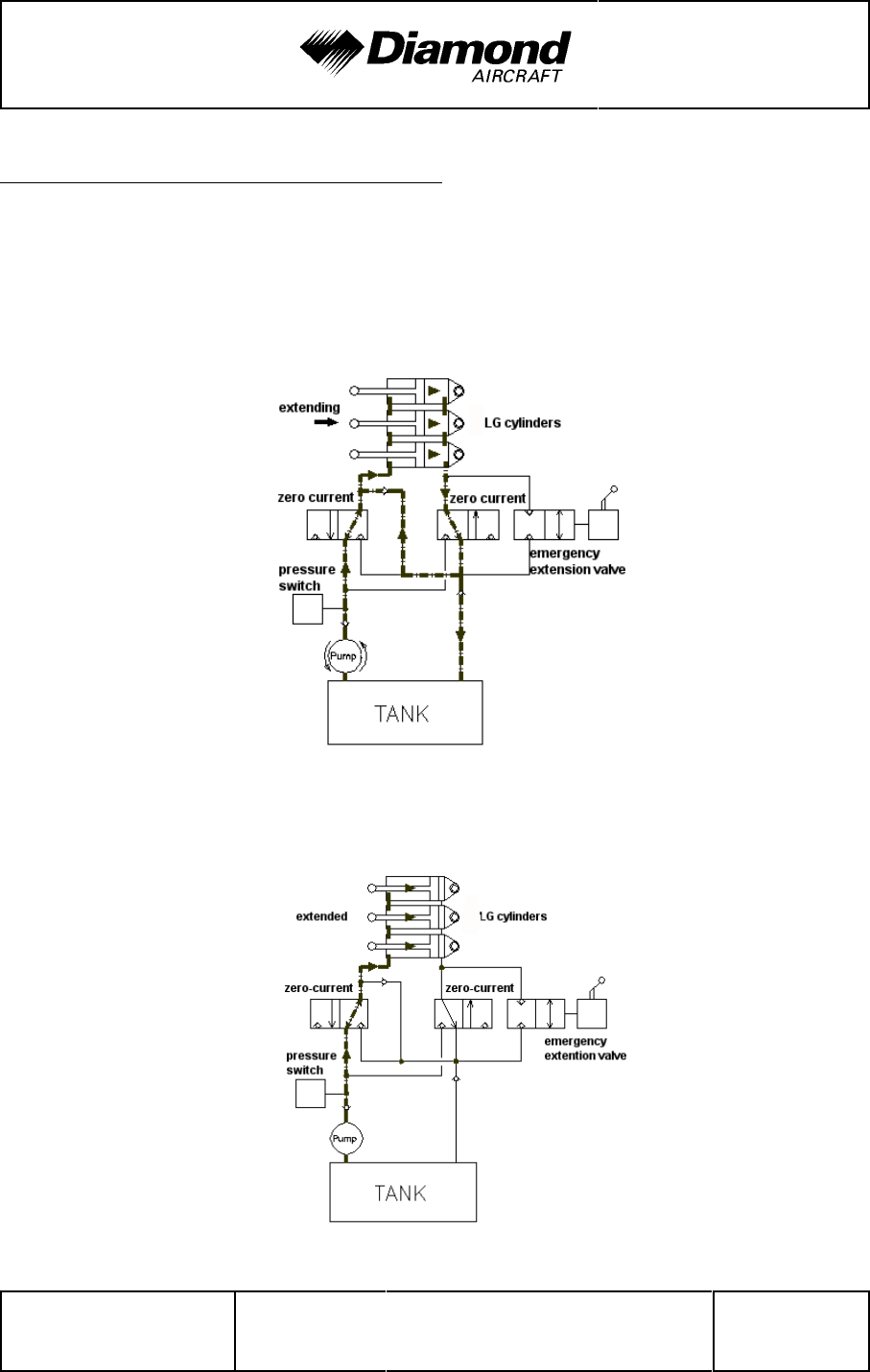
DA 42 AFM Airplane Description
Doc. No. 7.01.05-E Rev. 3 15-Oct-2005 Page 7 - 15
Hydraulic gear extension system schematic
The main landing gear of the DA 42 is extended with three hydraulic cylinders. The
following schematic figures show the system conditions for each operating mode.
In figure 1 the extension of the landing gear is shown. To reduce the amount of pumped
hydraulic fluid during this operation, the return flow is partly led into the feeding flow of
the system.
The figure below shows the system status when the landing gear is extended. All hydraulic
cylinders are under high pressure.
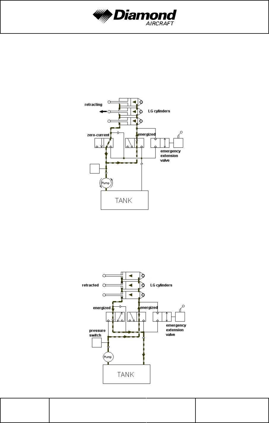
Airplane Description DA 42 AFM
Page 7 - 16 Rev. 3 15-Oct-2005 Doc. No. 7.01.05-E
The operating mode for the retraction of the landing gear is shown in the next figure. While
energizing the right hydraulic valve, the fluid flow in the hydraulic system is started due
'
to different piston areas of the landing gear cylinders although the pressure on both sides
of the system is equal.
While the landing gear is retracted both valves are energized and excessive hydraulic
fluid on one side is drained into the tank. This configuration of the system is shown in the
following figure.
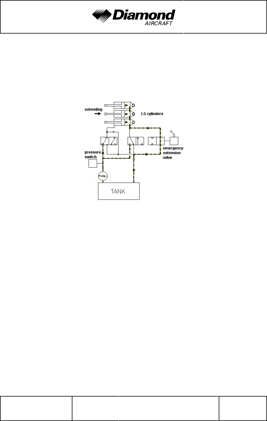
DA 42 AFM Airplane Description
Doc. No. 7.01.05-E Rev. 3 15-Oct-2005 Page 7 - 17
For an emergency extension of the landing gear, the hydraulic fluid can pass through an
emergency extension valve so that the gear is extended by gravity. The condition of the
system is shown in the figure below.
'
'
'
'
'
'
'
'
'
'
'
'
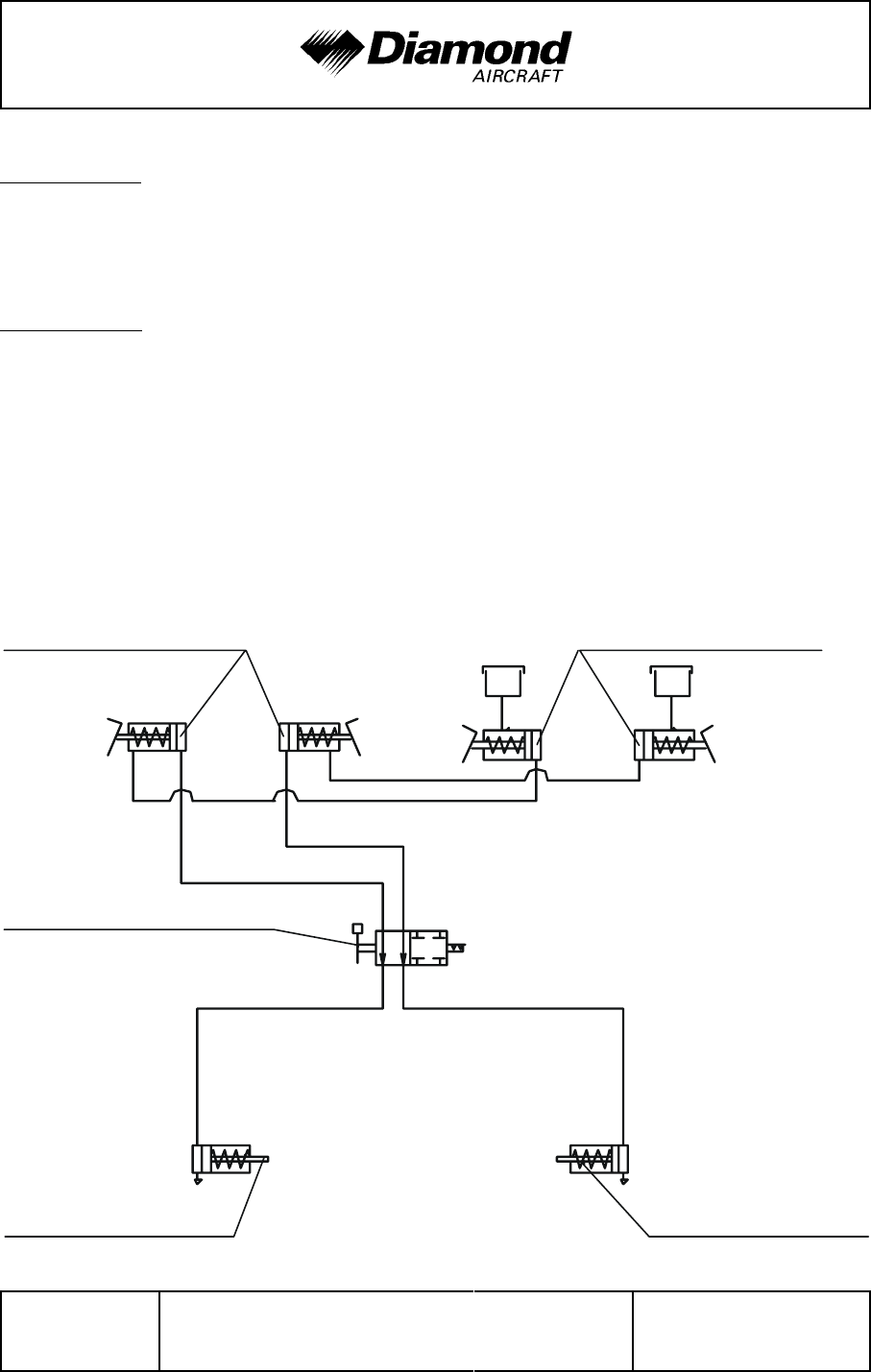
Airplane Description DA 42 AFM
Page 7 - 18 Rev. 3 15-Oct-2005 Doc. No. 7.01.05-E
brake pedals,
pilot brake pedals,
co-pilot
parking brake
valve
brake cylinder, LH brake cylinder, RH
Wheel brakes
Hydraulically operated disk brakes act on the wheels of the main landing gear. The wheel
brakes are individually operated by means of toe pedals.
Parking brake
The lever is located on the small center console under the instrument panel and is in the
upper position when the brakes are released. To operate the parking brake, pull the lever
downwards until it catches. Brake pressure is built up by multiple operation of the toe brake
pedals, and is maintained until the parking brake is released. To release, the lever is
pushed upwards.

DA 42 AFM Airplane Description
Doc. No. 7.01.05-E Rev. 3 15-Oct-2005 Page 7 - 19
7.6 SEATS AND SAFETY HARNESSES
To increase passive safety, the seats are constructed using a carbon fiber/Kevlar hybrid
material and GFRP. The seats are removable to allow the maintenance and inspection
of the underlying controls. Covers on the control sticks prevent loose objects from falling
into the area of the controls.
The seats have removable furnishings and are equipped with energy-absorbing foam
elements.
The seats are fitted with three-part safety harnesses. The harnesses are fastened by
inserting the end of the belts in the belt lock, and are opened by pressing the red release
on the belt lock.
The backs of the rear seats can be laid forward after pulling upwards on the locking bolt
knob.
7.7 BAGGAGE COMPARTMENT
There are two baggage compartments. One is located in the nose section and it is
accessible through two compartment doors.
The other baggage compartment is behind the seat backs of the rear seats. Baggage
may be loaded there provided it is restrained by means of a baggage net.

Airplane Description DA 42 AFM
Page 7 - 20 Rev. 3 15-Oct-2005 Doc. No. 7.01.05-E
7.8 CANOPY, REAR DOOR, AND CABIN INTERIOR
Front canopy
The front canopy is closed by pulling down on the canopy frame, following which it is locked
by means of a handle on the left hand side of the frame. On locking, steel bolts lock into
mating holes in polyethylene blocks.
“Cooling Gap” position: A second setting allows the bolts to lock in, leaving a gap under
the forward canopy.
The canopy can be blocked by a locking device on the left side near the canopy opening
lever by turning the key clockwise. The closed and blocked canopy can be opened from
inside by pulling the lever inside the opening handle.
WARNING
The airplane may be operated with the front canopy in the
“cooling gap” position on the ground only. Before take-off the
front canopy must be completely closed and locked.
Do not block the front canopy with the locking key before flight
in order to assure emergency evacuation from outside.
A window on the left and right hand side of the canopy can be opened for additional
ventilation or as an emergency window.

DA 42 AFM Airplane Description
Doc. No. 7.01.05-E Rev. 3 15-Oct-2005 Page 7 - 21
Rear door
The rear door is closed in the same way, by pulling down on the frame and locking it with
the handle. A gas pressure damper prevents the door from dropping; in strong winds the
assembly must be securely held. The rear door is protected against unintentional opening
by an additional lever.
The door can be blocked by a locking device on the left side near the door opening lever
by turning the key clockwise. The closed and blocked door can be opened from inside
by pulling the lever inside the opening handle.
WARNING
Do not block the door with the locking key before flight in
order to assure emergency access from outside.
Heating and ventilation
Heating and ventilation are operated using two levers located on the small center console
under the instrument panel.
Right lever: up = HEATING ON (Seats, Floor)
down = HEATING OFF
Center lever : up = DEFROST ON (Airflow to canopy)
down = DEFROST OFF
The heat of the RH engine is used for the front seats and floor, the heat of the LH engine
is used to defrost the canopy.
The Air inlet for the Ventilation System is placed on the underside of the RH wing, inboard
of the engine nacelle. The air is distributed within the cabin via 6 nozzles (2 on the
instrument panel LH/RH side, 2 on the overhead panel and 2 on the LH/RH side of the
passenger compartment). The jet direction of each cone can be changed easily and
the jet intensity can be regulated by rotation of the nozzle.

Airplane Description DA 42 AFM
Page 7 - 22 Rev. 3 15-Oct-2005 Doc. No. 7.01.05-E
7.9 POWER PLANT
7.9.1 ENGINES, GENERAL
There are two Thielert Aircraft Engines TAE125 installed, which have the following principal
specifications:
- Liquid-cooled four-cylinder-four-stroke Diesel-cycle engine with wet sump
lubrication
- In-line construction
- Common-rail direct injection
- Propeller speed-reducing gear 1:1.69
- Digital Engine Control with Integrated Propeller Governor (separate oil system)
- Turbo-charger with Intercooler
Displacement: 1689 cm3 (103 in³)
Max. power: 99 kW (135 DIN-HP) at 2300 RPM at sea level and ISA
Max. continuous power: 99 kW (135 DIN-HP) at 2300 RPM at sea level and ISA
The indications for monitoring important engine-parameters during operation are integrated
within the Garmin G1000 display. Each engine can only be operated with the ENGINE
MASTER switch ON. Each engine has an own ECU (Engine Control Unit) which receives
its electrical power from the generator when at least one engine is running. When both
engines are at standstill, the ECU receives its electrical power from the battery.
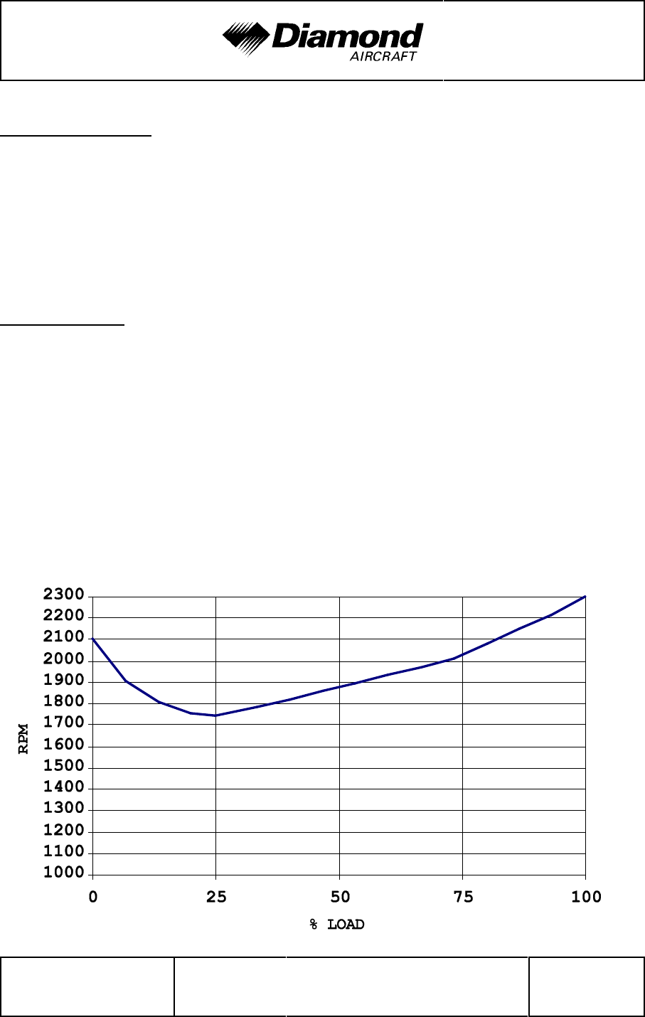
DA 42 AFM Airplane Description
Doc. No. 7.01.05-E Rev. 3 15-Oct-2005 Page 7 - 23
7.9.2 PROPELLER
Two mt-Propeller MTV-6-A-C-F/CF187-129 hydraulically regulated 3-bladed constant
speed feathering propellers are installed. Each propeller has wood-composite blades with
fiber-reinforced plastic coating and stainless steel edge cladding; in the region of the
propeller hub the leading edge is coated with adhesive PU foil. These blades combine
the lowest weight whilst minimizing vibration.
Propeller control
The propeller pitch control system is integrated into the engine. The pitch is controlled
automatically by the ECU. To change the blade pitch angle gearbox oil is pumped into
the propeller hub. The oil pressure is regulated by an electrically operated valve, the
governor valve, which is controlled by the ECU. Increasing the oil pressure leads to a
decrease of pitch and a higher RPM. Decreasing the pressure leads to higher pitch and
a lower RPM.
Depending on the power setting the propeller pitch is adjusted such that the required RPM
will be obtained as shown in the following diagram.

Airplane Description DA 42 AFM
Page 7 - 24 Rev. 3 15-Oct-2005 Doc. No. 7.01.05-E
Pressure accumulator:
The pressure accumulator is a nitrogen-oil type. It is connected to the gearbox oil circuit
via an electric valve at the accumulator, which is operated with the engine master switch.
When the engine master switch is set to ON the valve is opened. When the engine is
running, the accumulator is filled with oil at a pressure of approximately 20 bar (290 psi).
During engine operation the accumulator makes sure that enough oil pressure is available
even if the oil feed by the gearbox oil pump is decreasing due to negative acceleration.
The hydraulic pressure keeps the propeller pitch angle below the start lock position, or
moves the propeller blades beyond the start lock position.
Feathering:
To feather the propeller the engine must be shut down with the appropriate engine master
switch. This will open the electric governor valve. All oil will flow back from the propeller
hub, allowing the blades to move into the feathered pitch position. At the same time the
electric valve at the pressure accumulator closes, and the oil pressure is restored in the
accumulator.
Feathering is only possible at propeller speeds above 1300 RPM.
CAUTION
If the engine is shut down below an RPM of 1300 the propeller
pitch remains below the start lock position. In this case the
speed must be increased to increase the propeller RPM.

DA 42 AFM Airplane Description
Doc. No. 7.01.05-E Rev. 3 15-Oct-2005 Page 7 - 25
Unfeathering:
To unfeather the propeller, the associated engine master switch must be set to ON. This
will open the electric valve at the pressure accumulator. The pressure stored in the
accumulator will move the propeller blades into a low pitch position. As soon as the
propeller starts turning and the gearbox oil operates, the accumulator will be refilled.
Ground operation:
CAUTION
Operation on the ground at high RPM should be avoided as
far as possible, as the blades could suffer stone damage. For
this reason a suitable site for engine runs should be selected,
where there are no loose stones or similar items.
WARNING
Never move the propeller by hand.

Airplane Description DA 42 AFM
Page 7 - 26 Rev. 3 15-Oct-2005 Doc. No. 7.01.05-E
7.9.3 OPERATING CONTROLS
Power lever
Engine performance is controlled by a power lever for each engine. Both power levers
are situated on the large center console. ‘Front’ and ‘rear’ are defined in relation to the
direction of flight.
Each power lever is used to set the desired engine power LOAD (%)
Lever forward (MAX) = Full power
Lever to rear (IDLE) = Idle
A separate ECU for each engine controls manifold pressure, injected fuel quantity and
propeller speed according to the desired engine power preselected with the power lever.
If the power lever is in a low power position - as for a landing approach - while the landing
gear is retracted, an aural warning alerts the pilot to the retracted landing gear.
A propeller governor, which is controlled by the ECU, is flanged onto the front of each
engine. The propeller governor oil circuit is supplied with oil by the gearbox oil pump (also
see Section 7.9.2 - PROPELLER). A loss of oil pressure leads to a feathering of the
propeller blades, thus allowing continuation of the flight according to 3.7.3 - DEFECTIVE
PROPELLER RPM REGULATING SYSTEM.
CAUTION
Following governor failure the RPM should be adjusted using
the power lever. Every effort should be made not to exceed
2300 RPM.
CAUTION
The power lever should be moved slowly, in order to avoid
over-speeding and excessively rapid RPM changes. The light
wooden propeller blades produce more rapid RPM changes
than metal blades.

DA 42 AFM Airplane Description
Doc. No. 7.01.05-E Rev. 3 15-Oct-2005 Page 7 - 27
WARNING
It is possible that the propeller blades remain in the position
of highest pitch in case of a malfunction of the engine control
unit. In this case the reduced engine performance should be
taken into consideration.
ELECT. MASTER
The electric master switch has two positions:
OFF
disconnecting battery power
ON
connecting battery power to the power distribution system
ENGINE MASTER
Each engine can only be cranked with its ENGINE MASTER switched to ON. When
activated, the ENGINE MASTER provides the power supply for the preheat system, the
unfeathering accumulator valve and the engine itself. To shut down the engine the
appropriate ENGINE MASTER is switched to OFF.
START
Turning START key switch to the left starts the LH engine. Turning it to the right side starts
the RH engine.

Airplane Description DA 42 AFM
Page 7 - 28 Rev. 3 15-Oct-2005 Doc. No. 7.01.05-E
ECU SWAP
There are two ECU SWAP switches, one for each engine. For normal operation both
switches are set to AUTOMATIC. Each engine is controlled by its ECU A. In case of a
failure of the active engine control unit (ECU) there should be an automatic switch-over
to the appropriate ECU B. If the automatic switch-over fails, switch-over can be done
manually by switching to ECU B. This procedure should only be applied in an emergency.
ECU TEST
There are two ECU TEST buttons, one for each engine. Depending on the position of
'
the power lever and the engine speed, the ECU TEST button has two different functions.
'
Power lever at IDLE and RPM below approximately 900:
'
By pushing and holding the button until the end of the procedure, the self-test of each
'
engine control unit is started. The procedure is possible on the ground as well as during
'
flight, but only if the power lever is in the IDLE position. Otherwise the test will not start.
'
During the procedure the ECU performs a switch from ECU A to ECU B with the
'
propeller cycling. The propeller RPM is monitored automatically by the ECU. When
'
switching from one ECU to the other, a slight shake of the engine may occur. Finally
'
the ECU switches back from ECU B to ECU A. After that both caution lights must
'
extinguish and the engine must run without a change.
'
Power lever above IDLE, or RPM above approximately 900:
'
If an ECU A or ECU B caution message is displayed, the ECU TEST button can be
'
pressed for more than 2 seconds to reset the message. The reset is possible only once,
'
and only in case of system faults of minor criticality.
'

DA 42 AFM Airplane Description
Doc. No. 7.01.05-E Rev. 3 15-Oct-2005 Page 7 - 29
Alternate Air
In the event of power loss because of icing or blocking of the air filter, there is the
possibility of drawing air from the engine compartment. The ALTERNATE AIR operating
lever which serves both engines simultaneously is located under the instrument panel
to the right of the center console. To open the alternate air source the lever is pulled to
the rear. Normally, the alternate air source is closed with the lever in the forward position.
Placard on the lever, forward position:
ALTERNATE AIR
Placard on the lever, visible when lever is in the rearward position:
ALTERNATE AIR
ON
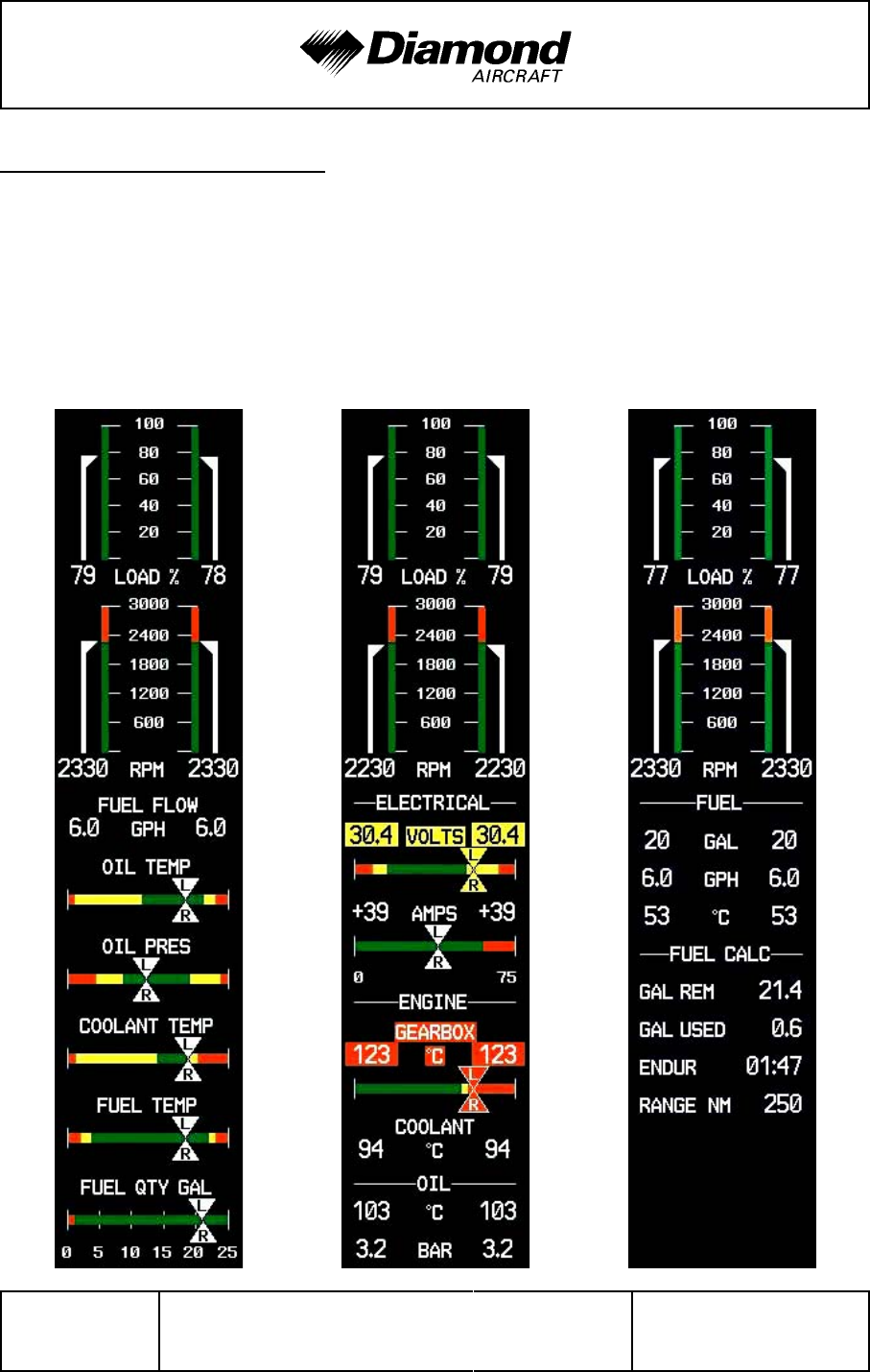
Airplane Description DA 42 AFM
Page 7 - 30 Rev. 3 15-Oct-2005 Doc. No. 7.01.05-E
7.9.4 ENGINE INSTRUMENTS
The engine instruments are displayed on the Garmin G1000 MFD. Also refer to Section
7.10.3 - MULTI-FUNCTION DISPLAY (MFD). Indications for the LH engine are on the
left side, indications for the RH engine are on the right side.
Default page Display when pushing Display when pushing
Engine the SYSTEM button the FUEL button

DA 42 AFM Airplane Description
Doc. No. 7.01.05-E Rev. 3 15-Oct-2005 Page 7 - 31
NOTE
The figure on previous page is a general demonstration of
a typical G1000 MFD to show the different display modes.
The pictured engine instrument markings may not stringently
agree with the current engine limitations of the DA 42.
NOTE
The fuel calculations on the FUEL CALC portion do not use
the airplane's fuel quantity indicators. The values shown are
numbers which are calculated from the last fuel quantity
update done by the pilot and actual fuel flow data. Therefore,
the endurance and range data is for information only, and
must not be used for flight planning.
Designation Indication Unit
LOAD Available power %
RPM Propeller RPM 1/min
VOLT Volts V
GENERATOR Ampères A
CT Coolant temperature °C
GT Gearbox temperature °C
OT Engine oil temperature °C
OP Oil pressure bar
FUEL Fuel quantity US gal
FUEL FLOW Fuel flow US gal/hr
FUEL TEMP. °C
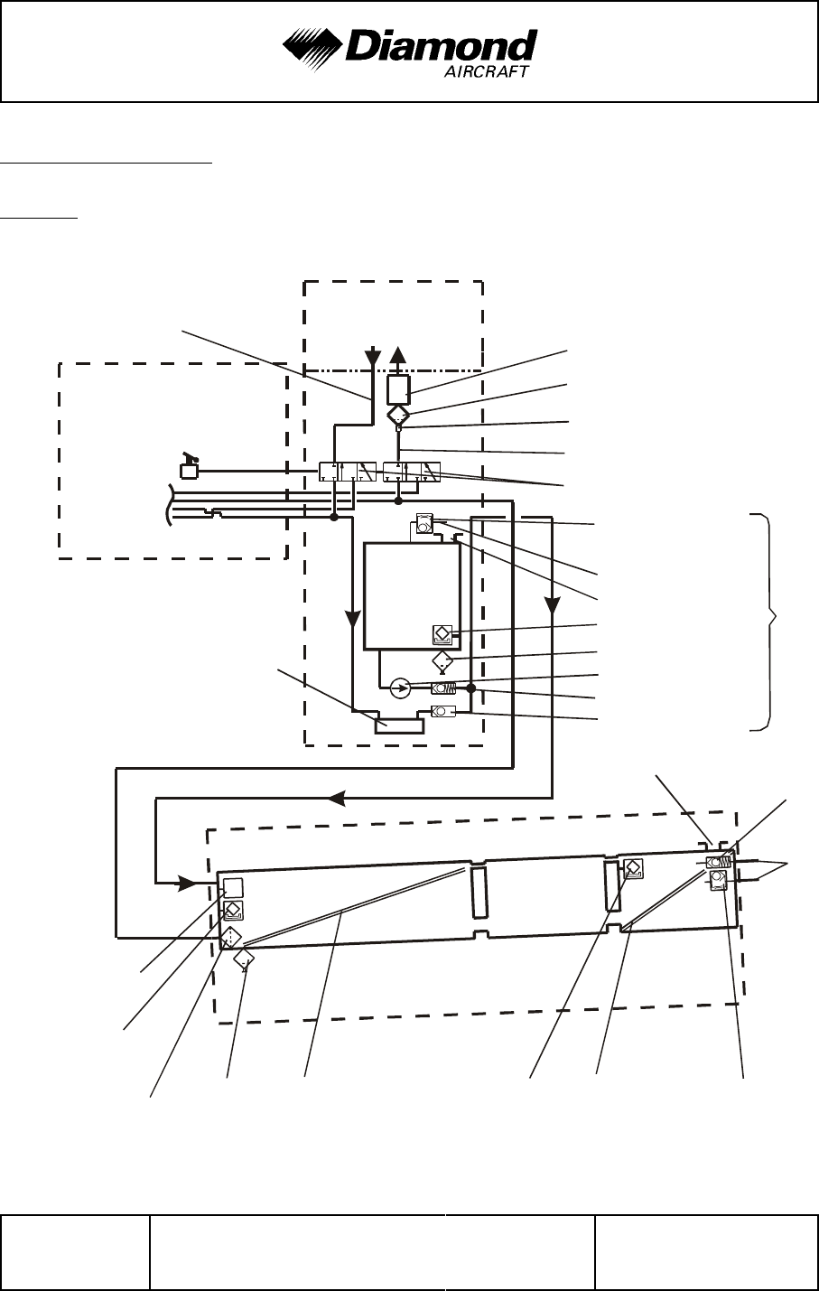
Airplane Description DA 42 AFM
Page 7 - 32 Rev. 3 15-Oct-2005 Doc. No. 7.01.05-E
TAE 125
ENGINE
firewall TAE Diesel filter
sediment bowl
drain
fuel selector valves
fuel level switch
fuel supply
return line
FUSELAGE
fuel system is symmetric
with respect to fuselage
cross-
feed
lines
fuel cooler aux. fuel pump
relief valve
check valve
aux. fuel
tank (op-
tional)
fuel temp.
sensor
low fuel
sensor
finger filter drain
drain
RH WING
inboard chamber
fuel
probe fuel
probe
fuel level
switch
middle
chamber
outboard
chamber
fuel filler
aux. fuel filler
pressure
relief valve
fuel
tank
vent
check valve
with capillary
optional
(OÄM 40-056)
vent line
check valve
with capillary
7.9.5 FUEL SYSTEM
General
'
'
'
'
'
'
'
'
'
'
'
'
'
'
'
'
'
'
'
'
'
'
'
'

DA 42 AFM Airplane Description
Doc. No. 7.01.05-E Rev. 3 15-Oct-2005 Page 7 - 33
Fuel is stored in the tanks which are located in the wings.
Normally fuel for the right engine is taken from the right wing main tank and for the left
'
engine from the left wing main tank.
'
On each engine fuel is injected with high pressure directly into the cylinders. The injection
nozzles (one per cylinder) are supplied with fuel by the common rail. Pressure inside the
rail is generated by a high pressure pump which receives fuel from a low pressure pump.
Depending on the power setting the rail pressure is controlled by the ECU through an
electric valve. Both pumps are powered mechanically by the engine. Fuel that is not
injected is fed back into the appropriate wing tank.
Both sides of the fuel system are interconnected by crossfeed lines.

Airplane Description DA 42 AFM
Page 7 - 34 Rev. 3 15-Oct-2005 Doc. No. 7.01.05-E
Fuel selector valves
For each engine one fuel selector valve is provided. The control levers for the fuel selector
valves are situated on the center console behind the power levers. The positions are ON,
X-Feed and OFF. During normal operation each engine takes the fuel from the tank on
the same side as the engine. When X-Feed is selected, the engine will draw fuel from
the tank on the opposite side in order to extend range and keep fuel weight balanced
during single engine operation. With the fuel selector valve both the feeding and the return
line are switched.
The desired position is reached by pulling the lever back. To reach the OFF position a
safety guard must be twisted. This is to ensure that this selection is not made
unintentionally.
NOTE
When one engine is inoperative the fuel selector valve for this
engine must be in the OFF position.
CAUTION
Do not operate with both fuel selector valves in X-Feed
Position. Do not take off with a fuel selector valve in X-Feed
Position.
CAUTION
Do not shut down an engine with the fuel selector valve. The
high pressure fuel pump can otherwise be damaged.
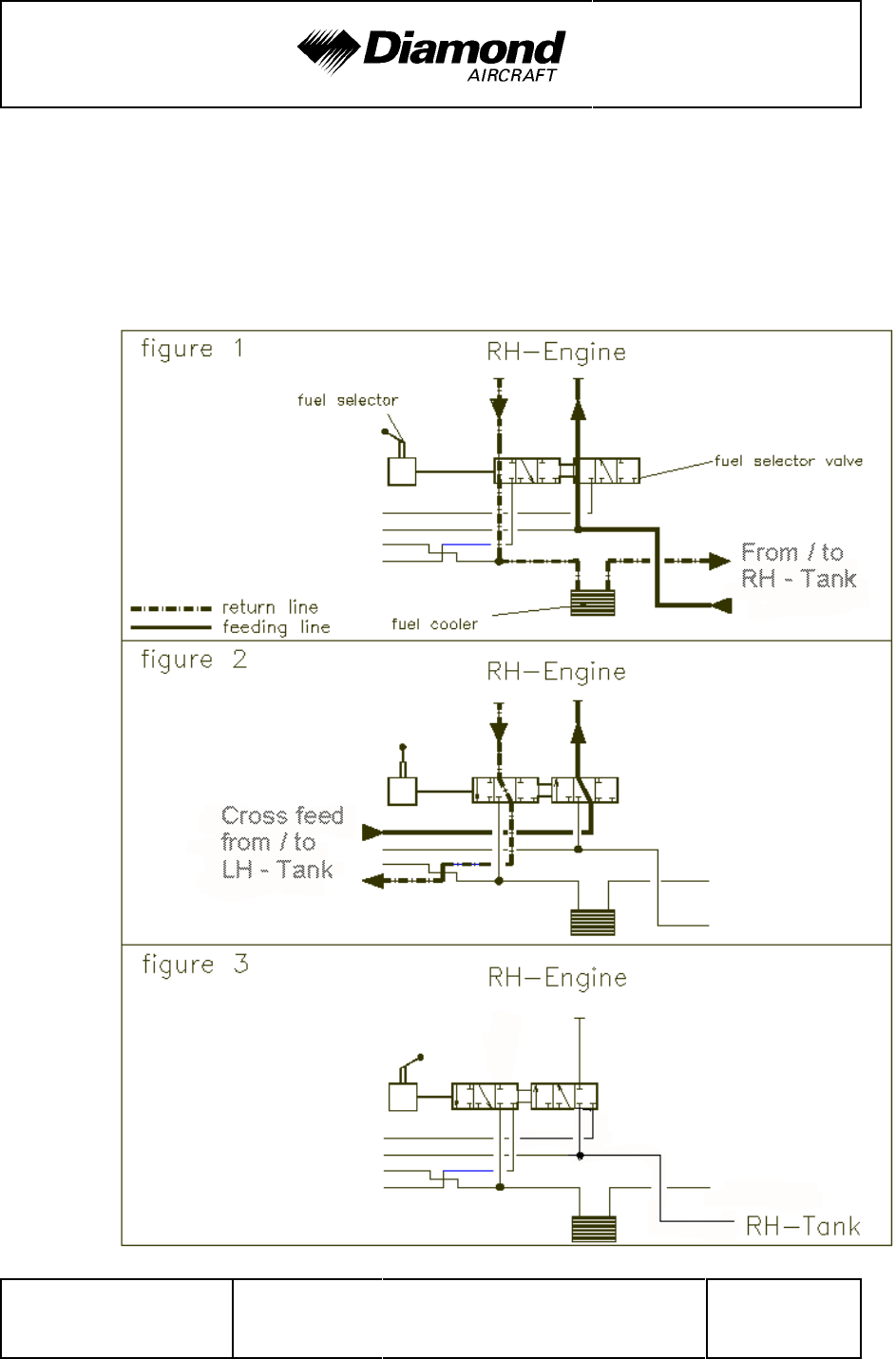
DA 42 AFM Airplane Description
Doc. No. 7.01.05-E Rev. 3 15-Oct-2005 Page 7 - 35
Scheme of the fuel selector valve positions:
Possible operating modes of the three fuel selector valve positions are outlined
systematically in the following scheme. The figures below show fuel flows for the
RH engine (fuel flows LH are alike):
'
'
'
'
figure 1:
'
normal
'
operation
'
'
'
'
'
'
figure 2:
'
cross-feed
'
operation
'
'
'
'
'
'
figure 3
'
shut-off
'
position
'
'
'
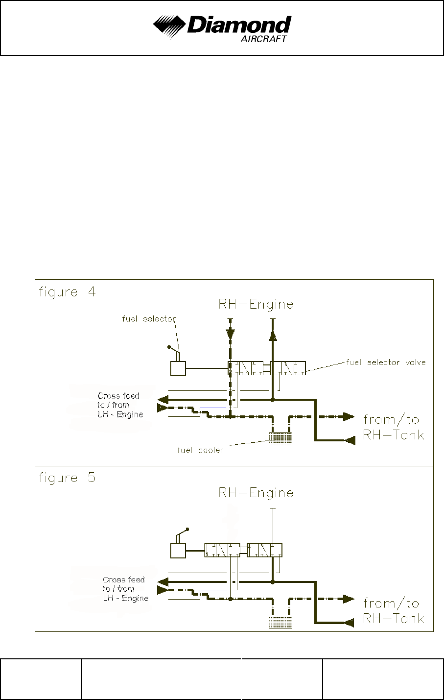
Airplane Description DA 42 AFM
Page 7 - 36 Rev. 3 15-Oct-2005 Doc. No. 7.01.05-E
With the LH fuel selector valve in cross-feed position, the fuel from the RH tank is
transferred to the LH engine. Depending on the position of the RH fuel selector valve,
the RH tank then feeds both engines (as shown in figure 4 below) or only the LH engine,
when the fuel selector valve of the RH engine is in shut-off position (as shown in figure
5 below).
figure 4... fuel selector valve RH normal operation
position, fuel selector valve LH cross feed
position
figure 5... fuel selector RH valve shut-off position, fuel
selector valve LH cross feed position
'

DA 42 AFM Airplane Description
Doc. No. 7.01.05-E Rev. 3 15-Oct-2005 Page 7 - 37
Main Fuel tanks
'
Each tank consists of three aluminum chambers which are connected by a flexible hose.
The tank is filled through a filler in the outboard fuel chamber. Only four liters (1 US gal)
of fuel in each wing are unusable, so that a total quantity of 96 liters (25.4 US gal) in each
wing is usable.
There are two tank vents. One includes a check valve with a capillary and one includes
a relief pressure valve, which operates at 150 mbar (2 psi) and allows fuel and air to flow
to the outside with higher internal pressure. The relief pressure valve protects the tank
against high pressure, if the tank was overfilled in case of an auxiliary fuel transfer failure.
The check valve with capillary allows air to enter the tank but prevents flow of fuel to the
outside. The capillary equalizes the air pressure during climb. The hose terminals are
located on the underside of the wing, approximately 2 meters (7 ft) from the wing tip.
In each tank a coarse filter (finger filter) is fitted before the outlet. To allow draining of
the tank, there is an outlet valve at its lowest point.
At the lowest point in each side of the fuel system a fuel filter with a drain valve is installed.
This drain valve can be used to remove water and sediment which has collected in the
fuel system. The drain valves are fitted in each nacelle behind the firewall, approximately
15 cm (0.56 ft) backward of the wing leading edge.
Fuel quantity indication
Two capacity probes measure the fuel quantity in each main tank. The indication is
provided by the G1000 flight display. Information about fuel consumption can be found
in Chapter 5 - PERFORMANCE.

Airplane Description DA 42 AFM
Page 7 - 38 Rev. 3 15-Oct-2005 Doc. No. 7.01.05-E
Auxiliary fuel tanks (if installed)
'
The auxiliary fuel tanks are optional equipment (OÄM 42-056).
'
'
Description
'
The auxiliary fuel tanks are installed in the rear section of the engine nacelles, above the
'
wing main spars. Each auxiliary fuel tank has a filler cap located on the top surface of
'
the nacelle. The additional fuel capacity is 13.7 US gallons (52 liters) per side. The total
'
fuel capacity (main fuel tanks and auxiliary fuel tanks) is 39.7 US gallons (150.4 liters)
'
per side.
'
The fuel supply connection attaches to a finger filter mounted at the rear of the auxiliary
'
fuel tank. Each auxiliary fuel tank has a fuel transfer pump which pumps fuel into the
'
related main fuel tank.
'
The vent line for the auxiliary fuel tank has a check valve with capillary. It allows air to
'
enter the tank but prevents flow of fuel to the outside. The capillary equalizes the air
'
pressure during climb. A fuel drain valve is located at the rear of each auxiliary tank.
'
'
Operation
'
Two FUEL TRANSFER switches in the cockpit are used to activate the fuel transfer pumps.
'
The switches are located behind the elevator trim wheel on the center console. Both
'
swithes are intended to be used simultaneously to prevent the airplane from additional
'
lateral imbalance. The fuel transfer pump pumps the fuel from the auxiliary fuel tank into
'
the related main fuel tank. Fuel level switches shut this pump off automatically when the
'
auxiliary fuel tank is empty or when the main fuel tank is full. During operation of the pumps
'
an advisory alert on the Garmin G1000 indicates that the fuel transfer is in progress.
'
If the auxiliary fuel tank is empty, a caution alert appears on the Garmin G1000. In this
'
case the fuel pumps must be switched OFF.
'

DA 42 AFM Airplane Description
Doc. No. 7.01.05-E Rev. 3 15-Oct-2005 Page 7 - 39
When one fuel transfer pump is defective, the fuel stored in the related auxiliary fuel tank
'
is not available. For use of the remaining fuel pump refer to to Section 4B.4.10, LH/RH
'
FUEL XFER FAIL. The flight plan must be amended accordingly.
'
The fuel transfer pumps are electrically connected to the LH Main Bus and protected by
'
a 5A circuit breaker, if no Ice Protection System (OÄM 42-053) is installed.
'
If the Ice Protection System is installed, both Systems are protected by a 10 A circuit
'
breaker and an additional 5A fuse for the fuel transfer pumps. The circuit breaker is
'
labeled XFER PUMP/DE ICE.
'
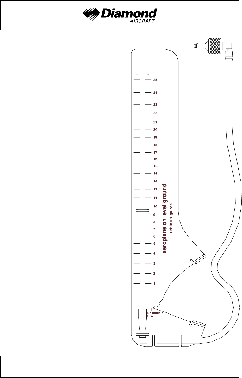
Airplane Description DA 42 AFM
Page 7 - 40 Rev. 4 30-Nov-2005 Doc. No. 7.01.05-E
Alternate means for fuel quantity
indication for the fuel tank:
The alternate means for fuel quantity
indication allows the fuel quantity in the
tank to be determined during the pre-flight
inspection. It functions according to the
principle of communicating containers.
The fuel quantity measuring device has
a recess which fits the airfoil of the wing
in front of the fuel tank drain, which lies
'
approximately 10 cm (4 in) outboard of
'
the engine nacelle. The metal connector
'
is pressed against the drain of the tank.
The amount of fuel in the tank can now
be read off from the vertical ascending
pipe.
For an exact indication the airplane must
stand on level ground and the measuring
device must be held vertically.
The designated location for the fuel
quantity measuring device is a bag on the
rear side of the pilot seat.

DA 42 AFM Airplane Description
Doc. No. 7.01.05-E Rev. 4 30-Nov-2005 Page 7 - 41
Fuel temperature
'
A fuel temperature sensor measures the fuel temperature in each main tank. The indication
'
is provided by the G1000 flight display. Information about fuel temperature limitations
'
can be found in Chapter 2 - OPERATING LIMITATIONS.
'
The lower yellow bar indicates that the airplane is not ready for take-off if Diesel fuel or
'
a blend of Diesel fuel with JET A-1 is used (approved only if MÄM 42-037 is carried out).
'
If the fuel grade is uncertain, take-off is not allowed in this temperature range either.
'
In the temperature range below -5 °C (23 °F) the engine must not be started if Diesel fuel
'
or a blend of Diesel fuel with JET A-1 is used. If the fuel blend is uncertain, the engine
'
must not be started in this temperature range either.
'
If the airplane is being operated with JET A-1, operation in the yellow temperature range
'
is permissible.
'

Airplane Description DA 42 AFM
Page 7 - 42 Rev. 4 30-Nov-2005 Doc. No. 7.01.05-E
Fuel grade
'
Approved fuel grades are listed in Section 2.14. As the fuel grade is important concerning
'
operating temperature limitations, the pilot must be sure about the fuel grade. Cold Diesel
'
fuel tends to flocculate, which can lead to clogging of the fuel filter. The fuel filter is not
'
heated.
'
If the airplane is operated in a cold environment, it must be changed from Diesel fuel
'
operation to JET A-1 operation. To ensure that no blend of JET A-1 with Diesel fuel is
'
in one of the tanks, each tank must be refilled at least twice with more than 17.2 US gal
'
(65 liters) of JET A-1. Otherwise both tanks must be drained before refueling with JET A-1.
'
'
NOTE
'
In order to provide information about the fuel grade it is
'
recommended to enter the fuel grade in the airplane log each
'
time fuel is refilled.
'
'
CAUTION
'
If the airplane is operated with Diesel fuel or a blend of Diesel
'
fuel with JET A-1 the use of the auxiliary tanks, if installed
'
(OÄM 42-056), is not permitted.
'
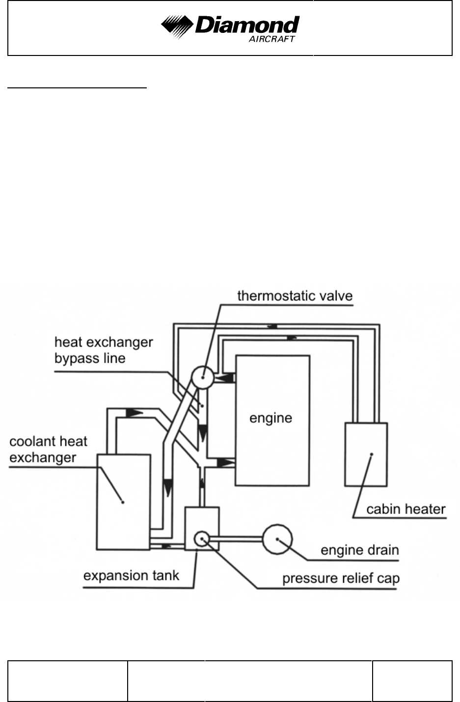
DA 42 AFM Airplane Description
Doc. No. 7.01.05-E Rev. 4 30-Nov-2005 Page 7 - 43
7.9.6 COOLING SYSTEM
Each engine is liquid cooled. The liquid cooling system consists of a radiator and a bypass
to this radiator. The bypass is in operation when coolant temperatures are low. It therefore
allows the engine to warm-up quickly. Upon reaching a certain temperature (approximately
88 °C or 190 °F) the radiator is activated by a thermostat valve. Additionally a coolant
to air heat exchanger is provided for the cabin heat system. The flow through the heat
exchanger is independent of the coolant temperature. An expansion tank helps to adjust
the pressure in the system. The system is protected against overpressure by means of
a pressure relief valve.

Airplane Description DA 42 AFM
Page 7 - 44 Rev. 4 30-Nov-2005 Doc. No. 7.01.05-E
7.9.7 OIL SYSTEMS
Each engine has two separate oil systems.
Lubrication system (engine and turbo-charger)
The engine lubrication is a wet sump lubrication system. The oil is cooled by a separate
cooler on the underside of the engine.
A dip-stick is provided to check the oil quantity through an inspection hole in the upper
cowling. If required, oil can also be filled in there (for approved oil grades refer to Section
2.4 - POWER-PLANT LIMITATIONS).
Gearbox and propeller governor system
The second oil circuit lubricates the gearbox and serves the governor system and the
regulation of the propeller.
The gearbox oil quantity can be checked with the help of an inspection glass which can
be reached through an inspection hole on the front side of the lower cowling.
CAUTION
If the gearbox oil quantity is too low, an unscheduled
maintenance is necessary (for approved oil grades refer to
Section 2.4 - POWER-PLANT LIMITATIONS).
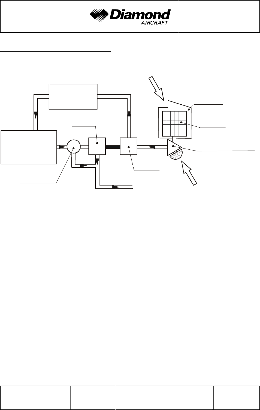
DA 42 AFM Airplane Description
Doc. No. 7.01.05-E Rev. 4 30-Nov-2005 Page 7 - 45
engine
air inlet
filter box
air filter
alternate air inlet
charger
turbine
exhaust
waste gate
engine
intercooler
alternate air valve
7.9.8 TURBO-CHARGER SYSTEM
The exhaust system contains a manifold which collects exhaust gases from the outlets
of the cylinders and feeds them to the turbine of the turbo-charger. Behind the turbine
the exhaust gases are guided through the lower cowling to the exterior of the airplane.
Excess exhaust gases bypass the turbine. The bypass is controlled by the ECU through
the waste gate valve. A manifold pressure sensor behind the compressor allows the ECU
to calculate the correct position of the waste gate valve. This prevents excessive manifold
pressures at low density altitudes. The intake air is compressed in the compressor which
is driven by the turbine, and is subsequently cooled down in the intercooler to increase
power. Cooling the air increases efficiency through the higher density of the cooler air.

Airplane Description DA 42 AFM
Page 7 - 46 Rev. 4 30-Nov-2005 Doc. No. 7.01.05-E
7.9.9 FIRE DETECTION SYSTEM
The fire detection system in the DA 42 consists of an overheat detector in the hot area
of each engine. In case of an increase of the engine compartment temperature above
250 °C (480 °F) the overheat detector closes the electric circuit and a warning message
appears in the annunciation window of the G1000 PFD.
To test the fire detectors (refer to Section 4A.5.1 - PRE-FLIGHT INSPECTION) push
the test button located next to the gear selector switch. An aural alert and the fire warning
message for the LH and RH engine should appear in the annunciation window of the
G1000 PFD.
CAUTION
If the aural alert or the warning does not appear, an
unscheduled maintenance is necessary.
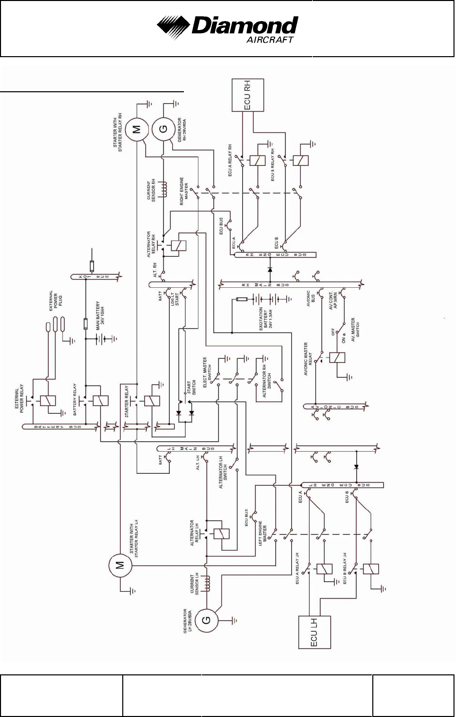
DA 42 AFM Airplane Description
Doc. No. 7.01.05-E Rev. 4 30-Nov-2005 Page 7 - 47
7.10 ELECTRICAL SYSTEM

Airplane Description DA 42 AFM
Page 7 - 48 Rev. 4 30-Nov-2005 Doc. No. 7.01.05-E
7.10.1 GENERAL
The DA 42 has 28 Volt DC system, which can be sub-divided into:
- Power generation
- Storage
- Distribution
- Consumers
Power generation
Power generation is provided by two 60 ampère alternators (generators) which are
mounted on the bottom left side of each engine. The alternators are driven by a flat-belt.
The power output line of the left-hand alternator is connected to the 'LH main bus' via
the LH alternator relay and a 70 ampère circuit breaker. The power output line of the right-
hand alternator is connected to the 'RH main bus' via the RH alternator relay and a 70
ampère circuit breaker. Both 'main busses' are connected to the 'battery bus' via a 90
ampère circuit breaker.
Both generator power output lines also run through a current sensor for each alternator,
which provides an indication of the power being supplied to the electrical system by an
alternator including the current for battery charging on the G1000. In the event of a main
battery failure the field of each alternator is energized by two 12 V, 1.3 Ah sealed-lead-acid
batteries ('excitation'-battery) connected in series, which are installed in the nose baggage
compartment. The 'ENGINE MASTER LH (RH)'-switches connect the 'excitation'-battery
to the alternator field via a 5 A fuse.
Alternator control:
Each alternator has an alternator control unit. It measures the alternator output voltage
and controls the current through the alternator field coils via a pulse-width modulated
signal. To keep the output voltage stable in all load and speed situations, the alternator
field signal is modulated accordingly.

DA 42 AFM Airplane Description
Doc. No. 7.01.05-E Rev. 4 30-Nov-2005 Page 7 - 49
The alternator control unit includes a comprehensive set of diagnostic functions that will
warn the operator using a caution message (L/R ALTN FAIL) on the G1000 PFD in case
of over- or undervoltage as well as a couple of other internal warning levels.
Load Balancing: The alternator control unit supports load balancing across the two
alternators via the internal alternator temperature. The temperature is measured and
the alternator control unit slightly decreases alternator voltage output at higher internal
alternator temperatures. Thus the load is partly shifted to the alternator with the lower
'
internal temperature. This system is able to balance the actual load within a few amps
'
between the two alternators installed.
Storage
'Main'-battery power is stored in a 24 V, 10 Ah lead-acid battery mounted on the right-aft
side of the front baggage compartment. The 'main' battery is connected to the 'hot battery
bus' via a 20 A fuse and to the 'battery bus' via the 'battery'-relay which is installed in
the relay junction box on the center-aft side of the front baggage compartment.
The 'battery'-relay is controlled with the 'ELECTRIC MASTER'-switch which is located
on the left-hand side of the instrument panel.
In addition, a non-rechargeable dry battery is installed as a further source of power for
the attitude gyro (artificial horizon) and the flood light. When the EMERGENCY switch
is set to ON, these two systems are supplied with power for at least 1.5 hours,
independent of all other electrical consumers. During each 100 hour inspection, this
battery is checked for proper functioning. Every 2 years or after use (broken seal on the
switch) the battery package must be replaced.
Distribution
Electrical power is distributed via the 'hot battery bus', the 'battery bus', the 'LH (RH) ECU-
bus', the 'LH (RH) main bus', and the 'avionic bus'.

Airplane Description DA 42 AFM
Page 7 - 50 Rev. 4 30-Nov-2005 Doc. No. 7.01.05-E
Hot battery bus:
The 'hot battery bus' is directly connected to the 'main'-battery via a 20 A fuse installed
in the relay junction box and cannot be disconnected from the 'main'-battery. The 'hot
battery bus' provides power to the pilot map/reading light which is protected by its own
fuse.
Battery bus:
The 'battery bus' is connected to the 'main'-battery via the 'battery'-relay which can be
controlled by the 'ELECTRIC MASTER'-switch. The 'battery bus' provides power to the
' LH (RH) main bus' and heavy duty power to both starters.
ECU bus:
The 'LH (RH) ECU bus' is connected to the 'LH (RH) main bus' via a diode and connected
to the power output line of the alternator via a 30 ampère circuit breaker and provides
power for the ECU A and ECU B via the 'LH (RH ECU A (B)'-Relays which are controlled
by the 'LH (RH) ENGINE MASTER'-switch. The 'LH (RH) ENGINE MASTER'-switch must
be set to 'ON' to connect the ECU A and ECU B to the 'ECU bus'.
Main bus:
The 'LH (RH) main bus' is connected to the 'battery bus' via a 90 ampère circuit breaker.
The 'LH main bus' provides power to the consumers directly connected to the 'LH main
bus'. The 'RH main bus' provides power to the consumers directly connected to the 'RH
main bus and the 'avionic bus' via the 'avionics master'-relay.
The 'AVIONIC MASTER'-switch must be set to 'ON' to connect the 'RH main bus' to the
'avionic bus'.

DA 42 AFM Airplane Description
Doc. No. 7.01.05-E Rev. 4 30-Nov-2005 Page 7 - 51
Consumers
The individual consumers (e.g. radio, position lights, etc.) are connected to the appropriate
bus via automatic circuit breakers.
Designations and abbreviations used to identify the circuit breakers are explained in
Section 1.5 DEFINITIONS AND ABBREVIATIONS.
Voltmeter
The voltmeter displays the voltage of the electrical system. Under normal operating
conditions the alternator voltage is shown, otherwise it displays the 'main'-battery voltage.
Ammeter
The ammeter displays the intensity of current which is supplied to the electrical system
by the LH (RH) alternator.
Landing and taxi lights
Landing and taxi lights are built into the wing center section, and are each operated by
means of a switch (LANDING, TAXI) located on the row of switches on the instrument
panel.
Position and strobe lights
Combined position and strobe lights (anti collision lights) are installed on both wing tips.
Each system is operated by a switch (POSITION, STROBE) located on the row of
switches on the instrument panel.
Flood light
A two-dimensional light emitter is mounted above the instrument panel. It illuminates the
instrument panel as well as all levers, switches, etc. The flood light is switched on and
its brightness is adjusted by means of a rotary button (FLOOD) in the left-hand section
of the instrument panel.

Airplane Description DA 42 AFM
Page 7 - 52 Rev. 4 30-Nov-2005 Doc. No. 7.01.05-E
Instrument lighting
With a rotary button (INSTRUMENT) in the left-hand section of the instrument panel the
internal lighting of the instruments is switched on and its brightness is adjusted.
Pitot heating
The Pitot probe, which provides measurement for the Pitot-static system, is electrically
heated. The heating is activated with a switch (PITOT HEAT) located on the row of
switches on the instrument panel. The temperature is automatically kept constant by
means of a thermal switch on the Pitot probe, and as an additional safety measure a
thermal fuse is built in. If this thermal fuse is activated, the Pitot heating can no longer
be switched on, and the Pitot heating caution will be displayed. In this case the system
should be serviced. The Pitot heat caution light is also on if the Pitot heating is switched
off.
External power socket
The DA 42 has an external 28 Volt DC power socket located on the lower surface of the
fuselage nose section. When external power is connected, the control relay is energized
and the external power comes on-line.
The socket itself has three pins:
• a large negative pin
• a large positive pin
• a small positive pin
A diode protects the system from reverse polarity.

DA 42 AFM Airplane Description
Doc. No. 7.01.05-E Rev. 4 30-Nov-2005 Page 7 - 53
7.10.2 ENGINE CONTROL UNIT / ECU
Engine control and regulation
The ECU monitors, controls and regulates all important parameters for engine operation.
Sensors installed are:
- Oil temperature (lubrication system engine) / OIL TEMP
- Oil pressure (lubrication system engine) / OIL PRES
- Coolant temperature / COOLANT TEMP
- Gearbox temperature / GEARBOX
- Camshaft RPM (twice)
- Crankshaft RPM (twice)
- Fuel pressure in the common rail
- Manifold pressure
- Manifold air temperature
- Ambient air pressure
- Propeller governor / oil pressure
- Power lever position (twice)
- Voltage
- Starter switch signal
- Fuel pressure
- 'ECU Swap'-switch signal
- 'ECU Test'-switch signal

Airplane Description DA 42 AFM
Page 7 - 54 Rev. 4 30-Nov-2005 Doc. No. 7.01.05-E
In accordance with the received signals and a comparison with the programmed
characteristic diagrams the necessary inputs are calculated and transmitted by the
following signal lines to the engine:
- Activation of starter (relay)
- Signal for propeller governor pressure valve
- Signal for the rail-pressure regulation valve
- Signal for each of the 4 injection nozzles
- Activation of the glow plugs
- Signal for the waste gate valve
The following alerts are displayed on PFD of the G1000:
- Glow sparks active
- Status ECU A
- Status ECU B
Normally each engine is controlled and regulated by the appropriate ECU A. The ECU
B is a backup system to ensure redundancy. In case of an internal error during operation
or the loss of a sensor signal the system automatically switches to ECU B. If the loss
of the sensor signal was the cause for the error, the system automatically switches back
to ECU A.
A fault in one of the ECU's is indicated by a caution message on the PFD (L/R ECU A/B
FAIL). In case of minor faults, the annunciation can be reset once by pressing the ECU
TEST button for more than 2 seconds. However, the annunciation will re-appear upon
the next attempt to start the engine. After the indication of the L/R ECU A/B FAIL caution
message, the engine must be serviced, even if the caution message could be reset.

DA 42 AFM Airplane Description
Doc. No. 7.01.05-E Rev. 4 30-Nov-2005 Page 7 - 55
7.10.3 WARNING, CAUTION AND ADVISORY MESSAGES
Crew Alerting System (CAS)
The G1000 Crew Alerting System (CAS) is designed to provide visual and aural alerts
to the flight crew. Alerts are divided into three levels as follows:
WARNING
CAUTION
ADVISORY
Crew alerts will appear in the Alerts Window on the PFD. In this window Warnings will
appear at the top, followed by Cautions and Advisories, respectively. Within the criticality
levels, messages will appear from newest (top) to oldest (bottom).
At the low right corner of the display there is a MSG (Message) soft key. The MSG key
provides two functions in the CAS:
1. Pressing the MSG key acknowledges a new master warning / caution / advisory
indication.
2. An additional MSG key press with no master alert indication active will open a
pop-up Auxiliary Flight Display (AFD) page that contains information for all active alerts.
This structure allows the crew to scroll through all system alerts if the Alerts Window
overflows. This approach displays the most critical alerts close to the pilot´s primary field
of view at all times, with the option of allowing lower criticality alerts to overflow and be
accessible from the pop-up AFD page/window.

Airplane Description DA 42 AFM
Page 7 - 56 Rev. 4 30-Nov-2005 Doc. No. 7.01.05-E
Alert levels
Level Text Color Importance Audible Tone
Warning Red May require
immediate
corrective action
Warning chime tone
which repeats
without delay until
acknowledged by
the crew
Caution Amber May require future
corrective action Single warning
chime tone
Annunciation
Advisory White None
Message Advisory White None
Safe Operation
Annunciation Green Lowest None

DA 42 AFM Airplane Description
Doc. No. 7.01.05-E Rev. 4 30-Nov-2005 Page 7 - 57
Warning alerts on the G1000
Warning alerts Meaning / Cause
L/R ENG TEMP The annunciation is active when the engine coolant temperature
is greater than 105 °C.
L/R OIL TEMP The annunciation is active when the engine oil temperature is
greater than 140 °C.
L/R OIL PRES The annunciation is active when the engine oil pressure is
less than 1 bar.
L/R FUEL TEMP The annunciation is active when the fuel temperature is
greater than 75 °C.
L/R GBOX TEMP The annunciation is active when the gearbox oil temperature is
greater than 120 °C.
L/R ALTN AMPS The annunciation is active when the alternator load is greater than
60 amps.
L/R ENG FIRE The annunciation is active when an engine fire is detected.
L/R STARTER This annunciation is used to indicate to the pilot that the starter
is engaged when it should not be.
DOOR OPEN The annunciation is used to indicate to the pilot if the baggage-,
canopy- or rear door is open.
POSN ERROR The annunciation is active when the G1000 will no longer
provide GPS based navigational guidance.
ATTITUDE FAIL The annunciation is active when the display system is not
receiving attitude reference information from the AHRS.
AIRSPEED FAIL The annunciation is active when the display system is not
receiving airspeed input from the air data computer.
ALTITUDE FAIL The annunciation is active when the display system is not
receiving altitude input from the air data computer.
VERT SPEED
FAIL The annunciation is active when the display system is not
receiving vertical speed input from the air data computer.
HDG The annunciation is active when the display system is not
receiving valid heading input from the AHRS.

Airplane Description DA 42 AFM
Warning alerts Meaning / Cause
Page 7 - 58 Rev. 4 30-Nov-2005 Doc. No. 7.01.05-E
WARN This annunciation constitutes a RAIM position warning. The
nav deviation bar is removed.
Audible warning alerts
Warning alerts Meaning / Cause
landing gear
retracted
A warning chime tone which repeats without delay is active
when the landing gear is retracted while the flaps move into
the LDG position or when the POWER lever is placed in a
position below 25 %.

DA 42 AFM Airplane Description
Doc. No. 7.01.05-E Rev. 4 30-Nov-2005 Page 7 - 59
Caution alerts on the G1000
Caution-alerts Meaning / Cause
L/R ECU A FAIL
or
L/R ECU B FAIL
The annunciation is active when a fault in ECU A or ECU B
has occurred.
In case of minor faults, the annunciation can be reset once by
pressing the ECU TEST button for more than 2 seconds.
However, the annunciation will re-appear upon the next
attempt to start the engine.
L/R FUEL LOW The annunciation is active when the fuel quantity is below
4 ± 1 gal usable fuel.
L/R VOLTS LOW The annunciation is active when bus voltage is less than
25 volts.
L/R ALTN FAIL The annunciation is active when the alternator has failed.
L/R COOL LVL The annunciation is active when engine coolant level is low.
PITOT FAIL The annunciation is active when the Pitot heater is failed.
PITOT HT OFF The annunciation is active when the Pitot heat is off.
STALL HT FAIL The annunciation is active when the stall heater is failed.
STALL HT OFF The annunciation is active when the stall heater is off.
STICK LIMIT Control stick limiting system (variable elevator stop) has
failed.
L/R AUX FUEL E
This annunciation can only occur when the auxiliary fuel tank
system (optional) is installed.
The annunciation is active when the L/R auxiliary fuel tank is
empty and the FUEL TRANSFER pump is ON.
INTEG
RAIM not
available
The annunciation is active when RAIM (Receiver
Autonomous Integrity Monitor) is not available.
AHRS ALIGN:
Keep Wings Level The annunciation is active when the AHRS (Attitude and
Heading Reference System) is aligning.

Airplane Description DA 42 AFM
Page 7 - 60 Rev. 4 30-Nov-2005 Doc. No. 7.01.05-E
Annunciation advisory alerts on the G1000
Advisory alerts Meaning / Cause
L/R GLOW ON The annunciation is active when the glow plugs are powered.
L/R FUEL XFER The annunciation is active when fuel transfer from auxiliary to
main tank is in progress.
Message advisory alerts on the G1000
Advisory alerts Meaning / Cause
PFD FAN FAIL The annunciation is active when the PFD fan is inoperative.
MFD FAN FAIL The annunciation is active when the MFD fan is inoperative.
GIA FAN FAIL The annunciation is active when the GIA fan is inoperative.

DA 42 AFM Airplane Description
Doc. No. 7.01.05-E Rev. 4 30-Nov-2005 Page 7 - 61
7.11 PITOT-STATIC SYSTEM
Total pressure is measured at the leading edge of a Pitot probe under the left wing. Static
pressure is measured at two orifices at the lower and rear edges of the same probe. To
protect against dirt and condensation there are filters in the system, which are accessible
from the wing root. The Pitot probe is electrically heated.
With the alternate static valve, the static pressure in the cabin can be used as static
pressure source in the event of a failure of the Pitot-static system.
7.12 STALL WARNING SYSTEM
The lift detector of the DA 42 is located on the front edge of the left wing below the wing
chord line. It is supplied electrically and provides a stall warning, before the angle of attack
becomes critical. The stall status is announced to the pilot by a continuous sound in the
cockpit.
The lift detector vane, the mounting plate and the complete housing are heated to prevent
icing. Heating is engaged together with the Pitot heating.

Airplane Description DA 42 AFM
Page 7 - 62 Rev. 4 30-Nov-2005 Doc. No. 7.01.05-E
7.13 GARMIN G1000 INTEGRATED AVIONICS SYSTEM
7.13.1 GENERAL
The Gamin G1000 is a fully integrated flight, engine, communication, navigation and
surveillance instrumentation system. This Integrated Avionics System consists of a
Primary Flight Display (PFD), a Multi-Function Display (MFD), an Audio Panel, an Attitude
and Heading Reference System (AHRS), an Air Data Computer (ADC) and the sensors
and computers to process flight and engine information for display to the pilot. The system
contains dual GPS receivers, dual VOR/ILS receivers, dual VHF communications
transceivers, a transponder, and an integrated annunciation system to alert the pilot of
certain abnormal conditions.
A remote avionic box is located behind the aft baggage compartment frame. A push-to-talk
(PTT) button for the COM portion of the G1000 is mounted on the end of each control
stick. There are connection facilities for up to 4 headsets between the front seats.
Refer to the Garmin G1000 Cockpit Reference Guide, Garmin P/N 190-00406-00, dated
September, 2004, and Pilot's Guide, P/N K00-00138-00, dated September, 2004, for
complete descriptions of the G1000 system and operating procedures.
NOTE
'
Near the DME ground station, it can happen under certain
'
adverse conditions that the Bendix/King KN 63 DME loses
'
the direct signal from the ground station and locks onto an
'
"echo". This will result in an inaccurate indication of the
'
distance.
'

DA 42 AFM Airplane Description
Doc. No. 7.01.05-E Rev. 4 30-Nov-2005 Page 7 - 63
7.13.2 PRIMARY FLIGHT DISPLAY (PFD)
The Primary Flight Display (PFD; see figure below) typically displays airspeed, attitude,
altitude, and heading information in a traditional format. Slip information is shown as a
trapezoid under the bank pointer. One width of the trapezoid is equal to a one ball width
slip. Rate of turn information is shown on the scale above the compass rose; full scale
deflection is equal to a standard rate turn. The following controls are available on the
PFD (clockwise from top right):
* Communications frequency volume and squelch knob
* Communications frequency set knobs
* Communications frequency transfer button
* Altimeter setting knob (baro set)
* Course knob
* Map range knob and cursor control
* FMS control buttons and knob
* PFD softkey buttons, including master warning/caution acknowledgment
* Altitude reference set knob
* Heading bug control
* Navigation frequency transfer button
* Navigation frequency set knobs
* Navigation frequency volume and Identifier knob
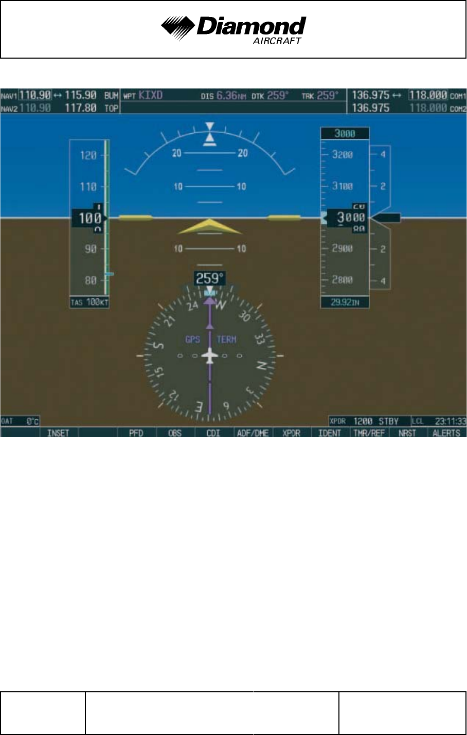
Airplane Description DA 42 AFM
Page 7 - 64 Rev. 4 30-Nov-2005 Doc. No. 7.01.05-E
The PFD displays the crew alerting (annunciator) system. When a warning or caution
message is received, a warning or caution annunciator will flash on the PFD, accompanied
by an aural tone. A warning is accompanied by a repeating tone, and a caution is
accompanied by a single tone. Acknowledging the alert will cancel the flashing and provide
a text description of the message. Refer to Chapter 3 - EMERGENCY PROCEDURES,
Chapter 4B - ABNORMAL OPERATING PROCEDURES, and Section 7.10.3 - WARNING,
CAUTION AND ADVISORY LIGHTS.

DA 42 AFM Airplane Description
Doc. No. 7.01.05-E Rev. 4 30-Nov-2005 Page 7 - 65
Advisory messages related to G1000 system status are shown in white and are
accompanied by a white flashing ADVISORY alert. Refer to the G1000 Pilot's Guide and
Cockpit Reference Guide for descriptions of the messages and recommended actions
(if applicable).
Trend vectors are shown on the airspeed and altimeter displays as a magenta line
predicting 6 seconds at the current rate. The turn rate indicator also functions as a trend
indicator on the compass scale.
The PFD can be displayed in a composite format for emergency use by pressing the
DISPLAY BACKUP button on the audio panel. In the composite mode, the full crew
alerting function remains, but no map functions are available.
7.13.3 MULTI-FUNCTION DISPLAY (MFD)
The Multi-Function Display (MFD) typically displays engine data, maps, terrain, traffic
and topography displays, and flight planning and progress information. The display unit
is identical to the PFD and contains the same controls as previously listed.
Engine instruments are displayed on the MFD. Discrete engine sensor information is
processed by the Garmin Engine Airframe (GEA) sub-system. When an engine sensor
indicates a value outside the normal operating range, the legend will turn yellow for caution
range, and turn red and flash for warning range.
Also refer to Section 7.9.4 - ENGINE INSTRUMENTS.

Airplane Description DA 42 AFM
Page 7 - 66 Rev. 4 30-Nov-2005 Doc. No. 7.01.05-E
7.13.4 AUDIO PANEL
The audio panel contains traditional transmitter and receiver selectors, as well as an
integral intercom and marker beacon system. The marker beacon lights appear on the
PFD. In addition, a clearance recorder records the last 2 ½ minutes of received audio.
Lights above the selections indicate what selections are active. Pressing the red DISPLAY
BACKUP button on the audio panel causes both the PFD and MFD to display a composite
mode.
7.13.5 ATTITUDE AND HEADING REFERENCE SYSTEM (AHRS)
The Attitude and Heading Reference System (AHRS) uses GPS, rate sensors, air data,
and magnetic variation to determine pitch and roll attitude, sideslip and heading. Operation
is possible in a degraded mode if the system loses any of these inputs. Status messages
alert the crew of the loss of any of these inputs. The AHRS will align while the airplane
is in motion, but will align quicker if the wings are kept level during the alignment process.
7.13.6 AIR DATA COMPUTER (ADC)
The Air Data Computer (ADC) provides airspeed, altitude, vertical speed, and air
temperature to the display system. In addition to the primary displays, this information
is used by the FMS and TIS systems.

DA 42 AFM Handling, Care,
Maintenance
Doc. No. 7.01.05-E Rev. 3 15-Oct-2005 Page 8 - 1
CHAPTER 8
AIRPLANE HANDLING, CARE AND MAINTENANCE
Page
8.1 INTRODUCTION .......................................8-2
8.2 AIRPLANE INSPECTION INTERVALS ......................8-2
8.3 AIRPLANE ALTERATIONS OR REPAIRS ....................8-3
8.4 SERVICING ...........................................8-3
8.4.1 REFUELING ......................................8-3
8.4.2 ENGINE OIL LEVEL CHECK .........................8-4
8.4.3 GEARBOX OIL LEVEL CHECK .......................8-4
8.4.4 TIRE INFLATION PRESSURE CHECK .................8-5
8.5 GROUND HANDLING / ROAD TRANSPORT .................8-6
8.5.1 GROUND HANDLING ..............................8-6
8.5.2 PARKING ........................................8-7
8.5.3 MOORING .......................................8-9
8.5.4 JACKING ........................................8-9
8.6 CLEANING AND CARE .................................8-10
8.6.1 PAINTED SURFACES .............................8-10
8.6.2 CANOPY AND REAR DOOR ........................8-11
8.6.3 PROPELLER ....................................8-11
8.6.4 ENGINE ........................................8-11
8.6.5 INTERIOR SURFACES ............................8-11
8.7 GROUND DE-ICING ....................................8-12

Handling, Care,
Maintenance DA 42 AFM
Page 8 - 2 Rev. 3 15-Oct-2005 Doc. No. 7.01.05-E
8.1 INTRODUCTION
Chapter 8 contains the manufacturer's recommended procedures for proper ground
handling and servicing of the airplane. The Airplane Maintenance Manual (Doc. No.
7.02.01) lists certain inspection and maintenance requirements which must be followed
if the airplane is to retain a new plane performance and reliability.
8.2 AIRPLANE INSPECTION INTERVALS
Inspections are scheduled every 50, 100, 200, 1000 and 2000 hours. Independent of the
flight hours an annual inspection must be performed every year. A non-recurring engine
inspection must be performed on new engines after 3 to 6 hours. The respective inspection
checklists are prescribed in the Airplane Maintenance Manual, Chapter 05.
For maintenance work on engine and propeller, the currently effective Operator's Manuals,
Service Instructions, Service Letters and Service Bulletins of TAE and mt-Propeller must
be followed. For airframe inspections, the currently effective checklists/manuals, Service
Bulletins and Service Instructions of the manufacturer must be followed.
CAUTION
Unscheduled maintenance checks are required after:
- hard landings
- propeller strike
- engine fire
- lightning strike
- occurrence of other malfunctions and damage
Unscheduled maintenance checks are described in the
Airplane Maintenance Manual (Doc. No. 7.02.01; Section
05-50).

DA 42 AFM Handling, Care,
Maintenance
Doc. No. 7.01.05-E Rev. 3 15-Oct-2005 Page 8 - 3
8.3 AIRPLANE ALTERATIONS OR REPAIRS
Alterations or repairs to the airplane may be carried out only according to the Airplane
Maintenance Manual, Doc. No. 7.02.01, and only by authorized personnel.
8.4 SERVICING
8.4.1 REFUELING
WARNING
Do not allow fire, sparks or heat near fuel. Fuel burns violently
and can cause injury to persons and damage to the airplane.
WARNING
Do not get fuel on your skin. Fuel can cause skin disease.
WARNING
Connect the airplane and the fuel supply vehicle to electrical
ground before refueling. If you do not ground the airplane,
static electricity can cause fire during refueling.
WARNING
Make sure that a suitable fire extinguisher is available at all
times during refueling.
WARNING
Turn off all ground equipment in the refueling area.
WARNING
Do not operate electrical switches in the airplane during
refueling.

Handling, Care,
Maintenance DA 42 AFM
Page 8 - 4 Rev. 4 30-Nov-2005 Doc. No. 7.01.05-E
CAUTION
Use only approved fuel types given in Chapter 2.
1. Ground the airplane and the fuel supply vehicle electrically.
2. Remove the fuel filler cap (located on top of the outer wing). Check cap
%
retaining cable for damage.
%
3. Refuel the airplane.
4. Install the fuel filler cap.
5. Repeat steps 2 to 4 for the other wing.
6. Remove the ground cable from the airplane and the fuel supply vehicle.
8.4.2 ENGINE OIL LEVEL CHECK
1. Open the inspection door on top of the upper left cowling.
2. Remove the filler cap.
3. Clean the oil dip-stick.
4. Install the filler cap.
5. Remove the filler cap again.
6. Read the oil level from the dip-stick.
7. If necessary, add engine oil and repeat steps 3 to 6.
8. Install the filler cap.
9. Close the inspection door.
10. Repeat steps 1 to 9 for the other engine.
8.4.3 GEARBOX OIL LEVEL CHECK
1. Open the inspection door on the forward left side of the lower cowling.
2. Check gearbox oil level in inspection window.
3. Close the inspection door.
4. Repeat steps 1 to 3 for the other engine.

DA 42 AFM Handling, Care,
Maintenance
Doc. No. 7.01.05-E Rev. 3 15-Oct-2005 Page 8 - 5
8.4.4 TIRE INFLATION PRESSURE CHECK
1. Remove the wheel cover (main wheels only).
%
2. Remove dust cap from valve stem by turning counter-clockwise.
3. Connect tire gauge to valve stem, read pressure.
4. Correct pressure if necessary (nose tire 6.0 bar/87 psi, main tires
4.5 bar/65 psi).
5. Install dust cap on valve stem by turning clockwise.
6. Install the wheel cover (main wheels only).
%
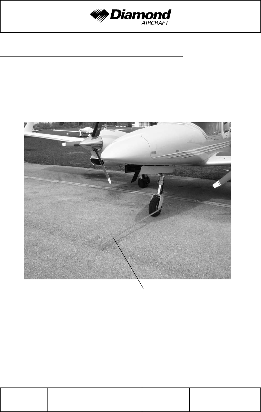
Handling, Care,
Maintenance DA 42 AFM
Page 8 - 6 Rev. 3 15-Oct-2005 Doc. No. 7.01.05-E
8.5 GROUND HANDLING / ROAD TRANSPORT
8.5.1 GROUND HANDLING
For pushing or pulling the airplane on the ground, it is recommended to use the tow bar
which is available from the manufacturer. The tow bar is engaged in the appropriate hole
%
in the nose wheel as shown on the picture.
%
%
%
%
%
%
%
%
%
%
%
%
%
%
%
%
Tow bar
%
WARNING
The tow bar must be removed before starting the engine.
CAUTION
The tow bar may only be used for moving the airplane on the
ground by hand. After moving the airplane, the tow bar must
be removed.

DA 42 AFM Handling, Care,
Maintenance
Doc. No. 7.01.05-E Rev. 3 15-Oct-2005 Page 8 - 7
CAUTION
%
Towing with towing vehicles is not approved.
%
8.5.2 PARKING
For short term parking, the airplane must be positioned into the wind, the parking brake
must be engaged and the wing flaps must be in the retracted position. For extended and
unattended parking, as well as in unpredictable wind conditions, the airplane must be
anchored to the ground or placed in a hangar. Parking in a hangar is recommended.
Control surfaces gust lock
%
The manufacturer offers a control surfaces gust lock which can be used to block the
%
primary controls. It is recommended that the control surfaces gust lock be used when
%
parking outdoors, because otherwise the control surfaces can hit the stops in strong tail
%
wind. This can lead to excessive wear or damage.
%
WARNING
%
The control surfaces gust lock must be removed before flight.
%
%
The control surfaces gust lock is installed as follows:
%
1. Move the rudder pedals fully forward.
%
2. Engage the control surfaces gustlock with the pedals.
%
3. Engage the stick, wrap straps around stick once.
%
4. Attach the locks and tighten the straps.
%
%
For removal reverse the sequence.
%
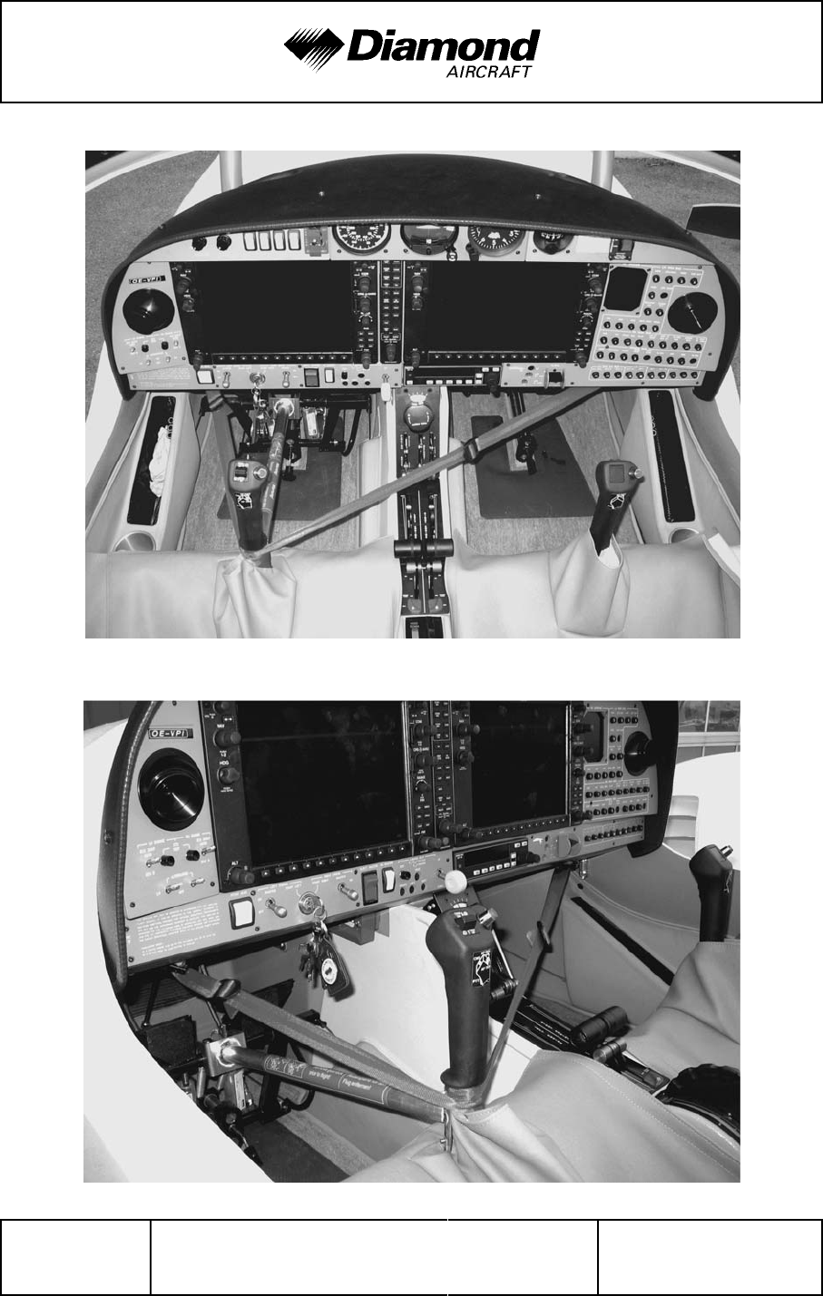
Handling, Care,
Maintenance DA 42 AFM
Page 8 - 8 Rev. 3 15-Oct-2005 Doc. No. 7.01.05-E
%
%
%
%
%
%
%
%
%
%
%
%
%
%
%
%
%
%
%
%
%
%
%
%
%
%
%
%
%
%

DA 42 AFM Handling, Care,
Maintenance
Doc. No. 7.01.05-E Rev. 3 15-Oct-2005 Page 8 - 9
8.5.3 MOORING
Near the lower end of the tail fin of the airplane there is a hole which can be used to tie-
%
down the airplane to the ground. Also on each wing near the wing tip, an eyelet with a
metric M8 thread can be installed and used as tie-down points.
8.5.4 JACKING
The airplane can be jacked at the two jackpoints located on the lower side of the center
wing's LH and RH root ribs as well as at the tail fin.

Handling, Care,
Maintenance DA 42 AFM
Page 8 - 10 Rev. 3 15-Oct-2005 Doc. No. 7.01.05-E
8.6 CLEANING AND CARE
CAUTION
The airplane must be kept clean. The bright surface prevents
the structure from overheating.
CAUTION
Excessive dirt deteriorates the flight performance.
8.6.1 PAINTED SURFACES
The entire surface of the airplane is painted with a white weatherproof two component
paint. Nevertheless, it is recommended to protect the airplane against moisture and
dampness. It is also recommended not to store the airplane outside for long periods of
time.
Dirt, insects, etc. can be removed with water alone and if necessary with a mild detergent.
An automotive paint cleaner can be used for stubborn spots. For best results, clean the
airplane after the day's flying is ended, so that the dirt will not become ingrained.
Oil stains, exhaust stains, etc. on the lower fuselage skin can be removed with a cold
detergent. Before starting, ensure that the detergent does not affect the surface finish.
Use commercial automotive preservatives without silicone additives to conserve the paint
finish.

DA 42 AFM Handling, Care,
Maintenance
Doc. No. 7.01.05-E Rev. 3 15-Oct-2005 Page 8 - 11
8.6.2 CANOPY AND REAR DOOR
The canopy, rear door and rear window should be cleaned with 'Plexiklar' or any other
acrylic glass detergent if available; otherwise use lukewarm water. Final cleaning should
be carried out with a clean piece of chamois-leather or soft cloth. Never rub or polish dry
acrylic glass.
8.6.3 PROPELLER
Damage and malfunctions during operation must be inspected by authorized personnel.
Surface
The manufacturer uses PU paint or acrylic paint which is resistant to almost any solvent.
The blades may be treated with commercial automotive cleaning agents or preservatives.
The penetration of moisture into the wooden core must be avoided by all means. Should
doubts arise, an appropriately rated inspector must be consulted.
8.6.4 ENGINE
Engine cleaning is part of the scheduled inspections.
8.6.5 INTERIOR SURFACES
The interior should be cleaned using a vacuum cleaner. All loose items (pens, bags etc.)
should be removed or properly stored and secured.
All instruments can be cleaned using a soft dry cloth. Plastic surfaces should be wiped
clean using a damp cloth without any cleaning agents.
The leather interior should be treated with leather sealer within 3 months since new, and
then at intervals of 3 to 6 months. Clean the leather interior with an appropriate mild leather
cleaning agent and a soft cleaning brush for leather.
Note that the acrylic glass windows transmit the ultraviolet radiation from the sun.

Handling, Care,
Maintenance DA 42 AFM
Page 8 - 12 Rev. 4 30-Nov-2005 Doc. No. 7.01.05-E
8.7 GROUND DE-ICING
Approved de-icing fluids are:
Manufacturer Name
Kilfrost TKS 80
Aeroshell Compound 07
AL-5 (DTD 406B)
%
1. Remove any snow from the airplane using a soft brush.
2. Spray de-icing fluid onto ice-covered surfaces using a suitable spray bottle.
3. Use a soft piece of cloth to wipe the airplane dry.

DA 42 AFM Supplements
Doc. No. 7.01.05-E Rev. 3 15-Oct-2005 Page 9 - 1
CHAPTER 9
SUPPLEMENTS
Page
9.1 INTRODUCTION .......................................9-2
9.2 LIST OF SUPPLEMENTS.................................9-2

Supplements DA 42 AFM
Page 9 - 2 Rev. 4 30-Nov-2005 Doc. No. 7.01.05-E
9.1 INTRODUCTION
Chapter 9 contains information concerning additional (optional) equipment of the DA 42.
Unless otherwise stated, the procedures given in the Supplements must be applied in
addition to the procedures given in the main part of the Airplane Flight Manual.
All approved supplements are listed in the List of Supplements in this Chapter.
The Airplane Flight Manual contains exactly those Supplements which correspond to the
installed equipment according to the Equipment Inventory of Section 6.5.
9.2 LIST OF SUPPLEMENTS
Airplane S/N: Registration: Date:
Sup.
No. Title Rev.
No. Date applicable
YES NO
A13 Autopilot System,
Bendix/King KAP 140 0 01-Dec-2004 99
S02 Ice Protection System 1
%
06-Dec-2005
%
99
S03
%
Ice Protection System
%
(Known Icing)
%
0
%
12-Jan-2006
%
99
