DBS 40 72 96 Programming Guide
User Manual: DBS 40-72-96 Programming Guide
Open the PDF directly: View PDF ![]() .
.
Page Count: 346 [warning: Documents this large are best viewed by clicking the View PDF Link!]
- Section 400 - Programming Guide
- Chapter 1 General Program Outline
- Chapter 2 Requirements for Programming
- Chapter 3 System Program Settings
- 3-1 [FF1] System Program Settings
- 3-2 [FF2] Central Office Line Program Settings
- 3-3 [FF3] Extension Program Settings
- 3-4 [FF4] Ring & Hunt Group Programming
- 3-5 [FF5] Flexible Key Programming for Lines & Features
- 3-6 [FF6] Name and Message Program Settings
- 3-7 [FF7] Toll Restriction Program Settings
- 3-8 [FF8] Least Cost Routing Program Settings
- 3-9 [FF9] Copy Program Settings
- 3-10 [FF10] System and Personal Speed Dial Settings
- Preface
- Section 400B - Addendum to Programming Instructions
- CPC-B V1.0 Data Tables
- FF 1 key System Programming V1.0
- FF 2 key Trunk Programming V1.0
- FF 4 key Ring Assignment and Hunt Groups V1.0
- FF 5 key Flexible Feature Key Programming V1.0
- CPC-B V2.0 Data Tables
- FF 1 key System Programming V2.0
- FF 2 key Trunk Programming V2.0
- FF 3 key Extension Programming V2.0
- FF 4 key Ring Assignment and Hunt Groups V2.0
- FF 5 key Flexible Feature Key Programming V2.0
- FF 6 key Name Assignment V2.0
- Index
- Section 450 - Programming Forms and Tables
zce_-_r
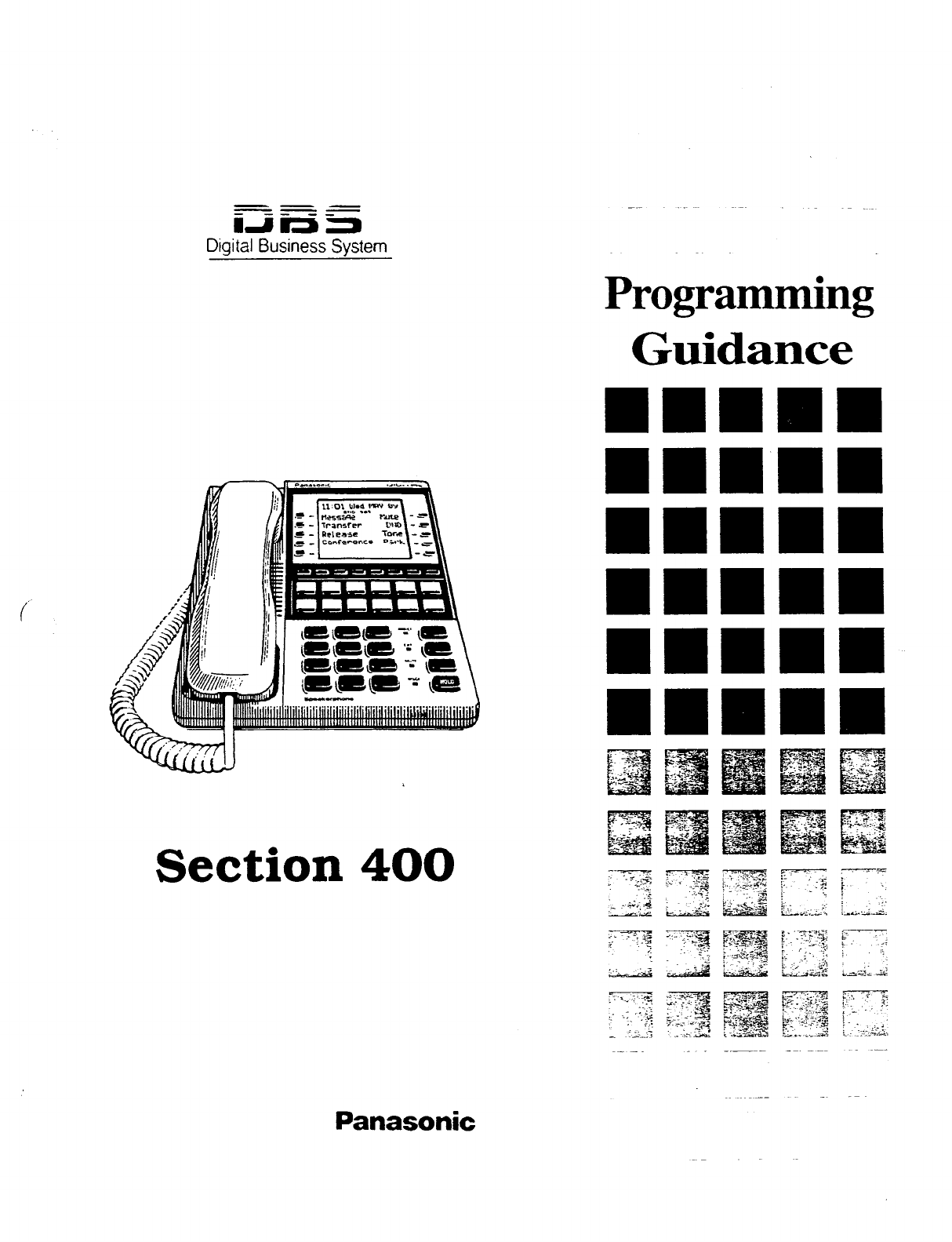
Digital Business System
Section 400
Panasonic
Technical Manuals Online! - http://www.tech-man.com
DBS Programming Instructions
WC-A / 3.0. CPC-B / 2.0 / 3.0 / 4.0
Chapter 1
General Program Outline
Prior to programming the system make
certain you have completed the following
steps.
Step 1:
Corr6rn-r the DBS system feature operations
meet the end userrequirements as outlined
in Section 700.
Step 2: ‘-“. ~ ,.,-’ :
Prepare section 450 with the end users
requirements.
Step 3:
Confirm the hardware required for the
end user.
_I._
‘ :. .,
Step 4:
Initialize the system to the default status.
See next page for this.
Step 5:
Follow the completed section 450 to
program thesystem.
The DBS program entries are divided
into 10 primary groups stored under FF
keys on the phone. The Flexible Function
Keys listed to the right show the major
programming groups. Each group
contains sub groups which combine
similar functions together.
Section 400 FE
Issue 3 July 1993
FFI
Key
System program settings
FF2
Key
Central Office line program settings
FF3
Key
Extension program settings
FF4 Key
Ring Bz Hunt group program settings
FF5 Key
Flexible key program settings for lines
& features
FF6 Key
Name & Message program settings
FF7 Key
Toll restriction program settings
FE? Key
Least cost routing program settings
FF9 Key
Copy program settings
FFIO Key
system and personal speed dial program
settings
Technical Manuals Online! - http://www.tech-man.com
Section 400 FFl
issue 2 July 1993
Before beginning to program a newly
installed DHS for the first lime, set the
system programs to the default values by
following steps
1 through 5
below:
1.TurnoffthepowerfortheMainCabinet.
(Both cabinets if a dual cabinet
configuration is being used.)
2. Slide the CPC RAM switch to the
CLEAR position.
3. Turn on the power for the Main
Cabinet(s), then
wait until the bottom
LED on the CPC card
stops flashhg.
Note: The CPC-B card will take about
twice as much time to initialize the
memory as a WC-A card does.
4. Slide the CPC RAM switch to-the RAM
HOLD position..
5. Verify the software version in the
system from any display telephone by
pressing the [ON/OFF]. [CONF], and
entering 7777.
DBS
Frogramming Instructfon~
WC-A / 3.0, WC-B / 2.0 /-3.0 / 4.0
This
procedure
must alwap be performed
priortoprogrammingtheDBSforthefb-st
time.orincaseswhereitisdesir&toretum
allchangedprogramming parameters to
the default initialized values. Failure to
initialize the CPC card may cause
operational problems.
Before upgrading fi-om one software ver-
sion to another, you must tit enter the
“New Function Reset” co
mmand (FF18#
l#).
For example, if you are upgrading from
Version 3.0 toversion 4.0,you must enter
this command. However, if
you
are up-
grading to a
point release
(4.10 to 4.11).
you do not need to enter the command.
The “New Function Reset” command
erases
Tl
and DID programming.
Technical Manuals Online! - http://www.tech-man.com
DBS Programming Instructions
WC-A / 3.0, CPC-B / 2.0 / 3.0 / 4.0
Chapter 2
Requirements for p~gramming
Section 400 FFl
Issue 3 July 1993
I
2-l PREPARING PROGRAMMING
DATA TABLE I
2-2 HOW TOACCESS
RR-G MODE
Prior to programming the DBS, complete
Section 450 (Programming Tables).
Review the desired functionality
with
the
end user, making any additional changes
as required. Ifthe end user has requested
specific functionality you are unfaxmliar
with, refer to Section 700 to confum the
.
DBS operation prior to installation.
,
WhenPreparingProgrammingDataTable
Section 450. observe the following:
Leave the default values for all
programmable areas of central o&e
lines, extensions and equipment not
being connected.
Record all program modifications made in
the programming tables of Section 450.
Program address numbers that
cannot be changed during normal system
operation have notes to this effect.
Program address numbers that are
specially marked arc available for the
specified version(s) of software only.
Programming
can
be performed from the
attendant display telephone. An
attendant telephone is connected to
extension port
1
and has an extension
number of 100, for all software versions.
Programming is also possible f?om other
extensions. See the note in “From a
-. _
Non Attendant Port”. Section Z-2.”
To enter the program mode from the
Attendant position perform the following
steps:
[ON/OFF], [PROG], ##, thenproceedwith
the FF key program desired.
Name settings can only be programmed
from the attendant telephone, or a DSS
console connected to it.
WhenprogmmminganactiveDBSsystem
through the Attendant position in a DBS
set for only one attendant, the DBS will
automatically
change to the “night” mode.
3
Technical Manuals Online! - http://www.tech-man.com
Section 400 FFl
Issue 2 July 1993
DBS
Ro@amming instructions
CPC-A / 3.0. CPC-B / 2.0 / 3.0 / 4.0
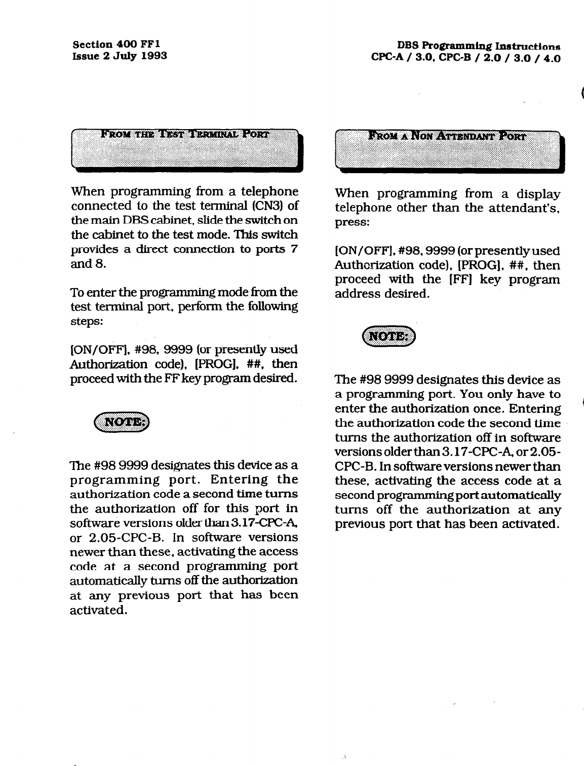
When programming from a telephone
connected to the test terminal (CN3) of
the main DBS cabinet, slide the switch on
the cabinet to the test mode. This switch
provides a direct connection to ports 7
and 8.
To enter the programming mode from the
test terminal port, perform the following
steps:
[ON/OFF], #98,9999 (or presently used
Authorization code), [PROG]. ##, then
proceed with the FF key program desired.
The #98 9999 designates this device as a
programming port. Entering the
authorization code a second time turns
the authorization off for this port in
software versions older than 3.17-CPCA,
or 2.05-CPC-B. In software versions
newer than these, activating the access
code at a second programming port
automatically turns off the authorization
at any previous port that has been
activated.
When programming from a display
telephone other than the attendant’s,
press:
[ON/OFF], #98.9999 (orpresentlyused
Authorization code). [PROG], ##. then
proceed with the [FF] key program
address desired.
The #98 9999 designates this device as
a programming port. You only have to
6
enter the authorization once. Entering
the authorization code the second time
turns the authorization off in software
versions olderthan 3.17-WC-A, or 2.05-
CPC-B. in software versions newer than
these. activating the access code at a
second
programming
port
automatically
turns off the authorization at any
previous port that has been activated.
Technical Manuals Online! - http://www.tech-man.com
DBS Programming Instructions
CPC-A / 3.0, CPC-B / 2.0 / 3.0 / 4.0 Section 400 FFl
Issue 3 JuIy 1993
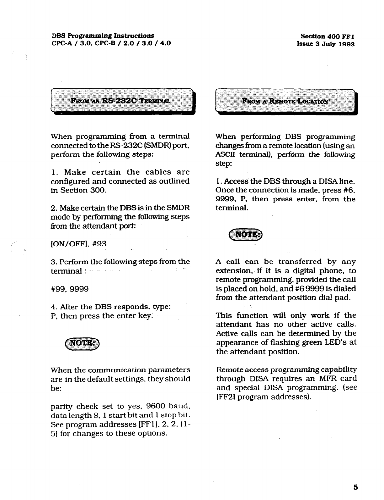
When programming from a terminal
connected to the RS232C (SMDR) port,
perform the .following steps:
1. Make certain the cables are
configured and connected as outlined
in Section 300.
2. Make certain the DBS is in the SMDR
mode by performing the following steps
i?om the attendant port:
!’
[ON/OFF], #93
!
3. Perform the following steps from the
terminal:..
. .
#99, 9999
4. After the DBS responds, type:
P, then press the enter key:
When the communication parameters
are in the default settings, they should
be:
When performing DBS programming
changes from a remote location (using an
ASCII terminal), perform the following
step:
1. Access the DBS through a DISA line.
Once the connection is made, press #6.
9999, P. then press enter. from the
terminal.
A call can be transferred by any
extension, if it is a digital phone, to
remote programming, provided the call
is placed on hold, and #6 9999 is dialed
from the attendant position dial pad.
This function will only work if the
attendant has no other active calls.
Active calls can be determined by the
appearance of flashing green LED’s at
the attendant position.
Remote access programming capability
through DISA requires an MFR card
and special DISA programming. (see
[FF2] program addresses).
parity check set to yes, 9600 baud.
data length 8, 1 start bit and 1 stop bit.
See program addresses [FFl], 2, 2.
(
l-
5) for changes to these options.
5
Technical Manuals Online! - http://www.tech-man.com
Section 400 FFl DBS
Programming Instructions
Issue 2 JuIy 1993 WC-A / 3.0. CPC-B / 2.0 / 3.0 / 4.0
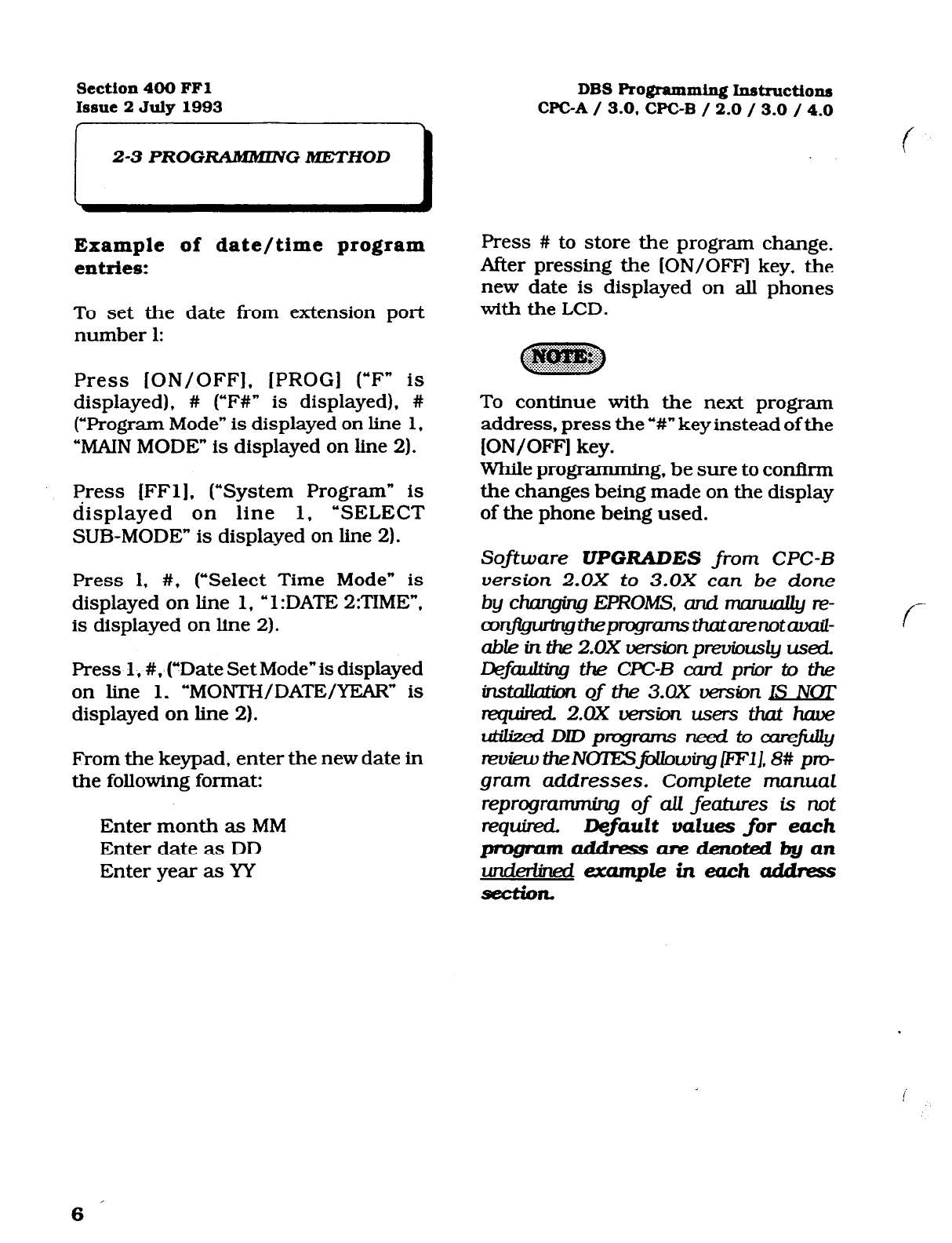
2-3 PROG- G METHOD
Example of date/time program
entries:
To set the date from extension port
number 1:
Press [ON/OFF], [PROG] (“F* is
displayed), # (“F#” is displayed), #
(“Program Mode” is displayed on line 1,
“MAIN MODE” is displayed on line 2).
Ffress
[FFl]. (“System Program” is
displayed on line 1, ‘SELECT
SUB-MODE” is displayed on line 2).
Press 1, #, (“Select Time Mode” is
displayed on line 1,
u
1 :DATE 2:TIME”.
is displayed on line 2).
Press 1,
#.
taDate Set Mode” is displayed
on line 1. “MONTH/DATE/YEAR” is
displayed on line 2).
From the keypad, enter the new date in
the following format:
Enter month as MM
Enter date as DD
Enter year as YY
Press #
to
store the program change.
After pressing the [ON/OFF] key, the
new date is displayed on all phones
with the LCD.
To continue with the next program
address, press the ‘Y#”
key
instead of the
[ON/OFF] key.
While programmin g, be sure to confirm
the changes being made on the display
of the phone being used.
Software UPGRADES from CPC-B
version 2.0X to 3.0X can be done
by changing EPROMS, and mawally IF-
wn$gwingthepngnzmsthban5otd-
able in the 2.0X rxrsbnpreviously used.
&faulting the CPC-B card
prior to the
instauation
of the 3.0X uersion IS NOT
quin?d.2.OXwMonusersthathave
LdilwiDJDprq-ams~toaareJiLuy
reukw the NOlESjiAhwing /ltW], 8# pm
gram
addresses. Complete manual
reprogramming of all features is not
requind.
Default values
for each
pmgmlnalddmssaredenotedbyan
-
f
Technical Manuals Online! - http://www.tech-man.com
DBS Programming Instructions Section 400 FFl
CPC-A / 3.0, CPC-B / 2.0 / 3.0 / 4.0 Issue 3 July 1993
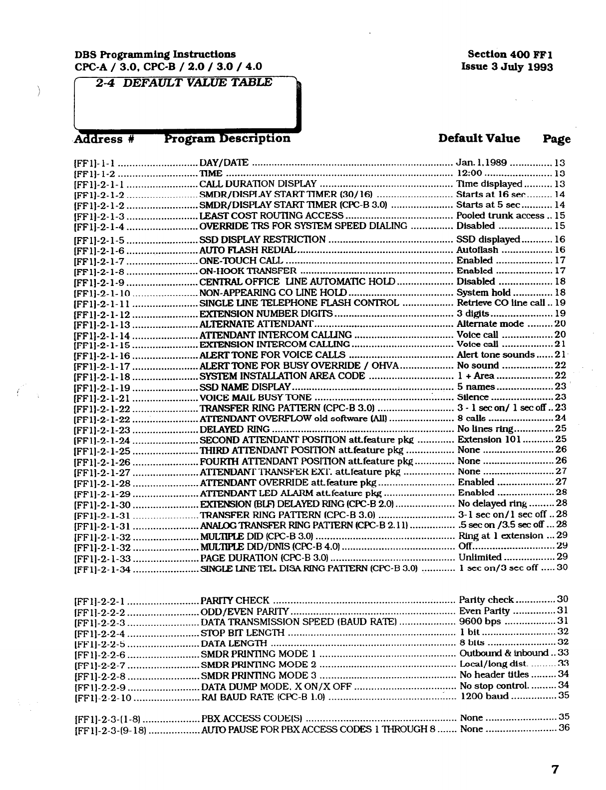
Page
Default Value
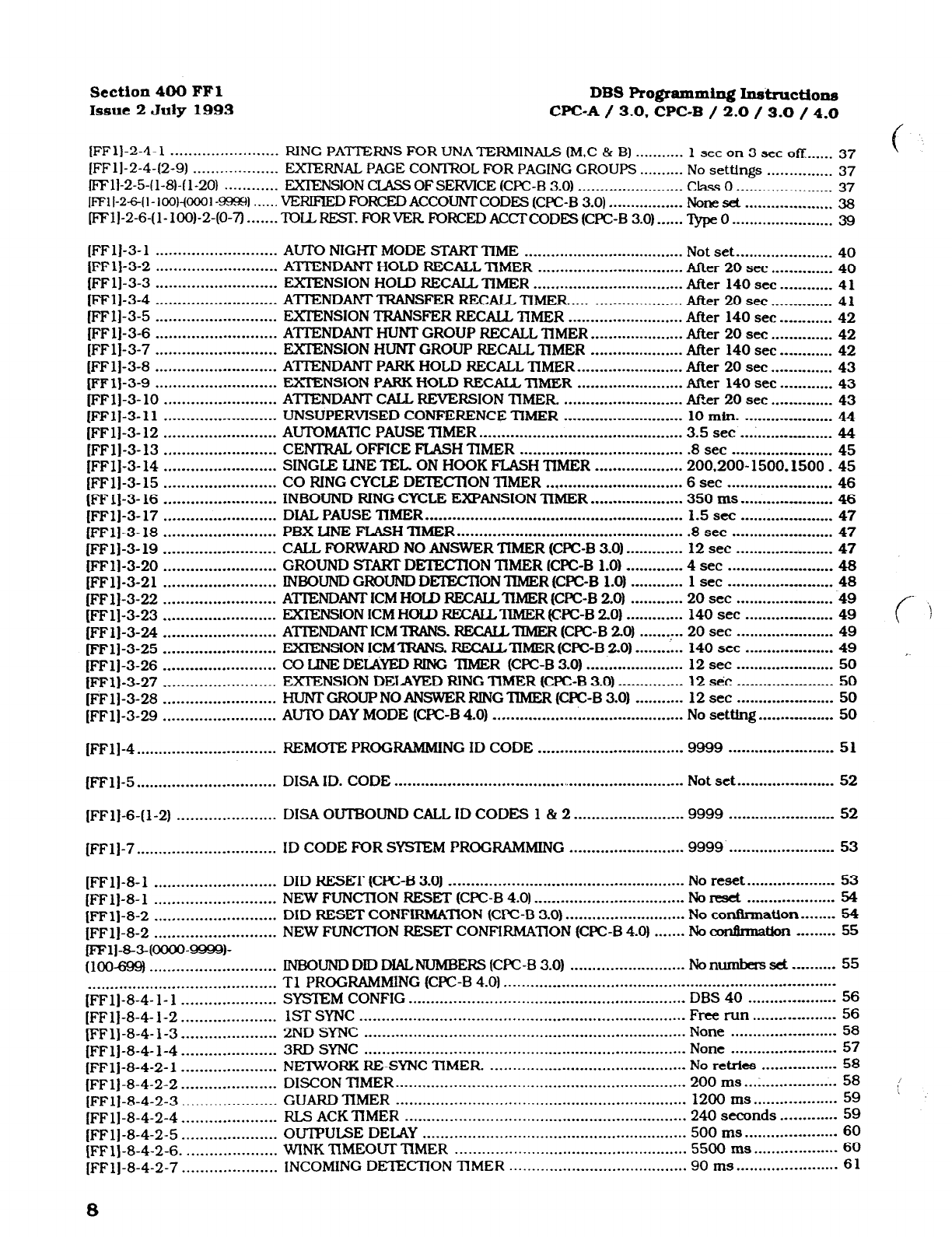
(FFI
[FFI
[FFI
[FFI
[FF 1
(FF 1
(FFI
[FFI
[FFI
[FFI
[FFI
[FFl
[FFl
[FFI
(FFI
[FFI
i::;
[FFI
[FFI
[FFl
i [FFI
[FFl
[FFI
[FFl
IFFI
-1-1 ............................
DAY/DATE .......................................................................
-1-2 ............................
TIME ................................................................................
-2-l-l .........................
CALL DURATION DISPLAY ...............................................
-2-l-2 ......................... SMDR/DISPLAY STARTTIMER (30/ 16) ...........................
-2-l-2 ......................... SMDR/DISPLAY START TIMER (CPC-B 3.0) ......................
-2- 1-3 .........................
LEAST COST ROUTING ACCESS ......................................
-2-l-4 .........................
OVERRIDE TRS FOR SYS’lEM SPEED DIALING ...............
-2-l-5 .........................
SSD DISPLAY RESTRIClION ............................................
-2-l-6
.........................
AUTG FLASH REDIAL.. .....................................................
-2-l-7 .......................
.-ONE-TOUC H CALL ...........................................................
-2- l-8 ......................... ON-HOOK TRANSFER ......................................................
-2-l-9 .........................
CENTRAL OFFICE LINE AUTOMATIC HOLD ....................
-2-l- 10 .......................
NON-APPEARING CO LINE HOLD .....................................
-2-1-11 .......................
SINGLE LINE TELEPHONE FLASH CONlROL ..................
-2-l- 12 .......................
EXTENSION NUMBER DIGITS ..........................................
-2-l- 13 .......................
ALTERNATE ATTENDANT
............. .
...................................
-2-l- 14 .......................
ATIENDANT INTERCOM CALLING ...................................
-2-l- 15 .......................
EXTENSION INTERCOM CALLING
....................................
-2-l- 16 .......................
ALERT TONE FOR VOICE CALLS .....................................
-2-l- 17 .......................
ALERTTONE FOR BUSY OVERRIDE / OHVA.. .................
Jan. 1.1989 ............... 13
12:oo.. ...................... 13
Time displayed .......... 13
Starts at 16 sec.. ....... 14
Starts at 5 sec.. ......... 14
Pooled trunk access.. 15
Disabled ................... 15
SSD displayed.. ......... 16
Autoilash .................. 16
Enabled .................... 17
Enabled .................... 17
Disabled ................... 18
System hoid .............. 18
Retrieve CO line call . -19
3 digits.. .................... 19
Alternate mode ......... 20
voice calI ................. .20
voice call .................. 21
Alert tone sounds......21.
No sound .................. 22
-2-l- 18 .......................
SYSTEM INSTALLATION AREA CODE .............................. 1 + Area ...................
.22
-2-l-19 ....................... SSDNAMEDISPLAY.. ...............................................
.
.......
5names .................... 23
-2-1-21 .......................
VOICE MAIL BUSY TONE ................................................. Silence
..................... .23
-2-l-22 .
.......................
TRANSFER RING PATTERN (CPC-B 3.0) ........................... 3 1 set on/ 1 se-c off.. 23
-2- 1-22 .......................
ATIENDANT OVERFLOW old software (All) ....................... 8 calls ......................
.24
-2-l-23 ....................... DELAYED RING ................................................................
No Iines ring.. ...........
.25
bFij-2- 1-24 ....................... SECOND ATIENDANT POSITION attfeature pkg ............. Extension 161 . . . . . . . . . . . 25
[FFlJ-2- l-25 .......................
THIRD ATTENDANT POSITION attfeature pkg ................. None . . . . . . . . . . . . . . . . . . . . . . . . . 26
[FFl]-2- l-26 .......................
FOURTH ATTENDANT POSITION a&feature pkg.. ............ None . . .._..___._............. 26
[FFl]-2-1-27 .......................
ATlENDANf TRANSFER EXT. attfeature pkg .................. None . .._..._........_........ 27
[FFl]-2- 1-28 .......................
ATTENDANT OVERRIDE att.feature pkg..
.........................
Enabled . . . . .._............. 27
[FFlJ-2- l-29.. .....................
ATTENDANT LED ALARM attfeature pkg.. ....................... Enabled .._..._............. 28
[FFl]-2- l-30 .......................
EXIENSION (Bu;l DEIAYED RlNG (CPC-B 2.0) ..................... No delayed ring . . . . . . . . . 28
[FFl]-2- 1-31 .......................
TRANSFER RlNG PATTERN (CPC-B 3.0) ........................... 3-l set on/l set off ..28
[FFl]-2- 1-31 .......................
ANALGG’IRANSFER RING PATIERN (CPC-B 2.11). ............... .5secon/3.5secoff...28
[FFl]-2- l-32 ....................... MULDPIE DID (CPC-B 3.0) ................................................. Ring at 1 extension . . . 29
[FFl]-2- l-32 .......................
MI-IL= DID/DNIS
(CPC-B 4.0) ........................................
Off
. . . . . . . . . . . . . . . . . . . . . . . . . . . . . 29
[FFlJ-2- l-33 .......................
PAGE DURATION (CPC-B 3.0) ............................................
Unlimited . . . . . . . . . . . . . . . . . . 29
(FFl]-2- l-34 .......................
SINGLE LINE ‘IEL DISA RING PAmRN (CFC-B 3.0) ............ 1 set on/3 set off . . . . . 30
[FFl]-2-2-1 ......................... PARITYCHECK ................................................................
Parity check.. ...........
.30
[FFl]-2-2-2.. .......................
ODD/EVEN PARITY ..........................................................
Even Parity ............... 3 1
[FFl]-2-2-3.. .......................
DATA TRANSMISSION SPEED (BAUD RATE) .................... 9600 bps .................. 31
[FFl]-2-2-4 STOP BlT LENGTH ........................................................... 1 bit ..........................
32
.........................
[FFl]-2-2-5 DATA LENGTH
.................................................................
8 bits ........................ 32
.........................
[FFl]-2-2-6 .........................
SMDR PRINTING MODE 1 ................................................ outbound & inhound.. 33
[FFl]-2-2-7 .........................
SMDR PRlNTlNG MODE 2
.. ..............................................
Local/long dis t. ......... 33
[FFl]-2-2-8 .........................
SMDR PIUIVI-ING MODE 3 ................................................ No header titles ........
.34
[FFl]-2-2-9 .........................
DATA DUMP MODE. X ON/X OFF.. .................................. No stop control. ........
.34
[FFl]-2-2- 10
....................... F&II
BAUD RATE (CPC-B 1.0)
............................................. 1200 baud ................ 35
[FFlj-2-3-( l-8) PBXACCESS CODE(S) ..................................................... None ........................
.35
....................
[FFl]-2-3-(9- 18) ..................
AUID PAUSE FOR PBXACCESS CODES 1 THROUGH 8 ....... None
........................ .36
7
Technical Manuals Online! - http://www.tech-man.com
Section 400 FFl DBS Pqpmming
Insimction~
Issue 2 July 1993 WC-A / 3.0, CPC-B / 2.0 / 3.0 / 4.0
[FFl]-2-4-1 ........................ RING PATIFRNS FOR UNA TERMINALS (M.C & Bl ........... 1 set on 3 set OR
...... 37
[FFl]-2-4-(2-g) ................... EXTERNAL PAGE CONTROL FOR PAGING CROUPS .......... No settings ............... 37
ml]-2-5-(l-8)-( l-20) ............ EXIENSION CIASS OF SERVICE (CPC-B 3.0) ........................
Class 0 ...................... 37
l~11-2~~1-100)-@001-~l.. .... VERIFlEDFORCEDACCOUNTCODES(CPC-B 3.0). ................ Noneset.. .................. 38
fFFl]-2-6-(l-100)-2-(0-7) ....... ToLLREsT.FoRvERFoRcED~~CODEs(CpC-B3.0) ...... TypeO.. ..................... 39
(FFl]-3- 1 ........................... AUTO NIGHT MODE START TIME .................................... Not set.. ....................
40
[FFlj-3-2 ........................... ATTENDANT HOLD RECALL ‘IlMER ................................. After 20 set .... __.
....... 40
[FF 11-3-3 ........................... EXTENSION HOLD RECALL TIMER .................................. After 140 see
............ 4 1
[FFl]-3-4 ........................... A’lllZNDAN! TRANSFER RECALL TIMER.. ...................... After 20 set .............. 41
[FFl]-3-5 ........................... EXIENSION TRANSFER RECALL IIMER .......................... After 140 set _.___. ...... 42
[FF 11-3-6 ........................... ATTENDANT HUNT GROUP RECALL ‘IIMER ..................... After 20 set .............. 42
[FFl]-3-7 ...........................
EXTENSION HUNT GROUP
RECALL ‘IIMER ..................... After 140 set .. . ......... 42
(FFl]-3-8 ........................... ATTENDANT PARK HOLD RECALL TIMER.. ......................
After 20 set .... _ ......... 43
[FFl]-3-9 ........................... EXTENSION PARK HOLD RECALL -TlMER ........................ After 140 set ............ 43
pFl]-3- 10 ......................... ATTENDANT CALL REVERSION nME R. ........................... Afk 20 set
..............
43
[FFl]-3-11
.........................
UNSUPERVISED CONFERENCE TIMER ........................... 10 min. .......... ___.
...... 44
[FFl]-3- 12 ......................... AU’IOMATIC PAUSE TIMER .............................................. 3.5 set ......... . . _._. ...... 44
[FFl]-3-13 ......................... CEIVlRAL OFFICE FLASH lJMER ..................................... .8 set ....................... 45
[FFl]-3- 14 ......................... SINGLE LINE TEL. ON HOOK FLASH TlMER .................... 200.200- 1500.1500
.
45
[FFl]-3- 15 ......................... CO RING CYCLE DETECIION TlMER ...............................
6 set .............. _. ........ 46
[FFl]-3- 16 ......................... INBOUND RING CYCLE EXPANSION TIMER.. ................... 350 ms.. ........ . _. ....... 46
[FFl]-3- 17 ......................... DIAL PAUSE lIMER.. ........................................................ 1.5 set ........ ..___ ........ 47
[FFl]-3- 18 ......................... PBX LINE FLASH ‘IlMER.. ................................................. .8 set ............ ___ ........ 47
[FFl]-3- 19 ......................... CALL FORWARD NO ANSWER TIMER (CFC-B 3.0) ............. 12 set ........... . . _._. ..... 47
[FFl]-3-20 ......................... GROUND STM DElECTlON TlMER (CFC-B 1.0) ............. 4 set ............. __ .._ ...... 48
[FFl]-3-21 ......................... INBOUND GROUND DETEC’IION TYMER (CPC-B 1.0) ............ 1 set ........... ..__._ ....... 48
[FFl]-3-22 ......................... A?TEMIANT ICM HOLD RECU’IIMER (Cm-8 2.0) ............ 20 set ...................... 49
(FFl]-3-23 ......................... EXIENSION
ICM
HOFD RECAILlIMER (CIPC-B
20) ............. 140 set ........ .._ _........ 49 (- ‘)
[FFl]-3-24 ......................... ATIENDM ICMlRANS. RECALLTIMER (Cl%-B 20) ...... .: .. 20 set .......... ..__ ........ 49
(FFl]-3-25 ......................... EXIENSION ICM’IRANS. RECAI&nMER (CFC-B 20) ........... 140 set ......... . . . ........ 49
~
[FFl]-3-26 ......................... CO LJNE DEI&ED RING ‘llMER (CPC-B 3.0) ...................... 12 set .......... .._ ......... 50
jFFl]-3-27 ......................... EXTENSION DELAYED RING TIMER (CPC-B 3.0) ............... 12 sic .......... .._ ......... 50
[FFl]-3-28 ......................... HuNTGROUPNOANSWERRlTVGTlMER(cpC-B3.0) ........... 12 set ......... ..__ ......... 50
[FFlj-3-29 ......................... AUTO
DAY MODE WC-B 4.0) ...........................................
No
setting.. ... .._ _........
50
[FFl]-4 . . . . . . . .._..._._...............
REMOTE
PROGRAMMING ID CODE . . . . . . . . . . . . . . . . . . . . . . . . . . . . . . . . . 9999 . . . . . . . . . . . .._._........ 51
[FFll-5 . . . . . . . . . . . . . . . . . . . . . . . . . . . . . . . DISA ID. CODE . . . . . . . . . .
_ . . . . . . . . . . . . . . . . . . . . . . . . . . . / ~..........................
Not set . . . . . . . . . . ..__........ 52
[FFl]-6-(l-2) ...................... DISA OUTBOUND CALL ID CODES 1 & 2.. ....................... 9999
........................
52
(FFl]-7.. ............................. ID
CODE
FOR SYSTEM PROGRAMMING ..........................
9999.. ....................... 53
[FFl]-8-1 ........................... DID RESET (CPC-B 3.0) ..................................................... No reset.. .................. 53
[FFl]-8-1 ........................... NEW FUNC’ITON RESET (CFC-B 4.0).
.................................
No reset .................... 54
(FFl]-8-2 ........................... DID RESET CONFIRMATION (CFC-B 3.0).
..........................
No confirmation ........ 54
[FFl]-8-2 ........................... NEW FUNCTION RESET CONFIRMAnON (CI’C-B 4.0) ....... No amhnation ......... 55
pFl]-8-3(oooo-9999)-
(loo_ ............................ INBOUND DID DIALNUMBERS (CFC-B 3.0) .......................... Nonumbers set .......... 55
.......................................... Tl PROGRAMMING (CFC-B 4.0). ..........................................................................
[FFl]-8-4- l- l ..................... SYSTEM CONFIG .............................................................. DBS 40 .................... 56
[FFl]-8-4-1-2.. IST SYNC ......................................................................... Free run.. ................. 56
...................
[FFlJ-8-4-l-3 ..................... 2ND SYNC
........................................................................
None ........................ 58
[FFl]-8-4-l-4 3RD SYNC
........................................................................
None ........................ 57
.....................
[FFl]-8-4-2- 1 ..................... NEIWORK RE-SYNC TIMER ............................................. No retries ................. 58
[FFlj-8-4-2-2..
...................
DISCON TIMER ................................................................. 200 ms.. ................... 58
[FFl]-8-4-2-3.. ................... GUARD TIMER
.................................................................
1200
(
ms.. ................. 59
(FFl]-8-4-2-4.. ................... RLS ACKlIMER
...............................................................
240 seconds.. ........... 59
[FFl]-8-4-2-5 ..................... OUTPULSE DELAY ........................................................... 500 ms.. ................... 60
[FFlj-8-4-2-6. .................... WINK TIMEOUT nMER .................................................... 5500
ms
................... 60
[FFl]-8-4-2-7 ..................... INCOMING DETECTION lYMER ........................................
90 ms.. ..................... 61
8
Technical Manuals Online! - http://www.tech-man.com
DBS Programming Instructions
Section
40OFFi
CPC-A/ 3.0, CPC-B / 2.0 / 3.0 /4.0
Issue
3 July
1993
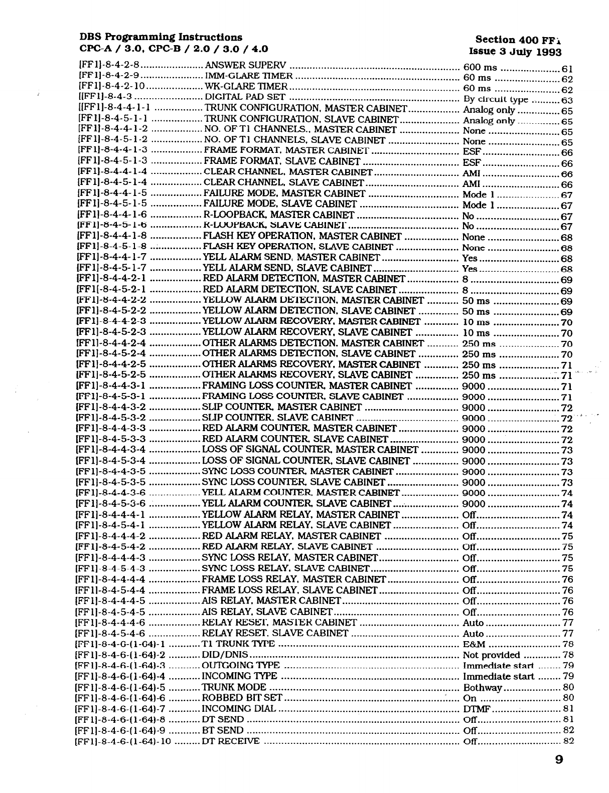
[FFl]-8-4-2-8 . . . . . . . . . . . . . . . . .._. . . ANSWER SUPERV . . . . . . . . . . . . . . . . . . . . . . . . . . . . . . . . . . . . . . . . . . . . . . .._...........
600 ms
[FFlj-8-4-2-9 . . . . ..I............... IMM-GLARE -lIMER . ..-..........._.....
61
[FFlj-8-4-2- 10 . . . . . . . . . . . . . . . . . . . . . . . . . . . . . . . . . . . . . . . . . . . . . . . . . . . . . . . . . . 60 ms 62
. . . . . . . . . . . . . . . . . . . . WK-GIARE TIMER . ..-f..................
. . . . . . . . . . . . . . . . . . . . . . . . . . . . . . . . . . . . . . . . . . . . . . . . . . . . . . . . . . . . 60 ms . . . . . .._.........._.... 62
[[FFlj-8-4-3 . . . . . . . . . . . . . . . . . . . . . . . . DIGITAL PAD SET . . . . . . . . . . . . . . . . . . . . . . . . . . . . . . . . . . . . . . . . . . . . . . . . . . .._.......
[[FFlj-8-4-4- 1- 1 By circuit type . . . . . . . . . . 63
. . . . . - . . . . . . . . . . . TFUJNK
CONFIGURATION. MASIER CABINET . . . . . . . . . . . . . . . . . . Analog only . . . . . . . . . . . _.._ 65
[FFl]-8-4-5-1-1 . . . . . . . . . . . . . . . . . . TRUNK CONFIGURATION, SLAVE CABINET . . . . . . . . . . . . . . . . . . . . . Analog only . . . .._... __ . . . . 65
[FFl]-8-4-4-1-2 . . . . . . . . . . . . . . . . . . NO. OF Tl CHANNELS., MASTER CABINET . . . . . . . . . . . . . . . . . . . . . None
[FFl]-8-4-5-1-2 . . . . . . . . . . . . . . . . . . . . . . . . . 65
. . . . . . . . . . . . . . . . . . NO. OF Tl CHANNELS. SLAVE CABINET ._....................... None
[FFl]-8-4-4- l-3 65
. . . . . . . . . . . . . . . . . . FRAME FORMAT. MASTER CABINET . . . . . . . . . . . . . . . . . . . . . . . . .
. . . . . . . . . . . . . . . . . . . . . . . . . . . . . . .
ESF
[FFl]-8-4-5-1-3 . . . . . . . . . . . . . . . . . . . . . . . . . . . 66
. . . . . . . . . . . . . . . . . . FRAME FORMAT, SLAVE CABINET . . . . . . . . . . . . . . . . . . . . . . . . . . . . . . . . . . ESF
[FFl]-8-4-4- l-4 . . . . . . . . . . . . . . . . . . . . . . . . . . .
66
. . . . . . . . . . . . . . . . . . CLEAR CHANNEL, MASTER CABINET . . . . . . . . . . . . . . . . . . . . . . . . . . . . . . AM1
[FFlj-8-4-5-1-4 . . . . . . . . . . . . . . . . . . . . . . . . . . . 66
. . . . . . . . . . . . . . . . . . CLEAR CHANNEL. SLAVE CABINET . . . . . . . . . . . . . . . . . . . . . _ . . . . . . . . . . . AMI
[FFl]-8-4-4-1-5
. . . . . . . . . . . . . . . . . . . . . . . . . . .
66
. . . . . . . . . . . . . . . . . . FAILURE MODE, MASTER CABINET . . . . . . . . . . . . . . . . . . . . . . . . . . . . . . . . Mode 1 . . . . . . . . . . . . . . . . . . . . . . 67
[FFl]-8-4-5-1-5 . . . . . . . . . . . . . . . . -. FAILURE MODE. SIAVE CABINET . . . . . . . . . . .._......_...............
Mode 1 . . . . . . . . . . . . . . . . . . . . . . 67
(FFl]-8-4-4-1-6 . . . . . . . . . . . . . . . . . . R-LOOPBACK, MASTER CABINET . . . . . . . . . . . . . . . . . . . . . . . . . . . . . . . . . . . . No . . . . . . . . . . . . . . . . . . . . . . . . . ._.. 67
[FFl]-8-4-5- l-6 . . . . . . . . . . . . . . . . . . R-LQOPBACK, SIAVE CABINEI. . . . . . . . . . . . . . . . . . . . . . . . . . . . . . . . . . . . . . . . No . . . . . . . . . . . . . . . . . . . . . . . . . . . . . 67
[FFlj-8-4-4-1-8 . . . . . . . . . . . . . . . . . . FLASH KEY OPERATION. MASTER CABINET . . . . . . . . . . . . . . . . . . . None . . . . . . . . . . . . . . . . . . . . . . . . . 68
[FFl]-8-4-5- l-8 . . . . . . . . . . . . . . . . . . FLASH KEY OPERATION. SLAVE CABINET . . . . . . . . . . . . . . . . . . . . . . None . .
. . . . . . . . . . . . . . . . . . . . . . .
68
[FFl]-8-4-4-1-7 . . . . . . . . . . . . . . . . . . YELL ALARM SEND, MASTER CABINET . . . . . . . . . . . . . . . . . . . . . . . . . . . Yes . . . . . . . . . . . . . . . . . . . . . . . . . . . .
68
[FFl]-8-4-5- l-7 . . . . . . . . . . . . . . . . . . YELL AIARM SEND. SLAVE CABINET . . . . . . . . . . . . . . . . . . . . . . . . . . . . . . Yes . . . . . . . . . . . . . . . . . . . . . . . . . . . . 68
[FFl]-8-4-4-2- 1 . . . . . . . . . . . . . . . . . . RED ALARM DETECTION. MASTER CABINET . . . . . . . . . . . . . . . . . . 8 . . . . . . . . . . . . . . . . . . . . . . . . . . . . . . . 69
[FFl[-8-4-5-2- 1 . . . . . . . . . . . . . . . . . . RED ALARM DETECTION, SLAVE CABINET . . . . . .._.............
8 69
[FFl]-8-4-4-2-2 . . . . . . . . . . . . . . . . . . YELLOW ALARM DETECTION. MASlER CABINET . . . . . . . . . . . 50
. . . . . . . . . . . . . . . . . . . . . . . . . . . . . . .
ms . . . . . . . . . . . . . . . . . . . . . . . 69
[FFl]-8-4-5-2-2 . . . . . . . . . . . . . . . . . . YELLOW ALARM DE’IECTION, SIAVE CABINET . . . . . . . . . . . . . . 50 ms . . . . . . . . . . . . . . . . . . . . . . . 69
[FFl]-8-4-4-2-3 . . . . . . . . . . . . . . . . . . YELLOW ALARM RECOVERY. MASTER CABINET’ . . . . . . . . . . . . 10 ms . . . . . . . . . . . . . . . . . . . . . . . 70
[FFl]-8-4-5-2-3 . . . . . . . . . . . . . . . . . . YELLOW ALARM RECOVERY. SLAVE CABINET . . . . . . . . . . . . . . . 10 ms . . . . . . . . . . . . . . . . . . . . . . . 70
[FFl]-8-4-4-2-4 . . . . . . . . . . . . . . . . . . OTHER ALARMS DETECTION. MASTER CABINET . . . . . . . . . . . 250 ms . . . . . . . . . . . . . . . . . . . . . 70
[FFl]-8-4-5-2-4 . . . . . . . . . . . . . . . . . .
OTHER AIARMS DETECTION. STAVE CABINET . . . . . . . . . . . . . .
250 ms . . . . . . . . . . . . . . . . . . . . . 70
[FFlj-8-4-4-2-5 . . . . . . . . . . . . . . . . . . OTHER ALARMS RECOVERY. MASTER CABINET . . . . . . . . . . . . 250 ms . . . . . . . . . . . . . . . . . . . . . 7 1
[FFlj-8-4-5-2-5 . . . . . . . . . . . . . . . . . . OTHER ALARMS RECOVERY. SLAVE CABINET . . . . . . . . . . . . . . . 250 ms . . . . . . . . . . . . . . . . . . . 1.71 .’ -
[FFl]-8-4-4-3- 1 . . . . . . . . . ..I...... FRAMING LOSS COUNTER MASTER CABINET . . . . . . . . . . . . . . . 9000 . . . . . . . . . . . . . . . . . . . . . . . . . 71
[FFl]-8-4-5-3-1 . . . . . . . . . . . . . . . . . . FRAMING LOSS COUNTER. SLAVE CABINET . . . . . . . . . . . . . . . . . . 9000 . . . . . . . . . . . . . . . . . . . . . . . . .
71
[FFlj-8-4-4-3-2 . . . . . . . . . . . . . . . . . . SLIP COUNlER MASTER CABINET . . . . . . . . . . . . . . . . . . . . . . . . . . . . . . . . . 9000 . . . . . . . _ . . . . . . . . . . . . . . . . . 72
[FFlj-8-4-5-3-2 . . . . . . . . . . . . . . . . . . SLIP COUNTER. SLAVE CABINET . . . . . . . . . . . . . . . . . . . . . . . . . . . . . . . . . . . . 9000 . . . . . . . . . . . . . . . . . . . . . . . . . 72 ’ L
(FFlj-8-4-4-3-3 . . . . . . . . . . . . . . . . . . RED ALARM COUNTER MASTER CABINET . . . . .._.............. 9000 . . . . . . . . . . . . . . . . . . . . . . . . .
72
[FFl]-8-4-5-3-3 . . . . . . . . . . .._..... RED ALARM COUNTER SLAVE CABINET . . . . . . . . . . . . . . . . . . . . . . . . 9000 . . . . . . . . . . . . . . . . . . . . . . . . . 72
[FFl]-8-4-4-3-4 . . . . . . . . . . . . . . . . . . LOSS OF SIGNAL COUNTER MASTER CABINET . . . . . . . . . . . . . 9000 . . . . . . . . . . . . . . . . . . . . . . . . . 73
[FFl]-8-4-5-3-4 . . . . . . . . . . . . . . . . . . LOSS OF SIGNAL COUNTER. SLAVE CABINET . . . . . . . . . . . . . . . . 9000 *........................ 73
[FFl]-8-4-4-3-5 . . . . . . . . . . . . . . . . . . SYNC LOSS COUNTER MASIER CABINET . . . . . . . . . . . . . . . . . . . . . . 9000 . . . . . . . . . . . . . . . . . . . . . . . . . 73
[FFl]-8-4-5-3-5 . . . . . . . . . . . . . . . . . . SYNC LOSS COUNTER SIAVE CABINET . . . . . . . . . . . . . . . . . . . . . . . . . 9000 . . . . . . . . . . . . . . . . . . . . . . . . . 73
[FFl]-8-4-4-3-6 . . . . . . . .._........ YELL ALARM COUNTER MASTER CABINET . . . . . . . . . . . . . . . . . . . . 9000 . . . . . . . . . . . . . . . . . . . . . . . . .
74
[FFlj-8-4-5-3-6 . . . . . . . . . . . . . . . . . . YELL ALARM COUNlER SLAVE CABINET . . . . . . . . . . . . . . . . . . . . . . . 9000 . . . . . . . . . . . . . . . . . . . . . . . . . 74
[FFl]-8-4-4-4- 1 . . . . . . . . . . . . . . . . . . YELLOW ALARh4 RELAY, MASTER CABINET . . . . . . . . . . . . . . . . . . . . Off . . . .._....................... 74
[FFlj-8-4-5-4-1 . .._ . . . . . . . . . . . . . . YELLOW ALARM RELAY, SIAVE CABINET . . . . . . . . ..f............ off . . . . . . . . . . . . . . . . ..I..........
74
[FFl]-8-4-4-4-2 . . . . . . . . . . . . . . . . . . RED AulRM RELAY. MASTER CABINn . . . .._.................... Off . . . . . . . . . . . . . . . . . . . . . . . . . . . . . 75
[FFlj-8-4-5-4-2 . . . . . . . . . . . . . . . . . . RED ALARM RELAY, SLAVE CABINET . . . . .._...................... Off . . . . . . . . . . . . . . . . . . . . . . . . . . . . . 75
[FFl]-8-4-4-4-3 . . . . . . . . . . . . . . . . . . SYNC LOSS RELAY, MASTER CABINET . . . . . . . . . . . . . . . . . . . . . . . . . . . . Off . . . . . . . . . . . . . . . . . . . . . . . . . . . . . 75
[FFl]-8-4-5-4-3 . . . . . . . . . . . . . . . . . . SYNC LOSS RELAY. SLAVE CABINET . . . . . . . . . . . . . . . . . . . . . . . . . . . . . . . off . . . . . . . . . . . . . . . . . . . . . . . . . . . . . 75
[FFlj-8-4-4-4-4 . . . . . . . . . . . . . . . . . . FRAME LOSS REIAY. MASTER CABINET . . . . . . . . . . . . . . . . . . . . . . . . . Off . . . . . . . . . . . . . . . . . . . . . . . . . . . . . 76
[FFl]-8-4-5-4-4 . . . . . . . . . . . ..I.... FRAME LOSS RELAY, SLAVE CABINET . . . . . . . . . . . . . . . . . . . . . . . . . . . . Off . . . . . . . . . . . . . . . . . . . . . . . . . . . . . 76
[FFlJ-8-4-4-4-5 . . . . . . . . . . . . . . . . . . AIS RELAY. MASIER CABINET . . . . . . . . . . . . . . . . . . . . . . . . . . . . . . . . . . . . . . . . . Off . . . . . . . . . . . . . . . . . . . . . . . . . . . . . 76
[FFl]-8-4-5-4-5 . . . . . . . . . _ . . . . . . . . AIS RJXAY. SLAVE CABINET . . . . . . . . . . . . . . . . . . . . . . . . . . . . . . . . . . . . .._..... Off . . . . . . . . . . . . . . . . . . . . . . . . . . . . . 76
[FFlj-8-4-4-4-6 . . . . . . . . . . . . . . . . . . RELAY RESET, MASTER CABINET . . . . . . . . . . . . . . . . . . . . . . . . . . . . . . . . . . . Auto . . . . . . . . . . . . . . . . . . . . . . . . . .
77
[FFlj-8-4-5-4-6 . . . . . . . . . . . . . . . . . . RELAY RESET, SLAVE CABINET . . . . . . . . . . .._.._......................
Auto . . . . . . . . . . . . . . . . . . . . . . . . . . 77
(FFlj-8-4-6-(1-64)-l . . . . . . . . . . . Tl TRUNK TYPE . . . . . . . . . . . . . . . . . . . . . . . . . . . . . . . . . . . . . . . . . . . . . . . . . . . . . . . . . . . . . . . E&M . . . . . . . . . . . . . . . . . . . . . . . . .
78
[FFl]-8-4-6-( l-64)-2 . . . . . . . . . . . DID/DNIS . . . . . . . . . . . . . . . . . . . . . . . . . . . . . . . . . . . . . . . . . . . . . . . . . . . . . . . . . . . . . . . . . . . . . . . . . Not provided . . . . . . . . . . . . .
78
[FFl]-8-4-6-( l-64)-3 . . . . . . . . . . . OUTGOING TYPE . . . . . . . . . . . . . . . . . . . . . . . . . . . . . . . . . . . . . . . . . . . . . . . . . . . . . . . . . . . . . Immediate start . . . . . . . . 79
[FF
l]-8-4-6-( l-64)-4 . . . . . . . . . . . INCOMING TYPE . . . . . . . . . . . . . . . . . . . . . . . . . . . . . . . . . . . _ . . . . . . . . . . . . . . . . . . . . . . . . . . Immediate start . . . . . . ,. 79
[FFl]-8-4-6-( l-641-5 . . . . .
_ . . . . .
TRUNK MODE . . . . . . . . . . . . . . . . . . . . . . . . . . . . . . . . . . . . . . . . . . . . . . . . . . . . . . . . . . . . . . . . . . Bothway . . . . . . . . . . . . . . . . . . . . 80
[FFl]-8-4-6-( l-641-6 . . . . . . . . . . .
ROBBED BIT SET . . . . . . . . . . . . . . . . . . . . . . . . . . . . . . . . . . . . . . . . . . . . . . . . . . . . . . . .
. . . . .
On . . . . . ..I.
_ . . . . . . . . . . . . . . . . . .
80
[FFl]-8-4-6-(l-64)-7 . . . . . . . . . . . INCOMING DIAL . . . . . . . . . . . . . . . . . . . . . . . . . . . . . . . . . . . . . . . . . . . . . . . . . . . . . . . . . . . . . . . MT!@ . . . . . . . . . . . . . . . . . . . . -..- 81
[FFl]-8-4-6-(l-64)-8 ._._....... DT SEND . . . . . . . . . . . . . . . . . . . . . . . . . . . . . . . . . . . . . . . . . . . . . . . . . . . . . . . . . . . . . . . . . . . . . . . . . . Off . . . . . . . . . . . . . . . . . . . . . . . .--... 81
[FFl]-8-4-6-(1-64)-g . . . . . . . . . . . BTSEND . . . . . . . . . . . . . . . . . . . . . . . . . . . . . . . . . . . . . _ . . . . . . . . . . . . . . . . . . . . . . . . . . . . . . . . . . . _ Off 82
[FFl]-8-4-6-( l-64)- 10 . . . . . . . . . IX- RECEIVE . . . . . . . . . .._........................................................
off
. . . . . . . . . . . . . . . . . . . . . . . . . . . . .
. . . . . . . . . . . . . . . . . . . . . . . . . . . . .
82
9
Technical Manuals Online! - http://www.tech-man.com
Section 400 FFl DBS Rogmmmfng Instructions
Issue 2
July
1993 CPC-A / 3.0, CPGB / 2.0 / 3.0 / 4.0
(FFl)-8-4-S-(1-64)-11 . . . . . . . .
RBTSEND . . . . . . . . . . . . . . . . . . . . . . . . . . . . . . . . . . . . . . . . . . . . . . . . . . . . . . . . . . . .._..........
Off . . . . . . . . . . . . . . . . . . . . . . . _ . . . . 83
[FFlj-8-4-6-(
l-64)-(0000-9999)-(100-699)
DNIS NUMBER SET . . . . . . . . . . . . . . . . . . . . . . . .._.......... No Nos. Asstgned . . . . . 83
[FF2]-( l-64)- 1 . . . . . . . . . . . . . . . . . . . . CENTRAL OFFICE LINE PORT OPERATlON . . . . . . . . . . . . . . . . . . . . . Ail lines tn service ..:. 84
[FF2]-(l-64)-2 . . . . . . . . . . . . . . . . . . . . TOUCH-TONE / PULSE DIALING . . . . . . . . . . . . . . . . . . . . . . . . . .._....
_ . .._
Touch tone . . . ..-_.__..... 84
(FF2]-(l-64)-3 ....................
(FF2]-(l-64)-(4-9) ...............
(FF2]-( l-64)- 10 ..................
(FF2]-(l-64)- 11 ..................
[FF2]-(l-64)- 12 ..................
[FF2]-(l-64)- 13 ..................
(FF2]-( l-64)- 14 ..................
(FF2]-(l-64)- 15 ..................
(FF2]-(l-64)- 16 ..................
(FF2]-( l-64)- 17 ..................
(FF2]-( l-64)- 18 ..................
[FF2]-(l-64)- 19 ..................
(FF2]-(l-64)-20 ..................
[FF21-(l-64)-21 ..................
(FF2]-(l-64)-21 ..................
(FF2]-(l-64)-21 ..................
(FF2]-( l-64)-22 ...................
(FF2]-(1X%)-23.. .................
(FF2]-( l-64)-24 ...................
(FF2]-(l-64)-25 ...................
(FF2]-(l-643-26 ...................
FF2]-( l-64)-26 ....................
[FF3]-(l-144)-1 ..................
[FF3]-(l-144)-2 ..................
(FF3]-(l-144)-2 ..................
[FF3]-(l-144)-3 ..................
(FF3]-( l- 144)-4 ..................
[FF3]-(l-144)-5 ..................
(FF3]-(l-144)-5 ..................
(FF3]-(l-1441-6 ..................
(FF3]-(l-144)-7 ..................
(FF3]-(l-144)-8 ..................
(FF3]-(l-144)-9 ..................
(FF3]-(l-144)-10 ................
(FF3]-(l-144)-11 ................
[FF3]-(l- 144)- 12 ................
(FF3]-(l-144)-13 ................
(FF3]-( l-144)- 14 ................
(FF3]-(l-144)-15 ................
[FF31-(l-1441-16 ................
(FF3]-(l-144)- 17 ................
[FF3]-(l- 144)-18-25 ...........
[FF3]-( l- 144)-26 ................
(FF3]-( l- 144)-27 ................
[FF3]-(l-144)-28 ................
(FF3]-( l- 144)-29 ................
[FF31-(l-144)-30 ................
(FF3]-(l-1441-31 ................
(FF3]-(l-144)-32 ................
[FF3]-(l- 144)-33 ................
(FF3]-(l-144)-34 ................
(FF3]-(l- 144)-35 ................
[FF3)-(l-1441-35 ................
[FF3]-(l-144)-36 ................
POOLED CO LINE GROUP 9 ACCESS.. ............................. All lines accessible ... 85
POOLED CO LINE GROUPS 8 l-86 ACCESS ..................... No lines accessible ... 85
CENTRAL OFFICE LINE
-IYPE
........................................... Cd’li&.
.................... 86
DISA AUTO ANSWER ........................................................
Disabled ................... 87
PRIVATE CENTRAL OFFICE LINE ..................................... No private lines ........ 87
AUTO PAUSE FOR PBX
LdIUE
............................................ Pause set ................. 88
DIAL-l-ONE DETEClION ................................................... Dial digits after dt .... 88
OUTBOUND M’MJ? SIGNAL DURATION.. .......................... 75 ms on/50 ms off
.
88
UNSUPERVISED CO CONFERENCE ................................. Dkabled ................... 89
INBOUND RING SIGNAL PATIF;RN ................................... Synchronized ........... 89
CENIRAL OFFICE LINE DISCONNECT TIMER.. ............... Greater than 350 ms .. 90
DISA SIXFZT
TIME ............................................................
Disabled ................... 90
DISA END TIME ................................................................ Disabled ................... 91
TRUNKlYPE L4xp start
................................................................................
.................. 91
LOOP START/GROUND START LINE (Cl%-B 1.11) ............ Loop start.. ............... 92
UxlP ZXm/CRND SIXRT/DlD LINE (CPC-B 20) ............... Loop start ................. 93
DID START (CPC-B 2.0)
......................................................
Immediate ................ 94
WINK START’flMER (CPC-B 2.0) ........................................ 200 ms. .................... 94
‘IYME OUT FOR DIALED m DIGl’IS (CFC-B 20) .................. 18 see ....................... 95
DID lNTERDlGlTllMEOUT (CPC-B 20) ............................. 80 ms. ...................... 95
TlPORTCLASS-TRUNK ................................................. By circuit type.. ........ 96
Tl PORT CLASS - TRUNK (CPC 4.00) ............................... By drcuit type.. ........ 96
EXTENSION
NUMBERS ....................................................
lOOto699(1Oto69). .97
‘IEFXMNAL -NPE .............................................................. Automatically
set ..... 98
TERMINAL TYPE
(WC-B 3.0) .......................................... Aut~matkaUy
set ..... 99
EM/24 PORTASSIGNMENT ............................................. Extension port 0 ....... 100
FORCED LEAST COST ROUTING.. .................................... No forced LCR .......... 10 1
FORCED ACCOUNT CODE ............................................... No code set. ..... . ........ 101
VERIFIED FORCED ACCOUNT CODES (CPC-B 3.0) ........ No code set. .............. 102
EXTENSION LOCKOUTCODE .......................................... No code set.. ............. 102
OFF HOOK SIGNAL.. ......................................................... Disabled ex 100,101 .. 103’
CALL WAITING NOTIFICATION TONE / OHVA.. ................ Disabled ................... 103
BUSY OVERRIDE SEND ................................................... Enabled.. .................. 104
BUSY OVERRIDE RECEIVE .............................................. Enabled.. .................. 104
PRIME LINE PICKUP.. ....................................................... Disabled ................... 105
AUTO PICKUP (RING LINE PREFERENCE) ........................ Enable.. .................... 105
UNSUPERVISED CONFERENCE ....................................... Disabled ................... 106
SMDR REPORT.. ............................................................... Disabled
...................
106
OFF HOOK SIGNAL VOLUME ........................................... 2nd level .................. 107
OFF HOOK SIGNAL PATIGRN.. ......................................... Continuous .............. 107
PSD NAh4E DISPLAY.. ....................................................... 5 names ................... 108
EXIENSION PAGE GROUP
...............................................
None ........................ 108
DISPLAY WHEN IDIE ....................................................... No change
................ 109
DISPLAY DURING DBS DIAL TONE ................................... No change ................ 110
DISPLAY WHEN CAluNG AN JXfENSlON ........................... No change..
..............
110
DISPLAY WHEN ACCESSING CO DIAL TONE ................... No change ................ 111
DISPLAY WHEN CONVERSING ON A CO LINE .................. No change ................ 111
DISPLAY WHEN RECEMNG A PAGE ................................ No change ................ 112
DISPIAYAFlERRECEIVINGACAILWAfI’TONE ................. No change.. .............. 112
DISPLAY WHEN DIALlNG AN EXTENSION ........................ No change ................ 113
EXIENSION DIRECTORY DISPLAY &XC-B 2.0) ..................... 5 name .................... 113
INBOUND DID DIAL NUMBER (CIX-B 2.0 to 3.0) .............. No numbers assigned .. 114
EXlENSlON CLASS OF SERVICE (CPC-B 3.0) .................... Class 0 ..................... 114
RINGBACK TONE FROM BUSY SIGNAL (CPC-B 2.0) .............. Enabled .................... 115
(Flq-( l- 1441-37 .................. Tl POKI- CL4SS--STA’IlON (CPC-B 4.0) ................................ No setllqq ................ 115
[FF3]-(l- 144)-38 ................ SINGLE LINE TELEPHONE HOOK FJASH (CPC-B 3.0) ........ HeId Itne amss ......... 116
10
Technical Manuals Online! - http://www.tech-man.com
DBS Programming Instructions section 400 FFl
WC-A/ 3.0,
CPC-B / 2.0 / 3.0 / 4.0 Issue 3July
1993
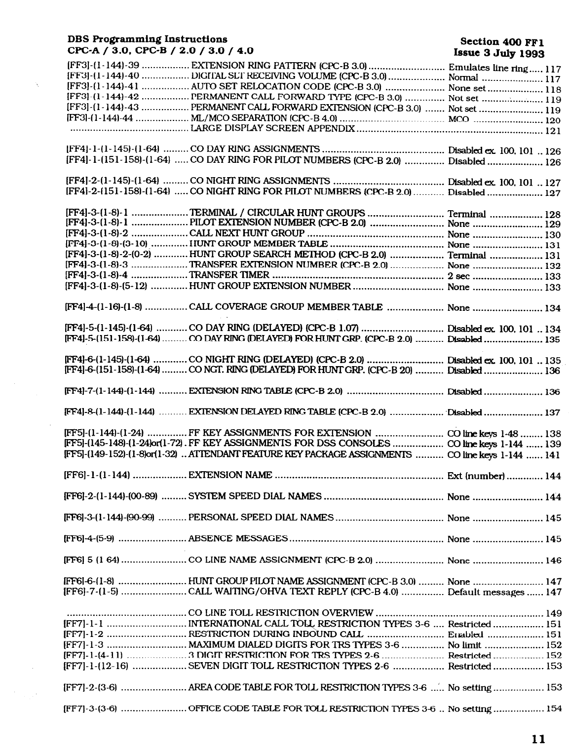
(FF3]-(l-144)-39 . . . . . . . . . . . . . . . . .
EXTENSION RING PAl-l-ERN (CPC-6 3.0) . . . . . . . . . . . . . . . . . . . . . . . . . . .
[FF3]-(l-144)-40 .._.............. DIGKALSLTRECEMNG VOLUME (CPC-B 3.0) . . . . . . . . . . . . . . . . . . . . Emulates Line rtng..... 117
Normal . . . . . . . . _..._ .._......
]FF3]-(l-144)-41
117
. . . . . . . . . . . . . . . . . AUTO SET RELOCATlON CODE (CPC-B 3.0) . . . . . . . . . . . . . . . . . . . . . None set . . . . . . . . . . . . . . . . . . . .
[FF3]-(l-144)-42
1 18
. . . . . . . . . . . . . . . . .
PERMANENTCALL FORWARD ‘IYPE (CFC-B 3.0) . . . . . . . . . . . . . . Not set . . . . . . . . . . .
. . . . . . . . . . .
[FF3]-(l-144)-43
119
. . . . . . . . . . . . . . . . . PERMANJZN’I- CAU, FORWARD EXTENSION (CPC-B 3.0)
. . . . . . .
Not set . . . . . . . . . . . . . . . . . . . . . . . 119
pF3]-(l-144)-44 . . . . . . . . . . . . . . . . . . . ML/MC0 SEPARATION (CPC-B 4.0) . . . . . . . . . . . . . . . . . . . . . . . . . . . . . . . . . . . . . MC0 . . . . . . . . . . . . . . . . . . . . . .._ _
120
. . . . . . . . . . . . . . . . . . . . . . . . . . . . . . . . . . . . . . . . . .
LARGE DISPLAY SCREEN APPENDIX . . . . . . . . . . . . . . . . . . . . . . . . . . . . . . . . . . . . . . . . . . .._....__...._..........
121
[FF4]-l-(1-145)-(1-64) ......... CO DAY RING ASSIGNMENTS ...........................................
[FF4]-l-(151-158)-(1-64) ..... CO DAYRINGFORPILOTNUMBERS(CFcB2.0) ..............
[FF4]-2-(l-145)-(1-64) ......... CO NIGHT RING ASSIGNMENTS .......................................
[FF4]-2-(151-158)-(l-64) ..... CO NIGHT RJNG FOR PILOT NUMBERS (CPC-B 2.0) ...........
[FF4]-3-(1-S)- 1 .................... TERMINAL /
CIRCULAR HUNT GROUPS ...........................
]FF4]-3-(1-S)- 1 .................... PILOT EXIENSION NUMBER (CPC-B 2.0) ..........................
[FF4]-3-( l-8)-2 .................... CALL NEXT HUNT GROUP ................................................
[FF4]-3-(l-8)-(3- 10) ............. . GROUP MEMBER TABLE ........................................
[FF4]-3-( l-8)-2-(O-23 ............ HUNT GROUP SEARCH METHOD (CPC-B 2.0) ...................
[FF4]-3-( l-8)-3 .................... TRANSFER EXIENSION NUMBER (CPC-B 2.0) ...................
[FF4]-3-(l-8)-4 .................... TRANSFER lXvlER ............................................................
[FF4]-3-( l-8)-(5- 12) ............. HUNT GROUP EXlENSION NUMBER.. ..............................
p4]4(1-16)-(1-S) ............... CALL COVERAGE GROUP MEMBER TABLE ....................
FF41-5-(l-145)-(1-64) ........... CO DAY RING (DELAYED] @XC-B 1.07) .............................
lFF4]-5(151-158)-(l-64) ......... CO DAY RING (DEIAYED) FORHUNI’GRP. (CPC-B 2.0) ..........
lFF4]-6-(l-145)-(1-64) ............ CO NIGHT RING (DELAYED) &XC-B 2.0) ...........................
rFF4]-6(151-158)~(l-64) ......... CO NGI’. RING 0 FOR HUNl-GRP. (CFC-B 20) ..........
lFF4]-7-(l-144)-(1-144) .......... IXlENSION RING TABIE (CPC-B 2.0) ..................................
FF4j-8(1-144)-(I-144) .......... EXIENSION DElAYED RING TABIE; (CPC-B 2.0) ...................
plq-(l-144)-(1-24) .............. FF KEY ASSIGNMEN-IS FOR EXl-ENSION ........................
ml-( 145- l&i)-( l-24)or(l-72J . FF KEY ASSIGNMEMS FOR DSS CONSOLES ..................
m-(149-152)-(l-S)odl-32) ..AmNDANi- FEKIURE KEYPACKAGEASSIGNMENIS ..........
[FF6]-l-(1-144) ................... EXIENSION NAME ...........................................................
pF6]-2-(I- 144)-(00-89) ......... SYSlEM SPEED DIAL NAMES ..........................................
IFFq-3(1- 1441-w-99) .......... PERSONAL SPEED DIAL NAMES.. ....................................
m]4-(5-9) ........................ ABSENCE MESSAGES.. ....................................................
[FF6]-5-( l-64) ....................... CO LINE NAME ASSIGNMENT (CPC-B 2.0) ........................
(FF6]-6-( 1-8) ........................ HUNTGROUPPIWTNAMEASSIGNhQZ~(CPC-B 3.0) .........
[FF6]-7-( l-5) ....................... CALL WA.ITlNG/OHVA TEXT REPLY (CK-B 4.0) ...............
Msabled ex 100.101 . .126
Disabled .................... 126
DisabId ex 100.101 . .127
Disabled .................... 127
Terminal ................... 128
None
.........................
129
None
.........................
130
None ......................... 131
Terminal ................... 13 1
None ......................... 132
2 set ......................... 133
None ......................... 133
None ......................... 134
Disabwex. 100.101 . .134
Disabled.. ................... 135
Disabled ac. 100.101 . .135
DkabkxI
..................... 136
Disabled ..................... 136
Disabled
..................... 137
C&deys l-48.. ...... 138
coltnekeys l-144 ...... 139
coIinekeys 1-144 ...... 141
Ext (number). ............ 144
None ......................... 144
None ......................... 145
None
.........................
145
None ......................... 146
None ......................... 147
Default messages ...... 147
..........................................
CO LINE TOLL RESTRICTlON OVERVIEW.. .........................................................
149
[FF7]-1-I ............................ INTERNAl-lONAL CALL ~RE-SlRICIlON TYPES 3-6 .... Restricted .................. 15 1
[FF7]- 1-2 ............................ RESTRICIlON DURING INBOUND CALL ........................... Enabled .................... 15 1
[FF7]-1-3 ............................ MAXIMUM DIALED DIGITS FORTRSTYPES 3-6.. ............. No hit ..................... 152
[FF7]- l-(4- 11) .................... .3 DIGlTRESlRICI’lON FORTRS’IYPES 2-6.. .................... Restricted.. ................ 152
[FF7]-l-(12-16) ................... SEVEN DIGIT TOLL RESlRICnON TYPES 2-6 .................. Restricted .................. 153
[FF7]-2-(3-6) ....................... AREACODETAI3LEFOR-IOURESIRICIlONlYPES3-6 ...... No setting.. ................ 153
[FF7]-3-(3-6) ....................... OFFICECODETABLE FORTOLLRESIRlC’IlONlYPES 3-6 .. No setthg .................. 154
11
Technical Manuals Online! - http://www.tech-man.com

Section 400 FFl
DBS Rogramming Instructions
Issue
2 Jdy 1993 WC-A / 3.0, CPC-B / 2.0 / 3.0 /
4.0
[FF7]-4-( l-4) . . . . . . . . . . . . . . . . . . . .._. SPECIAL AREA CODE TABLE FOR TRS TYPES 3-6 . . . . . . .._.. No setting . . . . . . . . . . . . . . . . . . 155 /
[FF7]-5-n-4) . . . . . . .._ _ . . . . . ..__..... SPECIAL OFFICE CODE TABLE FOR TYPES 3-6 . . . . . . . . . . . . . . . No set% . . . . . . . . . . ~ . . . . _..
156
[FF7]-6-(l-50) . . . . .._..._.......... SPECIAL7 DIGVTABlE FORlRS’IWES 2-6 . . . . . . . . . . . . . . . . . . . . . . No setttng . . . . . . . . . . . . . . . . . . 157
(FF7j-7-(1-w&)-(1-64) ........... DAY TOLL RESTRICTION lYPES O-7
................................. Type 7.. ..................... 157
[FF7J-7-(l-144)-65
................ DAY TOLL RESTRICnON TYPES O-7 ................................. No setting.. ................ 158
FF7j-8-(1-b&4)-(1-64) ........... NIGHT TOLL RESIRIC’IION TYPES O-7 ............................. m 7.. ..................... 158
m-8-( l-144)-65 ................
NIGHTToILRESlRICIlON?ypEs O-7 ................................ No setting.. ................ 159
]FF7]-9-(1-4) ....................... AREACODETABLE FOR’IRSTYPES 3-6 (GWBALCOpy) .... No set&-g.. ................ 159
[m-9-(5-8) ....................... OFFICE CODE TABIJZ FOR’lRS TYPES 3-6 (GLOBAL COPY) .. No
sett.Q
.................. 160
[FF7]-9-(9- 12) ..................... AREA&OmCECODETABIEFOR?IZS3_6(CU3BALCOPY) Nosetting.. ................ 161
[FF7]-9-( 13- 16) ................... SPECIAL OFFICE CODE TRS 3-6 (GLQBAL COPY) ............. No settiM.. ................ 162
.......................................... LEAST COST ROUITNG OVERVIEW ..................................................................... 164
[FF8]-l-(1-15)-(000-999) .....
LEAST COST ROUnNG AREA CODE ................................ No
settinff
.................. 166
[FFS]-2-(l-15)-(000-999) .....
LEAST COST ROUllNG OFFICE CODE ............................. No
setting
.................. 167
[FFS]-S( l-4)-(000-999) ....... SPECIAL LEAST COST ROUl-lNG AREA CODES TABLES .. No
setttq
.................. 168
m-4-( l-4)-( l- 15)~(000-999) . SPECIAL LEAST COST ROUllNG OFFICE CODE TABLES . No setting.. ................ 168
[FF8]-5-(l-15)-(1-48)-(1-8) .
..TlM E PRIOlU-lYROUIETABLES ....................................... No settiq.. ................ 169
[FF8]-S-(1-8)-(1-8)-(1-64) .....
LEAST COST ROUllNG Cd LINE GROUP TABLES ............ No
setttq
.................. 170
[FF8]-7-(l-8) .......................
LEAST COST ROU-l-lNG DIGIT DELJZ-I-ION TABLES.. .......... No setting.. ................ 171 f
[FF8]-8-(1-8) ....................... LEAST COST ROU’IlNG DIGIT ADD TABLES ..................... No setting .................. 172
]FFQ]-l-(1-64)-(1-64) . . . . . . . . . . .
CENTRAL OFFICE LINE COPY . . . . . . . . . . . . . . . . . . . . . . . . ..m........._..... No settirq .._............._. 174
[FF9]-2-(l-144)-(1-144) ....... EXlENSION COPY.. .......................................................... No s&m.. ................ 174
(FF9]-3-( l- 144)-( l- 144) ....... FF KEY COW ................................................................... No set-. ................. 175
[FFlOJ- l-(00-89) .................
SYSTEM SPEED DIAL NUMBERS.. .................................... No set-. ..................
176
[FFlO]-2-(l-14%)-(90-99) .....
PERSONAL SPEED DIAL NUMBERS.. ................................ No settiq.. ................ 177
i
12
Technical Manuals Online! - http://www.tech-man.com
DBS Programming Instructions
CPC-A / 3.0, CPC-B / 2.0 / 3.0 / 4.0
Section 400 FFl
Issue 3 July 1993
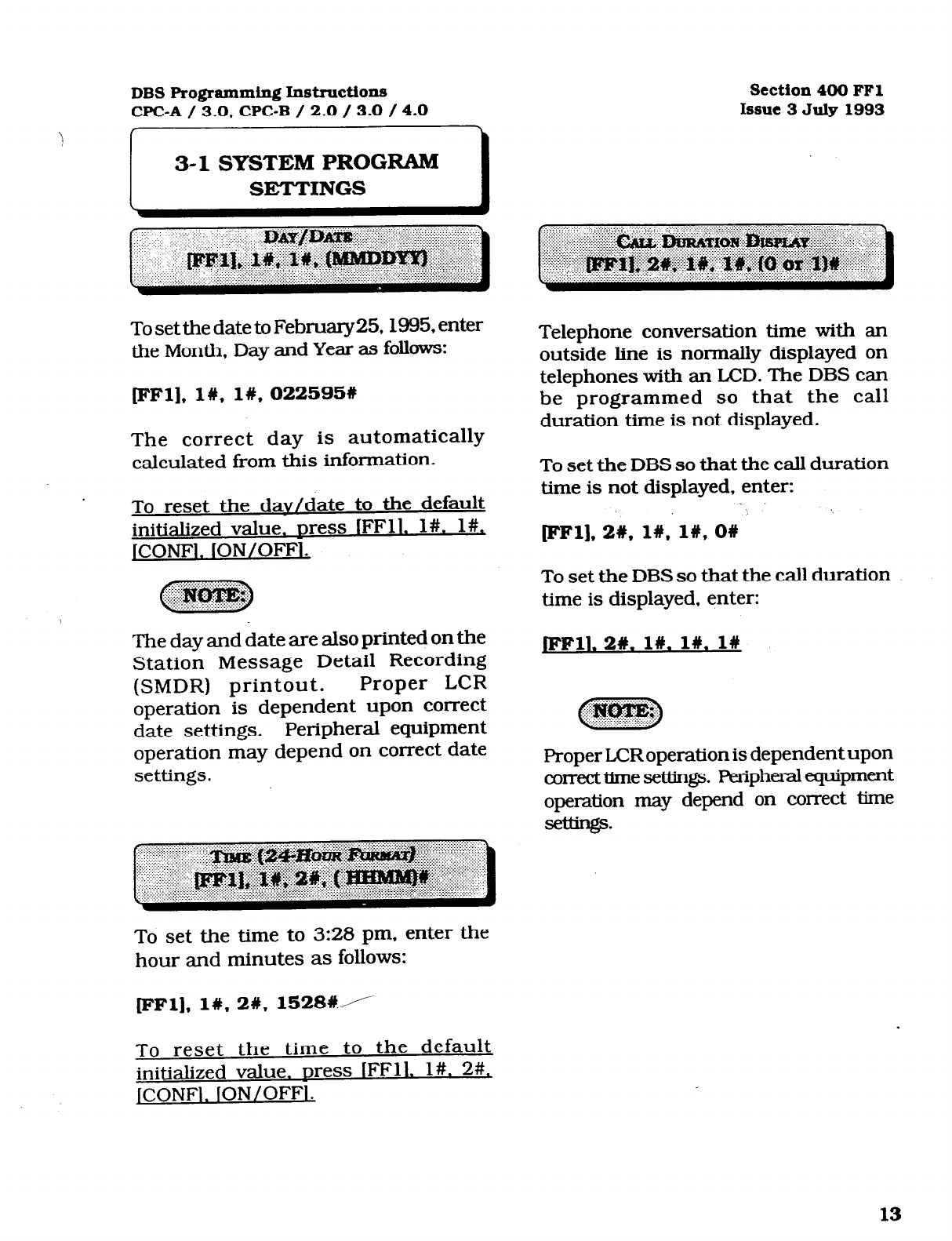
3-l SYSTEM PROGRAM
SETTINGS I
To set the date to February25,1985, enter
the Month, Day and Year as follows:
FF1],1#,1#,022595#
The correct day is automatically
calculated from this information.
To reset the dav/date to the default
initialized value. Dress IFFll. l#. l#,
JCONFl. ION/OFFl.
The day and date are also printed on the
Station Message Detail Recording
(SMDR) printout. Proper LCR
operation is dependent upon correct
date settings. Peripheral equipment
operation may depend on correct date
settings.
To set the time to 3:28 pm, enter the
hour and minutes as follows:
FFl], 1#,2#, 1528CA
Telephone conversation time with an
outside line is normally displayed on
telephones with an LCD. The DBS can
be programmed so that the call
duration time is not displayed.
To set the DBS so that the call duration
time is not displayed. enter:
[IFIFl],
2#,
1w. I#, ow
To set the DBS so that the call duration
time is displayed, enter:
JFFll.
2#.
l#. l#. l#
Proper LCRoperation is dependent upon
co~~ecttimesettings. peripheralequipment
operation may depend on correct time
seuings.
To reset the time to the default
initialized value. Dress lFFl1. l#. 2#,
ICONFl.
ION/OFF1 .
13
Technical Manuals Online! - http://www.tech-man.com
Section 400 FFl
Issue 2 July 1993
DBS Programming Instruct.io~~
WC-A / 3.0, WC-B / 2.0 / 3.0 / 4.0
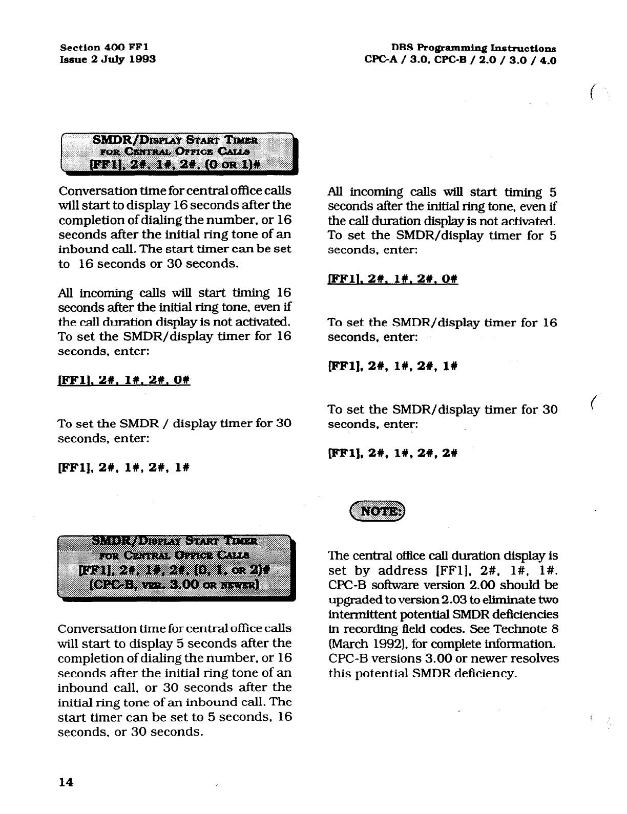
Conversation time for central office calls
will start to display 16 seconds after the
completion of dialing the number, or 16
seconds after the initial ring tone of an
inbound call. The start timer can be set
to
16
seconds or 30 seconds.
All incoming calls will start timing 16
seconds after the initial ring tone, even if
the call duration display is not activated.
To set the SMDR/display timer for 16
seconds. enter:
All incoming calls will start timing 5
seconds after the initial ring tone, even if
the call duration display is not activated.
To set the SMDR/display timer for 5
seconds, enter:
JFFll. 2w.
I#.
21. O#
To set the SMDR/display timer for 16
seconds, enter:
[eel],
2w, l#. 2w.
1w
JFFll.2#. l#. 26. OU
To set the SMDR/display timer for 30 (
To set the SMDR / display timer for 30
seconds, enter:
seconds, enter:
WFll,
2#,
l#,
2#, 28
[FFl], 2#,
l#,
2#,
1W
Conversation time for central office calls
will start to display 5 seconds after the
completion of dialing the number, or 16
seconds after the initial ring tone of an
inbound call, or 30 seconds after the
initial ring tone of an inbound call. The
start timer can be set to 5 seconds. 16
seconds, or 30 seconds.
The central office call duration display is
set by address [FFl], 2#. l#, l#.
WC-B software version 2.00 should be
upgraded to version 2.03 to eliminate two
intermittent potential SMDR defkiencies
in recording field codes. See Technote 8
(March 1992). for complete information.
CPC-B versions 3.00 or newer resolves
this potential SMDR deficiency.
14
Technical Manuals Online! - http://www.tech-man.com
DES Programming Instructions
WC-A / 3.0, CPC-B / 2.0 / 3.0 / 4.0 Section 400 FFl
Issue 3 July 1993
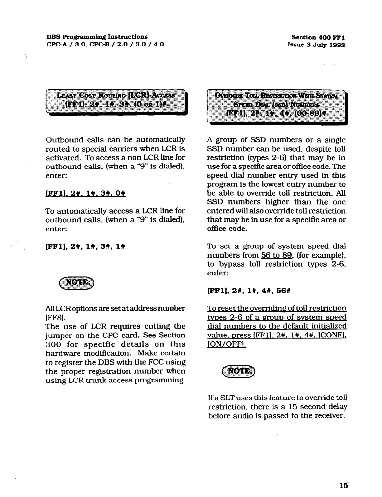
Outbound calls can be automatically
routed to special carriers when LCR is
activated. To access a non LCR line for
outbound calls, (when a “9” is dialed).
enter:
JFFll. 2#. I#. 39. 08
To automatically access a LCR line for
outbound calls, (when a “9” is dialed),
enter:
/’
cFF1],2#, I#, 3#, l#
All LCRoptions are set at address number
W-1.
The
use of LCR requires cutting the
jumper on the CPC card. See Section
300 for specific details on this
hardware modification. Make certain
to register the DBS with the FCC using
the proper registration number when
using LCR trunk access programming.
A group of SSD numbers or a single
SSD number can be used, despite toll
restriction (types 2-6) that may be in
use for a specific area or offrce code. The
speed dial number entry used in this
program is the lowest entry number to
be able to override toll restriction. All
SSD numbers higher than the one
entered will also override toll restriction
that may be in use for a specific area or
office code.
To set a group of system speed dial
numbers from 56 to 89, (for example),
to bypass toll restriction types 2-6,
enter:
[FFl], 26, 1#,4#, 568
To reset the overriding of toll restriction
tvnes 2-6 of a grout of svstem sueed
dial numbers to the default initialized
value. Dress (FF11, 2#. l#. 4#. (CONFL
jON/OFFI.
If a SLT uses this feature to override toll
restriction, there is a 15 second delay
before audio is passed to the receiver.
15
Technical Manuals Online! - http://www.tech-man.com
Section 400 FFl
Issue 2 July 1993 DBS Programming Instructions
CPC-A / 3.0, CPC-B / 2.0 / 3.0 / 4.0
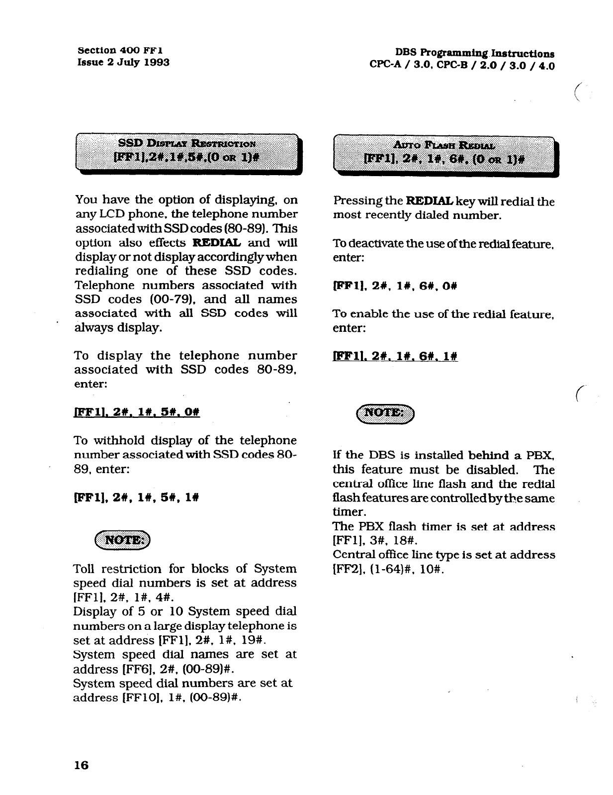
You have the option of displaying, on
any LCD phone, the telephone number
associated with SSD codes (80-89). This
option also effects
REDL&L
and will
display or not display accordingly
when
redialing one of these SSD codes.
Telephone numbers associated with
SSD codes (00-79). and all names
associated with all SSD codes will
’
always display.
To display the telephone number
associated with SSD codes 80-89,
enter:
JFFll. 2#. I#. 5w. 06
To withhold display of the telephone
number associated with SSD codes 80-
89, enter:
FFl], 2#, 19, 5#, 19
Toll restriction for blocks of System
speed dial numbers is set at address
[FFl], 2#, l#. 4#.
Display of 5 or 10 System speed dial
numbers on a large display telephone is
set at address ]FFl]. 2#. l#, 19#.
System speed dial names are set at
address [FF6], 2#. (00-89)#.
System speed dial numbers are set at
address [FFlO], l#, (00-89)#.
Pressing the
REDIAL
key will redial the
most recently dialed number.
To deactivate the use of the redial feature,
enter:
ml],
21,
l#,
6W. O#
To enable the use of the redial feature,
enter:
JFFll.
2W.
1%.
6W.
l#
If the DBS is installed behind a PBX,
this feature must be disabled. The
central office line flash and the redial
flash features are controlled
by
the same
timer.
The PBX flash timer is set at address
[FFl], 3#, 18#.
Central office line type is set at address
[FF2]. (l-64)#, lO#.
16
Technical Manuals Online! - http://www.tech-man.com
DBS Progmxmning Instructions Section 400 FFl
CPC-A / 3.0. CPC-B / 2.0 / 3.0 / 4.0 Issue 3 July 1993
The one-touch call feature provides
dialing to an extension by pressing a
single programmable key, and is enabled
by both settings. This feature cannot be
deactivated.
8’
An incoming call can be automatically
transferred to another extensionbyplacing
thecallonhold,dialingan&ensionnumber
. .
and hanging up.
To disable automatic transferring of a call,
to an internal extension, enter:
pm], 2#, l#* 8#, O#
To enable automatic transferring of a call
to an internal extension, enter:
JFFll. 2#. 1n. 88. 1w
~~-I-
. ..“fii$&@$
To transfer a call with this feature
disabled the [PROG] key must be
pressed after dialing an extension, but
before hanging up the handset. When
this option
is
enabled in a CPC-B
equipped system, intercom calls and
central office line calls can be transferred.
In systems equipped with a WC-A card,
only central office line calls can be
transferred to other extensions.
Transfer recall time for attendant(s). is set
at address [FFl], 3#, 4#.
Transfer recall time for extensions other
than the attendant(s), is set at address
[FFl], 3#, 5#.
Transfer recall time for intercom calls
from the attendant(s), is set at address
[FFl], 3#, 24#. This feature is found on
WC-B ver. 2.00 or newer. so&ware.
Transfer recall time for intercom calls
from extensions, is set at address [FFlJ,
3#, 2%. This feature is found on WC-B
ver. 2.00 or newer sofhvare.
Calls transferred by an extension, that
recall to the extension, and then are not
answered, will transfer -to extension 100.
In CPC-B ver. 2.00 and newer, up to
4
attendant positions can be designated.
Addresses to be used to set these
extensions are [FFl], 2#. l#, 24-27#.
The time for this transfer procedure is
set at address [FFl], 3#, 9#.
If a Voice Announce Unit (VAU model
VB-43708) is used, this address must be
set to the default setting as follows: [FFl],
2#, I#, 8#, l#.
17
Technical Manuals Online! - http://www.tech-man.com
Section 400 FFl
Issue 2 July 1993
DBS Pro@ammin. Instructions
WC-A / 3.0, CPCB / 2.0 / 3.0 / 4.0
Automatically places a central office-tie
that is in use on system hold, when you
press a ringing line key to answer a new
inbound call.
To disable the automatic hold feature for
a call on an existing central oflIce line,
when a new central office line call is
ringing in, enter:
pFlL 2#.1#,9#.0#
To
automatically place
an
existing
central
office line call on system hold, and to
answer a new inbound ringing central
office call, enter:
pFl],2#, 1#,9#,1#
Central office line-calls to a telephone that
does not have a dedicated key
appearance. can be placed on either
system hold or exclusive hold. Access to a
second central office line while using this
feature is not possible.
To enable the exclusive hold fature for
central of&e lines that do not appear on
a telephone. enter:
pFl],2#, l#, lO#,O#
To enable the system hold feature for
central office lines that do not appear on
a telephone, enter:
JFFll, 21. l#. low. l#
This hold feature applies to Single-Line
Telephones and/or digital telephones that
do not have a dedicated keys for a central
office line(s).
18
Technical Manuals Online! - http://www.tech-man.com
DBS Programming Instructions section 400 FF1
WC-A / 3.0, CPC-B / 2.0 / 3.0 / 4.0 Issue 3 July 1993
To provide differing capabilities for SLT
hookflash operation, this feature can be
set to retrieve DBS dial tone, or to retrieve
a central office line caller that has been
placed on hold%-om this telephone.
To activate the DBS intercom dial tone as
a result of a SLT hookflash, enter:
When installing more than 60 telenhones,
you must use a
3-digit
(100-699)
extension number dialing plan. For sites
using fewer than 60 telephones,
Zdigit
(
1 O-69). or 3digit extension numbers can
be used.
To set the DBS for 2 digit extension
number lengths, enter:
pFl],
2w,
I#, ll#,O#
lFFl],
2#,
lW, 12#,0##
/
To retrieve a central office line caller that
has been previously placed on hold at this
telephone (via a hookswitch flash), enter:
JFFll. 2w. l#. ll#. l#
When this feature is set for DBS system
dial tone, a caU placed on hold at another
telephone can be retrieved by dialing 79
and the extension number that originally
placed the call on hold.
To set the DBS for 3 digit extension
number lengths, enter:
JFFll.
29. I#. 12w.
I##
Thissettingcanadverse~~~ttyother
DBS setting that is based on extension
numbers. Examples of this are program
entries for DSS/BLF keys and call
forwarding.
ThispmgmrnoptionreouiresaconCnning#,
at the conclusion of the programming
sequence.
19
Technical Manuals Online! - http://www.tech-man.com
Section 400 FFl
Issue 2 July 1993 DBS Ro@umning Instructions
CPC-A / 3.0, CPC-B / 2.0 / 3.0 / 4.0
The alternate attendant extension wiII
have attendant features and can receive
overfknv intercom calls if the primary
attendant extension is busy.
To enable an alternate extension, enter:
pm],
2#,
l#, 13#,0#
To have no provision for an alternate
attendant, enter:
pFll. 2w. l#. 13w. l#
This feature is not available if the
*AttendwdFeaturePack~"isusedwith
CPC-B 2.00 or later software.
CaIIs transferred by an extension, that
recall to the extension. and then are not
answered, wiIl transfer to the extension
set as the attendant at this address.
‘The time for this transfer procedure is set
at address (FFl], 3#, 9#.
Intercom calls from an attendant
telephone can be established with a ring
tone, or directly by voice. After the
connectionisestablished,theattendantcan
changeii-omonetotheotherbydiaIing”1”.
To set attendant intercom calls to “tone”
calling, enter:
[eel],
2#,
l#, 14W.06
To set attendant intercom calls to “voice”
caIling. enter:
JFFll.
2#.
lW.146. l#
An alert tone for voice calling is set at
address [FFl], 2#. l#, 16#.
In CPC-B software versions earlier than
2.00. ifaSLTtmnsfersacentraIoi3celine
caI.I to an extension set for call forward no
answer, or calI forward busy, no answer,
the call wiII not transfer if addresses
[FFl], 2#, l#, 14 & 15# are set for tone
calling (O#). If this setting is required,
tmnsfeninga~tmIofEcelinecaIIkoma
SLT to an extension set as such can be
completed by dialing an “8” after the
extensionnumbertowhichthecaIIeristobe
transferred is diakd. CR-B software ver-
sionsnewerthan2.05donotrequimthe%”
tobediaIedafterthe&ensionnumberis
diakd. SeeTechnotes 9 & 12 (March 1992)
for complete tionnation.
Ifthis address is set to IFFlIt 2#. l#,
14#, l#
Pmicd' dir@, as
opposed to
ring
tone,
and
aVoice Announce Unit (modelVB-43708) is
connecfed to the
DBS, the VAU wiII not
answeranintercomcaUtoitunlessthecaIIer
diaIsa”1”akrtheVAU~ionnumber.
See Technote
14 (March
1992) for complete
information.
20
Technical Manuals Online! - http://www.tech-man.com
DBS Programming Instructions
WC-A / 3.0, CPC-B / 2.0 / 3.0 / 4.0 Section 400 FFL
Issue 3 July 1993
Intercom calls
from an extension (non
attendant) telephone can be established
with a ring tone or by voice. After the
connection is established, the extension
user can change from one to the other by
dialing “1”.
_.
To set extension intercom caIls to “tone”
calling, enter:
[eel], 2w, I#, 15#, on
Tosetextensionintercomcallingto”voice”
caII.ing, enter:
/ /
Dll. 2#.
l#. 1%. I#
An alert tone for voice caUing is set at
address [FFl], 2#, l#, 16#.
In CPC-B software versions earlier than
2.00, if a SLT transfers a central office
line calI to an extension set for caII
forward no answer, or calI forward busy,
no answer, the ca.II wiII not transfer if
addresses [FFl], 2#, l#, 14 & 15# are
set for tone calIing (0% If this setting is
required, transferring a central office line
calI from a SLT to an extension set as such
can be completed by diaIing an “8” after
the extension number to which the
caller is to be transferred is dialed.
CPC-B software versions newer than
2.05 do not require the “8”
to be dialed
after the extension number is dialed.
c..S.
T~cBL-r\t~~ 0 IzI
1 c) fA/l.-arr.k 1 aa
fnr
If this address is set to [FFl]. 2#, l#.
1%. l# rvoice” caIIing), as opposed to
ring tone, and a Voice Announce Unit
(model VB-43708) is connected to the
DBS. the VAU will not answer an
intercom calI to it unIess the caller dials
a “1” after the VAU extension number.
See Technote 14 (March 1992) for
complete information.
. .
An initial splash tone for “voice” intercom
c&Is can be sounded for 0.5 second before
the caller’s audio path is connected.
Intercom caI.Is can be set for no initiaI alert
tone by entering:
prlrll.
2#.
16.
16#. OW
Intercomcallscanbesetforaninftialalert
tone by entering:
ml],
28,
I#, 16#,1#
Technical Manuals Online! - http://www.tech-man.com
Section 400 FFl
Issue 2 July 1993
DBS Programming Instructions
WC-A / 3.0, CPC-B / 2.0 / 3.0 / 4.0
Ifan active central office caIl is interrupted
by another caller. on an extension set for
busy override, an alert tone can precede
the interruption.
To have no alert tone preceding an
interruption of an active central office
line call, enter:
When a “1” must be dialed preceding an
areacode to make along distance call, this
option must be set.
If long distance dialing requires the
dialing of a “1” prior to the area code,
enter:
[eelI, 2W, l#, 18#,0#
JFFlL 2#. 1s. 17#.0#
To provide an alert tone preceding an
intenuption of an active central o&e line
call, enter:
pFl]* 2w, 18, 17#, 1w
A conference call, or a conversation on a
telephone which has off hook voice
announce enabled, cannot be interrupted
by the busy override feature.
Extensions to be interrupted, are set at
address [FITS], (1- 144)#, lO#.
If long distance diaIing does not require
the dialingofa’1”priorto dialing an area
code. enter:
JFFll.2#. l#. 18W. l#
This setting must be enabled when toll
restriction and/or LCR is used.
Toll restriction programming is set with
[FM] addresses.
Least cost routing programming is set
with [FFB] addresses.
22
Technical Manuals Online! - http://www.tech-man.com
DBS Programming Instructions
CPC-A / 3.0, CPC-B / 2.0 / 3.0 / 4.0 Section 400 FFl
Issue 3 July 1993
Five or ten names can be displayed on the
LCD telephone directory at once. When 10
are chosen, the maximum length for each
of the names is limited to 7 characters.
To set LCD. directories for 5 name
capability, enter:
jFFll.an. l#. 19#.0#
To set LCD directories for 10 name
capability, enter:
pFl],2#, l#, 19#, 1n . .
To restrict a certain block of system speed
dial numbers, see address [FFl]. 2#, l#,
4#.
To enable or disable the display of System
speed dialnumbers see address [FFl]. 2#.
l#, 5#.
To assign a name to a system speed dial
number, see address [FFG]. 2#, (00-89)#.
Toassignanumbertoasystemspeeddial
bin, see address [FFlO], l#, (OO-89)#.
The DBS can be set to send a busy tone or
to send silence to a voice-mail port(s) at
the conclusion of a call. To set the DBS to
send silence at the conclusion of a voice
mail call, enter:
JPml. 2#. 1#.21#.0#
To set the DBS to send a busy tone at the
conclusion of a voice mail call, enter:
~1],2#. 1#,21#, l#
To utilize variable ring patterns for a
transferred call (specifically to amodem or
SLT user requiring ID of a transferred
call), this option must be used.
To set the transfer ring pattern to .4 sec.
on / 3.6 sec. off. enter:
pm,
2#. 1#.22#.0#
To set the transfer ring pattern to three .8
sec. on .2 sec. off bursts / 1.0 sec. off,
enter:
fml], 2#, 1#,22#, 1w
23
Technical Manuals Online! - http://www.tech-man.com

Section 400 FFl
Issue 2 July 1993
To set the transfer ring pattern to .8 sec.
on burst / .2 sec. off, .8 sec. on / 2.2 sec.
off enter:
pm], 21, 1#,22#,2#
To set the transfer ring pattern to .8 sec.
on / 2.2 sec. off, enter::
pm]* 2#, 1#,22#,3#
To set the transfer ring pattern to .8 sec.
on / 3.2 sec. off, enter:
[eel], 2w, 1#,22#,4#
L...
To set the transfer ring pattern to .8 sec.
on / 5.2 sec. off, enter:
(FF1].2#, 1#,22#,5#
To set the transfer ring pattern to .8 sec.
on / 3.2 sec. off / .8 sec. on / 7.2 sec. off,
enter:
ml). 2W, 1#,22#,6#
DBS Programming Instructions
CPC-A / 3.0, CPGB / 2.0 / 3.0 / 4.0
f
Toplacealimitonthenumberofincoming
calls that can be stacked to the first
attendant, a value must be placed in this
program. Calls exceeding the set limit are
automatically transferred to other
extensions. The day and night delayed
ring tables determine which extension(s)
receive overflow calls.
To set the attendant overflow feature to 8
calls, for example, enter:
mm 2w. 1#,22#.8#
Hold recalls, transferred recalls, and
reversion calls are included in this
number. Hold recalls are dependent on
attendantandextensionholdtimersfound
in addresses [FFl] 3#. 2# & 3#.
Transfer recalls are dependent on
attendant and extension transfer timers
found in addresses [FFl] 3#, 4# & 5#.
Hunt group recalls are dependent on
attendant and extension hunt group
timers found in addresses [FFl] 3#, 6# &
7#.
Reversion recalls are dependent on
attendant reversion timers found in
program address (FFl] 3#, 2# & lO#.
The attendant telephone is not included
as an overflow position in the delayed ring
table(s).
24
Technical Manuals Online! - http://www.tech-man.com
DBS Programming I.nstnxtions
WC-A / 3.0, CPC-B / 2.0 / 3.0 / 4.0 section 400 ITI
Is6ue3July1993
An alternate central office line ring
pattern is assigned in the delayed
ringing tables.
To disallow the use of delayed ring
assignments..in the DBS. enter:
JFFll. 2W. 1#.23#.0#
ToaUowtheuseofdelayedringass@mrents
in the DBS, enten
tFF1],2#, 1#,23#, l#
. . .
Delayed day ring programmmg is set at
address [FF4], 5#.
Delayed night ring programming is set at
address [FF4], 6#.
To set any DBS extension number to be
the second attendant position, this option
must be used.
To set extension number 103 to be
attendant position 2, for example. enter:
pFl],2#* 1#,24#, 103w
To reset the second attendant no&ion to
the default initialized value. Dress IFFlG
2#.
l#. 24#. lOl#. ON/OFF.
To clear the second attendant position
from extension number 101, set the
program address [FFl], 2#. l#. 24#,
ICONFJ. IOWOFFI.
The only way the second attendant
positioncanbeclearedistohaveadisplay
phone installed on the port.
The extension number must be a
number that is valid for the site.
Installation of Attendant feature package
so&ware involves the removal of EPROM
chip 1 from the CPC-B card, and
substitution of the chip with one
specifically designed with the special
Attendant features. Be sure the new
EPROM is installed in the proper
direction. See Technote 4 (September
1991). for complete information.
25
Technical Manuals Online! - http://www.tech-man.com
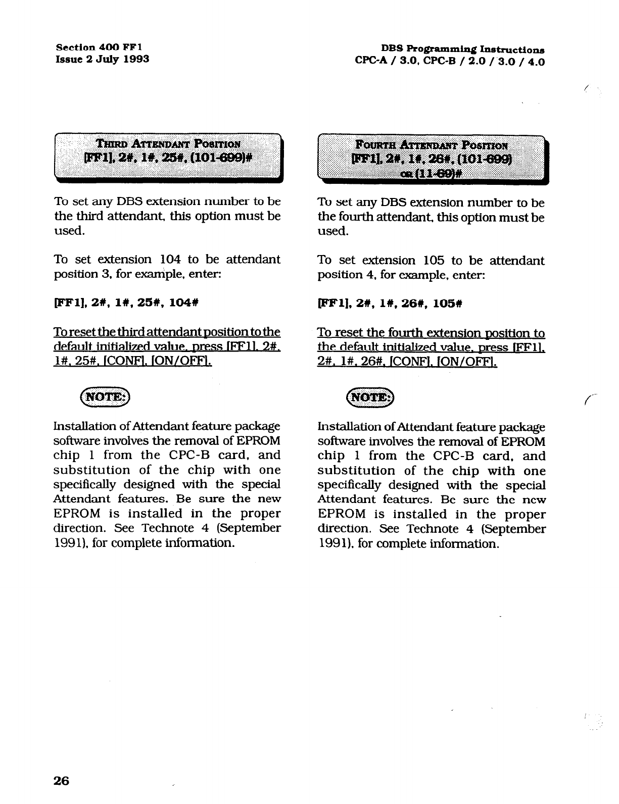
Section 400 FFl
Issue 2 July 1993
To set any DBS extension number to be
the third attendant, this option must be
used.
To set extension 104 to be attendant
position 3. for example, enter:
pFl],2#, 1#,25#, 104#
To reset the third attendant nosition to the
default initialized value.
press
IFFll. 2#,
l#. 25#. ICONFl. ION/OFFl.
Installation of Attendant feature package
software involves the removal of EPROM
chip 1 from the CPC-B card, and
substitution of the chip with one
specifically designed with the special
Attendant features. Be sure the new
EPROM is installed in the proper
direction. See Technote 4 (September
1991). for complete information.
DBS Programming Instructions
WC-A / 3.0, CPC-B / 2.0 /.3-O / 4.0
To set any DBS extension number to be
the fourth attendant, this option must be
used.
To set extension 105 to be attendant
position 4, for example. enter:
ml].2#, 1#,26#, 105W
To reset the fourth extension nosition to
the default initialized value. Dress 1FFlG
2#. l#. 26#. ICONFl. lON/OFFl.
f
Installation of Attendant feature package
software involves the removal of EPROM
chip 1 from the CPC-B card, and
substitution of the chip with one
specifically designed with the special
Attendant features. Be sure the new
EPROM is installed in the proper
direction. See Technote 4 (September
1991). for complete information.
26
Technical Manuals Online! - http://www.tech-man.com
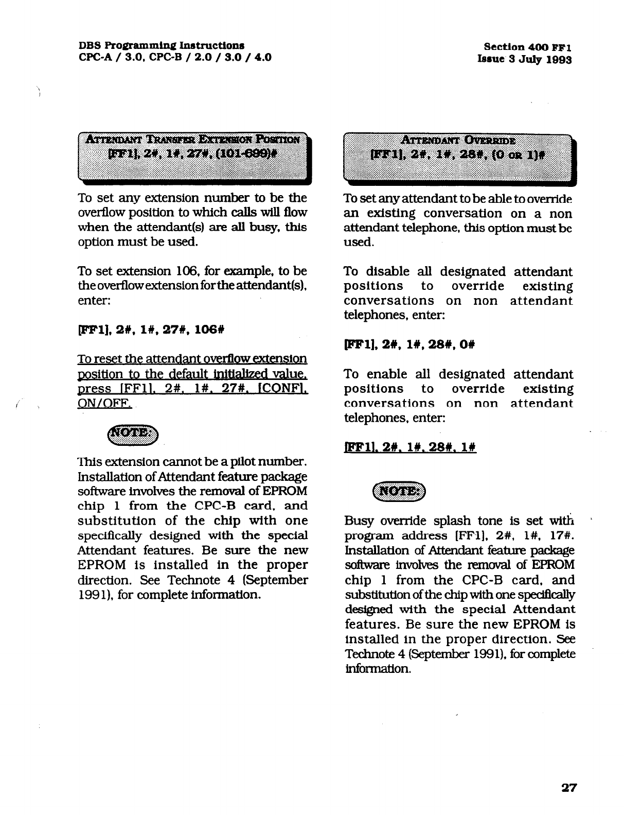
DBS Programming Instructiox~
WC-A / 3.0,
CPC-B / 2.0 / 3.0 / 4.0
Section4OO
FFl
Iesue
3
July 1093
To set any extension number to be the
overflow position to which calls will flow
when the attendant(s) are all busy, this
option must be used.
To set extension 106, for example, to be
the overflow extension forthe attendant(s),
enter:
To set any attendant to be able to override
an existing conversation on a non
attendant telephone, this option must be
used.
To disable all designated attendant
positions to override existing
conversations on non attendant
telephones, enter:
p1],2#, I#, 27#, 106# pFl],2#, 1#,28#,0#
To reset the attendant overflow extension
position to the default iniUallzed val e,
press IFFll. 2#. l#. 27#. WON:],
ON/OFF.
This extension cannot be a pilot number.
Installation ofAttendant feature package
software involves the removal of EPROM
chip 1 from the CPC-B card. and
substitution of the chip with one
specifkally designed with the special
Attendant features. Be sure the new
EPROM is installed in the proper
direction. See Technote 4 (September
199 1). for complete in.Sonnation.
To enable all designated attendant
positions to override existing
conversations on non attendant
telephones. enter:
JFFll. 2#. 1#.28#. l#
Busy override splash tone is set with /
program address [FFl], 2#, l#. 17#.
Installation of At&dam feature package
tsofhm involves the removal of EPROM
chip 1 from the CPC-B card, and
substitution of the chip with one spedficalty
designed with the special Attendant
features. Be sure the new EPROM is
installed in the proper direction. See
Technote 4 (September 1991). for complete
kknnation.
27
Technical Manuals Online! - http://www.tech-man.com

Section 400 FFl
Issue 2 July 1993 DBS Programming Instructions
CPC-A / 3.0. CPC-B / 2.0 /.3.0 / 4.0
To set an FF key that has been designated
as an alarm key on an attendant(s)
telephone to light, this option must be
used.
To disable the alarm key(s) on attendant
telephones from lighting, enter:
pm], 2#, l#, 29#, on
To enable the alarm key(s) on attendant
telephones to light, enter:
pml. 2w. l#, 29#. I#
Lnstallation of Attendant feature package
software involves the removal of EPROM
chip
1
from the CPC-B card. and
substitution of the chip with one
specifically designed with -the special 1
Attendant features. Be sure the new
EPROM is installed in the proper
direction. See Technote 4 (September
199 1). for complete information.
End
of
Attendant Feature Package
OptiOIlS
When a ringing extension is not answered,
calls can be distributed to other
extensions on the basis of extension
delayed ring programming.
To disable the extension delayed ring
option, enter:
Fell. 2#. 1w. 308. ow
To enable the extension delayed ring
option, enter:
Thisfeatureisusedtosetthetmnsferxing
signs pattern for devices
connected to an
analog extension port of the DBS. Any of
seven different ring pattern can be ’
chosen.
M
I#
2#
:3t
41
!i#
,5 Seconds ON / 3.5 M
3.0 Seconds ON/ I .O Second OFF
2.0 Srconds ON / 2.0 Seconds OFF
1 .O Seccmd ON /2.0 Seconds OFF
1 .O Second ON / 3.0 Seconds OFF
1 .O Seccmd ON / 5.0 Seconds OFF
1 .O Second ( )N I 7.0 Secmds OFF
28
Technical Manuals Online! - http://www.tech-man.com
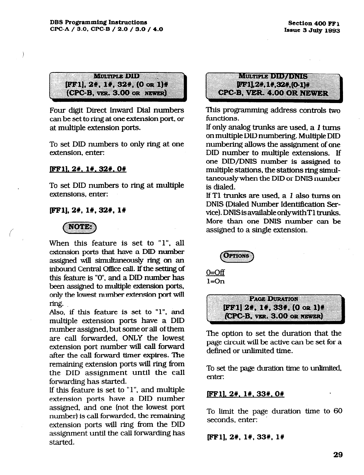
DBS Programming Instructiom~
CPC-A / 3.0, CPC-B / 2.0 / 3.0 / 4.0 Section 400 FFl
Issue 3 July 1993
Four digit Direct Inward Dial numbers
can be set to ring at one extension port, or
at multiple extension ports.
To set DID numbers to only ring at one
extension, enter:
JFFll. 2W. 1#.32#.0#
To set DID numbers to ring at multiple
extensions, enter:
ml],2#, 1#,32#, l#
When this feature is set to ” 1”. all
&e.nsion ports that have a DID number
asigned will simultaneously ring on an
inbound Central O&x call. Ifthe setting of
thisfeatureis”O”,andaDIDnumberhas
been assigned to multiple &en&on ports,
only the lowest number extension portwill
w. .
Also, if this feature is set to “1”. and
multiple extension ports have a DID
number assigned, but some or all of them
are call forwarded, ONLY the lowest
extension port number will call forward
after the call forward timer expires. The
remaining extension ports will ring from
the DID assignment until the call
foxwarding has started.
If this feature is set to ” 1”. and multiple
extension ports have a DID number
assigned. and one (not the lowest port
number) is call forwarded. the remaining
extension ports will ring ikom the DID
assignment until the call forwarding has
started.
This programming address controls two
functions.
Ifonlyanalogtrunksareused,aItums
on multiple DID numbering. Multiple DID
numbering allows the assignment of one
DID number to multiple extensions. If
one DID/DNIS number is assigned to
multiple stations, the stations ring simul-
taneouslywhen the DID or DMS number
is dialed.
IfTl trunks are used, a I also turns
on
DNIS (Dialed Number Identiiication Ser-
vice). DNISisavailableonlywithTltrunks.
More than one DNIS number can be
assigned to a single extension.
o=off
l=On
The option to set the duration that the
page circuit will be active can be set for a
deiIned or unlimited time.
Tosetthepageduraliontimetounknikd,
en&
jFF11, 2#. 1n. 33#.0#
To limit the page duration time to 60
seconds, enter:
pm], 2#, I#, 33#, 1w
29
Technical Manuals Online! - http://www.tech-man.com
Section 400 FFl
Issue 2 July 1993 DBS Programming Instructions
WC-A / 3.0, WC-B / 2.0 / 3.0 / 4.0
The ring pattern to a device that is
connected to a Panasonic ringer box, and
receives an inbound DISA call can be set
to mering patterns. The pattern can be
set to a one second on, three second off
ring burst, or it can follow any of the
patterns found in the normal Central
Oi&etransferringpattemsfoundin[FF1].
2#, l#, 22#.
TosettheSLTDiSAringpattemto l.Osec,
on / 3.0 set off, enter:
Jmll. 2R. 1#.34#.0#
To set the SLT DISA ring pattern to be the
same as the Central Office transfer ring
pattern setting, enter:
pF1],2#, 1#,34#, l#
This part of the communication
parameters checks for errors in the
tmnsmission of data for SMDR application
products, and local/remote pro-g.
To disable the parity check for all
transmission of datathmugh the SMDR
port enterI
[eel], 2%,2#, lW, ow
Tosettheparitycheckforalltransmission
of data through the SMDR port, enter:
EFll. 21y.21. I#. l#
Be Sure to properly set all axnmunication
Programming d- wfien modifjling
any single addressvalue. Communication
parametersaresetwithaddressesthatare
found at [FFl], 2#, 2#, 1 through lO##.
30
Technical Manuals Online! - http://www.tech-man.com
DBS Programming Instructions
WC-A / 3.0, CPC-B / 2.0 / 3.0 / 4.0 section 400 FFl
Issue 3 July 1993
If the parity check has been set, this
option determines whether the check is
based on an even count or an odd count.
To set the parity check for an odd value,
enter:
The data transmission speeds between
the DBS SMDR port and peripheral
equipment can be set in arange from 300
bits per second to 9600 bits per second.
To set the data transmission speed to 300
bps, enter:
pm]* 2#,2#, 2#,OW fFFl],2#,2#,3#, 1w
To set the parity check for an even value.
enter:
JFFll.2#.2#.2#. l#
Be sure to pmpexiy set all axnmunication
pmgmmming addresses when modifjing
anysingleaddressvaiue.
Communication parameters are set with
addresses that are found at lFFl], 2#, 2#. 1
thmugh lo??.
To set the data transmission speed to
1200 bps, enter:
pm], 2#,2#, 3#,2#
To set the data transmission speed to
4800 bps, enter:
pl], 2#, 2#, 3#,3#
To set the data transmission speed to
9600 bps. enter:
plw. 2#.2#. 3#.4#
Be sure to proper@ set all communication
programming addresses when modifying
single address value.
Communication parameters are setwith
addresses that are found at [FFl), 2#, 2#.
1 through lO#.
31
Technical Manuals Online! - http://www.tech-man.com
Section 400 FFl DBS Programming Instructiona
Issue 2 July 1993 WC-A / 3.0, CPC-B / 2.0 / 3.0 / 4.0
f
‘This option sets the length of the stop-bit
for transmitted data.
To set the length of the stop bit data to
1
bit. enter:
~ll.2#,2#.4#. l#
To set the length of the stop bit data to 1.5
bits, enter:
Sets the length of *he transmitted data
string at 5 to 8 bits.
To set the length of the data string at 5
bits, enter:
CFFl], 2w, 2w. w, 1w
To set the length of the data string at 6
bits, enter:
pFl],2#,2#,48,2# WFl],2#,2#. 5W, 2W
To set the length of the stop bit data to 2
bits, enter: To set the length of the data string at 7
bits, enter: f-
[eel], 2#,2#,4#, 3# IFFl],2#,2#,5#, 3%
: :......: : :.:..,: :)J::> ::: > . .
D
J&p&#@
To set the length of the data string at 8
bits, enter:
Be sure to properly set all communication
addresses when modifying any single
address value.
Communication parameters are set with
addresses that are found at [FFll, 2#, 2#,
1 through lO#.
11.2#.2#. 5#.4#
,*~
E3e sure to properly set all communication
addresses when modifying any single
address value.
Communication parameters are set with
addresses that are found at (FFl], 2#, 2#.
1 through lO#.
32
Technical Manuals Online! - http://www.tech-man.com
DBS
Programming Instructions
WC-A / 3.0, CPC-B / 2.0 / 3.0 / 4.0 Section 400 FFl
Issue 3 July 1993
The SMDR printer can record data for
outgoing calls only or both outbound
and inbound calls.
To set the SMDR. to record only
outbound call information, enter:
EFl], 2#, 2#, 6#, OW
To set the SMDR to record inbound and
outbound call information, enter:
FFll. 2#. 21. 6#. l#
The system must be in the SMDR mode
so that the printer can provide usable
SMDR data. This is done by performing
the following action from the attendant
extension: [ON/OFF], #, 93, [ON/OFF].
Al communication settings between the
printer and the DBS must be matched.
[FFl], 2#, 2#, 1 through 5# addresses
encompass these options. Be sure to
properly set all communication
addresses when modifying any single
address value. Communication
parameters are set with addresses that
are found at [FFl], 2#, 2#, 1 through
lO#.
CPC-B software version 2.00 should be
upgraded to version 2.05 to eliminate
two intermittent potential SMDR
deficiencies in recording field codes.
See Technote 8 & 12 (March 1992). for
complete information.
The SMDR printer can record data on
long-distance calls only or on all types
of outbound calls.
To record call data only on long distance
calls, enter:
[IFFl], 2#, 28, 7#, O#
To record call data on all types of
outbound calls, enter:
jFF11. 2#. 2W. 7#. l#
Be sure to properly set all communication
programming addresses when modifying
any single address value. Communica-
tion parameters are set with addresses
that are found at [FFl], 2#, 2#, 1 through
lO#.
CPC-B software version 2.00 should be
upgraded to version .2.05 to eliminate
two intermittent potential SMDR
deficiencies in recording field codes.
See Technotes 8 & 12 (March 1992). for
complete information.
33
Technical Manuals Online! - http://www.tech-man.com
Section 400 FFl
Issue 2 July 1993 DBS Programming h~~tn~ction~~
WC-A / 3.0, CPCB / 2.0 / 3.0 / 4.0
f
Titles such as Time, Duration and CO#
are printed every 60 lines if this feature
is enabled.
To disable the printing of a title line on
every 60th line of the SMDR report,
enter:
JFFll. 2#.2#. 8#. 0#
To set the printing of a title line on every
60th line of the SMDR report, enter:
The X-On/X-Off feature of the DBS is a
k&ware switch” to temporarily stop the
DBS fkom sending data out the SMDR
portiftheprinterbufferhasreceivedmore
data than it can print. The ability to send
a control code to the DBS can be enabled
on most commercially available printers.
To disable the X-On/X-Off feature of the
DBS, so that SMDR data always flows
from the SMDR port, enter:
mm 2#.2#.9#.0#
leel],2#,2#,8#. 19
Be sure to properly set all communication
addresses when modifying any single
address value. Communication
parameters are set with addresses that
are found at
[FF’l], 2#, 2#,
1 through lO#+.
CRC-B software version 2.00 should be
upgraded to version 2.05 to eliminate two
intermittent potential SMDR deficiencies
in recording field codes. See Technotes 8
81 12 (March 1992). for complete
information.
To enable the X-On/X-Off feature of the
DBS, so that SMDR data will
temporarily stop flowing when the printer
bulk is fiAl, enter:
rFFll,2#,2#, 9n, 1n
Be sure to properly set all communication
addresses when modifying any single
address value. Communication
parameters are set with addresses that
are found at [FFl], 2#, 2#. 1 through lO#.
CRC-B software version 2.00 should be
upgraded to version 2.05 to eliminate two
intermittent potential SMDR deficiencies
in recording field codes. See Technotes 8
& 12 (March 1992). for complete
information.
c-
34
Technical Manuals Online! - http://www.tech-man.com
DBS
Programming Inst~ctions
WC-A / 3.0,
CPC-B / 2.0 / 3.0 / 4.0
Section
400 FFl
Issue.3 July 1993
The baud rate that is used for remote
programming capability can be set to 300
or 1200 baud.
To set the baud rate for remote
progmmmingcapabilityto 3OObaud. enter:
fH@Fl],2#,2#, lO#,O#
To set the baud rate for remote
programming capability to 1200 baud,
enter:
jmll. 2#.2#. low. 1n
When a remote administration “B” card is
used, either baud rate setting can be
utilized. However when a remote
administration “B” card is used with a
d ual DBS having a voice mail system
connected to an analog extension port,
the baud rate must be set to 300 bps. See
Technote 3 (April 1991) for complete
information.
When a remote administration “A” card is
used, only the 300 baud rate setting can
be used. Parity check, even or odd parity,
and stop-bit length parameters are fixed
on the WC-B card. The use of peripheral
equipment with this card necessitateS that
the equipment communication pammeters
must be able to be modified. Be sure
to
properiy set all communication addresses
when modifying any single address value.
Communication pammeters are set with
addresses that are found at [FFl), 2#, 2#, 1
though lO#.
The DBS has the capability to dial 8
different PBX access codes. These codes
can be one, two. or three digits in length.
Thepurposeofthisfeatureissothatwhen
the DBS is installed behind a PBX or
Centrex, and toll restriction has been set
on the DBS, the DBS will disregard the
PBX access code digit(s) as part of the
dialed number.
To store “9” as the Grst PBX access code
(for example), enter:
pFl],2#,3#,1#,9#
To set the second PBX access code of “8”
(for example), enter:
To reset the PBX dial access code feature
tothedefaukinitializedvalue.~ressfFFll,
2#. 3#. (l-8)#. ICONFl#. fON/OFFl.
Use (FFl l] to store rr*n as awild card dialed
digit. Central office line type is set with
program address [FFZ?], (l-64)#. lO#.
The first parameter of the program code
(l-8). identies the number of the access
code. The second parameter of the
program code (O-999 or O*-99*), identifies
the actual code required to access the PBX
or Centrex.
Technical Manuals Online! - http://www.tech-man.com
Section 400 FFl DBS Programming Instructions
Issue 2 July 1993 CPC-A / 3.0, CPC-B / 2.0 / 3.0 / 4.0
To automatically insert a pause in the
PBX access code dialing (and SSD. PSD
codes), after the output of the first and/or
second, and/or third code number, use
this option. The purpose for the use of this
pause is that it may take several seconds
to connect with a central office telephone
line.
To set a pause after automatic outpuke of
the first dialed digit, (which is assumed to
be L( 1” in this example), enter:
pFl],2#,3#, 9#, l#
To set a pause after automatic outpulse of
the second dialed digit, (which is assumed
to be “2” in this example), enter:
To set a pause after automatic outpulse of
the sixth dialed digit. (which is assumed to
be “6” in this example), enter:
leel],2#,3#, 14#,6#
To set a pause after automatic outpulse
of the seventh dialed digit, (which is
assumed to be “7” in this example),
enter:
[FFl], 2#, 3W, 15#, 7W
To set a pause after automatic outpulse
of the eighth dialed digit, (which is
assumed to be “8” in this example),
enter:
@Wl].2#,3#, 16W.81
pFl],2#,3#, 10#,2#
To set apause after automatic outpuke of
the third dialed digit. (whichis assumed to
be “3” in this example), enter:
rFFl], 2#,3#, 11#,3#
To set a pause after automatic outpulse of
the fourth dialed digit, (which is assumed
to be “4” in this example), enter:
[eel], 2w, 3#, 12#,4#
To set a pause after automatic outpuke of
the fifth dialed digit, (which is assumed to
be “5” in this example), enter:
To reset the automatic cause for PBX
access code dialing to the default
initialized value. Dress lFF11. 2#. 3#,
]CONFl#. lON/OFFI.
lhe pause timer value is set with address
[FFl], 3#. 12#.
Central ofIke line flash timer options are
set at address [FF2], (l-64)+!. 13#.
pm], 2#, 3#, 13#,5#
36
Technical Manuals Online! - http://www.tech-man.com
DBS Programming In8t~~ction.s
WC-A / 3.0, CPC-B / 2.0 / 3.0 / 4.0 section 400 FFl
Issue 3 July 1993
The ring pattern for the universal night
answer (UNA) relay-terminals can be set
foracontinuousorintermittent ringburst.
To set the ring pattern for a 1 second on/
3 second off pattern, enter:
JFFll. 2#.4#. l#.OW
To set the ring pattern for a continuous
ring burst, enter:
pFl],2#,4#, lW, 1w
c j n
g@yJg$&
.::.. .:.. ::.: I.:::
When using a non central office sound.
source for the buzzer, select 1 second on/
3
second off to simulate an incomingring.
See section 300, Insta.Uation Instructions,
for more information on UNA.
To establish a central office line ring over
external page speakers when the DBS is
in the day mode, (and WC-A software is
being used) see address (FF4], l#, 73#. To
establish a central of&e line ring over
external page speakers when the DBS is
in the night mode, (and WC-A sofkvare is
being used) see address ]FF4], 2#. 73#.
To establish a central office line ring over
external page speakers when the DBS is
in the day mode, (and WC-B software is
being used) see address fFF4], l#, 145#.
To establish a central office line ring over
external page speakers when the DBS is
in the night mode, (and WC-B softwareis
being used) see address [FF4], l#. 145#.
To enableaccess toextemalpaginggroups
0 through 7. the relay(s) must be
activated.
To reset the external nage interface to the
default initialized value Dress. IFFll. 2#,
#. ICONFl.
lON/OFFl.
Extension class of service provides a
method to set defined groups of extension
features to a class of senrice. This class of
service is then assigned to an extension or
group of extensions, as desired. The 20
extension features can be assigned in any
order and in any amount to any of the 8
classes of service.
37
Technical Manuals Online! - http://www.tech-man.com
section 400 FFl DBS Pro@amd.n~ hstnrctions
Issue 2 July 1993 CPC-A / 3.0, CPC-B / 2.0 / 3.0 / 4.0
The 20
allowable features that can be
classified into any class of service
grouping are:
Fa8tum
Dial Tone On/Off 1#50)
2 Head/Handset Exchange (#51) -
3 BGM On/Off (#53)
/ 4 (Absence Message Set/Reset (71)
5 Call Forward Set/Reset (72)
6 Do Not Disturb (73)
7 Station Lockout (74)
8 Park Access (75)
9 Park Pick Up (76)
10
Meet
Me Answer (771
1 11 IUNA Pickuo (78)
12 IDirect pick Up (79) I
13 /Group Pick Up (70)
14 (Tone/Voice Mode (1)
15 /Message Waiting Set (2)
16 IBusy Override (4)
17 Icall waitin&? (3)
Single Une Telephone Transfer (8)
To set the extension class of sewice to the
default initialized value.
press
IFFll. 2#,
5#. (l-8)#. (l-20)#. O#. iON/OFFl.
The default value of this feature sets full
restriction on all classes of service. The
extension programmmg for this feature,
[FF3], (OOl-144)#, 35#, provides for all
features to be available on all extension
ports. When the DBS is in the default
condition, the extension programming of
this feature takes precedence.
There are 100 verified forced account
codes available for use. A four digit
account code ranging from 0001 to
9999 is checked against a list of up to
100 preset values. If the value of the
code matches one of the preset values,
Central Office line access is granted.
For example, to set verified forced
account code 1 to a value of 8888, enter:
[eel],
2#, 6#,
l#, 8888W
For example, to set verified forced account
code 56 to a value of 5656, enter:
CFFl],2#, 6#,56#, 5656#
To reset the ve&ed forced account code
parameter to the default initial&d value,
press IFFll. 2#. 6#t. (l-lOO)#. lCOm .
~ON/OFFl.
Forced Account codes found in earlier
versions of software have been replaced
by this feature. The account code feature
(non forced) remains.
A veiled forced account code of 0000 is
invalid.
When viewing an SMDR report, the veri-
fied forced account that was used to ac-
cess a Central Office line will appear
starting in position 70 of the call record
line.
38
Technical Manuals Online! - http://www.tech-man.com
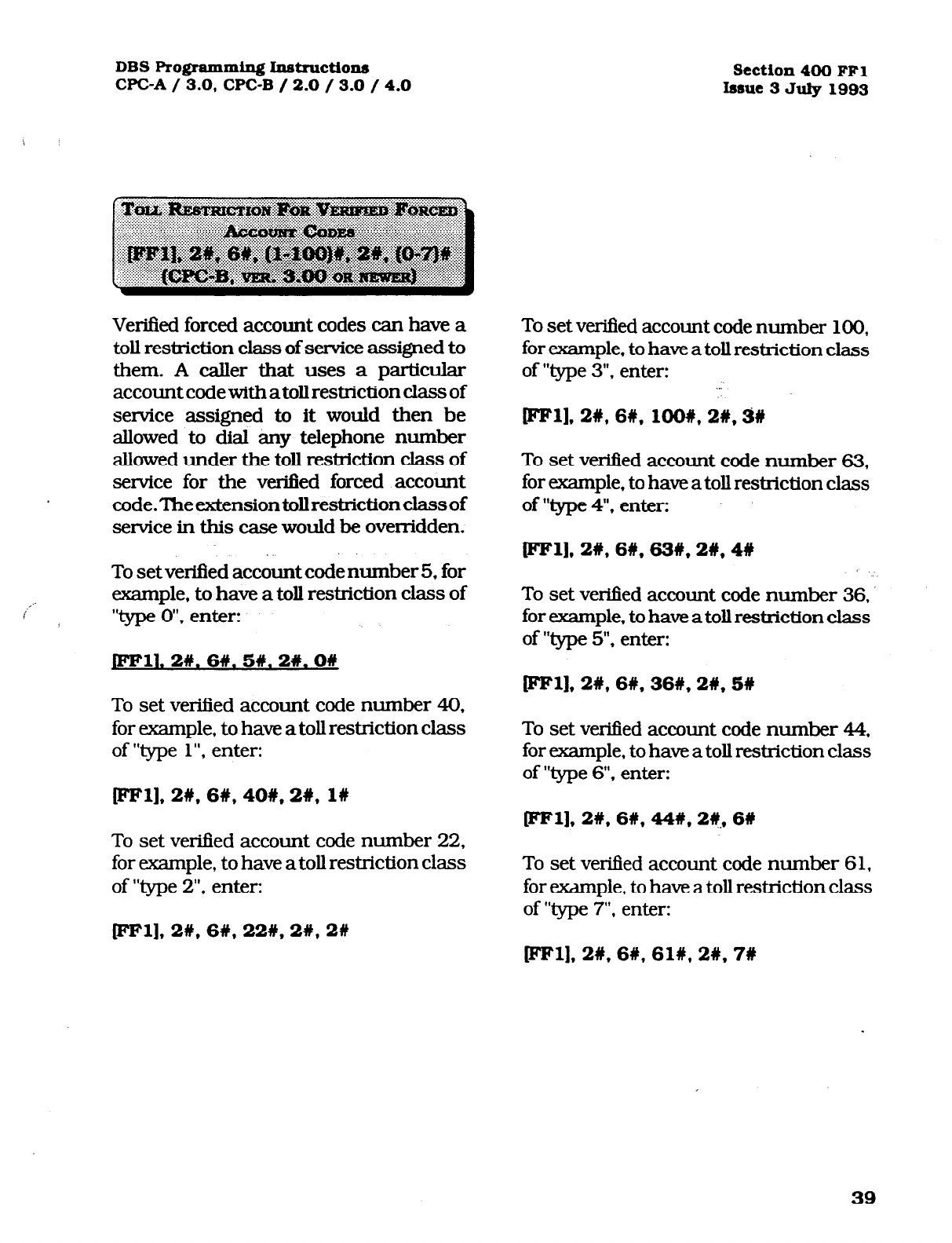
DBS Programming Instructions Section 400 FFl
CPC-A / 3.0, CPC-B / 2.0 / 3.0 / 4.0 Issue 3 July 1993
Verified forced account codes can have a
toll restriction class of service assigned to
them. A caller that uses a particular
account code with atoll restriction class of
service assigned to it would then be
allowed to dial any telephone number
allowed under the toll restriction class of
service for the verified forced account
code.Theextensiontollrestrictionclassof
service in this case would be overridden.
To set verified account code number 5, for
example, to have a toll restriction class of
“type 0”. enter:
To
set verified account code number 40,
for example, to have a toll restriction class
of “type
1”.
enter:
To set verified account code number
100,
for example, to have a toll restriction class
of “type 3”. enter:
IFFll, 2#, 6#, lOO#, 2#,3#
To set verified account code number 63,
for example, to have a toll restriction class
of “type 4”. enter:
[eel], 29,6#, 63#, 2#, 4W
To set vetied account code number 36.
for example, to have a toll restriction class
of “type 5”. enter:
Wl], 2#, 6#, 36#, 2W.58
To set verified account code number 44,
for example, to have a toll restriction class
of “type 6’. enter:
ml], 2#,6#,40#,2#, 1W ml], 2#,6#, 44#, 2#, 6U
To set vetied account code number 22,
for example, to have a toll restriction class
of “type 2”. enter: To set verified account code number 61,
for example, to have a toll restriction class
of “Iypc 7”. enter:
[eel], 2#,6#,22#,2#,2# Bl], 2#,6#,61#,2#,7#
39
Technical Manuals Online! - http://www.tech-man.com
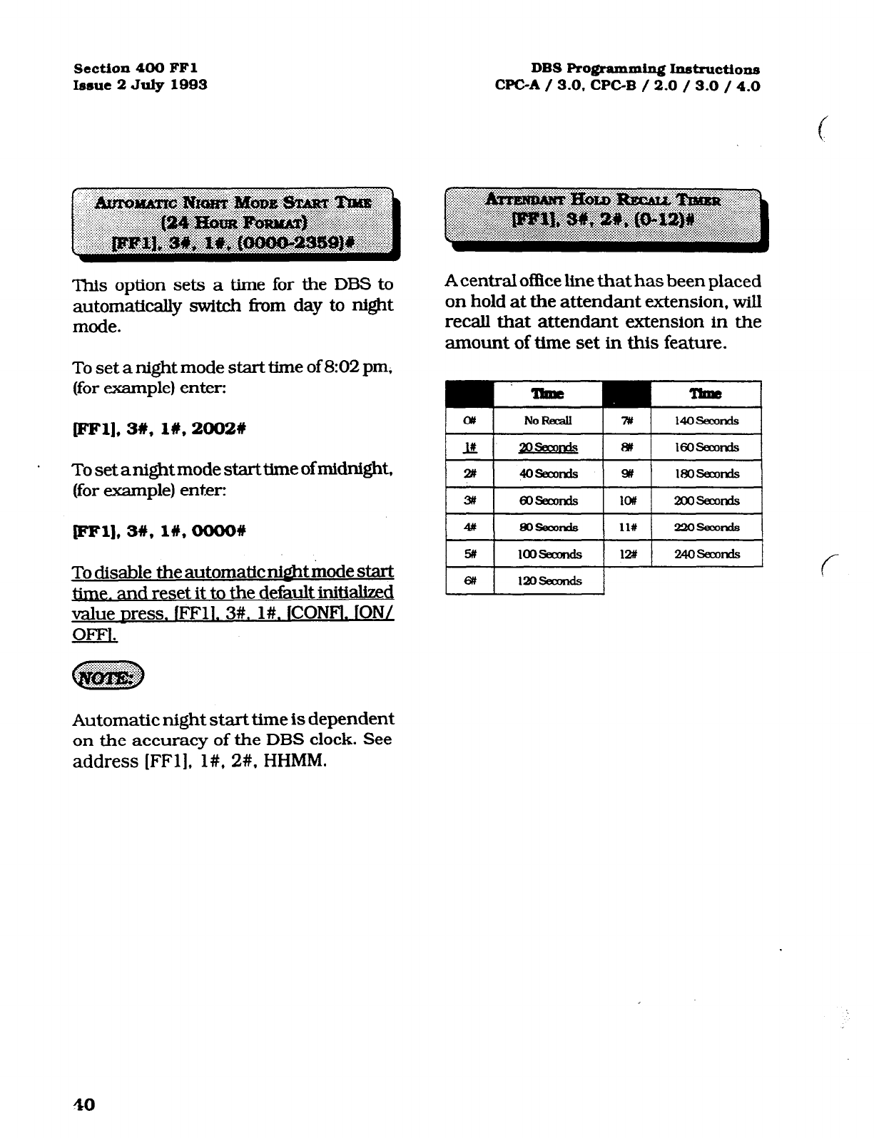
Section4OOFFl
Issue2JuIylQQS DBSPro@amm~~~ctions
WC-A/ S.O.CPCB / 2.0 / 3.0 / 4.0
‘This option sets a time for the DBS to
automatically switch from day to night
mode.
A central office line that has been placed
on hold at the attendant extension, will
recall that attendant extension in the
amount of time set in this feature.
To set a night mode start time of 8:02 pm,
(for example) enter:
pwl],3#, 1#,2002#
To set anight mode start time of midnight,
(for example) enter:
pF1],3#,1#,oooo#
To disable the automatic m&t mode start
time. and reset it to the default initialized
value Dress. IFFll. 3#. l#. ICONFl. ION/
OFFl.
cm NoRed 7t4
14OsecOnds
Automatic night start time is dependent
on the accuracy of the DBS clock. See
address (FFl], l#, 2#, HHMM.
40
Technical Manuals Online! - http://www.tech-man.com
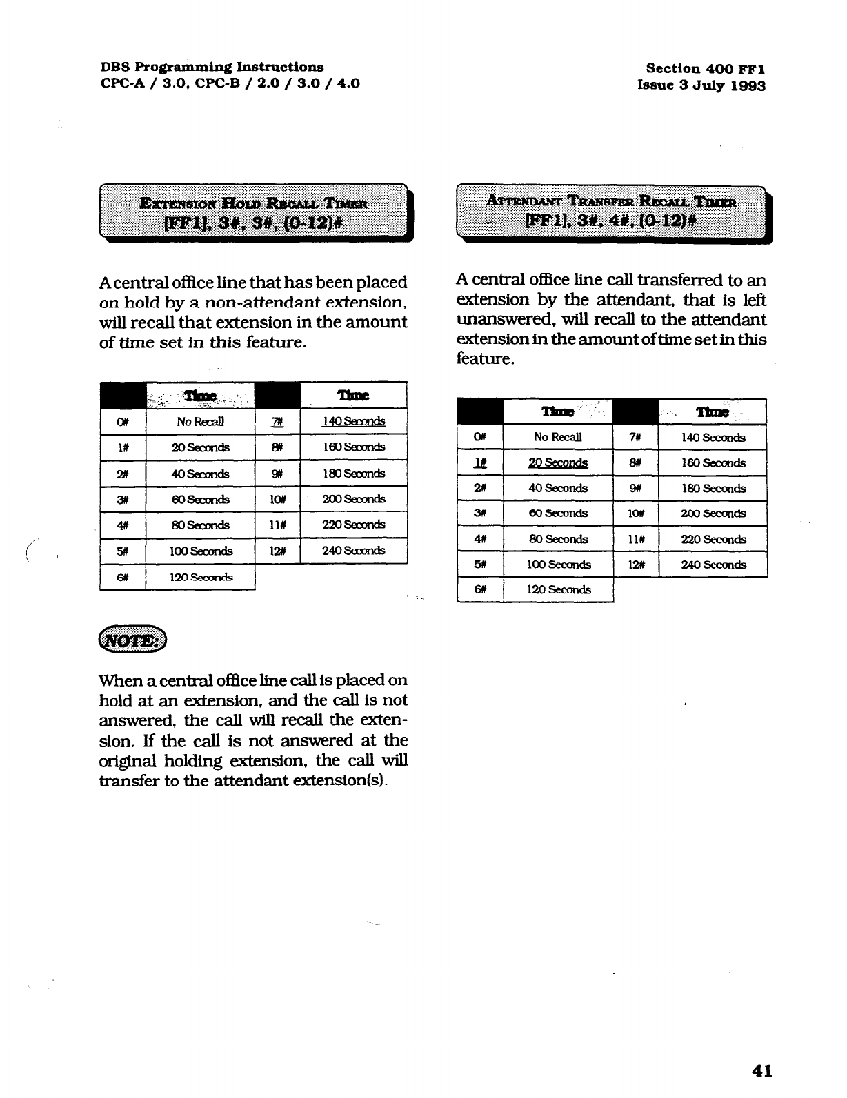
DBS Programming Instructions
WC-A / 3.0, CPC-B / 2.0 / 3.0 / 4.0 section 400 FFl
Issue 3 July 1993
A central oflice line that has been placed
on hold by a non-attendant extension,
will recall that extension in the amount
of time set in this feature.
. ._
A central of&e line call transferred to an
extension by the attendant, that is left
unanswered, will recall to the attendant
extensionintheamountofUmesetinthis
feature.
o#
No Recall 7# 14ofL?econds
I& 20Secoods a# 160 seconds
# 80!3ecmh
ll# 220 !5iecalds
5# loo SeaRIds 12# 24oisecmds
When a central office line call is placed on
hold at an extension. and the call is not
answered, the call will recall the exten-
sion. If the call is not answered at the
original holding extension, the call will
transfer to the attendant extension(s).
41
Technical Manuals Online! - http://www.tech-man.com
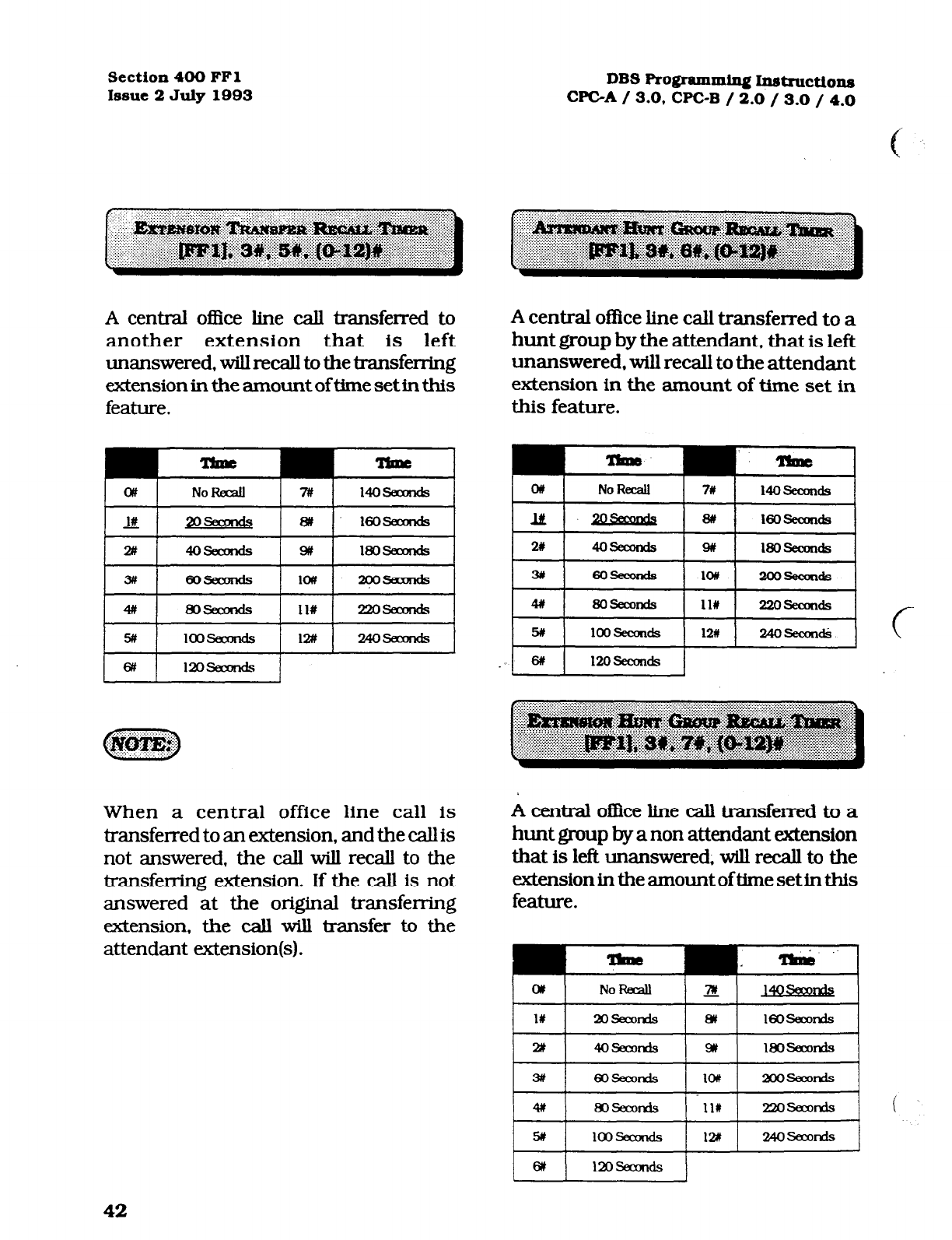
Section 400 FFl
Issue 2 July 1993 DBS
Programming Instnmtions
WC-A / 3.0. CPC-B / 2.0 / 3.0 / 4.0
A central office line call transferred to
another extension that is left
unanswered, will recall to the transferring
extension in the amount of time set in this
feature.
A central office line call transferred to a
hunt group by the attendant, that is left
unanswered, will recall to the attendant
extension in the amount of time set in
this feature.
o/t NolhA 7# 14osfxmds
on
No Recall fry 14OSeCOtldS
When a central office line call is
transferred to an extension, and the call is
not answered, the call will recall to the
transferring extension. If the call is not
answered at the original transferring
extension, the call will transfer to the
attendant extension(s).
lit - 8ft 160 seconds
2# 4oz3ecods w 180 seamds
3# 6oseaKKis IOU -2m.?eaJn&~
# Bosemnds
111 22oseconds
5# 1OOZkCOdS 12# 24oseculA
6# 120 secunds
A central o&e line call transferred to a
hunt group by a non attendant &ension
that is left unanswered, will recall to the
extension in the amount of time set in this
feature.
T&!l ‘.
42
Technical Manuals Online! - http://www.tech-man.com
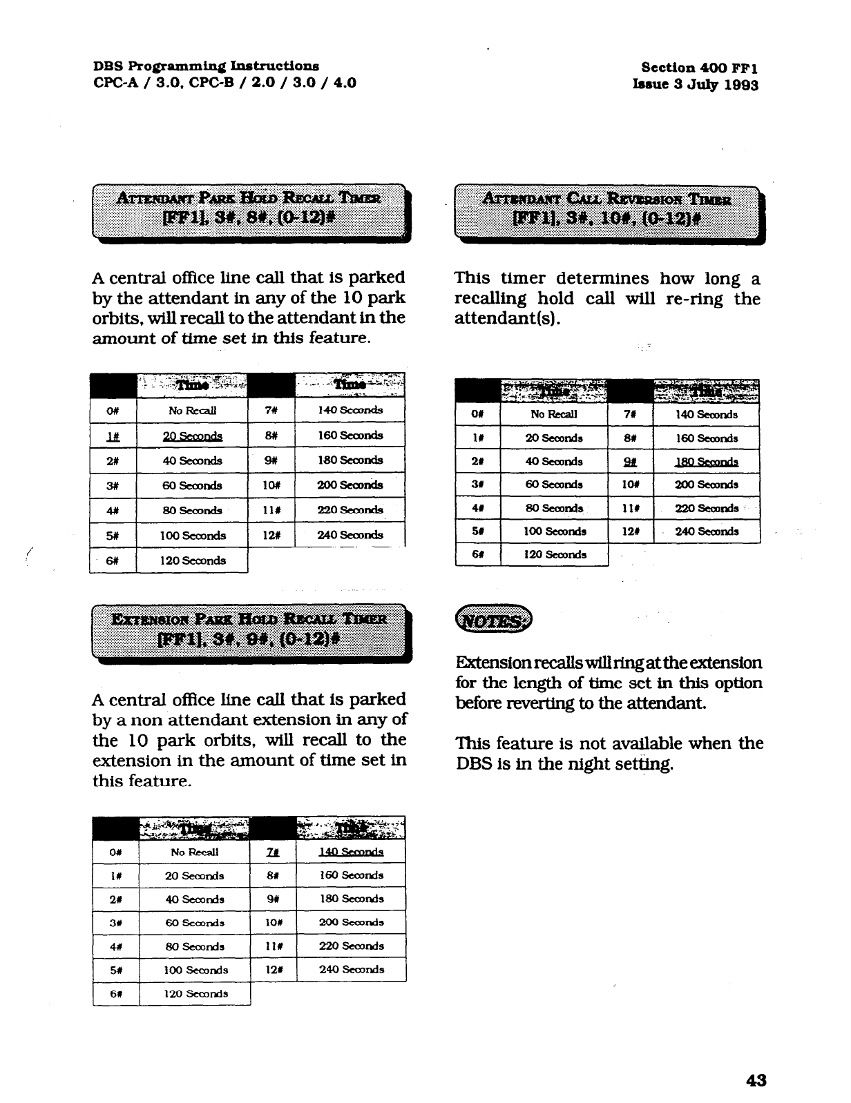
DBS Programming I.nstructions
CPC-A / 3.0. CPCB / 2.0 / 3.0 / 4.0 Section 400 FFl
hmue 3 July 1993
A central of&e line call that is parked
by the attendant in any of the 10 park
orbits, will recall to the attendant in the
amount of time set in this feature.
I 3# I 6ot3camds
I *o# I 2ooseoDnds
I
A central of&e line call that is parked
by a non attendant extension in any of
the 10 park orbits, will recall to the
extension in the amount of time set in
this feature.
This timer determines how long a
recalling hold call will re-ring the
attendant(s).
11
ExtensionrecallswUlringattheextension
for the length of time set in this option
before reverting to the attendant.
This feature is not available when the
DBS is in the night settjng.
Technical Manuals Online! - http://www.tech-man.com
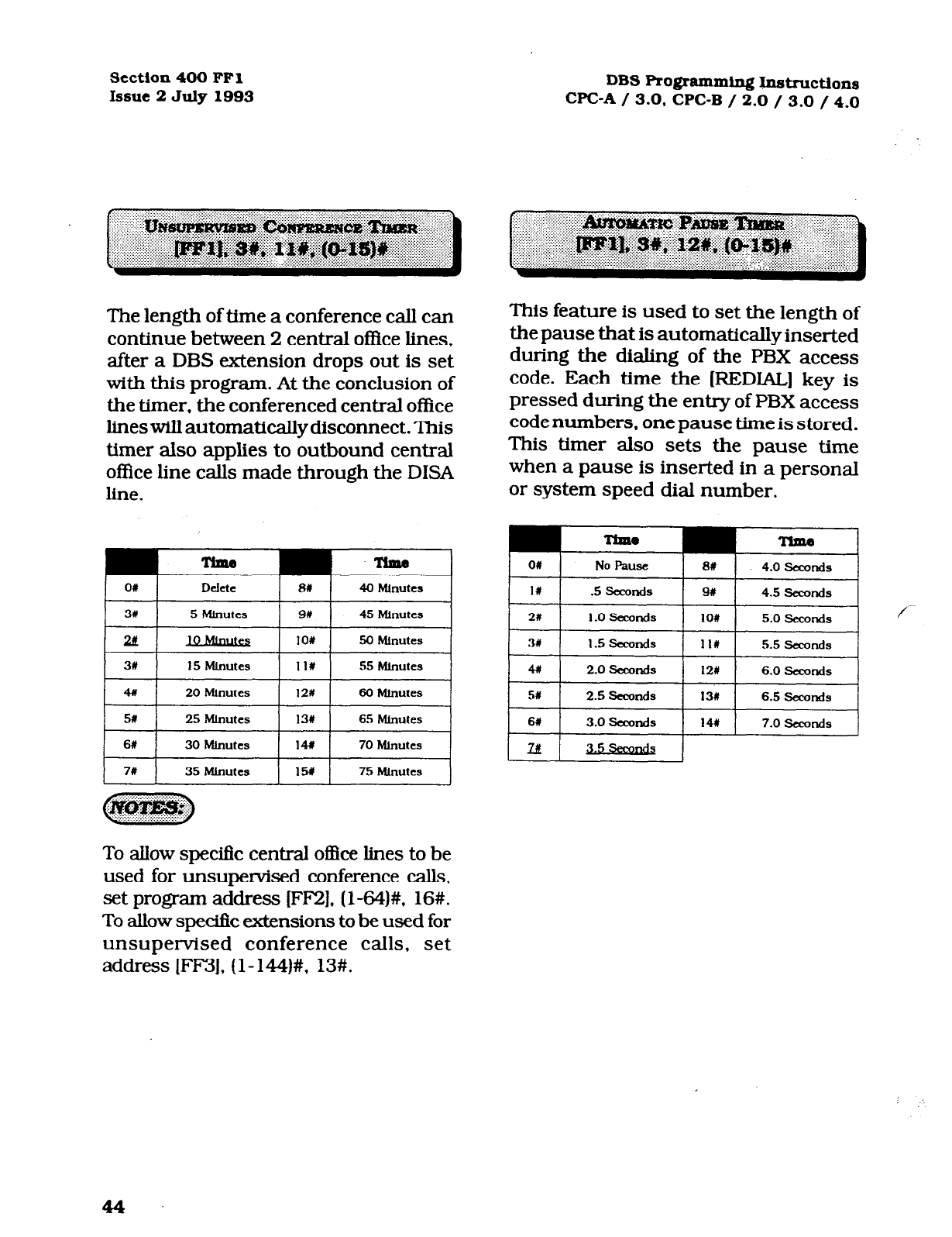
Section 400 FFl
Issue 2 July 1993
The length of time a conference call can
continue between 2 central office lines,
after a DBS extension drops out is set
with this program. At the conclusion of
the timer, the conferenced central office
lineswill automatically disconnect. This
timer also applies to outbound central
office line calls made through the DISA
line.
To allow specific central of&e lines to be
used for unsupervised conference calls,
set program address [FF2], (l-64)#, 16#.
To allow specific extensions to be used for
unsupervised conference calls, set
address [FF3], (l- 144)#, 13#.
DBS Programming Instructions
WC-A / 3.0. CPC-B / 2.0 / 3.0 / 4.0
This feature is used to set the length of
the pause that is automatically inserted
during the dialing of the PBX access
code. Each time the [REDIAL] key is
pressed during the entry of PBX access
code numbers, one pause time is stored.
This timer also sets the pause time
when a pause is inserted in a personal
or system speed dial number.
44
Technical Manuals Online! - http://www.tech-man.com
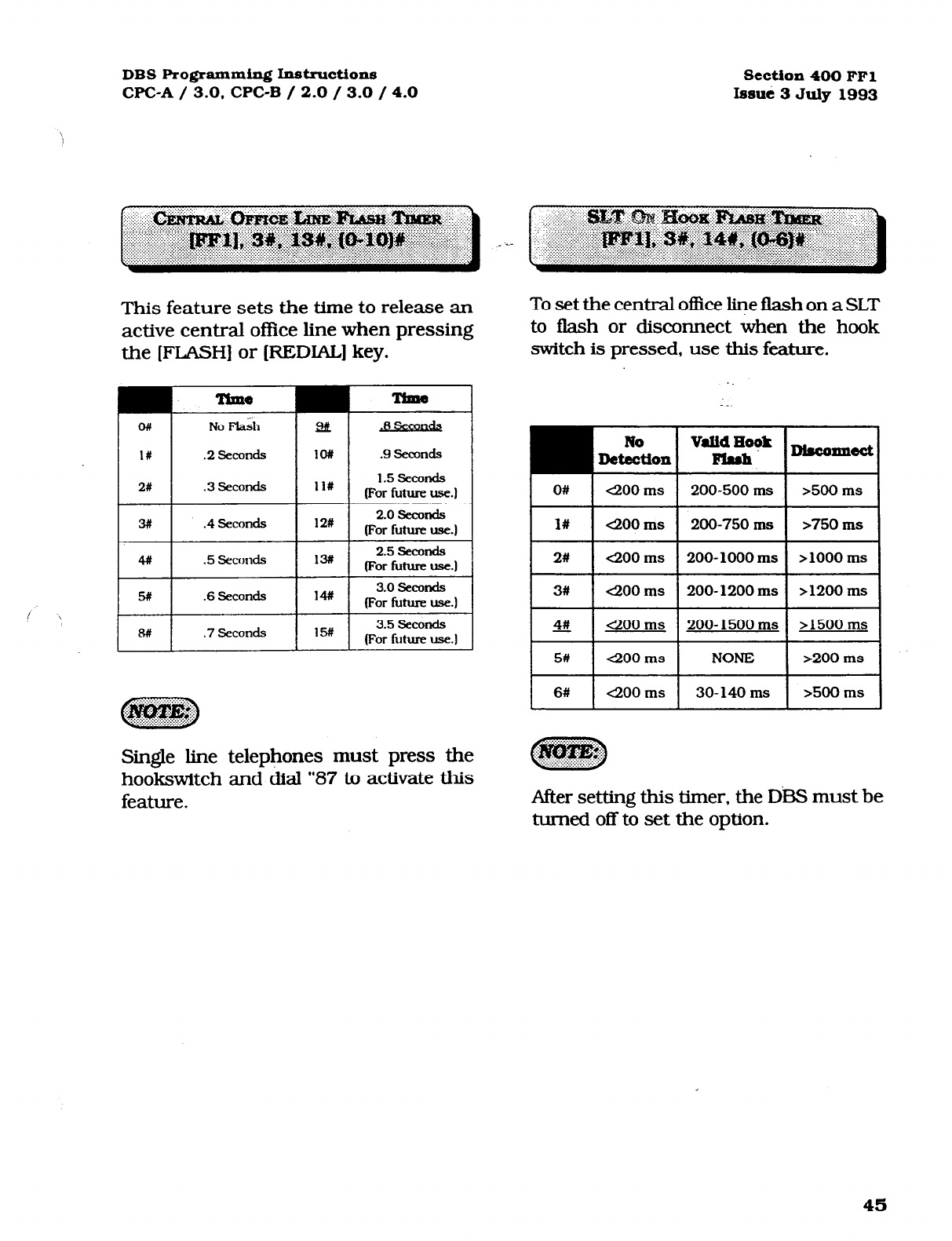
DBS Programming Instructions Section 400 FFl
WC-A / 3.0. CPC-B / 2.0 / 3.0 / 4.0 lssuti 3 July 1993
This feature sets the time to release an
active central office line when pressing
the [FLASH] or (REDIAL] key.
No F&h
.2 Seconds
.3 .secorKl.s
al B.-mllds
lO# .9
Seconds
11# 1.5 seconds
(For future use.)
3# .4
Seconds
12# 2.0 seconds
(For future use.)
4#
.5 scconcls 13# 2.5 Seconds
(For uure use.)
5# .6 Seconds 14# 3.0 seconcls
(For future use.)
! ’ 8#
.7 Seconds 15# 3.5 seconds
(For f&u-e use.1
Single line telephones must press the
hookswitch and dial “87 to activate this
feature.
To set the central office line flash on a SLT
to flash or disconnect when the hook
switch is pressed, use this feature.
O# 1 400 ms 1 200-500 ms 1 >500 ms
l#
4200 ms 200-750 ms >750 ms
2# 4200 ms 200- 1000 ms
> 1000
ms
3# 4200 ms 200- 1200 ms >1200 ms
4# 400 ms 200- 1500 ms >1500 ms
5# 4200 ms NONE >200 ms
6# 4200 ms 30- 140 ms 9dCl ms
After setting this timer, the D&3 must be
turned off to set the option.
45
Technical Manuals Online! - http://www.tech-man.com

section 400 FFl DBS Ro@amming Ixistructions
Issue 2 July 1993 WC-A / 3.0. CPGB /
2.0
/ 3.0 / 4.0
For the DBS to detect the length of time it
takes for the central office to complete a
fiAl ring cycle, this detection timer must
be set. Ifthe central office has a ring cycle
of 1 on and 4 off. for example, the DBS
setting should be placed at 6 to account
for two rings and one silent period of four
second duration.
OI 4 seaonds 2t 8 SeoDnds
UL 31) 10 fsccmds
This timer expands the ring cycle to com-
pensate for the time the DBS initcally
requires to detect the ring source.
OI kurpansloo a* .40 seconds
3# .5 sannds 90 .45 seconds
2# .lO Sccoado 101 so seconds
31 .lS secon& 11a .55 Eiecmds
4# -2o- 12* 60 seconds
51 .25seauMl¶ 13# ’ .6!5 seconds
61 .30- 14n .70 seconds
IurI.35
I 151 I .75 seconds
If this timer is set for to short of a time
period, the systemwUnotrecognizevalid
centml ofke ring signals.
Setting this timer for longer or shorter
periods oftimewill cause the first audible
ring cycle to be different from the source
ring cycle.
Technical Manuals Online! - http://www.tech-man.com
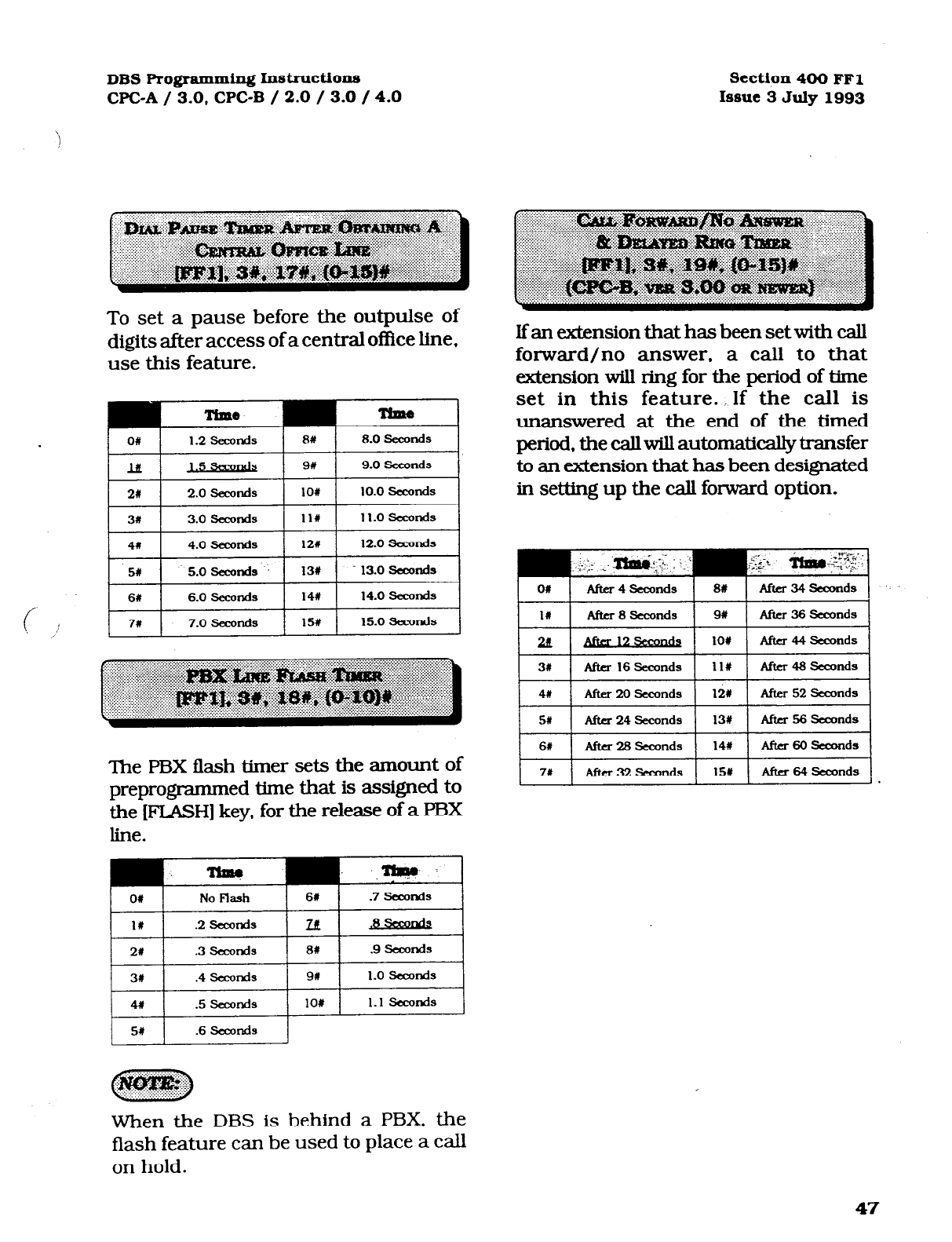
DBS Programming InstrUctions
WC-A / 3.0, CPC-B / 2.0 / 3.0 / 4.0 Section 400 FFl
Issue 3 July 1993
To set a pause before the outpulse of
digits after access of a central office line,
use this feature.
Time
The PBX flash timer sets the amount of
preprogrammed time that is assigned to
the [FLASH] key, for the release of a FBX
line.
OI No Flash 61 .7 tckmnds
II .2 .su%Jds ztt
21 3 .sccorKls 81 .9 slxonds
31 .4 slxods 91 1.0 seconds
4r 5 t3econds 101 1.1 slxonds
5# .6 Samnds
.
a
. jq@$p&$
. ,. . . . . . . . . . . . . . . . . . . *?.
Ifan extension that has been set with call
forward/no answer, a call to that
extension will ring for the period of time
set in this feature. If the call is
unanswered at the end of the timed
period, the call will automatically transfer
to an extension that has been designated
in setting up the call forward option.
When the DBS is behind a PBX, the
flash feature can be used to place a call
on hold.
47
Technical Manuals Online! - http://www.tech-man.com

Section 400 FFl
Issue 2 July 1993 DBS Pro#ammin~ I.nstructions
CPC-A / 3.0, CPGB / 2.0 / 3.0 / 4.0
When ground start lines are used, the
DBS sends a ground signal to the centml
of&e and waits for a return signal. When
a return signal is detected, the DBS starts
the line connection process. If a return
signal is not detected within the sped&d
time set in this feature, the system
regards the trunk as not available and
sends a busy tone to the caller.
3w 3sealfKl 71 7 8umnis
4s 8# 8 SXONIS
This feature is only available with the use
of a CFC-B card.
A ground-start trunk card (W-43531) is
required for ground start trunk
connections. Central office line ports on
this card can be conElgured as loop or
ground start ports.
This timer determines how long aground
signal from the central office must be
present in order to start the connection
process. When the ground signal is
detected, the line LED will turn red
indicating that the trunk is in use, even
though the call has not been processed.
To activate the ground detection timer, .
set the parameters for the loop-start/
ground-start type to ground-start in
[FF2], 21# address.
Install ground-start trunk card
(VB 43531) according to the
instructions in section 300.
Setting this timer for less then 3
seconds can cause false incoming calls.
This is due to the possibility of the
ground not being removed quickly at
the end of a call.
,
423’
Technical Manuals Online! - http://www.tech-man.com
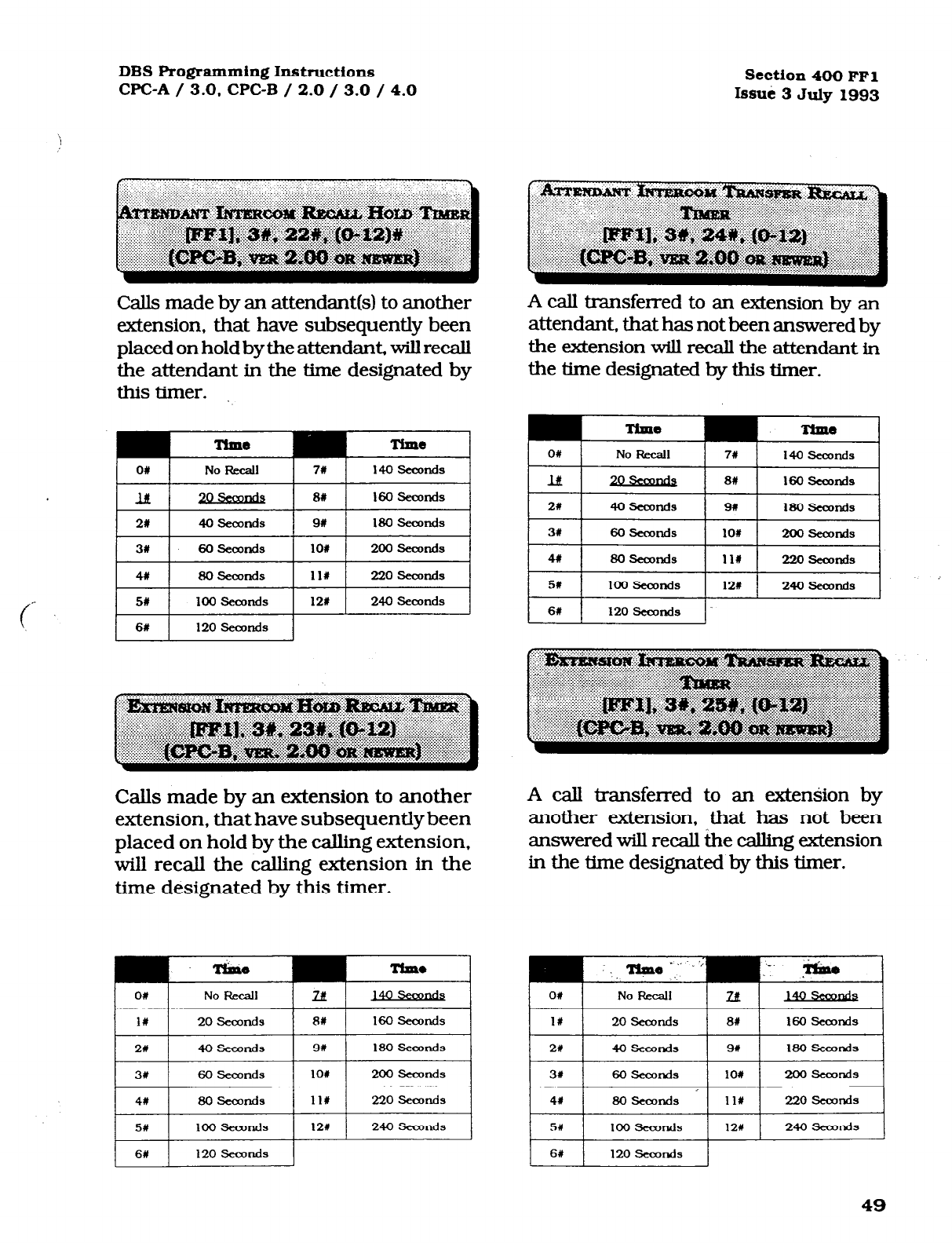
DBS Programming Instructions section 400 FFl
CPC-A / 3.0. CPC-B / 2.0 / 3.0 / 4.0 lssui 3 July 1993
CaJls made by an attendant(s) to another
extension, that have subsequently been
placed on hold by the attendant, will recall
the attendant in the time designated by
this timer.
Ttule Time
O# No Recall
7r 140 seamds
21
40 Seconds
91 180 seconds
31 60 seconds 101 200 seoonds
4x 60 sesonds
11r 220 seconds
5w loo seconds 12s 240 Seconds
I I
6X 120 Eieaxlds
Calls made by an extension to another
extension, #at have subsequently been
placed on hold by the calling extension,
will recall the calling extension in the
time designated by this timer.
A call transferred to an extension by an
attendant, that has not been answered by
the extension will recall the attendant in
the time designated by this timer.
O# No F&call
7w 140 SeaJnds
lit 8X 160 seomds
3# 60 .semnds lO# 200 .semnds
41 60 seconds 111 220 sesonds
5w I 100 SeaJrKls
11201
24osecmd-1
6W 120 seconds
A call transferred to an extension by
another extension, that has not been
answered will recall the calling extension
in the time designated by this timer.
Technical Manuals Online! - http://www.tech-man.com
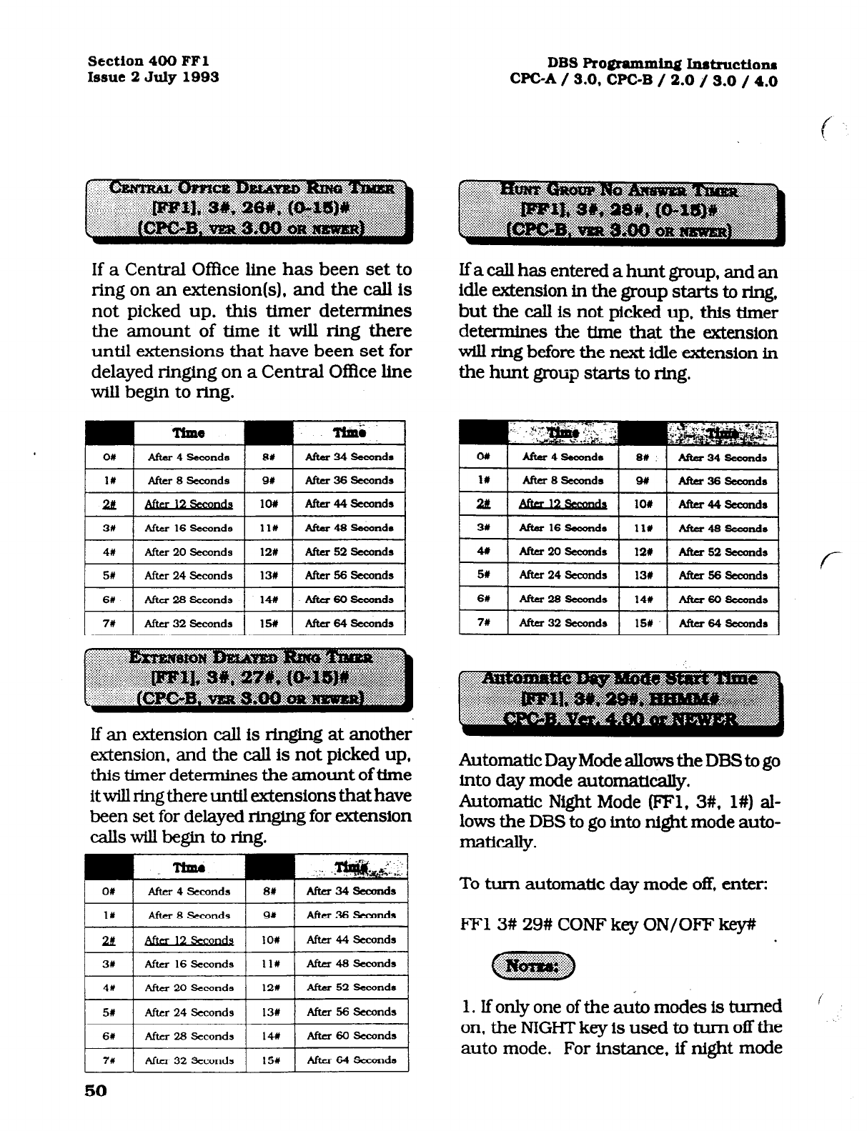
Section 400 FFl
Issue 2 July 1993
DBSRogramm~Instructiom
WC-A/ 3.0,CPC-B / 2.0 J 3.0 / 4.0
If a Central Office line has been set to
ring on an extension(s), and the call is
not picked up, this timer determines
the amount of time it will ring there
until extensions that have been set for
delayed ringing on a Central Oflice line
will begin to ring.
If an -ension call is ringing at another
extension, and the call is not picked up,
this timer determines the amount of time
it will ring there until extensions that have
been set for delayed ringing for extension
callswillbegintoring.
If a call has entered a hunt group, and an
idle extension in the group starts to ring,
but the call is not picked up, this timer
determines the time that the extension
will ring before the next idle extension in
the hunt group starts to ring.
2ii - 104 Afta44seamda
31 After 16 Seumds ll# Ana46second8
7W ( Afta 32 6eamds 1 15U 1 A&r 64 6axmds 1
AutomaticDayModeallowstheDBStogo
into day mode automatically.
Automatic Night Mode (FFl, 3#, l#) al-
lows the DBS to go into night mode auto-
matically.
To turn automatic day mode off, enter:
FF13# 29# CONF key ON/OFF key#
1. If only one of the auto modes is turned
on, the NIGHT key is used to turn off the
auto mode. For instance, if night mode
Technical Manuals Online! - http://www.tech-man.com
DBS Programming Instructions
CPC-A / 3.0, CPC-B / 2.0 / 3.0 / 4.0 Section 400 FFl
Issue 3 July 1993
has been activated automatically, the at-
tendant must press the NIGHT key to go
into day mode.
2. If both auto day and auto might modes
are turned on, the attendant NIGHT key
cannot be used.
3. Ifboth auto-modes are set, the starting
times must differ by at least one hour.
4. When one auto mode is turned on, the
mode cannot be reset by the NIGHT key
until 3 minutes after the auto mode is
activated. (Whenbothautomodesareset,
the NIGHT key cannot be used.]
If a remote programming ID code is set,
a dumb terminal or PC can be used to
program the DBS from a remote site or
on site, by connecting to the RS232C
interface.
To
set the remote programming ID code
to 0001, for example, enter:
[eel], 4#, ooo1n
To
reset the remote nro~ramrning ID
code to the default initialized value,
press IFFll. 4#. lCONF1. ION/OFFl.
Remote programming of the DBS requires
the foIlowing:
2.
Knowledge of the 4-digit DISA ID code.
(See-[FFl],
l#
through 5# program
addresses].
3. After the DBS automatically answers
your inbound call on the preset DISA line
with the intercom dialing tone, remote
programmingcanbeginbydialing#6and
the 4-digit remote-programming ID code.
4. An attendant or extension user can
manuaily transfer the remote
programmer into programming by
putting the remote programmer on hold,
dialing #6. and the 4 digit remote
programming lD code.
5. The following remote operations are . -
possible:
al Remote programming:
Remotely setting any DBS parameter,
just as would be done with on site
P~gramming~
b) Bus monitor data:
Remotelyviewbusmon.itordata..whichis
commonly used to troubleshoot
operational problems. This may be
possible in real time. depending on the
buffer of the device being used.
1. A
central o&e line that is set with DISA
CapZlbility.
51
Technical Manuals Online! - http://www.tech-man.com
Section 400 FFI
issue 2 July 1993 DBS Programming Instructions
WC-A / 3.0. WC-B / 2.0 / 3.0 / 4.0
The DISAID code provides direct access to
a DBS intercom dial tone, on an inbound
central ofIke Iine that is preprogrammed
as a DISA Iine.
To set the DISA ID code to 0001, for
example, enter:
pFl1, St, OoolW
To reset the DISA ID code to the default
initiaIized value. Dress IFFll. 5#. ICONfl
ION/OFFl.
The default setting of the DBS supplies
intercom dial tone to a Iine defined as a
DISA line. If a DISA ID code is stored in
place of the default setting (via remote
programming) an intercom dial tone wiII
not be heard, but rather a DISA dial tone
(fast busy tone).
The DISA dial tone is a signal to proceed
with your caII until you enter the stored
DISA ID code. After the DISA ID code is
entered, the intercom dial tone is
presented. This provides the opportunity
to make a DBS extension caII.
To make an outbound central office Iine
call. enter #7, dial 9 or 81-86 (to access a
central ofke line), then dial the 4-digit
DISA ID code. See (FFl], 6#, l# and 2#
addresses.
To provide an inbound DBS caller with
access to “fresh” outbound central
office dial tone, a four digit access code
is required.
To set the first DISA outgoing call ID
code to 0001, for example, enter:
IFFlI,6#, lW, OOOl#
To reset the first DISA outgoiw calI ID
code to the default initiaked value,
press IFFll. 6#. l#. ICONFl. ION/OFFl.
To provide an inbound DBS caller with
access to “fresh” outbound central
office dial tone, a four digit access code
is required.
To set the second DISA outgoing caII ID
code to 0002, for example, enter:
WF1],6#, 2W, 0002#
To reset the second DISA outgoing caII
ID code to the default initiahzed value,.
press IFFll. 6#. 2% ICONFl. ION/OFFl.
52
Technical Manuals Online! - http://www.tech-man.com
DBS Programming Instructions
WC-A / 3.0. CPC-B / 2.0 / 3.0 / 4.0 Section 400 FFl
Issue 3 July 1993
To perform DBS programming ikom an
extension other than the attendant
position, this option must be set. The
4-digit ID code set in this option must be
used as part of the access attempt to
program the DBS. when a non attendant
position is used in this manner.
To set the ID code for system
programming to 000 1, for example, enter:
To reset the ID code for svstem
c- promamming to the default initialized
/ value. Dress IFFll. 7#. ICONFl. ION/OFFl.
Only one non attendant extension can be
a programming extension at a particular
time. To set a different non attendant
position as the programming &en&on.
cancel the capability of the first extension
by reentering the 4digit ID code at the
original non attendant extension, then
enter the same ID code at the second
extension.
On CPC-A software versions later than
3.2 1, and WC-B versions later than 2.00,
entering the ID code for system
programming at a second extension, will
automatically cancel the programming
capabiltty that may have been previously
set but not canceled at a different
extension.
Direct Inward Dial numbers that have
been set up as a part of WC-B ver. 2.11 or
older software, need to be defaulted with
the use of this program after upgrading a
DBS to ver. 3.00 software. Also, at any
time that a default of ALL assigned DID
numbers is desired. this program must be
used.
To choose not to reset existing DID
number assignments, enter:
pFll.8#. l#.O#
At any time a reset of all assigned DID
numbers to the default value (no DID
numbers assigned) is desired, enter:
-
DrIrl], 8#. I#, 1n
DID settings have to be manually
configured if the DBS has a software
version older than 3.00, that is being
upgraded to version 3.00 or newer. Before
this manual reconfigurafion can be done
however, the DID reset program ([FFl],
8#, l#), must be done.
The maximum amount of DID number
assignments that a DBS can have is 500.
Multiple DID number assignments canbe
assigned to any extension port, and/or
the same DID number can be assigned to
multiple extension ports. Each DID
assignment uses one of the 500 that are
available.
53
Technical Manuals Online! - http://www.tech-man.com
Section 400 FFl
Issue 2 July 1993 DBS Programming Instructi01~1
CPC-A / 3.0,CPC-B / 2.0 / 3.0 /4.0
c
This is a
cor&rmation program for the
resetting of DID numher assignments
that can be accomplished with the use of
program number [FFl], 8#, l#.
To not reset the DID number
assignments, enter:
j?'Fll. 8#.2#.0#
To reset all of the DID number
assignments, enter:
ml), BW, 2#, 1W
DID&tingshavet&emaWlllycO~
ifthe DBS has a software version older than
3.00, that is being upgraded to version
3.00 or newer. Before this manual
reco&gumtion can be done however. the
DID reset program ([FFl]. 8#, l#), must be
done.
The maximum amount of DID number
assignments that a
DES can have is
500.
Multiple DID number assignments can be
assigned to any extension port, and/or
the same DID number can he assigned to
multiple extension ports. Each DID
assignment uses one of the 500 that are
available.
Resets program settings stored in SAM
(Static Random Access
Memory). The
reset
must be performed before upgrading from
one software version to another. For ex-
ample. if you are upsadirq from Version
3.00 toVersion4.00, you need to perform the
reset.
However, if you are
upgradiq to a
point release (4.10 to 4.11). you do not need
to perform the reset.
CkNo (retain settinfls1
l=Yes (clear settings)
c
.
54
Technical Manuals Online! - http://www.tech-man.com
DBS Programming Instructions
CPC-A / 3.0, CPC-B / 2.0 / 3.0 / 4.0 Section 400 FFl
issue 3 July 1993
The purpose of this display is to make sure Direct inward dialed numtws that have
you want to reset the data Enter “0” or ” 1,” been dialed by a cakr need to be assigned
depending on whether you want to complete to extension ports, so that the number
or cancel the reset. dialed will ring on all extensions they are
supposed to appear on. A DID number can
~~~
::‘“‘~~~~~. be set to ring on muhiple extensions, or only
one extension.
O=Do not reset
l=Reset To set DID number 4444 to ring on
extension number 120, for example,
enter:
1. If you enter a “1,” the following display
Wll, 8#, 3#, 4Q44#, 120#
appears:
CONFmM To set DID number 6358 to ring on
0: NO 1: YES extension number- 500, for example,
enter: -LT.
2. This command erases a.U Tl and DID
programming.
@WI], 8#,3#,6358#, 5oon
To reset DID numbers that have been as-
signed to extensions to the default
initialized value.
Dress lFF1’. 8#. 3#,
didWCXX#. lCONFl#. ION/OFF.
55
Technical Manuals Online! - http://www.tech-man.com
Section 400 FFl
Issue 2 July 1993
I
Tl PROGRAMMZN G OPTlONS
Allpcmmekm inthissectionreferbCPC-B,
Vet-son 4.00 or newer.
The following information describes pro-
gramming parameters for the Tl Interface.
The descriptions of each parameter include
alist of available options and the associated
programming address.
Default options are shown underlined.
Tl SYSTEM SFXTINGS
DBS Programming @iWuctions
CPC-A / 3.0. CPC-B / 2.0 / 3.0 / 4.0
cwcKsETTnvGs
I
The Sync Card (installed on the WC-B)
providesamethod ofsynchronizingtheDBS
with the public network. This parameter
determines the first clocking source for net-
work synchronizmon. If the first source
kils, the system will switch to the second
source. The system will attempt to go back
to the first source based on thevalue entered
under the Network Re-sync Timer.
The system considers a clock source to have
failed when the slip rate error counter is
exceeded within a 24-hour period.
In most cases, the 1st sync source is set to
“1.”
Idenmes the system size.
Optlons M 4p
1 =DB!5 72
2=DBS 96
3=DBS 40 + DES 40 Cl-1
must be in the slave
cabinet.)
4=DBS 72 + DBS 40 VI
IS
not supportrd.)
S=DBS 72 + DEB 72 VT1
must be tn the slave
cabinet.)
6=DE3s 96 + DBS 40
7=DL3S 96 + DEE 72
R=DL3S 96 + DEE 96
For changes to this parameter to take effect,
the system must be powered down, then
back up again.
To apply changes to this parameter, power
the system down, then back up.
56
Technical Manuals Online! - http://www.tech-man.com

DBS Programming Inst~ctions Section 400 FFl
WC-A / 3.0. CPC-B / 2.0 / 3.0 / 4.0 Issue 3 July 1993
Determines the source of clocking for the
second sync source. The system will at-
tempt to switch from the second source
back to the first source based on the value
entered under “Network Re-sync Tfmer.”
lfthe second source fails and the first source
is not working, the system will switch to the
third source..
ln most cases, a system with one Tl has the
2nd sync source set to “3.” Systems with two
Tls normally have the 2nd sync source set
to “2.”
One of the three sync sources should be set
to “3” (free run). A free-run setting is needed,
so the DBS Tl can provide its own clocking
if the network clock fails.
Options O=None
l=Tl of the master cabinet
2=Tl of the slave cabinet
Deterrnines the source of clocking for the
third sync source. The third sync source is
used ifboth the first and second source fail.
The system will attempt to switch from the
third source back to the first source based
on the value entered under “Network Re-
sync Timer.” _._
In most cases, a system with one Tl has the
3rd sync source set to “0.” Systems with two
Tl s normally have the 3rd sync source set to
“3.”
One of the three sync sources should be set
to “3” (free run). A free-run setting is needed,
so the DBSTl can provide its own clocking
if the network clock fails.
3=Free run (internal clocking)
For changes to this parameter to take effect,
the system must be powered down, then
back up.
For changes to this paraxneter to take effect,
the system must be powered down, then
back up again.
57
Technical Manuals Online! - http://www.tech-man.com

Section 400 FFl
Issue 2 July 1993
I
lf one clock source falls, the system will
switch to another clock source. The re-sync
timer determines how often the system at-
tempts to return to the original clock source.
For example, if the first clock source (1st
sync) f&, the system switches to the sec-
ond source. However, the system will try to
return to the fxst source based on the re-
sync timer.
Ifthesecondsourcefailsandthefirstsource
continues to be out-of service, the system
switches to the third source. Again, the re-
sync timer determines how often the system
will attempt to return to the first source.
3ptions O-25
O=lmmechatc
(DBS returns to
the first clock tmmedlately.)
I-24=hours (Determines how
often the DBS attempts to
return to the first clock)
I
25=no reties (DBS does not
attemDt to PO hack to the tlrst (
clock.1 I
When the system attempts to go back to the
fI.rst clock source, existing calls will be dis-
connected.
DBS Programming Instnictions
WC-A / 3.0, CPC-B / 2.0 / 3.0 / 4.0
f
Determines how long the DBS waits before
sending a disconnect signal from the Tl to
the CO. (II&e CO Disconnect Timer (FF2 (l-
64)# 18# (0-15#)] determines how long the
system waits to receive a disconnect signal
from the CO.)
3ptions
rralues
o-15
(1)
0= 15Oms
1=200ms
2=25Oms
3=3ooms
4=4ooms
!XiOOms
6= 1OOOms
7=15ooms
8=2oooms
9=25OOms
10=3000ms
11=35OOms
12=Off (DES does not
automatically send a
disconnect signal.)
f-
For changes to this
pammeter to take effect,
the system must be powered
down, then
back up.
‘-
Technical Manuals Online! - http://www.tech-man.com
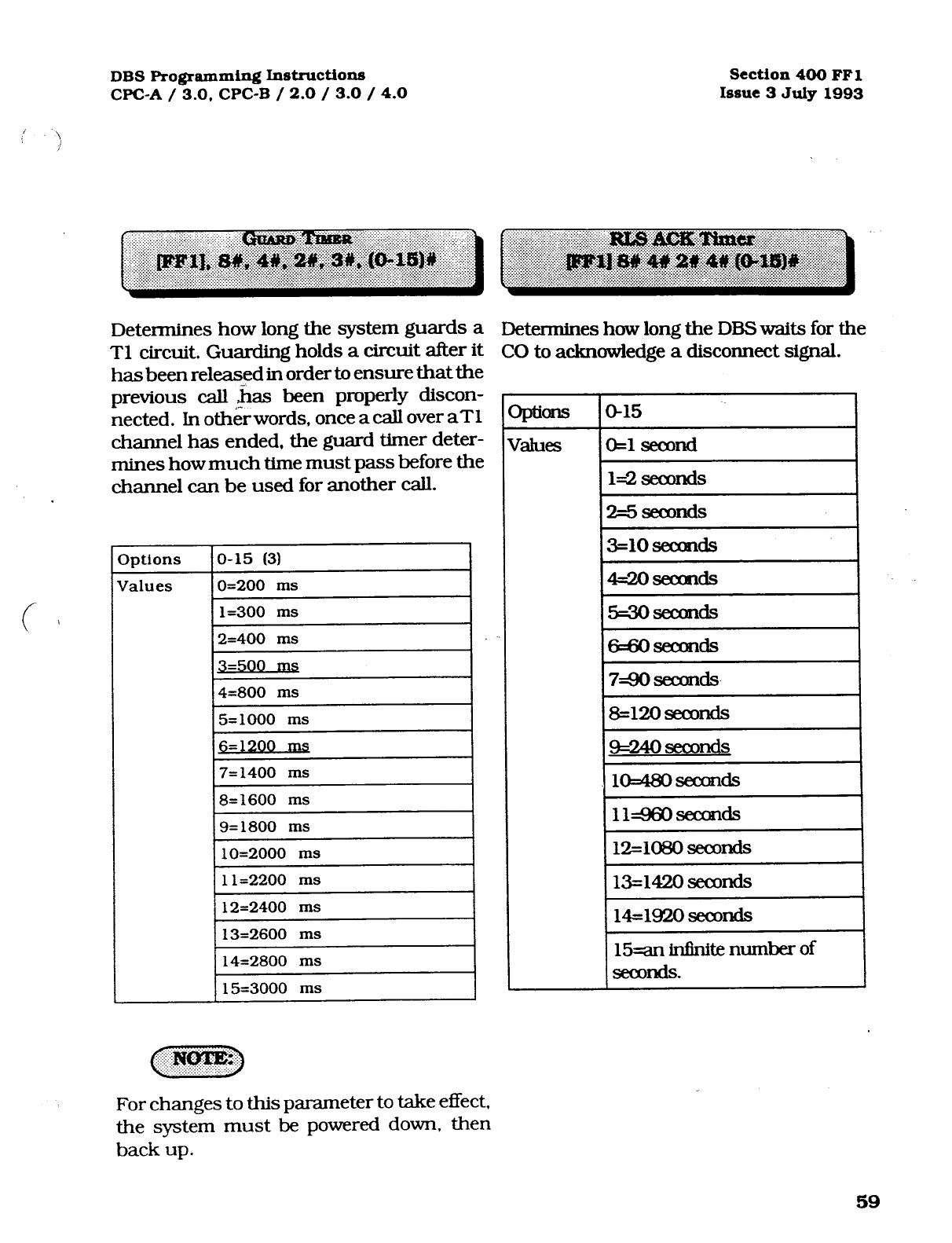
Technical Manuals Online! - http://www.tech-man.com
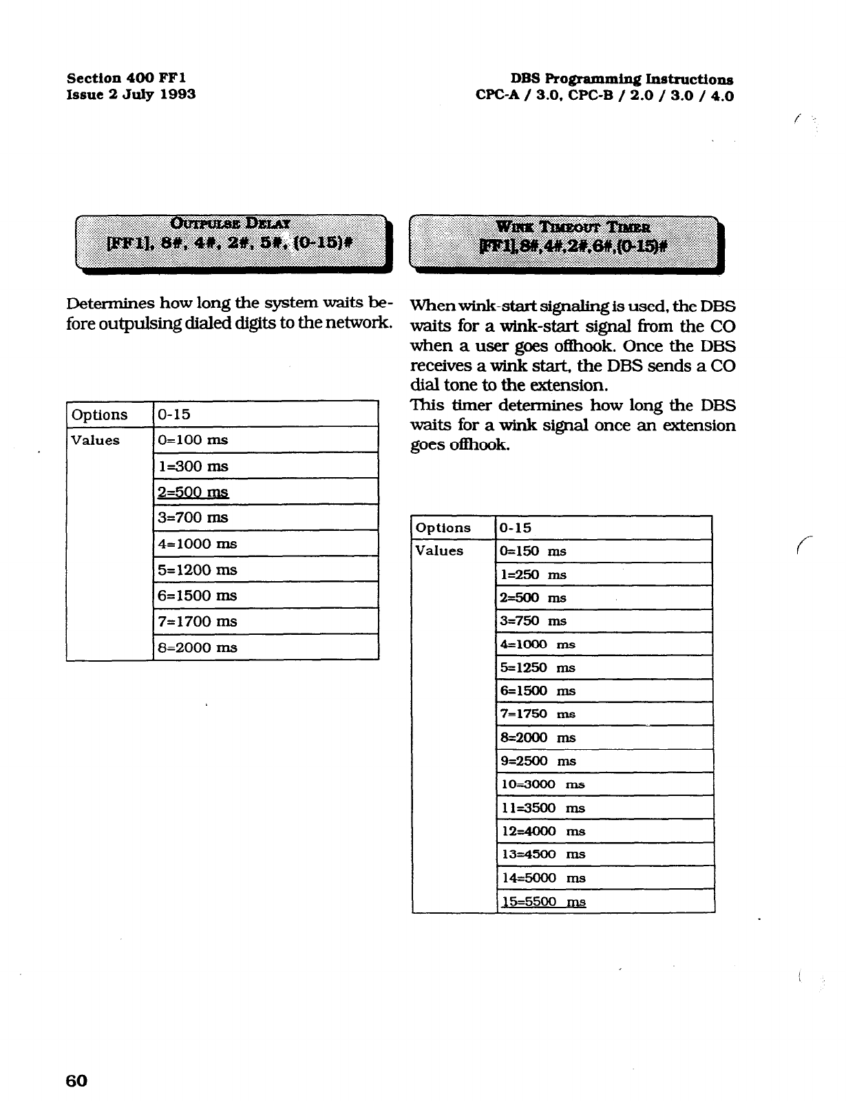
Sectfon 400 FFl
Issue 2
July 1993
DBS
Programming Instructions
WC-A / 3.0, CPC-B / 2.0 / 3.0 / 4.0
/ . . .
Determines how long the system waits be-
fore outpulsing dialed digits to the network.
3ptions
o-15
Values
O=lOO Ins
1=300 ms
2=500 Ins
3=700 ms
4=1000 ms
5=1200 ms
6=1500 ms
7=1700 ms
8=2000 ms
Whenwink-start signaling is used, the DBS
waits for a wink-start signal fi-om the CO
when a user goes ofbok. Once the DBS
receives a wink start, the DBS sends a CO
dial tone to the extension.
This timer determines how long the DBS
waits for a wink signal once an extension
goes ofbook.
lptions
Ialues
o-15
0=150 ms
1=250 In.5
2=5ooms
3=7!50 ms
Jklooo ms
5=12!TJo Ins
6=1500 rns
7=1750 Ins
8=2ooo ms
9=2!500 Ins
1o=sooo Ins
11=3500 ms
12-4Qoo ms
13=4500 ms
14=5ooo ms
15=5500 ms
60
Technical Manuals Online! - http://www.tech-man.com
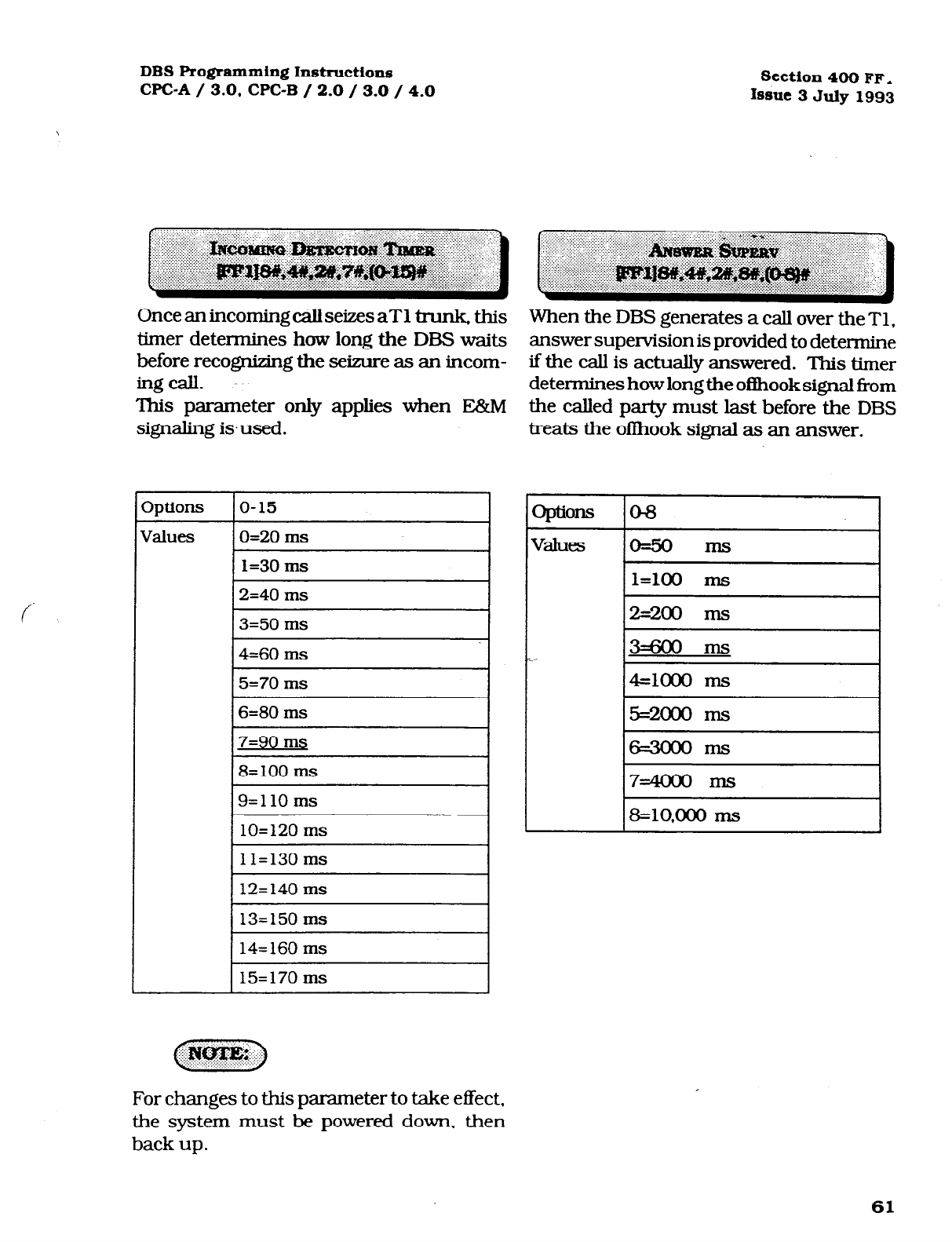
DBS Programming Instructions
CPC-A / 3.0, CPC-B / 2.0 / 3.0 / 4.0 Section 400 FF,
Issue 3 July 1993
Once anincomingcallseizes aT1 trunk+ this
timer determines how long the DBS waits
before recognizing the seizure as an incom-
ingcall.
This parameter only applies when E&M
signaling isused.
I
5=70 ms
7
I
12= 140 ms
l
When the DBS generates a call over the Tl,
answer supervision is provided to determine
if the call is actually answered. This timer
determines how long the oflhook signal Tom
the called party must last before the DBS
treats the oilhook signal as an answer.
oplions o-8
v*es lo=..=.. ms I
I l=loo ms I
12=200 ms
I
3=6ooms
c
4=1ooo ms
l5=2ooo ms
I
For changes to this parameter to take effect,
the system must be powered down. then
back up.
61
Technical Manuals Online! - http://www.tech-man.com
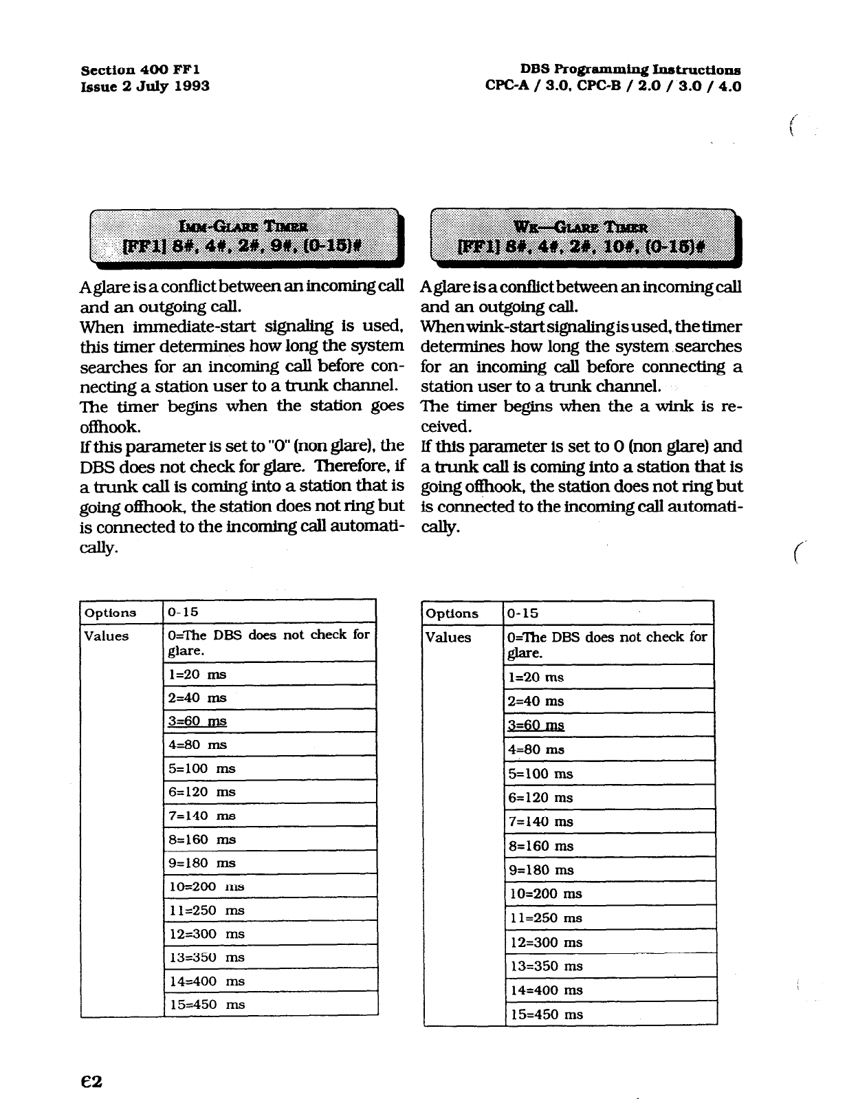
Section 400 FFl DBS Ro@ammiq Instructions
Issue 2 July 1993 WC-A / 3.0, CPC-B / 2.0 / 3.0 / 4.0
Aglare is a conflict between an incoming call
and an outgoing call.
When immediate-start signaling is used,
this timer detennines how long the system
searches for an incoming call before con-
necting a station user to a trunk channel.
The timer begins when the station goes
offhook.
If this parameter is set to “0” (non glare), the
DBS does not check for glare. Therefore, if
a trunk call is coming into a station that is
going oi3hook. the station does not ring but
is connected to the incoming call automati-
*
Aglareisaconflictbetweenaninconringcall
and an outgoing call.
Whenwink-startsignalingis used, the timer
determines how long the system.searches
for an incoming call before connecting a
station user to a trunk channel.
The timer begins when the a wink is re-
ceived.
lf this parameter is set to 0 (non glare) and
a trunk call is coming into a station that is
going o@ook, the station does not ring but
is connected to the incoming call automati-
m
c
Iptions ~ IO-15 I
3ptions
iralues
o-15
O=The DBS does not check for
glare.
1=20 ms
2=40 ms
Jalues ETlMdoesnotcheckforI
I2=40 ms I
3=60 ms 1
14=80 ms I
15=100 ms
I
16=120 ms
I
~7=140 ms
I
I
11=250 ms
I
I
12=300 ms
I
I13=350 ms
I
14=400 ms
IS=450 ms
Technical Manuals Online! - http://www.tech-man.com
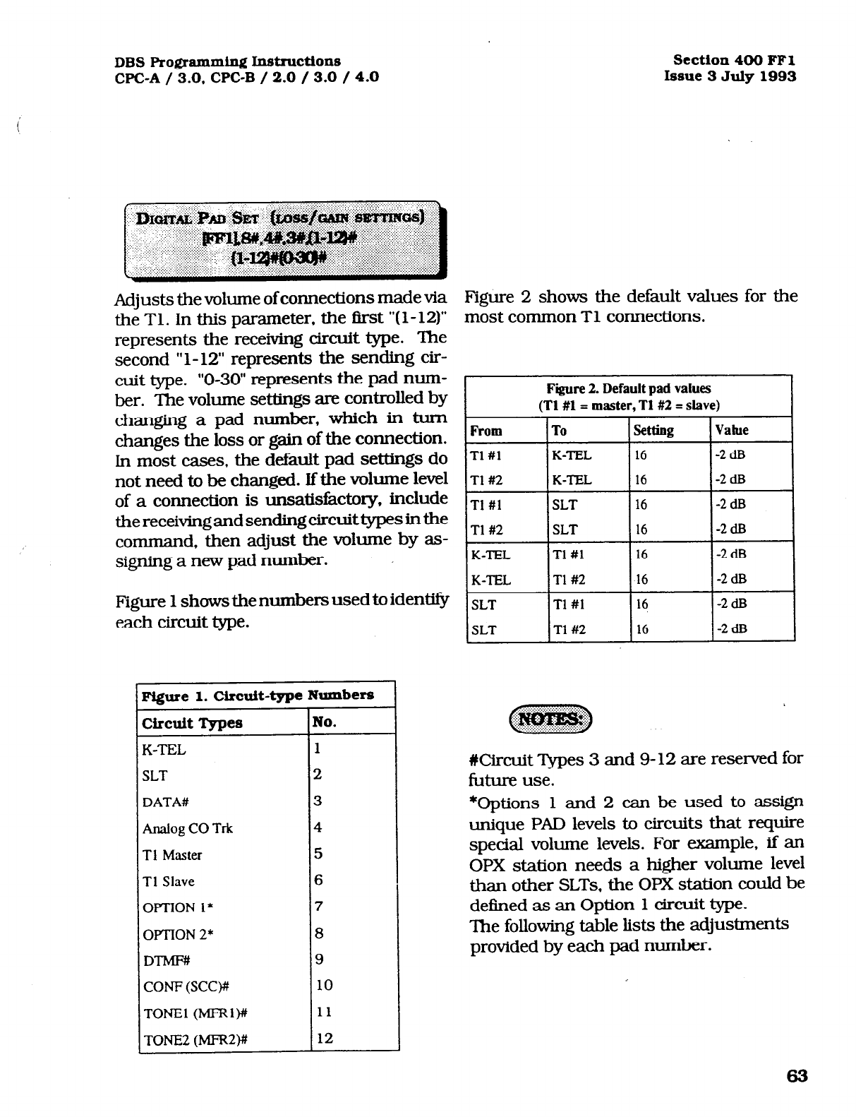
DBS Programming Instructions
WC-A / 3.0, CPC-B / 2.0 / 3.0 / 4.0
Adjusts the volume of connections made via
the Tl. In this parameter. the first “(l- 12)”
represents the receiving circuit type. The
second “l-12” represents the sending cir-
cuit type. “0-30” represents the pad num-
ber. The volume settings are controlled by
changing a pad number, which in turn
changes the loss or gain of the connection.
In most cases, the default pad settings do
not need to be changed. If the volume level
of a connection is unsatisfactory, include
thereceivingandsendfngcircuittypes inthe
command, then adjust the volume by as-
signing a new pad number.
Figure 1 shows the numbers used to identify
each circuit type.
1
Figure 1.
Circuit-type
Numbers
CircuitTypes No.
K-TEL 1
SLT
2
DATA#
3
Analog CO Trk
4
Tl Master
5
Tl Slave
6
OP-l-lON l*
7
OPTlON 2* 8
DTMF#
9
CONF (SCW 10
TONE1 (MFRlW 11
TONE2 (MFR2)# 12
1
section 400
FFl
Issue 3 July1993
Figure 2 shows the default values for the
most common Tl connections.
Fire 2. Default pad values
(Tl #1 = master, T1#2 = slave)
Tl #l SLT 16
-2 dB
T1#2 SLT 16
-2 ClB
K-TEL Tl #l 16
-2 ClEt
K-TEL T1#2 16
-2 dF3
SLT Tl #l 16
-2 dB
SLT T1#2 16
-2 dE3
#Circuit Types 3 and 9-12 are reserved for
future use.
*Options 1 and 2 can be used to assign
unique PAD levels to circuits that require
special volume levels. For example, if an
OPX station needs a higher volume level
than other SLTs, the OPX station could be
defined as an Option 1 circuit type.
The following table lists the adjustments
provided by each pad number.
63
Technical Manuals Online! - http://www.tech-man.com
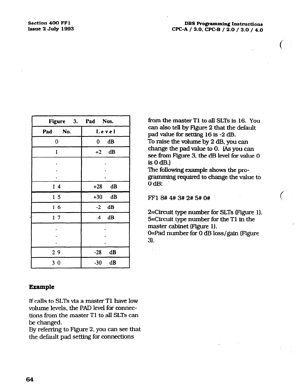
Section 400 FFl DBS
Programming Instructions
Issue 2 July 1993 WC-A / 3.0. CPC-B / 2.0 / 3.0 / 4.0
Figure 3. Pad Nos.
Pad No. I Level
I
0 dB I
+2 dB
.
14 +28 dB
I
15 I +30 dB I
I
16
I
-2 dB I
.
I
-4 dB
I
I
29
I
-28 dB
I
I
30
I
-30 dB
I
If calls to SLTs via a master Tl have low
volume levels, the PAD level for connec-
tions fi-om the master Tl to all SLTs can
be changed.
By referring to Figure 2, you can see that
the default pad setting for connections
from the master Tl to all SLTs is 16. You
can also tell by Figure 2 that the default
pad value for setting 16 is -2 dB.
To raise the volume by 2 dB, you can
change the pad value to 0. (As you can
see fkom Figure 3, the dB level for value 0
isOdl3.)
The following example shows the pro-
rg required to change the value to
.
.
FF18##3#2#5#0#
Circuit type number for SLTs (Figure 1).
5=Circuit type number for the Tl in the
master cabinet (Figure 1).
O=Pad number for 0 dB loss/gain (Figure
3).
64
Technical Manuals Online! - http://www.tech-man.com
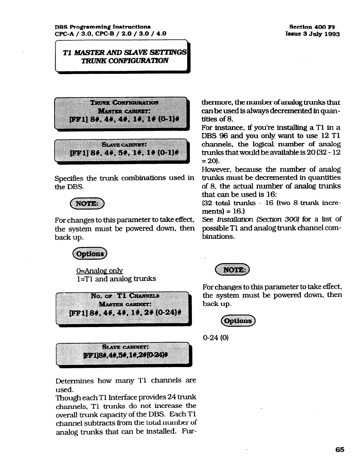
DBS Programming In.structiona
CPC-A / 3.0, CPC-B / 2.0 / 3.0 / 4.0
section 400 FF
Insue 3
July 1993
Specifies the trunk combinations used in
the DBS.
For changes to this parameter to take effect,
the system must be powered down, then
back up.
o=Analoa only
l=Tl and analog trunks
thermore, the number of analog &unks that
canbeusedisahvaysdecrementedinquan-
tities of 8.
For instance, if you’re installing a Tl in a
DBS 96 and you only want to use 12 Tl
channels, the logical: number of analog
trunks thatwould be available is 20 (32 - 12
= 20).
However, because the number of analog
trunks must be decremented in quantities
of 8, the actual number of analog trunks
that can be used is 16:
(32 total trunks - 16 (two 8-trunk incre-
ments) = 16.)
See Installation &rfion 3001 for a list of
possible Tl and analog trunk channel com-
binations.
For changes to this parameter to take effect,
the system must be powered down, then
back up.
O-24 (0)
Determines how many Tl channels are
used.
Though each Tl Interface provides 24 trunk
channels, Tl trunks do not increase the
overall trunk capadty of the DBS. Each Tl
channel subtracts from the total number of
analog trunks that can be installed. Fur-
Technical Manuals Online! - http://www.tech-man.com
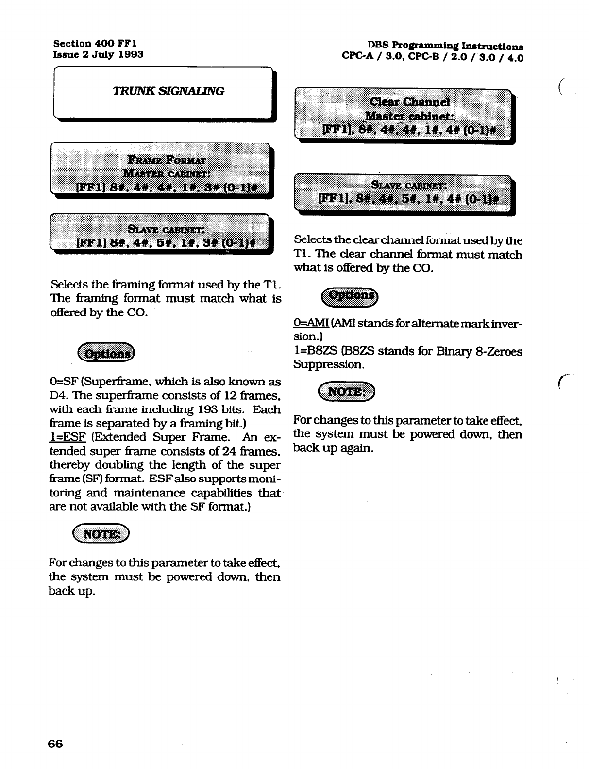
Section 400 FFl
Issue 2 July 1993 DBS Ro@ammiqf Imtnactionn
WC-A / 3.0, CF’GB / 2.0 / 3.0 / 4.0
i
TZWlVKSIG-G
l
Selects the framing format used by the Tl .
The framing format must match what is
offered by the CO.
O=SF (Superti-ame, which is also known as
D4. The superframe consists of 12 frames,
with each frame incIuding 193 bits. Each
frame is separated by a fi-aming bit.)
l=ESF (Extended Super Frame. An ex-
tended super kame consists of 24 ti-ames,
thereby doubling the length of the super
fi-ame (SF) format. ESF also supports moni-
toring and maintenance capabiIities that
are not available with the SF format.)
Selects the clear channel format used by the
Tl. The clear chan.neI format must match
what is offered by the CO.
&AIM1 @MI standsforaltematemarkinver-
sion.)
l=B8ZS (B8ZS stands for Binary 8-Zeroes
Suppression.
For changes to this parameter to take effect,
the system must be powered down, then
back up again.
For changes to this parameter to take effect,
the system must be powered down, then
back up.
i
66
Technical Manuals Online! - http://www.tech-man.com
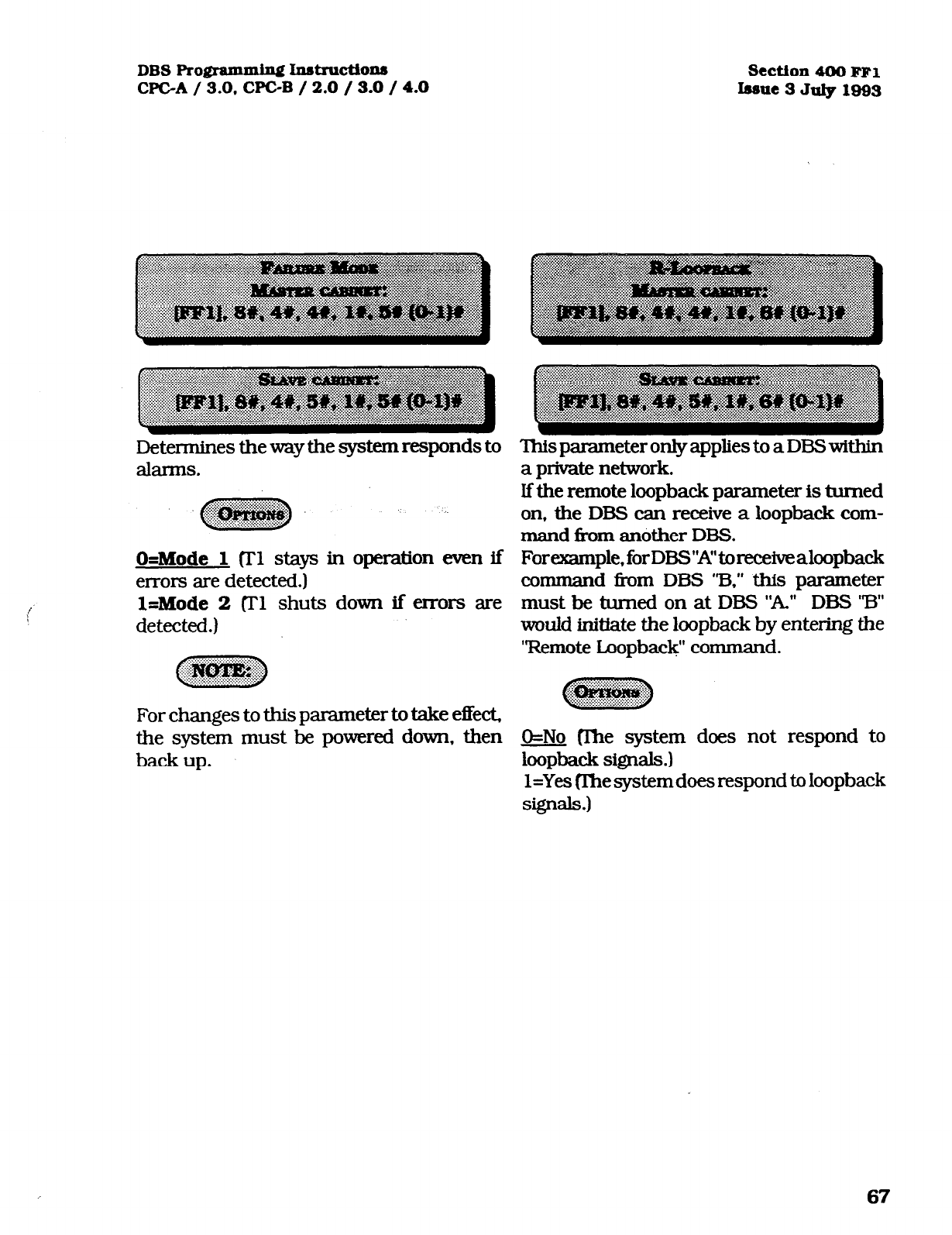
DBS Ro@ammhg I.nat~ctiox.u3
WC-A / 3.0. CPGB / 2.0 / 3.0 / 4.0
Determines the way the system responds to This parameter only applies to a DBS within
kZ&XIllS.
a private network.
If the remote loopback parameter is turned
on, the DBS can receive a loopback com-
mand from another DBS.
Forexample,forDBS”A”toreceivealoopback
command i?om DBS ‘73,” this parameter
must be turned on at DBS “A.” DBS 73”
would initiate the loopback by entering the
“Remote tiopback” command.
O=Mode
1 vl stays in operation even if
errors are detected.)
l=Mode 2 (II’1 shuts down if errors are
detected.)
For changes to this parameter to take effect,
the system must be powered down, then
back up.
section 4OOFFl
IssneBJdyl993
O=No (llxe system does not respond to
loopback si@Mls.)
l=Yes (Ihesystemdoesrespondtoloopback
signals.)
67
Technical Manuals Online! - http://www.tech-man.com
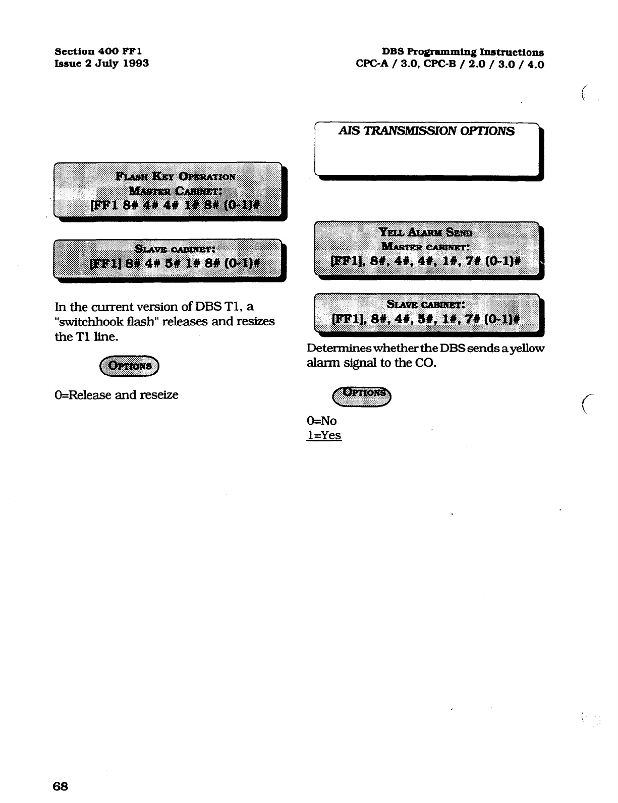
section 400 FFl
Issue 2 July 1993 DBS Programming Instructions
WC-A / 3.0, CPC-B / 2.0 / 3.0 / 4.0
In the current version of DES Tl, a
“switchhook flash“ releases and resizes
theT1 line.
O=Release and reseize
Determines whether the DES sends a yellow
alarm signal to the CO.
O=No
l=Yes
68
Technical Manuals Online! - http://www.tech-man.com
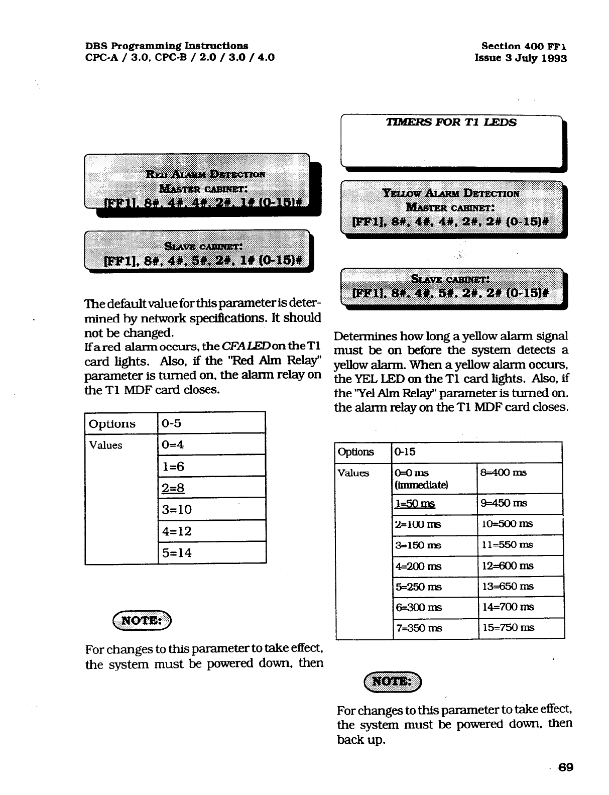
DBS Programming Instructions
CPC-A / 3.0. CPC-B / 2.0 / 3.0 / 4.0 Section 400 FF1
Issue 3 July1993
The default value for this parameter is deter-
mined by network spec&ations. it should
not be changed.
Lfared alarmoccurs. theCFALEDontheT1
card lights. Also, if the ‘Bed Alm Relay’
parameter is turned on, the alann relay on
the Tl MDF card closes.
3ptions O-5
Values 0=4
1=6
2=8
3=10
(?+.?+.>
%&xpg j::
For changes to this parameter to take effect,
the system must be powered down, then
Determines how long a yellow alarm signal
must be on before the system detects a
yellow alarm. When a yellow alarm occurs,
the YEL LED on the Tl card lights. Also, if
the ‘Yel Alm Relay’ parameter is turned on,
the alarm relay on the Tl MDF card closes.
>ptiOllS
o-15
o=oIIls t34ooms
orDmedhte1
1-30 945orm
2=100 ms
10=5OOnzS I
3=1!50 ITS 11=5!5oms
4=200 nB 12=600ITlS
25=25oms 13=65OIIlS
6=3oom!3 14=700 Ins
I
7=350 l-m I 15=75OmS I
For changes to this parameter to take effect,
the system must be powered down. then
back up.
’ 69
Technical Manuals Online! - http://www.tech-man.com

Section 400 FFl
Issue 2 July 1993 DBS RolErpmmipg hdxuctions
CPGA / 3.0, CPGB / 2.0 / 3.0 / 4.0
Determines how long the DBS tries to re-
cover from a yellow alarm before it re-syncs
the Tl trunk.
Options lo-15 I
Values 1 O=O ms (immediate) I8=80 ms
1
JElshls
!%I0 ms
2=2oms lO=llOms
3=30 ms 11=120 ms
44oms Lb130 ms
s=50 ms 13=140 ms
6=6oms 14=150 ms
7=70 ms 15=160 ms
For changes to this parameter to take effect,
the system must be powered down. then
back up.
Detennineshowlonganoutoffixne(OOF),
loss of signal. sync loss. 0rAiS signal must
be on before the system generates an alarm.
lfan OOF, sync loss, or AIS alaxm occurs, a
corresponding LED on the Tl card lights.
(Sync loss alarms light the SLIP LED.)
‘IhealarmrelayontheTlMDFcardwillalso
close ifthe corresponding relay parameter is
turned on.
315
a=oms 8=mms
l=w) 9=25ooms
2=5ahs 10=3000~
3=7soms 11=35ooms
4=1ooOmS l2=4omlns
s=l2soms l3=45ooms
6=15alms 14==mS
7=1750 ms l5=5sahns
For changes to this parameter to take effect,
the system must be powered down. then
back UD.
70
Technical Manuals Online! - http://www.tech-man.com
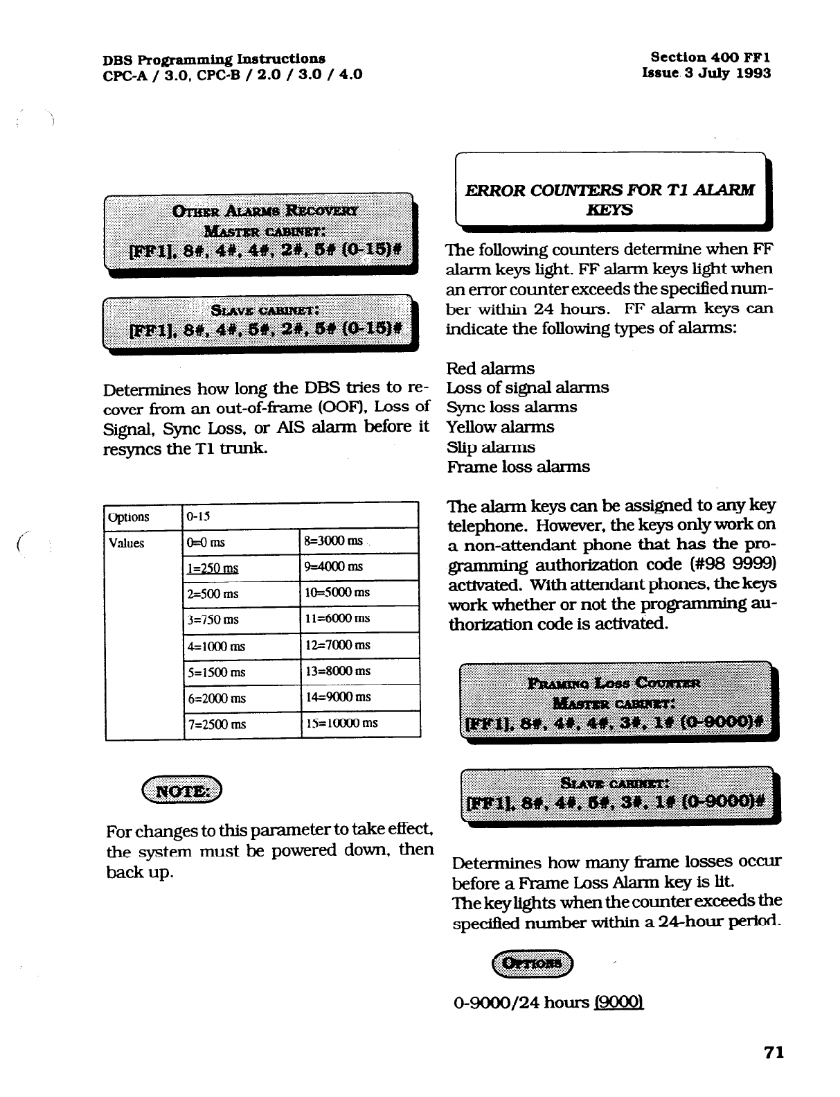
DBS Programming Insl~~ctions
WC-A / 3.0, CPC-B / 2.0 / 3.0 / 4.0
Section400
FFl
bsue 3 July
1993
Determines how long the DBS tries to re-
cover from an out-of-frame (OOF), Loss of
Signal, Sync Loss, or AIS alarm before it
resyncs the Tl trunk.
Options lo-15 I
values lo=o~
18=3cxIoms
I
1=250 ms 9=4oooms
2=500 ms lO=SCCIO ms
13=7SOms 111=6OOOms 1
14=1OOOms ~12=7OOOms I
I5=1500 ms
I
13=8000 ms
I
6=2000 ms 14=9000 ms
7=2500 ms lS=loooO ms
For changes to this parameter to take effect,
the system must be powered down, then
hack up.
ERRORCOUVTERSMIRT1AIARM
The following counters determine when FF
alarm keys light. FF alarm keys light when
an error counter exceeds the spectied num-
ber within 24 hours. FF alarm keys can
indicate the following types of alarms:
Red alarms
Loss of signal abmx3
sync loss alarms
Yellow alarms
slip alarms
Fl-arne loss alarms
Thealaxmkeyscanbeassignedtoanykey
telephone. However, the keys onlywork on
a non-attendant phone that has the pro-
gramming authorization code (#98 9999)
activated. With attendant phones, the keys
work whether or not the programming au-
thorization code is activati.
Determines how many fi-ame losses occur
beforeaFbmeLossAlarrnkeyislit.
Thekeylightswhenthecountxxexceedsthe
spedfied number within a 24hour period.
0-9CXM/24
hours Jm
71
Technical Manuals Online! - http://www.tech-man.com
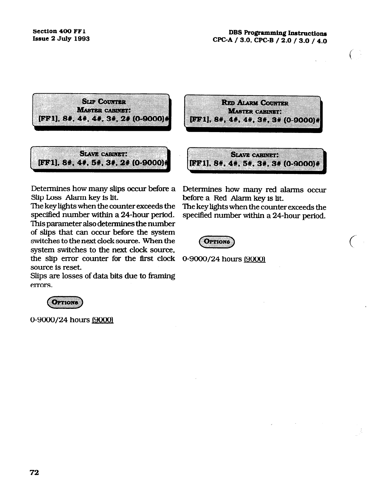
section 400 FFl
Issue 2 July 1993 DBS Pro@amming Intstruction~
CPGA / 3.0, CPC-B / 2.0 / 3.0 / 4.0
Determines how many slips occur befonz a
Slip Loss Alarm key is lit.
‘Ihe key lights when the counter exceeds the
specified number within a 24-hour period.
This parameter also determines the number
of slips that can occur before the system
switches to the next clock source. When the
system switches to the next clock source,
the slip en-or counter for the first clock
source is reset.
Slips are losses of data bits due to fixming
errors.
Determines how many red alarms occw
before a Red Alarm key is lit.
The key lights when the counter exceeds the
specified number within a 24-hour period.
O-9000/24 hours I90001
72
Technical Manuals Online! - http://www.tech-man.com

DBS Programming Instructions
WC-A / 3.0, CPC-B / 2.0 / 3.0 / 4.0 Section 400 FFl
Issue 3 July 1993
Determines how many instances of signal Determines how many instances of sync
loss occur before a Signal Loss Alarm key is 1ossoccurbeforeaSyncLmsAkmnkeyislit.
lit. The keylightswhenthecounterexceedsthe
The key lights when the counter exceeds the specified number within a 24hou.r period.
specitM number within a 24-hour period.
73
Technical Manuals Online! - http://www.tech-man.com
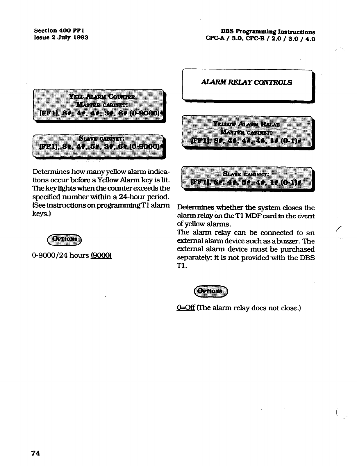
Section 400 FFl DBS Ro#ammlqj Instn~ctions
Issue 2 July 1993 WC-A / 3.0, CPGB / 2.0 / 3.0 / 4.0
Determines how many yellow alarm indica-
tions occur before a Yellow Alarm key is lit.
The key lights when the counter exceeds the
specified number within a 24-hour period.
(See instructions on programmingT1 alarm
keys.) Determines whether the system closes the
-alarmrelay&th&TlMDFcardinthee&nt
of yellow alarms.
like ah-m rday can be connected to an
tztemalalaxmdevicesuchasabuzzer. The
external alarm device must be purchased
separate& it is noit provided with the DBS
Tl.
f-
~
‘~~
O=OfT@he alarm relay does not close.)
i
74
Technical Manuals Online! - http://www.tech-man.com
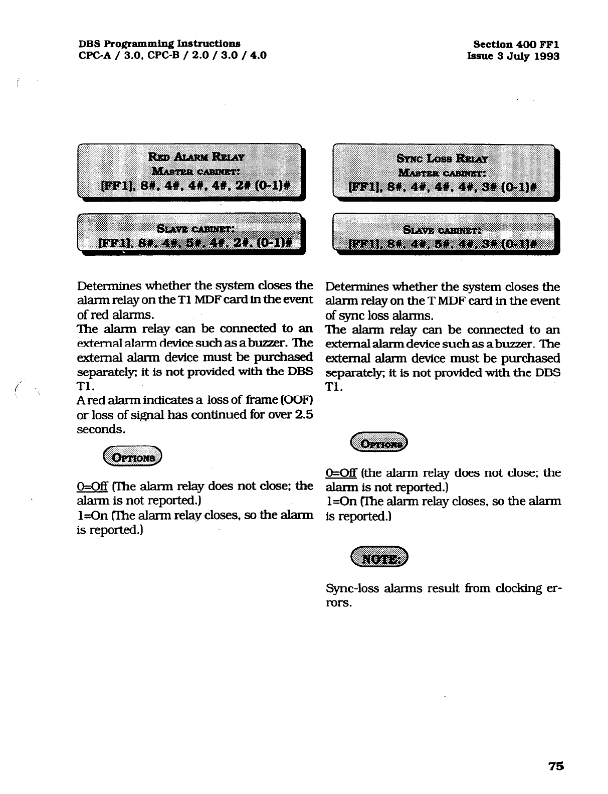
DBS Programming Instructions Section 400 FFl
CPC-A / 3.0, CPC-B / 2.0 / 3.0 / 4.0 Issue 3 July 1993
Determines whether the system closes the
alarm relay on the Tl MDF card in the event
of
red alarms.
The alarm relay can be connected to an
extemalalarmdevicesuchasabuzzer. The
external alarm device must be purchased
separately; it is not provided with the DBS
Tl.
A red alarm indicates a loss of fi-ame @OF)
or loss of signal has continued for over 2.5
seconds.
O=OB (The alarm relay does not close: the
alarm is not reported.)
l=On (The alarm relay closes, so the alarm
is reported.)
Determines whether the system closes the
alarm relay on the T MDF card in the event
of sync loss alalms.
The akmn relay can be connected to an
externalalanndevice suchas abuzzer. ‘Ihe
external alarm device must be purchased
separately; it is not provided with the DBS
Tl.
O=Off (the alarm relay does not close: the
alann is not reported.)
l=On (Ihe alarm relay closes, so the alarm
is reported.)
Sync-loss alarms result from clocking er-
rors.
75
Technical Manuals Online! - http://www.tech-man.com
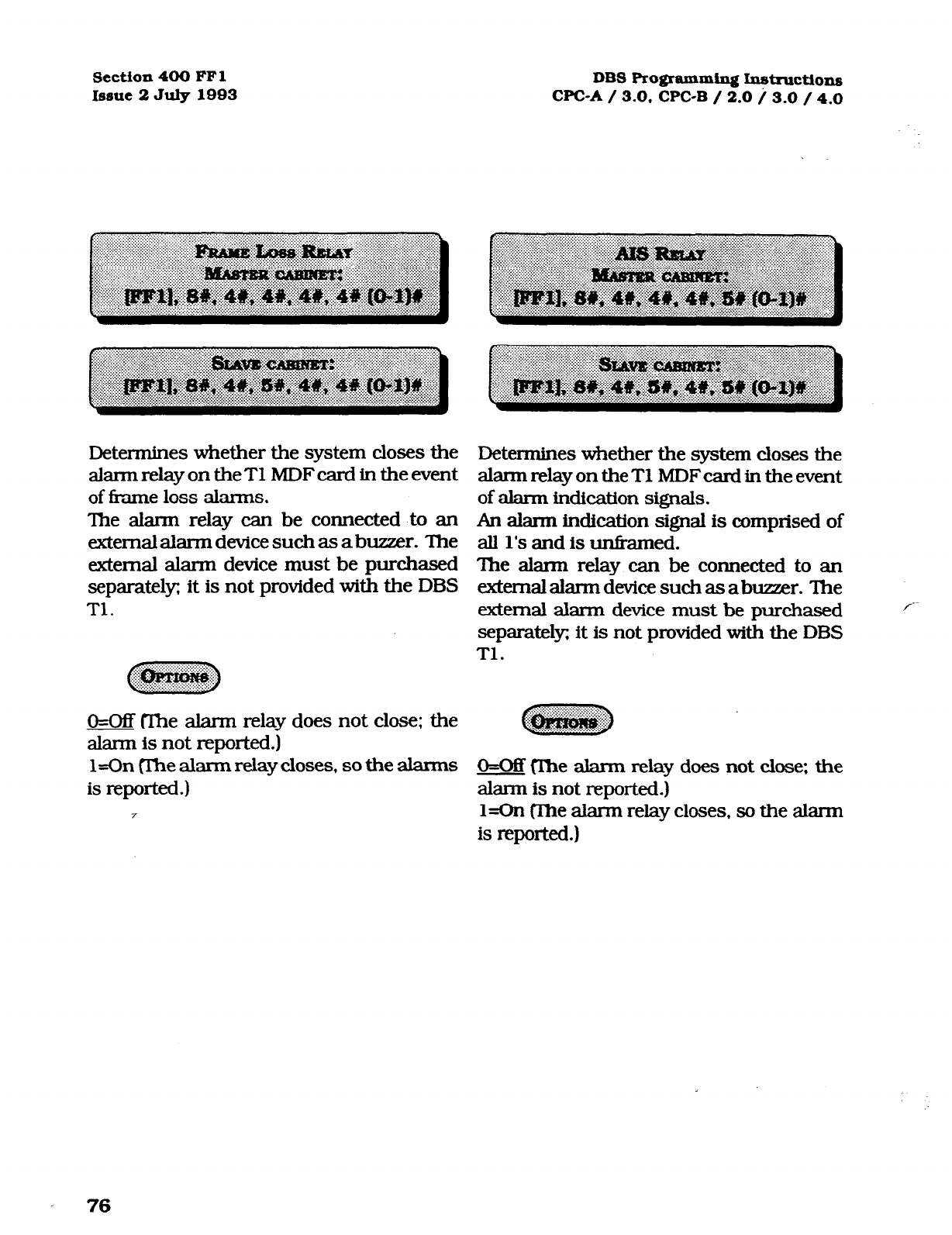
Section 400 FFl DBS Programming Instructions
Issue 2 July 1993 CPC-A / 3.0. CPC-B / 2.0 i 3.0 / 4.0
Determines whether the system closes the
alannrelayontheT1MDFcardintheevent
of fi-ame
loss alarms.
The alarm relay can be connected to an
external alarm device such as a buzzer. The
external alarm device must be purchased
separately; it is not provided with the DBS
Tl.
O=Off CIhe alarm relay does not close: the
alarm is not reported.)
l=On me alarm relay closes, so the alarms
is reported.)
Determines whether the system closes the
alannrelayontheT1 MDFcardin theevent
of alarm
indication signals.
An alann indication signal is comprised of
all l’s and is unfi-amed.
The alarm relay can be connected to an
extemalalarmdevicesuchasabuzwr. The
cxtemal alarm device must be purchased
separateb it is not provided with the DBS
Tl.
O=OB flhe alarm relay does not close; the
alarm is not reported.)
l=On me alarm relay closes, so the alarm
is reported.)
76
Technical Manuals Online! - http://www.tech-man.com
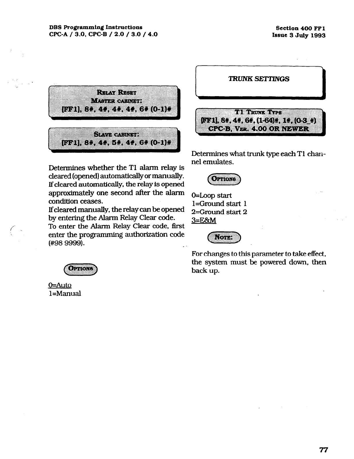
DBS Programming Instructions Section 400 FFI
WC-A / 3.0, CPC-B / 2.0 / 3.0 / 4.0 bsire 3 July 1993
Determines whether the Tl alarm relay is
cleared (opened) automatically or manuaJly.
If cleared automatically, the relay is opened
approximately one second after the alarm
condition ceases.
Ifcleared manually, the relay can be opened
by entering the Alarm Relay Clear code.
To enter the Alarm Relay Clear code, first
enter the programming authorization code
(#98 9999). .
Determines what trunk type each Tl chan-
nel emulates.
o=LQop start
l=Ground start 1
2=Gmund start 2
3=E&M
For changes to this parameter to take effect,
the system must be powered down, then
back up.
O=Auto
l=Manual
Technical Manuals Online! - http://www.tech-man.com
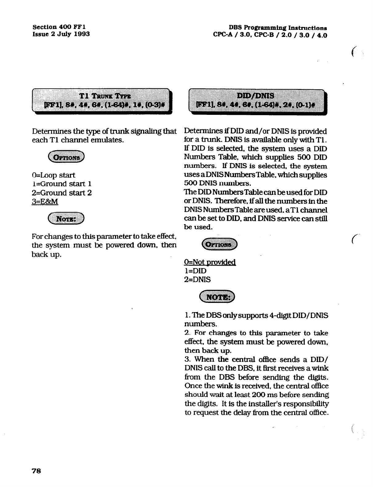
Section 400 FFl
Issue 2 July 1993 DBS Programming Instruct.io~
CPC-A / 3.0, CPC-B / 2.0 / 3.0 / 4.0
Deterrnines the type of trunk signaling that
each Tl channel emulates.
O=Loop start
I=Ground start 1
2=Ground start 2
3=Ex!zM
For changes to this parameter to take effect,
the system must be powered down, then
back up.
Determines if DID and/or DNIS is provided
for a trunk. DNIS is available only with Tl .
If DID is selected, the system uses a DID
Numbers Table, which supplies 500 DID
numbers. If DNIS is selected, the system
uses aDNISNumbersTable, which supplies
500 DNIS numbers.
The DID NumbersTable canbe used for DID
or DNIS. Therefore, ifall the numbers in the
DNISNumbersTableareused, aT1 channel
can be set to DID, and DIVE service can still
be used.
O=Not nrovided
l=DID
2=DNIS
1. The DBSonlysupports 4-digit DID/DNIS
numbers.
2. For changes to this parameter to take
effect, the system must be powered down,
then back up.
3. When the central oI3ce sends a DID/
DNIScalltotheDBS.itfi.rstrece.ivesawInk
from the DEB before sending the digits.
Once the wink is received, the central of&e
should wait at least 200 ms before sending
the digits. It is the installer’s responsibility
to request the delay from the central office.
i
78
Technical Manuals Online! - http://www.tech-man.com
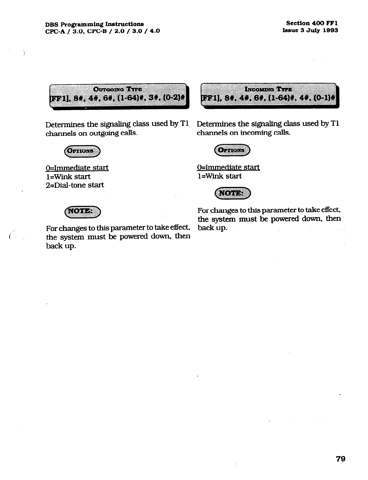
DBS Programming Inst~ctions section 400 FFl
WC-A / 3.0, CPC-B / 2.0 / 3.0 / 4.0 bsue 3 July 1993
Determines the signaling cbs used by T1 Determines the signaling class used by Tl
channels on outgoing calls. channels on incoming calls.
O=Immediate start
l=Wink start
2=Dial-tone start
~~~
@ggzpJg;:;
O=Immediate start
l=Wink start
c?z!ym!J
..ij~~~
For changes to this parameter to take effect.
the system must be powered down, then
i' ~
For changes to this parameter to take effect, back
up.
the system must be powered down, then
back up.
79
Technical Manuals Online! - http://www.tech-man.com
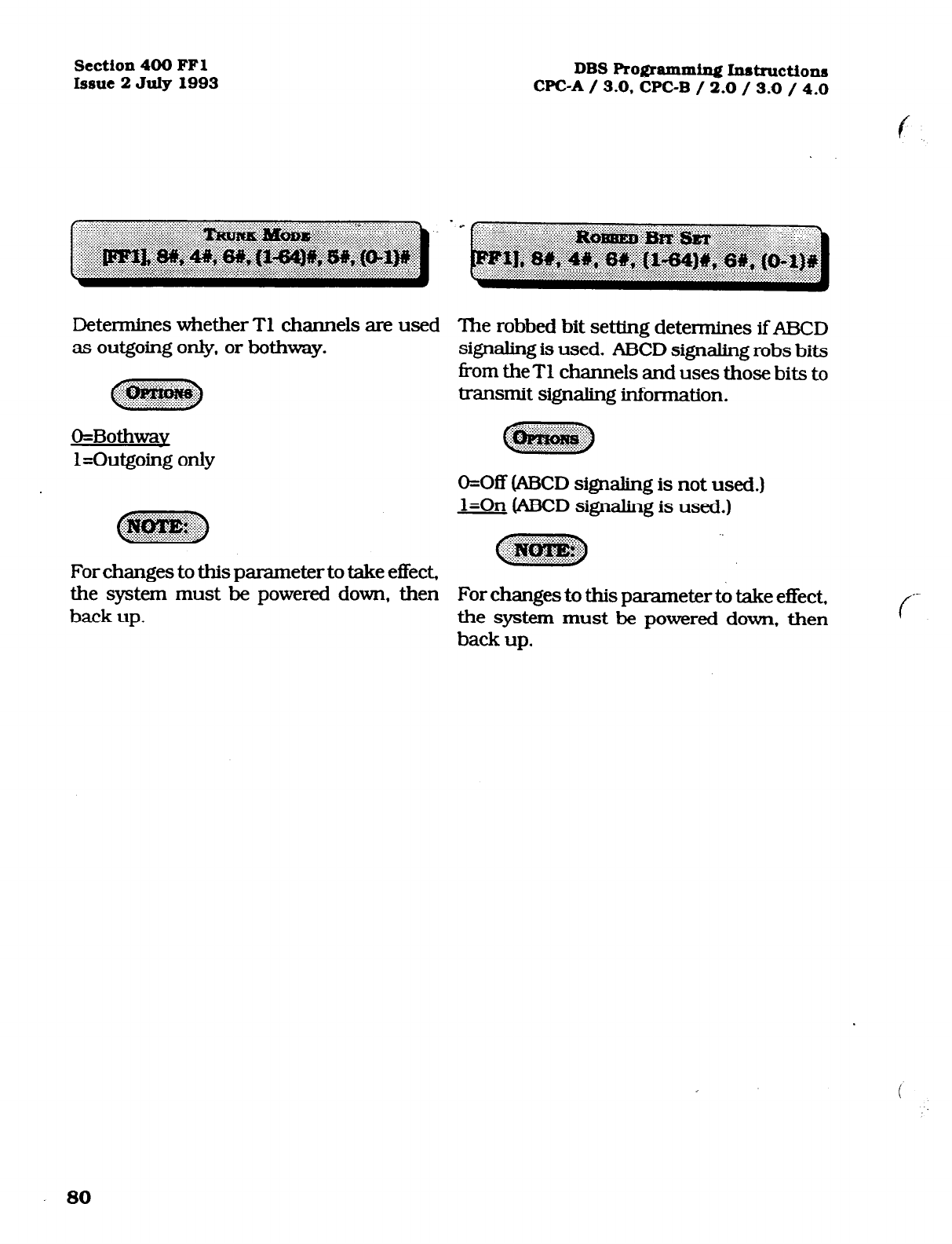
Section 400 FFl
Issue 2 July 1993 DBS Programming Instructions
CPC-A / 3.0. CPC-B / 2.0 / 3.0 / 4.0
f
Determines whether Tl channels are used The robbed bit setting determines lfAJ3CD
as outgoing only, or bothway. signaling is used. ABCD signaling robs bits
~ from the Tl channels and uses those bits to
..:“.$;, transmit signaling information.
O=Bothwav
l=Outgoing only
cw3
--::~~
O=Off (ABCD signaling is not used.)
~~~
l=On @BCD signaling is used.)
.:‘i~~~~~~ #@ggy$::
For changes to this parameter to take effect,
~~~ ~
the system must be powered down, then For changes
to
this parameterto take effect,
back up. the system must be powered down, then
back up.
f--
80
Technical Manuals Online! - http://www.tech-man.com

DBS Programming Instn~ctions Section 400 FFl
WC-A / 3.0, CPC-B / 2.0 / 3.0 / 4.0 Issue 3 July 1993
Determines whether the system expects DP ‘hnsmits dial tone hm the Tl channel to
or DTMF digits for incoming DID or DNIS another DBS within a private network.
calls.
If YXIVIF” is selected, the DBS must be
c- ) equipped with an MFR card.
81
Technical Manuals Online! - http://www.tech-man.com
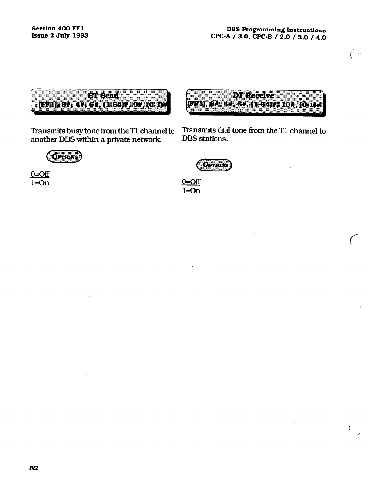
Section 400 FFl
Issue 2 July 1993 DBS Programming Instructions
WC-A / 3.0, CPC-B / 2.0 / 3.0 / 4.0
lbrmn.its busy tone from theT1 channel to lhnsmits dial tone from the Tl channel to
another DBS within a private network. DBS stations.
o=off
l=On
o=m
l=On
c
82
Technical Manuals Online! - http://www.tech-man.com
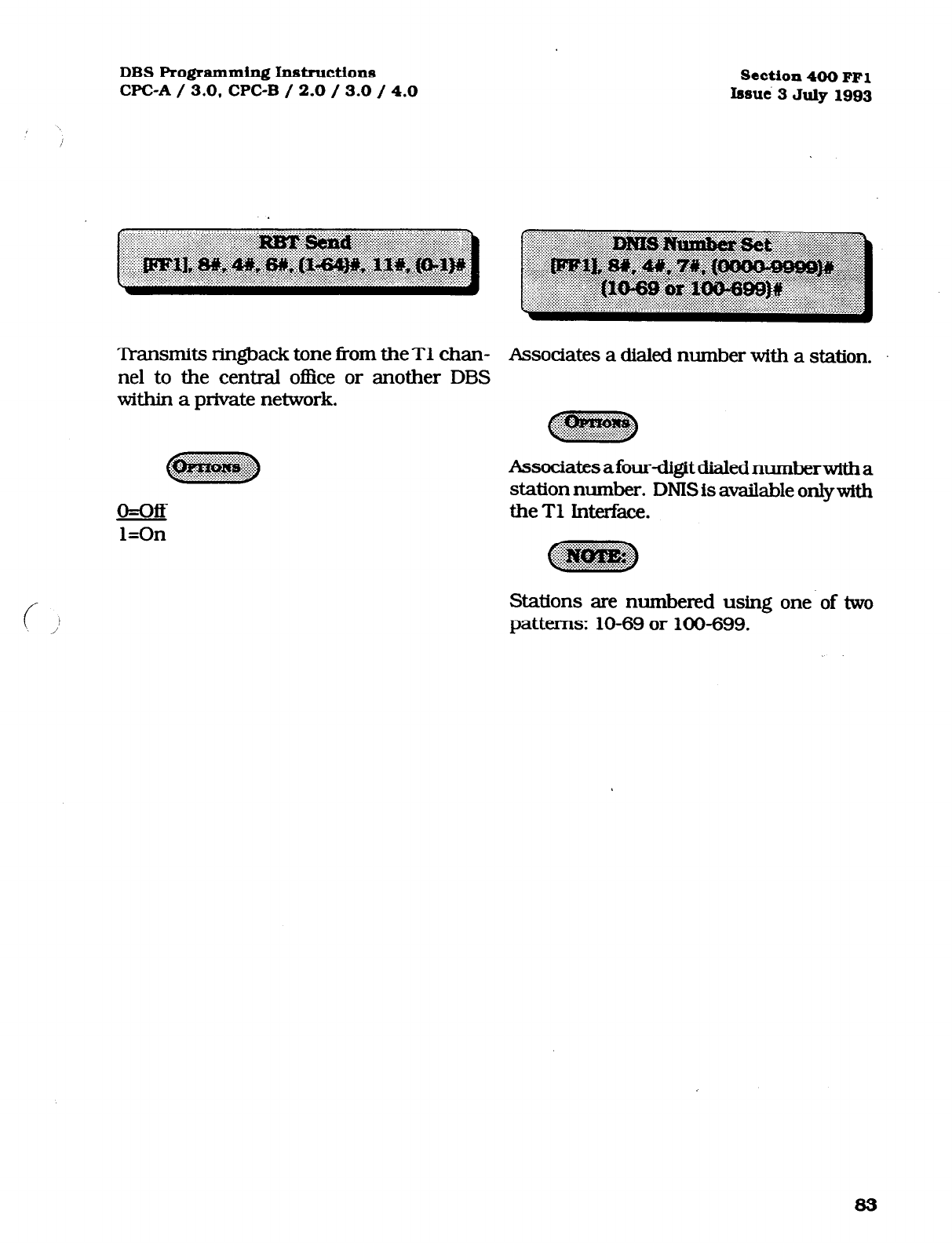
DBS Programming Instructiona
WC-A / 3.0, CPC-B / 2.0 / 3.0 / 4.0
Transmits ringback tone f?om theT1 chan-
nel to the central office
within a private network. or another DBS
o=off
l=On
section 400 FFl
Issut% 3 July 1993
Associates a dialed number with a station.
Associatesafour-digitdialednumberwitha
station number. DNIS is available onlywith
theT1 Interface.
Stations are numbered using one of two
patterns: 10-69 or 100-699.
83
Technical Manuals Online! - http://www.tech-man.com
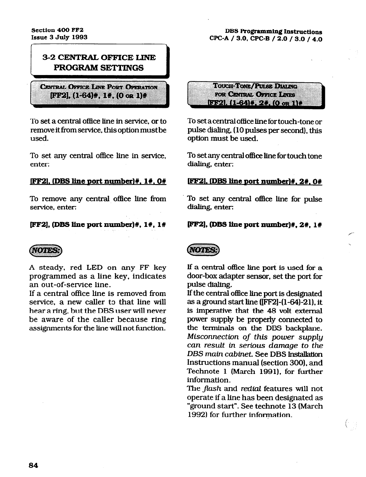
Section 400 FF2 DBS
Issue 3 July 1993 Programming Instructions
WC-A / 3.0. CPC-B / 2.0 / 3.0 / 4.0
To set a central o&e line in service, or to
remove it from service, this option must be
used.
To set a central office line for touch-tone or
pulse dialing. (10 pulses per second), this
option must be used.
To set any central office line in service.
enter: To set any central office line for touch tone
dialing, enter:
,lDBSl.ine~ort
numbed#.l#.OW
1. rDBs Iine
Dolt mmbex~#.
2#. on
To remove any central ofllce line from
service, enter: To set any centml o&e line for pulse
dialing, enter:
[FF2l,@BSlineportnumber)#,1#,1# CPllrZ),@BSlineportnumber)#,2#, l# /
A steady, red LED on any FF key
programmed as a line key, indicates
If a central office line is removed from
service, a new caller to that line will
an out-of-service line.
hear a ring, but the DBS user will never
be aware of the caller because ring
assignments for the line will not function.
If the central office line port is designated
as a ground start line (FF2]-(1-64-21)1 it
If a central oflice line port is used for a
is imperative that the 48 volt external
power supply be properly connected to
door-box adapter sensor, set the port for
the terminals on the DBS backplane.
Misconnection of this power supply
pulse dialing.
can result in serious damage to the
DBS main cabinet. See DBS In&all&on
Instructions manual (section 300). and
Technote 1 (March 1991). for further
information.
The j-lash and redial features will not
operate if a line has been designated as
“ground start*. See technote 13 (March
1992) for further information.
84
Technical Manuals Online! - http://www.tech-man.com
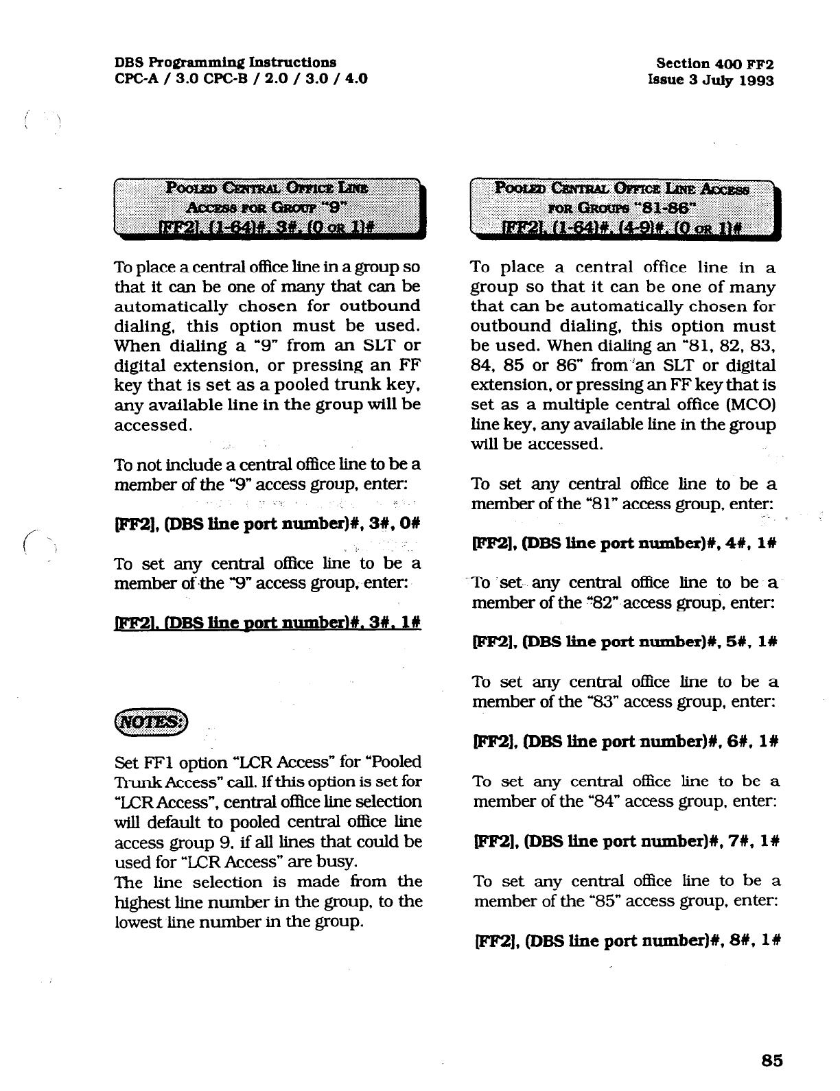
DBS Programming Instructions
CPC-A / 3.0 WC-B / 2.0 / 3.0 / 4.0
I
/ \
\
Section 400 FF2
Issue 3 July 1993
To place a central office line in a group so
that it can be one of many that can be
automatically chosen for outbound
dialing, this option must be used.
When dialing a “9” from an SLT or
digital extension, or pressing an FF
key that is set as a pooled trunk key,
any available line in the group will be
accessed.
To not include a central office line to be a
member of the “9” access group, enter:
.- .:\ ,i
~),@BSIlneportnumber)#,3#,0#
To set any central office line to be ‘a
member ofthe “9” access group, enter:
.IDBSline~ort
number)#.3#.1#
n. @gJgg’i
:..- .i.,.i,.,., . ..e
Set FFl option “LCR Access” for “Pooled
Trunk Access” cdl. If this option is set for
“LCRAccess”, central o&e line selection
will default to pooled central office line
access group 9, if all lines that could be
used for “ICR Access” are busy.
The line selection is made from the
highest line number in the group, to the
lowest line number in the group.
To place a central office line in a
group so that it can be one of many
that can be automatically chosen for
outbound dialing, this option must
be used. When dialing an
“81, 82.83,
84, 85 or 86” from ‘an SLT or digital
extension. or pressing an FF key that is
set as a multiple central office (MCO)
line key, any available line in the group
wilI be accessed.
To set any central office line to be a
member of the “81” access group, enter:
-:
~],@BSIlneportnumber)#,4#,1#
-To ‘set- any central office line to be a
member of the ?82” access group, enter:
To set any central office line to be a
member of the 333” access group, enter:
To set any central office line to be a
member of the “84” access group, enter:
To set any central office line to be a
member of the “85” access group. enter:
@FZJ,(DBSlineport
number)#,8#,1#
85
Technical Manuals Online! - http://www.tech-man.com
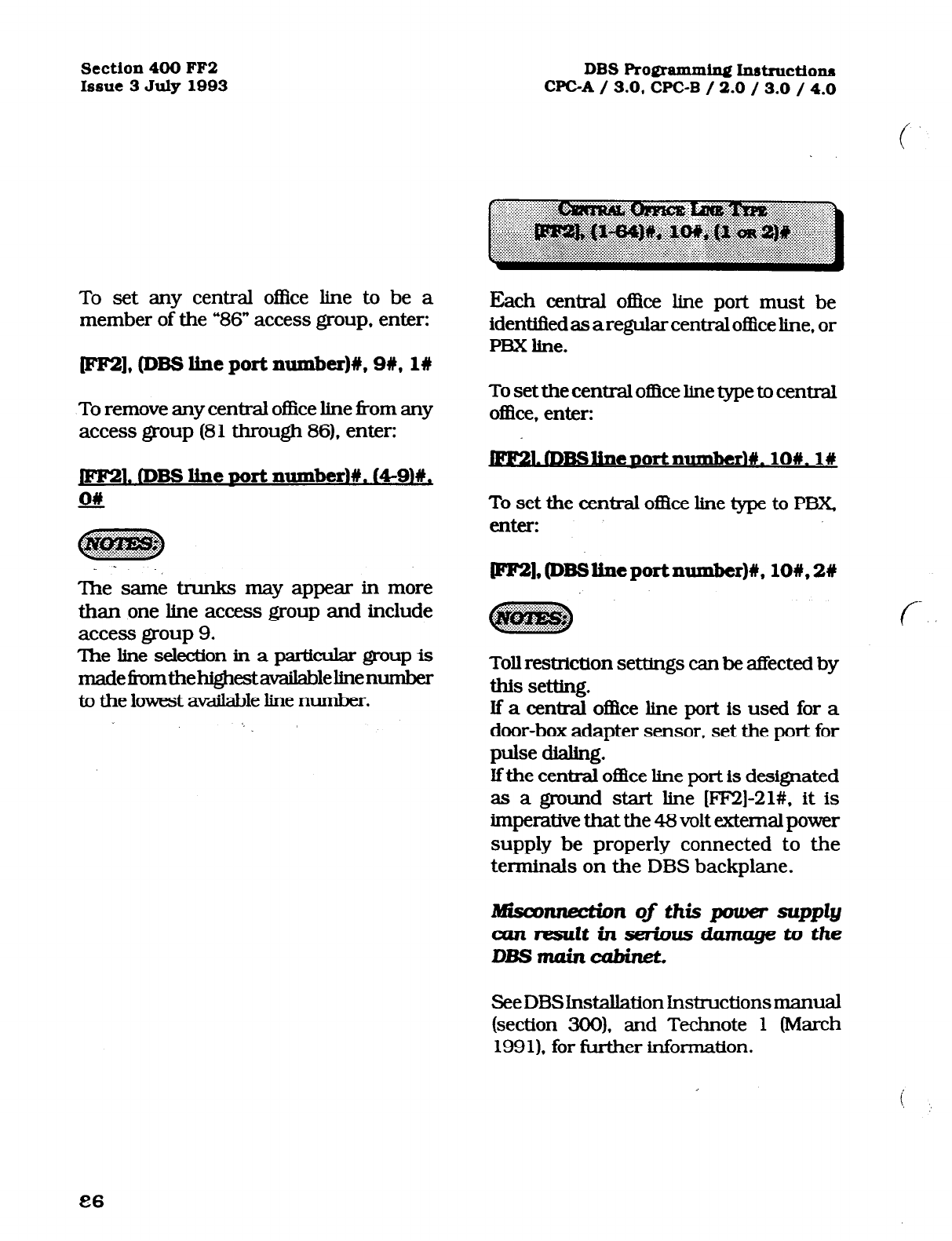
Section 400 FF2
Issue 3 July 1993
To set any central office line to be a
member of the “86” access group, enter:
[eez], (DBS line port number)#, 9#, l#
To remove any central office line &om any
access group (81 through 86), enter:
1. (DBS line Mlrt numberld. (49lW,
06
The same trunks may appear in more
than one line access group and include
access group 9.
The line selection in a particular group is
madef+omthehighestavailablelinenumber
to the lowest available line number.
DBS Programxdq Ix~tructiona
WC-A
/ 3.0, CPC-B / 2.0 / 3.0 / 4.0
Each central of&e line port must be
identified as a regular central o!IIce line, or
PBX line.
To set the central of&e line type to central
offke, enter:
1.KBSl.ineportnumber)#. 1OW. l#
To set the central of&e line type to PBX,
enter:
Toll restriction settings can be affected by
this setting.
lf a central o&e line port is used for a
door-box adapter sensor, set the port for
pulse dialing.
Ifthe central office line port is designated
as a ground start line [FF2]-21#. it is
imperative that the 48 volt external power
supply be properly connected to the
terminals on the DBS backplane.
nnection of this power supply
aznmsuZtinsedusdamagetothe
DBsmainctlbheL
See DBSlnstallation Instructions manual
(section 300). and Technote 1 (March
1991). for further i.nformation.
Technical Manuals Online! - http://www.tech-man.com

DBS Programming Inst.ructions
WC-A / 3.0 CPC-B / 2.0 / 3.0 / 4.0
i
Section 400 FF2
Issue 3 July 1993
To set acentral office Iine(s) to automaticaRy
provide DiSAtone upon connection with an
inbound cakr. this option must be set
To set any central office line to provide a
DISA tone when connected to a new
inbound caller, enter:
~],@BSlinep0rtnumher)#, ll#, l#
To ‘set any central of& I&e so that it does
not provide a DISA tone when connected
to a new inbound caller, enter:
l.lDBSline~ortnumberM. ll#.O#
To set automatic DISA start and end
times, see [FIG?] 19#. and 20# program
addresses, and the DISA code program
address at [FFl], 6#.
Any extension can be set with a private
centml ofIke line(s). A number of private
lines can belong to one extension, but
the same private line cannot be set on
multiple extensions.
To set extension port 15 for central office
Iine 12 to be a private central of&e I.i.ne(s),
enter:
pF2], lS#, 12#, 12#
To reset anv extension to the default
initialized
~rh&e he
value. Dress IFI%?L
@BS line oort number)#. 12#. ICONFZ,
JON/OFl?l.
Anincom.ingcalIonaprivateIinewiIlonIy
ring on one extension.
Once the private line option is set, other.
extensions cannot make outbound calls
or receive inbound caIls on that line.
Ifthe private Iine setting is disabled, caIIs
cannot be made or received on that line(s)
without manualIy reprogrammingthe toil
restriction options of an extension(s) to
which the line should now appear.
In DBS instaIlations using the WC-A
card, the highest extension port number
that can be used is 72.
87
Technical Manuals Online! - http://www.tech-man.com
Section 400 FF2
Issue 3 July 1993 DBS Programming Instructions
WC-A / 3.0, CPC-B / 2.0 / 3.0 / 4.0
To set an automatic pause during dialing
on a central of&e line defined as PBX this
option must be used.
To set the automatic pause on line 15 for
example, (once line 15 is defined as a
PBX). enter:
pm. SW. 13w. 19
To disable the automatic pause on line 12
for example. (once line 12 is defI.txd as a
PBX), enter:
pF2], 128, 136, ow
See [FFl], 3.# 12# program option, for the
timer used for this pause.
To define whether dialed digits will be
outpulsed after dial tone has been
detected, or not, this option is used.
To outpulse dialed digits only after dial
tone is detected, enter:
1,fDB!3liDeDOrtnumber~u.
141y.on
To outpulse dialed digits according to the
system dial pause timer, enter:
lfthis option is not set, the dialed number
is outpulsed according to the system dial
pause time.
To increase the duration of the MMF
signal when making an outbound call,
use this feature. c
To set the on/off duration of an
outbound
IXMF signal to 75 ms. on and
sd’ms.‘tAT.
enter:
1.nlBSliDeDortllDmber~#.
15#.1#
To set the on,!off duration of an
outbound .
M’MF signal to 125 ms. on and 125 ms.
off. enter:
PW2],(DBSlineportnumber)#, 15#,2#
To set the on/off duration of an
outbound
MMF signal to 250 111s. on and 250 ms.
off, enter:
lFF2], (DBSlineportnumber)#, 15#, 3W
fFF2],@ESlineportnumber)#, 14#, 111
88
Technical Manuals Online! - http://www.tech-man.com
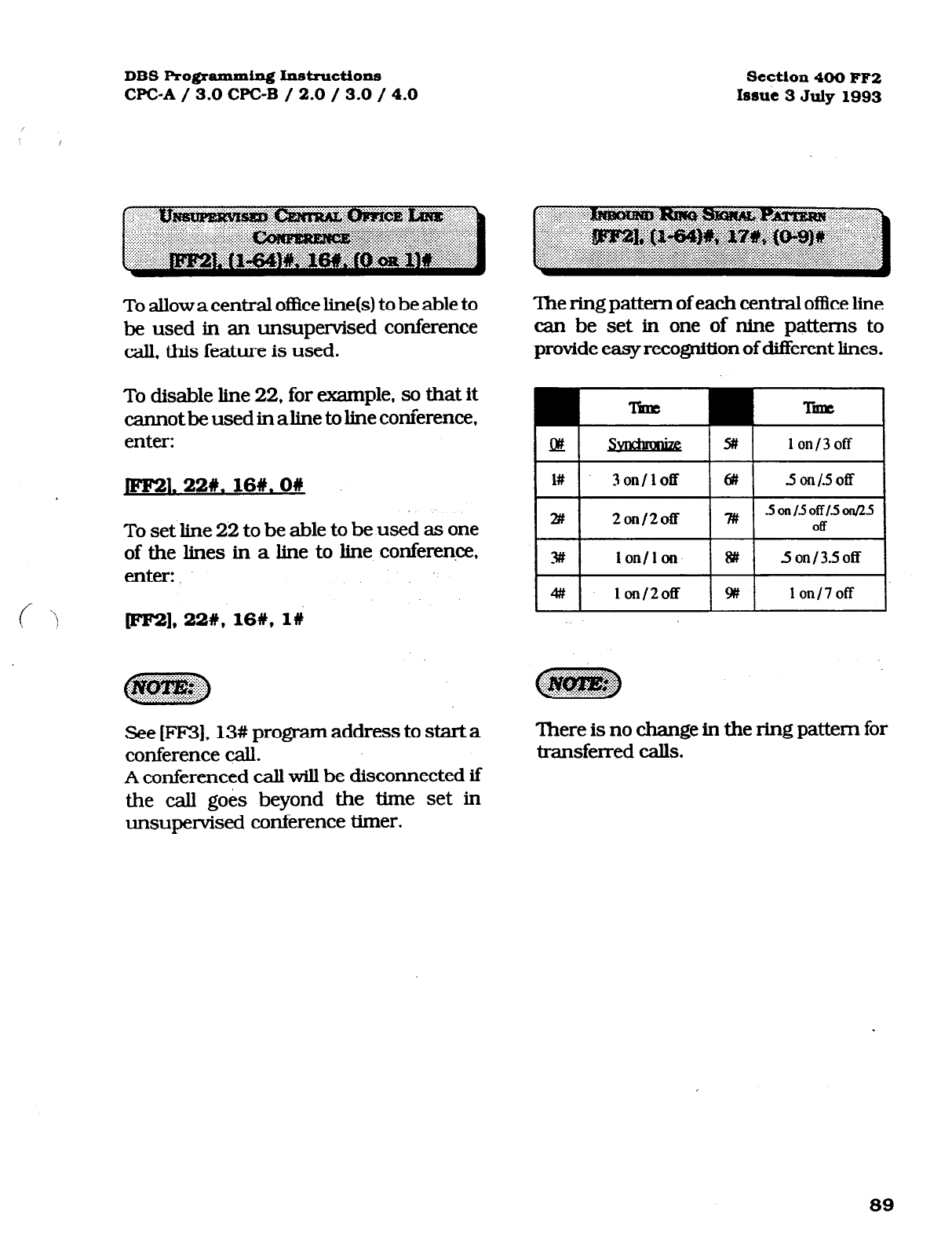
DBS Programming Instructions
WC-A
/ 3.0
WC-B / 2.0 / 3.0 / 4.0 Section 400 FF2
Issue 3 July 1993
To allow a central ofike line(s) to be able to
be used in an unsupervised conference
call, this feature is used.
To disable line 22, for (xample, so that it
cannot be used in aline to line conference,
enter:
JFKBl. 22#. 16W. OW
To set line 22 to be able to be used as one
of the lines in a line to he conference.
enter:.
c ‘> m], 22W. 16#, l#
See [FF3], 13# program address to start a
conference call.
A conferenced call will be disconnected if
the call go& beyond the time set in
unsupervised conference timer.
The ring pattem of each central oflice line
can be set in one of nine patterns to
provide easy recognition of different lines.
- MI
lon/3off 1
I I
1# 3on/loff I I
6# 5
OKl/.5Off
I
I I
2#
2on/2off ?I#
1 I 5 on I.5 off 1.5 onf2J
Off
I
I I
Y lon/lon I I
8# 5 onl3.5off I
I I
4# 1 on/2off I I
9# lon/7off I
There is no change in the ring pattern for
transferred calls.
89
Technical Manuals Online! - http://www.tech-man.com
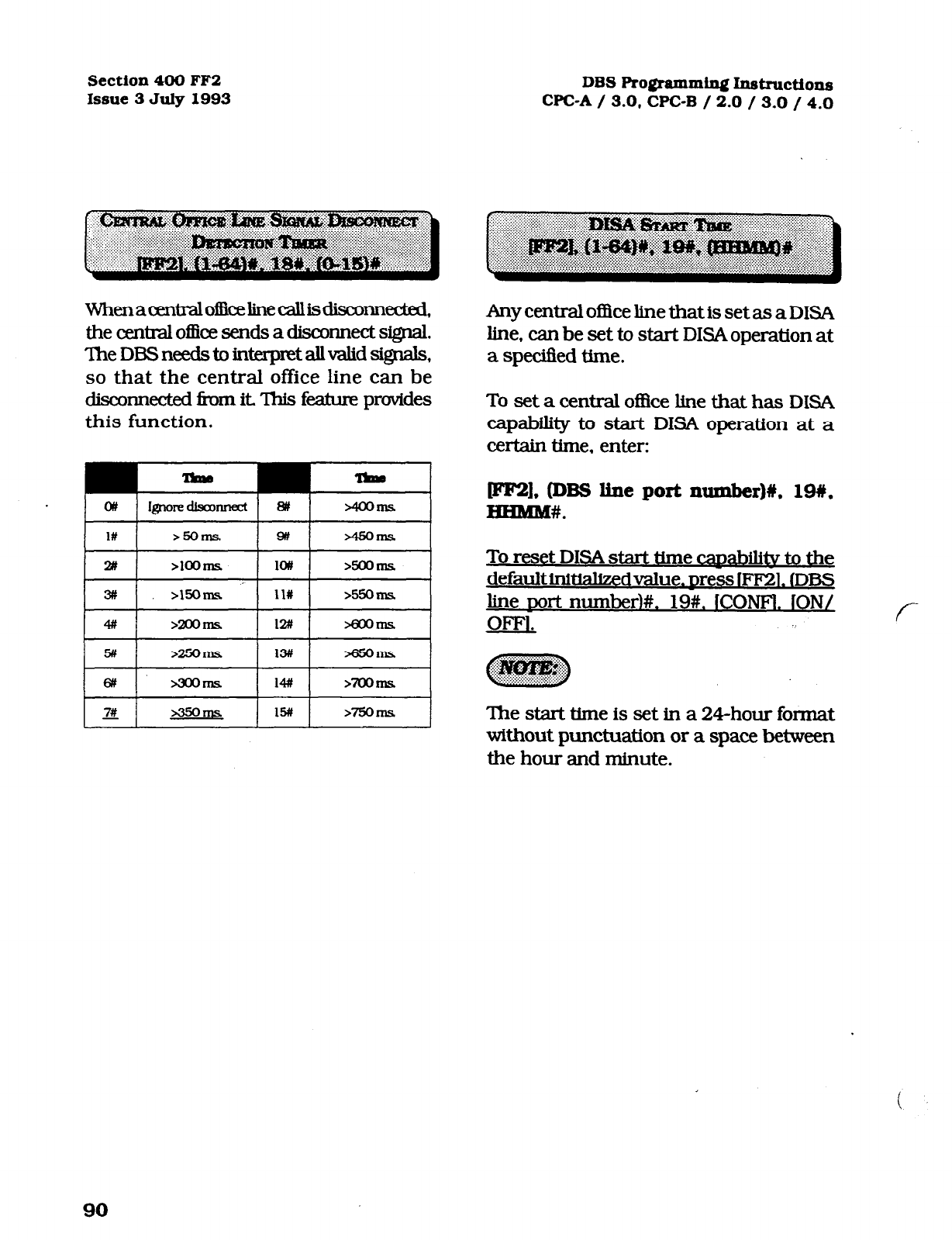
Section 400 FF2
Issue 3 July 1993 DBS Programming Instructions
CPC-A / 3.0, CPC-B / 2.0 / 3.0 / 4.0
WhenaazntmIoi3keIinecaIIisdisconnected,
theaxdralofficeSendSadiScoMectSignal.
TheDESneedstoint.erpretaIIvaIidsi@aIs,
so that the central office line can be
disco~ected fbm it This
feature provides
this function.
I
. -Ins I
I l# I >5OIllS 14 zQ5oms. I
I 2# I >loOlllS I 1o# I >5OORlS
I
I 3ff I
>15oms 1 11% I 9350 ms I
I7# 1 235oms I15# 1 >75oms /
Any centraI of&e Iine that is set as a DISA
line, can be set to start DISAoperation at
a speciBed time.
To set a central of&e I.ine that has DISA
capability to start DISA operation at a
certain time, enter:
FW, @BS tie port number)#, 19#,
HHMBM.
To reset DISA start time czmbiIitv to the
default initiakedvalue. mess lFF21. (DB!3
mrt numberl#, 19#. ICONFl. ION/ f-
The start time is set in a 24hour format
without punctuation or a space between
the hour and minute.
90
Technical Manuals Online! - http://www.tech-man.com

DBS Programming Inst~ctione
Section4OOFF2
WC-A / 3.0 WC-B / 2.0 / 3.0 / 4.0
hue
3JulJr 1993
AI-IY central oflke line
that is set as a DISA
line. can be set to stop DISA operation at
a speclfied time.
To set a central oflEe Iine that has DISA
capability to stop DISA operation at a
certain time, enter:
fFF2], (DBS line port number)#, 20#,
HH.MM#.
,f “\
\
To reset DISA ston time canabiI.itv to the
default i.nitializedvaIue. Dress IFF21. (DF3S
rmrt numberlt 20##. lCONFl. iON/
%I.
Determines whether the trunk circuit is
ananaIogloopstart, analogground start,
analog DID, or Tl.
o=bOD Start
l=Ground start
2=DID
3=Tl
For changes to this parameter to take
eBect,thesystemmustbepowereddown,
then back up.
‘Ihe stop time is set in a 24-hour format
without a space between the hour and
minute.
91
Technical Manuals Online! - http://www.tech-man.com
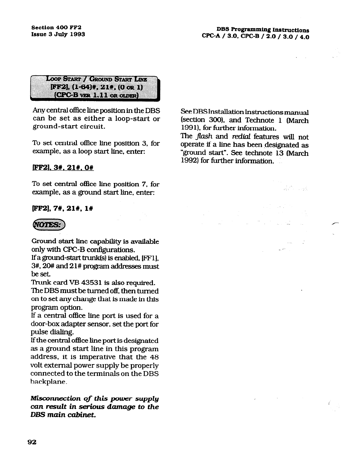
Section 400 FF2
Issue 3 July 1993
Any central office line position in the DBS
can be set as either a loop-start or
ground-start circuit.
To set central office line position 3, for
example, as a loop start line, enter:
ml. 3#.21#.0#
To set central o&e line position 7. for
example, as a ground start line, enter:
pF2],7#,21#, l#
Ground. start line capability is available
only with CFC-B configurations.
lfaground-starttrunk is enabled, FFl],
3#.
%I## and 21# progmm addresses must
beset
Trunk card VB 43531 is also required.
The DBS must be turned off, then turned
on to set any change that is made in this
program option.
lf a central of&e line port is used for a
door-box adapter sensor, set the port for
pulse dialing.
If the central of3ce line port is designated
as a ground start line in this program
address, it is imperative that the 48
volt external power supply be properly
connected to the terminals on the DBS
backplane.
DBS Rogramming Instructions
WC-A / 3.0, CPC-B / 2.0 / 3.0 / 4.0
See DBS installation Instructions manual
(section 300). and Technote 1 (March
199 1). for further information.
The j7mh and mdiaf features will not
operate if a line has been designated as
ground start”. See technote 13 (March
1992) for further tiormalion. :
Miinnection of this power suppZy
can result in serious damage to the
DBS main cabinet.
Technical Manuals Online! - http://www.tech-man.com
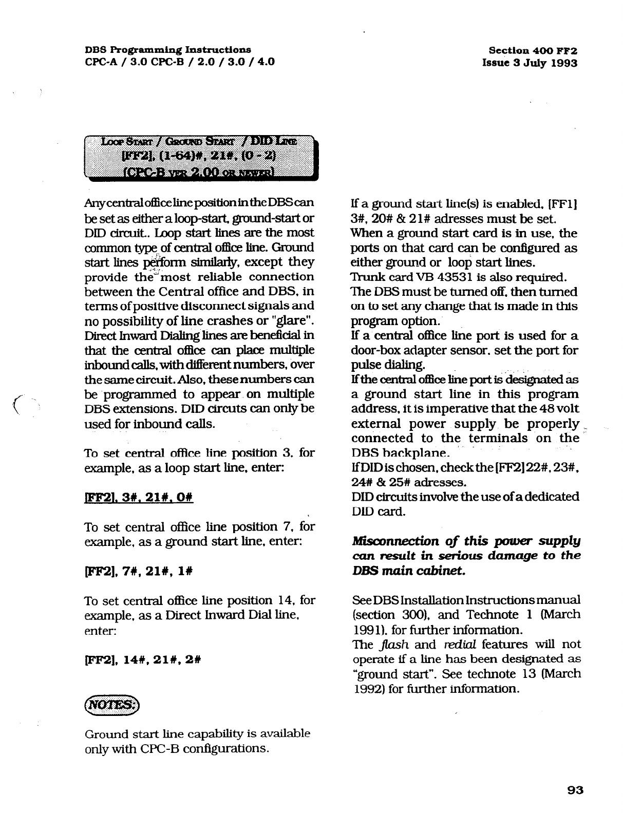
DBS Programming Instructions
CPC-A / 3.0 WC-B / 2.0 / 3.0 / 4.0 Section 400 FF2
Issue 3 July 1993
AnycentmlofficelinepositionintheDBScan
be set as either aloop-start, ground-start or
DIDcimuit..Loopstartlinesarethemost
common @pe of centml office line. Ground
start lines pi&on-n similaj, except they
provide
the” most reliable connection
between the Central office and DBS, in
terms of positive disconnect signals and
no possibility of line crashes or ‘glare”.
DiIrctInwaKlDiaJinglin~arebeneficialin
that the centml oilice can place multiple
inbound calls, with different numbers, over
thesamecircuit.Also, thesenumberscan
be .programmed to appear on multiple
DBS extensions. DID circuts can only be
used for inbound calls.
To set central office line position 3, for
example, as a loop start line. enter:
JFlm 3#.21#.0#
To set central office line position 7, for
example, as a ground start Iine, enter:
pT2],7#,21#, I#
To set
central office line position 14, for
example, as a Direct Inward Dial line,
enter:
p=m]*14#,21#,2#
If
a
ground start line(s) is enabled. [FFl]
3#. 20# & 21#
adresses
must be set.
When a ground start card is in use, the
ports on that card can be configured as
either ground or loop start lines.
Trunk card VB 43531 is also required.
‘Ihe DBS must be turned off. then turned
on to set any change that is made in this
program option.
If a central office line p0i-t is used for a
door-box adapter sensor, set the port for
pulse dialing.
Ifthecentxalofficeliieportis~iii&akdas
a
ground start line in this program
address, it is imperative that the 48 volt
external power supply be properly .-
connected to the terminals on the -.
DBS backplane.
IfDIDis chosen.
checkthe [FE!] 22#, 23#.
24# & 25#
adresses.
DID circuits involve the use of a dedicated
DID card.
nnection of this pozoer supply
am
result
in serious damage to the
DBS main cabinet.
See DBS Installation Instructions manual
(section 300). and Technote 1 (March
199 1). for fixther information.
‘The J&I and red&I features will not
operate
if a line has been designated as
“ground start”. See
technote 13 (March
1992) for further information.
Ground start line capability is available
only with WC-B configurations.
93
Technical Manuals Online! - http://www.tech-man.com
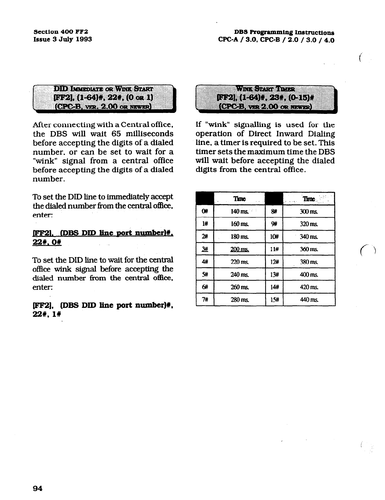
Section 400 FF2
Issue 3 July 1993 DBS Ro@ammin~ Ins~ctions
WC-A / 3.0, CPC-B / 2.0 / 3.0 / 4.0
After connecting with a Central office,
the DBS will wait 65 milliseconds
before accepting the digits of a dialed
number, or can be set to wait for a
“wink” signal from a central office
before accepting the digits of a dialed
number.
To set the DID line to immediately accept
the dialed number Tom the central oflice.
enter:
. CDBS DID line sort numbed%,
22w. on
To set the DID line to wait for the central
office wink signal before accepting the
dialed number f&m the central of.Ilce,
enter:
If “wink” signalling is used for the
operation of Direct Inward Dialing
line, a timer is required to be set. This
timer sets the maximum time the DBS
will wait before accepting the dialed
digits from the central office.
llun3 .~. . . . ..^ -me..y
14oms.~ lw 3ooms.
l# 16OmS 9# 32om
2# 18OmS lo# 34oms.
Id
26oms. I 14# I 42orIK I
FW, PBS DID line port number)%,
22#, l#
7# 28oms 44oms
94
Technical Manuals Online! - http://www.tech-man.com
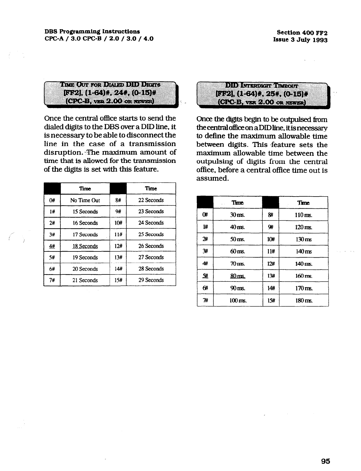
DBS Programming Instructions
Section400
FF2
CPC-A / 3.0 WC-B / 2.0 / 3.0 / 4.0 Issue 3July1993
Once the central office starts to send the
dialed digits to the DBS over a DID line, it
is necessary to be able to disconnect the
line in the case of a transmission
disruption.-The maximum amount of
time that is allowed for the transmission
of the digits is set with this feature.
Tinle Time
o#
No Time Out 8#
22Second.5
I I
l#
15 seconds I I
w
23Second.s I
2# 16Seconds
lo# 24 Seconds
3# 17Seconds
ll#
25
Seconds
48 18 Seconds 12#
26SecorKis
S# 19
Seconds 13#
27Seconds
6#
20 Seconds 14#
28Seconds
7# 21Seconds
1%
29Secods
L
Oncethedigitsbegintobeoutpulsedii-om
thecentralofEiceonaDIDline,itisnecessary
to define the maximum allowable time
between digits. This -feature sets the
maximum allowable time between the
outpulsing of digits from the central
office, before a central office time out is
assumed.
95
Technical Manuals Online! - http://www.tech-man.com
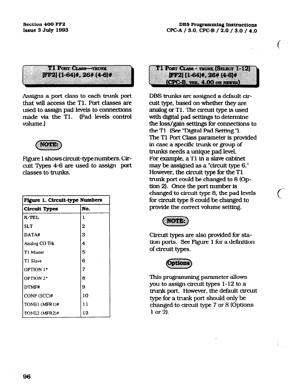
Section 400 FF2
Issue 3 July 1993 DBS Programming Instructions
WC-A / 3.0, CPC-B / 2.0 / 3.0 / 4.0
Assigns a port class to each trunk port
that will access the Tl. Port classes are
used to assign pad levels to connections
made via the Tl. (Pad levels control
volume.)
Figure 1 shows circuit-typenumbers. Cir-
cuit Apes 4-6 are used to assign port
classes to tlunks.
Figure 1. Circuit-type Numbers
circuit Types No.
K-TEL 1
SLT
2
DATA#
3
Analog CO Trk 4
Tl Master
5
Tl Slave
6
OPTION l*
7
OPTION 2* 8
DTMF# 9
CONF (SCC)# 10
TONE1 (MFRl)# 11
TONE2
(MFR2)# 12
DBS trunks are assigned a default cir-
cuit type. based on whether they are
analog or Tl. The circuit type is used
with digital pad settings to determine
the loss/gain settings for connections to
the Tl (See ‘Digital Pad Setting.“).
The Tl Port Class parameter is provided
in case a specific trunk or group of
trunks needs a unique pad level.
For example, aT1 in a slave cabinet
may be assigned as a ‘circuit type 6.”
However, the circuit type for the Tl
bunk port could be changed to 8 (Op-
tion 2). Once the port number is
changed to circuit type 8, the pad levels
for circuit type 8 could be changed to
provide the correct volume setting.
Circuit types are also provided for sta-
tion ports. See Figure 1 for a definition
of circuit types.
This programming parameter allows
youtoassigncircuittypes l-12toa
trunk port. However, the default circuit
type for a trunk port should only be
changed to circuit type 7 or 8 (Options
1 or 2).
c
96
Technical Manuals Online! - http://www.tech-man.com
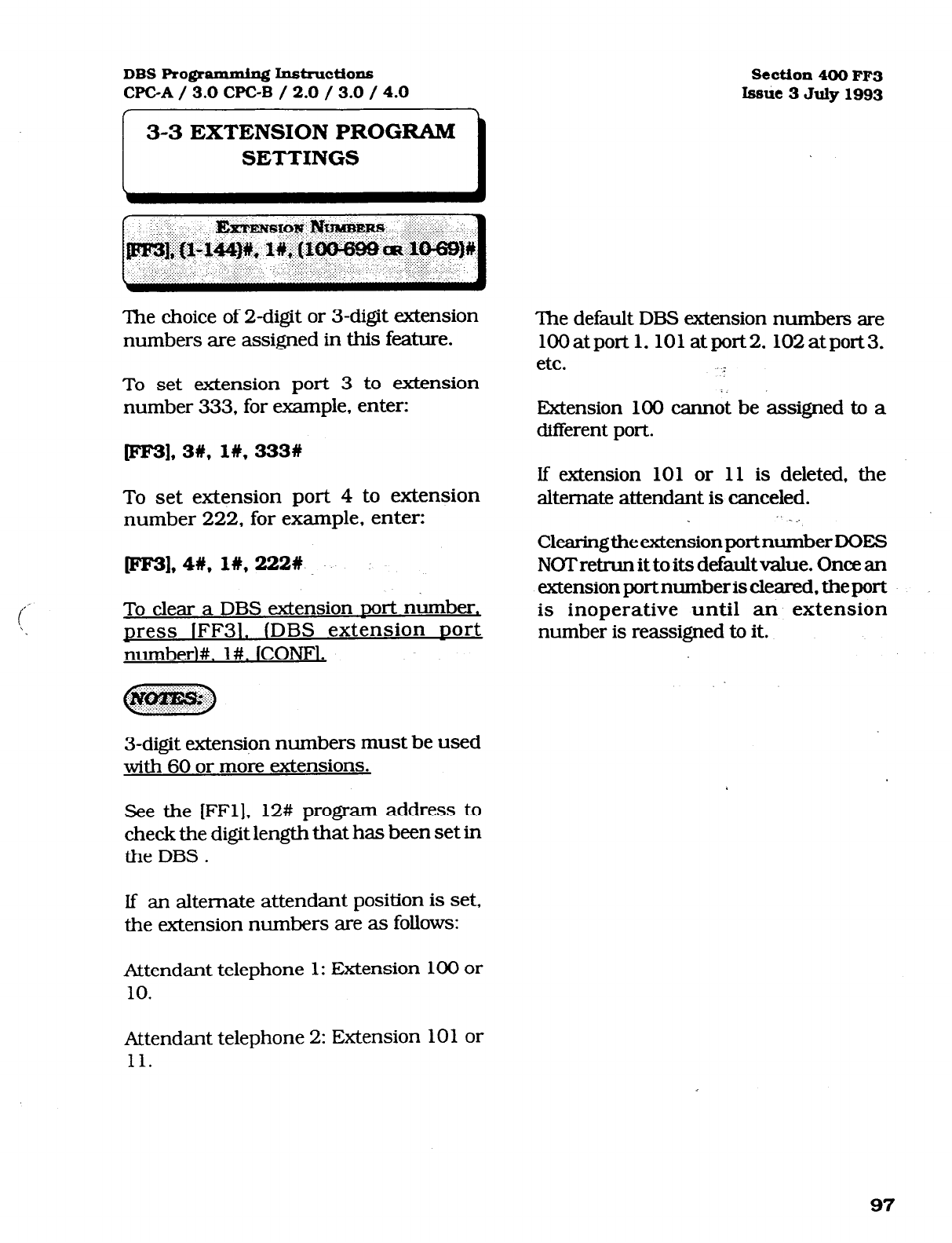
i
,’
DBS Romanming Instructions
WC-A / 3.0 CPC-B / 2.0 / 3.0 / 4.0 Section 400 FF3
Issue 3 July 1993
3-3 EXTENSION PROGRAM
SETTINGS
The choice of 2-digit or 3-digit extension
numbers are assigned in this feature.
To set extension port 3 to extension
number 333, for example, enter:
pF3], 3#, I#, 333w
To set extension port 4 to extension
number 222, for example, enter:
FF31,4#, I#, 222%
To clear a DBS extension nor-t number,
press lFF31. (DBS extension nort
number)#, l#. lCONF1.
Cl>
&&)$gⅈ;
3-digit extension numbers must be used
with 60 or more extensions.
See the [FFl], 12# program address to
check the digit length that has been set in
the DBS .
If an alternate attendant position is set,
the extension numbers are as follows:
Attendant telephone 1: Extension 100 or
10.
The default DBS extension numbers are
1OOatpor-t 1,101 atport2.102atport3,
etc. _
Extension 100 cannot be assigned to a
different port.
If extension 10 1 or 11 is deleted, the
alternate attendant is canceled.
_ _.
ClearingtheextensionportnumberDOES
NOT retrun it to its default value. Once an
extension port number is cleared. the port
is inoperative until an extension
number is reassigned to it.
Attendant telephone 2: Extension 101 or
11.
97
Technical Manuals Online! - http://www.tech-man.com
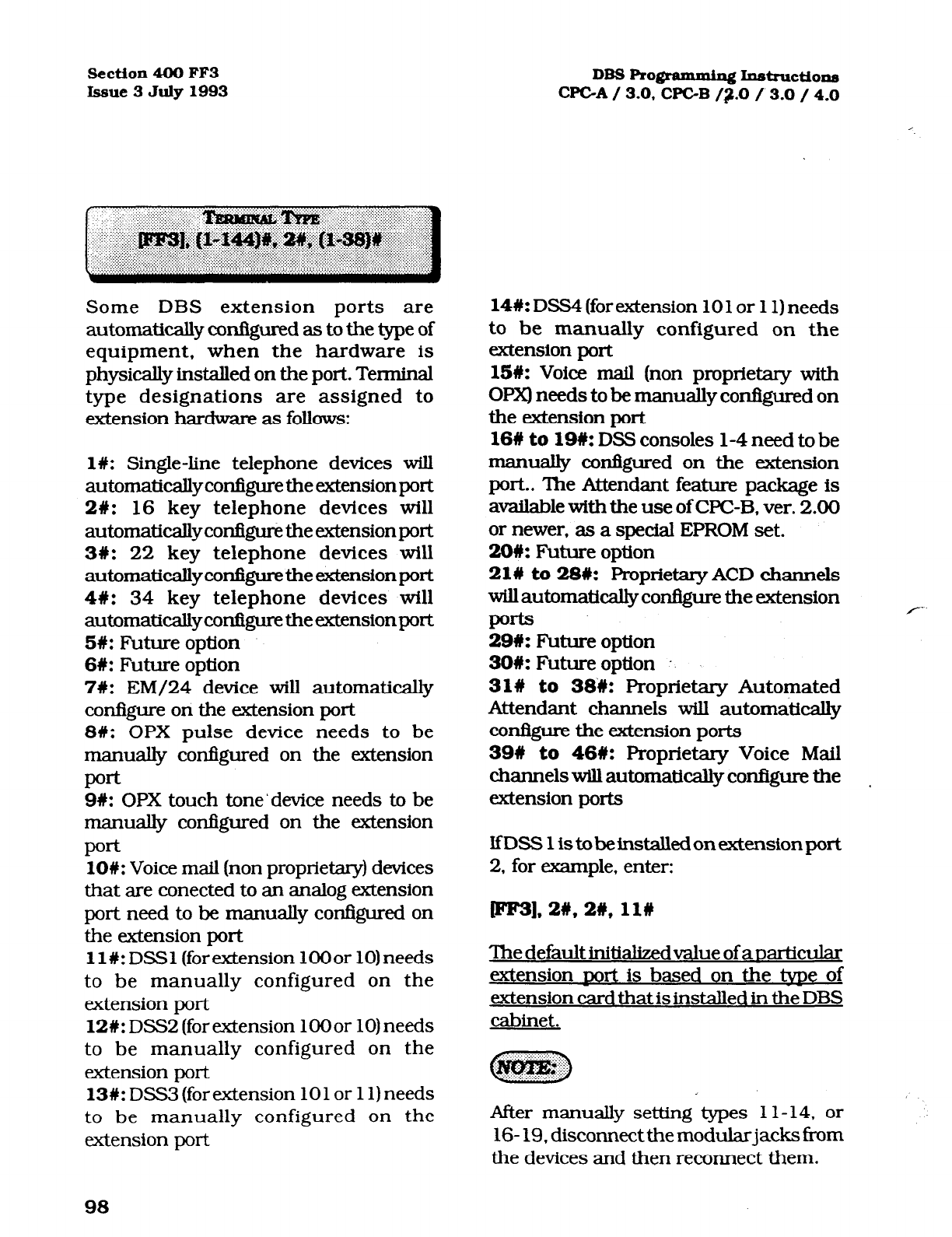
Section4OOFF3 DBS Rogramming lnstn~ctions
Issue 3July1993 CPGA/ 3.0, WC-B /;r.O / 3.0 /4.0
Some DBS extension ports are
automatically configured as to the type of
equipment, when the hardware is
physically installed on the port. Terminal
type designations are assigned to
extension hardware as follows:
l#:
Single-line telephone devices will
automaticallyconfiguretheextensionport
28: 16 key telephone devices will
automatically configure the extension port
3#: 22 key telephone devices will
automaticallyconQuretheextensionport
48: 34 key telephone devices will
automaticallyconfQuretheextensionport
58:
Future option
6W: Future option
7W:
EM/24 device will automatically
configure on the extension port
8W: OPX pulse device needs to be
manually configured on the extension
pod
9W: OPX touch tone’ device needs to be
manually configured on the extension
Poe
lO#: Voice mail (non proprietary) devices
that are corrected to an analog extension
port need to be manually configured on
the extension port
ll#:DSSl (forextension lOOor 10)needs
to be manually configured on the
extension port
12#: DSS2 (for extension lOOor 10) needs
to be manually configured on the
extension port
13W: DSS3 (for extension 10 1 or 11) needs
to be manually configured on the
extension port
14#:
DSS4 (for extension 10 1 or 11) needs
to be manually configured on the
extension port
15#:
Voice mail (non proprietary with
OPX) needs to be manually configured on
the extension port
168 to lQ#:
DSS consoles l-4 need to be
manually confIgured on the extension
port.. The Attendant feature package is
available with the use of CPC-B, ver. 2.00
or newer, as a special EPROM set.
206: Future option
21W to 286: Proprietary ACD channels
willautomaticaUy configure the extension
PO*
29U:
Future option
39U: Futureoption .
31#
to
38#: Proprietary Automated
Attendant channels will automatically
co*m the extension ports
396 to 46#:
Proprietary Voice Mail
channels will automatically configure the I
extension ports
lfDSS1istobeinstalledonextensionport
2,
for example, enter:
pF3].2#,2#,11#
‘lhedefaultinitia&edvalueofaoarticular
extension nor-t is based on the tvne of
extension card that is installed in the DBS
cabinet.
After manually setting types 1 l- 14, or ’ :
16- 19, disconnect the modularjacks from
the devices and then reconnect them.
Technical Manuals Online! - http://www.tech-man.com
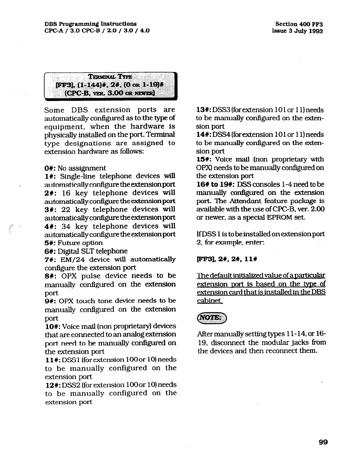
DBS Programming I.nstructionf~ Section4OOFF3
CPGA/ 3.0 CPGB / 2.0 / 3.0 / 4.0
Issue
3July1993
Some DBS extension ports are
automatically configured as to the type of
equipment, when the hardware is
physically installed on the port. Terminal
type designations are assigned to
extension hardware as follows:
OW: No assignment
l#: Single-line telephone devices will
automaticallyconfiguretheextensionport
2#: 16 key telephone devices will
automaticallyconfrgurethe extensionport
3#: 22 key telephone devices will
automatically configure the extension port
4C: 34 key telephone devices will
automaticallycotiguretheextensionport
5#: Future option
6W: Digital SLT telephone
7W: EM/24 device will automatically
configure the extension port
SW: OPX pulse device needs to be
manually configured on the extension
pod
9#: OPX touch tone device needs to be
manually confIgured on the extension
PO*
lO#: Voice mail (non proprietary) devices
that are connected to an analog extension
port need to be manually configured on
the extension port
11%: DSS 1 (for extension 100 or 10) needs
to be manually configured on the
extension port
12#: DSS2 (for extension 1OOor 10) needs
to be manually configured on the
extension port
13d: DSS3 (for extension 10 1 or 11) needs
to be manually configured on the &en-
sion port
14W: DSS4 (for extension 10 1 or 11) needs
to be manually configured on the &en-
sion port
SW:
Voice mail (non- proprietary with
OPX) needs to be manually configured on
the extension port
16# to-19%: DSS
consoles l-4 need to be
manually configured on the extension
port. The Attendant feature package is
available with the use of WC-B, ver. 2.00
or newer, as a special EPROM set.
lfDSS 1 is tobeinstalledonextensionport
2,
for example, enter-z
W],2#, 2#, 11w
The default initializedvalue of anariicular
extension nort is based on the tyne of
extension card that is installed in the DBS
cabinet.
Aftermanuallysettingtypes 11-14, or 16-
19, disconnect the modular jacks from
the devices and then reconnect #em.
99
Technical Manuals Online! - http://www.tech-man.com
Scction4-OOFF3
Issue3JulylS93
Define the EM/24 extension module
hardware port number, then assign an
extension port number that will be used
with it. The first program entry relates
to the EM/24 port number, the second
program entry refers to the extension
port that the EM/24 works with.
To set a po& for the EM/24 to work with
extension port 30, for example, enter:
pF3],
55#, 31c;3ow
To reset the use of an EM/24 on anv
extension
sort
to the default initialized
value. Dress (FF31. (DBS extension
DOI%
number). 3#. lCONF1. ION/OFF1
DBSRo@ammin~Ins~ctions
CF'GA/ 3.0, CPGB /2.0 / 3.0 / 4.0
a. set the port that the EM/24 is on
[FF3], (l- 144)#, 2#.
b. Reset the EM/24 by unplugging it
and reconnecting it.
c. Proceed with key programming via
[FF5], (l-144)#, (l-24)#.
When programming an EM/24 with
CPC-B software versions newer than
2.11. this programming order is not
required. SeeTechnote 15 (August 1992)
for complete information.
After manually reprogramming an
EM/24 when any version of CPC
software is used, disconnect the
modular jack from the device and then
reconnect it.
When a change to the default key
assignments is required on an EM/24,
and CPC-B 2.0X series software prior to
version 2.05 is being used, the program
procedure must be done in the following
order:
100
Technical Manuals Online! - http://www.tech-man.com
DBS Programming Inst~~ctlons
CPGA / 3.0 CF’C-B / 2.0 / 3.0 / 4.0 Section 400 FF3
Issue 3 July 1993
If an extension is set for Least Cost
Routing, the user must dial “9”. or press
an FF key that is set for the LCR h&ion,
in order to gain access to a central office
line.
To set an extension port so that the dialing
of a “9”. or the necessity to press an LCR
key is not needed. enter:
[FF3], (DBS eit&on port number)#,
46, on
Tosetanextensionportsothatthedialing
of a “9”. or the necessity to press an LCR
key is needed, enter: .
DBS extensions can be set so that central
office-line calls can only be made after
entering an account code.
“I.
To set an extension so that an account
code is not needed to make a central office
line call, enter:
1. IDBS
extension sort number)%,
5#.0#
To set an extension so that an account
code is needed to make a central of&e line
call, enter:
WI. @BS extension port number)#,
5#,
I#
1, lDBs
extension
sort
numb&#,
4#.1#
101
Technical Manuals Online! - http://www.tech-man.com
Scction4OOFF3
Issue3
July1993 DBS I’m@ammiq Iustructions
CF'GA/ 3.0, CPGB /2.0 / 3.0 / 4.0
DBS extensions can be set so that central
office-line calls can only be made after
entering a forced account code that is
verified. Verification is enabled or
disabled on an extension basis.
To set an extension so that a verified
forced account code is not needed to make
a central of&e line call, enter:
1. lDB6 exte!nsion DOIt
numberI%,
5#. on
To set an extension so that a verified
forced account code is needed to make a
central office line call, enter:
D31, @Bs
extension port number)#,
5#,
1#
WC-B versions 3.00 and newer, do not
have the forced account code capability of
earlier versions. All forced account codes
have to be verified. The use of non forced,
non verified account codes is still an
option if stringent access to Central Office
lines is not required.
A
4-digit lockout code can be set on an
extension to prevent unauthorized people
from making central office line calls from
the extension.
To set extension 100, with lockout code
452
1, for example, enter:
PF3],11y,6#,4521#
To reset anreviouslvlocked out
extension
to the default inttialtzed value.
DRSS
lFF3l
IDBS extension
sort
number)#. 6#,
jCONFi. lON/OFFI,
102
Technical Manuals Online! - http://www.tech-man.com
DBS Pro@ammh~ I.nstructions Section 400 FF3
CPGA/ 3.0 CPGB / 2.0 / 3.0 / 4.0 Issue 3 July 1993
To be notified by a tone. when a new
central o&e line call has anived at an
extension that is currently engaged in a
conversation, this option must be set.
To disable extension 100, for example. for
off hook signaling, enter:
ml, I#*
7#,0#
To
send a tone from acaJling extension to
an extension that is in use, this option
must be set. A tone is not sent however,
when off hookvoice announce is enabled.
ln the case of OHVA being used, the
calling party to an extension in use can
verbally override the existing
conversation.
To enable extension 100, for example, for
off hook signaling, enter:
To disable the call waiting notitication
tone or the OHVA capability on extension
100, for example, enter:
JFF3L I.#. 7#. l# pFe31. 1#,8#,0#
,' \
./'
To reset anv extension
DORIS
to the default
initialized value, Dress IFF31. uort.#. 7#, To enable the callwaitingnot&alion tone
conf#. ION/OFFl. or the OHVA capability on extension 100.
for example, enter:
pm.
I#. 8#. l#
This tone will not be sent during a
conference call, while the called extension
is on hold, or during a &l on m central
office line for which there is no kne key on
the telephone. The call waiting noti&ation tone cannot
be sent to an extension set with an
The off-hook signal volume and the
off-hook signal pattern are separate
settings. See program addresses [FF3],
15#, & lf3. When an off-hook tone is
enabled on an extension. the extension
will be excluded Tom any hunt group
setting that may be enabled for it.
absence message, or that is on hold, or
that is receiving another call or that is
involved in a conference call.
IfaVoiceAnnoun~ Unit (modelVB-43708)
is co~ected to the
DEB off hook signalkng
@ES], (l-144)#, 7#, l#) must be enabled on
all&ensions.SeeTecbnote 14(March 1992)
for complete tiormation.
103
Technical Manuals Online! - http://www.tech-man.com
Section 400 FF3
DB3RogmmmhnInstructions
Issue3July1993 WC-A / 3.0, CPGB /2-O / 3.0 / 4.0
To be able to “barge into” an extension
that is currently in use from another
extension, this option must be enabled
on the baruinq extension.
To
disable the use of the busy override
option from extension 100, for example,
enter:
plea. l#. 9#,0#
To enable the use of the busy override
option from extension 100, for example.
enter:
pF31, lW, 9#, l#
The busy override option cannot be
disabled on the attendant telephones in
all WC-A software versions, and CPC-B
softwareversi0nsearlierthanversi0n2.00.
The busy override option can be
disabled on the attendant telephones in
CPC-B software. newer than ver. 2.00
Busy override is not possible to an
extension: that is not set to accept it, or
is involved in a conference call.
To be able to override a busy extension,
the calling extension must be in the
same page group. Page group 00 is not
included in this exception.
To allow an extension to be able to be
“barged into” from another extension,
this option must be enabled on the
barged extension.
To disable extension 101, for example,
from being barged into by another
extension enter:
fFF3],2#,10#,0#
To enable extension 101, for example,
to be able to be barged into by another
extension enter:
jFF31.2#.10#:1# l
The override tone can be set to sound
during an ongoing central office call, to
indicate a new call arrival.
104
Technical Manuals Online! - http://www.tech-man.com
DBS Pro@ammin~ Instmctions
CPCA / 3.0 CPGB / 2.0 / 3.0 / 4.0 Section 400 FF3
Issue 3 July 1993
Access to an available central office line
assigned to the FFl key can be
automatic by picking up the receiver.
If the FFl key is a pooled trunk key, an
available central office line is accessed
in numerical order from the highest line
number assigned to the key, to the
lowest.
To disable prime line pickup on
extension 100, for example, enter:
pF31.
l#. ll#.O#
To enable prime line pickup on
extension 100, for example, enter:
fm3],1#,11#,1#
Picking up the receiver at a ringing
extension connects the incoming
central office line call, hold recall, or
transferred call, if this option is
enabled. . .
To disable auto pickup at extension
100. for example, enter:
p3],1#,12%,0#
To enable auto pickup at extension 100.
for example, enter:
@F31. l#. lb. l#
Intercom calls cannot be made with this
option enabled, unless an intercom call
key is assigned to another FF key.
105
Technical Manuals Online! - http://www.tech-man.com
Section 400 FF3
Issue3
July1993
DBS ~ogmumiq~ Instructiona
WC-A / 3.0. CPC-B /2.0 /-3.0 / 4.0
c
To enable a DBS user to initiate a three
party conference between 2 central office
lines and his extension, this option must
be set. Once the conference is initialized,
the DBS msion user can drop out of the
callbypmssingeitherofthecentralofficeline
keysusedtocalltheoth~parties.
To disable extension 100, for example, to
not be able to initiate a three party
conference, enter:
mm
1#.13#.0#
To enable extension 100, for example to be
abletoWiateathreepartyconfen3rce,enten
pF31, 1n,131Y, l#
TheDBSusercanreentertheconferenceby
pressing either of the two centml office line
keys used to initiate the conferenaz. The
conferencewillautornaticallyexpireafterthe
period of time set in the Unsupervised
conference
l7me.r. set by the Wl], 3#,
1 l#
address.
See auto pause for PBX line address (FF2],
13#. Auto pause cannot be used ifthe
mnfmce feature is desired when the DBS
isusedbehindaPBX
The Central Office line program for
conferencing, [FF2], 16# must also be
set when conferences are allowed.
Any extension can be removed from the
SMDR report, so that call activity from
that port will not be recorded.
To not include extension 100. for
example, in the SMDR report, enter:
ml,
lW, 14#, ow
To include extension 100, for example,
in the SMDR report, enter:
ml.
I#. 14#. l#
Check the SMDR start timer feature
found at program address [FFl], 2#, l#,
2#.
Communication program options
that need to be checked when this
option is set include all options found
under [FFl], 2#, 2#, l-lO#. I
CPC-B software version 2.00 should be
upgraded to version 2.05 to eliminate
two intermittent potential SMDR
deficiencies in recording Aeld codes.
See Technotes 8 & 12 (March 1992). for
complete information.
106
Technical Manuals Online! - http://www.tech-man.com
DBS Ro@ammin~ Instructions
CPGA / 3.0 CPGB / 2.0 / 3.0 / 4.0 Section 400 FF3
Issue 3 July 1993
Off-hook signaling volume can be set to
either of four different levels.
To set the off hook signal volume to the
minimum level on extension 100, for
example, enter:
When off hook signaling is set on an
extension, the tone pattern can be sent
continuously or only once.
To send a continuous tone pattern for
an off hook signal to extension 100, for
example, enter:
wF3], 19, 15#, l#
LFF31.
1#.16#.0#
To set the off hook signal volume to the
next level on extension 100. for
example, enter: To send a single tone pattern for an off
hook signal to extension 100, for
example, enter:
jFF31.
l#. 15#.2# lep3], l#, 166. 1W
To set the off hook signal volume to the
third level on extension 100, for
example, enter:
(pLIp3], lW, 15#,3#
To set the off hook signal volume to the
maximum level on extension 100, foi
example, enter:
(FF3],1#,15#,4#
See alert tone for busy override at
address [FFl], 2 #, l#, 17#.
See alert tone for busy override at ad-
dress [FFl], 2 #, l#, 17#.
See off hook signal address [FF3], 7#.
See offhook signal volume address [FF3],
15#.
See off hook signal address ]FF3]. 7#.
See off hook signal pattern address
[FF3], 16#.
107
Technical Manuals Online! - http://www.tech-man.com
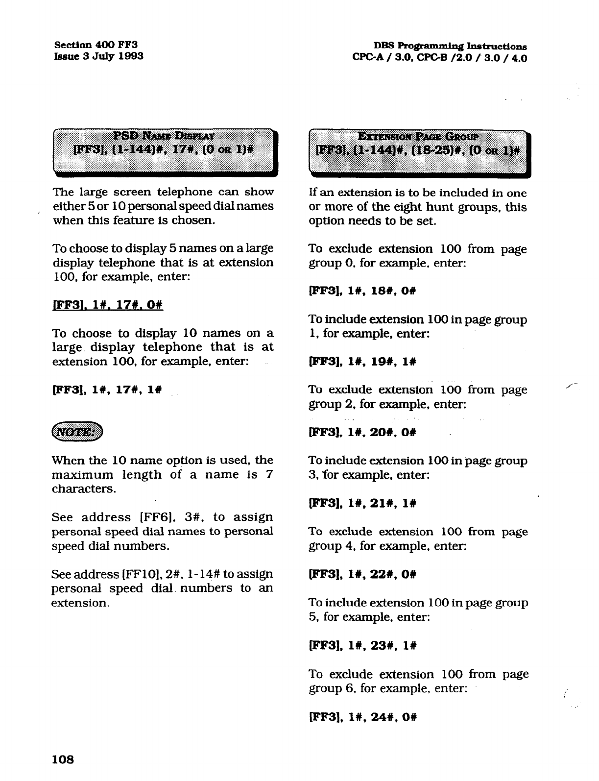
Section4OOFF3 DBS Ro@ammin~ Instructions
Issue3July1993 WC-A/ 3.0, WC-B /2.0 13.0 / 4.0
The large screen telephone can show
either 5 or 10 personal speed dial names
when this feature is chosen.
To choose to display 5 names on a large
display telephone that is at extension
100, for example, enter:
If an extension is to be included in one
or more of the eight hunt groups, this
option needs to be set.
To exclude extension 100 from page
group 0, for example, enter:
m3],1#,18#,0#
JFF31.1#.17#.0#
To choose to display 10 names on a
large display telephone that is at
extension 100, for example, enter:
wF31, l#, 17W, l#
When the 10 name option is used, the
maximum length of a name is 7
characters.
See address [FFG], 3#, to assign
personal speed dial names to personal
speed dial numbers.
See address (FFlO], 2#, l-14# to assign
personal speed dial. numbers to an
extension.
To include extension 100 in page group
1. for example, enter:
rFF31, 18, 19#, l#
To exclude extension 100 from page
group 2, for example, enter:
.
/-
pw3],1#,20#,0#
To include extension 100 in page group
3, for example, enter:
pm], 1#,21#, 1w
To exclude extension 100 from page
group 4. for example, enter:
ml. 1#,22#,0#
To include extension 100 in page group
5, for example, enter:
lFF3],1#,23#,1#
To exclude extension 100 from page
group 6. for example, enter:
tFF3],1#,24#,0#
10s
Technical Manuals Online! - http://www.tech-man.com
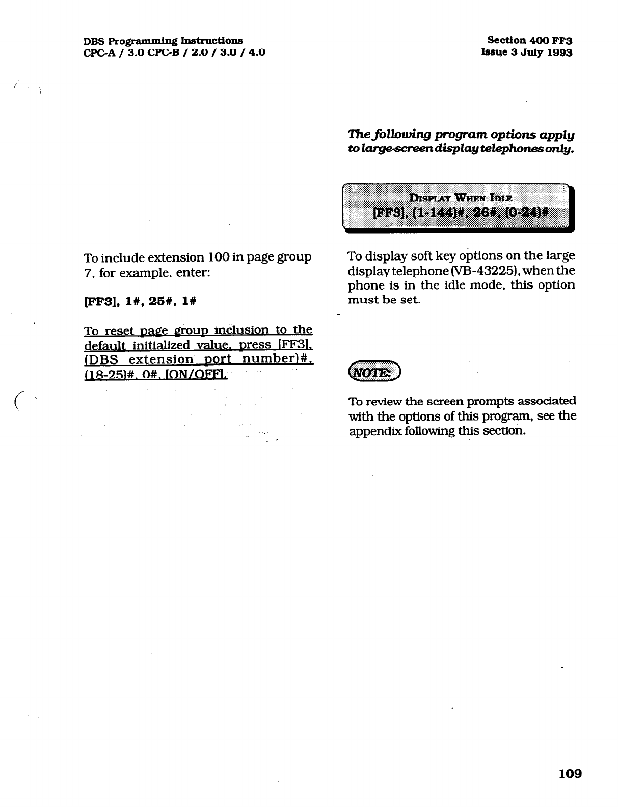
DBS Pro@mmhg Inb-uctions
CFGA/ 3.0 CPGB / 2.0 / 3.0 / 4.0
Section 400
FF3
Issue3
July1993
ThejXowing program options apply
toI~dispZayte&phonesonZy.
To include extension 100 in page group
7. for example, enter:
p3], I#, 25#, I#
To reset Dagle IlrOuD inclusion to the
default initialized value. Dress lFF3L
IDBS extension Dart number)#,
j18-25)#. O#. lON/OFFl:
c
\
I
. -I
To display soft key options on the large
display telephone (VB-43225). when the
phone is in the idle mode, this option
must be set.
To review the screen prompts associated
with the options of this program, see the
appendix following this section.
109
Technical Manuals Online! - http://www.tech-man.com
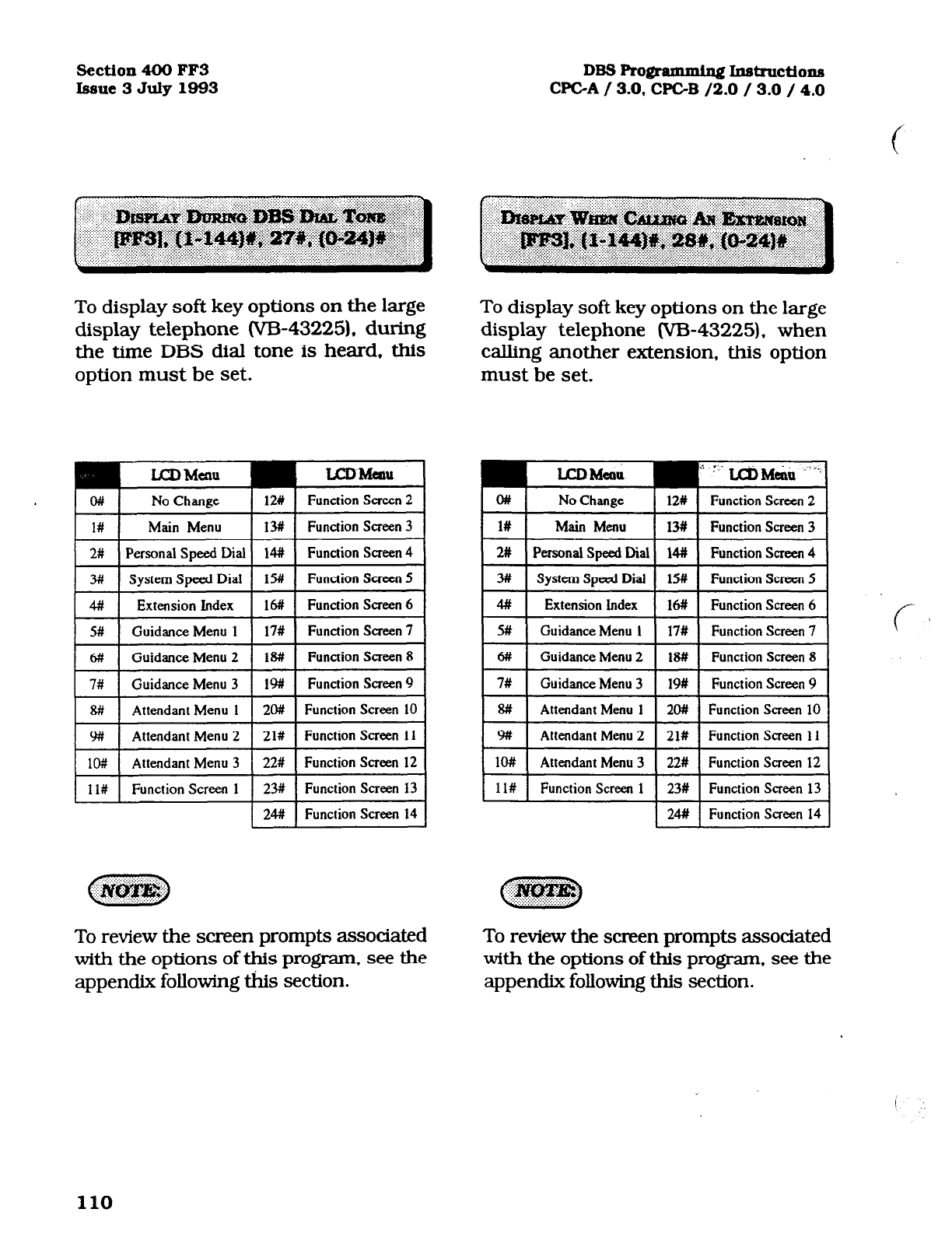
Section 400 FF3 DB3 Programming Instructtons
Issue 3 July 1993 WC-A / 3.0. CPGB /2.0 / 3.0 / 4.0
To display soft key options on the large
display telephone (VB-43225). during
the time DBS dial tone is heard, this
option must be set.
To display soft key options on the large
display telephone (VB-43225). when
calling another extension, this option
must be set.
o#
1#
No Change
Main Menu
12# Function Saeen 2
lut Function Saeen 3
2# Personal Speed Dial 14# Function Screen 4
3# System Speed Dial 15# Function Saeen 5
4# Extension Index 16# Function Screen 6
o#
l#
No Change 12# Function Screen 2
Main
Menu
13# Function Screen 3
2# PersonalSpeedDial 14# Function Saeen 4
3# system speed Dial 15# Function Screen 5
4# Extension Index 16# Function Screen 6
5# Guidance Menu 1 17# Function Screen 7
6# Guidance Menu 2 1% Function Screen 8
1 1 7# Guidance Menu 3 I-># 1 Function Screen 9 I
8# Attendant Menu 1 20# Function Screen 10
y# Attendant Menu 2 21# Function Screen 11
1 lo# 1 Attendant Menu 3 ~ ---22# [~Function Saeenl2 I
1 l# Function Screen 1 2ut Function Screen 13
2# Function Screen 14
11# Function Screen 1 23# Function Screen 13
2# Function Saeen 14
To review the screen prompts associated
with the options of this program, see the
appendix following this section.
To review the screen prompts associated
with the options of this program, see the
appendix following this section.
110
Technical Manuals Online! - http://www.tech-man.com
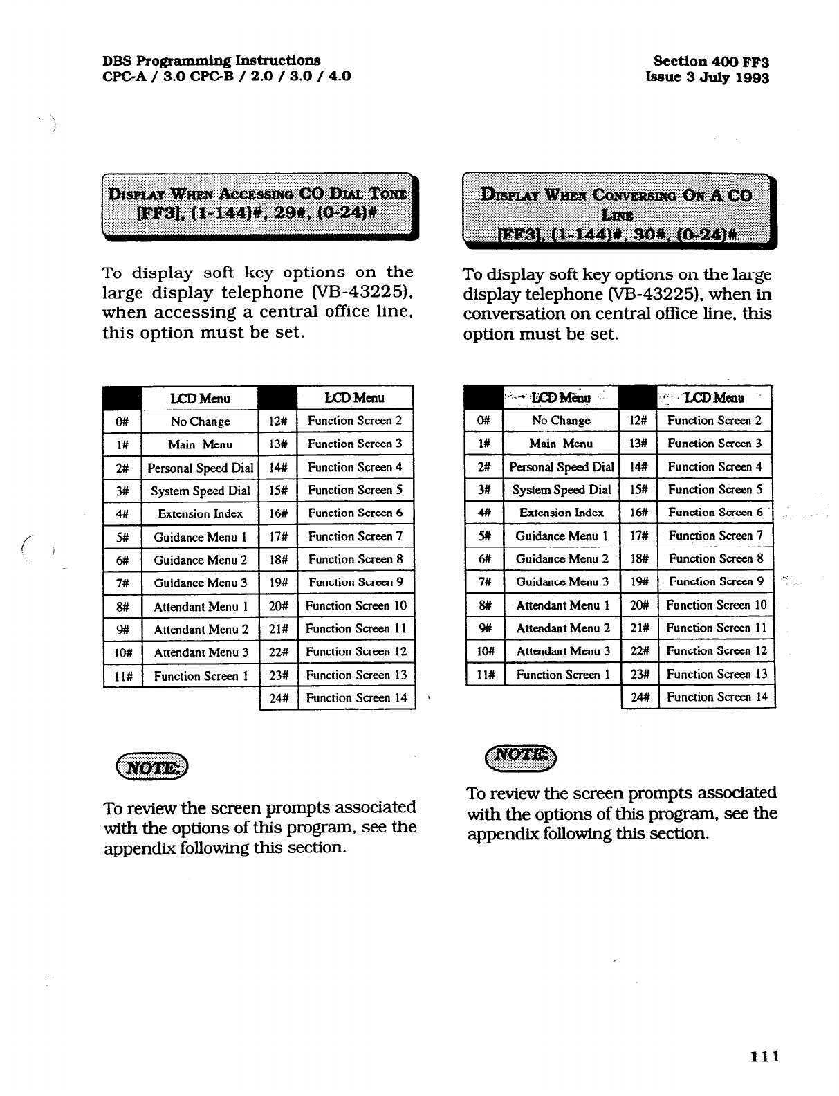
DBSPro@-~Instructions
WC-A/ 3.0 CPGB / 2.0 / 3.0 / 4.0 Scction4OOFF3
Issue3
July1993
To display soft key options on the
large display telephone m-43225).
when accessing a central office line,
this option must be set.
LCD Menu LCD Menu
o#
No Change 12# 1 Function Screen 2
(1#)nMen u 1 13# 1 Function Screen 3 1
2# .Personal Speed Dial 14# Function Screen 4
3# System Speed Dial 15# Function Screen 5
4# Extension Index 16# Function Screen 6
5#
Guidance Menu 1 17# Function Screen 7
6# Guidance Menu 2 18# Function Screen 8
7# Guidance Menu 3 19# Function Screen 9
ll# Function Screen 1 23# Function Screen 13
24## Function Screen 14 1
D -:#@J!$$p
. . . . .::. : . . ..*:‘.
To review the screen prompts associated
with the options of this program, see the
appendix following this section.
To display soft key options on the large
display telephone W-43225). when in
conversation on central office line, this
option must be set.
::..i .pb9 : ...I ~~eQll
a#
No Change 12# Function Screen 2
4#
Extension Index 16#I Function Screen 6
5# Guidance Menu 1 17# Function Saeen 7
rir-
Guidance Menu 2 I 1~
I
Function Screen 8
I
To review the screen prompts associated
with the options of this program, see the
appendix following this section.
111
Technical Manuals Online! - http://www.tech-man.com
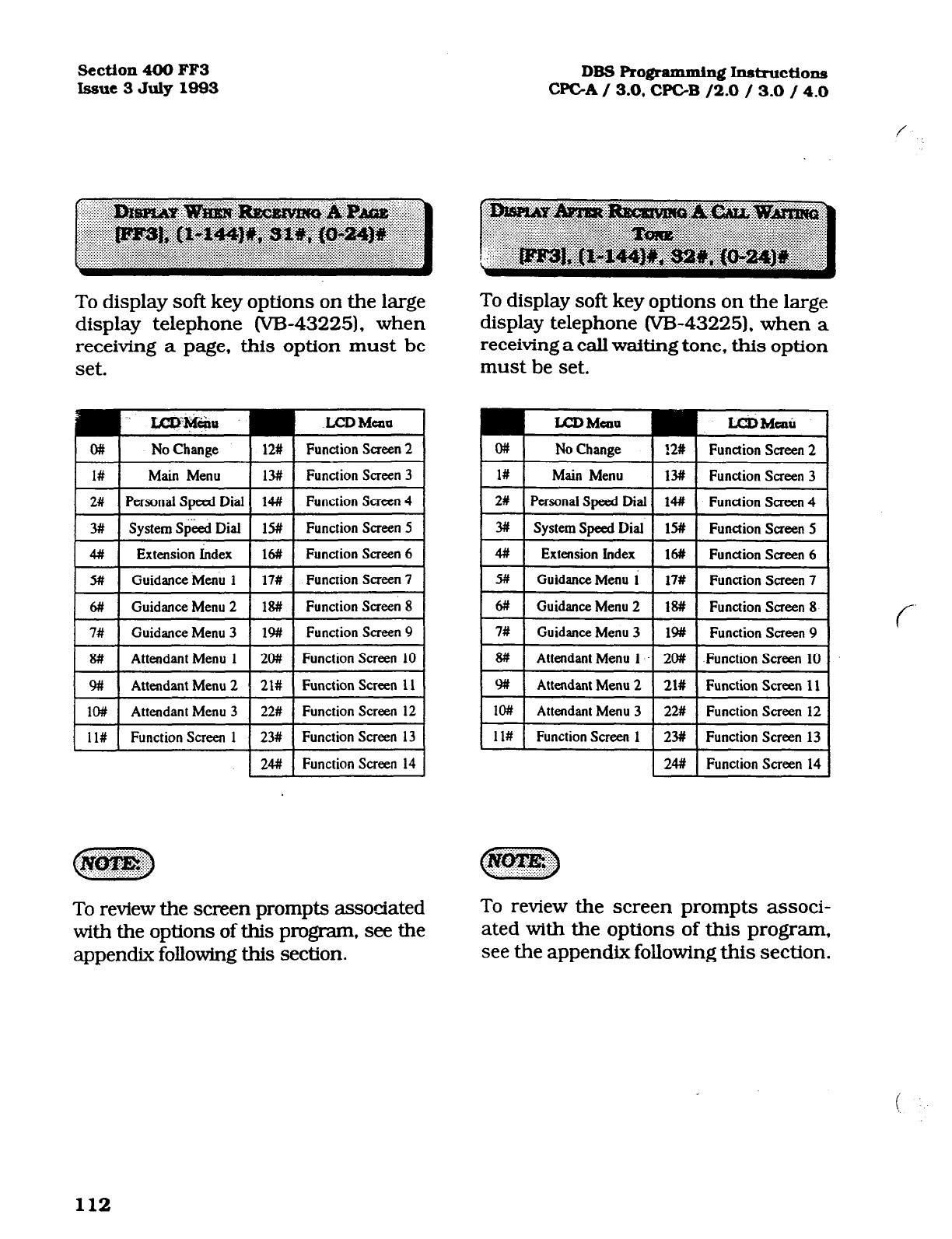
Section 400 FF3 DBS Pro@ammiqf InsIndions
Issue 3 July 1993 CPGA / 3.0, WC-B /2.0 / 3.0 / 4.0
To display soft key options on the large
display telephone (V&43225), when
receiving a page, this option must be
set.
LCJI Main
Function Saeen 2
I 1# I
Main Menu 1 13# 1 Function Screen 3 I
To display soft key options on the large
display telephone (VB-43225). when a
receiving a call waiting tone, this option
must be set.
OH
l#
No Change !2# Function Screen 2
Main Menu 13# Function Saeen 3
I
2#
I
Personat Sueed Dial
I
1~ I Function Screen 4
I I
2# I Personai Streed Fiat I 14#
I
Function Screen 4
7
3##
System Speed Dial 15# Function Saeen 5
4# Extension kdex 16# Function Screen 6
3# System Speed Dial 1% Function Screen 5
4# Extension Index 16# Function Saeen 6
I
H
I
GuidanceMenu 1 I 17# I Function Saeen 7 I
6# Guidance Menu 2 18# Function Saeen 8
7# Guidance Menu 3 I# Function Saeen 9
I
8#
~1
Attendant Menu 1 I 20# I Function Screen 10 I I 8# I Attendant Menu 1 --I 20#
I
Function Screen 10 I
9#i Attendant Menu 2 21# Function Screen 11
1W Attendant Menu 3 22# Function Screen 12
9# Attendant Menu 2 21# Function Screen 11
10# Attendant Menu 3 22# Function Screen 12
I Id
Function Saeen 1
I
23#
I
Function Screen 13
I
24# Function Screen 14
To review the screen prompts associated
with the options of this program, see the
appendix following this section.
ll# Function Screen 1 23# Function Screen 13
24# Function Screen 14
To review the screen prompts associ-
ated with the options of this program,
see the appendix following this section.
112
Technical Manuals Online! - http://www.tech-man.com
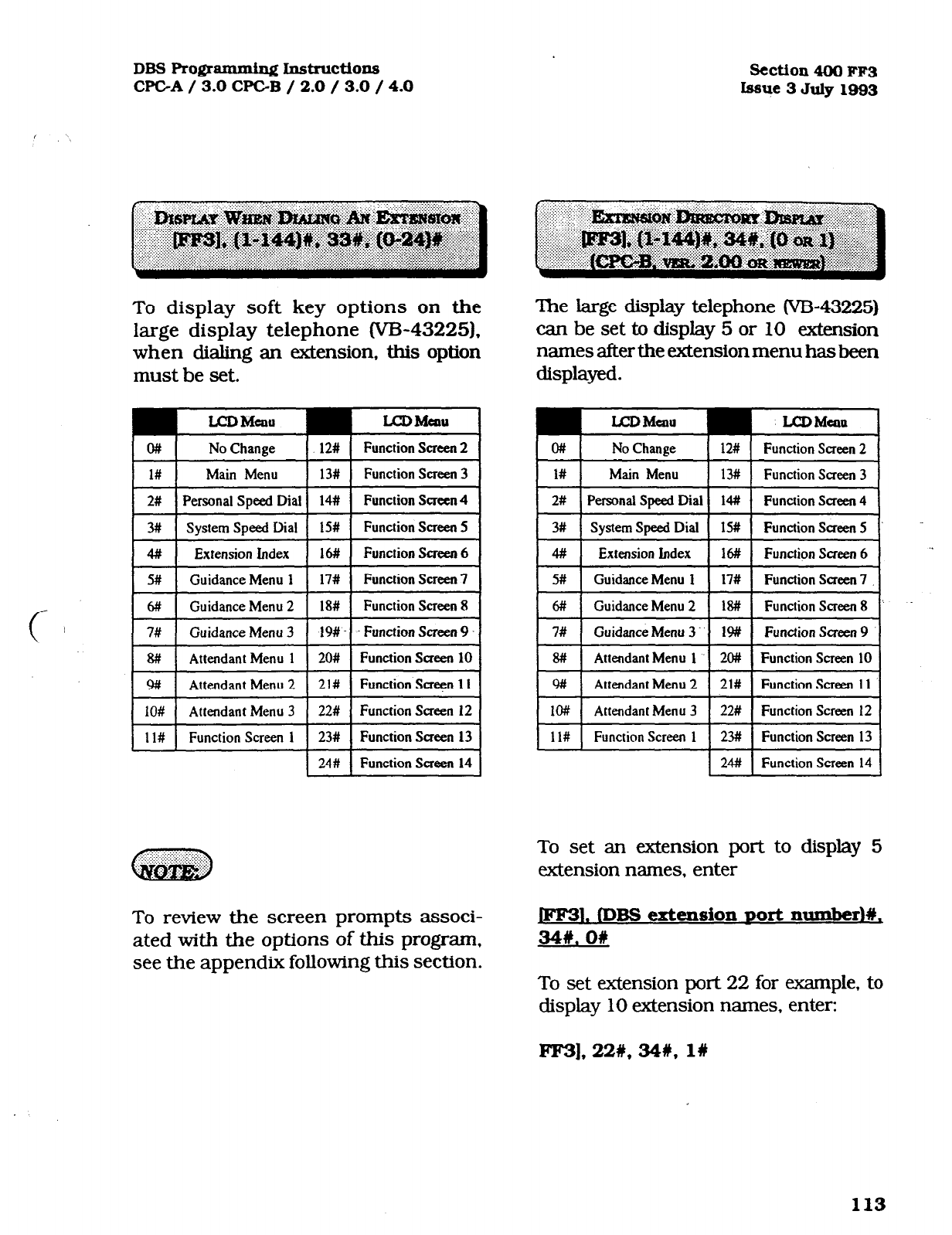
DBS Pro@ammin~ Instructions Section 400 FF3
CPGA / 3.0 CF’C-B / 2.0 / 3.0 / 4.0 Issue 3 July 1993
To display soft key options on the
large display telephone W-43225).
when dialing an extension, this option
must be set.
UJDMUIU LCDMHUI
o#
No Change 12# 1 FunctionScreen
The large display telephone (W-43225)
can be set to display 5 or 10 extension
names after the extension menu hasbeen
displayed.
rxD h4eau
No Change
LcDMe4ltt
12# I Function keen 2
I 1# I
Main Menu 1 13# 1 FunctionScreen I
I 1# I
Main Menu I 13# I Function Screen 3 1
I
2#
I
Personal speed Dial I 1~ I Function Screen4 I I 2# I krson~ Speed Dial I 14# I Function Screen 4 I
3# System Speed Dial 1% Function Screen 5
# Extension Index 16# Function Screen 6
3# System Speed Dial lS# FunctionSaeen5
4# Extension Index 16# Function Saecn 6
5#
c 6#
7#
E
8#t
9f#
lO#
Guidance Menu 1
Guidance Menu 2
Guidance Menu 3
Attendant Menu 1
Attendant Menu 2
Attendant Menu 3
Guidance Menu 3. Function Sacen 9
Function Screen 10
I Id ~ :-
Functton Screen 1
To review the screen prompts associ-
ated with the options of this program,
see the appendix following this section.
ll# Function Screen 1 23# Function Screen 13
24# Function Screen 14
To set an extension port to display 5
extension names. enter
1. fD= extt%MiOXl
DOti Xlumber)#,
341. on
To set extension port 22 for example, to
display
10
extension names, enter:
FF3],22#, 341, 1w
113
Technical Manuals Online! - http://www.tech-man.com
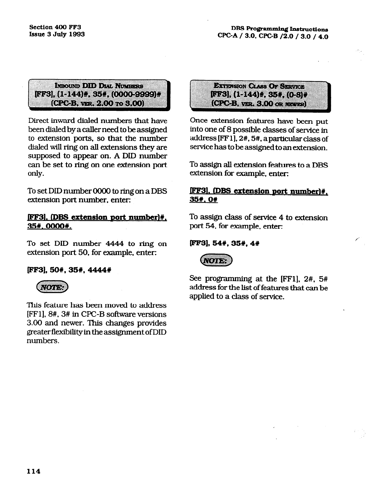
Section 400 FF3
Issue3July1993 DBSRograrmPaingI.n&ructions
CPGA/ 3.0, WC-B /2.0 / 3.0 / 4.0
Direct inward dialed numbers that have
been dialed by a caller need to be assigned
to extension ports, so that the number
dialed will ring on all extensions they are
supposed to appear on. A DID number
can be set to ring on one extension port
only.
To set DID number 0000 to ring on a DBS
extension port number, enter:
1. (Dm C?XtC!DSiOll DOrt llUIDk~~#,
35#.oooo#.
To set DID number 4444 to ring on
extension port 50. for example, enter:
Once extension features have been put
into one of 8 possible classes of service in
address [FFl], 2#, 5#, aparticularclass of
service has to be assigned to an extension.
To assign all extension features to a DBS
extension for exxnple, enter:
1. tDBS
extension port numberl#,
35#.0#
To assign class of service 4 to extension
port 54, for example. enter:
ml* 54#,35#,4#
~
:_ . . . : *: :. *FF
See programming at the (FFl]. 2#, 5#
address for the list of features that can be
applied to a class of service.
This feature has been moved to address
[FFl], 8#, 3# in UC-B software versions
3.00 and newer. This changes provides
greater flexibility in the assignment of DID
numbers.
114
Technical Manuals Online! - http://www.tech-man.com
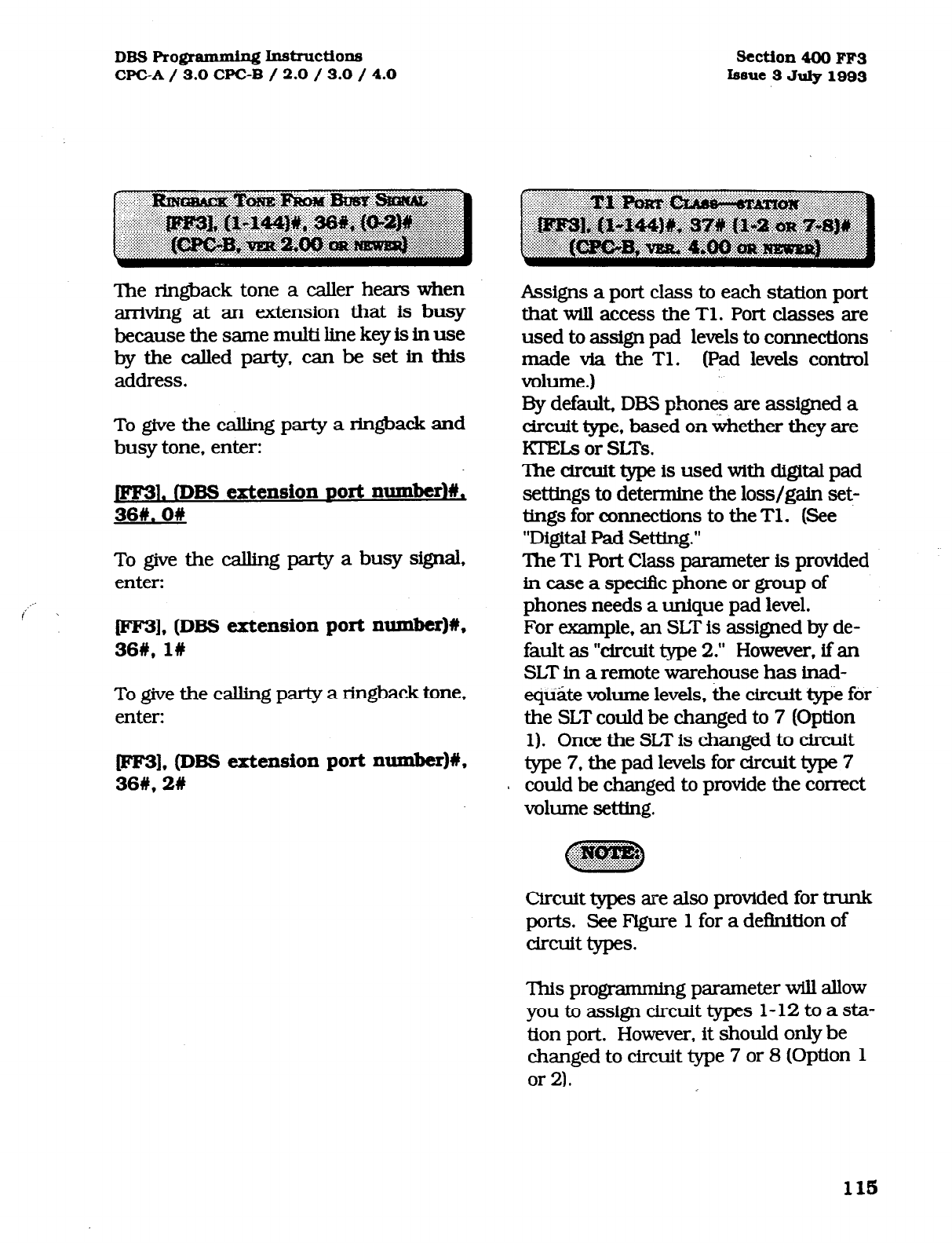
DB!3F'rogrammh.g~~ctio~
WC-A/ 3.0 CPGB / 2.0 / 3.0 / 4.0 Section4OOFF3
iseue 3July1993
The ringback tone a caller hears when
arriving at an extension that is busy
because the same multi line key is in use
bythecalledparty,canbesetintbis
address.
To give the calling party a ringback and
busy tone, enter:
1. (DBS extension Port number)#,
36#.0#
To give the calling party a busy signal,
enter:
fFF3], (DBS extension port xwmber)#,
36#,1#
To give the calling party a ringback tone,
enter:
[FF3), (DBS extension port number)#,
36#,2#
Assigns a port class to each station port
that will access the Tl. Port classes are
used to assign pad levels to connections
made via the Tl. (Pad levels control
volume.)
By default, DEB phones are assigned a
circuit type, based on whether they are
lCEI.s or SLTs.
The
circuit
type is used with digital pad
settings to determine the loss/gain set-
tings for connections to the Tl. (See
“Digital Pad Setting.”
The Tl port Class parameter is provided
in case a specific phone or group of
phones needs a unique pad level.
For example, an SLT is assigned by de-
fault as “circuit type 2.” However, if an
SLT in a remote warehouse has inad-
eQi2.e volume levels, the circuit type for
the SLT could be changed to 7 (Option
1). Once the SLT is changed to drcuft
type 7, the pad levels for circuit type 7
could be changed to provide the correct
volume setting.
Circuit types are also provided for trunk
ports. See Figure 1 for a definition of
drcLlit types.
This programming parameter will allow
youtoassigncircuittypes l-12toasta-
tion port. However, it should only be
changed to circuit type 7 or 8 (Option 1
or 2).
115
Technical Manuals Online! - http://www.tech-man.com
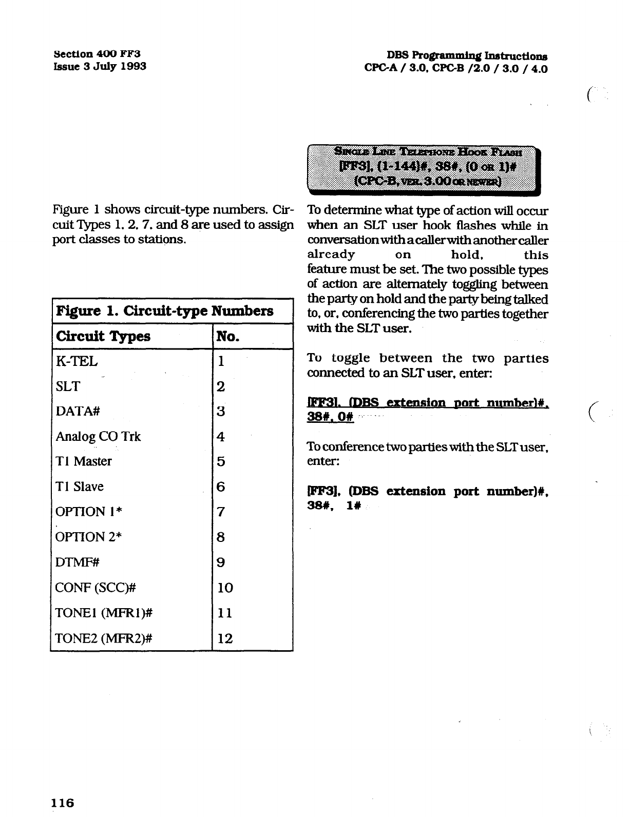
Section 400 FF3
Issue 3 July 1993 DBS programming Instructions
WC-A / 3.0. CFGB /2.0 / 3.0 / 4.0
f
Figure 1 shows circuit-type numbers. Cir- To determine what type of action will occur
cuit ‘Apes 1.2.7, and 8 are used to assign when an SLT user hook flashes while in
port classes to stations.
Figure 1. Circuit-type Numbers
circuit Types No.
K-TEL 1
SLT _ 2
DATA#
3
Analog CO Trk
4
Tl Master
5
Tl Slave
6
OPTlONl* 7
&llON 2* 8
DTMF## 9
CON-F (SCC)# 10
TONE1 (MFRl)# 11
TONE2 (MFR2)# 12
~nversationwithacallerwithanothercaIler
already on hold, this
feature must be set. The two possible types
of action are alternately tog@ng between
the party on hold and the party being talked
to, or, conferencing the two parties together
with the SLT user.
To toggle between the two parties
connected to an SLT user, enter:
. mBs
extension
DOrt
number)#.
38w. O# -.- .. c
To conferencetwopartieswiththe SLTuser,
enter:
P31, @BS extension port number)#,
38#,
l#
116
Technical Manuals Online! - http://www.tech-man.com
DBS Rogramminx instructions
CF’GA / 3.0 CPGB / 2.0 / 3.0 / 4.0
To set a distinctive extension ring pattern
for central office calls that are set to ring at
an extension, this feature must be set.
The ring patterns for proprietary DBS
phones are different than those of SLT or
OPX phones. Either of ten different
patterns can be set for an extension.
Section 400 FFS
issue
3
July 1993
The handset receive volume of the digital
single line telephone can be set to a
normal or louder than normal volume.
The louder than normal setting gives a
+fSdB gain over the normal setting, which
results in a volume level approximately
twice that of the normal setting.
To set the digitial SLT handset receiving
volume to the normal level, enter:
.fDBs extensionDOrt numberl#.
40#. ow
To set the digitial SLT handset receiving
volume to louder than normal, enter:
W], (DBS extension port number)#,
40#,1#
117
Technical Manuals Online! - http://www.tech-man.com
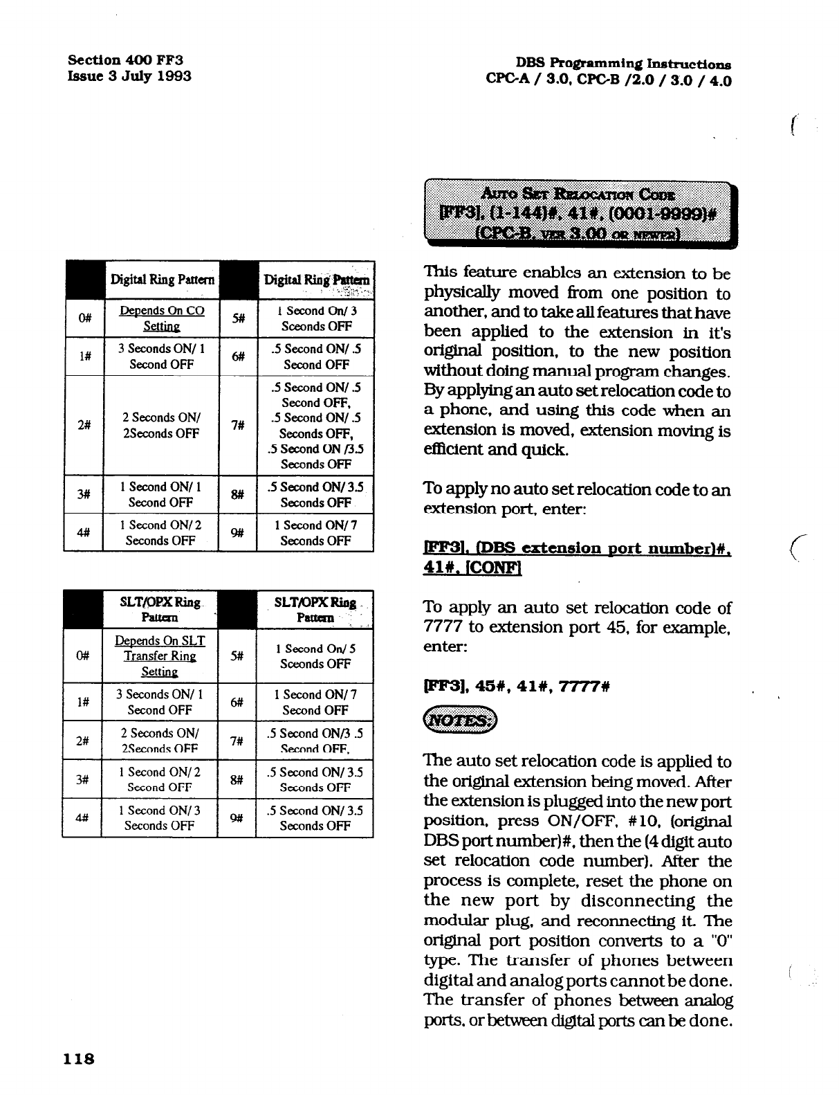
Section4OOFF3
Issue3July1993 DBSRo@ammin~Instructions
CPGA/ 3.0, CPGB /2.0 / 3.0 / 4.0
2#
3#
4#l
Digital Ring Pattan
2 Seconds ON/
2Seconds OFF 7#
1 Second ON/ 1
Second Off
1 Second ON/ 2
Seconds OFF
lSecondOnl3
Sceonds OFF
.5 Second ON/ .5
Second OFF
.5 Second ON/ .5
Second OFF.
.5 Second ON/ .5
Seconds OFF,
.5 Second ON t3.5
Seconds OFF
.5 Second ON/ 3.5
Seconds OFF
1 Second ON/7
Seconds Off
SLT&X?XRing SLT/ovxRia~.
F%ttan . Pattan . . .
DeDends On SLT
w Transfer Ring 5# 1 Second On/ 5
Settine Sctxnds OFF
l# 3 Seconds ON/ 1
Second OFF 1 Second ON/7
Second Off
I I
2# 2 Seconds ON/ I I
7# .5 Second ONn.5
2Seconds OFF Second OFF,
I I
3#
1 Second ON/2
Second OFF I I
8# .5 Second ON/ 3.5
Seconds OFF I
4## 1 Second ON/ 3
Seconds Off .5 Second ON/ 3.5
Seconds OFF
This feature enables an extension to be
physically moved from one position to
another, and to take all features that have
been applied to the extension in it’s
origInal position, to the new position
without doing manual program changes.
By applying an auto set relocation code to
a phone, and using this code when an
extension is moved, extension moving is
eflkient and quick.
To apply no auto set relocation code to an
extension port, enter:
1. mBs
extension Dolt
number)#,
4lklCONFl
To apply an auto set relocation code of
7777 to extension port 45, for example,
enter:
rFF3]*45%*41#,7777#
~ :.. :: .:... :::, ..:.. _ ,... *
The auto set relocation code is applied to
the original extension being moved. After
the extension is plugged into the new port
position, press ON/OFF. #lo. (original
DBS port number)#, then the (4 digit auto
set relocation code number). After the
process is complete, reset the phone on
the new port by disconnecting the
modular plug, and reconnecting it. The
origlnal port position converts to a “0”
type. The transfer of phones between
digital and analog ports cannot be done.
The transfer of phones between analog
ports, or between digital ports can be done.
118
Technical Manuals Online! - http://www.tech-man.com
DBS Rogrammin~ hstructions Section 400 FF3
CE’GA/ 3.0 CPC-B / 2.0 / 3.0 / 4.0 Issue3 July1993
An extension can be set in a permanent
call forward setting. This fatunz is mainly
forusewithperipheralequipment(s~~
voice mail applications)), where it is desired to
haveanexknsionring for a period oftime,
and then always forward to the same
extension port.
To not have an extension permanently
call forwarded for all calls, enter:
l rDBs extension Dort numberl#,
42W. On
To turn permanent call forwarding off,
enter:
FF3], (DBS extension port number)#,
.-.
42#, 1W
To have an extension permanently call
forwardedwhenanextensionuserisbusy,
enter:
(FF3], (DBS extension port number)#,
42#, 26
To have an extension permanently call
forwarded when an extension user does
not answer, enter:
(FF3]. (DBS extension port number)#,
426.36
If permanent call forwarding is applied, an
extension number must be set as the
target of forwarded calls. This ad-
dress sets the call forward target.
If permanent call forwarding is not
enabled, no call forwarding extension
is required. The default initialized
value of this adddress would then be:
jFF31. (DBS extension
DO&
number)#,
43w. ICONFL
To set extension number 333 as the
target extension of calls from source
extension number 105, enter:
(FF3],105#. 438.333%
Permanent call forwarding can be
overridden by call forwarding set at
the extension level.
119
Technical Manuals Online! - http://www.tech-man.com
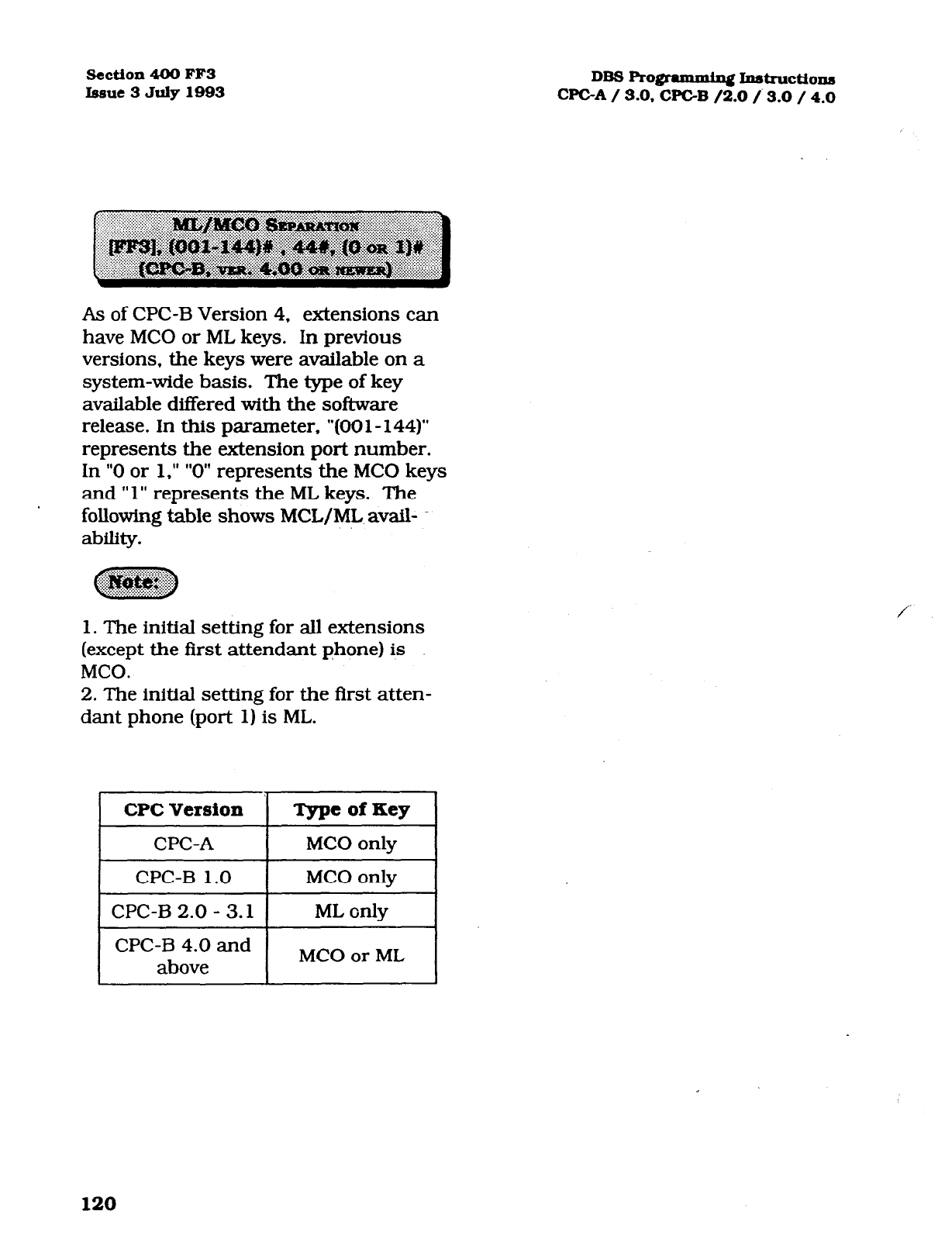
Section 400 FF3
issue 3 July 1993
DBS Rogmmmin~ Instructions
WC-A / 3.0, WC-B /2.0 /. 3.0 / 4.0
As of CPC-B Version 4, extensions can
have MC0 or ML keys. In previous
versions, the keys were avaiIable on a
system-wide basis. The type of key
available ditTered with the software
release. In this parameter, “(00 1 - 144)”
represents the extension port number.
In “0 or 1,” ” 0” represents the MC0 keys
and ” 1” represents the ML keys. The
following table shows MCL/ML avail-
ability.
1. The initial setting for all extensions
(except the first attendant phone) is
MCO.
2. The initial setting for the first atten-
dant phone (port 1) is ML.
CPC Version 1 TypeofKey 1
1
CPC-A I MC0 only I
I
CPC-B 1.0 I MC0 only I
1 CPC-B 2.0 - 3.1 1 ML only 1
I I
I I
I
CPC-B 4.0 and
above I MC0 or ML I
120
Technical Manuals Online! - http://www.tech-man.com
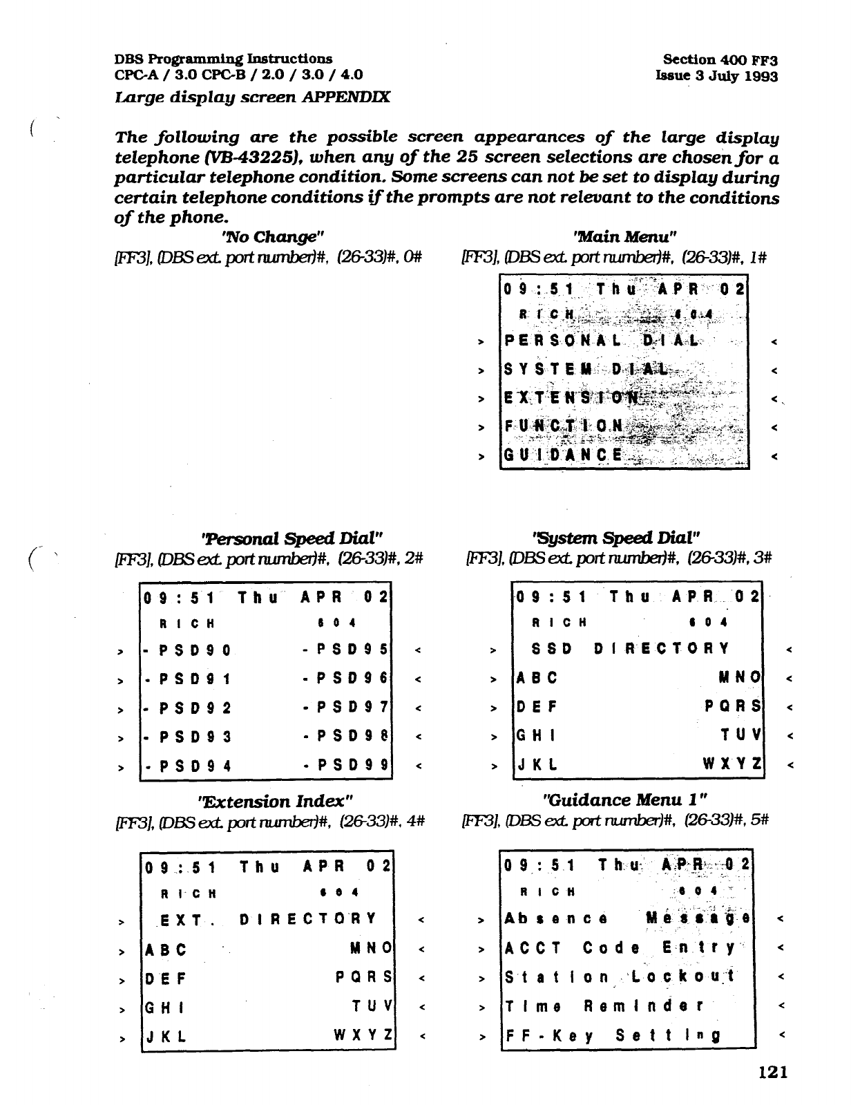
DBS Pro@mming Instructions
CPC-A
/ 3.0
WC-B / 2.0 / 3.0 / 4.0
Large display screen APPElVDlX
%‘%tion 400 FF3
Issue 3
July 1993
The fotlowing are the possible screen appearances of the large display
telephone
(‘VB-43225),
when any of the 25 screen selections are chosenfor a
particular telephone condition, Some screens can not be set to display during
certain telephone conditions if the prompts are not reteuant to the conditions
of the phone. ‘No Change”
(/ T%sonaz speed Did”
\
rnJ, CDBS ext port rlum&+, (26-33)#, 2#
09:51 Thu APR 02
RI CH 6 0 4
>
- PSDSO -PSD95
> -PSDOl -PSD96
> - PSD92 -PSD97
> - PSD93 -PSD96
> -PSD94 -PSD99
‘!&tension Index”
0 9 2.5 1 Thu APR 02
R 1.C H 4 0 4
.EXT. DIRECTO‘RY
ABC MN0
DEF PQRS
GH I TUV
JKL WXY2
‘system speed Dial”
PT3J, (Dss set pat ruunkd#.
@6-3333)#, 3#
09:Sl Thu APR.02.
RICH 804
SSD DI R.ECTORY <
ABC MN0 <
DEF PQRS c
GH I TUV <
JKL WXYZ <
“Guidance Menu I ”
r,
0 9
: 5 .1 T h: u: &i?:@+O 2
:..- ‘..
R I CH ,.[a 0 4 y
Absence 1H Q -,.i ye
-
ACCT Code E.n tti--
S.t
a
t I o n ;..L-o c k 0 u:.t
T I me Reminder
FF-Key Sett lnQ
<
<
<
<
<
121
Technical Manuals Online! - http://www.tech-man.com
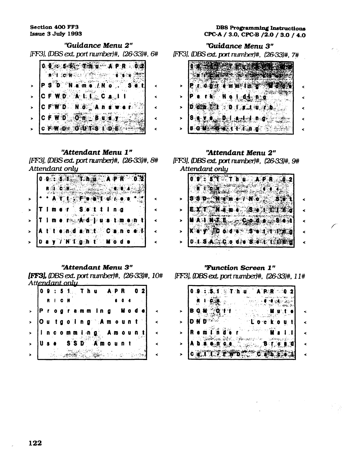
DBS Prorpammins Instructions
CPGA / 3.0, CPC-B /2.0 / 3.0 / 4.0
‘Guidance Menu 3”
ml, DE3 at pt rtumbe#* cxxE#k
Section 400 FF3
Issue 3 July 1993
“Guidance Menu 2”
ml, ms ext. port numbaf#, c26-331#, is
‘Attendant Menu 3”
Em, DBssctport-. l%3--33)#
At&U&&J&
00
:Si,. Thu
A-PR 02
RI CR’ 0 0 I
> PI og’t a-mm In g Y o d-e
> Ou tgolng‘.Amount
1, 1m
‘IAttendant Menu 2”
ml, D~ex?Qofinumber)#, tz?6-33..#* 9?Y
Attendant 0nl.g
Tunction Screen 1 *V
<
-2
<
*
*
<
<
<
<
<
f
122
Technical Manuals Online! - http://www.tech-man.com
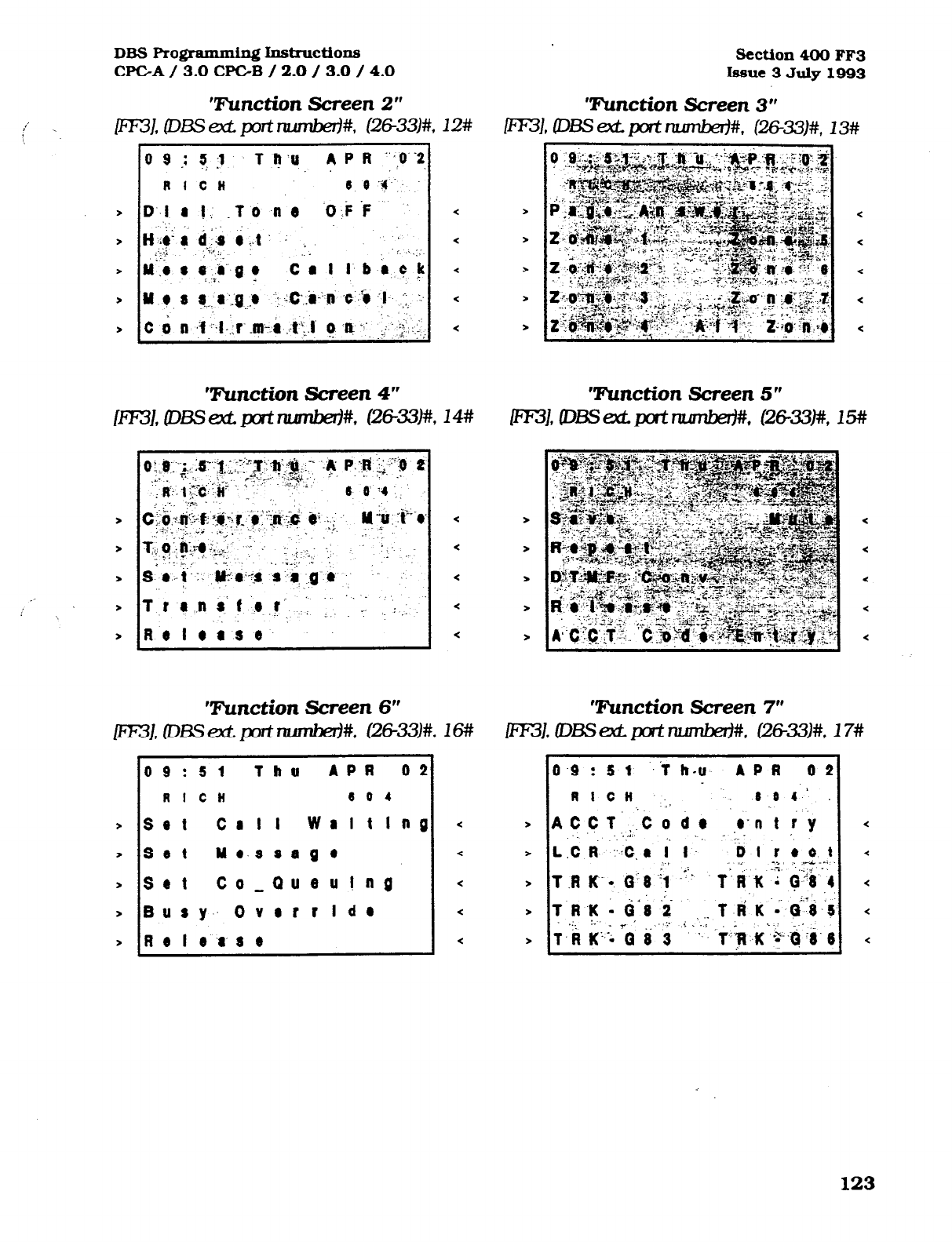
DBS F’ro@ammin~ hst~ctions
CPGA / 3.0
CPGB / 2.0 / 3.0 / 4.0
‘Function Screen 2”
pl?3], DBS exL pat lllm&ed#, (2&33M, 1%
hAion 400 FF3
Issue
3
July 1993
‘Function Screen 3”
WJ, DES ed pat rurmber)#, Wz)#,
13#
I 0 9 .: F :I .. 1 ‘I! ‘U
A P R -‘,o’-a
I RICH ( 0 .*.-.
‘!Function Screen 6”
f-31, Iz>Bs fzxt port number3#, (26-331#, 16#
09:51 Thu APR 02
RI CH
6
0 4
Set
C6 I I
W8I
tlng
set Y 0,s 9 a g 0
set co -Queu!ng
Busy--0vrrrIdo
R e I e a’s e
‘Function Screen 5”
rnL DB-Qxldnumber)#, (26-33Pt, 15#
‘Function
Screen
7”
ml. DB act pat numberf#, (B33)#, 17#
O-9 : 5 t .;r h-u
RICH -
> A c c 1 ,Yc 0 d 0
> L.C d ‘:.,c @ i’ I
123
Technical Manuals Online! - http://www.tech-man.com
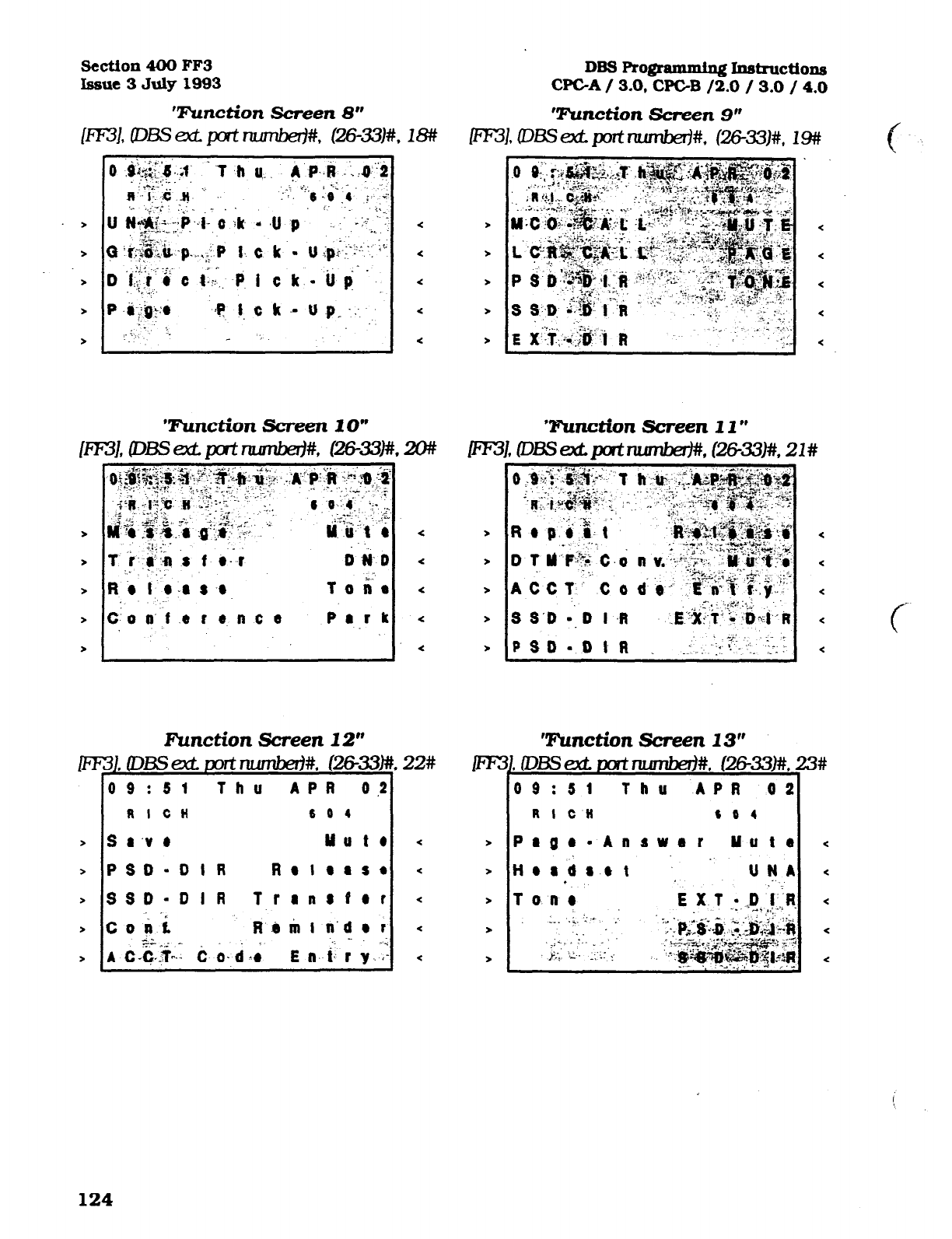
Sectton 400 FF3
Issue 3 July 1993
‘Function Screen 8”
m3L 03s ext p-t number3#, t26-331#. 18#
>
>
>
>
>
P
Ri r e-as-a.
toti*
c- 0 8’ ‘f .e c 0 n c 0 Park
Function Screen
12”
09 :Sl
Thu APR 0.2
RICH
6 0 4
s a 'V e uu t 4
PSD-DIR RBlars4
SSD-DIR Transfer
r
coit Rdrirrn’dar
^. -.
cc..: -
A C-C,.T,‘.- 6 0. d .; E a. i: r
y
. . ‘,
DBS Rogrammtng Instructions
CPGA / 3.0,
WC-B /2.0 / 3.0 /
4.0
‘Z%mction Screen 2 l)(
P-J iz?ix.BM* 21#
z
>
>
>
>
m
,
>
>
>
>
3h
I
‘Function Screen 13”
09:Sl Thu APR 02
RI cm 6 6 4
Plge- Answer Mute <
tlordaet _ UNA .c
. ,
T 0. n 0
124
Technical Manuals Online! - http://www.tech-man.com
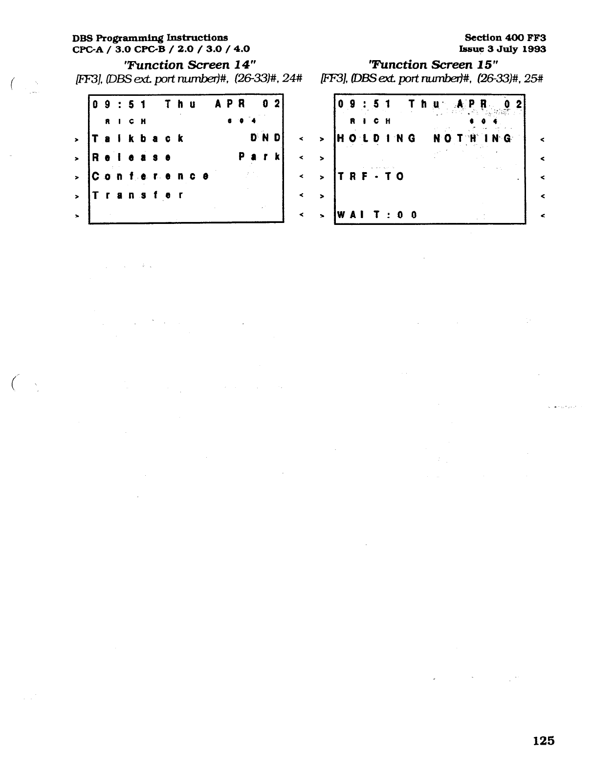
/
DBS Pro@mmiqj Instructions
Section 400 FF3
WC-A/ 3.0 CPGB / 2.0 / 3.0 /CO Issue 3 July 1993
‘!hnction Screen 14” Tunction Screen 15”
LFF31, DES ext p-t nuJnM#,
c=331#, 24#
ml, DBsct port number)#, c26-33)#, 2!3#
\
>
>
>
>
>
0 9
:51 Thu APiI 02
R I CH
0 0.4
Telkback DND
Release Park
Conference
Transf.er
< >
< >
< >
< >
< >
09
:, 5 1 T h u;
:A:.P p. ,iJ ?
_. .” . :: .,.I
RI CH
8 0.4
HOLDING N 0 1 II‘ .i N- i
TRF’-TO
WAI T: 0 0
125
Technical Manuals Online! - http://www.tech-man.com
Section 400 FF4
Issue 3 July 1993 DBS Rogramming I~tructions
WC-A / 3.0, WC-B / 2.0 / 3.0 / 4.0
I
3-4 RING8tHUNTGROUP
PROGRAMMING
P
Central office line “day mode” ring Central office line “day mode” ring
assignments for all extensions are set assignments for all hunt group pilot
with this option. numbers are set with this option.
To set extension 120 not to ring on
central office line 19 when the DBS is in
the “day mode”, for example, enter:
JFF41.
l#. l#. 19W. OW
To set extension 120 to ring on central
office line 50 when the DBS is in the
“day mode”, for example, enter:
_ P'F41, lW, lW, 50#, 1X
DefhIt initialized mIues for DBS extension
port 1 is:
EF41.
l#. l#. (1-64I#. l#. ION/
OFFI. and for extension rxxt 2 is: IFF41. l#,
2#.
fl-W#. l#. ION/OFFl.
If an outbound central office call is
made from an extension that is not set
to ring on for any inbound cent.ra.I ofice
line calls. the automatic answer option
wiII not function. To answer inbound
central office Iine caIls, press the &&.ing
green Iine key. To pick up a central office
linecallthatisrin&ingatanothertelephone,
use the Dimcted caIl pickup or Group caII
pickup options. Port number 145 is used
to assign ringing to the extemaI page /
UNA interface. Ail unassigned ringing
trunks wilI be directed to the attendant.
To set pilot number 600 (which has
been assigned as. the pilot number for
hunt group 3, in this example) not to
ring on central office line 14 when the
DBS is in the uday mode”, for example,
enter:
jFF41.
1W. 153W. 14Q. O#
To set pilot number 500 (which has
been assigned as the pilot number for
hunt group 1, in this example) to ring on
central office line 10 when the DBS is in
the @day mode”, for example, enter:
pF4],
I#, 151#, lO#, l#
126
Technical Manuals Online! - http://www.tech-man.com
DBS F’ro@amming hStruC~onS Section 400 FFQ
CPC-A / 3.0 WC-B / 2.0 issue 2 June 1993
Central office line “night mode” ring
assignments for all extensions are set
with this option.
To set extension 120 not to ring on
central ot&e line 19 when the DBS is in
the “night mode”. for example. enter:
JFF41.2#. 218. lQ#.O#
To set extension 120 to ring on central
offke line
50
when the DBS is in “night
mode”, for example, enter:
Central office line “night mode” ring
assignments for all hunt group pilot
numbers are set with this option. The
address numbers 15 1 - 158 refer to hunt
group numbers l-8.
To set pilot number 300 (which has
been assigned as the pilot number for
hunt group 2, in this example) to ring on
central ofiice line 13 when the DBS is in
the “night mode”, for example, enter:
@'F4].2#, 152#, 13#, l#
~F4].2#,21#,50#, 1n
Defiult initialized values for DBS extension
port 1 is: lFF41. 2#.
l#. (1-64M l#. ION.+!
OFFI. and for &ension uort 2 is: 1FF41.2#,
2#.
11-641#. l#. ION/OFFl.
To set pilot number 350 (which has
been assigned as the pilot number for..
hunt group 4, in this example] not to
ring on central of&e line 17 when the
DBS is in the %ight mode”, for example,
enter:
JFF41.2#. 154w. 17%.0#
Ifanoulboundcentmlofficecallismade~m
an&ensionthatisnotsettoringonforany
inbound central office line calls, the
automatic answer option wiIl not function.
To answer inbound central office line calls,
pressthefkhinggreenlineky. Topickup
a central office line call that is ringing at
another telephone, use the Directed call
pickup or Group call pickup options.
Port number 145 is used to assign ringing
to the external page / UNA interface.
Toresetcentiof3ceni&Wingass&nments
for nilot numbers to the default fnitialized
value. mess lFF41. 2#. 151-KM. kentral
offie sort numberl#. CM. ION/OFFl.
127
Technical Manuals Online! - http://www.tech-man.com
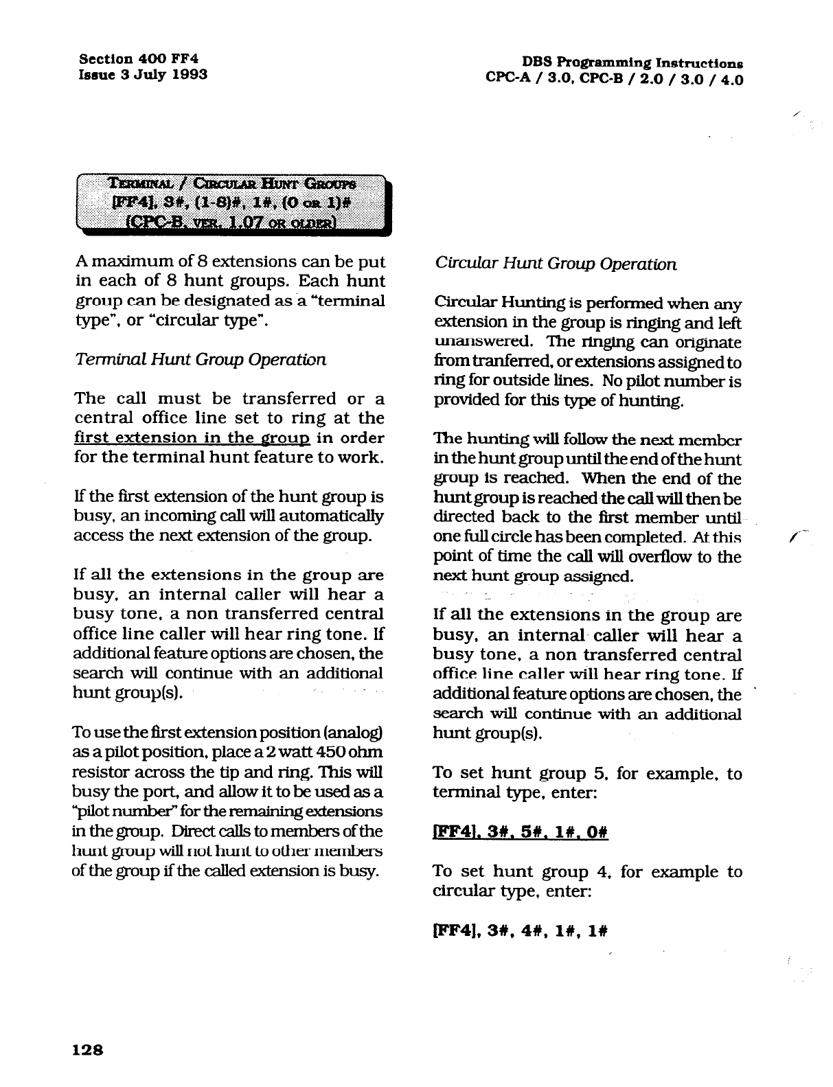
Section 400 FF4
Issue 3 July 1993
A maximum of 8 extensions can be put
in each of 8 hunt groups. Each hunt
group can be designated as a “terminal
type”, or “circular type”.
Terminal Hunt Group Operation
The call must be transferred or a
central office line set to ring at the
first extension in the grout in order
for the terminal hunt feature to work.
If the first extension of the hunt group is
busy, an incoming call will automatically
access the next extension of the group.
If all the extensions in the group are
busy, an internal caller will hear a
busy tone, a non transferred central
office line caller will hear ring tone. If
additional feature options are chosen, the
search will continue with an additional
hunt group,(s).
To use the first extension position (analog)
as a pilot position, place a 2 watt 450 ohm
resistor across the tip and ring. This will
busytheport,andallowittobeusedasa
“pilot numb& for the remaining &f!nsions
inthegroup. Directcallstomembersofthe
hunt group will not hunt to other members
of the group ifthe called extension is busy.
DBS Programming Instructions
CPC-A / 3.0. CPC-B / 2.0 / 3.0 / 4.0
Circular Hunt Group Operation
Circular Hunting is performed when any
extension in the group is ringing and left
unanswered. The ringing can originate
from tranferred, or extensions assigned to
ring for outside lines. No pilot number is
provided for this type of hunting.
The hunting will follow the next member
in the hunt group until the end ofthe hunt
group is reached. When the end of the
hunt group is reached the call will then be
directed back to the first member until
one full circle has been completed. At this
point of time the call will overflow to the
next hunt group assigned.
If all the extensions in the group are
busy, an internal. caller will hear a
busy tone, a non transferred central
office line caller will hear ring tone. If
additional feature options are chosen, the
search will continue with an additional
hunt group(s).
To set hunt group 5. for
example, to
terminal type, enter:
JFF41. 3w. 5n. l#.O#
To set hunt group 4, for example to
circular type, enter:
/-
Iee41, 3#, 4W, l#, l#
128
Technical Manuals Online! - http://www.tech-man.com
DBS Programming Instructions
WC-A / 3.0 CPC-B / 2.0 Section 400 FF4
Issue 2 June 1993
If all extensions are busy, an incoming
call will wait for an available extension.
If an extension within either type of
hunt group: is set with an absence
message, with a call forward feature, or
to DND, the hunt feature will skip that
extension, and procede to the next
extension within the group. If the fast
extension within either type of hunt
group is set with an absence message,
with a call forward feature, or to DND,
the hunt feature will not work.
6 ”
If a SLT hunt group member takes a
central office line call, puts it on hold,
and replaces the handset, additional
central office line calls will not hunt to
idle extensions.
Previously searched hunt groups
cannot be searched again. If all
members of all searched groups are
busy, the call will be parked for the frst
group searched only.
Central of&e lines that are set to ring at
extensions set to call forward to a hunt
group will not call forward to extension
types 10 and 15.
An extension that is a member of a hunt
group cannot be a member of another
hunt group, nor a member of a call
coverage group. The off hook signaling
[FF3]- 16 address should be removed
from members in a hunt group.
A maximum of 8 extension numbers
can be assigned to work as one of a
maximum of 8 pilot numbers. One
pilot number can be,used as the lead
number for each of the 8 hunt groups.
To assign extension number 255, for
example, as a pilot number for the frost
hunt group, enter:
WF4], 3W;l#, lW.2558
To assign no extension number (and ..
therefore no pilot number), for example,.’ ., .. :.
for the first hunt group, enter:
pF4], 3W, lW, lW, conf,# ,. ..I
To assign extension number 110, for
example, as a pilot number for the
second hunt group, enter:
cIpIp4). 3#, 2W, l#, 1lOW
To assign extension:.number 300. for
example, as a pilot number for the third
hunt group. enter:
IFF4],3#,3#, l#, 3006
To assign extension number 699, for
example, as a pilot number for the
fourth hunt group, enter:
WF4], 3#,4#, lW.6996
To assign extension number 600. for
example, as a pilot number for the fifth
hunt group, enter:
129
Technical Manuals Online! - http://www.tech-man.com
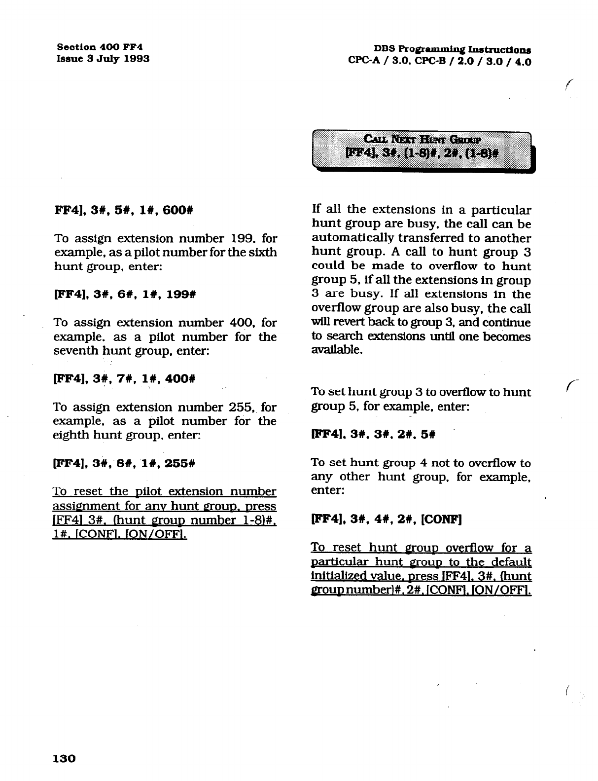
Section 400 FF4
Issue 3 July 1993
FF4],3#,5#, 1#,600#
To assign extension number 199, for
example, as a pilot number for the sixth
hunt group, enter:
[FF4],3#,6#, l#, 199#
To assign extension nuqber 400, for
example, as a pilot number for the
seventh hunt group, enter:
lFF41.35 7C, 1#,400#
To assign extension number 255,. for
example, as a pilot number for the
eighth hunt group, enter:
[FF4], 3#, 8#;1#, 255W
To reset the uilot extension number
assignment for anv hunt Q~OUD. Dress
jFF41 3#. (hunt groun number l-81#,
l#. ICONFl. fON/OFFl.
DBS Ro@amrnin~ Inst~ctiom~
CI’GA / 3.0, CPGB / 2.0 / 3.0 / 4.0
If all the extensions in a particular
hunt group are busy, the calI can be
automatically transferred to another
hunt group. A call to hunt group 3
could be made to overflow to hunt
group 5, if all the extensions in group
3 are busy. If all extensions in the
overflow group are also busy, the call
will rem-t back to group 3, and con&me
to search extensions until one becomes
available.
To set hunt group 3 to overflow to hunt
group 5, for example. enter:
[FF41, 3w, 3#, 21, 51
To set hunt group 4 not to overflow to
any other hunt group, for example,
enter:
rFF41, 3#, 48, 26, [CONF]
To reset hunt grout overflow for a
particuku hunt PROUD to the default
initialized value. Dress lFF41.3#. (hunt
gr-ou~numberl#. 2#. ICONFI. lON/OFFl.
130
Technical Manuals Online! - http://www.tech-man.com

DBS Programming Inst.ructions
WC-A / 3.0
WC-B / 2.0
Section 400 FF4
Issue 2
June 1993
Use this option to insert an extension in a
specific position of one of the eight hunt
groups. A maximum of 8 extensions can
be put into a hunt group.
To place extension number 500 in the
first hunt group’s first position, enter:
pF4],3#. lW, 31.5001
(FF41. 3t. (l-SW. (3)t. (IOO-699H
1 st member for hunt groups ( l-8)
?OCorXXX.#
(FF41, 3U. (l-8lrt. (4)#, (loo-699M
2nd member for hunt groups (I-81 xx0rxxx.n
(FF41, 3#, (l-81#. (5)#, (loo-6991#
3rd member for hunt groups (l-8) xx0rxxx.t
(FF41. 3#. (1-8l#. (6)#. (IOO-6991#
4th member for hunt groups (l-81 xxorxxx.%
IFF4). 3t. (I-8)t. (7’J#. (loo-699)#
5th member for hunt groups (l-81 xxorxxx,#
(FF41. 3#. (l-8)#. (8)#, (lOO-699)t
6th member for hunt groups (1-B) xx0rxxx.U
(FF41. 3#. (l-8)+!, (9)#. (IOO-699)#
7th member for hunt groups (l-8) xxorxxx.#
(FF41. 3#, (l-8,!+. (lOl#. (lOO-699M
8th member for hunt groups (l-81 I xx0rxxx.U
To reset an extension to it’s default initial-
ized hunt $30~~ value.
press:
IFF41. 3#
(DBS hunt grow numberl#. (DBS hunt
grout nositionI#. fCONFl#. fON/OFFl.
An extension that is a member of a hunt
group cannot be a member of another
hunt group, nor a member of a call
coverage group. The off hook signaling
[FF3]- 16
address should be removed
from members in a hunt group.
The type of extension search that is
used once the call is connected to a
hunt group can be set to terminal,
distributed, or longest idle.
.-. .-
TenninuZ Hunt Group~Operation
The call must be transferred or a central
office line must be set to ring at the nilot
number of the hunt groun in order for
the terminal hunt feature to work.
The hunt begins with the pilot number,
and sequentially moves through the
eight extensions. If all the extensions in
the group are busy. the hunt for a free
extension W-III terminate.
If the pilot number of another hunt
group, or same hunt group. is specified,
the search will continue with an
additional hunt group(s). If not, the
caller will receive a busy tone.
Distributed Hunt Group Operatim
The call must be transferred or a central
ofke line must be set to ring at the Dilot
number of the hunt
croup
in order for
the distributed hunt feature to work.
The hunt begins at the extension after
the last one to pick up the previous
caller, and continues in a circular
manner for successive calls.
If the pilot number of another hunt group
is specified, the search will continue with
an additional hunt group(s). If not, the
caller will receive a busy tone.
131
Technical Manuals Online! - http://www.tech-man.com
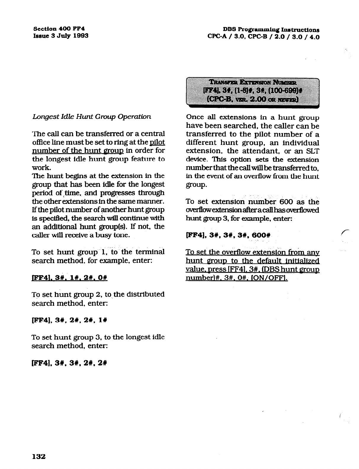
section 400 FF4
hue 3 July 1993
Longest Idle Hunt Group Operation
The call can be transferred or a central
of&e line must be set to ring at the pilot
number of the hunt
a-OUD
in order for
the longest idle hunt group feature to
work.
The hunt begins at the extension in the
group that has been idle for the longest
period ofTtime, and progresses through
the other extensions in the same manner.
lfthe pilot number of another hunt group
is spedfled, the search will continue with
an additional hunt group(s). If not, the
caller will receive a busy tone.
. .
To set hunt group .l, to the termin&
search method, for example, enter:
JFF41. 34. I#. 2W. O#
To set hunt group 2, to,,the distributed
search method, enter:
WF4], 3#, 21, 2#,
l#
To set hunt group 3, to the longest idle
search method, enter:
DBS Rogrammixag In#ructi~ns
WC-A / 3.0, WC-B / 2.0 / 3.0 / 4.0
Once all extensions in a hunt group
have been searched, the caller can be
transferred to the pilot number of a
different hunt group, an individual
extension, the attendant, or an SLT
device. This option sets the extension
numberthatthecallwillbetransferredto,
in the event of an overflow Tom the hunt
group.
To set extension number 600 as the
~owMensionafteracallhasoverflowed
hunt group 3, for example, enter:
[FF4),3#,3#,3#,600# P
To set the overflow extension from anv
hunt
BOUD
to the default initialized
value. Dress (FF41.3#. (DBS hunt Proun
numberHI. 3#. O#. ION/OFFi.
rFF4].3#, 3#,2#.2#
132
Technical Manuals Online! - http://www.tech-man.com
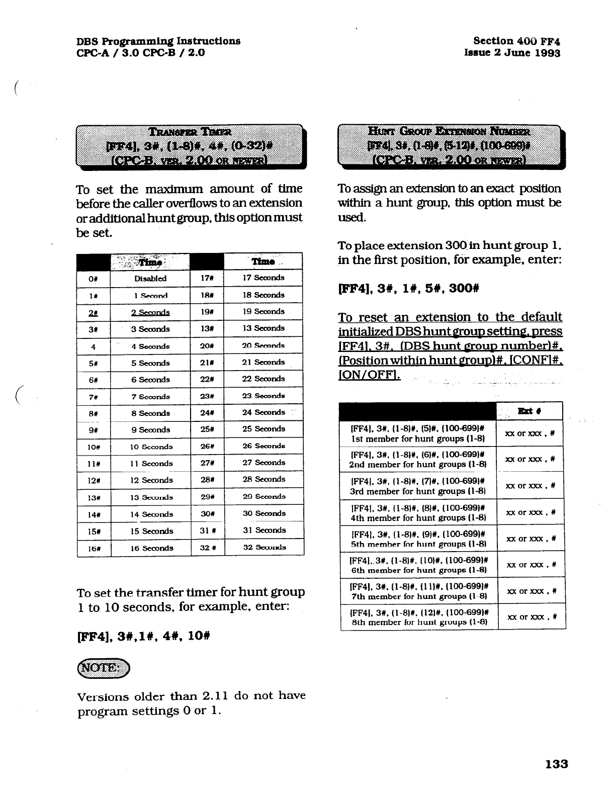
DBS Programming In!kructiox.w
WC-A / 3.0 CPGB / 2.0 section 4c90 FF4
Issue 2 June 1993
To set the maximum amount of time
before the caller overflows to an extension
or additional huntgroup, this option must
be set.
111 11 seconds 271 27 Seconds
121 12 seamcls 281 28 semnds
13u 13 seconds 291 29 seconds
141) 14 seamds 301 30 tseamds
15# 15 seconds 31 # 31 SeoJnds
16# 16 Sea&s 32 I 32 !Seamds
To set the transfer timer for hunt group
1 to 10 seconds, for example, enter:
[FF4], 3W,lW, 4#,10#
To assign an exkMon to an exact position
within a hunt group, this option must be
used.
To place extension 3OO.in hunt group 1,
in the tist position, for example, enter:
pF4], 3w, 1#,5#y,300#
To reset an extension to the default
initialized DBS hunt groun setting. Dress
jFF41.3#. lDBS hunt
LOUD
numberl#,
JPositionwithin hunt grounj#. ICONFl#,
JON’OFF’* .:. ._ :.. _
IFF41. 3#. (1-81s. (51#. (100-6991#
1st member for hunt grows (l-8) I
XX0rDCX.U
I
I
(FF41, 3#. (I-8lU. (8H. (IOO-699M
4th member for hunt
groups
(l-8) I xx0rxxx.l
I
(FF41. 31. (l-8)#, (9)#, (100-6991X
5th member for hunt gmuns (l-81 I xx0rxxx.W I
I
(FF41..3#. (I-811. [lOl#, (100-6991#
6th member for hunt gmuns (l-81 I xx0rxxx.t
I
IFF4J. 3W. (l-8)ff. (1 IIN. (loo-6991#
7th member for hunt gmuos I1 -81 I xxorxxx.# I
I
(FF41. 3U. (l-8)#, (121X. (lOO-6991#
8th member for hunt grows (l-81 I xx0rxxx.n
Versions older than 2.11 do not have
program settings 0 or 1.
133
Technical Manuals Online! - http://www.tech-man.com
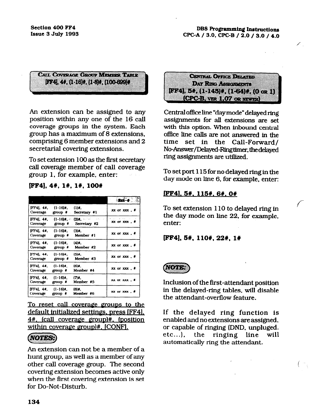
Section 400 FF4
Issue
3
July 1993
DBS Ro@ammiq Inst~ctions
-C-A/ 3.0, WC-B / 2.0 / 3.0 / 4.0
An extension can be assigned to any
position within any one of the 16 call
coverage groups in the system. Each
group has a maximum of 8 extensions,
comprising 6 member extensions and 2
secretarial covering extensions.
To set extension
100 as the
first secretary
caIl coverage member of call coverage
group 1, for example, enter:
[FF4], 48, I#, l#, lOO#
;&&; ,t
:,.
iFF41. 41. ‘1-1611. ‘1)X.
coverage group # Fiea-etaly I1 xxorxxx.#
I~41. 4#. (1-16)X.: (211. .’
cavenge @-up# secretary x2 ‘.A & k , #
xxorxn.#
IFF41. 41. (l-16)1. ‘6)#.
-eraBe ID-UP # Member #4 xx0raa.t
tFF41. 4X. (I-16)#. (7)#.
Q=rage group # Member #5 I XXW?ZX.# I
I
IFF41. 4#. ‘l-16)#. ‘8M
covcra&?e SOUP t Member #6 I xxorxxx .# I
To reset call cover=
~OUDS
to the
default initialized settings. Dress IFF4L
4#.
lcall coveraee groun)#. (oosition
within COVeraf!e aOUD)#. iCONF1.
An extension can not be a member of a
hunt group, as well as a member of any
other call coverage group. The second
covering extension becomes active only
when the first covering extension is set
for Do-Not-Disturb.
Central o!3ce Iine “day mode” delayed ring
assignments for all extensions are set
with this option. When inbound centml
o&e line cab are not answered in the
time set in the Call-Forward/
No-Answer/Delayed-RingUmer,thedelayed
ring assignments are utilized.
To set port 115 for no delayed ring in the
day mode on line 6, for example, enter:
W41. 5#.
1151y. 6#.0#
To set extension 110 to delayed ring in
the day mode on line 22, for example,
enter:
pF4], 5#,
110#,22%, l#
Inclusion of the first-attendant position
in the delayed-ring tables. wiIl disable
the attendant-overflow feature.
If the delayed ring function is
enabled and no extensions are assigned,
or capable of ringing (DND, unpluged.
etc...), the ringing line will
automatically ring the attendant.
134
Technical Manuals Online! - http://www.tech-man.com
DBS Pro@amming hdruCti0~ 3eCtion4OOFF4
WC-A / 3.0 WC-B / 2.0 Issue 2 June 1993
Central office line “day mode” delayed ring
assignments for pilot numbers of hunt
groups are set with this option. When
inbound central office line calls are not
answered in the time set in the
Call-Forward/No-Answer/Delayed-Ring
timer, the delayed ring assignments are
unlized.
To set the pilot number for hunt group 1
for no delayed ringin the day mode on line
22,
for example. enter:
(
JFF41. 5#.
151#. 22#.0#
To set the pilot number for hunt group
2 for delayed ring in the day mode on
line 15, for example, enter:
Central office line “night mode” delayed
ring assignments for all extensions are
set with this option., When inbound
central office line callsare not answered
in the time set in the, Call-Forward/
No-Answer/Delayed-Ring timer, the
delayed ring assignments are utilized.
To set extension 120 for no delayed ring
in the night mode on line 3, for example,
enter:
JFF41. 6#. 120#. 3W.
O#
To set extension 400 to delayed ring in
the night mode on line 20, for example,
enter:
[FF4], 66, 120#, 3#,
l#
WF4]. 5#, 152#, 15W. l#
Inclusion of the first-attendant position
in the delayed-ring tables, will disable
the attendant-overflow feature.
If the delayed ring function is
enabled and no extensions are assigned,
or capable of ringing (DND, unpluged.
etc...). the ringing line will
automatically ring the attendant.
,135
Technical Manuals Online! - http://www.tech-man.com
Section4OOFF4
Issue3July1993 DBSRo@ammfngInstructions
WC-A / 3.0. WC-B / 2.0 / 3.0 / 4.0
Central of&e line “night mode” delayed
ring assignments for pilot numbers of
hunt groups are set with this option.
When inbound central office line calls are
not answered dn the time set in the Call-
Forward/No-Answer/Delayedelayed-Wngtimer,
the delayed ring assignments are utilized.
To set the pilot number for hunt group 4
for delayed ring in the night mode on line
28, for example, enter:
JFF4l. 6W. 154#.26i/.O#
To set the pilot number for hunt group
1 for no delayed ring in the night mode
on line 10, for example, enter:
Extensions th at have a DSS/BLF key
assignment for other DBS extensions
can be set to ring on those keys for
any type of call that is directed to the
other extensions. This feature allows
a second extension user to answer a
ringing call to an absent extension
position(s) by accessing the DSS/BLF
key on their phone that represents
the other extension position(s). The
first extension enumerated in the
address is the target extension; and
the second is the source extension.
To set extension port 15 not to ring for
calli directed to ‘extension port 44, enter:
JFF41. 7w. 44w. 15W.06
[FF4], 6#, 151#, 106, l#
To set extension port 1 to ring for calls
directed to extension port 60. enter:
tFF41, 76,6O#,l# 1n
136
Technical Manuals Online! - http://www.tech-man.com
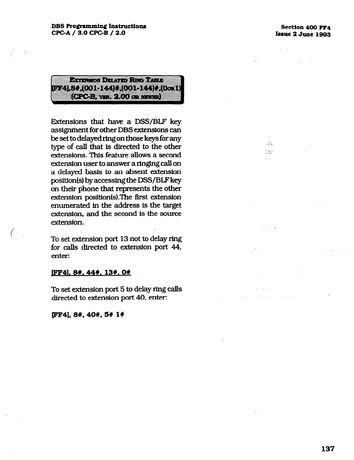
DBS ROM Inntnwtions
WC-A / 3.0 WC-B / 2.0
Extensions that ham a DSS/BLF key
assignment for other DBS extensions can
besettodelayedringonthosekeysforany
type of caU-*t is directed to the other
&ensions.‘cs feature allows a second
extension user to answer a ringing call on
a delayed basis to an absent extension
position(s) by accessingthe DSS/BLFkey
on their phone that represents the other
extension position(s).?he Brst extension
enumerated in the address is the target
extension. and the second is the source
extension.
To set extension port 13 not to delay ring
for calls directed to extension port 44,
enter:
JFF41. wt. 44u. 13#. ow
To set extension port 5 to delay ring calls
directed to extension port 40, enter:
W4], su, 4ow, 5# l#
section 400 FF4
Isane 2 June 1993
137
Technical Manuals Online! - http://www.tech-man.com
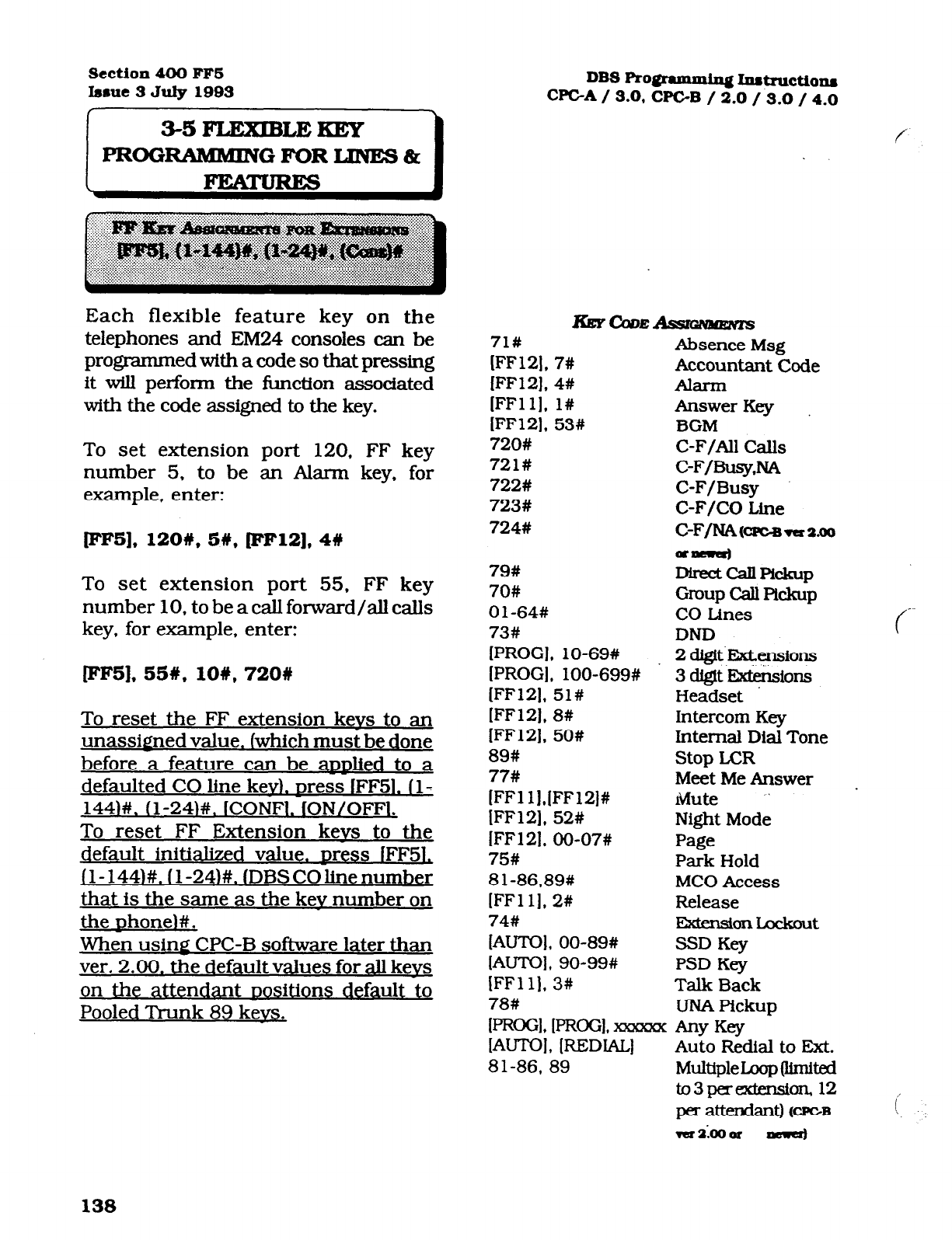
Section 400 FFS
Isrue July 1993
Each flexible feature key on the
telephones and EM24 consoles can be
programmed with a code so that pressing
it wiU perform the function associated
with the code assigned to the key.
To set extension port 120. FF key
number 5, to be an Alarm key, for
example, enter:
PF5], 12OW. 5#, pF12],
4#
To set extension port 55, FF key
number 10, to be a call forward/all calls
key, for example, enter:
EF5], 55#,10#,720#
To reset the FF extension kevs to an
unassigned value. [which must be done
before a feature can be aDDlied to a
defaulted CO line kevl. Dress lFF51. (l-
1441#. (l-24I#. ICONFI. IONIOFFI.
To reset FF Extension kevs to the
default initialized value. Dress fFF5L
jl-1441#. 11-241#. (DBSCOlinenumber
that is the same as the kev number on
the nhoneI#.
When using CPC-B software later than
ver. 2.00. the default values for all kevs
on the attendant nositions default to
Pooled Trunk 89 kevs.
DBS Ro@ammin~ I~tructio~~
CPCA / 3.0, CPGB / 2.0 / 3.0 / 4.0
f
71#
[FFl2]. 7#
[FF12], 4#
IFFll], l#
IFF121, 53#
720#
721#
722#
723#
724#
79#
70#
Ol-64#
73#
[PROGI , lo-69#
IPROGI, lOO-699#
(FF121, 51#
1FF121, 8#
lFF121, 50#
89#
77#
[FFl lj,[FF12]#
IFF121, 52#
IFF121, 00-07#
75#
81-86,89#
[FFll]. 2#
74#
[AUTOI. 00-89#
IAUTOI, 90-99#
IFFlll, 3#
78#
Absence Msg
Accountant Code
Alarm
Answer Key
BGM
C-F/AU CaIls
C-F/Busy .NA
C-F/Busy
C-F/CO Line
C-F/NAWGB~~.~~
Qm
DkCtCdlpfckup
Group call pllckup
CO Lines
DND
2 dQgi~~ensions
3 dglt F57di&ions
Headset
Intercom Key
Internal Dial Tone
Stop LCR
Meet Me Answer .
Mute ”
Night Mode
Page
Park Hold
MC0 Access
Release
-onLockcnlt
SSD Key
PSD Key
Talk Back
UNA Pickup
(-
IPROGI, [FRGGI, xzawcx
-Y Key
[AuToI, [REDIAL] Auto Redial to Ext.
81-86,
89 MuIUpleIzop (United
to3pereKtfnsi~ 12
per attendan m-2 i
138
Technical Manuals Online! - http://www.tech-man.com
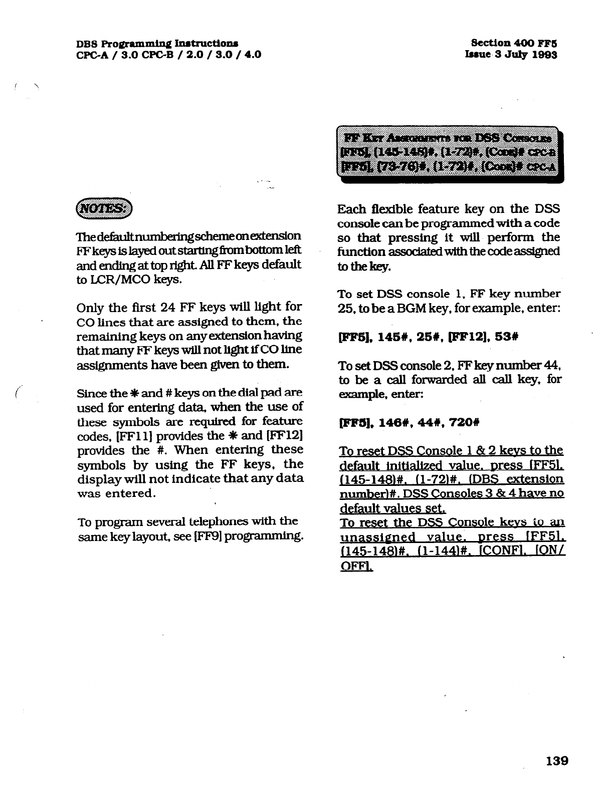
DBS Promming Inst~ctio~u
CPC-A / 3.0 CPGB / 2.0 / 3.0 / 4.0
‘lhedef&knumbenngschemeonextension
FFke@AayedoutstarUngfmmbottoml&
andendingattopright.AUFFkeys default
to LCR/MCO keys.
Only the first 24 FF keys will light for
CO lines that are assigned to them, the
remaining keys on anyextensionhaving
thatmanyFFkeyswillnotlightifCOhne
assignments have been given to them.
Sincethe~and#keysonthedialpadare
used for entering data, when the use of
these symbols are required for feature
codes, (FFll] provides the 0 and (FF12)
provides the #. When entering these
symbols by using the FF keys, the
display will not indicate that any data
was entered.
To program several telephones with the
same key layout, see [FF9] progmmming.
section 400 FFS
Issue 3 July 1093
Each flexfble feature key on the DSS
console can be programmed with a code
so that pressing it will perform the
functionassodaWwiththecodeassigned
tothekey.
To set DSS console 1, FF key number
25. to be a BGM key, for example, enter:
lFF51, 145w, 251, [FF12].53#
TosetDSSconsole 2, FFkeynumber44,
to be a call forwarded all call key, for
example, enter:
@'F5],148#,44#,720#
To reset DSS Console 1 & 2 kevs to the
default initialized val e. Dress fFF51,
J145-148w fl-721#. YDBS extension
number~#. DSS Consoles 3 814 have no
default values set,
To reset the DSS Console kevs to an
unassigned value. Dress fFF51,
J145-1481#. fl-144N. ICONM. IONI
OFFI.
139
Technical Manuals Online! - http://www.tech-man.com
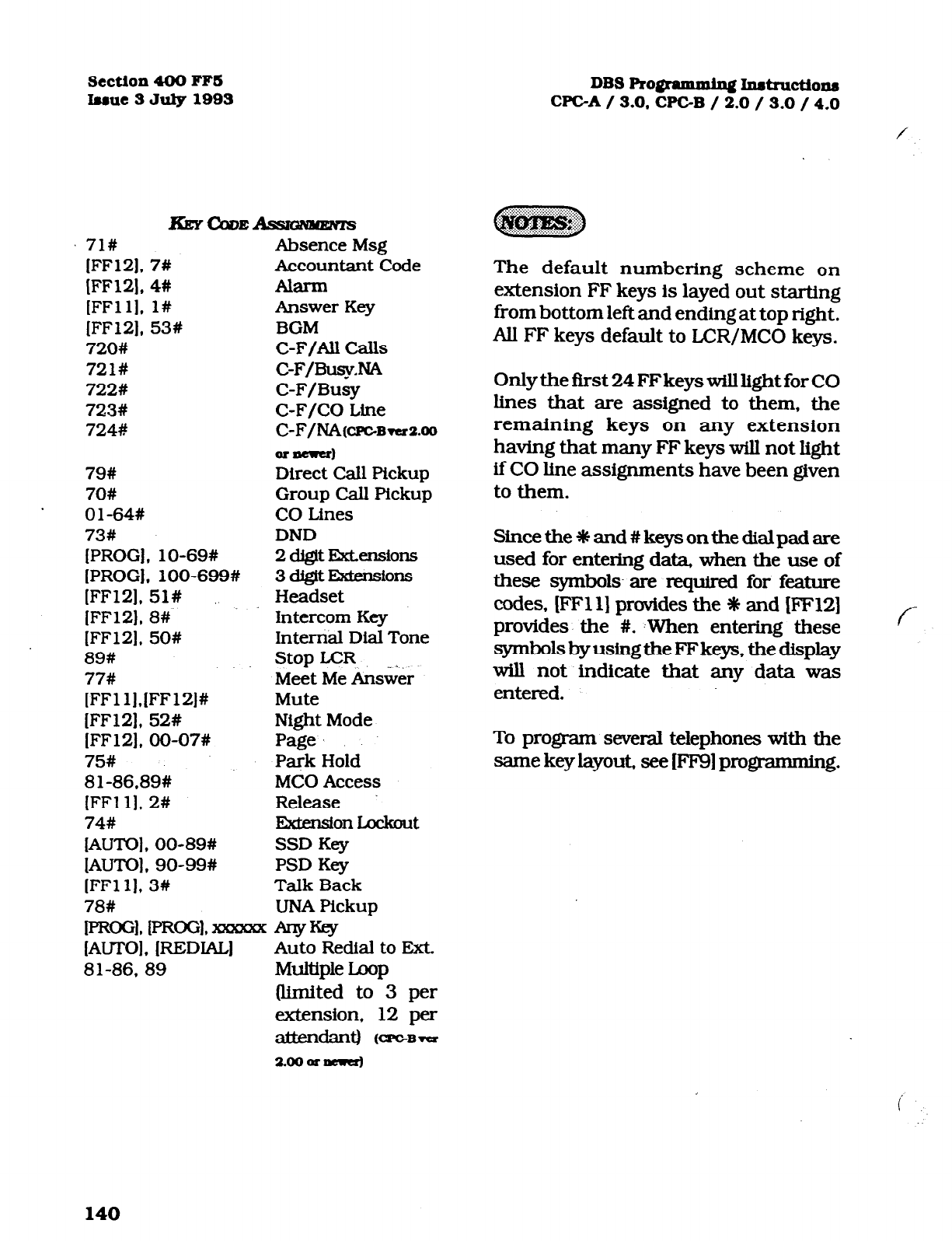
Section 400 FFS
luue SJuly1993 DBSRo~rammin~Instructio~
WC-A
/ 3.0,
CPC-B / 2.0 / 3.0 / 4.0
KEYQDE-
71# Absence Msg
[FFlZ], 7# Accountant Code
[FF121, 4# Alarm
[FFll]. l# Answer Key
[FF12], 53# BGM
720# C-F/Au calls
721# C-F/BusyNA
722# C-F/Busy
723# C-F/CO Line
7248
C-F/NA(c~~~versoo
@=aerer)
79#
Direct Call Pickup
70# Group Call Pickup
Ol-64# CO Lines
73# DND
[PROG], lo-69# 2 d&it E7clxnsions
[PROG], lOO-699# 3 dlgtt I3dm!3ions
[FF12], 51# Headset
[FF12), 8# Intercom Key
[FF121. 50# Internal Dial Tone
89# Stop LCR
77# Meet Me An&er
[FFl l],[FF12]# Mute
[FF12], 52# Night Mode
[FF12]. 00-07# Page
75# Park Hold
81-86,89# MC0
Access
[FFll]. 2# Release
74# ExiznstonLcchut
IAUTOl, 00-89# SSD Key
[AUTO], 90-99# PSD Key
[FFl 11, 3# Talk Back
78# UNA Pickup
IPROGI. I~oGl* ~ Any-
IAUTOI, [=Dml
Auto Redial to Ext.
81-86, 89 Multiplex
(limited to 3 per
extension, 12 per
ElttfBldaIl~ K==Brer
The default numbering scheme on
extension FF keys is layed out starting
from bottom left and ending at top right.
All FF keys default to LCR/MCO keys.
Only the first 24 FFkeyswilllight for CO
lines that are assigned to them, the
remaining keys on any extension
having that many FF keys will not light
ifC0 line assignments have been given
to them.
Sincethe~and#keysonthedialpadare
used for entering data, when the use of
these symbols- are required for feature
codes, (FFll] provides the * and [FFl2]
provides the #. YWhen entering these
symbolsbyusingtheFFkeys,thedisplay
will not indicate that any data was
entered.
To program several telephones with the
same key layout. see (FF9J programming.
140
Technical Manuals Online! - http://www.tech-man.com
DBS F’ro@amxdng Instructiona
WC-A / 3.0 CPGB / 2.0 / 3.0 / 4.0
Section 400 FFS
batte SJ* 1993
Eachflextblefeature keyontheAttendant
console can be pmgmnmed with a code
so that pressing itwill perform the function
assodatedwitbtbecodeassi$ledtothekey.
Tosetatt@antcmsole 1,FFkqynumber
25, to be a BGM key, far example, enter
(P'Irg], 145#,25#, pFl2], 53W
When usin#
softwa.re Ihe DSS Console kevs default
as indicated in the am endix following
i this section
:
To
reset the Attendant Console keys to
m unassigned value. mess IFF5L
1149-152)#. (l-144)#. lCONF1. ION/
OFF1 .
71#
[FF12], 7#
[FF12], 4#
[FFll]. l#
[FF12], 53#
720#
721W
722#
723#
724#
79#
70#
Ol-64#
73#
[PROG], lo-69#
[PROG]. lOO-699#
[FF12], 51#
(FF121. 8#
[FF12], 50#
89#
77#
[FFl l],[FF12]#
[FF12]. 52#
IFF121. 00-07#
75#
8 1-86,89#
(FFlll. 2#
74#
[AUTO], 00-89#
[AUTO], 90-99#
[FFll]. 3#
78#
Absence Msg
Accountant Code
Alarm
Answer Key
BGM
C-F/AU CalIs
C-F/BusyJW
C-F/Busy
C-F/CO Line
C-F/NA
(CPGB w 2.00 or a-)
DirectCanPlckup
GroupCaIlPichp
CO Lines
DND
2 d.ig¶t l9cknsiorls
~ 3 digtt Rctensions
Headset
Intercom Key
Internal Dial Tone
Stop LCR
Meet Me Answer
Mute
Night Mode
Page
Park Hold
MC0 Access
Release
ExtensionLockout
SSD Key
PSD Key
Talk Back
UNA Pickup
m-4. mm* Jmmxx *Key
[AUTO] t IREDIAL] Auto Redial to Ext.
81-86. 89 Multiple Loop
(limited to 3 per
extension, 12 per
attendant)(cpc-B VQ
2.00 or -1
141
Technical Manuals Online! - http://www.tech-man.com
section 400 ma
I~sue3
July1993 DBSRo#ammin~Instructions
CF’GA
/ 3.0.
WC-B / 2.0 / 3.0 / 4.0
The default numbering scheme on
attendant console FF keys is layed out
starting from bottom left and ending at
top right. All FF keys default to LCR/
MC0 keys.
Only the Arst 24 FF keys will light for CO
lines that are assigned to them, the
remaining keys on any attendant con-
sole having that many FF keys will not
light if CO line assignments have been
given to them.
Since the * and # keys on the dial pad are
used for entering data, when the use of
these symbols are required for feature
codes, [FFl l] provides the * and [FI712]
provides the #. When entering these
symbols by using the FF keys, the display
will not indicate that any data was
entered.
To program several telephones with the
same key layout, see [FF9] progmmming.
142
Technical Manuals Online! - http://www.tech-man.com
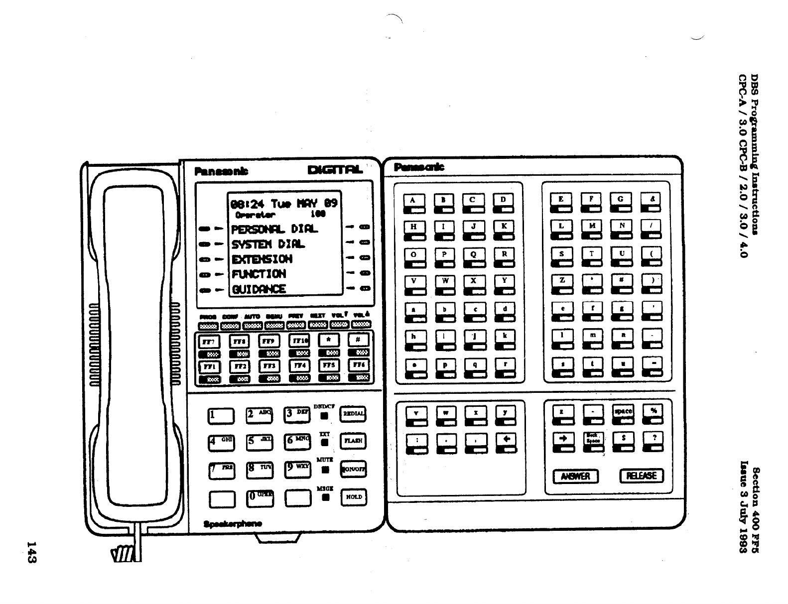
DBS Pro@-ammh~ Instruction
CPGA/ 3.0 CPGB / 2.0 / 3.0 / 4.0 section 400 Flw
Isaue3Juiy1993
143
Technical Manuals Online! - http://www.tech-man.com

section 400 FM DBS Programming Instructions
Issue 3 July 1993 WC-A / 3.0. CPC-B / 2.0 / 3.0 / 4.0
,
3-6NAMEANDlUESSlGE
PRrnRAMS~Gs
c
Names of up to 10 characters can be
assigned to each extension number. This
name appears on the second line of a
telephone with a display, and on the top
line of a display extension that is calling.
,.
To assign a name to extension port 40,
with the characters RICH M.. for example,
enter:
Names of up to 16 characters can be
assignedtoSystemSpeedDialnumbersOO-
89. The namesaredisplayedalphabeticauy
on large screen ICD telephones to provide
comlnnation of the name of the person
being cakd when using a SSD code.
Toassignthename”Panasonic”tosystem
speed dial number 05. for example, enter:
ml, iw, 40#, C0NPW. (see am-~
following this sectim)# ,. (ITS), 2#, 05#, (see appendix following
this s+ion)#
To assign a name to extension port 1, with To reset the names of s&em sneed dial
the characters Operator. for example, numbers to the default initialized values,
enter: press IFF21..2#. 00-691#. ICONFl. ION/
[FF6], l#, IS. [CONFIn, (see appendix
OF-n.
folbwing this sectim)# ~~~
.:W$
To reset &ension names to the default
iniuauzed val
e.
DIZSS
rmw.
l#. fl-144
jCONFl#. fONU/OFFI.
If the “Attendant Feature Package”
sotiisbeingused.theDSSConsole
mustbejn&3llysetastypellin[Fl?3],2#to
enaIde thelqsfo--es.
See Ihe appendix following this section for
key designations on the DSS Console
which is used to store characters for
extension names. IfaDSS is not available
seesectfon700,intheopgatingInstructions
Manual under UAttendant Telephone
Features” for alternate instructions
on how to store characters.
If the “Attendant Feature Package”
sofhvare is being used, the DSS Console
mustbein.iUallysetastype llin(FF3]2#,
to enable the keys for programming
capabilities. See the appendix following
this section for key designations on the DSS
Consolewhichisusedto store characters
for system speed dial numbers. If a
DSS is not available, see section 700,
in the Operating Instructions Manual,
under “AttendantTelephone Features”
for alternate instructions on how to
store characters.
144
Technical Manuals Online! - http://www.tech-man.com
DBS Pro@8mxd.n~ Instn~ctions
section 400 FF6
WC-A / 3.0 CPGB / 2.0 / 3.0 / 4.0 Issge 3 July 1903
Names of up to 16 characters can be
assigned to PersonalSpeed Dialnumbers
90-99. The names are displayed alpha-
betically on large screen LCD telephones
to provide con3rmation of the name of the
person being called when using a PSD
code. .
To assign the name “Bill” to personal
speed dial number 90, on prt 21 for :
example, enter:
Amessageofupto 15chamdemcanbe
aeatedsothatapemoncalkngfmma
displayphonetoanextensionthatissetwith
anabsencemessage,canbetiomxdofthe
status ofthe extensionwer.
Toassignthemessage”Leavingat3:00”to
absence message 5, for example, enter:
W61,
4#, 5% [coNelK (see appendix
following this secfiion)#
m, 3#, 021#, 90#, [CONFl#,
(see
appendix following this section)# To assign the message “Don’t Bother Me”
to absence
message 6, for example, enter:
To reset the names of nersonal sneed dial
numbers
to the default initiaked values,
press
rFF61. 3#.
(ool-144#. @o-99)#,
JCONFl. ION/OFFl.
If the “Attendant Feature Package”
software is being used, the DSS Console
must be initially set as type 11 [FF3] 2#,
to enable the keys for programming
capabilities.
See the appendix following this section
for key designations to be used to store
chara~forpemonalspeeddialnumbers.
IfaDSSisnot availabe, see section 700, in
the Opeding Instructions Manual, under
“AttendantTekphoneFeatures*faaakemate
instruc%nsonhowtostomcham&zs.
W61,4#,
6% ICOW% b= appendix _
following this section)U
To assign the message ‘Call Later’ to
absence message 7, for example. enter:
[eesl, 48, 7#, [CONFj#, (see appendix
following this section)#
To assign the message “Return at 2:OO” to
absence message 8, for example, enter:
lFW, 4#. 8% ICOlW% (see appendix
following this section)#
To assign the message “In Bathroom” to
absence message 9, for example, enter:
ml, 4#, 9#, [CONFlU, (see appendix
following this section)#
See Technotes 10 & 12 (March 1992) for
complete information.
145
Technical Manuals Online! - http://www.tech-man.com
section 400 FF6
IssueBJulylQQB
To reset the absence me-es to the
default initialized values.
press
IF’FU. 4#,
J5-91#. ICONFl. ION/OFFl.
If the “Attendant Feature Package”
software is being used, the DSS Console
mustbeinitiaIIysetastypellm[FF3]2#,
to enable the keys for programming
capabilities.
See the appendix folIowing this section
for key designations to be used to store
characters for absence messages.
A
DSS Console must be used to set
absence messages.
DBSRogrmnmh~Inrtrrrctioxu
CI'GA / 3.0, CFGB / 2.0 / 3.0 / 4.0
Central office Iines can be given names of
up to 6 characters to help ident@ the
source of the caII. When an inbound calI
rings at an &ension, the top lfne of the
ED indicates the Iine name.
To set central o&e line 3 to “support!‘. for
example. enter:
BW, SK 3% KONW, be appendix
folhwing this section)#
, To reset central omce Ihe names to the
defauItinitiaI&dvaI e .
press
IFF61.5#,
fl-641#. ICONFM. ,0uN/&.
If the “Attendant Feature Package”
software is being used; the DSS Console
mustbemMaIIysetastype11in[FFB]2#,
to enable the keys for programming
capabilities.
See the appendix following this section
for key designations to be used to store
characters for central of&e line names.
If a DSS is not available, see section 700,
under “Attendant Telephone Features”
for alternate instructions on how to store
characters.
f-
See Technotes 10 & 12 (March 1992) for
complete information..
146
Technical Manuals Online! - http://www.tech-man.com
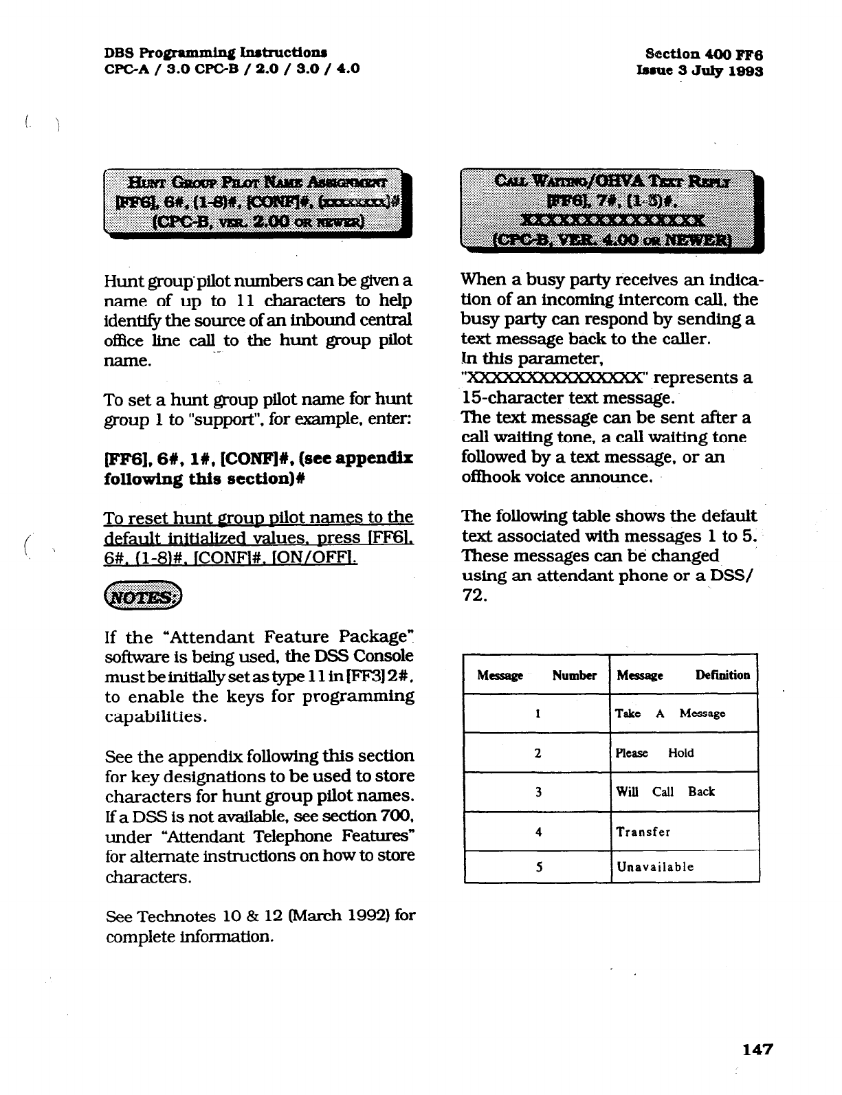
DBS Pro@ammin~ h~tructions 2%ction 400 FF6
CPGA
/ 3.0 CPGB / 2.0 / 3.0 / 4.0 bme3JdylSQ3
Hunt grouppilot numbers can be given a
name of up to 11 characters to help
identify the source of an inbound centraI
office line call to the hunt group pilot
_-
name.
To set a hunt group pilot name for hunt
group 1 to “support”, for wple, enter:
lees], 6#, l#, [CONFlU, (see appendix
following this section)#
To reset hunt
E~OUD Dilot
names to the
default initialized values. Dress IFI?
6#. ll-8l#.
ICONF]#. ION/OFFI,
If the “Attendant Feature Package?
software is being used, the DSS Console
mustbeinit&IIysetastype11i.nFF3)2#.
to enable the keys for programming
capabilities.
See the appendix following this section
for key designations to be used to store
characters for hunt group pilot names.
If a DSS is not available, see section 700.
under “Attendant Telephone Features”
for alternate instructions on how to store
characters.
When a busy party receives an indica-
tion of an incoming intercom call, the
busy party can respond by sending a
text message back to the caller.
.In this parameter,
“p’ represents a
15character text message.
The text message can be sent after a
call waiting tone, a call waiting tone
followed by a text message, or an
oflhook voice announce.
The following table shows the default
text associated with messages 1 to 5.
These messages can be changed
using an attendant phone or a DSS/
72.
I
2 I Please
Hold I
I
3 I
Will Call Back I
4 I
Transfer I
5 I
Unavailable I
See Technotes 10 & 12 (March 1992) for
complete information.
147
Technical Manuals Online! - http://www.tech-man.com
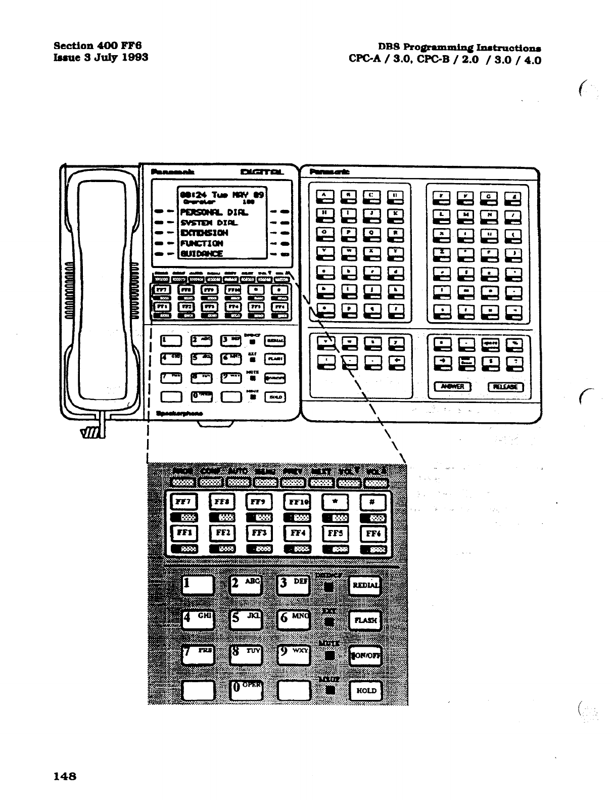
section 400 FF6
Issue 3 July 1993 DBS Rogramming I~tmctions
WC-A / 3.0, CPC-B / 2.0 / 3.0 / 4.0
\ \ \
148
Technical Manuals Online! - http://www.tech-man.com
se!ction 400 FF7
Iasue3
July1993
DBS Ro@axnmin~ hstructions
CPGA/ 3.0.
WC-B / 2.0 / 3.0 /4.0
I
S-7 TOLL RESTRICTION
PROGRAM SETTINGS
CENTRAL OFFICE LINE
TOLL
RESTRICTION
(0fxi?fview)
There are 7 types of toll-restriction that can be used to curtail dialing of certain types
of calls on a central office line. Toll restriction is effective on a line by hne basis per
extension, for the DBS day and night operation modes. The following is a brief
description of each type. -.
Type 0: Full restriction of outbound dialing and inbound calls on a central of&e line
Calls can be answered on a type 0 line when the line is assigned to ring on the restricted
extension..
Tppe 1: Full restriction of outbound dialing on a central off&x line. Inbound ringing
central office lines to all telephones can be answered and/or transferred by a type 1
toll restricted telephone.
me 2: Partial restriction of outbound dialing on a central office line. 3 digit dialing
of 211-911 numbers is restricted according to the program option [FM], l#, (4-l 1).
Outbound dialing of system speed dial numbers is restricted according to the program
option [FFl]. 2#, l#, 4#. Up to fif@ 7 digit numbers that are preset in program option : .,’
[FF7], 6#. are restricted (depending on the setting in [FF7]. l#;. -12#).:Operator. calls
are restricted. International calls are restricted. Toil free dialing is allowed. Inter-digit
timer is set for 6 seconds. Inbound ringing central office lines to all telephones can be
answered and/or transferred by a type 2 toll restricted telephone.
me 3: Full restriction (in default condition) of all access to any area or office code.
Options to allow outbound dialing to selected area codes [FF7], 2#, 3#, and selected
of&e codes [FF7], 3#, 3# to ease full restriction. 3 digit dialing of2 1 l-9 11 numbers
is restricted according to the program option [FF7], l#, (4- 11). Outbound dialing of
system speed dial numbers is restricted according to the program option [FFl], 2#,
l#, 4#. Outbound dialing of up to fifty preset 7 digit numbers in program option [FM],
6#, is restricted (depending on the setting in (FM], l#, 13#). Four specially selected
area codes [FF7]. 4#, (l -4)# will restrict the first 6 digits, by tying each of these special
area codes to a special ofhce code table [FF7], 5#, (l-4)#, 000-999# of restrictions.
International calls are restricted according to program option [FF7]. l#, l#. Operator calls
are restricted. Toll fkee dialing is allowed. Inter-digit timer is set for 6 seconds. Inbound
ringing central ofEke lines to all telephones can be answered and/or transferred by a type
3 toll restricted telephone.
me 4: No restriction (in default condition) of all office code dialing.
Full
restriction
(in default condition) of all area code dialing. Options to allow outbound dialing to
selected area codes [FIV], 2#, 4#. and selected of&e codes
[FM],
3#, 4# to alter default
149
Technical Manuals Online! - http://www.tech-man.com
section 400 FF7 DBS PrognmminqInat~~tio~~
Isaue3Jdy1993 CPGA3.0, WC-B / 2.0/.3.0 / 4.0
restrictions. 3 digit diaIing of 2 1 l-9 11 numbers is restricted according to the program
option [FF7], l#, (4- 11). Outbound dialing of system speed dial numbers is restricted
according to the program option [FFlJ, 2#, l#, 4#. Outbound dialing of up to fifty
preset 7 digit numbers in program option [FM]. 6#, is restricted (depending on the
setting in [FF7], l#, 14#). Four specialIy selected area codes (FF7], 4#, (l-4)# will
restrict the first 6 digits. by tying each of these special area codes to a special of&e
code table [FF7], 5#. (1-4)#, 000-999# ofrestrictions. International caI.Is are restricted
according to program option [FM], 1#. l#. Operator caIIs are restricted. Inter-digit
timer is set for 6 seconds. Inbound ringing centraI office lines to aI.I telephones can be
answered and/or transferred by a type 4 toII restricted telephone.
t’ .
Type 5: No restriction (in default condition) of aII area code diaIing. No restriction (in
defauh condition) of alI office code diahng. Options to restrict outbound dialing to
selected area codes (FF7],2#, 5#, and selected office codes [FF7], 3#, 5# to alter default
restrictions. 3 digit dialing of 2 1 l-9 11 numbers is restricted according to the program
option [FF7], l#, (4- 11). Outbound dialing of system speed dial numbers is restricted
according to the program option [FFl], 2#, l#. 4#. Outbound diaIing of up to fifty
preset 7 digit numbers in program option [FM], 6#, is restricted (depending on the
setting in [FF7], l#, 15#). Four specially selected area codes [FM], 4#, (l-4)# wiII
restrict the tirst 6 digits, by tying each of these special area codes to a special of&e
code table [FF7], 5#, (1-4)#, 000-999# of restrictions. International calls are restricted
according to program option [FM], 1 #, l#. Operator caUs are restricted. Inter-digit
timer is set for 6 seconds. Inbound ringing central office Iines to alI telephones can be
answered and/or transferred by a type 5 toll restricted telephone. c
Type 6: No restriction (in default condition) of dialing to any area or of&e code.
Options to restrict outbound diaIing to selected area codes [FM], 2#, 6##; and selected
ofIke codes [FM], 3#, 6#. 3 digit diaI.ing of 2 11-911 numbers is restricted according
to the program option [FM], l#, (4-l 1). Outbound diaI.ing of system speed dial
numbers is restricted according to the program option [FFl], 2#, l#, 4#. Outbound
dialing of up to Wty preset 7 digit numbers in program option [FF7], 6#, is restricted
(depending on the setting in [FM], l#, 16#). Four speciaIIy selected area codes (FIV),
4#, (1-4)# wiII restrict the first 6 digits, by tying each of these special area codes to a
special office code table [FM], 5#. (1-4)#, OOO-999# of restrictions. International caI.Is
are restricted according to program option [FM], l#, l#. Operator calls are restricted.
ToII free dialing is allowed. Inter-digit timer is set for 6 seconds. Inbound ringing
cent& office lines to a.II telephones can be answered and/or transferred by a type 6
toII restricted telephone.
Type 7: No restrictions to outbound dialing on ah central office Iines in the defaulted
configuratlon.
For ToII Restriction types 3 through 6 operator calIs are allowed in default if FM-
l#- l# is set to l#. The Of&e code tables are used to restrict aII 0 plus diaIi.ng,
the next two digits wiII also be anahzed.
i
150
Technical Manuals Online! - http://www.tech-man.com
DBS Pro@ammhqf hdructiona
CPGA/ 3.O,CPC-B / 2.0 / 3.0 / 4.0 3tction4oom7
Inllt-3JutylQQ3
The dialing of international calls can be
allowed or denied on all central office
lines set with a toll restriction classes of
3-6.
To
restrict dialing of international calls
for central office lines set with a toll
restriction classes of 3 through 6, for
example, enter:
To enable dialing of international calls
for central office lines set with a toll
restriction classes of 3 through 6. for
example, enter:
This progmm option is tied to the System
installation of&e code address [FFl], 2#,
l#, 18#.
When a new outbound call is being
placed on a central of&e line (with class
of service 3 through 6). immediately
after a call has been received on that
line, this option enables toll rest&ion,
To restrict the use of the flash key and
additional digits dialed, to make an
outbound call on a line set for a toll
restriction class of 3 through 6, enter:
(FF71,1#,26,0# _
To allow the use of a flash key to make
a new outbound call on a line set for a
toll restriction class. of 3 through 6,
enter:
jFF7l.l#.2#. l#
If international calls are
allowed,
011
should be allowed in types 3 through 6
offlce code tables.
151
Technical Manuals Online! - http://www.tech-man.com
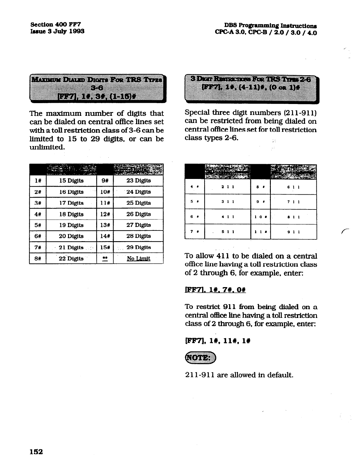
section 400 FF7
lrsue3July1993
DBS Ro@amming Instxuctio~
CFCA3.0,CPGB / 2.0 /S.O / 4.0
The m-urn number of digits that
can be dialed on central offke lines set
with a toll restriction class of 3-6 can be
limited to 15 to 29 digits, or can be
unlimited.
Special three digit numbers (2
1
l-9 11)
can be restricted from being dialed on
central ofke lines set for toll restriction
class types 2-6. ; I
I l# I
15 Digits I 9# I 23 Digits
~s#:D~tglts 1 14# 1 28 Digits I
7#
21Dlgits :‘ 151 ., 29 D&its
86 22.Digits ” JJo L&&
I I
211
Is.1
I”
1 la 911
I
To allow 411 to be dialed on a central
ofilce line having a toll restriction class
of 2 through 6, for example, enter:
JFml. 18.7#.0#
To restrict 911 fkom being dialed on a
central o&e line having a toll restriction
class of 2 through 6, for example, enter:
2 1 l-9 11 are allowed in default.
152
Technical Manuals Online! - http://www.tech-man.com

DBS FVo@mmh. Jndructions section 400 FF7
WC-A / 3.0, CPC-B / 2.0 / 3.0 / 4.0 Insue 3 July 1983
( \
Seven digit toll restriction allows or
denies the dialing of a certain 7 digit
number when a toll restriction type 2
through 6 is set. Reference is made to
[FF7], 6#. That address is for special 7
digit numbers. If there are any entries
set in [FFV];-6#, these entries will be
reviewed before the call continues to be
processed.
To disable the 7 digit table for type 2 toll
restriction, enter:
~,1#12#,0#
To enable 7 digit toll restriction for
type 3, enter: ” :’
pF7l.l# 13#.1#
(FFTj. l#, (12-16)# the 12-16 refers to types 2
through 6 toll restriction.
7 digit toll restriction when enabled will
look at the last seven digits dialed, area
codes which are allowed may be denied
access to specific telephone
numbers such as WX 555- 12 12.
Areacode dialing restrictions on central
oflice lines set for toll restriction types
3-6
are set in this program option.
Telephone users that access a central
ofllce line set to one of these classes of
service, will be allowed or denied access
to a specific area code; -according to the
setting in this option.
To allow dialing to area code 404 on a
central office line set with a toll restriction
class of service of 3, for example, enter:
lr(le7l,2#,3#,404#,0#
To allow dialing to area code 406 on a
centralo~celinesetwitha~~restriction
class of service of 4, for example, enter:
To restrict dialing to area code 212 on a
central of&e line set with a toll restriction
class of service of 5. for example, enter:
Iee7],2#,5#,212#,1#
To restrict dialing to area code 506 on a
central of&e line set with a toll restriction
class of service of 6, for example, enter:
[FF71,2#,6#,508#,1#
153
Technical Manuals Online! - http://www.tech-man.com
&?ction 400 FF7
I.asut3Jtdy1993
To reset area code toll restricllons for
central office lines set as classes 3 and
4 to the default initialized value. Dress
jFF71,2#.
I3 or 4)#. KKIO-999)#. l#. ION/
OFFl.
To reset area code toll restrictions for
central of&e lines set as classes 5 and
6 to the default initialized val e. press
JFF71.2#. (5 or 61#. 1000-9991#k. ION/
OFFI.
This address is tied to the system
installation area code address. (FFl],
2#,
l#, 18#.
DBS~IMXUCtiOM
CPC-A
3.0.
CPCB / 2.0 / 3.0 / 4.0
Oflke code dialing restrictions on central
oflice lines set for toll restriction types 3-
6aresetinthisprogramoption.‘Ikkphone
LlsasthatacJcEss
acentmlofEcehnesetto
oneoftheseclassesofsewi~willbeabwed
or denied accesstoaspecffko&ecode,
accordingtotheseUinginthisoption.
To allow dialing to o&e code 663 on a
centralofkeline setwithatollrestriction
class of sewice of 3. for example. enter:
Iee7],3%,3#,663#,0# ;
f
To restrict dialing to of&e axle 346 on a
centraloBkeline setwithatollrestriction
class of sewice of 4, for example. enter:
Iee7],3#,4#,346#, l#
To restrict dialing to o&e code 261 on a
1 central of&e line set with a toll restriction
class of sewice of 5, for example, enter:
154
Technical Manuals Online! - http://www.tech-man.com
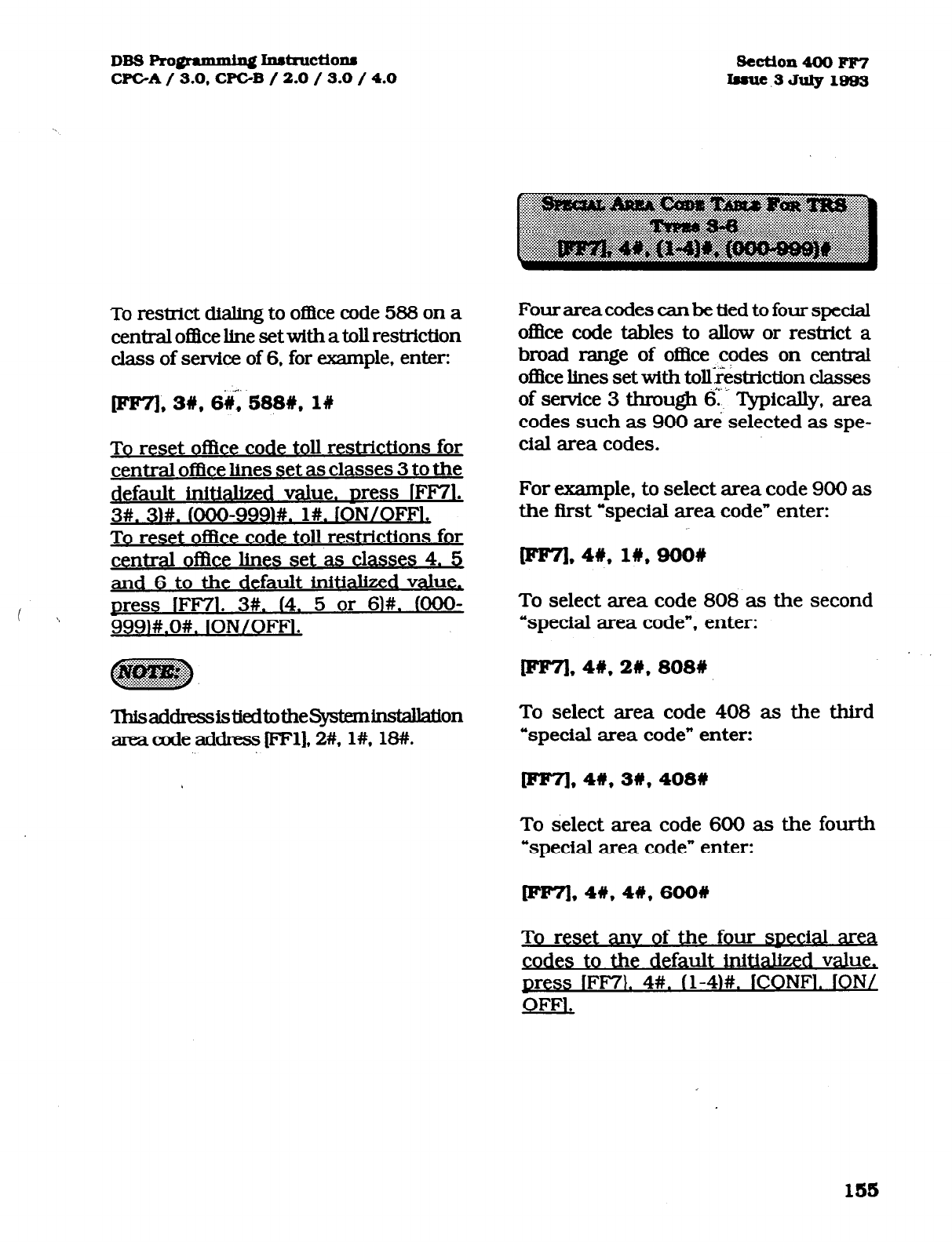
DB3Pro@ammingInstructio~
CPGA/ 3.0, CPC-B / 2.0 / 3.0 / 4.0
To restrict dialing to of&e code 588 on a
central of&e line set with a toll restriction
class of service of 6, for example, enter:
.-.
m, 3#, 6#,
588%. l#
To reset ofike code toll restrictions for
central of&e lines set as classes 3 to the
default initialized value. press IFF71.
3#. 3M. @OO-999)#. l#. ION/OFFL
To reset of&e code toll restrictions for
central ofhce lines s t as classes 4. 5
and 6 to the defaulteinitialized values
press lFF71. 3#. (4. 5 or 61#. fOOO-
9991#.0#. ION/OFFl.
ThisaddressistiedtolheSystcminstallation
area code address pl], 2#, l#, 18#.
Four area codes can be tied to four special
oflice code tables to allow or restrict a
broad range of o&e codes on central
of&e lines set with tollAriction classes
of service 3 through 6’ Typically, area
codes such as 900 are selected as spe-
cial area codes.
For example, to select area code 900 as
the first “special area code” enter:
m,41y,
1#,900#
To select area code 808 as the second
“special area code”, enter:
plq. 4#, 26,808#
To select area code 408 as the third
“special area code” enter:
pFq, 4#, 3#, 408W
To select area code 600 as the fourth
“special area code” enter:
[FF71,4#, 4#,600#
To reset anv of the four special area
codes to the default initialized value,
p ess IFF7). 4#. tl-4M. lCONF1. ION/
OkF, .
lb8
Technical Manuals Online! - http://www.tech-man.com
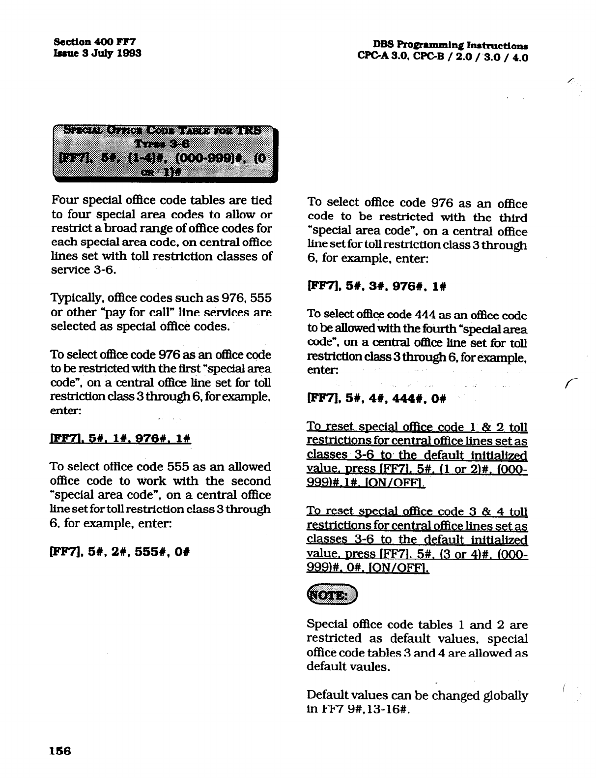
&ction 400 FF7
Iuuc3July1833 DBs~gmnmingInstmctions
CFGA3.0, CPGB / 2.0/.3.0 / 4.0
Four special of&e code tables are tied
to four special area codes to allow or
restrict a broad range of office codes for
each special area code, on central office
lines set with toll restriction classes of
service 3-6.
Typically, office codes such as 976.555
or other *pay for call” line sexvices are
selected as special o&e codes.
To select of&e code 976 as an oflice code
to be restricted with the first “special area
code”, on a central of&x line set for toll
resMction class 3 through 6, for example,
enter:
.5#.
lIy.9768. l#
To select oflIce code 555 as an allowed
office code to work with the second
“special area code”, on a central office
line set for toll restriction class 3 through
6, for example, enter:
[FF71,5#, 2#, 555#, O#
To select of&e code 976 as an office
code to be restricted with the third
“special area code”. on a central office
line set for toll restriction class 3 through
6, for example. enter:
Iee7], SW, 3W, 9761y,
l#
To select of&e code 444 as an of&e code
tobe allowedwiththefourth”specialarea
code”, on a central ofWe line set for toll
restriction class 3 through 6, for example,
enter t-
(FF71,5#, 4#, 4448, on
To reset mecial office code 1 & 2 toll
restrictions for central oflke lines set as
classes 3-6 to, the default initialized
value. Dress lFF71. 5#. I1 or 2M. fOOO-
999M. l#. lON/OFFl.
To reset soecial office cod 3 & 4 toll
restrictions for central officz lines set as
classes 3-6 to the default initialized
value. Dress lFF71. 5#. (3 or 4)#. KM30-
999M. O#. ION/OFFl.
Special office code tables 1 and 2 are
restricted as default values, special
ofike code tables 3 and 4 are allowed as
default vaules.
Default values can be changed globally
in FM 9#, 13- 16#.
156
Technical Manuals Online! - http://www.tech-man.com

DBS Pro@ammh~ h~truction8
CPGA/ 3.0, CPGB / 2.0 / 3.0 / 4.0 section 400 FF7
Issue3JuIy1803
Up to 50 preset 7 digit numbers can be
restricted from being dialed behind all
area codes on central of&e lines set for
toll restriction types 2 through 6. The
identifkation of these numbers are set
in this program option. [FM], l#, (12-
16)#, determines whether the seven digit
number that is dialed is reviewed by
this address.
Toassign5551212asthef%tof50preset
numberstoberestxictedfiombeingdtaled
onacentral office line set for toll restriction
class 2
(assuming [FF7], l#, 12# is set
witi l#), for example. enter:
[FF7),6#,1#,5551212# -
To assign 976- 12 12 as the second of 50
preset nuxnbers to be restricted from
being dialed on a central office line set
for toll restriction class 3 (assuming
[FF7), l#, 13# is setwith l#). forexample,
enter:
m,6#, 2W.97612128
To reset anv of the 50 nreset restricted
7 digit numbers to the default initialized
value. Dress lFF71.6#. (l-50)#. ICONFl,
JON/OFFl.
There are 7 types of toll restriction that
can be used to curtail dialing of certain
types of calls on a central office line.
when the DBS is in the day setting. Toll
restriction is effective on a line by line
basis, per extension. See the overview
at the beginning of this programming
section for a review of each type of toll
restriction.
To set toll restriction on extension port
60
(when the DBS is in the day setting)
for central office line 10 to type 3. for .
example, enter: :; :
To set toll restriction on extension port
22
(when the DBS is in the day setting)
for central office line 5 to type 7, for
example, enter: _
Iep71,7#,22#,5#,7#
To reset central office toll restriction on
am line on anv extension (when the
DBS is in the dav setting). to the default
initialized value. Dress iFF71. 7#. fl-
144)#. (l-64)#. 7#, lON/OFFk
157
Technical Manuals Online! - http://www.tech-man.com
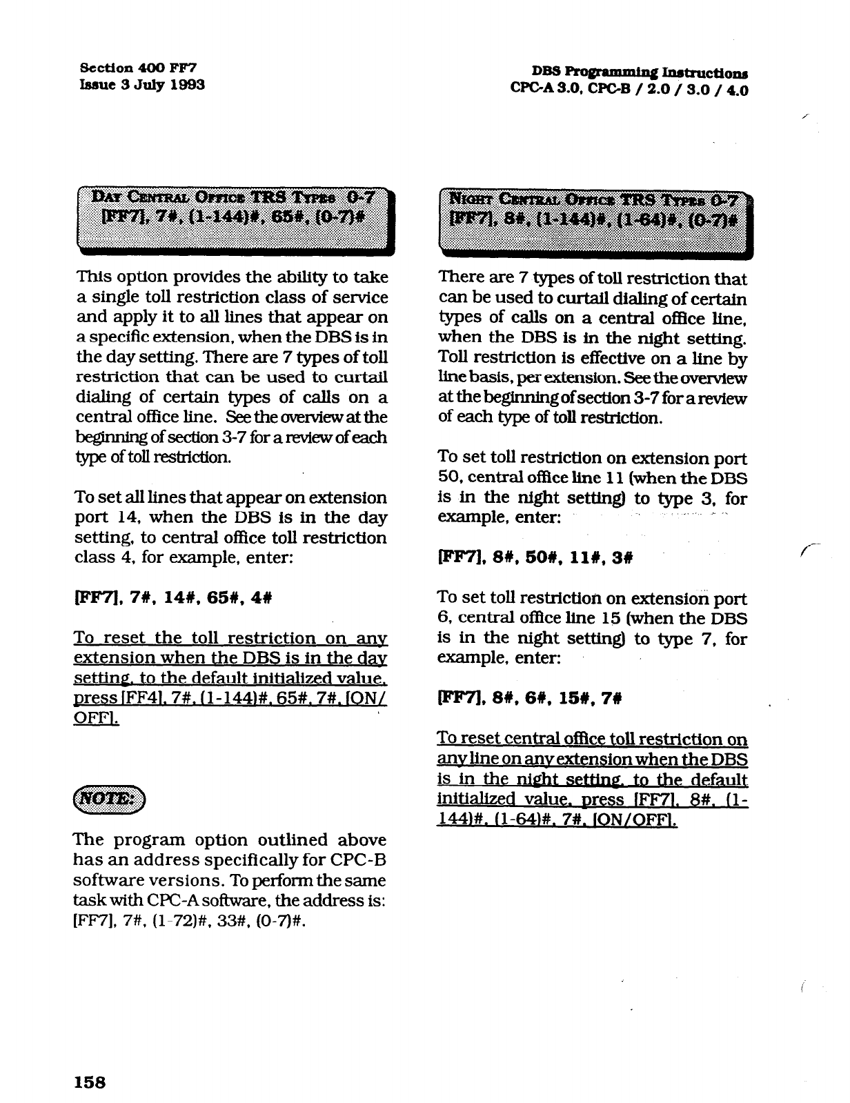
section 400 FF7
Issue3July1993 DB3Frogrammin~~~~ons
CPGA3.0, CPGB / 2.0 / 3.0 / 4.0
This option provides the ability to take
a single toll restriction class of service
and apply it to all lines that appear on
a specific extension, when the DBS is in
the day setting. There are 7 types of toll
restriction that can be used to curtail
dialing of certain types of calls on a
central office line. Seetheovemiewatthe
nofsection3-7forareviewofeach
type of toll mstriction.
To set all lines that appear on extension
port 14, when the DBS is in the day
setting, to central of&e toll restrictfon
class 4, for example, enter:
IIfIF71,7#, 14#,65#,4#
To reset the toll restriction on anv
extension when the DBS is in the dav
setting. to the default initialized value,
press lFF41.7#. (l-1441#. 65#. 7#. ION/
OFFl.
There are 7 types of toll restricUon that
can be used to mrtail dialing of certain
types of calls on a central office lihe,
when the DBS is in the night setting.
Toll restriction is effective on a line by
line basis, per extension. See the overview
at the beginning of section 3-7 for a review
of each type of toll restriction.
To set toll resUicUon on extension port
50,
central of&e line 11 (when the DBS
is in the night setting) to type 3, for
example, enter:
m7l,8#,50#,11#,3# /-
To set toll restriction on extension port
6,
central of&e line 15 (when the DBS
is in the night setting) to type 7, for
example, enter:
IFF7),8U,6#,15#,7#
To reset central of&e toll restriction on
anvline on anvextensionwhen the DBS
is in the night setting. to the default
initialized value. Dress lFF71. 8#. (l-
144M. IL-64M. 7#. ION/OFFl.
The program option outlined above
has an address specifically for CPC-B
software versions. To perform the same
task with WC-A software, the address is:
[FM], 7#, (l-72)#. 33#, (0-7)#.
158
Technical Manuals Online! - http://www.tech-man.com
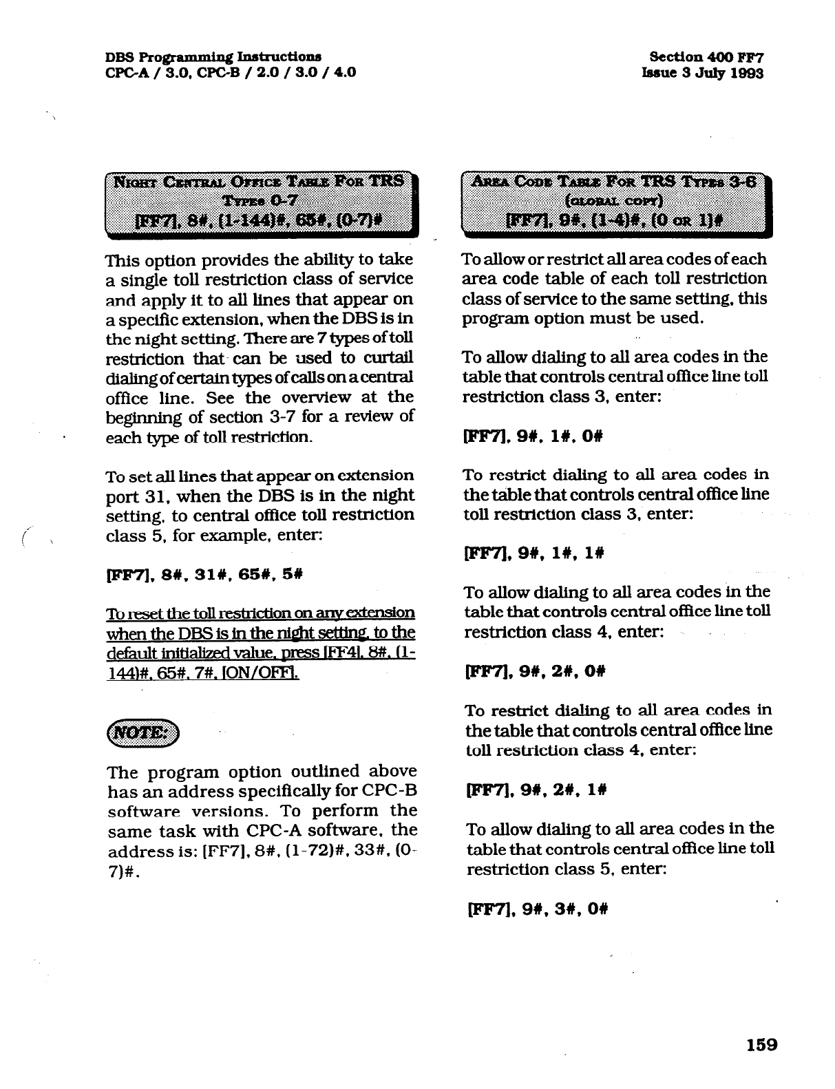
DBSPro@ammh&jInstructio~
CFCA/
3.0,
CPC-B / 2.0 / 3.0 /4.0
section 400 FF7
Issue3July1993
This option provides the ability to take
a single toll restriction class of service
and apply it to all lines that appear on
a specific extension, when the DBS is in
the night setting. There are 7 types of toll
restriction that. can be -used to curtail
diali.ngofcertaintypesofcallsonacentral
office line. See the overview at the
beginning of section
3-7
for a review of
each type of toll restriction.
To set aJl lines that appear on extension
port
31,
when the DBS is in the night
setting, to central oflice toll restxiction
c \ class 5. for example, enter:
IFF7],8#,31#,65#,5#
ToresetthetollrestHctiononanve~tension
whentheDBSisintheniQhtsetUng.tothe
default initialized value.
DIFSS f’FF41.8#. (I-
144]#. 65#. 7#. ION/OFFl.
The program option outlined above
has an address specifically for CPC-B
software versions. To perform the
same task with CPC-A software, the
address is: [FF7], 8#. (l-72)++. 33#. (O-
7)#.
To allow or restrict all area codes of each
area code table of each toll restriction
class of service to the same setting, this
program option must be used.
To allow dialing to all area codes in the
table that controls central office line toll
restriction class 3, enter:
[Irp'/l,9#,16,0#
To restrict dialing to all area codes in
the table that controls central office line
toll restriction class 3, enter:
Iee7],9#,1#,1#
To allow dialing to all area codes in the
table that controls central office line toll
restriction class 4, enter:
To restrict dialing to all area codes in
the table that controls central ofhce line
toll restriction class 4, enter:
To allow dialing to all area codes in the
table that controls central office line toll
restriction class 5, enter:
159
Technical Manuals Online! - http://www.tech-man.com
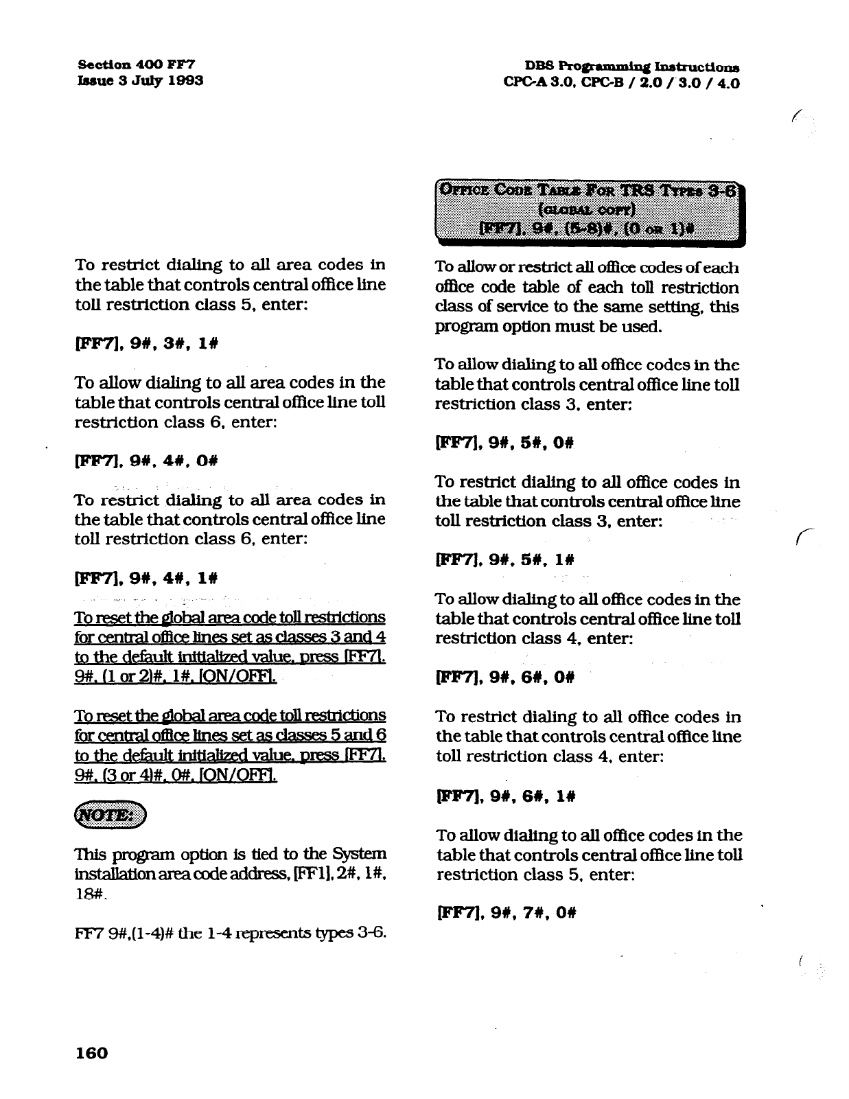
Section 400 FF7
laaue3July1993 DB!3Progfaxmhg~~tio1~
CPGA3.0. CPC-B / 2.0 /.3.0 / 4.0
f
To restrict dialing to all area codes in
the table that controls central office line
toll restriction class 5, enter:
To allow dialing to all area codes in the
table that controls central office line toll
restriction class 6, enter:
To allow or restrict all o&e codes of each
of&e code table of each toll restriction
class of sewice to the same setting, this
program option must be used.
To allow dialing to all of&e codes in the
table that controls central of&e line toll
restriction class 3, enter:
[p’esrl, 9#, 5#, O#
To r&&& dialing to all area codes in
the table that controls central ofike line
toll restriction class 6. enter:
IFe7].9#,4#,
l#
_ . , .
Toresetthe~ohalareacodetollrekicUons
forcentraloEkeIinessetasclasses3and4
to the defkult inWaked value. press iFF’?‘l
.
9#. (1 or 21#. l#. ION/OFFS.
To reset the piobal area code toll restrictions
forcentralofflixhwssetas&sses5and6
to the defkult initiahzed value.
DRSS m .
9#. 13
or 41#. O#. ION/OFFI.
ThisprogmmoptionistiedtotheSystem
inst.&Won area code address, (FFl]. 2#. l#,
18#.
To restrict dialing to all of&e codes in
the table that controls central office line
toll restriction class 3. enter:
Ir(le71,9#,5#,1#
To allow dialing to all of&e codes in the
table that controls central 0Bice line toll
restriction class 4, enter:
To restrict dialing to all of&e codes in
the table that controls central office line
toll restriction class 4, enter:
(pIIr7.91y.66, l#
To allow dialing to all office codes in the
table that controls central o&e line toll
restriction class 5, enter:
f
FIT 9#,(1-4)# the l-4 represents types 3-6.
160
Technical Manuals Online! - http://www.tech-man.com
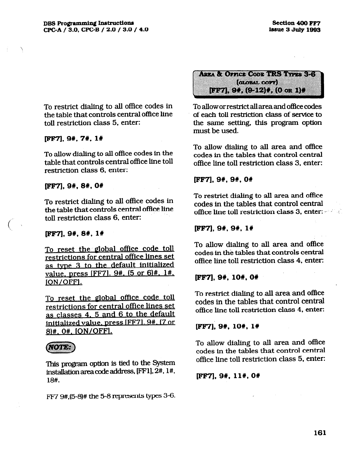
DBS Pro@.ammhg Insbuctio~
CPGA/ 9.0, WC-B / 2.0 / 3.0 / 4.0 section 400 FF7
Issue3July19fl3
To restrict dialing to all office codes in
the table that controls central office line
toll restriction class 5, enter:
[FF71,9#,7#, 1Q
To allow dialing to all office codes in the
table that controls central office line toll
restriction class 6, enter:
Toalloworrestrictallareaandofhcecodes
of each toll restriction class of service to
the same setting, this program option
must be used.
To allow dialing to all area and office
codes in the tables that control central
office line toll restriction class 3, enter:
[FF71,9#,8#,0#
To restrict dialing to all o&e codes in
the table that controls central office line
toll restriction class 6, enter:
To reset the global office code toll
restrictions for central office lines set
as tvne 3 to the default initialized
value. Dress IFF71. 9#. (5 or 6M. I#,
]ON/OFFl.
To
reset the global office code toll
restrictions for central office lines set
as classes 4. 5 and 6 to the default
initialized value. Dress IFF71.9#. 17 or
$I#. O#. fON/OFFl.
This pro@m option is tied to the System
instakUonareacodeaildress, FF1],2#, l#.
18#.
To restrict dialing to all area and office
codes in the tables that control central
of&e line toll restriction class 3, enter: --. ; :‘
rF-e71,9#*9#* l#
To allow dialing to all area and office
codes in the tables that controls central
office line toll restriction class 4. enter:
wF7l,S#, lO#,O#
To restrict dialing to all area and office
codes in the tables that control central
office line toll restriction class 4, enter:
~,9#,10#, 1w
To allow dialing to all area and oEice
codes in the tables that control central
of&e line toll restriction class 5, enter:
161
Technical Manuals Online! - http://www.tech-man.com
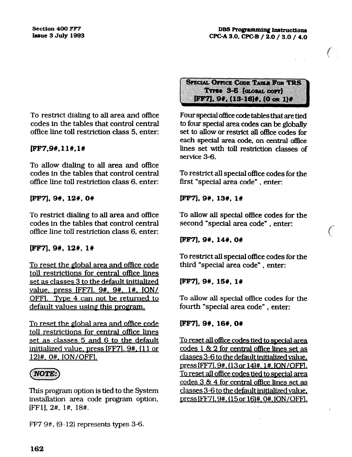
section 400 FP7
Issue3July1993 DB3 Ro@am&q I.ustructio~
CPGA 3.0, CF’GB / 2.0 /.B.O / 4.0
To restrict dialing to all area and of&e
codes in the tables that control central
of&e line toll restriction class 5, enter:
To allow dialing to all area and office
codes in the tables that control central
office line toll restriction class 6. enter:
leP7],9#,12#, ow
To restrict dialing to all area and of&e
codes in the tables that control central
office line toll restriction class 6. enter:
Fourspedalof3cecodetablesthataretied
to four special area codes can be globally
set to allow or restrict all of&e codes for
each special area code, on central of&e
lines set with toll restriction classes of
service 3-6.
To restrict all special office codes for the
first “special area code” , enter:
[FF71,9#,13#, l#
To allow all special office codes for the
second “special area code” , enter:
pw7],9#,12#,1#
To
reset the alobal area and of&e code
toll restrictions for central ofIke lines
set as classes 3 to the default initialized
value. Dress IFF71. 9#. 9#. l#. ION/
OFFl. Tide 4 can not be returned to
default values usin@ this Drogram.
To reset the mobal area and office code
toll restrictions for central office lines
set as classes 5 and 6 to the default
initialized value. Dress lFF7l. 9#. (11 or
12)#. O#. ION/OFFi.
‘Ihis program option is tied to the System
installation area code program option,
[FFl], 2#, l#, 18#.
To restrict all special of&e codes for the
third “special area code” , enter:
rFF7L 9#,15#,1#
To allow all special office codes for the
fourth “special area code” , enter:
To reset all of&e codes tied to swxial ama
codes 1 & 2 for central of&e lines set as
classes 3-6 to the default i.nitialized value,
press lFF71.9#. (13or 141#. l#. lON/OFFl.
To reset all of&e codes tied to special area
codes 3 & 4 for central of&e lines set as
classes 3-6 to the default initialized value,
press IFIV1.9#. (15or 16)#. O#. lON/OFFl.
F’F7 9#. (9-12) represents types 3-6.
162
Technical Manuals Online! - http://www.tech-man.com
DBS Pro@=amming lnatructtonr
CPC-A / 3.0, CPC-B / 2.0 / 3.0 / 4.0
FF7 9#, (13- 16) represents special
office code tables 1-4.
Default values for special office code tables
Special office code table 1 All Denied
Special oflice code table 2 AU Denied
Special office code table 3 All Allowed
Special office code table 4 AllAllowed
section 400 FF7
Imue3July1999
163
Technical Manuals Online! - http://www.tech-man.com
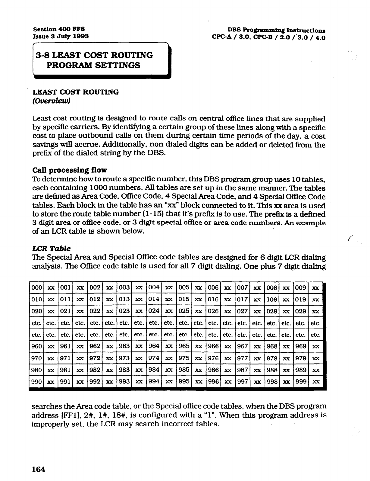
Sect.ion 400 FFS
bsue3
July 1093
DBS Rogmmmin~ Instruction
WC-A
/ 3.0, CPGB / 2.0 /.3.0 / 4.0
LEAST COST ROUTING
t-d
Least cost routing is designed to route calls on central o&e lines that are supplied
by speciffc carriers. By identifying a certain group of these lines along with a specific
cost to place outbound calls on them during certain time periods of the day. a cost
savings will accrue. Additionally, non dialed digits can be added or deleted from the
prefI.x of the dialed string by the DBS.
Call processing flow
To determine how to route a specific number. this DBS program group uses 10 tables,
each containing 1000 numbers. All tables are set up in the same manner. The tables
are defined as Area Code, Office Code, 4 Special Area Code, and 4 Special Office Code
tables. Each block in the table has an “z& block connected to it. This xx area is used
to store the route table number (l- 15) that it’s pre& is to use. The pre& is a defined
3 digit area or o&e code, or 3 digit special office or area code numbers. An example
of an LCR table is shown below.
LCR Table
The Special Area and Special OfRce code tables are designed for 6 digit LCR dialing
analysis. The Office code table is used for all 7 digit dialing. One plus 7 digit dialing
xx 007 xx
TF
xx 017 xx
etc.
<
etc.
008 xx
+
108 xx
#
lxx 001 xx
xx 011 xx
lxx 021 xx
004
014
024
etc.
etc.
964
974
984
994
005 xx 006
015 ZM 016
025 xx 026
etc. etc. etc.
etc. etc. etc.
965 xx 966
975 xx 976
985 xx 986
995 xx 996
xx
xx
xx
etc.
xx
zuc
xx
etc.
etc.
xx
xx
xx
xx
012
022
etc.
020
etc.
0281 xx
~ etc. etc. etc.
=tt
etc. etc. etc.
etc.
etc.
I
etc.
etc. etc. etc. etc. etc.
I I etc. etc.
I etc.
etc.
xx
960
962 .xx 19671 xx ‘968) xx 969 xx 19611 xx
xx I9711 xx
xx 19771 xx
,978( xx
xx 1981) xx xx 19871 xx 19881 xx 989
xx 1991) xx xx 1997) xx 19981 xx
searches the Area code table, or the Special office code tables, when the DBS program
address [FFl], 2#, l#, 18#. is configured with a “1”. When this program address is
improperly set, the LCR may search incorrect tables.
164
Technical Manuals Online! - http://www.tech-man.com
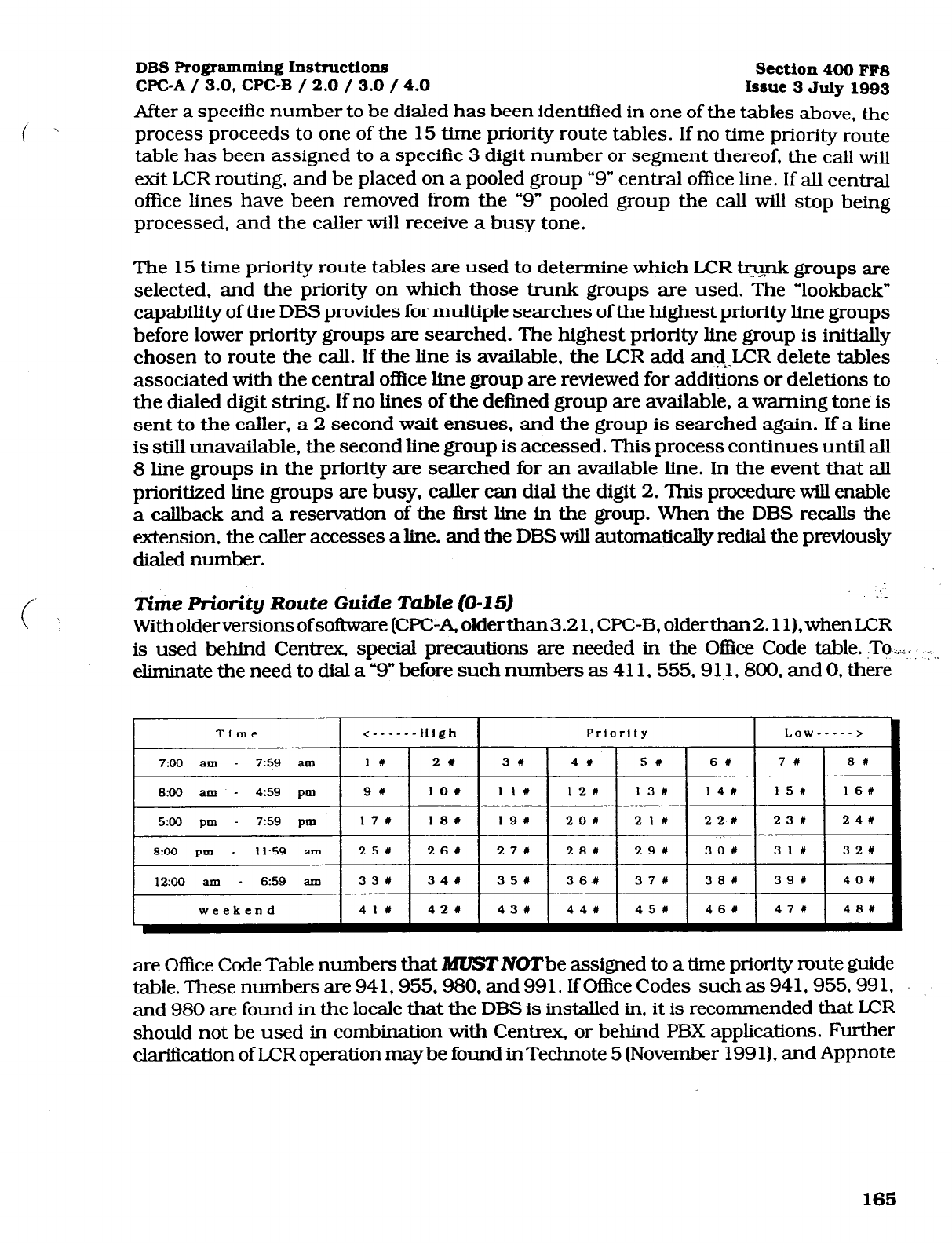
DBS Programming
Instructions
Section400 FFS
WC-A / 3.0, CPC-B / 2.0 / 3.0 / 4.0 Issue 3 July 1993
After a specific number to be dialed has been identified in one of the tables above, the
process proceeds to one of the 15 time priority route tables. If no time priority route
table has been assigned to a specific 3 digit number or segment thereof, the call will
exit
LCR
routing, and be placed on a pooled group “9” central office line. If all central
office lines have been removed from the “9” pooled group the call will stop being
processed, and the caller will receive a busy tone.
The 15 time priority route tables are used to determine which
LCR w groups a.rtz
selected, and the priority on which those trunk groups are used. The “lookback”
capability of the DBS provides for multiple searches of the highest priority line groups
before lower priority groups are searched. The highest priority line group is initially
chosen to route the call. If the line is available, the LCR add and-,.LCR delete tables
associated with the central oflice line group are reviewed for additions or deletions to
the dialed digit string. If no lines of the defined group are available. a warning tone is
sent to the caller, a 2 second wait ensues. and the group is searched again. If a line
is still unavailable, the second line group is accessed. This process continues until all
8 line groups in the priority are searched for an available line. In the event that all
prioritized line groups are busy, caller can dial the digit 2. This procedure will enable
a callback and a reservation of the first line in the group. When the DBS recalls the
extension, the caller accesses a line, and the DBS will automatically redial the previously
dialed number.
Time Priority Route Guide Table (0-Z 5)
With
older versions of software (WC-A, olderthan3.2 1, WC-B, older than 2.11). when LCR
is used behind Centrex, special precautions are needed in the O&e Code table. -To+. ,:,.
eliminate the need to dial a “9” before such numbers as 411. 555,91.1,800. and 0, there
weekend 44# 1 45# 1 46W 1 47# 48#
are Oflice Code Table numbers that MUSTlVOTbe assigned to a time priority mute guide
table. These numbers are 94 1,955,980, and 99 1. If OfEke Codes such as 94 1.955.99 1,
and 980 are found in the locale that the DEE is installed in, it is recommended that LCR
should not be used in combination with Centrex, or behind FBX applications. Further
clari&ation of LCR operation maybe found inTechnote 5 (November 1991). and Appnote
165
Technical Manuals Online! - http://www.tech-man.com

Section 400 FFS
Issue 3 July 1993
When an outbound central o&e line is
accessed to make a call, in a DBS set with
Least Cost Routing, the DBS searches one
of 15 preprogrammed routing tables for
the least expensive central oflIce line,
based on time of day and cost of the hne.
Toll restriction settings for the line are
checked, and the number is then
outpulsed.
To add 203 to route. using time priority
table 1, for example, enter:
FFS], I#, I#, 2031, l#
To add 5 16 to route, using lime priority
table 2, for example. enter:
[ee8], lW, 2W, 5166, l#
To remove 409 from time priority table
three, for example, enter:
p7F8],
lW, 31y.4091, O#
DBS Pro@ammhq Instruction
WC-A / 3.0, WC-B / 2.0 / 3.0 / 4.0
To remove 609 from time priority table
four, for example, enter:
Df’F8],
l#, 4%. 609#, 08
To reset the LCRArea Code tables to the
default initialized value. Dress IFF78L
l#. (l-15)#. (OOO-999)#. O#. ION/OFFl.
The time priority route guide table option
found at address: [FFS], 5#. (l-15)#, (l-
4$3)#,
(l-8)#.
must be set.
Once a line has been accessed through
LCR, the [FLASH] operation will not
work.
All area code numbers must be pointed
td a specifh time priority table and
enabled in order for LCR to
automatically route the call.
When executing changes in this address,
a “1” entry signifies addition to the table,
and a “0” signifies the o&e code is not
part of the table.
I
166
Technical Manuals Online! - http://www.tech-man.com
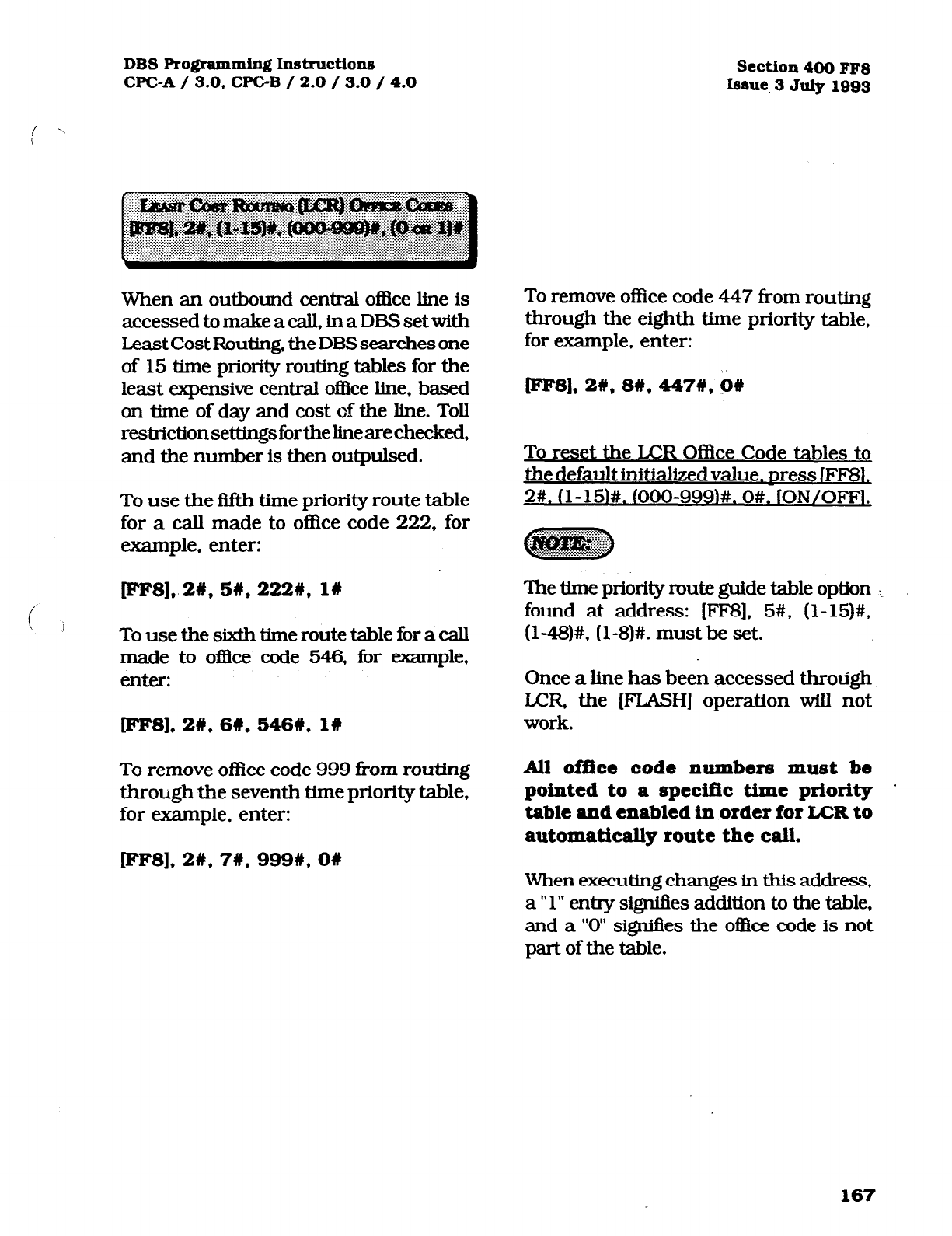
DBSRo~ammingIns~ctions
CFC-A / 3.0, WC-B / 2.0 / 3.0 / 4.0 Section4OOFF8
Issue 3July1993
When an outbound central office line is
accessed to make a call, in a DES set with
Least Cost Routing, the DBS searches one
of 15 time priority routing tables for the
least expensive central of&e line, based
on time of day and cost of the line. Toll
restrictionseUingsfortheknearechecked,
and the number is then outpulsed.
To use the fifth time priority route table
for a call made to office code 222, for
example, enter:
fFFS], 2#, 5#, 222#, 1W
! j
To use the sixth time route table for a call
made to of&e code 546, for example.
enter:
cples], 2W, 66, 5461, l#
To remove office code 999 from routing
through the seventh time priority table,
for example, enter:
lFF8]* 2w, 7#, 999n, ow
To remove of&e code 447 from routing
through the eighth time priority table,
for example, enter:
[eesl, 2#, 8#, 447#,
‘o#
To reset the LCR Office Code tables to
the default initialized value. Dress IFF8L
2#. (l-151#.
OXKb999)#. O#. lON/OFFI.
The time priority route guide table option . . .
found at address: [FF8], 5#, (l-15)#,
(l-48)#, (l-8)#. must be set.
Once a line has been accessed through
LCR the [FLASH] operation will not
work.
All office code numbers must be
pointed to a specific time priority .
table and enabled in order for
LCR
to
automatically route the call.
When executing changes in this address.
a ” 1” entry signifies addition to the table,
and a “0” sigr&es the o&e code is not
part of the table.
167
Technical Manuals Online! - http://www.tech-man.com
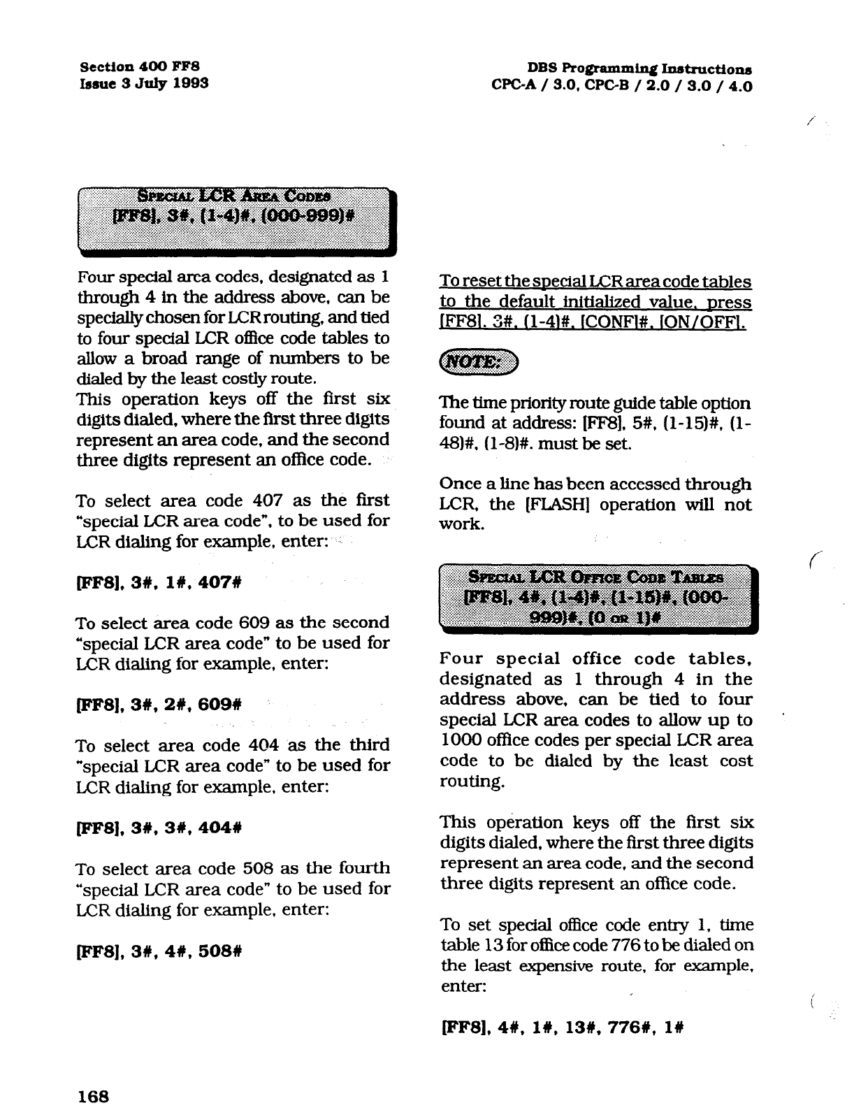
Section 400 FF8
Issue 3 Juiy 1993 DBS Programming Instruction
CPGA / 3.0, CPGB / 2.0 / 3.0 / 4.0
Four special area codes, designated as
1
through 4
in the address above, can be
specially chosen for LCR routing. and tied
to four special LCR of&e code tables to
allow a broad range of numbers to be
dialed by the least costly route.
This operation keys off the first six
digits dialed. where the first three digits
represent an area code, and the second
three digits represent an of&e code.
To
select area code 407 as the first
“special LCR area code”, to be used for
LCR
dialing for example, enter:
[ees], 3#, I#, 407#
To select area code 609 as the second
“special LCR area code” to be used for
LCR dialing for example, enter:
[IrIF8]. 3#, 2#, 609#
To select area code 404 as the third
“special LCR area code” to be used for
LCR dialing for example. enter:
FF8]* 3#, 3#, 4048
To select area code 508 as the fourth
“special LCR area code” to be used for
LCR dialing for example, enter:
PF8], 3W, 4#, 508U
To reset the snecial LCR area code tables
to the default initialized value. Dress
]FFSl. 3#. (l-4)#. (CONFl#. (ON/OFFl.
‘The the priority route guide table option
found at address: [FF8], 5#, (l-15)#, (l-
48)#, (l-8)#. must be set.
Once a line has been accessed through
LCR, the [FLASH] operation will not
work.
Four special office code tables,
designated as 1 through 4 in the
address above. can be tied to four
special LCR area codes to allow up to ’
1000 office codes per special LCR area
code to be dialed by the least cost
routing.
This operation keys off the first six
digits dialed, where the first three digits
represent an area code, and the second
three digits represent an office code.
To set special office code entry 1, time
table 13 for office code 776 to be dialed on
the least expensive route, for example,
enter:
lep8], 4#, l#, 13#, 7768, l#
168
Technical Manuals Online! - http://www.tech-man.com
DBS Ro@ammiq Inst~ctions
cpc-A
/ 3.0, CPC-B / 2.0 / 3.0 / 4.0 Section 400 FF8
lsstie 3 July 1993
To set special o&e code entry 2, time
table 5 for office code 392 to be dialed on
the least expensive route, for example,
enter:
~F8],4#,2#y,5#,392#, l#
To set special ofke code entry 3, time
table 15 for of&e code 248 to be dialed on
the least expensive route, for example,
enter:
pF8],4#, 3s. lS#, 248#, l#
i '
To reset the snecial LCR office code
tables to the default initialized value,
press lFF81. 4#. (l-4M. (l-15)#, fOOO-
999)#. O#. ION/OFFI.
When executing changes in this address,
a “1” entry si@es addition to the table,
and a “0” signifies the o&e code is not
part of the table.
Since central of&e line costs can vary
by time of day, when least cost routing
is being used outbound calls will be
automatically placed on difkrent central
office line groups depending on the time of
day. This option provides for this.
For example, to use time route table
1, priority 1, LCR line group 1 for
outbound calls placed by the least
cost routing method, enter:
pF8],5#, l#, l#, l#
For ewmple, to use ‘time route table 2,
priority 9, LCR line group 6 for outbound
calls placed by the least cost routing
method, enter:
W8L 5#,2#,9#, 6#
For example, to use time route table 15,
priority 17, LCRline group 4foroutbound
calls placed by the least cost routing
method, enter:
FF8], 5#, 15#, 17#,4#
169
Technical Manuals Online! - http://www.tech-man.com
Section 400 FFS
Issue 3 July 1993 DBS Ro@-ammin~ Instmctio~
WC-A / 3.0, CPGB / 2.0 / 3.0 / 4.0
To reset anv CO line
DOLID
Dosition in
anv time Drioritv route table to the
default initialized value. Dress IFF8L
5#. (l-15)#. (l-48)#. fCONF1. ION/OFFl.
The 15 time priority route tables are each
divided into 6 preset time periods, with 8
’ priority positions in each time period for
LCRhegroupassignme.nts.‘Ihesixpmset
timepcriodsareasfollows:
1. 7:00 am to 7:59 am, positions l-8
2. 8:00
am to 4:59pm positions 9-16
3. 5:00
pm to 7:59 pm, positions 17-24
4.8:OO
pm to 11:59 am, positions 25-32
5.12:OO
art-t to 6:59 am, positions 33-40
6.
WEEKEND, positions 41-48
See feature options [FFl], 2#, l#. 3#,
(System
setting for LCR), and [FF8], 6#,
&CR Trunk group table.)
See Time Priority Route Guide Tables
(1- 15), for priority numbers 1 through
48
on page 133.
/‘.
‘Iheu.seofI.CRrequhspnxietermhed I.CR
line @mp to be pri01MM awordhgto the
cost of line(s). ‘Ihe.xx are 8 gmups, and each
group has 8 positions for central ofIke lines.
Once the central oflice line priorities have
bWle&lblish~these~Rgmups~
inserted in the time priority muk g&de
tables, so that predetermined ER @oups
willbeutilizeddurhgeachpresetthneperiod
for outbound calling.
To set up LCR group 1, position 1 with
central office line 16. for example, enter:
[eF8],6#, I#, I#, 16#
To set up LCR group 2, position 1 with
central o&e line 3, for example, enter:
lFF8], 6#, 2#, lW, 36
To set up LCR group 3, position 2 with
central office line 6, fdr example, enter:
lFF81, 6#, 3#,2#,6#
To set up L.CR group 4, position 5 with
central of&e line 64, for example, enter:
[ee81,
6W.4#, 5#,64#
To set up LCR group 5, position 6 with
central of&e line 12, for example, enter:
F'FSI, 6#,5#, 6W, 12W
170
Technical Manuals Online! - http://www.tech-man.com
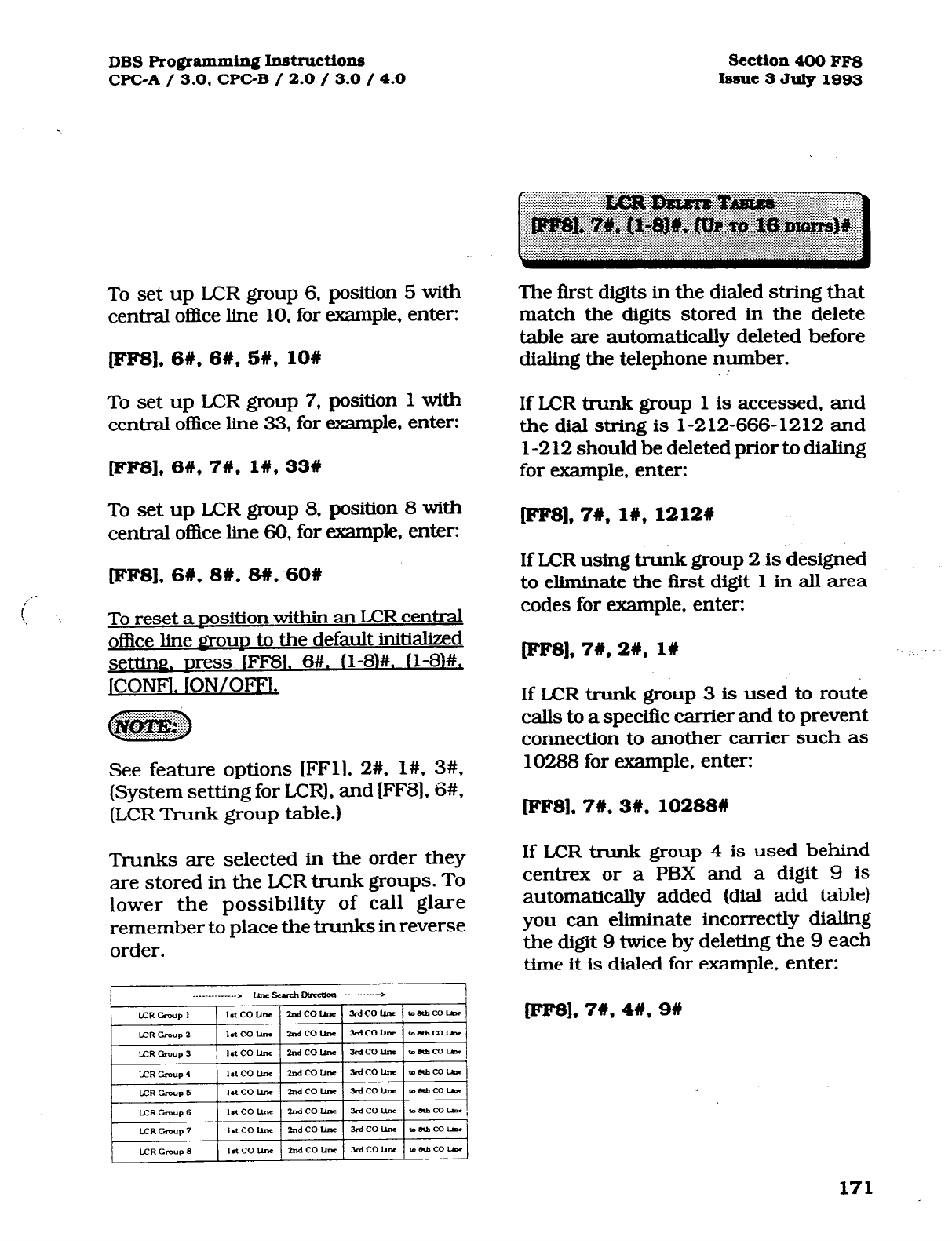
DBS Programming Inst~ctions
WC-A
/ 3.0,
CPGB / 2.0 / 3.0 / 4.0
Section4OOFF8
Issue 3 July 1993
To set up LCR group 6, position 5 with
central of&e line 10, for example, enter:
[IfIFs]. 6W, 6W. SW, 109
To set up LCR.group 7, position 1 with
central of&e line 33, for example, enter:
[FFS], 6#,7#. 1#,33#
To set up ICR group 8, position 8 with
central of&e line 60, for example, enter:
pF8],6#, 8#,8#,60#
To reset a nosition within an ICR central
office line
Q'~OUD
to the default initialized
setting. mess lFF81. 6#. (l-8)#. (l-W+,
]CONFl. ION/OFFl.
See feature options [FFl], 2#, l#, 3#.
(System setting for LCR), and (FF8], 6#,
(LCR Trunk group table.)
Trunks are selected in the order they
are stored in the LCR trunk groups. To
lower the possibility of call glare
remember to place the trunks in reverse
order.
The first digits in the dialed string that
match the digits stored in the delete
table are automatically deleted before
dialing the telephone number.
If LCR trunk group 1 is accessed, and
the dial string is 1-212-666-1212 and
l-2 12 should be deleted prior to dialing
for example, enter:
[eesl, 7W, I#, 12124
If LCR using trunk group 2 is designed
to eliminate the first digit 1 in all area
codes for example. enter:
[FFs1,7#,2#, 16
If LCR trunk group 3 is used to route
calls to a specific carrier and to prevent
connection to another carrier such as
10288 for example, enter:
[FFS), 7W.3W.102888
If LCR trunk group 4 is used behind
centrex or a PBX and a digit 9 is
automatically added (dial add table)
you can eliminate incorrectly dialing
the digit 9 twice by deleting the 9 each
time it is dialed for example, enter:
[IrIrs], 7w, 4#, 9#
171
Technical Manuals Online! - http://www.tech-man.com

Secti0n400FF8
Issue 3
Juiy 1993
If LCR trunk group 5 is a direct Tl
access line to another facility in a differ-
ent area code such as 7 14, and the digit
string 714 should not be dialed for
example, enter:
[eesl,7#, 5#, 714W
To reset the LCR delete tables to the :,
default initialized value, Dress lFF8L
7#. (l-8)#. ICONFl. ION/OFFl. .:
^
,.
Digit Delete Tables are matched to the
LCR trunk groups. Each time one of
these groups are accessed the dial
delete table is checked.
DBS Rogrammb~ lnst~~tions
WC-A
/ 3.0.
CPGB /
2.0 / 3.0 /4.0
Digits in the dialed stringthat are needed
to be outpulsed after a central of&e line
has been seized (such as access codes),
are automatically added before the dialed
telephone number is outpulsed on the
central of&e line. This option allows for
the addition of digits.
If LCR line group 1 is to be accessed.
and the digit string 10288 is to be added
before the dialed number is outpulsed
for example. enter:
@W8],8#, l#, 10288#
If LCR trunk group 2 is to be accessed,
and you want to add the digit 1 before all
long distance numbers dialed for
example, enter:
lees], SW, 2#, l#
If LCR trunk group 3 is to be accessed,
and the digit 9 is to be added before the
dialed number is outpulsed for example,
enter:
P'FS], 8#, 3#, 9#
If LCR trunk group 4 is to be accessed,
and the digit string 8 is to be added
before the dialed number is outpulsed
for example. enter:
[FF81, SW, 4U, SW , I
172
Technical Manuals Online! - http://www.tech-man.com
DBS Programming Instructions
CPC-A / 3.0, CPC-B / 2.0 / 3.0 / 4.0
To reset the LCR add tables to the
default initialized value. Dress rFF8L
8#. (l-8)#. lCONF1. ION/OFFl.
.‘.
If digits are being added and deleted
from the same CO line group. the DBS
will delete digits first, then add digits.
5 ,
Section 400 FFS
Issue 3 July 1993
173
Technical Manuals Online! - http://www.tech-man.com

section 400 FFQ
Issue 3 July 1993
,
3-9 COPY PROGRAM
SETTINGS
DBS Ro@ammiq Instructione
WC-A 3.0, CPGB / 2.0 / 3.0 / 4.0
/
To copy all the attributes of one central
office line to another, this option is
used. Copying must be done on aline by
line basis. The first line number of this
address is the source line being copied,
the second line number is the target
destination.
To copy the attributes of central office
line port 1 to that of central office line
port 5, for example, enter:
To copy the attributes of central office
line port
7
to that of central office line
port 3, for example. enter:
To copy aJl the attributes of one extension
to another, this option is used. Copying
must be done on an extension by
extension basis. The first extension
port number of this address is the
source extension being copied, the
second extension port number is the
target destination.
To copythe attributes oftiension port 10
to that of extension port 5. for example,
enter:
IFF9J,2#,10#,5##
To copy the attributes ofmension port70
to that of extension port 3, for example,
enter:
p9],1#.7#,3## pF9]* 2#,70#,3##
There is no default initialized value for
this ontion.
Using this address to copy central office
line attributes results in the copying of
all attributes for the line except the
private line attribute.
lke second # a&r the second central oflIce
lineentxyisapartoftheproglamsequence,
which confhns the copy action.
There is no default initialized value for
this ODtion.
Using this address to copy extension
attributes results in the copying of all
attributes including toll restriction
for an extension except the extension
number, telephone type, station
lock-out code, and EM 24 port
number (BLF port setting).
The second # after the second extension
entry is a part of the program sequence.
which confIrms the copy action.
f
174
Technical Manuals Online! - http://www.tech-man.com
DBS Programming Instruction
WC-A / 3.0 CPGB / 2.0 / 3.0 / 4.0
To copy all the attnbtrtes of one extensions
LED FF keys to another, this option is
used. Copying must be done on an
extension by extension basis. The first
extension port number of this address
is the FF key source extension being
copied, the second extension port number
istheFFkeytargetextensionportnumber.
To copy the LED FF key attributes of
extension port 2 to that of extension
port 5, for example, enter:
[pF9]*3#,2#,5##
To copy the LED FF key attributes of
extension port 6 to that of extension
port 10, for-example, enter:
Dres],3#,6#, lO##
There is no default initialized value for
this ontion.
The options to the FF key copypro@am
arethatoNLytheLEDFFkeypn@xmMg
canbecopied.NonLEDFFkeysettingswill
not be copied. The second # after the
second extension entry is a part of the
program sequence, which conGms the
copy action.
section 400 FF9
Issue 3 July 1992
When copying the FF keys of a phone to
another that is in the default condition,
the originally assigned keys must first be
cleared. This is done in address [FFS],
(l-144)#, (l-24)#.
A quick way to accomplish copying the
same FF key settings (that are diBerent
than the default settings) is to go to the
FF5 addressindicated above, and clear all
keys. Then copy the cleared keys to all
other extensions with address [FW], 3#.-
Return to the (FF5], (l-144)#, (1-24)#
address and create the key configuration
desired. Finally, return to [FF9], 3#, and
copy those features to all extensions.
175
Technical Manuals Online! - http://www.tech-man.com
Section 400 FFlO
Issue 3 July 1993
3- 10 SYSTEM AND PERSONAL
SPEED DIAL, SETTINGS I
The storage of up to 90 speed dial
numbers for use by designated DBS
extension users are set in this feature
option.
To set the telephone number (203)
555-1212, in system speed dial bin
number 00, for example. enter:
EFlO], lW, OOW, 2035551212%
To set the telephone number (800)
555-1212, in system speed dial bin
number 64, for example, enter:
WFlO], l#, 64#,8005551212#
To set the telephone number (203)
555-1212, in system speed dial bin
number 00. for example, enter:
EFlO], I#, OO#, 20355512121
To set the telephone number (404)
555- 1212. in system speed dial bin
number 44, for example, enter:
[FFlO], lW, 44#, 4045551212#
To reset a svstem speed dial bin to
the default initialized value. Dress,
JFFlOl. I#. (OO-891#. fCONF1. ION/
OFF1 .
DBS Programming Instructions
CPC-A / 3.0, CPCB / 2.0 /3.0 /4.0
systemspeeddialnumberswiIldisplayon
largediSp~~OrleSiIl*~tiCalOIdff.
Abkrckof~speeddialnumbemcanbe
restricted from general use. To aeate this
partition, seeffzatuteoption FFl], 2#, l#, 4#.
To restrict the display of system speed dial
numbers, see [FFl], 2#, l#, 5#. To&large
displaytelephonestodisplay5orlOsystem
speed dial numbem, see ml], 2#, 19#. To
storeanassociatednameforasystemspeed
dialnumber see lFl%), 2#. (00-89)#. IfaDSS
console is available fw m it is
possible to assign a central office line
group as part of a system speed dial
number. To make use of this capability,
insertaC asthefirstcharacterofthespeed
dialbin,followedby1-6todesignatetheline
group number. A 9 can also be used to
access the pooled line capahilty. The C is
required for an SLT to use SSD. A
P will
insert a pause, complete the entry with
the COMPLETE number as it would be
dialed if manuaJly done. The following
keys perform the indicated functions for
the programming of speed dial numbers:
[COW, on the phone clears entered data
1X-1, on the DSS backspaces
iBS], on the DSS backspaces
[->I, on theDSS forward spaces
P, pauses
EXAMPLE:
C 1 P555 12 12 will access line group 1,
then pause, then dial 555-1212.
176
Technical Manuals Online! - http://www.tech-man.com
DBS Programming Instructiona
WC-A / 3.0 CPC-B / 2.0 /3.0 /4.0 Section 400 FFlO
Issue 3 July 1993
The storage ofup to 10 personal speed dial
numbers for use by each DBS extension
user are set in this feature option.
To set the telephone number (203)
555- 12 12 for extension port 20, in
personal speed dial bin number 90,
for example, enter:
FFlO], 2#, 2OW. 90#,2035551212#
To set the telephone number (800)
555-1212, for extension port 140, in
personal speed dial bin number 95,
for example, enter:
F‘FlO], 2#, 140#,95#. 8005551212W
To reset a oersonal sneed dial bin to
the default initialized value. Dress,
JFFlOl. 2%. (l-144lW. I90-991#. ICONFL
JON/OFFl.
Personal speed dial numbers will display
on large display telephones in alphabetiti
order.
CPC-B software version 2.00 requires
the use of a large display telephone on
port 1. in order for the personal speed
dial keys to function. WC-B soflsvare
newer than version 2.05, allows personal
speed dial key operation with the use of
any model telephone. See Technotes 10
& 12(March 1992)forcompletetionnation.
Apersonalspeeddialnumbercanonlybe
usedbylheMensionportitisseton.Toset
large display telephones to display 5 or
10 personal speed dial numbers, see
[FF3], (l-144)#, 17#.
Tostoreanassociatednameforapersonal
speed dial number, see (FFG), 3#, (l-144)#,
(9&99)#.
IfaDSSconsolefsavaiWleforp
it is possible to assign a central o&e line
group as part of a personaI speed dial
number. To make use of this capability,
insert a C as the first character of the __ .
speed dial bin, foIlowed by l-6 to designate
thelinegroupnumber.A9canalsobeused
toaccessthepooledlinecapabil~. TheC is-
required for an SLT to use SSD. A
P will
fns&apause.completetheentrywiththe
COMPLEIEnumberasitwouldbedialedif
manually done. The followfng keys perform
theindicatedfforthep~ .
ofspeeddialnumbersz
EXAMPIES:
ClP5551212will accesshnegroup81,then
pause, then dial 555-1212.
C9P120155512i2, willaccess pooled
line group 9, then pause. then dial 1
(201) 555-1212.
177
Technical Manuals Online! - http://www.tech-man.com

Preface
Preface
CPC-B - VERSIONS 1.0 and 2.0
There are now two versions of DBS CPC-B.
CPC-B, Version 2.0 (DBS III) has many new or
improved features. Included in this publication are
new programming addresses as well as addresses
for CPC-B, Version
1 .O
(Enhanced DBS).
See DBS Progr atnming Insi~uction.s, Section 400,
for
other programming addresses:
Page 1
Technical Manuals Online! - http://www.tech-man.com

Issue 1 September 1991
Addendum to the DBS Programming Instructions
Section 400B
CPC-B Versions 1 .O and 2.0
Contents
Preface 1 CF’C-B V2.0 - Data Tables 9
CPC-B Vl .O - Data Tables Vl .O 2 FF 1 Key - System Programming V2.0 13
FF 1 Key - System Programming Vl
.O
3 FF 2 Key - Trunk Programming V2.0 18
FF 2 Key - Trunk Programming Vl
.O
6 FF 3 Key - Extension Programming V2.0 21
FF4 Key - Ring Assignment and Hunt Groups Vl .O 7 FF 4 Key - Ring Assignment and Hunt Groups V2.0 23
FF 5 Key - Flexible Feature Key Assignment V1.0 8 FF 5 Key - Flexible Feature Key Assignment V2.0 28
FF 6 Kev - Name Assinnment V2.0 31
Index
.
32
Technical Manuals Online! - http://www.tech-man.com
CPC-B
WI .o
DATA TABLES
Technical Manuals Online! - http://www.tech-man.com
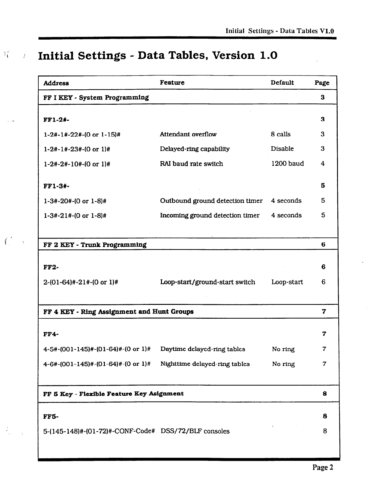
Initial Settings - Data Tables V1.0
‘i
/ Initial Settings - Data Tables, Version
1.0
,i’ ’
3 1
AddreSS
Feature Default Page
FF I KEY - System Programming 3
FFl-2#- 3
l-2#-l#-22#-(0 or l-15)# Attendant overflow 8 calls 3
l-2#-l#-23#-(0 or l)# Delayed-ring capability Disable 3
l-2#-2#-lO#-(0 or l)# RAl baud rate switch 1200 baud 4
FFl-3X- 5
l-3#-20#-(0 or l-8)# Outbound ground detection timer 4 seconds 5
l-3#-21#-(0 or l-8)# incoming ground detection timer 4 seconds 5
FF 2 KEY - Trunk Programming 6
FF2- 6
2-(Ol-64)#-21#-(0 or l)# Loop-start/ground-start switch Loop-start 6
FF 4 KEY - Ring Assignment and Hunt Groups 7
FF4- 7
4-5#-(OOl-145)#-(Ol-64)#-(0 or l)# Daytime delayed-ring tables No ring 7
4-6#-(OOl-145)#-(Ol-64)#-(0 or l)# Nighttfme delayed-ring tables No rFng 7
FF 6 Key - Flexible Feature Key Asignment 8
FFS- 8
5-(145-148)#-(Ol-72)#-CONF-Code# DSS/72/BLF consoles 8
Page 2
Technical Manuals Online! - http://www.tech-man.com
FF 1 KEY
SYSTEM PROGRAMMING
“- :._“: VI ‘0
Technical Manuals Online! - http://www.tech-man.com
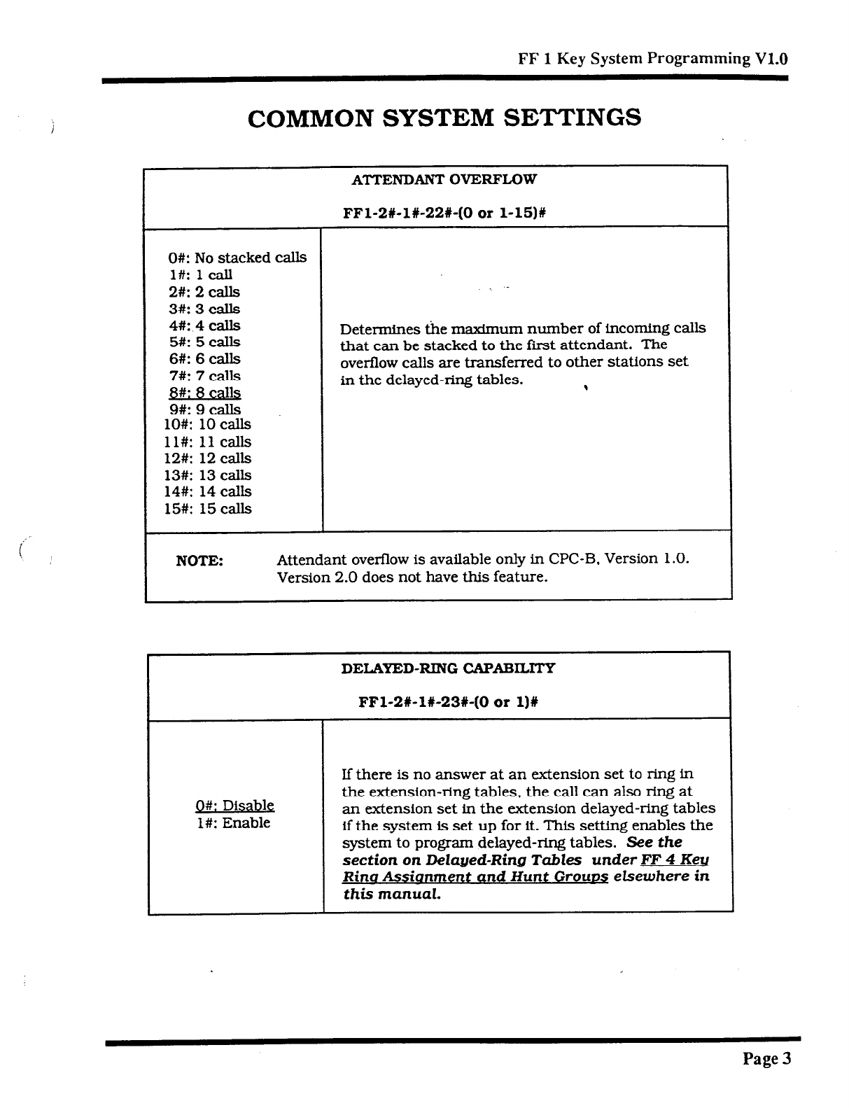
FF 1 Key
System Programming V1.0
COMMON SYSTEM SETTINGS
i
\
ATTENDANT OVERFLOW
FFl-2#-l#-22#-(0 or l-15)#
0#: No stacked calls
l#: 1 call
2#: 2 calls
3#: 3 calls
4#: 4 calls
5#: 5 calls
6#: 6 calls
7#: 7 calls
j3#: 8 calls
9#: 9 calls
lO#: 10 calls
ll#: 11 calls
12#: 12 calls
13#: 13 calls
14#: 14 calls
15#: 15 calls
-
Determines the maxImum number of incoming calls
that can be stacked
to
the frost attendant. The
overflow calls are transferred to other stations set
in the delayed-ring tables. 9
NOTE: Attendant overflow is available only in CPC-B. Version 1 .O.
Version 2.0 does not have this feature.
DELAYED-RING CAPABILITY
FFl-2f-l&239-(0 or l)#
g#: Disable
l#: Enable
If there is no answer at an extension set to ring in
the extension-ring tables, the call can also ring at
an extension set in the extension delayed-ring tables
if the system is set up for it. This setting enables the
system to program delayed-ring tables. See
the
section on Delayed-Ring Tables under FF 4
Keu
Rina Assianment and Hunt Gtourq elsewhere in
this manual.
Page 3
Technical Manuals Online! - http://www.tech-man.com
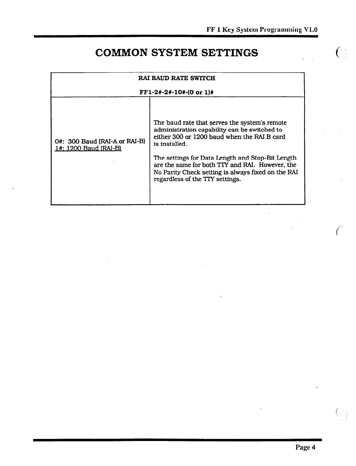
FF 1 Key System Programming V1.0
COMMON SYSTEM SETTINGS
RAIBAUDRATESWlTCH
FFl-2#-2X-10%-(0 or l)#
The baud rate that serves the system’s remote
administration capability can be switched to
O#: 300 Baud
(RN-A or
RAI-B) either 300 or 1200 baud when the RAI B card
l#: 1200 Baud IRAI-Bl is installed .
The settings for Data Length and Stop-Bit Length
are the sane for both TTY and FM. However, the
No Parity Check setting is always fixed on the RAI
regardless of the TIY settings.
Page 4
Technical Manuals Online! - http://www.tech-man.com
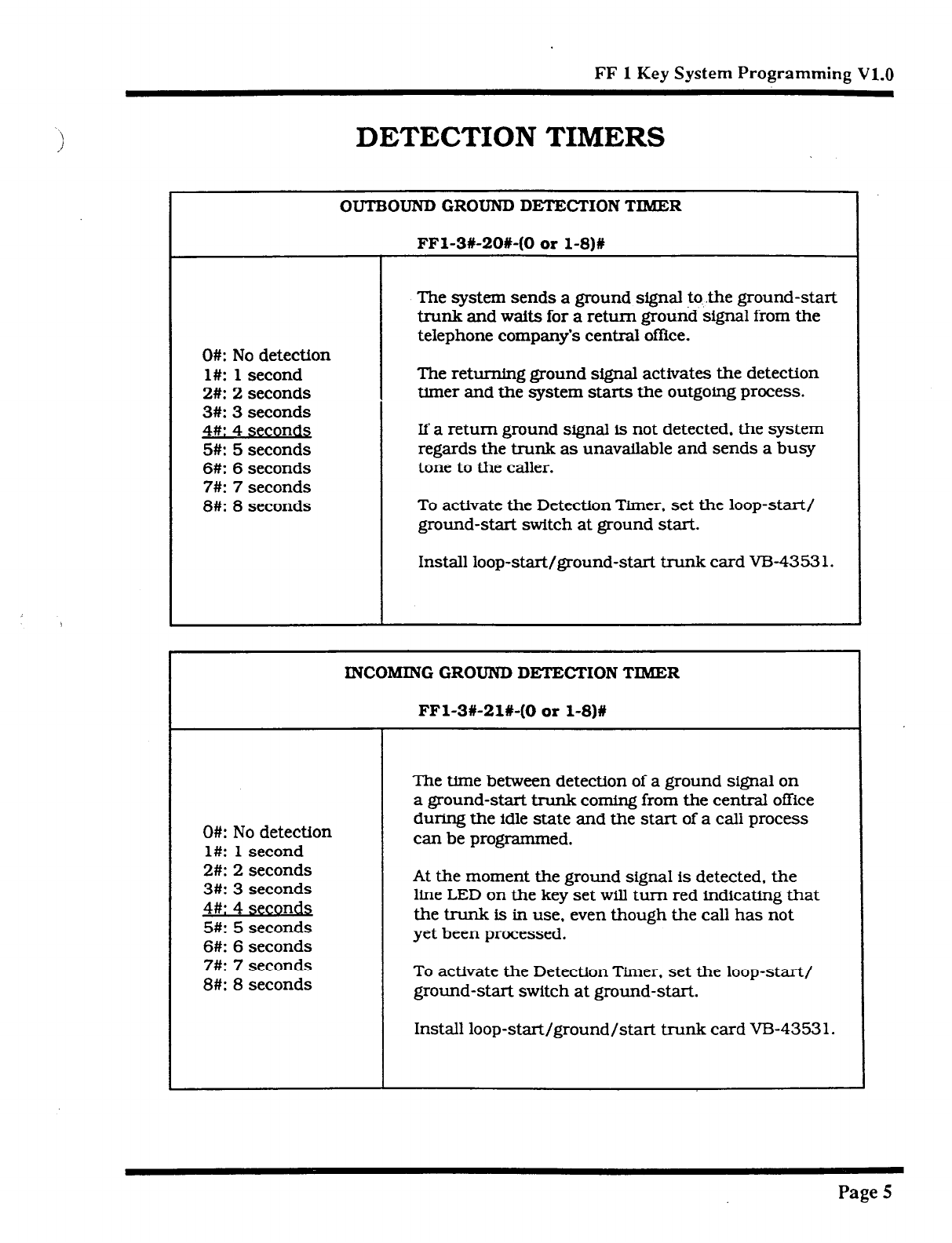
FF
1
Key
System Programming V1.0
DETECTION TIMERS
OUTBOUND GROUND DETECTION TIMER
FFl-3620#-(0 or l-8)#
0#: No detection
l#: 1 second
2#: 2 seconds
3#: 3 seconds
4#: 4 secon&
5#: 5 seconds
6#: 6 seconds
7#: 7 seconds
8#: 8 seconds
The system sends a ground signal to .the ground-start
trunk and wafts for a return ground signal from the
telephone company’s central office.
The returning ground signal activates the detection
timer and the system starts the outgoing process.
If a return ground signal is not detected. the system
regards the trunk as unavailable and sends a busy
tone to the caller.
To activate the Detection Timer. set the loop-start/
ground-start switch at ground start.
Install loop-start/ground-start trunk card VB4353 1.
INCOMING GROUND DETIXTION TIMER
FFl-3#-21#-(0 or l-8)#
O#: No detection
l#: 1 second
2#: 2 seconds
3#: 3 seconds
4#: 4 seconds
5#: 5 seconds
6#: 6 seconds
7#: 7 seconds
8#: 8 seconds
The time between detection of a ground signal on
a ground-start trunk coming from the central office
during the idle state and the start of a call process
can be programmed.
At the moment the ground signal is detected. the
line LED on the key set will turn red indicating that
the trunk is in use, even though the call has not
yet been processed.
To activate the Detection Timer. set the loop-start/
ground-start switch at ground-start.
Install loop-start/ground/start tnmk card VD-43531.
Page 5
Technical Manuals Online! - http://www.tech-man.com
FF
2
KEY
TRUNK PROGRAMMING
VI .o
Technical Manuals Online! - http://www.tech-man.com
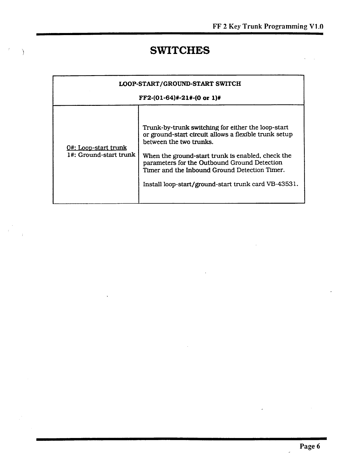
FF 2 Key Trunk Programming V1.0
SWITCHES
LOOP-START/GROUND-START SWITCH
FF2-(Ol-64)#-21%-(0 or l)%
Trunk-by-trunk switching for either the loop-start
or ground-start circuit allows a flexible trunk setup
between the two trunks.
O#: Loowstart trunk
l#: Ground-start trunk When the ground-start trunk is enabled, check the
parameters for the Outbound Ground Detection
Timer and the Inbound Ground Detection Timer.
Install loop-start/ground-start trunk card V-B-4353 1.
Page 6
Technical Manuals Online! - http://www.tech-man.com
FF 4 KEY
RING ASSIGNMENT
il ) AND
HUNT GROUPS
VI .o
Technical Manuals Online! - http://www.tech-man.com
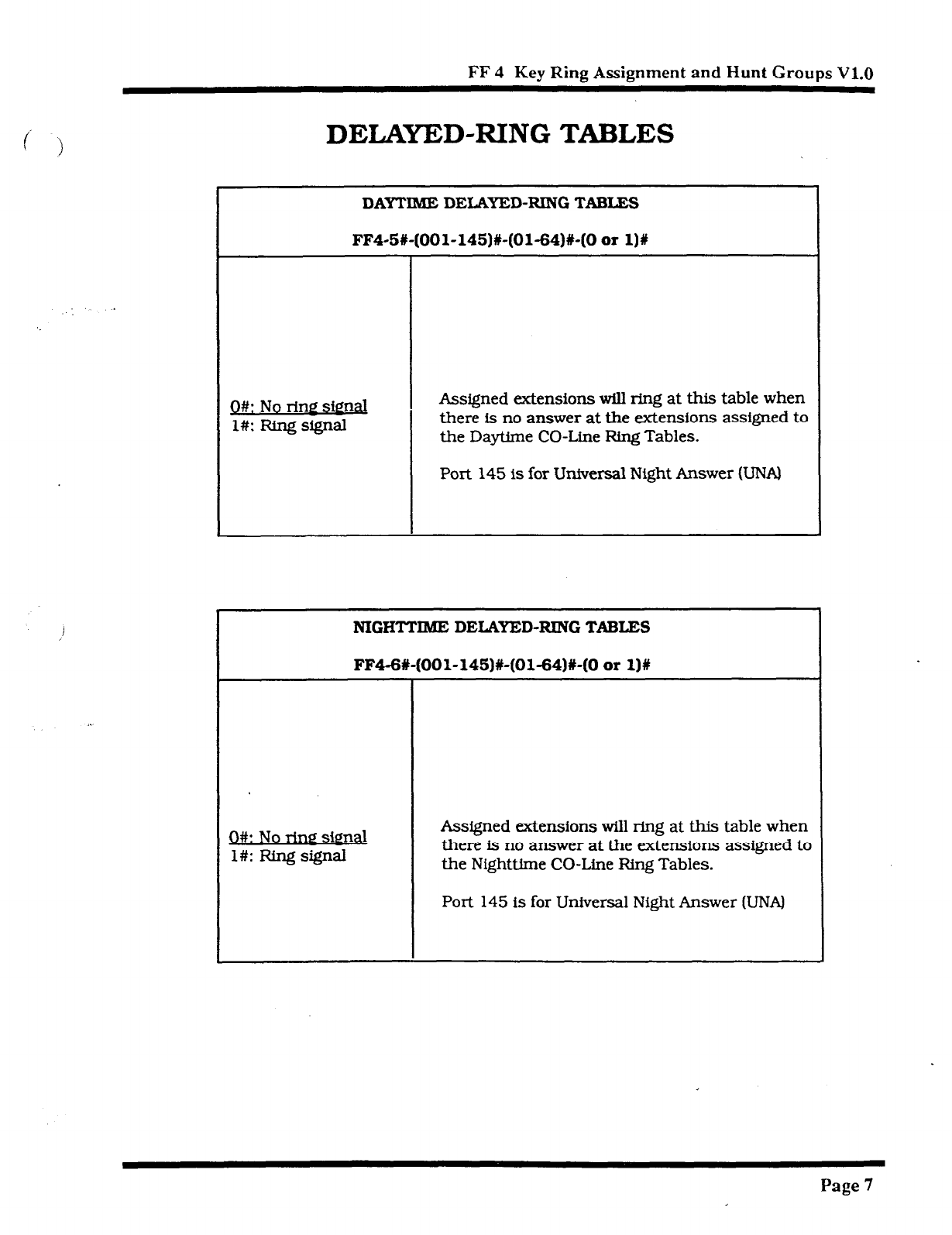
FF 4 Key Ring Assignment and Hunt Groups V1.0
DELAYED-RING TABLES
DAYTIME DEWIYED-RXNG TABLE!3
FF4-5#-(OOl-145)#-(01-64)#-(0 or l)#
0#: No rim sim&
l#: Ring signal
Assigned extensions will ring at this table when
there is no answer at the extensions assigned to
the Daytime CO-Line Ring Tables.
Port 145 Is for Universal Night Answer KJNAI
NIGHTTIME DELAYED-RING TABLES
FF4-6#-(OOl-145)#-(01-54)#-(0 or 1)#
0#: No rim2 simal
l#: Ring signal
Assigned extensions will ring at this table when
there is no answer at the extensions assigned to
the Nighttime CO-Line Ring Tables.
Port 145 is for Universal Night Answer (UNAI
Page 7
Technical Manuals Online! - http://www.tech-man.com

FF 5 KEY
FLEXIBLE FEATURE KEY
PROGRAMMING
VI .o
Technical Manuals Online! - http://www.tech-man.com
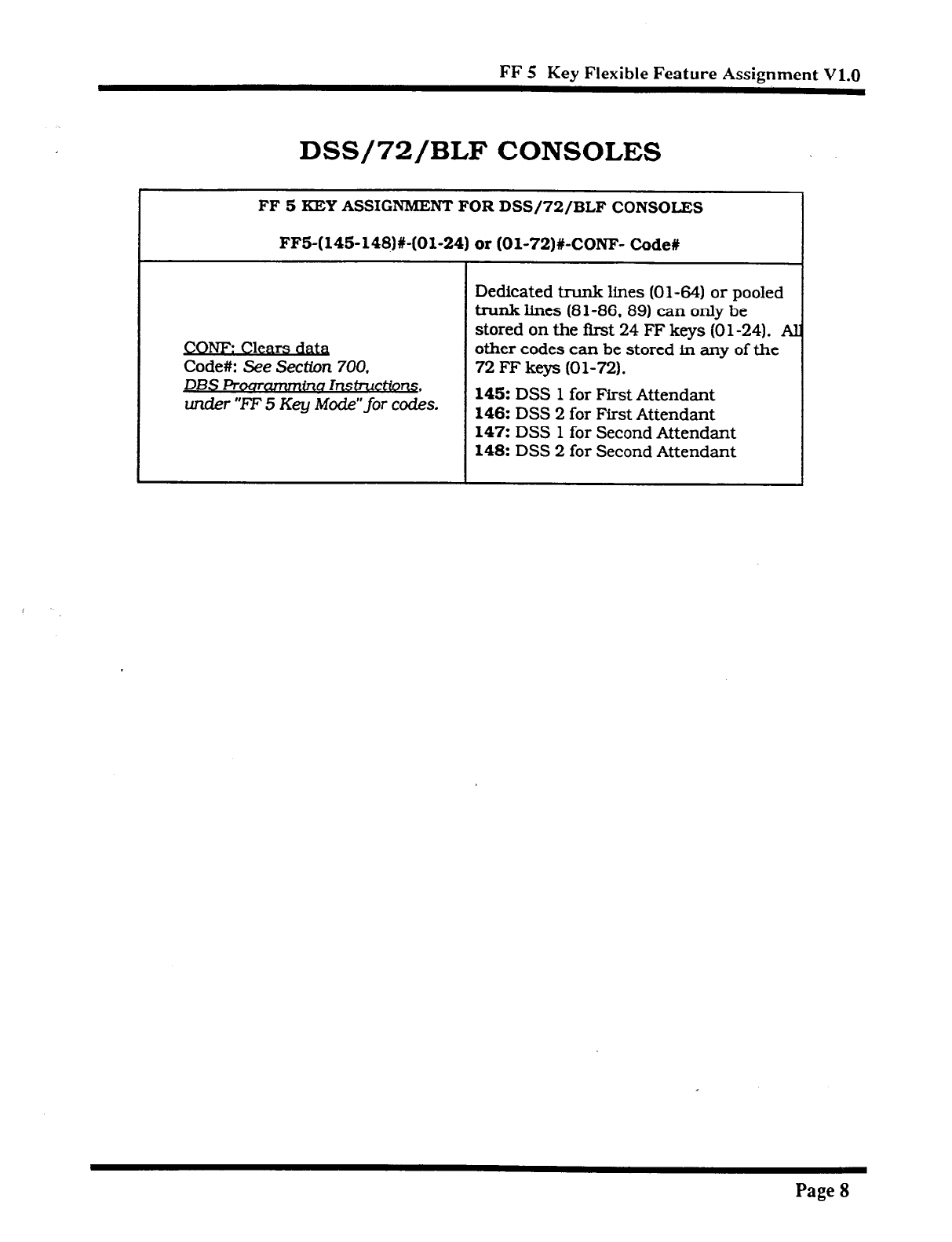
FF 5 Key Flexible Feature Assignment V1.1)
DSS/72/BLF CONSOLES
FF 5 KEY ASSIGNMENT’ FOR DSS/72/BLF CONSOIZS
FF5-(14%148)#-(01-24) or (Ol-72)#-CONF- Code#
CONF: Clears d&
Code#: See
Section 700.
DBS Proammmfnc~ Insfructio~ .
under “FF 5 Key Mode” for codes.
Dedicated trunk lines (01-64) or pooled
trunk lines (81-86.89)
can only be
stored on the first 24 FF keys (0 l-24). A
other codes can be stored in any of the
72
FF keys (01-72).
145: DSS 1 for First Attendant
146: DSS 2 for First Attendant
147: DSS 1 for Second Attendant
148: DSS 2 for Second Attendant
Page 8
Technical Manuals Online! - http://www.tech-man.com

CPC-B
v2.0
DATA TABLES
Technical Manuals Online! - http://www.tech-man.com

Initial Settings - Data Tables V2.0
\
Initial Settings - Data Tables, Version 2.0
Address Feature
Default Page
FF I KEY - System
Programming 13
FFl-2#-l#- 13
1-2#- l#-24#-CONF-( 101-699/l l-69+0 _-
Second attendant 101 13
l-2#-l#-25#-CONF-(101-699/l l-69#)
Third attendant CONF 13
l-2#- l#-26#-CONF-( 101-699/l l-69#)
Fourth attendant CONF 13
l-2#-l#-27#-CONF-(lOl-699/11-69#)
Attendant transfer extension number CONF 14
l-2#- l#-28#-(0 or l)# Attendant override switch Enable 14
l-2#- l#-29#-(0 or l)# AIM key LED Lights 15
l-2+ l#-30#-(0 or l)# Extension delayed-ring capability Noring 15
FFl-3#- 16
l-3#-22#-(0 or l-12)# Att. intercom hold-recall timer 20 seconcjs 16
l-3#-23#-(0 or l-12)# Ext. intercom hold-recall timer 140 seconds 16
l-3#-24#-(0 or l-12)# Att. intercom transfer-recall timer 20 seconds 17
l-3#-25#-(0 or l-12)# Ext. intercom transfer-recall timer 140 seconds 17
Page 9
Technical Manuals Online! - http://www.tech-man.com
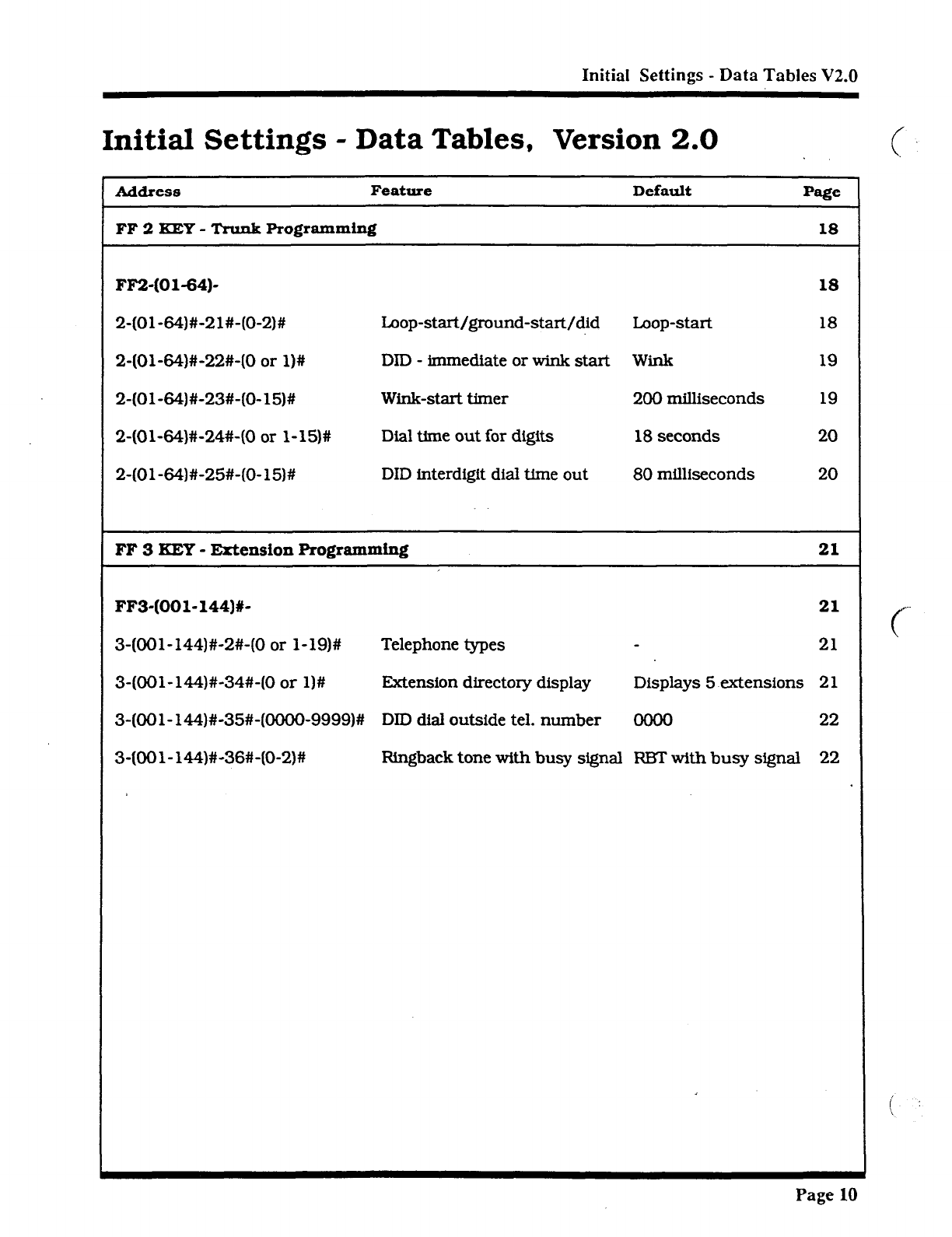
Initial Settings - Data Tables V2.0
Initial Settings - Data Tables, Version 2.0
Address Feature
FF 2 KEY - Trunk
Programming
Default Page
18
FF2-(01-64)- 18
2-(Ol-64)#-21#-(O-2)# Loop-start/ground-start/did loop-start 18
2-(Ol-64)#-22#-(0 or l)# DID - immediate or wink start Wink 19
2-(Ol-64)#-23#-(0-15)# Wink-start timer 200 milliseconds 19
2-(Ol-64)#-24%(0 or l-15)# Dial time out for digits 18 seconds 20
2-(Ol-64)#-2%(O-15)# DID interdigit dial time out 80 milliseconds 20
FF 3 KEY -
Extension Programming 21
FF3-(001-144)X- 21
3-(OOl-144)#-2#-(0 or l-19)# Telephone types 21
3-(OOl-144)#-34#-(0 or l)# Extension directory display Displays 5 extensions 21
3-(OOl-144)#-35#-@OOO-9999)# DID dial outside tel. number 0000 22
3-(OOl-144)#-36#-(0-2)# Ringback tone with busy signal RE3T with busy signal 22
Page 10
Technical Manuals Online! - http://www.tech-man.com
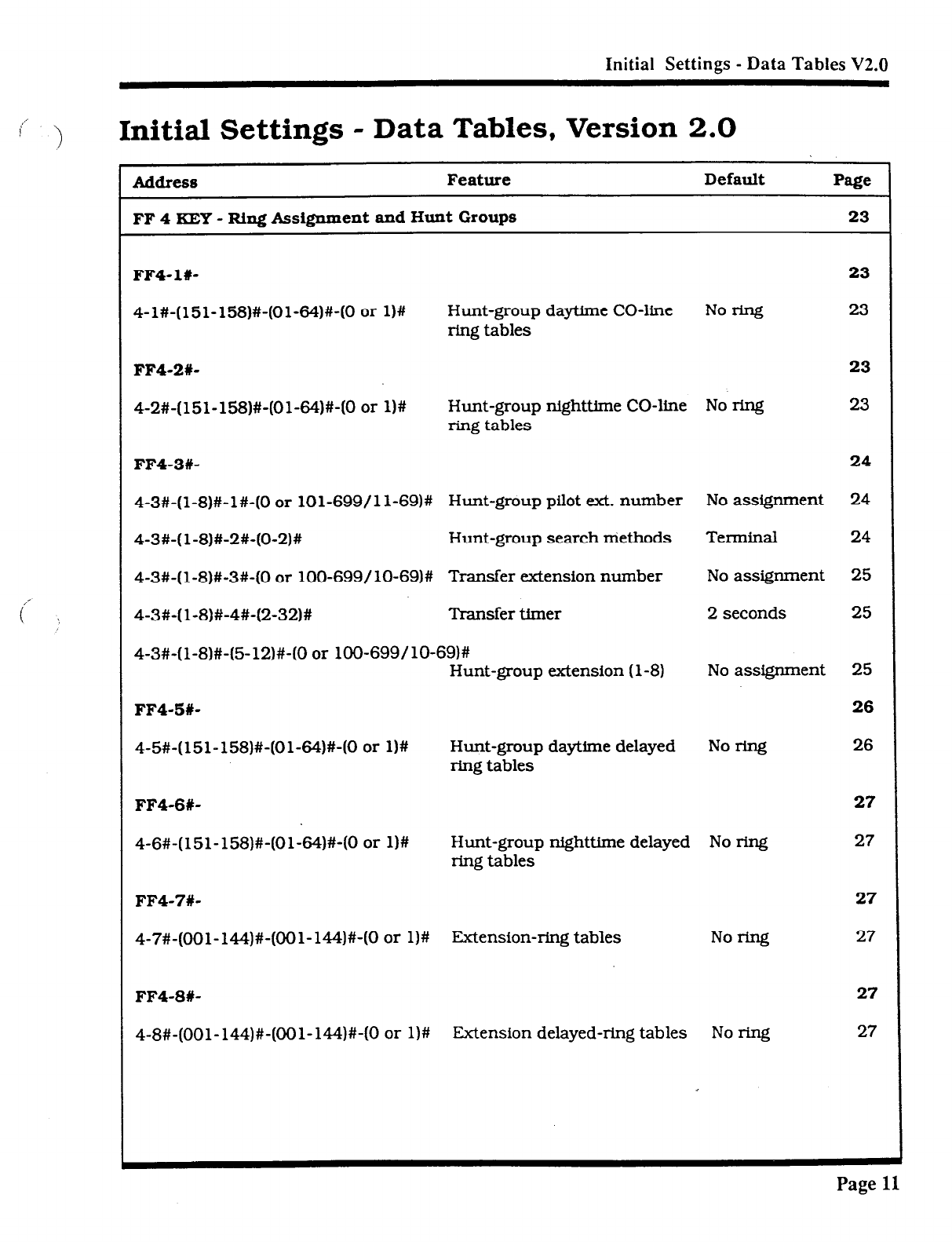
Initial Settings - Data Tables V2.0
,’
( !
Initial Settings - Data Tables, Version 2.0
Address Feature Default Page
FF 4 KEY - Ring Assignment and Hunt Groups 23
FF4-16 23
4-l#-(151-158)#-(Ol-64)#-(0 or l)# Hunt-group daytlme CO-line
ring tables No W 23
FF4-2#-
23
4-2#-(151-158)#-(Ol-64)#-(0 or W Hunt-group nighttime CO-line No ring 23
ring tables
FF4-3#-
24
4-3#-(l-8)#-l#-(0 or 101-699/l l-69)# Hunt-group pilot ext. number No assignment 24
4-3#-( l-8)#-2#-(0-2)# Hunt-group search niethods Terminal 24
4-3#-(l-8)#-3#-(0 or lOO-699/ lo-69)# Transfer extension number No assignment 25
4-3#-( l-8)#-4#-(2-32)# Transfer timer 2 seconds 25
4-3#-( l-8)#-(5-12)#-(0 or lOO-699/ lo-69)#
Hunt-group extension (l-8) No assignment 25
FF4-5#- 26
4-5#-(151-158)#-(Ol-64)#-(0 or l)# Hunt-group daytime delayed Noring
ring tables 26
FF4-6X-
4-6#-(151-158)#-(Ol-64)#-(0 or 1)s Hunt-group nighttime delayed No ring
ring tables
FF4-7#-
4-7#-(OOl-144)#-(OOl-144)#-(0 or l)# Extension-ring tables Norfng
FF4-8#-
4-8#-(OOl-144)#-(OOl-144)#-(0 or l)# Extension delayed-ring tables Noring
27
27
27
27
27
27
Page 11
Technical Manuals Online! - http://www.tech-man.com
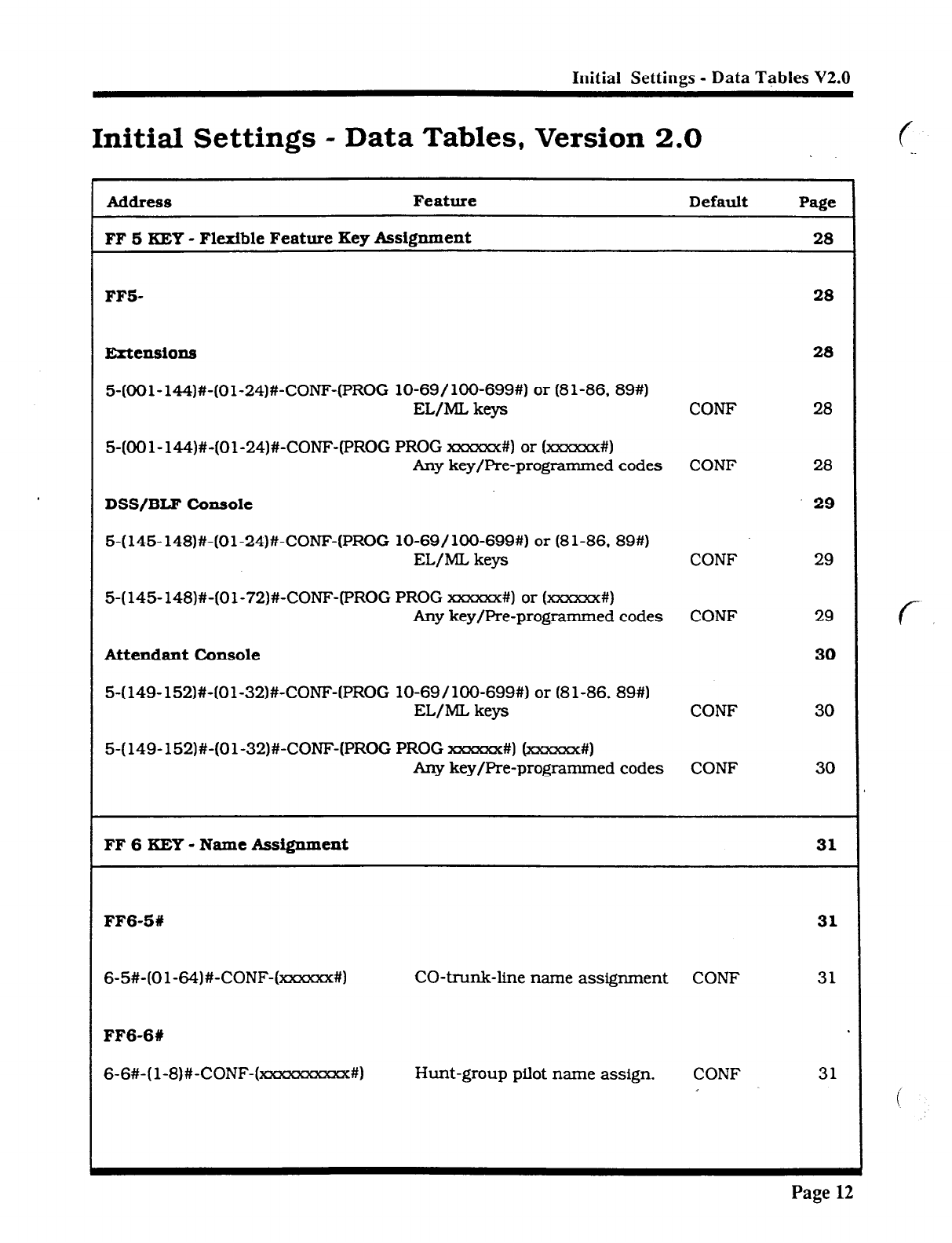
Initial Settings - Data Tables V2.0
Initial Settings - Data Tables, Version 2.0
Address
Feature
FF 6 KEY - Flexible Feature Key Assignment
Default Page
28
FF5-
Extensions
5-(CKIl-144)#-(Ol-24)#-CONF-(PROG lo-69/1OO-699#) or (81-86, 89#)
EL/ML keys CONF
5-(OOl-144)#-(Ol-24)#-CONF-(PROG PROG xmzxx#) or (xxxxxx#)
hy key/Pre-programmed codes CONF
DSS/BLF Console
5-( 145- 148)#-(Ol-24)#-CONF-(PROG lo-69/ lOO-699#) or (8 l-86, 89#)
EL/ML keys CONF
5-( 145- 148)#-(01-72)#-CONF-(PROG PROG xxxxxx#) or (xxxxm#)
Any key/Pre-programmed codes CONF
Attendant Console
5-(149-152)#-(Ol-32)#-CONF-(PROG lo-69/100-699#) or (81-86. 89#)
EL/ML keys CONF
5-(149-152)#-(Ol-32)#-CONF-(PROG PROG ===#I (xxxxxx#)
Any key/Pre-programmed codes CONF
28
28
28
28
29
30
30
FF 6 KEY - Name Assignment 31
FF6-51 31
6-5%(Ol-64)#-CONF-(XSXXX#) CO-trunk-line name assignment CONF 31
FF6-6t
6-6#-( l-8)#-CONF-(w#) Hunt-group pilot name assign. CONF 31
Page
12
Technical Manuals Online! - http://www.tech-man.com
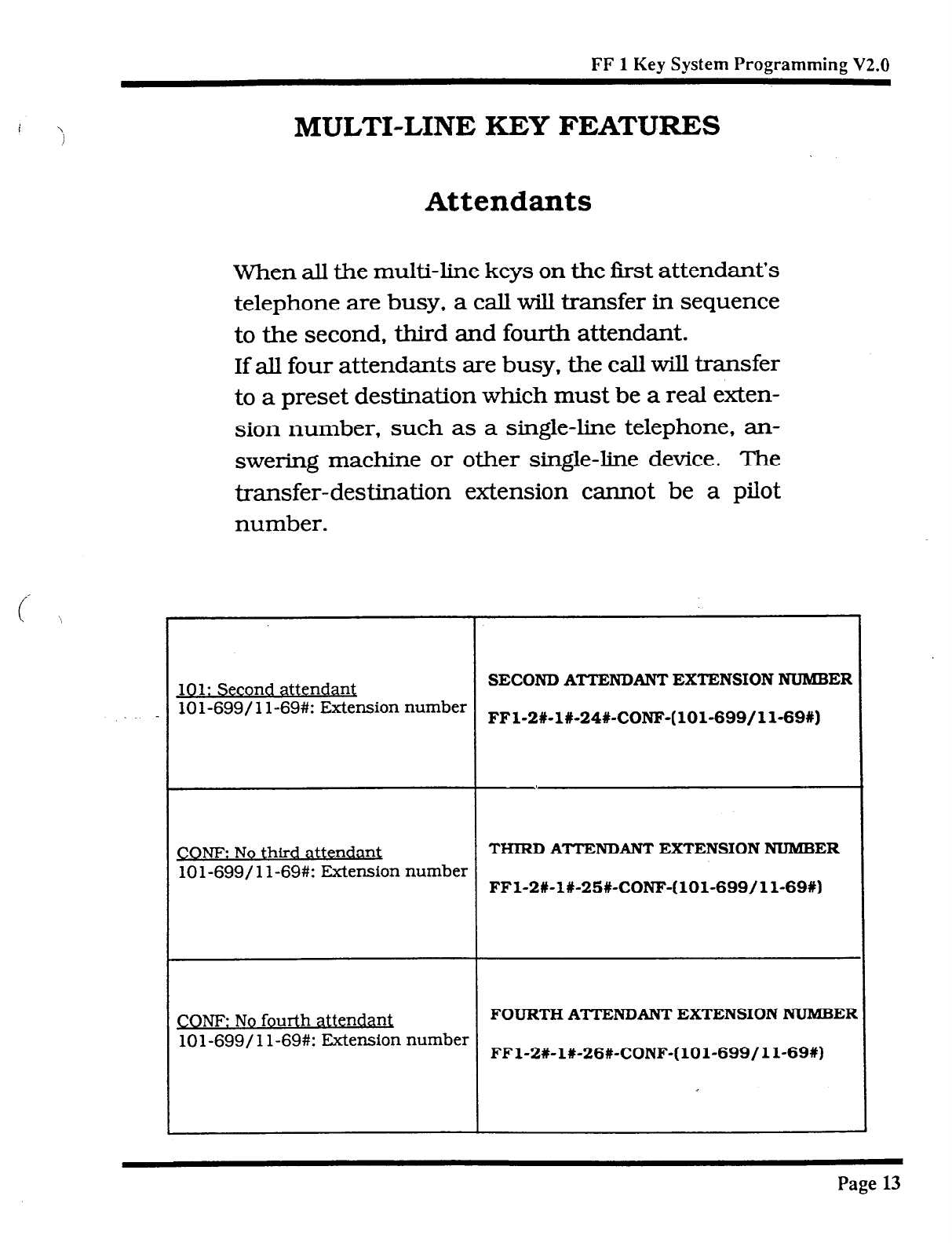
i \
FF 1 Key System Programming V2.0
MULTI-LINE KEY FEATURES
Attendants
When all the multi-line keys on the first attendant’s
telephone are busy, a call will transfer in sequence
to the second, third and fourth attendant.
If
all four attendants are busy, the call will transfer
to a preset destination which must be a real exten-
sion number, such as a single-line telephone, an-
swering machine or other single-line device. The
transfer-destination extension cannot be a pilot
number.
101: Second atte ndant
SECOND ATTENDANT EXTENSION NUMBER
10 l-699/ l l-69#: Extension number
FFl-2#-l#-24%CONF-(101-699/11-69X)
COW No third attendant
THIRD ATTENDANT EXTENSION NUMBER
lOl-699/ 1 l-69#: Extension number
FFl-2#-l#-25#-CONF-(lOl-699/11-69#)
CONF: No fourth attendant
FOURTH ATTENTUSNT EXTENSION NUMBEF
lOl-699/ 1 l-69#: Extension number
FFl-2X-l#-26#-CONF-(lOl-699/11-69%)
Page 13
Technical Manuals Online! - http://www.tech-man.com
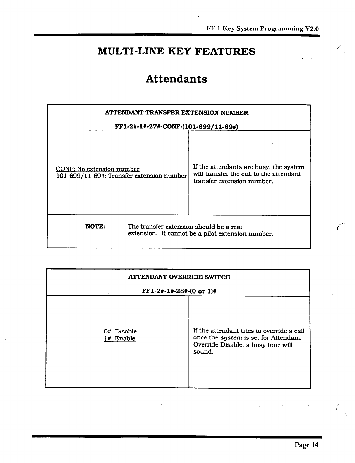
FF 1 Key System Programming V2.0
MULTI-LINE KEY FEATURES
Attendants
ATTENDANT TRANSFER EXTENSION NUMBER
FFl-2#-l#-27X-CONF-( 101-699/ 1 l-69#)
CONE No extension number
10 l-699/ 1 l-69#: Transfer extension number
If the attendants are busy, the system
will transfer the call to the attendant
transfer extension number.
NOTE: The transfer extension should be a reaI
extension. It cannot be a piIot extension number.
ATTENDANT’ OVERRIDE SWITCH
FFl-2X-1X-28U
O#: Disable
l#: Enable
0 or l)#
If the attendant tries to override a call
once the system is set for Attendant
Oven-ide Disable, a busy tone will
sound.
f
Page 14
Technical Manuals Online! - http://www.tech-man.com

FF 1 Key System Programming V2.0
i \
COMMON SYSTEM SETTINGS
ALMKEYLED
FFl-2X-1X-29#-(0 OX 1)X
O#: Does not light
l#: Li@hts
The Alarm (ALM) key on the Attendant
Console will either light or not light
with this setting.
EXTENSION (BUSY LAMP FIELD) DELAYED-RING CAPABILITY
FFl-2#-l#-30#-(0 or l)#
When there is no answer at the
extensions set in the extension
ring tables, calls are distributed
NQ O#:
l#: Yes
to other extensions set in the
extension delayed-ring tables.
See the section on Delayed-
Ring Tables under FF 4 K&y
.
ma Assianment an4
Hunt
GIVUDS
elsewhere
in
this manual.
Page 15
Technical Manuals Online! - http://www.tech-man.com
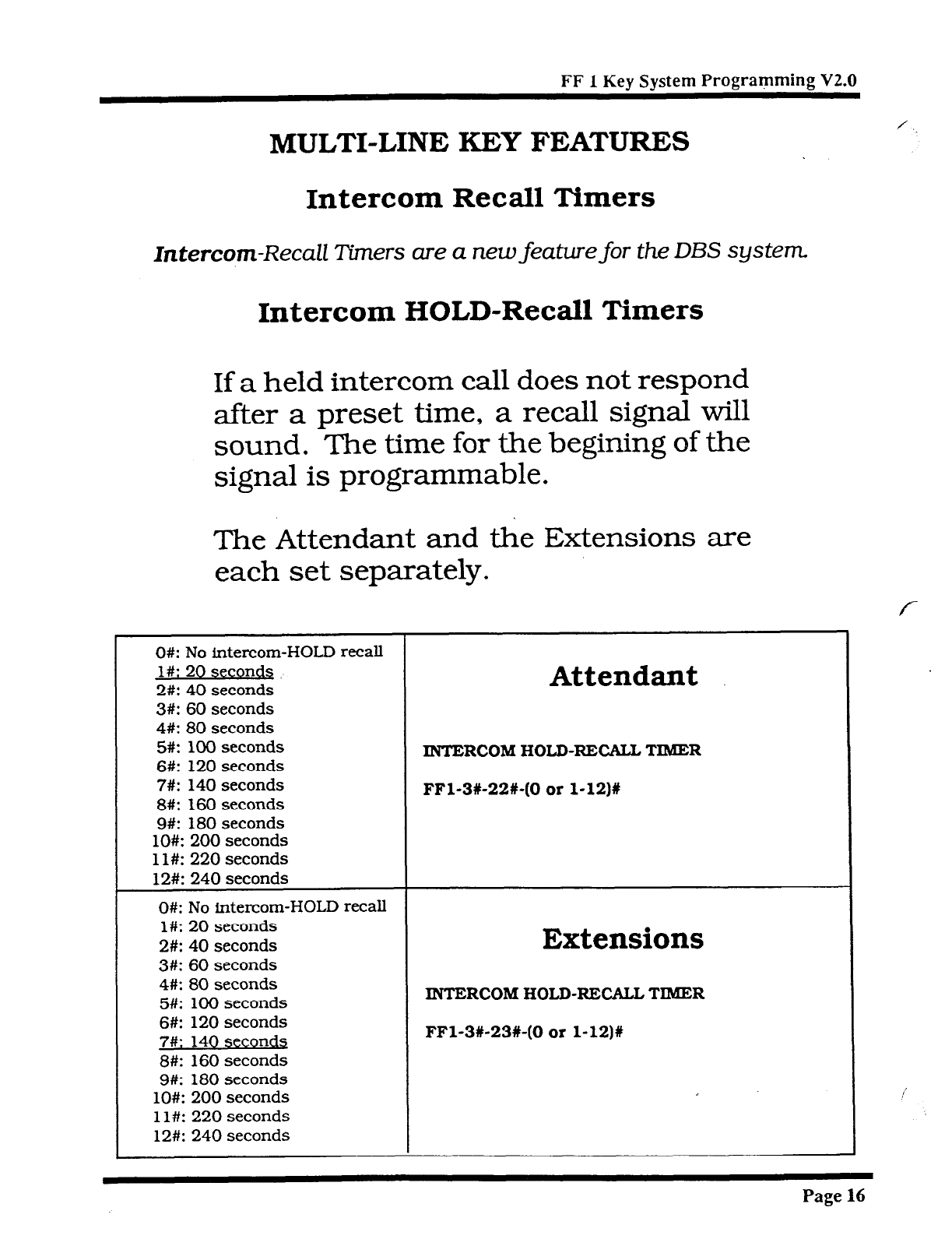
FF 1 Kev Svstem Programming V2.0
MULTI-LINE KEY FEATURES
0#: No intercom-HOLD recall
l#: 20 seconds
2#: 40 seconds
Attendant
3#: 60 seconds
4#: 80 seconds
5#: 100 seconds
6#: 120 seconds
7#: 140 seconds
8#: 160 seconds
9#: 180 seconds
lO#: 200 seconds
1 l#: 220 seconds
12#: 240 seconds
INTERCOM HOLD-RECALL TIMER
FFl-3X-22+(0
or
1-12)X
0#: No intercom-HOLD recall
l#: 20 seconds
2#: 40 seconds
Extensions
3#: 60 seconds
4#: 80 seconds
5#: 100 seconds
6#: 120 seconds
7#: 140 seco rids
8#: 160 seconds
9#: 180 seconds
lO#: 200 seconds
1 l#: 220 seconds
12#: 240 seconds
INTERCOM HOLD-RECALL TIMER
FFl-3#-23#-(0 or l-12)#
Intercom Recall Timers
Intercom-Recall
Timers are
a new
feature for the
DBS
system
Intercom HOLD-Recall Timers
If a held intercom call does not respond
after a preset time, a recall signal will
sound. The time for the begining of the
signal is programmable.
The Attendant and the Extensions are
each set separately.
Page 16
Technical Manuals Online! - http://www.tech-man.com
: ,
FF 1 KEY
SYSTEM PROGRAMMING
v2.0
Technical Manuals Online! - http://www.tech-man.com
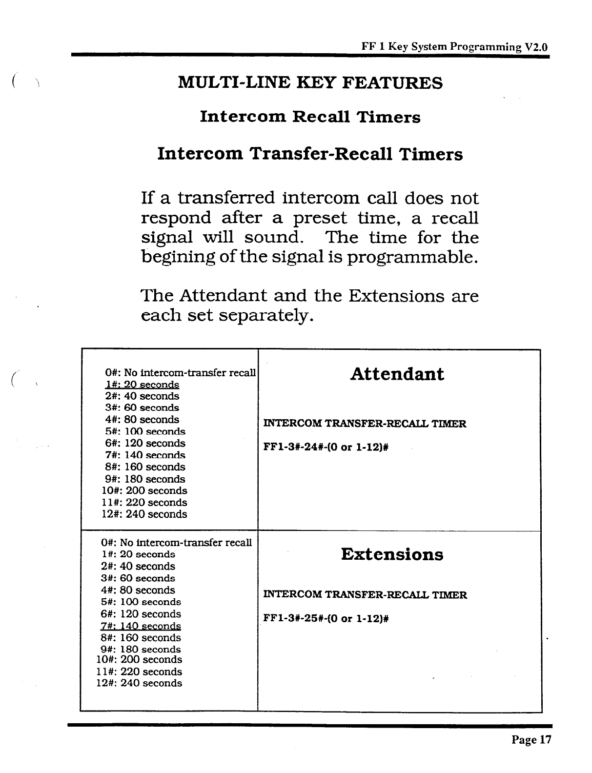
FF 1 Key System Programming V2.0
t’ ‘\
i \
MULTI-LINE KEY FEATURES
Intercom Recall
Timers
Intercom Transfer-Recall Timers
If a transferred intercom call does not
respond after a preset time, a recall
signal will sound. The time for the
begining of the signal is programmable.
The Attendant and the Extensions are
each set separately.
O#: No intercom-transfer recall
Attendant
J#: 20 seconds
2#: 40 seconds
3#: 60 seconds
4#: 80 seconds
5#: 100 seconds
6#: 120 seconds
7#: 140 seconds
8#: 160 seconds
9#: 180 seconds
lO#: 200 seconds
1 l#: 220 seconds
12#: 240 seconds
INTERCOM TRANSFER-RECALL TIMER
FFl-3X-24X-(0 or l-12)#
O#: No intercom-transfer recall
l#: 20 seconds
Extensions
2#: 40 seconds
3#: 60 seconds
4#: 80 seconds
5#: 100 seconds
6#: 120 seconds
7#: 140 secon&
8#: 160 seconds
9#: 180 seconds
lO#: 200 seconds
1 l#: 220 seconds
12#: 240 seconds
INTERCOM
TRANSFER-RECALL TIMER
FFl-3#-25#-(0 or l-l2)#
Page 17
Technical Manuals Online! - http://www.tech-man.com
FF
2
KEY
TRUNK PROGRAMMING
v2.0
Technical Manuals Online! - http://www.tech-man.com
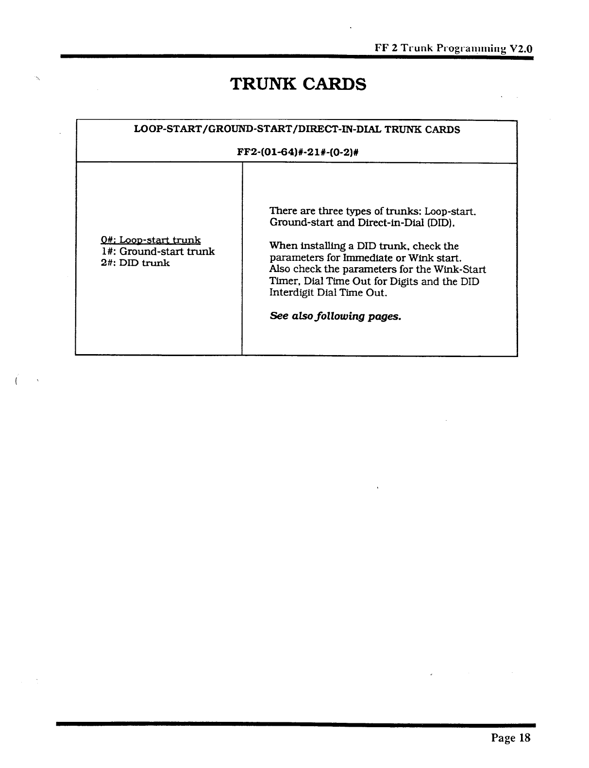
FF 2 Trunk Prograryming V2.0
TRUNK CARDS
LOOP-START/GROUND-START/DIRECT-IN-DIAL TRUNK CARDS
FF2-(Ol-f34)#-21X-(O-2)#
Ok L.ooD-start trunk
l#: Ground-start trunk
2% DID trunk
There are three types of trunks: Loop-start.
Ground-start and Direct-in-Dial (DID).
When installing a DID trunk. check the
parameters for Immediate or Wink start.
Also check the parameters for the Wink-Start
Timer, Dial Time Out for Digits and the DID
Interdigit Dial Time Out.
See also following pages.
Page 18
Technical Manuals Online! - http://www.tech-man.com
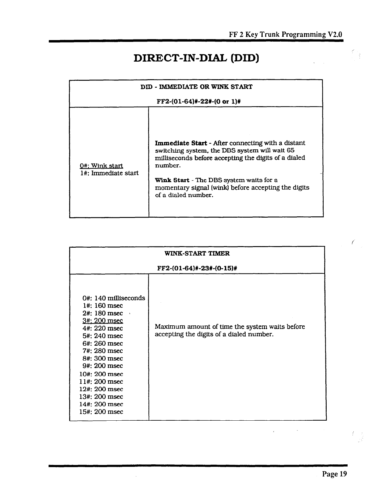
FF 2 Key Trunk Programming V2.0
DIRECT-IN-DIAL (DID)
DID - IMMEDIATE OR WINK START
1
FF2-(Ol-64)#-22%(0 or l)%
Q#: Wink start
l#: Immediate start
Immediate Start -
After comxcting with a distant
switching system. the
DBS
system will wait 65
milliseconds before accepting the digits of a dialed
number.
WinIs
Start
- The DBS system waits for a
momentary signal hink~ before accepting the digits
of a dialed number.
WIN-K-START
TIMER
0#:
140 milliseconds
l#: 160 msec
2#: 180 msec 1
3#: 200 msec:
4#: 220 msec Maximum amount of time the system waits before
5#: 240 msec accepting the digits of a dialed number.
6#: 260 msec
7#: 280 msec
8#: 300 msec
9#: 200 msec
lO#: 200 msec
1 l#: 200 msec
12#: 200 msec
13#: 200 msec
14#: 200 msec
15#: 200 msec
Page 19
Technical Manuals Online! - http://www.tech-man.com
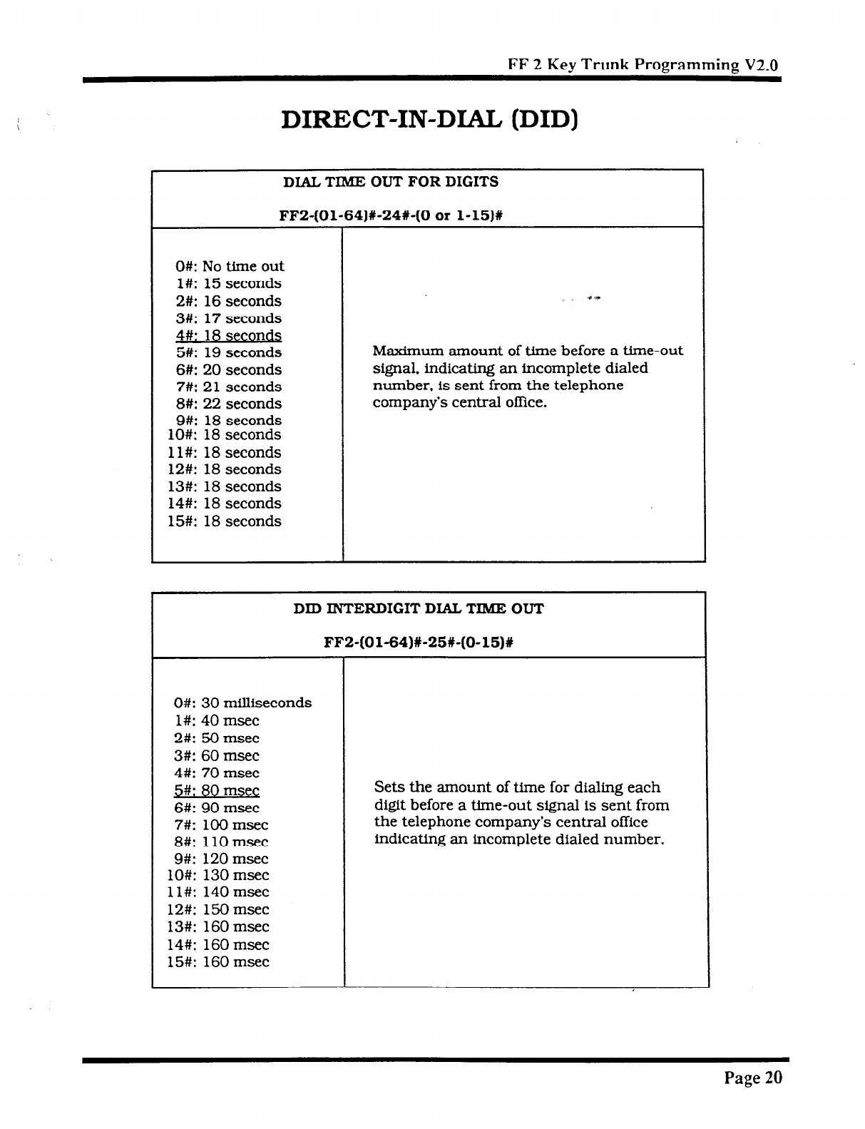
FF 2 Kev Trunk Programming V2.0
DIRECT-IN-DIAL (DID)
DIAL TIME OUT FOR DIGITS
FF2-(Ol-64)%-24#-(0
or l-15)%
O#: No time out
l#: 15 seconds
2#: 16 seconds
3#: 17
seconds
4% 18 seconds
5#: 19 seconds
6#: 20 seconds
7#: 21 seconds
8#: 22 seconds
9#: 18 seconds
lO#: 18 seconds
ll#: 18 seconds
12#: 18 seconds
13#: 18 seconds
14#: 18 seconds
15#: 18 seconds
Maximum amount of time before a time-out
signal. indicating an incomplete dialed
number. is sent from the telephone
company’s central office.
DID INTERDIGIT DIAL TIME OUT
FF2-(01-64)#-25t-(O-15)W
0#: 30 milliseconds
l#: 40 msec
2#: 50 msec
3#: 60 msec
4#: 70 msec
5#: 80 mseg
6#: 90 msec
7#: 100 msec
8#: 110 msec
9#: 120 msec
O#: 130 msec
l#: 140msec
2#: 150 msec
3#: 160 msec
4#: 160 msec
5#: 160 msec
Sets the amount of time for dialing each
digit before a time-out signal is sent from
the telephone company’s central office
indicating an incomplete dialed number.
Page 20
Technical Manuals Online! - http://www.tech-man.com
FF 3 KEY
EXTENSION
PROGRAMMING
v2.0
Technical Manuals Online! - http://www.tech-man.com

FF 3 Kev Extension Programming V2.0
EXTENSION PROGIMMMING
TELEPHONE TYPES
FF3-(001-144)X-2%-(0 or l-19)%
Ok No assignment
l#: Analog telephone
2#: Digital telephone (FF 6 key)
3#: Digital telephone (FF 12 key)
4#: Digital telephone (FF 24 key)
5#: Reserved
6#: Reserved
7#: EM/24 W-43310
8#: OPX (pulse)
9#: OPX (tone)
lO#: Voice mail &EC)
1 l#: DSSl - Extension lOO/ 10
12#: DSS2 - Extension lOO/lO
13#: DSS3 - Extension 10 l/ 11
14#: DSS4 - Extension 101/l 1
15#: Voice mail (OPXI
CPGB, Version 2.0
.
Stores telephones in the system.
16#: First attendant console
17#: Second attendant console
18#: Third attendant console
19#: Fourth attendant console
EXTENSION DIRECTORY DISPLAY
FF3-(OOl-144)#-34#-(0 or l)#
O#: DisDlavs 5 extensions Extension directory display on
l#: Displays 10 extensions a large-screen display telephone.
Page 21
Technical Manuals Online! - http://www.tech-man.com
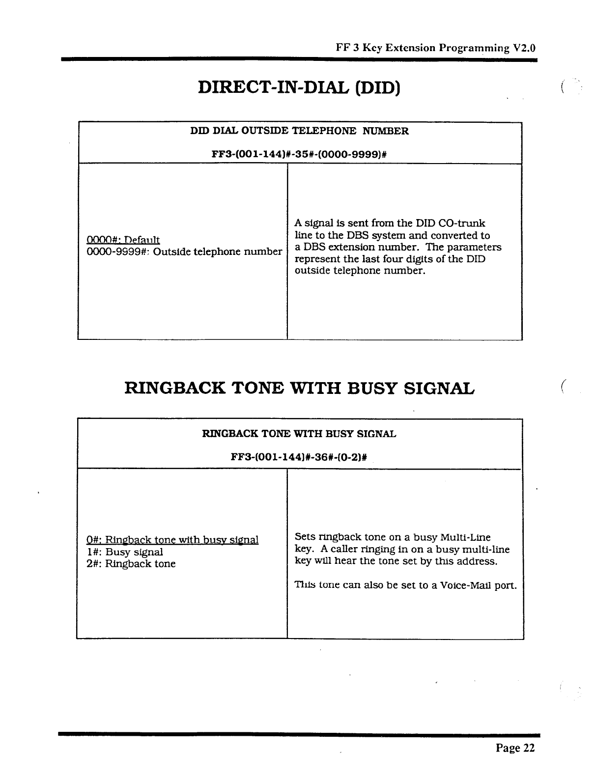
FF 3 Key Extension Programming V2.0
DIRECT-IN-DIAL (DID) i -*.
\
DID DIAL
OUTSIDE
TELEPHONE NUMBER
FF3-(OOl-144)#-35#-(0000-9999)#
A signal is sent from the DID CO-trunk
QOOO#: Default line to the DBS system and converted to
0000-9999#: Outside telephone number a DBS extension number. The parameters
represent the last four digits of the DID
outside telephone number.
RINGBACK TONE WITH BUSY SIGNAL
RINGBACK TONE WITH BUSY SIGNAL
FF3-(OOl-144)#-36#-(0-2)X
Q#: Rirwback tone with busv siQnd
l#: Busy signal
2#: Ringback tone
Sets ringback tone on a busy Multi-Line
key. A caller ringing in on a busy multi-line
key will hear the tone set by this address.
This tone can also be set to a Voice-Mail port.
Page 22
Technical Manuals Online! - http://www.tech-man.com

FF 4
KEY
RING ASSIGNMENT-
AND
HUNT GROUPS
v2.0
Technical Manuals Online! - http://www.tech-man.com
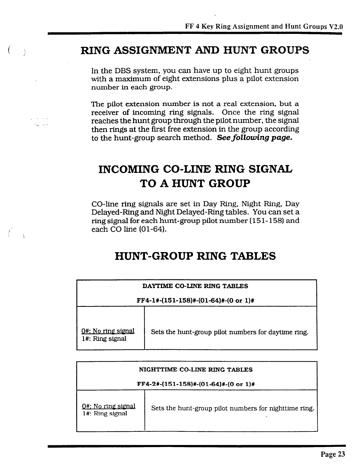
FF 4 Key Ring Assignment and
Hunt Groups
V2.0
( )
RING ASSIGNMENT AND HUNT GROUPS
In the DBS system, you can have up to eight hunt groups
with a maximum of eight extensions plus a pilot extension
number in each group.
The pilot extension number is not a real extension, but a
receiver of incoming ring signals. Once the ring signal
reaches the hunt group through the pilot number, the signal
then rings
at
the frost free extension in the group according
to
the hunt-group search method. Seefollowing page.
INCOMING CO-LINE RING SIGNAL
TO A HUNT GROUP
CO-line ring signals are set in Day Ring. Night Ring, Day
Delayed-Ring and Night Delayed-Ring tables. You can set a
ring signal for each hunt-group pilot number (15 1- 158) and
each CO Iine (01-64).
HUNT-GROUP RING TABLES
DAYTIME CO-LINE RING TABLE3
FF4-l%-(151-158)#-(01-64)#-(0 or 1)#
Q#: No ring simd
l#: Ring signal Sets the hunt-group pilot numbers for daytime ring.
NIGHTTIME CO-LINE RING TABLES
FFQ-P%-(El-1581%(01-64)#-(0 or 1)X
Q#: No rim signal
l#: Ring signal Sets the hunt-group pilot numbers for nighttime ring.
Page 23
Technical Manuals Online! - http://www.tech-man.com
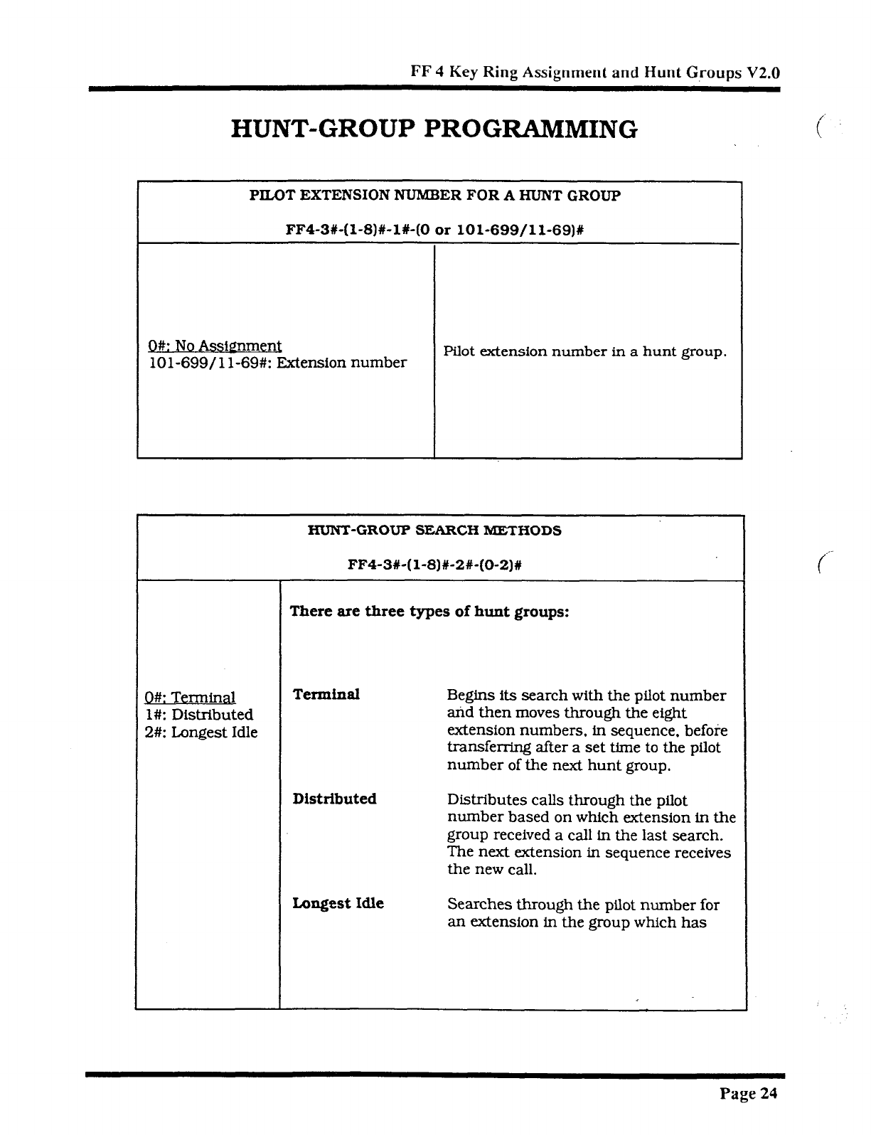
FF 4
Key
Ring Assignment and Hunt Groups V2.0
HUNT-GROUP PROGRAMMING
PILOT EXTENSION NUMBER FOR A HUNT GROUP
FF4-3#-(1-8)#-l#-(0 or lOl-699/11-69)#
O#: No Assi~men~
101-699/l l-69#: Extension number Pilot extension number in a hunt group.
HUNT-GROUP SEARCH METHODS
FF4-3X-(l-8)#-2#-(O-2)1
There are three types of hunt groups:
Q#: Terminal
1 #: Distributed
2#: Longest Idle
Terminal
Begins its search with the pilot number
and then moves through the eight
extension numbers, in sequence. before
transferring after a set time to the pilot
number of the next hunt group.
Distributed
Distributes calls through the pilot
number based on which extension in the
group received a call in the last search.
The next extension in sequence receives
the new call.
Longest Idle
Searches through the pilot number for
an extension in the group which has
Page
24
Technical Manuals Online! - http://www.tech-man.com
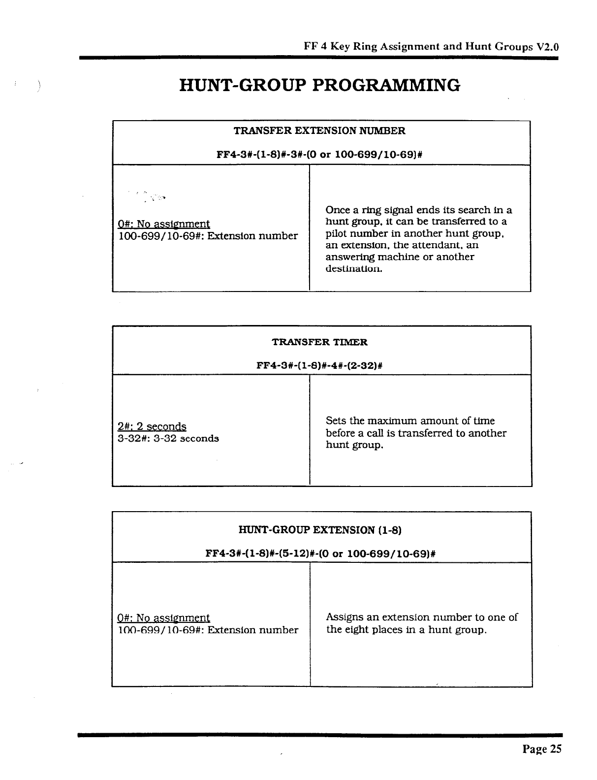
FF 4 Key Ring Assignment and Hunt Groups V2.0
HUNT-GROUP PROGWiMMING
I ._
_ ..: : .
D#: No assirmment
lOO-699/ lo-69#: Extension number
TRANSFER EXTENSION NUMBER
FF4-3#-( l-8)#-3#-(0 or lOO-699/10-69)#
Once a ring signal ends its search in a
hunt group, it can be transferred to a
pilot number in another hunt group,
an extension. the attendant. an
answering machine or another
destination.
TRANSFER TIMER
FF4-3#-( l-8)%-4#-(2-32)#
2#: 2
seconds
3-32#: 3-32
seconds
Sets the maximum amount of time
before a call is transferred to another
hunt group.
HUNT-GROUP EXTENSION (l-8)
FF4-3#-(l-8)+(5-12)%-(0 or lOO-699/10-69)#
0#: No assignment
lOO-699/ lo-69#: JZxtension number Assigns an extension number to one of
the eight places in a hunt group.
J
Page 25
Technical Manuals Online! - http://www.tech-man.com
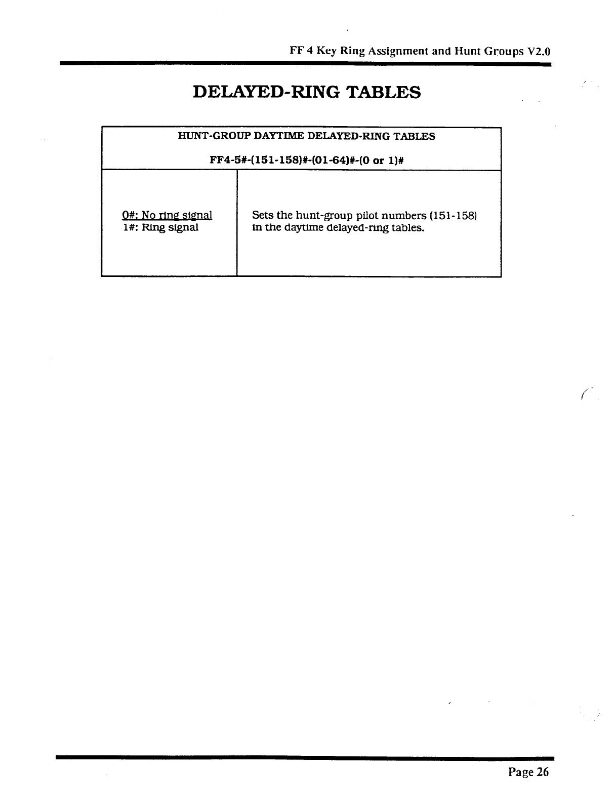
FF 4 Key Ring Assignment and Hunt Groups V2.0
DELAYED-RING TABLES
HUNT-GROUP DAYTIME DELAYED-RING TABLES
FF4-5%-(151-158)#-(01-64)#-(0 or l)#
Q#: No rine sienal Sets the hunt-group pilot numbers (151- 158)
l#: Ring signal in the daytime delayed-ring tables.
Page 26
Technical Manuals Online! - http://www.tech-man.com
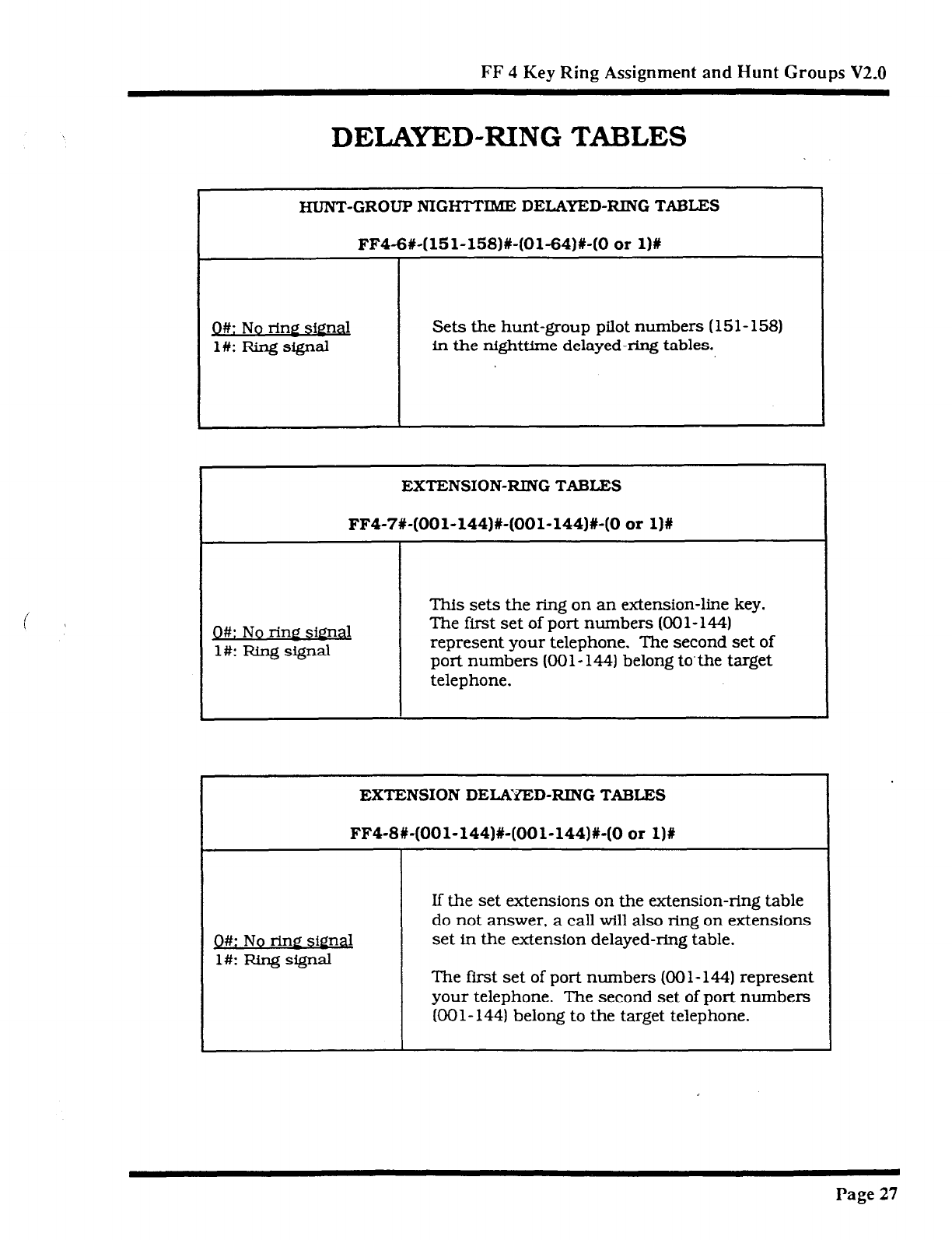
FF 4 Key Ring Assignment and Hunt Groups V2.0
DELAYED-RING TABLES
HUNT-GROUP NIGHTTIME DELAYED-RING TABLES
FF4-6#-(151-158)#-(01-64)#-(0
or
1)R
Q#: No rinP .sjg& Sets the hunt-group pilot numbers ( 15 1 - 158)
l#: Ring signal in the nighttime delayed-ring tables.
EXTENSION-RING TABLES
FF4-7#-(OOl-144)#-(001-144)X-(0 or l)#
Q#: No ring signal
l#: Ring signal
This sets the ring on an extension-line key.
The first set of port numbers (OOl-
144)
represent your telephone. The second set of
port numbers (OOl- 144) belong to’the target
telephone.
EXTENSION DELAYED-RING TABLES
FFQ-8#-(OOl-144)X-(OOl-144)#-(0 or l)#
Q#: No ring signal
l#: Ring signal
If the set extensions on the extension-ring table
do not answer, a call will also ring on extensions
set in the extension delayed-ring table.
The first set of port numbers (00 1- 144) represent
your telephone. The second set of port numbers
KKll-144) belong to the target telephone.
Page 27
Technical Manuals Online! - http://www.tech-man.com

FF 5 KEY
FLEXIBLE FEATURE KEY
PROGRAMMING
v2.0
Technical Manuals Online! - http://www.tech-man.com
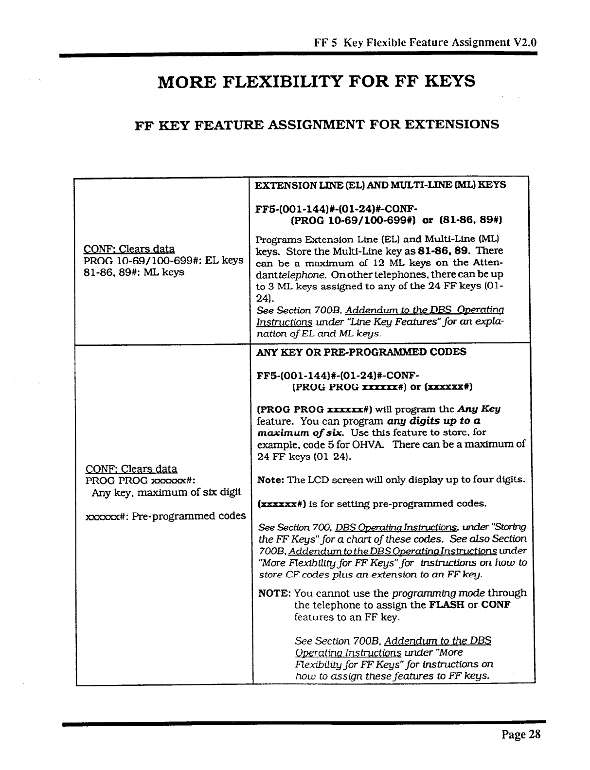
FF 5 Key Flexible Feature Assignment V2.0
MORE FLEXIBILITY FOR FF KEYS
FF KEY FEATURE ASSIGNMENT FOR EXTENSIONS
EXTENSION LINE (EL) AND MULTI-LINE (ML) KEYS
FF5-(OOl-144)#-(Ol-24)#-CONF-
(PROG lo-69/100-699#) or (81-86, 89X)
CONF: Clears data Programs Extension-Line (EL) and Multi-Line (ML)
PROG lo-69/ lOO-699#: EL keys keys. Store the Multi-Line key as 81-86.89. There
Sl-86.89#: ML keys can be a maximum of 12 ML keys on the Atten-
damtelephone. On other telephones. there can be up
to 3 ML keys assigned to any of the 24 FF keys (Ol-
24).
See Section
700B.
Addendum
to the DBS ODerating
lr&uction~ under “Line Key Fea,tures”for an ewpla-
nation ofEL and ML keys.
ANY XEY OR PRE-PROGRAMME D CODES
FF5-(OOl-144)#-(01-24)#-CONF-
(PROG PROG xxxxxx#)
or (xxxxxx#)
(PROG PROG
-#) will program the Any Key
feature. You can program
any digits up to a
maximum
of six. Use this feature to store, for
example, code 5 for OHVA. There can be a maxfmum of
24
FF keys (01-24).
CONF: Clears d&
PROG PROG xxxxxx#: Note: The LCD screen will only display up to four digits.
Any key, maximum of six digit (=xxxx#) is for setting pre-programmed codes.
xxxxxx#: Pre-programmed codes
See Section 700. DBS Owemtbw lnsbuctions. under “~
the FF Keys” for a chart of these codes. See also Section
700B. Addendum to the DBS Ormatina Instructions under
“More Flexibility for FF Keys” for instructions
on how to
store CF codes plus an
extension to an FF key.
NOTE: You
cannot
use the programming mode through
the telephone to assign the
FLASH
or CONF
features to an FF key.
See Section 700B. Addendum to the DBS
Operatim lns~ctiorq under “More
Flexibility for FF Keys” for instiffons on
how to assign these features to FF keys.
Page
28
Technical Manuals Online! - http://www.tech-man.com
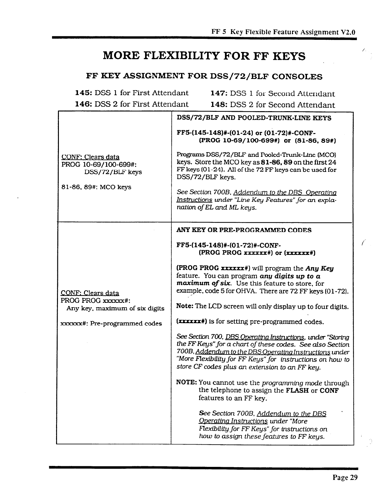
FF 5 Ker Flexible Feature Assignment
V2.0
MORE FLEXIBILITY FOR FF KEYS
FF KEY ASSIGNMENT FOR DSS/72/BLF CONSOLES
145: DSS 1 for First Attendant 147: DSS 1 for Second Attendant
146: DSS 2 for First Attendant 148: DSS 2 for Second Attendant
DSS/72/BLF AND POOLED-TRUNK-LINE KEYS
FFS-(145-148)X-(01-24) or (Oi-72)#-CONF-
(PROG lo-69/100-699#) or (81-86, 89#1
CONE Clears data
PROG lo-69/1OO-699#:
DSS/72/BLF keys
81-86, 89#: MC0 keys
Pmgrams DSS/72/BLF and Pooled-Trunk-Line (MCO)
keys. Store the MC0 key as 8 l-86,89 on the first 24
FF keys (0 l-24). All of the 72 FF keys can be used for
DSS/72/BLF keys.
See Section 700B. Addendum to the DBS ODeratinq
Instructions under “Line Key Features” for an eupla-
natim ofEL and ML keys.
ANY KEY OR PREPROG RAMMED CODES
FF5-(145148)#-(01-72)#-CONF-
(PROG PROG XXXXXX#) or (xxxxxx%I
CONF: Clears daQ
PROG PROG xxxxxx#:
(PROG PROG
xxxxxx#) will program the
Any Key
feature. You can program
any digits up to a
maximum ofsix. Use this feature to store, for
example, code 5 for OHVA. There are 72 FF keys (0 1-72).
..
Any key, m-urn of six digits
Note:
The LCD screen will only display up to four digits.
KXXXXX#: Pre-programmed codes (rxrxxr%) is for setting pre-programmed codes.
See Section 700. DBS ODemtina lnsb-uct&~~. under “Storing
the EF Keys”for a chart of these codes. See also Section
7OOB. Addendum to the DBS ODeratina Instructions mder
“‘More Flexibility for FF Keys” for insb-uctions on how to
store CF codes plus an extension to an FF key.
NOTE: You
cannot use the programming mode through
the telephone to assign the
FLASH
or CONF
features to an FF key.
See Section 700B. Addendum to the DBS
ODeratina InstructionS under ‘More
lQxibility for FF Keys” for instructions on
how to assign these features to FF keys.
.
Page 29
Technical Manuals Online! - http://www.tech-man.com
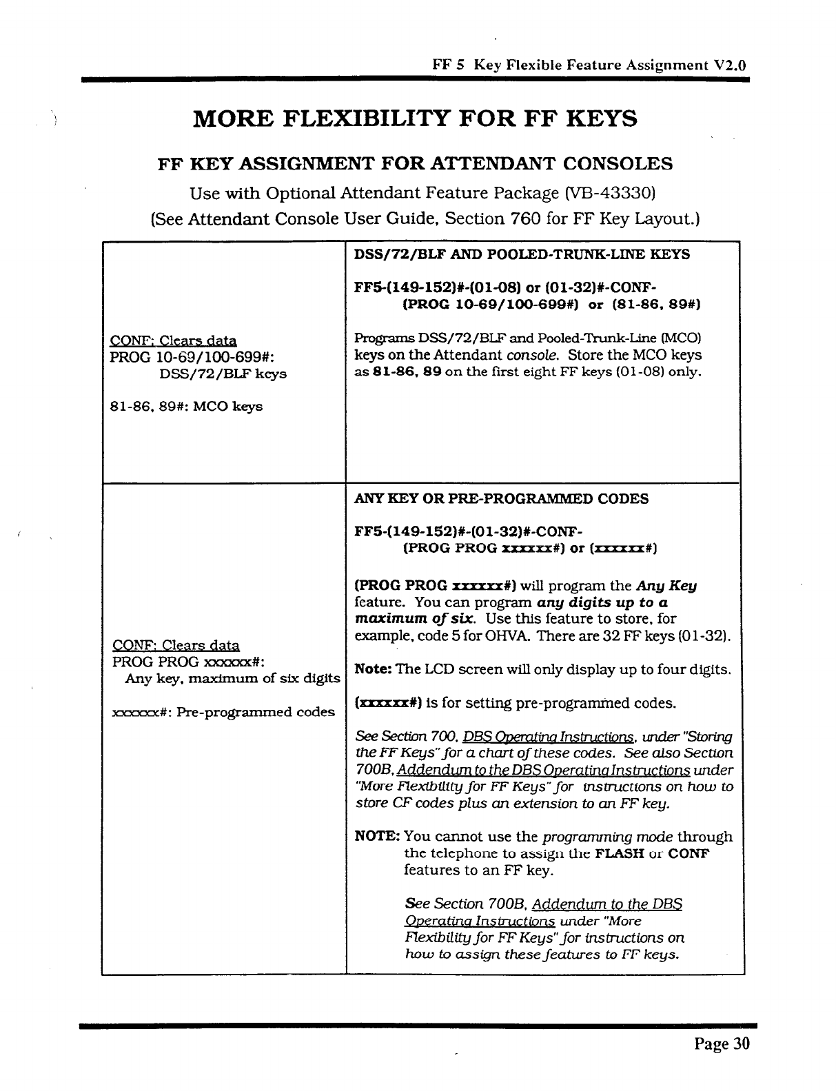
FF 5 Kev Flexible
Feature Assignment V2.0
MORE FLEXIBILITY FOR FF KEYS
FF
KEY ASSIGNMENT FOR ATTENDANT CONSOLES
Use
with Optional Attendant Feature Package (VB-43330)
(See Attendant
Console User Guide. Section 760 for FF Key Layout.)
DSS/72/BLF
AND POOLED-TRUNK-LINE KEYS
FF5-(149-152)#-(01-08) or (Ol-32)X-CONF-
(PROG 10-69/100-699%) or (81-86. 89#)
CONF: Clears dau
PROG lo-69/100-699#:
DSS/72/BLF keys
81-86,89#: MC0 keys
Pmgrams DSS/72/BLF and Pooled-Trunk-Line (MC01
keys on the Attendant console. Store the MC0 keys
as 8 l-86.89 on the first eight FF keys (0 l-08) only.
ANY KEY OR PRE-PROG XUIMMED CODES
FF5-(149-152)X-(Ol-32)#-CONF-
(PROG PROG xxxxxx#) or (-#)
CONF: Clears data
PROG PROG m#:
(PROG PROG
xnxxx#) will program the Any
Key
feature. You can program any digits up to a
maximum ofsix. Use this feature to store, for
example. code 5 for
OIWA. There are 32 F’F
keys (0 l-32).
Any key, maximum of six digits
Note:
The LCD screen will only display up to four digits.
xxxxxx#: Pre-programmed codes (xrxxxxX) is for setting pre-programed codes.
See !3ecm 700.
DBS OKETU&W Instn&ions. URder “Storing
the FF Keys” for a chart of these codes. See also Section
700B. Addendum to the DBS Oweratina Instructions under
“More Flex-&i@ for FF Keys” for instructions on how to
store CF codes plus an extension to an FF key.
NOTE You cannot use the programming mode through
the telephone to assign the
FLASH
or CONF
features to an FF key.
See Section 700B. Addendum to the DBS
Qperatina lnsbuctions under “More
FZexibUity for FF Keys”for instructions on
how to assign these features b FF keys.
Page 30
Technical Manuals Online! - http://www.tech-man.com
i I
FF 6 KEY
NAME ASSIGNMENT
v2.0
Technical Manuals Online! - http://www.tech-man.com
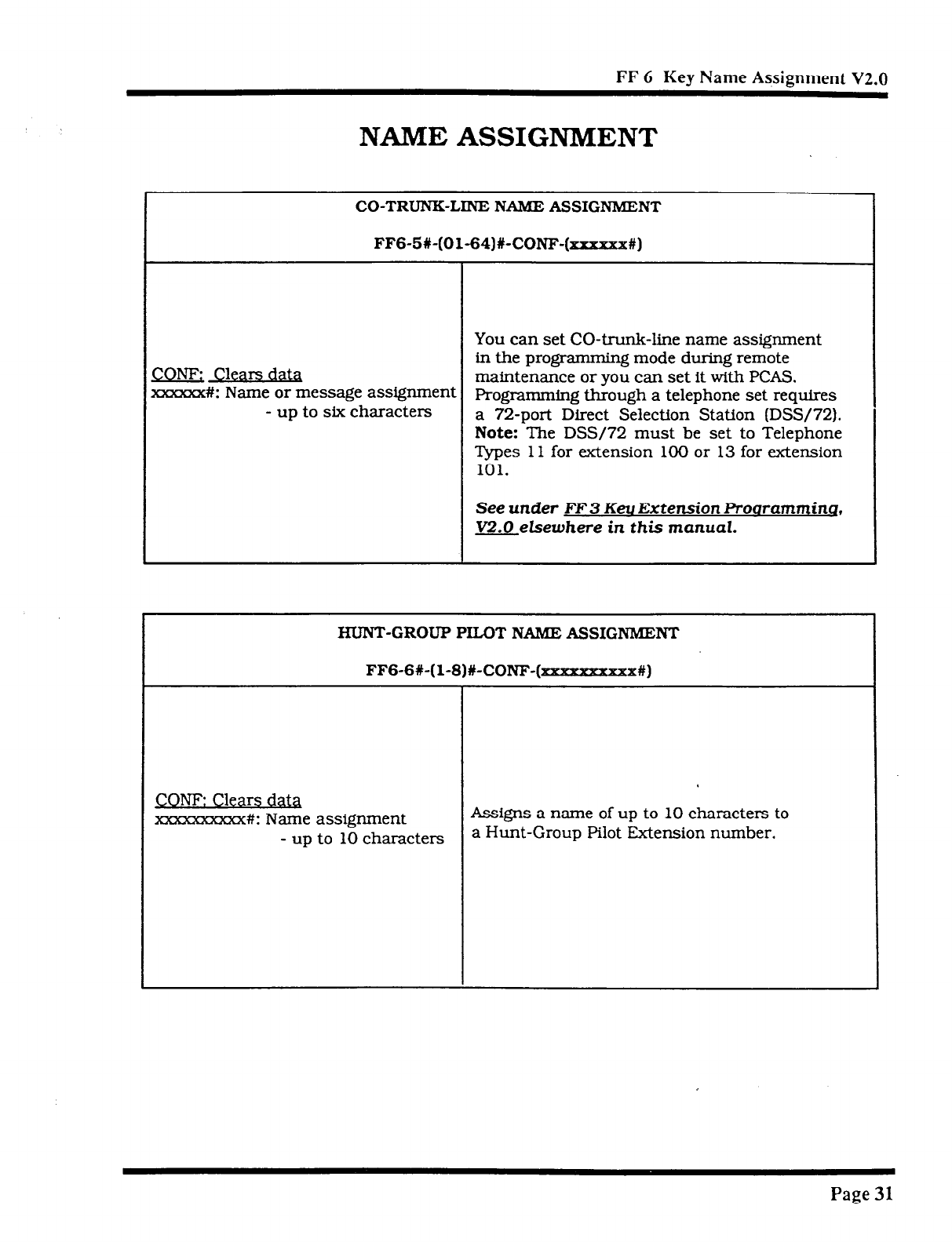
FF 6 Key Name Assignment V2.0
NAME ASSIGNMENT
CO-TRUNK-LINE NAME ASSIGNMENT
FF6-5W-(01-64)#-CONF-(xxxxxx#)
You can set CO-trunk-line name assignment
COW; Clears data in the programming mode during remote
maintenance or you can set it with PCAS.
xxxxxx#I: Name or message assignment Programming through a telephone set requires
- up to six characters a 72-port Direct Selection Station (DSS/72).
Note:
The DSS/72 must be set to Telephone
Types 11 for extension 100 or 13 for extension
101.
See under F’F 3 Keu Extension Proaramminq,
V2.0 elsewhere in this manual.
HUNT-GROUP PILOT NAME ASSIGNMENT
FF6-6X-(l-8)#-CON-F-(naanaaxrmx#)
CONl? Clears data
m#: Name assignment Assigns a name of up to 10 characters to
- up to 10 characters a Hunt-Group Pilot Extension number.
I
Page 31
Technical Manuals Online! - http://www.tech-man.com
\
Index
A
ALMkeyLED 9.15
Any key 12.28.29.30
Attendrqrt console FF key assignment/Any
key/Pre-programmed codes 12.29.30
Attendant console DSS/72/BLF keys 12.29.
30
Attendant consoles 12.29.30
Attendant intercom hold-recall timer 9. 16
Attendant intercom transfer-recall timer 9.
17
Attendant overflow 2.3
Attendant override switch 9. 14
Attendant transfer extension number 9. 14
Attendants 9. 13, 14
B
BLF 8, 12, 29, 30
Busy signaI 10.22
C
CO-trunk-line name assignment
Common system setttngs. V1.0
Common system settings, V2.0
CONF 28.29.30 (See NOTE)
CPC-B - Version 1.0 2-8
WC-B - Version 2.0 9-31
D
Data tables. Vl.0 2
Data tables. V2.0 9- 12
12.31
3.4
9, 15
Daytime delayed-ring tables.
V1.0
2. 7
Delayed-ring capability 2.3
Delayed-ring tables, V1.0 7
Delayed-ring tables. V2.0 10.26. 27
Detection timers, V1.0 5
Dial time out for digits 10.20
DID dial outside telephone number 10. 22
DID interdigit dial time out 10. 20
DID. immediate or wink start 10, 19
DID trunk cards 10. 18
Direct-in-dial (DID) - extensions 22
Direct-in-dial (DID) - trunks 10. 18, 19. 20
Direct Station Select console, V1.0 2. 8
Direct Station Select console. V2.0 12. 29.
30
Distributed. hunt groups 24
DSS/72/BLF consoles, V1.0 2. 8
DSS/72/BLF consoles, V2.0 12. 29. 30
E
EL (extension Iine) keys 12.28
Extension delayed-ring tables 11. 27
Extension delayed-ring capability 9, 15
Extension directory display 10. 21
Extension FF key assignment/Any key/Pre-
programmed codes 12.28
Extension FF key assignment/EL/ML keys
12.28
&tension intercom hold-recall timer 9, 16
Extension intercom transfer-recall timer 9.
17
Extension line (EL) keys 12.28
Extension programming, V2.0 10. 21.22
Extension ring tables 11, 27
F, G
FF 1 Key - System Programming. V1.0 2, 3.
4. 5
FF 1 Key - System Frograrnm irlg. v2.0 9. 13.
14. 15. 16. 17
FF 2 Key - Trunk Programming. W-0 2.6
FF 2 Key - Trunk Programming. V2.0 10.
18
Page 32
Technical Manuals Online! - http://www.tech-man.com
FF 3 Key - Extension Programming, V2.0 10.
21.22
FF 4 Key - Ring Assignment and Hunt Groups,
v1.0 2, 7
FF 4 Key - Ring Assignment and Hunt Groups,
V2.0 10. 23, 24. 25, 26, 27
FF 5 Key - Flexible Feature Key Assignment
V1.0 2. 8
FF 5 Key - Flexible Feature Key Assignment
V2.0 12, 28. 29. 30
FF 6 Key - Name Assignment 12.31
FIASH 28.29.30 (See NOTE)
Fourth attendant extension number 9. 13
H
Hunt-group Daytime CO-line ring tables 11,
23
Hunt-group daytime delayed-ring tables 11,
26
Hunt-group extensions 11.25
Hunt-group nighttime CO-line ring tables 11,
23
Hunt-group nighttime delayed-ring tables 11,
27
Hunt-group-pilot extension number 11, 24
Hunt-group-pilot name assignment 12. 31
Hunt-group programming 11, 24. 25
Hunt-group ring tables 11. 23
Hunt-group search methods 11.24
I. J, K
Incoming CO-line ring signal to a hunt group
23
Incoming ground detection timer, V1.0 2. 5
Initial settings - data tables, V1.0 2
Initial settings - data tables. V2.0 9. 10. 11.
12
Intercom HOLD-recall timers 9. 16
Intercom recall timers 9. 16. 17
Intercom transfer-recall timers 9. 17
L
Longest idle. hunt groups 24
Loop-start/ground-start switch. V1.0 2, 6
Loop-start/ground-start/direct-in-dial. V2.0
10. 18
M
MLkeys 12.28
More flexibility for FF keys 12. 28.29. 30
Multi-line (ML) key features 13. 14. 16. 17
N
Name assignment 12.31
Nighttime delayed-ring tables. V1.0 2. 7
0
(
Outbound ground detection timer. V1.0 2. 5
p* 9
Pilot extension number for a hunt group 11.
24
Preface 1
Pre-programm ed codes 12. 28. 29.30
Pooled-Trunk-Line keys 12. 29. 30
R
RAI baud rate switch, V1.0 2. 4
Ring assignment and hunt groups, V1.0 2, 7
Ring assignment and hunt groups, V2.0 11.
23. 24. 25. 26.27
Ringback tone 22
Ringback tone with busy signal 10.22
Ring tables. V1.0 2. 7
Ring tables. V2.0 11. 23. 24, 25. 26.27
Page 33
Technical Manuals Online! - http://www.tech-man.com
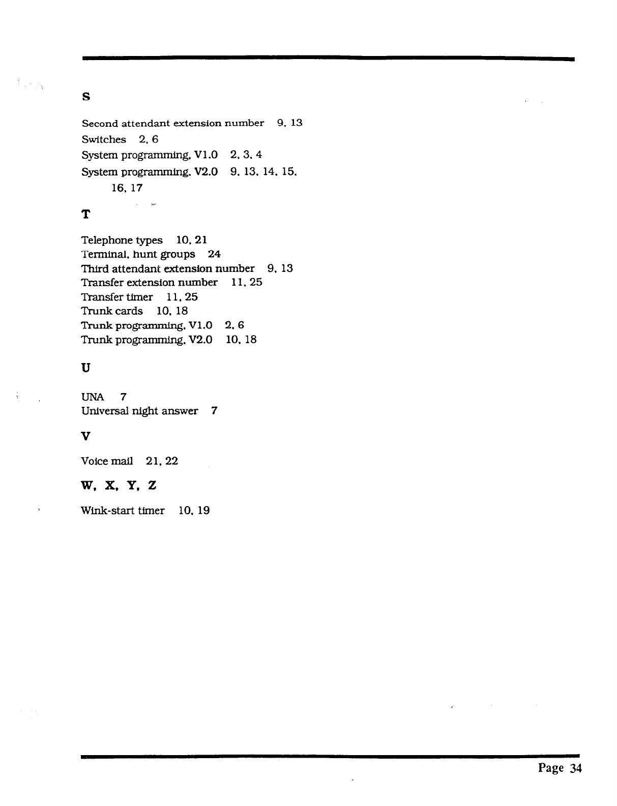
S
Second attendant extension number 9. 13
Switches 2. 6
System programming. V1.0 2. 3. 4
System programming. V2.0 9. 13. 14. 15,
16. 17
v.
T
Telephone types 10.21
Terminal. hunt groups 24
Third attendant extension number 9. 13
Transfer extension number 11.25
Transfer timer 11.25
Trunk cards 10. 18
Tnmk programming, V1.0 2. 6
Trunk programming, V2.0 10.18
U
UNA7
Universal night answer 7
V
Voice mail 21, 22
Wink-start timer 10. 19
Page 34
Technical Manuals Online! - http://www.tech-man.com
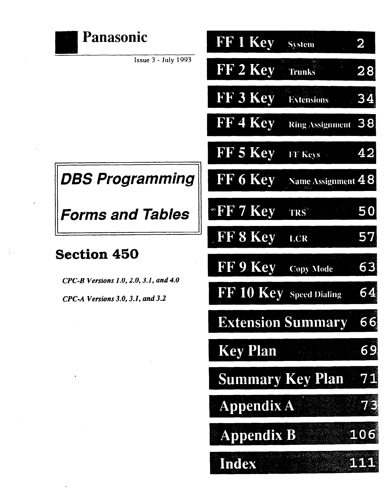
m
Panasonic
Issue 3 -
July 1993
DBS Programming
Forms and Tables
Section 450
CPC-B Versions 1.0,2.0,3.1, and 4.0
CPC-A Versions 3.0,3.1, and 3.2
Technical Manuals Online! - http://www.tech-man.com
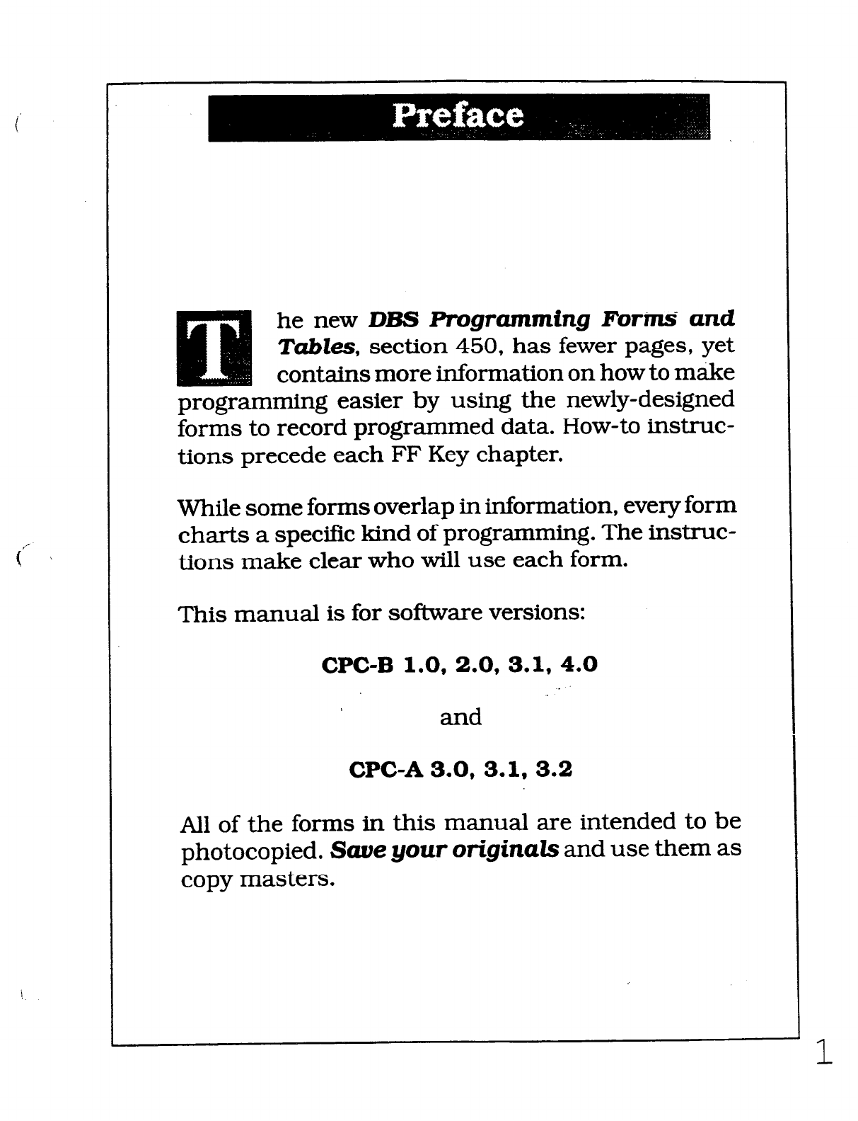
he new DBS Ffogramming Forins‘ and
Tabks, section 450, has fewer pages, yet
contains more information on how to make
programming easier by using the newly-designed
forms to record programmed data. How-to instruc-
tions precede each FF Key chapter.
While some forms overlap in information, every form
charts a specific kind of programming. The instruc-
tions make clear who will use each form.
This manual is for software versions:
CPC-B 1.0, 2.0, 3.1.4.0
and
CPGA3.0, 3.1, 3.2
All of the forms in this manual are intended to be
photocopied. Saue your origin& and use them as
copy masters.
Technical Manuals Online! - http://www.tech-man.com

he FFl Key is for system-wide program-
ming. There are seven submodes (l# to 7#)
for this key.
Time and Date, Recall and Pause timers, and DISA
(Direct Inward System Access) are a few of the nearly
100 features available for programmin g on the FFl
Key.
Features programmed on this key affect the entire
system. In contrast, the other nine FF keys affect only
one extension or trunk, and are programmed on an
extension-by-extension or trunk-by-trunk basis. The
exception to these keys is System Speed Dial. in the
FFlO Key which also affects the entire system.
The programming forms and tables for the FFl Key
apply to each DBS system (single or double cabinet).
The data options for most features are 0 and 1, but
some features have more than these two programming
options. For example, the options for the Paging fea-
ture range from 00 to 07. Other features offer up to 15
options, such as the Automatic Pause Timer and
Unsupervised Conference Talk-Time (trunk-to-trunk
conferencing).
Save Your Original Foims!!!
5 /
Y
8
t
e
m
W
i
d
e
S
8
t
t
i
n
Q
8
( I
/
2
Technical Manuals Online! - http://www.tech-man.com
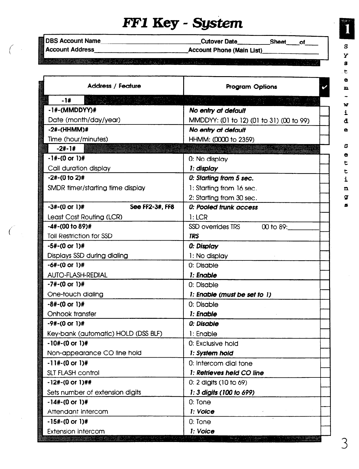
EFIKey-Sgskem
Account Address
SMDR timer/starting time display 1: Starting from 16 sec.
One-touch dialin
-9#-(0 or l)# 0: DisaWe
Key-bank (automatic) HOLD (DSS BLF) 1: Enable
-lO#-(0 or 11% 0: Exclusive hold
Non-appearance CO line hold 1: System ho/d
-1 l#-(0 or l)# 0: Intercom dial tone
SLT FLASH control 1: Retrieves he/d CO line
-12#-(0 or I)## 0: 2 digits (10 to 69)
Sets number of extension digits 1: 3 digiis (100 to 699)
-14#-(Oar 1)X 0: Tone
Attendant intercom 1: Voice
-15#-(0 or 1)X 0: Tone
Extension intercom 1: Voice
s
Y
6
.t
e
m
W
i
d
e
S
e
t
t
i
P
ST
s
3
Technical Manuals Online! - http://www.tech-man.com
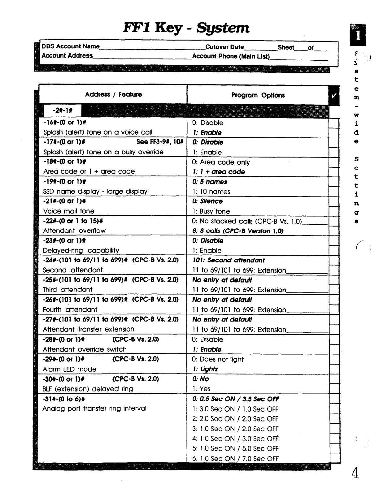
l?FlKey-System
DBF Account Name Cutover Date sheet of
Account Address Account Phone (Main List)
Address / Feature
-16#-(0 or l)#
Solash (alert) tone on a voice call
-17#-(0 or 11% See FF3-99, lO#
Splash (alert) tone on a busy override
-1w(0 or 11%
Area code or 1 + area code
-19#-(0 or I)#
SSD name display - large display
-21X40 or 1)C
Voice mail tone
-22#-(0 or 1 to lS)#
Attendant overflow
-23#-(0 or l)#
Delayed-ring capability
-248~(101 to 69/l 1 to 699)# (WC-B Vs. 20)
Second attendant
-2514101 to 69/l 1 to 699)# (UC-B Vs. 2.0)
Third attendant
-26#-(101 to 69/l 1 to 699)# (CPC-8 Vs. 2.0)
Fourth attendant
-27#-(101 to 69/l 1 to 699)t (WC-B Vs. 20)
Attendant transfer extension
-28140 or 1M (CPC-8 vs. 2.0)
Attendant override switch
-29WO or l)i (CPC-B Vs. 2.0)
Alarm LED mode
-3O#-(0 or 1)R (WC-B Vs. 2.0)
BLF (extension) delaved ring
-31#40 to 6M
Analog port transfer ring interval
1: 10 names
calls (CPC-B Vs. 1.0)
1: 3.0 Set ON / 1 .O Set OFF
2: 2.0 Set ON / 2.0 Set Off
3: 1 .O Set ON / 2.0 Set OFF
4:
1 .O Set ON / 3.0 Set O#
i.. I
1
S
t
8
m
W
i
d
e
S
e
t
t
i
n
Q
8
Technical Manuals Online! - http://www.tech-man.com
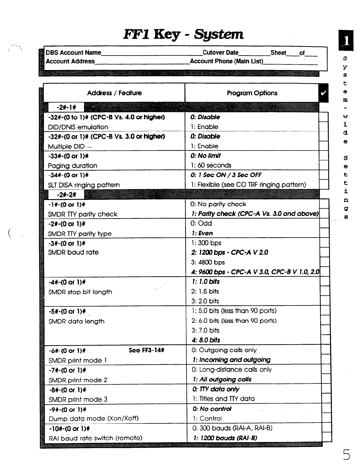
FFIKey-System
Address / Feature Program Options
-32#-(0 to 1)W (CPC-B Vs. 4.0 or higher)
DID/DNIS emulation
0: Disuble
1: Enable
-32X-(0 or l)# (CPC-B Vs. 3.0 or higher)
Multiole DID --
0: Disable
1: Enable
-33%-(0 or 1 )# 0: No limit
Paging duration 1: 60 seconds
-34%-(0 or 1 )# 0: ISecON/3SecOFF -
-I#-(0 or l)#
SMDR lTY parity check
-2#-(0 or I)#
SMDR lTY parity type
-3#-(0 or 1)R
SMDR baud rate
-4#-(0 or 1)X ..
SMDR stop-bit length .
-W-(0 or 1)X
SMDR data length
-6#-(0 or l)# See FF3-14R
SMDR print mode 1
-7#-(0 or l)#
SMDR print mode 2
-8X-(0 or I)#
SMDR print mode 3
-9#-(0 or l)#
Dump data mode (Xon/XoffI
-lO#-(0 or I)#
RAI baud rate switch (
0: No parity check
1: Purify check (CPC-A Vs. 3.0 and above)
0: Odd
1: Even
1: 300 bps
2: 1200 bp - WC-A V 2.0
3: 4800 bps
4: %lXl bps - WC-A V 3.0, CPC-B V 1.0,2-O
1: l.Obits
2: 1.5 bits
3: 2.0 bits
1: 5.0 bits (less than 90 ports)
2: 6.0 bits (less than 90 ports)
3: 7.0 bits
4: 8.0 bits
0: Outgoing calls only
1: lncofning und outgoing
0: Long-distance calls only
1: Ail outgoing calls
O:lWCklfUonly
1: Titles and llY data
0: No control
I: Control
0: 300 bauds (RAI-A, RAI-B)
s
Y
S
t
e
m
W
i
d
e
S
e
t
t
i
n
B
8
Technical Manuals Online! - http://www.tech-man.com
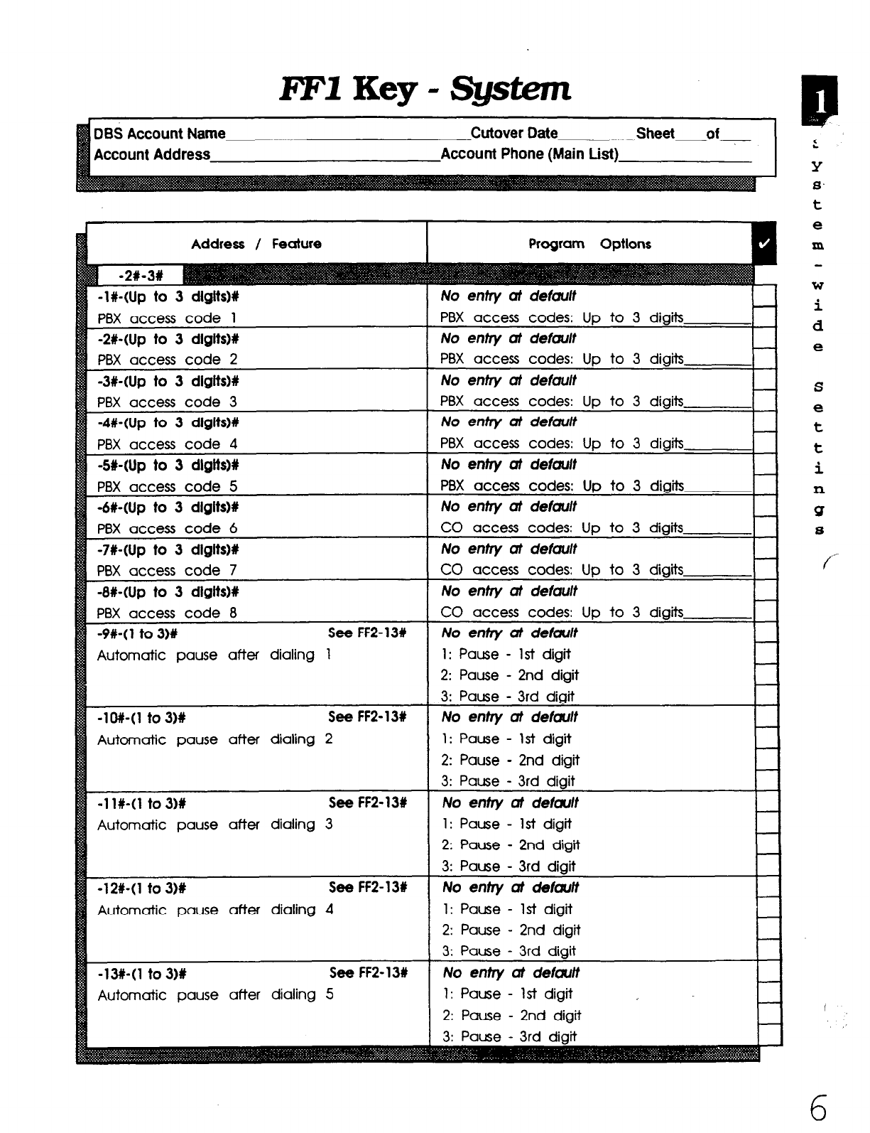
FFlKey-System
me
Account Address
Cutover Date
Account Phone (Main
Address / Feature
-I#-(Up to 3 dlglts)#
PBX access code 1
-2X-(Up to 3 dlgits)#
PBX access code 2
-3X-(Up to 3 digits)#
PBX access code 3
-4X-(Up to 3 dlgltsM
PBX access code 4
-5HUp to 3 dlgtts)P
PBX access code 5
-6#-(Up to 3 dlglts)#
PBX access code 6
-7#-(Up to 3 dlgits)t
PBX access code 7
-8WUp to 3 dlglts)#
PBX access code 8
-9%~(1 to 3)#
See FF2-13#
Automatic pause after dialing 1
-low to 3)X See FF2-13t
Automatic pause after dialing 2
-1 l#-(1 to 3)# See FF2-131
Automatic pause after dialing 3
-12#-(1 to 3)# See FFZ- 13#
Automatic pause after dialing 4
-13w to 3)# See FF2-131
Automatic pause after dialing 5
1: Pause - 1st digit
2:
Pause - 2nd digit
3: Pause - 3rd diait
No entry at default
1: Pause - 1st digit
2:
Pause - 2nd digit
3:
Pause - 3rd diait
No entry at deiautt
1: Pause - 1st digit
2:
Pause - 2nd digit
3: Pause - 3rd digit
No
enfry at default
1: Pause - 1st digit
2:
Pause - 2nd digit
2
Y
8.
t
e
m
W
i
d
e
S
e
t
t
i
n
Q
8
/-
6
Technical Manuals Online! - http://www.tech-man.com
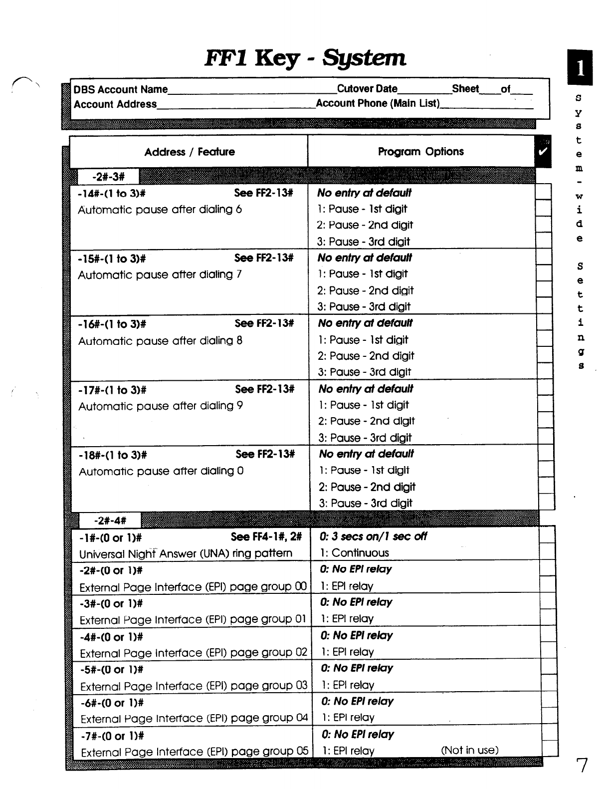
PFlKey-System
Account Address
Address / Feature
-14#-(1 to 316 See FF2-13#
Automatic pause after dialing 6
-W-(1 to 3)# See FF2-13#
Automatic pause after dialing 7
-l#-(1 to 3)# See FF2-13#
Automatic pause after dialing 8
-17#-(1 to 3)# See FF2-13#
Automatic pause after dialing 9
-18#-(1 to 3M See FF2-13#
Automatic pause after dialing 0
-l#-(0 or l)# See FF4- 1#, 2#
Universal Nigtif‘ Answer (UNA) ring pattern
-2#-(0 or l)#
External Page Interface (EPI) page group OC
-3#-(0 or l)#
External Page Interface (EPI) page group 01
-4#-(0 or l)#
External Page Interface (EPI) page group 0:
-5#-(0 or l)#
External Page Interface (EPI) page group 0:
-6#-(0 or l)#
External Page Interface (EPI) page group 01
-7#-(0 or l)#
Program Options
No entry at defauff
1: Pause - 1st digit
2: Pause - 2nd digit
1: Pause - 1 st digit
2: Pause - 2nd digit
No entry of defuu/f
1: Pause - 1 st digit
2: Pause - 2nd digit
1: Pause - 1 st digit
2: Pause - 2nd digit
1: Pause - 1st digit
2: Pause - 2nd digit
0:3secson/l secot7
1: Continuous
0: No fP/ reluy
1: EPI relay
0: No ffl reluy
1: EPI relay
0: No
EPI rely
1: EPI relay
0: No EPI rew
S
Y
S
t
e
m
W
i
d
e
S
e
t
t
i
n
Q
S
Technical Manuals Online! - http://www.tech-man.com
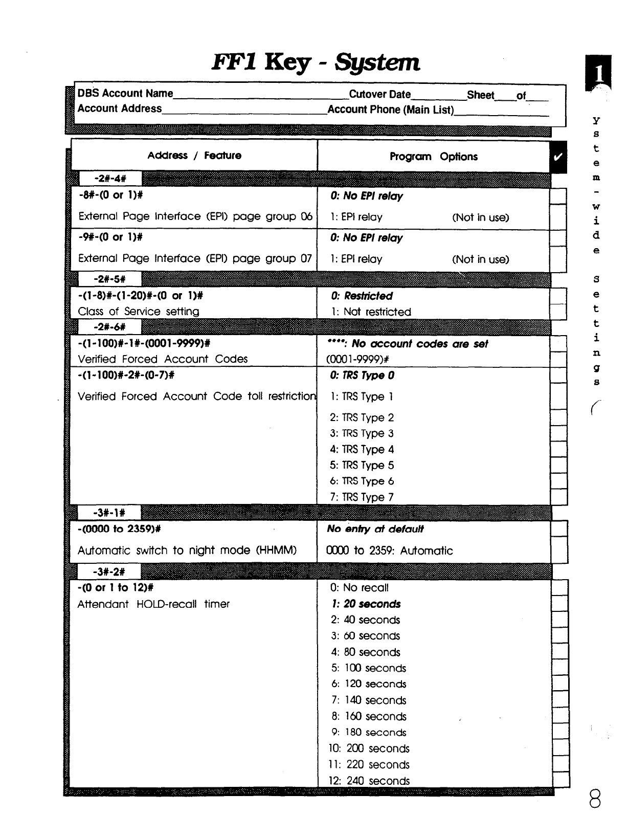
FFIKey-system
Account Address Account Phone (Main List)
I I
Address / Feature
8x-(0 or I)#
ixternal Page interface (EPI) page group 06
lxternal Page Interface (EPI) page group 07
(l-8)+( l -20)#-(0 or 1)X
:lass of Service settina
(l-100)X-l#-(0001~9999)X
‘erified Forced Account Codes
(1-l OO)#-2#-(0-7)s
‘erified Forced Account Code toll restrictior
(0000 to 2359)#
Uomatic switch to night mode (HHMM)
(0 or 1 to 12)#
rttendant HOLD-recall timer
1: EPI relay (Not in use)
0: No EPI relay
1: EPI relay (Not in use>
0: Restricted
1: Not restricted
l “*: No uccount
cooo1-9999w
codes me
0:TRSTypeO
1: TPSType 1
2:
m.S Type 2
3:
TRS Type 3
4: lRS Type 4
5: TRS Type 5
6:
TRS Type 6
No infry af defautf
OWO to 2359: Automatic
0: No recall
I: 20
seconds
2:
40 seconds
3:
60 seconds
4:
80 seconds
5: 100 seconds
6: 120 seconds
7:
140 seconds
8:
160 seconds
9:
180 seconds
10: 200 seconds
11: 220 seconds
12: 240 seconds
Y
s
t
e
m
W
i
d
e
Technical Manuals Online! - http://www.tech-man.com
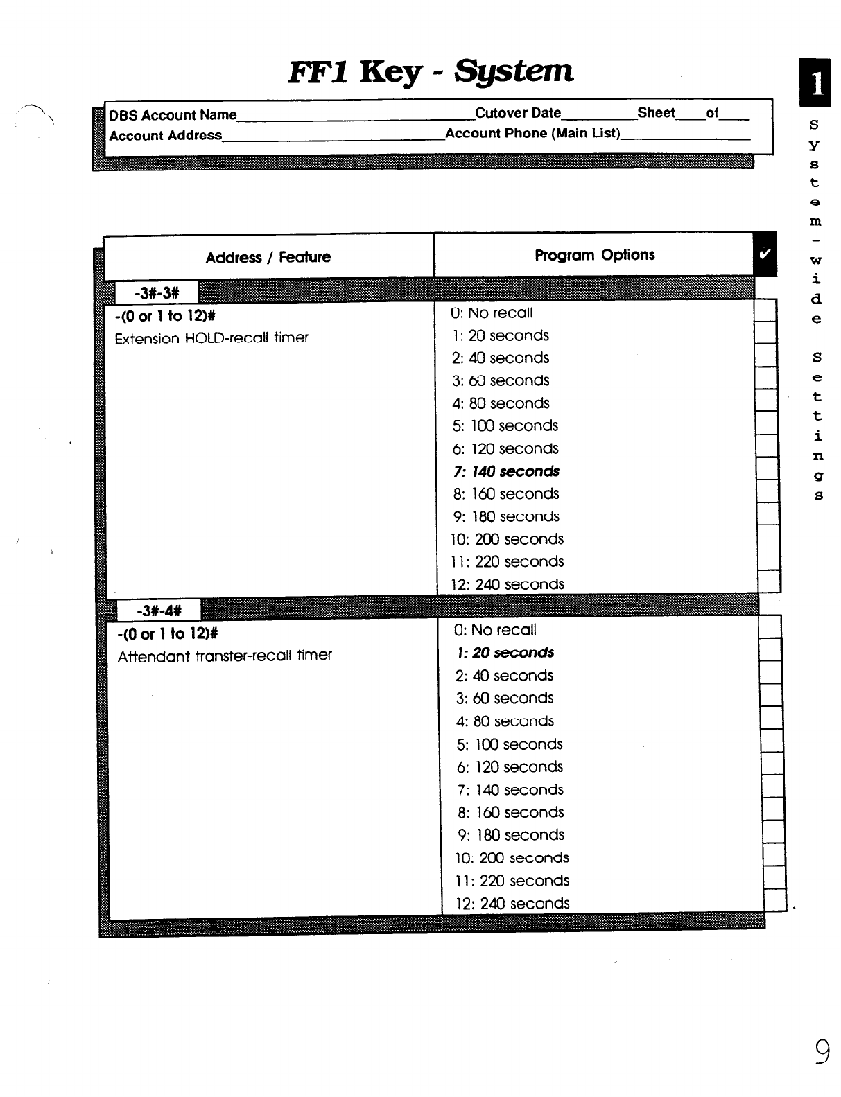
RF1
Key - System
Account Address Account Phone (Main List)
Address / Feature
-(O or 1 to 12)X
Extension HOLD-recall timer
-(O or 1 to 12)#
Attendant transfer-recall timer
0: No recall
1: 20 seconds
2: 40 seconds
3: 60 seconds
4: 80 seconds
5: 100 seconds
6: 120 seconds
7:
14Oseconds
8: 160 seconds
9: 180 seconds
10: 200 seconds
11: 220 seconds
0: No recall
I: 20
seconds
2: 40 seconds
3: 60 seconds
4: 80 seconds
5: 100 seconds
6: 120 seconds
7: 140 seconds
8: 160 seconds
9: 180 seconds
10: 200 seconds
11: 220 seconds
12: 240 seconds
S
Y
8
t
e
In
W
i
d
e
S
e
t
t
i
n
Q
8
9
Technical Manuals Online! - http://www.tech-man.com

I?FlKey-Systam
Address / Feature
-(O or 1
to
121%
Extension transfer-recall timer
Attendant Hunt Group recall timer
0: No recall
1: 20 seconds
2: 40 seconds
3: 60 seconds
4: 80 seconds
5: 100 seconds
6: 120 seconds
7:
14oseconds
8: 160 seconds
9: 180 seconds
10: 200 seconds
11: 220 seconds
12: 240 seconds
0: No recall
1: 20 seconds
2: 40 seconds
3: 60 seconds
4: 80 seconds
5: 100 seconds
6: 120 seconds
7: 140 seconds
8: 160 seconds
9: 180 seconds
10: 200 seconds
11: 220 seconds
9.
F
Y
8
t
e
m
W
i
d
e
10
Technical Manuals Online! - http://www.tech-man.com

FEY
Key - System
f-‘ Bs Account Name Cutover Date Sheet of
\ ccount Address Account Phone (Main List)
Address /’ Feature
Extension Hunt Group recall timer
Attendant park HOLD recall timer
1: 20 seconds
2: 40 seconds
3: 60 seconds
4: 80 seconds
5: 100 seconds
6: 120 seconds
7: 14Oseconds
8: 160 seconds
9: 180 seconds
10: 200 seconds
11: 220 seconds
0: No recall
1: 20 seconds
2: 40 seconds
3: 60 seconds
4: 80 seconds
5: 100 seconds
6: 120 seconds
7: 140 seconds
8: 160 seconds
9: 180 seconds
10: 200 seconds
11: 220 seconds
S
Y
8
t
e
m
W
i
d
e
S
e
t
t
i
n
Q
s
1:
Technical Manuals Online! - http://www.tech-man.com
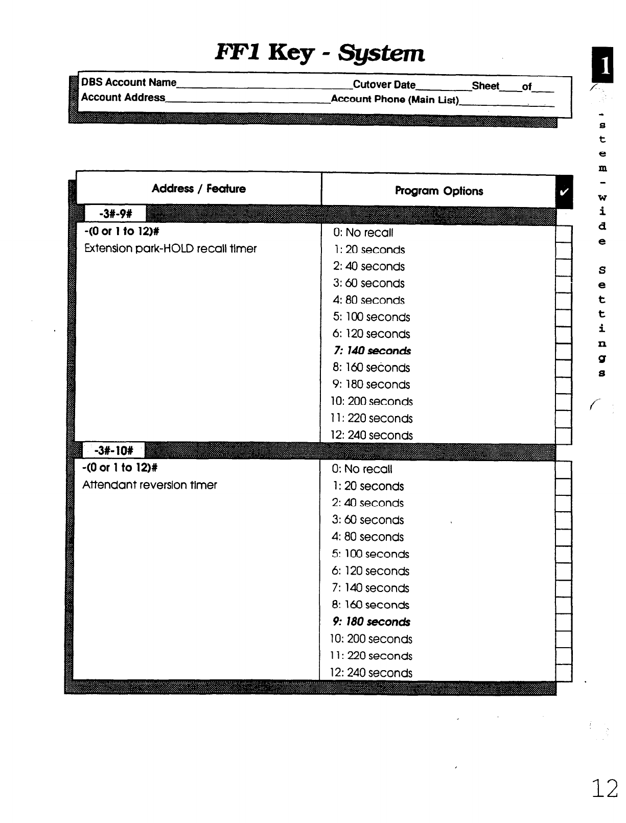
FFY
Key - Sgstem
BS Account Name
ccount Address
Cutover Date Sheet of
Account Phone (Main List)
Address / Feature
&tension park-HOLD recall tlmer
(0 or 1 to 12)#
Wendant reversion timer
0: No recall
1: 20 seconds
2: 40 seconds
3: 60 seconds
4: 80 seconds
5: 100 seconds
6: 120 seconds
7: 140 seconds
8: 160 seconds
9: 180 seconds
10: 200 seconds
11: 220 seconds
0: No recall
1: 20 seconds
2: 40 seconds
3: 60 seconds
4: 80 seconds
5: 100 seconds
6: 120 seconds
7: 140 seconds
8: 160 seconds
9: 180 seconds
10: 200 seconds
11: 220 seconds
u
/r.
8
t
e
In
W
i
d
e
S
e
t
t
i
Il
Q
8
12
Technical Manuals Online! - http://www.tech-man.com
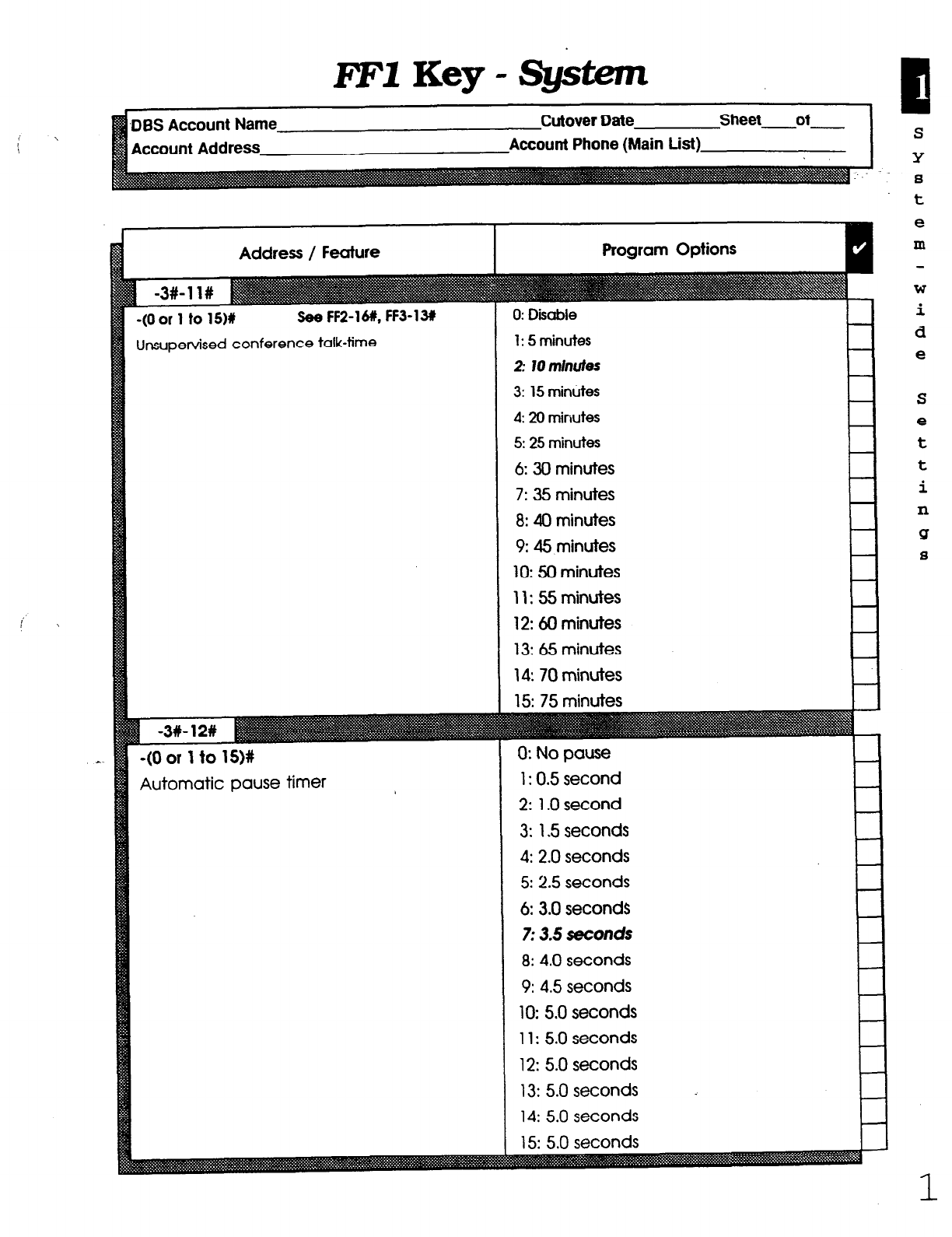
l?Fl
Key - System
unt Phone (Main List)
Address / Feature
(Oor 1 to 1511 See FF2-16#, FF3-131
Insupervised conference talk-time
*(O or 1
to
1SM
4utomatic pause timer
1: 5 minutes
2: l0m//wfes
3:
15 minutes
4: 20 minutes
5: 25
minutes
6: 30 minutes
7: 35 minutes
8: 40 minutes
9: 45 minutes
10: 50 minutes
11: 55 minutes
12: 60 minutes
13: 65 minutes
14: 70 minutes
0: No pause
1: 0.5 second
2:
1 .O second
3:
1.5 seconds
4: 2.0
seconds
5: 2.5 seconds
6: 3.0
seconds
7: 3.5 seconds
8: 4.0
seconds
9: 4.5
seconds
10: 5.0 seconds
11: 5.0 seconds
12: 5.0 seconds
13: 5.0 seconds
14: 5.0 seconds
t
e
m
W
i
d
e
S
e
t
t
i
n
sr
a
Technical Manuals Online! - http://www.tech-man.com
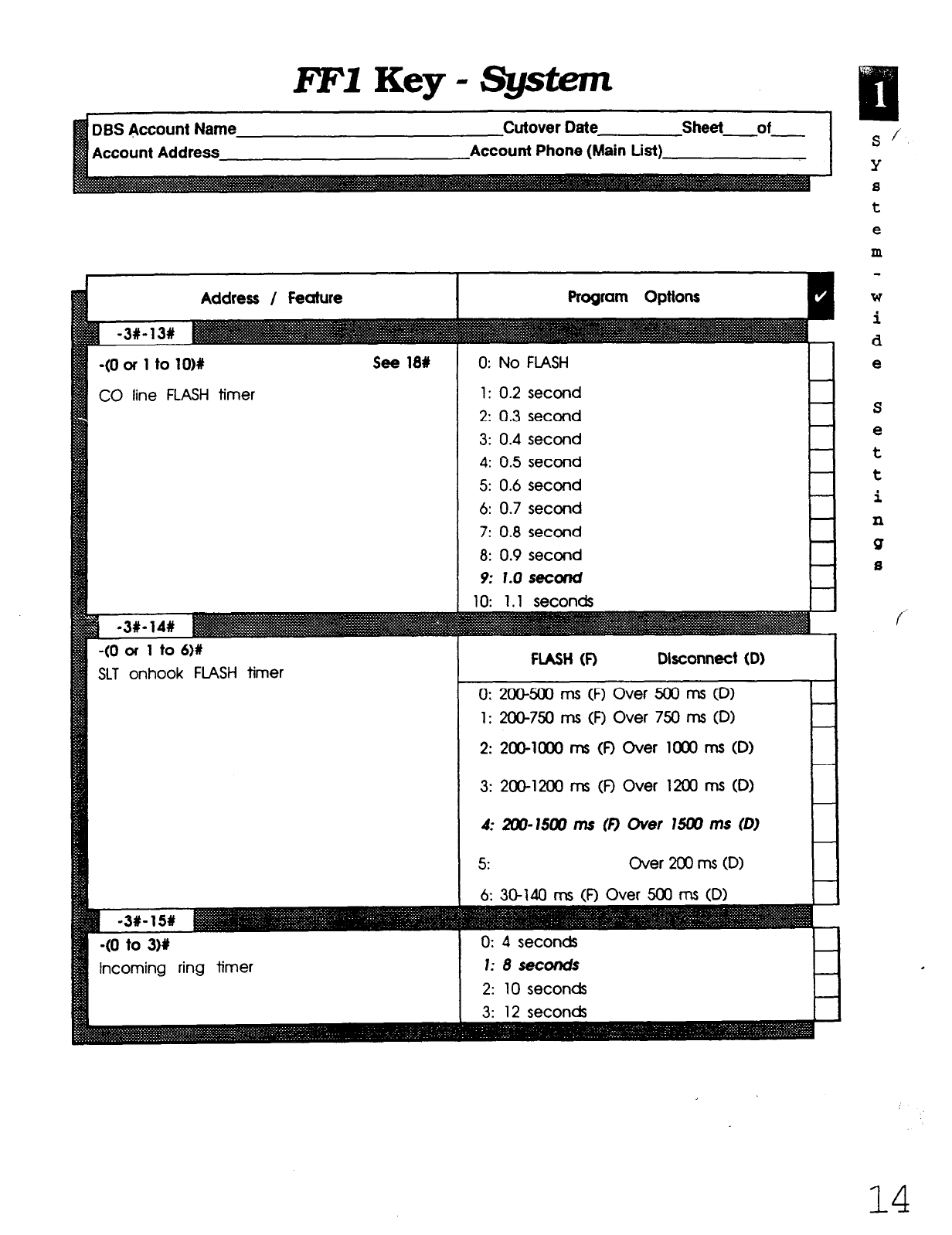
FFlKey-@stem
Name
Account Address
Cutover Date Sheet of
Account Phone (Main List)
Address / Feature
-(O or 1 to 1OM
CO line FLASH timer
see 18#
-(O or 1 to 6)#
SLT onhook FLASH timer
-(O to 3M
incoming ring timer
0: No FLASH
1: 0.2 second
2: 0.3 second
3: 0.4 second
4: 0.5 second
5: 0.6 second
6: 0.7 second
7: 0.8 second
8: 0.9 second
9: 1.0 secorld
FLASH (0
Disconnect
(D) I
0: 200-500 ms (I? Over 500 IT-IS CD)
1:
2OW50 ms (0 Over 750 ms 0
2: 200-1CXlO ms (0 Over 1 Ooo ms (D)
3: 2O@l200 ms (0 Over 1200 ms (0)
4: ZW-15W
ms 0 Over 15W ms (0
5: Over 200 ms CD>
6: 30-W rns CR Over 500 ms (D)
0: 4 seconds
1:8seconds
S/
Y
s
t
e
m
W
i
d
e
f
14
Technical Manuals Online! - http://www.tech-man.com
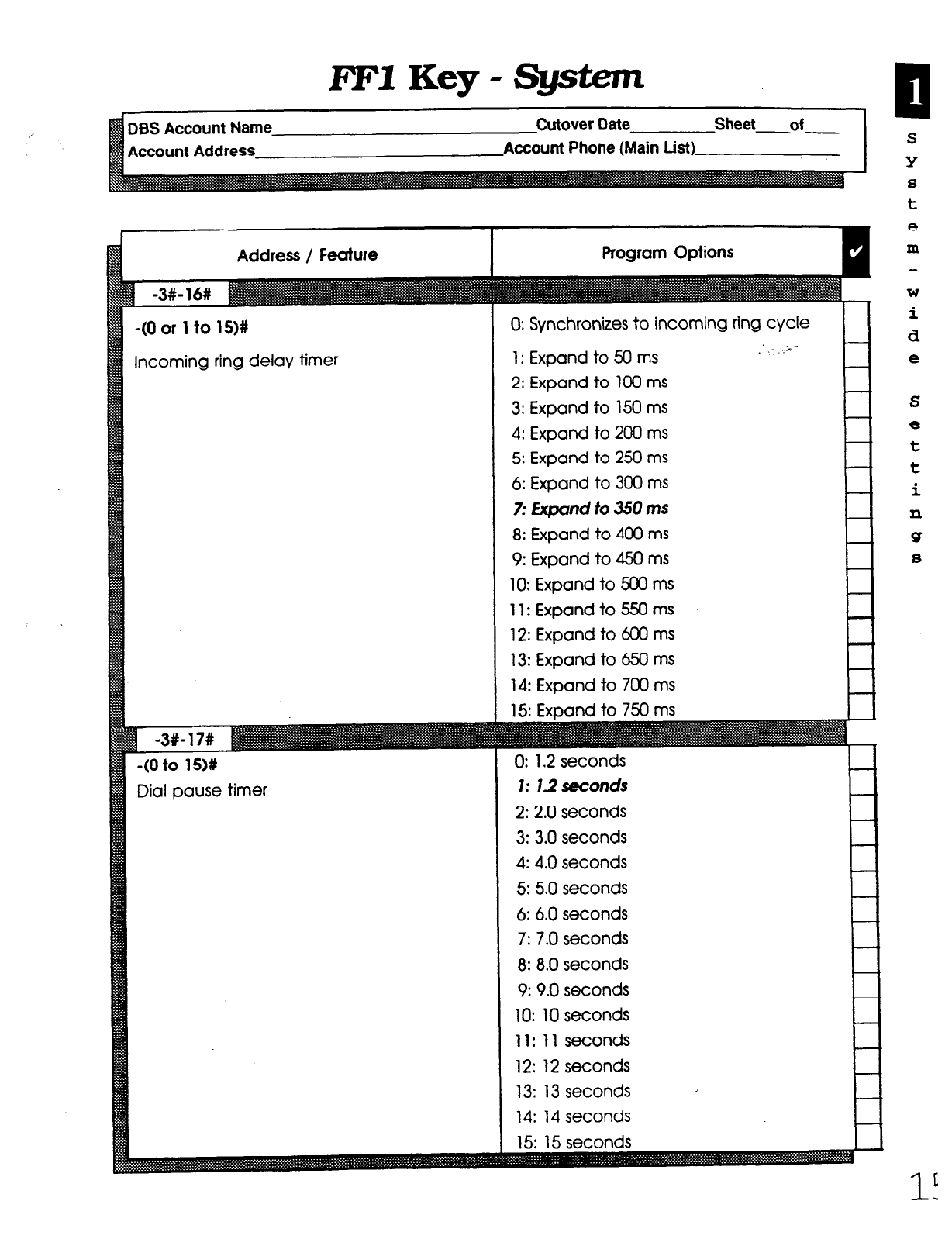
FFYKey-System
Account Address
Address /
Feature
-(O 01 1 to 15)#
ncoming ring delay timer
-(O to lS)#
Dial pause timer
O: Synchronizes to incoming ring cycle
1: Expand to 50 ms
2: Expand to 100 ms
3: Expand to 150 ms
4: Expand to 200 ms
5: Expand to 250 ms
6: Expand to 300 ms
7:
Expand to 350 ms
8: Expand to 400 ms
9: Expand to 450 ms
IO: Expand to 500 ms
I 1: Expand to 550 ms
12: Expand to 600 ms
13: Expand to 650 ms
14: Expand to 700 ms
0: 1.2 seconds
1: 1.2 seconds
2: 2.0
seconds
3: 3.0
seconds
4: 4.0
seconds
5: 5.0 seconds
6: 6.0
seconds
7: 7.0
seconds
8: 8.0
seconds
9: 9.0
seconds
10: 10 seconds
11: 11 seconds
12: 12 seconds
13: 13 seconds
14: 14 seconds
P
S
Y
8
t
e
m
W
i
d
e
S
e
t
t
i
xl
Q
8
Technical Manuals Online! - http://www.tech-man.com
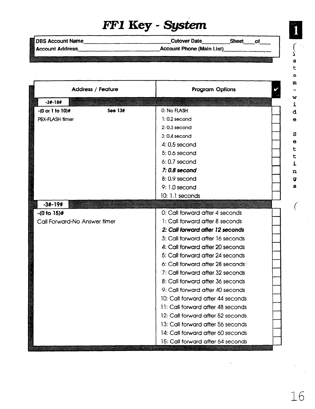
lTF1 Key - System
BS Account Name Cutover Date
ccount Address Account Phone (Main List)
Address / Feature
-(O or 1 to lO)#
PBX-FLASH timer
-(O to 15)#
Call Forward-No Answer timer
0: No FLASH
1: 0.2 second
2: 0.3 second
3: 0.4 second
4: 0.5 second
5: 0.6 second
6: 0.7 second
7: 0.8 second
8: 0.9 second
9: 1 .O second
10: 1.1 seconds
0: Call forward after 4 seconds
1: Call forward after 8 seconds
2: Cd forward affer 12 seconds
3: Call forward after 16 seconds
4: Call forward after 20 seconds
5: Call forward after 24 seconds
6: Call forward after 28 seconds 1
7: Call forward after 32 seconds
8: Call forward after 36 seconds
9: Call forward after 40 seconds
10: Call forward after 44 seconds
11: Call forward after 48 seconds
12: Call forward after 52 seconds
13: Call forward after 56 seconds
14: Call forward after 60 seconds
j
t
s
8
t
e
m
w
i
d
e
S
e
t
t
i
n
Q
8
16
Technical Manuals Online! - http://www.tech-man.com
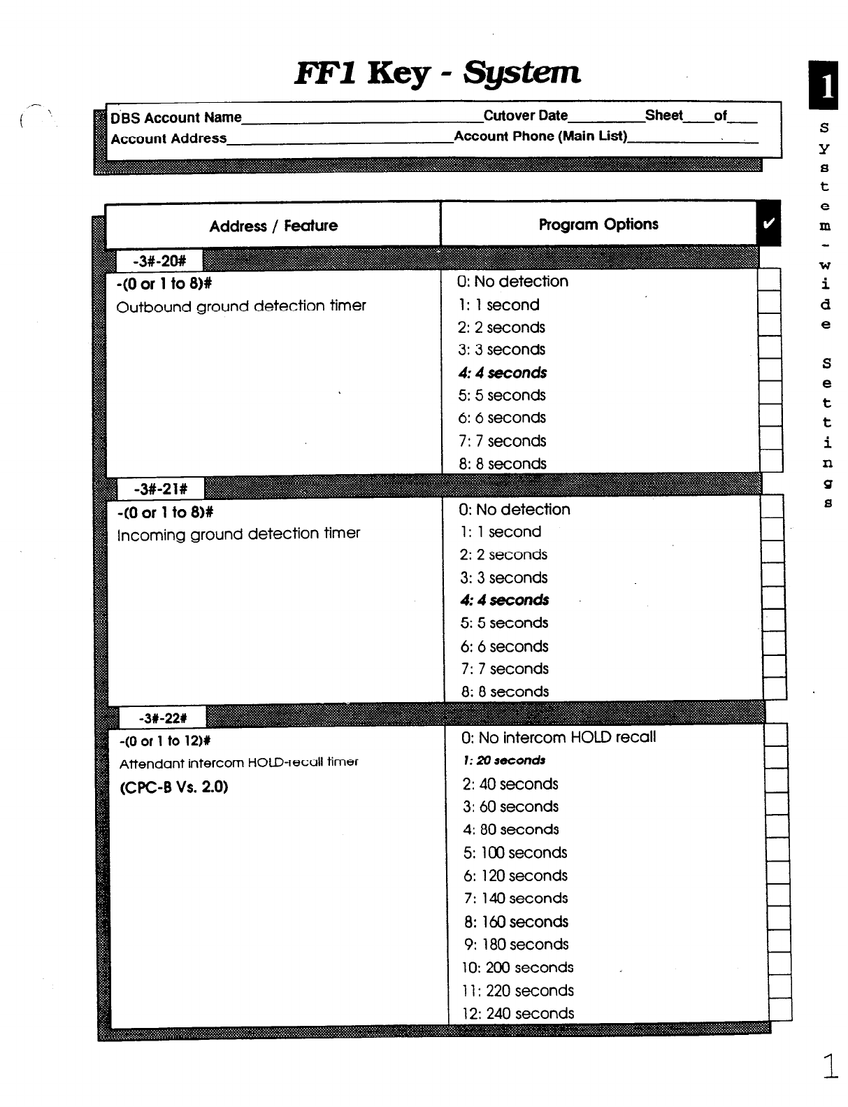
i’- ’
FFlKey-Systxm
dBS Account Name
Account Address
Cutover Date Sheet of
Account Phone (Main List)
Address / Feature
-(O or 1 to 8)#
Outbound ground detection timer
-(O or 1 to 818
Incoming ground detection timer
-(O or 1 to 1216
Attendant intercom HOLD-recall timer
(UC-B Vs. 2.0)
1: 1 second
2: 2
seconds
3: 3
seconds
4: 4
seconds
5: 5 seconds
6: 6 seconds
7: 7
seconds
0: No detection
1: 1 second
2: 2
seconds
3: 3
seconds
#:#seconds
5: 5 seconds
6: 6 seconds
7: 7
seconds
0: No intercom HOLD recall
I: 20 seconds
2: 40
seconds
3: 60
seconds
4:
80 seconds
5:
100 seconds
6:
120 seconds
7:
140 seconds
8:
160 seconds
9: 180
seconds
10: 200 seconds
11: 220 seconds
S
Y
8
t
e
m
W
i
d
e
S
e
t
t
i
n
Q
8
1
Technical Manuals Online! - http://www.tech-man.com
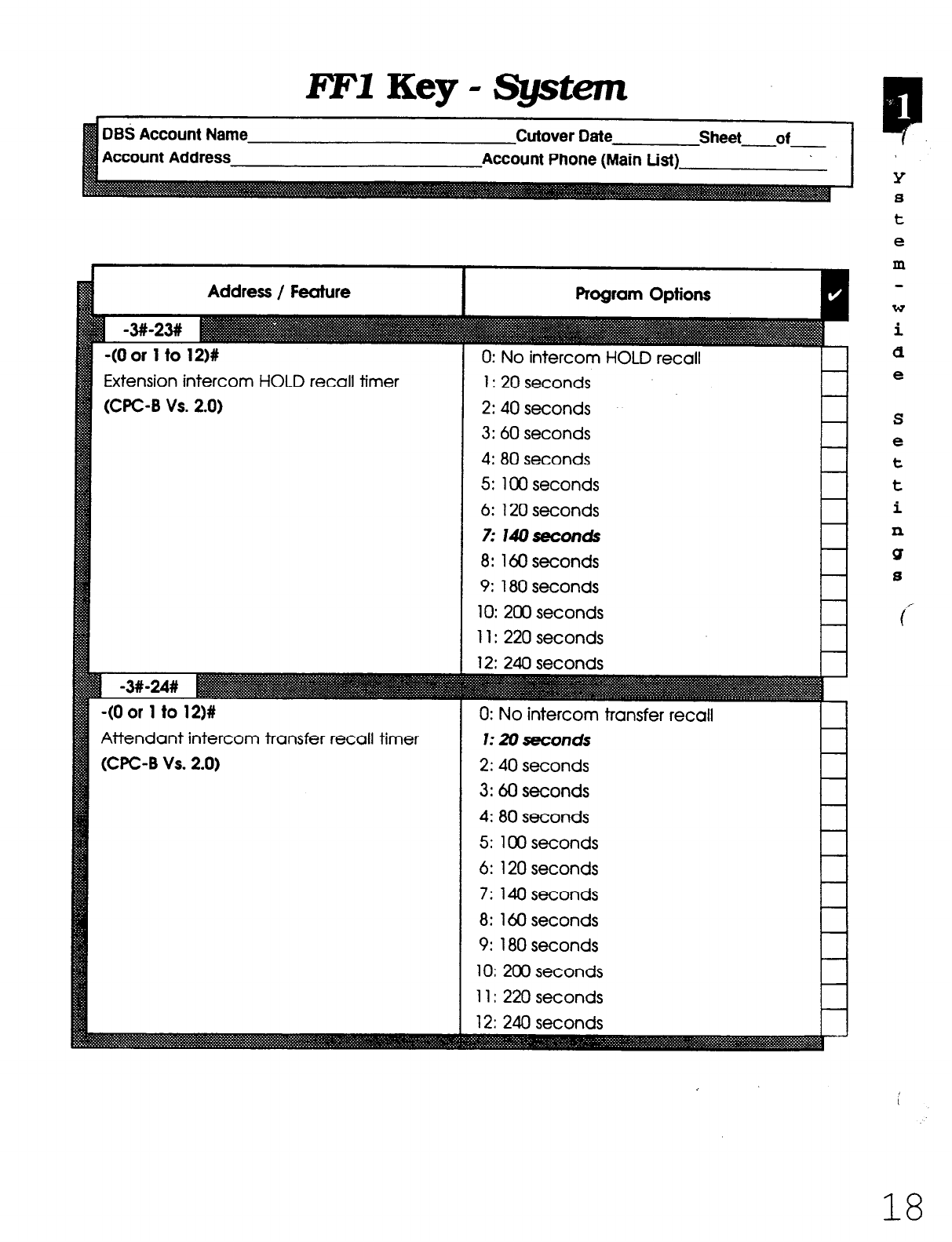
RF1
Key - System
Account Addre
Address / Feature
-(O or 1 to 12)#
Extension intercom HOLD recall timer
WC-B Vs. 2.0)
-(O or 1 to 12)#
Attendant intercom transfer recall timer
WC-8 Vs. 2.0)
Program Options
0: No intercom HOLD recall
1: 20 seconds
2: 40
seconds
3: 60
seconds
4: 80
seconds
5: 100 seconds
6:
120 seconds
7:
14oseconds
8:
160 seconds
9:
180 seconds
10: 200
seconds
11: 220 seconds
12: 240 seconds
0: No intercom transfer recall
1: 20 seconds
2: 40
seconds
3:
60 seconds
4: 80
seconds
5: 100 seconds
6:
120 seconds
7:
140 seconds
8:
160 seconds
9:
180 seconds
10: 200 seconds
11: 220 seconds
12: 240 seconds
Y
8
t
e
m
W
i
d
e
S
e
t
t
i
11
Q
8
18
Technical Manuals Online! - http://www.tech-man.com
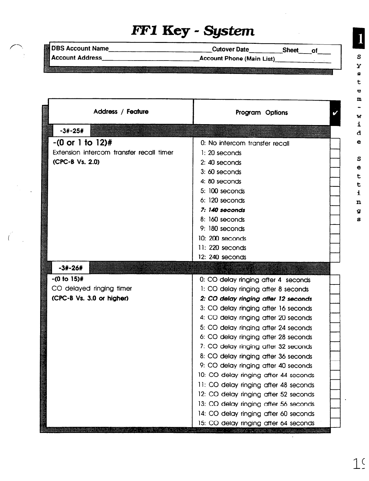
RF1
Key - Sgstem
D’BS Account Name
Account Address
Cutover Date Sheet of
--
Account Phone (Main List)
Address / Feature
-(O or 1 to 12)#
Extension intercom transfer recall timer
(CPC-6 vs. 2.0)
CO delayed ringing timer
WC-B Vs. 3.0 or higher)
Program Options
0: No intercom transfer recall
1: 20
seconds
2:
40 seconds
3:
60 seconds
4: 80 seconds
5: 100 seconds
6: 120 seconds
7: 140 seconds
8:
160 seconds
9: 180 seconds
10: 200
seconds
11: 220 seconds
12: 240 seconds I I
0: CO delay ringing after 4 seconds
1: CO delay ringing after 8 seconds
2:
CO delay ringing ufier 12 seconds
3: CO delay ringing after 16 seconds
4: CO delay ringing after 20 seconds
5: CO delay ringing after 24 seconds
6: CO delay ringing after 28 seconds
7: CO delay ringing after 32 seconds
8: CO delay ringing after 36 seconds
9: CO delay ringing after 40 seconds
10: CO delay ringing after 44 seconds
11: CO delay ringing after 48 seconds
12: CO delay ringing after 52 seconds
13: CO delay ringing after 56 seconds
14: CO delay ringing after 60 seconds
S
Y
8
t
e
m
W
i
d
e
S
e
t
t
i
n
!3
8
Technical Manuals Online! - http://www.tech-man.com

FFIKey-System
DBS Account Name Cutover Date Sheet of
Account Address Account Phone (Main List)
Address / Feature
EXT. delayed ringing timer
(WC-6 Vs. 3.0 or higher)
Hunt Group no answer
(CPC-B Vs. 3.0 or higher)
-(HHMMM
(WC-B Vs. 4.0 or higher)
0: EXT. delay ringing after 4 seconds
1: EXT. delay ringing after 8 seconds
2: EXT. deby thgbhg crlyer 12 seconds
3: EXT. delay ringing after 16 seconds
4: EXT. delay ringing after 20 seconds
5: EXT. delay ringing after 24 seconds
6: EXT. delay ringing after 28 seconds
7: EXT. delay ringing after 32 seconds
8: EXT. delay ringing after 36 seconds
9: EXT. delay ringing after 40 seconds
10: EXT. delay ringing after 44 seconds
11: EXT. delay ringing after 48 seconds
12: EXT. delay ringing after 52 seconds
13: EXT. delay ringing after 56 seconds
14: EXT. delay ringing after: 60 seconds
0: H. Group no answer after 4 seconds
1: H. Group no answer after 8 seconds
2: If. Grout no mswer offer 12 seconds
3: H. Group no answer after 16 seconds
4: H. Group no answer after 20 seconds
5: H. Group no answer after 24 seconds
6: H. Group no answer after 28 seconds
7: H. Group no answer after 32 seconds
8: H. Group no answer after 36 seconds
9: H. Group no answer after 40 seconds
10: H. Group no answer after 44 seconds
11: H. Group no answer after 48 seconds
12: H. Group no answer after 52 seconds
13: H. Group no answer after 56 seconds
14: H. Group no answer atier 60seconds
15: H. GrouD no answer after 64 seconds
HH: Hours (00 to 23)
MM: Minutes (00 to 23)
P
Y
8
t
e
m
W
i
d
e
S
e
t
t
i
n
Q
8
c
c
2c
Technical Manuals Online! - http://www.tech-man.com

FFl Key -
System
DBS Account Name
Account Address
Cutover Date Sheet of
Account Phone (Main List)
Address / Feature
-(4 digts)# Ako used with DISA
Remote maintenance I
-(4 diglts)# See FF2-ill. 191, 20#
-(4 d@tsM See FFZ-11X, 19#, 20#
-(4 digtk)#
-(O Of 1)Y (CPC-B Vs. 3.0 or hlghed
DID reset
-(O to 111 (CPC-B Vs. 4.0 01 hlgher)
DID/l1 reset (6)
-(O of l)# (WC-B Vs. 3.0 of higher)
Confirmation of DID reset
-(O or I)# (WC-B Vs. 4.0 or higher)
-(O to 9999)#-(10 to 69 or 100 to 699I1
DID Number Set
-1X-1X-(0 to W
System size
(CPC-B Vs. 4.0 OT higherl
1111: Default
9999: Dekutt l-l
0: No (do not reset DID numbers)
10 to 69
loo to 699 #
0: D6S 40
1: DBS 72
2: DBS 96
3: DBS 40 + DES 40
(Tl must be in slave cabinet.)
4: Df3S 72 + DBS 40 fll not supported)
5: DE3S 72 + DBS 72
01 must be In slave cabinet.)
6: DES 96 + DES 40
7: DEE 96 + DBS 72
S
Y
s
t
e
m
W
i
d
e'
S
e
t
t
i
n
Q
8
2
Technical Manuals Online! - http://www.tech-man.com
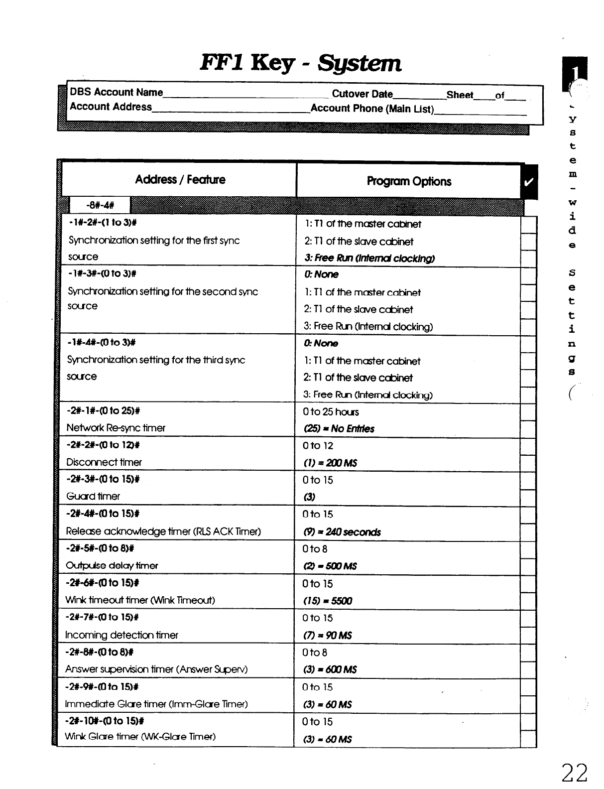
EFIKey-system
Account Address Sheet of
Account Phone (Main List)
Address / Feature
-l#-2#-(1 to 3)Y
Synchronization setting for the first sync
some
- l #-3#-(0 to 3)#
Synchronization setting for the second sync
sauce
-l#-#-Cl to 3hv
Synchronization setting for the third sync
some
-2#-l#-(0 to 2sM
Neiwuk Resync timer
-2#-2#-(IJ to 12)#
Diiconnect timer
-m-3#-(0 to 15)#
Guard timer
-2#-4#-(0 to lS)#
Release acknowiedge timer (RLS ACK Timer)
-2#-!i#-(0 to 8)Y
Duipdse
delaq timer
-2#45#-(0 to 1511
tink timeout timer OJVink Timeout)
~2#-7#-(oto
15)#
ncoming detection timer
-2#-W-(0 to 8)x
Ynswer supervision timer (Answer Super4
.2#-9#-(0
to
1 5)#
mmediate Glue timer (Imm-Glare Timer)
*2#- 1 or-<0 to 15)#
&ink Glare timer M-Glare Timer)
1: Tl of the
master cabinet
2:
Tl of the slave cabinet
o:NCYE
1: Tl of the master cabinet
2: Tl of the slave ccbinet
3:
Free Run (Internal clocking)
OrNOne
1: Tl of the master cabinet
2:Tl oftheslavecabinet
3:
Free Run (lntemd docking)
Oto25hous
= No Entries
Oto8
Oto8
(3)-6mMs t-i
oto 15
(3)=6clMs
?
L
Y
8
t
e
m
W
i
d
e
S
e
t
t
i
n
Q
s
(
22
Technical Manuals Online! - http://www.tech-man.com

FFl
Key - Sgstem
r \-
Account Address Account Phone (Main List)
Address / Feature
Program options
-3X-(1 to 8)X-(1 to 8)#-(0 to 3OM
Digital pad settings (Digital Pad Set)
-8#-4W 1
1
CklJitTvr>es
K-TEL
SLT
DATA
PmbgCOTrk
Tl Master
Tl slave
OPllONl”
OlllON2”
DPVW
CoNF~C)#
Tone 1 &lFRl)#
Tone2&lFM)#
#CrcuitType3&912cxe
rae4vedtifuiureuse.
YJse~~la7d2to
CX&lUliCjUePADlevels
tocicuikthutrequke
speddvdmew
No.
1
2
3
4
5
6
7
8
9
lo
11
‘12
Figure 1 shows the numbers used to identify each
circuit type.
Figure 2 shows the defautt values for the
most common Tl connections.
figure 3 lists the adjustments provided by each
pad number.
I
F/awe 2: Default wd vaiues I
From To Sefflng Value
Tl%l K-TEL 16
-2
dB
Tl f2 .K-TEL 16
-2
dB
Tl Xl SLT 16
-2
dB
Tl f2 SLT 16
-2
dB
K-TEL Tl Rl 16
-2
dB
K-TEL Tl 62
16 -2
dB
SLT Tl 81 16
-2
dB
SLT Tl #2 16
-2
dB
I
F&we 3: Ptd Nos.
I
Pad No. 1 Level ]
i +28 dB 1
29
30
-28 dB
-30 dB
P
S
Y
.s
t
e
m
W
i
d
e
23
Technical Manuals Online! - http://www.tech-man.com
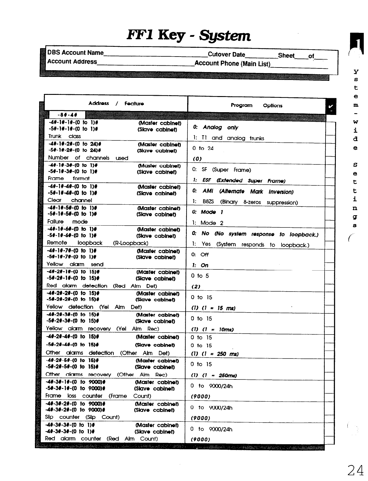
IF1
Key - System
Account Address Account Phone (Main List)
Address / Feature
-4#-l#-l#-(0 to I)# (Master cablnet)
-5#-l#-l#-(0 to l)# Glave cabhot)
Trunk class
-4#-l#-2X-(0 to 24)# (Master cabhot)
-M-l#-2#-(0 to 24)# Glave cablnetl
Number of channels used
-4#-l#-3#-(0 to l)# @laster cabinet)
-s#-1x-3#-(0 to 1)# (Slave cabinet)
Frame format
-4#-1#-4#-(0 to l)# (Master cabinet)
-5#-1#-4#-(0 to l)li Wave cablnet)
Clear chawwl
-4#-l#-sr-co to l#
-St-l#-5#-(0 to 1M (Master cabinet)
(slave cabhot)
Failure mode
-4+1#-6+(0 to l)# (Master cabinet)
-5X-it-M-(0 to I)# Gtave cabinet)
Remote loopback (R-Loooback)
-4+1#-7#-(0 to l)#
-5#-l#-71(0 to I)#
Yellow akxm send
-4#-2#-l#-(0 to 15)#
-5#-2#-W-(0 to iS)#
(Master cabhot)
(Slave cabinet)
(Master cablnet)
tslave CabInetI
Red alarm detection (Red Aim Det)
-4#-2#-2#-(0
to
lS)# Nader cablnen
-SI-2#-21-(0 to isjr kitave cabtnell
Yellow detection (YeI Aim Det)
-4#-2#-3#-(0 to 15)# (Master cablneb
-St-263#-(0 to lS)# Mave cabinet)
Yellow alam recovq (YeI Aim Ret)
-4#-2#-4#-(0 to 1511 (Master cabhot)
-s#-2##-(0 to 1511 fslave cabinen
3her darms detection (Other Alm Det)
-4#-2#-5#-(0 to lS)# (Mastor CabInen
-5#-2#-5#-(0 to 1511 Grave cabtnen
Other alarms recovery (Other Aim Ret)
-4#-3#-ll-(0 to 9ooo)# (Master cabinet)
-St-Jli-l#-(0 to 9ooo)# &v* CaMnet) -
Frame loss counter (Frame Count)
-4#-31-2#-(0 to 9ooo)# (Master cabinet)
-4+3#-2#-(0 to 9alo)# (Skve cabinet)
Slip counter (Slip Count)
-&l-3&3+(0 to I)# (Master cabinet)
-4+3#-31140 to 1H Slave cabirmt)
Red alarm counter (Red Aim Count)
0: Analog only
1: Tl and analog trunks
0 to 24
co,
0: SF (Super Frame)
1: ESF @Mended Super Frame)
0: AM (Alternate Mark lnverslon)
1:
B8ZS (Binary 8-zeros suppression)
0: Mode 1
1: Mode 2
0: No (No system response to loop&ac&.)
1: Yes (System responds to loopback.)
aoff
1: on
0 to 5
(2)
0 to 15
n
Y
8
t
e
m
W
i
d
e
S
e
t
t
i
n
SJ
8
c
j
24
Technical Manuals Online! - http://www.tech-man.com
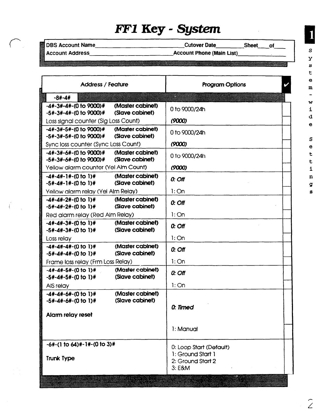
RF1
Key - System
DBS Account Name
Account Address
Cutover Date Sheet-of
Account Phone (Main List)
Address / Feature
-4#-3#-4#-(0to 9oooM
(Master cabinet)
-5#-3#-4#-(oto5QOO)u
(slave cabinet)
Loss
sianal counter (Sla Loss Count)
-4#-3#-5+(0to 5xmo)#
(Master cabinet)
-5#-3#-5#-(0t09000)x
(Slave cabinet)
Svnc loss counter (Svnc Loss Count)
-4#-3#-#-(0t05aOO)x
(Master cabinet)
-S#-3#-#-(0
to 9000)# (slave cabinet)
Yellow alarm counter (Yet Alm Count)
-4x-4#-l#-(0 to 1)X (Master cabinet)
-5#-4#-1X-(0 to I)# (5lave cabinet)
Yellow alarm relay (Ye1 Alm Relay)
-4X-4X-2+(0
to 1)#
(Master cabinet)
-W-4%-2+(0
to l)# (5lave cabinet)
Red alarm relay (Red Aim Relay)
-4%-4#-3%-(Oto
1)R (Master cabinet)
-5#-4#-3n-(oto
I)# (slave cabinet)
Loss relay
-4#-4#-4%-(0t0
1)X (Master cabinet)
-5#-4#-4n-(oto l)#
(5Jave cabinet)
Frame loss
relav (Frm Loss Relav)
-4#-4#-5n-(oto
I)#
-5#-4#-5#-(0t0
I)#
A6 relay
-4#-4#-6#-(Oto
I)#
-5#-4#-6#-(Oto
l)#
(Master cabinet)
(slave cabinet)
(Master cabinet)
(Slave cabinet)
Alarm relay reset
Trunk Type
0 to 9000/24h
0 to 9000/24h
&limed
1: Manual
1: Ground Start 1
2: Ground Start 2
3:
E&M
S
Y
8
t
e
In
W
i
d
e
Technical Manuals Online! - http://www.tech-man.com
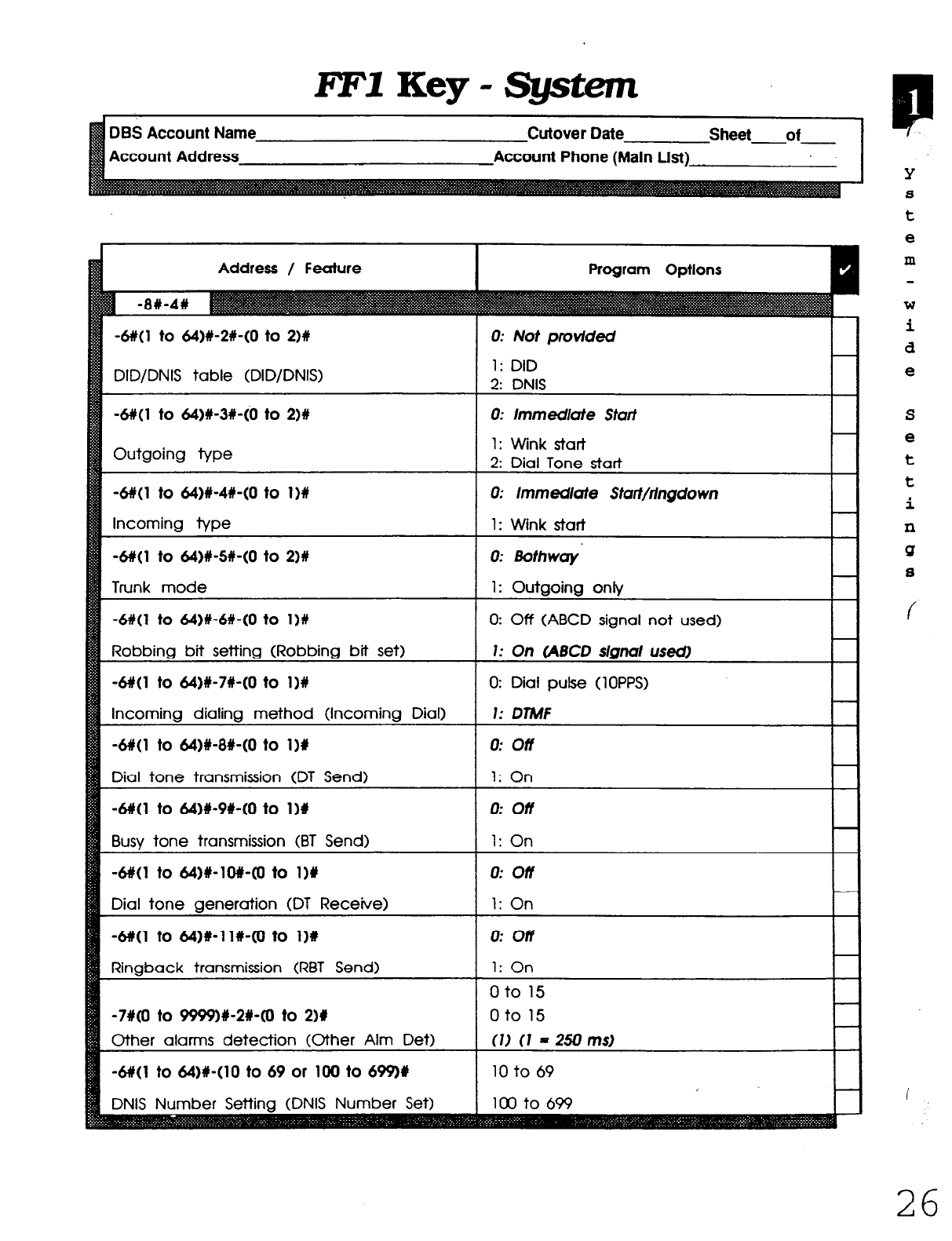
l?FlKey-Sptem
DBS Account Name Cutover Date Sheet of
Account Address Account Phone (Main List)
DID/DNIS table (DID/DNIS) 1: DID
2: DNIS
-6#(1 to 64)#-3#-(0 to 211
Outgoing type
0: lmmedute Staff
1: Wink stati
2: Dial Tone start
-6#(1 to 64)#-4#-(0 to 1 I#
Incoming type
0: lmmedlote Sfat/rlngdown
1: Wink start
-6#(1 to 64)#-H-(0 to 2)#
Trunk mode
-6#(1
to
&I)#-61140 to I>#
Robbing bit setting (Robbing bit set)
0: Bothwoy
1: Outgoing only
0: Off (ABCD signal not used)
1: On CABCD s/gnu/ used)
-6#(l to 64)#-7#-(0 to l)#
Incoming dialing method (Incoming Dial)
0: Dial pulse (1 OPPS)
1: DtMF
-6#(1 to 64)#-8#-(0 to l)#
Dial tone transmission (DT Send)
0: off
1: On
-6#(1 to 64)#-9#-(0 to l)# I 0: off I
Busy tone transmission (BT Send) 1: On
-6#(1 to 64)#-lO#-(0 to 1)Y
Dial tone generation (DT Receive)
0: off
1: On
-6#(1 to 64)#-ll#-(0 to
1M
Ringback transmission (RBT Send)
0: on
1: On
oto 15
-7#(o to 99%9#-2#-(0 to 2)# oto 15
Other alarms detection (Other Aim Det) (1) (1 - 250 ms) I
I
-&/(I to &a)#-(10 to 69 or 100 to 699M
Y
8
t
e
m
W
i
d
e
f
26
Technical Manuals Online! - http://www.tech-man.com
FFl
Key -
System
S
Y
8
t
e
m
W
i
d
e
S
e
t
t
i
n
Q
8
2
r
Technical Manuals Online! - http://www.tech-man.com
he FF2 Key is for programming trunk lines
and acts as an interface between the CO
or DID trunk lines and the DBS system.
There are two programming forms for the FF2 Key:
The Trunk Port list is for assigned names
and TelCo circuit numbers.
The Trunk Features list is for recording any
of the 25 features that can be programmed
on each trunk port.
Notes:
(1) The Pooled Tmk Group Access settings in the FF2
Key (Trunks’ programming) are different from the
Trunk Group settings in the FF8 Key (LCR program-
ming):
(a) Trunk lines set in the FF2 Key are accessed by
the user with access codes (9, 8 1 to 86).
(b) Trunk lines set in the FF8 Key are automatically
selected by the system.
Save Your Original Forms!!!
c
d
F
F
2
K
e
Y
28
Technical Manuals Online! - http://www.tech-man.com

FF2Key-TrunkRwts FF2Key-TrunkRwts
Account Address Account Addre Account Phone (Main List)
T
r
U
n
k
P
0
r
t
L
i
8
t
Technical Manuals Online! - http://www.tech-man.com
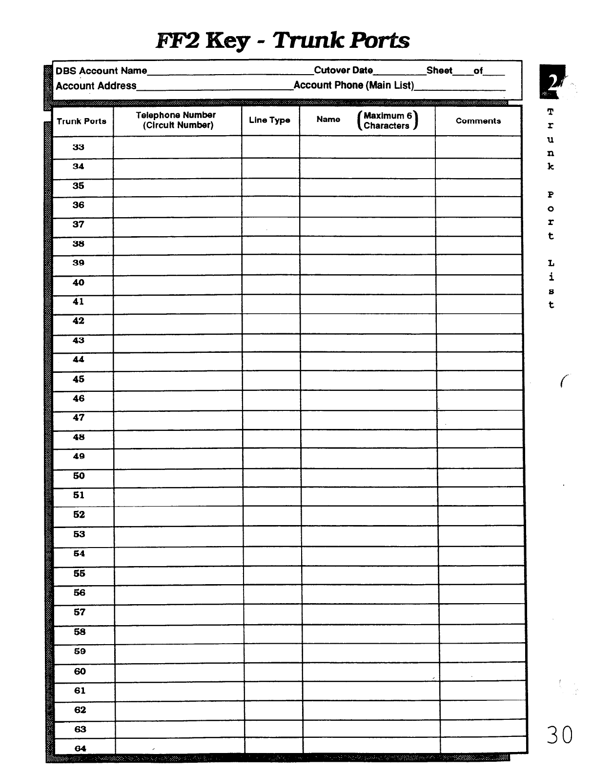
#?F2Key-TmnkPb~
Trunk Ports I ~‘.y”.-.. ..“...D.
(Circuit Number)
U
n
L
i
S
t
f
Technical Manuals Online! - http://www.tech-man.com
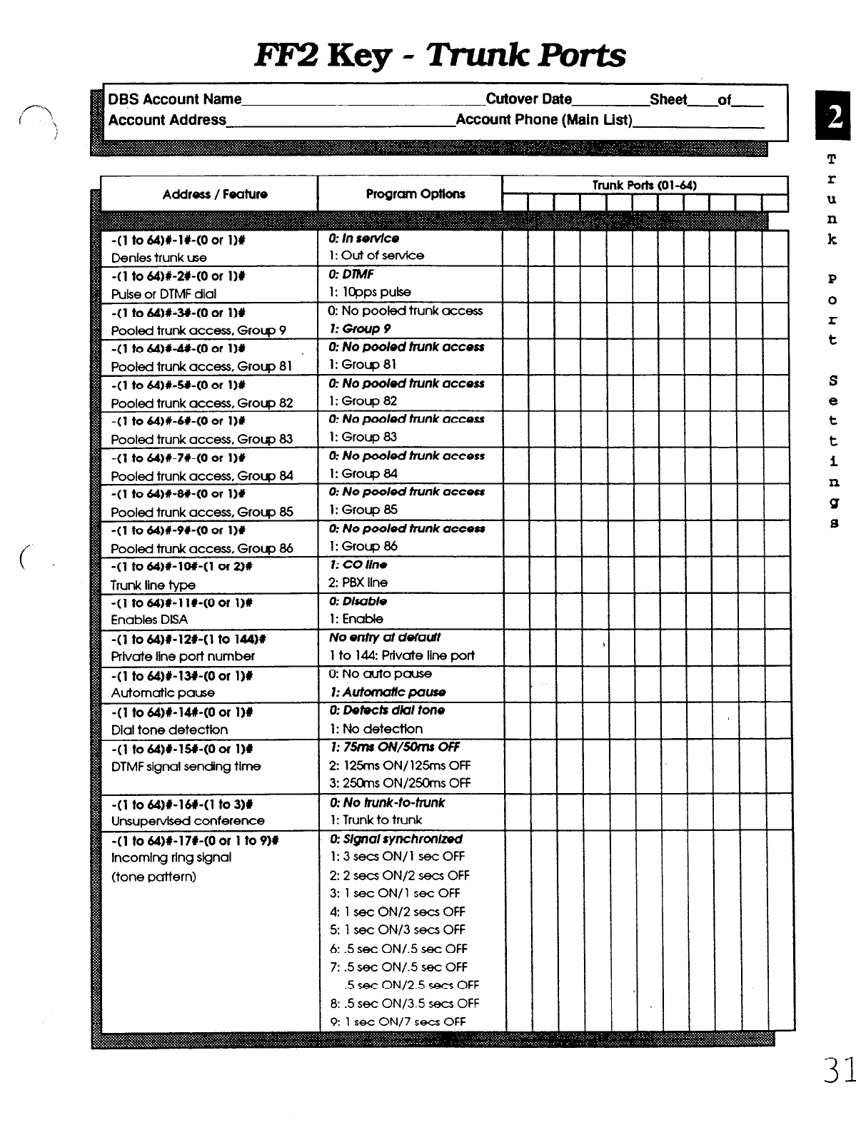
FlCZKey-TmnkRrts
DBS Account Name
Account Address
Cutover Date Sheet of
Account Phone (Main List)
r
Adctre~~ I Feature
I
Progrcml optkms
I I
Trunk Ports (01-W
I I I I I I I I I
0: No pooled trunk access
Pooled trunk access, Group 84
-(l to 6A)#-W-(0 or 111
Pooled trunk access, Group 85
-(l to 64#-9#-(0 or l)#
Pooled trunk access, Group 86
-(l to 64)Clow1 or a0
Trunk llne type
-(l to 64)#-1 l#-(0 of l)#
Enables DISA
1: Group 84
0: No pooled trunk access
l:GfoupE!s
0: No poded trunk access
1: Group 86
1: CO line
2: PBX he
Private line port number
MF signal sending time
omlng ring signal 1:3secsON/l secOFF
2: 2 sea ON/2 sea OFF
3: 1 set ON/l set OFF
4: 1 secON/2secsOFF
5: 1 secON/3secsOFF
6: 5 set ON/.5 set OFF
7: .5 set ON/.5 set OFF
.5 see ONl2.5 sea OFF
8: .5 set ON/X5 sea OFF
P
T
r
U
n
k
S
e
t
t
i
n
Q
s
Technical Manuals Online! - http://www.tech-man.com
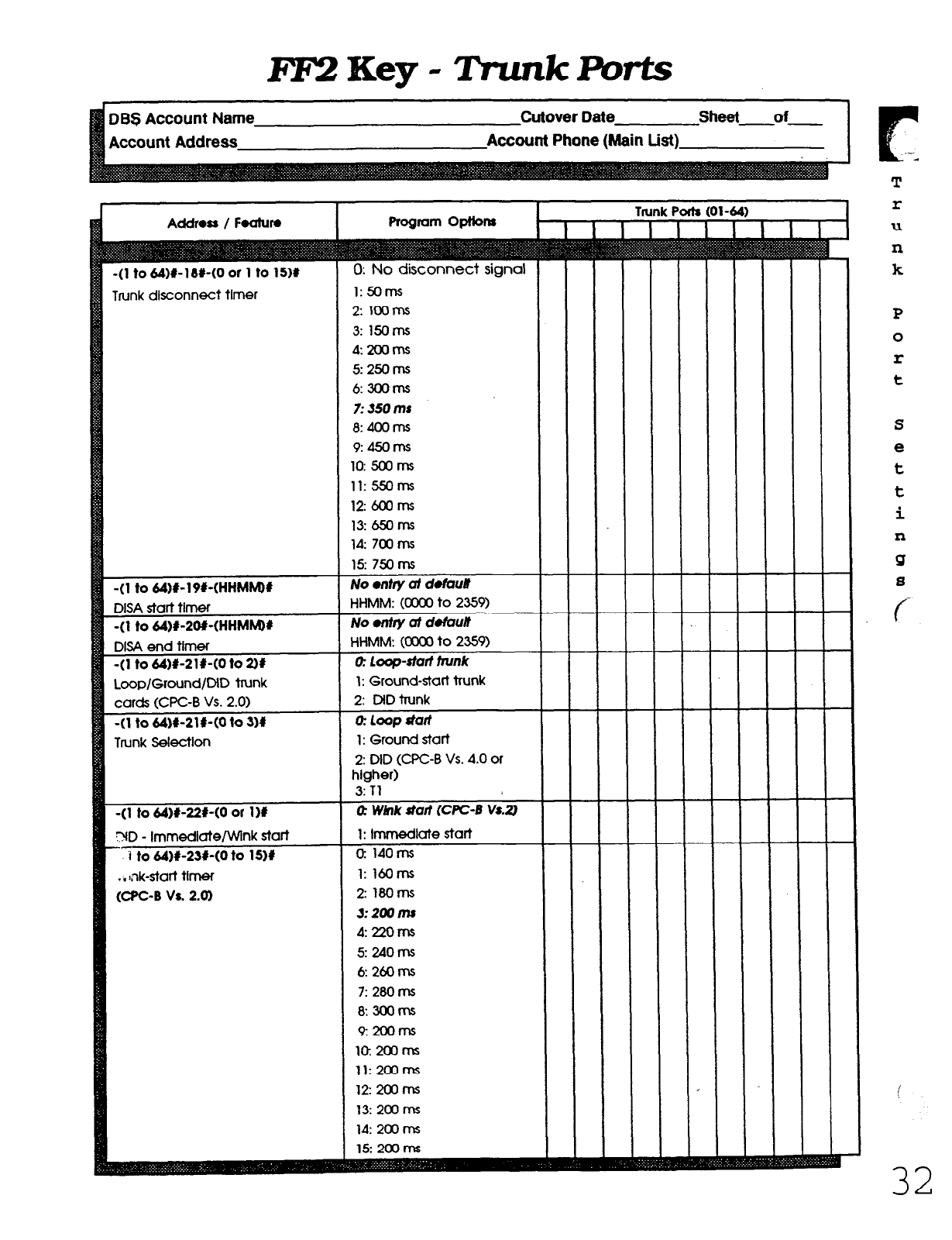
FF2Key-IVunkPorts
Account Address
Cutover Date sheet of
Account Phone (Main List)
r
Addross / Fwh~ro I Program OptIons I I I
Trunk Ports (01-64)
I I
I I I I I
Trunk disconnect timer
-(l to 64)#-19f-(HHMMM
7: SO ms
8: 4OOms
9: 45orns
10: 5ooms
11: 55oms
12: 6ooms
13:65orn.s
ld: 7txms
15: 750 ms
No entry d defaun
1: Ground-start trunk
(CPC-B Va 2.0)
r
T
r
U
n
k
P
0
r
t
S
e
t
t
i
n
Q
s
c
32
Technical Manuals Online! - http://www.tech-man.com
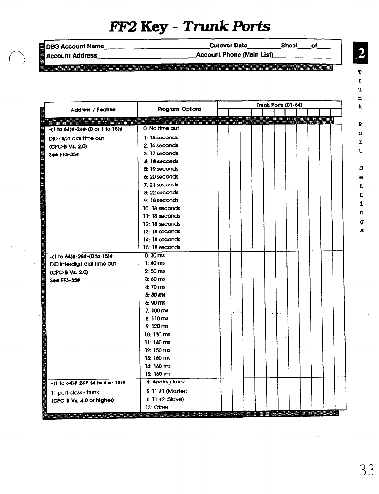
FF2Key-TrunkPorts
DBS Account Name
Account Address
Cutover Date Sheet of
Account Phone (Main List)
(CPC-B Va 2.0)
3.0 FF3-351
1: 15seconds
2 16seconds
3: 17smnds
4 I8socalds
5 19seconds
6:2oseconds
7: 21 seconds
8:22seconds
lo: 18 seconds
11: 18 seconds
12: 18seconds
13: 18seconds
(CPC-8 Va 2-a)
!30. FF3-351
Tl port clas - trunk
(CPC-B Vs. 4.0 or high.0
r
T
r
u
n
k
P
0
r
t
S
e
t
t
i
n
!Y
a
Technical Manuals Online! - http://www.tech-man.com
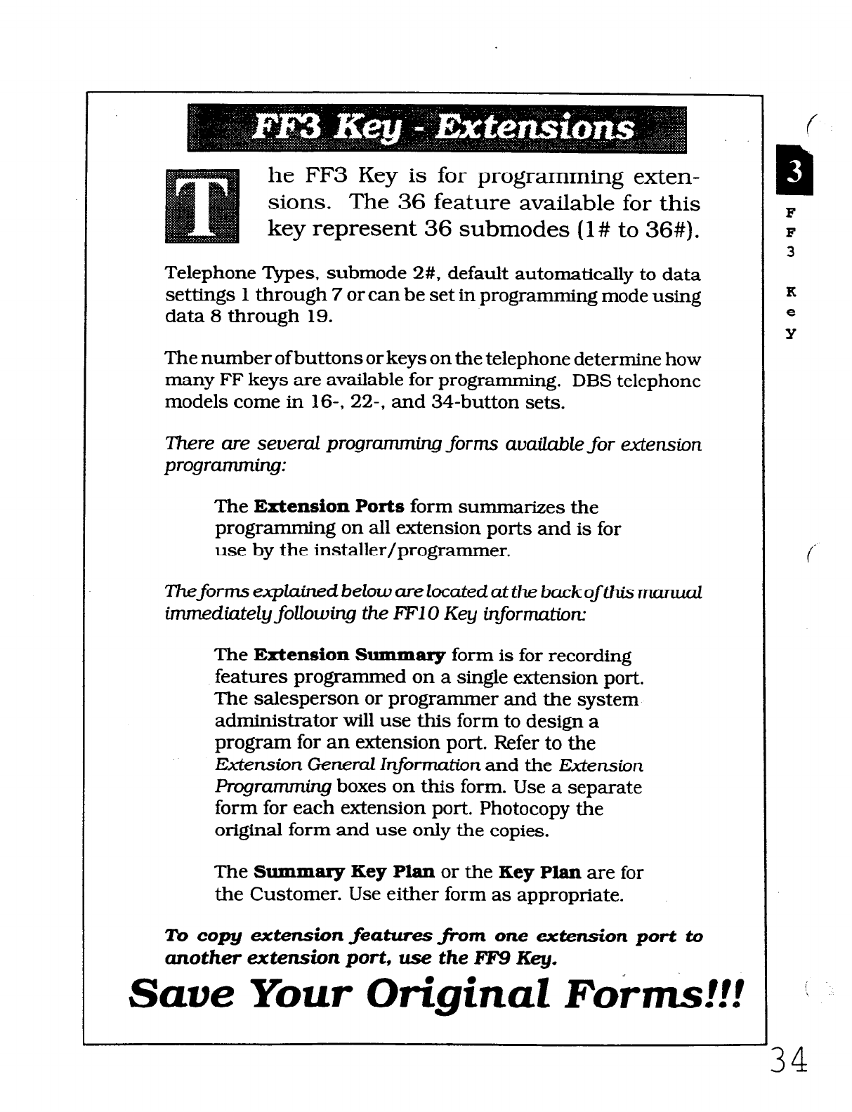
he FF3 Key is for programming exten-
sions. The 36 feature available for this
key represent 36 submodes (l# to 36#).
Telephone Types, submode 2#, default automatically to data
settings 1 through 7 or can be set in programming mode using
data 8 through 19.
The number ofbuttons or keys on the telephone determine how
many FF keys are available for programming. DBS telephone
models come in 16-, 22-, and 34-button sets.
There are several programming forms avaiZable for extension
programming:
The Extension Ports form summarizes the
programming on all extension ports and is for
use by the installer/programmer.
Theforms expU.ned
below are located at the backof this mama2
inunediately following the RF1 0 Key
information:
The Extension Summary form is for recording
features programmed on a single extension port.
The salesperson or programmer and the system
administrator will use this form to design a
program for an extension port. Refer to the
Extension General hformztim and the Extension
Programning boxes on this form. Use a separate
form for each extension port. Photocopy the
original form and use only the copies.
The Summary Key Plan or the Key Plan are for
the Customer. Use either form as appropriate.
To copy extension
featuresjhm one extension port to
another
extension port, use
the FF9 Key.
Save Your Original Forms!!!
F
F
3
K
e
Y
i
\
34
Technical Manuals Online! - http://www.tech-man.com
EF3Key-mns
DBS Account Name Cutover Date
J Account Address Account Phone (Main List)
Addross / F.&MO
-(l to 144)#-11(100 to 699/10 to 69)#
Extension numbers
-(l to 144)#-2#-(0 of 1 to 19)#
Telephone types
(CPC-6 Vs. 20 of hlghor)
-(l to 144)#-3#-(001 to 144)X
EM/24 console station-port number
-(I to 144)X-/#-(0 or 1)X
Forced LCR restriction
-(l to 144)~~W-(0 Of 1M
Forced verified account code
-(l to 144)~~66(4 digits)##
Station lockout code
-(l to 144)#-7(1-(0 or l)#
CO line off hook slgnal
-(l to lM)W-#-(0 or I)#
Call waiting
-(l to 144)#-Pi-(0 or 1)X
Busy override
-(l to 144)#-W-(0 or l)#(Seo FFl-2#-I#-174
Busy overridden
-(l to 144)#-116(0 of l)#
Prime line preference
-(l to 144)#-12#-(0 01 l)#
Ringlng line preference
-(I to 144)C13#-(0 o( l)O(FF2-lH,FF-3#-11I
Unsupervised conference - Extension-wide
-(l to 144)#-14#-(0 or l)#(FFl-21.-21-61)
SMDR printout of Incomlna cdts
Program options
140 to 6W/10 to 69: Extonslons
0: No assignment
1: Analog telephone
2: Dlgital telephone (6 FF Ilnes)
3: Dlgltal telephone (12 FF Ilnes)
4: Dlgttal telephone (24 FF lines)
5: Reserved
6: DSLT (Vs. 3.0 or higher)
7: EM/24 VB-43310
8: OPX (pulse)
9: OPX (tone)
10: Voice mall (AEC)
11: DSSl - Extension lO/lCKl
12: DSS2 - Extension lo/100
13: DSS3 - Extension ll/lOl
14: DSS4 - Extension ll/iOl
15: Voice mall (OPX)
16: First attendant console
17: Second altendant console
18: Third attendant console
19: Fourth aftendant console
EM/ar nd connoclod
1 to 144~ Stored extensions on EM/24
Q No LCR restrict/cm for oubld~ cd/s
1: Forced LCR
0: Disabk
1: Enable
No dry d delmli
ooa3 to 9999: Statlon lockout code
I:Exhns&nPortstand2
0: Eafonsbn Potts 2 to W
0: No call wattlng
I: Cd wattha
0: Dbab&
1: Enable
0: Rejects
I: Accepts
0: Dbabh
1: Enable
0: Dkable
I: En&k
0: Dkabh
1: Enable
0: Dkable
I: EndJk
Extonskn Pats (1 to 144)
-
-
-
-
-
-
-
-
-
-
-
-
-
-
-
-
-
-
-
-
-
-
-
-
-
-
-
-
-
-
-
-
-
-
-
-
-
-
-
-
-
-
-
-
-
-
-
-
-
-
-
-
-
-
-
-
-
-
-
-
L
-
-
-
-
-
-
-
-
-
-
-
-
-
c
R
E
X
t
0
n
a
i
0
n
P
0
r
t
8
Technical Manuals Online! - http://www.tech-man.com
FF3Key-Extensions
Account Address Account Phone (Main List)
-(I to lU)#-15f-(0 of 1 to 4)(1
CO line off-hook slgnol volume
-(l to lU)I-W-(0 Q 1H
CO llne off hook
slgml
pattern
-(l to lU)#-171-(0 OI I)#
PSD names (5 or 10 norms) - large display
-(l to lU)*-lM-(O u l)#
Sets extenslms ICI page groups 00
-(l to lU)r-lPI-(O u l)#
sets extensions to page groups 01
-(l to lU)C20#-(0 of l)#
sets extensions to poQe groups 02
-(l to 144)#-21I-(0 u l)#
Sets extensl0ns to page groups 03
-(l to lu)(r-22+(0 of l)#
%tS 0xtensionS t0 PClge QRXPS 04
-(l to lu)r-zsr-(o u l)#
sets extensions to p&Je groups 05
-(l to lU)II-w-co u 11*
sets extensions to WQe Qrwps 06
-(l to lU)I-2940 of l)r
Sets adnskms t0 PaQ0 Qt0’JPs 07
-(l to lU)#-26+(0 u 1 to 24H
idle dkpkxy - large-dkpluy telephone
-(l to 144)&27#-(0 Q 1 to 24)#
ID1 off hook dkpW - kq?AkP~
-(l to lU)I-28+(0 u 1 to 24H
ID1 colt status display - kXQe-dkpkYY
-(l to lU)M9e-(0 u 1 to 24)#
CO line call dkplay during diillng
-(l to lu)r-sor-(o u 1 to 24)l
CO line call d&pkry after diing
-(l to lU)r-31r-(0 u 1 to 24)1
Page call dkplay - brge-dkplcw
-(l to lU)(I-32#-(0 Q 1 to 24)#
Cal waltlng dkplay - kxJe-dkplov
-(l to lu)r-3s(0 u 1 to 24)#
Intercom busy tone dkpkzy - large-dkpluy
-(l to lU)#-34C(O u I)# (CPC-B va. 2.0)
Extension directory display - large dkpm
-(l to 1u)~-35.-(0 oI 1 to 6)# (CPC-I) VI 3.0 0
hlghor)
Extension clcss of service setting
1: Mlnlrnum volume
2 Lowu me&ml wkme
3: l-igher medium volume
I I
Doea not wing to page Qarp 00
1: Page grq 00
0: 9o.a not Mong to pqp Qc4@ 01
1: Page group 01
0: o0.a not -9 to m qoLp 02
1: Page grocp 04
0: D0.a no/ Mong to pqp Qolp 05
1: Page grq 05
0: 0o.a not behmg
to
page gu#J 04
1: page Qroql 06
0: 0o.a not -9 to pqa qarp 07
1 to 24: See programming Mawal
ograrwnlng Mcnud
0: No ctnngo
1 to 24: See Rogrammlng Manual
0: No dratgo
1 to 24: See Programming Mcnwl
1 to 8: Set to IndMdwl extension
c
h
E
X
t
e
n
8
i
0
n
P
0
r
t
a
c.
i
36
Technical Manuals Online! - http://www.tech-man.com
FlQ Key - JZxtensions
DES Account Name
kcount Address
Cutover Oate sheet of
Account Phone (Main List)
Address / Foaturo
-(I to 14&#-36#-(0
to 2H (WC-B Vs. 3.0)
RIngback tone wtth busy signal
-(l to lU)#-37#-(1 to 3 or 7 to 13H
Tl port class station
(CF’C-B Vs. 4.0 or hQh.0 . . c
-(l to 144)#-3W-(0 or l# (WC-B Vs. 3.0 or
hlghor)
SLT hook flash
-(l to 144H-39#-(0 to 9H (WC-B Vs. 3.0 or
hlghorl
Extension ring pattern MTEL)
-(l to ~MH-39#-(0 to PM (CPC-B Vs. 3.0 or
hlghor)
Extension ring pattern (.SlT/OPW
-(I to IM)#-UU-(0 or 111 (CPC-B Vs. 3.0 or
hlghor)
DSLT handset vdume level
-(l to 144)#-41#-(0001
to 9999H (WC-B Vs.
3.0 w hlghor)
Auto set relocaiion codes
-(l to 144~~42#-(0
to 3)# (CPC-B Vs. 3.0 or
hlghor)
Permanent call forward
-(l to 144)#-UI-(NN(N))#
(WC-B Vs. 3.0 01
higher)
Permanent call forward extension
-(I to IM)#-UI-(O or l)# (CFC-B
Vs. 4.0
or
hlahor)
MljMCil separailon
0: Rtngback ton. wltt~
busy s/gnat
1: Busy sQnal
2: Wngback tone
1: KTEL
2:
SLT
3: DATA
7: OPT1
8: OPT2
9: DTMF
lo: CONF (SCC)
11:
MFRl
12: MFRZ
0: BrokUs hobd
1: lnltiie conference call
0: 0-d on trunk dng
1: 3 set ON/l set OFF
2: 2 set ON/2 set OFF
3:
1 set ON/l set OFF
4:
1 set ON/2 set OFF
5: 1 set ON/3 set OFF
6:
0.5 set ON/OS set OFF
7: 0.5 set ON/OS set OFF
0.5 set ON12.5 sac OFF
8: 0.5 set ON/3.5
set OFF
9:
1 set ON/7 set OFF
0:
DO&WICWI~
on SlT t- rtng
@hrrt h proonrm sdng
1: 3 set ON/l set OFF
2: 2 set ON/2 ssc OFF
3:
1 set ON/2 set OFF
4: 1 set ON/3 set OFF
5:
1 set ON/5 set OFF
6:
1 set ON/7 set OFF
7: 0.5 set ONf3.5
set OFF
8: 0.5 set ON/J.5
set OFF
9: 0.5 set ON/3.5
set OFF
0: Nonmaf
1: Louder (+6dB Gain)
“=: No relocallon codas sot
0: Nof lowurdod
1: Busy/No answer
2: eusy
3: No answer
NN(N): Call forward exMnsion number
0: MC0 keys
1: ML kevs
Extmston Ports (1 to 144)
-
-
-
Q
E
X
t
e
n
0
i
0
n
3
';
Technical Manuals Online! - http://www.tech-man.com
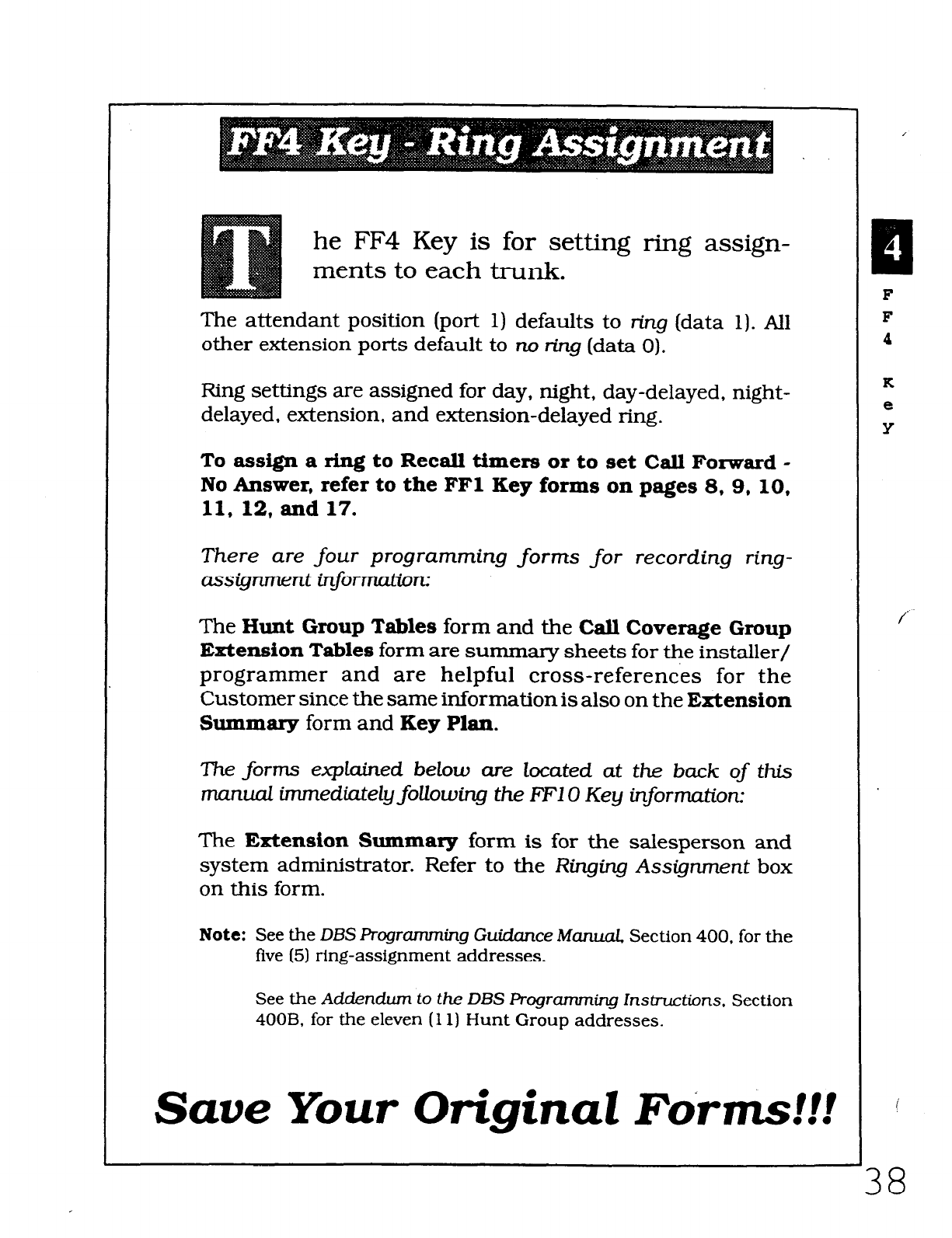
he FF4 Key is for setting ring assign-
ments to each trunk.
The attendant position (port 1) defaults to ring (data 1). All
other extension ports default to no r-kg (data 0).
Ring settings are assigned for day, night, day-delayed, night-
delayed, extension, and extension-delayed ring.
To assign a ring to Recall timers or to set Call Forward -
No Answer, refer to the FFl Key forms on pages 8, 9, 10,
11, 12, and 17.
There are four programming forms for recording ring-
assignment information:
The Hunt Group Tables form and the Call Coverage Group
Extension Tables form are surnmary sheets for the installer/
programmer and are helpful cross-references for the
Customer since the same information is also on the Extension
Summary form and Key Plan.
The forms explained below cue located at the buck of this
manual immedia.teZy foUowing the FFIO Key information:
The Extension Summary form is for the salesperson and
system administrator. Refer to the Ringing Assignment box
on this form.
Note: See the DBS Programming Guicfance
Manual
Section 400, for the
five (5) ring-assignment addresses.
See the
Addendwn
to
the DBS
Progranuning lnsb-uctions. Section
400B, for the eleven (11) Hunt Group addresses.
Save Your Original Forms!!!
I
F
F
4
K
e
Y
i
38
Technical Manuals Online! - http://www.tech-man.com
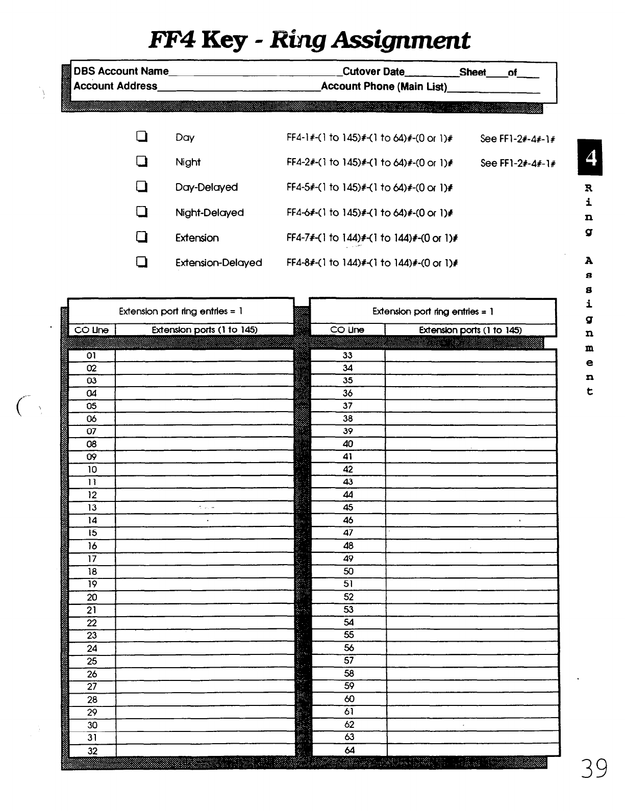
liYF4 Key - Ring Assignment
DBS Account Name
Accbunt Address
Cutover Date sheet of
Account Phone (Main List)
cl
Day FF4-1 X-(1 to 145)%-(1 to &I)#-(0 or l>U See FFl -2X-4+ 1 #
0 Night FF4-2X-(1 to 14!Wo to &I)#-(0 or 1)P See FFl-2#-4R-lt
0 Day-Delayed FF4-5+(1 to 14%&o to &W-(0 or 1Y
c1 Night-Delayed FF4-W(1 to 14!5)#< 1 to 64)%<0 or 1 I#
cl Extension FF4-7#-(1 to 144)#< 1 to 144)%-tO or 1 )B
c
cl Extension-Delayed FF4-#<1 to 14&W to L&W-CO or l>a
tl
A
3
i
n
Q
A
8
s
i
Q
n
m
e
11
t
Technical Manuals Online! - http://www.tech-man.com

FIT4
Key - Ring Assignment
Adcount Address
-
Hunt Group 1
Yot Name
lot ExVPofl
me
qF Extension
Hunt Group 3
Pilot Name
Pilot Ext./Port
Type
TRF Extension
Pilot
Name
Pilot ExVPOrt
Type
TRF Extension
TRF Timer
Pilot Name
Pilot ExVPort
Type
TRF Extension
TRF Timer
?F Timer
tiension 1
xtension 2
xtension 3
Extension 1
Extension 2
Extension 3
Cdbneinn
d
TRF Timer
Extension 1
Extension 2
Extension 3
Extension 1
Extension 2
Extension 3
Extension 4
Extension 5
xtension 4
xtension 5
xtension 6
xtension 7
lay Delayed Ring-
-ensIon 0
Day Delayed Ring-
Night Delayed Ring-
Day Delayed Ring-
‘ilot Name
TRF Timer
Extension 1
Extension 2
H
U
n
t
T
a
b
i
Technical Manuals Online! - http://www.tech-man.com
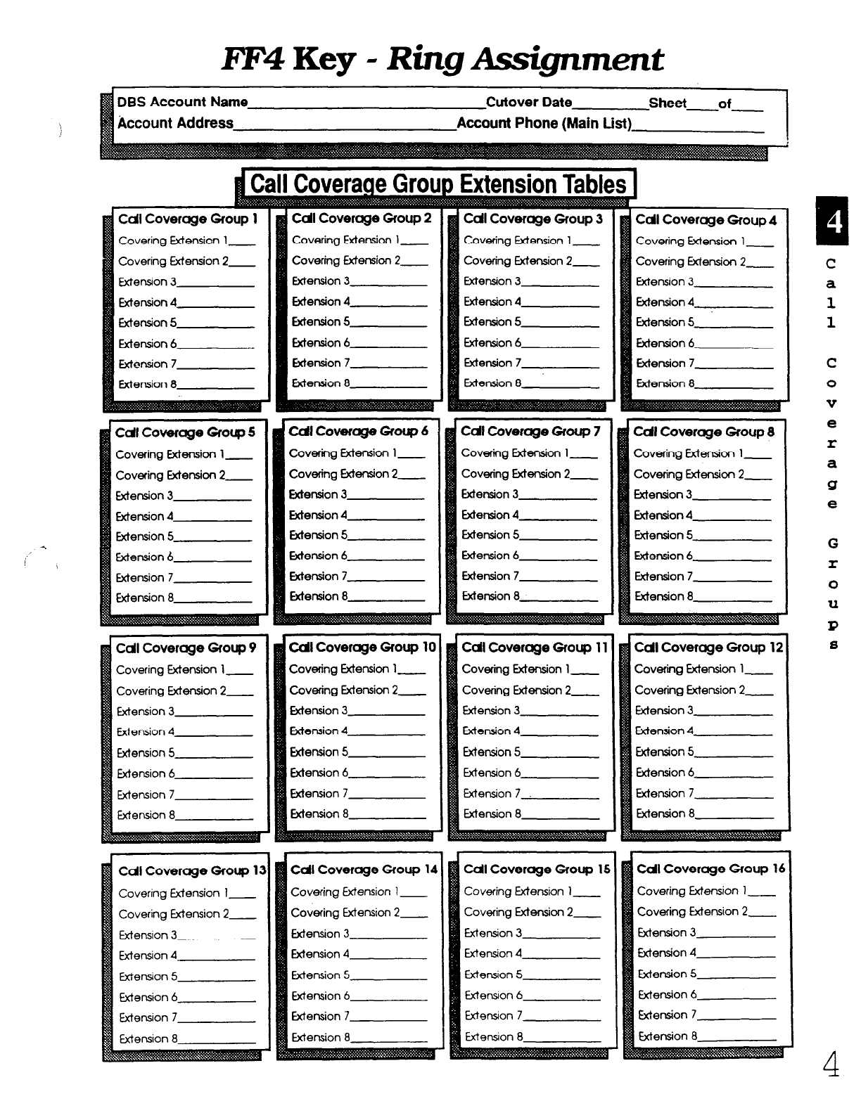
FF4 Key - Ring Assignment
DBS Account Name Cutover Date
\ Account Addre
i
Covering Extension l-
Covering Extension 2-
Cdl Coverage Group 5
Covering ExtensiOn l-
Covering Extension 2-
Extension 3
Extension 4
Extension 5
Extension b
Extension 7
Extension 8
cdlCoverogeGfoup2
Covering Extension l-
Coveting Exiension 2-
Extension 3
Extension 4
Extension 5
Extension 6
Extension 7
Extension 8
Extension Tab14
CdlCoverogeGroup3
Covering Extension 1 -
COVWiIlQ
k-tension 2-
Extension 3
Extension 4
Extension 5
Extension 6
Extension 7
Extension 8
cdl coverage Group 6
COV&lQ Extension
l-
covefinQ Extension
2-
Extension 3
Extension 4
Extension 5
Extension 6
Extension 7
Extension 8
Cdl Coverage Group 7
Covering Extension l-
CovefinQ Extension
2-
Extension
3
Extension
4
, Extension 5
Wetion 6
&tendon 7
Extension 8
Cdl Coverage Gfoup 9
Covering Ex.tension l-
Covering Extension 2-
Extension 3
Extension 4
Extension 5
Extension 6
Extension 7
Extension 8
cdl coverage Group 10
Covering Extension l-
Covering Extension 2-
Extension 3
Extension 4
Extension 5
Extension 6
Extension
7
Extension 8
Cdl Coverage Group 1:
Covering Exfension I-
Covering Extension 2-
Extension 3
Extension 4
Extension 5
Extension 6
Extension 7
Extension 8
CdlCoverogeGfoupl4
Covering Extension I-
Covering Extension 2-
Extension 3
Extension 4
Extension 5
Extension 6
Extension 7
Extension 8
Cdl Coverage Group 11
Covering Extension l-
Covering Ex-tension 2-
Extension 3
Extension 4
Extension 5
Extetion 6
Edension 7
Extension 8
Cdl Coverage Group 15
Covering Extension l-
Covering E&nsbn 2-
Extension 3
Extendon 4
Extension 5
Extension 6
Extension 7
Cdl Coverage Group 4
Covering Extension l-
Covering &tension 2-
Extension
3
Extension 4
Extension5
Extension 6
Edetion 7
Extension 8
Cdl Coverage Group 8
Covering Extension l-
Covf3finQ Extension
2-
Extension 3
Extension 4
Extension 5
Extension 6
Extension 7
Extension 8
Cdl Coverage Group 12
Coveimg Extension l-
Covering Extension 2-
Extension 3
Extension 4
Extension 5
Extension 6
Extension 7
Extension 8
Cdl Coverage Group 16
Covering Exkmsion 1 __
Covering Extension 2-
Extension 3
Extension 4
Extension 5
Extension 6
Extension 7
Extension 8
a
A
C
a
1
1
C
0
V
e
r
a
Q
e
G
r
0
U
P
s
4
Technical Manuals Online! - http://www.tech-man.com
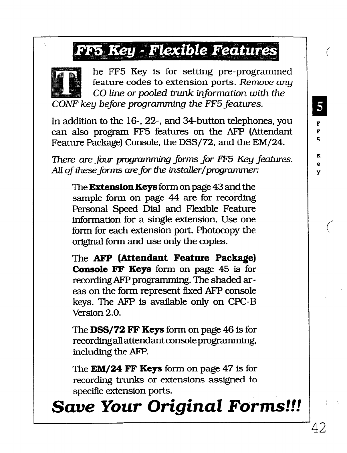
he FF5 Key is for setting pre-programmed
feature codes to extension ports. Remooe any
CO line or pooled trunk information with the
CONF key before programming the FE5 features.
In addition to the
16-, 22-,
and 34-button telephones, you
can also prograxn FF5 features on the AFP (Attendant
Feature Package) Console, the DSS/72, and the EM/24.
7here are
four
prtgrm forms for 8F5 Key features.
AU of these forms are
for
the instakr/pmgrummer:
TheExtensionKe~formonpage43andthe
sample form on page 44 are for recording
Personal Speed Dial and Flexible Feature
information for a single extension. Use one
for-r-n for each extension port. Photocopy the
original form and use only the copies.
The AFP (Attendant Feature Package)
Console F’F Keys form on page 45 is for
recording AFP progmmming. The shaded ar-
eas on the form represent fIxed AFP console
keys. The AFP is available only on CPC-B
Version 2.0.
The DSS/72 FF Keys form on page 46 is for
recordi.ngallattendantconsoleprogrammmg,
including the AFP.
The EM/24 FF Keys form on page 47 is for
recording trunks or extensions assigned to
specific extension ports.
Save Your Original Forms!!!
i
E
F
F
5
K
e
Y
Technical Manuals Online! - http://www.tech-man.com
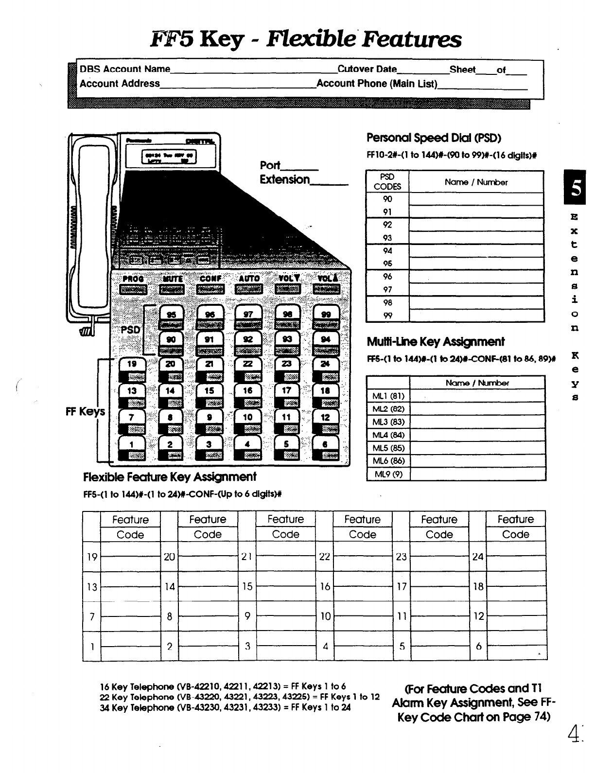
I??5 Key - Fkible’Featums
I
FF Keys
1
Flexible Feature Key Assignment
Penonal Speed Dial (PSD)
FFl O-2#-( 1 to 144)#-(90 to
W#-(
16 digits)#
P!sD
CODES
90
Name / Number
L J
93
94
95
96
97
98
99 I
Mullt-llne Key Assignment
B
E
X
t
e
n
8
i
0
n
1 ML5 (85) 1
1 ML9 (9) I
I
FFS-( 1 to lM)#-( 1 to 24WCONF-(Up to 6 digits)ll
Feature Feature Feature Feature Feature Feature
Code Code Code Code Code Code
19 20 21 22 . 23 24
13 .14- 15 16 17, 18
7 - 8 . 9
10 11
12
1 2 3 4 5 6- 1
1 c
16 Key Telephone (VW221 0,42211,42213) = FF Keys 1 to 6
22 Key Telephone (VB-43220,43221,43223,43225) = FF Keys 1 to 12
(For Feature Codes and Tl
34 Key Telephone (VB-43230,43231,432X3) = FF Keys 1 to 24
Alarm Key Assignment, See FF-
Key Code Chart on Page 74)
Technical Manuals Online! - http://www.tech-man.com
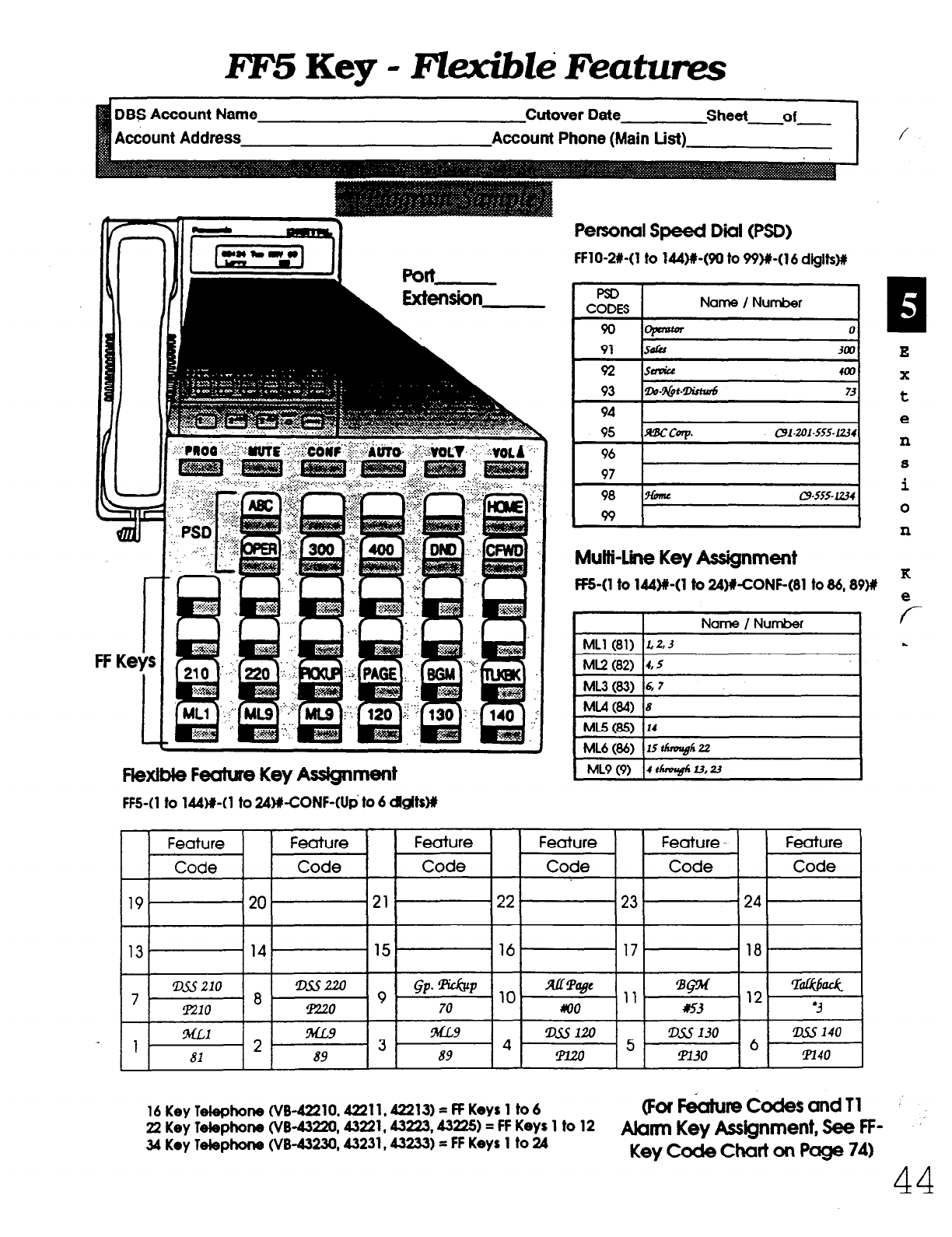
DBS Account Name Cutover Date Sheet of
Account Address Account Phone (Main List)
FF Keys
1
Flexible Feature Key Assignment
FFS-(1 to 144)#-(1 to W&CONF-(Up’ to 6 Qgits#
FFlO-2141 to 144)+(90 to 99)#-(16 d@ts)#
Name / Number I
90 ,opmtm a
91 solis
3m
92 sauk 4m
93 ap-*t-m 73
94
95 BCCW. c91-w1-555-f234
Personal Speed Dii (PSD)
MutMne Key Assignment
FF5-(1 to 144)#-(1 to 24WCONF-(81 to 86,89M
K
1
E
x
t
e
P
S
i
0
n
Name
/
Number
ML1 (81) faZ3
ML2 (82) 4,s
ML3(83) 6 7
ML4(84) 8
ML5(85) I4
ML6 (86) 15 th$gh 22
ML9 (9) 4 thmvBlr u, 23
T-
L
Feature Feature Feature Feature Feature .. Feature
Code Code Code Code Code Code
19 20 21 .22 23 124
13 14 15 . 1 16 17 . I 18.
D&s 210 !D.ssm
7 8 9
GP*-h ,. XllTage
11,
BPf
. ,12
-Rhk
Pa0 I1220 70 RIO
~~
‘3
ML1 !ML9 ML9 lXSl20 lxs 130 !D.s.s 140
1 - 2 3
89
4 m 5 6 .
81 89 !Pl30 m40
16KeyTelephone(\16-42210,42211,a2213)=ff Keys 1 to6
(For F&turn Codes and 11
22 Key Tete~hone (V&43220,43221,43223,43225) = FF Keys 1 to 12
Alarm Key Assignment, See FF - ..
34 Key Telephone (\/B-43230,43231,43233) = FF Keys 1 to 24
Key Code Chart on Page 74)
44
Technical Manuals Online! - http://www.tech-man.com
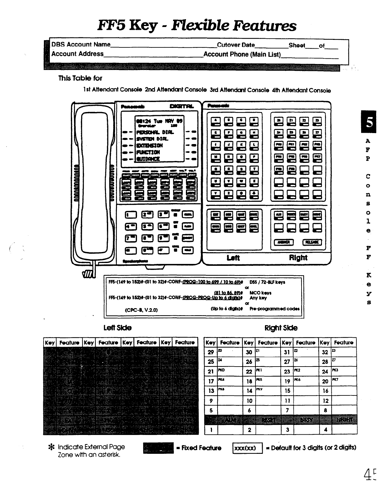
FF5 Key - FkxibZe Featzms
DBS Account Name
Account Address
Cutover Date Sheet-of
Account Phone (Main List)
This Table for
1 st Attendant Console 2nd Attendcmt Console 3rd Attendant Console 4th Attendant Console
\ r
FFS-(149 k 1s2wm to SwcoNF- m wS/7ldlFkyr
u
F&(149 k Ia-(01 to 32WCONF- [PIK)CPPOCUD hvkw
Riitsii
/Key1 Feahin 1 Kev i -Feature
Feah~ro Feature 1
Kevl Feature I Kev I Feature I Kevl Feature I Kev I Feature
E
A
F
P
c
0
P
s
0
1
e
F
F
K
e
Y
s
* Indicate External Page
Zone with an asterisk. - Fixed Feclture EZKI - D&un for 3 dii (or 2 digits)
4-
c
Technical Manuals Online! - http://www.tech-man.com
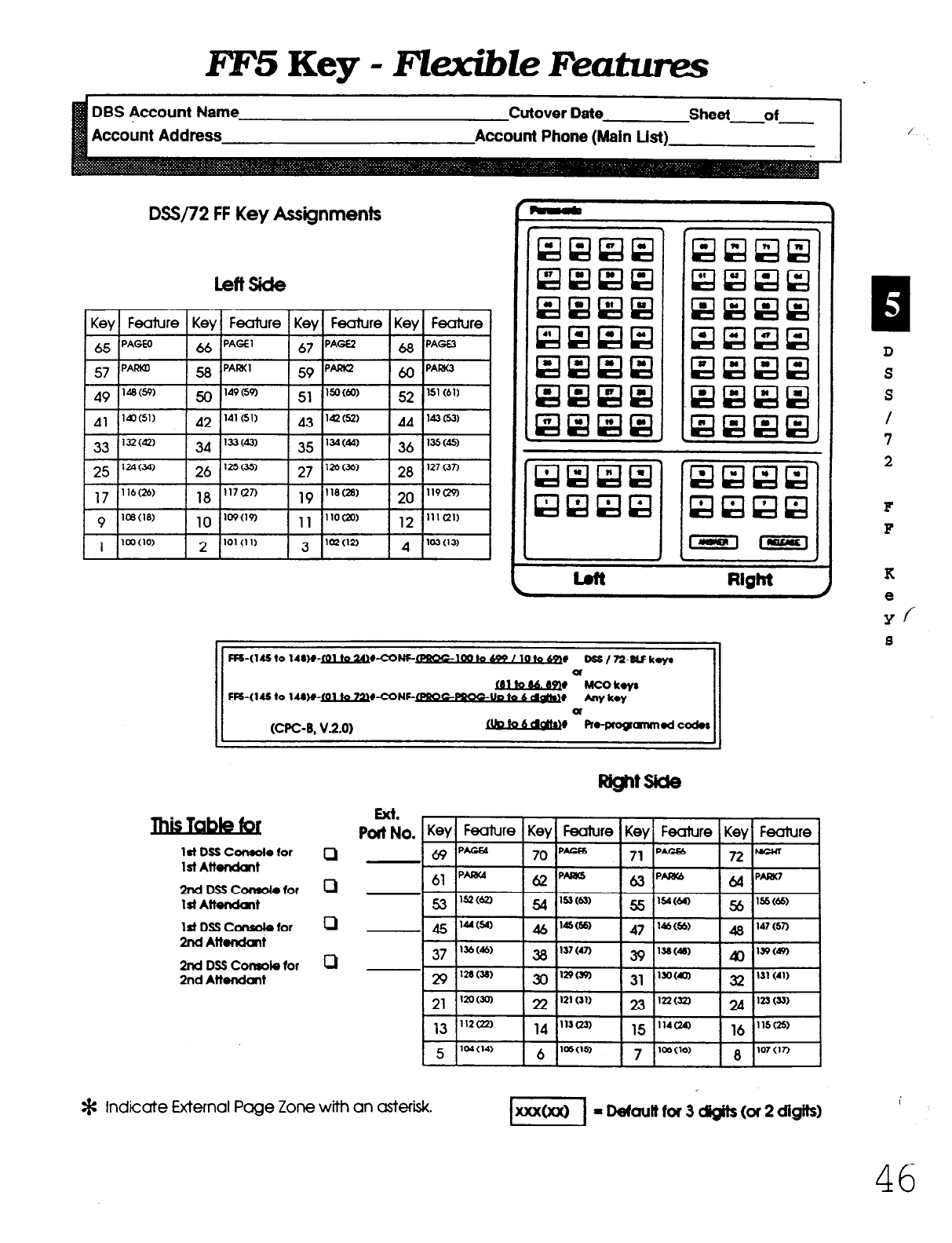
FE5 Key - FZexibZe Features
Account Address Account Phone (Main List)
DSS/72 FF Key Assignments
lettside
Key Fealure Key Feature Key Feature Key Feature
65 PAGE0 66 PAGE1
67 pAGE2
68 PAGE.3
57 pAGia3
58 PARK1
59 p-
60 PAM3
1stDSSConsotefor f-J
1st Attendant
2nd DSS Consot. for 0
1 St Attendant
1st DSS Ccnsole for 0
mdAblu!ant
2nd DSS Console for 0
2nd Attefldant
Ext. ,
p~No. Key Feature Key Feature Key Feature Key Feature
69
PAGU
70 p- 71p- 72-
61 p-
PAW5 PNM PNW
B
D
S
S
/
7
2
F
F
K
e
Y/
8
* Indicate External Page Zone with an asterisk.
46
Technical Manuals Online! - http://www.tech-man.com
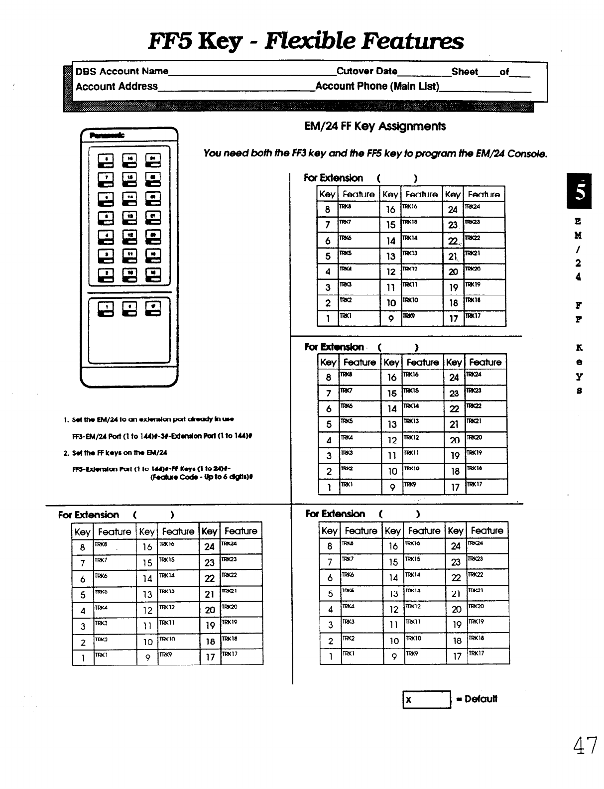
E‘FS Key - Flexible Features
DBS Account Name
Account Addre
Cutover Date
EM/24 FF Key Assignments
You need both the FF3 key crnd the FF5 key to program the EM/24 Cons/e.
47
Technical Manuals Online! - http://www.tech-man.com
he FF6 Key, in combination with the
DSS/72, can create messages for ab-
sence message codes 5 to 9, and can
assign names to extensions, system speed dial,
personal speed dial, trunk lines, and hunt group
pilot extensions.
When there are several DSS units, use only the unit
positioned nearest the telephone for programming.
Use the Name Assignment formwith the Speed Dial
I&t, Key Plan, and Summary Key Plaq. All these
forms are for the installer / programmer.
13
1
F
F
6
K
e
Y
(
Save Your Original Forms!!! .-
1 1
48
Technical Manuals Online! - http://www.tech-man.com
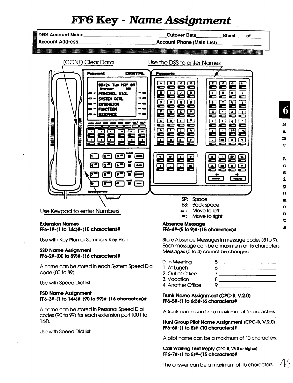
FEY3 Key - Nane Assignment
Account Addre Account Phon
(CON0 Clear Data Use the DSS to enter Names
13
1
N
a
m
e
A
8
s
i
Q
n
Use Keypad to enter Numbers
EXWlSbN-
FM-IX-(1 to lM)R-(10 chamcters~
Use with Key Plan or Summary Key Plan
SSDNcme&sQment
FF 6-28400 to 89)#-( 16 &xactersM
A name can be stored in each System Speed Dial
code (00 to 89).
Use with Speed Dial list
PSD Name iesignment
FF6-3#-(1 to 144)#-(90 to 99)#-(16 charoctws)#
A name can be stored in Personal Speed Dial
codes (90 to 99) for each extension port (001 to
144).
Use with Speed Dial list
Sp: Space
Bs: Backspace
C: Movetoieft
-: Move to right
-M==w
FF 6-M-(5 to 9)#-(15 chamctefsb
m
e
xl
t
8
Store Absence Messages in message codes (5 to 9).
Each message can be a maximum of 15 characters.
Messages (0 to 4) cannot be changed.
0: In Meeting 5:
1: At Lunch 6:
2: Out of Office 7:
3: Vacation 8:
4: Another Offrice 9
Ttunk Ncme Asigmmt (CPC-8, V2.0)
FF6-SR-(1 to 64)#-(6 chcmcters)#
A trunk name can be a maximum of 6 characters.
Hunt Group f’ilot Name Ass&merit (CPC-B, V.2.0)‘
FF6-#-( 1 to 8)#-( 10 charcicters)#
A pilot name can be a maxtmum of 10 characters.
Cd WcMng Text Reply (cpc-E, m.o or higher)
FF6-7#-(1 to 5)#-(15 chcm&rsM
The answer can be a matimum of 15 characters.
4
(
_
Technical Manuals Online! - http://www.tech-man.com
he FF7 Key is for programming toll
restricted Area and Office codes. The sub-
modes are (l# to 9#).
7hereareseuenfoms iheinstaller/prqgrammer canusetorecord these
ades:
The TRS System Settings form is for submode l#. ‘This
programming affects the entire toll restrict system.
TheTRS&eaCodes/OfficeCodesformisforsubmodesZ#
and 3#. It establishes restrictions for Classes of Restriction
3 to 6.
The TRS Special Area Code
Tables
form is for submodes 4#
and 5#. It is for Classes of Restriction 3 to 6. Each of the four
tablescanacceptonethousand(1,000)officecodeoramacode
entries.
The
7-Digit
Call
Restrict
form is for submode 6#. Use this
optional table to restrict up to tMy 7-digit numbers for Classes
of Restriction 2 to 6.
The TRS
Day
/ Night Assignments form is for submodes 7#
and 8#. In most cases, the “all-trunk” setting is used for each
extension, but excepfioIls can be made wherever needed.
Enter trunk number and COR (0 to 7). Photocopy the original
form and use a separate page for day and night.
The TRS
Block
Mode form is for submode 9#. Record default
changes (deny, allow) for each CORkom 3 to 6 throughout the
toll restrict system.
7hefol7nexpzuinedbebwislocatedattibackofthismanual
. .
zmm&at@foUowing the IF1 0 Key information:
The Extension
Summary form is for assigning toll reslric-
tions to each extension. Use one form for each extension port.
Photocopy the original form and use only the copies. Refer to
the TdRes~nbox on this form.
Save Your Original Forms!!!
PI
F
F
7
K
e
Y
c
50
Technical Manuals Online! - http://www.tech-man.com

FlVKey-TRS
’ 3% Account Name Cutover Date Sheet of
Account Phone (Main List) I
n
Settings 1
International calls
ofWe code tab/8
0: Disable
-l#-2# Incoming calls I: m&8
Not f8Shkted
-l#-3% Maximum digits dialed 1 to 15: 15th to 29th digit
0: Allow
-I#-AX 211 dial restriction 1: Deny
0: Allow
-l#-5# 311 dial restriction 1: Deny
0: A/low
-l#-6# 411 dial
restriCtiOn
1: Deny
0: Allow
-l#-7# 511 dial restriction 1: Deny
0: Allow
-111-M 611 dial restriction 1: Deny
0: Allow
-l#-9# 7 11 dial restriction 1: Deny
0: Allow
-l#-low 811 dial restriction 1: Deny
0: A/law
-I#-1 l# 911 dial restriction 1: Deny
See FF7-M
0: Allow
-111-121
74g1i
resirkt table COR Tvpe 2
1: R8ddCt
See FF7-M
0: Allow
-l#-13#
7-ciigit
restrict table COR Tvpe 2
?: i?8SfdCt
see FF7-6#
0: Allow
-11-141
restrId table COR TYW 2 I: Resfrkf
T
R
S
S
Y
s
t
e
m
Technical Manuals Online! - http://www.tech-man.com
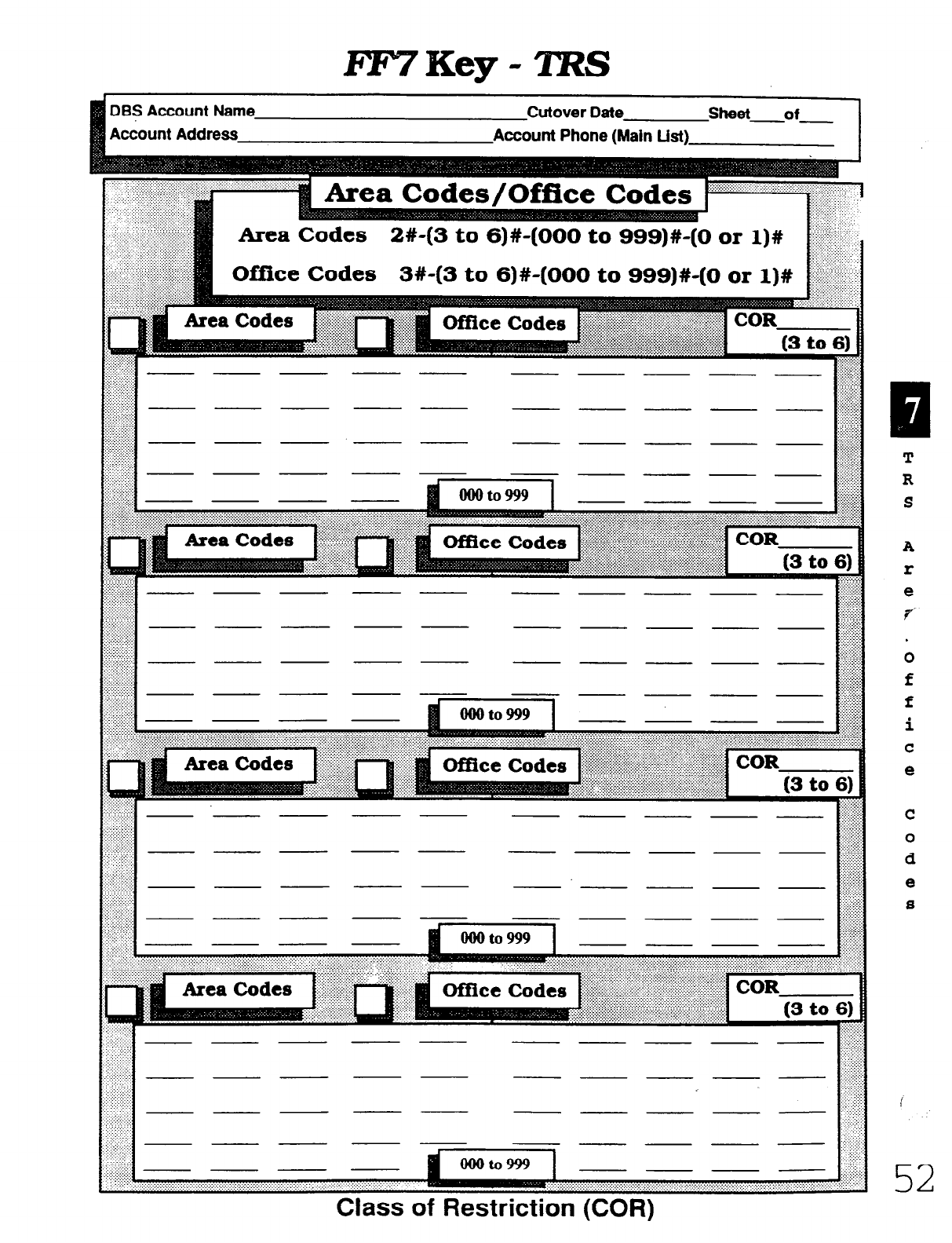
Cutover Date
Account Phone (Main List)
- - -
I- - -
- - ---- - .::~::::::::::
.\...:..:.-
1:
bi
::.:.:.z::::::
- - -
- ~
- ___ ~ - - ~
- - - - -
- - -
. . . . . . . . ..y. 7.. .:.A:.:.:.‘:..:.: .:: ,.:. ,. .:: ,. . . . . .
A
r
e
f
52
Class of Restriction (COR)
Technical Manuals Online! - http://www.tech-man.com
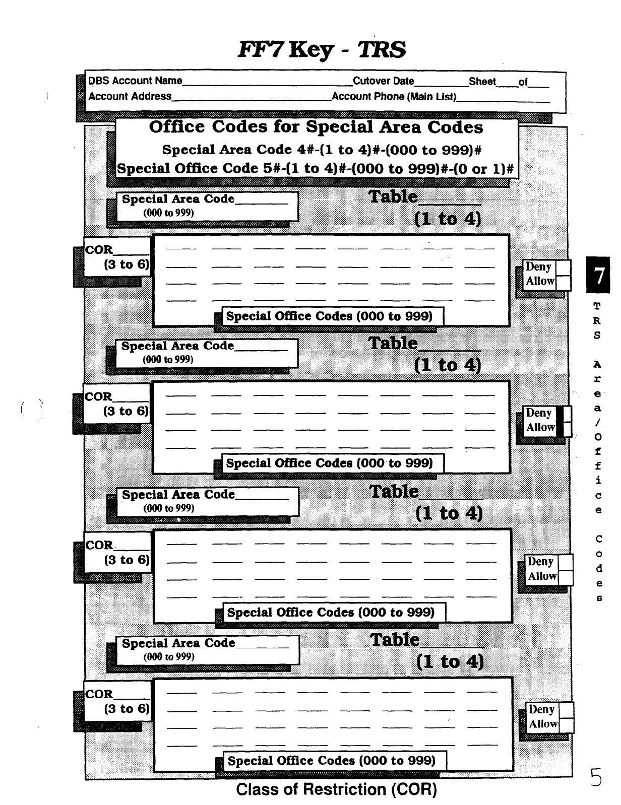
FYVKey-ZftZS
( ‘:
PBS Account Name Cutover Date Sheet of
1 Account Address Account Phone (Main List)
---
(3 to 6)l ::i$!:.
- - -- - - - - - F
:F&
COR ---m----
(3to6) I - - - - - - - -
-- ------
--------
-- - - - - - -
- - - __ - -
COR l------------
(3 to 64 - ___ ___ ___ -
- - - - - - -
- - - - -
d Special Office Codes (000 to 999)
T
R
S
A
r
e
a
/
0
f
f
i
C
e
.. 3 ...... “. :
. .: ..:;. ..
Class of Restriction (COR)
Technical Manuals Online! - http://www.tech-man.com
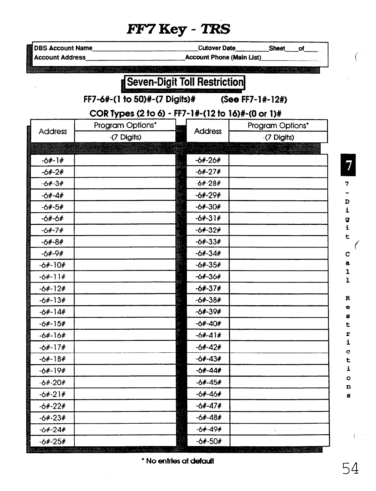
DBS Account Name Cutover Date sheet of
Account Address Account Phone (Main List)
FF7-6#-(1
F7-l#-(12to 16)#-(Oar l)#
l Noentriesatddautt
D
i
Q
i
t
c
C
a
1
1
R
e
s
t
r
i
C
t
i
0
n
S
54
Technical Manuals Online! - http://www.tech-man.com
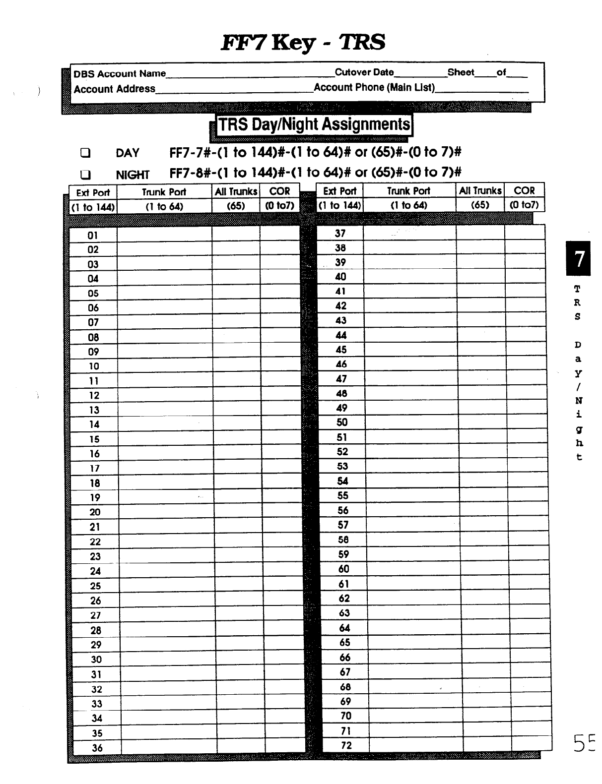
Account Address
Cutover Date sheet of
Account Phone (Main Ust)
0
DAY
FF7-7#-( 1 to 144)#-( 1 to &I)# or (65)#-(0 to 7)#
0 NIGHT FF7-8#-( 1 to lb!)+( 1 to 64)# or (&)#-(0 to 7)#
42
R
43
s
44
D
a
Y
I I
49 I
I
N
I I I
53 1 t
I
26
77
-- I I
65
1 I I I
c
5-
Technical Manuals Online! - http://www.tech-man.com
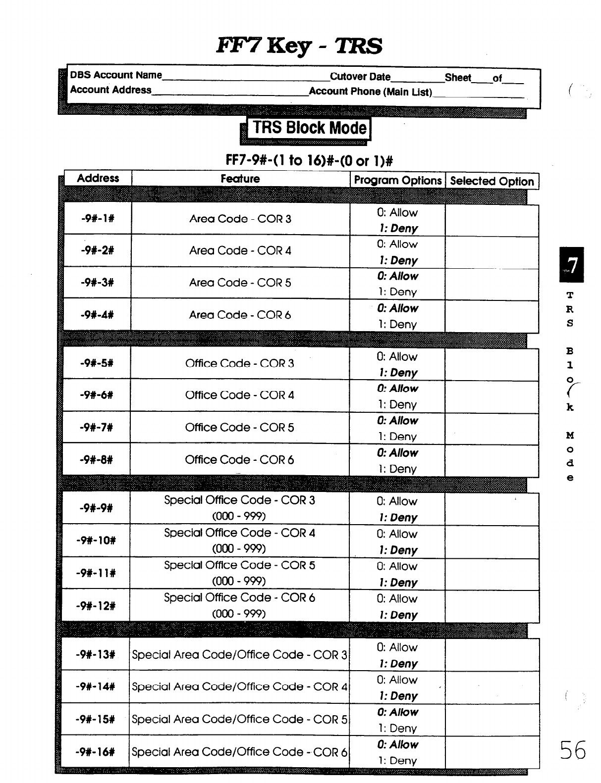
DES Account Name Cutover Date Sheet of
Account Address Account Phone (Main List)
FF7-9#-(1 to 16)#-(0 or l)#
-9#- 1%
-9#-2%
-9#-3w
Area Code - COR 3
Area Code - COR 4
Area Code COR 5 -
0: Allow
1: Deny
0: Allow
1: Deny
0: Allow
1: Deny
Office Code - COR 3
Office Code - COR 5
Office Code - COR 6
B
1
0
c-
k
M
0
d
e
Technical Manuals Online! - http://www.tech-man.com
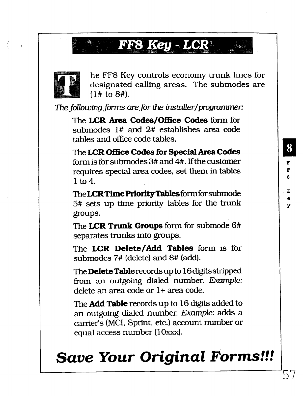
he FF8 Key controls economy trunk lines for
designated calling areas. The submodes are
(l# to 8#).
The following forms are for the iizstaUer/pr
The LCR Area Codes/Office Codes form for
submodes l# and 2# establishes area code
tables and office code tables.
The LCR Of!fice Codes for Special AreaCodes
form is for submodes 3# and 4#. Ifthe customer
requires special area codes, set them in
tables
1 to 4.
‘l3eLCRTimePriorityTabksformforsubmode
5#
sets up time priority tables for the trunk
groups.
The Ix=R Trunk Groups form for submode 6#
separates trunks into groups.
The LCR Delete/Ad$ Tables form
is for
submodes 7# (delete) and 8# (add).
TheDeleteTablerecordsupto 16digitsstripped
Tom an outgoing dialed number. Example:
delete an area code or l+ area code.
The Add Table records up to 16 digits added to
an outgoing dialed number. ICw-@e: adds a
carrier’s (MCI, Sprint, etc.) account number or
equal access number (1 m).
Save Your Original Forms!!!
K
e
Y
Technical Manuals Online! - http://www.tech-man.com
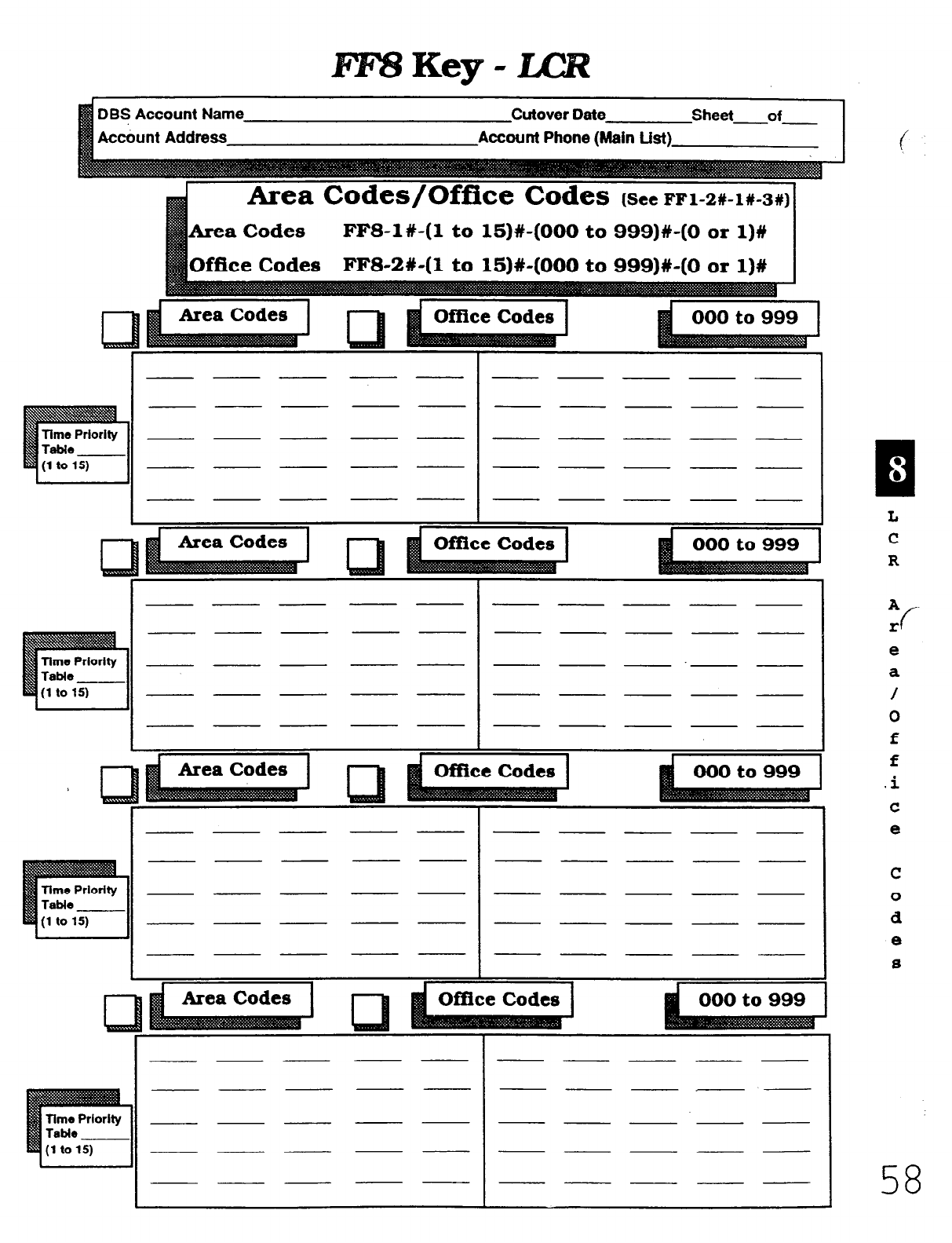
DBS Account Name Cutover Date Sheet of
FFS-l#-(1 to 15)#-(000 to 999)#-(0 or l)#
L
3 I 1
- - - - - - - - - ___
- - - -- -----
1
- ~ - - - -----
~ ~ - - - - - - - -
I - - - - - - - ~ - -
I I
I I
I I I
I - - - - - - - - - ~
I I
- - - ~ - - - - - -
- - - ~ - - - -.- -
- - - - - - - - - -
- - - ~- -----
I I
- - - I
- - - - - - - I
- ~ - -- -----
~ - - - - - - - ___
- - - - - - - - - -
___ - - - - - - - - ___
c
Time Prlorlty
Table
(1 to 15)
1
J
I I I
___ - - ___ - - - - - -
I I
1 !
A
I: f
e
a
/
0
f
f
.i
C
e
58
Technical Manuals Online! - http://www.tech-man.com

DES Account Name
Account Address
Cutover Date sheet of
Account Phone (Main List)
Time Priority Table
Special Area Codes FF8-3#-(1 to 4)#-(000 to 999)#
- - - - - - -
- - - -
fiecial
Area Code
Table 4)~ (1 to
- - - - -
:: :. .: . . . y.: :.:.:.: :.-.
- - - - - -
- - - - -
- - - - - -
dOffice Code Entries (000 to 999)1
S
P
e
C-
i
a
1
A
t
e
a
Technical Manuals Online! - http://www.tech-man.com
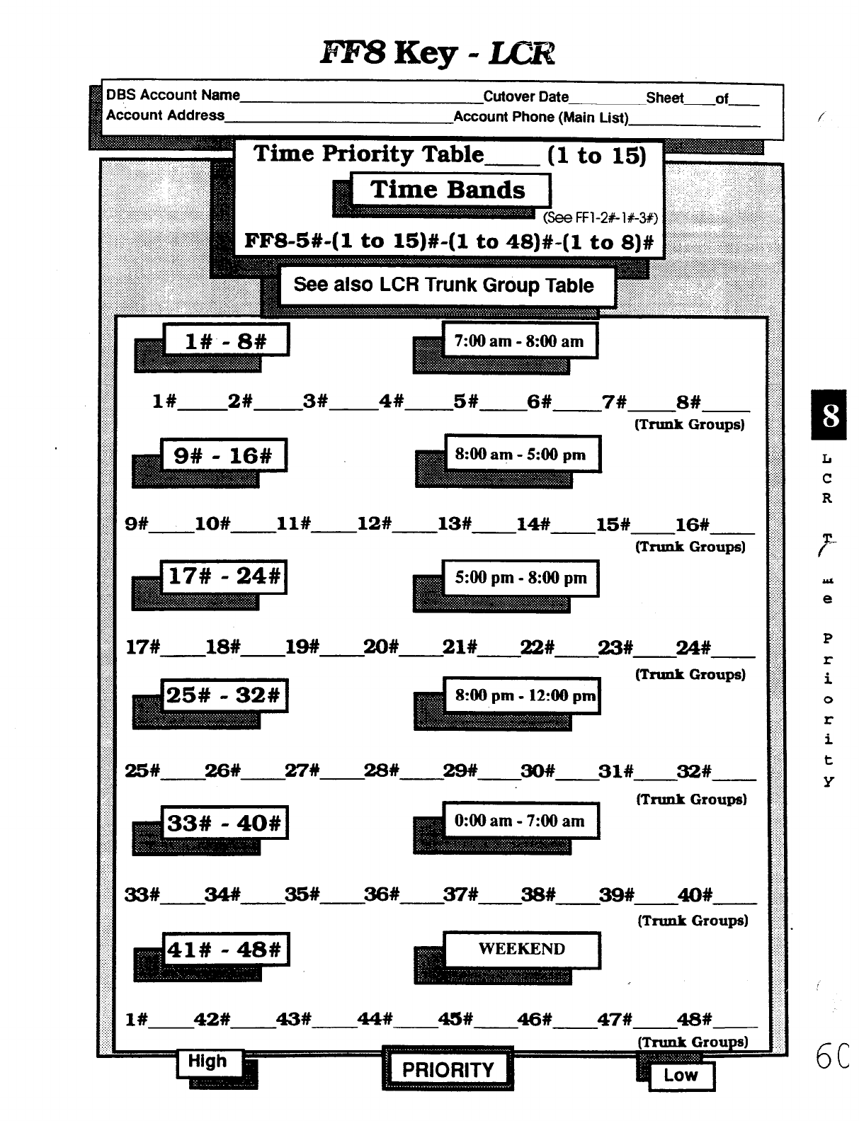
BlBKey-LCR
DES Account Nam
Account Address unt Phone (Main List)
6C
7:00
am - 8:OO am
:.:.>..
.+:.:
. . . . . . .
j;::::
. . . . :
lK--2#~3#~4# 5# 6# 7# s# $$f
P -
(Tnmk Groups) @
..:::
.:::.:::
:...-.
i......
ii....
i......
:.:.“.
. . . . ..i
. . . . . . .
:(.:.:.
.:...>
:.,_:.:.
. . . . . . .
..:.>:..
-.. . .
9#
--ax--- ll# 12# 14# 13# -15#-
16# .#
(Tmnk Groups) ;$$!
. . . ..A
:::.
::j:::::
.::,x..
. . . . . .
.._....
. . . . . . . .
.._..A
..:. . .
_...
. . . ..A.
. . . . . .,.
. . . . . .
17#
.---18#-1~-~#- - ~-
21# 22# 23# 24# 2
::...
;,.,,._
. . . . .
. . .._ -..
.:.:.:.:
(Trunk
Groups)
Q
i..:.
. . . . . .
..:i.
. . . . . . .
. . .
:
:.
.:..
>..,i
. . . . :.
:.:.,.:
::
:
:._j..
. . . . .
25# 26# 27!# 28# 29# 30# 31# a# g
(Td Group) i$
. ...:;
: ::
:.>:.
.._...
. . . .
::..
::
:.::.:
. . ..l
. . . . .
A....
::.
..:
. . . . .
.:.:>
.;
:
. ..A
. . . . .
:::
:.:.:
3=L-~%~~#.-.-~# 38# 39# 40# .:.
:..
;;:I
. . ...\
..::
,::..:.
(TN& Groups) “;::
f'-
Aa
e
P
I:
i
0
r
i
t
Y
l#
42#
43# 4.M 45# @# :
-47#48#- .:;.:
II
. . .
Technical Manuals Online! - http://www.tech-man.com
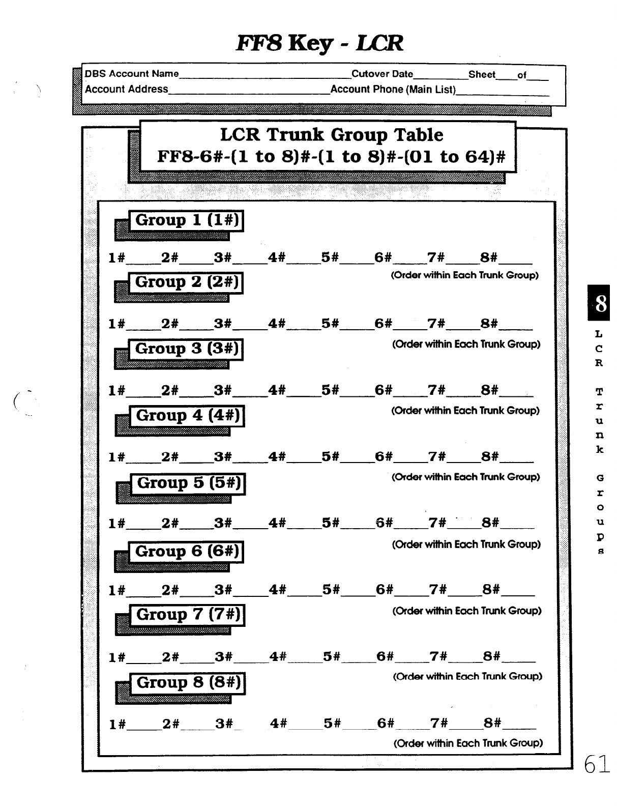
FZV?Key-LCR
DBS Account Name
Account Address
Cutover Date Sheet of
--
Account
Phone (Main List)
1#--2# 3# 4#
5#
6# 7# 8#
I
(Order within Each Trunk Group)
1#---2#-3# 4#
5#
6# 7# 8#
(OKbf withm Each Trunk Group)
1#-.-2# 3# 4# 5# 6# 7# 8#
(oldet withm Each Trunk Group)
1#p2# 3# 4# 5# 6# 7# 8#
@rder wilhm Each Trunk Group)
1#-2# 3# 4# 5# 6# 8#
7# ’
--
(older within Each Trunk Group)
1#-2#.-3# 4# 5# 6# 7# 8#
(Order within Each Trunk Group)
1#-2# 3# 458 5# 6# 7# 8#
(Order within Each Trunk Group)
1#-e-2# 3# 4# 5# 6# 7# 8#
(kf9f within Each Trunk Group)
L
C
R
T
r
U
n
k
G
r
0
U
P
s
61
Technical Manuals Online! - http://www.tech-man.com
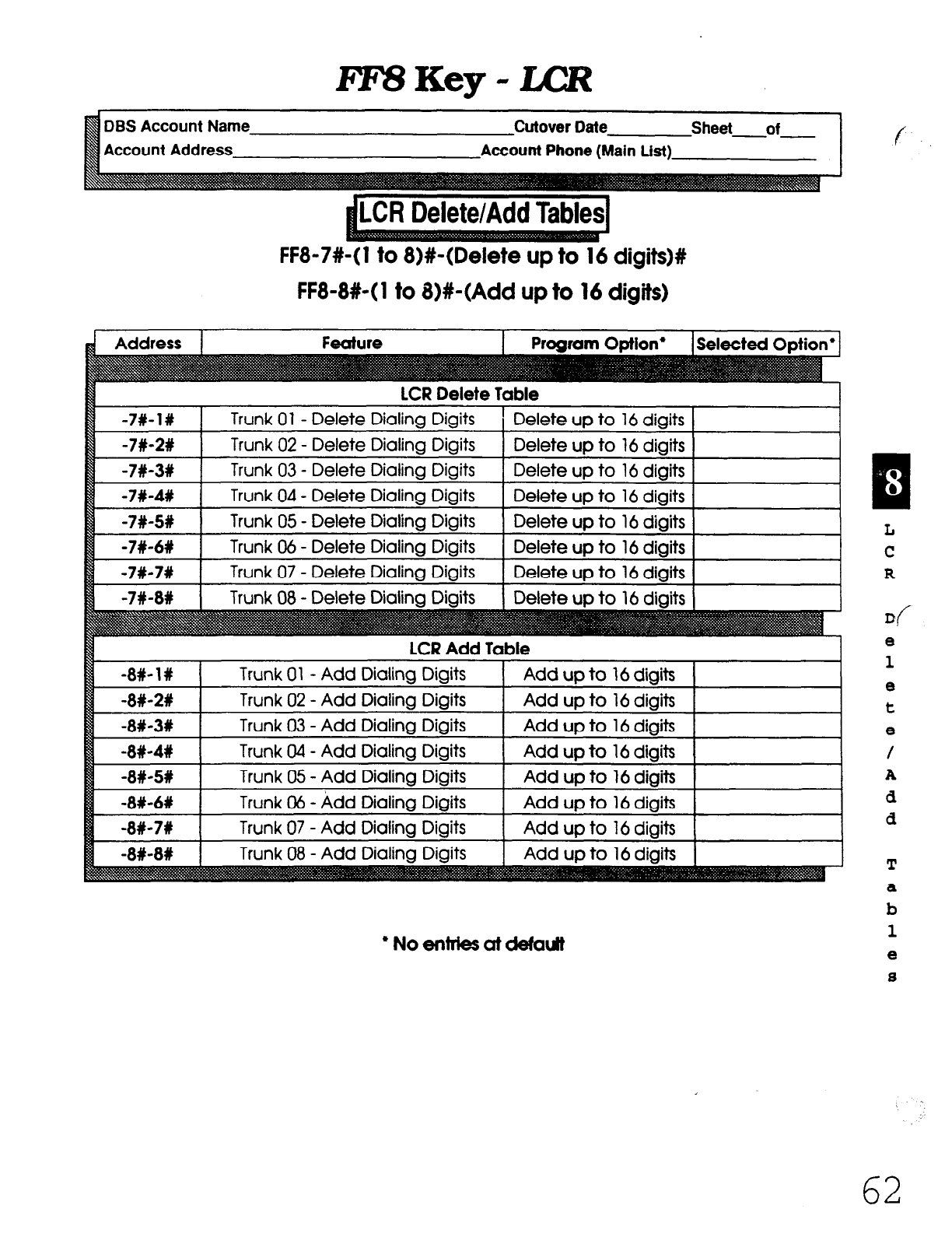
RZ%Key-LB?
DBS Account Name
Account Address
Cutover Date
lLCR Delete/Add Tables1
FF8-7#-( 1 to 8)#-(Delete up to 16 digits)#
FF8-8#-( 1 to 8)#-(Add up to 16 digits)
Address 1 Feature I Proaram Otiion’ I Selected O&ion’ I
LCR Delete Table
Trunk 01 - Delete Dialing Digits ’ Delete up to 16 digits
-7#-2%
-7#-3w
-7#-4#
-7#-SW
-7#-6R
-7#-7#
Trunk 02 - Delete Dialing Digits Delete up to 16 digits
Trunk 03 - Delete Dialing Digits Delete up to 16 digits
Trunk 04 - Delete Dialing Digits Delete up to 16 digits
Trunk 05 - Delete Dialing Digits Delete
up
to 16 digits
Trunk 06 - Delete Dialing Digits Delete up to 16 digits
Trunk 07 - Delete Dialing Digits Delete up to 16 digits
-7#-8# Trunk 08 - Delete Dialina Diaits Delete
UD
to 16 diaits
-8#-1X
-8#-2#
-8#-3#
-8#-4#
-8#-5%
-8#-6W
-8#-7#
LCR Add Table
Trunk 01 - Add Dialing Digits Add up to 16 digits
Trunk 02 - Add Dialing Digits Add up to 16 digits
Trunk 03 - Add Dialing Digits Add up to 16 digits
Trunk 04 - Add Dialing Digits Add up to 16 digits
Trunk 05 - Add Dialing Digits Add up to 16 digits
Trunk 06 - kdd Dialing Digits Add up to 16 digits
Trunk 07 - Add Dialing Digits Add up to 16 digits
Trunk 08 - Add Dialina D&its
I
Add UD to 16 diaits
I
l NoentriesutcWoutt
f
a :
L
C
R
d
8
1
8
t
8
/
A
d
d
, -.
62
Technical Manuals Online! - http://www.tech-man.com

he FF9 Key copies programmed data from exten-
sion to extension, trunk to trunk, or FF key to FF
key. The sub-modes are l# to 3#.
:-
Tnm&s/submode l#.
FF9-l#-(Ol to 64)#-(01 to 64)##
Trunk features can be copied to another txunkwith the single 1
exception of the Private Line feature, which cannot be copied.
m
a
mtensions/submode 2#. FF9-2#-fl
to 144)#-(1 to 144)##
C
With four exceptions, all other features can be copied to any
extension in the DBS system.
7Ie&~- exe@ons are= extension number, telephone type,
station lockout code, and the EM/24 port number (BLF).
EFKeys/submode 3#. FF9-3#-(1
to 144)#-(1 to 14-4)##
Save Your Original Forms!!!
I 1
63
Technical Manuals Online! - http://www.tech-man.com
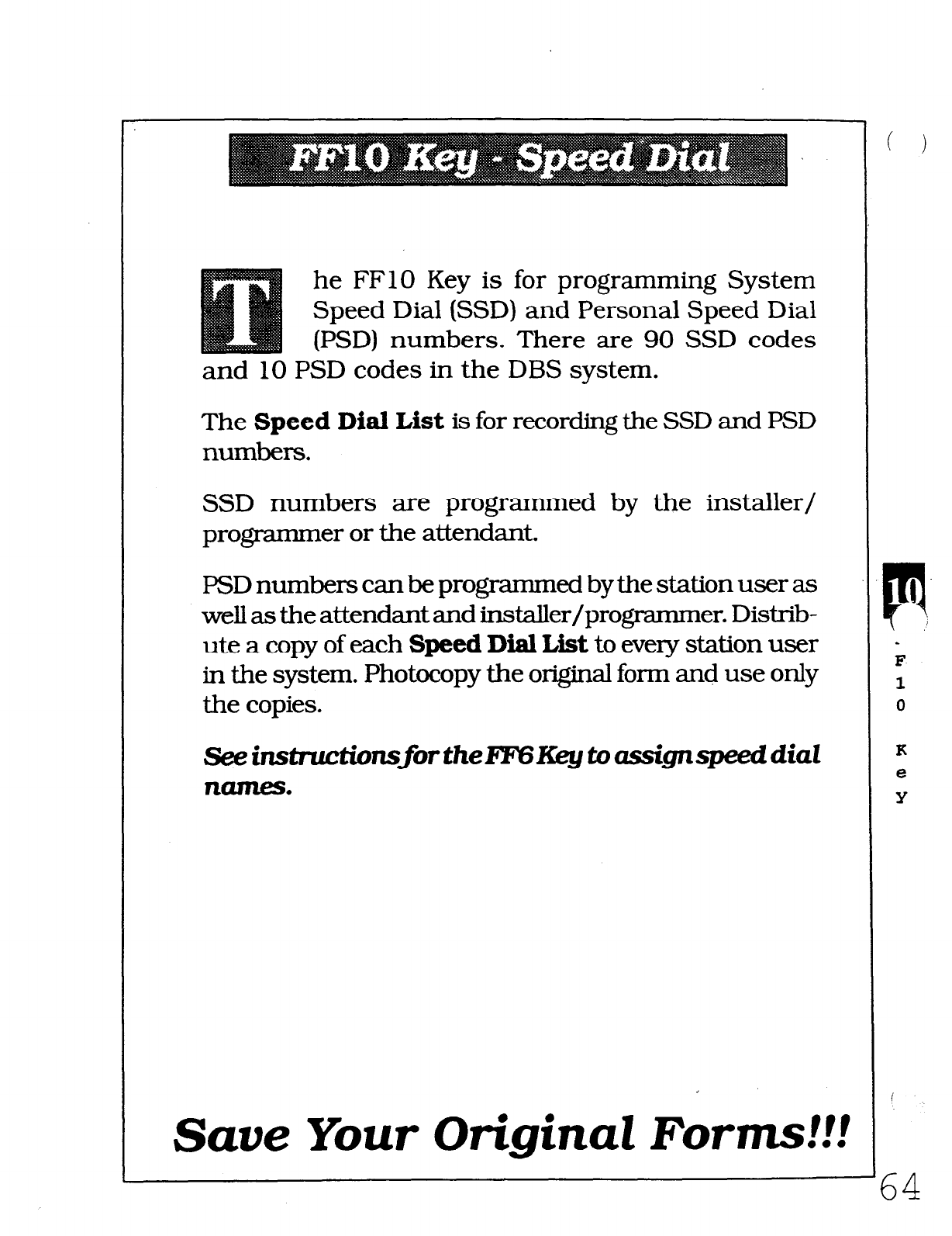
he FFlO Key is for programming System
Speed Dial (SSD) and Personal Speed Dial
(PSD) numbers. There are 90 SSD codes
and 10 PSD codes in the DBS system.
The Speed Dial List is for recording the SSD and PSD
numbers.
SSD numbers are programmed by the installer/
programmer or the attendant.
PSD numbers canbe programmed by the station user as
well as the attendant and installer/progmmmer. Distrib-
ute a copy of each Speed Dial List to every station user
in the system. Photocopy the original forrn and use only
the copies.
See instmctionsfor thel?FWCey to assignspeed diat
ll-.
Save Your Original Forms!!!
64
Technical Manuals Online! - http://www.tech-man.com
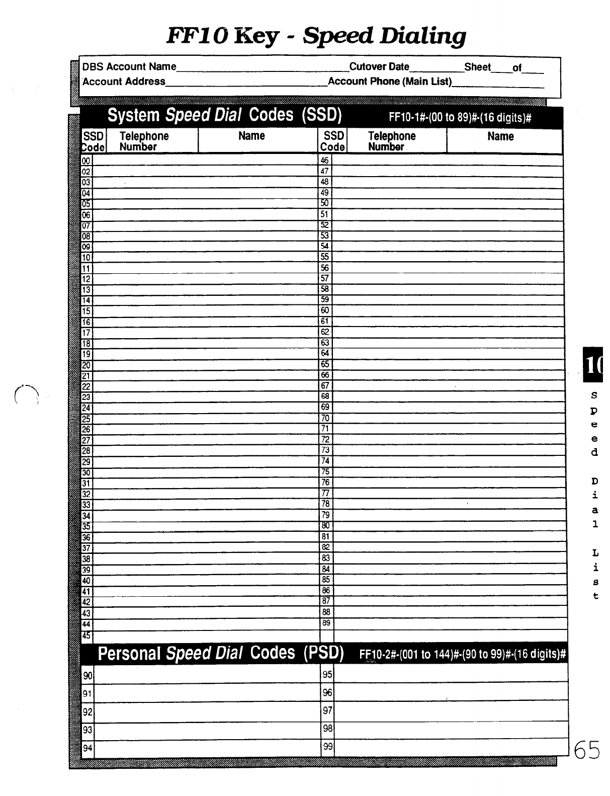
FFlO Key -
Speed
DiaZing
DES Account Name
Account Address
Cutover Date Sheet-of
Account Phone (Main List)
P
I
S
P
e
e
d
D
i
a
1
65
Technical Manuals Online! - http://www.tech-man.com
he Extension Summary form is for
recording all the FF3, 4, 6, and 7
Key features associated with each
extension port.
This form is for the installer/programmer
who will eventually transcribe the informa-
tion onto the Summary Key Plan or the
Key Plan for sign-off by the Customer.
Save Your Original Forms!!!
CL
:
E
X
t
8
n
s
i
0
n
S
U
m
m
a
r
Y
66
Technical Manuals Online! - http://www.tech-man.com
Extension Summary
DBS Account Name
Account Address
Cutover Date Sheet-of
Account Phone (Main List)
Extension General Information (FF3,6)
]16022034CI)Std.
7
Hunf Group (FF4)
~(1. ran
(1 to 144)
Hunt Group Member
Hunt Group Number
Hunt Type
Transfer Extension
Pilot Extension/Name
I to6
T/D/L
Ex-tension Programming 1 (FF3) Mu/k = Defautt
ForcZz
Forced Veriied Acct Code DEnable 0 Ditcrble
1 1
Station Lockout Code
CO Off Hook Signal
Call Waiting . .-
Busy Override
Busy Overridden
I I 1 1 1 4
DEnable
q
Disable
1
Accept
0 Reject
lEnable mm&/e
mAcc&
q
Reiect 1
-
mEnable nDiscrMe 1
~Etlable i$isabie
DEnable 0 Discrble
loYes ONo
Ringing Line Preference
Unsupervised Conference
SMDR Printout
Prime Une Preference
Off Hook signal Puttem
Off Hook Sianal Volume
Page Group Pickup
1.2.3.4 I
i
none b conmfe
00.01,02.03
(External Paaina) I 04.05.06.07 I
Ext. Ring Assign. Ext. 10 to 69 (100 to 699)
lmmediie
Delayed
cdl caverage (FF4)
Tall Resfdcfbn Uass of Resfricfian QF7)
DAY Type (0 to 7) Trunks (1 to 64) DAY Type (0 to 7) Trunks (1 to 64)
-mS VW IRS TYW
~3 Type TRS Type
TFS Type TRS Type
TRS Type TRS TYW
m
E
X
t
e
.n
8
i
0
n
S
U
m
m
a
r
Y
67
Technical Manuals Online! - http://www.tech-man.com
Extension Summary
DBS Account Name
Account Address
Cutover Date
Account
Phone
(Main List)
Ext. Port Extension
____ __ ._ ___ ._ _. .__ ______-_
Ex-lension hrmral InformatIon (FF3.6)
Hunt Group (FF4)
Tdl Reshktion Class of Restriction (FF7)
(1 to 14.4)
NlOto6W/lOto69)
Extension Rogramting 1 (FF3)
h/k = DefauR
Forced LCR (
Forced Verified Acct Code DEnable HfIis.
iEEl
Station Lockout Code
CO OfY Hook Signal
Call Waiting
Busy Override
Busy Overridden
abh9
I- 1 I I :! I; I
4
]
a
anable [7Dis
-
mabk
S1Accec bt OReject
able
!eiect
xept. -I-
Prime tine Preference IllEn Iable ~D&able
Ringing Line Preference I[aErwf9e 0 Disable
Unsupervised Conference mnable 0 Disable
s ‘MDR Printout
q N0
Off Hook Signal Pattern
Off Hook Sianal Volume
Page Group Pickup
(External Paging)
1.2.3.m 1
q one jqcontinue
od ti.02.03 I
04.05.05.07
~1
EXT Ring Pattern
Ringing Assignment QF4)
CO Ring Assiin. Trunks (1 to 64)
Day
4
IO 9,
14
Niaht 1 to
14
Coverage Member
Coverage Group number I to 16
Coverinc~ Extension 1
Covering Extension 2 I 1
0
E
x
t
e
.n
8
i
0
n
S
ll
m
m
a
r
Y
i
6%
Technical Manuals Online! - http://www.tech-man.com
he Key
Plan
is a summary-of the
programming on each station for
the
FF3,4,5,6,7,8,9,
and 10 keys.
Programmed data is taken from the floor plan
of an installation site which, along with the
Summary Key
Plan,
is the only other place
cable numbers are documented.
This form is used on the final walk-through
of an installation or upgrade to verify the
programming on each station.
Save Your Original Forms!!!
[1:
1
K
8
Y
P
1
a
n
Technical Manuals Online! - http://www.tech-man.com
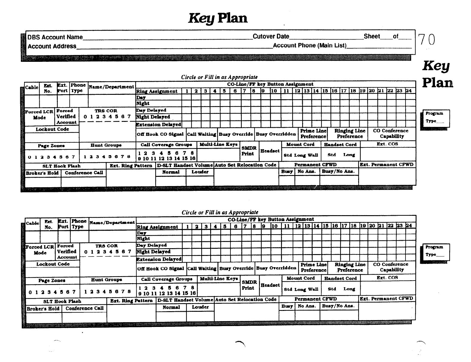
DBS Account Name
Account Address
Cutover Date Sheet of
Account Phone (Main List)
70
lms COR
2348
---
Circle or Fill in as Appropriate
co-Llne/FF key
Button
Amignment
Asoment 1 2 3 4 5 6 7 6 9 10 11 12 13 14 15 16 17 18 10 20 21 22 I23 b-4
my
Ntht
ht
Delayed
PlaI
1
Circle or Fill in as Appropriate
**e Nulhe/Deputmsnt co-Llne/FF key Button
Auignment I
hdmmsnt
1 ll2l3t4i6 IS 17 IS IO I10
Technical Manuals Online! - http://www.tech-man.com
he Summary Key Plan is a summary
of the programming on the FF3,4, 5,
6, and 7 keys for each station.
The form is for larger installations where most,
but not all the details of an installation are
recorded.
The floor plan, Key
Plan,
and Summary Key
Plan
are the only places where cable numbers
are documented.
The Summary Key
Plan
is used by the in-
staller/programmer and the Customer to sign
off on the installation.
Save Your Original Forms!!!
Q
S
U
m
m
a
I:
Y
I K
8
Y
71
Technical Manuals Online! - http://www.tech-man.com
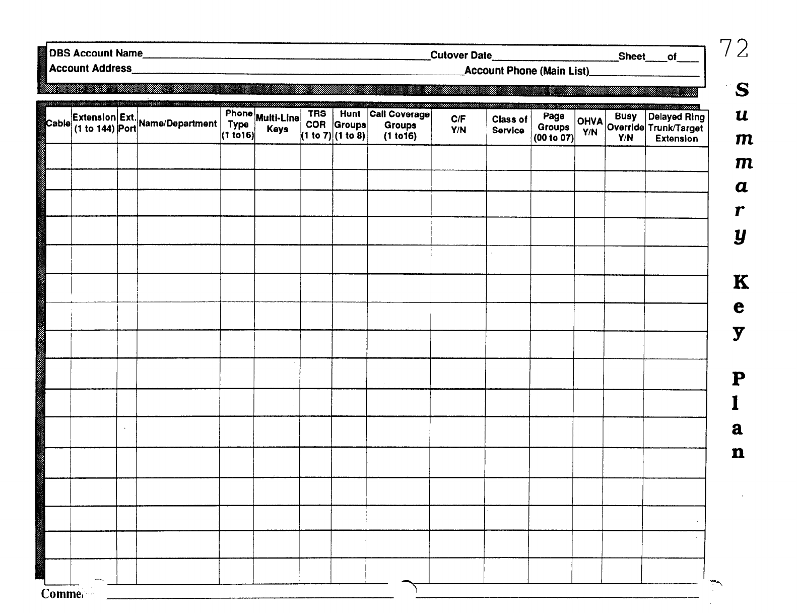
72
S
K
m
m
a
r
Y
K
e
9
P
1
a
n
Cornme,
Technical Manuals Online! - http://www.tech-man.com
ppendix A is a master list of FF key
defaults. Following the master list
is a pocket-sized version of the FF
key default chart beginning on page 90.
1 A
P
P
e
n
d
i
X
A
Technical Manuals Online! - http://www.tech-man.com
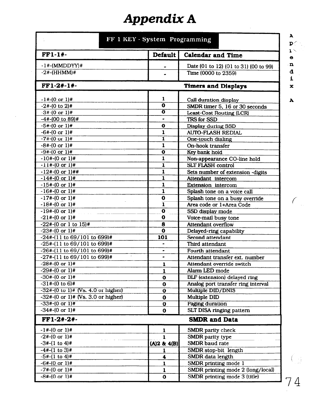
Appendix A
FFl-l#-
- 1 #-(MMDDYYj#
-2#-(HHMM)#
1 Default 1 Ca lendar ax td Time I
Date (01 to 12) (01 to 311 (00 to 99)
Time (0000 to 2359)
FFl-2#-1#- Timers and Displays I
-l#-(0 or l)#
- _- -. 1 Call duration display
-a#-(U to 2)#
-3#-(0
or l)#
-4#-(00
to 89)#
-5#-(0
or l)#
-6#-(0
or l)#
-7#-(0
or l)#
-8#-(0
or l)#
-9#-(0 or l)#
-lO#-(0 or l)#
-1 l#-(0 or l)#
-12#-(0 or l)##
-14#-(0 or 11#
-15#-(0 or l)#
SMDR timer 5. 16 or 30 seconds
ii Least-Cost Routing (LCR)
- TRS for SSD
0 Display during SSD
1 iWTO-FLASH REDIAL
1
One-touch dialing t
1
On-hook transfer
0 Key bank hold
1
Non-appearance CO-line hold
1
SLT FLASH control
I
1
1 Sets number of extension -digits
1
1 Attendant intercom
-16#-(0 or l)#
-17#-(0 or l)#
-18#
1
I Extension intercom I
1
1 Splash tone on a voice call
0
1 Splash tone on a busy override I
I
-27#-(11 to 69/ 101
1 -30%(0
or l)#
Attendant transfer ext. number
1
Attendant override switch
1
Alarm LED mode
I 0
1 BLF (extensionrdklayedring
1 FFl-2#-2#- SBMDR and Data
-l#-(0 or I)#
-2#-(0
or l)#
-3#-(1 to 4)#
-4#-(1 to 3)#
-5#-(1 to 4)#
-6#-(0
or I)#
-7#-(0
or l)#
-8#-(0
or l)#
1
SMDR parity check
SMDR parity type
(Al2:4m
SMDR baud rate
1
SMDR stop-bit length
4
SMDR data len&h
1 SMDR printing mode 1
1
SMDR printing mode 2 (long/local)
0 SMDR
~rlntim
mode 3 (title) ,
A
P
1‘
8
.n
d
i
x
A
74
Technical Manuals Online! - http://www.tech-man.com
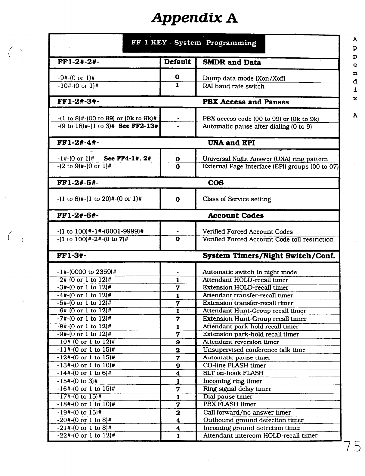
Appendix A
FFl-2#-2W-
-9#-(0 or l)#
-lO#-(0 or l)#
FFl-2#-3W-
-
Default SB%DR and Data
0 Dump data mode (Xon/Xoff)
1
PAI baud rate switch
PBX Access and Pauses
I I
I
-(l to a)#-(00 to 99) or (Ok to 9k)# - PBX access code (00 to 99) or (Ok to 9k)
49 to 18)#-(1 to 3)# See FF!&l% - Automatic pause after dialing (0 to 9)
FFl-2#-4#-
I I
UNA and EPI I
-1%(0 or 1)8 See
FF4-1#.2#
-(2
to 9)#-(0 or l)#
FFl-2#-5#-
Universal Night Answer (UNA) ring pattern
External Page Interface (EPI) groups (00 to 07)
0
0 I
cos
I
-(l to 8)#-(1 to 20)#-(0 or l)# I O I Class of Service setting
FFl-2#-6#- I Account Codes
I
-(l to lOO)#-l#-(OOOl-9999)# - Verified Forced Account Codes
-(l to lOO)#-2#-(0 to 7)# 0 Verified Forced Account Code toll restriction
FFl-3#- System Timers/Night Switch/Conf.
- l#-(0000 to 2359)#
-2#-(0
or 1 to 12)#
1
-3#-(0
or 1 to 12)#
7
-4#-(0
or 1 to 12)#
1
-5#-(0
or 1 to 12)#
7
-6%(0
or 1 to 12)#
1‘
- -7iWO
or 1 to
-a#-CO
or 1
12)#
to 12)#
7
1
-9#-(0 or 1 to 12)#
7
-lO#-(0 or 1 to 12)# 9
Automatic switch to night mode
Attendant HOLD-recall timer
Extension HOLD-recall tfmer
Attendant transfer-recall timer
Extension transfer-recall timer
Attendant Hunt-Groun recall timer
Extension Hunt-Group recall timer
Attendant park-hold recall timer
Extension park-hold recall timer
Attendant reversion timer
Unsupervised conference ta.Ik time
Automatic pause timer
CO-line FLASH timer
SLT on-hook FLASH
Incoming ring timer
Ring signal delay timer
Dial pause timer
PBX FLASH timer
Call forward/no answer timer
Outbound ground detection tlrner
Incoming ground detection timer
Attendant mtercom HOLD-recall timer
A
P
R
e
n
d
i
x
A
Technical Manuals Online! - http://www.tech-man.com
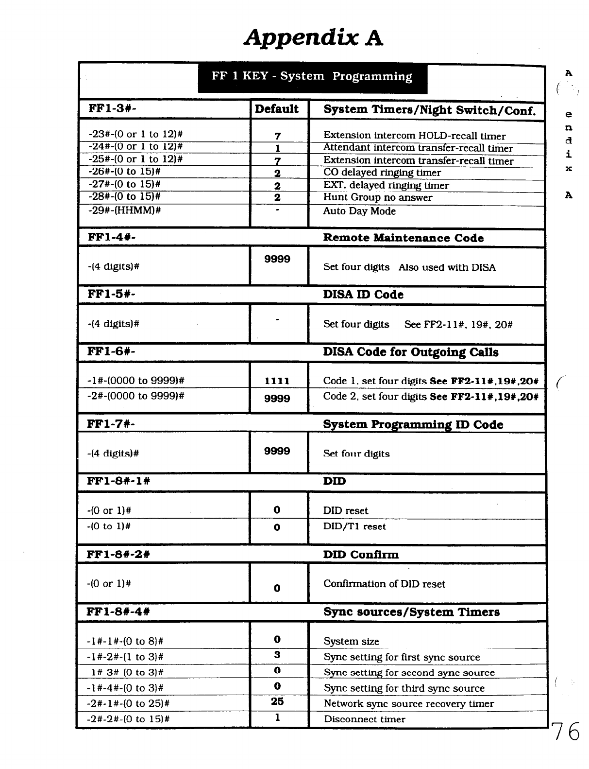
Appendix
A
e
n
d
i
x
-23#-(0 or 1 to 12)#
-24#. 40 or 1 to 12)#
-25#-(0 or 1 to 12)#
-26#-(0 to 15)#
1 -27#-(0 to 15)#
f
-28#-(0 to 15)#
-29#-(HHMM)#
Extension intercom HOLD-recall timer
Attendant intercom transfer-recall
timer I
I 7
I 1
7 Extension intercom transfer-recall timer
2 CO delayed ringing timer
2 EXT. delayed ringing timer
2 Hunt Group no answer
e Auto Day Mode
I I
A
1 FFl-4#- Remote Maintenance Code I
I
-(4 digits)#
I
9999
Set four digits Also used with DISA I
1 FFl-BW- DISA ID Code
Set four digits See Fl%!-ll#. 19#. 20#
-(4 digits)#
/ FFl-6#- DISA Code for Outgoing Calls
-l#-(0000 to 9999)#
1111
-2#-(0000 to 9999)# 9999
_, (
Code 1. set four dieits See
FF2-11#.19#.20#
Code 2. set four digits See
FF2-11#,19#,20#
FFl-7#- System Programming ID Code
Set four digits
-(4 digits) #
FFl-8#-l#
9999
DID
I
0
-(O or l)# DID reset
DID/T1 reset
I
0
FFl-8#-2W
40 or l)# 0
DID Confirm
Confirmation of DID reset
FFl-8W-4# Sync sources/System Timers
-l#-l#-(0 to 8)#
-l#-2#-(1 to 3)#
- l#-3#-(0 to 3)#
-l#-4#-(0 to 3)#
-2#- l#-(0 to 25)#
-2#-2#-(0 to 15)#
0 System size
3 Sync setting for first sync source
0 Sync setting for second sync source
0 Sync setting for third sync source
2s Network sync source recovery timer
1
Disconnect timer
76
Technical Manuals Online! - http://www.tech-man.com
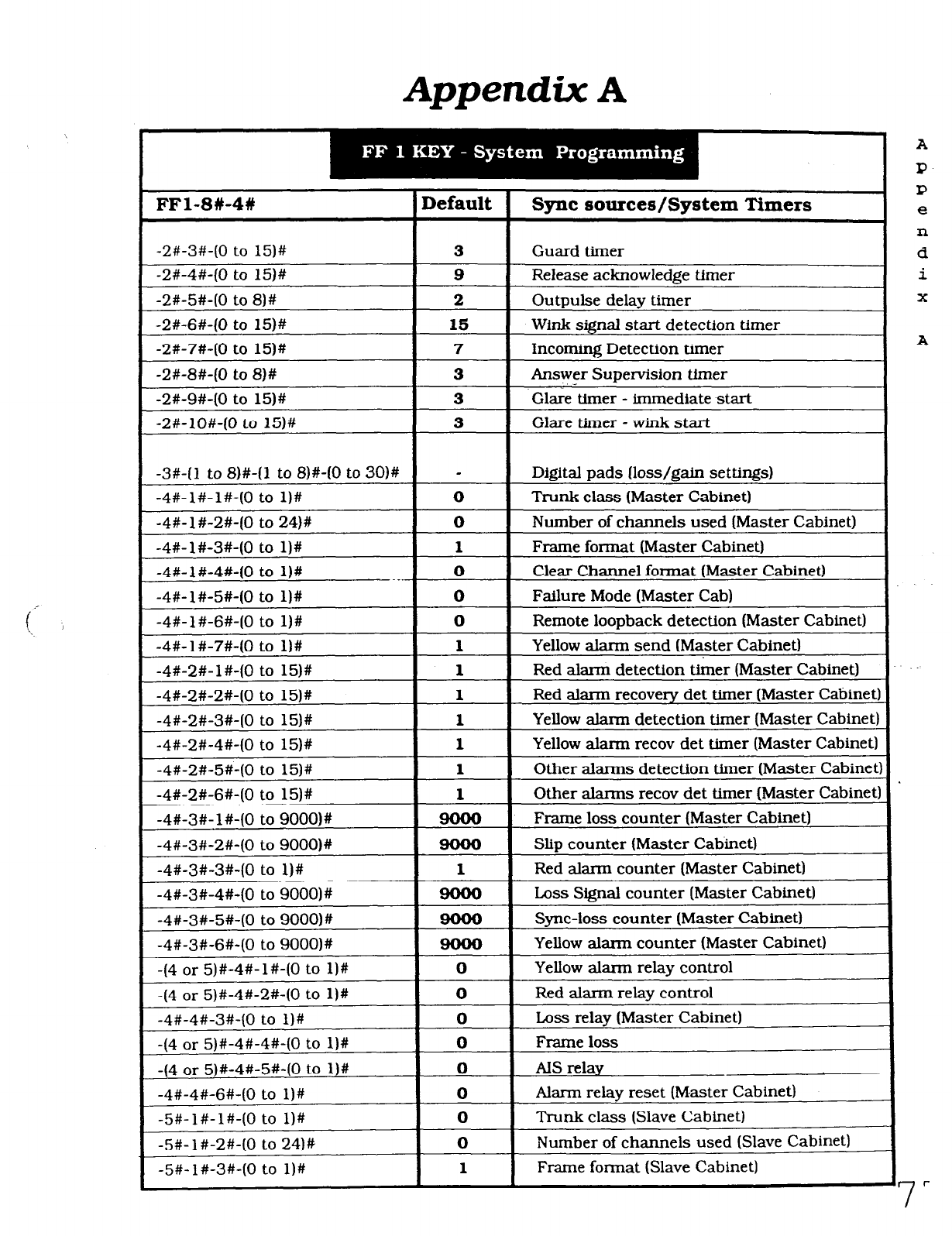
Appendix A
FFl-SW-4# Default Sync sources/System Timers
-2#-3#-(0 to 15)#
-2#-4#-(0 to 15)#
-2#-5#-(0 to 8)#
-2#-6#-(0 to 15)#
-2#-7#-(0 to 15)#
-2#-8#-(0 to 8)#
-2#-9#-(0 to 15)#
-2#-10%(0 to 15)#
-3#-(1 to S)#-(1 to 8)#-(0 to 30)#
-4#-l#-l#-(0 to l)#
-4#- l #-2#-(0 to 24)#
-4#- l#-3#-(0 to l)#
-4#-l#-4#-(0 to l)#
-4% l#-5#-(0 to l)#
-4#-l#-6#-(0 to l)#
-4#-l#-7#-(0 to l)#
-4%2#- l#-(0 to 15)#
-4#-2#-2#-(0 to 15)#
-4#-2#-3#-(0 to 15)#
-4#-2#-4#-(0 to 15)#
-4#-2#-5#-(0 to 15)#
-4#-2#-6#-(0 to 151#
-4#-3#- l#-(0 to 9000)#
-4#-3#-2#-(0 to 9000)#
-4#-3#-3#-(0 to l)#
-4#-3#-4#-(0 to 9000)#
-4#-3#-5#-(0 to 9000)#
-4#-3#-6%(0 to 9000)#
-(4 or 5)#-4#- l#-(0 to l)#
-(4 or 5)#-4#-2#-(0 to l)#
-4#-4#-3#-(0 to l)#
-(4 or 5)#-4#-4#-(0 to l)#
-(4 or 5)#-4#-5#-(0 to l)#
-4#-4#-6#-(0 to l)#
-5#-l#-l#-(0 to l)#
-5#- l#-2#-(0 to 24)#
-5#- l#-3#-(0 to 1)#
3
9
2
15
7
3
3
3
-
0
0
1
0
0
0
1
1
1
1
1
1
1
1
0
0
0
0
0
0
0
0
1
Guard timer
Release acknowledge timer
Outpulse delay timer
Wink signal start detection timer
Incoming Detection timer
Answer Supervision
timer
Glare‘timer - immediate start
Glare timer - wink start
Digital pads (loss/gain settings)
Trunk class (Master Cabinet)
Number of channels used (Master Cabinet)
Frame format (Master Cabinet)
Clear Channel format (Master Cabinet)
Failure Mode (Master Cab)
Remote loopback detect-ton (Master Cabinet)
Yellow alarm send (Master Cabinet)
Red alarm detection timer (Master Cabinet)
Red alarm recovery det timer (Master Cabinet)
Yellow alarm detection timer (Master Cabinet)
Yellow alarm recov det timer (Master Cabinet)
Other alarms detection timer (Master Cabinet:
Other alarms recov det timer (Master Cabinet)
Frame loss counter (Master Cabinet)
Slip counter (Master Cabinet)
Red alarm counter (Master Cabinet)
Loss Signal counter (Master Cabinet)
Sync-loss counter (Master Cabinet)
Yellow alarm counter (Master Cabinet)
Yellow alarm relay control
Red alarm relay control
Loss relay (Master Cabinet)
Frame loss
AIS relay
Alarm relay reset (Master Cabinet)
Trunk class (Slave Cabinet)
Number of channels used (Slave Cabinet)
Frame format (Slave Cabinet)
A
P-
P
e
n
d
i
X
A
7
I-
Technical Manuals Online! - http://www.tech-man.com
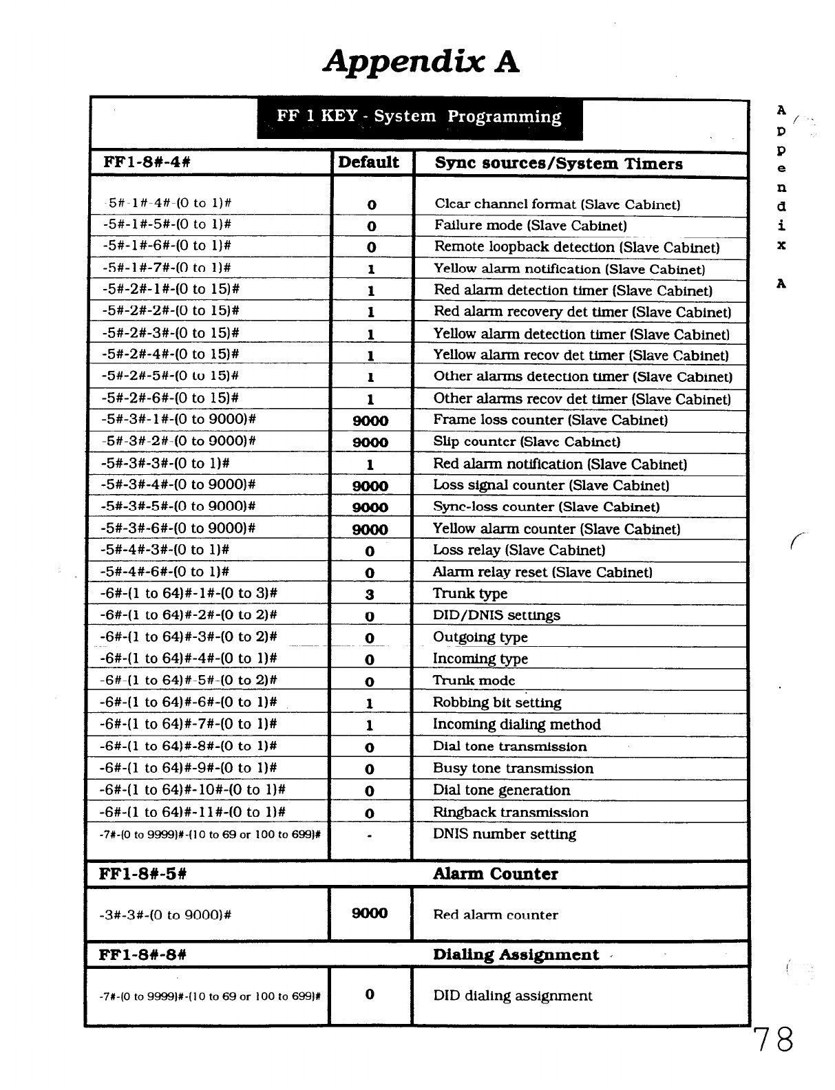
Appendix A
A / ..
P
P
e
xl
d
i
X
A
f-
I’
78
Default Sync sources/System Timers
0
0
0
1
1
1
1
1
1
1
1
0
0
3
0
0
0
0
1
1
0
0
0
0
-
Clear channel format (Slave Cabinet)
Failure mode (Slave Cabinet)
Remote loopback detection (Slave Cabinet)
Yellow alarm notlficatlon (Slave Cabinet)
Red alarm detection timer (Slave Cabinet)
Red alarm recovery det timer (Slave Cabinet)
Yellow alarm detectton timer (Slave Cabinet)
Yellow alarm recov det timer (Slave Cabinet)
Other alarms detection timer (Slave Cabinet)
Other alarms recov det timer (Slave Cabinet)
Frame loss counter (Slave Cabinet)
Slip counter (Slave Cabinet)
Red alarm notification (Slave Cabinet)
boss signal counter (Slave Cabinet)
Sync-loss counter (Slave Cabinet)
Yellow alarm counter (Slave Cabinet)
Loss relay (Slave Cabinet)
Alarm relay reset (Slave Cabinet)
Trunk type
DID/DNIS settings
Outgolm? tvoe
Incomine tvoe
Trunk mode
Robbing bit setting
Incoming dialing method
Dial tone transmission
Busy tone transmission
Dial tone generation
Rlngback transmission
DNIS number setting
-5#-l#-6#-(0 to l)#
-5#-2#- 1 #-(0 to 15)#
-5#-2#-2#-(0 to 15)#
-5#-2#-3%(0 to 15)#
-5#-2%4#-(0 to 15)#
-5#-2#-5#-(0 to 15)#
-5#-2#-6#-(0 to 15)#
-5#-3#-2#-(0 to 9000)#
-5#-3#-3#-(0 to l)#
-5#-3#-6#-(0 to 9000)#
-5#-4#-3#-(0 to l)#
-5#-4%6#-(0 to l)#
-6#-(1 to 64)#-l#-(0 to 3)#
-6#-(1 to 64)#-2#-(0 to 2)#
-SW1 to 64)#-3#-(0 to 2)#
-6#-(1 to 64)#-4#-(0 to l)#
-6#-(1 to 64)#-5#-(0 to 2)#
-6+(1 to 64)#-6#-(0 to l)#
-6#-(1 to 64)#-7#-(0 to l)#
-6#-(1 to 64)#-8#-(0 to l)#
-6+(1 to 64)#-9#-(0 to I)#
-6#-(1 to 64)#-lO#-(0 to l)#
-6#-(1 to 64)#-1 I#-(0 to l)#
-7t-(0 to 9999)#-(10 to 69 or 100 to 699)R
Alarm Counter
FFl-8#-51
-3#-3#-(0 to 9000)#
FFl-8#-8#
-7t-(0 to 9999)#-( 10 to 69 or 100 to 6991t
Red alarm counter
Dialing Assignment
DID dialing assignment
Technical Manuals Online! - http://www.tech-man.com
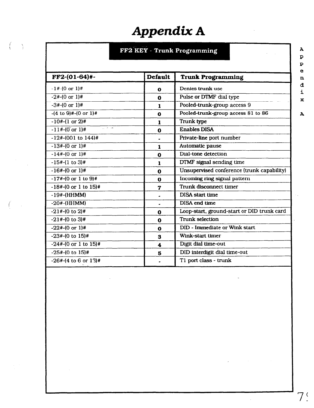
Appendix A
i \
!
i
FF2-(01-64)#- Default Trunk Programming
-l#-(0 or l)# 0 Denies trunk use
-2#-(0 or I)# 0 Pulse or DTMF dial type
-3#-(0 or l)# 1 Pooled-trunk-group access 9
-(4 to 9)#-(0 or l)# 0 Pooled-trunk-group access 81 to 86
-lO#-(1 or 2)#
1 Trunk type
-ll#-(dor l)# ’ ^ 0 Enables DISA
-12#-(001 to 144)# Private-he port number
-13#-(0 or l)#
1
Automatic pause
-14#-(0 or l)# 0 Dial-tone detection
-15#-(1 to 3)# 1 IYMF signal sending time
-16#-(0 or l)# 0 Unsupervised conference (trunk capability)
-17#-(0 or 1 to 9)# 0 Incoming ring signal pattern
-18#-(0 or 1 to 15)# 7 Trunk disconnect timer
- 19#-(HHMM) DISA start time
-20#-(HHMM) DISA end time
-21#-(0 to 2)# 0 Loop-start. ground-start or DID trunk card
-2 1 #-(0 to 3)# 0 Trunk selectfon
-22#-(0 or l)# 0 DID - immediate or Wink start
-23#-(0 to 15)# 3 Wink-start timer
-24#-(0 or 1 to 15)# 4 Digit dial time-out
-25#-(0 to 15)# 5 DID interdigit dial time-out
-26#-(4 to 6 or 13)# a Tl port class - trunk
A
P
P
e
n
d
i
X
A
Technical Manuals Online! - http://www.tech-man.com
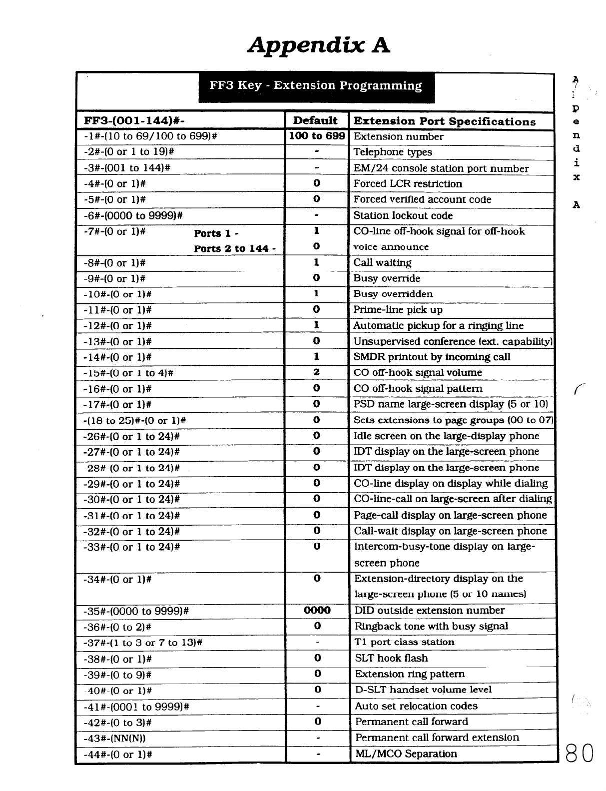
Appendix
A
FF3-(001-144)#-
-l#-(10 to 69/100 to 699)#
-2%(0
or 1 to 19)#
-3#-(001 to 144)#
-4#-(0
or l)#
-5th(0
or I)#
-S#-(0000
to 9999)#
-7#-(0
or
l)#
Portsl-
Ports2to144-
-8#-(0
or l)#
-9#-(0 or l)#
-lO#-(0 or l)#
-1 l#-(0 or l)#
-12#-(0 or l)#
-13#-(0 or l)#
-14#-(0 or l)#
-15#-(0 or 1 to 4)#
-16#-(0 or l)#
-17#-(0 or l)#
-(18 to 25)#-(0 or l)#
-26#-(0
or 1 to 24)#
-27#-(0
or 1 to 24)#
-28#-(0
or 1 to 24)#
-29#-(0 or 1 to 24)#
-3O#-(0
or 1 to 24)#
-31%(0 or 1 to 24)#
-32#-(0
or 1 to 24)#
-33#-(0
or 1 to 24)#
-34#-(0
or l)#
-35#-(0000
to
9999)#
-36#-(0
to 2)#
-37#-(
1 to 3 or 7 to 13)#
-38#-(0
or l)#
-39#-(0 to 9)#
-4O#-(0
or l)#
-4
1 #-(000 1 to 9999)#
-42#-(0
to 3)#
-43%(NN(N))
-44#-(0
or l)#
Default
100 to 699
0
0
1
0
1
0
1
0
1
0
1
2
0
0
0
0
0
0
0
0
0
0
0
0
0
0
0
0
0
-
Extension Port Specifications
Extension number
Telephone types
EM/24 console station port number
Forced LCR restriction
Forced verified account code
Station lockout code
CO-line off-hook signal for off-hook
voice announce
Call waiting
Busy
override
Busy
overridden
Prime-line pick up
Automatic pickup for a ringing line
Unsupervised conference (ext. capabilib
SMDR printout by incoming call
CO off-hook signal volume
CO off-hook signal pattern
PSD name large-screen display (5 or 10)
Sets extensions to page groups (00 to Oi
Idle screen on the large-display phone
[DT display on the large-screen phone
[DT display on the large-screen phone
CO-line display on display while dialing
CO-line-call on large-screen after dialin
Page-call display on large-screen phone
Call-wait display on large-screen phone
Intercom-busy-tone display on large-
screen phone
Extension-directory display on the
large-screen phone (5 or 10 names)
DID outside extension number
Ringback tone with busy signal
Tl port class station
SLT hook flash
Extension ring pattern
D-SLT handset volume level
Auto set relocation codes
Permanent call forward
Permanent call forward extension
ML/MC0 Separation
3
1
P
e
n
d
i
X
A
f
! .-.
80
Technical Manuals Online! - http://www.tech-man.com
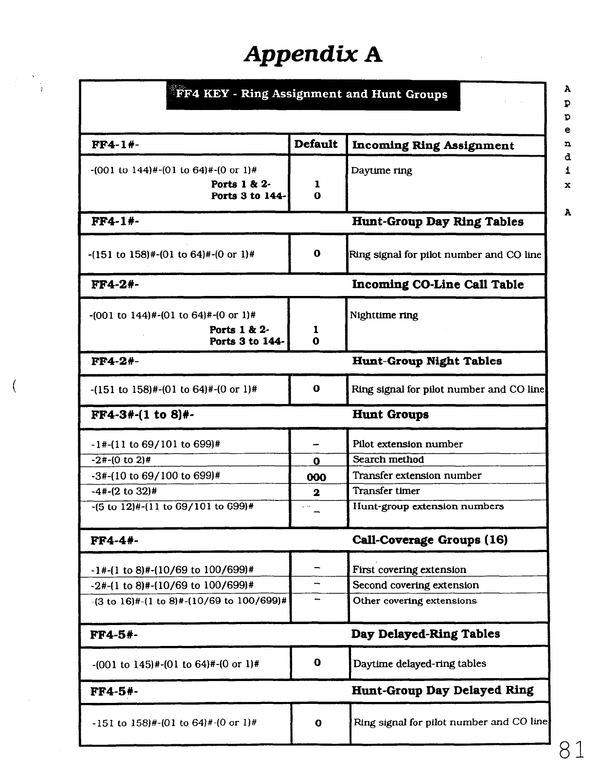
Appendix A
FF4-l#- 1 Default 1 Incoming Ring Assignment
-(OOl to 144)#-(01 to 64)#-(0 or l)#
Ports 1 at 2- 1
Port83to144- 0
DayUme ring
FF4- 1 #- Hunt-Group Day Ring Tables
-(151 to 158)#-(01 to 64)#-(0 or l)#
I I
0
FUng signal for pilot number and CO line
FF4-2#- Incoming CO-Line Call Table
-(OOl to 144)#-(01 to 64)#-(0 or l)#
Ports l&k 2- 1
Ports 3 to 144- 0
Nighttime ring
FF4-2#- Hunt-Group Night Tables
-(151 to 158)#-(01 to 64)#-(0 or l)# I 0 I F&g signal for pilot number and CO lin
FF4-3#-(1 to 8)#- Hunt Groups
-1%(11 to 69/101 to 699)#
-2%(0 to 2)# 0
-3#-(10 to 69/100 to 699)#
-4#-(2 to 32)# 2
-15 to 12)#-(11 to 69/101 to 699)# i
Pilot extension number
Search method
Transfer extension number
Transfer timer
Hunt-group extension numbers
FFQ-4#- Call-Coverage Groups (16)
-l#-(1 to 8)#-(lo/69 to 100/699)#
-(3 to lS)#-( 1 to 8)#-( lo/69 to 100/699)#
First~coverine extension
Second covering extension
Other covering extensions
FM-5#- Day Delayed-Ring Tables
-(OOl to 145)#-(01 to 64)#-(0 or l)# 0 Daytime delayed-ring tables
FF4-5#- Hunt-Group tiay Delayed Ring
-151 to 158)#-(01 to 64)#-(0 or l)# 0 Ring signal for pilot number and CO lir
Technical Manuals Online! - http://www.tech-man.com
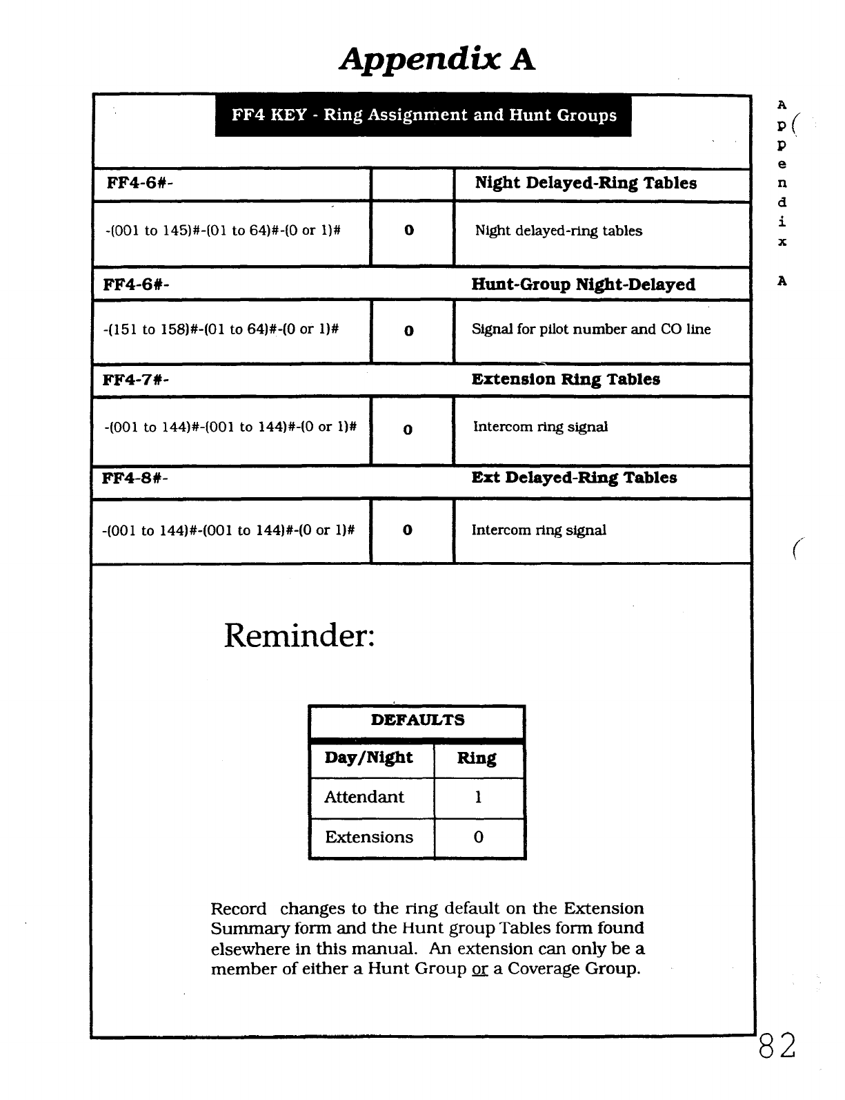
Appendix
A
FF4-6#- 1 Night Delayed-Ring Tables
-(OOl to 145W(01 to 64)#-(0 or l)#
I I
0 Night delayed-ring tables
FF4-6#- Hunt-Group Night-Delayed
-(151 to 158)#-(01 to 64)#-(0 or l)#
I I
0 Signal for pilot number and CO line
FF4-7#- Extension Ring Tables
-(OOl to 144)#-(001 to 144)#-(0 or l)#
FF4-8#-
-(OOl to 144)#-(001 to 144)#-(0 or l)#
0 intercom ring signal
Ert Delayed-Ring Tables
I
I
0
Intercom ring signal
Reminder:
82
DEFAULTS
Record changes to the ring default on the Extension
Summary form and the Hunt group Tables form found
elsewhere in this manual. An extension can only be a
member of either a Hunt Group x a Coverage Group.
A
4
I?
e
n
d
i
X
A
Technical Manuals Online! - http://www.tech-man.com
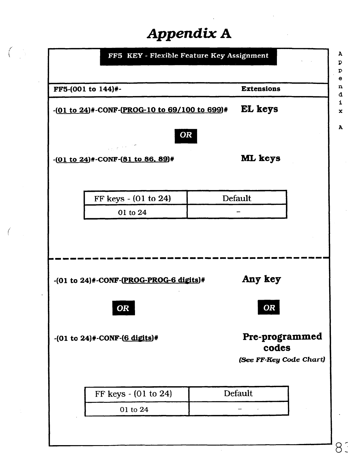
Appendix A
~~ -
I
FF5-(001 to 144)#- Extensions
-(01 to 24)#-CONF-(PROGlO to 69/100 to 699)#
EL keys
_-
:
-(Ol to 24)#-COl’W(81 to 86. 89)W
ML keys
.
FF keys - (01 to 24)
01 to
24
Default
-(Ol to 24)#-CONF-(PROGPROG-6 di&tsJ# Aw key
FF keys - (01 to 24) I Default I
-(Ol to 24)#-CONF-(6 dieits)#
Pre-programmed
codes
(See FF-Key Code Chart)
01 to 24
I
A
P
0
e
n
d
i
X
A
8:
Technical Manuals Online! - http://www.tech-man.com
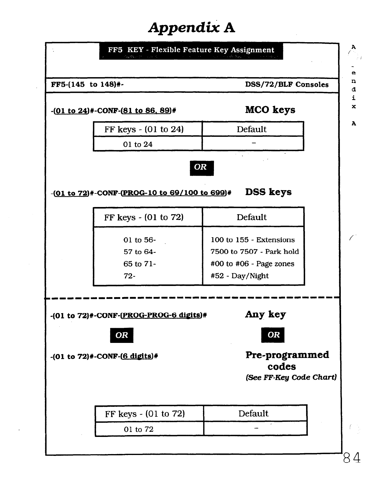
Appendi% A
FFS-(145 to 148)#- DSS/72/BLF Consoles
-(Ol to 24)#-CONF-(81 to 86. 89)#
MC0 keys
1 FF keys - (01 to 24) Default
-01 to 24
-(Ol to 72)#-CONF-(PROGlO to SS/lOO to 699)#
DSS keys
I
FF keys - (01 to 72)
01 to 56-
57 to 64-
65 to 71-
72-
Pre-programmed
codes
(See FF-Key Code
Chart]
I
Default
r--
01 to 72 I - I
,'
84
Default
100 to 155 - Extensions
7500 to 7507 - Park hold
#OO to #06 - Page zones
#52 - Day/Night
-(Ol to 72)#-CONF-(PROGPROG6 dis!its)#
-(Ol to 72)#-CONF-(6 ditits)#
1 FFkeys-(01 to72) 1
A
/
i
e
n
d
i
x
A
/
Technical Manuals Online! - http://www.tech-man.com
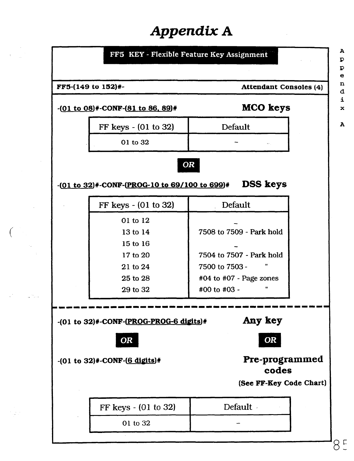
Amendix A
FFS-(149 to 152)#- Attendant Consoles (4)
-(Ol to 08)#-CONF-(81 to 86. 89)#
MC0 keys
I
FF keys - (01 to 32) I Default
01 to 32
I _.
-(Ol to 32)#-CONF-(PROGlO to 69/100 to 699)#
DSS keys
FF keys - (01 to 32)
01 to 12
13 to 14
15 to 16
17 to 20
21 to 24
25 to 28
29 to 32
Default
7508 to 7509 - Park hold
7504 to 7507 - Park hold
7500 to 7503 - ”
#04 to #07 - Page zones
#OO to #03 - ”
-(Ol to 32)#-CONF-(PROGPROG6 ditits)W
-(Ol to 32)#-CONF-(6 d&its)!!
Pre-programmed
codes
(See FF-Key Code Chart)
r ~~
FF keys - (01 to 32) I Default a
01 to 32
A
P
P
e
n
d
i
X
A
8-
L
Technical Manuals Online! - http://www.tech-man.com
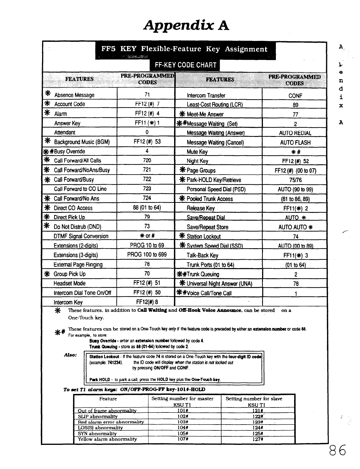
Appendix A
* Absence Message 71
d Account Code FF12 (#) 7
* Alarm FF12 (#) 4
Answer Key FFll (*) 1
Attendant 0
* Background Music (BGM) FF12 (#) 53
Intercom Transfer
Least-Cost Roulitlg (LCR)
* Meet-Me Answer
*Wessage Waiting (Set)
Message Waking (Answer)
Message waiting (Cancel)
CONF
69
77
2
AUTO REDIAL
AUTO FLASH
$# #Busy Override
* Call Forward/All Calls
m Call ForwardMoAnslBusy
* Call Forward/Busy
4 Mute Key *c#
720 Night Key FF12 (#) 52
721 *Page Groups FF12 (#) (00 to 07)
722 * Park-HOLD Key/Retrieve 75176
Call Forward to CO Line PermnalSpeedDial (PSD) AUTO (90 to 99)
Headset Mode I FF12 (#) 51 1 % Universal Night
AISWK
(UNA) 1 76
Intercom Dial Tone On/Off 1 FF12 (#) 50 I*#voice call/Tone Call I 1
Intercom Key I FF12(#) 8 I I
% These features. tn addition to Crg
Walthg
and OSHook
Volcc
Aaaormcc. can be stored on a
One-Touch key.
*# These features can be stored on a
One-Touch key only if the feature coda is preceded b either an oxtension numbw or mde &I
For example, to store:
Busy Ovwrfdo - enter an rxtonsbn nurnbw followed by code 4.
Tnnlr Qwulng - store as 88 (0144) folbwed by mde 2.
Also:
1 Sotion Lockout - II the feature mda 74 is stored on a One-Touch key with the four-dfgft ID code1
II
(example:741234), theIDcodewilldisphylrhenthestati~kndkckedout -
by pressing ON/OFF and CONF. II
Pufc HOID - IO pa& a call. press the HOLD key plus the ChwTowh key.
To
et
T1 ahrm key: OR/OFF-PROC+FF key-lOl#-HOID
Feature Setttng number for master Setttng number for slave
A.
L‘
e
n
d
i
X
A
I
86
Technical Manuals Online! - http://www.tech-man.com
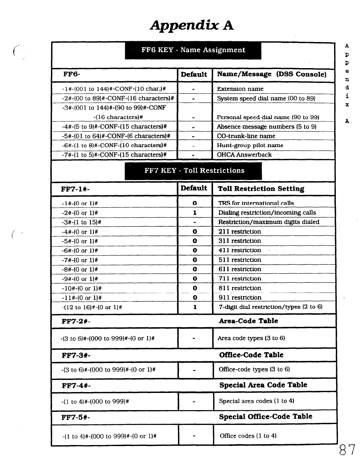
Appendix A
FF6- Default Name/Message (DSS Console)
-l#-(001 to 144)#-CONF-(10 char.)+/ Extension name
-2#-(00 to 89)#-CONF-(16 characters)# - System speed dial name (00 to 89)
-3#-(001 to 144)#-(90 to 99)#-CONF
-( 16 character+
-4#-(5 to 9)#-CONF-(15 characters)#
-5#-(01 to 64)#-CONF-(6 characters)#
-6#-( 1 to 8)#-CONF-ii0 cha.ractexs)#
-7#-( 1 to 5)#-CONF-( 15 characteIs)#
-
-
-
Personal speed dial name (90 to 99)
Absence message numbers (5 to 9)
CO-trunk-line name
Hunt-group pilot name
OHCA Answerback _l.
FF7-l#-
-l#-(0 or l)#
-2#-(0 or l)#
-3#-(1 to 15)#
-4#-(0 or l)#
-5#-(0 or l)#
-S#-(0 or l)#
-7#-(0 or l)#
-8#-(0 or I)#
-9#-(0 or l)#
-lO#-(0 or l)#
-1 l#-(0 or l)#
-(12 to 16)#-(0 or l)#
FF7-2#-
-(3 to S)#-(000 to 999)#-(0 or 1)#
FF7-3#-
-(3 to S)#-(000 to 999)WO or l)#
FF7-4#-
-(l to 4)#-(000 to 999)#
FFT-5#-
-11 to 4)#-(000 to 999)WO or l)#
Default
Toll Restriction Setting
0 TRS for international calls
1
Dialing restriction/incoming calls
F&xQ.riction/maximum digits dialed
0 211 restriction
0. 3 11 restriction
0 411 restriction
0 5 11 restriction
0 6 11 restriction
0 7 11 restriction
0 8 11 restriction
0 9 11 restriction
1 7-digit dial restriction/types (2 to 6)
Area-Code Table
Area code types (3 to 6)
Office-Code Table
OtTice-code types (3 to 6)
Special Area Code Table
Special area codes (1 to 4)
Special Office-Code Table
Of&e codes (1 to 4)
A
87
Technical Manuals Online! - http://www.tech-man.com
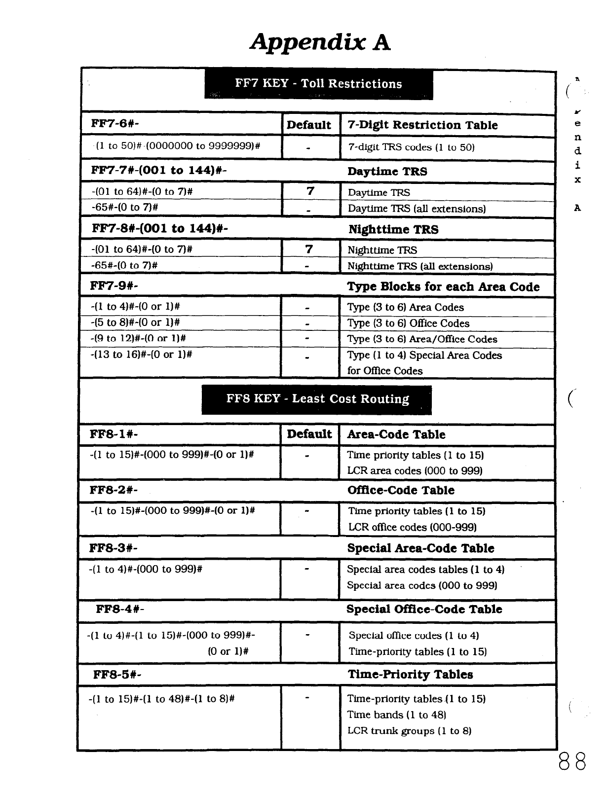
Appendix A
FF7-6#- I Default 7-Digit Restriction Table
7-digit TRS codes (1 to 50)
FlW-7#-(001 to 144)#- Daytime TRS
-(Ol to 64)#-(0 to 7)#
-65#-(0 to 7)#
FF7-8#-(001 to 144)#-
-(Ol to 64)#-(0 to 7)#
-65#-(0 to 7)#
7 Daytime TRS
Daytime TRS (all extensions)
Nighttime TRS
7 Nighttime TRS
Nighttime TRS (all extensions)
FF7-9#- Type Blocks for each Area Code
-( 1 to 4)#-(0 or l)#
-(5 to 8)#-IO or l)#
49 to 12)#-(0 or l)#
-(13 to 16)#-(0 or l)#
‘Ibe (3 to 6) Area Codes
Type (3 to 61 Office Codes
‘l&e (3 to 6) Area/Office Codes
Type (1 to 4) Special Area Codes
for Office Codes
FFS-l#-
-(l to 15)#-(000 to 999)#-(0 or l)#
Default Area-Code Table
Time priority tables (1 to 15)
1 LCR area codes (000 to 999)
FFS-2#- Office-Code Table
-11 to 15)#-(000 to 999)#-(0 or l)#
I
- Time priority tables (1 to 15)
LCR offke codes (000-9991
FF&3W- Special Area-Code Table
-(l to 4)#-(000 to 999)#
FFS-4W-
Speclal area codes tables (1 to 4)
Special area codes (000 to 999)
Special Office-Code Table
-(l to 4)#-(1 to 15)#-(000 to 999)#- -
(0 or l)# I
Special office codes (1 to 4)
Time-priority tables (1 to 15)
FFS-5#- Time-Prioritv Tables
-(l to 15)#-(1 to 48)#-(1 to 8)# Time-priority tables -( 1 to 15)
Time bands (1 to 481
LCR trunk groups (1 to 8)
Cn
Y
e
n
d
i
X
A
i
38
Technical Manuals Online! - http://www.tech-man.com
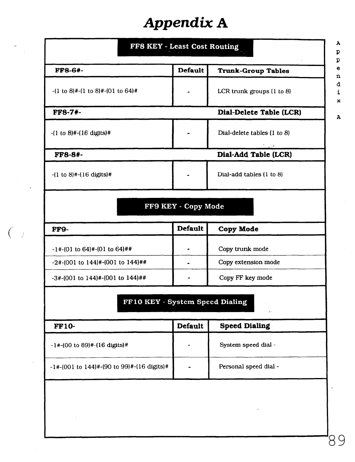
Appendix A
FFS-6#- Trunk-Group Tables
-(l to 8)#-(1 to 8)#-(01 to 64)# LCR trunk groups (1 to 8)
FF8-7#- Dial-Delete Table &CR)
-(l to 8)#-(16 digit&# Dial-delete tables (1 to 8)
FFS-SW- Dial-Add Table &CR)
-(l to 8)#-(16 digits)#
I- I
Dial-add tables (1 to 8)
FF9-
-l#-(01 to 64)#-(01 to 64)##
-2#-(001 to 144)#-(001 to 144)##
-3#-(001 to 144)#-(001 to 144)##
Default Copy Mode
Copy trunk mode
Copy extension mode
Copy FF key mode
FFlO- 1 Default
-l#-(00 to 89)#-(16 d@ts)#
-l#-(001 to 144)#-(90 to 99)#-(16 digits)#
Speed Dialing
System speed dial -
Personal speed dial -
A
39
Technical Manuals Online! - http://www.tech-man.com
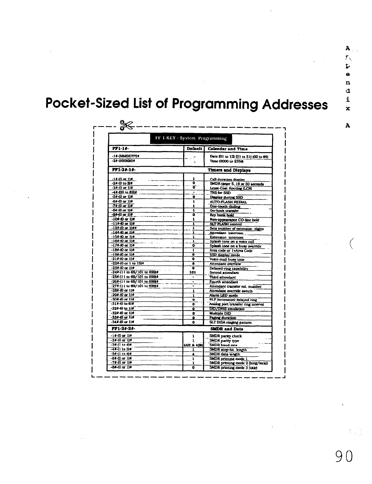
A
T\
L;
e
n
d
Pocket-Sized List of Programming Addresses t
r--- s --a----------------
1
A
I
I
I
I
I
I
1
I
I
I
I
I
I
I
I
I
I
I
I
I
I
I
I
I
I
I
I
I
I
I
-1r4oa 1v I I
I
I
I
I
I
I
I
I
I
I
I
I
I
I
I
I
I
I
I
I
I
I
I
I
I
I
I
I
90
Technical Manuals Online! - http://www.tech-man.com
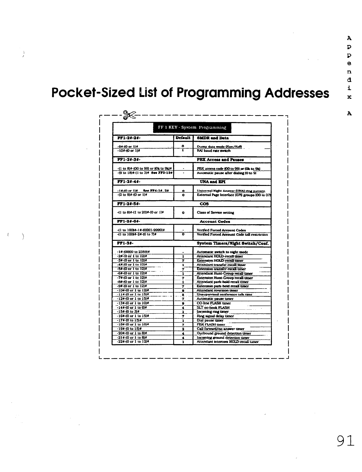
Pocket-Sized List of Programming Addresses
I
I
I
I
I
I
I
I
I
I
I
I
I
I
I
I
I
I
I
I
I
I
I
I
I
I
I
I
I
I
I
i
I
I
I
I
I
I
I
I
I
I
I
I
I
I
I
I
I
I
I
I
I
I
I
I
I
I
I
A
P
P
e
n
d
i
x
A
L ------------------------ -1
91
Technical Manuals Online! - http://www.tech-man.com
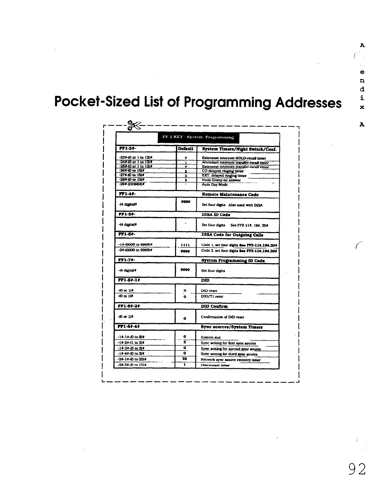
A
e
xl
d
Pocket-Sized List of Programming Addresses i
l----
%x
--------------------
1
A
I
I
I
I
I
I
I
1
I
I
I
I
I
I
I
I
I
I
I
I
I
I
I
I‘
I
I
I
I
I
I
FFI-SI-I#
DID
4oOW 0 DID reset
-_. -
40 to 111 0 OIOrrl Iuet
Rl-s#-l# DrncQnnnn
I
I
I
I
I
I
I
I
I
I
I
I
I
I
I
I
I
I
I
I
I
I
I
I
I
I
I
I
I
I
I
I -----------------,-,,,,,-I
92
Technical Manuals Online! - http://www.tech-man.com
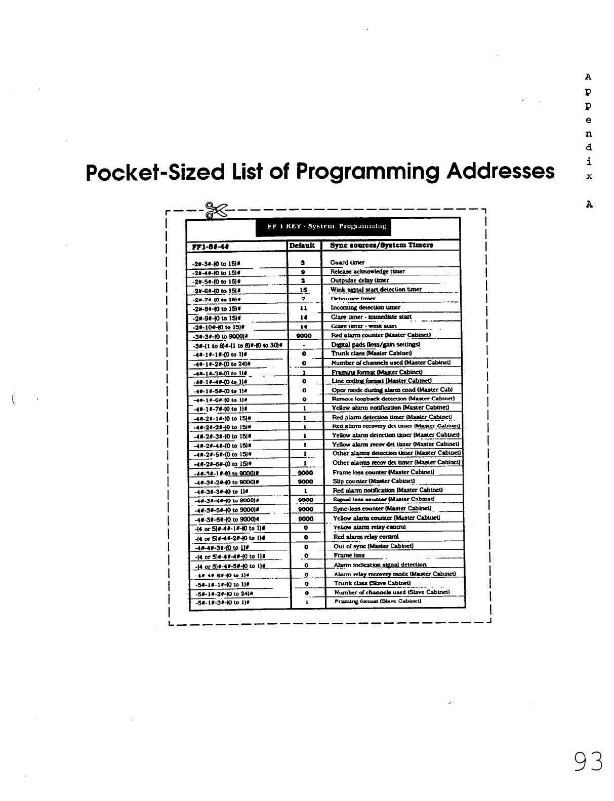
Pocket-Sized List of Programming Addresses
r---@&&--------- _--- ------7
I
I
I
I
I
I
I
I
I
I
I
I
I
I
I
I
I
I
I
I
I
I
I
I
I
I
I
I
I
I
I
r
~1” ._ .- ,- .- ..- I
-~
-4u- I@-2r-(0 to 24w 0 - Number dchmnch used Waster Cabhell
__
-4ElKw-m to 114 1 l3unu~(Mwrcab0
-4r-1r-4r4oto IW - -’ _ 0 ._ Un mdtra hmmt Master CabInetI
-aa-ar-4crO to mu
-4ff-21-W-(0 to l&
I
I
I
I
I
I
I
I
I
I
I
I
I
I
I
I
I
I
I
I
I
I
I
I
I
I
I
I
I
I
L ----- __-_-____vw------e- -1
A
P
P
e
n
d
i
X
A
93
Technical Manuals Online! - http://www.tech-man.com
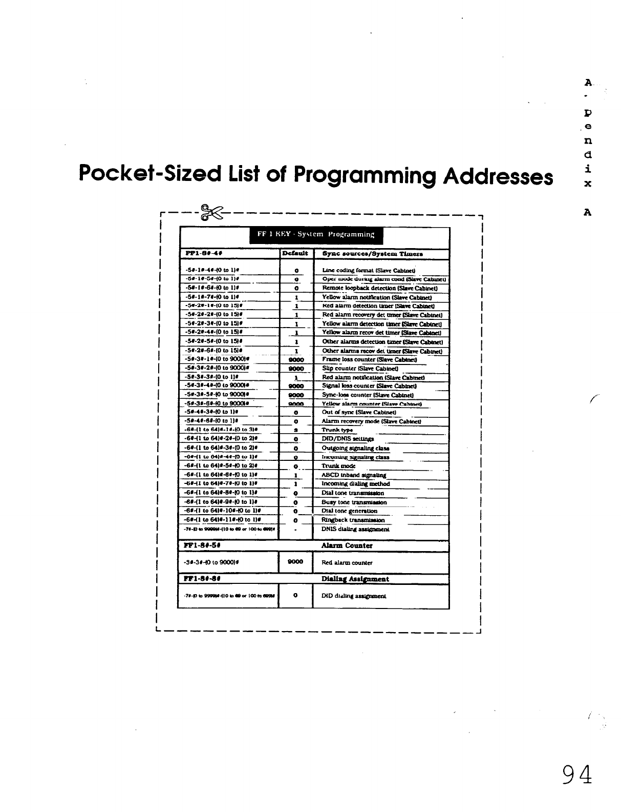
I?
8
n
d
Pocket-Sized List of Programming Addresses i
l----
x --------------------
1
A
i
I
I
I
I
I
I
I
I
I
I
I
I
I
I
I
I
I
I
I
I
I
I
I
I
I
I
I
I
I
I
f
L --------------------,,-,-I
94
Technical Manuals Online! - http://www.tech-man.com
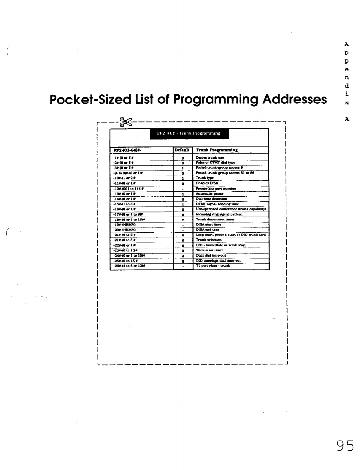
Pocket-Sized list of Programming Addresses
r ___ --------------------~
if%
i
I
I
I
I
I
I
I
I
I
I
I
I
I
I
I
I
I
I
f
I
I
I
I
I
I
I
I
I
I
mm401-64w lD&ult I TnmkR0afomda
~.
-I4woar Ilf -‘-
_ ._-._-
I 0 Dlablme d-
-15e-11 ta31e I 1 ‘bii4FslmalsmdiMtmx ‘.
!
I
t
I
I
I
I
I
I
I
I
I
I
I
I
I
I
I
I
I
I
I
I
I
I
I
I
A
P
P
e
n
a
i
x
A
L ___-_---_-------_------- J
95
Technical Manuals Online! - http://www.tech-man.com
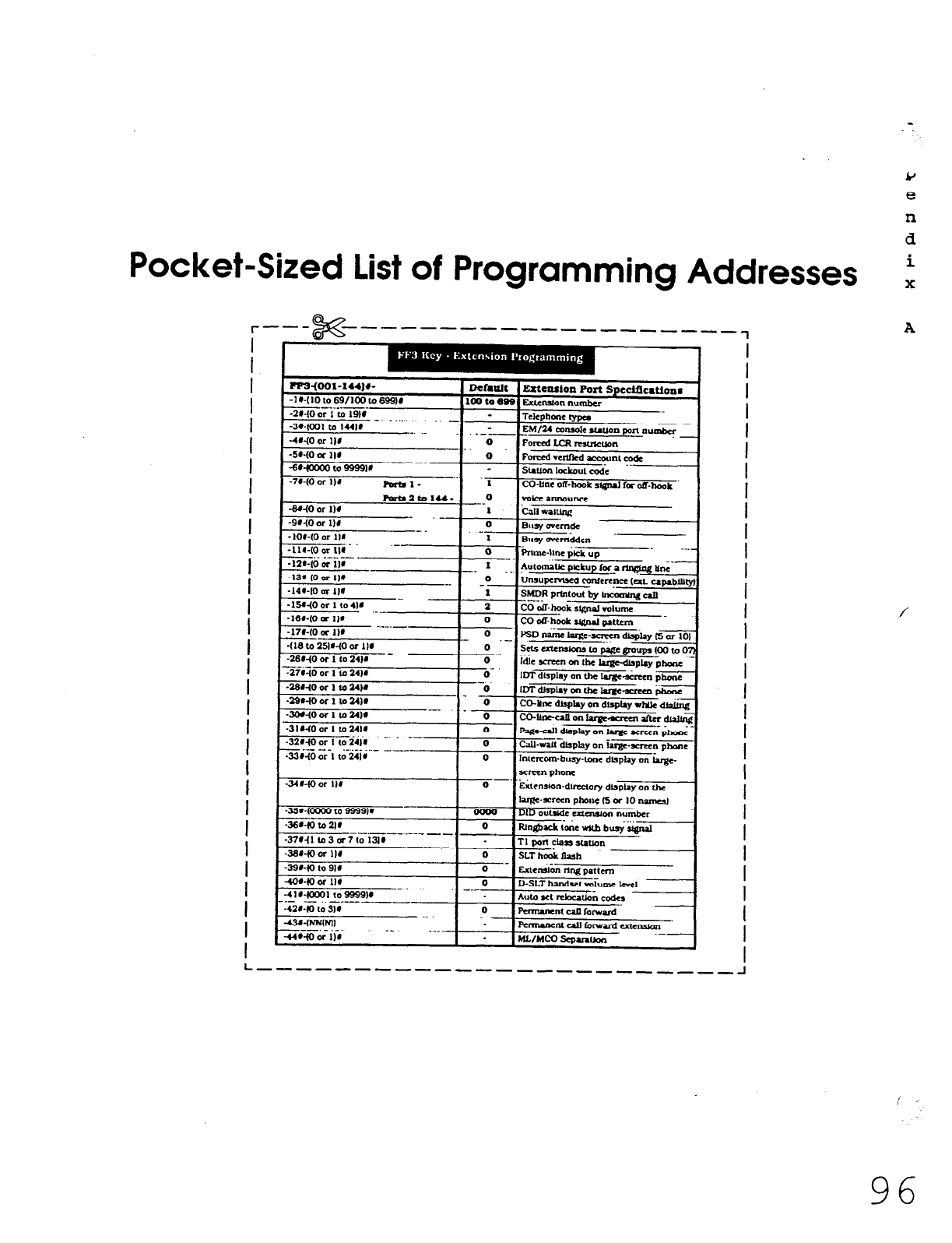
Pocket-Sized List of Programming Addresses
I
I
I
I
I
I
I
I
I
I
I
I
I
I
i
I
I
I
I
I
I
I
I
I
I
I
I
I
I
I
I
FPs+o1-lU)#-
Default Extewlon Port Speclflcatims
-IWlOlo69/lOOt0699J#
--_.---- 100 to 809 ExluWan number
-21.IO or 1 u)
19l#
- _ Tekphme typea
-3wcoI to 1441# EM/24 oonrole station port llumbcr
41io or 111 .-
0 Forced LCR -wn
-5r-(0 oc lI# 0 Fcmxdvulflcd-ntcodc
---_
-6ctoooO lo 9999v s.mlon lakout c0.i; ..
-74-(0 or 114 -I- .1 CO-Une of?-hook ~,@,a, la o,T-,,.,.,k
-
.-n_
-35r-(oooo to 9999M - 0000 DID outside camsion nu&r
-36r-to to 21r 0
-----.--_ -- Iul&ck i&e v&h . . ..~
busy SIgnal
-37r-(1co3ar7t01311 - l-1 MR Ckt) slauon
-36rio or I)#
-
-39140 to 911
-41r4oax ta9999w
.- -..- _--. -_-
-4/I-(0 to 314
-43wNNlNll
---._._. -- __-.
-44wo or IW UlJMcQ .scpanuon
I
I
I
I
I
I
I
I
I
I
I
I
I
I
I
I
I
I
I
I
I
I
I
I
f
I
I
I
I
L --------------------------I
&J
e
n
d
i
X
A
96
Technical Manuals Online! - http://www.tech-man.com
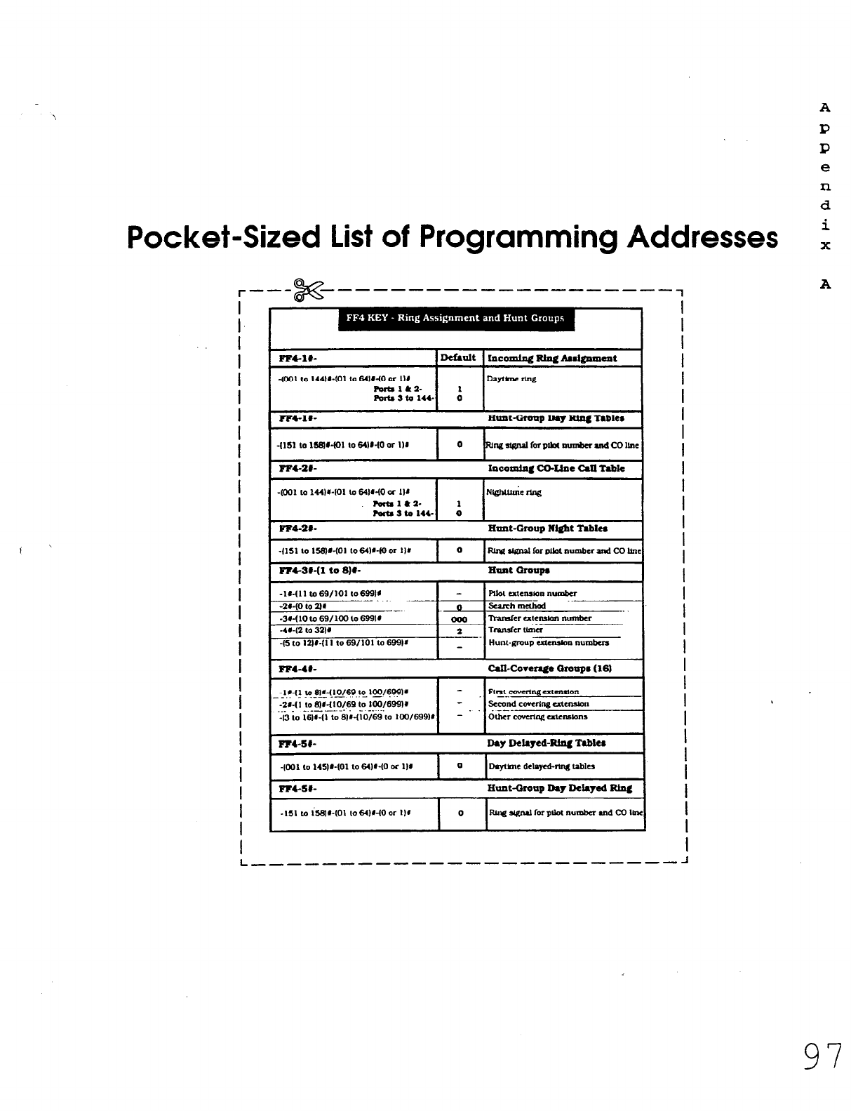
A
P
P
e
n
d
Pocket-Sized
List of Programming Addresses i
r--- x -m------------------7
I
I
I
I
I
I
I
I
I
I
I
I
I
I
I
I
I
I
i
I
I
I
I
I
I
I
I
I
I
FPCIO- Defiult blcolnhg lung Adglmlout
+I01 ,o 144lwJ1 to 64lNO or I)# Dayune rine
FWtS1&2- 1
Pmts2t.a 144 0
-fool to 1441401 lo 641r40 or 111 N&c Nlfi
ratalC2- 1
rortssto144. 0
FF4-21-
Hunt-Group N&bt Table6
FM-Sb-
Da+
lkla~ed-Rlr~ Tabkr I
I
I
I
I
I
I
I
I
I
I
I
I
I
I
I
I
I
I
I
I
I
I
I
I
I
I
I
I
L _____-__------_---_----- J
A
97
Technical Manuals Online! - http://www.tech-man.com
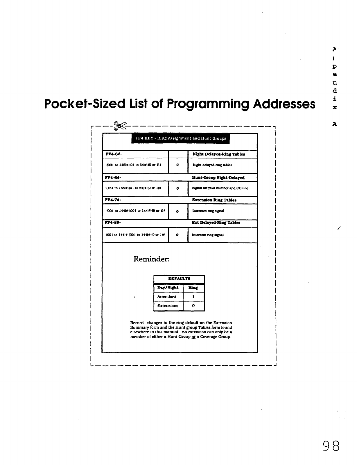
P
.
. P
P
e
n
d
Pocket-Sized List of Programming Addresses i
I
I
I
I
I
I
I
I
I
I
I
I
I
I
I
I
I
I
I
I
I
I
I
I
I
I
I
I
1
I
Reminder:
F&cord changes to the rtng default on the Mention
Summary form and the Hunt group Tables form found
elsewhere tn this manual. An atenslon can only be a
member of either a Hunt Croup pi a Coverage Group.
I
I
I
I
I
I
I
I
I
I
I
I
I
I
I
I
I
I
I
I
I
I
I
I
I
I
I
I
I
I
L __-----------m--s------- -I
98
Technical Manuals Online! - http://www.tech-man.com
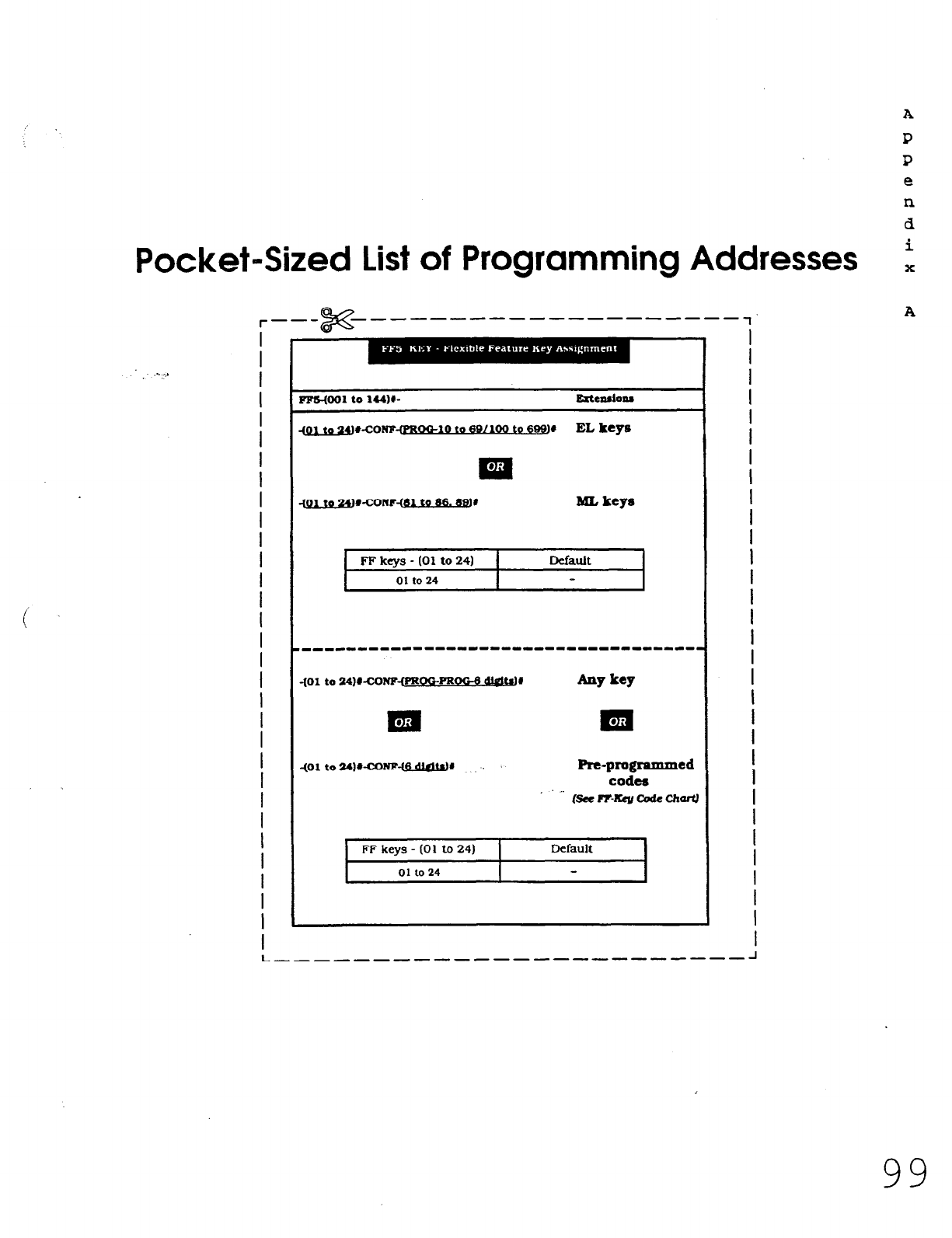
Pocket-Sized List of Programming Addresses
I
I
I
I
I
I
I
I
I
I
I
I
I
I
I
I
I
I
I
I
I
I
I
I
I
I
I
I
I
I
I
FFs-(Ool to 144w RtCdOO8
cpl to Z~#-CONF-@BQQ-IO to @,CXNB to 69$9
EL key13
FF
keys
- (01 to 24) 1 Default
01 to 24
I I
401 to 24)WZONF-(PROOPROGB wr JW key
Pm-programmed
codes
_ fsn? R-Rev &de CJmIiJ
FF keys - (01 to 24)
01
to
24
Default
1
I
I
I
I
I
I
I
I
I
I
I
I
I
I
I
I
I
I
I
I
I
I
I
I
I
I
I
I
I
I
I
L,--~-~~---~----~~---- --- A
A
P
P
e
n
d
i
X
A
99
Technical Manuals Online! - http://www.tech-man.com
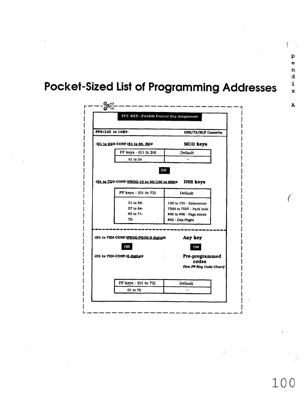
P
e
n
d
Pocket-Sized List of Programming Addresses i
I
I
I
I
I
I
I
I
I
f
I
I
I
I
I
I
I
I
I
I
I
I
I
I
I
I
I
I
I
I
mlH145 to 14I?w D6s/72/BLFconso1er
q&l to !24wcoNF-~ to 66.88)r
FFkeys-(01 to241
01 to24
MC0 keys
Default
FFkeys-(01 to72) Default
01 to 56- 100 to 155 - Extensions
57to64- 7500
to 7507 - Park hold
65to71- MO
to
x06 - Page zones
72- 152
- Day/Night
---------I--------------------------
401 to 72WCON?~#
Pre-programmed
codes
IsarF-~codrckart
FFkcys-(Olto72)
01 to 72
Default
I
I
I
I
I
I
I
i
I
I
I
I
I
I
I
I
I
I
I
I
I
I
I
I
I
I
I
I
I
I
L -------------------,,--,~
100
Technical Manuals Online! - http://www.tech-man.com
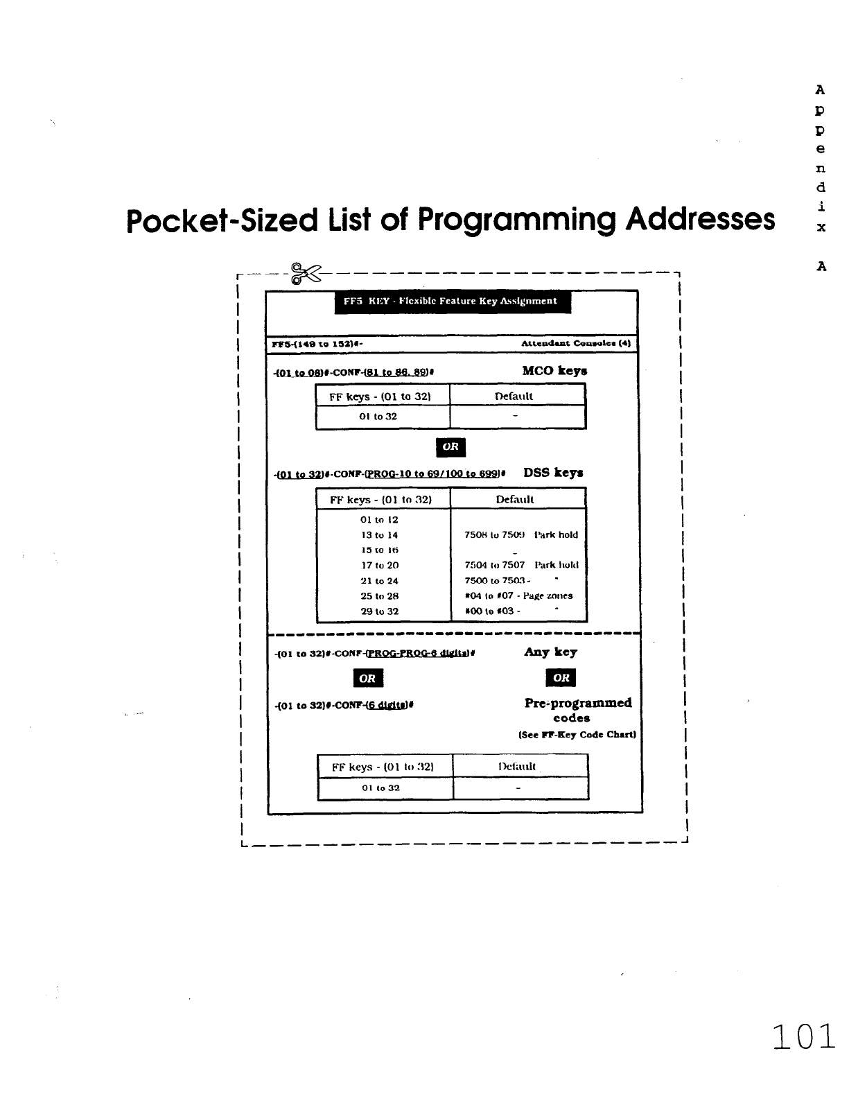
A
P
P
e
n
d
Pocket-Sized List of Programming Addresses i
I
I
I
I
I
I
I
I
I
I
I
I
I
I
I
I
I
I
I
I
I
I
I
I
I
I
I
I
I
ms414s to 152w
Attaadoat
CoPaoka (41
-to-CONF-@~$fll@
MC0 keys
FF kevs - (01 to 321 I rkfarlll I
I
01 to 32
.
m
-tQlldWto-CONF-O’ROO-10
to 69/166 ma DSS keys
FF
keys - (01 ta 32)
011n I2
13 to 14
15 to 16
17to20
21 lo 24
25 to 28
29 to 32
Dcfnllil
750H lo 7.StXJ Park hold
7504 ,,I 7507 Park hokl
75Ooto7m3- -
x04 IO 107 - Pagr mncs
roolo a03 - -
Re~programmed
codes
(See R-Key Code Chart
FF keys - (01 lo 321
01 IO 32
Iktilrllt
I
I
I
I
I
I
I
I
I
I
I
I
I
I
I
I
I
I
I
I
I
I
I
I
I
I
I
I
I
I
I
101
Technical Manuals Online! - http://www.tech-man.com
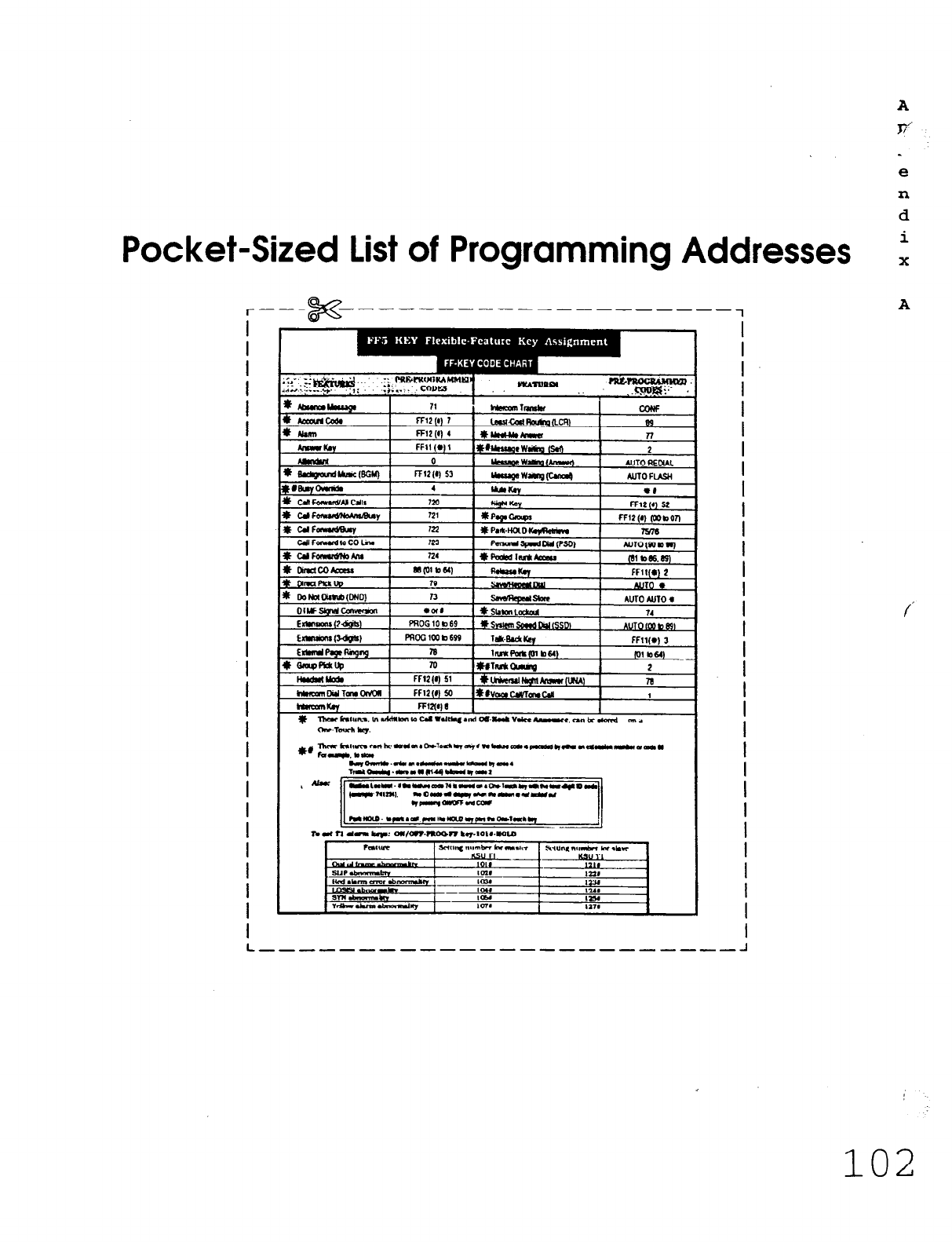
e
n
d
Pocket-Sized List of Programming Addresses t
r--s i% ---em ----- ---- -_____
1
A
I
I
I
I
I
I
1
I
I
I
I
I
I
I
I
I
I
I
I
I
I
I
I
I
I
I
I
I
I
I
C UFRy 721
t UFm 722
c#FawMtocoLhl 723
FFl2(r,
fmbon
7976
A”lO(Wb”)
I
I
I
I
I
I
I
I
I
I
I
I
I
I
I
I
I
I
I
I
I
I
I
I
I
I
I
I
I
L __-----------------e--w- -I
102
Technical Manuals Online! - http://www.tech-man.com
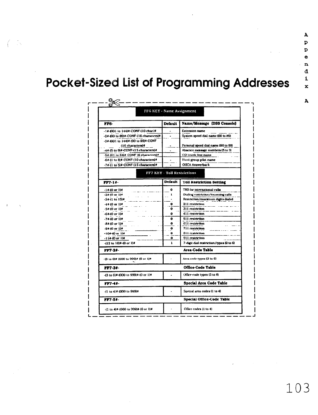
, \
Pocket-Size IList of Programming Addresses
r--$&=-- ------------------,
A
P
P
e
n
d
i
X
A
I
I
I
I
I
I
I
I
I
I
I
I
I
I
I
I
i
I
I
I
I
I
I
I
I
I
r?5-
-Iu-IIXII lo 1441~-CONF-U0ch~l~
--
&00 to 691r-coti-il6 chuacun1r
_.__- _--- __-_
-3r-fco1 to 144l~.160 (0 OOPCONF
416 chalaclcn)d
_ . ..-- - ----
:4r.15 to 918-420NFi15 channcn1r
_-_--- -.
-5~.@l 10 64WCONF-I6 &~~trrslR
.6U-(I to BJWJONF-(1Ochfuaclersl~
-7U-(I LO 5WCONF-(15 chxaclurl~
rP7-l#-
Pm-2#-
_.--
-. _--
A_.
A
-._
m
DeQult
0
1
-.
.- 0
0
0
0
0
0
.-
0
---
0
1
r
E
;
I
[
_ - I
(
1
(
1
.
- _
~
.
_
- -
-
~uno/Mcuagc DSS Ccndc)
4tas101 -
-- - __ -_. -.
;yslm qmd d&l name ICI3 to 661
-. .__~ _...
. -_ .-___ --
HKA AIlwcrbut
roll Restdctlon Sattia~
2 11 mtrkllna
31 I rcstmkn
- .--.--- --- _ --
41 I mwll-tk.n
51 I rnll4r4loll
_ -_.-.-_-.
Gil-Ion
_-_. ---
711- -... _ _ ---__ . . - ..-.
611 rcItrruw __. ---
I)1 1 Rs(~lon
----
7digil dial raWkthn/lyp% P UI 6l
keecedo Tabk
t
I
I
I
I
I
I
I
I
I
I
I
I
I
I
I
I
I
I
I
I
I
I
I
I
I
I
103
Technical Manuals Online! - http://www.tech-man.com
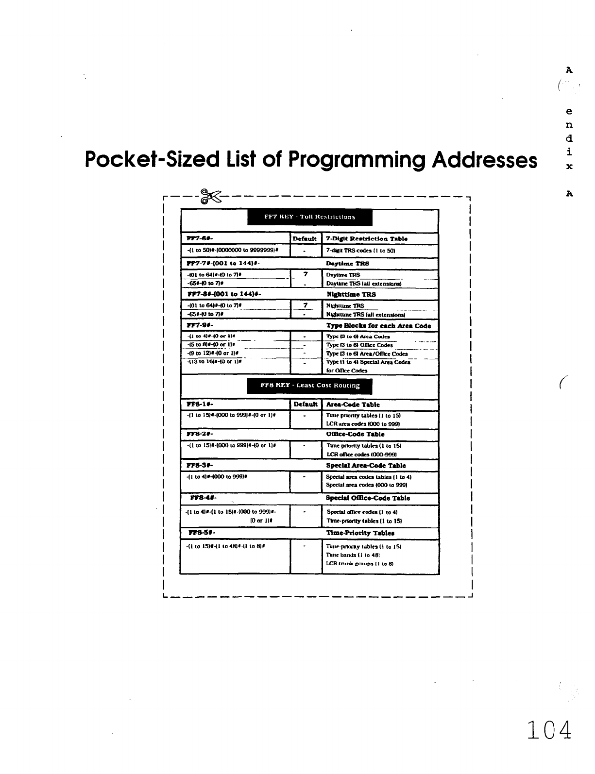
Pocket-Sized List of Programming Addresses
r--- x ------------ ---- ----
1
I
I
I
I
I
I
I
I
I
i
I
I
I
I
I
I
I
I
I
I
I
I
I
I
1
I
I
I
I
I FF7-71-mo1to 14416 Devtlme nts -1
I
I
I
I
f
I
I
I
I
I
I
I
I
I
I
I
I
I
I
I
I
I
I
I
I
I
I
A
L -----c------------------ -I
104
Technical Manuals Online! - http://www.tech-man.com
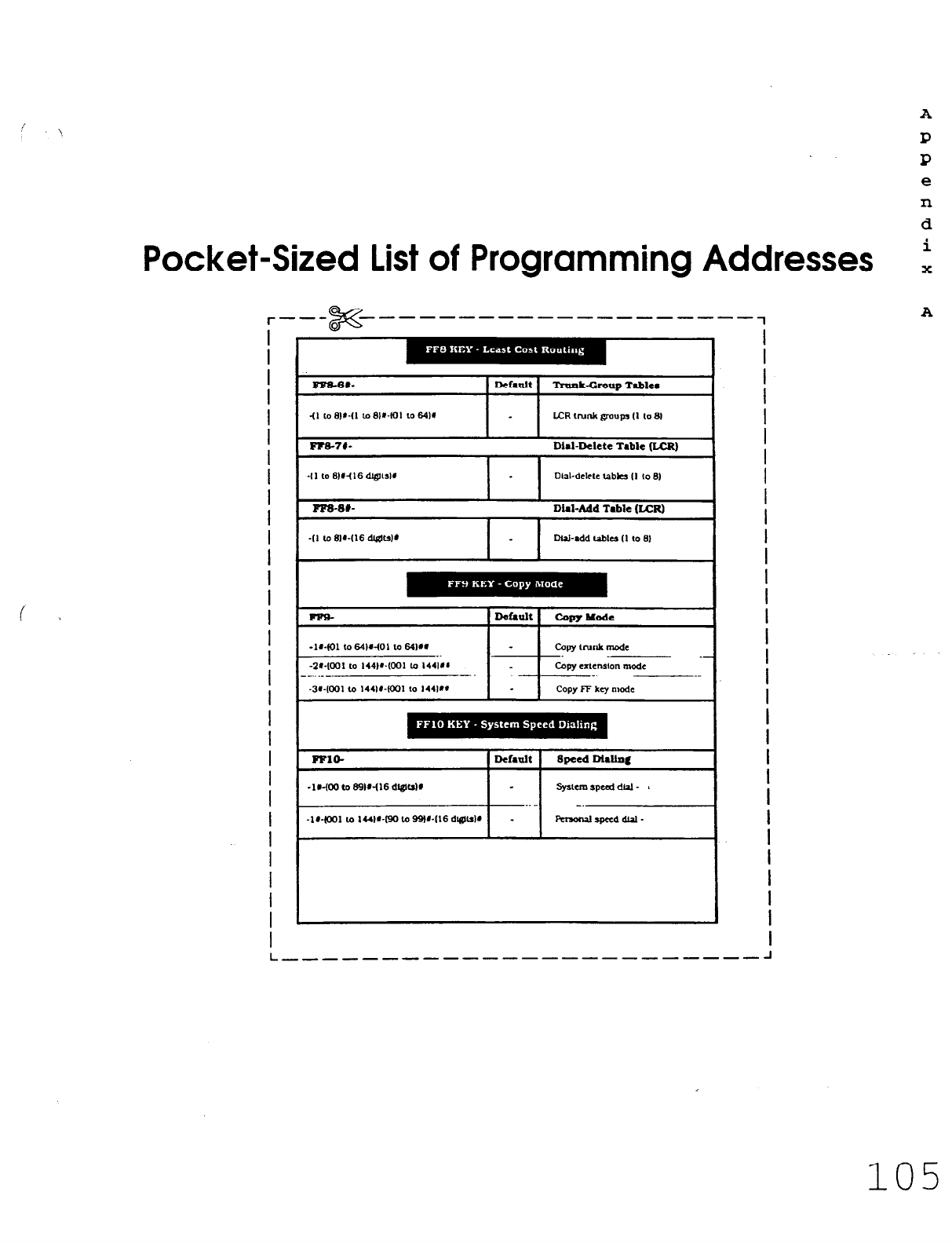
A
P
l?
e
n
d
Pocket-Sized List of Programming Addresses i
I
I
I
I
I
I
I
I
I
I
I
I
I
I
I
I
I
I
I
I
I
I
I
I
I
I
I
I
I
C
P-m-74-
1 1
Did-Delete Table &CR)
-1,~(001 10 IUV-(90 lo 99Wl16 dl@lsIL
I
I
I
I
I
I
I
I
I
I
I
I
I
I
I
I
I
I
I
I
I
I
I
I
I
I
I
I
I
L ___-------------__------ -I
105
Technical Manuals Online! - http://www.tech-man.com
CC RuZes and Regulations
106
A
p f ':
P
e
n
d
i
X
B
f
Technical Manuals Online! - http://www.tech-man.com
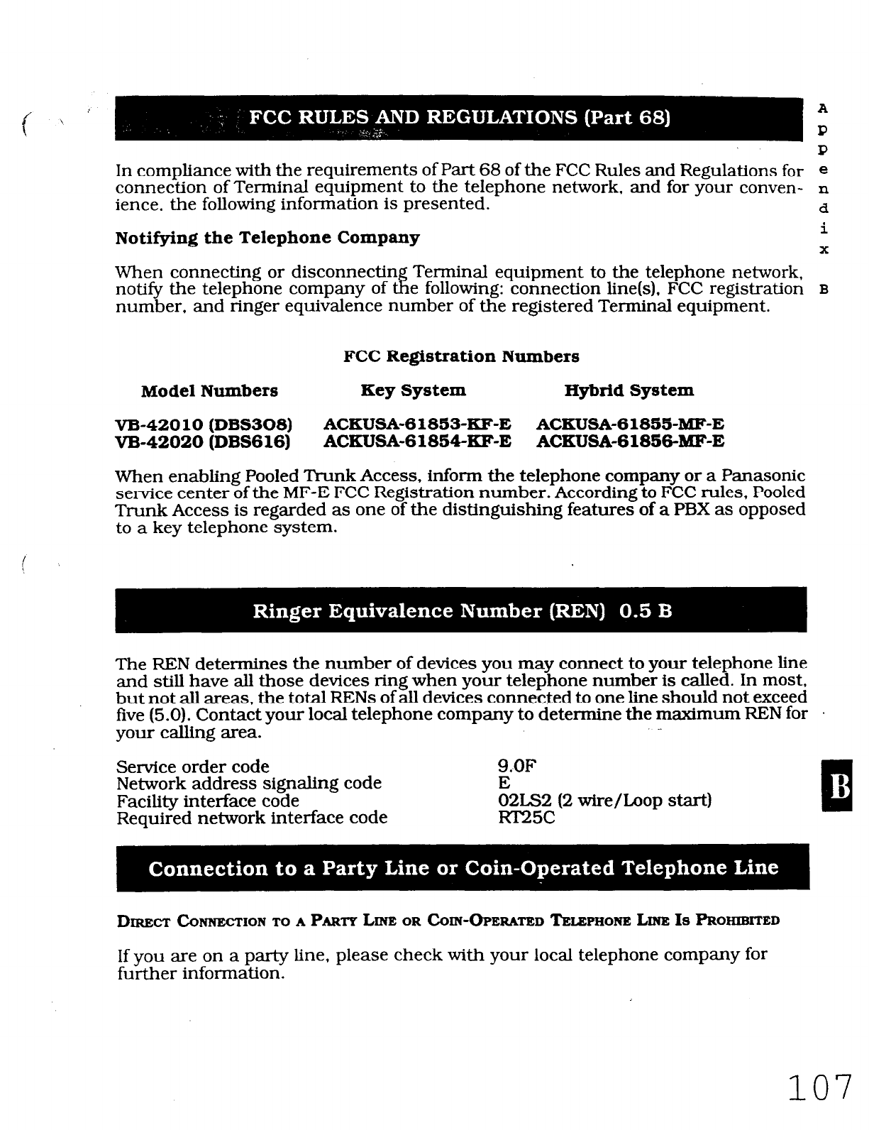
In compliance with the requirements of Part 68 of the FCC Rules and Regulations for e
connection of Terminal equipment to the telephone network, and for your conven- n
ience. the following information is presented. d
Notifying
the Telephone Company i
x
When connecting or disconnectin Terminal equipment to the telephone network,
notify the telephone company of tfl e following: connection line(s), FCC registration
B
number, and ringer equivalence number of the registered Terminal equipment.
FCC Registration Numbers
Model Numbers Key System Hybrid System
VB-420
10 (DBS308) ACKUSA-61853~KF-E ACKUSA-61855~MF-E
VB-42020 (DBS616) ACKUSA-6185~KF-E ACKUSA-61856-MF-E
When enabling Pooled Trunk Access, inform the telephone company or a Panasonic
service center of the MF-E FCC Registration number. According to FCC rules, Pooled
Trunk Access is regarded as one of the distinguishing features of a PBX as opposed
to a key telephone system.
The REN determines the number of devices you may connect to your telephone line
and still have all those devices ring when your telephone number is called. In most,
but not all areas, the total RENs of all devices connected to one line should not exceed
five (5.0). Contact your local telephone company to determine the maximum REN for .
your calling area.
Service order code
Network address signaling code
Facility interface code
Required network interface code
9.OF
E
02LS2 (2
wire/loop start)
RT25c
DIRECT
C~NNECTIONTOA
PARTYLINE
ORCOIN-OPERATEDTELSPHOXE
LINEIS
PROMBITED
If you are on a party line, please check with your local telephone company for
further information.
107
Technical Manuals Online! - http://www.tech-man.com
Should Terminal equipment cause harm to the telephone network. the telephone company shall. e
where practical. notify the customer that service may be temporarily disconUnued. However, where
prior noUce is not practical, the telephone company may temporarily discontinue service forthwith, n
if such action is reasonable in the circumstances. In case of un-notified temporary discontinuance of d
service. the telephone company shall: i
X
0 Promptly notify the customer of such temporary discontinuance of service.
B
(B)
Afford the customer the opportunity to correct the situation which gave rise
to the temporary disconttnuance.
(Cl
Inform the customer of the right to bring a complaint to the Commission
pursuant to the procedures set out in Part 68 of the FCC Rules and Regulations.
(A)
Availability of telephone information:
Technical information on interface parameters and specifications not set by FCC Rules,
including the number of ringers which may be connected to a particular telephone line
to permit Terminal equipment to operate in a manner compatible with telephone
company commumcaUons facilities, shah be provided by the telephqne company upon
customer’s request.
f
03
Changes in telephone company communications facilities. equipment, operations
and procedures:
The telephone company may make changes in its communicaUons facilities. equip-
ment. operauons or procedures. where such action is reasonably required in the ’
operaUon of its business and is not inconsistent with the rules and regulations in FCC
Part 68. lfsuch changes can be reasonably expected to render any customer’sTerminal
equipment IncompaUble with telephone company communications facilities or require
modification or alteration of such Terminal equipment or otherwise materially affect its
use or performance. the customer shall be given adequate notfce. in writing, to allow
the customer an opportunity to maintain uninterrupted service.
;
108
Technical Manuals Online! - http://www.tech-man.com
This system is hearing-aid compatible. e
n
d
i
%iEN bX3
EWHMINQ EMERQENCT
NUMBERS
OR B&JUNG
TEAT CALLS lro
EMEROENCY
NUMBERS:
(A) Remain on the line and briefly explain to the dispatcher the reason for the call.
x
B
U.3
Program or test emergency numbers only in off-peak hours: these are usually in the
early morning or late evening.
THE GRANTEE OR ITS Acmm
SHALL
PROWDE THE
USER OF THE
REGISTERED EQUIPMENT WITH
THE FOLLOWING
INFORMATION:
(A1
installation. operation and repair procedures. where applicable.
/
I \ 03
Registered Terminal equipment may not be used with party lines or coin lines.
(Cl
When a malfunction is indicated the customer shall disconnect the registered equipment
from the telephone line to determine the problem. Until the problem is corrected, discon-
nect all equipment.
(D)
If connections other than W25C are needed. contact the local telephone company.
109
Technical Manuals Online! - http://www.tech-man.com
PLEASE OEBERVE THE
FOLLOW~O GUIDELINES
TO ASSURE THE
SAFE
USE OF Yom
TELEPHONE
(A)
03
(Cl
(D)
(El
(F)
(G)
(HI
This product is an electrical device and
can
be hazardous if immersed in water.
To avoid the risk of electrical shock. do not use this unit while in the bathtub. shower.
or when wet. lf you accidently drop the unit into water. unplug it first. then retrieve it
by pulling the cord.
The telephone should not be exposed to heat sources, direct sunlight. extreme
temperatures. moisture, strong vibrations or greasy or dusty environments.
Never attempt to insert wires. pins or similar objects in the vents or openings of the
telephone.
Never clean the telephone with benzol. paint thinner or other solvent materials.
Never install telephone wiring during a lightning storm.
Never install telephone jacks in a wet area unless they are specifically designed for
that purpose.
Never touch un-insulated telephone wires or terminals unless the telephone line has
been disconnected at the network interface.
Warning -This unit generates, uses, and can radiate radio frequency energy. And if not installed and
used in accordance with the instructions manual. may cause radio interference. The Unit has been
tested and found to comply with the limits for a Class A digital device pursuant to Part 15 of FCC Rules,
which are designed to provide reasonable protection against such interference when operated in a
commercial environment.
Operation of this equipment in a residential area is likely to cause harmful interference in which case
the user at his own expense will be required to take whatever measures are necessary to correct the
interference.
If necessary, the user should consult the dealer or an experienced radio/television technician for
additional suggestions.
The user may find the following booklet prepared by the Federal Communications Commission helpful:
A
P .,
P
8
n
d
i
X
B
This booklet is available locally from FCC regional offices.
110
Technical Manuals Online! - http://www.tech-man.com
. . -
. . .
ndex
111
Technical Manuals Online! - http://www.tech-man.com
Index
A
211 restriction 51.87, 103
311 restriction 51, 87. 103
411 restriction 51.87. 103
511 restriction 51.87. 103
611 restriction 51.87. 103
7-digit dial restriction/COR types (2 to 6)
50, 51. 54. 87. 88. 103, 104
711 restriction 51.87. 103
811 restriction 51.87, 103
911 restriction 51.87. 103
ABCD inband si.@alhq 27.78.94
Absence messages (5 to 9) 48. 49.86.87.
102. 103
Account code 35.67.70.86, 102
Add table &CR) 57.62.89
AFP 42.45
Alarm indication sigual (AIS) detection 25.
77.93
Alarm LED mode 4.74.90
Alarm notification
red 24. 26. 77. 78. 93. 94
yellow 24.25. 77. 78.93. 94
Alarm relay recovery mode. 24.25. 77, 78.
93. 94
Alert tone 4.74.90
Analog port transfer ring interval 4.74.90
Answer key 86. 102
Auy key/pre-programmed codes 45. 46.
83-85. 99- 10 1
Appendix A 73- 105
Appendix B 106-l 10
Area Codes
LCR 57.58.88. 104
TRS 50, 52. 56. 87. 88. 103. 104
Attendant 3. 4. 8-13. 18. 19, 42. 45. 74. 86,
90. 102
consoles/flexible feature key assignment
42, 45, 85. 101
feature package (AFP) 42, 45, 85, 101
HOLD-recall ttmer 8, 76.92
Hunt Group recall timer 10. 75. 9.1
intercom
HOLD-recall timer 9, 75, 91
transfer recall timer 9. 75. 9 1
voice/tone call 3. 74. 90
overflow 4, 74. 90
I
Y ‘,
r :
e
X
override switch 4. 74. 90
park-HOLD recall timer 11, 75, 91
reversion timer 12. 75. 91
transfer extension 4. 74. 90
transfer recall timer 9. 75. 9 1
Auto day mode 20.76. 92
AUTO-FLASH-RED&IL 3.74,90
Auto set relocation codes 37. 67, 68. 70,
80. 96
Automatic Dialers 109
Automatic HOLD (key-bank HOLD) 3,74,90
Automatic pause 31.79.95
Automatic pause after dialiug (1 to 9.0)
6. 7. 75.91
Automatic pause timer 13.75.91 c
Automatic switch to uight mode 8.75.91
B
Background music (BGM) 86, 102
BGM (Background music) 86, 102
BLF (busy-lamp field) 4. 74. 90
BLF (extension) delayed ring 4.74.90
BLF port number (EM/24 console station-
port number) 35, 77.93 n
Busy-lamp field (BLF) 4. 74, 90
Busy overridden 35.67.68.77.93
Busy override 35. 67.68.70.71.86, 102
Busy tone (voice mail) 4, 74, 90
Busy tone transmission 27. 78. 94
C
Cable 70, 72
i
112
Technical Manuals Online! - http://www.tech-man.com
Call forward 72.86. 102
/busy 86, 102
/CO line 86. 102
/no answer 86. 102
/no answer/busy 86, 102
/no answer timer 16.75,91
CalI waiting 36, 67.70.86. 102
display/large-display telephone 37. 77. 93
Call Coverage Group 38.4 1.5 1.68. 70. 72,
81.97
covering extension 1 41. 51, 68.81. 97
covering extension 2 41. 51, 68. 81. 97
extensions 41. 97
Call Coverage Group extension tables
(1 to 16) 38. 41. 81
Call duration display 3. 74.90
Chart/FF key codes 86. 102
Circuit number (telephone number) 29. 30.
Class of Restriction (COR) 50-56.87. 88.
100, 101
Class of sedce setting 51.87. 1038.67.68.
70. 72. 75. 91
CO delayed ringing timer 19.76.92
CO line
display after dialing/large-display 37, 77.
91
display during dialing/large-display 37. 77
91
FLASH timer 14, 75. 90
off hook signal 35. 77.91
off hook signal pattern 36. 67. 68. 77. 91
off hook signal volume 36. 67.68. 77. 91
co trunk
name 49.87. 103
preference (access code 881 86. 102
Compatibility of the Telephone Network
and Terminal Equipment 108
CONF key 42
Connection to a Coin-Operated Telephone
Line 107
Connection to a Party Line 107
Copy Mode
extensions 34, 63, 89, 102
LED FF keys 63. 89, 102
trunks 63. 89, 102
113
COR I
(Class of Restriction) 50-56. 87. 88. 103, n
104 d
WRSI types 50-56. 87, 88, 103, 104 e
X
D
Damage to a telephone line 108
Date 3. 74.90
Day 3.74.90
TRS - all extensions 88. 104
Day 3.74.90
delayed-ring tables 81. 97
riw 81.97
TRS 88.104
Debounce timer 22.77.93
Default charts 74-89
pocket-sized version 90- 105
Delayed-ring capability 4.72
Delete table &CR) 57. 62.89, 105
Detection timers 17. 75. 91
Dial time-out for digits, DID 33, 76.92
Dial pause timer 15.75.91
Dial tone detection 3 1.76.92
Dial tone generation 27.78.94
Dial tone transmission 27. 78. 94
Dialing restriction during an incoming call
(TRS) 51. 87. 103
DID
confirmation of reset 21.76. 92
dial setting 27. 78. 94
digit dial time-out 33. 76, 92
Immediate or Wink start 32. 76. 92
interdigit dial time-out 33. 76. 92
outside extension 37. 76. 92
reset 21. 76. 92
trunk card 32, 76. 92
trunk lines 28
DID dialing assignment 27.78.94
DID/DNIS emulation 5.74.90
DID/T1 reset 21, 76. 92
Digital pads 23. 77.,93
Digit restrictions (TRS) 52, 88. 104
Technical Manuals Online! - http://www.tech-man.com
Direct Inward System Access (DISA) 2 1. 32,
76.92
Direct Station Select (DSS) 42. 46. 48, 49.
84, 100
DISA
enable 32, 76. 92
end timer 32. 76. 92
ID code 32.76. 92
outgoing codes 1 and 2 32, 76. 92
start timer 32, 76. 92
Disconnect timer 22. 76. 92
Display (SSD) 3. 74. 90
DND (Do Not Disturb) 86, 102
DMS dialing assignment 27. 78.94
Do Not Disturb (DND) 86. 102
D-SLT handset volume level 67.68. 70
DSS
(Direct Station Select) 42. 46, 48. 49.84.
85. 100, 101
extensions 46.84, 100
DSS/72
BLF consoles flexible feature key
assignment 46.49.84.85. 100. 101
FF keys 42.46.84
DTMF signal sending time 31.76.92
-p-data mode (Xon/Xoff) 5.74.90
E
EL (extension line) 83.99
EL/ML keys 43.44.83.99
EM (Extension Module) 35.42.47. 77.93
EM/24 console station port number 35.77.
93
Enables DXSA 31. 76. 92
EPI (external page interface) 7. 8, 75.91
Exclusive HOLD 3.74.90
Extension
delayed-ring tables 4. 67. 68, 8 1. 97
delayed ringing timer 20, 76, 92
digits 3. 74. 90
directory display/large-display telephone
37, 80, 96
114
flexible feature key assignment 42-44. I
83-86 n
HOLD-recall timer 9, 75. 91 d
Hunt Group recall timer 11, 75, 91 e
X
intercom
HOLD-recall timer 18, 75. 91
transfer-recall timer 19. 75. 91
voice/tone caIl 3. 74. 90
keys 42-44, 83-85
name assignment 49.87. 103
number 35.80.96
page groups (00 to 07) 36.80.96
page ring 86. 102
park-HOLD recall timer 12. 75. 91
ports 34, 35-37.80.96
programming 34-37. 80. 96
ring tables 81, 97
ring pattern 67. 68, 70
KTEL 37.80.96
SLT/OPX 37.80.96
transfer-recall timer
Extension Module (EM) 35.42.47.77.93
Extension summary 34.38.50.66-70
Extensions - (two or three digits) 86, 102
External Page Interface (Em) page groups
7.8. 75, 91
F
FCC Rules and Regulations 106- 110
FFl key - System programming 2-27. 74-78.
90-94
1’F2 key - Trunk programming 28-33.79.95
FF3 key - &tension programming 34-37.
80.96
FF4
key - Ring
assignment and Hunt
Groups 38-41.81.82. 97, 98
FFS
key
- Flexible feature
key
assignment
42-47, 83-86. 99- 102
FF6
key -
Name assignment 48.49.87.103
FF7 key - Toll restrictions 50-56.87, 88,
104
FFS
key
- Least Cost Routing 57-62.88.89.
104. 105
Technical Manuals Online! - http://www.tech-man.com
FF9 key - Copy mode 63.89. 105
FFlO key - System speed dialing 64.65.89.
105
FF key code chart 85.86, 101.102
First attendant 46. 84, 100
FLASH 3, 74. 90
FLASH timer (CO line) 14. 75, 91
FLASH timer (PDX) 16. 75.91
Flexible feature
key
assignment 42-44,
83-86
Forced verified account code 35.67. 68. 70.
80.96
Forced LCR restriction 35.67. 68. 70, 80. 96
Fourth attendant 4, 74.90
Frame loss 25. 76.92
Frame loss counter 26, 77.93
Framing format 25. 76, 92
extensions 81. 97
night
I
n
rl
CO line / pilot extension ring tables u
81.97 e
delayed-ring 40. 8 1, 97
X
no answer 20, 76, 92
pilot extension 40. 67. 68. 81. 97
pilot name 40. 67.68.81.97
recall timers
attendant 10, 75. 93
extension 11. 75. 93
search methods 4.67.68.81.97
tables (1 to 8) 38. 40. 8 1. 97
transfer extension 40.67. 68. 8 1, 97
transfer timer 40. 8 1. 97
Hunt Groups 70. 72, 81.82.97.98
I
G
Glare timer
immediate start 22. 77. 93
wink start 22. 77. 93
Group pickup 86. 102
Guard timer 22. 77. 93
H
Headset mode 86. 102
Hearing-aid compatibihty 109
HOLD 3. 74.90
automatic
exclusive
system
HOLD-recall timers
attendant 8. 75, 91
extensions 9. 75.91
Hour 3
Hunt Groups
day CO line / pilot extension ring tables
81.97
delayed-ring 40. 8 1, 97
Idle display / large-display telephone 37.
80.96
IDT(intercom dial tone) 37.86. 102
LDT (laqIedispl& 37
Incoming calls restriction (TRS) 5 1,87. 103
Incoming detection timer 22. 77. 93
Incoming Diahng Method 27.78.94
Incoming ground detection timer 17.75. 91
Incoming ring
delay timer 15. 76. 92
signal pattern 3 1, 76. 92
timer 14. 76. 92
Incoming ring 39.81.97
day rinR
delayed
day
night
night ring
Incoming signaDng class 27. 78,94
Index 111
Instructions 1. 2. 28. 34, 38. 42. 48. 50. 57.’
63. 64. 66. 69. 73, 106. 111
Intercom 4
busy tone display / large-display telephone
37. 80. 96
115
Technical Manuals Online! - http://www.tech-man.com
call status display (IDT) / large-display
telephone 37. 80, 96
dial tone (IDT) 37. 80. 96
key 86, 102
off hook display / large-display telephone
37, 80, 96
ring signal 81, 97
transfer 86. 102
Intercom timers
attendant 17, 18. 76. 92
HOLD recall 17. 76. 92
transfer recall 18. 76. 92
extensions 18, 19. 76.92
HOLD recall 18.76.92
transfer recall 19, 76.92
Intercom tone
continuous (SLT FLASH control) 3, 74. 90
International call (TRS) 51.87. 103
J. K
Key
Plan 34. 38. 48. 66. 69. 70. 71
Key bank (automatic) HOLD 3.74.90
L
Large-display telephones 4.36, 37, 74. 80.
87.96, 103
LCR
add table 57. 62. 89. 105
area codes/office codes 57. 58.88, 104
delete table 57. 62, 89. 105
forced 35. 67. 68, 70. 80. 96
office codes/special area codes 57. 59, 88.
104
time bands 88. 104
time priority tables 57. 58. 60, 88. 104
trunk groups 57.60.61,88, 104
trunk ports 88. 104
LCR (Least Cost Routing) 28.57-62.86. 102
Least Cost Routing (LCR) 28. 57-62, 86. 102
Line coding format 24. 25, 77. 78. 93. 94
Lockout code 35. 67.68. 70.74.90
Long-distance calls 5. 74. 90
Loop
keys
hmlti-liue) 43.83.99 n
.
hop start, ground start, or DID truuk cards
d
32. 76, 92
e
Loop start trunk card 32, 76.92
X
M
MC0 45.46.84.85. 100, 101
Meet-me answer 86. 102
Message
waiting 86. 102
answer
cancel
set
Mmltes
3.74.90
ML/EL keys 83.99
ML/MC0 separation 37.80.96
Month 3.74.90
Multi-line key assigument 43.44.70. 72,
83.99
Multiple DID 5. 74.90
Mute key 86. 102 f-
N
n
Name and message storing 48.49.87. 103
Name assignment 48.49.87. 103
Network
sync source recovery timer 22.
76, 92
wiw automatic switch 8
/day 82.84.98. 100
delayed-ring tables 82. 98
key 86,102
ring 39.75.91
TRS 55.86
all extensions 55.88
Non-appearance CO line HOLD (exclusive/ .
system) 3.74.90
Number of channels used 24. 25. 77.93
f
116
Technical Manuals Online! - http://www.tech-man.com
0
Off hook signal (CO line) 36.80.96
Office codes
LCR 57.58
TRS 50. 52. 56
OHCA
answerback 49. 87. 103
Onhook transfer 3, 74.90
One-touch dialing 3.74.90
Operating mode during alarm condition
24, 25. 77. 78, 93. 94
OrQinal forms
1.2.28. 34, 38. 42, 48. 50.
57. 63. 64.66.69. 73, 106. 111
Outbound ground detection timer 17. 75.9
1
Outgoing signaBn% class 27.78.94
Outpulse delay timer 22. 77, 93
Out of sync 25.26.77,78.93,94
Overrides TRS (allows SSD) 3.74.90
P
c 1
Page groups (00 to 07)
extensions 36.67.68. 72.86
relay 7. 8. 75. 91
Page zones 70.84.85. 100, 101
Page call display/large-display telephone 37
Pa@qj duration 5.74.90
Parity check (SMDR) 5.74.90
Park-H&I
key
retrieve 84,85, 100, 101
Park-HOLD recall timers
attendant 11, 75. 91
extensions 12, 75.91
Pause (automatic after dialing 1 to 9,OI 6.
7, 75. 91
Pause-timer (automatic) 13. 75. 91
PBX
access codes 5. 6. 75. 91
FLASH timer 16.75.91
Permanent call forward 37.67.68.
70.80.96
extension 37, 67.68. 70, 80. 96
Personal speed dial (PSD) 36.43.49.64.65.
86,89. 102. 105
Photocopying
1
I
Wet extension (Hunt Group)
40. 81.82.97, n
98 d
Pooled trunk access (MCO) group
settings e
(9, 81 to 86) 28, 31. 86. 102
X
Ports 70
Pre-programmed codes
45.46. 83-85, 99-
10 1
Reface
1
Prime line preference 35.67. 68. 70.86. 102
Private line port number 3
1
Product SafetJr
110
Programming addresses - FFl to FFlO Keys
2-105
PSD
name
assignment (90 to 99) 49.87. 103
names - large display
PSD (personal speed dial) 36.43.49.64.65.
86.89. 102. 105
Pulse or DTMF dial 31. 76. 92
99 R
Radio interference
110
RAl-A baud rate switch 5.74.90
RAI-B baud rate switch 4. 74.90
Recall timers 2. 8-12, 38. 75,
91
Red alarm counter 22.77.93
Red alarm detection timer 24.26, 77, 78.
93.94
Red alarm recovery detection timer 24.26.
77, 78, 93. 94
Red alarm relay control 25.77.93
Redial 3. ?4
Registering equipment 107
Relay (page groups) 7.8. 75.
91
Release acknowledge timer 22.77.93
Remote
loopback
detection 24.25. 77.78.
93.94
Remote Maintenance Code
19. 75.91
Responsibility of Manufacturer of
Registered Equipment
109
Restriction on maximum digits dialed 5 1.
87, 103
Reversion timer (attendant) 12. 75
Technical Manuals Online! - http://www.tech-man.com
Ring assignment and Hunt Groups 38.39.
81. 82. 97, 98
Ring assignments 38.40.67.68, 70, 81.82,
97.98
Rw? signal
delay timer 14, 75, 91
incoming 31. 76. 92
pilot number and CO line 39.8 1.97
Ring timer (incoming) 14.81.97
Ringback tone with busy signal 37.67.68.
80.96
Ringback transmission 27, 78.94
Ringer Equivalence Number (REN) 107
Ringing Une preference 36. 67. 68, 70. 80.
96
S
Save/repeat 86. 102
dial
store
Second attendant 4. 46. 74.90
Signal loss counter 25.26. 77, 78.93. 94
Single line telephone (SLT) 3. 14, 74. 75.
90.91
Slip counter 24. 26, 77. 78. 93.94
SLT
FLASH control 3, 74.90
hook flash 37.67.68.70.80.96
onhook FLASH timer 14. 75.91
SLT (single line telephone) 3. 14. 74. 75.
90.91
SLT DISA ringing pattern 5.74.90
SMDR
baud rate 5. 74. 90
data length 5, 74. 90
print mode 1 5.74.90
print mode 2 (long distance/local calls) 5.
74. 90
print mode 3 (titles and TN data) 5. 74. 90
printout/incoming calls 36. 67. 68, 70
stop-bit length 3. 5. 74. 90
timer 16/30 3. 74.90
lTY parity check 4, 74. 90
TTY parity type 4.74.90
Software versions 1
1.0. 2.0 - B card
3.0. 3.1 - A card
Special area codes
LCR 57. 59,88,89. 104. 105
TRS 50. 53, 56.87. 88. 103. 104
Special office codes
LCR 57,59,88,89, 104, 105
TRS 50. 53. 56.87. 88. 103. 104
Speed dial list 48.64.65.89. 105
Splash tone
busy override 4. 74. 90
voice call 4. 74, 90
SSD
display mode 3.74.90
name assignment (00 to 89) / large-display
telephones 4, 49. 87. 103
toll restriction override 3, 74.90
SSD (system speed dial) 2.3.4.48.49. 64,
65. 74. 86. 89. 90. 102. 105
Stacked calls (attendant overflow) 4.74.90
Station lockout code 35.67.68.70.86. 102
Stored codes 21
Snbmodes 2.34
Summary
key
plan 71.72
Synchronization setting
first sync source 22.76.92
second sync source 22.76.92
third sync source 22. 76, 92
Sync loss counter 25, 26. 77. 78. 93.. 94
System HOLD 3.74.90
System programming 2-27. 76.92
ID code 21. 75.91
System size 2 1. 76.92
System speed dial (SSD) 2.3.4.48.49, 64.
65, 74. 86, 89. 90, 102. 105
T
Tl alarm
keys
43.44.86. 102
Tl port class
station 37. 80. 96
trunk 33.79.95
I
n /
d
e
X
(’
118
Technical Manuals Online! - http://www.tech-man.com
Talk back key 86, 102
Telephone types 34.35.80.96
Telephone line system (trunk type) 3 1. 76.
92
Third attendant 4. 74. 90
Time 2. 3. 74. 90
Time bands (LCR) 59, 88, 104
Time priority tables (LCR) 57. 58. 60. 88.
104
Timers
attendant
HOLD-recall 8, 75. 91
Hunt Group recall 10, 75, 91
intercom
HOLD-recall 17, 75. 91
transfer-recall 18. 75. 91
park-HOLD recall 11.75.9 1
reversion 12. 75, 9 1
transfer-recall 9. 75. 9 1
automatic pause timer 13.75.91
call forward/no answer 16.75.91
CO he FLASH 13. 75.91
dial pause 15.75, 91
DISA end 32.76. 92
DISA start 32, 76, 92
extensions
HOLD-recall 8, 75. 92
Hunt Group recall 10. 75. 92
intercom
HOLD-recall 18. 75. 91
transfer-recall 18. 75, 9 1
incoming ground detection 17. 75. 91
incoming ring delay 15. 75. 9 1
outbound ground detection 17. 75.9 1
PBX FIASH 16.75.91
SLT onhook FLASH 14.75.91
trunk disconnect 32, 76. 92
unsupervised conference talk-time 13. 75,
91
Wink start (DID) 32, 76, 92
Titles 5, 74. 90
Toll Restriction System (TRS) 3, 50-56. 67,
68. 87. 88. 103. 104
Tone busy (voice mail) 4, 74. 90
Tone call 3.86. 102
Tone pattern (incoming ring signal) 3 1. 76.
92
L
Transfer extension (attendant) 4. 74: 90 d
Transfer-recall timers e
X
attendant 9. 75. 91
extension 10.75.91
TRS
area codes/of&e codes 50, 52. 87.88,
103. 104
block mode/area codes (1 to 4)
:,I,c COR types (3 to 61 56. 88, 104
block mode/of&e codes (5 to 8)
COR types (3 to 6) 56.88. 104
block mode/special area office codes
(13 to 16) 56, 88, 104
COR types (3 to 6) 56, 88, 104
block mode/special office codes (9 to 12)
COR types (3 to 6) 56.88, 104
COR 70.87.88, 103. 104
day assignment 50. 55. 67. 68. 88, 104
international calIs 5 1.87, 103
night assignment 50. 55.67.68.88, 104
override 3.87.88. 103. 104
special area code table 50, 53.87. 103
TRS (toll restriction system) 3. 50-56. 67.
68, 87, 88. 103. 104
Trunk class 24.25.77.93
Tmnk mode 27.78.94
-PO-
queueing 86. 102
Trunk selection 32.79. 95
Tnmk-to-trunk conferencing (unsupervised)
2. 13. 31, 75, 76.91.92
Trunk type 26.78,94
disconnect timer 32. 76. 92
features list 28.31-33, 76. 92
LCR
group order 61, 89. 105
group settings 28.88,89. 104. 105
group tables 60. 61. 88.89. 104, 105
lines 28.76.92
names 29.30. 49. 87. 103
port lists 28-30.76.92
port settings 31. 32. 76. 92
119
Technical Manuals Online! - http://www.tech-man.com
piogramrning 28-33 I
setting 3 n
.
types (CO line/PBX line) 3 1, 76.92 d
use 31. 76. 92 e
lTY data 5.74.90 i
U
UNA (Universal Night Answer) 7. 75.91
Unattended (unsupervised) conference 2.
13. 31. 35. 67. 68, 75, 76, 91, 92
Universal Night Answer (UNA) riug pattern
7. 75, 91
Unsupervised conference
extension capability 35. 75. 91
talk-time 2, 13. 75.91
trunk capability 2, 3 1. 76. 92
V
Verified Account Codes 8.75.91
Verified Account Code Toll Restriction 8,
75.91
Voice call 3. 74. 86.90. 102
Voice mail (busy tone) 4. 74. 90
W
Whk signal start detection timer 22.77.93
Wink start timer @ID) 32.79.95
n
Yellow alarm couuter 25.26. 77. 78.93.94
Yellow alarm detection timer 24.26.77. 78.
93.94
Yellow alarm notification 24.26.77.78.93,
94
Yellow alarm recovery detection timer 24, !’
26. 77. 78. 93. .94
Yellow alarm relay control 25. 77.93
Year 3.74.90
120
Technical Manuals Online! - http://www.tech-man.com
