300.bk DBS Section 300 Installation
cpcex 292d708e-b97b-4a7e-9c73-16275b5cef63 Panasonic Telephone CPC-EX User Guide |
User Manual: DBS Section 300 Installation
Open the PDF directly: View PDF ![]() .
.
Page Count: 204 [warning: Documents this large are best viewed by clicking the View PDF Link!]
- Table of Contents
- Purpose
- Related Information
- Chapter 1. Requirements
- Chapter 2. System Overview
- Chapter 3. Cabinet Installation
- Chapter 4. Trunks and Lines
- Chapter 5. Peripheral Equipment
- Chapter 6. Double-Cabinet Systems
- Chapter 7. Specifications
- Appendix A: CPC-EX 1.0 Updates
- Compatibility
- 44-Series Phone Support
- FF-Key Programming
- Speed Dial Enhancements
- Additional Serial Port
- T1 Networking Capability
- Modification to Toll Restriction Service
- Maximum Time Priority Route Tables
- SMDR Modifications
- ISDN Support
- Modification to T1 Signaling Types
- Installation Notes
- 44-Series Enhanced Phone Features
- Additional Serial Port on CPC Card
- Appendix B: CPC-AII/B 8.0 Updates
Section 300
Installation
Panasonic
a
(Applies to CPC-AII/B Version 9.2
and CPC-EX Version 2.3)
Version 2.3/9.2
Revised April 2000

The contents of this manual are subject to change without notice and do not constitute a
commitment on the part of Panasonic Telecommunication Systems Company (PTSC). Every
effort has been made to ensure the accuracy of this document. However, due to ongoing product
improvements and revisions, Panasonic cannot guarantee the accuracy of printed material after
the date of publication nor can it accept responsibility for errors or omissions. Panasonic will
update and revise this document as needed.
This document may be reproduced either electronically or in print as needed by certified dealers
and technicians of DBS products. However, the information contained in this document must not
be altered, copied, or changed in any way that misrepresents the installation, operation, or other
function or feature of the DBS product or Panasonic. Panasonic assumes no liability for any
alteration or misrepresentation of information contained herein.
The software and hardware described in this document may be used or copied only in accordance
with the terms of the license pertaining to said software or hardware.
Copyright 1995 by Panasonic Telecommunication Systems Company
Revised April 2000
All rights reserved.
Warning: This service information is designed for experienced repair
technicians only and is not designed for use by the general public. It does not
contain warnings or cautions to advise non-technical individuals of potential
dangers in attempting to service a product. Products powered by electricity
should be serviced or repaired only by experienced professional technicians.
Any attempt to service or repair the product or products dealt with in this
service information by anyone else could result in serious injury or death.

DBS-2.3/9.2-300 DBS Manual - Revised April 2000 iii
Table of Contents
Purpose ...................................................................................................................................... xi
Related Documents ................................................................................................................... xi
Chapter 1 Requirements .......................................... 1-1
Model Numbers ...................................................................................................................... 1-1
FCC Requirements .................................................................................................................. 1-1
General Requirements ............................................................................................................. 1-1
DID Requirements .................................................................................................................. 1-3
T1 Requirements ..................................................................................................................... 1-4
Environmental Requirements ................................................................................................. 1-4
Cleaning .................................................................................................................................. 1-5
Chapter 2 System Overview .................................... 2-1
Cabinet Description ................................................................................................................ 2-3
Configurations ........................................................................................................................ 2-5
Printed Circuit Cards .............................................................................................................. 2-6
Processor Description ............................................................................................................. 2-9
Chapter 3 Cabinet Installation ................................. 3-1
Wall-Mounting the Cabinet .................................................................................................... 3-3
Guidelines ............................................................................................................................... 3-3
Installation .............................................................................................................................. 3-3
Grounding ............................................................................................................................... 3-5
Guidelines ............................................................................................................................... 3-5
Installation .............................................................................................................................. 3-5
Card Installation ...................................................................................................................... 3-6
Guidelines ............................................................................................................................... 3-6
Installation .............................................................................................................................. 3-8
Battery Backup ....................................................................................................................... 3-9
Guidelines ............................................................................................................................... 3-9
Installation for the DBS 40 ................................................................................................... 3-10
Installation for the DBS 72 and 96 ....................................................................................... 3-11
Key Phone Wall Mounting ................................................................................................... 3-13
DSLT Wall Mounting ........................................................................................................... 3-15
System Initialization ............................................................................................................. 3-17
Test Phone ............................................................................................................................. 3-18
Guidelines ............................................................................................................................. 3-18
Installation ............................................................................................................................ 3-18

Contents Section 300-Installation
iv DBS Manual - Revised April 2000 DBS-2.3/9.2-300
Chapter 4 Trunks and Lines .................................... 4-1
Trunks ..................................................................................................................................... 4-3
Trunk Connectors ................................................................................................................... 4-3
Trunk Connector Pinouts ........................................................................................................4-4
Loop-Start Trunks ................................................................................................................... 4-7
Ground Start and DID Trunks ................................................................................................ 4-9
T1 Interface ........................................................................................................................... 4-11
Lines ...................................................................................................................................... 4-31
Extension Connectors ...........................................................................................................4-31
Extension Connector Pinouts ................................................................................................ 4-32
Analog Extensions ................................................................................................................ 4-37
Digital Extensions ................................................................................................................. 4-41
Trunk and Line Expansion .................................................................................................... 4-44
Chapter 5 Peripheral Equipment ............................. 5-1
Local Terminal or SMDR Device ........................................................................................... 5-3
Guidelines ............................................................................................................................... 5-3
Installation .............................................................................................................................. 5-4
Remote Administration Interface (RAI) ................................................................................. 5-6
Guidelines ............................................................................................................................... 5-6
Installation .............................................................................................................................. 5-6
Background Music/Music-On-Hold ....................................................................................... 5-8
Guidelines ............................................................................................................................... 5-8
Installation .............................................................................................................................. 5-8
Off-Premises Adaptor (OPX) ............................................................................................... 5-10
Guidelines ............................................................................................................................. 5-10
Installation ............................................................................................................................ 5-11
Paging ................................................................................................................................... 5-14
Guidelines ............................................................................................................................. 5-14
External Page Zone Installation ............................................................................................ 5-14
External General Page/UNA Installation .............................................................................. 5-16
External Ringer (UNA Device) ............................................................................................ 5-17
Guidelines ............................................................................................................................. 5-17
Installation ............................................................................................................................ 5-18
Power Failure Unit ................................................................................................................ 5-19
Guidelines ............................................................................................................................. 5-19
Installation ............................................................................................................................ 5-19
Voice Announce Unit (VAU) ............................................................................................... 5-22
Guidelines ............................................................................................................................. 5-22
Installation ............................................................................................................................ 5-22
Recording and Playing Messages ......................................................................................... 5-26
Door Box Adaptor (Trunk Port) ........................................................................................... 5-27
Guidelines ............................................................................................................................. 5-27

Section 300-Installation Contents
DBS-2.3/9.2-300 DBS Manual - Revised April 2000 v
Installation ............................................................................................................................ 5-28
Door Box Adaptor (Extension Port) ..................................................................................... 5-31
Single Line Telephone Adaptor ............................................................................................ 5-34
Chapter 6 Double-Cabinet Systems ....................... 6-1
Guidelines ............................................................................................................................... 6-3
Installation ............................................................................................................................ 6-10
Chapter 7 Specifications ......................................... 7-1
Electrical Characteristics ........................................................................................................ 7-3
Environmental Requirements ................................................................................................. 7-4
Resource Maximums ..............................................................................................................7-5
Cabling Specifications .......................................................................................................... 7-13
Communication Parameters .................................................................................................. 7-14
Signaling Characteristics ......................................................................................................7-15
Tone Characteristics ............................................................................................................. 7-16
Appendix A: CPC-EX 1.0 Updates ...........................A-1
Compatibility ......................................................................................................................... A-1
44-Series Phone Support ........................................................................................................A-1
Directory Mode ...................................................................................................................... A-2
Variable Mode ....................................................................................................................... A-2
Handset Mute ......................................................................................................................... A-2
Off-Hook Monitoring ............................................................................................................A-2
Analog Adapter ...................................................................................................................... A-2
MSG (Message) Key ............................................................................................................. A-2
DSS/72 and EM/24 - Key Arrangement ................................................................................ A-2
FF-Key Programming ............................................................................................................ A-3
Speed Dial Enhancements ..................................................................................................... A-3
Additional Serial Port ............................................................................................................ A-3
T1 Networking Capability ..................................................................................................... A-3
Modification to Toll Restriction Service ............................................................................... A-3
Maximum Time Priority Route Tables .................................................................................. A-3
SMDR Modifications .............................................................................................................A-4
ISDN Support ........................................................................................................................ A-4
Modification to T1 Signaling Types ...................................................................................... A-4
Installation Notes ................................................................................................................... A-4
CPC-EX Installation .............................................................................................................. A-4
44-Series Enhanced Phone Features ...................................................................................... A-7
Analog Adapter .................................................................................................................... A-12
MSG (Message) Key ........................................................................................................... A-13
DSS/72 Console - Key Arrangement ................................................................................... A-15

Contents Section 300-Installation
vi DBS Manual - Revised April 2000 DBS-2.3/9.2-300
EM/24 - Key Arrangement .................................................................................................. A-17
Additional Serial Port on CPC Card .................................................................................... A-19
Appendix B: CPC-AII/B 8.0 Updates ........................B-1
Contents ..................................................................................................................................B-2
44-Series Phone Support .........................................................................................................B-3
Enhanced Phone Features .......................................................................................................B-4
Analog Adapter .......................................................................................................................B-8
MSG (Message) Key ..............................................................................................................B-9
DSS/72 Console - Key Arrangement ....................................................................................B-10
EM/24 - Key Arrangement ...................................................................................................B-13
TAPI Support ........................................................................................................................B-14
Key Telephone Installation Notes .........................................................................................B-14
Desi Strip Cover ....................................................................................................................B-14
Key Telephone Wall Mounting Instructions ........................................................................B-14
Index ....................................................................Index-1

Section 300-Installation List of Figures
DBS-2.3/9.2-300 DBS Manual - Revised April 2000 vii
List of Figures
Figure 2-1. The DBS cabinet (DBS 96 shown) ................................................................. 2-3
Figure 2-2. The DBS cabinet (DBS 96 shown) ................................................................. 2-3
Figure 2-3. Trunk, line, and peripheral connections .......................................................... 2-4
Figure 2-4. Slot labels for printed circuit packages ........................................................... 2-9
Figure 3-1. Cover removal ................................................................................................. 3-3
Figure 3-2. Cabinet mounting bracket ............................................................................... 3-4
Figure 3-3. Cabinet wall-mounting ................................................................................... 3-4
Figure 3-4. Cabinet ground screw ..................................................................................... 3-5
Figure 3-5. SCC-B Switch 4 .............................................................................................. 3-6
Figure 3-6. CPC Strap S1 .................................................................................................. 3-7
Figure 3-7. Printed circuit card installation ....................................................................... 3-8
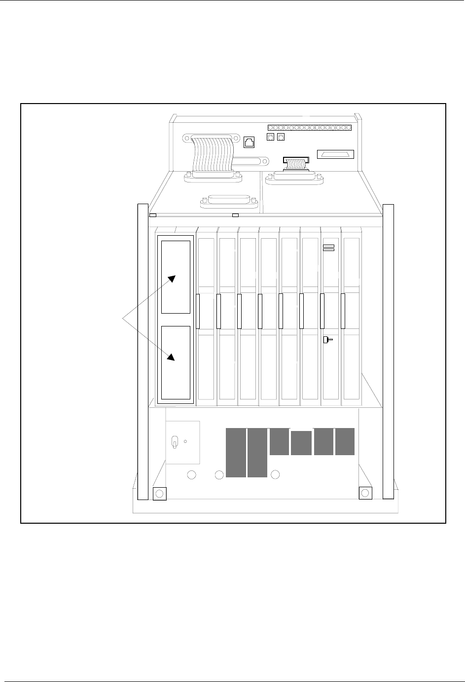
Figure 3-8. Battery location, DBS 40 .............................................................................. 3-10
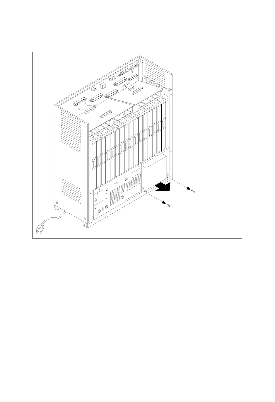
Figure 3-9. Battery tray, DBS 72 and 96 ......................................................................... 3-11
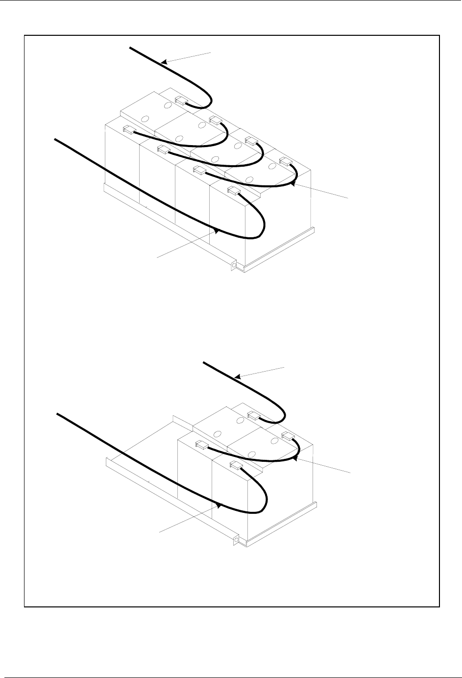
Figure 3-10. Battery pack connection, DBS 72 and 96 ..................................................... 3-12
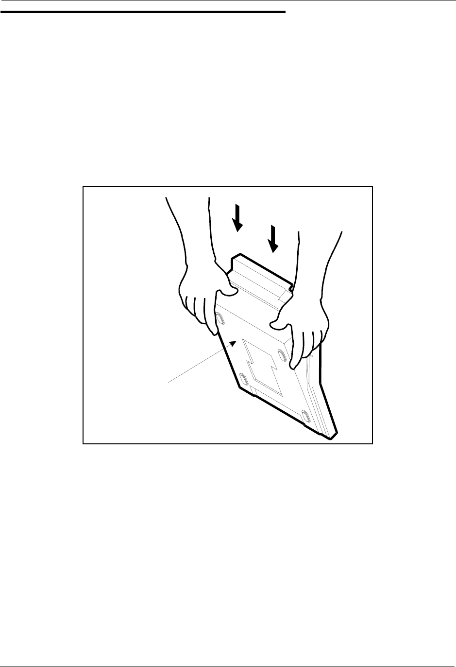
Figure 3-11. Wall-mount adaptor removal ........................................................................ 3-13
Figure 3-12. Wall-mount adaptor replacement .................................................................. 3-14
Figure 3-13. Handset guide insertion for wall-mounting, key phone ................................ 3-14
Figure 3-14. Desk stand removal for DSLT wall mounting .............................................. 3-15
Figure 3-15. Desk stand attachment for DSLT wall mounting ......................................... 3-16
Figure 3-16. Handset guide insertion for wall-mounting, DSLT ...................................... 3-16
Figure 3-17. CPC memory clear switch ............................................................................ 3-17
Figure 3-18. Test telephone connection ............................................................................ 3-19
Figure 4-1. DBS trunk connections (DBS 96) ................................................................... 4-3
Figure 4-2. L-TRK Card Strap J1 and Switch Locations ................................................. 4-7
Figure 4-3. Attaching Caller ID Card to the L-TRK Card ................................................ 4-8
Figure 4-4. -48Vpower supply installation ...................................................................... 4-10
Figure 4-5. Connector 4 (CN4) strapping, Sync Unit ...................................................... 4-21
Figure 4-6. T1 Sync Unit installation .............................................................................. 4-22
Figure 4-7. T1 MDF card installation .............................................................................. 4-23
Figure 4-8. Sync Unit and T1 connection, single-cabinet installation ............................ 4-24
Figure 4-9. RJ48 pinouts, CN1 connector ....................................................................... 4-25
Figure 4-10. T1 cabinet connections, single-cabinet installation ...................................... 4-26
Figure 4-11. Sync cable connections, double-cabinet with a T1 in the slave .................... 4-28
Figure 4-12. Clock sync cable and sync cable connections, double-cabinet installation .. 4-30
Figure 4-13. DBS extension connections .......................................................................... 4-31
Figure 4-14. SLT ringer box installation .......................................................................... 4-38
Figure 4-15. EMI filter installation (DBS 40 only) ........................................................... 4-40
Figure 4-16. DSS/72 connection using one cable with two pairs. ..................................... 4-42
Figure 4-17. EM/24 connection using one cable with two pairs ....................................... 4-43
Figure 4-18. Trunk or extension expansion ....................................................................... 4-45
Figure 5-1. RS-232C connection ...................................................................................... 5-4

List of Figures Section 300-Programming
viii DBS Manual - Revised April 2000 DBS-2.3/9.2-300
Figure 5-2. SMDR Format for CPC-AII and CPC-B Version 3.1 or higher ..................... 5-5
Figure 5-3. RAI connection............................................................................................... 5-7
Figure 5-4. Installation of music-on-hold and background music ..................................... 5-9
Figure 5-5. Cable punch-out plate, OPX Adaptor ........................................................... 5-11
Figure 5-6. OPX installation ............................................................................................ 5-13
Figure 5-7. External zone paging installation .................................................................. 5-15
Figure 5-8. External general page/UNA installation ....................................................... 5-16
Figure 5-9. External ringer (UNA device) installation .................................................... 5-18
Figure 5-10. Cable punch-out plate, Power Failure Unit .................................................. 5-20
Figure 5-11. Power Failure Unit (PFU) installation .......................................................... 5-21
Figure 5-12. Cable punch-out plate, Voice Announce Unit .............................................. 5-24
Figure 5-13. Extension cord connection to the VAU ....................................................... 5-25
Figure 5-14. Voice Announce Unit (VAU) installation ................................................... 5-25
Figure 5-15. Cable punch-out plate, Door Box Adaptor ................................................... 5-29
Figure 5-16. Installation of the door box, door opener, and door sensor .......................... 5-30
Figure 5-17. Cable punch-out plate, Door Box Adaptor ................................................... 5-31
Figure 5-18. Installation of the door box, door opener ...................................................... 5-32
Figure 5-19. Connections to the Door Box Adaptor ........................................................ 5-33
Figure 5-20. Cable punch-out plate, SLTA ....................................................................... 5-34
Figure 5-21. SLTA installation ......................................................................................... 5-36
Figure 6-1. Slot usage for two-cabinet systems, DBS 40 + DBS 40 ................................. 6-4
Figure 6-2. Slot usage for two-cabinet systems, DBS 72 + DBS 40 ................................. 6-5
Figure 6-3. Slot usage for two-cabinet systems, DBS 72 + DBS 72 ................................. 6-6
Figure 6-4. Slot usage for two-cabinet systems, DBS 96 + DBS 40 ................................. 6-7
Figure 6-5. Slot usage for two-cabinet systems, DBS 96 + DBS 72 ................................. 6-8
Figure 6-6. Slot usage for two-cabinet systems, DBS 96 to DBS 96 ................................ 6-9
Figure 6-7. Strap 3, MFR card ......................................................................................... 6-10
Figure 6-8. Double-cabinet installation ........................................................................... 6-11
Figure 6-9. CBL-S to Connector Panel connection, slave cabinet .................................. 6-11

Section 300-Installation List of Tables
DBS-2.3/9.2-300 DBS Manual - Revised April 2000 ix
List of Tables
Table 1-1. DBS model numbers ....................................................................................... 1-1
Table 1-2. FCC information ............................................................................................. 1-2
Table 1-3. Interface information ...................................................................................... 1-2
Table 2-1. Trunk and extension capacities according to system size ............................... 2-5
Table 2-2. Printed circuit card descriptions and maximums ............................................ 2-6
Table 2-3. Printed circuit package slot usage ................................................................... 2-8
Table 2-4. CPC/SCC features ........................................................................................... 2-9
Table 3-1. Battery backup packages for the DBS 40, 72, and 96 .................................... 3-9
Table 4-1. Main trunks and expansion trunks provided with each system type .............. 4-4
Table 4-2. Pinouts and trunk numbers for the main trunk connector.............................. . 4-5
Table 4-3. Pinouts and trunk numbers for trunk expansion connector CN1 .................... 4-6
Table 4-4. -48V current consumption for ground-start and DID trunks .......................... 4-9
Table 4-5. -48V power supplies tested with the DBS ..................................................... 4-9
Table 4-6. T1 Hardware requirements for single-cabinet systems ................................. 4-11
Table 4-7. T1 Hardware requirements for double-cabinet systems ............................... 4-12
Table 4-8. T1 slot usage for two-cabinet systems .......................................................... 4-13
Table 4-9. T1 and analog trunk assignments, DBS 40 ................................................... 4-14
Table 4-10. T1 and analog trunk assignments, DBS 72 ................................................... 4-14
Table 4-11. T1 and analog trunk assignments, DBS 96 ................................................... 4-15
Table 4-12. Maximum T1 assignments for two-cabinet systems ..................................... 4-15
Table 4-13. T1 and analog trunk assignments, DBS 40 + 40 (16-channel fractional T1 in the
slave) 4-16
Table 4-14. T1 and analog trunk assignments, DBS 72 + DBS 72 (24-channel T1 in the slave)
4-16
Table 4-15. T1 and analog trunk assignments, DBS 96 + DBS 40 (24-channel T1 in the master;
16-channel T1 in the slave) 4-17
Table 4-16. T1 and analog trunk assignments, DBS 96 + DBS 72 (24-channel T1 in the master;
24-channel T1 in the slave) 4-18
Table 4-17. T1 and analog trunk assignments, DBS 96 + DBS 96 (24-channel T1 in the master;
24-channel T1 in the slave) 4-19
Table 4-18. Extension ports provided with each system ................................................. 4-32
Table 4-19. Pinouts and color codes for extension connector CN12 ............................... 4-33
Table 4-20. Pinouts and color codes for extension connector CN13 ............................... 4-34
Table 4-21. Pinouts and color codes for extension connector CN14 ............................... 4-35
Table 4-22. Pinouts and color codes for extension expansion connector CN1 ................ 4-36
Table 5-1. RS-232C pin designations used for CN6 ........................................................ 5-3
Table 5-2. RAI compatibility ........................................................................................... 5-6
Table 5-3. Maximum distances for direct connection to OPX stations ........................ 5-10
Table 5-4. Switch settings for SW1, VAU ..................................................................... 5-22
Table 5-5. Switch settings for delay answer timing, VAU ........................................... 5-23
Table 5-6. Switch settings for DTMF detection timing, VAU ....................................... 5-23

List of Tables Section 300-Installation
x DBS Manual - Revised April 2000 DBS-2.3/9.2-300
Table 5-7. Switch settings for wait timing between dialed digits, VAU ....................... 5-23
Table 5-8. Switch settings for abbreviated dialing digit length, VAU ........................... 5-24
Table 5-9. Maximum distances for SLTA installation ................................................... 5-35
Table 6-1. Trunk and extension port maximums for double-cabinet systems ................. 6-3
Table 7-1. Input power ..................................................................................................... 7-3
Table 7-2. Power consumption and heat generation ........................................................ 7-3
Table 7-3. Battery backup capacity .................................................................................. 7-3
Table 7-4. Temperature and humidity requirements ........................................................ 7-4
Table 7-5. Dimensions and weight, single-cabinet systems and phones ......................... 7-4
Table 7-6. Dimensions for two-cabinet systems .............................................................. 7-4
Table 7-7. Trunk and line capacities ................................................................................ 7-5
Table 7-8. Feature-related capacities ............................................................................... 7-5
Table 7-9. Hardware maximums for single-cabinet systems .......................................... 7-7
Table 7-10. Hardware maximums for double-cabinet systems ........................................ 7-10
Table 7-11. Maximum cabling distances ......................................................................... 7-13
Table 7-12. Voice path from KTELs to DBS ................................................................... 7-14
Table 7-13. Data communications ports .......................................................................... 7-14
Table 7-14. Signaling to CO ............................................................................................ 7-15
Table 7-15. Signaling levels ............................................................................................. 7-15
Table 7-16. Transmission specifications .......................................................................... 7-15
Table 7-17. Tone Plan ...................................................................................................... 7-16
Table 7-18. DTMF frequencies ........................................................................................ 7-17

Section 300-Installation About This Manual
DBS-2.3/9.2-300 DBS Manual - Revised April 2000 xi
About This Manual
Purpose
This manual provides installation instructions for the Digital Business System
(DBS). The following table summarizes the purpose of each chapter.
Related Information
Appendix A and Appendix B, located in the back of this manual.
For instructions on DBS programming, see Programming Guidance (Section
400).
For detailed descriptions of DBS features, see Feature Operation (Section
700).
Chapter
No. Title Purpose
1 Requirements Includes DBS model numbers and FCC information that
may be required during installation. In addition,
environmental requirements are included to ensure proper
operation.
2 System Overview Provides an overview of the DBS. The overview includes
descriptions of the cabinet, system configurations, printed
circuit cards, and the call processor.
3 Cabinet Installation Explains how to install and power up the cabinet. Before
you begin installation, be sure to read Chapter 1 -
“Requirements.”.
4 Trunks and Lines Describes trunk and line installation. See the “Peripheral
Equipment” chapter for instructions on connecting
peripheral equipment through trunks or lines.
5 Peripheral
Equipment
Describes peripheral equipment installation. Some
peripheral equipment also requires trunk and/or line
interfaces (door phones or power failure units, for
example). For information on trunk and line connections,
see Chapter 4.
6 Double-Cabinet
Systems
Explains installation procedures for two-cabinet systems.
7 Specifications Contains frequently referenced DBS specifications.

About This Manual Section 300-Installation
xii DBS Manual - Revised April 2000 DBS-2.3/9.2-300
DBS-2.3/9.2-300 DBS Manual - Revised April 2000 1-1
Chapter 1. Requirements
This chapter includes DBS model numbers and FCC information that may be
required during installation. In addition, environmental requirements for proper
operation are included.
This chapter covers the following topics:
Model Numbers
Table 1-1. DBS model numbers
FCC Requirements
General Requirements
• The Federal Communications Commission (FCC) has established Rules
which permit the DBS to be directly connected to the telephone network.
Standardized jacks are used for these connections. This equipment should
not be used on party lines or coin lines.
• Key FCC information appears in the following table.
• Before connecting the DBS, provide the telephone company with the
following information
Topic Page
1-1
FCC Requirements 1-1
Environmental Requirements 1-4
Cleaning 1-5
DBS System Model Number
DBS 40 VB-43030
DBS 72 VB-43050
DBS 96 VB-43060

Section 300-Installation Chapter 1. Requirements
DBS-2.3/9.2-300 DBS Manual - Revised April 2000 1-2
Table 1-2. FCC information
Table 1-3. Interface information
• This equipment complies with Part 68 of the FCC Rules. On the left cover
panel of this equipment is a label that contains, among other information, the
FCC registration number and Ringer Equivalence Number (REN) for this
equipment. If requested, provided this information to your telephone
company.
• If the DBS telephone equipment caused harm to the Telephone Network, the
Telephone Company may discontinue your service temporarily. If possible,
they will notify you in advance. But if advance notice isn’t practical, you
will be notified as soon as possible. You will be advised of your right to file
a complaint with the FCC.
• Under the FCC Rules, no customer is authorized to repair this equipment.
This restriction applies regardless of whether the equipment is in or out of
Item Specification
FCC Registration
Number When used as a key system: ACK4A4-60490-KF-E
When used as a PBX: ACK4A4-60489-MF-E
Ringer Equivalence 0.5B *
Network Address
Signaling Code
E
* The ringer equivalence number (REN) is useful to determine the quantity of
devices that you may connect to your telephone line and still have all of those
devices ring when your number is called. In most areas, the sum of the RENs
of all devices on any one line should not exceed five (5.0). To be certain of
the number of devices you may connect to your line, as determined by the
REN, you should call your telephone company to determine the maximum
REN for your calling area.
Port Type Type of
Interface USOC Jack
Connector Service
Order Code* Facility Interface
Code
Loop Start
Trunk 2-wire loop RJ21X 9.0F 02LS2
Ground Start
Trunk 2-wire ground RJ21X 9.0F 02GS2
DID Trunk 2-wire DID RJ21X 9.0F 02RV2-T
T1 Trunk T1 RJ48C 6.0F 04DU9-DN,
04DU9-1SN
OPX Adaptor OPX RJ21X (at
DBS DBS) 9.0F 0L13A
0L13B
0L13C (recommended)

Chapter 1. Requirements Section 300-Installation
1-3 DBS Manual - Revised April 2000 DBS-2.3/9.2-300
warranty. However, the customer may replace fuses, and plug-in cards, as
needed.
• The Telephone Company may make changes in its facilities, equipment,
operations or procedures, that could affect the proper operation of your
equipment. If they do, you will be given advance notice so as to give you an
opportunity to maintain uninterrupted service.
• The Digital Key Telephones designed for use with this system are hearing
aid compatible.
• This equipment is capable of providing users access to interstate providers
of operator services through the use of access codes. Modification of this
equipment by call aggregators to block access dialing codes is a violation of
the Telephone Operator Consumers Act of 1990.
• If you experience trouble with the DBS, please contact Panasonic
Communication & Systems Company, Business Telephone Systems Division,
Two Panasonic Way Panazip 7B-3, Secaucus, NJ 07094 (Phone: (1-800-822-
0909) for repair/warranty information. Upon establishing contact, properly
identify the equipment, along with your company name/service center, and
address. The telephone company may ask you to disconnect this equipment from
the network until the problem has been corrected.
• The software contained in the DBS to allow user access to the network
must be upgraded to recognize newly established network area codes and
exchange codes as they are placed in service.
- Failure to upgrade the premises systems of peripheral equipment
to recognize the new codes as they are established will restrict
the customer and the customer’s employees from gaining access
to the network and to these codes.
- Bell Communications Research (Bellcore) publishes the North
American Numbering Plan (NANP) information in paper,
microfiche and tape. An abbreviated summary of the newly
established area codes and exchange codes is also available.
Bellcore may be contacted on (908) 699 6700 to obtain
appropriate information to keep customer equipment upgraded.
DID Requirements
Allowing this equipment to be operated in such a manner as to not provide for
proper answer supervision is a violation of Part 68 of the FCC Rules.
Proper answer supervision is when:
A. This equipment returns answer supervision to the PSTN when DID calls are:
- Answered by the called station

Section 300-Installation Chapter 1. Requirements
DBS-2.3/9.2-300 DBS Manual - Revised April 2000 1-4
- Answered by the attendant
- Routed to a recorded announcement that can be administered by
the CPE user
- Routed to a dial prompt.
B. This equipment provides answer supervision on all DID calls forwarded to
the PSTN. Permissible exceptions are:
- A call is unanswered
- A busy tone is received
- a reorder tone is received
T1 Requirements
This device must only be connected to the T1 network connected behind an
FCC Part 68 registered channel service unit. Direct connection is not allowed.
Environmental Requirements
Temperature: The environment should be free from excessive temperatures in
order to avoid component damage. Room temperatures should be 32 to 104° F
(0 to 40° C).
Humidity: The environment should be free from excessive humidity, which
may rust metallic parts and degrade performance. Do not install the system
where humidity could condense on its surfaces. Relative humidity ranges
should be between 30 and 90 percent.
Ventilation: Adequate ventilation must be provided to allow upward air
circulation through the cabinet grille.
Gas and airborne particles: To avoid corrosion or oxidation of electrical
contacts, the environment should be free from airborne particles and corrosive
gas.
Electrical noise: The environment should be free from excessive electrical
noise, which could disturb the operation of digital circuits. The system should
be located at least 10 ft. (3 m) away from welders, dimmers, or other high-
current machines. Phones connected to the system should not be located near
fluorescent lamps, air conditioners, washing machines, TVs, or radios.
Vibration: The environment should be free from excessive vibration, which
could loosen components.
Water Exposure: Because the DBS is an electric device, exposure to water is
dangerous. Do not place anything containing water on the system. Do not install

Chapter 1. Requirements Section 300-Installation
1-5 DBS Manual - Revised April 2000 DBS-2.3/9.2-300
under overhead plumbing, sprinkler system valves, or in areas that are
susceptible to flooding.
Lighting: Sufficient lighting is required for testing and maintenance.
Lightning Protection/Grounding: The system must be properly grounded to
protect from lightning damage. The following UL conditions must be met to
ensure proper grounding. (For grounding instructions, see page 3-5.)
• Supplemental and independent equipment grounding conductors are to be
installed between the system and the wiring system ground.
• One of the equipment grounding conductors must be a conductor that is as
large or larger than the ungrounded branch-circuit supply conductors. The
equipment grounding conductor is to be installed as part of the circuit that
supplies the system and is to be connected to ground at the service
equipment. Bare, covered, or insulated grounding conductors are acceptable.
Individually covered or insulated grounding conductors should have a
continuous outer finish that is either green or green with one or more yellow
stripes. The equipment grounding conductor should be connected to ground
at the service equipment.
• The other equipment grounding conductor shall comply with the general
rules for grounding contained in Article 250 of the National Electric Code,
NFPA 70, but its connection to ground shall not depend on the cord and plug
of the system.
• The attachment-plug receptacles of the same type as that used by the
systems that are in the vicinity of the DBS are all to be of a grounding type,
and the equipment grounding conductors serving these receptacles are to be
connected to earth ground at the service equipment.
• A marking adjacent to the telecommunications jacks must instruct the user
to connect a supplementary equipment grounding conductor before any
telecommunication lines are connected to the product or system.
Cleaning
•Use a slightly damp cloth to clean the phones. The phones should never be
cleaned with benzene, paint thinner, or other solvents.

Chapter 1. Requirements Section 300-Installation
1-6 DBS Manual - Revised April 2000 DBS-2.3/9.2-300

DBS-2.3/9.2-300 DBS Manual - Revised April 2000 2-1
Chapter 2. System Overview
This chapter gives an overview of the Digital Business System (DBS). This
overview includes descriptions of the DBS cabinet, system configurations,
printed circuit cards, and the call processor.
This chapter covers the following topics::
Topic Page
Cabinet Description 2-3
Configurations 2-5
Printed Circuit Cards 2-6
Processor Description 2-9

2-2 DBS Manual - Revised April 2000 DBS-2.3/9.2-300
Section 300-Installation Chapter 2. System Overview
DBS-2.3/9.2-300 DBS Manual - Revised April 2000 2-3
Cabinet Description
Panasonic’s Digital Business System (DBS) is a hybrid telephone system that
can be used as a key service unit (KSU) or a private branch exchange (PBX).
The DBS cabinet includes an AC power supply, backup batteries (optional),
dedicated card slots, and a central connector panel for line and trunk
connections.
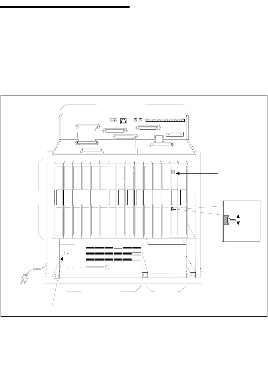
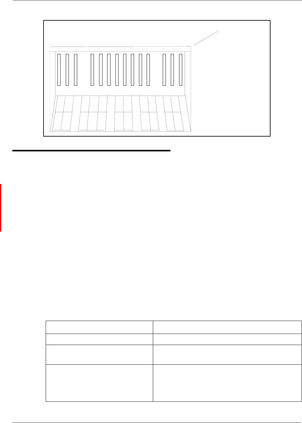
Figure 2-1. The DBS cabinet (DBS 96 shown)
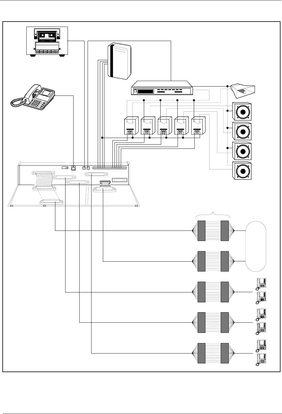
In addition to trunk and line connection, the connector panel is used to
connect peripheral equipment such as paging speakers, external ringers, and
music-on-hold/background music sources. Figure 2-2 on page 2-4 shows
trunk and line connections, as well as some peripheral connections.
Peripheral connections are covered in detail in Chapter 5, “Peripheral
Equipment.”
CN11
CN12 CN13 CN14 CN15 CN6
SW 1 CN3
TRK1 TR K2 TRK3 EC1 EC2 EC3 EC4 EC5 EC6 EC7 EC8 EC/TR K SCC CPC AU X1 AU X2
CN5 CN4 CN2
CN1
CN1
C onnector Panel
Card
Slots
Power Supply
Power Switch
Batteries
STATUS
LED
RAM HOLD
RAM CLR
Chapter 2. System Overview Section 300-Installation
2-4 DBS Manual - Revised April 2000 DBS-2.3/9.2-300
Figure 2-2. Trunk, line, and peripheral connections
A
#00 #01 #04#02 #03
Tape R ecorder
forM usic-On-Hold
and B ackground M usic
Test
Phone
SLT RingerBox
(VB-2089P )
Am plifier
CN11
CN12 CN5
CN13
CN3
CN14CN15
CN1
CN1
CN2
CN4
Trunk Ports
1-24
Trunk Ports
25 -32
MDF
Extension Ports
1-24
Extension Ports
25 -48
Extension Ports
49 -72
All-Page
Speaker
Zone P ag
e
#01
Zone P ag
e
#02
Zone P ag
e
#04
Relays
Zone P ag
e
#03
CO

Section 300-Installation Chapter 2. System Overview
DBS-2.3/9.2-300 DBS Manual - Revised April 2000 2-5
Configurations
The DBS comes in three models, which provide from 40 to 96 ports. Up to
two systems can be combined to increase port capacity up to 192 ports (DBS
96 + DBS 96).
In addition to dedicated trunk and extension slots, each system includes one
expansion slot (labeled EC/TRK) that can be used for either trunks or
extensions. The following table shows port capacities for individual systems
and for different combinations of systems.
Table 2-1. Trunk and extension capacities according to system size
System Size Trunk
Ports Extension
Ports Expansion Ports
(Trunks or Extensions)
DBS 40 8 24 8
DBS 72 16 48 8
DBS 96 24 64 8
DBS 40 + DBS 40 16 48 8 (See Note 1.)
DBS 72 + DBS 40 24 72 0 (See Note 2.)
DBS 72 + DBS 72 32 96 8 (See Note 1.)
DBS 96 + DBS 40 32 88 16
DBS 96 + DBS 72 40 112 16
DBS 96 + DBS 96 48 128 16
Notes:
1. The slave cabinet must be used for expansion ports.
2. When a DBS 72 and DBS 40 are connected, expansion ports cannot be used.

Chapter 2. System Overview Section 300-Installation
2-6 DBS Manual - Revised April 2000 DBS-2.3/9.2-300
Printed Circuit Cards
The following table describes the printed circuit cards and other equipment
that can be used with the DBS. Also included are brief descriptions of each
card and the maximum number that can be installed in each cabinet.
Table 2-2. Printed circuit card descriptions and maximums
Part No. Printed Circuit Cards and Other
Equipment Quantity
DBS 40 DBS 72 DBS 96
VB-43110 Cable kit for 2-system connection N/A N/A N/A
VB-43410 Call processor card (CPC-A)
111VB-43411 Call processor card (CPC-B)
VB-43412 Call processor card (CPC-AII)
VB-43420 Service circuit card (SCC-A) 111
VB-43421 Service circuit card (SCC-B)
VB-43431 DTMF signal receiver for 8 SLT lines
(MFR/8) 111
VB-43510A 4-port loop-start trunk card (L-TRK/4)
234
VB-43511A 8-port loop-start trunk card (L-TRK/8)
VB-43541 8-port Direct-inward-dialing trunk card
(DID)
VB-43531 8-port ground-start trunk card (G-TRK/8)
VB-43561 T1 Interface 1 1 1
VB-43562 T1 MDF card 1 1 1
VB-43563 T1 Sync Unit 1 1 1
VB-43611 8-port digital extension card (DEC) 4 7 9
VB-43621A 8-port analog extension card (AEC) 3 4 4
Expansion Connectors
VB-43120 Trunk expansion connector 111
VB-43121 Extension expansion connector
Doorbox Equipment (Trunk)
VB-43701 2-port Door box adaptor 8* 12* 16*
VB-43705 Door box 16* 24* 32*
Doorbox Equipment (Extension)
VB-43711 1-port Extension-Based Door box adaptor 4 4 4
VB-43705 Door box 4 4 4

Section 300-Installation Chapter 2. System Overview
DBS-2.3/9.2-300 DBS Manual - Revised April 2000 2-7
Optional Equipment
VB-43706 Remote Administration Interface (RAI-A) 111
VB-43707 Remote Administration Interface (RAI-B)
VB-43551 8-circuit Caller ID daughter board 1 per VB-
43511A AEC 1 per VB-
43511A AEC 1 per VB-
43511A AEC
VB-43130 Built-in system backup battery kit 1 1 1
VB-43709 Single Line Telephone Adaptor 8 14 18
VB-2089P SLT ringer box 1 1 1
VA-43703 4-line power failure unit 6 8 8
VB-43702 Off-premise extension adaptor 8 8 8
VB-43940 Standard Application processor interface
(API) 111
VB-43941 Telephony Services Kit (includes revised
API card, described in Telephone Services
Documentation) 111
* Note: These maximums are based on overall trunk capacities and do not allow for trunks used
for outside lines.
Part No. Printed Circuit Cards and Other
Equipment Quantity
DBS 40 DBS 72 DBS 96

Chapter 2. System Overview Section 300-Installation
2-8 DBS Manual - Revised April 2000 DBS-2.3/9.2-300
Printed circuit cards are installed in dedicated slots in the DBS cabinet.
Table 2-3 shows the cards that can be installed in each slot. Figure 2-3 on
page 2-9 illustrates slot labels.
Table 2-3. Printed circuit package slot usage
Card Type Card Acceptable Slots
Analog
Trunks
L-TRK/4
TRK or EC/TRK
L-TRK/8
G-TRK/8
DID/8
Digital Trunks T1/24 EC/TRK
Digital Lines DEC/8 EC 1-8 or EC/TRK
Analog Lines AEC/8 EC 2-8 or EC/TRK
Service
Circuits
SCC-A SCC
SCC-B
Processor Cards CPC-A CPC
CPC-B
CPC-AII
DTMF Circuits MFR/8 AUX1 or AUX2
CPC (See Note 1.)
Interface Cards API (1 or 2 Circuits) AUX1 or AUX2 (See Note 2.)
CBL-M CPC or AUX2 (See Note 3.)
CBL-S
Notes:
1. With one-cabinet systems, the MFR card can be installed in the AUX1 or AUX2 slot,
depending on whether an API card is used. With two-cabinet systems, placement of the MFR
cards differs according to the cable kit used. With Cable Kit Version 1.1, one MFR is installed
in the Master AUX1, and one MFR is installed in the Slave AUX1. With Cable Kit Version
1.2, both MFR cards are installed in the slave cabinet--one in the CPC slot and one in AUX1.
(See page 6-10 for instructions on installing MFR cards in double-cabinet systems.)
2. The API card is installed in AUX1 only when a CBL card is used.
3. Part VB-43110 includes both the CBL-M and CBL-S cards, as well as the required connect-
ing cables. CBL-M is installed in the master cabinet, CBL-S in the slave cabinet.
Section 300-Installation Chapter 2. System Overview
DBS-2.3/9.2-300 DBS Manual - Revised April 2000 2-9
Figure 2-3. Slot labels for printed circuit packages
Processor Description
DBS call-processing is controlled by the Call Processor Card (CPC). Four
CPC models are available: CPC-A, CPC-B, CPC-AII, and CPC-EX. For a
complete list of hardware enhancements available with the CPC-B, CPC-AII,
and CPC-EX, please see Appendix A and Appendix B, located in the back of
this manual. See the Appendix in Section 700 - Feature Operation for a
complete list of feature enhancements associated with each of these CPCs.
In most cases, the features provided with the DBS depend on the model and
software version of the CPC. However, the availability of some features also
depends on the model and version of the Service Circuit Card (SCC).
The following table shows some of the major differences between CPC/SCC
features. Other differences are noted throughout this manual when they apply
to specific installation instructions. For more details on the features provided
with each processor, see Feature Operation, Section 700.
Table 2-4. CPC/SCC features
Feature CPC/SCC Requirements
Double cabinet system CPC-B, Version 1.0 or greater plus SCC-B
DID CPC-B, Version 2.0 or greater plus SCC-B,
Version 1.2 or greater
T1 Interface CPC-B, Version 4.0 or greater plus SCC-B.
(The CPC-B must have BPU 1.3 or later. The
SCC-B ROM 1.3 or later is required if the CO
does not provide dial tone.)
TRK1 TR K2 TRK3 EC1 EC2 EC3 EC4 EC5 EC6 EC7 EC8 EC/TRK SCC CPC AUX1 AUX2
Slot Label
s
(D BS 96)

Chapter 2. System Overview Section 300-Installation
2-10 DBS Manual - Revised April 2000 DBS-2.3/9.2-300

DBS-2.3/9.2-300 DBS Manual - Revised April 2000 3-1
Chapter 3. Cabinet Installation
This chapter explains how to install and power up the cabinet. Before you
begin installation, be sure to read the “Requirements” chapter, which begins
on page 1-1.
This chapter covers the following topics::
Topic Page
Wall-Mounting the Cabinet 3-3
Grounding 3-5
Card Installation 3-6
Battery Backup 3-9
Key Phone Wall Mounting 3-13
DSLT Wall Mounting 3-15
System Initialization 3-17
Test Phone 3-18

3-2 DBS Manual - Revised April 2000 DBS-2.3/9.2-300
Section 300-Installation Chapter 3. Cabinet Installation
DBS-2.3/9.2-300 DBS Manual - Revised April 2000 3-3
Wall-Mounting the Cabinet
Guidelines
• The DBS is shipped with the cover installed to protect components. Before
wall-mounting the cabinet, remove the cover.
• Handle the cabinet carefully to avoid damage.
Installation
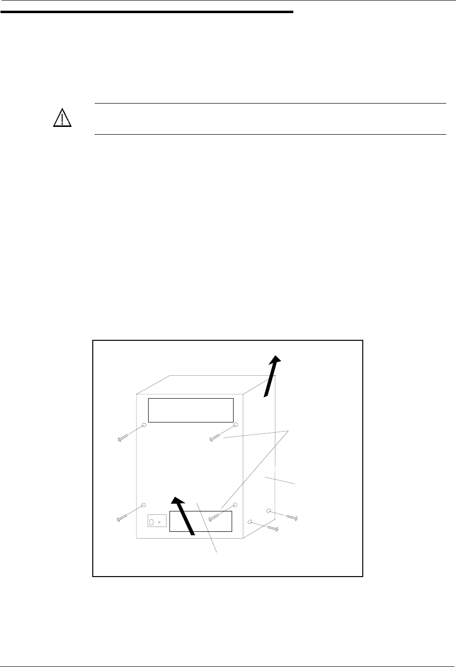
1. Remove the eight screws from the front and sides of the cabinet.
2. Take the front cover off by pulling it from the bottom and lifting it up.
3. Take the side covers off by sliding them up, then away.
Figure 3-1. Cover removal
Caution: Always turn the power switch OFF before beginning installa-
tion.
Screw s
Front C over
Side C ove
r
Chapter 3. Cabinet Installation Section 300-Installation
3-4 DBS Manual - Revised April 2000 DBS-2.3/9.2-300
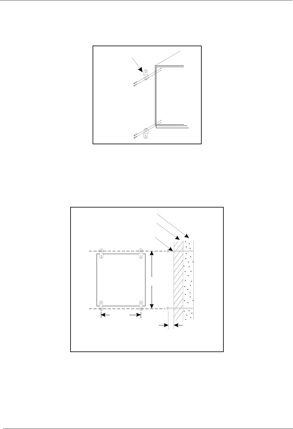
4. Attach the mounting brackets to the four corners of the back side of the
cabinet.
Figure 3-2. Cabinet mounting bracket
5. Install four screws in the wall studs according to the dimensions given in
Figure 3-3. (Note that the width dimension is different for the DBS 40.)
The screws are used to attach the mounting brackets to the wall. The
screws should protrude from the wall 5/16 in.
Figure 3-3. Cabinet wall-mounting
6. Hang the cabinet on the wall by placing the mounting brackets over the
screws.
7. Tighten the screws to secure the cabinet.
Metal M ounting
Bracket
MainCabinet
Back Side
17 5/8"
(DBS 72,96)
13 7/16"
(D B S 40)
22 3/16"
5/16"
Wall
Stud
Screw
(# 1 0 -1 3 /4)
Section 300-Installation Chapter 3. Cabinet Installation
DBS-2.3/9.2-300 DBS Manual - Revised April 2000 3-5
Grounding
Guidelines
• Before grounding the DBS, read the “Lightning Protection/Grounding”
requirements beginning on page 1-6.
• The ground cable must be at least 18 AWG.
• Resistance to ground must be 10 Ohms or less.
Installation
1. Attach the ground cable to the ground screw on the front of the power
supply.
2. Connect the ground cable to the building ground.
Figure 3-4. Cabinet ground screw
CN11
CN12 CN13 CN14 CN6
SW 1 CN3
TRK1 TRK2 TRK3 EC1 EC2 EC3 EC4 EC5 EC6 EC7 EC8 EC/TRK SCC CPC AUX1 AUX2
CN5 CN4 CN2
CN1
Ground Screw
Chapter 3. Cabinet Installation Section 300-Installation
3-6 DBS Manual - Revised April 2000 DBS-2.3/9.2-300
Card Installation
Guidelines
• Install the cards in the following order:
- TRK
- DEC
- AEC or API
- SCC
- CPC
- MFR or CBL
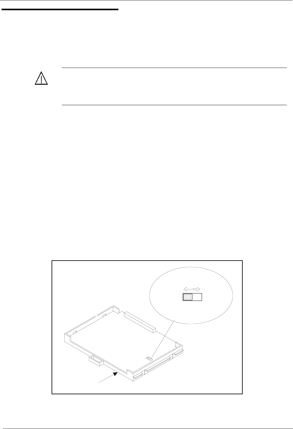
• If you are installing a CPC-A or CPC-AII card with an SCC-B card, set
SW4 to “Mode A.” The default setting is “Mode B,” which specifies that
CPC-B is used.
Figure 3-5. SCC-B Switch 4
Caution: Before handling printed circuit cards, discharge static electric-
ity by grounding yourself. Static electricity can damage components.
Turn off the power before installiing. Installing cards with the power on
can damage components.
(C P C -B
CPC-EX) (C P C -A
CPC-AII)
SW 4
SCC-B Card
ModeB ModeA
Section 300-Installation Chapter 3. Cabinet Installation
DBS-2.3/9.2-300 DBS Manual - Revised April 2000 3-7
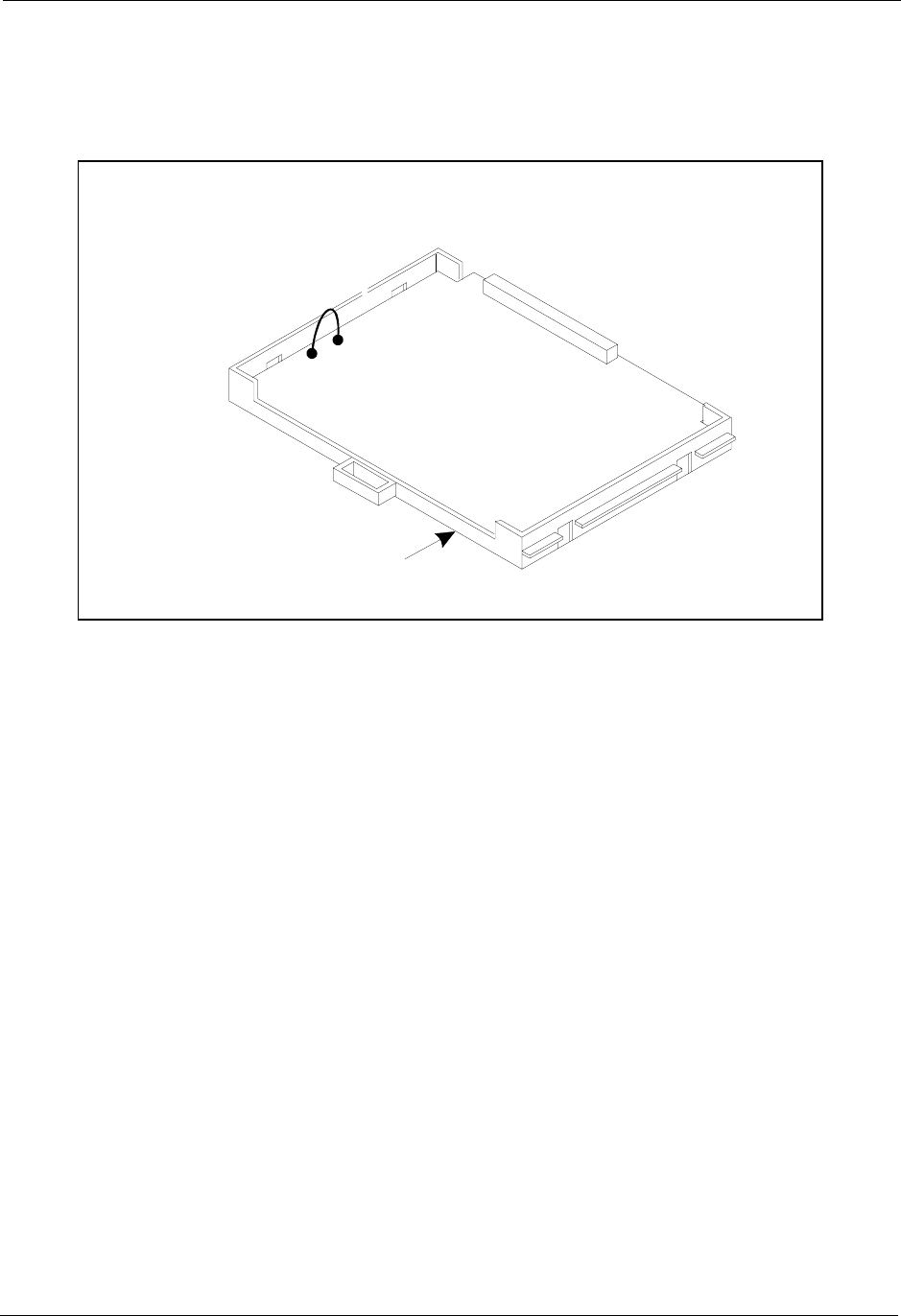
• Before installing the CPC card, determine if the DBS will be used as a
KSU or PBX. To use it as a PBX, cut Strap S1 on the CPC. Cutting this
strap allows use of pooled trunks as opposed to line appearances.
Figure 3-6. CPC Strap S1
• Install cards only in their dedicated slots. The slot type is marked on the
cabinet directly above each slot.
CPC-AIIor
CPC-B
S1
CutS1forPooled Trunks (PBX Operation)
DoNotCutS1forLine Appearances (KS U O peration)
Chapter 3. Cabinet Installation Section 300-Installation
3-8 DBS Manual - Revised April 2000 DBS-2.3/9.2-300
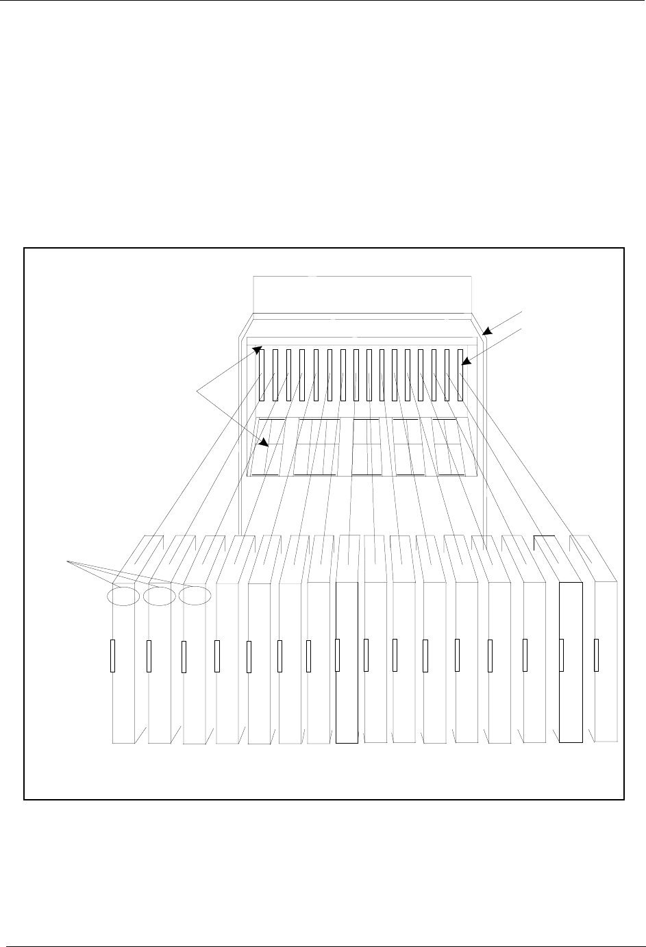
Installation
1. With the lettering on the card pointed up, position the card within the slot
guides. (See Figure 3-7.)
2. Hold the card on the top and bottom edges with both hands and carefully
push the card into the slot.
3. When the connector at the far end of the card touches the corresponding
connector on the backplane, press the card in until it is firmly seated.
Figure 3-7. Printed circuit card installation
TR K1 TR K2 TR K 3 EC1 EC2 EC 3 EC 4 EC5 EC 6 EC 7 EC8 EC/TRK SCC CPC AUX1 AUX2
TRK TRK TRK EC*EC EC EC EC EC EC EC TRK
or
T1
or
EC
SCC CPC
or
MFR#
MFR
or
API
API
or
CBL
or
MFR
Guide
Slot Label
C onnector
Card
Label
The M FR cardcanbeinstalled inthe C PC slotofslave cabinets.
*
Section 300-Installation Chapter 3. Cabinet Installation
DBS-2.3/9.2-300 DBS Manual - Revised 5/22/97 3-9
Battery Backup
Guidelines
• The DBS 40 uses two 12-volt batteries; the DBS 72 and 96 use four 6-volt
batteries or two 12-volt batteries. The following table includes the part
numbers for the battery packages.
Table 3-1. Battery backup packages for the DBS 40, 72, and 96
• The backup batteries are connected in a series circuit, using cables
provided with the DBS.
• With maximum traffic, the backup batteries last up to 40 minutes for the
DBS 40 and 72, and up to 30 minutes for the DBS 96.
• The backup batteries should be replaced about every 3 years.
System Battery Backup Part No.
DBS 40 VB-43130 (some systems may be
equipped with VB-2450A-2P)
DBS 72 and 96 VB-43130 (some systems may be
equipped with VB-2650-2P)
THE PRODUCT YOU HAVE PURCHASED MAY CONTAIN SEALED LEAD
ACID BATTERIES WHICH ARE RECYCLABLE. AT THE END OF THEIR
USEFUL LIFE, UNDER VARIOUS STATE AND LOCAL LAWS, IT IS ILLEGAL
TO DISPOSE OF THESE BATTERIES INTO YOUR MUNICIPLE WASTE
STREAM. PLEASE CALL 1-800-SAV-LEAD FOR INFORMATION ON HOW TO
RECYCLE THESE BATTERIES.
Chapter 3. Cabinet Installation Section 300-Installation
3-10 DBS Manual - Revised April 2000 DBS-2.3/9.2-300
Installation for the DBS 40
1. Place one battery in the top tray of the battery compartment, the other
battery in the bottom tray.
Figure 3-8. Battery location, DBS 40
2. Connect the positive cable (red) to the + terminal of the top battery.
3. Connect the connecting cable (white) to the - terminal of the top battery.
4. Connect the negative cable (blue) to the - terminal of the bottom battery.
5. Connect the connecting cable (white) from the top battery to the +
terminal on the bottom battery.
CN12
Batteries
CN11
CN4
CN3
EC2 EC3EC1 SCCTRK1 CPC AUX2EC/TRK AUX1
CN2
CN15 CN6
CN1
CN1
CN5
Section 300-Installation Chapter 3. Cabinet Installation
DBS-2.3/9.2-300 DBS Manual - Revised April 2000 3-11
Installation for the DBS 72 and 96
1. Slide the battery compartment out and place the batteries inside the tray.
Figure 3-9. Battery tray, DBS 72 and 96
2. Connect the positive cable (red) to the + terminal on the first battery.
3. Connect the negative cable (blue) to the - terminal on the last battery.
4. Connect the remaining positive and negative terminals with the white
connection cables, as shown in Figure 3-10.
Rem ove Screw s
and Slide Batter
y
Tray O ut
Chapter 3. Cabinet Installation Section 300-Installation
3-12 DBS Manual - Revised April 2000 DBS-2.3/9.2-300
Figure 3-10. Battery pack connection, DBS 72 and 96
-
+
-
+
-
+
-
+
-
+
-
+
White
C onnection
Cables
Four 6-Volt Batteries
(O ld e r V e rs io n )
VB-2650-2P
T w o 1 2 -V o lt B a tte rie s
(N ew er Version)
VB-43130
White
C onnectio
n
Cables
Blue C onnection C able
FrontN egative
Blue C onnection C able
FrontN egative
Red C onnection C able
Back Positive
Red C onnection C able
Back Positive
Section 300-Installation Chapter 3. Cabinet Installation
DBS-2.3/9.2-300 DBS Manual - Revised April 2000 3-13
Key Phone Wall Mounting
DBS key phones can be modified for wall mounting by reversing the wall-
mount adaptor on the bottom of the phone. The wall-mount adaptor includes a
small hole for attaching the phone to a screw inserted in the wall.
1. Place the bottom edge of the telephone on a desk or other hard surface.
2. Press the wall-mount adaptor down until it detaches from the phone
(Figure 3-11).
Figure 3-11. Wall-mount adaptor removal
Wall-Mount
Adaptor
Chapter 3. Cabinet Installation Section 300-Installation
3-14 DBS Manual - Revised April 2000 DBS-2.3/9.2-300
3. Turn the wall-mount adaptor around and re-attach it to the phone.
Figure 3-12. Wall-mount adaptor replacement
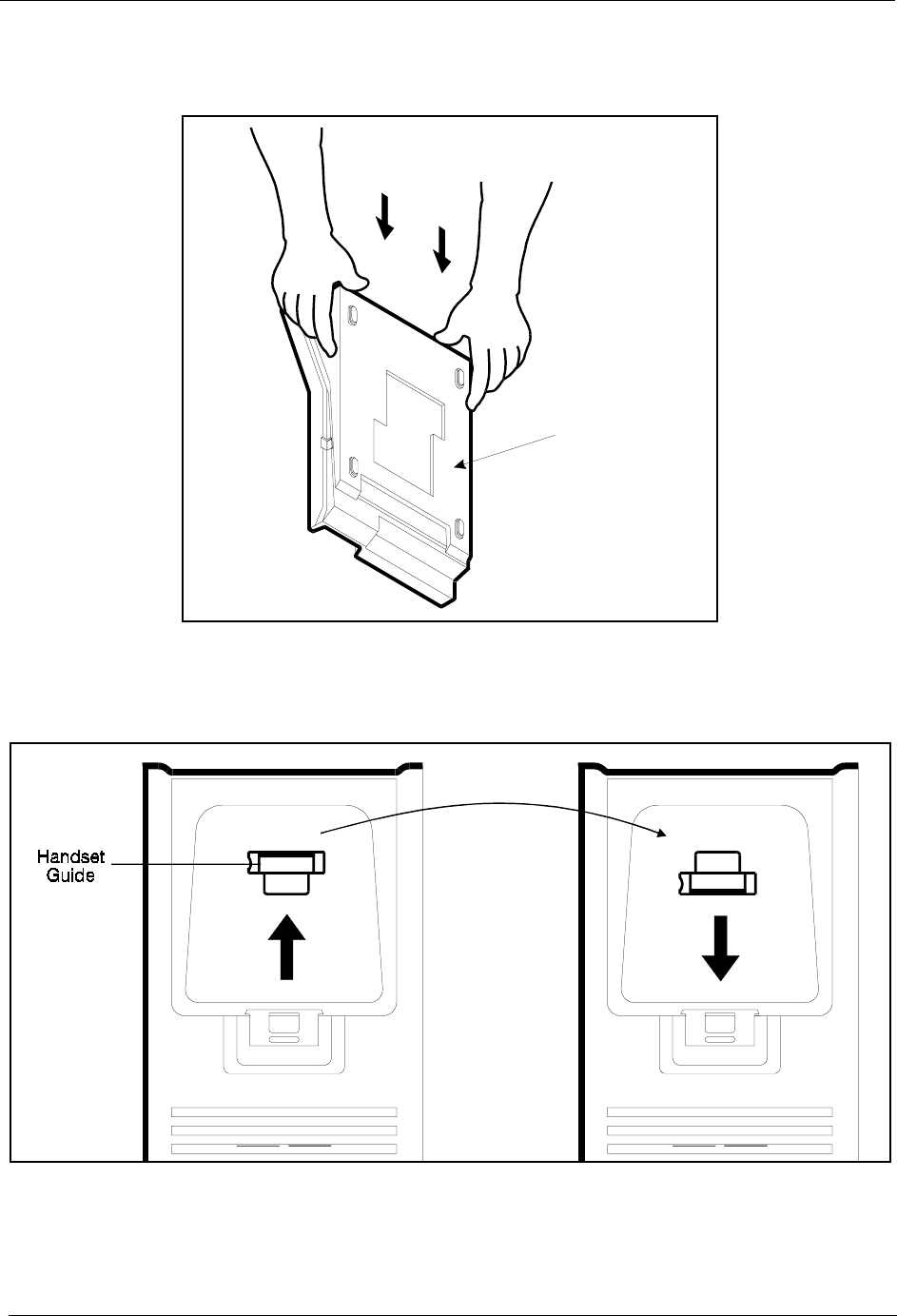
4. Remove the handset guide with a small screwdriver, turn it over, and
reinsert it into the phone.
Figure 3-13. Handset guide insertion for wall-mounting, key phone
Wall-M ount
Adaptor
Section 300-Installation Chapter 3. Cabinet Installation
DBS-2.3/9.2-300 DBS Manual - Revised April 2000 3-15
DSLT Wall Mounting
Digital Single-Line Telephones (DSLTs) can be modified for wall mounting
by removing the desk stand and mounting it on the bottom of the phone. The
back of the DSLT and the desk stand include slots for attaching the phone to a
screw inserted in the wall.
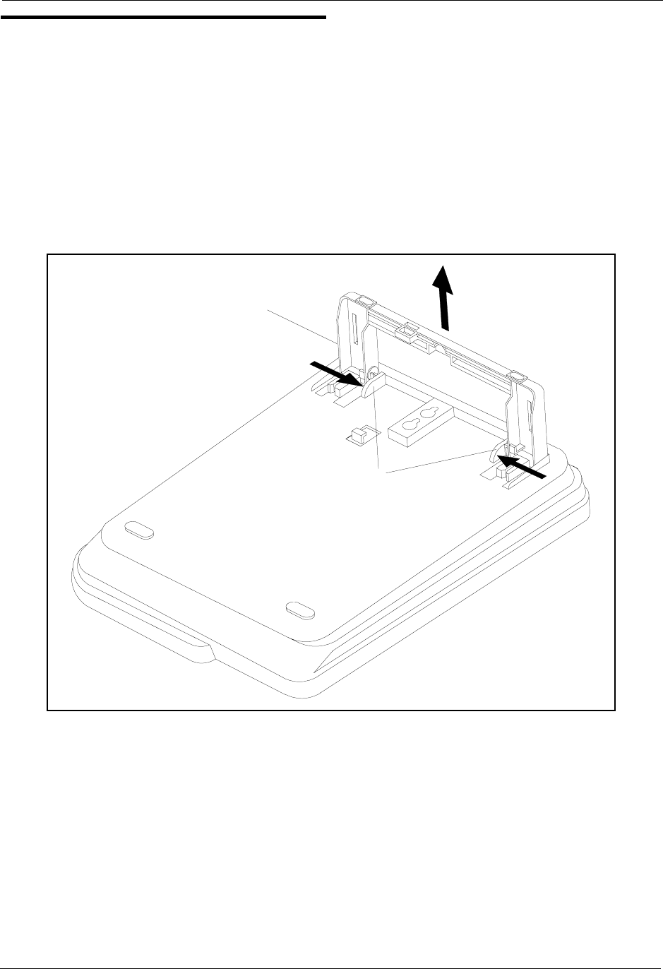
1. Press the stand releases in toward the middle of the phone to release the
desk stand (Figure 3-14).
Figure 3-14. Desk stand removal for DSLT wall mounting
Desk
Stand
Stand
Releases
Chapter 3. Cabinet Installation Section 300-Installation
3-16 DBS Manual - Revised April 2000 DBS-2.3/9.2-300
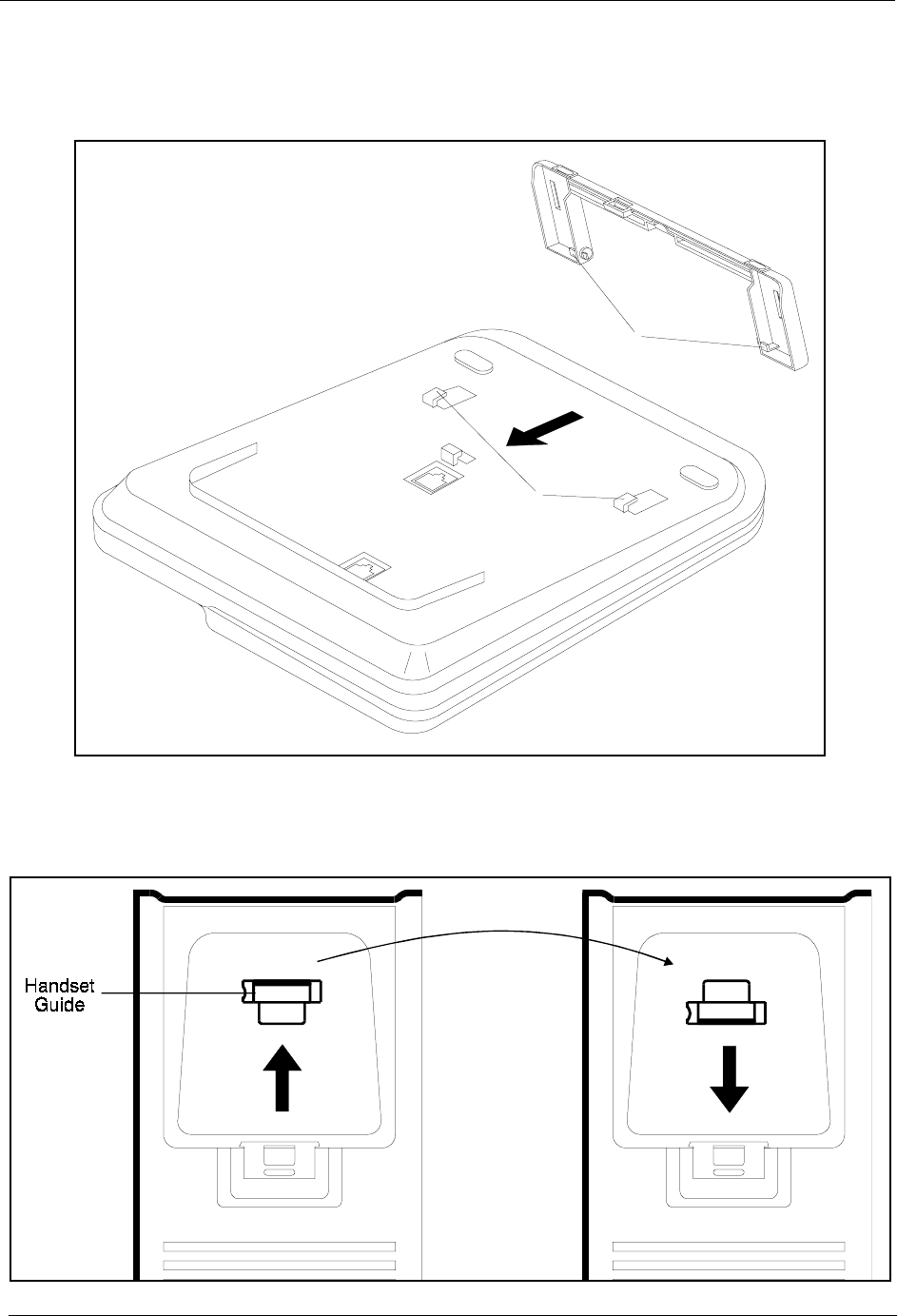
2. Attach the desk stand to the bottom of the phone by aligning the tabs and
tab guides and sliding it into place (Figure 3-15).
Figure 3-15. Desk stand attachment for DSLT wall mounting
3. Remove the handset guide with a small screwdriver, turn it over, and
reinsert it into the phone.
Figure 3-16. Handset guide insertion for wall-mounting, DSLT
Tab
Guides
Tabs
Section 300-Installation Chapter 3. Cabinet Installation
DBS-2.3/9.2-300 DBS Manual - Revised April 2000 3-17
System Initialization
1. Confirm that the DBS power switch is OFF.
2. Plug the power cord into a dedicated 120V 15 amp AC wall outlet.
Note: A surge protector should be installed on the power cord.
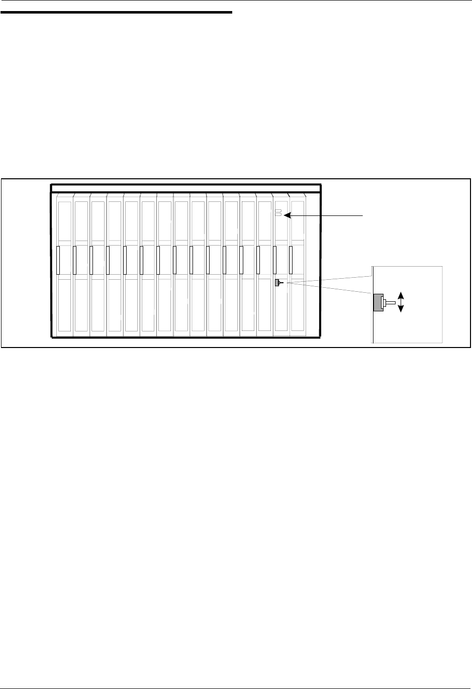
3. Set SW1 on the CPC card to RAMCLR (RAM Clear).
Figure 3-17. CPC memory clear switch
4. Turn the power switch on.
As the system loads, the bottom LED lamp on the CPC card will flash.
5. Once the bottom LED lamp on the CPC card stops flashing, set SW1 on
the CPC to RAMHOLD.
RAM HOLD
TRK1 TRK2 TRK3 EC1 EC2 EC3 EC4 EC5 EC6 EC7 EC8 EC/TRK SCC CPC AUX1 AUX2
STATUS
LED
SW 1
RAM CLR

Chapter 3. Cabinet Installation Section 300-Installation
3-18 DBS Manual - Revised April 2000 DBS-2.3/9.2-300
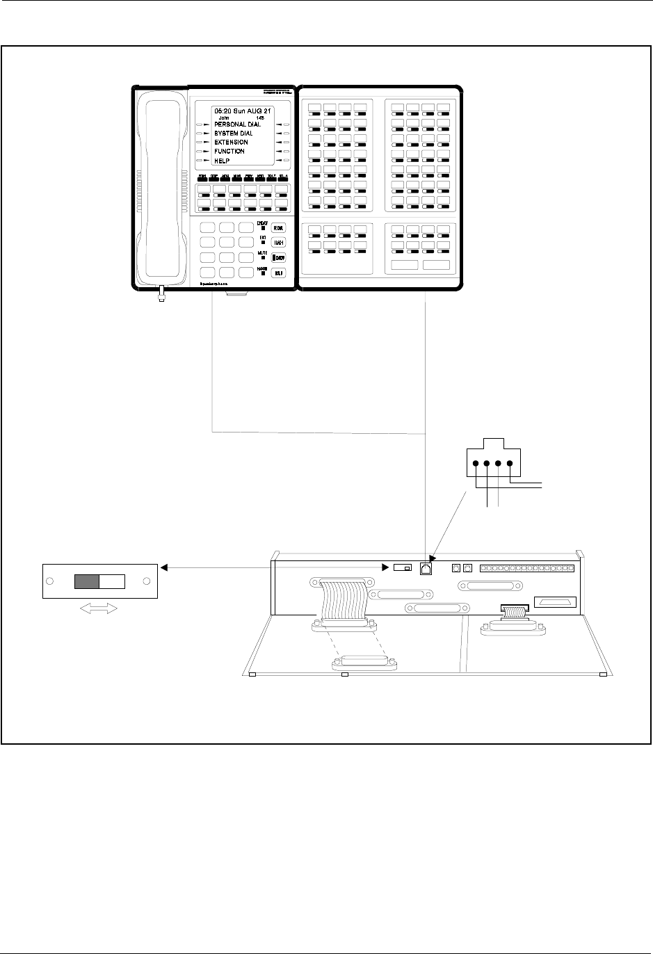
Test Phone
Guidelines
• The test terminal (CN3) on the DBS Connector Panel can be used to
connect a display phone for programming.
The test terminal can be used for initial programming before extension
cabling is completed.
• The test terminal is turned on by flipping SW1 on the Connector Panel to
the “Test” position. When SW1 is in the test position, extension ports 7
and 8 are connected through the test terminal. When SW1 is not in the test
position, extension ports 7 and 8 are connected through the MDF.
Note: Before using the test terminal on a DBS that is operational, be sure
the phones connected to ports 7 and 8 can be taken out of service.
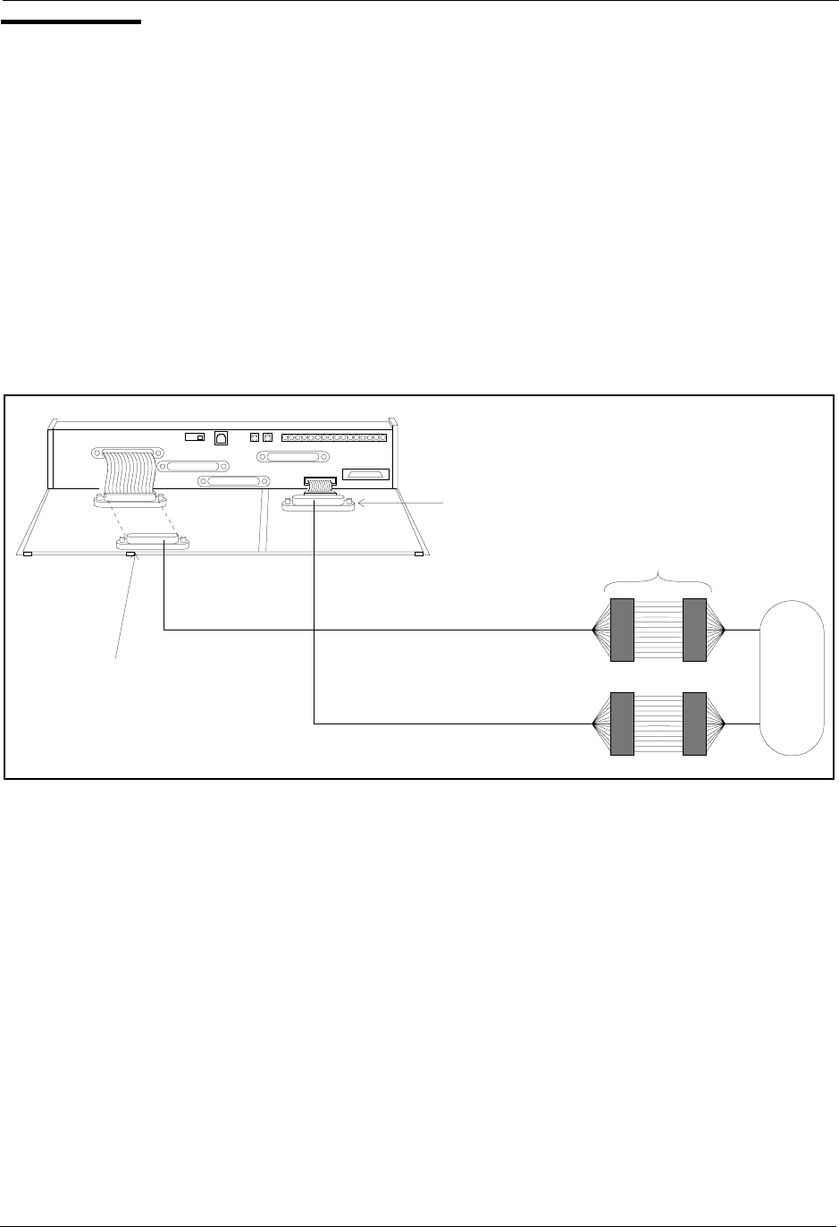
• A DSS/72 can be connected to the display phone for text entry. Port 7 must
be assigned as extension 101 and the DSS/72 must be assigned as
telephone type 13 for the DSS/72 to operate.
Installation
1. Connect the telephone and DSS (optional) to CN3 on the Connector
Panel. (See Figure 3-18 on page 3-19.)
2. Set SW1 to “Test.”
3. When programming is completed, set SW1 back to “ST.”
Section 300-Installation Chapter 3. Cabinet Installation
DBS-2.3/9.2-300 DBS Manual - Revised April 2000 3-19
Figure 3-18. Test telephone connection
TestPhone D SS C onsole
CN3
To the
telephone
To the
DSS/72
Tw o-C onductor
C able(Port7) Tw o-C onductor
Cable(Port8)
ST=Ports7and8
are connected through
the M D F
TEST=Ports7and8
are connected through
CN3
ST TEST
SW 1
CN11
CN12 CN5
CN13
CN3
CN14CN15
CN1
CN1
CN2
CN4
Note:Port7mustbe
assigned as extension
101 and the D SS/72
assigned as telephone
type13forthe DSS/72
tooperate.
3DEF
1
789
25
6
34
10 11 12
Panasonic Panasonic
!
2ABC
4GHI
1
5JKL 6MNO
7PRS 8TUV 9WXY
#
0OPER
ANSW ER RELEASE

Chapter 3. Cabinet Installation Section 300-Installation
3-20 DBS Manual - Revised April 2000 DBS-2.3/9.2-300

DBS-2.3/9.2-300 DBS Manual - Revised April 2000 4-1
Chapter 4. Trunks and Lines
This chapter describes trunk and line installation. Some peripheral equipment
also requires trunk and/or line interfaces (for example, door phones or power
failure units). See Chapter 5 for instructions on connecting peripheral
equipment through trunks or lines.
This chapter covers the following topics::
Topic Page
Trunks 4-3
Loop-Start Trunks 4-7
Ground Start and DID Trunks 4-9
T1 Interface 4-11
Lines 4-31
Analog Extensions 4-37
Digital Extensions 4-41
DSS/72 4-41
EM/24 4-43
Trunk and Line Expansion 4-44

4-2 DBS Manual - Revised April 2000 DBS-2.3/9.2-300
Section 300-Installation Chapter 4. Trunks and Lines
DBS-2.3/9.2-300 DBS Manual - Revised April 2000 4-3
Trunks
Trunk Connectors
Each DBS cabinet is provided with one main trunk connector, labeled CN1.
In addition, a trunk expansion connector (VB-43120) can be added to the
DBS to provide eight additional trunk connections. (The trunk expansion
connector is also labeled CN1.)
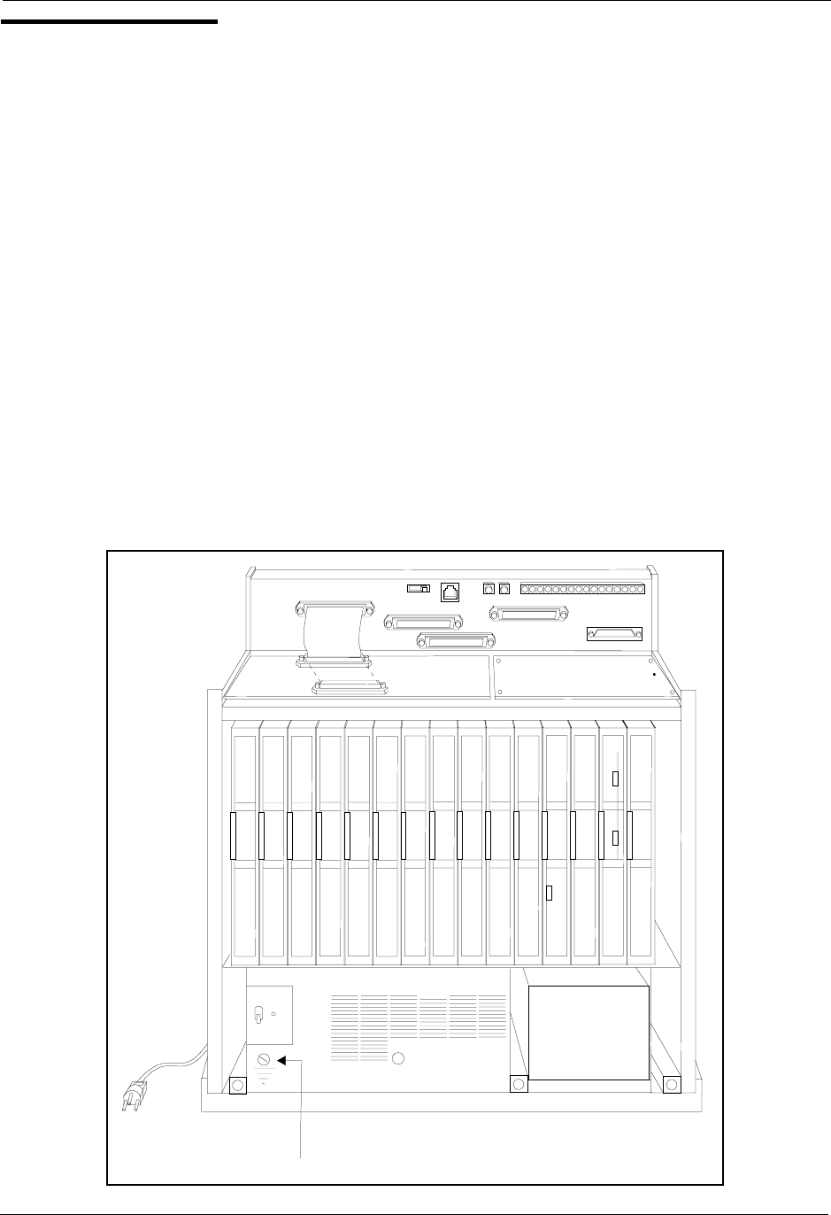
Figure 4-1 shows the maximum number of trunks that can be connected when
both trunk connectors are used with a DBS 96.
Figure 4-1. DBS trunk connections (DBS 96)
Exp a nsion Trunk C onnector
CN11
CN12 CN5
CN13
CN3
CN14CN15
CN1
CN1
CN2
CN4
Trunk P orts
1-24
Trunk P orts
25 -32
MDF
CO
(V B -43120)
MainTrunkC onnector

Chapter 4. Trunks and Lines Section 300-Installation
4-4 DBS Manual - Revised April 2000 DBS-2.3/9.2-300
The number of trunks that can be connected through the main trunk connector
depends on the type of system you have and the number of trunk cards
installed. Table 4-1 shows the main trunks and expansion trunks available
with each system type. Chapter 6 includes trunk maximums for two-cabinet
systems.
Table 4-1. Main trunks and expansion trunks provided with each system type
Trunk Connector Pinouts
Table 4-2 includes pinouts and color codes for the main trunk connector.
Table 4-3 shows pinouts and color codes for the trunk expansion connector.
Instructions on installing the expansion connector begin on 4-44.
System Type Main Trunk Numbers Expansion Trunk Numbers
DBS 40 1-8 9-16
DBS 72 1-16 17-24
DBS 96 1-24 25-32

Section 300-Installation Chapter 4. Trunks and Lines
DBS-2.3/9.2-300 DBS Manual - Revised April 2000 4-5
Table 4-2. Pinouts and trunk numbers for the main trunk connector.
Trunk Slot1
1. Trunks connections for a trunk card installed in the EC/TRK slot appear on the Trunk Port Expansion connector
as described on the next page.
Color Code Pin No. Desig. Function
TRK1
(DBS 40,
DBS 72,
DBS 96)
WH-BL
BL-WH
26
1
1T
1R
Trunk 1
WH-OR
OR-WH
27
2
2T
2R
Trunk 2
WH-GN
GN-WH
28
3
3T
3R
Trunk 3
WH-BR
BR-WH
29
4
4T
4R
Trunk 4
WH-SL
SL-WH
30
5
5T
5R
Trunk 5
RD-BL
BL-RD
31
6
6T
6R
Trunk 6
RD-OR
OR-RD
32
7
7T
7R
Trunk 7
RD-GN
GN-RD
33
8
8T
8R
Trunk 8
TRK2
(DBS 72,
DBS 96)
RD-BR
BR-RD
34
9
9T
9R
Trunk 9
RD-SL
SL-RD
35
10
10T
10R
Trunk 10
BK-BL
BL-BK
36
11
11T
11R
Trunk 11
BK-OR
OR-BK
37
12
12T
12R
Trunk 12
BK-GN
GN-BK
38
13
13T
13R
Trunk 13
BK-BR
BR-BK
39
14
14T
14R
Trunk 14
BK-SL
SL-BK
40
15
15T
15R
Trunk 15
YL-BL
BL-YL
41
16
16T
16R
Trunk 16
TRK3
(DBS 96 only)
YL-OR
OR-YL
42
17
17T
17R
Trunk 17
YL-GN
GN-YL
43
18
18T
18R
Trunk 18
YL-BR
BR-YL
44
19
19T
19R
Trunk 19
YL-SL
SL-YL
45
20
20T
20R
Trunk 20
VI-BL
BL-VI
46
21
21T
21R
Trunk 21
VI-OR
OR-VI
47
22
22T
22R
Trunk 22
VI-GN
GN-VI
48
23
23T
23R
Trunk 23
VI-BR
BR-VI
49
24
24T
24R
Trunk 24
VI-SL
SL-VI
50
25
Not used

Chapter 4. Trunks and Lines Section 300-Installation
4-6 DBS Manual - Revised April 2000 DBS-2.3/9.2-300
Table 4-3. Pinouts and trunk numbers for trunk expansion connector CN1
Trunk Slot Color
Code Pin
No.1
1. Only the first 8 pairs on the trunk expansion connector are used.
Desig. Trunk Assignments According to
System Type
DBS 40 DBS 72 DBS 96
EC/TRK WH-BL
BL-WH
26
1
1T
1R
Trunk
9
Trunk
17
Trunk
25
WH-OR
OR-WH
27
2
2T
2R
Trunk
10
Trunk
18
Trunk
26
WH-GN
GN-WH
28
3
3T
3R
Trunk
11
Trunk
19
Trunk
27
WH-BR
BR-WH
29
4
4T
4R
Trunk
12
Trunk
20
Trunk
28
WH-SL
SL-WH
30
5
5T
5R
Trunk
13
Trunk
21
Trunk
29
RD-BL
BL-RD
31
6
6T
6R
Trunk
14
Trunk
22
Trunk
30
RD-OR
OR-RD
32
7
7T
7R
Trunk
15
Trunk
23
Trunk
31
RD-GN
GN-RD
33
8
8T
8R
Trunk
16
Trunk
24
Trunk
32
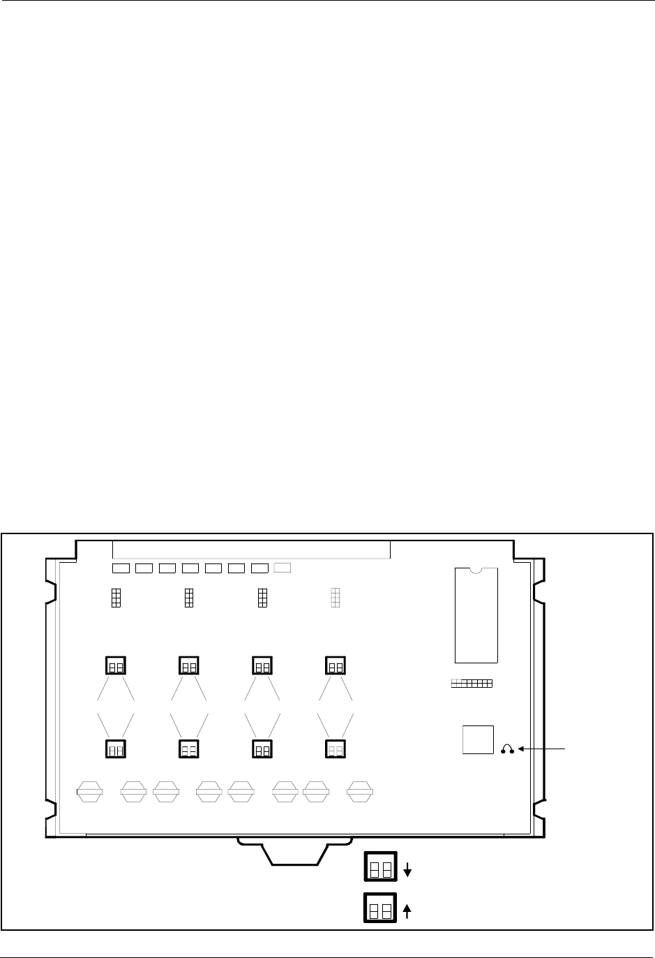
Section 300-Installation Chapter 4. Trunks and Lines
DBS-2.3/9.2-300 DBS Manual - Revised April 2000 4-7
Loop-Start Trunks
Guidelines
• Two versions of the loop-start trunk are available: the four-port version
(VB-43510) and the eight-port version (VB-43511).
• The following procedure covers loop-start trunk installation using the main
trunk connector. For instructions on using the expansion trunk connector,
see “Trunk and Line Expansion” on page 4-44
• For pinouts and color codes for the main trunk connector, see Table 4-2 on
page 4-5.
Installation
Installation without Caller ID
1. If installing VB-43511A Loop Start Card:
a. Remove the cover from the L-TRK card (VB-43511A).
b. Set the all option switches to ON as shown in Figure 4-2.
c. Replace the cover on the L-TRK card (VB-43511A).
Figure 4-2. L-TRK Card Strap J1 and Switch Locations
ON ON ON ON
ON
ON
ON ON ON ON
L-TRK Card
(VB-43511A)
SW1 SW3 SW5
SW2 SW4 SW6 SW8
SW7
TK1 TK2 TK3 TK4 TK5 TK6 TK7 TK8
When a Caller ID Card Is Installed,
Set All Switches to the OFF Position
When No Caller ID Card Is Installed,
Set All Switches to the ON Position
J1 Strap J1
must be
cut to
receive
Caller ID
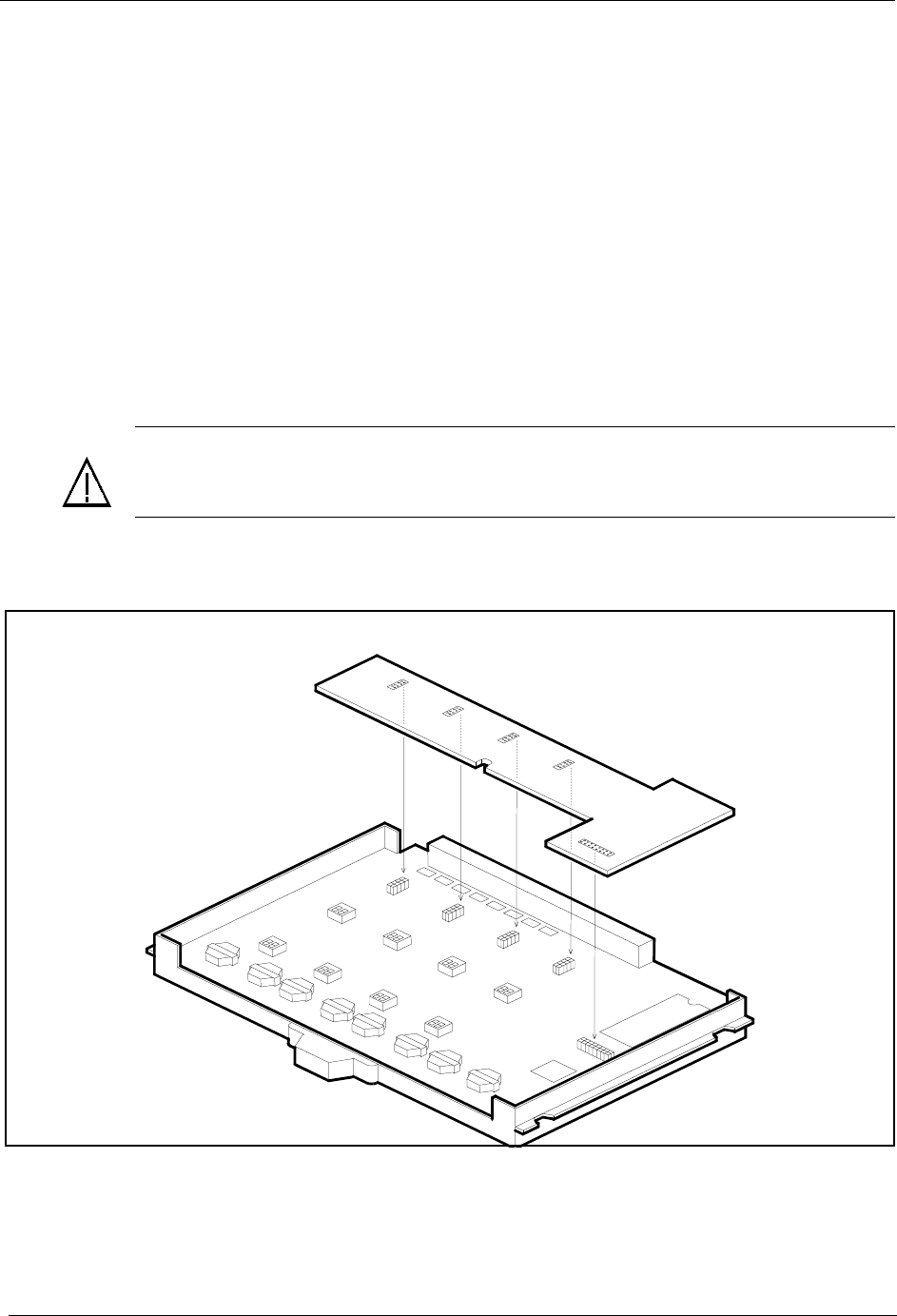
Chapter 4. Trunks and Lines Section 300-Installation
4-8 DBS Manual - Revised April 2000 DBS-2.3/9.2-300
2. Install the loop-start trunk in a trunk slot.
3. Use a standard 50-pin cable to connect the trunks from the MDF to the
main trunk connector CN1.
Installation with Caller ID
1. Remove the cover from the L-TRK card (VB-43511A). This cover should
be set aside since it cannot be reinstalled with a Caller ID Board installed.
2. Cut strap J1 on the L-TRK card as shown in Figure 4-2.
3. Set switches SW1 through SW8 on the L-TRK card (VB-43511A) to
OFF.
4. Attach the Caller ID card to the L-TRK card.
Figure 4-3. Attaching Caller ID Card to the L-TRK Card
5. Install the L-TRK card in a trunk slot.
6. Use a standard 50-pin cable to connect the trunks from the MDF to the
main trunk connector CN1.
IMPORTANT: When caller ID is used, you must correctly set the switches to prevent possible
damage to the L-TRK card.
Caller
ID Board
(VB-43551)
L-TRK Card
(VB-43511A)

Section 300-Installation Chapter 4. Trunks and Lines
DBS-2.3/9.2-300 DBS Manual - Revised April 2000 4-9
Ground Start and DID Trunks
Guidelines
• The following procedure covers ground-start (VB-43531) and DID (VB-
43541) installation using the main trunk connector. For instructions on
using the expansion trunk connector, see “Trunk and Line Expansion” on
page 4-44.
• For pinouts and color codes for the main trunk connector, see Table 4-2 on
page 4-5.
• Each circuit on the ground-start trunk card can be used as either a loop-
start or ground-start trunk. By default, all circuits on the ground-start trunk
are assigned as loop start.
• The ground-start trunk card requires CPC-B Version 1.0 or higher.
• The DID card requires CPC-B (Version 2.0 or higher) and SCC-B
(Version 1.2 or higher).
• Both ground start and DID trunks require an external -48V floating output
power supply. The following table shows -48V power consumption for
one- and two-cabinet systems.
Table 4-4. -48V current consumption for ground-start and DID trunks
• The following -48V floating output power supplies have been tested with
DBS ground-start and DID trunks.
Table 4-5. -48V power supplies tested with the DBS
• The following “Installation” section includes details on installing the -48V
power supply.
System Size Current Consumption
(Output voltage = 48 ± 4 V
Ripple voltage = ±500 mVp-p)
One-cabinet system 1 Amp
Two-cabinet system 2 Amps
Manufacturer Model Number Rating
Valcom VP-2048B 2 Amps
Tellabs 81-8002 2 Amps
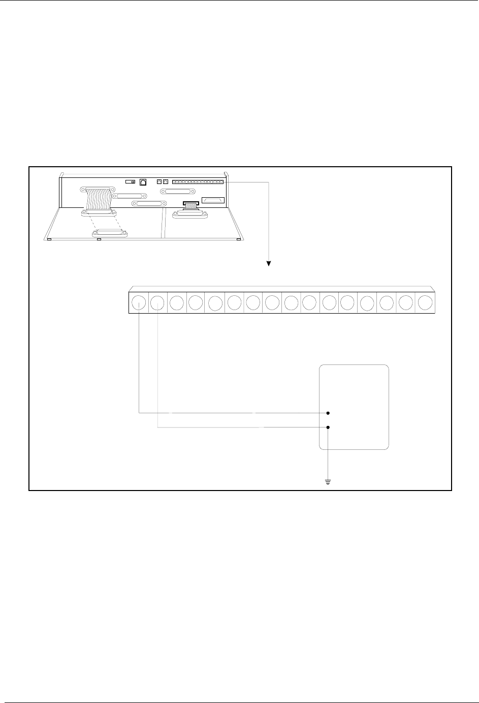
Chapter 4. Trunks and Lines Section 300-Installation
4-10 DBS Manual - Revised April 2000 DBS-2.3/9.2-300
Installation
1. Install the G-TRK/8 or DID card in a trunk slot.
2. Connect the power supply by cabling the positive side to the SG
connector on CN2 (Figure 4-4).
Note: Use cables that are 18 AWG or larger to connect the power supply
to the DBS.
Figure 4-4. -48Vpower supply installation
3. Ground the positive side of the -48V power supply to the building
ground.
Note: Resistance to ground must be 10 Ohms or less, and the ground
cable must be 18 AWG or larger.
4. Install power-surge protectors between the wall outlet and the -48V
power supply.
5. Use a standard 50-pin cable to connect the trunks from the MDF to the
main trunk connector CN1.
6. Use a test set to verify the polarity of the trunk.
SG RG
SYN R G +24V Z0GND C Z2BM Z1 Z3 RE2Z4 RE1-48V
-48V Pow erSupply
R ecom m end:
Tellabs-8001
Tellabs-8002
CN2
CN11
CN12 CN5
CN13
CN3
CN14CN15
CN1
CN1
CN2
CN4
-
+

Section 300-Installation Chapter 4. Trunks and Lines
DBS-2.3/9.2-300 DBS Manual - Revised April 2000 4-11
Connect the test set across the tip and ring of the trunk to be tested. With
the test set in the “monitor” position, apply ground to the ring side of the
trunk.
If you hear dial tone, the polarity of the trunk is okay, and you can switch
the test set to the “talk” mode to test the voice path.
If you do not hear dial tone, ground the tip side of the trunk. If you
receive dial tone when grounding the tip side, polarity is reversed.
T1 Interface
Guidelines
Read the following guidelines before beginning T1 installation. Installation
instructions begin on page 4-21.
Hardware Requirements
• The T1 requires the following DBS hardware.
Table 4-6. T1 Hardware requirements for single-cabinet systems
CPC-B 4.0 or
Higher
(VB-43411)
SCC-B
(VB-43421) T1 Trunk Card
(VB-43561) T1 MDF Card
(VB-43562) Sync Unit
(VB-43563)
1
(See Note 1.)
1
(See Notes 2 and 3.)
111
Notes:
1. Version 1.3 or higher of the Bus Processor Unit (BPU) chip is required for T1.
2. An MFR card is required for DID/DNIS if DTMF signaling is used. If DID/DNIS is provided through
DP signaling, an MFR card is not required.
3. SCC-B with ROM 1.3 or higher is required if the central office does not provide T1 dial tone.

Chapter 4. Trunks and Lines Section 300-Installation
4-12 DBS Manual - Revised April 2000 DBS-2.3/9.2-300
Table 4-7. T1 Hardware requirements for double-cabinet systems
• The T1 trunk card must be installed in the “EC/TRK” slot.
• The installer must provide a Channel Service Unit (CSU) that complies
with FCC Part 15 and Part 68. The CSU is installed between the DBS and
the public network. The CSU provides alarm, diagnostic, and monitoring
functions, as well as network protection.
The CSU must be compatible with the framing format (SF or ESF) that is
provided by the public network.
Maximums
• One T1 card can be installed per cabinet.
• The number of T1 cards that can be installed in double-cabinet systems
depends on the sizes of the connected systems. Table 4-12 on page 4-15
shows T1 maximums for double-cabinet systems.
Note: The DBS 72 + DBS 40 combination does not support T1.
T1
Location
CPC-B V4
(VB-43411)
(See Note
1.)
SCC-B
(VB-
43421)
(See Notes
2 and 3.)
T1 Trunk
Card
(VB-
43561)
T1 MDF
Card
(VB-
43562)
Sync
Card
(VB-
43563)
T1 Cable
(VB-
43564)
Cable Kit
(VB-43110)
(See Note
4.)
T1 in the
Master
1 1 1110 1
T1 in the
Slave
1 11111 1
T1 in both
Master
and
Slave
1 122111
Notes:
1. Version 1.3 of the Bus Processor Unit (BPU) chip is required for T1.
2. An MFR card is required for DID/DNIS if DTMF signaling is used. If DID/DNIS is provided through DP sig-
naling, an MFR card is not required.
3. SCC-B with ROM 1.3 or later is required if the central office does not provide T1 dial tone.
4. Version 1.2 of the Cable Kit is required for T1.

Section 300-Installation Chapter 4. Trunks and Lines
DBS-2.3/9.2-300 DBS Manual - Revised April 2000 4-13
Table 4-8. T1 slot usage for two-cabinet systems
•Fractional T1 can be used when fewer than 24 T1 trunks are needed.
Fractional T1 allows you to use only a portion of the 24 channels provided
on the T1 card.
• Though each T1 Interface provides 24 trunk channels, T1 trunks do not
increase the overall trunk capacity of the DBS. Each T1 channel subtracts
from the total number of analog trunks that can be installed.
• With CPC-B earlier than 5.00, the number of analog trunks that can be
used with Fractional T1 are always decremented in quantities of 8.
For example, if you are installing a T1 in a DBS 96 and you only want to
use 12 T1 channels, the logical number of analog trunks that would be
available is 20 (32 - 12 = 20).
The number of analog trunks must be decremented in quantities of 8, the
actual number of analog trunks that can be used is 16:
(32 total trunks - 16 (two 8-trunk increments) = 16.)
Tables 4-9 through 4-11 show the possible combinations of analog and
digital trunks assignments based on system size.
The trunk numbering shown in these tables is determined by backplane
trunk port assignments. Therefore, the numbering cannot be changed.
• With CPC-B 5.00 and higher and the VB-43511A Loop Start Trunk Card,
the number of analog trunks that can be used with Fractional T1 are
decremented in quantities of 1.
Note: Analog trunks are numbered beginning with “1.” T1 trunk channels
are numbered beginning with the highest trunk channel used.
System Size EC/TRK Slot Usage for T1
Master Slave
DBS 40 + DBS 40 No Yes
DBS 72 + DBS 40 No No
DBS 72 + DBS 72 No Yes
DBS 96 + DBS 40 Yes Yes
DBS 96 + DBS 72 Yes Yes
DBS 96 + DBS 96 Yes Yes

Chapter 4. Trunks and Lines Section 300-Installation
4-14 DBS Manual - Revised April 2000 DBS-2.3/9.2-300
Trunk Assignments for Single-Cabinet Systems
• Programming is not required to associate trunk ports with slot locations.
However, you must use programming to specify that a combination of T1
and analog trunks are installed, and you must also specify how many T1
channels are used.
Table 4-9. T1 and analog trunk assignments, DBS 40
Table 4-10. T1 and analog trunk assignments, DBS 72
Trunk
Number Fractional T1
using 16 Channels Fractional T1
using 8 Channels
1 T1 channel 16 Analog trunk 1
↓↓ ↓
8 T1 channel 9 Analog trunk 8
9 T1 channel 8 T1 channel 8
↓↓ ↓
16 T1 channel 1 T1 channel 1
Note: Since the DBS 40 supports a maximum of 16 trunks, all 24 chan-
nels of the T1 cannot be used.
Trunk
Number 24-Channel T1 Fractional T1
using 16
Channels
Fractional T1
using 8 Channels
1 T1 channel 24 Analog trunk 1 Analog trunk 1
↓↓↓↓
8 T1 channel 17 Analog trunk 8 Analog trunk 8
9 T1 channel 16 T1 channel 16 Analog trunk 9
↓↓↓↓
16 T1 channel 9 T1 channel 9 Analog trunk 16
17 T1 channel 8 T1 channel 8 T1 channel 8
↓↓↓↓
24 T1 channel 1 T1 channel 1 T1 channel 1

Section 300-Installation Chapter 4. Trunks and Lines
DBS-2.3/9.2-300 DBS Manual - Revised April 2000 4-15
Table 4-11. T1 and analog trunk assignments, DBS 96
Trunk Assignments for Double-Cabinet Systems
• When T1 is used in a double-cabinet system, the number of T1 channels
that can be assigned in each cabinet depends on the master/slave
designation.
The following table shows the maximum number of T1 channels that can
be assigned in two-cabinet systems.
Table 4-12. Maximum T1 assignments for two-cabinet systems
• Two-cabinet systems use the same trunk numbering scheme as single-
cabinet systems. Analog trunks are numbered from “1” upward; T1 trunk
channels are numbered downward from the highest channel used.
Trunk
Number 24-Channel T1 Fractional T1
using 16
Channels
Fractional T1
using 8 Channels
1 Analog trunk 1 Analog trunk 1 Analog trunk 1
↓↓↓↓
8 Analog trunk 8 Analog trunk 8 Analog trunk 8
9 T1 channel 24 Analog trunk 9 Analog trunk 9
↓↓↓↓
16 T1 channel 17 Analog trunk 16 Analog trunk 16
17 T1 channel 16 T1 channel 16 Analog trunk 17
↓↓↓↓
24 T1 channel 9 T1 channel 9 Analog trunk 24
25 T1 channel 8 T1 channel 8 T1 channel 8
↓↓↓↓
32 T1 channel 1 T1 channel 1 T1 channel 1
System Size Master Slave
DBS 40 + DBS 40 8 analog trunks 16 T1 trunks
DBS 72 + DBS 72 16 analog trunks 24 T1 trunks
DBS 96 + DBS 40 24 T1 trunks
8 analog trunks
16 T1 trunks
DBS 96 + DBS 72 24 T1 trunks
8 analog trunks
24 T1 trunks
DBS 96 + DBS 96 24 T1 trunks
8 analog trunks
24 T1 trunks
8 analog trunks

Chapter 4. Trunks and Lines Section 300-Installation
4-16 DBS Manual - Revised April 2000 DBS-2.3/9.2-300
Tables 4-13 through 4-17 show trunk numbering for two-cabinet systems
using the maximum number of T1 channels.
Table 4-13. T1 and analog trunk assignments, DBS 40 + 40 (16-channel fractional T1 in the slave)
Table 4-14. T1 and analog trunk assignments, DBS 72 + DBS 72 (24-channel T1 in the slave)
Trunk Number Master Cabinet Slave Cabinet
1 Analog trunk 1
↓↓ N/A
8 Analog trunk 8
9 T1 channel 16
↓N/A ↓
16 T1 channel 9
17 T1 channel 8
↓Ν/Α ↓
24 T1 channel 1
Trunk Number Master Cabinet Slave Cabinet
1 Analog trunk 1
↓↓ N/A
8 Analog trunk 8
9 Analog trunk 9
↓↓ N/A
16 Analog trunk 16
17 T1 channel 24
↓Ν/Α ↓
24 T1 channel 17
33 T1 channel 16
↓Ν/Α ↓
40 T1 channel 9
41 T1 channel 8
↓Ν/Α ↓
48 T1 channel 1

Section 300-Installation Chapter 4. Trunks and Lines
DBS-2.3/9.2-300 DBS Manual - Revised April 2000 4-17
Table 4-15. T1 and analog trunk assignments, DBS 96 + DBS 40 (24-channel T1 in the master; 16-
channel T1 in the slave)
Trunk Number Master Cabinet Slave Cabinet
1 Analog trunk 1
↓↓ N/A
8 Analog trunk 8
9 T1 channel 24
↓↓ N/A
16 T1 channel 17
17 T1 channel 16
↓↓ N/A
24 T1 channel 9
25 T1 channel 8
↓↓ N/A
32 T1 channel 1
33 T1 channel 16
↓Ν/Α ↓
40 T1 channel 9
41 T1 channel 8
↓Ν/Α ↓
48 T1 channel 1

Chapter 4. Trunks and Lines Section 300-Installation
4-18 DBS Manual - Revised April 2000 DBS-2.3/9.2-300
Table 4-16. T1 and analog trunk assignments, DBS 96 + DBS 72 (24-channel T1 in the master; 24-
channel T1 in the slave)
Trunk Number Master Cabinet Slave Cabinet
1 Analog trunk 1
↓↓ N/A
8 Analog trunk 8
9 T1 channel 24
↓↓ N/A
16 T1 channel 17
17 T1 channel 16
↓↓ N/A
24 T1 channel 9
25 T1 channel 8
↓↓ N/A
32 T1 channel 1
33 T1 channel 24
↓Ν/Α ↓
40 T1 channel 17
41 T1 channel 16
↓Ν/Α ↓
48 T1 channel 9
49 T1 channel 8
↓Ν/Α ↓
56 T1 channel 1

Section 300-Installation Chapter 4. Trunks and Lines
DBS-2.3/9.2-300 DBS Manual - Revised April 2000 4-19
Table 4-17. T1 and analog trunk assignments, DBS 96 + DBS 96 (24-channel T1 in the master; 24-
channel T1 in the slave)
Trunk Number Master Cabinet Slave Cabinet
1 Analog trunk 1
↓↓ N/A
8 Analog trunk 8
9 T1 channel 24
↓↓ N/A
16 T1 channel 17
17 T1 channel 16
↓↓ N/A
24 T1 channel 9
25 T1 channel 8
↓↓ N/A
32 T1 channel 1
33 Analog trunk 1
↓Ν/Α ↓
40 Analog trunk 8
41 T1 channel 24
↓Ν/Α ↓
48 T1 channel 17
49 T1 channel 16
↓Ν/Α ↓
56 T1 channel 9
57 T1 channel 8
↓Ν/Α ↓
64 T1 channel 1

Chapter 4. Trunks and Lines Section 300-Installation
4-20 DBS Manual - Revised April 2000 DBS-2.3/9.2-300
Installation
The following procedures provide step-by-step instructions for installing the
T1 Interface. The procedure that you should use depends on the type of
system you have and the number of T1s you are installing.
If you are installing ... Use this procedure...
A T1 in a single cabinet “Installing a T1 in a Single Cabi-
net” (page 4-21)
One T1 in a double cabinet, with the
T1 located in the master “Installing a T1 in a Single Cabi-
net” (page 4-21)
One T1 in a double cabinets, with the
T1 located in the slave “Installing a T1 in a Double Cabi-
net with the T1 in the Slave”
(page 4-27)
T1s in both the master and slave “Installing a T1 in a Double Cabi-
net with T1s in the Master and
Slave” (page 4-27)
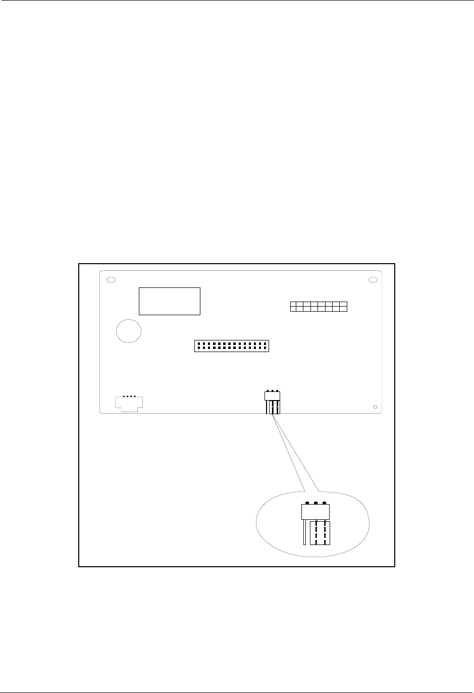
Section 300-Installation Chapter 4. Trunks and Lines
DBS-2.3/9.2-300 DBS Manual - Revised April 2000 4-21
Installing a T1 in a Single Cabinet
The following instructions explain how to install a T1 in a single-cabinet
system. These instructions also apply when a T1 is installed in only the
master cabinet of a two cabinet system.
If only one T1 is installed in a two-cabinet system, it must be installed in the
cabinet specified in Table 4-8 on page 4-13.
Note: The T1 Interface cannot be used for systems consisting of a DBS 72
connected to a DBS 40.
1. Check connector 4 (CN4) on the Sync Unit (VB-43563). Make sure that
Pins 2 and 3 are strapped. (See Figure 4-5.)
When Pins 2 and 3 are strapped, the Sync Unit synchronizes the DBS T1
card with the signaling provided by the public network.
Figure 4-5. Connector 4 (CN4) strapping, Sync Unit
CN2
CN3
CN1 CN4
Free N et
13
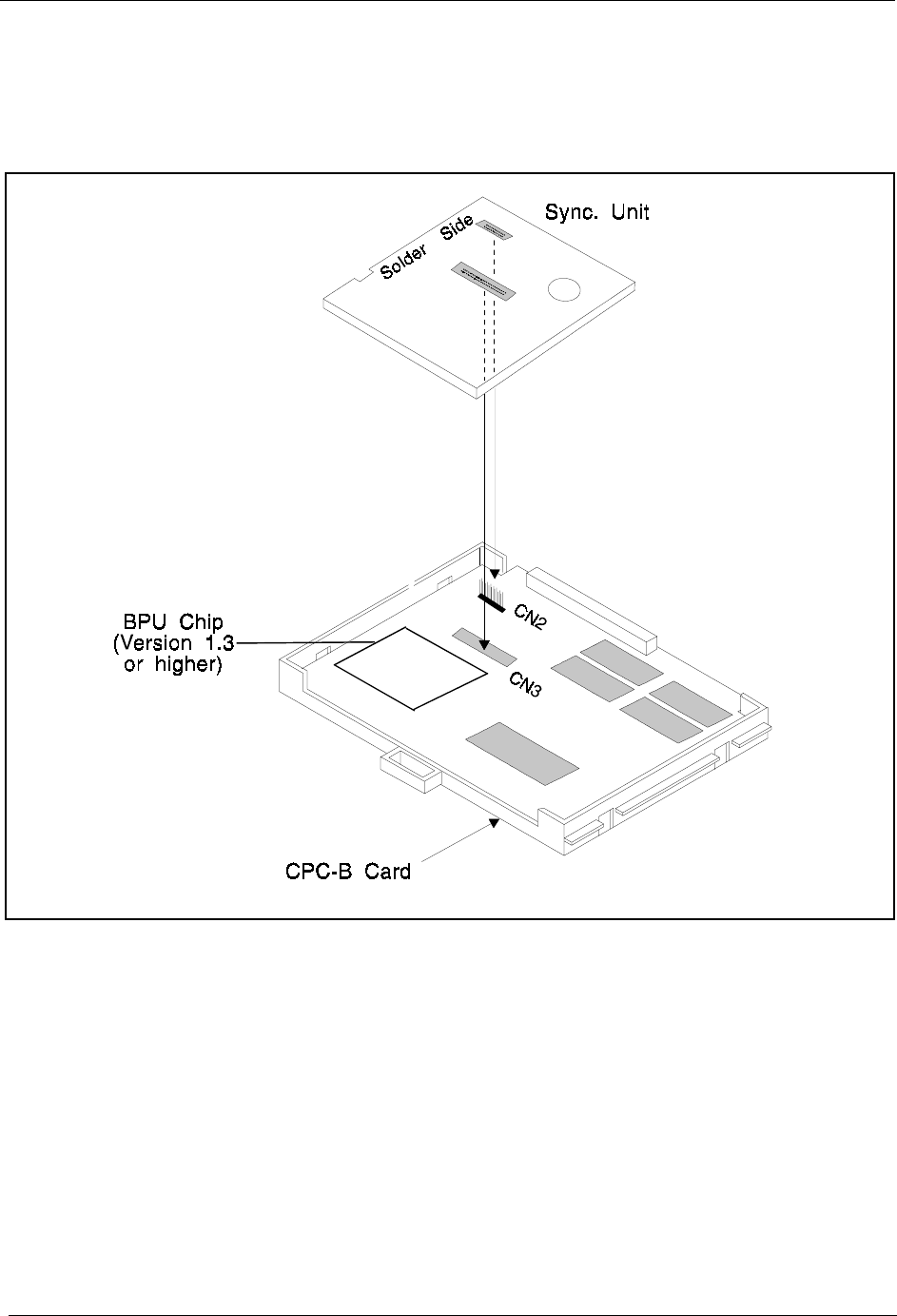
Chapter 4. Trunks and Lines Section 300-Installation
4-22 DBS Manual - Revised April 2000 DBS-2.3/9.2-300
2. Attach the Sync Unit to the CPC-B card.
Note: Before attaching the Sync Unit, insert the three spacers provided
with the unit and remove the jumpers from CN2 of the CPC-B card.
Figure 4-6. T1 Sync Unit installation
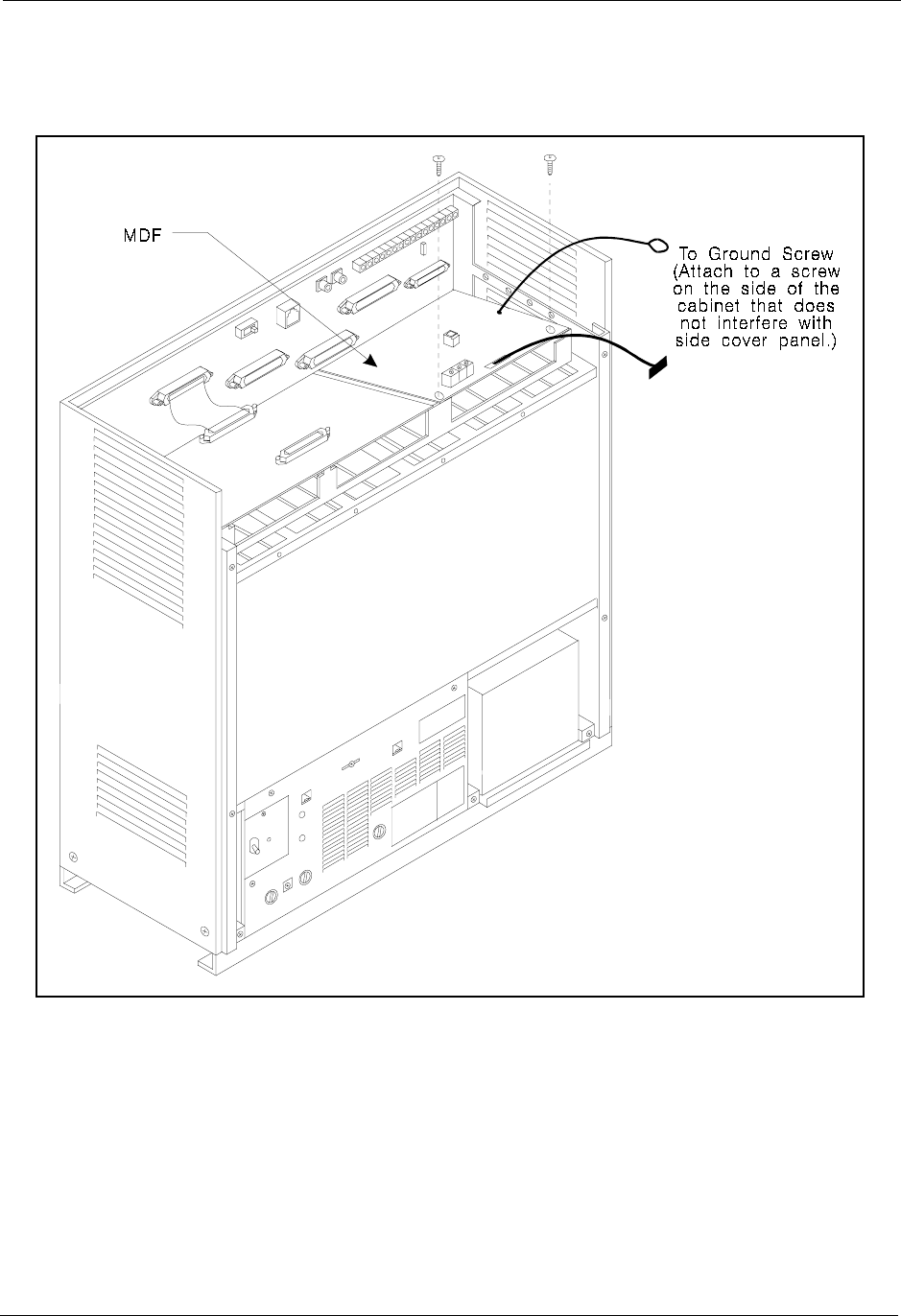
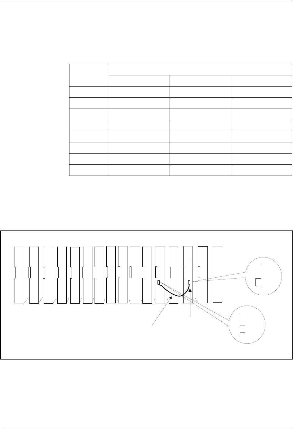
Chapter 4. Trunks and Lines Section 300-Installation
4-24 DBS Manual - Revised April 2000 DBS-2.3/9.2-300
4. Set SW1 on the T1 card according to the following table.
These switch settings correspond to the distance between the DBS and the
CSU. To turn a switch on, flip it to the “up” position.
Table 4-18. Switch settings for SW1 on the T1 card
5. Install the T1 card in the “EC/TRK” slot
6. Connect the Sync Cable from CN1 on the Sync Unit to CN5 on the T1
card.
Figure 4-8. Sync Unit and T1 connection, single-cabinet installation
7. Connect the cable attached to CN3 on the T1 MDF card to CN3 on the T1
card (Figure 4-10).
8. Using an RJ48 cable, connect CN1 on the T1 MDF card to the CSU
(Figure 4-10). The following illustration shows CN1 pinouts.
SW Distance from the DBS to the CSU
0 to 150 ft. 150-450 ft. 450-655 ft.
SW1 On Off Off
SW2 Off On Off
SW3 Off Off On
SW4 Off On Off
SW5 Off Off On
SW6 Off On Off
SW7 Off Off On
SW8 Not used Not used Not used
TR K DEC DEC DEC DEC DEC DEC DEC DEC T1
TRK SCC CPC MFR
N
O
T
U
S
E
D
Sync.U nit
CN5
CN1
S.U.
Sync Cable
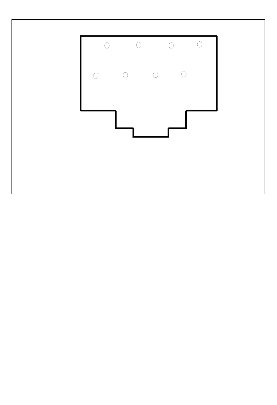
Section 300-Installation Chapter 4. Trunks and Lines
DBS-2.3/9.2-300 DBS Manual - Revised April 2000 4-25
Figure 4-9. RJ48 pinouts, CN1 connector
FG
Tip
NC
Ring NC
1
2
7
8
Ring 1
Tip1 FG
CN1 (RJ48)
Tip1
Ring 1
Tip
Ring
= Receive
=Transm it
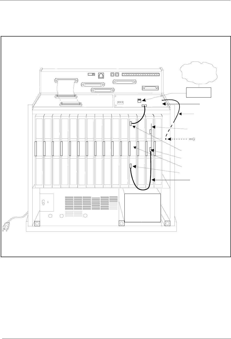
Chapter 4. Trunks and Lines Section 300-Installation
4-26 DBS Manual - Revised April 2000 DBS-2.3/9.2-300
9. Connect the ground cable from the T1 MDF card to the cabinet as shown
in Figure 4-10.
Figure 4-10. T1 cabinet connections, single-cabinet installation
Sync Unit
Sync Cable
CN3
CN11
CN12 CN13 CN14 CN6
SW 1 CN3
TRK1 TRK2 TRK3 EC1 EC2 EC3 EC4 EC5 EC6 EC7 EC8 EC/TRK SCC CPC AUX1 AUX2
CN5 CN4 CN2
CN1
CSU
T-1 L ine
CN1 CN3
CN1
CN5
Ground C abl
e
T-1MDF
T-1Card

Section 300-Installation Chapter 4. Trunks and Lines
DBS-2.3/9.2-300 DBS Manual - Revised April 2000 4-27
Installing T1 in a Double Cabinet with the T1 in the Slave
1. Install the Sync Unit in the master cabinet as described in Steps 1 and 2
under “Installation for a Single T1.”
2. Install a T1 MDF card in the slave cabinet. (See Step 3 on page 4-23.)
3. Set Switch 1 on the T1 card. (See Step 4 on page 4-24.)
4. Install a T1 card in the “EC/TRK” slot of the slave cabinet.
5. Connect the Sync Cable from CN1 on the Sync Unit to CN5 on the T1
card (Figure 4-11).
Note: Part Number VB-43564 is used for the Sync Cable when a T1 is
installed only in the slave cabinet of a two-cabinet system.
6. At the slave cabinet, connect the cable attached to CN3 on the T1 MDF
card to CN3 on the T1 card (Figure 4-10).
7. Using an RJ48 cable, connect CN1 of the T1 MDF card to the CSU. (See
Figure 4-9 on page 4-25 for RJ48 pinouts.)
8. At the slave cabinet, connect the ground cable on the T1 MDF card as
shown in Figure 4-10 on page 4-26.
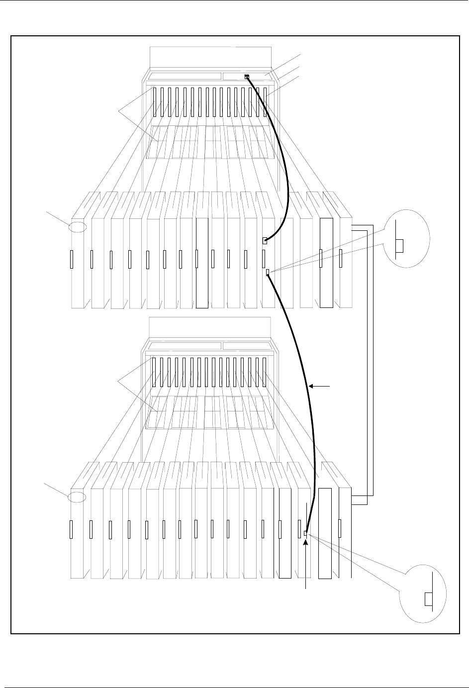
Chapter 4. Trunks and Lines Section 300-Installation
4-28 DBS Manual - Revised April 2000 DBS-2.3/9.2-300
Figure 4-11. Sync cable connections, double-cabinet with a T1 in the slave
Cable
(VB-43564)
MFR
1CBL
(S)
Interconnection
Cables
CBL
(M)
SCC CPC
TRK1 TR K2 TRK3 EC1 EC2 EC 3 EC4 EC5 EC6 EC7 EC8 EC/TRK SCC CPC AUX1 AUX2
TRK DEC DEC DEC DEC DEC DEC DEC DEC MFR
2
Guide
Slot Label
C onnector
N
O
T
U
S
E
D
TRK1 TR K2 TRK3 EC1 EC2 EC 3 EC4 EC5 EC6 EC7 EC8 EC/TRK SCC CPC AUX1 AUX2
TRK DEC DEC DEC DEC DEC DEC DEC DEC
T1
TRK
Guide Sync
Master C abinet
Slave C abinet
Card
Label
Card
Label
T-1 M D F
Sync.Unit
CN5
CN1
N
O
T
U
S
E
D
Note:The num berofanalog trunks thatcan be
installed depends on how m any T1 channelsare
used.

Section 300-Installation Chapter 4. Trunks and Lines
DBS-2.3/9.2-300 DBS Manual - Revised April 2000 4-29
Installing T1 in a Double Cabinet with T1s in the Master and Slave
1. Install the Sync Unit in the master cabinet as described in Steps 1 and 2
under “Installation for a Single T1.”
2. Install a T1 MDF card in each cabinet. (See Step 3 on page 4-23.)
3. Set Switch 1 on the T1 cards. (See Step 4 on page 4-24.)
4. Install a T1 card in each “EC/TRK” slot.
5. Connect the Clock Sync Cable from CN4 on the master-cabinet T1 to
CN5 on the slave-cabinet T1, as shown in Figure 4-12.
Note: Part Number VB-43564 is used for the Clock Sync Cable when
T1s are installed in the master and slave cabinets.
6. At the master cabinet, connect the Sync Cable from CN1 on the Sync
Unit to CN5 on the T1 card (Figure 4-12).
7. At each cabinet, connect the cable attached to CN3 on the T1 MDF card
to CN3 on the T1 card (Figure 4-10).
8. Using an RJ48 cable, connect CN1 of each T1 MDF card to a CSU. (See
Figure 4-9 on page 4-25 for RJ48 pinouts.)
9. For both cabinets, connect the ground cable from the T1 MDF card as
shown in Figure 4-10 on page 4-26.
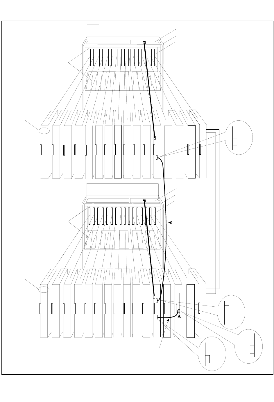
Chapter 4. Trunks and Lines Section 300-Installation
4-30 DBS Manual - Revised April 2000 DBS-2.3/9.2-300
Figure 4-12. Clock sync cable and sync cable connections, double-cabinet installation
C onnector
MFR
1CBL
(S)
Interconnection
Cables
CBL
(M)
SCC CPC
TRK1 TRK2 TRK3 EC1 EC2 EC3 EC4 EC5 EC6 EC7 EC8 EC/TRK SCC CPC AUX1 AUX2
TRK DEC DEC DEC DEC DEC DEC DEC DEC MFR
2
Guide
Slot Label
C onnector
N
O
T
U
S
E
D
TRK1 TRK2 TR K3 EC1 EC2 EC3 EC4 EC5 EC6 EC7 EC8 EC/TRK SCC CPC AUX1 AUX2
TRK DEC DEC DEC DEC DEC DEC DEC DEC T-1
TRK
T1
TRK
Guide
Slot Label
(VB-43564)
Clock Sync.
Cable
Master Cabinet
Slave C abinet
Card
Label
Card
Label
T-1 M D F
T-1 M D F
Sync.Unit
CN5
CN4
CN1
CN5
N
O
T
U
S
E
D
Sync
Cable
Note:The num berofanalog trunks thatcan be
installed depends on how m any T1 channelsare
used.
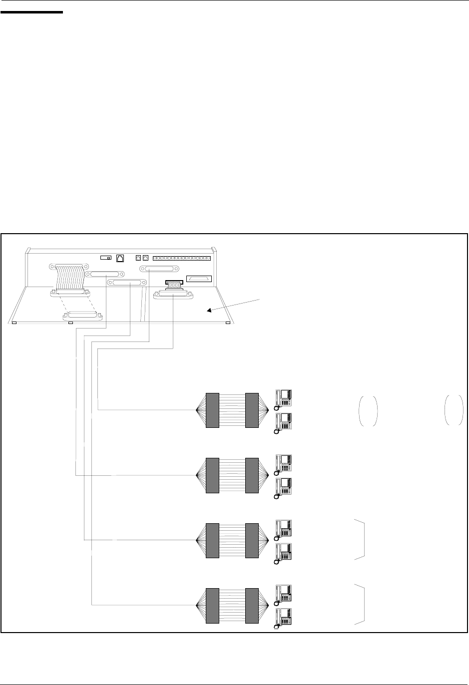
Section 300-Installation Chapter 4. Trunks and Lines
DBS-2.3/9.2-300 DBS Manual - Revised April 2000 4-31
Lines
Extension Connectors
The number of extension ports that can be connected to your system depends
on the type of system you have. Figure 4-13 shows the maximum number of
extensions that can be connected to each system when the extension
expansion connector is used.
Table 4-1 summarizes the number of ports that can be used without the
extension expansion connector. Chapter 6 includes extension maximums for
two-cabinet systems.
Figure 4-13. DBS extension connections
Extension Ports
25 -32
or
49 -56
Extension P orts
1-24
To
CN12
To
CN13
To
CN14
ToCN1 on the Extension
Expansion C onnector
Extension E xpansion C onnector
VB-43121
MDF
Extension P orts
49 -72
Extension P orts
25 -48
Extension 24
Extension 1
Extension 72
Extension 49
DBS 72
and 96
Extension 48
Extension 25
DBS 96
only
or
Extension 49
Extension 56
Extension 32
Extension 25 DBS
72
DBS
40
CN11
CN12 CN5
CN13
CN3
CN14CN15
CN1
CN1
CN2
CN4

Chapter 4. Trunks and Lines Section 300-Installation
4-32 DBS Manual - Revised April 2000 DBS-2.3/9.2-300
Table 4-19. Extension ports provided with each system
Extension Connector Pinouts
Tables 4-20 through 4-22 provide pinouts and color codes for extension
slots.Table 4-22 on page 4-35 provides pinouts and color codes for the
extension expansion connector.
Instructions on installing the expansion connector begin on 4-44.
System Type Extension Ports
(Not including the Expansion Connector*)
DBS 40 1-24
DBS 72 1-48
DBS 96 1-72
*Note: Extensions 65 to 72 on the DBS 96 use the EC/TRK slot, but they
do not require the extension expansion connector. If extensions 65 to 72 are
used, the trunk expansion connector cannot be used.

Section 300-Installation Chapter 4. Trunks and Lines
DBS-2.3/9.2-300 DBS Manual - Revised April 2000 4-33
Table 4-20. Pinouts and color codes for extension connector CN12
Note: Only digital extensions can be used in slot EC1. Port 1 is reserved for Attendant 1 and requires a Display Key Phone.
Extension Slot Color Code Pin No. Desig. Function
EC1
(DBS 40,
DBS 72,
DBS 96)
WH-BL
BL-WH
26
1
1T
1R
Extension Port 1
WH-OR
OR-WH
27
2
2T
2R
Extension Port 2
WH-GN
GN-WH
28
3
3T
3R
Extension Port 3
WH-BR
BR-WH
29
4
4T
4R
Extension Port 4
WH-SL
SL-WH
30
5
5T
5R
Extension Port 5
RD-BL
BL-RD
31
6
6T
6R
Extension Port 6
RD-OR
OR-RD
32
7
7T
7R
Extension Port 7
RD-GN
GN-RD
33
8
8T
8R
Extension Port 8
EC2
(DBS 40,
DBS 72,
DBS 96)
RD-BR
BR-RD
34
9
9T
9R
Extension Port 9
RD-SL
SL-RD
35
10
10T
10R
Extension Port 10
BK-BL
BL-BK
36
11
11T
11R
Extension Port 11
BK-OR
OR-BK
37
12
12T
12R
Extension Port 12
BK-GN
GN-BK
38
13
13T
13R
Extension Port 13
BK-BR
BR-BK
39
14
14T
14R
Extension Port 14
BK-SL
SL-BK
40
15
15T
15R
Extension Port 15
YL-BL
BL-YL
41
16
16T
16R
Extension Port 16
EC3
(DBS 40,
DBS 72,
DBS 96)
YL-OR
OR-YL
42
17
17T
17R
Extension Port 17
YL-GN
GN-YL
43
18
18T
18R
Extension Port 18
YL-BR
BR-YL
44
19
19T
19R
Extension Port 19
YL-SL
SL-YL
45
20
20T
20R
Extension Port 20
VI-BL
BL-VI
46
21
21T
21R
Extension Port 21
VI-OR
OR-VI
47
22
22T
22R
Extension Port 22
VI-GN
GN-VI
48
23
23T
23R
Extension Port 23
VI-BR
BR-VI
49
24
24T
24R
Extension Port 24
VI-SL
SL-VI
50
25
Not used

Chapter 4. Trunks and Lines Section 300-Installation
4-34 DBS Manual - Revised April 2000 DBS-2.3/9.2-300
Table 4-21. Pinouts and color codes for extension connector CN13
Extension Slot Color Code Pin No. Desig. Function
EC4
(DBS 72,
DBS 96)
WH-BL
BL-WH
26
1
1T
1R
Extension Port 25
WH-OR
OR-WH
27
2
2T
2R
Extension Port 26
WH-GN
GN-WH
28
3
3T
3R
Extension Port 27
WH-BR
BR-WH
29
4
4T
4R
Extension Port 28
WH-SL
SL-WH
30
5
5T
5R
Extension Port 29
RD-BL
BL-RD
31
6
6T
6R
Extension Port 30
RD-OR
OR-RD
32
7
7T
7R
Extension Port 31
RD-GN
GN-RD
33
8
8T
8R
Extension Port 32
EC5
(DBS 72,
DBS 96)
RD-BR
BR-RD
34
9
9T
9R
Extension Port 33
RD-SL
SL-RD
35
10
10T
10R
Extension Port 34
BK-BL
BL-BK
36
11
11T
11R
Extension Port 35
BK-OR
OR-BK
37
12
12T
12R
Extension Port 36
BK-GN
GN-BK
38
13
13T
13R
Extension Port 37
BK-BR
BR-BK
39
14
14T
14R
Extension Port 38
BK-SL
SL-BK
40
15
15T
15R
Extension Port 39
YL-BL
BL-YL
41
16
16T
16R
Extension Port 40
EC6
(DBS 72,
DBS 96)
YL-OR
OR-YL
42
17
17T
17R
Extension Port 41
YL-GN
GN-YL
43
18
18T
18R
Extension Port 42
YL-BR
BR-YL
44
19
19T
19R
Extension Port 43
YL-SL
SL-YL
45
20
20T
20R
Extension Port 44
VI-BL
BL-VI
46
21
21T
21R
Extension Port 45
VI-OR
OR-VI
47
22
22T
22R
Extension Port 46
VI-GN
GN-VI
48
23
23T
23R
Extension Port 47
VI-BR
BR-VI
49
24
24T
24R
Extension Port 48
VI-SL
SL-VI
50
25
Not used

Section 300-Installation Chapter 4. Trunks and Lines
DBS-2.3/9.2-300 DBS Manual - Revised April 2000 4-35
Table 4-22. Pinouts and color codes for extension connector CN14
Note: The EC/TRK slot is wired to CN14 only in the DBS 96. In the DBS 40 and
72, a card placed in the EC/TRK slot must be wired to the expansion connector.
Extension Slot Color Code Pin No. Desig. Function
EC7
(DBS 96 Only)
WH-BL
BL-WH
26
1
1T
1R
Extension Port 49
WH-OR
OR-WH
27
2
2T
2R
Extension Port 50
WH-GN
GN-WH
28
3
3T
3R
Extension Port 51
WH-BR
BR-WH
29
4
4T
4R
Extension Port 52
WH-SL
SL-WH
30
5
5T
5R
Extension Port 53
RD-BL
BL-RD
31
6
6T
6R
Extension Port 54
RD-OR
OR-RD
32
7
7T
7R
Extension Port 55
RD-GN
GN-RD
33
8
8T
8R
Extension Port 56
EC8
(DBS 96 Only)
RD-BR
BR-RD
34
9
9T
9R
Extension Port 57
RD-SL
SL-RD
35
10
10T
10R
Extension Port 58
BK-BL
BL-BK
36
11
11T
11R
Extension Port 59
BK-OR
OR-BK
37
12
12T
12R
Extension Port 60
BK-GN
GN-BK
38
13
13T
13R
Extension Port 61
BK-BR
BR-BK
39
14
14T
14R
Extension Port 62
BK-SL
SL-BK
40
15
15T
15R
Extension Port 63
YL-BL
BL-YL
41
16
16T
16R
Extension Port 64
EC/TRK
(DBS 96 only)
YL-OR
OR-YL
42
17
17T
17R
Extension Port 65
YL-GN
GN-YL
43
18
18T
18R
Extension Port 66
YL-BR
BR-YL
44
19
19T
19R
Extension Port 67
YL-SL
SL-YL
45
20
20T
20R
Extension Port 68
VI-BL
BL-VI
46
21
21T
21R
Extension Port 69
VI-OR
OR-VI
47
22
22T
22R
Extension Port 70
VI-GN
GN-VI
48
23
23T
23R
Extension Port 71
VI-BR
BR-VI
49
24
24T
24R
Extension Port 72
VI-SL
SL-VI
50
25
Not used

Chapter 4. Trunks and Lines Section 300-Installation
4-36 DBS Manual - Revised April 2000 DBS-2.3/9.2-300
Table 4-23. Pinouts and color codes for extension expansion connector CN1
Extension
Slot Color
Code Pin No. Desig. Extension Port Assignments
According to System Type
DBS 40 DBS 72 DBS 96
EC/TRK WH-BL
BL-WH
26
1
1T
1R
Extension
Port 25
Extension
Port 49
No
Extension
Expansion
Card
Required
(uses
CN14
instead)
WH-OR
OR-WH
27
2
2T
2R
Extension
Port 26
Extension
Port 50
WH-GN
GN-WH
28
3
3T
3R
Extension
Port 27
Extension
Port 51
WH-BR
BR-WH
29
4
4T
4R
Extension
Port 28
Extension
Port 52
WH-SL
SL-WH
30
5
5T
5R
Extension
Port 29
Extension
Port 53
RD-BL
BL-RD
31
6
6T
6R
Extension
Port 30
Extension
Port 54
RD-OR
OR-RD
32
7
7T
7R
Extension
Port 31
Extension
Port 55
RD-GN
GN-RD
33
8
8T
8R
Extension
Port 32
Extension
Port 56

Section 300-Installation Chapter 4. Trunks and Lines
DBS-2.3/9.2-300 DBS Manual - Revised April 2000 4-37
Analog Extensions
Note: Normally analog extensions are supported using the AEC (VB-43621).
Alternatively, a Single Line Telephone Adaptor (SLTA, VB-43709) may be
used to support analog DTMF (2500 set) extensions. The SLTA converts up
to 4 digital ports to analog ports. See “Single Line Telephone Adaptor” on
page 5-34 for more information.
Guidelines
• An MFR card (VB-43431) is required when the AEC is used. The MFR
card, which provides DTMF signals, includes eight circuits that are shared
among the analog extensions.
• The AEC also requires the SLT ringer box (VB-2089P).
Installation
1. Install the AEC cards in extension slots.
2. Install the MFR card in AUX1 or AUX2. If installing in a two-cabinet
system, see Chapter 6 for specific information for installing MFR card(s).
3. Install the SLT Ringer Box as shown in Figure 4-14. Be sure to note the
differences between the DBS 40 Connector Panel and the Connector
Panel on the DBS 72 and 96.

Chapter 4. Trunks and Lines Section 300-Installation
4-38 DBS Manual - Revised April 2000 DBS-2.3/9.2-300
Figure 4-14. SLT ringer box installation
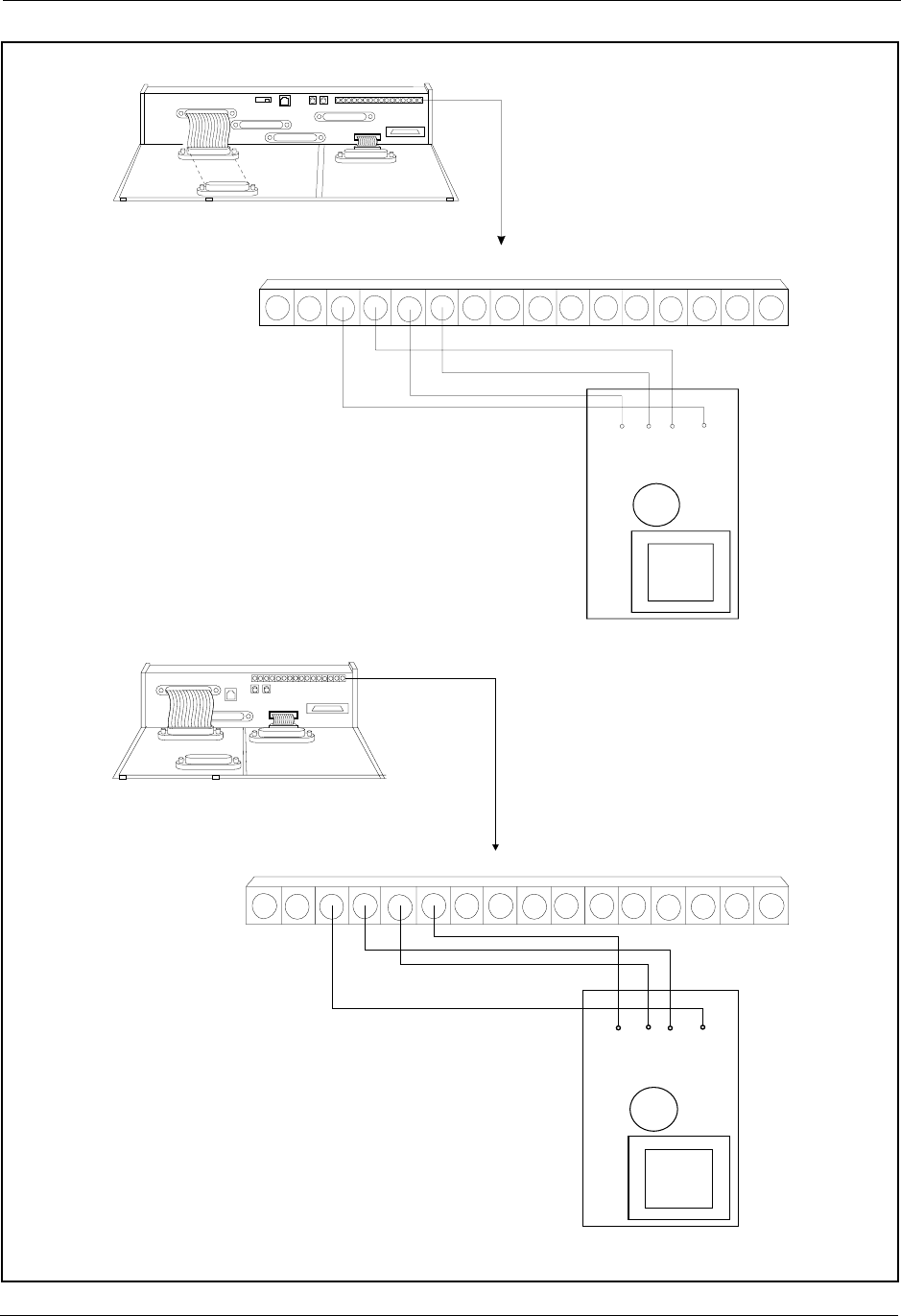
Section 300-Installation Chapter 4. Trunks and Lines
DBS-2.3/9.2-300 DBS Manual - Revised April 2000 4-39
Ringer box installation with the DBS 72 and DBS 96
SLT Ringer Box
(VB-2089P)
-48V
RG
SYN RG +24V Z0
GND MZ2C B Z1 Z3 RE2Z4 RE1
SG
CN2
RG
(BRN)
+24V RG
SYN
(RED)
GND
CN12
CN11
CN4
CN3 CN2
CN15 CN6
CN1
CN1
CN5
SLT RingerB ox
(VB-2089P)
SG RG
SYN RG +24V Z0GND C Z2BM Z1 Z3 RE2Z4 RE1-48V
CN2
CN11
CN12 CN5
CN13
CN3
CN14CN15
CN1
CN1
CN2
CN4
RG
(BRN)
+24V R G
SYN
(RED)
GND
Ringer box installation with the DBS 40
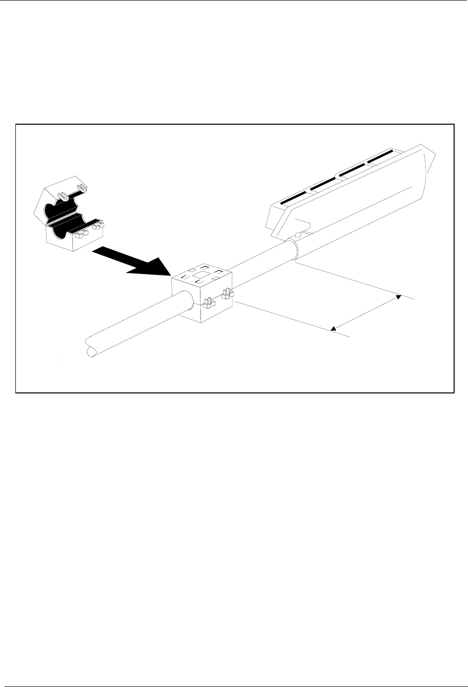
Chapter 4. Trunks and Lines Section 300-Installation
4-40 DBS Manual - Revised April 2000 DBS-2.3/9.2-300
4. Use a standard 50-pin cable to connect the extensions from the MDF to
the appropriate extension connector. (Refer to Tables 4-20 through 4-22
for extension pinouts.)
5. If you are installing a DBS 40 system, attach the EMI filter to the
amphenol cable as shown in Figure 4-15.
Figure 4-15. EMI filter installation (DBS 40 only)
EM I
Filter
31/2"

Section 300-Installation Chapter 4. Trunks and Lines
DBS-2.3/9.2-300 DBS Manual - Revised April 2000 4-41
Digital Extensions
The following instructions explain how to connect digital extensions. These
instructions apply for key phones and Digital Single-Line Telephones
(DSLTs). Special instructions are provided for installing the DSS/72 and
EM24 terminals, which connect to digital phones.
1. Install the DEC cards in extension slots.
2. Use a standard 50-pin cable to connect the extensions from the MDF to
the appropriate extension connector, as shown in Figure 4-13 on page 4-
31. (Refer to Tables 4-20 through 4-22 for extension pinouts.)
3. If you are installing a DBS 40, attach the EMI filter to the amphenol
cable, as shown in Figure 4-15.
DSS/72
Guidelines
• The DSS/72 (VB-43320) is a 72-key console that can be attached to the
attendant phone. It provides direct station selection and busy lamp fields
for internal lines. The DSS/72 can also be used for text assignment.
• When the attendant feature package (VB-43330) is installed (CPC-B
Version 2.0 to 4.0 only), the DSS/72 can be used as an Attendant Console.
The Attendant Console provides station monitoring and call transfer by
name for large systems, even if a large display phone is not used. For a
detailed description of the differences between the standard DSS/72 and a
DSS/72 configured as an Attendant Console, see Feature Operation,
Section 700. For instructions on using the Attendant Console, see the
Attendant Console User Guide, Section 760.
• Up to two DSS/72s or one Attendant Console can be assigned to attendant
phones 1 and 2. Attendant phones 3 and 4 can each have one Attendant
Console assigned, but neither can have a DSS/72.
• If more than one DSS/72 is assigned to an attendant phone, only one of the
DSS/72s can be cabled from the same wall jack as the attendant phone.
Additional DSS/72s must be cabled from separate wall jacks.
• The DSS/72 comes with a mounting bracket, screws, and a two-conductor
cable for attaching the DSS to the key phone.
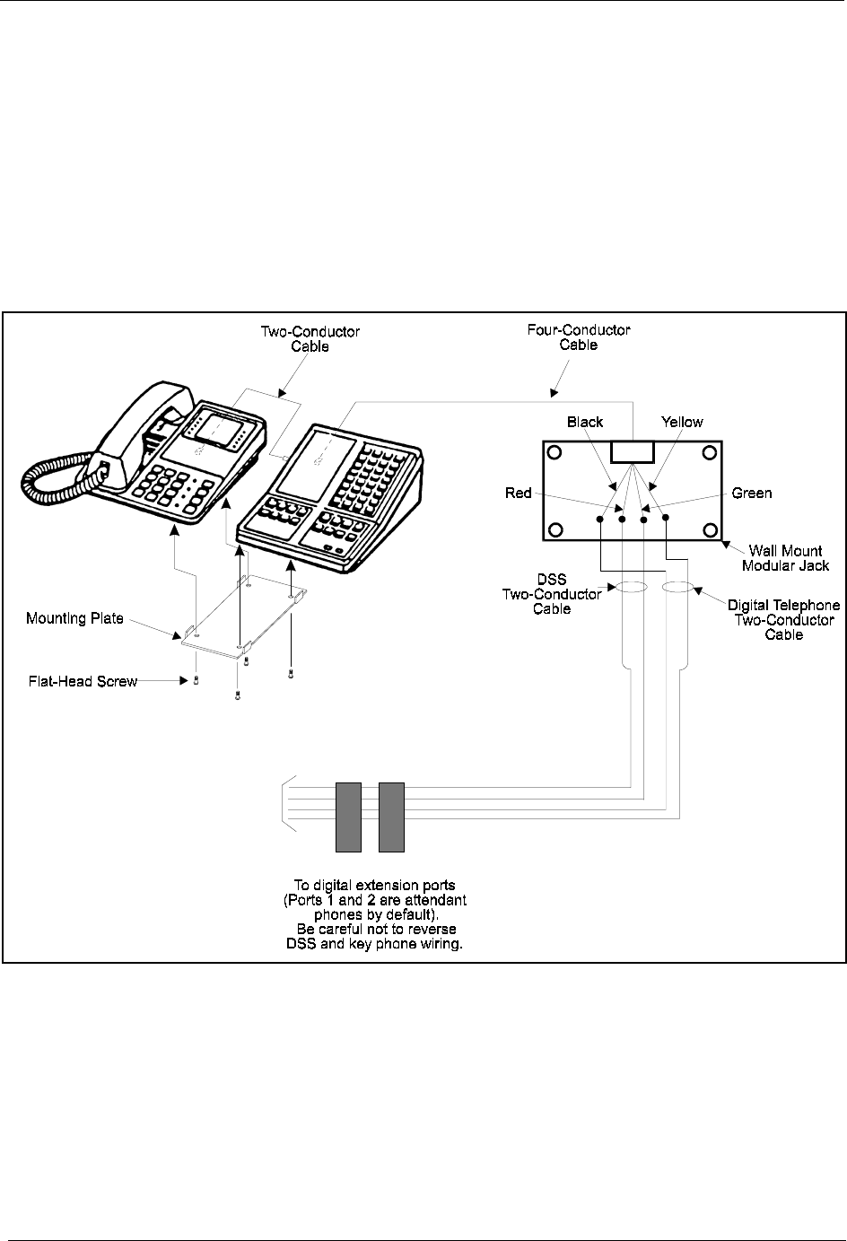
Chapter 4. Trunks and Lines Section 300-Installation
4-42 DBS Manual - Revised April 2000 DBS-2.3/9.2-300
Installation
1. Attach the DSS/72 to the key phone using the mounting plate and the four
screws.
2. Connect the DSS to the key phone using the two-conductor cable.
3. Connect the DSS to the wall jack using a four-conductor cable.
4. Connect the four wires from the key phone and DSS to the MDF.
Figure 4-16. DSS/72 connection using one cable with two pairs.
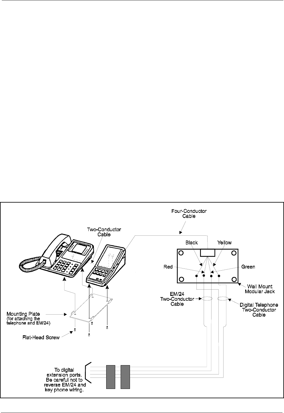
Section 300-Installation Chapter 4. Trunks and Lines
DBS-2.3/9.2-300 DBS Manual - Revised April 2000 4-43
EM/24
Guidelines
• The EM/24 (VB-43310) provides 24 flexible function (FF) keys. It can be
attached to any key phone.
• The EM/24 comes with a mounting bracket, screws, and a two-conductor
cable for attaching it to a key phone.
Installation
1. Attach the EM/24 to the key phone using the mounting plate and the four
screws, as shown in Figure 4-17.
2. Connect the EM/24 to the key phone using the two-conductor cable.
3. Connect the EM/24 to the wall jack using a four-conductor cable.
4. Connect the four wires from the key phone and EM/24 to the MDF
connector.
Figure 4-17. EM/24 connection using one cable with two pairs

Chapter 4. Trunks and Lines Section 300-Installation
4-44 DBS Manual - Revised April 2000 DBS-2.3/9.2-300
Trunk and Line Expansion
Guidelines
• The EC/TRK slot can be used for a trunk or extension card.
• Different expansion connectors are used for trunks and extensions:
Note: With the DBS 96, the expansion connector is not required to use
the EC/TRK slot for an extension card. The DBS 96 uses connector CN14
to accommodate an extension card in the EC/TRK slot. Table 4-22 on
page 4-35 shows the pinouts from the EC/TRK slot to CN14.
Installation
1. Install a trunk or extension card in the slot marked EC/TRK.
2. Connect the appropriate expansion connector to the main cabinet with
two screws, as shown in Figure 4-18.
3. Connect the ground cable from the FG terminal of the expansion
connector to a screw already in use on the right side of the main cabinet.
4. Connect CN2 of the expansion connector to CN15 on the mother board.
5. Prepare a cable with a 50-pin connector on one end and wiring for the
MDF on the other end.
6. Cross-connect the cable to the trunks or extensions through the MDF. See
Table 4-3 “Pinouts and trunk numbers for trunk expansion connector
CN1” on page 4-6 or Table 4-23 “Pinouts and color codes for extension
expansion connector CN1” on page 4-36.
7. Connect the 50-pin connector to CN1 on the expansion connector.
Expansion connector Part No.
Trunk expansion connector VB-43120
Extension expansion connector VB-43121
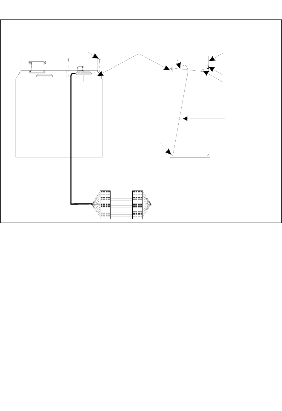
Section 300-Installation Chapter 4. Trunks and Lines
DBS-2.3/9.2-300 DBS Manual - Revised April 2000 4-45
Figure 4-18. Trunk or extension expansion
See Table 4-3 on page 4-6 for pinout and trunk number information for the
trunk expansion connector.
CN11
CN1CN1
CN15
Screw Motherboar
d
FG
Term inal
Fasten
withScrew
CN15
CN2
(On the
expansion
connector)
Right Side ViewFront View
Ground
Cable
CO Lines or
Extensions
Trunk or
Extension
Expansion
C onnector


DBS-2.3/9.2-300 DBS Manual - Revised April 2000 5-1
Chapter 5. Peripheral Equipment
This chapter describes peripheral equipment installation. Some peripheral
equipment requires trunk and/or line interfaces (for example, door phones or
power failure units). For information on trunk and line connections, see
Chapter 4.
This chapter covers the following topics:
Topic Page
Local Terminal or SMDR Device 5-3
Remote Administration Interface (RAI) 5-6
Background Music/Music-On-Hold 5-8
Off-Premises Adaptor (OPX) 5-10
Paging 5-14
External Ringer (UNA Device) 5-17
Power Failure Unit 5-19
Voice Announce Unit (VAU) 5-22
Door Box Adaptor (Trunk Port) 5-27
Door Box Adaptor (Extension Port) 5-31
Single Line Telephone Adaptor 5-34

5-2 DBS Manual - Revised April 2000 DBS-2.3/9.2-300

Section 300-Installation Chapter 5. Peripheral Equipment
DBS-2.3/9.2-300 DBS Manual - Revised April 2000 5-3
Local Terminal or SMDR Device
Guidelines
• Connector 6 (CN6) on the Connector Panel provides an RS-232C interface
for connection of a local programming terminal or an SMDR device such
as a printer or call accounting machine.
• The following table contains RS-232C designations.
Table 5-1. RS-232C pin designations used for CN6
• For instructions on connecting a remote PCAS PC, see the PCAS User’s
Guide.
• For instructions on connecting the remote DBS Manager, see the DBS
Manager User Guide.
Pin Signal Name Description
1 N/A Not used.
2 TD Transmit Data
3 RD Receive Data
4 CTS Clear to Send
5 RTS Request to Send
6 DSR Data Set Ready
7 SG Signal Ground
8 CD Carrier Detect
20 DTR Data Terminal Ready
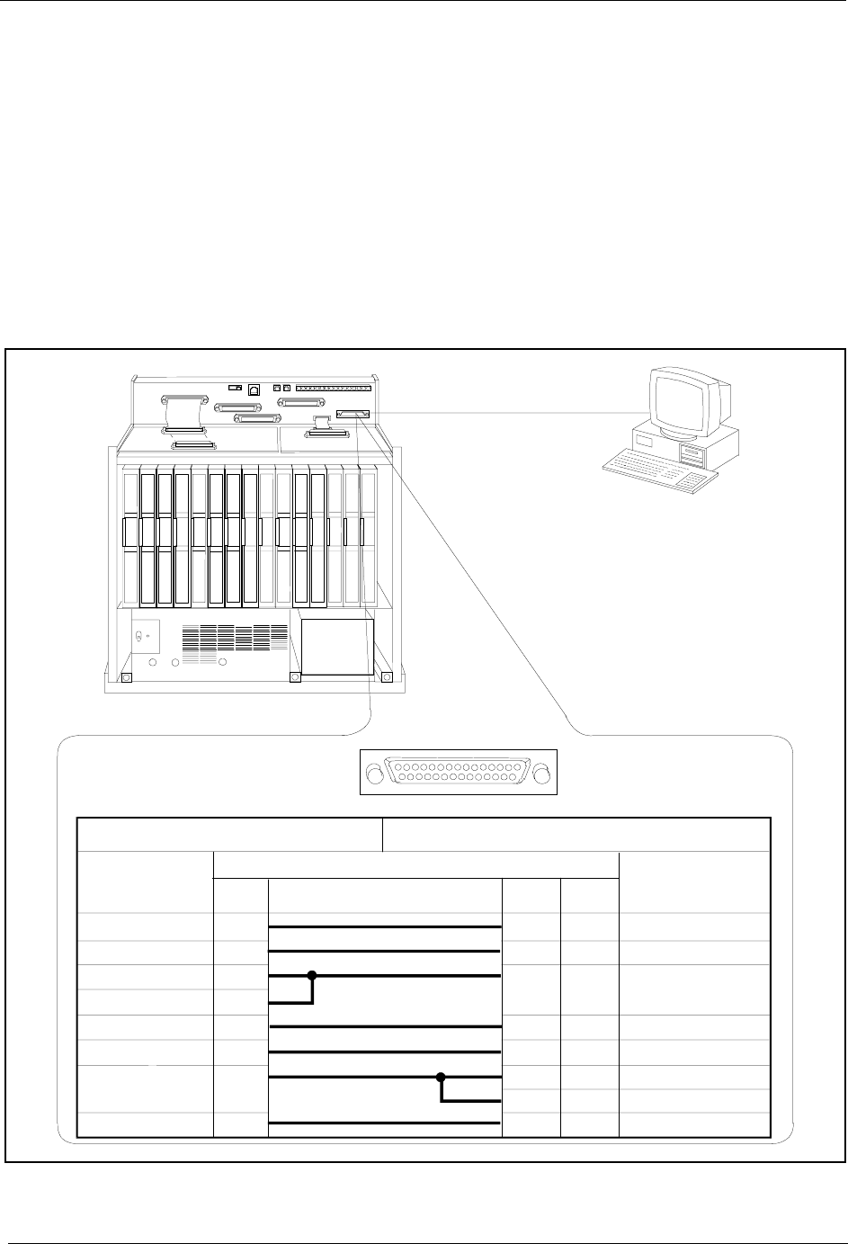
Chapter 5. Peripheral Equipment Section 300-Installation
5-4 DBS Manual - Revised April 2000 DBS-2.3/9.2-300
Installation
1. Connect one end of the RS-232C cable to CN6 on the Connector Panel.
Figure 5-1 shows cable pinouts for 25-pin and 9-pin RS-232C devices.
These connections have been used successfully with many PCs and
SMDR devices; however, consult the documentation of the PC or SMDR
device before fabricating a cable.
2. Connect the other end of the RS-232C cable to the local programming
terminal or SMDR device.
Figure 5-1. RS-232C connection
CN11
CN12 CN13 CN14 CN15 CN6
SW 1 CN3
TRK1 TRK2 TRK3 EC1 EC2 EC3 EC4 EC5 EC6 EC7 EC8 EC/TRK SCC CPC AUX1 AU X2
CN5 CN4 CN2
CN1
CN1
RS-232C
M aster C abinet
Programming Term inal
or
SM D R D evice
113
14 25
Main C abinet (C N 6) RS-232C Prog.Term.orSMDR Printer R S-232C
Signal
Name
Pin N o. and C onnection Signal
Name
DB-25
DB-25 DB-9
TD
RD
CTS
RTS
DSR
SG
CD
DTR
2
3
4
5
6
7
8
20
2
3
1
4
5
7
8
6
3
2
8
20
7
4
5
6
RD
TD
CD
DTR
SG
RTS
CTS
DSR
CN6

Section 300-Installation Chapter 5. Peripheral Equipment
DBS-2.3/9.2-300 DBS Manual - Revised April 2000 5-5
Figure 5-2. SMDR Format for CPC-AII and CPC-B Version 3.1 or higher
1 2 3 4 5 6 7
012345678901234567890123456789012345678901234567890123456789012345678901234567
1 2 3 4 5 6 7 8 9
T MM/DD HH:MM:SS HH:MM.SS NNN DDDDDDDDDDDDDDDDDDDDDDDDDDDD AAAAAAAAAA VVVVV NN
1=Call type
S=Inbound DISA
s=Outbound DISA
I=Incoming
O=Outgoing
T=Transfer (See Note 1.)
N=DNIS
D=DID
2=Date
MM=month
DD=day
3=Call start time
HH=hours
MM=minutes
SS=seconds
4=Call duration
HH=hours
MM=minutes
SS=seconds
5=Extension number
10-69, 100-699=extensions
CO number=DISA
6=Dialed digits or Caller ID
DD=digits 0-9 or symbols * or #
(See Note 2.)
7=Account code
A=0-9999999999
8=Verified account code or walking
COS code
V0000-V9999=verified account codes
W0000-W9999=walking COS codes
9=Trunk Number
NN=number (01-64)
Notes:
1. Transferred calls include direct and group call pickups and conference calls.
If a station call is transferred to an outside number, an SMDR record is
also created for the station that is transferred.
2. The * symbol appears as a greater-than sign (>) on the SMDR printout; the # symbol
appears as a less-than sign (<). Centrex and PBX codes, as well as LCR access codes, do
not appear as dialed digits. If the Caller ID Feature is installed and enabled,
“Private” appears with calls that have restricted Caller ID display and “Out of Area”
with long distance calls that do not provide Caller ID information.

Chapter 5. Peripheral Equipment Section 300-Installation
5-6 DBS Manual - Revised April 2000 DBS-2.3/9.2-300
Remote Administration Interface (RAI)
Guidelines
• The RAI is a modem card that installs on the SCC card. The card is used to
remotely administer the system through a trunk line.
• Two versions of the RAI card are available. Both versions use 1 Stop bit, 8
data bits, and no parity. The RAI-A card has a fixed baud rate of 300. The
RAI-B card supports both 300 and 1200 baud operation. The following
table shows the transmission rate of each card along with the SCC version
compatibility.
Table 5-2. RAI compatibility
Installation
• Remove the upper cover of the SCC card.
Jumper 1 (J1) on the RAI-B controls the transmission rate. When closed,
the transmission rate is switchable from 300 bps to 1200 bps through
system programming. When open, the rate is fixed at 300 bps.
• Connect the RAI card to the connector on the SCC card.
The RAI-A connects to CN3. RAI-B connects to CN2 and CN3.
• Replace the upper cover of the SCC.
Note: To adjust the output level of the RAI, set switch 4 as shown in
Figure 5-3.
RAI Version/Part No. Transmission
Parameters SCC Compatibility
RAI-A (VB-43706) 300 bps, 1 stop bit,
8 data bits, no
parity
SCC-A or SCC-B
RAI-B (VB-43707) 300 bps/1200 bps,
1 stop bit, 8 data
bits, no parity
SCC-B only
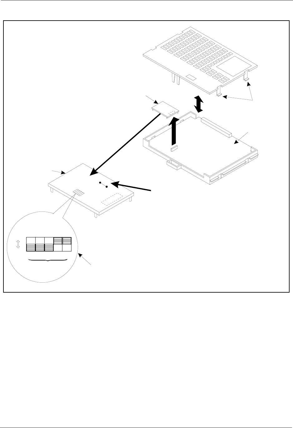
Section 300-Installation Chapter 5. Peripheral Equipment
DBS-2.3/9.2-300 DBS Manual - Revised April 2000 5-7
Figure 5-3. RAI connection
RAI-A(VB-43706): 300 bps
or
RAI-B(VB-43707): 300 or 1200 bps
SCC-B Car
d
(VB-43421)
Hooks
OFF
ON
SW 4
J
1
124816
7dBm
RAI-B C a rd
Setsattenuation level.
The attenuation isthe
sum of the "ON"settings.
LeaveJ1Closed
(300 BPS/1200
BPS M ode)

Chapter 5. Peripheral Equipment Section 300-Installation
5-8 DBS Manual - Revised April 2000 DBS-2.3/9.2-300
Background Music/Music-On-Hold
Guidelines
• A single music source can be used for both background music (BGM) and
music-on-hold (MOH), or separate music sources can be used for each
feature.
• If a single music source is used for both MOH and BGM, the music source
connects to CN5 on the Connector Panel. If separate sources are used, the
MOH source connects to CN5, and the BGM source connects to the BGM
connector on the SCC card.
• If an FM radio is connected to the BGM connector on the SCC, install it at
least 16.5 ft. (5m) away from the main cabinet. If it is too close, the
receiver may not function properly.
• The maximum input impedance of both terminals is 10k ohms. The
maximum signal level is -10 dB.
• Beginning with CPC-AII and CPC-B Version 7.0, an internal hold tone
may be selected in programming. If selected, the internal hold tone will
always be used even if a sound source is connected to MOH connector
CN5.
Installation
1. If you are using a single source for both BGM and MOH, connect the
source to CN5 on the Connector Panel. If using separate sources, connect
the MOH source to CN5 and the BGM source to the BGM connector on
the SCC card.
2. Strap the CN5 block (SCC-A) or the CN4 block (SCC-B) according to
the number of music sources used.
To route the music from ... Do this ...
A single source Short pin 3 to 2.
Separate sources Short pin 1 to 2.
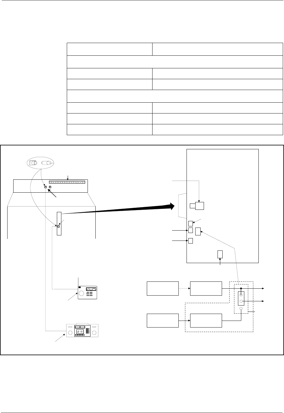
Section 300-Installation Chapter 5. Peripheral Equipment
DBS-2.3/9.2-300 DBS Manual - Revised April 2000 5-9
Note: To change the volume levels of the music sources, adjust the
variable resistors on the SCC card.
Table 5-3. SCC variable resistors
Figure 5-4. Installation of music-on-hold and background music
Variable Resistor Purpose
SCC-A
VR1 Adjusts CO ringing tone volume.
VR5 Adjust MOH and BGM volume.
SCC-B
VR1 Adjusts MOH volume.
VR2 Adjust BGM volume.
VR6 Adjusts CO ringing tone volume.
CN2
MOH Input
MotherBoard
BGM
C onnector
BGM
C onnector
VR2
VR1
VR6
SW 4
(SCC-BOnly)
Earphone
Jack
Radio
BG M only
ToMOH
Circuit
C onnectPins 3 and 2 toroutemusicfrom a single source.
C onnectPins 1 and 2 toroutemusicfrom m ultiplesources
oruse internalM O H tone.
Tap e
Recorder
Radio
CN5on
MotherBoard
BGM
C onnector
To B G M
Circuit
SCC-A=CN5
SCC-B=CN4
SCC
3
2
1
Tape R ecorder
MOH or
M O H and BG M
Earphone
Jack
CN5 CN4
SCC

Chapter 5. Peripheral Equipment Section 300-Installation
5-10 DBS Manual - Revised April 2000 DBS-2.3/9.2-300
Off-Premises Adaptor (OPX)
Guidelines
• Analog phones can be connected as off-premise stations through a direct
line to the DBS or through the central office, depending on how far the
stations are from the OPX Adaptor.
Table 5-4 shows how far the OPX stations can be from the adaptor without
going through a CO.
Table 5-4. Maximum distances for direct connection to OPX stations
• One OPX Adaptor (VB-43702) is required for each OPX station.
• The ringing output of the OPX Adaptor is 225 Vp-p (peak-to-peak) at 20
Hz.
• When OPX stations are connected through the central office, an external
ringer supply may be required. If required, the ringing supply is connected
to the OPX Adaptor.
• Order an OL13C circuits for OPX stations connected through a CO.
• The following tools are required to install the OPX Adaptor:
- Phillips screwdriver
- Needle-nose pliers
- Diagonal shears.
Wiring
gauge Max. distance (in feet) between
the OPX Adaptor and the OPX
station
AWG 22 27877
AWG 24 17532
AWG 26 11025
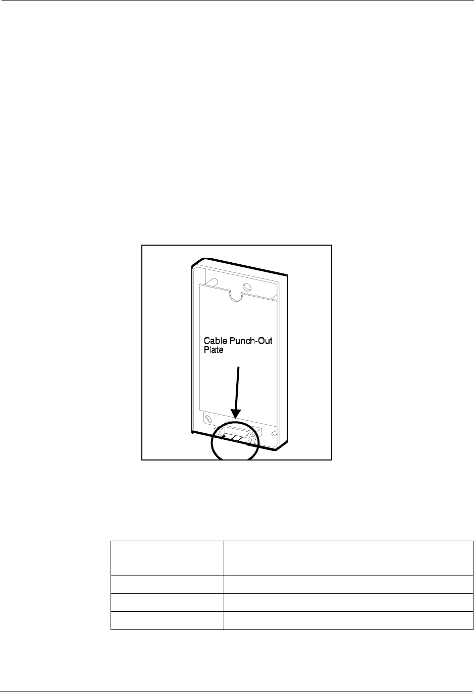
Section 300-Installation Chapter 5. Peripheral Equipment
DBS-2.3/9.2-300 DBS Manual - Revised April 2000 5-11
Installation
The following procedures describe direct OPX connection and OPX
connection through a CO. Order an OL13C circuit for an OPX through a CO.
Refer to Figure 5-6 on page 5-13 when installing the OPX.
Installing an OPX Station Without Going Through a Central Office
1. Remove the cover from the OPX Adaptor.
2. Remove the cable punch-out plate (Figure 5-12) to make an opening for
the cables coming into the OPX Adaptor.
To remove the plate, cut the grooves on either side with diagonal shears.
Then bend the plate back and forth with needle-nose pliers to remove it.
Figure 5-5. Cable punch-out plate, OPX Adaptor
3. Mount the OPX Adaptor to the wall.
Note: Table 5-5 shows how far the Adaptor can be located from the DBS.
Table 5-5. Maximum distances for OPX Adaptor installation
Wiring gauge Max. distance (in feet) between the DBS and
OPX Adaptor
AWG 22 309
AWG 24 194
AWG 26 122

Chapter 5. Peripheral Equipment Section 300-Installation
5-12 DBS Manual - Revised April 2000 DBS-2.3/9.2-300
4. Connect the “R” and “T” leads to a digital extension port on the DBS.
5. Connect the “GND” lead on the OPX Adaptor to the DBS Frame Ground
screw.
6. Connect the “TR” and “TT” leads to the OPX station.
7. Install the cover on the OPX Adaptor.
8. Turn the system off and back on, or unplug the cable connected to the
digital extension and then plug it back in.
Installing an OPX Station Through a Central Office
1. Perform Steps 1 through 5 of “Installing an OPX Station Without Going
Through a Central Office” on page 5-11.
2. Connect the “TR” and “TT” leads to the central office.
Note: If the central office requests a ground on the tip side of the OPX,
strap Pins 1 to 2 on CN3.
3. If the ringing level at the OPX station is not sufficient, connect a ringing
supply to the “E-RG+” and “E-RG-” terminals on the OPX Adaptor.
Note: Signals to the external ringer should not exceed 300 Vp-p.
4. If a ringing supply is used, cut Straps J1 and J2 on the OPX Adaptor.
5. Install the cover on the OPX Adaptor.
6. Power the system down then back up, or unplug the cable connected to
the digital extension, then plug it back in.
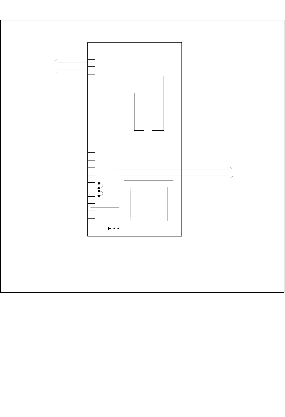
Section 300-Installation Chapter 5. Peripheral Equipment
DBS-2.3/9.2-300 DBS Manual - Revised April 2000 5-13
Figure 5-6. OPX installation
R
T
Off-Prem ise
Extension Adaptor
(VB-43702)
CN3
GND
TT
J1J2
IC4
IC5
TR
To off-prem ise
SLT or
dem arcation
block
To the D B S
FrameGround
screw
(Terminals
forexternal
ringing source)
E-RG+
E-RG-
ToaDBS
digitalline
port
13

Chapter 5. Peripheral Equipment Section 300-Installation
5-14 DBS Manual - Revised April 2000 DBS-2.3/9.2-300
Paging
The DBS allows extensions to be grouped into paging groups numbered 00-
07. When you issue a page (by dialing #00-#07), you specify a paging group,
so that your announcement is heard over the key telephones and Digital
Single Line Telephones that are members of that group. Paging groups often
include people whose work is related.
External zone paging allows you to connect up to five speaker groups to the
DBS. Each speaker group is assigned to one of five paging zones (00-04).
Zone 00 corresponds to group 00. When you page group 00, your page is
heard over the All-Page Speaker(s) as well as all other external zones. Zones
01-04 correspond to groups 01-04. For example, when you page group 02, the
page is heard on the external speaker(s) assigned to zone 02. Paging groups
05-07 have no external paging zones.
If zone paging is not required, general paging relay terminals C (common), B
(break) and M (make) are also provided. The relay terminals activate any
time there is a page to an external page group. These are used when paging
and UNA use the same paging amplifier system. (See notes for more
information.)
Guidelines
• The paging amplifier, zone relays, and speakers are not provided with the
DBS. They must be purchased separately.
• The maximum current for each zone paging terminal on the Connector
Panel (Z0-Z4) is 50 mA; the resistance of the relay used for each zone
paging terminal must be 2600 to 2800 Ohms.
• The contact rating for the UNA/General Paging “C” and “M” terminals is
30V DC, 1 amp (maximum).
• Connector 4 (CN4) on the Connector Panel is used to connect the paging
amplifier. The output impedance of CN4 is 600 Ohms; the loss/gain setting
is 0 dB.
External Page Zone Installation
1. Connect the paging amplifier to CN4 on the DBS Connector Panel. (See
Figure 5-7 on page 5-15.)
2. Connect the paging speakers to the amplifier and relays.
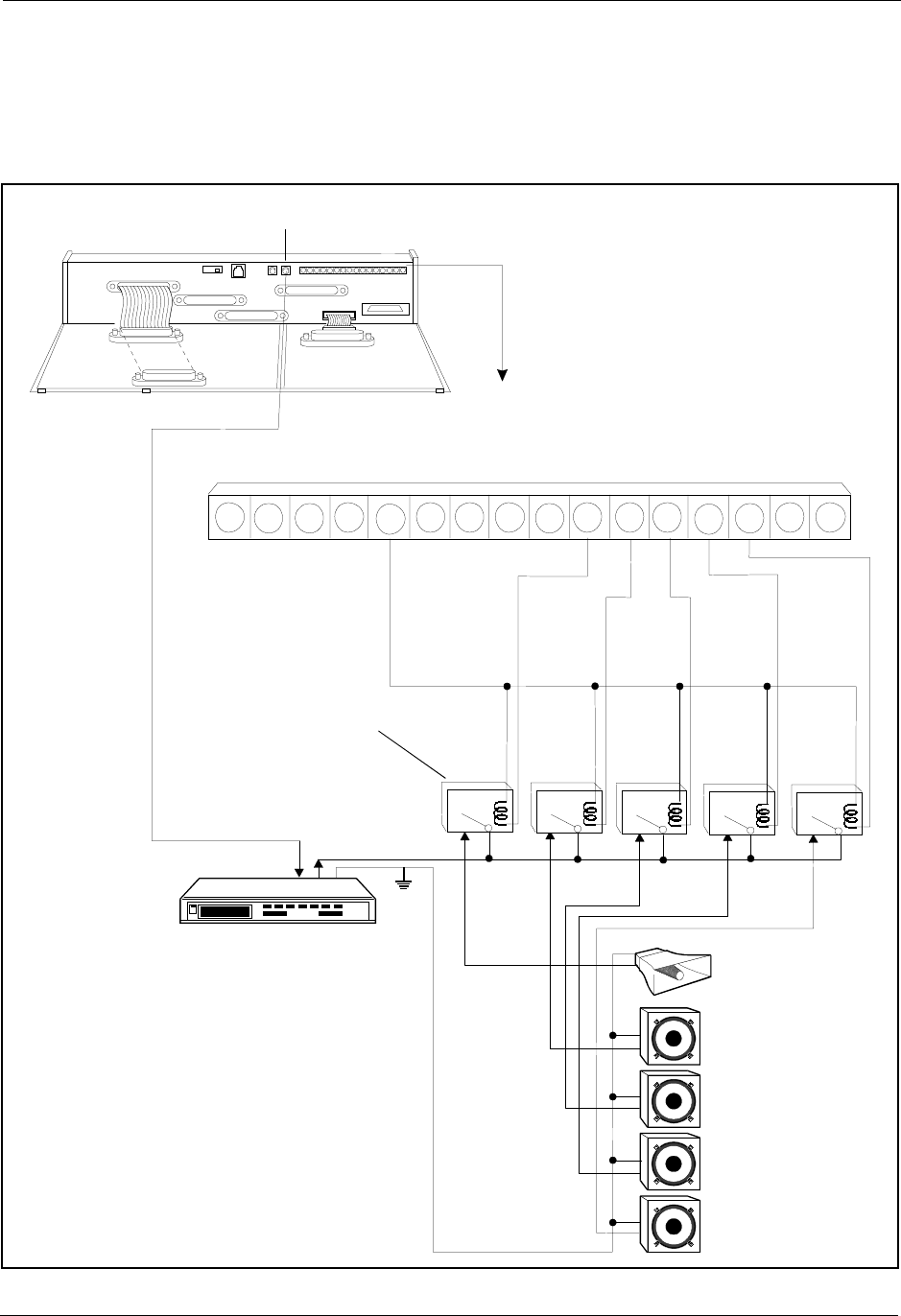
Section 300-Installation Chapter 5. Peripheral Equipment
DBS-2.3/9.2-300 DBS Manual - Revised April 2000 5-15
3. Connect the zone relays to the amplifier.
4. Connect the zone relays to the +24V and zone paging terminals (Z0-Z4)
on the Connector Panel.
Figure 5-7. External zone paging installation
Am plifier
All-Page
Speaker
Zone Page
#01
Zone Page
#02
Zone Page
#04
Zone Page
#03
SG RG
SYN RG +24V Z0GND C Z2BM Z1 Z3 RE2Z4 RE1-48V
CN4
(R C A C onnector)
CN2
CN11
CN12 CN5
CN13
CN3
CN14CN15
CN1
CN1
CN2
CN4
6
AudioInput AudioOutput
GND
6
6
6
6
33
3
3
3
1
1
1
1
1
12 12
1212
12
#00 #04
#03
#02
#01
Zone Relay:
Use Arom atRelay
Type D F2E-24V
(availableasStock
# 46F5752 at
NewarkElectronics
1-800-4-NEW ARK)
orSimilarRelay
COMMON
MAKE
PAGEALL(ZONE0)
ZONE1
ZONE2
ZONE3
ZONE4
BREAK
Note: This is a simplified example
to show how the connections
operate. A more elaborate paging
system may be installed to balance
volume levels, etc.
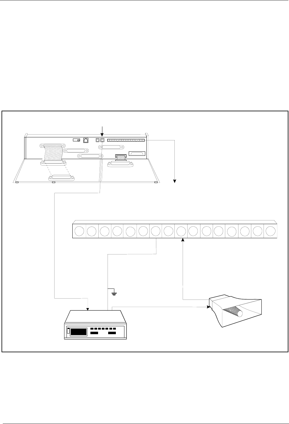
Chapter 5. Peripheral Equipment Section 300-Installation
5-16 DBS Manual - Revised April 2000 DBS-2.3/9.2-300
External General Page/UNA Installation
Use this procedure to connect a general page system, connect UNA over a
page system or connect a combined page/UNA system.
1. Connect CN4 on the DBS Connector Panel to the audio input of the
paging amplifier. (See Figure 5-8.)
2. Connect the audio output of the amplifier through the C and M relay
terminals to the speaker(s) as shown in Figure 5-8.
Figure 5-8. External general page/UNA installation
Notes:
• Instead of the described combined Paging/UNA configuration, most often
Universal Night Answer notification is provided by an external ringer
device. (See “External Ringer (UNA Device)” on page 5-17 for more
information on UNA external ringer device installation.)
Am plifier
G eneralPage and/or
U N A S peaker
SG RG
SYN RG +24V Z0GND C Z2B M Z1 Z3 RE2Z4 RE1-48V
CN4
(RCA Connector)
CN2
CN11
CN12 CN5
CN13
CN3
CN14CN15
CN1
CN1
CN2
CN4
AudioInput
Signaland G N D
(2wire)
AudioOutputS ignal
AudioOutput
GND
COMMON
MAKE
BREAK

Section 300-Installation Chapter 5. Peripheral Equipment
DBS-2.3/9.2-300 DBS Manual - Revised April 2000 5-17
• If UNA operates over the paging system, the Audio Output of CN4
provides the Audio Ringback sound to be heard over the paging system
when a trunk rings UNA.
• If UNA operates over the paging system, the UNA ringing will always
takes precedence over paging. When a page is interrupted in progress, the
pager must hang up and wait until after UNA ringing ends to reinstate the
page.
• If UNA rings over the paging system, set the Ring Patterns for UNA
Terminals (M, C, & B) to continuous ring burst (FF1 2# 4# 1# 1#). This
sets the contacts to remain continuously activated during the UNA ring
broadcast.
External Ringer (UNA Device)
Guidelines
• An external ringer device can be used to alert users when Universal Night
Answer (UNA) calls come in.
• The external ringer device is not provided with the DBS. It must be
purchased separately.
• UNA calls can also be set to ring over an external paging system. See
“Paging” on page 5-14 for more information. This alternate connection is
preferred when both paging and UNA are required.
• The contact rating for the “C” and “M” terminals is 30V DC, 1 amp
(maximum).
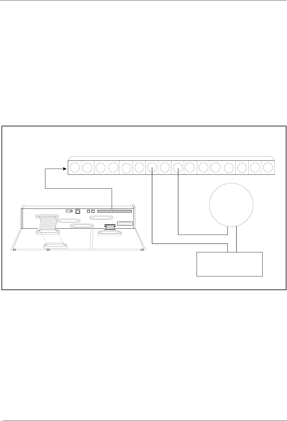
Chapter 5. Peripheral Equipment Section 300-Installation
5-18 DBS Manual - Revised April 2000 DBS-2.3/9.2-300
Installation
1. Connect the external ringer to the “C” and “M” terminals on the
Connector Panel. (See Figure 5-9 on page 5-18.)
Note: When the Ring Patterns for UNA Terminals (M, C, & B)
programming command (FF1 2# 4# 1# (0 or 1)# is set to 0, connecting the
ringer to the “C” and “M” terminals provides a “1 second on/3 seconds
off” ringing pattern and connecting to “C” and “B” terminals provides a
“1 second off/3 seconds on” ringing pattern.
2. Connect the external ringer to its DC power source.
Figure 5-9. External ringer (UNA device) installation
Notes:
• Most often, Unlivery Night Answer notification is provided by an external
ringer device. Universal Night Answer (UNA) can alternatively be set to
ring over the paging system. See “Paging” on page 5-14 for more
information.
• If UNA operates over a external ringer device, it is not recommend that
external paging also be used. Since contacts C, B and M activate for both
UNA calls and external pages, the external ringer device would turn ON
for all pages.
SG RG
SYN R G +24V Z0GND C Z2B M Z1 Z3 RE2Z4 RE1-48V
Bellor
OtherR inging
Device
Note:C onnectto C and B Terminalsif
bellneeds tobreak contacttotrip.
DC
Pow erS upply
CN11
CN12 CN5
CN13
CN3
CN14CN15
CN1
CN1
CN2
CN4
CN2

Section 300-Installation Chapter 5. Peripheral Equipment
DBS-2.3/9.2-300 DBS Manual - Revised April 2000 5-19
Power Failure Unit
Guidelines
• Up to four SLTs can be connected to the Power Failure Unit (VA-43703).
If a power failure occurs, the SLTs will automatically receive dial tone
directly from the central office. DBS features and restrictions do not apply
when the SLTs are receiving dial tone from the CO.
• If a call is in progress through the Power Failure Unit (PFU) when the
power is restored, the call will be disconnected.
• The following tools are required to install the PFU:
- Phillips screwdriver
- Needle-nose pliers
- Diagonal shears.
Installation
1. Remove the cover from the Power Failure Unit (PFU).
2. Remove the cable punch-out plate (Figure 5-12) to make an opening for
the cables coming into the PFU.
To remove the plate, cut the grooves on either side with diagonal shears.
Then bend the plate back and forth with needle-nose pliers to remove it.

Chapter 5. Peripheral Equipment Section 300-Installation
5-20 DBS Manual - Revised April 2000 DBS-2.3/9.2-300
Figure 5-10. Cable punch-out plate, Power Failure Unit
3. Mount the PFU on the wall using the three screws provided with the unit.
(See Figure 5-11.)
4. Connect the trunks from the central office to the PFU.
5. Connect the SLTs to the AEC extension ports on the PFU.
6. Connect the trunks from the DBS to the PFU.
7. Connect the AEC ports from the DBS to the PFU.
When a power failure occurs, AEC “A” is switched to Trunk “A,” AEC
“B” is switched to Trunk “B,” and so on.
8. Connect the +24V and GND terminals from CN2 on the DBS Connector
Panel to the PFU.
9. Install the cover on the PFU.
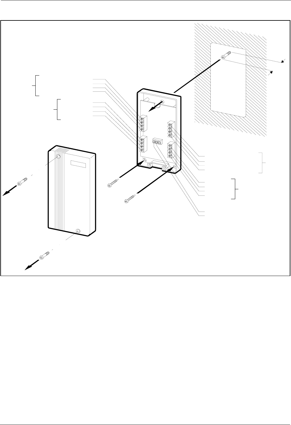
Section 300-Installation Chapter 5. Peripheral Equipment
DBS-2.3/9.2-300 DBS Manual - Revised April 2000 5-21
Figure 5-11. Power Failure Unit (PFU) installation
To +24V and G N D
on C N 2 ofthe
Main C abinet
(no polarization)
CN5
From
the M ain
Cabinet
AEC Extension PortN o.A
AEC Extension PortN o.B
AEC Extension PortN o.C
AEC Extension PortN o.D
To
theMain
C abinet
TRK PortN o.A
TRK PortN o.B
TRK PortN o.C
TRK PortN o.D
To the C entra l O ffice
Trunk Line A
Trunk Line B
Trunk Line C
Trunk Line D
To S LT
5/16 in
.
AEC Extension PortN o.A
AEC Extension PortN o.B
AEC Extension PortN o.C
AEC Extension PortN o.D
PowerFailureUnit
(VA-43703)

Chapter 5. Peripheral Equipment Section 300-Installation
5-22 DBS Manual - Revised April 2000 DBS-2.3/9.2-300
Voice Announce Unit (VAU)
Guidelines
• Operating temperatures for the Voice Announce Unit (VB-43708) should
be between 35 and 105 ° F.
• Maximum loop resistance for the VAU is 10 Ohms.
• The VAU contains a rechargeable lead-acid battery. Recharging circuity
for the battery is included on the VAU.
• The ports used for the VAU must have all FF key assignments cleared
before voice messages and abbreviated dial numbers are programmed.
• The following tools are required to install the VAU:
- Phillips screwdriver
- Needle-nose pliers
- Diagonal shears.
Installation
1. Remove the cover from the Voice Announce Unit.
2. Set SW1 and SW2 according to the following tables. (Default settings are
italicized.)
See Figure 5-14 for the location of the switch blocks.
Table 5-6. Switch settings for SW1, VAU
Switch Block 1 (SW1)
Switch Function
1ON=Enable blind transfer
OFF=Disable blind transfer
(VAU chip 1.1 or later is required for blind transfer.)
2ON=Small DBS
OFF=DBS and DBS 824
3 ON=Two messages up to 16 seconds each
OFF=One message up to 32 seconds
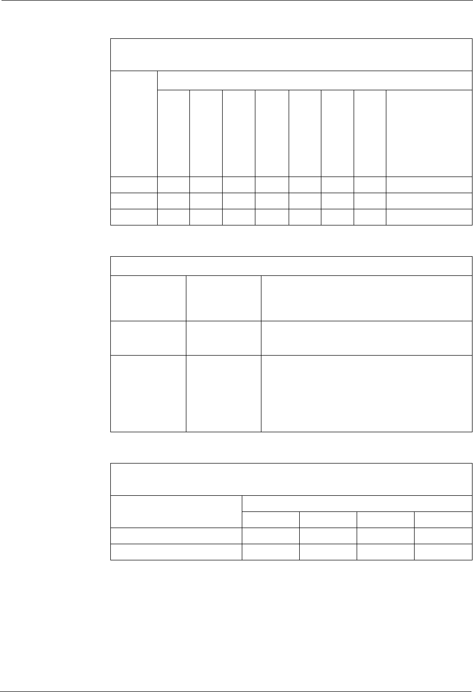
Section 300-Installation Chapter 5. Peripheral Equipment
DBS-2.3/9.2-300 DBS Manual - Revised April 2000 5-23
Table 5-7. Switch settings for delay answer timing, VAU
Table 5-8. Switch settings for DTMF detection timing, VAU
Table 5-9. Switch settings for wait timing between dialed digits, VAU
Switch Block 2 (SW2)
Delay Answer Timer (Switches 1-3)
Switch Timer (in seconds)
4812
16 20 24 28 No Answer
(VAU 1.1 or
below) or
Immediate
Answer (VAU
1.2 or above)
1OFFOFFOFF
OFF ON ON ON ON
2OFFOFFON
ON OFF OFF ON ON
3OFFONOFF
ON OFF ON OFF ON
DTMF Detection Timer
VAU
Version Switch
block and
switch
Function
1.1 or above SW2, pin 4 ON=80 ms
OFF=40 ms
1.0 or below SW1, pin 1
and SW2,
pin 4
Where X/X=SW1 setting/SW2 setting:
ON/ON=40
OFF/ON=60
ON/OFF=80
OFF/OFF=100
Switch Block 2 (SW2)
Wait Time Between Dialed Digits (Switches 5-6)
Switch Time (in seconds)
26
10 14
5OFFOFF
ON ON
6OFFON
OFF ON
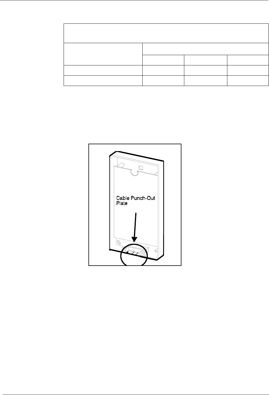
Chapter 5. Peripheral Equipment Section 300-Installation
5-24 DBS Manual - Revised April 2000 DBS-2.3/9.2-300
Table 5-10. Switch settings for abbreviated dialing digit length, VAU
3. Remove the cable punch-out plate (Figure 5-12) to make an opening for
the cable coming into the VAU.
To remove the plate, cut the grooves on either side with diagonal shears.
Then bend the plate back and forth with needle-nose pliers to remove it.
Figure 5-12. Cable punch-out plate, Voice Announce Unit
4. Mount the VAU on the wall using the three screws provided with the unit.
(See Figure 5-14.)
5. Connect the extension cable from the DBS to CN1 on the VAU.
Note: The two inside pins on CN1 are port 1. The two pins on either side
are port 2, as shown in Figure 5-13.
Switch Block 2 (SW2)
Abbreviated Dialing Digit Length (Switches 7-8)
Switch Number of Digits
1 Digit 2 Digits 3 Digits
7OFFOFF
ON
8OFFON
OFF
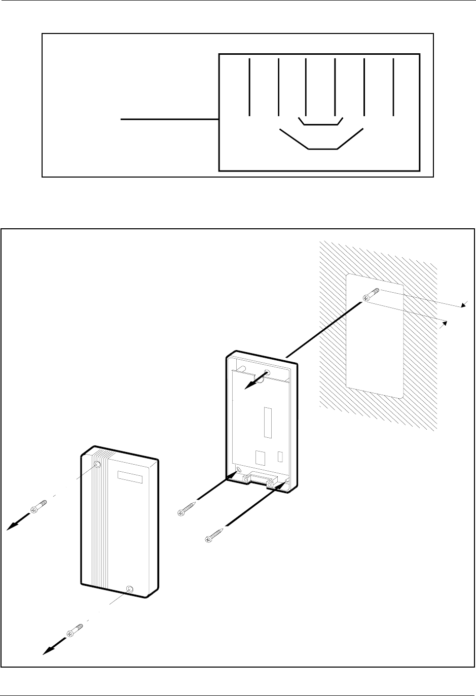
Section 300-Installation Chapter 5. Peripheral Equipment
DBS-2.3/9.2-300 DBS Manual - Revised April 2000 5-25
Figure 5-13. Extension cord connection to the VAU
6. Install the cover on the VAU.
Figure 5-14. Voice Announce Unit (VAU) installation
Port 1
BK R G Y
Port 2
CN1 on
the bottom
of the VAU
SW 2
CN1
SW 1
5/16 in
Voice A nnounce U nit
(VB-43708)

Chapter 5. Peripheral Equipment Section 300-Installation
5-26 DBS Manual - Revised April 2000 DBS-2.3/9.2-300
Recording and Playing Messages
You can record the VAU messages from either an extension or a trunk.
Notes: You must use a DTMF telephone to record and play VAU
messages. To change existing messages, record over them.
To record and play messages, complete the following steps.
1. Do one of the following:
2. After the VAU answers, do one of the following:
Notes: You can enter the *97 codes again to replay messages without
ending your call. You can only record one message at a time. To record
another message, you must end your call and redial the VAU.
3. When the operation is complete, put the phone on hook.
Note: For more information on the VAU and its operation, see Section
770, “Voice Announce Unit User Guide.”
If . . . Then . . .
You are recording or play-
ing from an extension Take your phone off hook.
Dial the VAU extension number. (If the intercom is set for
Voice, dial 1 to change from Voice to Tone.)
You are recording or play-
ing from a trunk Dial the phone number of the VAU, or call in and have the opera-
tor transfer you to the VAU extension.
If . . . Then . . .
You want to record the
first message Dial * 98 1
Wait for a beep. After the beep, record the message.
You want to record the
second message Dial * 98 2
Wait for a beep. After the beep, record the message.
You want to play the first
message Dial * 97 1
The VAU plays the message.
You want to play the
second message Dial * 97 2
The VAU plays the message.

Section 300-Installation Chapter 5. Peripheral Equipment
DBS-2.3/9.2-300 DBS Manual - Revised April 2000 5-27
Door Box Adaptor (Trunk Port)
Guidelines
There are two types of door phone adaptors available for the DBS. The first
type (VB-43701) utilizes a trunk connection to connect to the door box and is
described below. The second type (VB-43711) utilizes a digital port
extension to connect to the door box and door opener. See“Door Box Adaptor
(Extension Port)” on page 5-31 for more information.
Each Door Box Adaptor (VB-43701) can be used to connect one door sensor
and up to two Door Boxes (VA-43705) equipped with door openers. Door
openers and door sensors are not sold by Panasonic; they can be purchased
separately from an electronics dealer.
Door Sensors
• A door sensor is similar to an alarm; different types of sensors detect
different things, such as a door opening, moisture, heat, etc. When the
sensor is tripped, a trunk rings on a dedicated key. You can reset the
“alarm” by answering the key.
• To set up a sensor, assign a trunk to ring at a phone, and then assign that
trunk to an FF key.
• Each sensor uses one trunk port.
Door Boxes with Door Openers
• Door Boxes and door openers work together. The Door Box allows
visitors to announce their presence from outside the office. The door
opener enables a user to unlock the door using a telephone.
• To set up the Door Box and opener, assign a trunk to ring at a phone and
then assign that trunk to an FF key.
• When a visitor is announced from the Door Box, the user presses the
ringing FF key to answer the call. Then, to open the door, the user dials 3.
• The door opener can be set to open the door for 15 seconds, 30 seconds, or
one minute.
• Up to two Door Boxes with openers can be connected to a Door Box
Adaptor.
• Each Door Box and opener use one trunk port.

Chapter 5. Peripheral Equipment Section 300-Installation
5-28 DBS Manual - Revised April 2000 DBS-2.3/9.2-300
Requirements
• Trunks used for Door Boxes and openers must be set up as dial pulse
trunks.
• Equipment combinations used with the Door Box Adaptor require the
number of trunks in the following table:
• The following tools are required to install the Door Box Adaptor:
- Phillips screwdriver
- Needle-nose pliers
- Diagonal shears.
Installation
1. Remove the cover from the Door Box Adaptor.
2. Set the switches in the Door Box Adaptor as shown in Figure 5-16.
3. Remove the cable punch-out plate Figure 5-12 in order to make an
opening for the cables coming into the Door Box Adaptor.
To remove the plate, cut the grooves on either side with diagonal shears.
Then bend the plate back and forth with needle-nose pliers to remove it.
If you use . . . The adaptor uses
1 sensor and 1 Door Box/opener 2 trunks
1 sensor and 2 Door Boxes/open-
ers 2 trunks
1 sensor 1 trunk
1 Door Box/opener 1 trunk
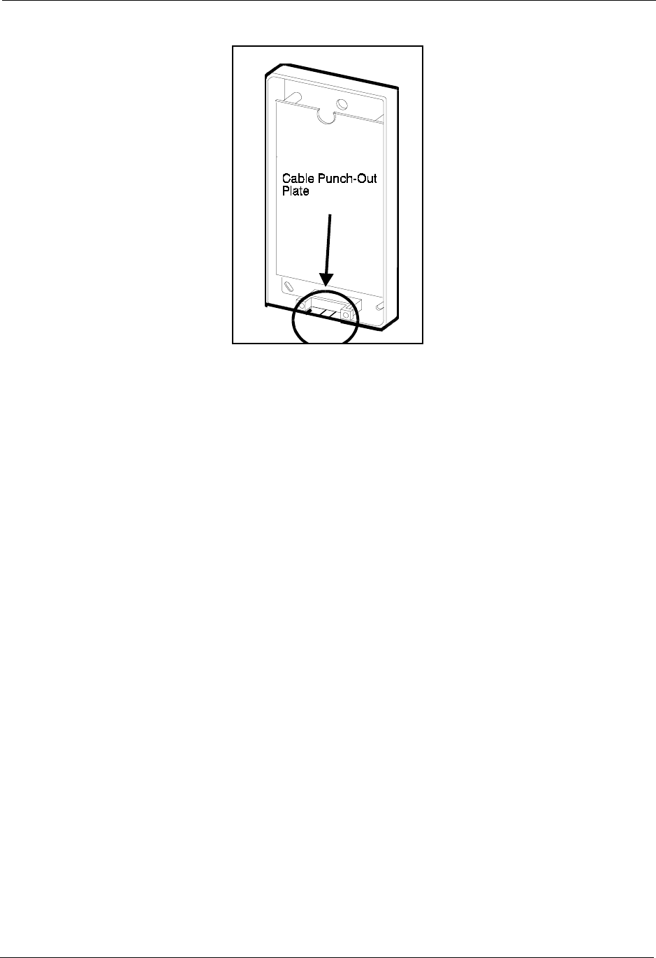
Section 300-Installation Chapter 5. Peripheral Equipment
DBS-2.3/9.2-300 DBS Manual - Revised April 2000 5-29
Figure 5-15. Cable punch-out plate, Door Box Adaptor
4. Mount the Door Box Adaptor on the wall using the three screws provided
with the unit.
5. Connect the trunk line(s) to the Door Box Adaptor, as shown in Figure 5-
16.
The “CO.D” connector is used for the Door Box and opener. The “CO.S”
connector is used for the sensor.
6. Connect the Door Box, door opener, and sensor to the Door Box Adaptor.
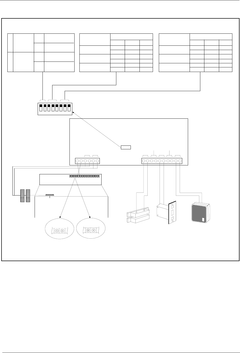
Chapter 5. Peripheral Equipment Section 300-Installation
5-30 DBS Manual - Revised April 2000 DBS-2.3/9.2-300
Figure 5-16. Installation of the door box, door opener, and door sensor
CN2
CO,SCO,D
GND
+24V
CN1
MDF
DBS 40 DBS 72
/
DBS 96
DoorBoxAdaptor(VB-43701)
Sensor D oorO pener1 D oorB ox 1
G N D +24V +24V G N D
Sensor D PH 1O pener1
DPH 2O pener2
ON
OFF 12345678
Sensor
Type
Detect-Close
Detect-Open
Sounds During
Detect
Sounds Until
Reset
1
2Sensor
Detection
Tone
ON
ON
OFF
OFF
D oorO pener
Operation Time
1Sec
DipSW
3Sec
5Sec
678
ON
ON
ON
OFF
OFF OFF
OFF
OFFOFF
DoorBox
CallTime
15 Sec
DipSW
30 Sec
60 Sec
345
ON
ON
ON
OFF
OFF OFF
OFF
OFFOFF
Contact Ratings for
Opener 1 and 2:
120V AC: 0.3 amps
30V DC: 1 amp
Door Opener
Contact Short
Occurs During
Trip of Relay
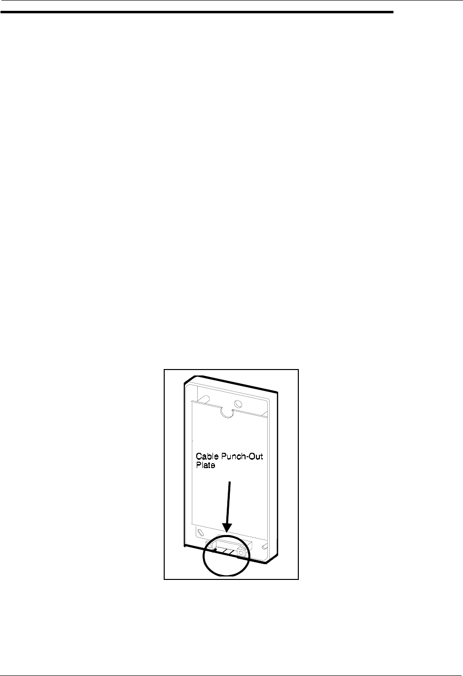
Section 300-Installation Chapter 5. Peripheral Equipment
DBS-2.3/9.2-300 DBS Manual - Revised April 2000 5-31
Door Box Adaptor (Extension Port)
Note: There are two types of door phone adaptors available for the DBS. The
first type (VB-43701) utilizes a trunk connection to connect to the door box.
See “Door Box Adaptor (Trunk Port)” on page 5-27 for more information.
The second type (VB-43711) utilizes a digital port extension to connect to the
door box and door opener and is described below.
Guidelines
• The Door Box Adaptor (VB-43711) requires a door opener. In addition, a
Door Box (door phone) (VA-43705) is normally used with the Door Box
Adaptor. The door opener is not sold by Panasonic; it can be purchased
separately from an electronics dealer.
• Each Door Box and opener use one extension port.
Installation
1. Remove the cover from the Door Box Adaptor.
2. Remove the cable punch-out plate (Figure 5-17) in order to make an
opening for the cables coming into the Door Box Adaptor. To remove the
plate, cut the grooves on either side with diagonal cutters. Then bend the
plate back and forth with needle-nose pliers to remove it.
Figure 5-17. Cable punch-out plate, Door Box Adaptor
3. Mount the Door Box Adaptor on the wall using the three screws provided
with the unit.
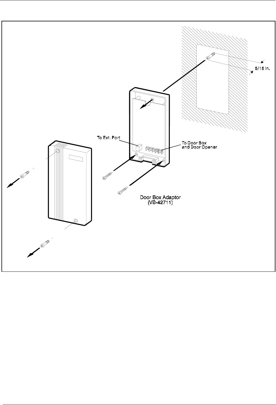
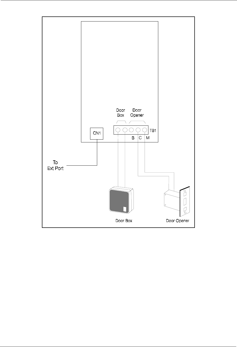
Section 300-Installation Chapter 5. Peripheral Equipment
DBS-2.3/9.2-300 DBS Manual - Revised April 2000 5-33
Figure 5-19. Connections to the Door Box Adaptor
5. Connect the Door Box and door opener to the Door Box Adaptor.
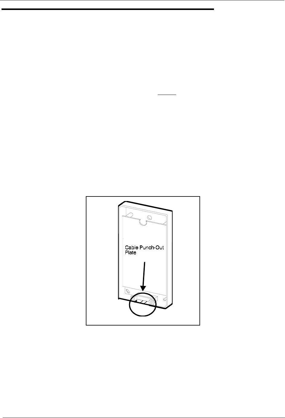
Chapter 5. Peripheral Equipment Section 300-Installation
5-34 DBS Manual - Revised April 2000 DBS-2.3/9.2-300
Single Line Telephone Adaptor
Guidelines
• The Single Line Telephone Adaptor (SLTA, VB-43709) provides an
alternative way of connecting analog DTMF telephones (2500 sets). One
SLTA supports up to 4 Single Line Telephones.
• Each SLT extension requires a digital extension port connection to the
SLTA.
Installation
1. Remove the cover from the SLTA.
2. Remove the cable punch-out plate (Figure 5-20) to make an opening for
the cables coming into the SLTA.
To remove the plate, cut the grooves on either side with diagonal cutters.
Then bend the plate back and forth with needle-nose pliers to remove it.
Figure 5-20. Cable punch-out plate, SLTA
3. Mount the SLTA to the wall (see Figure 5-21).
Note: Table 5-11 shows the maximum distance the SLTA can be located
from the DBS.

Section 300-Installation Chapter 5. Peripheral Equipment
DBS-2.3/9.2-300 DBS Manual - Revised April 2000 5-35
Table 5-11. Maximum distances for SLTA installation
4. If the DBS is powered up, turn off the power.
5. Connect the GND and +24V leads on the SLTA to the DBS connector
panel. Be sure the wires do not touch each other or touch the metal
frame housing.
6. Turn on the DBS power.
7. Connect the “T” and “R” leads to the digital extension ports on the DBS
as per Figure 5-21. One digital extension port is required for each SLT.
8. Connect the SLT “T” and “R” leads to the SLTs.
9. Install the cover on the SLTA.
Wiring
gauge Max. distance (in feet) between
the DBS and SLTA Max. distance (in feet) between
the SLTA and the SLT
AWG 22 300’ or 10 W 3000’ or 100 W
AWG 24 190’ or 10 W 1900’ or 100 W
AWG 26 120’ or 10 W 1200’ or 100 W
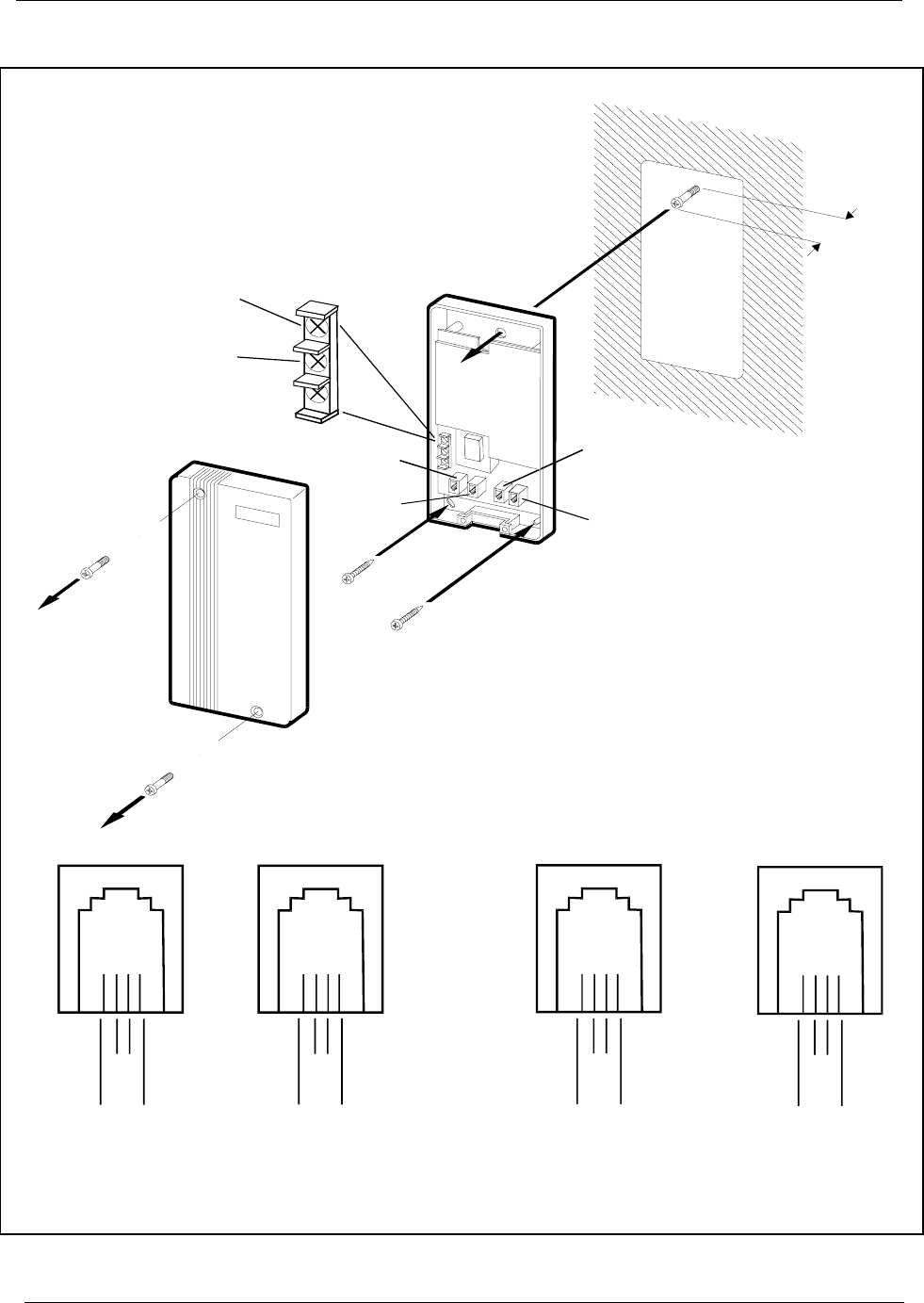
Chapter 5. Peripheral Equipment Section 300-Installation
5-36 DBS Manual - Revised April 2000 DBS-2.3/9.2-300
Figure 5-21. SLTA installation
DBS
Ext.P ort
AandB
DBS
Ext.P ort
CandD
To SLT A and B
To S LT C and D
5/16 in.
SLTA
(VB-43709)
BKRGYBKRGYBKRGYBKRGY
CN1
TTT
T
TTT
T
RRR
R
RRR
R
CN2 CN3 CN4
Ext
B
SLT
"B" SLT
"
D
"
Ext
D
Ext
A
SLT
"A" SLT
"C"
Ext
C
To G N D on
DBS CN2
C onnector
To +24V
onDBS CN2
C onnector

DBS-2.3/9.2-300 DBS Manual - Revised April 2000 6-1
Chapter 6. Double-Cabinet Systems
Two DBS cabinets can be connected in order to increase capacity. This
chapter includes connection procedures, as well as capacities for two-cabinet
systems.
See Chapter 4 for instructions on installing T1s in two-cabinet systems.
This chapter covers the following topics:
Topic Page
Guidelines 6-3
Installation 6-10

6-2 DBS Manual - Revised April 2000 DBS-2.3/9.2-300
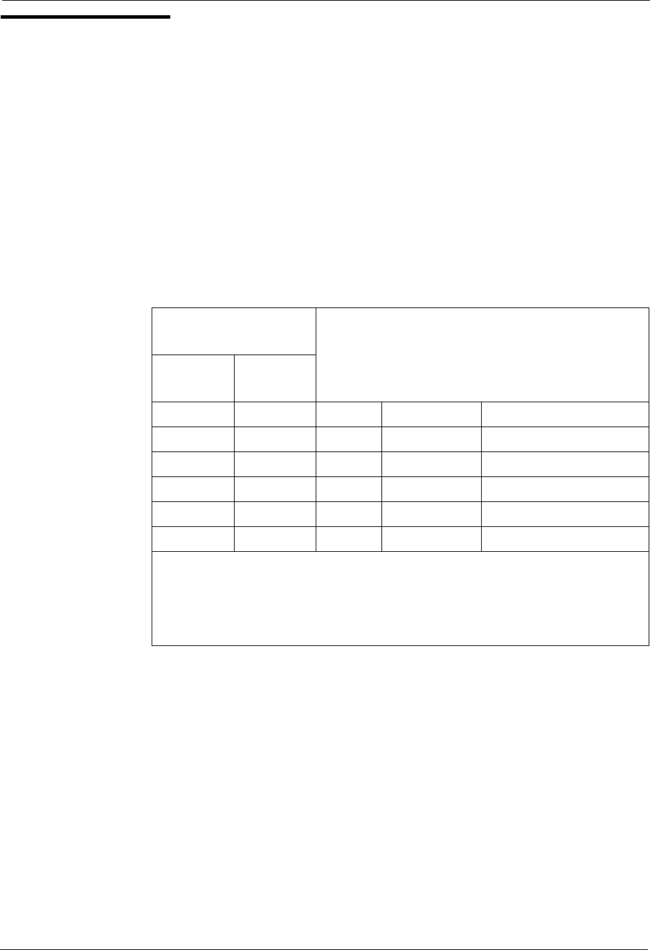
Section 300-Installation Chapter 6. Double-Cabinet Systems
DBS-2.3/9.2-300 DBS Manual - Revised April 2000 6-3
Guidelines
• Two DBS cabinets can be connected to increase line size. The maximum
line size consists of two DBS 96 cabinets, which provide 192 ports.
• CPC-B and SCC-B are required for two-cabinet systems.
• If ground start or DID trunks are used in both cabinets, separate -48V
supplies must be supplied for each cabinet. If AECs are used in both
cabinets, separate SLT ringer boxes must be supplied for each cabinet.
• The following table shows the acceptable combinations of system types
Table 6-1. Trunk and extension port maximums for double-cabinet systems
• Figures 6-1 through 6-6 shows slot usage for two-cabinet combinations.
System
Combinations Trunk Extension Expansion Ports
Master Slave Ports Ports (Trunk lines or
extensions)
DBS 40 DBS 40 16 48 8 (See Note 1.)
DBS 72 DBS 40 24 72 0 (See Note 2.)
DBS 72 DBS 72 32 96 8 (See Note 1.)
DBS 96 DBS 40 32 88 16
DBS 96 DBS 72 40 112 16
DBS 96 DBS 96 48 128 16
Notes:
1. The slave cabinet must be used for expansion ports.
2. When a DBS72 and DBS40 are connected, expansion ports cannot be
used.
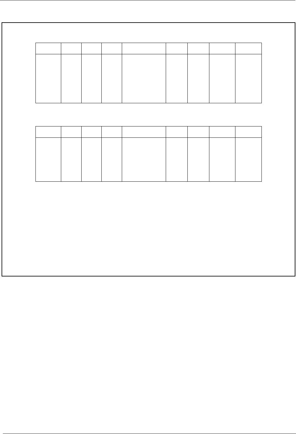
Chapter 6. Double-Cabinet Systems Section 300-Installation
6-4 DBS Manual - Revised April 2000 DBS-2.3/9.2-300
Figure 6-1. Slot usage for two-cabinet systems, DBS 40 + DBS 40
DBS 40 (Slave)
DBS 40 (Master)
Notes:
*See “T1 Interface” on page 4-11 for EC/TRK port numbers for T1.
#A maximum of two MFR cards can be installed in a two-cabinet system. With Cable Kit
Version 1.1, one MFR is installed in the Master AUX1, and one MFR is installed in the
Slave AUX1. With Cable Kit Version 1.2, both MFR cards are installed in the slave
cabinet--one in the CPC slot and one in AUX1. (When two MFR cards are used, Strap S3
on the second card must be cut.)
TRK1 EC1 EC2 EC3 EC/TRK SCC CPC AUX1 AUX2
TRK 9-16
EXT 25-32
EXT 33-40
EXT 41-48
TRK 17-24* or
EXT 49-56
N/A
MFR#
MFR#
CBL-S
TRK1 EC1 EC2 EC3 EC/TRK SCC CPC AUX1 AUX2
TRK 1-8
EXT 1-8
EXT 9-16
EXT 17-24
N/A
SCC-B
CPC-B
MFR# or API
CBL-M
Section 300-Installation Chapter 6. Double-Cabinet Systems
DBS-2.3/9.2-300 DBS Manual - Revised April 2000 6-5
Figure 6-2. Slot usage for two-cabinet systems, DBS 72 + DBS 40
DBS 40 (Slave)
DBS 72 (Master)
Notes:
*A maximum of two MFR cards can be installed in a two-cabinet system.With Cable Kit
Version 1.1, one MFR is installed in the Master AUX1, and one MFR is installed in the
Slave AUX1. With Cable Kit Version 1.2, both MFR cards are installed in the slave
cabinet--one in the CPC slot and one in AUX1. (When two MFR cards are used, Strap S3
on the second card must be cut.)
TRK1 EC1 EC2 EC3 EC/TRK SCC CPC AUX1 AUX2
TRK 17-24
EXT 49-56
EXT 57-64
EXT 65-72
N/A
N/A
MFR*
MFR*
CBL-S
TRK1 TRK2 EC1 EC2 EC3 EC4 EC5 EC6 EC/TRK SCC CPC AUX1 AUX2
TRK 1-8
TRK 9-16
EXT 1-8
EXT 9-16
EXT 17-24
EXT 25-32
EXT 33-40
EXT 41-48
N/A
SCC-B
CPC-B
MFR* or API
CBL-M
Chapter 6. Double-Cabinet Systems Section 300-Installation
6-6 DBS Manual - Revised April 2000 DBS-2.3/9.2-300
Figure 6-3. Slot usage for two-cabinet systems, DBS 72 + DBS 72
DBS 72 (Slave)
DBS 72 (Master)
Notes:
*See “T1 Interface” on page 4-11 for EC/TRK port numbers for T1.
Beginning with CPC-B Version 4, the EC/TRK slot in the slave DBS 72 can be used for
trunks or lines. Prior to CPC-B Version 4, this slot could only be used for lines.
#A maximum of two MFR cards can be installed in a two-cabinet system. With Cable Kit
Version 1.1, one MFR is installed in the Master AUX1, and one MFR is installed in the
Slave AUX1. With Cable Kit Version 1.2, both MFR cards are installed in the slave cabinet-
-one in the CPC slot and one in AUX1. (When two MFR cards are used, Strap S3 on the
second card must be cut.)
TRK
1TRK
2EC1 EC2 EC3 EC4 EC5 EC6 EC/
TRK SCC CPC AUX
1AUX
2
TRK 17-24
TRK 33-40
EXT 49-56
EXT 57-64
EXT 65-72
EXT 73-80
EXT 81-88
EXT 89-96
TRK 41-48* or
EXT 97-104
N/A
MFR#
MFR#
CBL-S
TRK
1TRK
2EC1 EC2 EC3 EC4 EC5 EC6 EC/
TRK SCC CPC AUX
1AUX
2
TRK 1-8
TRK 9-16
EXT 1-8
EXT 9-16
EXT 17-24
EXT 25-32
EXT 33-40
EXT 41-48
N/A
SCC-B
CPC-B
MFR# or API
CBL-M
Section 300-Installation Chapter 6. Double-Cabinet Systems
DBS-2.3/9.2-300 DBS Manual - Revised April 2000 6-7
Figure 6-4. Slot usage for two-cabinet systems, DBS 96 + DBS 40
DBS 40 (Slave)
DBS 96 (Master)
Notes:
*See “T1 Interface” on page 4-11 for EC/TRK port numbers for T1.
#A maximum of two MFR cards can be installed in a two-cabinet system. With Cable Kit
Version 1.1, one MFR is installed in the Master AUX1, and one MFR is installed in the
Slave AUX1. With Cable Kit Version 1.2, both MFR cards are installed in the slave cabinet-
-one in the CPC slot and one in AUX1. (When two MFR cards are used, Strap S3 on the
second card must be cut.)
TRK
1EC1 EC2 EC3 EC/
TRK SCC CPC AUX
1AUX
2
TRK 33-40
EXT 73-80
EXT 81-88
EXT 89-96
TRK 41-48* or
EXT 97-104
N/A
MFR#
MFR#
CBL-S
TRK
1TRK
2TRK
3EC1 EC2 EC3 EC4 EC5 EC6 EC7 EC8 EC/
TRK SCC CPC AUX
1AUX
2
TRK 1-8
TRK 9-16
TRK 17-24
EXT 1-8
EXT 9-16
EXT 17-24
EXT 25-32
EXT 33-40
EXT 41-48
EXT 49-56
EXT 57-64
TRK 25-32* or
EXT 65-72
SCC-B
CPC-B
MFR# or API
CBL-M
Chapter 6. Double-Cabinet Systems Section 300-Installation
6-8 DBS Manual - Revised April 2000 DBS-2.3/9.2-300
Figure 6-5. Slot usage for two-cabinet systems, DBS 96 + DBS 72
DBS 72 (Slave)
DBS 96 (Master)
Notes:
*See “T1 Interface” on page 4-11 for EC/TRK port numbers for T1.
#A maximum of two MFR cards can be installed in a two-cabinet system. With Cable Kit
Version 1.1, one MFR is installed in the Master AUX1, and one MFR is installed in the
Slave AUX1. With Cable Kit Version 1.2, both MFR cards are installed in the slave cabinet-
-one in the CPC slot and one in AUX1. (When two MFR cards are used, Strap S3 on the
second card must be cut.)
TRK
1TRK
2EC1 EC2 EC3 EC4 EC5 EC6 EC/
TRK SCC CPC AUX
1AUX
2
TRK 33-40
TRK 41-48
EXT 73-80
EXT 81-88
EXT 89-96
EXT 97-104
EXT 105-112
EXT 113-120
TRK 49-56* or
EXT 121-128
N/A
MFR#
MFR#
CBL-S
TRK
1TRK
2TRK
3EC1 EC2 EC3 EC4 EC5 EC6 EC7 EC8 EC/
TRK SCC CPC AUX
1AUX
2
TRK 1-8
TRK 9-16
TRK 17-24
EXT 1-8
EXT 9-16
EXT 17-24
EXT 25-32
EXT 33-40
EXT 41-48
EXT 49-56
EXT 57-64
TRK 25-32* or
EXT 65-72
SCC-B
CPC-B
MFR# or API
CBL-M

Section 300-Installation Chapter 6. Double-Cabinet Systems
DBS-2.3/9.2-300 DBS Manual - Revised April 2000 6-9
Figure 6-6. Slot usage for two-cabinet systems, DBS 96 to DBS 96
DBS 96 (Slave)
DBS 96 (Master)
Notes:
*See “T1 Interface” on page 4-11 for EC/TRK port numbers for T1.
#A maximum of two MFR cards can be installed in a two-cabinet system. With Cable Kit
Version 1.1, one MFR is installed in the Master AUX1, and one MFR is installed in the
Slave AUX1. With Cable Kit Version 1.2, both MFR cards are installed in the slave cabinet-
-one in the CPC slot and one in AUX1. (When two MFR cards are used, Strap S3 on the
second card must be cut.)
TRK
1TRK
2TRK
3EC1 EC2 EC3 EC4 EC5 EC6 EC7 EC8 EC/
TRK SCC CPC AUX
1AUX
2
TRK 33-40
TRK 41-48
TRK 49-56
EXT 73-80
EXT 81-88
EXT 89-96
EXT 97-104
EXT 105-112
EXT 113-120
EXT 121-128
EXT 129-136
TRK 57-64* or
EXT 137-144
N/A
MFR#
MFR# or API
CBL-S
TRK
1TRK
2TRK
3EC1 EC2 EC3 EC4 EC5 EC6 EC7 EC8 EC/
TRK SCC CPC AUX
1AUX
2
TRK 1-8
TRK 9-16
TRK 17-24
EXT 1-8
EXT 9-16
EXT 17-24
EXT 25-32
EXT 33-40
EXT 41-48
EXT 49-56
EXT 57-64
TRK 25-32* or
EXT 65-72
SCC-B
CPC-B
MFR# or API
CBL-M
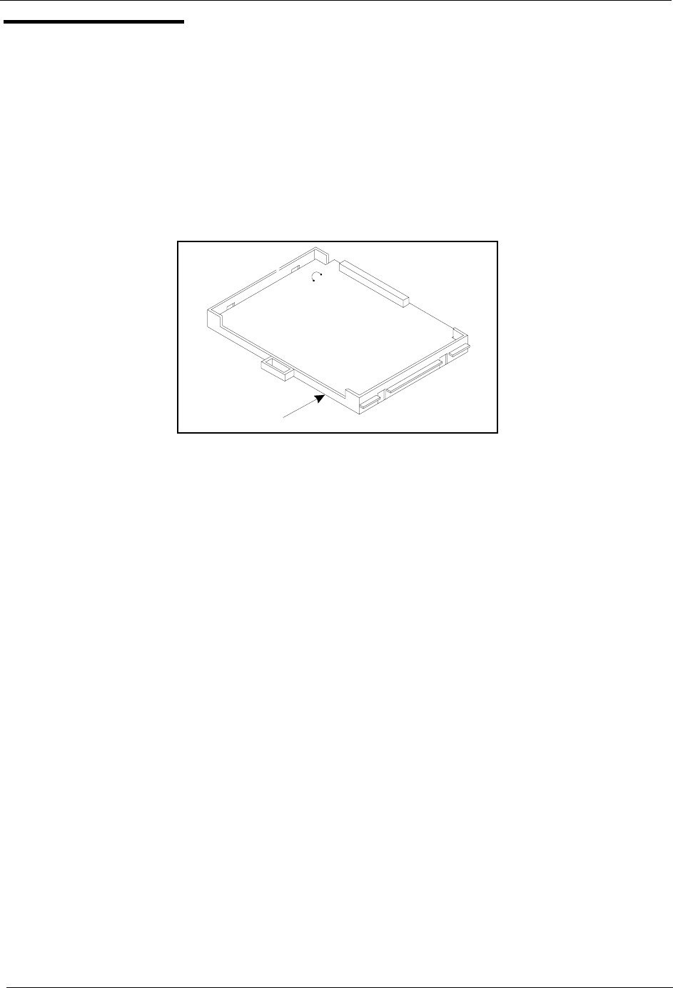
Chapter 6. Double-Cabinet Systems Section 300-Installation
6-10 DBS Manual - Revised April 2000 DBS-2.3/9.2-300
Installation
1. Install the trunk and extension cards according to the layouts shown in the
Figures 6-1 through 6-6.
Note: The port numbers for each slot are fixed.
2. If you are using two MFR cards, cut Strap S3 on the second card.
Figure 6-7. Strap 3, MFR card
3. Using the cables provided, connect the CBL-M card in the master cabinet
to the CBL-S card installed in the slave cabinet.
Note: The EMI filter must be installed as close to the cabinet as possible,
as shown in Figure 6-8 on page 6-11.
MFR Card
S3
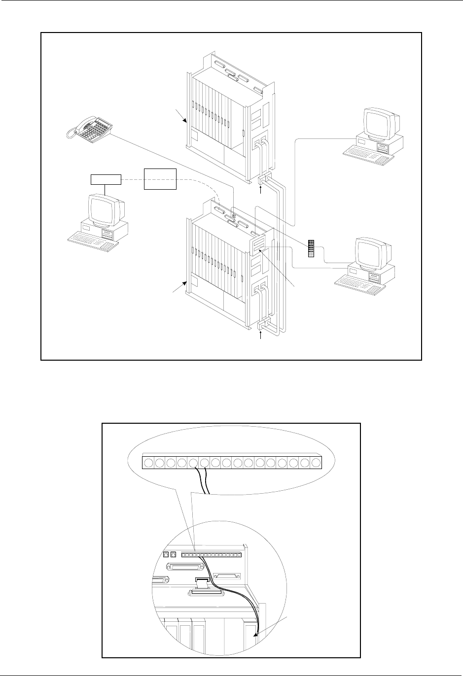
Section 300-Installation Chapter 6. Double-Cabinet Systems
DBS-2.3/9.2-300 DBS Manual - Revised April 2000 6-11
Figure 6-8. Double-cabinet installation
4. Connect two 24V power supply cords from the CBL-S card to the 24V
and GND terminals on CN2 of the Connector Panel of the slave cabinet.
Figure 6-9. CBL-S to Connector Panel connection, slave cabinet
Modem Programming Term ina
l
or
SM DR Printer
PC
(AC D or VM S)
MDF
SLT Lines
RS-232C
RS-232C
Adapter
EM I
Filters
EM I
Filters
Rem ote
PCAS
Digital D eskset
Program m ing Phone
RS-232C
Slave C abinet
Master C abinet
To C O
CN13 CN14 CN13 CN6
EC7 EC8 EC/TRKSCCCPCAUX1AUX2
CN5 CN4 CN2
-48V SG RG
SYN RG +24V GND C B M Z0 Z1 Z2 Z3 Z4 RE2 RE1
CBL-S
CARD
Black
Red
Slave
Cabinet
CN2

Chapter 6. Double-Cabinet Systems Section 300-Installation
6-12 DBS Manual - Revised April 2000 DBS-2.3/9.2-300
5. Set SW1 on the CBL-M card according to the following table.
Table 6-2. CBL-M switch settings
System Combinations Switch Settings
MasterSlave 12345678
DBS40 DBS40 ON ON ON ON ON ON OFF ON
DBS72 DBS40 ON OFF ON ON ON ON OFF OFF
DBS72 DBS72 ON OFF ON OFF ON OFF ON OFF
DBS96 DBS40 OFF ON OFF ON ON OFF OFF OFF
DBS96 DBS72 OFF ON OFF ON ON OFF OFF OFF
DBS96 DBS96 OFF ON OFF ON ON OFF OFF OFF

DBS-2.3/9.2-300 DBS Manual - Revised April 2000 7-1
Chapter 7. Specifications
This chapter contains frequently referenced DBS specifications.
Note: All maximums may not be attainable simultaneously. Also, attainment
of some maximums depends on levels of feature usage and optional hardware
requirements.
Though every effort has been made to ensure the accuracy of these
specifications, Panasonic does not warrant them in regard to merchantability
or fitness for a particular purpose. Specifications are subject to change
without notice.
This chapter covers the following topics::
Topic Page
Electrical Characteristics 7-3
Environmental Requirements 7-4
Resource Maximums 7-5
Cabling Specifications 7-13
Communication Parameters 7-14
Signaling Characteristics 7-15
Tone Characteristics 7-16

7-2 DBS Manual - Revised April 2000 DBS-2.3/9.2-300
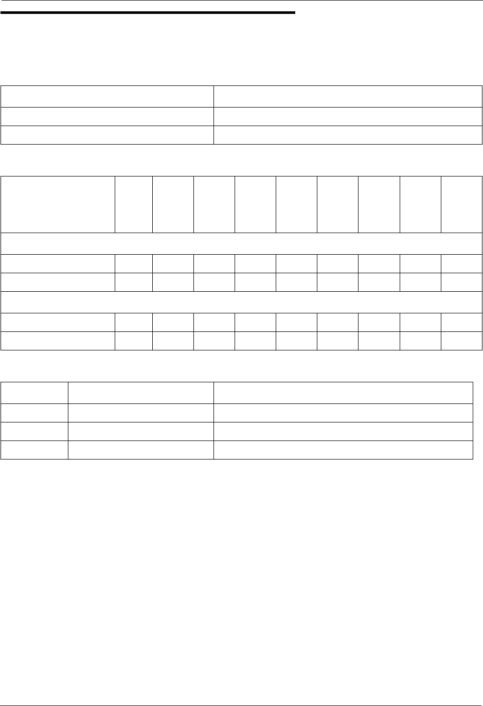
Section 300-Installation Chapter 7. Specifications
DBS-2.3/9.2-300 DBS Manual - Revised April 2000 7-3
Electrical Characteristics
Table 7-1. Input power
Table 7-2. Power consumption and heat generation
Table 7-3. Battery backup capacity
Equipment Power Requirements
All DBS cabinets 120V AC ± 10 % 60 Hz
DBS key phones 3 watts maximum (powered from the DBS)
System
Status
DBS 40
DBS 72
DBS 96
DBS 40 +
DBS 40
DBS 72 +
DBS 40
DBS 72 +
DBS 72
DBS 96 +
DBS 40
DBS 96 +
DBS 72
DBS 96 +
DBS 96
Power Consumption (in Watts)
With no traffic 170 250 320 340 420 500 490 570 640
With max. traffic 216 324 444 432 540 648 660 768 888
Heat Generation (Btu per hour)
With no traffic 580 853 1092 1160 1433 1706 1672 1945 2184
With max. traffic 737 1106 1515 1474 1843 2212 2253 2621 3031
System Battery Pack Capacity (with maximum traffic)
DBS 40 VB-43130 40 minutes
DBS 72 VB-43130 40 minutes
DBS 96 VB-43130 30 minutes

Chapter 7. Specifications Section 300-Installation
7-4 DBS Manual - Revised April 2000 DBS-2.3/9.2-300
Environmental Requirements
Table 7-4. Temperature and humidity requirements
Table 7-5. Dimensions and weight, single-cabinet systems and phones
Table 7-6. Dimensions for two-cabinet systems
Environmental Conditions Requirements
Temperature 32 to 104° F (0 to 40° C)
Relative Humidity 30 to 90%
Physical
Characteristics DBS 40 DBS 72 DBS 96
Dimensions (H x W x D in inches)
Cabinet 21 x 15 x 9.35 21 x 19.5 x 9.4 21 x 19.5 x 9.4
VB-43225 4 1/8 x 7 3/8 x 9
Other key phones 3 3/4 x 7 3/8 x 9
DSLT 3 1/8 x 7 3/8 x 9 1/8
DSS/72 3 1/2 x 7 1/2 x 9
EM/24 3 3/13 x 3 1/8 x 8 3/8
Weight (lbs)
Cabinet 53 65 68
VB-43225 2.3
Other key phones 2.2
DSLT 1.6
DSS/72 1.6
EM/24 .9
Cabinet Installation DBS 40 + DBS 40 All Other Combinations
Cabinets installed one above the other
(10 in. between) 52 x 15 x 9.35 52 x 19.5 x 9.4
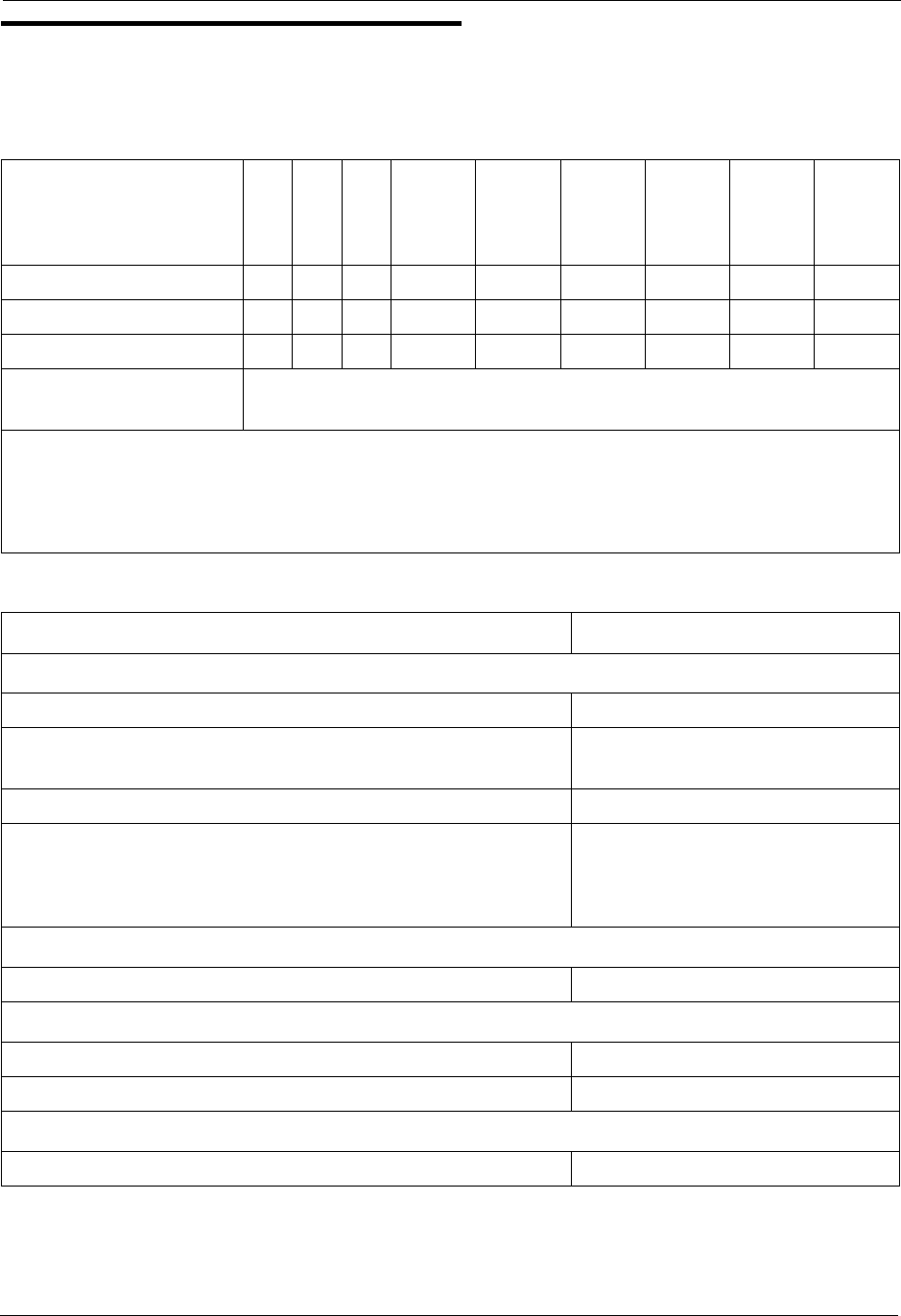
Section 300-Installation Chapter 7. Specifications
DBS-2.3/9.2-300 DBS Manual - Revised April 2000 7-5
Resource Maximums
Table 7-7. Trunk and line capacities
Table 7-8. Feature-related capacities
System
Resources
DBS 40
DBS 72
DBS 96
DBS 40 +
DBS 40
DBS 72 +
DBS 40
DBS 72 +
DBS 72
DBS 96 +
DBS 40
DBS 96 +
DBS 72
DBS 96 +
DBS 96
Trunk ports 8 16 24 16 24 32 32 40 48
Extension ports 24 48 64 48 72 96 88 112 128
Expansion ports 8 8 8 8 0 8* 16 16 16
Trunk/Extension speech
path switching nonblocking
Notes:
*Beginning with CPC-B Version 4, the EC/TRK slot in the slave DBS 72 can be used for trunks
or lines. Prior to CPC-B Version 4, this slot could only be used for lines. CPC-AII also allows
this.
Resource Maximums
Attendants
No. of attendants with CPC-A 2
No. of attendants with CPC-B and CPC-AII (Version 2.0 or
later) 4
No. of attendants that can be assigned DSS/72s 2 (ATTs 1 and 2 only)
No. of attendants that can be assigned Attendant Consoles
CPC-A and CPC-AII 0
CPC-B (Version 2.0 to 4.0 only) 4 (1 per attendant)
Callback requests
No. of requests that can be received by a single station 4
Call coverage
No. of groups 16
No. of stations in a group 8
Call forwarding
No. of simultaneous call forwarding registrations No. of stations in the system

Chapter 7. Specifications Section 300-Installation
7-6 DBS Manual - Revised April 2000 DBS-2.3/9.2-300
Conference circuits
SCC-A 3 four-party circuits
SCC-B with CPC-B 8 four-party circuits
SCC-B with CPC-A and CPC-AII 3 four-party circuits
DISA
No. of incoming authorization codes 1
No.of outgoing authrorization codes 2
No.of digits in each authorization code 4
Hunting
No. of groups 8
No. of stations in a group 8
Least cost routing
No. of routing tables 1 Area Code table
1 Office Code table
4 Special Area Code tables
4 Special Office Code tables
No. of entries in each routing table 1000
No. of digit addition tables 8
No. of digits that can be added 16
No. of digit deletion tables 8
No. of digits that can be deleted 16
No. of time priority tables 15
No. of LCR trunk groups 8
Toll Restrictions
No. of Toll Restriction types 8
No. of 7-digit restrictions 50
No. of area code restriction tables 4
No. of entries in each area code restriction table 1000 (4000 total)
No. of office code restriction tables 4
No. of entries in each office code restriction table 1000 (4000 total)
Paging
No. of groups 8
No. of stations in a group No. of stations in the system
Resource Maximums
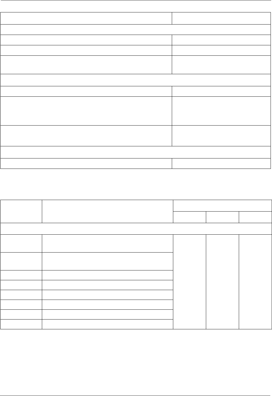
Section 300-Installation Chapter 7. Specifications
DBS-2.3/9.2-300 DBS Manual - Revised April 2000 7-7
Table 7-9. Hardware maximums for single-cabinet systems
Paging (continued)
No. of external paging zones 5
No. of stations in external paging zone 00 No. of stations in the system
No. of stations in external paging zones 01-04 No. of stations in corresponding
paging group 01-04
Speed dial
No. of personal speed dial numbers 10 per extension
No. of system speed dial numbers 90 (00 ~ 89) or
200 (000-199) with CPC-AII and
CPC-B Version 7.0
No. of digits per speed dial number
(personal and system)
16
Trunk Queuing
No. of trunk queuing registrations 1 per station
Part No. Description Quantity
DBS 40 DBS 72 DBS 96
Phones
VB-43210 16-key standard telephone with handsfree
answerback
32 56 72
VB-43220 22-key standard telephone with handsfree
answerback
VB-43221 22-key speakerphone
VB-43223 22-key speakerphone with LCD display
VB-43225 22-key speakerphone with large LCD display
VB-43230 34-key telephone with handsfree answerback
VB-43231 34-key speakerphone
VB-43233 34-key speakerphone with LCD display
Resource Maximums
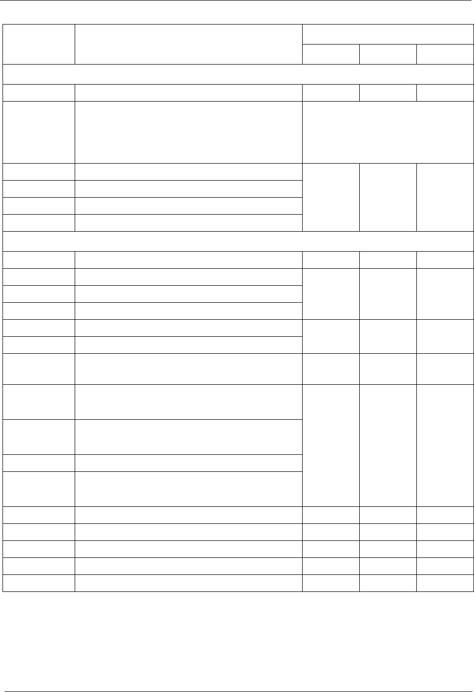
Chapter 7. Specifications Section 300-Installation
7-8 DBS Manual - Revised April 2000 DBS-2.3/9.2-300
Phone Options
VB-43310 24-key expansion module (EM24) 16 28 36
VB-43320 72-key DSS/BLF module (DSS/72) CPC-A and CPC-AII: 4
CPC-B: 8 (up to 4 can be assigned
as DSS/72s; up to 4 can be
assigned as Attendant Consoles)
VB-43884 7 ft. handset cord
32 56 72
VB-43885 15 ft. handset cord
VB-43886 25 ft. handset cord
VB-43890 K-type handset
Printed Circuit Cards
VB-43110 Cable kit for 2-system connection N/A N/A N/A
VB-43410 Call processor card (CPC-A)
111VB-43411 Call processor card (CPC-B)
VB-43412 Call processor card (CPC-AII)
VB-43420 Service circuit card (SCC-A) 111
VB-43421 Service circuit card (SCC-B)
VB-43431 DTMF signal receiver for 8 SLT lines (MFR/
8) 111
VB-43510 4-port loop-start trunk card
(L-TRK/4)
234
VB-43511 8-port loop-start trunk card
(L-TRK/8)
VB-43541 Direct-inward-dialing trunk card (DID)
VB-43531 8-port ground-start trunk card
(G-TRK/8)
VB-43561 T1 Interface 1 1 1
VB-43562 T1 MDF card 1 1 1
VB-43563 T1 Sync Unit 1 1 1
VB-43611 8-port digital extension card (DEC) 4 7 9
VB-43621 8-port analog extension card (AEC) 3 4 4
Part No. Description Quantity
DBS 40 DBS 72 DBS 96
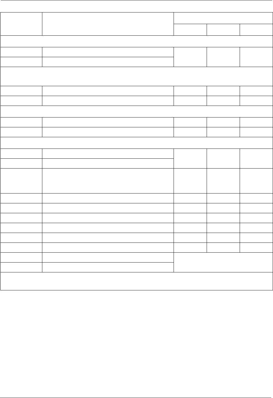
Section 300-Installation Chapter 7. Specifications
DBS-2.3/9.2-300 DBS Manual - Revised April 2000 7-9
Expansion Connectors
VB-43120 Trunk expansion connector 111
VB-43121 Extension expansion connector
Doorbox Equipment (Trunk)
VB-43701 Door box adaptor 8* 12* 16*
VB-43705 Door box 16* 24* 32*
Doorbox Equipment (Extension)
VB-43711 Extension-Based Door box adaptor 4 4 4
VB-43705 Door box 4 4 4
Optional Equipment
VB-43706 Remote Administration Interface (RAI-A) 111
VB-43707 Remote Administration Interface (RAI-B)
VB-43551 8-circuit Caller ID daughter board 1 per
VB-43511A
AEC
1 per
VB-43511A
AEC
1 per
VB-43511A
AEC
VB-43130 Built-in system backup batteries 1 1 1
VB-43709 Single Line Telephone Adaptor 8 14 18
VB-2089P SLT ringer box 1 1 1
VA-43703 4-line power failure unit 6 8 8
VB-43702 Off-premise extension adaptor 8 8 8
VB-43940 Application processor interface (API) 1 1 1
VB-43991 PCAS software 1
VB-43993 DBS Manager software
* Note: These maximums are based on overall trunk capacities and do not allow for trunks used
for outside lines.
Part No. Description Quantity
DBS 40 DBS 72 DBS 96
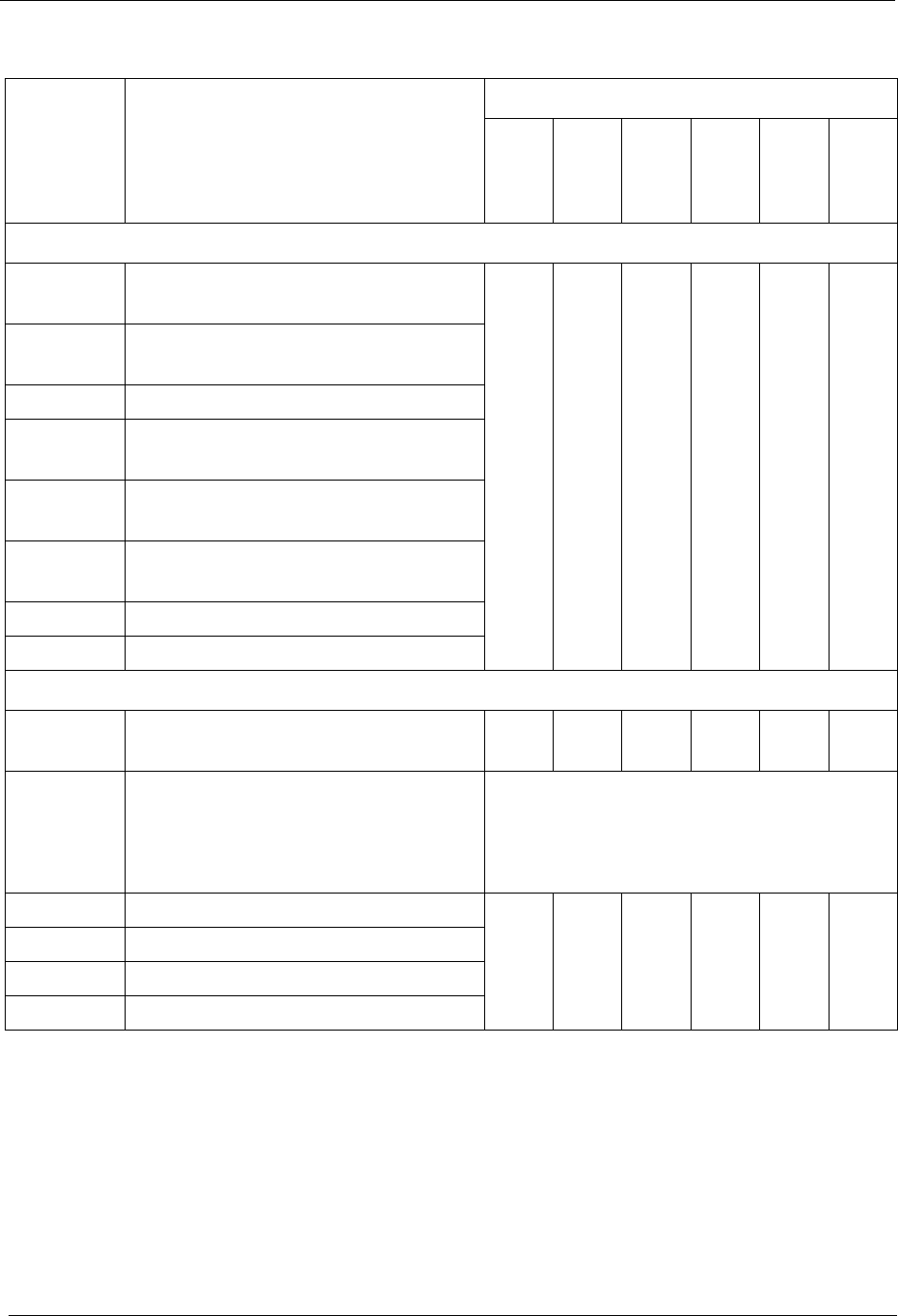
Chapter 7. Specifications Section 300-Installation
7-10 DBS Manual - Revised April 2000 DBS-2.3/9.2-300
Table 7-10. Hardware maximums for double-cabinet systems
Part No. Description Quantity
DBS 40 +
DBS 40
DBS 72 +
DBS 40
DBS 72 +
DBS 72
DBS 96 +
DBS 40
DBS 96 +
DBS 72
DBS 96 +
DBS 96
Phones
VB-43210 16-key keyphone
w/ handsfree answerback
56 72 104 104 128 144
VB-43220 22-key keyphone
w/ handsfree answerback
VB-43221 22-key speakerphone
VB-43223 22-key speakerphone
w/ LCD display
VB-43225 22-key speakerphone
w/ large LCD display
VB-43230 34-key keyphone
w/ handsfree answerback
VB-43231 34-key keyphone
VB-43233 34-key keyphone w/ LCD display
Phone Options
VB-43310 24-key expansion
module (EM24) 32 44 56 52 64 72
VB-43320 72-key DSS/BLF module (DSS/72) CPC-A and CPC-AII: 4
CPC-B (Version 2.0 to 4.0 only): 8 (up to 4
can be assigned as DSS/72s; up to 4 can be
assigned as Attendant Consoles)
VB-43884 7 ft. handset cord
56 72 104 104 128 144
VB-43885 15 ft. handset cord
VB-43886 25 ft. handset cord
VB-43890 K-type handset

Section 300-Installation Chapter 7. Specifications
DBS-2.3/9.2-300 DBS Manual - Revised April 2000 7-11
Part No. Description Quantity
DBS 40 +
DBS 40
DBS 72 +
DBS 40
DBS 72 +
DBS 72
DBS 96 +
DBS 40
DBS 96 +
DBS 72
DBS 96 +
DBS 96
Printed Circuit Cards
VB-43110 Cable kit for 2-cab. systems 1 1 1 1 1 1
VB-43410 Call processor card (CPC-A)
111111VB-43411 Call processor card (CPC-B)
VB-43412 Call processor card (CPC-AII)
VB-43420 Service circuit card (SCC-A) 111111
VB-43421 Service circuit card (SCC-B)
VB-43431 DTMF signal receiver for 8
SLT lines (MFR/8) 222222
VB-43510 4-port loop-start trunk card
(L-TRK/4)
335678
VB-43511 8-port loop-start trunk card
(L-TRK/8)
VB-43541 8-port Direct-inward-dialing
trunk card (DID)
VB-43531 8-port ground-start trunk
card (G-TRK/8)
VB-43561T1 Interface 101222
VB-43562T1 MDF Card 101222
VB-43563 T1 Sync Card 1 0 1 1 1 1
VB-43611 8-port digital extension card
(DEC) 7 9 13 13 16 18
VB-43621 8-port analog extension card
(AEC) 678788
VB-43551 8-port Caller ID Daughter
Board (used with Loop Start
Trunk Card VB-43511A)
1 per
VB-
43511A
1 per
VB-
43511A
1 per
VB-
43511A
1 per
VB-
43511A
1 per
VB-
43511A
1 per
VB-
43511A
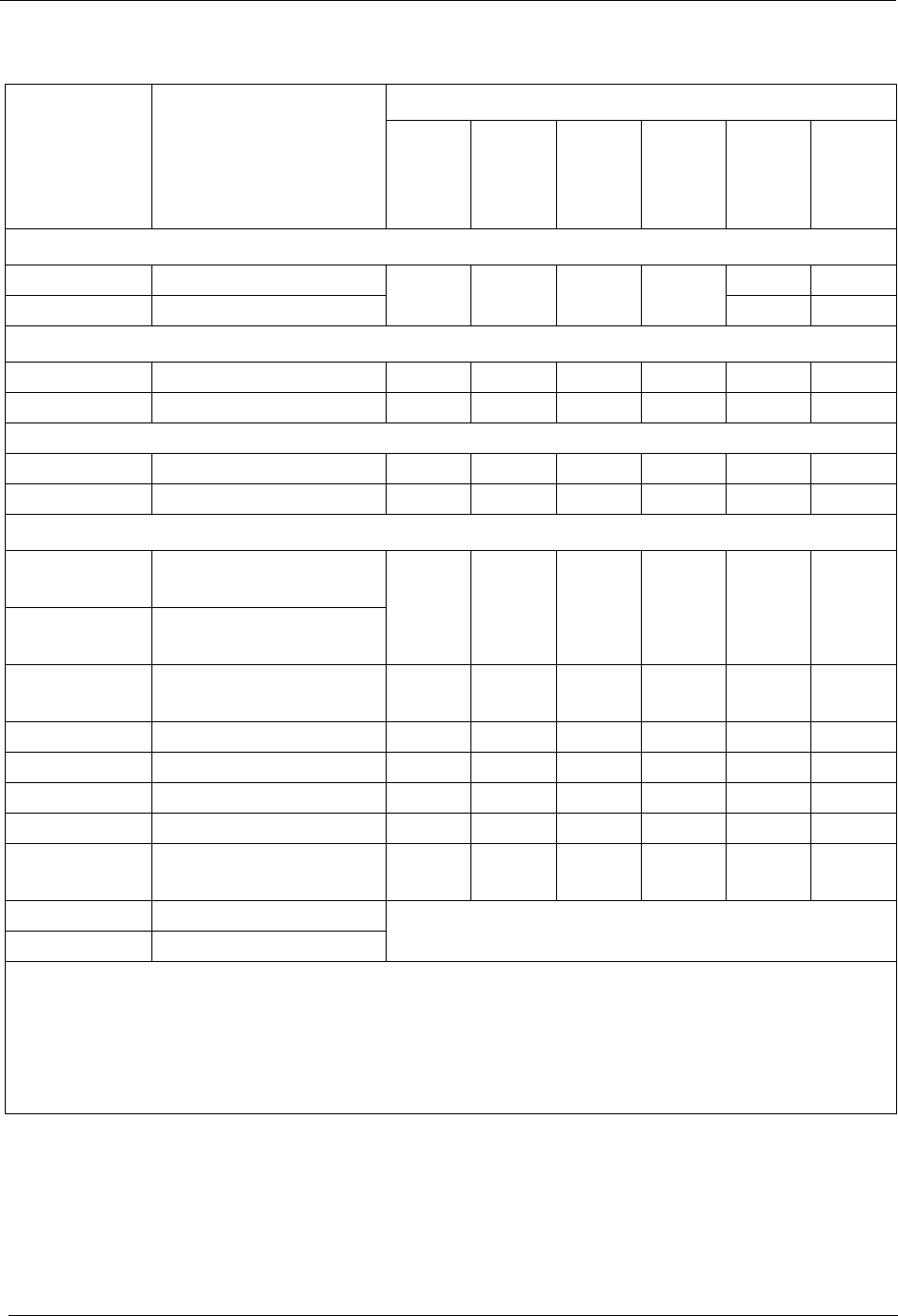
Chapter 7. Specifications Section 300-Installation
7-12 DBS Manual - Revised April 2000 DBS-2.3/9.2-300
Part No. Description Quantity
DBS 40 +
DBS 40
DBS 72 +
DBS 40
DBS 72 +
DBS 72
DBS 96 +
DBS 40
DBS 96 +
DBS 72
DBS 96 +
DBS 96
Expansion Connectors
VB-43120 Trunk exp. connector 222222
VB-43121 Ext. exp. connector 1* 0*
Doorbox Equipment (Trunk Port)
VB-43701 Door box adaptor 12# 12# 20# 24# 28# 32#
VB-43705 Door box 24# 24# 40# 48# 56# 64#
Doorbox Equipment (Extension Port)
VB-43711 Doorbox adaptor 4 4 4 4 4 4
VB-43705 Doorbox 4 4 4 4 4 4
Optional Equipment
VB-43706 Remote Administration
Interface (RAI-A) 111111
VB-43707 Remote Administration
Interface (RAI-B)
VB-43130 Built-in system backup
batteries 222222
VB-43709 SLT Adaptor 16 22 28 26 32 36
VB-2089P SLT ringer box 222222
VA-43703 4-line power fail unit 12 14 16 14 16 16
VB-43702 Off-premise ext adaptor 16 16 16 16 16 16
VB-43940 Application processor
interface (API) 111111
VB-43991 PCAS software 1
VB-43993 DBS Manager software
Notes:
*An expansion connector is not required to use an extension card in the EC/TRK slot of a DBS
96. The DBS 96 uses connector CN14 to accommodate an extension card in the EC/TRK slot.
# These maximums are based on overall trunk capacities and do not allow for trunks used for
outside lines.
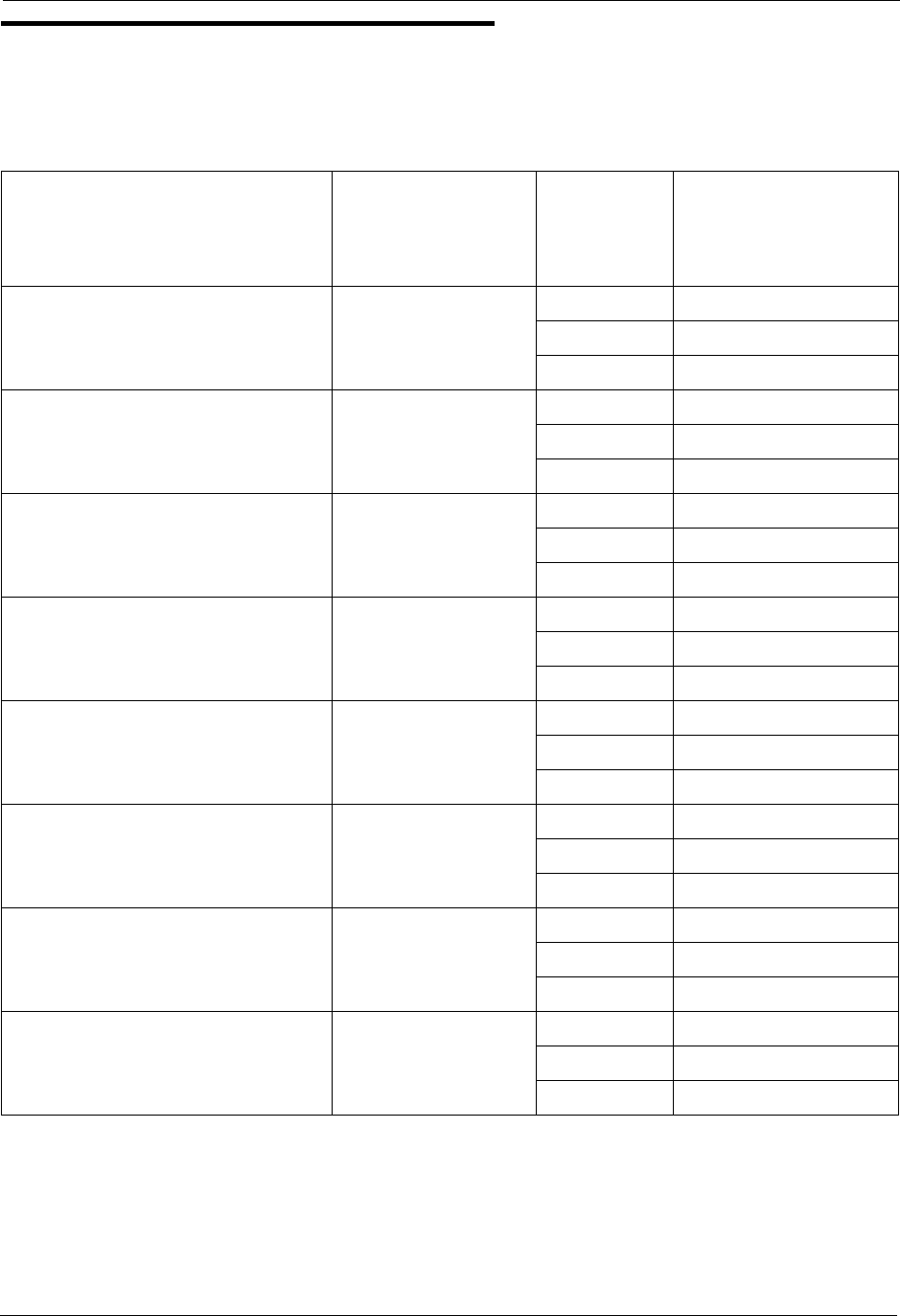
Section 300-Installation Chapter 7. Specifications
DBS-2.3/9.2-300 DBS Manual - Revised April 2000 7-13
Cabling Specifications
Table 7-11. Maximum cabling distances
Loop Type and Resistance Resistance Cable Gauge
(AWG) Maximum Cabling
Length in Feet
(Distance from the
DBS)
Key phone, EM/24 40 Ohms
22 1239
24 779
26 490
DSS/72 20 Ohms
22 619
24 388
26 244
SLT 100 Ohms
22 3097
24 1948
26 1225
OPX (Loop between the DBS and
the OPX Adaptor) 10 Ohms
22 309
24 194
26 122
OPX (Loop between the OPX
Adaptor and a pushbutton SLT) 900 Ohms
(excluding end
impedance)
22 27877
24 17532
26 11025
Doorphone (Loop between the
DBS and the Doorphone Adaptor) 10 Ohms
22 309
24 194
26 122
Doorphone (Loop between the
Doorphone Adaptor and the Door-
phone) 40 Ohms
22 1239
24 779
26 490
Voice Announce Unit 10 Ohms
22 309
24 194
26 122
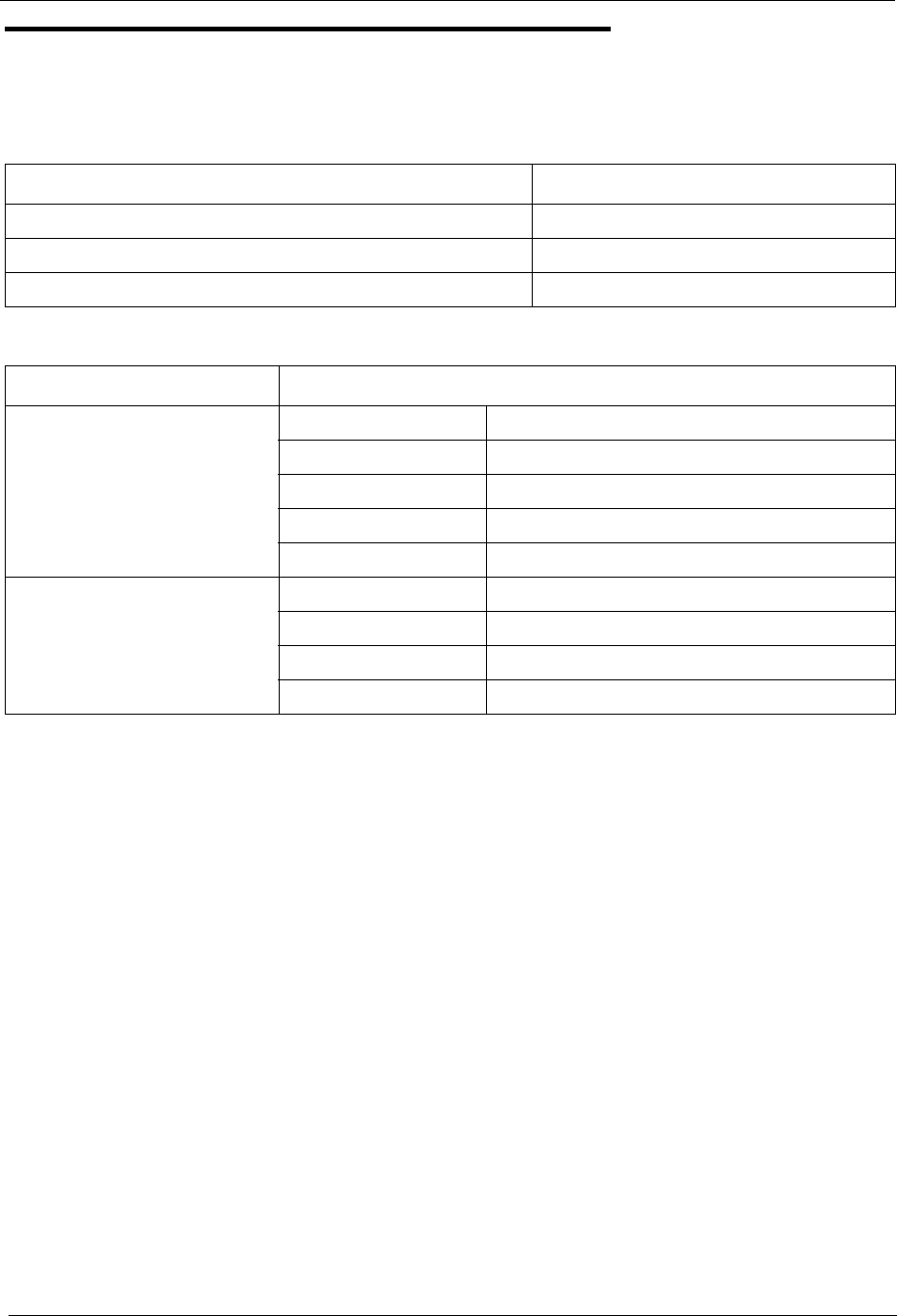
Chapter 7. Specifications Section 300-Installation
7-14 DBS Manual - Revised April 2000 DBS-2.3/9.2-300
Communication Parameters
Table 7-12. Voice path from KTELs to DBS
Table 7-13. Data communications ports
Channel Speed
Overall communications path 256 kbps
D-channel data 16 kbps
B-channel data 64 kbps
Port Parameters
SMDR Interface RS232-C
Baud rate 300, 1200, 4800 or 9600 kbps
Parity Even, odd, or none
Stop bit length 1, 1.5, or 2
Data bit length 5, 6, 7, or 8
Maintenance (RAI card) Baud rate 300 (RAI-A) or 300 or 1200 (RAI-B)
Stop bit length 1
Data bit length 8
Parity None
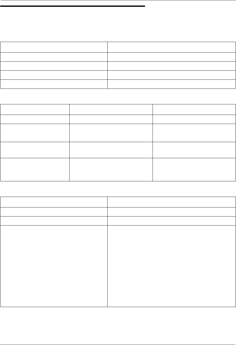
Section 300-Installation Chapter 7. Specifications
DBS-2.3/9.2-300 DBS Manual - Revised April 2000 7-15
Signaling Characteristics
Table 7-14. Signaling to CO
Table 7-15. Signaling levels
Table 7-16. Transmission specifications
Item Specification
Dial pulse 8 to 11 pulses per second (PPS)
Break ratio 58 to 64%
Minimum pause 0.7 to 1.0 seconds
Trunk start Loop or ground start
Item Level Distortion
Trunk input (DISA) -40 dBm (minimum) Less than 10%
Output from DBS (at MDF) High level: -8 dBm (minimum)
Low level: -10 dBm (minimum)
Analog station input (Dial
status) -35 dBm (minimum) Less than 10%
Analog station output (Talk
path originated from a key
phone to an SLT)
High level: -8 dBm+/-0.5 dBm
Low level: -6 dBm+/-0.5 dBm
Less than 5%
Item Specification
Impedance 600 Ohms
Overload level 600 Ohms
Insertion Loss
CO trunk to analog station 0 dB
Analog station to CO trunk 0 dB
CO trunk to digital station 0 dB
Digital station to CO trunk 0 dB
Digital station to digital station 6 dB
Digital station to analog station 6 dB
Analog station to digital station 6 dB
Analog station to analog station 6 dB

Chapter 7. Specifications Section 300-Installation
7-16 DBS Manual - Revised April 2000 DBS-2.3/9.2-300
Tone Characteristics
Table 7-17. Tone Plan
Tone Name Frequency Timing (seconds)
CO Call Tones
CO incoming call 550/400 Hz at 16 Hz Programmable
Hold recall 550/400 Hz at 16 Hz 0.5 on/3.5 off
Transfer recall 550/400 Hz at 16 Hz 0.5 on/3.5 off
Trunk queuing 550/400 Hz at 16 Hz 0.5 on/0.5 off/0.5 on/2.5 off
CO offhook signal 550 Hz 1 on/7 off
Internal Tones (Key Phones)
Dial tone 400 Hz Continuous
CO incoming call 550 Hz 1 on/3 off (Prior to CPC-B 3.1)
Programmable (CPC-AII and CPC-B 3.1 or
higher)
Callback 400 Hz 1 on/3 off
Busy 400 Hz 0.5 on/0.5 off
Busy override 400 Hz 0.25 on/0.25 off/0.25 on
Splash 550 Hz 0.5 on
Error 400 Hz 0.5 on/0.5 off
Reminder call 550 Hz 4 on/1 off/4 on/1 off/4on 1 off/4 on/silence
Call waiting 550 Hz 0.25 on/0.25 off/0.25 on/7.25 off
Key press 1 kHz Duration of the key press
Internal Tones (SLTs)
CO/Station ringing
Hold recall Callback 20 Hz 1 on/3 off
Transfer (Prior to
CPC-B 2.11) 20 Hz 0.5 on/3.5 off
Transfer (CPC-AII
and CPC-B 2.11 or
higher)
20 Hz Programmable

Section 300-Installation Chapter 7. Specifications
DBS-2.3/9.2-300 DBS Manual - Revised April 2000 7-17
Table 7-18. DTMF frequencies
Dial tone 400 Hz Continuous
Ringing 400 Hz 1 on/3 off
Busy 400 Hz 0.5 on/0.5 off
Voice mail ringing 550/400 Hz at 16 Hz 2 on/2 off
Digit Frequency (Hz)
1 697 + 1209
2 697 + 1336
3 697 + 1477
4 770 + 1209
5 770 + 1336
6 770 + 1477
7 852 + 1209
8 852 + 1336
9 852 + 1477
* 941 + 1209
0 941 + 1336
# 941 + 1477
Tone Name Frequency Timing (seconds)

Chapter 7. Specifications Section 300-Installation
7-18 DBS Manual - Revised April 2000 DBS-2.3/9.2-300

DBS-2.3/9.2-300 DBS Manual - Revised April 2000 Page A-1
Appendix A: CPC-EX 1.0 Updates
CPC-EX Version 1.0 (and above) offers the following enhancements to the
DBS phone system:
Compatibility
CPC-EX Version 1.0 supports all features of CPC-B Version 7.1 (with the exception of
TSAPI support). In addition, CPC-EX Version 1.0 adds support for additional features,
including the 44-Series phones, T1 Networking, and ISDN.
The CPC-EX card can be installed into an existing DBS cabinet, with no hardware
modifications.
CPC-EX software uses existing CPC-B programming addresses, with the same numbering.
Additional addresses have been added for CPC-EX features.
Note: CPC-EX requires SCC-B.
44-Series Phone Support
CPC-EX provides full support for Panasonic’s 44-Series phones (VB-44xxx). Table 1 below
lists all 44-Series phone models and their part numbers. Most models are available in two
colors: gray and black.
Table A-1. 44-Series Phones
16-Key Phone (gray) VB-44210G
16-Key Phone (black) VB-44210B
16-Key Speakerphone (gray only) VB-44211G
22-Key Phone (gray only) VB-44220G
22-Key Small-Display Speakerphone (gray) VB-44223G
22-Key Small-Display Speakerphone (black) VB-44223B
34-Key Small-Display Phone (gray only) VB-44230G
34-Key Small-Display Speakerphone (gray) VB-44233G
34-Key Small-Display Speakerphone (black) VB-44233B
22-Key Large-Display Speakerphone (gray) VB-44225G
22-Key Large-Display Speakerphone (black) VB-44225B
DSS/72 Console (gray) VB-44320G
DSS/72 Console (black) VB-44320B
EM/24 Unit (gray) VB-44310G
EM/24 Unit (black) VB-44310B

Appendix A. EX 1.0 Feature Update Section 300-Installation
Page A-2 DBS Manual - Revised April 2000 DBS-2.3/9.2-300
Enhanced DBS features that can be executed on the 44-Series phones are described below:
Directory Mode
On the small-display phones, you can scroll through SSD names, PSD names, or extension
names and select a displayed name for dialing.
Variable Mode
The small-display phones provide one-touch access to various features displayed during each
of the following call states: 1) during an intercom call; 2) during CO dial tone; 3) during a
trunk call; and 4) after dialing a busy extension.
Handset Mute
The large-display phone now contains a MUTE key, and a mute feature is available on all 44-
series phones. Pressing the MUTE key during an off-hook call will block audio from the
handset transmitter to the outside party. You can still hear them, but they can’t hear you.
Off-Hook Monitoring
If you press the ON/OFF key during an off-hook call on any 44-series speakerphone, the
other party’s voice will be heard through both the handset and the speaker. This allows a third
party to hear both sides of a conversation. Note: This feature does not activate your phone’s
microphone - audio will be transmitted only through your handset.
Analog Adapter
The large-display phone can be enhanced with an analog port adapter which allows you to
connect to an analog device such as a FAX or modem to the phone. This allows the same
phone to be alternately used for analog or digital communications.
MSG (Message) Key
A MSG key on the large-display phone will perform Auto-Callback (automatically dialing
the extension that sent a “Message Waiting” to your phone), or Auto-Answer Message
(automatically dialing your voice mailbox).
DSS/72 and EM/24 - Key Arrangement
The keys on the consoles are arranged differently, affecting the text layout and default
extension numbers assigned to these keys.

Section 300-Installation Appendix A. EX 1.0 Feature Update
DBS-2.3/9.2-300 DBS Manual - Revised April 2000 Page A-3
FF-Key Programming
Because T1 Networking adds the capability of 4-digit extension numbering, you can now
program up to 8 digits (not 6) into an FF-key.
Speed Dial Enhancements
CPC-EX supports up to 500 System Speed Dial (SSD) numbers. CPC-EX also allows SSD
codes to be chained, or “linked”, to another SSD number, and either PSD or SSD codes to be
chained to a PSD number.
Additional Serial Port
The CPC-EX card contains an on-board serial port (Serial Port 2) which can be used for Bus
Monitor/Maintenance. This allows remote maintenance to be accomplished without
disconnecting SMDR cabling.
T1 Networking Capability
Up to 4 DBS’s can now be connected together via T1 interface to form a DBS phone
network. The DBS’s can be located in the same building, in separate buildings in a campus-
type environment, or at remote locations in separate states. Networked DBS’s use 4-digit
extensions, with the first digit of the extension number identifying the DBS site.
Each site requires its own DBS cabinet with a CPC-EX card and a T1 card. Programming
addresses are included in CPC-EX software for setting up the T1 Network. (see the T1
Networking Reference Manual for complete instructions.)
Modification to Toll Restriction Service
The program address for TRS Operator Access (FF7 1# 18#) has been modified to allow an
extension to dial “0+NXX” phone numbers, even if “0-only” dialing is denied.
Maximum Time Priority Route Tables
CPC-EX allows a maximum of 8 Time Priority Route Tables (not 15) to be used during LCR
programming. Since few systems use more than 3 Time Priority Route Tables, this change
will allow the saved memory space to be used for future enhancements.

Appendix A. EX 1.0 Feature Update Section 300-Installation
Page A-4 DBS Manual - Revised April 2000 DBS-2.3/9.2-300
SMDR Modifications
SMDR reports contain several additional call types and other parameters due to CPC-EX
support of T1 Networking and ISDN calls.
ISDN Support
CPC-EX supports ISDN-PRI (Integrated Services Digital Network -- Primary Rate
Interface). The program address for Trunk Circuit Type (FF2 (trunk #)# 21#) has been
modified to allow for ISDN. Programming addresses have also been added in CPC-EX to
support ISDN. (See the ISDN Reference Manual for complete instructions.)
Modification to T1 Signaling Types
To allow easier programming of E&M trunks, CPC-EX uses “Wink Start” (not “Immediate
Start”) as the default for T1 Incoming and Outgoing Signal Types.
Installation Notes
CPC-EX Installation
Use normal installation procedures to install the CPC-EX. The following illustration shows
an installed CPC-EX:
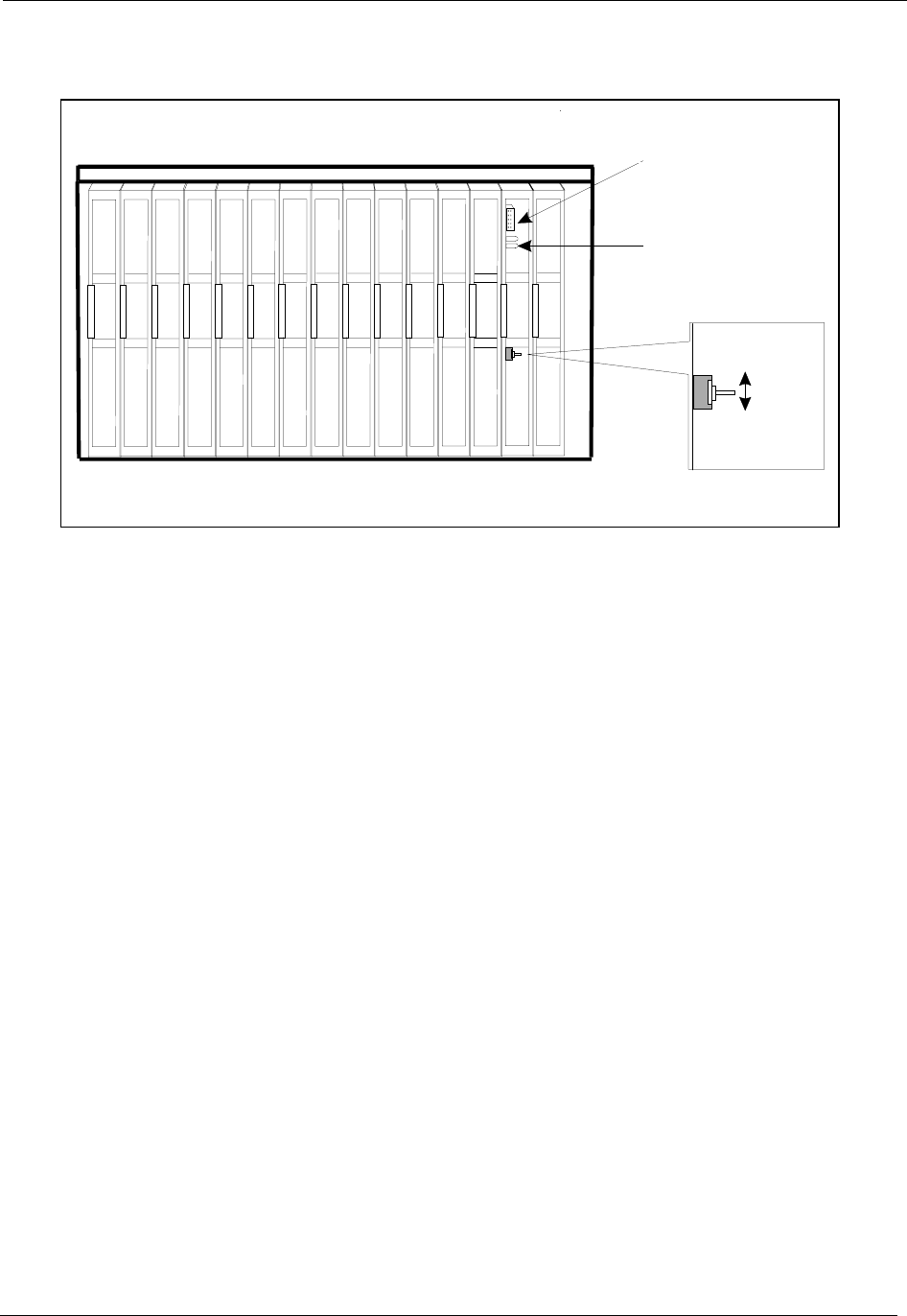
Section 300-Installation Appendix A. EX 1.0 Feature Update
DBS-2.3/9.2-300 DBS Manual - Revised April 2000 Page A-5
Figure A-1 CPC-EX
Key Telephone Installation
Desi Strip Cover
The 44-Series Key Telephones are shipped with a thin green protective film over the Desi
strip cover. Be sure to remove this film from both sides of the Desi cover before placing the
phone in service.
Key Telephone Wall Mounting Instructions
The following procedures apply to 44-Series Key Telephones only. Please be sure to follow
these procedures exactly. Removing the desk stand incorrectly can result in damage to the
telephone and/or desk stand.
1. Place the telephone face down on a flat surface.
2. Grasp the top of the desk stand (at the >ABS< label) and pull up the end to 90° vertical
(refer to Step 2 in Figure A-2). The stand will click as it releases from the plastic securing
latches.
3. Lift the desk stand as shown in Step 3 of Figure A-2.
RAM HOLD
TRK1 TRK2 TRK3 EC1 EC2 EC3 EC4 EC5 EC6 EC7 EC8 EC/TRK SCC CPC AUX1 AUX2
STATUS
LED
SERIAL
PO RT 2
SW 1
RAM CLR
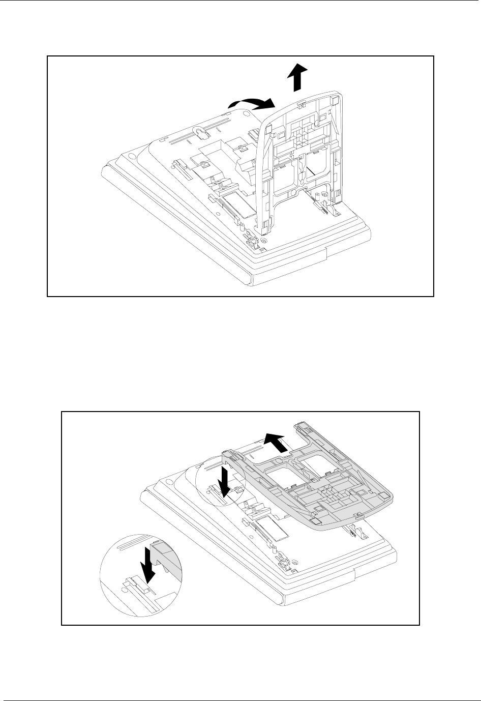
Appendix A. EX 1.0 Feature Update Section 300-Installation
Page A-6 DBS Manual - Revised April 2000 DBS-2.3/9.2-300
Figure A-2.Desk Stand Removal.
4. Rotate the desk stand 180°. In this position it doubles as a wall mount bracket.
5. Insert the wall mount bracket into the mounting guides as shown in Figure A-3.
6. Slide the wall mount bracket onto the telephone.
Figure A-3.Inserting the wall mount bracket (rotated desk stand)
7. While viewing the front of the telephone, find the handset guide located just below the
hookswitch (see Figure A-4).
Step 2 Step 3
Step 5
Step 6
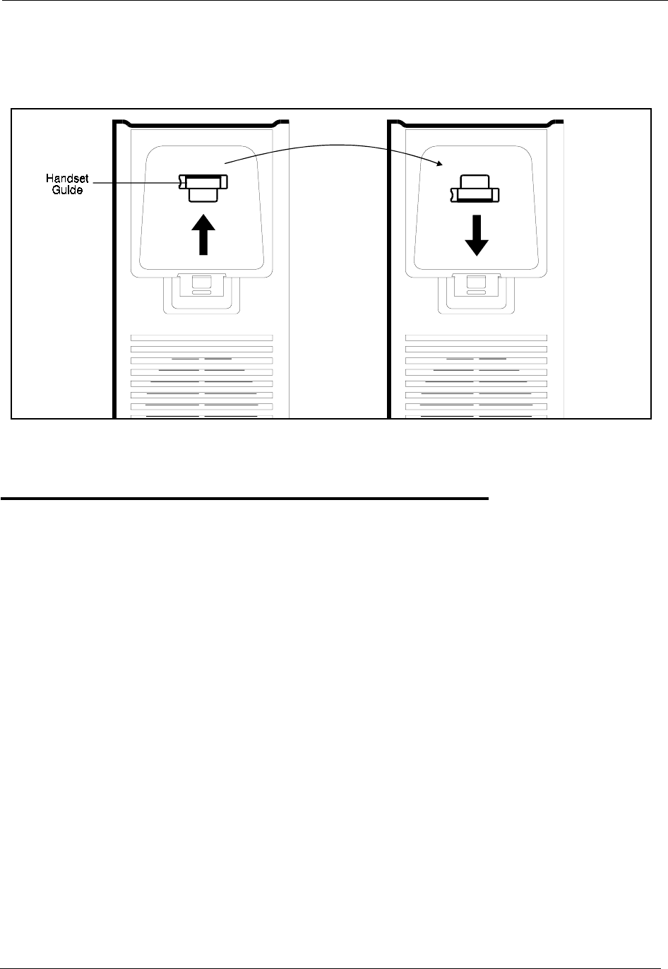
Section 300-Installation Appendix A. EX 1.0 Feature Update
DBS-2.3/9.2-300 DBS Manual - Revised April 2000 Page A-7
8. Slide the handset guide out, rotate 180° so that the holding clip is exposed, and reinsert.
Figure A-4.Handset guide insertion for wall mounting, key telephone
44-Series Enhanced Phone Features
Note: The enhanced features introduced with these phones are supported by CPC-EX
Version 1.0, CPC-AII/B Version 8.0, and CPC-S/M Version 2.0. You can also
use the 44-Series phones with previous DBS versions, but the enhanced
features won’t be supported.
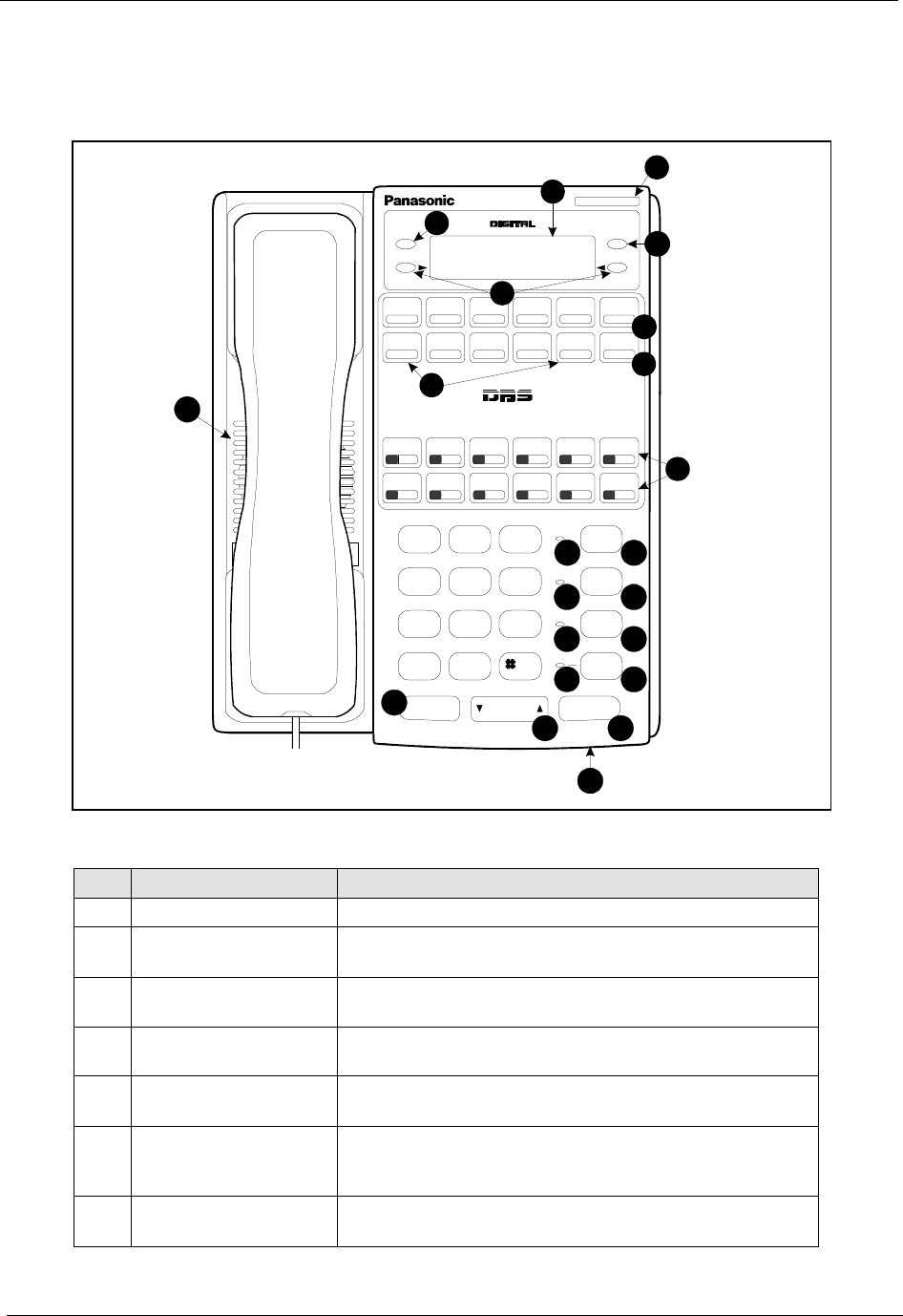
Appendix A. EX 1.0 Feature Update Section 300-Installation
Page A-8 DBS Manual - Revised April 2000 DBS-2.3/9.2-300
Figure A-5.44-Series Small-Display Phone
Table A-2. Small-Display Phone Features
#Feature Description
1 Message Indicator Indicates that you have a message.
2 Display Displays information about phone’s status, menus,
dialing directories, and text message information.
3 Mode Key Used to change display modes from default to direc-
tory mode.
4 End Key Used to exit directory mode and return display to
default mode.
5 Select Keys Used to select and dial System Speed Dial, Personal
Speed Dial, and Extension numbers from a directory.
6 PROG Key Used to program FF and one-touch keys and to adjust
ringer volume. Depending on the setup of your sys-
tem, may also be used to transfer calls.
7 CONF Key Used to establish conference calls, check FF key and
one-touch features, and scroll through messages.
1
ENDMODE
DND/CF
ABC
JK L
TUV
OPER
GHI
PRS
DEF
MNO
WXY
MUTE
EXT
REDIAL
PROG
CONF
MUTE
AUTO
ON/OFF
FLASH
Speakerphone
VOLUM E HOLD
DIGITAL BUSINESS SYSTEM
1
4
7
*
2
5
8
0
3
6
9
14
9
87
6
5
4
3
2
15
16
17
22
21
08:24 Tue N O V 14
Sandy 173
10
11
12
13
18
19 20

Section 300-Installation Appendix A. EX 1.0 Feature Update
DBS-2.3/9.2-300 DBS Manual - Revised April 2000 Page A-9
8 One-Touch Keys Used to make outside calls or to access call-handling
features.
9 Flexible Function
(FF) Keys Used to access outside lines or to access call-handling
features.
10 DND/CF Indicator Indicates that Do-Not-Disturb, Call Forwarding, or
Absence Message is set.
11 MUTE Indicator Indicates that your voice is muted - i.e., party on the
other end cannot hear you. Lights solid when your
hands-free microphone is muted and flashes when
your handset is muted.
12 EXT Indicator Lights when you are on a call; flashes when you hold a
call.
13 ON/OFF Indicator Lights when ON/OFF key has been pressed.
14 REDIAL Key Used to redial last outside number dialed.
15 MUTE Key Used to activate/deactivate MUTE function. When
activated, the party on the other end cannot hear you.
(See item 11, MUTE Indicator.)
16 AUTO Key Used to access speed dialing, enter account codes, or
for message waiting answer/cancel.
17 ON/OFF Key Used to make a call without lifting handset.
18 FLASH Key Used to end an outside call and to restore dial tone
without hanging up receiver.
19 VOLUME Key Used to adjust level of tones, background music, ring-
ing, receiver volume, and display contrast.
20 HOLD Key Used to hold calls, to retrieve held calls, and to com-
plete FF key programming.
21 Microphone Used to talk with other party without using the hand-
set.
22 Speaker Outputs tones and voice at your extension.
#Feature Description
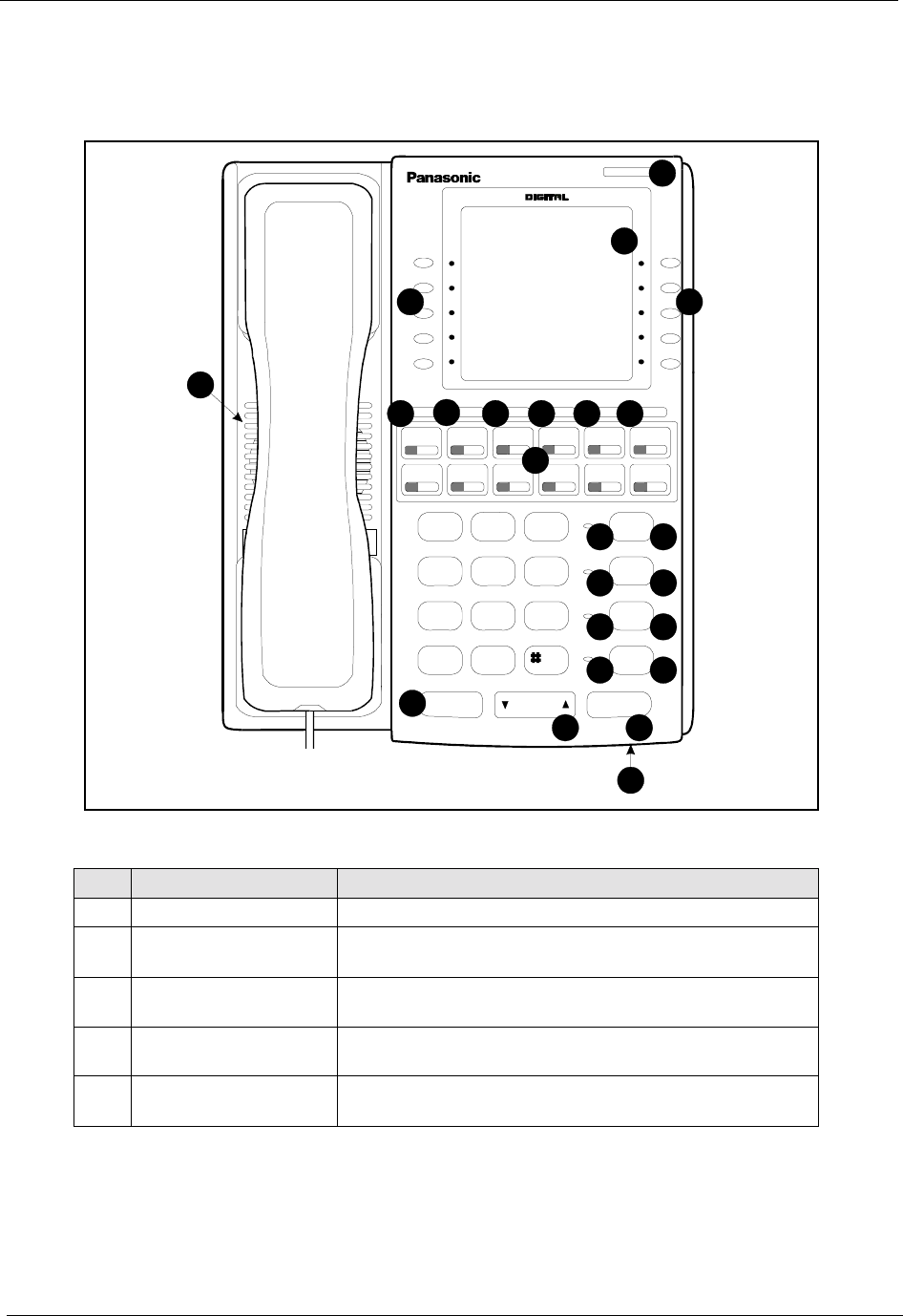
Appendix A. EX 1.0 Feature Update Section 300-Installation
Page A-10 DBS Manual - Revised April 2000 DBS-2.3/9.2-300
Figure A-6.44-Series Large-Display Phone
Table A-3. Large-Display Phone Features
#Feature Description
1 Message Indicator Indicates that you have a message.
2 Display Displays information about phone’s status, menus,
dialing directories, and text message information.
3 Soft Keys Used to make outside calls or to access call-handling
features.
4 MSG Key Used for Auto-CallBack to a telephone which has left
a text message or to access voice messages.
5 CONF Key Used to establish conference calls, check FF and one-
touch key settings, and scroll through messages.
DND/CF
ABC
JK L
TUV
OPER
GHI
PRS
DEF
MNO
WXY
MUTE
EXT
REDIAL
CONF M ENU PREV NEXT PRO GMSG
MUTE
AUTO
ON/OFF
FLASH
Speakerphone
VOLUM E HOLD
1
4
7
*
2
5
8
0
3
6
9
02:28 Thu N O V 14
PERSONAL DIAL
SYSTEM DIAL
EXTENSION
FUNCTION
HELP
LangfordS 173
10
11
12
13
14
15
16
17
18
21
22
20
19
9876
5
4
33
2
1
23

Section 300-Installation Appendix A. EX 1.0 Feature Update
DBS-2.3/9.2-300 DBS Manual - Revised April 2000 Page A-11
6 MENU Key Used to return to the Main Menu screen. The default
Main Menu screen contains the following items:
• PERSONAL DIAL
• SYSTEM DIAL
• EXTENSION
• FUNCTION
• HELP
7 PREV Key Used to return to the previous menu.
8 NEXT Key Used to advance to the next menu.
9 PROG Key Used to program FF and one-touch keys and to adjust
ringer volume. Depending on the setup of your sys-
tem, may also be used to transfer calls.
10 Flexible Function
(FF) Keys Used to access outside lines or to access call-handling
features.
11 DND/CF Indicator Indicates that Do-Not-Disturb, Call Forwarding, or
Absence Message is set.
12 MUTE Indicator Indicates that your voice is muted - i.e., party on the
other end cannot hear you. Lights solid when your
hands-free microphone is muted and flashes when
your handset is muted.
13 EXT Indicator Lights when you are on a call; flashes when you hold a
call.
14 ON/OFF Indicator Lights when ON/OFF key has been pressed.
15 REDIAL Key Used to redial last outside number dialed.
16 MUTE Key Used to activate/deactivate MUTE function. When
activated, the party on the other end cannot hear you.
(See item 12, MUTE Indicator.)
17 AUTO Key Used to access speed dialing, enter account codes, or
for message waiting answer/cancel.
18 ON/OFF Key Used to make a call without lifting handset.
19 FLASH Key Used to end an outside call and to restore dial tone
without hanging up receiver.
20 VOLUME Key Used to adjust level of tones, background music, ring-
ing, receiver volume, and display contrast.
21 HOLD Key Used to hold calls, to retrieve held calls, and to com-
plete FF key programming.
22 Microphone Used to talk with other party without using the hand-
set.
23 Speaker Outputs tones and voice at your extension.
#Feature Description

Appendix A. EX 1.0 Feature Update Section 300-Installation
Page A-12 DBS Manual - Revised April 2000 DBS-2.3/9.2-300
Analog Adapter
Description The Analog Adapter (VB-44100) consists of a base adapter and PC board
which is installed on the underside of the phone. It is used to connect the
44-Series large-display phone to an analog device such as an SLT
telephone, cordless phone, FAX machine, or modem. This allows the same
phone line to be used to alternate between normal phone calls and analog
communications. (To install, see the instructions supplied with VB-44100).
Operation The first device to go off-hook will seize the line (off-hook is either lifting
the handset or pressing the ON/OFF key). If the analog device goes off-
hook first, the large-display phone will be unable to dial or go off-hook.
You can choose which device will ring by going off-hook at either the
digital key telephone or the analog device and dialing *71. The digital key
telephone display will reflect “Analog port RING” or “Key Tel RING”,
depending on which device is selected - the default is “Key Tel RING”.
You can still answer an incoming call from either device, regardless of
which device is ringing. For example, if the analog device is ringing, you
can pick up the call on the digital key telephone by going off-hook before
the analog device does. Similarly, if the digital key telephone is ringing or
has not answered a voice call, the analog device can pick up the call by
going off-hook first.
You can program the *71 ring select command into an FF key. Pressing the
key toggles between “Analog Port RING” and “Key Tel RING”. When the
analog port is set to ring, the FF key LED lights red. When the key
telephone is set to ring, the LED is off.
Notes Phone Restrictions
• The Analog Adapter will work on the large-display phone only (VB-
44225).
• A dial-pulse SLT will not function on the analog port.
• Stutter Dial Tone (indicating Call-Forwarding mode, Do-Not-Disturb
mode, etc.) will not function on an SLT connected to the Analog
Adapter.
• An analog phone connected to the Analog Adapter cannot program or
access speed dials.
Incoming Calls
• You cannot program both devices to ring simultaneously.
• The “*71” code will not work if the other device is in use.

Section 300-Installation Appendix A. EX 1.0 Feature Update
DBS-2.3/9.2-300 DBS Manual - Revised April 2000 Page A-13
• The “*71” code will not work if FF3 (ExtPort)# 51# is set to “0”.
• If set to “Analog port RING”, the large-display phone will work like an
SLT/OPX (no page announcements, no voice calls from other
extensions, etc.).
• If the phone is in CF/DND (Call-Forward or Do Not Disturb), the phone
will remain in CF/DND even if the ringing device is changed via the
*71 code.
• The incoming ring pattern for the analog device is the same as for the
digital key telephone (determined by the Extension Ring Pattern in FF3
(ExtPort)# 39# (0-9)#). If this address is set to “0” (determined by CO),
the analog device will automatically default to “1 second ON, 3 seconds
OFF.”
Ring Patterns Not Applicable to Analog Device. The following ring
pattern addresses will not affect the analog device:
Analog Transfer Ring Pattern FF1 2# 1# 31# (0-6)#
SLT DISA Ring Pattern FF1 2# 1# 34# (0 or 1)#
Inbound Ring Pattern FF2 (Trunk)# 17# (0-9)#
Flash Interaction. Any disconnect signal sent to the analog port must be
greater than the SLT Flash Control; otherwise the disconnect signal will be
interpreted as a flash and the call will be placed on hold.
Programming Addresses That Affect the Analog Device. The following
addresses will control the analog device, but will not affect the digital key
telephone:
AEC Disconnect Duration FF1 2# 1# 35# (0-15)#
SLT Flash Control FF1 2# 1# 11# (0 or 1)#
SLT Onhook Flash Timer FF1 3# 14# (0-6)#
AEC Disconnect FF3 (ExtPort)# 46# (0
or 1)#
Analog Port on Large-Display Phone FF3 (ExtPort)# 51# (0
or 1)#
Data Security on Analog Port FF3 (ExtPort)# 52# (0
or 1)#
MSG (Message) Key
Description The MSG key on the VB-44225 Large-Display Phone adds the following
functionality to the phone:
•Auto-Callback. If a callback message has been left by another
extension, you can press the MSG key to place an automatic callback to
the extension that sent the message. If more than one callback message

Appendix A. EX 1.0 Feature Update Section 300-Installation
Page A-14 DBS Manual - Revised April 2000 DBS-2.3/9.2-300
has been received, pressing the MSG key will perform auto-callback in
the order received.
•Auto-Answer Voice Message. You can press the MSG key to
automatically access your voice mailbox. The phone will dial your
voice mailbox and send access codes (if programmed) for retrieving
messages.
Operation To Program Voice Mailbox Access Codes into the MSG Key:
Press PROG MSG [16-digit number] HOLD
The display will reflect “Regist Data”.
To Confirm a Voice Mailbox Access Code Programmed into the
Message Key..
Press CONF MSG.
The programmed access code will be displayed.
Notes Operation With Message Waiting Indicator. The Message Waiting
Indicator on the phone’s upper right corner will flash whenever a callback
message or voice message has been received.
Operation During Call States. The MSG key will work only when the
phone is idle, receiving dial tone, or in Directory Mode (via select key).
Operation If Phone Has Both a Callback Message from another
Extension and a Voice Message. Messages are accessed in a First In, First
Out order. If the callback message was received before the voice message,
then pressing the MSG key will activate Auto-Callback first. Likewise, if
the voice message was received before the callback message, pressing the
MSG key will access your Voice Mailbox.
Interaction with Tone-Calling Mode. If an Auto-Callback is placed to a
phone that is in tone-calling mode (i.e., not voice-calling), that phone must
answer or the message canceled before another message can be accessed.
FF-Key Restriction. These MSG features cannot be assigned to an FF-
key.
Reprogramming the MSG key if Extension Number Digits is changed. If
the DBS is reprogrammed to use a different extension numbering plan (i.e.,
changed from 2-digit to 3-digit extensions, 3-digit to 4-digit extensions,

Section 300-Installation Appendix A. EX 1.0 Feature Update
DBS-2.3/9.2-300 DBS Manual - Revised April 2000 Page A-15
etc.), the Voice Mailbox Access Code must be reprogrammed into the
MSG key.
DSS/72 Console - Key Arrangement
Description The keys on the DSS/72 Console (VB-44320) are arranged differently
from the VB-43320 model. The DSS console has 6 columns x 12 rows of
keys (not 8 columns x 9 rows as in the previous version). This affects the
following:
•Name and Message Assignments (FF6 addresses). The alphabetical
arrangement of the keys is different.
•FF-Keys. The FF-keys on the DSS/72 console are numbered left-to-
right, bottom row first.
•DSS #1 Defaults. The default extension number assignments on DSS #1
are different.
The DSS key arrangement is shown in Figures A-7 & A-8.
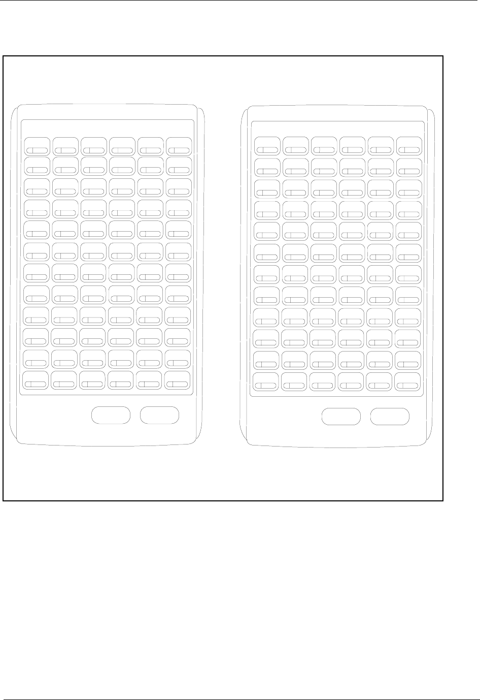
Appendix A. EX 1.0 Feature Update Section 300-Installation
Page A-16 DBS Manual - Revised April 2000 DBS-2.3/9.2-300
Figure A-7.DSS/72 Console (VB-44320) key layout
Answer Release Answer Release
Panasonic Panasonic
ABCDEF
GHI JKL
MN OP Q R
S T UVWX
YZ$%? '
abcdef
ghijkl
mno pqr
stuvwx
yz ; * #=
()<>BSSP
FF67 FF68 FF69 FF70 FF71 FF72
FF61 FF62 FF63 FF64 FF65 FF66
FF55 FF56 FF57 FF58 FF59 FF60
FF49 FF50 FF51 FF52 FF53 FF54
FF43 FF44 FF45 FF46 FF47 FF48
FF37 FF38 FF39 FF40 FF41 FF42
FF31 FF32 FF33 FF34 FF35 FF36
FF25 FF26 FF27 FF28 FF29 FF30
FF19 FF20 FF21 FF22 FF23 FF24
FF13 FF14 FF15 FF16 FF17 FF18
FF7 FF8 FF9 FF10 FF11 FF12
FF1 FF2 FF3 FF4 FF5 FF6
DSS/72 Key Layout(alphabetical)DSS/72 Key Layout(FF-key num bering)
_,:/-.
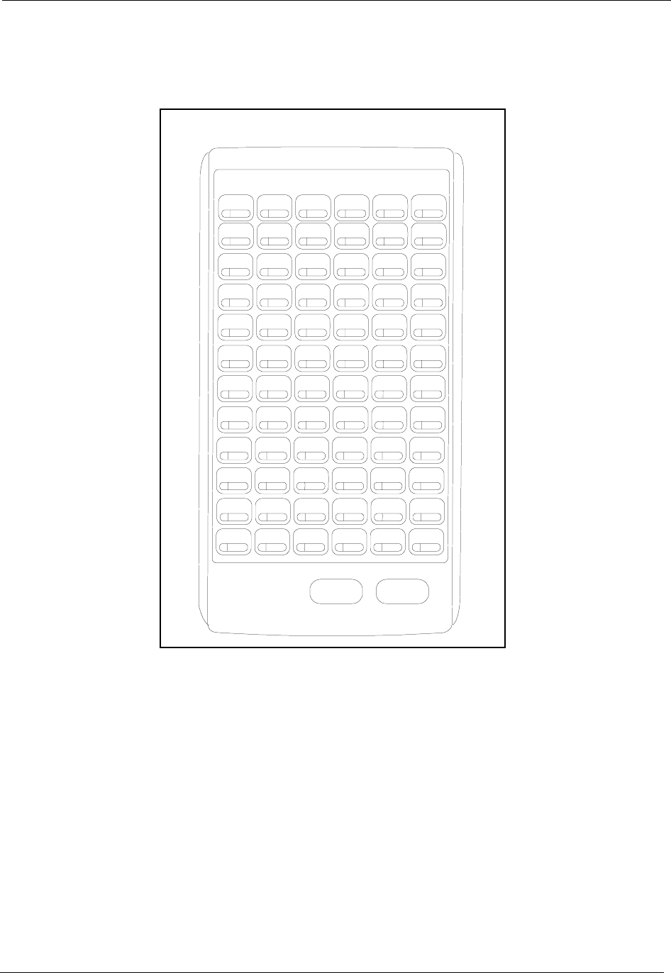
Section 300-Installation Appendix A. EX 1.0 Feature Update
DBS-2.3/9.2-300 DBS Manual - Revised April 2000 Page A-17
Figure A-8.DSS/72 #1 Default Extension Numbers
Operation The 44-Series DSS/72 operates the same as previous models.
EM/24 - Key Arrangement
Description The keys on the EM/24 unit (VB-44310) are arranged differently from the
VB-43310 model. The EM/24 unit has 2 columns x 12 rows of keys (not 3
columns x 8 rows as in the previous version). This affects the following:
•FF-Keys. The FF-keys on the EM/24 are numbered bottom-to-top, left
column first.
The EM/24 key arrangement is shown in Figure A-9.
Answer Release
Page-2 Page-3 Page-4 Page-5 Page-6 Night
Panasonic
154 155 Park 0 Park 1 Park 2 Park 3
148 149 150 151 152 153
142 143 144 145 146 147
136 137 138 139 140 141
130 131 132 133 134 135
124 125 126 127 128 129
118 119 120 121 122 123
112 113 114 115 116 117
106 107 108 109 110 111
100 101 102 103 104 105
DSS #1 DefaultExtension Num bers
Park-4 Park-5 Park-6 Park-7 Page-0 Page-1
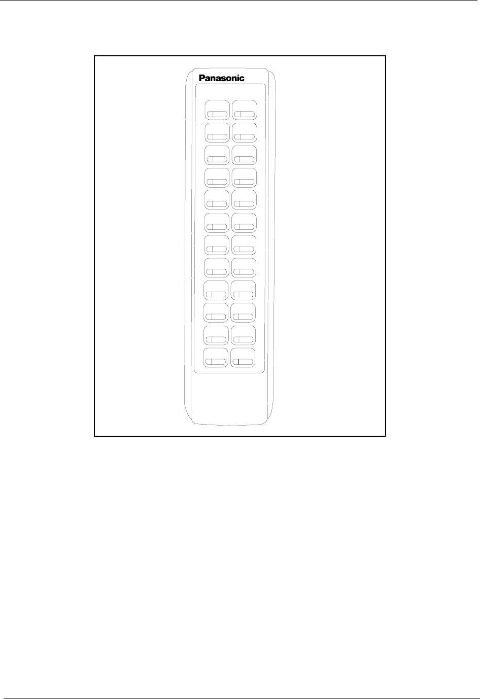
Appendix A. EX 1.0 Feature Update Section 300-Installation
Page A-18 DBS Manual - Revised April 2000 DBS-2.3/9.2-300
Figure A-9.EM/24 Unit (VB-44310) keys
Operation The 44-Series EM/24 operates the same as previous models.
FF12 FF24
FF11 FF23
FF10 FF22
FF9 FF21
FF8 FF20
FF7 FF19
FF6 FF18
FF5 FF17
FF4 FF16
FF3 FF15
FF2 FF14
FF1 FF13
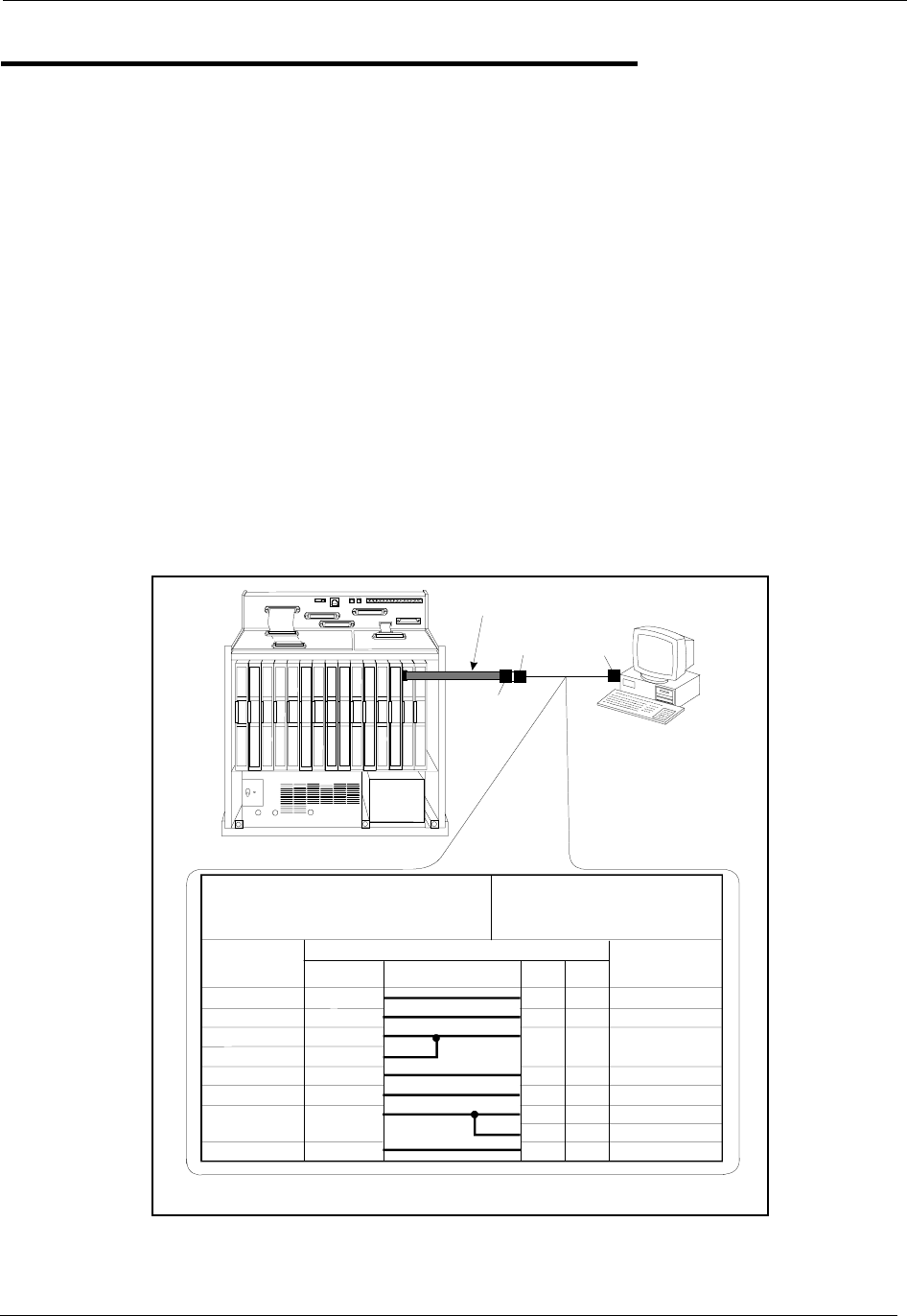
Section 300-Installation Appendix A. EX 1.0 Feature Update
DBS-2.3/9.2-300 DBS Manual - Revised April 2000 Page A-19
Additional Serial Port on CPC Card
Description The CPC-EX card contains an on-board serial port (Serial Port 2) which
can be used for Bus Monitor/ Remote Maintenance. This serial port
(labeled CN5) is located just above the LEDs on the front of the card (see
the illustration on Appendix A:-4). This additional serial port allows you to
dial directly into the system for remote maintenance, without having to
disconnect the SMDR cabling from the backplane serial port (Serial Port
1).
• Serial Port 1 (the backplane port) and Serial Port 2 have separate controls
for baud rate, stop bit, parity, and data length
Installation Serial Port 2 requires the CPC-EX Serial Port Adapter Cable (VB-43890).
This cable connects to Serial Port 2 via a 10-pin connector, and to a
programming terminal via a DB25 connector.
Figure A-10.CPC-EX Serial Port 2
CN11
CN12 CN13 CN14 CN15 CN6
SW 1 CN3
TRK1 TRK2 TRK3 EC1 EC2 EC3 EC4 EC5 EC6 EC7 EC8 EC/TRK SCC CPC AUX1 AUX2
CN5 CN4 CN2
CN1
CN1
RS-232C
Master C abinet
Programming Term inal
Serial Port Adapter C ableEnd
(Requires D B-25 M ale) Program m ing Term inal End
(Requires D B -9 or D B -25 M ale)
Signal
Name
Pin N o. and C onnection Signal
Nam e
DB-25
W/DB-25
Adapter DB-9
TD
RD
N/C
CTS
DSR
SG
N/C
DTR
2
3
4
5
6
7
8
20
2
3
1
4
5
7
8
6
3
2
8
20
7
4
5
6
RD
TD
CD
DTR
SG
RTS
CTS
DSR
VB-43890
Adapter C able
DB-25
Male
DB-25
Fem ale*
DB-9or
DB-25 M ale
*The standard DBS SM DR/Maintenance cable(normally connected toCN6)maybe
connected tothe program m ing terminal.

Appendix A. EX 1.0 Feature Update Section 300-Installation
Page A-20 DBS Manual - Revised April 2000 DBS-2.3/9.2-300
Notes • Serial Port 2 requires a special interface cable.
• Serial Port 2 can be used for Bus Monitor/Maintenance only. You must
continue to use the backplane port (Serial Port 1) for SMDR.
• Port selections are made from the Attendant phone as follows:
• When Serial Port 2 is used (i.e., #92 has been entered), the internal RAI
modem cannot be accessed.
to set Serial Port 1 for... and Serial Port 2 for...
dial #90 Bus Monitor/Maintenance no output
dial #92 SMDR Bus Monitor/Maintenance
dial #93 SMDR/Maintenance no output

DBS-2.3/9.2-300 DBS Manual - Revised April 2000 Page B-1
Appendix B: CPC-AII/B 8.0 Updates
CPC-AII/B Version 8.0 offers support for the Panasonic 44-Series telephones (VB-44xxx),
as well as Computer Telephony Integration (CTI) through the Windows™ Telephony
Applications Processing Interface (TAPI).
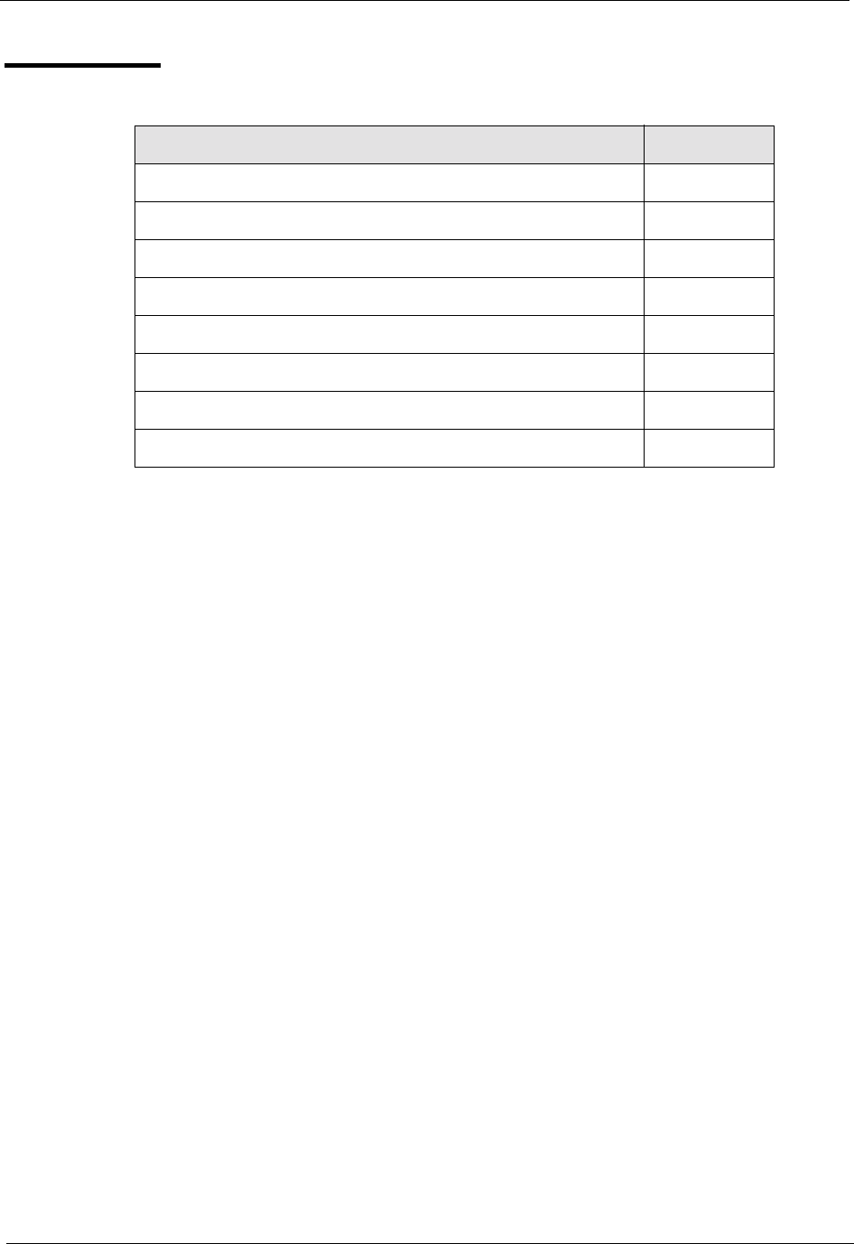
Appendix B. CPC-AII/B 8.0 Feature Update Section 300-Installation
Page B-2 DBS Manual - Revised April 2000 DBS-2.3/9.2-300
Contents
Topic Page
44-Series Phone Support B-3
Enhanced Phone Features B-4
Analog Adapter B-8
MSG (Message) Key B-9
DSS/72 Console - Key Arrangement B-10
EM/24 - Key Arrangement B-13
TAPI Support B-14
Key Telephone Installation Notes B-14

Section 300-Installation Appendix B. CPC-AII/B 8.0 Feature Update
DBS-2.3/9.2-300 DBS Manual - Revised April 2000 Page B-3
44-Series Phone Support
CPC-AII/B Version 8.0 provides full support for Panasonic’s 44-Series phones (VB-44xxx).
Table D-1, below, lists all 44-Series phone models and their part numbers. Most models are
available in two colors: gray and black.
Table B-1.44-Series Phones
16-Key Phone (gray) VB-44210G
16-Key Phone (black) VB-44210B
16-Key Speakerphone (gray only) VB-44211G
22-Key Phone (gray only) VB-44220G
22-Key Small-Display Speakerphone (gray) VB-44223G
22-Key Small-Display Speakerphone (black) VB-44223B
34-Key Small-Display Phone (gray only) VB-44230G
34-Key Small-Display Speakerphone (gray) VB-44233G
34-Key Small-Display Speakerphone (black) VB-44233B
22-Key Large-Display Speakerphone (gray) VB-44225G
22-Key Large-Display Speakerphone (black) VB-44225B
DSS/72 Console (gray) VB-44320G
DSS/72 Console (black) VB-44320B
EM/24 Unit (gray) VB-44310G
EM/24 Unit (black) VB-44310B
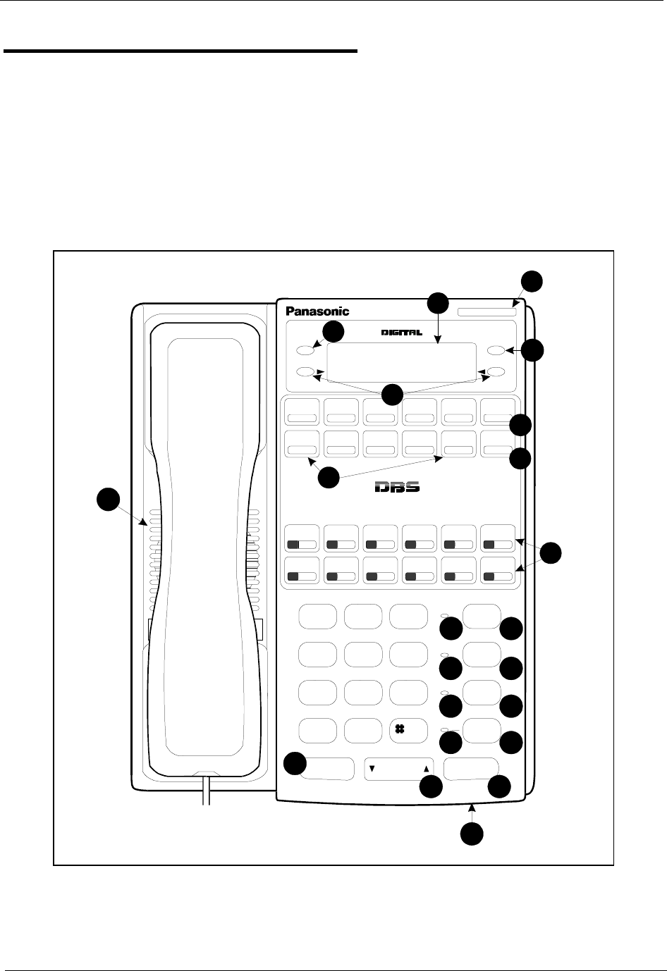
Appendix B. CPC-AII/B 8.0 Feature Update Section 300-Installation
Page B-4 DBS Manual - Revised April 2000 DBS-2.3/9.2-300
Enhanced Phone Features
Enhanced DBS features that can be executed on the 44-Series phones are described below:
Note: The features introduced with these phones are supported by CPC-AII/B Version
8.0, CPC-S/M Version 2.0, and CPC-EX Version 1.0. You can also use the 44-
Series phones with previous DBS versions, but the enhanced features won’t be
supported.
Figure B-11.44-Series Small-Display Phone
1
ENDMODE
DND/CF
ABC
JK L
TUV
OPER
GHI
PRS
DEF
MNO
WXY
MUTE
EXT
REDIAL
PROG
CONF
MUTE
AUTO
ON/OFF
FLASH
Speakerphone
VOLUM E HOLD
DIGITAL BUSINESS SYSTEM
1
4
7
*
2
5
8
0
3
6
9
14
9
87
6
5
4
3
2
15
16
17
22
21
08:24 Tue N O V 14
Sandy 173
10
11
12
13
18
19 20

Section 300-Installation Appendix B. CPC-AII/B 8.0 Feature Update
DBS-2.3/9.2-300 DBS Manual - Revised April 2000 Page B-5
Table B-2.Key to 44-Series Small-Display Phone
#Feature Description
1 Message Indicator Indicates that you have a message.
2 Display Displays information about phone’s status, menus,
dialing directories, and text message information.
3 Mode Key Used to change display modes from default to direc-
tory mode.
4 End Key Used to exit directory mode and return display to
default mode.
5 Select Keys Used to select and dial a System Speed Dial, Personal
Speed Dial, or Extension number from a directory.
6 PROG Key Used to program FF and one-touch keys and to adjust
ringer volume. Depending on the setup of your sys-
tem, may also be used to transfer calls.
7 CONF Key Used to establish conference calls, check FF key and
one-touch features, and scroll through messages.
8 One-Touch Keys Used to make outside calls or to access call-handling
features.
9 Flexible Function
(FF) Keys Used to access outside lines or to access call-handling
features.
10 DND/CF Indicator Indicates that Do-Not-Disturb, Call Forwarding, or
Absence Message is set.
11 MUTE Indicator Indicates that your voice is muted - i.e., party on the
other end cannot hear you. Lights solid when your
hands-free microphone is muted and flashes when
your handset is muted.
12 EXT Indicator Lights when you are on a call; flashes when you hold a
call.
13 ON/OFF Indicator Lights when ON/OFF key has been pressed.
14 REDIAL Key Used to redial last outside number dialed.
15 MUTE Key Used to activate/deactivate MUTE function. When
activated, the party on the other end cannot hear you.
(See item 11, MUTE Indicator.)
16 AUTO Key Used to access speed dialing, enter account codes, or
for message waiting answer/cancel.
17 ON/OFF Key Used to make a call without lifting handset.
18 FLASH Key Used to end an outside call and to restore dial tone
without hanging up receiver.
19 VOLUME Key Used to adjust level of tones, background music, ring-
ing, receiver volume, and display contrast.
20 HOLD Key Used to hold calls, to retrieve held calls, and to com-
plete FF key programming.
21 Microphone Used to talk with other party without using the hand-
set.
22 Speaker Outputs tones and voice at your extension.
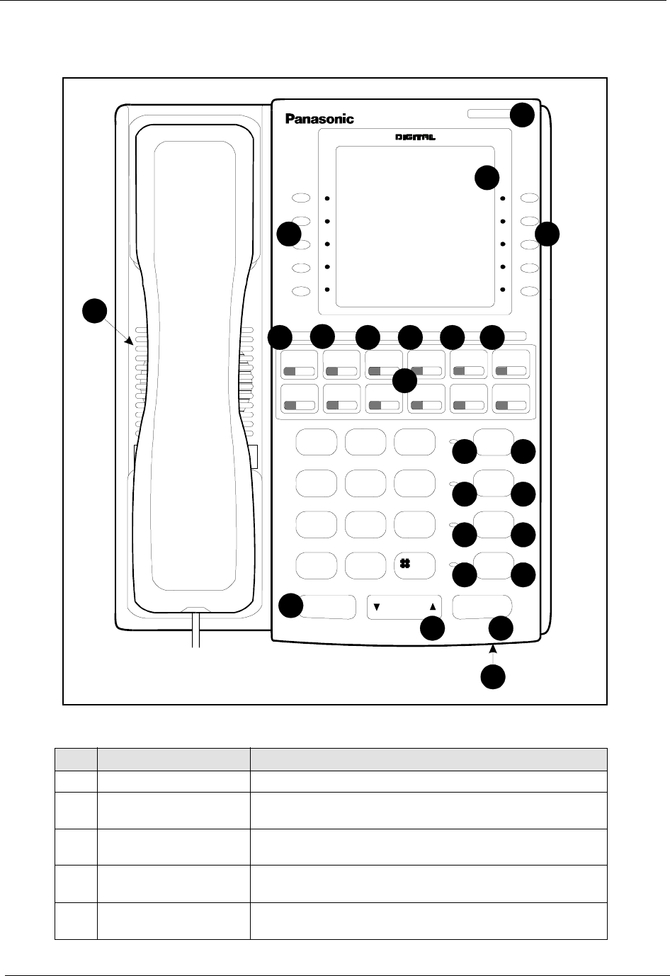
Appendix B. CPC-AII/B 8.0 Feature Update Section 300-Installation
Page B-6 DBS Manual - Revised April 2000 DBS-2.3/9.2-300
Figure B-12.44-Series Large-Display Phone
Table B-3.Key to 44-Series Large-Display Phone
#Feature Description
1 Message Indicator Indicates that you have a message.
2 Display Displays information about phone’s status, menus,
dialing directories, and text message information.
3 Soft Keys Used to make outside calls or to access call-handling
features.
4 MSG Key Used for Auto-CallBack to a telephone which has left
a text message or to access voice messages.
5 CONF Key Used to establish conference calls, check FF and
one-touch key settings, and scroll through messages.
DND/CF
ABC
JK L
TU V
OPER
GHI
PRS
DEF
MNO
WXY
MUTE
EXT
REDIAL
CONF MENU PREV NEXT PROGMSG
MUTE
AUTO
ON/OFF
FLASH
Speakerphone
VOLUM E HOLD
1
4
7
*
2
5
8
0
3
6
9
02:28 Thu N O V 14
PERSONAL DIAL
SYSTEM DIAL
EXTENSION
FUNCTION
HELP
LangfordS 173
10
11
12
13
14
15
16
17
18
21
22
20
19
9876
5
4
33
2
1
23

Section 300-Installation Appendix B. CPC-AII/B 8.0 Feature Update
DBS-2.3/9.2-300 DBS Manual - Revised April 2000 Page B-7
6 MENU Key Used to return to the Main Menu screen. The default
Main Menu screen contains the following items:
• PERSONAL DIAL
• SYSTEM DIAL
• EXTENSION
• FUNCTION
• HELP
7 PREV Key Used to return to the previous menu.
8 NEXT Key Used to advance to the next menu.
9 PROG Key Used to program FF and one-touch keys and to adjust
ringer volume. Depending on the setup of your sys-
tem, may also be used to transfer calls.
10 Flexible Function
(FF) Keys Used to access outside lines or to access call-handling
features.
11 DND/CF Indicator Indicates that Do-Not-Disturb, Call Forwarding, or
Absence Message is set.
12 MUTE Indicator Indicates that your voice is muted - i.e., party on the
other end cannot hear you. Lights solid when your
hands-free microphone is muted and flashes when
your handset is muted.
13 EXT Indicator Lights when you are on a call; flashes when you hold a
call.
14 ON/OFF Indicator Lights when ON/OFF key has been pressed.
15 REDIAL Key Used to redial last outside number dialed.
16 MUTE Key Used to activate/deactivate MUTE function. When
activated, the party on the other end cannot hear you.
(See item 12, MUTE Indicator.)
17 AUTO Key Used to access speed dialing, enter account codes, or
for message waiting answer/cancel.
18 ON/OFF Key Used to make a call without lifting handset.
19 FLASH Key Used to end an outside call and to restore dial tone
without hanging up receiver.
20 VOLUME Key Used to adjust level of tones, background music, ring-
ing, receiver volume, and display contrast.
21 HOLD Key Used to hold calls, to retrieve held calls, and to com-
plete FF key programming.
22 Microphone Used to talk with other party without using the hand-
set.
23 Speaker Outputs tones and voice at your extension.
#Feature Description

Appendix B. CPC-AII/B 8.0 Feature Update Section 300-Installation
Page B-8 DBS Manual - Revised April 2000 DBS-2.3/9.2-300
Analog Adapter
44-Series phones only
CPC-AII/B Version 8.0, CPC-S/M Version 2.0, or CPC-EX Version 1.0 only
Description The Analog Adapter (VB-44100) consists of a base adapter and PC board
which is installed on the underside of the phone. It is used to connect the
44-Series large-display phone to an analog device such as an SLT
telephone, cordless phone, FAX machine, or modem. This allows the same
phone line to be used to alternate between normal phone calls and analog
communications. (To install, see the instructions supplied with VB-44100).
Operation The first device to go off-hook will seize the line (off-hook is either lifting
the handset or pressing the ON/OFF key). If the analog device goes off-
hook first, the large-display phone will be unable to dial or go off-hook.
You can choose which device will ring by going off-hook at either the
digital key telephone or the analog device and dialing *71. The digital key
telephone display will reflect “Analog port RING” or “Key Tel RING”,
depending on which device is selected - the default is “Key Tel RING”.
You can still answer an incoming call from either device, regardless of
which device is ringing. For example, if the analog device is ringing, you
can pick up the call on the digital key telephone by going off-hook before
the analog device does. Similarly, if the digital key telephone is ringing or
has not answered a voice call, the analog device can pick up the call by
going off-hook first.
You can program the *71 ring select command into an FF key. Pressing the
key toggles between “Analog Port RING” and “Key Tel RING”. When the
analog port is set to ring, the FF key LED lights red. When the key
telephone is set to ring, the LED is off.
Notes Phone Restrictions
• The Analog Adapter will work on the large-display phone only (VB-
44225).
• A dial-pulse SLT will not function on the analog port.
• Stutter Dial Tone (indicating Call-Forwarding mode, Do-Not-Disturb
mode, etc.) will not function on an SLT connected to the Analog
Adapter.
• An analog phone connected to the Analog Adapter cannot program or
access speed dials.
Incoming Calls
• You cannot program both devices to ring simultaneously.

Section 300-Installation Appendix B. CPC-AII/B 8.0 Feature Update
DBS-2.3/9.2-300 DBS Manual - Revised April 2000 Page B-9
• The “*71” code will not work if the other device is in use.
• The “*71” code will not work if FF3 (ExtPort)# 51# is set to “0”.
• If set to “Analog port RING”, the large-display phone will work like an
SLT/OPX (no page announcements, no voice calls from other
extensions, etc.).
• If the phone is in CF/DND (Call-Forward or Do Not Disturb), the phone
will remain in CF/DND even if the ringing device is changed via the
*71 code.
• The incoming ring pattern for the analog device is the same as for the
digital key telephone (determined by the Extension Ring Pattern in FF3
(ExtPort)# 39# (0-9)#). If this address is set to “0” (determined by CO),
the analog device will automatically default to “1 second ON, 3 seconds
OFF.”
Ring Patterns Not Applicable to Analog Device. The following ring
pattern addresses will not affect the analog device:
Analog Transfer Ring Pattern FF1 2# 1# 31# (0-6)#
SLT DISA Ring Pattern FF1 2# 1# 34# (0 or 1)#
Inbound Ring Pattern FF2 (Trunk)# 17# (0-9)#
Flash Interaction. Any disconnect signal sent to the analog port must be
greater than the SLT Flash Control; otherwise the disconnect signal will be
interpreted as a flash and the call will be placed on hold.
MSG (Message) Key
44-Series phones only
CPC-AII/B Version 8.0, CPC-S/M Version 2.0, or CPC-EX Version 1.0 only
Description The MSG key on the VB-44225 Large-Display Phone adds the following
functionality to the phone:
•Auto-Callback. If a callback message has been left by another
extension, you can press the MSG key to place an automatic callback to
the extension that sent the message. If more than one callback message
has been received, pressing the MSG key will perform auto-callback in
the order received.
•Auto-Answer Voice Message. You can press the MSG key to
automatically access your voice mailbox. The phone will dial your
voice mailbox and send access codes (if programmed) for retrieving
new messages.

Appendix B. CPC-AII/B 8.0 Feature Update Section 300-Installation
Page B-10 DBS Manual - Revised April 2000 DBS-2.3/9.2-300
Operation To Program Voice Mailbox Access Codes into the MSG Key:
Press PROG MSG [16-digit number] HOLD
The display will reflect “Regist Data”.
To Confirm a Voice Mailbox Access Code Programmed into the
Message Key..
Press CONF MSG.
The programmed access code will be displayed.
Notes Operation With Message Waiting Indicator. The Message Waiting
Indicator on the phone’s upper right corner will flash whenever a callback
message or voice message has been received.
Operation During Call States. The MSG key will work only when the
phone is idle, receiving dial tone, or in Directory Mode (via select key).
Operation If Phone Has Both a Callback Message from another
Extension and a Voice Message. Messages are accessed in a First In, First
Out order. If the callback message was received before the voice message,
then pressing the MSG key will activate Auto-Callback first. Likewise, if
the voice message was received before the callback message, pressing the
MSG key will access your Voice Mailbox.
Interaction with Tone-Calling Mode. If an Auto-Callback is placed to a
phone that is in tone-calling mode (i.e., not voice-calling), that phone must
answer or the message canceled before another message can be accessed.
FF-Key Restriction. These MSG features cannot be assigned to an FF-
key.
Reprogramming the MSG key if Extension Number Digits is changed. If
the DBS is reprogrammed to use a different extension numbering plan (i.e.,
changed from 2-digit to 3-digit extensions, 3-digit to 4-digit extensions,
etc.), the Voice Mailbox Access Code must be reprogrammed into the
MSG key.
DSS/72 Console - Key Arrangement
44-Series phones only
CPC-AII/B Version 8.0, CPC-S/M Version 2.0, or CPC-EX Version 1.0 only
Description The keys on the enhanced DSS/72 Console (VB-44320) are arranged
differently from the VB-43320 model. The enhanced DSS console has 6
Section 300-Installation Appendix B. CPC-AII/B 8.0 Feature Update
DBS-2.3/9.2-300 DBS Manual - Revised April 2000 Page B-11
columns x 12 rows of keys (not 8 columns x 9 rows as in the previous
version). This affects the following:
•Name and Message Assignments (FF6 addresses). The alphabetical
arrangement of the keys is different.
•FF-Keys. The FF-keys on the DSS/72 console are numbered left-to-
right, bottom row first.
•DSS #1 Defaults. The default extension number assignments on DSS #1
are different.
The newer arrangement for the DSS keys is shown in Figures 13 & 14.
Figure B-13.DSS/72 Console (VB-44320) key layout
Answ er R elease A nsw er R elease
Panasonic Panasonic
ABCDEF
GHI JKL
MN OP Q R
S T UVWX
YZ$%? '
abcdef
ghijkl
mno pqr
stuvwx
yz ; * #=
()<>BSSP
FF67 FF68 FF69 FF70 FF71 FF72
FF61 FF62 FF63 FF64 FF65 FF66
FF55 FF56 FF57 FF58 FF59 FF60
FF49 FF50 FF51 FF52 FF53 FF54
FF43 FF44 FF45 FF46 FF47 FF48
FF37 FF38 FF39 FF40 FF41 FF42
FF31 FF32 FF33 FF34 FF35 FF36
FF25 FF26 FF27 FF28 FF29 FF30
FF19 FF20 FF21 FF22 FF23 FF24
FF13 FF14 FF15 FF16 FF17 FF18
FF7 FF8 FF9 FF10 FF11 FF12
FF1 FF2 FF3 FF4 FF5 FF6
DSS/72 Key Layout(alphabetical)DSS/72 Key Layout(FF-key num bering)
_,:/-.
Appendix B. CPC-AII/B 8.0 Feature Update Section 300-Installation
Page B-12 DBS Manual - Revised April 2000 DBS-2.3/9.2-300
Figure B-14.DSS/72 #1 Default Extension Numbers
Operation The 44-Series DSS/72 operates the same as previous models.
Answer Release
Page-2 Page-3 Page-4 Page-5 Page-6 Night
Panasonic
154 155 Park 0 Park 1 Park 2 Park 3
148 149 150 151 152 153
142 143 144 145 146 147
136 137 138 139 140 141
130 131 132 133 134 135
124 125 126 127 128 129
118 119 120 121 122 123
112 113 114 115 116 117
106 107 108 109 110 111
100 101 102 103 104 105
DSS #1 DefaultExtension Num bers
Park-4 Park-5 Park-6 Park-7 Page-0 Page-1
Section 300-Installation Appendix B. CPC-AII/B 8.0 Feature Update
DBS-2.3/9.2-300 DBS Manual - Revised April 2000 Page B-13
EM/24 - Key Arrangement
44-Series phones only
CPC-AII/B Version 8.0, CPC-S/M Version 2.0, or CPC-EX Version 1.0 only
Description The keys on the enhanced EM/24 unit (VB-44310) are arranged differently
from the VB-43310 model. The enhanced EM/24 unit has 2 columns x 12
rows of keys (not 3 columns x 8 rows as in the previous version). This
affects the following:
•FF-Keys. The FF-keys on the EM/24 are numbered bottom-to-top, left
column first.
The newer arrangement for the EM/24 keys is shown in Figure 15.
Figure B-15.EM/24 Unit (VB-44310) keys
FF12 FF24
FF11 FF23
FF10 FF22
FF9 FF21
FF8 FF20
FF7 FF19
FF6 FF18
FF5 FF17
FF4 FF16
FF3 FF15
FF2 FF14
FF1 FF13

Appendix B. CPC-AII/B 8.0 Feature Update Section 300-Installation
Page B-14 DBS Manual - Revised April 2000 DBS-2.3/9.2-300
Operation The 44-Series EM/24 operates the same as previous models.
TAPI Support
CPC-AII/B offers full support for the Panasonic Telephony Applications Processing
Interface (TAPI). TAPI is a Windows™ application which allows a PC to be connected to a
telephone extension and used to control incoming and outgoing calls through that extension.
Typical PC applications that might be used with TAPI include Contact Managers and
Personal Organizers.
The Panasonic TAPI product (VB-43720) provides the necessary interface between a DBS
and a PC-based TAPI application. This product consists of a TAPI Adapter and the
Panasonic TAPI Service Provider (SP) software which resides on the PC. The TAPI Adapter
provides the physical connection between a PC, a DBS extension, and the DBS itself. Its
purpose is to intercept telephone and call control signaling messages from the DBS and
telephone extension and then forward a copy of those messages to the Service Provider
software on the PC. After interpreting the messages, the Service Provider software passes
them on to the TAPI application.
No special programming of the DBS is required for TAPI. For detailed information, see the
TAPI Installation Guide, Part Number 575X00201, Section 570.
Key Telephone Installation Notes
Desi Strip Cover
The 44-Series Key Telephones are shipped with a thin green protective film over the Desi
strip cover. Be sure to remove this film from both sides of the Desi cover before placing the
phone in service.
Key Telephone Wall Mounting Instructions
The following procedures apply to 44-Series Key Telephones only. Please be sure to follow
these procedures exactly. Removing the desk stand incorrectly can result in damage to the
telephone and/or desk stand.
1. Place the telephone face down on a flat surface.
2. Grasp the top of the desk stand (at the >ABS< label) and pull up the end to 90° vertical
(refer to Step 2 in Figure D-16). The stand will click as it releases from the plastic securing
latches.
3. Lift the desk stand as shown in Step 3 of Figure D-16.
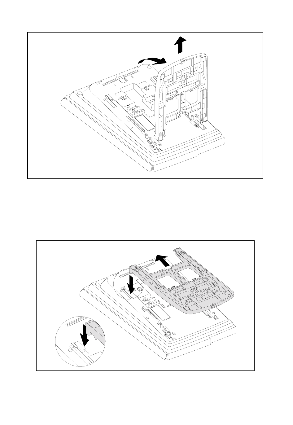
Section 300-Installation Appendix B. CPC-AII/B 8.0 Feature Update
DBS-2.3/9.2-300 DBS Manual - Revised April 2000 Page B-15
Figure B-16.Desk Stand Removal.
4. Rotate the desk stand 180°. In this position it doubles as a wall mount bracket.
5. Insert the wall mount bracket into the mounting guides as shown in Figure D-17.
6. Slide the wall mount bracket onto the telephone.
Figure B-17.Inserting the wall mount bracket (rotated desk stand)
7. While viewing the front of the telephone, find the handset guide located just below the
hookswitch (see Figure D-8).
8. Slide the handset guide out, rotate 180° so that the holding clip is exposed, and reinsert.
Step 2 Step 3
Step 5
Step 6
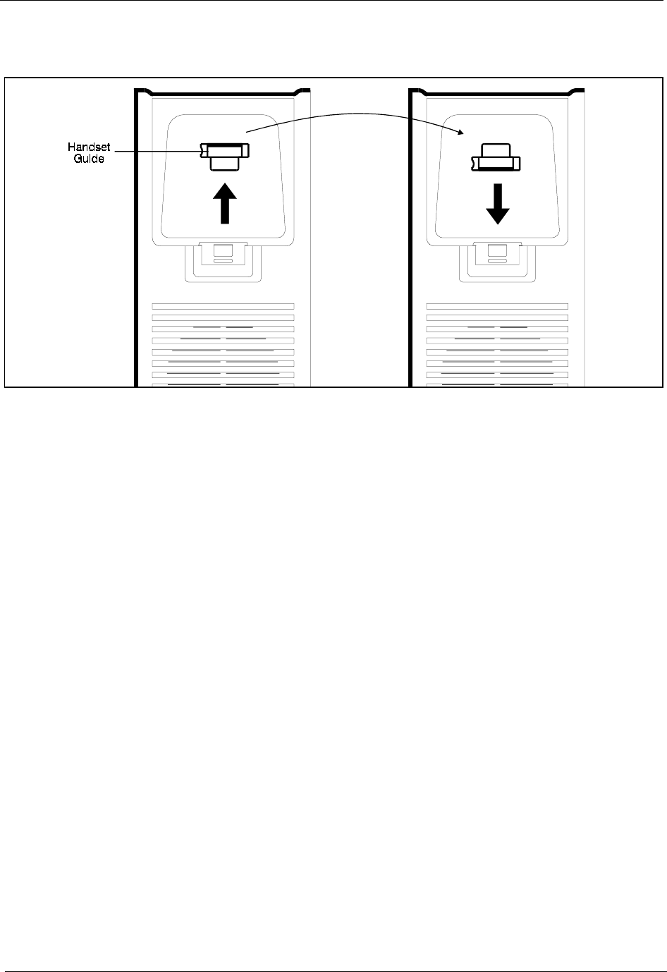
Appendix B. CPC-AII/B 8.0 Feature Update Section 300-Installation
Page B-16 DBS Manual - Revised April 2000 DBS-2.3/9.2-300
Figure B-18.Handset guide insertion for wall mounting, key telephone

DBS-2.3/9.2-300 DBS Manual - Revised April 2000 Index-1
A
Analog extensions 4-37
guidelines 4-37
installation 4-37
see also SLTA
B
Background music
see Peripheral equipment, BGM
Battery backup
capacities 7-3
guidelines 3-9
installation 3-9
DBS 40 3-10
DBS 72 and 96 3-11
part numbers 3-9
specifications 7-3
BGM
see Peripheral equipment, BGM
C
Cabinet description 2-3
Cabinet installation 3-1
batteries 3-9
guidelines 3-9
installation
DBS 40 3-10
DBS 72 and 96 3-11
circuit cards 3-6
guidelines 3-6
installation 3-8
DSLT wall mounting 3-15
desk stand attachment 3-16
desk stand removal 3-15
grounding 3-5
guidelines 3-5
installation 3-5
initialization 3-17
key phone wall mounting 3-13
mount adaptor removal 3-13
mount adaptor replacement 3-14
test phone 3-18
guidelines 3-18
installation 3-18
wall mounting 3-3
cover removal 3-3
guidelines 3-3
installation 3-3
mounting brackets 3-4
mounting illustration 3-4
Cabling
distances 7-13
specifications 7-13
Cards
see Circuit cards
Channel service unit 4-12
Circuit cards
CPC
description 2-9
strap S1 3-7
SW1 3-17
installation 3-6, 3-8
guidelines 3-6
MDF card 4-23
MFR slots 2-8
SCC-B switch 4 3-6
slot locations 2-8
Cleaning 1-5
Clock sync cable 4-29
Communications parameters 7-14
Configuration 2-5
extension capacities 2-5
trunk capacities 2-5
Connector panel 2-3
Connectors
pinouts for trunks 4-4
trunks 4-3
Cover removal 3-3
CPC
description 2-9
RAM clear 3-17
RAM hold 3-17
strap S1 3-7
SW1 3-17
CSU 4-12
Index

Index Section 300-Installation
Index-2 DBS Manual - Revised April 2000 DBS-2.3/9.2-300
D
Data communications ports 7-14
DBS
cabinet description 2-3
configurations 2-5
model numbers 1-1
requirements 1-1
DID trunks 4-9
guidelines 4-9
installation 4-10
Digital extension
see DSLT
Dimensions of system 7-4
Door 5-27, 5-31
Door box 5-31
Door box adaptor 5-31
Door box adaptor (extension port) 5-31
Door box adaptor (trunk port)
see Peripheral equipment, door box adaptor
(Trunk Port)
Door phone 5-31
see Peripheral equipment, door box adaptor
(trunk port)
Double-cabinet systems 6-1
guidelines 6-3
DBS 40 + DBS 40 6-4
DBS 72 + DBS 40 6-5
DBS 72 + DBS 72 6-6
DBS 96 + DBS 40 6-7
DBS 96 + DBS 72 6-8
DBS 96 + DBS 96 6-9
maximum capacities 6-3
installation 6-10
MFR cards 6-4
strap S3 6-10
DSLT
installation 4-41
DSS/72 4-42
guidelines 4-41
EM/24 4-43
guidelines 4-43
wall mounting 3-15
desk stand attachment 3-16
desk stand removal 3-15
DSS/72 4-41
DTMF frequencies 7-17
E
Electrical
characteristics 7-3
noise 1-4
EM/24 4-43
EMI filter 4-40
Environmental requirements 1-4, 7-4
electrical noise 1-4
gas and airborne particles 1-4
humidity 1-4, 7-4
lightening protection/grounding 1-5
lighting 1-5
temperature 1-4, 7-4
ventilation 1-4
vibration 1-4
water exposure 1-4
Extensions
analog
guidelines 4-37
installation 4-37
analog -- See also SLTA
connectors 4-31
pinouts 4-32
digital 4-41
DSS/72 4-41
guidelines 4-41
installation 4-42
EM/24 4-43
guidelines 4-43
installation 4-43
EMI filter 4-40
maximum capacities 2-5
pinouts 4-32
External ringer
see Peripheral equipment, external ringer
F
FCC information
network address signaling code 1-2
registration number 1-2
ringer equivalence 1-2
Feature-related capacities 7-5
Fractional T1 4-13

Section 300-Installation Index
DBS-2.3/9.2-300 DBS Manual - Revised April 2000 Index-3
G
Gas and airborne particles 1-4
Grounding 1-5, 3-5
guidelines 3-5
installation 3-5
T1 4-26
Ground-start trunks 4-9
guidelines 4-9
installation 4-10
H
Hardware maximums
double-cabinet systems 7-10
single-cabinet systems 7-7
Heat generation 7-3
Humidity 1-4, 7-4
I
Initialization of system 3-17
Input power 7-3
Installation
analog extensions 4-37
background music 5-8
cabinet 3-1
batteries 3-9
DBS 40 3-10
DBS 72 and 96 3-11
guidelines 3-9
grounding 3-5
guidelines 3-5
installation 3-5
circuit cards 3-6, 3-8
CPC strap S1 3-7
guidelines 3-6
SCC-B switch 4 3-6
DID trunks 4-10
door box adaptor 5-28
double-cabinet systems 6-1, 6-10
extensions
analog 4-37
digital 4-41
DSS/72 4-41
EM/24 4-43
external ringer 5-18
ground-start trunks 4-10
initialization of system 3-17
line expansion 4-44
loop-start trunks 4-7
OPX adaptor 5-11
with central office 5-12
without central office 5-11
paging 5-14
PCAS terminal 5-4
power failure unit 5-19
remote administration interface 5-6
SMDR device 5-4
T1 interface 4-20
double cabinet
T1 in both cabinets 4-29
T1 in slave 4-27
single cabinet 4-21
test phone 3-18
guidelines 3-18
trunk expansion 4-44
voice announce unit 5-22
wall mounting cabinet
cover removal 3-3
illustration 3-4
mounting brackets 3-4
wall mounting DSLT 3-15
desk stand attachment 3-16
desk stand removal 3-15
wall mounting key phone 3-13
mount adaptor removal 3-13
mount adaptor replacement 3-14
wall-mounting cabinet 3-3
guidelines 3-3
Introduction to system 2-1
K
KTEL-to-DBS voice path 7-14
L
Lighting 1-5
Lightning protection 1-5
Lines 4-1, 4-31
expansion 4-44
guidelines 4-44
installation 4-44
extensions

Index Section 300-Installation
Index-4 DBS Manual - Revised April 2000 DBS-2.3/9.2-300
see Extensions
maximums 7-5
Local Terminal
see Peripheral equipment, local terminal
Loop-start trunks 4-7
guidelines 4-7
installation 4-7
M
Maximums
cabling distances 7-13
double-cabinet systems 6-3
feature-related 7-5
hardware
double-cabinet systems 7-10
single-cabinet systems 7-7
lines 7-5
MFR cards in double-cabinet system 6-4,
6-5, 6-6, 6-7, 6-8, 6-9
OPX adaptor distances 5-11
OPX direct connect distances 5-10
system resources 7-5
T1 4-12
T1 trunk assignments 4-14, 4-15
trunk connections 4-3
trunks 7-5
MDF card 4-23
MFR cards
in double cabinet systems 6-4, 6-5, 6-6, 6-
7, 6-8, 6-9
slot locations 2-8
strap S3 6-10
Model numbers for DBS 1-1
Mounting brackets 3-4
Music on hold
see Peripheral equipment, BGM
N
Network
address signaling code 1-2
O
Off-premises adaptor
see Peripheral equipment, OPX
OPX
see Peripheral equipment, OPX
Overview of system 2-1
P
Paging
see Peripheral equipment, Paging
Part numbers
VA-43703 5-19
VB-2450A-2P 3-9
VB-2650-2P 3-9
VB-43030 1-1
VB-43110 4-12
VB-43120 4-44
VB-43121 4-44
VB-43130 3-9
VB-43511 4-7
VB-43561 4-11, 4-12
VB-43562 4-11, 4-12
VB-43563 4-11, 4-12, 4-21
VB-43564 4-12, 4-27
VB-43701 5-27, 5-31
VB-43702 5-10
VB-43705 5-31
VB-43706 5-6
VB-43707 5-6
VB-43708 5-27, 5-31
VB-43711 5-31
VB-53531 4-9
Peripheral equipment 5-1
BGM
guidelines 5-8
installation 5-8
SCC variable resistors 5-9
door box adaptor
guidelines 5-27
installation 5-28
door box adaptor (trunk port)
external ringer
guidelines 5-17
installation 5-18
Local terminal
OPX
guidelines 5-10
installation 5-11
with central office 5-12
without central office 5-11

Section 300-Installation Index
DBS-2.3/9.2-300 DBS Manual - Revised April 2000 Index-5
paging
guidelines 5-14
installation 5-14
PCAS terminal
guidelines 5-3
installation 5-4
RS-232 connection 5-4
power failure unit
guidelines 5-19
installation 5-19
RAI
guidelines 5-6
installation 5-6
SMDR device
guidelines 5-3
installation 5-4
RS-232 connection 5-4
voice announce unit
guidelines 5-22
installation 5-22
PFU
see Peripheral equipment, power failure
unit
Ports for data communications 7-14
Power consumption 7-3
Power failure unit
see Peripheral equipment, power failure
unit
Printed circuit cards
see Circuit cards
Processor description 2-9
R
RAI
see Peripheral equipment, RAI
Registration number 1-2
Remote administration interface
see Peripheral equipment, RAI
Requirements 1-1
Resource maximums 7-5
Ringer equivalence number 1-2
RJ48 pinouts for T1 4-25
RS-232C
25-pin to 25-pin cable 5-4
S
SCC
switch 4 (SCC-B) 3-6
variable resistors 5-9
Signaling
characteristics 7-15
level 7-15
to CO 7-15
Single Line Telephone Adaptor 5-34
Single Line Telephones 5-34
SLTA 5-34
SLTs 4-37, 5-34
see Analog extensions
SMDR
see Peripheral equipment, SMDR device
Specifications 7-1
backup batteries 7-3
cabling 7-13
cabling distances 7-13
communications parameters 7-14
data communications ports 7-14
dimensions and weight 7-4
DTMF frequencies 7-17
electrical characteristics 7-3
environmental requirements 7-4
feature-related capacities 7-5
hardware maximums
double-cabinet systems 7-10
single-cabinet systems 7-7
heat generation 7-3
input power 7-3
power consumption 7-3
resource maximums 7-5
signaling 7-15
signaling level 7-15
signaling to CO 7-15
tone characteristics 7-16
tone plan 7-16
transmission specification 7-15
trunk and line capacities 7-5
voice path from KTEL to DBS 7-14
Sync
cable 4-24, 4-27, 4-29
unit 4-21, 4-22
System

Index Section 300-Installation
Index-6 DBS Manual - Revised April 2000 DBS-2.3/9.2-300
configurations 2-5
initialization 3-17
overview 2-1
requirements 1-1
T
T1 interface 4-11
clock sync cable 4-29
distance from DBS to CSU 4-24
fractional T1 4-13
grounding 4-26
guidelines 4-11
hardware requirements 4-11
maximums 4-12
trunk assignments for double-cabinet
systems 4-15
trunk assignments for single-cabinet
systems 4-14
installation 4-20
double cabinet
T1 in both cabinets 4-29
T1 in slave 4-27
single cabinet 4-21
MDF card 4-23
RJ48 pinouts 4-25
sync cable 4-24, 4-27, 4-29
sync unit 4-21, 4-22
trunk number
double-cabinet systems 4-15
single-cabinet systems 4-14
Temperature 1-4, 7-4
Test phone 3-18
guidelines 3-18
installation 3-18
Tone
characteristics 7-16
plan 7-16
Transmission specification 7-15
Trunks 4-3
connector pinouts 4-4
connectors 4-3
DID 4-9
guidelines 4-9
installation 4-10
expansion 4-44
guidelines 4-44
installation 4-44
groud-start
installation 4-10
ground-start 4-9
guidelines 4-9
loop-start 4-7
guidelines 4-7
installation 4-7
maximums 2-5, 7-5
trunk numbering
single-cabinet systems 4-14
Trunks and lines 4-1
U
UNA device
see Peripheral equipment, external ringer
V
VA-43703 5-19
VAU
see Peripheral equipment, voice announce
unit
VB-2450A-2P 3-9
VB-2650-2P 3-9
VB-43050 1-1
VB-43060 1-1
VB-43110 4-12
VB-43120 4-44
VB-43121 4-44
VB-43130 3-9
VB-43541 4-9
VB-43561 4-11, 4-12
VB-43562 4-11, 4-12
VB-43563 4-11, 4-12, 4-21
VB-43564 4-12, 4-27
VB-43701 5-27, 5-31
VB-43702 5-10
VB-43705 5-31
VB-43706 5-6
VB-43707 5-6
VB-43708 5-27, 5-31
VB-43711 5-31
Ventilation 1-4
Vibration 1-4
Voice announce unit

Section 300-Installation Index
DBS-2.3/9.2-300 DBS Manual - Revised April 2000 Index-7
see Peripheral equipment, voice announce
unit
Voice path from KTEL to DBS 7-14
W
Wall mounting
cabinets 3-3
cover removal 3-3
guidelines 3-3
installation 3-3
mounting brackets 3-4
mounting illustration 3-4
DSLT 3-15, 3-16
key phones 3-13
mount adaptor removal 3-13
mount adaptor replacement 3-14
Water exposure 1-4
Weight of system 7-4

Index Section 300-Installation
Index-8 DBS Manual - Revised April 2000 DBS-2.3/9.2-300
