C2000 Digital Control Library DCL User's Guide
DCL_User's_Guide
DCL_User's_Guide
DCL_User's_Guide
DCL_User's_Guide
DCL_User's_Guide
User Manual:
Open the PDF directly: View PDF ![]() .
.
Page Count: 91
- Table of Contents
- Preface
- 1 Introduction
- 2 Using the Digital Control Library
- 3 Controllers
- 4 Utilities
- 5 Examples
- 6 Support
- Important Notice

C2000™ Digital Control Library
User's Guide
Literature Number: SPRUID3
January 2017

2SPRUID3–January 2017
Submit Documentation Feedback
Copyright © 2017, Texas Instruments Incorporated
Contents
Contents
Preface ........................................................................................................................................ 6
1 Introduction......................................................................................................................... 7
1.1 Supported Devices .......................................................................................................... 8
1.2 Overview of the Library ..................................................................................................... 8
1.3 Changes to Version 1 ....................................................................................................... 8
1.3.1 New Features ....................................................................................................... 8
1.3.2 Function Naming.................................................................................................... 9
1.3.3 Calling Convention ................................................................................................ 10
1.3.4 Bug Fixes........................................................................................................... 10
1.4 Benchmarks................................................................................................................. 10
2 Using the Digital Control Library .......................................................................................... 12
2.1 What the Library Contains ................................................................................................ 13
2.1.1 Header Files ....................................................................................................... 13
2.1.2 Source Files........................................................................................................ 13
2.1.3 Examples ........................................................................................................... 14
2.2 How to Add the DCL to your Code....................................................................................... 14
2.2.1 Steps to Add the DCL to Existing C Code ..................................................................... 14
2.2.2 Calling the Library Functions From Assembly................................................................. 16
3 Controllers ........................................................................................................................ 17
3.1 Linear PID Controllers ..................................................................................................... 18
3.1.1 Description ......................................................................................................... 18
3.1.2 Implementation .................................................................................................... 19
3.1.3 PID Functions...................................................................................................... 23
3.2 Linear PI Controllers ....................................................................................................... 25
3.2.1 Description ......................................................................................................... 25
3.2.2 Implementation .................................................................................................... 26
3.2.3 Summary of PI Functions ........................................................................................ 28
3.3 Non-linear PID Controller.................................................................................................. 31
3.3.1 Description ......................................................................................................... 31
3.3.2 Implementation .................................................................................................... 35
3.3.3 NLPID Functions .................................................................................................. 36
3.4 Direct Form 1 (Third Order) Compensators............................................................................. 37
3.4.1 Description ......................................................................................................... 37
3.4.2 Implementation .................................................................................................... 39
3.4.3 DF13 Functions.................................................................................................... 40
3.5 Direct Form 2 (Second Order) Compensators ......................................................................... 44
3.5.1 Description ......................................................................................................... 44
3.5.2 Implementation .................................................................................................... 46
3.5.3 DF22 Functions.................................................................................................... 47
3.6 Direct Form 2 (Third Order) Compensators............................................................................. 50
3.6.1 Description ......................................................................................................... 50
3.6.2 Implementation .................................................................................................... 52
3.6.3 DF23 Functions.................................................................................................... 53
4 Utilities.............................................................................................................................. 57

www.ti.com
3
SPRUID3–January 2017
Submit Documentation Feedback Copyright © 2017, Texas Instruments Incorporated
Contents
4.1 Control Clamps ............................................................................................................. 58
4.1.1 Description ......................................................................................................... 58
4.1.2 Clamp Functions .................................................................................................. 58
4.2 Data Logger................................................................................................................. 59
4.2.1 Description ......................................................................................................... 59
4.2.2 DCL Functions..................................................................................................... 61
4.3 Transient Capture Module ................................................................................................ 65
4.3.1 TCM_idle Mode.................................................................................................... 66
4.3.2 TCM_armed Mode ................................................................................................ 67
4.3.3 TCM_capture Mode............................................................................................... 68
4.3.4 TCM_complete Mode ............................................................................................. 70
4.3.5 TCM Functions .................................................................................................... 71
4.4 Performance Measurement ............................................................................................... 73
4.4.1 Description ......................................................................................................... 73
4.4.2 IES Functions...................................................................................................... 74
5 Examples .......................................................................................................................... 77
5.1 Example 1: DF22 Compensator Running on C28x .................................................................... 78
5.1.1 Example Overview ................................................................................................ 78
5.1.2 Code Description .................................................................................................. 78
5.1.3 Running the Example............................................................................................. 78
5.2 Example 2: DF23 Compensator Running on CLA ..................................................................... 80
5.2.1 Example Overview ................................................................................................ 80
5.2.2 Code Description .................................................................................................. 80
5.2.3 Running the Example............................................................................................. 81
5.3 Example 3: NLPID Controller Running on C28x ....................................................................... 82
5.3.1 Example Overview ................................................................................................ 82
5.3.2 Code Description .................................................................................................. 82
5.3.3 Running the Example............................................................................................. 82
5.4 Example 4: PI Controller Running on CLA.............................................................................. 83
5.4.1 Example Overview ................................................................................................ 83
5.4.2 Code Description .................................................................................................. 84
5.4.3 Running the Example............................................................................................. 84
5.5 Example 5: PID Controller Running on C28x........................................................................... 85
5.5.1 Example Overview ................................................................................................ 85
5.5.2 Code Description .................................................................................................. 85
5.5.3 Running the Example............................................................................................. 85
5.6 Example 6: TCM Running on C28x...................................................................................... 86
5.6.1 Example Overview ................................................................................................ 86
5.6.2 Code Description .................................................................................................. 86
5.6.3 Running the Example............................................................................................. 87
6 Support............................................................................................................................. 89
6.1 References .................................................................................................................. 90
6.2 Training ...................................................................................................................... 90

www.ti.com
4SPRUID3–January 2017
Submit Documentation Feedback
Copyright © 2017, Texas Instruments Incorporated
List of Figures
List of Figures
1-1. DCL Version 1 Function Naming .......................................................................................... 9
1-2. DCL Version 2 Function Naming .......................................................................................... 9
2-1. CCSv6 Include Options.................................................................................................... 14
3-1. Parallel Form PID Controller.............................................................................................. 18
3-2. PID Control Action ......................................................................................................... 19
3-3. DCL_PID_C1 Architecture ................................................................................................ 21
3-4. DCL_PID_C3 Architecture ................................................................................................ 22
3-5. DCL_PI_C1 Architecture .................................................................................................. 26
3-6. DCL_PI_C3 architecture .................................................................................................. 27
3-7. Non-Linear PID Input Architecture ....................................................................................... 31
3-8. Non-Linear PID Output Architecture ..................................................................................... 32
3-9. Non-Linear Control Law Input-Output Plot.............................................................................. 33
3-10. NLPID Linearized Region ................................................................................................. 34
3-11. DCL_DF13_C1 Architecture .............................................................................................. 37
3-12. DCL_DF13_C2C3 Architecture........................................................................................... 38
3-13. DF13 Data and Coefficient Layout....................................................................................... 39
3-14. DCL_DF22_C1 Architecture .............................................................................................. 45
3-15. DCL_DF22_C2 Architecture .............................................................................................. 45
3-16. DCL_DF22_C3 Architecture .............................................................................................. 46
3-17. DCL_DF23_C1 Architecture .............................................................................................. 50
3-18. DCL_DF23_C2 Architecture .............................................................................................. 51
3-19. DCL_DF23_C3 Architecture .............................................................................................. 51
3-20. DF23 Data and Coefficient Layout....................................................................................... 52
4-1. Data Log Pointer Allocation............................................................................................... 60
4-2. TCM Operation in TCM_idle Mode ...................................................................................... 66
4-3. TCM Operation in TCM_armed Mode ................................................................................... 67
4-4. TCM Operation in Capture Mode (monitor frame un-winding) ....................................................... 68
4-5. TCM Operation in TCM_capture Mode (lead frame complete) ...................................................... 69
4-6. CM Capture Complete..................................................................................................... 70
4-7. Transient Servo Error...................................................................................................... 73
5-1. Graph Setup Window ...................................................................................................... 79
5-2. ek Buffer..................................................................................................................... 79
5-3. Plot of u1k and u2k Buffers ............................................................................................... 80
5-4. u1k Memory Buffer at Address 0xE000 ................................................................................. 81
5-5. Plot of u1k Memory Buffer ................................................................................................ 81
5-6. Expression Window ........................................................................................................ 83
5-7. Expression Window ........................................................................................................ 84
5-8. Expression Window ........................................................................................................ 86
5-9. Contents of the 1601-Point yBuf Memory............................................................................... 87
5-10. 350-Point Contents of the dBuf Buffer................................................................................... 87

www.ti.com
5
SPRUID3–January 2017
Submit Documentation Feedback Copyright © 2017, Texas Instruments Incorporated
List of Tables
List of Tables
1-1. Controller Execution and Code Size Benchmarks ..................................................................... 10
2-1. List of DCL Header Files .................................................................................................. 13
2-2. List of DCL Source Files .................................................................................................. 13
3-1. List of PID Structure Elements and Address Offsets .................................................................. 21
3-2. Summary of PID Functions ............................................................................................... 23
3-3. List of PI Structure Elements and Address Offsets .................................................................... 26
3-4. PI Functions................................................................................................................. 28
3-5. List of NLPID Structure Elements and Address Offsets............................................................... 35
3-6. Summary of NLPID Functions............................................................................................ 36
3-7. List of DF13 Structure Elements and Address Offsets................................................................ 39
3-8. Summary of DF13 Functions ............................................................................................. 40
3-9. List of DF22 Structure Elements and Address Offsets................................................................ 46
3-10. Summary of DF22 Functions ............................................................................................. 47
3-11. List of DF23 Structure Elements and Address Offsets................................................................ 52
3-12. Summary of DF23 Functions ............................................................................................ 53
4-1. Summary of Clamp Functions ............................................................................................ 58
4-2. Data Log Read/Write Benchmarks....................................................................................... 60
4-3. Summary of DCL Functions .............................................................................................. 61
4-4. Summary of TCM Functions .............................................................................................. 71
4-5. Performance Index Function Benchmarks .............................................................................. 74
4-6. Summary of IES Functions................................................................................................ 74

6SPRUID3–January 2017
Submit Documentation Feedback
Copyright © 2017, Texas Instruments Incorporated
Preface
SPRUID3–January 2017
About This Manual
This user's guide contains information relating to the C2000 Digital Control Library (DCL). Here you will
find technical descriptions of the library functions and how to use them. The user's guide does not contain
information on control applications or on the underlying theory of control.
Chapter 1 introduces the library and provides background information. Chapter 2 describes how to use the
library. Chapter 3 describes the controller functions and provides detailed information on their use.
Chapter 4 describes the utility functions included in the library. Chapter 5 describes the supporting
software examples that illustrate the use of the library. A list of useful technical references and training can
be found in Chapter 6.
The scope of this user's guide is restricted to description and use of the C2000 Digital Control Library.
Information on specific devices and applications is not covered; however, the references listed in
Chapter 6 provide a good selection of relevant material and may be of interest.
How to Use This Manual
The reader is advised to begin by reading the library overview in Chapter 1.Chapter 2 provides a useful
step-by-step guide of how to add the library code to a C program, and should be read carefully by all
users. Once the decision has been made on which type of controller to implement, performance and other
important information in the relevant subsection of Chapter 3 should be read carefully. If data array
management or performance measurement is required, Chapter 4 describes supporting library functions
that may be of interest. Finally, the examples listed in Chapter 5 provide a good starting point for new
users of the library.
Related Documentation
For a complete list of related documentation and development tools for the C2000 device, visit the C2000
page on the Texas Instruments website at www.ti.com/c2000.
If You Need Assistance
Technical support for C2000 products is available online via the TI “E2E” Community:
e2e.ti.com/support/microcontrollers/c2000.
Trademarks
C2000 is a trademark of Texas Instruments.
7
SPRUID3–January 2017
Submit Documentation Feedback Copyright © 2017, Texas Instruments Incorporated
Introduction
Chapter 1
SPRUID3–January 2017
Introduction
This chapter contains a brief introduction to the Texas Instruments C2000 Digital Control Library.
Topic ........................................................................................................................... Page
1.1 Supported Devices............................................................................................... 8
1.2 Overview of the Library ........................................................................................ 8
1.3 Changes to Version 1 ........................................................................................... 8
1.4 Benchmarks ...................................................................................................... 10

Supported Devices
www.ti.com
8SPRUID3–January 2017
Submit Documentation Feedback
Copyright © 2017, Texas Instruments Incorporated
Introduction
1.1 Supported Devices
The Digital Control Library (DCL) only supports C2000 devices that contain a 32-bit Floating Point Unit
(FPU). Among these devices are:
• TMS320F28004x
• TMS320F2837xD
• TMS320F2807x
• TMS320F2833x
• TMS320C2834x
• TMS320F2806x
• TMS320F28M35x
• TMS320F28M36x
The library includes functions that run on the Control Law Accelerator (CLA). This core is only found on
certain C2000 devices, including:
• TMS320F28004x
• TMS320F2837xD
• TMS320F2837xS
• TMS320F2807x
• TMS320F2806x
1.2 Overview of the Library
This document describes version 2.0 of the C2000 Digital Control Library (DCL). The DCL provides a suite
of robust, open source software functions for developers of control applications using the C2000 MCU
platform from Texas Instruments. The library is available for free download at: www.ti.com/c2000.
The DCL functions are intended for use in any system in which a C2000 device is used. The DCL may not
be used with any other devices. The DCL is independent of other application specific C2000 software
libraries, including “motorWARE” and the “Digital Power Library”, providing attention is paid to data type
and range, and integration with these packages should be straightforward.
The library is not extensive. Version 2.0 contains 40 controller functions and 24 supporting functions, all of
which are supplied in source code form. Six different types of controller are represented: three PID types,
and three “Direct Form” types. The former are typically used to tune transient response properties, while
the latter are used in applications where control performance is specified in terms of frequency response
properties.
Supporting functions fall into three groups: data logging & buffer management, performance
measurement, and transient capture. All supporting functions run on the C28x core only and are supplied
in C code form. Some time-critical supporting functions are also supplied in C28x assembly code form.
The library includes a small set of example projects that illustrate how DCL functions might be
implemented in user code. All example code was prepared for the F28069 device using the TI peripheral
header files for that device.
1.3 Changes to Version 1
1.3.1 New Features
Version 2 of the DCL contains approximately twice the number of controller functions as version 1. The
new version of the DCL also adds a number of new utility functions for transient capture and performance
measurement. To reflect the broader scope of the library, the name has been changed from Digital
Controller Library to Digital Control Library.
The following is a list of features that are new to version 2.0 of the DCL.
• Expanded set of 40 controller functions, compared with 19 in version 1.0
• Controllers coded in C, C28x assembly, and CLA assembly
DCL_runDF23_C1
Library Identifier
Controller type
PID
PI
DF13
DF22
DF23
CPU core
C = FPU32
L = CLA
Identifier
A unique number which identifies the
controller implementation
DCL_runDF23pc
Library Identifier
Controller type
PID
PI
DF13
DF22
DF23
Pre-computation
blank = not pre-computed
i = immediate term
p = partial term
CPU core
blank = C28x main CPU
c = CLA
www.ti.com
Changes to Version 1
9
SPRUID3–January 2017
Submit Documentation Feedback Copyright © 2017, Texas Instruments Incorporated
Introduction
• A non-linear PID controller
• Data clamp functions
• A triggered burst data log module for transient capture
• Fast read/write data log functions
• Performance measurement functions
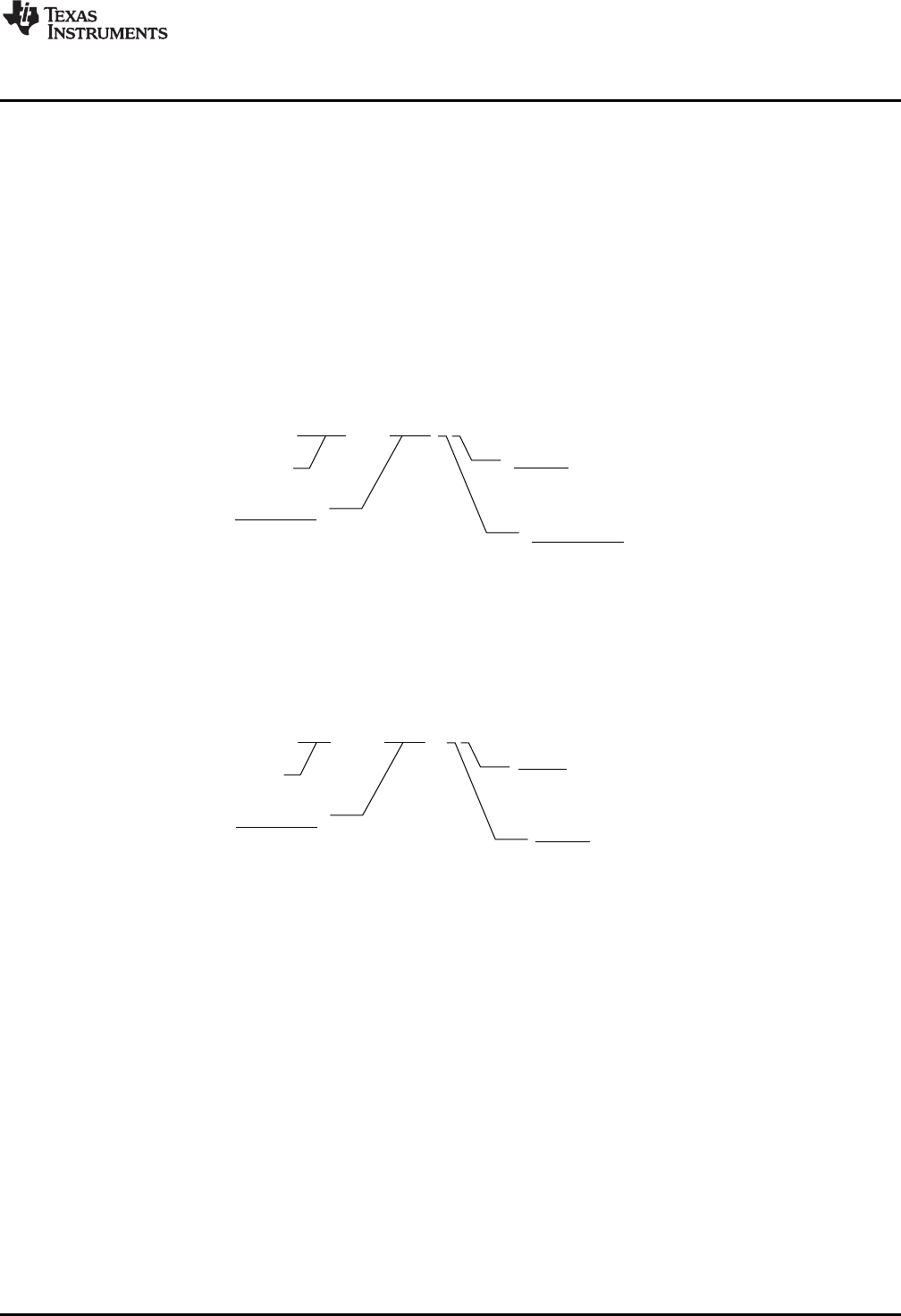
1.3.2 Function Naming
The function naming convention has changed in version 2.0 of the library. The new naming allows several
controllers of similar type, but with slightly different implementation, to be included in the library and to be
used together in the same program if required.
An example of a function from version 1 of the library is shown in Figure 1-1.
Figure 1-1. DCL Version 1 Function Naming
The corresponding function in version 2 of the library is shown in Figure 1-2.
Figure 1-2. DCL Version 2 Function Naming
In the new name format, the controller type, and the CPU on which it runs are explicit. This has been done
to allow future expansion of the library with variations of each controller type. An example of this is the PID
controller that exists in both “ideal” and “parallel” forms in the new library. The final digit is an arbitrary
number that identifies the implementation. Users may add their own controller variations to the DCL
controllers by adjusting the final two characters of the function name.
All previous function names have been deprecated in the new library. Previous names are mapped to the
new equivalents using the definition list seen near the top of the DCL.h header file. It is not necessary to
change any existing code that uses version 1.0 function names.
Changes to Version 1
www.ti.com
10 SPRUID3–January 2017
Submit Documentation Feedback
Copyright © 2017, Texas Instruments Incorporated
Introduction
1.3.3 Calling Convention
All functions in version 2 of the DCL are designed to be called from a C program. The context save and
restore in each function assumes the standard parent register save is performed. If any of the assembly
functions are called from an assembly program, additional context save and restore instructions must be
added. This differs from version 1.0 in which a full register save and restore was implemented in each
function. The new approach has the advantage of fewer instruction cycles when called from a C program,
which is the most common use case. For further details, see Section 2.2.2.
1.3.4 Bug Fixes
Only one software bug was known in version 1. This affected the DCL_fillLog() function in the data logger
and resulted in the last element in the log not being written. This issue has been corrected in version 2.
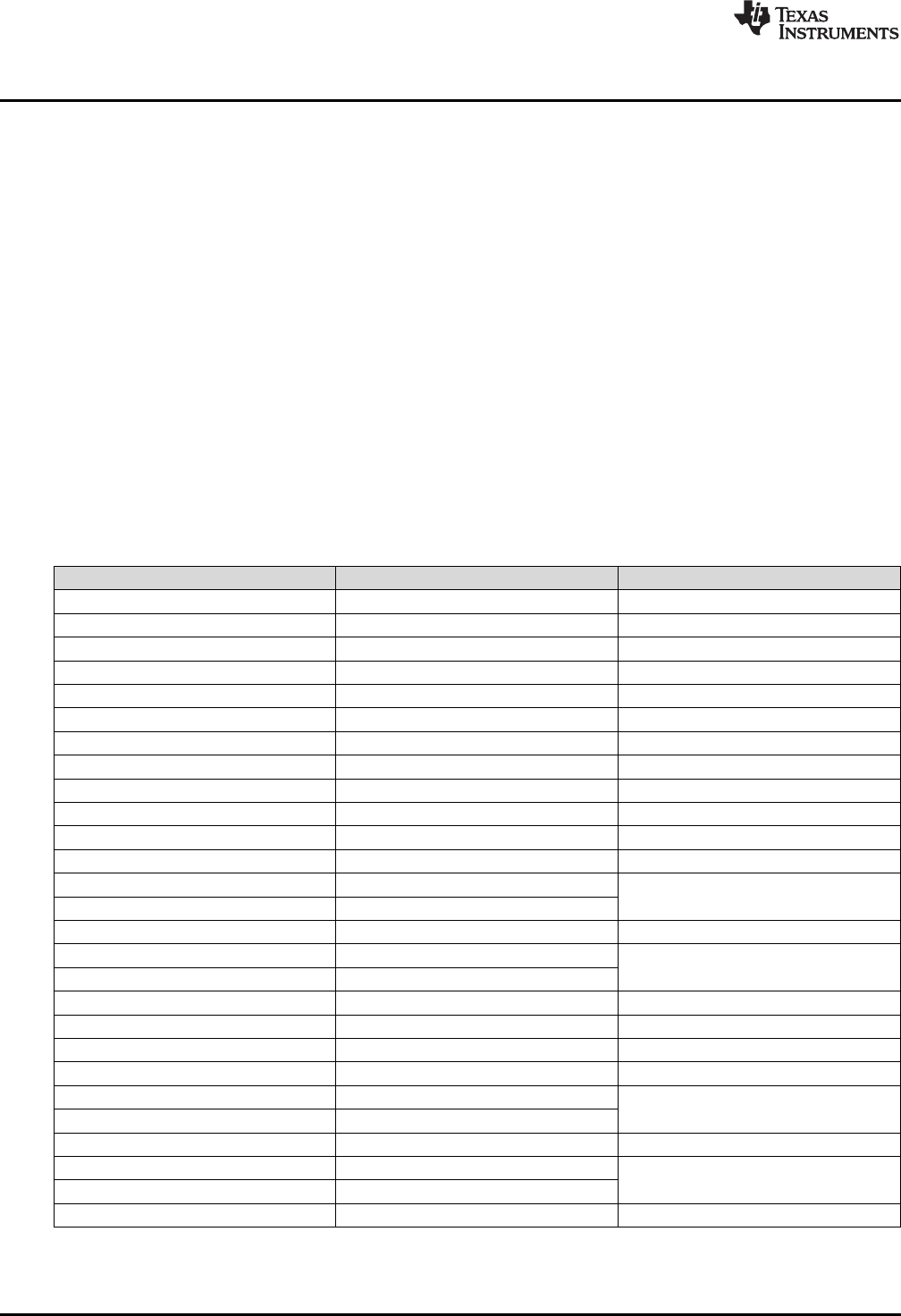
1.4 Benchmarks
Table 1-1 lists the performance of each library function by cycle count. In all cases, cycle count
benchmarks were measured by logging a free-running PWM timer before and after each function call.
Therefore, the measured cycle count includes the function calling overhead from the C environment.
Compiler optimization was disabled in all tests. Function sizes are given in units of 16-bit words, as
reported in the “.map” file.
(1) All paths operating in linearized error region. For all paths in non-linear operation, total cycle count is approximately 1,433. For
more information, see Section 3.3.1.
(2) Measured with run-time library support for the pow() function.
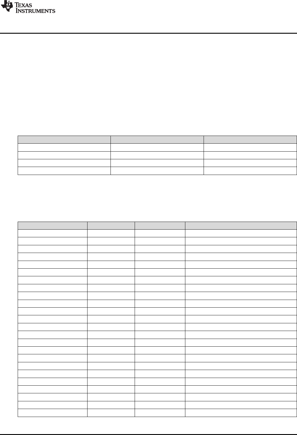
Table 1-1. Controller Execution and Code Size Benchmarks
Function Cycles Size (W)
DCL_runPID_C1 81 97
DCL_runPID_C2 197 207
DCL_runPID_C3 186 196
DCL_runPID_C4 84 90
DCL_runPID_L1 53 70
DCL_runPID_L2 45 58
DCL_runPI_C1 50 52
DCL_runPI_C2 117 121
DCL_runPI_C3 122 126
DCL_runPI_C4 48 37
DCL_runPI_L1 34 42
DCL_runPI_L2 33 40
DCL_runNLPID_C1 284 (1),(2) 312
DCL_setGamma 2090 (2)
DCL_runDF13_C1 71 66
DCL_runDF13_C2 20 79
DCL_runDF13_C3 74
DCL_runDF13_C4 175 162
DCL_runDF13_C5 40 38
DCL_runDF13_C6 121 126
DCL_runDF13_L1 61 86
DCL_runDF13_L2 20 100
DCL_runDF13_L3 58
DCL_runDF22_C1 44 45
DCL_runDF22_C2 19 48
DCL_runDF22_C3 39
DCL_runDF22_C4 71 75
www.ti.com
Benchmarks
11
SPRUID3–January 2017
Submit Documentation Feedback Copyright © 2017, Texas Instruments Incorporated
Introduction
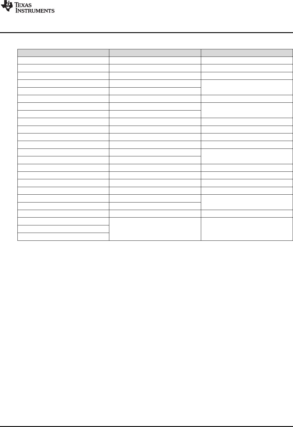
Table 1-1. Controller Execution and Code Size Benchmarks (continued)
Function Cycles Size (W)
(3) Cycle count depends on buffer length. For more information, see Section 3.4.1.
DCL_runDF22_C5 29 26
DCL_runDF22_C6 60 67
DCL_runDF22_L1 33 40
DCL_runDF22_L2 20 60
DCL_runDF22_L3 34
DCL_runDF23_C1 62 64
DCL_runDF23_C2 20 69
DCL_runDF23_C3 54
DCL_runDF23_C4 98 107
DCL_runDF23_C5 29 26
DCL_runDF23_C6 82 97
DCL_runDF23_L1 44 60
DCL_runDF23_L2 20 80
DCL_runDF23_L3 44
DCL_writeLog 48 N/A
DCL_readLog 39 N/A
DCL_freadLog 22 11
DCL_fwriteLog 22 14
DCL_runClamp_C1 28 20
DCL_runClamp_C2 71
DCL_runClamp_L1 25 26
DCL_runITAE_C1 60 (3)
DCL_runIAE_C1
DCL_runIES_C1

12 SPRUID3–January 2017
Submit Documentation Feedback
Copyright © 2017, Texas Instruments Incorporated
Using the Digital Control Library
Chapter 2
SPRUID3–January 2017
Using the Digital Control Library
This chapter describes how to use the Digital Control Library.
Topic ........................................................................................................................... Page
2.1 What the Library Contains................................................................................... 13
2.2 How to Add the DCL to your Code ....................................................................... 14
www.ti.com
What the Library Contains
13
SPRUID3–January 2017
Submit Documentation Feedback Copyright © 2017, Texas Instruments Incorporated
Using the Digital Control Library
2.1 What the Library Contains
The DCL library is supplied entirely in open source format. There are no object or “.lib” files in the library.
This makes it possible for a user to modify the controller functions if different functionality is required.
Controller functions are coded in the following formats:
• Inline C code
• C28x (FPU32) assembly code
• CLA assembly code
2.1.1 Header Files
The four header files shown in Table 2-1 are included in the library.
Table 2-1. List of DCL Header Files
Filename Type Description
DCL h Library functions
DCL_fdlog h Data logger functions
DCL_NLPID h Non-linear PID functions
DCL_TCM h Transient capture functions
2.1.2 Source Files
The source files shown in Table 2-2 are included in the library.
Table 2-2. List of DCL Source Files
Filename Type CPU Description
DCL_PID_C1 asm C28x Ideal linear PID
DCL_PID_C4 asm C28x Parallel linear PID
DCL_PID_L1 asm CLA Ideal linear PID
DCL_PID_L2 asm CLA Parallel linear PID
DCL_PI_C1 asm C28x Ideal linear PI
DCL_PI_C4 asm C28x Parallel linear PI
DCL_PI_L1 asm CLA Ideal linear PI
DCL_PI_L2 asm CLA Parallel linear PI
DCL_DF13_C1 asm C28x Full DF1 (3rd order)
DCL_DF13_C2C3 asm C28x Pre-computed DF1 (3rd order)
DCL_DF13_L1 asm CLA Full DF1 (3rd order)
DCL_DF13_L2L3 asm CLA Pre-computed DF1 (3rd order)
DCL_DF22_C1 asm C28x Full DF2 (2nd order)
DCL_DF22_C2C3 asm C28x Pre-computed DF2 (2nd order)
DCL_DF22_L1 asm CLA Full DF2 (2nd order)
DCL_DF22_L2L3 asm CLA Pre-computed DF2 (2nd order)
DCL_DF23_C1 asm C28x Full DF2 (3rd order)
DCL_DF23_C2C3 asm C28x Pre-computed DF2 (3rd order)
DCL_DF23_L1 asm CLA Full DF2 (3rd order)
DCL_DF23_L2L3 asm CLA Pre-computed DF2 (3rd order)
DCL_frwlog asm C28x Fast read/write log functions
DCL_clamp_C1 asm C28x Data clamp
DCL_clamp_L1 asm CLA Data clamp
DCL_index asm C28x Performance measurement
What the Library Contains
www.ti.com
14 SPRUID3–January 2017
Submit Documentation Feedback
Copyright © 2017, Texas Instruments Incorporated
Using the Digital Control Library
2.1.3 Examples
Six examples are supplied with the Digital Control Library. These were prepared using CCS version 6 and
run without modification on the F28069 device. The examples include linker command files that show how
to allocate device memory when using the DCL. For more details, see Chapter 5.
2.2 How to Add the DCL to your Code
The Digital Control Library is intended to be used with a project written in the C programming language.
Typically, the controller functions for the C28x would be inserted into an Interrupt Service Routine (ISR)
triggered by a hardware event, which ensures they are executed at a fixed rate and their timing is
synchronized with the availability of incoming control data. Control functions for use on the CLA would be
called from a CLA task, which again, would typically be triggered by a hardware event.
2.2.1 Steps to Add the DCL to Existing C Code
The following is a sequence of steps that can be followed when adding the DCL to an existing C program.
For a set of code examples that illustrates configuration and use of the DCL, see Chapter 5.
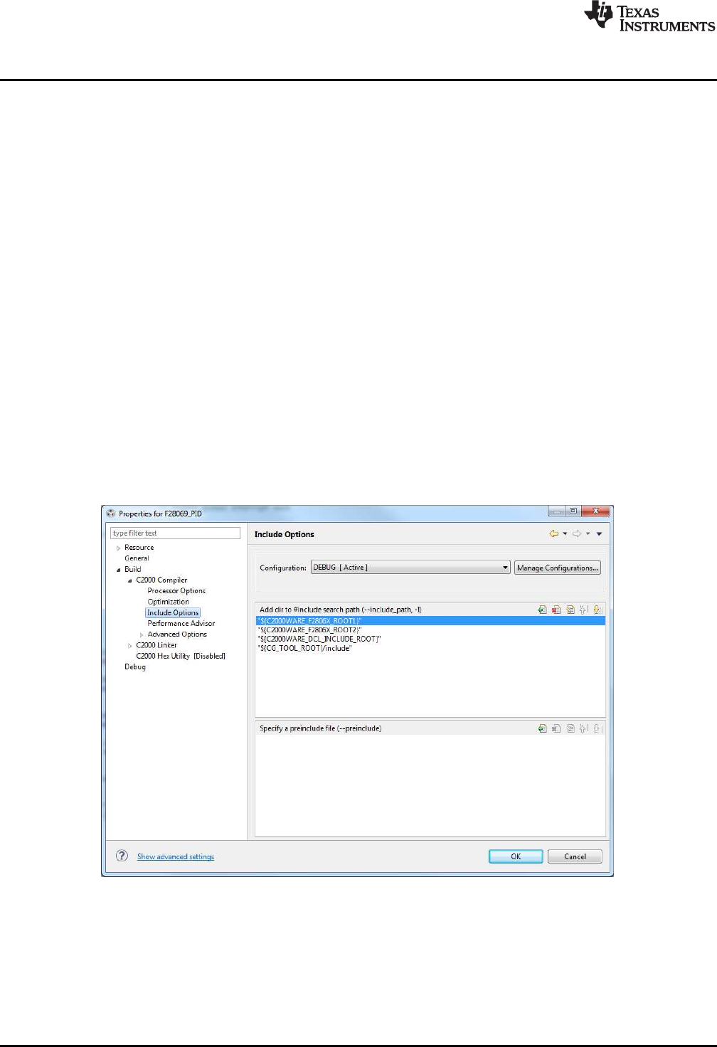
1. Specify the include file(s)
Before you can begin using the library you must add the library header file to your project.
#include “DCL.h”
This must be done in such a way that the DCL header file is visible to all program source files that
reference controller variables or functions. The include file search options in CCS allow users to
specify header file paths. The project properties can be found by right-clicking on the project name,
selecting “Properties”, and navigating to the “Include Options” section.
Figure 2-1. CCSv6 Include Options
If you want to include the data logger or functions in the TCM, you must also include those respective
header files. Note that the TCM includes the data log header file.
If you want to use the non-linear PID functions, the header file “DCL_NLPID.h” must be included in
your program. Note that the NLPID does not run on the CLA and the header file should not be included
in any CLA files.

www.ti.com
How to Add the DCL to your Code
15
SPRUID3–January 2017
Submit Documentation Feedback Copyright © 2017, Texas Instruments Incorporated
Using the Digital Control Library
2. Add the source files to the project.
The source files for the controllers that you want to use must be added to your CCS project. You can
manually copy the files into your project directory, or specify the library pathname in the CCS compiler
options. It is only necessary to add those source files for the functions that you want to use.
3. Allocate the controller functions in the linker command file.
DCL functions that execute on the C28x core can be allocated to a specific memory block in the linker
command file. It is common to place the controller functions in internal zero wait state RAM, since this
allows them to run at the maximum speed of the device. Note that all CLA functions must run from
internal zero wait state RAM.
C28x library functions are placed in the user defined code section “dclfuncs”. An example showing how
this section might be mapped into the internal L4 RAM memory block is shown below.
dclfuncs : > RAML4, PAGE = 0
See also the linker command file “F28069_DCL.cmd” in the project examples.
In a stand-alone application, code must be stored in non-volatile memory (such as internal flash) and
copied into RAM at run-time. For information on how to do this, see Running an Application from
Internal Flash Memory on the TMS320F28xxx DSP (SPRA958).
More details on the linker section allocation can be found in the TMS320C28x Assembly Language
Tools User’s Guide (SPRU513).
4. Create an instance of the controller
You must declare an instance of the controller you wish to use. Examples can be found for each
controller type in the corresponding chapter that describes it. For example, to create an instance of a
PID controller named “pid1”, you would add the following line to the variable list in your C source.
PID pid1 = DCL_PID_DEFAULTS;
This creates a variable of type “PID”, the elements of which are initialized to those default values
specified in the “DCL.h” header file. Like any C variable, the structure must be visible to any source
files that reference it.
Note that CLA variables must be initialized at run-time by user code (they cannot be initialized at the
variable declaration). Typically, this is done using a separate CLA task.
5. Declare variables
In addition to a pointer to the controller structure, each controller function requires certain input
variables to be passed as arguments to the function. You should declare instances of these variables
in your code and ensure they can be referenced by all files that call the controller functions. For
example:
float uk; // control
float rk = 0.0f; // reference
float yk = 0.0f; // feedback
float lk = 1.0f; // saturation
Again, CLA variables cannot be initialized at the variable declaration.
6. Initialize the controller
The elements of the (CPU) controller structure were initialized to default settings in step 3. The user
program must configure any controller elements with specific values before the function is called. For
example:
pid.Kp = 9.4f; // set proportional gain to 9.4
pid.Umax = 10.0f; // upper output clamp limit = 10
If a CLA based controller is being used, its parameters must always be initialized using a separate
task. For more information on the CLA C compiler, see the CLA Compiler chapter of the TMS320C28x
Optimizing C/C++ Compiler v16.12.0.STS User's Guide.
Direct Form control structures incorporate one or two delay lines that hold previous controller output
data. These must be initialized to zero before calling the controller functions. It is possible that
uninitialized delay line data, especially in the recursive path, might cause the controller to saturate or
deliver unreliable results. The initialization of the delay line elements is the responsibility of the user.
For examples of delay line initialization, see the code examples 1 and 2 described in Chapter 5.

How to Add the DCL to your Code
www.ti.com
16 SPRUID3–January 2017
Submit Documentation Feedback
Copyright © 2017, Texas Instruments Incorporated
Using the Digital Control Library
7. Call the controller function
Typically, the controller functions would be inserted into an ISR, which is triggered by a hardware
timer. This ensures that the control law is executed at a deterministic and fixed time interval. Each
control function returns a single floating-point variable that represents the controller output. An example
of a controller function call is shown below.
uk = DCL_runPID(&pid1, rk, yk lk);
2.2.2 Calling the Library Functions From Assembly
The assembly coded functions in the DCL have been written to be called from a C program. The context
save and restore sections within each function protect only those core registers that are not already
protected by the C environment. In applications where the DCL controller functions must be called from an
assembly program, the user must place additional register save and restore instructions near the start and
end of each called function.
For the C28x, see the Register Conventions and Function Structure and Calling Conventions sections of
the TMS320C28x Optimizing C/C++ Compiler v16.12.0.STS User's Guide for detailed information on
register usage and calling conventions. For the CLA, see the Function Structure and Calling Conventions
section of the same document.

17
SPRUID3–January 2017
Submit Documentation Feedback Copyright © 2017, Texas Instruments Incorporated
Controllers
Chapter 3
SPRUID3–January 2017
Controllers
This chapter provides detailed information on the controller functions in the Digital Control Library.
The DCL contains six basic types of controller.
• Linear PID
• Linear PI
• Non-linear PID
• Direct Form 1 (third order)
• Direct Form 2 (second order)
• Direct Form 2 (third order)
In this guide, the three direct form types are referred to as “compensators”. This reflects a situation typical
in power supply design, where the objectives are to compensate some feature of the open loop frequency
response, such as phase shift. In such cases the controller is specified using a set of pole and zero
frequencies, which leads naturally to a transfer function description. The “Direct Form” nomenclature
comes from different implementations of digital filters having transfer function descriptions.
Each controller type is coded in C, and in assembly using two different instruction sets (FPU32 and CLA).
There are therefore three different functions for each controller. For more information on function names,
see Section 1.3.2. Additionally, each of the three Direct Form compensators is implemented in both full
and pre-computed forms.
An exception is the non-linear PID controller that is only available in C coded form. At the present time,
support for the pow() function used in the control law is only available in the standard C run-time support
library. Note that this controller is not supported on the CLA.
The description of each controller in this chapter is broken down into three subsections.
• A general description of the controller
• Information of the implementation of the controller
• A detailed list of functions
The implementation subsection always includes a block diagram showing the variables used in the code.
Local variables, which do not need to be preserved between functions, are pre-fixed with the letter “v”.
Variables that are part of the controller structure and, therefore, preserved between functions, are pre-
fixed with some other letter according to their purpose. For example, “i10” refers to a variable used in the
PID integrator. These same variable names are used in the library source code, so it is straightforward to
correlate the source code with the diagrams.
All functions in the DCL are re-entrant.
Topic ........................................................................................................................... Page
3.1 Linear PID Controllers ........................................................................................ 18
3.2 Linear PI Controllers........................................................................................... 25
3.3 Non-linear PID Controller .................................................................................... 31
3.4 Direct Form 1 (Third Order) Compensators ........................................................... 37
3.5 Direct Form 2 (Second Order) Compensators ........................................................ 44
3.6 Direct Form 2 (Third Order) Compensators ........................................................... 50
( )
( ) ( ) ( )
tde t
u t K e t K e d K
p i d dt
W W
³
f
Kp
Ki
Kd
u(t)
y(t)
r(t) ++
+
+
-œ
d
dt
Linear PID Controllers
www.ti.com
18 SPRUID3–January 2017
Submit Documentation Feedback
Copyright © 2017, Texas Instruments Incorporated
Controllers
3.1 Linear PID Controllers
3.1.1 Description
The basic controller described here is a linear PID type. The PID implementations in the DCL include
several features not commonly found in basic PID designs, and this complexity is reflected the benchmark
figures. Applications that do not require derivative action, or are more sensitive to cycle efficiency, may be
better served by the simpler PI controller structure described in Chapter 4.
PID control is widely used in systems that employ output feedback control. In such systems, the controlled
output is measured and fed back to a summing point where it is subtracted from the reference input. The
difference between the reference and feedback corresponds to the control loop error (or servo error) and
forms the input to the PID controller.
The PID controller output is the parallel sum of three paths that act on the error, error integral, and error
derivative, respectively. The relative weight of each path is adjusted by the user to optimize transient
response.
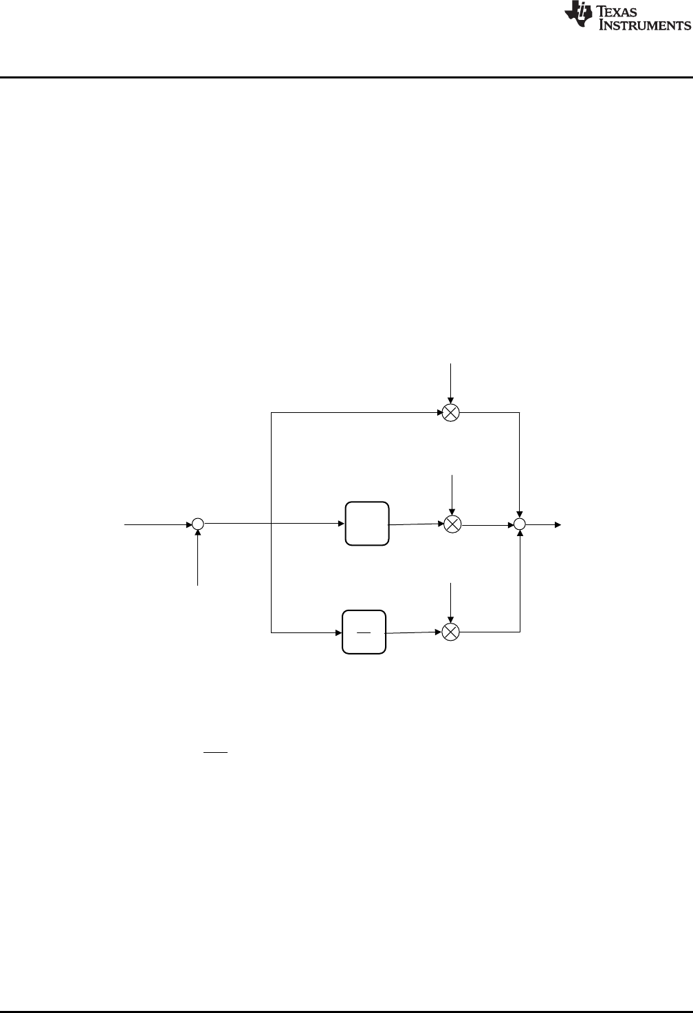
Figure 3-1. Parallel Form PID Controller
The diagram above shows the structure of a continuous time “parallel” PID controller. The output of this
controller is captured in Equation 1.
(1)
Conceptually, the controller comprises three separate paths connected in parallel. The upper path
contains an adjustable gain term (Kp). Its effect is to fix the open loop gain of the control system. Since
loop gain is proportional to this term, Kpis known as proportional gain.
A second path contains an integrator that accumulates error history. A separate gain term acts on this
path. The output of the integral path changes continuously as long as a non-zero error (e) is present at the
controller input. A small but persistent servo error has the effect of driving the output of the integrator such
that the loop error will eventually disappear. The principal effect of the integral path is therefore to
eliminate steady state error. The effect of the integral gain term is to change the rate at which this
happens. Integral action is especially important in applications such as electronic power supplies, which
must maintain accurate regulation over long periods of time.
The third path contains a differentiator. The output of this path is large whenever the rate of change of the
error is large. The principal effect of the derivative action is to damp oscillation and reduce transients.
www.ti.com
Linear PID Controllers
19
SPRUID3–January 2017
Submit Documentation Feedback Copyright © 2017, Texas Instruments Incorporated
Controllers
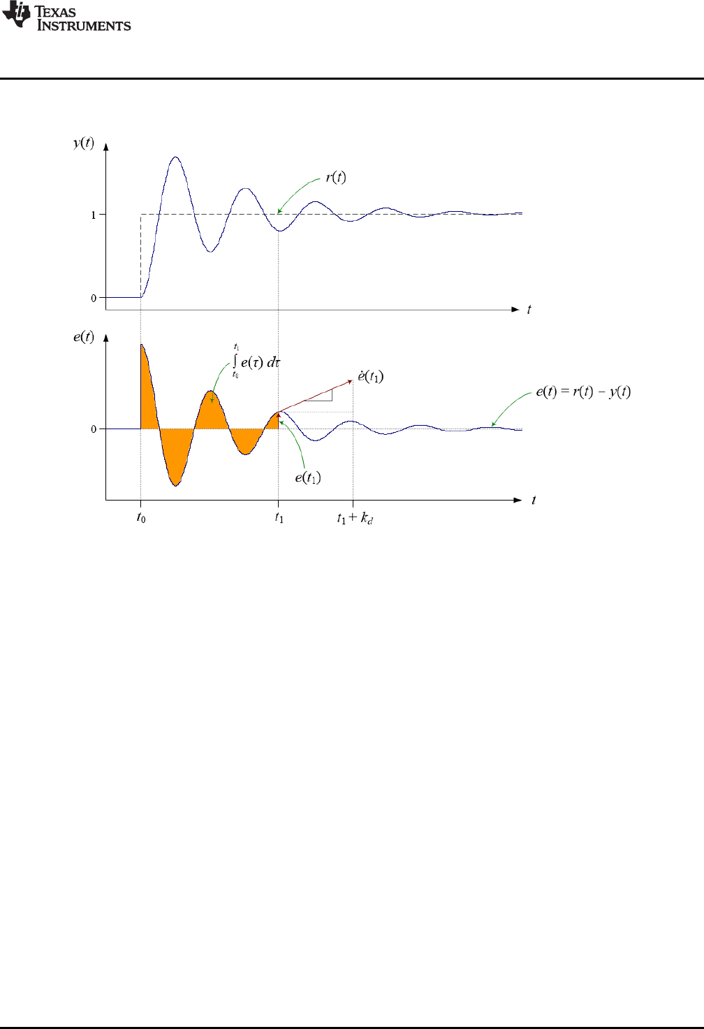
The operation of the PID controller can be visualized in terms of the transient error following a step
change of set-point.
Figure 3-2. PID Control Action
Figure 3-2 shows the action of the PID controller in terms of the control loop error at time t1. The
proportional term contributes a control effort that is proportional to the instantaneous loop error. The
output of the integral path is the accumulated error history: the shaded area in the lower plot. The
contribution of the derivative path is proportional to the rate of change of the loop error. Derivative gain
fixes the time interval over which a tangential line to the error curve is projected forward in time.
Tuning the PID controller is a matter of finding the optimum combination of these three effects. This in turn
means finding the best balance of the three gain terms. For more information on PID control and tuning,
see Section 6.1.
The PID shown above is known as the “parallel” form because the three controller gains appear in
separate parallel paths. A different PID architecture in which the proportional gain is moved into the output
path (that is, after the summing point), so that the proportional path becomes a direct connection between
the controller input and the summing point, is known as the “ideal” form. In the ideal form, the open loop
gain is directly influenced by the proportional controller gain, and there is less interaction between the
controller gains. However, the proportional gain cannot be zero (since the loop would be opened), and to
maintain good control cannot be small. The parallel form allows the proportional gain to be small;
however, there is slightly more interaction between the three controller gains. The DCL contains both ideal
and parallel PID functions.
3.1.2 Implementation
The linear PID controllers in the DCL include the following features:
• Parallel and ideal forms
• Programmable output saturation
• Independent reference weighting on proportional path
• Anti-windup integrator reset
• Programmable low-pass derivative filter
2
22
T
cT
W
W
2
12
cT
W
( ) ( 1)
3 2 4
d k c v k
( ) ( -1)
2 1
d k v k
( ) ( ) ( ) ( )
4 1 2 3
v k v k d k d k
Linear PID Controllers
www.ti.com
20 SPRUID3–January 2017
Submit Documentation Feedback
Copyright © 2017, Texas Instruments Incorporated
Controllers
• External saturation input for integrator anti-windup
• Adjustable output saturation
All PID type controllers in the library implement anti-windup reset in a similar way. A clamp is present at
the controller output that allows the user to set upper and lower limits on the control effort. If either limit is
exceeded, an internal floating-point controller variable changes from 1.0f to 0.0f. This variable is multiplied
by the integrator input, such that the integrator accumulates successive zero data when the output is
saturated, avoiding the well-known wind-up phenomenon.
The PID controllers in the library make provision for anti-windup reset to be triggered from an external part
of the loop. This is useful in situations where a component outside the controller mat be saturated. The
floating-point variable “lk” is expected to be either 1.0f or 0.0f in the normal and saturated conditions
respectively. If this feature is not required, the functions should be called with the “lk” argument set to 1.0f.
External saturation is not provided on the PI controllers.
The derivative PID path includes a digital low-pass filter to avoid amplification of un-wanted high frequency
noise. The filter implemented here is a simple first order lag filter with differentiator, converted into discrete
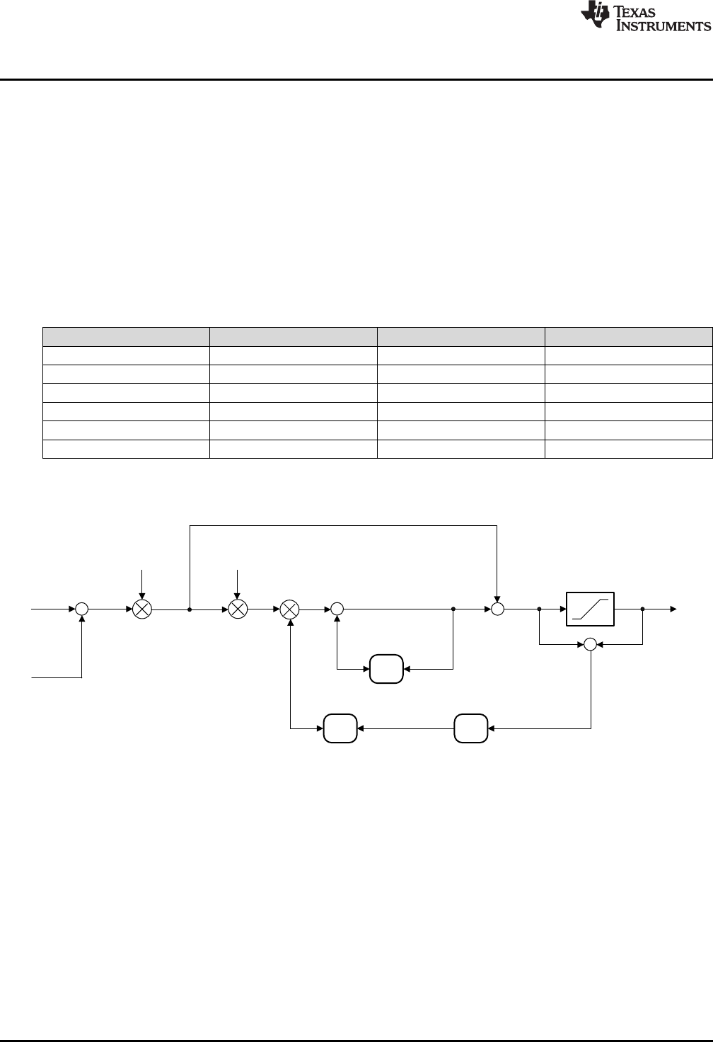
form using the Tustin transform. Referring to Figure 3-3, the difference equation of the filtered
differentiator is:
(2)
The temporary storage elements d2 & d3 interval must be preserved from the (k - 1)th interval, so the
following must be computed after the differentiator update.
(3)
(4)
The derivative filter coefficients are:
(5)
(6)
Both the sample period (T) and filter time constant (τ) are required for definition of this filter. The time
constant is the reciprocal of the desired filter bandwidth in radians per second.
All linear PID controller functions use a common C structure to hold coefficients and data, defined in the
header file “DCL.h”.
typedef volatile struct {
float Kp; //!< Proportional gain
float Ki; //!< Integral gain
float Kd; //!< Derivative gain
float Kr; //!< Set point weight
float c1; //!< D-term filter coefficient 1
float c2; //!< D-term filter coefficient 2
float d2; //!< D-term filter intermediate storage 1
float d3; //!< D-term filter intermediate storage 2
float i10; //!< I-term intermediate storage
float i14; //!< Intermediate saturation storage
float Umax; //!< Upper saturation limit
float Umin; //!< Lower saturation limit
} PID;
z-1
Kp
Kp
+
+
+
+
-
+
r(k)
z-1
Kd
z-1
+
c2
d3
c1
y(k)
u(k)
+
Ki-
-
-
d2
l(k)
i10
-
+
Krv6
v4
v8
v5
v7
+ -
==0
?
v9
v11
v12
i14
v1
z-1
upos uneg
www.ti.com
Linear PID Controllers
21
SPRUID3–January 2017
Submit Documentation Feedback Copyright © 2017, Texas Instruments Incorporated
Controllers
The memory address offsets of the structure elements are shown in Table 3-1.
Table 3-1. List of PID Structure Elements and Address Offsets
Element Offset (Hex) Offset (Dec) Description
Kp 0 0 Proportional gain
Ki 2 2 Integral gain
Kd 4 4 Derivative gain
Kr 6 6 Set point weight
c1 8 8 D-term filter coefficient 1
c2 A 10 D-term filter coefficient 2
d2 C 12 D-term filter intermediate
storage 1
d3 E 14 D-term filter intermediate
storage 2
i10 10 16 I-term intermediate storage
i14 12 18 Intermediate saturation storage
Umax 14 20 Upper saturation limit
Umin 16 22 Lower saturation limit
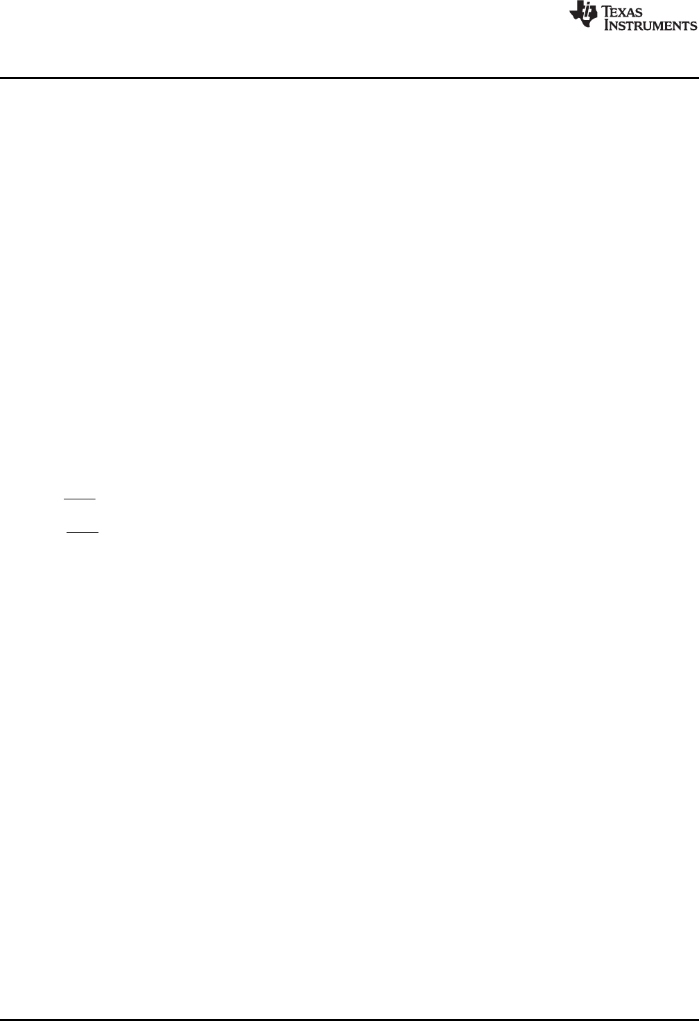
The ideal form PID implementation is shown in Figure 3-3.
Figure 3-3. DCL_PID_C1 Architecture
z-1
Kp
+
+
+
-
+
r(k)
z-1
Kd
z-1
+
c2
d3
c1
y(k)
u(k)
Ki
-
-
d2
l(k)
i10
v6
v4
v8
v5v7
+ -
==0
?
v9
v11
v12
i14
v1
z-1
umax umin
+
+
Linear PID Controllers
www.ti.com
22 SPRUID3–January 2017
Submit Documentation Feedback
Copyright © 2017, Texas Instruments Incorporated
Controllers
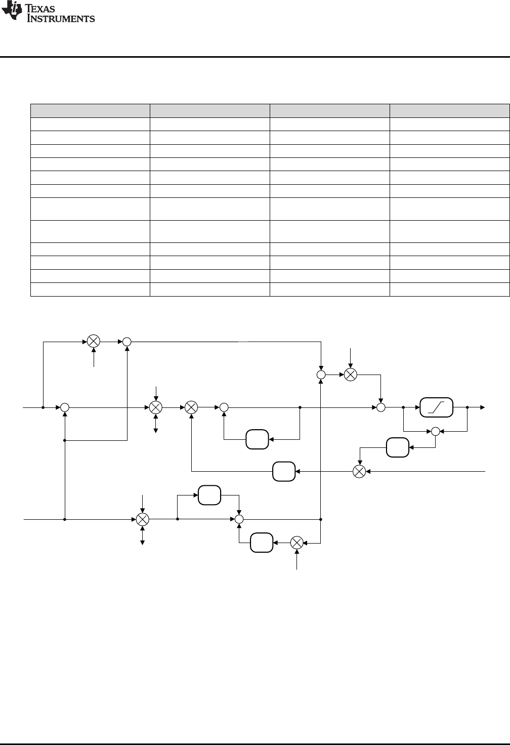
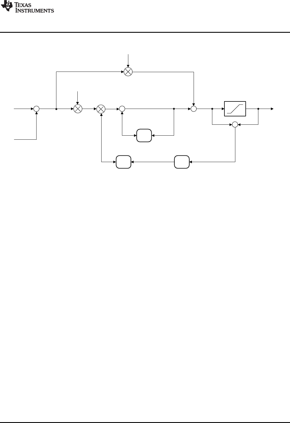
The parallel form PID is shown in Figure 3-4.
Figure 3-4. DCL_PID_C3 Architecture
www.ti.com
Linear PID Controllers
23
SPRUID3–January 2017
Submit Documentation Feedback Copyright © 2017, Texas Instruments Incorporated
Controllers
3.1.3 PID Functions
Table 3-2. Summary of PID Functions
Title ...................................................................................................................................... Page
DCL_runPID_C1 —Run the Ideal Form PID Controller............................................................................ 23
DCL_runPID_C2 —Run the Ideal PID Form Controller............................................................................ 23
DCL_runPID_C3 —Run the Parallel Form PID Controller......................................................................... 24
DCL_runPID_C4 —Run the Parallel Form PID Controller......................................................................... 24
DCL_runPID_L1 —Run the Ideal Form PID Controller ............................................................................ 25
DCL_runPID_L2 —Run the Parallel Form PID Controller......................................................................... 25
DCL_runPID_C1 Run the Ideal Form PID Controller
Header File DCL.h
Source File DCL_PID_C1.asm
Declaration float DCL_runPID_C1(PID *p, float rk, float yk, float lk)
Description This function executes an ideal form PID controller on the C28x. The function is coded in
C28x assembly.
Parameters
p The PID structure
rk The controller set-point reference
yk The measured feedback value
lk External output clamp flag
Return The control effort
DCL_runPID_C2 Run the Ideal PID Form Controller
Header File DCL.h
Source File N/A
Declaration float DCL_runPID_C2(PID *p, float rk, float yk, float lk)
Description This function executes an ideal form PID controller on the C28x, and is identical in
structure and operation to the C1 form. The function is coded in inline C.
Parameters
p The PID structure
rk The controller set-point reference
yk The measured feedback value
lk External output clamp flag
Return The control effort

DCL_runPID_C3 — Run the Parallel Form PID Controller
www.ti.com
24 SPRUID3–January 2017
Submit Documentation Feedback
Copyright © 2017, Texas Instruments Incorporated
Controllers
DCL_runPID_C3 Run the Parallel Form PID Controller
Header File DCL.h
Source File N/A
Declaration float DCL_runPID_C3(PID *p, float rk, float yk, float lk)
Description This function executes a parallel form PID controller on the C28x. The function is coded
in inline C.
Parameters
p The PID structure
rk The controller set-point reference
yk The measured feedback value
lk External output clamp flag
Return The control effort
DCL_runPID_C4 Run the Parallel Form PID Controller
Header File DCL.h
Source File DCL_PID_C4.asm
Declaration float DCL_runPID_C4(PID *p, float rk, float yk, float lk)
Description This function executes a parallel form PID controller on the C28x, and is identical in
structure and operation to the C3 form. The function is coded in inline C.
Parameters
p The PID structure
rk The controller set-point reference
yk The measured feedback value
lk External output clamp flag
Return The control effort
( ) ( ) ( )
t
u t K e t K e d
p i
W W
³
f
www.ti.com
DCL_runPID_L1 — Run the Ideal Form PID Controller
25
SPRUID3–January 2017
Submit Documentation Feedback Copyright © 2017, Texas Instruments Incorporated
Controllers
DCL_runPID_L1 Run the Ideal Form PID Controller
Header File DCL.h
Source File DCL_PID_L1.asm
Declaration float DCL_runPID_L1(PID *p, float rk, float yk, float lk)
Description This function executes an ideal form PID controller on the CLA. The function is coded in
CLA assembly.
Parameters
p The PID structure
rk The controller set-point reference
yk The measured feedback value
lk External output clamp flag
Return The control effort
DCL_runPID_L2 Run the Parallel Form PID Controller
Header File DCL.h
Source File DCL_PID_L2.asm
Declaration float DCL_runPID_L2(PID *p, float rk, float yk, float lk)
Description This function executes a parallel form PID controller on the CLA. The function is coded
in CLA assembly.
Parameters
p The PID structure
rk The controller set-point reference
yk The measured feedback value
lk External output clamp flag
Return The control effort
3.2 Linear PI Controllers
3.2.1 Description
The continuous time parallel PI control equation is shown in Equation 7.
(7)
The linear PI controllers in the DCL differ from the PID in the following respects:
• Removal of derivative path
• Removal of set-point weighting
• No provision for external saturation input
In all other regards the PI controllers are similar to the PID controllers described in the previous
subsection.
z-1
Kp
+
+
+
-
+
r(k)
y(k)
u(k)
+
Ki
i10
v4
v2
v3
+-
v5
v6
v1
z-1
i6
v8
==0
?
Linear PI Controllers
www.ti.com
26 SPRUID3–January 2017
Submit Documentation Feedback
Copyright © 2017, Texas Instruments Incorporated
Controllers
3.2.2 Implementation
All linear PI controller functions use a common C structure to hold coefficients and data, defined in the
header file “DCL.h”.
typedef volatile struct {
float Kp; //!< Proportional gain
float Ki; //!< Integral gain
float i10; //!< I storage
float Umax; //!< Upper saturation limit
float Umin; //!< Lower saturation limit
float i6; //!< Saturation storage
} PI;
The memory address offsets of the structure elements are shown in Table 3-3.
Table 3-3. List of PI Structure Elements and Address Offsets
Element Offset (Hex) Offset (Dec) Description
Kp 0 0 Proportional gain
Ki 2 2 Integral gain
i10 4 4 I storage
Umax 6 6 Upper saturation limit
Umin 8 8 Lower saturation limit
i6 A 10 Saturation storage
The ideal form PI implementation is shown in Figure 3-5.
Figure 3-5. DCL_PI_C1 Architecture
Linear PI Controllers
www.ti.com
28 SPRUID3–January 2017
Submit Documentation Feedback
Copyright © 2017, Texas Instruments Incorporated
Controllers
3.2.3 Summary of PI Functions
Table 3-4. PI Functions
Title ...................................................................................................................................... Page
DCL_runPI_C1 —Run the Ideal Form PI Controller................................................................................ 28
DCL_runPI_C2 —Run the Ideal PI Form Controller................................................................................ 28
DCL_runPI_C3 —Run the Parallel Form PI Controller ............................................................................ 29
DCL_runPI_C4 —Run the Parallel Form PI Controller ............................................................................ 29
DCL_runPI_L1 —Run the Ideal Form PI Controller ............................................................................... 30
DCL_runPI_L2 —Run the Parallel Form PI Controller............................................................................. 30
DCL_runPI_C1 Run the Ideal Form PI Controller
Header File DCL.h
Source File DCL_PID_C1.asm
Declaration float DCL_runPI_C1(PI *p, float rk, float yk)
Description This function executes an ideal form PI controller on the C28x. The function is coded in
C28x assembly.
Parameters
p The PI structure
rk The controller set-point reference
yk The measured feedback value
Return The control effort
DCL_runPI_C2 Run the Ideal PI Form Controller
Header File DCL.h
Source File N/A
Declaration float DCL_runPI_C2(PI *p, float rk, float yk)
Description This function executes an ideal form PI controller on the C28x, and is identical in
structure and operation to the C1 form. The function is coded in inline C.
Parameters
p The PI structure
rk The controller set-point reference
yk The measured feedback value
Return The control effort

www.ti.com
DCL_runPI_C3 — Run the Parallel Form PI Controller
29
SPRUID3–January 2017
Submit Documentation Feedback Copyright © 2017, Texas Instruments Incorporated
Controllers
DCL_runPI_C3 Run the Parallel Form PI Controller
Header File DCL.h
Source File N/A
Declaration float DCL_runPI_C3(PI *p, float rk, float yk)
Description This function executes a parallel form PI controller on the C28x. The function is coded in
inline C.
Parameters
p The PI structure
rk The controller set-point reference
yk The measured feedback value
Return The control effort
DCL_runPI_C4 Run the Parallel Form PI Controller
Header File DCL.h
Source File DCL_PI_C4.asm
Declaration float DCL_runPI_C4(PI *p, float rk, float yk)
Description This function executes a parallel form PI controller on the C28x, and is identical in
structure and operation to the C3 form. The function is coded in inline C.
Parameters
p The PI structure
rk The controller set-point reference
yk The measured feedback value
Return The control effort

DCL_runPI_L1 — Run the Ideal Form PI Controller
www.ti.com
30 SPRUID3–January 2017
Submit Documentation Feedback
Copyright © 2017, Texas Instruments Incorporated
Controllers
DCL_runPI_L1 Run the Ideal Form PI Controller
Header File DCL.h
Source File DCL_PI_L1.asm
Declaration float DCL_runPI_L1(PI *p, float rk, float yk)
Description This function executes an ideal form PI controller on the CLA. The function is coded in
CLA assembly.
Parameters
p The PI structure
rk The controller set-point reference
yk The measured feedback value
Return The control effort
DCL_runPI_L2 Run the Parallel Form PI Controller
Header File DCL.h
Source File DCL_PI_L2.asm
Declaration float DCL_runPI_L2(PI *p, float rk, float yk)
Description This function executes an ideal form PI controller on the CLA. The function is coded in
CLA assembly.
Parameters
p The PI structure
rk The controller set-point reference
yk The measured feedback value
Return The control effort
-
+
r(k)
y(k)
v4
Pre-conditioning
block I-term
non-linear block
D-term
non-linear block
P-term
non-linear block
v1
v2
v3
v5
v9
www.ti.com
Non-linear PID Controller
31
SPRUID3–January 2017
Submit Documentation Feedback Copyright © 2017, Texas Instruments Incorporated
Controllers
3.3 Non-linear PID Controller
3.3.1 Description
The DCL includes one implementation of a non-linear PID controller, denoted NLPID. The controller is
similar to the DCL implementation of ideal PID, except that there is no set-point weighting and the
derivative path sees the servo error instead of the feedback. A non-linear gain block appears in series with
each of the three paths.
To improve computational efficiency, the non-linear law is separated into two parts: one part that is
common to all paths, and a second part that contains terms specific to each path. The non-linear part of
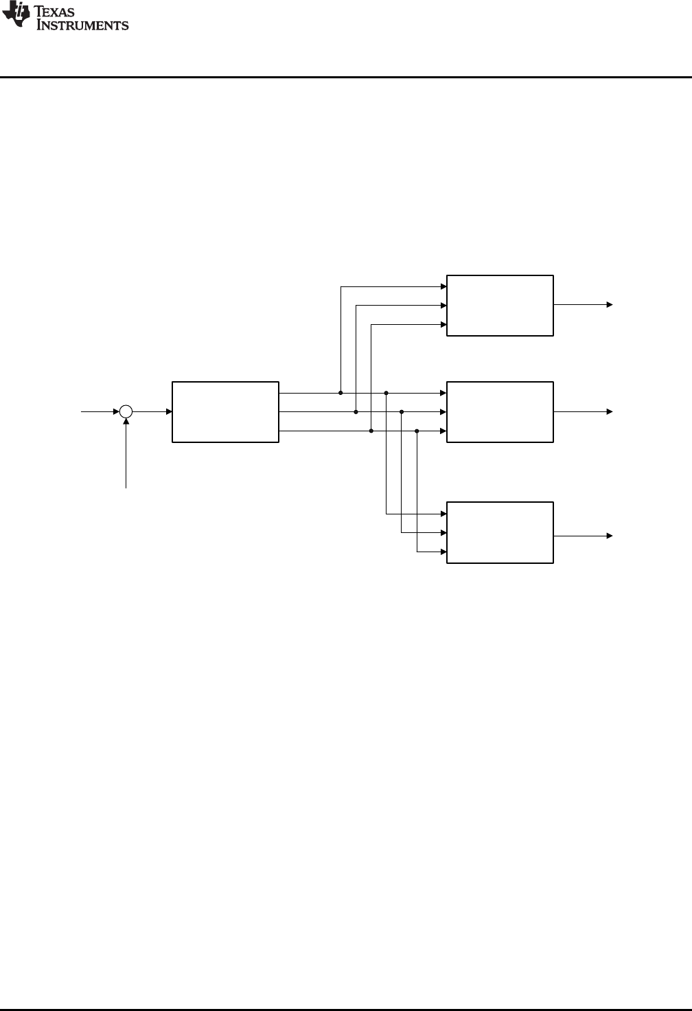
the high-level controller structure is shown in Figure 3-7.
Figure 3-7. Non-Linear PID Input Architecture
y x sign x
D
z-1
Kp
Kp
+
+
+
+
z-1
Kd
z-1
+
c2
d3
c1
u(k)
+
Ki-
-
-
d2
l(k)
i7
v12
v8
v4
+ -
==0?
v13
v15
i16
v10
z-1
upos
uneg
v5
v9
Non-linear PID Controller
www.ti.com
32 SPRUID3–January 2017
Submit Documentation Feedback
Copyright © 2017, Texas Instruments Incorporated
Controllers
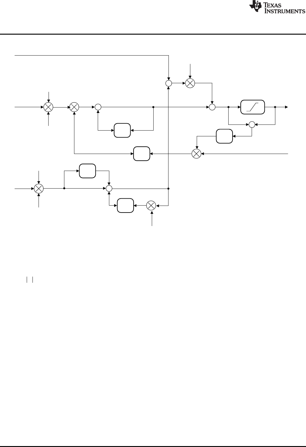
The linear part of the NLPID controller is shown in Figure 3-8.
Figure 3-8. Non-Linear PID Output Architecture
The non-linear control law is based on a power function of the modulus of the servo error, with a linearized
region about the zero error point. In Equation 8, x represents the input to the control law, y, the output,
and αis a user selectable modulus exponent representing the degree of non-linearity.
(8)
1
D
J G
:
1:
x sign x x
yx x
DG
D
G G
-t
°
®
°d
¯
-1 -0.8 -0.6 -0.4 -0.2 0 0.2 0.4 0.6 0.8 1
-1
-0.8
-0.6
-0.4
-0.2
0
0.2
0.4
0.6
0.8
1
.= 0.2
.= 2
www.ti.com
Non-linear PID Controller
33
SPRUID3–January 2017
Submit Documentation Feedback Copyright © 2017, Texas Instruments Incorporated
Controllers
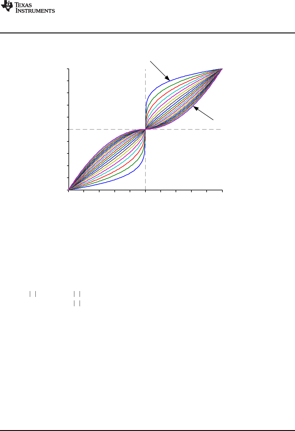
Figure 3-9 shows the x-y relationship for values of αbetween 0.2 and 2. Notice that the curves intersect at
x = 0, and x = ±1.
Figure 3-9. Non-Linear Control Law Input-Output Plot
The gain of the control law is the slope of the x-y curve. Observe that with α= 1 the control is linear with
unity gain. With α> 1 the gain is zero when x = 0, and increases as x increases. In the controller, this
value of αproduces controller gain that increases with increasing control error. With α< 1, the gain at x =
0 is infinite, and falls as x increases. This αsetting produces controller gain that decreases with increasing
control error.
The presence of zero or infinite gain at the zero control error point leads to practical control difficulties. For
example, with α< 1, it is common to encounter oscillation or “chattering” near the steady-state. These
issues can be overcome by limiting the controller gain close to x = 0. This is done by modifying the control
law as follows to introduce a user selectable region about x = 0 with linear gain is applied. The non-linear
control law becomes
(9)
When the magnitude of servo error falls below δ, the linear gain is applied; otherwise, the gain is
determined by the non-linear law. For computational efficiency, define the gain in the linear region as γ.
(10)
/
Ó/
x
y
Non-linear PID Controller
www.ti.com
34 SPRUID3–January 2017
Submit Documentation Feedback
Copyright © 2017, Texas Instruments Incorporated
Controllers
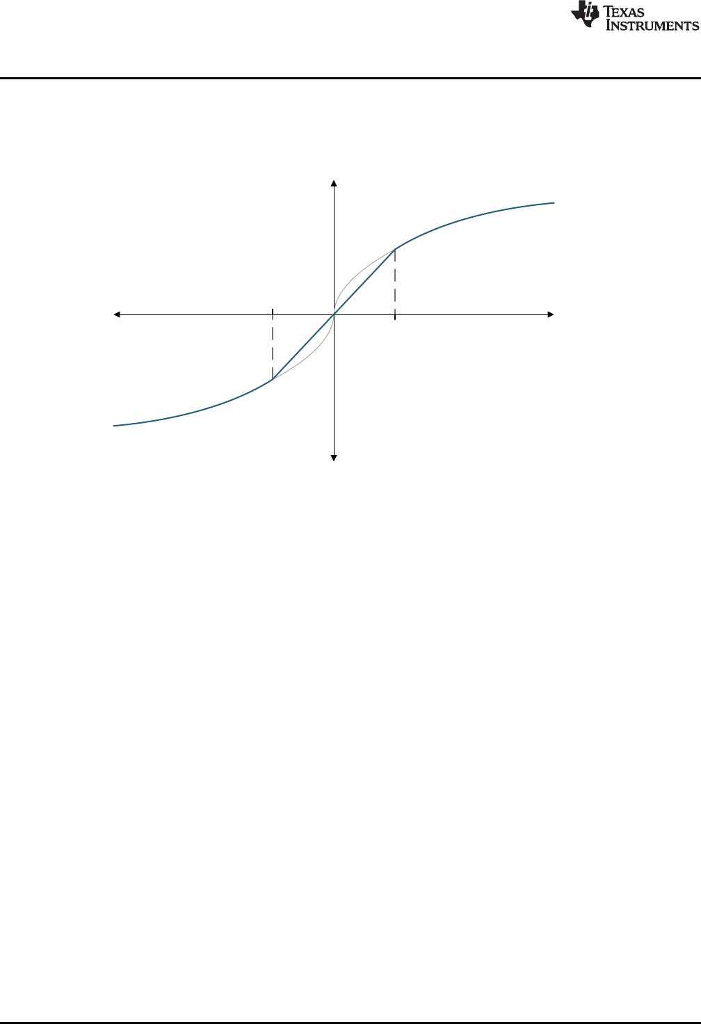
A typical plot of the linearized control law is shown in Figure 3-10. Observe that when x = δthe linear and
non-linear curves intersect, so the controller makes a smooth transition between the linear and non-linear
regions as the servo error passes through x = ±δ.
Figure 3-10. NLPID Linearized Region
In addition to the P, I, and D gains, the user must select two additional terms in each control path: αand δ.
The library includes a separate function to compute and update γfor each path.
The NLPID controller has been seen to provide significantly improved control in many cases; however, it
must be remembered that increased gain, even if only applied to part of the control range, can lead to
significantly increased output from the controller. In most cases, this ‘control effort’ is limited by practical
factors such as actuator saturation, PWM modulation range, and so on. The corollary is that not every
application benefits equally from the use of non-linear control and some may see no benefit at all. In
cases where satisfactory performance cannot be achieved through the use of linear PID control, the user
is advised to start with all α= 1, and experiment by introducing non-linear terms gradually while monitoring
both control performance and the magnitude of the control effort. In general, P and I paths benefit from
increased gain at high servo error (α> 1), while the D path benefits from reduced gain at high servo error
(α<1), but this is not universally true.
Further information on this control law can be found in: “From PID to Active Disturbance Rejection
Control”, Jingqing Han, IEEE Transactions on Industrial Electronics, Vol. 56, NO. 3, March 2009.
www.ti.com
Non-linear PID Controller
35
SPRUID3–January 2017
Submit Documentation Feedback Copyright © 2017, Texas Instruments Incorporated
Controllers
3.3.2 Implementation
The NLPID controller uses a C structure to hold coefficients and data, defined in the header file
“DCL_NLPID.h”. Note that the NLPID functions make use of the “pow()” function in the standard C library.
For this reason, the header file “math.h” must be included, which is not supported by the CLA compiler. To
allow different DCL functions to be run on both the CPU and CLA in the same program, the NLPID
functions are located in a separate header file. The NLPID structure is shown below.
typedef volatile struct {
float Kp; //!< Linear proportional gain
float Ki; //!< Linear integral gain
float Kd; //!< Linear derivative gain
float alpha_p; //!< P path non-linear exponent
float alpha_i; //!< I path non-linear exponent
float alpha_d; //!< D path non-linear exponent
float delta_p; //!< P path linearized range
float delta_i; //!< I path linearized range
float delta_d; //!< D path linearized range
float gamma_p; //!< P path gain limit
float gamma_i; //!< I path gain limit
float gamma_d; //!< D path gain limit
float c1; //!< D path filter coefficient 1
float c2; //!< D path filter coefficient 2
float d2; //!< D path filter intermediate storage 1
float d3; //!< D path filter intermediate storage 2
float i7; //!< I path intermediate storage
float i16; //!< Intermediate saturation storage
float Umax; //!< Upper saturation limit
float Umin; //!< Lower saturation limit
} NLPID;
The memory address offsets of the NLPID structure are shown in Table 3-5.
Table 3-5. List of NLPID Structure Elements and Address Offsets
Element Offset (Hex) Offset (Dec) Description
Kp 0 0 Linear proportional gain
Ki 2 2 Linear integral gain
Kd 4 4 Linear derivative gain
alpha_p 6 6 P path non-linear exponent
alpha_i 8 8 I path non-linear exponent
alpha_d A 10 D path non-linear exponent
delta_p C 12 P path linearized range
delta_i E 14 I path linearized range
delta_d 10 16 D path linearized range
gamma_p 12 18 P path gain limit
gamma_i 14 20 I path gain limit
gamma_d 16 22 D path gain limit
c1 18 24 D path filter coefficient 1
c2 1A 26 D path filter coefficient 2
d2 1C 28 D path filter intermediate
storage 1
d3 1E 30 D path filter intermediate
storage 2
i7 20 32 I path intermediate storage
i16 22 34 Intermediate saturation storage
Umax 24 36 Upper saturation limit
Umin 26 38 Lower saturation limit
Non-linear PID Controller
www.ti.com
36 SPRUID3–January 2017
Submit Documentation Feedback
Copyright © 2017, Texas Instruments Incorporated
Controllers
As with all DCL controllers, it is the responsibility of the user to initialize the NLPID structure before use. A
set of default values is defined in the library header file and can be used with the variable declaration. An
example of an initialized NLPID structure declaration is shown below.
NLPID myCtrl = NLPID_DEFAULTS;
3.3.3 NLPID Functions
Table 3-6. Summary of NLPID Functions
Title ...................................................................................................................................... Page
DCL_runNLPID_C1 —Run the Non-Linear PID Controller........................................................................ 36
DCL_setGamma —Compute the Non-Linear PID Gain Limits ................................................................... 36
DCL_runNLPID_C1 Run the Non-Linear PID Controller
Header File DCL_NLPID.h
Source File N/A
Declaration float DCL_runNLPID_C1(NLPID *p, float rk, float yk, float lk)
Description This function executes a non-linear PID controller on the C28x. The function is coded in
inline C.
Parameters
p The NLPID structure
rk The controller set-point reference
yk The measured feedback value
lk External output clamp flag
Return The control effort
DCL_setGamma Compute the Non-Linear PID Gain Limits
Header File DCL_NLPID.h
Source File N/A
Declaration void DCL_setGamma(NLPID *p)
Description This function computes the three gain limits for the non-linear PID controller on the
C28x. The function is coded in inline C.
Parameters
p The NLPID structure
Return The control effort
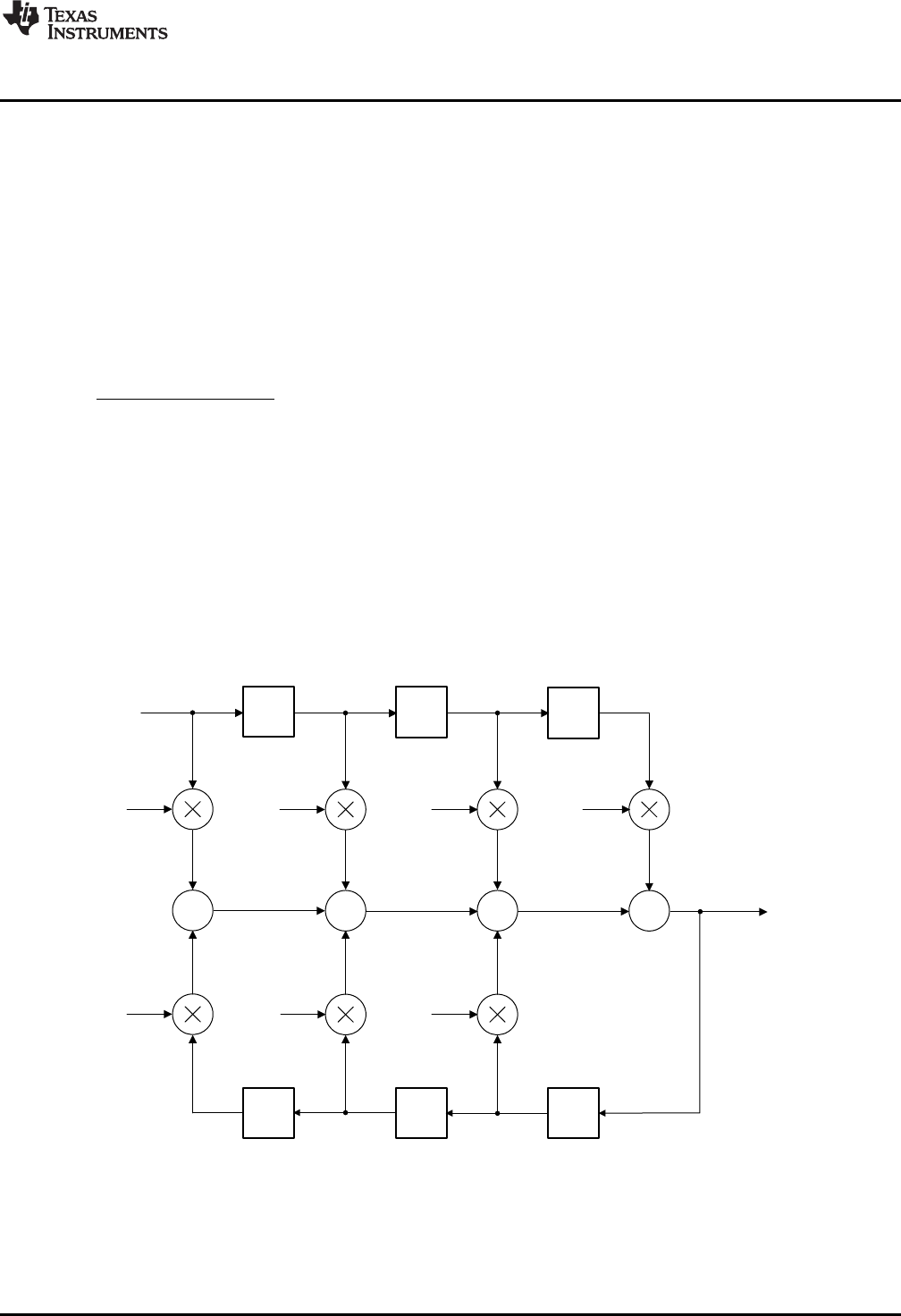
z-1 z-1
+
z-1 z-1
++
-a1
-a2
b1b2b3
e(k-3)
e(k-2)
u(k-2) u(k-1)
u(k)
z-1
+
z-1
-a3
b0
e(k)
u(k-3)
e(k-1)
v1v2v3
v0
d1d2d3
d0
v6v5
v4
v7
d7d6d5
d4
( ) ( ) ( 1) ( 2) ( 3)
0 1 2 3
( 1) ( 2) ( 3)
1 2 3
u k b e k b e k b e k b e k
a u k a u k a u k
1 2 3
0 1 2 3
( ) 1 2 3
11 2 3
b b z b z b z
F z a z a z a z
www.ti.com
Direct Form 1 (Third Order) Compensators
37
SPRUID3–January 2017
Submit Documentation Feedback Copyright © 2017, Texas Instruments Incorporated
Controllers
3.4 Direct Form 1 (Third Order) Compensators
3.4.1 Description
The Direct Form 1 (DF1) structure is a common type of discrete time control structure used to implement a
control law specified either as a pole-zero set, or as a rational polynomial in z (transfer function). The DCL
includes one third order DF1 example, denoted “DF13”.
In general, the Direct Form 1 structure is less numerically robust than the Direct Form 2 (see below), and
for this reason users are encouraged to choose the latter type whenever possible. The DF13 structure is
very common in digital power supplies and for that reason is included in the library. The same function
supports a second order control law after the superfluous coefficients (a3 and b3) have been set to zero.
The general form of third order transfer function is shown in Equation 11.
(11)
Notice that the coefficients have been adjusted to normalize the highest power of z in the denominator.
There is no notational standard for numbering of the controller coefficients. The notation used here has
the advantage that the coefficient suffixes are the same as the delay line elements and this helps with
clarity of the assembly code, however, other notation may be found in the literature. The corresponding
difference equation is shown in Equation 12.
(12)
The DF13 controller uses two, three-element delay lines to store previous input and output data required
to compute u(k). A diagrammatic representation is shown in Figure 3-11.
Figure 3-11. DCL_DF13_C1 Architecture
The DF13 control law consists of seven multiplication operations that yield seven partial products, and six
addition or subtraction operations that combine the partial products to obtain the compensator output, u(k).
When implemented in this way, the control law is referred to as the “full” DF13 form.
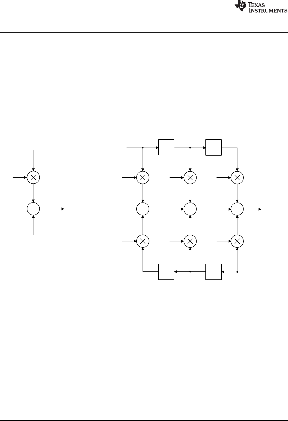
u(k)
+
b0
e(k)
v(k)
z-1
+
z-1
+
-a1
-a2
b1b2b3
e(k-2)
u(k-2) u(k-1)
v(k+1)
z-1
+
z-1
-a3
e(k) e(k-1)
u(k)
v1v2v3
v6v5v4
d1d2
d0
d6d5
( ) ( ) ( 1) ( 2) ( ) ( 1) ( 2)
1 2 3 1 2 3
v k b e k b e k b e k a u k a u k a u k
( ) ( ) ( 1)
0
u k b e k v k
Direct Form 1 (Third Order) Compensators
www.ti.com
38 SPRUID3–January 2017
Submit Documentation Feedback
Copyright © 2017, Texas Instruments Incorporated
Controllers
The DF13 control law can be re-structured to reduce control latency by pre-computing six of the seven
partial products that are already known in the previous sample interval. The control law is then broken into
two parts: the “immediate” part and the “partial” part.
The advantage of doing this is to reduce the “sample-to output” delay, or the time between e(k) being
sampled, and a corresponding u(k) becoming available. By partially pre-computing the control law, the
computation delay can be reduced to one multiplication and one addition.
In the kth interval, the immediate part is computed.
(13)
Next, the v(k) partial result is pre-computed for use in the (k+1)th interval.
(14)
Structurally, the pre-computed control law can be drawn as shown in Figure 3-12.
Figure 3-12. DCL_DF13_C2C3 Architecture
The pre-computed structure allows the controller output (u(k)) to be used as soon as it is computed. The
remaining terms in the third order control law do not involve the newest input e(k) and, therefore, do not
affect u(k). These terms can be computed after u(k) has been applied to the control loop and the input-
output latency of the controller is therefore reduced.
A further benefit of the pre-computed structure is that it allows the control effort to be clamped after the
immediate part. Computation of the pre-computed part can be made dependent on the outcome of the
clamp such that if u(k) matches or exceeds the clamp limits there is no point in pre-computing the next
partial control variable and the computation can be avoided. The DCL includes three clamp functions
intended for this purpose (see Chapter 4).
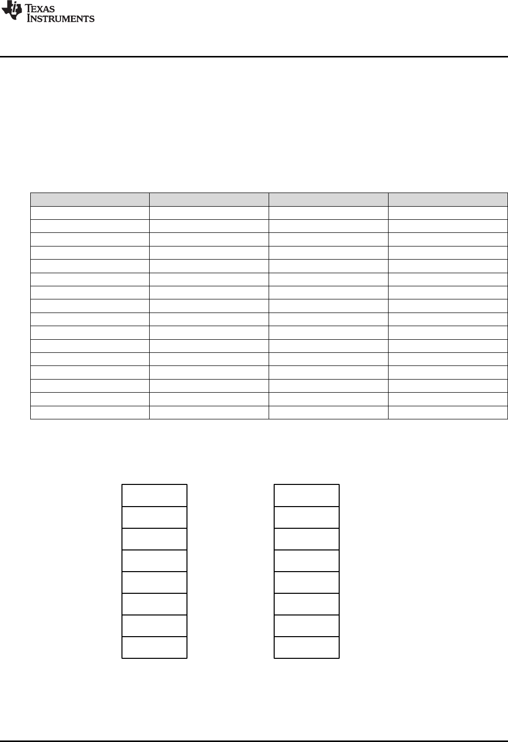
c[0]
c[1]
c[2]
c[3]
c[4]
c[5]
c[6]
c[7]
d[0]
d[1]
d[2]
d[3]
d[4]
d[5]
d[6]
d[7]
DataCoefficients
b0
b1
b2
b3
a0
a1
a2
a3
e(k)
e(k-1)
e(k-2)
e(k-3)
u(k)
u(k-1)
u(k-2)
u(k-3)
www.ti.com
Direct Form 1 (Third Order) Compensators
39
SPRUID3–January 2017
Submit Documentation Feedback Copyright © 2017, Texas Instruments Incorporated
Controllers
3.4.2 Implementation
All DF13 functions use a common C structure to hold coefficients and data, defined in the header file
“DCL.h”.
typedef volatile struct {
float c[8]; // coefficients
float d[8]; // data
} DF13;
The memory address offsets of the structure elements are shown in Table 3-7.
Table 3-7. List of DF13 Structure Elements and Address Offsets
Element Offset (Hex) Offset (Dec) Description
b0 0 0 Coefficient b0
b1 2 2 Coefficient b1
b2 4 4 Coefficient b2
b3 6 6 Coefficient b3
a0 8 8 Coefficient a0
a1 A 10 Coefficient a1
a2 C 12 Coefficient a2
a3 E 14 Coefficient a3
d0 10 16 Data e(k)
d1 12 18 Data e(k-1)
d2 14 20 Data e(k-2)
d3 16 22 Data e(k-3)
d4 18 24 Data u(k)
d5 1A 26 Data u(k-1)
d6 1C 28 Data u(k-2)
d7 1E 30 Data u(k-3)
The assignment of coefficients and data in the DF13 structure to those in the diagram is shown in
Figure 3-13.
Figure 3-13. DF13 Data and Coefficient Layout
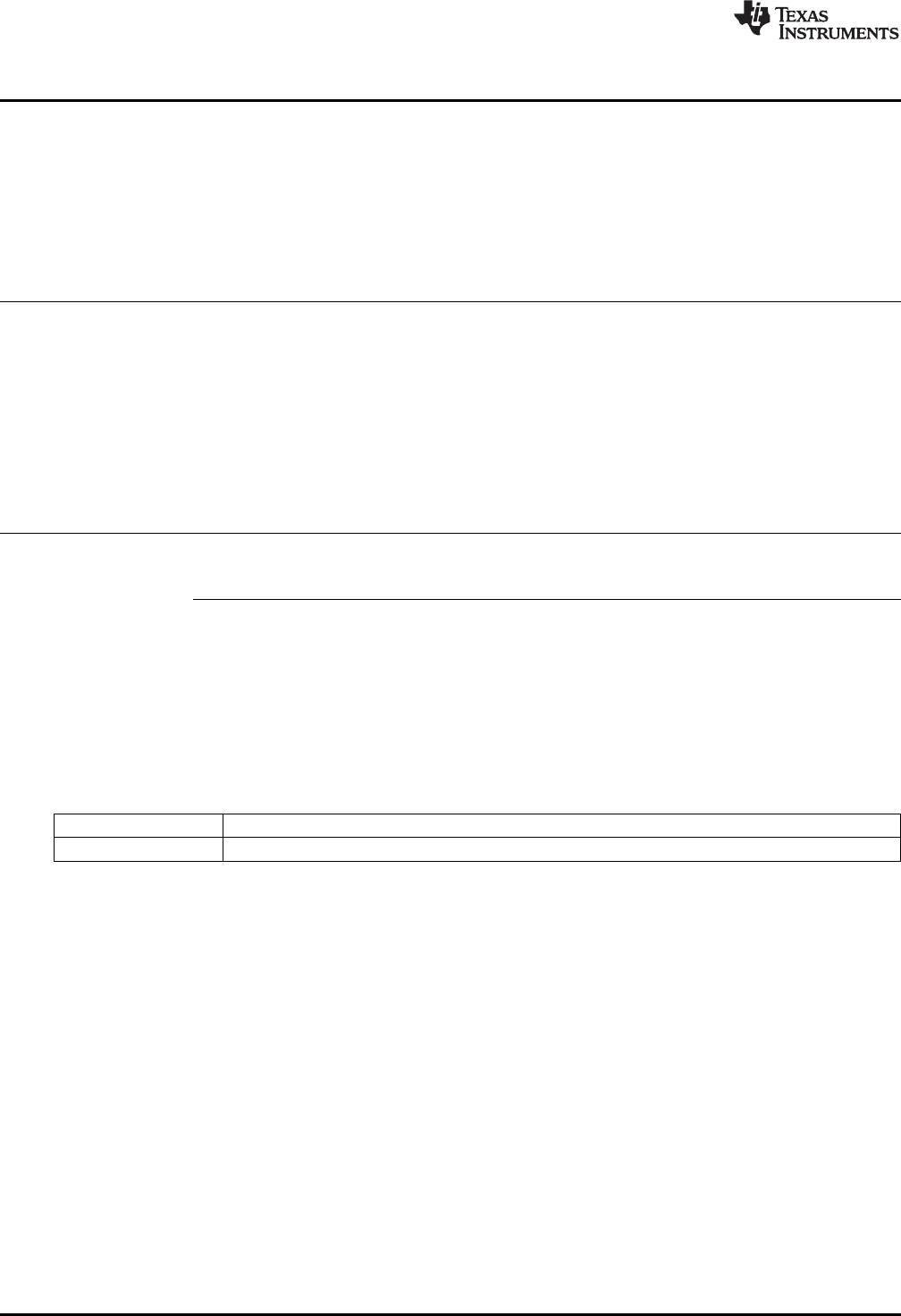
Direct Form 1 (Third Order) Compensators
www.ti.com
40 SPRUID3–January 2017
Submit Documentation Feedback
Copyright © 2017, Texas Instruments Incorporated
Controllers
It is the responsibility of the user to initialize both arrays prior to use. A set of default values is defined in
the library header file and can be used with the variable declaration. An example of an initialized DF13
structure declaration is shown below:
DF13 myCtrl = DF13_DEFAULTS;
3.4.3 DF13 Functions
Table 3-8. Summary of DF13 Functions
Title ...................................................................................................................................... Page
DCL_runDF13_C1 —Run the DF13 Full Compensator............................................................................ 40
DCL_runDF13_C2 —Run the Immediate DF13 Compensator ................................................................... 41
DCL_runDF13_C3 —Run the Partial DF13 Compensator ........................................................................ 41
DCL_runDF13_C4 —Run the DF13 Full Compensator............................................................................ 42
DCL_runDF13_C5 —Run the Immediate DF13 Compensator ................................................................... 42
DCL_runDF13_C6 —Run the Partial DF13 Compensator ........................................................................ 43
DCL_runDF13_L1 —Run the DF13 Full Compensator on the CLA ............................................................. 43
DCL_runDF13_L2 —Run the Immediate DF13 Compensator on the CLA ..................................................... 44
DCL_runDF13_L3 —Run the Partial DF13 Compensator on the CLA .......................................................... 44
DCL_runDF13_C1 Run the DF13 Full Compensator
Header File DCL.h
Source File DCL_DF13_C1
Declaration float DCL_runDF13_C1(DF13 *p, float ek)
Description This function computes a full third order control law using the Direct Form 1 structure.
The function is coded in C28x assembly.
Parameters
p The DF13 structure
ek The servo error
Return The control effort
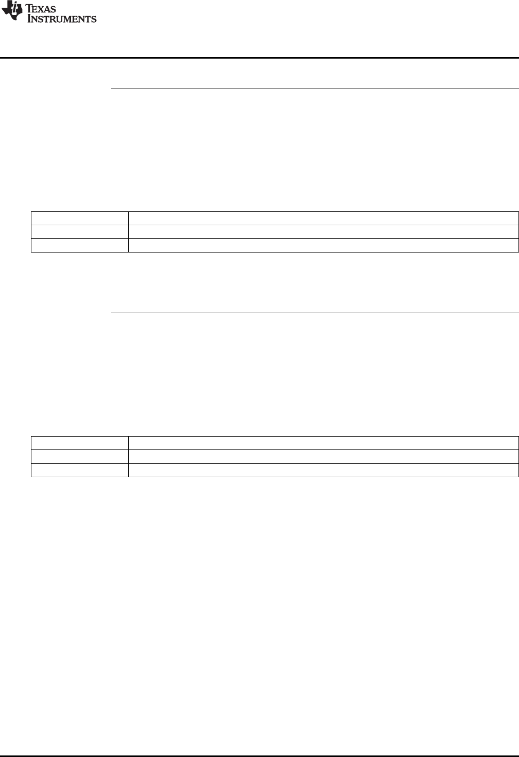
www.ti.com
DCL_runDF13_C2 — Run the Immediate DF13 Compensator
41
SPRUID3–January 2017
Submit Documentation Feedback Copyright © 2017, Texas Instruments Incorporated
Controllers
DCL_runDF13_C2 Run the Immediate DF13 Compensator
Header File DCL.h
Source File DCL_DF13_C2C3.asm
Declaration float DCL_runDF13_C2(DF13 *p, float ek, float vk)
Description This function computes the immediate part of the pre-computed DF13 controller. The
function is coded in C28x assembly.
Parameters
p The DF13 structure
ek The servo error
vk The pre-computed partial control effort
Return The control effort
DCL_runDF13_C3 Run the Partial DF13 Compensator
Header File DCL.h
Source File DCL_DF13_C2C3.asm
Declaration float DCL_runDF13_C3(DF13 *p, float ek, float uk)
Description This function computes the partial result of the pre-computed DF13 controller. The
function is coded in C28x assembly.
Parameters
p The DF13 structure
ek The servo error
vk The pre-computed partial control effort
Return The control effort
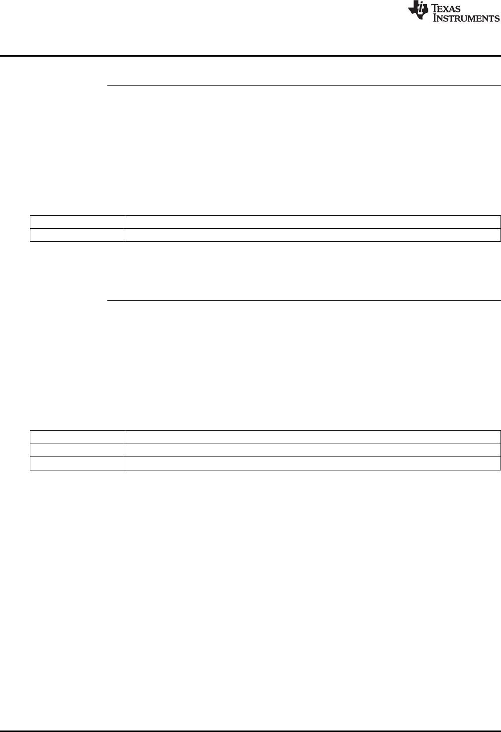
DCL_runDF13_C4 — Run the DF13 Full Compensator
www.ti.com
42 SPRUID3–January 2017
Submit Documentation Feedback
Copyright © 2017, Texas Instruments Incorporated
Controllers
DCL_runDF13_C4 Run the DF13 Full Compensator
Header File DCL.h
Source File N/A
Declaration float DCL_runDF13_C4(DF13 *p, float ek, float uk)
Description This function computes a full third order control law using the Direct Form 1 structure,
and is identical in structure and operation to the C1 form. The function is coded in inline
C.
Parameters
p The DF13 structure
ek The servo error
Return The control effort
DCL_runDF13_C5 Run the Immediate DF13 Compensator
Header File DCL.h
Source File N/A
Declaration float DCL_runDF13_54(DF13 *p, float ek, float uk)
Description This function computes the immediate part of the pre-computed DF13 controller. The
function is identical in structure and operation to the C2 form. The function is coded in
inline C.
Parameters
p The DF13 structure
ek The servo error
vk The pre-computed partial control effort
Return The control effort
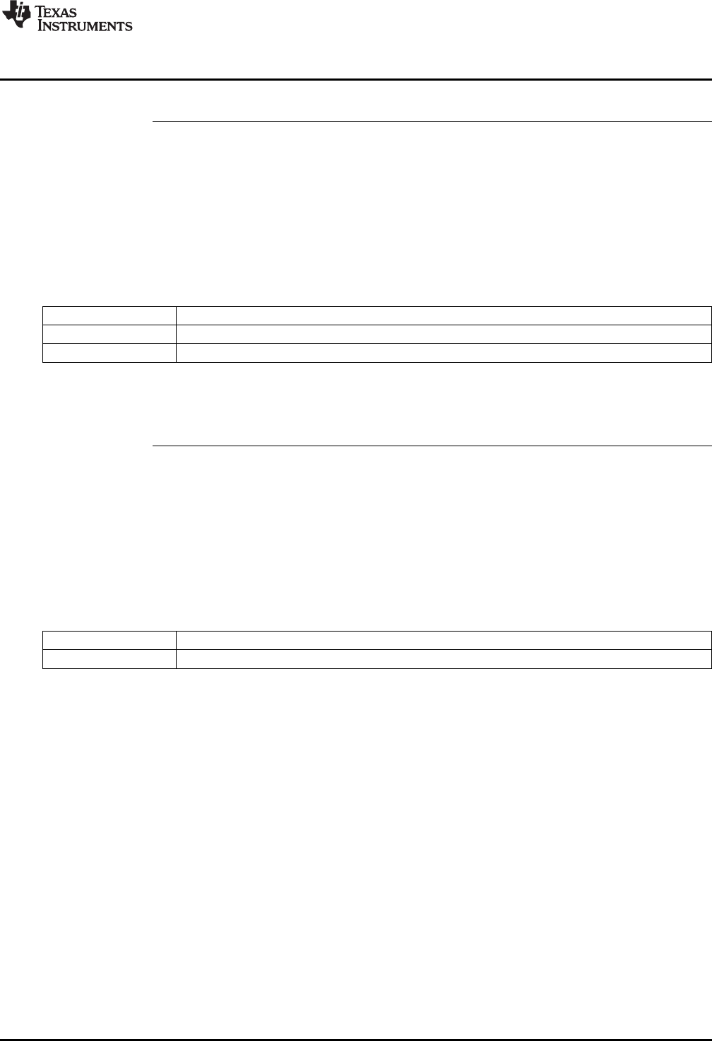
www.ti.com
DCL_runDF13_C6 — Run the Partial DF13 Compensator
43
SPRUID3–January 2017
Submit Documentation Feedback Copyright © 2017, Texas Instruments Incorporated
Controllers
DCL_runDF13_C6 Run the Partial DF13 Compensator
Header File DCL.h
Source File N/A
Declaration float DCL_runDF13_C6(DF13 *p, float ek, float uk)
Description This function computes the partial result of the pre-computed DF13 controller. The
function is identical in structure and operation to the C3 form. The function is coded in
inline C.
Parameters
p The DF13 structure
ek The servo error
vk The control effort in the previous sample interval
Return The control effort
DCL_runDF13_L1 Run the DF13 Full Compensator on the CLA
Header File DCL.h
Source File DCL_DF13_L1.asm
Declaration float DCL_runDF13_L1(DF13 *p, float ek)
Description This function computes a full third order control law using the Direct Form 1 structure,
and is identical in structure and operation to the C1 form. The function is coded in CLA
assembly language.
Parameters
p The DF13 structure
ek The servo error
Return The control effort

( ) ( ) ( 1) ( 2) ( 1) ( 2)
0 1 2 1 2
u k b e k b e k b e k a u k a u k
1 2
0 1 2
( ) 1 2
11 2
b b z b z
F z a z a z
DCL_runDF13_L2 — Run the Immediate DF13 Compensator on the CLA
www.ti.com
44 SPRUID3–January 2017
Submit Documentation Feedback
Copyright © 2017, Texas Instruments Incorporated
Controllers
DCL_runDF13_L2 Run the Immediate DF13 Compensator on the CLA
Header File DCL.h
Source File DCL_DF13_L2L3.asm
Declaration float DCL_runDF13_L2(DF13 *p, float ek, float vk)
Description This function computes the immediate part of the pre-computed DF13 controller. The
function is identical in structure and operation to the C2 form. The function is coded in
CLA assembly language.
Parameters
p The DF13 structure
ek The servo error
vk The pre-computed partial control effort
Return The control effort
DCL_runDF13_L3 Run the Partial DF13 Compensator on the CLA
Header File DCL.h
Source File DCL_DF13_L2L3.asm
Declaration float DCL_runDF13_L3(DF13 *p, float ek, float vk)
Description This function computes the partial result of the pre-computed DF13 controller. The
function is identical in structure and operation to the C3 form. The function is coded in
CLA assembly language.
Parameters
p The DF13 structure
ek The servo error
vk The control effort in the previous sample interval
Return The control effort
3.5 Direct Form 2 (Second Order) Compensators
3.5.1 Description
The C2000 Digital Controller Library contains a second order implementation of the Direct Form 2
controller structure, denoted “DF22”. This structure is sometimes referred to as a “bi-quad” filter and is
commonly used in a cascaded chain to build up digital filters of high order.
The transfer function of a second order discrete time compensator is shown in Equation 15.
(15)
The corresponding difference equation is shown in Equation 16.
(16)
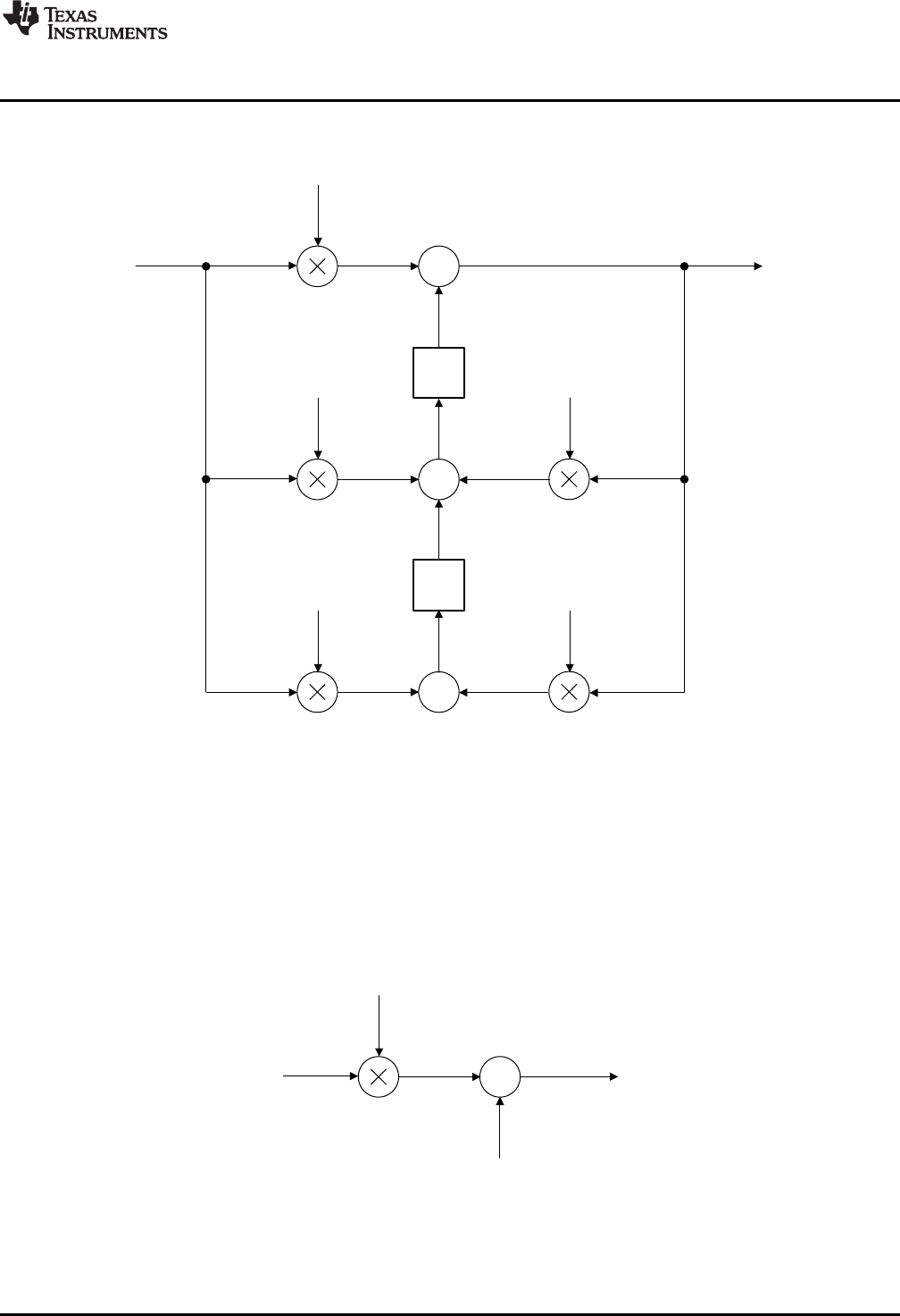
b0
u(k)e(k) +
v(k)
x1
( 1) ( ) ( 1) ( ) ( 1)
1 2 1 2
v k b e k b e k a u k a u k
( ) ( ) ( )
0
u k b e k v k
-a1
-a2
b2
b1
b0
u(k)
e(k)
z-1
+
+
z-1
+
v1v3
v2v4
v7
v0
v5
v6
x1
x1d
x2
x2d
www.ti.com
Direct Form 2 (Second Order) Compensators
45
SPRUID3–January 2017
Submit Documentation Feedback Copyright © 2017, Texas Instruments Incorporated
Controllers
Figure 3-14 shows a diagrammatic representation of the full Direct Form 2 realization.
Figure 3-14. DCL_DF22_C1 Architecture
As with the DF13 compensator, sample-to-output delay can be reduced through the use of pre-
computation. The immediate and pre-computed control laws are as follows. In the kth interval, the
immediate part is computed.
(17)
Next, the v(k) partial result is pre-computed for use in the (k+1)th interval.
(18)
The pre-computed form of DF22 is shown in Figure 3-15 and Figure 3-16.
Figure 3-15. DCL_DF22_C2 Architecture
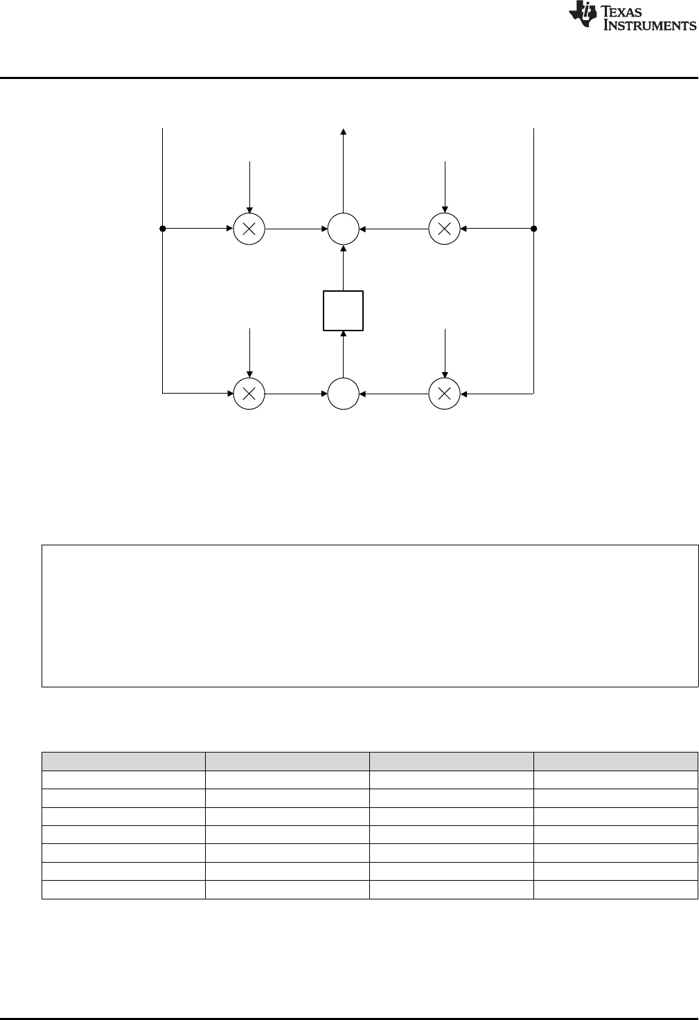
-a1
-a2
b2
b1
u(k)
e(k)
+
z-1
+
v(k+1)
x1d
x2d
x2
v1v3
v2v4
Direct Form 2 (Second Order) Compensators
www.ti.com
46 SPRUID3–January 2017
Submit Documentation Feedback
Copyright © 2017, Texas Instruments Incorporated
Controllers
Figure 3-16. DCL_DF22_C3 Architecture
3.5.2 Implementation
All DF22 functions use a common C structure to hold coefficients and data, defined in the header file
“DCL.h”.
typedef volatile struct {
float b0; //!< b0
float b1; //!< b1
float b2; //!< b2
float a1; //!< a1
float a2; //!< a2
float x1; //!< x1
float x2; //!< x2
} DF22;
The memory address offsets of the structure elements are shown in Table 3-9.
Table 3-9. List of DF22 Structure Elements and Address Offsets
Element Offset (Hex) Offset (Dec) Description
b0 0 0 Coefficient b0
b1 2 2 Coefficient b1
b2 4 4 Coefficient b2
a1 6 6 Coefficient a1
a2 8 8 Coefficient a2
x1 A 10 State x1
x2 C 12 State x2
It is the responsibility of the user to initialize both arrays prior to use. A set of default values is defined in
the library header file and can be used with the variable declaration. An example of an initialized DF22
structure declaration is shown below:
DF22 myCtrl = DF22_DEFAULTS;
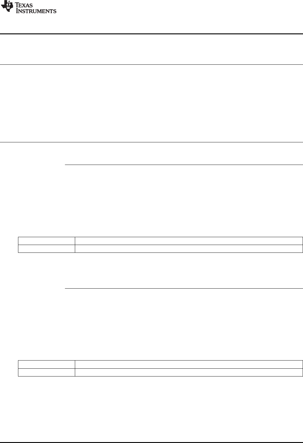
www.ti.com
Direct Form 2 (Second Order) Compensators
47
SPRUID3–January 2017
Submit Documentation Feedback Copyright © 2017, Texas Instruments Incorporated
Controllers
3.5.3 DF22 Functions
Table 3-10. Summary of DF22 Functions
Title ...................................................................................................................................... Page
DCL_runDF22_C1 —Run the DF22 Full Compensator............................................................................ 47
DCL_runDF22_C2 —Run the Immediate DF22 Compensator ................................................................... 47
DCL_runDF22_C3 —Run the Partial DF22 Compensator ........................................................................ 48
DCL_runDF22_C4 —Run the DF22 Full Compensator............................................................................ 48
DCL_runDF22_C5 —Run the Immediate DF22 Compensator ................................................................... 48
DCL_runDF22_C6 —Run the Partial DF22 Compensator ........................................................................ 49
DCL_runDF22_L1 —Run the DF22 Full Compensator on the CLA ............................................................. 49
DCL_runDF22_L2 —Run the Immediate DF22 Compensator on the CLA ..................................................... 49
DCL_runDF22_L3 —Run the Partial DF22 Compensator on the CLA .......................................................... 50
DCL_runDF22_C1 Run the DF22 Full Compensator
Header File DCL.h
Source File DCL_DF22_C1
Declaration float DCL_runDF22_C1(DF22 *p, float ek)
Description This function computes a full second order control law using the Direct Form 2 structure.
The function is coded in C28x assembly.
Parameters
p The DF22 structure
ek The servo error
Return The control effort
DCL_runDF22_C2 Run the Immediate DF22 Compensator
Header File DCL.h
Source File DCL_DF22_C2C3.asm
Declaration float DCL_runDF22_C2(DF22 *p, float ek)
Description This function computes the immediate part of the pre-computed DF22 controller. The
function is coded in C28x assembly.
Parameters
p The DF22 structure
ek The servo error
Return The control effort
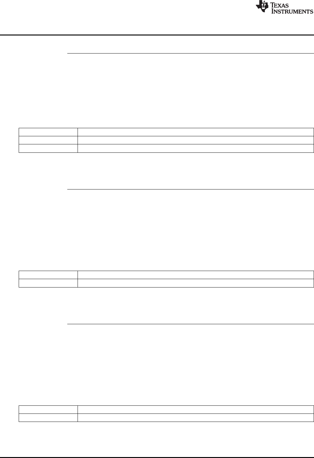
DCL_runDF22_C3 — Run the Partial DF22 Compensator
www.ti.com
48 SPRUID3–January 2017
Submit Documentation Feedback
Copyright © 2017, Texas Instruments Incorporated
Controllers
DCL_runDF22_C3 Run the Partial DF22 Compensator
Header File DCL.h
Source File DCL_DF22_C2C3.asm
Declaration void DCL_runDF22_C3(DF22 *p, float ek, float uk)
Description This function computes the partial result of the pre-computed DF22 controller. The
function is coded in C28x assembly.
Parameters
p The DF22 structure
ek The servo error
uk The control effort in the previous sample interval
Return The control effort
DCL_runDF22_C4 Run the DF22 Full Compensator
Header File DCL.h
Source File N/A
Declaration float DCL_runDF22_C4(DF22 *p, float ek)
Description This function computes a full second order control law using the Direct Form 2 structure,
and is identical in structure and operation to the C1 form. The function is coded in inline
C.
Parameters
p The DF22 structure
ek The servo error
Return The control effort
DCL_runDF22_C5 Run the Immediate DF22 Compensator
Header File DCL.h
Source File N/A
Declaration float DCL_runDF22_C5(DF22 *p, float ek)
Description This function computes the immediate part of the pre-computed DF22 controller. The
function is identical in structure and operation to the C2 form. The function is coded in
inline C.
Parameters
p The DF22 structure
ek The servo error
Return The control effort
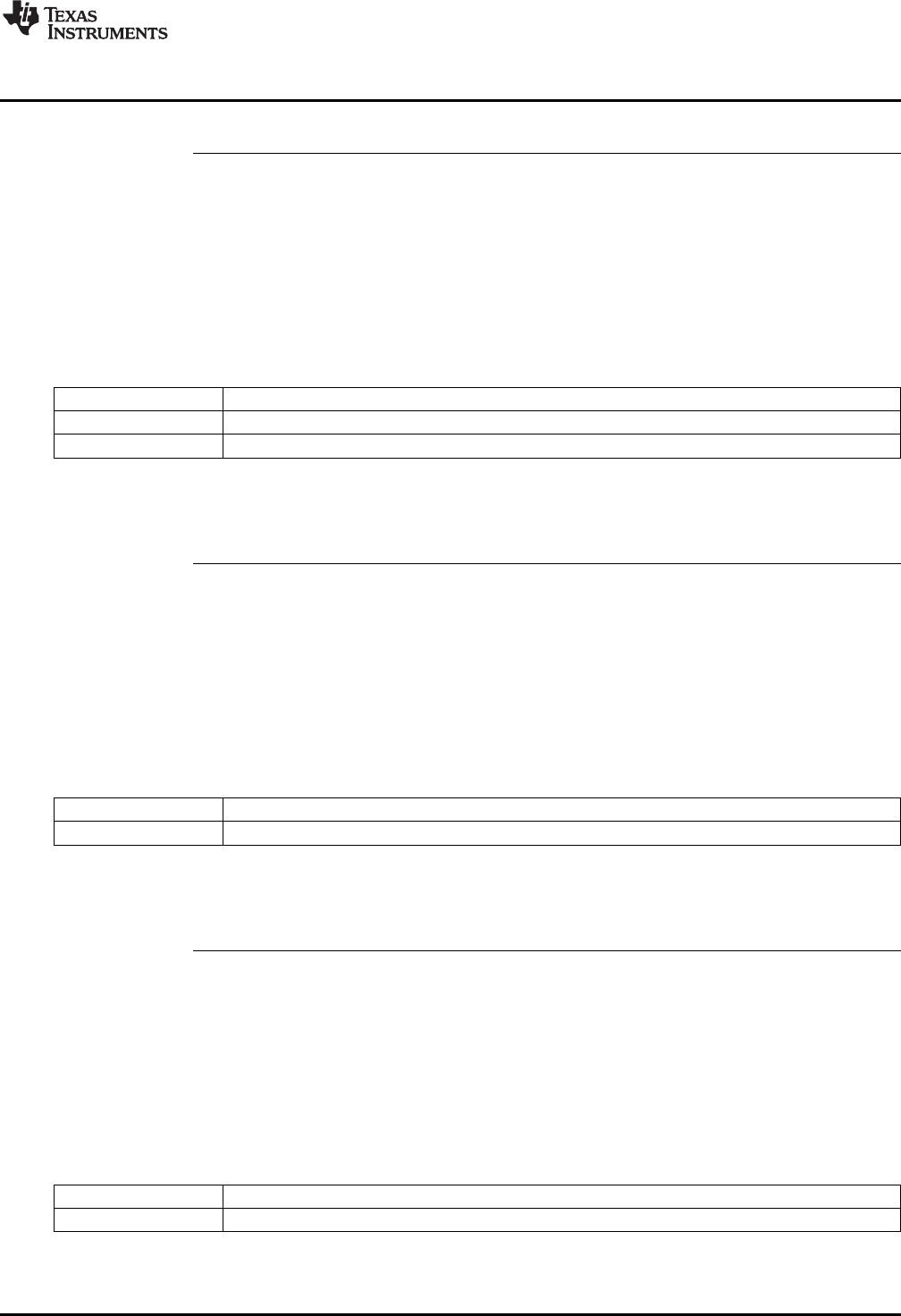
www.ti.com
DCL_runDF22_C6 — Run the Partial DF22 Compensator
49
SPRUID3–January 2017
Submit Documentation Feedback Copyright © 2017, Texas Instruments Incorporated
Controllers
DCL_runDF22_C6 Run the Partial DF22 Compensator
Header File DCL.h
Source File N/A
Declaration float DCL_runDF22_C6(DF22 *p, float ek)
Description This function computes the partial result of the pre-computed DF22 controller. The
function is identical in structure and operation to the C3 form. The function is coded in
inline C.
Parameters
p The DF22 structure
ek The servo error
uk The control effort in the previous sample interval
Return The control effort
DCL_runDF22_L1 Run the DF22 Full Compensator on the CLA
Header File DCL.h
Source File DCL_DF22_L1.asm
Declaration float DCL_runDF22_L1(DF22 *p, float ek)
Description This function computes a full third order control law using the Direct Form 2 structure,
and is identical in structure and operation to the C1 form. The function is coded in CLA
assembly language.
Parameters
p The DF22 structure
ek The servo error
Return The control effort
DCL_runDF22_L2 Run the Immediate DF22 Compensator on the CLA
Header File DCL.h
Source File DCL_DF22_L2L3.asm
Declaration float DCL_runDF22_L2(DF22 *p, float ek)
Description This function computes the immediate part of the pre-computed DF22 controller. The
function is identical in structure and operation to the C2 form. The function is coded in
CLA assembly language.
Parameters
p The DF22 structure
ek The servo error
Return The control effort
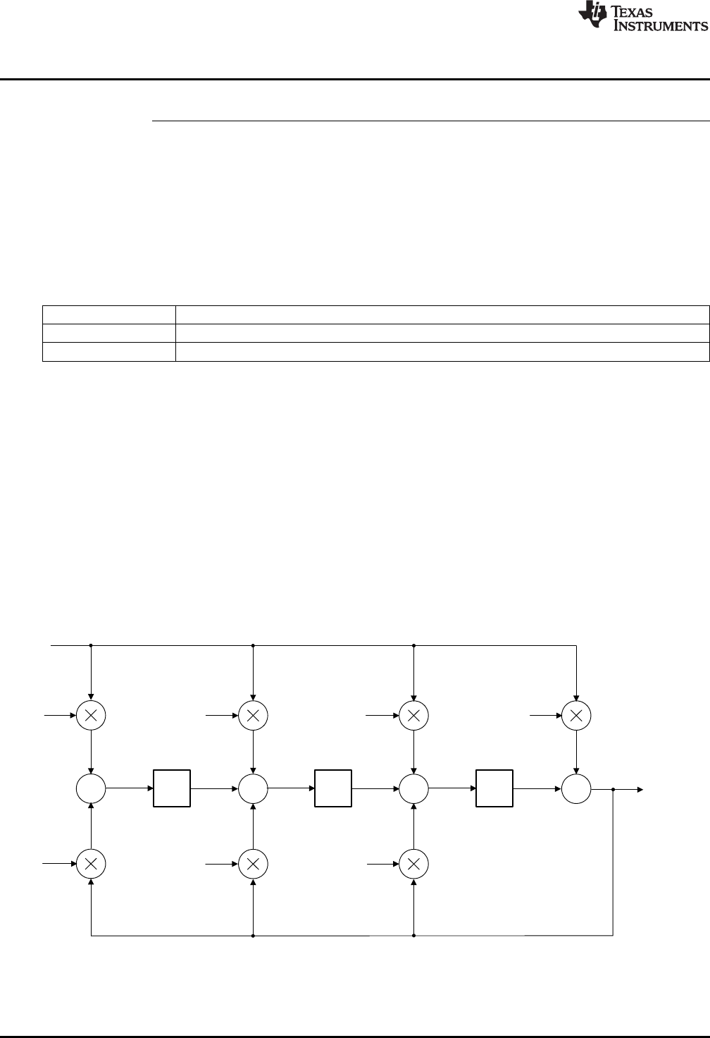
+++
-a1
-a2
b2b1b0
u(k)
z-1
+
-a3
b3
e(k)
z-1 z-1
x3x2x1
v6v1
v2
v3
v4
v5
v7
x3d x2d x1d
( ) ( ) ( 1) ( 2) ( 3)
0 1 2 3
( 1) ( 2) ( 3)
1 2 3
u k b e k b e k b e k b e k
a u k a u k a u k
DCL_runDF22_L3 — Run the Partial DF22 Compensator on the CLA
www.ti.com
50 SPRUID3–January 2017
Submit Documentation Feedback
Copyright © 2017, Texas Instruments Incorporated
Controllers
DCL_runDF22_L3 Run the Partial DF22 Compensator on the CLA
Header File DCL.h
Source File DCL_DF22_L2L3.asm
Declaration float DCL_runDF22_L3(DF22 *p, float ek)
Description This function computes the partial result of the pre-computed DF22 controller. The
function is identical in structure and operation to the C3 form. The function is coded in
CLA assembly language.
Parameters
p The DF22 structure
ek The servo error
uk The control effort in the previous sample interval
Return The control effort
3.6 Direct Form 2 (Third Order) Compensators
3.6.1 Description
The third order Direct Form 2 compensator (DF23) is similar in all respects to the DF22 compensator.
Separate full and pre-computed forms are supplied in C and assembly for computation on the C28x, and
in assembly for computation on the CLA.
The control law is the same as the DF13 compensator.
(19)
Figure 3-17 shows a diagrammatic representation of the full third order Direct Form 2 compensator.
Figure 3-17. DCL_DF23_C1 Architecture
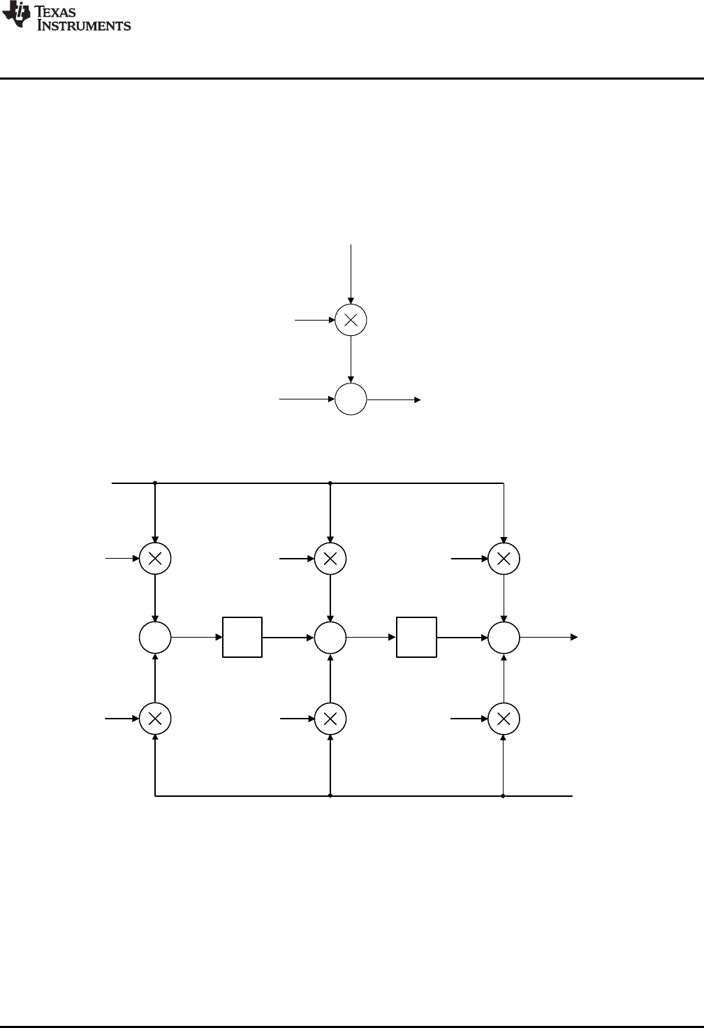
++
-a1
-a2
b2b1
u(k)
z- 1
+
-a3
b3
e(k)
z- 1
x3x2v(k + 1)
v2
v3
v4
v5
v6
v7
x1
x3d x2d
+
b0
u(k)
e(k)
v(k)
( 1) ( ) ( 1) ( 2) ( ) ( 1) ( 2)
1 2 3 1 2 3
v k b e k b e k b e k a u k a u k a u k
( ) ( ) ( )
0
u k b e k v k
www.ti.com
Direct Form 2 (Third Order) Compensators
51
SPRUID3–January 2017
Submit Documentation Feedback Copyright © 2017, Texas Instruments Incorporated
Controllers
Sample-to-output delay can be reduced through the use of pre-computation, in a similar way to the DF22
compensator. In the kth interval, the immediate part is computed.
(20)
Next, the v(k) partial result is pre-computed for use in the (k+1)th interval.
(21)
Figure 3-18 and Figure 3-19 show the pre-computed form of DF23.
Figure 3-18. DCL_DF23_C2 Architecture
Figure 3-19. DCL_DF23_C3 Architecture
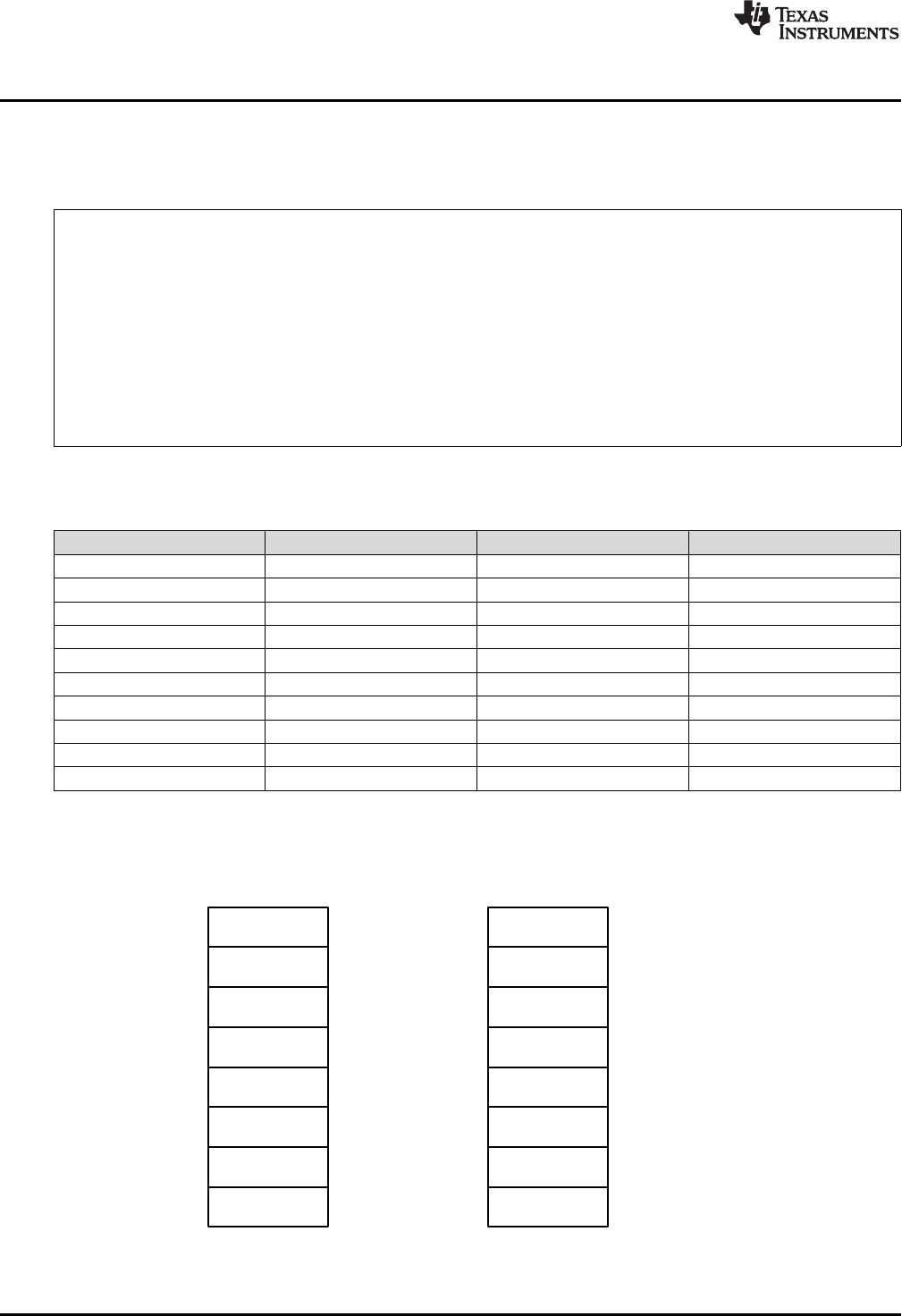
c[0]
c[1]
c[2]
c[3]
c[4]
c[5]
c[6]
c[7]
d[0]
d[1]
d[2]
d[3]
d[4]
d[5]
d[6]
d[7]
DataCoefficients
b0
b1
b2
b3
a0
a1
a2
a3
e(k)
e(k-1)
e(k-2)
e(k-3)
u(k)
u(k-1)
u(k-2)
u(k-3)
Direct Form 2 (Third Order) Compensators
www.ti.com
52 SPRUID3–January 2017
Submit Documentation Feedback
Copyright © 2017, Texas Instruments Incorporated
Controllers
3.6.2 Implementation
All DF23 functions use a common C structure to hold coefficients and data, defined in the header file
“DCL.h”.
typedef volatile struct {
float b0; //!< b0
float b1; //!< b1
float b2; //!< b2
float b3; //!< b3
float a1; //!< a1
float a2; //!< a2
float a3; //!< a3
float x1; //!< x1
float x2; //!< x2
float x3; //!< x3
} DF23
The memory address offsets of the structure elements are shown in Table 3-11.
Table 3-11. List of DF23 Structure Elements and Address Offsets
Element Offset (Hex) Offset (Dec) Description
b0 0 0 Coefficient b0
b1 2 2 Coefficient b1
b2 4 4 Coefficient b2
b3 6 6 Coefficient b3
a1 8 8 Coefficient a1
a2 A 10 Coefficient a2
a3 C 12 Coefficient a3
x1 E 14 State x1
x2 10 16 State x2
x3 12 18 State x3
The assignment of coefficients and data in the DF23 structure to those in the diagram shown in Figure 3-
20.
Figure 3-20. DF23 Data and Coefficient Layout
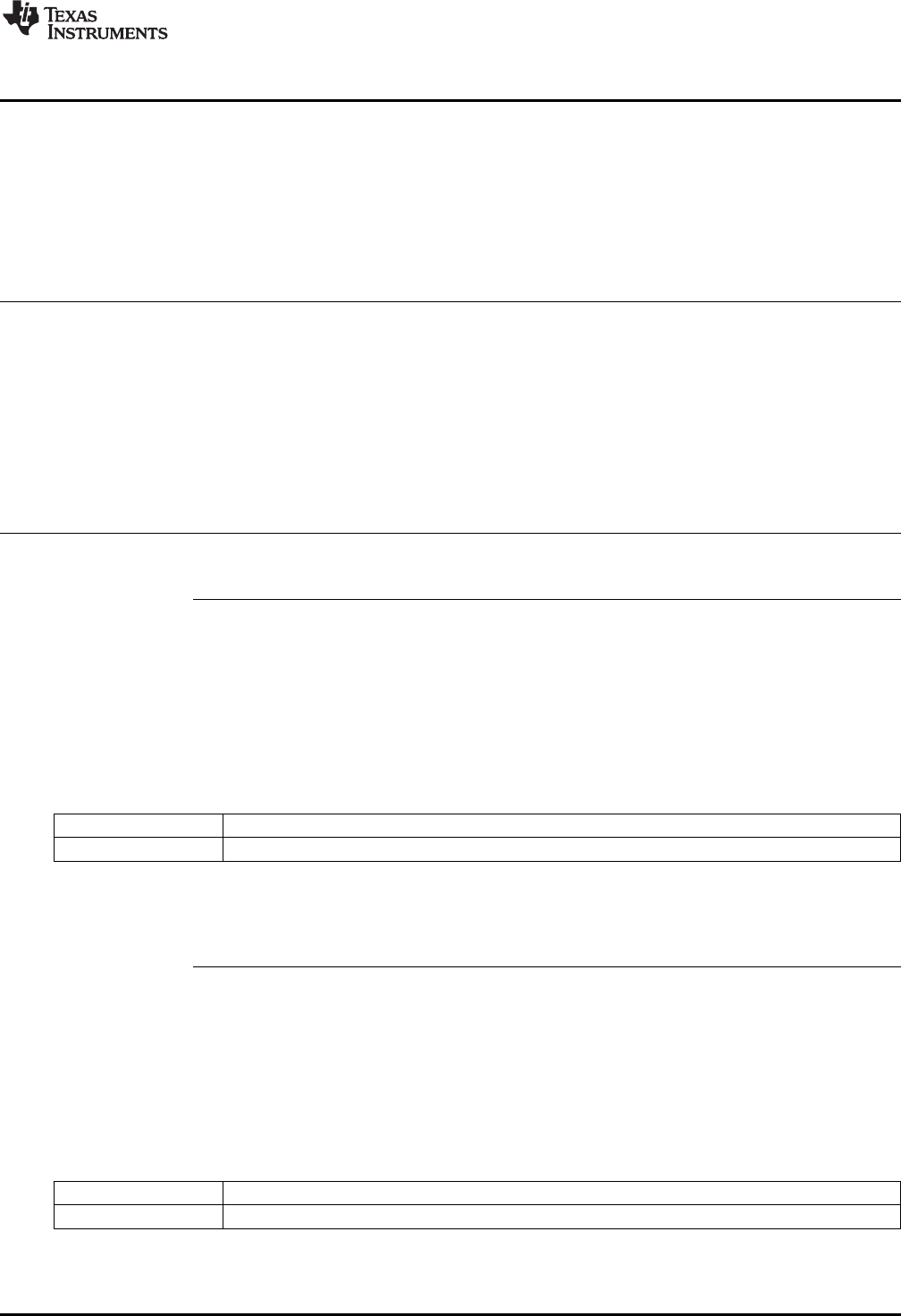
www.ti.com
Direct Form 2 (Third Order) Compensators
53
SPRUID3–January 2017
Submit Documentation Feedback Copyright © 2017, Texas Instruments Incorporated
Controllers
It is the responsibility of the user to initialize both arrays prior to use. A set of default values is defined in
the library header file and can be used with the variable declaration. An example of an initialized DF23
structure declaration is shown below:
DF23 myCtrl = DF23_DEFAULTS;
3.6.3 DF23 Functions
Table 3-12. Summary of DF23 Functions
Title ...................................................................................................................................... Page
DCL_runDF23_C1 —Run the DF23 Full Compensator............................................................................ 53
DCL_runDF23_C2 —Run the Immediate DF23 Compensator ................................................................... 53
DCL_runDF23_C3 —Run the Partial DF23 Compensator ........................................................................ 54
DCL_runDF23_C4 —Run the DF23 Full Compensator............................................................................ 54
DCL_runDF23_C5 —Run the Immediate DF23 Compensator ................................................................... 54
DCL_runDF23_C6 —Run the Partial DF23 Compensator ........................................................................ 55
DCL_runDF23_L1 —Run the DF23 Full Compensator on the CLA ............................................................. 55
DCL_runDF23_L2 —Run the Immediate DF23 Compensator on the CLA ..................................................... 55
DCL_runDF23_L3 —Run the Partial DF23 Compensator on the CLA .......................................................... 56
DCL_runDF23_C1 Run the DF23 Full Compensator
Header File DCL.h
Source File DCL_DF23_C1
Declaration float DCL_runDF23_C1(DF23 *p, float ek)
Description This function computes a full third order control law using the Direct Form 2 structure.
The function is coded in C28x assembly.
Parameters
p The DF23 structure
ek The servo error
Return The control effort
DCL_runDF23_C2 Run the Immediate DF23 Compensator
Header File DCL.h
Source File DCL_DF23_C2C3.asm
Declaration float DCL_runDF23_C2(DF23 *p, float ek)
Description This function computes the immediate part of the pre-computed DF23 controller. The
function is coded in C28x assembly.
Parameters
p The DF23 structure
ek The servo error
Return The control effort

DCL_runDF23_C3 — Run the Partial DF23 Compensator
www.ti.com
54 SPRUID3–January 2017
Submit Documentation Feedback
Copyright © 2017, Texas Instruments Incorporated
Controllers
DCL_runDF23_C3 Run the Partial DF23 Compensator
Header File DCL.h
Source File DCL_DF23_C2C3.asm
Declaration void DCL_runDF23_C3(DF23 *p, float ek, float uk)
Description This function computes the partial result of the pre-computed DF23 controller. The
function is coded in C28x assembly.
Parameters
p The DF23 structure
ek The servo error
uk The control effort in the previous sample interval
Return The control effort
DCL_runDF23_C4 Run the DF23 Full Compensator
Header File DCL.h
Source File N/A
Declaration float DCL_runDF23_C4(DF23 *p, float ek)
Description This function computes a full third order control law using the Direct Form 1 structure,
and is identical in structure and operation to the C1 form. The function is coded in inline
C.
Parameters
p The DF23 structure
ek The servo error
Return The control effort
DCL_runDF23_C5 Run the Immediate DF23 Compensator
Header File DCL.h
Source File N/A
Declaration float DCL_runDF23_C5(DF23 *p, float ek)
Description This function computes the immediate part of the pre-computed DF23 controller. The
function is identical in structure and operation to the C2 form. The function is coded in
inline C.
Parameters
p The DF23 structure
ek The servo error
Return The control effort

www.ti.com
DCL_runDF23_C6 — Run the Partial DF23 Compensator
55
SPRUID3–January 2017
Submit Documentation Feedback Copyright © 2017, Texas Instruments Incorporated
Controllers
DCL_runDF23_C6 Run the Partial DF23 Compensator
Header File DCL.h
Source File N/A
Declaration float DCL_runDF23_C6(DF23 *p, float ek, float uk)
Description This function computes the partial result of the pre-computed DF23 controller. The
function is identical in structure and operation to the C3 form. The function is coded in
inline C.
Parameters
p The DF23 structure
ek The servo error
uk The control effort in the previous sample interval
Return The control effort
DCL_runDF23_L1 Run the DF23 Full Compensator on the CLA
Header File DCL.h
Source File DCL_DF23_L1.asm
Declaration float DCL_runDF23_L1(DF22 *p, float ek)
Description This function computes a full third order control law using the Direct Form 2 structure,
and is identical in structure and operation to the C1 form. The function is coded in CLA
assembly language.
Parameters
p The DF23 structure
ek The servo error
Return The control effort
DCL_runDF23_L2 Run the Immediate DF23 Compensator on the CLA
Header File DCL.h
Source File DCL_DF23_L2L3.asm
Declaration float DCL_runDF23_L2(DF23 *p, float ek)
Description This function computes the immediate part of the pre-computed DF23 controller. The
function is identical in structure and operation to the C2 form. The function is coded in
CLA assembly language.
Parameters
p The DF23 structure
ek The servo error
Return The control effort
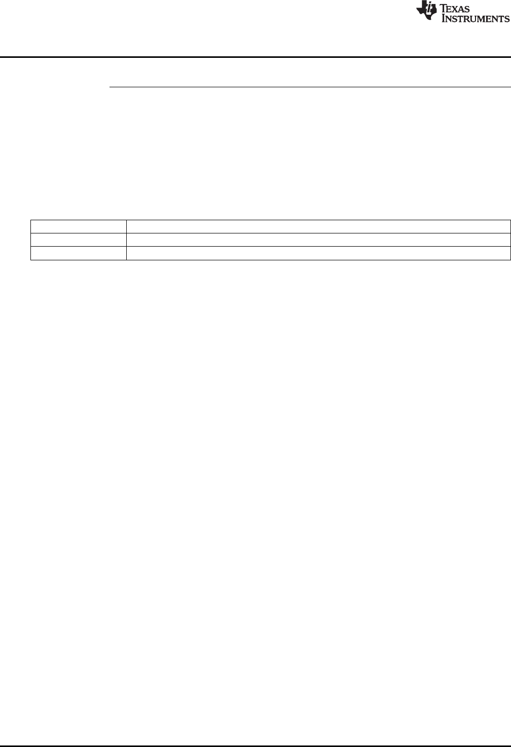
DCL_runDF23_L3 — Run the Partial DF23 Compensator on the CLA
www.ti.com
56 SPRUID3–January 2017
Submit Documentation Feedback
Copyright © 2017, Texas Instruments Incorporated
Controllers
DCL_runDF23_L3 Run the Partial DF23 Compensator on the CLA
Header File DCL.h
Source File DCL_DF23_L2L3.asm
Declaration float DCL_runDF23_L3(DF23 *p, float ek, float uk)
Description This function computes the partial result of the pre-computed DF23 controller. The
function is identical in structure and operation to the C3 form. The function is coded in
CLA assembly language.
Parameters
p The DF23 structure
ek The servo error
uk The control effort in the previous sample interval
Return The control effort

57
SPRUID3–January 2017
Submit Documentation Feedback Copyright © 2017, Texas Instruments Incorporated
Utilities
Chapter 4
SPRUID3–January 2017
Utilities
This chapter describes the supporting functions included in the Digital Control Library.
The Digital Controller Library includes a small number of utilities intended to support use of the library.
These include:
• Clamp functions for the CPU and CLA
• A floating-point data-logger
• A Transient Capture Module
• Functions for measurement of control performance
Topic ........................................................................................................................... Page
4.1 Control Clamps.................................................................................................. 58
4.2 Data Logger....................................................................................................... 59
4.3 Transient Capture Module ................................................................................... 65
4.4 Performance Measurement.................................................................................. 73
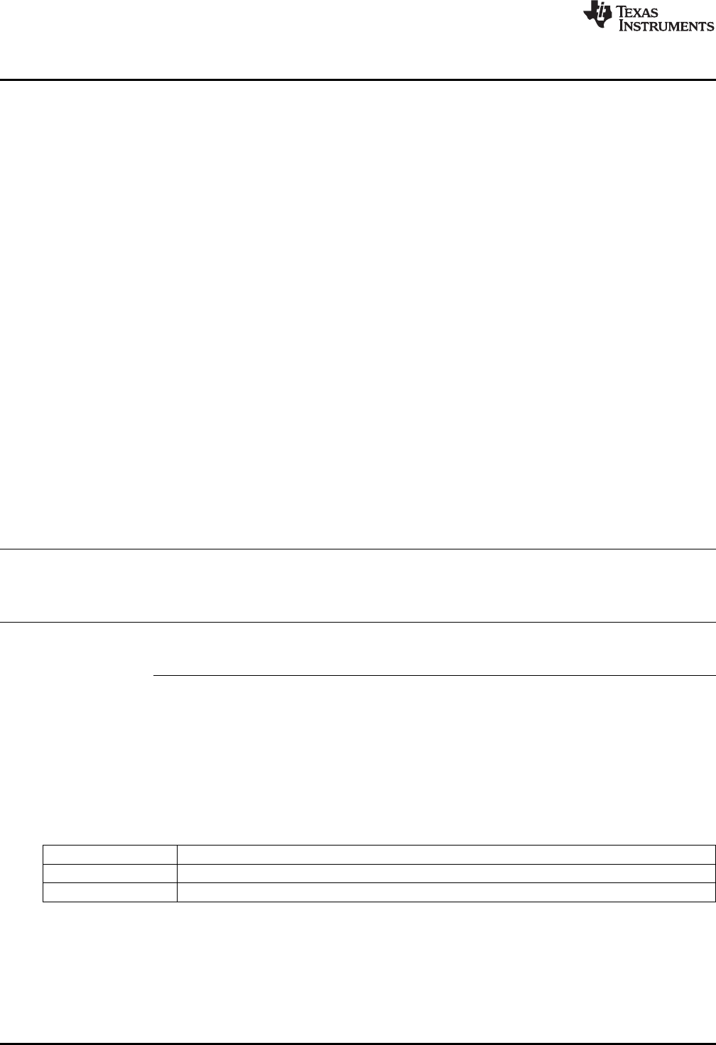
Control Clamps
www.ti.com
58 SPRUID3–January 2017
Submit Documentation Feedback
Copyright © 2017, Texas Instruments Incorporated
Utilities
4.1 Control Clamps
4.1.1 Description
The library contains three functions for clamping a control variable to specified upper and lower limits.
These would typically be used to bound the output of a controller function to pre-defined limits to avoid
actuator saturation or overload. Saturation in a control loop must be handled with care since control of the
system is effectively lost. Furthermore, controllers that implement integration of historical servo data can
exhibit a phenomenon known as “wind-up”, in which the controller output increases in magnitude while the
loop is saturated. This condition leads to delay in recovering from the saturation because the accumulated
controller output must be “wound down” before it comes within range of the actuator and the controller
resumes proper operation. For more information on wind-up, refer to the linear PID controller description
in Section 3.1.
The clamp functions bound the input data variable to pre-determined limits and return a logical value 1 if
either bound is matched or exceeded. If the input data lies definitely within limits (for example, neither
bound is matched or exceeded) the functions return logical 0. The return value can be used by the PID
regulators in the library to implement anti-windup reset, and may be used to clamp the output of the pre-
computed forms of DF1 and DF2 compensators. An example of the latter can be found in the DF22
example project supplied with the library (see Chapter 5).
A difference exists between the C28x clamp function and that of the CLA. On the CPU the returned value
is an unsigned integer of either 0 or 1, while the corresponding CLA function returns a floating point value
of 0.0f or 1.0f. This is because the handling of fixed-point data on the CLA is less efficiently supported
than on the main CPU.
4.1.2 Clamp Functions
Table 4-1. Summary of Clamp Functions
Title ...................................................................................................................................... Page
DCL_runClamp_C1 —Floating-Point Data Clamp ................................................................................. 58
DCL_runClamp_C2 —Floating-Point Data Clamp ................................................................................ 59
DCL_runClamp_L1 —Floating-Point Data Clamp.................................................................................. 59
DCL_runClamp_C1 Floating-Point Data Clamp
Header File DCL.h
Source File DCL_clamp_C1.asm
Declaration uint16_t DCL_runClamp_C1(float *data, float Umax, float Umin)
Description This function clamps a floating-point data value to defined limits and returns a non-zero
integer if either limit is matched or exceeded. The function is coded in assembly.
Parameters
data The TCM structure
Umin The upper data limit
Umax The lower data limit
Return 0 if the data lies definitely within limits, 1 if the data matches or exceeds the limits.
www.ti.com
DCL_runClamp_C2 — Floating-Point Data Clamp
59
SPRUID3–January 2017
Submit Documentation Feedback Copyright © 2017, Texas Instruments Incorporated
Utilities
DCL_runClamp_C2 Floating-Point Data Clamp
Header File DCL.h
Source File N/A
Declaration uint16_t DCL_runClamp_C2(float *data, float Umax, float Umin)
Description This function clamps a floating-point data value to defined limits and returns a non-zero
integer if either limit is matched or exceeded. The function is coded in inline C.
Parameters
data The TCM structure
Umin The upper data limit
Umax The lower data limit
Return 0 if the data lies definitely within limits, 1 if the data matches or exceeds the limits.
DCL_runClamp_L1 Floating-Point Data Clamp
Header File DCL.h
Source File DCL_clamp_L1.asm
Declaration float DCL_runClamp_L1(float *data, float Umax, float Umin)
Description This function clamps a floating-point data value to defined limits and returns a non-zero
floating-point result if either limit is matched or exceeded. The function is coded in CLA
assembly.
Parameters
data The TCM structure
Umin The upper data limit
Umax The lower data limit
Return 0 if the data lies definitely within limits, 1 if the data matches or exceeds the limits.
4.2 Data Logger
4.2.1 Description
The Digital Control Library includes a general-purpose floating-point data logger utility, which is useful
when testing and debugging control applications. The intended use of the data logger utility is to capture a
stream of data values in a block of memory for subsequent analysis. The data logger is supplied in the
form of a C header file and one assembly file, and it may be used on any C2000 device irrespective of
whether the DCL is used. The utility may not be used on the CLA.
The data logger operates with arrays of 32-bit floating-point data. The location, size and indexing of each
array are defined by three pointers capturing the start address, end address, and data index address. All
three pointers are held in a common C structure with the data type “FDLOG”, defined as follows.
typedef volatile struct {
float *fptr;
float *lptr;
float *dptr;
} FDLOG;
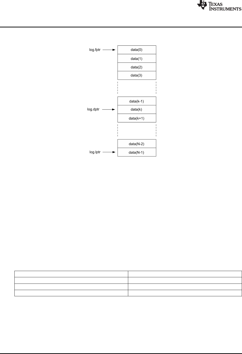
Data Logger
www.ti.com
60 SPRUID3–January 2017
Submit Documentation Feedback
Copyright © 2017, Texas Instruments Incorporated
Utilities
Conceptually, the relationship between the array pointers and the elements of a data array of length “N” is
shown in Figure 4-1.
Figure 4-1. Data Log Pointer Allocation
The data index pointer (dptr) always points to the next address to be written or read, and advances
through the memory block as each new data value is written into the log. On reaching the end of the log,
the pointer is reset to the first address in the log. The data logger header file contains a set of in-line C
functions to access and manipulate data logs.
To use the data logger, you must include the header file “DCL_fdlog.h” in your project. Typically, a user
would create an instance of an FDLOG structure as follows:
FDLOG myBuf = FDLOG_DEFAULTS;
The log pointers can then be initialized in the user’s code such that they reference a memory block in a
specific address range. Thereafter, the code can clear or load the buffer a specific data value, and then
begin writing data into it using the DCL_writeLog() function. The DF22 code example project shows how
this is done.
Version 2.0 of the DCL adds two functions that perform fast read and write to a data log. These are
assembly coded functions in the source file “DCL_frwlog.asm”. The execution cycles for these and the
corresponding C coded DCL functions are shown in Table 4-2.
Table 4-2. Data Log Read/Write Benchmarks
DCL_writeLog 48
DCL_readLog 39
DCL_fwriteLog 22
DCL_freadLog 22
www.ti.com
Data Logger
61
SPRUID3–January 2017
Submit Documentation Feedback Copyright © 2017, Texas Instruments Incorporated
Utilities
4.2.2 DCL Functions
Table 4-3. Summary of DCL Functions
Title ...................................................................................................................................... Page
DCL_deleteLog —Delete a Data Log................................................................................................ 61
DCL_resetLog —Reset a Data Log .................................................................................................. 61
DCL_initLog —Initialize a Data Log Structure ...................................................................................... 62
DCL_writeLog —Write Data into a Log.............................................................................................. 62
DCL_fillLog —Fill a Data Log with Specified Data................................................................................. 62
DCL_clearLog —Fill a Data Log Contents with Zero .............................................................................. 63
DCL_readLog —Fill a Data Log Contents with Zero............................................................................... 63
DCL_freadLog —Performs Fast Read from a Data Log .......................................................................... 64
DCL_writeLog —Performs Fast Write into a Data Log ............................................................................ 64
DCL_deleteLog Delete a Data Log
Header File DCL_fdlog.h
Source File N/A
Declaration void DCL_deleteLog(FDLOG *p)
Description This function resets all structure pointers to null value.
Parameters
p The FDLOG structure
Return None
DCL_resetLog Reset a Data Log
Header File DCL_fdlog.h
Source File N/A
Declaration void DCL_resetLog(FDLOG *p)
Description This function resets the data index pointer to start of the data log.
Parameters
p The FDLOG structure
Return None

DCL_initLog — Initialize a Data Log Structure
www.ti.com
62 SPRUID3–January 2017
Submit Documentation Feedback
Copyright © 2017, Texas Instruments Incorporated
Utilities
DCL_initLog Initialize a Data Log Structure
Header File DCL_fdlog.h
Source File N/A
Declaration void DCL_initLog(FDLOG *p, float *addr, uint16_t size)
Description This function assigns the buffer pointers to a memory block or array and sets the data
index pointer to the first address.
Parameters
p The FDLOG structure
addr The start address of the memory block
size The length of the memory block in 32-bit words
Return None
DCL_writeLog Write Data into a Log
Header File DCL_fdlog.h
Source File N/A
Declaration float DCL_writeLog(FDLOG *p, float data)
Description This function writes a data point into the buffer and advances the indexing pointer,
wrapping if necessary. The function returns the data value being over-written, which
allows simple implementation of a fixed-length delay line.
Parameters
p The FDLOG structure
data The input data value addr
Return The over-written data value
DCL_fillLog Fill a Data Log with Specified Data
Header File DCL_fdlog.h
Source File N/A
Declaration void DCL_fillLog(FDLOG *p, float data)
Description This function fills the data log with a given data value and resets the data index pointer
to the start of the log.
Parameters
p The FDLOG structure
data The input data value addr
Return None
www.ti.com
DCL_clearLog — Fill a Data Log Contents with Zero
63
SPRUID3–January 2017
Submit Documentation Feedback Copyright © 2017, Texas Instruments Incorporated
Utilities
DCL_clearLog Fill a Data Log Contents with Zero
Header File DCL_fdlog.h
Source File N/A
Declaration void DCL_clearLog(FDLOG *p)
Description This function clears the buffer contents by writing 0 to all elements and resets the data
index pointer to the start of the log.
Parameters
p The FDLOG structure
Return None
DCL_readLog Fill a Data Log Contents with Zero
Header File DCL_fdlog.h
Source File N/A
Declaration float DCL_readLog(FDLOG *p)
Description This function reads a data point from the buffer and then advanced the index pointer,
wrapping if necessary.
Parameters
p The FDLOG structure
Return The indexed data value
DCL_copyLog Copies one Data Log into Another
Header File DCL_fdlog.h
Source File N/A
Declaration void DCL_copyLog(FDLOG *p, FDLOG *q)
Description This function copies the contents of one log into another and resets both buffer index
pointers. The function assumes both logs have the same length.
Parameters
p The FDLOG structure
q The source FDLOG structure
Return None
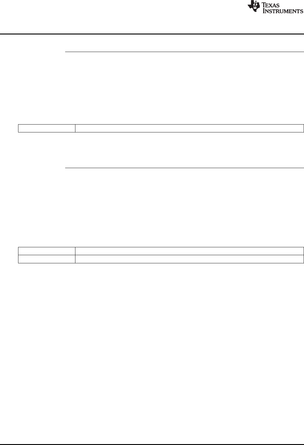
DCL_freadLog — Performs Fast Read from a Data Log
www.ti.com
64 SPRUID3–January 2017
Submit Documentation Feedback
Copyright © 2017, Texas Instruments Incorporated
Utilities
DCL_freadLog Performs Fast Read from a Data Log
Header File DCL_fdlog.h
Source File DCL_frwlog.asm
Declaration float DCL_freadLog(FDLOG *p)
Description This function reads a data point from the log and then advances the indexing pointer,
wrapping if necessary. This function is coded in assembly.
Parameters
p The FDLOG structure
Return The indexed data value
DCL_writeLog Performs Fast Write into a Data Log
Header File DCL_fdlog.h
Source File DCL_frwlog.asm
Declaration float DCL_fwriteLog(FDLOG *p, float data)
Description This function writes a data point into the buffer and advances the indexing pointer,
wrapping if necessary. Returns the over-written data value for delay line or FIFO
implementation. This function is coded in assembly.
Parameters
p The FDLOG structure
data The input data value
Return The over-written data value

www.ti.com
Transient Capture Module
65
SPRUID3–January 2017
Submit Documentation Feedback Copyright © 2017, Texas Instruments Incorporated
Utilities
4.3 Transient Capture Module
The Transient Capture Module (TCM) is a triggered data logger that captures a burst of incoming data. A
typical use is the capture of a transient response following a step input to a control system. The trigger
conditions are a pair of user defined limits on the incoming data. The capture process is triggered by the
first data point that exceeds either limit.
A feature of the TCM is that it captures a programmable length lead frame, allowing the user to inspect
conditions immediately prior to the trigger condition. This is accomplished with three FDLOG structures,
which are elements in the TCM data structure, together with the limit pair. Once initialized, the status of
the TCM is captured in one of four enumerated operating modes:
• TCM_idle
• TCM_armed
• TCM_capture
• TCM_complete
The TCM data is contained in a C structure as shown below:
typedef volatile struct {
FDLOG moniFrame; //!< Monitor data frame
FDLOG leadFrame; //!< Lead data frame
FDLOG captFrame; //!< Capture data frame
float trigMax; //!< Upper trigger threshold
float trigMin; //!< Lower trigger threshold
uint16_t mode; //!< Operating mode
uint16_t lead; //!< Lead frame size in 32-bit words = trigger crossing index
} TCM;
The current mode is available in the “mode” element in the TCM structure. To use the TCM, the user must
do the following.
1. Include the header file “TCM.h” in the project
2. Allocate a RAM memory block to hold the full capture buffer.
3. Create an instance of the TCM structure and initialize it using DCL_initTCM().
4. Arm the TCM using DCL_armTCM()
5. Log data into the TCM using DCL_runTCM()
6. Monitor the “mode” element in the TCM structure to determine when the capture is complete.
A code example illustrating the use of the TCM is supplied with the library and is described in Chapter 5.
In the following diagrams, lead, capture, and monitor frames are indexed using the FDLOG structures x, y,
and z, respectively (note that these are not the names used in the TCM structure). FDLOG pointers are
color coded blue, green, and red, respectively. To help visualize the sequence of events, the diagram
shows the data that will eventually be logged into the TCM in light gray, and in blue the current frame
contents in each mode.
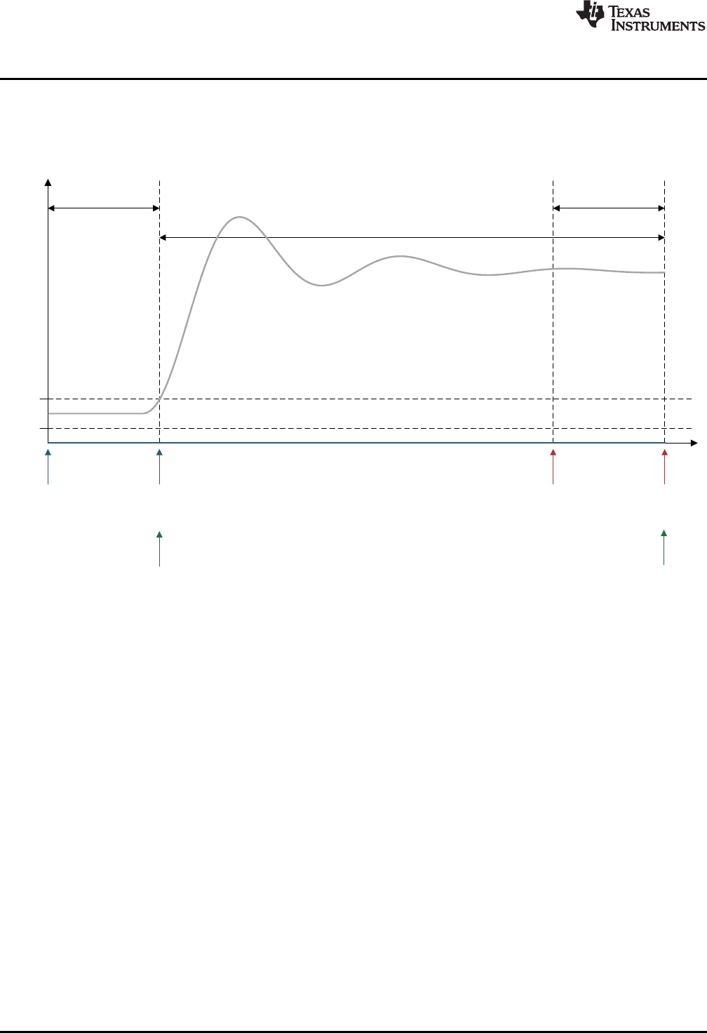
umax
umin
y(t)
z.lptr
x.lptr
z.fptr
z.dptr
x.lptrx.fptr
x.dptr
Monitor
Frame
Lead
Frame
Capture Frame
y.fptr
y.dptr
Transient Capture Module
www.ti.com
66 SPRUID3–January 2017
Submit Documentation Feedback
Copyright © 2017, Texas Instruments Incorporated
Utilities
4.3.1 TCM_idle Mode
In “TCM_idle” mode the TCM buffers are as shown in Figure 4-2. All buffer contents are zero, all frame
data pointers are at the start of their respective frames and no data is being logged. This is the condition
after the DCL_initTCM() function has been called.
Figure 4-2. TCM Operation in TCM_idle Mode
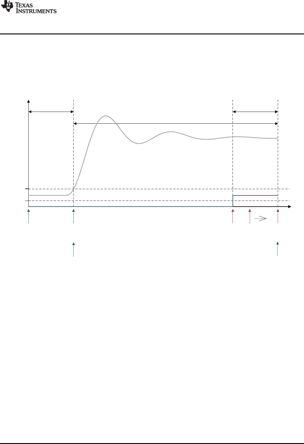
umax
umin
y(t)
z.lptr
x.lptr
z.fptr z.dptrx.lptrx.fptr
x.dptr
Monitor
Frame
Lead
Frame
Capture Frame
y.fptr
y.dptr
www.ti.com
Transient Capture Module
67
SPRUID3–January 2017
Submit Documentation Feedback Copyright © 2017, Texas Instruments Incorporated
Utilities
4.3.2 TCM_armed Mode
The TCM is armed by a call to DCL_armTCM(). In this mode, incoming data is continually logged in the
monitor frame. The monitor frame acts as a circular buffer, the index pointer wrapping to the start of the
monitor frame when it reaches the end
Each data point is compared with the upper and lower trigger thresholds to determine whether to initiate a
capture sequence. As long as the incoming data remains within the specified limits, the TCM remains in
TCM_armed mode.
Figure 4-3. TCM Operation in TCM_armed Mode
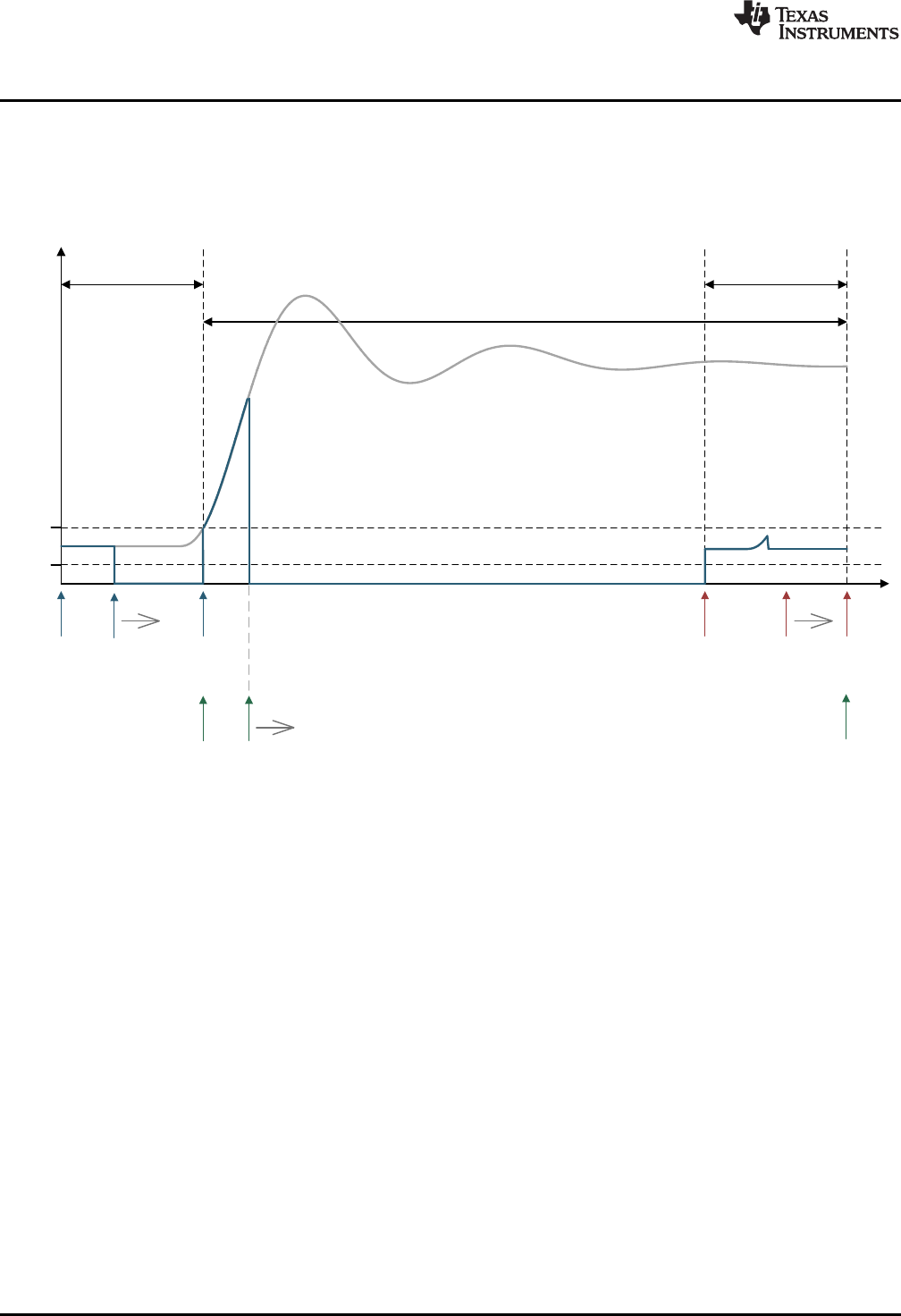
umax
umin
y(t)
z.lptr
x.lptr
z.fptr z.dptr
x.lptrx.fptr x.dptr
Monitor
Frame
Lead
Frame
Capture Frame
y.fptr y.dptr
Transient Capture Module
www.ti.com
68 SPRUID3–January 2017
Submit Documentation Feedback
Copyright © 2017, Texas Instruments Incorporated
Utilities
4.3.3 TCM_capture Mode
The first data point that exceeds either trigger threshold initiates a capture sequence. The TCM
automatically enters “TCM_capture” mode and incoming data is logged into the capture frame. Meanwhile,
the monitor frame stops collecting data and starts to “un-wind” its contents into the lead frame. Notice that
the monitor frame contains the lead data sequence, but the starting point is not aligned with the frame.
Figure 4-4. TCM Operation in Capture Mode (monitor frame un-winding)
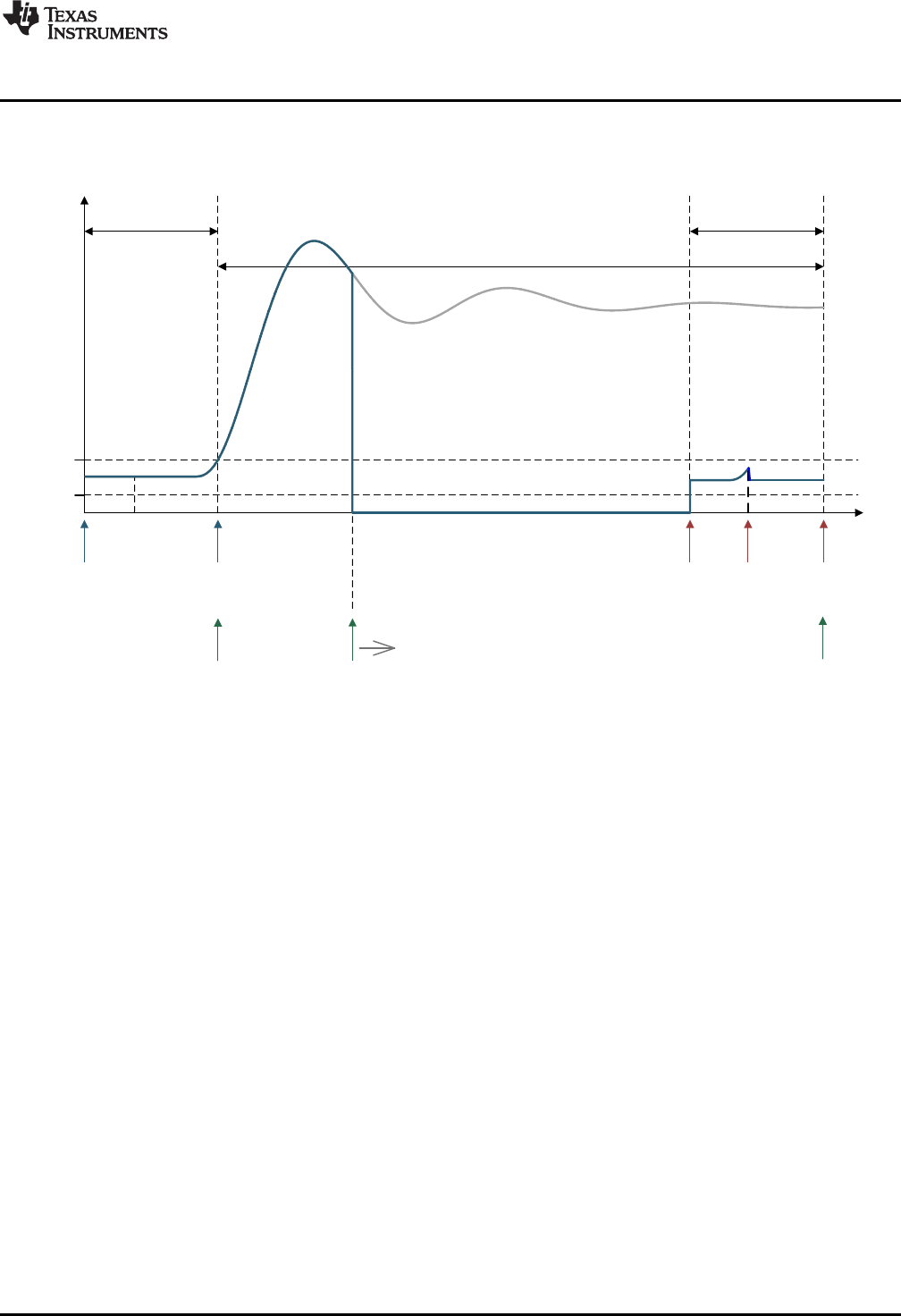
umax
umin
y(t)
z.lptr
x.lptr
z.fptr z.dptrx.lptrx.fptr
x.dptr
Monitor
Frame
Lead
Frame
Capture Frame
y.fptr y.dptr
www.ti.com
Transient Capture Module
69
SPRUID3–January 2017
Submit Documentation Feedback Copyright © 2017, Texas Instruments Incorporated
Utilities
Once the lead frame is full, the monitor frame stops copying out its data. Incoming data continues being
logged into the capture frame until it is full. The monitor frame contents have now been completely loaded
into the lead frame and will be over-written.
Figure 4-5. TCM Operation in TCM_capture Mode (lead frame complete)
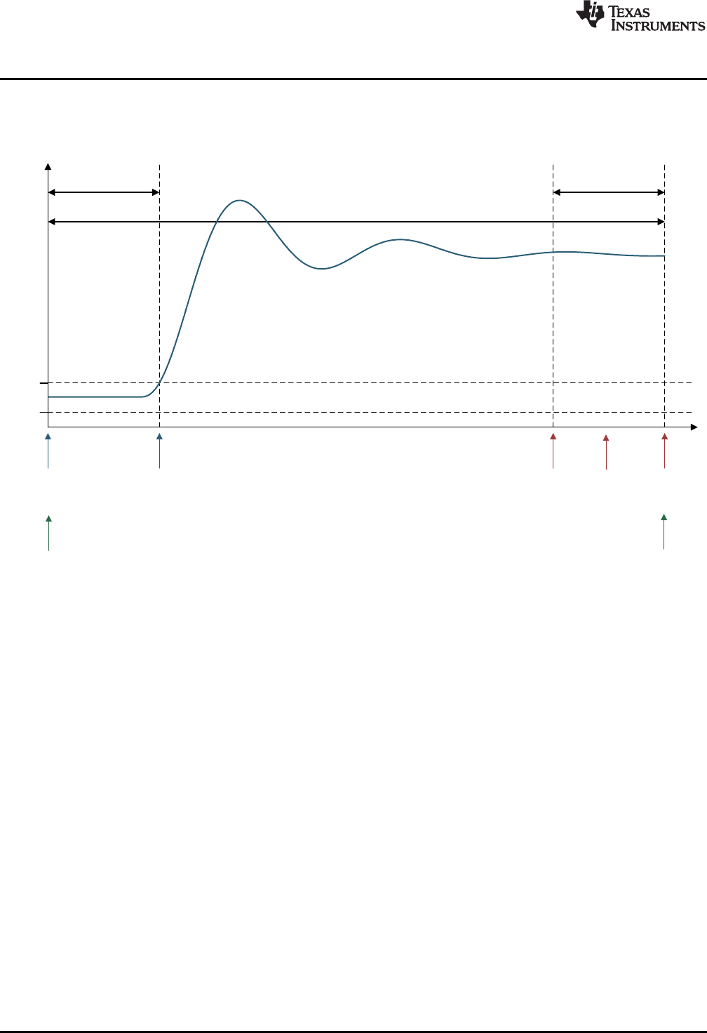
umax
umin
y(t)
z.lptr
x.lptr
z.fptr z.dptr
x.lptrx.fptr
x.dptr
Monitor
Frame
Lead
Frame
Capture Frame
y.fptr y.dptr
Transient Capture Module
www.ti.com
70 SPRUID3–January 2017
Submit Documentation Feedback
Copyright © 2017, Texas Instruments Incorporated
Utilities
4.3.4 TCM_complete Mode
Once the capture frame is full, data logging stops and the TCM enters “TCM_complete” mode. The
capture frame pointers are adjusted to span the entire TCM buffer, as shown below.
Figure 4-6. CM Capture Complete
The buffer contents may now be read out using DCL_readLog() or DCL_freadLog().
www.ti.com
Transient Capture Module
71
SPRUID3–January 2017
Submit Documentation Feedback Copyright © 2017, Texas Instruments Incorporated
Utilities
4.3.5 TCM Functions
Table 4-4. Summary of TCM Functions
Title ...................................................................................................................................... Page
DCL_initTCM —Initialize the TCM.................................................................................................... 71
DCL_armTCM —Arm the TCM........................................................................................................ 72
DCL_runTCM —Run the TCM ........................................................................................................ 72
DCL_initTCM Initialize the TCM
Header File DCL_TCM.h
Source File N/A
Declaration void DCL_initTCM(TCM *q, float *addr, uint16_t size, uint16_t lead, float tmin, float tmax)
Description This function resets the TCM module. All buffer contents are loaded with zero, and the
operating mode is set to “TCM_idle”.
Parameters
p The TCM structure
addr The start address of the memory block
size The size of the memory block in 32-bit words
lead The length of the lead frame in samples
tmin The upper trigger threshold
tmax The lower trigger threshold
Return None
DCL_resetTCM Reset the TCM
Header File DCL_TCM.h
Source File N/A
Declaration void DCL_resetTCM(TCM *q)
Description This function resets the TCM. The contents of the capture frame are loaded with zero.
All data log pointers are re-initialized, and the operating mode is set to “TCM_idle”.
Parameters
q The TCM structure
Return The over-written data value
DCL_armTCM — Arm the TCM
www.ti.com
72 SPRUID3–January 2017
Submit Documentation Feedback
Copyright © 2017, Texas Instruments Incorporated
Utilities
DCL_armTCM Arm the TCM
Header File DCL_TCM.h
Source File N/A
Declaration uint16_t DCL_armTCM(TCM *q)
Description If the current TCM mode is “TCM_idle”, this function changes it to “TCM_armed”,
otherwise it is unchanged.
Parameters
q The TCM structure
Return The current operating mode
DCL_runTCM Run the TCM
Header File DCL_TCM.h
Source File N/A
Declaration uint16_t DCL_runTCM(TCM *q, float data)
Description Runs the TCM module.
Parameters
q The TCM structure
Return The current operating mode
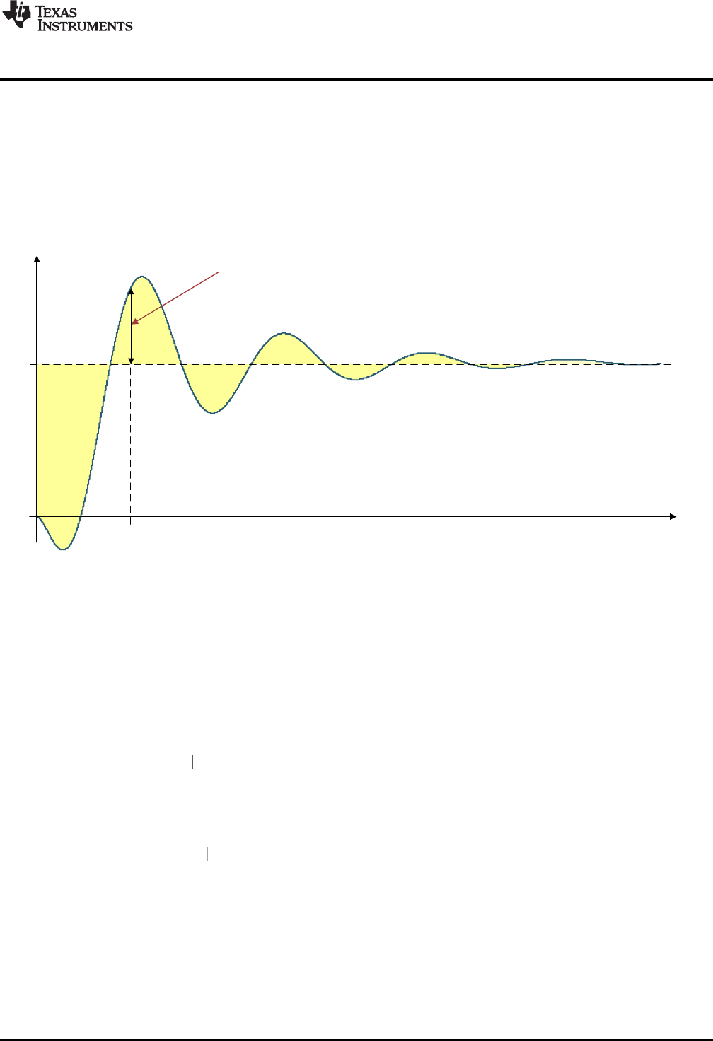
( ) ( )
1
N
P k r k y k
ITAE k
¦
( ) ( )
1
N
P r k y k
IAE k
¦
2
( ) ( )
1
N
P r k y k
IES k
¦
t
0
y(t)
1
Transient error
e(t0) = r(t0) - y(t0)
t0
www.ti.com
Performance Measurement
73
SPRUID3–January 2017
Submit Documentation Feedback Copyright © 2017, Texas Instruments Incorporated
Utilities
4.4 Performance Measurement
4.4.1 Description
The Digital Control Library includes functions for the computation of control performance. All functions are
based on discrete integration over a fixed interval of a variable representing servo error. The result is a
non-negative scalar representing the quality of control: the smaller the result, the better the control.
Figure 4-7 shows conceptually the transient servo error during a typical transient response.
Figure 4-7. Transient Servo Error
There are three performance measures available in the library.
• The IES performance index is based on the square of the servo error. For an interval of N samples,
with loop reference r and feedback y, the IES index (PIES) is computed as shown in Equation 22.
(22)
• The IAE performance index is based on the absolute value of the servo error. For an interval of N
samples, with loop reference r and feedback y, the IAE index (PIAE) is computed as shown in
Equation 23.
(23)
• The ITAE performance index is based on the time weighted absolute value of the servo error. For an
interval of N samples, with loop reference r and feedback y, the ITAE index (PITAE) is computed as
shown in Equation 24.
(24)
Each index is available in two forms: one coded in assembly, the other in inline C. The computation time
will depend on the length of the error log, but the assembly functions will always be significantly faster.
Performance Measurement
www.ti.com
74 SPRUID3–January 2017
Submit Documentation Feedback
Copyright © 2017, Texas Instruments Incorporated
Utilities
Table 4-5 shows cycle count benchmarks for each function, for a buffer of N data points. Cycle counts
include function calling overhead from C.
Table 4-5. Performance Index Function Benchmarks
Function Cycles
IES_C1 24 + 6N
IES_C2 73 + 30N
IAE_C1 24 + 6N
IAE_C2 72 + 24N
ITAE_C1 26 + 7N
ITAE_C2 77 + 31N
4.4.2 IES Functions
Table 4-6. Summary of IES Functions
Title ...................................................................................................................................... Page
DCL_runIES_C1 —Compute the IES Performance Index......................................................................... 74
DCL_runIES_C2 —Compute the IES Performance Index......................................................................... 75
DCL_runIAE_C1 —Compute the IAE Performance Index ........................................................................ 75
DCL_runIAE_C2 —Compute the IAE Performance Index ........................................................................ 75
DCL_runITAE_C1 —Compute the ITAE Performance Index ..................................................................... 76
DCL_runITAE_C2 —Compute the ITAE Performance Index ..................................................................... 76
DCL_runIES_C1 Compute the IES Performance Index
Header File DCL_TCM.h
Source File DCL_index.asm
Declaration float DCL_runIES_C1(FDLOG *eLog)
Description This function computes an IES performance index using the servo error data in a given
memory block. The function is coded in assembly.
Parameters
eLog The servo error data log
Return The IES index
www.ti.com
DCL_runIES_C2 — Compute the IES Performance Index
75
SPRUID3–January 2017
Submit Documentation Feedback Copyright © 2017, Texas Instruments Incorporated
Utilities
DCL_runIES_C2 Compute the IES Performance Index
Header File DCL_TCM.h
Source File N/A
Declaration float DCL_runIES_C2(FDLOG *eLog)
Description This function is equivalent to DCL_runIES_C1, but is coded in inline C.
Parameters
eLog The servo error data log
Return The IES index
DCL_runIAE_C1 Compute the IAE Performance Index
Header File DCL_TCM.h
Source File DCL_index.asm
Declaration float DCL_runIAE_C1(FDLOG *eLog)
Description This function computes an IES performance index using the servo error data in a given
memory block. The function is coded in assembly.
Parameters
eLog The servo error data log
Return The IES index
DCL_runIAE_C2 Compute the IAE Performance Index
Header File DCL_TCM.h
Source File N/A
Declaration float DCL_runIAE_C2(FDLOG *eLog)
Description This function is equivalent to DCL_runIAE_C1, but is coded in inline C.
Parameters
eLog The servo error data log
Return The IES index
DCL_runITAE_C1 — Compute the ITAE Performance Index
www.ti.com
76 SPRUID3–January 2017
Submit Documentation Feedback
Copyright © 2017, Texas Instruments Incorporated
Utilities
DCL_runITAE_C1 Compute the ITAE Performance Index
Header File DCL_TCM.h
Source File N/A
Declaration float DCL_runIAE_C2(FDLOG *eLog)
Description This function is equivalent to DCL_runIAE_C1, but is coded in inline C.
Parameters
eLog The servo error data log
Return The ITAE index
DCL_runITAE_C2 Compute the ITAE Performance Index
Header File DCL_TCM.h
Source File N/A
Declaration float DCL_runITAE_C2(FDLOG *eLog, float prd)
Description This function is equivalent to DCL_runITAE_C1, but is coded in inline C.
Parameters
eLog The servo error data log
prd The sample period in seconds
Return The ITAE index

77
SPRUID3–January 2017
Submit Documentation Feedback Copyright © 2017, Texas Instruments Incorporated
Examples
Chapter 5
SPRUID3–January 2017
Examples
This chapter describes the example projects shipped with the Digital Controller Library.
The Digital Controller Library package includes a set of code examples intended to illustrate how to
integrate the library functions into a user program. All examples are supplied as CCS projects prepared for
use with the F28069, and will run on any target board fitted with that device. Code changes to support a
different C2000 device are minimal and do not affect the DCL. There are six example projects:
• DF22 compensator running on C28x
• DF23 compensator running on CLA
• NLPID controller running on C28x
• PI controller running on CLA
• PID controller running on C28x
• TCM running on C28x
The examples are located in the C2000ware installation directory, at the sub-directory
“\libraries\control\DCL\c28\examples”. Each example has a “CCS” sub-directory containing a “.projectspec”
file, which should be imported as a project into your CCS workspace.
The following sections describe the example code and outline the steps to run them. The examples were
prepared using CCS version 6 and a F28069 target board. It is assumed the reader is familiar with CCS
v6 and how to build and run code. For information on these topics, the reader is referred to the F28069
training workshop (see Section 6.2).
Topic ........................................................................................................................... Page
5.1 Example 1: DF22 Compensator Running on C28x .................................................. 78
5.2 Example 2: DF23 Compensator Running on CLA ................................................... 80
5.3 Example 3: NLPID Controller Running on C28x...................................................... 82
5.4 Example 4: PI Controller Running on CLA............................................................. 83
5.5 Example 5: PID Controller Running on C28x.......................................................... 85
5.6 Example 6: TCM Running on C28x ....................................................................... 86

Example 1: DF22 Compensator Running on C28x
www.ti.com
78 SPRUID3–January 2017
Submit Documentation Feedback
Copyright © 2017, Texas Instruments Incorporated
Examples
5.1 Example 1: DF22 Compensator Running on C28x
5.1.1 Example Overview
This example demonstrates the DF22 compensator running on the C28x core. The code creates two
separate instances of the DF22 compensator: one to be implemented using the full DCL_DF22_C1
function, the other using the pre-computed DCL_DF22_C2 and DCL_DF22_C3 functions. The pre-
computed compensator makes use of a clamp function to limit the compensator output.
The program contains one ISR that is triggered by a CPU timer at 1kHz. The ISR reads a single input
from a data buffer and runs both DF22 compensators. The compensator outputs are compared, and then
both outputs and their difference logged into three separate data buffers. When the last point of the input
buffer has been read and processed, the ISR passes through the line containing a “NOP” instruction near
the bottom of the program. The user can place a break-point here to examine the results of the
compensator test.
The program makes use of four data buffers at the following addresses:
• 0xC000 – contains input data representing servo loop error
• 0xE000 – contains output data from the full DF22 compensator
• 0x10000 – contains output data from the pre-computed DF22 compensator
• 0x12000 – contains the difference between the two compensator outputs
Each data buffer contains 1601 single precision floating-point data points.
5.1.2 Code Description
The following lines in the Example_F28069_DF22.c program files are important:
• Lines 9-29: create four data buffers and assign them to memory blocks defined in the linker file
“F28069_DCL.cmd”
• Lines 43-44: create instances of the two DF22 compensators
• Lines 66-72: initialize the data log structures and data buffers
• Lines 75-86: initialize the coefficients of the two compensators
• Lines 89-90: set the clamp limits for the pre-computed compensator
• Line 115: tests whether the last element in the input data buffer has been reached
• Line 118: reads the input data point
• Line 121: runs the full DF22 compensator
• Line 124: runs the immediate part of the pre-computed compensator
• Line 125 clamps the output of the pre-computed compensator
• Lines 126-129: run the partial part of the pre-computed compensator
5.1.3 Running the Example
To run this example, first build and load the program onto the C28x, then load the data file
“DF22_edata.dat” into data memory at address 0xc000. This file contains a pre-recorded data sequence
representing simulated servo loop error at the controller input.
Place a break-point at the line indicated in the control ISR and run the program. When the program
reaches the break-point, inspect the memory buffers by opening a CCS graph window.
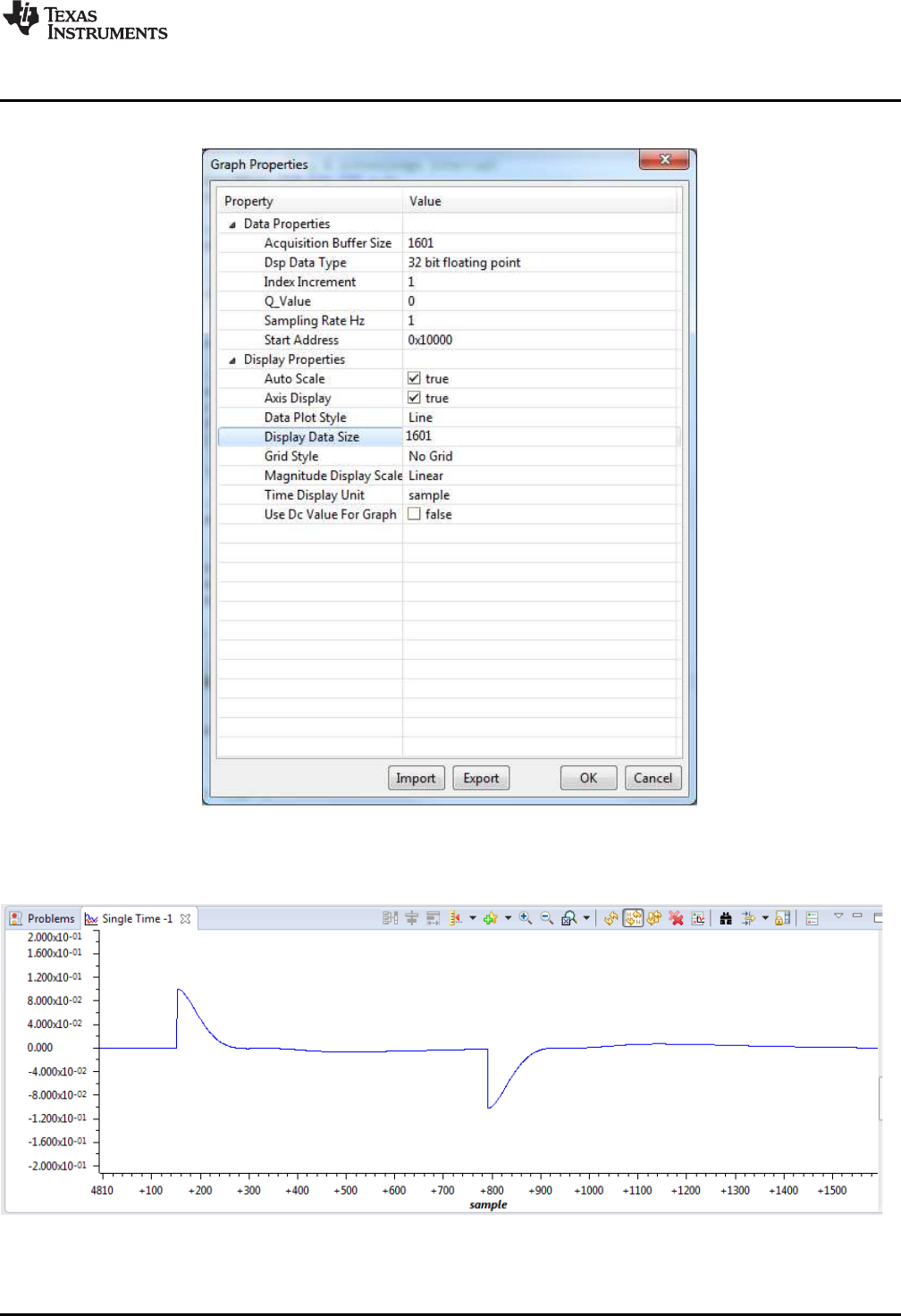
www.ti.com
Example 1: DF22 Compensator Running on C28x
79
SPRUID3–January 2017
Submit Documentation Feedback Copyright © 2017, Texas Instruments Incorporated
Examples
Figure 5-1 shows how to configure the graph to view the pre-computed compensator output (u2k).
Figure 5-1. Graph Setup Window
Figure 5-2 shows what the ek buffer should look like.
Figure 5-2. ek Buffer
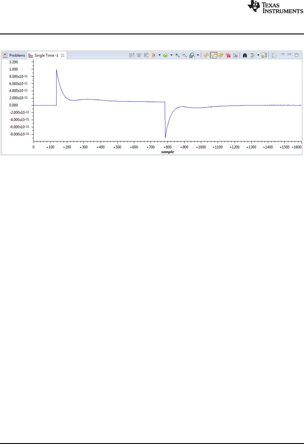
Example 2: DF23 Compensator Running on CLA
www.ti.com
80 SPRUID3–January 2017
Submit Documentation Feedback
Copyright © 2017, Texas Instruments Incorporated
Examples
Figure 5-3 shows what the plot of the u1k and u2k buffers should look like.
Figure 5-3. Plot of u1k and u2k Buffers
5.2 Example 2: DF23 Compensator Running on CLA
5.2.1 Example Overview
This example demonstrates one method of running a DF23 compensator on the CLA. In this example,
incoming data is read in an ISR on the C28x CPU and passed to the CLA using a variable (ek), which is
located in CPU-to-CLA message RAM. The ISR then triggers task 3 on the CLA and waits for it to
complete.
The CLA task calls two different DF23 compensators and stores their results in two variables (u1k and
u2k), which are located in CLA-to-CPU message RAM. These results are read by the CPU ISR, which
computes the difference between them. The ISR then stores both results and their difference to three data
buffers. When the final input value has been processed in this way, the ISR passes through a “NOP”
instruction allowing the user to place a break-point and inspect the results.
5.2.2 Code Description
The following lines in the file “Example_F28069_DF23.c” are important:
• Lines 11-31: create four buffers that will be used to hold control data
• Lines 37-42: create variables that will pass control data between C28x and CLA
• Lines 68-74: assign data logs to the buffers and initialize them
• Line 141: reads the next data point from the input data file
• Line 145: triggers the CLA task that will call the DF23 compensator
• Line 149: compute the difference between the two compensator results
• Lines 152-154: write the compensator results into the data buffers
The following lines in the file “F28069_DF23_CLA.cla” are important:
• Line 31: calls the full DF23 compensator and stores the result in “u1k”
• Line 34: calls the immediate DF23 compensator and stores the result in “u2k”
• Line 35: clamps the immediate result and sets the clamp flag “vk”
• Lines 36-39: pre-compute the next partial DF23 result, providing the immediate part is in range
• Lines 72-92: initialize the two DF23 compensator structures
• Lines 95-96: initialize the clamp limits for the pre-computed DF23 compensator
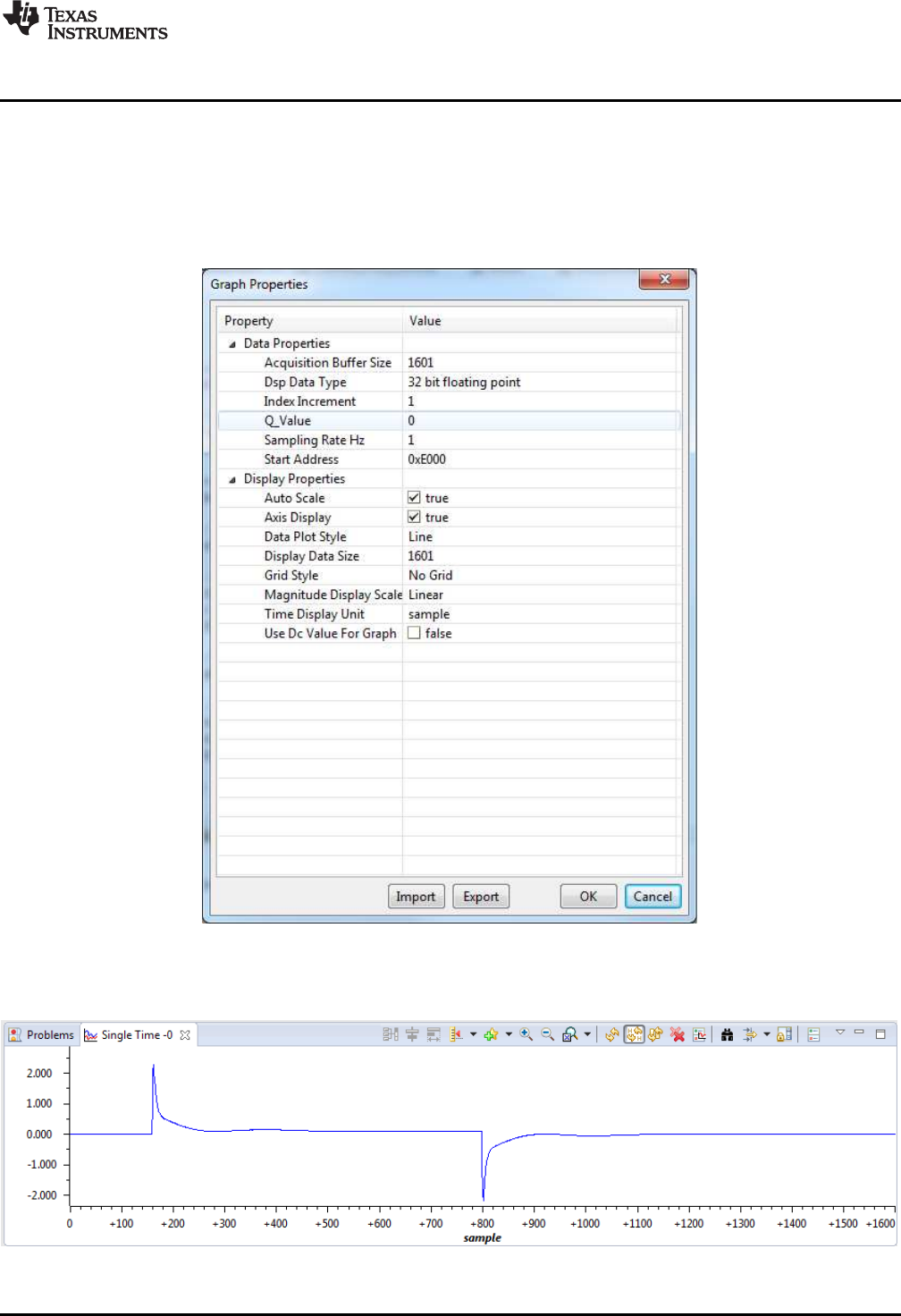
www.ti.com
Example 2: DF23 Compensator Running on CLA
81
SPRUID3–January 2017
Submit Documentation Feedback Copyright © 2017, Texas Instruments Incorporated
Examples
5.2.3 Running the Example
To run this example, first build the project, then load the project onto the C28x and load symbols onto the
CLA. Load the pre-recorded data file “DF23_edata.dat” into C28x memory at address 0xC000. Place a
break-point at the “NOP” instruction in line 159 of the file Example_F28069_DF23.c, and run the program.
After the break-point is reached, open a graph window to inspect the contents of the u1k memory buffer at
address 0xE000.
Figure 5-4. u1k Memory Buffer at Address 0xE000
The graph contents should look like this.
Figure 5-5. Plot of u1k Memory Buffer

Example 3: NLPID Controller Running on C28x
www.ti.com
82 SPRUID3–January 2017
Submit Documentation Feedback
Copyright © 2017, Texas Instruments Incorporated
Examples
These results were produced by the full DF23 compensator. To view the pre-computed compensator,
change the “Start Address” field in Graph Properties to 0x10000. The buffer at address 0x12000 contains
the difference in compensator results, all of which should be zero or very small.
5.3 Example 3: NLPID Controller Running on C28x
5.3.1 Example Overview
This example demonstrates the use of the non-linear PID controller on the C28x core. The code is similar
to the linear PID example below. Note that in addition to the DCL header file, the program also includes
“DCL_NLPID.h” that contains the controller functions.
The ADC is triggered by a PWM zero match event, and samples two channels. An ISR is triggered by an
ADC end-of-conversion event and reads the ADC results. Channel A0 represents the control loop
feedback, and channel B0 represents an external saturation input that is used for integrator anti-windup.
The DCL_runClamp_C2 function is used to convert the ADC result into an integer with the logical value 1
or zero.
The ISR calls the DCL_NLPID_C1 controller, and stores the control effort in the “uk” variable. This is
converted into an unsigned 16-bit integer and used to modulate the PWM duty cycle. In this way, the
program implements a non-linear closed loop controller that regulates the floating-point reference, “rk”.
5.3.2 Code Description
The following lines in the file Example_F28069_NLPID.c are important:
• Line 20: creates an instance of the NLPID controller
• Lines 93-113: initialize the elements of the NLPID structure
• Line 114: computes the linearized gains and updates the NLPID structure
• Lines 115-116: initialize the control reference and saturation flag
• Lines 132-136: update linearized gains if the NL parameters are changed
• Line 152: reads the control feedback and converts to signed floating-point format
• Line 156: converts the saturation input to 0.0f or 1.0f for anti-windup reset
• Line 159: calls the non-linear PID controller function
• Line 162: converts the controller output to unsigned 16-bit integer
• Line 163: updates the PWM duty cycle
5.3.3 Running the Example
To run this example, simply build, load, and run the program on the C28x core. Place a break-point at the
last instruction in the ISR (line 164) and run the program. The following variables can be monitored in a
watch window:
• rk – input reference
• yk – feedback
• lk – external saturation flag
• uk – controller output
• nlpid1 – the NLPID controller structure
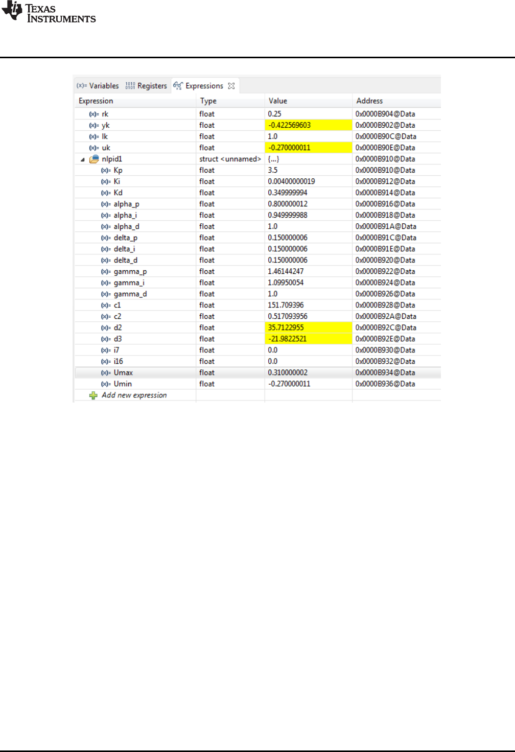
www.ti.com
Example 4: PI Controller Running on CLA
83
SPRUID3–January 2017
Submit Documentation Feedback Copyright © 2017, Texas Instruments Incorporated
Examples
Figure 5-6. Expression Window
The user can run repeatedly to the break-point, modifying controller parameters and examining the
change of controller variables. If any of the “alpha” or “delta” parameters are changed, the variable
“calFlag” should be set to 1 to enable the “gamma” gains to be computed and updated in the background
loop.
5.4 Example 4: PI Controller Running on CLA
5.4.1 Example Overview
This example demonstrates one method of running a PI controller on the CLA. The CPU program contains
an ISR that is triggered by an ADC end-of-conversion in the same way as example 3. Feedback data is
read from the ADC in an ISR on the C28x CPU and passed to the CLA using a variable (yk) that is located
in CPU-to-CLA message RAM, together with the servo reference (rk). The ISR converts the ADC result
into signed floating-point format, then triggers task 3 on the CLA and waits for it to complete.
CLA task 3 calls the function DCL_runPI_L1() that computes the PI controller in an assembly function. The
result is stored in the variable uk, which is located in CLA-to-CPU message RAM.
The PI controller result is read by the ISR, converted into a scaled un-signed 16-bit integer, and written to
the PWM duty cycle register.
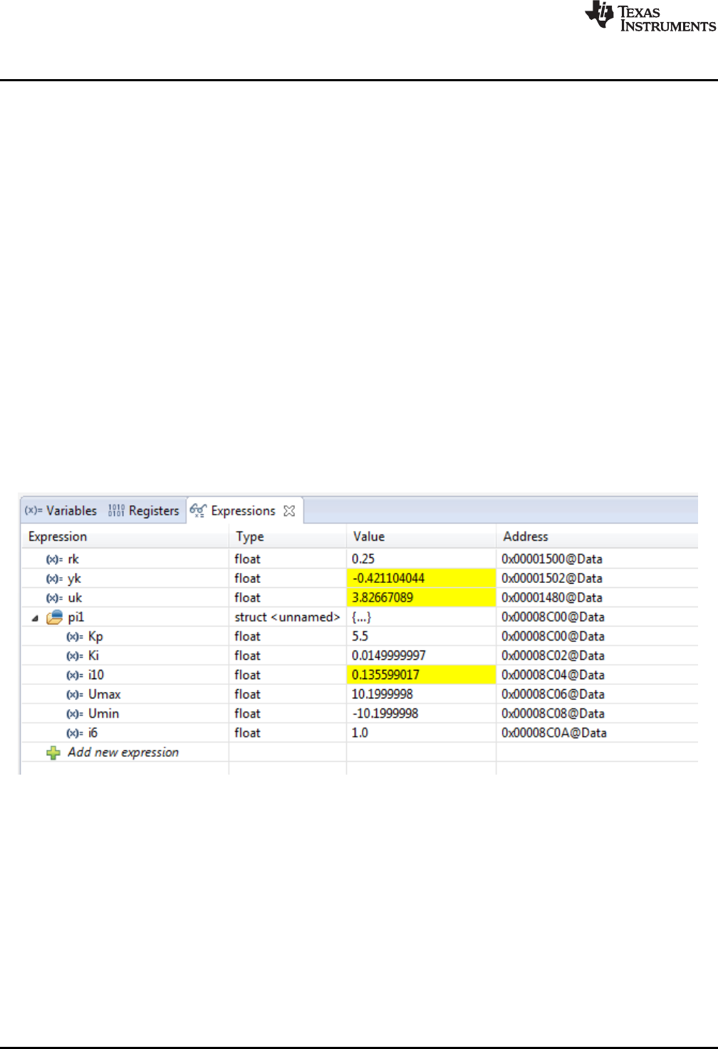
Example 4: PI Controller Running on CLA
www.ti.com
84 SPRUID3–January 2017
Submit Documentation Feedback
Copyright © 2017, Texas Instruments Incorporated
Examples
5.4.2 Code Description
The following lines in the file “Example_F28069_PI.c” are important:
• Lines 19-24: create instances of the control variables and assign them to the appropriate message
RAM blocks
• Lines 26-27: create an instance of the PI controller structure and place it in CPU-to-CLA message
RAM. This allows controller parameters to be modified from code running on the C28x CPU.
• Lines 44-49: initialize the PI controller parameters
• Line 168: reads the feedback data from the ADC and converts it into floating-point format
• Line 172: starts CLA task 3 and waits for it to complete
• Lines 175-176: convert the controller result to 16-but unsigned integer and write it to the PWM duty
cycle register
The following line in the file “F2806x_PI_CLA.cla” is important:
• Line 24: calls the PI controller function DCL_runPI_L1()
Note that in this example, initialization of the PI controller is performed on the C28x CPU, so there is no
need to allocate a separate CLA task for that purpose.
5.4.3 Running the Example
Build and load the project onto the C28x, then load the symbols onto the CLA. Place a break-point at the
last instruction in the ISR (line 178), and run the program. Open an Expressions Window in CCS, and
inspect the control variables and PI controller structure.
Figure 5-7. Expression Window
At this point, controller gains can be manually changed and the code run repeatedly to observe the effect
on the control variables.

www.ti.com
Example 5: PID Controller Running on C28x
85
SPRUID3–January 2017
Submit Documentation Feedback Copyright © 2017, Texas Instruments Incorporated
Examples
5.5 Example 5: PID Controller Running on C28x
5.5.1 Example Overview
This simple example demonstrates a common digital control scenario: a single linear PID controller
running on the C28x core that reads an ADC channel and manipulates PWM duty cycle.
The example project contains an ISR that is triggered by an ADC end-of-conversion event. The ADC is
triggered by a PWM zero match event, and samples two channels that are read by the ISR. Channel A0
represents the control loop feedback, and channel B0 represents an external saturation input that is used
for integrator anti-windup. The DCL_runClamp_C1 function is used to convert the ADC result into an
integer with the logical value 1 or zero.
The ISR calls the DCL_PID_C4 parallel form PID controller to compute control effort held in the “uk”
variable. This is converted into an unsigned 16-bit integer and used to modulate the PWM duty cycle. In
this way, the program implements a simple closed loop PWM controller that regulates the floating-point
reference, “rk”.
5.5.2 Code Description
The following lines in the example file Example_F28069_PID.c are important:
• Lines 94-105: initializes the elements of the PID structure
• Line 107: sets the reference input to the control loop
• Line 108: initializes the external saturation flag
• Line 137: reads the feedback and converts to the range ±1.0f
• Line 138: reads the external saturation variable lk
• Line 141: converts lk to 1.0f or 0.0f
• Line 144: runs the PID controller
• Line 147: convert the controller output to unsigned integer in the range 0 to PRD
• Line 148: write result to PWM duty cycle register
5.5.3 Running the Example
To run this example, simply build, load, and run the program on the C28x core. Place a break-point at the
last instruction in the ISR and run the program (line 150). The following variables can be monitored in a
watch window:
• rk – input reference
• yk – feedback
• lk – external saturation flag
• uk – controller output
• pid1 – the PID controller structure
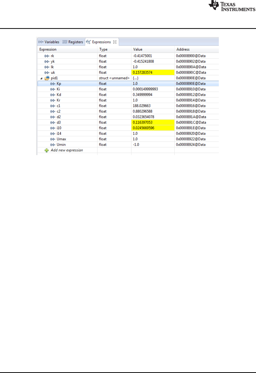
Example 6: TCM Running on C28x
www.ti.com
86 SPRUID3–January 2017
Submit Documentation Feedback
Copyright © 2017, Texas Instruments Incorporated
Examples
Figure 5-8. Expression Window
The user can run repeatedly to the break-point modifying controller parameters and examining the change
of controller variables.
5.6 Example 6: TCM Running on C28x
5.6.1 Example Overview
This example illustrates the use of the TCM to capture a portion of a pre-recorded sample transient
response. The code demonstrates how to configure and use the TCM, together with computation and
storage of servo error, use of the fast read and write data log functions, and use of the performance index
functions.
The code contains a single ISR triggered at 1kHz by a CPU timer. The ISR uses the fast read function
DCL_fread() to read values from two buffers representing servo reference (rBuf), and feedback (yBuf), and
then runs the TCM on the feedback sample to detect and capture the transient response in a third buffer
(dBuf). The code subtracts yk from rk to find the instantaneous servo error, and logs the result into a
fourth buffer (eBuf). When the final point in the input data sequence has been read and acted upon, the
dBuf buffer should contain a portion of the feedback sequence around the transient edge, while the eBuf
buffer contains the servo error. The variables P1, P2, and P3 contain the ITAE, IAE, and IES performance
indices respectively. These are computed over the entire input sequence.
5.6.2 Code Description
The following lines in the file Example_F28069_TCM.c are important:
• Lines 14-32: create instances of four data buffers and assign them to specific regions defined in the
linker command file F28069_DCL.cmd.
• Lines 39-41: create instances of the control variables
• Line 42: creates an instance of the TCM module and initializes it to default values
• Lines 43-45: creates variables to hold the performance indices
• Lines 67-71: assign the data buffers to FDLOG structures and clear the servo error buffer
• Lines 101-102: read the servo reference and feedback data
• Line 105: runs the TCM
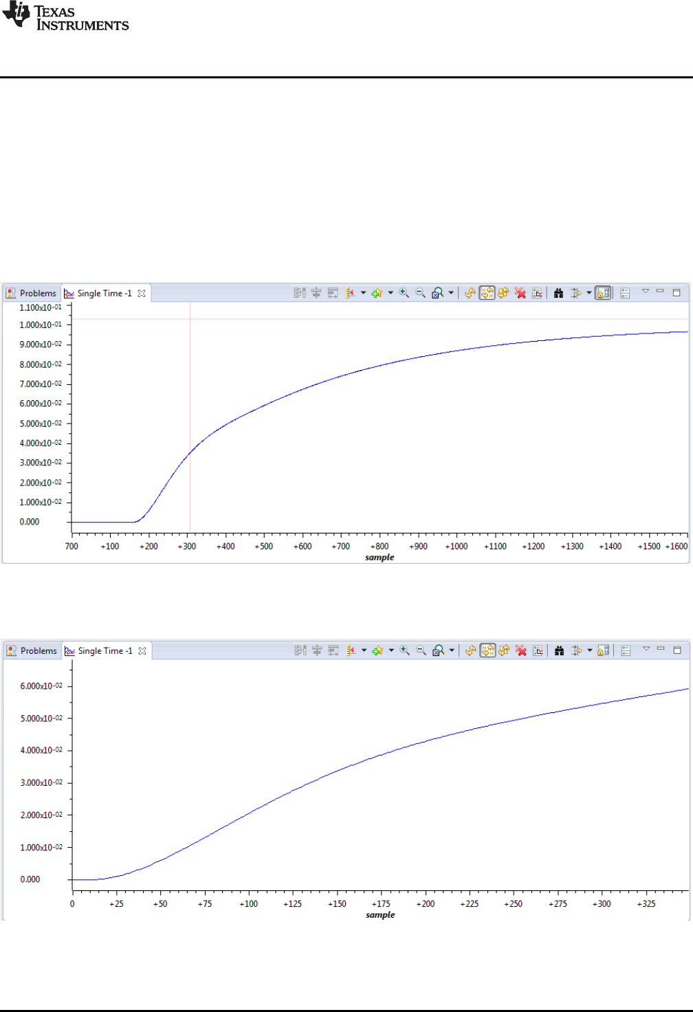
www.ti.com
Example 6: TCM Running on C28x
87
SPRUID3–January 2017
Submit Documentation Feedback Copyright © 2017, Texas Instruments Incorporated
Examples
• Lines 108-109: compute the servo error and log is to the eBuf data buffer
• Line 112: detects if the final point in the input buffer has been processed
• Lines 118-120: compute the three performance indices
5.6.3 Running the Example
To run this program, build and load the project onto the target device. Then, load the two supplied data
files “TCM_input.dat” and “TCM_response.dat” into data memory addresses 0xc000 and 0xe000
respectively. Place a break-point on the “NOP” instruction at the bottom of the ISR, and run the program.
When the break-point is reached, open a graph window to view the contents of the 1601-point yBuf
memory at address 0xe000.
Figure 5-9. Contents of the 1601-Point yBuf Memory
Open a second graph to display the 350-point contents of the dBuf buffer at address 0x12000.
Figure 5-10. 350-Point Contents of the dBuf Buffer

Example 6: TCM Running on C28x
www.ti.com
88 SPRUID3–January 2017
Submit Documentation Feedback
Copyright © 2017, Texas Instruments Incorporated
Examples
The TCM buffer contains part of the feedback data near the transient. Notice that the first part of the TCM
buffer (approximately 25 samples) contains data that has not exceeded either trigger threshold. This is the
lead frame.
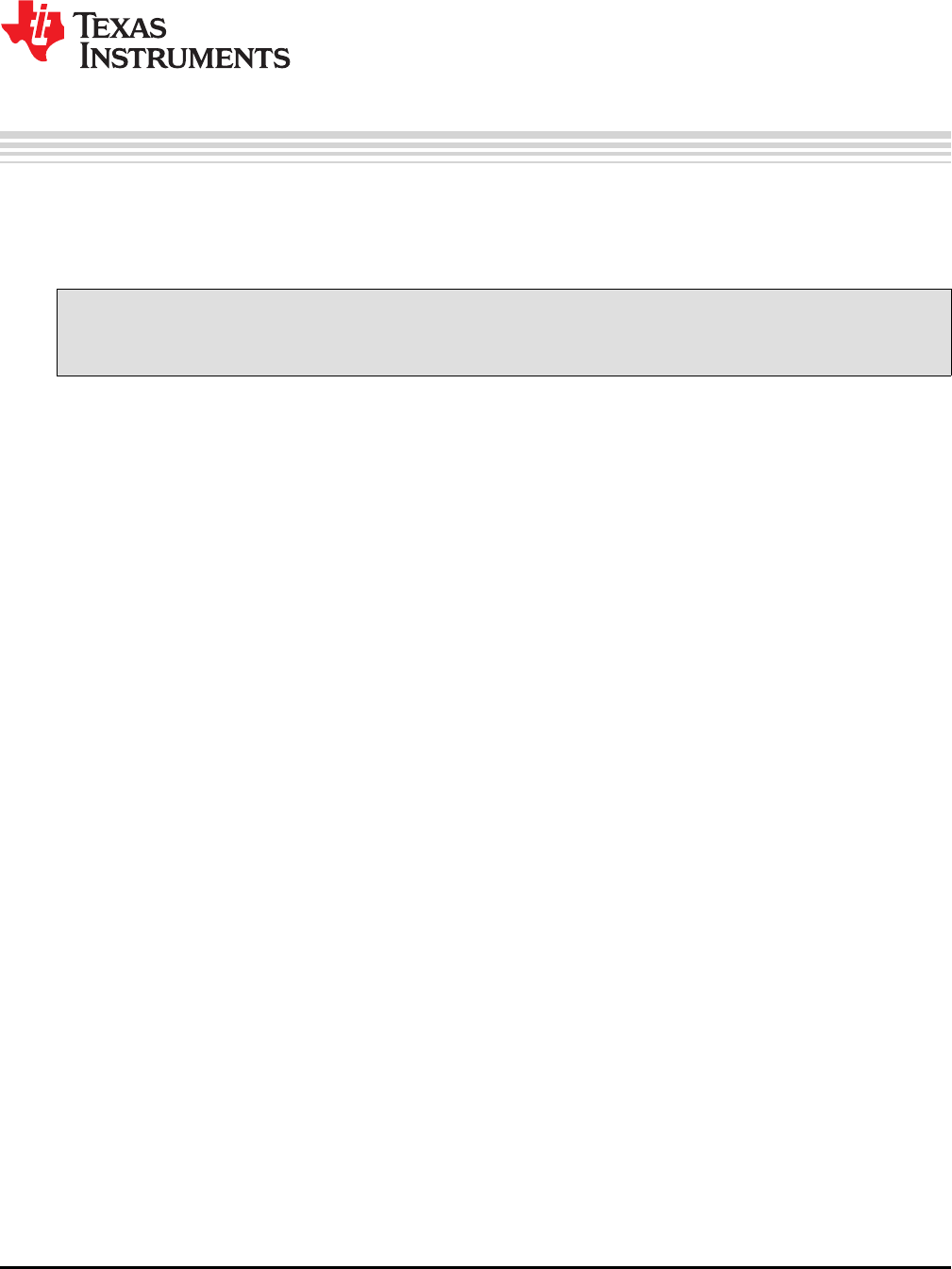
89
SPRUID3–January 2017
Submit Documentation Feedback Copyright © 2017, Texas Instruments Incorporated
Support
Chapter 6
SPRUID3–January 2017
Support
This chapter contains a list of useful technical resources relevant to the DCL.
Topic ........................................................................................................................... Page
6.1 References ........................................................................................................ 90
6.2 Training ............................................................................................................ 90

References
www.ti.com
90 SPRUID3–January 2017
Submit Documentation Feedback
Copyright © 2017, Texas Instruments Incorporated
Support
6.1 References
Documentation for C2000 MCU devices can be found on their respective product pages at
www.ti.com/c2000.
The following is a list of relevant publications:
• Feedback & Control Systems J.J.DiStefano, A.R.Stubberud and I.J.Williams, Schaum, 2011
• Digital Control of Dynamic Systems G.F.Franklin, J.D.Powell & M.L.Workman, Addison-Wesley, 1998
• Control Theory Fundamentals R.Poley, CreateSpace, 2015
•Running an Application from Internal Flash Memory on the TMS320F28xxx DSP
•TMS320C28x Assembly Language Tools User’s Guide
•TMS320C28x Optimizing C/C++ Compiler v16.12.0.STS User's Guide
6.2 Training
• Training materials for the C2000 devices from Texas Instruments can be found at
processors.wiki.ti.com/index.php/Category:C2000_Training
• Recordings of a 1-day hands-on workshop using the F28069 device can be found at
training.ti.com/c2000-mcu-1-day-workshop-8-part-series
• Information on a series of technical seminars in control theory can be found at
www.controltheoryseminars.com.

IMPORTANT NOTICE FOR TI DESIGN INFORMATION AND RESOURCES
Texas Instruments Incorporated (‘TI”) technical, application or other design advice, services or information, including, but not limited to,
reference designs and materials relating to evaluation modules, (collectively, “TI Resources”) are intended to assist designers who are
developing applications that incorporate TI products; by downloading, accessing or using any particular TI Resource in any way, you
(individually or, if you are acting on behalf of a company, your company) agree to use it solely for this purpose and subject to the terms of
this Notice.
TI’s provision of TI Resources does not expand or otherwise alter TI’s applicable published warranties or warranty disclaimers for TI
products, and no additional obligations or liabilities arise from TI providing such TI Resources. TI reserves the right to make corrections,
enhancements, improvements and other changes to its TI Resources.
You understand and agree that you remain responsible for using your independent analysis, evaluation and judgment in designing your
applications and that you have full and exclusive responsibility to assure the safety of your applications and compliance of your applications
(and of all TI products used in or for your applications) with all applicable regulations, laws and other applicable requirements. You
represent that, with respect to your applications, you have all the necessary expertise to create and implement safeguards that (1)
anticipate dangerous consequences of failures, (2) monitor failures and their consequences, and (3) lessen the likelihood of failures that
might cause harm and take appropriate actions. You agree that prior to using or distributing any applications that include TI products, you
will thoroughly test such applications and the functionality of such TI products as used in such applications. TI has not conducted any
testing other than that specifically described in the published documentation for a particular TI Resource.
You are authorized to use, copy and modify any individual TI Resource only in connection with the development of applications that include
the TI product(s) identified in such TI Resource. NO OTHER LICENSE, EXPRESS OR IMPLIED, BY ESTOPPEL OR OTHERWISE TO
ANY OTHER TI INTELLECTUAL PROPERTY RIGHT, AND NO LICENSE TO ANY TECHNOLOGY OR INTELLECTUAL PROPERTY
RIGHT OF TI OR ANY THIRD PARTY IS GRANTED HEREIN, including but not limited to any patent right, copyright, mask work right, or
other intellectual property right relating to any combination, machine, or process in which TI products or services are used. Information
regarding or referencing third-party products or services does not constitute a license to use such products or services, or a warranty or
endorsement thereof. Use of TI Resources may require a license from a third party under the patents or other intellectual property of the
third party, or a license from TI under the patents or other intellectual property of TI.
TI RESOURCES ARE PROVIDED “AS IS” AND WITH ALL FAULTS. TI DISCLAIMS ALL OTHER WARRANTIES OR
REPRESENTATIONS, EXPRESS OR IMPLIED, REGARDING TI RESOURCES OR USE THEREOF, INCLUDING BUT NOT LIMITED TO
ACCURACY OR COMPLETENESS, TITLE, ANY EPIDEMIC FAILURE WARRANTY AND ANY IMPLIED WARRANTIES OF
MERCHANTABILITY, FITNESS FOR A PARTICULAR PURPOSE, AND NON-INFRINGEMENT OF ANY THIRD PARTY INTELLECTUAL
PROPERTY RIGHTS.
TI SHALL NOT BE LIABLE FOR AND SHALL NOT DEFEND OR INDEMNIFY YOU AGAINST ANY CLAIM, INCLUDING BUT NOT
LIMITED TO ANY INFRINGEMENT CLAIM THAT RELATES TO OR IS BASED ON ANY COMBINATION OF PRODUCTS EVEN IF
DESCRIBED IN TI RESOURCES OR OTHERWISE. IN NO EVENT SHALL TI BE LIABLE FOR ANY ACTUAL, DIRECT, SPECIAL,
COLLATERAL, INDIRECT, PUNITIVE, INCIDENTAL, CONSEQUENTIAL OR EXEMPLARY DAMAGES IN CONNECTION WITH OR
ARISING OUT OF TI RESOURCES OR USE THEREOF, AND REGARDLESS OF WHETHER TI HAS BEEN ADVISED OF THE
POSSIBILITY OF SUCH DAMAGES.
You agree to fully indemnify TI and its representatives against any damages, costs, losses, and/or liabilities arising out of your non-
compliance with the terms and provisions of this Notice.
This Notice applies to TI Resources. Additional terms apply to the use and purchase of certain types of materials, TI products and services.
These include; without limitation, TI’s standard terms for semiconductor products http://www.ti.com/sc/docs/stdterms.htm), evaluation
modules, and samples (http://www.ti.com/sc/docs/sampterms.htm).
Mailing Address: Texas Instruments, Post Office Box 655303, Dallas, Texas 75265
Copyright © 2017, Texas Instruments Incorporated
