F/A 18C DCS FA Early Access Guide EN
User Manual:
Open the PDF directly: View PDF ![]() .
.
Page Count: 156 [warning: Documents this large are best viewed by clicking the View PDF Link!]

DCS F/A-18C HORNET
Early Access Guide

DCS
[F/A-18C]
2
Contents
HEALTH WARNING! ...................................................................................................................... 6
INSTALLATION AND LAUNCH........................................................................................................ 7
GAME PROBLEMS .................................................................................................................... 7
USEFUL LINKS ......................................................................................................................... 7
CONFIGURE YOUR GAME .............................................................................................................. 8
PLAY A MISSION ........................................................................................................................ 12
FLIGHT CONTROL ...................................................................................................................... 13
F/A-18C HORNET COCKPIT OVERVIEW ....................................................................................... 15
Left Instrument Panel ............................................................................................................ 17
Center Instrument Panel ........................................................................................................ 21
Right Instrument Panel .......................................................................................................... 25
Left Vertical Panel .................................................................................................................. 27
Left Console .......................................................................................................................... 29
Right Vertical Panel ................................................................................................................ 31
Right Console ........................................................................................................................ 33
Control Stick .......................................................................................................................... 36
Throttles ............................................................................................................................... 37
DDI and AMPCD Pages ............................................................................................................... 38
Support (SUPT) Pages............................................................................................................ 38
Tactical (TAC) ....................................................................................................................... 46
HEAD UP DISPLAY...................................................................................................................... 51
PROCEDURES ............................................................................................................................ 53
Cold Start .............................................................................................................................. 53
Taxi ...................................................................................................................................... 60
Normal Takeoff...................................................................................................................... 61
Landing ................................................................................................................................. 62
HORNET COMMUNICATION SYSTEM ........................................................................................... 67
How to Use the Radios ........................................................................................................... 67
UFC Radio Functions .............................................................................................................. 68
HORNET MASTER MODES ........................................................................................................... 70

[F/A-18C]
DCS
3
HORNET NAVIGATION (NAV) ...................................................................................................... 70
How to Navigate Using Waypoints ........................................................................................... 70
Waypoint Navigation .............................................................................................................. 74
TACAN Navigation .................................................................................................................. 76
DATA Option Sublevel ............................................................................................................ 79
A/C (Aircraft) Sublevel ....................................................................................................... 79
WYPT (Waypoint) Sublevel................................................................................................. 80
TCN (TACAN) Sublevel ....................................................................................................... 80
Automatic Direction Finder (ADF) Navigation ........................................................................... 81
How to Navigate Using ADF Beacons ....................................................................................... 81
Additional HSI Symbology ...................................................................................................... 82
Setting a Course .................................................................................................................... 83
Autopilot Relief Modes ............................................................................................................ 83
HORNET AIR-TO-GROUND (A/G) ................................................................................................. 85
Air-to-Ground Stores Management System (SMS) Bombing Page .............................................. 85
A/G Stores Programming ................................................................................................... 87
Air-to-Ground Bombing HUD ................................................................................................... 89
Continuously Computed Impact Point (CCIP) Bombing HUD ................................................. 89
How to Bomb Using CCIP Mode .......................................................................................... 90
Automatic (AUTO) Bombing HUD ....................................................................................... 91
Manual (MAN) Bombing HUD ............................................................................................. 97
Air-to-Ground Gun and Rockets .............................................................................................. 99
How to Use A/G Guns ........................................................................................................ 99
How to Use Rockets .......................................................................................................... 99
A/G Gun SMS Page .......................................................................................................... 100
Rockets SMS Page ........................................................................................................... 101
A/G Gun and Rocket HUD ................................................................................................ 102
HORNET AIR-TO-AIR (A/A) ....................................................................................................... 105
Air-to-Air RADAR .................................................................................................................. 106
Basic Air-to-Air RADAR Information .................................................................................. 106
Range While Search (RWS) .............................................................................................. 108
How to Use RADAR in Beyond Visual Range Mode ............................................................. 108

DCS
[F/A-18C]
4
Air-to-Air RADAR HOTAS Controls ..................................................................................... 111
Range While Search (RWS) DATA ..................................................................................... 114
Air Combat Maneuvering (ACM) Modes .............................................................................. 115
M61A2 Gun, Air-to-Air Mode (A/A GUNS) ............................................................................... 117
How to Use the Gun Summary .......................................................................................... 117
A/A GUNS SMS Page ............................................................................................................. 117
A/A GUNS HUD ..................................................................................................................... 119
Radar Not Tracking Mode ................................................................................................. 119
Radar Tracking Mode ....................................................................................................... 122
AIM-9 Sidewinder Air-to-Air Missile ........................................................................................ 127
How to Use the AIM-9 Summary ....................................................................................... 127
IR Cool Switch ................................................................................................................. 127
AIM-9 on the SMS Page .................................................................................................... 128
AIM-9 HUD ...................................................................................................................... 129
AIM-7 Sparrow Air-to-Air Missile ............................................................................................ 135
How to Use the AIM-7 Summary ....................................................................................... 135
AIM-7 SMS Page .............................................................................................................. 136
AIM-7, No RADAR Tracking ............................................................................................... 137
AIM-7, RADAR Tracking .................................................................................................... 138
AIM-7 with L&S Target ..................................................................................................... 140
HORNET DEFENSIVE SYSTEMS .................................................................................................. 143
Integrated Countermeasures Control Panel (ICMCP) .................................................................... 144
EW Page .............................................................................................................................. 146
Azimuth Indicator ................................................................................................................. 149
Right Instrument Panel Warning / Advisory / Threat Display Panel ............................................... 152
BIT ........................................................................................................................................... 153
Control Indicator Panel .............................................................................................................. 154
HOTAS ..................................................................................................................................... 155

[F/A-18C]
DCS
5

DCS
[F/A-18C]
6
HEALTH WARNING!
HEALTH WARNING!
Please read before using this computer game or allowing your children to use it.
A very small proportion of people may experience a seizure or loss of consciousness when exposed to
certain visual images, including flashing lights or light patterns that can occur in computer games.
This may happen even with people who have no medical history of seizures, epilepsy, or
“photosensitive epileptic seizures” while playing computer games.
These seizures have a variety of symptoms, including light-headedness, dizziness, disorientation,
blurred vision, eye or face twitching, loss of consciousness or awareness even if momentarily.
Immediately stop playing and consult your doctor if you or your children experience any of the above
symptoms.
The risk of seizures can be reduced if the following precautions are taken, (as well as a general
health advice for playing computer games):
Do not play when you are drowsy or tired.
Play in a well-lit room.
Rest for at least 10 minutes per hour when playing the computer game.

[F/A-18C]
DCS
7
INSTALLATION AND LAUNCH
You will need to be logged into Windows with Administrator rights in order to install the game.
After purchasing DCS: F/A-18C Hornet from our e-Shop, start DCS World. Select the Module Manager
icon at the top of the Main Menu. Upon selection, your Hornet will automatically install.
DCS World is the PC simulation environment that the F/A-18C Hornet simulation operates within.
When you run DCS World, you in turn launch DCS: F/A-18C Hornet.
As part of DCS World, the Su-25T Frogfoot attack aircraft and TF-51 training aircraft are also included
for free.
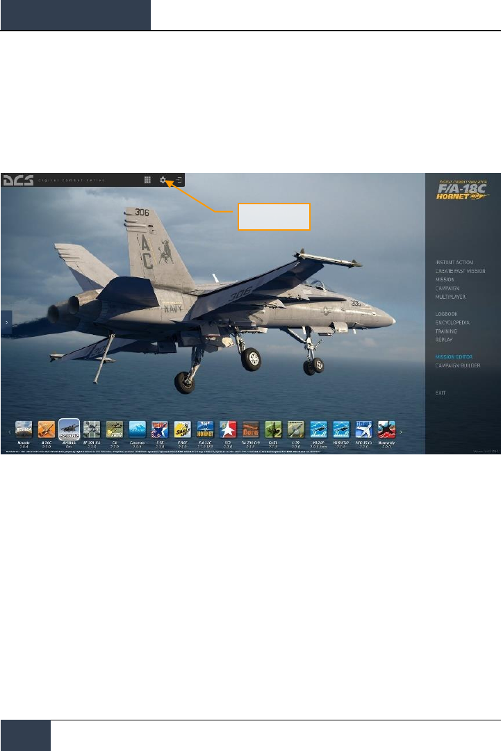
After executing the DCS World icon on your desktop, the DCS World Main Menu page is opened.
From the Main Menu, you can read DCS news, change your wallpaper by selecting either the F/A-18C
Hornet or Su-25T Frogfoot icons at the bottom of the page, or select any of the options along the
right side of the page. To get started quickly, you can select Instant Action and play any of the
missions listed in the F/A-18C Hornet tab.
GAME PROBLEMS
If you encounter a problem, particularly with controls, we suggest you back up and then delete your
Saved Games\User Name\DCS\Config folder, which is created by DCS on your operating system drive
at first launch. Restart the game and this folder will be rebuilt automatically with default settings,
including all of the controller input profiles.
If problems persist, we suggest consulting our online technical support forums at
http://forums.eagle.ru/forumdisplay.php?f=251
USEFUL LINKS
DCS Homepage:
http://www.digitalcombatsimulator.com/
DCS: F/A-18C Hornet forum:
https://forums.eagle.ru/forumdisplay.php?f=557
DCS Wiki:
http://en.wiki.eagle.ru/wiki/Main_Page
DCS
[F/A-18C]
8
CONFIGURE YOUR GAME
CONFIGURE YOUR GAME
Before jumping into the Hornet cockpit, the first thing we suggest is to configure your game. To do
so, select the Options button at the top of the Main Menu screen. You can read a detailed description
of all Options in the DCS World Game Manual. For this Early Access Guide, we will just cover the
basics.
Figure 1. DCS World Main Menu
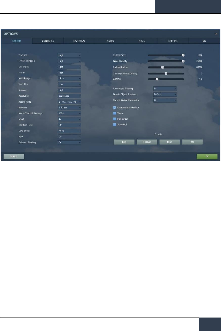
Upon selecting the Options screen, you will see seven tabs along the top of the page.
Options
[F/A-18C]
DCS
9
Figure 2. DCS World Options
SYSTEM. Configure your graphics options to best balance aesthetics with performance. You have
PRESET options along the bottom of the page, but you can further adjust your graphics settings to
best suit your computer. If you have lower performance, we suggest selecting the Low PRESET and
then increase graphics options to find your best balance.
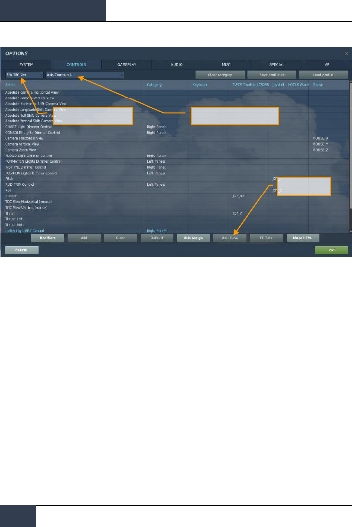
CONTROLS. Set up your controls and functional bindings. Let’s take a closer look at this page:
First, select the aircraft you wish to assign control inputs to by use of the Aircraft Selection drop-
down. Next, along the left side of the screen are all the ACTIONS associated with the selected Input
Function drop down. To the right are all the detected input devices that have been detected to
include keyboard, mouse, and any joysticks, throttles and rudder pedals.
DCS
[F/A-18C]
10
CONFIGURE YOUR GAME
Figure 3. Controls Configuration
1. Aircraft Selection. From this drop-down menu, select F/A-18C Sim.
2. Input Functions. This displays various categories of input functions, such as axis devices,
views, cockpit functions, etc. To assign a function, double mouse-click in the box that
corresponds to the desired input function and the input controller device. Once selected,
press the button or move the axis of the device to assign it.
3.
a. Example 1: if setting a pitch axis, first select AXIS COMMANDS from the Input
Functions drop down. Find the box where your Joystick input device and the
Pitch Action intersect, and double mouse-click in the box. In the ADD
ASSIGNMENT PANEL, move your joystick forward and back to assign the axis.
Press OK when done.
b. Example 2: if setting a keyboard of HOTAS command like cycle the landing gear,
first select ALL as the Input Function category. Find the box where your input
device and the LANDING GEAR CONTROL HANDLE – UP/DOWN Action intersect,
and double mouse-click in the box. In the ADD ASSIGNMENT PANEL, press the
keyboard or controller device button you wish to assign to the action. Press OK
when done.
4. Axis Tune. When assigning an axis (like X and Y axis for a joystick), you can use this sub-
page to assign a dead zone, response curve, and other tuning. This can be very useful if
you find the aircraft overly sensitive to control.
Aircraft Selection
Axis Tune
Input Functions

[F/A-18C]
DCS
11
GAMEPLAY. This page primarily allows you to adjust the game to be as realistic or casual as you
want it to be. Choose from many difficulty settings like labels, tool tips, unlimited fuel and weapons,
etc.
AUDIO. Use this page to adjust the audio levels of the game. You also have the option to turn on
and off different audio effects.
MISC. This is a catch-all of features to further tune the game to your preference.
VR. The VR tab allows you to enable support for the Oculus Rift and HTC Vive and adjust its
functionality. When using VR, be particularly aware of the Pixel Density setting as it can have a
dramatic effect on game performance.
DCS
[F/A-18C]
12
PLAY A MISSION
PLAY A MISSION
Now that you have configured your game, let’s get to why you purchased DCS: F/A-18C, to fly some
missions! You have several options to fly a single-player mission.
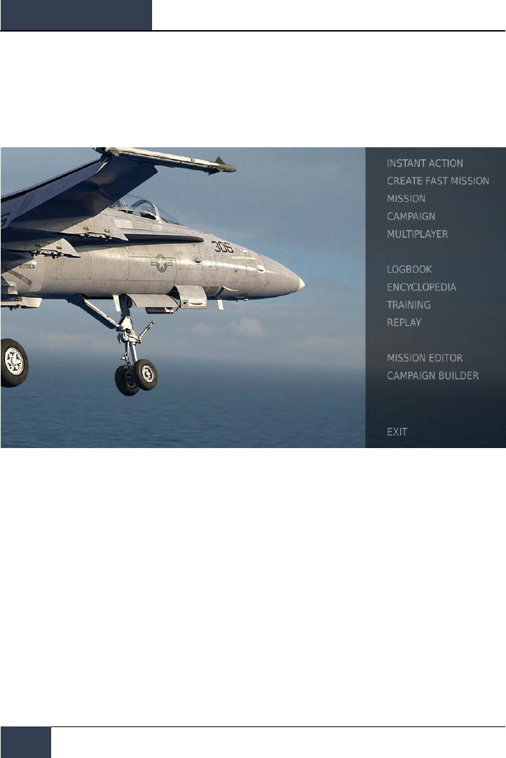
Figure 4. DCS World Main Menu
1. INSTANT ACTION. Simple missions that place you in the task of your choice. We will be
using several of these in this Early Access Guide to test what you learn.
2. CREATE FAST MISSION. Set various mission criteria to allow a mission to be created for
you.
3. MISSION. More in-depth, stand-alone missions.
4. CAMPAIGN. Linked missions to create a campaign narrative.
5. MULTIPLAYER. Create your own or join an internet server.
6. MISSION EDITOR. Use this very powerful Mission Editor to create your own missions.
On the Main Menu page, you the options to fly the Hornet in an INSTANT ACTION mission, CREATE
FAST MISSION, load a MISSION, play a Hornet CAMPAIGN when campaigns are available, or create a
mission in MISSION EDITOR. You also have the option to jump online and fly with others.
Select the INSTANT ACTION from the right side of the screen. From here, you will be presented a
number of F/A-18C Hornet INSTANT ACTION missions to choose from.
[F/A-18C]
DCS
13
To get started, we suggest the FREE FLIGHT mission. Later on, you can also use these missions to
practice starting up the aircraft, takeoffs, landings, navigation and sensor / weapon employment.
FLIGHT CONTROL
Primary aircraft flight controls include the flight control stick, throttle, and rudder pedals. The stick is
used to roll the aircraft left and right to perform turns and pitch the nose up and down to climb or
descend. The throttle is used to control engine power and resulting airspeed. The pedals are used to
yaw the airplane left and right using the rudder (like a boat). Pedal use in flight is limited to
eliminating sideslip and helping to coordinate smooth turns, but they are also used on the ground to
turn the nose wheel when taxiing.
To fly the aircraft to the right or left: roll the aircraft in the direction you wish to go and gently pull
back on the stick. The greater you pull back on the stick, the faster your turn rate will be and the
more speed you will lose.
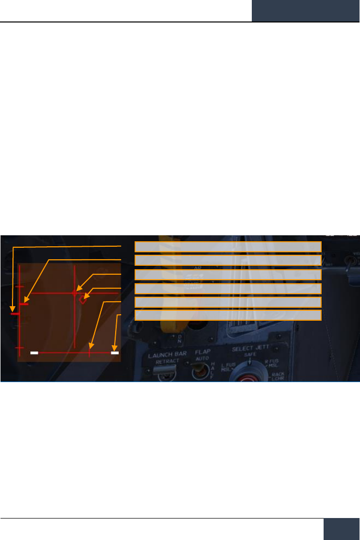
When flying from the cockpit, you can toggle the Controls Indicator display by pressing |RCtrl +
Enter| to see a visual reference of the positions of your flight controls.
Figure 5: Controls Indicator display
Maximum Pitch Trim Deviation Indicator. Before takeoff, the pitch trim indicator (5) shall be set
approximately to a neutral position
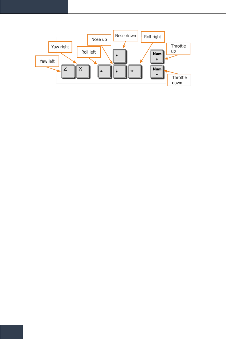
If you are flying only with a keyboard, the primary flight control keys will be: arrow keys to control
roll and pitch, |Numpad+| and |Numpad-| to control throttle, and |Z| / |X| to control the rudder
pedals. If you do have a joystick, it may be equipped with a throttle handle and/or a twist grip, which
will allow you to control the rudder pedals.
Left Throttle and Position Indication
Right Throttle and Position Indication
Trim Tab Position (mechanism used to reduce pressure on control
stick)
Control Stick and Position Indication
Pedals and Rudder Pedal Indicator
Wheel Brake pressure Indicator
DCS
[F/A-18C]
14
FLIGHT CONTROL
Figure 6. Flight Key Commands

[F/A-18C]
DCS
15
F/A-18C HORNET COCKPIT OVERVIEW
Once in the cockpit, it’s best to have a general understanding of where the various controls are
located. To help locate items more easily, we have broken the Hornet cockpit into eight primary
areas. In later sections of this Early Access Guide, we will reference these locations.
Hornet Instant Action Mission: Hornet Cold and Dark. Use this mission to explore then cockpit and
become familiar with its layout. To move your view:
• Keypad 8: Up
• Keypad 6: Right
• Keypad 2: Down
• Keypad 4: Left
• Keypad *: Zoom In
• Keypad /: Zoom Out
Press pressing [LEFT ALT + C] toggles mouse control between interacting with the cockpit and
controlling your view.
What follows is a summary description of cockpit functions included in this Early Access version that
are generally not described elsewhere in this document.
Instant Action Mission Practice: Hornet Cold and Dark
DCS
[F/A-18C]
16
F/A-18C HORNET COCKPIT OVERVIEW
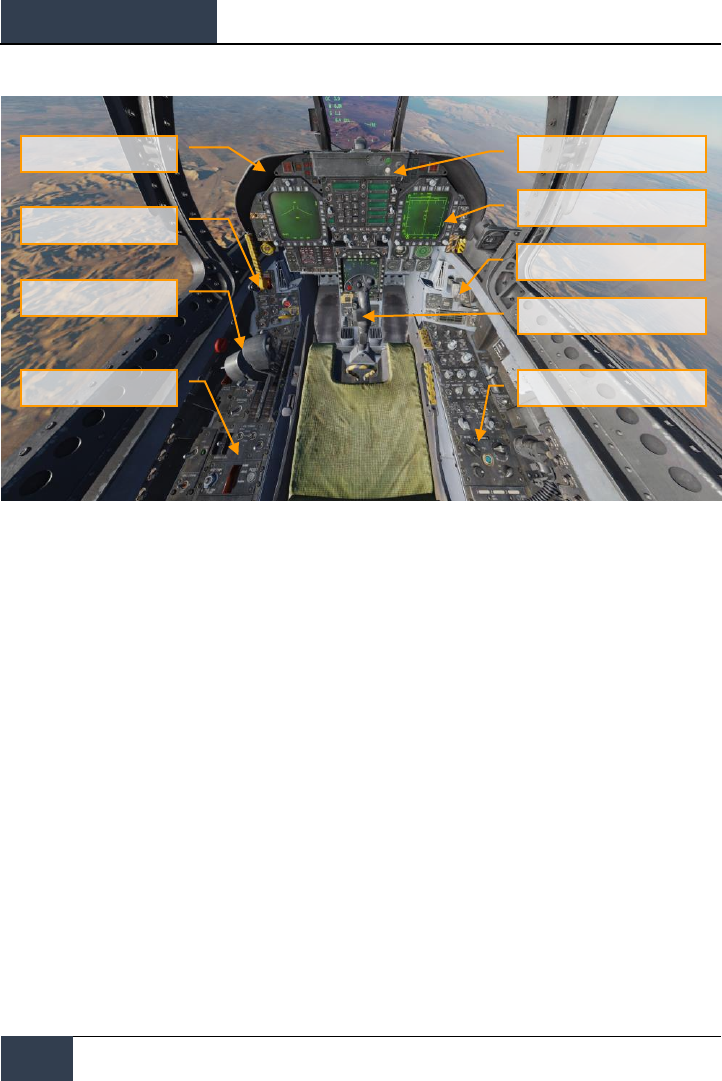
Figure 7. F/A-18C Cockpit Overview
Left Instrument Panel
Center Instrument Panel
Left Vertical Panel
Left Console
Throttles
Right Instrument Panel
Right Vertical Panel
Control Stick
Right Console
[F/A-18C]
DCS
17
Left Instrument Panel
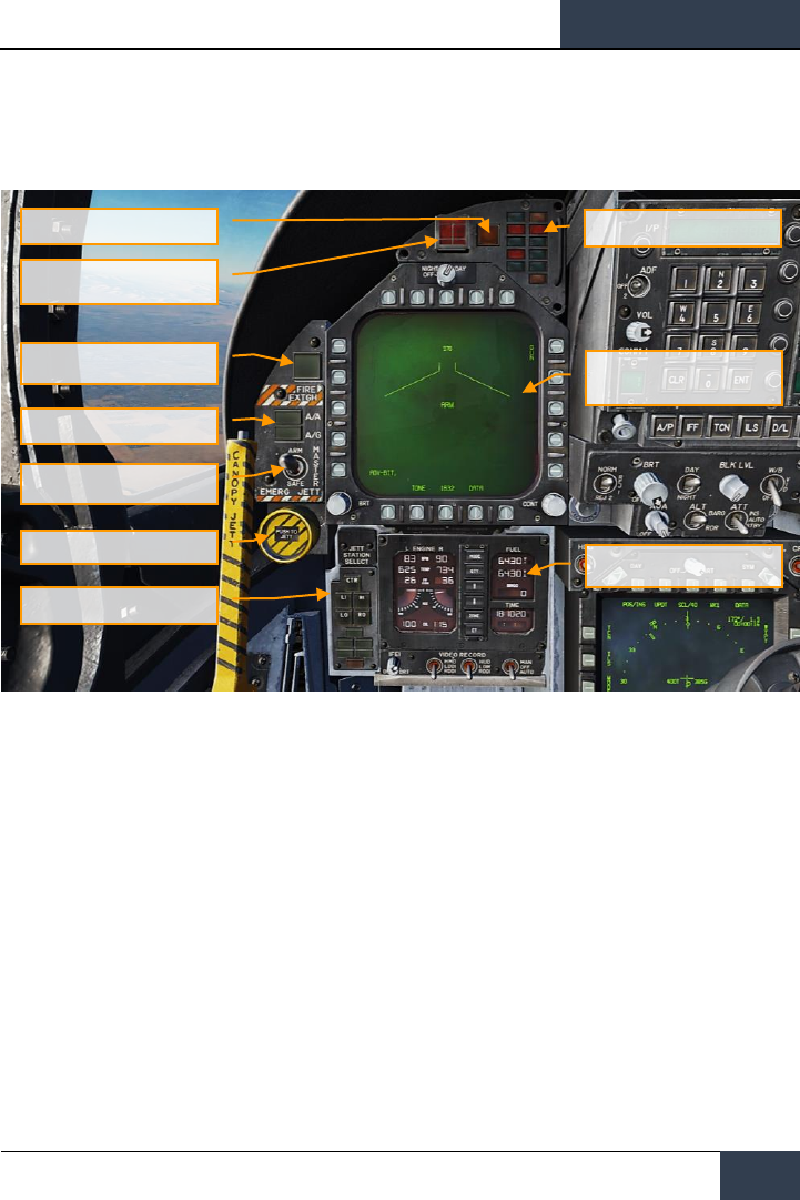
Figure 8. Left Instrument Panel
1. Left Digital Display Indicator (DDI). The left DDI is a 3-color display that provides desired
information to control various aircraft functions and displays. There are 20 pushbuttons on the
DDI which are used to select the function and the mode for proper indicator display.
• Brightness Selector Knob. Placing this rotary knob to OFF prevents the DDI from
operating. Placing the knob to NIGHT provides a lower brightness control range, and the
DAY setting provides a more bright default setting.
• Brightness Control. This knob varies the intensity of the symbols and text.
• Contrast Control. This knob varies the contrast between symbology and the dark
background on any level of brightness.
2. Master Mode Buttons. These two buttons allow you to change between Air-to-Air (A/A) |1| and
Air-to-Ground (A/G) |2| master modes. There are three master modes of operation: navigation
(NAV), air-to-air (A/A), and air-to-ground (A/G). The controls, displays, and the avionic equipment
operation are tailored as a function of the master mode you select.
3. Master Arm Switch |M|. This switch controls the ability for weapons to be employed or
jettisoned. Weapons can only be released when this switch is set to the ARM position.
4. Emergency Jettison Button. The emergency jettison button, labeled EMERG JETT jettisons
stores from the parent bomb racks on external stores stations 2, 3, 5, 7 and 8. Holding the button
down for 375 msec initiates jettison.
Master Mode Buttons
Left Digital Display Indicator
(DDI)
Left Warning/Caution Advisory
Lights
Integrated Fuel / Engine
Indicator (IFEI)
Master Arm Switch
Emergency Jettison Button
Selective Jettison / Landing
Gear, and Flap Position Lights
Panel
Fire Extinguisher Pushbutton
Left Engine Fire
Warning/Extinguisher Lights
Master Caution Light

DCS
[F/A-18C]
18
F/A-18C HORNET COCKPIT OVERVIEW
5. Selective Jettison / Landing Gear, and Flap Position Lights Panel. This panel has three
primary functions; the top is used to selectively select stations to jettison and the bottom two
provide landing gear and flaps status.
• Station Jettison Select Buttons. These buttons are labeled CTR (center), LI (left
inboard), RI (right inboard), LO (left outboard) and RO (right outboard). Pressing a button
illuminates it and selects the weapon station for jettison. Selective jettison is performed by
the selective jettison knob in conjunction with the station jettison select buttons.
• Landing Gear Indications. There are three green landing gear position lights marked
NOSE, LEFT and RIGHT. The lights indicate that the gear is down and locked, or that a
gear link is not locked.
• Flap Indications. A green light indicates the aircraft is within flight parameters for the
flight control computer to adjust flap scheduling in accordance with the selected switch
position.
o HALF. FLAP switch at HALF setting and airspeed below 250 knots.
o FULL. FLAP switch at FULL setting and airspeed below 250 knots.
o FLAPS. FLAP switch HALF or FULL settings and airspeed over 250 knots,
abnormal flap condition (any flap is off or lacks hydraulic pressure), in spin
recovery mode, or GAIN switch in ORIDE position.
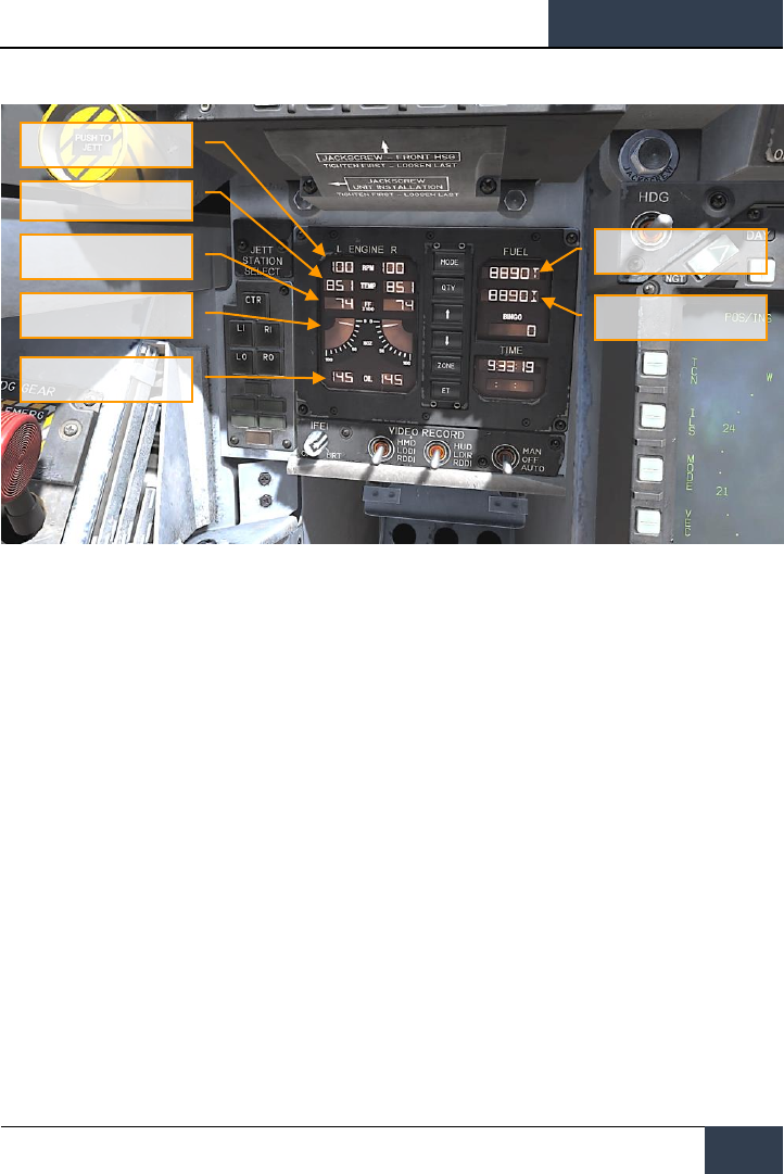
6. Integrated Fuel / Engine Indicator (IFEI). The integrated fuel/engine indicator (IFEI) engine
display contains a left and right liquid crystal display for RPM (N2)%, TEMP (EGT)°C, FF (fuel
flow) PPH, NOZ (nozzle position)%, and OIL (oil pressure) psi. During engine starts without
external electrical power, only RPM and TEMP are displayed by battery power until the APU comes
on line. With the APU on line or external power, all engine data is displayed.
• Engine RPM. Displays engine N2 rpm from 0 to 100%. There is no RPM indication of
afterburner.
• Exhaust Gas Temperature (TEMP). Displays turbine exhaust gas temperature
(EGT) from 0 to 1,999°C.
• Engine Fuel Flow (FF). Displays main engine fuel flow only (afterburner fuel flow is
not displayed). Range is 300 to 15000 Pounds Per Hour (PPH) with 100 pound per
hour increments. The tens of units positions have fixed zeros. When fuel flow is less
than 320 PPH, zero is displayed.
• Engine Nozzle Position (NOZ). Displays exhaust nozzle position from 0 to 100%
open in 10% increments.
• Engine Oil Pressure (OIL). Displays engine oil pressure from 0 to 195 psi in 5 psi
increments.
The IFEI fuel display window contains three digital counters to provide dynamic fuel quantity
indications. The upper digital counter displays total aircraft fuel quantity (10-pound increments).
The middle digital counter displays total internal fuel quantity (10-pound increments). A digital
counter legend is displayed to the right of the upper and middle counters (T - total fuel, I - internal
fuel). The lower digital counter displays the selected BINGO fuel quantity (100-pound increments).
[F/A-18C]
DCS
19
Figure 9. Integrated Fuel / Engine Indicator (IFEI)
7. Left Engine Fire Warning/Extinguisher Lights. If a fire is detected in the left engine,
this indicator, marked FIRE, will be lit along with an "Engine Fire Left, Engine Fire Left"
audio warning. This is a steady state, red light. To enable the fire bottle to discharge into
the selected engine/AMAD bay, the pilot must lift the guard over the FIRE warning light
and press the FIRE button. The button has two positions. Pushed in shuts off fuel flow to
the engine and arms the fire extinguisher and the READY light will illuminate. Pushing this
FIRE Warning button in once more toggles the button to the out position and the fuel valve
will open again for that engine and the READY light will turn off.
8. Master Caution Light. A yellow MASTER CAUTION light, on the upper left part of the
instrument panel, comes on when any of the caution lights or caution displays come on.
The MASTER CAUTION light goes out when it is pressed (reset). An audio tone is initiated
whenever the MASTER CAUTION light comes on. This button is also used to “re-stack”
caution and advisory notices.
9. Left Warning/Caution Advisory Lights. The Left Warning/Caution Advisory Lights
provide visual indications of normal aircraft operation and system malfunctions affecting
safe operation of the aircraft. A red warning light normally indicate a systems malfunction
that could be a severe hazard to further flight, and may require immediate action. Yellow
caution lights and displays normally, but not always, indicate malfunctions that require
attention but not immediate action. After the malfunction has been corrected, warning and
caution lights and caution displays go out. Advisory lights and displays indicate safe or
normal conditions and supply information for routine purposes.
Total Fuel
Total Internal Fuel
Engine RPM
Exhaust Gas Temperature
Engine Fuel Flow
Engine Nozzle Position
Engine Oil Pressure

DCS
[F/A-18C]
20
F/A-18C HORNET COCKPIT OVERVIEW
• L BLEED. Will light when the Fire and Bleed Air Test Switch is pressed or bleed air
leak or fire (600F degrees) has been detected in the left engine bleed air ducting. If
illuminated, the left bleed valve is automatically closed. Will light when TEST A or
TEST B switch is held or a bleed air leak or fire has been detected in the left engine
ducting. A "Bleed Air Left, Bleed Air Left" audio message will also sound. L BLD OFF
caution will be displayed on the LDDI.
• R BLEED. Will light when the Fire and Bleed Air Test Switch is pressed or bleed air
leak or fire (600F degrees) has been detected in the right engine bleed air ducting. If
illuminated, the right bleed valve is automatically closed. Will light when TEST A or
TEST B switch is held or a bleed air leak or fire has been detected in the right engine
ducting. A "Bleed Air Right, Bleed Air Right" audio message will also sound. R BLD
OFF caution will be displayed on the LDDI.
• SPD BRK. Will light anytime the speed brake is not fully retracted.
• STBY. When ALQ-165 ECM mode switch is set to STBY on the ECM control panel, the
STBY light indicates that the ECM Jammer is in warm up mode. This will last five
minutes and then time out and extinguish.
• L BAR (Red). Launch bar malfunction. Nose gear cannot retract. The launch bar can
only be extended with weight on wheels.
• L BAR (Green). Launch bar extended with weight on wheels. Will extinguish when the
launch bar switch is in the UP position (catapult shuttle holds the launch bar in the
extend position until the end of the catapult stroke).
• REC. Indicates that the aircraft is being illuminated by a threat RADAR.
• XMIT. Lit when ECM Jammer is transmitting.
• GO. Indication of successful BIT test of ALQ-165. Will remain illuminated until BIT
mode is deselected.
• NO GO. Indication of unsuccessful BIT test of ALQ-165. Will remain illuminated until
BIT mode is deselected. ALQ-126 is inoperable.
10. Fire Extinguisher Pushbutton. This switch has two lights. A yellow light labeled READY
and a green light labeled DISCH (discharge). When READY is on, the fire extinguisher bottle
is armed. The READY light comes on when the appropriate fire warning/extinguisher light is
lit. Pressing an engine fire warning/extinguisher light shuts off fuel to the engine at the feed
tank. With READY on, pressing the fire extinguisher pushbutton discharges the fire
extinguisher bottle and turns on the DISCH light.
[F/A-18C]
DCS
21
Center Instrument Panel
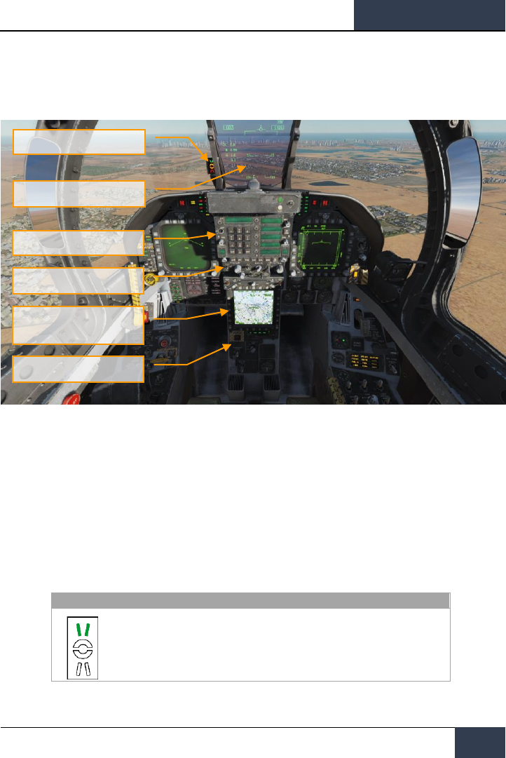
Figure 10. Center Instrument Panel
1. Head Up Display (HUD). The HUD is used as the primary flight instruments, weapon
status, and weapon delivery display for the aircraft under all selected conditions. The HUD
receives attack, navigation, situation, and steering control information from the left or right
DDI symbol generators (under mission computer control), and projects symbology on the
combining glass for head-up viewing. The HUD will be discussed in much greater detail
later in this guide.
2. Angle of Attack Indexer Lights. The AOA indexer is mounted to the left of the HUD. It
displays approach angle of attack (AoA) with lighted symbols. Corresponding AOA
indications are shown on the HUD.
SYMBOL
AIRSPEED
AOA
Slow
9.3° to 90.00°
Head Up Display (HUD)
Up Front Controller (UFC)
HUD Control Panel
Advanced Multipurpose Color
Display (AMPCD)
Lower Console Instrument Group
Angle of Attack Indexer Lights
DCS
[F/A-18C]
22
F/A-18C HORNET COCKPIT OVERVIEW
Slightly slow
8.8° to 9.3°
On speed
7.4° to 8.8°
Slightly fast
6.9° to 7.4°
Fast
0° to 6.9°
3. Upfront Controller (UFC). The UFC is on the main instrument panel below the HUD. The
UFC is used to select the autopilot, ILS, data link, and radios. The UFC is used in conjunction
with the two DDIs and the AMPCD to enter navigation, sensor, and weapon delivery data.
The UFC will be discussed in greater detail in the communications, navigation, and
procedures section of this guide.
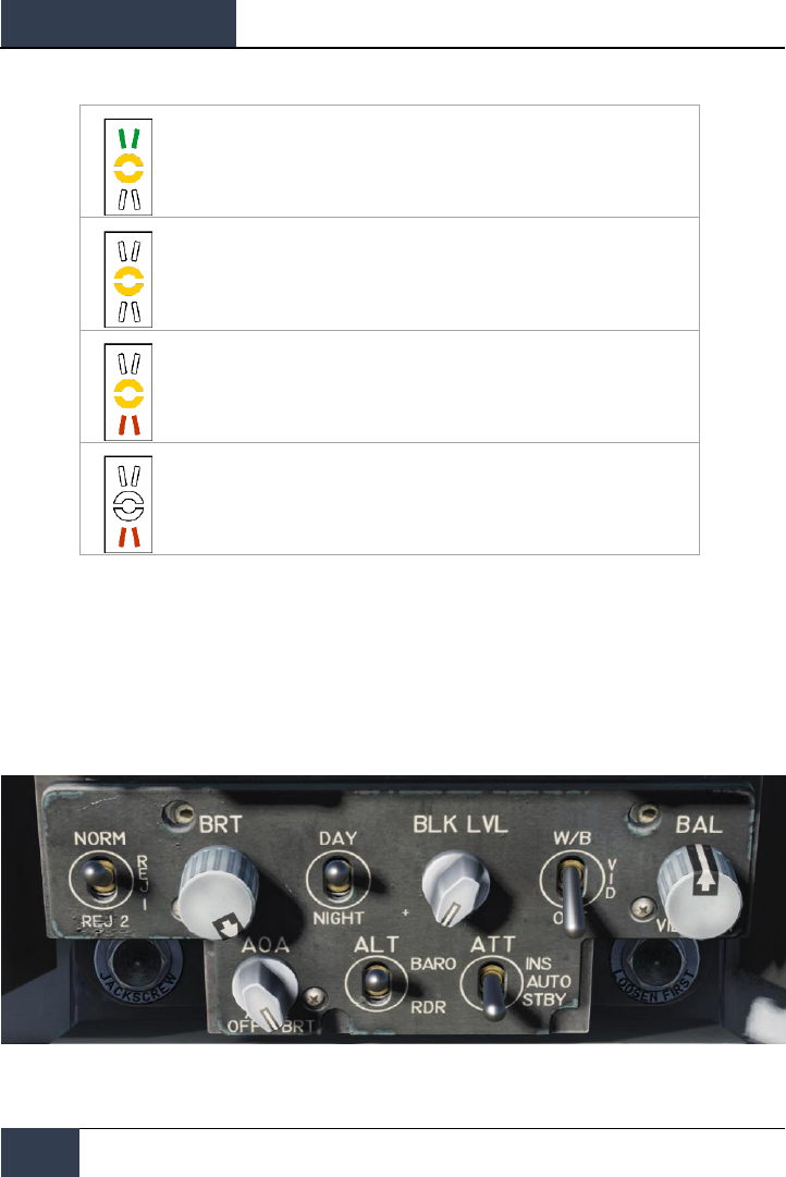
4. HUD Control Panel. The HUD control panels allows the pilot to adjust the HUD display
and how some data is presented.
Figure 11. HUD Control Panel

[F/A-18C]
DCS
23
• HUD Symbology Reject Switch. This three-position toggle switch has positions of
NORM, REJ 1, and REJ 2. With the switch placed to NORM, the normal amount of
symbology is provided for all HUD displays. Placing the switch to REJ 1 removes aircraft
Mach number, aircraft G’s, bank angle and pointer, airspeed box, altitude box, peak
positive G, and required ground speed cue from the HUD. Placing the switch to REJ 2
removes all REJ 1 symbology plus the heading scale, current heading indication
(caret/T), command heading marker, NAV/TACAN range, and the ET/CD timer.
• HUD Symbology Brightness Control. This knob is used to turn on the HUD and then
varies the display intensity.
• AOA Indexer Control. This knob controls the brightness of the AoA indexer lights.
• HUD Symbology Brightness Selector Knob. This is a two-position toggle switch
with positions of DAY and NIGHT. Placing the switch to DAY provides maximum symbol
brightness in conjunction with the HUD symbology brightness control. With the switch
set to NIGHT, a reduced symbol brightness is provided in conjunction with the HUD
symbology brightness control.
• Altitude Switch. The ALT switch is used to select either RADAR altitude or barometric
altitude for display on the HUD and as the primary altitude source for the mission
computer. When the switch is set to RDR (RADAR), the altimeter altitude followed by
an R is displayed in the upper right portion of the HUD display. If RADAR altitude
becomes invalid, such as the aircraft exceeding the 5,000 feet AGL RADAR altimeter
limit, barometric altitude is displayed and a B next to the altitude flashes to indicate
barometric altitude is being displayed.
5. Advanced Multipurpose Color Display (AMPCD). The AMPCD (generally referred to as
just the MPCD) is a full-color, NVG compatible digital display capable of providing any MENU
selectable format except the A/G RADAR display. The MPCD is driven by either the Digital
Map Set (DMS) for HSI displays, or the left DDI for all other MENU selectable formats. Four
momentary two-position rocker switches and a rotary knob, located on the front of the MPCD,
permit control of MPCD off/brightness, night/day viewing modes, symbology, gain, and
contrast.
• Off/Brightness Control. This rotary switch is located in the top-center of the MPCD
and is used to turn the AMPCD on and off or to select the brightness level.
• Night/Day Brightness Selector. This rocker switch is located in the upper left corner
of the MPCD and is used to select the lower brightness control (night) range and disable
automatic contrast control (NITE position selected) or to select the higher brightness
control (day) range (DAY position selected).
• Symbology Control. Momentary actuations of the upper half of the switch
incrementally narrows the symbology, making it sharper and dimmer. Momentary
actuations of the lower half incrementally widens the symbology, making it brighter and
less sharp.
• Gain Control. Momentary actuations of the upper half of the switch incrementally
increases background video brightness. Momentary actuations of the lower half
incrementally decreases video brightness.

DCS
[F/A-18C]
24
F/A-18C HORNET COCKPIT OVERVIEW
• Contrast Control. Momentary actuations of the upper half of the switch incrementally
increase the contrast of the display. Momentary actuations of the lower half
incrementally decrease the contrast of the display.
• Heading and Course Set Switches. At either side of the top of the MPCD are the
Course (CRS) and Heading (HDG) switches that allow the pilot to manually set course
and headings on the HSI. Both switches are spring-loaded to the center position, but
can be held up to increase value (degrees) or held down to decrease value (degrees).
Increase Heading |LALT + LSHIFT + 2| and decrease |LALT + LSHIFT + 1|. Increase
course |LALT + LSHIFT + 4| and decrease |ALT + LSHIFT + 3|.
6. Lower Console Instrument Group. Aside from the cabin pressure gauge, this group of
instruments is dedicated toward defensive systems. These will be discussed in the Defensive
Systems portion of this guide.
[F/A-18C]
DCS
25
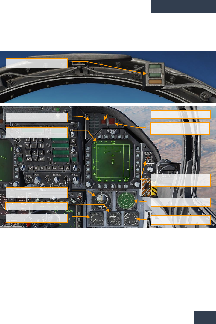
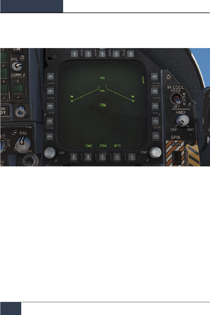
Right Instrument Panel
Figure 12. Right Instrument Panel
1. Lock / Shoot Lights. The Lock/Shoot cue function is provided during air-to-air (A/A)
operation for the AIM-9 Sidewinder and A/A gun mode. This function provides a visual
indication for RADAR lock on (LOCK light) and when weapon release interlocks are satisfied
(SHOOT light/SHOOT cue).
• Lock: Single Target Track (STT) and target within Rmax range.
• Shoot / Steady / Missile: target locked and within Rmax range.
• Shoot / Flashing / Missile: target locked and within Rne range.
• Shoot / Steady / Gun: target within solution.
Lock / Shoot Lights
APU Fire Light
Right Warning/Caution Advisory
Lights
Right Digital Display Indicator (DDI)
Standby Attitude Reference Indicator
(SARI)
Standby Altimeter
Right Engine Fire
Warning/Extinguisher Lights
IR Cool Switch
Azimuth Indicator
Standby Vertical Velocity Indictor
Standby Airspeed Indicator

DCS
[F/A-18C]
26
F/A-18C HORNET COCKPIT OVERVIEW
The strobe light below the SHOOT cue will also flash when shot is valid.
The Shoot light function is also provided during air to ground (A/G) rocket delivery, and with
no weapon selected, shoot light is functional for A/G gun mode when gun is selected on left
DDI. Lock light is not functional during A/G mode operation.
2. Right Warning/Caution Advisory Lights. The Right Warning/Caution Advisory lights
provide visual indications of the recorder and the onboard Threat Warning System (TWS).
See Defensive Systems Chapter for greater details.
• DISP. Countermeasure dispense program is active.
• SAM. Surface-to-Air Missile tracking RADAR locked to aircraft. Light is solid when
RADAR is tracking and flashing when guiding a missile.
• AI. Airborne Intercept (AI) RADAR locked to aircraft.
• AAA. Ant-Aircraft Artillery (AAA) fire control RADAR locked to aircraft. This is a steady
light for all RADAR directed AAA except ZSU-23-4 in which the light will flash at 3 Hz.
• CW. Aircraft illuminated by Continuous Wave (CW) RADAR.
3. APU Fire Light. The APU Fire Light will light when a fire has been detected in the APU
compartment.
4. Right Engine Fire Warning/Extinguisher Lights. If a fire is detected in the right
engine, this indicator will be lit. it will light when a temperature greater than 1,000 degrees
F is detected in the right engine bay.
5. Right Digital Display Indicator (DDI). The right DDI functions identically to the left DDI.
6. IR Cool Switch. Manually provides coolant to AIM-9 seekers. See AIM-9 procedures section
of this guide.
7. Standby Attitude Reference Indicator (SARI). This is a self-contained instrument to
indicate aircraft pitch, roll, and yaw. Cage and increase pitch |LALT + LSHIFT + V| cage and
decrease pitch |LALT + LSHIFT + X|
8. Azimuth Indicator. Also referred to as the RADAR Warning Receiver (RWR), this is
discussed in the Defensive Systems section of this guide.
9. Standby Airspeed Indicator. Indication of airspeed in knots x100.
10. Standby Altimeter. Indication of aircraft barometric altitude. Increase |LALT + LSHIFT +
S| and decrease |LALT + LSHIFT + A|
11. Standby Vertical Velocity Indictor. Indication of aircraft positive or negative change of
altitude rate.
[F/A-18C]
DCS
27
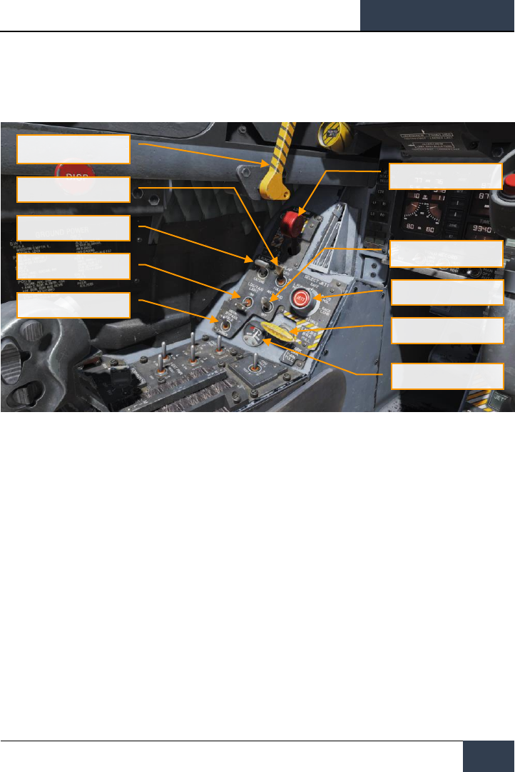
Left Vertical Panel
Figure 13. Left Vertical Panel
1. Canopy Jettison Handle. The black and yellow striped canopy jettison handle is on the
left inboard canopy sill just aft of the instrument panel. Pulling the handle aft fires the
canopy jettison system.
2. Landing Gear Handle. The landing gear is controlled by a two-position, wheel-shaped
handle on the lower left side of the main instrument panel. Two conditions must be met
before the gear can be raised: the aircraft must sense that weight is off all three landing
gear and the launch bar must be retracted. |G|
3. Launch Bar Switch. Raises and lowers the carrier takeoff-required launch bar.
4. Flap Switch. The FLAP switch selects which of the two flight control computer modes (auto
flap up or takeoff and land) is active and thus determines the flight characteristics for those
conditions.
• AUTO. Without Weight Off Wheels (WOW), leading and trailing edge flaps are
scheduled as a function of AoA. With WOW, leading and trailing edge flaps and aileron
droop are set to 0°. |F|
• HALF. Below 250 knots, leading edge flaps are scheduled as a function of AoA. Trailing
edge flaps and aileron droop are scheduled as a function of airspeed to a maximum of
30° at approach airspeeds. Above 250 knots, the flaps operate in the auto flap up mode
and the amber FLAPS light comes on. On the ground, the leading edge flaps are set to
12°. The trailing edge flaps and aileron droop are set to 30°. With the wing unlocked,
aileron droop is set to 0°. |LSHIFT + F|
Canopy Jettison Handle
Landing Gear Control
Handle
Flap Switch
Launch Bar Switch
Landing / Taxi Light
Arrestor Hook Bypass
Switch
Anti-Skid Switch
Selective Jettison Knob
Emergency / Parking Brake
Handle
Brake Accumulator Pressure
Gauge

DCS
[F/A-18C]
28
F/A-18C HORNET COCKPIT OVERVIEW
• FULL. Below 250 knots, leading edge flaps are scheduled as a function of AoA. Trailing
edge flaps and aileron droop are scheduled as a function of airspeed to a maximum of
45° flaps and 42° aileron droop at approach airspeeds. Above 250 knots, the flaps
operate in the auto flaps up mode and the amber FLAPS light comes on. On the ground,
the leading edge flaps are set to 12°. The trailing edge flaps are set to 43° to 45° and
aileron droop to 42°. With the wings unlocked, aileron droop is set to 0°. |LCTRL + F|
5. Selective Jettison Knob. The selective jettison knob on the left vertical panel has rotary
positions L FUS MSL, SAFE, R FUS MSL, RACK/LCHR, and STORES. L FUS MSL and R FUS
MSL selects the required fuselage missile for jettison. The RACK/LCHR and STORES positions
select what is to be jettisoned from the weapon stations selected by the station jettison
select buttons. The JETT center pushbutton activates the jettison circuits provided the
landing gear is up and locked and the master arm switch is in ARM. The SAFE position
prevents any selective jettison.
6. Landing / Taxi Light. This is a combination landing and taxi light is on the nose gear strut.
The light is controlled by the LDG/TAXI light switch on the left vertical panel.
• OFF. Light is off.
• ON. If the landing gear handle is in DN and the landing gear is down, the light is on.
7. Anti-Skid Switch. The anti-skid circuit prevents brake application on landing until wheel
speed is over 50 knots, or if a wet runway delays wheel spin-up, 3 seconds after
touchdown. A locked wheel protection circuit releases the brakes if the speed of one main
wheel is 40% of the other main wheel. The locked wheel protection circuit is disabled at
about 35 knots. The anti-skid system is totally disabled below 10 knots. Anti-skid is used
for airfield operation, but not for carrier operations.
8. Emergency / Parking Brake Handle. The emergency brake system is activated by pulling
the emergency/parking brake handle out to the detent. The system is deactivated by pushing
the emergency/parking brake handle back into the stowed position. The parking brake
system is activated by rotating the emergency/parking brake handle 90° counterclockwise
from the horizontal stowed position and pulling it out to a positive locked position.
9. Brake Accumulator Pressure Gauge. Brake accumulator pressure is shown on a pressure
gage on the lower left corner of the main instrument panel and is redlined to indicate
pressure below 2,000 psi. 3,000 psi is a normal level.
10. Arrestor Hook Bypass Switch. With this switch set to the CARRIER position, the AoA
Indexer Lights will light solid when the arrestor hook and landing gear are down and
locked. It will however flash if the arrestor hook is up. When set to FIELD, the AoA Indexer
Lights will stay solid when the arrestor hook is not down.
[F/A-18C]
DCS
29
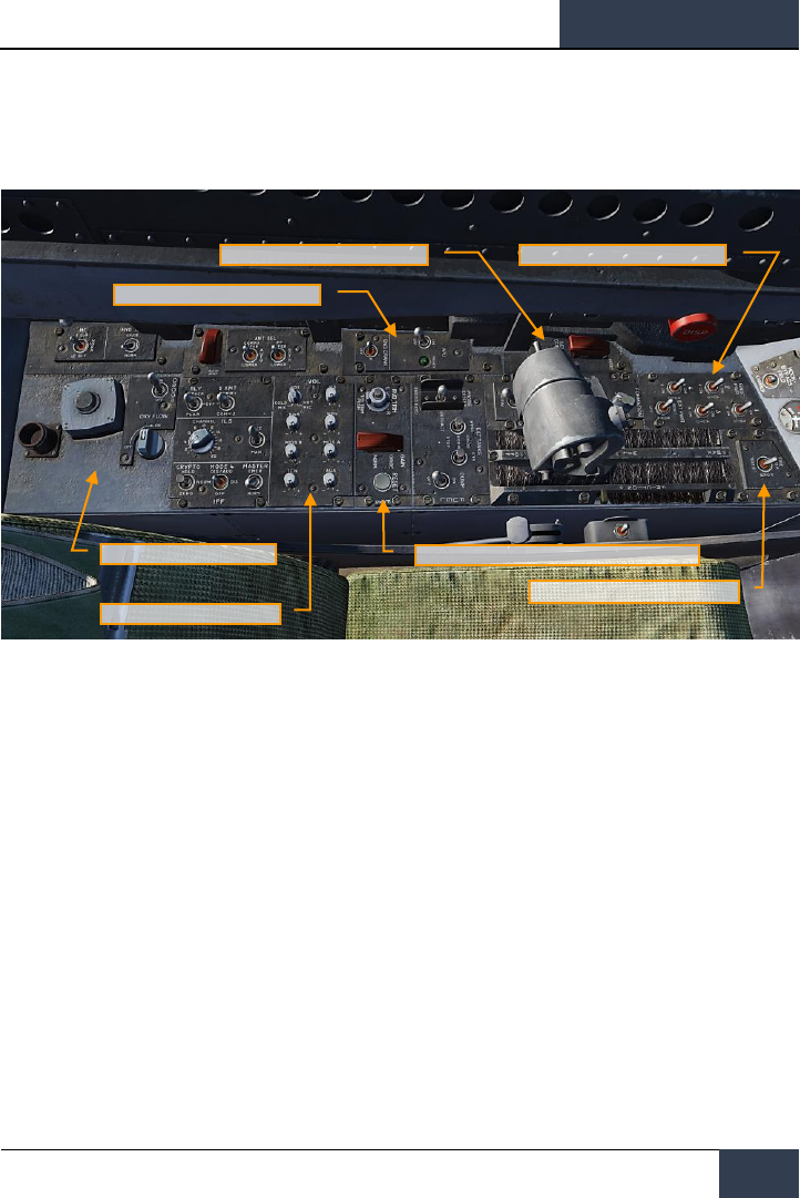
Left Console
Figure 14. Left Console
1. Ground Power Panel. If wishing to not use the battery to start the aircraft, or run
electrical systems without starting the aircraft, the ground power panel can be used once
electrical power is requested from the ground crew. Once EXT PWR (External Power) is
selected from the panel, four groups can be selected with each having sub A and B groups
of instruments and systems being powered by the group.
2. Fire Test Switch. The fire/bleed air leakage detection sensors and associated circuits are
tested by the fire and bleed air test switch. When actuated to TEST A or TEST B, the fire
warning, bleed air leak detection and voice alert warning circuitry for the designated loop is
tested. The switch must manually be held in the test position.
3. Exterior Lighting Panel. Three lighting controls comprise this panel:
• Position Lights. The position lights include a white light just below the tip of the right
vertical tail fin, three green lights on the right side of the aircraft, and three red lights
on the left side of the aircraft. The position lights are controlled by the POSITION lights
knob. The exterior lights master switch must be ON for the position lights knob to
operate.
• Formation Lights. Eight formation lights are provided. Two lights are on each wing tip
and show above and below a wing tip missile when installed, two lights are on the
outboard of the vertical tail fins, two lights are on the aft fuselage below the vertical tail
fins, and two lights are on either side of the forward fuselage just forward of the LEX.
The formation lights are controlled by the FORMATION lights control knob on the
Ground Power Panel
Exterior Lights Panel
APU and Engine Crank Panel
Oxygen System Panel
Volume Panel
Flight Control System (FCS) Panel
Fire Test Switch

DCS
[F/A-18C]
30
F/A-18C HORNET COCKPIT OVERVIEW
exterior lights panel which provides variable lighting between positions OFF and BRT.
The exterior lights master switch must be ON for the formation lights knob to operate.
• Strobe Lights. Two red anti-collision strobe lights, one on each outboard vertical tail
fin, are provided. The strobe lights are controlled by the STROBE lights switch on the
exterior lights panel. The exterior lights master switch must be ON for the strobe lights
switch to be operative.
o OFF Lights are off.
o BRT Lights illuminate at full intensity.
o DIM Lights illuminate at reduced intensity.
4. APU and Engine Crank Panel. The APU switch enables and disables the Auxiliary Power
Unit. When the APU is operating normally, the green APU light next to the switch will
illuminate. The Engine Crank switch has left and right positions and is moved to the
respective side during engine start. See the Cold Start procedure of this guide.
5. Flight Control System (FCS) Panel. On the left side of the panel is the rudder trim knob
with can be rotated left and right to add rudder trim. In the center of the knob is the
takeoff trim button which pressed to set the flight control surfaces to takeoff trim settings.
On the right side of the panel is the FCS Reset button. This button is pressed in the event
of an FCS failure in order to re-start the FCS channels.
6. Volume Panel. This panel consists of eight knobs that can control the volume heard
through the headset. For this Early Access version, the knobs for WPN (AIM-9 seeker),
RWR (RADAR warning receiver), and TCN (TACAN) are functional.
7. Oxygen System Panel. The Oxygen System panel includes control of the Onboard
Oxygen Generation Systems (OBOGS). Controls include an ON/OFF switch and flow dial.
Along the left wall are the circuit breakers for FCS channels 1 and 2, as well as for the speed brake
and launch bar. The large red button is the countermeasures dispenser button.
[F/A-18C]
DCS
31
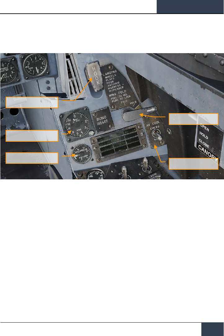
Right Vertical Panel
Figure 15. Right Vertical Panel
1. Standby Magnetic Compass. A conventional aircraft magnetic compass is mounted on
the right windshield arch.
2. Arresting Hook Handle and Light. To extend the arresting hook, place the arresting
hook handle down. The HOOK light comes on when the hook is in transit and goes out
when the hook reaches the selected position. The light remains on if the hook is in contact
with the deck and is prevented from reaching the hook down proximity switch. The HOOK
light remains on any time the hook position does not agree with the handle position. Lower
|LCTRL + H| and raise |LCTRL + H|
3. Wing Fold Handle. Normal folding and spreading the wings is accomplished through
operation of the wing fold handle. To fold the wings, pull out and rotate counterclockwise
to FOLD. The MASTER CAUTION light comes on. To spread the wings, rotate the wing fold
handle clockwise to SPREAD. To lock the wings after they have fully spread, push the
handle in. The wings can be stopped and held in any intermediate position by placing the
wing fold handle to HOLD.
4. RADAR Altimeter. The RADAR altimeter set indicates clearance over land or water from 0
to 5,000 feet. The height indicator, on the instrument panel, consists of a calibrated scale
from 0 to 5,000 feet, a push to test switch, a low altitude index pointer, an altitude pointer,
an OFF flag, a low altitude warning light, and a BIT light. This is normally set at 200 feet
for airfield operations and 40 feet for carrier operations.
Arresting Hook Handle and
Light
RADAR Altimeter
Hydraulic Pressure Indicator
Wing Fold Handle
Oxygen System Panel

DCS
[F/A-18C]
32
F/A-18C HORNET COCKPIT OVERVIEW
5. Hydraulic Pressure Indicator. The left, or system 1, provides power to the primary
flight control surface actuators exclusively. The right, or system 2, also provides power to
the primary flight control actuators and additionally supplies power to the speed brake and
non-flight control actuators.
6. Right Warning / Caution Advisory Lights. All lights on this panel are steady state,
yellow lights.
• APU ACC. Indicates that the APU accumulator pressure necessary for the starting
the engine is inadequate.
• FUEL LO. Indicates the fuel quantity remaining is below 800 pounds in either of
the two feed tanks. FUEL LO will remain on for at least one minute for each fuel
low occurrence to avoid repetitive occurrences due to fuel sloshing.
• L GEN. Indicates that the left generator outputs has failed or is turned off.
• R GEN. Indicates that the right generator outputs has failed or is turned off.
• BATT SW. Battery switch is set to ON.
• FCS HOT. The flight control computer and transformer/rectifier are undercooled.
This is due to insufficient avionics cooling in the right hand equipment bay. In such
a situation, the EMERG position on the FCS Cool switch should be selected.
• FCSES. A function has been lost in one or more axis of the Flight Control Electronics
Systems. Loss of one of the eleven flight control functions.
• GEN TIE. GEN TIE switch set to RESET.
• CK SEAT. Ejection seat has not been armed.
[F/A-18C]
DCS
33
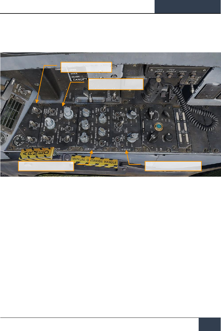
Right Console
Figure 16. Right Console
1. Electrical Panel. The electrical (ELEC) panel has controls for both generators, the battery
and its voltage meter.
• Left Generator Switch. Used to enable or disable the left generator. This switch has
two positions. NORM to enable normal operation and OFF to disable the generator.
• Right Generator Switch. Used to enable or disable the right generator. This switch
has two positions. NORM to enable normal operation and OFF to disable the generator.
• Batteries Voltmeter. The voltmeter, which combines a U battery voltmeter and E
battery voltmeter in one indicator, is on the electrical power panel. With the battery
switch OFF, the voltmeters are inoperative and the indicator needles indicate 16 volts.
With the battery switch ON both voltmeters are operative; with the switch in ORIDE
only the E voltmeter is operative.
• Battery Switch. The battery switch controls operation of the two onboard batteries
and has three positions:
o OFF. Batteries can be charged, but battery contactors will not energize to
connect a battery to the essential bus in response to low voltage conditions.
o ON. Enables control circuitry of both battery contactors so the U battery
contactor will automatically close in response to a low voltage condition on
the left 28 volt dc bus, and the E battery contactor will subsequently close in
response to a low voltage condition from the U battery output and left 28 volt
dc bus.
Electrical Panel
Environmental Systems Control
Panel
Interior Lighting Panel
Sensors Panel

DCS
[F/A-18C]
34
F/A-18C HORNET COCKPIT OVERVIEW
o ORIDE. Energizes E battery contactor regardless of charge status of U
battery, providing voltage on left 28 volt dc bus is absent or low. Position can
be used to connect E battery to the essential buses in the event U battery
contactor fails to energize with switch in the ON position.
2. Environmental Control System Panel. The ECS panel controls that will be applicable to
the Hornet Early Access include:
• Bleed Air Select Switch. This switch controls the bleed air source. Bleed air is
automatically shut off if a leak is detected.
o BOTH. Bleed airflow is provided to the ECS by both engines.
o R OFF. Bleed airflow is provided to the ECS by only the left engine.
o L OFF. Bleed airflow is provided to the ECS by only the right engine.
o OFF. All bleed airflow from the engines is shut off. This includes ECS
cooling, cabin pressurization, and warm air. Ram air is automatically used
instead.
o AUG. Allows the APU to augment bleed air pressurization of the cabin when
the aircraft has weight on wheels and engine operating at less than
intermediate settings.
• Engine Anti-Ice Switch. This switch controls anti-ice heating of the engine inlets.
o ON. Allows hot bleed air to circulate through the engine inlet and engine
components.
o OFF. Turns off engine anti-ice.
o TEST. Triggers ice caution message.
• Pitot Heater Switch. There are two pitot-static tubes mounted under the nose on
each side forward of the nosewheel well. Each tube contains one pitot source and two
static sources. The pitot heater switch on the ECS panel has positions ON and AUTO.
o AUTO. Heaters are on when airborne.
o ON. Heaters are on when ac power available.
3. Interior Lighting Panel. The interior light panel controls all illumination options and
settings within the cockpit.
• Console Lighting Knob. Integral and light panel lighting for the left and right
consoles, the hydraulic pressure indicator, and both cockpit circuit breaker panels are
controlled by the CONSOLES knob which provides variable lighting between positions
OFF and BRT. With the MODE knob in the NVG position, the CONSOLES knob provides
variable NVG floodlighting between OFF and BRT for the consoles.
• Instrument Lighting Knob. Integral and light panel lighting for the instrument panel,
UFC background, right and left vertical panels (except for the hydraulic pressure
indicator) and standby magnetic compass are controlled by the INST PNL knob which
provides variable lighting between positions OFF and BRT. The strobe shoot light does
not illuminate when the instrument lights are on. The INST PNL knob provides variable
lighting between OFF and BRT, with the MODE switch in either NORM or NVG.
• Flood Lighting Knob. Eight white floodlights are provided for secondary lighting.
Three console floodlights are above each console, and an instrument panel floodlight is
located to either side of the instrument panel. The FLOOD knob is inoperative with the
MODE switch in the NVG position.
• Chart Lighting Knob. A chart light is installed on the canopy arch. An NVG compatible
chart light is controlled by the CHART knob and rotates in two axis with variable lighting

[F/A-18C]
DCS
35
between OFF and BRT. The chart light operates independent of the MODE switch
position.
• Lights Test Switch. A lights test switch, labeled LT TEST, is provided to test the
warning/caution/advisory lights in addition to the AOA indexer lights and the integrated
fuel/engine indicator LCD displays.
• Warning and Caution Lights Knob. A knob labeled WARN/CAUT is provided on the
interior lights control panel to vary the brightness of the warning/caution/advisory lights
within the low intensity range.
• Mode Switch. The MODE switch has positions of NVG, NITE, and DAY. The DAY
position permits the maximum brightness range for the warning, caution, and advisory
lights and the main and console panel lighting. The NITE position provides reduced
brightness for the warning, caution, and advisory lights, and normal intensity for the
main and console lighting. The NVG position provides reduced brightness for the
warning, caution, and advisory lights, disables the integral console lighting, and enables
NVG compatible flood lights to illuminate the consoles.
4. Sensors Panel. At this Early Access stage, functionality of the sensor panels includes the
RADAR knob and the INS knob. For the INS knob, place the knob in NAV for navigation
functions.
• INS Knob. This eight-position rotary knob controls the inertial navigation system.
For this Early Access release, the following positions operate:
o OFF. Removes power from the INS.
o GND. Places the INS in ground alignment.
o NAV. Places the INS in navigation mode.
• RADAR Knob. Four position rotary knob controls all operating power applied to the
RADAR set.
o OFF. Removes all RADAR set power.
o STBY. Activates all components except for high voltage. Allows RADAR set
to warm-up before application of high voltage, or, removes high voltage but
maintains RADAR for immediate application of high voltage.
o OPR. Commands RADAR to full operation if all safety interlocks have been
satisfied and initial warm-up time is complete.
Along the right wall are the canopy control switch, the FCS BIT switch, and circuit breaks for the
arrestor hook, landing gear and FCS channels 3 and 4.
DCS
[F/A-18C]
36
F/A-18C HORNET COCKPIT OVERVIEW
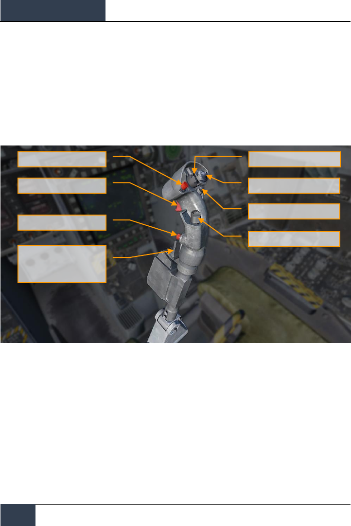
Control Stick
The stick contains the pitch and roll trim switch, sensor control switch, Air-to-Ground bomb release
button, gun/forward-firing weapons trigger, Air-to-Air weapon select switch, un-designate/nose wheel
steering button. An autopilot/nose wheel steering disengage switch (paddle switch) is mounted below
the stick grip. Stick position sensors transmit an electrical signal proportional to stick displacement
from neutral to the flight control computers.
Several of the switches have multiple functions that depend on a selected mode. We will discuss
those in the later, relevant sections of this Quick Start manual.
Figure 17. Control Stick
AIR/GROUND weapon release
button
Trigger switch
Undesignated nosewheel
steering button
Nosewheel steering disengage.
Auto-pilot disengage.
G-limiter override switch.
(paddle switch)
Pitch and roll trim switch
Sensor control switch (4 position)
Recce event mark
Weapon select switch
[F/A-18C]
DCS
37
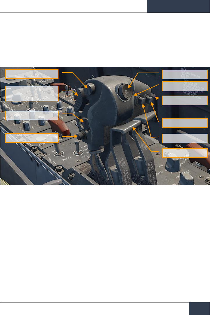
Throttles
The throttle grips contain switches that provide various systems control without moving the hand
from the throttles. As with the Control Stick, the HOTAS functions of the Throttles vary in
functionality depending on the state and operational modes of the aircraft. These are discussed in the
appropriate sections of this document.
Figure 18. Throttles
Dispense Switch
AFT – OFF - FWD
Communications
COMM1 – COMM2
MIDS A – MIDS B
Speed brake
EXTEND – OFF - RETRACT
CAGE/UNCAGE button
Throttle designator
controller
Antenna elevation control
RAID/FLIR FOV select
button
ATC Engage/Disengage
Finger lifts
Exterior lights
DCS
[F/A-18C]
38
DDI and AMPCD Pages
DDI and AMPCD Pages
In addition to the physical controls of the Hornet cockpit, much of your interaction will be through the
multitude of pages on the left and right Digital Display Indicators (DDI) and the central Advanced
Multipurpose Color Display (AMPCD). The AMPCD is commonly referred to as just the MPCD.
Before we discuss common Hornet procedures, let’s review some of the more important DDI and
MPCD pages you’ll use. Additional DDI pages will become functional during the Early Access period.
There are two primary pages in which all other pages are selected from: The Support (SUPT) page
and the Tactical (TAC) page. You can toggle between these pages, or return to them, by pressing the
pushbutton marked MENU. When airborne, the MENU pushbutton converts to a timer, but still acts as
a MENU button.
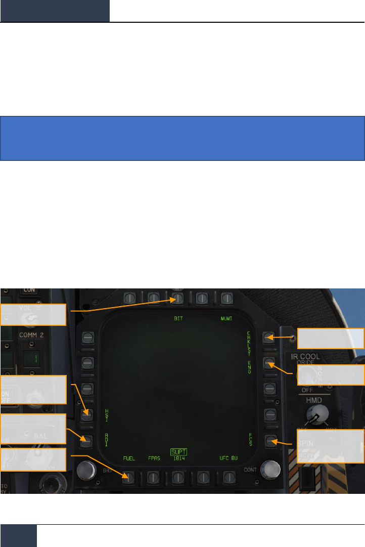
Support (SUPT) Pages
Figure 19. Support (SUPT) Pages
Instant Action Mission Practice: Hornet Ready on the Ramp
Horizontal Situation
Indicator (HSI) Page
Checklist Page
Engine Page
Flight Control Systems
(FCS) Page
Electronic Attitude
Display Indicator Page
Fuel page
Built In Test (BIT)
Page

[F/A-18C]
DCS
39
Built In Test (BIT) Page. The Hornet consists of a numerous sub systems, each with has its own
built in test system. This page allows the pilot to test these systems and view their status.
Figure 20. BIT Page
DCS
[F/A-18C]
40
DDI and AMPCD Pages
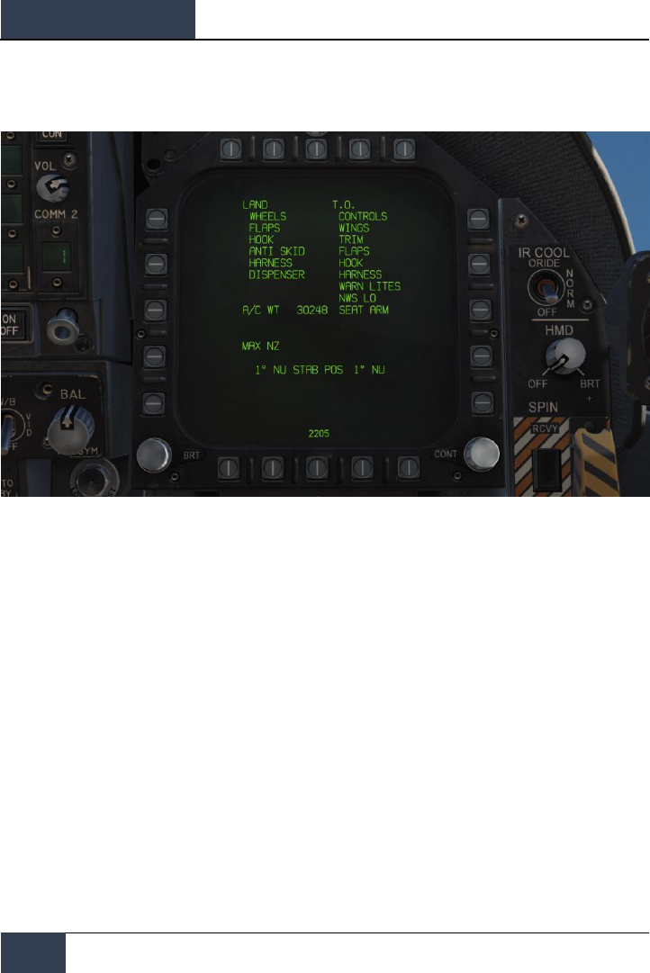
Check List (CHKLST) Page. In addition to providing checklists for landing and takeoff, this page
also displays aircraft weight and stabilator position.
Figure 21. Checklist Page
[F/A-18C]
DCS
41
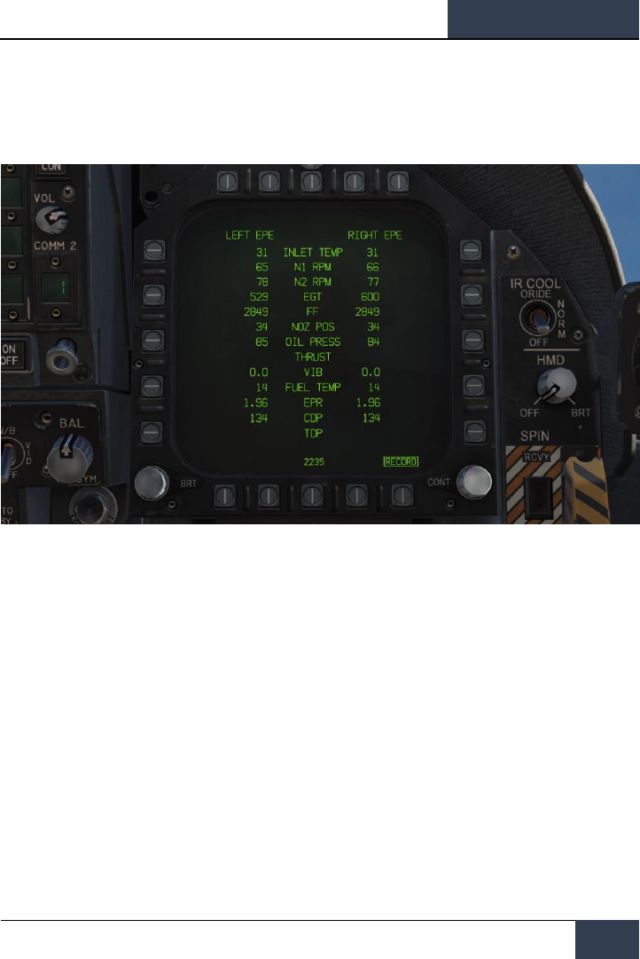
Engine (ENG) Page. The Engine page provides important engine performance data for both
engines, which often duplicates engine data on the IFEI such as engine RPM, engine temperature,
fuel flow, and oil pressure. Most often though, you will be using the IFEI to check engine
performance.
Figure 22. Engine Page
DCS
[F/A-18C]
42
DDI and AMPCD Pages
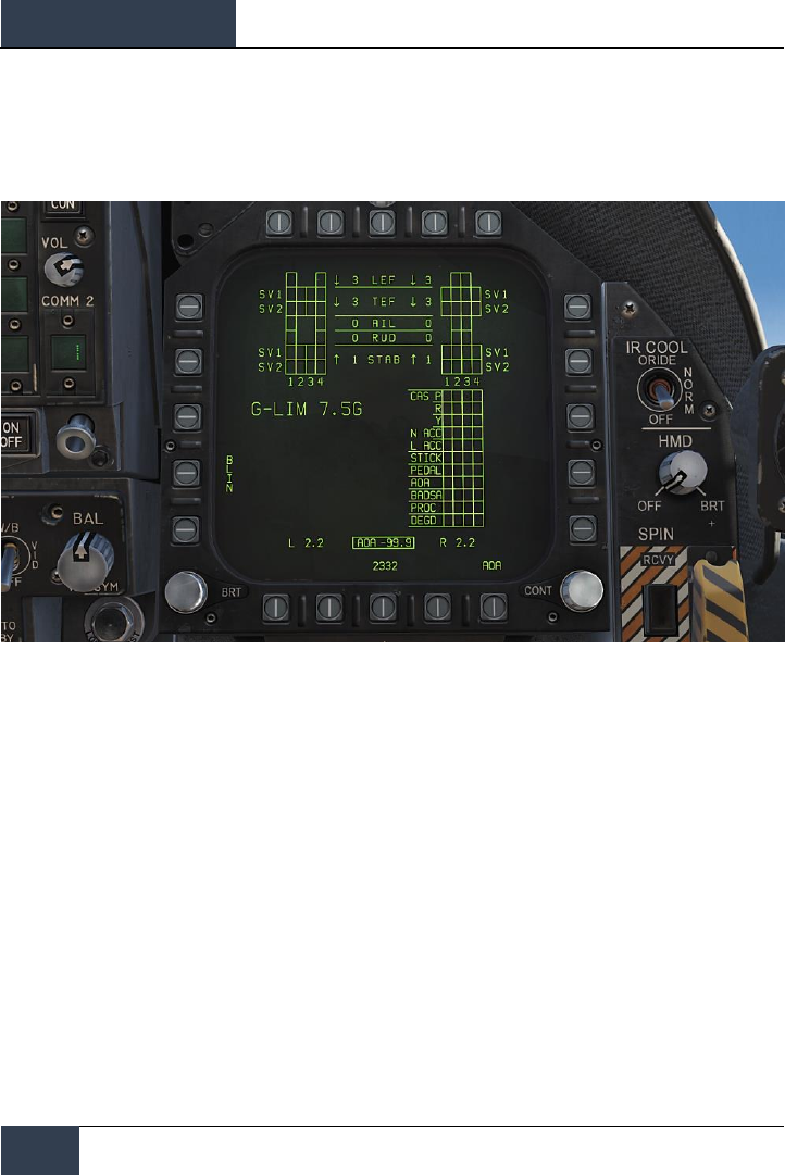
Flight Control System (FCS) Page. The FCS page displays monitoring data of the flight control
surfaces like the leading and trailing edge flaps, ailerons, rudders, and stabilator. It will also note any
FCS errors noted in the four channels as “Xs”. This page also displays the G limit based on aircraft
gross weight.
Figure 23. Flight Control System (FCS) Page
[F/A-18C]
DCS
43
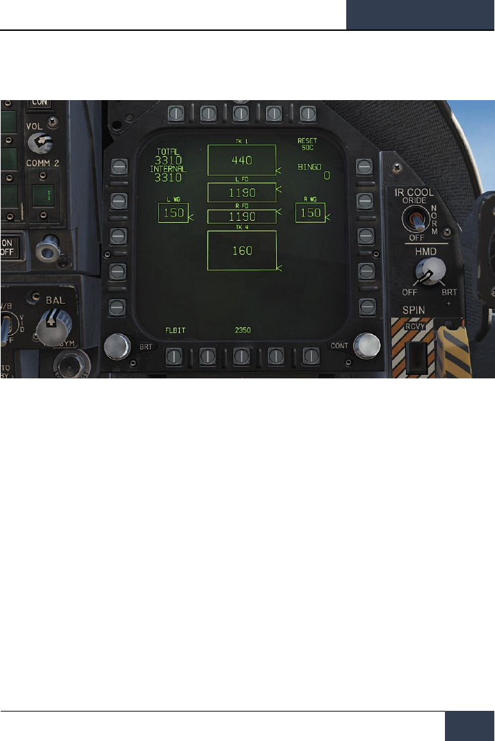
Fuel (FUEL) Page. The Fuel page duplicates much of the fuel information displayed in the IFEI, but
provides additional information on the fuel quantity of individual fuel tanks.
Figure 24. Fuel Page
DCS
[F/A-18C]
44
DDI and AMPCD Pages
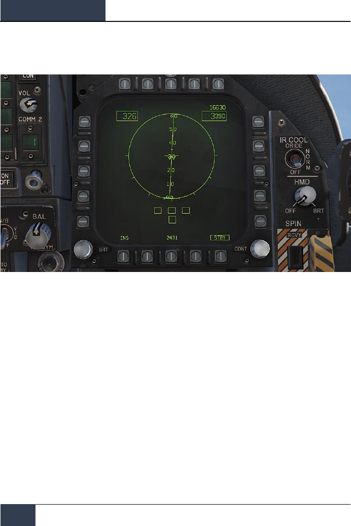
Electronic Attitude Director Indicator (EADI) Page. The EADI page provides a digital
representation of the aircraft’s pitch, roll, and yaw attitude. The EADI also displays aircraft airspeed
and altitude in the top left and right corners.
Figure 25. Electronic Attitude Director (EADI) Indicator
[F/A-18C]
DCS
45
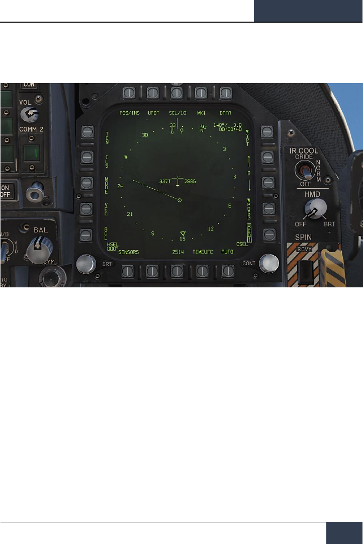
Horizontal Situation Indicator (HSI) Page. Mostly displayed on the MPCD, the HSI provides a
top-down navigation display with your aircraft in the center. The HSI will be discussed later in the
navigation portion of this guide.
Figure 26. Horizontal Situation Indicator (HSI) Page
DCS
[F/A-18C]
46
DDI and AMPCD Pages
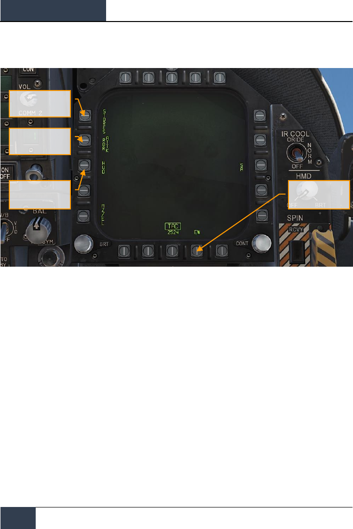
Tactical (TAC)
Figure 27. Tactical (TAC) Pages
Stores Management
System (SMS) Page
Head Up Display
(HUD) Page
Attack RADAR (RDR)
Page
Early Warning (EW)
page
[F/A-18C]
DCS
47
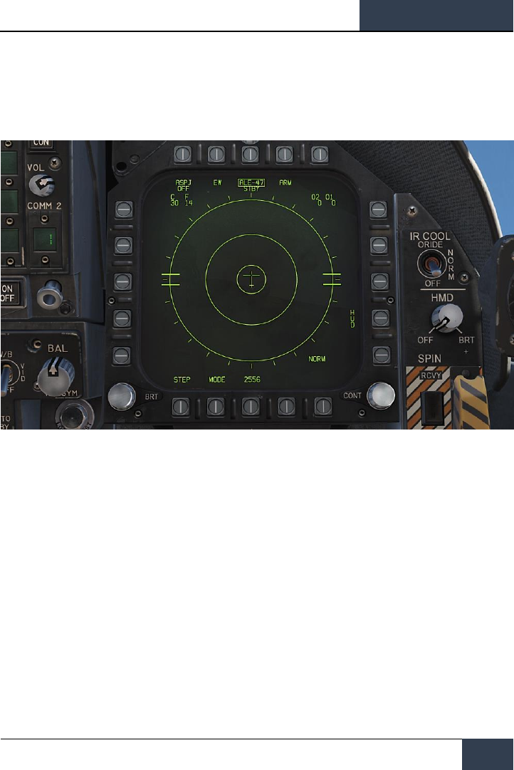
Electronic Warfare (EW) Page. The EW page combines the display of detected radar emitters,
control of Electronic Countermeasures (ECM), and control of expendable countermeasure that
includes chaff, flares, and ECM decoys.
Figure 28. EW Page

DCS
[F/A-18C]
48
DDI and AMPCD Pages
Head Up Display (HUD) Page. The HUD page duplicates what is displayed on the HUD glass at
the top of the instrument panel. This is most often used when the HUD fails or is unreadable due to
lighting. It can also be useful when “head down” and not being able to easily check the HUD.
Figure 29. Head Up Display (HUD) Page
[F/A-18C]
DCS
49
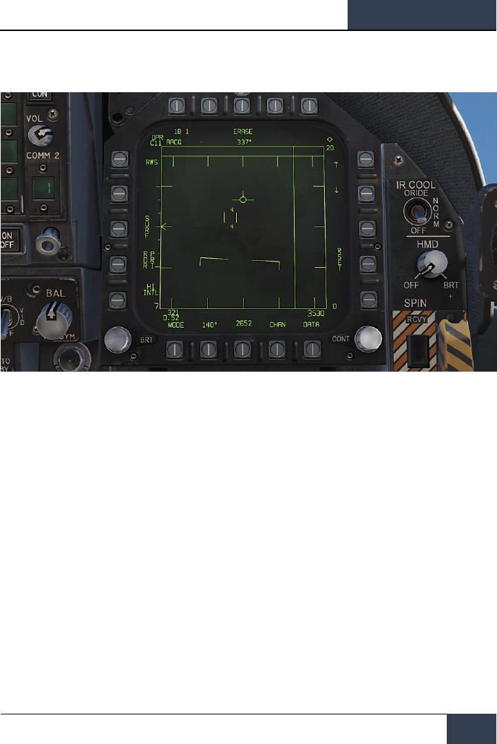
Attack RADAR (RDR) Page. For this initial version of the Hornet Early Access, this page will
display air-to-air RADAR. Please see the RADAR section of this guide for details.
Figure 30. Attack RADAR Page
DCS
[F/A-18C]
50
DDI and AMPCD Pages
Stores Management System (SMS) Page. The SMS page allows you to view all loaded stores
and determine their delivery properties. We will discuss this page in detail in the weapon procedure
sections of this guide.
Figure 31. Stores Management System (SMS) Page
[F/A-18C]
DCS
51
HEAD UP DISPLAY
The Head Up Display, or HUD, is one of your most important instruments and provides valuable
information as to your aircraft flight performance and weapon / sensor information. In later sections
of this guide we will discuss aspects of the HUD that are specific to certain weapons and sensors, but
the HUD does have a common set of information that is almost always displayed.
The HUD as pictured below is independent of aircraft Master Mode with the exception of the bank
angle scale, vertical velocity, and heading scale.
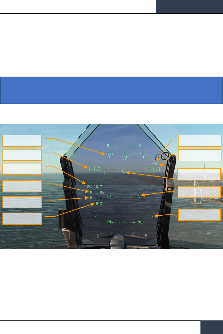
Figure 32. Basic HUD Information
1. Heading. This 30 degree, moving heading scale displays the aircraft’s magnetic or true
heading (set in HSI/DATA). The aircraft’s heading is indicated as the caret in the center of
the scale. When True heading is selected, a “T” is placed below the heading caret.
2. Airspeed. Calibrated airspeed as determined by the Air Data Computer (ADC).
3. Vertical Velocity. Positive or negative aircraft altitude change in feet per minute.
4. Altitude. Barometric or RADAR altitude in feet as set by the ALT switch on the HUD
control panel. When RADAR altitude is selected, an “R” is displayed next to the altitude
Instant Action Mission Practice: Hornet Ready on the Ramp
Heading
Airspeed
Angle of Attack
Mach Number
Aircraft Gs
Peak Aircraft G
Velocity Vector
Vertical Velocity
Altitude
Flight Path/Pitch Ladder
Bank Angle Scale

DCS
[F/A-18C]
52
HEAD UP DISPLAY
box. If however the RADAR altitude is invalid, a flashing “B” is displayed to indicate that
barometric altitude is being used instead.
5. Angle of Attack. True angle of attack in degrees of the aircraft.
6. Mach Number. Aircraft speed as Mach airspeed.
7. Aircraft Gs. Normal acceleration value of the aircraft.
8. Peak Aircraft G. Maximum achieved G over 4 G’s.
9. Velocity Vector. Represents the point toward which the aircraft is flying along the
aircraft’s actual flight path. When not displaying accurate information, the symbol will flash.
The Velocity Vector can be caged and uncaged to the center of the HUD with the
cage/uncage button on the throttle.
10. Flight Path/Pitch Ladder. The vertical flight path angle of the aircraft as indicated by
the position of the Velocity Vector on the Flight Path/Pitch Ladder. The aircraft’s pitch angle
is indicated as the aircraft waterline on the Flight Path/Pitch Ladder.
11. Bank Angle Scale. With marks at 5, 15, 30 and 45 degrees, rolling the aircraft to place
the center caret in relation to these marks provides a bank angle reference.
Barometric Setting. The barometric altitude is displayed below the altitude box for five
seconds when the barometric altitude is changed on the standby altimeter. It will also display if
the aircraft is below 10,000 feet and at an airspeed less than 300 knots if previously above both
values.
Ghost Velocity Vector. When the Velocity Vector is caged, the Ghost Velocity Vector is
displayed and shows the true velocity vector of the aircraft.
[F/A-18C]
DCS
53
PROCEDURES
In the following sections, we will provide “How To” checklists for the primary procedures you’ll need
to understand to get started in the Hornet.
Cold Start
There are two methods you can use to start a cold and dark Hornet. The first, and easiest, is the
Auto-Start. By pressing |LEFT WIN + HOME|, the aircraft will be started automatically for you. To
cease the Auto-Start, you can press |LEFT WIN + END|.
Being a DCS title though, the Hornet really shines when you take advantage of the detailed systems
modeling, like manually starting the aircraft. As an Early Access Guide, we will skip the pre-flight
check list and go straight to starting up the aircraft to the point of being ready to taxi.
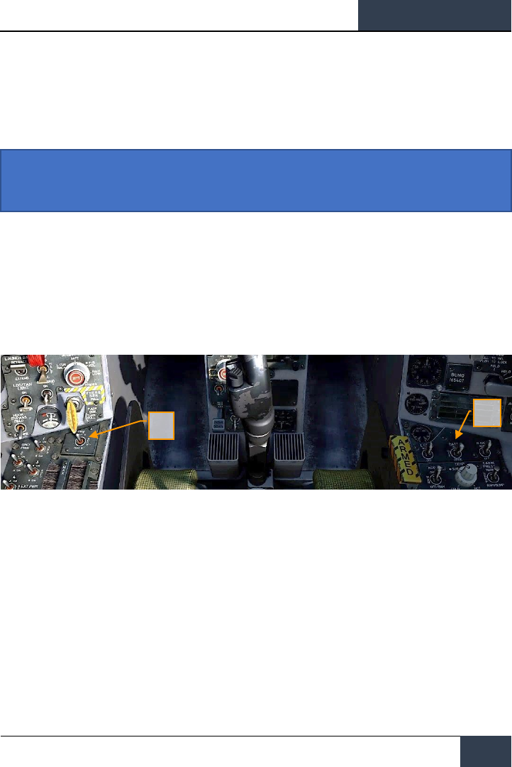
1. Set the BATTERY switch to ON and confirm both Left and Right Generators are ON.
|RIGHT CONSOLE|
2. Move and hold the fire detection switch to FIRE TEST A and wait for all of the audio
caution messages to play. Once complete, wait 10 seconds and then do the same
for FIRE TEST B. Between running FIRE TEST A and FIRE TEST B, you can reset
the battery switch to rewind the fire test tape. |LEFT CONSOLE|
Instant Action Mission Practice: Hornet Cold and Dark
2
1
DCS
[F/A-18C]
54
PROCEDURES
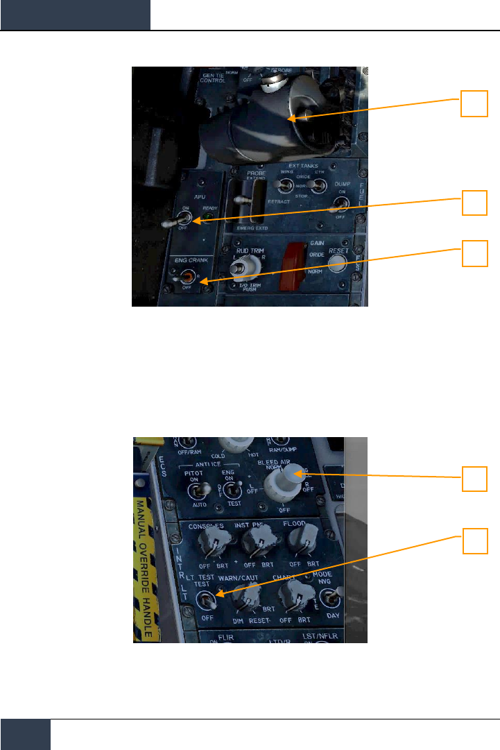
3. APU switch to ON and wait for green APU READY light. |LEFT CONSOLE|
4. Move the ENG CRANK switch to the right to start the right engine. |LEFT CONSOLE|
5. Move the right throttle from OFF to IDLE when the right engine is above 25% rpm
(as shown on IFEI). |LSHIFT + HOME|
6. Once right engine RPM is over 60%, rotate the BLEED AIR knob 360 degrees
clockwise, from NORM to NORM. |RIGHT CONSOLE|
7. Test the CAUTION, WARNING and ADVISORY lights test. |RIGHT CONSOLE|
8. Turn on the power to both DDIs, MPCD and HUD. Select the FCS page on the left
DDI and the BIT page on the right DDI. |INSTRUMENT PANEL|
3
4
5
7
6
[F/A-18C]
DCS
55
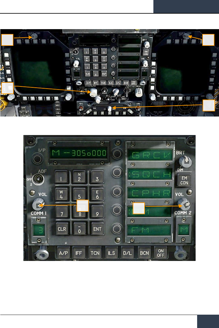
9. Set COMM 1 and COMM 2 radios as required for the mission.
8
8
8
8
9
9
DCS
[F/A-18C]
56
PROCEDURES
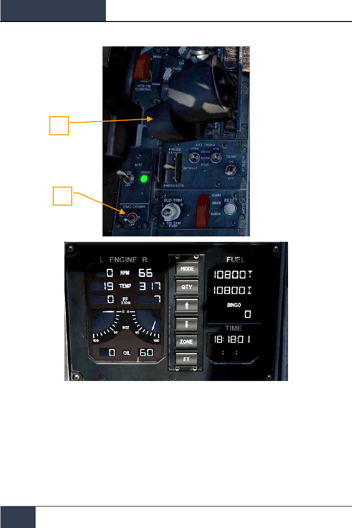
10. Move the ENG CRANK switch to the left after confirming that the right engine has
an rpm between 63 and 70%, a TEMP between 190 and 590 degrees, Fuel Flow
between 420 and 900 PPH, a nozzle position between 73 and 84%, and an OIL
pressure between 45 and 110 psi. |LEFT CONSOLE|
11. Move the right throttle from OFF to IDLE when left engine has reached at least
25% rpm by pressing [RIGHT ALT + HOME]. |THROTTLES|
10
11
[F/A-18C]
DCS
57
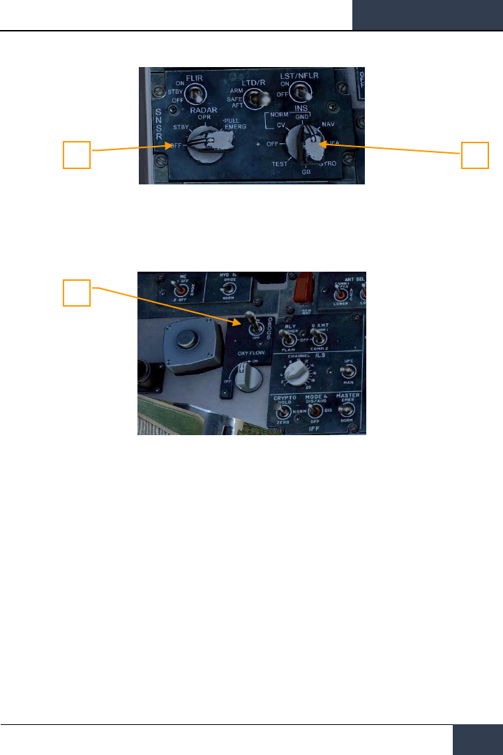
12. Once the left engine has an RPM greater than 60%, rotate the INS knob to GND
(ground) or CV (carrier), depending on your parking location. RIGHT CONSOLE|
13. Set the RADAR knob to OPR (operate). |RIGHT CONSOLE|
14. Set the OBOGS control switch and FLOW switch to ON. |LEFT CONSOLE|
13
12
14
DCS
[F/A-18C]
58
PROCEDURES
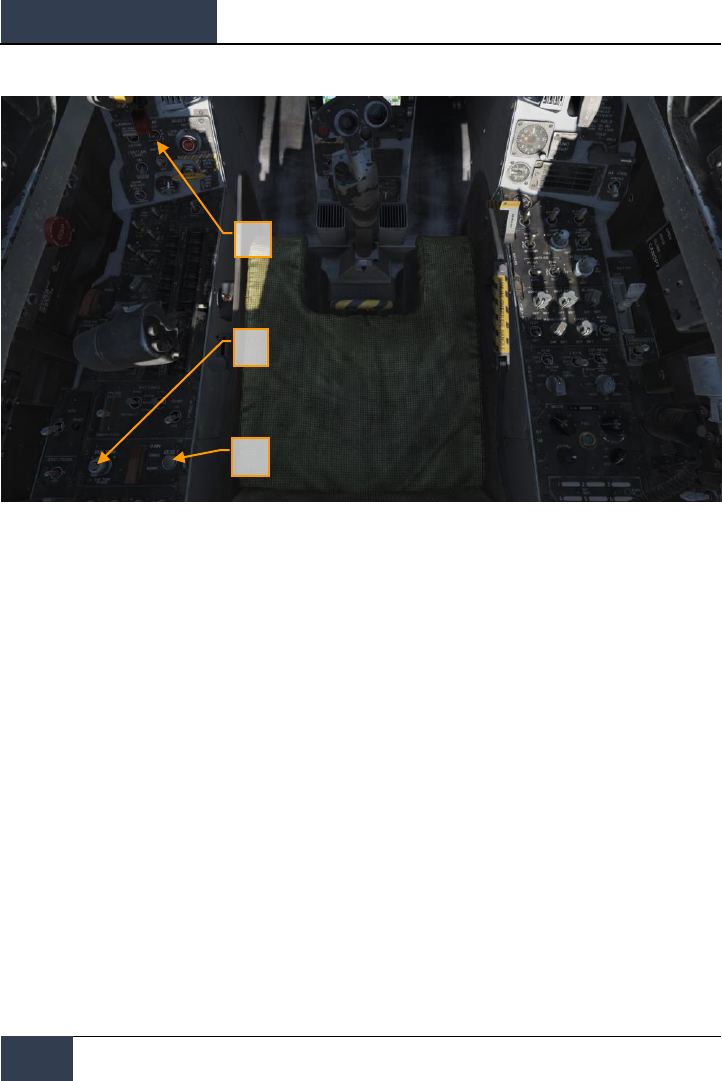
15. Press the FCS RESET button and monitor FCS DDI page. |LEFT CONSOLE|
16. Set the Flap switch to AUTO. |LEFT QUARTER PANEL|
17. Press Takeoff Trim button. |LEFT CONSOLE|
18. While holding up the FCS BIT switch [Y] on the right wall, press the FCS OSB on
the BIT / FCS page at the same time.
15
16
17

[F/A-18C]
DCS
59
19. Four down test. Cycle / test the refueling probe, speed brake, launch bar, arrestor
hook, pitot heat, and set flaps to HALF. |LEFT CONSOLE, THROTTLES, LEFT
QUARTER PANEL, RIGHT QUARTER PANEL, and RIGHT CONSOLE|
20. Left mouse click on the hand brake to release it.
19
19
19
19
18
19
20

DCS
[F/A-18C]
60
PROCEDURES
21. Set your BINGO fuel level (minimum fuel to return home) by pressing the up and
down arrows on the IFEI. |LEFT INSTRUMENT PANEL|
22. Set the Standby Barometric Altimeter to airfield elevation. |RIGHT INSTRUMENT
PANEL|
23. Set the RADAR Altimeter to 200 feet for an airfield takeoff or 40 feet from the
carrier. |RIGHT QUARTER PANEL|
24. Uncage the standby Attitude Indicator. |RIGHT INSTRUMENT PANEL|
25. Set the Attitude Source to STBY (standby). |CENTER INSTRUMENT PANEL|
Taxi
For the purposes of this Early Access Guide, we will cover the taxi and takeoff procedures when
operating from an airfield. The full manual will detail aircraft carrier operations.
1. Whether you have completed a cold start or are starting the mission in a “hot”
aircraft, your next step will be to taxi to the runway. Slowly advance the throttles
|PAGE UP| and use the rudder pedals to steer left |Z| and right |X|. Reduce throttle
by pressing |PAGE DOWN|. Holding down the Noses Wheel Steering (NWS) button,
you can enable NWS HI mode enabled tighter taxi turns. Press |W| to apply wheel
brakes.
2. Set the left DDI to the checklist page and the right DDI to the FCS page.
3. At the hold short before entering the active runway:
21
22
23
24
25
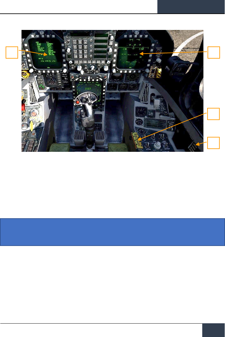
[F/A-18C]
DCS
61
4. Arm the ejection seat. |RIGHT CONSOLE|
5. Close the canopy if you have not already done so. |RIGHT CONSOLE|
6. Set the left DDI to the HUD page. |LEFT INSTRUMENT PANEL|
Normal Takeoff
1. Align the aircraft down the center of the runway and roll forward to align the
nosewheel down the runway.
2. Set left DDI to the HUD page.
3. Advance to throttles to afterburner.
4. Use nosewheel steering to maintain a straight track down the runway.
Instant Action Mission Practice: Hornet Takeoff
5
4
3
6
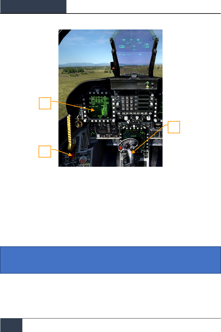
DCS
[F/A-18C]
62
PROCEDURES
5. At nosewheel rotation speed, hold the control stick back until 6 to 8 degrees nose
high attitude (water line above the horizon line on the HUD)
6. Raise the landing gear and set the FLAP switch to AUTO once positive climb is
established.
7. Switch the right DDI to air-to-air RADAR.
Landing
Being aircraft carrier capable aircraft, the Hornet can land on both “the boat” and airfields. Both
landing patterns are quite similar. For this guide though, we will just review the procedure for landing
at an airfield. The full manual will cover aircraft carrier operations.
6
7
Instant Action Mission Practice: Hornet Airfield VFR Landing
2
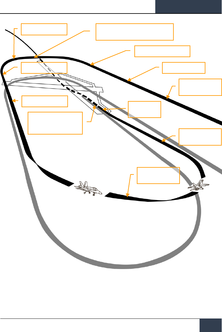
[F/A-18C]
DCS
63
Figure 33. Airfield Landing Pattern
Call up the air-to-air RADAR page on your right DDI and HUD repeater on your left DDI.
ENTER
Armament switch OFF
Breck
SPEEDBRAKE (as required)
LANDING GEAR DOWN, FLAPS FULL
250 knots
SPEEDBRAKE RETRACT
ON SPEED AOA
LANDING CHECK LIST
WAVEOFF
Mil Power (Max if required)
Retract gear and flaps only
after safe climb is established
TOUCHDOWN
Throttles idle
FINAL APPROACH
Maintain on speed AOA
BASE LEG
Maintain on speed AOA
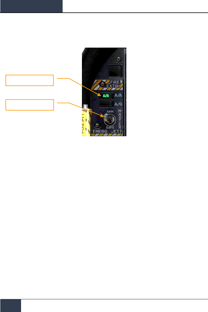
DCS
[F/A-18C]
64
PROCEDURES
Enter Navigation master mode and set the Master Arm Switch to SAFE on the |LEFT INSTRUMENT
PANEL| and approach at 350 knots and 800 feet Above Ground Level (AGL) along the heading of the
landing runway and offset yourself slightly away from your first turn into the pattern.
Five to ten seconds after your wingtip passes the end of the runway (the greater the time, the more
time you have to establish your on-speed AoA on the downwind leg), turn into the downwind leg of
the landing pattern. Generally, pull 1% of your airspeed in G. For example: 350 knots would equal
3.5 G. Roll out on a reciprocal landing heading and an altitude of 600 feet AGL.
Your lateral offset from the runway should be about 1.2 miles.
Once your airspeed is below 250 knots, lower your landing gear and place your flaps in the FULL
down position. |LEFT QUARTER PANEL|
Master Mode Buttons
Master Arm Switch

[F/A-18C]
DCS
65
Allow your airspeed to decay until you reach your on-speed angle of attack as indicated left of the
HUD on the Angle of Attack Indexer. This will equate to 8.1 degrees of angle of attack which will
appear as the yellow circle on the AoA Indexer. On the HUD, the Velocity Vector should be centered
in the AoA “E” Bracket. Establish your on-speed AoA at 600 feet AGL.
You will need to trim the aircraft to 8.1 degrees to be hands-free.
Landing Gear Handle
Flap Switch
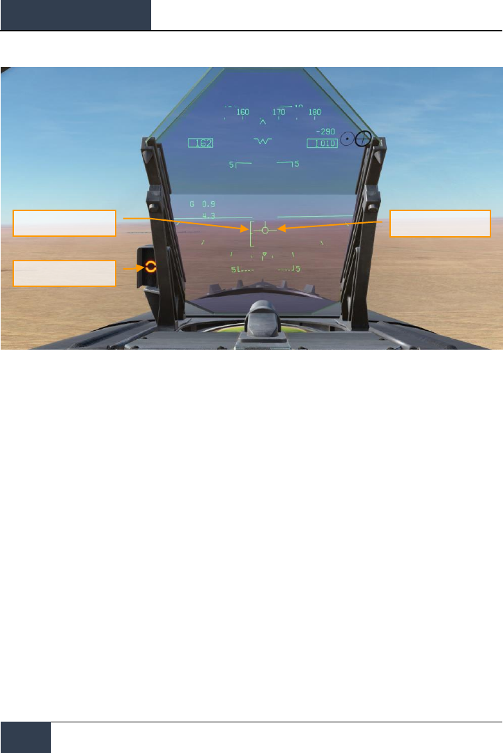
DCS
[F/A-18C]
66
PROCEDURES
Turn into the landing base leg when your wing tip aligns with the runway threshold while maintaining
on-speed AoA. Your bank angle should be 30 degrees and the HUD velocity vector should be just
below the HUD horizon line. You will need to slightly increase throttle to maintain this AoA. Continue
the on-speed descending turn until you are aligned with runway landing heading (a good idea is to
set your course line to the landing airfield along the landing runway heading).
Maintain on-speed AoA with the HUD velocity vector placed 500 feet past the runway threshold. Use
your throttle to maintain a 3 degree flight path.
At touchdown, reduce the throttles to idle and use small rudder corrections to stay aligned down the
runway roll-out.
AoA Bracket
AoA Indexer Lights
Velocity Vector

[F/A-18C]
DCS
67
HORNET COMMUNICATION SYSTEM
The DCS: F/A-18C Hornet is equipped with two ARC-210 (RT-1556) radios. These act as COMM 1 and
COMM 2 and operate as both VHF and UHF radios for air-to-air and air-to-ground voice
communications, in addition to Automatic Direction Finding (ADF).
Up two 20 channels in the 30 to 400 MHz band can be set as pre-assigned frequencies for each
radio. Guard frequency operates at 243.00 AM. Preset frequencies are set in the Mission Editor, but
can be manually edited while in flight.
To radio transmit on COMM 1 or COMM 2, the radio switch on the throttles must be pressed to the
selected radio (1 or 2).
Instant Action Mission Practice: Hornet Ready on the Ramp
How to Use the Radios
1. Select desired radio preset frequency by rotating either the COMM 1 or COMM 2 knob.
The frequency preset will be displayed on the Scratchpad.
2. Press COMM 1 or COMM 2 on the radio switch on the throttles based on radio the
frequency is tuned to.
3. Use the Radio Menu to issue your radio message.
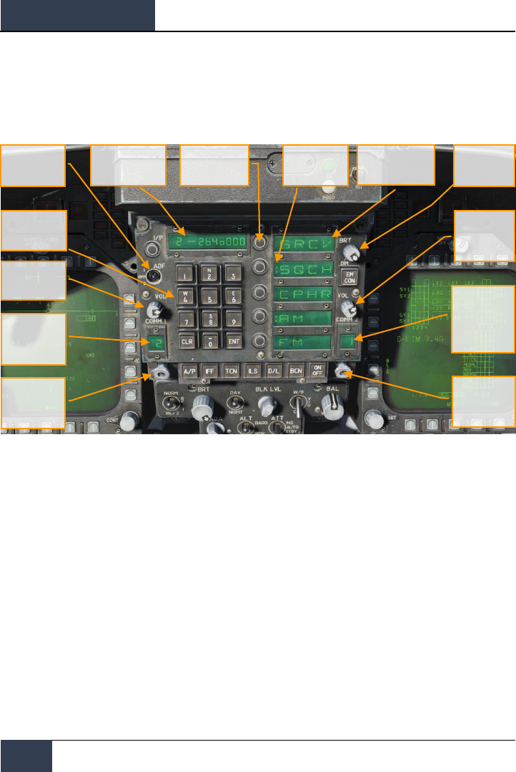
DCS
[F/A-18C]
68
HORNET COMMUNICATION SYSTEM
UFC Radio Functions
Primary control of the radios is done with the Upfront Control (UFC) include:
Figure 34. UFC Radio Functions
COMM 1 and COMM 2 Volume Control. Rotate these two knobs to control radio volume of the
two radios.
COMM 1 and COMM 2 Channel Selector Knobs. When either knob is pulled, the active frequency
is displayed on the Scratchpad Window. When rotated, they cycle through each of their 20 preset
channels. Additionally, manual frequency selection mode (M), guard channel (G) at 121.5 Mhz for
VHF and 243.0 for UHF, cue channel (C), and maritime (S) are available.
When Manual (M) is selected, the UFC keypad can be used to enter a frequency without having to
overwrite an existing preset.
COMM 1 and COMM 2 Channel Display Windows. These two windows display the selected
preset channel (1-20) and the G, M, C and S channels.
ADF Function Switch. This switch enables ADF steering on a selected radio beacon. When ADF 1 is
selected, ADF steering is based on the COMM 1 radio setting. When set to ADF 2, ADF steering is in
regards to the COMM 2 frequency. The OFF setting disables ADF steering.
Pilot Cueing
Brightness
Knob
Option Display
Window
COMM 2
Volume
Сontrol
COMM 2
Channel
Display
Window
COMM 2
Channel
Selector Knob
Option Select
Pushbuttons
Scratchpad
Window
ADF Function
Select Switch
Pushbutton
Keyboard
COMM 1
Volume Control
COMM 1
Channel
Display
Window
COMM 1
Channel
Selector Knob

[F/A-18C]
DCS
69
ADF steering is indicated on the Horizontal Situation Indicator (HSI) as a small circle. See Navigation
section of this guide.
Scratchpad Window. The selected radio preset or G, M, C, and S frequency are displayed on the
Scratchpad, by either pulling either COMM knob or rotating the knob. The Scratchpad is also used to
enter a frequency using the Manual entry (M) mode.
Option Display Windows. When a preset or G, M, C, S frequency is selected, options are displayed
on the Option Display Windows in the center of the UFC. These include:
• GRCV. When selected and colon is visible, Guard is enabled. Guard is disabled when the
colon is absent.
• SQCH. With colon visible, radio squelch is enabled to reduce the level of radio noise.
With no colon displayed, squelch is disabled.
• CPHR. No function for this Early Access version.
• AM. Colon indicates that AM modulation is selected.
• FM. Colon indicates that FM modulation is selected.
Option Select Pushbuttons. These buttons are used to select the options indicated in the Option
Display Windows.
Brightness Control Knob. Rotating this knob controls the brightness of the UFC display.

DCS
[F/A-18C]
70
HORNET MASTER MODES
HORNET MASTER MODES
The Hornet has three master modes of operation: Navigation (NAV), Air-to-Air (A/A), and Air-to-
Ground (A/G). The controls, displays and avionics equipment operations are tailored as a function of
the selected master mode. A/A master mode is entered by either pressing the A/A master mode
button or by selecting an A/A weapon with the Weapon Select Switch. When A/A is selected, the
RADAR display is placed on the right DDI and the Stores Management System (SMS) display is placed
on the left DDI. A/G master mode is selected by pressing the A/G master mode button. When neither
master button is enabled (neither button lit), the Hornet is in the NAV master mode.
Before using the Hornet navigation system, enable the system by placing the INS knob on the Sensor
Panel to the NAV position. |RIGHT CONSOLE|
HORNET NAVIGATION (NAV)
Navigation systems of the Hornet includes an Inertial Navigation System (INS) waypoints, Tactical Air
Navigation (TACAN), Automatic Direction Finding (ADF), and Instrumented Carrier Landing System
(ICLS). Together, these systems provide accurate navigation day or night and in all weather
conditions. The primary navigation indicator is the Horizontal Situation Indicator (HSI) which is most
often displayed on the central MPCD. A moving map can also be enabled with full-color capability on
the MPCD and monochrome on the DDIs. The UFC is used for navigation data entry.
The primary methods of navigation are the TACAN mode which provides steering to navigation
beacons and Waypoint based navigation points created in the Mission Editor or while in the cockpit.
Both modes provide DATA pages for each TACAN station or waypoint, bearing and range to the
location, time to reach the location, and various steering aids.
Instant Action Mission Practice: Hornet VFR Navigation
How to Navigate Using Waypoints
1. Select HSI from the SUPT DDI page
2. Select the WYPT Option Select Button
3. Use the Up and Down arrows to select waypoint as indicated between the arrows
4. Fly to the waypoint based on HSI and HUD command steering indicators

[F/A-18C]
DCS
71
Regardless of navigation method, the HSI has the following options and indicators. Option buttons for
the main HSI include:
Figure 35. HSI Option Buttons
1. POS/XXX Option. The POS Option button determines the position keeping source.
Pressing this Option Button displays the four options along the top of the DDI with an HSI
option button to return to the main HSI page without making a change. The selected
source is displayed as POS/(selected source).
Figure 36. Position Keeping Source Selection
2. UPDT Option. No function in this Early Access version.
3. SCL Option. This options allows selection of the range scale of the HSI. Successive
presses of this button select and then wrap ranges of 5, 10, 20, 40, 80, and 160 miles. The
selected scale is indicated right of the SCL legend.
4. MK Option. Pressing the MK option button saves a mark point at the location of the
aircraft when the button was pressed. Up to nine mark points can be created. After the
1
5
4
2
3
18
16
15
14
13
6
9
10
11
17
7
8
12

DCS
[F/A-18C]
72
HORNET NAVIGATION (NAV)
ninth, the first mark point will be over-written and so forth. Not implemented at Early
Access release.
5. DATA Option. With either TCN or WYPT selected as the navigation method, pressing the
DATA button will display a sublevel with additional information about the aircraft, selected
TACAN and selected Waypoint. See DATA section below.
6. WYPT Option. When selected and box, steering information is presented in regards to the
selected waypoint. See Waypoint Navigation.
7. Waypoint / Mark Point Selection. The number between the two arrows is the selected
waypoint, and the up arrow selects the next waypoint in the waypoint sequence and the
down arrow selects the previous waypoint. At the end of the waypoint sequence, mark
points are available in sequence.
8. WPDSG Option. Pressing the WPDSG designates the current navigation point as a target
waypoint (TGT). When a waypoint is designated as a target, the WPDSG legend is removed
and the WYPT legend changes to TGT. HUD symbology also reflects the change to be a
target location.
9. SEQ # Option. When selected and boxed, all waypoints of the sequence are displayed on
the HSI and dashed lines connect them in sequence. The dashed lines are removed when
the map is slewed. Successive presses of this button cycle through the sequences. The
Hornet can store three sequences.
10. AUTO Option. When selected and boxed, automatic sequence steering to the next
waypoint is enabled. WYPT must be selected as the navigation method.
11. TIMEUFC Option. Selecting this options allows time selection options from the UFC.
These include SET, ET (elapsed time) and CD (count down). Upon selecting (boxing) this
option button, the UFC lists the time options to display on the HSI and HUD.
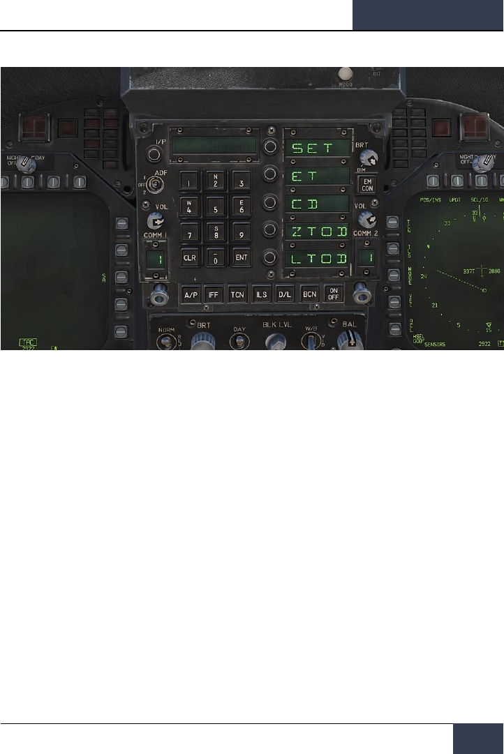
[F/A-18C]
DCS
73
Figure 37. TIMEUFC Options on UFC
SET. Displays the date.
ET. Starts incrementing time in minutes and seconds up to 59:59. Press the UFC
ENT button to start the counter and successive presses of the ENT button will
pause and start the counter.
CD. The countdown timer starts to decrement time in minutes and seconds,
starting from 06:00. Upon selection of the CD option, pressing the ENT button
starts the timer and successive presses of the ENT button pauses and start the
counter.
ZTOD. When selected, the zulu time of day is displayed.
LTOD. When selected, the local time of day is displayed.
Note that ET and CD are mutually exclusive and ZTOD and LTOD are mutually
exclusive.
12. MENU Option. Displays the TAC menu page.
13. SENSORS Option. When enabled, aerial targets detected by the RADAR in range and
azimuth are displayed on the HSI.
14. ACL Option. No function for this Early Access version.
15. VEC Option. No function for this Early Access version.
16. MODE Option. Pressing the MODE option button displays sublevel options along the left
side of the HSI. These include T UP (HSI is oriented to the flight track is always pointed
towards the top of the HSI display), N UP (true north is always at the top of the display),
DCTR (de-center placed the aircraft symbol at the bottom of the display), MAP (enable or
disable moving map), and SLEW (slew map with TDC when TDC assigned to the display).
17. ILS Option. No function for this Early Access version.
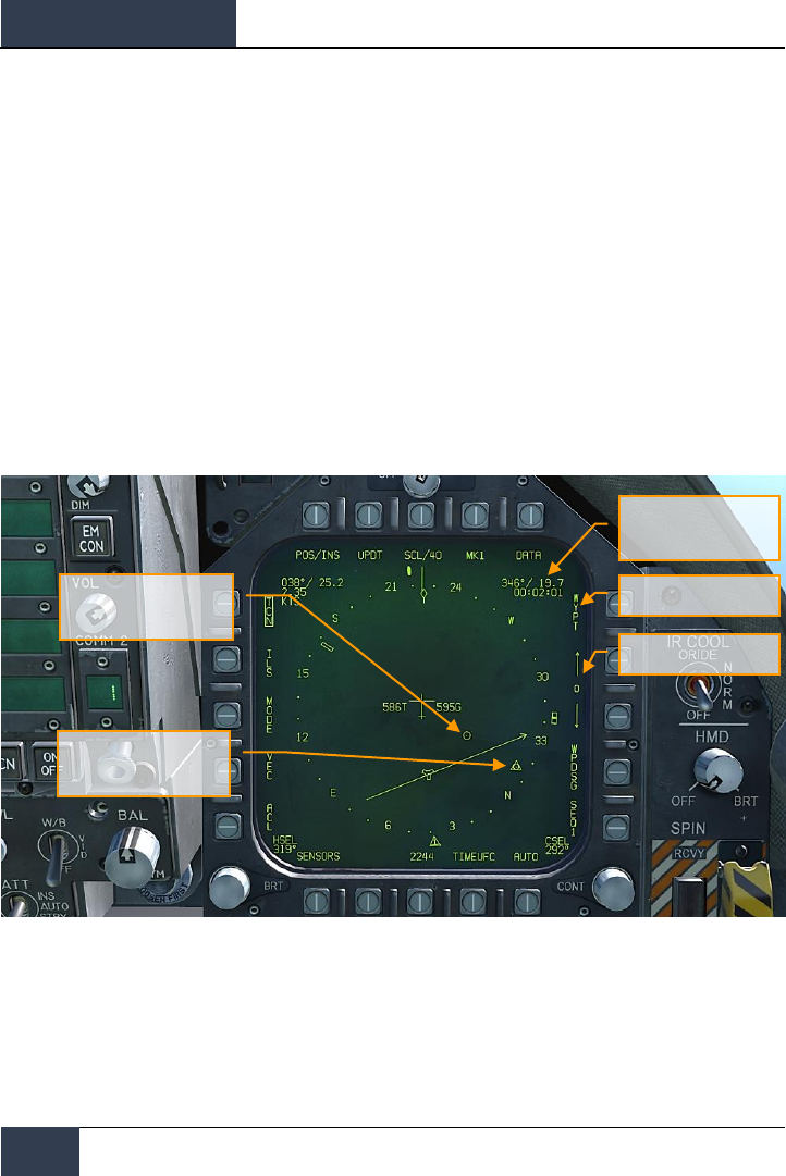
DCS
[F/A-18C]
74
HORNET NAVIGATION (NAV)
18. TCN Option. TACAN is selected as the navigation method. See TACAN Navigation
Waypoint Navigation
Waypoint navigation consists of a series of navigation points to create a navigation sequence. This
allows point-to-point steering along the sequence using automatic (AUTO) sequencing. Any waypoint
can also be designated as a target point (TGT) using the WPDSG option. Additionally, up to nine
mark point can be created that can also act as waypoints. Command heading, distance, and time to
reach the selected waypoint is provided on the HSI Waypoint Data Block and HUD.
Waypoint steering is selected by pressing the WYPT option button on the right side of the HSI. Below
are increment and decrement arrows to select the steer-to waypoint as indicated between the
arrows.
In the top right of the HSI, the bearing to, distance to and time remaining to reach the selected
waypoint are displayed in the Waypoint Data Block. Inside the compass rose, the waypoint bearing
indicator and waypoint symbol provide heading steering information.
Figure 38. HSI Waypoint Steering
Additional waypoint steering is provided on the HUD.
Waypoint Bearing Pointer
Waypoint Data Block
Waypoint Steering
Waypoint Select
Waypoint Symbol
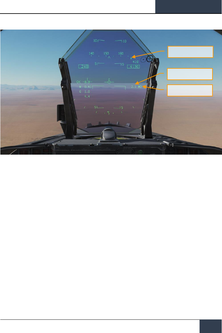
[F/A-18C]
DCS
75
Figure 39. Waypoint Steering on HUD
While in waypoint navigation steering and a waypoint selected, the WPDSG (waypoint designate)
option button on the right side of the HSI can be pressed to change the selected waypoint to a target
point. On the HUD, the target appears as a Target Designation diamond which can be slewed with
the TDC when the TDC is assigned to the HUD.
Command Heading
Waypoint Distance
Waypoint Name

DCS
[F/A-18C]
76
HORNET NAVIGATION (NAV)
Figure 40. Waypoint as Target on HUD
TACAN Navigation
The ARN-118 TACAN system provides relative bearing and/or slant range distance to a selected
TACAN station (land, ship or aircraft). TACAN range depends on aircraft altitude Line Of Sight (LOS)
to the station, but can have a maximum range of 200 miles for an airborne station and 390 miles for
a surface station. Each TACAN station has a three letter identifier which is used to identify the beacon
and is displayed on the HSI and HUD when using TCN steering.
To use TACAN steering:
1- Select TCN from the UFC
2- Press X or Y of the desired channel from the UFC Option Select Window / Button
3- Turn on the TACAN by pressing the ON/OFF button on the UFC
4- Press CLR (Clear) on the UFC keypad to clear the scratchpad
5- Using the UFC key pad, enter the desired TACAN channel and then press the ENT button
on the UFC
6- Select TCN on the HSI display
Command Heading
Target Symbol
Distance to Target
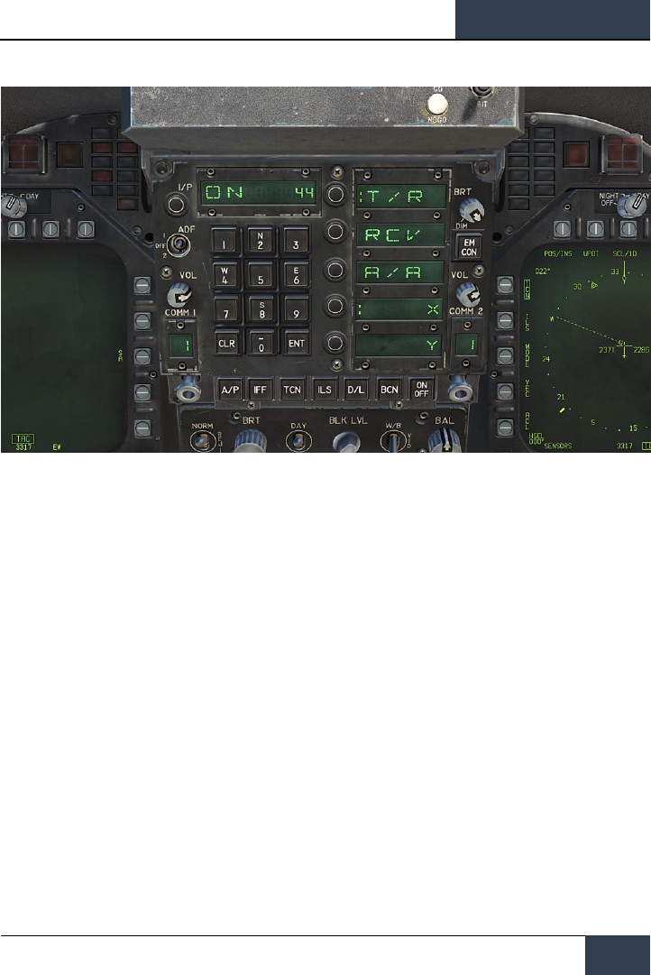
[F/A-18C]
DCS
77
Figure 41. TACAN Options on UFC
TACAN modes from the UFC include:
• T/R (Transmit / Receive). Computes bearing and measures slant range from the selected
TACAN station.
• RCV (Receive Only). Only bearing information from the selected TACAN station is
computed.
• A/A (Air-to-Air TACAN). Computes range for up to five airborne TACAN stations.
• X. Selects the X channel option.
• Y. Selects the Y channel option.
With TACAN steering selected with a valid TACAN station channel, steering to the selected station is
provided on both the HSI and HUD as follows:
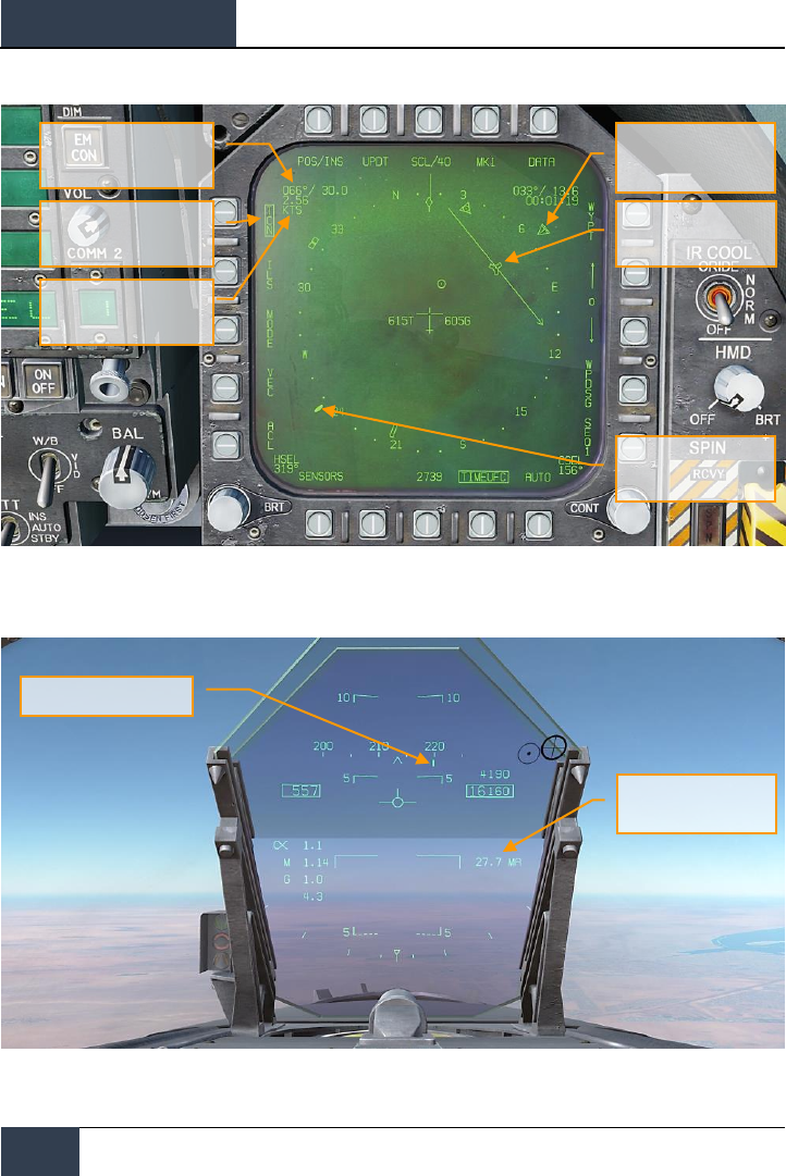
DCS
[F/A-18C]
78
HORNET NAVIGATION (NAV)
Figure 42. TACAN Steering on HSI
Figure 43. TACAN Steering on HUD
TACAN Steering Option
Button
TACAN Station Identifier
TACAN Bearing and Range
TACAN Bearing Pointer
(T)
Slant Range and TACAN
Station Identifier
TACAN Location Symbol
TACAN Steering Symbol
Tail
TACAN Command Steering
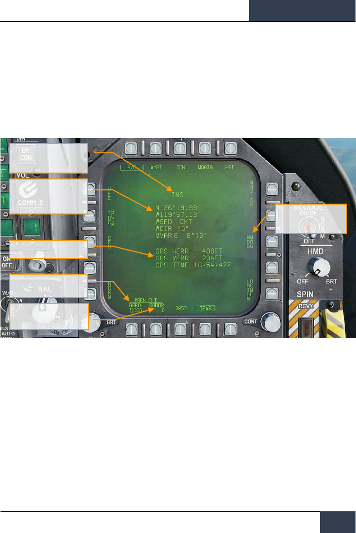
[F/A-18C]
DCS
79
DATA Option Sublevel
Upon selecting the DATA option button from the top of the HSI page, the DATA sublevel page is
displayed with further sublevels for A/C (aircraft), WYPT (waypoint), and TCN (TACAN). The HSI
pushbutton returns the MPCD/DDI to the main HSI page.
A/C (Aircraft) Sublevel
The following items are functional in this Early Access version:
Figure 44. Aircraft HSI DATA Sublevel
Note: BARO (barometric) and RADAR altitude warnings are set by pressing their pushbuttons and
then entering the desired altitude warning on the UFC for the ALT option select. Maximum value for
RADAR is 5,000 and 25,000 for BARO. Flying below the set value will trigger the ALTITUDE,
ALTITUDE alert.
Baro Altitude Option
Aircraft LAT/LONG, Wind
Speed, Wind Direction, and
Magnetic Variation
Position Keeping Source
True or Magnetic
Heading Select
GPS Position Errors
RADAR Altitude Option
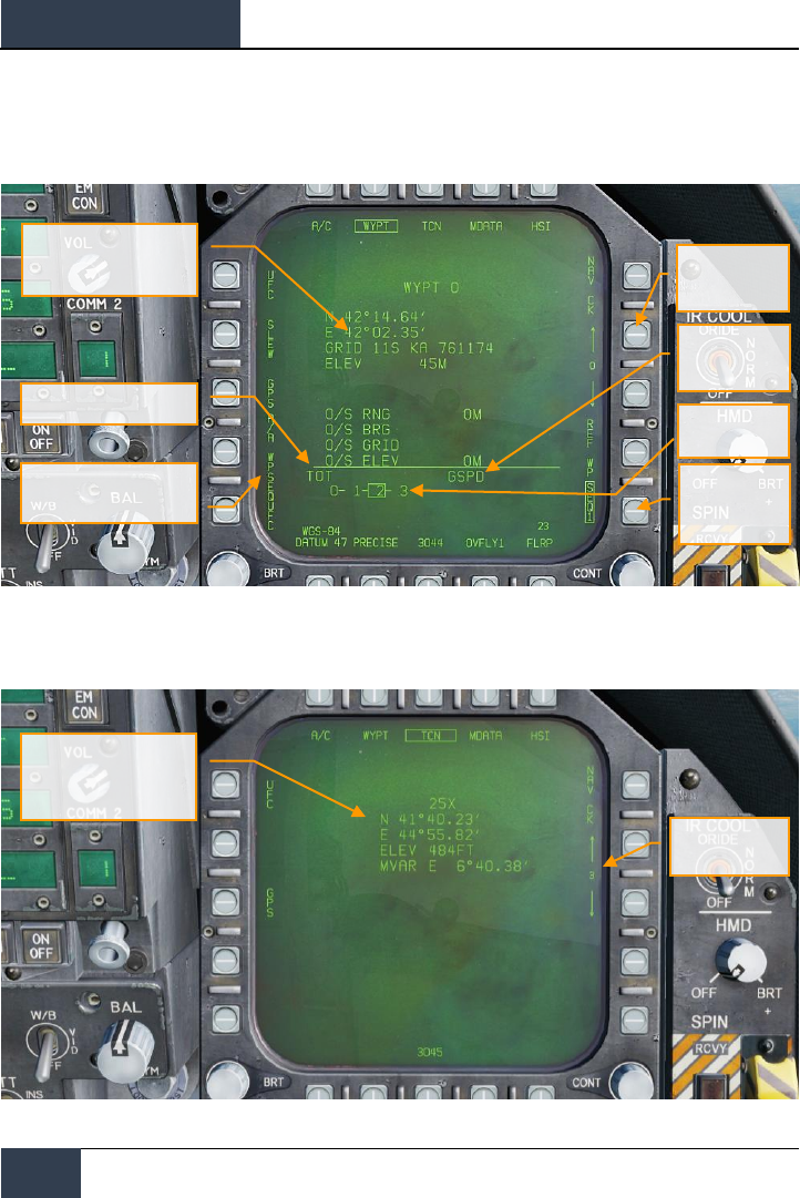
DCS
[F/A-18C]
80
HORNET NAVIGATION (NAV)
WYPT (Waypoint) Sublevel
The following items are functional in this early access version:
Figure 45. Waypoint HSI DATA Sublevel
TCN (TACAN) Sublevel
Figure 46. TACAN HSI DATA Sublevel
Waypoint Location,
LAT/LONG, MGRS, and
Elevation
Time to Waypoint
Set as Air-to-Air Waypoint
Waypoint
Selection
Waypoint
Sequence
Selection
Ground Speed
Waypoint
Sequence
TACAN Channel, LAT/LOG,
Elevation, and Magnetic
Variation
Waypoint Select

[F/A-18C]
DCS
81
Automatic Direction Finder (ADF) Navigation
A third method of navigation is Automatic Direction Finder (ADF). ADF uses radio-navigation based
on beacons in the 190 to 535 kHz range. Either radio in the Hornet can be tuned to the desired ADF
channel and receiving steering information for the selected beacon. However, no range information is
given. The bearing to the selected ADF beacon is displayed as a circle on the outer periphery of the
HSI compass rose.
How to Navigate Using ADF Beacons
1. Select either 1 (COMM 1) or 2 (COMM 2) from the ADF switch on the UFC
2. Rotate the channel selector of the selected ADF switch to the Manual (M)
3. Using the UFC keypad, enter the frequency of the desired ADF beacon into the UFC
Scratchpad and press ENT on the UFC
4. The selected ADF beacon should now appear on the HSI as a circle and the ADF code
will be heard (adjusted through the Volume Panel

DCS
[F/A-18C]
82
HORNET NAVIGATION (NAV)
Additional HSI Symbology
In addition to the HSI symbols described above, other symbols are present to assist in navigation.
These include:
Figure 47. Additional HSI Symbols
1. Compass Rose. 360 degree compass with cardinal directions. Rotation of the compass is
in reference to aircraft heading from a top-down view.
2. Lubber Line. A line marked on the compass rose that indicates aircraft heading.
3. Heading Select Marker. Heading marker on the compass rose to indicate set heading
value as indicted in the Heading Select numeric indication.
4. Course Line. Set course line through the selected TACAN station or Waypoint and rotated
to match the Selected Course numeric.
5. Aircraft Symbol. Placed in the center or de-centered in the compass rose, this indicates
the location of the aircraft.
6. Ownship True Airspeed. True airspeed of your aircraft.
7. Ownship Ground Speed. True ground speed of your aircraft.
8. Selected Heading. Heading value set using the Heading Select Switch on the MPCD.
9. Time. Time indication as selected from the TIMEUFC option button.
10. Selected Course. Course value set using the Course Select Switch on the MPCD.
11. Ground Track Pointer. Actual track of the aircraft over ground.
12. Automatic Direction Finding (ADF Symbol). When ADF is selected to a valid
frequency, this icon provides a heading cue to the selected ADF beacon. Not pictured.
1
6
11
2
5
9
8
10
3
4
7
12

[F/A-18C]
DCS
83
Setting a Course
A course can be set using the Course Select Switch on the MPCD. The selected course value is then
displayed on the HSI in the Course Select (CSEL) field and drawn through the selected TACAN or
Waypoint. The Course Line has an arrow at the end that points in the direction of the set course.
Pressing the Course Switch left and right allows the CSEL to be rotated to match the desired course.
On the HUD, the selected course is displayed as a small arrow with two dots on either side to denote
course offset. The arrow provide a horizontal situation indication relative to the Velocity Vector. The
dots left and right of the arrow indicate 4- and 8-degrees off course. The dots disappear when course
error is less than 1.25 degrees.
Figure 48. Course Setting on HSI and HUD
Autopilot Relief Modes
The Hornet includes several autopilots modes that assist the pilot in flying the aircraft. These are
selected by pressing the A/P button on the lower portion of the UFC. Upon doing so, the available
Course Line
Course Line
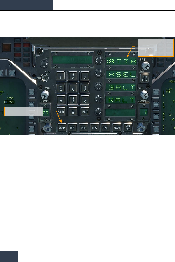
DCS
[F/A-18C]
84
HORNET NAVIGATION (NAV)
autopilots modes are listed in the UFC Option Select Windows. For this Early Access version, the pilot
assist autopilots modes include:
Figure 49. UFC Autopilot Modes
• Attitude Hold (ATTH). The aircraft will maintain the existing pitch and roll attitude
between +/- 45-degrees in pitch and +/- 70-degrees in roll.
• Heading Select (HSEL). When enabled, the aircraft will turn to and fly the heading as
set on the HSI.
• Barometric Altitude Hold (BALT). When engaged, the aircraft will maintain the current
heading and barometric altitude between 0 and 70,000 feet.
• RADAR Altitude Hold (RALT). When engaged, the aircraft will maintain current heading
and RADAR altitude between 0 and 5,000 feet.
Autopilot modes listed on the UFC are selected by pressing the Option Select Button next to the
Option Select Window of the autopilot mode. When selected, a colon is displayed next to the
autopilot name on the Option Select Window. Once selected, pressing the ON/OFF button on the UFC
enables the mode. An A/P advisory is displayed on the left DDI when an autopilot mode is engaged.
Autopilot is disengaged by pressing the Paddle Switch on the Control Stick.
Autopilot Select
Autopilot Mode Options,
Colon is Selected
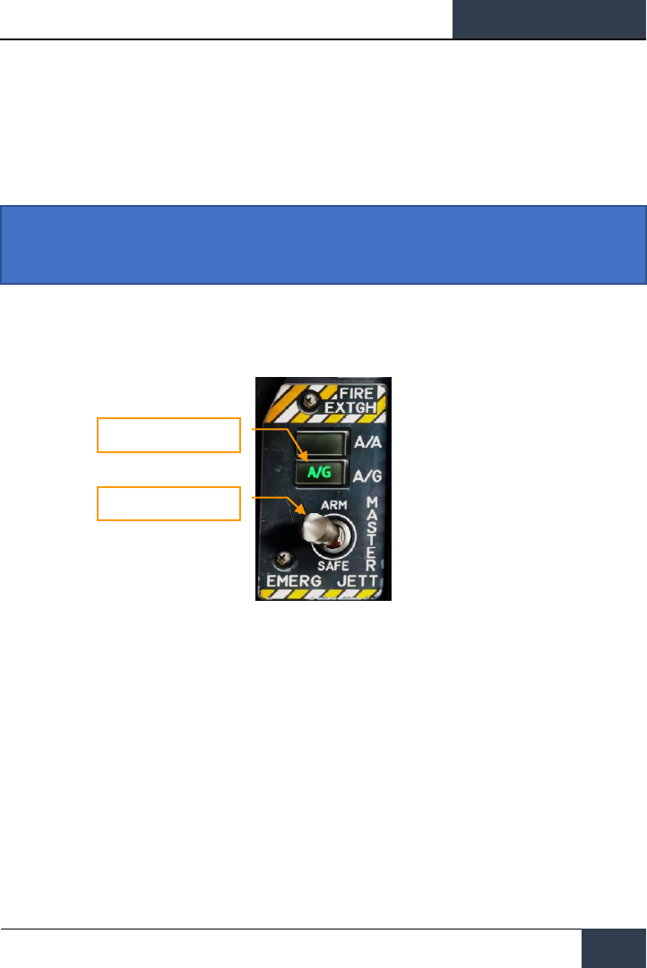
[F/A-18C]
DCS
85
HORNET AIR-TO-GROUND (A/G)
For this Early Access release of our Hornet, we are including the M61A2 gun and unguided weapons
for ground attack. In later updates, guided A/G weapons will be added. Additionally, A/G RADAR and
FLIR will also be added later during the Early Access period.
To place the Hornet in A/G mode, first press the A/G button from the Master Mode from the left
instrument panel and there must be no weight on wheels. If the Master Arm switch is placed in the
SAFE position, weapon release is inhibited and the SIM training mode is available. When in the ARM
position, weapons may be released normally.
Figure 50. A/G Master Mode Select
Air-to-Ground Stores Management System (SMS)
Bombing Page
Upon selection of the A/G master mode, the A/G SMS page is displayed on the left DDI. Based on the
priority weapon, the information on the SMS page can vary. For conventional bombs, the SMS
commonly includes the following:
Instant Action Mission Practice: Hornet CCIP Bombing
Master Mode Switch
Master Arm Switch

DCS
[F/A-18C]
86
HORNET AIR-TO-GROUND (A/G)
Figure 51. A/G Conventional Bombing SMS Page
1. Weapon Select Options. The top row of pushbuttons are used to select the desired A/G
weapon. One option is provided for each displayed weapon type (maximum 5). An
abbreviation of the selected weapon type is displayed below the pushbutton. When a
weapon is selected, the abbreviation is boxed. Pressing the button again will unselect the
weapon. If the A/G weapon is in a release condition, “RDY” is displayed below the weapon
box. Otherwise, an “X” is displayed through the weapon box.
2. Wingform Display. The wingform display provides the number, type, and status of all
stores loaded on the aircraft’s weapon stations. A weapons rack is indicated as a diamond
symbol, and the number below indicates the number of weapons loaded on the rack /
station. Various indications can be displayed below the number of weapons numeric to
indicate weapon status, such as: RDY (ready), STBY (standby), selected (SEL), LKD
(locked) and ULK (unlocked). A box is displayed around the weapon abbreviation on the
wingform when it is selected as the priority weapon. The gun rounds remaining is indicated
at the top of the wingform (578 being a full load and XXX when empty).
3. Delivery Program Options. Based on the selected weapon, it may have different
delivery options that can be adjusted using these pushbuttons along the left side of the
display. Pressing a program button then displays the possible settings for that program
option. This will be discussed ahead in the A/G Stores Programming section of this guide.
4. Program Data. This area of the display is provided to show release settings as set in the
Delivery Program Options for conventional and laser-guided bombs. When a Program
contains invalid data, the PROG and number will have an “X” through it.
1
2
3
5
4
6
7
8
9
10
11

[F/A-18C]
DCS
87
5. Program Select Option (PROG). This option is only available for conventional and laser-
guided bombs and allows the selection of five release programs for each weapon type.
Successive presses of the PROG pushbutton cycles through the programs. The selected
program is displayed at the top of the Program Data. Any changes to the program data for
a program is saved and can be retried later when the program is re-selected.
6. Tone Option. Only when the DATA option is enabled, the TONE option is displayed. This
option is used to enabled, a ½ second tone that is transmitted either over the COMM 1 or
COMM 2 radios when the pickle button is pressed. The first press of this pushbutton
changes the label to “TONE 1” and is boxed, and a second press changes the label to
“TONE 2”. A third press disables the tone function and returns the label to an un-boxed
TONE. The Master Arm switch must be set to ARM.
7. SIM Mode Option. When the Master Arm Switch is set to SAFE, the SIM option becomes
available. SIM mode allows simulated SMS page and HUD operations, but all weapon
release functions are inhibited. When in SIM mode, SIM replaces the ARM/SAFE indication
on the A/G SMS page.
8. Up-Front Control (UFC) Option. This option is displayed when the selected weapon can
have data entered for it using the UFC like weapon release quantity, interval, etc.
9. Station Step Option (STEP). The option is provided when the Stores page determines
that the weapons of the selected type are available for release on more than one weapon
station. Each successive press of the STEP push tile changes the selected weapon to the
next weapon station.
10. Gun Option. The GUN option is used to select the gun as the priority A/G weapon, or
enable the gun to be used in conjunction with delivery of another weapon (HOT GUN).
11. Master Arm Status. This displays the status of the Master Arm switch, and can be either
ARM, SAFE or SIM.
A/G Stores Programming
Programming A/G stores can be done from either A/G or NAV master modes. Up to five delivery
programs can be created for each A/G weapon except the gun. Using the PROG pushbutton, you can
cycle through the programs with successive presses. There are two primary aspects of creating a
delivery program for a weapon: The Delivery Program Options along the left side of the SMS page
and the UFC.
Delivery Program Options
For the Hornet Early Access, the A/G weapons are primarily conventional, unguided bombs that use
the same set of delivery program options. After selecting a Delivery Program Option, the left side of
the SMS page will change the pushbuttons to show the possible selections for the selected option:
• MODE (Delivery Mode)
o AUTO (Automatic)
o FD (Flight Director) – non-function for this Early Access version
o CCIP (Continuously Computed Impact Point)
o MAN (Manual Release)
• MFUZ (Mechanical Fuze)
o OFF
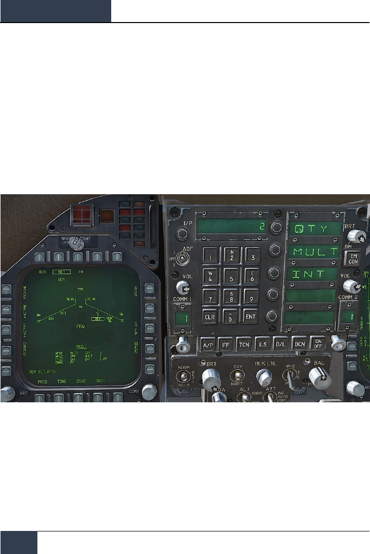
DCS
[F/A-18C]
88
HORNET AIR-TO-GROUND (A/G)
o NOSE (Nose Fuze Only)
o TAIL (Tail Fuze Only)
o NT (Nose and Tail)
• EFUZ (Electronic Fuze)
o OFF
o VT (Variable Time or Proximity)
o INST (Instantaneous)
o DLY1 (Delay 1)
o DLY2 (Delay 2)
• DRAG
o FF (Free Fall)
o RET (Retarded)
Figure 52. UFC Bomb Settings
By pressing an Option Select Key on the UFC, you can select the bomb program parameter to enter.
The selected parameter is indicated by the colon ( : ) next to the indicator of:
• Quantity (QTY). Number of bombs to release, ranging from 1 to 30. When more than
one bomb is selected, you must hold the Weapon Release Button down until all bombs in
the salvo are released.
• Multiples (MULT). Number of bombs to be released simultaneously from the weapon
stations in each salvo

[F/A-18C]
DCS
89
• Interval (INT). The ground impact spacing in feet when in AUTO, FD, and CCIP modes,
but milliseconds when on MAN mode.
After each value is entered using the UFC keypad, the ENTER button on the UFC must be pressed to
save the value to the program. Once saved, the value is displayed on the Program Data for the
selected program (1 to 5).
Another possible UFC option is the Reticle (RTCL) option. When displayed, you may enter a value in
milliradians for manual delivery release. This in turn adjust the bombing reticle on the HUD. This will
be discussed in the Manual Bombing section of this guide.
Air-to-Ground Bombing HUD
For the initial Early Access release of the Hornet, the HUD has three weapon delivery modes:
• Continuously Computed Impact Point (CCIP)
• Automatic (AUTO)
• Manual (MAN)
Continuously Computed Impact Point (CCIP) Bombing
HUD
The CCIP mode is a computed visual delivery mode with manual weapon release. This mode allows a
high degree of flexibility since the point on the ground at which the weapon will impact is
continuously indicated by a CCIP Bombing Cross on the HUD. No target designation is required. In
essence, place the thing on the thing and drop the bomb.
To use, fly to place the CCIP bombing cross over the intended target and hold the Weapon Release
Button down (pickle button). A Displayed Impact Line (DIL) is also on the HUD between the CCIP
bombing cross and the velocity vector. The pickle button must be held down until all bombs have
been released as part of the program.
After bomb release, the Time To Impact (TTI) is presented on the HUD as the Time Of Fall (TOF).
If the CCIP impact point does not lay within the HUD field of view, the CCIP Reflected Cue is shown
as a short, horizonal line on the DIL instead of the CCIP Bombing Cross. The cue is displaced to the
same distance above the bottom of the DIL as the computed position of the CCIP Bombing Cross is
below the HUD limit.
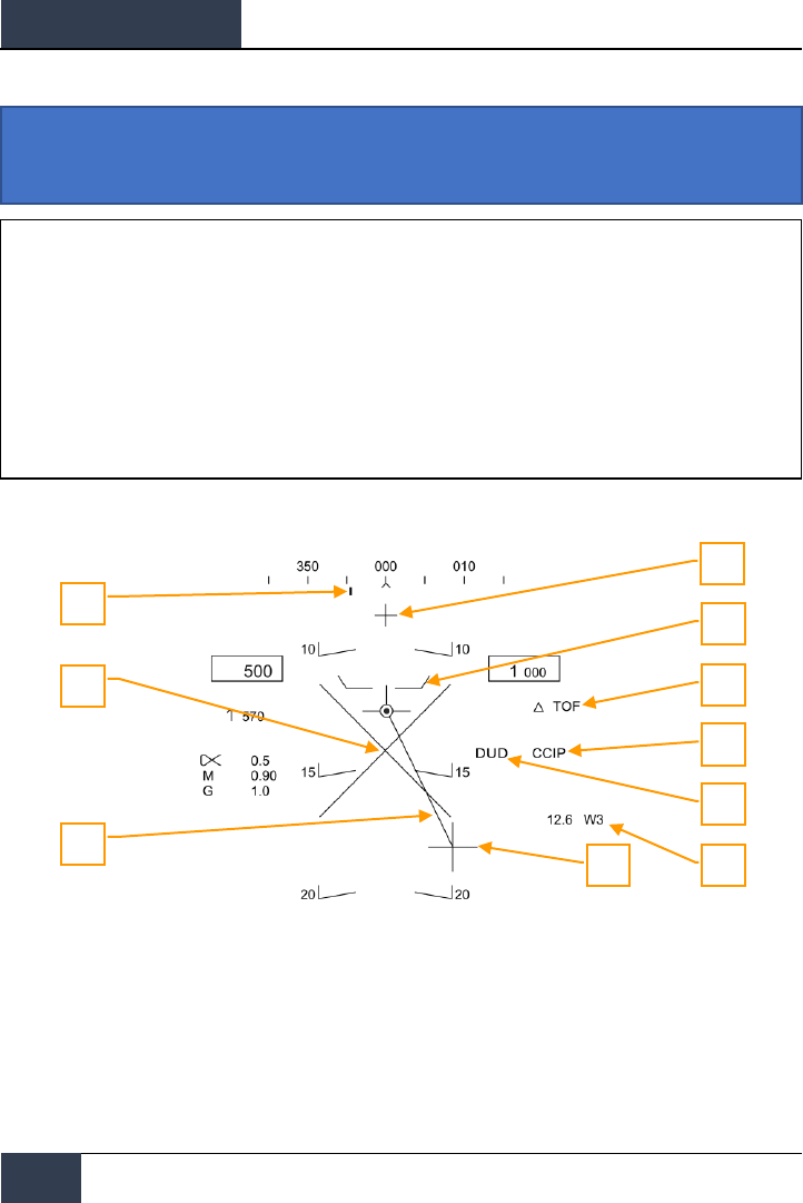
DCS
[F/A-18C]
90
HORNET AIR-TO-GROUND (A/G)
Elements of the CCIP Bombing HUD include:
Figure 53. CCIP Bombing HUD
1. Steering Point (Command Heading). this pointer on the heading scale provides steering
to the selected waypoint or TACAN station.
2. Pullup Cue. The distance between the Pull Up Cue and the Velocity Vector provides a
relative indication of a safe altitude for delivering the selected weapon. For a safe weapon
release, the Pull Up Cue should always be below the Velocity Vector. The Pull Up Cue also
provides minimum altitude release for cluster munitions.
3. Breakaway X. The flashing Breakaway X will appear on the HUD when the Pull Up Cue is
coincident or above the velocity vector.
Instant Action Mission Practice: Hornet Conventional Bombing
1
7
6
8
5
3
4
2
9
10
How to Bomb Using CCIP Mode
1. Master Mode switch to A/G
2. Select a conventional A/G bomb from the SMS page
3. Set MODE option to CCIP
4. Assign TDC to the HUD (Sensor Control Switch forward)
5. Fly to place the CCIP Bombing Cross over the target while keeping the Velocity Vector
above the Pullup Cue
6. Press and hold the Weapon Release button, bombs away!

[F/A-18C]
DCS
91
4. Displayed Impact Line (DIL). The line between the CCIP Bomb Cross and the Velocity
Vector represents the bomb fall line.
5. CCIP Bomb Cross. This cross represents the impact point of the bomb(s).
6. Waypoint and Distance. Selected waypoint number and distance to the selected
waypoint in miles. If in TACAN steering, this would be in relation to the selected TACAN
station.
7. Mode Indication. The selected bombing mode. CCIP in this situation.
8. Time of Fall. Estimated time until weapon impact of the last weapon released. This is
indicated in seconds with a “TOF” suffix.
9. Hot Gun Cue. Displayed when GUN has been selected from the SMS page. The gun can
be fired while in CCIP using the trigger.
CCIP Target Designation Option: When in CCIP mode and the TDC is assigned to the HUD, and
the CCIP Bombing Cross is within the HUD field of view, pressing the TDC displays the TD on the
HUD and it can be slewed within the HUD field of view using the TDC. The TD will initialize on the
Velocity Vector or at 7.5 degrees, whichever pitch angle is greater. When the TDC button is released,
AUTO bombing mode is entered based on the new target location.
Automatic (AUTO) Bombing HUD
The AUTO mode provides computed, automatic release of bombs. It computes release solutions for
dive, dive toss, level, and low angle lofts up to 45 degrees. This mode requires a ground designation
point from which to build the bombing solution. Command steering is provided to the appropriate
weapon release point and the weapon will release automatically at the proper time such that the
weapons hit the target.
The Mission Computer (MC) provides an Azimuth Steering Line (ASL) to provide steering to the
designated target. Designation is accomplished pressing and holding the Weapon Release Button
when the Reticle or TDC are over the target. By placing the Velocity Vector on the ASL and holding
down the Weapon Release Button, the weapon will release at the proper time and account for wind.
Instant Action Mission Practice: Hornet Conventional Bombing

DCS
[F/A-18C]
92
HORNET AIR-TO-GROUND (A/G)
Target Designation
In order to calculate a bombing solution in AUTO mode, a target first must be designated. For this
initial Early Access Hornet, this can be done by:
• Designating a waypoint location as the target as set on the HSI using the WPDSG option.
• Flying to place the reticle pipper over the target and designate it with the Weapon Release
Button
• Setting the TDC to the HUD and slewing the TDC over the target and designating it by
pressing the TDC switch
How to Bomb Using AUTO Mode
1. Master Mode switch to A/G
2. Select conventional A/G bomb from the SMS page
3. Set MODE option to AUTO
4. Assign TDC to the HUD (Sensor Control Switch forward)
5. Fly to place the Reticle over the target and then designate the target by pressing the
TDC switch
6. While flying to keep the Velocity Vector above the Pullup Cue, keep the Velocity Vector
over the Azimuth Steering Line (ASL), and hold the Weapon Release button down
when the Release Cue appears on the HUD
7. Release the Weapon Release Button once all bombs in the pass have been released
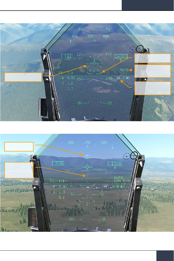
[F/A-18C]
DCS
93
Figure 54. AUTO Bombing HUD, No Designation
Figure 55. AUTO Bombing HUD, No Designation <7.5 Degree Dive Angle
Reticle
Pullup Cue
Hot Gun Cross
Displayed Impact
Line (DIL)
Mode Indication
Waypoint and Distance

DCS
[F/A-18C]
94
HORNET AIR-TO-GROUND (A/G)
1. Reticle. This Reticle consists of tic marks in 50-mil diameter circle with a pipper in the
center. The TDC must be assigned to the HUD (Sensor Control Switch forward) for the
reticle to be visible on the HUD. The Reticle serves as a steering reference for weapon
delivery by having the pilot fly the aircraft to place the pipper of the Reticle over the
intended target and then designating it.
2. Pullup Cue. The distance between the Pull Up Cue and the Velocity Vector provides a
relative indication of a safe altitude for delivering the selected weapon. For a safe weapon
release, the Pull Up Cue should always be below the Velocity Vector. The Pull Up Cue also
provides minimum altitude release for cluster munitions. When the Velocity Vector is below
the Pullup Cue, the Breakaway X is displayed on the HUD.
3. Mode Indication. Indication of the selected bombing mode from the Stores page.
4. Waypoint and Distance. The selected waypoint number and the distance to the
waypoint in miles. If the target is co-located with the waypoint, this will also be the Target
Distance. This may also be in reference to TACAN steering.
5. Hot Gun Cue. Displayed when GUN has been selected from the SMS page. The gun can
be fired while in AUTO mode using the trigger.
6. Displayed Impact Line (DIL). The flashing, dashed DIL is displayed on the HUD when
dive angle is greater than 7.5 degrees. The DIL extends from the Vertical Velocity indicator
to the center of the Reticle.
Once the target is designated, the Azimuth Steering Line (ASL) is displayed on the HUD and
provides steering direction to the target as indicated by the Steering Pointer on the Heading
Scale. When within the HUD field of view, the target will also be marked with a diamond Target
Designator that denotes the targets line of sight location. By flying the aircraft to keep the
Velocity Vector on the ASL, the aircraft will assume the correct azimuth steering to satisfy the
bombing solution. By flying to maintain the Velocity Vector over the Pullup Cue, adequate
release altitude is also assured to avoid weapon fragmentation and weapon fuzing.
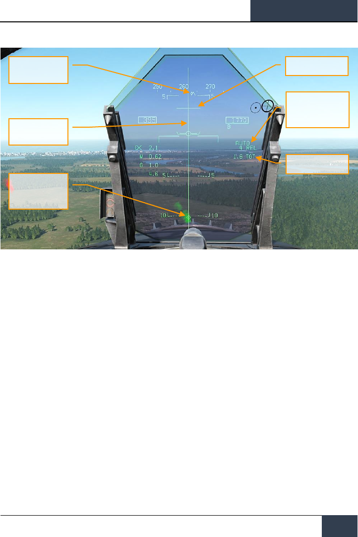
[F/A-18C]
DCS
95
Figure 56. AUTO Bombing HUD, Designated
1. Steering Pointer. Once a target has been designated, the cue changes from a line
indicating navigation steering (waypoint or TACAN), to a diamond that indicates steering to
the designated target.
2. Release Cue. This small, horizonal line centered on the ASL is displayed when the target
is designated, and it indicates both in-range and release cue anticipation indicator. For high
drag bombs, the cue is displayed 5 seconds before release.
3. Azimuth Steering Line (ASL). The ASL is always perpendicular to the horizon and
provides an azimuth steering reference to the designated target with respect to the
Velocity Vector. The ASL is removed from the HUD when the target command steering is
greater than 90 degrees
4. Target Designator (TD). This symbol shows the line of sight to the designated target.
The symbol is 9 mils long on each side and has a pipper in the center when the TDC is
assigned to the HUD. Using the TDC, the TD can be moved within the HUD field of view
(useful when refining a target designation). If the TD is outside the HUD field of view, it is
clamped to the nearest side and flashes. The TD is removed from the HUD when the target
command steering is greater than 90 degrees.
5. Time To Go / Time To Impact. Upon target designation, the estimated time to release is
indicated in seconds with an “REL” suffix. After the bomb(s) is released, this field indicates
the estimated Time To Impact and is indicated in seconds of the last weapon released with
a “TTI” suffix.
6. Target Range. When the target is designated, the range to the target is indicated in
miles.
Steering Pointer
Release Cue
Mode and Time To Go
/ Time To Impact
Target Range
Azimuth Steering
Line (ASL)
Target Designator
(TD)

DCS
[F/A-18C]
96
HORNET AIR-TO-GROUND (A/G)
Note that when the target is not within the HUD field of view, the target arrow is displayed that
points in the direction of the target and the number of degrees to the target is displayed next to the
arrow.

[F/A-18C]
DCS
97
Manual (MAN) Bombing HUD
Manual mode is a backup mode for visual delivery. From the A/G SMS page with MAN selected as the
delivery mode, the UFC function allows the pilot to adjust the HUD reticle position in mils. By
understanding the bombing table data for a weapon (release angle, altitude and airspeed), the
manual mode can be an effective means to place bombs on target.
Instant Action Mission Practice: Hornet MAN (Manual) Bombing
How to Bomb Using MAN Mode
1. Master Mode switch to A/G
2. Select weapon
3. Select conventional A/G bomb from SMS page
4. Set MODE option to MAN
5. Select the UFC Option Select Button on the A/G SMS page and enter the desired mils
setting on the UFC using the keypad. When complete, press the ENTER button on the
UFC
6. Fly to place the Reticle over the target based bombing table data
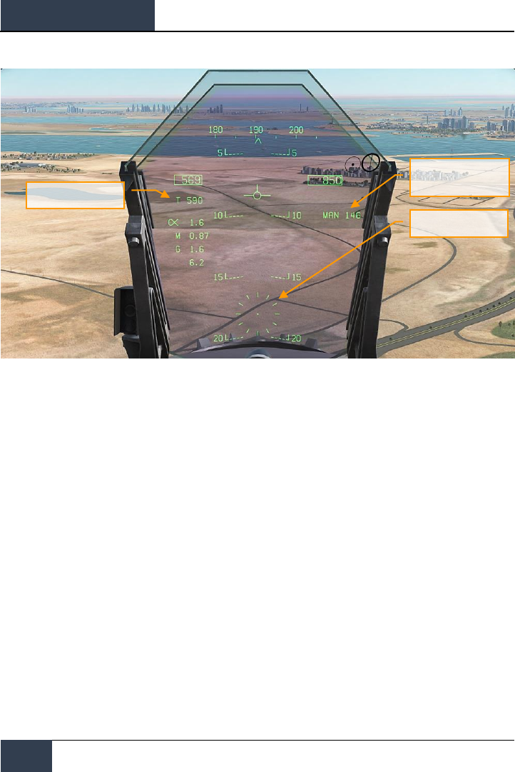
DCS
[F/A-18C]
98
HORNET AIR-TO-GROUND (A/G)
Figure 57. MAN (Manual) Bombing HUD
1. Manual Reticle Depression. Depression of the Reticle in mils based on the UFC input.
2. Reticle. Fixed Reticle at static position on the HUD based on the manual mils setting.
3. True Airspeed. When in MAN mode, True Air Speed (T) is displayed below the indicated
airspeed box.
True Airspeed
Manual Reticle
Depression
Reticle

[F/A-18C]
DCS
99
Air-to-Ground Gun and Rockets
Two modes for the A/G gun and rockets are available from the A/G Stores page: CCIP and MAN.
These can be enabled by selecting the weapon from the A/G SMS page and then selecting the
desired delivery mode. They feature either a “point and shoot” CCIP reticle or a manually adjusted
manual sight based on a manual mils setting. Both the A/G Gun and Rockets are very similar in their
programming, HUD, and delivery modes.
Instant Action Mission Practice: Hornet A/G Gun
Instant Action Mission Practice: Hornet Rockets
How to Use A/G Guns
1. Master Mode switch to A/G
2. Select/box GUN on the A/G SMS page with no other weapon selected
3. Select Mode as CCIP
4. Fly to place the pipper in the center of the Reticle over the target and hold down the
trigger when the IN RNG or SHOOT cue appear on the HUD
How to Use Rockets
1. Master Mode switch to A/G
2. Select rockets at the top of the A/G SMS page
3. Select Mode as CCIP Mode
4. Fly to place the pipper in the center of the Reticle over the target and hold down the
trigger when the IN RNG or SHOOT cue appear on the HUD
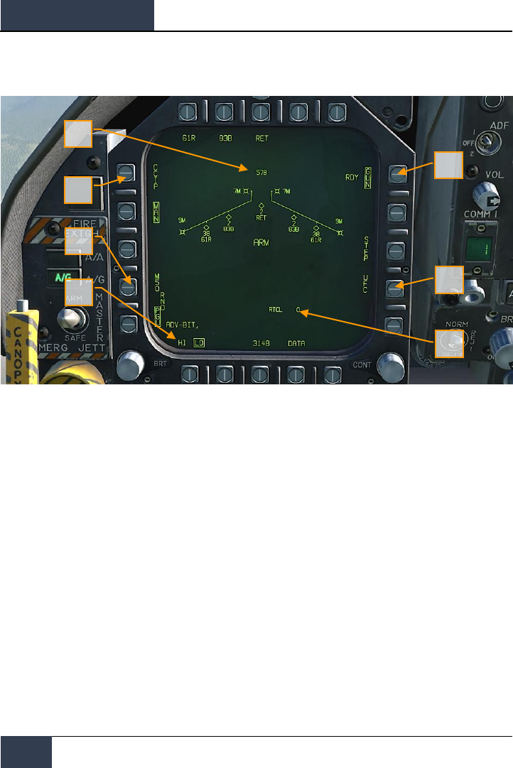
DCS
[F/A-18C]
100
HORNET AIR-TO-GROUND (A/G)
A/G Gun SMS Page
Figure 58. A/G Guns SMS Page
1. A/G Gun Option. The A/G gun is selected by pressing the GUN Option Select Button
on the A/G SMS page. If another weapon is selected, the gun will operate in Hot Gun
mode (fixed 2,000 ft gun cross). When selected, the GUN legend is boxed and an RDY
(Ready) indication is displayed to the left of the box.
2. Mode Selection. Separate buttons are available for CCIP and MAN modes. Selecting
a mode boxes the legend.
3. Gun Ammunition Type. Gun ammunition can be selected between M50 and PGU-
28B 20mm rounds. The selected gun round type is boxed.
4. Gun Fire Rate. HI (High) and LO (Low) gun fire rates can be selected with the
selection being boxed.
5. UFC. When the Mode is set to MAN (Manual), the UFC Option Select Button is
displayed. Pressing this button boxes the legend and allows the pilot to manually
enter the gun reticle depression on the UFC. The value can range from 0 to 270 mils.
Once complete, the ENTER button on the UFC is pressed to save the value. Note that
this value is not saved to a program.
6. Reticle Setting. Next to the RTCL is the entered reticle setting in mils.
7. Gun Rounds Remaining. At the top of the Wingform, the number of gun round
remaining is displayed, with a full load being 578 rounds.
2
3
4
1
5
6
7
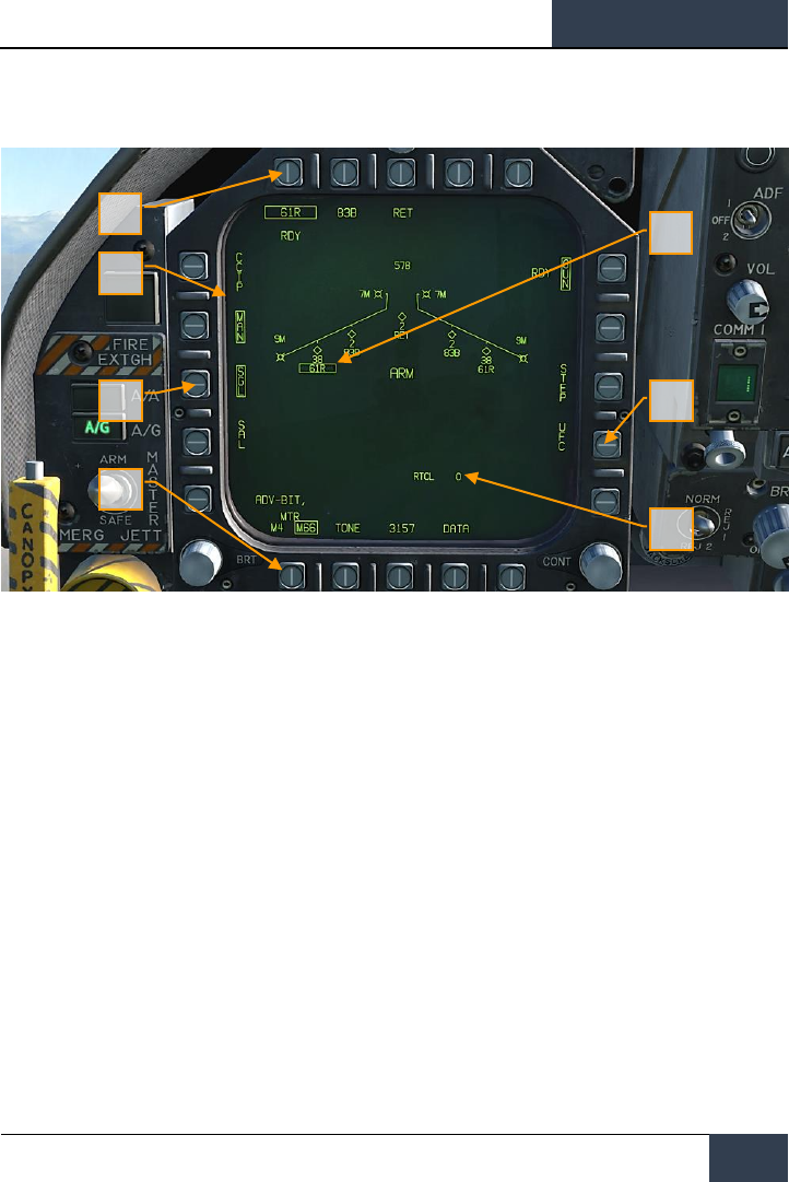
[F/A-18C]
DCS
101
Rockets SMS Page
Figure 59. Rockets SMS Page
1. Rocket Selection. The top row of options is used to select the desired A/G weapon.
One option is provided for each displayed weapon type (maximum 5). An abbreviation
of the selected weapon type is displayed below the push tile. When a weapon is
selected, the abbreviation is boxed. Pressing the button again will unselect the
weapon. If the A/G weapon is in a release condition, “RDY” is displayed below the
weapon box. Otherwise, an “X” is displayed through the weapon box.
2. Wingform Indication. When a rocket pod is selected, its indication on the Wingform
will boxed. Next to the rocket type abbreviation, the number of remaining rockets in
the pod on the station is indicated. Successive presses of the STEP button will cycle
the selected weapon station of rockets of the same type.
3. Mode Selection. Separate buttons are available for CCIP and MAN modes. Selecting
a mode boxes the legend.
4. Firing Mode. Options for SGL (single) and SAL (salvo) are displayed when more than
one rocket pod of the same type is loaded on the aircraft. When SGL is selected, one
rocket will be launched with each press of the Weapon Release Button. When SAL is
selected, two rockets will be launched with each press of the Weapon Release Button,
from different rocket pods.
When SAL is selected, the weapon STEP option is not available.
1
3
4
5
6
7
2
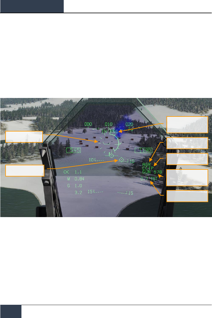
DCS
[F/A-18C]
102
HORNET AIR-TO-GROUND (A/G)
5. MTR (Motor) Type. Most rockets can have one of two motor types: M4 or M66.
Presses of the MTR Option Select Button cycles between the two types with the
selected being boxed.
6. UFC. When the Mode is set to MAN (Manual), the UFC Option Select Button is
displayed. Pressing this button boxes the legend and allows the pilot to manually
enter the rocket reticle depression on the UFC. The value can range from 0 to 270
mils. Once complete, the ENTER button on the UFC is pressed to save the value.
7. Reticle Setting. Next to the RTCL is the entered reticle setting in mils.
A/G Gun and Rocket HUD
Figure 60. A/G Gun HUD
In Range / Shoot Cue
AGR Ranging Active
Mode
Weapon Type and
Number Remaining
Range to Target
Reticle
Target Designator
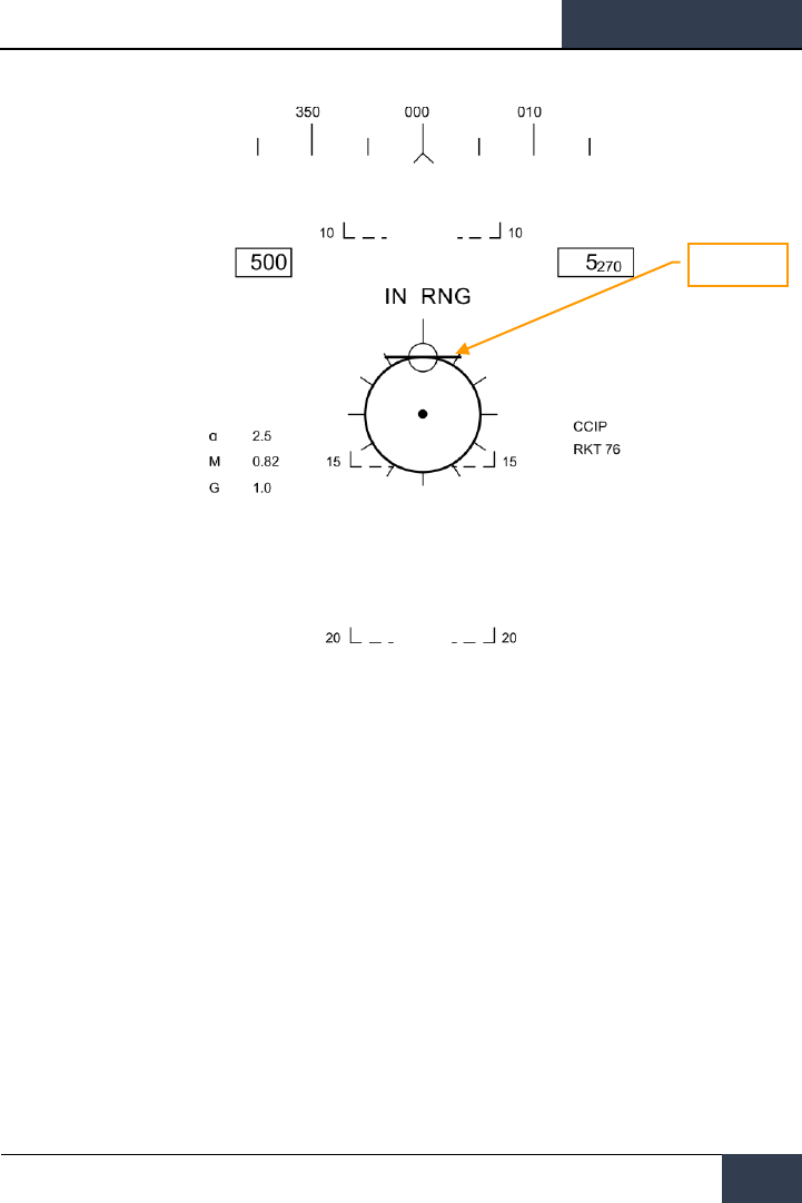
[F/A-18C]
DCS
103
Figure 61. Rocket HUD
1. Reticle. This Reticle consists of tic marks in 50-mil diameter circle with a pipper in the
center. When in CCIP mode, the Reticle indicates the calculated impact point of the gun
rounds/rocket. When in MAN mode, the reticle is adjusted based on the depressible mils
setting from the SMS page/UFC.
When in CCIP mode, an analog range bar is inscribed within the reticle. Slant range is
provided by the RADAR via Air to Ground Ranging (AGR) and barometric altitude. Each tic
mark on the reticle represents 1,000 feet of slant range and can indicate ranges from 0 to
23,000 feet. The bar will rotate clockwise to indicate increasing range and rotate counter-
clockwise to indicate decreasing range.
2. In Range / Shoot Cue. When in CCIP mode and the gun/rocket is within maximum slant
range of the pipper’s aim point, the “IN RNG” cue is provided. If however there is a
designated ground target, the “SHOOT” cue will be displayed if the gun/rocket is within
range of the target.
3. Mode. The selected delivery mode for the gun/rocket is indicated as either CCIP or MAN
based on the SMS page program setting.
4. AGR Ranging Active. When in CCIP mode and the RADAR is using AGR to determine
range, the RDR indication is displayed.
Rocket Bar

DCS
[F/A-18C]
104
HORNET AIR-TO-GROUND (A/G)
5. Weapon Type and Number Remaining. The selected weapon name and the number of
remaining rounds/rockets are displayed and updated as weapons are expended. This will
display either GUN or RKT (rockets).
6. Range to Target. When a target has been designated and in CCIP mode is enabled, the
range to the target is displayed in miles.
7. Target Designator. When the TDC is assigned to the HUD, the TD is displayed as a
diamond within the HUD field of view with a pipper in the center. The TDC can then slew
the TD within the HUD field of view.
When in MAN mode, true airspeed is displayed below the calibrated airspeed box.
Pressing the Cage/Uncage Button will fix the CCIP Reticle to 5,000 feet slant range.
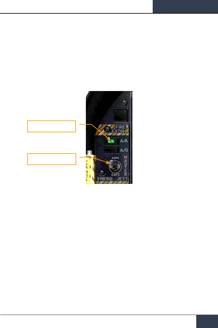
[F/A-18C]
DCS
105
HORNET AIR-TO-AIR (A/A)
Initial air-to-air weapons of the DCS: F/A-18C Hornet include the internal M61A2 20mm gun and the
AIM-9L/M/P Sidewinder short-range missile.
For air-to-air weapon employment, you will need to be airborne with landing gear up and have the
Master Arm switch set to ARM and A/A selected. When the Master Mode switch in in SAFE, the
priority weapon indications on the HUD and RADAR will have an “X” through them. Also when in
SAFE mode, the SIM training option is available.
Figure 62. A/A Master Mode Select
Master Mode Switch
Master Arm Switch

DCS
[F/A-18C]
106
HORNET AIR-TO-AIR (A/A)
Air-to-Air RADAR
Perhaps the most important sensor of the F/A-18C is its AN/APG-73 RADAR. The AN/APG-73 is an x-
band, all-weather, coherent, multimode, multi-waveform search-and-track sensor that uses
programmable digital processors to provide great flexibility in air-to-air tasks.
For this Early Access Guide, we will first discuss aspects of the RADAR that spans multiple modes,
and then later we will discuss RADAR functions specific to unique applications/weapons.
Basic Air-to-Air RADAR Information
The AN/APG-73 is a pulse-Doppler, look-down / shoot-down RADAR with both Beyond Visual Range
(BVR) and close in, Air Combat Maneuvering (ACM) modes of operation. For this Early Access version
of our Hornet, we are including the Range While Search (RWS), Single Target Track (STT), and
several ACM modes.
The air-to-air RADAR display uses a standard B-scope format in which the ownship (your aircraft) is
located in the bottom center of the display. As such, all indications on the b-scope are ahead of the
ownship. Targets on the scope are displayed in range from the closest being at the bottom and the
more distant being toward the top. Contacts left and right of the ownship are represented as being
indicted left and right of the center of the display to indicate azimuth.
Important, basic components of the b-scope include:
Figure 63. A/A RADAR Basic Symbols
1. B-sweep. The B-sweep is a vertical sweep on the display that indicates the instantaneous
azimuth position of the RADAR antenna.
B-sweep
Option Select Button
Antenna Elevation Caret
Target Symbols
Range Scale
TDC Acquisition
Cursor
AOJ “Dugout”

[F/A-18C]
DCS
107
2. Antenna Elevation Caret. The antenna elevation caret symbol indicates antenna
elevation in the vertical plane. The symbol is pitch and roll stabilized in reference to the
ownship horizontal plane. In search modes, the symbol responds to the RADAR elevation
control on the throttles.
3. Range Scale. The right side of the b-scope represents RADAR range. The scale includes
marks for ¼, ½, and ¾ of the selected RADAR range.
4. TDC Acquisition Cursor. Consisting of two parallel, vertical lines, this cursor is moved in
response to Throttle Designation Control (TDC) commands on the throttles. When in a
RADAR search mode, the altitude band being covered by the RADAR beam is indicated
above and below the cursor. When placed over a target symbol, the contact’s airspeed is
indicated to the left of the cursor and it’s altitude is displayed to the right.
5. Target Symbols. Target symbols are displayed as solid rectangles (bricks). The horizonal
position of the target symbol indicates angular position in respect to ownship heading. The
vertical position indicates range.
6. AOJ “Dugout”. Targets that are denying the RADAR range information are placed at the
top of the b-scope in the Angle On Jam (AOJ) “dugout”. Only target azimuth information is
available.
7. Pushbuttons. Around the periphery of the RADAR display are 20 buttons that can be used
to control RADAR modes and parameters. Depressing a button will enable or disable the
function, or successive depressions will cycle through all available options for that function.

DCS
[F/A-18C]
108
HORNET AIR-TO-AIR (A/A)
Range While Search (RWS)
Range While Search (RWS) is the default search mode for air-to-air or when an air-to-air missile is
placed in priority. RWS mode provides all-aspect (nose-on, tail-on) and all altitude (look-up, look-
down) target detection. The display shows range as the vertical axis and azimuth angle on the
horizontal.
While in RWS mode, the RADAR can maintain up to 10 trackfiles.
Instant Action Mission Practice: Hornet A/A RADAR
How to Use RADAR in Beyond Visual Range Mode
1. RADAR control switch on the Sensor Panel to Operate (OPR)
2. Master Mode switch to A/A or NAV (A/A and A/G unselected)
3. Select Attack RADAR (ATTK RDR) from the TAC page on the right DDI
4. Use Throttle Designator Control (TDC) to move the TDC cursor on the RADAR display
tactical area
5. Lock the target by either pressing down on the TDC or pressing the Sensor Control
switch to the right, or…
6. Place TDC not over a target symbol and press Sensor Control switch right to lock
closest target in RADAR scan volume
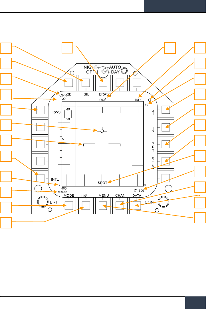
[F/A-18C]
DCS
109
Information and functions of RWS mode consist of:
Figure 64. Range While Search (RWS)
Primary control of the air-to-air RADAR is done with the Throttle Designator Control (TDC). This can
be used to position the TDC cursor and pressed to initiate an action.
1. Operational Mode. When the RADAR operating and emitting, this indicator shows OPR.
When the RADAR is in standby mode, it displays as STBY.
2. TDC Control Indication. When the RADAR display is selected for TDC control, this
diamond symbol is displayed in the top right corner of the display. Selecting the RADAR for
TDC control is done by moving the Sensor Control Switch to the right. Note that the RADAR
is normally placed on the right DDI.
3
4
5
1
26
25
24
23
22
21
20
19
18
17
6
7
2
8
9
10
11
12
13
14
15
16

DCS
[F/A-18C]
110
HORNET AIR-TO-AIR (A/A)
3. Elevation Bar Scan. When in RWS, successive presses cycle between 1, 2, 4 and 6 bars
of raster scanning. The greater the number of bars equates to a larger elevation volume
being scanned. However, the greater the number of bars equates to a longer period of
time to complete a complete scan (frame). Bar spacing is generally 1.3 degrees; however,
when 5 nm scale is selected, it is 4.2 degrees.
4. Silent (SIL) Mode. When SIL mode is selected (boxed), the RADAR ceases scan
operation and places the RADAR in standby mode. This is also indicated by the Iron Cross
shown in the lower left portion of the display.
When in SIL mode, the ACTIVE option is available in the top left corner of the display
(replaces target ageing indication). When pressed, the RADAR will conduct one complete
scan / frame based on the current RADAR settings and properties. Once the scan is
complete, it will automatically return to SIL mode.
5. Erase. By pressing the ERASE push button, all target history on the RADAR display are
removed until detected and displayed again. This also removes all history during Silent
(SIL) operation. This can be useful when a long age time is selected.
6. Heading. Ownship heading in degrees. This is generally the magnetic heading but true
heading can be selected from the HSI/DATA/A/C sublevel.
7. Weapon and Number. The name of the priority weapon and the quantity of the weapon
remaining.
8. Display Range. Selected display range of the RADAR. Possible settings are 5, 10, 20, 40,
80 and 160 nm.
9. Range Increment. Pressing this pushbutton increases the RADAR display range. When at
maximum range, the increment arrow is no longer displayed. The arrow and function is
removed if the RADAR is in STT mode.
10. Range Decrement. Pressing this pushbutton decreases the RADAR display range. When
at minimum range, the increment arrow is no longer displayed. The arrow and function is
removed if the RADAR is in STT mode.
11. SET. Pressing the SET pushbutton will save the RADAR settings for the weapon in priority.
This includes display range, elevation bar scan, azimuth, PRF, and target ageing.
12. RESET. When pressed, the RADAR settings are returned to the default settings of the
weapon in priority.
13. Spot Light mode. When the TDC designation switch is pressed and held for greater than
one second, the RADAR will conduct a 22-degree in azimuth bar scan of the location of the
TDC location using the current PRF and bar settings. During this, the SPOT indication is
displayed in the bottom center of the display. While in Spot Light mode, the TDC can be
slewed 60 degrees. To cease Spot Light mode, the undesignated button is pressed.
14. Altitude. Ownship altitude.
15. DATA. Press this pushbutton to change the RADAR display to the DATA sublevel.
16. CHAN. Select the radio frequency channel on which the RADAR will transmit. When
selected, the CHAN indicator is replaced with AUTO MAN and the DCLTR option is replaced
with the corresponding channel. Successive presses of the AUTO MAN button cycles
between automatic and manual channel selection.

[F/A-18C]
DCS
111
17. MENU. Press to return to the TAC page.
18. Azimuth Scan. The RADAR can have azimuth scan settings of 20, 40, 60, 80, and 140
degrees. Pressing this pushbutton cycles between the settings with successive presses.
19. MODE. Successive presses commands the RADAR to RWS, VS, or TWS modes. (not
functional for this Early Access)
20. Airspeed. Ownship airspeed in IAS and Mach.
21. Sensitivity Indicator. Indication of RADAR level of gain when detecting contacts. High
numbers indicate high sensitivity and low numbers indicate low sensitivity.
22. PRF. Pulse Repetition Frequency (PRF) selection between Medium (MED), High (HI), and
INTL (Interleaved). Medium PRF minimizes “blind zones” reduces false targets, better all-
aspect detection, but has less detection range. High PRF has greater range, but has inferior
low to medium aspect detection. Interleaved alternates Medium and High bar coverage.
23. Horizon Line. Mirror of the HUD horizon line.
24. Velocity Vector. Mirror of the HUD velocity vector and is displayed at a fixed position and
used in conjunction with the moving horizon line to indicate ownship flight path pitch and
roll
25. RADAR Mode. Indication of the selected RADAR mode.
26. RF Channel. The RADAR’s radio frequency channel as selected from the CHAN
pushbutton.
Air-to-Air RADAR HOTAS Controls
When flying air combat missions, it is very helpful to keep your hands on the stick and throttle and
not have to take your hands off them to manipulate controls. The Hornet has an excellent set of
Hands On Throttle and Stick (HOTAS) controls. Here are some of the more important HOTAS
functions to know for air-to-air combat:
Control Stick
On the control stick, the Sensor Control Switch and the Undesignated Button are vital. When in
Beyond Visual Range (BVR) mode, pressing the Sensor Control Switch to the right will set TDC
control to the RADAR when on the right DDI. When the display has the TDC assigned to it, a
diamond with a dot in the center is displayed in the top right corner of the display.
Pressing the Sensor Control Switch to the right when the TDC is already assigned to it will place the
RADAR in Auto Acquisition (AACQ) mode. If the TDC if over a target symbol when AACQ is
commanded, it will instruct the RADAR to lock on to that target. If AACQ is pressed with no target
symbol under the acquisition symbol, then the RADAR will attempt to lock on to the closest target
within the selected RADAR scan volume.
Sensor Control Switch. There are two general modes for this four-way switch. When in air-to-air
mode:
When in Beyond Visual Range (BVR) mode, it functions as:
• Forward: Switch to Air Combat Maneuvering (ACM) mode with Boresight being selected by
default
• Aft: Assigned TDC to center, MPCD

DCS
[F/A-18C]
112
HORNET AIR-TO-AIR (A/A)
• Left: Assigns TDC to left DDI
• Right: TDC to right DDI or enters RADAR in Auto Acquisition mode if TDC already assigned
to the right DDI
When in ACM mode, the Sensor Control Switch works as:
• Forward: RADAR Boresight (BST) mode
• Aft: RADAR Vertical Acquisition (VACQ) mode
• Left: RADAR Wide Angle Acquisition (WACQ) mode
• Right: Exit ACM mode to Return To Search (RTS)
Weapon Select Switch. This is a five-position switch that allows you quickly to set the selected air-
to-air weapon as priority. In doing so, it will also set the RADAR to default settings to best employ
the weapon:
• Forward: AIM-7 Sparrow (no function for this Early Access version)
• Press Down: AIM-9 Sidewinder
• Aft: M61A2 20mm Gun
• Right: AIM-120 AMRAAM (no function for this Early Access version)
• Left: No Function
Trigger. Fires forward directed weapons like the gun and air-to-air missiles.
Undesignated Button. When in air-to-air mode, the primary function of the Undesignate Button is
to un-lock a RADAR-designated targets. It can also be used to return to RADAR search mode when in
a RADAR ACM mode.
Throttle
For this Early Access release, the two most important RADAR controls are the Throttle Designator
Controller (TDC) and the RADAR elevation control.
The RADAR elevation control is a wheel that when rotated back elevates the RADAR scan and when
rotated forward lowers the elevation scan.
The TDC is a cursor control with a press-button function. When assigned to the RADAR on the right
DDI, it controls the TDC acquisition cursor within the RADAR tactical display area. When on the air-
to-air RADAR display, the number above and below the TDC cursor indicate the maximum and
minimum altitude coverage of the RADAR at the range of the TDC on the display.
When the TDC is moved across the display boundary, it can be used for RADAR mode and parameter
changes. If the TDC is moved over the boundary into the mode selection area, the mode options will
appear on the display. Positioning the cursor over the desired mode and depressing the TDC will
command the RADAR to display the optimum parameters for the mode selected. Other parameters
shown around the perimeter of the display may also be controlled.
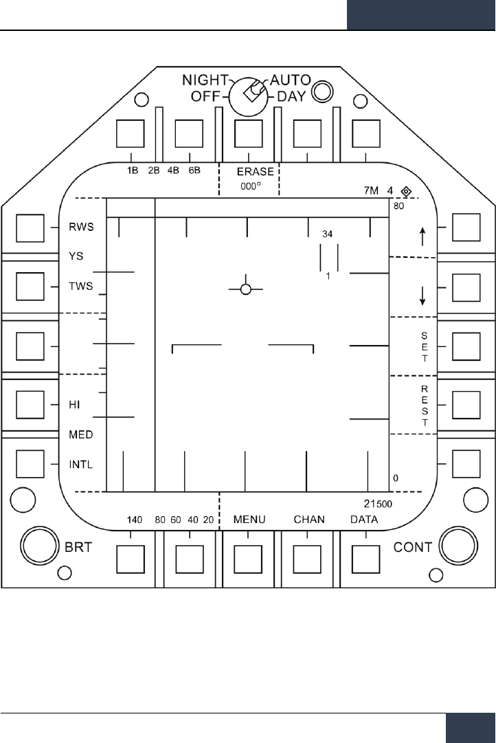
[F/A-18C]
DCS
113
Figure 65. HOTAS TDC Control Zones
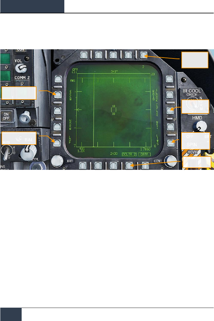
DCS
[F/A-18C]
114
HORNET AIR-TO-AIR (A/A)
Range While Search (RWS) DATA
Figure 66. RWS DATA Sublevel
1. Target Ageing. The amount of time a target symbol remains on the display after RADAR
contact has been lost can be adjusted with successive presses between 2, 4, 8, 16 and 32
seconds.
When SIL mode is selected, this field is replaced with the ACTIVE indication.
2. COLOR. Selects the RADAR display to be presented in monochrome or limited use of
colors of three colors.
3. Latent TWS (LTWS). LTWS provides a Track While Scan (TWS) function while in RWS
mode. With LTWS enabled, placing the TDC over a target symbol will display Launch and
Steer (L&S) track symbols. However, no “Shoot” cues are displayed. An LTWS target will
have it’s airspeed in Mach displayed to the left and its altitude in thousands of feet to the
right. Additionally, its range and closure information is displayed along the right tactical
border.
4. DATA. Exits the DATA sublevel
5. Declutter. Allows selection of two levels of declutter form the RADAR display. DCLTR1
removes the horizon line and velocity vector. DCLTR2 removes all DCLTR1 items, plus
target differential altitude, target heading, range rate numeric, and the range caret when in
STT mode. The selected mode will be indicated as boxed DCLTR1 OR DCLTR2.
Declutter
Speed Gate
Target Ageing
Color
Latent TWS
(LTWS)
ECCM Option

[F/A-18C]
DCS
115
6. Speed Gate. Selects between Normal (NORM) and WIDE target speed gates to determine
the width of the doppler radial velocity notch. This is used to not detect/filter out slow
moving targets like cars and general aviation aircraft. When in WIDE mode, the notch filter
is increased and slow targets will be detected and displayed.
7. ECCM. Enables or disables Electronic Counter-Counter Measures. When enabled, the
jamming effects of hostile aircraft are less pronounced, but the sensitivity of the RADAR is
reduced.
Air Combat Maneuvering (ACM) Modes
The ACM RADAR modes are designed for close-in combat with auto acquisition in mind. The ACM
modes can be selected by either pressing forward on the Sensor Control Switch while in air-to-air
BVR mode, or by pressing aft on the Weapon Select Switch to set A/A GUN as priority.
Except for the Guns Acquisition mode, any air-to-air missile can be used for all ACM modes.
How to Use RADAR in Air Combat Maneuvering (ACM) Mode
1. RADAR control switch on the Sensor Panel to Operate (OPR)
2. Master Mode switch to A/A
3. Select Attack RADAR (ATTK RDR) from the TAC page on the right DDI
4. Press forward on the Sensor Control Switch to enter ACM mode, or…
5. Press aft on the Weapon Select Switch to set A/A Gun as priority and place the RADAR in
Gun Auto Acquisition (GACQ) mode
6. Once in ACM mode, use the Sensor Control Switch to select ACM modes: forward for
Boresight (BST), aft for Vertical (VACQ), and left for Wide Angle (WACQ)
There are four ACM modes:
• Gun Acquisition (GACQ) mode is automatically enabled when air to air guns is selected.
This mode is represented as a 20 degree, dashed circle on the HUD that encompasses the
entire HUD field of view. Unlike the other ACM modes, GACQ can only be used for guns.
GACQ searches for targets out to 5 miles.
• Boresight (BST) by pressing forward on the Sensor Control Switch. When selected, a
dashed, 3.3 degree circle is displayed on the HUD. This circle indicates the RADAR’s auto-
acquisition search zone. BST searches for targets out to 10 miles.
• Vertical Acquisition (VACQ) mode is selected by pressing aft on the Sensor Control
Switch. Upon doing so, two, dashed vertical line are displayed in the HUD. This vertical
auto-acquisition search pattern covers from -13 degrees to +46 degrees. VACQ searches
for targets out to 5 miles.
• Wide Acquisition (WACQ) is a spaced-stabilized mode and is selected by pressing left
on the Sensor Control Switch. Upon doing so, a rectangle is displayed in the lower right
corner of the HUD. This rectangle represents the auto acquisition scan pattern and can be
slewed using the TDC controller when uncaged. The rectangle is placed on a grid that

DCS
[F/A-18C]
116
HORNET AIR-TO-AIR (A/A)
represents the complete scan limits of the RADAR. WACQ searches for targets out to 10
miles.
At Early Access release, WACQ will include caged mode, but uncaged mode will come later
into the Early Access process.
• Automatic Acquisition Mode (AACQ) is selected from the BVR RADAR modes, like
RWS. It is not selected from the ACM modes. When in a BVR RADAR mode and the TDC
cursor is not over a target symbol, the RADAR will attempt to auto lock the nearest target
in its search pattern when the Sensor Control switch is moved right. AACQ searches for
targets out to range setting of the RADAR. If the RADAR is already in ACM mode, selecting
AACQ will exit ACM mode and return to last BVR mode.
Figure 67. ACM RADAR Acquisition Zones

[F/A-18C]
DCS
117
M61A2 Gun, Air-to-Air Mode (A/A GUNS)
The A/A-49A1 M61A1/M61A2 20MM automatic gun system provides the pilot with a formidable A/A
weapon capability. The system has a capacity of 578 rounds of ammunition. The rate select switch
provides for the selection of either 4,000 or 6,000 shots per minute.
The gun is used for close-in engagements and can either be RADAR-directed or not.
A/A GUNS is selected by an aft press on the Weapon Select Switch or |LShift + X|. To fire the gun,
press the Trigger on the Control Stick |Space Bar|.
A/A GUNS SMS Page
Regardless of which air-to-air gun mode you select, the air-to-air gun (A/A GUNS) SMS page will
remain the same. The SMS page is accessed through the TAC menu DDI page, or it can be
automatically called up by selecting A/A GUNS.
The A/A GUNS SMS page allows you to configure the following weapon settings:
Instant Action Mission Practice: AA Gun and AIM-9 Sidewinder
How to Use the Gun Summary
1. Master Arm switch to ARM
2. Weapon Select switch to A/A GUNS
3. Fly to place target in dashed circle on the Heads Up Display (HUD) to lock it on RADAR
when at 5 nautical miles or closer
4. Fly to place the dot in the center of the gun reticle over the target and squeeze the
trigger when you see the SHOOT cue on the HUD.
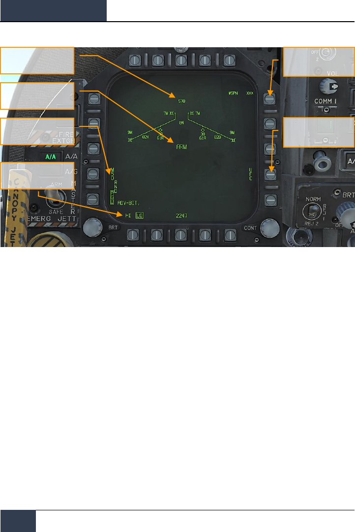
DCS
[F/A-18C]
118
HORNET AIR-TO-AIR (A/A)
Figure 68. A/A GUNS SMS Page
1. Gun rounds Remaining. Displayed when available. If no rounds remain, XXX is
displayed. A full gun load is 578 rounds.
2. Gun Round Options. RND M50/PGU option is provided to select the type of 20MM
ammunition which is loaded. The selected ammunition type is boxed. The M50 option
represents MK-50 series ammunition and the PGU option represents PGU-28 ammunition.
3. Gun Firing Rate Option. High rate (HI) is initialized on power up, pressing the Option
Select Button selects the alternate gun fire rate (LO). Gun fire rate legend is boxed when
selected. HI = 6,000 rounds per minute, and LO = 4,000 round per minute.
4. Master Arm Cue. The status of the Master Arm switch (ARM, SAFE) or the selection of
simulation mode (SIM) is displayed.
5. Expected Target Wingspan. The UFC is used to program the wingspan size for the
expected target. This selection is then used to properly adjust the Funnel Cue. The
selectable wingspan values are whole numbers between 10 to 150 with a default of 40
feet. The wingspan value is entered by selecting the UFC Option Select Button 14 on the
A/A GUNS SMS page. The current wingspan value is displayed as WSPN XXX. With WSPN
displayed, the pilot enters a wingspan value using the keypad, followed by the ENT key.
6. UFC Option. Press to enable manual wingspan entry using the UFC.
Gun rounds Remaining
Master Arm Cue
Gun Round Options
Gun Firing Rate Option
Expected Target
Wingspan
UFC Option
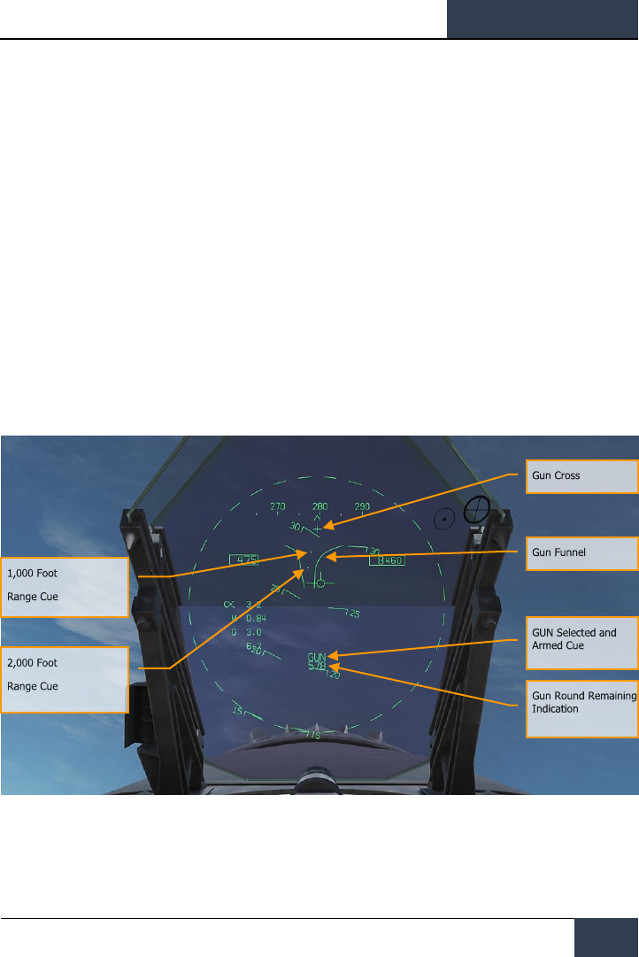
[F/A-18C]
DCS
119
A/A GUNS HUD
The Hornet has three functional A/A GUN modes:
• Radar Not Tracking Mode
• Training Mode (not for early access launch)
• Radar Tracking Mode
Radar Not Tracking Mode
The Radar Not Tracking Mode, also called the Funnel Mode, is obtained immediately upon A/A GUNS
selection if the RADAR is not already tracking a target or at any time if RADAR track is lost or broken.
To use the funnel, fly to place the target aircraft’s wings between the funnel such that its wing tips
just touch the sides of the funnel.
A fixed range of 2,000 feet is used for the radar not tracking mode lead angle computations. A 12.5-
mil diameter stadia metric reticle, corresponding to a target wing span of 25 feet at this range, is
displayed on the HUD.
Specific symbology to the Radar Not Tracking gun HUD includes:
Figure 69. A/A GUNS HUD, Radar Not Tracking Mode
1. Gun Cross. Displayed when A/A gun is selected. The Gun Cross is centered in azimuth and
2°above aircraft waterline to indicate gun boresight.
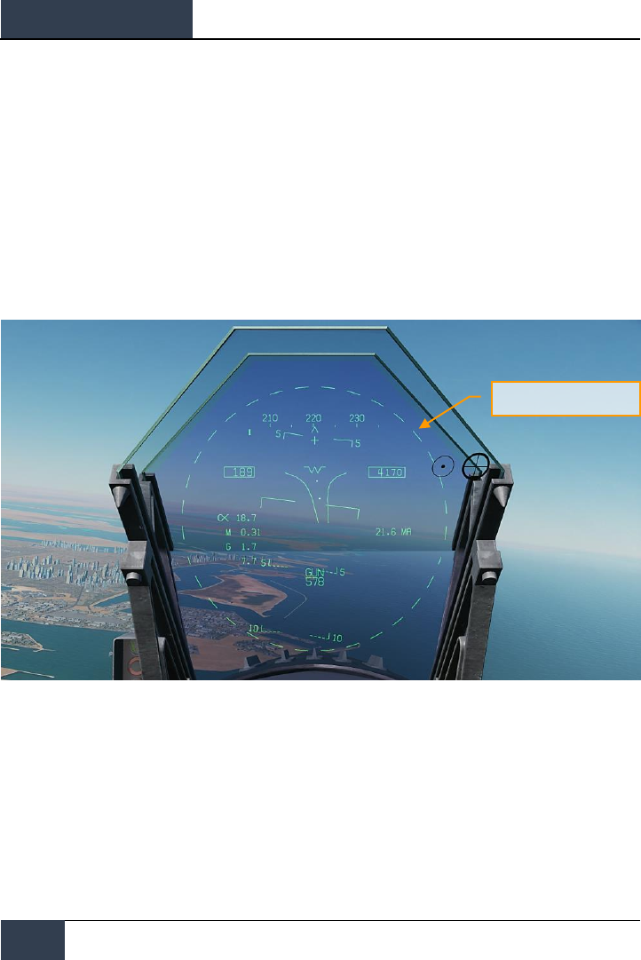
DCS
[F/A-18C]
120
HORNET AIR-TO-AIR (A/A)
2. Funnel Cue. The funnel mode is displayed if the RADAR is not tracking the L&S target, or
if lock-on is broken.
3. 1,000 Foot Range Cue. A range of 1,000 feet is represented by the pipper.
4. 2,000 Foot Range Cue. A range of 2,000 feet is represented by this pipper.
5. GUN Selected and Armed Cue. Indication of the gun being the selected weapon.
6. Gun Round Remaining Indication. Number of gun round remaining.
When A/A GUNS is selected and the RADAR is operating, the RADAR will automatically enter the air-
to-air Guns Auto Acquisition mode (GACQ). This is a 5 bar elevation scan with 20 degrees of
elevation centered 4 degrees below the RADAR boresight. This scan covers the entire HUD field of
view. This mode also places the RADAR in a 5 mile range setting. When any aerial target flies within
this scan zone, it will automatically be locked on to in Single Target Track (STT).
Figure 70. A/A GUNS Auto Acquisition Area
GACQ Scan Area
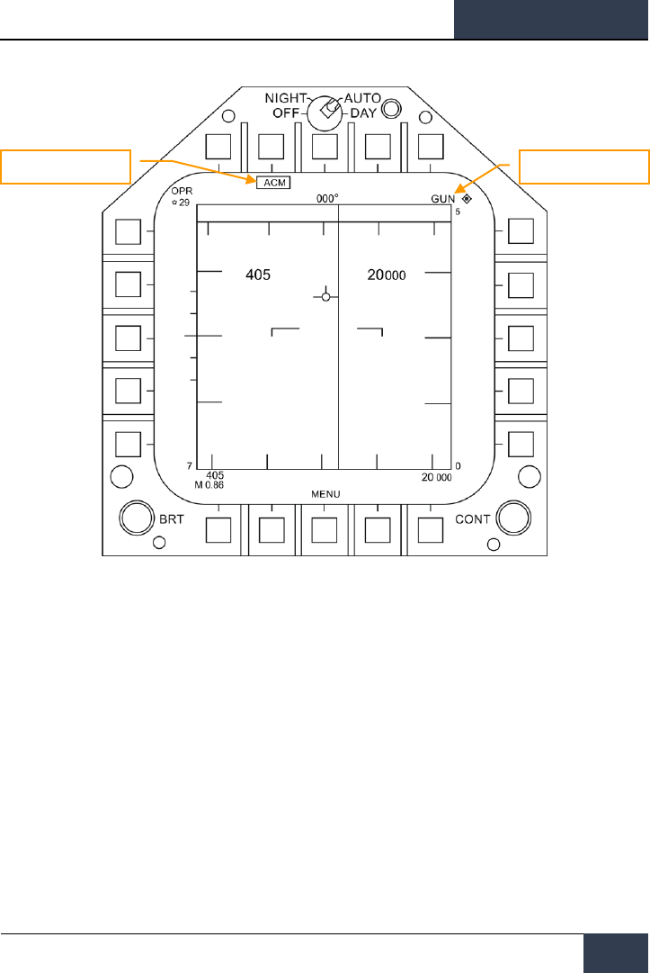
[F/A-18C]
DCS
121
Figure 71. A/A GUNS Acquisition Radar
At any time, you can also select one of the ACM RADAR submodes. ACM submodes are selected by
pressing the Sensor Control Switch forward. Once in ACM mode, the Sensor Control Switch can select
three ACM submodes.
• Boresight (BST) Sensor Select switch forward
• Vertical Acquisition (VACQ) Sensor Select switch aft
• Wide Acquisition (WACQ) Sensor Select switch left
Note 1: When the RADAR is at a 5 nm range setting, ownship airspeed and altitude are displayed
inside the RADAR display.
Note 2: When in a turning fight, VACQ can often be a good choice to lock up a target above your lift
vector.
To return to GACQ, select GUNS on the Weapon Select Switch.
GUN in Priority
ACM Mode Indication

DCS
[F/A-18C]
122
HORNET AIR-TO-AIR (A/A)
Radar Tracking Mode
Radar Tracking Mode is the primary air-to-air gun mode of the Hornet. Radar Tracking Mode is
obtained immediately upon gun selection if the RADAR is tracking an aerial target. Valid range, range
rate, and angle tracks are required for Radar Tracking Mode operation.
Once the RADAR is locked on, the Target Designator (TD) indicates the position of the target being
tracked, and target range is displayed on an analog bar on the 50-mil diameter gun reticle along with
a maximum firing range cue. Maximum gun firing range corresponds to a maximum bullet time of
flight of 1.5 seconds and a minimum impact velocity (bullet Vc) of 500 feet per second or a minimum
bullet velocity (Vb) at impact of 1,000 feet per second, whichever range is less. Maximum firing range
is much greater head-on than tail-on.
An advantage of the Radar Tracking Mode is the use of RADAR track data. The use of track data
makes the lead angle computation dependent only on target motion and the encounter geometry.
The computed lead angle is essentially independent of aircraft attitude. The Radar Tracking Mode
obtains firing solutions quickly since rapid attitude changes have little short term effect on the
required lead angle. As a result, the pilot's task is solely flying to aim the gun reticle since the target
tracking function is being performed by the RADAR.
As a further aid to the pilot and for consistency with the missile modes, a SHOOT cue appears if the
target is within maximum firing range. If the predicted miss distance is less than 20 feet, and all
other firing constraints (master arm, weight off wheels) are satisfied, the SHOOT CUE comes on. The
SHOOT cue includes a 0.5 second anticipation needed for pilot reaction time plus gun delay time. The
SHOOT cue remains on until the predicted miss distance exceeds 30 feet.
Radar Tracking Mode is automatically selected if A/A GUNS is selected while there is a RADAR lock. If
there is no RADAR lock, it will go to Radar Not Tracking Mode.
Elements of the A/A GUNS Radar Tracking Mode on the HUD include:
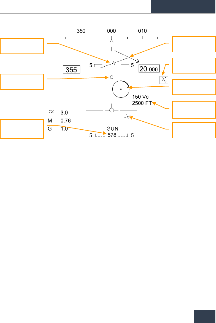
[F/A-18C]
DCS
123
Figure 72. A/A GUNS HUD, Radar Tracking Mode
1. Gun Reticle. This circle indicates predicted gun impact location based on aircraft
maneuvering. RADAR lock provides target range data that is included in the reticle. A
maximum gun firing range cue is displayed on the gun reticle display. It indicates the
maximum effective gun firing range. The target analog range bar inscribed in the gun
reticle shows the current target range as indicated by RADAR is presented as a circular arc
about the gun reticle, the length of which represents the target range increasing clockwise
about the reticle. When the arc's clockwise length is less than the position of the Gun
Maximum Range Cue, the target is within the range of the gun.
2. 1G and 9G FORESIGHT Cues. Fluid Omni-Range/Rate Sight (FORSIGHT). The
FORSIGHT cues indicates the targets potential to maneuver. It is made up of two
horizontal lines with center tick marks. The upper or longer line represents the targets 1G
left or right out-of-plane maneuver capability under 1G in-plane loading. The lower or
shorter line represents the targets 9G left or right out-of-plane maneuver capability under
9G in-plane loading. The distance between the two FORSIGHT cue lines represents the 1G
to 9G in-plane maneuver potential for the target. The separation between the 1G and 9G
maneuver potential lines is not limited beyond Rmax (Gun Maximum Range cue). The 1G
maneuver potential line is limited to the HUD field of view at the same distance from the
HUD center used for the gun reticle. When the 1G maneuver potential line is HUD limited,
it is displayed flashing.
3. BATR Cue. Bullet At Target Range (BATR). The BATR cue displays the real time position of
a bullet at target range. The BATR cue serves as a post-fire or hypothetical bullet hit
position cue. The cue is updated for each bullet fired as the bullet reaches the applicable
target range. The cue is displayed on the HUD when the gun is firing or in SIM mode with
the trigger held. The cue is displayed using the gun boreline offset from the target LOS.
Target Designator (TD)
1G Foresight Cue
Target Locator Line
Gun Reticle
Target Closure and
Range
9G Foresight Cue
BATR Cue
Gun Rounds Remaining

DCS
[F/A-18C]
124
HORNET AIR-TO-AIR (A/A)
4. Gun Cross. The Gun Cross is centered in azimuth and 2°above aircraft waterline to
indicate gun boresight.
5. Target Locator Line. Attached to gun cross, this arrow will point in direction of TD box
when TD box is off the HUD field of view. The number of degrees to the target is also
displayed next to the arrow.
6. Target Designator (TD). This is an indication of target location. If the target is identified
as hostile, the box is rotated 45-degrees to create a diamond symbol and an inverted “V”
symbol is placed over the diamond.
7. Target Vc and Range. When a valid RADAR STT track is established on the target, the
target range and closing rate are displayed in nautical miles (NM) and feet/second. These
are displayed in the same location as displayed when a missile is the selected weapon.
When the target comes within 1NM, the range display reverts to a display of target range
in 100's of feet.
8. Gun Rounds Remaining. Gun rounds remaining is displayed next to the GUN legend.
XXX is displayed when the MC receives the last rounds signal from the SMS.
SHOOT Cue (not pictured). The shoot cue is displayed until target miss distance exceeds 30
feet. The shoot cue is provided when the below criteria have been satisfied:
• A/A Gun is selected
• All firing constraints are satisfied
• RADAR is in STT on the target
• Target is inside gun Rmax for the selected round type (MK-50 or PGU-28)
• Target center is within 20 feet of an imaginary line connecting the 1G and 9G pippers
of the Foresight cue (maximum 20 feet miss distance)
When the RADAR is locked on to the target while in A/A GUNS in Single Target Track (STT) mode,
the RADAR picture will appears as shown below. Note that the GACQ is indicated on the left side as
the selected RADAR mode and that your airspeed and altitude are displayed inside the B-scope.
While in STT mode, the RADAR will automatically change scale based on the range to the locked
target.
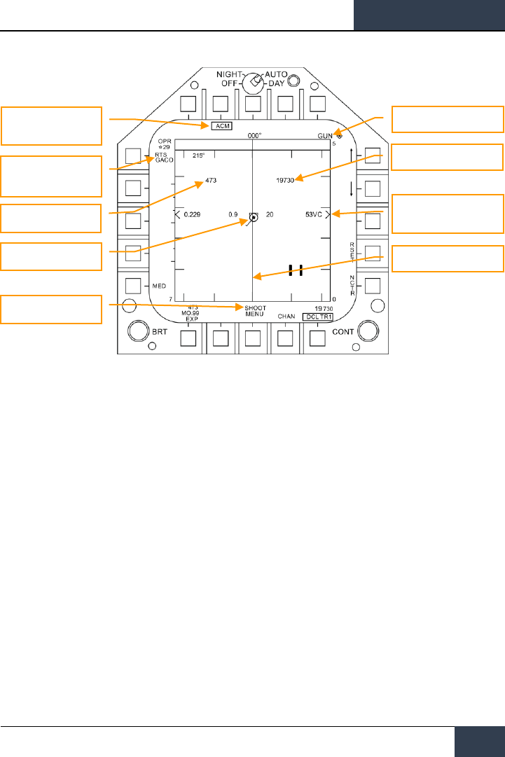
[F/A-18C]
DCS
125
Figure 73. A/A GUNS Radar, Radar Tracking Mode
1. ACM Submode Indication. This is a reminder that if an RTS is commanded, it will return
to the last ACM mode.
2. GUN Priority. When gun is the priority weapon, GUN is placed in the top right field of the
RADAR display.
3. Return To Search (RTS) Indication. When the RADAR is in STT mode, the search
mode that is entered when an STT lock is disengaged is displayed.
4. Ownship Airspeed. This is displayed when at a 5 nm RADAR range.
5. Ownship Altitude. This is displayed when at a 5 nm RADAR range.
6. L&S Target. When the target is locked in STT and set as the Launch and Steering (L&S)
target, its air speed in Mach is to left and of the star symbol and altitude in thousands of
feet to the right. When tracked in STT, its aspect pointer is displayed as a line coming from
the target symbol.
7. Target Range and Closure. The target closure velocity and range is displayed along the
right side range scale.
8. Target ASL. The L&S target will have an Azimuth Steering Line (ASL) running vertically
through the target symbol.
9. SHOOT Cue. The shoot cue is displayed until target miss distance exceeds 30 feet. The
shoot cue is provided when the below criteria have been satisfied:
• A/A Gun is selected
• All firing constraints are satisfied
• RADAR is in STT on the target
• Target is inside gun Rmax for the selected round type (MK-50 or PGU-28)
ACM Submode Indication
GUN Priority
Ownship Airspeed
L&S Target
SHOOT Cue
Ownship Altitude
Target Range and Closure
Target ASL
Return To Search (RTS)
Indication

DCS
[F/A-18C]
126
HORNET AIR-TO-AIR (A/A)
• Target center is within 20 feet of an imaginary line connecting the 1G and 9G pippers
of the Foresight cue (maximum 20 feet miss distance)

[F/A-18C]
DCS
127
AIM-9 Sidewinder Air-to-Air Missile
The AIM-9 is a short-range, infrared-guided missile best used in a dogfight. It is fire-and-forget and
can be used with and without a sensor-slaved lock. The primary indication of a seeker lock is a
higher-pitched lock tone and the SHOOT cue. The seeker can also be uncaged to ensure the seeker is
tracking the target when it has first been sensor-slaved to the target.
Note that the AIM-9 can be decoyed by flares and it’s a good idea to ensure you have a good seeker
lock before launching an AIM-9 with flares in the seeker field of view.
To select the AIM-9, press down on the Weapon Select Switch on the Control Stick |Left Shift + S|.
Doing so will also automatically activate A/A Master Mode. To launch an AIM-9, press the Trigger on
the Control Stick |Space Bar|.
IR Cool Switch
On the right side of the instrument panel is the IR COOL switch. For the infrared seeker in the nose
of the AIM-9 to function best, it must first be cooled down to increase sensitivity and reduce
background noise. This is done with the IR COOL switch. Place this switch in the NORM position to
cool the seekers.
If the switch though is in the OFF position, cooling will still be sent to the AIM-9 seekers if there is no
weight on wheels, the Master Arm switch is set to ARM, and AIM-9 is selected as the priority weapon.
There is enough coolant to last three hours.
Instant Action Mission Practice: Hornet AIM-9 Sidewinder
How to Use the AIM-9 Summary
1. Master Arm switch to ARM
2. Weapon Select Switch to AIM-9
3. Select ACM RADAR submode
4. Flying to place target in the ACM RADAR scan mode, as displayed on the Heads Up
Display (HUD), over the intended target to lock it on RADAR when at 5 nautical miles
or closer
5. Fly to place the Steering Dot inside the ASE/NIRD Circle and squeeze the trigger when
you see the SHOOT cue over the Target Designation (TD) box on the HUD
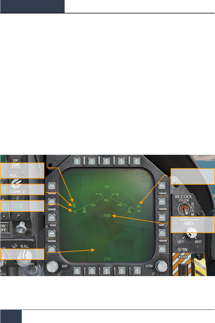
DCS
[F/A-18C]
128
HORNET AIR-TO-AIR (A/A)
AIM-9 on the SMS Page
Regardless of which AIM-9 version the pilot selects, the SMS page will appear the same when the
AIM-9 is selected. The SMS page is accessed through the TAC menu DDI page, or it can
automatically be called up by selecting AIM-9 from the Weapon Select Switch. The selected AIM-9 on
the SMS page is indicated by the SEL indication above or below the station. In the case of a dual
launcher, it will be indicated as either the L (left) or R (right) rail. For example: L SEL would indicate
the left rail in the indication as the priority station.
For this Early Access release of DCS: F/A-18C Hornet, we have three versions of the AIM-9. Each has
a unique alpha numeric indication on the SMS page.
• AIM-9L = 9L
• AIM-9M = 9M
• AIM-9P = 9P
You can cycle through all AIM-9 loaded stations with repeatedly selecting AIM-9 on the Weapon
Select Switch.
Unlike the other air-to-air weapons, there are no unique AIM-9 functions on the SMS page.
The SMS page presents the following indications:
Figure 74. AIM-9 SMS Page
1. Missile Form
2. Selected (SEL) Missile Indication
SAFE / ARM / SIM
Indication
Unselected Missile
Indication
Missile Designation
Missile Form
Selected (SEL) Missile
Indication
DATA Freeze

[F/A-18C]
DCS
129
3. Unselected Missile Indication
4. SAFE / ARM Indication
5. Data Freeze
6. Missile Designation
AIM-9 HUD
There are three primary presentations of the AIM-9 HUD:
• Not locked and no RADAR acquisition mode
• Not locked but in a RADAR acquisition mode
• RADAR locked
Not Locked and No RADAR Acquisition Mode (Seeker Boresight Mode)
When the AIM-9 is selected without a RADAR lock and no RADAR acquisition mode is active, the AIM-
9 seeker boresight reticle is indicated on the HUD. To use the AIM-9 in this manner, the pilot will fly
the aircraft and place the seeker boresight reticle over an aerial target until the audio threshold is
exceeded and; the angle of coincidence is no more than 15 degrees of aircraft boresight; and the
seeker is uncaged. a high-pitched lock tone is heard. With seeker lock acquired, pulling the trigger on
the Control Stick will launch the missile.
When the AIM-9 seeker is locked on a target, it can be uncaged by pressing the Cage/Uncage button
on the Throttles to allow the seeker lock on and follow the target within the confines of the missile
seeker’s field of view. This is a useful tool to ensure the seeker is tracking the desired target.
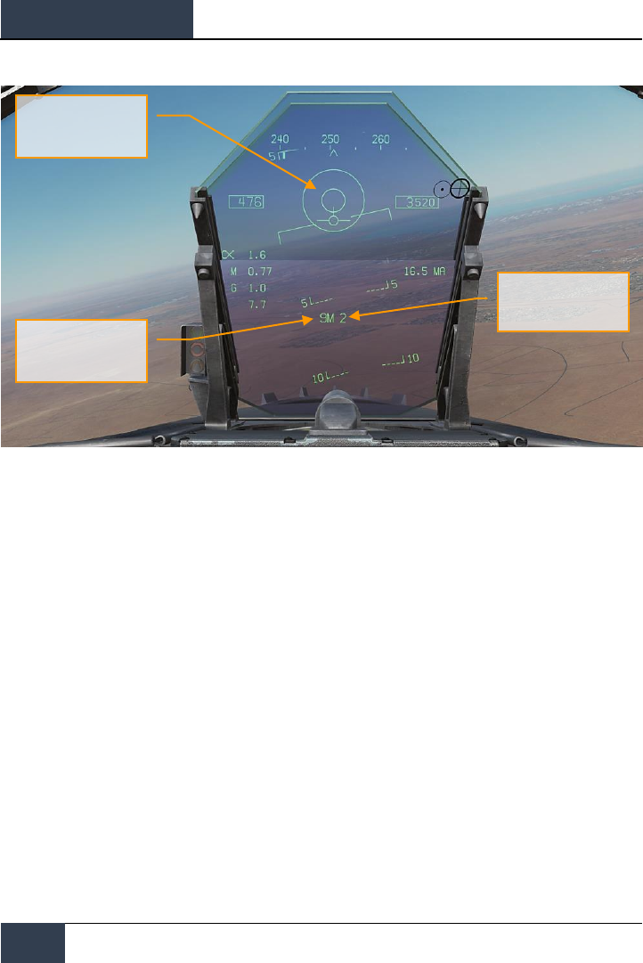
DCS
[F/A-18C]
130
HORNET AIR-TO-AIR (A/A)
Figure 75. AIM-9 HUD, Seeker Boresight
1. AIM-9 Seeker Boresight Reticle
2. AIM-9 Selected and Armed Cue
3. Number of remaining AIM-9
This is a stealthy way to conduct an AIM-9 attack as it can be done without use of RADAR.
Not Locked but in RADAR Acquisition Mode
When employing the AIM-9 in close range combat, one of the RADAR Air Combat Maneuvering (ACM)
auto acquisition modes can be used to lock a target and then slave the AIM-9 seeker to that target.
To select the ACM modes, press the Sensor Control Switch forward. Once in ACM mode, three ACM
modes are available:
• Boresight (BST) Sensor Select switch Sensor Select switch forward
• Vertical Acquisition (VACQ) Sensor Select switch aft
• Wide Acquisition (WACQ) Sensor Select switch left
These are explained in greater detail in the RADAR Air-to-Air Modes section of this Early Access
Guide.
When in an ACM mode, the RADAR will indicate that it is in ACM mode and the specific ACM
acquisition mode.
Number of remaining
AIM-9
AIM-9 Seeker Boresight
Reticle
AIM-9 Selected and
Armed Cue

[F/A-18C]
DCS
131
When a target is within the scan zone of the select auto acquisition mode, it will automatically be
locked in a Single Target Track (STT) mode and the HUD will change to the AIM-9 sensor locked
target mode. Use the best ACM acquisition mode to match the combat situation.
Please refer to the RADAR chapter for an explanation of the RADAR ACM modes.
RADAR Locked Mode
Upon locking a target with the AIM-9 as the priority weapon, the HUD will change to provide useful
information regarding target location, weapon ranges, and other data to assist in a successful
engagement. While the RADAR is in Single Target Track (STT) mode, the RADAR range scale will
automatically adjusted based on the range to the locked target.
Elements of the AIM-9 HUD with RADAR lock include:
Figure 76. AIM-9 HUD, Radar Locked Target
1. Normalized In-Range Display (NIRD) / Allowable Steering Error (ASE) Circle.
The NIRD circle is centered on the aircraft waterline and relative range markers are
displayed inside and outside of the circle. Relative range is calculated from the 12 o’clock
2
3
1
8
9
14
7
6
5
10
11
13
4
12

DCS
[F/A-18C]
132
HORNET AIR-TO-AIR (A/A)
position and increases clockwise. Rather than changing in size of the NIRD/ASE circle
based on target intercept changes, the Steering Dot rate of change is adjusted.
2. Relative Target Range. Relative range of the target on the NIRD circle in relation to the
missile range cues.
3. Minimum Launch Range. Computed minimum launch range for the priority AIM-9.
4. Gun Maximum Range. Indicated the maximum range for a valid gun shot and more than
12,000 feet.
5. No Escape Range (Rne). This is the calculated range at which the target will remain
within maximum range even if the target turns instantaneously 180 degrees aspect.
6. Maximum Launch Range (Rmax). Computed maximum range of the missile against the
locked target.
7. Raero. Maximum aerodynamic range is displayed when the launch aircraft has more
velocity than the missile, but the missile is still capable of a 5 G maneuver.
8. Target Aspect Angle Pointer. Displays relative target heading.
9. Steering Dot. The Steering Dot in conjunction with the NIRD/ASE circle indicates lead
angle steering to the locked target. The pilot should fly to place the Steering Dot inside the
NIRD/ASE circle to satisfy lead angle computations. The Steering Dot will flash when within
15 degrees of the RADAR’s azimuth limit and when within 5 degrees of the RADAR’s
elevation limit.
10. AIM-9 Time of Flight. Displays the calculated time in seconds before launch for missile
to reach locked targets. After launch, Time To Go (TTG) and SW suffix are added indicate
calculated missile time to impact.
11. ACM Submode Cue. ACM is displayed when the system is in an ACM submode.
12. Target Designator (TD). This box indicates the line of sight between the aircraft and the
primary locked target. If the locked target is outside the HUD field of view, the TD box
flashes. If the target is identified as hostile, the box is rotated 45-degrees to create a
diamond symbol and an inverted “V” symbol is placed over the diamond.
13. AIM-9 Seeker Circle. Indicates the seeker head position of the AIM-9. If the seeker is
pointed outside the HUD field of view, the circle flashes. When the AIM-9 is slaved to the
locked RADAR target, the TD box and AIM-9 Seeker Circle will coincide.
14. Shoot Cue. The word “SHOOT” is displayed above the TD box/diamond when AIM-9 shoot
conditions are satisfied. If the locked target is in the no escape zone (Rne), the Shoot Cue
flashes.
With a RADAR lock on the target for an AIM-9 launch, several pieces of important information are
presented on the RADAR display. Much of the information on the RADAR mirrors that on the HUD.
Note that when the target is outside the HUD field of view, the Target Locator Line appears and
points in the direction of the target. Additionally, degrees to the target is displayed next to the arrow.

[F/A-18C]
DCS
133
Figure 77. AIM-9 RADAR, RADAR Locked Target
1. Return to Search (RTS) indication with RWS to be the return mode
2. Priority weapon and number remaining
3. Rmax
4. Rne
5. Rmin
6. ASE Circle
7. Steering Dot
8. Target Closure Velocity and Range
9. Breakaway “X”
10. Shoot Cue
11. Locked target in STT RADAR mode with airspeed in mach to the left, altitude in thousands
of feet to the right, and velocity vector line. The Star symbol indicates that is the Launch
and Steering (L&S) target
12. Altitude Differential
1
3
4
9
5
2
6
11
8
7
10
12

DCS
[F/A-18C]
134
HORNET AIR-TO-AIR (A/A)
Note that the range cues on the HUD and attack RADAR mirror each other, but use a different
presentation format:
Figure 78. Weapon Range Cues

[F/A-18C]
DCS
135
AIM-7 Sparrow Air-to-Air Missile
The AIM-7 Sparrow is a Semi-Active RADAR Homing (SARH) missile that requires the RADAR to be
tracking the target in Single Target Track (STT) mode the entire missile time-of-flight (Home-On-Jam
being the exception). The AIM-7 has a large warhead and can engage targets beyond visual range as
well as in close combat. The AIM-7 can be a deadly missile in close combat when combined with the
RADAR ACM submodes.
The AIM-7 also has the FLOOD mode that allows it to launch and guide on a non-locked target, and it
has a LOFT option for extended range.
To select the AIM-7, push forward on the Weapon Select Switch on the CONTROL STICK |Left Shift +
W|. Selecting AIM-7 will automatically place the Master Mode in A/A.
The RADAR must be in Single Target Track (STT) mode in order to support guidance for an AIM-7.
This can be done by pressing the Cage/Uncage button less than .8 seconds when there is an L&S
target. Alternatively, you may press right on the Sensor Control switch when the RADAR is on the
right DDI and the target TDC is already over the target on the RADAR.
NOTE: FLOOD and HOJ modes will not be available at Early Access launch, but they will be
implemented later.
Instant Action Mission Practice: Hornet AIM-7 Sparrow
How to Use the AIM-7 Summary
1. Master Arm switch to ARM
2. Weapon Select switch to AIM-7
3. Designate target on RADAR to Single Target Track (STT) or select ACM RADAR
submode and fly to place target in ACM RADAR scan mode, as displayed on the Heads
Up Display (HUD), over the intended target to lock it on RADAR when at 5 nautical
miles or closer
4. Fly to place the Steering Dot inside the ASE Circle and squeeze the trigger when you
see the SHOOT cue over the Target Designation box on the HUD.
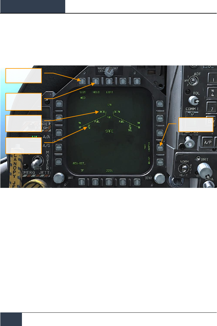
DCS
[F/A-18C]
136
HORNET AIR-TO-AIR (A/A)
AIM-7 SMS Page
When selected as the priority weapon, the Stores pages includes the following information and
options for the AIM-7:
Figure 79. AIM-7 SMS Page
1. Missile Symbol. Missile shape indicating AIM-7 loaded on the station.
2. Weapon Type. AIM-7 alphanumeric, which will either be 7F or 7M. The priority AIM-7 will
have a SEL below this indication.
3. Target Size Select. Allows selection of missile fuzing based on intended target size. This
can be cycled between SML, MED, and LRG. When this option button is pressed, each
option is shown as a separate Option Select Button across the top of the page.
4. Sparrow Special Mode. This mode is only used for engagement of helicopters. When
enabled, HELO appears below the Option Select Button. When disabled, an “X” is through
the HELO legend.
5. Sparrow Test. All Sparrows must be tuned before they are employed. The initial tune
occurs at the end of the RADAR Operational Readiness Test and after the SMS has applied
power to the missile for approximately three minutes. The three minute warm-up time
begins at the completion of the SMS BIT and weapon inventory. When the tune process
begins, the TEST portion of the SP TEST option is boxed. The RADAR provides a missile
compatible PDI sample to the missile. The SMS receives a Missile Ready Signal from each
Target Size Select
Sparrow Special
Mode
Missile Symbol
Weapon Type
Sparrow Test
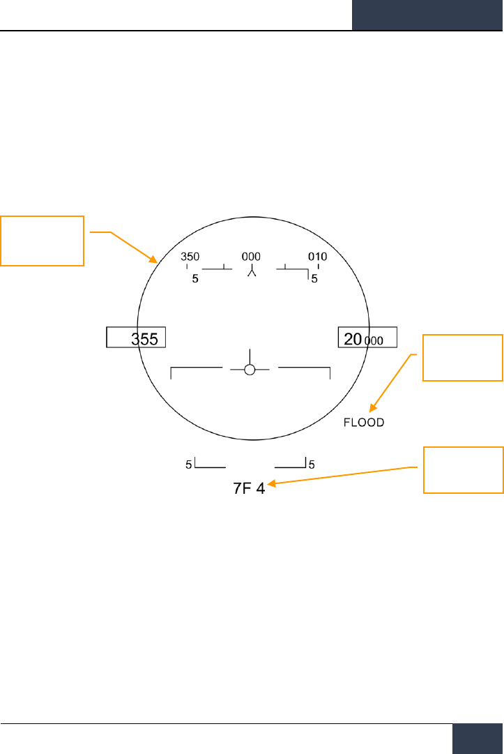
[F/A-18C]
DCS
137
missile that has been successfully tuned. Successful tune of a Sparrow is indicated by the
removal of the “X” overlaying the 7F or 7M on the SMS page.
AIM-7, No RADAR Tracking
When an AIM-7 is the priority weapon and no target has been designated with a sensor, the AIM-7
HUD includes the following indicators in addition to the standard air to air mode HUD indications:
Figure 80. AIM-7 HUD, No Target
1. AIM-7 Field of View Circle. Displayed when AIM-7 is in priority but no target has been
designated. This also delineates the FLOOD antenna coverage field of view.
2. AIM-7 Type and Quantity. Displays the type of AIM-7 in priority (7M or 7F) and the
number of the missile type remaining.
When AIM-7 is selected as the priority weapon, the RADAR will default to the followings settings
unless a SET profile was already created:
• 140 degree azimuth
• 4-bar elevation scan
• 40 nm range
AIM-7 Field of View
Circle
FLOOD Indication
AIM-7 Type and
Quantity

DCS
[F/A-18C]
138
HORNET AIR-TO-AIR (A/A)
• 8 seconds aging
• Interleaved PRF
When the AIM-7 is the priority weapon but no target has been designated, the RADAR includes the
following information:
Figure 81. AIM-7 Radar, No Lock
AIM-7, RADAR Tracking
With an L&S trackfile created for a target, additional engagement information is displayed on the
HUD and RADAR. As with the AIM-9 sensor-locked mode, this additional information includes multiple
weapon range cues, target closure and aspect, target range, and other information to help provide a
successful AIM-7 engagement.
If though the target is being tracked but not in Single Track Target (STT) mode, a “GO STT” cue is
displayed on the HUD to remind the pilot to achieve an STT lock before launching the missile.
Components of the AIM-7 HUD with a RADAR-locked target include:
Range While Search Mode
AIM-7 in Priority, SAFE
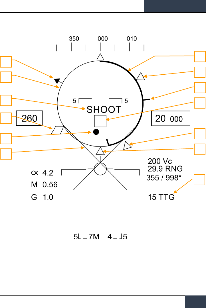
[F/A-18C]
DCS
139
Figure 82. AIM-7 HUD with L&S Target
1. Normalized In-Range Display (NIRD) / Allowable Steering Error (ASE) Circle.
The NIRD circle is centered on the aircraft waterline and relative range markers are
displayed inside and outside of the circle. Relative range is calculated from the 12 o’clock
position and increases clockwise.
1
2
6
3
4
10
5
7
9
8
11
12
13

DCS
[F/A-18C]
140
HORNET AIR-TO-AIR (A/A)
Rather than changing in size of the NIRD/ASE circle based on target intercept changes, the
Steering Dot rate of change is adjusted.
2. Relative Target Range. Relative range of the target on the NIRD circle in relation to the
missile range cues.
3. Minimum Launch Range. Computed minimum launch range for the priority AIM-7.
4. No Escape Range (Rne). This is the calculated range at which the target will remain
within maximum range even if the target turns instantaneously 180 degrees aspect.
5. Maximum Launch Range (Rmax). Computed maximum range of the missile against a
locked, non-maneuvering target.
6. Raero. Maximum aerodynamic range is displayed when the launch aircraft has more
velocity than the missile, but the missile is still capable of a 5 G maneuver.
7. Target Aspect Angle Pointer. Displays relative target heading.
8. Steering Dot. The Steering Dot in conjunction with the NIRD/ASE circle indicates lead
angle steering to the locked target. Fly to place the Steering Dot inside the NIRD/ASE circle
to satisfy lead angle computations. The Steering Dot will flash when within 15 degrees of
the RADAR’s azimuth limit and when within 5 degrees of the RADAR’s elevation limit.
9. AIM-7 Time of Flight. Displays the calculated time in seconds for missile to reach the
locked target. After launch, Time To Go (SP TTG) suffix is added indicate calculated missile
time to impact.
10. Target Designator (TD). This box/diamond indicates the line of sight between the
aircraft and the primary locked target. If the locked target is outside the HUD field of view,
the TD box flashes. A “GO STT” cue is displayed below the TD if the RADAR is not tracking
the target in Single Track Target mode.
If RADAR tracking on the target is lost, the TD box will be hashed to indicate the RADAR is
in memory (MEM) mode and extrapolating its position to reacquire it.
If the target is identified as hostile, the box is rotated 45-degrees to create a diamond
symbol and an inverted “V” symbol is placed over the diamond.
11. Breakaway X. Displayed when range to target is less than Minimum Range Cue.
12. Gun Maximum Range. Indicates the maximum range for a valid gun shot and more than
12,000 feet.
13. Shoot Cue. The word SHOOT is displayed above the TD box when AIM-7 shoot conditions
are satisfied. If the locked target is in the no escape zone (Rne), the Shoot Cue flashes
Note that when the target is outside the HUD field of view, the Target Locator Line appears and
points in the direction of the target.
Additionally, degrees to the target is displayed next to the arrow.
AIM-7 with L&S Target
With an AIM-7 as the priority weapon and the target locked in STT on the RADAR, the RADAR
provides the following useful information that is pertinent to an AIM-7 engagement:
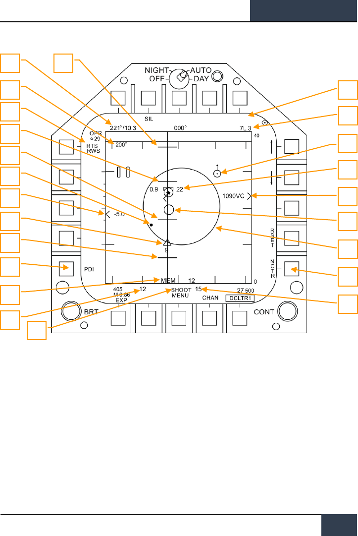
[F/A-18C]
DCS
141
Figure 83. AIM-7 RADAR with L&S Target
1. Return to Search (RTS) Indication. Single Track Target (STT) mode with Return To
Search (RTS) indication.
2. FLOOD Indication. This field will display the FLOOD indication when the AIM-7 is
commanded to FLOOD mode.
3. Selected Weapon and Number Remaining. AIM-7 as Priority Weapon and Remaining
Number.
4. Target Range and Closure Indication. The range of the target is indicated in reference
to the range scale and selected RADAR range display setting. Left of the caret, closure
velocity (Vc) is indicated.
5. Memory Mode indication and Memory Track Time. If the RADAR loses track on the
target, it will automatically enter memory (MEM) mode. During this period, the RADAR will
6
2
4
19
7
8
11
15
9
12
13
10
1
3
23
18
17
16
14
20
21
22
5

DCS
[F/A-18C]
142
HORNET AIR-TO-AIR (A/A)
attempt to reacquire the target and the amount of time the RADAR is in memory mode is
displayed in seconds to the right.
6. Shoot and Lost Cue. When the target is within Rmax range, the Shoot Cue appears as
solid. When the target range is within Rne, the Shoot Cue flashes.
7. Missile Time of Flight. This indicates the estimated Time Of Flight for the un-launched
missile to reach the locked target. Once the missile has been launched, the missile fly-out
indication displays missile time to go.
8. Rmin. Calculated minimum launch distance.
9. Rne. Calculated no escape distance.
10. Rmax. Calculated maximum range distance.
11. AIM-7 Fly-Out indication and Time to Go. Graphically displays the fly-out of the AIM-7
and the estimated Time To Go (TTG) until target intercept.
12. AIM-7 Max Seeker Range Cue. This small circle appears on the azimuth steering line
when the AIM-7 is in STT and LOFT is selected. The cue indicates the range at which the
AIM-7 Semi-Active RADAR Homing (SARH) seeker can guide of RADAR illumination off the
locked target. If LOFT is not selected, the cue only appears when the SARH seeker range is
less than the target range and the target is between Rmin and Rmax.
13. Locked Target. Around the L&S star symbol, target information is displayed that includes
Acceleration Vector, Target Aspect Angle Pointer, Tracked Target indication, Target Altitude
in thousands of feet, and Target Airspeed in Mach.
The Acceleration Vector is displayed in the direction of acceleration, perpendicular to the
target heading vector when the target exceeds 3 Gs. The length of the Acceleration Vector
lengthens with greater target G.
14. Allowable Steering Error (ASE) Circle. Static ASE circle for the AIM-7.
15. Steering Dot. In conjunction with the ASE circle, the Steering Dot indicates lead angle
steering to the locked target. Fly to place the Steering Dot inside the ASE circle to satisfy
lead angle computations. The Steering Dot will flash when within 15 degrees of the
RADAR’s azimuth limit and when within 5 degrees of the RADAR’s elevation limit.
16. Air-to-Air Waypoint with North Arrow. This is only displayed when selected from the
HSI A/AWP option and the waypoint is within the RADAR’s field of view.
17. Target Bearing and Range to Air-to-Air Waypoint. If an air-to-air waypoint has been
created from the HSI/DATA/A/C sublevel, the bearing and range to that waypoint is
indicated in this field.
18. Target Heading. Flight heading of the L&S target.
19. Non-Cooperative Target Recognition (NCTR). When enabled, the RADAR will attempt
to identify the L&S target based on unique RADAR reflections.
20. Rloft. Maximum range using a LOFT launch.
21. Pulse Doppler Illuminator (PDI) indication. When the AIM-7 is launched, it requires
PDI illumination to track the target. PDI is displayed when this illumination occurs.
22. Target Altitude Differential. Displays the difference in altitude between the target and
ownship in thousands of feet.

[F/A-18C]
DCS
143
23. Maximum Aspect Cue. This cue can range from 1 to 18 and indicates shot quality. The
higher the number, the great probability of missile intercept.
HORNET DEFENSIVE SYSTEMS
As this is Digital COMBAT Simulator, you will often find yourself as the target of enemy weapon
systems. The Hornet includes several defensive systems to assist you in your fight to keep alive that
includes expendable countermeasures of chaff and flares and Electronic Countermeasures (ECM).
The lower console instrument group is dominated by the countermeasures dispensing system. This
system provides protection against tracking RADAR, air-to-air and surface-to-air missiles. Protection is
provide by ejecting chaff, flare, or jammer payloads (GEN-X).
The ALQ-165 Airborne Self Protection Jammer (ASPJ) is the onboard Electronic Countermeasure
(ECM) system. The ALQ-165 detects and deceives threat pulse fire control and guidance RADARs and
has four operating modes: standby, receive, transmit, and built in test. This ECM system detects,
processes, and transmits a simulated target echo for deception when a RADAR signal is received. The
simulated echoes are recognized by the enemy RADAR as true target returns. Tracking RADAR then
tracks a false target and breaks lock from the true target. Threat RADAR indications are indicated as
both indicators lights and the RADAR Warning Receiver.
Instant Action Mission Practice: Hornet Defensive Systems

DCS
[F/A-18C]
144
Integrated Countermeasures Control Panel (ICMCP)
Integrated Countermeasures Control Panel (ICMCP)
The ICMCP replaces the old ALR-39 panel and moves many of the control functions to the DDI EW
page.
Figure 84. Integrated Countermeasures Control Panel
Elements of the ICMCP include:
• Dispenser Jettison Button. Pressing this button releases all chaff and flares onboard.
This switch only works with no weight on wheels and the button will illuminate when
pressed.
• Dispenser Mode Select Switch. This switch has three positions:
o OFF: Turns the CMDS power off and ALE-47 legend on the EW page has an X
through it. However, the ECM JETT button will still function.
o ON: When set to on, there is a five second warm up period and a BIT is
conducted. After five seconds, it is ready for operation. When in ON mode, the
release modes of STBY, MAN, SEMI, and AUTO can be selected.
▪ When first set to ON, SF TEST will appear for five seconds below the
EW legends on the DDI EW page. After which, PBIT GO will be
displayed for ten seconds. Once that is complete, OFF or the selected
mode will be displayed.
o BYPASS. This selection bypasses the countermeasure programmer and will
release a single chaff or single flare based on the HOTAS countermeasure
release command. When set to bypass, the ALE-47 indication on the DDI EW
Dispenser Jettison
ASPJ Power and mode Selector
Dispenser Mode Select
Switch

[F/A-18C]
DCS
145
page will have a dash through it and the EW page BIT element will indicate NOT
RDY.
• ASPJ Power and Mode Selector Knob.
o STBY. Once the ALQ-65 is turned on to STBY, in enters a four minute warm-up
period. After four minutes, the STBY (green) light on the threat panel will
extinguish.
o BIT. Commands the ALQ-65 to perform a self-test. The ASPJ will cycle power and
then provide a GO (green) or NO GO (yellow) light indication.
o REC. System only detects and displays threat RADARs, no electronic attack is
initiated though. The green REC light will illuminate when radio frequency energy
has been detected. The REC light will also light during an ASPJ BIT.
o XMIT. System detects and displays threats and then uses active electronic
attack. The green XMIT light and green REC lights will light when the ALQ-65 is
transmitting to jam a radar. A JAM cue will also be visible on the radar display.
o OFF. Removes power from the ASPJ.
Figure 85. ASPJ annunciator panel

DCS
[F/A-18C]
146
Integrated Countermeasures Control Panel (ICMCP)
EW Page
Figure 86. EW Page
At the bottom of the countermeasure panel is the control indicator. This panel has the following
functions:
• ASPJ Power and Mode Indicator. Based on the setting of the ALQ-165 ASPJ Power and
Mode Selector, the ASPJ legend will an OFF below it when the ASPJ is set to OFF. When set
to one of the other four modes, the mode is displayed below the ASPJ legend: XMIT, REC,
STBY, or BIT.
• Chaff Indicator. This field indicates the number of chaff bundles remaining. A box is
placed over the number when a chaff bundle is released.
• Flare Indicator. This field indicates the number of flares remaining. A box is placed over
the number when a flare is released.
• Decoy Indicator (O1 and O2). GEN-X decoys can be carried in two bays, O1 and O2.
The number of decoys per bay are indicated. When a decoy is released, the bay will be
boxed.
• ALE-47 Power and Program Indicator. When the dispenser switch is set to ON, the
selected release program type is displayed below the ALE-47 legend. There are 6 manual
(MAN) programs that can be stored and edited. Semi-Automatic (S/A) and Automatic
modes (AUTO) are also available that will select the a program to match the threat and
allow the pilot to initiate a program (S/A) or have the CMDS initiate a program
automatically (AUTO). To select manual (MAN) programs, successive presses of the STEP
OSB will cycle through the programs and the name of the selected program will be
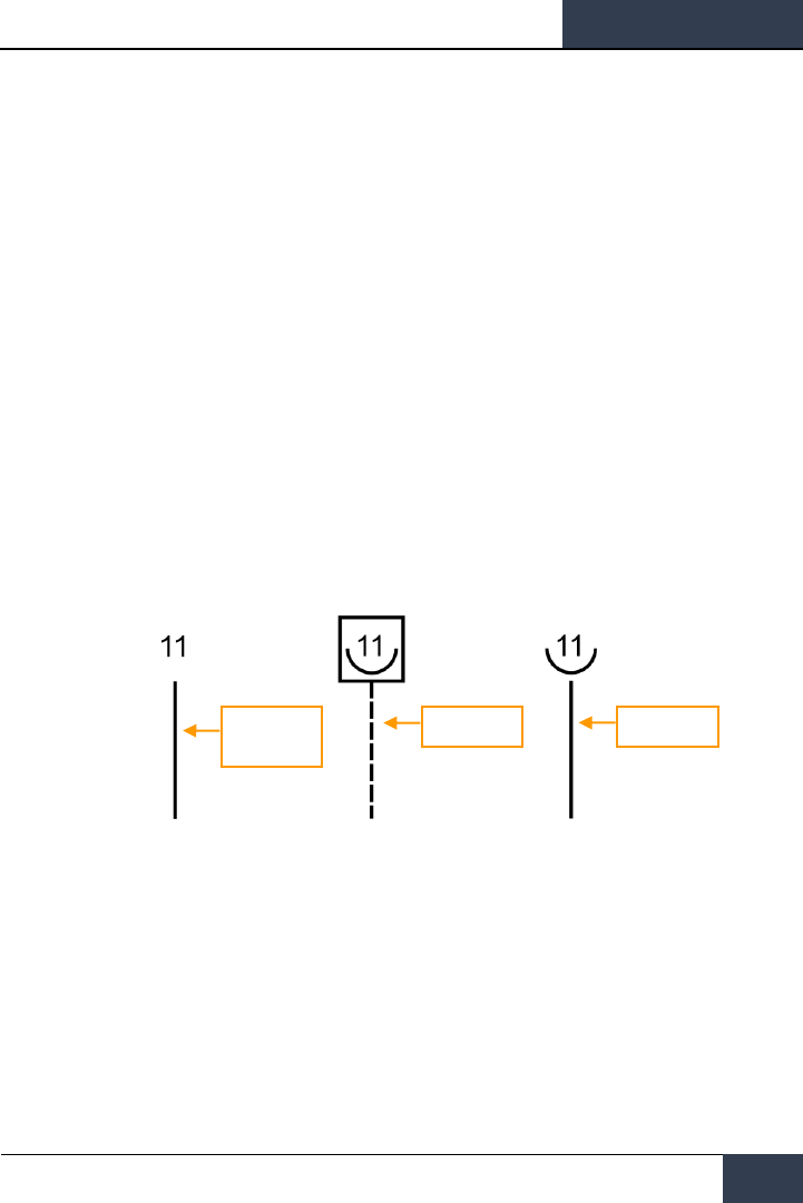
[F/A-18C]
DCS
147
displayed below the ALE-47 legend (i.e. MAN 5). If semi-automatic mode is selected, S/A
will be displayed and if automatic mode is selected AUTO will be displayed.
o If the ALE-47 is powered off from the ICMCP panel, then OFF will be displayed
below the ALE-47 legend.
o When first set to ON, SF TEST will appear for five seconds below the EW legends
on the DDI BIT page. After which, PBIT GO will be displayed (EW BIT complete).
Once the BIT is completed, the OFF legend is removed.
o Pressing the ALE-47 OSB should box the ALE-47 legend and the C, F, O1, and O2
indications should appear on the along the top of the EW DDI page with the
following values: C 14, F 18, O1 14, and O2 14.
o When the dispensers are set to Bypass, the legend will have a dash through it.
• EW Power OSB. Indicates power status of the ALR-67(V) system based on the Control
Indicator Panel power button. When un-powered, the EW legend has OFF below it. Also
when disabled, the EW mode, offset, limit, and HUD status indications on the EW page are
removed.
• EW HUD OSB. Pressing this OSB 18 toggles EW information displayed to the head up
display. Using two alphanumeric identifiers and stems extending from the EW symbols on
the periphery of the HUD toward the center to better indicate relative azimuth. The stem
indicates the threat level of the EW threat:
o Non-critical/lethal steams are solid and short
o Critical threat stems are solid and long
o Lethal threat stems are dashed and long
Figure 87. Threat level of the EW threat
In air-to-air, air-to-ground, and navigation modes, the six highest priority EW threats are
indicated on the HUD. However, this can change based on radar activity and HUD REJECT
setting.
• In Gun ACM mode or gun tracking mode, a maximum of three indications can be
displayed.
• In AIM-7 tracking mode, a maximum of two indications can be displayed.
• In AIM-9 tracking mode, a maximum of one indication can be displayed.
Nonlethal or
Unknown
Lethal
Critical
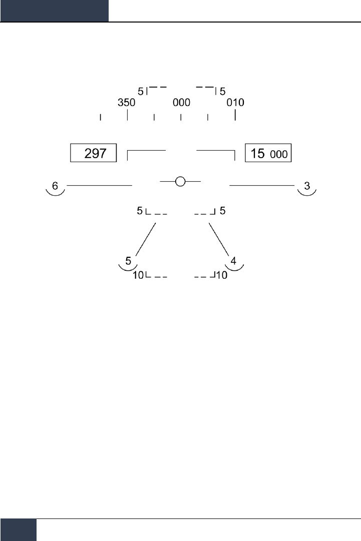
DCS
[F/A-18C]
148
Integrated Countermeasures Control Panel (ICMCP)
If however HUD REJECT 1 is selected, and additional two indications can be displayed. If HUD
REJECT 2 is selected, up to six indications can be displayed in all conditions.
Figure 88. HUD REJECT
• EW Status Indications. Based on the enabling of the EW MODE, OFFSET, and LIMIT
options on the Control Indicator Panel, the selection will be indicated in the bottom right
portion of the EW page.
• EW MODE OSB. Successive presses of the mode OSB will cycle through the EW mode
options:
o STBY. The CMDS has power but cannot dispense countermeasures except for
EW JETT.
o MAN. Up to six manual programs can be selected and programmed using the
PROG sub-level. Only on MAN mode are the STEP and PROG OSB options visible.
o S/A. The CMDS will choose from a library to select the best program against the
primary threat. The pilot though must consent to initiate the program.
o AUTO. The CMDS will choose from a library to select the best program against
the primary threat. The CMDS will automatically initiate the program.
• ARM OSB. When the ALE-47 OSB is pressed and boxed, the ARM legend is displayed.
When the ARM OSB is pressed, the SAVE OSB will appear next to the STEP OSB.
Additionally, new manual programming options will appear. To create a manual program,
pressing the ARM OSB displays the CMDS PROG sub-level. Successive presses of the STEP
OSB will cycle through the five, manual programs. The selected program can be seen in
the center of the page (CMDS PROG x). Along the left side of the page, OSBs to select
chaff (CHAF), flares (FLAR), GEN-X decoys (OTH1 and OTH2), release repeat (RRT), and
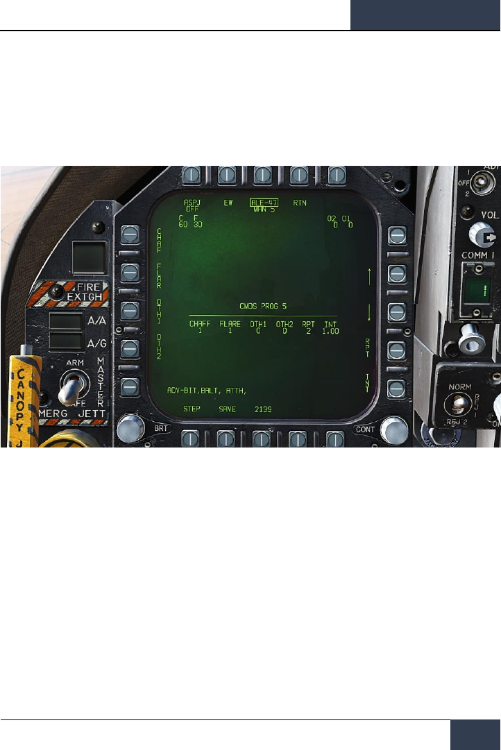
[F/A-18C]
DCS
149
release internal (INT) parameters are displayed. Pressing one of these OSBs will box the
legend and thereby select it for programming. Using the up and down arrows on the right
side of the page, you may adjust the value of the selected program element. The value for
each program element is displayed in the center of the page. Once complete, pressing the
SAVE OSB will have the parameters to the selected program and pressing the RTN (return)
OSB will return to the main EW page.
Figure 89. EW Programs
• ALE-47 Program STEP OSB. Manual programs can be cycles through (1-6) with
successive presses of the STEP OSB. The selected program number is indicated below the
ALE-47 legend at the top of the page.
The primary means for dispensing chaff and flares is with the countermeasures dispense switch on
the throttle.
• Flare / Rear. Releases one flare from each of the left and right dispensers that contain a
flare in a group of 10.
• Chaff / Forward. Released one chaff burst.
Azimuth Indicator
Detected RADARs by the ALR-67(V) are displayed on the Azimuth Indicator (aka RADAR Warning
Receiver) and on the HUD when enabled.
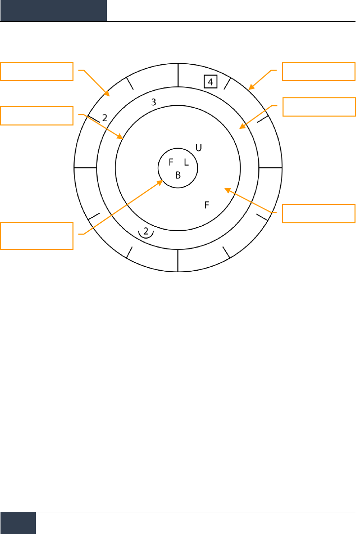
DCS
[F/A-18C]
150
Integrated Countermeasures Control Panel (ICMCP)
Figure 90. Azimuth Indicator
When a RADAR emitter is detected, the ALR-67(V) Azimuth Indicator visually indicates the RADAR
signal source with a coded symbol. The coded symbol indicates the type of emitter detected, and its
position on the azimuth indicator indicates the relative bearing to the emitter. The ALR-67(V) system
detects multiple emitters and provides relative bearing to each emitter. Audio tones are produced as
an advisory for emitter, or BIT status change. This will mirror the DDI EW page.
The emitter and status display is shown on the azimuth indicator when power is applied to the ALR-
67(V) system. When an emitter is detected and analyzed by the ALR-67 system, an alphanumeric
symbol representing the emitter is displayed. Certain types of emitters, when detected, are assigned
unique alphanumeric symbols for display.
The azimuth position of the displayed emitter symbol represents the relative bearing of the emitter
with respect to the nose of the aircraft. As an example, the image above shows a naval threat
enhancement (boat symbol) at 40 degrees.
The display area of the azimuth indicator is divided into four unique areas listed below:
• Critical band
• Lethal band
• Nonlethal band
• Status circle
Display Edge
Lethal Band
Critical Band
Non-Lethal Threat Band
Lethality Ring
System Status Circle
(With Areas I, II and III)

[F/A-18C]
DCS
151
The critical band is the innermost band in which specific threats or modes of lethal threats are
displayed. Azimuth tic marks are engraved in the outer most portion of the critical band. The tic
marks are in 30 degree increments. The lethal band is the second band in from the outer most
portion of the display. Emitters displayed in the lethal band are threats that have been determined to
be lethal. The nonlethal band is the outermost band of the display. Emitter symbols in the nonlethal
band represent unknown and friendly emitters. Known emitters that have been determined to be
nonlethal are also displayed in the nonlethal band.
The status circle is in the center of the azimuth indicator and displays ALR-67(V) system status. The
status circle is divided into three areas of display:
Upper left quadrant of circle (area I)
Upper right quadrant of circle (area II)
Bottom half of circle (area III)
• Area I displays the priority setting of the EW Mode as set on the EW page (N, I, A, U or F).
• Area II is either blank when ALR-67(V) system is operating in the full display mode, or
displays the character L when operating in the display limit mode.
• Area III displays current ALR-67(V) Built-In Test (BIT) status. Area III is blank when there
are no ALR-67(V) system failures. The character B is displayed when a failure is detected.
The character T is displayed when a thermal overload has been detected in
Countermeasures Computer or RADAR Receiver.
Any time a new emitter symbol is displayed on the azimuth indicator or an emitter symbol goes from
a less lethal to a more lethal band, a status change tone is generated by the ALR-67(V) system.
Special tones are also generated for specific threats or critical threat modes of operation. Threats no
longer transmitting or going from a more lethal to a less lethal band do not cause a status change
tone.
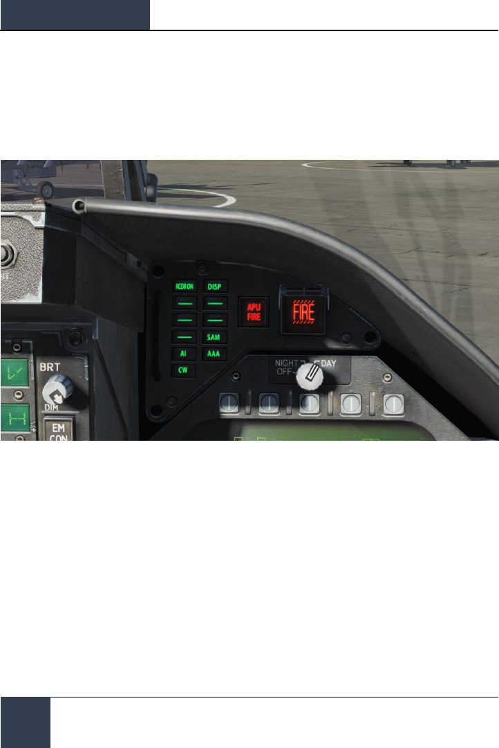
DCS
[F/A-18C]
152
Right Instrument Panel Warning / Advisory / Threat
Display Panel
Right Instrument Panel Warning / Advisory / Threat
Display Panel
Figure 91. Right Instrument Panel Warning / Advisory / Threat Display Panel
Working as part of the ALR-67, red warning lights at the top of the right instrument panel alert the
pilot of the type of radar energy painting the aircraft:
AI: Hostile air intercept radar in lock mode (lethal band)
CW: Hostile radar in continuous wave mode and probably guiding a missile (critical band)
SAM: Surface-to-Air Missile radar that has locked on (critical band)
AAA: Radar directed anti-aircraft artillery.
DISP. The ALE-47 has a program ready for the detected threat and is waiting for start consent. In
addition, a DISPENSE cue will be displayed on the HUD.
GO and NO. BIT test result from when the Dispense switch is set to ON or BYPASS. BIT will take five
seconds.
[F/A-18C]
DCS
153
BIT
When conducting an EW BIT, both graphical and audio tests will be run.
On both the EW page and azimuth indicator, the following test images will be displayed with three
seconds between each.
Figure 92. EW BIT Test Images
In parallel, each of the ALR-67 tones would be played. These include:
• New Contact (waterfall)
• AAA
• Missile Launch
• Radar Lock
• Power Up
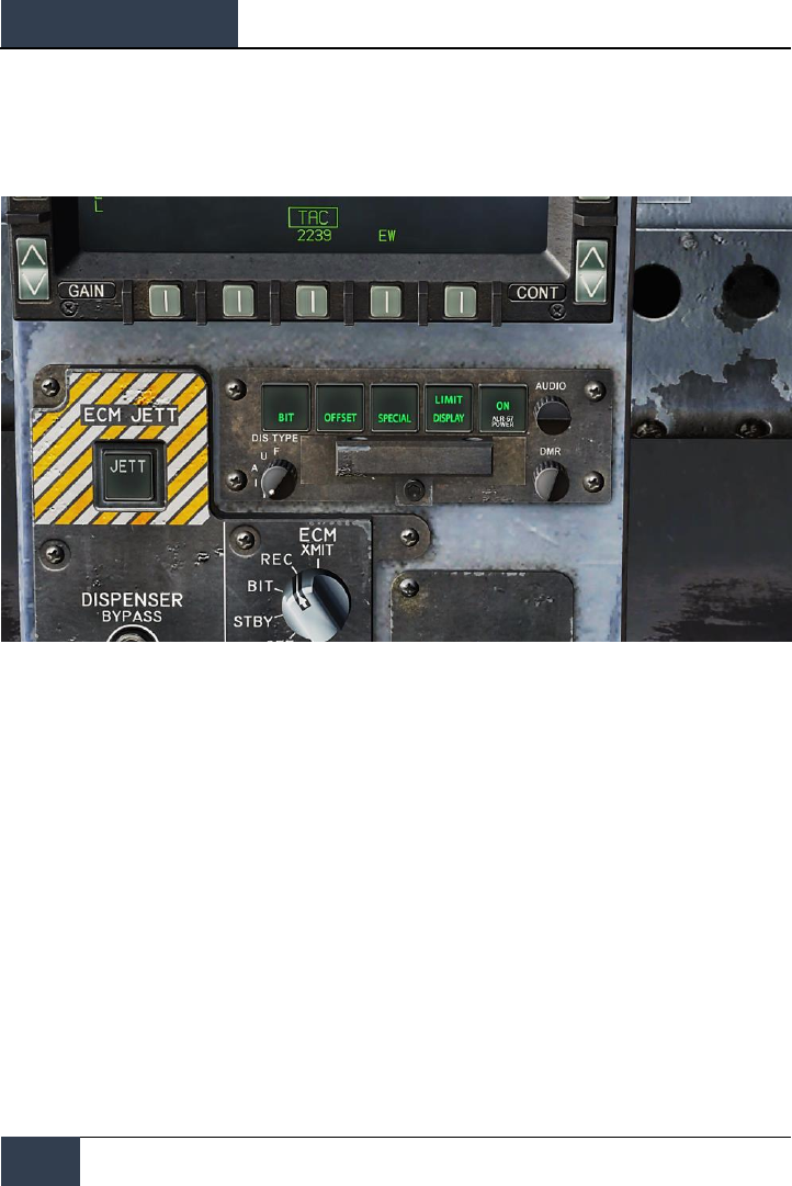
DCS
[F/A-18C]
154
Control Indicator Panel
Control Indicator Panel
Figure 93. Control Indicator Panel
At the bottom of the countermeasure panel is the control indicator. This panel duplicates the
functions on the DDI EW page. This panel has the following functions:
• POWER Pushbutton Switch. Turns the ALR-67(V) system on and off. When pressed to
the on position, the POWER, DISPLAY, SPECIAL, OFFSET AND BIT light will illuminate.
• DISPLAY Pushbutton Switch. When pressed, LIMIT light on DISPLAY pushbutton
switch comes on and emitter display is limited to the six highest priority emitters. .L. will be
displayed in status circle area II on azimuth indicator. Pressing again deselects the option.
• OFFSET Pushbutton Switch. When pressed, ENABLE light on OFFSET pushbutton switch
comes on, and overlapping symbols on azimuth indicator are separated to ease reading of
display. Pressing again deselects the option.
• BIT Pushbutton Switch. When pressed, enables current BIT status to be displayed on
the azimuth indicator. FAIL light on BIT pushbutton switch will come on whenever periodic
BIT detects a failure. Pressing again deselects the option.
• DMR Control. Controls brightness of the lamps on the control-indicator. Clockwise
rotation increases brightness, counterclockwise rotation decreases brightness.
• DIS TYPE Switch. Selects priority of emitter type to be displayed. Switch setting to N
(normal), I (intercept), A (AAA), U (unknown), or F (friendly) are also displayed in status
circle area I on azimuth indicator.

[F/A-18C]
DCS
155
HOTAS
On the throttle, there is a three place switch for countermeasures.
• Center. This is the OFF position and no dispense action is taken.
• Aft. When in BYPASS mode, this will release one flare. If not in BYPASS mode or OFF,
AUTO, S/A, or MAN mode will initiate the program.
• Forward. When in BYPASS mode, this will release one chaff bundle. If not in BYPASS
mode or OFF, it will initiate manual program 5.

DCS
[F/A-18C]
156
HOTAS
Good hunting!
The Eagle Dynamics and Belsimtek Teams
EAGLE DYNAMICS © 2018
