DeepMind 12 Behringer User Manual M EN
Behringer DEEPMIND 12 User Manual deepmind_12_m_en Behringer - DEEPMIND 12 - User Manual
Behringer DEEPMIND 12 User Manual deepmind_12_m_en Behringer - DEEPMIND 12 - User Manual
User Manual: Behringer DEEPMIND 12 User Manual Behringer - DEEPMIND 12 - User Manual
Open the PDF directly: View PDF ![]() .
.
Page Count: 135 [warning: Documents this large are best viewed by clicking the View PDF Link!]
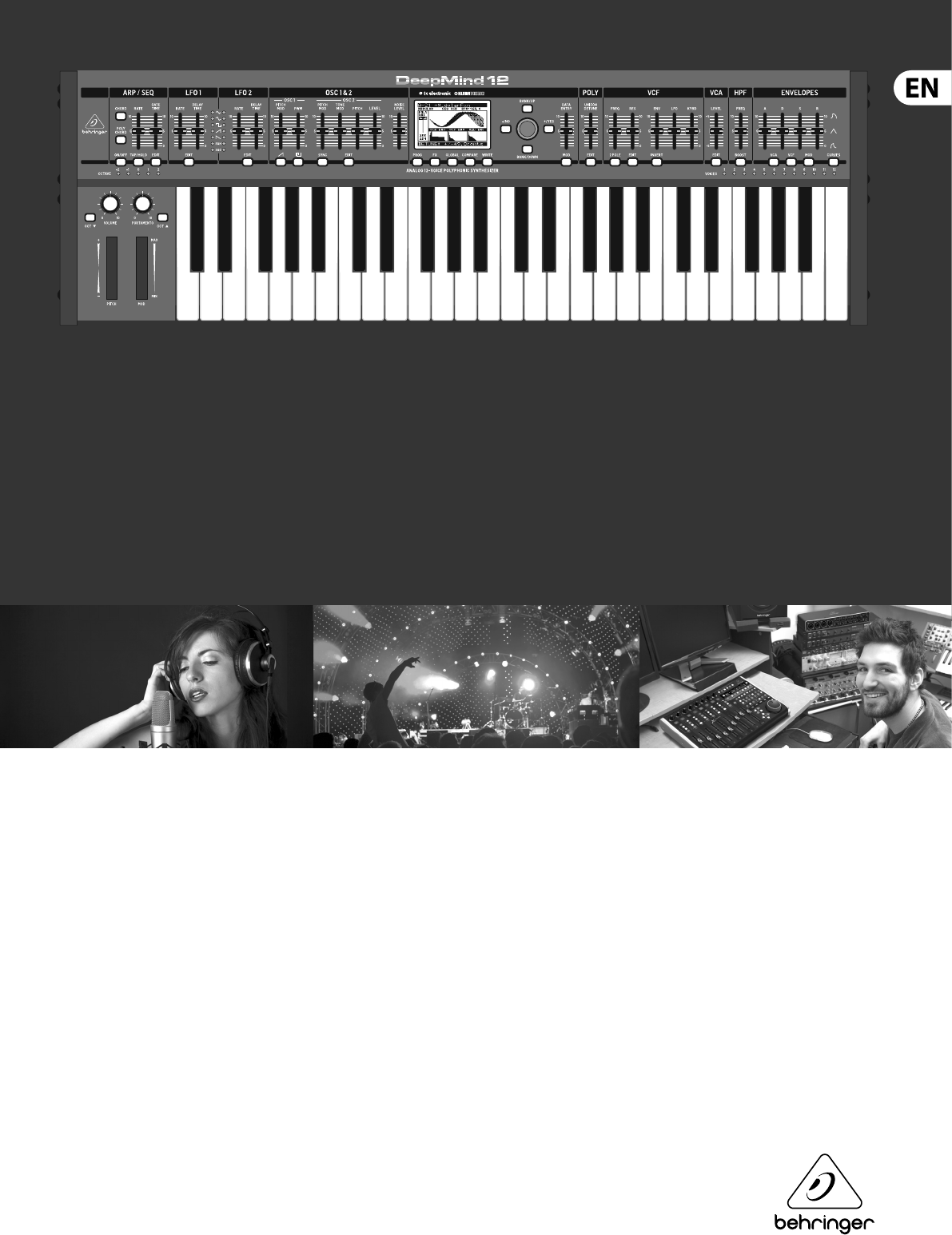
User Manual
DeepMind 12
True Analog 12-Voice Polyphonic Synthesizer with
4 FX Engines, 2 OSCs and LFOs per Voice, 3 ADSR Generators,
8-Channel Modulation Matrix, 32-Step Sequencer,
Tablet Remote Control and Built-In WiFi

2DeepMind 12 User Manual
Table of Contents
Thank you........................................................................ 2
Important Safety Instructions ...................................... 3
Legal Disclaimer ............................................................. 3
Limited warranty ............................................................ 3
About the DeepMind 12 ................................................. 4
1. Introduction ............................................................... 5
2. Features ...................................................................... 5
3. Controls ...................................................................... 7
4. Program Management ............................................ 11
5. Playing Guide ........................................................... 15
6. Signal Path / Voice Structure ................................. 17
7. Menu System ............................................................ 19
8. Programming ........................................................... 36
9. E ects Reference Guide .......................................... 79
10. Short-cuts ............................................................. 102
11. Applications .........................................................103
12. DAW MIDI Con guration .....................................108
13. System Block Diagram ........................................109
14. Connection Wiring Diagrams ............................. 111
15. Technical Speci cations ...................................... 112
16. MIDI Commands .................................................. 113
17. MIDI NRPN Commands ........................................ 117
18. Global Commands ............................................... 120
19. MIDI SysEx Commands ........................................ 121
20. Firmware Update ................................................. 127
21. Troubleshooting .................................................. 127
22. Bootloader Menu ................................................. 128
23. De nition of Terms .............................................. 129
24. Appendix 1 - Octave Shifting ............................. 133
25. Appendix 2 - ARP/SEQ/LFO Sync Timing ........... 133
Thank you
Thank you very much for expressing your con dence in BEHRINGER products by
purchasing the DeepMind 12 analog polyphonic synthesizer—our True Analog
12-Voice Polyphonic Synthesizer with 4 FX Engines, 2 OSCs and LFOs per Voice,
3 ADSR Generators, 8-Channel Modulation Matrix, 32-Step Sequencer, Tablet
Remote Control and Built-In Wi-Fi.
3DeepMind 12 User Manual
Important Safety
Instructions
LEGAL DISCLAIMER
LIMITED WARRANTY
Terminals marked with this symbol carry
electrical current of su cient magnitude
to constitute risk of electric shock.
Use only high-quality professional speaker cables with
¼" TS or twist-locking plugs pre-installed. Allother
installation or modi cation should be performed only
by quali edpersonnel.
This symbol, wherever it appears,
alertsyou to the presence of uninsulated
dangerous voltage inside the
enclosure-voltage that may be su cient to constitute a
risk ofshock.
This symbol, wherever it appears,
alertsyou to important operating and
maintenance instructions in the
accompanying literature. Please read the manual.
Caution
To reduce the risk of electric shock, donot
remove the top cover (or the rear section).
No user serviceable parts inside. Refer servicing to
quali ed personnel.
Caution
To reduce the risk of re or electric shock,
do not expose this appliance to rain and
moisture. The apparatus shall not be exposed to dripping
or splashing liquids and no objects lled with liquids,
suchas vases, shall be placed on the apparatus.
Caution
These service instructions are for use
by quali ed service personnel only.
Toreduce the risk of electric shock do not perform any
servicing other than that contained in the operation
instructions. Repairs have to be performed by quali ed
servicepersonnel.
1. Read these instructions.
2. Keep these instructions.
3. Heed all warnings.
4. Follow all instructions.
5. Do not use this apparatus near water.
6. Clean only with dry cloth.
7. Do not block any ventilation openings. Install in
accordance with the manufacturer’s instructions.
8. Do not install near any heat sources such as
radiators, heat registers, stoves, or other apparatus
(including ampli ers) that produce heat.
9. Do not defeat the safety purpose of the polarized
or grounding-type plug. A polarized plug has two blades
with one wider than the other. A grounding-type plug
has two blades and a third grounding prong. The wide
blade or the third prong are provided for your safety. Ifthe
provided plug does not t into your outlet, consult an
electrician for replacement of the obsolete outlet.
10. Protect the power cord from being walked on or
pinched particularly at plugs, convenience receptacles,
and the point where they exit from the apparatus.
11. Use only attachments/accessories speci ed by
themanufacturer.
12. Use only with the
cart, stand, tripod, bracket,
or table speci ed by the
manufacturer, orsold with
the apparatus. When a cart
is used, use caution when
moving the cart/apparatus
combination to avoid
injury from tip-over.
13. Unplug this apparatus during lightning storms or
when unused for long periods of time.
14. Refer all servicing to quali ed service personnel.
Servicing is required when the apparatus has been
damaged in any way, such as power supply cord or plug
is damaged, liquid has been spilled or objects have fallen
into the apparatus, the apparatus has been exposed
to rain or moisture, does not operate normally, or has
beendropped.
15. The apparatus shall be connected to a MAINS socket
outlet with a protective earthing connection.
16. Where the MAINS plug or an appliance coupler is
used as the disconnect device, the disconnect device shall
remain readily operable.
17. Correct disposal of this
product: This symbol indicates
that this product must not be
disposed of with household
waste, according to the WEEE
Directive (2012/19/EU) and
your national law. This product
should be taken to a collection center licensed for the
recycling of waste electrical and electronic equipment
(EEE). The mishandling of this type of waste could have
a possible negative impact on the environment and
human health due to potentially hazardous substances
that are generally associated with EEE. At the same time,
your cooperation in the correct disposal of this product
will contribute to the e cient use of natural resources.
For more information about where you can take your
waste equipment for recycling, please contact your local
city o ce, or your household waste collection service.
18. Do not install in a con ned space, such as a book
case or similar unit.
19. Do not place naked ame sources, such as lighted
candles, on the apparatus.
20. Please keep the environmental aspects of battery
disposal in mind. Batteries must be disposed-of at a
battery collection point.
21. Use this apparatus in tropical and/or
moderate climates.
MUSIC Group accepts no liability for any loss
which may be su ered by any person who relies
either wholly or in part upon any description,
photograph, or statement contained herein.
Technical speci cations, appearances and other
information are subject to change without notice.
All trademarks are the property of their respective
owners. MIDAS, KLARK TEKNIK, LAB GRUPPEN, LAKE,
TANNOY, TURBOSOUND, TC ELECTRONIC, TC HELICON,
BEHRINGER, BUGERA and DDA are trademarks
or registered trademarks of MUSIC Group IP Ltd.
© MUSIC Group IP Ltd. 2017 All rights reserved.
For the applicable warranty terms and conditions
and additional information regarding MUSIC Group’s
Limited Warranty, please see complete details online at
music-group.com/warranty.

4DeepMind 12 User Manual
About the DeepMind 12
The DeepMind 12 is a True Analog 12-Voice Polyphonic Synthesizer with TC
ELECTRONIC / KLARK TEKNIK FX and iPad Remote Control.
The DeepMind 12 was created to serve the creative needs of players, performers,
artists, sound designers, engineers and producers.
The DeepMind 12 o ers all the features of a traditional analog polyphonic
synthesizer, and adds incredible new features to enhance and expand the creative
possibilities.
•
• Classic polyphonic synthesizer with 12 true analog oscillators for insanely fat
and authentic sounds.
•
• 4 simultaneous world-class TC ELECTRONIC and KLARK TEKNIK FX with over
30 algorithms including Reverb, Chorus, Flanger, Phaser, Delay and multi-
band Distortion.
•
• 12 voices with 2 OSCs per voice with oscillator sync mode 2 LFOs per voice
with 7 waveform shapes, key sync, MIDI sync and envelope auto-triggering.
•
• 3 ADSR generators per voice for control of VCF, VCA and MOD envelopes.
•
• Flexible 8-channel modulation matrix with 22 sources and 129 destinations
including e ects parameters.
•
• 32-step control sequencer with adjustable slew rate and MIDI sync.
•
• Full remote control via iPad*/PC/Mac and selected Android* Application over
USB, MIDI or built-in Wi-Fi for extended parameter control.
•
• 49 semi-weighted full-size keys featuring velocity sensitivity
and after-touch.
•
• Pure analog signal path with legendary IR3109-style VCFs and stereo VCAs.
•
• OSC 1 generates sawtooth and square/pulse waveforms with
pulse width modulation.
•
• OSC 2 generates square/pulse waveforms with tone modulation.
•
• Selectable dual slope 12/24 dB analog low pass lter per voice with
adjustable resonance.
•
• Envelope faders seamlessly transform individual envelope segments
between linear, exponential and reverse exponential curves.
•
• Powerful unison and poly modes with detune, pan spread and drift
parameters featuring up to 12 voices per note.
•
• Global noise generator dramatically expands waveform generation.
•
• Incredible polyphonic portamento with exible xed rate, xed time and
exponential pitch glide modes.
•
• Sophisticated arpeggiator with tap tempo button and user con gurable
pattern modes.
•
• Chord and Poly Chord memories enable polyphonic performances from
monophonic playing styles.
•
• Global variable 6 dB high pass lter with bass boost switch.
•
• 26 sliders and one switch per function give direct and real-time access to all
important parameters.
•
• Spring-loaded pitch and assignable modulation wheels provide total
hands-on performance.
•
• LCD Display with encoder, navigation switches and data value fader for rapid
menu parameter editing and program selection.
•
• 1024 user program memories with "compare and match” feature to quickly
match all analog controls to values stored in program.
•
• Fully servo-balanced stereo outputs for highest signal integrity.
•
• CV/pedal input for connection to modular systems.
•
• Comprehensive MIDI implementation (including NRPN/CC control of all
parameters and bulk load/save).
•
• Integrated and con gurable Wi-Fi client / Access point allows easy and
secure connection to home network.
•
• 3-Year Warranty Program*.
•
• Designed and engineered in the U.K.

5DeepMind 12 User Manual
1. Introduction
The DeepMind 12 is a True Analog 12-Voice Polyphonic Synthesizer with 4 FX
Engines, 2 OSCs and LFOs per Voice, 3 ADSR Generators, 8-Channel Modulation
Matrix, 32-Step Sequencer, Tablet Remote Control and Built-In Wi-Fi.
The DeepMind 12 was created to serve the creative needs of players, performers,
artists, sound designers, engineers and producers.
The DeepMind 12 o ers all the features of a traditional analog polyphonic
synthesizer, and adds incredible new features to enhance and expand the
creative possibilities.
! This manual rst describes the terminology used, so that
you understand the unit and its functions. Please read the manual
carefully and keep it for future reference.
1.1 Before you get started
1.1.1 Shipment
The DeepMind 12 was carefully packed in the factory to guarantee safe transport.
Nevertheless, we recommend that you carefully examine the packaging and
its contents for any signs of physical damage, which may have occurred during
transit.
! If the unit is damaged, please do NOT return it to us, but
notify your dealer and the shipping company im mediately, otherwise
claims for damage or replacement may not be granted.
1.1.2 Initial operation
Be sure that there is enough space around the unit for cooling purposes and, to
avoid over-heating, please do not place the DeepMind 12 on high-temperature
devices such as radiators or power amps.
* Blown fuses must only be replaced by fuses of the same
type andrating!
The console is connected to the mains via the supplied cable. It meets the
required safety standards.
◊
◊ Please make sure that all units have a proper ground connection.
For your own safety, never remove or disable the ground conductor
from the unit or the AC power cord.
1.2 The product manual
The product manual is designed to give you both an overview of the DeepMind 12
analog polyphonic synthesizer, as well as detailed information on each of the
controls and parameters. You will nd an overview of the physical control
elements in the next chapter.
1.3 Preparation
! Remember to turn your monitors / loudspeakers on last
when powering up your system, and turn your monitors / loudspeakers
o rst when powering down your system.
2. Features
2.1 Voices
•
• Twelve independent Voices.
•
• Two discrete OSCs per voice.
•
• OSC 1 : Simultaneous Sawtooth and Pulse / Square function.
•
• OSC 2 : Square with Tone Mod wave shape function.
•
• Variable Pulse width (OSC1) Tone Mod (OSC2) manual and variable
modulation depth for each OSC.
•
• Hard sync option: oscillator 2 either syncs to oscillator 1 or can free run.
•
• Variable Pitch o set for OSC2 (+/- 1 octave) for harmonic richness.
•
• Three octave ranges per OSC, 16", 8", 4".
•
• OSC drift amount for controllable tuning instability.
•
• Unison modes (1,2,3,4,6,12 voice) with detune for huge sounds.
•
• Variable Oscillator 2 level.
2.2 Filters
•
• 2/4 pole resonant Midas Low-Pass Filter.
•
• Continuous High-Pass Filter frequency.
•
• LP Filter can be driven into self-oscillation.
•
• Switchable Bi-polar lter envelope depth.
•
• Variable Keyboard / Frequency tracking.
•
• Switchable +12 db Bass Boost for massive low end.
2.3 Envelopes
• Dedicated VCA, VCF and auxiliary (MOD) envelope Four-stage (ADSR)
envelope generator with continuously variable curves for unique exibility.
• Trigger modes (Key, Loop, Control Sequencer, LFO1, LFO2).
2.4 LFO
•
• Two LFOs per voice.
•
• Variable slew rate.
•
• Mono / Poly / Spread modes for linking and unlinking LFO phase across
voices.
•
• High maximum LFO rate for cross mod type e ects.
•
• Sine, Triangle, Square, Ramp Up, Ramp Down, Sample and Hold,
Sample and Glide.
•
• Key Sync on/o .
•
• Clock sync (internal or external MIDI clock).
•
• Delay and Fade in Per LFO.
•
• High maximum LFO rate which can track note number via mod matrix for
cross mod type e ects.
2.5 VCA
•
• Stereo VCA per voice with overall pan spread control and individual voice
pan modulation.

6DeepMind 12 User Manual
2.6 E ects
•
• Over 30 high grade studio quality chainable e ects.
•
• E ects from TC Electronic, Behringer X32 and Midas Consoles.
•
• 4 E ects per Program.
•
• True bypass.
•
• Tap Tempo.
•
• Many e ect parameters are a destination in the Mod Matrix allowing endless
possibilities.
•
• 10 di erent E ects con gurations including shimmer routings with
feedback.
•
• TC-DeepVRB, Ambience, Room Rev, VintageRm, Hall Rev, Chamber Rev, Plate
Rev, Rich Plate, Gated Rev, Reverse, ChorusVerb, DelayVerb, FlangeVerb,
4Band EQ, Enhancer, FairComp, MulBndDist, RackAmp, EdisonEX1, Auto-Pan,
NoiseGate, Delay, 3TapDelay, 4TapDelay, T-RayDelay, ModDlyRev, Chorus,
Chorus-D, Flanger, Phaser, MoodFilter, Dual Pitch, RotarySpkr.
2.7 Mod Matrix
•
• 8 Mod matrix busses.
Modulation Sources (22):
•
• Pitch Bend, Mod Wheel, Foot Ctrl, Breath Controller, Pressure, LFO 1, LFO
2, VCA Envelope, VCF Envelope, Mod Envelope (Auxiliary Envelope), Note
Number, Note Velocity, Ctrl Sequencer, LFO1 (unipolar), LFO2 (unipolar), LFO1
Fade, LFO2 Fade, Note O Velocity, Voice Number, CC X-Axis, CC Y-Axis, CC
Z-Axis.
Modulation Destinations (122):
•
• LFO1 Rate, LFO1 Delay, LFO1 Slew, LFO2 Rate, LFO2 Delay, LFO2 Slew, OSC1+2
Pitch, OSC1 Pitch, OSC2 Pitch, LFO Depth, PWM Depth, Tone Mod Depth, OSC2
Pulse Modulation Depth, Portamento Time, VCF Frequency, VCF Resonance,
VCF Envelope, VCF LFO, All Envelope Rates, All Envelope Attacks, All Envelope
Decays, All Envelope Sustains, All Envelope Releases, Envelope (1-3) Rates,
Envelope (1-3) Curves, Envelope (1-3) Attack, Envelope (1-3) Decay, Envelope
(1-3) Sustain , Envelope (1-3) Release, Envelope (1-3) Attack Curve, Envelope
( 1-3) Decay Curve, Envelope (1-3) Sustain Curve , Envelope (1-3) Release
Curve, VCA All, VCA Active, VCA Envelope Depth, LFO Pan Spread, VCA Pan,
OSC2 Level, Noise Level, HP Frequency, Unison Detune, Modulation 1-8
Depth, E ects (1-4) All loaded FX Parameter(1-12).
2.8 Keyboard
•
• Full-sized, semi-weighted, 49-note keyboard with note on and o velocity,
and aftertouch.
•
• Backlit pitch and mod wheel.
•
• Spring-loaded pitch wheel with selectable range per program (1 to 24
semitones up and down).
•
• Transpose controls for an 8-octave range.
•
• Polyphonic Portamento.
2.9 PSU
•
• IEC mains connection - No Wall Wart.
2.10 Clock
•
• Master clock with tap tempo.
•
• BPM control and display.
•
• MIDI clock sync
2.11 Arpeggiator
•
• Variable Gate Time.
•
• Up to six octave range.
•
• 32 Preset and 32 User programmable rhythmic patterns with up to 32 steps
and rests.
•
• Variable swing function.
•
• Arpeggiator Modes :
•
• UP, DOWN, UP-DOWN ,UP-INV, DOWN-INV, UP-DN-INV, UP-ALT, DOWN-ALT,
RAND, AS-PLAYED, CHORD.
•
• User Pattern.
•
• Arp Clock options : 1/2, 3/8, 1/3, 1/4, 3/16, 1/6, 1/8, 3/32, 1/12, 1/16, 1/24,
1/32, 1/48.
•
• Hold switch latches held notes on.
2.12 Chord / Poly Chord
•
• Maps chords to trigger keys.
•
• Up to 12 notes per chord.
•
• Enough storage for 36x 6 note chords.
2.13 Control sequencer
•
• Up to 32 steps and rests. Output routable via the mod matrix.
2.14 Editor
•
• Comprehensive Apple iPad, Apple MacOS and Windows PC editor.
2.15 Program Memory
•
• 1024 Programs arranged in 8 Banks of 128 Programs.
2.16 Input / Output
•
• Built in USB Midi Interface.
•
• USB for iPad/PC/Mac connection MIDI.
•
• USB for bidirectional MIDI communication.
•
• Flexible MIDI routing.
•
• Expression Pedal / CV (0-5v) in.
•
• Left and right balanced audio outputs (2 x 1/4” TRS).
•
• Headphone output (stereo, 1/4” TRS).
•
• MIDI IN, OUT, and THRU ports.
•
• Con gurable Wi-Fi client / Access point allows easy and secure connection to
home network.
•
• Wireless control with RTP (Real-Time Protocol) MIDI support.
7DeepMind 12 User Manual
(5) (6) (7) (1) (3)
(20)
(19)
(18)
(17)
(16)
(15)
(14)
(2) (4) (8) (9) (10) (11) (12)
(13)
(20)
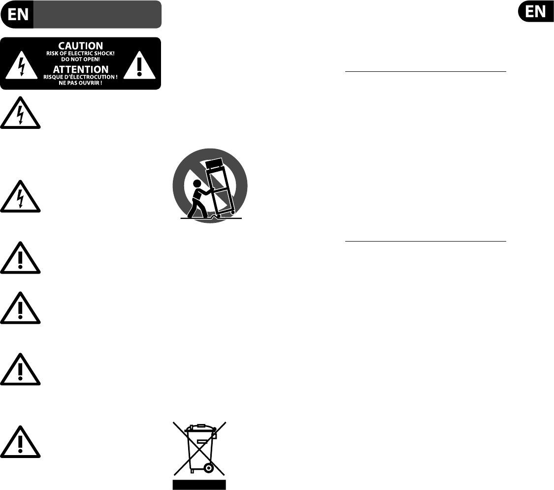
3. Controls
3.1 Top Controls

8DeepMind 12 User Manual
(1) DISPLAY - this large backlit LCD screen shows the synthesizer status,
parameters, and the ve main menus. The contrast and brightness are
adjustable on the PANEL SETTINGS page of the GLOBAL menu.
(2) NAVIGATION - navigate within the display menus using the UP, DOWN, +/
YES and -/NO buttons.
(3) MENUS - these switches allow access to the display menus.
PROG MENU- the main display of the synthesizer. Shows the current
program, the currently adjusted parameter and a visual representation of
the parameter and the three envelopes.
FX MENU - add up to four e ects from the list available. Change the e ects
routing by selecting one of the ten MODEs available. Each of the e ects has
individual controls for all parameters.
GLOBAL MENU - view and adjust settings for the synthesizer. There are
ve pages, CONNECTIVITY, KEYBOARD, PEDAL, PANEL and SYSTEM.
COMPARE MENU - in this menu, you can compare the current program
with the stored program and see the di erence in physical fader positions.
WRITE MENU - in this menu, you can write the current program settings
to the program library. You can also rename the program and set its
category type.
(4) DATA ENTRY - selected parameters on the display are adjusted using the
rotary knob or the fader. The rotary knob has a click which allows very
accurate control. The fader allows rapid adjustment across the full range.
MOD- this switch opens the modulation matrix on the display and allows
up to 8 modulations to be created from the list of sources and destinations.
(5) ARP/SEQ - this area controls the arpeggiator and the control sequencer.
ON/OFF - when activated, this generates an arpeggio based on pressed
keys. Note - the control sequencer is turned on from its edit page only.
RATE - adjusts the rate of the arpeggiator / sequencer in beats per minute
(BPM).
GATE TIME - adjusts the duration of the note played based on a
percentage of the time between triggered notes.
CHORD - allows you to play any chord with a single key. The chord is given
a root note and mapped across the keyboard.
POLY CHORD - allows you to play multiple chords from multiple keys. The
chords are mapped to individual keys.
TAP/HOLD - tap this button in time with your performance to set the rate/
BPM, or press and hold to engage the HOLD function.
EDIT - this allows additional arpeggiator/control sequencer parameters to
be edited from the main display.
(6) LFO 1 and 2- low frequency oscillators used to modulate or control other
parameters.
RATE- this sets the rate, or speed of the LFO.
DELAY TIME - the duration of time which will elapse before the LFO starts.
EDIT - this allows additional LFO parameters to be edited from the main
display.
LFO WAVEFORMs - these LEDs indicate the type and status of the
waveforms produced by each LFO.
(7) OSC 1 & 2 - These analog full range oscillators create waveforms which are
the sound source of the synthesizer.
OSC 1 & 2 PITCH MOD - amount of pitch modulation applied to
respective OSC.
OSC 1 SQUAREWAVE- this switch turns the square wave output for
OSC 1 on/o .
OSC 1 PWM - amount of pulse width modulation applied to
the OSC 1 square wave.
OSC 1 SAWTOOTH- this switch turns the sawtooth output for OSC 1 on/o .
OSC 2 TONE MOD- amount of tone modulation applied to OSC 2.
OSC 2 PITCH- controls the base pitch of OSC 2.
OSC 2 LEVEL- controls the level of OSC 2.
NOISE LEVEL- controls the amount of white noise added to the oscillators.
EDIT- this allows additional OSC parameters to be edited from
the main display.
(8) POLY - this area is used to control the polyphony of the synthesizer.
UNISON DETUNE - when voices are playing in unison, this adjusts the
amount of detuning between the voices.
EDIT- this allows additional POLY parameters to be edited from
the main display.
(9) VCF - the voltage controlled low pass lter used to lter high frequencies
from the sound of the synthesizer.
FREQ - adjusts the cut-o frequency of the lter.
2-POLE - changes the roll o slope of the lter from the default 4-POLE
mode to a 2-POLE mode.
RES - adjusts the resonance of the lter cut-o point.
EDIT - allows additional VCF parameters to be edited from
the main display.
ENV - adjusts the level of the VCF ENVELOPE which controls the
lter cut-o frequency.
INVERT - used to invert the polarity of the VCF envelope applied to the
lter cut-o frequency.
LFO - adjusts the depth of the selected LFO waveform applied to the lter
cut-o frequency.
KYBD - adjusts the amount of keyboard tracking to be applied to the lter
cut-o frequency.
(10) VCA - the voltage controlled ampli er used to control the output level.
LEVEL - controls the output level of the VCA.
EDIT - this allows additional VCA parameters to be edited from
the main display.
(11) HPF - the voltage controlled high pass lter used to lter low frequencies
from the sound of the synthesizer.
FREQ - used to adjust the frequency of the high pass lter.
BOOST - this switch applies a +12 dB bass boost to the signal path
(12) ENVELOPE - these are the three envelopes used to modulate
other parameters.
A [ATTACK]- controls the attack time of the envelope.
D [DECAY] - controls the decay time of the envelope.
S [SUSTAIN] - controls the sustain level of the envelope.
R [RELEASE] - controls the release time of the envelope.
VCA - selects the envelope used to control the voltage controlled ampli er.
9DeepMind 12 User Manual
(22) (21)
(23) (24) (25) (26) (27) (28) (29) (30)
VCF - selects the envelope used to control the voltage controlled lter.
MOD - selects the envelope used for user speci c modulation.
CURVES - changes the ADSR controls to a ect the associated curves for
each stage of the envelope.
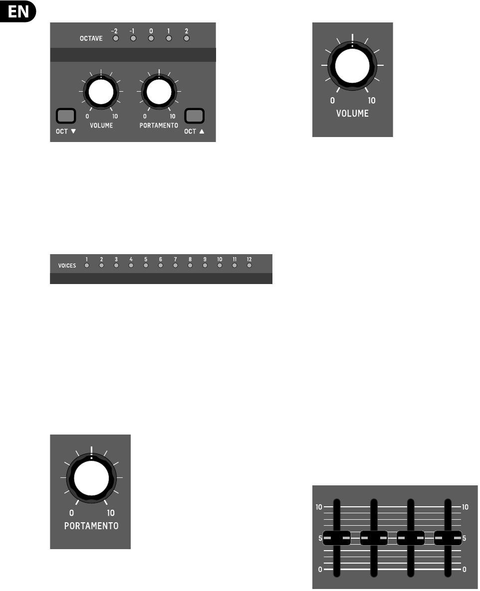
(13) VOICES - these LEDs show which voices are active as keys are played.
(14) OCTAVE - these LEDs show the octave shift applied to the keyboard.
(15) PORTAMENTO - changes the slide time between played notes.
(16) VOLUME - controls the output level of the synthesizer.
(17) OCTAVE UP/DOWN - raise or lower the keyboard’s pitch range in
steps of an octave.
(18) PITCH BEND WHEEL - this spring loaded wheel allows you to lower / raise
the pitch expressively.
(19) MOD WHEEL - used for expressive modulation of parameters.
(20) KEYS - 49 semi-weighted full-size keys featuring expressive velocity and
after-touch.
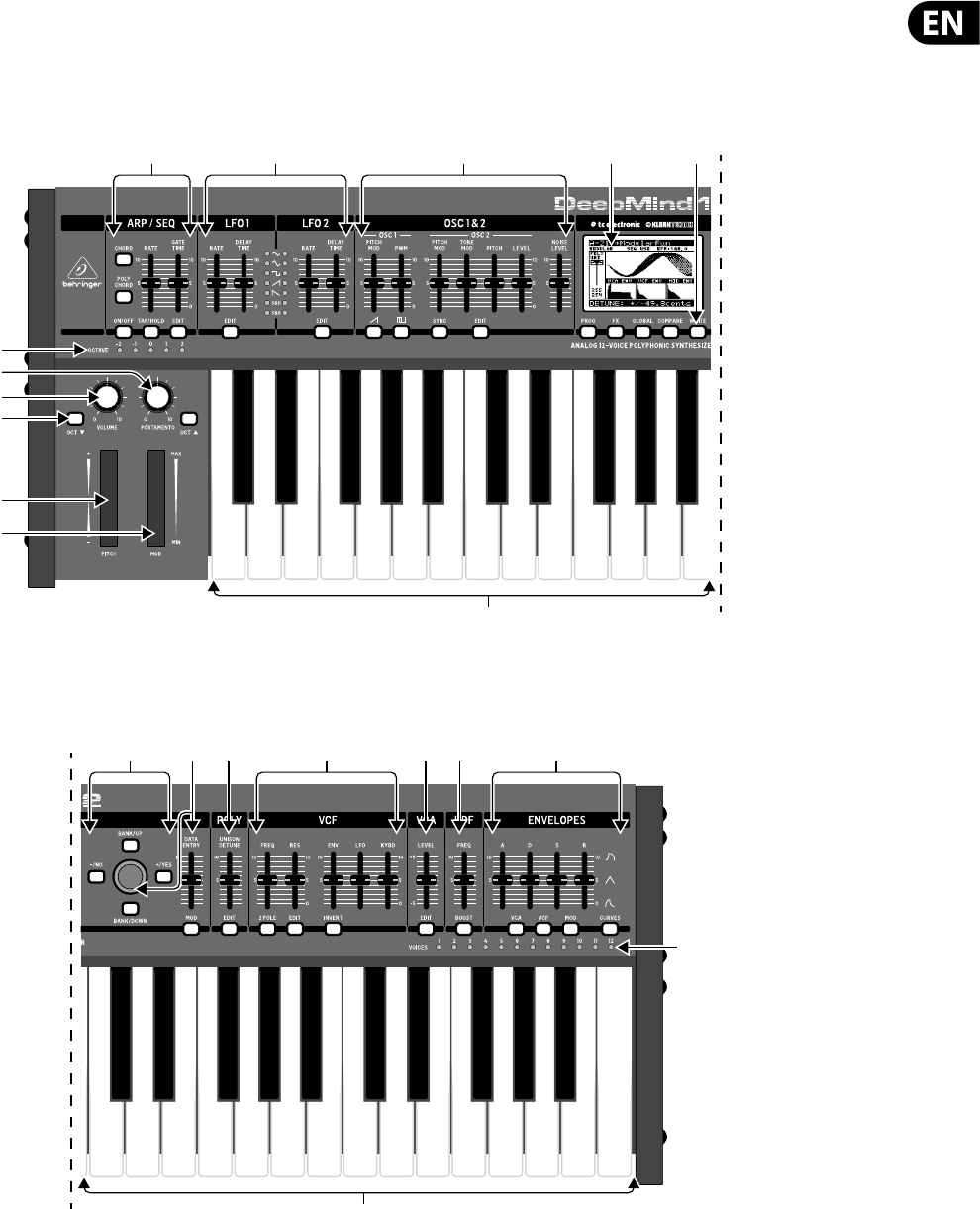
3.2 Rear Panel

10 DeepMind 12 User Manual
Rear Panel
(21) POWER INPUT - connect using the supplied power cable only.
(22) POWER SWITCH - use this to turn the synthesizer on and o . Only turn it
on after all connections have been made.
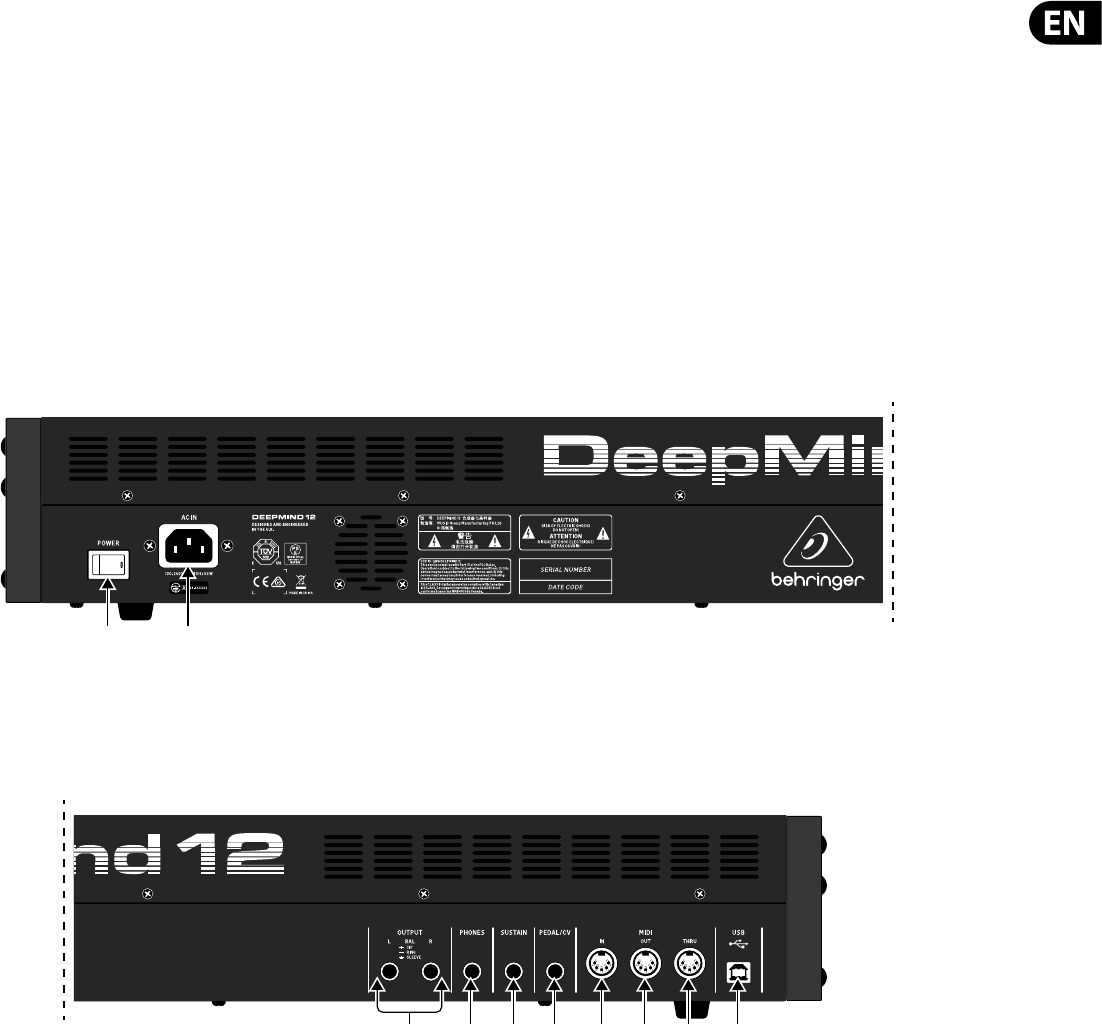
(23) OUTPUT L / R - this is the main output of the synthesizer. It should be
connected to your audio interface or sound system. Remember to turn your
monitors / loudspeakers on last when turning on your system and turn
your monitors / loudspeakers o rst when turning your system o .
(24) PHONES - the headphones output of the synthesizer follows the main
output. Connect your headphones here. Ensure the volume control is at
minimum when putting on headphones or when turning the synthesizer
on or o .
(25) SUSTAIN - this ¼" TS jack allows you to connect a sustain pedal, such as a
normally-open switch.
The operation of this pedal can be customized using the GLOBAL /
PEDAL SETTINGS menu.
(26) PEDAL/CV - this ¼" TRS jack allows you to connect an expression pedal.
The operation of this pedal can be customized using the GLOBAL / PEDAL
SETTINGS menu.
(27) MIDI IN - this 5-pin DIN jack receives MIDI data from an external source.
This will commonly be an external hardware sequencer, a computer
equipped with a MIDI interface, etc.
(28) MIDI OUT - this 5-pin DIN jack sends MIDI data to an external source. This
will commonly be an external hardware sequencer, a computer equipped
with a MIDI interface, etc.
(29) MIDI THRU - this 5-pin DIN jack is used to pass through MIDI data received
at the MIDI INPUT. This will commonly be sent to another synthesizer or
drum machine assigned to a di erent DEVICE ID, or MIDI Channel.
(30) USB PORT - this USB type B jack allows connection to a computer. The
DeepMind 12 will show up as a class-compliant USB MIDI device, capable
of supporting MIDI in and out. The DeepMind 12 does not require any
additional drivers to work with Windows, Android, MacOS and iOS devices.
USB MIDI IN - accepts incoming MIDI data from an application.
USB MIDI OUT - sends MIDI data to an application.
11 DeepMind 12 User Manual
4. Program Management
This chapter covers the program management for the DeepMind 12 analog
polyphonic synthesizer. It is important to understand how to manage your
programs and maintain your library.
4.1 Program Library
The DeepMind 12 contains a total of 1,024 programs. There are 8 Banks (A-H)
of 128 programs. All programs can be overwritten as required, please consult
the chapter on restoring factory defaults if you need to return the DeepMind 12
program library to its original state.
All current changes from the stored program are stored in temporary "Editing
Memory". The changes are also placed into "Backup Memory" which can be used
to recover unsaved programs.
Note: The DeepMind 12 Programs are stored in EEPROM memory and will be
retained through a power cycle.
4.2 Selecting Programs
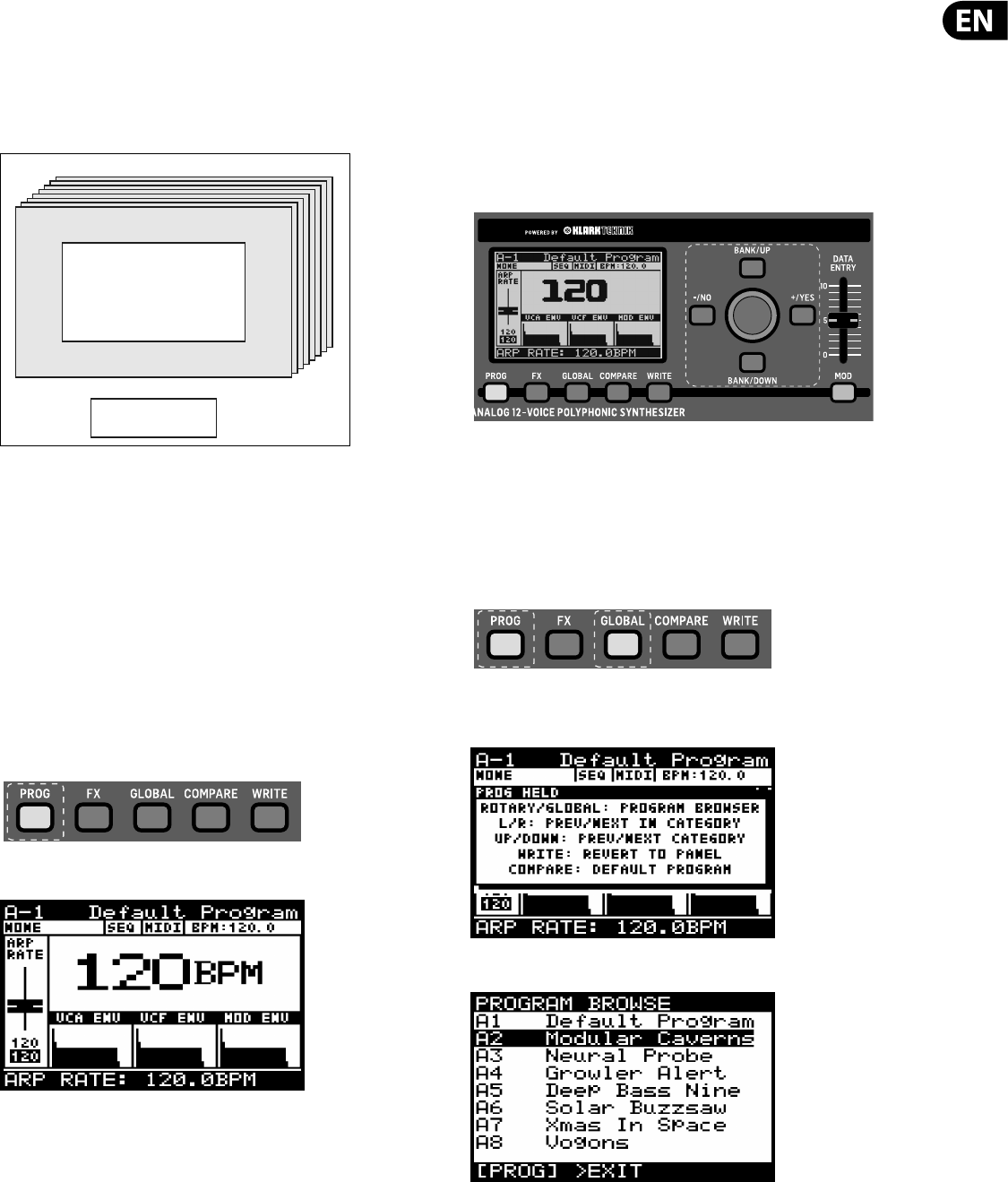
Press the PROG switch to open the PROG menu. This is also the screen which will
be displayed when the DeepMind 12 is turned on.
The PROG (Programming) page will be displayed:
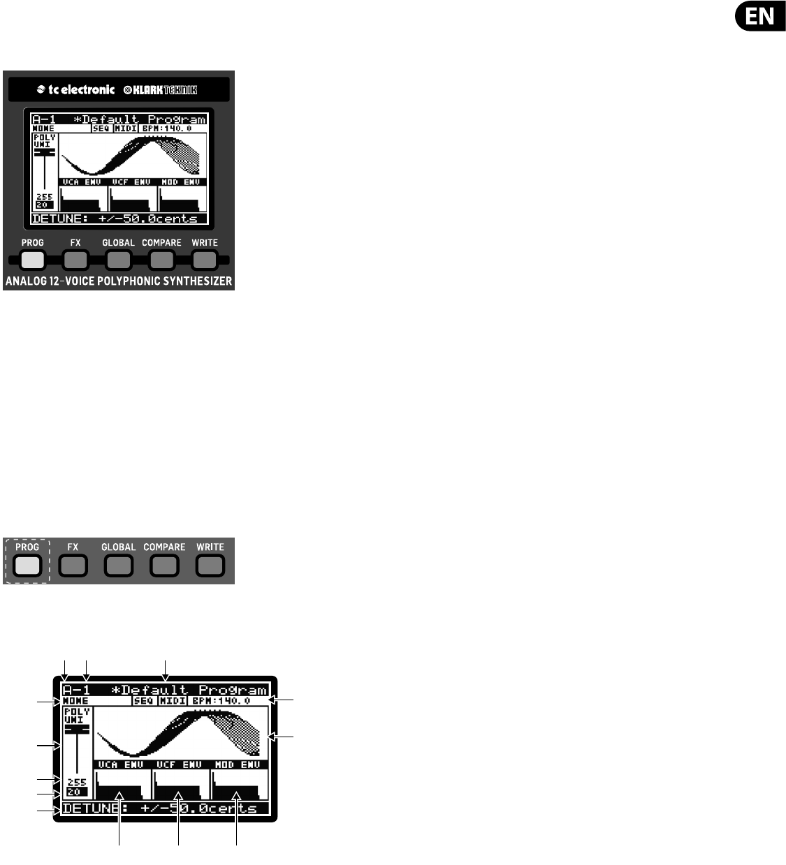
The PROG (Programming) page is the main display of the synthesizer. It shows
the current program name, the category name, the currently adjusted parameter
and a visual representation of the parameter plus the three envelopes.
There are three methods of changing the current program:
•
• Step forwards/backwards through programs using the -NO and+YES
switches, or by stepping up and down through the banks using the BANK/UP
and BANK/DOWN switches.
•
• Using the program browser.
•
• From an external device using a MIDI program change message.
4.2.1 Using the Navigation Switches
Pressing -NO or +YES will load the previous/next program in the bank.
Pressing BANK/UP to BANK/DOWN will change banks.
4.2.2 Using the Program Browser
To access the program browser, press and hold the PROG switch, then move the
rotary knob (or press the GLOBAL switch).
Note: a help menu will appear while the PROG switch is held, showing additional
guidance and commands:
The program browser will then appear:
When in program browser mode you can use the rotary knob to scroll through
the list of programs. When you stop on a program it will be automatically loaded.
Banks A-H
Programs 1-128
Editing Memory
12 DeepMind 12 User Manual
4.2.3 Using MIDI Program Change messages
You can change the program using a MIDI program change message. This special
MIDI message can be sent from your Digital Audio Workstation (DAW) or from an
external MIDI device which is capable of transmitting program change messages.
For details on the message please consult the section on MIDI commands.
4.3 Program Categories
Each program is assigned to a category from the list of options below:
•
• NONE - No category information is stored.
•
• BASS - Used for bass sounds.
•
• PAD - Used for pad sounds.
•
• LEAD - Used for lead sounds.
•
• MONO - Used for monophonic sounds.
•
• POLY - Used for polyphonic sounds.
•
• STAB - Used for stab sounds.
•
• SFX - Used for sound e ects.
•
• ARP - Used for programs with the arpeggiator active.
•
• SEQ - Used for programs with sequencing.
•
• PERC - Used for percussion sounds.
•
• AMBIENT - Used for ambient or texture sounds.
•
• MODULAR -Used for programs with modular type programming.
•
• USER-1/4 - Used for user/project speci c sounds..
For information on how to assign a category, please consult the section on
writing programs.
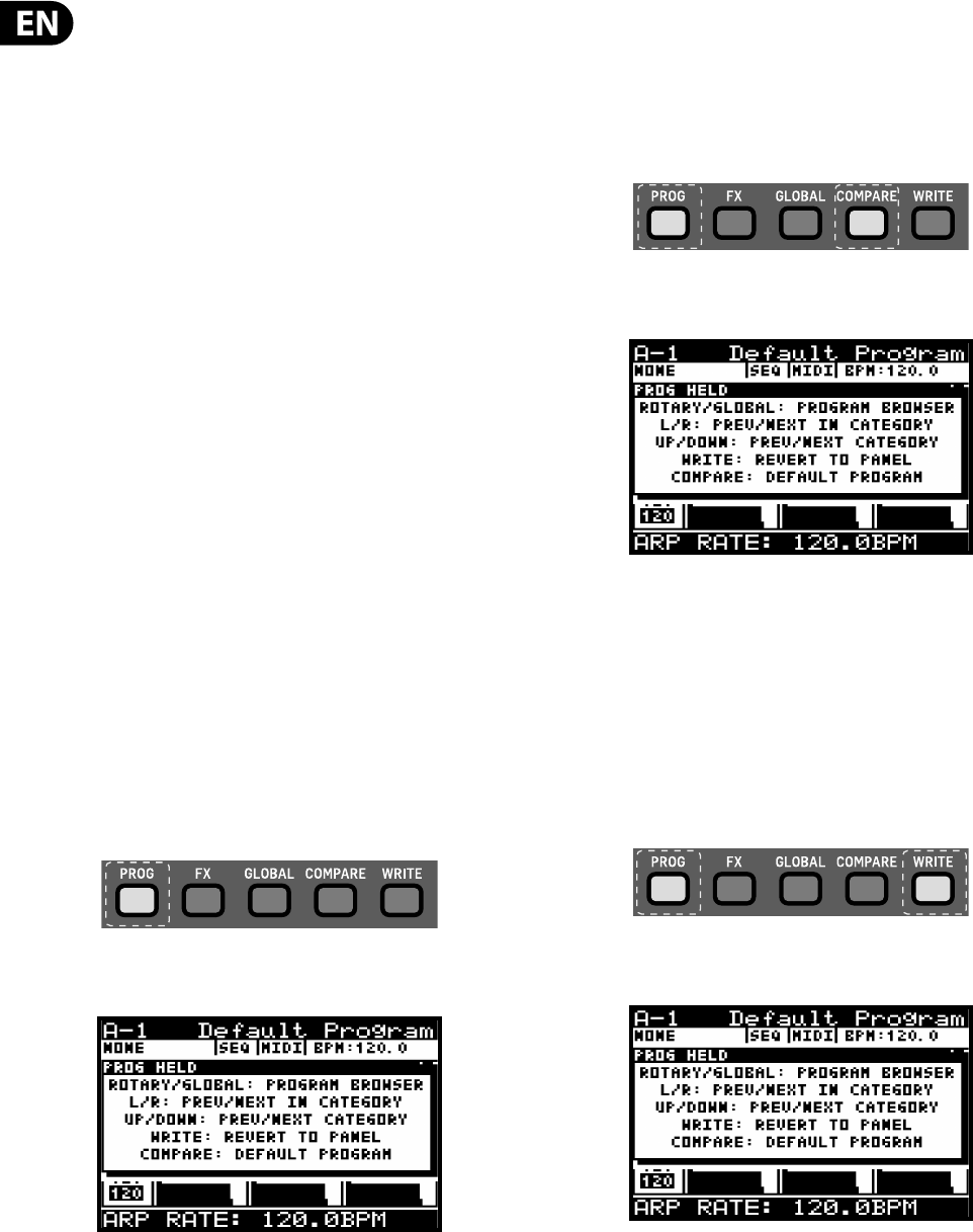
4.4 Browsing by Category
To access the program browser, press and hold the PROG switch.
Note: a help menu will appear while the PROG switch is held, showing additional
guidance and commands:
To change programs, while you have the PROG switch held you can press the
LEFT/RIGHT switches to select the PREVIOUS/NEXT programs within the category.
To change categories, while you have the PROG switch held you can press the UP/
DOWN switches to select the PREVIOUS/NEXT category.
Note: While the PROG switch is held you can still see the category changes
displayed behind the pop-up menu.
4.5 Default Program
In order to return to a xed point when creating programs you recall a default
program using the short-cut described here. The default program is con gured
without modulation/e ects and uses basic settings in each of the sections.
To load the default program, press and hold the PROG switch, then press the
COMPARE switch.
Note: a help menu will appear while the PROG switch is held, showing additional
guidance and commands.:The default program will then be loaded.
4.6 Revert to Panel
When you load a program, all the physical controls on the DeepMind 12 may not
match the position stored in memory. In order to send all the physical positions
to the program (rather than moving each individually until you reach the
stored value), follow the procedure below:
Warning: When you do this the sound/character of the program will often
change radically as the multiple parameters are updated.
To revert to the panel controls, press and hold the PROG switch, then press the
WRITE switch.
Note: a help menu will appear while the PROG switch is held, showing additional
guidance and commands:
The current program will then be updated with the positions of the physical
controls on the DeepMind 12.
13 DeepMind 12 User Manual
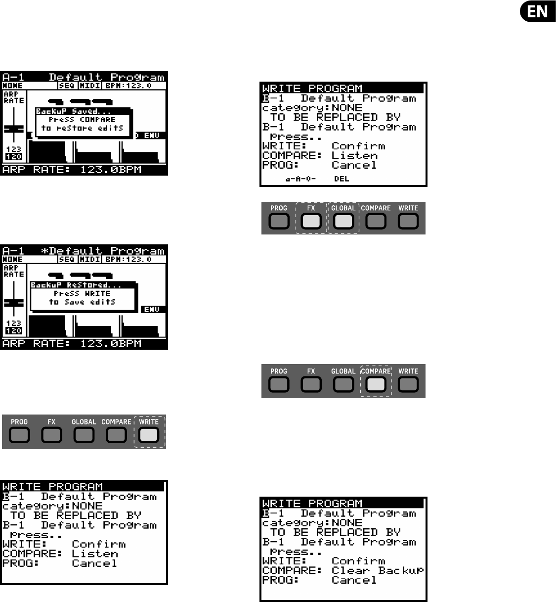
4.7 Restoring Program Data
If you edit a program and forget to write it before selecting a new program -
don't panic - a backup of the program is stored in memory. Whenever this
happens a pop-up menu will appear with a message saying "Press COMPARE to
restore edits":
By pressing the COMPARE switch your previously editing patch will be
re-instated.
You will then see another pop-up message reminding you to press WRITE to store
your edits:
4.8 Writing Programs
To write a program to memory press the WRITE switch to open the WRITE
PROGRAM menu.
The WRITE PROGRAM menu will then appear:
In this menu you can use the -NO/+YES switches to navigate through the
sections. The selected section will be highlighted by an inverted character (white
on black).
The rst section is the program location the current program will be saved.
You can use the UP/DOWN switches, the rotary knob, or the fader to select the
required BANK (A-H) and PROGRAM NUMBER (1-128).
The second section is the CATEGORY to select any of the available categories.
Again you can use the UP/DOWN switches, the rotary knob, or the fader to select
the required CATEGORY.
The third section is REPLACED BY which allows you to name the program to be
written. You can use the -NO/+YES switches to step through each character of the
name and use the UP/DOWN switches, the rotary knob, or the faders to change
the character.
There are also two short-cuts for selecting characters indicated by text above the
FX and GLOBAL switches:
a-A-0 - Pressing the FX switch will cycle between lower-case, upper-case and
numbers.
DEL - Pressing the GLOBAL switch will delete the currently selected character.
Note: These short-cuts only appear when you are editing the name of the
REPLACED BY program.
To compare the current program with the intended program location you can
press the COMPARE switch to listen to the di erence. To return to the current
program, press the compare switch again.
Once you have selected the new location and named the program simply press
the WRITE switch again to write the program.
At anytime you decide you do not want to write the program, you can press the
PROG switch to return to the main programming display.
Note: If there is a program in the backup memory then you will see the message
"COMPARE to clear backup".
If you wish to listen to the intended program location as described earlier you will
need to press the COMPARE switch to clear the backup memory. Once the backup
has been cleared then the message will revert to "COMPARE to listen" and you
can listen to the intended program location as normal.
4.9 Re-naming Programs
To rename a program simply follow the procedure for writing a program and
keep the BANK and PROGRAM NUMBER the same.
14 DeepMind 12 User Manual
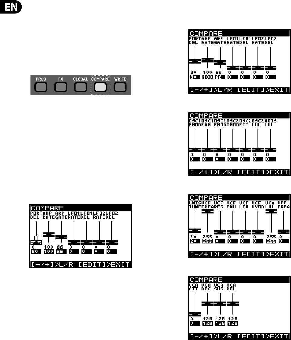
4.10 The COMPARE function
The COMPARE feature has two main functions:
Firstly you can use it to COMPARE the current (edited) program with the original
program.
Secondly you can use it to COMPARE and/or match the current position of the
physical faders on the surface with the original program. This is necessary when
you wish to maintain the sound/character of the program.
To perform both functions simply press the COMPARE switch.
Note: If you have not edited the program (i.e. changed some parameters) when
you press the COMPARE switch you will restore the backup as described in a
previous chapter.
Firstly the sound/character will return to its original state so that you can
compare your edits.
Note: If you do not want to match the fader positions you can simply press
COMPARE again to return to programming.
Secondly, you now have the option to match the position of the physical faders to
the positions stored in the original program.
You will then see a page of the COMPARE menu (page 1 is displayed below). The
page shown will be the last page you used. If you have never used the COMPARE
function since turning the DeepMind 12 on, it will default to page 1.
Each page of the COMPARE menu shows a section of the faders.
If the position of the fader matches the position of the stored value the fader will
be black.
If the fader does not match the position it will be white with a superimposed
arrow pointing in the direction it needs to move in order to approach the
stored value.
There is also a white bar to show how far the fader needs to move in order to
match the stored value.
Once the fader reaches the stored position it will turn black to indicate it is now
matched.
Note: The pages will switch automatically when you begin to adjust any
of the faders.
There are four pages of faders in the COMPARE menu, to access the other pages
use the +/- switches to select the previous/next pages.
Page 1 Shows the ARP/SEQ and LFO faders:
Page 2 shows the OSC faders:
Page 3 shows the UNISON, VCF, HPF and VCA faders:
Page 4 shows the ENVELOPE faders:
Note: You can still select speci c envelopes to match the faders depending on
your requirements.
15 DeepMind 12 User Manual
5. Playing Guide
This section describes the use of the DeepMind 12 for playing and performance. It
covers all the main aspects of the synthesizer.
There are 64 physical controls on the DeepMind 12 made up of illuminated
switches, faders, rotary knobs and wheels.
There are also many virtual controls/parameters and menu based controls
within the software, please consult the section on programming for detailed
information.
5.1 Display
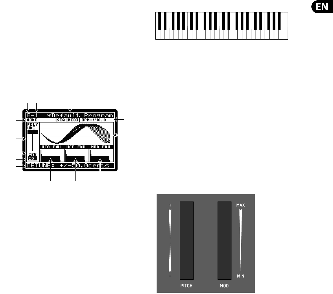
The PROG (Programming) page is the main display of the synthesizer.
During playing the display can show the status of the synthesizer when the PROG
switch is pressed. The PROG switch will be illuminated when you are in this mode.
Being able to see all this information on one screen allows you to quickly check
any of the following parameters shown on the display:
(1) PROGRAM BANK ("A "in the example above).
(2) PROGRAM NUMBER ("1" in the example above).
(3) PROGRAM NAME ("Default Program" in the example above.
(4) PROGRAM CATEGORY ("NONE" in the example above).
(5) SEQ STATUS / MASTER BPM EXTERNAL / BPM ( "OFF", "MIDI","140.0" in the
example above).
(6) PARAMETER CONTROL ("POLY UNI" in the example above).
(7) CURRENT PARAMETER MIDI VALUE (255 in the example above).
(8) STORED PARAMETER VALUE (20 in the example above).
(9) CURRENT PARAMETER EXPLICIT NAME/VALUE ( "DETUNE +/-50.0cents" in the
example above).
(10) PARAMETER VISUALIZATION (the UNISON waveform in the example above).
(11) VCA ENV VISUALIZATION (VCA ENV in the example above).
(12) VCF ENV VISUALIZATION (VCF ENV in the example above).
(13) MOD ENV VISUALIZATION (MOD ENV in the example above).
Note: The brightness and contrast of the display can be adjusted in the
GLOBAL-PANEL SETTINGS menu.
For more detail on the PROG screen and the status of the synthesiser, please
consult the programming section later in this manual.
5.2 Keyboard (Velocity/Aftertouch)
The DeepMind 12 has 49 semi-weighted full-size keys featuring expressive
velocity and after-touch.
The keyboard spans four octaves with the ability to shift octaves up or down to
meet your playing requirements.
The aftertouch and velocity expression can have individual curves applied to their
response in order to ne tune your playing style/requirements.
The velocity is expressive in two ways:
The (NOTE) ON VELOCITY - i.e. The velocity that you strike the keys.
The (NOTE) OFF VELOCITY - i.e. The velocity that you release the keys.
The ON/OFF velocities can be set to a xed value if required which will override
the velocity of the strike and release values.
Note: The settings to adjust the response curves and xed values can be found in
the GLOBAL-KEYBOARD SETTINGS menu.
Note: You can also turn o the keyboard's LOCAL messages allowing you to play
an external device, without a ecting the DeepMind 12.
5.3 Pitch Bend and Modulation Wheels
PITCH WHEEL - The pitch wheel allows you to lower or raise the pitch of the
notes being played expressively.
The range of the PITCH BEND can be assigned in the second page of the POLY
menu (accessed by pressing the POLY switch twice).
The pitch wheel is spring loaded and will naturally return to its centre point after
you adjust it and release the wheel.
MODULATION WHEEL - The modulation wheel allows you to apply any type of
modulation or expression to a single (or multiple) parameters.
For traditional playing this can be used to create vibrato, or in a more creative
way e.g. to open the lter by assigning to the VCF FREQUENCY.
The wheels are illuminated so that they can be seen even in low light conditions.
They can be xed on, turned o or placed in AUTO mode which will increase the
LED intensity as the wheel is moved.
For more detail on controlling advanced parameters relating to the PITCH WHEEL
and the MODULATION WHEEL please consult the section later in this manual.
(2) (3)
(7)
(8)
(4)
(13)
(5)
(6) (10)
(11) (12)
(1)
(9)
16 DeepMind 12 User Manual
5.4 Octave Shift (OCT UP/DOWN)
These switches allow you to raise or lower the keyboard’s pitch range in steps of
one octave.
The LEDs above the switches labelled OCTAVE will show the current octave shift
applied to the keyboard.
Pressing both switches together will reset to Octave 0 (no transpose).
5.5 Voice Indication
The DeepMind 12 has 12 independent voices. There are 12 LEDs above the
keyboard showing the status of each voice.
When playing in traditional POLY mode the voice LEDs will light individually using
the full polyphonic capabilities.
When playing in any of the UNISON or MONO modes the voice LEDs will light
simultaneously depending on the number of voices allocated.
Note: The settings to adjust the polyphony and voice allocation can be found in
the POLY-VOICE PARAMETERS menu.
5.6 Portamento
The PORTAMENTO function makes the pitch of a note glide up or down from
the previously played note. The PORTAMENTO knob controls the time taken to
transition from the previous note to the currently played note.
The knob ranges from 0 seconds (instant change of note, with no pitch gliding) to
10 seconds.
The PORTAMENTO function can be tuned to your speci c playing requirements by
way of 14 di erent modes.
The PORTAMENTO function can also be balanced between the OSCs, allowing you
to set the ratio of PORTAMENTO applied to OSC 1 and OSC 2.
For more detail on controlling advanced parameters relating to PORTAMENTO
please consult the section later in this manual.
5.7 Volume
The volume knob controls the output level for both the main outputs
and the headphones simultaneously. If you nd the need to compensate
the main output level, please do so using your gain stage on your mixer,
audio interface or ampli er.
5.8 Pedal Input (Rear Panel)
The pedal input is a ¼ " TRS jack that allows you to connect an expression pedal.
The pedal input can be assigned to operate in one of ve modes: FOOT CONTROL,
MOD WHEEL, BREATH, VOLUME or EXPRESSION.
The operation of this pedal can be customized using the GLOBAL / PEDAL
SETTINGS menu.
For more detail on controlling advanced parameters relating to the pedal input
please consult the section later in this manual.
5.9 Sustain Input (Rear Panel)
The sustain input is a ¼" TS jack that allows you to connect a sustain pedal, such
as a normally-open switch.
The sustain input can be assigned to operate in one of several modes. For more
information please consult the PEDAL SETTINGS section later in this document.
The operation of this pedal can be customized using the GLOBAL / PEDAL
SETTINGS menu.
For more detail on controlling advanced parameters relating to the sustain input
please consult the section later in this manual.
5.10 Slide Fader Operation Modes
The slide faders can operate in two modes: PASS-THRU or JUMP.
For more detail on controlling the way the slide faders respond when adjusted,
please consult the section later in this manual.
Note: You can also turn o the faders LOCAL messages allowing you to control an
external device, without a ecting the DeepMind 12.
17 DeepMind 12 User Manual
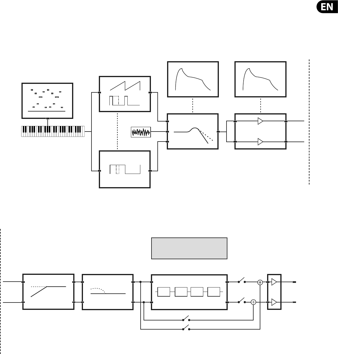
6. Signal Path / Voice Structure
The signal path / voice structure from the OSCs to the main outputs is completely analog. The DSP e ects can be bypassed completely to maintain the analog path.
When routed through the DSP e ects all sampling is done at 24-Bit 48 kHz. All internal DSP e ects are processed at 32/40-Bit oating point resolution.
VCF Env VCA Env
VCF VCA
Key Pitch
OSC-1
Arpeggiator
Noise
OSC-2
FX
1234
HPF BOOST
ANALOG PATH
DIGITAL PATH
Volume
Main Outputs &
Headphones
MODE
INSERT
SEND
BYPASS
ANALOG PATH
OFF
ON
ON
DIGITAL PATH
ON
ON
OFF
18 DeepMind 12 User Manual
Mod Matrix
The Modulation Matrix is a large scale digital routing matrix which allows a massive number of potential modulations. The matrix con guration is stored and recalled
with the program data.
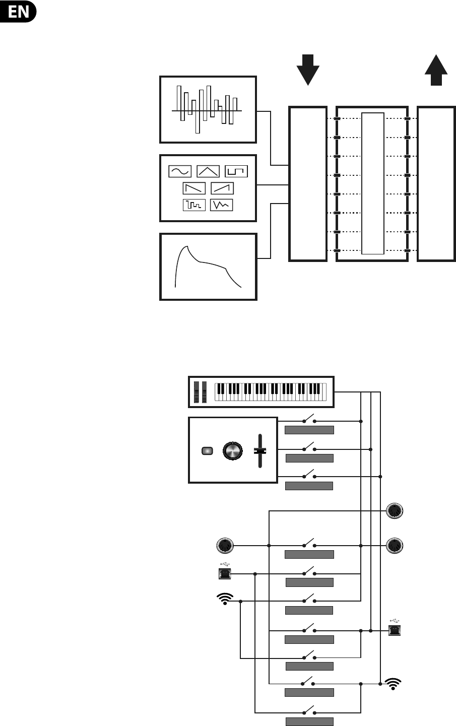
MIDI Routing
The DeepMind 12 o ers extreme MIDI routing possibilities, allowing you to integrate the synthesizer with many di erent pieces of hardware and software.
Modulation
Destinations
Modulation
Sources 8x8 Mod Matrix
22,880 Possible Modulations (All Automatable)
22 SOURCES
130 DESTINATIONS
MOD Env
LFO1&2
Control Sequencer
ROUTING LEVELS
SOFT-THRUSOFT-THRU
MIDI>USB-THRU
MIDI>WIFI-THRU
USB>MIDI-THRU
USB>WIFI-THRU
WIFI>MIDI-THRU
WIFI>USB-THRU
Keyboard Data
Control Data
Wi-Fi
USB
MIDI IN
Wi-Fi
USB
MIDI THRU
MIDI OUT
SOFT-THRUMIDI-CTRL
USB-CTRL
WIFI-CTRL
19 DeepMind 12 User Manual
7. Menu System
The DeepMind 12 Display allows you to access the detailed parameters, controls,
options and features of the synthesizer.
Navigating the MENU system can be done by pressing the top level menu
switches PROG, FX, GLOBAL, COMPARE and WRITE.
Note: The FX and GLOBAL menus have several pages, to access successive pages
simply press the same switch again to cycle through the pages.
Note: The DeepMind 12 will always return you to the last page within a menu
that was accessed. This way you can return to your last change without needing
to cycle though the previous pages. Note: You can change this functionality using
the REMEMBER PAGES option in the GLOBAL SETTINGS.
7.1 PROG (Programming Menu)
To access the PROG menu, press the PROG switch, the PROG switch will remain
illuminated while you are in this menu.
The PROG (Programming) menu will then be shown:
The PROG (Programming) page is the main display of the synthesizer.
During playing the display can show the status of the synthesizer when the PROG
switch is pressed.
Being able to see all this information on one screen allows you to quickly check
any of the following parameters shown on the display:
7.1.1 PROGRAM BANK
(1) ("A "in the example diagram) - There are 8 BANKS of PROGRAMs, each BANK
contains 128 program locations. The DeepMind 12 comes pre-loaded with
1024 programs from leading synthesizer programmers from around the
world.
7.1.2 PROGRAM NUMBER
(2) ("1" in the example diagram) - There are 128 PROGRAMs in each BANK.
7.1.3 PROGRAM NAME
(3) ("Default Program" in the example diagram) - The PROGRAM name can use
up to 16 characters, including uppercase, lowercase, numbers and symbols.
Note: When you see the '*' symbol at the start of a PROGRAM name this
indicates that the PROGRAM has been edited/changed from its stored state.
Once you complete your editing and WRITE the program, the '*' symbol will no
longer be shown.
7.1.4 PROGRAM CATEGORY
(4) ("NONE" in the example diagram) - Each PROGRAM can be assigned to a one
of 17 categories. By assigning a category to a PROGRAM, it helps browsing
for a particular type of sound much easier.
The available categories are listed here:
•
• NONE - No category information is stored.
•
• BASS - Used for bass sounds.
•
• PAD - Used for pad sounds.
•
• LEAD - Used for lead sounds.
•
• MONO - Used for monophonic sounds.
•
• POLY - Used for polyphonic sounds.
•
• STAB - Used for stab sounds.
•
• SFX - Used for sound e ects.
•
• ARP - Used for programs with the arpeggiator active.
•
• SEQ - Used for programs with sequencing.
•
• PERC - Used for percussion sounds.
•
• AMBIENT - Used for ambient or texture sounds.
•
• MODULAR -Used for programs with modular type programming.
•
• USER-1 - Used for user/project speci c sounds.
•
• USER-2 - Used for user/project speci c sounds.
•
• USER-3 - Used for user/project speci c sounds.
•
• USER-4 - Used for user/project speci c sounds.
For information on how to assign a category, please consult the section on
writing programs.
(2) (3)
(7)
(8)
(4)
(13)
(5)
(6) (10)
(11) (12)
(1)
(9)

20 DeepMind 12 User Manual
7.1.5 SEQ STATUS, MIDI SYNC SOURCE, BPM VALUE
(5) It is important to note that on this line there are three separate pieces of
information:
•
• SEQ STATUS ("SEQ" in the example diagram) - This shows the status of
the CONTROL SEQUENCER. If the letters SEQ are inverted (white on a black
background) then the CONTROL SEQUENCER is ON. If the letters SEQ appear as
normal text the CONTROL SEQUENCER is OFF. Note: The CONTROL SEQUENCER
ON/OFF control can only be adjusted from the CONTROL SEQUENCER MENU
described later in this document.
•
• MASTER BPM SOURCE ("MIDI" in the example diagram) - The Master
BPM can be generated internally (shown as "INT"), or the DeepMind 12 can
synchronize to an incoming MIDI clock signal from the MIDI IN socket (shown
as "MIDI"), or USB ports (shown as "USB"). If the letters are inverted (white
on a black background) then the clock is synchronised to the external source.
If the letters appear as normal text the external source is not present and
the DeepMind 12 will use its internal Master BPM until the external source is
present. Note: The settings for the MIDI SYNC can be found in the EDIT page
of the ARPEGGIATOR described later in this document.
•
• BPM VALUE ("BPM:120.0" in the example diagram) - The Arpeggiator,
Control Sequencer and Patterns use a system wide Master BPM (Beats Per
Minute) Clock. The BPM is shown and will auto update if using an external
synchronisation source.
7.1.6 PARAMETER CONTROL
(6) ("POLY UNI" in the example diagram) - This is a fader representation of the
parameter which is currently being adjusted (or was last adjusted). The
name of the parameter is also shown:
If the position of the fader matches the position of the stored value the fader will
be black.
If the fader does not match the position it will be white with a superimposed
arrow pointing in the direction it needs to move in order to approach the stored
value.
When the fader does not match the position there is also a white bar to show
how far the fader needs to move in order to match the stored value.
Note: If the physical fader position is close to the stored value the white bar can
be obscured by the fader.
7.1.7 CURRENT PARAMETER MIDI VALUE
(7) (255 in the example diagram) - This is the value of the parameter which is
currently being adjusted (or was last adjusted).
Note: The parameter is displayed here as a simple value (0-255) which allows you
to quickly compare current and stored values. For explicit values please see the
area at the bottom of the page discussed later in this chapter.
7.1.8 STORED PARAMETER VALUE
(8) (20 in the example diagram) - This is the stored value of the parameter
which is currently being adjusted (or was last adjusted).
The stored parameter is shown in reverse text (i.e. white on a black background)
7.1.9 CURRENT PARAMETER NAME/VALUE
(9) ("DETUNE +/-50.0cents" in the example diagram) - In this area you will see
more detailed information on the parameter being adjusted.
The enhanced information contains:
•
• A more detailed description of the parameter being adjusted.
•
• A more accurate value of the parameter being adjusted.
•
• The type of units used for the value (cents in the example above,
but could be Hz for frequency etc.).
7.1.10 PARAMETER VISUALIZATION
(10) (The UNISON waveform in the example diagram) - This area shows a
visualization of the parameter being adjusted (or last adjusted).
These visualizations are designed to:
•
• Help anyone with limited experience to achieve a deeper understanding of
each of the parameters while learning the synthesizer.
•
• Help the experienced player/sound designer/programmer to work quickly
and get visual con rmation about the adjustment being made.
7.1.11 VCA ENV VISUALIZATION
(11) (VCA ENV in the example diagram) - This area shows a visualization of the
VCA envelope. The full Attack, Decay, Sustain, Release and their respective
curves are represented.
7.1.12 VCF ENV VISUALIZATION
(12) (VCF ENV in the example diagram)- This area shows a visualization of the VCF
envelope. The full Attack, Decay, Sustain, Release and their respective curves
are represented.
7.1.13 MOD ENV VISUALIZATION
(13) (MOD ENV in the example diagram) - This area shows a visualization of the
MOD envelope. The full Attack, Decay, Sustain, Release and their respective
curves are represented.
21 DeepMind 12 User Manual
7.2 FX (E ects Menu)
The on-board virtual FX Rack provides access to four true-stereo, multi-e ects
processors including delay, chorus, dynamics and production-quality true-stereo
reverbs.
You can select any combination of high-end simulations of legendary studio
e ects.
7.2.1 FX OVERVIEW
To access the FX menu simply press the FX switch:, the FX switch will be
illuminated when you are in this menu.
The display will then show the FX OVERVIEW menu:
To navigate within the FX OVERVIEW menu, navigate within the display menus
using the UP, DOWN, +/YES & -/NO switches.
Selected parameters on the display are adjusted using the rotary knob or the
fader. The rotary knob has a click which allows very accurate control. The fader
allows rapid adjustment across the full range.
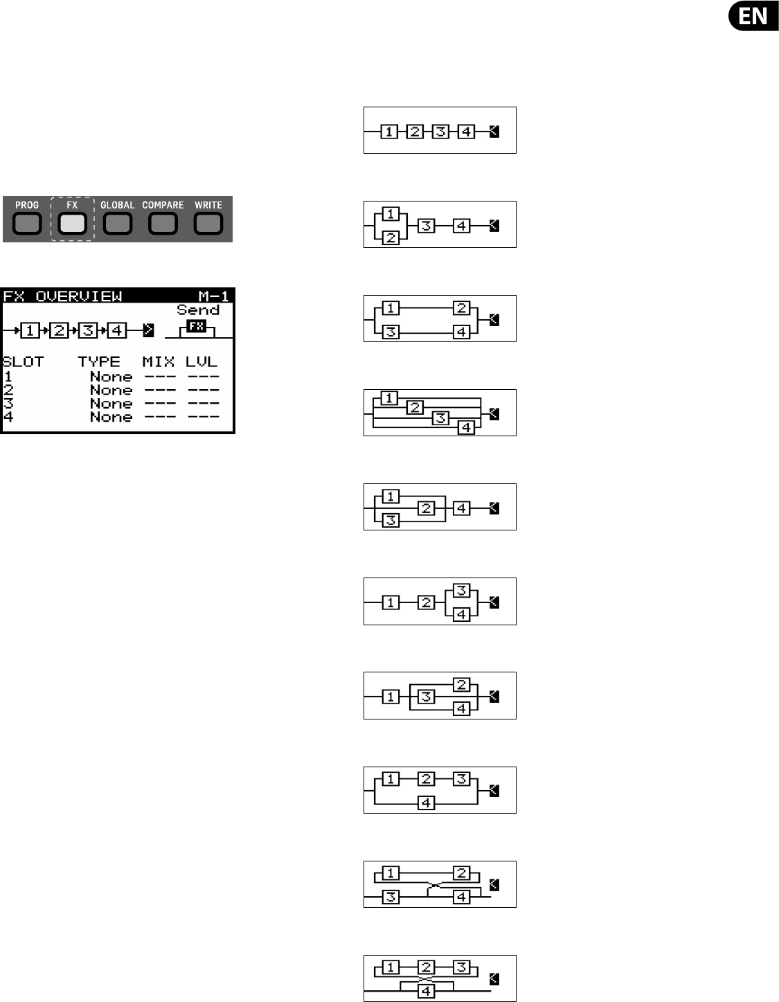
The options available in the FX OVERVIEW menu are as follows:
FX ROUTING - At the top of the FX OVERVIEW menu you will see the FX ROUTING
shown as a series of 4 boxes representing the individual e ects.
In order to expand the sonic possibilities of the DSP FX inside the DeepMind 12
there are several routing options for the four slots.
! Warning: The routings with feedback are highly creative,
but as they employ feedback loops, careful consideration should be
made while using them. It is recommended to keep the VOLUME knob in
a low position while experimenting.
FX MODE - This allows you to choose if the e ects are to be con gured in INSERT
MODE, SEND(and Return) MODE, or to BYPASS the e ects.
FX SLOTS - These are the four slots you can load e ects modules into.
MIX - The MIX parameter controls how much of the original sound is blended
with the e ected/processed sound for each FX slot.
LEVEL - The LEVEL parameter controls the output level of any e ects which are
con gured in parallel, or any e ects which are the last e ect before reaching the
output stage.
To exit the FX menu press the PROG switch to return to the main programming
screen.
Note: To reduce the possibility of excessive low frequency build up there is
a 30 Hz High Pass Filter used in the feedback path for routing options which
include feedback.
7.2.2 SELECTING FX ROUTING
To select a routing make sure that the '<' symbol is highlighted next to the
routing diagram, then you can either turn the rotary knob, or use the data entry
fader to select from one of the following routings:
SERIAL 1-2-3-4 (M-1)
PARALLEL 1/2 SERIAL 3-4 (M-2)
PARALLEL 1/2 PARALLEL 3/4 (M-3)
PARALLEL 1/2/3/4 (M-4)
PARALLEL 1/2/3 SERIAL 4 (M-5)
SERIAL 1-2 PARALLEL 3/4 (M-6)
SERIAL 1 PARALLEL 2/3/4 (M-7)
PARALLEL (SERIAL 1-2-3)/4 (M-8)
SERIAL 3-4 FEEDBACK4(1-2) (M-9)
SERIAL 4 FEEDBACK4(1-2-3) (M-10)
!
!
22 DeepMind 12 User Manual
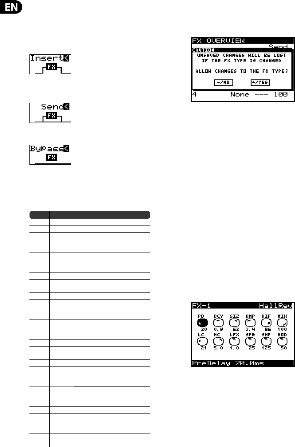
7.2.3 SELECTING FX MODE
To select an e ects MODE make sure that the '<' symbol is highlighted next to
the e ects MODE symbol, then you can either turn the rotary knob, or use the
data entry fader to select from one of the following routings.
INSERT - In this con guration the e ects slots are placed as INSERT e ects into
the signal ow of the synthesizer outputs.
SEND - In this con guration the synthesizer output signals are SENT to the e ects
slots and the returned into the signal ow of the synthesizer outputs.
BYPASS - In this con guration the e ects are bypassed.
7.2.4 SELECTING FX
To load an e ect into a slot, make sure that the '<' symbol is highlighted next to
the slot you wish to use. Then you can either turn the rotary knob, or use the data
entry fader to select from one of the following e ects:
No Name Type
1 TC-DeepVRB Reverb
2 Ambience Reverb
3 Room Rev Reverb
4VintageRev Reverb
5 Hall Rev Reverb
6 Chamber Rev Reverb
7Plate Rev Reverb
8 Rich Plate Reverb
9Gated Rev Reverb
10 Reverse Reverb
11 ChorusVerb Reverb
12 DelayVerb Reverb
13 FlangeVerb Reverb
14 4Band EQ Processing
15 Enhancer Processing
16 FairComp Processing
17 MulBndDist Processing
18 RackAmp Processing
19 EdisonEX1 Processing
20 Auto-Pan Processing
21 NoiseGate Processing
22 Delay Delay
23 3TapDelay Delay
24 4TapDelay Delay
25 T-RayDelay Delay
26 DecimDelay Delay
27 ModDlyRev Delay
28 Chorus Creative
29 Chorus-D Creative
30 Flanger Creative
31 Phaser Creative
32 MoodFilter Creative
33 Dual Pitch Creative
34 RotarySpkr Creative
When you stop on an e ect it is automatically loaded into the chosen slot.
Warning: If you have made edits to any of the parameters within an e ect you
will be shown a pop-up warning dialog (unless dialogs are disabled in the
GLOBAL MENU):
If you need to save your changes, press the -NO switch and then WRITE the
PROGRAM as described in the chapter on writing programs.
If you don't need to save your changes, press the +/YES switch and continue
selecting a new e ect.
7.2.5 CONTROLLING MIX / LEVEL
To adjust the MIX parameters make sure that the '<' symbol is highlighted next to
the word MIX on the e ect slot you want to adjust. Then you can either turn the
rotary knob, or use the data entry fader to change the value.
7.2.6 CONTROLLING LEVEL
To adjust the LEVEL parameters make sure that the '<' symbol is highlighted next
to the word LEVEL on the e ect slot you want to adjust. Then you can either turn
the rotary knob, or use the data entry fader to change the value.
Note: Not all e ects have a MIX parameter as it is only used on e ects which
are marked as "Processing" types in the E ects List. Also, be aware that the MIX
parameter seen on the FX OVERVIEW and the MIX parameter in the FX editing
pages are the same parameter and are shown in both pages for convenience.
If the either the MIX or LEVEL parameter is not available you will see the "--"
symbols in the FX OVERVIEW screen.
7.2.7 FX PAGES1-4
Each of the e ects pages show individual controls for each e ect slot. There are
up to 12 parameters per slot, depending on the e ect which is loaded.
Note: To access successive FX pages simply press the same switch again to cycle
through the pages.
7.2.8 ADJUSTING EFFECTS PARAMETERS
To navigate to the parameter you wish to adjust, use the UP/DOWN/+/- switches.
The selected parameter will be highlighted in black and its detail shown on the
bottom of the screen. To adjust a parameter you can either turn the rotary knob,
or use the data entry slider.
Note: For detailed information on all e ects and their parameters please consult
the EFFECTS LIBRARY section later in this document.
23 DeepMind 12 User Manual
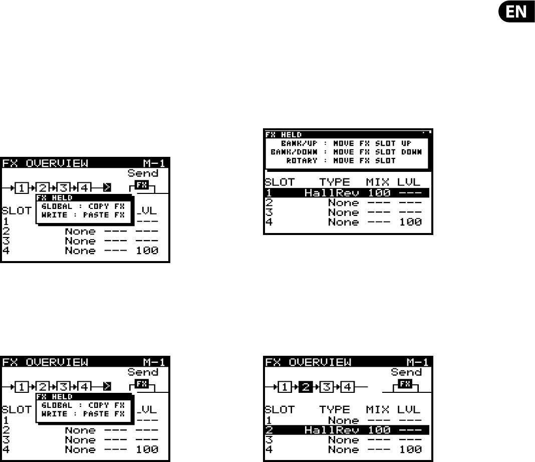
7.2.9 COPY/PASTE FX SETTINGS
If you need to copy e ects settings from a previously stored e ect, please follow
this procedure.
1) Ensure you have saved any edits you have made to your current program
if required.
2) Load the program which has the e ects settings you intend to copy.
3) Navigate to the 1, 2, 3, 4 ow diagram near the top of the FX screen.
4) Press the FX switch to enter the FX page.
5) Press and hold the FX switch until you see the following message and
the GLOBAL/WRITE switches are ashing:
6) While continuing to hold the FX switch, press the GLOBAL switch to copy
the e ects settings into memory.
7) Then load the program you intend to paste the e ects settings to.
8) Press the FX switch to enter the FX page.
9) Press and hold the FX switch until you see the following message:
10) While continuing to hold the FX switch, press the WRITE switch to copy
the e ects settings from memory into the program.
Note: All settings relating to e ects will be copied/pasted, these include FX
routing, FX modes and all of the FX slots and their settings.
7.2.10 MOVING EFFECTS
If you need to move an e ect to a di erent slot, please follow this procedure.
1) Ensure you have saved any edits you have made to your current program
if required.
2) Press the FX switch to enter the FX page.
3) Navigate to the e ects slot you wish to move.
4) Press and hold the FX switch until you see the following message and
the BANK UP/DOWN switches begin ashing:
5) While continuing to hold the FX switch, you can move the e ects slot
to another location using one of these methods:
•
• To move the slot to an adjacent upper slot press the BANK/UP switch.
•
• To move the slot to an adjacent lower slot press the BANK/DOWN switch.
•
• To move the slot to any other slot, turn the rotary knob.
You can continue to move the slot with any of the methods above, the new slot
will be highlighted as shown below:
6) Once you release the FX switch the e ect will be moved to the new slot.
Note: All e ects parameters will be moved with the e ect.
24 DeepMind 12 User Manual
GLOBAL (Global Menu)
Within the GLOBAL menu there are ve pages:
•
• CONNECTIVITY - All settings relating to connectivity and communication
with external devices including backup and restore functions.
•
• KEYBOARD SETTINGS - All settings relating to the keyboard including
aftertouch and velocity.
•
• PEDAL SETTINGS - All settings relating to the pedal inputs.
•
• PANEL SETTINGS - All settings relating to panel (local), faders, dialogs,
menu functionality, and display brightness and contrast.
•
• SYSTEM SETTINGS - All system settings, including versions, fan speed,
calibration, and backup.
This chapter covers each of the pages in detail.
Note: To access successive GLOBAL pages simply press the GLOBAL switch again
to cycle through the pages. There is a help message on the bottom of each screen
to show you what the next menu will be if you press the GLOBAL switch again.
To access the GLOBAL menu simply press the GLOBAL switch, the switch will
remain illuminated while you are in this menu:
The display will then show the GLOBAL menu.
Note: The rst time you access the GLOBAL menu after turning on the DeepMind
12, you will see the CONNECTIVITY page. Whenever you access the GLOBAL menu
after that point, you will be returned to the last page you visited within the menu
system. This feature is reset when the unit is powered o .
Note: The page location memory function can be turned o using the
REMEMBER PAGES function in the PANEL SETTINGS menu.
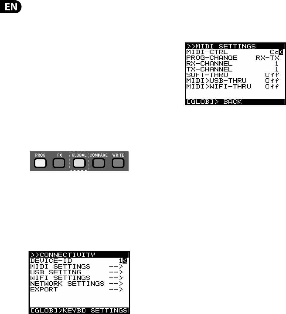
7.2.11 CONN EC TIVIT Y
In this menu there are all the settings relating to connectivity and
communication with external devices including backing up and restoring
programs and data.
To navigate the options in the CONNECTIVITY menu, use the UP, DOWN, switches.
Selected parameters are adjusted using the -NO/+YES switches, the rotary knob
or the fader. The rotary knob has a click which allows very accurate control. The
fader allows rapid adjustment across the full range.
DEVICE ID - This is MIDI Device Identi er (ID) which is used to identify the device.
This is important when multiple devices are present in a system, and ensures
that the device in question responds to the system exclusive messages which are
solely for the device in question.
The DEVICE ID can be any number from 1-16.
To change the DEVICE ID, make sure that the '<' symbol next to the DEVICE ID
number is highlighted. Then you can either turn the rotary knob, or use the data
entry slider.
MIDI SETTINGS MENU - This menu contains settings for the MIDI sockets on the
rear of the DeepMind 12.
To access the MIDI SETTINGS menu, make sure that the '<' symbol on the MIDI
SETTINGS line is highlighted. Then press the +/YES switch, you will now see the
MIDI SETTINGS menu.
•
• MIDI-CTRL - This option sets the MIDI CONTROLLER communication mode
for the DeepMind 12 MIDI sockets on the rear of the synthesizer. You can
choose O (No controller messages will be sent), Cc (Continuous Controller)
or NRPN (Non-Registered Parameters).
Note: Both MIDI and NRPN data is always received and actioned.
Note: For more information on controlling the DeepMind 12 via MIDI,
please consult the section on MIDI later in this document.
•
• PROG-CHANGE - This option sets the PROGRAM CHANGE communication
mode for the DeepMind 12 MIDI sockets. You can choose from the following
options:
RX - Program change messages will be received only.
TX - Program changes will be transmitted only.
RX-TX - Program changes will be transmitted and received.
NONE - No program change messages will be sent or received.
•
• RX-CHANNEL - This option sets the MIDI channel that will be used to
RECEIVE MIDI messages. The CHANNEL can be any number from 1-16.
•
• TX CHANNEL - This option sets the MIDI channel that will be used to
TRANSMIT MIDI messages. The CHANNEL can be any number from 1-16
•
• SOFT-THRU - This option enables PASS-THRU mode from the MIDI INPUT
socket to the MIDI OUTPUT socket. The options are On or O .
•
• MIDI>USB-THRU - This option enables PASS-THRU mode from the MIDI
INPUT socket to the USB host. The options are On or O .
•
• MID>WIFI-THRU - This option enables PASS-THRU mode from the MIDI
INPUT socket to the WIFI connection. The options are On or O .
To exit this menu press the GLOBAL switch to return to the CONNECTIVITY menu.
25 DeepMind 12 User Manual
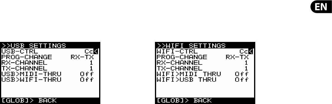
USB SETTINGS MENU- This menu contains settings for the USB port on the rear
of the DeepMind 12.
To access the USB SETTINGS menu, make sure that the '<' symbol on the USB
SETTINGS line is highlighted. Then press the +/YES switch, you will now see the
USB SETTINGS menu..
•
• USB-CTRL - This option sets the MIDI CONTROLLER communication mode for
the DeepMind 12 USB port on the rear of the synthesizer. You can choose O
(No controller messages will be sent), Cc (Continuous Controller) or NRPN
(Non-Registered Parameters.
Note: Both MIDI and NRPN data is always received and actioned.
Note: For more information on controlling the DeepMind 12 via USB-MIDI,
please consult the section on MIDI later in this document.
•
• PROG-CHANGE - This option sets the PROGRAM CHANGE communication
mode for the DeepMind 12 USB host port. You can choose from the following
options:
RX - Program change messages will be received only.
TX - Program changes will be transmitted only.
RX-TX - Program changes will be transmitted and received.
NONE - No program change messages will be sent or received.
•
• RX-CHANNEL - This option sets the MIDI channel that will be used to
RECEIVE MIDI messages. The CHANNEL can be any number from 1-16.
•
• TX CHANNEL - This option sets the MIDI channel that will be used to
TRANSMIT MIDI messages. The CHANNEL can be any number from 1-16.
•
• USB>MIDI-THRU - This option enables PASS-THRU mode from the USB port
to the MIDI-THRU socket. The options are On or O .
•
• USB>WIFI-THRU - This option enables PASS-THRU mode from the USB port
to the WIFI host. The options are On or O .
To exit this menu press the GLOBAL switch to return to the CONNECTIVITY menu.
WIFI SETTINGS MENU- This menu contains settings for the WIFI connection of
the DeepMind 12.
To access the WIFI SETTINGS menu, make sure that the '<' symbol on the WIFI
SETTINGS line is highlighted. Then press the +/YES switch, you will now see the
WIFI SETTINGS menu
•
• WIFI-CTRL - This option sets the MIDI CONTROLLER communication mode
for the DeepMind 12 WIFI connection. You can choose O (No controller
messages will be sent), Cc (Continuous Controller) or NRPN (Non-Registered
Parameters.
Note: Both MIDI and NRPN data is always received and actioned.
Note: For more information on controlling the DeepMind 12 via WIFI-MIDI
please consult the section on MIDI later in this document.
•
• PROG-CHANGE - This option sets the PROGRAM CHANGE communication
mode for the DeepMind 12 WIFI connection. You can choose from the
following options:
RX - Program change messages will be received only.
TX - Program changes will be transmitted only.
RX-TX - Program changes will be transmitted and received.
NONE - No program change messages will be sent or received.
•
• RX-CHANNEL - This option sets the MIDI channel that will be used to
RECEIVE MIDI messages. The CHANNEL can be any number from 1-16.
•
• TX CHANNEL - This option sets the MIDI channel that will be used to
TRANSMIT MIDI messages. The CHANNEL can be any number from 1-16.
•
• WIFI>MIDI-THRU - This option enables PASS-THRU mode from the WIFI
connection to the MIDI-THRU socket. The options are On or O .
•
• WIFI>USB-THRU - This option enables PASS-THRU mode from the WIFI
connection to the USB host. The options are On or O .
To exit this menu press the GLOBAL switch to return to the CONNECTIVITY menu.
26 DeepMind 12 User Manual
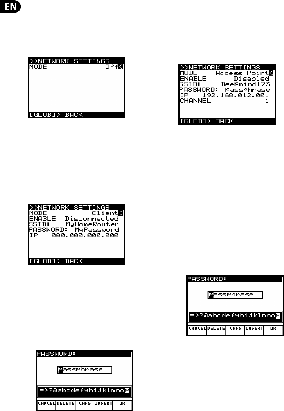
NETWORK SETTINGS MENU- This menu contains settings for the WiFi
connection of the DeepMind 12.
The DeepMind 12 supports the Real-Time MIDI (RTP) protocol for use with
network devices/applications.
To access the NETWORK SETTINGS menu, make sure that the '<' symbol on the
NETWORK SETTINGS line is highlighted. Then press the +/YES switch, and you
will now see the NETWORK SETTINGS menu:
There are three modes for the NETWORK connection:
•
• O - Network connection is disabled.
•
• Client - This mode allows the DeepMind 12 to act as a client so that it can
connect to an access point.
•
• Access Point (Software Enabled Access Point) - The DeepMind 12 can create
an access point which will allow clients/devices to connect to it.
The default mode for the NETWORK connection is O . This mode persists across
power cycles.
Client Mode - When Client mode is selected, additional options are displayed:
To navigate the options in Client mode, use the UP and DOWN switches.
In order to change any of the parameters, make sure that the '<' symbol is on the
respective line, and press the +YES switch to edit.
•
• ENABLE - This shows the current state of the Client Mode connection - there
are 4 states: Disconnected, Connecting, Connected, and Disconnecting.
It is possible to initiate a connection using the YES switch, and cancel a
connection using the NO switch.
•
• SSID and Password - These are the SSID and Password strings the
DeepMind12 uses to connect to the desired network. Editing the values of
these strings will bring up a text editing pop up dialog.
When editing any of the details, the dialog allows you to enter alphanumeric
characters and also shows CANCEL, DELETE, CAPS LOCK and INSERT options.
Once you have changed the details to your requirements, press the OK switch
to con rm the settings.
•
• IP - Shows the IP address assigned to the DeepMind12 by the DHCP server
running on the Access Point it is connected to.
Access Point Mode - When this mode is selected, additional options
are displayed:
In Access Point mode, you will need to enter the details of the access point you
wish to create.
To navigate the options in Access Point mode, use the UP and DOWN switches.
In order to change any of the parameters make sure that the '<' symbol is on the
respective line, and press the +YES switch to edit.
•
• ENABLE - This shows the current state of the Access Point connection - there
are 7 states: Disabled, Enabling, Enabled, Disabling, Connecting, Connected,
and Disconnecting. It is possible to enable the AP using the YES switch, and
disable the AP using the NO switch. Once the AP is enabled, the connection
status of any client that connects to the DeepMind12 will be shown as either
Connecting, Connected, or Disconnecting. It is possible to reject a client that
has already connected, by pressing NO.
•
• SSID and Password - These are the SSID and Password strings the
DeepMind12 uses to create the Access Point network. Editing the values of
these strings will bring up a text editing pop up dialog:
When editing any of the details, the dialog allows you to enter alphanumeric
characters and also shows CANCEL, DELETE, CAPS LOCK and INSERT options.
Once you have changed the details to your requirements, press the OK switch
to con rm the settings.
•
• IP - Shows the IP address the DeepMind12 uses for the Access Point.
•
• Channel - This shows the Wireless channel used by the Access Point.
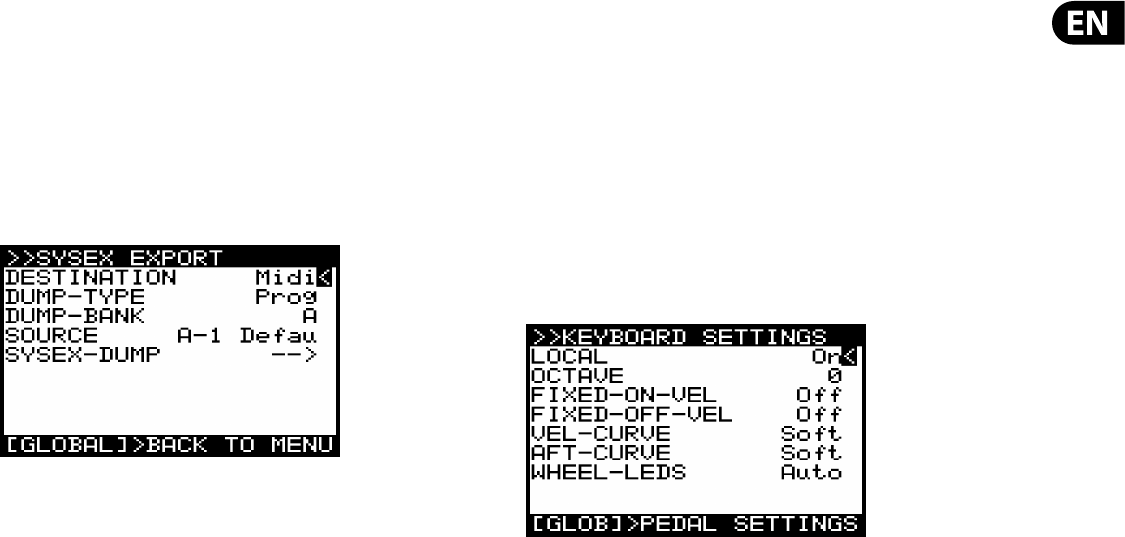
27 DeepMind 12 User Manual
SYSEX EXPORT MENU- This menu contains settings for the EXPORT menu of the
DeepMind 12.
Note: Backing up your data is an important factor when working with the
DeepMind 12. It allows you to keep a safe copy of your programming, manage
settings depending on your use, and share your work with others.
To access the SYSEX EXPORT menu, press the GLOBAL switch until the
CONNECTIVITY menu appears. Make sure that the '<' symbol on the EXPORT line
is highlighted. Then press the +/YES switch, you will now see the
SYSEX EXPORT menu.
•
• DESTINATION - This option sets the communication mode for the DeepMind
12 SYSTEM EXCLUSIVE (SysEx) messages.
Midi - SysEx messages will be transmitted from the MIDI sockets on the rear
of the synthesizer).
USB - SysEx messages will be transmitted to the USB host.
WiFi - SysEx messages will be transmitted to the WiFi connection.
•
• DUMP TYPE - This option sets the type of data which be exported. You can
choose from the following:
Prog - A single PROGRAM.
Bank - An entire BANK of 128 PROGRAMs.
EditProg -The PROGRAM in the EDIT BUFFER, i.e. the program you are
currently working on.
Glob - The GLOBAL settings, useful if you need di erent settings depending
on your location/activity/requirements).
UserPat - Any one of the 32 USER PATTERNs from the Arpeggiator.
EditPat -The current PATTERN stored in the EDIT BUFFER, i.e. the PATTERN
which is assigned in the program you are currently working on.
AllPat - All user PATTERNs.
All - All Banks, Programs, Patterns, and Global Settings.
CalData - The data from the calibration routine.
•
• DUMP BANK - You can select the appropriate BANK here, from one of the 8
available (A-H). This option is only available when exporting.
•
• SOURCE - You can select the appropriate PROGRAM or PATTERN here. This
option is only available when exporting.
•
• SYSEX DUMP (EXPORTING) - Pressing the +/YES switch while this option is
selected will initiate the EXPORT based on the selected options.
To exit this menu press the GLOBAL switch to return to the CONNECTIVITY menu.
To exit the CONNECTIVITY menu press the PROG switch to return to the main
programming screen, or press GLOBAL to cycle to the KEYBOARD SETTINGS menu.
7.2.12 KEYBOARD SETTINGS
Note: To access successive GLOBAL pages just press the GLOBAL switch again to
cycle through the pages.
In this menu there are all the settings relating to keyboard.
To navigate the options in the KEYBOARD SETTINGS menu, use the UP and DOWN,
switches.
In order to change any of the parameters make sure that the '<' symbol on the
respective line is highlighted.
Selected parameters are adjusted using the -NO/+YES switches, the rotary knob
or the fader. The rotary knob has a click which allows very accurate control. The
fader allows rapid adjustment across the full range.
LOCAL - This option turns LOCAL CONTROL for the DeepMind 12 keyboard ,
aftertouch, pitch wheel and modulation wheel On and O . It is sometimes
useful to turn LOCAL CONTROL o when using the DeepMind 12 to control other
hardware/software synthesizers, e ects and/or applications.
OCTAVE - This option allow you to adjust the OCTAVE setting for the keyboard.
The OCTAVE setting a ects the whole keyboard.
The default setting is 0, which means if you play the lowest note it will be a C2.
The OCTAVE can be adjusted from -2 to +2, allowing you to use the 49 keys to
access the full eight octaves (98 keys).
Please refer to Appendix 1 - Octave Shifting at the end of this document for a
diagram.
FIXED-ON-VEL - This option xes the NOTE ON VELOCITY at a set value, so that
regardless of how hard you strike the note, the value will always be the same. The
higher the value, the higher the volume of the note. The value can range from
0-127. When this option is set to O , the NOTE ON VELOCITY will be dependant
upon how hard you strike the note.
Note: The NOTE ON VELOCITY sensitivity can be adjusted in the VCA edit page.
Please refer to the VCA section later in this document for more details.
FIXED-OFF-VEL - This option xes the NOTE OFF VELOCITY at a set value, so
that regardless of how fast you release the note, the value will always be the
same. The higher the value, the higher the volume of the note. The value can
range from 0-127. When this option is set to O , the NOTE OFF VELOCITY will be
dependant upon how fast you release the note.
Note: The NOTE OFF VELOCITY is only available within the MOD MATRIX as a
MODULATION SOURCE. It is not used elsewhere in the synthesizer. Please refer to
the MOD MATRIX section later in this document for more details.
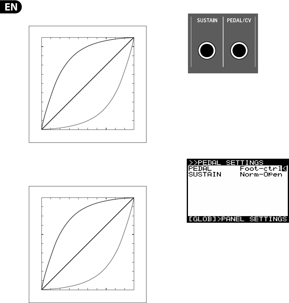
28 DeepMind 12 User Manual
VEL CURVE - You can adjust the response curve for the VELOCITY here. The Hard
setting will reduce the dynamic range of played notes. The Soft setting will
increase the dynamic range of played notes.
The default setting is Soft.
AFT-CURVE - You can adjust the response curve for the AFTERTOUCH here. The
Hard setting will reduce the dynamic range of key pressure. The Soft setting will
educe the dynamic range of key pressure.
The default setting is Soft.
Note: The DeepMind 12 keyboard sends "Channel Aftertouch", meaning the MIDI
message created is common to all keys.
WHEEL-LEDS - Both the PITCH WHEEL and the MODULATION WHEEL have the
possibility to be illuminated, depending on your requirements. You can control
the illumination mode here by selecting one of the following options:
Auto - In this mode, the illumination will get brighter as the respective wheel is
moved, reaching its brightest point at the end of its travel.
On - In this mode the illumination is xed on.
O - In this mode the illumination is turned o .
The default setting is Auto.
To exit this menu press the PROG switch to return to the main
programming screen, or press GLOBAL to cycle to the PEDAL SETTINGS menu.
7.2.13 PEDAL SETTINGS
In this menu there are all the settings relating to PEDAL/CV and SUSTAIN inputs
on the rear of the DeepMind 12.
To navigate the options in the PEDAL SETTINGS menu, use the UP and DOWN
switches.
In order to change any of the parameters make sure that the '<' symbol on the
respective line is highlighted.
Selected parameters are adjusted using the -NO/+YES switches, the rotary knob
or the fader. The rotary knob has a click which allows very accurate control. The
fader allows rapid adjustment across the full range.
PEDAL/CV - This option allows you to choose the PEDAL/CV MODE from the
following options:
The PEDAL/CV input can work with a typical foot pedal, where the voltage is
supplied by the DeepMind 12 and fed back at a level which is dependant on the
position of the pedal. The further the pedal is pressed, the higher the voltage.
The PEDAL/CV input can also work with a CV (Control Voltage) input
from any source with a 0 to +5V output e.g. the Control Voltage from a
modular synthesizer.
Note: For wiring diagrams and pin connections information please consult the
guide later in this document.
The PEDAL input takes the voltage from the connector and turns it into a control
signal. The control signal can be mapped to any of the following:
•
• Foot-ctrl - The Foot-Ctrl (Foot Controller) is available as a modulation source
in the MOD MATRIX.
•
• Mod-Wheel - Here the PEDAL input is mapped to the MODULATION WHEEL
which is available as a modulation source in the MOD MATRIX.
•
• Breath - Here the PEDAL input is mapped to the BREATH controller which is
available as a modulation source in the MOD MATRIX.
•
• Volume - Here the PEDAL input is mapped to the VOLUME controller.
•
• Expression - Here the PEDAL input is mapped to the EXPRESSION controller.
The default setting is Foot-ctrl.
SUSTAIN - This option allows you to choose the SUSTAIN MODE from the
following options:
The SUSTAIN input can work with a switched input which is either open when
pressed, or closed when pressed.
Soft
Med
Hard
Velocity Sensitivity Curve Settings
Strike Speed
Slow Fast
Velocity
AfterTouch Sensitivity Curve Settings
Key Pressure
Velocity
Soft
Med
Hard
Soft Hard
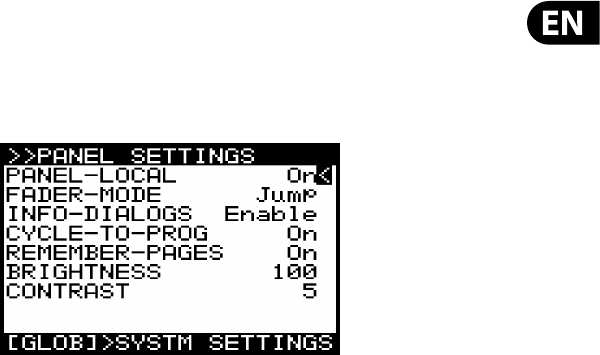
29 DeepMind 12 User Manual
Gate Functionality - The SUSTAIN input can also be used with a GATE signal
from a CV and GATE interface or a modular synthesizer. This functionality requires
the GATE signal to operate between +5V and 0V.
Note: For wiring diagrams and pin connections information please consult the
guide later in this document.
•
• Norm-Open Here when the connected switch is pressed the notes are held
in the SUSTAIN stage of all ENVELOPEs. In this mode the correct operation is
designed for a switch whose contacts close when pressed.
•
• Norm-Closed Here when the connected switch is pressed the notes are held
in the SUSTAIN stage of all ENVELOPEs. In this mode the correct operation is
designed for a switch whose contacts open when pressed.
•
• Tap-N.O Here the SUSTAIN input is mapped to the TAP function so when
the switch is pressed a signal is sent to the Master BPM Generator. In this
mode the correct operation is designed for a switch whose contacts close
when pressed.
•
• Tap-N.C Here the SUSTAIN input is mapped to the TAP function so when
the switch is pressed a signal is sent to the Master BPM Generator. In this
mode the correct operation is designed for a switch whose contacts open
when pressed.
•
• Arp+Gate Here the SUSTAIN input is mapped to the ARPEGGIATOR notes, so
when a GATE input from a CV & GATE interface, or a modular synthesizer is
connected, the gate signal will step though the notes of the ARPEGGIATOR.
In this mode the ARPEGGIATOR note duration is set by length of time that the
gate signal is high (+5V).
•
• Arp-Gate Here the SUSTAIN input is mapped to the ARPEGGIATOR notes, so
when a GATE input from a CV & GATE interface, or a modular synthesizer is
connected, the gate signal will step though the notes of the ARPEGGIATOR.
In this mode the ARPEGGIATOR note duration is set by length of time that the
gate signal is low (0V).
•
• Seq+Gate Here the SUSTAIN input is mapped to the CONTROL SEQUENCER
steps, so when a GATE input from a CV & GATE interface, or a modular
synthesizer is connected, the gate signal will move though the steps of the
CONTROL SEQUENCER. In this mode the CONTROL SEQUENCER will transition
to the next step each time a positive edge (a transition from 0V to 5V)
is received.
•
• Seq-Gate Here the SUSTAIN input is mapped to the CONTROL SEQUENCER
steps, so when a GATE input from a CV & GATE interface, or a modular
synthesizer is connected, the gate signal will move though the steps of the
CONTROL SEQUENCER. In this mode the CONTROL SEQUENCER will transition
to the next step each time a negative edge (a transition from 5V to 0V)
is received.
•
• Arp&Seq+Gate Here the SUSTAIN input is mapped to the ARPEGGIATOR
notes, and to the CONTROL SEQUENCER steps. When a GATE input from a CV
& GATE interface, or a modular synthesizer is connected, the gate signal will
step though the notes of the ARPEGGIATOR, and also move though the steps
of the CONTROL SEQUENCER. In this mode the ARPEGGIATOR note duration
is set by length of time that the gate signal is high (+5V). Also in this mode
the CONTROL SEQUENCER will transition to the next step each time a positive
edge (a transition from 0V to 5V) is received.
•
• Arp&Seq-Gate Here the SUSTAIN input is mapped to the ARPEGGIATOR
notes, and to the CONTROL SEQUENCER steps. When GATE input from a CV &
GATE interface, or a modular synthesizer is connected, the gate signal will
step though the notes of the ARPEGGIATOR, and also move though the steps
of the CONTROL SEQUENCER. In this mode the ARPEGGIATOR note duration is
set by length of time that the gate signal is low (0V). Also in this mode the
CONTROL SEQUENCER will transition to the next step each time a negative
edge (a transition from 5V to 0V) is received.
The default setting is Norm-Open.
To exit this menu press the PROG switch to return to the main programming
screen, or press GLOBAL to cycle to the PANEL SETTINGS menu.
7.2.14 PANEL SETTINGS
PANEL-LOCAL - This option turns LOCAL CONTROL for the DeepMind 12 panel
controls (including all faders, non menu edit switches and portamento knobs)
On and O . It is sometimes useful to turn LOCAL CONTROL o when using
the DeepMind 12 to control other hardware/software synthesizers, e ects
and/or applications.
The default setting is On.
FADER MODE - This option allows you to choose the mode in which the faders
respond when you initially move a fader which has a di erent physical position to
the stored value. You can choose one of the following options:
•
• Pass-thru - In this mode, when the fader is moved, it will need to "Pass-
thru" the stored value before it will start to change.
•
• Jump - In this mode, when the fader is moved the value of the parameter
will "Jump" to the physical position of the fader.
The default setting is Jump.
INFO DIALOGS - This option allows you to disable the pop-up dialogs and
messages which are designed to aid you while learning how the DeepMind 12
operates. The default setting is Enable.
CYCLE TO PROG - When this option is turned On, the menu cycle function will
return you to the programming screen. When this option is O , the menu cycle
function will return you to the rst menu page. The default setting is On.
REMEMBER PAGES - With this option turned on your position in any menu
will be remembered so that you return to the same position you left. When this
option is o , any access of a menu will always position you in the rst menu page.
The default setting is On.
BRIGHTNESS - This option allows you to control the brightness of the display.
The range is 0-100, with 0 being dim and 100 being the brightest setting. This is
useful if you are operating in low light conditions and want to protect your vision,
or if you are working under strong lighting conditions and want to maximise
viability.
The default setting is 100.
CONTRAST - This option allows you to control the contrast of the display. The
range is 0-14, with 0 being least contrast and 14 being the most contrast. This is
useful to compensate for di erent viewing angles, and/or light conditions.
The default setting is 10.
To exit this menu press the PROG switch to return to the main programming
screen.
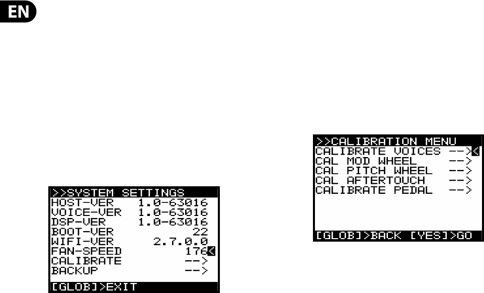
30 DeepMind 12 User Manual
7.2.15 SYSTEM SETTINGS
Note: To access successive GLOBAL pages just press the GLOBAL switch again to
cycle through the pages.
In this menu are all the SYSTEM SETTINGS of the DeepMind 12. These include
VERSION NUMBERS of the hardware/ rmware, settings for the fan speed and
access to the CALIBRATION routines.
To navigate the options in the SYSTEM SETTINGS menu, use the UP and DOWN
switches.
In order to change any of the parameters make sure that the '<' symbol on the
respective line is highlighted.
Selected parameters are adjusted using the -NO/+YES switches, the rotary knob
or the fader. The rotary knob has a click which allows very accurate control. The
fader allows rapid adjustment across the full range.
HOST-VER - This is the version number of the host rmware.
VOICE-VER - This is the version number of the voice circuit board.
DSP-VER - This is the version of the DSP rmware.
BOOT-VER - This is the version of the bootloader used to initialize the synthesizer.
WIFI-VER - This is the version of the WiFI.
FAN-SPEED - This allows you to adjust the fan speed. The fan speed is adjustable
from 0 (o ) to 255 (maximum). Adjust the fan speed to suit your listening
conditions and preference. If the local temperature is high, please make sure
that the fans are not turned o . The DeepMind 12 is equipped with 2 fans, one
internal and one at the rear. At an approximate setting of 40 the internal fan is
running and the rear fan is o .
7.2.16 CALIBRATE
This menu allows you to perform CALIBRATION of the VOICES, MOD WHEEL, PITCH
WHEEL, AFTERTOUCH and PEDAL INPUT.
To navigate the options in the CALIBRATION menu, use the UP, DOWN, switches.
Selected parameters are adjusted using the -NO/+YES switches, the rotary knob
or the fader. The rotary knob has a click which allows very accurate control. The
fader allows rapid adjustment across the full range.
In order to start a calibration routine make sure that the '<' symbol on the
appropriate CALIBRATE line is highlighted and press the +/YES switch.
The DeepMind 12 has 12 voices. Each voice has its own LFO, OSC, VCF, ENV and
VCA stages.
The CALIBRATION routine is used for the Voice checking, OSC wave shapes, VCF
self-oscillation, Pulse Width modulation and the VCA bias.
VCF - Unlike many other synthesizers, the DeepMind 12 is capable of
accurate pitch tracking even when the lter resonance is pushed to (and
past) the point where the lter starts to self-oscillate. When using this self-
oscillating feature of the VCF as a sound source, the VCF calibration ensures
the correct response when playing the entire scale of the keyboard.
The DeepMind 12 VCFs are calibrated at the factory during production.
However, because its lters are voltage controlled and can be a ected
by extremes of temperature, you may need to use the built-in calibration
function to ne tune them occasionally. Calibration may also be required
after a rmware upgrade or when being requested to do so by an authorised
Behringer support technician.
OSC - The DeepMind 12 OSCs are calibrated at the factory during production.
The oscillators are discrete analog circuits but they are digitally controlled.
Compared to a Voltage Controlled oscillator (VCO), the OSC has far superior
stability, especially when they have a very high frequency, low-jitter master
clock sources, as used in the DeepMind 12. This stage calibrates the slope of
the sawtooth waveform to ensure even volume and pulse-width across the
full range of the synthesizer.
This means that the OSCs should never need re-calibrating except for after
a rmware upgrade or being requested to do so by an authorised Behringer
support technician.
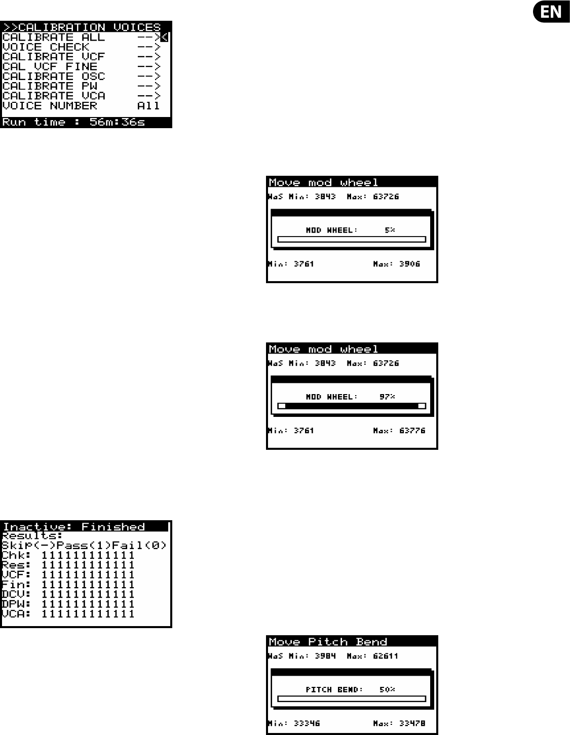
31 DeepMind 12 User Manual
CALIBRATE VOICES
Overview of the calibration routines:
ALL - This will initiate all of the routine.
VOICE CHECK - This performs a series of functionality tests on each voice.
VCF - This routine puts the voice into self oscillation and tunes to 1 kHz in order to
calibrate the resonance of the VCF for that voice. The routine then puts the voice
into self oscillation and checks the tuning at 50 Hz, 220 Hz, 880 Hz and 10 kHz to
ensure the VCF is performing as expected. The test is repeated for all voices.
OSC - This routine adjusts the slope of the sawtooth at octave intervals. This
ensures the precision of the slope so that it performs as designed. The test is
repeated for all voices.
PW - This routine adjusts the pulse width (mark to space ratio) of the pulsewave.
This ensures the precision of the ratio so that it performs as designed. The test is
repeated for all voices.
VCA - The Voltage Controlled Ampli er (VCA) uses a bias voltage to set its
operating level. This bias voltage is balanced so that the VCA responds as
designed. The test is repeated for all voices.
In order to start the calibration routine make sure that the '<' symbol on the
appropriate CALIBRATE line is highlighted and press the +/YES switch.
Note: The calibration run time is shown on the bottom of the screen so that you
can plan your work around any of the calibration phases.
The calibration routine will then start. Throughout the tests you will see various
waveforms being played. It is safe to turn down the volume while the calibration
routine is running.
Note: There is the option while the calibration is running to mute the signal
using the BANK/DOWN switch and un-mute using the BANK/UP switch.
Once the calibration routine is complete you will see a summary of the test
results as shown below:
Note: During the calibration the GLOBAL and -/NO switches will be ashing. If
at any time you want to cancel the calibration routine, you can press the -/NO
switch. No previous calibration data will be changed if you do cancel the routine.
CAL MOD WHEEL
To calibrate the MOD WHEEL, please use the following process:
Note: During the calibration the GLOBAL, -NO and +/YES switches will be
ashing. If at any time you want to cancel the calibration routine, you can press
the -/NO switch. No previous calibration data will be changed if you do cancel the
routine. To con rm the calibration at each stage press +/YES as described below.
First move the MOD WHEEL to its minimum position (shown on the panel)
In order to start the calibration routine make sure that the '<' symbol on the CAL
MOD WHEEL line is highlighted and press +/YES.
You will see the following display showing a bar representing the MOD WHEEL
value. Also on this screen you can see the stored calibration data above the bar
and the current value below the bar.
Then move the MOD WHEEL to its maximum position (shown on the panel).
You will see the following display showing the new position of the MOD WHEEL
and the associated values:
Note: To cancel the routine you can press the -/NO switch.
To con rm the CALIBRATION of the MOD WHEEL, press the +/YES switch: The
calibration data will then be stored for the MOD-WHEEL and you will be returned
to the CALIBRATE menu. From here you can perform another calibration from the
menu, or press the GLOBAL switch again to return to the SYSTEM SETTINGS menu.
CAL PITCH WHEEL
To calibrate the PITCH WHEEL, please use the following process:
In order to start the calibration routine make sure that the '<' symbol on the CAL
PITCH WHEEL line is highlighted and press +/YES.
You will see the following display showing a bar representing the PITCH WHEEL
value. Also on this screen you can see the stored calibration data above the bar
and the current value below the bar:
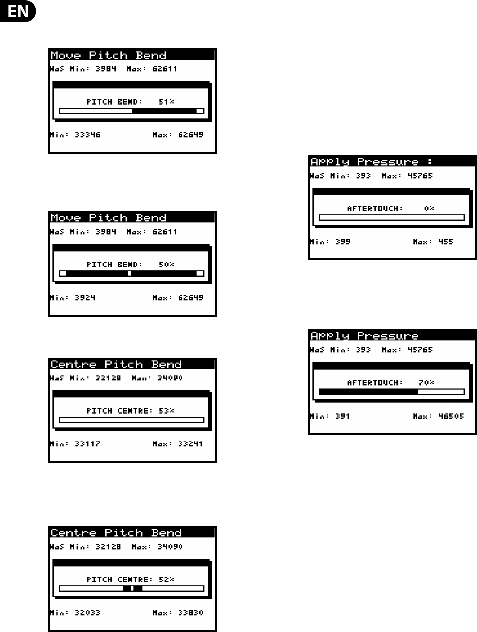
32 DeepMind 12 User Manual
Then move the PITCH WHEEL to its maximum position (shown on the panel).
You will see the following display showing the maximum position of the PITCH
WHEEL and the associated values:
Then move the PITCH WHEEL to its minimum position (shown on the panel).
You will see the following display showing the maximum position of the PITCH
WHEEL and the associated values:
To con rm the CALIBRATION of the PITCH WHEEL press the +/YES switch and you
will be moved on to the PITCH CENTRE page:
At this point move the PITCH WHEEL within the dead zone where you don't feel
the tension of the spring. This is ensure that no pitch information is sent while the
pitch wheel is not being touched. You will see the following display showing a
guide to assist you:
Note: To cancel the routine you can press the -/NO switch.
To con rm the CALIBRATION of the PITCH CENTRE press the +/YES switch: The
calibration data will then be stored for the PITCH CENTRE and you will be returned
to the CALIBRATE menu. From here you can perform another calibration from the
menu, or press the GLOBAL switch again to return to the SYSTEM SETTINGS menu.
CAL AFTERTOUCH
To calibrate the KEYBOARD AFTERTOUCH please use the following process:
Note: During the calibration the GLOBAL, -NO and +/YES switches will be
ashing. If at any time you want to cancel the calibration routine, you can press
the -/NO switch. No previous calibration data will be changed if you do cancel the
routine. To con rm the calibration at each stage press +/YES as described below.
In order to start the calibration routine make sure that the '<' symbol on the CAL
AFTERTOUCH line is highlighted and press +/YES.
You will see the following display showing a bar representing the current
AFTERTOUCH value (0% for no pressure). Also on this screen you can see the
stored calibration data above the bar and the current value below the bar:
Then apply pressure to any one of the keys (or multiple keys) until the value stops
increasing.
You will see the following display showing the maximum position of the
AFTERTOUCH and the associated value:
Note: To cancel the routine you can press the -/NO switch.
To con rm the CALIBRATION of the AFTERTOUCH press the +/YES switch: The
calibration data will then be stored for the AFTERTOUCH and you will be returned
to the CALIBRATE menu. From here you can perform another calibration from the
menu, or press the GLOBAL switch again to return to the SYSTEM SETTINGS menu.
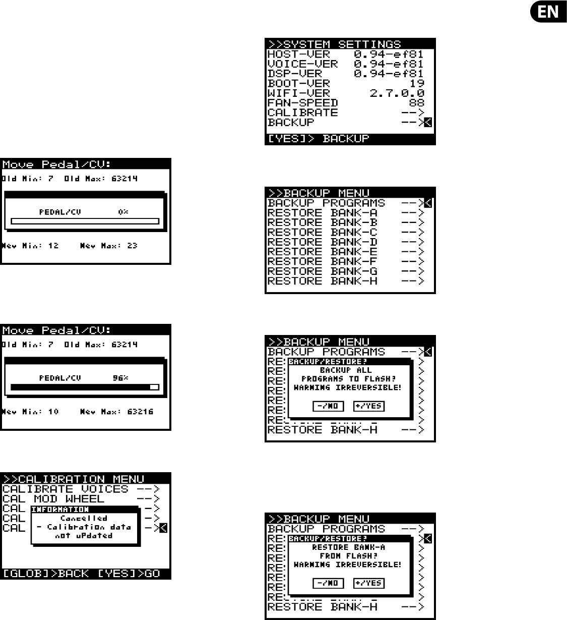
33 DeepMind 12 User Manual
CALIBRATE PEDAL
To calibrate the PEDAL please use the following process:
Note: During the calibration the GLOBAL, -NO and +/YES switches will be
ashing. If at any time you want to cancel the calibration routine, you can press
the -/NO switch. No previous calibration data will be changed if you do cancel the
routine. To con rm the calibration at each stage press +/YES as described below.
In order to start the calibration routine make sure that the '<' symbol on the CAL
CALIBRATE PEDAL line is highlighted and press +/YES.
You will see the following display showing a bar representing the current PEDAL
value (0% for no pressure). Also on this screen you can see the stored calibration
data above the bar and the current value below the bar:
Then press the pedal until the value stops increasing.
You will see the following display showing the maximum position of the PEDAL
input and the associated value:
Note: To cancel the any routine you can press the -/NO switch, you will see the
following message:
To con rm the CALIBRATION of the PEDAL input press the +/YES switch: The
calibration data will then be stored for the PEDAL and you will be returned to the
CALIBRATE menu. From here you can perform another calibration from the menu,
or press the GLOBAL switch again to return to the SYSTEM SETTINGS menu.
7.2.17 BACKUP (backup Menu)
The last item in the SYSTEM SETTINGS menu is BACKUP.
Pressing +/YES when “BACKUP -->” is selected, will bring up the BACKUP MENU.
(The "RESTORE BANK" lines only appear after the rst backup is done).
Pressing /YES when “BACKUP PROGRAMS” is selected, will bring up a
con rmation dialog:
Pressing YES again, copies all Banks of programs from EEPROM to ash, and
overwrites the “factory default” data.
Pressing +/YES when any of the RESTORE-BANK-A to RESTORE-BANK-H lines is
selected, will bring up a con rmation dialog:
Pressing YES again will restore the selected bank from ash.
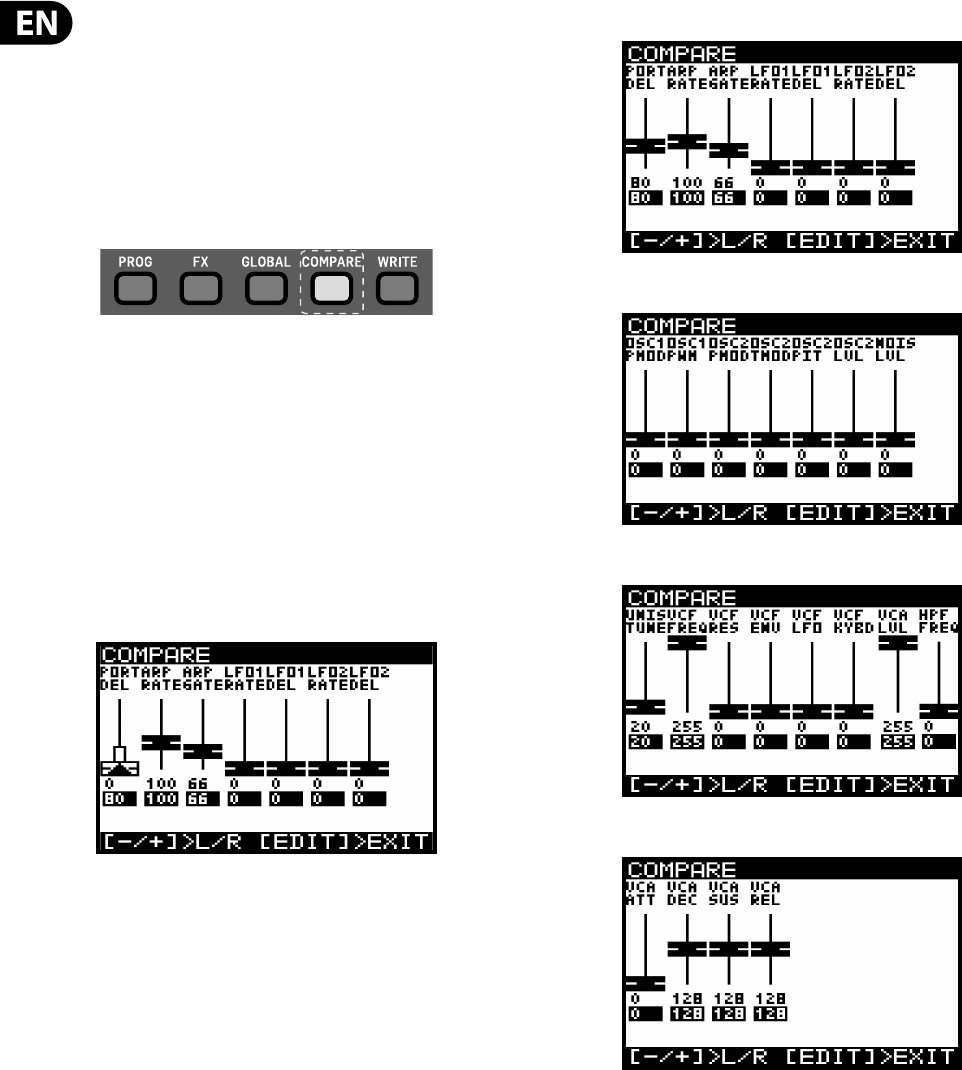
34 DeepMind 12 User Manual
7.3 COMPARE (Compare Menu)
The COMPARE feature has two main functions:
Firstly you can use it to COMPARE the current (edited) program with the original
program.
Secondly you can use it to COMPARE and/or match the current position of the
physical faders on the surface with the original program. This is necessary when
you wish to maintain the sound/character of the program.
To perform both functions simply press the COMPARE switch.
Note: If you have not edited the program (i.e. changed some parameters) when
you press the COMPARE switch you will restore the backup as described in a
previous chapter.
Firstly the sound/character will return to its original state so that you can
compare your edits. Note: If you do not want to match the fader positions you can
simply press COMPARE again to return to programming.
Secondly, you now have the option to match the position of the physical faders to
the positions stored in the original program.
You will then see a page of the COMPARE menu (page 1 is displayed below). The
page shown will be the last page you used. If you have never used the COMPARE
function since turning the DeepMind 12 on, it will default to page 1.
Each page of the COMPARE menu shows a section of the faders .
If the position of the fader matches the position of the stored value the fader will
be black.
If the fader does not match the position it will be white with a superimposed
arrow pointing in the direction it needs to move in order to approach the stored
value.
There is also a white bar to show how far the fader needs to move in order to
match the stored value.
Once the fader reaches the stored position it will turn black to indicate it is now
matched.
Note: The pages will switch automatically when you begin to adjust any of the
faders.
There are four pages of faders in the COMPARE menu, to access the other pages
use the +/- switches to select the previous/next pages.
Page 1 Shows the PORTAMENTO rotary and the ARP/SEQ/LFO faders:
Page 2 shows the OSC faders:
Page 3 shows the UNISON, VCF, HPF and VCA faders:
Page 4 shows the ENVELOPE faders:
Note: You can still select speci c envelopes to match the faders depending on
your requirements.
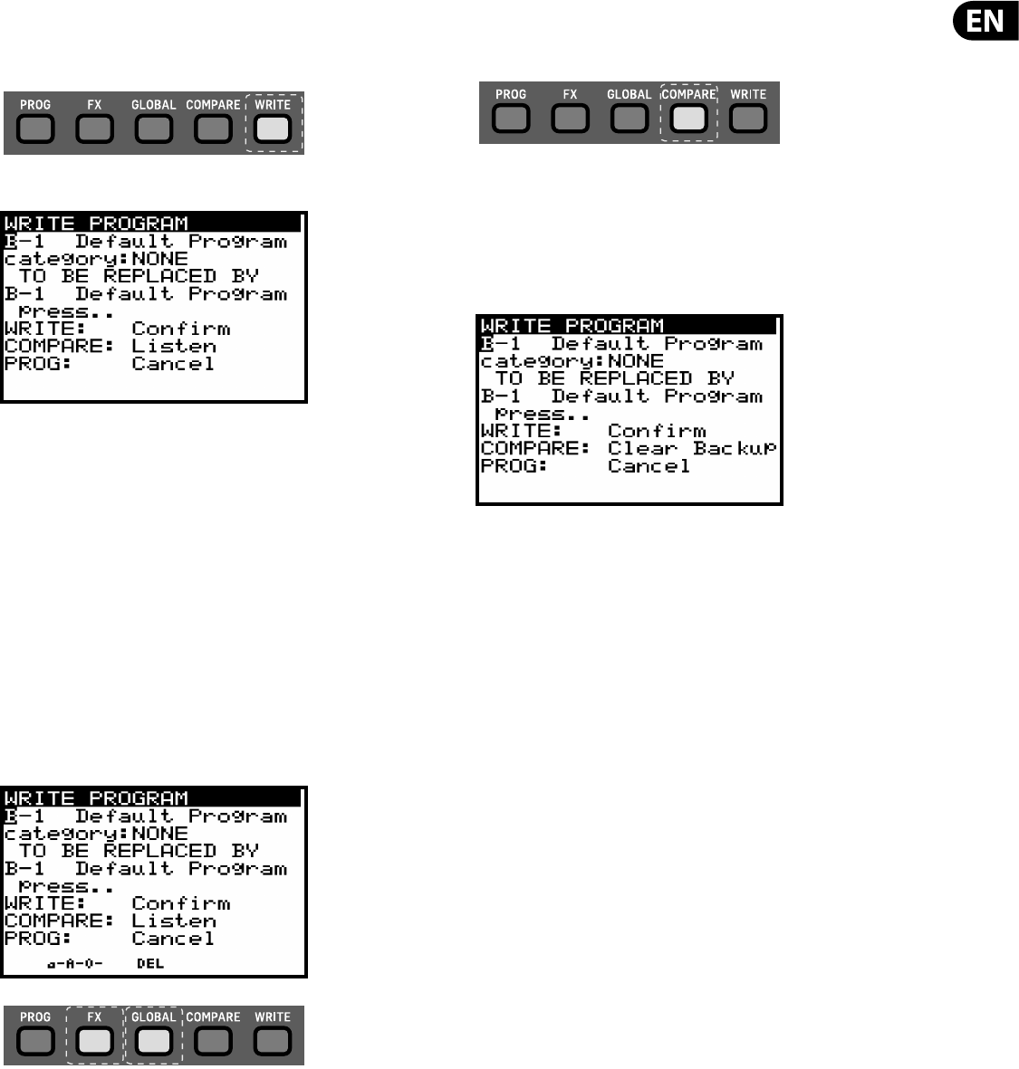
35 DeepMind 12 User Manual
7.4 WRITE (Write Menu)
To write a program to memory press the WRITE switch to open the WRITE
PROGRAM menu.
The WRITE PROGRAM menu will then appear:
In this menu you can use the -NO/+YES switches to navigate through the
sections. The selected section will be highlighted by an inverted character (white
on black).
The rst section is the program location the current program will be saved.
You can use the UP/DOWN switches, the rotary knob, or the fader to select the
required BANK (A-H) and PROGRAM NUMBER (1-128).
The second section is the CATEGORY to select any of the available categories.
Again you can use the UP/DOWN switches, the rotary knob, or the fader to select
the required CATEGORY.
The third section is REPLACED BY which allows you to name the program to be
written. You can use the -NO/+YES switches to step through each character of the
name and use the UP/DOWN switches, the rotary knob, or the faders to change
the character.
There are also two short-cuts for selecting characters indicated by text above the
FX and GLOBAL switches:
a-A-0 - Pressing the FX switch will cycle between lower-case, upper-case and
numbers.
DEL - Pressing the GLOBAL switch will delete the currently selected character.
Note: These short-cuts only appear when you are editing the name of the
REPLACED BY program.
To compare the current program with the intended program location you can
press the COMPARE switch to listen to the di erence. To return to the current
program, press the compare switch again.
Once you have selected the new location and named the program simply press
the WRITE switch again to write the program.
At anytime you decide you do not want to write the program, you can press the
PROG switch to return to the main programming display. Note: If there is a
program in the backup memory then you will see the message "COMPARE to clear
backup".
If you wish to listen to the intended program location as described earlier you will
need to press the COMPARE switch to clear the backup memory. Once the backup
has been cleared then the message will revert to "COMPARE to listen" and you
can listen to the intended program location as normal.
7.5 Re-naming Programs
To rename a program simply follow the procedure for writing a program and
keep the BANK and PROGRAM NUMBER the same.
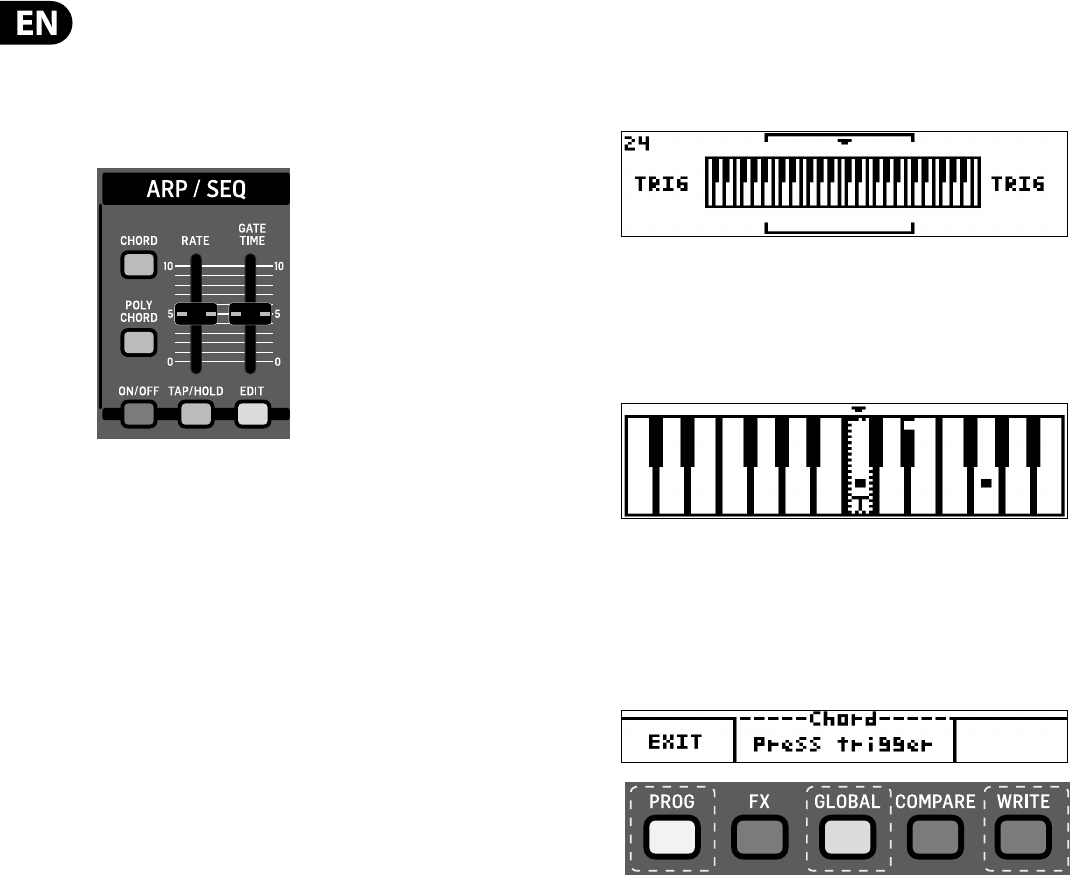
36 DeepMind 12 User Manual
8. Programming
8.1 CHORDS/ARP/SEQ/SYNC SETTINGS
The ARP/SEQ section controls all parameters relating to the internal
ARPEGGIATOR, CONTROL SEQUENCER and PATTERN editing. This section also
contains the controls for CHORD and POLY CHORD programming.
CHORD / POLY CHORDS - You can program a single chord to be mapped across
the entire keyboard, or multiple chords to individual keys/notes.
ARPEGGIATOR - The DeepMind 12 ARPEGGIATOR allows you to play a pattern
based on the individual keys being held. The patterns note order can be selected
from a number of modes. The tempo of the ARPEGGIATOR can be sourced from
either an internal or external clock. The clock can be divided from the Master BPM
allowing you to select di erent timing structures.
The ARPEGGIATOR also has a looping pattern editor which allows you to adjust
velocity and gate values for each step. The pattern editor has 32 "Fixed Presets"
allowing you to start using the patterns quickly and 32 "User Presets" so that
you can store your own unique patterns. The patterns can be up to 32 steps long
allowing a large range of creative possibilities.
There is also a clock swing feature which allows you to ne tune the swing (or
"groove") to your speci c requirements.
The ARPEGGIATOR can be set to synchronize with the rst key you strike, or
synchronised with the Master BPM clock (internal or external).
CONTROL SEQUENCER - The DeepMind 12 CONTROL SEQUENCER is not part of the
ARPEGGIATOR. The CONTROL SEQUENCER is a modulation source in the same way
an LFO or ENVELOPE is. The CONTROL SEQUENCER allows you to create a pattern
which can be used to modulate other parameters. The tempo of the CONTROL
SEQUENCER can be sourced from either an internal or external clock. The clock
can be divided from the Master BPM allowing you to select di erent timing
structures.
The CONTROL SEQUENCER has a looping editor which allows you to adjust the
values for each step. The modulation waveform that is produced can have
negative or positive values. The CONTROL SEQUENCER can be up to 32 steps long
allowing a large range of creative possibilities.
There is also a clock swing feature which allows you to ne tune the swing (or
"groove") to your speci c requirements.
The CONTROL SEQUENCER can be set to synchronize with the rst note you strike,
or synchronised with the Master BPM clock (internal or external).
For more information on using the CONTROL SEQUENCER as a modulation source
please consult the MOD MATRIX section later in this document.
CLOCK NOTES - One the great advantages of having a Master BPM is that the
LFOs, ENVELOPES, and many EFFECTS parameters of the DeepMind 12 can be
synchronised to the BPM.
8.1.1 CHORD SWITCH
The DeepMind 12 CHORD switch allows you to program a chord to memory. That
chord is then transposed across the full range of the keyboard.
CHORD SCREEN UPPER SECTION
On the upper section of the CHORD screen there is a visual representation of the
four physical octaves of the keyboard. The words next to the keyboard describe
what is shown (NOTE or TRIG). The bracket shows the zoom position for the lower
section. The number in the top left hand corner shows the MIDI note number.
CHORD SCREEN LOWER SECTION
On the lower section of the CHORD screen there is a visual representation
of the keyboard which is zoomed to the two octaves represented by the
vertical brackets on the top section. The letter T shows the last played trigger
key. The small indicator dots on the keys show the currently played notes
during recording.
CHORD SCREEN SOFT KEYS
At the bottom of the CHORD page you will see three areas which indicate the
software function of the PROG, GLOBAL and WRITE switches.
PROG switch - Always perform the EXIT function and return you to the
PROG screen.
GLOBAL switch - Only used to RECORD a new CHORD. Otherwise the area above
the switch is used to show the status of the CHORD programming function i.e.
Armed, Learning, or Press Trigger.
WRITE switch - Used to DELETE the chord, but only once a chord is programmed
(otherwise this area will be blank and the switch will not be illuminated)
Note: The CHORD is stored in persistent memory and will be retained through a
power cycle.
Note: The CHORD memory can also be cleared using the bootloader menu
described later in this document.
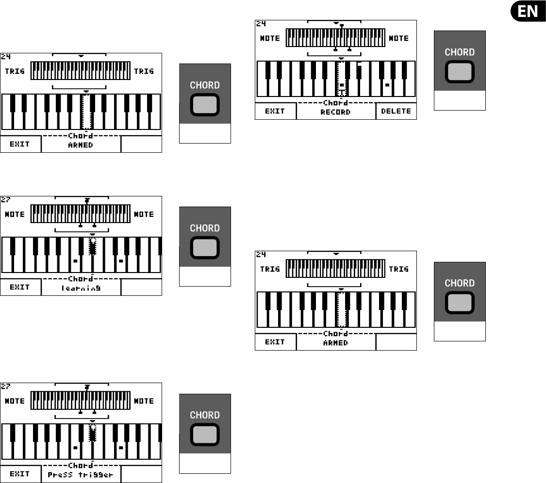
37 DeepMind 12 User Manual
CHORD PROGRAMMING - To program a chord, press the CHORD switch (or the
RECORD soft switch if replacing an existing chord). The CHORD switch will begin
double ashing and you will then see the screen with the message "Armed" as
shown below:
While the message "Armed" is shown, hold the keys of the chord down and you
will then see the screen with the message "Learning" below:
At this point you can add additional notes to the chord. Once you have all the keys
required held down simultaneously you can release them all. The chord will then
be ready to be assigned and the CHORD switch will ash slowly.
Note: The CHORD size is limited to 12 notes.
You will see a message to "Press Trigger" as shown below:
Now press the root note key for the chord to be transposed up or down from.
Once you press a key, the chord you played will have its root note assigned to that
key. The CHORD switch will then stay illuminated (no ashing) and the CHORD
mode will be active for the entire keyboard (including any OCTAVE shift applied).
Note: In CHORD mode you can only play one key/CHORD at a time. I.e. when you
hold a key down then press another key, the CHORD will be played from the last
pressed key only.
The screen will now show the following:
Now playing any key on the keyboard will play the CHORD you have programmed.
The CHORD will be transposed from the root note to the key that you are playing.
RECORDING A NEW CHORD - To record a new chord (and overwrite the exisiting
chord), press the RECORD soft switch. The existing chord will be deleted and you
will see the message "Armed" indicating that the synthesizer is ready to program
a new CHORD.
DELETING THE CHORD - To delete the chord press the DELETE soft switch. The
chord will be deleted and you will see the message "Armed" indicating that the
synthesizer is ready to program a new CHORD.
EXITING THE CHORD SCREEN - Press the EXIT soft switch to exit the CHORD
page. This will return you to the PROG screen but CHORD mode will still be active
and the CHORD switch will be illuminated.
EXITING CHORD MODE - Press the CHORD switch again to turn o CHORD MODE,
the switch will no longer be illuminated.
Note: When the keyboard local control is on, all chords will be sent to any
connected devices. When keyboard local control is o only the trigger note
will be sent to any connected devices. When the trigger notes are received the
DeepMind 12 will play respective chords based on incoming trigger notes.
2X FLASHING FAST
2X FLASHING FAST
FLASHING SLOW
ILLUMINATED
2X FLASHING FAST
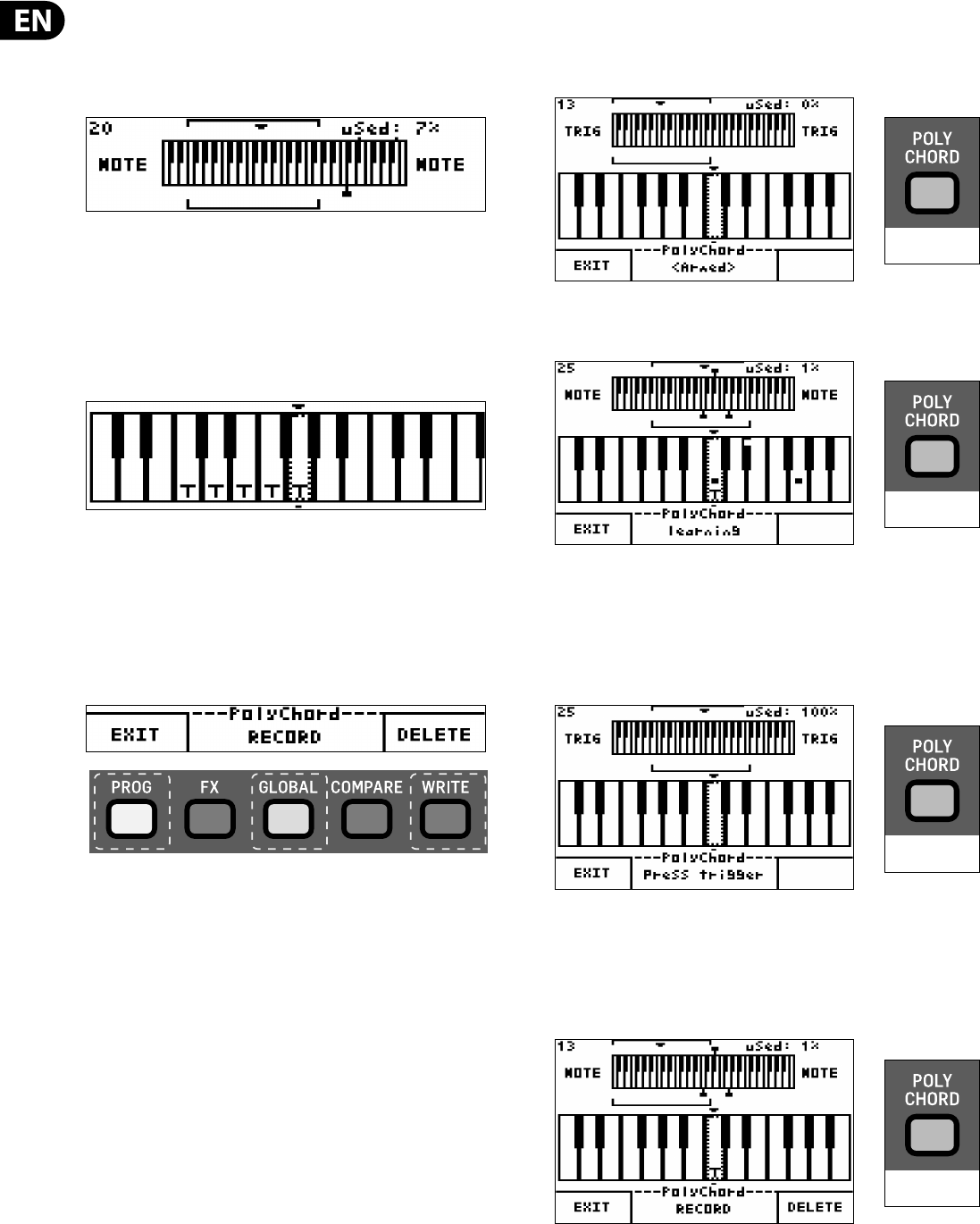
38 DeepMind 12 User Manual
8.1.2 POLY CHORD SWITCH
The DeepMind 12 POLY CHORD switch allows you to program multiple chords to
memory. The chords can be assigned to any of the 49 physical keys.
POLY CHORD SCREEN UPPER SECTION
On the upper section of the POLY CHORD screen there is a visual representation
of the four physical octaves of the keyboard. The words next to the keyboard
describe what is shown (NOTE or TRIG). The bracket shows the zoom position for
the lower section. The number in the top left hand corner shows the MIDI note
number. The number in the top right hand corner indicates how much of the
available memory has been used.
POLY CHORD SCREEN LOWER SECTION
On the lower section of the POLY CHORD screen there is a visual representation
of the keyboard which is zoomed to the two octaves represented by the vertical
brackets on the top section. The letter T is shown on all trigger keys, i.e. the
keys which are programmed to play a chord when pressed. The small indicator
dots on the keys show the currently played notes in the selected chord or during
recording.
POLY CHORD SCREEN SOFT KEYS
At the bottom of the POLY CHORD page you will see three areas which indicate
the software function of the PROG, GLOBAL and WRITE switches.
PROG switch - Always performs the EXIT function and returns you to the
PROG screen.
GLOBAL switch - Used to RECORD (add or overwite) a new POLY CHORD.
Otherwise the area above the switch is used to show the status of the POLY
CHORD programming function i.e. Armed, Learning, or Press Trigger.
WRITE switch - Used to DELETE a chord, but only once a chord is programmed
(otherwise this area will be blank and the switch will not be illuminated) Note:
The CHORD is stored in persistent memory and will be retained through a power
cycle.
Note: The CHORD memory can also be cleared using the bootloader menu
described later in this document.
POLY CHORD PROGRAMMING - To program a chord, press the POLY CHORD
switch (or the RECORD switch if replacing or adding an existing chord). The POLY
CHORD switch will begin double ashing and you will then see the screen with
the message "Armed" as shown below :
While the message "Armed" is shown, hold the keys of the chord down and you
will then see the screen with the message "Learning" below:
At this point you can add additional notes to the chord. Once you have all the keys
required held down simultaneously you can release them all. The chord will then
be ready to be assigned and the POLY CHORD switch will ash slowly.
Note: The POLY CHORD size is limited to 12 notes.
You will see a message to "Press Trigger" as shown below:
Now press the root note key for the chord to be assigned to. Once you press a key,
the chord you played will be assigned to that key. The POLY CHORD switch will
then stay illuminated (no ashing) and the POLY CHORD mode will be active for
the entire keyboard (including any OCTAVE shift applied).
The screen will now show the following:
Now playing any of the trigger keys will play the chords assigned to the
respective keys.
2X FLASHING FAST
2X FLASHING FAST
FLASHING SLOW
ILLUMINATED
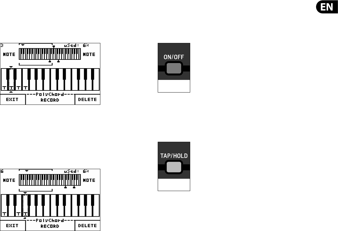
39 DeepMind 12 User Manual
RECORDING / ADDING A NEW POLY CHORD - To record/add a new chord , press
the RECORD soft switch. You will see now see the message "Armed" indicating
that the synthesizer is ready to program a new CHORD.
Each of the keys which have been assigned to trigger a chord, will be marked
with the letter T as shown below:
DELETING A POLY CHORD - To delete a chord you rst need to select the trigger
key. This can be done using the rotary knob, the -/NO and +/YES switches, or by
pressing the trigger key for the chord you wish to delete.
The selected key will be highlighted by a dotted line as shown above. When the
key is selected press the DELETE soft switch. The chord will be deleted and the
letter T will no longer be shown. You will also see the message "Armed"
indicating that the synthesizer is ready to record a new CHORD.
EXITING THE POLY CHORD SCREEN - Press the EXIT soft switch to exit the POLY
CHORD page. This will return you to the PROG screen but POLY CHORD mode will
still be active and the POLY CHORD switch will be illuminated.
EXITING POLY CHORD MODE - Press the POLY CHORD switch again to turn o
POLY CHORD MODE, the switch will no longer be illuminated.
Note: In POLY CHORD mode you can play a sequence of chords using the trigger
keys while playing individual notes using unassigned keys.
Note: You can use the rotary knob and/or the -NO and +/YES switches to scroll
the zoomed view up and down the keyboard. This is useful when you want to see
any playing notes which are outside of the current zoom position.
Note: When the keyboard local control is on, all chords will be sent to any
connected devices. When keyboard local control is o only the trigger note
will be sent to any connected devices. When the trigger notes are received the
DeepMind 12 will play respective chords based on incoming trigger notes.
Note: The number of POLY CHORDs you can program is limited, depending on the
number of notes used in each POLY CHORD. There is enough space for 216 notes,
e.g. 36 x 6 note POLY CHORDs.
8.1.3 ARP ON/OFF SWITCH
The ON/OFF switch in the ARP/SEQ section turns the ARPEGGIATOR function ON
and OFF. When the ARPEGGIATOR is switched ON and you hold down one or more
keys the ARPEGGIATOR will start playing. When you release all keys the
ARPEGGIATOR will stop playing.
Note: The ON/OFF switch only a ects the ARPEGGIATOR, it does not a ect the
CONTROL SEQUENCER.
The default ON/OFF setting is OFF.
8.1.4 TAP/HOLD SWITCH
The TAP/HOLD switch has two functions:
TAP - When you strike the TAP switch successively the DeepMind 12 will calculate
the Master BPM value from the tempo of your tapping. After 5 taps the BPM will
update to the tempo of your tapping.
The BPM is calculated on an average of the last 5 taps, so you can continue
tapping until you feel the displayed tempo is correct.
Note: If you are using an external sync source the TAP/HOLD switch will ash at
the rate of the external source.
The supported TAP TEMPO range for both internal and external sources is from
20.0-275.0 BPM
HOLD - When you press and hold the TAP/HOLD switch for more than 1 second,
the switch is illuminated and HOLD mode is active. In this mode when you press
any key it will be held on and the ARPEGGIATOR will continue playing.
If you press a key and hold it down, you can add other notes to the ARPEGGIATOR.
Once you release all keys the ARPEGGIATOR will continue to play until you press
another key.
Note: The HOLD switch can also be used without the ARPEGGIATOR function.
When the ARPEGGIATOR is o and the HOLD switch is pressed it will hold and
played notes in their SUSTAIN phase of all ENVELOPEs. This can be useful during
sound design when you want to work on the sustained content of a program and
operate the surface controls with both hands.
To turn HOLD mode o press and hold the TAP/HOLD switch again for more than 1
second, the switch is no longer illuminated and HOLD mode is no longer active.
The default HOLD setting is OFF.
ARPEGGIATOR
ON/OFF
TAP=FLASH
HOLD=ON
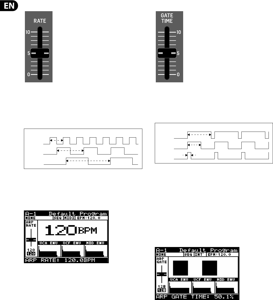
40 DeepMind 12 User Manual
8.1.5 ARP RATE FADER
The RATE fader controls the Master BPM RATE of the ARPEGGIATOR. The Master
BPM is used by the ARPEGGIATOR, CONTROL SEQUENCER and is also used in any
parameters which can be linked to the Master BPM, such as the LFO, Envelopes
and some E ect parameters.
Decreasing the value will make the Master BPM RATE slower, and increasing the
value will make the Master BPM rate faster as shown below:
The Master BPM RATE range is from 20.0 to 275.0 BPM. The default Master BPM
RATE value is 120.0 BPM.
The fader position, current value and stored value for the ARP RATE fader is
shown on the PROG screen. There is also a visualization of the ARP RATE as
shown below:
8.1.6 ARP GATE TIME FADER
The GATE TIME fader controls the length of the note as shown below.
With the fader in the middle position, the GATE TIME is equally split so that the
note length is exactly half of a step. Decreasing the value will make the GATE
TIME shorter, and increasing the value will make the GATE TIME longer as shown
below:
Note: The GATE TIME FADER on the front panel, and the GATE TIME PARAMETER in
the PATTERN EDITOR both a ect the length of the notes.
With the GATE TIME FADER at maximum the note length matches the full length
of the PATTERN GATE TIME.
When the GATE TIME fader is in the middle then the note length is half of the
PATTERN GATE TIME.
The GATE TIME range is from 0 to 255, with 0 being no note and 255 being a full
note. The default GATE TIME value is 128, which represents half of a step.
The fader position, current value and stored value for the ARP GATE TIME fader is
shown on the PROG screen. There is also a visualization of the ARP GATE TIME
period, using the width of two consecutive notes as shown below:
FAST
MED
SLOW
MASTER BPM (RATE) LONG
EQUAL
SHORT
GATE TIME
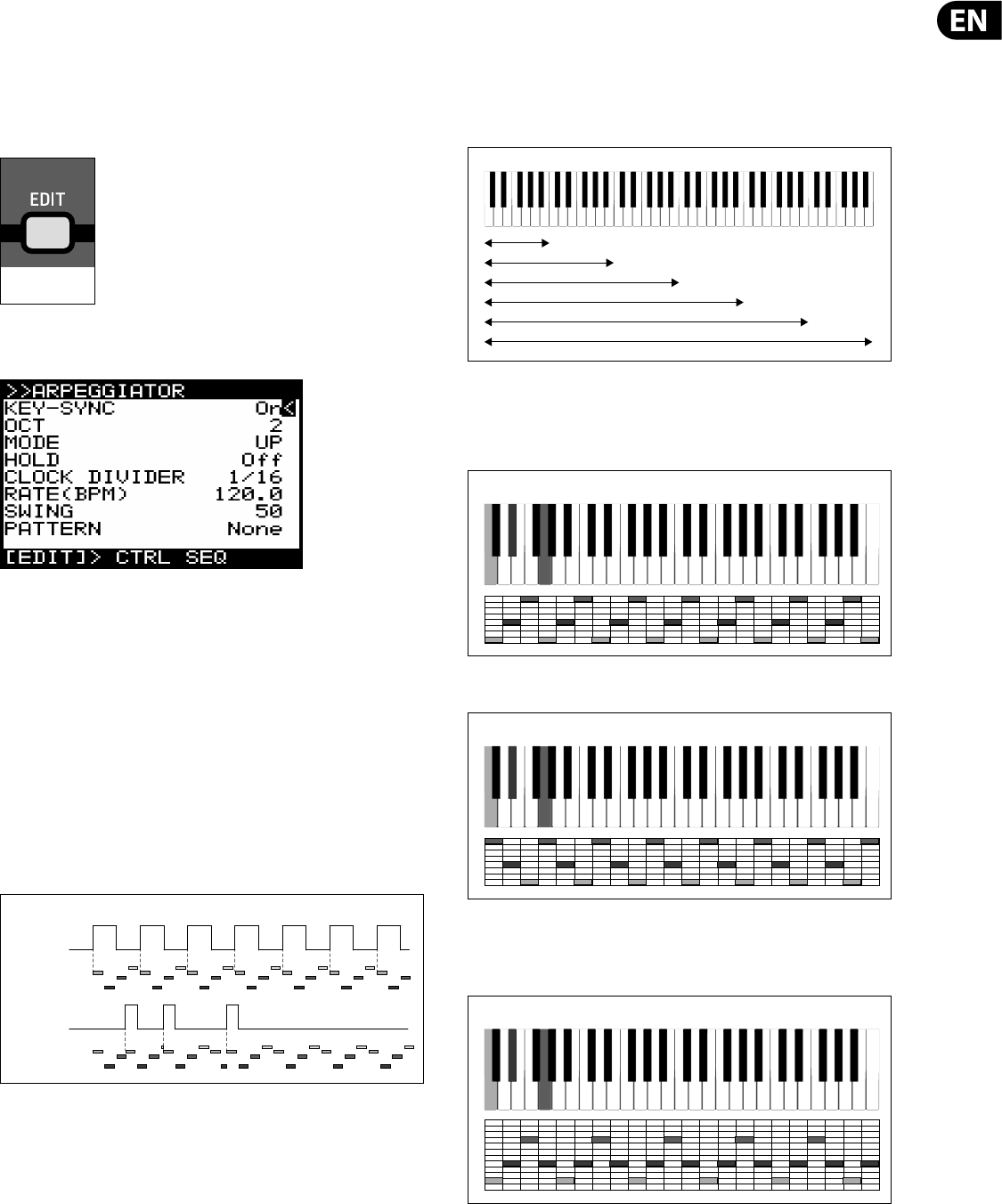
41 DeepMind 12 User Manual
8.1.7 EDIT ARP/SEQ SWITCH
The DeepMind 12 ARPEGGIATOR allows you to play a pattern of notes based on
the individual keys being held. This section covers in detail all the parameters
related to the ARPEGGIATOR.
To enter the EDIT page for the ARPEGGIATOR & CONTROL SEQUENCER press the
EDIT switch.
The EDIT switch will then start ashing and the ARPEGGIATOR menu will
then appear:
Note: In the ARP/SEQ EDIT menu there are three pages (ARPEGGIATOR, CONTROL
SEQUENCER and SYNC SETTINGS). This section covers the ARPEGGIATOR menu. To
cycle through the pages use consecutive presses of the EDIT switch. The bottom
line of the screen will show guidance to the next page.
To navigate the options in the ARPEGGIATOR menu, use the UP, DOWN, switches.
Selected parameters are adjusted using the -NO/+YES switches, the rotary knob
or the fader. The rotary knob has a click which allows very accurate control. The
fader allows rapid adjustment across the full range.
KEY SYNC - This option allows you to turn KEY-SYNC (Key Synchronisation) On and
O . When KEY-SYNC is On, the arpeggiator will start playing at soon as you strike
the rst note (when no keys are pressed). When KEY-SYNC is O , the arpeggiator
will start playing using the Master BPM (internal or external) and ARP CLOCK
(after division) as its timing source. The default value is O .
OCT - This option allows you to choose how many OCTAVES the ARPEGGIATOR will
cycle through. The OCTAVE range is from 1 to 6. If you only choose one OCTAVE
the ARPEGGIATOR will simply cycle the notes based on the root note and the
MODE. If you choose more than one OCTAVE the ARPEGGIATOR will cycle through
the notes/MODEs for each OCTAVE sequentially.
The default value is 2 OCTAVES.
MODE - This option allows you to select the note order for the arpeggiator from
one of the options below:
•
• UP - Notes are played from the lowest to the highest, then repeated.
•
• DOWN - Notes are played from the highest to the lowest, then repeated.
•
• UP-DOWN - Notes are played from the lowest to the highest, then from the
highest to the lowest, then repeated. There is no repetition at the highest
and lowest notes.
FLASHING=EDIT
ARP CLOCK
KEY PRESS
ARP NOTES
(KEY SYNC OFF)
ARP NOTES
(KEY SYNC ON)
ARPEGGIATOR KEY SYNC
1 OCTAVE
2 OCTAVES
3 OCTAVES
4 OCTAVES
5 OCTAVES
6 OCTAVES
ARPEGGIATOR OCTAVES
ARPEGGIATOR MODE - UP
ARPEGGIATOR MODE - DOWN
ARPEGGIATOR MODE - UP/DOWN
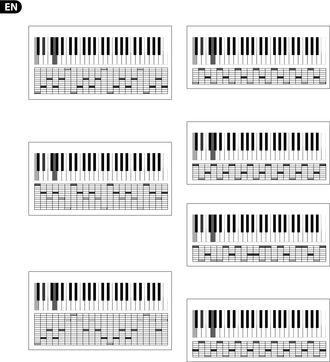
42 DeepMind 12 User Manual
•
• UP-INV - Notes are played from the lowest to the highest, then the chord is
inverted and the notes are played from the lowest to the highest. This is then
repeated. There is no repetition at the highest and lowest notes.
•
• DOWN-INV - Notes are played from the highest to the lowest, then the
chord is moved to its 2nd inversion and lowered one octave then the notes
are played from the highest to the lowest. This is then repeated. There is no
repetition at the highest and lowest notes.
•
• UP-DN-INV -Notes are played from the lowest to the highest, then the chord
is moved to its 1st inversion and the notes are played from the lowest to the
highest. Next the chord is moved to its 2nd inversion and the notes are
played from the highest to the lowest. Then the chord is moved back to the
1st inversion and the notes are played from the highest to the lowest. This is
then repeated. There is no repetition at the highest and lowest notes.
•
• UP-ALT - Notes are played as lowest, then highest, then next lowest, then
next highest and so on until the notes have all been played. This is then
repeated. There is no repetition at the highest and lowest notes.
•
• DOWN-ALT - Notes are played as highest, then lowest, then next highest,
then next lowest and so on until the notes have all been played. This is then
repeated. There is no repetition at the highest and lowest notes.
•
• RAND - The notes are played at random.
•
• AS PLAYED - The notes are played by the ARPEGGIATOR in the order that you
play the notes. This is then repeated. There is no repetition at the highest
and lowest notes.
ARPEGGIATOR MODE - UP/INV
ARPEGGIATOR MODE - DOWN/INV
ARPEGGIATOR MODE - UP/DOWN/INV
ARPEGGIATOR MODE - UP/ALT
ARPEGGIATOR MODE - DOWN/ALT
ARPEGGIATOR MODE - RANDOM
ARPEGGIATOR MODE - AS PLAYED
123
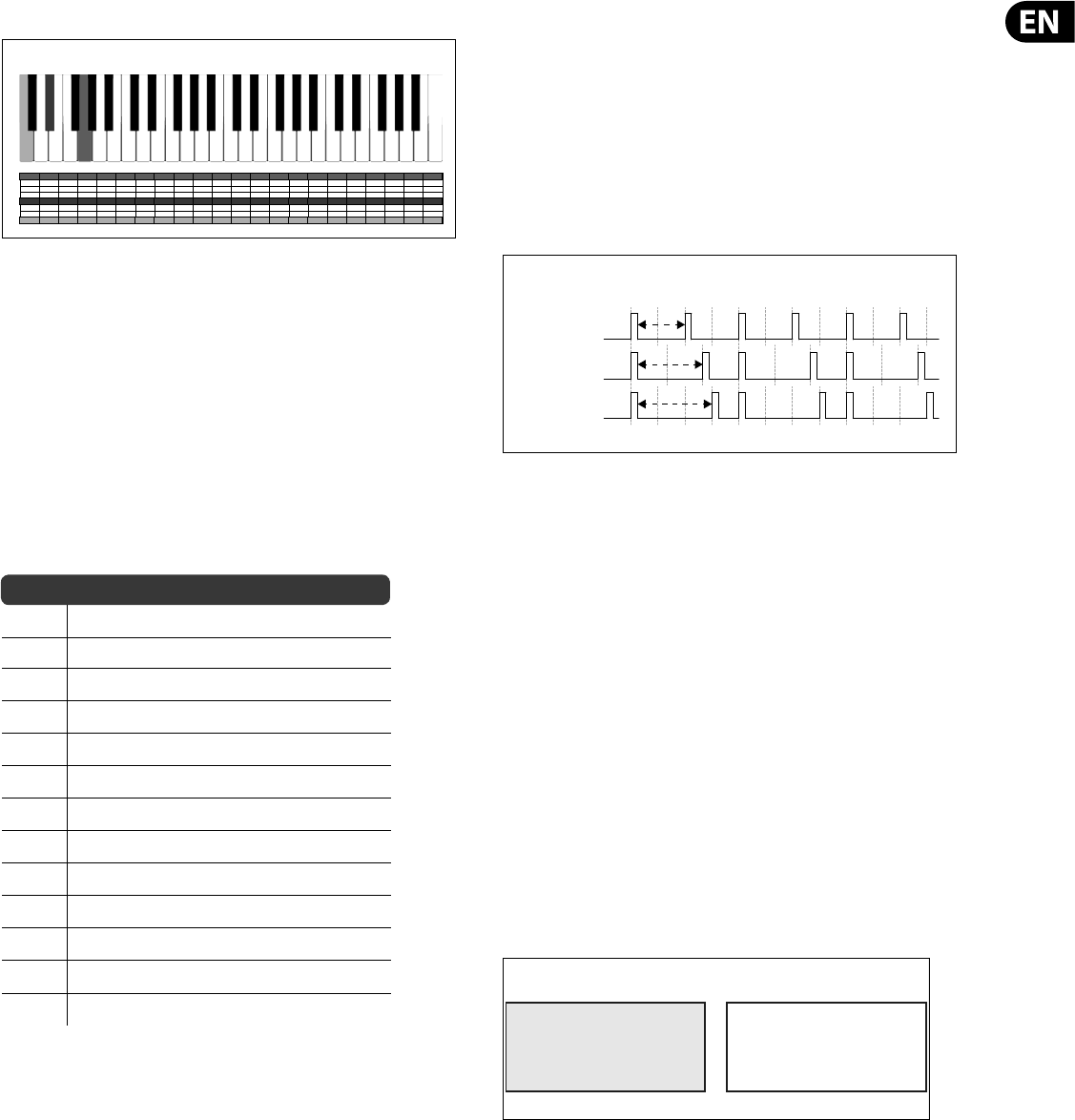
43 DeepMind 12 User Manual
•
• CHORD -The notes are played together for each step of the ARPEGGIATOR.
The default mode of the ARPEGGIATOR is UP.
HOLD - This option is the same as the HOLD switch on the surface when the
ARPEGGIATOR is switched on. The switch will follow any changes made here, and
changes on the surface will be re ected here. The default HOLD mode is OFF.
CLOCK DIVIDER - This option allows you divide the Master BPM in a number of
ways to produce the ARPEGGIATOR CLOCK.
Note: When the SUSTAIN input is set to any of the GATE modes in the PEDAL
SETTINGS the value will be replaced by "(Gate)" to indicate that the CLOCK
DIVIDER is not used and the ARPEGGIATOR notes are controlled by the GATE input.
You can select one of the division modes from the list below:
Note: For a timing diagram please consult the section later in this document.
RATIO DESCRIPTION
1/2 Half note
3/8 Dotted quarter note
1/3 Third note (Half note triplets)
1/4 Quarter note
3/16 Dotted eighth note
1/6 Sixth note(Quarter note triplets)
1/8 Eighth note
3/32 Dotted sixteenth note
1/12 Twelfth note (Eighth note triplets)
1/16 Sixteenth note
1/24 Twenty-fourth note (Sixteenth note triplets)
1/32 Thirty-second note
1/48 Forty-eighth note (Thirty-second note triplets)
The default value is 1/16 (sixteenth note).
RATE(BPM) - This option is the same as the RATE fader on the surface. Any
changes on the surface will be re ected here.
The Master BPM RATE range is from 20.0 to 275.0 BPM. The default RATE value is
120.0 BPM.
Note: When the SUSTAIN input is set to any of the GATE modes in the PEDAL
SETTINGS the value will be replaced by "(Gate)" to indicate that the RATE is not
used and the ARPEGGIATOR notes are controlled by the GATE input.
SWING - This option allows you to adjust the swing (or groove) of the
ARPEGGIATOR.
When applying SWING, every other step is delayed by an amount set by the
swing value. The swing value represents the ratio of time between two steps. I.e.
When the swing is at 50% there will be equal timing between the steps. When
wanting to adjust the SWING timing to fall where a triplet would, you should set
the SWING to 66%.
You can use the SWING parameter to add timing element which can help create
propulsive rhythms, or laid back styles which can help give the sequence of notes
movement, or allow it to breath, or make room for other parts of the mix.
The SWING RATE range is from 50 to 75. The default SWING value is 50.
Note: When the SUSTAIN input is set to any of the GATE modes in the PEDAL
SETTINGS the value will be replaced by "(Gate)" to indicate that the SWING is not
used and the ARPEGGIATOR notes are controlled by the GATE input.
PATTERN - The ARPEGGIATOR has a looping PATTERN function which can
dynamically control the VELOCITY and GATE TIME values for each step.
When the ARPEGGIATOR starts playing and a PATTERN is selected, the VELOCITY
and GATE TIME values from the PATTERN editor will be applied to the notes of
the ARPEGGIATOR. The PATTERN will continue to cycle while the ARPEGGIATOR is
playing.
You can set the PATTERN LENGTH to match the ARPEGGIATOR notes, or use a
di erent PATTERN LENGTH to create variations and movement. E.g. When using
DOWN-INV 6 notes are played during each cycle of the ARPEGGIATOR. With a
PATTERN LENGTH setting of 4, you will hear the pattern moving through the
ARPEGGIATOR cycle.
The pattern editor has 32 xed "Preset Patterns" allowing you to start using the
patterns quickly and 32 "User Patterns" so that you can store your own unique
patterns. The patterns can be up to 32 steps long allowing a large range of
creative possibilities.
ARP PATTERN SELECTION - To select an ARPEGGIATOR PATTERN, make sure that
the '<' symbol on the PATTERN line is highlighted. The default setting is O , to
select a PATTERN (Preset or User) use the rotary knob, or the fader.
ARPEGGIATOR MODE - CHORD
NO SWING (50%)
TRIPLET SWING (66%)
SWING SETTING
FULL SWING (75%)
Pattern Memory
Preset Patterns 1-32 User Patterns 1-32
Locked - Can be edited but not overwritten Can be edited and saved
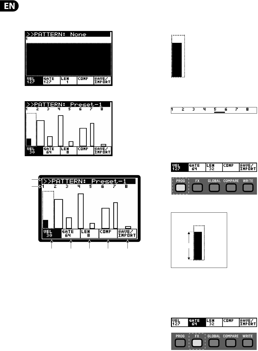
44 DeepMind 12 User Manual
ARP PATTERN EDITING - To use the PATTERN EDITOR make sure that the '<'
symbol on the PATTERN line is highlighted. Then press the +/YES switch and the
PATTERN EDITOR will then be displayed.
If no PATTERN is selected it will look like this:
If a PATTERN is selected it will look something like this:
The controls for the PATTERN EDITOR are as follows:
Note: The parameter being edited is selected using the switches directly under
the tabs at the bottom of the screen.
(1) PATTERN NAME - The PATTERN name is displayed at the top of the screen.
The pattern can be changed by pressing the -NO/+YES switches.
Note: If a PATTERN is edited a * will be displayed by its name to indicate that
editing has been done and is not yet saved.
Note: Navigating away from edited pattern allows you to return to it
without losing changes. However, if you begin to edit a di erent pattern,
your edits to the original PATTERN will be lost.
(2) STEP INDICATORS - The STEP values are shown at the top of the screen. The
current step can be selected using the rotary knob, each click will move the
selection forward or backward one step. The current step number is
displayed in the header and the step is highlighted in black and indicated
using a dotted rectangle.
Note: When the ARPEGGIATOR is ON and running, you will see a PATTERN
POSITION POINTER (PPP) under the step being played. The PPP is a small
black bar which is updated in real-time.
Note: To duplicate steps, start by. selecting the step to duplicate, hold the
PROG switch then navigate to the target step and release the PROG switch.
(3) VELOCITY - The VELOCITY of each step is shown by the height of the bar
within the step. To adjust the velocity for a step, press the PROG switch
(under the VEL text) to enter VELOCITY editing mode. When you are in
VELOCITY editing mode the virtual switch will be reversed (white on black).
The height of the bar indicates the current velocity setting.
The VELOCITY for each step can then be changed by using the UP/DOWN switches
or using the data entry fader.
(4) GATE - The GATE TIME of each is shown by the width of the bar within each
step. To adjust the GATE TIME for a step, press the FX switch (under the GATE
text) to enter GATE TIME editing mode. When you are in GATE TIME editing
mode the virtual switch will be reversed (white on black).
(
2)
(3) (7)(4) (5) (6)
(1)
VELOCITY
PATTERN STEP VELOCITY
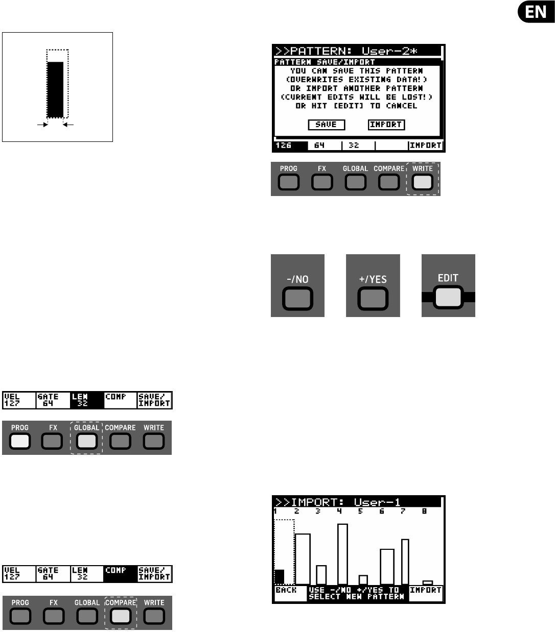
45 DeepMind 12 User Manual
The GATE TIME for each step can then be changed by using the UP/DOWN
switches or using the data entry fader.
Note: To tie steps start by selecting the step you want to tie to the next one,
hold the FX switch, then turn rotary knob clockwise. You can tie several steps
together by continuing to rotate the rotary knob without having to release
the FX switch. To remove the tie, select the note that is tied to previous, hold
FX switch, turn rotary knob anti-clockwise. You can also do this with several
steps in the same way as creating a tie.
Note: The GATE TIME FADER on the front panel, and the GATE TIME
PARAMETER in the PATTERN EDITOR both a ect the length of the notes.
With the GATE TIME FADER at maximum the note length matches the full
length of the PATTERN GATE TIME.
With the GATE TIME fader is in the middle then the note length is half of the
PATTERN GATE TIME.
(5) LENGTH - To adjust the LENGTH of the pattern (the number of steps), press
the GLOBAL switch (under the LEN text) to enter LENGTH editing mode.
When you are in LENGTH editing mode the virtual switch will be reversed
(white on black).
The LENGTH of the PATTERN can then be changed by using the UP/DOWN
switches or using the data entry fader.
(6) COMP - This switch allows you to COMPARE the current status of the
PATTERN being edited against the stored PATTERN. To use the PATTERN
COMPARE function, press the COMPARE switch (under the COMP text) to
enter COMPARE mode. When you are in COMPARE mode the virtual switch
will be reversed (white on black).
Note: The COMP switch is only available when a USER PATTERN is selected.
(7) SAVE/IMPORT -This switch allows you to SAVE the current PATTERN, or
IMPORT a PATTERN. When you press the WRITE switch (under the SAVE/
IMPORT text) you will be presented with two options:
You can now use the -/NO and +/YES switches to select SAVE or IMPORT, or
the EDIT ARP/SEQ switch to exit the dialog. All three switches will ash to
show that they are the available options:
SAVE - This will save your edits into the currently selected location. This will
overwrite the PATTERN stored in the current location.
Note: You can only SAVE into USER PATTERN locations, as the PRESET
PATTERNS are protected.
IMPORT - Selecting IMPORT will open a read only version of the PATTERN
EDITOR page, so that you can preview the pattern which will be imported
into the current location. Parameters cannot be edited in this page.
To select a PATTERN to IMPORT use the -/NO and +/YES switches. To IMPORT a
PATTERN press the WRITE switch (under the IMPORT text). To cancel the IMPORT,
press the PROG switch (under the BACK text).
CANCEL - This will cancel the SAVE/IMPORT function and return you to the
PATTERN EDITOR.
Note: The SAVE/IMPORT switch is only available when a USER PATTERN is
selected.
GATE TIME
PATTERN STEP GATE TIME
NO=SAVE YES=IMPORT EDIT=CANCEL
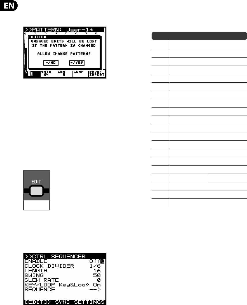
46 DeepMind 12 User Manual
Note: If you have edited a PATTERN and then go to select another PATTERN
without saving your changes you will be presented with a warning message that
unsaved edits will be lost. You can press +/YES to allow the change, or -/NO to
cancel the change.
To exit the PATTERN page press the ARP/SEQ EDIT switch to return to the main
ARPEGGIATOR/CONTROL SEQUENCE/SYNC SETTINGS menu.
To exit the ARPEGGIATOR/CONTROL SEQUENCE/SYNC SETTINGS menu press the
EDIT switch again (or press the PROG switch) to return the main display.
8.1.8 EDIT CTRL SEQUENCER
The CONTROL SEQUENCER allows you to create a pattern which can be used to
modulate other parameters. This section covers in detail all the parameters
related to the CONTROL SEQUENCER.
For more information on using the CONTROL SEQUENCER as a modulation source
please consult the MOD MATRIX section later in this document.
To enter the EDIT page for the ARPEGGIATOR & CONTROL SEQUENCER press the
EDIT switch.
In the ARP/SEQ EDIT menu there are three pages, this section covers the CONTROL
SEQUENCER menu. To cycle through the pages use consecutive presses of the EDIT
switch. The bottom line of the screen will show guidance to the next page.
To access the CONTROL SEQUENCER menu directly you can press the ARP/SEQ EDIT
switch twice. The CONTROL SEQUENCER menu is then shown:
To navigate the options in the CONTROL SEQUENCER menu, use the UP, DOWN,
switches.
Selected parameters are adjusted using the -NO/+YES switches, the rotary knob
or the fader. The rotary knob has a click which allows very accurate control. The
fader allows rapid adjustment across the full range.
ENABLE - This option turns the CONTROL SEQUENCER function On and O .
CLOCK DIVIDER - This option allows you divide the Master BPM in a number
of ways to produce the CONTROL SEQUENCER CLOCK. You can select any of the
options from the following table:
Note: For a timing diagram please consult the section later in this document.
RATIO DESCRIPTION
4Four bars
3Three bars
2Two bars
1One bar
1/2 Half note
3/8 Dotted quarter note
1/3 Third note (Half note triplets)
1/4 Quarter note
3/16 Dotted eighth note
1/6 Sixth note(Quarter note triplets)
1/8 Eighth note
3/32 Dotted sixteenth note
1/12 Twelfth note (Eighth note triplets)
1/16 Sixteenth note
3/64 Dotted thirty-second note
1/24 Twenty-fourth note (Sixteenth note triplets)
1/32 Thirty-second note
3/128 Dotted sixty-fourth note
1/48 Forty-eighth note (Thirty-second note triplets)
1/64 Sixty-fourth note
The default value is 1/16.
Note: When the SUSTAIN input is set to any of the GATE modes in the PEDAL
SETTINGS the value will be replaced by "(Gate)" to indicate that the CLOCK
DIVIDER is not used and the CONTROL SEQUENCER steps are controlled by the
GATE input.
LENGTH - This option allows you to adjust the length (number of steps) of the
CONTROL SEQUENCE. This can also be adjusted within the SEQUENCE EDITOR.
The default value is 6.
SWING - This option allows you to adjust the swing (or groove) of the CONTROL
SEQUENCER.
When applying SWING, every other step is delayed by an amount set by the swing
value. The swing value represents the ratio of time between two steps. I.e. When
the swing is at 50% there will be equal timing between the steps. When wanting
to adjust the SWING timing to fall where a triplet would, you should set the
SWING to 66%.
You can use the SWING parameter to add timing element which can help create
propulsive rhythms, or laid back styles which can help give the sequence of notes
movement, or allow it to breath, or make room for other parts of the mix.
The SWING RATE range is from 50 to 75. The default SWING value is 50.
Note: When the SUSTAIN input is set to any of the GATE modes in the PEDAL
SETTINGS the value will be replaced by "(Gate)" to indicate that the SWING is not
used and the CONTROL SEQUENCER steps are controlled by the GATE input.
FLASHING=EDIT
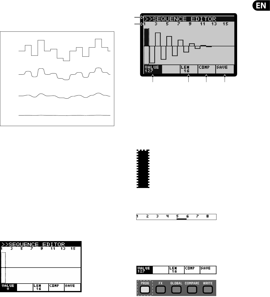
47 DeepMind 12 User Manual
SLEW-RATE - This option allows you to adjust the SLEW RATE of the CONTROL
SEQUENCER. The SLEW RATE is the rate at which the value changes from one step
to the next. With a high slew rate you will get a sloped transition between steps,
and with a SLEW RATE of 0, you will get an instantaneous change from one step
to the next.
The SLEW RATE range is from 0-255, with 0 being no change and 255 full
smoothing.
The default SLEW RATE setting is 0.
KEY/LOOP - The KEY/LOOP mode controls how the CONTROL SEQUENCER looping
and key synchronisation operate. The choices are as follows:
•
• Loop On - This option makes the CONTROL SEQUENCE loop continuously
but does not restart when keys are pressed. This mode is useful when using
the CONTROL SEQUENCER in conjunction with the ARPEGGIATOR and the
SEQUENCE LENGTH is longer than the ARPEGGIATOR CLOCK DIVIDER.
•
• Key Sync On - This option will force the SEQUENCE to restart when a key is
pressed. Note in this mode the CONTROL SEQUENCER will not loop.
•
• Key&Loop On - This option makes the CONTROL SEQUENCE loop
continuously and also forces a reset when keys are pressed.
SEQUENCE EDITING - To use the SEQUENCE EDITOR make sure that the '<' symbol
on the SEQUENCE line is highlighted. Then press the +/YES switch and the
SEQUENCE EDITOR will then be displayed:
The controls for the SEQUENCE EDITOR are as follows:
Note: The parameter being edited is selected using the switches directly under
the tabs at the bottom of the screen.
(1) TITLE - The top bar shows the text "SEQUENCE EDITOR".
(2) STEP INDICATORS - The STEP values are shown at the top of the screen. The
current step can be selected using the rotary knob, each click will move the
selection forward or backward one step. The current step number is
displayed in header and the step is highlighted in black and indicated using a
dotted rectangle.
Note: When the CONTROL SEQUENCER is ON and running, you will see a
SEQUENCE POSITION POINTER (SPP) under the step being played. The SPP is a
small black bar which is updated in real-time.
Note: To duplicate steps start by selecting the step to duplicate, hold the
PROG switch, then navigate to target step and release the PROG switch.
(3) VALUE - The VALUE of each step is shown by the height of the bar within the
step. To adjust the value for a step, press the PROG switch (under the VALUE
text) to enter VALUE editing mode. When you are in VALUE editing mode the
virtual switch will be reversed (white on black).
0
85
170
CONTROL SEQUENCER SLEW RATE
255
(2)
(3) (4) (5) (6)
(1)
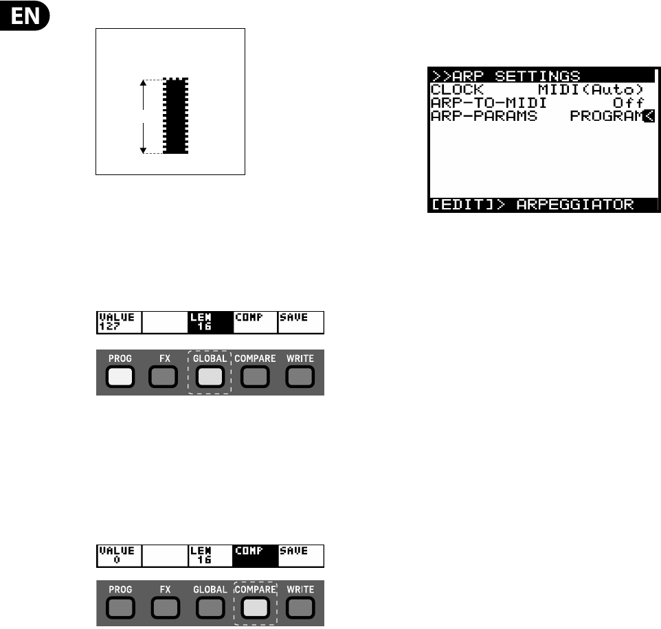
48 DeepMind 12 User Manual
The height of the bar indicates the current value setting.
The VALUE for each step can then be changed by using the UP/DOWN
switches or using the data entry fader.
(4) LENGTH - To adjust the LENGTH of the SEQUENCE (the number of steps),
press the GLOBAL switch (under the LEN text) to enter LENGTH editing mode.
When you are in LENGTH editing mode the virtual switch will be reversed
(white on black).
The LENGTH of the SEQUENCE can then be changed by using the UP/DOWN
switches or using the data entry fader.
(5) COMP - This switch allows you to COMPARE the current status of the
SEQUENCE being edited against the stored SEQUENCE. To use the SEQUENCE
COMPARE function, press the COMPARE switch (under the COMP text) to
enter COMPARE mode. When you are in COMPARE mode the virtual switch
will be reversed (white on black).
(6) SAVE -This switch takes you to the WRITE PROGRAM dialog (i.e. the normal
use of the WRITE switch).
To exit this menu press the ARP/SEQ EDIT switch to return to the main
ARPEGGIATOR/CONTROL SEQUENCE/ARP SETTINGS menu.
To exit the ARPEGGIATOR/CONTROL SEQUENCE/ARP SETTINGS menu press the
EDIT switch twice, (cycling past the ARP SETTINGS menu to exit), or press the
PROG switch to return the main display.
8.1.9 ARP SETTINGS
To access the ARP SETTING menu directly you can press the ARP/SEQ EDIT switch
three times. The ARP SETTINGS menu is then shown
To navigate the options in the SYNC SETTINGS menu, use the UP, DOWN, switches.
Selected parameters are adjusted using the -NO/+YES switches, the rotary knob
or the fader. The rotary knob has a click which allows very accurate control. The
fader allows rapid adjustment across the full range
CLOCK - This option allows you to select the Master BPM clock source for the
DeepMind 12 ARPEGGIATOR, CONTROL SEQUENCER, LFOs, ENVELOPEs and certain
time based FX parameters.
•
• Internal - The Master BPM clock is generated internally and uses the RATE
fader to control the tempo.
•
• MIDI (Auto) - The Master BPM clock is sourced from the MIDI IN socket and
uses the RATE fader to control the CLOCK DIVIDER. If no MIDI clock is present
at the MIDI IN socket, the DeepMind 12 will AUTO revert to the internally
generated clock.
•
• USB Auto - The Master BPM clock is sourced from the USB port and uses
the RATE fader to control the CLOCK DIVIDER. If no MIDI clock is present at
the USB port, the DeepMind 12 will AUTO revert to the internally generated
clock.
The default CLOCK setting is MIDI(Auto).
ARP-TO-MIDI - This option sends the notes played by the ARPEGGIATOR to all
MIDI sources. This allows you to record the ARPEGGIATOR note sequence.
The default ARP-TO-MIDI setting is O .
Note: When an external source (MIDI or USB) is used you can nudge the sync
point back and forward by using the -NO/+YES switches when "ARP RATE" is
selected in the ARPEGGIATOR menu. This allows you to o set the synchronisation
if required when working with other hardware/software and associated
latencies.
Note: Please ensure that you do not create any MIDI loops in your DAW MIDI
routing, as feeding back the ARPEGGIATOR notes will cause unpredictable results.
ARP-PARAMS - This option controls how the ARPEGGIATOR is linked.
•
• PROGRAM - In this mode the ARPEGGIATOR is stored with the program.
•
• GLOBAL - In this mode the ARPEGGIATOR keeps its current settings and
status even when you change programs. This can be useful for creating a
sequence and then browsing programs while the ARPEGGIATOR continues to
play the same notes/pattern/sequence.
Note: The CONTROL SEQUENCER remains una ected by this option.
Note: When switching from GLOBAL to PROGRAM mode, the current settings
are preserved and are used in place of the settings contained in the selected
program.
To exit the ARPEGGIATOR/CONTROL SEQUENCE/ARP SETTINGS menu press the EDIT
switch again (or press the PROG switch) to return the main display.
VALUE
SEQUENCE STEP VALUE
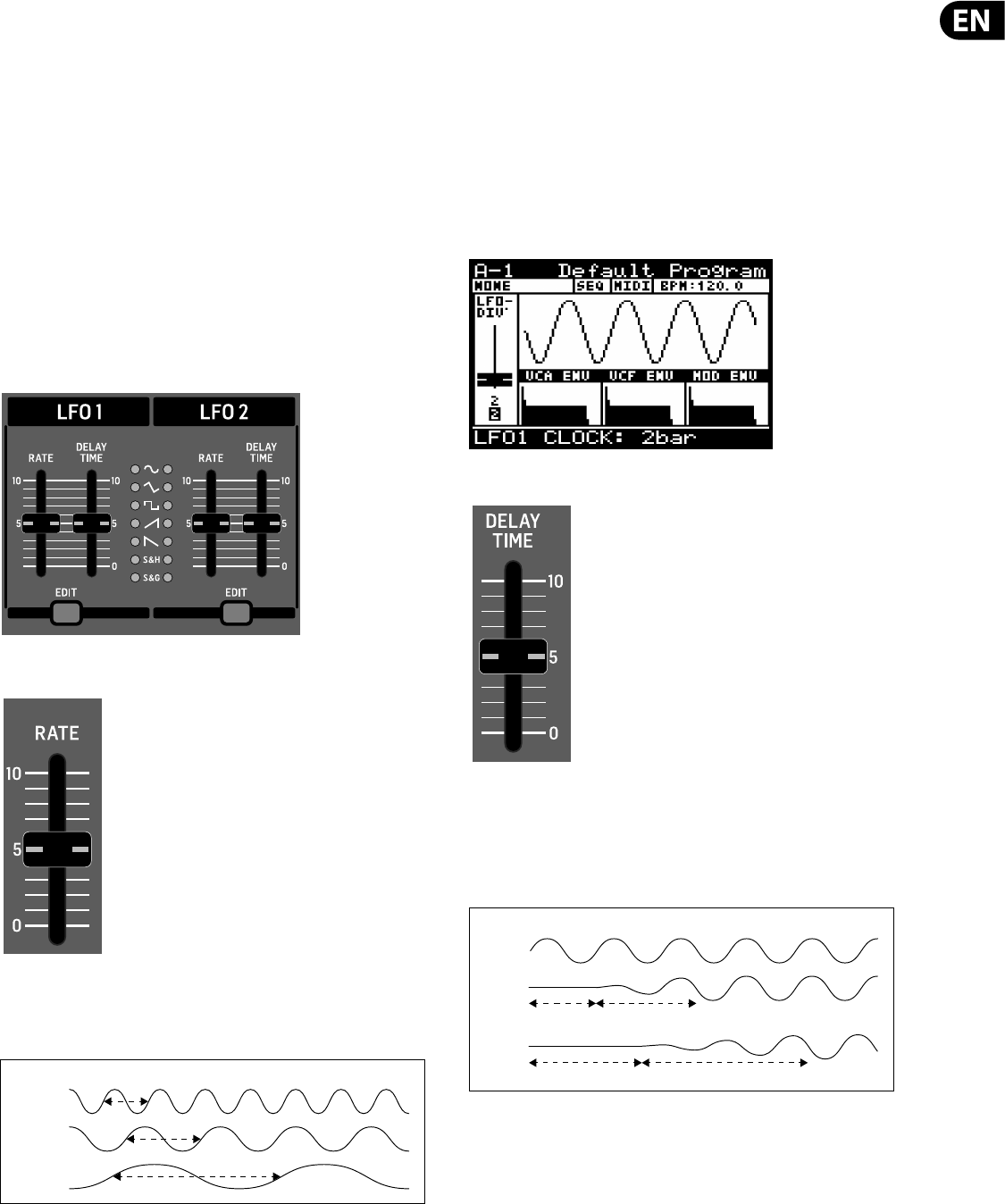
49 DeepMind 12 User Manual
8.2 LFO (1&2)
Note: The operation of LFO1 and LFO2 is identical and therefore only described
once in this section.
The Low Frequency Oscillator (LFO) creates signals which are used to modulate
or control other parameters. LFOs are traditionally used to add vibrato by
modulating the pitch, tremolo by modulating the amplitude or a ripple e ect
by modulating the lter cut o frequency. The DeepMind 12 LFO uses traditional
shapes such as sinusoidal and ramping, but also o ers advanced LFO shapes such
as sample and hold, and sample and glide.
The LFOs are also MOD MATRIX sources and can be applied to any of 130
destinations allowing for a huge amount of options to enhance your sound
design.
The LFOs can also be used to trigger any of the ENVELOPES, for more detail please
consult the ENVELOPE section later in this document.
The DeepMind 12 o ers an LFO speed which can reach into audio frequencies,
opening another door to creative modulation possibilities.
8.2.1 LFO RATE FADER
The LFO RATE fader controls the speed of the LFO.
Decreasing the value will make the LFO RATE slower, and increasing the value will
make the LFO RATE faster as shown below:
The LFO RATE range is from 0 to 255, with 0 being 0.041 Hz (24.1 s) and 255 being
65.4 Hz (15.3 ms) The default LFO RATE value is 0.
Note: The LFO RATE can extend beyond the rate set by the fader when the LFO1
RATE MOD MATRIX DESTINATION is modulated by a MOD MATRIX SOURCE. The
maximum rate when controlled via the MOD MATRIX is 1280 Hz. When the NOTE
NUMBER is used as the source for modulation you can create cross modulation
type e ects.
Note: When the ARP-SYNC is on, the LFO RATE fader no longer controls the RATE
directly but chooses a time division of the Master BPM RATE as described in the
EDIT LFO section.
The fader position, current value and stored value for the LFO RATE fader is shown
on the PROG screen. There is also a visualization of the waveform as shown
below:
8.2.2 LFO DELAY TIME FADER
The DELAY TIME fader controls the amount of delay before the LFO starts.
When the LFO waveform starts it is faded in over a period of time. If you think of
the time to reach the full LFO waveform as 100%, then 40% of that time is used
for the delay period where no waveform is produced and 60% of that time is used
for the fade duration.
The DELAY TIME range is from 0.00s to 6.59s. The default DELAY TIME value is
0.00s.
FAST
MED
SLOW
LFO RATE
NONE
MED
NO LFO FADE IN
NO LFO FADE IN
SLOW
LFO DELAY TIME
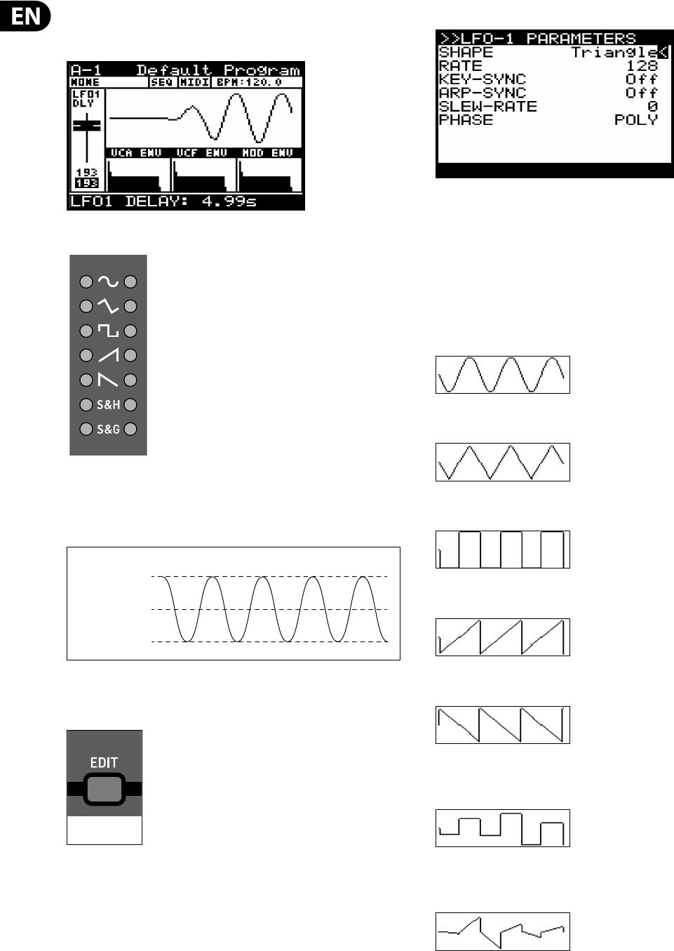
50 DeepMind 12 User Manual
The fader position, current value and stored value for the LFO DELAY TIME fader is
shown on the PROG screen. There is also a visualization of the waveform as
shown below:
8.2.3 LFO WAVEFORMS INDICATORS
The LFO waveform shape setting is always shown on the LEDs.
The LFO waveform shape in use will have an illuminated LED next to it.
The LED will glow to show the status of the waveform as shown below:
8.2.4 LFO EDIT MENU
To access the LFO EDIT menu press the LFO EDIT switch.
Shortcut Note: To change the LFO waveform shape press and hold the LFO EDIT
switch. While holding the switch you can use the LFO RATE fader to set the LFO
waveform shape.
The LFO EDIT switch will then start ashing and the LFO EDIT menu is then shown:
To navigate the options in the LFO EDIT menu, use the UP, DOWN, switches.
Selected parameters are adjusted using the -NO/+YES switches, the rotary knob
or the fader. The rotary knob has a click which allows very accurate control. The
fader allows rapid adjustment across the full range .
SHAPE - This option allows you to select one of the waveform shapes from the
following options (shown with their respective visualization waveforms from the
PROG display).
Sine - A mathematically correct sinusoidal waveform.
Triangle - A symmetrical triangular waveform.
Square - A symmetrical square waveform.
Ramp Up - An up ramping triangular waveform.
Ramp Down - An up ramping triangular waveform.
Smp&Hold (Sample and Hold) - A random stepped waveform which
transitions instantly from step to step.
Smp&Glide (Sample and Glide) - A random stepped waveform which glides
from step to step.
The default LFO SHAPE setting is Triangle.
FULL BRIGHTNESS
HALF BRIGHTNESS
OFF
LFO WAVEFORM INDICATORS
FLASHING=EDIT
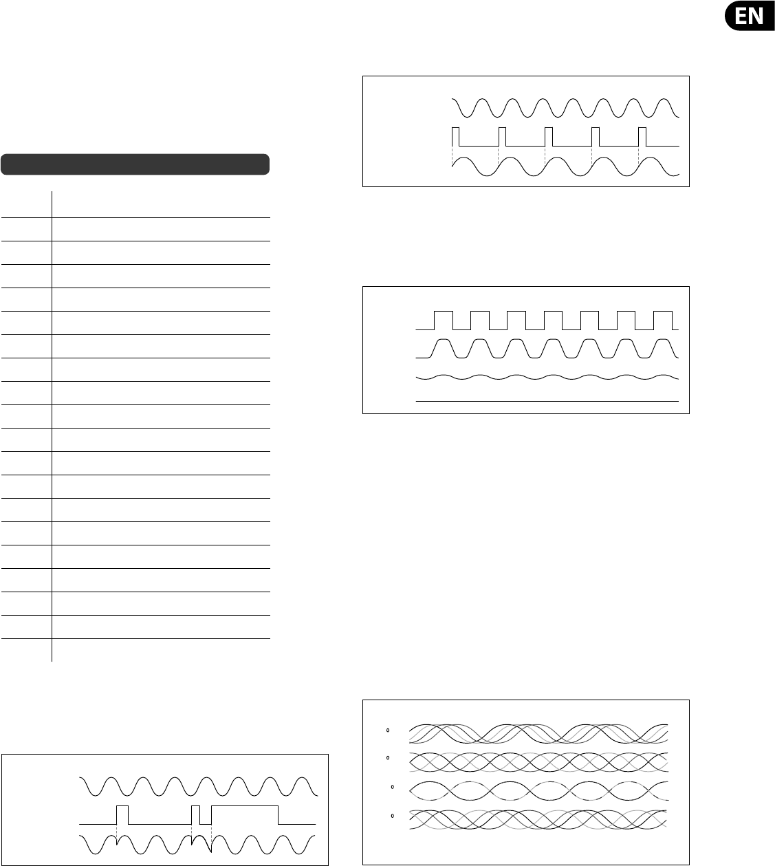
51 DeepMind 12 User Manual
RATE - This option is the same as the LFO RATE fader on the surface. Any changes
on the surface will be re ected here.
The LFO RATE range is from 0 to 255, with 0 being 0.05371 Hz (18.6 s) and 255
being 85 Hz The default LFO RATE setting is 0.
Note: When the ARP-SYNC is ON, the RATE parameter is not shown,
but CLOCK-DIVIDE instead. This shows values based on time division of the
Master BPM RATE as shown below:
Note: For a timing diagram please consult the section later in this document.
RATIO DESCRIPTION
4Four bars
3Three bars
2Two bars
1One bar
1/2 Half note
3/8 Dotted quarter note
1/3 Third note (Half note triplets)
1/4 Quarter note
3/16 Dotted eighth note
1/6 Sixth note(Quarter note triplets)
1/8 Eighth note
3/32 Dotted sixteenth note
1/12 Twelfth note (Eighth note triplets)
1/16 Sixteenth note
3/64 Dotted thirty-second note
1/24 Twenty-fourth note (Sixteenth note triplets)
1/32 Thirty-second note
3/128 Dotted sixty-fourth note
1/48 Forty-eighth note (Thirty-second note triplets)
1/64 Sixty-fourth note
KEY SYNC - This option allows you to turn KEY-SYNC (Key Synchronisation) On
and O . When KEY-SYNC is On, the LFO waveform generation will be reset as you
strike a note (keeping in mind the LFO DELAY TIME is also part of the waveform
generation). When KEY-SYNC is O , the LFO will free run.
The default KEY-SYNC setting is O .
ARP SYNC - This option allows you to turn ARP-SYNC (Arpeggiator
Synchronisation) On and O . When ARP-SYNC is On, the LFO waveform will
synchronize to the Master BPM. When ARP-SYNC is o the LFO will run at the rate
set by the LFO RATE fader/parameter.
The default ARP-SYNC setting is O .
SLEW-RATE - This option allows you to smooth out the transitions of the LFO
waveform. The SLEW RATE reduces the rate of change of the LFO waveform
shape.
The SLEW RATE range is from 0-255, with 0 being no change and 255 full
smoothing.
The default SLEW RATE setting is 0.
PHASE - As each voice has independent LFOs, this option allows you to control
the phase relationship between the LFO waveforms.
•
• POLY - All voices use an independent LFO. This is the default mode.
•
• MONO - All voices use a common LFO.
•
• SPREAD - With a setting of 1 there is a 1 degree shift between the LFOs for
each voice. As you begin to increase the SPREAD value the phase of the LFO
for each consecutive voice will be shifted by the amount of SPREAD applied.
I.e. with a 90 degree setting, the rst voice will always be at 0 degrees, and
each consecutive voice will be shifted by an additional 90 degrees. So with 4
voice UNISON, voice 1 would be at 0 degrees, voice 2 would be at 90 degrees,
voice 3 would be at 180 degrees and voice 4 would be at 270 degrees.
The PHASE range is from 1-254 degrees.
The default PHASE setting is POLY.
To exit the LFO EDIT menu press the EDIT switch again (or press the PROG switch).
to return the main display.
LFO (KEY SYNC OFF)
KEY GATE
LFO (KEY SYNC ON)
LFO KEY SYNC
LFO (ARP SYNC OFF)
ARP CLOCK
LFO (ARP SYNC ON)
LFO ARP SYNC
0
85
170
LFO SLEW RATE
255
45
90
180
225
LFO PHASE SPREAD (UNISON 4 SHOWN)
VOICE 1 LFO VOICE 2 LFO VOICE 3 LFO VOICE 4 LFO
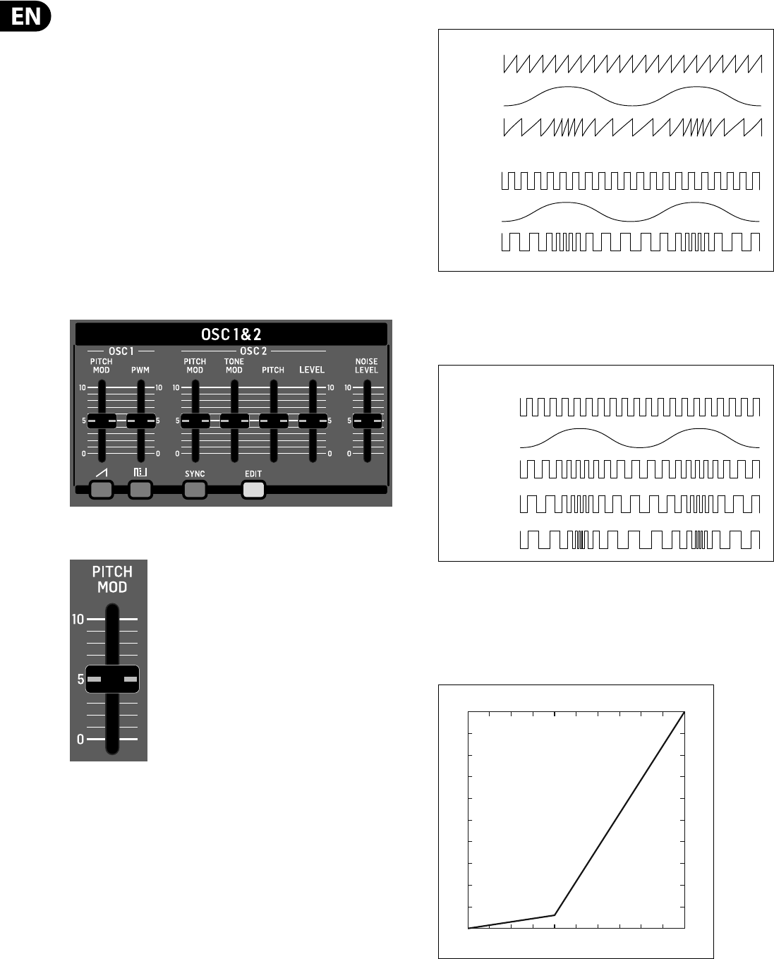
52 DeepMind 12 User Manual
8.3 OSC
The Oscillators (OSCs) have a completely analog implementation. The signal path
of the waveform is purely analog circuitry. The pitch of these analog oscillators
is controlled digitally to ensure superior tuning accuracy and stability across the
entire range of playable notes.
OSC 1 - This dual oscillator generates two di erent waveforms - one SAWTOOTH,
and one SQUARE. The waveforms can be used independently or together to create
harmonically rich content.
Features include pitch modulation of both the sawtooth and square waveforms,
and pulse width modulation of the square waveform.
OSC 2 - This single oscillator generates a SQUARE waveform.
Features include pitch o set, independent level control, pitch modulation and
tone control modulation of the square waveform.
NOISE - This generates a NOISE waveform. The NOISE generator is a completely
analog implementation and produces pink noise with a gentle roll o of
lower frequencies.
8.3.1 OSC 1 PITCH MOD FADER
The OSC 1 PITCH MOD fader controls the amount of PITCH MODULATION applied
to the OSC1 waveforms. The PITCH MODULATION SOURCE is selected in the OSC
EDIT page described later in this section. Pitch modulation is often used to create
a vibrato e ect, but can be used in many other ways. The range of modulation is
very wide, allowing both traditional and creative modulations.
Controlling the frequency using an external signal is a form of frequency
modulation (FM), however as FM is more commonly used to describe the
use of an audio oscillator modulating another audio oscillator the use of the
term PITCH MODULATION is preferred in this instance.
Note: Because the DeepMind 12 LFO can reach well into the audio range
(1280 Hz) it is possible to create traditional frequency modulation (FM) when the
LFO is used as the source for PITCH MODULATION of the OSCs.
The diagram below shows the waveforms obtained with LFO control of OSC 1:
As you increase the amount of PITCH MODULATION the variance in the pitch of
oscillator will increase resulting in larger increases and decreases as
demonstrated in the diagram below. The PITCH MODULATION will a ect both the
SAWTOOTH and SQUARE waveforms produced by OSC 1.
The OSC 1 PITCH MOD range is from 0.00cents to 36.0 semitones. The default OSC
1 PITCH MOD setting is 0.00cents.
The OSC 1 PITCH MOD fader has a non-linear response which gives more
resolution at smaller settings, to allow delicate or ne use of the modulation. The
response of the OSC 1 PITCH MOD fader is shown below:
OSC 1 (SAW)
LFO (SIN)
PITCH MOD
OSC 1 PITCH MODULATION (LFO AS SOURCE)
OSC 1 (SQR)
LFO (SIN)
PITCH MOD
OSC 1 PITCH MODULATION AMOUNT (LFO AS SOURCE)
OSC 1 (SQR)
LFO (SIN)
PITCH MOD LOW
PITCH MOD MED
PITCH MOD HIGH
36
0
010
PITCH MOD Fader Response
Fader Position
Modulation Depth (semitones)
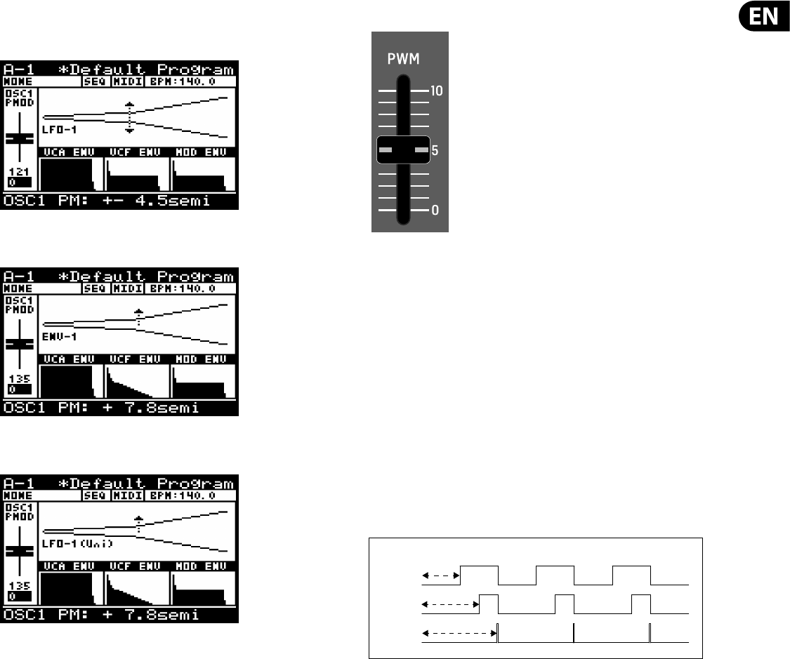
53 DeepMind 12 User Manual
The fader position, current value and stored value for the OSC 1 PITCH MOD fader
is shown on the PROG screen. There is also a visualization of the modulation as
shown below. The arrows indicate the polarity of the modulation..
Note: for ENVELOPE sources the arrow will only point in the UP direction
indicating that the modulation will be positive from the base pitch.
Note: for Uni-polar LFO sources the arrow will only point in the UP direction
indicating that the modulation will be positive from the base pitch.
The default source for the pitch modulation is LFO1. For more information on
selecting the OSC 1 pitch modulation source please consult the section later in
this document.
8.3.2 OSC 1 PWM FADER
The OSC 1 PWM fader controls the PULSE WIDTH of the OSC 1 SQUARE waveform,
or the depth of PULSE WIDTH MODULATION (PWM) applied to the OSC1 SQUARE
waveform. The PWM SOURCE is selected in the OSC EDIT page described later
in this section. When the PWM source is set to MANUAL, the fader controls the
PULSE WIDTH. When the PWM source is set to any of modulation sources the
fader controls the depth of PULSE WIDTH MODULATION.
PWM adds harmonic structure to the sound and is often used to create a phasing/
movement e ect, or used when creating string type sounds and sonic drones.
The pulse wave (aka rectangle wave) is often described as more"narrow
sounding" than a fully symmetrical square wave. As the pulse width modulation
is increased the "thinner" or "more hollow" the sound will become. Very high
values of PWM played at very low frequencies will start to sound like clicks, pops
or thumps.
As you increase the PULSE WIDTH the ratio of the positive cycle to the negative
cycle (also jointly known as duty cycle) will increase. The PULSE WIDTH
MODULATION does not a ect the SAWTOOTH waveform.
The OSC 1 PWM range is from 50.0% (symmetrical square-wave) to 99.0% (short
pulsewave). The default OSC 1 PWM setting is 50.0%.
With a PULSE wave, the harmonic content changes depending on the pulse
width. It is characterized by a lack of the nth harmonic series when the pulse
width is 1/n. The example below does not have 3rd, 6th, or 9th harmonics
because the pulse width is 1/3 (33%).
PULSE WIDTH MODULATION
50%
75%
99%
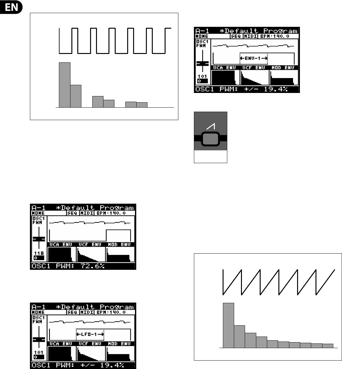
54 DeepMind 12 User Manual
The characteristics of the PULSE waveform are shown below:
The fader position, current value and stored value for the OSC 1 PWM fader is
shown on the PROG screen. There is also a visualization of the modulation as
shown below.
Note: Whenever two waveforms are shown, the top waveform represents the
summed output of the OSCs and the bottom waveform shows the parameter
being adjusted.
The summed output shows 4 cycles and the parameter being adjusted shows a
single cycle allowing you to see the detail of the changes you are making while
adjusting the parameter.
Note: When an LFO is used as a PWM source, the arrows indicate the range of
modulation as shown below. In this mode the PWM fader is used to adjust the
amount of modulation from 0 to +/- 49%..
Note: When an ENVELOPE is used as a PWM source, the arrows indicate the range
of modulation as shown below. In this mode the PWM fader is used to adjust the
amount of modulation from 0 to +/- 49%:.
8.3.3 SAWTOOTH WAVEFORM SWITCH
This switch controls the SAWTOOTH waveform output for OSC 1.
The SAWTOOTH waveform has a rasping, buzzy and hard sound. Classic
synthesizer basses, strings, brass and pad sounds are often created using
sawtooth waveforms. The large range of harmonic content makes the SAWTOOTH
waveform a good candidate to start with when creating a program that you want
to sound "fat".
The SAWTOOTH waveform contains a fundamental sine wave and all of its
integral harmonic sine waves at a xed ratio.
The characteristics of the SAWTOOTH waveform are shown below:
The SAWTOOTH waveform output can be On/O . The default program
setting is On.
HARMONIC
CONTENT
f 2nd 7th 8th
PULSE WAVE
OSC
(33% PULSE)
4th 5th
ON=SAWTOOTH
OSC (SAW)
HARMONIC
CONTENT
f 2nd 3rd 4th 5th 6th 7th 8th 9th 10th
SAWTOOTH WAVE
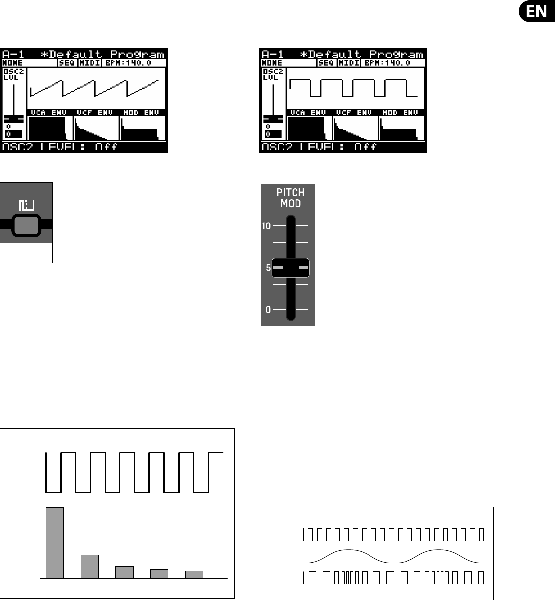
55 DeepMind 12 User Manual
Note: The OSC 1 SAWTOOTH waveform output can be used independently or in
combination with the OSC 1 SQUARE waveform output.
There is also a visualization of the SAWTOOTH waveform as shown below:
8.3.4 SQUARE WAVEFORM SWITCH
This switch controls the SQUARE waveform output for OSC 1.
The SQUARE waveform has a hollow sound, which does not sound as rich as
a sawtooth waveform due to the lack of even harmonics. Traditionally it is
often used to emulate a clarinet because of its similarity to the output of the
instrument. However in modern electronic music it is commonly used to thin,
nasal or cavernous sounds.
The SQUARE waveform contains a fundamental sine wave and its odd numbered
harmonics at a xed ratio. The level of each harmonic is the same as sawtooth
wave. I.e. the content of nth harmonic is 1/n, except there are no even numbered
harmonics present.
The characteristics of the SQUARE waveform are shown below:
The SQUARE waveform output can be On/O . The default program setting is On.
Note: The OSC 1 SQUARE waveform output can be used independently or in
combination with the OSC 1 SAWTOOTH waveform output.
There is also a visualization of the SQUARE waveform as shown below:
8.3.5 OSC 2 PITCH MOD FADER
The OSC 2 PITCH MOD fader controls the amount of PITCH MODULATION applied
to the OSC 2 SQUARE waveform. The PITCH MODULATION SOURCE is selected in
the OSC EDIT page described later in this section. Pitch modulation is often used
to create a vibrato e ect, but can be used in many other ways. The range of
modulation is very wide, allowing both traditional and creative modulations.
Controlling the frequency using an external signal is a form of frequency
modulation (FM), however as FM is more commonly used to describe the use of
an audio oscillator modulating another audio oscillator the use of an LFO signal
the term PITCH MODULATION is preferred in this instance.
Note: Because the DeepMind 12 LFO can reach well into the audio range
(1280 Hz) it is possible to create traditional frequency modulation (FM) when the
LFO is used as the source for PITCH MODULATION of the OSCs
The diagram below shows the waveforms obtained with LFO control of OSC 2.
ON=SQUARE
HARMONIC
CONTENT
f 3rd 5th 7th 9th
SQUARE WAVE
OSC (SQR)
OSC 2 PITCH MODULATION
OSC 2
LFO (SIN)
PITCH MOD
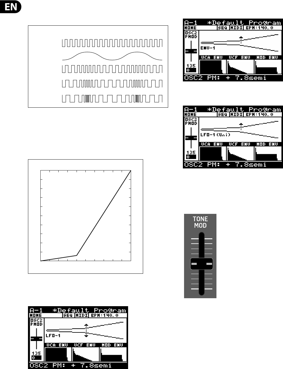
56 DeepMind 12 User Manual
As you increase the amount of PITCH MODULATION the variance in the pitch of
oscillator will increase resulting in larger increases and decreases as
demonstrated in the diagram below:.
The OSC 2 PITCH MOD range is from 0.00cents to 36.0 semitones. The default OSC
2 PITCH MOD setting is 0.00cents.
The OSC 2 PITCH MOD fader has a non-linear response which gives more
resolution at smaller settings, to allow delicate or ne use of the modulation. The
response of the OSC 2 PITCH MOD fader is shown below:
The fader position, current value and stored value for the OSC 2 PITCH MOD fader
is shown on the PROG screen. There is also a visualization of the waveform as
shown below. The arrows indicate the polarity of the waveform.
Note: for ENVELOPE sources the arrow will only point in the UP direction
indicating that the base modulation will be positive from the base pitch.
Note: for Uni-polar LFO sources the arrow will only point in the UP direction
indicating that the base modulation will be positive from the base pitch.
The default source for the pitch modulation is LFO1. For more information on
selecting the OSC 1 pitch modulation source please consult the section later in
this document.
8.3.6 OSC 2 TONE MOD FADER
The OSC 2 TONE MOD fader controls the TONE MODULATION of the OSC 2 SQUARE
waveform, The TONE MOD SOURCE is selected in the OSC EDIT page described
later in this section. When the TONE MOD source is set to MANUAL, the fader
controls the TONE MODULATION. When the TONE MOD source is set to any of the
modulation sources the fader controls the depth of TONE MODULATION.
TONE MODULATION can be used in many ways e.g. to create a double phasing
e ect, or used when creating complex string type sounds. The harmonic
structure of the OSC changes considerably when using TONE MODULATION, and
the results can often have a metallic quality.
OSC 2 PITCH MODULATION AMOUNT (LFO AS SOURCE)
OSC 2
LFO (SIN)
PITCH MOD LOW
PITCH MOD MED
PITCH MOD HIGH
36
0
010
PITCH MOD Fader Response
Fader Position
Modulation Depth (semitones)
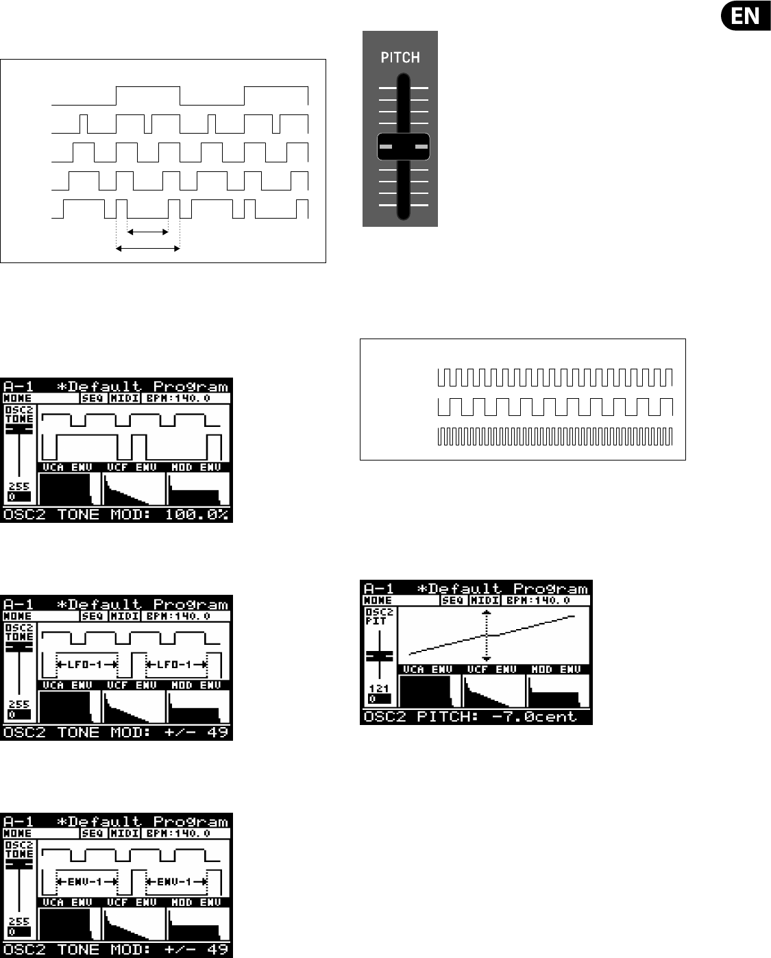
57 DeepMind 12 User Manual
As you increase the amount of TONE MODULATION the positive and negative parts
of the cycle are split by a pulse. The further you increase the fader, the width of
the pulse increases.
The TONE MOD range is from 50%(symmetrical square-wave) to 100% (pulse
interrupt is 60% of half cycle). The default TONE MOD setting is 50%.
The fader position, current value and stored value for the TONE MOD fader is
shown on the PROG screen. There is also a visualization of the waveform as
shown below
Note: for ENVELOPE sources the arrow will only point in the UP direction
indicating the range of modulation. In this mode the TONE MOD fader is used to
adjust the amount of modulation from 0 to +/- 49%
Note: for Uni-polar LFO sources the arrow will only point in the UP direction
indicating the range of modulation. In this mode the TONE MOD fader is used to
adjust the amount of modulation from 0 to +/- 49%.
8.3.7 OSC 2 PITCH FADER
The OSC 2 PITCH fader controls the PITCH of the OSC 2 SQUARE waveform. The
pitch can be tuned to match the pitch of OSC1, o set slightly to create a wider
sound, or o set more to create harmonic overtones.
As you increase/decrease the PITCH fader the pitch of the oscillator will increase/
decrease.
The OSC 2 PITCH range is from -12.0 semitones to +12.0 semitones. The default
OSC 2 PITCH setting is 0 semitones.
The fader position, current value and stored value for the OSC 2 PITCH fader is
shown on the PROG screen. There is also a visualization of the pitch setting as
shown below:
Note: The centre of the line shown on the visualization highlights the ne
resolution that is available around the centre point. Here the units of adjustment
will change from semitones to cents
TONE MODULATION
50%
62.5%
75%
87.5%
100%
100%
60%
OSC 2 PITCH
0 (KEY PITCH)
-12 SEMITONES
+12 SEMITONES
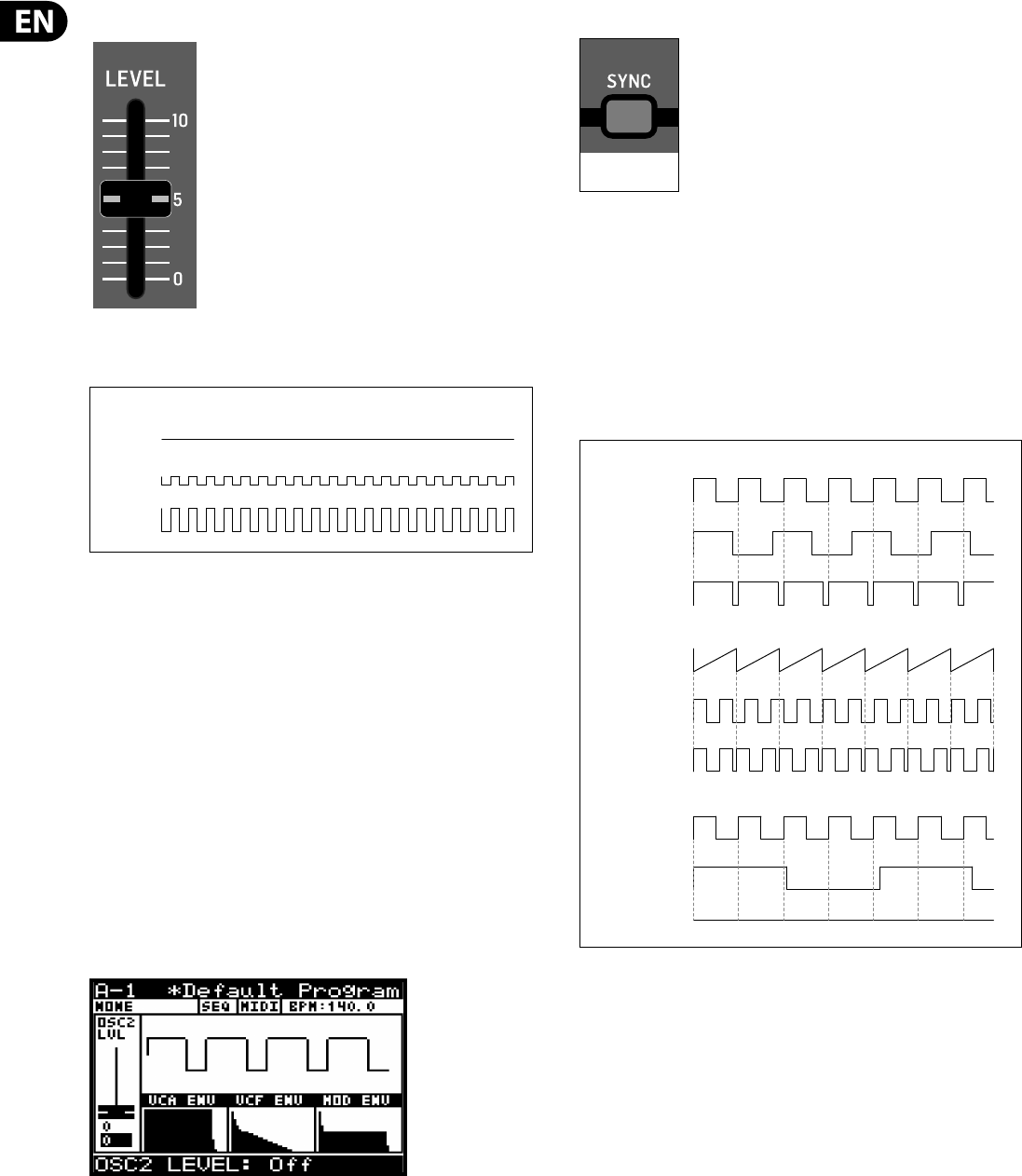
58 DeepMind 12 User Manual
8.3.8 OSC 2 LEVEL FADER
The OSC 2 LEVEL fader controls the LEVEL of the OSC 2 SQUARE waveform. The
level setting can be used to adjust balance between OSC 1 and OSC 2.
The balance between OSC 1 and and OSC 2 when when used together allows you
to increase the sonic palette of the program. Combing oscillators can be done to
create new waveforms and the harmonic structure of the program. By slightly
detuning the oscillators you can create bigger, thicker sounds. Detuning in small
and equal increments will not make a noticeable di erence to the base pitch of
the sound, but as you increase the amount of detuning it will start to become
noticeable. Detuning can be done in musical intervals e.g. a fth, or a seventh,
to add harmony to a pad sound or even an entire octave to give a bass program a
deeper sound.
The OSC 2 LEVEL can be set to O , or its operational range is from -48 to 0.0 dB.
The default OSC 2 LEVEL setting is 0 .
The fader position, current value and stored value for the OSC 2 LEVEL fader
is shown on the PROG screen. There is also a visualization of the waveform as
shown below.
Note: It is important to note that the visualization shows the combination of OSC
1 and OSC 2.
8.3.9 OSC SYNC SWITCH
This switch controls the synchronisation of the OSCs.
The OSC 1 pitch is set by the keys that you play, and the OSC 2 pitch may be tuned
to (or detuned from) this frequency. By applying hard synchronisation of OSC 2 to
OSC1, every time the OSC 1 cycle starts again, the OSC 2 will be re-triggered,
regardless of its position. If OSC 2 is tuned to a lower frequency than OSC 1 it will
be re-triggered before it completes an entire cycle, and if it is tuned to a higher
frequency it will be re-triggered during a later cycle. This ensures that the OSCs
are playing at the same frequency, however the irregular cycle of OSC 2 can create
complex timbres and rich harmonies.
OSC 2 LEVEL
0FF
-12.0 dB
0.0 dB
ON=SYNC ACTIVE
OSC 1 (SAW)
MASTER
OSC SYNC EXAMPLE 1 - OSC2 LOWER FREQUENCY THAN OSC1
OSC SYNC EXAMPLE 1 - OSC2 LOWER THAN 1/2 OF OSC1
OSC SYNC EXAMPLE 1 - OSC2 HIGHER FREQUENCY THAN OSC1
OSC 1 (SQR)
MASTER
OSC 2 SYNC OFF
OSC 2 SYNC OFF
OSC 2 SYNC ON
OSC 2 SYNC ON
OSC 1 (SQR)
MASTER
OSC 2 SYNC OFF
OSC 2 SYNC ON
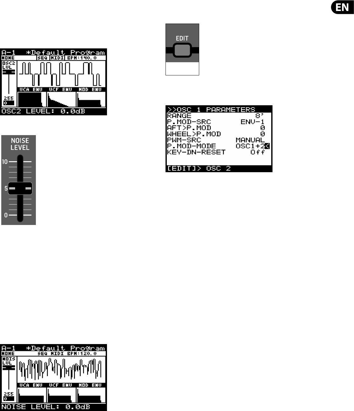
59 DeepMind 12 User Manual
Note: If OSC 2 is lower than 1/2 of the frequency of OSC 1 then there will be no
output from OSC 2 when SYNC is ON because the waveform will never reach its
negative cycle.
The OSC SYNC option can be On/O . The default program setting is O .
There is also a visualization of the SYNC waveform as shown below
8.3.10 NOISE LEVEL FADER
The NOISE LEVEL fader controls the LEVEL of the NOISE signal.
The noise generator is implemented using analog circuitry and creates pink
noise with a low frequency roll-o designed speci cally for the DeepMind 12.
The noise generator is commonly used with non-pitched sounds or non-pitched
components of a sound e.g. a snare drum or an atmospheric sound.
Pink noise contains equal amounts of energy in each octave. As human hearing is
roughly logarithmic, this type of noise sounds as if it has an equal amount of all
frequencies and produces a rushing sound similar to that of a waterfall.
The NOISE LEVEL can be set to O , or its operational range is from -48.1 dB to
0.0 dB. The default NOISE LEVEL setting is 0 .
The fader position, current value and stored value for the NOISE LEVEL fader is
shown on the PROG screen. There is also a visualization of the noise signal as
shown below:
8.3.11 OSC EDIT SWITCH (OSC 1)
To access the OSC EDIT menu press the OSC EDIT switch.
The OSC EDIT switch will then start ashing and the OSC 1 EDIT menu
is then shown:
To navigate the options in the OSC 1 EDIT menu, use the UP, DOWN, switches.
Selected parameters are adjusted using the -NO/+YES switches, the rotary knob
or the fader. The rotary knob has a click which allows very accurate control. The
fader allows rapid adjustment across the full range:
Note: At this point if you wish to access the OSC 2 EDIT menu, press the EDIT
switch again.
Shortcut Note: To change any of the OSC Modulation sources press and hold the
OSC EDIT switch. While holding the switch you can use any of the following faders
to set the source for the respective parameter
8.3.12 OSC 1 MENU
The following options are available in the OSC 1 EDIT menu:
RANGE - This option allows you selects the base pitch of the OSC as follows:
16' - The lowest note on the keyboard (C) is tuned to 16.35 Hz.
8' - The lowest note on the keyboard (C) is tuned to 32.7 Hz.
4'- The lowest note on the keyboard (C) is tuned to 65.4 Hz.
The default setting for the RANGE is 8'.
FLASHING=EDIT
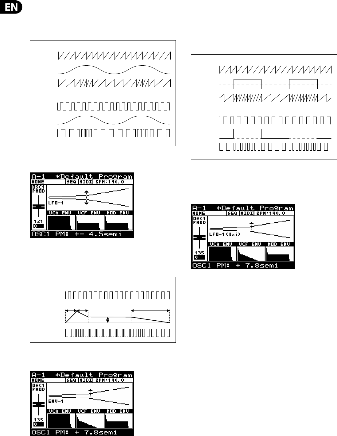
60 DeepMind 12 User Manual
P. M OD -S RC - This option allows you to select the source for the amount of PITCH
MODULATION from the following:
•
• LFO-1 - Bipolar use of the LFO 1 waveform.
•
• LFO-2 - Bipolar use of the LFO 2 waveform.
There is also a visualization of the modulation as shown below. The arrows
indicate the polarity of the modulation.
•
• ENV-1 - Unipolar use of the ENV 1 envelope.
•
• ENV-2 - Unipolar use of the ENV 2 envelope.
•
• ENV-3 - Unipolar use of the ENV 3 envelope.
Note: In the visualization for ENVELOPE sources the arrow will only point in the
UP direction indicating that the modulation will be positive from the base pitch.
•
• LFO-1(Uni) - Unipolar use of the LFO 1 waveform.
•
• LFO-2(Uni) - Unipolar use of the LFO 1 waveform.
Note: In any of the Unipolar (Uni) modes the waveform is only used for positive
modulation. This is useful when you want the note to play at the original
frequency and modulation uses that as a reference point (Unipolar), rather than
have the note modulated to positive and negative o sets (Bipolar).
The default setting for the P.MOD-SRC is LFO-1.
Note: In the visualization for Uni-polar LFO sources the arrow will only point in
the UP direction indicating that the modulation will be positive from the base
pitch.
AFT>P.MOD - This option controls how much PITCH MODULATION is increased
by AFTERTOUCH pressure. This allows you to expressively control the PITCH
MODULATION and its e ect using key pressure
The AFT>P.MOD range is from 0-255, and the default setting is 0 (O ).
WHEEL>P.MOD -This option controls how much PITCH MODULATION depth is
increased by the MOD WHEEL position. This allows you to expressively control the
PITCH MODULATION and its e ect using the MOD WHEEL.
The AFT>P.MOD range is from 0-255, and the default setting is 0 (O ).
PWM-SRC - This option allows you to select the source for the amount of PULSE
WIDTH MODULATION from the following:
•
• MANUAL - In this mode the PWM fader is used to manually adjust the PULSE
WIDTH.
OSC 1 (SAW)
LFO (SIN)
PITCH MOD
OSC 1 PITCH MODULATION (LFO AS SOURCE)
OSC 1 (SQR)
LFO (SIN)
PITCH MOD
OSC 1 PITCH MODULATION AMOUNT (ENVELOPE AS SOURCE)
OSC 1 (SQR)
ENVELOPE
ATTACK DECAY
SUSTAIN
RELEASE
PITCH MOD
OSC 1 (SAW)
OSC 1 WITH
PITCH MOD
OSC 1 WITH
PITCH MOD
OSC 1 PITCH MODULATION (BIPLOAR/UNIPOLAR LFO AS SOURCE)
OSC 1 (SQR)
LFO (SQR)
BIPOLAR
LFO (SQR)
UNIPOLAR
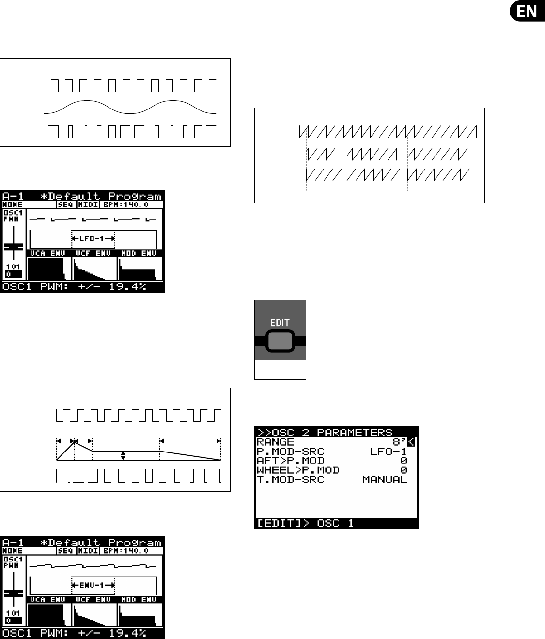
61 DeepMind 12 User Manual
•
• LFO-1 - Bipolar use of the LFO 1 waveform. In this mode the PWM fader is
used to adjust the amount of modulation from 0 to +/- 49%.
•
• LFO-2 - Bipolar use of the LFO 2 waveform. In this mode the PWM fader is
used to adjust the amount of modulation from 0 to +/- 49%.
Note: When an LFO is used as a PWM source, the arrows indicate the range of
modulation as shown below:
•
• ENV-1 - Unipolar use of the ENV 1 envelope. In this mode the PWM fader is
used to adjust the amount of modulation from 0 to +/- 49%.
•
• ENV-2 - Unipolar use of the ENV 2 envelope. In this mode the PWM fader is
used to adjust the amount of modulation from 0 to +/- 49%.
•
• ENV-3 - Unipolar use of the ENV 3 envelope. In this mode the PWM fader is
used to adjust the amount of modulation from 0 to +/- 49%.
Note: When an ENVELOPE is used as a PWM source, the arrows indicate the range
of modulation as shown below:.
P.MOD MODE - This option allows you to select which oscillators are controlled
by the OSC 1 PITCH MOD fader.
Note: It is useful to have both OSCs responding for e ects like tremolo.
•
• OSC1+2 -Both OSCs have PITCH MODULATION applied to them.
•
• OSC1 - Only OSC 1 has PITCH MODULATION applied to it.
KEY-DN-RESET - This option allows you to reset the phase of oscillator waveform
to start from its reset point each time a key is pressed.
The default setting for KEY-DN-RESET is O .
To exit the OSC EDIT menu press the PROG switch to return the main display, or to
continue to the OSC 2 EDIT menu press the OSC EDIT switch again.
8.3.13 OSC EDIT SWITCH (OSC 2)
To access the OSC EDIT menu press the OSC EDIT switch.
The OSC EDIT switch will then start ashing and the OSC 1 EDIT menu is then
shown. Press the EDIT switch again to show the OSC 2 EDIT menu:
To navigate the options in the OSC 2 EDIT menu, use the UP, DOWN, switches.
Selected parameters are adjusted using the -NO/+YES switches, the rotary knob
or the fader. The rotary knob has a click which allows very accurate control. The
fader allows rapid adjustment across the full range.
8.3.14 OSC 2 MENU
The following options are available in the OSC 2 EDIT menu:
RANGE - This option allows you selects the base pitch of the OSC as follows:
16' - The lowest note on the keyboard (C) is tuned to 16.35 Hz.
8' - The lowest note on the keyboard (C) is tuned to 32.7 Hz.
4'- The lowest note on the keyboard (C) is tuned to 65.4 Hz.
The default setting for the RANGE is 8'.
OSC 1 PULSE WIDTH MODULATION (LFO AS SOURCE)
OSC 1 (SQR)
LFO (SIN)
PWM
OSC 1 PULSE WIDTH MODULATION (ENVELOPE AS SOURCE)
OSC 1 (SQR)
ENVELOPE
ATTACK DECAY
SUSTAIN
RELEASE
PWM
OSC 1 (SAW)
KEY-DN-RESET
OFF
KEY-DN-RESET
ON
OSC 1 KEY DOWN RESET
KEY PRESS KEY PRESS KEY PRESS
FLASHING=EDIT
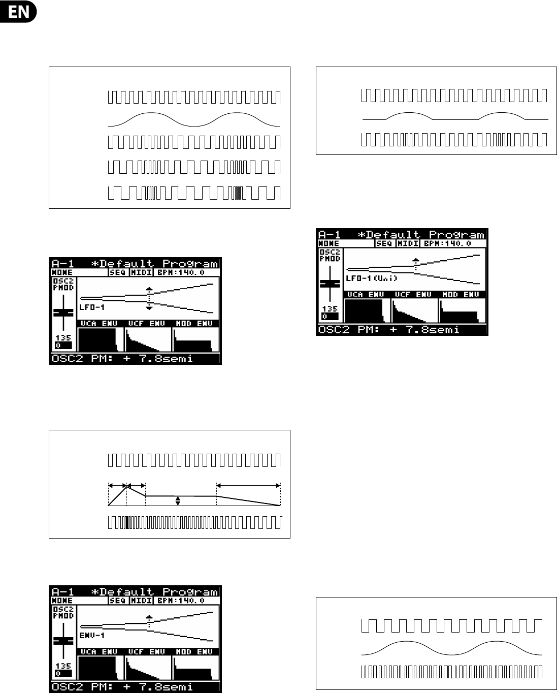
62 DeepMind 12 User Manual
P. M OD -S RC - This option allows you to select the source for the amount of PITCH
MODULATION from the following:
•
• LFO-1 - Bipolar use of the LFO 1 waveform.
•
• LFO-2 - Bipolar use of the LFO 2 waveform.
There is also a visualization of the modulation as shown below. The arrows
indicate the polarity of the modulation..
•
• ENV-1 - Bipolar use of the ENV 1 envelope.
•
• ENV-2 - Bipolar use of the ENV 2 envelope.
•
• ENV-3 - Bipolar use of the ENV 3 envelope.
Note: In the visualization for ENVELOPE sources the arrow will only point in the
UP direction indicating that the modulation will be positive from the base pitch.
•
• LFO-1(Uni) - Unipolar use of the LFO 1 waveform.
•
• LFO-2(Uni) - Unipolar use of the LFO 1 waveform.
Note: In any of the Unipolar (Uni) modes the waveform is only used for positive
modulation.
The default setting for the P.MOD-SRC is LFO-1.
Note: In the visualization for Uni-polar LFO sources the arrow will only point in
the UP direction indicating that the modulation will be positive from the base
pitch.
The default setting for the P.MOD-SRC is LFO-1.
AFT>P.MOD - This option controls how much PITCH MODULATION is increased
by AFTERTOUCH pressure. This allows you to expressively control the PITCH
MODULATION and its e ect using key pressure.
The AFT>P.MOD range is from 0-255, and the default setting is 0 (O ).
WHEEL>P.MOD -This option controls how much PITCH MODULATION depth is
increased by the MOD WHEEL position. This allows you to expressively control the
PITCH MODULATION and its e ect using the MOD WHEEL.
The MOD WHEEL>P.MOD range is from 0-255, and the default setting is 0 (O ).
T.MOD-SRC - This option allows you to select the source for the amount of TONE
MODULATION from the following:
•
• MANUAL - In this mode the TONE MOD fader is used to manually adjust the
PWM.
•
• LFO-1 - Bipolar use of the LFO 1 waveform. In this mode the TONE MOD fader
is used to adjust the amount of modulation from 0 to +/- 49%.
•
• LFO-2 - Bipolar use of the LFO 2 waveform. In this mode the TONE MOD fader
is used to adjust the amount of modulation from 0 to +/- 49%.
OSC 2 PITCH MODULATION AMOUNT (LFO AS SOURCE)
OSC 2
LFO (SIN)
PITCH MOD LOW
PITCH MOD MED
PITCH MOD HIGH
OSC 2 PITCH MODULATION AMOUNT (ENVELOPE AS SOURCE)
OSC 1 (SQR)
ENVELOPE
ATTACK DECAY
SUSTAIN
RELEASE
PITCH MOD
OSC 2 PITCH MODULATION (UNIPOLAR LFO AS SOURCE)
OSC 1 (SQR)
PITCH MOD
LFO (SIN)
UNIPOLAR
OSC 2 TONE MODULATION (LFO AS SOURCE)
OSC 2 (SQR)
LFO (SIN)
TONE MOD
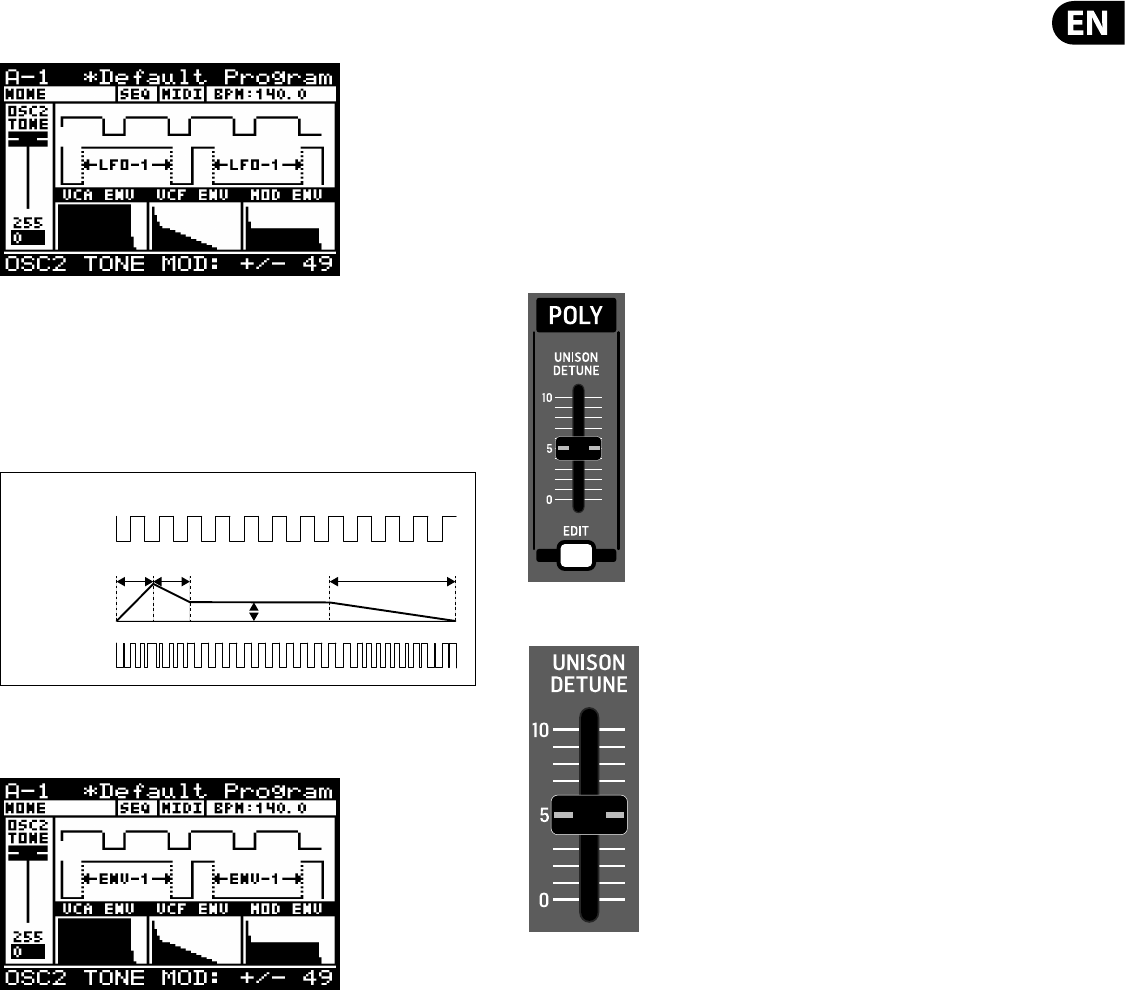
63 DeepMind 12 User Manual
Note: When an LFO is used as a TONE MOD source, the arrows indicate the range
of modulation as shown below:
•
• ENV-1 - Bipolar use of the ENV 1 envelope. In this mode the TONE MOD fader
is used to adjust the amount of modulation from 0 to +/- 49%.
•
• ENV-2 - Bipolar use of the ENV 2 envelope. In this mode the TONE MOD fader
is used to adjust the amount of modulation from 0 to +/- 49%.
•
• ENV-3 - Bipolar use of the ENV 3 envelope. In this mode the TONE MOD fader
is used to adjust the amount of modulation from 0 to +/- 49%.
Note: When an ENVELOPE is used as a TONE MOD source, the arrows indicate the
range of modulation as shown below:.
To exit the OSC EDIT menu press the PROG switch to return the main display, or
because you are in the OSC 2 EDIT menu you can press the OSC EDIT switch again
to return to the main display.
8.4 POLY
The POLY section is where you can control all settings related to the POLYPHONY
of the DeepMind 12. The options allow you to be highly creative in your use of the
polyphonic, unison and monophonic capabilities of the voice structure.
Having 12 voices gives you the ability to play 12 simultaneous notes, allowing
the creation of large chords, or being able to play complex sequences without
needing to worry about a note being cut o because there are not enough voices.
When playing voices in unison, you also have the ability to de-tune the voices.
The POLY EDIT menu also allows access to all settings related to PITCH
management, including transposition, portamento, pitch bend and tuning.
8.4.1 UNISON DETUNE FADER
The UNISON DETUNE fader controls how much detuning is applied across voices
when using any of the UNISON modes. The UNISON DETUNE can be used to
create thicker and richer sounds. This is a powerful aspect of the DeepMind 12
architecture. Having 12 independent analog voices can make some extremely
luxurious and sonically gigantic sounds.
When UNISON DETUNE is applied, up to +/- 50 cents of tuning is spread over the
number of voices used in UNISON.
The UNISON DETUNE range is from +/-0.0cents to 50.0cents. The default UNISON
DETUNE setting is 0.0cents(O ).
Note: When using UNISON DETUNE in combination with the OSC KEYDOWN
RESET setting you will hear the a ects of phase drift much more clearly as the
OSCs will all start from the same point on their waveforms.
OSC 2 TONE MODULATION (ENVELOPE AS SOURCE)
OSC 2 (SQR)
ENVELOPE
ATTACK DECAY
SUSTAIN
RELEASE
TONE MOD
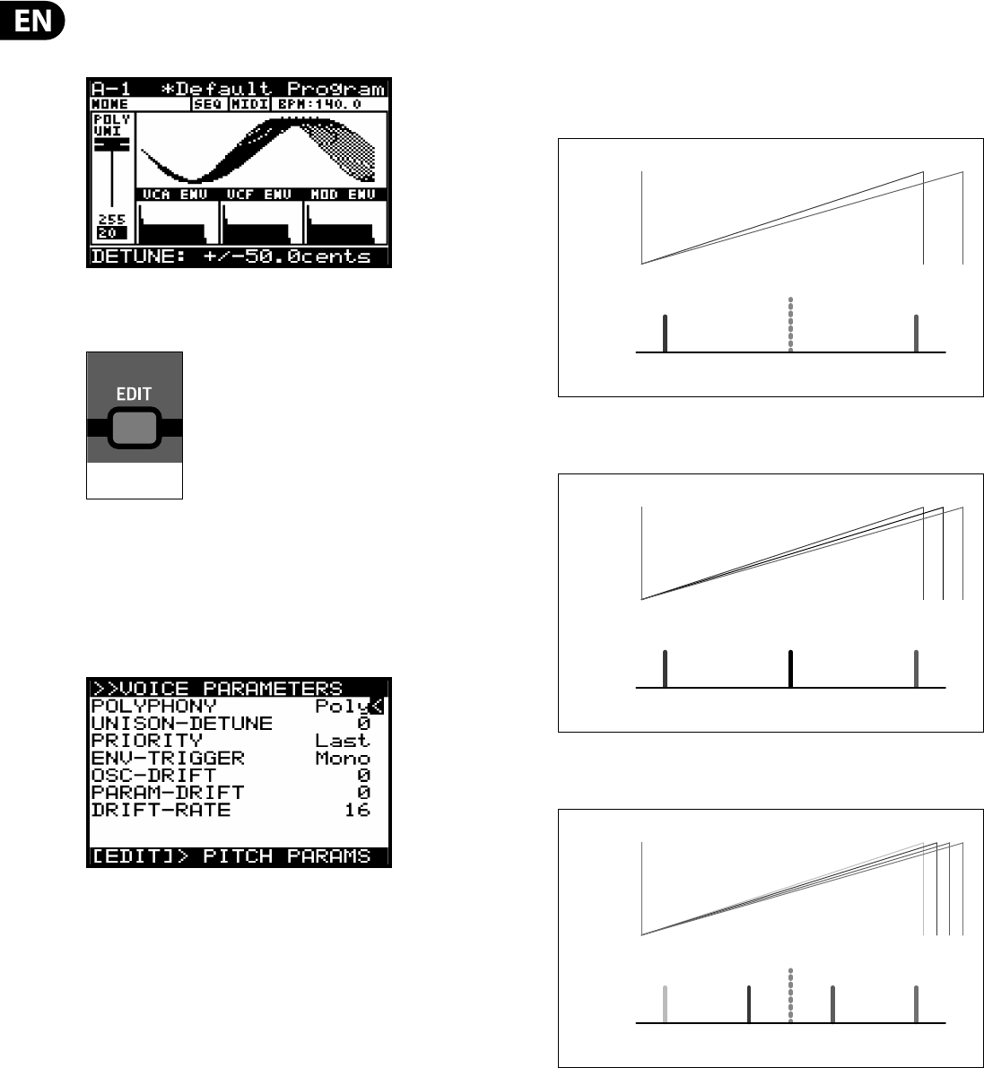
64 DeepMind 12 User Manual
The fader position, current value and stored value for the UNISON DETUNE fader is
shown on the PROG screen. There is also a visualization of the detuning amount
as shown below:
8.4.2 POLY EDIT SWITCH
To access the POLY EDIT menu press the POLY EDIT switch.
The POLY EDIT switch will then start ashing and either the VOICE PARAMETERS
or PITCH PARAMETERS menu is then shown (depending on what you had last
worked on, as the location is remembered.
8.4.3 VOICE PARAMETERS MENU
This is the VOICE PARAMETERS menu:
To navigate the options in the VOICE PARAMETERS menu, use the UP, DOWN,
switches.
Selected parameters are adjusted using the -NO/+YES switches, the rotary knob
or the fader. The rotary knob has a click which allows very accurate control. The
fader allows rapid adjustment across the full range:
Note: At this point if you wish to access the PITCH PARAMETERS menu, press the
EDIT switch again.
The following options are available in the VOICE PARAMETERS menu:
POLYPHONY - This allows you to choose how the DeepMind 12 voices are
allocated from one of the following options:
•
• Poly - A single voice is allocated to each note.
•
• Unison-2 - The next available two voices are allocated to each note played.
Detuning is applied as shown below:
Unison-3 - The next available three voices are allocated to each note played.
Detuning is applied as shown below:
•
• Unison-4 - The next available four voices are allocated to each note played.
Detuning is applied as shown below:
FLASHING=EDIT
UNISON 2
WAVEFORM
UNISON 2
SPECTRUM
ROOT NOTE
FREQUENCY
MAX -VE
DETUNE
MAX +VE
DETUNE
UNISON 2
12
UNISON 3
WAVEFORM
UNISON 3
SPECTRUM
ROOT NOTE
FREQUENCY
MAX -VE
DETUNE
MAX +VE
DETUNE
UNISON 3
123
UNISON 4
WAVEFORM
UNISON 4
SPECTRUM
ROOT NOTE
FREQUENCY
MAX -VE
DETUNE
MAX +VE
DETUNE
UNISON 4
1234
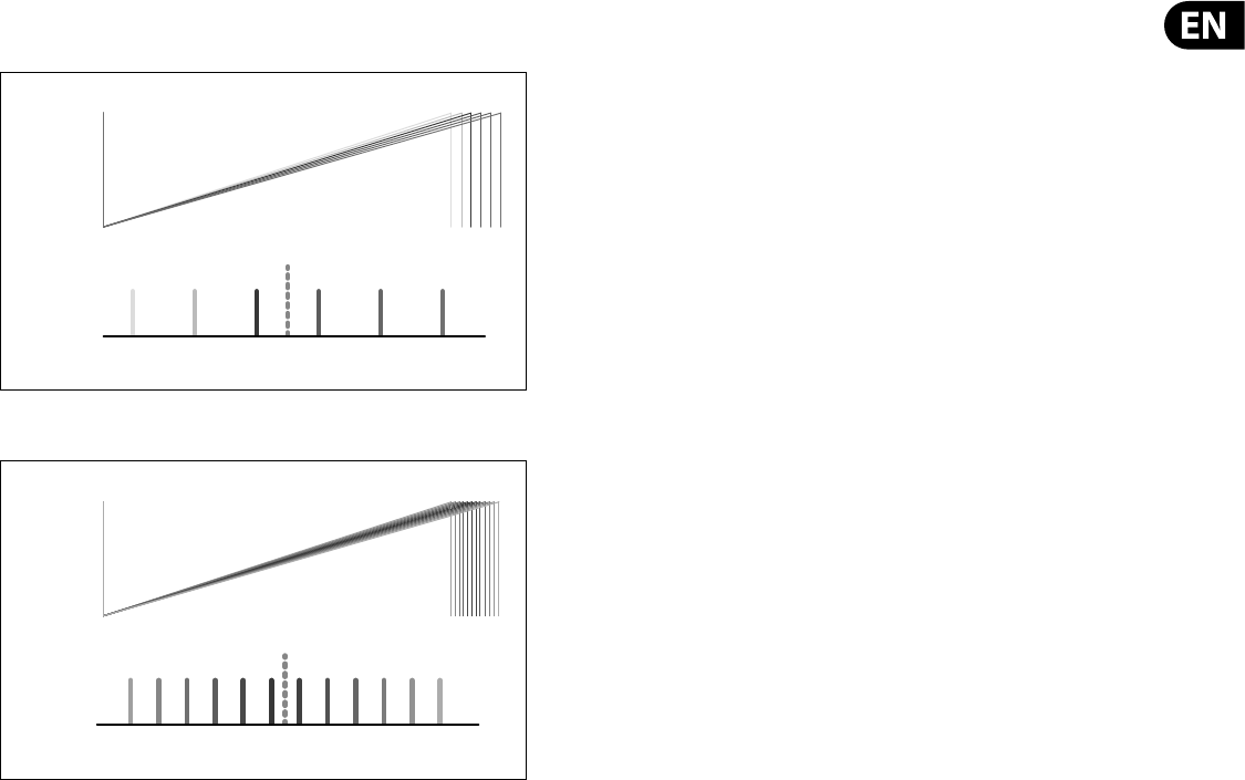
65 DeepMind 12 User Manual
•
• Unison-6 - The next available six voices are allocated to each note played.
Detuning is applied as shown below:
•
• Unison-12 - All 12 voices are allocated to each note played
•
• Mono - The same voice is allocated to every note played.
•
• Mono-2 - The same two voices are allocated to each note played. Voices are
spread in the same way as Unison-2 mode.
•
• Mono-3 - The same three voices re allocated to each note played. Voices are
spread in the same way as Unison-3 mode.
•
• Mono-4 - The same four voices are allocated to each note played. Voices are
spread in the same way as Unison-4 mode.
•
• Mono-6 -The same six voices are allocated to each note played. Voices are
spread in the same way as Unison-6 mode.
•
• Poly-6 - A single voice is allocated to each note played, but polyphony is
limited to the next available six notes.
•
• Poly-8 - A single voice is allocated to each note played, but polyphony is
limited to the next available eight notes.
Note: When an even number of voices are used (Unison2/4/6/12, Mono 2/4/6)
the voices are spread across the spectrum evenly which means the root note
is not actually played. However if an odd number of voices are used, when the
voices are spread across the spectrum one voice will be playing the root note.
UNISON DETUNE - This option is the same as the UNISON DETUNE fader on the
surface. Any changes on the surface will be re ected here.
The UNISON DETUNE range is from +/-0.0cents to 50.0cents (0 to 255).
The default UNISON DETUNE setting is 0.0cents(O ).
PRIORITY - When in monophonic mode, or when more notes are played than
there are voices available (due to polyphonic/unison settings), this mode controls
which notes are prioritized.
•
• Lowest - In lowest note priority, when a newly requested note is lower
in pitch than the notes currently being played then it will be given priority
and will steal the voice that is playing the highest note.
•
• Highest - In highest note priority, when a newly requested note is
higher in pitch than the notes currently being played then it will be given
priority and will steal the voice that is playing the lowest note.
•
• Last - In this mode the notes are prioritized based on the order in which they
are played. When a newly requested note is triggered while all voices are
playing, it steals the voice used by the note played least recently.
The default PRIORITY setting is Last.
ENV-TRIGGER - The envelopes can be triggered in di erent ways. This allows you
to choose a mode from the following options:
•
• Mono - In this triggering mode the voice will start its attack stage from the
current envelope level. I.e. its last level from the previous release.
•
• Retrigger - In this triggering mode the envelope will be reset to zero and
then start its attack stage.
•
• Legato - In this triggering mode the envelope does not re-trigger when a
new note is played. The only time the envelope will start the attack stage
again is once the note is released.
•
• One-shot - In this triggering mode the envelope will be reset to zero and
then start its attack stage. Once the decay phase is complete the envelope
will jump immediately to its release stage (i.e. there is no sustain phase)
The default triggering mode is Mono.
OSC-DRIFT - This option allows you to recreate the tuning drift that vintage
analog synthesizers have.
As you increase the OSC-DRIFT value, the pitch of the oscillators will be slowly
modulated at random.
OSC-DRIFT is applied to both OSC 1 and OSC 2.
The OSC-DRIFT range is from 0 to 255. The default OSC-DRIFT setting is 0.
PARAM-DRIFT - This option allows you to recreate the drift that many
parameters in a vintage analog synthesizers have.
As you increase the PARAM-DRIFT value, the drift distances will increase.
Note: The parameters which DRIFT is applied to are OSC1 PITCH MOD, OSC1 PWM,
OSC2 PITCH MOD, OSC2 TONE MOD, VCF FREQ, VCF RES, VCF ENV DEPTH, VCF LFO
DEPTH, VCA ENV DEPTH and MOD ENV DEPTH.
The PARAM-DRIFT range is from 0 to 255. The default PARAM-DRIFT setting is 0.
DRIFT-RATE - This controls the RATE at which the OSC-DRIFT and PARAM-DRIFT
operate at. It is important to note that each voice has independent random DRIFT
generators for the OSC-DRIFT and the PARAM-DRIFT to more closely replicate the
characteristics of a vintage synthesizer.
The rate is controlled by a random timer which generates a ramp between a
multiplier of 1x and a multiplier of 2x the rate set by the DRIFT-RATE parameter.
The OSC-DRIFT range is from 0(25 ms-50 ms) to 255(2.5 s-5.0 s). The default
OSC-DRIFT setting is 0.
To summarize, if at 0, each “drift” will be a random time between 25 and 50 ms
and then the parameter drifts to another random value. At 255, each “drift”
will be a random time between 2.5 s and 5.0 s and then the parameter drifts to
another random value.
To exit the VOICE PARAMETERS menu press the PROG switch to return the main
display.
UNISON 6
WAVEFORM
UNISON 6
SPECTRUM
123456
ROOT NOTE
FREQUENCY
MAX -VE
DETUNE
MAX +VE
DETUNE
UNISON 6
UNISON 12
WAVEFORM
UNISON 12
SPECTRUM
ROOT NOTE
FREQUENCY
MAX -VE
DETUNE
MAX +VE
DETUNE
UNISON 12
2 4 61 3 5 7 98 11 1210
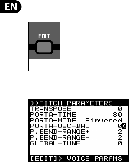
66 DeepMind 12 User Manual
8.4.4 PITCH PARAMETERS MENU
To access the PITCH PARAMETERS menu press the POLY EDIT switch.
The POLY EDIT switch will then start ashing and the VOICE PARAMETERS menu is
then shown. Press the EDIT switch again to show the PITCH PARAMETERS menu:
Note: The page location memory function can be turned o using the
REMEMBER PAGES function in the GLOBAL SETTINGS menu.
To navigate the options in the PITCH PARAMETERS menu, use the UP, DOWN,
switches.
Selected parameters are adjusted using the -NO/+YES switches, the rotary knob
or the fader. The rotary knob has a click which allows very accurate control. The
fader allows rapid adjustment across the full range:
The following options are available in the PITCH PARAMETERS menu:
TRANSPOSE - This option allows you to TRANSPOSE notes played on the
keyboard. The notes played can be transposed in steps of single semitones.
The TRANSPOSE range is from -48 to +48. The default TRANSPOSE setting is 0.
So a transpose of -7 would mean that all played keys would be transposed down
by seven semitones.
PORTA-TIME - This option is the same as the PORTAMENTO knob on the surface.
Any changes on the surface will be re ected here.
The PORTAMENTO function makes the pitch of a note glide up or down from
the previously played note. The PORTAMENTO knob controls the time taken to
transition from the previous note to the currently played note.
The PORTAMENTO range is from 0(0.00s - instant change of note) to 255(10.00s of
glide). The default PORTAMENTO setting is 0(0.00s/O ).
PORTA-MODE - This option allows you to con gure the PORTAMENTO function
to operate in di erent ways depending on your requirements. The options are as
follows:
•
• Normal - In this mode the slide time between played notes is a xed time,
regardless of overlapping notes or pitch distance. The sliding between notes
is linear.
•
• Fingered - In this mode the slide time between played notes is a xed time,
regardless of pitch distance. Sliding is only applied when notes overlap. The
sliding between notes is linear.
•
• Fix-Rate - In this mode the slide time between played notes is a xed rate,
regardless of overlapping notes. The pitch distance from note to note will
a ect the time it takes to slide between notes. The sliding between notes is
linear.
•
• Fix-Fing - In this mode the slide time between played notes is a xed rate.
The pitch distance from note to note will a ect the time it takes to slide
between notes. Sliding is only applied when notes overlap. The sliding
between notes is linear.
•
• Exp - In this mode the slide time between played notes is a xed rate. The
pitch distance from note to note will a ect the time it takes to slide between
notes. Sliding is only applied when notes overlap. The sliding between notes
is exponential.
•
• Exp-Fing - In this mode the slide time between played notes is a xed
rate. The pitch distance from note to note will a ect the time it takes to
slide between notes. Sliding is only applied when notes overlap. The sliding
between notes is exponential.
•
• Fixed+2 - In this mode the note always starts at a pitch two semitones
above the played note regardless of overlapping notes or pitch distance. The
sliding between notes is exponential.
•
• Fixed-2 - In this mode the note always starts at a pitch two semitones below
the played note regardless of overlapping notes or pitch distance. The sliding
between notes is exponential.
•
• Fixed+5 - In this mode the note always starts at a pitch ve semitones
above the played note regardless of overlapping notes or pitch distance. The
sliding between notes is exponential.
•
• Fixed-5 - In this mode the note always starts at a pitch ve semitones below
the played note regardless of overlapping notes or pitch distance. The sliding
between notes is exponential.
•
• Fixed+12 - In this mode the note always starts at a pitch twelve semitones
(one octave) above the played note regardless of overlapping notes or pitch
distance. The sliding between notes is exponential.
•
• Fixed-12 - In this mode the note always starts at a pitch twelve semitones
(one octave) below the played note regardless of overlapping notes or pitch
distance. The sliding between notes is exponential.
•
• Fixed+24 - In this mode the note always starts at a pitch twenty-four
semitones (two octaves) above the played note regardless of overlapping
notes or pitch distance. The sliding between notes is exponential.
•
• Fixed-24 - In this mode the note always starts at a pitch twenty-four
semitones (two octaves) below the played note regardless of overlapping
notes or pitch distance. The sliding between notes is exponential .
FLASHING=EDIT
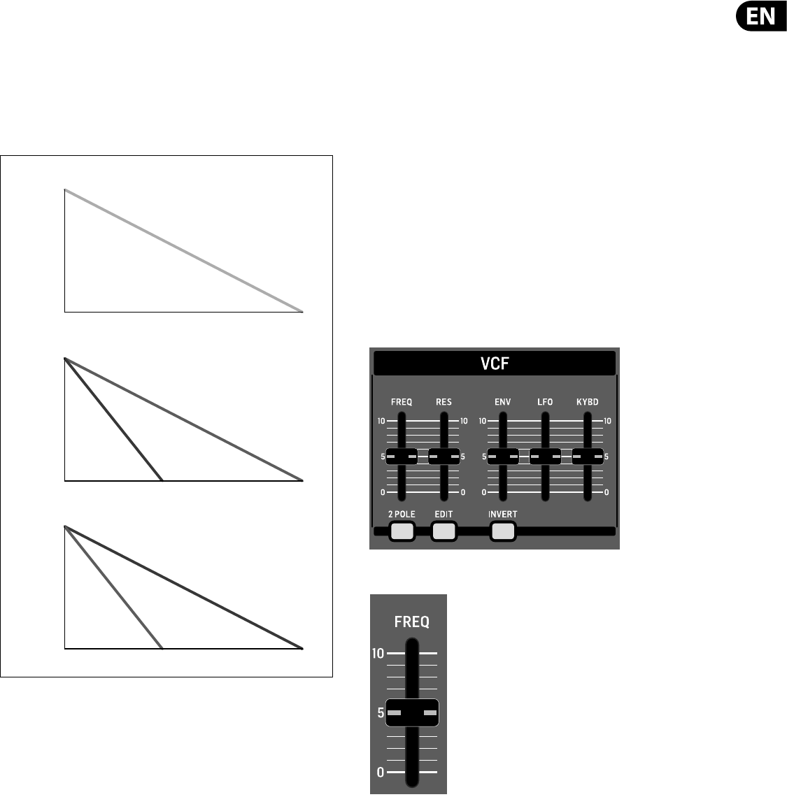
67 DeepMind 12 User Manual
PORTA-OSC-BAL - This option allows you to balance the application of PORTA-
TIME (I.e. the slide time between played notes) between OSC 1 and OSC 2.
When a positive setting is chosen, the OSC 1 PORTA-TIME will decrease. At its
maximum value (127) the OSC 1 PORTA-TIME will be zero and the pitch change
will happen immediately (no sliding).
When a negative setting is chosen, the OSC 2 PORTA-TIME will decrease. At its
minimum value (-127) the OSC 2 PORTA-TIME will be zero and the pitch change
will happen immediately (no sliding).
The PORTA-OSC-BAL parameter ranges from -128 to 127. The default setting is 0.
P.B EN D R ANG E+ - This option allows you to set the upper limit of the PITCH
WHEEL.
The P.BEND RANGE+ parameter can be varied from 0(0 notes) to 24(24 notes). The
default P.BEND RANGE+ setting is 2(2 notes).
P.B EN D R ANG E- - This option allows you to set the lower limit of the PITCH
WHEEL.
The P.BEND RANGE- parameter can be varied from 0(0 notes) to 24(24 notes). The
default P.BEND RANGE- setting is 2(2 notes).
GLOBAL-TUNE - This option allows you to adjust the GLOBAL TUNING for the
synthesizer. The range is -128 to 127.
To exit the PITCH PARAMETERS menu press the PROG switch to return the main
display, or because you are in the PITCH PARAMETERS menu you can press the
POLY EDIT switch again to return to the main display.
8.5 VCF
The VOLTAGE CONTROLLED FILTER (VCF) is an advanced lter designed speci cally
for the DeepMind 12. The VCF lter changes the tone color created by the OSCs
and NOISE generator by cutting o , or emphasizing frequencies/harmonics. The
VCF stage allows the low frequencies to pass and cuts o higher frequencies. This
approach is used by many classic subtractive synthesizers.
The VCF is a fully analog lter, with the ability to be switched from a 2-pole/12 dB
per octave lter to 4-pole/24 dB per octave lter. The dB per octave refers to the
angle of the lter's slope/response curve.
The VCF also has adjustable resonance which creates a narrow peak around
the lter cut-o frequency. The DeepMind 12 lter is capable of being driven
into self oscillation when the resonance setting is high. Unlike many other
synthesizers, the synthesizer is capable of accurate pitch tracking even when the
lter resonance is pushed to (and past) the point where the lter starts to self-
oscillate. The self-oscillation is tuned so that you can play it as a fully polyphonic
3rd oscillator across the entire range of playable notes.
The VCF can be modulated dynamically by the VCF Envelope, LFO or Keyboard
Tracking. The VCF Frequency is also available in the Mod Matrix as a destination
where it can be modulated from any of the Mod Matrix sources.
8.5.1 VCF FREQ FADER
The VCF FREQ fader controls the cut-o frequency of the VCF. The VCF will begin
cutting frequencies below the cut-o frequency and continue to cut them at a
rate depending on the number of poles used.
You can use the lter to sculpt the sonic characteristics of the OSCs and noise
generator, or you can dynamically adjust the fader to create sweeps of the lter
which will create distinctive movement.
Modulating the cut-o frequency with sources such as an envelope generator,
with fast attack settings can help emulate the attack transients of natural
instruments, or be used to creative e ect.
PITCH (Hz)
Start Pitch PORTA-BAL 0
OSC 1 and OSC 2
Stop Pitch
TIME (seconds)
PORTAMENTO BALANCE
PITCH (Hz)
Start Pitch PORTA-BAL +VE
OSC 1 OSC 2
Stop Pitch
TIME (seconds)
PITCH (Hz)
Start Pitch PORTA-BAL +VE
OSC 2 OSC 1
Stop Pitch
TIME (seconds)
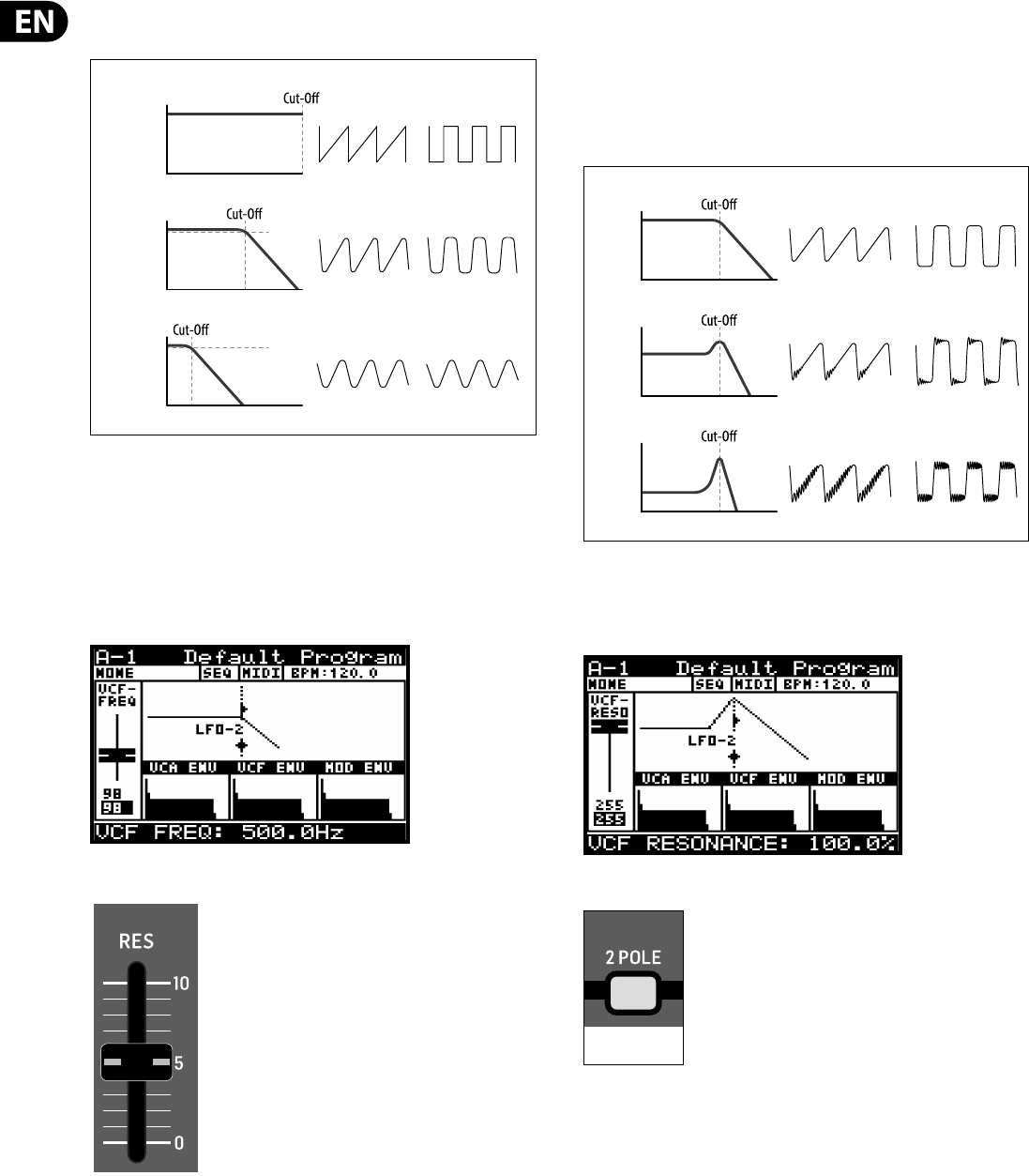
68 DeepMind 12 User Manual
The diagram below shows the results from high, medium and low settings of the
cut-o frequency when applied to the SAWTOOTH and SQUARE waveforms.
The VCF FREQ range is from 50.0 Hz to 20000.0 Hz. The default VCF FREQUENCY
setting is 20000.0 Hz(fully open).
The fader position, current value and stored value for the VCF FREQ fader is shown
on the PROG screen. There is also a visualization of the lter curve as shown
below.
Note: The slope of the lter will update depending on the use of a 2-pole or
4-pole con guration.
8.5.2 VCF RES FADER
The VCF RES fader controls the resonance of the lter. When resonance is
increased the frequencies/harmonics/partials around the cut-o frequency are
emphasized. The resonance along with the lter slope help de ne the character
of the lter.
The DeepMind 12 lter is capable of being driven into self oscillation. Unlike many
other synthesizers, the synthesizer can guarantee an accurate pitch even when
the lter resonance is pushed to (and past) the point where the lter starts to
self-oscillate. When using this self-oscillating feature of the VCF as a sound
source, the VCF calibration ensures the correct response when playing the entire
scale of the keyboard. For more information please consult the section on
calibration later in this document.
The VCF RES range is from 0.0% to 100.0%. The default VCF RES setting is 0.0%.
The fader position, current value and stored value for the VCF RES fader is shown
on the PROG screen. There is also a visualization of the resonance as shown below
8.5.3 2-POLE SWITCH
This switch controls the con guration of poles used in the VCF.
The number of poles used in the lter determines the angle of the lters slope/
response curve.
The VCF uses 4-poles, but can be switched into 2-pole operation. If con gured for
4-pole operation the low-pass lter rolls o signals above the cut-o frequency
at a rate of 24 dB/octave. When con gured for 2-pole operation the low-pass
lter rolls o signals above the cut-o frequency at a rate of 12 dB/octave.
LEVEL (dB)
FREQUENCY (Hz)
HIGH
SAWTOOTH SQUARE
MED
LOW
VCF FREQUENCY
LEVEL (dB)
-3 dB
FREQUENCY (Hz)
LEVEL (dB)
-3 dB
FREQUENCY (Hz)
LEVEL (dB)
FREQUENCY (Hz)
LOW
SAWTOOTH SQUARE
MED
HIGH
VCF RESONANCE
LEVEL (dB)
FREQUENCY (Hz)
LEVEL (dB)
FREQUENCY (Hz)
ON=2P / OFF=4P
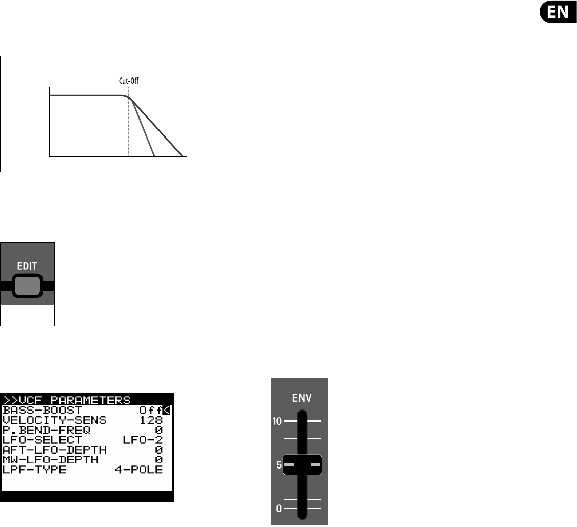
69 DeepMind 12 User Manual
This can be useful to control the sonic character of the lter as the 2-pole mode
will allow more of the signal above the cut-o frequency to pass and sound
brighter / more natural. The 4-pole mode allows less of the signal above the
cut-o frequency to pass and sounds deeper/ more unusual.
The 2-POLE con guration can be On(2-Pole) or O (4-Pole). The default program
setting is O (4-Pole).
8.5.4 VCF EDIT SWITCH
To access the VCF menu press the VCF EDIT switch.
The VCF EDIT switch will then start ashing and the VCF PARAMETERS menu is
then shown:
To navigate the options in the VCF PARAMETERS menu, use the UP, DOWN,
switches.
Selected parameters are adjusted using the -NO/+YES switches, the rotary knob
or the fader. The rotary knob has a click which allows very accurate control. The
fader allows rapid adjustment across the full range:
The following options are available in the VCF PARAMETERS menu:
BASS-BOOST - This option engages an analog bass boost circuit. This setting
follows the BOOST switch status.
VELOCITY-SENS - This option controls how much the velocity at which you strike
the keys will a ect how much VCF envelope modulation is applied. I.e. the harder
you strike the keys, the more the lter will open and the brighter the sound will
become (unless the operation is inverted using the INVERT switch).
The VELOCITY-SENS range is from 0 to 255. The default VELOCITY-SENS setting
is 128.
P. BE ND - FRE Q - This option controls how much the PITCH BEND WHEEL position
will a ect the cut-o frequency. I.e. the further you move the wheel forward
from its central position, the more the lter will open and the brighter the sound
will become, the further you move the wheel backward from its central position,
the more the lter will close and the darker the sound will become.
The P.BEND-FREQ range is from 0 to 255. The default P.BEND-FREQ setting is 128.
LFO-SELECT - This option allows you to select which LFO is assigned to the VCF
LFO MODULATION FADER.
You can select either LFO 1 or LFO 2. The default setting is LFO 2, which allows
you to use LFO 1 for voice modulation and keep the functionality separated. You
can of course use the same LFO to modulate the OSC and VCF if you desire.
AFT-LFO-DEPTH - This option controls how much the AFTERTOUCH pressure will
increase the LFO MODULATION DEPTH. This allows you to add LFO modulation of
the lter frequency expressively while you play.
The AFT-LFO-DEPTH range is from 0 to 255. The default AFT-LFO-DEPTH setting
is 0.
MW-LFO-DEPTH - This option controls how much the MOD WHEEL position will
a ect the LFO MODULATION DEPTH. This allows you to add LFO modulation of the
lter frequency expressively while you play.
The MW-LFO-DEPTH range is from 0 to 255. The default MW-LFO-DEPTH setting
is 0.
LPF-TYPE - This option is the same as the 2-POLE switch on the surface. Any
changes on the surface will be re ected here.
The LPF-TYPE con guration can be 2-POLE or 4-POLE. The default program
setting is 4-POLE.
8.5.5 VCF ENV FADER
The VCF ENV fader controls the amount of VCF ENVELOPE modulation that will be
applied to the cut-o frequency value.
When the cut-o frequency is modulated by the VCF ENVELOPE each note will be
a ected by the ADSR (and Curves) stages for the VCF ENVELOPE. You can use this
to apply subtle or aggressive modulation to the harmonic characteristics of each
note played for the duration they are playing.
When modulating the cut-o frequency using the VCF ENVELOPE, it is advised
to set the fader to a lower level when using normal polarity, and set it to a
higher level when using the INVERT function of the VCF ENVELOPE MODULATION
parameter.
When no ENV MODULATION is applied the lter cut-o frequency will stay xed
(unless other sources of modulation are applied).
The cut-o frequency setting can limit the modulation from the VCA ENVELOPE.
If the VCF FREQ fader is already at its maximum setting, and the lter is already
wide open then no positive modulation can take the cut-o frequency higher.
VCF POLES ( CUT OFF SLOPE)
LEVEL (dB)
4-Pole 2-Pole
FREQUENCY (Hz)
FLASHING=EDIT
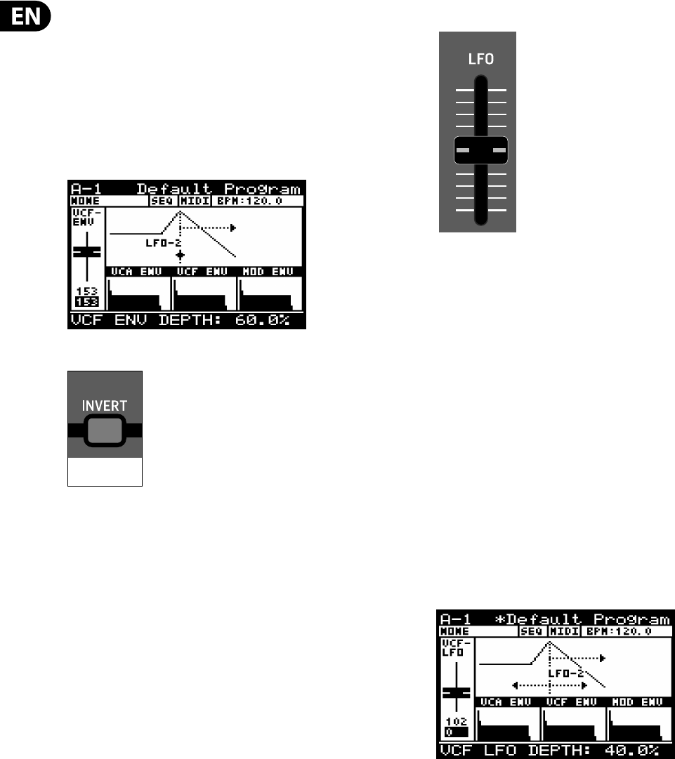
70 DeepMind 12 User Manual
This is also true for negative values when the VCF ENVELOPE is inverted.
The VCF ENV range is from 0.0% to 100.0%. The default VCF ENV setting is
0.0%(O ).
The fader position, current value and stored value for the VCF ENV fader is shown
on the PROG screen. There is also a visualization of the envelope amount (the
arrow pointing to the right) as shown below:
Note: When you invert the polarity of the envelope, the arrow indicating the
envelope modulation will be reversed and point to the left to indicate negative
modulation.
8.5.6 INVERT SWITCH
This switch controls the polarity of the VCF ENVELOPE modulation. When the
switch is on, the polarity of the envelope will be inverted.
It is advised to set the fader to a lower level when using normal polarity, and
set it to a higher level when using the INVERT function of the VCF ENVELOPE
MODULATION parameter.
The INVERT switch can be set to On or O . The default program setting is On.
8.5.7 VCF LFO FADER
The VCF LFO fader controls the amount of VCF LFO modulation that will be applied
to the cut-o frequency value. You can select which LFO will be used as the
modulation source in the VCF PARAMETERS menu.
When the cut-o frequency is modulated by the VCF LFO each note will be
a ected by the shape and speed of the LFO. You can use this aggressively to
create a wah pedal type e ect, or used subtly to add movement and variation to
the program.
When no LFO MODULATION is applied the lter cut-o frequency will stay xed
(unless other sources of modulation are applied).
The cut-o frequency setting can limit the modulation from the LFO. If the VCF
FREQ fader is already at its maximum setting, and the lter is already wide open
then no positive modulation can take the cut-o frequency higher.
The VCF LFO range is from 0.0% to 100.0%. The default VCF LFO setting is
0.0%(O ).
The fader position, current value and stored value for the VCF LFO fader is shown
on the PROG screen. There is also a visualization of the LFO amount (the arrows
pointing left and right below the LFO-1 text) as shown below:
Note: The distance between the arrows represents the amount of LFO
modulation which is being applied to the lter cut-o frequency.
Shortcut Note: To change the VCF LFO source press and hold the VCF EDIT
switch. While holding the switch you can use the VCF LFO fader to select the
source LFO. The following message will be shown to give you guidance while
holding the LFO 1 EDIT switch.
ON=INVERTED
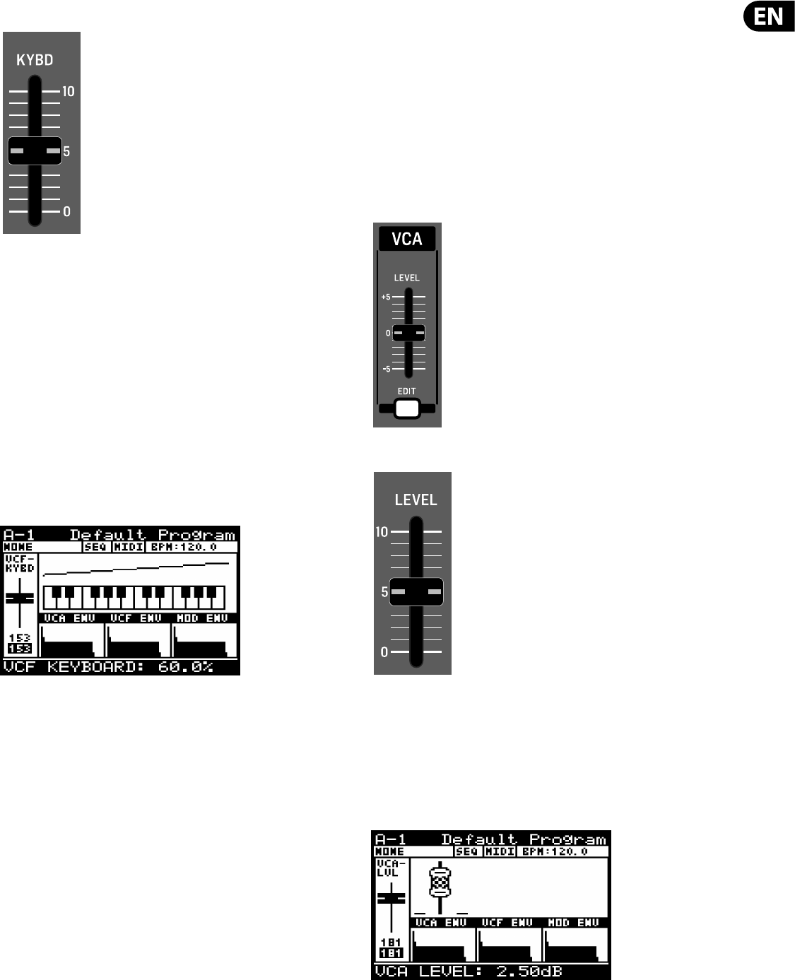
71 DeepMind 12 User Manual
8.5.8 VCF KYBD FADER
The VCF KYBD fader controls the keyboard tracking of the VCF. The keyboard
tracking can be used to compensate the cut-o frequency of the lter depending
on the notes being played.
It can prevent inconsistencies in the harmonic content caused by pitch changes.
When the VCF KYBD fader is raised, the higher the note (above the middle C)
played on the keyboard, the more the lter opens. At the same time the lower the
note (below the middle C) played on the keyboard, the more the lter closes.
This modulation can be used to emulate the response of a natural instrument, or
used to creative e ect.
The VCF KYBD range is from 0.0% to 100.0%. The default VCF KYBD setting is
0.0%(O ).
The fader position, current value and stored value for the VCF KYBD fader is
shown on the PROG screen. There is also a visualization of the modulation
amount as shown below:
8.6 VCA
The VOLTAGE CONTROLLED AMPLIFIER (VCA) is split into two stages. The rst
is a per voice stereo VCA which can be modulated by the VCA ENVELOPE, the
PAN-SPREAD setting, the VELOCITY SENSITIVITY of the keyboard and the Pan
Destination in the Mod Matrix.
The second stage is a common VCA used to correct, or compensate the level so
that it is consistent between programs.
Both stages use a voltage to control the amount of signal passed through to the
next stage. The higher the control voltage, the more of the signal will be passed.
The per voice VCA Level is also available in the Mod Matrix as a destination where
it can be modulated from any of the Mod Matrix sources.
8.6.1 LEVEL
The VCA LEVEL fader controls the second stage of the VCA, I.e. how much
ampli cation or attenuation is applied to the summed voice signals.
The VCA LEVEL range is from -12.0 dB to 6.0 dB. The default VCA LEVEL setting is
0.0 dB(O ).
The fader position, current value and stored value for the VCA LEVEL fader is
shown on the PROG screen. There is also a visualization of the position as
shown below:
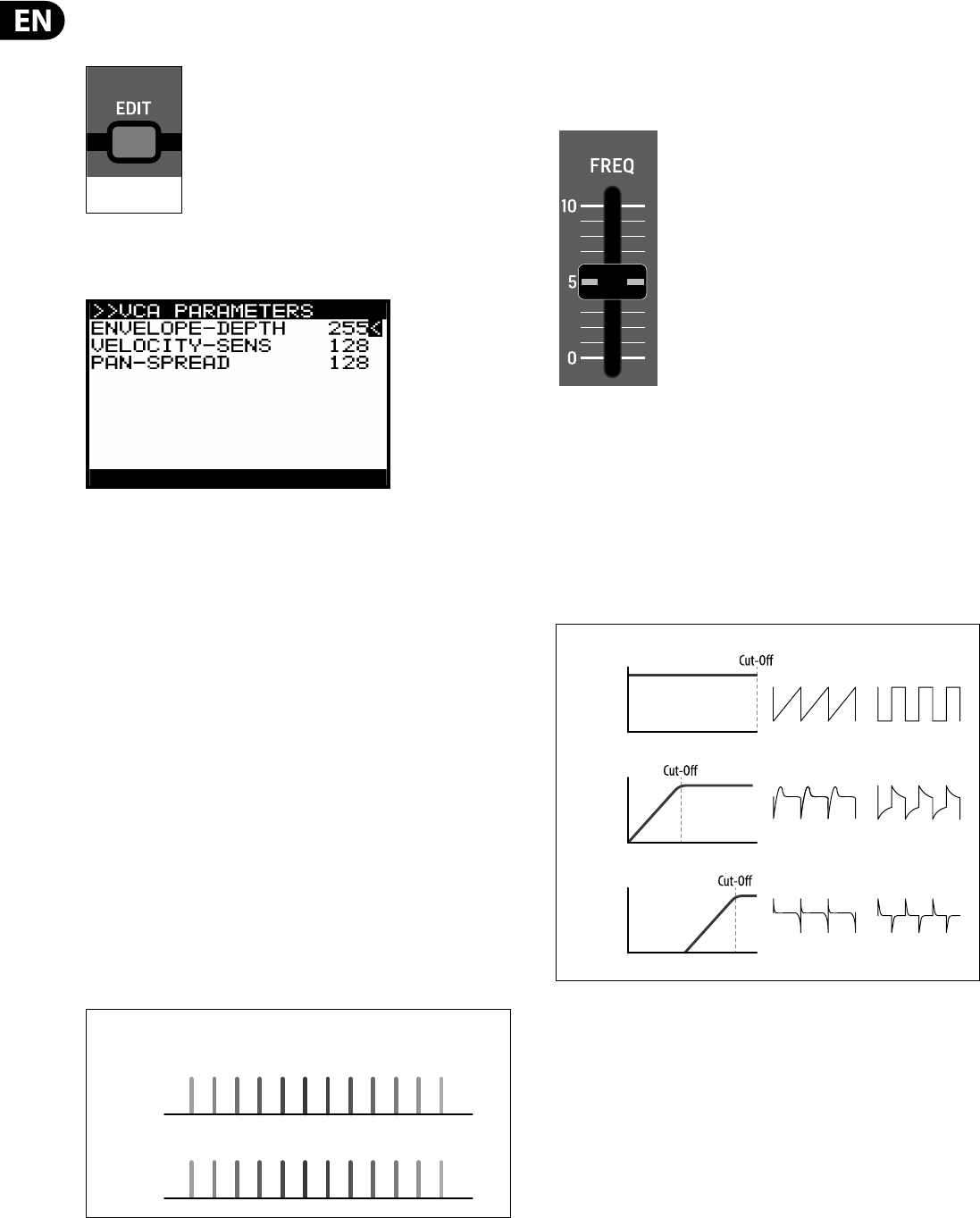
72 DeepMind 12 User Manual
8.6.2 VCA EDIT MENU
To access the VCA PARAMETERS menu press the VCA EDIT switch.
The VCA EDIT switch will then start ashing and the VCA PARAMETERS menu is
then shown.
To navigate the options in the VCA PARAMETERS menu, use the UP,
DOWN, switches.
Selected parameters are adjusted using the -NO/+YES switches, the rotary knob
or the fader. The rotary knob has a click which allows very accurate control. The
fader allows rapid adjustment across the full range:
The following options are available in the VCA PARAMETERS menu:
ENVELOPE-DEPTH - This option allows you to control how much the VCA
ENVELOPE will be used to modulate the per voice VCA.
This is the primary method to sculpt the shape of a sound. For more information
please consult the section on the VCA ENVELOPE
The ENVELOPE-DEPTH range is from 0 to 255. The default ENVELOPE-DEPTH
setting is 255.
VELOCITY-SENS - This option allows you to control how much the velocity at
which you strike the keys will a ect the per voice VCA. I.e. the harder you strike
the keys, the louder the sound and the softer you strike the keys the quieter the
sound will be.
The VELOCITY-SENS range is from 0 to 255. The default VELOCITY-SENS setting
is 128.
PAN-SPREAD - This option allows you to control how much the individual voices
will be spread across the stereo image.
The PAN-SPREAD range is from 0 to 255. The default PAN-SPREAD setting is 0.
8.7 HPF
The HIGH PASS FILTER (HPF) is applied to the output of the VCA. Because the VCA
has summed all the voices the HPF will a ect all voice simultaneously by design.
8.7.1 HPF FREQ FADER
The HPF FREQ fader controls the cut-o frequency of the HPF. The HPF will begin
cutting frequencies above the cut-o frequency at continue to cut them at a rate
of -6 dB per octave.
The HPF lter can be useful to remove subsonic frequencies from your sound
if required. You can also use the lter to sculpt the sonic characteristics of the
program, or you can dynamically adjust the fader to create sweeps of the lter
which will create distinctive movement.
The HPF Frequency is available in the Mod Matrix as a destination where it can be
modulated from any of the Mod Matrix sources.
The HPF FREQ range is from 20.0 Hz to 2000.0 Hz. The default HPF FREQ setting is
20.0 Hz (fully open).
FLASHING=EDIT
+VE
PAN SPREAD
VCA PAN SPREAD
24 61 3 5 7 98 11 1210
-VE
PAN SPREAD
2
46 13579 81112 10
LEVEL (dB)
FREQUENCY (Hz)
LOW
SAWTOOTH SQUARE
MED
HIGH
HPF FREQUENCY
LEVEL (dB)
FREQUENCY (Hz)
LEVEL (dB)
FREQUENCY (Hz)
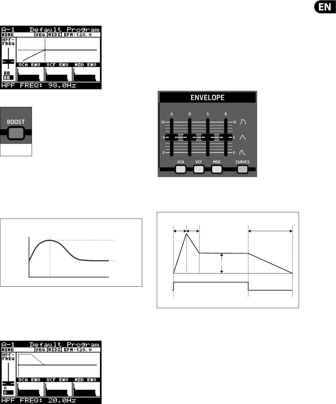
73 DeepMind 12 User Manual
The fader position, current value and stored value for the HPF FREQ fader is
shown on the PROG screen. There is also a visualization of the lter curve as
shown below.
8.7.2 BOOST SWITCH
This switch controls the BOOST stage of the DeepMind 12.
The boost function enables an analog circuit which is designed to boost
low frequencies at 100 Hz using a shelving equalization and DC blocking
functionality..
The BOOST function can be used to give programs an enhanced low frequency
response resulting in more depth and body
The BOOST function can be On/O . The default program setting is O .
There is also a visualization of the BOOST lter curve on the PROG screen as
shown below.
Note: You will only see the BOOST visualization if the HPF fader was the last fader
that was moved..
8.8 ENVELOPES
The DeepMind 12 has three envelope generators. Each of these generates a
control signal with 4 stages (Attack, Decay, Sustain and Release).
The VCA envelope is used to adjust the level of the note being played over time.
The VCF envelope is used to adjust the cut-o frequency of the lter for each note
played over time.
The MOD envelope can be used to modulate any of the MOD MATRIX destinations
for each note being played over time.
The envelopes are normally triggered by the playing of a key, but they also have
di erent triggering modes (LFO, Looping & Sequencer).
It is important to note that the ATTACK, DECAY and SUSTAIN stages are measured
in units of time, and the SUSTAIN stage is measured in units of level.
The stages of the ENVELOPE are shown below:
Note: In any of the looping modes the sustain stage is not considered and as
soon as the envelope reaches the sustain stage it immediately starts the release
stage.
ON=BASS BOOST
BOOST RESPONSE
LEVEL (dB)
100 Hz
0 dB
6 dB
FREQUENCY (Hz)
ATTACK DECAY
SUSTAIN
ENV
LEVEL
KEY
GATE
RELEASE
KEY PRESSED KEY RELEASED
ENVELOPE STAGES
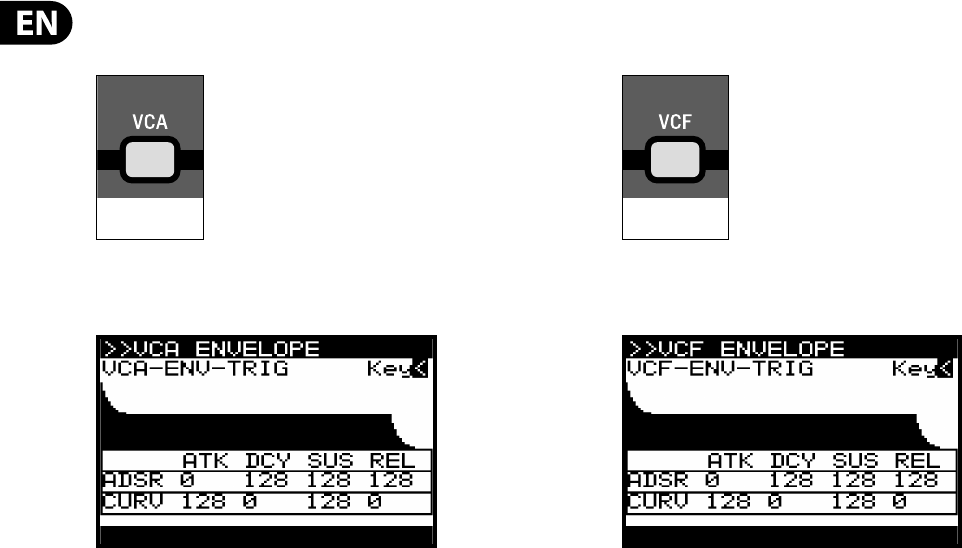
74 DeepMind 12 User Manual
8.8.1 VCA ENVELOPE SWITCH
To access the VCA ENVELOPE page press the VCA Envelope switch.
The VCA ENVELOPE switch will then start ashing and the VCA ENVELOPE menu is
then shown:
To navigate the options in the VCA ENVELOPE menu, use the UP, DOWN, switches.
Selected parameters are adjusted using the -NO/+YES switches, the rotary knob
or the dedicated fader. The rotary knob has a click which allows very accurate
control. The fader allows rapid adjustment across the full range:
The following options are available in the VCA ENVELOPE menu:
VCA-ENV-TRIG - This option allows you to select the triggering mode for the VCA
ENVELOPE from the following:
•
• Key - This option will force the envelope to be triggered each time a key is
pressed.
•
• LFO-1 - This option will force the envelope to be triggered each time LFO 1
starts a new cycle.
•
• LFO-2 - This option will force the envelope to be triggered each time LFO 2
starts a new cycle.
•
• Loop - This option will force the envelope to be re-triggered each time the
end of the release stage is reached.
•
• Seq - This option will force the envelope to be re-triggered on every step of
the CONTROL SEQUENCER.
ADSR ATK: - This controls the attack time of the VCA envelope. I.e. the time is
take for the sound to transition from zero to its maximum level. As the value
increases, the slower the attack time becomes and the longer it takes for the
sound to reach its maximum level.
ADSR DCY: This controls the decay time of the VCA envelope. After a sound
reaches the maximum level, the decay time controls how quickly the level will
transition to the sustain level. As the value increases, the longer the decay time
becomes.
ADSR SUS: This controls the level for the sustain stage of the VCA envelope. The
sound will stay at this level while a note is held on the keyboard.
ADSR REL: This option control the release time of the VCA envelope. This controls
how quickly it takes the sound to decay from the sustain level to zero when a key
is released.
8.8.2 VCF ENVELOPE SWITCH
To access the VCF ENVELOPE page press the VCF ENVELOPE switch.
The VCF ENVELOPE switch will then start ashing and the VCF ENVELOPE menu is
then shown:
To navigate the options in the VCF ENVELOPE menu, use the UP, DOWN, switches.
Selected parameters are adjusted using the -NO/+YES switches, the rotary knob
or the fader. The rotary knob has a click which allows very accurate control. The
fader allows rapid adjustment across the full range:
The following options are available in the VCF ENVELOPE menu:
VCF-ENV-TRIG - This option allows you to select the triggering mode for the VCF
ENVELOPE from the following:
•
• Key - This option will force the envelope to be triggered each time a key is
pressed.
•
• LFO-1 - This option will force the envelope to be triggered each time LFO 1
starts a new cycle.
•
• LFO-2 - This option will force the envelope to be triggered each time LFO 2
starts a new cycle.
•
• Loop - This option will force the envelope to be re-triggered each time the
end of the release stage is reached.
•
• Seq - This option will force the envelope to be re-triggered on every step of
the CONTROL SEQUENCER.
ADSR ATK: This controls the attack time of the VCF envelope. I.e. the time is take
for the lter to open from the VCF FREQ fader setting to the level set by the VCF
ENV fader. As the value increases, the slower the attack time becomes and the
longer it takes for the lter to open.
ADSR DCY: Sets the decay time of the VCF envelope. After a sound reaches the
frequency set at its attack stage, the decay controls how quickly the lter then
transitions to the frequency set with the sustain knob.
ADSR SUS: Sets the lter cut-o frequency for the sustained portion of the
sound. The sound will stay at this lter frequency for as long as a note is held on
the keyboard.
ADSR REL: Sets the release time of the envelope. This controls how quickly the
lter closes when a key is released.
FLASHING=EDIT FLASHING=EDIT
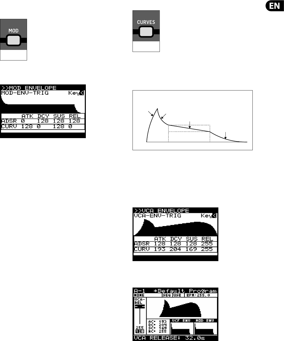
75 DeepMind 12 User Manual
MOD ENVELOPE SWITCH
To access the MOD ENVELOPE page press the MOD ENVELOPE switch.
The MOD ENVELOPE switch will then start ashing and the MOD ENVELOPE menu
is then shown:
To navigate the options in the MOD ENVELOPE menu, use the UP, DOWN, switches.
Selected parameters are adjusted using the -NO/+YES switches, the rotary knob
or the fader. The rotary knob has a click which allows very accurate control. The
fader allows rapid adjustment across the full range:
The following options are available in the MOD ENVELOPE menu:
MOD-ENV-TRIG - This option allows you to select the triggering mode for the
MOD ENVELOPE from the following:
•
• Key - This option will force the envelope to be triggered each time a key is
pressed.
•
• LFO-1 - This option will force the envelope to be triggered each time LFO 1
starts a new cycle.
•
• LFO-2 - This option will force the envelope to be triggered each time LFO 2
starts a new cycle.
•
• Loop - This option will force the envelope to be re-triggered each time the
end of the release stage is reached.
•
• Seq - This option will force the envelope to be re-triggered on every step of
the CONTROL SEQUENCER.
ADSR ATK: - This controls the attack time of the MOD envelope. I.e. the time is
take for the envelope to reach its peak setting. As the value increases, the slower
the attack time becomes and the longer it takes for the envelope to reach its
maximum point.
ADSR DCY: This controls the decay time of the MOD envelope. After the envelope
reaches the maximum value, the decay time controls how quickly the envelope
will transition to the sustain level. As the value increases, the longer the decay
time becomes.
ADSR SUS: This controls the value for the sustain stage of the MOD envelope. The
sound will stay at this level while a note is held on the keyboard.
ADSR REL: This option control the release time of the MOD envelope. This
controls how quickly it takes the envelope to decay from the sustain value to zero
when a key is released.
8.8.3 CURVES SWITCH
This switch changes the operation of the ADSR faders from adjusting the ADSR
stages to adjusting the curve of each stage.
To activate CURVES mode press the CURVES switch. The switch will illuminate and
the faders will now control the curve of each stage.
CURV ATK: This controls the curve shape of the attack stage.
CURV DCY: This controls the curve shape of the decay stage.
CURV SUS: This controls the curve shape (or slope) of the sustain stage.
CURV REL: This controls the curve shape of the release stage.
Using the curve functionality of the waveforms allows advanced sculpting of any
of the envelopes. An example is shown below:
Note: When you adjust any of the envelope faders while viewing the PROG screen
you will see a visualization of the envelope. Below the visualization you will see
the standard or curve parameter values as shown below:
To return to normal operation of the ADSR stages press the CURVES switch again.
The switch will no longer illuminate and the faders will now control the ADSR
stages.
FLASHING=EDIT
ON=CURVES
ATTACK
CURVE DECAY
CURVE SUSTAIN
CURVE(SLOPE)
RELEASE
CURVE
ENVELOPE CURVES
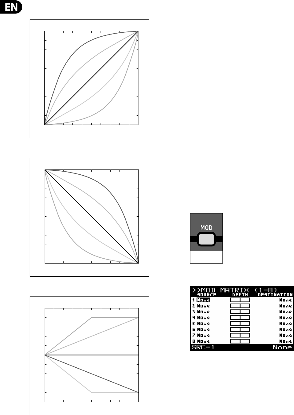
76 DeepMind 12 User Manual
Note: The curve values and the respective response curves are shown below for
guidance:
8.9 MOD MATRIX
The MODULATION MATRIX (MOD MATRIX) is one of the most powerful aspects
of the DeepMind 12 synthesizer. To understand how and why the modulation
matrix is so important we need to understand one simple concept, modulation.
Modulation is the process of controlling one or more properties (destinations) of
a signal using another signal (source).
A simple example would be the control of the VCF cut-o frequency by an
sinusoidal LFO signal. The LFO would open and close the lter automatically
which you could of course do by moving the fader manually. However, by using
a modulation signal you not only free up your hands and mind, you also open up
additional options such as:
•
• Synchronisation with other parameters and actions
•
• Speeds of modulation well past what you could achieve by hand
•
• Accuracy, or programmed inaccuracy of modulation signal
•
• Modulating multiple destinations from the same source
•
• Using multiple sources to modulate the same destination.
•
• Using a source to modulate a parameter e.g. LFO Rate, which indirectly
a ects another modulation e.g. Velocity to Attack Time.
•
• Using a source to modulate the depth of another modulation
Taking the concept further the DeepMind 12 o ers a huge amount of sources and
destinations. For a full list please consult the tables at the end of this section.
The DeepMind 12 MOD MATRIX allows creation of eight "busses". Each bus has a
source, a destination modulations and a routing depth.
To access the MOD MATRIX page press the MOD switch.
The MOD switch will then start ashing and the MOD MATRIX page is then shown:
To navigate the options in the MOD MATRIX page, use the UP, DOWN, switches.
Selected parameters are adjusted using the -NO/+YES switches, the rotary knob
or the fader. The rotary knob has a click which allows very accurate control. The
fader allows rapid adjustment across the full range.
0
64
128
192
255
Attack Curve Settings
Time
Level
Time
0
64
128
192
255
Decay/Release Curve Settings
Level
Time
0
64
128
192
255
Sustain Curve (Slope) Settings
Level
ON=EDIT MATRIX
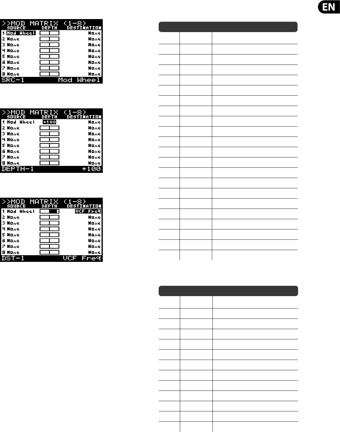
77 DeepMind 12 User Manual
MODULATION SOURCE - To add a modulation source navigate to the source on
the bus you wish to use and select the required source.
MODULATION ROUTING DEPTH - To change the bus routing depth navigate to
the source on the bus you wish to use and select the required source.
MODULATION DESTINATION - To add a modulation destination navigate to the
destination on the bus you wish to use and select the required source.
Note: The possible modulation are 8 busses x 22 sources x 129 destinations
which will allow over 22,000 possible combinations.
8.9.1 MODULATION SOURCES
The following modulation sources are available:
No Name Description
1 Pitch Bend Pitch Bend Wheel
2 Mod Wheel Modulation Wheel
3 Foot Ctrl Foot Controller
4 BreathCtrl Breath Controller
5 Pressure Aftertouch Pressure
6 LFO1 LFO 1
7 LFO2 LFO 2
8Env 1 VCA Envelope
9Env 2 VCF Envelope
10 Env 3 Mod Envelope
11 Note Num Note Number
12 Note Vel Note Velocity
13 Ctrl Seq Control Sequencer
14 LFO1 (Uni) LFO1 (Unipolar)
15 LFO2 (Uni) LFO 2 (Unipolar)
16 LFO1 (Fade) LFO 1 (Fade Envelope)
17 LFO2 (Fade) LFO 2 (Fade Envelope)
18 NoteO Vel Note O Velocity
19 Voice Num Voice Number
20 CC X (114) Continuous Controller X-Axis (114)
21 CC Y (115) Continuous Controller Y-Axis (115)
22 CC Z (116) Continuous Controller Z-Axis (116)
8.9.2 MODULATION DESTINATIONS
The following modulation destinations are available:
No Name Description
1 LFO1 Rate LFO 1 Rate
2 LFO1 Delay LFO 1 Delay Time
3 LFO1 Slew LFO 1 Slew Rate
4 LFO1 Shape LFO 1 Shape
5 LFO2 Rate LFO 2 Rate
6 LFO2 Delay LFO 2 Delay Time
7 LFO2 Slew LFO 2 Slew Rate
8 LFO2 Shape LFO 2 Shape
9 OSC1+2 Pit OSC 1 + 2 Pitch
10 OSC1 Pitch OSC 1 Pitch
11 OSC2 Pitch OSC 1 Pitch
12 OSC1 PM Dep OSC 1 Pitch Modulation Depth
13 PWM Depth OSC 1 Pulse Width Modulation Depth
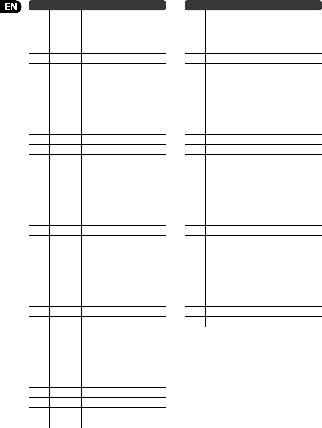
78 DeepMind 12 User Manual
No Name Description
14 TMod Depth OSC 2 Tone Modulation Depth
15 OSC2 PM Dep OSC 2 Pitch Modulation Depth
16 Porta Time Portamento Time
17 VCF Freq VCF Cut-o Frequency
18 VCF Res VCF Resonance
19 VCF Env VCF Envelope
20 VCF LFO VCF LFO
21 Env Rates All Envelope Rates
22 All Attack All Attack Times
23 All Decay All Decay Times
24 All Sus All Sustain Levels
25 All Rel All Release Times
26 Env1 Rates All Envelope 1 Rates
27 Env2 Rates All Envelope 2 Rates
28 Env3 Rates All Envelope 3 Rates
29 Env1CurveS All Envelope 1 Curves
30 Env2CurveS All Envelope 2 Curves
31 Env3CurveS All Envelope 3 Curves
32 Env1 Attack Envelope 1 Attack Time
33 Env1 Decay Envelope 1 Decay Time
34 Env1 Sus Envelope 1 Sustain Level
35 Env1 Rel Envelope 1 Release Time
36 Env1 AtCur Envelope 1 Attack Time Curve
37 Env1 DcyCur Envelope 1 Decay Time Curve
38 Env1 SuSCur Envelope 1 Sustain Level Curve
39 Env1 RelCur Envelope 1 Release Time Curve
40 Env2 Attack Envelope 2 Attack Time
41 Env2 Decay Envelope 2 Decay Time
42 Env2 Sus Envelope 2 Sustain Level
43 Env2 Rel Envelope 2 Release Time
44 Env2 AtCur Envelope 2 Attack Time Curve
45 Env2 DcyCur Envelope 2 Decay Time Curve
46 Env2 SuSCur Envelope 2 Sustain Level Curve
47 Env2 RelCur Envelope 2 Release Time Curve
48 Env3 Attack Envelope 3 Attack Time
49 Env3 Decay Envelope 3 Decay Time
50 Env3 Sus Envelope 3 Sustain Level
51 Env3 Rel Envelope 3 Release Time
52 Env3 AtCur Envelope 3 Attack Time Curve
53 Env3 DcyCur Envelope 3 Decay Time Curve
54 Env3 SuSCur Envelope 3 Sustain Level Curve
No Name Description
55 Env3 RelCur Envelope 3 Release Time Curve
56 VCA All** VCA Gain for All Voices
57 VCA Active** VCA Gain for Active Voices
58 VCA EnvDep VCA Envelope Depth
59 Pan Spread Pan Spread
60 VCA Pan VCA Pan
61* OSC2 Lvl OSC 2 Level
62* Noise Lvl Noise Level
63* HP Freq HPF Cut-o Frequency
64* Uni Detune Unison Detune
65* OSC Drift OSC Drift
66* Param Drift Parameter Drift
67* Drift Rate Drift Rate
68* Arp Gate Arpeggiator Gate
69* Seq Slew Control Sequencer Slew
70 Mod 1 Dep Mod Matrix Routing 1 Depth
71 Mod 2 Dep Mod Matrix Routing 2 Depth
72 Mod 3 Dep Mod Matrix Routing 3 Depth
73 Mod 4 Dep Mod Matrix Routing 4 Depth
74 Mod 5 Dep Mod Matrix Routing 5 Depth
75 Mod 6 Dep Mod Matrix Routing 6 Depth
76 Mod 7 Dep Mod Matrix Routing 7 Depth
77 Mod 8 Dep Mod Matrix Routing 8 Depth
78-89 Fx 1 Params E ects Slot 1 Parameters
90-101 Fx 2 Params E ects Slot 2 Parameters
102-113 Fx 3 Params E ects Slot 3 Parameters
114-125 Fx 4 Params E ects Slot 4 Parameters
126 Fx 1 Level E ects Slot 1 Level
127 Fx 2 Level E ects Slot 2 Level
128 Fx 3 Level E ects Slot 3 Level
129 Fx 4 Level E ects Slot 4 Level
Note: Destinations marked with a '*' are common to all voices.
** VCA Active - This destination a ects the VCA Gain for all active voices.
*** VCA All - This destination a ects the VCA Gain for all voices, regardless of
whether they are active or not.
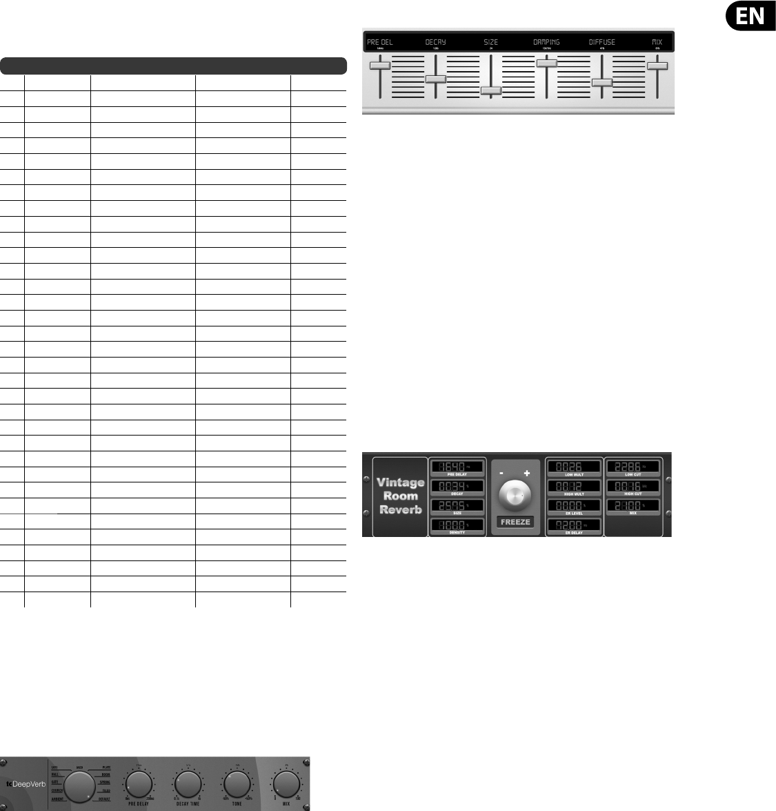
79 DeepMind 12 User Manual
9. E ects Reference Guide
9.1 E ects Table
No Name Description Device Inspiration Type
1 TC-DeepVRB TC Deep Reverb TC Hall of Fame Reverb
2 AmbVerb Ambient Reverb Lexicon 480L Reverb
3 RoomRev Room Reverb Lexicon 480L Reverb
4 VintageRev Vintage Room Reverb EMT250 Reverb
5 HallRev Hall Reverb Lexicon 480L Reverb
6 ChamberRev Chamber Reverb Lexicon 480L Reverb
7 PlateRev Plate Reverb Lexicon PCM-70 Reverb
8 RichPltRev Rich Plate Reverb Lexicon 480L Reverb
9 GatedRev Gated Reverb Lexicon 300/480L Reverb
10 Reverse Reverse Reverb Lexicon 300/480L Reverb
11 ChorusVerb Chorus & Reverb Lexicon PCM-70 Reverb
12 DelayVerb Delay & Reverb Lexicon PCM-70 Reverb
13 FlangVerb Flange & Reverb Lexicon PCM-70 Reverb
14 MidasEQ Midas Equaliser Midas ProX* Processing
15 Enhancer Enhancer SPL Vitalizer Processing
16 FairComp Fair Compressor Fairchild 670 Processing
17 MulBndDist Multi-Band Distortion Midas ProX* Processing
18 RackAmp Rack Ampli er Tech 21 SansAmp Processing
19 EdisonEX1 Stereo Imaging Edison EX-1 Processing
20 Auto Pan Auto-Panning Behringer X32* Processing
21 NoiseGate Noise Gate Midas ProX* Processing
22 Delay Delay Behringer X32* Delay
23 3TapDelay 3-Tap Delay Behringer X32* Delay
24 4TapDelay 4-Tap Delay Behringer X32* Delay
25 T-RayDelay Tel-Ray Delay Tel-Ray Delay Delay
26 DecimDelay Decimator Delay Decimator Delay Delay
27 ModDlyRev Mod, Delay & Reverb Lexicon PCM-70 Delay
28 Chorus Chorus Behringer X32* Creative
29 Chorus-D Chorus D Roland Dimension D Creative
30 Flanger Flanger Behringer X32* Creative
31 Phaser Phase Behringer X32* Creative
32 MoodFilter Mood Filter Moog Type Filter Creative
33 DualPitch Dual Pitch Shifter Harmonizer Creative
34 RotarySpkr Rotary Speaker Leslie Creative
* - Direct algorithms from the hardware devices designed by Music Group
companies.
9.2 E ects Descriptions
Here is a list and brief description of the e ects available on the DeepMind 12
synthesizer.
TC Deep Reverb
TC Electronic is synonymous with some of the best sounding reverbs out there.
There are nine iconic reverb modes you know and love into this e ect that simply
sounds so insanely good – you just have to try it. It’s amazing that just four
controls (Decay, Tone and PreDelay) can give such a wide range of tonal options –
bright and springy, warm and bouncy or gigantic dark re ections… It’s all there
– and then some.
The PRE DELAY fader controls the amount of time before the reverb is heard
following the source signal. TONE enhances high frequencies for positive settings
and enhances low frequencies for negative settings. DECAY controls the amount
of time it takes for the reverb to dissipate. Note: The decay range changes
depending which of the modes is selected.
HallRev, AmbVerb, RichPltRev, RoomRev, ChamberRev
These 5 reverb emulations are inspired by the Lexicon 480L. Hall simulates the
reverberation that occurs when sound is recorded in medium to large-sized
concert halls. Ambience creates a customizable virtual acoustic space to add
warmth and depth without coloring the direct sound.
The PRE DELAY fader controls the amount of time before the reverb is heard
following the source signal. DECAY controls the amount of time it takes for the
reverb to dissipate. SIZE controls the perceived size of the space being created by
the reverb. The DAMP fader adjusts the decay of the high frequencies within the
reverb tail. DIFF(usion) controls the initial re ection density, and LEVEL controls
the e ect output.
LO and HI CUT allow the frequencies a ected by the reverb to be narrowed.
BASSMULT(iplier) controls the low frequency build-up. SPREAD emphasizes
the stereo e ect of the reverb. SHAPE adjusts the contour of the reverberation
envelope. MOD SPEED controls the reverb tail modulation rate and TAIL GAIN
adjusts the volume of the reverb tail. The Rich Plate and Room reverbs allow
the stereo ECHO DELAY and the delay FEEDBACK to be adjusted independently
for each side. The Chamber reverb allows the stereo REFL(ection) DELAY and
GAINtobe adjusted independently.
VintageRev
Vintage Room simulates the reverberation that occurs when sound is recorded in
a small room. When you want to add a bit of warmth and just a touch of reverb,
the Vintage Room breathes life into close-mic'd guitar and drum tracks. (Inspired
by the Quantec QRS)
Set the early re ection times for the left and right channel with ER DELAY L
and ER DELAY R. ER LEVEL sets the loudness of the early re ection level. REV
DELAY controls the amount of time before the reverberation is heard following
the source signal. HI/LOW MULTIPLY adjusts the decay time of the high and
bass frequencies. ROOM SIZE adjusts the size of the room e ect being created
incrementally from small to large. HIGH CUT sets the frequency above which
the source signal does not pass through the reverb. DENSITY manipulates the
re ection density in the simulated room. (This slightly changes the reverb decay
time). LOW CUT sets the frequency below which the source signal does not pass
through the reverb.
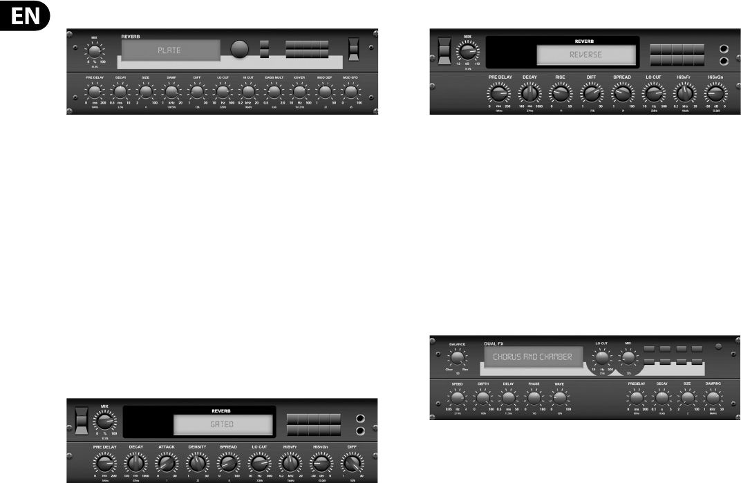
80 DeepMind 12 User Manual
Plate Reverb
A plate reverb was originally created by sending a signal through a transducer
to create vibrations on a plate of sheet metal which were then picked up as an
audio signal. Our algorithm simulates that sound with high initial di usion and a
bright colored sound. The Plate Reverb will give your tracks the sound heard on
countless hit records since the late 1950s. (Inspired by the Lexicon PCM-70)
PRE DELAY controls the amount of time before the reverberation is heard
following the source signal. DECAY controls the amount of time it takes for the
reverb to dissipate. SIZE adjusts the size of the virtual room created by the reverb
e ect. The DAMP knob adjusts the decay of high frequencies within the reverb
tail. DIFF(USION) controls the initial re ection density. The LO CUT knob sets the
frequency beneath which the source signal will not pass through the reverb.
The HI CUT knob sets the frequency above which the source signal will not pass
through the reverb. The BASS MULT(IPLIER) knob adjusts the decay time of the
bass frequencies. XOVER controls the crossover point for bass. MOD DEPTH and
SPEED control the intensity and speed of the reverb tail modulation.
Gated Reverb
This e ect was originally achieved by combining a reverb with a noise gate.
Ourgated reverb creates the same impression by a special shaping of the
reverbtail.
Gated Reverb is especially e ective for creating a 1980s-style snare sound or to
enlarge the presence of a kick drum. (Inspired by the Lexicon 300/480L)
PRE DELAY controls the amount of time before the reverberation is heard
following the source signal. DECAY controls the amount of time it takes for the
reverb to dissipate. ATTACK controls how fast the re ection density builds up.
DENSITY shapes the reverb decay tail. The higher the density, the greater the
number of sound re ections. SPREAD controls how the re ection is distributed
through the envelope of the reverb. The LO CUT knob sets the frequency beneath
which the source signal will not pass through the reverb. The HiSvFr/ HiSvGn
knobs adjust a Hi-Shelving lter at the input of the reverb e ect. DIFF(USION)
controls the initial re ection density.
Reverse Reverb
Reverse Reverb takes the trail of a reverb, turns it around, and places it in front
of the sound source. Use the swelling crescendo of the Reverse Reverb to add an
ethereal quality to vocal and snare tracks. (Inspired by the Lexicon 300/480L)
Adjusting the PRE DELAY knob adds up to 200 milliseconds of time before the
reverb follows the source signal. The DECAY knob adjusts the time it takes for
the reverb to completely dissipate. RISE controls how quickly the e ect builds
up. DIFF(USION) controls the initial re ection density. SPREAD controls how the
re ection is distributed through the envelope of the reverb. The LO CUT knob
sets a low frequency beneath which the source signal will not pass through the
reverb. The HiSvFr/HiSvGn knobs adjust a Hi-Shelving lter at the input of the
reverb e ect.
Chorus + Chamber
Taking up only one FX slot, the Chorus + Chamber e ect combines the shimmer
and doubling characteristics of a studio-grade Chorus with the sweet sound of a
traditional Chamber reverb. (Reverb is Inspired by the Lexicon PCM 70)
The BALANCE knob adjusts the balance between chorus and reverb.
Lowfrequencies can be excluded with the LO CUT knob, and the MIX knob adjusts
how much of the e ect is added to the signal. SPEED, DELAY and DEPTH adjust
the rate, delay, and modulation depth of the chorus. The LFO PHASE between left
and right channel can be o set by up to 180 degrees, and WAVE adjusts the LFO
waveform from a sine wave to triangular wave. The PREDELAY knob determines
the hesitation before the reverb a ects the signal. The DECAY knob adjusts how
quickly the reverb fades. The SIZE controls how large or small the simulated
space is (room, cathedral, etc.). The DAMPING knob determines the decay of high
frequencies within the reverb tail.
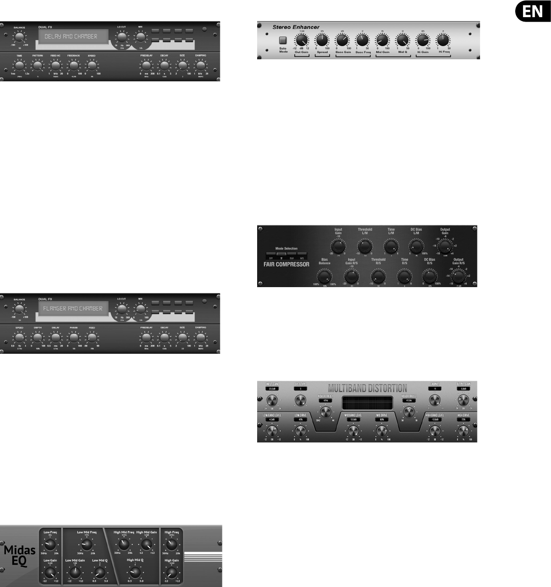
81 DeepMind 12 User Manual
Delay + Chamber
Here we have combined Delay and Chamber reverb, so a single device can provide
a variety of delay settings, plus add just the right type and amount of reverb to
the selected signal. This device only uses one FX slot. (The Reverb is Inspired by
the Lexicon PCM 70)
Use the BALANCE knob to adjust the ratio between delay and reverb.
Lowfrequencies can be excluded with the LO CUT knob, and the MIX adjusts
how much of the e ect is added to the signal. The TIME knob adjusts the delay
time for the left channel delay, and the PATTERN sets the delay ratio for the
right channel delay. Adjust the FEEDBACK and trim some high frequencies with
the FEED HC (high-cut) knob. The XFEED knob allows you to send the delay
sound to the reverb e ect, so instead of running completely parallel, the reverb
a ects the echoes to a selected degree. The PREDELAY knob determines the
hesitation before the reverb a ects the signal. The DECAY knob adjusts how
quickly the reverb fades. The SIZE controls how large or small the simulated
space is (room,cathedral, etc.). The DAMPING knob determines the decay of high
frequencies within the reverb tail.
Flanger + Chamber
Add the mind-bending, lter-sweeping e ect of a state-of-the-art Flanger to
the elegant sweetening of a traditional Chamber reverb — all in one FX slot.
(Reverbis Inspired by the Lexicon PCM 70)
The BALANCE knob adjusts the ratio between anger and reverb. Low frequencies
can be excluded with the LO CUT knob, and the MIX knob adjusts how much
of the e ect is added to the signal. SPEED, DELAY and DEPTH adjust the rate,
delay,and modulation depth of the anger. FEEDback can be adjusted with
positive and negative amounts. The PHASE can be o set by up to 180 degrees.
The PREDELAY knob determines the hesitation before the reverb a ects the
signal. The DECAY knob adjusts how quickly the reverb fades. The SIZE controls
how large or small the simulated space is (room, cathedral, etc.). The DAMPING
knob determines the decay of high frequencies within the reverb tail.
MidasEQ
The Midas EQ is a four-band sweep parametric equalizer taken from the Midas
Pro X console that allows tonal control of the input signal via the parametric EQ
section. The mid bands also have a Q Factor adjustment to tailor the shape of the
EQ curve. The four bands are low, low mid, high mid and high. Any combination
of the four bands can be used to control the signal.
Enhancer
These Enhancers are so called “Psycho EQs”. They can enhance the signal
spectrum in bass, midrange and high frequencies but they di er from traditional
equalizers. When you need to generate maximum punch, clarity and detail,
without turning up the overall volume, our enhancers are the solution.
(Inspiredby the SPL Vitalizer)
Adjust the BASS, MID and HI GAIN knobs to add or reduce content in those
spectrums. The BASS and HI Frequencies can be speci cally selected, while the
MID Q (bandwidth) can be adjusted instead. The OUT GAIN knob compensates for
changes in level resulting from the e ect, and the SPREAD knob (Stereo version
only) emphasizes the stereo content for a wider mix. Engage the SOLO MODE
to isolate only the audio resulting from the e ect so you can hear exactly what
you’re adding to the mix.
Fair Compressor
This model of a Fairchild 670 delivers some of the nest colorations in compressor
history. The two paths L/M and R/S both have the same functionality. The
controls include input GAIN, THRESHOLD, TIME and DC BIAS (which controls the
ratio and knee of the compression curve. There is also a BIAS BALANCE which can
help accentuate attacks. There are modes available for dual, stereo-linked, or
mid/side operation via the MOD control.
MulBndDist
The Multiband Distortion unit, useful for making sound gritty, adding more
warmth through saturation, or even enhancing a speci c frequency region. There
are three bands, adjustable by a 24 dB per octave crossover lter.
There are six distortion types, going from soft saturation to more aggressive
distortion and post lter variants. The 'Drive' parameter controls the amount
of distortion introduced to the sound. This parameter, together with the right
distortion type, can instead bring some soft saturation to the sound.
The e ect also features a Cabinet Unit applied to the output, which can add the
characteristic timbre of 11 di erent cabinet types.
Finally the level of the sound can be controlled by the input and output gain
parameters.
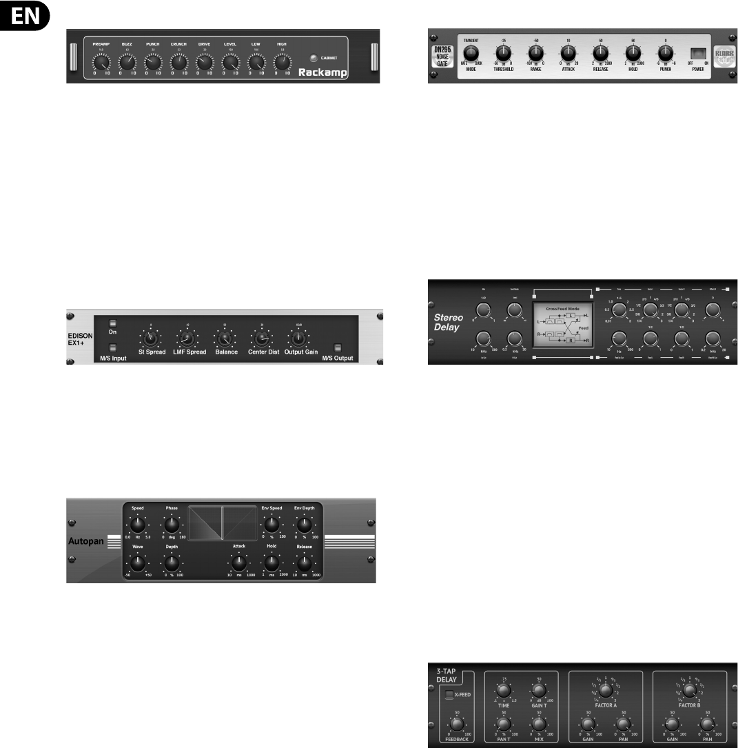
82 DeepMind 12 User Manual
Rack Ampli er
Modelled after the Tech 21 SansAmp, the Stereo / Dual Guitar Amp simulates the
sound of plugging into a real guitar amp. From shimmering cleans to saturated
crunch, the Stereo / Dual Guitar Amp allows an electric guitar player to sound
great without using an amp on stage. The PREAMP knob adjusts the amount of
input gain prior to the band-speci c distortion adjustment. BUZZ adjusts the
low-end breakup, PUNCH adjusts the midrange distortion, and CRUNCH tailors
the high-frequency content and distortion for smooth or cutting notes. The DRIVE
knob simulates the amount of power amp distortion from a tube amp. The LOW
and HIGH knobs allow EQ adjustment independent of distortion content, and the
overall output is controlled by the LEVEL knob. There are 11 CABINET emulations
which can be selected using the CAB parameter. The CABINET simulation can also
be bypassed which allows the e ect to function like a boost or distortion pedal.
Edison EX1
The EDISON EX1+ is a remarkably e ective tool that allows manipulation of the
stereo eld. The e ect o ers stereo and mid/side input and output and a phase
correlation meter. Exaggerate the stereo eld with the ST SPREAD knob and
adjust the ratio of mono to stereo content with the BALANCE knob. The CENTER
DIST knob allows the mono content to be panned. Compensate for level changes
with the OUTPUT GAIN knob.
Auto-Pan
Auto-pan creates an up and down volume change at a constant and even tempo
just like the guitar amps of yesteryear. Use the Auto-pan to add a unique “surf-
music” texture.
SPEED adjusts the LFO rate and DEPTH sets the amount of modulation. PHASE
can be used to set an LFO phase di erence between the left and right channel,
which can be used for panning e ects. The WAVE knob blends the LFO waveform
between triangular and square shape. The signal envelope, shaped by ATTACK,
HOLD and RELEASE, can be used to modulate the LFO speed (ENV SPEED) and the
LFO modulation depth (ENV DEPTH).
NoiseGate
The Noise Gate not only handles the duties of a traditional version, but also o ers
enhanced "Transient Accenting" characteristics to gated signals. Enhance the
attack envelope beyond merely opening the gate, and provide up to 12 dB of
additional transient energy to percussive programs. In many cases the DN265's
control over transients may prove to be a viable alternate to EQ.
Attack is exponential which means it can be set extremely fast to reduce signal
loss at the start of sounds while remaining sonically transparent - no clicks.
Gate release is reverse exponential so it can be set relatively fast and blend in
seamlessly with the natural decay of the material.
Delay
Stereo Delay provides independent control of left and right delay (echo) times
and features high and low pass lters for enhanced tone shaping of the delayed
signals. Use the Stereo Delay to give your mono signals a wide presence in the
stereo eld.
The MIX control lets you blend the source signal and the delayed signal.
TIMEadjusts the master delay time up to three seconds. LO CUT adjusts the low
frequency cut, allowing lower frequencies to remain una ected by the delay.
HI CUT adjusts the high frequency cut, allowing higher frequencies to remain
una ected by the delay. FACTOR L sets the delay on the left channel to rhythmic
fractions of the master delay time. FACTOR R sets the delay on the right channel
to rhythmic fractions of the master delay time. OFFSET LR adds a delay di erence
between the left and right delayed signals. The FEED LO CUT/HI CUT adjusts lters
in the feedback paths. FEED L and FEED R control the amount of feedback for
the left and right channels. MODE sets the feedback mode: Mode ST sets normal
feedback for both channels, X crosses feedbacks between left and right channels.
M creates a mono mix within the feedback chain.
3-Tap Delay
Sometimes called a 3-Tap Delay, the Triple Delay provides three delay stages with
independent frequency, gain, and pan controls. Create time-based echo e ects
with the Triple Delay to increase the sense of stereo separation.
TIME sets the master delay time, which is also the delay time for the rst stage.
GAIN T sets the gain level of the rst stage of the delay. BASE T sets the position
of the rst delay stage in the stereo eld. X-FEEDindicates that stereo cross-
feedback of the delays is active. FEEDBACK adjusts the amount of feedback.
FACTOR A controls the amount of delay time in the second stage of the delay.
GAIN A controls the gain level of the second delay stage. PAN A sets the position
of the second delay stage in the stereo eld. FACTOR B controls the amount of
delay time in the third stage of the delay. GAINB controls the gain level of the
third delay stage. PAN B sets the position of the third gain stage in the stereo
e l d .
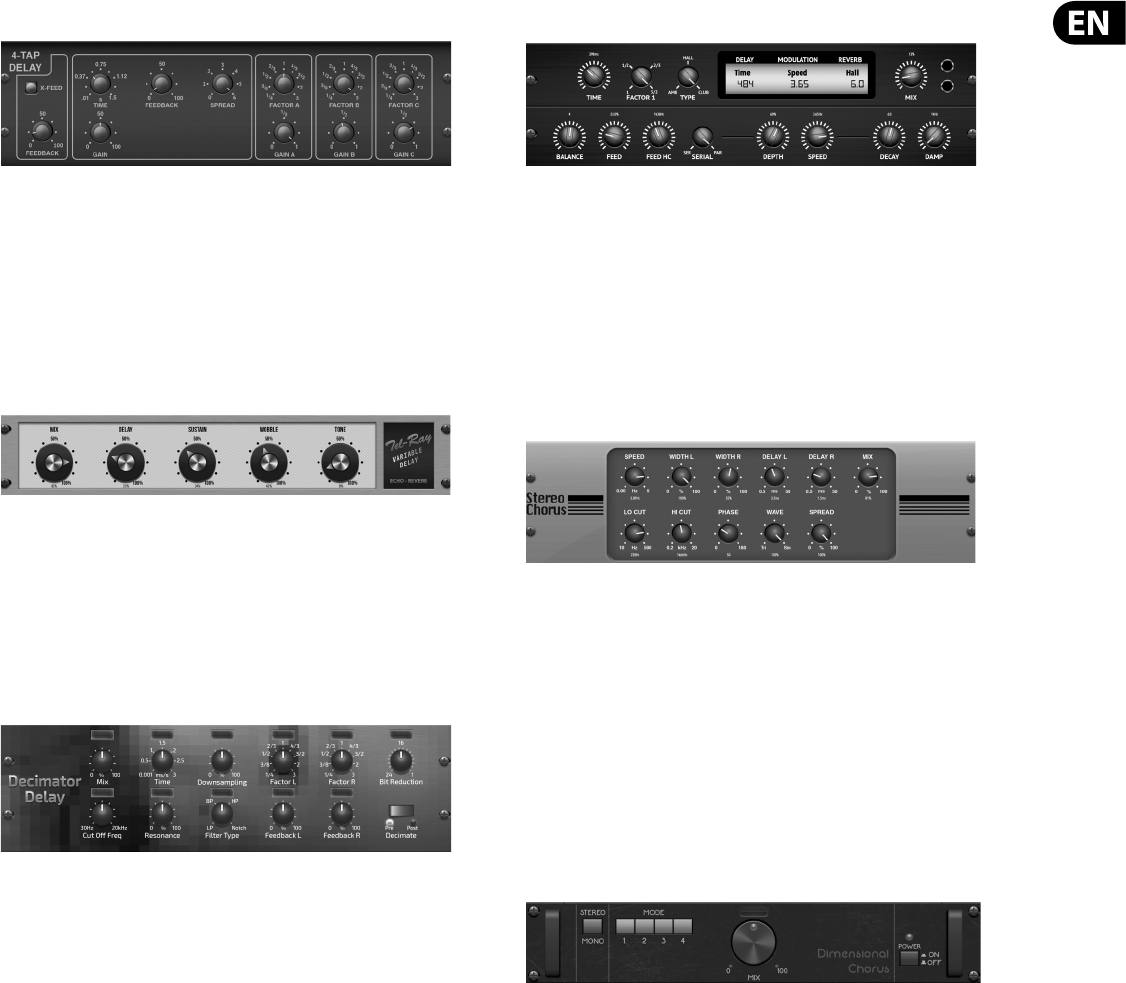
83 DeepMind 12 User Manual
4-Tap Delay
The 4-Tap Delay provides 4 stages of delay with independently adjustable gain
and rate, allowing unique syncopation to be created in the layered repeats.
TIME sets the master delay time, which is also the delay time for the rst stage.
GAIN sets the gain for the rst stage. SPREAD positions the rst delay stage in
the stereo eld. A global FEEDBACK adjustment is also available. FACTOR A, B and
C adjust the delay rate relative to the global TIME setting for the 2nd, 3rd and
4th stages respectively. Each stage also has its own GAIN adjustment. X-FEED
indicates that stereo cross-feedback of the delays is active.
Tel-Ray Delay
Inspired by the original Tel-Ray hardware from the 1960's using a tuna can,
some oil and a motor. It has a very simple set of controls but allows you to create
delays, echo, chorus, vibrato and reverb type e ects. An incredibly versatile and
creative e ect which has a lush and unique character.
DELAY controls the delay time. SUSTAIN controls how long the delay is sustained
for. WOB controls the amount of wobble which is caused by age and quality of
materials in the original hardware.
Decimator Delay
This is a delay e ect including a decimator unit in its chain. It will decimate the
sound by reducing the sampling frequency and the bit-depth. The Decimator
Delay is a creative tool that can be used in many ways, from emulating the
aliasing noise, found in older samplers, to generating complex, low- and rough
delay lines.
Decimate the sound by adjusting the DOWNSAMPLE and BIT-REDUCE. The lter
section will help you manipulate your preferred frequencies to smooth or retain
the grittiness of the sound. The TIME, FACTOR and FEEDBACK parameters will
handle the delay behavior. The DECIMATE (PRE-POST) parameter will set the
decimation to a ect the input source or the only the delay line accordingly.
Modulation Delay + Reverb
Modulation Delay combines three of the most used time modulation e ects
into one easy-to-operate unit, featuring true-stereo delay with a lush chorus,
toppedo with three reverb models to choose from.
The BALANCE knob adjusts ratio of delay to reverb. The processor chain can
operate as serial where one e ect ows into the next, or parallel where each
e ect is applied to the source signal independently. TIME, FEED(back), LOWand
HI CUT all a ect the delay. Modulation DEPTH and SPEED are adjustable.
Threetypes of reverb are available – ambience, club and hall – with adjustable
DECAY and HI DAMP.
Chorus
Chorus samples the input, slightly detunes it and mixes it with the original
signal to produce a somewhat thicker, shimmering sound. Use it to thicken up
background vocals, or to double the sound of brass and woodwind instruments.
Where as DELAY L/R set the total amount of delay for the left and right channel,
WIDTH determines the amount of modulated delay. SPEED sets the modulation
speed. MIX adjusts the balance of the dry and wet signals. You can further sculpt
the sound by trimming some of the low and high end from the e ected signal
with the LO and HI CUT knobs. Additionally, the PHASE knob can tweak the
phase o set of the LFO between left and right channel and the SPREAD knob
adjusts how much of the left channel is mixed into the right and vice versa.
Finally,theWAVE knob blends between the “Danish-style” digital triangular
chorus sound and the classic analog sine wave.
Dimensional Chorus
The Dimensional Chorus o ers the most user-friendly and classic sounds,
bestdescribed as “space” and “dimensional”. The 4 MODE switches can
be engaged individually or simultaneously for light chorus or very thick,
exaggerated modulation.
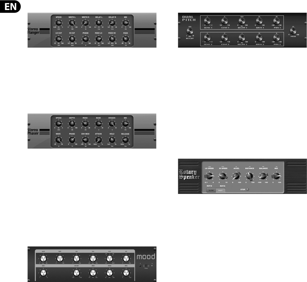
84 DeepMind 12 User Manual
Flanger
The Flanger emulates the phase-shifting sound (comb- ltering) originally
created by applying pressure against the ange of the reel on a tape recorder.
This e ect creates a unique “wobbly” sound that is quite dramatic when used on
vocals and instruments.
The controls of this e ect are nearly identical to the Chorus e ect block.
Additionally, the FEEDBACK can be adjusted with positive and negative amounts
and also band-limited with the FEED HC (high-cut) and FEED LC (low-cut) knobs.
Phaser
A Stereo Phaser, or phase shifter, applies multiple STAGES of modulated lters to
the input signal to create a “notch” in the frequency response, and then applies
a MIX with the original for a “swirling” e ect. Use the Stereo Phaser to add a
“spaced-out” sound to vocal or instrument tracks.
SPEED adjusts the LFO rate and DEPTH sets the LFO modulation depth. The BASE
knob adjusts the frequency range of the modulated lters. The resonance is
adjusted with the RES knob. The WAVE knob shapes the symmetry of the LFO
waveform and PHASE dials in an LFO phase di erence between the left and right
channel. The modulation source can also be the signal envelope, which produces
vowel-like opening and closing tones. The ENV knob adjusts how much this e ect
takes place (positive and negative modulation is possible), and the ATTACK, HOLD
and RELEASE knobs all tailor the response of this feature.
Mood Filter
The Mood Filter uses an LFO generator and an auto-envelope generator to control
a VCF (voltage-controlled lter), as well as a side chain function where the
channel B signal controls the envelope of channel A.
This lter can be modulated with the signal’s envelope using the ENV MOD
(withpositive and negative amounts), ATTACK and RELEASE knobs, or the
LFOcan modulate the lter. The WAVE knob selects between 7 di erent wave
forms–triangular, sine, saw plus, saw minus, ramp, square, and random.
ThePHASE can be o set by up to 180 degrees. The SPEED knob adjusts the rate
of the LFOand the DEPTH adjusts the amount of LFO modulation. Adjustthe
resonance of the lter until self-oscillation with the RESO(nance) knob.
BASEadjusts the range of the lter from 20 Hz to 15 kHz. The MODE switch
selects between low pass (LP), high-pass (HP), band-pass (BP) and Notch. Use the
MIXknob to blend the e ected signal with the dry sound. With the 4 POLE switch
engaged, there will be a steeper slope than the OFF (2 pole) setting. The DRIVE
knob adjusts the level and can also introduce an overdrive e ect (as with real
analog lters) if pushed hard.
Stereo / Dual Pitch
Pitch shifting is often used in two di erent ways. One is to set the Mix knob lower
and only use the Cent knob to make a small o set in pitch between the wet and
dry tones. This results in a “voice doubling” e ect that thickens the overall sound
in a more subtle way. The extreme use of the e ect is to turn the Mix knob fully
clockwise so the entire signal is e ected. This way, the signal can be shifted into
other keys up to an octave above or below the original. When used on a voice,
this results in a “chipmunk” sound or a low Darth Vader e ect.
When the SEMI and CENT knobs are set at 12:00, the pitch is not altered.
Makingadjustments by semitone will have a very pronounced e ect,
whereaschanges to the CENT knob will be very minor. The DELAY knob creates
a time di erence between the wet and dry sound. The LO and HI CUT knobs
allow the e ected signal to be band-limited. The Dual Pitch e ect allows
the leftandright channels to be adjusted independently, and allows GAIN
compensation andpanning of the two channels.
Rotary Speaker
Rotary Speaker emulates the sound of a Leslie rotating speaker. The Rotary
Speaker provides more exibility than its electromechanical counterpart, andcan
be used with a variety of instruments, and even vocals, to create a whirling,
psychedelic e ect.
The LO SPEED and HI SPEED knobs adjust the rotational speed of the
SLOWand FAST Speed selection, and can be toggled with the FAST switch.
TheACCEL(eration) knob adjusts how quickly the speed increases and
decreases from the Slow mode to the Fast mode. The rotation e ect can also
be disengaged with the STOP switch, which will stop the movement of the
speakers. DISTANCEadjusts the distance between the Rotary speakers and the
virtualmicrophone.
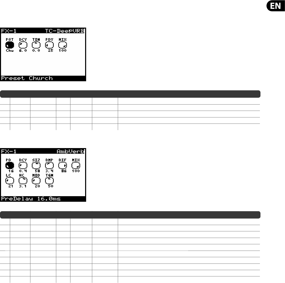
85 DeepMind 12 User Manual
9.3 E ects Parameters
Note: E ects parameters which appear as modulation destinations are marked with a '*'.
TC-DeepVRB (TC DEEP REVERB)
No DM12 REF PARAMETER UNITS MIN MAX DESCRIPTION
1 PST Preset — — — Options: Ambience, Church, Gate, Hall, Lo Fi, Modulated, Plate, Room, Spring, Tile, Default.
2* DCY Decay s 0.1 s 6.0 s Controls the amount of time it takes for the reverb to dissipate (range is preset dependant).
3* TON Tone % -50.0% 50.0% Enhances high frequencies/low frequencies for positive/negative settings respectivly.
4 PDY PreDelay ms 0.0 200.0 ms Controls the amount of time before the reverb is heard following the source signal.
5* MIX Mix % 0.0% 100% Controls the mix (or ratio) of wet (processed) and dry (unprocessed) signals.
AmbVerb (AMBIENT REVERB)
No DM12 REF PARAMETER UNITS MIN MAX DESCRIPTION
1 PD PreDelay ms 0.0 200.0 ms Controls the amount of time before the reverb is heard following the source signal.
2* DCY Decay s 0.2 s 7.3s Controls the amount of time it takes for the reverb to dissipate.
3 SIZ Size — 2.0 100.0 Controls the perceived size of the space being created by the reverb.
4* DMP Damping Hz 1000 Hz 20000 Hz Adjusts the decay of the high frequencies within the reverb tail.
5 DIF Di usion — 1.0 30.0 Controls the initial re ection density.
6* MIX Mix % 0.0% 100% Controls the mix (or ratio) of wet (processed) and dry (unprocessed) signals.
7* LC LoCut Hz 10.0 Hz 500.0 Hz Allows the low frequencies a ected by the reverb to be reduced.
8* HC Hi Cut Hz 200.0 Hz 20000.0 Hz Allows the high frequencies a ected by the reverb to be reduced.
9 MOD Mod % 0.0% 100% Controls the reverb tail modulation depth.
10* TGN TailGain % 0.0% 100% Adjusts the volume of the reverb tail.
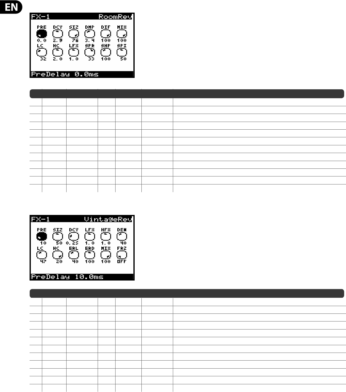
86 DeepMind 12 User Manual
RoomRev (ROOM REVERB)
No DM12 REF PARAMETER UNITS MIN MAX DESCRIPTION
1 PRE PreDelay ms 0.0 200.0 ms Controls the amount of time before the reverb is heard following the source signal.
2* DCY Decay s 0.3 s 28.9 s Controls the amount of time it takes for the reverb to dissipate.
3 SIZ Size m 4.0 m 76.0 m Controls the perceived size of the space being created by the reverb.
4* DMP Damping Hz 1000 Hz 20000 Hz Adjusts the decay of the high frequencies within the reverb tail.
5 DIF Di usion % 0.0% 100% Controls the initial re ection density.
6* MIX Mix % 0.0% 100% Controls the mix (or ratio) of wet (processed) and dry (unprocessed) signals.
7* LC LoCut Hz 10.0 Hz 500.0 Hz Allows the low frequencies a ected by the reverb to be reduced.
8* HC Hi Cut Hz 200.0 Hz 20000.0 Hz Allows the high frequencies a ected by the reverb to be reduced.
9* LFX BassMult -- 0.2 4.0 Controls the low frequency build-up.
10 SPR Spread -- 0.0 50.0 Emphasizes the stereo e ect of the reverb.
11* SHP Shape -- 0.0 250.0 Adjusts the contour of the reverberation envelope.
12 SPI Spin % 0.0% 100% Controls randomization / modulation e ects within the reverb.
VintageRev (VINTAGE ROOM REVERB)
No DM12 REF PARAMETER UNITS MIN MAX DESCRIPTION
1 PRE PreDelay ms 0.0 200.0 ms Controls the amount of time before the reverb is heard following the source signal.
2 SIZ Size % 1.0% 100% Controls the perceived size of the space being created by the reverb. A ects DECAY range.
3* DCY Decay s 0.1 s 20.7 s Controls the amount of time it takes for the reverb to dissipate. Range dependant on SIZE.
4* LFX Lo Mult -- 0.1 10.0 Controls the low frequency build-up.
5* HFX Hi Mult -- 0.1 10.0 Controls the high frequency build-up.
6* DEN Density % 0.0% 100% Manipulates the re ection density in the simulated room.
7* LC LoCut Hz 10.0 Hz 500.0 Hz Allows the low frequencies a ected by the reverb to be reduced.
8* HC Hi Cut Hz 200.0 Hz 20000.0 Hz Allows the high frequencies a ected by the reverb to be reduced.
9* ERL ER Level % 0.0% 100% Set the early re ection times.
10 ERD ER Delay ms 0.0 200.0 ms Sets the loudness of the early re ection level.
11* MIX Mix % 0.0% 100% Controls the mix (or ratio) of wet (processed) and dry (unprocessed) signals.
12* FRZ Freeze -- OFF ON Applies freeze mode and blends signals into a continuous response.
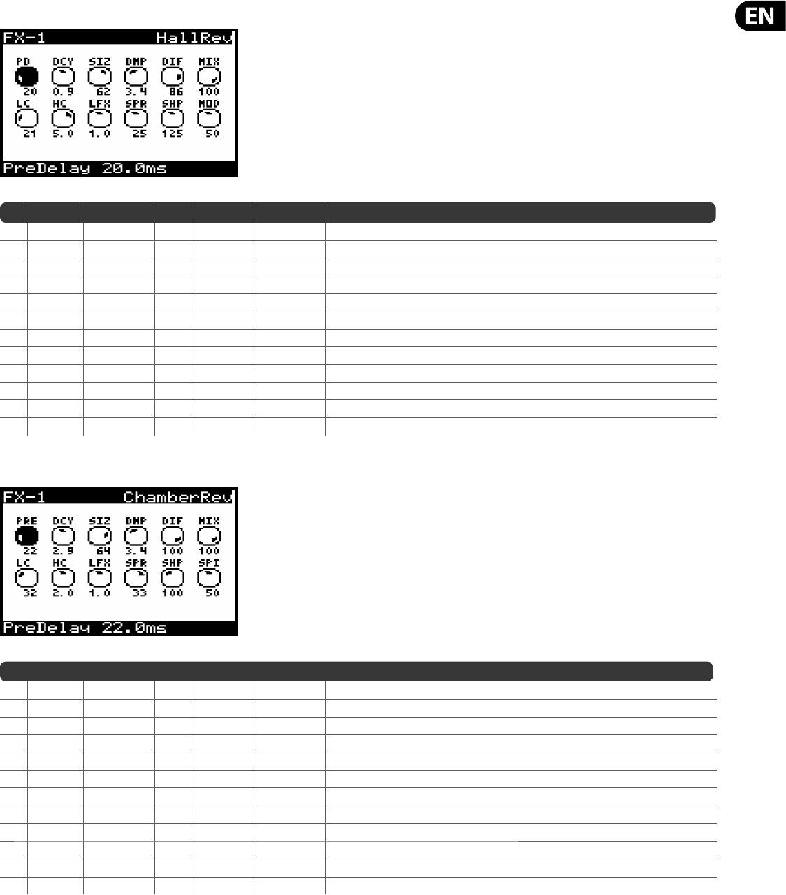
87 DeepMind 12 User Manual
HallRev (HALL REVERB)
No DM12 REF PARAMETER UNITS MIN MAX DESCRIPTION
1 PD PreDelay ms 0.0 200.0 ms Controls the amount of time before the reverb is heard following the source signal.
2* DCY Decay s 0.2 s 4.9 s Controls the amount of time it takes for the reverb to dissipate.
3 SIZ Size -- 2.0 200.0 Controls the perceived size of the space being created by the reverb.
4* DMP Damping Hz 1000 Hz 20000 Hz Adjusts the decay of the high frequencies within the reverb tail.
5 DIF Di usion -- 1.0 30.0 Controls the initial re ection density.
6* MIX Mix % 0.0% 100% Controls the mix (or ratio) of wet (processed) and dry (unprocessed) signals.
7* LC LoCut Hz 10.0 Hz 500.0 Hz Allows the low frequencies a ected by the reverb to be reduced.
8* HC Hi Cut Hz 200.0 Hz 20000.0 Hz Allows the high frequencies a ected by the reverb to be reduced.
9* LFX BassMult -- 0.5 2.0 Controls the low frequency build-up.
10 SPR Spread -- 0.0 50.0 Emphasizes the stereo e ect of the reverb.
11* SHP Shape -- 0.0 250.0 Adjusts the contour of the reverberation envelope.
12 MOD ModSpeed -- 0.0 100.0 Controls the reverb tail modulation rate.
ChamberRev (CHAMBER REVERB)
No DM12 REF PARAMETER UNITS MIN MAX DESCRIPTION
1 PRE PreDelay ms 0.0 200.0 ms Controls the amount of time before the reverb is heard following the source signal.
2* DCY Decay s 0.3 s 28.9 s Controls the amount of time it takes for the reverb to dissipate.
3 SIZ Size m 4.0 m 76.0 m Controls the perceived size of the space being created by the reverb.
4* DMP Damping Hz 1000 Hz 20000 Hz Adjusts the decay of the high frequencies within the reverb tail.
5 DIF Di usion % 0.0% 100% Controls the initial re ection density.
6* MIX Mix % 0.0% 100% Controls the mix (or ratio) of wet (processed) and dry (unprocessed) signals.
7* LC LoCut Hz 10.0 Hz 500.0 Hz Allows the low frequencies a ected by the reverb to be reduced.
8* HC Hi Cut Hz 200.0 Hz 20000.0 Hz Allows the high frequencies a ected by the reverb to be reduced.
9* LFX BassMult -- 0.2 4.0 Controls the low frequency build-up.
10 SPR Spread -- 0.0 50.0 Emphasizes the stereo e ect of the reverb.
11* SHP Shape -- 0.0 250.0 Adjusts the contour of the reverberation envelope.
12 SPI Spin % 0.0% 100% Controls randomization / modulation e ects within the reverb.
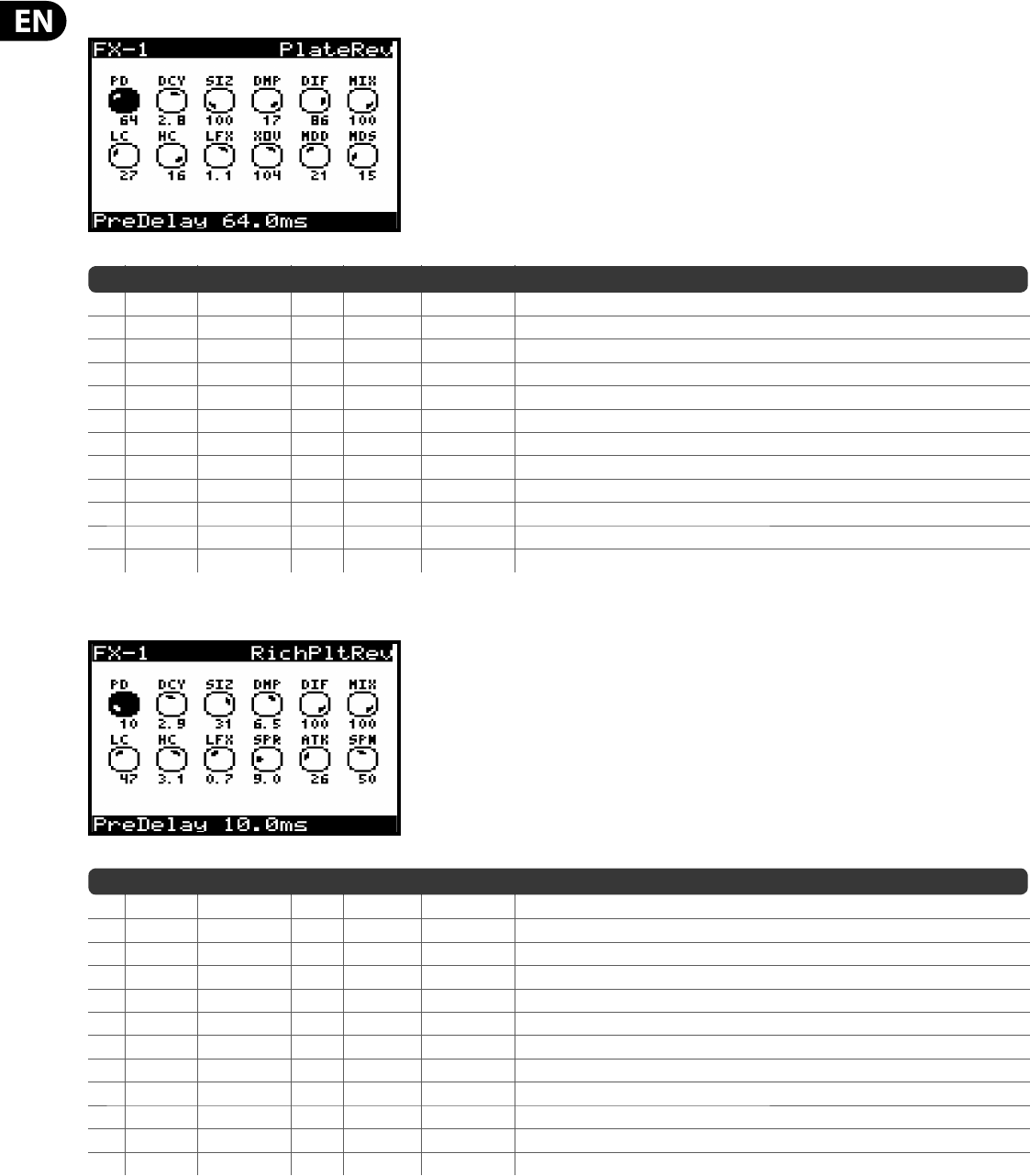
88 DeepMind 12 User Manual
PlateRev (PLATE REVERB)
No DM12 REF PARAMETER UNITS MIN MAX DESCRIPTION
1 PD PreDelay ms 0.0 200.0 ms Controls the amount of time before the reverb is heard following the source signal.
2* DCY Decay s 0.5 s 10.0 s Controls the amount of time it takes for the reverb to dissipate.
3 SIZ Size — 2.0 200.0 Controls the perceived size of the space being created by the reverb.
4* DMP Damping Hz 1000 Hz 20000 Hz Adjusts the decay of the high frequencies within the reverb tail.
5 DIF Di usion — 1.0 30.0 Controls the initial re ection density.
6* MIX Mix % 0.0% 100% Controls the mix (or ratio) of wet (processed) and dry (unprocessed) signals.
7* LC LoCut Hz 10.0 Hz 500.0 Hz Allows the low frequencies a ected by the reverb to be reduced.
8* HC Hi Cut Hz 200.0 Hz 20000.0 Hz Allows the high frequencies a ected by the reverb to be reduced.
9* LFX BassMult — 0.5 2.0 Controls the low frequency build-up.
10* XOV Xover Hz 10.0 Hz 500.0 Hz Controls the crossover point for bass multiplier.
11 MOD ModDepth — 1.0 50.0 Controls the reverb tail modulation depth.
12 MDS ModSpeed — 0.0 100.0 Controls the reverb tail modulation rate.
RichPltRev (RICH PLATE REVERB)
No DM12 REF PARAMETER UNITS MIN MAX DESCRIPTION
1 PD PreDelay ms 0.0 200.0 ms Controls the amount of time before the reverb is heard following the source signal.
2* DCY Decay s 0.3 s 28.9 s Controls the amount of time it takes for the reverb to dissipate.
3 SIZ Size m 4.0 m 39.0 m Controls the perceived size of the space being created by the reverb.
4* DMP Damping Hz 1000 Hz 20000 Hz Adjusts the decay of the high frequencies within the reverb tail.
5 DIF Di usion % 0.0% 100% Controls the initial re ection density.
6* MIX Mix % 0.0% 100% Controls the mix (or ratio) of wet (processed) and dry (unprocessed) signals.
7* LC LoCut Hz 10.0 Hz 500.0 Hz Allows the low frequencies a ected by the reverb to be reduced.
8* HC Hi Cut Hz 200.0 Hz 20000.0 Hz Allows the high frequencies a ected by the reverb to be reduced.
9* LFX BassMult — 0.2 4.0 Controls the low frequency build-up.
10 SPR Spread — 0.0 50.0 Emphasizes the stereo e ect of the reverb.
11* ATK Attack — 0.0 100.0 Adjusts the contour of the reverberation envelope.
12* SPN Spin % 0.0% 100% Controls randomization / modulation e ects within the reverb.
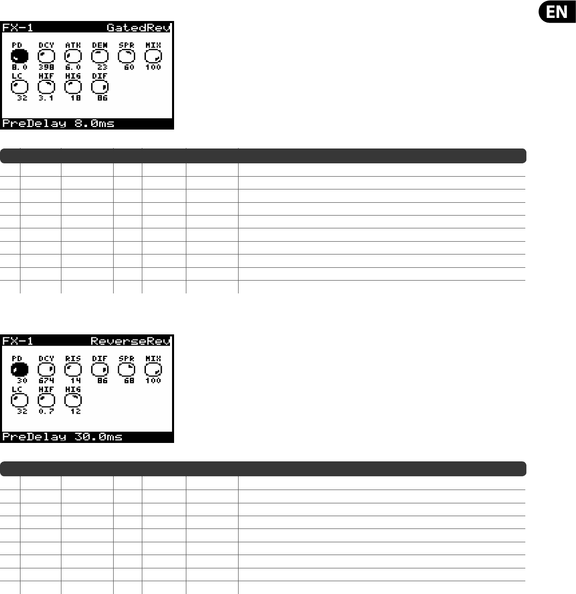
89 DeepMind 12 User Manual
GatedRev (GATED REVERB)
No DM12 REF PARAMETER UNITS MIN MAX DESCRIPTION
1 PD PreDelay ms 0.0 200.0 ms Controls the amount of time before the reverb is heard following the source signal.
2 DCY Decay ms 140.0 ms 1000.0 ms Controls the amount of time it takes for the reverb to dissipate.
3* ATK Attack — 0.0 30.0 Adjusts the contour of the reverberation envelope.
4* DEN Density — 1.0 50.0 Manipulates the re ection density in the simulated room.
5 SPR Spread — 0.0 100.0 Emphasizes the stereo e ect of the reverb.
6* MIX Mix % 0.0% 100% Controls the mix (or ratio) of wet (processed) and dry (unprocessed) signals.
7* LC LoCut Hz 10.0 Hz 500.0 Hz Allows the low frequencies a ected by the reverb to be reduced.
8* HIF HiSvFreq Hz 200.0 Hz 20000.0 Hz Adjusts the frequency of a Hi-Shelving lter at the input of the reverb e ect.
9* HIG HiSvGain dB -30.0 dB 0.0 dB Adjusts the gain of a Hi-Shelving lter at the input of the reverb e ect.
10 DIF Di usion % 0.0% 100% Controls the initial re ection density.
Reverse (REVERSE REVERB)
No DM12 REF PARAMETER UNITS MIN MAX DESCRIPTION
1 PD PreDelay ms 0.0 200.0 ms Controls the amount of time before the reverb is heard following the source signal.
2 DCY Decay ms 140.0 ms 1000.0 ms Controls the amount of time it takes for the reverb to dissipate.
3* RIS Rise — 0.0 50.0 Controls how quickly the e ect builds up.
4 DIF Di usion — 1.0 30.0 Controls the initial re ection density.
5 SPR Spread — 0.0 100.0 Controls how the re ection is distributed through the envelope of the reverb.
6* MIX Mix % 0.0% 100% Controls the mix (or ratio) of wet (processed) and dry (unprocessed) signals.
7* LC LoCut Hz 10.0 Hz 500.0 Hz Allows the low frequencies a ected by the reverb to be reduced.
8* HIF HiSvFreq Hz 200.0 Hz 20000.0 Hz Adjusts the frequency of a Hi-Shelving lter at the input of the reverb e ect.
9* HIG HiSvGain dB -30.0 dB 0.0 dB Adjusts the gain of a Hi-Shelving lter at the input of the reverb e ect.
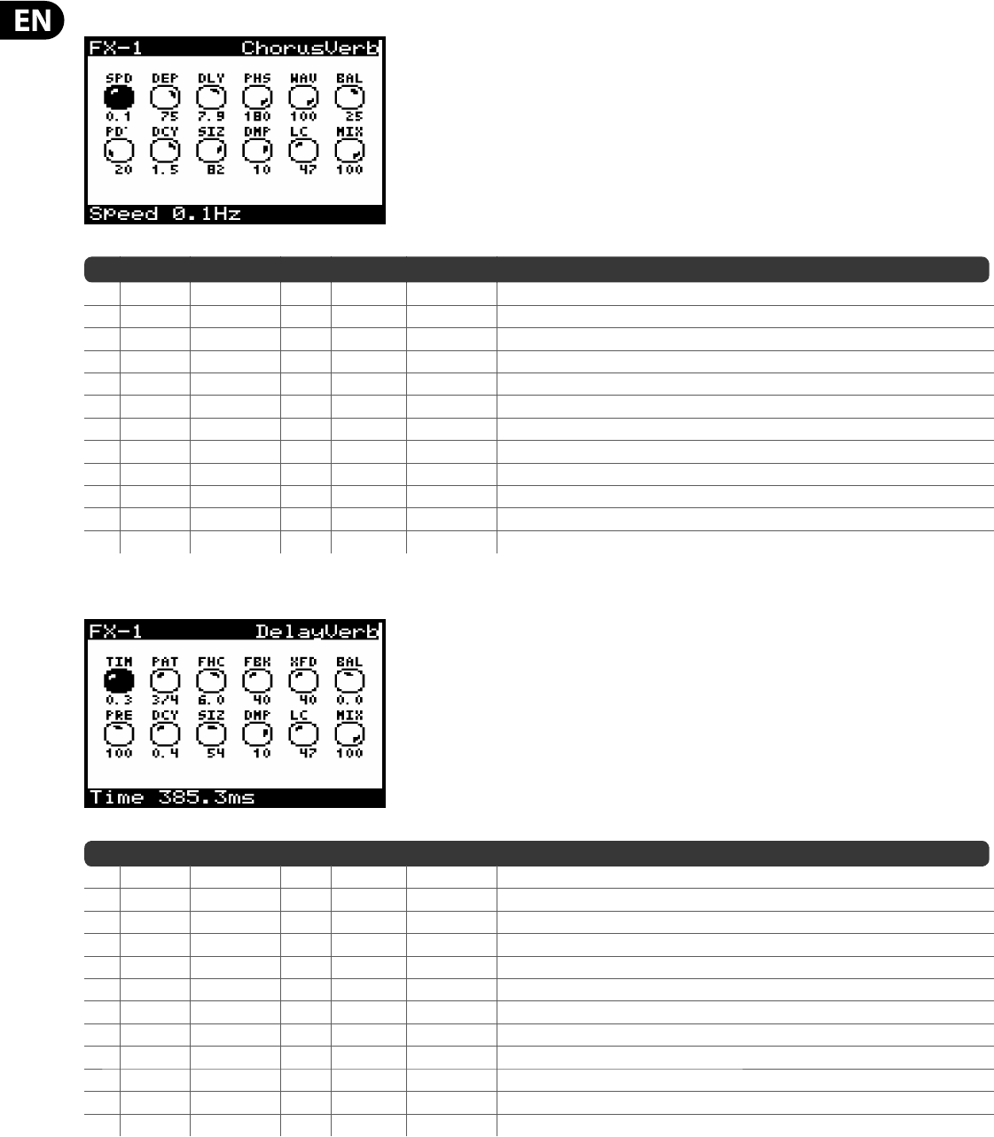
90 DeepMind 12 User Manual
ChorusVerb (CHORUS & REVERB)
No DM12 REF PARAMETER UNITS MIN MAX DESCRIPTION
1* SPD Speed Hz 0.0 Hz 4.0 Hz Adjusts the rate of the chorus. Time synchronised options from 4 to 1/64 bars.
2* DEP Depth % 0.0% 100% Adjusts the modulation depth of the chorus.
3 DLY Delay ms 0.5 ms 50.0 ms Adjusts the delay of the chorus.
4* PHS Phase — 0.0 180.0 O sets the phase between the left and right channels.
5 WAV Wave % 0.0% 100% Adjusts the LFO waveform from a sine wave to triangular wave.
6* BAL Balance — -100.0 100.0 Adjusts the balance between chorus and reverb.
7 PRE PreDelay ms 0.0 200.0 ms Controls the amount of time before the reverb is heard following the source signal.
8* DCY Decay s 0.1 s 5.0 s Controls the amount of time it takes for the reverb to dissipate.
9 SIZ Size — 2.0 200.0 Controls how large or small the simulated space is.
10* DMP Damping Hz 1000 Hz 20000 Hz Determines the decay of high frequencies within the reverb tail.
11* LC LoCut Hz 10.0 Hz 500.0 Hz Excludes low frequencies below the value.
12* MIX Mix % 0.0% 100% Controls the mix (or ratio) of wet (processed) and dry (unprocessed) signals.
DelayVerb (DELAY & REVERB)
No DM12 REF PARAMETER UNITS MIN MAX DESCRIPTION
1 TIM Time ms 1.0ms 1500.0ms Adjusts the delay time for the left channel delay. Time sync options from 4 to 1/64 bars.
2 PAT Pattern — 1/4 1X Sets the delay ratio for the right channel delay.
3* FHC FeedHC Hz 200.0 Hz 20000.0 Hz Trims high frequencies from the feedback.
4* FBK Feedback % 0.0% 100% Controls the percentage of feedback.
5* XFD X-Feed % 0.0% 100% Control the amount of delay sound sent to the reverb e ect.
6* BAL Balance — -100.0 100.0 Adjusts the ratio between delay and reverb.
7 PRE PreDelay ms 0.0 200.0 ms Controls the amount of time before the reverb is heard following the source signal.
8* DCY Decay s 0.1 s 5.0 s Controls the amount of time it takes for the reverb to dissipate.
9 SIZ Size — 2.0 200.0 Controls how large or small the simulated space is.
10* DMP Damping Hz 1000 Hz 20000 Hz Determines the decay of high frequencies within the reverb tail.
11* LC LoCut Hz 10.0 Hz 500.0 Hz Excludes low frequencies below the value.
12* MIX Mix % 0.0% 100% Controls the mix (or ratio) of wet (processed) and dry (unprocessed) signals.
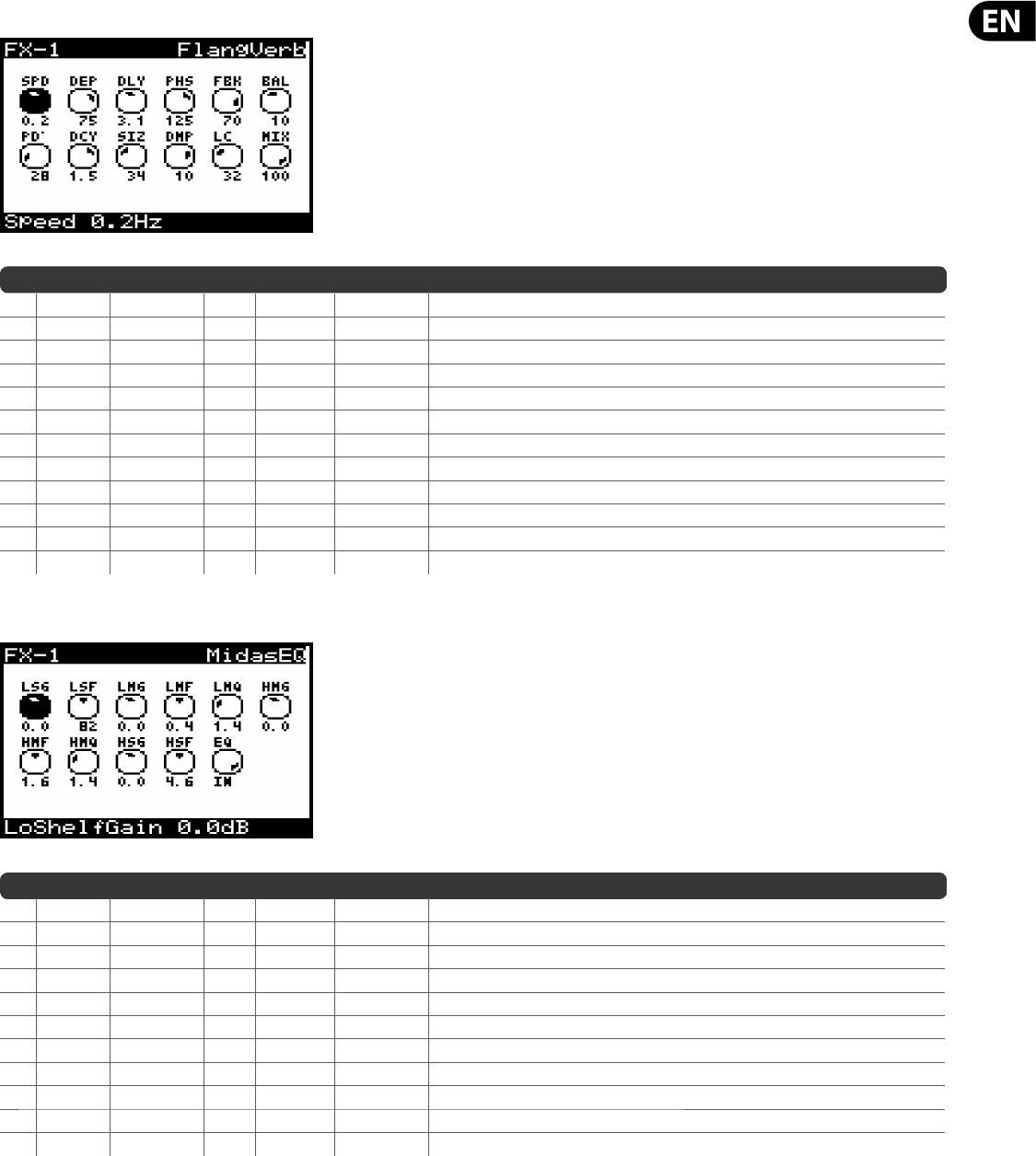
91 DeepMind 12 User Manual
FlangeVerb (FLANGER & REVERB)
No DM12 REF PARAMETER UNITS MIN MAX DESCRIPTION
1* SPD Speed Hz 0.0 Hz 4.0 Hz Adjusts the rate of the anger. Time synchronised options from 4 to 1/64 bars.
2* DEP Depth % 0.0% 100% Adjusts the modulation depth of the anger.
3 DLY Delay ms 0.5 ms 20.0 ms Adjusts the delay of the anger.
4* PHS Phase — 0.0 180.0 O sets the phase between the left and right channels.
5* FBK Feed % -90.0% 90.0% Controls the percentage of positive or negative feedback.
6* BAL Balance — -100.0 100.0 Adjusts the balance between anger and reverb.
7 PRE PreDelay ms 0.0 200.0 ms Controls the amount of time before the reverb is heard following the source signal.
8* DCY Decay s 0.1 s 5.0 s Controls the amount of time it takes for the reverb to dissipate.
9 SIZ Size — 2.0 200.0 Controls how large or small the simulated space is.
10* DMP Damping Hz 1000 Hz 20000 Hz Determines the decay of high frequencies within the reverb tail.
11* LC LoCut Hz 10.0 Hz 500.0 Hz Excludes low frequencies below the value.
12* MIX Mix % 0.0% 100% Controls the mix (or ratio) of wet (processed) and dry (unprocessed) signals.
MidasEQ (MIDAS EQUALIZER)
No DM12 REF PARAMETER UNITS MIN MAX DESCRIPTION
1 LSG* LoShelfGain dB -12.0 dB 12.0 dB Adjusts the gain of the low band.
2 LSF* LoShelfFreq Hz 30.0 Hz 20000.0 Hz Adjusts the frequency of the low band.
3 LMG* LoMidGain dB -12.0 dB 12.0 dB Adjusts the gain of the low-mid band.
4 LMF* LoMidFreq Hz 30.0 Hz 20000.0 Hz Adjusts the frequency of the low-mid band.
5 LMQ* LoMidQ — 0.3 5.0 Adjusts the Q-factor of the low-mid band.
6 HMG* HiMidGain dB -12.0 dB 12.0 dB Adjusts the gain of the high-mid band.
7 HMF* HiMidFreq Hz 30.0 Hz 20000.0 Hz Adjusts the frequency of the high-mid band.
8 HMQ* HiMidQ — 0.3 5.0 Adjusts the Q-factor of the high-mid band.
9 HSG* HiShelfGain dB -12.0 dB 12.0 dB Adjusts the gain of the high band.
10 HSF* HiShelfFreq Hz 30.0 Hz 20000.0 Hz Adjusts the frequency of the high band.
11 EQ* EQ — IN OUT Adjusts the frequency of the high band.
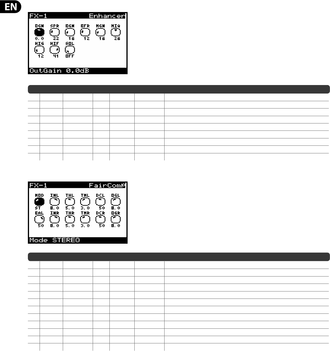
92 DeepMind 12 User Manual
Enhancer (ENHANCING EQ)
No DM12 REF PARAMETER UNITS MIN MAX DESCRIPTION
1* OGN OutGain dB -12.0 dB 12.0 dB Compensates for changes in level resulting from the e ect.
2* SPR Spread % 0.0% 100% Emphasizes the stereo content for a wider mix.
3* BGN BassGain % 0.0% 100% Adjusts the gain of the bass band.
4* BFR BassFreq — 1.0 50.0 Adjusts the frequency of the bass band.
5* MGN MidGain % 0.0% 100% Adjusts the gain of the mid band.
6* MIQ MidQ — 1.0 50.0 Adjusts the Q-factor of the mid band.
7* HIG HiGain % 0.0% 100% Adjusts the gain of the high band.
8* HIF HiFreq — 1.0 50.0 Adjusts the frequency of the high band.
9 SOL FactorC — OFF ON Solo mode - used to isolate only the audio resulting from the e ect.
FairComp (COMPRESSOR)
No DM12 REF PARAMETER UNITS MIN MAX DESCRIPTION
1 MOD Mode — — Mode of operation: O , Stereo, Dual, M/S (Mid/Side).
2* INL InGain L/M — -20.0 0.0 Controls the input gain for the Left/Mid signal.
3* THL ThreshL/M — 0.0 10.0 Controls the threshold for the Left/Mid signal.
4 TML TImeL/M — 1.0 6.0 Controls the attack and release time for the Left/Mid signal.
5* DCL DCBiasL/M % 0.0% 100% Adjust the ratio and knee of the compression curve for the Left/Mid signal.
6* OGL OutGainL/M dB -18.0 dB 6.0 dB Controls the output gain for the Left/Mid signal.
7* BAL Bias Bal % -100.0% 100% Adjust the bias current, creating accentuation of attacks
8* INR InGain R/S — -20.0 0.0 Controls the input gain for the Right/Side signal.
9* THR ThreshR/S — 0.0 10.0 Controls the threshold for the Right/Side signal.
10 TMR TImeR/S — 1.0 6.0 Controls the attack and release time for the Right/Side signal.
11* DCR DCBiasR/S % 0.0% 100% Adjust the ratio and knee of the compression curve for the Right/Side signal.
12* OGR OutGainR/S dB -18.0 dB 6.0 dB Controls the output gain for the Right/Side signal.
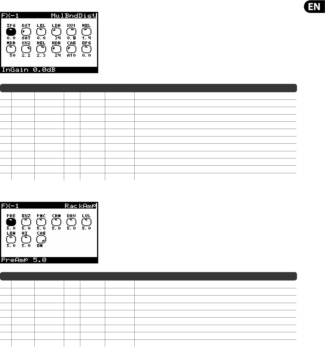
93 DeepMind 12 User Manual
MulBndDist (MULTIBAND DISTORTION)
No DM12 REF PARAMETER UNITS MIN MAX DESCRIPTION
1* IPG InputGain dB -24.0 dB 24.0 dB Controls the amount of input gain applied to the signal.
2 DST Dist Types — — — Distortion Type: VAL(Valve), SAT(Saturation), TUB (Tube), & Post Filter variants (PFV/PFS/PFT).
3* LBL Low Level dB -12.0 dB 12.0 dB Controls the level of the frequencies below XoverFreq 1.
4* LDR Low Drive % 0.0% 100% Controls the percentage of distortion introduced below XoverFreq 1.
5* XV1 Xover Freq 1 Hz 30.0 Hz 9000.0 Hz Sets the lower cross over frequency.
6* MBL Mid Level dB -12.0 dB 12.0 dB Controls the level of the frequencies between Xover1 Freq and Xover2 Freq.
7* MDR Mid Drive % 0.0% 100% Controls the percentage of distortion introduced between Xover1 Freq and Xover2 Freq.
8* XV2 Xover Freq 2 Hz 30.0 Hz 9000.0 Hz Sets the upper cross over frequency.
9* HBL High Level dB -12.0 dB 12.0 dB Controls the level of the frequencies below XoverFreq 2.
10* HDR High Drive % 0.0% 100% Controls the percentage of distortion introduced above XoverFreq 2.
11 CAB Cabinet — — — Cabinet Type: OFF, VTw, VBs, A10, Mid, BFC, B60, V30, S78, Oax, A12, Rck. (See Table Above).
12* OPG OutputGain dB -12.0 dB 12.0 dB Controls the amount of output gain applied to the signal.
RackAmp (RACK AMPLIFIER)
No DM12 REF PARAMETER UNITS MIN MAX DESCRIPTION
1* PRE PreAmp — 0.0 10.0 Adjusts the amount of input gain prior to the band-speci c distortion adjustment.
2* BUZ Buzz — 0.0 10.0 Adjusts the amount of low-end breakup.
3* PNC Punch — 0.0 10.0 Adjusts the amount of midrange distortion.
4* CRN Crunch — 0.0 10.0 Tailors the high-frequency content and distortion for smooth or cutting notes.
5* DRV Drive — 0.0 10.0 Emulates the amount of power amp distortion from a tube amp.
6* LVL Level — 0.0 10.0 Controls the overall output level.
7* LOW Low — 0.0 10.0 EQ adjustment of the low frequencies, independent of distortion content.
8* HI High — 0.0 10.0 EQ adjustment of the high frequencies, independent of distortion content.
9 CAB Cabinet — OFF ON Turns the cabinet simulation on or o .
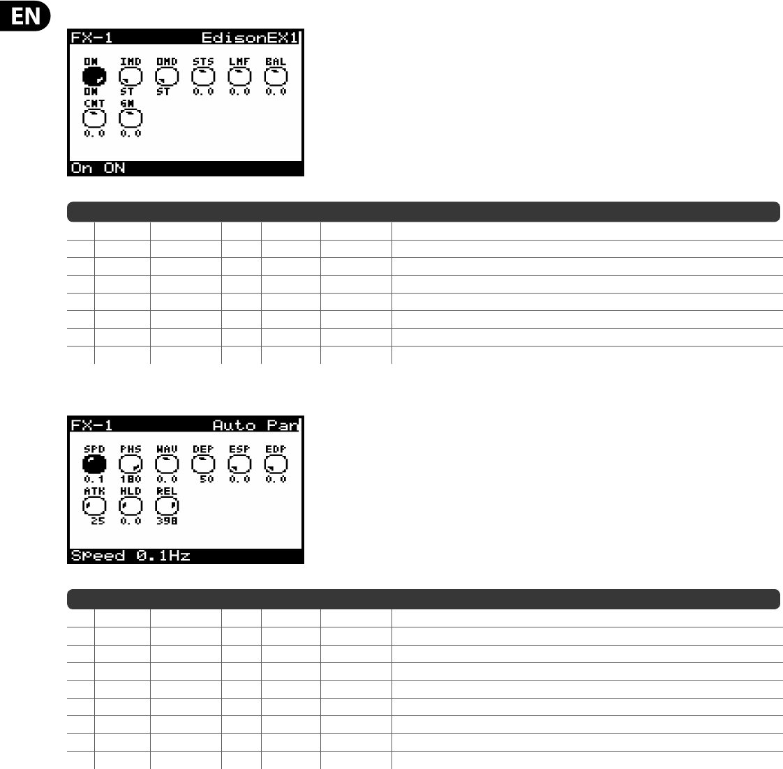
94 DeepMind 12 User Manual
EdisonEX1 (STEREO IMAGING)
No DM12 REF PARAMETER UNITS MIN MAX DESCRIPTION
1 ON On — OFF ON Allows the e ect to be turned On or O .
2 IMD InMode — ST M/S Controls the input mode (Stereo or Mid/Side).
3 OMD OutMode — ST M/S Controls the output mode (Stereo or Mid/Side).
4* STS StSpread — -50.0 50.0 Controls the spread of the stereo eld.
5* LMF LMFSpread — -50.0 50.0 Controls the spread of the stereo eld for low/mid frequencies only.
6* BAL Balance — -50.0 50.0 Adjusts the ratio of mono to stereo content.
7* CNT CntrDist — -50.0 50.0 Allows the mono content to be panned.
8* GN Gain dB -12.0 dB 12.0 dB Controls the amount of output gain applied to the signal.
Auto Pan (AUTO PANNING)
No DM12 REF PARAMETER UNITS MIN MAX DESCRIPTION
1* SPD Speed Hz 0.0 Hz 5.0 Hz Adjusts the LFO rate. Time synchronised options from 4 to 1/64 bars.
2* PHS Phase — 0.0 180.0 Controls the LFO phase di erence between the left and right channels.
3* WAV Wave — -50.0 50.0 Blends the LFO waveform between triangular and square shape.
4* DEP Depth % 0.0% 100% Controls the depth (amount) of modulation.
5* ESP EnvSpd % 0.0% 100% Adjusts how much the LFO speed is modulated by the envelope.
6* EDP EnvDepth % 0.0% 100% Adjusts the depth of the envelope modulation.
7* ATK Attack ms 10.0 ms 1000.0 ms Controls the envelope attack stage time.
8* HLD Hold ms 1.0 ms 2000.0 ms Controls the envelope hold stage time.
9* REL Release ms 10.0 ms 1000.0 ms Controls the envelope release stage time.
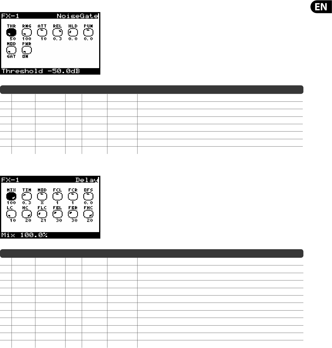
95 DeepMind 12 User Manual
NoiseGate (NOISE GATE)
No DM12 REF PARAMETER UNITS MIN MAX DESCRIPTION
1* THR Threshold dB -50.0 0.0 Sets signal level at which gate opens.
2 RNG Range dB -100.0 0.0 Control adjusts the amount of gain reduction applied to the signal below threshold.
3* ATT Attack ms 0.0 20.0 Adjusts time taken for gate to open after an over-threshold signal.
4* REL Release ms 2.0 1999.9 Adjusts time taken for gate to close after programme material falls back below threshold.
5* HLD Hold ms 2.0 1999.9 This de nes a waiting period before the gate starts to close.
6 PUN Punch — -6.0 6.0 Used to increase tonal shaping or reduce gated breathing/delay/resonant howl-round.
7 MOD Mode — — — GAT (Gate), TRN (Transient Gate), DUC (Ducker).
8 PWR Power — ON OFF Enables gate in the signal path. When switched o , gate is bypassed.
Delay (STEREO DELAY)
No DM12 REF PARAMETER UNITS MIN MAX DESCRIPTION
1* MIX Mix % 0.0% 100% Controls the mix (or ratio) of wet (processed) and dry (unprocessed) signals.
2 TIM Time ms 1.0 ms 1500.0 ms Adjusts the master delay time. Time synchronised options from 4 to 1/64 bars.
3 MOD Mode — — — S- Stereo feedback, X - crosses feedback between channels, M - Mono mix in feedback chain.
4 FCL FactorL — — — Sets left delay to rhythmic fractions of the master delay (1/4, 3/8, 1/2, 2/3, 1, 4/3, 3/2, 2, 3).
5 FCR FactorR — — — Sets right delay to rhythmic fractions of the master delay (1/4, 3/8, 1/2, 2/3, 1, 4/3, 3/2, 2, 3).
6 OFS O set ms -100.0 ms 100.0 ms Adds a delay di erence between the left and right delayed signals.
7* LC LC Hz 10.0 Hz 500.0 Hz Adjusts the low frequency cut, allowing lower frequencies to remain una ected by the delay.
8* HC HC Hz 200.0 Hz 20000.0 Hz Adjusts the high frequency cut, allowing higher frequencies to remain una ected by the delay.
9* FLC FeedLC Hz 10.0 Hz 500.0 Hz Adjusts the low cut lter frequency in the feedback paths.
10* FBL FeedL % 0.0% 100% Control the amount of feedback for the left channel.
11* FBR FeedR % 0.0% 100% Control the amount of feedback for the right channel.
12* FHC FeedHC Hz 200.0 Hz 20000.0 Hz Adjusts the high cut lter frequency in the feedback paths.
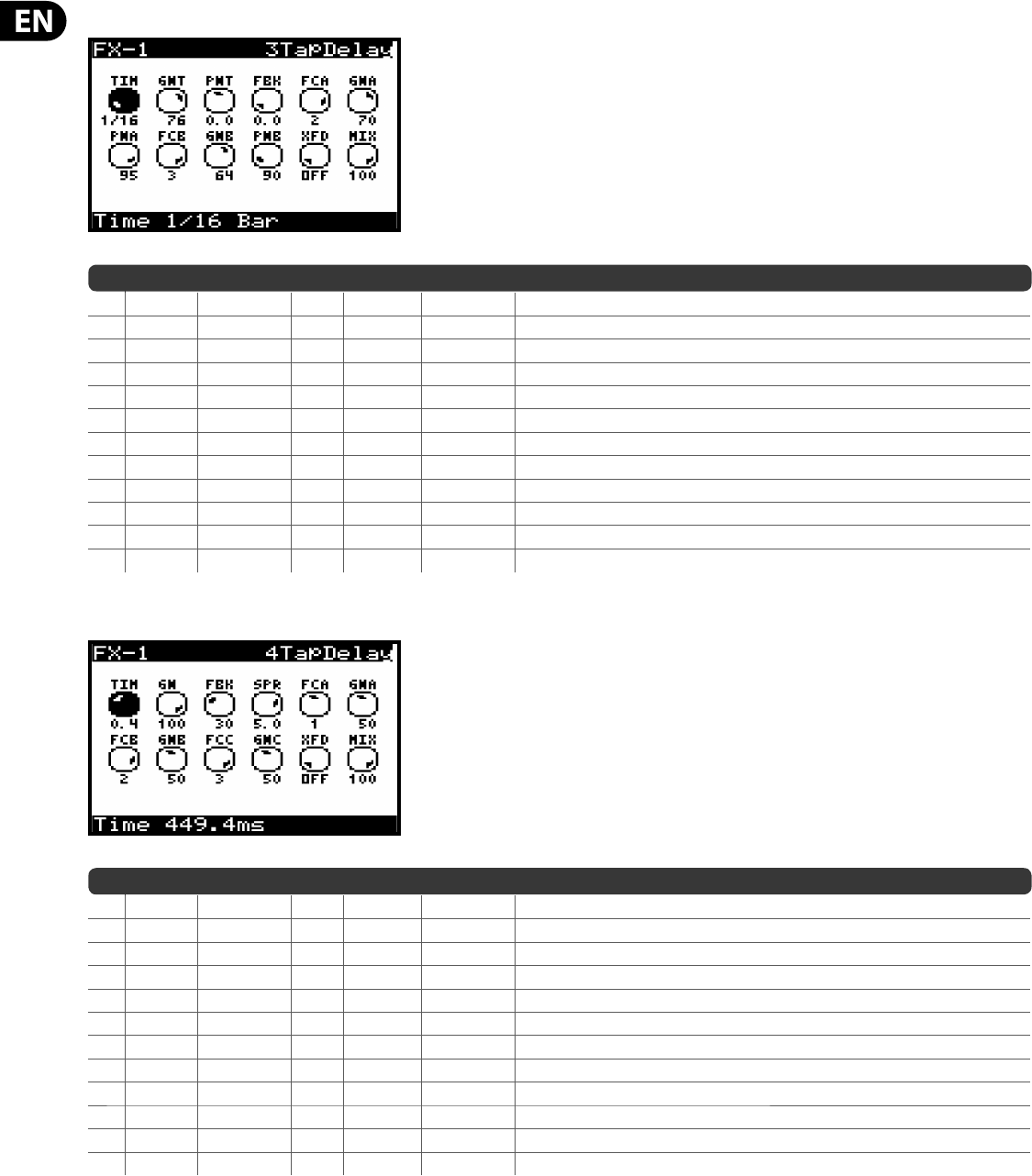
96 DeepMind 12 User Manual
3TapDelay (3-TAP DELAY)
No DM12 REF PARAMETER UNITS MIN MAX DESCRIPTION
1 TIM Time ms 1.0 ms 1500.0 ms Sets the master delay time, and the rst stage. Time synchronised options from 4 to 1/64 bars.
2* GNT GainT % 0.0% 100% Sets the gain level of the rst stage of the delay.
3* PNT PanT % -100% 100% Sets the position of the rst delay stage in the stereo eld.
4* FBK Feedback % 0.0% 100% Adjusts the amount of feedback.
5 FCA FactorA — — — Controls the delay time in the second stage of the delay (1/4, 3/8, 1/2, 2/3, 1, 4/3, 3/2, 2, 3).
6* GNA GainA % 0.0% 100% Controls the gain level of the second delay stage.
7* PNA PanA % -100% 100% Sets the position of the second delay stage in the stereo eld.
8 FCB FactorB — — — Controls the delay time in the third stage of the delay (1/4, 3/8, 1/2, 2/3, 1, 4/3, 3/2, 2, 3).
9* GNB GainB % 0.0% 100% Controls the gain level of the third delay stage.
10* PNB PanB % -100% 100% Sets the position of the third gain stage in the stereo eld.
11 XFD X-Feed — OFF ON Turns the stereo cross-feedback of the delays On or O .
12 MIX Mix % 0.0% 100% Controls the mix (or ratio) of wet (processed) and dry (unprocessed) signals.
4TapDelay (4-TAP DELAY)
No DM12 REF PARAMETER UNITS MIN MAX DESCRIPTION
1 TIM Time ms 1.0 ms 1500.0 ms Sets the master delay time, and the rst stage. Time synchronised options from 4 to 1/64 bars.
2* GN Gain % 0.0% 100% Sets the gain level of the rst stage of the delay.
3* FBK Feedback % 0.0% 100% Adjusts the amount of feedback.
4 SPR Spread — 0.0 6.0 Positions the rst delay stage in the stereo eld.
5 FCA FactorA — — — Controls the delay time in the second stage of the delay (1/4, 3/8, 1/2, 2/3, 1, 4/3, 3/2, 2, 3).
6* GNA GainA % 0.0% 100% Controls the gain level of the second delay stage.
7 FCB FactorB — — — Controls the delay time in the third stage of the delay (1/4, 3/8, 1/2, 2/3, 1, 4/3, 3/2, 2, 3).
8* GNB GainB % 0.0% 100% Controls the gain level of the third delay stage.
9 FCC FactorC — — — Controls the delay time in the fourth stage of the delay (1/4, 3/8, 1/2, 2/3, 1, 4/3, 3/2, 2, 3).
10* GNC GainC % 0.0% 100% Controls the gain level of the fourth delay stage.
11 XFD X-Feed — 0.0 1.0 Turns the stereo cross-feedback of the delays On or O .
12* MIX Mix % 0.0% 100% Controls the mix (or ratio) of wet (processed) and dry (unprocessed) signals.
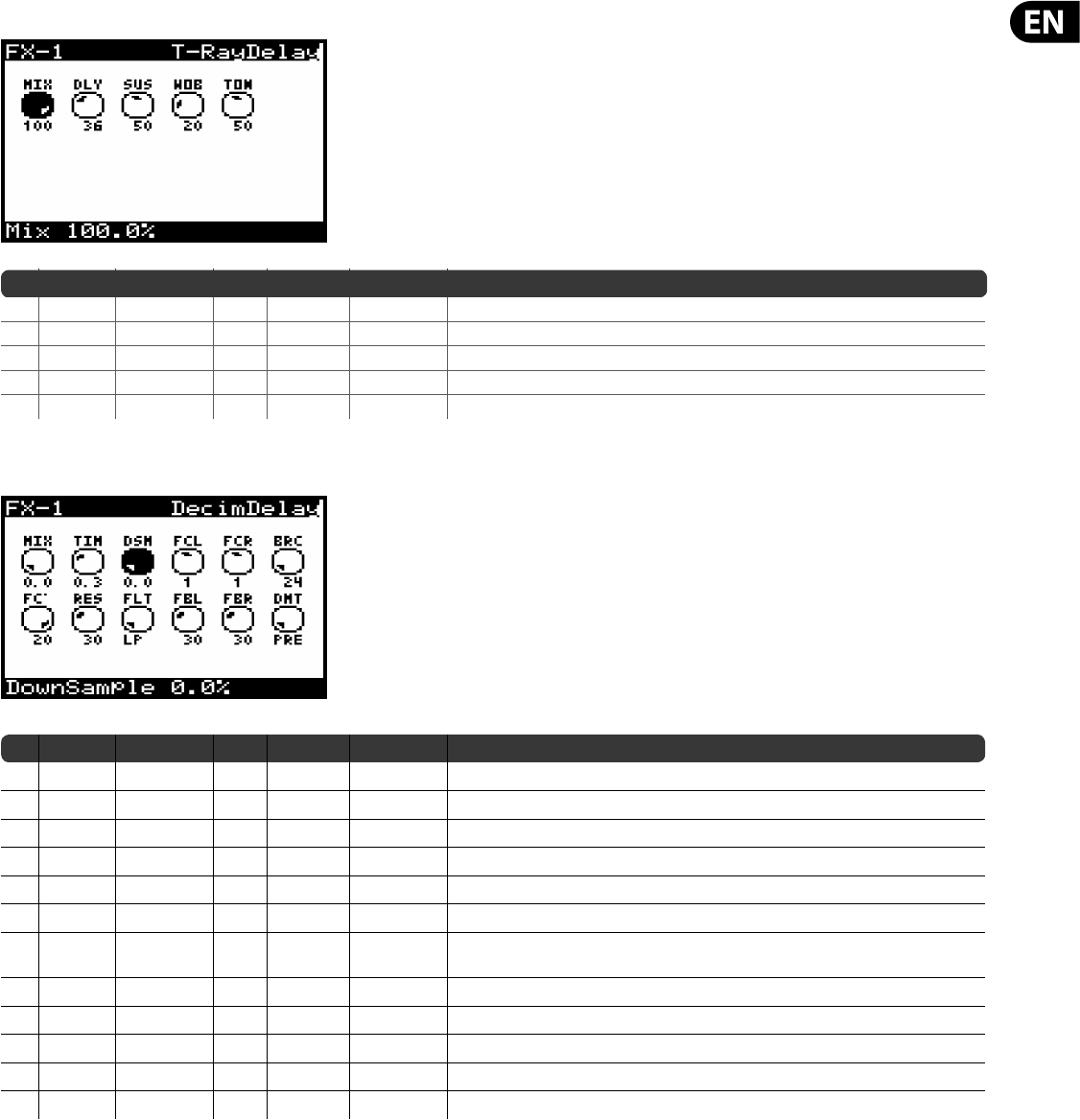
97 DeepMind 12 User Manual
T-RayDelay (TEL-RAY DELAY)
No DM12 REF PARAMETER UNITS MIN MAX DESCRIPTION
1* MIX Mix % 0.0% 100% Controls the mix (or ratio) of wet (processed) and dry (unprocessed) signals.
2* DLY Delay % 0.0% 100% Adjusts the master delay time.
3* SUS Sustain % 0.0% 100% Controls how long the delay is sustained for. Warning at 100% build up will occur.
4* WOB Wobble % 0.0% 100% Adjusts the amount of wobble caused by age and quality of build/materials.
5* TON Tone % 0.0% 100% Controls the tone of the delays.
DecimDelay (Decimator Delay)
No DM12 REF PARAMETERS UNITS MIN MAX DESCRIPTION
1MIX Mix % 0.00% 100.00% Controls the mix (or ratio) of wet (processed) and dry (unprocessed) signals.
2TIM Time Ms 1.0 ms 1500.0 ms Adjusts the master delay time. Time synchronized options from 4 to 1/64 bars.
3DSM
Downsample
% 0.00% 100.00% Decimates the signal by reducing the sampling frequency.
4FCL FactorL — — — Sets left delay to rhythmic fractions of the master delay (1/4, 3/8, 1/2, 2/3, 1, 4/3, 3/2, 2, 3).
5FCR FactorR — — — Sets right delay to rhythmic fractions of the master delay (1/4, 3/8, 1/2, 2/3, 1, 4/3, 3/2, 2, 3).
6BRC Bit-Reduce — 24 1 Decimates the signal by reducing the bit-depth.
7FC Cuto Hz 30.0 Hz 20000.0 Hz Adjust the cuto frequency of the lter, allowing speci c frequencies to be a ected
by the delay.
8RES Resonance % 0.00% 100.00% Adjusts the resonance of the lter.
9FLT Type — — — It sets the lter type (Lowpass, Highpass, Bandpass, Notch).
10 FBL FeedL % 0.00% 100.00% Controls the amount of feedback for the left channel.
11 FBR FeedR % 0.00% 100.00% Controls the amount of feedback for the right channel.
12 DMT Decimate — — — It sets the decimation on the input signal (PRE) or only on the delay (POST).
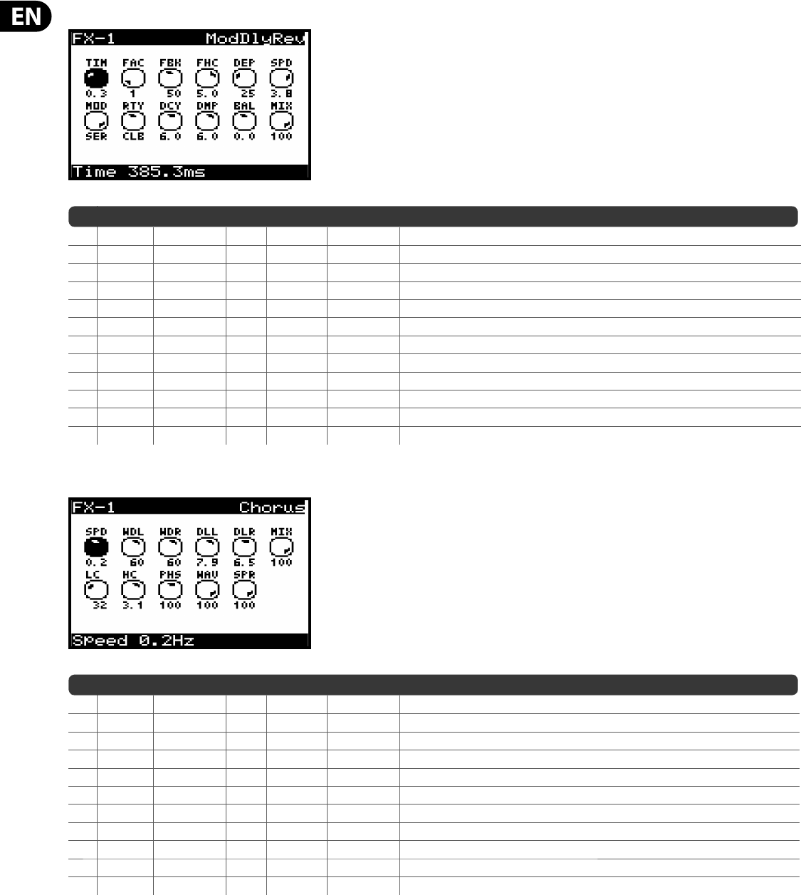
98 DeepMind 12 User Manual
ModDlyRev (MODULATION/DELAY/REVERB)
No DM12 REF PARAMETER UNITS MIN MAX DESCRIPTION
1 TIM Time ms 1.0 ms 1500.0 ms Sets the master delay time. Time synchronised options from 4 to 1/64 bars.
2 FAC Factor — — — Sets the delay to rhythmic fractions (1, 1/2, 2/3, 3/2).
3* FBK Feedback % 0.0% 100% Controls the percentage of positive feedback.
4* FHC FeedHC Hz 200.0 Hz 20000.0 Hz Adjusts the high cut lter frequency in the feedback path.
5* DEP Depth % 0.0% 100% Controls the depth (amount) of modulation.
6* SPD Speed Hz 0.0 Hz 10.0 Hz Adjusts the rate of the modulation. Time synchronised options from 4 to 1/64 bars.
7 MOD Mode — PAR SER Controls the processor chain routing (Serial/Parallel)
8 RTY Rtype — — — Reverb Type can be set to AMB (Ambience), CLUB, or HALL.
9* DCY Decay — 1.0 10.0 Controls the amount of time it takes for the reverb to dissipate.
10* DMP Damping — 1000 Hz 20000 Hz Determines the decay of high frequencies within the reverb tail.
11* BAL Balance — -100.0 100.0 Adjusts ratio of the delay signal to the reverb signal.
12* MIX Mix % 0.0% 100% Controls the mix (or ratio) of wet (processed) and dry (unprocessed) signals
Chorus (STEREO CHORUS)
No DM12 REF PARAMETER UNITS MIN MAX DESCRIPTION
1* SPD Speed Hz 0.0 Hz 5Hz Sets the modulation speed. Time synchronised options from 4 to 1/64 bars.
2* WDL WidthL % 0.0% 100% Determines the amount of modulated delay in the left channel.
3* WDR WidthR % 0.0% 100% Determines the amount of modulated delay in the right channel.
4 DLL DelayL ms 0.5 ms 50.0 ms Sets the total amount of delay for the left channel.
5 DLR DelayR ms 0.5 ms 50.0 ms Sets the total amount of delay for the right channel.
6* MIX Mix % 0.0% 100% Controls the mix (or ratio) of wet (processed) and dry (unprocessed) signals.
7* LC LoCut Hz 10.0 Hz 500.0 Hz Allows the low frequencies in the signal to be reduced.
8* HC Hi Cut Hz 200.0 Hz 20000.0 Hz Allows the high frequencies in the signal to be reduced.
9 PHS Phase — 0.0 100.0 Adjusts the phase o set of the LFO between left and right channel.
10 WAV Wave % 0.0% 100% Blends between the digital triangular chorus sound and the classic analog sine wave.
11* SPR Spread % 0.0% 100% Adjusts how much of the left channel is mixed into the right and vice versa.
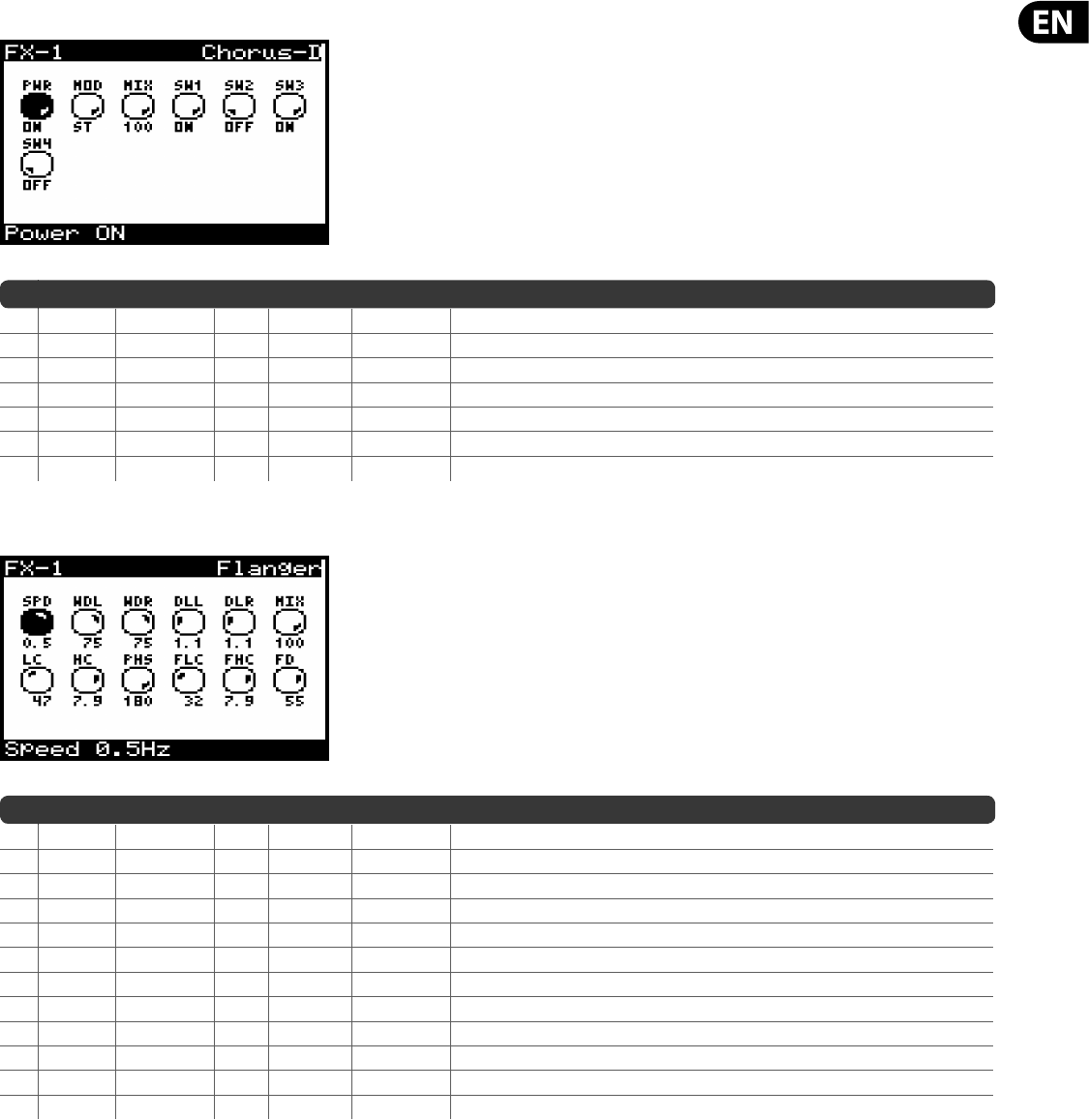
99 DeepMind 12 User Manual
Chorus-D (DIMENSIONAL CHORUS)
No DM12 REF PARAMETER UNITS MIN MAX DESCRIPTION
1 ON On — OFF ON Allows the e ect to be turned On or O .
2 MOD Mode — M ST Switches the operation between Mono and Stereo modes.
3* MIX Mix % 0.0% 100% Controls the mix (or ratio) of wet (processed) and dry (unprocessed) signals.
4 SW1 Sw1 — OFF ON Engages level one intensity (minimum).
5 SW2 Sw2 — OFF ON Engages level two intensity.
6 SW3 Sw3 — OFF ON Engages level three intensity.
7 SW4 Sw4 — OFF ON Engages level four intensity (maximum).
Flanger (STEREO FLANGER)
No DM12 REF PARAMETER UNITS MIN MAX DESCRIPTION
1* SPD Speed Hz 0.0 Hz 5 Hz Sets the modulation speed. Time synchronised options from 4 to 1/64 bars.
2* WDL WidthL % 0.0% 100% Determines the amount of modulated delay in the left channel.
3* WDR WidthR % 0.0% 100% Determines the amount of modulated delay in the right channel.
4 DLL DelayL ms 0.5 ms 20.0 ms Sets the total amount of delay for the left channel.
5DLR DelayR ms0.5 ms 20.0 ms Sets the total amount of delay for the right channel.
6* MIX Mix % 0.0% 100% Controls the mix (or ratio) of wet (processed) and dry (unprocessed) signals.
7* LC LoCut Hz 10.0 Hz 500.0 Hz Allows the low frequencies in the signal to be reduced.
8* HC Hi Cut Hz 200.0 Hz 20000.0 Hz Allows the high frequencies in the signal to be reduced.
9 PHS Phase — 0.0 180.0 Adjusts the phase o set of the LFO between left and right channel.
10* FLC FeedLC Hz 10.0 Hz 500.0 Hz Adjusts the low cut lter frequency in the feedback path.
11* FHC FeedHC Hz 200.0 Hz 20000.0 Hz Adjusts the high cut lter frequency in the feedback path.
12* FD Feed % -90.0% 90.0% Controls the percentage of positive or negative feedback.
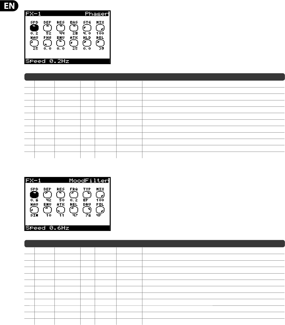
100 DeepMind 12 User Manual
Phaser (STEREO PHASER)
No DM12 REF PARAMETER UNITS MIN MAX DESCRIPTION
1* SPD Speed Hz 0.0 Hz 5 Hz Sets the modulation speed. Time synchronised options from 4 to 1/64 bars.
2* DEP Depth % 0.0% 100% Controls the depth (amount) of modulation.
3* RES Reso % 0.0% 100% Adjusts the resonance of the multiple lter stages.
4* BAS Base Freq Hz 20 Hz 15000 Hz Adjusts the frequency range of the modulated lters.
5 STG Stages — 2.0 12.0 Controls how many lter stages are used.
6* MIX Mix % 0.0% 100% Controls the mix (or ratio) of wet (processed) and dry (unprocessed) signals.
7 WAV Wave — -50.0 +50.0 Shapes the symmetry of the LFO waveform.
8 PHS Phase deg 0.0 180.0 Adjusts the LFO phase di erence between the left and right channel
9* ENV EnvMod ms -100.0% 100% Adjusts the level of positive or negative envelope modulation.
10* ATK Attack ms 10.0 ms 1000.0 ms Controls the envelope attack stage time.
11* HLD Hold ms 1.0 ms 2000.0 ms Controls the envelope hold stage time.
12* REL Release ms 10.0 ms 1000.0 ms Controls the envelope release stage time.
MoodFilter (MOOG TYPE FILTER)
No DM12 REF PARAMETER UNITS MIN MAX DESCRIPTION
1 SPD Speed Hz 0.0 Hz 20.0 Hz Sets the modulation speed. Time synchronised options from 4 to 1/64 bars.
2* DEP Depth % 0.0% 100% Controls the depth (amount) of modulation.
3* RES Resonance % 0.0% 100% Adjusts the resonance of the lter.
4* FRQ Base Freq Hz 20 Hz 15000 Hz Adjusts the level of positive or negative envelope modulation.
5 TYP Type LP — — — Selects between low pass (LP), high-pass (HP), band-pass (BP) and Notch (NOT).
6* MIX Mix % 0.0% 100% Controls the mix (or ratio) of wet (processed) and dry (unprocessed) signals.
7 WAV Wave — — — Selects modulation waveform Triangular, Sine, Saw Up, Saw Down, Ramp, Square or Random.
8* ENV EnvMod % -100.0% 100% Adjusts the level of positive or negative envelope modulation.
9* ATK Attack ms 10.0 ms 249.9 ms Controls the lter attack time.
10* REL Release ms 10.0 ms 500.0 ms Controls the lter release time.
11* DRV Drive % 0.0% 100% Adjusts the level, also introduces an overdrive e ect if pushed hard.
12 4P 4-Pole — 2P 4P 100.0 Adjusts the slope of the lter from 2-pole to 4-pole (steeper).
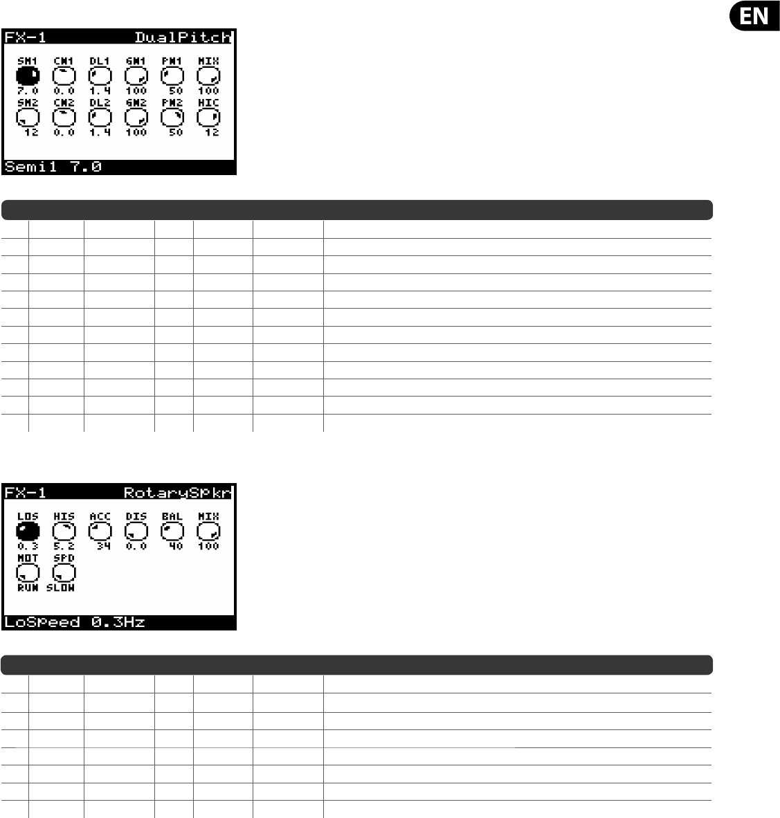
101 DeepMind 12 User Manual
Dual Pitch (DUAL PITCH SHIFTER)
No DM12 REF PARAMETER UNITS MIN MAX DESCRIPTION
1* SM1 Semi1 — -12.0 12.0 Adjusts the pitch of the rst channel in semi-tones.
2* CN1 Cent1 — -50.0 50.0 Adjusts the pitch of the rst channel in cents.
3 DL1 Delay1 ms 1.0 ms 500.0 ms Adjusts the time di erence between the wet and dry signals. Sync options from 4 to 1/64 bars.
4* GN1 Gain1 % 0.0% 100% Allows gain compensation to be applied to the rst channel.
5* PN1 Pan1 % -100.0% 100% Allows panning of the rst channel.
6* MIX Mix % 0.0% 100% Controls the mix (or ratio) of wet (processed) and dry (unprocessed) signals.
7* SM2 Semi2 — -12.0 12.0 Adjusts the pitch of the second channel in semi-tones.
8* CN2 Cent2 — -50.0 50.0 Adjusts the pitch of the second channel in cents.
9 DL2 Delay2 ms 1.0 ms 500.0 ms Adjusts the time di erence between the wet and dry signals. Sync options from 4 to 1/64 bars.
10* GN2 Gain2 % 0.0% 100% Allows gain compensation to be applied to the second channel.
11* PN2 Pan2 % -100.0% 100% Allows panning of the second channel.
12* HIC HiCut Hz 200.0 Hz 20000.0 Hz Allows the high frequencies a ected by the pitch shifting to be reduced.
RotarySpkr (ROTARY SPEAKER)
No DM12 REF PARAMETER UNITS MIN MAX DESCRIPTION
1* LOS LoSpeed Hz 0.1 Hz 4.0 Hz Adjusts the rotational speed when the Low Speed operation is selected.
2* HIS HiSpeed Hz 2.0 Hz 9.9 Hz Adjusts the rotational speed when the High Speed operation is selected.
3* ACC Accel % 0.0% 100% Adjusts how quickly the speed increases and decreases from the Slow mode to the Fast mode.
4* DIS Distance % 0.0% 100% Adjusts the distance between the Rotary speakers and the virtual microphone.
5* BAL Balance — -100.0 100.0 Adjusts the balance between the virtual horn and virtual drum controlling the signal tone.
6* MIX Mix % 0.0% 100% Controls the mix (or ratio) of wet (processed) and dry (unprocessed) signals.
7* MOT Motor — RUN STOP Allows The rotation e ect of the motor to be disengaged (STOP).
8* SPD Speed — SLOW FAST Selects either the slow or fast speeds for rotation.
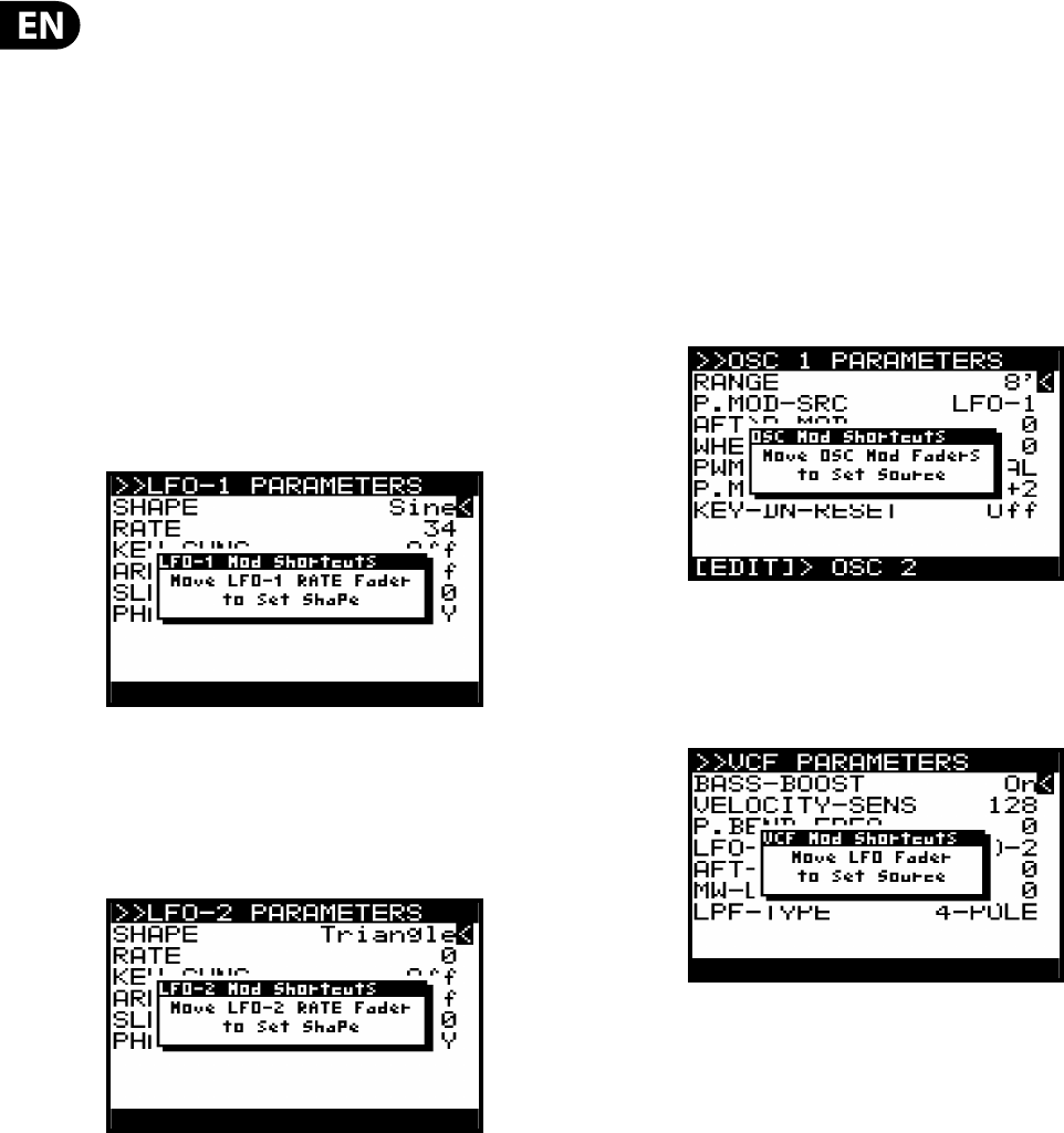
102 DeepMind 12 User Manual
10. Short-cuts
In order to speed up programming tasks there are several short-cuts
implemented on the DeepMind 12 as listed below.
Note: While holding down any of the shortcut switches the menu will
momentarily switch to the relevant menu. Once you release the shortcut switch
you will be returned to the PROG screen.
10.1 Menu Parameter Reset
To reset any menu parameter to its default setting momentarily press the -NO
and+YES switches at the same time.
10.2 LFO 1 Shape
To change the LFO 1 waveform shape press and hold the LFO 1 EDIT switch. While
holding the switch you can use the LFO 1 RATE fader to set the LFO 1 waveform
shape. The following message will be shown to give you guidance while holding
the LFO 1 EDIT switch.
10.3 LFO 2 Shape
To change the LFO 2 waveform shape press and hold the LFO 2 EDIT switch. While
holding the switch you can use the LFO 2 RATE fader to set the LFO 2 waveform
shape. The following message will be shown to give you guidance while holding
the LFO 2 EDIT switch.
10.4 OSC Modulation Sources
To change any of the OSC Modulation sources press and hold the OSC EDIT switch.
While holding the switch you can use any of the following faders to set the
source for the respective parameter:
•
• OSC 1 PITCH MOD
•
• OSC 1 PWM
•
• OSC 2 PITCH MOD
•
• OSC 2 TONE MOD
The following message will be shown to give you guidance while holding the OSC
EDIT switch
10.5 VCF LFO Source
To change the VCF LFO source press and hold the VCF EDIT switch. While holding
the switch you can use the VCF LFO fader to select the source LFO. The following
message will be shown to give you guidance while holding the LFO 1 EDIT switch.
10.6 MOD MATRIX Bus Con guration
Each MOD MATRIX bus can be con gured without having to scroll through the
large lists of sources and destinations. In order to do this please use the following
steps:
1) Use the navigation switches to select and of the parameters on the bus
you would like to con gure.
2) Press and hold the MOD switch
3) To select a modulation source press an edit switch (further presses will
cycle though the options associated with the switch), or press any key
on the keyboard to cycle through the sources associated with notes.
4) To select a modulation destination move the fader of the required
parameter.
5) To set the modulation depth adjust the data entry fader.
Once you have con gured the bus as you require you can release the
MOD MATRIX switch.
Note: All changes will immediately have an e ect so that you can hear the
changes to your program by the modulation bus.
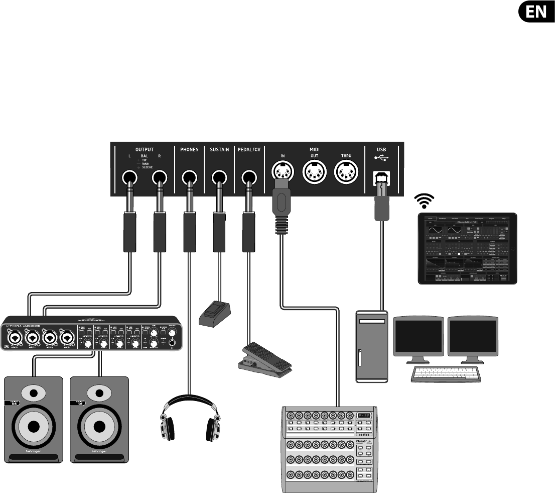
103 DeepMind 12 User Manual
11. Applications
On the following pages we present the most useful applications for your DeepMind 12 analog polyphonic synthesizer, using a few practical examples.
11.1 Studio Con guration Example
OUTPUT2
CVNORM
OUTPUT1MIN VOL
10
0
Desktop Computer
MIDI Controller
Expression Pedal
Headphones
Studio Monitors
Audio Interface
Footswitch
DeepMind iOS App
Wi-Fi Connection
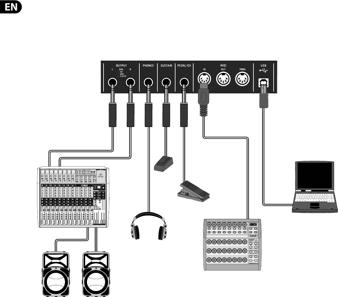
104 DeepMind 12 User Manual
11.2 Live Con guration Example
OUTPUT2
CVNORM
OUTPUT1MIN VOL
10
0
Mixing console
Active Loudspeakers
Laptop Computer
MIDI Controller
Expression Pedal
Headphones
Footswitch
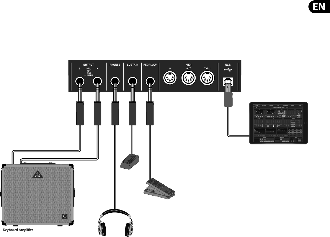
105 DeepMind 12 User Manual
11.3 Band/Practice Con guration Example
Expression Pedal
Headphones
Footswitch
DeepMind iOS App
DeepMind iOS App
OUTPUT2
CVNORM
OUTPUT1MIN VOL
10
0
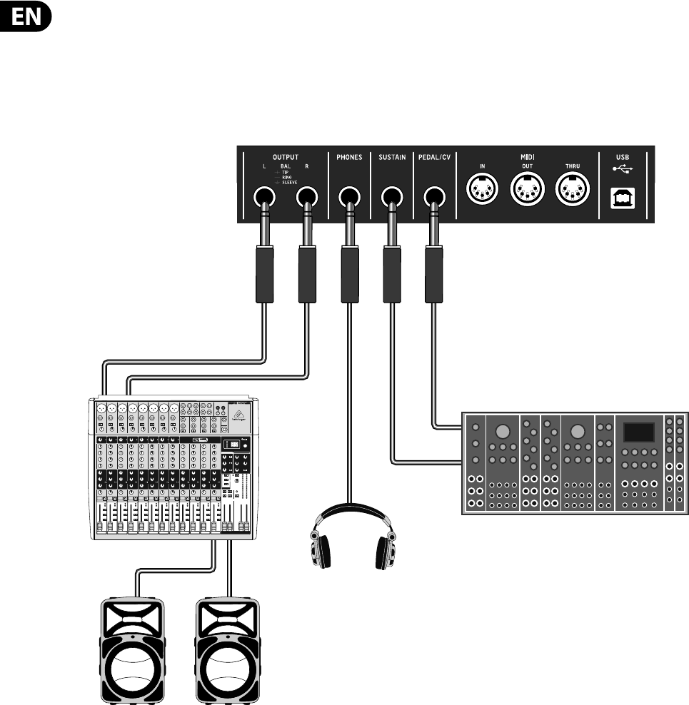
106 DeepMind 12 User Manual
11.4 Interfacing with Other Hardware Example
Mixing console
Active Loudspeakers
Headphones
Modular Synthesizer
CV
Gate
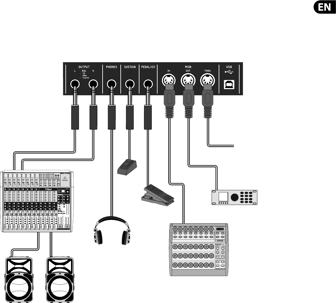
107 DeepMind 12 User Manual
11.5 Interfacing with Modular Synthesizer Example
Expression Pedal
Headphones
Footswitch
OUTPUT2
CVNORM
OUTPUT1MIN VOL
10
0
Mixing console
Active Loudspeakers
MIDI Controller
External Sound Module
Sync to another Player

108 DeepMind 12 User Manual
12. DAW MIDI Con guration
All the parameters which can be controlled by MIDI can of course be recorded
and then played back as automation data within any DAW or application that
supports MIDI.
The DeepMind 12 o ers three methods of communicating via MIDI:
•
• Physical MIDI Ports - When using the physical MIDI ports you will need to
connect these to a MIDI interface or other device which can pass the MIDI
information to your host computer/tablet/phone.
•
• USB-MIDI - The DeepMind 12 is a class compliant USB device and should
appear as both inputs and outputs in most applications without the need for
any additional drivers.
•
• WiFi-MIDI - The DeepMind 12 supports RTP-MIDI and should appear as both
inputs and outputs in most applications without the need for any additional
drivers.
In order to use the DeepMind 12 analog polyphonic synthesizer in conjunction
with a Digital Audio Workstation (DAW) or any Audio/MIDI application please
follow these steps:
Ensure that the relevant interface (MIDI/USB/Wi-Fi) is con gured correctly in the
GLOBAL-CONNECTIVITY menu.
Ensure that the DeepMind 12 is an active input and output in your DAW /
Application MIDI setup.
Ensure that the your DAW is setup to receive MIDI on the same channel as the
DeepMind 12 Transmit channel.
Recording, editing and playback of Note data such as Note number, Velocity, Note
Length etc, should be possible in most applications.
Recording, editing and playback of MIDI CC data such as Aftertouch, Pitch Bend,
Mod Wheel or any of the faders should be possible in most applications.
Recording and playback of MIDI NRPN data is only possible in certain applications,
please consult your manufacturers data for details on NRPN support.
Note: If you adjust a parameter using an external device or application
connected the DeepMind 12 will forward the change to the other interfaces. E.g.
a changed received over Wi-Fi will be re-transmitted by the DeepMind 12 to both
the USB port and the MIDI socket. The data format will be dependant on the
mode settings for each interface
Warning: Be careful not to create any kind of MIDI loop as feeding back the same
information to the DeepMind 12 will cause erratic behavior.
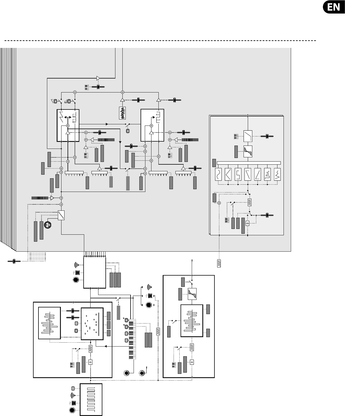
109 DeepMind 12 User Manual
13. System Block Diagram
Voices 1-12
Portamento Time
PB DEPTH +/-
Pitch
Bend
Key Pitch
OSC1 RANGE
OSC2 RANGE
P
.MOD MODE
LFO-1
LFO-2
ENV-1
ENV-2
ENV-3
LFO-1(Uni)
LFO-2(Uni)
P.MOD-SRC
OSC DRIFT
PARAM DRIFT
VEL-CURVE
AFT CURVE
PWM-SRC
AFT>P.MOD
WHEEL>P.MOD
OSC 1
Pitch
PW
Mod
Mod
Wheel
Aftertouch
LFO-1
LFO-2
VCA ENV
VCF ENV
MOD ENV
MANUAL
PWM
SYNC
TONE
MOD
OSC 2
Pitch
TM
Mod
PITCH
Noise
NOISE
LEVEL
LEVEL
UNISON
DETUNE
Unison
Voice
KYBD
LFO 1
RATE
Arp
Clock
DELAY
TIME
Mono
LFO
Phase
Voice LFO
Clock
LFO
Destination
LFO 2
RATE
GATE
TIME
CHORD
PEDAL/CV
SUSTAIN POLY
CHORD
ON/OFF
TAP
PORTA-OSC-BAL
PORTA-MODE
ARP-TO-MIDI
Sine
Smp&Hold
Smp&Glide
Triangle
Square
Ramp Up
Ramp Down
OCTOCT
Tracking
Key Gate
Key Gate
PARAM DRIFT
LFO-1
LFO-2
ENV-1
ENV-2
ENV-3
LFO-1(Uni)
LFO-2(Uni)
P.MOD-SRC
ENABLE
LOOPING
T.MOD-SRC
ARP-SYNC
CLOCK DIVIDER
CLOCK DIVIDER
SLEW RATE
SLEW RATE
KEY-SYNC
Key Gate
KEY-SYNC
PHASE SHAPE
AFT>P.MOD
WHEEL>P.MOD
Mod
Wheel
PITCH
MOD
PITCH
MOD
Aftertouch
LFO-1
LFO-2
VCA ENV
VCF ENV
MOD ENV
MANUAL
Arpreggiator
Master
BPM
Arp Input
Notes
OCT MODE SWING
CtrlSeq
Mod Destination
Pedal
Mod Destination
HOLD
Pattern Editor
SWING LENGTH
OSC DRIFT
Control Sequencer
Sequence Editor
Pattern Editor
Wi-FiUSBMIDI IN
Wi-FiUSBMIDI OUT
VOICE ALLOCATION
Wi-FiUSBMIDI IN
POLYPHONY
PRIORITY
TRIGGERING
Master BPM Clock Generator
Mono LFO 1
Clock Generator
Arp
Clock
Velocity Gate
CLOCK DIVIDER
Key Gate
KEY-SYNC
Master
BPM CtrlSeq
Clock
External MIDI Clock Generator
Mono LFO 2
Clock Generator
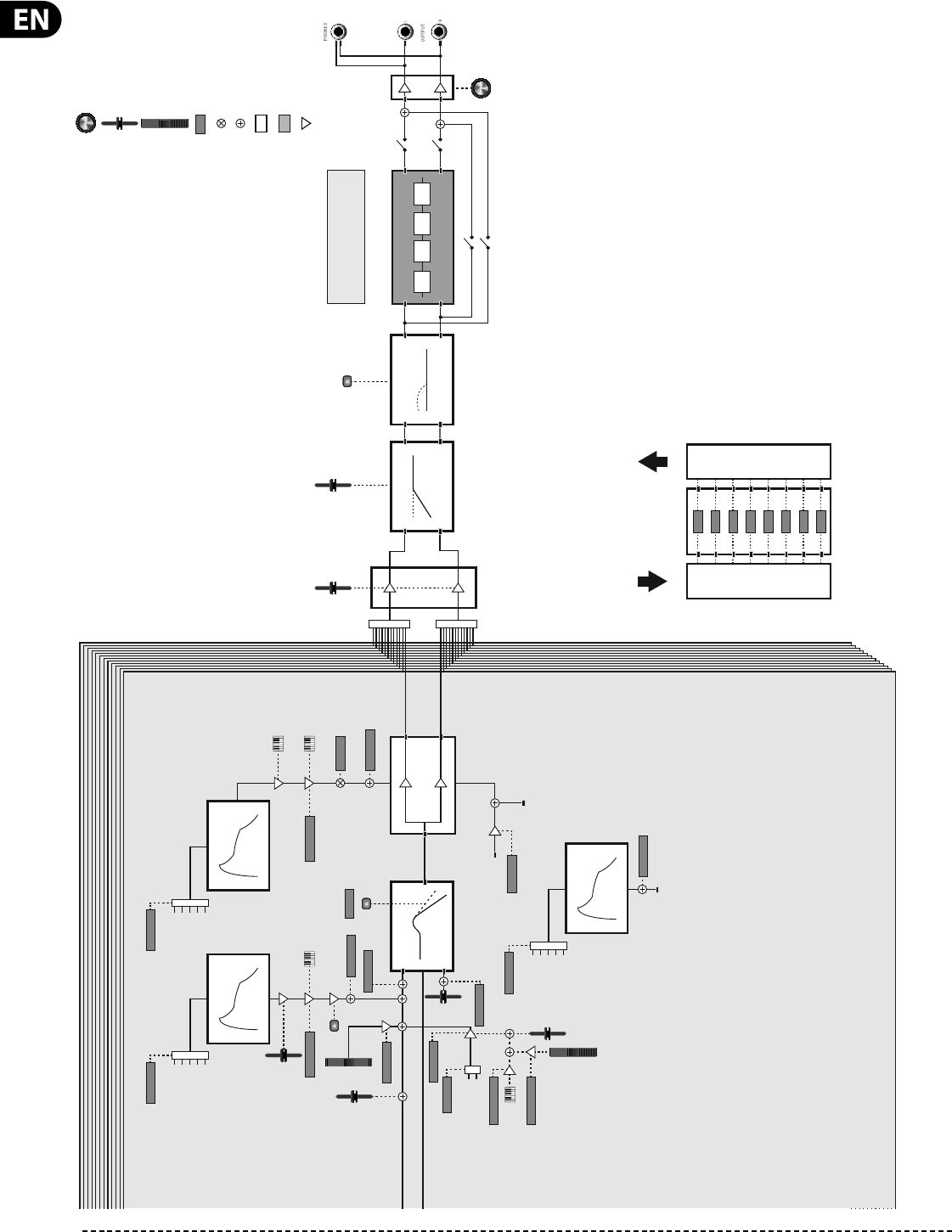
110 DeepMind 12 User Manual
Mod
Wheel
MW-LFO-DEPTH
PAN-SPREAD
PARAM DRIFT
LPF TYPE
PARAM DRIFT
PARAM DRIFT
PARAM DRIFT
P.BEND-FREQ
ENV-DEPTH
VCF-ENV-TRIG
LFO SELECT
ROTARY CONTROL
FADER CONTROL
WHEEL CONTROL
DIGITAL CONTROL (FROM MENU)
SIGNAL MODULATION
SIGNAL SCALING
ANALOG PROCESSING
RES
FREQ
LFO
VCF Env VCA Env
VCF
Freq
Res
VCA
Pan
Destination
Voice Number
Key Gate
Left Output
Right Output
VCA
HPF
FREQ
BOOST
Pitch
Bend
AFT-LFO-DEPTH
DEPTH
DEPTH
DEPTH
DEPTH
DEPTH
DEPTH
DEPTH
DEPTH
MOD Env
Mod Destination
LFO-1
LFO-2
Key
LOOP
LFO-1
LFO-2
SEQ(Step)
VCF-ENV-TRIG
LFO-1
LFO-2
Key
LOOP
SEQ(Step)
Aftertouch
Volume
ENV
TEXT
DIGITAL PROCESSING
AMPLIFIER STAGE
Key Velocity
MOD Env
VCF-ENV-TRIG
LFO-1
LFO-2
Key
LOOP
SEQ(Step)
VELOCITY-SENS
Key Velocity
VELOCITY-SENS
2 POLE
INVERT
Modulation
Destinations
Modulation
Sources 8x8 Mod Matrix
22,880 Possible Modulations (All Automatable)
22 SOURCES
130 DESTINATIONS
FX
1234
ANALOG PATH
DIGITAL PATH
Volume
MODE
INSERT
SEND
BYPASS
ANALOG PATH
OFF
ON
ON
DIGITAL PATH
ON
ON
OFF
PARAM DRIFT
PARAM DRIFT
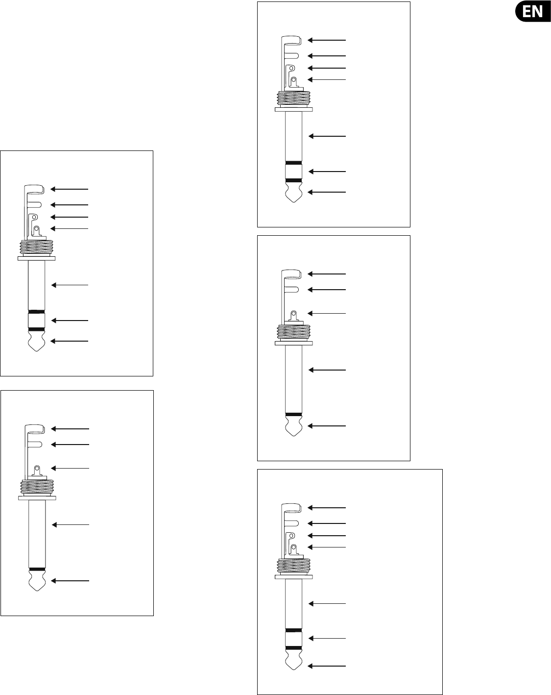
111 DeepMind 12 User Manual
14. Connection Wiring Diagrams
The DeepMind 12 analog polyphonic synthesizer uses servo-balanced outputs.
The circuit design has an automatic hum suppression with balanced signals and
is able to operate, without problem, even at highest levels. Externally-induced
mains hum etc, is thus e ciently suppressed.
Theservo-function, also automatic, recognizes the connection of unbalanced
pin assignments and changes the nominal level internally so that there is no
di erence in level between the input and output signals (6dB correction).
!Please ensure that only quali ed persons install and operate the device.
During installation and operation the user must have su cient contact to earth.
Electrostatic discharges might a ect the operation of the unit.
strain relief clam
sleeve
sleeve
ring
tip
tip
ground / shield
ring
right
left
Headphones Connection Cable Wiring
strain relief clam
sleeve
sleeve
tip
tip
ground / shield
signal
Sustain Connection Cable Wiring
strain relief clam
sleeve
sleeve
ring
tip
tip
ground / shield
ring
expression pedal output,
or control voltage
+5V
Expression or Control Voltage Connection Cable Wiring
strain relief clam
sleeve
sleeve
tip
tip
ground / shield
signal
Un-Balanced Connection Cable Wiring
strain relief clam
sleeve
sleeve
ring
tip
tip
ground / shield
ring
cold - negative (-)
hot - positive (+)
Balanced Connection Cable Wiring

112 DeepMind 12 User Manual
15. Technical Speci cations
Global
Display Backlit LCD
Main Menus PROG, FX, GLOBAL, COMPARE, WRITE
Edit Menus ARP/SEQ, LFOs, OSCs, POLY, VCF, VCA,
VCA ENV,
VCF ENV, MOD ENV, MOD MATRIX
Presets 8 banks each with 128 programs
Fader Modes MIDI CC, NRPN, OFF
Controls
Keyboard 49 semi-weighted, full-size keys
Keyboard sensing Aftertouch and note on/o velocity
Encoders 1 rotary knob
Faders 26 slide faders (35 mm)
Switches 33 backlit switches
Modulation Free moving wheel
Pitch Bend Spring loaded wheel
Connectivity
MIDI In/Out/Thru 5-pin DIN / 16 channels
Pedal/CV ¼ " TRS
Sustain ¼ " TS
USB USB 2.0, type B
Output L/R ¼ " TRS, balanced, max. +18 dBu
Headphones ¼ " TRS, unbalanced, max. +21 dBu
Synthesizer Architecture
Number of voices 12 analog
OSC 2 per voice
LFO 2 per voice
VCF 2-pole / 4-pole
HPF (Common to all voices)
6 dB per octave
Envelopes VCA, VCF, MOD
Mod Matrix 22 sources / 130 destinations
Digital E ects
FX Slots 4 per Program
FX Types 34 Algorithms
Internal e ects engines 1 true stereo SHARC DSP
E ects signal processing 32/40-bit oating point @ 48 kHz
A/D-D/A performance 24-bit 48 kHz, 114 dB dynamic range
Bypass True hard bypass
USB
Type Class compliant USB 2.0, type B
Supported operating systems Windows 7 or higher**
Mac OS X 10.6.8 or higher
iOS 8 or higher (iPad)
Android 6.0 or higher
Wi-Fi
Antenna Internal
Access Point, number of clients Max. 1
IEEE 802.11 b/g standard 2.4 GHz
Frequency Range 2,412 - 2,462 MHz
WLAN channels 11
Max Output Power 16 dBm (802.11 b) /20 dBm (802.11 g) /
20 dbm (802.11 n)
Power
Mains connector Standard IEC receptacle
Power consumption 55 W max.
Fuse T3.15AH250 V
Internal Switch-mode PSU
Autorange 100-240 V,
(50/60 Hz)
Environmental
Operating temperature range 5°C – 40°C (41°F – 104°F)
Physical (Packaged)
Dimensions (H x W x D) 103 x 822 x 257 mm
(4.1 x 32.4 x 10.1")
Weight 8.4 kg (18.5 lbs)
Shipping Weight 10.5 kg (23.1 lbs)
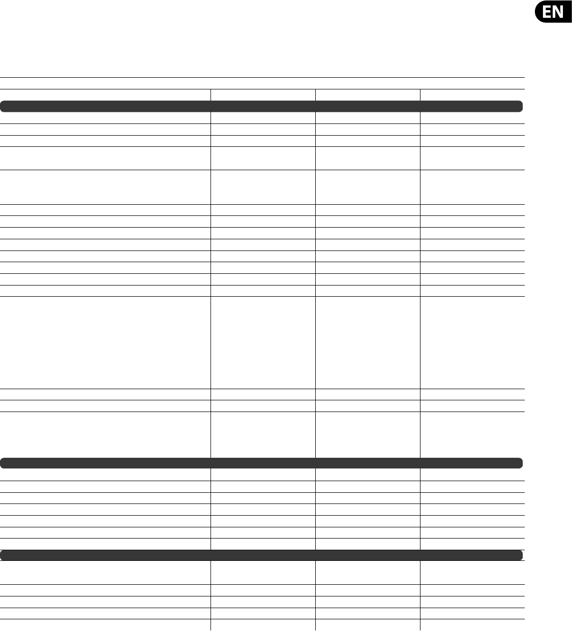
113 DeepMind 12 User Manual
16. MIDI Commands
MIDI (Musical Instrument Digital Interface) is a messaging protocol used to transfer or communicate information between devices and/or host computers.
16.1 MIDI Implementation Chart
MIDI Implementation Chart v. 2.0
Manufacturer: Behringer Model: DeepMind 12 Version:1.0 Date: 01 September 2016
Transmit/Export Recognize/Import Remarks
1. Basic Information
MIDI channels 1-16 — —
Note numbers C0-C8 — —
Program change Yes Yes —
"Bank Select response? (Yes/No)
If yes, list banks utilized in remarks column"
Yes Yes —
"Modes supported : Mode 1: Omni-On, Poly (Yes/No)
Mode 2: Omni-On, Mono (Yes/No) Mode 3: Omni-O , Poly (Yes/No) Mode 4:
Omni-O , Mono (Yes/No) Multi Mode (Yes/No)"
———
Note-On Velocity (Yes/No) Yes Yes —
Note-O Velocity (Yes/No) Yes Yes —
Channel Aftertouch (Yes/No) Yes Yes —
Poly (Key) Aftertouch (Yes/No) No No —
Pitch Bend (Yes/No) Yes Yes —
Active Sensing (Yes/No) — — —
System Reset (Yes/No) — — —
Tune Request (Yes/No) — — —
"Universal System Exclusive: Sample Dump Standard (Yes/No)
Device Inquiry (Yes/No) File Dump (Yes/No) MIDI Tuning (Yes/No) Master Volume
(Yes/No) Master Balance (Yes/No)
Notation Information (Yes/No) Turn GM1 System On (Yes/No) Turn GM2 System
On (Yes/No) Turn GM System O (Yes/No) DLS-1 (Yes/No)
File Reference (Yes/No) Controller Destination (Yes/No)
Key-based Instrument Ctrl (Yes/No) Master Fine/Coarse Tune (Yes/No) Other
Universal System Exclusive"
———
Manufacturer or Non-Commercial System Exclusive — — —
NRPNs (Yes/No) ———
"RPN 00 (Pitch Bend Sensitivity) (Yes/No) RPN 01 (Channel Fine Tune) (Yes/No)
RPN 02 (Channel Coarse Tune) (Yes/No) RPN 03 (Tuning Program Select) (Yes/No)
RPN 04 (Tuning Bank Select) (Yes/No)
RPN 05 (Modulation Depth Range) (Yes/No)"
———
2. MIDI Timing and Synchronization
MIDI Clock (Yes/No) — — —
Song Position Pointer (Yes/No) — — —
Song Select (Yes/No) ———
Start (Yes/No) Continue (Yes/No) Stop (Yes/No) Start: Yes, Continue: Yes, Stop: Yes — —
MIDI Time Code (Yes/No) — — —
MIDI Machine Control (Yes/No) — — —
MIDI Show Control (Yes/No) If yes, MSC Level supported — — —
3. Extensions Compatibility
"General MIDI compatible? (Level(s)/No)
Is GM default power-up mode? (Level/No)"
———
DLS compatible? (Levels(s)/No) (DLS File Type(s)/No) — — —
Standard MIDI Files (Type(s)/No) — — —
XMF Files (Type(s)/No) — — —
SP-MIDI compatible? (Yes/No) — — —

114 DeepMind 12 User Manual
16.2 Continuous Controller Messages
MIDI Implementation Chart v. 2.0 Control Number Information Page 1 of 3
Manufacturer: Behringer Model: DeepMind 12 Version:1.0 Date: 01 September 2016
1. Basic Information
Control # Function Transmitted (Y/N) Recognized (Y/N) Remarks
0 Bank Select (MSB) Yes Yes —
1 Modulation Wheel (MSB) Yes Yes —
2 Breath Controller (MSB) Yes Yes —
3— —- —
4 Foot Controller (MSB) Yes Yes —
5 Portamento Time (MSB) Yes Yes —
6 Data Entry (MSB) Yes Yes —
7Channel Volume (MSB) Yes Yes —
8Balance (MSB) Yes Yes —
9— —— —
10 Pan (MSB) Yes Yes —
11 Expression (MSB) Yes Yes —
12 Arpeggiator Rate Yes Yes Replaces: E ect Control 1 (MSB)
13 Arpeggiator Gate Time Yes Yes Replaces: E ect Control 2 (MSB)
14 — — — —
15 — — — —
16 LFO 1 Rate Yes Yes Replaces: General Purpose Controller 1 (MSB)
17 LFO 1 Delay Time Yes Yes Replaces: General Purpose Controller 2 (MSB)
18 LFO 2 Rate Yes Yes Replaces: General Purpose Controller 3 (MSB)
19 LFO 2 Delay Time Yes Yes Replaces: General Purpose Controller 4 (MSB)
20 OSC1 Pitch Modulation Yes Yes —
21 OSC1 Pulse Width Modulation Yes Yes —
22 — — — —
23 OSC 2 Pitch Modulation Yes Yes —
24 OSC 2 Tone Modulation Yes Yes —
25 OSC 2 Pitch Yes Yes —
26 OSC 2 Level Yes Yes —
27 Noise Level Yes Yes —
28 Unison Detune Yes Yes —
29 VCF Frequency Yes Yes —
30 VCF Resonance Yes Yes —
31 VCF Envelope Modulation Yes Yes —
32 Bank Select (LSB) Yes Yes —
33 VCF LFO Modulation Yes Yes Replaces: Modulation Wheel (LSB)
34 VCF Keyboard Modulation Yes Yes Replaces: Breath Controller (LSB)
35 HPF Frequency Yes Yes
36 VCA Level Yes Yes Replaces: Foot Controller (LSB)
37 VCA Envelope Attack Yes Yes Replaces: Portamento Time (LSB)
38 Data Entry (LSB) Yes Yes —
39 VCA Envelope Decay Yes Yes Replaces: Channel Volume (LSB)
40 VCA Envelope Sustain Yes Yes Replaces: Balance (LSB)
41 VCA Envelope Release Yes Yes —
42 VCF Envelope Attack Yes Yes —
43 VCF Envelope Decay Yes Yes Replaces: Pan (LSB)
44 VCA Envelope Sustain Yes Yes Replaces: Expression (LSB)
45 VCF Envelope Release Yes Yes Replaces: E ect Control 1 (LSB)
46 MOD Envelope Attack Yes Yes Replaces: E ect Control 2 (LSB)
47 MOD Envelope Decay Yes Yes —
48 MOD Envelope Sustain Yes Yes —
49 MOD Envelope Release Yes Yes Replaces: General Purpose Controller 1 (LSB)
50 VCA Envelope Attack Curve Yes Yes Replaces: General Purpose Controller 2 (LSB)

115 DeepMind 12 User Manual
MIDI Implementation Chart v. 2.0 Control Number Information Page 2 of 3
Manufacturer: Behringer Model: DeepMind 12 Version:1.0 Date: 01 September 2016
1. Basic Information
Control # Function Transmitted (Y/N) Recognized (Y/N) Remarks
51 VCA Envelope Decay Curve Yes Yes Replaces: General Purpose Controller 3 (LSB)
52 VCA Envelope Sustain Curve Yes Yes Replaces: General Purpose Controller 4 (LSB)
53 VCA Envelope Release Curve Yes Yes —
54 VCF Envelope Attack Curve Yes Yes —
55 VCF Envelope Decay Curve Yes Yes —
56 VCA Envelope Sustain Curve Yes Yes —
57 VCF Envelope Release Curve Yes Yes —
58 MOD Envelope Attack Curve Yes Yes —
59 MOD Envelope Decay Curve Yes Yes —
60 MOD Envelope Sustain Curve Yes Yes —
61 MOD Envelope Release Curve Yes Yes —
62 E ects Slot 1 Parameter 1 Yes Yes —
63 E ects Slot 1 Parameter 2 Yes Yes —
64 Sustain Pedal Yes Yes —
65 E ects Slot 1 Parameter 3 Yes Yes Replaces: Portamento On/O
66 E ects Slot 1 Parameter 4 Yes Yes Replaces: Sostenuto
67 E ects Slot 1 Parameter 5 Yes Yes Replaces: Soft Pedal
68 E ects Slot 1 Parameter 6 Yes Yes Replaces: Legato Footswitch
69 E ects Slot 1 Parameter 7 Yes Yes Replaces: Hold 2
70 E ects Slot 1 Parameter 8 Yes Yes Replaces: Sound Controller 1 (default: Sound Variation)
71 E ects Slot 1 Parameter 9 Yes Yes Replaces: Sound Controller 2 (default: Timbre / Harmonic Quality)
72 E ects Slot 1 Parameter 10 Yes Yes Replaces: Sound Controller 3 (default: Release Time)
73 E ects Slot 1 Parameter 11 Yes Yes Replaces: Sound Controller 4 (default: Attack Time)
74 E ects Slot 1 Parameter 12 Yes Yes Replaces: Sound Controller 5 (default: Brightness)
75 E ects Slot 2 Parameter 1 Yes Yes Replaces: Sound Controller 6 (GM2 default: Decay Time)
76 E ects Slot 2 Parameter 2 Yes Yes Replaces: Sound Controller 7 (GM2 default: Vibrato Rate)
77 E ects Slot 2 Parameter 3 Yes Yes Replaces: Sound Controller 8 (GM2 default: Vibrato Depth)
78 E ects Slot 2 Parameter 4 Yes Yes Replaces: Sound Controller 9 (GM2 default: Vibrato Delay)
79 E ects Slot 2 Parameter 5 Yes Yes Replaces: Sound Controller 10 (GM2 default: Unde ned)
80 E ects Slot 2 Parameter 6 Yes Yes Replaces: General Purpose Controller 5
81 E ects Slot 2 Parameter 7 Yes Yes Replaces: General Purpose Controller 6
82 E ects Slot 2 Parameter 8 Yes Yes Replaces: General Purpose Controller 7
83 E ects Slot 2 Parameter 9 Yes Yes Replaces: General Purpose Controller 8
84 E ects Slot 2 Parameter 10 Yes Yes Replaces: Portamento Control
85 E ects Slot 2 Parameter 11 Yes Yes —
86 E ects Slot 2 Parameter 12 Yes Yes —
87 E ects Slot 3 Parameter 1 Yes Yes —
88 E ects Slot 3 Parameter 2 Yes Yes —
89 E ects Slot 3 Parameter 3 Yes Yes —
90 E ects Slot 3 Parameter 4 Yes Yes —
91 E ects Slot 3 Parameter 5 Yes Yes Replaces: E ects 1 Depth (default: Reverb Send)
92 E ects Slot 3 Parameter 6 Yes Yes Replaces: E ects 2 Depth (default: Tremolo Depth)
93 E ects Slot 3 Parameter 7 Yes Yes Replaces: E ects 3 Depth (default: Chorus Send)
94 E ects Slot 3 Parameter 8 Yes Yes Replaces: E ects 4 Depth (default: Celeste [Detune] Depth)
95 E ects Slot 3 Parameter 9 Yes Yes Replaces: E ects 5 Depth (default: Phaser Depth)
96 Data Increment Yes Yes —
97 Data Decrement Yes Yes —
98 Non-Registered Parameter Number (LSB) Yes Yes —
99 Non-Registered Parameter Number(MSB) Yes Yes —
100 Registered Parameter Number (LSB) Yes Yes —
116 DeepMind 12 User Manual
MIDI Implementation Chart v. 2.0 Control Number Information Page 3 of 3
Manufacturer: Behringer Model: DeepMind 12 Version:1.0 Date: 01 September 2016
1. Basic Information
Control # Function Transmitted (Y/N) Recognized (Y/N) Remarks
101 Registered Parameter Number(MSB) Yes Yes —
102 E ects Slot 3 Parameter 10 Yes Yes —
103 E ects Slot 3 Parameter 11 Yes Yes —
104 E ects Slot 3 Parameter 12 Yes Yes —
105 E ects Slot 1 Type Yes Yes —
106 E ects Slot 2 Type Yes Yes —
107 E ects Slot 3 Type Yes Yes —
108 E ects Slot 4 Type Yes Yes —
109 E ects Slot 1 Gain Yes Yes —
110 E ects Slot 2 Gain Yes Yes —
111 E ects Slot 3 Gain Yes Yes —
112 E ects Slot 4 Gain Yes Yes —
113 Analog Thru Yes Yes —
114 E ects Mode Yes Yes —
115 3D Controller X-Axis Yes Yes —
116 3D Controller Y-Axis Yes Yes —
117 3D Controller Z-Axis Yes Yes —
118 — — — —
119 — — — —
120 All Sound O Yes Yes —
121 Reset All Controllers Yes Yes —
122 Local Control On/O Yes Yes —
123 All Notes O Yes Yes —
124 Omni Mode O Yes Yes —
125 Omni Mode On Yes Yes —
126 Poly Mode O Yes Yes —
127 Poly Mode On Yes Yes —
117 DeepMind 12 User Manual
17. MIDI NRPN Commands
NRPN (Non-Registered Parameter Numbers) are a special type of MIDI communication that allows control of parameters that are not de ned in the basic MIDI
standard. NRPNs work by using groups of de ned controller messages to expand the number of available parameter numbers and also to extend the maximum
resolution. For more information on NRPNs and their implementation please consult the MIDI Manufacturers Association at www.midi.org. For speci c information
regarding the support of NRPN data within any Audio/MIDI application please consult the manufacturer.
An NRPN message consists the following byte sequence
The Data Entry (MSB) message is optional and can be ignored for switch parameters or any parameters which have a range of 0-127 or less.
Note : When Running Status is taken into account, this bytes sequence is reduced to.. B0, 63, aa, 62, bb, 06, cc, 26, dd.
Note : Once the NRPN parameter ID has been selected with the rst two messages if the previously selected parameter is changed again (i.e. user is moving a single
control) then the rst two messages can be omitted leaving just the Data Entry LSB & MSB messages.
Note : The DeepMind 12 treats NPRNs from USB, Wi-Fi & the physical MIDI ports separately i.e. it has a 'selected NPRN parameter' for each interface.
The NRPN implementation of the DeepMind 12 is listed in the table below:
MSB LSB 14-bit Parameter Name Range Notes
0 0 00 LFO 1 Rate 0-255 —
0 1 01 LFO 1 Delay / Fade 0-255 —
0 2 02 LFO 1 Shape 0-6 Sine (0), Triangle (1), Square (2), Ramp Up (3), Ramp Down (4), Sample & Hold (5), Sample & Glide (6)
0 3 03 LFO 1 Key Sync 0-1 O (0), On (1)
0 4 04 LFO 1 Arp Sync 0-1 O (0), On (1)
0 5 05 LFO 1 Mono Mode 0-1 Poly (0) Mono (1) or SPREAD-1(2) to SPREAD-254(255)
0 6 06 LFO 1 Slew Rate 0-255 —
0 7 07 LFO 2 Rate 0-255 —
0 8 08 LFO 2 Delay / Fade 0-255 —
0 9 09 LFO 2 Shape 0-6 Sine (0), Triangle (1), Square (2), Ramp Up (3), Ramp Down (4), Sample & Hold (5), Sample & Glide (6)
0 10 10 LFO 2 Key Sync 0-1 O (0), On (1)
0 11 11 LFO 2 Arp Sync 0-1 O (0), On (1)
0 12 12 LFO 2 Mono Mode 0-255 Poly (0) Mono (1) or SPREAD-1(2) to SPREAD-254(255)
0 13 13 LFO 2 Slew Rate 0-255 —
0 14 14 OSC 1 Range 0-2 16' (0), 8' (1), 4' (2)
0 15 15 OSC 2 Range 0-2 16' (0), 8' (1), 4' (2)
0 16 16 OSC 1 PWM Source 0-5 Manual (0), LFO 1 (1), LFO 2 (2), VCA Env (3), VCF Env (4), Mod Env (5)
0 17 17 OSC 2 Tone Mod Source 0-5 Manual (0), LFO 1 (1), LFO 2 (2), VCA Env (3), VCF Env (4), Mod Env (5)
0 18 18 OSC 1 Pulse Enable 0-1 O (0), On (1)
0 19 19 OSC 1 Saw Enable 0-1 O (0), On (1)
0 20 20 OSC Sync Enable 0-1 O (0), On (1)
0 21 21 OSC 1 Pitch Mod Depth 0-255 —
0 22 22 OSC 1 Pitch Mod Select 0-6 LFO 1 (0), LFO 2 (1), VCA Env (2), VCF Env (3), Mod Env (4), LFO 1 Unipolar (5), LFO 2 Unipolar (6)
0 23 23 OSC 1 Aftertouch > Pitch Mod Depth 0-255 —
0 24 24 OSC 1 Mod Wheel > Pitch Mod Depth 0-255 —
0 25 25 OSC 1 PWM Depth 0-255 —
0 26 26 OSC 2 Level 0-255 —
0 27 27 OSC 2 Pitch 0-255 —
0 28 28 OSC 2 Tone Mod Depth 0-255 —
0 29 29 OSC 2 Pitch Mod Depth 0-255 —
0 30 30 OSC 2 Aftertouch > Pitch Mod Depth 0-255 —
0 31 31 OSC 2 Mod Wheel > Pitch Mod Depth 0-255 —
0 32 32 OSC 2 Pitch Mod Select 0-6 LFO 1 (0), LFO 2 (1), VCA Env (2), VCF Env (3), Mod Env (4), LFO 1 Unipolar (5), LFO 2 Unipolar (6)
03333Noise Level 0-255 —
0 34 34 Portamento time 0-255 —
0 35 35 Portamento mode 0-13 Normal (0), Fingered (1), Fixed Rate (2), Fixed Rate Fingered (3), Exponential (4), Exponential Fingered (5), Fixed
+2 (6), Fixed -2 (7), Fixed +5 (8), Fixed -5 (9), Fixed +12 (10), Fixed -12 (11), Fixed +24 (12), Fixed -24 (13)
0 36 36 Pitch bend Up depth 0-24 In steps of 1 semitone
0 37 37 Pitch bend Down depth 0-24 In steps of 1 semitone
0 38 38 OSC 1 Pitch Mod Mode 0-1 0 ( OSC1+2), 1 (OSC 1 Only)
03939VCF Frequency 0-255 —
0 40 40 VCF HighPass Frequency 0-255 —
04141VCF Resonance 0-255 —
0 42 42 VCF Envelope Depth 0-255 —
0 43 43 VCF Envelope Velocity Sensitivity 0-255 —
0 44 44 VCF Pitch Bend to Freq Depth 0-255 —
118 DeepMind 12 User Manual
MSB LSB 14-bit Parameter Name Range Notes
0 45 45 VCF LFO Depth 0-255
0 46 46 VCF LFO Select 0-1 LFO 1 (0), LFO 2 (1)
0 47 47 VCF Aftertouch > LFO Depth 0-255
0 48 48 VCF Mod Wheel > LFO Depth 0-255
0 49 49 VCF Keyboard Tracking 0-255
0 50 50 VCF Envelope Polarity 0-1 Negative (0), Positive (1)
0 51 51 VCF 2 Pole Mode 0-1 4 Pole (0), 2 Pole (1)
0 52 52 VCF Bass Boost 0-1 O (0), On (1)
0 53 53 VCA Envelope Attack Time 0-255
0 54 54 VCA Envelope Decay Time 0-255
0 55 55 VCA Envelope Sustain Level 0-255
0 56 56 VCA Envelope Release Time 0-255
0 57 57 VCA Envelope Trigger Mode 0-4 Key (0), LFO 1 (1), LFO 2 (2), Loop (3), Control Sequencer Step (4)
0 58 58 VCA Envelope Attack Curve 0-255
0 59 59 VCA Envelope Decay Curve 0-255
0 60 60 VCA Envelope Sustain Curve 0-255
0 61 61 VCA Envelope Attack Curve 0-255
0 62 62 VCF Envelope Attack Time 0-255
0 63 63 VCF Envelope Decay Time 0-255
0 64 64 VCF Envelope Sustain Level 0-255
0 65 65 VCF Envelope Release Time 0-255
0 66 66 VCF Envelope Trigger Mode 0-4 Key (0), LFO 1 (1), LFO 2 (2), Loop (3), Control Sequencer Step (4)
0 67 67 VCF Envelope Attack Curve 0-255
0 68 68 VCF Envelope Decay Curve 0-255
0 69 69 VCF Envelope Sustain Curve 0-255
0 70 70 VCF Envelope Attack Curve 0-255
0 71 71 Mod Envelope Attack Time 0-255
0 72 72 Mod Envelope Decay Time 0-255
0 73 73 Mod Envelope Sustain Level 0-255
0 74 74 Mod Envelope Release Time 0-255
0 75 75 Mod Envelope Trigger Mode 0-4 Key (0), LFO 1 (1), LFO 2 (2), Loop (3), Control Sequencer Step (4)
0 76 76 Mod Envelope Attack Curve 0-255
0 77 77 Mod Envelope Decay Curve 0-255
0 78 78 Mod Envelope Sustain Curve 0-255
0 79 79 Mod Envelope Attack Curve 0-255
08080VCA Level 0-255
08181VCA Envelope Depth 0-255
0 82 82 VCA Envelope Velocity Sensitivity 0-255
0 83 83 VCA Pan Spread 0-255 -128 (0) to +127 (255)
0 84 84 Voice Priority Mode 0-2 Lowest (0), Highest (1), Last (2)
08585Polyphony Mode 0-12
Poly (0), Unison 2 (1), Unison 3 (2), Unison 4 (3), Unison 6 (4), Unison 12 (5), Mono (6), Mono 2 (7), Mono 3 (8).
Mono 4 (9), Mono 6 (10), Poly 6 (11), Poly 8 (12)
0 86 86 Envelope Trigger Mode 0-3 Mono (0), Re-Trigger (1), Legato (2), One-Shot (3)
0 87 87 Unison Detune 0-255 Sets the amount phatness!
08888Voice Drift 0-255
08989Parameter Drift 0-255
09090Drift Rate 0-255
0 91 91 OSC Portamento Balance 0-255 -128 (0) to +127 (255)
0 92 92 OSC Key Down Reset 0-1 O (0), On (1)
0 93 93 Mod 1 Source 0-22 See Modulation Matrix Source List
0 94 94 Mod 1 Destination 0-129 See Modulation Matrix Destination List
0 95 95 Mod 1 Depth 0-255 -128 (0) to +127 (255)
0 96 96 Mod 2 Source 0-22 See Modulation Matrix Source List
0 97 97 Mod 2 Destination 0-129 See Modulation Matrix Destination List
0 98 98 Mod 2 Depth 0-255 -128 (0) to +127 (255)
0 99 99 Mod 3 Source 0-22 See Modulation Matrix Source List
0 100 100 Mod 3 Destination 0-129 See Modulation Matrix Destination List
0 101 101 Mod 3 Depth 0-255 -128 (0) to +127 (255)
0 102 102 Mod 4 Source 0-22 See Modulation Matrix Source List
0 103 103 Mod 4 Destination 0-129 See Modulation Matrix Destination List
0 104 104 Mod 4 Depth 0-255 -128 (0) to +127 (255)
0 105 105 Mod 5 Source 0-22 See Modulation Matrix Source List

119 DeepMind 12 User Manual
MSB LSB 14-bit Parameter Name Range Notes
0 106 106 Mod 5 Destination 0-129 See Modulation Matrix Destination List
0 107 107 Mod 5 Depth 0-255 -128 (0) to +127 (255)
0 108 108 Mod 6 Source 0-22 See Modulation Matrix Source List
0 109 109 Mod 6 Destination 0-129 See Modulation Matrix Destination List
0 110 110 Mod 6 Depth 0-255 -128 (0) to +127 (255)
0 111 111 Mod 7 Source 0-22 See Modulation Matrix Source List
0 112 112 Mod 7 Destination 0-129 See Modulation Matrix Destination List
0 113 113 Mod 7 Depth 0-255 -128 (0) to +127 (255)
0 114 114 Mod 8 Source 0-22 See Modulation Matrix Source List
0 115 115 Mod 8 Destination 0-129 See Modulation Matrix Destination List
0 116 116 Mod 8 Depth 0-255 -128 (0) to +127 (255)
0 117 117 Ctrl Sequencer Enable 0-1 O (0), On (1)
0 118 118 Ctrl Sequencer Clock Divider 0-15 See Control Sequencerdivider table
0 119 119 Sequence Length 0-31 1 (0) to 32 (31) steps
0 120 120 Sequencer Swing Timing 0-25 50% (0) to 75% (25)
0 121 121 Key Sync & Loop 0-2 Loop On (0),Key Sync On (1), Loop & Key Sync On (2)
0 122 122 Slew Rate 0-255
0 123 123 Seq Step Value 1 0-255 Bipolar step value -127 (1) to +127 (255). A value of 0 is "skip step".
0 124 124 Seq Step Value 2 0-255 Bipolar step value -127 (1) to +127 (255). A value of 0 is "skip step".
0 125 125 Seq Step Value 3 0-255 Bipolar step value -127 (1) to +127 (255). A value of 0 is "skip step".
0 126 126 Seq Step Value 4 0-255 Bipolar step value -127 (1) to +127 (255). A value of 0 is "skip step".
0 127 127 Seq Step Value 5 0-255 Bipolar step value -127 (1) to +127 (255). A value of 0 is "skip step".
1 0 128 Seq Step Value 6 0-255 Bipolar step value -127 (1) to +127 (255). A value of 0 is "skip step".
1 1 129 Seq Step Value 7 0-255 Bipolar step value -127 (1) to +127 (255). A value of 0 is "skip step".
1 2 130 Seq Step Value 8 0-255 Bipolar step value -127 (1) to +127 (255). A value of 0 is "skip step".
1 3 131 Seq Step Value 9 0-255 Bipolar step value -127 (1) to +127 (255). A value of 0 is "skip step".
1 4 132 Seq Step Value 10 0-255 Bipolar step value -127 (1) to +127 (255). A value of 0 is "skip step".
1 5 133 Seq Step Value 11 0-255 Bipolar step value -127 (1) to +127 (255). A value of 0 is "skip step".
1 6 134 Seq Step Value 12 0-255 Bipolar step value -127 (1) to +127 (255). A value of 0 is "skip step".
1 7 135 Seq Step Value 13 0-255 Bipolar step value -127 (1) to +127 (255). A value of 0 is "skip step".
1 8 136 Seq Step Value 14 0-255 Bipolar step value -127 (1) to +127 (255). A value of 0 is "skip step".
1 9 137 Seq Step Value 15 0-255 Bipolar step value -127 (1) to +127 (255). A value of 0 is "skip step".
1 10 138 Seq Step Value 16 0-255 Bipolar step value -127 (1) to +127 (255). A value of 0 is "skip step".
1 11 139 Seq Step Value 17 0-255 Bipolar step value -127 (1) to +127 (255). A value of 0 is "skip step".
1 12 140 Seq Step Value 18 0-255 Bipolar step value -127 (1) to +127 (255). A value of 0 is "skip step".
1 13 141 Seq Step Value 19 0-255 Bipolar step value -127 (1) to +127 (255). A value of 0 is "skip step".
1 14 142 Seq Step Value 20 0-255 Bipolar step value -127 (1) to +127 (255). A value of 0 is "skip step".
1 15 143 Seq Step Value 21 0-255 Bipolar step value -127 (1) to +127 (255). A value of 0 is "skip step".
1 16 144 Seq Step Value 22 0-255 Bipolar step value -127 (1) to +127 (255). A value of 0 is "skip step".
1 17 145 Seq Step Value 23 0-255 Bipolar step value -127 (1) to +127 (255). A value of 0 is "skip step".
1 18 146 Seq Step Value 24 0-255 Bipolar step value -127 (1) to +127 (255). A value of 0 is "skip step".
1 19 147 Seq Step Value 25 0-255 Bipolar step value -127 (1) to +127 (255). A value of 0 is "skip step".
1 20 148 Seq Step Value 26 0-255 Bipolar step value -127 (1) to +127 (255). A value of 0 is "skip step".
1 21 149 Seq Step Value 27 0-255 Bipolar step value -127 (1) to +127 (255). A value of 0 is "skip step".
1 22 150 Seq Step Value 28 0-255 Bipolar step value -127 (1) to +127 (255). A value of 0 is "skip step".
1 23 151 Seq Step Value 29 0-255 Bipolar step value -127 (1) to +127 (255). A value of 0 is "skip step".
1 24 152 Seq Step Value 30 0-255 Bipolar step value -127 (1) to +127 (255). A value of 0 is "skip step".
1 25 153 Seq Step Value 31 0-255 Bipolar step value -127 (1) to +127 (255). A value of 0 is "skip step".
1 26 154 Seq Step Value 32 0-255 Bipolar step value -127 (1) to +127 (255). A value of 0 is "skip step".
1 27 155 Arp On/O 0-1 O (0), On (1)
128156Arp Mode 0-10
Up (0), Down (1), Up&Down (2), Up Inv (3), Down Inv (4), Up&Down Inv (5), Up Alt (6), Down Alt (7), Random (8),
As Played (9), Chord (10)
1 29 157 Arp Rate (tempo) 0-255 20 bpm (0) to 275 bpm (255)
1 30 158 Arp Clock 0-12 See Arpeggiator clock divider table
1 31 159 Arp Key Sync 0-1 O (0), On (1)
1 32 160 Arp Gate Time 0-255
1 33 161 Arp Hold 0-1 O (0), On (1)
1 34 162 Arp Pattern 0-64 None (0), Preset-1 (1) ... User-1 (33) ... User-32 (64 )
1 35 163 Arp Swing 0-25 50% (0) to 75% (25)
1 36 164 Arp Octaves 0-5 1 to 6 Octaves
1 37 165 FX Routing 0-9 SeeFX Connection Modes
1 38 166 FX 1 Type 0-33 See FX Type list
120 DeepMind 12 User Manual
MSB LSB 14-bit Parameter Name Range Notes
1 39 - 50 167 -178 FX 1 Params 0-255 FX Slot 1 Parameters
1 51 179 FX 2 Type 0-33 See FX Type list
1 52 -63 180 -191 FX 2 Params 0-255 FX Slot 2 Parameters
1 64 192 FX 3 Type 0-33 See FX Type list
1 65 - 76 193 -204 FX 3 Params 0-255 FX Slot 3 Parameters
1 77 205 FX 4 Type 0-33 See FX Type list
1 78 - 89 206 -217 FX 4 Params 0-255 FX Slot 4 Parameters
1 90 218 FX 1 Output Gain 0-150 —
1 91 219 FX 2 Output Gain — —
1 92 220 FX 3 Output Gain — —
1 93 221 FX 4 Output Gain 0-150 Output gain for FX slots 1-4
1 94 222 FX Mode 0-2 Insert (0), Send (1), Bypass (2)
1 95 - 111 223 -239 Program Name 0-127 Null terminated Program name. 16(+1) char ASCII string.
1 112 240 Program Category 0-16 See program category table
1 113 241 Program Transpose 80 -176 -48 (80) ... 0 ( 128) ... 176 (+48 )
18. Global Commands
Parameter Name Range Description
MIDI Channel 0-16 Sets MIDI Rx / Tx channel. 0 = All, 1 = Ch1 ... 16 = Ch16
Keyboard Local 0-1 Sets the keyboard, mod and pitch wheels 'local' mode, i.e whether they control the synth (1) or just send MIDI (0)
Fader Local 0-1 Sets the fader local mode, i.e whether the faders control the synth (1) or just send MIDI (0)
Global Tune 0-255 0=-128 cents, 128=0 cents 255 = +127 cents
MIDI Clock Source 0-2 Sets the source for the Arp clock. MenuItemMidiClock_e (Internal, MIDI, USB )
MIDI Program Change Mode 0-2 Sets whether the synth receives or sends Program changes or both. MenuItemProgramChangeMode_e (Rx, Tx, Both)
USB Control mode 0-2 Sets whether the synth sends CC (eg for controlling a soft synth) or NRPN messages to USB (for our iOS App) - this is set automatically when an
app notify message is received.
MIDI Control mode 0-2 Sets whether the synth sends CC (eg for controlling another synth) or NRPN messages to MIDI (for our VST App) - this is set automatically when
an app notify message is received.
MIDI Soft Thru 0-1 Sets whether the synth forwards messages received on MIDI In to MIDI Out (O , On ).
USB to MIDI 0-1 Sets whether the synth forwards messages received on USB to MIDI Out (O , On )
MIDI to USB 0-1 Sets whether the synth forwards messages received on MIDI In to USB (O , On )
Fixed Velocity 0-1 Sets whether the keyboard sends xed (1) or dynamic (0) velocity as part of a Note On message.
Velocity 0-127 Sets the velocity sent when in xed mode.
Velocity Curve 0-127 (-64 : +63 - TBD ) sets the curve used to convert key velocity into MIDI note velocity - adjust to suit style of playing
Transpose 0-96 (-48 : 48 ) set the keyboard transpose amount (a ects local & MIDI operation)
Aftertouch Curve 0-127 (-64 : +63 TBD) sets the curve used to convert key pressure into MIDI aftertouch - adjust to suit style of playing
Pedal CC 0-3 Sets the MIDI Controller sent by the foot controller pedal input ( Foot Control (CC4), Breath (CC3), Volume (CC7), Expression (CC11)
Sustain CC 0-3 Sets the polarity and function of the sustain pedal switch (Normal+, Normal-, Arp(+), Arp(-))
Fader Pick Up Mode 0-2 Set the Fader pick-up mode (Relative, Pass-thru, Jump )
LCD Brightness 0-9 Sets the LCD brightness in 10% steps (10% to 100%)
LCD Contrast 0-9 Sets the LCD contrast in 10% steps (10% to 100%)
Arp Send to MIDI 0-1 Enables transmission of arpeggiator output to MIDI out (both USB and physical MIDI)
Send NRPN on load 0-2 (may be removed for release version) - Dumps NRPN values when a new program is loaded (mainly for ctrlr)MenuItemSendNrpnOnLoad_e (O ,
MIDI, USB)
Keyboard Octave 0-7 (0-MAX_KEYBOARD_OCT) Sets octave shift for keyboard. At 0, left most key is C0
121 DeepMind 12 User Manual
19. MIDI SysEx Commands
SysEx (System Exclusive) are a special type of MIDI communication that allows control of parameters and settings on a device/manufacturer speci c basis. For more
information on SysEx and its implementation please consult the MIDI Manufacturers Association at www.midi.org. For speci c information regarding the support of
SysEx data within any third party Audio/MIDI applications please consult the manufacturer.
The SysEx implementation of the DeepMind 12 is described in the following sections:
19.2.1 Universal System Exclusive Message (Device Inquiry)
This message can be used to detect the presence of the synth and to get the current global MIDI channel setting (also used as a Sysex Device ID when
addressing the synth).
DEVICE ENQUIRY SYSEX REQUEST
MIDI Bytes Description
F0 System Exclusive Status Byte
7E Non Real Time Message Code
nn or 7F Device ID (0-15) or 7F for broadcast
06 General Information Message Code
01 Identity Request Message Code
F7 End of System Exclusive
DEVICE ENQUIRY SYSEX RESPONSE
MIDI Bytes Description
F0 System Exclusive Status Byte
7E Non Real Time Message Code
nn Device ID of unit 0-15
06 General Information Message Code
01 Identity Reply Message Code
00, 20, 32 Behringer Manufacturers ID
20 DeepMind12 Product Family ID Code (LSByte)
00 DeepMind12 Product Family ID Code (MSByte)
01 DeepMind12 Family Member ID Code (LSByte)
00 DeepMind12 Family Member ID Code (MSByte)
jn Main Software Version Revision Information j = minor revision (0-7) n=major revision (0-15)
00 Reserved
ii Voice Software Major Version Number (0-127)
nn Voice Software Minor Version Number (0-127)
F7 End of System Exclusive
01 Identity Request Message Code
F7 End of System Exclusive
19.2.2 App Notify Messages
This message is transmitted to the synth to identify that there is a control app connected on a particular MIDI interface. The synth, on receiving this message will
ensure that NPRN and sysex messages are enabled on this interface and then will reply with device ID, rx/tx channels and interface ID of the interface which the app
notify message was received on. When an app is connected on an interface, the unit sends out additional sysex messages such as key down & voice allocation update
messages
APP NOTIFY REQUEST
MIDI Bytes Description
F0 System Exclusive Status Byte
00, 20, 32, Behringer Manufacturers ID
20 DeepMind 12 Model ID
0d Device ID 0-15
00 Control App Notify
rr reserved
F7 End of System Exclusive
122 DeepMind 12 User Manual
APP NOTIFY RESPONSE
MIDI Bytes Description
F0 System Exclusive Status Byte
00, 20, 32 Behringer Manufacturers ID
20 DeepMind 12 Model ID
0d Device ID 0-15
10 Control App Notify Response
rx Midi Receive Ch 0-16 (All, 1-16)
tx Midi Transmit Ch 0-15 (1-16)
if Interface ID (0=MIDI 1=USB 2=Wi )
cb Currently selected bank (0-7)
cp Currently selected program (0-127)
F7 End of System Exclusive
00 Reserved
ii Voice Software Major Version Number (0-127)
nn Voice Software Minor Version Number (0-127)
F7 End of System Exclusive
01 Identity Request Message Code
F7 End of System Exclusive
19.2.3 Bulk Dump Packed Data Format
The bulk dumps listed below all use "Packed MS bit" format data packing so a raw data set of 7 bytes x 8 bits are transmitted as 8 bytes of 7-bits (MSB is 0 for sysex
message data) with the MSBs of the original bytes packed into the rst bytes of the 8 byte transmitted sequence.
DATA ( 1set = 8bit x 7byte )
b7 ~ b0
— — ——————
7n+1
b7 ~ b0
— — ——————
7n+2 ~7n+5
b7 ~ b0
— — ——————
7n+6
MIDI DATA ( 1set = 7bit x 8byte )
b7b7b7b7b7b7b7
0 — ——————
7n+0
b6 ~ b0
0 — ——————
7n+0
b6 ~~ b0
0 — ——————
7n+0
b6 ~ b0
0 — ——————
7n+0
123 DeepMind 12 User Manual
19.2.4 Dump Messages
These messages can be used to request a data dump and are shown with their responses. Each parameter is stored in its own byte and the data format is documented
in the NRPN table.
PROGRAM DUMP REQUEST
MIDI Bytes Description
F0 System Exclusive Start
00, 20, 32 Behringer Manufacturers ID
20 DeepMind12 Model ID
0d Device ID ( 0-15 )
01 Program Dump Request
0b Bank Number (0-7)
pp Program Number (0-127)
F7 End of System Exclusive
PROGRAM DUMP RESPONSE
MIDI Bytes Description
F0 System Exclusive Start
00, 20, 32 Behringer Manufacturers ID
20 DeepMind12 Model ID
0d Device ID ( 0-15 )
02 Program DumpResponse
06 Comms Protocol Version
0b Bank Number (0-7)
pp Program Number (0-127)
—242 bytes of Program Data packed into 278 7-bit message bytes.
F7 End of System Exclusive
EDIT BUFFER DUMP REQUEST
MIDI Bytes Description
F0 System Exclusive Start
00, 20, 32 Behringer Manufacturers ID
20 DeepMind12 Model ID
0d Device ID ( 0-15 )
03 Edit Bu er Dump Request
F7 End of System Exclusive
EDIT BUFFER DUMP RESPONSE
MIDI Bytes Description
F0 System Exclusive Start
00, 20, 32 Behringer Manufacturers ID
20 DeepMind12 Model ID
0d Device ID ( 0-15 )
04 Edit Bu er Dump Response
06 Comms Protocol Version
—242 bytes of Program Data packed into 278 7-bit message bytes.
F7 End of System Exclusive
GLOBAL PARAMETER DUMP REQUEST
MIDI Bytes Description
F0 System Exclusive Start
00, 20, 32 Behringer Manufacturers ID
20 DeepMind12 Model ID
0d Device ID ( 0-15 )
05 Global Parameter Dump Request
F7 End of System Exclusive
124 DeepMind 12 User Manual
GLOBAL PARAMETER DUMP RESPONSE
MIDI Bytes Description
F0 System Exclusive Start
00, 20, 32 Behringer Manufacturers ID
20 DeepMind12 Model ID
0d Device ID ( 0-15 )
06 Global Parameter DumpResponse
06 Comms Protocol Version
— 45 Bytes of Global Data packed into 56 7-bit message bytes.
F7 End of System Exclusive
SINGLE USER PATTERN DUMP REQUEST
MIDI Bytes Description
F0 System Exclusive Start
00, 20, 32 Behringer Manufacturers ID
20 DeepMind12 Model ID
0d Device ID ( 0-15 )
07 Single User Pattern Dump Request
pp Pattern Number (0-31)
F7 End of System Exclusive
SINGLE USER PATTERN DUMP RESPONSE
MIDI Bytes Description
F0 System Exclusive Start
00, 20, 32 Behringer Manufacturers ID
20 DeepMind12 Model ID
0d Device ID ( 0-15 )
08 Single User Pattern DumpResponse
06 Comms Protocol Version
pp Pattern Number (0-31)
— 65 byteUser Pattern packed into 80 7-bit message bytes. User pattern data is 1 byte length followed by 32 bytes for step velocy and 32 bytes for step gate
F7 End of System Exclusive
EDIT BUFFER PATTERN DUMP REQUEST
MIDI Bytes Description
F0 System Exclusive Start
00, 20, 32 Behringer Manufacturers ID
20 DeepMind12 Model ID
0d Device ID ( 0-15 )
0E Edit Bu er Pattern Dump Request
F7 End of System Exclusive
EDIT BUFFER PATTERN DUMP RESPONSE
MIDI Bytes Description
F0 System Exclusive Start
00, 20, 32 Behringer Manufacturers ID
20 DeepMind12 Model ID
0d Device ID ( 0-15 )
08 Edit Bu er Pattern DumpResponse
06 Comms Protocol Version
— 65 byteUser Pattern packed into 80 7-bit message bytes.
F7 End of System Exclusive
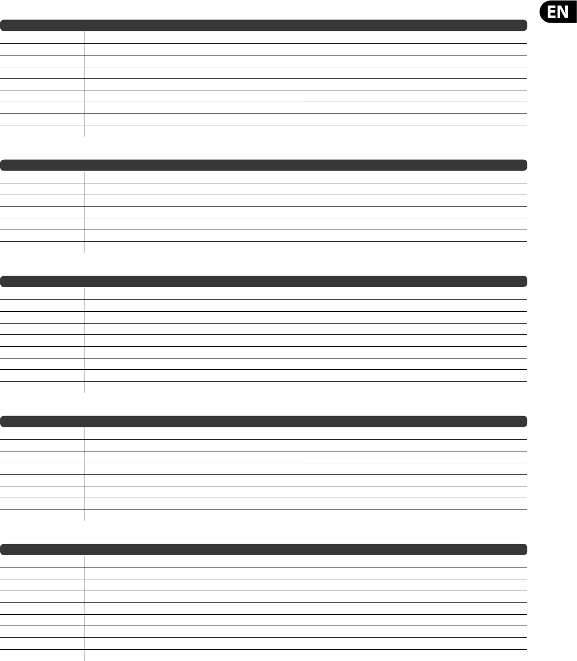
125 DeepMind 12 User Manual
PROGRAM BANK DUMP REQUEST (Response is individual program dump responses in a sequence)
MIDI Bytes Description
F0 System Exclusive Start
00, 20, 32 Behringer Manufacturers ID
20 DeepMind12 Model ID
0d Device ID ( 0-15 )
09 Bank Durmp Request
bb Bank Number (0-7)
First Program (0-127)
ll Last program (0-127)
F7 End of System Exclusive
PROGRAM BANK NAMES DUMP REQUEST
MIDI Bytes Description
F0 System Exclusive Start
00, 20, 32 Behringer Manufacturers ID
20 DeepMind12 Model ID
0d Device ID ( 0-15 )
0A Bank Program Names Dump Request
bb Bank Number
F7 End of System Exclusive
PROGRAM BANK NAMES DUMP RESPONSE
MIDI Bytes Description
F0 System Exclusive Start
00, 20, 32 Behringer Manufacturers ID
20 DeepMind12 Model ID
0d Device ID ( 0-15 )
0B Bank Program Names Dump Response
vv Comms Protocol Version
bb Bank Number
— Program name chars unpacked length = 128 Programs * 16 bytes = 2048 Bytes. Packed data length = 2344
F7 End of System Exclusive
SINGLE PROGRAM NAME DUMP REQUEST
MIDI Bytes Description
F0 System Exclusive Start
00, 20, 32 Behringer Manufacturers ID
20 DeepMind12 Model ID
0d Device ID ( 0-15 )
0C Single Program Name Dump Request
bb Bank Number
pp Program Number
F7 End of System Exclusive
SINGLE PROGRAM NAME DUMP RESPONSE
MIDI Bytes Description
F0 System Exclusive Start
00, 20, 32 Behringer Manufacturers ID
20 DeepMind12 Model ID
0d Device ID ( 0-15 )
0D Bank Program Names Dump Response
06 Comms Protocol Version
bb Bank Number
— 16 byte Program name packed into 24 bytes
F7 End of System Exclusive
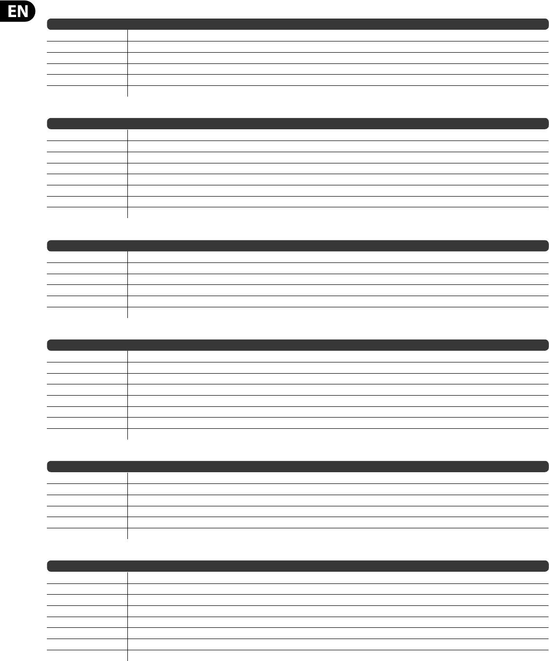
126 DeepMind 12 User Manual
CALIBRATION DATA DUMP REQUEST
MIDI Bytes Description
F0 System Exclusive Start
00, 20, 32 Behringer Manufacturers ID
20 DeepMind12 Model ID
0d Device ID ( 0-15 )
11 Calibration Data Dump Request
F7 End of System Exclusive
CALIBRATION DATA DUMP RESPONSE
MIDI Bytes Description
F0 System Exclusive Start
00, 20, 32 Behringer Manufacturers ID
20 DeepMind12 Model ID
0d Device ID ( 0-15 )
12 Calibration Data Dump Response
06 Comms Protocol Version
— Voice and Controller calibration data packed into688 7-bit message bytes
F7 End of System Exclusive
CHORD MEMORY DUMP REQUEST
MIDI Bytes Description
F0 System Exclusive Start
00, 20, 32 Behringer Manufacturers ID
20 DeepMind12 Model ID
0d Device ID ( 0-15 )
1B Chord Memory Dump Request
F7 End of System Exclusive
CHORD MEMORY DUMP RESPONSE
MIDI Bytes Description
F0 System Exclusive Start
00, 20, 32 Behringer Manufacturers ID
20 DeepMind12 Model ID
0d Device ID ( 0-15 )
1C Poly Chord Memory Dump Response
06 Comms Protocol Version
— 26 bytes Chord memory packed into 32 7-bit message bytes. Note unused locations set to 0xFF
F7 End of System Exclusive
POLY CHORD MEMORY DUMP REQUEST
MIDI Bytes Description
F0 System Exclusive Start
00, 20, 32 Behringer Manufacturers ID
20 DeepMind12 Model ID
0d Device ID ( 0-15 )
1D Poly Chord Memory Dump Request
F7 End of System Exclusive
POLY CHORD MEMORY DUMP RESPONSE
MIDI Bytes Description
F0 System Exclusive Start
00, 20, 32 Behringer Manufacturers ID
20 DeepMind12 Model ID
0d Device ID ( 0-15 )
1E Poly Chord Memory Dump Response
06 Comms Protocol Version
— 512 bytes Poly Chord memory packed into 592 7-bit message bytes. Note unused locations set to 0xFF
F7 End of System Exclusive

127 DeepMind 12 User Manual
20. Firmware Update
The DeepMind 12 can receive operating system updates which may add new
features or resolve issues. These operating system updates come in the form of
" rmware".
To perform a rmware update, follow these steps:
1. Check update availability at www.behringer.com/DeepMind 12
2. Download update
3. Unzip/Expand les to a folder on your local hard drive.
4. Inside the folder start the "DeepMind Updater" application
5. Follow the instructions in the readme le included with the download.
6. Once complete, enjoy new features/performance.
21. Troubleshooting
Before turning on the DeepMind 12 power, please check that:
Your speakers or headphones connected are correctly
The external devices are powered-o
Turn the VOLUME knob on the surface to the 0 position.
Turn on the POWER switch located on the rear panel.
The DeepMind 12 operating system will start and you should see the Behringer
logo.
Once the PROG menu is visible you can then turn on power to the connected
devices, and raise the volume to an appropriate level.
Before turning o the DeepMind 12 power, please check that:
Turn the output level down on all connected audio devices.
Turn o the power for all connected audio devices.
21.1 There is no sound coming from
the synthesizer
Check the audio connections are made.
Check the volume control is not down.
Check that keyboard LOCAL setting is ON in the GLOBAL-KEYBOARD SETTINGS
menu.
Recall the default program (Press PROG+WRITE). If the default program
produces sound then you should examine the program you are trying to use in
detail to nd any parameter settings which may be preventing the program from
producing any audio.
21.2 The synthesizer does not to respond when
using any of the keys or controls
Check that keyboard LOCAL setting is ON in the GLOBAL-KEYBOARD SETTINGS
menu.
21.3 The program sounds di erent in
some way
Use the compare function to return all faders to their stored positions/
Ensure the modulation wheel is set to the default position for your program.
21.4 There is no MIDI coming from
the synthesizer
Check the MIDI connections are made.
Check the MIDI settings for your connection (Physical/USB/Wi-Fi.
21.5 The arpeggiator or control sequencer is
not running
Check the clock source of the arpeggiator.
21.6 Buzzing or humming sounds can be heard
in the audio outputs
USB and or audio connections made between devices using di erent power
supplies / sockets can sometimes create ground loops. You can attempt to resolve
the grounding issues between the computer and the DeepMind 12 by following
good grounding practice and ensuring all devices use the same ground reference.
Other possible solutions include using a DI Box where the transformer will isolate
the audio connections, or using the physical MIDI sockets which are optically
isolated.
21.7 When recording MIDI the synthesizer is
sending pitch bend signals without touching
the pitch wheel.
This can be resolved by running the pitch wheel calibration routine found in the
GLOBAL-SYSTEM SETTINGS-CALIBRATE menu
21.8 The pitch and/or mod wheel is not
responding as expected.
This can be resolved by running the pitch wheel or mod wheel calibration routine
found in the GLOBAL-SYSTEM SETTINGS-CALIBRATE menu.
21.9 The synthesizer is behaving erratically.
Check that any connected devices/applications are not creating a MIDI loop which
is feeding back MIDI data.
21.10 The synthesizer sounds out of tune:
Perform the voice calibration routine found in the GLOBAL-SYSTEM SETTINGS-
CALIBRATE menu.
21.11 The VCF resonance is not tracking notes
as expected
Perform the voice calibration routine found in the GLOBAL-SYSTEM SETTINGS-
CALIBRATE menu.

128 DeepMind 12 User Manual
22. Bootloader Menu
! This menu is for factory or service use only. Improper use
may cause damage to the DeepMind 12.
Note: Please ensure you backup any programs / patterns before using any of the
bootloader functionality
To show the bootloader menu follow these steps:
1. Ensure the DeepMind 12 is turned o .
2. Press and hold the PROG and WRITE switches.
3. Turn the DeepMind 12 on.
4. Release the PROG and WRITE switches.
You will now see the bootloader menu, the options are decribed in this section.
In order to select an option make sure that the '<' symbol on the appropriate
CALIBRATE line is highlighted using the BANK/UP and BANK/DOWN switches then
press the +/YES switch.
22.1 1- Format WiFi Flash
Factory Use Only.
22.2 2- MIDI Update
Factory Use Only.
22.3 3- Reset Cal Data
This option will reset the calibration data.
22.4 4- Reset Chords
This option will reset the chord memory.
22.5 5- Reset PolyChords
This option will reset the polychord memory.
22.6 6- Reset Globals
This option will reset the global settings.
22.7 7- Reset ALL
This option will perform all formatting resetting covered in options 1-5 settings.
22.8 8- EXIT
This option will exit the bootloader menu and return the DeepMind 12 to
normal operation.

129 DeepMind 12 User Manual
23. De nition of Terms
This glossary provides an explanation of the symbols, terms and abbreviations
used in this manual.
16'/8'/4' Used to describe the range of an oscillator, this term originates from
pipe organs. The length of the pipe is inversely proportional to the pitch it
produces e.g. a 4' pipe is one octave higher than an 8' pipe.
ADC or A/D Analog to Digital Converter, used to describe the process of signal
conversion
AC Alternating Current
ADSR Attack, Decay, Sustain and Release, an envelope with four stages.
Aftertouch - The pressure applied to a key after it has been pressed. This
pressure is converted into a MIDI signal to allow the amount of pressure to
modulate another parameter.
Algorithm: A process or set of rules used to accomplish an operation.
Ampli er A circuit which increased the level of a signal.
Amplitude Modulation (AM) Modulation of the amplitude (or level) of a sound
by another signal source. AM is used to produce tremolo using a low frequency
modulation source.
Analog Something which is proportional or similar to something else. In the
case of the synthesizer, audio electronic circuits are another form of air pressure
waves. Analog signals contain distortions from the components, topology,
circuits and designs which are often perceived as warmer and more natural than
their digitally generated counterparts.
Arpeggiator An "Apreggio" is a number of notes played sequentially instead
of simultaneously. The Arpeggiator responds to a number of keys being held by
playing a sequence of notes. The notes, and their sequence can be con gured
using the preset modes of operation.
Attack Time The rst stage of an ADSR envelope, used to control the initial
part of a sound. Speci ed as the duration of time for an envelope to reach the
maximum level after it has been triggered on by a key press or gate signal.
Attenuate To reduce the level of a signal.
Automation The recording and playback of control signals.
Auto-panning An e ect which cyclically adjusts the position of the audio signal
within the stereo eld.
Balanced Audio A type of audio connection that uses the three wires in a cable
as part of a phase-cancelling arrangement to boost the signal and reduce noise.
Band A range of frequencies.
Bandwidth The di erence between the upper and lower frequencies of a lter.
Bank A group of programs
Bass Lower frequencies in a signal ranging from 60 Hz to 250 Hz (Approximately
B1 to B3).
Beat Frequency When two waveforms of di erent frequencies are mixed
together the resulting waveform will have points of constructive and destructive
interference. The beat frequency is equal to the di erence in frequencies and is
heard as a "beating" or amplitude modulation.
Beats Per Minute (BPM) Used to describe the tempo of a composition by
specifying the number of beats which should occur in every minute.
Cent Unit of measurement for pitch tuning. There are one hundred cents
in a semitone.
Chorus An e ect which uses multiple copies of a signal played together and
slightly out of time, to create a shimmering e ect. Sometimes referred to as
“Ensemble”.
Clock A digital waveform typically square which is used as a timing source for
other components in a system.
Comb Filtering Removal of signal components using a lter shape with a
number of regularly spacedfrequencies.
Compressor A dynamics processor that reduces the level of any signal exceeding
a speci ed threshold volume.
Continuous Controller A type of MIDI message assigned to a speci c
parameter. When the parameter is adjusted a continuous controller messages are
sent. If the assigned continuous controller is received then the parameter will be
adjusted.
Control Voltage (CV) A voltage signal used to control any parameter. Was
common on synthesizers before MIDI, and is now found mostly on modular
synthesizers.
Cross-Modulation (X-Mod) Two oscillators modulating each other at the same
time. The outputs is a mix of the sum and di erence of the oscillators. The term
is also used to describe the ability for parameters of a synthesizer to be able to
modulate other parameters.
Cut-O Frequency The frequency which a lter is set to. Beyond this frequency
(in a lo-pass lter, the most common), the sound is cut o (attenuated) at a rate
set by the slope of the lter response curve.
Cycle In a sound wave, the cycle refers to a single repetition of a wave-shape.
E.g. in a square waveform it is the time from a positive edge, to the next positive
edge.
DAC or D/A Digital to Analog Converter, used to describe the process of signal
conversion
Data Digitally stored information
dB Symbol for “decibel”. A unit of measurement of the loudness of sound.
SeedBu.
dBu A unit of measurement of sound used in professional audio. Derived from
the decibel, where the “u” stands for unloaded, this unit is an RMS measurement
of voltage based on 0.775 VRMS, which is the voltage at which you get 1mV of
power in a 600 ohm resistor. This used to be the standard impedance in most
professional audio circuits.
DC O set An imbalance that sometimes occurs in A/D converters . It is a
constant voltage that is present which can eat up headroom and cause clicks and
pops during editing.
Decay Time The second stage of an ADSR envelope. Speci ed as the duration of
time for an envelope to reach the sustain level after the maximum level has been
reached during the attack stage.
Default An initial value for parameter, i.e., the value before any changes have
been made.
Delay An e ect by which a reproduction of a signal is played back later then
itsoriginal. Primarily used for echo, but also is the basis for phasing, anging,
chorus and basic reverb type e ects.
Detuning The action of adjusting the pitch of an oscillator from a reference point
or another oscillator. When oscillators are detuned slightly they will make the
output sound "fatter" or "wider". When oscillators are detuned heavily to note
intervals it can create harmonies.
Digital Audio Workstation (DAW) A computer based recording system.
More commonly used to describe the software package used to record, process
and mix.

130 DeepMind 12 User Manual
Digitally Controlled Oscillator An analog oscillator circuit controlled and
monitored by a digital processor. The advantages over a VCO is increased stability
which results in far less tuning drift.
Digital Signal Processing (DSP) The numerical manipulation of signals,
usually with the intention to measure, lter, change, e ect, produce or compress
continuous analog signals.
Distortion An e ect based on pushing the boundaries of what a speci c
technology or implementation can achieve. At the point where technology
begins to overload, overdrive, clip, saturate or generally misbehave is where
distortion starts to appear. Examples include tape, valve, transistors, and also
digital algorithms and processes.
Dynamic The range of levels in an audio signal, from the softest to the loudest.
Dynamic Processor A device used to control and/or change the dynamics of a
signal.
Dynamic Range – The di erence between the lowest level and the highest
level an audio system can produce.
Edit / Editing The combined methods of creating a program from a starting
point or program.
Edit Bu er: A temporary storage memory for a program.
E ect: One of a number of audio processes that can be applied to a signal to
modify it, such as reverb, anging, phasing, delay etc.
E ects Send A copy of the channel signal which is sent to an e ects processor in
order for it to be returned.
E ects Return An e ected audio signal which is returned to mix with the
original channel signal.
Envelope Generator (EG): An envelope signal which can be adjusted to a
speci c shape in order to control the way a sound behaves over time.
Equalisation (EQ) Processor used to adjust the volumes of various frequency
ranges for creative or corrective purposes.
Exponential A mathematical function of growth or decay where the
independent variable is the exponent. This results in a "hockey stick" shaped
curve.
Expression Pedal A Pedal which can be connected to an expression input and
used to send a control signal dependant on the position of the pedal. The control
signal can then be used to modulate other parameters, and/or to add expression.
Fader A physical linear control also known as a slider, or slide potentiometer
which can be used to adjust a parameter.
Feedback: A loop created between an audio input and an audio output of an
audio circuit, system or processing block.
Filter A device that attenuate certain frequencies while letting other frequencies
through. Using a lter to reduce harmonics changes the timbre or color of the
sound.
Flanger An e ect that mixes a slightly delayed copy of the signal with the
original signal, producing a linear harmonic comb lter response. The copy’s
delay time is modulated by an LFO which results in jet-like sounds suitable for
sweeps, and can also be used to add metallic type resonance to a sound.
Frequency Modulation (FM) Using one frequency to modulate another
frequencies pitch. When the modulation source is in the audio range it can be
perceived as a change in the timbre or color of the sound. FM can be used to
create a wide range of rich and complex sounds and is often described as having
a clear and distinctive timbre.
Frequency: The number of times that a sound waves cycle repeats within
onesecond.
Fundamental Frequency The lowest frequency of a periodic waveform.
Gain The amount of signal level increase provided by an ampli er stage.
Gate (Synthesizer) A signal used to trigger an event, such as a note or an
envelope.
Gate (Dynamics) A device used to cut o the level of a signal when it falls
below a speci ed threshold. Can be used to cut background noise, control reverb
tails or creatively to produce chopping type e ects.
Glide - See Portamento
Globals The settings and parameters which govern the general operation of the
synthesizer and are not directly associated with the voice engines
Harmonics A series of integer-related sine waves at varying levels creating
di erent timbres. Waveforms (other than a pure sinusoidal) generate various
harmonics which help de ne the character of the sound.
Hertz (Hz) A unit of frequency equal to one cycle of a sound wave per second.
High Pass Filter (HPF) A lter that attenuates lower frequencies from a signal,
leaving the higher frequencies una ected.
Hum Undesirable low frequency tone present in a signal due to grounding
problems or proximity to a power source.
Impedance (Z) Opposition to the ow of alternating current in a circuit,
measured in ohms.
Insert A point in a processing chain where a device can be inserted.
Keyboard A range of keys, arranged in order of ascending pitch, which enables
the synthesizer to be played by hand.
Keyboard Tracking Allows the control signal from played keys to adjust another
parameter. Commonly used to open a lter as higher notes are played which then
enhances harmonics.
Kilohertz (kHz): A unit of frequency equal to one thousand cycles of a sound
wave per second.
Latency: A delay introduced by processing. Measured by the time is takes to
produce a signal after a request has been made. In a synthesizer it is the time
taken to produce a note after a key has been played. In an audio interface it is
used to measure the time it takes for an input signal to reach the processor, or for
a signal from the processor to reach the output.
Level Used to describe the magnitude of a sound, often relative to an arbitrary
reference.
Limiter A device used to limit the level to a range of values irrespective of the
input level.
Linear Used in audio to describe a straight line response of circuit or process
which results in a change which is directly proportional to an independent
variable.
Line Level A nominal operating level used by audio equipment. Professional
line level is normally +4 dBu and consumer line level is -10 dBv.
Looping Automatically restarting a function at the end of a period of time or
de ned cycle to create a continuous loop.
Low Frequency Oscillator (LFO) An oscillator that commonly runs at a very low
speed and is used to modulate another parameter.
Low Pass Filter (LPF) A lter that attenuates higher frequencies from a signal,
leaving the lower frequencies una ected
Mark to Space Ratio The ratio between the positive and negative parts of a
rectangular waveform, or pulsewave.
Memory Digital storage of information/data.

131 DeepMind 12 User Manual
Meter: Visual device to indicate the level of a signal.
MIDI (Musical Instrument Digital Interface) (A technical standard that
describes a protocol, digital interface and connectors and allows a wide variety of
electronic musical instruments, computers and other related hardware/software
devices to connect and communicate.
MIDI Clock A clock signal which is broadcast over MIDI to ensure that devices are
synchronised. Also known as MIDI Beat Clock or MIDI Timing Clock.
MIDI Message Data or information transmitted from one MIDI device to another.
Each MIDI message contains at least two numbers: one that identi es the type of
message being sent, and another which represents a value for the selected type
of message.
Midrange Frequencies in a signal ranging from 250 Hz to 5 kHz (Approximately
B3 to D#8).
Mix The balance of level between one signal and another.
Mixer A device that blends input signals into composite signals for output.
Modular synthesis A synthesis system comprised of a number of modules which
can be connected in many di erent ways. Modules can perform a single function
such as an oscillator or lter or perform multiple functions.
Modulation The process of controlling one or more properties (destinations) of a
signal using another signal (source).
Modulation Matrix: A matrix which allows the creation of multiple source to
destination modulations, each with adjustable levels of operation.
Modulation Wheel (Mod Wheel) A wheel located to the left of a keyboard that
allows you to change speci ed parameters in real-time.
Monitors: Studio quality loudspeakers, providing an accurate representation of
the audio signals.
Mono: A single signal.
Monophonic Only one note can be played at any given time as there is only a
single voice.
Mute Function that allows a signal to be silenced.
N/A Abbreviation for “not applicable”.
Noise Generator A circuit or process that produces a random (or aperiodic)
signal. The frequency response can di er depending on the type of noise.
Note-Priority Determines which note is played when several are held
simultaneously.
Non-Registered Parameter Number (NRPN) A series of controller change
messages used to transmit a parameter change with up to 14-bits of resolution.
Octave or Oct Unit of measurement for pitch. Every time the frequency of a
waveform doubles, the pitch increases by one octave.
Ohm (Ω) Unit of electrical resistance.
Oscillator An electronic device which generates a periodic signal used to form
the basis of a synthesizer program.
One Shot A single event that has to be triggered each it is required.
Output The signal sent out by a device or process. Also used to describe the
physical socket where a signal leaves a device.
Overtone Any frequency that is present in a waveform that is higher than the
fundamental frequency of that waveform.
Pad A program that is usually characterized by slow attack and release times.
Panning / Pan The positioning of a signal within a stereo image.
Parameter: A setting whose value can be changed.
Parametric EQ A type of EQ that allows all of the parameters of equalisation to
be changed, including centre frequency, boost/cut in gain and bandwidth.
Partial Any of the sinusoidal waveforms which form part of a complex tone.
Patch The cables used on modular synthesizers (or synthesizers with modular
compatibility) to connect devices together. Patch cables can carry audio, gate or
control voltage signals.
Period The time that it takes a wave to complete a full cycle. Period is calculated
by dividing 1 by the frequency
Phase: A measurement (in degrees) of the time di erence between
twowaveforms or between a single waveform and a reference point.
Phaser An e ect which uses a series of notched all-pass lters (also called
stages) to create a comb lter response which does not always have harmonic
relationships between the notches. The result is a sweeping e ect similar to a
anger but smoother and often more natural sounding.
Pink Noise A type of signal that has equal power in each band. Human hearing is
roughly logarithmic, therefore each octave is discerned to have an equal amount
of power across the audible spectrum.
Pitch: A quality of sound that makes is possible to judge if a sound is higher or
lower than another.
Pitch Bend / Pitch Bend Wheel Controlling the pitch of a note after it has been
played.
Pitch shift Alteration of pitch or frequency, but without adjusting tempo.
Pole A section of a lter stage. The more poles a lter has, the steeper its
attenuation slope will be, and the more accurate the lter will be.
Polyphonic Capable of playing more than one note at once.
Polyphony The number of notes a polyphonic synthesizer can play
simultaneously.
Portamento An adjustable performance e ect that glides or bends the pitch
from one note to the next.
Post The point for accessing audio just after it leaves a speci c component or
stage.
Pre The point for accessing audio just before it reaches a speci c component or
stage.
Preset: A program or part of a program that is built into a synthesizer patches
that are sometimes xed and sometimes editable.
Program A complete set of parameters and settings which the synthesizer uses
to create the a speci c sound.
Power Supply Unit (PSU) The component in a system which is responsible for
supplying and managing power.
Psychoacoustics The study of the perception of sound, that is, how we
listen, our psychological responses and the physiological e ects on the human
nervoussystem.
Pulse Wave Similar to a square wave, but without symmetry. Also known as a
"Rectangle Wave"
Pulse Width Modulation (PWM) Modulation of the pulse width (the duty
cycle of a pulse wave measured as a percentage). A pulse width of 50% has equal
positive and negative sections and is considered a square wave.
Q Factor A bandwidth (or selectivity), of a particular band in an equalizer. The
higher the Q Factor, the wider the bandwidth.
Rate The speed at which a particular device is operating at.
Release Time The fourth and nal stage of an ADSR envelope. Speci ed as the
duration of time for an envelope to reach zero after the played key is released.

132 DeepMind 12 User Manual
Resonance The emphasis of frequencies around the cut-o point just before
attenuation starts to occur. As resonance increases it will reach a point where the
lter will start to OSCillate, producing a signal even when there is no input.
Reverb An e ect where the ambience of a physical space is simulated.
s Symbol for “second”. A unit of time.
Sample Rate The number of digital samples used every second to represent an
analog waveform.
Sample Resolution (Bit Depth) The number of digital bits used to de ne the
amplitude of an analog signal. Higher resolution results in greater dynamic range.
Sawtooth A waveform that combines an instantaneous rise or fall, followed by a
gradual linear incline or decline. The name comes from the waveforms similarity
to the teeth of a saw.
Semitone A chromatic half-step. There are twelve semitones in an octave.
Sequencer A programmable device or module used to arrange/sequence timed
events into musical patterns and songs.
Self-oscillation Occurs when the resonance of a lter is increased to the point
where it will begin to generate a sine wave independently of any input.
Signal ow: The path of a signal from one module (or component of a system)
to another.
Sinusoidal / Sine Wave Mathematical description of a smooth waveform that
contains only the fundamental frequency and has no additional harmonics. The
shape resembles the letter S rotated 90 degrees.
Slew Rate The rate of change of a voltage or control signal.
Spectrum First used to describe the full range of colors in visible light the term is
also used to describe the full range of frequencies in the audio spectrum.
Square Wave A symmetrical waveform that combines an instantaneous rise or
fall, followed by a positive or negative steady state. The name comes from the
waveforms similarity to a square..
Step A step is one stage in a sequence and can be a control signal, single note,
chord or rest.
Stereo / Stereophonic The most common method of sound reproduction where
separate channels, left and right, used to give the impression of direction.
Stereo-Field / Stereo Image A virtual space created by stereo loudspeakers/
monitors.
Sub-Bass Frequencies in a signal ranging from 10 Hz to 60 Hz (Lower than C0 to
approximately B1).
Subtractive synthesis A technique of creating sounds by ltering waveforms
which are rich in harmonics
Sustain Level The third stage of an ADSR envelope. Speci ed as the level an
envelope will return to after the decay stage. The envelope will remain at the
sustain level until the played key is held.
Sustain Pedal A Pedal containing a switch which can be connected to an sustain
input and used to send a control signal dependant on the state of the switch (On/
O ). The control signal can then be used to modulate other parameters, and/or
to add expression.
Synchronisation (Sync): Coordination of timing between devices.
Sync (Tempo) A function where an cyclical event such as an LFO is synchronised
to a tempo value.
Sync (Oscillator) A function where one oscillator is synchronised to another. The
waveform of the slave oscillator is reset whenever the waveform of the master
oscillator restarts.
Sync (Arp/Seq) A function where an arpeggiator or sequencer is synchronised to
a tempo value.
Sync (Key) A function where an event is synchronised to the pressing of a key.
System Exclusive (SysEx) messages are multi-byte message used to transfer a
complete program or globals. Come in the form of request - response. Threshold:
Level at which dynamics processing will begin to operate.
Tempo The speed at which a composition should be played, usually expressed in
beats per minute.
Threshold In dynamic e ects, this is the level that must be passed before the
processing is engaged.
Timbre The tone, character, or aesthetic qualities of a sound.
Transposition / Transpose: A function that allows you to shift the entire
keyboard up and down in pitch.
Treble: Frequencies in a signal ranging from 5 kHz to 20 kHz (Approximately D#8
to above C10).
Tremolo A periodic change in amplitude.
Triggering - Activation of a function. E.g. the start of a note, envelope, LFO etc.
Tune / Tuning The process of adjusting the root pitch of the instrument to a
speci c reference frequency.
Unbalanced audio: A type of audio connection that uses two wires in a cable
and does not o er the noise rejection qualities of a balanced system.
Unison Two or more voices that are playing together at roughly the same pitch.
Universal Serial Bus (USB): A "plug and play" interface that provides a fast
connection between a computer and peripherals.
Volt (V): A unit of electrical potential di erential or electromotive force. A
di erence in charge between two points in a circuit. This di erence, when
combined with the rate of the charge (current) allows for the control of many
analog circuits that “synthesise” sound.
VoltageControlledAmpli er (VCA) An ampli er whose resultant magnitude
is controlled by a voltage.
Voltage Controlled Filter (VCF) A lter whose cut-o frequency can be
controlled by a voltage.
Voltage Controlled Oscillator (VCO) An oscillator whose cut-o frequency can
be controlled by a voltage. Typically creates the possibility of tuning drift when
used in a synthesizer.
Velocity The speed at which a key is pressed. The velocity is converted into a
MIDI signal to allow the amount of pressure to modulate another parameter.
Velocity Sensitivity A keyboards ability to change the MIDI velocity message to
scale key presses before use for modulation.
Vibrato A periodic change in pitch.
Voice: A physical embodiment of a complete set of OSC, Envelopes, LFOs and VCF
which can play a single note. Multiple voices can be stacked together playing the
same note in unison modes or assigned to di erent notes in polyphonic mode.
Waveform A repeating signal typically created by an oscillator. A waveform can
also be random in the case of noise.
Wavelength The shortest distance between two successive points on a wave
that are in phase. When used in audio or acoustics the physical wavelength is
calculated by dividing the velocity of sound in air (approximately 340m/s) by the
waveform frequency.
133 DeepMind 12 User Manual
24. Appendix 1 - Octave Shifting
25. Appendix 2 - ARP/SEQ/LFO Sync Timing
C0C1C2C3C4
(Middle C)
-1 OCTAVE
+1 OCTAVE
DEFAULT
DeepMind 12 Keyboard
C5C6C7C8
-2 OCTAVES
+2 OCTAVES
ARP/SEQ/LFO SYNC TIMING
12345
RATIO DESCRIPTION
1 One bar
1/2 Half note
3/8 Dotted quarter note
1/3 Third note (Half note triplets)
1/4 Quarter note
3/16 Dotted eighth note
1/6 Sixth note(Quarter note triplets)
1/8 Eighth note
3/32 Dotted sixteenth note
1/12 Twelfth note (Eighth note triplets)
1/16 Sixteenth note
3/64 Dotted thirty-second note
1/24 Twenty-fourth note (Sixteenth note triplets)
1/32 Thirty-second note
3/128 Dotted sixty-fourth note
1/48 Forty-eighth note (Thirty-second note triplets)
1/64 Sixty-fourth note
Straight Notes Triplet Notes Dotted Notes

134 DeepMind 12 User Manual
FEDERAL COMMUNICATIONS
COMMISSION COMPLIANCE
INFORMATION
Responsible Party Name: MUSIC Group Services NV Inc.
Address: 5270 Procyon Street
Las Vegas, NV 89118
USA
Phone Number: +1 702 800 8290
DeepMind 12
complies with the FCC rules as mentioned in the followingparagraph:
This equipment has been tested and found to comply with the limits for a ClassB
digital device, pursuant to part 15 of the FCC Rules. These limits are designed
to provide reasonable protection against harmful interference in a residential
installation. This equipment generates, uses and can radiate radio frequency
energy and, if not installed and used in accordance with the instructions, may cause
harmful interference to radio communications. However, there is no guarantee that
interference will not occur in a particular installation. If this equipment does cause
harmful interference to radio or television reception, which can be determined
by turning the equipment o and on, the user is encouraged to try to correct the
interference by one or more of the followingmeasures:
•
• Reorient or relocate the receiving antenna
•
• Increase the separation between the equipment and receiver
•
• Connect the equipment into an outlet on a circuit di erent from that to which the
receiver is connected
•
• Consult the dealer or an experienced radio/TV technician forhelp
This device complies with Part 15 of the FCC rules. Operation is subject to the
following two conditions:
(1) this device may not cause harmful interference, and
(2) this device must accept any interference received, including interference that may
cause undesired operation.
Important information:
Changes or modi cations to the equipment not expressly approved by MUSIC Group
can void the user’s authority to use the equipment.
FCC RF Radiation Exposure Statement:
1. This Transmitter must not be co‐located or operating in conjunction with any other
antenna or transmitter.
2. This equipment complies with FCC RF radiation exposure limits set forth for an
uncontrolled environment. This equipment should be installed and operated with a
minimum distance of 50 mm between the radiator and your body.
DeepMind 12

135 DeepMind 12 User Manual
Dedicate Your Life to MUSIC
