PDF DEFINITY ECS R6 Administration & Feature Description
User Manual: PDF T E X T F I L E S
Open the PDF directly: View PDF ![]() .
.
Page Count: 2350 [warning: Documents this large are best viewed by clicking the View PDF Link!]
- Table of Contents
- List of Features
- List of Forms
- About This Document
- 1. Before You Begin
- 2. System Basics
- 3. System Security
- 4. Basic Features
- Abbreviated Dialing
- Administered Connections
- Administrable Language Displays
- Administration without Hardware
- Alphanumeric Dialing
- Alternate Operations Support System Alarm Number
- Answer Detection
- Attendant Auto-Manual Splitting
- Attendant Backup Alerting
- Attendant Call Waiting
- Attendant Calling of Inward Restricted Stations
- Attendant Console
- Attendant Control of Trunk Group Access
- Attendant Crisis Alert
- Attendant Direct Extension Selection with Busy Lamp Field
- Attendant Direct Trunk Group Selection
- Attendant Display
- Attendant Intrusion
- Attendant Override of Diversion Features
- Attendant Priority Queue
- Attendant Recall
- Attendant Release Loop Operation
- Attendant Serial Calling
- Audible Message Waiting
- Authorization Codes
- Auto Start and Don’t Split
- Automated Attendant
- Automatic Callback
- Automatic Circuit Assurance
- Automatic Incoming Call Display
- Block Collect Call
- Bridged Call Appearance
- Bulletin Board
- Busy Verification of Terminals and Trunks
- Button View
- Call Charge Information
- Call Coverage
- Call Detail Recording
- How to administer CDR
- How to administer Account Code Dialing
- How to administer FEAC
- How to administer Incoming Trunk Call Splitting
- How to administer Outgoing Trunk Call Splitting
- How to administer Intraswitch CDR
- How to administer CDR Privacy
- Detailed description
- CDR Record formats
- Call detail record field description
- Security
- Considerations
- Interactions
- Call Forwarding
- Call Park
- Call Pickup
- Call Timer
- Call Waiting Termination
- Calling Party/Billing Number
- Calling Party Number Restriction
- CallVisor Adjunct-Switch Application Interface
- Class of Restriction
- Class of Service
- Code Calling Access
- Conference — Attendant
- Conference — Terminal
- Consult
- Coverage Callback
- Coverage Incoming Call Identification
- Customer-Provided-Equipment Alarm
- Data Call Setup
- Data Hotline
- Data Privacy
- Data Restriction
- Data-Only Off-Premises Extensions
- Default Dialing
- Demand Print
- Dial Access to Attendant
- Dial Plan
- Distinctive Ringing
- Dual DCP I-Channels
- Emergency Access to the Attendant
- Enhanced Voice Terminal Display
- Extended User Administration of Redirected Calls
- External Device Alarming
- Facility Busy Indication
- Facility Test Calls
- Flexible Billing
- Go to Cover
- Group Listen
- Group Paging
- Hold
- Hold — Automatic
- Hot Line Service
- Hunt Groups
- Incoming Call Line Identification on Analog Trunks
- Individual Attendant Access
- Integrated Directory
- Integrated Services Digital Network — Basic Rate Interface Endpoints
- Intercept Treatment
- Intercom — Automatic
- Intercom — Dial
- Internal Automatic Answer
- International Operator Access
- Last Number Dialed
- Leave Word Calling
- Line Lockout
- Listed Directory Numbers
- Loudspeaker Paging Access
- Malicious Call Trace
- Manual Message Waiting
- Manual Originating Line Service
- Manual Signaling
- Messaging Server Interface
- Multifrequency Signaling
- Misoperation Handling
- Modem Pooling
- Multiappearance Preselection and Preference
- Music-on-Hold Access
- Night Service
- Off-Premises Station
- On-Hook Dialing
- PC Console
- PC/PBX Connection
- Personal Station Access
- Personalized Ringing
- Power Failure Transfer
- Priority Calling
- Privacy — Attendant Lockout
- Privacy — Manual Exclusion
- Public Network Call Priority
- Pull Transfer
- Recall Signaling
- Recorded Announcement
- How to administer Recorded Announcement
- Detailed description
- Interactions
- Recorded Telephone Dictation Access
- Remote Access
- Restricted/Unrestricted Call Lists
- Restriction — Controlled
- Ringback Queuing
- Ringer Cutoff
- Ringing — Abbreviated and Delayed
- Security Violation Notification
- Send All Calls
- Service Observing
- Single-Digit Dialing and Mixed Station Numbering
- Station Hunting
- Station Security Codes
- Temporary Bridged Appearance
- Tenant Partitioning
- Terminal Self Administration
- Terminal Translation Initialization
- Terminating Extension Group
- Timed Reminder and Attendant Timers
- Transfer
- Transfer — Outgoing Trunk to Outgoing Trunk
- Trunk Flash
- Trunk Group Busy/Warning Indicators to Attendant
- Trunk Identification by Attendant
- Trunk-to-Trunk Transfer
- Visually Impaired Attendant Service
- Voice Message Retrieval
- Voice Messaging Systems
- Voice Terminal Alerting Options
- Voice Terminal Display
- Whisper Page
- World-Class Tone Detection
- World-Class Tone Generation
- 5. Basic Forms
- Abbreviated Dialing List — Enhanced List
- Abbreviated Dialing List — Group List
- Abbreviated Dialing List — Personal List
- Abbreviated Dialing List — System List
- Abbreviated Dialing List — 7103A Button List
- Administered Connection
- Alias Station
- Alphanumeric Dialing Table
- Announcements/Audio Sources
- Attendant Console
- Authorization Code — COR Mapping
- Bulletin Board
- Cabinet
- CAMA Numbering Format form
- CDR System Parameters
- Circuit Packs
- Class of Restriction
- Class of Service
- Code Calling IDs
- Console-Parameters
- Coverage Answer Group
- Coverage Path
- Dial Plan Record
- Duplication-Related System Parameters
- ETA Call Screening Table
- Extensions Administered to have an MCT-Control Button
- External Device Alarm
- Feature Access Code
- Feature-Related System Parameters
- Fiber Link Administration
- Administration commands
- Form instructions
- Page 1 of the form
- Basic Fiber Link Administration
- Duplicated Fiber Link Administration
- DS1C Converter Complex Administration for TN574 Ci...
- Duplicated DS1C Converter Complex Administration f...
- DS1 Converter Complex Administration for T1 TN1654...
- Duplicated DS1 Converter Complex Administration fo...
- DS1 Converter Complex Administration for E1 TN1654...
- Duplicated DS1 Converter Complex Administration fo...
- Page 1 of the form
- Hunt Group
- Intercom Group
- Inter-Exchange Carrier (IXC) Codes
- Interface Links
- Intra-Switch CDR
- ISDN-BRI Trunk Circuit Pack
- Language Translations
- Listed Directory Numbers
- Loudspeaker Paging
- Maintenance-Related System Parameters
- Mode Code Related System Parameters
- Modem Pool Group
- Multifrequency-Signaling-Related System Parameters
- Music Sources
- Packet Gateway Board
- Processor Channel Assignment for R5r and later Installations
- Processor Channel Assignment for R5si and later Installations
- Pickup Group
- Remote Access
- Remote Call Coverage Table
- Second Digit Table
- Security-Related System Parameters
- System Parameters Country-Options
- System Parameters Customer-Options
- System Parameters OCM Call Classification
- Telecommuting Access
- Tenant
- Terminating Extension Group
- Time of Day Coverage Table
- Toll Analysis
- User Defined Adjunct Names
- 6. Voice Terminal, PC Interface, and Data Module Administration
- Voice Terminal, PC Interface, and Data Module Administration
- Voice terminals — general
- Terminal Parameters form
- Voice-terminal feature button descriptions
- Station form field descriptions
- 10-MET, 20-MET, and 30-MET voice terminals
- 500, 2500, K2500, 7101A, 7102A, 7103A, 7104A, 8110, DS1FD, DS1SA, and VRU voice terminals
- 510D personal terminal and 515 business communications terminal
- 6402, 6402D, 6408, 6408+, 6408D, 6408D+, 6416D+, 66424D+ voice terminals
- 7302H, 7303H, and 7305H MERLIN voice terminals
- 7303S, 7305S, and 7309H voice terminals
- 7313H, 7314H, 7315H, 7316H, and 7317H voice terminals
- 7401D, 7401+, 7403D, 7404D, 7410D, and 7410+ voice terminals
- 7405D voice terminal
- 7406D, 7406+, 7407D, and 7407+ voice terminals
- 7434D and 7444D voice terminal
- 7505D, 7506D, 7507D, 8503D, 8510T, and 8520T ISDN-BRI voice terminals
- CALLMASTER II and III voice terminals
- CALLMASTER VI voice terminal
- Personal Computer
- Constellation voice/data terminals
- MDC9000 and MDW9000 cordless voice terminals
- CP9530 cordless voice terminals
- 8403B, 8405B, 8405B+ and 8410B voice terminals
- 8405D, 8405D+, 8410D, and 8434D voice terminals
- 8411B and 8411D voice terminals
- World Class Basic Rate Interface terminal
- PC Interface Administration
- Data Module Administration
- Voice Terminal, PC Interface, and Data Module Administration
- 7. Trunk Group Administration
- Automatic Transmission Measurement System
- DS1 Trunk Service
- Digital Multiplexed Interface
- Enhanced ICSU
- ISDN Trunks— General
- Call-by-Call Service Selection
- Facility and Non-Facility Associated Signaling
- Wideband Switching
- Trunk Group Administration Forms
- Access Endpoint
- ATMS Trunk Test Schedule
- DS1 Circuit Pack form
- Digit Absorption
- ISDN Numbering — Private
- ISDN Numbering — Public/ Unknown
- ISDN TSC Gateway Channel Assignments
- Network-Facilities
- PRI Endpoint
- Signaling Group
- Synchronization Plan
- Trunk Groups — General
- Access trunk group
- APLT trunk group
- CAMA - E911 trunk group
- CO trunk group
- CPE trunk group
- DID trunk group
- DIOD trunk group
- DMI-BOS trunk group
- FX trunk group
- ISDN-BRI trunk group
- Administration commands
- Hardware requirements
- How to administer ISDN-BRI trunk groups
- Notes for Above Tables
- Design Considerations
- Field descriptions
- Fields unique to this form
- Implementation notes
- Fields unique to this form
- Implementation notes
- Shared UUI Feature Priorities Page
- Fields unique to this form
- Implementation notes
- Fields unique to this form
- Implementation note
- Fields unique to this form
- Implementation notes
- Fields unique to this form
- ISDN-PRI trunk group
- Administration commands
- Hardware requirements
- How to administer ISDN-PRI trunk groups
- Notes for the Above Tables
- Design Considerations
- Field descriptions
- Fields unique to this form
- Implementation notes
- Fields unique to this form
- Implementation notes
- Shared UUI Feature Priorities Page
- Fields unique to this form
- Implementation notes
- Fields unique to this form
- Implementation note
- Fields unique to this form
- Implementation notes
- Fields unique to this form
- Implementation notes
- Fields unique to this form
- PCOL trunk group
- RLT trunk group
- Tandem trunk group
- Tie trunk group
- WATS trunk group
- 8. Automatic Routing
- Automatic Routing
- Automatic Routing — General
- AAR and ARS
- AAR and ARS Overlap Sending
- AAR and ARS Partitioning
- Facility Restriction Levels and Traveling Class Marks
- Alternate Facility Restriction Levels
- Generalized Route Selection
- Look-Ahead Routing
- Subnet Trunking
- Time of Day Routing
- Automatic Routing Forms
- Automatic Routing
- 9. Call Center
- Call Center
- Abandoned Call Search
- Add/Remove Skills
- Agent Call Handling
- How to administer Agent Call Handling
- Detailed description
- Expanded technical information
- Considerations
- Interactions
- Auto-Available Split
- Automatic Call Distribution
- Basic Call Management System
- Best Service Routing™
- Call Management System
- Call Prompting
- Call Vectoring
- Expert Agent Selection
- Inbound Call Management
- Information Forwarding
- Intraflow and Interflow
- Look-Ahead Interflow
- Multiple Call Handling
- Queue Status Indications
- Reason Codes
- Redirection on No Answer
- Universal Call ID
- VDN in a Coverage Path
- VDN of Origin Announcement
- Voice Response Integration
- VuStats
- Call Center Forms
- Call Center
- 10. Hospitality
- 11. Multimedia
- Multimedia Applications Server Interface
- Before you start
- About this document
- List of terms
- Planning for MASI
- MASI configurations
- How to administer MASI
- Step 1 — Establish customer options (Lucent Technologies)
- Step 2 — Establish maintenance parameters and alarming options (Lucent Technologies)
- Step 3 — Establish the physical connection
- Step 4 — Administer circuit pack
- Step 5 — Administer a signaling group
- Step 6 — Administer ISDN-PRI trunk group
- Step 7 — Administer MASI Path Parameters
- Step 8 — Administer MASI trunk groups
- Step 9 — Administer MASI terminals
- Duplicate masi terminal
- Step 10 — Administer features
- Step 11 — Verify administration
- MASI command permissions
- Detailed description of features
- Interactions & Unsupported Features
- Troubleshooting
- Multimedia Call Handling
- Multimedia Forms
- Administration commands
- Hunt Group Form
- Call Vector Form
- Duplicating multimedia endpoints
- Basic Mode MM complex
- Enhanced Mode MM complex
- 1-number access
- ORIGINATION
- - originating voice calls
- - originating multimedia calls
- Answering
- Answering voice calls
- Answering multimedia calls
- - multiple call appearance operation
- - creating a multi-party video conference
- Data Collaboration
- Voice station audio vs. H.320 DVC system audio
- Switching between Basic and Enhanced modes
- Forwarding of voice and multimedia calls
- Coverage
- Hunt Groups using Enhanced Mode Complexes
- Interactions
- Troubleshooting
- Monitoring MMCH
- List measurements commands
- Considerations
- References
- Multimedia Applications Server Interface
- 12. Private Networking
- Private Networking
- ATM-PNC
- Centralized Attendant Service
- Distributed Communications System
- DCS Alphanumeric Display for Terminals
- DCS Attendant Control of Trunk Group Access
- DCS Attendant Direct Trunk Group Selection
- DCS Attendant Display
- DCS Automatic Callback
- DCS Automatic Circuit Assurance
- DCS Busy Verification of Terminals and Trunks
- DCS Call Coverage
- DCS Call Forwarding
- DCS Call Waiting
- DCS Distinctive Ringing
- DCS Leave Word Calling
- DCS Multiappearance Conference/ Transfer
- DCS Over ISDN-PRI D-channel
- DCS with Rerouting
- DCS Trunk Group Busy/Warning Indication
- Emergency (911) Calls
- Enhanced DCS
- DCS feature considerations
- DCS Alphanumeric Display considerations
- DCS Attendant Control of Trunk Group Access considerations
- DCS Attendant Direct Trunk Group Selection considerations
- DCS Attendant Display considerations
- DCS Automatic Callback considerations
- DCS Busy Verification of Terminals and Trunks considerations
- DCS Call Coverage considerations
- DCS Call Forwarding considerations
- DCS Distinctive Ringing considerations
- DCS LWC considerations
- DCS Multiappearance Conference/Transfer considerations
- DCS Over ISDN-PRI D-channel considerations
- DCS Trunk Group Busy/Warning Indication considerations
- Enhanced DCS considerations
- DCS Interactions
- DCS Alphanumeric Display interactions
- DCS Attendant Control of Trunk Group Access interactions
- DCS Attendant Display interactions
- DCS Automatic Callback interactions
- DCS Automatic Circuit Assurance interactions
- DCS Busy Verification interactions
- DCS Call Coverage interactions
- DCS Call Forwarding interactions
- DCS Call Waiting interactions
- DCS Distinctive Ringing interactions
- DCS LWC interactions
- DCS Multiappearance Conference/Transfer interactions
- DCS Over ISDN-PRI D-channel interactions
- DCS Trunk Group Busy/Warning Indication interactions
- Enhanced DCS interactions
- Extended Trunk Access
- Extension Number Portability
- Inter-PBX Attendant Service
- Node Number Routing
- Private Network Access
- QSIG
- QSIG Call Forwarding (Diversion)
- QSIG Call Transfer
- QSIG Name and Number Identification
- QSIG Path Replacement (ANF–PR)
- QSIG Supplementary Service - Call Completion
- QSIG Supplementary Service - Call Offer
- QSIG Transit Counter (ANF–TC)
- Uniform Dial Plan
- Private Networking Forms
- Private Networking
- A. Transition Reference
- B. Administration Commands
- C. References
- Glossary and Abbreviations
- Index

555-230-522
Comcode 108215740
Issue 4
May 1998
DEFINITY®
Enterprise Communications Server
Release 6
Administration and Feature Description
Copyright 1998, Lucent Technologies
All Rights Reserved
Printed in U.S.A.
Notice
Every effort was made to ensure that the information in this book was
complete and accurate at the time of printing. However, information is
subject to change.
Your Responsibility for Your System’s Security
Toll fraud is the unauthorized use of your telecommunications system
by an unauthorized party, for example, persons other than your com-
pany’s employees, agents, subcontractors, or persons working on your
company’s behalf. Note that there may be a risk of toll fraud associated
with your telecommunications system and, if toll fraud occurs, it can
result in substantial additional charges for your telecommunications
services.
You and your system manager are responsible for the security of your
system, such as programming and configuring your equipment to pre-
vent unauthorized use. The system manager is also responsible for
reading all installation, instruction, and system administration docu-
ments provided with this product in order to fully understand the fea-
tures that can introduce risk of toll fraud and the steps that can be taken
to reduce that risk. Lucent Technologies does not warrant that this
product is immune from or will prevent unauthorized use of com-
mon-carrier telecommunication services or facilities accessed through
or connected to it. Lucent Technologies will not be responsible for any
charges that result from such unauthorized use.
Lucent Technologies Fraud Intervention
If you suspect that you are being victimized by toll fraud and you need
technical support or assistance, call Technical Service Center Toll
Fraud Intervention Hotline at 1 800 643-2353.
Federal Communications Commission Statement
Part 15: Class A Statement. This equipment has been tested and
found to comply with the limits for a Class A digital device, pursuant
to Part 15 of the FCC Rules. These limits are designed to provide rea-
sonable protection against harmful interference when the equipment is
operated in a commercial environment. This equipment generates,
uses, and can radiate radio-frequency energy and, if not installed and
used in accordance with the instructions, may cause harmful interfer-
ence to radio communications. Operation of this equipment in a resi-
dential area is likely to cause harmful interference, in which case the
user will be required to correct the interference at his own expense.
Part 68: Network Registration Number. This equipment is registered
with the FCC in accordance with Part 68 of the FCC Rules. It is identi-
fied by FCC registration number AS593M-13283-MF-E.
Part 68: Answer-Supervision Signaling. Allowing this equipment to
be operated in a manner that does not provide proper answer-supervi-
sion signaling is in violation of Part 68 Rules. This equipment returns
answer-supervision signals to the public switched network when:
• Answered by the called station
• Answered by the attendant
• Routed to a recorded announcement that can be administered by
the CPE user
This equipment returns answer-supervision signals on all DID calls
forwarded back to the public switched telephone network. Permissible
exceptions are:
• A call is unanswered
• A busy tone is received
• A reorder tone is received
Canadian Department of Communications (DOC)
Interference Information
This digital apparatus does not exceed the Class A limits for radio
noise emissions set out in the radio interference regulations of the
Canadian Department of Communications.
Le Présent Appareil Nomérique n’émet pas de bruits radioélectriques
dépassant les limites applicables aux appareils numériques de la class
A préscrites dans le reglement sur le brouillage radioélectrique édicté
par le ministére des Communications du Canada.
Trademarks
See the preface of this document.
Ordering Information
Call: Lucent Technologies BCS Publications Center
Voice 1 800 457-1235 International Voice 317 322-6416
Fax 1 800 457-1764 International Fax 317 322-6699
Write: Lucent Technologies BCS Publications Center
2855 N. Franklin Road
Indianapolis, IN 46219
Order: Document No. 555-230-522
Comcode 108215740
Issue 4, May 1998
For additional documents, refer to Appendix C, “References.”
You can be placed on a standing order list for this and other documents
you may need. Standing order will enable you to automatically receive
updated versions of individual documents or document sets, billed to
account information that you provide. For more information on stand-
ing orders, or to be put on a list to receive future issues of this docu-
ment, contact the Lucent Technologies Publications Center.
European Union Declaration of Conformity
The “CE” mark affixed to the DEFINITY® equipment described in
this book indicates that the equipment conforms to the following Euro-
pean Union (EU) Directives:
• Electromagnetic Compatibility (89/336/EEC)
• Low Voltage (73/23/EEC)
• Telecommunications Terminal Equipment (TTE) i-CTR3 BRI
and i-CTR4 PRI
For more information on standards compliance, contact your local dis-
tributor.
Comments
To comment on this document, return the comment card at the front of
the document.
Acknowledgment
This document was prepared by Product Documentation Development,
Lucent Technologies, Denver, CO.

DEFINITY Enterprise Communications Server Release 6
Administration and Feature Description
555-230-522
Issue 4
May 1998
Contents
Page iii
Contents
Contents iii
List of Features xix
List of Forms xxvii
About This Document xxxi
■Overview xxxi
■Purpose xxxi
■Audience xxxii
■Reason for reissue xxxii
■How to use this document xxxii
■Organization xxxii
■Feature-related information xxxiv
■Conventions used in this document xxxiv
■Trademarks and service marks xxxv
■How to get help xxxvi
■How to make comments about
this document xxxvii
1 Before You Begin 1-1
■Overview 1-1
■Communications survey 1-1
■Administration sequence 1-5
2 System Basics 2-1
■Overview 2-1
■How to log in and log off 2-2
■Using the SAT 2-4
■Commands 2-6
■Login administration 2-7
■Remote administration 2-14
■How to set the system date and time 2-17
■How to print on demand 2-18
■System backup for R6vs/si and later configurations 2-18
■System backup for R6r and later configurations 2-24

DEFINITY Enterprise Communications Server Release 6
Administration and Feature Description
555-230-522
Issue 4
May 1998
Contents
Page iv
3 System Security 3-1
■Overview 3-1
■Learn about the problem 3-1
■Where to get help 3-1
■Basic security 3-2
■Physical security 3-3
■Features requiring security precautions 3-3
4 Basic Features 4-1
■Abbreviated Dialing 4-1
■Administered Connections 4-13
■Administrable Language Displays 4-20
■Administration without Hardware 4-40
■Alphanumeric Dialing 4-49
■Alternate Operations Support System
Alarm Number 4-51
■Answer Detection 4-52
■Attendant Auto-Manual Splitting 4-54
■Attendant Backup Alerting 4-55
■Attendant Call Waiting 4-57
■Attendant Calling of Inward
Restricted Stations 4-60
■Attendant Console 4-61
■Attendant Control of Trunk Group
Access 4-62
■Attendant Crisis Alert 4-66
■Attendant Direct Extension Selection
with Busy Lamp Field 4-68
■Attendant Direct Trunk Group
Selection 4-72
■Attendant Display 4-74
■Attendant Intrusion 4-83
■Attendant Override of Diversion
Features 4-84
■Attendant Priority Queue 4-85
■Attendant Recall 4-88
■Attendant Release Loop Operation 4-89
■Attendant Serial Calling 4-90

DEFINITY Enterprise Communications Server Release 6
Administration and Feature Description
555-230-522
Issue 4
May 1998
Contents
Page v
■Audible Message Waiting 4-92
■Authorization Codes 4-93
■Auto Start and Don’t Split 4-97
■Automated Attendant 4-98
■Automatic Callback 4-100
■Automatic Circuit Assurance 4-104
■Automatic Incoming Call Display 4-108
■Block Collect Call 4-110
■Bridged Call Appearance 4-112
■Bulletin Board 4-128
■Busy Verification of Terminals
and Trunks 4-130
■Button View 4-135
■Call Charge Information 4-136
■Call Coverage 4-146
■Call Detail Recording 4-167
■Call Forwarding 4-224
■Call Park 4-232
■Call Pickup 4-236
■Call Timer 4-242
■Call Waiting Termination 4-244
■Calling Party/Billing Number 4-246
■Calling Party Number Restriction 4-247
■CallVisor Adjunct-Switch Application
Interface 4-250
■Class of Restriction 4-264
■Class of Service 4-277
■Code Calling Access 4-280
■Conference — Attendant 4-282
■Conference — Terminal 4-284
■Consult 4-286
■Coverage Callback 4-287
■Coverage Incoming Call Identification 4-288
■Customer-Provided-Equipment Alarm 4-289
■Data Call Setup 4-290
■Data Hotline 4-298

DEFINITY Enterprise Communications Server Release 6
Administration and Feature Description
555-230-522
Issue 4
May 1998
Contents
Page vi
■Data Privacy 4-301
■Data Restriction 4-303
■Data-Only Off-Premises Extensions 4-305
■Default Dialing 4-307
■Demand Print 4-309
■Dial Access to Attendant 4-310
■Dial Plan 4-311
■Distinctive Ringing 4-314
■Dual DCP I-Channels 4-317
■Emergency Access to the Attendant 4-318
■Enhanced Voice Terminal Display 4-322
■Extended User Administration of
Redirected Calls 4-333
■External Device Alarming 4-340
■Facility Busy Indication 4-341
■Facility Test Calls 4-343
■Flexible Billing 4-345
■Go to Cover 4-348
■Group Listen 4-349
■Group Paging 4-352
■Hold 4-358
■Hold — Automatic 4-361
■Hot Line Service 4-363
■Hunt Groups 4-365
■Incoming Call Line Identification on Analog Trunks 4-373
■Individual Attendant Access 4-376
■Integrated Directory 4-379
■Integrated Services Digital Network —
Basic Rate Interface Endpoints 4-382
■Intercept Treatment 4-390
■Intercom — Automatic 4-393
■Intercom — Dial 4-395
■Internal Automatic Answer 4-397
■International Operator Access 4-401
■Last Number Dialed 4-403
■Leave Word Calling 4-405

DEFINITY Enterprise Communications Server Release 6
Administration and Feature Description
555-230-522
Issue 4
May 1998
Contents
Page vii
■Line Lockout 4-409
■Listed Directory Numbers 4-410
■Loudspeaker Paging Access 4-412
■Malicious Call Trace 4-422
■Manual Message Waiting 4-429
■Manual Originating Line Service 4-430
■Manual Signaling 4-432
■Messaging Server Interface 4-433
■Multifrequency Signaling 4-438
■Misoperation Handling 4-445
■Modem Pooling 4-449
■Multiappearance Preselection and
Preference 4-452
■Music-on-Hold Access 4-455
■Night Service 4-457
■Off-Premises Station 4-467
■On-Hook Dialing 4-469
■PC Console 4-470
■PC/PBX Connection 4-471
■Personal Station Access 4-474
■Personalized Ringing 4-480
■Power Failure Transfer 4-482
■Priority Calling 4-483
■Privacy — Attendant Lockout 4-486
■Privacy — Manual Exclusion 4-487
■Public Network Call Priority 4-489
■Pull Transfer 4-496
■Recall Signaling 4-498
■Recorded Announcement 4-500
■Recorded Telephone Dictation Access 4-508
■Remote Access 4-509
■Restricted/Unrestricted Call Lists 4-515
■Restriction — Controlled 4-518
■Ringback Queuing 4-520
■Ringer Cutoff 4-523
■Ringing — Abbreviated and Delayed 4-526

DEFINITY Enterprise Communications Server Release 6
Administration and Feature Description
555-230-522
Issue 4
May 1998
Contents
Page viii
■Security Violation Notification 4-531
■Send All Calls 4-538
■Service Observing 4-539
■Single-Digit Dialing and Mixed Station Numbering 4-553
■Station Hunting 4-557
■Station Security Codes 4-563
■Temporary Bridged Appearance 4-566
■Tenant Partitioning 4-568
■Terminal Self Administration 4-578
■Terminal Translation Initialization 4-583
■Terminating Extension Group 4-591
■Timed Reminder and Attendant
Timers 4-594
■Transfer 4-597
■Transfer — Outgoing Trunk to
Outgoing Trunk 4-599
■Trunk Flash 4-603
■Trunk Group Busy/Warning Indicators
to Attendant 4-607
■Trunk Identification by Attendant 4-609
■Trunk-to-Trunk Transfer 4-611
■Visually Impaired Attendant Service 4-613
■Voice Message Retrieval 4-615
■Voice Messaging Systems 4-618
■Voice Terminal Alerting Options 4-625
■Voice Terminal Display 4-626
■Whisper Page 4-633
■World-Class Tone Detection 4-642
■World-Class Tone Generation 4-643
5 Basic Forms 5-1
■Abbreviated Dialing List — Enhanced List 5-2
■Abbreviated Dialing List — Group List 5-5
■Abbreviated Dialing List — Personal
List 5-8
■Abbreviated Dialing List — System List 5-11
■Abbreviated Dialing List — 7103A Button List 5-14

DEFINITY Enterprise Communications Server Release 6
Administration and Feature Description
555-230-522
Issue 4
May 1998
Contents
Page ix
■Administered Connection 5-17
■Alias Station 5-21
■Alphanumeric Dialing Table 5-23
■Announcements/Audio Sources 5-26
■Attendant Console 5-35
■Authorization Code — COR Mapping 5-54
■Bulletin Board 5-56
■Cabinet 5-58
■CAMA Numbering Format form 5-61
■CDR System Parameters 5-63
■Circuit Packs 5-69
■Class of Restriction 5-72
■Class of Service 5-81
■Code Calling IDs 5-84
■Console-Parameters 5-86
■Coverage Answer Group 5-92
■Coverage Path 5-94
■Dial Plan Record 5-99
■Duplication-Related System Parameters 5-104
■ETA Call Screening Table 5-106
■Extensions Administered
to have an MCT-Control Button 5-108
■External Device Alarm 5-109
■Feature Access Code 5-113
■Feature-Related System Parameters 5-123
■Fiber Link Administration 5-146
■Hunt Group 5-158
■Intercom Group 5-175
■Inter-Exchange Carrier (IXC) Codes 5-177
■Interface Links 5-179
■Intra-Switch CDR 5-183
■ISDN-BRI Trunk Circuit Pack 5-186
■Language Translations 5-193
■Listed Directory Numbers 5-207
■Loudspeaker Paging 5-209

DEFINITY Enterprise Communications Server Release 6
Administration and Feature Description
555-230-522
Issue 4
May 1998
Contents
Page x
■Maintenance-Related System
Parameters 5-212
■Mode Code Related System Parameters 5-220
■Modem Pool Group 5-223
■Multifrequency-Signaling-Related
System Parameters 5-228
■Music Sources 5-243
■Packet Gateway Board 5-246
■Processor Channel Assignment for
R5r and later Installations 5-248
■Processor Channel Assignment for
R5si and later Installations 5-252
■Pickup Group 5-256
■Remote Access 5-258
■Remote Call Coverage Table 5-263
■Second Digit Table 5-264
■Security-Related System Parameters 5-266
■System Parameters Country-Options 5-271
■System Parameters Customer-Options 5-277
■System Parameters OCM Call
Classification 5-289
■Telecommuting Access 5-291
■Tenant 5-292
■Terminating Extension Group 5-295
■Time of Day Coverage Table 5-298
■Toll Analysis 5-299
■User Defined Adjunct Names 5-303
6 Voice Terminal, PC Interface, and
Data Module Administration 6-1
■Voice terminals — general 6-4
■Terminal Parameters form 6-9
■Voice-terminal feature button descriptions 6-14
■Station form field descriptions 6-28
■10-MET, 20-MET, and 30-MET voice terminals 6-41
■500, 2500, K2500, 7101A, 7102A, 7103A,
7104A, 8110, DS1FD, DS1SA, and VRU
voice terminals 6-47

DEFINITY Enterprise Communications Server Release 6
Administration and Feature Description
555-230-522
Issue 4
May 1998
Contents
Page xi
■510D personal terminal and 515
business communications terminal 6-55
■6402, 6402D, 6408, 6408+, 6408D, 6408D+,
6416D+, 6424D+ voice terminals 6-60
■7302H, 7303H, and 7305H MERLIN voice terminals 6-72
■7303S, 7305S, and 7309H voice terminals 6-73
■7313H, 7314H, 7315H, 7316H, and
7317H voice terminals 6-80
■7401D, 7401+, 7403D, 7404D, 7410D,
and 7410+ voice terminals 6-90
■7405D voice terminal 6-99
■7406D, 7406+, 7407D, and 7407+ voice terminals 6-111
■7434D and 7444D voice terminal 6-121
■7505D, 7506D, 7507D, 8503D, 8510T,
and 8520T ISDN-BRI voice terminals 6-130
■CALLMASTER II and III voice terminals 6-141
■CALLMASTER VI voice terminal 6-147
■Personal Computer 6-153
■Constellation voice/data terminals 6-158
■MDC9000 and MDW9000 cordless voice terminals 6-163
■CP9530 cordless voice terminals 6-168
■8403B, 8405B, 8405B+ and 8410B voice
terminals 6-172
■8405D, 8405D+, 8410D, and 8434D
voice terminals 6-180
■8411B and 8411D voice terminals 6-189
■World Class Basic Rate Interface terminal 6-194
PC Interface Administration 6-217
■EIA Interface 6-218
■PC Interface 6-220
Data Module Administration 6-225
■Data Modules — general 6-226
■Data module form field description 6-230
■Announcement Data Module 6-233
■Data Line Data Module 6-234
■Processor/Trunk Data Module 6-243
■Netcon Data Module 6-245

DEFINITY Enterprise Communications Server Release 6
Administration and Feature Description
555-230-522
Issue 4
May 1998
Contents
Page xii
■Processor Interface Data Module 6-246
■System Port Data Module 6-248
■X.25 Data Module 6-249
■7500 Data Module 6-252
■World Class BRI Data Module 6-255
7 Trunk Group Administration 7-1
■Automatic Transmission Measurement System 7-2
■DS1 Trunk Service 7-11
■Digital Multiplexed Interface 7-19
■Enhanced ICSU 7-21
■ISDN Trunks— General 7-25
■Call-by-Call Service Selection 7-42
■Facility and Non-Facility Associated Signaling 7-49
■ Wideband Switching 7-56
■Trunk Group Administration Forms 7-71
■Access Endpoint 7-72
■ATMS Trunk Test Schedule 7-76
■DS1 Circuit Pack form 7-79
■Digit Absorption 7-91
■ISDN Numbering — Private 7-93
■ISDN Numbering — Public/ Unknown 7-95
■ISDN TSC Gateway Channel Assignments 7-98
■Network-Facilities 7-100
■PRI Endpoint 7-102
■Signaling Group 7-106
■Synchronization Plan 7-112
■Trunk Groups — General 7-115
■Access trunk group 7-150
■APLT trunk group 7-156
■CAMA - E911 trunk group 7-161
■CO trunk group 7-168
■CPE trunk group 7-174
■DID trunk group 7-178
■DIOD trunk group 7-183
■DMI-BOS trunk group 7-188

DEFINITY Enterprise Communications Server Release 6
Administration and Feature Description
555-230-522
Issue 4
May 1998
Contents
Page xiii
■FX trunk group 7-193
■ISDN-BRI trunk group 7-198
■ISDN-PRI trunk group 7-219
■PCOL trunk group 7-246
■RLT trunk group 7-252
■Tandem trunk group 7-257
■Tie trunk group 7-262
■WATS trunk group 7-268
8 Automatic Routing 8-1
■Automatic Routing — General 8-2
■AAR and ARS 8-3
■AAR and ARS Overlap Sending 8-20
■AAR and ARS Partitioning 8-21
■Facility Restriction Levels and
Traveling Class Marks 8-24
■Alternate Facility Restriction Levels 8-29
■Generalized Route Selection 8-33
■Look-Ahead Routing 8-45
■Subnet Trunking 8-48
■Time of Day Routing 8-50
Automatic Routing Forms 8-54
■AAR and ARS Digit Analysis Table 8-55
■AAR and ARS Digit Conversion Table 8-63
■Route Pattern form 8-67
■ARS Toll Table 8-75
■RHNPA Table 8-76
■Time of Day Routing Plan 8-78
9 Call Center 9-1
■Abandoned Call Search 9-3
■Add/Remove Skills 9-5
■Agent Call Handling 9-7
■Auto-Available Split 9-22
■Automatic Call Distribution 9-25
■Basic Call Management System 9-40
■Best Service Routing™ 9-44

DEFINITY Enterprise Communications Server Release 6
Administration and Feature Description
555-230-522
Issue 4
May 1998
Contents
Page xiv
■Call Management System 9-58
■Call Prompting 9-60
■Call Vectoring 9-63
■Expert Agent Selection 9-72
■Inbound Call Management 9-81
■Information Forwarding9-89
■Intraflow and Interflow 9-95
■Look-Ahead Interflow 9-98
■Multiple Call Handling 9-104
■Queue Status Indications 9-110
■Reason Codes 9-112
■Redirection on No Answer 9-116
■Universal Call ID 9-130
■VDN in a Coverage Path 9-145
■VDN of Origin Announcement 9-146
■Voice Response Integration 9-152
■VuStats 9-161
Call Center Forms 9-192
■Agent LoginID 9-193
■Best Service Routing (BSR) Application Plan 9-197
■BCMS/VuStats Login ID 9-200
■Call Center System Parameters 9-202
■Call Vector 9-207
■Reason Code Names 9-211
■SIT Treatment for Call Classification 9-212
■Vector Directory Number 9-214
■Vector Routing Table 9-219
■VuStats Display Format 9-221
10 Hospitality 10-1
■Attendant Room Status 10-2
■Automatic Wakeup 10-4
■Do Not Disturb 10-11
■Hospitality Services 10-15
■Names Registration 10-17
■Property Management System Interface 10-21

DEFINITY Enterprise Communications Server Release 6
Administration and Feature Description
555-230-522
Issue 4
May 1998
Contents
Page xv
Hospitality Forms 10-29
■Hospitality 10-30
11 Multimedia 11-1
■Multimedia Applications Server Interface 11-2
■Multimedia Call Handling 11-30
■Multimedia Forms 11-39
■Basic Mode MM complex 11-59
■Enhanced Mode MM complex 11-73
■References 11-98
12 Private Networking 12-1
■ATM-PNC 12-3
■Centralized Attendant Service 12-4
■Distributed Communications System 12-11
■DCS Alphanumeric Display for
Terminals 12-27
■DCS Attendant Control of Trunk
Group Access 12-28
■DCS Attendant Direct Trunk Group
Selection 12-29
■DCS Attendant Display 12-31
■DCS Automatic Callback 12-32
■DCS Automatic Circuit Assurance 12-34
■DCS Busy Verification of Terminals
and Trunks 12-35
■DCS Call Coverage 12-36
■DCS Call Forwarding 12-41
■DCS Call Waiting 12-42
■DCS Distinctive Ringing 12-43
■DCS Leave Word Calling 12-44
■DCS Multiappearance Conference/
Transfer 12-46
■DCS Over ISDN-PRI D-channel 12-47
■DCS with Rerouting 12-50
■DCS Trunk Group Busy/Warning
Indication 12-52
■Emergency (911) Calls 12-54
■Enhanced DCS 12-55

DEFINITY Enterprise Communications Server Release 6
Administration and Feature Description
555-230-522
Issue 4
May 1998
Contents
Page xvi
■DCS feature considerations 12-56
■Extended Trunk Access 12-67
■Extension Number Portability 12-70
■Inter-PBX Attendant Service 12-72
■Node Number Routing 12-74
■Private Network Access 12-75
■QSIG 12-77
■QSIG Call Forwarding (Diversion) 12-82
■QSIG Call Transfer 12-84
■QSIG Name and Number Identification 12-86
■QSIG Path Replacement (ANF–PR) 12-90
■QSIG Supplementary Service - Call Completion 12-91
■QSIG Supplementary Service - Call Offer 12-96
■QSIG Transit Counter (ANF–TC) 12-99
■Uniform Dial Plan 12-103
Private Networking Forms 12-109
■.ATM-PNC Form 12-110
■Extended Trunk Access Call Screening Form 12-113
■Extension Number Portability Numbering Plan Form 12-115
■Hop Channel Assignments Form 12-116
■Node Number Routing Form 12-119
■Uniform Dial Plan Form 12-121
A Transition Reference A-1
■DEFINITY ECS R6.1 to R6.3
Transition Reference A-1
■Release 6.3 Features A-1
■Release 6.3 EnhancementsA-12
B Administration Commands B-1
■Commands B-1
■Add B-2
■Change B-3
■Clear B-4
■Display B-5
■Duplicate B-6
■List B-7

DEFINITY Enterprise Communications Server Release 6
Administration and Feature Description
555-230-522
Issue 4
May 1998
Contents
Page xvii
■Remove B-8
■Status B-9
C References C-1
■Basic DEFINITY ECS Documents C-1
■Call Center Documents C-5
■Application-Specific Documents C-6
■Documents on CD-ROM C-10
GL Glossary and Abbreviations GL-1
IN Index IN-1

DEFINITY Enterprise Communications Server Release 6
Administration and Feature Description
555-230-522
Issue 4
May 1998
Contents
Page xviii

DEFINITY Enterprise Communications Server Release 6
Administration and Feature Description
555-230-522 Issue 4
May 1998
List of Features
Page xix
List of Features
A
■AAR 8-3
■AAR and ARS Overlap Sending 8-20
■AAR and ARS Partitioning 8-21
■Abandoned Call Search 9-3
■Abbreviated Dialing 4-1
■Add/Remove Skills 9-5
■Administered Connections 4-13
■Administrable Language Displays 4-20
■Administration without Hardware 4-40
■Agent Call Handling 9-7
■Alphanumeric Dialing 4-49
■Alternate Facility Restriction Levels 8-29
■Alternate Operations Support System Alarm Number 4-51
■Answer Detection 4-52
■ARS 8-3
■Attendant Auto-Manual Splitting 4-54
■Attendant Backup Alerting 4-55
■Attendant Call Waiting 4-57
■Attendant Calling of Inward Restricted Stations 4-60
■Attendant Console 4-61
■Attendant Control of Trunk Group Access 4-62
■Attendant Crisis Alert 4-66
■Attendant Direct Extension Selection with Busy Lamp Field 4-68
■Attendant Direct Trunk Group Selection 4-72
■Attendant Display 4-74
■Attendant Intrusion 4-83
■Attendant Override of Diversion Features 4-84
■Attendant Priority Queue 4-85
■Attendant Recall 4-88
■Attendant Release Loop Operation 4-89
■Attendant Room Status 10-2
■Attendant Serial Calling 4-90
■Audible Message Waiting 4-92
■Audio Information Exchange (AUDIX) Interface 4-618
■Authorization Codes 4-93
■Auto Start and Don’t Split 4-97
■Auto-Available Split 9-22
■Automated Attendant 4-98
■Automatic Call Distribution 9-25

DEFINITY Enterprise Communications Server Release 6
Administration and Feature Description
555-230-522 Issue 4
May 1998
List of Features
Page xx
■Automatic Callback 4-100
■Automatic Circuit Assurance 4-104
■Automatic Incoming Call Display 4-108
■Automatic Routing — General 8-2
■Automatic Transmission Measurement System 7-2
■Automatic Wakeup 10-4
B
■Basic Call Management System 9-40
■Block Collect Call 4-110
■Bridged Call Appearance 4-112
■Bulletin Board 4-128
■Busy Verification of Terminals and Trunks 4-130
■Button View 4-135
C
■Call Charge Information 4-136
■Call Coverage 4-146
■Call Detail Recording 4-167
■Call Forwarding 4-224
■Call Management System 9-58
■Call Park 4-232
■Call Pickup 4-236
■Call Prompting 9-60
■Call Vectoring 9-63
■Call Waiting Termination 4-244
■Call-by-Call Service Selection 7-42
■Calling Party/Billing Number 4-246
■CallVisor Adjunct Switch Application Interface 4-250
■Centralized Attendant Service 12-4
■Class of Restriction 4-264
■Class of Service 4-277
■Code Calling Access 4-280
■Conference — Attendant 4-282
■Conference — Terminal 4-284
■Consult 4-286
■Coverage Callback 4-287
■Coverage Incoming Call Identification 4-288
■Customer-Provided-Equipment Alarm 4-289

DEFINITY Enterprise Communications Server Release 6
Administration and Feature Description
555-230-522 Issue 4
May 1998
List of Features
Page xxi
D
■Data Call Setup 4-290
■Data Hotline 4-298
■Data Only Off Premises Extensions 4-305
■Data Privacy 4-301
■Data Restriction 4-303
■DCS 12-11
■DCS Alphanumeric Display for Terminals 12-27
■DCS Attendant Control of Trunk Group Access 12-28
■DCS Attendant Direct Trunk Group Selection 12-29
■DCS Attendant Display 12-31
■DCS Automatic Callback 12-32
■DCS Automatic Circuit Assurance 12-34
■DCS Busy Verification of Terminals and Trunks 12-35
■DCS Call Coverage 12-36
■DCS Call Forwarding 12-41
■DCS Call Waiting 12-42
■DCS Distinctive Ringing 12-43
■DCS Leave Word Calling 12-44
■DCS Multiappearance Conference/Transfer 12-46
■DCS Over ISDN-PRI D-channel 12-47
■DCS Trunk Group Busy/Warning Indication 12-52
■Default Dialing 4-307
■Demand Print 4-309
■Dial Access to Attendant 4-310
■Dial Plan 4-311
■Digital Multiplexed Interface 7-19
■Distinctive Ringing 4-314
■Distributed Communications System 12-11
■Do Not Disturb 10-11
■DS1 Trunk Service 7-11
■Dual DCP I-Channels 4-317
E
■EIA Interface 6-218
■Emergency Access to the Attendant 4-318
■Enhanced DCS 12-55
■Enhanced ICSU 7-21
■Enhanced Voice Terminal Display 4-322
■Expert Agent Selection 9-72
■Extended Trunk Access 12-67

DEFINITY Enterprise Communications Server Release 6
Administration and Feature Description
555-230-522 Issue 4
May 1998
List of Features
Page xxii
■Extended User Administration of Redirected Calls 4-333
■Extension Number Portability 12-70
■External Device Alarming 4-340
F
■Facility and Non-Facility Associated Signaling 7-49
■Facility Busy Indication 4-341
■Facility Restriction Levels and Traveling Class Marks 8-24
■Facility Test Calls 4-343
■Flexible Billing 4-345
G
■Generalized Route Selection 8-33
■Go to Cover 4-348
■Group Listen 4-349
■Group Paging 4-352
H
■Hold 4-358
■Hold — Automatic 4-361
■Hospitality Services 10-15
■Hot Line Service 4-363
■Hunt Groups 4-365
I
■Inbound Call Management 9-81
■Individual Attendant Access 4-376
■Integrated Directory 4-379
■Integrated Services Digital Network — Basic Rate Interface 4-382
■Intercept Treatment 4-390
■Intercom — Automatic 4-393
■Intercom — Dial 4-395
■Internal Automatic Answer 4-397
■Inter-PBX Attendant Service (IAS) 12-72
■Intraflow and Interflow 9-95
■ISDN — General 7-25
L
■Last Number Dialed 4-403
■Leave Word Calling 4-405

DEFINITY Enterprise Communications Server Release 6
Administration and Feature Description
555-230-522 Issue 4
May 1998
List of Features
Page xxiii
■Line Lockout 4-409
■Listed Directory Numbers 4-410
■Look-Ahead Interflow 9-98
■Look-Ahead Routing 8-45
■Loudspeaker Paging Access 4-412
M
■Manual Message Waiting 4-429
■Manual Originating Line Service 4-430
■Manual Signaling 4-432
■Messaging Server Interface 4-433
■MF signaling 4-438
■Misoperation Handling 4-445
■Modem Pooling 4-449
■Multiappearance Preselection and Preference 4-452
■Multimedia Call Handling 11-30
■Multiple Call Handling 9-104
■Music-on-Hold Access 4-455
N
■Night Service 4-457
■Node Number Routing 12-74
O
■Off-Premises Station 4-467
P
■PC Console 4-470
■PC Interface 6-220
■PC/PBX Connection 4-471
■Personal Station Access 4-474
■Personalized Ringing 4-480
■Power Failure Transfer 4-482
■Priority Calling 4-483
■Privacy — Attendant Lockout 4-486
■Privacy — Manual Exclusion 4-487
■Private Network Access 12-75
■Property Management System Interface 10-21
■Public Network Call Priority 4-489
■Pull Transfer 4-496

DEFINITY Enterprise Communications Server Release 6
Administration and Feature Description
555-230-522 Issue 4
May 1998
List of Features
Page xxiv
Q
■QSIG 12-77
■QSIG Name and Number Identification 12-86
■QSIG Transit Counter (ANF-TC) 12-99
■Queue Status Indications 9-110
R
■Reason Codes 9-112
■Recall Signaling 4-498
■Recorded Announcement 4-500
■Recorded Telephone Dictation Access 4-508
■Redirection on No Answer 9-116
■Remote Access 4-509
■Restricted/Unrestricted Call Lists 4-515
■Restriction — Controlled 4-518
■Ringback Queuing 4-520
■Ringer Cutoff 4-523
■Ringing — Abbreviated and Delayed 4-526
S
■Security Violation Notification 4-531
■Send All Calls 4-538
■Service Observing 4-539
■Single-Digit Dialing and Mixed Station Numbering 4-553
■Station Hunting 4-557
■Station Security Codes 4-563
■Subnet Trunking 8-48
T
■Temporary Bridged Appearance 4-566
■Tenant Partitioning 4-568
■Terminal Self Administration 4-578
■Terminal Translation Initialization 4-583
■Terminating Extension Group 4-591
■Time of Day Routing 8-50
■Timed Reminder and Attendant Timers 4-594
■Transfer 4-597
■Transfer — Outgoing Trunk to Outgoing Trunk 4-599
■Trunk Flash 4-603
■Trunk Group Administration 7-1

DEFINITY Enterprise Communications Server Release 6
Administration and Feature Description
555-230-522 Issue 4
May 1998
List of Features
Page xxv
■Trunk Group Busy/Warning Indicators to Attendant 4-607
■Trunk Identification by Attendant 4-609
■Trunk-to-Trunk Transfer 4-611
U
■Uniform Dial Plan 12-103
V
■VDN in a Coverage Path 9-145
■VDN of Origin Announcement 9-146
■Visually Impaired Attendant Service 4-613
■Voice Message Retrieval 4-615
■Voice Response Integration 9-152
■Voice Terminal Alerting Options 4-625
■Voice Terminal Display 4-626
■VuStats 9-161
W
■Wideband Switching 7-56
■World-Class Tone Detection 4-642
■World-Class Tone Generation 4-643

DEFINITY Enterprise Communications Server Release 6
Administration and Feature Description
555-230-522 Issue 4
May 1998
List of Features
Page xxvi

DEFINITY Enterprise Communications Server Release 6
Administration and Feature Description
555-230-522 Issue 4
May 1998
List of Forms
Page xxvii
List of Forms
Numerics
■7500 Data Module 6-252
A
■AAR and ARS Digit Analysis Table 8-55
■AAR and ARS Digit Conversion Table 8-63
■Abbreviated Dialing List — 7103A Button List 5-14
■Abbreviated Dialing List — Enhanced List 5-2
■Abbreviated Dialing List — Group List 5-5
■Abbreviated Dialing List — Personal List 5-8
■Abbreviated Dialing List — System List 5-11
■Access Endpoint 7-72
■Access trunk group 7-150
■Administered Connection 5-17
■Agent LoginID 9-193
■Alias Station 5-21
■Alphanumeric Dialing Table 5-23
■Announcement Data Module 6-233
■Announcements/Audio Sources 5-26
■APLT trunk group 7-156
■ARS Toll Table 8-75
■ATMS Trunk Test Schedule 7-76
■Attendant Console 5-35
■Authorization Code — COR Mapping 5-54
B
■BCMS/VuStats Login ID 9-200
■Bulletin Board 5-56
C
■Cabinet 5-58
■Call Center System Parameters 9-202
■Call Vector 9-207
■CDR System Parameters 5-63
■Circuit Packs 5-69
■Class of Restriction 5-72
■Class of Service 5-81
■CO trunk group 7-168

DEFINITY Enterprise Communications Server Release 6
Administration and Feature Description
555-230-522 Issue 4
May 1998
List of Forms
Page xxviii
■Code Calling IDs 5-84
■Console-Parameters 5-86
■Coverage Answer Group 5-92
■Coverage Path 5-94
■CPE trunk group 7-174
D
■Data Line Data Module 6-234
■Dial Plan Record 5-99
■DID trunk group 7-178
■Digit Absorption 7-91
■DIOD trunk group 7-183
■DMI-BOS trunk group 7-188
■DS1 Circuit Pack form 7-79
■Duplication-Related System Parameters 5-104
E
■ETA Call Screening Table 5-106
■Extended Trunk Access Call Screening 12-113
■Extension Number Portability Numbering Plan 12-115
■Extensions Administered to have an MCT-Control Button 5-108
■External Device Alarm 5-109
F
■Feature Access Code (FAC) 5-113
■Feature-Related System Parameters 5-123
■Fiber Link Administration 5-146
■FX trunk group 7-193
H
■Hop Channel Assignments 12-116
■Hospitality 10-30
■Hunt Group 5-158
I
■Intercom Group 5-175
■Inter-Exchange Carrier (IXC) Codes 5-177
■Interface Links 5-179
■Intra-Switch CDR 5-183
■ISDN Numbering — Private 7-93

DEFINITY Enterprise Communications Server Release 6
Administration and Feature Description
555-230-522 Issue 4
May 1998
List of Forms
Page xxix
■ISDN Numbering — Public/ Unknown 7-95
■ISDN TSC Gateway Channel Assignments 7-98
■ISDN-PRI trunk group 7-198
L
■Language Translations 5-193
■Listed Directory Numbers 5-207
■Loudspeaker Paging 5-209
M
■Maintenance-Related System Parameters 5-212
■Modem Pool Group 5-223
■Multifrequency-Signaling-Related System Parameters 5-228
■Music Sources 5-243
N
■Netcon Data Module 6-245
■Network-Facilities 7-100
■Node Number Routing 12-119
P
■Packet Gateway Board 5-246
■PCOL trunk group 7-246
■Pickup Group 5-256
■PRI Endpoint 7-102
■Processor Channel Assignment for R5r Installations 5-248
■Processor Channel Assignment for R5si Installations 5-252
■Processor Interface Data Module 6-246
■Processor/Trunk Data Module 6-243
R
■Reason Code Names 9-211
■Remote Access 5-258
■Remote Call Coverage Table 5-263
■RHNPA Table 8-76
■RLT trunk group 7-252
■Route Pattern form 8-67

DEFINITY Enterprise Communications Server Release 6
Administration and Feature Description
555-230-522 Issue 4
May 1998
List of Forms
Page xxx
S
■Second Digit Table 5-264
■Security-Related System Parameters 5-266
■Signaling Group 7-106
■SIT Treatment for Call Classification 9-212
■Synchronization Plan 7-112
■System Parameters Country-Options 5-271
■System Parameters Customer-Options 5-277
■System Parameters OCM Call Classification 5-289
■System Port Data Module 6-248
T
■Tandem trunk group 7-257
■Telecommuting Access 5-291
■Tenant 5-292
■Terminal Parameters 6-9
■Terminating Extension Group 5-295
■Tie trunk group 7-262
■Time of Day Coverage Table 5-298
■Time of Day Routing Plan 8-78
■Toll Analysis 5-299
■Trunk Groups — General 7-115
U
■Uniform Dial Plan 12-121
■User Defined Adjunct Names 5-303
V
■Vector Directory Number 9-214
■Vector Routing Table 9-219
■VuStats Display Format 9-221
W
■WATS trunk group 7-268
■World Class BRI Data Module 6-255
X
■X.25 Data Module 6-249

About This Document
Page xxxiOverview
DEFINITY Enterprise Communications Server Release 6
Administration and Feature Description
555-230-522 Issue 4
May 1998
About This Document
Overview
This document describes the DEFINITY Enterprise Communications Server
(ECS) Release 6 and includes all incremental releases up to and including
Release 6.2. For details about changes in Release 6.1, refer to Appendix A,
‘‘Transition Reference’’ in this manual. You may also want to refer to the DEFINITY
ECS 6.1.0 Change Description.
NOTE:
This book contains information previously contained in the
DEFINITY ECS
Feature Description
and
DEFINITY ECS
Implementation
books.
DEFINITY ECS is a family of cost-effective digital communication systems. These
systems:
■Route voice and data information between various endpoints (telephones,
terminals, computers)
■Provide highly robust networking capabilities
■Include an extensive set of standard features: attendant consoles, voice
processing interface, call coverage, DS1 (T1 and E1) connectivity,
hospitality support, recorded announcement, and trunk-to-trunk transfer
■Provide flexibility and allow for the addition of optional features and/or
upgrades to the system as business needs change
Purpose
This document explains the features that comprise DEFINITY ECS. It provides an
introduction to each feature and presents required forms for administration,
detailed descriptions, considerations, and interactions between features. This

DEFINITY Enterprise Communications Server Release 6
Administration and Feature Description
555-230-522 Issue 4
May 1998
About This Document
Page xxxiiAudience
document provides an overall reference for planning, operating, and
administering your DEFINITY ECS. Hardware required for specific features is
presented in Appendix A.
This document includes the forms required to implement DEFINITY ECS and
descriptions of the fields along with valid values and ranges for each field.
This document is not procedural. It does not contain information about how to
install, maintain, repair, or troubleshoot the switch. Refer to Appendix C for a list
of related DEFINITY ECS documents.
Audience
This document is intended for the DEFINITY ECS system administrators and
managers, end-users interested in information about specific features, and
Lucent Technologies support personnel responsible for planning, designing,
configuring, selling, and supporting the system.
Reason for reissue
This document is updated to include DEFINITY ECS Release 6.2 information.
How to use this document
This document is designed to be used as a reference document. If you are
interested in information about a particular feature, use the index or table of
contents to locate the page number where the feature is described. Forms also
can be located this way. They are listed alphabetically in each chapter in the
table of contents. The title that appears on the form is the form name.
Organization
This document is organized into chapters by subject. Features are in
alphabetical order within each chapter. Pertinent forms follow the features. Basic
features and forms are presented in a chapter with the same title. The document
includes:
Chapter 1, ‘‘Before You Begin’’ describes the Communications Survey for
gathering system information: its users, their job functions, and their
communications needs. It also provides an administration sequence.
Chapter 2, ‘‘System Basics’’ tells you how to log on, log off, enter commands,
set user permissions, print, and use the management terminal. It provides
instructions for remote administration and system backup.

DEFINITY Enterprise Communications Server Release 6
Administration and Feature Description
555-230-522 Issue 4
May 1998
About This Document
Page xxxiiiOrganization
Chapter 3, ‘‘System Security’’ describes security practices you should follow
and lists the features requiring special measures to secure them from
unauthorized use. (You can also consult the index under “Security Measures.”)
Chapter 4, ‘‘Basic Features’’ contains feature-by-feature descriptive and
administrative information. These features comprise the core group of DEFINITY
ECS features.
Chapter 5, ‘‘Basic Forms’’ contains all of the forms required to administer basic
features, descriptions of the fields on each form, and special notes about usage.
Chapter 6, ‘‘Voice Terminal, PC Interface, and Data Module Administration’’
contains all of the voice terminal, PC interface and data module forms and
administration in one convenient, easy to use location.
Chapter 7, ‘‘Trunk Group Administration’’ contains all of the trunking features
and associated forms necessary to administer trunks. DS1, ISDN, and related
features. All trunk group forms are included.
Chapter 8, ‘‘Automatic Routing’’ contains the AAR and ARS features. It
includes other features and forms that support automatic routing.
Chapter 9, ‘‘Call Center’’ contains the Call Center features and the forms
required to administer these features.
Chapter 10, ‘‘Hospitality’’ contains the Hospitality features and the form
required to administer these features.
Chapter 11, ‘‘Multimedia’’ contains the Multimedia features and the forms
required to administer these features.
Chapter 12, ‘‘Private Networking’’ contains the Private Networking features and
the forms required to administer these features. Included are DCS, QSIG, and
Uniform Dial Plan.
Appendix A, ‘‘Transition Reference’’ provides a list indicating new and
enhanced features for Release 6.1 and briefly describes Release 6.1 feature
enhancements.
Appendix B, ‘‘Administration Commands’’ contains the commands you use to
administer DEFINITY ECS features, functions, and services. The use of an
abbreviated command structure is discussed as are special command line
functions.
Appendix C, ‘‘References’’ provides a list and brief descriptions of reference
documents.

DEFINITY Enterprise Communications Server Release 6
Administration and Feature Description
555-230-522 Issue 4
May 1998
About This Document
Page xxxivFeature-related information
“Glossary and Abbreviations” provides a glossary and list of abbreviations for
this and other related DEFINITY ECS documents.
“Index” provides an index for the entire document.
Feature-related information
The information for each feature is usually presented under five headings:
■Feature title
Gives the name and a brief overview of the feature. Tells what it does or
how it serves the system.
■How to administer
Provides a list of the forms that are used to administer a feature. Required
fields on these forms also are identified.
■Detailed description
Provides more detailed, technical information about a feature. When
appropriate, additional guidelines and examples are provided. In some
cases, expanded technical information is provided on one or several
aspects of the feature.
■Considerations
Discusses the applications and benefits of a feature and any other factors
to be considered when using the feature.
■Interactions
Lists and briefly discusses other features that may significantly affect a
feature. Interacting features are those that:
— Depend on each other — if one of the features is provided, the
other also must be provided.
— Cannot coexist — if one of the features is provided, the other
cannot be provided.
— Affect each other — the normal operation of one feature modifies,
or is modified by, the normal operation of the other feature.
— Enhance each other — the features, in combination, provide
improved service to the user.
Conventions used in this document
This document uses the following conventions:
NOTE:
Draws attention to information that you must heed.

DEFINITY Enterprise Communications Server Release 6
Administration and Feature Description
555-230-522 Issue 4
May 1998
About This Document
Page xxxvTrademarks and service marks
!CAUTION:
Denotes possible harm to software, possible loss of data, or possible
service interruptions.
!WARNING:
Denotes possible harm to hardware or equipment.
!SECURITY ALERT:
Indicates when system administration may leave your system open to toll
fraud.
Trademarks and service marks
The following are trademarks or registered trademarks of Lucent Technologies:
■5ESS™, 4ESS™
■AUDIX®
■Callvisor®
■Callmaster®
■CentreVu™
■CONVERSANT®
■DEFINITY®
■DIMENSION®
■MERLIN®
■VOICE POWER®
The following are trademarks or registered trademarks of AT&T:
■ACCUNET®
■DATAPHONE®
■MEGACOM®
■MULTIQUEST®
■TELESEER®
The following are trademarks or registered trademarks of other companies:
■Ascend® (registered trademark of Ascend, Inc.)
■Audichron® (registered trademark of the Audichron Company)
■MS-DOS® (registered trademark of the Microsoft Corporation)

DEFINITY Enterprise Communications Server Release 6
Administration and Feature Description
555-230-522 Issue 4
May 1998
About This Document
Page xxxviHow to get help
■MicroChannel® (registered trademark of IBM Systems)
■MULTIQUEST® (registered trademark of Telecommunications Service)
■PagePac® (trademark of the Dracon Division of the Harris Corporation)
■PictureTel® (registered trademark of PictureTel Corporation)
■ProShare® (registered trademark of Intel Corporation)
■UNIX® (trademark of the Novell Corporation)
■Zydacron (registration pending for Zydacron Corporation)
How to get help
For those times when you need additional help, the following help services are
available. You may need to purchase an extended service agreement to use
some of these help services. See your Lucent Technologies representative for
more information.
■Lucent Technologies Centers of Excellence
—Asia/Pacific
65-872-8686
— Western Europe/Middle East/South Africa
441-252-391-889
— Central/Eastern Europe
361-270-5160
— Central/Latin America/Caribbean
1-303-538-4666
— North America
1-800-248-1111
■DEFINITY Helpline
1-800-225-7585
■Lucent Technologies Toll Fraud Intervention
1-800-643-2353
■Lucent Technologies National Customer Care Center Support Line
1-800-242-2121
■Lucent Technologies Corporate Security
1-800-822-9009

DEFINITY Enterprise Communications Server Release 6
Administration and Feature Description
555-230-522 Issue 4
May 1998
About This Document
Page xxxviiHow to make comments about this document
How to make comments about
this document
We provide reader comment cards at the back of this document. While we have
tried to make this document fit your needs, we are interested in your suggestions
for improving it and urge you to complete and return a reader comment card. If
the reader comment cards have been removed from this document, please send
your comments to:
Lucent Technologies
Product Documentation Group
Room 22-2H15
11900 North Pecos Street
Denver, CO 80234-2703 USA

DEFINITY Enterprise Communications Server Release 6
Administration and Feature Description
555-230-522 Issue 4
May 1998
About This Document
Page xxxviiiHow to make comments about this document

Before You Begin
Page 1-1Overview
1
DEFINITY Enterprise Communications Server Release 6
Administration and Feature Description
555-230-522 Issue 4
May 1998
1
1Before You Begin
Overview
This chapter contains guidelines to help you get ready to administer your system.
Before you do this, you should attend the customer training system
administration course. You should have thorough training on the following items
before attempting to administer the system:
■System and voice terminal features
■Hardware requirements
■Port assignments
■Management terminal operation
Communications survey
Before you begin to administer your DEFINITY ECS, complete the following
communications survey. This task consists of gathering information about the
system, its users, their job functions, and their communications needs. After you
identify this information, you can match it to the available features and hardware
to design a system that fulfills your requirements.
Basically, the survey:
■Identifies the appropriate features and calling privileges for each user
■Assigns appropriate data on hard-copy forms that subsequently become
part of the system’s software database
Before you begin the survey, do a quick review of the information provided in the
rest of this book.”About This Document” provides an overview of the contents of
the remaining chapters, and is a good place to start.

DEFINITY Enterprise Communications Server Release 6
Administration and Feature Description
555-230-522 Issue 4
May 1998
Before You Begin
Page 1-2Communications survey
1
Complete each of the survey steps in the order given. Depending on the offer
definition, some steps are best performed as a cooperative effort between you
and your Lucent Technologies account team.
Become familiar with the features, the forms required, and the data to be entered
on the forms. Some of the steps in this survey ask you to gather information using
duplicates of forms from the system. These forms are available in either
DEFINITY Enterprise Communications Server Implementation Blank Forms
or
DEFINITY Enterprise Communications Server Administration and Feature
Description
. You can use these forms as a guide when you actually administer
the system.
The following documents provide additional information:
■
DEFINITY Enterprise Communications Server Release 6 System
Description Pocket Reference
■
DEFINITY Communications System Generic 3 Planning and Configuration
■
DEFINITY Enterprise Communications Server Release 6 — Installation and
Test for Single-Carrier Cabinets
or
Installation and Test for Multi-Carrier
Cabinets
Step 1 — Equipment and feature list
■Obtain a list of equipment (including number and type) that has been
ordered for the system. Identify the system cabinets ordered.
■Find out what features and services are to be provided.
Step 2 — Port assignment records
and Circuit Pack forms
See
DEFINITY Communications System Generic 3 Planning and Configuration
for
information about how to complete port assignment records for the system. For
information about how to complete the Circuit Pack forms, see Chapter 5, ‘‘Basic
Forms’’. You will need this data to complete the feature and network forms
covered in this manual.
Step 3 — Trunk groups
You can have a variety of trunk types connected to your system. One or more
trunks of a particular type make up a trunk group. A complete list of all trunk
groups supported by the system appears below. For each trunk type you will
use, review the associated trunk group description in this book. Identify the
associated trunk group forms required and the fields on the forms to be
completed. Complete the appropriate fields on all forms as required.
■Access
■Advanced Private Line Termination (APLT)

DEFINITY Enterprise Communications Server Release 6
Administration and Feature Description
555-230-522 Issue 4
May 1998
Before You Begin
Page 1-3Communications survey
1
■CAMA - E911
■Centralized Automatic Message Accounting (CAMA/E911)
■Central Office (CO)
■Customer-Provided Equipment (CPE)
■Digital Multiplexed Interface Bit-Oriented Signaling (DMI-BOS)
■Direct Inward Dialing (DID)
■Direct Inward Outward Dialing (DIOD)
■Foreign Exchange (FX)
■Integrated Services Digital Network (ISDN)
■Personal Central Office Line (PCOL)
■Release Link Trunk (RLT)
■Tandem
■Tie
■Wide Area Telecommunications Service (WATS)
Step 4 — Optional feature software
Many features are optional and may or may not be purchased with your system.
To enable optional features, a representative of Lucent Technologies must
complete the System-Parameters Customer-Options form. You can view this form
to determine which optional features are active on your system. Once you know
this, you can assemble the information necessary to administer these features.
For each optional feature you need to administer, review the feature description
in this book. Identify the associated system forms and the fields on the forms to
be completed, and determine the number of forms required. Complete the
appropriate fields on the duplicated forms as required.
NOTE:
You cannot access forms or fields on forms associated with an optional
feature that is not activated.
Step 5 — Remaining system features and services
For each feature you need to administer, review the feature description in this
book. Identify the associated system forms and the fields on the forms to be
completed, and determine the number of forms required. Complete the fields on
the duplicated forms as required.
As you proceed, there will be times when the data for a field on a form has not yet
been identified. For those cases, note the fields requiring completion and then
proceed. Later, complete the form when the applicable data is identified.

DEFINITY Enterprise Communications Server Release 6
Administration and Feature Description
555-230-522 Issue 4
May 1998
Before You Begin
Page 1-4Communications survey
1
Step 6 — End-user survey
Establish contact with a representative from each department, section, or work
group that will be using the system. Each person selected must have the
authority to make some decisions about the new communications system. You
will need to interview these contacts as you go about the process of completing
the system forms.
Identify each system user name, terminal type, and extension number to be
assigned.
If required, enter each user name, terminal type, and extension number on a floor
plan, or equivalent drawing. The floor plan will help you visualize various work
groups and make later group assignments such as call-answering groups or
call-pickup groups easier. This drawing, or an equivalent, can then be used by
the installation technicians when installing voice terminals and associated
equipment.
For all terminal types and quantities of each type identified, remove the
applicable blank station forms from
DEFINITY ECS Implementation Blank Forms
and duplicate as many times as necessary.
On each duplicated station form, enter the applicable terminal type, user name,
extension number, and port number.
Step 7 — Group forms
For each of the following features to be provided, review the associated
description in this book, identify the associated forms and the fields on the forms
to be completed, and determine the number of forms required. Remove the
applicable blank station forms from
DEFINITY ECS Implementation Blank Forms
or
DEFINITY ECS Administration and Feature Description
and duplicate as many
times as necessary.
■Abbreviated Dialing List — System List
■Abbreviated Dialing List — Group List
■Abbreviated Dialing List — Personal List
■Abbreviated Dialing List — Enhanced List
■Call Coverage
■Hunt Groups
■Intercom Groups — Automatic and Dial
■Malicious Call Trace
■Pickup Group
■Terminating Extension Group

DEFINITY Enterprise Communications Server Release 6
Administration and Feature Description
555-230-522 Issue 4
May 1998
Before You Begin
Page 1-5Administration sequence
1
Step 8 — Voice terminals
Complete the various fields on the previously obtained station forms. Before
actually assigning features on the forms, review the features that can be
assigned to each terminal type, the recommended button names, and the
abbreviated feature name that must be entered on the form. You also need to
consider the maximum number of buttons that can be assigned to a feature or
function.
Voice terminal figures in this book show each terminal that can be assigned, their
associated button positions, and a suggested standard button arrangement. The
maximum number of buttons that can be assigned features (administrable
buttons) is shown for each terminal type. You must not exceed this number when
assigning feature buttons to the terminal.
A set of preprinted labels comes with each voice terminal. After you make button
assignments, be sure to insert the labels next to the appropriate button.
Step 9 — Review
Review all the features and services that you will use and ensure that you have
completed forms for all features and services to be provided.
Retain all completed forms for use during system initialization.
Administration sequence
After the system is installed and you have completed the communications survey,
you must enter the data into system memory. Chapter 2, ‘‘System Basics’’,
provides information about how to login and how to use the system
administration terminal (SAT).
Obtain all duplicated forms from the survey and sort them into groups. For
example, separate the forms for all voice terminals, hunt groups and trunk
groups. Have a copy of the port-assignment record available to keep track of the
items as you install them.
Record keeping
Record keeping plays a vital role in system administration. Records provide a
current status of what hardware and which features have been installed.
The port assignment record provides a record of how a system is initialized and
administered. Ports are the physical location on a circuit pack where terminals,
trunks, or system adjuncts are connected. Once port numbers are assigned,
they become the address of the associated equipment or facility in the system. It

DEFINITY Enterprise Communications Server Release 6
Administration and Feature Description
555-230-522 Issue 4
May 1998
Before You Begin
Page 1-6Administration sequence
1
is necessary that a record be made and kept of port assignments for system
installation/initialization and ongoing administration.
Use a work request form or worksheet to keep track of who has requested
features and the features they desired. Follow your company policy concerning
keeping records.
Entering translations
Translations tell the system how you want things to be in your particular system.
For example, a user’s name, extension, terminal type, class of restriction, and
port number are all translations that are specific to your system. Everything you
do to make the system meet your needs is a translation.
When entering this information into the system, you should periodically save the
translations. This creates a nonvolatile copy of the translations you have already
entered into the system. Then if a power outage or system failure occurs, you will
not need to retype each translation.
You should enter the system translations in an ordered manner. The following is
the recommended order:
1. Login and password (change password, if necessary)
2. Dial Plan
3. Feature Access Codes
4. System Features (Class of Service and Class of Restriction)
5. Console Parameters
6. Attendant Consoles
7. System Parameters
8. Voice Terminals
9. Data Modules
10. Netcon Channels
11. Groups (hunt groups, pickup groups, etc.)
12. Trunk Groups
13. Automatic Route Selection
14. Administered Connections
Login and password
Once you have all the forms together, you can log in to the system. For security
reasons, it is a good idea to change your password at this time. For login
process, see ‘‘Login to the SAT’’ on page 2-3.

DEFINITY Enterprise Communications Server Release 6
Administration and Feature Description
555-230-522 Issue 4
May 1998
Before You Begin
Page 1-7Administration sequence
1
Establish a Dial Plan
You must administer the Dial Plan and Feature Access Codes (FACs) before you
can administer voice terminals, hunt groups, pickup groups, coverage groups,
and attendant consoles. You can change the default values for the Dial Plan if
they do not meet business requirements.
Feature Access Codes
The FAC form contains default values, which you may change to meet your
business requirements. The number of digits assigned to the FAC must agree
with the Dial Plan.
System Features
System features include the Class of Service (COS) and Class of Restriction
(COR). You cannot add these features, but you can change them.
Console Parameters and Attendant Consoles
Attendant consoles must be added one at a time. A vacant port on a digital line
circuit pack is required for each attendant console used. For reliability, attendant
consoles should not be assigned to the same circuit pack.
System Parameters
System parameters allow you to assign values for system-related features such
as Leave Word Calling (LWC), Hospitality Features, and Call Detail Recording
(CDR).
Voice Terminals
Once you have established the Dial Plan and FACs, you can add voice terminals.
The duplicate command can be used to add the same types of voice terminals.
The extension number, location, type, and user name should be entered on the
form.
Data Modules
You can assign data modules after voice terminal administration, or at the same
time, if the voice terminal has a data module.
Netcon Channels/SAPs
Netcon channels provide switched data access for the following:
■Call Detail Recording (CDR)
■On-premises administration/maintenance terminal
■Remote administration/maintenance terminal

DEFINITY Enterprise Communications Server Release 6
Administration and Feature Description
555-230-522 Issue 4
May 1998
Before You Begin
Page 1-8Administration sequence
1
■Property Management System (PMS) Link
■PMS Log Printer
■Journal Printer
■Recorded Announcements
■System Printer
Netcon channels are assigned by entering the command add data-module
(extension number or next) and then entering Netcon in the Type field. Up to
four Netcon channels can be assigned. The channels can be added by entering
the command duplicate data-module xxx (extension number to be
duplicated).
Groups
After you have administered the voice terminals, you can administer the following
items using the add commands:
■Abbreviated Dialing (System, Group, Enhanced)
■Hunt Groups
■Call Coverage Answer Groups
■Pickup Groups
■Intercom Groups
■Terminating Extension Groups
Trunk groups
Your account team should help you determine what information you need to
complete the trunk group forms. See ‘‘Trunk Group Administration’’ on page 7-1
and ‘‘Private Networking’’ on page 12-1 for more information.

System Basics
Page 2-1Overview
2
DEFINITY Enterprise Communications Server Release 6
Administration and Feature Description
555-230-522 Issue 4
May 1998
2
2System Basics
Overview
This chapter provides basic information you need to manage your DEFINITY
Enterprise Communications Server (ECS). This includes how to log in and log off,
how to add and remove logins, how to set permissions for others who use the
administration terminal, and how to back up the information you administer.
If you use the DEFINITY Communications System Generic 3 Management
Applications (G3-MA) to administer your system, see
DEFINITY Communications
System Generic 3 Management Applications Operations
, for system
management procedures.
The system administrator’s role
As system administrator, you are responsible for the following:
■Adding, changing, removing, and monitoring the system and voice
terminal features on a day-to-day basis
■Performing system backup procedures
■Monitoring system performance
■Maintaining system security

DEFINITY Enterprise Communications Server Release 6
Administration and Feature Description
555-230-522 Issue 4
May 1998
System Basics
Page 2-2How to log in and log off
2
The system administration terminal
Your DEFINTY ECS comes equipped with a system administration terminal (SAT)
that consists of a monitor and a keyboard. You use the SAT to configure your
system, to change system settings, and to monitor system performance.
Maintenance personnel may also use the SAT to perform testing and
maintenance operations.
The system can be equipped with one of several different terminal types,
including the following:
■715 Multi-Task (MT) terminal
■513 BCT
■610 BCT
■615 MT terminal
■4410 terminal
■4425 terminal
■Personal Computer (PC) using a 513, 4410, or 4425 emulation software
package
■DEC VT220
Terminal emulation
Some terminals can emulate other terminal types. You need to use terminal
emulation if you use a PC. See the documentation that came with the terminal to
determine how you should set it up.
Programmable keys
Some keyboards are equipped with programmable function keys, often called
user PF keys. You can program a key to automatically type a command on the
command line, such as add station next, or duplicate station. You may then need
to type additional qualifiers, such as an extension. See your terminal
documentation to see if you can do this.
How to log in and log off
Before you can perform any system administration commands or functions, you
must successfully log in to the system. When you are not using the system, you
should log off for security purposes.

DEFINITY Enterprise Communications Server Release 6
Administration and Feature Description
555-230-522 Issue 4
May 1998
System Basics
Page 2-3How to log in and log off
2
Login to the SAT
1. Turn on the monitor, if required. The Login: prompt appears.
2. Enter your login name and press RETURN.
Some keyboards have two keys labeled ENTER and none labeled RETURN.
These keys do not have the same function. Where this document says to
press RETURN, press the ENTER key next to the alphabet keys. Where this
document says to press ENTER, press the ENTER key on the number pad.
The Password: prompt appears.
3. Enter your password and press RETURN.
For security reasons, your password does not display as you type it. The
system verifies a valid login and password name were entered. If you
entered an invalid login or password name, the system responds with
INCORRECT LOGIN and the Login: prompt reappears for you to try
again.
4. If the system recognizes the login and password name,
Terminal Type (Enter 513, 715, 4410, 4425, or VT220):
[513]
displays on the screen.
5. If your terminal is a 513 or emulates a 513 terminal, simply press RETURN to
accept the default. If your terminal is anything other than a 513, type in the
terminal type or the type your system emulates, then press RETURN.
NOTE:
If you accidentally enter the wrong terminal type, it can lock up your
system. Type newterm
(correct terminal type
) and press ENTER. If
this does not work, turn the power off ON THE TERMINAL ONLY. The
terminal reboots and you can login again.
6. The Command: prompt appears.
Logoff of the SAT
You should logoff the system any time you are not using the SAT. To log off the
system, at the Command: prompt, type logoff and press RETURN. The system
automatically disconnects you from the system.
Logoff notification
If you attempt to logoff while a facility test call or remote access is active, and
logoff notification is enabled for your login, the logoff notification screen appears.
You need to respond to the Proceed with Logoff prompt on the logoff
screen. The response defaults to n; type y to override the default.
DEFINITY Enterprise Communications Server Release 6
Administration and Feature Description
555-230-522 Issue 4
May 1998
System Basics
Page 2-4Using the SAT
2
Screen 2-1. Logoff Notification Screen
!SECURITY ALERT:
To logoff with the Facility Test Calls feature access code administered
poses a significant security risk.
To logoff with Remote Access administered poses a significant security risk
if you are using the feature in conjunction with Facility Test Calls.
A notification screen also appears if you attempt to logoff while alarm origination
is disabled. If you do this and the system generates an alarm, Lucent support
services will not receive any notification of the alarm. See
DEFINITY Enterprise
Communications Server Release 6 Maintenance for R6r
or
DEFINITY Enterprise
Communications Server Release 6 Maintenance for R6vs/si
or
DEFINITY
Enterprise Communications Server Release 6 Maintenance for R6csi.
Using the SAT
The DEFINITY ECS administration terminal is easy to use. When in doubt, press
HELP.
Help
At any point on the command line, or when your cursor is in a field on a form, you
can press the Help key to see a list of available commands or entries. If the level
requires a particular keyword (that is, the level is an Action or Object level), a list
of the valid keywords at that level is displayed. If the level is the Qualifier level, a
message is displayed describing the format and the type of parameter required
at that level. Brackets ([ ]) around keywords or qualifiers indicate that the
keyword, qualifier, or the part of the qualifier enclosed in the brackets is optional.
Facility Test Call Administered
Remote Access Administered
Proceed with Logoff? [n]

DEFINITY Enterprise Communications Server Release 6
Administration and Feature Description
555-230-522 Issue 4
May 1998
System Basics
Page 2-5Using the SAT
2
The system only displays those commands and objects that you have permission
to use and that are relevant to your system configuration.
Display screen format
For the command line interface, the display screen is made up of 27 lines of 80
characters each. The screen is partitioned as follows:
SAT function keys
Some special keys perform certain functions within the system. These keys may
be labeled with a name (CANCEL, HELP) or they may be labeled F1, F2, etc. If your
keys are not labeled, you should have a legend at the bottom of the screen to tell
you what key to use for each function.
■Cancel — Pressing CANCEL on the command line cancels the command,
and clears the command line. When the cursor is in a form, CANCEL returns
the cursor to the command line, and the system ignores any changes you
made to the form.
■Character Erase — The BACKSPACE key erases the character to the left of
the cursor and moves the cursor to that position. If the cursor is at the first
position, BACKSPACE causes the terminal bell to ring.
■Help — Pressing the HELP function key displays a list of valid keywords for
the current level or a message describing the format and the type of
parameter expected at this level.
■Word Delete — The BACKTAB (shift-tab) key erases the last word typed on
the command line. If there are no words on the command line, word delete
backs up one level along the hierarchical command structure.
Line 1 Line 1 is the command path line and displays the command
you entered to view the current form, the active switch
processing element in duplicated systems, and the page
number.
Lines 2–22 These lines display command output and multiline help
messages.
Line 23 This line is the message line and displays single-line help and
error messages.
Line 24 This line is the command line, where commands appear as you
type.
Lines 26, 27 These lines display the functions of screen-labeled
programmable keys. Normally, these lines are blank.

DEFINITY Enterprise Communications Server Release 6
Administration and Feature Description
555-230-522 Issue 4
May 1998
System Basics
Page 2-6Commands
2
■Command Line Terminator — Pressing RETURN or TAB from the
command line enters the current command into the system. If the cursor is
in a form, these keys move the cursor to the next field.
Some keyboards have two keys labeled ENTER and none labeled RETURN.
These keys do not have the same function. Where this document says to
press RETURN, press the ENTER key next to the alphabet keys. Where this
document says to press ENTER, press the ENTER key on the number pad.
■Print — Typ ing print as part of a display or list command allows you to
print all or part of the translation data of the specified object at a slave
printer. If the “print” option is entered as part of other commands, the
system returns an error message and a prompt for a correct command.
■Direct Page Access — When a multipage form is being displayed, the
user may skip directly to any page by pressing the OPTS key (this is
labeled GO TO PAGE on a 715) and entering the desired page number,
rather than by using the “Page” key to advance to the desired page.
■Repeat Last Command — Typ ing R at the command prompt causes the
previously executed command line to be re-displayed with the cursor
positioned at the end of the line. You can execute the command “as-is” by
simply pressing the RETURN key, or edit the command using the Word
Delete functions described above.
■Cursor keys — The cursor keys allow you to move the cursor between
fields and pages on a screen form. The cursor must be positioned in a
field before you can change information in that field.
Commands
Commands are grouped into the following four categories:
■Administration — Used to administer data associated with terminals,
facilities, and system parameters. Appendix C contains a list of
Administration commands and their associated objects. Note that not all
commands are available to all logins.
■Maintenance — Used to perform maintenance and testing on trunks,
terminals, ports, and system control modules. Also used to obtain displays
of error and alarm logs. See
DEFINITY Enterprise Communications Server
Maintenance
manuals for information associated with maintenance
commands.
■Measurements — Used to obtain displays of measurement reports for
trunk groups, hunt groups, attendants, etc. See
DEFINITY Enterprise
Communications Server System Monitoring and Reporting
for information
associated with measurement commands.
■System — Used to change passwords and administer the command
authorization structure. This chapter discusses these commands.

DEFINITY Enterprise Communications Server Release 6
Administration and Feature Description
555-230-522 Issue 4
May 1998
System Basics
Page 2-7Login administration
2
You must be logged onto DEFINITY ECS before you can enter commands. The
DEFINITY ECS is case-sensitive. Always enter commands in lowercase, unless a
name, login-ID or password contains uppercase characters.
Command structure
A command consists of
Action
,
Object
, and sometimes
Qualifier
words that
instruct the system to do a specific task.
The Action is the first word you enter on the command line and specifies the
operation to be performed (such as, add, change, or delete). The Object is the
second word you enter and specifies the object to be operated on, for example,
a station, trunk group, or hunt group. Finally, the qualifier can be one or more key
words or digits that further identify or complete the object. The qualifier may be
mandatory or optional, depending on the command or system configuration.
You can enter only one command at a time. For example, the command required
to add a station with extension number 1212 is shown below:
add station 1212
In the above example,
add
is the Action word,
station
is the Object word, and
1212
is the Qualifier word.
You must separate each Action, Object, and Qualifier word with spaces.
Command abbreviation and keyword entry
In most cases, you do not need to type every character of a command. You can
type a shortened form of the command, as long as what you type is unique to the
command.
For example, for the command line change station 3600
,
you could type ch st
3600. If the character string you enter is not unique, an error message appears.
For example, if you type dis for the command display, the system replies with
‘dis’ is an ambiguous entry and a list of all the possible commands that
start with dis. At this point, you only need to add the p to the abbreviation to form
disp
, an entry that is not ambiguous.
Login administration
When your DEFINITY ECS is delivered, one customer super-user login and
password combination is already defined. You must administer additional logins
and passwords if needed. If you are the super-user, you have full customer
permissions and can customize any login you create. The maximum number of
customer logins is 11.

DEFINITY Enterprise Communications Server Release 6
Administration and Feature Description
555-230-522 Issue 4
May 1998
System Basics
Page 2-8Login administration
2
As super-user, you can establish permissions for the other logins in your system.
You can block access to any object that may compromise switch security.
NOTE:
You cannot use a shortened form of the login ID for any of the following
actions.
The following login administration commands are available.
To add a login
To add a customer login you must be a super-user with authority to administer
permissions. To establish a login, first use the Login Administration form. Once
the login is established, set permissions using the Command Permission
Categories form.
If you are adding a login, enter the new login name as part of the add command.
The name must be 3–6 characters, and can contain the characters 0-9, a-z, A-Z.
If you add or remove a login, the “Security Measurement” reports are not
updated until the next hourly poll, or you type the clear measurements
security-violations command.
Action Object Qualifier
add login xxxxxx (login-ID)
change login xxxxxx (login-ID)
change permissions xxxxxx (login-ID)
display login xxxxxx (login-ID) [print or schedule]
display permissions xxxxxx (login-ID) [print or schedule]
list logins
remove login xxxxxx (login-ID)

DEFINITY Enterprise Communications Server Release 6
Administration and Feature Description
555-230-522 Issue 4
May 1998
System Basics
Page 2-9Login administration
2
Screen 2-2. Login Administration form
This form contains the following fields.
■Password of Login Making Change — You must enter your password in
order to change any field on this form.
■Login’s Name — Displays the login name you assigned when you
entered the add login command.
■Login Type — Indicates whether this login belongs to a customer or to
Lucent services personnel. The default and only valid value for customer
logins is customer.
■Service Level — Indicates whether this user has super-user or
non-super-user permissions. Default is non-super-user. You cannot
change your own service level.
— The super-user login has access to the add, change, display, list,
and remove commands for all customer logins and passwords.
The super-user can administer any mix of super-user and
non-super-user logins, up to a total of eleven customer logins.
— “Non-super-user” permissions are limited by restrictions specified
by the super-user when administering the non-super-user login. A
non-super-user can change his/her password with permission set
by the super-user, however once a password has been changed
the non-super-user must wait 24 hours before changing the
password again. A non-super-user cannot change other user
passwords, login characteristics, or permissions.
LOGIN ADMINISTRATION
Password of Login Making Change:
LOGIN BEING ADMINISTERED
Login’s Name:xxxxxxx
Login Type:
Service Level:
Disable Following a Security Violation?
Access to INADS Port?
LOGIN’S PASSWORD INFORMATION
Login’s Password:
Reenter Login’s Password:
Password Aging Cycle Length (Days):
LOGOFF NOTIFICATION
Facility Test Call Notification? y Acknowledgment Required? y
Remote Access Notification? y Acknowledgment Required? y

DEFINITY Enterprise Communications Server Release 6
Administration and Feature Description
555-230-522 Issue 4
May 1998
System Basics
Page 2-10Login administration
2
■Disable Following a Security Violation — Enter y (default) to disable this
login following a login security violation. This field only appears when the
SVN Login Violation Notification feature is enabled.
■Access to INADS Port — Enter y to allow access to the remote
administration port. This field only appears if Lucent Technologies has
enabled customer access to the INADS Remote Administration Port.
Default is n.
■Login’s Password — You must assign the initial password for this login.
The owner of the login should change the password immediately.
Passwords must be 4–11 characters in length and contain at least 1
alphabetic and 1 numeric character. Valid characters include numbers,
and !&*?;’^ (),.:- The password does not display on the screen as you type.
■Re-enter Login’s Password — The login’s password as above, for
verification. The password does not display on the screen as you type.
■Password Aging Cycle Length — For security purposes, you should
assign password aging to all logins. Enter the number of days that the
password will remain valid. The system tracks a password from the day
the login was created or the day the user last changed the password. If
you enter a blank in this field, password aging does not apply to the login.
Default is blank.
■Facility Test Call Notification — If this field is y, the user receives
notification at logoff that the facility test call feature access code is
administered. Default is y. For security purposes, this field should be y for
all logins.
■(Facility Test Call Notification) Acknowledgment Required — If this
field is y, the user is required to acknowledge that he or she wishes to
logoff while Facility Test Call is still administered. Default is y.
■Remote Access Notification — If this field is y, the user receives
notification at logoff that remote access is still administered. Default is y.
For security purposes, this field should be y for all logins.
■(Remote Access Notification) Acknowledgment Required — If this field
is y, the user is required to acknowledge that he or she wishes to logoff
while remote access is still administered. Default is y.
To change a login’s attributes
To change a customer login’s attributes you must be a super-user, and have
administration permissions.
1. Enter the command change login (login-ID) to access the Login
Administration form. Make any necessary changes and press ENTER to
record the changes in the system.

DEFINITY Enterprise Communications Server Release 6
Administration and Feature Description
555-230-522 Issue 4
May 1998
System Basics
Page 2-11Login administration
2
To display a login
To display a specific login:
1. Enter the command display login (login-ID) and press the Enter key.
The system displays the Login Administration form with all information
about the requested login except the password.
To l ist lo gi n s
To list all of the system logins and the status of each login, enter the command
list logins.
The system displays the following information for all current logins:
■Name
■Service level
■Status (active, inactive, disabled, svn-disabled, void)
■Password aging cycle length
The system displays only those logins with the same, or lower, service level as
the user making the request.
To remove a login
To remove a login from the system, you must use a super-user login:
1. Enter the command remove login (login-ID).
The system displays the Login Administration form with all information
about the requested login except the password.
2. Press ENTER to remove the login, or press CANCEL to cancel the procedure
without removing the login.
Forced password aging
Password aging is an option that you can activate while administering logins. The
password for each login can be aged starting with the date the password was
created, or changed, and continuing for a specified number of days (1 to 99).
The user is notified at the login prompt, 7 days before the password expiration
date, that the password is about to expire. When the password expires, the user
must enter a new password into the system before logging in. Once a
non-super-user has changed his or her password, the user must wait 24 hours to
change the password again.

DEFINITY Enterprise Communications Server Release 6
Administration and Feature Description
555-230-522 Issue 4
May 1998
System Basics
Page 2-12Login administration
2
Screen 2-3. Change Password screen
Command permission categories
Once you have created a login, you can modify the permissions associated with
the login. The system maintains default permissions for each level of login, but
you may want to further restrict the login, or at least make sure the defaults are
appropriate for the user. The default values for these fields vary based on the
login type.
When set to y, the permissions on this form apply for any object that is not
restricted. The second and third pages of the Command Permission Categories
form allow you to restrict the user from any access to specified objects. To
access this form, use the command change permissions (login-ID).
Screen 2-4. Command Permission Categories (Page 1 of 3)
Login: telmgr
Password:
Your Password has expired, enter a new one.
Reenter Current Password:
New Password:
Reenter New Password:
Page 1 of 3
COMMAND PERMISSION CATEGORIES
Login Name: Sup3ru
COMMON COMMANDS
Display Admin. and Maint. Data? y
System Measurements? y
ADMINISTRATION COMMANDS
Administer Stations? y Administer Features? y
Administer Trunks? y Administer Permissions? y
Additional Restrictions? n
MAINTENANCE COMMANDS
Maintain Stations? n Maintain Switch Circuit Packs? n
Maintain Trunks? n Maintain Process Circuit Packs? n
Maintain Systems? n Maintain Enhanced DS1? n

DEFINITY Enterprise Communications Server Release 6
Administration and Feature Description
555-230-522 Issue 4
May 1998
System Basics
Page 2-13Login administration
2
■Login Name — This field displays the login to which these permissions
apply.
■Display Admin. and Maint. Data — Users with this permission can use
display, list, monitor, status and schedule (reports) commands. They can
also change their own passwords, and schedule reports.
■System Measurements — Users with this permission can use the list
measurements commands. This field only appears for vs/si systems.
■Administer Stations — Users with this permission can add, change,
duplicate or remove stations, data modules and associated feature, such
as abbreviated dialing, vectors and routing tables.
■Administer Features — Users with this permission can administer
feature-related parameters, such as coverage paths, class of service,
class of restriction, system parameters, authorization codes and security.
Use caution when assigning this permission to a user.
■Administer Trunks — Users with this permission can administer
AAR/ARS, trunk groups, remote access and route patterns. This
permission should only belong to users who are very familiar with these
features.
■Administer Permissions — Users with this permission can administer
logins and command permissions. This permission only applies to
super-user logins.
■Additional Restrictions — If this field is y, the second and third pages of
this form appear. You can use these pages to add up to 40 objects that
this user cannot manipulate. If an object appears on the Additional
Restrictions page, users cannot display, add, change, or do anything with
that object.
■Maintain Stations — You can only enter y in this field if Station and
Trunk MSP is y on the System-Parameters Customer-Options form.
Allows users to perform station maintenance.
■Maintain Switch Circuit Packs — You can only enter y in this field if
Station and Trunk MSP is y on the System-Parameters
Customer-Options form. Allows users to perform circuit pack
maintenance.
■Maintain Trunks — You can only enter y in this field if Station and
Trunk MSP is y on the System-Parameters Customer-Options form.
Allows users to perform trunk maintenance.
■Maintain Process Circuit Packs — You can only enter y in this field if
Processor and System MSP is y on the System-Parameters
Customer-Options form. Allows users to perform processor maintenance.

DEFINITY Enterprise Communications Server Release 6
Administration and Feature Description
555-230-522 Issue 4
May 1998
System Basics
Page 2-14Remote administration
2
■Maintain Systems — You can only enter y in this field if Processor and
System MSP is y on the System-Parameters Customer-Options form.
Allows users to perform system maintenance.
■Maintain Enhanced DS1 — You can only enter y in this field if DS1 MSP is
y on the System-Parameters Customer-Options form. Allows users to
perform enhanced DS1 maintenance.
Screen 2-5. Command Permissions Categories (Page 2)
Pages 2 and 3 of this form are identical, and allow you to specify certain objects
that this user cannot access. If you want to limit a user’s permissions beyond
those on page one, enter the objects in this list. For example, if you want a user to
be able to add and change stations, but not VDNs, you can enter y in the
Administer Stations field and the Additional Restrictions field. Then
on this page, enter vdn as a restricted object.
Remote administration
Remote administration allows the system to be administered from a remote
terminal. A local administration terminal is one that is located on-premises within
50 (15.25m) feet of the system cabinet. A terminal located more than 50 feet
(15.25m) from the system cabinet is considered remote. A remote administration
terminal can be on-premises or off-premises. The remote terminal can perform
the same functions as the local terminal.
You can connect several terminals to the system at the same time. These
terminals can display information simultaneously, but the system limits the type of
simultaneous changes that users can make from any two (or more) terminals.
These limitations, and the number of terminals you can connect to a system, are
documented in
DEFINITY ECS Release 6 System Description Pocket Reference
.
Page 2 of 3
COMMAND PERMISSION CATEGORIES
RESTRICTED OBJECT LIST
_______________________ ______________________
_______________________ ______________________
_______________________ ______________________
_______________________ ______________________
_______________________ ______________________
_______________________ ______________________
_______________________ ______________________
_______________________ ______________________
_______________________ ______________________
_______________________ ______________________

DEFINITY Enterprise Communications Server Release 6
Administration and Feature Description
555-230-522 Issue 4
May 1998
System Basics
Page 2-15Remote administration
2
!SECURITY ALERT:
When logging into the system from a remote location using the
asynchronous link, you should not be on the link too long or leave the
terminal unattended while logged in. This link is used by the system to
transmit alarms and errors to a central maintenance site. A long login
session may block reporting of important maintenance information.
See the
BCS Products Security Handbook
for suggestions on preventing
unauthorized access to system ports.
To allow remote administration, you need to establish a remote administration
link, and you may need to assign the remote administration extension to a hunt
group. The members of this hunt group are the extensions of the data modules
available to connect to the SAT. For information about how to do this, find the
data module type you are using elsewhere in this book.
To set up the system to allow Remote Administration, do the following:
1. For Release 5vs/si and later configurations, translate all four netcon
channels. For Release 5r and later configurations, administer the system
access ports.
2. Translate a Uniform Call Distribution (UCD) hunt group using a hunt group
form.
a. In the Group Extension field, enter an extension number. If you
use Direct Inward Dialing (DID) for remote administration, enter a
DID extension number.
!SECURITY ALERT:
Using DID for remote administration presents a major
security risk.
b. In the Group Members Assignment field, enter the four
extension numbers previously assigned to the four netcon channels
or system access ports.
If the system will be remotely administered from an on-premises terminal,
no additional translations are required. You do not need to administer DID
if the remote terminal is on-premises or accessible through DCS.
If the system will be remotely administered from an off-premises location
via a dial-up facility, complete Steps 3 and 4.
3. Translate a pooled modem if not translated previously. See ‘‘Modem
Pooling’’ on page 4-449 for more information.
4. Translate a trunk group if not translated previously.

DEFINITY Enterprise Communications Server Release 6
Administration and Feature Description
555-230-522 Issue 4
May 1998
System Basics
Page 2-16Remote administration
2
How to perform remote administration
1. Using either the keyboard or voice terminal, dial the UCD group extension
number. This number will be one of the following (see Table 2-1):
a. From off-premises:
■The DID number, or
■An LDN (you must use a voice terminal), or
■The trunk number dedicated to remote administration
b. From on-premises:
■An extension number
2. If a DID number, dedicated trunk number, or extension was dialed, receive
data tone or visually receive answer confirmation.
If an LDN was dialed, the attendant will answer. Ask to be transferred to
the UCD group extension number. Receive data tone or visually receive
answer confirmation. Transfer the voice call to your data terminal.
3. The Login: prompt appears.
4. Enter your login and password.
5. Perform system administration.
6. Log off and disconnect.
Data terminal speed settings
Ensure data terminal speed settings are compatible with the modem pool and
the netcon/data channel. Use the table below to determine the data terminal
speed setting that you need.
Table 2-1. Data Terminal Speed Settings
Data Terminal Speed
Integrated pooled modem
circuit pack TN758 1200 BPS
Combined modem pools
NETCON data channel Up to 9.6PBS
System access ports 9.6 KBS

DEFINITY Enterprise Communications Server Release 6
Administration and Feature Description
555-230-522 Issue 4
May 1998
System Basics
Page 2-17How to set the system date and time
2
How to set the system date and time
You use the Date and Time form to set the system date and time. You should
always update the date and time for events such as a leap year, daylight savings
time, or a system restart after a power failure.
If a time of day is not administered, CDR records are not generated. The correct
time and date assure that CDR records are correct for the records being kept.
CDR does not work until the time and date have been entered. To set the system
time and date:
Enter the command set time and press RETURN. The Date and Time form
appears.
Screen 2-6. Date and Time screen
This form contains the following fields:
■Day of the Week — Valid values are Sunday–Saturday.
■Month — Valid values are January–December.
■Day of the Month — Valid values are 1–31.
■Year — Valid values are 1990–2099.
■Hour — Valid values are 0–23 using the 24-hour clock. For example, if the
current time is 2:00 p.m., enter 14.
■Second — Displays the seconds. You cannot update this field. It resets to
0 when you press ENTER.
■Minute — Valid values are 0–59.
Verify the date and time by entering the command display time.
set time page 1 of 1
DATE AND TIME
DATE
Day of the Week: __________ Month: _________
Day of the Month: __ Year: ____
TIME
Hour: __ Second: XX
Minute: __

DEFINITY Enterprise Communications Server Release 6
Administration and Feature Description
555-230-522 Issue 4
May 1998
System Basics
Page 2-18How to print on demand
2
How to print on demand
When you use the list and display commands, you can either view the information
on screen, or redirect the output to a printer. To get a printout of the data, add the
word print or the abbreviation pr to the end of the command. This command
prints to the printer connected to the SAT, rather than to the system printer.
For example, the command display abbreviated-dialing group 20 print
provides a printout of AD group number 20. See
DEFINITY ECS System
Monitoring and Reporting
for more information about the system printer and
report scheduler.
System backup for R6vs/si and later
configurations
Save and restore Recorded Announcements
TN750C announcement circuit pack
The TN750C circuit pack contains flash memory which provides internal backup
of announcements on the circuit packs. Thus, the TN750C circuit pack does not
need the save and restore processes still available for the TN750 and TN750B
circuit packs. However, you can use the save and restore processes to copy
announcements between TN750B/C circuit packs.
The command syntax for saving from a TN750C circuit pack is:
save announcements [‘from’ cabinet(1-X). carrier (A-E), slot (0-20)]
where X for cabinet is the system maximum and where “slot” is the number of the
slot occupied by the circuit pack you want to back up or restore.
The command syntax for restoring to a TN750C circuit pack is:
Restore announcements [disk | tape [‘to’ cabinet(1-X). carrier (A-E), slot
(0-20)]]
where X for cabinet is the system maximum and where “slot” is the number of the
slot occupied by the circuit pack you want to back up or restore.
If there are multiple circuit packs in your system, you must specify the slot
location of the circuit pack. If there is only one circuit pack, the system defaults to
the proper location.

DEFINITY Enterprise Communications Server Release 6
Administration and Feature Description
555-230-522 Issue 4
May 1998
System Basics
Page 2-19System backup for R6vs/si and later configurations
2
When you execute a restore command, you receive a warning message:
!WARNING:
WARNING: This restore announcement command will overwrite the
specified circuit packs existing announcements.
Save translation
To backup the DEFINITY Release 5si/vs and later configurations, you use a
memory card. In case of a power failure, the system translations and
announcements can be restored using the memory card.
Translation data can be automatically saved every 24 hours, if administered on
the System-Parameters Maintenance form. However, if your translation data
changes frequently, you should also save translations frequently to assure that
you have the most up-to-date information.
NOTE:
You should not save translations if memory card alarm conditions occur or if
the system is having problems (such as processor, memory, or netcon
alarms).
NOTE:
Save translations after business hours to prevent dial tone delays. Or, if
your business operates 24 hours, save translations during slow business
hours.
Use the following procedure to save translations to the memory card:
1. Verify that the memory card is in the Netcon circuit pack.
2. Log in to the administration terminal.
3. Verify that the screen displays the prompt Command:
4. Enter save translation and press RETURN. This command instructs the
system to take all translation information in memory and transfer it into the
memory card.

DEFINITY Enterprise Communications Server Release 6
Administration and Feature Description
555-230-522 Issue 4
May 1998
System Basics
Page 2-20System backup for R6vs/si and later configurations
2
Screen 2-7. Save Translation screen — SPEA
5. Verify that the Success message appears in the Command Completion
Status field. If it does not, an error message appears instead.
6. If the system is equipped with an Announcement circuit pack, you can
save the recorded announcements using the save announcements
command. Enter save announcements and press RETURN.
Screen 2-8. Save Announcements screen — SPEA
7. Verify that the Success message appears in the Command Completion
Status field. If it does not, an error message appears instead.
One memory card is provided with the system. If you also have a backup
memory card, replace the existing card with the backup card, and perform the
save translation operation. You can also save announcements to the backup
memory card. The procedure is the same.
Remove the backup memory card and replace the original card when finished.
Label the memory card as a backup, and include the date and time. Store the
backup memory card in a secure place.
save translation SPE A
SAVE TRANSLATION
Processor Command Completion Status Error Code
SPE_A Success 0
Command successfully completely enter command:
save announcements
SAVE ANNOUNCEMENTS
Processor Command Completion Status Error Code
SPE_A Success 0
Command successfully completely enter command:

DEFINITY Enterprise Communications Server Release 6
Administration and Feature Description
555-230-522 Issue 4
May 1998
System Basics
Page 2-21System backup for R6vs/si and later configurations
2
Errors
Memory card-related failures may occur for two reasons: the card is at fault or the
Netcon circuit pack is at fault. When these failures occur, the system responds
with error messages. The following is a list of the error messages in alphabetical
order and recommended responses to each. Check for proper operation after
each response is completed. You should also check the hardware error log for
errors, and then use the maintenance manual or complete repair procedures.
1. Cannot access file storage area
The wrong memory card may be installed.
Response:
Check to see which memory card is installed. If the correct one
is installed, test it. If it passes, and the problem still persists, escalate the
problem to the next level of support.
2. Cannot access file; wrong type of Memory Card is
inserted
You have not inserted the correct memory card for the operation you wish
to perform.
Response:
Load the appropriate memory card.
3. Cannot access mass storage system now; try again later
Indicates the storage system is in use.
Response:
Try again later.
4. Cannot turn on 12 volt power supply
Indicates something may be wrong with the (TN777B) Netcon circuit pack
(where the power supply is).
Response:
Test the 12-volt power supply by running the test card-mem
command from the system administration terminal. Executing the
command causes the system to run Test 701 (12 Volt Power Supply Test).
If the power supply test fails, replace the (TN777B) Netcon circuit pack. To
do this, follow the instructions in the Maintenance manual for MO
12v-PWR. Then, repeat whichever command failed.
5. Command has been aborted; please try later
The command has been preempted.
Response:
Try again later.
6. Could not write to Memory Card
Indicates something may be wrong with the memory card.
Response:
Test the memory card (run test card-mem).
7. File size exceeded
You have run out of file space.
Response:
Call your Lucent Technologies representative.
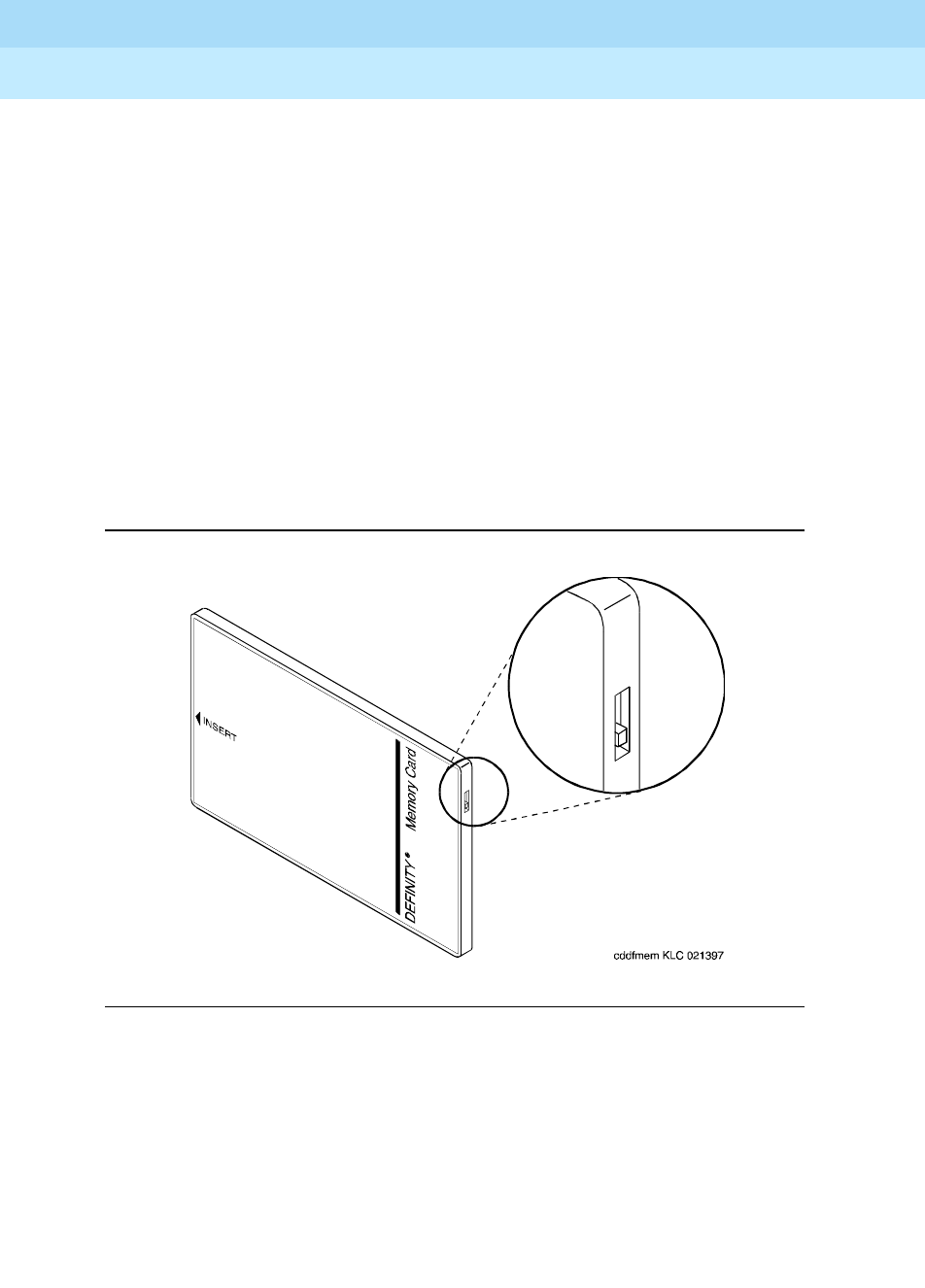
DEFINITY Enterprise Communications Server Release 6
Administration and Feature Description
555-230-522 Issue 4
May 1998
System Basics
Page 2-22System backup for R6vs/si and later configurations
2
8. Invalid directory on memory card
Indicates the memory card needs refreshing, or that something is wrong
with the memory card.
Response:
Run test card-mem and be sure all tests pass. Replace the
memory card.
9. Memory Card is not inserted in the system
You have not inserted the memory card.
Response:
Insert the memory card.
10. Memory Card is write-protected
Indicates the switch on the top side of the memory card is incorrectly set.
Response:
Move the switch to the correct position with the point of a
pencil or similar object. See the following figure:
Figure 2-1. Memory Card Write-Protect Switch
11. Memory Card is unusable
Indicates something is wrong with the memory card.
Response:
Replace the Memory Card.
12. Request is incompatible with currently running
operations
Indicates the storage system is in use.
Response:
Try again later.

DEFINITY Enterprise Communications Server Release 6
Administration and Feature Description
555-230-522 Issue 4
May 1998
System Basics
Page 2-23System backup for R6vs/si and later configurations
2
13. Saved copy of announcements is unusable
The file on the memory card is unusable.
Response:
Use another backup card if you have one. Instances such as
this illustrate the importance of having backup cards.
14. Saved copy of translations is unusable
The copy of the translations on your memory card is faulty.
Response:
Run the save translations command again.
15. Success: translation file nearly full — get larger card
This message appears in response to a “save translation” command. The
translation was saved successfully but this is just a warning that the card
is 95 percent full.
Response:
Order a larger card.
16. Transmission problem; please try later
There is a problem communicating with the announcement circuit pack.
Response:
Check to see that a data module, “Type: announcement” has
been administered correctly. Use the list data-module command to
determine if the data-module “Type: announcement” is administered. The
data module “Type: announcement” is administered using the add
data-module <
extension_number of data module type announcement
>. If
adding or checking the data module type announcement, verify that the
“Board:” field is translated with network, carrier and slot where the
announcement circuit pack is installed. Check that the Class of Restriction
(COR) of the data module “Type announcement” is allowed to terminate
calls from the data-modules “Type: netcon.” The data modules “Type
Netcon:” with their COR can be identified by using the “list data-module”
command. Note that netcon data modules must also have their COR’s
translated so that they can call each other.
17. Unknown type of Memory Card
The software does not know what type of memory card is inserted in the
slot. This can occur if the card is unformatted or if the current vintage of
the software does not recognize that type of memory card.
Response:
Replace the memory card with a formatted memory card the
software can recognize.
18. Upgrade Memory Card inserted
You may have inserted the System Upgrade memory card instead of the 4
Mb memory card.
Response:
Insert the 4 Mb memory card.

DEFINITY Enterprise Communications Server Release 6
Administration and Feature Description
555-230-522 Issue 4
May 1998
System Basics
Page 2-24System backup for R6r and later configurations
2
System backup for R6r and later
configurations
The primary backup operations are:
■Save translation: All translation data is kept in memory during system
operation. This means that all data would be lost if the switch went down.
The save translation operation allows the system administrator to save the
in-memory translation data on disk/tape. This operation may be done as
part of scheduled maintenance and/or as required.
■Backup/Restore: In a disk/tape configuration, additional data integrity is
achievable through the disk-to-tape backup process. The backup
operation can be done as part of scheduled maintenance and/or as
required. The contents of the disk are copied onto a tape. This tape
backup contains enough formatting/structure to allow the system to boot
from it.
The save announcement command is only allowed if there is an integrated
announcement circuit pack in the system (E28).
When MSS devices on both processors in a duplicated system are specified, the
save announcements operation saves announcement data from the
announcement circuit pack to the active and standby MSS devices in parallel.
The status of each save operation is reported to the user separately. If one of the
save operations fail, the save operation to the other device continues. The goal is
to save the new announcement data on some MSS device so that it is not totally
lost; this causes the announcement data to be inconsistent between these MSS
devices.
In case of a failure, it is the user’s responsibility to make the announcement files
on the two MSS devices consistent. The files may become inconsistent due to
hardware failures or if “save” to one device fails while the other continues; for
example, while using the either option.
Restore Announcements Command
The restore announcements command copies announcement data from the
specified MSS device to the announcement circuit pack.
Command Syntax
restore announcements [disk | tape]
The announcement file is always restored from the active device.
The [disk | tape] options specify the device from which to restore the
announcement circuit pack data. This set of options only applies in a system with
a disk.

DEFINITY Enterprise Communications Server Release 6
Administration and Feature Description
555-230-522 Issue 4
May 1998
System Basics
Page 2-25System backup for R6r and later configurations
2
Invoking the restore announcements command with the disk option forces the
system to copy the announcement circuit pack data from the disk to the
announcement circuit pack.
Invoking the restore announcements command with the tape option forces the
system to copy the announcement circuit pack data from the tape to the
announcement circuit pack.
Command Operation
There is only one announcement circuit pack allowed in the system. The
announcement file is always restored from the active processor’s device.
The restore announcements command is not allowed if there is no integrated
announcement circuit pack in the system (E28); or if any port on the ANN circuit
pack is active (E31).
In the case where the system crashes and/or there is a processor interchange,
the restore operation fails. In this case, there is not a valid announcement file on
the announcement circuit pack. The command should be restarted on the newly
active processor to copy the announcements from the active processor’s MSS
device to the announcement circuit pack. Until the announcements are
successfully and completely copied to the announcement circuit pack, calls are
not connected to any announcements on the ANN circuit pack.
When the ANN circuit pack is plugged in or reset, maintenance performs a series
of tests, including a DRAM Checksum test. The test fails due to the power loss to
the circuit pack, resulting in automatic downloading of the announcement file.
Error Conditions
The following is a list of all error messages displayed to the user. If any of these
error conditions can be attributed to hardware failures or disk/tape configuration
problems, they are logged with the maintenance subsystem. Error messages that
are caused by a user entering improper command operations are not logged
with the maintenance subsystem; the user is notified of the error.
For each error message listed, an identifier is provided that indicates where on
the screen the message occurs. If (M) is shown next to the error code, the error
message appears on the message line. If (W) is shown next to the error code, the
error message appears as command output.
A failure can occur on either processor in a duplicated system. When the error is
displayed, it is associated with the processor on which the error was
encountered.

DEFINITY Enterprise Communications Server Release 6
Administration and Feature Description
555-230-522 Issue 4
May 1998
System Basics
Page 2-26System backup for R6r and later configurations
2
E3 (M) MSS is currently in use
Some other administration or maintenance user is currently making
use of the MSS device and, therefore, it is not available for the MSS
operation requested.
E11 (M) Standby option invalid on a simplex system
A duplex option to a command was specified on a simplex system.
E12 (M) The disk option is invalid in a tape-only system
A disk option was entered on an MSS command for a tape-only
system.
E13 (W) Disk device is out of service
The disk device has been taken out of service by maintenance.
E14 (W) Tape device is out of service
The tape device has been taken out of service by maintenance.
E16 (W) Standby processor (PE_A) is not available or
Standby processor (PE_B) is not available
The standby processor has been taken out of service by
maintenance, that the PE-SELECT switches are not in their normal
position, or that some other hardware problem exists. When the
standby processor is out of service, memory shadowing from the
active processor to the standby processor is disabled.
E28 (W) Integrated announcement board not present
The announcement circuit pack is not present in the system.
E29 (W) Required data module not administered or
unavailable
The required data module is either not administered or is currently
in use.
E31 (W) Announcement port in use; please try later
One or more of the announcement ports are in use for an
integrated announcements session or for integrated
announcement playback.
E32 (W) Bad announcement file on tape (disk)
The announcement file stored on disk or tape is corrupt. A valid file
must be stored on the MSS before it can be accessed. This helps
to prevent overwriting valid announcements on the ANN circuit
pack.
Continued on next page

DEFINITY Enterprise Communications Server Release 6
Administration and Feature Description
555-230-522 Issue 4
May 1998
System Basics
Page 2-27System backup for R6r and later configurations
2
E33 (W) No announcements on board
Announcements must be stored on the ANN circuit pack in order to
proceed with command. This helps to prevent overwriting or
corrupting a good announcement file on the MSS.
E34 (W) Announcement data module out of service
The announcement data module has been taken out of service by
maintenance. The data module could have been taken out of
service because of errors on the data module detected by
maintenance.
E35 (W) Required system access port not administered or
out of service
A system access port is either not available or is out of service.
E36 (W) Announcement data module not available
Cannot access the announcement data module because the
upload/ download port is active.
E37 (W) Tape access failure; no tape cartridge or tape
drive failure
No tape is in the tape drive.
E38 (W) Tape write failure; no tape cartridge or tape
drive failure
The tape is write protected.
E39 (W) Required system access port unavailable
The required system access port is unavailable.
E40 (W) Tape (disk) not formatted with announcement file
Device must be formatted with the announcement file in order to
read or write it.
E41 (W) Refresh currently in progress, please try again
later
MSS is in use by SPE duplication memory refresh. This is an
indication to try the command again later.
E42 (W) MSS device is maintenance busy
Continued on next page

DEFINITY Enterprise Communications Server Release 6
Administration and Feature Description
555-230-522 Issue 4
May 1998
System Basics
Page 2-28System backup for R6r and later configurations
2
Save Translation command
The save translation command copies translation data from memory to the
MSS. By default, translation data is written to the primary MSS device in a
simplex processor system, or to both primary MSS devices in a duplicated
processor system. In addition, the save translation command can be directed to
write to devices on either of the processors and/or the secondary device(s). The
translation data can be automatically backed up as part of regularly scheduled
maintenance. It is recommended that automatic backup be performed on a daily
basis.
Command syntax
The bracketed options specify to which mass storage system the translation data
is to be saved. This set of options only applies in a duplicated system. The
options, SPE_A and SPE_B, see processors A and B respectively in a
duplicated system.
Invoking the command with the active option instructs the system to write to the
specified device in the active processor.
Invoking the command with the standby option instructs the system to write to
the specified device in the standby processor.
Invoking the command with the either option causes the system to write the
translation data to the specified device on both processors. If the standby
processor is inaccessible, the command still executes on the active processor
and data is copied to the specified device.
Invoking the save translation command with the SPE_A option forces the
system to write the translation data to the specified device in processor A.
SPE_A is the default in a simplex system.
Invoking the save translation command with the SPE_B option forces the
system to write the translation data to the specified device in processor B.
In duplicated systems, both is the default option.
The [disk | tape] option specifies the device on which to save the translation
data. This option set only applies in a system with a disk.
Invoking the save translation command with the disk option forces the system
to write the translation data to the disk. In a system configured with both a disk
and a tape, disk is the default.
Invoking the save translation command with the tape option forces the system
to write the translation data to the tape. In a system configured with only a tape
unit, tape is the default.

DEFINITY Enterprise Communications Server Release 6
Administration and Feature Description
555-230-522 Issue 4
May 1998
System Basics
Page 2-29System backup for R6r and later configurations
2
In a duplex system, the capability to save translation to only one of the MSS
devices is provided. This capability should be exercised with extreme caution
since it is likely to lead to translation data inconsistencies between the different
devices on the two processors.
Command operation
The save translation command writes two time-stamped identical copies of
translation data to the selected devices. The time stamp for both copies are the
same (the time of writing to the first copy). Each copy also contains the state of
the copy (either “good” or “bad”).
The save operation writes one complete copy first, then writes the second copy
in a different area of the device. The save operation updates only one copy at a
time. The save operation always overwrites the “least good” copy first. The
following selection criteria should be applied on both the active and standby
devices:
■If a copy has a bad status, always overwrite that copy first.
■If both copies have good status, overwrite the one with the older time
stamp. If both time stamps are the same, it does not matter which copy is
overwritten first since the copies are identical.
Each copy of the translation data is marked “bad” prior to a translation save
operation, and it is only marked “good” after the save operation to that file
completes successfully. Any failure during the save operation, including a system
crash, usually affects only one copy of translation data. If this occurs, the
affected copy is marked with a “bad” status indicator and should not be used to
load translation into the system. Thus an intact copy of translation can be used as
a backup. Normally at least one of the two copies is in a good state. If save
translation is performed automatically as part of daily scheduled maintenance,
there is a high degree of probability that identical copies of translation exist on
the tape.
When MSS devices on both processors in a duplicated system are specified, the
save operation saves translation data from the active processor to the active and
standby MSS devices in parallel. The status of each save operation is reported to
the user separately. If one of the save operations fail, the save operation to the
other device continues.
If invoked during regularly scheduled maintenance, the save translation
command in a duplicated processor system saves the translation to one of the
MSS devices even if the other device is out of service.
The command completion status is displayed on Screen 2-9.

DEFINITY Enterprise Communications Server Release 6
Administration and Feature Description
555-230-522 Issue 4
May 1998
System Basics
Page 2-30System backup for R6r and later configurations
2
Screen 2-9. Command Completion Status
■In a simplex system, only the active (default) SPE status is given. In a
duplex system, if a qualifier is used to select save translation for only one
SPE, only that SPE’s status is given.
The displayed information includes either a success message or an error
message and error code for each processor (see Table 2-2). A success message
means both copies of translation data were updated successfully on a particular
device from the in-memory translation data. The error code for each processor
provides further information as to whether only one or two copies of translation
data were updated successfully. If only one copy was updated or neither copy
was updated, an alarm would be raised on that device so that the system
technician can take appropriate repair actions.
The following operational rules apply to the save translation command:
1. The save translation command is only allowed if there are no translation
updates being made. All requests to update translation after the
command starts are denied (E1).
If Terminal Translation Initialization (TTI) activation or deactivation is in
progress, the save translation command is denied (E2).
2. The save translation command is not allowed if the MSS is engaged by
another user or is being used for background maintenance (E3).
Table 2-2. Save Translation Command Error Codes
CODE Interpretation
0 The save operation was a complete success;
both copies of translation data were updated.
1 The save operation was a partial success;
only one of the two copies of translation data was updated.
2 The save operation failed completely;
no translation was saved to either copy of translation data.
Save Translation
Processor Command Completion Status Error Code
SPE_A* success/specific error message n1
SPE_B* success/specific error message n2

DEFINITY Enterprise Communications Server Release 6
Administration and Feature Description
555-230-522 Issue 4
May 1998
System Basics
Page 2-31System backup for R6r and later configurations
2
3. The options entered by the user are validated against the system
configuration and the target devices for the save translation command
are determined (E11, E12).
4. If the user requests that translation be saved to a disk, the disk must be in
service (E13). If the user requests that translation be saved to a tape, the
tape must be in service (E14). If the user requests that translation be
saved to the standby processor, the standby processor must be in
service, shadowing must be enabled, refresh must be completed, and
handshake must be up (E16).
5. If the file system of the target device is a core-dump file system, the
command is denied (E17).
If the target device is a tape, and the file system type of the tape is an
installation file system, and the vintage of the boot image running in the
active processor matches the vintage of the boot image on the tape, then
the system first configures the tape with the same configuration as is
currently running. If the in-memory vintage does not match the vintage on
the tape, the save translation command is denied (E18). In this situation,
the user must manually configure the tape by using the configure
command and then reissue the save translation command.
6. If errors are encountered in the operations described above, the save
operation should not be attempted.
Backup command
Additional data integrity is achievable through disk to tape backups. These
backups may be done on demand or run daily as part of scheduled
maintenance. The backup command works in either a simplex SPE or a duplex
SPE system. When the command is run as part of scheduled maintenance, the
default for a simplex system is an incremental backup of SPE A. In a duplex
system, the default is an incremental backup on both SPE A and SPE B.
When the backup command is executed on demand the defaults remain the
same.
Command syntax
backup disk [active | standby | SPE_A | SPE_B | both | either] [incremental |
full]
The bracketed options, [active | standby | SPE_A | SPE_B | both | either],
specify which mass storage system the user wishes to backup. Invoking the
backup command with the SPE_A option causes files from the disk associated
with processor A to be copied to the tape cartridge on the same processor.
SPE_A is the default in a simplex system. Invoking the backup command with
the SPE_B option causes the files on the disk on processor B to be copied to the
tape on the same processor.

DEFINITY Enterprise Communications Server Release 6
Administration and Feature Description
555-230-522 Issue 4
May 1998
System Basics
Page 2-32System backup for R6r and later configurations
2
Invoking the command with the active option causes the files on the disk on the
active processor to be copied to the tape on that processor.
Invoking the command with the standby option causes the files on the disk on
the standby processor to be copied to the tape on that processor.
Invoking the backup command with the both option causes files on the disks
associated with both of the processors to be backed up to their respective tapes
concurrently. If the standby processor is inaccessible the command fails on both
processors. No files are copied from disk to tape on either processor. The default
value in a duplex system is both.
Invoking the backup disk command with the either option causes the files on the
disks associated with both of the processors to be backed up to their respective
tapes concurrently. If the standby processor is inaccessible, the command still
executes on the active processor and the disk files is copied to tape.
Invoking the command with the incremental option causes a selective backup to
be performed. In this case, all files on the disk that are marked as “good files”
and which have a newer last file update time than the corresponding tape files,
are copied to the tape. Not copying files marked as “bad” ensures that corrupted
files do not overwrite good (but possibly older) files. The default value is
incremental.
If a full disk backup is specified, the entire disk is copied to tape. All files, “good”
and “bad,” regardless of the last file update times, are copied to the tape.
Command operation
When an incremental backup is performed, the following procedure governs
this operation. Before each file is copied from the disk to the tape, the file on the
tape is marked as “bad.” When the file has been completely copied over to the
tape, the file is then marked as “good” on the tape. This process ensures that if
the system were to reboot in the middle of this operation, files in the process of
being copied are not usable (on the tape) because they are still marked as
“bad.”
When a full backup is performed, the following procedures are used. When the
process begins, all files on the tape are marked as “bad.” When the entire disk
has been copied, the files on the tape are marked as “good.” The only exception
to this is that a file which is marked as “bad” on the disk retains this marking on
the tape also.
When the backup is performed on both processors, the operation is performed
in parallel. If the backup operation fails on one processor the backup operation
proceeds on the other processor.
The success or failure of the backup operation for each processor is displayed
on the screen, as shown on Screen 2-10.

DEFINITY Enterprise Communications Server Release 6
Administration and Feature Description
555-230-522 Issue 4
May 1998
System Basics
Page 2-33System backup for R6r and later configurations
2
Screen 2-10. Backup Completion Station
* In a simplex system, only the active (default) SPE status is given. In a duplex system, if a
qualifier is used to select backup disk for only one SPE, only that SPE’s status is given.
The following operational rules apply to the backup command:
1. The backup command is only allowed if there are no other applications
currently using the MSS devices (E3).
2. The options entered by the user are validated against the system
configuration and the target devices for the backup command are
determined (E11).
3. The disk must be in service (E13). The tape must be in service (E14).
4. If the user requests that the backup take place on the standby processor,
the standby processor must be in service, shadowing enabled, and
refresh completed (E16). If the file system of the tape is a core-dump file
system, the command is denied (E17).
For incremental backup, if the file system type of the tape is an installation
file system, and the vintage of the boot image running in the active
processor matches the vintage of the boot image on the tape, then the
system first configures the tape with the same configuration as is currently
running. If the in-memory vintage does not match the vintage on the tape,
the backup command is denied (E18). The tape must be manually
configured in this situation.
If the incremental option is specified and the file systems of the disk and
tape are not the same, the command is denied (E23).
5. For full backup, if the tape has installation, large, or core-dump file system,
backup proceeds.
6. If errors are encountered in the operations described above, the backup
operation should not be attempted.
Backup Disk
Processor Command Completion Status
SPE_A* success/specific error message
SPE_B* success/specific error message

DEFINITY Enterprise Communications Server Release 6
Administration and Feature Description
555-230-522 Issue 4
May 1998
System Basics
Page 2-34System backup for R6r and later configurations
2
Restore command
The restore command allows the user to copy files from a tape (which was used
to backup the disk) to the disk. This operation is used for system installation,
system upgrades/updates, or after a repair of the disk has occurred.
Command syntax
restore disk [active | standby | SPE_A | SPE_B | both | either] [incremental |
full]
The options, [active | standby | SPE_A | SPE_B | either | both], specify which
mass storage system the user wishes to restore.
Invoking the restore command with the SPE_A option causes files from the tape
associated with processor A to be copied to the disk on that same processor.
SPE_A is the default in a simplex system.
Invoking the restore command with the SPE_B option causes files from the tape
associated with processor B to be copied to the disk on that same processor.
Invoking the restore command with the active option causes the files on the tape
on the active processor to be copied to the disk on the same processor.
Invoking the restore command with the standby option causes files from the
tape associated with the standby processor to be copied to the disk on that
same processor.
Invoking the restore command with the both option forces the system to copy
files from the tape-to-disk device on both mass storage systems concurrently. If
the standby processor is inaccessible, the command fails on both processors.
This means that no data is written on either of the specified processors. The
default in a duplex system is both.
Invoking the restore command with the either option forces the system to copy
files from tape to disk device in both mass storage systems concurrently. If the
standby processor is inaccessible, the command still executes on the active
processor and files are copied to the disk.
Invoking the command with the incremental option causes a selective restore
operation to be performed. In this case, all files on the tape that are marked as
“good” and which have a newer last file update time than the corresponding disk
files, are copied to the disk. Not copying files marked as “bad” ensures that
corrupted files do not overwrite good (but possibly older) files. The default value
is full.
If a full disk restore is specified, the entire contents of the tape are copied to the
disk. All files, “good” and “bad,” regardless of the last file update times, are
copied to the disk.

DEFINITY Enterprise Communications Server Release 6
Administration and Feature Description
555-230-522 Issue 4
May 1998
System Basics
Page 2-35System backup for R6r and later configurations
2
Command operation
For an incremental restore, the files are copied in the following manner. Before
each file is copied from the tape to the disk, the file on the disk is marked as
“bad.” When the file from the tape has been completely copied over onto the
disk, the file is then marked as “good” on the disk. This process ensures that if
the system were to reboot in the middle of the operation, files in the process of
being copied are not usable because they are still marked as “bad.”
For a full restore operation, the files are copied in the following manner. When the
process begins, all files on the disk are marked as “bad.” When the entire tape
has been copied to disk, the files on the disk are marked as “good.” The only
exception to this is that a file which is marked as “bad” on the tape retains this
marking on the disk also.
The success or failure of the command for each processor is displayed on the
screen, as shown in Screen 2-11.
Screen 2-11. Restore Completion Status
The following operational rules apply to the restore command:
1. The restore command is only allowed to run if there are no other
applications currently using the MSS devices (E3).
2. The options entered by the user are validated against the system
configuration, and the target devices for the restore command are
determined (E11).
3. The disk must be in service (E13). The tape must be in service (E14).
4. If the user requests that the restore take place on the standby processor,
the standby processor must be in service, shadowing enabled, and
refresh completed (E16).
5. If the file system of the tape is a core-dump file system, the command is
denied (E17).
If the file system of the tape is an installation file system, the command is
denied (E22). If the incremental option is specified and the file systems of
the disk and tape are not the same, the command is denied (E23).
6. If errors are encountered in the operations described above, the restore
operation should not be attempted.
Restore Disk
Processor Command Completion Status
SPE_A* success/specific error message
SPE_B* success/specific error message

DEFINITY Enterprise Communications Server Release 6
Administration and Feature Description
555-230-522 Issue 4
May 1998
System Basics
Page 2-36System backup for R6r and later configurations
2
Error conditions
The following is a list of all error messages displayed to the user. If any of these
error conditions can be attributed to hardware failures or disk/tape configuration
problems, they are logged with the maintenance subsystem. Error messages that
are caused by a user entering improper command options are not logged with
the maintenance subsystem; the user is notified of the error.
For each error message listed, an identifier is provided that indicates where on
the screen the message occurs.
A failure can occur on either processor in a duplicated system. When the error
displays, it is associated with the processor on which the error was encountered.
E1 login:cha station 51001 has data locked
This error message is displayed for the save translation command
when there is an active translation update command.
E2 (M) TTI activation or deactivation is in progress;
this command is not allowed at this time
When TTI activation or deactivation is in progress, save
translation cannot occur. The TTI activation or deactivation must
be suspended first.
E3 (M) ‘loginid’: “command” has cmd conflict
The user logged in with ‘loginid’ has a command that conflicts with
the MSS command you are using.
E4 (W) No tape in tape drive
The tape cartridge is missing from the drive.
E5 (W) Tape write failure: tape cartridge or device
failure
There is a failure in writing to the tape. This may be caused
because the tape cartridge is missing from the tape drive, or by
non-operational tape hardware.
E6 (W) Tape read failure: tape cartridge or device
failure
There is a failure in reading from the tape. This may be caused
because the tape cartridge is missing from the tape drive, or by
non-operational tape hardware.
E7 (M) System error; Reboot
There was a severe system error while processing this request.
This might require system reboot or system technician intervention
to resolve.
Continued on next page

DEFINITY Enterprise Communications Server Release 6
Administration and Feature Description
555-230-522 Issue 4
May 1998
System Basics
Page 2-37System backup for R6r and later configurations
2
E9 (W) Disk write failure: device failure
There is a hardware problem with the drive itself.
E10 (W) Disk read failure: device failure
There was a failure in reading from the disk. This may be caused
by a media error or by non-operational disk hardware.
E12 (M) The disk option is invalid in a tape-only system
The disk option was entered on an MSS command for a tape-only
system.
E13 (W) Disk device is out of service
The disk device has been taken out of service by maintenance.
E14 (W) Tape device is out of service
The tape device has been taken out of service by maintenance.
E16 (M) Standby processor (SPE_A) is not available” or
Standby processor (SPE_B) is not available
The standby processor has been taken out of service by
maintenance, that the SPE-SELECT switches are not in their normal
position, or that some other hardware problem exists. When the
standby processor is out of service, memory shadowing from the
active processor to the standby processor is disabled.
E17 (W) Tape contains a coredump file system
The wrong type of tape is in the tape drive.
E18 (W) Tape vintage does not match in-memory vintage;
must configure tape first
By ensuring that the tape vintage matches the in-memory vintage,
the system technician is made aware of a possible operational
error.
E19 (W) Large system boot image is corrupt on the tape
The large system boot image has been overwritten by a core
dump. The tape cannot be converted to a large system tape.
E22 (W) Tape file contains an installation file system
The wrong type of tape is in the tape drive.
E23 (W) Disk and tape are configured with different file
systems
The disk and tape are configured with different file systems and the
user issued backup or restore commands with the incremental
options.
Continued on next page

DEFINITY Enterprise Communications Server Release 6
Administration and Feature Description
555-230-522 Issue 4
May 1998
System Basics
Page 2-38System backup for R6r and later configurations
2
E27 (W) Device access failure: device directory corruption
The directory files on a device are corrupt.
E28 (W) Small file system already exists
The user is trying to configure a small file system to a tape that
already contains a small file system. This operation is not allowed.
E29 (W) Large file system already exists
The user is trying to configure a large file system to a tape that
already contains a large file system. This operation is not allowed.
Continued on next page

System Security
Page 3-1Overview
3
DEFINITY Enterprise Communications Server Release 6
Administration and Feature Description
555-230-522 Issue 4
May 1998
3
3System Security
Overview
Toll fraud is the theft of long distance service, and can come from both internal
and external sources. When toll fraud occurs, your company is responsible for
usage charges. In addition, unauthorized use may tie up your system, preventing
your customers from reaching you and your employees from doing business.
Lucent Technologies has designed the DEFINITY ECS to help you to limit toll
fraud. However, there are steps that you as the administrator must also take to
keep your system secure from unauthorized use.
Learn about the problem
The
BCS Products Security Handbook
contains a wealth of information about toll
fraud and what you can do to prevent it. It discusses the methods people use to
gain access to your system, how to detect toll fraud, and what to do if you
suspect that your system has been compromised.
The
BCS Products Security Handbook
contains security information for many
Lucent Technologies products, so you can ensure that all of your
telecommunications equipment is secure. It also contains security checklists for
each of these products. You should go through these with your Lucent
Representative for each piece of equipment you use.
Where to get help
For assistance with toll fraud prevention, call the Lucent Technologies National
Customer Care Center Support Line at 1-800-643-2353.

DEFINITY Enterprise Communications Server Release 6
Administration and Feature Description
555-230-522 Issue 4
May 1998
System Security
Page 3-2Basic security
3
If you have identified fraudulent calling in progress, and require assistance in
stopping the fraud, call the Lucent Technologies Technical Service Center at
1-800-242-2121 and select the option for toll fraud help.
Basic security
The following is a partial list that you can use to help secure your system. It is not
intended as a comprehensive security checklist. The
BCS Products Security
Handbook
provides more detail about these and other security-related features.
■When administering logins, enable logoff notification and forced password
aging. You must assign passwords for these logins at setup time.
■Administer Security Violation Notification to report unsuccessful attempts
to access the system. Security Violation Notification allows you to
automatically disable a valid login ID following a security violation
involving that login ID and disable remote access following a security
violation involving a barrier code or authorization code.
■Use the list history command to determine if unauthorized changes have
been made to the system. To assist in identifying unauthorized use of the
system, the History report lists each time a user logs in or off the system.
See
DEFINITY ECS System Monitoring and Reporting
for a detailed
discussion of this report.
■Ensure that the Remote Administration port is secure. If it is not secure, an
unauthorized user can compromise the system in many ways, such as
viewing Barrier and Authorization codes or viewing Feature Access
Codes. You can restrict this port to certain login IDs using the Login
Administration form. The optional Remote Port Security Device (RPSD) is a
password encryption device that can be attached to the Remote
Administration Port for increased security.
■If you suspect that unauthorized access has occurred, change the barrier
codes, authorization codes, passwords, and any other sensitive codes.
■Secure trunks using Automatic Route Selection, Class of Restriction,
Facility Restriction Levels and Alternate FRLs, Authorization Codes,
Automatic Circuit Assurance and Forced Entry of Account Codes (see
CDR).
■Monitor your system on a regular basis so that you will notice unusual
traffic patterns if they occur. Call Detail Recording, Security Violation
Notification and a number of reports allow you to do this.
■Activate Enhanced Call Transfer for your voice messaging system, if
available. This limits transfers to valid extensions, but you also need to
restrict transfers to extensions that may offer dial tone to the caller, such as
remote access extensions.

DEFINITY Enterprise Communications Server Release 6
Administration and Feature Description
555-230-522 Issue 4
May 1998
System Security
Page 3-3Physical security
3
Physical security
■Keep wiring closets and switch rooms secure.
■Keep any documentation pertaining to switch operation secure.
■Keep any reports that may reveal trunk access code, remote access
barrier codes, authorization codes, or password information secure.
Features requiring security precautions
Follow the guidelines in the
BCS Products Security Handbook
when
administering the following features:
■Automated Attendant
■AUDIX Interface
■Call Coverage
■Call Forwarding
■Call Vectoring
■Extended User Administration of Redirected Calls
■Facility Test Calls
■PC Interface
■Personal Station Access
■Remote Access
■Remote Administration
■Service Observing
■Terminal Translation Initialization
■Transfer — Trunk-to-Trunk
■Trunk-to-Trunk Transfer Restriction Override
■Tr u n k Fl a sh
■Voice Response Integration
Consult the
BCS Products Security Handbook
, for additional steps to secure your
system and to find out how to regularly obtain information concerning security
developments.

DEFINITY Enterprise Communications Server Release 6
Administration and Feature Description
555-230-522 Issue 4
May 1998
System Security
Page 3-4Features requiring security precautions
3

Basic Features
Page 4-1Abbreviated Dialing
4
DEFINITY Enterprise Communications Server Release 6
Administration and Feature Description
555-230-522 Issue 4
May 1998
4
4Basic Features
Abbreviated Dialing
Abbreviated Dialing (AD) provides lists of stored numbers for:
■Placing local, long-distance, and international calls
■Activating features
■Accessing remote computer equipment
Voice-terminal and data-terminal users can access stored numbers from all types
of lists: group-number, system-number, enhanced-number, and personal-number
via AD numbers. Attendants can access stored numbers from group-number,
system-number, and enhanced-number lists via AD numbers. AD numbers can
have up to 24 digits. Users can access designated numbers not stored on AD
lists via automatic-dialing buttons. Automatic-dialing buttons can have up to 16
digits.
Each stored number is one list entry. Users choose an appropriate list by dialing
an access code followed by its 1-, 2-, 3-, or 4-digit list entry number. The number
is then dialed automatically by the system. Users may reach a frequently-called
number with a single button press by storing the dialing sequence on an AD
button.

DEFINITY Enterprise Communications Server Release 6
Administration and Feature Description
555-230-522 Issue 4
May 1998
Basic Features
Page 4-2Abbreviated Dialing
4
How to administer AD
Required forms
Form Field Page
AD 7103A ■All 5-14
AD Enhanced List ■All 5-2
AD Group List ■All 5-5
AD Personal List ■All 5-8
AD System List ■All 5-11
Attendant Console ■Feature Button Assignments
■AD buttons
■AD Program Buttons
■AD Special Character Buttons
5-35
Console-Parameters ■AD List 1
■AD List 2
■AD List 3
5-86
Data Line Data Module ■List1 6-234
Feature Access Code
(FAC)
■AD List 1 Access Code
■AD List 2 Access Code
■AD List 3 Access Code
■AD Program Group List Access Code
■Program Access Code
5-113
Continued on next page

DEFINITY Enterprise Communications Server Release 6
Administration and Feature Description
555-230-522 Issue 4
May 1998
Basic Features
Page 4-3Abbreviated Dialing
4
Detailed description
List types
Numbers are stored in four types of lists: personal-number, group-number,
system-number, and enhanced-number. Switch type and version determine
available lists and maximum entries per list.
■Personal-number lists
Personal-number lists are used by voice-terminal and data-terminal users
who need a set of stored personal numbers. An individual user can have
up to three personal-number lists. You, or the user, program the
personal-number lists. You determine which users are allowed to have a
personal list and the size of each list. Personal-number lists are created
automatically when the capability of accessing a personal list is
administered for the individual station.
■Group-number lists
Group-number lists are used by members of groups such as purchasing
and personnel departments, who have the need to frequently dial the
same numbers. Voice-terminal users, data-terminal users, and attendants
Feature-Related
System Parameters
■Off-Premises Tone Detect Time-out
Interval
■AD Programming by Assigned List
5-123
Station
(multiappearance)
■AD List 1
■AD List 2
■AD List 3
■Feature Button Assignments
■AD Buttons
■Autodial Buttons
■AD Program Buttons
■AD Special Character Buttons
■Hot Line Destination (if applicable)
■AD List Number
■Dial Code
6-14
Required forms — Continued
Form Field Page
Continued on next page

DEFINITY Enterprise Communications Server Release 6
Administration and Feature Description
555-230-522 Issue 4
May 1998
Basic Features
Page 4-4Abbreviated Dialing
4
can access up to three specific group-number lists. You administer the
lists. You can choose a designated user in each group to program the list.
Specify this user on the Abbreviated Dialing Group List form.
■System-number lists
System-number lists are used by voice-terminal users, data-terminal
users, and attendants who need to frequently dial the same numbers as a
member of a group (such as members of purchasing or personnel
departments). You administer the system-number lists.
■Enhanced-number lists
Enhanced-number lists are used by voice-terminal users, data-terminal
users, and attendants who need more list entries than those allowed in
group-number and system-number lists. One enhanced-number list is
allowed per system in addition to the system-number list. The
enhanced-number list can contain any number or dial-access code. You
administer the enhanced-number lists and determine which users can
access the list.
NOTE:
You can designate all group-number lists, system-number lists, and
enhanced-number lists as “privileged.” Calls automatically dialed
from a privileged list are completed without class of restriction (COR)
or facility restriction level (FRL) checking. This allows access to
selected numbers that some voice-terminal users might otherwise
be restricted from manually dialing. For example, a voice-terminal
user may be restricted from making long-distance calls. However,
the number of another office location may be long distance. This
number could be entered in a list designated as privileged. The user
could then call the office location using AD, while still being
restricted from making other long-distance calls.
List entries
The following describes the numbering schemes used to select a list entry once
an AD list is accessed.
Personal-number list entries
For personal-number lists administered for five or ten entries, the user dials a
single digit to access a list entry number. Entries are numbered 1 through 9, and
0 (list entry 10). For example, to access entry 6 the user dials 6, to access entry
10 the user dials 0.
For personal-number lists administered for more than ten entries, the user dials a
2-digit number to access a list entry. For example, to access entry 6 the user
dials 06, to access entry 100 the user dials 00.

DEFINITY Enterprise Communications Server Release 6
Administration and Feature Description
555-230-522 Issue 4
May 1998
Basic Features
Page 4-5Abbreviated Dialing
4
Group-number and system-number list entries
AD provides the option of selecting between two group-number and
system-number list entry numbering schemes. The type of numbering scheme
used is administered on the System-Parameters Customer-Options form.
Enhanced-number lists
The number of digits in enhanced-number list entry numbers can be either three
or four digits, as administered on the System-Parameters Feature form.
Special characters
Digits stored in AD lists include numerical digits and special characters that
instruct the system to take specified actions. Special characters count as two
digits toward the 24-maximum-allowable digit limit. You and multiappearance
voice-terminal users program special characters. Available characters are
shown in the following table.
Table 4-1. Group-Number and System-number List Entry Numbering
Schemes
List Entry Number User Dials (Scheme 1) User Dials (Scheme 2)
1
2
.
.
.
11
12
..
..
..
01
02
..
..
..
10
11
..
89
90
91
..
..
20
21
..
99
00
01
..
..
10
11
..
89
90
91
..
..
100 10 00

DEFINITY Enterprise Communications Server Release 6
Administration and Feature Description
555-230-522 Issue 4
May 1998
Basic Features
Page 4-6Abbreviated Dialing
4
Table 4-2. Special characters
Special
Character Description Function
Indefinite Wait
(~W) This means that an
indefinite wait follows the
indefinite wait character
until dial tone is detected.
■Useful when frequent
dial-tone delays of longer
than one minute occur
Mark (~m) This means end-to-end
signaling digits.
■Useful when doing
touch-tone signaling over
dial-pulse trunks
■Place mark characters
prior to digits to be
outpulsed with touch-tone
signaling
Pause (~p) This means that
1.5-second delays follow
pause characters when
digits are being
outpulsed over a trunk.
The interval is
administrable.
■Useful when far-end dial
tones from another switch
returns within 1.5 seconds
■Used with tandem
switching through private
networks or end-to-end
signaling
■May cause aborted calls if
used as the first digit
Suppress (~s) This means that digits
following suppress
characters are not
displayed through the
voice-terminal display
feature. A lowercase s
displays for each digit.
■Useful when the user does
not want part of a dialed
number to be displayed.
■Affects the display of
stored-number digits.
Digits following suppress
characters appear as a
lowercase s.
Continued on next page

DEFINITY Enterprise Communications Server Release 6
Administration and Feature Description
555-230-522 Issue 4
May 1998
Basic Features
Page 4-7Abbreviated Dialing
4
AD access options
AD numbers can be accessed by any of the following options:
■AD codes
Users can access a stored number by dialing the AD feature-access code
(FAC) and a list entry number. Each AD code automatically dials the
number stored in the list the user accessed.
■AD buttons
Multiappearance voice-terminal users and attendants can access stored
numbers by pressing one or more buttons. Each AD button automatically
dials the number stored in the list and the list entry number administered
to the button.
Access to any list and associated list entry number can be programmed
on an AD button on a multiappearance voice terminal. An AD button on an
attendant console can be programmed to access a group, system, or
enhanced list and associated list entry numbers.
You administer the AD button. If the button is administered to access a
number in the user’s personal-number list, the user can change the
number assigned to the button. If the number assigned to the button
accesses an entry on a group list, you or a designated user can make the
change. If the number assigned to the button accesses an entry on the
system list or the enhanced list, only you can make the change.
Wait (~w) This means that a 5- to
25-second delay (or a
delay until dial-tone is
detected) follows wait
characters when digits
are being outpulsed over
a trunk. The delay is
administrable.
■Useful when frequent,
variable-length dial tone
delays or network blocking
outside the system is
experienced
■Used with tandem
switching through private
networks or end-to-end
signaling
■May cause aborted calls if
used with the first digit
Table 4-2. Special characters — Continued
Special
Character Description Function
Continued on next page

DEFINITY Enterprise Communications Server Release 6
Administration and Feature Description
555-230-522 Issue 4
May 1998
Basic Features
Page 4-8Abbreviated Dialing
4
■Automatic-dialing buttons
Users can directly dial numbers by pressing one or more buttons. Each
automatic-dialing button is administered to automatically dial a number
that is not stored on any of the AD lists. The number can have up to 16
characters. You or the user program the automatic-dialing buttons.
Autodialing is not affected by AD lists.
■7103A group-number lists
A separate list, the 7103A group-number list, is used only by 7103A Fixed
Feature voice-terminal users as a group. This list allows button access to
stored numbers and can have eight list entries. Any number can be stored
in the 7103A group-number list; however, it is intended primarily for FACs.
You program the 7103A group-number lists.
■Programming
Users can program their personal-number lists, any AD buttons that
access a number from their personal-number list, and their
automatic-dialing buttons. Only designated users can program an AD
button that accesses a number from a group-number list. Programming is
done by dial access or by pressing the program button, if assigned.
End-user operations
Programming personal lists, AD buttons, and automatic-dialing buttons
■To program an entry in a personal-number list, the user:
1. Dials the program-access code or presses the program button
2. Dials the personal-list number, the dial-code number, and the
number to be stored (up to 24 digits)
3. Presses either # or the AD button
Confirmation tone is heard when the number is stored. While in the
program mode, users can program all personal-number list entries. To exit
the program mode, the user hangs up.
■To program an AD button administered to access a particular entry in the
personal-number list, the user:
1. Dials the program-access code or presses the program button, if
assigned
2. Presses the AD button, dials the number (up to 24-digits)
3. Presses #
Confirmation tone is heard when the number is stored. In the program
mode, the user can program as an unlimited amount of AD buttons
(including automatic-dialing buttons). To exit the program mode, the user
hangs up.

DEFINITY Enterprise Communications Server Release 6
Administration and Feature Description
555-230-522 Issue 4
May 1998
Basic Features
Page 4-9Abbreviated Dialing
4
Programming group lists
Voice-terminal users can program the group lists to which they are assigned as
the designated user. For example, a department secretary may be the
designated user for a group list created for the department. Designated users
are assigned per group list on the Abbreviated Dialing Group List form. Users
who attempt to program group lists for which they are not the designated user
receive intercept tone.
The method a designated user uses to program a group list depends on the
access codes and buttons administered for the terminal and system. The
designated user can program the group list using the:
■Program-access code or AD program button in conjunction with an AD
button. In this case, the number to be programmed must be associated
with that AD button.
■Program-access code or AD program button when an AD button is not
available. In this case, the user can only program lists assigned (as list
1, 2, or 3) to the terminal he or she is using. Other lists for which the user is
the designated user cannot be programmed in this way.
Group lists can only be programmed in this way if the Abbr Dial
Programming By Assigned List field is set to y
on the
Feature-Related System-Parameters form.
■AD group list program FAC. When the AD group list program FAC is used
to program a group list, the user can program any list for which they are
specified as the designated user.
The following instructions describe how designated users program group lists
from their voice terminals. You can program group lists on the switch.
■Programming the group list with the AD program-access code or AD
program button with an AD button
An AD button can be used by the designated user to program the group
list number associated with that button. The user:
1. Dials the AD program-access code or presses the AD program
button
2. Presses the AD button, dials the number
3. Presses #
Confirmation tone is heard when the number is stored.

DEFINITY Enterprise Communications Server Release 6
Administration and Feature Description
555-230-522 Issue 4
May 1998
Basic Features
Page 4-10Abbreviated Dialing
4
■Programming the group list with the AD program-access code or AD
program button (no AD button)
The user:
1. Dials the AD program-access code or presses the AD program
button
2. Dials 1, 2, or 3 to select a group list (administered on their station
form) followed by the 2-digit list entry number of the entry to be
programmed
3. Dials the number
4. Presses #
Confirmation tone is heard when the number is stored.
■Programming the group list with the AD group list program FAC
The user:
1. Dials the AD group list program FAC
2. Dials the 3- or 4-digit group list number to select a group list
followed by the 2-digit list entry number of the entry to be
programmed
3. Dials the number
4. Presses #
Confirmation tone is heard when the number is stored.
Programming AD labels on 6400 and 8400 display sets
Users of the 8400- and 6400-series display phones can customize the display
labels for Abbreviated Dialing buttons. Messages appear on the display to guide
users through the programming of AD numbers and softkey labels. For this
feature to work, the speaker must be activated on the phone, and the switch
software must be R6.3 or higher.
To program a softkey button, the user:
1. Presses the button labeled Prog, or selects Prog from the softkey
menu
The message
Press button to program apprears on the
display.
2. Selects the softkey/feature button to program
3. The message Change number? Yes=1 No=2 appears.
4. Presses 1 to enter a new number or change an existing one, or
2
to
skip this step and move on to programming the label
5. Enters the number for this AD button
6. Presses # to save the number

DEFINITY Enterprise Communications Server Release 6
Administration and Feature Description
555-230-522 Issue 4
May 1998
Basic Features
Page 4-11Abbreviated Dialing
4
Confirmation tone is heard when the number is stored. The
message Change label? Yes=1 No=2 appears.
7. Presses 1 to change the label, or 2 to skip this step.
The message Enter label appears.
8. Enters the label (up to five characters) using the dial pad. The first
time the users presses a key, the first letter on that key appears on
the display. For example, if the user presses 2 on the dial pad, the
letter A appears. If the users presses 2 a second time, the letter B
appears.
9. Presses the * key to accept the letter on the display and move to
the next space.
10. Presses # to accept the entire label.
The message Label saved appears, followed by Hang up to
update display, and then Press button to program.
11. Presses another button to program, or
12. Hangs up the phone to exit programming. Pressing the EXIT button
does not exit program mode.
NOTE:
If a user makes a mistake while programming, the only way to correct it is to
press the “#” key to save the entry, and start over.
Users can follow similar steps to program AD numbers for hardkey buttons.
When prompted for the button to program, the user presses the desired hardkey,
enters the number, and presses # to save the number.
Considerations
■AD provides easy access to selected numbers by decreasing the number
of dialed digits required to place the call. Instead of dialing the entire
number, the user dials a short code to access the number. The system
then dials the stored number automatically. For frequently called numbers,
an AD button or automatic-dialing button can be assigned, allowing the
call to be placed by pressing the button. By assigning a privileged list of
numbers, a user is allowed to place calls to selected numbers that might
otherwise be restricted.
■Users can be assigned access to three AD lists. The three lists can be
made up of any combination of up to three personal lists, up to three
group-number lists, the system-number list, and the enhanced-number
list. A personal list cannot be administered to an attendant console.
■A number stored in any list in the switch can contain up to 24 digits. A
special character used for indefinite wait, mark, pause, suppress, or wait
counts as two digits.

DEFINITY Enterprise Communications Server Release 6
Administration and Feature Description
555-230-522 Issue 4
May 1998
Basic Features
Page 4-12Abbreviated Dialing
4
■A terminal or attendant cannot be removed if it is designated as the
extension number that is permitted to program a group-number list.
!SECURITY ALERT:
Privileged group-number, system-number, and enhanced-number
lists provide access to numbers that typically would be restricted.
Interactions
■Attendant Consoles
Automatic-dialing buttons are not allowed on attendant consoles.
Attendant consoles do not have access to personal lists.
■AUDIX Interface
When using an AD button to access AUDIX, the user’s login and password
should not be assigned to the button. The system ignores button entries
after the AUDIX number.
■Bridged Call Appearance
A user, accessing AD while on a bridged call appearance, accesses his
or her own AD lists. The user does not access the AD lists of the primary
extension associated with the bridged call appearance.
A designated user permitted to program a group-number list is not
permitted to program the group list from the bridged call appearance of
the designated extension number.
■Hotline Destination
The hotline service destination number is stored in an AD list.
■Last Number Dialed
This feature places a call to the same number as called previously, even if
AD was used on the previous call. However, if any special characters
(indefinite wait, mark, pause, suppress, and wait) are included in the
previous call, they are not used on the last-number-dialed call.
If the previously called number was in an AD privileged list, and if the user
is not normally allowed to dial the number because of his or her class of
restriction, intercept treatment is given when using Last Number Dialed. To
redial the number, the user must again use the AD privileged list.
■Remote Access
Users can access the group-number, system-number, and
enhanced-number AD lists via the remote-access trunk. Users of remote
access can access the AD lists administered on the Console form.

DEFINITY Enterprise Communications Server Release 6
Administration and Feature Description
555-230-522 Issue 4
May 1998
Basic Features
Page 4-13Administered Connections
4
Administered Connections
An Administered Connection (AC) is a connection between two access or data
endpoints. DEFINITY ECS automatically establishes the connection based on the
attributes you administer. ACs provides the following capabilities.
■Support of both permanent and scheduled connections
■Auto Restoration (preserving the active session) for connections routed
over Software Defined Data Network (SDDN) trunks
■Administrable retry interval (from 1 to 60 minutes) per AC
■Administrable alarm strategy per AC
■Establishment/retry/auto restoration order based on administered priority
How to administer Administered Connections
Required forms
Form Field Page
Data Module-general 6-226
Data Line Data Module
— use with TN726 circuit
pack
■All 6-234
Processor/Trunk Data
Module
— use with MPDMs 700D,
7400B, 7400D, or
8400B
— use with MTDMs
700B, 700C, 700E, or
7400A
■All 6-243
Processor Interface Data
Module
— use with processor
interface circuit packs
■All 6-246
X.25 Data Module
— use with DCS networks
■All 6-249
Continued on next page

DEFINITY Enterprise Communications Server Release 6
Administration and Feature Description
555-230-522 Issue 4
May 1998
Basic Features
Page 4-14Administered Connections
4
7500 Data Module
— use with TN556
ISDN-BRI or TN2198
ISDN-BRI circuit packs
■All 6-252
World Class Core BRI
Data Module
— use with wcbri
■All 6-255
DS1 Circuit Pack (trunks)
— use with switch node
carriers
■All 7-79
Access Endpoint ■All 7-72
Trunk Groups
ISDN-BRI
ISDN-PRI
Tie
■All
■All
■All
7-198
7-219
7-262
Class of Restriction (COR) ■All 5-72
Class of Service (COS) ■All 5-81
Dial Plan Record Local Node Number
— Number from 1–63 that matches
the DCS switch node number
and the CDR node number
5-99
Administered Connection All
— Originator (depending on
hardware)
5-17
Station (multiappearance) Feature Button Assignments
— ac-alarm 6-14
Attendant Console Feature Button Assignments
—ac-alarm 5-35
Required forms — Continued
Form Field Page
Continued on next page

DEFINITY Enterprise Communications Server Release 6
Administration and Feature Description
555-230-522 Issue 4
May 1998
Basic Features
Page 4-15Administered Connections
4
Detailed description
The SDDN provides virtual private-line connectivity using the AT&T Switched
Network. Access to the service is provided via an ISDN trunk group whose
Service Type field is SDDN. The system uses the Destination field on the
AC form to route calls when AC is active, based on associated authorized
time-of-day fields.
Establish an AC between the following:
■Two endpoints on the same switch
■Two endpoints in the same private network, but on different switches
■One endpoint on the controlling switch and another endpoint off the
private network
In all configurations, administer the AC on the switch having the originating
endpoint. For an AC in a private network, if the two endpoints are on two different
switches, normally the connection routes via AAR through tie trunks (ISDN, DS1,
or analog tie trunks) and intermediate switches. If required, route the connection
via ARS and Generalized Route Selection (GRS) through the public network. The
call routes over associated ISDN trunks. When the far-end answers, a connection
occurs between the far-end and the near-end extension in the Originator field
on the AC form.
Access endpoints
Access endpoints are non-signaling trunk ports. They neither generate signaling
to the far-end of the trunk nor respond to signaling from the far-end. Designate an
access endpoint as the originating endpoint or destination endpoint in an AC.
Typical AC applications
The following are typical AC applications:
■A local data endpoint connection to a local or remote-access endpoint.
Examples: an MPDM ACCUNET digital service connecting to SDDN via an
ISDN trunk-group DS1 port; an MPDM ACCUNET digital service
connecting to an ACCUNET Switched 56 Service via a DS1 port.
■A local-access endpoint connecting to a local or remote-access endpoint.
Examples: a DSO cross-connect and a 4-wire leased-line modem to a
4-wire modem connection via an analog tie trunk.
■A local data endpoint connecting to a local or remote data endpoint such
as a connection between two 3270 data modules.
NOTE:
The following guidelines do not include AAR and ARS, or GRS
administration information for routing AC calls over trunk groups.

DEFINITY Enterprise Communications Server Release 6
Administration and Feature Description
555-230-522 Issue 4
May 1998
Basic Features
Page 4-16Administered Connections
4
See the respective feature elsewhere in this book for that
information.
Establishing Administered Connections
The originating switch attempts to establish an AC only if one of the following
conditions exist:
■AC is active.
■AC is due to be active (either a permanent AC or time-of-day requirements
are satisfied if it is a scheduled AC).
■Originating endpoint is in in-service or idle state.
If the originating endpoint is not in service or is idle, no activity takes place for the
AC until the endpoint transitions to the desired state. The originating switch uses
the destination address to route the call to the desired endpoint. When the switch
establishes two or more ACs at the same time, the switch arranges the
connections in order of priority.
AC attempts can fail for the following reasons:
■Resources are unavailable to route to the destination.
■A required conversion resource is not available.
■Access is denied by COR, FRL, BCC. Or, an attempt is made to route
voice-band-data over SDDN trunks in the public switch network.
■Destination address is incorrect.
■Destination endpoint is busy.
■Other network or signaling failures occur.
In the event of a failure, an error is entered into the error log, which generates an
alarm, if it is warranted by your alarming strategy. You can display AC failures via
the status-administered connection command.
As long as an AC is due to be active, the originating switch continues to establish
an AC unless the attempt fails because of an administrative error (for example, a
wrong number) or service-blocking condition (for example, outgoing calls
barred).
■The frequency with which failed attempts are retried is determined by the
administered retry interval (1 to 60 minutes) for each AC.
■Retries are made after the retry interval has elapsed regardless of the
restorable attribute of the AC.
■ACs are retried in priority order.
■When you change the time of day on the switch, an attempt is made to
establish all ACs in the waiting-for-retry state.

DEFINITY Enterprise Communications Server Release 6
Administration and Feature Description
555-230-522 Issue 4
May 1998
Basic Features
Page 4-17Administered Connections
4
Dropping Administered Connections
An AC remains active until one of the following occurs:
■The AC is changed, disabled, or removed.
■The time-of-day requirements of a scheduled AC are no longer satisfied.
■One of the endpoints drops the connection. This could be because of user
action (in the case of a data endpoint), maintenance activity resulting from
an endpoint failure, busying out of the endpoint, or handshake failure. If
the endpoints are incompatible, the connection is successful until
handshake failure occurs.
NOTE:
An AC between access endpoints remains connected even if the
attached access equipment fails to handshake.
■An interruption (for example, facility failure) occurs between the
endpoints.
If an AC drops because it was disabled/removed or is no longer due to be active,
no action is taken. If an AC drops because of changed AC attributes, an
immediate attempt is made to establish the connection with the changed
attributes if it is still due to be active. Existing entries in the error/alarm log are
resolved if they no longer apply. If handshake failure resulted in the dropping of
the connection, in the case of an AC involving at least one data endpoint, no
action is taken for that AC until the change administered-connection command is
executed.
Administered Connections failure: Auto
Restoration and Fast Retry
When an active AC drops prematurely, you must invoke either auto restoration or
fast retry to determine whether auto restoration is attempted for an active AC.
If you option AC for auto restoration and the connection was routed over SDDN
trunks, auto restoration is attempted. During restoration, connections are
maintained between the switch and both endpoints. In addition to allowing the
active session to be maintained, AC also provides a high level of security by
prohibiting other connections from intervening in active sessions. Auto
restoration generally completes before the 60-second endpoint holdover interval.
If auto restoration is successful, the call might be maintained (no guarantee). The
restoration is transparent to the user with the exception of a temporary disruption
of service while restoration is in progress. A successful restoration is reflected by
the
restored
state on the status AC screen. Although the restoration was
successful, the data session may not have been preserved.
If auto restoration is not active or if the AC is not routed over SDDN trunks, the
switch immediately attempts to reestablish the connection (fast retry). The switch
also attempts a retry if the originating endpoint initiated the drop. With fast retry,

DEFINITY Enterprise Communications Server Release 6
Administration and Feature Description
555-230-522 Issue 4
May 1998
Basic Features
Page 4-18Administered Connections
4
connections are not maintained on both ends. Fast Retry is not attempted for an
AC that was last established via fast retry, unless the AC is active for at least two
minutes.
If auto restoration or fast retry fails to restore or reestablish the connection, the
call drops and the AC goes into retry mode. Retry attempts continue, at the
administered retry interval, as long as the AC is due to be active.
Interactions
■AAR/ARS/GRS
Use these features when routing an AC.
■Abbreviated Dialing
Use Abbreviated Dialing entries in the Destination field. Entries must
comply with restrictions.
■Busy Verification of Stations and Trunks
This feature does not apply to access endpoints because they are used
only for data.
■Call Detail Recording
For an AC that uses a trunk when CDR is active, the origination extension
is the originator of the call.
CDR is not available for access endpoints.
■Class of Restriction
Reserve a COR for AC endpoints and SDDN trunks. This restricts
endpoints that are not involved in AC from connecting to SDDN trunks or
endpoints involved in AC.
■Class of Service/Call Forwarding
Assign to an AC endpoint a COS that blocks Call Forwarding activation at
the endpoint.
■Data Call Setup
Do not assign a default dialing destination to a data module when it is
used in an AC.
■Data Hotline
Do not assign a hotline destination to a data module that is used in an AC.
■Digital Multiplexed Interface (DMI)
Use DMI endpoints as the destination in an AC. DMI endpoints do not
have associated extensions, so do not use them as the originator in
an AC.

DEFINITY Enterprise Communications Server Release 6
Administration and Feature Description
555-230-522 Issue 4
May 1998
Basic Features
Page 4-19Administered Connections
4
■Facility Test Calls
The feature does not apply to access endpoints because an access
endpoint acts as an endpoint rather than as a trunk.
■Hunting
Do not use a hunt-group extension as the origination extension of an AC.
■Modem Pooling
If you require a modem in an AC, one is inserted automatically. If no
modem is available, the connection is dropped.
■Non-Facility Associated Signaling (NFAS) and D-Channel Backup
Auto restoration for an AC that is initially routed over an NFAS facility may
fail if the only backup route is over the facility on which the backup
D-channel is administered. The backup D-channel may not come into
service in time to handle the restoration attempt.
■Set Time Command
When you change the system time via the set time command, all
scheduled ACs are examined. If the time change causes an active AC to
be outside its scheduled period, the AC is dropped. If the time change
causes an inactive AC to be within its scheduled period, the switch
attempts to establish the AC.
If any AC (scheduled or continuous) is in retry mode and the system time
changes, the switch attempts to establish the AC.
■System Measurements
Access endpoints are not measured. All other trunks in an AC are
measured as usual.
■Terminal Dialing
Turn off terminal dialing for data modules involved in an AC. This prevents
display of call-processing messages (INCOMING CALL,...) on the
terminal.
■Tr u n k Gro u p s
To invoke auto restoration, route an AC over SDDN trunks. Because a
successful restoration depends on a SDDN path, keep some SDDN trunks
idle.

DEFINITY Enterprise Communications Server Release 6
Administration and Feature Description
555-230-522 Issue 4
May 1998
Basic Features
Page 4-20Administrable Language Displays
4
Administrable Language Displays
The Administrable Language Display enables the system to display
voice-terminal messages in English, French, Italian, Spanish, or a user-defined
language on attendant consoles and voice terminals equipped with 40-character
displays.
How to administer Administrable
Language Displays
Detailed description
This feature allows you to select a display language for messages that appear on
DCP station sets with 40-character displays and on DCP/ISDN-BRI attendant
sets. You need to administer one of five language options: English (default),
French, Italian, Spanish, or “user-defined.” Note that the meanings of the
messages do not change, only the language.
To create the user-defined language, translate the English display message set
into the desired language via the change display-messages command.
Feature displays
This section shows the English, French, Italian, and Spanish message for each
feature.
NOTE:
When the system displays time, only the English language option uses
AM/PM notation; all other languages use 24-hour time.
Required forms
Form Field Page
Attendant Console ■Display Language 5-35
Station
— 7404D, 7410D, 7410+
— 7404D, 7410D, 7410+
— 7405D
— 7406D, 7406+, 7407D, 7407+
— 7506D, 7507D, 8510D, 8520D
— 8410D, 8434D
■Display Language
■Display Language
■Display Language
■Display Language
■Display Language
6-90
6-99
6-111
6-130
6-180
Language Translations ■All 5-193

DEFINITY Enterprise Communications Server Release 6
Administration and Feature Description
555-230-522 Issue 4
May 1998
Basic Features
Page 4-21Administrable Language Displays
4
Table 4-3. Automatic Wakeup
English French Italian Spanish
AUTO WAKEUP - Ext:
xxxxx Time: --:-- xM
REVEIL AUTO. -
POSTE: xxxxx
HEURE: --:--
SERVIZIO SVEGLIA -
Tel: xxxxx Ora: --:--
DESPERT
AUTOMA - EXT:
xxxxx HORA:
--:--
INVALID EXTENSION -
TRY AGAIN
NUMERO DE POSTE
EST ERRONE -
REESSAYER
NUMERO ERRATO -
RIPETERE
EXTENSION NO
VALIDO -
INTENTE DE
NUEVO
WAKEUP ENTRY
DENIED - INTERVAL
FULL
DEM. REVEIL
REFUSEE -
INTERVALLE PLEIN
SVEGLIA NON
ATTIVATA - ORARIO
OCCUP
ENTRADA
DENEGADA -
INTERVALO
COMPLETO
WAKEUP ENTRY
DENIED - NO
PERMISSION
DEM. REVEIL
REFUSEE - SANS
AUTORISATION
SVEGLIA NON
ATTIVATA - NON
PERMESSO
ENTRADA
DENEGADA -
SIN PERMISO
WAKEUP ENTRY
DENIED - SYSTEM
FULL
DEM. REVEIL
REFUSEE -
ENCOMBREMENT
SVEGLIA NON
ATTIVATA -
CONGESTIONE
ENTRADA
DENEGADA -
SISTEMA
COMPLETO
WAKEUP ENTRY
DENIED - TOO SOON
DEM. REVEIL
REFUSEE - TROP
TOT
SVEGLIA NON
ATTIVATA - TROPPO
PRESTO
ENTRADA
DENEGADA -
MUY PRONTO
WAKEUP REQUEST
CANCELED
DEMANDE DE
REVEIL EST
ANNULEE
RICHIESTA SVEGLIA
CANENTRYATA
SOLICITUD DE
DESPERTADOR
CANCELADA
WAKEUP REQUEST
CONFIRMED
DEMANDE DE
REVEIL EST
CONFIRMEE
RICHIESTA SVEGLIA
CONFERMATA
SOLICITUD DE
DESPERTADOR
CONFIRMADA
Wakeup Call APPEL DE REVEIL Serv. Sveglia Despierte
Table 4-4. ASAI
English French Italian Spanish
You have adjunct
messages
MESSAGES
SUPPLEMENTAIRES
MESSAGGI
AGGIUNTIVI
TIENE
MENSAJES
ADICIONALES

DEFINITY Enterprise Communications Server Release 6
Administration and Feature Description
555-230-522 Issue 4
May 1998
Basic Features
Page 4-22Administrable Language Displays
4
Call-Appearance designation
For each display language option, the display to indicate call appearance
designation appears as:
"a ="
(English)
Call-appearance buttons are designated on the display by a lower-case letter (a
through z for the first 26 call-appearances, then A through Z) in position 1,
followed by “=.”
Table 4-5. Busy Verification of Terminals and Trunks
English French Italian Spanish
ALL MADE BUSY TOUS OCC. TUTTI OCCUPATI TODAS OCUPADAS
BRIDGED EN DERIVATION OCCUPATO PUENTEADA
DENIED INTERDIT NON PERMESSO DENEGADO
INVALID ERRONE NON VALIDO NO VALIDO
NO MEMBER AUCUN MEMBRE NESSUN ELEMENTO NINGUN MIEMBRO
OUT OF SERVICE HORS SERVICE FUORI SERVIZIO FUERA SERVICIO
RESTRICTED RESTREINT RISTRETTO RESTRINGIDO
TERMINATED TERMINE TERMINATO TERMINADO
TRUNK SEIZED CIRCUIT SAISI GIUNZIONE IMP. ENLACE OCUPADO
VERIFIED VERIFIE VERIFICATO VERIFICADO
Table 4-6. Call Detail Recording
English French Italian Spanish
CDR OVERLOAD" SURCHARGE EDA SVRACCARICO DAC SOBRECARGA
DAT

DEFINITY Enterprise Communications Server Release 6
Administration and Feature Description
555-230-522 Issue 4
May 1998
Basic Features
Page 4-23Administrable Language Displays
4
Table 4-7. Call Progress Feedback Displays
English French Italian Spanish
busy
(Extension Busy,
Intrusion Not Allowed,
Call Waiting Not
Allowed)
OCCUPE
(Occupe)
occ
(Occupato)
OCUPADA
(Ocupada)
busy(I)
(Extension Busy,
Intrusion Allowed, Call
Waiting Not Allowed)
OCC.(E)
(Entree ligne occupe)
occ(I)
(Occupato-
Intrusione)
OCUP(I)
(Ocupada-
intrusion)
ringing
(Extension Ringing)
SONNE
(Libre)
libero
(Libero)
LIBRE
(Libero)
wait
(Extension Busy,
Intrusion Not Allowed,
Call Waiting Allowed)
ATTENTE
(Attente)
auat
(Autoattesa)
ESPERA
(Espera)
(I) wait
(Extension Busy,
Intrusion Allowed, Call
Waiting Allowed)
(E) ATTENTE
(Entree ligne attente)
(I) auat
(Intrusione-
Autoattesa)
(I) ESPERA
(Intrusion, en
espera)
Table 4-8. Class of Restriction Displays
Restriction English French Italian Spanish
Toll TOLL INT. TASS TARF
Full FULL COM. DISB LLEN
No Restrictions NONE AUC. ABIL NING
Origination ORIG DEP. ORIG ORIG
Outward OTWD SOR. USCN SALI
Table 4-9. Date/Time Mode — Time Not Available
English French Italian Spanish
SORRY, TIME
UNAVAILABLE NOW
HEURE ET DATE
INDISPONIBLES
ORA E DATA
TEMPON
DISPONIBILI
HORA Y FECHA
NO
DISPONIBLES
AHORA

DEFINITY Enterprise Communications Server Release 6
Administration and Feature Description
555-230-522 Issue 4
May 1998
Basic Features
Page 4-24Administrable Language Displays
4
If time
is available, you see the following screens.
Screen 4-1. Date/Time Mode and Formats – English
Screen 4-2. Date/Time Mode and Formats – French, Italian, Spanish, and User-Defined
Table 4-10. Days of the Week Format
English French Italian Spanish
SUNDAY DIMANCHE DOMENICA DOMINGO
MONDAY LUNDI LUNEDI LUNES
TUESDAY MARDI MARTEDI MARTES
WEDNESDAY MERCREDI MERCOLEDI MIERCOLES
THURSDAY JEUDI GIOVEDI JUEVES
FRIDAY VENDREDI VENERDI VIERNES
SATURDAY SAMEDI SABATO SABADO
<DATE/TIME> <TIME><b><b><DATE>
<TIME> <HR>:<MIN><b><M>
<HR> 1-12 (hour of day, no leading zeroes)
<MIN> 00-59 (minute of hour)
<M> "am" or "pm"
<DATE> <DOW><b><MONTH><b><DOM>,<b><YEAR>
<DOW> Day of week, upper case, unabbreviated
<MONTH> Month of year, upper case, unabbreviated
<DOM> 1-31 (day of month, no leading zeroes)
<YEAR> Year in 4 digits
<b> Blank
<DATE/TIME> <TIME><b><b><DATE>
<TIME> <HR>:<MIN>
<HR> 0-23 (hour of day, no leading zeroes)
<MIN> 00-59 (minute of hour)
<DATE> <DOW><b><DOM><b><MONTH>,<b><YEAR>
<DOW> Day of week, upper case, unabbreviated
<DOM> 1-31 (day of month, no leading zeroes)
<MONTH> Month of year, upper case, unabbreviated
<YEAR> Year in 4 digits
<b> Blank

DEFINITY Enterprise Communications Server Release 6
Administration and Feature Description
555-230-522 Issue 4
May 1998
Basic Features
Page 4-25Administrable Language Displays
4
Table 4-11. Months of the Year Format
English French Italian Spanish
JANUARY JANVIER GENNAIO ENERO
FEBRUARY FEVRIER FEBBRAIO FEBRERO
MARCH MARS MARZO MARZO
APRIL AVRIL APRILE ABRIL
MAY MAI MAGGIO MAYO
JUNE JUIN GIUGNO JUNIO
JULY JUILLET LUGLIO JULIO
AUGUST AOUT AGOSTO AGOSTO
SEPTEMBER SEPTEMBRE SETTEMBRE SEPTIEMBRE
OCTOBER OCTOBRE OTTOBRE OCTUBRE
NOVEMBER NOVEMBRE NOVEMBRE NOVIEMBRE
DECEMBER DECEMBRE DICEMBRE DICIEMBRE
Table 4-12. Do Not Disturb (Hotel/Motel Feature)
English French Italian Spanish
DO NOT DIST -
Group: xx Time: --:--
xM
NE PAS DERANGER
GROUPE: xx
HEURE: --:--
NON DISTURBARE -
Grp: xx Ora: --:--
NO MOLESTAR -
GRUPO: xx HORA:
--:--
DO NOT DIST - Ext:
xxxxx Time: --:-- xM
NE PAS DERANGER
POSTE:xxxxx
HEURE: --:--
NON DISTURBARE -
Tel: xxxxx Ora: --:--
NO MOLESTAR -
EXT: xxxxx HORA:
--:--
DO NOT DIST ENTRY
DENIED - INTERVAL
FULL
DEMANDE EST
REFUSEE -
INTERVALLE PLEIN
SERVIZIO NON
ATTIVATO - ORARIO
OCCUP
ENTRADA
DENEGADA -
INTERVALO
COMPLETO
DO NOT DIST ENTRY
DENIED - NO
PERMISSION
DEMANDE EST
REFUSEE - SANS
AUTORISATION
SERVIZIO NON
ATTIVATO - NON
PERMESSO
ENTRADA
DENEGADA - SIN
PERMISO
DO NOT DIST ENTRY
DENIED - SYSTEM
FULL
DEMANDE EST
REFUSEE -
ENCOMBREMENT
SERVIZIO NON
ATTIVATO -
CONGESTIONE
ENTRADA
DENEGADA -
SISTEMA
COMPLETO
Continued on next page

DEFINITY Enterprise Communications Server Release 6
Administration and Feature Description
555-230-522 Issue 4
May 1998
Basic Features
Page 4-26Administrable Language Displays
4
Enhanced Abbreviated Dialing
Use this form to define the “user-defined language” for enhanced abbreviated
dialing. On the Station form, set the Display Language field to user-defined so
your language translations appear on the terminal display.
DO NOT DIST ENTRY
DENIED - TOO SOON
DEMANDE EST
REFUSEE - TROP
TOT
SERVIZIO NON
ATTIVATO - TROPPO
PRESTO
ENTRADA
DENEGADA - MUY
PRONTO
INVALID GROUP -
TRY AGAIN
GROUPE ERRONE -
REESSAYER
GRUPPO NON
VALIDO - RIPETERE
GRUPO NO VALIDO -
INTENTE DE NUEVO
THANK YOU - DO
NOT DIST ENTRY
CONFIRMED
MERCI - DEMANDE
EST CONFIRMEE
NON DISTURBARE -
RICHIESTA
CONFERMATA
NO MOLESTAR -
ENTRADA
CONFIRMADA
THANK YOU - DO
NOT DIST REQUEST
CANCELED
MERCI - DEMANDE
EST ANNULEE
NON DISTURBARE -
RICHIESTA
CANENTRYATA
MUCHAS GRACIAS -
SOLICITUD
CANCELADA
Table 4-12. Do Not Disturb (Hotel/Motel Feature) — Continued
English French Italian Spanish
Continued on next page
Page 1 of 1
Language Translations
English
1. Press button to program. 1. ****************************************
2. Change number? 2. ***********************
3. Yes=1 No=2 3. ****************
4. Enter number: 4. ****************************************
5. Press # to save. 5. ****************
6. Number saved. 6. ****************************************
7. Change label? 7. ***********************
8. Enter label: 8. ****************************************
9. Press * to advance; # to save. 9. ******************************
10. Press * to reenter; # to save. 10. ******************************
11. Label saved. 11. ****************************************

DEFINITY Enterprise Communications Server Release 6
Administration and Feature Description
555-230-522 Issue 4
May 1998
Basic Features
Page 4-27Administrable Language Displays
4
Table 4-13. Field Separator
English French Italian Spanish
<calling party>
"to"
<called party>
<calling party>
"a"
<called party>
<calling party>
"a"
<called party>
<calling party>
"a"
<called
party>
Table 4-14. Integrated Directory Display Model
English French Italian Spanish
DIRECTORY -
PLEASE ENTER NAME
ANNUAIRE - ENTRER
LE NOM
ELENCO UTENTI -
INTRODURRE NOME
GUIA
TELEFONICA -
INTRODUZCA
NOMBRE
DIRECTORY
UNAVAILABLE - TRY
LATER
ANNUAIRE
INDISPONIBLE -
REESSAYER
ELENCO UTENTI
TEMP. NON
DISPONIBILE
GUIA TEL
INDISPONIBLE
- INTENTE
DESPUES
NO MATCH - TRY
AGAIN
INTROUVABLE -
REESSAYER
NESSUNA
CORRISPONDENZA -
RIPETERE
NO
CORRESPONDE
- INTENTE DE
NUEVO
Table 4-15. ISDN
English French Italian Spanish
ANSWERED BY REPONDU PAR RISPOSTA DA RESPONDIDO
POR
CALL FROM APPEL DE CHIAMATA DA LLAMADA DE
INTL INTL INTL INTL
DEFINITY Enterprise Communications Server Release 6
Administration and Feature Description
555-230-522 Issue 4
May 1998
Basic Features
Page 4-28Administrable Language Displays
4
Leave Word Calling
Screen 4-3. Leave Word Calling Format – English
Screen 4-4. Leave Word Calling Formats – French, Italian, Spanish, and User-Defined
<CALLER_ID><b><DATE><b><TIME><M><b><C><b>CALL<EXT_NO>
<CALLER_ID> The calling identifier, up to 15 characters
<DATE> <MONTH>/<DOM>
<MONTH> 1-12 (month of year, no leading zeroes)
<DOM> 1-31 (day of month, no leading zeroes)
<TIME> <HR>:<MIN>
<HR> 1-12 (hour of day, no leading zeroes)
<MIN> 00-59 (minute of hour)
<M> "a" or "p"
<C> Number of calls received, 1 digit *
<EXT_NO> Calling extension number, up to 5 digits
<b> blank
<CALLER_ID><b><DATE><b><TIME><b><C><b>APPL<b><EXT_NO>
<CALLER_ID> The calling identifier, up to 15 characters
<DATE> <DOM>/<MONTH>
<DOM> 1-31 (day of month, no leading zeroes)
<MONTH> 1-12 (month of year, no leading zeroes)
<TIME> <HR>:<MIN>
<HR> 0-23 (hour of day, no leading zeroes)
<MIN> 00-59 (minute of hour)
<C> Number of calls received, 1 digit *
<EXT_NO> Calling extension number, up to 5 digits

DEFINITY Enterprise Communications Server Release 6
Administration and Feature Description
555-230-522 Issue 4
May 1998
Basic Features
Page 4-29Administrable Language Displays
4
Table 4-16. Leave Word Calling Messages
English French Italian Spanish
CANNOT BE
DELETED - CALL
MESSAGE CENTER
NE PEUT ETRE
SUPP./APPELER
RECEP. MESS.
NON
CANENTRYATO.
CHIAMARE CENTRO
MESSAGGI
NO
ELIMINADO-LLAMA
CENTRO DE
MENSAJES
DELETED SUPPRIME MESSAGGIO
CANENTRYATO
ELIMINADO
END OF MESSAGES
(NEXT TO REPEAT)
FIN DES MESSAGES
(SUIVANT POUR
REPETER)
FINE MESSAGGI.
<successivo> PER
RIPETERE
FIN DE MENSAJES
(SIGUIENTE PARA
REPITIR)
GET DIAL TONE,
PUSH Cover Msg
Retrieval
TONALITE D’ENVOI -
<LECT. MESS.
COUV.>
<rec mess copert>
DOPO IL TONO DI
CENTR
OBTENGA TONO
OPRIMA <RECUP
MNSJE COBERT>
IN PROGRESS EN COURS ATTENDERE... EN CURSO
MESSAGE
RETRIEVAL DENIED
LECTURE DE
MESSAGES
INTERDITE
LETTURA
MESSAGGIO NON
PERMESSA
RECUPERACION DE
MENSAJES
DENEGADA
MESSAGE
RETRIEVAL LOCKED
LECTURE DE
MESSAGES
BLOQUEE
LETTURA
MESSAGGIO
BLOCCATA
RECUPERACION DE
MENSAJES
BLOQUEADA
MESSAGES FOR MESSAGES POUR MESSAGGI PER MENSAJES PARA
MESSAGES
UNAVAILABLE - TRY
LATER
MESSAGES
INDISPONIBLES -
REESSAYER
MESSAGGI
TEMPORANEAMENT
E NON DISPONIBILI
MENSAJES NO
DISPONIBLES,
INTENTE DESPUES
Message Center
(AUDIX) CALL
APPEL DE LA
RECEPTION DE
MESS. (AUDIX)
Chiamata dal Centro
Messaggi (AUDIX)
LLAMADA DEL
CENTRO DE
MENSAJES (AUDIX)
NO MESSAGES PAS DE MESSAGES NESSUN
MESSAGGIO
NINGUN MENSAJE
WHOSE
MESSAGES? (DIAL
EXTENSION
NUMBER)
MESSAGES DE
QUEL NO.?
(ENTRER NO.
POSTE)
LETTURA
MESSAGGI.
INTRODURRE
NUMERO TEL.
MENSAJES DE
QUIEN? (MARCAR
EXTENSION)
Continued on next page

DEFINITY Enterprise Communications Server Release 6
Administration and Feature Description
555-230-522 Issue 4
May 1998
Basic Features
Page 4-30Administrable Language Displays
4
Table 4-17. Malicious Call Trace
English French Italian Spanish
MALICIOUS CALL
TRACE REQUEST
DEPISTAGE
D’APPELS
MALVEILLANTS
RICHIESTA
RINTRACCIO
CHIAMATE
MALEVOLE
RASTREO DE
LLAMADA
MALINTENCION
ADA
MCT activated by: for: DAM ACTIVE par:
pour:
RCM attivato da: per: RLM activada
por: para:
original call redirected
from:
redirection appel
initial de:
(EXTENSION)
chiamata iniziale
rinviata da:
llamada orig.
transferida de:
party: (EXTENSION) demandeur:
(EXTENSION)
utente: (INTERNO) usuario:
(EXTENSION)
party: (ISDN SID/CNI) demandeur:
(NIP/INA ISDN)
utente: (NIC/INC
ISDN)
usuario: (ISDN
NIE/INU)
party: (PORT ID) demandeur: (REF.
PORT ISDN)
utente: (ID DELLA
PORTA ISDN)
usuario: (ID
DEL PUERTO
ISDN)
party: (ISDN PORT ID) demandeur: (REF.
PORT)
utente: (ID DELLA
PORTA)
usuario: (ID
DEL PUERTO)
END OF TRACE
INFORMATION
FIN DES INFO DE
DEPISTAGE
INFORMAZIONI
FINALI SUL
RINTRACCIO
FIN DE
INFORMACION
DE RASTREO
voice recorder port: port enregistreur
vocal:
porta del registratore: puerto de
grabado de voz:
Table 4-18. Caller Information
English French Italian Spanish
Info: INFO.: Info: INFORM:
Table 4-19. Emergency Access to Attendant
English French Italian Spanish
a=xxxxxxxxxxxxxxx Ext
xxxxx xx in EMRG Q
a=xxxxxxxxxxxxxxx
POSTE xxxxx xx FIL
URG
a=xxxxxxxxxxxxxxx
Der xxxxx xx in C
EMRG
a=xxxxxxxxxxxx
xxx EXT xxxxx
xx EN C EMRG

DEFINITY Enterprise Communications Server Release 6
Administration and Feature Description
555-230-522 Issue 4
May 1998
Basic Features
Page 4-31Administrable Language Displays
4
Table 4-20. Queue Status
English French Italian Spanish
HUNT GROUP <x>
NOT ADMINISTERED
GROUPE DE DIST.
<x> NON
ADMINISTRE
GRUPPO <x> NON
AMMINISTRATO
GRUPO
BUSQUEDA
<x> NO
ADMINISTRADO
Table 4-21. Queue Status Indication
English French Italian Spanish
<15 chrs> Q-time
xx:xx calls xx
<15 chrs> TEMPS-F
xx:xx APPELS xx
<15 chrs> T-coda
xx:xx chiam xx
<15 chrs>
HORA-C xx:xx
LLAMADAS xx
Table 4-22. Miscellaneous Call Identifier
English French Italian Spanish
sa
(ACD Supervisor
Assistance)
AS
(Assistance
surveillant)
as
(Assistenza
Supervisoree)
AS
(Ayuda de
supervisor)
ac
(Attd Assistance Call)
AA
(Appel assistance)
ao
(Assistenza
Operatore)
AO
(Ayuda de
operadora)
tc
(Attd Control Of A
Trunk Group)
CF
(Commande
faisceau)
fc
(Fascio Controllato)
CE
(Control enlaces)
an
(Attd No Answer)
TR
(Telephoniste sans
reponse)
on
(Operatore Non
Risp onde)
ON
(Operadora no
responde)
pc
(Attd Personal Call)
AP
(Appel personnel)
cp
(Chiamata Personale)
LP
(Llamada personal)
rc
(Attd Recall Call)
RA
(Rappel)
rc
(Richiamata)
RL
(Rellamada)
rt
(Attd Return Call)
RE
(Retour)
rt
(Ritornata)
RT
(Retorno)
Continued on next page

DEFINITY Enterprise Communications Server Release 6
Administration and Feature Description
555-230-522 Issue 4
May 1998
Basic Features
Page 4-32Administrable Language Displays
4
sc
(Attd Serial Call)
AS
(Appel en serie)
ic
(Inoltro a Catena)
LS
(Llamada en serie)
co
(Controlled Outward
Restriction)
RD
(Restriction de
depart)
cu
(Controllata Uscente)
RS
(Restriccion saliente)
cs
(Controlled Station to
Station Restriction)
RP
(Restriction vers
postes)
cd
(Controllata Derivati)
CS
(Control estacion)
ct
(Controlled
Termination
Restriction)
AR
(Restriction d’arrivee)
ct
(Controllata
Terminante)
RE
(Restriccion entrante)
db
(DID Find Busy
Station With CO
Tones)
OP
(Occupation du
poste)
po
(Passante Occupata)
EO
(Estacion occupada)
da
(DID Recall Go To
Attd)
RT
(Rappel telephoniste)
pr
(Richiamata su
Passante)
RD
(Rellamada directa)
qf
(Emerg. Queue Full
Redirection)
FP
(File d’urgence pleine
deviation)
de
(Deviata Emergenza)
DE
(Desvio de
emergencia)
hc
(Held Call Timed
Reminder)
AG
(Indicatif d’appel en
garde)
at
(Avviso Chiamata in
tenuta)
LR
(Recordatorio de
llamada retenida)
ic
(Intercept)
IN
(Interception)
in
(Intercettata)
IN
(Intercepcion)
ip
(Interposition Call)
AI
(Appel interposition)
ip
(Interposizione)
EP
(Entre posiciones)
ld
(LDN Calls on DID
Trunks)
SD
(Selection directe)
pd
(Diretta Passante)
LD
(Larga distancia)
so
(Service Observing)
ES
(ecoute du service)
is
(Inclusione
Supervisore)
SS
(Supervision del
servicio)
na
(Unanswered or
Incomplete DID Call)
SR
(Sans reponse)
pn
(Passante Non
Risp osta)
SR
(Sin respuesta)
ACB
(Automatic Callback)
R. AUTO.
(Rappel automatique)
PRN
(Prenotazione
Automatica)
RA
(Rellamada
automatica)
callback
(Callback Call)
RAPPEL
(Rappel)
prenotaz
(Prenotazione)
RELLAM
(Rellamada)
Table 4-22. Miscellaneous Call Identifier — Continued
English French Italian Spanish
Continued on next page

DEFINITY Enterprise Communications Server Release 6
Administration and Feature Description
555-230-522 Issue 4
May 1998
Basic Features
Page 4-33Administrable Language Displays
4
park
(Call Park)
G. I.
(garde par) indicatif
parch.
(Parcheggiata)
ESTAC
(Estacionamiento de
llamada)
control
(Control)
CONTROLE
(Controle)
cntr.op.
(Controllo Operatore)
CONTROL
(Control)
ICOM
(Intercom Call)
INTERCOM
(Intercommunication)
ICOM
(Intercom)
INTERF
(Llamda interfono)
OTQ
(Outgoing Trunk
Queuing)
FFD
(File faisceaux de
depart)
RFO
(Richiamata su
Fascio Occupato)
EES
(Espera de enlace
de salida)
priority
(Priority Call)
PRIORITE
(Appel prioritaire)
priorita
(Priorita’)
PRIORIT
(Llamada prioritaria)
recall
(Recall Call)
APP.RAP.
(Appel rappel)
richiam
(Richiamata)
REPET
(Rellamada)
return
(Return Call)
RETOUR
(Retour)
ritorno
(Chiamata Ritornata)
RETORNO
(Llamada de retorno)
ARS
(Automatic Route
Selection)
SAA
(Selection de
l’acheminement
automatiqe)
SAI
(Selez. Autom.
Instradam.)
SAR
(Seleccion
automatica de rutas)
forward
(Call Forwarding)
RENVOI
(Renvoi)
deviata
(Deviata)
REENVIO
(Reenvio de llamada)
cover
(Cover)
SUPPL.
(Suppleance)
copert.
(Copertura)
COBER
(Cobertura)
DND
(Do Not Disturb)
NPD
(Ne pas deranger)
nd
(Non Disturbare)
NM
(No molestar)
p
(Call Pickup)
P
(Prise)
a
(Assente)
C
(Captura de llamada)
c
(Cover All Calls)
s
(Suppleance)
c
(Copertura)
c
(Cobertura de toda
llamada
n
(Night Sta. Serv.,
Incoming No Answer)
N
(Service nuit, entrant
pas reponse)
n
(Serv. Notte, Esterna
Non Risposta)
N
(Servicion noct. ext.
no responde)
B
(All Calls Busy)
O
(Tous occupes)
O
(Tutte Occupate)
O
(Todas ocupadas)
f
(Call Forwarding)
R
(Renvoi)
d
(Deviata)
R
(Reenvio de llamada)
Table 4-22. Miscellaneous Call Identifier — Continued
English French Italian Spanish
Continued on next page

DEFINITY Enterprise Communications Server Release 6
Administration and Feature Description
555-230-522 Issue 4
May 1998
Basic Features
Page 4-34Administrable Language Displays
4
1. If these displays are associated with a DCS call, you can administer the displays and
they will appear translated. If the displays are not associated with a DCS call, the name
that appears is the name administered on the form used to administer the trunk group.
2. You cannot translate this display.
b
(Cover Busy)
o
(Suppleance
occupee)
o
(Copertura per
Occupato)
o
(Cobertura ocupada)
d
(Cover Don’t Answer)
n
(Suppleance pas de
reponse)
n
(Copertura per Non
Risp osta)
n
(Cobertura sin
respuesta)
s
(Send All Calls)
E
(Envoi tous appels)
r
(Rinvio)
E
(Envio de toda
llamada)
Table 4-23. Party Identifiers
English French Italian Spanish Identifier
OPERATOR TELEPHONISTE OPERATORE OPERADORA Attendant1
CONFERENCE CONFERENCE CONFERENZA CONFERENCIA Conference Call
EXT POSTE DER EXTENSION Extension
PAGING PAGING PAGING PAGING Paging2
OUTSIDE CALL APPEL EXT. ESTERNA LLAMADA EXT. Trunk Group1
UNKNOWN
NAME
INTROUVABLE NOME
SCONOSC.
DESCONOCIDO Unknown
Table 4-22. Miscellaneous Call Identifier — Continued
English French Italian Spanish
Continued on next page

DEFINITY Enterprise Communications Server Release 6
Administration and Feature Description
555-230-522 Issue 4
May 1998
Basic Features
Page 4-35Administrable Language Displays
4
Table 4-24. Property Management System Interface
English French Italian Spanish
CHECK IN - Ext: ENREGISTREMENT -
POSTE:
CHECK IN - Tel: REGISTRARSE -
EXTENSION:
CHECK IN: ROOM
ALREADY
OCCUPIED
ENREGISTREMENT:
CHAMBRE
OCCUPEE
CHECK IN: CAMERA
OCCUPATA
REGISTRARSE:
HABITACION
OCUPADA
CHECK IN
COMPLETE
ENREGISTREMENT
EFFECTUE
CHECK IN
COMPLETATO
REGISTRO
TERMINADO
CHECK IN FAILED ECHEC
D’ENREGISTREMENT
CHECK IN ERRATO REGISTRARSE:
FALLIDO
CHECK OUT - Ext: DEPART - POSTE: CHECK OUT - Tel: PAGAR LA CUENTA -
EXTENSION:
CHECK OUT
COMPLETE:
MESSAGE LAMP
OFF
DEPART: PAS DE
MESSAGES
CHECK OUT
COMPLETATO:
NESSUN
MESSAGGIO
PAGO TERMINADO:
NINGUN MENSAJE
CHECK OUT
COMPLETE:
MESSAGE LAMP ON
DEPART: MESSAGES CHECK OUT
COMPLETATO:
MESSAGGI IN
ATTESA
PAGO DE CUENTA
TERMINADO:
MENSAJES
CHECK OUT FAILED ECHEC
PROCEDURE DE
DEPART
CHECK OUT
ERRATO
PAGAR LA CUENTA:
FALLIDO
CHECK OUT: ROOM
ALREADY VACANT
DEPART - CHAMBRE
INOCCUPEE
CHECK OUT:
CAMERA NON
OCCUPATA
PAGAR LA CUENTA:
HABITACION
VACANTE
MESSAGE LAMP
OFF
PAS DE MESSAGES NESSUN
MESSAGGIO IN
ATTESA
LUZ DE MENSAJE
APAGADA
MESSAGE LAMP ON MESSAGES MESSAGGI IN
ATTESA
LUZ DE MENSAJE
ENCENDIDA
MESSAGE
NOTIFICATION
FAILED
ECHEC D’AVIS
MESSAGES
NOTIFICA
MESSAGGI ERRATA
AVISO DE MENSAJE
FALLIDO
MESSAGE
NOTIFICATION OFF
- Ext: xxxxx
AVIS DE MESSAGES
DESACTIVE -
POSTE:xxxxx
NOTIFICA
MESSAGGI DISABIL.
- Tel: xxxxx
AVISO DE MENSAJE
APAGADO - EXT:
xxxxx
MESSAGE
NOTIFICATION ON -
Ext: xxxxx
AVIS DE MESSAGES
ACTIVE -
POSTE:xxxxx
NOTIFICA
MESSAGGI
ABILITATA - Tel:
xxxxx
AVISO DE MENSAJE
ENCENDIDO - EXT:
xxxxx
Continued on next page

DEFINITY Enterprise Communications Server Release 6
Administration and Feature Description
555-230-522 Issue 4
May 1998
Basic Features
Page 4-36Administrable Language Displays
4
Table 4-25. Security Violation Notification
English French Italian Spanish
Barrier Code Violation VIOLATION DU
CODE D’ENTREE
VIOLAZIONE DI
CODICI DE TAGLIO
VIOLACIAON
CONDIGO
LIMITE
Login Violation VIOLATION DE
L’ACCES A
L’ADMINISTRATION
IOLAZIONE DI INIZIO
DI REGISTRAZIONE
VIOLACION
CLAVE
ACCESO
Station Security Code
Violation
VIOLATION DE
CODE D’ACCESS
DE SECURITE
VIOLAZIONE DI
CODICE DE
SICUREZZA UTENTE
VIOLACION DE
SEGURIDAD
DE LA
ESTACION
Authorization Code
Violation
VIOLATION DEU
CODE ACCES
VIOLAZION DEL
CODICE
D’AUTHORIZZAZIONE
VIOLACION DE
CODIGO DE
AUTORIZACION
Table 4-26. Stored Number
English French Italian Spanish
NO NUMBER STORED AUCUN NUMERO EN
MEMOIRE
NESSUN NUMERO IN
MEMORIA
NINGUN
NUMERO
ALMACENADO
Table 4-27. Special Codes1
English French Italian Spanish
m
(Mark)
M
(Marquer)
m
(Marcato)
M
(Marca)
p
(Pause)
P
(Pause)
p
(Pausa)
P
(Pausa)
s
(Suppress)
S
(Supprimer)
s
(Soppresso)
S
(Suprimir)
w
(Wait)
A
(Attendre)
a
(Attesa)
E
(Espera)
W
(Indefinite Wait)
a
(Attendre)
A
(Attesa)
e
(Espera)

DEFINITY Enterprise Communications Server Release 6
Administration and Feature Description
555-230-522 Issue 4
May 1998
Basic Features
Page 4-37Administrable Language Displays
4
Station Hunting
In the following displays, x and y denote the Route Plan Number (RPN 1-8), yyy is
a 3-letter abbreviation for the day of the week, and zz:zz is the activation time
(24-hour time). Table 4-31 lists the 3-letter abbreviations for the day of the week.
1. The system does not change numeric and touch-tone characters before it displays
them.
Table 4-28. Calling Party Display
English French Italian Spanish
HUNT Routage Ricerca Busqueda
Table 4-29. Hunt-to Station Display
English French Italian Spanish
hrrb

DEFINITY Enterprise Communications Server Release 6
Administration and Feature Description
555-230-522 Issue 4
May 1998
Basic Features
Page 4-38Administrable Language Displays
4
Table 4-30. Time-of-Day Routing Messages
English French Italian Spanish
ENTER ACTIVATION
ROUTE PLAN, DAY &
TIME
ENTRER PLAN
D’ACTIVATION,
JOUR ET HEURE
INTRODURRE PIANO
DA ATTIV., GIORNO E
ORA
INTRODUZCA
PLAN ACT DE
RUTAS, DIA Y
HORA
ENTER
DEACTIVATION DAY
AND TIME
ENTRER JOUR ET
HEURE DE
DESACTIVATION
INTRODURRE
GIORNO E ORA DI
DISATTIVAZ
INTRODUZCA
DIA Y HORA DE
DESACTIVACIO
N
OLD ROUTE PLAN: x
ENTER NEW PLAN:
ACHEMINEMENT
ANT.: x ENTRER
NOUVEAU:
INSTRADAMENTO
PREC: x INTROD IL
NUOVO:
PLAN RUTAS
ANT: x
INTRODUZCA
EL NUEVO:
OLD ROUTE PLAN: x
NEW PLAN: y
ACHEMINEMENT
ANT.: x NOUVEAU
PLAN: y
INSTRADAMENTO
PREC: x NUOVO
PIANO: y
PLAN RUTAS
ANT: x NUEVO
PLAN: y
ROUTE PLAN: x FOR
yyy ACT-TIME: zz:zz
ACHEM.: x POUR yyy
ACT-HEURE: zz:zz
INSTRADAMENTO: x
PER yyy ATTIV
ORE:zz:zz
PLAN RUTAS: x
PARA yyy
HORA-ACT:
zz:zz
ROUTE PLAN: x FOR
yyy DEACT-TIME:
zz:zz
ACHEM.: x POUR yyy
DESACT-HEURE:
zz:zz
INSTRADAM.: x PER
yyy DISATTIV
ORE:zz:zz
PLAN RUTAS: x
PARA yyy
HORA-DESACT:
zz:zz

DEFINITY Enterprise Communications Server Release 6
Administration and Feature Description
555-230-522 Issue 4
May 1998
Basic Features
Page 4-39Administrable Language Displays
4
Considerations
Users of a 32-character display set cannot choose a display language. These
sets (in particular, the hybrid MERLIN 7315H and 7317H sets) default to English.
Interactions
None
1. To enter the day of the week, the user dials 1 for Sunday, 2 for Monday, and so on.
Table 4-31. Time-of-Day Routing Days of the Week1
English French Italian Spanish
Mon
LUN Lun LUN
Tue
MAR Mar MAR
Wed
MER Mer MIE
Thu
JEU Gio JUE
Fri
VEN Ven VIE
Sat
SAM Sab SAB
Sun
DIM Dom DOM

DEFINITY Enterprise Communications Server Release 6
Administration and Feature Description
555-230-522 Issue 4
May 1998
Basic Features
Page 4-40Administration without Hardware
4
Administration without Hardware
Administration without Hardware (AWOH) allows you to perform station
translations without specifying terminal port locations. These stations are called
AWOH stations until they are associated with a terminal port.
How to administer AWOH
Detailed description
AWOH streamlines system initializations, major additions, and rearrangements or
changes by allowing you to enter station translations without assigning ports. It
also allows voice-terminal users, data-terminal users, and technicians to
disassociate station translations from the current terminal port and then associate
them with another terminal port. Terminal users perform these station
disassociations and associations with Personal Station Access (PSA) while
technicians use Terminal Translation Initialization (TTI) to perform these tasks.
Because AWOH stations do not have physical terminals associated with them,
they cannot generate alarms or errors. In addition, their lamps or alerting tones
cannot be affected by the system or other terminals. Likewise, pressing buttons
on a physical terminal that is not associated with a station has no affect.
AWOH works the same as administration with hardware translation. For example,
when terminals are moved, user-activated features such as Call Forwarding and
Send All Calls remain active. Any action that changes the station’s status or
lamps is reflected once the terminal becomes associated with a terminal.
An AWOH station is considered disassociated when no hardware ports are
assigned to the station. To indicate that there is not yet any hardware associated
with a station you are administering, set the Port fields to X. When the port is
assigned later, the AWOH station is considered associated
.
Required forms
Form Field Page
Attendant Console ■Port 5-35
Data Modules ■Port
or
■Board
6-226
Hunt Group ■Calls Warning Port
■Time Warning Port
5-158
Station ■Port 6-28

DEFINITY Enterprise Communications Server Release 6
Administration and Feature Description
555-230-522 Issue 4
May 1998
Basic Features
Page 4-41Administration without Hardware
4
AWOH allows you to:
■Administer station forms without specifying a port location
■Use phantom extensions to provide call coverage (including AUDIX
coverage) for users who do not have stations physically located on the
switch
■Use phantom extensions for ACD Dialed Number Identification Service
(DNIS). This allows you to administer a phantom extension on the switch
for each call type that needs to be identified to ACD agents. Either the
phantom extension is Call Forwarded (via Console Permissions) to an
ACD split, or its coverage path is defined to include the ACD split. The
Name field for the phantom extension identifies the service that the caller
wants, allowing the agent to properly address the caller.
■Store duplicated stations without specifying a port
■Administer phantom stations so that, with Terminal Translation Initialization
(TTI), you can connect to the system by dialing a special digit sequence
from the station. Station users use PSA to assign terminals to AWOH
stations.
Interactions
Voice-terminal interactions
■Abbreviated Dialing
Abbreviated Dialing calls to AWOH stations behave as normally dialed
station-to-station calls to AWOH extensions. A station with abbreviated
dialing that becomes disassociated retains its list entries.
■Automatic Call Distribution
An AWOH station cannot be logged into an ACD split. The station cannot
be logged into an ACD split via a bridged appearance, even if it has a
bridged appearance on another station.
■Automatic Callback
Attempting automatic callback to any AWOH station sends reorder tone to
the caller, indicating that Automatic Callback cannot be activated.
■Bridged Call Appearance
A normal station (not an AWOH station) that has an appearance of an
AWOH station can originate a call on the bridged call appearance. Calls
can be made to an AWOH station and answered at any of its bridged
appearances on other stations. An AWOH station may contain bridged
call appearances, but calls cannot be placed to them.
■Busy Verification of Terminals and Trunks
An AWOH station appears to be out of service when busy verification of
terminals and trunks is attempted on that station.

DEFINITY Enterprise Communications Server Release 6
Administration and Feature Description
555-230-522 Issue 4
May 1998
Basic Features
Page 4-42Administration without Hardware
4
■Call Coverage
AWOH stations interact with Call Coverage as if all call appearances are
busy. A disassociated station can have Call Coverage active.
■Call Forward
AWOH stations can have Call Forward active while in a disassociated
state. When the station is associated, Call Forward remains active.
■Call Park
A call to an AWOH station can be parked only if the primary extension of
that station has a bridged call appearance on a normal station (not an
AWOH station). A call parked from a bridged call appearance is parked
on the primary extension.
■Call Waiting Termination
Call Waiting Termination can be administered on a single-line AWOH
station, but the caller receives a busy signal if the station is disassociated.
■Conference
No conferencing of AWOH stations is possible.
■Customer-Provided Equipment (CPE) Alarm
If a CPE alarm is activated for an AWOH station, no equipment is available
to ring or light.
■Data Buttons
Data buttons are not lit for AWOH data modules.
■Display
The display for calls originating or terminating from a bridged call
appearance for AWOH stations, is the same as for normal bridging.
■Facility Busy Indication
Normal stations can have busy indicator lights for AWOH stations, but the
lights are not lit. This is because Facility Busy Indication indicates if a
station is off-hook or on-hook, even if you have assigned bridged
appearances. A station without hardware translation is always on-hook.
Busy indicator lights can be administered on AWOH stations.When a port
is assigned to the station so it is no longer AWOH, busy indicator lights
function normally.
■Incoming Destination
If the incoming destination is an AWOH station, the caller hears ringback
tone from the central office. Incoming Destination calls are routed based
on features active for the station, such as Call Forward and Call Coverage.

DEFINITY Enterprise Communications Server Release 6
Administration and Feature Description
555-230-522 Issue 4
May 1998
Basic Features
Page 4-43Administration without Hardware
4
■ISDN-BRI voice terminals
If TTI is enabled, you cannot use the SAT to enter X in the Port field of a
BRI voice terminal that is already connected to the switch. Instead, you
must dial the TTI disassociate code from the voice terminal. See ‘‘Terminal
Translation Initialization’’ on page 4-583 for more information.
■Leave Word Calling
An AWOH station can be left a LWC message.
■Manual Message Waiting
When Manual Message Waiting is activated toward an AWOH station,
there is no terminal on which to light the message waiting lamp. However,
once the AWOH station is associated with a port or terminal, the message
waiting lamp does light.
■Manual Signaling
Manual Signaling to an AWOH station does nothing, since there is no
terminal to signal. However, the originator of the manual signal cannot tell
that the station is an AWOH station and does not know that the signal is
not received.
■Personal Central Office Line
AWOH stations can be administered with PCOL. If a call terminates at an
AWOH station with no coverage, the caller receives ringback (no answer).
Otherwise, the call routes to coverage.
■Priority Calling
A priority call terminating to an AWOH station hears a busy signal.
■Send All Calls
Send All Calls remains active on AWOH stations.
■Station Hunting
An AWOH station can be in a hunt chain.
■Station-to-Station Call
A call that terminates on an AWOH station is treated like a call to a station
with all call appearances busy.
■Transfer
An attempt to transfer to an AWOH station has the same result as an
attempt to a busy station would.
Attendant interactions
■Attendant Group
If all attendants of a group are using AWOH consoles, internal callers
receive ringback tone indefinitely. Attendant AWOH consoles behave the
same as AWOH stations in group interactions.

DEFINITY Enterprise Communications Server Release 6
Administration and Feature Description
555-230-522 Issue 4
May 1998
Basic Features
Page 4-44Administration without Hardware
4
■Emergency Access to Attendant
If Emergency Access to the Attendant is activated while all attendants are
using AWOH stations, and there is no backup extension or the backup
extension is also AWOH, the originating party receives a busy signal.
■Interposition Calling (Attendant to Attendant)
Calls to individual attendants with AWOH stations receive intercept.
■Night Station Service
If an attendant activates Night Station Service, response to the caller
depends on the administration of the endpoint. For instance, if the
endpoint is a AWOH station, the caller hears a busy signal.
■World Class Attendant
— Attendant Override
If an attendant activates Attendant Override (and therefore
bypasses coverage), the attendant hears a busy signal for calls to
AWOH stations.
— Attendant Serial Calling
Attempting to extend a call to an AWOH station causes busy signal.
Data-terminal interactions
■Administered Connections
Endpoints for ACs can be AWOH stations.
■Data Call Setup
— Data Terminal Dialing – A keyboard-dialed call that terminates to a
data-endpoint AWOH station causes a BUSY message on the
screen, indicating that the terminal is in use, out of service, or
AWOH.
— Voice Terminal Dialing – See ‘‘Station-to-Station Call’’ on page 4-43.
■Hunt-Group (UCD/DDC)
See ‘‘Call Coverage’’ on page 4-42.
■Incoming Destination
See ‘‘Incoming Destination’’ on page 4-42.
■Terminal-to-Data Module Call
If a data endpoint is an AWOH station, either BUSY appears on the screen
or a busy signal results, depending on the originating hardware. See
‘‘Station-to-Station Call’’ on page 4-43.

DEFINITY Enterprise Communications Server Release 6
Administration and Feature Description
555-230-522 Issue 4
May 1998
Basic Features
Page 4-45Administration without Hardware
4
Association and disassociation interactions
This refers to whether a voice terminal has been assigned a port location. Some
of these functions are limited to multibutton sets.
■Attendant
Because the attendant is a central focus for incoming calls, it is advisable
to have the attendant in Position Busy mode to route incoming calls.
Attendant Priority Queuing ensures that individual attendant access and
interposition calling are not reclassified and directed to the attendant
group. These calls queue for the attendant and prevent the attendant from
disassociating. Any calls queued, held, or seen as active for the attendant
prevent the individual attendant from attempting to disassociate while in
Position Available mode.
■Attendant Night Service
A night service station cannot be removed while in night service. To
remove an endpoint AWOH station while night service is active, See
‘‘Night Station Service’’ on page 4-44.
■Attendant Release Loop Operation
Calls that are held with the release loop operation by the attendant are
reclassified as attendant group calls if the attendant disassociates before
the attendant timed-reminder interval expires.
■Automatic Callback
If a station becomes disassociated while a normal station has automatic
callback active for the disassociated station, the normal station’s
automatic callback light turns off and callback sequence is broken.
■Bridged Call Appearance
If a station has a bridged call appearance of an off-hook station, the first
station can disassociate at any time and not disrupt a call in progress on
the bridge.
If a station with a bridged call appearance associates itself while the
extension for the bridged appearance is on a call, the associating station
can join the call.
Disassociation cannot be performed from a bridged call appearance.
Disassociation (TTI) must be performed from the port on which the station
resides.
■Call Coverage
If an AWOH station disassociates while Send-All-Calls or Go-to-Coverage
is active, these features remain active.
■Call Coverage Answer Group
If any AWOH station is inserted into translation via TTI or station
administration, that station cannot join current calls to the call-coverage
answer group. The station can join subsequent calls.

DEFINITY Enterprise Communications Server Release 6
Administration and Feature Description
555-230-522 Issue 4
May 1998
Basic Features
Page 4-46Administration without Hardware
4
■Call Forward
A station can disassociate while Call Forward is active. If a Call Forward
destination disassociates, Call Forwarding to that extension remains
active.
■Call Park
If a line appearance is available, a station may disassociate while a call to
that station is parked, and retrieve the call from another station.
■Call Pickup
If a line appearance is available, a member of a Call Pickup group may
disassociate at any time.
If a call is ongoing to any extension in the group, any member of the group
can disassociate or associate. That member does not join the group for
the ongoing call, but is available for subsequent calls.
■CPE Alarm
If a station that has been administered with a CPE alarm becomes
associated with a port while an alarm is active, the station receives the
alarm once it is associated.
■Hunt Group UCD/DDC
If any AWOH station endpoint is inserted into translation via TTI or station
administration, that station cannot join calls to the hunt group. The station
can join subsequent calls.
■Hold
A station user may place a call on hold, disassociate, associate and
retrieve the held call.
■Intercom Group — Auto/Dial
See ‘‘Station-to-Station Call’’ on page 4-46.
■Message Light
Messages need not be deleted before disassociation. If a station receives
messages while it is disassociated, when the station receives hardware
translation, the message light updates.
■Send All Calls
Send All Calls remains active when a station disassociates.
■Station-to-Station Call
Disassociation is disallowed while a call is in progress.
■Terminating Extension Group
If any AWOH station is inserted into translation via TTI or station
administration, that station cannot join current calls to the terminating
extension group. The station can join subsequent calls.

DEFINITY Enterprise Communications Server Release 6
Administration and Feature Description
555-230-522 Issue 4
May 1998
Basic Features
Page 4-47Administration without Hardware
4
■Transfer
After a connection has been made from first to third party, the second
party who performed the transfer can disassociate. Parties one and three
are treated as a station-to-station call.
■Tr u n k Gro u p N i g h t Se rv i c e
If the night service destination is a station, disassociation operates the
same as disassociation for stations. See ‘‘Station-to-Station Call’’ on page
4-46. If the night service destination is an attendant, disassociation
operates the same as disassociation for attendants. See ‘‘Attendant’’ on
page 4-45.
World Class Attendant interactions
■Attendant Return Call
If the attendant is disassociated upon return from a call that has been
extended to a station, the call is reclassified as an attendant group call
and routes to the group.
■Serial Calling
In a serial call, the attendant is not in a busy state after releasing a call,
and can disassociate. If the attendant is disassociated upon return from a
call that has been extended to a station, the call is reclassified as an
attendant group call and routes to the group.
Data modules
Data modules can be associated/disassociated by:
■Data-terminal dialing
■Voice-terminal dialing
■Other devices including using a default set type to associate, and then
removing the default set type and replacing it with the proper data
endpoint
Because DTDMs reside on some station types, the port is automatically inherited
from the host station. The DTDM receives its port identification when the station
associates/disassociates.
■Administered Connections
If a connection is administered without hardware translation, the system
attempts to establish a connection only when both endpoints are
associated with hardware translation.
Administered connections can disassociate by changing the port for the
data module to an X, either by administration or via TTI.

DEFINITY Enterprise Communications Server Release 6
Administration and Feature Description
555-230-522 Issue 4
May 1998
Basic Features
Page 4-48Administration without Hardware
4
■Hunt Group (UCD/DDC)
See ‘‘Call Coverage’’ on page 4-42.
■Terminal-to-Data Module Call
See ‘‘Station-to-Station Call’’ on page 4-43l.
■Transfer
See ‘‘Transfer’’ on page 4-43.

DEFINITY Enterprise Communications Server Release 6
Administration and Feature Description
555-230-522 Issue 4
May 1998
Basic Features
Page 4-49Alphanumeric Dialing
4
Alphanumeric Dialing
Alphanumeric Dialing enhances data-terminal dialing by allowing users to place
data calls by entering an alphanumeric name rather than a long string of
numbers.
How to administer Alphanumeric Dialing
Detailed description
Alphanumeric Dialing allows a user to place a data call using Data Call Setup
and an alphanumeric string or alpha-name for the call-destination address. For
example, a user could type 9+1-800-telefon instead of 9+1-800-835-3366 to
make a call. Users need to remember only the alpha-name of the far-end
terminating point.
Alphanumeric Dialing allows you to change a mapped string (digit-dialing
address) without having to inform all users of a changed dial address. Users dial
the alpha name.
When a user enters an alphanumeric name, the system converts the name to a
sequence of digits according to an alphanumeric-dialing table. If the entered
name is not found in the table, the system denies the call attempt and the user
receives either an Invalid Address message (DCP) or a Wrong Address
message (ISDN-BRI).
Because data terminals access the switch via DCP or ISDN-BRI data modules,
dialing procedures vary:
■For DCP, at the DIAL: prompt users type the alphanumeric name and
press Return.
■For ISDN-BRI, at the CMD: prompt users type
d
, a space, and the
alphanumeric name, and press Return.
Required forms
Form Field Page
Alphanumeric Dialing Table ■Alpha-name
■Mapped String
5-23

DEFINITY Enterprise Communications Server Release 6
Administration and Feature Description
555-230-522 Issue 4
May 1998
Basic Features
Page 4-50Alphanumeric Dialing
4
Considerations
■Alphanumeric dialing does not apply to endpoints with Hayes modems.
■More than one alphanumeric name can refer to the same digit string.
Interactions
None

DEFINITY Enterprise Communications Server Release 6
Administration and Feature Description
555-230-522 Issue 4
May 1998
Basic Features
Page 4-51Alternate Operations Support System Alarm Number
4
Alternate Operations Support System
Alarm Number
Alternate Operations Support System Alarm (OSSA) Number allows you to
establish a second number for the switch to call when an alarmable event
occurs. This feature is useful to alert a second support organization, such as
INADS or OneVision™.
This feature interacts with external trouble tracking and maintenance systems
such as:
■INADS
■OneVision™ Network Management Solutions
■PSI (Expert System)
■Trouble Tracker
■Other tools that parse the alarm log entries
How to administer Alternate OSSA Number
Considerations
■When the switch processor element (SPE) is down, DEFINITY ECS sends
notification and restart history to the first OSS number only. The second
OSSA number does not affect attendant console and maintenance board
lamp status.
■You can administer the system to have the switch call both numbers in the
event of an alarm. If the first number acknowledges the alarm so that the
alarm is no longer active, the alarm never reaches the second number.
Interactions
None
Required Forms
Form Field Page
Maintenance-Related
System Parameters
■Second OSS Telephone Number
■Alarm Origination to OSS Numbers
5-212

DEFINITY Enterprise Communications Server Release 6
Administration and Feature Description
555-230-522 Issue 4
May 1998
Basic Features
Page 4-52Answer Detection
4
Answer Detection
For purposes of call-detail recording, it is important to know when the called
party answers a call. DEFINITY ECS provides three ways to determine whether
the far end has answered an outgoing call.
■Call Classification — A call-classifier board detects tones and
voice-frequency signals on the line and determines whether a call has
been answered. This method is fairly accurate. Special Information Tones
(SIT) are not detected as answer by the call classifier.
■Network Answer Supervision — The central office (CO) sends back a
signal to indicate that the far end has answered. If a call has traveled over
a private network before reaching the CO, the signal is transmitted back
over the private network to the originating system. This method is
extremely accurate, but is not available over most loop-start trunks (for
example, CO, FX and WATS trunks in the US).
■Answer Supervision by Timeout — You set a timer for each trunk group. If
the caller is off-hook when the timer expires, the system assumes that the
call has been answered. This is the least accurate method. Calls that are
shorter than the timer duration do not generate call records, and calls that
ring for a long time produce call records whether they are answered or
not. True answer supervision does not override answer supervision by
timeout.
How to administer Answer Detection
Required forms for Call Classification
Form Field Page
System Parameters Customer-Options ■Answer Supervision
by Call Classifier 5-277
System Parameters OCM Call
Classification (outside US and Canada)
■All 5-289
Required forms for Answer Supervision
Form Field Page
Trunk Groups ■Receive Answer Supervision 7-115

DEFINITY Enterprise Communications Server Release 6
Administration and Feature Description
555-230-522 Issue 4
May 1998
Basic Features
Page 4-53Answer Detection
4
Considerations
■Call Classification does not always detect all types of tones accurately. For
a normal answered call, the call is usually correctly classified as answer.
However, some calls may be incorrectly classified as fast busy when they
are actually answer.
■Miscellaneous tones, such as confirmation tones, may be classified as
answer. In addition, loud background noise may activate Answer
Detection, causing a call to be classified as answer even if the call is not
connected.
■If Call Classification incorrectly classifies a call as answered, the system
still generates a call record. If Call Classification incorrectly classifies a
call as answered, and the call is subsequently answered, the call duration
reported by CDR includes the time between the incorrect call
classification and the actual far-end answer, and the remaining duration of
the call.
Interactions
■Call Detail Recording
Answer Detection provides more accurate call records where tone
detection is possible and Network Answer Supervision is not received.
■Call Prompting
Answer Detection competes with Call Prompting for ports on the call
classifier circuit pack.
■CallVisor ASAI
Answer Detection competes with CallVisor ASAI switch-classified calls for
ports on the call classifier circuit pack. Answer Detection triggers
reporting of a connect event to ASAI.
Required forms for Answer Supervision by Timeout
Form Field Page
Trunk Groups ■Answer Supervision Timeout 7-115

DEFINITY Enterprise Communications Server Release 6
Administration and Feature Description
555-230-522 Issue 4
May 1998
Basic Features
Page 4-54Attendant Auto-Manual Splitting
4
Attendant Auto-Manual Splitting
Attendant Auto-Manual Splitting allows the attendant to announce a call or
consult privately with the called party without being heard by the calling party on
the call. Attendant Auto-Manual Splitting provides for splitting the calling party
away so the attendant can confidentially determine if the called party can accept
the call.
How to administer Attendant
Auto-Manual Splitting
Detailed description
This feature activates automatically when the attendant, active on a call, presses
any of the following:
■The START button
■A Hundreds Select button
■And a Direct Extension Selection button (if provided)
■A Trunk Group Select button
Interactions
None
Required forms
Form Field Page
Attendant Console ■Feature Button Assignments
— split
— dont-split
5-35

DEFINITY Enterprise Communications Server Release 6
Administration and Feature Description
555-230-522 Issue 4
May 1998
Basic Features
Page 4-55Attendant Backup Alerting
4
Attendant Backup Alerting
The Attendant Backup Alerting feature allows other system users to pick up
attendant calls when the attendant is unable to do so.
How to administer Attendant Backup Alerting
Detailed description
This feature provides both audible and visual alerting to backup stations when
the attendant queue reaches its queue warning level. When the queue drops
below the queue warning level, alerting stops.
Audible alerting also occurs when the attendant console is in night mode,
regardless of the attendant queue size.
Considerations
■Backup-station users must meet the following criteria to answer alerting
calls in the attendant queue by dialing the FAC of Trunk Answer Any
Station (TAAS).
— Be at a multiappearance voice terminal
— Have the atd-qcall feature button assigned to the station
—Not
have client-room COS. (COS set to no); otherwise, the user
receives intercept treatment when trying to use the Attendant
Backup Alerting feature
■The atd-qcall feature button provides the visual alerting for this feature.
When this button is dark (idle state), there are no calls in the attendant
queue. When the button shows a steady light (busy state), there are calls
in the attendant queue. When button shows a flashing light (warning
Required Forms
Form Field Page
Console-Parameters ■Backup Alerting
■Calls in Queue Warning
■Time in Queue Warning
5-86
Class of Service ■Client Room 5-81
Station ■Feature Button Assignments
—atd-qcalls
6-14
Feature Access Code (FAC) ■Trunk Answer Any Station 5-113

DEFINITY Enterprise Communications Server Release 6
Administration and Feature Description
555-230-522 Issue 4
May 1998
Basic Features
Page 4-56Attendant Backup Alerting
4
state), the number of calls in the attendant queue exceeds the queue
warning. The backup-station user also hears an alerting signal every 10
seconds.
■When the attendant console is in daymode and the Attendant Backup
Alerting feature is disabled, visual alerting is as described above.
However, no audible alerting signal applies to the backup stations and
station users cannot answer attendant calls by dialing the TAAS FAC.
Interactions
■Ringer Cutoff
Activating the Ringer Cutoff feature disables the audible alerting signal. If
a backup station has Ringer Cutoff activated, the system audibly alerts the
station only when the attendant queue exceeds the queue warning level.
If Ringer Cutoff is not activated, the system audibly alerts the backup
station every 10 seconds until the attendant queue falls below the queue
warning level.
■TAAS
If the system is in night mode and a TAAS port is not assigned, the
attendant can answer queued calls exceeding the queue warning level
only by dialing the TAAS FAC.
■Tenant Partitioning
You cannot use Attendant Backup Alerting if Tenant Partitioning is
enabled on the System Parameters Customer-Options form.

DEFINITY Enterprise Communications Server Release 6
Administration and Feature Description
555-230-522 Issue 4
May 1998
Basic Features
Page 4-57Attendant Call Waiting
4
Attendant Call Waiting
Attendant Call Waiting allows an attendant-originated or -extended call to a busy
single-line voice terminal to wait at the called terminal. The attendant is free to
handle other calls.
How to administer Attendant Call Waiting
Detailed description
The attendant activates Attendant Call Waiting for a single-line station whenever
he or she originates or extends a call to a busy single-line voice terminal. The
attendant hears a ringback tone; the busy voice-terminal user hears a single-call
waiting tone. The calling voice-terminal user does not hear the tone. You can
administer the number of bursts (1, 2, or 3) in the Attendant Originated
Calls field on the Feature-Related System Parameters form. The default is 2.
When Attendant Call Waiting is activated, the attendant can cancel the call,
release the call, or hold the call on the console. However, releasing an
attendant-originated call results in dropping the call completely.
If the attendant activates Attendant Call Waiting, and the administered Return
Call Time-Out or Timed Reminder on Hold interval expires without the call being
answered, the call returns to the console. You administer these intervals on the
Console Parameters form.
The attendant can place a call in progress at the voice terminal on hold. After
answering the held call, the attendant uses the Hold feature to return to the held
call or toggle back and forth between the two calls.
As an example of how to use Attendant Call Waiting, assume that extension 123,
a single-line voice terminal, is busy. An attendant extends a call to extension 123
and hears the call waiting ringback tone indicating that Attendant Call Waiting is
activated. The attendant can announce the call-waiting condition to the calling
party. Alternatively, the attendant can cancel the call and ask the calling party to
call again later. Finally, the attendant can release the call or place the call on hold
at the console. The user at extension 123 hears a tone and knows a call is
waiting. The user can then terminate the call in progress, or place the call in
Required Forms
Form Field Page
Station (Single-Line) ■Att. Call Waiting Indication
— att. originating calls
6-28
Feature-Related System
Parameters
■Attendant Originated Calls 5-123

DEFINITY Enterprise Communications Server Release 6
Administration and Feature Description
555-230-522 Issue 4
May 1998
Basic Features
Page 4-58Attendant Call Waiting
4
progress on hold and answer the waiting call. If the waiting call is not answered
before a preassigned time interval (Return Call Timeout or Timed Reminder on
Hold), the call returns to the attendant.
Attendant Call Waiting, as covered above, also applies to satellite PBX stations
via TGU/TGE trunks.
Considerations
■Attendant Call Waiting applies only for calls to single-line voice terminals
within the system. Only one call per voice terminal can wait at a time.
Interactions
■Automatic Callback
Activating Automatic Callback at the called voice terminal denies
Attendant Call Waiting.
■Call Coverage
Attendant Call Waiting calls redirect to coverage if the called voice
terminal has Data Privacy or Data Restriction activated. If one of these
conditions exists, and you assign call coverage to a voice terminal, and
you activate Send All Calls or coverage criteria are met, the call redirects
to coverage. The operation is as follows:
— The Coverage Don’t Answer interval specifies how long a call
remains directed to the called voice terminal before redirecting to
coverage. This interval applies to both the Busy and Don’t Answer
criteria. Attendant Call Waiting if applicable on the call, is active for
the duration of the Don’t Answer interval only. At the end of this
interval, the call redirects to coverage.
— If the Return Call Timeout (Timed Reminder) interval expires before
the Don’t Answer interval expires, the call does not go to coverage,
but returns to an attendant console. If the Don’t Answer interval
expires first, the call redirects to coverage, but can still return to the
console if a coverage point does not answer the call before the
Return Call Timeout.
— If the Station Hunting field is assigned and the called station is
busy, the call redirects to the Hunt To Station Assignment.
— If Send All Calls is active or if the redirection criterion is Cover All
Calls, the call immediately redirects to coverage instead of waiting.
— An attendant can release from an extended call at any point during
the call without affecting the preceding operations.

DEFINITY Enterprise Communications Server Release 6
Administration and Feature Description
555-230-522 Issue 4
May 1998
Basic Features
Page 4-59Attendant Call Waiting
4
■Data Privacy
Activating Data Privacy at the called voice terminal denies Attendant Call
Waiting.
■Data Restriction
Activating Data Restriction at the called voice terminal denies Attendant
Call Waiting.
■DDC and UCD
Calls to a DDC or UCD group do not wait. However, they can enter the
group queue, if provided.
■Loudspeaker Paging Access
Activating Loudspeaker Paging Access at the called voice terminal denies
Attendant Call Waiting.
■Music-on-Hold Access
The calling party hears music if the call is a trunk-transferred call
administered to receive Music-on-Hold. Otherwise, the calling party hears
ringing.
■Recorded Telephone Dictation Access
Activating Recorded Telephone Dictation Access at the called voice
terminal denies Attendant Call Waiting.

DEFINITY Enterprise Communications Server Release 6
Administration and Feature Description
555-230-522 Issue 4
May 1998
Basic Features
Page 4-60Attendant Calling of Inward Restricted Stations
4
Attendant Calling of Inward
Restricted Stations
A voice terminal with a Class of Restriction (COR) that is inward restricted cannot
receive public network, attendant-originated, or attendant-extended calls.
The Attendant Calling of Inward Restricted Stations feature allows you to override
this restriction.
How to administer Attendant Calling of Inward
Restricted Stations
Interactions
None
Required forms
Form Field Page
Class of Restriction ■Restriction Override 5-72

DEFINITY Enterprise Communications Server Release 6
Administration and Feature Description
555-230-522 Issue 4
May 1998
Basic Features
Page 4-61Attendant Console
4
Attendant Console
The attendant console is a digital call-handling station with push-button control
used not only to answer incoming calls and place outgoing calls, but also to
manage and monitor some system operations.
See System Capacity Limits in
DEFINITY ECS System Description Pocket
Reference
to determine the number of attendant consoles that you can
administer in each system configuration.
How to administer Attendant Console
Interactions
None
Required forms
Form Field Page
Console-Parameters ■All 5-86
Attendant Console ■All 5-35

DEFINITY Enterprise Communications Server Release 6
Administration and Feature Description
555-230-522 Issue 4
May 1998
Basic Features
Page 4-62Attendant Control of Trunk Group Access
4
Attendant Control of Trunk Group
Access
Attendant Control of Trunk Group Access allows the attendant to control trunk
groups, and prevents voice-terminal users from directly accessing a controlled
trunk group.
How to administer Attendant Control of Trunk
Group Access
Required forms
Form Field Page
Attendant Console ■Feature Button Assignments
—act-tr-grp
— deact-tr-g
—local-tgs
— remote-tgs
5-35
Trunk Group
— Access
—APLT
—CO
—CPE
—DIOD
—DMI-BOS
—FX
— ISDN-PRI
—RLT
— Tandem
—Tie
—WATS
■Busy Threshold 7-115
7-150
7-156
7-168
7-174
7-183
7-188
7-193
7-219
7-252
7-257
7-262
7-268

DEFINITY Enterprise Communications Server Release 6
Administration and Feature Description
555-230-522 Issue 4
May 1998
Basic Features
Page 4-63Attendant Control of Trunk Group Access
4
Detailed description
Each attendant console has 12 designated Trunk Hundreds Select buttons
usable with Attendant Control of Trunk Group Access. Each console may have up
to 12 of its feature buttons administered as additional Trunk Hundreds Select
buttons, for a total of 24 buttons. The attendant gains direct access to an
outgoing trunk group by pressing the button assigned to that trunk group.
All Trunk Hundreds Select buttons (including any administered on the console’s
feature buttons) have a busy lamp that lights when all trunks in the associated
trunk group are busy. If you administer one of the 2-lamp feature buttons on a
basic console as a Trunk Hundreds Select button, use the bottom lamp as the
busy lamp. Six of the designated buttons (basic console) or all 12 designated
buttons (enhanced console) have two additional lamps used for Attendant
Control of Trunk Group Access. The two additional lamps are:
■Warn (warning) lamp
Lights when a pre-set number of trunks are busy in the associated trunk
group
■Cont (control) lamp
Lights when the attendant activates Attendant Control of Trunk Group
Access for the associated trunk group
The attendant activates Attendant Control of Trunk Group Access by pressing a
CONT ACT (Control Activate) button followed by the desired Trunk Hundreds Select
button. The Trunk Group Select button used must have a CONT (control) lamp. If a
user attempts to access a controlled trunk group directly, the call automatically
redirects to the attendant. If the attendant wants to allow the call to go through,
the attendant can connect the user to the desired trunk group by pressing the
associated Trunk Group Select button. The attendant then releases the call or
holds the call on the console.
Activation of Attendant Control of Trunk Group Access does not affect calls
already in the queue for that trunk group. For example, if an attendant activates
Attendant Control of Trunk Group Access for a specific trunk group while a user
is waiting in queue for an outside trunk in that trunk group, the call is not affected.
The call remains in queue until an idle trunk becomes available, at which time the
call connects to that idle trunk.
The attendant deactivates Attendant Control of Trunk Group Access by pressing
the CONT DEACT (Control Deactivate) button followed by the desired Trunk
Hundreds Select button. Attendant Control of Trunk Group Access activates and
deactivates separately for each trunk group.
After an attendant presses a CONT ACT or CONT DEACT button, the attendant can
perform other operations before pressing the desired Trunk Hundreds Select
button. This has no effect on the activation or deactivation of the feature. For
example, if the attendant presses the CONT ACT button and then has to answer

DEFINITY Enterprise Communications Server Release 6
Administration and Feature Description
555-230-522 Issue 4
May 1998
Basic Features
Page 4-64Attendant Control of Trunk Group Access
4
another call, the attendant presses the desired Trunk Hundreds Select button
after answering the call, then activates, Attendant Control of Trunk Group Access
for the associated trunk group.
Considerations
■By activating Attendant Control of Trunk Group Access, the attendant
obtains control of access to specific trunk groups. This allows the
attendant to monitor the use of these trunk groups. Watching the lamps
associated with the trunk groups, the attendant can determine if the
number of busy trunks in a specific trunk group reaches a preset warning
level and if all trunks in a specific trunk group are busy. The attendant can
then handle other calls to these trunk groups accordingly.
■If Attendant Control of Trunk Group Access is activated and an attendant
is not assigned, or if the attendant is later removed, calls to a controlled
trunk group route to the attendant queue.
Interactions
■Attendant Direct Trunk Group Selection
Assign this feature with the Attendant Control of Trunk Group Access.
■Attendant Display
When a call redirects to the console because Attendant Control of Trunk
Group Access activates, the alphanumeric display identifies the calling
party and shows that a call is attempting to access a controlled trunk
group.
■Authorization Codes
Authorization codes do not collect when a trunk group has an incoming
destination set to the attendant.
■Automatic Route Selection and Automatic Alternate Routing (ARS/AAR)
Activating Attendant Control of Trunk Group Access removes the
controlled trunk groups from the ARS and AAR patterns. Deactivating the
feature reinserts the groups into the patterns. ARS calls do not route to the
attendant.
■QSIG
QSIG trunks do not support Attendant Control of Trunk Group Access.
■Trunk Group Busy/Warning Indicators to Attendant
This feature keeps the attendant informed of trunk-group status. Use this
status to determine when to activate control.

DEFINITY Enterprise Communications Server Release 6
Administration and Feature Description
555-230-522 Issue 4
May 1998
Basic Features
Page 4-65Attendant Control of Trunk Group Access
4
■Uniform Dial Plan
Activating Attendant Control of Trunk Group Access removes the
controlled trunk groups from preferences. Deactivating the feature
enables the UDP to access the trunk groups.

DEFINITY Enterprise Communications Server Release 6
Administration and Feature Description
555-230-522 Issue 4
May 1998
Basic Features
Page 4-66Attendant Crisis Alert
4
Attendant Crisis Alert
Attendant Crisis Alert sends visual and audible alerting to attendant consoles
when an emergency call (such as 911) is placed.
How to administer Attendant Crisis Alert
Note that you can set up any access code for crisis alert. If this feature is
installed and administered, a record is also printed on the journal/schedule
printer.
Detailed description
Attendant Crisis Alert indicates from where an emergency call is made. This
information allows the attendant to direct emergency-service response to the
caller.
Audible alerting sounds like an ambulance siren. Visual alerting consists of
flashing of the crss-alert button lamp and display of the caller name and
extension.
When crisis alerting is active at the attendant console, the console is in
position-busy mode so that no other incoming calls interfere with the emergency
call. The console can still originate calls. The attendant must press the
position-busy button to unbusy the console and the crss-alert button to
deactivate audible and visual alerting.
Required Forms
Form Field Page
ARS Digit Analysis ■call type
—alrt
8-54
Attendant Console ■Feature Button Assignment
— crss-alert
5-35
How to use Attendant Crisis Alert
Action Lamp Ringer Display
Emergency alert Flashing Siren Caller Ext
First push Flashing None Caller Ext
Second push Steady None Caller Ext
Third push Off None Cleared

DEFINITY Enterprise Communications Server Release 6
Administration and Feature Description
555-230-522 Issue 4
May 1998
Basic Features
Page 4-67Attendant Crisis Alert
4
Report
The Emergency Access Calls Report is used to track emergency calls by
extension, event, type of call, and time of day. This log prints in the system
journal printer with name, time and event code (attendant crisis alert).
To display the Emergency Access Calls Report, enter:
list emergency [print/schedule]
Considerations
■Only one crss-alert button is allowed per attendant console.
■Consoles without a crss-alert button do not receive emergency
notification.
Interactions
■Tenant Partitioning
If tenant partitioning is active, only attendants within each partition can
receive emergency notification from callers within the partition.

DEFINITY Enterprise Communications Server Release 6
Administration and Feature Description
555-230-522 Issue 4
May 1998
Basic Features
Page 4-68Attendant Direct Extension Selection with Busy Lamp Field
4
Attendant Direct Extension Selection
with Busy Lamp Field
Attendant Direct Extension Selection with Busy Lamp Field allows the attendant
to track extension status (idle or busy) and to place or extend calls to extension
numbers assigned to the system without having to dial the extension number.
How to administer Attendant Direct Extension
Selection with Busy Lamp Field
Detailed description
NOTE:
An associated DXS lamp for a vector directory number (VDN) is always dark. The DXS
button may be used to place a call to a VDN.
The attendant can use this feature in two ways:
■Using standard Direct Extension Selection (DXS) tracking. If your
attendant console has one or more Hundreds Select buttons, press a
Hundreds Select button and a DXS button to access a station.
■Using Enhanced DXS tracking when:
— Your attendant console does not use Hundreds Select buttons.
— Your attendant console uses Hundreds Select buttons, but you
have one or more hundreds groups not administered by a
Hundreds Select button.
In either case, you can use a Group Select button and dial the first two or three
digits of the station and then use the DXS button to access the station. See the
Enhanced DXS Tracking subsection below.
In both cases (using a Hundreds Select button or the Group Select button), when
the system tracks a group of extensions, the attendant can place or extend
subsequent calls to extensions in that group by pressing the DXS button, without
having to reselect the group. Both of these capabilities eliminate the need to dial
extensions.
Extensions may be voice-terminal extensions, hunt-group extensions, off-switch
extensions (such as UDP extensions), or non voice-terminal extensions.
Required forms
Form Field Page
Attendant Console Hundreds Select Button Assignments (1-20) 5-35

DEFINITY Enterprise Communications Server Release 6
Administration and Feature Description
555-230-522 Issue 4
May 1998
Basic Features
Page 4-69Attendant Direct Extension Selection with Busy Lamp Field
4
Whichever method you use to access and track DXS extensions, view the group
of extensions currently being tracked using a Group Display feature button. This
button on the console indicates the range of extensions tracked by the selector
console.
Standard DXS Tracking
The basic selector console has 8 Hundreds Select buttons and 100 DXS buttons.
The enhanced selector console has 20 Hundreds Select buttons and 100 DXS
buttons. You can assign 12 additional Hundreds Select buttons to feature buttons
on the attendant console. However, if using these feature buttons, the total
number of Hundreds Select buttons per attendant (including both the
attendant-console feature buttons and the selector-console buttons) cannot
exceed 20. Label each Hundreds Select button with a different hundreds group
number used in the system. For example, if a system uses 4-digit extensions, you
could label the Hundreds Select buttons 2400, 2500, 2800, and so on. Likewise,
you could label a 3-digit system 100, 200, 300, and so on. And you could label a
5-digit system 28400, 28500, 28600, and so on.
The 100 DXS buttons are labeled 00 to 99, and each button represents the last
two digits of an extension. Each DXS button, combined with a Hundreds Select
button, represents a unique extension. To place a call to an extension, the
attendant presses the appropriate Hundreds Select button followed by the
appropriate DXS button. For example, to call extension 4321, the attendant
presses Hundreds Select button 4300 followed by DXS button 21.
A lamp associated with each Hundreds Select button indicates the selected
hundreds group. A selected hundreds group remains selected until you press
another Hundreds Select button. The associated lamp lights and remains lighted
until you press another Hundreds Select button. Each DXS button also has an
adjacent lamp, used to determine the idle/busy active status of the facility
associated with the button. When a facility is busy/active, the lamp at the
associated DXS button lights. When the associated facility is idle, the lamp is
dark. For multifunction voice terminals with a speakerphone or the CallMaster
voice terminal, the facility is busy when a user is active on a call appearance
(talking or originating a call) and idle when all call appearances are idle, ringing,
or held. For other voice terminals, the facility is busy when the station is off-hook
and idle when the station is on-hook.
Although the Group Select and DXS buttons may be used to dial any extension,
the Busy Lamp field reflects the status of on-switch resources.
After the attendant presses the Hundreds Select button, if the lamp adjacent to
the desired DXS button is lighted to indicate busy status, the attendant can
sometimes still place or extend the call or can activate Attendant Call Waiting for
a single-line voice terminal. A multiappearance voice terminal user receives the
call on an idle appearance. If no idle appearance becomes available, the call
routes to coverage, or receives busy tone when coverage in not available.

DEFINITY Enterprise Communications Server Release 6
Administration and Feature Description
555-230-522 Issue 4
May 1998
Basic Features
Page 4-70Attendant Direct Extension Selection with Busy Lamp Field
4
Enhanced DXS Tracking
Enhanced DXS Tracking can help you if you have more than 100 stations, but you
use a console that does not have Hundreds Select buttons administered. It can
help if you have more stations than you do Hundreds Select buttons (and thus
have hundreds groups that are administered with Hundreds Select buttons). This
means that, if you have the basic selector console but have more than 800
stations, or if you have the enhanced selector console but have more than 2000
stations, you can still use the selector console to track the extra unadministered
stations and extend calls to them.
To do this, you must have a Group Select feature button. This button allows you to
track and extend calls to stations that do not have Hundreds Select buttons
administered. This button is useful if the attendant prefers to use the dial pad to
access a group of stations rather than press a Hundreds Select button.
The Group Select feature button works for extensions of 3-, 4-, or 5-digits
(extensions 100 through 99999).
NOTE:
Enhanced DXS Tracking supports only stations that reside on the same
PBX as the attendant console. The attendant can extend calls to another
DCS switch via Enhanced DXS Tracking, but the DXS console does not
show busy or idle status of stations on the other switch.
To view extension status or extend calls using the Group Select button, press the
Group Select button, dial the 2- or 3-digit prefix of the extension you want, and
press the # button. The lamps on the selector console light for all extensions in
that group that are busy. For example, to view the status of extension 84463,
press the Group Select button, dial
844,
and press the pound
#
button. The
lamps on the selector console indicate busy extensions for the group
84400-84499. You can now handle the call as normal. If you want to extend the
call to a station in the group, press the DXS button for that station.
If you press any Hundreds Select button on the DXS module and the console
currently is in the Group Select mode, the console reverts to normal mode.
The Group Display Button
You can administer a Group Display button to help you track extension status.
The button enables you to see which group of extensions the system currently
tracks. Press this button and the system indicates on the display panel the range
of extensions currently tracked by the selector console.
NOTE:
Administer the Group Display button for either the feature area or the
display area of the console.

DEFINITY Enterprise Communications Server Release 6
Administration and Feature Description
555-230-522 Issue 4
May 1998
Basic Features
Page 4-71Attendant Direct Extension Selection with Busy Lamp Field
4
If you select this button, the system identifies the digits associated with a
Hundreds Select button — unless it finds no Hundreds Select button is lit, in
which case it identifies the digits last entered with the Group Select button. The
system continues to track the selected group of extensions until you either press
a Hundreds Select button, or press the Group Select feature button and dial the
prefix for the new extension group and the # button. In either case, the system
tracks the new group of stations.
Considerations
■With the Attendant Direct Extension Selection with Busy Lamp Field, the
attendant can place calls to 800 extensions using the basic selector
console, 2000 extensions using the enhanced selector console or up to
99999 extensions using the Group Select feature button (extension
numbers from 100 to 99999). If the desired hundreds group is being
tracked with either a Hundreds Select button or the Group Select feature
button, the attendant presses the desired DXS button to access a station.
■This feature provides the attendant with a visual indication of the
idle/active status of the extension numbers assigned to the selected
hundreds group. Up to 100 extensions can be monitored for idle or active
status at a time.
■Enhanced DXS Tracking does not support extensions with fewer than
three digits.
■Station tracking is possible only for the PBX on which the attendant
resides.
Interactions
■Attendant Display
When the attendant uses the Attendant Direct Extension Selection with
Busy Lamp Field, the alphanumeric display identifies the call through the
Attendant Display.
■Call Coverage
If Send All Calls is activated, or if the Call Coverage redirection criteria are
met, then an extended call redirects to the coverage path.
■Centralized Attendant Service
When the attendant uses a DXS button to make a CAS call, it takes a few
seconds before the attendant hears ringback tone.

DEFINITY Enterprise Communications Server Release 6
Administration and Feature Description
555-230-522 Issue 4
May 1998
Basic Features
Page 4-72Attendant Direct Trunk Group Selection
4
Attendant Direct Trunk Group
Selection
Attendant Direct Trunk Group Selection allows the attendant to access an idle
outgoing trunk.
How to administer Attendant Direct Trunk Group
Selection
Detailed description
You can use up to 12 designated Trunk Hundreds Select buttons on each
console. In addition, you can administer up to 12 of the feature buttons as
additional Trunk Hundreds Select buttons, for a total of 24 Trunk Hundreds Select
buttons per console. Each button allows the attendant direct access to an
outgoing select trunk group.
While an attendant is talking on a call, that call can be split away and a new call
placed to the outgoing trunk specified by the trunk group select button. The
attendant can then press Release to connect the split-away parties to the trunk’s
dial tone, or the attendant can dial the destination and press Release to connect
the split-away party to the called party.
All Trunk Hundreds Select buttons (including any administered on the feature
buttons) have a Busy lamp that lights when all trunks in the associated trunk
group are busy. If you administer one of the 2-lamp feature buttons on a basic
console as a Trunk Hundreds Select button, use the bottom lamp as the Busy
lamp. Six of the designated buttons (basic console) or all 12 designated buttons
(enhanced console) also have a Warn (warning) lamp and a CONT (control) lamp.
The Warn lamp lights when a preset number of trunks in the associated trunk
group are busy. The Cont lamp lights when the attendant activates Attendant
Control of Trunk Group Access for the associated trunk group.
You can assign Loudspeaker Paging zones rather than trunk groups to Trunk
Hundreds Select buttons. The Busy lamp then indicates the idle/busy status of
the associated Loudspeaker Paging zone.
Required forms
Form Field Page
Attendant Console ■DTGS Button Assignments (TAC) (1-12)
—local-tgs
5-35

DEFINITY Enterprise Communications Server Release 6
Administration and Feature Description
555-230-522 Issue 4
May 1998
Basic Features
Page 4-73Attendant Direct Trunk Group Selection
4
Considerations
■Attendant Direct Trunk Group Selection eliminates the need for the
attendant to memorize, or look up, and dial the trunk-access codes
associated with frequently used trunk groups. A label associated with
each Trunk Hundreds Select button identifies its destination or use — for
example, Chicago, FX, or WATS. Pressing the button selects an idle trunk
in the desired group.
Interactions
■Attendant Control of Trunk Group Access
If Attendant Control of Trunk Group Access is provided, this feature must
also be provided.
■QSIG
Attendant Direct Trunk Group Selection does not apply to QSIG trunks.

DEFINITY Enterprise Communications Server Release 6
Administration and Feature Description
555-230-522 Issue 4
May 1998
Basic Features
Page 4-74Attendant Display
4
Attendant Display
The Attendant Display feature shows call-related information on the
alphanumeric display that helps the attendant operate the console more
efficiently. It also shows personal-service and message information.
How to administer Attendant Display
Detailed description
The system allows the attendant to select either American English (default),
French, Italian, Spanish, or user-defined language displays. See ‘‘Administrable
Language Displays’’ for more information.
Assign the following display modes to the eight buttons in the display area of the
console, or to any programmable feature button on the console. The system also
provides Normal and Test modes; the other modes are optional.
■Normal
Displays call-related information for the active call appearance. The
alphanumeric display is in normal mode unless the attendant selects
another mode. The display must be in normal mode to answer incoming
calls.
Required forms
Form Field Page
Attendant Console ■Feature Button Assignments
—call-disp
— type-disp
— cov-msg-rt
—date-time
— delete-msg
—timer
—inspect
—directory
— next
— normal
— stored-num
— class-rstr
5-35

DEFINITY Enterprise Communications Server Release 6
Administration and Feature Description
555-230-522 Issue 4
May 1998
Basic Features
Page 4-75Attendant Display
4
■Inspect
Displays call-related information for a call on hold or an unanswered call
■Stored Number
Displays the number to a button administered through the Facility Busy
Indication feature or the number assigned to an Abbreviated Dialing
button.
■Date/Time
Displays the current date and time of day
■Te s t
Displays a test pattern representing each of the 40 characters. The lamp
test switch on the console does not require an additional button
assignment.
■Elap sed Time
Displays elapsed time in hours, minutes, and seconds. Pressing the
button starts or stops timing.
■Integrated Directory
Turns off the touch-tone signals and allows use of the touch-tone buttons
to key in the name of a system user. After a name is keyed in, the display
shows that name and associated extension.
■Coverage Message Retrieval
Retrieves and displays Leave Word Calling and Call Coverage messages
for system users. Messages can be retrieved at any time. The attendant
can be active on a call and still retrieve messages.
Assign three additional buttons to the console when assigning the Coverage
Message Retrieval mode or the Integrated Directory model:
■Next Message
Retrieves and displays the next message, displays NO MESSAGES, or
displays END OF MESSAGES,(PUSH Next TO REPEAT) when in the
Coverage Message Retrieval Mode. Displays the next name in the
alphabetical listing when in the Integrated Directory mode. Assign this
button when assigning the Retrieval button.
■Call Display
Automatically returns the call requested by the currently displayed
message or the currently displayed name and extension number. This
button is optional.
■Delete
Deletes the currently displayed message. Assign the Delete button when
assigning the Retrieval mode button. This button is not used with
Integrated Directory.

DEFINITY Enterprise Communications Server Release 6
Administration and Feature Description
555-230-522 Issue 4
May 1998
Basic Features
Page 4-76Attendant Display
4
You can administer a Call Type button for the attendant console. When the
attendant presses the Call Type button, the system displays the call type of the
active call. The call type appears for one second and then the display returns to
normal mode. The following are the three possible call types:
■Call Type 1: an outgoing public network call that receives answer
supervision when the Answer Supervision Timer of the trunk group
expires, even if the trunk is actually still ringing. An incoming call classifies
as Type 1 when it is answered.
■Call Type 2: an incoming external public network call before it receives
answer supervision or before the Answer Supervision Timer of the trunk
group expires.
■Call Type 3: all other calls — all internal calls, conference calls, and tie
trunk calls of any type.
Call-Related Information
Call Appearance Identification
The display labels the attendant call-appearance buttons alphabetically.
Calling Party Identification
When a call is from a system user, the display shows the caller’s name or a
unique identification administered for the voice terminal used, along with the
calling party’s extension. When the call is from outside the system, the display
shows the trunk identification, such as CHICAGO, and the trunk access code
assigned to the trunk group used for the call.
When a call comes from an ISDN trunk group, additional information may be
provided.
Called Party Identification
On internal calls, the display shows the digits as dialed. After dialing is
completed, the display shows the called party’s name and extension. If no name
is assigned, only the extension displays.
On outgoing calls, the display shows the digits as dialed or the name and trunk
access code assigned to the trunk group being used. You can suppress the
name of any trunk group.
When a call comes from an ISDN trunk group, additional information may be
provided.

DEFINITY Enterprise Communications Server Release 6
Administration and Feature Description
555-230-522 Issue 4
May 1998
Basic Features
Page 4-77Attendant Display
4
Internal class of restriction
All system users have a class of restriction (COR) to define their calling
privileges. The COR is a 2-digit number followed immediately by a hyphen and a
4-character identifier. Press a COR button to display a user’s COR. COR
identifiers are:
Call Progress Feedback
The system presents Call Progress Feedback including ringing, busy, and
call waiting.
Call Purpose
This refers to calls directed, redirected, or returning to the console. The English
language call-purpose identifiers are:
Table 4-32. Call Progress Feedback
Class of Restriction Identifier
ORIG Origination restriction
OTWD Outward restriction
TOLL Toll restriction
CODE Code restriction
NONE No restriction
Table 4-33. Call Purpose
Identifier Purpose
an – Attendant No Answer Indicates that a redirected call went to another
attendant because the attendant no answer and
attendant alerting interval timers expired.
co – Controlled Outward
Restriction Call Indicates a redirected call from an internal user
to the attendant. The voice terminal is
administered for Controlled Outward Restriction
and tried to make an outgoing call.
ct – Controlled Termination
Restriction Call Indicates a redirected call to the attendant. The
voice terminal is administered for Controlled
Termination Restriction and the calling party
tried to call the terminal.
Continued on next page

DEFINITY Enterprise Communications Server Release 6
Administration and Feature Description
555-230-522 Issue 4
May 1998
Basic Features
Page 4-78Attendant Display
4
cs – Controlled
Station-to-Station
Restriction Call
Indicates a redirected call from an internal user
to the attendant. The voice terminal has
Controlled Station-to-Station Restriction and
tried to make a station-to-station call.
da – DID Recall Indicates that the central office operation
activated the DID recall feature when the switch
disconnected first from an incoming DID call
placed by the operator. The resulting call routes
to the attendant group. DID Recall is used only
in some countries.
hc – Held Call Indicates that a call held by the attendant is left
on hold longer than the held call timeout value
ic – Intercept Call Indicates a redirected incoming call to the
attendant as a result of Intercept Treatment
(defined attendant as default on System
Parameter Features form).
ip – Inter-Position Call Indicates an incoming call to the attendant’s
individual extension by another attendant. ip
does not display at the terminating attendant
console if permissions for the associated COS
field are set to n.
NOTE:
“ip” does not display at the terminating
attendant console if Console
Permissions fields on the associated
Class of Service are n.
ld – DID LDN Call Indicates that an incoming call is a listed-
directory-number (LDN) call on a DID trunk
n – night service Indicates call routing to the attendant due to
night service on a trunk group or hunt group
na – no answer Indicates an unanswered incoming DID call for
longer than the no answer timeout value
p – Call Pickup Indicates that the attendant answered a call via
the Call Pickup feature
pc – Personal Call Indicates an incoming call to the attendant’s
individual extension, and not to the attendant
group
Table 4-33. Call Purpose — Continued
Identifier Purpose
Continued on next page

DEFINITY Enterprise Communications Server Release 6
Administration and Feature Description
555-230-522 Issue 4
May 1998
Basic Features
Page 4-79Attendant Display
4
Call Coverage
When the Call Coverage feature is active and the attendant is a covering user,
the following call-purpose identifiers display:
rt – Returned Call Indicates an unanswered attendant-extended
call within the administered interval. The call
returned to the console.
qf – Queue Full Indicates redirection of a call to the attendant (or
switch) because the emergency queue is full
rc – Recall Call Indicates that an internal user, active on a call
held on the console, requests attendant
assistance
sc – Serial Call Indicates a serial call
tc – Trunk Control Indicates that an internal user tried to access an
attendant-controlled trunk. The call was
redirected to the console.
f – Call Forwarding Indicates that an internal user has calls
forwarded automatically to the attendant
Table 4-34.
Identifier Purpose
s – Send All Calls Indicates the called party is temporarily sending all
calls to coverage.
d – Don’t Answer or
Cover Indicates a called party sent a call to coverage, or
party is not available. It also indicates that the called
party has a temporary bridged appearance of the
call.
b – Busy Indicates the called party is active on a call, and the
party has a temporary bridged appearance of the
call.
Continued on next page
Table 4-33. Call Purpose — Continued
Identifier Purpose
Continued on next page

DEFINITY Enterprise Communications Server Release 6
Administration and Feature Description
555-230-522 Issue 4
May 1998
Basic Features
Page 4-80Attendant Display
4
Sample displays
The attendant console has a 1-line 40-character alphanumeric display. Some
typical displays follow:
Internal call originated by the attendant:
a=3602
then
a= TOM BROWN 3062
or
a= EXT 3602 3602
Outgoing trunk call originated by the attendant:
b=87843541
Where 8 is the trunk-access code and 784-3541 is the number dialed.
then
b= OUTSIDE CALL 8
or
b= WATS 101
Where 101 is the trunk-access code of the outgoing-trunk group.
Incoming-trunk call to the attendant:
B – Busy Indicates the called party is active on a call, and the
party does not have a temporary bridged appearance
of the call. All calls to single-line voice terminals that
go to coverage display B.
c – Cover All Indicates the called party has all calls redirected to
coverage.
sc – Serial Call Indicates an incoming call is a serial call.
Table 4-34. — Continued
Identifier Purpose
Continued on next page

DEFINITY Enterprise Communications Server Release 6
Administration and Feature Description
555-230-522 Issue 4
May 1998
Basic Features
Page 4-81Attendant Display
4
a= OUTSIDE CALL 102
Where 102 is the trunk-access code of the incoming-trunk group.
Conference call originated by the attendant:
b= CONFERENCE 4
Where 4 is the number of conferees, not including the attendant.
Internal call redirected to coverage:
b= EXT 3174 to EXT 3077 d
or
b= BOB SMITH to JOYCE THOMAS d
Where d indicates that Go to Cover activates by the calling party.
Incoming-trunk call redirected to coverage:
b= OUTSIDE CALL to DON SMITH s
Where s indicates that Send All Calls activates by the called party.
Coverage Message Retrieval:
IN PROGRESS
then
dial extension
MESSAGES FOR BETTY R. SIMS
then
JOE JONES 10/16 11:40a 2 CALL 3124
This display shows that Joe Jones called Betty R. Sims on October 16. The
system stored the message at 11:40 a.m. Joe wants Betty to call his
extension, 3124.
Integrated Directory mode:
CARTER, ANN 3408 3
This display shows the name and extension administered in the system. The 3
indicates that three buttons were pressed to reach this particular display.

DEFINITY Enterprise Communications Server Release 6
Administration and Feature Description
555-230-522 Issue 4
May 1998
Basic Features
Page 4-82Attendant Display
4
Considerations
■If the attendant group is administered for system-wide message retrieval,
attendants can retrieve messages for all voice-terminal users. Permission
to have coverage message retrieval can also be administered for the
voice-terminal user. It is not possible for selected attendants to retrieve
messages for selected voice-terminal users.
■The display must be in normal mode for the attendant to answer incoming
calls.
■A call from the primary extension or a bridged call appearance of the
primary extension displays as a call from the primary extension.
Interactions
■Hospitality
With Hospitality Services administered, incoming trunk calls that return to
the attendant unanswered after being extended by the attendant to a
client room do not have the standard return call display. Rather, they show
the client name and room number along with the rt Indicator. Client-room
calls to the attendant that return to the attendant after being extended to a
second client room display the client name and room number with a ex
Reason Indicator. The ex Reason Indicator does not appear for any other
type of call.

DEFINITY Enterprise Communications Server Release 6
Administration and Feature Description
555-230-522 Issue 4
May 1998
Basic Features
Page 4-83Attendant Intrusion
4
Attendant Intrusion
Attendant Intrusion (Call Offer) allows an attendant to intrude on an existing call
to offer a new call or message to the intruded party.
How to administer Attendant Intrusion
Detailed description
■Upon the attendant’s release from the intruded call, the source party
shows as Call Waiting at the intruded party’s analog voice terminal or is
sent to an available line appearance on a digital voice terminal.
NOTE:
If there is already a call waiting call on the intruded party’s terminal,
the source party (split from the attendant) cannot wait at the intruded
party’s terminal because only one call can be call waiting at a time.
Interactions
■Intrusion is denied in the following cases:
— A station is on a conference call with administered maximum
number of conferees
— A call is established with Data Privacy activated
— Establish a call with Data Restriction activated
— A station is a forward-to point of another station
— A station is busy talking to another attendant
■If a call is already call waiting for the intruded party, the source (split from
attendant) party cannot wait for the intruded party using Call Waiting.
■The attendant display shows the character ‘1 wait’ or ‘1 busy’ if an
intrusion is possible. Otherwise, the display shows ‘wait’ or ‘busy’.
■The system provides Attendant Intrusion on remote stations via TGU/TGE
trunks (Italy only).
Required forms
Form Field Page
Attendant Console ■Feature Button Assignments
— intrusion
5-35

DEFINITY Enterprise Communications Server Release 6
Administration and Feature Description
555-230-522 Issue 4
May 1998
Basic Features
Page 4-84Attendant Override of Diversion Features
4
Attendant Override of Diversion
Features
Attendant Override of Diversion Features allows an attendant to bypass
call-diversion features invoked by and associated with a dialed extension. A
diversion feature is any feature that, when activated, causes a call to alert at a
point different from the dialed station. Send All Calls, Call Coverage, Call
Forwarding All Calls, and Call Forwarding Busy/Don’t Answer are diversion
features.
How to administer Attendant Override of
Diversion Features
End-user procedures
To invoke this feature, press the OVERRIDE button. The OVERRIDE lamp lights.
Press the CANCEL, RELEASE, or FORCED RELEASE button during dialing, to
deactivate the feature. If you press the OVERRIDE button again, the lamp goes out.
The feature also deactivates when the call to the dialed extension terminates, or if
a trunk-access code is dialed.
The system allows activation or deactivation of the override feature while dialing.
Considerations
■Use this feature together with the Attendant Intrusion (Call Offer) feature to
get an emergency or urgent call through to a station user.
Interactions
■Centralized Attendant Services
Centralized Attendant Services function as usual in conjunction with this
feature.
Required forms
Form Field Page
Attendant Console ■Feature Button Assignments
—override
5-35

DEFINITY Enterprise Communications Server Release 6
Administration and Feature Description
555-230-522 Issue 4
May 1998
Basic Features
Page 4-85Attendant Priority Queue
4
Attendant Priority Queue
Attendant Priority Queue allows attendants to answer calls by call category (for
example, by trunk type). You can order calls as received into a category or by
call type within the category.
How to administer Attendant Priority Queue
Detailed description
Attendant Priority Queue handles incoming calls to an attendant when the call
cannot be immediately terminated to an attendant. These calls are placed in the
Attendant Priority Queue in order of priority queue level and timestamp within that
level. The calling party hears ringback until an attendant answers the call.
Priorities by Call Categories
You assign a priority queue level to each of the 12 incoming attendant call
categories. Each category has a default level. You can reset the level for any
category.
The attendant call categories are:
■Emergency Call to the Attendant Group — A call from a station user who
dials the emergency access code (default is highest-priority level)
■Assistance Call to the Attendant Group — A call from a station user who
dials the attendant-group access code, or from a station that has the
Manual Originating Line Service feature activated
■Attendant Group Call over a CO/FX/WATS Trunk — An incoming trunk call
to an attendant group (not including trunk calls returned to the attendant
group after a timeout or deferred attendant recall)
■Attendant Group Call over a DID Trunk — As above except for a DID trunk
Required forms
Form Field Page
Console Parameters ■Queue Priorities 5-86
Feature-Related System Parameters ■Reserved Slots for
Attendant Priority Queue
(page 3)
5-123
Language Translations ■Miscellaneous-Features
— Page 5 - Number 46,
Call Type
5-193

DEFINITY Enterprise Communications Server Release 6
Administration and Feature Description
555-230-522 Issue 4
May 1998
Basic Features
Page 4-86Attendant Priority Queue
4
■Attendant Group Call over a Tie Trunk — As above except for a tie trunk
(dial-repeating or direct types)
■Redirected DID or Redirected ACD Call — A DID or ACD call that times
out due to ring/no-answer, busy condition (if applicable), or Number
Unobtainable and reroutes to the attendant group
■Redirected Call — A call assigned to one attendant, but redirected to the
attendant group because the attendant is now busy
■Attendant Return Call — A call returned to the attendant after it times out.
If the attendant is now busy, the call redirects to the attendant group.
■Serial Call — A call from the Attendant Serial Call feature when an outside
trunk call (designated as a serial call by an attendant) is extended to and
completed at a station, and then the station user goes on-hook. If the
attendant who extended the call is busy, the call redirects to the attendant
group.
■Individual Attendant Access Call — A call from a station user, incoming
trunk call, or a system feature to the Individual Attendant Access (IAA)
extension of a specific attendant. If the attendant is busy, the call queues
until the attendant is available.
■Interposition Call — A call from one attendant to the Individual Attendant
Access (IAA) extension of another attendant
■Miscellaneous Call — All other calls
You can assign the same priority level to more than one category. Assigning all
categories the same priority level creates a first-in first-out queue.
When at least one call queues in the Attendant Priority Queue, the Calls Waiting
lamp lights steadily on all active attendant consoles. If the number of calls in the
queue reaches the attendant-group calls-waiting threshold, the Queue Warning
lamp lights steadily on all active attendant consoles.
Priority by Call Type
You can further define the priority assigned to calls in the Attendant Priority
Queue by call type. Then, within each call type, prioritize calls by time (first-in
first-out). The call types, in descending order of priority, are:
■Type 1 call: outgoing public-network calls receive answer supervision
when the Answer Supervision Timer of the trunk group expires, even if the
trunk is actually still ringing. Also, incoming calls when answered by the
attendant.
■Type 2 call: incoming external public-network calls before they receive
answer supervision or before the Answer Supervision Timer of the trunk
group expires
■Type 3 call: all other calls (internal calls, conference calls, and tie-trunk
calls of any type)

DEFINITY Enterprise Communications Server Release 6
Administration and Feature Description
555-230-522 Issue 4
May 1998
Basic Features
Page 4-87Attendant Priority Queue
4
Note that external public-network calls have priority over all other calls including
conference calls. And, answered public-network calls have priority over those
calls not yet answered.
You can assign a Call Type button on the attendant console. Pressing this button
displays the call type of the active call.
Considerations
■An incoming call that defaults to an attendant and redirects to the
attendant group, does not change the associated Attendant Priority
Queue level. The reason-code display on the answering attendant’s
display remains the same as the code on the original attendant’s display.
Interactions
■Multiparty Calls
The system always treats multiparty calls as Type 3 calls. If a multiparty
call becomes a single-party call while in the queue it remains a Type 3
call.
■Night Service — Hunt Group
When you use Night Service-Hunt Groups, retrieve calls from the hunt
groups rather than the Attendant Priority Queue. Since call-type
prioritization does not apply to hunt groups, do not retrieve calls in order of
call-type unless you designate the Attendant Priority Queue as the
termination.
■Off Premises Station
Always identify calls from off-premises stations as Type 3 calls.

DEFINITY Enterprise Communications Server Release 6
Administration and Feature Description
555-230-522 Issue 4
May 1998
Basic Features
Page 4-88Attendant Recall
4
Attendant Recall
Attendant Recall allows voice-terminal users on a 2-party call, or on an attendant
conference call held on the console, to recall the attendant for assistance.
Single-line users press the RECALL button or flash the switch hook to recall the
attendant.
Multiappearance users press the Conference or Transfer button to recall the
attendant.
How to administer Attendant Recall
None required
Interactions
■Individual Attendant Access
If a user is holding a hunt-group call to an individual attendant on the
console, a system user active on the call cannot recall the attendant.
However, the user can transfer calls or make conference calls.

DEFINITY Enterprise Communications Server Release 6
Administration and Feature Description
555-230-522 Issue 4
May 1998
Basic Features
Page 4-89Attendant Release Loop Operation
4
Attendant Release Loop Operation
Attendant Release Loop Operation allows the attendant to hold any call off the
console (such as a call extended to a busy single-line voice terminal or to a voice
terminal that does not answer). The attendant is free to handle other calls.
How to administer Attendant Release Loop
Operation
None required
Detailed description
When an incoming call arrives on a call appearance at an attendant console and
is answered, extended, and released by the attendant, the call releases from that
call appearance. The console is then available to receive the next call.
Timed Reminder (return-call Time-Out) starts once the call is off the console. If
the called terminal or coverage-point user does not answer before the
administered interval expires, the call returns to the attendant queue. The special
recall tone applies and the alphanumeric display shows the call identification.
Normal recall calls (for example, calls exceeding the Attendant Time Reminders
on Hold setting) have normal ringing. You can administer either secondary
ringing (recall ringing) or primary ringing (incoming call ringing).
Timed Reminders tries to return the call to the attendant who first handled it; if
that attendant is unavailable, the call returns to the queue. The called station is
no longer notified of the call.
Considerations
■Attendant Release Loop Operation improves attendant efficiency by
allowing the attendant to release from a call without having to wait for an
answer.
Interactions
■Attendant Display
This feature provides call identification.
■Timed Reminder
This feature provides a timed reminder tone and a return-call Time-Out
interval.

DEFINITY Enterprise Communications Server Release 6
Administration and Feature Description
555-230-522 Issue 4
May 1998
Basic Features
Page 4-90Attendant Serial Calling
4
Attendant Serial Calling
Attendant Serial Calling enables the attendant to transfer trunk calls that return to
the same attendant after the called party hangs up. Once outside callers reach
an attendant, they can use the same line into the switch for multiple calls.
How to administer Attendant Serial Calling
Detailed description
Attendant Serial Calling is useful if trunks are scarce and Direct Inward Dialing
services are unavailable. An outside caller may have to redial often to get
through because trunks are so busy.
The attendant’s display shows if a return call is a serial call. The code displayed
is sc.
Attendant Serial Calling remains activated until either the trunk drops from the
switch or the attendant deactivates the feature manually (by pressing the Serial
Call button). Once the attendant answers the serial call, the lamp associated with
the serial call button lights. If an attendant receives a serial call but has no Serial
Call button, the attendant cannot deactivate the feature until the trunk hangs up
or until an attendant with a Serial Call button takes control of the call.
If no attendants are available, then the call goes to the attendant’s priority queue.
Considerations
■Only attendants can activate this feature.
■The Attendant Serial Calling feature is valid only on calls that have only
one trunk on the connection. You can administer only one Serial Call
button per attendant console.
■You can activate the feature on a conference call as long as only one trunk
is on the conference.
Required forms
Form Field Page
Attendant Console ■Feature Button Assignments
— serial-cal
5-35

DEFINITY Enterprise Communications Server Release 6
Administration and Feature Description
555-230-522 Issue 4
May 1998
Basic Features
Page 4-91Attendant Serial Calling
4
Interactions
■Centralized Attendant Services
Attendant Serial Calling does not work with Centralized Attendant
Services.
■DCS
Attendant Serial Calling works in a DCS environment only if the attendant
activates it on the same node as the trunk to which the attendant is
connected. Do not conference the incoming trunk call with a DCS party
when activating. This would put two trunks on the connection.
■Priority Queue
A special priority exists for serial calls.

DEFINITY Enterprise Communications Server Release 6
Administration and Feature Description
555-230-522 Issue 4
May 1998
Basic Features
Page 4-92Audible Message Waiting
4
Audible Message Waiting
Audible Message Waiting places a stutter at the beginning of a station dial tone
on a station that has a message waiting. Audible Message Waiting is particularly
useful for visually impaired people who may not be able to see a message light.
Messages for a station can be waiting in system memory (to be accessed via
display or voice synthesizer), Property Management System (PMS), Message
Servicing Adjunct (MSA), or AUDIX.
Audible Message Waiting is typically, but not necessarily, used on voice
terminals without message-waiting lights. Often these are analog terminals.
How to administer Audible Message Waiting
Considerations
■You must inform the user where to call to retrieve messages.
■Use Clear Message Waiting Indicators to turn off message-waiting
indicators when the system loses synchronization between voice terminals
and message-status data.
■Audible Message Waiting requires a separate software right-to-use fee.
■Audible Message Waiting may not be applicable in countries that restrict
the characteristics of dial tones provided to users.
Interactions
None
Required forms
Form Field Page
System Parameter Customer-Option ■Audible Message
Waiting 5-277
Station ■Audible Message
Waiting 6-28

DEFINITY Enterprise Communications Server Release 6
Administration and Feature Description
555-230-522 Issue 4
May 1998
Basic Features
Page 4-93Authorization Codes
4
Authorization Codes
Authorization Codes provides the means for extending control of system users’
calling privileges. They extend calling-privilege control and enhance security for
remote-access callers.
Authorization codes may be used to:
■Override facility restriction levels (FRLs) assigned to originating stations or
trunks
■Restrict individual incoming tie trunks and remote-access trunks
■Track CDR calls for cost-allocation purposes
■Provide additional security control
How to administer Authorization Codes
Detailed description
When an authorization code is dialed, the FRL assigned to the extension number,
attendant console, incoming trunk group, or remote access trunk group being
used for the call is replaced by the FRL assigned to the authorization code. The
new FRL functions the same as the one it replaces; however, the new FRL may
Required forms
Form Field Page
Authorization Code — COR
Mapping
■AC, COR 5-54
Feature-Related System
Parameters
■Authorization Code Enabled
■Authorization Code Length
■Authorization Code Cancellation
■Symbol
■Attendant Time Out Flag
5-123
Station ■COR 6-28
Class of Restriction ■FRL 5-72
Route Patterns ■Trunk Group Number
■FRL
8-67
Remote Access ■Authorization Code Remote
Access Dial Tone 5-258
Trunk Groups: ■Auth Code 7-115

DEFINITY Enterprise Communications Server Release 6
Administration and Feature Description
555-230-522 Issue 4
May 1998
Basic Features
Page 4-94Authorization Codes
4
represent greater or lesser calling privileges than the FRL that it replaces.
Access to any given facility depends on the restrictions associated with the
authorization code FRL.
Example
A supervisor is at a desk of an employee and wants to make a call that is not
normally allowed by the FRL assigned to that employee’s extension. The
supervisor, however, can still make the call by dialing an authorization code that
is assigned an FRL that is not restricted from making that type of call.
For security reasons, authorization codes range from four to seven digits. The
number of digits in the codes must be a fixed length for a particular DEFINITY
ECS.
Incoming trunk groups within a system may be administered to always require an
authorization code. The system applies recall dial tone to a call when the user
must dial an authorization code. If the user dials a correct authorization code
within 10 seconds (interdigit timeout), the call completes as dialed. If the user
does not dial an authorization code or dials an incorrect authorization code, the
call routes to the attendant, or routes to intercept tone, depending on system
administration.
Normally, DID trunks should not require authorization codes. However, it can be
done and care should be taken when administering DID trunks to require an
authorization code, because different type calls could terminate at different
endpoints, and requiring an authorization code could be confusing to the caller.
A Cancellation of Authorization Code Request (CACR) digit may be
administered. The CACR digit cancels the 10-second interval between dialing.
When the CACR digit is dialed, the call immediately routes according to system
administration. (Incoming trunk calls receive intercept treatment or go to the
attendant.) Other calls receive intercept treatment unless the user’s FRL is high
enough to route the call. A CACR digit from an off-premises extension over
DID/Tie trunks use DID/Tie trunk intercept treatment. Internal calls receive
intercept tone.
!CAUTION:
Do not program passwords or authorization codes onto auto dial buttons.
Display telephones display the programmed buttons, providing internal
abusers access to the auto dial buttons to originate unauthorized calls. If
passwords or authorization codes must be programmed onto auto dial
buttons, use the ~s (suppress) character to prevent displaying the codes.

DEFINITY Enterprise Communications Server Release 6
Administration and Feature Description
555-230-522 Issue 4
May 1998
Basic Features
Page 4-95Authorization Codes
4
AAR and ARS Calls
Each authorization code is assigned a COR that contains an associated FRL.
Within a system, access privileges are determined by the FRL assigned to the
facility where the call is originated. When an AAR/ARS call is dialed, the system
allows or denies the call based on the FRL of the originating station. COR is used
to restrict internal or non-AAR/ARS calls.
Authorization codes are given to individual users and provide a method of
specifying the level of calling privileges for that user regardless of the originating
facility. Once an authorization code is required and dialed on an AAR/ARS call,
the FRL assigned to the authorization code replaces the originating FRL and
controls and defines the user’s privileges.
An AAR or ARS call originated by a system user or routed over an incoming tie
trunk may require a dialed authorization code to continue routing.
Extreme care should be taken when administering authorization codes, so that a
user does not have to dial the authorization code more than once. For example, if
a user makes an AAR or ARS call and the user’s FRL is not high enough to
access any of the trunks in the routing pattern, the system prompts the user for
an authorization code. If the FRL assigned to the authorization code is high
enough to access the next trunk group in the routing pattern, the user is not
prompted to dial the code again. If the call is routed through another PBX, the
user may be required to dial an authorization code again. This type of situation
can be avoided through careful administration.
When an authorization code is required on some, but not all, trunk groups, the
system prompts for an authorization code when the originating FRL is not
adequate to access the next available trunk group in the routing pattern.
Considerations
■From remote locations users typically access authorization from
touch-tone stations. However they can also do so from rotary dialing
stations at specified authorization-code-forced locations that follow
appropriate trunk administration practices. Rotary station users access
attendants via LDN or remote access numbers (RAN) and can experience
a 10-second timeout.
■The use of Authorization Codes does not limit other call-control methods
such as Toll Restriction, Miscellaneous Trunk Restriction, and Outward
Restriction.
■For security reasons, authorization codes should be assigned randomly.
■If timeout to attendant does not occur or CACR digit codes are dialed
instead of authorization codes, the system assumes that invalid
authorization codes were dialed and the caller is given intercept tones.
■Authorization codes impact calling privileges by:

DEFINITY Enterprise Communications Server Release 6
Administration and Feature Description
555-230-522 Issue 4
May 1998
Basic Features
Page 4-96Authorization Codes
4
— Changing outgoing-call FRLs when they are insufficient to access
preferred routing patterns assigned by AAR/ARS. FRLs are
assigned to Class of Restrictions (COR) associated with user
authorization codes. No additional COR data is assigned.
— Overriding COR for remote access calls assigned to barrier codes,
when required. For remote-access calls, if an authorization code is
required, the user is assigned the COR of the dialed authorization
code, with all connected data, such as the FRL. This COR overrides
the COR assigned to any required barrier code.
■Incoming trunk calls that require authorization codes do not change user
privileges.
Interactions
■AAR/ARS Partitioning
Partitioned group numbers (PGN) are assigned by COR and Authorization
Codes can change CORs. Therefore, PGNs can be changed on incoming
remote access calls by authorization codes. For originating calls, user
CORs determine PGNs.
■Cancellation of Authorization Code Request (CACR)
■COR and FRL
Authorization codes used for AAR/ARS calls override associated FRLs.
Associated CORs determine remote-access user privileges.
■Forced Entry of Account Codes and CDR
For 94A LSU (no longer supported) and 3B2 CDRU (no longer supported)
18-word records, authorization codes are output if administered
account-code lengths are fewer than six digits. For 59-character records,
authorization codes are never recorded.
Authorization codes are recorded after destination addresses are dialed.
Invalidly-dialed authorization codes are recorded, and patterns can be
traced using CDR printouts.
If Then
CACR =1 ■Authorization ≠ 1
Network = DEFG1, DEFG3 or DEF
ECSR5
■CACR can be #
Network - S85s, DIM PBX ■CACR = 1 (default)

DEFINITY Enterprise Communications Server Release 6
Administration and Feature Description
555-230-522 Issue 4
May 1998
Basic Features
Page 4-97Auto Start and Don’t Split
4
Auto Start and Don’t Split
Auto Start and Don’t Split allows the attendant to initiate a call by pressing any
key on the keypad without having to first press the Start button.
How to administer Auto Start and Don’t Split
Detailed description
Auto Start reduces the number of buttons that attendants must press to handle
calls. If the attendant is on a call and presses any key on the keypad, the system
splits the call and dials the next call. The Start button is disabled and end-to-end
signaling is not allowed.
To deactivate Auto Start, press the Don’t Split button. To reactivate Auto Start,
and allow end-to-end signaling, press the Don’t Split button again, press Cancel,
or let the current call terminate. When Don’t Split is active, keys pressed on the
keypad are heard by the parties on the call. Use Don’t Split to send touch-tones
to the far end to pick up answering-machine messages.
To extend a call to another extension in Auto Start mode, dial the extension. The
call is automatically put on hold. Once the called party answers, press Release.
Considerations
■If an attendant enables Auto Start and dials an AAR number where the min
and max in the AAR analysis table are not equal, the attendant must dial a
#
after the digit string or the call does not process.
Interactions
■CDR — Account Code Dialing
If the system is using Call Detail Recording Account Code Dialing, Auto
Start and Don’t Split is not activated.
■Visually Impaired Service
If VIS is activated or deactivated while Don’t Split is active, Don’t Split
deactivates.
Required forms
Form Field Page
Attendant Console ■Feature Button Assignments
— dont-split
5-35

DEFINITY Enterprise Communications Server Release 6
Administration and Feature Description
555-230-522 Issue 4
May 1998
Basic Features
Page 4-98Automated Attendant
4
Automated Attendant
Automated Attendant uses vector commands to allow a caller to enter the
extension of the party that he or she would like to reach. The call is routed by the
vector to that extension.
See “Treating Digits as a Destination” in Chapter 5 of the
DEFINITY Enterprise
Communications Server Call Vectoring/EAS Guide
for a detailed description of
Automated Attendant and for a sample vector that can be used for this feature.
The guide contains information that is critical to the effective and efficient use of
Automated Attendant.
How to administer Automated Attendant
You can administer any display-equipped voice terminal or attendant console
with a Caller Information CALLR-INFO button. The button displays digits
collected for the last
collect digits
command.
Considerations
Automated Attendant competes with several features for ports on the call
classifier — detector circuit pack or equivalent.
Required forms
Form Field Page
System Parameters
Customer-Options
■Vectoring (Prompting) 5-277
Feature-Related System
Parameters
■Prompting Timeout 5-123
Vector Directory Number ■All 9-214
Announcements/Audio
Sources
■Complete all fields for each
extension that provides an
Automated Attendant
announcement
5-26
Hunt Group ■Vector 5-158
Call Vector ■Complete a form for each
Automated Attendant vector 9-207
Station
(multi-appearance)
■Button/Feature Button Assignments
- callr-info 6-14
Attendant Console ■Feature Button Assignments
-callr-info 5-35

DEFINITY Enterprise Communications Server Release 6
Administration and Feature Description
555-230-522 Issue 4
May 1998
Basic Features
Page 4-99Automated Attendant
4
Interactions
■AUDIX
Automated Attendant gives the caller the option of leaving a message or
waiting in queue for an attendant. See “Message Collection” in Chapter 5
of the
DEFINITY Enterprise Communications Server Call Vectoring/EAS
Guide
.
■Authorization Codes
If authorization codes are enabled, and a
route-to
command in a
prompting vector accesses AAR or ARS, if the VDN’s FRL does not have
the permission to use the chosen routing preference, then the system
does not prompt for an authorization code and the
route-to
command fails.
■CallVisor ASAI
ASAI-provided digits can be collected by the Call Vectoring feature via the
collect
vector command as dial-ahead digits. CINFO is passed to
CallVisor ASAI.
■Hold
If a call is put on hold during the processing of a
collect
command, the
command restarts, beginning with the announcement prompt, when the
call is taken off hold. All dialed-ahead digits are lost. Similarly, if a call to a
vector is put on hold, vector processing is suspended when a
collect
command is encountered. When the call becomes active, the
collect
command resumes.
■Inbound Call Management (ICM)
You can use Automated Attendant to collect information that may later be
used by an adjunct to handle a call.
■Transfer
If a call to a VDN is transferred during a
collect
command, the
collect
command restarts when the transfer is complete, and all dialed-ahead
digits are lost. Similarly, if a call to a vector is transferred, vector
processing is suspended when a
collect
command is encountered. When
the transfer is complete, the
collect
command resumes. Attendant
extended calls do suspend vector processing in the same way as
transferred calls.

DEFINITY Enterprise Communications Server Release 6
Administration and Feature Description
555-230-522 Issue 4
May 1998
Basic Features
Page 4-100Automatic Callback
4
Automatic Callback
Automatic Callback (ACB) allows internal users who placed a call to a busy or
unanswered internal voice terminal to be called back automatically when the
called voice terminal becomes available.
When a user activates ACB, the system monitors the called voice terminal. When
the called voice terminal becomes available to receive a call, the system
originates the ACB call. The originating party receives priority ringing. The calling
party then lifts the handset and the called party receives the same ringing
provided on the original call.
How to administer Automatic Callback
Detailed description
A single-line voice terminal user activates this feature by pressing the Recall
button or flashing the switchhook and then dialing the ACB access code. A
single-line user can activate ACB for only one call at a time.
A multi-appearance voice terminal user can activate ACB for the number of ACB
buttons assigned to the terminal. After placing a call to a voice terminal that is
busy or that is not answered, the caller simply presses an idle ACB button and
hangs up.
If the calling voice terminal user answers an ACB call, and for some reason the
called extension cannot accept a new call, the calling user hears confirmation
tone and then silence. The call is still queued.
Users cannot activate ACB for calls to:
■An attendant console group
■A voice terminal assigned Termination Restriction
■A voice terminal when using Automatic Call Distribution
Required forms
Form Field Page
Feature-Related System
Parameters
■Automatic Callback — No Answer
Timeout Interval (number of rings) 5-123
Feature Access Code
(FAC)
■Automatic Callback Activation and
Deactivation 5-113
Station (multiappearance) ■Button/Feature Button Assignments
— auto-cback 6-28
Class of Service ■Auto Callback (0-15) 5-81

DEFINITY Enterprise Communications Server Release 6
Administration and Feature Description
555-230-522 Issue 4
May 1998
Basic Features
Page 4-101Automatic Callback
4
■An extension with ACB already activated toward it
■A data terminal (or data module)
■A Direct Department Calling group
■A Uniform Call Distribution group
■A Terminating Extension Group
■A VDN Extension
Considerations
■The system cancels an ACB request for any of the following reasons:
— The called party is not available within 30 minutes.
— The calling party does not answer the callback call within the
administered interval (2–9 ringing cycles).
— The calling party decides not to wait and presses the same ACB
button a second time (multi-appearance voice terminal) or dials the
ACB cancellation code (single-line voice terminal).
■ACB is administered to individual voice terminals by their COS and cannot
be assigned to the attendant(s). Multi-appearance voice terminals must
have an ACB button to activate the feature.
■ACB works differently depending on if the called party was busy or did not
answer the call. For a busy call, ACB takes place as soon as the called
party hangs up. If the called party did not answer, the voice terminal must
be used for another call and then hung up before ACB is activated.
NOTE:
If the ACB originator has all line appearances occupied when the
ACB call comes in, the user will hear priority ringing once, and the
ACB lamp will blink. However, if the user presses the ACB button to
answer the ACB call, one of the other calls will drop.
Interactions
■Attendant Call Waiting and Call Waiting Termination
If a user activates ACB to or from a single-line voice terminal, Call Waiting
Termination is denied.
■Attendant Intrusion
Attendant Intrusion does not work if a user has activated ACB.
■Bridged Call Appearance
Users cannot activate ACB from a bridged call appearance. If a user
activates ACB from a primary extension number, the return-call notification
rings at all bridged call appearances.

DEFINITY Enterprise Communications Server Release 6
Administration and Feature Description
555-230-522 Issue 4
May 1998
Basic Features
Page 4-102Automatic Callback
4
■Busy Verification
If a voice terminal has activated ACB, you cannot perform Busy
Verification of that terminal.
■Call Coverage
ACB calls do not redirect to coverage.
■Call Forwarding
If the called voice terminal has Call Forwarding activated, the calling party
cannot activate ACB. However, if ACB was activated before the called
voice terminal user activated Call Forwarding, the system redirects the
callback call attempt toward the forwarded-to party.
■Call Pickup
A group member cannot answer a callback call for another group
member.
■Class of Restriction
Voice terminals with origination restriction cannot activate ACB.
■Conference and Transfer
A single-line voice-terminal user cannot activate conference or transfer if
ACB is active.
■DCS
ACB operates over a DCS network as if it were on a local switch.
■Hold
A single-line voice terminal cannot receive ACB calls if the user has
placed a call on hold.
■Hot Line Service
Voice terminals administered for Hot Line Service cannot activate ACB.
■Intercom - Automatic and Dial
Intercom calls are not eligible for ACB.
■Internal Automatic Answer (IAA)
IAA does not automatically answer ACB calls.
■Manual Originating Line Service
Voice terminals with Manual Originating Line Service cannot activate ACB.
■Ringback Queuing
Users can press an ACB button to activate Ringback Queuing.

DEFINITY Enterprise Communications Server Release 6
Administration and Feature Description
555-230-522 Issue 4
May 1998
Basic Features
Page 4-103Automatic Callback
4
■Voice Terminal Display
When the system generates an ACB call, the display of the originating
voice terminal displays
ACB
(or the equivalent for Administrable
Language Displays).

DEFINITY Enterprise Communications Server Release 6
Administration and Feature Description
555-230-522 Issue 4
May 1998
Basic Features
Page 4-104Automatic Circuit Assurance
4
Automatic Circuit Assurance
Automatic Circuit Assurance (ACA) helps you identify possible trunk
malfunctions. With ACA enabled, the system measures the holding time of each
trunk call. If the measurements show calls with either extremely long or extremely
short holding times, DEFINITY ECS places a referral call to an attendant or voice
terminal.
The system records holding time from when a trunk is accessed to when it is
released. You set short-holding-time and long-holding-time limits for each trunk
group. The system then compares the recorded holding times against these
limits.
How to administer ACA
Required forms
Form Field Page
Feature-Related System
Parameters
■Automatic Circuit Assurance (ACA)
Enabled
■ACA Referral Calls
■ACA Referral Destination
■ACA Short Holding Time Originating
Extension
■ACA Long Holding Time Originating
Extension
■ACA Remote PBX Identification
(if Referral Calls = remote)
5-123
Trunk Group (All) ■ACA Assignment
■Short Holding Threshold
■Long Holding Time (hours)
■Short Holding Time (seconds)
7-115
Attendant Console ■Feature Button
— aca-halt 5-35
Station ■Feature Button
— aca-halt 5-35

DEFINITY Enterprise Communications Server Release 6
Administration and Feature Description
555-230-522 Issue 4
May 1998
Basic Features
Page 4-105Automatic Circuit Assurance
4
Detailed description
You enable ACA for the entire system, and administer thresholds for individual
trunk groups. You can have all trunks or only certain trunks measured.
DEFINITY ECS deals with long-holding and short-holding calls differently. For
every call that is shorter than the administered short-holding time, the system
increases the short-holding counter by 1. For calls over the same trunk that are
within the normal range, it decreases the short-holding counter by 1. Thus, trunks
that handle a normal variety of call lengths are not singled out as faulty. If the
counter reaches the administered short-holding threshold, the system places a
referral call.
If one long call exceeds the long-holding time, the system makes a referral call.
The referral call
The display or voice-synthesized message that accompanies an ACA call
contains the following information:
■The fact that this is an ACA call
■The trunk access code, trunk group number, and trunk group member
number
■The type of referral (short or long holding time)
Once the referral call is answered, this information is displayed and remains
displayed until the call is released. If the call is not answered within three
minutes, the call stops. The system places the call again after one hour, and
continues to place the call hourly until someone answers.
The attendant or voice-terminal user who receives the referral call can stop
further calls by pressing the aca-halt button, if one is provided. This is a toggle
button, and turns off the feature until the user presses the button again.
The audit trail
Each time a referral call is necessary, the system also adds a record to an audit
trail. Audit trail records are available on the ACA Measurements Report. Each
record contains the following information:
■Time and date of referral
■Trunk group number, trunk access code, and trunk group member
■The type of referral (short or long holding time)
The audit trail contains up to 64 records. New records overwrite older ones when
the buffer is full.
DEFINITY ECS System Monitoring and Reporting
contains more
information on the ACA Measurements Report.

DEFINITY Enterprise Communications Server Release 6
Administration and Feature Description
555-230-522 Issue 4
May 1998
Basic Features
Page 4-106Automatic Circuit Assurance
4
Considerations
■You cannot measure personal CO lines, out-of-service trunks, or trunks
undergoing maintenance testing.
Interactions
■Administrable Language Displays
You cannot administer languages for ACA messages.
■AUDIX
Do not set the referral-call extension to a terminal that covers to AUDIX.
AUDIX could potentially overload with the volume of calls, because ACA
calls remain active for up to three minutes.
■Busy Verification of Terminals and Trunks
Once you have identified a potentially defective trunk, you can use Busy
Verification to check it.
■Centralized Attendant Services
When CAS is activated, the referral-call destination must be on the local
switch. The system interprets a referral destination of 0 as the local
attendant, if one exists. The CAS attendant cannot activate or deactivate
ACA referral calls at a branch location.
■DCS
Referral calls may be placed across a DCS network. One switch (the
primary) is administered to receive ACA referred calls from remote nodes
for all switches within the network. You must administer the field ACA
Remote PBX Identification with the PBX ID of the node that is designated
as primary.
If ACA referral calls are sent off the switch that generates the referral, the
display and voicing information indicating the failed trunk is lost, even if
the referral call is made over a DCS network.
■Internal Automatic Answer
ACA calls are not eligible for IAA.
■Night Service
Referral calls to the attendant are not placed if the system is in Night
Service mode.
■Visually Impaired Attendant Service
If the attendant presses the DISPLAY STATUS button and an ACA call has not
been answered, then the words Automatic Circuit Assurance are
voiced.

DEFINITY Enterprise Communications Server Release 6
Administration and Feature Description
555-230-522 Issue 4
May 1998
Basic Features
Page 4-107Automatic Circuit Assurance
4
If a visually-impaired attendant presses the DISPLAY STATUS button and the
ACA call has been answered, then the words Automatic Circuit
Assurance and the extension assigned to the ACA call are voiced.
If your switch contains a voice-synthesis board, ACA referral calls are
accompanied by an audible message identifying the type of ACA
infraction encountered. The message is “Automatic circuit assurance
<long> or <short> holding time threshold has been exceeded for trunk
group <#> member number <#>.”
■Voice Message Retrieval
If you use Voice Message Retrieval, you can assign a nondisplay voice
terminal as a referral destination.
■Wideband Switching
ACA treats wideband-trunk calls as a single-trunk call and therefore
triggers a single referral call. The call information shows the lowest
B-channel trunk member associated with the wideband channel.

DEFINITY Enterprise Communications Server Release 6
Administration and Feature Description
555-230-522 Issue 4
May 1998
Basic Features
Page 4-108Automatic Incoming Call Display
4
Automatic Incoming Call Display
Automatic Incoming Call Display allows the system to provide information about
an incoming call when the called party is active on a call. The system does this
by displaying incoming call information on the called party’s display-equipped
voice terminal.
How to administer Automatic Incoming Call
Display
You do not need to administer this feature. However, if you want the displays to
be in a language other than English, (the system default language), you need to
administer the language you want to use. See ‘‘Administrable Language
Displays’’ on page 4-20 for information on administering non-English displays.
Detailed description
The system replaces any display information with the identity of the incoming
call. It displays the information for 30 seconds unless:
■The called party receives another call.
In this case, the system overwrites the current display with information
about the incoming call. This is true for each new incoming call.
■The called party hangs up.
In this case the system clears the display.
■The calling party hangs up.
In this case the system returns to the previous display information.
The display returns to the current call information after 30 seconds unless the
information is displayed on a CALLMASTER terminal. In that case, the display
goes blank after 30 seconds.
If the called party is in the process of placing a call, the system does not replace
the display information with incoming call information.
Considerations
■The system displays call information only if the call terminates at the called
party’s voice terminal. For example, the system does not display
information when it forwards a call to another extension.
■The called party’s voice-terminal display must be on and in the normal
mode to display call information.

DEFINITY Enterprise Communications Server Release 6
Administration and Feature Description
555-230-522 Issue 4
May 1998
Basic Features
Page 4-109Automatic Incoming Call Display
4
Interactions
■Station Type PC/PBX
The system may omit the call-appearance designation (a=, b=, c=, d=)
information in order for the
find capability of the Call Log in the PC/PBX
Connection software to work properly.
■Tr u n k s
When a caller makes an outgoing trunk call on a trunk group and the Trunk
Group form’s Outgoing Display Option field set to no:
— Incoming station calls to the caller do not replace the display while
the caller is on the call.
— Incoming trunk calls to the caller do not replace the display while
the caller is on the call.
The caller’s dialed number stays on the display and is not replaced by the
trunk group name.
■Voice Terminal Display
The Automatic Incoming Call Display feature enhances the Voice Terminal
Display feature by providing automatic identification of incoming calls. The
same incoming-call information can be provided by putting the display in
the inspect mode. However, this is not automatic; you must reset the mode
manually for each call.

DEFINITY Enterprise Communications Server Release 6
Administration and Feature Description
555-230-522 Issue 4
May 1998
Basic Features
Page 4-110Block Collect Call
4
Block Collect Call
Block Collect Call disallows collect calls on a trunk group by trunk group basis.
This feature is used only with central offices (COs) that react in this manner to a
2-second flash. COs in Brazil do so.
How to administer Block Collect Call
■Set Country to 23 and the Flash Length to 2000 on each trunk group
form.
Detailed description
Block Collect Call is administered by trunk group for CO, DID, and DIOD trunks.
If these two fields (Country and Flash Length) on a trunk group are set to the
above values, on all incoming calls by this trunk group, the switch sends a
double answer. This is a short answer followed by a flash for 2 seconds.
If a call is collect, it is blocked. The central office (CO) either returns a busy tone
on analog CO trunks or signals a disconnect on analog DID or digital trunks.
If a call is not collect, a 2-way talk path is re-established after double answer.
Interactions
■Automatic Call Distribution
During the double-answer interval, the agent hears clicking or silence.
Forced announcement is recommended to prevent agents from answering
a call before the double-answer interval completes.
■BCMS
Calls are recorded only when they are answered by an agent or an
announcement. Calls that drop are recorded as abandoned calls.
Required forms
Form Field Page
Trunk Group
—CO
—DID
—DIOD
■Country
■Flash Length
7-168
7-178
7-183

DEFINITY Enterprise Communications Server Release 6
Administration and Feature Description
555-230-522 Issue 4
May 1998
Basic Features
Page 4-111Block Collect Call
4
■Busy-Tone Detection
An OEM/CPE Busy-Tone Detection adjunct for analog trunks is
highly
recommended for use with this feature. It prevents connecting abandoned
calls to the answering agent, and locking up trunk-to-trunk connections
and repetitive announcements.
■Call Coverage
Block Collect Call does not apply to calls that cover off-net.
■Call Forward
Block Collect Call does not apply to calls that forward off-net.
■Call Vectoring
The double-answer interval applies before any vector steps are
processed.
■Distributed Communications System
Block Collect Call is available only on trunks that come into a switch and
are answered by a station on the same switch.
■Electronic Tandem Network
Block Collect Call is not provided over ETN trunks.
■Remote Access
Do not use Block Collect Call on remote-access trunks. They require a
barrier code and are not directed toward a station.
■Voice Terminal
During the double-answer interval, the called party hears clicking or
silence. The voice terminal displays the same caller information with Block
Collect Call as it does without it.

DEFINITY Enterprise Communications Server Release 6
Administration and Feature Description
555-230-522 Issue 4
May 1998
Basic Features
Page 4-112Bridged Call Appearance
4
Bridged Call Appearance
Bridged Call Appearance allows single-line and multiappearance voice-terminal
users to have an appearance of another user’s primary extension number. The
bridged call appearance can be used to originate, answer, and bridge onto calls
to or from the other user’s primary extension number.
How to administer Bridged Call Appearance
Required forms for Single-Line Voice Terminals
Form Field Page
Coverage Path ■Terminate Coverage Pts. with
Bridged Appearance? 5-94
Feature-Related
System-Parameters
■Prohibit Bridging with Data Privacy 5-123
Station (multiappearance) ■Bridged Call Alerting
■Feature Button Assignments
brdg-appr
6-14
Station (single-line) ■Line Appearance 6-28
Required forms for Multiappearance Voice Terminals
Form Field Page
Coverage Path ■Terminate Coverage Pts. with
Bridged Appearances? 5-94
Feature-Related
System-Parameters
■Prohibit Bridging with Data Privacy 5-123
Station (multiappearance) ■Auto Select Any Idle Appearance
■Bridged Call Alerting
■Feature Button Assignments
abrdg-appr
■Feature Button Assignments
brdg-appr
6-14

DEFINITY Enterprise Communications Server Release 6
Administration and Feature Description
555-230-522 Issue 4
May 1998
Basic Features
Page 4-113Bridged Call Appearance
4
Detailed description
An appearance of a voice terminal’s primary extension number at another voice
terminal is called a bridged call appearance. A bridged call appearance can be
used to originate, answer, or bridge onto an existing call to or from the primary
terminal user’s extension number.
On single-line voice terminals, Bridged Call Appearance is used by going
off-hook. On multiappearance voice terminals, Bridged Call Appearance is used
by going off-hook and pressing the bridged appearance button. In both cases,
the user is then bridged onto the primary terminal’s extension number and can
handle calls on that extension number.
An incoming call rings the primary extension number’s voice terminal and all
voice terminals that have a bridged call appearance of the voice terminal’s
primary extension number. Each voice terminal is visually alerted for all bridged
appearances on the voice terminal, but has the option of audible ringing.
On multiappearance voice terminals, a bridged call appearance can be
assigned to any 2-lamp button. It does not require the use of a regular call
appearance.
A bridged call appearance can be used just like a regular call appearance for
most features. For example, Conference, Transfer, Hold, Drop, and Priority
Calling can be used from a bridged appearance, just as they are used from a
regular call appearance.
You can administer a voice terminal with zero call appearances of its primary
extension. In this way, a voice terminal can be administered to have only bridged
appearances.
Extension administrable buttons and lamps for
multiappearance voice terminals
You can administer the message lamp and some feature buttons to apply to a
specified extension rather than the extension of the terminal they reside on.
■You can administer the message lamp to light when messages are waiting
for the extension specified on the Station form. In this way, the bridged
user’s terminal can be set up to indicate when messages are waiting for
the primary extension.
■You can administer the call forwarding all calls and call forwarding
busy/don’t answer buttons to activate Call Forwarding for any extension
that is on the voice terminal, even if this extension is a bridged
appearance. In addition, you can administer the lamp associated with the
call forwarding button to track the call forwarding status of any extension.
In this way, a bridged user can activate or deactivate Call Forwarding for

DEFINITY Enterprise Communications Server Release 6
Administration and Feature Description
555-230-522 Issue 4
May 1998
Basic Features
Page 4-114Bridged Call Appearance
4
all primary and bridged appearances of the extension from the bridged
appearance terminal, and the bridged appearance terminal shows the
call forwarding status of the specified extension.
■You can administer the send all calls button to activate Send All Calls for
any administered extension. The lamp associated with Send All Calls
tracks the status of the administered extension. In this way, a bridged user
can activate Send All Calls for the primary extension user.
Sample applications
■A secretary making or answering calls on an executive’s primary extension
These calls can be placed on hold for later retrieval by the executive, or
the executive can simply bridge onto the call. In all cases, the executive
handles the call as if he or she had placed or answered the call. It is never
necessary to transfer the call to the executive.
■A secretary taking care of details for an executive who is already active on
a call
A secretary can bridge onto an active call and take down information such
as an address or telephone number.
■Visitor telephones
An executive may have another voice terminal in their office that is to be
used by visitors. It may be desirable that the visitor be able to bridge onto
a call that is active on the executive’s primary extension number. A
bridged call appearance makes this possible.
■Service environments
It may be necessary that several people be able to handle calls to a
particular extension number. For example, several users may be required
to answer calls to a hot line number in addition to their normal functions.
Each user may also be required to bridge onto existing hot line calls. A
bridged call appearance provides this capability.
■A user frequently using voice terminals in different locations
A user may not spend all of their time in the same place. For this type of
user, it is convenient to have their extension number bridged at several
different voice terminals.
■Executive suite environments (multiappearance voice terminals only)
You can administer terminals with zero call appearances of their primary
extension number. When this feature is combined with extension
administrable buttons and lamps, it is possible to administer several
nearly identical phones for one office suite. You can then operate their
voice terminal the same way regardless of which voice terminal is being
used.

DEFINITY Enterprise Communications Server Release 6
Administration and Feature Description
555-230-522 Issue 4
May 1998
Basic Features
Page 4-115Bridged Call Appearance
4
Considerations for single-line voice terminals
■The number of bridged call appearances allowed varies by system. See
DEFINITY Enterprise Communications Server Release 6 System
Description Pocket Reference
for those numbers. A bridging user cannot
have more than one bridged appearance for a particular primary terminal.
However, a multiappearance bridging user can have appearances of
more than one analog terminal on their terminal (a multiappearance
bridging user, by use of different buttons, can bridge onto several different
primary terminals).
■The number of bridged appearances allowed on a multiappearance
bridging user’s terminal is limited only by the number of 2-lamp buttons
available on the terminal.
■If the primary single-line terminal is correctly administered, but not in
service, calls can still be placed by the bridging users, and received on
the bridged appearances of the terminal. The primary terminal can be out
of service for several reasons, such as an unplugged terminal, a
nonexistent terminal system technician busyout command, etc.
■If more than one user goes off-hook on a bridged appearance at the same
time, only the user who was the first to go off-hook can dial.
■If a bridging user is not active on a call, and bridges onto the appearance
of an active call, the user is bridged onto the active call. If a
multiappearance bridging user is active on a call, and bridges onto the
appearance of an active call, the previously selected call is dropped and
the user is bridged onto the active call.
■The Privacy-Manual Exclusion feature can be activated by the bridging
user only, while active on a call, to prevent accidental bridging of an active
call.
■If a call terminates at a voice terminal on an extension number other than
the primary extension number (for example, terminating extension group
(TEG), uniform call distribution (UCD) group, call coverage answer group,
or direct department calling (DDC) group extension number), a bridged
call appearance is not maintained. Therefore, the primary terminal should
not be made a member of such a group (even though administration of
this is not prohibited).
■The Bridged Call Appearance feature should not be considered as a
replacement for Call Coverage or any other similar features.
■If two parties are bridged together on an active call with a third party, and
if the conference tone feature is enabled, conference tone is heard.

DEFINITY Enterprise Communications Server Release 6
Administration and Feature Description
555-230-522 Issue 4
May 1998
Basic Features
Page 4-116Bridged Call Appearance
4
Considerations for multiappearance voice
terminals
■The number of bridged call appearances allowed at each voice terminal is
limited only by the number of 2-lamp buttons available on the voice
terminal. The number of appearances per primary extension varies by
system. See
DEFINITY Enterprise Communications Server Release 6
System Description Pocket Reference
for this information.
■Up to six parties can be off-hook and involved in a conversation on a
bridged appearance of an extension.
■A bridging voice terminal should have a bridged call appearance
corresponding to each call appearance of the primary extension number
at the bridged voice terminal. For example, if a primary voice terminal has
three call appearances, a bridging voice terminal should have three
bridged call appearances of that primary extension. This allows users to
refer to the individual call appearances when talking about a specific call.
■Bridged call appearances may result in the reduction of available feature
buttons, thereby reducing a user’s capabilities. A Call Coverage module or
expansion module can be used to provide up to 20 bridged call
appearances. This leaves the other 2-lamp buttons as call appearances,
or with other features such as Centralized Attendant Service (CAS).
■If a call terminates at a voice terminal on an extension number other than
the primary extension number (for example, TEG, UCD group, call
coverage answer group, or DDC group extension number), a bridged call
appearance is not maintained. Therefore, the primary terminal should not
be made a member of such a group (even though administration of this is
not prohibited).
■Bridged Call Appearance should not be considered a replacement for
Call Coverage.
■You can administer conference tone, which, when enabled, is heard when
two parties are bridged together on an active call with a third party.
Interactions
■Abbreviated Dialing
A user, accessing Abbreviated Dialing while on a bridged call
appearance, accesses their own Abbreviated Dialing lists. The user does
not access the Abbreviated Dialing lists of the primary extension
associated with the bridged call appearance.
A user cannot use an abbreviated dialing FAC after using a priority calling
FAC.
■Adjunct Switch Applications Interface (ASAI)
If you are using ASAI, do not administer more than 16 bridged
appearances.

DEFINITY Enterprise Communications Server Release 6
Administration and Feature Description
555-230-522 Issue 4
May 1998
Basic Features
Page 4-117Bridged Call Appearance
4
■Attendant Display and Voice Terminal Display
A call from the primary extension number or from a bridged call
appearance of the primary extension number is displayed as a call from
the primary extension number (the call is displayed as coming from the
primary extension number regardless of which appearance placed the
call).
On multiappearance voice terminals, the display at a principal shows the
same information for a bridged call appearance as it does for a
nonbridged call. For calls to the principal’s extension number, the display
at a zero call appearance bridging station shows a call from the originator
to the principal with no “redirection reason” character. As stations bridge
onto the call, the display updates to show the number of parties in the
conference.
■Automatic Call Distribution
Bridged appearances cannot be accessed via non-ACD hunt groups
(although administrable).
■Automatic Callback
Automatic Callback calls cannot originate from a bridged call
appearance. However, when Automatic Callback is activated from the
principal user’s station, the callback call rings (with priority call distinctive
ringing signal) at all bridged appearances of the extension as well as at
the principal user’s station. Displays at all stations (principal and bridged
users) show that it is a callback call.
■Call Coverage
— Single-line voice terminals
When an analog station is administered as a bridged call
appearance, the terminal user cannot invoke Send All Calls for the
extension of their voice terminal. The user does not have a send all
calls button, and the call appearance is associated with another
extension. When the user dials a feature-access code (FAC), Send
All Calls is activated for the extension associated with the call
appearance.
— Multiappearance voice terminals
Coverage criteria for bridged call appearances is based entirely on
the criteria of the primary extension associated with bridged
appearance. A call to the primary extension that requires call
coverage treatment follows the coverage path of the primary
extension and not the path of any of the bridged appearances.
Bridged call appearances do not receive redirection notification.
A user with bridged call appearances can activate or deactivate
Send All Calls for a principal’s primary call appearance if they are
on the bridged appearance.

DEFINITY Enterprise Communications Server Release 6
Administration and Feature Description
555-230-522 Issue 4
May 1998
Basic Features
Page 4-118Bridged Call Appearance
4
The primary terminal should not be a member of a call coverage
group, because calls to the primary terminal as a member of the
group are not bridged.
You can administer the system so that a call can appear at a
terminal as both a bridged call and a redirected call. In this way, if
the bridged user is the first coverage point, the call redirects to that
terminal when the coverage criteria are met.
If the principal is an analog voice terminal with a bridged call
appearance on a multiappearance voice terminal, an incoming call
to the analog voice terminal that goes to coverage terminates at a
primary call appearance on the bridging user’s voice terminal as a
coverage call. If the bridging user is a zero primary call
appearance voice terminal, the call cannot redirect to the bridging
user since there are no primary call appearances. Therefore, the
call redirects to the next available coverage point.
■Call Detail Recording
If a bridging user originates or answers a call on a bridged appearance,
the extension of the bridge is recorded as the calling/called terminal. A
conference or transfer by a bridging user also appears as though it was
performed by the terminal user.
On multiappearance voice terminals, when a call originated from a
bridged call appearance on a terminal administered for zero primary call
appearance is recorded by CDR, the extension number associated with
the appearance is recorded as the calling party. A conference or transfer
by a bridged call appearance on a zero primary call appearances
terminal also appears as though it were performed by the extension
associated with the appearance.
■Call Forwarding All Calls, Call Forward Busy/Don’t Answer
Call Forwarding can be activated or canceled for the primary extension
number from any bridged call appearance of that number. When
activated, calls to the primary extension number do not terminate at the
bridged call appearances, but go to the designated forwarding
destination. Bridged call appearances do not receive redirection
notification of the call to the primary extension when it is forwarded unless
Ringing — Abbreviated and Delayed is administered.
■Call Park
When a call is parked from a bridged call appearance, it is parked on the
primary extension number.
■Call Pickup
— Single-line voice terminals
Calls to the primary terminal, alerting at bridged appearances of
the primary terminal, can be picked up by member’s of the bridging
user’s call pickup group. This causes all bridged appearances of
the call to be dropped.

DEFINITY Enterprise Communications Server Release 6
Administration and Feature Description
555-230-522 Issue 4
May 1998
Basic Features
Page 4-119Bridged Call Appearance
4
Calls ringing at a primary terminal can be picked up by members of
the primary terminal’s call pickup group. However, if the primary
terminal and the bridging user’s terminal are not in the same call
pickup group, the bridging user cannot pick up calls to other
members of the primary terminal’s call pickup group.
Originating on a bridged appearance and dialing the call pickup
FAC is interpreted as an attempt to pick up a call from the primary
terminal’s call pickup group.
A bridging user can use Call Pickup to pick up a call that is alerting
at a bridged appearance, instead of selecting the bridged
appearance button. This causes the call at the primary terminal and
all bridged appearances of the call to be dropped.
If the bridging user has appearances of numerous single-line
(primary) terminals (for example, sales, service, and warehouse),
and it is not desired that the calls be answered by anyone other
than the primary terminal user or the bridging users, the bridging
user(s) should not be assigned to a pick up group.
— Multiappearance voice terminals
If a voice terminal receives ringing on a bridged call appearance,
the incoming call can be picked up by members of that voice
terminal’s call pickup group. This causes all bridged call
appearances to be dropped. Calls ringing at a primary terminal can
be picked up by members of the terminal’s call pickup group.
However, if the primary terminal and the bridging user’s primary
terminal are not in the same call pickup group, the bridging user
cannot pick up calls to other members of the primary terminal’s call
pickup group.
Originating on a bridged appearance and dialing the call pickup
FAC is interpreted as an attempt to pick up a call from the primary
terminal’s call pickup group.
A bridging user can use Call Pickup to pick up a call that is alerting
at a bridged appearance, instead of selecting the bridged
appearance button. This causes the call to terminate on the
bridging user’s primary extension button, and the primary terminal
and all bridged appearances of the call are dropped.
If the bridging user has appearances of numerous terminals (for
example, sales, service, and warehouse), and it is not desired that
the calls be answered by anyone other than the terminal user or the
bridging users, the bridging users should not be assigned to a pick
up group.
A terminal with zero primary call appearances can be assigned to a
call pickup group.

DEFINITY Enterprise Communications Server Release 6
Administration and Feature Description
555-230-522 Issue 4
May 1998
Basic Features
Page 4-120Bridged Call Appearance
4
■Call Waiting Termination (single-line voice terminals only)
Call Waiting Termination applies only to an active call on the primary
terminal that has no one else bridged on. If one or more bridging users are
active on a call, call waiting calls are denied whether or not the primary
user is also off-hook on the call. A bridging user can bridge onto a call
with the primary user if there is also a call waiting.
■Class of Restriction (multiappearance voice-terminal users only)
The COR assigned to a voice terminal’s primary extension also applies to
calls originated from a bridged call appearance.
■Conference — Attendant, Conference — Te r m i n a l
— Single-line voice terminals
A bridged call cannot be conferenced if more than one user is
active on that call. This is because the bridging user has no access
to the call after the primary terminal user places the call on soft
hold, and the primary terminal user has no access to the bridging
user’s call appearance used for conference/transfer attempts.
If a bridging user is active on a bridged call and the primary analog
terminal user attempts a conference, the attempt is ignored. The
same is true if an analog bridging user attempts a conference when
the primary terminal user and another bridging user is active on a
call.
When the primary terminal user is active on a call, and no other
bridging user is active on the call, that call can be placed on hold
by the primary terminal user utilizing normal single-line conference
procedures. Any attempt by a bridging user to bridge onto the call
during a successful conference attempt is denied.
A bridging user, alone on a bridged call, can conference the call
utilizing the normal multiappearance terminal conference
procedures. Any attempt by the analog primary terminal user to
bridge onto the call during a successful conference attempt is
ignored. Any attempt by other bridging users is denied (standard
denial response is returned to the bridged appearance).
If a conference is not allowed because of the preceding limitations,
the user can accomplish a transfer by asking an internal
nonbridged party in the connection to create the conference, or
asking the remaining bridging users and primary user to
disconnect so that the conference can be completed. At
completion of the conference, the parties that left the call can
reenter the call if control of the conference remains with the primary
terminal. If control of the conference does not remain with the
primary terminal, the bridging user must conference the primary
terminal and the bridging user back into the call as required.

DEFINITY Enterprise Communications Server Release 6
Administration and Feature Description
555-230-522 Issue 4
May 1998
Basic Features
Page 4-121Bridged Call Appearance
4
If the bridging user has no other available bridged appearances of
the primary extension (other than the one he or she is currently on),
the bridging user, after pressing the conference/transfer button,
must select a call appearance to be used for the conference,
before dialing the number.
— Multiappearance voice terminals
Call Waiting Termination applies only to an active call on the
primary terminal that has no one else bridged on. If one or more
bridging users are active on a call, Call Waiting calls are denied
whether or not the primary user is also off-hook on the call. A
bridging user cannot bridge onto a call with the primary user if
there is also a call waiting.
Conferences can be set up on bridged appearances using the
usual conference operations. Either a primary extension button or a
bridged appearance button can be used to make the calls for
adding to the conference.
You can administer the system to automatically select the first idle
appearance if there is no idle appearance with an extension
matching the extension that is conferencing the call.
When the user presses the conference button (the second time) to
connect the parties together, the newly formed conference call
appears on the primary or bridged appearance to which the user
was connected at the time of that last conference button
depression. The other appearance is disassociated from the
conference call. Therefore, if the original call is on a bridged
appearance, and the conference is formed on an appearance of
the bridged user’s own primary extension, the bridged extension
becomes disassociated from the conference call and the principal
user of that bridged extension can no longer bridge onto the
conference.
This disassociation of the conference from the bridged extension
can be avoided by setting up the conference in the opposite order.
To do this, the user:
1. Presses the hold button to hold the original call on the
bridged appearance
2. Selects a call appearance and calls the party to be added
3. Presses the conference or transfer button
4. Selects the held bridged appearance
5. Presses the conference button (again)
When this procedure is used, the conference is formed on the
bridged appearance so that the primary user of the bridged
extension can still bridge onto the conference call.

DEFINITY Enterprise Communications Server Release 6
Administration and Feature Description
555-230-522 Issue 4
May 1998
Basic Features
Page 4-122Bridged Call Appearance
4
If the primary user and the bridged user are both on the call when
one user transfers the call, the user performing the transfer
becomes the controlling user for the participation of both users on
the conference. To disassociate the appearance from the call, the
controlling user must be the latter of the two users to hang up from
the call. If the controlling user hangs up first, the appearance goes
on soft hold when the noncontrolling party hangs up. In this case,
one of two things must occur to disassociate the appearance from
the call: all other parties on the call hang up, or the controlling user
rejoins the call and hangs up again.
The display shows the number of other active parties in a call,
including active bridged appearances.
■Consult (multiappearance voice terminals only)
Bridged call appearances of the primary extension do not ring on a
consult call to the primary extension.
■Coverage Answer Group
— Single-line voice terminals
The primary (analog) terminal is not a member of a call coverage
answer group, because calls to the primary terminal as a member
of the group
are not bridged
.
If the primary terminal is made a member of a coverage group,
coverage criteria is based entirely on the criteria of the primary
terminal. This means that a call to the primary terminal that requires
call coverage treatment follows the path of the primary terminal and
not the path of any of the terminals with bridged appearances of
the primary terminals. In this case, it is desirable to have the
bridging user in the coverage path of the primary terminal. Then,
when a call to the primary terminal requires coverage treatment, it
follows the coverage path to the bridging user’s terminal, call
appearances of the call are dropped, and the call terminates at the
bridging user’s terminal as a coverage call.
— Multiappearance voice terminals
Bridged call appearances of a primary extension do not ring when
there is a CAG call to the primary extension. Bridged call
appearances cannot bridge onto the call.
■Data Privacy, Data Restriction
When Data Privacy is activated or Data Restriction is assigned to a station
involved in a bridged call and the primary terminal and/or bridging user
attempts to bridge onto the call, Data Privacy and Data Restriction are
automatically overridden (or deactivated in the case of Data Privacy).
■Facility Busy Indication (multiappearance voice terminals only)
The call is placed to the resource from the first available bridged call
appearance for zero primary call appearance voice terminals.

DEFINITY Enterprise Communications Server Release 6
Administration and Feature Description
555-230-522 Issue 4
May 1998
Basic Features
Page 4-123Bridged Call Appearance
4
■Hold — Automatic
— Single-line voice terminals
A call cannot be put on hold if more than one user is active on that
call.
The primary terminal user, when no other bridges are active on the
call, can put the call on hold, using normal single-line hold
procedures. If the primary terminal user successfully soft holds the
call, the status lamp at all of the bridged appearances shows the
hold indication; and then the call can be put on hard hold by dialing
the hard hold FAC. The hard held call is no longer accessible to the
bridging users until it is taken off hold by the primary terminal user.
After the call is put on hard hold, any new call to the primary
terminal is tracked by the bridged appearances.
A bridging user can place an active call on hold (if the primary
terminal or any other bridges are not active on the call) by using
normal multiappearance hold procedures. Any attempt to enter the
held call returns it to the status of an active call that can then be
accessed using bridging procedures.
If hold is not allowed because of the preceding reasons, the user
can just go on-hook and then reenter the call as required, because
the call remains accessible as long as the primary terminal or any
bridging user is active on it.
— Multiappearance voice terminals
Any user (primary or bridged appearance) can place an active call
on hold. If only one user is active on a call and places that call on
hold, the indicator lamp at both the principal’s appearance button
and the bridged party’s appearance button shows that the call is on
hold. If more than one user is bridged onto the active call, and one
of the users activates Hold, the activator receives “hold” indication
for the call and status lamp of all other bridged users remains
active.
■Hotline Service (single-line voice terminals)
If a single-line voice terminal is administered for Hotline Service, bridged
appearances of that voice terminal’s extension also places a hot line call
automatically when a user goes off-hook on that bridged appearance.
■Hunt Group (DDC or UCD)
Bridged call appearances cannot be used in conjunction with DDC or
UCD hunt groups.
Although you can assign a bridged extension to a hunt group, such
assignment is not recommended because DDC/UCD calls do not
terminate at any bridged appearances of that extension on other stations.

DEFINITY Enterprise Communications Server Release 6
Administration and Feature Description
555-230-522 Issue 4
May 1998
Basic Features
Page 4-124Bridged Call Appearance
4
■Intercom — Automatic and Intercom — Dial (multiappearance voice
terminals only)
Bridged appearances of a primary extension number are not rung for
intercom calls. Furthermore, if a station has no primary call appearances it
can never be rung for an intercom call. Therefore, if a secretary is
screening all calls for the principal, and is indicating who is calling via
intercom, the principal must have a call appearance on which to receive
and send intercom calls.
■Internal Automatic Answer
Calls terminating to a bridged appearance of an IAA-eligible station are
not eligible for IAA.
■Last Number Dialed
Activation of the LND feature causes the last number dialed from the
activating voice terminal to be redialed, regardless of the extension
number used (primary or bridged call appearance).
■Leave Word Calling
A LWC message left by a user on a bridged call appearance leaves a
message for the called party to call the primary extension number
assigned to the bridged call appearance.
When a user calls a primary extension, and activates LWC, the message is
left for the primary extension, even if the call was answered at a bridged
call appearance.
LWC messages left by the primary user can be canceled by a bridged
appearance user (for example, a secretary can cancel a LWC message
left by a boss).
■Personal Central Office Line
— Single-line voice terminals
A single-line primary terminal cannot be a member of a PCOL
group.
— Multiappearance voice terminals
If a user is active on his or her primary extension number on a
PCOL call, bridged call appearances of that extension number
cannot be used to bridge onto the call. The call can only be
bridged onto the call if another voice terminal is a member of the
same PCOL group and has a PCOL button.
■Preference
Ringing Line Preference selects an alerting bridged appearance; Idle Line
Preference does not.

DEFINITY Enterprise Communications Server Release 6
Administration and Feature Description
555-230-522 Issue 4
May 1998
Basic Features
Page 4-125Bridged Call Appearance
4
■Priority Calling
The primary terminal user or the bridging user can make a priority call. If a
priority call is made to an idle terminal, the primary terminal and all
bridging users are alerted by priority alerting.
A user cannot use an abbreviated dialing FAC after using a priority calling
FAC.
■Privacy-Manual Exclusion
Exclusion prevents any other user from bridging onto the call. Activation of
exclusion by any user (primary or bridged appearance) before placing a
call, prevents any other user from bridging onto the call. Activation of
exclusion by any user active on a call, while the primary user and/or any
other bridging users are active on the call, drops all other users from the
call (including the primary user), leaving only the activator and the
calling/called party on the call.
■Redirection Notification (multiappearance voice terminals only)
Redirection Notification is not provided at stations with a bridged
appearance of a primary extension number unless Ringing —
Abbreviated and Delayed is administered to give notification.
■Ringback Queuing
Ringback Queuing is not provided on calls originated from a bridged call
appearance. However, after the principal user of the bridged extension
has activated Ringback Queueing, the resulting callback call alerts at
bridged appearances as well as at the principal user’s station. The call
can be answered from the primary user’s station or from any bridged
appearance.
■Ringer Cutoff (multiappearance voice terminals only)
Ringer Cutoff prevents any nonpriority (or nonintercom) incoming call from
ringing at that station. This is independent of whether the call is to the
station’s primary extension or to any of the bridged appearance’s’
extensions.
■Ringing — Abbreviated and Delayed
See Ringing — Abbreviated and Delayed, for other bridged appearance
alerting options.
■Service Observing
The terminal user or bridging user can bridge onto a service observed call
at any time. If the terminal is being service observed and an incoming call
is answered by the bridging user, the call is not observed unless or until
the terminal user bridges onto the call. Conversely, if the bridging user is
being service observed and an incoming call is answered by the terminal
user, the call is not observed unless or until the bridging user bridges onto
the call.

DEFINITY Enterprise Communications Server Release 6
Administration and Feature Description
555-230-522 Issue 4
May 1998
Basic Features
Page 4-126Bridged Call Appearance
4
If the bridging user activates Service Observing using a bridged
appearance, Service Observing is activated for the bridging user.
■Terminating Extension Group
TEG calls to the primary extension do not ring at the associated bridged
appearances. TEG calls cannot be answered or bridged onto from a
bridged appearance of the TEG member’s primary extension. The primary
terminal should not be assigned to a TEG.
■Transfer
— Single-line voice terminals
A call cannot be transferred by an analog station if more than one
user is active on that call.
The primary terminal user, when no other bridges are active on the
call, can transfer the call using normal single-line transfer
procedures. Any attempt by a bridging user to bridge onto this call
during a successful transfer attempt is denied (a standard denial
response is returned to the bridged appearance).
An analog bridging user, alone on a bridged call, can transfer the
call, using normal transfer procedures. Any attempt by the primary
terminal user to bridge onto this call during a successful transfer
attempt is ignored; and any attempt to bridge on by a bridging user
is denied.
If the bridging user has no other available bridged appearances of
the primary extension (other than the one he or she is currently on),
the bridging user, after pressing the conference/transfer button,
must select a call appearance to be used for the transfer, before
dialing the number.
— Multiappearance voice terminals
If the bridging user has at least one available bridged appearance
of the primary extension (other than the one he or she is currently
on), the system automatically selects a bridged call appearance for
the transfer when the conference/transfer button is pressed.
You can administer the system to automatically select the first idle
appearance if there is no idle appearance with an extension
matching the extension that is transferring the call.
If the primary user and the bridged user are both on the call when
one user transfers the call, the user performing the transfer
becomes the controlling user for the participation of both users on
the conference. The controlling user is immediately dropped from
the call. When the noncontrolling user hangs up, the appearance
goes on soft hold. In this case, one of two things must occur to
disassociate the appearance from the call: all other parties on the
call hang up, or the controlling user rejoins the call and hangs up
again.

DEFINITY Enterprise Communications Server Release 6
Administration and Feature Description
555-230-522 Issue 4
May 1998
Basic Features
Page 4-127Bridged Call Appearance
4
■Videophone 2500 (single-line voice terminals)
A user may not use an analog bridge to a Videophone 2500 principal that
is on a video call.
■Voice Message Retrieval
A voice message to the primary extension can be retrieved on a bridged
appearance by the bridged appearance user. If a security code is
required to retrieve the message, the bridging user must use the security
code of the primary terminal.
■Voice Paging
The use of Voice Paging automatically invokes exclusion. Therefore,
interactions for this feature are the same as for Privacy-Manual Exclusion.

DEFINITY Enterprise Communications Server Release 6
Administration and Feature Description
555-230-522 Issue 4
May 1998
Basic Features
Page 4-128Bulletin Board
4
Bulletin Board
The bulletin board is a place on the switch where you can post information and
receive messages from other switch administrators, including Lucent
Technologies personnel. Anyone with appropriate permissions can use the
bulletin board for everyday messages. In addition, Lucent Technologies
personnel can leave high-priority messages, which are displayed on the first 10
lines of the bulletin board.
This feature is not intended as a substitute for existing escalation procedures, but
rather as an aid to your existing procedures.
How to administer Bulletin Board
Detailed description
Whenever you log in to the system, the system alerts you to any messages on the
bulletin board and the date of the last-entered message. In addition, if a Lucent
Technologies employee enters a high-priority message while you are logged in,
you receive notification the next time you enter a command. This message
disappears after you enter any command, and recurs at login until the
high-priority messages are taken out.
The bulletin board provides three pages of message space. You can write on any
available line other than the high-priority lines.
It is your responsibility to maintain the bulletin board. If the bulletin board is at
80% or more capacity, an additional message appears at login indicating how full
the bulletin board is (for example, 86%). If the bulletin board is full, any new
messages overwrite old messages.
Required forms
Form Field Page
Command Permission
Categories
■Display Admin and Maint Data
■Administer Features
2-12
Bulletin-Board ■All 5-56

DEFINITY Enterprise Communications Server Release 6
Administration and Feature Description
555-230-522 Issue 4
May 1998
Basic Features
Page 4-129Bulletin Board
4
Considerations
■Only users with init or inads logins can add or edit high-priority messages.
■Only one user can change a message at a time.
■The bulletin board does not lose information during a system reset at level
1 or level 2. If you save translations, the information can be restored if a
system reset occurs at levels 3, 4, or 5.
Interactions
None

DEFINITY Enterprise Communications Server Release 6
Administration and Feature Description
555-230-522 Issue 4
May 1998
Basic Features
Page 4-130Busy Verification of Terminals and Trunks
4
Busy Verification of Terminals
and Trunks
Busy Verification of Terminals and Trunks (Verify) allows attendants and specified
multiappearance voice-terminal users to make test calls to trunks, voice
terminals, and hunt DDC and UCD groups. Attendants and multiappearance
voice-terminal users can distinguish between a voice terminal that is truly busy
and one that only appears busy because of some trouble condition. They can
also use this feature to quickly identify faulty trunks.
How to administer Busy Verification of Terminals
and Trunks
Detailed description
An attendant or multiappearance voice-terminal user can activate Busy Verify by
pressing the Verify button. If they want to verify a voice terminal or hunt group,
they enter an extension number. If they want to verify a trunk, they dial a
trunk-access code, followed by the 2- or 3-digit number of the trunk-group
member to be verified. If the trunk-group member number is less than 10, the
system requires a leading zero (01 or 001 rather than 1).
NOTE:
For Release 5vssi/csi and later, the member number is a 2-digit number; for
Release 5r and later, the member number is a 3-digit number.
After an attendant or multiappearance voice-terminal user has activated Busy
Verification of Terminals and Trunks, the system checks the validity of the
extension or trunk-access code and member number. If the number is not a
voice-terminal extension, DDC/ UCD group-extension, ACD split number, or trunk
access code with a valid member number, the system denies Verify and returns
intercept tone.
When you use Verify to check a valid voice-terminal extension (one that is in the
dial plan and assigned to a station), the system initiates a priority call to that
extension. Table 4-35 describes the process.
Required forms
Form Field Page
Attendant Console ■Feature Button Assignments
— verify
— Display Language
5-35
Station (multiappearance) ■Button/Feature Button Assignments
— verify
— Display Language
6-14

DEFINITY Enterprise Communications Server Release 6
Administration and Feature Description
555-230-522 Issue 4
May 1998
Basic Features
Page 4-131Busy Verification of Terminals and Trunks
4
When you use Verify to check a valid ACD split, UCD group, or DDC group, the
system initiates a priority call to that group. (Valid in this case means the split or
group is translated and at lease one member is logged in.) Table 4-36 describes
the process.
Table 4-35. Verification of a Voice Terminal
Terminal Status System Response Result
Idle ■Generates priority ringing
at the voice terminal
■Processes the call as a
normal station-originated or
attendant-originated call
■Verification is complete.
■Anyone can place a call to
the voice terminal.
Active on a call and
has an idle call
appearance
■Generates priority ringing
at the first idle appearance
■Processes the call as a
normal
attendant-originated call
■Verification is complete.
■Anyone can place a call to
the voice-terminal
extension.
Active on a call and
has no idle call
appearances or
has only one line
appearance
■Bridges the attendant onto
the call
■Generates a warning tone to
all active parties and
repeats the tone every 15
seconds while the attendant
remains bridged onto the
call
■Verification is complete.
■The attendant can
determine if the voice
terminal is actually in use.
Out of service ■Generates reorder tone ■Verification is denied.

DEFINITY Enterprise Communications Server Release 6
Administration and Feature Description
555-230-522 Issue 4
May 1998
Basic Features
Page 4-132Busy Verification of Terminals and Trunks
4
When you use Verify to check a valid trunk, the system checks the status of that
trunk. (Valid in this case means the trunk is translated with members and is not in
an out-of-service state.) Table 4-37 describes the process.
Table 4-36. Verification of an ACD Split, UCD Group, or DDC Group
Split or Group
Member Status System Response Result
Available for an
incoming call
■Generates priority ringing
at the member’s voice
terminal
■Processes the call as a
normal
attendant-originated call
■Verification is complete.
■Anyone can place a call to
the member’s voice
terminal.
All activated Make
Busy
■Generates reorder tone ■Verification is denied.
Not available for
incoming calls
■The system does not queue
the call even if a queue is
available.
■Generates reorder tone
■Verification is denied.
Table 4-37. Verification of a Trunk
Trunk Status System Response Result
The trunk is idle
and incoming.
■The system generates
confirmation tone.
■Verification is complete.
■Anyone can use the trunk.
The trunk is idle
and outgoing.
■The system generates dial
tone.
■Verification is complete.
■Anyone can use the trunk.
The trunk is busy
with an active call.
■The system bridges the Verify
originator onto the call.
■The system generates a
warning tone to all active
parties and repeats the tone
every 15 seconds while the
Verify originator remains
bridged onto the call.
■Verification is complete.
■The trunk is in use.
The trunk is out of
service.
■The system generates
reorder tone.
■Verification is denied.

DEFINITY Enterprise Communications Server Release 6
Administration and Feature Description
555-230-522 Issue 4
May 1998
Basic Features
Page 4-133Busy Verification of Terminals and Trunks
4
Considerations
■A busy verification cannot be made to an analog extension that is waiting
to be answered at another extension. A call must be answered before it
can be verified.
■If your country requires a tone other than 440 Hz, use the Intrusion feature
rather than Verify to verify voice terminals.
■The system does not provide bridging when you verify UCD and DDC
groups or RLTs.
■You cannot make outgoing test calls on DID trunks.
■You can verify an extension that is administered without hardware. In this
case, the system generates reorder tone.
■If the system denies Verify for any reason other than those identified in
Table 4-35, Table 4-36, or Table 4-37, the system generates intercept tone
or reorder tone.
■The system denies Verify for vector directory numbers.
Interactions
■Automatic Callback
Once the called party in an Automatic Callback call hangs up, neither
extension can be busy-verified until both the calling and called parties are
connected or the callback attempt is canceled (by the activating party or
by time-out of the callback interval).
■Call Coverage
Since the busy-verification call to an extension is originated as a priority
call, the call does not go to coverage.
■Call Forwarding
Busy verification made to an extension with call forwarding activated,
does not busy verify the forwarded-to extension. Only the called extension
is busy verified.
■Call Waiting Termination
You cannot verify an extension that called an active station and is
receiving call-waiting ringback tone unless the extension has an idle call
appearance.
■Conference — Attendant and Terminal
The system denies busy verification of any extension involved in a
conference call of more than five people.

DEFINITY Enterprise Communications Server Release 6
Administration and Feature Description
555-230-522 Issue 4
May 1998
Basic Features
Page 4-134Busy Verification of Terminals and Trunks
4
parties that does not have an available call appearance. However, the
system does allow a busy verification of any extension involved in a
conference call of 5 or fewer parties. The system also denies busy
verification of a trunk on a 6-party call.
■Data Privacy
Busy verification is denied if it would cause a bridging attempt on a voice
terminal that has activated Data Privacy.
■Data Restriction
The system denies Verify if Data Restriction is active on a call, and a busy
verification bridging attempt is made on that call.
■Hold
Busy verification of a multiappearance voice terminal is denied if all call
appearances have calls on hold.
■Individual Attendant Access
An attendant cannot make a busy verification of another individual
attendant console or of the attendant group.
■Loudspeaker Paging Access
The system denies busy verification if the voice terminal or trunk to be
verified is connected to paging equipment.
■Transfer
Once the originator of busy verification has bridged onto a call, any
attempt to transfer the call is denied until the originator drops from the call.
■Voice Terminal Origination Restriction
A voice terminal that is origination restricted can be assigned a Busy
Verify button. However, the button cannot be used.
■Voice Terminal Termination Restriction
The system denies busy verification of voice terminals that are termination
restricted.

DEFINITY Enterprise Communications Server Release 6
Administration and Feature Description
555-230-522 Issue 4
May 1998
Basic Features
Page 4-135Button View
4
Button View
Button View allows users to view, on the terminal’s display, the contents of any
feature button. After the user presses the btn-view feature button or the BtnVu
softkey, and a specific feature button, they see the feature name and any
auxiliary data. These displays are helpful for users who want to see what is on
their administered feature buttons. The terminal stays in the Button View mode to
allow the user to view multiple features until:
■The user presses the Exit button.
■Five seconds expires since the last feature button was pressed.
This feature works on any 6400-, 7400-, or 8400-series voice terminal that has at
least a 24-character display. Button View is an enhancement to the existing
“View” softkey or “stored-num” feature button functionality, which only works on
abbreviated dialing and autodial buttons and does not display feature names.
See
6400-Series Single-Line Telephone User’s Guide
(555-230-738) and
6400-Series Multi-Line Telephone User’s Guide
(555-230-739) for more
information about user interactions.
How to administer Button View
For new terminals and stations, use the add command to ad the station and to
administer a btn-view feature button for this feature. For systems upgrading, the
Button View functionality is a default softkey for 6400-series display sets.
There can only be one Button View button assigned to each terminal; however,
there is no limit on the number of Button View buttons per system, allowing for
memory constraints.
To administer user-defined language for
displayed messages
Use the Change Display-Messages View-Button form to administer user-defined
language. If the displayed language is set to “user-defined” for any user in the
system, change the translation for each “user-defined” message to the language
that the user requests.
1. Use the change display-messages view-button command to access the
8-page Change Display-Messages View-Button form.
2. Change the translation for each “user-defined” message to the language
that the user requests.
Interactions
None

DEFINITY Enterprise Communications Server Release 6
Administration and Feature Description
555-230-522 Issue 4
May 1998
Basic Features
Page 4-136Call Charge Information
4
4
Call Charge Information
DEFINITY ECS provides two ways to know the approximate charge for calls
made on outgoing trunks:
■Advice of Charge — for ISDN trunks
Advice of Charge (AOC) collects charge information from the public
network for each outgoing call. Charge advice is a number representing
the cost of a call; it is recorded as either a charging or currency unit.
■Periodic Pulse Metering — for non-ISDN trunks
Periodic Pulse Metering (PPM) accumulates pulses transmitted from the
public network at periodic intervals during an outgoing trunk call. At the
end of the call, the number of pulses collected is the basis for determining
charges.
Call-charge information helps you to account for the cost of outgoing calls
without waiting for the next bill from your network provider. This is especially
important in countries where telephone bills are not itemized. You can also use
this information to let employees know the cost of their phone calls, and so
encourage them to help manage the company’s telecommunications expenses.
Note, however, that you cannot necessarily use this information to dispute
telephone bills with the network provider.
You need to request either AOC or PPM service from your network provider. In
some areas, your choice may be limited. Your Lucent Technologies
representative can help you determine the type of service you need.
NOTE:
This feature is not offered by the public network in some countries,
including the US.
Charge Display and CDR
DEFINITY ECS provides two ways for you to view call-charge information: on a
voice-terminal display or as part of the Call Detail Recording (CDR) report.
From a voice-terminal display, you can see the cost of an outgoing call, both
while the call is in progress and at the end of the call. If you want end users to
control when they view this information, you can assign a display button that they
can press to see the current call charges. If you want call charges to display
automatically whenever a user places an outgoing call, you can set Automatic
Charge Display to y on the user’s Class of Restriction (COR) form.

DEFINITY Enterprise Communications Server Release 6
Administration and Feature Description
555-230-522 Issue 4
May 1998
Basic Features
Page 4-137Call Charge Information
4
How to administer AOC (ISDN networks)
■The Charge Advice field must contain one of the following values.
— Automatic — Use this only if your public network sends AOC
information automatically.
— End-on-request — Use this if DEFINITY ECS must request charge
information with each call, and you want to receive only the final call
charge.
— During-on-request — Use this if DEFINITY ECS must request
charge information with each call, and you want charges to display
during and at the end of a call.
■In the Service Type field, enter public-ntwrk.
Required forms
Form Field Page
ISDN-PRI Trunk Group ■Charge Advice
■Service Type
■Supplementary Service Protocol
■CDR Reports
7-219

DEFINITY Enterprise Communications Server Release 6
Administration and Feature Description
555-230-522 Issue 4
May 1998
Basic Features
Page 4-138Call Charge Information
4
How to administer PPM (non-ISDN networks)
■Direction must be either two-way or outgoing.
■If you administer a PCOL trunk, set the CDR Reports field to y.
■PPM transmissions can occur up to five seconds after the call is dropped.
In the Outgoing Glare Guard Timer field, enter a value large enough
to account for this.
Required forms
Form Field Page
Any of the Trunk Groups listed
below
■Direction
■CDR Reports
■Analog PPM
■Frequency
■Outgoing Glare Guard timer
7-115
—CO
—DIOD
—FX
—PCOL
—WATS
— DS1 Circuit Pack form
7-168
7-183
7-193
7-246
7-268
7-79
— DS1 Circuit Pack form ■Received Digital Metering
Pulse Minimum
■Received Digital Metering
Pulse Maximum
■Received Digital Metering
Pulse Value
7-79

DEFINITY Enterprise Communications Server Release 6
Administration and Feature Description
555-230-522 Issue 4
May 1998
Basic Features
Page 4-139Call Charge Information
4
How to administer for CDR reports
■Primary (or Secondary) Output Format field must be one of the
following types.
— Customized — You must also include either the ISDN-CC or PPM
fields in your record design. If you use both types of call-charge
information, you need both fields.
— Expanded (Enhanced 24-word standard ASCII)
— Int-direct
— Int-ISDN (International ISDN expanded)
— Int-process
— Unformatted (Enhanced 24-word standard ASCII)
■If you want call charges to restart at 0 for calls that are forwarded or
transferred, administer Outg Trk Call Splitting.
Required forms
Form Field Page
ISDN-PRI Trunk Group
(page 1)
■CDR Reports 7-219
CDR System Parameters ■All 5-63

DEFINITY Enterprise Communications Server Release 6
Administration and Feature Description
555-230-522 Issue 4
May 1998
Basic Features
Page 4-140Call Charge Information
4
How to administer for call charge display
Instructions
Trunk Group form
The following fields are optional. If you want call charges to appear as currency,
complete these fields as indicated.
■In the Charge Conversion field, enter the value of a charge unit in
terms of currency. DEFINITY ECS multiplies the number of charge units by
the value of this field, and displays this as a currency amount. Valid values
are 1–64,500. Default is 1.
■In the Decimal Point field, enter comma, period, or none. Entering
comma or period in this field divides the charge value by 100. Default is
none.
■In the Currency Symbol field, enter the symbol you want to appear in
front of the charge amount. Valid values are any characters, to a maximum
of 3, that you can enter from your keyboard. Default is blank.
■In the Charge Type field, enter a text string to describe the charges. This
field appears on a user’s voice-terminal display. Default is units.
Feature-Related System Parameters form
■If the duration of a call is less than the Charge Display Update Frequency,
the display will not automatically show charge information. To see charge
information for a call, the user must have a disp-chrg button and must
press the button before the call drops.
Required forms
Form Field Page
Trunk Group
(page 2)
■Charge Conversion
■Decimal Point
■Currency Symbol
■Charge Type
7-115
Feature-Related
System Parameters
■Charge Display Update Frequency 5-123
Station ■Display or Feature Buttons
—disp-chrg
6-14
Class of Restriction ■Automatic Charge Display 5-72
CDR System Parameters ■Outg Trk Call Splitting 5-63
Language Translations ■Call Charge 5-193

DEFINITY Enterprise Communications Server Release 6
Administration and Feature Description
555-230-522 Issue 4
May 1998
Basic Features
Page 4-141Call Charge Information
4
Station form
■In an available Display Button or Feature Button field, enter
disp-chrg to give this user the ability to control the charge display. You
must administer a disp-charge button for attendant consoles to display
charges.
Detailed description
The availability of AOC and PPM varies from one country to the next.
■In some countries, the public network sends call-charge information only
at the end of a call. In others, the public network sends information during
a call as well.
■In some countries, AOC information is received automatically for each call.
In others, the system must request AOC information for each call.
CDR Output
The ISDN Call Charge or PPM field contains the last cumulative charge
received from the network. If Call Splitting or Attendant Call Recording is
enabled, and a call has been transferred for the first time, the ISDN Call
Charge field contains the cumulative charge most recently received from the
network.
For all subsequent transfers, the ISDN Call Charge field contains the
difference between the cumulative charge most recently received and the value
generated in the previous CDR record for the same call.
A zero appears in the Call Charge field when: no AOC information is received;
a value of zero is the last charge information received; or the outgoing trunk
group is not administered for AOC or PPM.
Considerations
Attendant consoles
Automatic Charge Display Mode does not apply to attendant consoles. The
attendant must always press a button to enter display mode.
Performance impact
Call Charge Information can impact system performance in several ways. The
information coming in over ISDN trunks takes up bandwidth, and reduces the
maximum amount of traffic the ISDN D-channel can handle. This is especially
true in countries such as Germany and France, where the network sends
charging information updates as often as every 3 to 10 seconds for each active
international call.

DEFINITY Enterprise Communications Server Release 6
Administration and Feature Description
555-230-522 Issue 4
May 1998
Basic Features
Page 4-142Call Charge Information
4
The number of sets that display charge information and the frequency of updates
also affect performance. Normally, the update frequency should match the
average rate at which call charge updates are received from the public network.
!CAUTION:
Updating displays too frequently can cause unnecessary system
performance degradation. If performance slows to an unacceptable rate,
you may need to lengthen the amount of time between updates.
Button operations
If you administer a button for charge display, the display-set user can press the
disp-chrg button at any time during the call to see the current charges. If your
public network sends charge information only at the end of a call, display-set
users must have this button and press it just before they hang up. After the call
drops, the charge will appear.
Other display functions
If a user invokes the elapsed-timer display, the timer may overwrite part of the
charge display. If the user has a local directory (Dir button), and presses this
button while a call is in charge display mode, the call-charge information will
overwrite the directory any time an update comes in. To avoid this, the user must
press Exit or Normal.
Interactions
■Attendant Features
Attendant consoles cannot have automatic charge display. If you want the
attendant to see call charges, you must assign a disp-chrg button to the
attendant console. If the attendant moves to transfer an outgoing call, the
display returns to normal mode. If the transfer does not complete, or the
call remains at the attendant station for whatever reason, the attendant
must press the disp-chrg button again to view call charges.
■Automatic Incoming Call Display
When a call alerts on another line appearance, the display returns to
normal mode for a short time to show the identity of the caller. The user
must press disp-chrg again to view call charges, or if automatic charge
display is enabled, must wait for the Charge Update Frequency Timer to
expire.
■Bridged Appearance
If a user makes a call using a bridged appearance, the call charges
display on the voice terminal from which the call is made. If that voice
terminal has Automatic Charge Display as part of its COR, the charges will

DEFINITY Enterprise Communications Server Release 6
Administration and Feature Description
555-230-522 Issue 4
May 1998
Basic Features
Page 4-143Call Charge Information
4
appear automatically. The actual charge for the call appears on the CDR
report as if the call had been made from the principal’s extension, not the
bridged appearance.
■Call Coverage or Forwarding — Off Net
Call charges for a call to a station whose calls are redirected over a
public-network trunk are charged to the called station, not the calling
station. However, if the call is placed from an internal station that has
charge display capability, the caller will see the charges for the redirected
call.
■Call Park
When a user parks a call, the display mode returns to Normal. If a user
retrieves a parked, outgoing call from another display station, the display
on that set shows the current call charges if the user presses a disp-chrg
button, or if the user’s COR allows Automatic Charge Display. If call
splitting is enabled, the display shows the charges accumulated since the
user unparked the call.
■Call Transfer
For Advice of Charge, if a transferred call is routed over a public-network
ISDN-PRI trunk group, AOC administration for the outgoing trunk group
controls whether AOC information is requested or recorded for the call. If
two or more outgoing trunks are connected together via trunk-to-trunk
transfer, the DEFINITY ECS may receive AOC information from the network
for each outgoing trunk involved in the call.
■CDR Adjuncts
DEFINITY ECS does not tandem AOC information through a private
network to other switches. Therefore, the CDR adjunct that records AOC
information must receive its input from DEFINITY ECS directly connected
to the public network.
■CDR Call Splitting
If you use CDR Call Splitting for outgoing trunks, each time a call is
transferred, the system generates a separate record. Attendant Call
Recording, a form of Call Splitting, generates a CDR record when an
attendant drops from a call. Incoming Trunk Call Splitting has no effect on
charge information.
If you rely on Call Splitting or Attendant Call Recording, you should
request call charge information during the call. However, for AOC, this
increases message activity on the signaling channel and reduces Busy
Hour Call Capacity of the DEFINITY System.
In some countries, or with specific protocols, AOC information during a
call is not available. In this case, you can use the Elapsed Time in the CDR
records to allocate the charges among the parties on the call.
You must use CDR Call Splitting if you want the charge display to restart
at 0 when a call is transferred.

DEFINITY Enterprise Communications Server Release 6
Administration and Feature Description
555-230-522 Issue 4
May 1998
Basic Features
Page 4-144Call Charge Information
4
■Centralized Attendant Services
In any configuration where a branch system has no direct connection to
the public network, the private network does not pass call-charge
information to these branches.
■Conference
If a user adds a third party to a call in charge-display mode, the display
returns to normal. Call charges will not appear as long as there are more
than two parties on the call.
■Distributed Communications System (DCS)
In any configuration where a branch system has no direct connection to
the public network, the private network does not pass call-charge
information to these branches.
■Electronic Tandem Network (ETN)
In any configuration where a branch system has no direct connection to
the public network, the private network does not pass call-charge
information to these branches.
■Enhanced Voice Terminal Display
If you have Enhanced Voice Terminal Display enabled, you can use the
expanded character set to enter translations for the Charge Type and
Call Charge fields.
■Hold
If a user places a call on hold, the display returns to normal mode. The
user must press disp-chrg again to view call charges, or if automatic
charge display is enabled, must wait for the Charge Update Frequency
Timer to expire.
■Last Number Dialed
Users can view the dialed number while active on a call by pressing the
stored-numb button, then the last-numb button. To view call charges
again, the user must then press the disp-chrg button, or (if Automatic
Charge Display is part of the user’s COR) the Normal button.
■QSIG
In any configuration where a branch system has no direct connection to
the public network, the private network does not pass call charge
information to these branches.
■Software updates — call preserving
In the event of a call-preserving software update, call charge displays for
any active calls will stop, and no final charge information will be available.
The CDR report will
not
contain records for calls active during a software
upgrade.
■System Resets

DEFINITY Enterprise Communications Server Release 6
Administration and Feature Description
555-230-522 Issue 4
May 1998
Basic Features
Page 4-145Call Charge Information
4
If you perform a warm reset while calls are active with charge display, the
charge display will freeze. To resume call charge updates, users must
press the Normal button.

DEFINITY Enterprise Communications Server Release 6
Administration and Feature Description
555-230-522 Issue 4
May 1998
Basic Features
Page 4-146Call Coverage
4
Call Coverage
Call Coverage provides automatic redirection of calls to alternate answering
positions in a Call Coverage path. Call Coverage allows you to:
■Establish coverage paths with up to 6 alternate answering positions
■Establish redirection criteria that govern when a call redirects
■Redirect calls to a local switch location
■Redirect calls to a location on another switch in a DCS network (see
‘‘Distributed Communications System’’ on page 12-11 for more
information)
■Redirect calls to a remote location
■Redirect calls based on time-of-day
■Allow users to change back and forth between two coverage choices
(either specific lead coverage paths or time-of-day tables). Users may
make these changes either an on- or off-site location
How to administer Call Coverage
Required forms
Form Field Page
Coverage Answer Group1■All 5-92
Coverage Path ■All 5-94
Feature Access Code (FAC) ■Send All Calls Activation and
Deactivation
■Transfer into AUDIX
5-113
Feature-Related System
Parameters
■Coverage Subsequent
Redirection/CFWD No Answer
Interval
■Coverage — Caller Response
Interval (seconds)
■Keep Held SBA at Coverage
Point
■Coverage of Calls Redirected
Off-Net Enabled
5-123
Continued on next page

DEFINITY Enterprise Communications Server Release 6
Administration and Feature Description
555-230-522 Issue 4
May 1998
Basic Features
Page 4-147Call Coverage
4
Detailed description
When a call meets the redirection criteria of the principal, the call attempts to
route to one of up to 6 points in the coverage path. If no coverage points are
available, the call may revert to the called principal or group. If any point in the
path is available, the call either rings the individual voice terminal or member of a
1. Not for Remote Call Coverage
Hunt Group ■Coverage Path
■Redirect to VDN
5-158
Remote Call Coverage Table ■All 5-263
Station
(principals — the one to
whom the call is first directed)
■Coverage Path Redirect
Notification
■Coverage Msg Retrieval
Permission
■Button/Feature Button
Assignments
— send-calls (Type:__Grp:__)
6-4
Station (multiappearance)
(covering user — the one to
whom the call redirects)
■Button/Feature Button
Assignments
— consult
— cov-cback
— goto-cover
— send-calls (Type:__Grp:__)
6-14
Station (multiappearance)
(where users place calls that
can redirect to coverage)
■Button/Feature Button
Assignments
— goto-cover
6-14
Terminating Extension Group1■Coverage Path 5-295
Time of Day Coverage Table ■All 5-298
Trunk Group
—APLT
— ISDN-PRI
—Tie
■Internal Alert
■Internal Alert
■Internal Alert
7-156
7-219
7-262
Required forms — Continued
Form Field Page
Continued on next page

DEFINITY Enterprise Communications Server Release 6
Administration and Feature Description
555-230-522 Issue 4
May 1998
Basic Features
Page 4-148Call Coverage
4
group specified for that point or queues on the group. Once a call is ringing or
queued at any point in a coverage path, the call never reverts to the called
principal or group, or to the previous point. A call remains at a coverage point for
the Coverage Subsequent Redirection interval. At the end of this interval, the call
attempts to route to any remaining points in the coverage path. If no other point is
available to accept the call, the call remains queued or continues ringing the
current coverage point.
Coverage Path
A Call Coverage path is a list of up to six alternate answering positions (covering
users/points) that are accessed, in sequence, when the called party or group is
not available to answer the call.
You can assign any of the following entities a coverage path so they are eligible
to have calls redirected to coverage:
■ACD split
■Agent LoginID
■PCOL group
■TEG
■Hunt group
■Voice terminal (on-net or off-net)
You establish the coverage paths and set the redirection criteria. If a coverage
path is not assigned to a particular facility, calls are not redirected from that
facility, unless another feature is assigned. A coverage path can include any of
the following:
■Announcement
■Attendant group
■AUDIX
■Coverage answer group
■Hunt group
■Public network number (off-net)
■VDN
■Voice terminal (on-net or off-net)
DEFINITY ECS allows for multiple coverage paths. However, for any particular
call only one coverage path is used. The “lead” coverage path is the first
coverage path in a chain that is considered when a call redirects to coverage.
The chain is defined in the Next Path Name field on the Coverage Path form.

DEFINITY Enterprise Communications Server Release 6
Administration and Feature Description
555-230-522 Issue 4
May 1998
Basic Features
Page 4-149Call Coverage
4
When a call redirects to coverage, the lead coverage path at that time is checked
to determine whether its coverage redirection criteria match the call status. If
there is a match the lead coverage path is used. If the lead path does not match,
the system moves down the path chain until it finds a coverage path with
redirection criteria that matches the call status. If the chain is exhausted before
the system finds a match, the call does not redirect to coverage. Once a
coverage path is selected, it is used exclusively through the duration of the call.
You can assign lead coverage paths directly in the Coverage Path 1 or
Coverage Path 2 fields on the appropriate forms. For example, to assign a
lead path for a TEG, set the Coverage Path fields on the Terminating Extension
Group form. You can also assign the lead paths indirectly by assigning a
Time-of-Day Coverage Table to the Coverage Path 1 and Coverage Path 2
fields. Then, the system selects the lead path according to the time of day.
Call redirection criteria
Redirection criteria determine the conditions under which a call redirects from
the principal (called) extension to the first position in the coverage path. The
criteria and conditions that apply are as follows:
■Active
Redirects call-to-call coverage immediately when the principal is active on
at least one call appearance. For a voice terminal with only one
appearance or a single-line extension, assign the Busy criterion
(discussed below) instead of the Active criterion.
■Busy
Redirects calls to coverage when all available call appearances at the
principal extension are in use. For multiappearance voice terminals, one
call appearance can be reserved for outgoing calls or incoming priority
calls (discussed later). The remaining assigned call appearances are
available for other incoming calls. An incoming call (other than a priority
call) redirects to coverage only when all of these unreserved call
appearances are in use. If at least one unreserved call appearance is idle
at the principal extension, the call remains at that idle appearance.
A Terminating Extension Group (TEG) is considered busy if any voice
terminal in the group is active on a call.
Each voice terminal in a UCD or DDC group must be active on at least one
call appearance for the call to redirect to coverage. If any voice terminal in
the group is idle the call directs to that voice terminal. If no voice terminal
is available, the call can queue if queuing is provided. If queuing is not
provided, then the call routes to coverage. If the queue is full or all agents
are in an auxiliary state, the group is considered busy and the call routes
to coverage. Queued calls remain in queue for the Don’t Answer Interval.
A call will not cover to a hunt group if no agents are logged in, or if all
agents are in AuxWork mode.

DEFINITY Enterprise Communications Server Release 6
Administration and Feature Description
555-230-522 Issue 4
May 1998
Basic Features
Page 4-150Call Coverage
4
■Don’t Answer
Redirects calls to coverage if unanswered during the assigned Don’t
Answer Interval. A call rings for the Don’t Answer Interval and then
redirects to coverage.
■Cover All Calls
Redirects all incoming calls to coverage. This criterion has precedence
over any other criterion previously assigned.
■Send All Calls/Go to Cover
Allows users to activate Send All Calls or Go to Cover as an overriding
coverage criteria. This redirection criteria must be assigned before a user
can activate Send All Calls or Go to Cover (discussed later).
■No Coverage
Occurs when none of the above criteria are assigned. Calls redirect to
coverage only when the principal has activated Send All Calls or the caller
has activated Go to Cover. Both of these overriding criteria are discussed
later.
Redirection criteria can be assigned in combinations. For example, you can
combine Active/Don’t Answer and Busy/Don’t Answer. Other combinations are
not possible or do not provide any useful function. For example, Active/Busy
does not accomplish anything. A busy voice terminal is always active.
Redirection criteria are assigned separately for internal and external calls. By
linking the coverage paths, Busy/Don’t Answer can be assigned for internal calls
and Active can be assigned for external calls. Similarly, Busy/Don’t Answer can
apply for external calls and No Coverage can apply for internal calls. In the latter
case, internal calls remain directed to the called terminal or group.
All calls extended by the attendant are treated as external.
Features that override Call Coverage
Some system features override Call Coverage criteria; they are checked before
the redirection criteria are checked. These features are:
■Call Forwarding All Calls
Call Forwarding provides a temporary override of the redirection criteria, if
Send All Calls is not active. The call attempts to complete to the
forwarded-to extension before redirecting to coverage. If the principal’s
redirection criteria are met at the forwarded-to extension, the call redirects
to the principal’s coverage path.
■Go to Cover
Go to Cover allows users, when calling to another internal extension, to
send the call directly to coverage. This is optionally assigned to a button
on a voice terminal and is activated by the internal calling party. Use of Go
to Cover is discussed later.

DEFINITY Enterprise Communications Server Release 6
Administration and Feature Description
555-230-522 Issue 4
May 1998
Basic Features
Page 4-151Call Coverage
4
■Send All Calls
Send All Calls allows principals to temporarily direct all incoming calls to
coverage regardless of the assigned redirection criteria. For example, if
the redirection criteria are administered so that no calls redirect, all
incoming calls terminate at the principal’s voice terminal unless Send All
Calls is activated. Also, Send All Calls allows covering users to temporarily
remove their voice terminals from the coverage path.
Send All Calls is activated by pressing the Send All Calls button or by
dialing the Send All Calls access code. It is deactivated by pressing the
button a second time or by dialing the deactivate code.
A user who is not assigned a coverage path with Send All Calls or Cover
All Calls redirection criteria, cannot activate Send All Calls.
Any attempt to activate Send All Calls is denied if the currently active
coverage path does not allow it in its coverage criteria. However, if the
user activates Send All Calls for a coverage path that does allow it, and
then the user’s coverage path is changed by the system to a coverage
path that does
not
allow Send All Calls:
— The Send All Calls button remains lit.
— Send All Calls automatically resumes when the user is changed
back to a coverage path that does allow it.
If a user has activated Send All Calls and has only one coverage point,
and receives a call from that coverage point, the call rings silently at the
user’s voice terminal, because the coverage point is already on the call.
Send All Calls is similar to Cover All Calls, discussed previously. However,
you set Cover All Calls and it is used for screening the principal’s call. The
principal may or may not be rung on an incoming call, depending on how
this function is assigned. Send All Calls is controlled by the principal and
is normally used when the principal is away temporarily.
TEG calls are not affected by Send All Calls.
■Send Term
Send Term is the Send All Calls equivalent for TEG. Since a TEG cannot
be in a coverage path, Send Term applies only to a directly called TEG.
Conditions that override Call Coverage
Call Coverage provides redirection of calls from the called principal or group to
alternate answering positions when certain criteria are met. Certain provisions
allow calls to direct to and/or be answered by the principal even though the
redirection or overriding criteria are met. These provisions are:
■If no answering positions are available in the Coverage Path, the call rings
the called voice terminal, if possible; otherwise, the calling party receives
busy tone. This applies even if the Cover All Calls redirection criterion or
the Send All Calls overriding criterion is active.

DEFINITY Enterprise Communications Server Release 6
Administration and Feature Description
555-230-522 Issue 4
May 1998
Basic Features
Page 4-152Call Coverage
4
■Similarly, calls directed to a UCD or DDC group are queued, if queuing is
available, when no group members are available to answer the call. The
call remains in queue for the Don’t Answer Interval before routing
according to the coverage path. If no points on the path are available, the
call remains in queue. The worst case is when group queuing and the
coverage points are both unavailable. In this case, the caller receives
busy tone or ringback, depending on the type of trunk carrying the call.
■If the redirection criterion is Active or Cover All Calls, a called principal
can receive a redirection notification signal (a short burst of ringing) when
the call routes to coverage. (Redirection Notification is optional on a
per-terminal basis.) Note that in the Active, Cover All Calls, and Don’t
Answer cases, the principal could answer the call. Busy means no call
appearances are available to answer the call. Redirected calls maintain
an appearance on the called voice terminal, if possible. The call
appearance status lamp flashes to indicate an incoming call before the
call redirects. When the call does redirect, the status lamp lights steadily.
The user can answer the call by pressing the call appearance button. If
the call has already been answered, the principal is bridged onto the call.
This provision is called Temporary Bridged Appearance.
■A voice-terminal user can use Directed Call Pickup to pick up a principal’s
call or a call alerting at a coverage point. Directed Call Pickup allows a
voice-terminal user to answer an alerting call from any station on the
DEFINITY ECS. That is, the alerting and answering stations do not need to
be members of the same Call Pickup group. You enable and disable
Directed Call Pickup on a system-wide base. However, permission to use
the feature can be allowed or disallowed based on COR.
■Priority Calling, Dial Intercom, and Automatic Intercom Calls always route
directly to the principal’s voice terminal until the calling party activates Go
to Cover. These calls take precedence over the redirection criteria and
can seize the call appearance normally reserved for outgoing calls, if no
other call appearances are available.
An internal calling party is informed that a call is redirecting to coverage by a
single, short burst of ringing, called a Call Coverage tone. This tone is followed
by an optional period of silence, called a Caller Response Interval. This interval
allows the calling party time to decide what to do: hang up or activate Leave
Word Calling, Automatic Callback, or Go to Cover. Activating Go to Cover
cancels the remaining interval.
Covering-user options
For specific Call Coverage needs, the following options are available to
voice-terminal users:
■Consult
Allows the covering user, by first pressing the Transfer button and then the
Consult button, to call the principal (called party) for private consultation.
These two actions place the caller on hold and establish a connection

DEFINITY Enterprise Communications Server Release 6
Administration and Feature Description
555-230-522 Issue 4
May 1998
Basic Features
Page 4-153Call Coverage
4
between the principal and the covering user. If the principal wishes, the
covering user can complete the conference and add the calling party to
the conversation. Similarly, the call can be transferred to the principal.
Consult calls use the Temporary Bridged Appearance maintained on the
call, if there is one. If not, the Consult call seizes any idle call appearance.
If there is no idle call appearance, the Consult call is denied.
■Coverage Callback
Allows a covering user, by pressing the Cover Callback button, to leave a
message for the principal to call the calling party. Coverage Callback uses
Implied Principal Addressing to infer both extensions so that the covering
user does not have to dial either the principal’s or the caller’s number. The
caller must be an internal caller. The principal receives no indication that
the covering user handled the call.
Alternatively, if the covering user presses the Leave Word Calling button, a
“call me” message is left for the principal. The principal calls the covering
user to get the message. This method is used when an external call is
received or when an internal caller wants to leave a message but is not
available for a return call.
■Coverage Answer Group
A Coverage Answer Group can have up to eight members. When a call is
redirected to a Coverage Answer Group, all voice terminals in the group
ring simultaneously. Anyone in the group can answer the call. A Coverage
Answer Group member already handling a group call is rung when
another call is redirected to that Coverage Answer Group. If a Coverage
Answer Group member is also a member of another Coverage Answer
Group, he or she can also receive calls for the other group. A second call
directed to a Coverage Answer Group lights a Coverage Incoming Call
Identification (ICI) lamp.
■Coverage Incoming Call Identification
A Coverage ICI button can be assigned to multiappearance
voice-terminal users without a display in a Coverage Answer Group.
The Coverage ICI status lamp identifies a call incoming to that Coverage
Answer Group. If a Coverage Answer Group is assigned to more than one
Call Coverage path, the path number cannot be identified. Likewise, if a
given path is assigned to more than one principal, the individual principals
cannot be identified. To provide unique path and principal identification,
you must establish a unique path for each principal and a unique
Coverage Answer Group to be included in the path. A second coverage
call takes control of the Coverage ICI lamp and does not return control to
the previous call when the second call is released.
Time-of-Day Coverage
The Time-of-Day Coverage Table allows you to redirect calls to different
lead-coverage paths at different times of the day and on different days of the
week.

DEFINITY Enterprise Communications Server Release 6
Administration and Feature Description
555-230-522 Issue 4
May 1998
Basic Features
Page 4-154Call Coverage
4
For example, an employee may want incoming calls to cover to a co-worker
(office) during normal business hours, to cover to an off-net destination (home) in
the early evening, and to cover to AUDIX at all other times. By specifying the
appropriate lead-coverage paths in the Time-of-Day Coverage Table, the
employee can have the call redirection flexibility shown in Table 4-38. (If you were
actually administering a Time-of-Day Coverage Table, you would provide the
lead-coverage path numbers that redirect the calls to the employee’s office, to
their home, and to AUDIX.
Time is represented in 24-hour format and activation times are ascending from
the earliest to the latest. There are no gaps in the activation times; the entire day
is covered. If you do not assign a lead-coverage path to a specific time interval,
there is no coverage from that time until the next activation time with an assigned
lead-coverage path.
Table 4-38. Time-of-Day Call Redirection example
Day of the
Week
Time 1
Directed To
Time 2
Directed To
Time 3
Directed To
Time 4
Directed To
Monday 00:00
CovPath3
(AUDIX)
08:00
CovPath1
(Office)
17:30
CovPath2
(Home)
20:00
CovPath3
(AUDIX)
Tuesday 00:00
CovPath3
(AUDIX)
08:00
CovPath1
(Office)
17:30
CovPath2
(Home)
20:00
CovPath3
(AUDIX)
Wednesday 00:00
CovPath3
(AUDIX)
08:00
CovPath1
(Office)
17:30
CovPath2
(Home)
20:00
CovPath3
(AUDIX)
Thursday 00:00
CovPath3
(AUDIX)
08:00
CovPath1
(Office)
17:30
CovPath2
(Home)
20:00
CovPath3
(AUDIX)
Friday 00:00
CovPath3
(AUDIX)
08:00
CovPath1
(Office)
17:30
CovPath2
(Home)
Saturday 00:00
CovPath3
(AUDIX)
Sunday 00:00
CovPath3
(AUDIX)
Continued on next page

DEFINITY Enterprise Communications Server Release 6
Administration and Feature Description
555-230-522 Issue 4
May 1998
Basic Features
Page 4-155Call Coverage
4
When a call arrives at a principal, the system queries for the lead coverage path
in effect at that time and uses that information to determine call redirection. If call
coverage is changed via administration
while the call is in progress
, the
administration changes do not affect that call.
Off-Net Call Coverage
Call Coverage allows for redirection of a call to a destination that is on the public
network. The remote (off-net) number is administered on the Remote Call
Coverage Table form and may have up to 16 digits including the FAC specifying
ARS or AAR, to the outgoing trunk access code (TAC). Any coverage point in a
coverage path can be an off-net destination.
When the Coverage of Calls Redirected Off-Net Enabled field on the
Feature-Related System Parameters form is enabled:
■The system monitors off-net calls (call classification) and brings them
back to the switch if they are not answered within the defined time interval.
(You set this interval in the Coverage Subsequent
Redirection/CFWD No Answer Interval field on the Feature-Related
System Parameters form.) Calls also return to the switch if the systems
detects a call progress tone, such as busy or reorder. Answer
Supervision by Call Classifier on the System-Parameters
Customer-Options form must be y.
■A simulated bridge appearance is put on the principal and the green lamp
is put in flashing mode; the principal can pick up the call at any time.
■The switch plays local ringback tone to the caller while the off-net call is
being classified. That call classification is fast, but not instantaneous. If a
call is answered off-net, it is possible that the first few syllables spoken
after answer will be covered up by this local ringback tone.
■If any party on the call is on HOLD when the call routes off net, the off-net
call reverts to a non-call classified state. It behaves in the same manner as
off-net calls when Coverage of Calls Redirected Off-Net is not
enabled.
■While an off-net call is undergoing call classification, any party who is not
already on the call will be unable to bridge onto the call. Also, the
originating party cannot conference anyone else onto the call or transfer
the call to a new party. Once the call is answered off-net or the call is
returned to the switch for further call processing, then these restrictions
are removed.
■In some instances more than one call classifier may be monitoring an off
net (coverage/forwarding) call. If the call is answered and for some reason
one of the call classifiers fails to detect the answer, the call may be
disconnected and redirected to further coverage treatment.

DEFINITY Enterprise Communications Server Release 6
Administration and Feature Description
555-230-522 Issue 4
May 1998
Basic Features
Page 4-156Call Coverage
4
■DEFINITY ECS has no control over any redirection of the call that may take
place at an off-net destination. However, further coverage treatment will be
provided if the Coverage Subsequent Redirection/CFWD No Answer
Interval expires before the call is answered off-net.
If the Coverage of Calls Redirected Off-Net field is
not
activated, the
system does not monitor off-net calls and bring them back for additional
call-coverage processing. In this case, once a call is directed to the remote
call-coverage point, the principal is dropped from the call.
VDN in a Call Coverage path
Assigning a VDN extension as the last point in a Call Coverage path allows the
functionality of Call Vectoring to be applied to a coverage point. The
programmable vector associated with the VDN effectively can provide great
flexibility in call handling. The integration of the Call Vectoring and Call Coverage
features can drive powerful AUDIX and Message Server applications.
For example, you can program the vector assigned to the VDN in the coverage
path to queue a redirected call to a messaging split for call answer operation and
to allow the caller to leave a message for the called principal. The same VDN can
also be used to retrieve messages. The vector program may also be varied by
time of day or split status to provide different types of coverage.
When a redirected call covers to a VDN, the principal’s temporary bridged
appearance is removed when vector processing begins. VDN override does not
apply to calls that are redirected by Call Coverage.
When covered or direct calls are connected to AUDIX or a messaging split via
call vectoring, the original reason for redirection and the called principal must be
passed to the adjunct over the Switch Communication Interface (SCI) link. Also
the VDN number must be entered (rather than the split extension) in the Group
Extension field on the Hunt Group form.
Use of a VDN as a coverage point provides integration to Centralized
Messaging. That is, the Distributed Communications System (DCS) message
sent to the remote switch with AUDIX includes the original reason for redirection
and called principal.
An administration change is required to allow an extension that is assigned as a
VDN to be entered as the last point in the coverage path. See
DEFINITY
Enterprise Communications Server Call Vectoring/EAS Guide
for more
information.

DEFINITY Enterprise Communications Server Release 6
Administration and Feature Description
555-230-522 Issue 4
May 1998
Basic Features
Page 4-157Call Coverage
4
Extended User Administration of
Redirected Calls
The Extended User Administration of Redirected Calls feature (also called
telecommuting access) allows system users to change their lead-coverage path
or their call-forwarding designated destination from any on-site or off-site
location. See ‘‘Extended User Administration of Redirected Calls’’ on page 4-333
for more information on this feature.
Measurements and reports
Three reports provide measurement information about Call Coverage:
■The Coverage Path Measurement Report describes coverage activity as it
relates to the coverage paths.
■The Principal Coverage Measurement Report describes coverage activity
as it relates to the principal extensions.
■The Call Detail Recording (CDR) shows the outgoing trunk calls.
For each report, a selection form lists the specific coverage paths or principal
extensions to be measured. For more detailed information on these reports and
their associated commands, see
DEFINITY Enterprise Communications Server
Release 5 System Monitoring and Reporting
.
Considerations
■Incoming tie-trunk calls can be administered as either internal or external
and are redirected to Call Coverage accordingly.
Guidelines and examples of Call Coverage
Call Coverage is an extremely flexible feature and allows several combinations of
coverage points. To illustrate the usefulness of Call Coverage, three typical
coverage arrangements are given below.
■Executive Coverage
Provides a principal with call redirection to covering users having a close
working relationship with the principal. Because of the status of the
principal, personalized answering should be provided. Also, the principal
may or may not choose to answer his or her own calls.
Redirection of a principal’s calls to a secretary is a typical example of this
form of coverage. The secretary would be informed of the principal’s daily
schedule and other useful information such as the importance of certain
calls. The secretary could provide personalized answering by answering
calls with the principal’s name.

DEFINITY Enterprise Communications Server Release 6
Administration and Feature Description
555-230-522 Issue 4
May 1998
Basic Features
Page 4-158Call Coverage
4
If the secretary is unavailable to answer the coverage call for the principal,
the call redirects to a backup answering position. Personalized answering
should also be provided at the backup position.
■Middle Manager Coverage
Provides a group of principals with call redirection to one or more covering
users (such as a secretary). The secretary should have some knowledge
of the principal’s daily schedule. A backup answering position should be
provided in case the secretary is unavailable.
■General User Coverage
Provides less-personal coverage for a broader spectrum of users.
Covering users typically consist of a group or pooled answering
arrangement. Coverage calls may be distributed among the members of
the answering group.
Following is an example of how to provide an Executive Coverage arrangement.
1. Determine if the secretary and backup position have a call display
capability.
— If so, Coverage Answer Groups are not required.
— If not, establish a unique Coverage Answer Group for each one
without a display. Specify only the applicable extension. The
Coverage Answer Group contains only one member. Establish two
groups, if required. Note that, if the secretary and/or backup
answering position are in a Coverage Answer Group, each receives
only one redirected call for the executive at any given time. Calls do
ring a Coverage Answer Group member already busy on a call to
the group. For frequently called executives, the secretary and
possibly the backup answering position should have digital-display
capability.
2. Establish a unique Call Coverage Path for the executive.
— If the secretary screens calls, specify Cover All Calls as the
redirection criteria.
— If the executive answers calls, specify Active, Busy, Don’t Answer,
Active/Don’t Answer, or Busy/Don’t Answer as desired.
— Specify the secretary and the backup position (or the Coverage
Answer Groups containing the secretary’s and backup position’s
extensions) as the coverage points in the path.
3. Optionally, specify a Send All Calls button on the executive’s voice
terminal. If someone else answers the executive’s calls, the button is not
needed.
4. Specify a Send All Calls button and a Consult button on the secretary’s
voice terminal. Specify a Coverage ICI button if the secretary does not
have a call display. Send All Calls is needed if the secretary is unavailable
for a period of time. Consult is needed to enable private consultation with

DEFINITY Enterprise Communications Server Release 6
Administration and Feature Description
555-230-522 Issue 4
May 1998
Basic Features
Page 4-159Call Coverage
4
the executive during an established call. Coverage ICI is needed to
identify the call as a call to the executive rather than a personal call to the
secretary.
5. Specify a Consult button and a Coverage ICI button on the backup
position’s voice terminal for the same reasons that these buttons were
specified for the secretary.
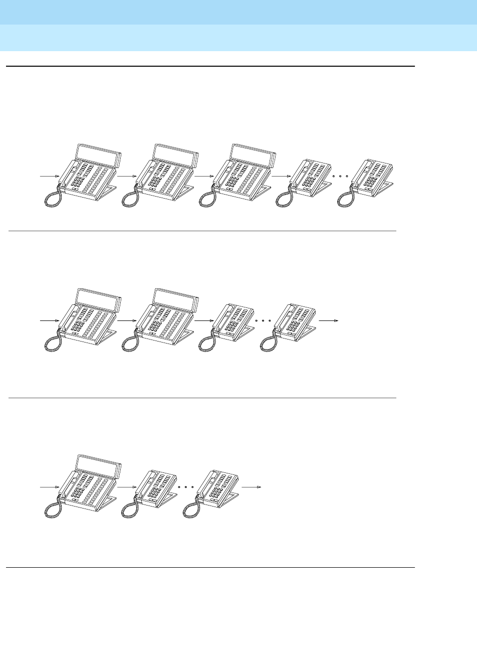
DEFINITY Enterprise Communications Server Release 6
Administration and Feature Description
555-230-522 Issue 4
May 1998
Basic Features
Page 4-160Call Coverage
4
Figure 4-1. Coverage path examples
Incoming
call
mr. brown’s
terminal point 1 point 2 point 3
another
manager
assistant
manager
coverage answer
group with ici
point 1 point 2 point 3
assistant
manager
coverage answer
group with ici
mr. brown’s
terminal
Incoming
call audix
mr. brown’s
terminal
Incoming
call
coverage answer
group with ici
audix
point 1 point 2 point 3
not
used
call type - INSIDE
criteria - SEND ALL CALLS ACTIVATED
call type - INSIDE
criteria - BUSY AND DON’T ANSWER (SEND ALL CALLS NOT ACTIVATED)
call type - OUTSIDE
CRITERIA - busy, don’t answer, and send all calls (when activated)
EXAMPLE 2 COVERAGE PATH FOR INSIDE CALLS
EXAMPLE 3 COVERAGE PATH FOR INSIDE CALLS
EXAMPLE 1 COVERAGE PATH FOR OUTSIDE CALLS
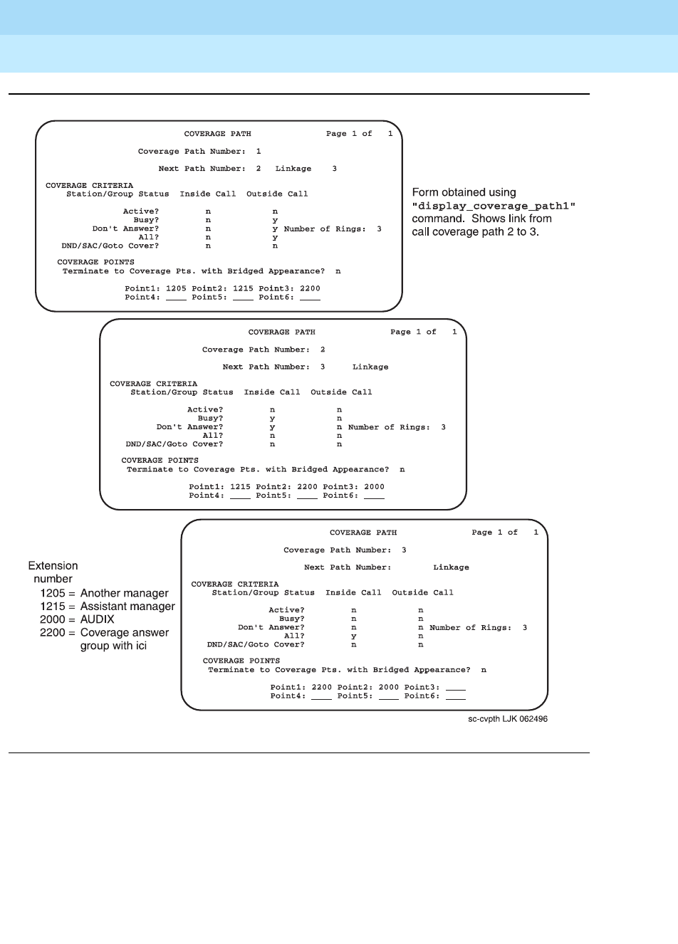
DEFINITY Enterprise Communications Server Release 6
Administration and Feature Description
555-230-522 Issue 4
May 1998
Basic Features
Page 4-161Call Coverage
4
Figure 4-2. Coverage Path form examples

DEFINITY Enterprise Communications Server Release 6
Administration and Feature Description
555-230-522 Issue 4
May 1998
Basic Features
Page 4-162Call Coverage
4
Interactions
■Administration without Hardware
Stations administered without hardware translation interact with Call
Coverage as if all their call appearances are busy. A disassociated station
can have Call Coverage active for the following call-coverage groups:
— Coverage answer groups
— Hunt groups
— Intercom groups
— Pickup groups
— Terminating Extension Groups (TEGs)
— Vector Directory Number (VDN)
■Agent Call Handling
Do not assign Cover All Calls to agents with the Automatic Answer option.
Any call (ACD or non-ACD), to an extension that has Automatic Answer
enabled and has its coverage redirection criteria administered as Cover
All Calls does not go to coverage but to the called extension. Cover All
Calls redirection criteria have no effect on an incoming call when a user is
in the Auto-Answer mode.
■Automatic Callback and Ringback Queuing
Callback calls do not redirect to coverage. The caller can activate
Automatic Callback when ringing, redirection notification signal, or busy
signal is heard.
■Automatic Intercom, Dial Intercom, and Priority Calling
Calls using these features are not redirected to coverage unless the caller
presses the Go to Cover button.
■Bridged Call Appearance
Coverage criteria for bridged call appearances are based entirely on the
criteria of the primary extension associated with the bridged call
appearance.
If a voice-terminal user has activated Send All Calls on the primary
extension, incoming calls still ring bridged call appearances of that
extension as long as a temporary bridged appearance of the call is
maintained at the primary extension.
The switch blocks a user from bridging onto a call that has routed off-net
while the call is undergoing call classification.

DEFINITY Enterprise Communications Server Release 6
Administration and Feature Description
555-230-522 Issue 4
May 1998
Basic Features
Page 4-163Call Coverage
4
■Call Detail Recording
When Coverage of Calls Redirected Off-Net is enabled, a CDR
record is generated only after the call has actually been answered off-net.
The dialed number in the record is the off-net number to which the call
covers. The calling number is the station that is covered to the off-net
location.
■Call Forwarding
Call Forwarding provides a temporary override of the redirection criteria.
Normally, calls forward instead of redirecting to coverage. When a
forwarding extension’s redirection criteria are met at the designated
(forwarded-to) extension, the call redirects to the forwarding extension’s
coverage path.
The system allows calls forwarded off-net to be tracked for busy or
no-answer conditions and to return for further call-coverage processing
under those conditions. However, if the principal does not have a
coverage path, the system does not track the call and it is left at the off-net
destination regardless of whether it is answered or busy.
If the principal has Send All Calls activated, the system does not attempt
Call Forwarding Off-Net, except for priority calls. Likewise, the system
does not attempt Call Forwarding Off-Net for coverage paths that specify
Cover All, except for priority calls.
If Cover All Calls is part of the coverage redirection criteria and if Call
Forwarding is active at a voice terminal, incoming priority calls forward to
the designated extension.
The Redirection Notification Signal applies to both Call Coverage and Call
Forwarding.
If an extension has both Send All Calls and Call Forwarding activated,
calls to that extension that immediately can be redirected to coverage are
redirected. However, other calls, such as Priority Calls, are forwarded to
the designated extension.
Activation of Send All Calls at the forwarded-to extension does not affect
calls forwarded to that extension.
■Call Pickup
Any call redirected to a covering user who is a member of a Call Pickup
group can be answered by other members of the group.
■Centralized Attendant Service
If an incoming CAS call is directed to a hunt group, the call is not
redirected to the hunt group’s coverage path.
■Class of Restriction and Controlled Restrictions
Users who may normally be restricted from receiving calls can still receive
calls directed to them via Call Coverage.

DEFINITY Enterprise Communications Server Release 6
Administration and Feature Description
555-230-522 Issue 4
May 1998
Basic Features
Page 4-164Call Coverage
4
■Conference
The switch blocks users from conferencing another party onto a call which
has routed off-net while that call is undergoing call classification. If any
party on the call is on hold, the call routes off-net, but without undergoing
call classification, even when the Coverage of Calls Redirected
Off-Net is enabled.
■Direct Department Calling, Uniform Call Distribution, and Automatic Call
Distribution
If a user has an Auxiliary Work button, and activates or deactivates Send
All Calls, the Auxiliary Work function associated with DDC or UCD is
activated or deactivated simultaneously.
If a user has no Auxiliary Work button, activating or deactivating Send All
Calls still makes the user available or unavailable for DDC and UCD calls,
but Auxiliary Work is not activated or deactivated. The Auxiliary Work
activate or deactivate code and the DDC, UCD, and ACD extension must
be dialed to activate the Auxiliary Work function.
Activating or deactivating the Auxiliary Work function does not activate or
deactivate Send All Calls.
■Hold
If a covering user puts a call on hold, and the principal picks up on the
call, the coverage appearance may or may not be dropped, depending
on administration.
If any party is on hold when a coverage call routes off-net, that call does
not undergo call classification, even when Coverage of Calls
Redirected Off-Net is enabled.
■Internal Automatic Answer
If an internal call is redirected to another voice terminal by a Call
Coverage redirection criteria, then that call is eligible for IAA at that voice
terminal.
IAA does not apply to calls to the original called extension when:
— The called voice terminal has activated Do Not Disturb, Send All
Calls, or Cover All Calls
— The calling voice terminal has selected Go To Cover before placing
the call
Calls directed to a Coverage Answering Group are not eligible for IAA.
■Leave Word Calling
Call Coverage can be used with or without LWC. However, the two
features complement each other. When a covering user activates LWC
during a coverage call, a message is left for the principal to call the
covering user. When a covering user activates Coverage Callback during
a coverage call, a message is left for the principal to call the internal caller.

DEFINITY Enterprise Communications Server Release 6
Administration and Feature Description
555-230-522 Issue 4
May 1998
Basic Features
Page 4-165Call Coverage
4
■Night Service
Calls routed to the night station via Night Service follow the coverage path
of the night extension under all coverage criteria except Send All Calls.
■Privacy — Manual Exclusion
When the primary or principal user bridges onto a call that went to
coverage and has been answered at the coverage point, the user is not
dropped when Privacy — Manual Exclusion is activated.
■Temporary Bridged Appearance
Calls redirected to coverage maintain an appearance on the called voice
terminal if a call appearance is available to handle the call. The called
party can bridge onto the call at any time. The system can be
administered to allow a temporary bridged appearance of the call to either
remain at or be removed from the covering voice terminal after the
principal bridges onto the call.
A Temporary Bridged Appearance is maintained for calls covered by an
off-net coverage point if the Coverage of Calls Redirected
Off-Net feature is enabled. A Temporary Bridged Appearance cannot be
maintained for calls if the coverage point is linked to AUDIX.
Consult calls use the temporary bridged appearance maintained on the
call. At the conclusion of a consult call, the bridged appearance is no
longer maintained. If the principal chooses not to talk with the calling
party, the principal cannot bridge onto the call later.
If a call that has, or has had, a temporary bridged appearance is
conferenced or transferred, and redirects to coverage again, a temporary
bridged appearance is not maintained at the conferenced-to or
transferred-to extension.
■Tenant Partitioning
The caller and called party must be able to access a coverage point. The
caller is considered to be the covering user and the called party is
considered to be the covered user. Both parties must be able to access
the coverage point.
■Transfer
The switch blocks a user from transferring a call which has routed off-net
to another party while that call is undergoing call classification. If any party
on a call that has routed off-net is on hold, the call does route off-net
without undergoing call classification, even when Coverage of Calls
Redirected Off-Net is enabled.

DEFINITY Enterprise Communications Server Release 6
Administration and Feature Description
555-230-522 Issue 4
May 1998
Basic Features
Page 4-166Call Coverage
4
Transfer interacts with Call Coverage as listed in the following table.
NOTE:
The coverage criteria for transferred DID calls depends upon the
External Treatment For Transferred Incoming Calls
field on the Feature-Related System Parameters form.
Source Transfer initiator Destination Coverage type
External Local station
Local station
Remote station
Remote station
Attendant
Attendant
Local station
Remote station
Local station
Remote station
Local station
Remote station
External
External
Internal
Internal
External
External
Internal Local station
Local station
Remote station
Remote station
Attendant
Attendant
Local station
Remote station
Local station
Remote station
Local station
Remote station
Internal
Internal
Internal
Internal
External
External

DEFINITY Enterprise Communications Server Release 6
Administration and Feature Description
555-230-522 Issue 4
May 1998
Basic Features
Page 4-167Call Detail Recording
4
Call Detail Recording
Call Detail Recording (CDR) collects detailed information about all incoming and
outgoing calls on specified trunk groups and, if you use intraswitch CDR, about
calls between designated extensions on the switch. It sends this information to a
printer or other CDR output device that may also provide reports.
You can use this information to compute call costs, allocate charges, analyze
calling patterns, detect unauthorized calls, and keep track of unnecessary calls.
For additional information on CDR, see Call Detail Acquisition and Processing
Reference.
Call Detail Recording has the following capabilities:
■Account Code Dialing and Forced Entry of Account Codes (FEAC)
■Call Splitting for Incoming and Outgoing Trunks
■Intraswitch CDR
■Privacy
How to administer CDR
■Assign a netcon channel using the Data Module form and enter
data-channel or netcon channel for the type.
■Assign a system port using the Data Module form and enter system port
for the type.
Required forms
Form Field Page
Trunk Groups ■CDR Reports
■Answer Supervision Timeout
■Disconnect Supervision
7-115
CDR System Parameters ■All 5-63
Inter-exchange Carrier
Codes
■All 5-177
Feature Access Code (FAC) ■CDR Account Code Access Code 5-113
Netcon Data Module ■All 6-245
System Port Data Module ■All 6-248
Loudspeaker Paging and
Code Calling Access
■CDR 5-209

DEFINITY Enterprise Communications Server Release 6
Administration and Feature Description
555-230-522 Issue 4
May 1998
Basic Features
Page 4-168Call Detail Recording
4
■A Data Line circuit pack can also be used in conjunction with an ADU to
connect to an output device. If the CDR output device is connected to a
Data Line circuit pack via an ADU, administer a Data Line Type Data
Module.
For more information about how to connect a CDR output device, see
DEFINITY
Enterprise Communications Server Release 6 Installation for Adjuncts and
Peripherals
.
How to administer Account Code Dialing
How to administer FEAC
Forced Entry of Account Codes is a subset of account code dialing. You must
administer account code dialing in addition to the fields described below.
Required forms
Form Field Page
Feature Access Code (FAC) ■CDR Account Code Access Code 5-113
CDR System Parameters ■CDR Account Code Length 5-63
Station ■Feature button assignments
— account (optional) 6-14
Required forms
Form Field Page
System Parameters Customer-
Options
■Forced Entry of Account
Codes 5-277
CDR System Parameters ■Force Entry of Account
Codes for Calls Marked
on Toll Analysis Form
■CDR Account Code
Length
5-63
Class of Restriction ■Forced Entry of Account
Codes 5-72
Continued on next page

DEFINITY Enterprise Communications Server Release 6
Administration and Feature Description
555-230-522 Issue 4
May 1998
Basic Features
Page 4-169Call Detail Recording
4
How to administer Incoming Trunk Call Splitting
How to administer Outgoing Trunk Call Splitting
Call Originating Facility (station, data
module, trunk group)
■COR N/A
Toll Analysis ■Dialed String
■Min
■Max
■CDR FEAC
5-299
Station ■Feature button
assignments
— account (optional)
6-14
Required forms
Form Field Page
CDR System Parameters ■Record Outgoing Calls Only = n
■Inc Trk Call Splitting
■Inc Attd Call Record
5-63
Required forms
Form Field Page
CDR System Parameters ■Outg Trk Call Splitting
■Outg Attd Call Record
5-63
Required forms — Continued
Form Field Page
Continued on next page

DEFINITY Enterprise Communications Server Release 6
Administration and Feature Description
555-230-522 Issue 4
May 1998
Basic Features
Page 4-170Call Detail Recording
4
How to administer Intraswitch CDR
How to administer CDR Privacy
Detailed description
CDR tracks call information on a per-trunk-group or station-to-station basis. For
every trunk group (including auxiliary trunks) that you administer for CDR reports,
the system keeps track of incoming, outgoing and tandem calls. You can also
receive reports on temporary signaling connections (TSCs) that involve trunks,
and calls made using loudspeaker paging or code calling access.
You can also ask the system to report on ineffective call attempts. This may
greatly increase the number of calls recorded, but may also help you to increase
security, since the system records call attempts that are blocked because of
insufficient calling privileges. This can also let you know if your users are not able
to make calls because all trunks are busy.
Some call accounting systems do not support all of the information offered by
CDR. See your Lucent Technologies representative for details.
Account Code Dialing
Account Code Dialing allows certain calls to be associated with a particular
project or account number. To do this, users enter account codes when they
place certain types of outgoing calls. These account codes then appear on the
call record, which you can use for accounting or billing purposes. Account code
dialing can be optional or mandatory (forced).
To associate an account code with a particular call, a user first dials the CDR
account code access code that you have established, then dials the desired
account code. Next, the user dials the desired trunk access code, or ARS
access code, followed by the phone number.
Required forms
Form Field Page
CDR System Parameters ■Intraswitch CDR 5-63
Intra-Switch CDR Form ■All 5-183
Required forms
Form Field Page
Station (All) ■CDR Privacy 6-28
CDR System Parameters ■Privacy — Digits to Hide 5-63

DEFINITY Enterprise Communications Server Release 6
Administration and Feature Description
555-230-522 Issue 4
May 1998
Basic Features
Page 4-171Call Detail Recording
4
The call record contains the account code, TAC or ARS access code, and the
phone number. It does not contain the account code FAC.
Forced Entry of Account Codes
You can force your users to enter account codes on a system-wide, per-trunk or
per-user basis, or on the basis of the digit string the user dials. If you have this
feature in place, the system rejects any call that requires an account code where
one is not supplied. To maximize system security, it is recommended that you use
Forced Entry of Account Codes (FEAC).
!SECURITY ALERT:
DEFINITY ECS does not verify account codes. As long as the user enters a
digit string of the appropriate length, the system allows the call. You must
use Authorization Codes if you want the system to determine if the user is
authorized to make the call.
You can assign FEAC in the following ways:
■All calls marked for FEAC on the Toll Analysis table
If you activate this CDR system parameter, all users must dial an account
code when the digits dialed match a digit string with FEAC=y. This
includes calls made by ARS or TAC.
■Toll calls made by users with a specific class of restriction (COR)
If FEAC is assigned to a specific COR, any voice-terminal user assigned
that COR must dial an account code before making calls that are
administered forced entry of account codes.
■All calls made over a trunk group with FEAC in COR (TAC calls)
Users cannot access a trunk group that is assigned a COR with FEAC until
they dial an account code. If a call is routed via ARS, the system does not
check for FEAC in the trunk group’s COR. Therefore, if you want your users
to enter account codes for ARS calls, you must administer this in the Toll
Analysis table.
If an account code is required for a call and the user does not enter one, the
system responds with intercept tone.
The following types of calls never require an account code:
■Attendant originated call
■Busy verification of a trunk by an attendant or voice-terminal user
■DCS (unless required by the trunk group’s COR)
■Personal CO Line
■Remote access without barrier codes
■Trunk-to-trunk connections

DEFINITY Enterprise Communications Server Release 6
Administration and Feature Description
555-230-522 Issue 4
May 1998
Basic Features
Page 4-172Call Detail Recording
4
Call Splitting
Call splitting keeps track of calls where more than two parties are involved. These
can be calls that are transferred, conferenced, or where an attendant becomes
involved. If you have call splitting activated and any of these situations arise,
CDR produces a separate record for each new party on the call.
You can administer call splitting for both incoming and outgoing trunks, and both
can have attendant calls recorded separately.
Incoming trunk call splitting
If incoming trunk call splitting is enabled, CDR starts a new record whenever an
incoming trunk call is conferenced or transferred. Whenever a user drops from
the call or the call is successfully transferred, CDR outputs the record relevant to
this user’s participation. These call records show the amount of time each party
was on the call, the incoming trunk access code, the dialed number and the
condition code, as well as the other fields specified in the record format.
For incoming trunk calls that are conferenced, CDR creates a new record
whenever a new party comes on the call. The duration field in these records
shows how long each party participated on the call. Conference calls produce
records with duration fields that overlap. The duration of a transferred call begins
when the transferring party presses the TRANSFER button for the second time, so
there is no overlap.
If ITCS is enabled and an incoming trunk call is conferenced or transferred to a
local extension that is optioned for Intraswitch CDR, the call produces an
incoming trunk call record. It does not produce an Intraswitch record.
ITCS examples
The following scenarios depict calls made with ITSC active. The tables that follow
do not show all fields, only those that may change due to call splitting. Call
durations are approximate.
Caller A (TAC 123) makes an incoming trunk call to switch party B (5657890).
They talk for 2 minutes. B then conferences in C (ext. 54321), and D (ext. 59876).
The entire group talks for another 8 minutes, at which point B drops off the call.
This produces a record for segment A–B.

DEFINITY Enterprise Communications Server Release 6
Administration and Feature Description
555-230-522 Issue 4
May 1998
Basic Features
Page 4-173Call Detail Recording
4
A, C and D continue to talk for another 5 minutes. All remaining parties drop,
producing two more records; A–C and A–C. Note that each record shows the
incoming trunk ID as the calling number.
A (TAC 123) calls Station B (57890). They talk for 1 minute, then B transfers the
call to C (54321). CDR generates a record for segment A–B. A and C talk for 5
minutes. CDR generates a record for segment A–C.
A (TAC 123) calls switch party B (5657890), they talk for one minute. B transfers
the call to public-network party C (5665555), they talk for 4 minutes. Note that the
duration of the original incoming trunk call includes the time after the call was
transferred to an outgoing trunk, until all trunk parties drop.
Outgoing trunk call splitting
If outgoing trunk call splitting is active, CDR creates records of transferred calls
as described above for incoming trunk call splitting. For conferenced calls, the
originator of the conference will be charged until he or she drops from the call, at
which point CDR begins a second record for the conferenced user. Records for
parties on a conference do not overlap; they are split.
Table 4-39. ITCS conference
Segment Duration
Condition
Code
Access
Code Used
Calling
Number
Dialed
Number
A–B 0:10:0 C 123 5657890
A–C 0:13:0 C 123 54321
A–D 0:13:0 C 123 59876
Table 4-40. ITCS transfer
Segment Duration
Condition
Code
Access
Code Used
Calling
Number
Dialed
Number
A–B 0:01:0 9 123 5657890
A–C 0:05:0 9 123 54321
Table 4-41. ITCS transfer to outgoing trunk
Segment Duration
Condition
Code
Access
Code Used
Calling
Number
Dialed
Number
A–B 0:05:0 9 123 5657890
A–C 0:04:0 9 345 123 5665555

DEFINITY Enterprise Communications Server Release 6
Administration and Feature Description
555-230-522 Issue 4
May 1998
Basic Features
Page 4-174Call Detail Recording
4
OTCS examples
In the next example, switch party A (57890) calls B(7771234), talks for 5 minutes,
then conferences in C (7775678). They all talk for another 5 minutes, at which
point all parties drop.
Switch party A (51234) calls public-network party B (5659999). They talk for 5
minutes. A then transfers the call to switch party C (54444).
Attendant call recording
Both incoming and outgoing call splitting give you the option of recording the
attendant portion of calls that are transferred. To enable this option, set
Incoming and/or Outgoing Attendant Call Record to y.
If either incoming or outgoing trunk call splitting is enabled, the attendant portion
of a conference call always produces a separate record.
Table 4-42. OTCS conference
Segment Duration
Condition
Code
Access
Code Used
Calling
Number
Dialed
Number
A–B 0:10:0 C 345 57890 7771234
A–C 0:05:0 C 345 57890 7775678
Table 4-43. OTCS transfer
Segment Duration
Condition
Code
Access
Code Used
Calling
Number
Dialed
Number
A–B 0:01:0 A 345 51234 5659999
C–B 0:05:0 A 345 54444 5659999

DEFINITY Enterprise Communications Server Release 6
Administration and Feature Description
555-230-522 Issue 4
May 1998
Basic Features
Page 4-175Call Detail Recording
4
Attendant call recording examples
Public-network party A (TAC 123) calls the attendant (Attd), and asks to be
transferred to switch party B (58888).
The attendant (Attd) dials switch party A (59999), then transfers the call to
public-network party B (4445678).
Intraswitch CDR
Intraswitch CDR generates call records for calls to and from users on the local
switch. For the system to generate an intraswitch CDR record, one of the
extensions involved in a call must have intraswitch CDR assigned.
If a station is optioned for Intraswitch CDR, and ITCS is also enabled, ITCS
overrides Intraswitch CDR. That is, incoming trunk calls involving the station
produce trunk call records, not Intraswitch CDR records.
The output for intraswitch CDR follows the same format you have established for
other call records. Certain fields do not appear on intraswitch call records,
because they do not pertain to internal calls. For example, an intraswitch record
does not contain trunk access codes or circuit IDs, since these do not apply.
Some calls may seem to be intraswitch CDR calls, but actually result in trunk
calls. For example, a station-to-station call to an extension that is forwarded to an
outgoing trunk produces only a trunk CDR record, regardless of whether or not
either station has intraswitch CDR assigned.
You can assign intraswitch CDR to terminating extension groups (TEGs),
stations, data modules, VDNs, PRI endpoints, access endpoints, or hunt groups.
The number that appears in the dialed number field depends on whether you
have administered CDR System Parameters to record hunt group/member or
Table 4-44. Attendant transfer incoming trunk
Segment Duration
Condition
Code
Access
Code Used
Calling
Number
Dialed
Number
A–Attd 0:01:0 9 123 Attd
A–B 0:05:0 9 123 58888
Table 4-45. Attendant transfer outgoing trunk
Segment Duration
Condition
Code
Access
Code Used
Calling
Number
Dialed
Number
Attd–B 0:01:0 A 345 Attd 4445678
A–B 0:05:0 A 345 59999 4445678

DEFINITY Enterprise Communications Server Release 6
Administration and Feature Description
555-230-522 Issue 4
May 1998
Basic Features
Page 4-176Call Detail Recording
4
VDN information. You
cannot
assign intraswitch CDR to attendant consoles or
CallVisor ASAI stations.
NOTE:
If an extension with intraswitch CDR is neither the originator of the call nor
the dialed number of the call, the system does not produce a call record,
even though the extension might be a party on the call (via Call Pickup, Call
Forwarding, etc.).
Privacy
CDR Privacy allows you to administer the system to blank a given number of
dialed digits from a CDR report. This is useful when it is necessary to know
details of a person’s calls for accounting purposes, but it is not necessary or
desirable to know the exact number called.
You can administer the number of digits to hide, up to 7. The value in Privacy
Digits to Hide determines how many digits do not appear on the call record. This
parameter is system-wide. Whether or not an individual’s calls receive Privacy
treatment is determined by the CDR Privacy field on the Station form.
When an adjunct-originated call is made on behalf of a hunt group and the CDR
system parameter Calls to Hunt Group - Record option is set to
group-ext, then CDR privacy does not apply. If this field is set to member-ext,
privacy does apply.
NOTE:
Certain countries have requirements that a certain number of digits must be
blanked from every call. Also, certain report processors do not support this
option.
CDR output
If your system uses two CDR output formats, one is administered as the primary
CDR output format; the other is administered as the secondary CDR output
format. The secondary output format is typically used for a local storage format
(CDRU) to provide CDR data to NCOSS for assessing network performance or
helping to find network problems.
The primary and secondary ports work independently. Each port will work even if
the link to the other port is down. If a link is down for more than a minute, some
data may be lost. However, the most recent 500 (Release 5vs/si/csi and later), or
1,900 (Release 5r and later) records are stored for the primary port even when a
loss of records occurs. When the link comes back up, these records are output
on a first-in, first-out basis.

DEFINITY Enterprise Communications Server Release 6
Administration and Feature Description
555-230-522 Issue 4
May 1998
Basic Features
Page 4-177Call Detail Recording
4
If the CDR buffer is full, you can select a call record handling option to determine
which of the following occurs:
■Calls are blocked with a reorder tone
■Calls overwrite records
■Calls are routed to an attendant as non-CDR calls
Overwrite old CDR records with new ones if the buffer is full.
The following information applies to the port used for the secondary CDR output
device:
■Data going to the secondary port should be the same as that going to the
primary port. You can use the following record types for secondary output:
LSU, Int-Direct, Int-Process, and Unformatted.
■If the system experiences problems in sending records to the primary
CDR Output Device, the system discontinues sending records to the
secondary port for 2 minutes. The secondary port should be run at the
highest possible speed in order to prevent loss of information.
■If the output buffer is full, the system busies out the secondary port for 2
minutes. This makes system resources available to send data to the
primary CDR port before the data is lost. The system continues to busy out
the secondary port for 2-minute intervals until less than 400 records (1800
for Release 5r and later) remain in the buffer.
CDR Record formats
Two types of formats are sent to the CDR output device, date record and call
detail formats.
Date record format
CDR sends date information to the CDR device once a day (at midnight), or
when the device is connected. This is a non-call record, and contains only the
information shown in the date record formats below.
Several formats are available for date records: one for CDRUs, one for the printer,
and one for the TELESEER. The records sent to the TELESEER and printer
contain the date only while the records sent to the CDRU contain time. See Ta b l e
4-46, Table 4-47, and Table 4-48.
NOTE:
The date can be in month/day
or
day/month format, as selected on the CDR
System Parameters form. The date/time may also be reversed for
international standards.

DEFINITY Enterprise Communications Server Release 6
Administration and Feature Description
555-230-522 Issue 4
May 1998
Basic Features
Page 4-178Call Detail Recording
4
.
Table 4-46. Date Record Format to LSU, LSU-Expand, Unformatted, and
Customized
Position Data Field Description
1–2 Hour (leading 0 added if needed)
3 Colon (:)
4–5 Minute (leading 0 added if needed)
6 Blank
7–8 Month (Leading Zero Added if Needed)
9Slash (/)
10–11 Day (leading 0 added if needed)
12 Carriage return
13 Line feed
14–16 Null
Table 4-47. Date Record Format for Printer and Expanded
Position Data Field Description
1–2 Month (leading 0 added if needed)
3Space
4–5 Day (leading 0 added if needed)
6 Carriage return
7 Line feed
8–10 Null
Table 4-48. Date Record Format for TELESEER 59 Character, Int-Proc,
Int-Direct, and Int-ISDN
Position Data Field Description
1–2 Month (leading 0 added if needed)
3–4 Day
5 Carriage return
6 Line feed
7–9 Null

DEFINITY Enterprise Communications Server Release 6
Administration and Feature Description
555-230-522 Issue 4
May 1998
Basic Features
Page 4-179Call Detail Recording
4
Call Detail Record Formats
Customized Format
You can use the customized record format to make up your own call record. You
can determine the data elements you want and their positions in the record. This
method may be necessary if you want to include certain data elements that are
not available on the standard formats.
However, whatever device you use to interpret the CDR data needs to be
programmed to accept these formats. Consult your Lucent Technologies
representative before using a custom record format.

DEFINITY Enterprise Communications Server Release 6
Administration and Feature Description
555-230-522 Issue 4
May 1998
Basic Features
Page 4-180Call Detail Recording
4
Table 4-49. CDR Data Format — TELESEER
Position Data Field Description
1–3 Space
4–5 Time of day-hours
6–7 Time of day-minutes
8 Duration-hours
9–10 Duration-minutes
11 Duration-tenths of minutes
12 Condition code
13–15 Access code dialed
16–18 Access code used
19–33 Dialed number
34–38 Calling number
39–53 Account code
54 FRL
55 IXC
56–58 Incoming circuit ID
59–61 Outgoing circuit ID
62 Feature flag
63–69 Authorization code
70–76 Space
77 Carriage return
78 Line feed
79–81 Null

DEFINITY Enterprise Communications Server Release 6
Administration and Feature Description
555-230-522 Issue 4
May 1998
Basic Features
Page 4-181Call Detail Recording
4
Table 4-50. CDR Data Format — ISDN TELESEER
Position Data Field Description
1–3 Space
4–5 Time of day-hours
6–7 Time of day-minutes
8 Duration-hours
9–10 Duration-minutes
11 Duration-tenths of minutes
12 Condition code
13–15 IXC
16–18 Access code used
19–33 Dialed number
34–38 Calling number
39–53 Account code
54 INS (units)
55 FRL
56–58 Incoming circuit ID
59–61 Outgoing circuit ID
62 Feature flag
63–69 Authorization code
70–71 INS (hundreds, tens)
72–76 Space
77 Line feed
78–80 Null

DEFINITY Enterprise Communications Server Release 6
Administration and Feature Description
555-230-522 Issue 4
May 1998
Basic Features
Page 4-182Call Detail Recording
4
Table 4-51. CDR Data Format — Enhanced TELESEER
Position Data Field Description
1–3 Space
4–5 Time of day-hours
6–7 Time of day-minutes
8 Duration-hours
9–10 Duration-minutes
11 Duration-tenths of minutes
12 Condition code
13–16 IXC code
17–19 Access code used
20–34 Dialed number
35–39 Calling number
40–54 Account code
55 ISDN NSV (units)
56 FRL
57–59 Incoming circuit ID
60–62 Outgoing circuit ID
63 Feature flag
64–70 Authorization code
71–72 ISDN NSV (hundreds, tens)
73–76 Space
77 Carriage return
78 Line feed
79–81 Null

DEFINITY Enterprise Communications Server Release 6
Administration and Feature Description
555-230-522 Issue 4
May 1998
Basic Features
Page 4-183Call Detail Recording
4
Table 4-52. CDR Data Format — 59 Character
Position Data Field Description
1–2 Time of day-hours
3–4 Time of day-minutes
5 Duration-hours
6–7 Duration-minutes
8 Duration-tenths of minutes
9 Condition code
10–12 Access code dialed
13–15 Access code used
16–30 Dialed number
31–35 Calling number
36–50 Account code
51 FRL
52 IXC
53–55 Incoming circuit ID
56–58 Outgoing circuit ID
59 Carriage return
60 Line feed
61–63 Null

DEFINITY Enterprise Communications Server Release 6
Administration and Feature Description
555-230-522 Issue 4
May 1998
Basic Features
Page 4-184Call Detail Recording
4
Table 4-53. CDR Data Format — Printer
Position Data Field Description
1–2 Time of day-hours
3–4 Time of day-minutes
5Space
6 Duration-hours
7–8 Duration-minutes
9 Duration-tenths of minutes
10 Space
11 Condition code
12 Space
13–15 Access code dialed
16 Space
17–19 Access code used
20 Space
21–35 Dialed number
36 Space
37–41 Calling number
42 Space
43–57 Account code
58 Space
59–65 Authorization code
66–69 Space
70 FRL
71 Space
72 IXC
73 Space
74–76 Incoming circuit ID
77 Space
78–80 Outgoing circuit ID
81 Space
82 Feature flag
83 Carriage return
84 Line feed

DEFINITY Enterprise Communications Server Release 6
Administration and Feature Description
555-230-522 Issue 4
May 1998
Basic Features
Page 4-185Call Detail Recording
4
Table 4-54. CDR Data Format — ISDN Printer
Position Data Field Description
1–2 Time of day-hours
3–4 Time of day-minutes
5Space
6 Duration-hours
7–8 Duration-minutes
9 Duration-tenths of minutes
10 Space
11 Condition code
12 Space
13–15 IXC
16 Space
17–19 Access code used
20 Space
21–35 Dialed number
36 Space
37–41 Calling number
42 Space
43–57 Account code
58 Space
59–65 Authorization code
66 Space
67–68 INS (hundreds, tens)
69 Space
70 INS (units)
71 Space
72 FRL
73 Space
74–76 Incoming circuit ID
77 Space
78–80 Outgoing circuit ID
81 Space
82 Feature flag
83 Carriage return
84 Line feed

DEFINITY Enterprise Communications Server Release 6
Administration and Feature Description
555-230-522 Issue 4
May 1998
Basic Features
Page 4-186Call Detail Recording
4
Table 4-55. CDR Data Format — Enhanced Printer
Position Data Field Description
1–2 Time of day-hours
3–4 Time of day-minutes
5Space
6 Duration-hours
7–8 Duration-minutes
9 Duration-tenths of minutes
10 Space
11 Condition code
12 Space
13–16 IXC code
17 Space
18–21 Access code used
22 Space
23–37 Dialed number
38 Space
39–43 Calling number
44 Space
45–59 Account code
60 Space
61–67 Authorization code
68 Space
69–71 ISDN NSV
72 Space
73 FRL
74 Space
75–77 Incoming circuit ID
78 Space
79–81 Outgoing circuit ID
82 Space
83 Feature flag
84 Carriage return
85 Line feed
Continued on next page

DEFINITY Enterprise Communications Server Release 6
Administration and Feature Description
555-230-522 Issue 4
May 1998
Basic Features
Page 4-187Call Detail Recording
4
Table 4-56. CDR Data Format — LSU-Expand
Position Data Field Description
1–2 Time of day-hours
3–4 Time of day-minutes
5Space
6 Duration-hours
7–8 Duration-minutes
9 Duration-tenths of minutes
10 Space
11 Condition code
12 Space
13–15 Access code dialed
16–18 Access code used
19 Space
20–34 Dialed number
35 Space
36–39 Calling number
40 Space
41–45 Account code
46 Space
47–53 Authorization code
54–57 Space
58 FRL
59 Space
60 Calling number (1st digit)
61 Space
62–63 Incoming circuit ID (tens, units)
64 Space
65 Feature flag
66 Space
67–68 Outgoing circuit ID (tens, units)
69 Space
70 Outgoing circuit ID (hundreds)
71 Space
72 Incoming circuit ID (hundreds)
73 IXC
74 Carriage return
75 Line feed
76–78 Null

DEFINITY Enterprise Communications Server Release 6
Administration and Feature Description
555-230-522 Issue 4
May 1998
Basic Features
Page 4-188Call Detail Recording
4
Table 4-57. CDR Data Format — LSU
Position Data Field Description
1 Duration-hours
2-3 Duration-minutes
4 Duration-tenths of minutes
5 Condition code
6–8 Access code dialed
9–11 Access code used
12–26 Dialed number
27–30 Calling number (digits 2–5 for 5-digit dial plan)
31–35 Account code (first 5 digits)
36–42 Authorization code or digits 6–12 of account
code
43–44 Space or digits 13–14 of account code
45 FRL or digit 15 of account code
46 Calling number (1st digit)
47–48 Incoming circuit ID (tens, units)
49 Feature flag
50–52 Outgoing circuit ID (tens, units, hundreds)
53 Incoming circuit ID (hundreds)
54 IXC
55 Carriage return
56 Line feed
57–59 Null
Continued on next page

DEFINITY Enterprise Communications Server Release 6
Administration and Feature Description
555-230-522 Issue 4
May 1998
Basic Features
Page 4-189Call Detail Recording
4
Table 4-58. CDR Data Format — ISDN LSU
Position Data Field Description
1 Duration-hours
2–3 Duration-minutes
4 Duration-tenths of minutes
5 Condition code
6–8 IXC
9–11 Access code used
12–26 Dialed number
27–30 Calling number (digits 2–5 for 5-digit dial plan)
31–35 Account code (digits 1–5)
36–42 Authorization code or digits 6–12 of account code
43–44 INS or digits 13–14 of account code
45 INS (3rd digit), FRL, or digit 15 of account code
46 Calling number (1st digit of 5-digit calling number)
47–48 Incoming circuit ID (tens, units)
49 Feature flag
50–52 Outgoing circuit ID (tens, units, hundreds)
53 Incoming circuit ID (hundreds)
54 FRL
55 Carriage return
56 Line feed
57–59 Null
Continued on next page

DEFINITY Enterprise Communications Server Release 6
Administration and Feature Description
555-230-522 Issue 4
May 1998
Basic Features
Page 4-190Call Detail Recording
4
Table 4-59. CDR Data Format — Enhanced LSU
Position Data Field Description
1 Duration-hours
2–3 Duration-minutes
4 Duration-tenths of minutes
5 Condition code
6–9 IXC code
10–12 Access code used
13–27 Dialed number
28–31 Calling number
32–35 Account code (digits 1–4)
36–42 Authorization code or digits 6–12 of account code
43–45 ISDN NSV
46 1st digit of a 5-digit calling number
47–48 Incoming circuit ID (tens, units)
49 Feature flag
50–52 Outgoing circuit ID (tens, units, hundreds)
53 Incoming circuit ID (hundreds)
54 FRL
55 Carriage return
56 Line feed
57–59 Null
Continued on next page

DEFINITY Enterprise Communications Server Release 6
Administration and Feature Description
555-230-522 Issue 4
May 1998
Basic Features
Page 4-191Call Detail Recording
4
Table 4-60. CDR Data Format — Expanded
Position Data Field Description
1–2 Time of day-hours
3–4 Time of day-minutes
5Space
6 Duration-hours
7–8 Duration-minutes
9 Duration-tenths of minutes
10 Space
11 Condition code
12 Space
13–16 Access code dialed
17 Space
18–21 Access code used
22 Space
23–37 Dialed number
38 Space
39–48 Calling number
49 Space
50–64 Account code
65 Space
66–72 Authorization code
73-76 Space
77 FRL
78 Space
79–81 Incoming circuit ID
82 Space
83–85 Outgoing circuit ID
86 Space
87 Feature flag
88 Space
89–90 Attendant console
91 Space
92–95 Incoming trunk access code
Continued on next page

DEFINITY Enterprise Communications Server Release 6
Administration and Feature Description
555-230-522 Issue 4
May 1998
Basic Features
Page 4-192Call Detail Recording
4
96 Space
97–98 Node number
99 Space
100–102 INS
103 Space
104–106 IXC
107 Space
108 BCC
109 Space
110 MA-UUI
111 Space
112 Resource flag
113 Space
114–117 Packet count
118 Space
119 TSC flag
120 Space
121–129 Reserved
130 Space
131 Carriage return
132 Line feed
133–135 Null
Table 4-60. CDR Data Format — Expanded — Continued
Position Data Field Description
Continued on next page

DEFINITY Enterprise Communications Server Release 6
Administration and Feature Description
555-230-522 Issue 4
May 1998
Basic Features
Page 4-193Call Detail Recording
4
Table 4-61. CDR Data Format — Enhanced Expanded
Position Data Field Description
1–2 Time of day-hours
3–4 Time of day-minutes
5Space
6 Duration-hours
7–8 Duration-minutes
9 Duration-tenths of minutes
10 Space
11 Condition code
12 Space
13–16 Access code dialed
17 Space
18–21 Access code used
22 Space
23–37 Dialed number
38 Space
39–48 Calling number
49 Space
50–64 Account code
65 Space
66–72 Authorization code
73 Space
74–75 Time in queue
76 Space
77 FRL
78 Space
79–81 Incoming circuit ID
82 Space
83–85 Outgoing circuit ID
86 Space
87 Feature flag
88 Space
89–90 Attendant console
Continued on next page

DEFINITY Enterprise Communications Server Release 6
Administration and Feature Description
555-230-522 Issue 4
May 1998
Basic Features
Page 4-194Call Detail Recording
4
91 Space
92–95 Incoming TAC
96 Space
97–98 Node number
99 Space
100–102 ISDN NSV
103 Space
104–107 IXC code
108 Space
109 BCC
110 Space
111 MA-UUI
112 Space
113 Resource flag
114 Space
115–118 Packet count
119 Space
120 TSC flag
121 Space
122–123 Bandwidth
124 Space
125–130 ISDN CC (digits 1–6)
131–135 ISDN CC (digits 7–11)/PPM count (1–5)
136–146 Reserved for future use
147 Carriage return
148 Line feed
149–151 Null
Table 4-61. CDR Data Format — Enhanced Expanded — Continued
Position Data Field Description
Continued on next page

DEFINITY Enterprise Communications Server Release 6
Administration and Feature Description
555-230-522 Issue 4
May 1998
Basic Features
Page 4-195Call Detail Recording
4
Table 4-62. CDR Data Format — Unformatted
Position Data Field Description
1–2 Time of day-hours
3–4 Time of day-minutes
5 Duration-hours
6–7 Duration-minutes
8 Duration-tenths of minutes
9 Condition code
10–13 Access code dialed
14–17 Access code used
18–32 Dialed number
33–42 Calling number
43–57 Account code
58–64 Authorization code
65–66 Space
67 FRL
68–70 Incoming circuit ID (hundreds, tens, units)
71–73 Outgoing circuit ID (hundreds, tens, units)
74 Feature flag
75–76 Attendant console
77–80 Incoming TAC
81–82 Node number
83–85 INS
86–88 IXC
89 BCC
90 MA-UUI
91 Resource flag
92–95 Packet count
96 TSC flag
97–100 Reserved
101 Carriage return
102 Line feed
103–105 Null
Continued on next page

DEFINITY Enterprise Communications Server Release 6
Administration and Feature Description
555-230-522 Issue 4
May 1998
Basic Features
Page 4-196Call Detail Recording
4
Table 4-63. CDR Data Format — Enhanced Unformatted
Position Data Field Description
1–2 Time of day-hours
3–4 Time of day-minutes
5 Duration-hours
6–7 Duration-minutes
8 Duration-tenths of minutes
9 Condition code
10–13 Access code dialed
14–17 Access code used
18–32 Dialed number
33–42 Calling number
43–57 Account code
58–64 Authorization code
65–66 Time in queue
67 FRL
68–70 Incoming circuit ID
71–73 Outgoing circuit ID
74 Feature flag
75–76 Attendant console number
77–80 Incoming TAC
81–82 Node number
83–87 ISDN NSV
88–89 IXC code
90 BCC
91 MA-UUI
92 Resource flag
93–96 Packet count
97 TSC flag
98–99 Bandwidth
100–105 ISDN CC (digits 1–6)
106–110 ISDN CC (digits 7–11)/PPM count (1–5)
111–114 Reserved for future use
115 Carriage return
116 Line feed
117–119 Null
Continued on next page

DEFINITY Enterprise Communications Server Release 6
Administration and Feature Description
555-230-522 Issue 4
May 1998
Basic Features
Page 4-197Call Detail Recording
4
Table 4-64. CDR Data Format — Int Process
Position Data Field Description
1–2 Format code
3–4 Time of day-hours
5–6 Time of day-minutes
7 Duration-hours
8–9 Duration-minutes
10 Duration-tenths of minutes
11 Space
12 Condition code
13 Space
14–16 Access code dialed
17–19 Access code used
20 Space
21–38 Dialed number (digits 1–18)
39–43 Calling number (digits 1–5)
44 Space
45–59 Account code (digits 1–15)
60 Space
61 IXC
62 FRL
63–65 Space
66–67 Incoming circuit ID (digits 1–2)
68–70 Space
71–72 Outgoing circuit ID (digits 1–2)
73 Space
74–78 PPM count (digits 1–5)
79 Carriage return
80 Line feed
81–83 Null
Continued on next page

DEFINITY Enterprise Communications Server Release 6
Administration and Feature Description
555-230-522 Issue 4
May 1998
Basic Features
Page 4-198Call Detail Recording
4
Table 4-65. CDR Data Format — Int-Direct
Position Data Field Description
1–2 Day of month
3–4 Month
5–6 Year
7Space
8–9 Time of day-hours
10–11 Time of day-minutes
12 Space
13 Duration-hours
14–15 Duration-minutes
16 Duration-tenths of minutes
17 Space
18 Condition code
19 Space
20–22 Access code dialed
23–25 Access code used
26 Space
27–44 Dialed number used
45 Space
46–50 Calling number
51 Space
52–66 Account code
67 Space
68–72 PPM count
73 Space
74–75 Incoming circuit ID
76 Space
77–78 Outgoing circuit ID
79 Carriage return
80 Line feed
Continued on next page

DEFINITY Enterprise Communications Server Release 6
Administration and Feature Description
555-230-522 Issue 4
May 1998
Basic Features
Page 4-199Call Detail Recording
4
Table 4-66. CDR Data Format — Int-ISDN
Position Data Field Description
1–2 Time of day-hours
3–4 Time of day-minutes
5Space
6 Duration-hours
7–8 Duration-minutes
9 Duration-tenths of minutes
10 Space
11 Condition code
12 Space
13–16 Access code dialed
17 Space
18–21 Access code used
22 Space
23–37 Dialed number
38 Space
39–48 Calling number
49 Space
50–64 Account code
65 Space
66–72 Authorization code
73 Space
74 Line feed
75 Space
76 FRL
77 Space
78 Incoming circuit ID (hundreds)
79 Incoming circuit ID (tens)
80 Incoming circuit ID (units)
81 Space
82–84 Outgoing circuit ID
85 Space
86 Feature flag
Continued on next page

DEFINITY Enterprise Communications Server Release 6
Administration and Feature Description
555-230-522 Issue 4
May 1998
Basic Features
Page 4-200Call Detail Recording
4
87 Space
88–89 Attendant console (1st digit)
90 Space
91–94 Incoming trunk access code
95 Space
96–97 Node number
98 Space
99–101 INS
102 Space
103–106 IXC
107 Space
108 BCC
109 Space
110 MA-UUI
111 Space
112 Resource flag
113 Space
114–119 Reserved
120–124 PPM or reserved
125–131 Space
132 Carriage return
133 Line feed
134–136 Null
Table 4-66. CDR Data Format — Int-ISDN — Continued
Position Data Field Description
Continued on next page

DEFINITY Enterprise Communications Server Release 6
Administration and Feature Description
555-230-522 Issue 4
May 1998
Basic Features
Page 4-201Call Detail Recording
4
Call detail record field description
The following list describes the CDR data collected for each call and the number
of digits in each field. All information is right adjusted in the respective field,
unless otherwise indicated. Where the field name for customized records is
different from the standard, the custom field name appears in parentheses.
■Access Code Dialed (code-dial) — 3 or 4 digits
The access code the user dialed to place an outgoing call. This can be
the ARS access code, AAR access code, or the access code of a specific
trunk group. This field is also used to record the X.25 Feature Access
Code of an outgoing X.25-addressed call.
■Access Code Used (code-used) — 3 or 4 digits
This field is used only for outgoing calls when the trunk group used is
different from the access code dialed. It is not used when a TAC is dialed.
For example, your system may use a feature access code for ARS. This
field contains the access code of the actual trunk group that the call was
routed over. When the dialed and used access code are the same, this
field will be blank.
If you use ISDN or enhanced formats with TELESEER, LSU, or Printer
record types, this field always shows the access code of the trunk group,
even if it is the same as the access code dialed.
■Account Code (acct-code) — up to 15 digits
This field may contain a number to associate call information with projects
or account numbers. For some formats, a long account code overwrites
spaces on the record that are assigned to other fields.
■Attendant Console (attd-console) — 2 digits
This field contains the attendant console number of the attendant that
handled the call in a record that is marked as being attendant handled.
■Authorization Code (auth-code) — 4–7 digits
This field contains the authorization code used to make the call. For
non-ISDN and ISDN LSU formats, the authorization code is fewer than 6
digits in length. It is 5 for Enhanced LSU. On the 59-character record, the
authorization code is never recorded.
■Bandwidth — 2 digits
Used to capture the bandwidth of the wideband calls to support H0, H11,
H12, and N x 64 kbps data rates. For Enhanced Expanded, Enhanced
Unformatted and customized record formats, this value is expressed as
the number of DSOs of 64 Kbps channels comprising a call.

DEFINITY Enterprise Communications Server Release 6
Administration and Feature Description
555-230-522 Issue 4
May 1998
Basic Features
Page 4-202Call Detail Recording
4
■Bearer Capability Class (bcc) — 1 digit
This field contains the BCC for ISDN calls, identifying the type of an ISDN
call. It will distinguish between voice and different types of data. The BCC
is a single digit. Any one of the following may appear in this field.
— 0 = Voice Grade Data and Voice
— 1 = Mode 1 (56 kbps synchronous data)
— 2 = Mode 2 (less than 19.2 kbps synchronous or asynchronous
data)
— 3 = Mode 3 (64 kbps data for LAPD protocol)
— 4 = Mode 0 (64 kbps data clear)
— w = Wideband
Intraswitch CDR outputs a value in this field for Wideband calls
only.
■Calling Number (calling-num) — up to 10 digits
For outgoing or intraswitch calls, this field contains the extension number
of the originating voice-terminal user. For incoming and tandem calls, this
field contains the TAC in standard formats. The fifth digit is the first digit of
a 5-digit dialing plan. In formats where the field is less than 7 digits, this
also shows the TAC of the incoming call.
This field shows the calling party number in Unformatted or Expanded
records. If the CPN is not available, this field is blank for both formats.
This field contains the local extension of the NCA-TSC endpoint when the
CDR record is for an outgoing (or originating) NCA-TSC. This field is blank
for other NCA-TSC CDR records (that is, terminating, tandem, or
unsuccessful).
■Calling Number/Incoming TAC (clg-num/in-tac)
You can use this field on a customized record to display the calling
number if it is available. If calling party number is not available, this field
contains the Incoming TAC. For outgoing calls, this field contains the
calling extension.
■Carriage Return (return)
The ASCII carriage return character followed by a line feed indicates the
end of a call record.
■Condition Code — 1 character
The condition code indicates what type of call this record describes. For
example, condition code C indicates a conference call, 7 indicates an
ARS call, etc.

DEFINITY Enterprise Communications Server Release 6
Administration and Feature Description
555-230-522 Issue 4
May 1998
Basic Features
Page 4-203Call Detail Recording
4
Table 4-67 shows condition codes for most record formats.The
59-character format uses different condition codes from those used for
other record types. The codes that apply to 59-character records appear
in parentheses in the table.
Table 4-67. Condition Codes
Condition
Codes Description
0 Identifies an intraswitch call (a call that originates and terminates on the
switch).
1 (A) Identifies an attendant-handled call or an attendant-assisted call (except
conference calls).
4 (D) Identifies an extremely long call (10 hours or more) or an extremely high
message count TSC (9999 messages or more). On a call exceeding 10
hours, a call record with this condition code and a duration entry of 9 hours,
59 minutes, and 1–9 tenths of a minute is produced after the first period. A
similar call record with this condition code is produced after each
succeeding 10-hour period. When the call does terminate, a final call record
with a different condition code identifying the call type is produced.
6 (E) Identifies calls that are not recorded because of resource exhaustion. A
record with this condition code is only generated for calls that are routed to
the attendant or calls that require CDR to overwrite records. This record
includes the time and duration of the outage.
7 (G) Identifies calls served by the AAR or ARS Selection feature.
8 (H) Identifies calls which have been served on a delayed basis via the
Ringback Queuing feature.
9 (I) Identifies an incoming or tandem call, or an incoming or tandem NCA-TSC.
A Identifies an outgoing call.
B Identifies an adjunct-placed outgoing call.
C (L) Identifies a conference call. For trunk CDR, a separate call record with this
condition code is produced for each incoming or outgoing trunk serving the
conference connection. The only voice terminal recorded for a conference
call is the conference call originator, provided ITCS and OTCS are disabled.
For intraswitch CDR, if the originator is optioned for intraswitch, each time
the originator dials a non-trunk party a separate call record is produced with
this condition code, provided ITCS is disabled. If the originator is not
optioned for intraswitch CDR, a separate record with this condition code is
produced for each intraswitch party dialed.
Continued on next page

DEFINITY Enterprise Communications Server Release 6
Administration and Feature Description
555-230-522 Issue 4
May 1998
Basic Features
Page 4-204Call Detail Recording
4
If the trunk-group field CDR Reports is set to ring, CDR records the ring
time to answer or abandon for incoming calls originated by the trunk
group. In addition, CDR indicates if the incoming destination is busy. This
record is separate from the normal call duration record printed for an
answered call. This information is indicated by the condition code.
When an incoming call originated by a trunk group with this option set is
terminated to an internal destination, the call is tracked from the time
ringing feedback is given to the originator. If the call is answered, a CDR
record is printed with the condition code “G” and the duration reflects the
time between the start of ringing and the answer of the call. If the call is
abandoned before being answered, the system prints a record with the
condition code “H” and the duration reflects the time between the start of
ringing and the time the call was abandoned. If the destination is busy, a
CDR record is printed with the condition code “I” and a duration of 0.
E (N) An ineffective call attempt due to facilities not being available, such as all
trunks are busy and either no queuing exists or the queue is full on an
outgoing call, or the called voice terminal is busy or unassigned for an
incoming call attempt. This also means an ISDN Call By Call Service
Selection call was unsuccessful because of an administered trunk usage
allocation plan. Incoming trunk calls to a busy terminal do
not
generate a
CDR record.
F Identifies an ineffective call attempt because of either insufficient calling
privileges of the originator (assigned per FRL), ISDN calls rejected by the
switch due to an NSF mismatch, or an authorization mismatch which
prevents the completion of a data call.
G Indicates a call terminating to a ringing station.
H Indicates that a ringing call has been abandoned.
I Indicates a call terminated to a busy station.
J Indicates an incoming trunk call that is a new connection using ANF-PR
(Additional Network Feature–Path Replacement, see QSIG) or DCS with
Rerouting.
K Indicates an outgoing trunk call that is a new connection using ANF-PR
(Additional Network Feature–Path Replacement, see QSIG) or DCS with
Rerouting.
Table 4-67. Condition Codes — Continued
Condition
Codes Description
Continued on next page

DEFINITY Enterprise Communications Server Release 6
Administration and Feature Description
555-230-522 Issue 4
May 1998
Basic Features
Page 4-205Call Detail Recording
4
■Condition Code overrides
If two condition codes apply to the same call, one code overrides the
other. The matrix below, Table 4-68, defines the overrides. To use this
matrix, assume that condition codes 7 and A apply to the same call. To
find the condition code that overrides, look at the point of where row 7
intersects column A (or where row A intersects column 7). In this case,
condition code 7 overrides.
■Date
You can include the date in customized records only. The format is based
on the value of CDR Date Format on the CDR System Parameters form.
■Dialed Number (dialed-num) — up to 18 digits
This field contains the number dialed. If it is an outgoing call, the field
contains the number dialed by a system user. If it is an incoming call, the
field contains the extension that was dialed (or implied, as in Dialed
Number Identification System). If more than 18 digits are dialed, the least
significant digits (starting from the right) are truncated.
Table 4-68. Condition Code Override Matrix
CONDITION CODE
0146789ABCEFJK
0 NA0 4 6 0 NANANAB C NANANANA
10NA461NA91BCENAJK
444NA6444444NANAJK
6666NA6666666666
70146NA797BCEFJK
8 NA NA 4 6 7 NA NA 8 B C E NA NA K
9 NA9 4 6 9 NANANANAC E F NANA
ANA14678NANABCEFNANA
BBB46BBNABNABEFNAK
CCC4 6 CCCCBNANANAJ K
ENAENA6EEEEENANANAEE
F NANANA6 F NAF F F NANANAF F
J NAJ J 6 J NANANANAJ E F NANA
KNAKK6KKNANANAKEFNANA

DEFINITY Enterprise Communications Server Release 6
Administration and Feature Description
555-230-522 Issue 4
May 1998
Basic Features
Page 4-206Call Detail Recording
4
If CDR Privacy is active for the calling number and this is an outgoing call,
the trailing digits of the dialed number are blank in the call record. If more
than 18 digits are dialed, the system truncates the dialed number to 18
digits, then blanks the administered number of digits.
For an outgoing (or originating) NCA-TSC or tandem NCA-TSC, this field
contains the dialed digits used to establish a route to a far-end switch. It
contains the extension of the local extension used as the NCA-TSC
endpoint when it is for a terminating NCA-TSC. For an unsuccessful
NCA-TSC, this field is blank.
The # sign (or E for some formats) may appear in this field in the following
cases for both ARS and TAC calls.
— When the user dials # at the end of digit dialing
— If an outgoing call experiences an interdigit-timeout interaction with
the ARS Analysis table
— When a user dials a TAC for a Look Ahead Interflow (LAI). For
example: A successful LAI to <TAC> 1001 where 1001 is the
remote VDN extension will yield 1001E or 1001# in the Dialed
Number field. The # or E is used by the vector processing software
to indicate the end of dialing.
You can eliminate the # or E as the last digit of the CDR record using the
CDR System Parameters form.
■Duration (duration or sec-dur) — 4 digits
This is the duration of the call, recorded in hours (0–9), minutes (00–59),
and to tenths of minutes (0–9). Calls are rounded down in 6-second
increments. Therefore, a call of 5-second duration will be indicated as 0
duration. If 9999 appears in this field, this call was in progress when a time
change was made in the switch.
You can use the customized record format to have the duration reported in
hours/minutes/seconds. This field is called sec_dur.
■Feature Flag (feat-flag) — 1 digit
The feature flag indicates whether a call received network answer
supervision, and if the call was interworked in the network. The call
duration starts at the point of receiving the network answer.
You can administer the feature flag (on the CDR System Parameters form)
to reflect whether an outgoing ISDN call was reported as interworked by
the network.
— A 0 in this field indicates a voice call without network answer
supervision, or NCA-TSC not established.
— A 1 in this field indicates a data call without network answer
supervision.
— A 2 in this field indicates a voice call with network answer
supervision, but interworked.

DEFINITY Enterprise Communications Server Release 6
Administration and Feature Description
555-230-522 Issue 4
May 1998
Basic Features
Page 4-207Call Detail Recording
4
— A 3 in this field indicates a data call with network answer
supervision, but interworked.
— A 4 in this field indicates a voice call with network answer
supervision.
— A 5 in this field indicates a data call with network answer
supervision.
If the feature flag indicates that the call received network answer
supervision, then the time of answer is accurate, and the recorded
duration is also accurate. If a call does not receive network answer
supervision, or receives answer supervision but is interworked with
non-ISDN trunks, the time of answer is not necessarily accurate. Therefore
the recorded duration for these calls may also not be entirely accurate.
Calls are considered data calls if they use a conversion resource (such as
a modem) and/or originate or terminate on a data module.
■Format Code — 2 digits
This field contains 2 values: 00 is no PPM; 03 denotes a PPM count in the
digits record.
■FRL — 1 digit
FRLs, numbered 0–7, are associated with the AAR and ARS features and
define calling privileges. The information contained in this field is as
follows:
— If the call is an outgoing call and an authorization code is not used
to make the call, this field contains the originating voice-terminal
user’s FRL.
— If the call is an outgoing call and an authorization code is used to
make the call, this field contains the FRL associated with the dialed
authorization code.
— If the call is an incoming or tandem call, this field contains the FRL
assigned to the incoming trunk group.
— If the call is an incoming tandem tie trunk call, this field contains
either the FRL assigned to the tandem tie trunk or the raveling class
mark (TCM) sent with the tandem tie trunk call, depending on which
was used to complete the call. On ISDN calls, this field always
contains the TCM, if it was received.

DEFINITY Enterprise Communications Server Release 6
Administration and Feature Description
555-230-522 Issue 4
May 1998
Basic Features
Page 4-208Call Detail Recording
4
You can administer CDR so that disconnect information appears in this
field in place of the FRL. If you do this, for trunk CDR, the following
disconnect information appears:
For intraswitch CDR, the following call disconnect data appears in this
field in place of the FRL data:
■Incoming Circuit Identification (in-crt-id) — 3 digits
This field contains the member number of a trunk within a trunk group
used for an incoming call. For outgoing calls, this field is blank. Tandem
calls contain both incoming and outgoing circuit id-numbers.
The format of this field varies from record to record. For printer, Teleseer
and 59-character formats, the numbers appear inverted on the record. For
example, the circuit ID 123 appears as 231 (tens, units, hundreds). If you
want to change this to appear in hundreds, tens, units format (123), use
the Modified Circuit ID Display field on the CDR System
Parameters form.
■Incoming TAC (in-trk-code) — 4 digits
This field contains the access code of the incoming trunk group.
Data Meaning
0 Cannot determine who dropped first
1 Switch party dropped first
2 CO dropped first
3 Maintenance seized the trunk
Data Meaning
0 Cannot determine who dropped first
1 Calling number dropped first
2 Dialed number dropped first

DEFINITY Enterprise Communications Server Release 6
Administration and Feature Description
555-230-522 Issue 4
May 1998
Basic Features
Page 4-209Call Detail Recording
4
■INS (3 digits)
This field specifies the ISDN Network Service requested for a call. This
field applies only to ISDN calls. Each Network Specific Facility has a
corresponding INS value, shown in Table 4-69.
This field also appears as ISDN NSV (Network Service Value).
■ISDN CC
The call charge supplied by the ISDN advice of charge function (see ‘‘Call
Charge Information’’ on page 4-136.
■ISDN NSV
See INS.
■IXC Code
— Non-ISDN Formats — 1 digit hexadecimal
Interexchange Carrier (IXC) codes,1–F hexadecimal, indicate the
carrier used on the call. This information is sent to the CDR output
device in ASCII code as a hexadecimal representation (for
example, ASCII “F” equals “15”).
Table 4-69. Network Specific Facility to INS Mapping
Network Specific Facility INS Value
OUTWATS Band 0
OUTWATS Band 1–255
33
34–288
Network Operator 324
Presubscribed Common Carrier Operator 325
Software Defined Network (SDN) 352
MEGACOM 800 353
MEGACOM 354
INWATS 355
Maximum Banded WATS 356
ACCUNET Digital Service 357
AT&T Long Distance Service 358
International 800 359
Multiquest 367

DEFINITY Enterprise Communications Server Release 6
Administration and Feature Description
555-230-522 Issue 4
May 1998
Basic Features
Page 4-210Call Detail Recording
4
Users must dial an IXC access number to access a specific
common carrier for a call. In the US, this number is in the form
10XXX, 950 — 1XXX, or any 8–11 digit number. The IXC access
numbers applicable at a given location are associated with an IXC
code on the Inter-Exchange Carrier Codes form.
When ARS is used, and a route pattern inserts one of the
administered IXC codes, the report contains the associated IXC
code. If no IXC access number is used, or the carrier is selected at
the CO, the report contains a 0.
— ISDN formats — 3 or 4 digits
With an ISDN record format, this field is a 3 or 4-digit field that
identifies the actual IXC used on an ISDN call. This information is
determined from the route pattern administration. For AAR and ARS
calls, the 3-digit IXC value is administered in the route pattern for all
ISDN calls. If a user dials an IXC code with a 10XXX format as
administered on the Inter-Exchange Carrier Codes form, the CDR
record contains only the last 3 digits (4 for Enhanced). If a user
dials a 7-digit IXC code, this field contains a 0.
■Line Feed — 1 character
The ASCII line feed character follows a carriage return to terminate CDR
records.
■MA-UUI — 1 digit
Message Associated User-to-User Signaling shows the number of ISDN
messages containing user data sent on an outgoing call. Data in this field
can range from 0 to 9.
■Node Number (node-num) — 2 digits
This field identifies the DCS node number of a switch within a DCS
arrangement. The number output is the same as the node number on the
Dial Plan form (the local id).
■Null — 1 character
The NULL is used to terminate and divide CDR Records (usually in
triplets) when needed by the receiving adjunct.
■Outgoing Circuit Identification (out-crt-id) — 3 digits
For outgoing calls, this field contains the member number of the trunk
within a trunk group used. This field is blank for incoming calls. Tandem
calls include both incoming and outgoing circuit id numbers. For outgoing
and tandem NCA-TSCs, this field contains the signaling group used to
carry the NCA-TSC.
The format of this field varies from record to record. For printer, Teleseer
and 59-character formats, and the ISDN and enhanced forms of those
records, the numbers appear inverted on the record. For example, the
circuit ID 123 appears as 231 (tens, units, hundreds). If you want to

DEFINITY Enterprise Communications Server Release 6
Administration and Feature Description
555-230-522 Issue 4
May 1998
Basic Features
Page 4-211Call Detail Recording
4
change this to appear in hundreds, tens, units format (123), use the
Modified Circuit ID Display field on the CDR System Parameters
form.
■Packet Count (tsc_ct) — 4 digits
For ISDN TSCs, this field contains the number of ISDN-PRI USER INFO
messages sent, received, or (for tandem TSCs) passing through the
switch.
■PPM
Periodic Pulse Metering (PPM) contains pulse counts transmitted over the
trunk line from the serving CO. These are used to determine call charges.
■Resource Flag (res_flag) — 1 digit
Indicates whether the call was circuit switched or packet switched,
whether a conversion resource was used, or if the call involved a MASI
terminal or trunk.
— 0 — circuit switched, no conversion device used
— 1 — packet switched, no conversion device used
— 2 — circuit switched, conversion device used
— 3 — packet switched, conversion device used
—8 — MASI call
■Sec-dur
For customized records only, this field allows you to set the duration field
to display seconds instead of tenths of minutes.
■Space — up to 40 characters
The ASCII space character separates other CDR fields or fills unused
record locations.
■TSC-Count (tsc_ct)
This is the customized name for Packet Count. See Packet Count.
■TSC Flag (tsc_flag) — 1 digit
This field describes call records that pertain to temporary signalling
connections. When not equal to 0, this field will indicate the status of the
TSC. Table 4-70 presents the TSC Flag encoding.

DEFINITY Enterprise Communications Server Release 6
Administration and Feature Description
555-230-522 Issue 4
May 1998
Basic Features
Page 4-212Call Detail Recording
4
Table 4-70. Encoding for TSC Flag
Encoding Meaning
0 Circuit-switched call without TSC requests
1–3 Reserved
4 Call Associated TSC requested and accepted in response to SETUP,
no congestion control (applicable to originating node). Call
Associated TSC received and accepted via SETUP, no congestion
control (applicable to terminating node).
5 Call Associated TSC received and accepted via SETUP, congestion
control (applicable to terminating node).
6 Call Associated TSC requested, accepted after SETUP, no congestion
control (applicable to originating node). Call Associated TSC received
and accepted after SETUP, no congestion control (applicable to
terminating node).
7 Call Associated TSC received and accepted after SETUP, congestion
control (applicable to terminating node).
8 Call Associated TSC requested, rejected (rejection came from outside
the local switch).
9 Call Associated TSC requested, rejected (rejection came from the
local switch, that is, lack of resource).
A Non Call Associated TSC received, accepted, no congestion control
(applicable to terminating node). Non Call Associated TSC received,
accepted, no congestion control (applicable to terminating node).
B Non Call Associated TSC requested, accepted, congestion control
(applicable to originating node). Non Call Associated TSC received,
accepted, congestion control (applicable to terminating node).
C Non Call Associated TSC requested, rejected (rejection came from
outside the local switch).
D Non Call Associated TSC requested, rejected (rejection came from the
local switch, that is, lack of resource).
E Reserved for future use.
F Reserved for future use.
Continued on next page

DEFINITY Enterprise Communications Server Release 6
Administration and Feature Description
555-230-522 Issue 4
May 1998
Basic Features
Page 4-213Call Detail Recording
4
■Time
This fields contains the time that the call ended, or the time that a user
dropped from a multi-party call, if Call Splitting is active.
■VDN (vdn) — 5 digits
This field is only available on customized records. The call record contains
the VDN extension number. If VDN Return Destination is active, this field
contains the first VDN the caller accessed.
Security
Monitor call detail records daily for unusual calling patterns, long calls,
international calls, calls outside of normal business hours, and other indications
of toll fraud. Call accounting systems are available that automatically monitor
CDR output for fraudulent calling patterns.
Considerations
■Date and Time
If a time of day is not administered in the system, DEFINITY ECS does not
generate CDR records. If the time is changed while a call is in progress,
the actual duration for that call is not reflected in the CDR record. Instead,
a special sequence of 9999 is recorded in the CDR record to indicate that
the call was in progress during a time change.
Interactions
■Abbreviated Dialing
When a user places a call using Abbreviated Dialing or a Facility Busy
Indication button, all outpulsed digits appear on the record.
■Answer Detection
The DEFINITY ECS provides Answer Detection using a Call Classifier
circuit pack. This feature is assigned as an option per system and requires
8-port circuit packs. The circuit packs must be engineered to handle the
expected outgoing calls from end of outpulsing until either answer is
detected by the circuit pack or actual Answer Supervision is received from
the trunk. The time the answer is detected by the circuit pack is used as
the start of a call to record call duration in the CDR record.
■Attendant Console
If an attendant-assisted call involves an outgoing trunk, the primary
extension of the voice-terminal user requesting attendant service is
recorded as the calling number, even if the attendant dialed the outside
number. Condition Code 1 indicates the call was assisted by the
attendant.

DEFINITY Enterprise Communications Server Release 6
Administration and Feature Description
555-230-522 Issue 4
May 1998
Basic Features
Page 4-214Call Detail Recording
4
If the attendant allows through dialing, the primary extension of the
voice-terminal user who dialed the number is recorded as the calling
party. Condition Code 1 indicates that a trunk access code was extended
by the attendant. Condition Code 7 indicates that a feature access code
was extended by the attendant.
If Incoming or Outgoing Attendant Call Record is enabled, the system
produces a separate record for the attendant portion of incoming or
outgoing calls that are transferred.
On attendant-assisted calls that require an account code, the account
code must be entered before the trunk access code.
If the attendant is redirecting an incoming call to a voice terminal, the
attendant may dial an account code before dialing the extension number.
It is not possible to option the attendant for intraswitch calls. Intraswitch
records are produced for an intraswitch-optioned extension calling the
attendant or for a call from the attendant to an intraswitch-optioned
extension. In the case of an attendant-assisted call involving an
intraswitch extension, the calling number recorded is the extension of the
party who called the attendant, and the dialed number recorded is the
extension that the attendant extended the call to. The record has a
Condition Code 0.
■AUDIX
For remote AUDIX over DCS, if station A on node 1 forwards its calls to
AUDIX on node 2, each switch produces a call record. The record from
node 1 contains A as the dialed number. The record from node 2 contains
AUDIX as the dialed number. If the calling number is on a different switch
within the DCS network, or the call comes in over ISDN, the actual calling
number is recorded in the Calling Number field, and the TAC of the
trunk bringing the call into the local switch is recorded in the Incoming
Trunk Access Code field of 24-word records. If the forwarded call is an
incoming call, then, as in all cases (other than vectoring) in which an
incoming call is forwarded, transferred, or conferenced using an outgoing
trunk, two separate CDR records are produced, one for incoming and one
for outgoing trunk usage. The outgoing trunk usage record lists AUDIX as
the Calling Number.
■Authorization Codes
Authorization codes are recorded on CDR records if account codes do not
exceed 5 digits for both non-ISDN and ISDN LSU formats and 4 digits for
Enhanced LSU formats. On the 59-character CDR International
Processing and International Direct records, the authorization code is
never recorded. When account codes are dialed, for the non-ISDN and
the ISDN LSU formats, authorization codes are recorded on CDR printouts
if the account code length does not exceed 6 digits. For Enhanced LSU,
the account code length must not exceed 6 digits.

DEFINITY Enterprise Communications Server Release 6
Administration and Feature Description
555-230-522 Issue 4
May 1998
Basic Features
Page 4-215Call Detail Recording
4
■AAR and ARS
CDR records contain the following information for Automatic Route
Selection (ARS):
— Fact that an ARS call was made
— Calling extension number
— FRL of the calling extension
— Called number
— TAC of trunk group used for the ARS call
— Time of call completion
— Call duration (how long the parties talked)
— IXC code, if any
If CDR is suppressed for the trunk group actually used on an ARS call, a
CDR record is not generated; otherwise, Condition Code 7 applies. The
ARS access code is recorded in the Access Code Dialed field and the
trunk access code for the trunk group actually used is recorded in the
Access Code Used field.
If an AAR call is placed to a busy trunk group and CDR is suppressed for
that trunk group, the user hears reorder tone and the CDR output shows
an ineffective call attempt.
If an ARS call is an attendant-assisted call, the CDR record shows the call
with a Condition Code of 7 (ARS call) instead of a Condition Code of 1
(attendant-assisted call). This occurs because CDR is not notified until
after the trunk is seized and, in this case, the trunk is not seized until the
voice-terminal user dials the number.
For FEAC, if a trunk group is accessed via ARS, the trunk group’s COR is
not used to determine if an account code needs to be entered.
■Automatic Callback
When the Automatic Callback feature is used for an intraswitch call, no
CDR record is generated for the first call attempt or the ringback.
However, if the caller or extension being called is optioned for intraswitch
CDR, a record of the actual call is output provided the call is answered
and completed.
■Automatic Circuit Assurance
ACA calls generate intraswitch CDR if the terminating extension is
monitored by CDR. The originating extension for ACA calls cannot be
administered for intraswitch monitoring.

DEFINITY Enterprise Communications Server Release 6
Administration and Feature Description
555-230-522 Issue 4
May 1998
Basic Features
Page 4-216Call Detail Recording
4
■Automatic Wakeup
No CDR intraswitch records are generated for wakeup calls.
■Bridged Call Appearance
CDR does not record any information on the party who bridges onto a call.
Instead, the number that was called appears in the Dialed Number field
of the CDR record. The duration of the call is recorded when the last party
drops off the call. This also applies for intraswitch calls.
If the user originates a call over a bridged appearance, the call record
contains the calling number of the bridged appearance extension and not
the extension number of the original, calling station.
■Busy Verification of Terminals and Trunks
An attendant or voice-terminal user is never required to enter an account
code when making a busy verification.
■Call-by-Call Service Selection
When a successful call is made on a Call-by-Call Service Selection trunk,
the network specific facility used on the call is translated into an INS
number and recorded in the INS field of the call record. If a Call-by-Call
Service Selection call is unsuccessful because of an administered trunk
usage allocation plan, the INS number is recorded in the INS field of the
report with a condition code of “E.”
■Call Coverage
When an incoming or intraswitch call is answered by a covering voice
terminal, the extension number dialed by the originating party is recorded
as the dialed number. If a call is covered to an off-net location, the dialed
number is the number of the off-net location, the calling number is the
number of the station that is covered to the remote location.
■Call Forwarding All Calls
When a call is forwarded to another voice terminal, the extension number
dialed by the calling party is recorded as the dialed number. If a call is
forwarded to an off-net location, the dialed number is the number of the
off-net location, the calling number is the number of the station that is
forwarded to the remote location.
CDR generates one record for a forwarded intraswitch call. In this record,
the dialed number is the same as the extension dialed by the originating
party.
For a trunk call to a station that is forwarded to a trunk, CDR generates two
records. The first record shows an incoming trunk call to the station. The
second record shows an outgoing trunk call from the station.
For FEAC, calls cannot be forwarded to a destination where a user is
required to enter an account code.

DEFINITY Enterprise Communications Server Release 6
Administration and Feature Description
555-230-522 Issue 4
May 1998
Basic Features
Page 4-217Call Detail Recording
4
■Call Park
When a voice-terminal user parks an incoming or intraswitch call, that
user’s extension is recorded as the dialed number in the CDR record. Call
duration in CDR reflects the entire time the incoming trunk is busy
(incoming) or until the call ends (intraswitch).
■Call Pickup
When an incoming or intraswitch call is answered by another
voice-terminal user in the pickup group, the extension number dialed by
the calling party is recorded as the dialed number.
■Call Vectoring
The CDR System Parameters form can be administered so that the VDN
extension is used in place of the Hunt Group or Member extension. If
administered to do so, this overrides the Calls to Hunt Group -
Record option of CDR for incoming Call Vectoring calls.
Outgoing vector calls generate ordinary outgoing CDR records with the
originating extension as the calling number.
For incoming calls to a VDN, the duration of the call is recorded from the
time answer supervision is returned.
— If answer supervision is returned by the vector (via an
announcement, collect, disconnect, or wait with music command),
and the call never goes to another extension, the VDN extension is
recorded as the called number in the CDR record.
— If the call terminates to a hunt group, the VDN, hunt group, or agent
extension is recorded as the called number as per the
administration discussed above.
— If the call terminates to a trunk, CDR generates the following two
records:
■An incoming record with the incoming TAC as the dialed
number.
■An outgoing record with the incoming TAC as the calling
number and the digits dialed through the vector step as the
dialed number.
If “member extensions” is administered on the CDR System Parameters
form and the call successfully completes to a station via the “route-to”
command, the call record shows an incoming call to that station.
Call Vectoring “route to” commands that are unsuccessful do not generate
ineffective call attempt records.
If a vector interacts with an extension or group that has Call Forwarding All
Calls active, normal Call Forwarding/CDR interactions apply.

DEFINITY Enterprise Communications Server Release 6
Administration and Feature Description
555-230-522 Issue 4
May 1998
Basic Features
Page 4-218Call Detail Recording
4
Some calls may originally look like intraswitch calls, but result in trunk calls
(for example, a call from a station administered for intraswitch CDR to a
VDN, which ends up an outgoing call on an outgoing trunk). Such calls will
not generate intraswitch CDR records; the CDR record will have a
condition code A - outgoing.
■Call Waiting Termination
Call duration timing starts when the voice terminal answers an incoming
call.
■Centralized Attendant Services
If a CAS attendant extends a call for a user, and CDR is not assigned to
the RLT trunk group, the user’s extension is recorded as the originator of
the call. If the RLT trunk group does have CDR administered, the RLT trunk
is recorded. If a CAS attendant answers a call but does not extend the
call, no CDR records are made.
■CO Trunks
All incoming and outgoing calls on a CO trunk group are recorded, if CDR
is assigned to the trunk group and CDR is administered to record
incoming calls.
■Conference
For the purpose of CDR, a call is considered a conference call if it
contains at least one trunk that is eligible for CDR plus two or more parties,
or if it contains at least one party optioned for intraswitch CDR. Condition
Code C applies to each CDR record made for a conference call.
For a conference call, a separate CDR record is produced for each
outgoing/incoming trunk serving the conference call. If ITCS or OTCS is
enabled, CDR produces a separate record for each internal party on the
call as well.
For the outgoing portion of a conference call involving multiple voice
terminals, the voice terminal which requested outside dial tone to bring an
outside party into the conference is recorded as the calling party.
For the outgoing/incoming portion of a conference call, the call duration in
CDR reflects the entire time the trunk is on the conference call.
A separate CDR record is produced for each trunk used in a trunk-to-trunk
transfer. If ITCS is active, the incoming trunk record shows the duration of
the entire call.
If the originator of the conference call is optioned for intraswitch CDR,
each time the originator dials a non-trunk party, a new CDR record is
started. For example, Station A is optioned for intraswitch CDR and calls
Station B. Station A conferences in Station C. Station A drops from the call.
Station B or C drops from the call. Two CDR records are output with
Condition Code C: one for the A to B call and one for the A to C call.

DEFINITY Enterprise Communications Server Release 6
Administration and Feature Description
555-230-522 Issue 4
May 1998
Basic Features
Page 4-219Call Detail Recording
4
If the originator is not optioned for intraswitch CDR, but one or more
parties brought into the conference are, one record with Condition Code C
is generated for each dialed intraswitch party. For example, Station A calls
Station B, which is optioned for intraswitch CDR. Station A conferences
Station C. Station A drops from the call. Station B or C drops from the call.
One CDR record is output with condition code C for the A to B call.
Intraswitch conference call CDR records are output when both the calling
number (originator) and dialed number (terminator) of the call drop. The
duration of the call will be from the time the terminator answers until both
the originator and terminator drop from the call.
If the attendant originates the conference, only the dialed numbers
corresponding to intraswitch optioned extensions stimulate the creation of
CDR records.
■DCS
Station information is not passed throughout the DCS network for CDR
purposes.
■DID trunks
All incoming calls on the DID trunk group will be recorded if administered
to record incoming CDR and if CDR is administered for this trunk group.
■Emergency Access to the Attendant
CDR does not generate intraswitch records for Emergency Access calls.
■Expert Agent Selection
A logical extension can be assigned to an agent who can log into a phone
using that extension number. On the CDR System Parameters form, you
can chose to record the logical agent’s extension rather than the
hunt-group extension or hunt-group-member extension.
■FX Trunks
All calls made on an FX trunk group are recorded if administered to record
CDR and if CDR is administered for this trunk group.
■Hotline Service
The stored number used on an outgoing or intraswitch Hotline call is
recorded by CDR the same as if it was manually dialed.
■Hunt Groups
Either the hunt group extension number or individual hunt group member
extension number is recorded as the called number. This is administrable
on the CDR System Parameters form.
■Intercept Treatment
If an outgoing or tandem call is routed to Intercept Treatment, the number
dialed by the calling party is recorded as the dialed number, and
Condition Code F is recorded.

DEFINITY Enterprise Communications Server Release 6
Administration and Feature Description
555-230-522 Issue 4
May 1998
Basic Features
Page 4-220Call Detail Recording
4
■Intercom Automatic
Intercom calls can generate intraswitch CDR records.
■Intercom Dial
Intercom calls can generate intraswitch CDR records.
■Inter-PBX Attendant Calls
If a user calls an Inter-PBX attendant and the trunk group used has CDR
assigned, call records contain the following information:
— Condition Code — A
— Access Code Dialed — Blank
— Access Code Used — Trunk access code of trunk used
— Dialed Digits — Inter-PBX attendant access code
■ISDN
When true answer supervision is received from the network, an indication
is sent to the CDR device to this effect. If an ISDN call has been
interworked, the call record shows this, and answer supervision may or
may not be accurate. If you use unformatted or expanded record formats,
the SID/ANI appears in the record, if sent.
■Last Number Dialed
The CDR access code and account code dialed are stored as part of the
Last Number Dialed. However, some digits may be lost due to the limit on
the number of digits stored for this feature.
■Manual Originating Line Service
If an attendant establishes an outgoing call for a voice terminal,
designated as a Manual Originating Line, the CDR record for the call is the
same as for any attendant-assisted outgoing call. The calling voice
terminal extension number is recorded as the calling number, and
Condition Code 1 applies.
■Multiple LDNs
If incoming call information is recorded, the called number recorded for
LDN calls is the extension number or trunk group access code to which
the attendant completes the call. If the call terminates at the attendant
console only, the dialed number is the attendant extension. The attendant
extension number is administrable (the default is 0).
LDNs cannot be administered for intraswitch CDR. However, a call from an
intraswitch optioned extension to a LDN produces an intraswitch CDR.
■Night Service
The extension number assigned to the attendants is recorded as the
dialed number. The attendant extension number is administrable (the
default is 0).

DEFINITY Enterprise Communications Server Release 6
Administration and Feature Description
555-230-522 Issue 4
May 1998
Basic Features
Page 4-221Call Detail Recording
4
■Off-Premises Station
CDR data is recorded if the voice terminal is involved in an
outgoing/incoming trunk call or it (or the other terminal involved in the call)
is optioned for intraswitch CDR.
■PCOL trunks
An outgoing PCOL call shows the dialed number in the Dialed Number
field of the CDR record rather than a TAC. An outgoing PCOL call is
recorded as a call from the originating extension number via the trunk
group associated with the PCOL. On incoming PCOL calls the answering
voice terminal’s primary extension is recorded as the called number if
incoming calls are recorded.
■Planned Interchange
When a planned interchange occurs (either demand or scheduled), it is
possible for the CDR records on calls ending within 10–20 seconds after
the interchange to report as “invalid long duration calls” (duration of 9:59:9
and Condition Code other than 4). This is caused by deviations in the
clocks between the two processors and the short duration of the calls.
Consider these records invalid.
■Private Network Access
Private Network Access calls are recorded if CDR is assigned for
incoming or outgoing tie trunks.
■Remote Access
Remote Access calls are recorded if Remote Access is provided on a per
trunk group basis, and those trunks are administered for CDR. The call
record gives no indication that this is a remote access call, other than the
remote access extension.
■Ringback Queuing
Condition Code 8 is recorded for an outgoing call which is queued for a
trunk before completion. The length of time the call is queued is not
recorded.
When an outgoing call is queued for a trunk and is unsuccessful (the
queue times out or the calling party does not answer the callback) a CDR
record is not generated for the call.
■Security Violation Notification
SVN calls generate intraswitch CDR if the terminating extension is
monitored. You cannot administer the originating extension for intraswitch
monitoring.
■Service Observing
No CDR records are generated for Service Observing calls.Tandem
Tie-Trunk Switching

DEFINITY Enterprise Communications Server Release 6
Administration and Feature Description
555-230-522 Issue 4
May 1998
Basic Features
Page 4-222Call Detail Recording
4
The calling party on an incoming trunk can dial the CDR account code.
The Calling Number field in CDR is the trunk access code for the
incoming trunk group, the called number is the number dialed.
■Temporary Bridged Appearance
A CDR record is not affected by any second or subsequent voice terminal
bridging a call.
■Temporary Signaling Connections
Cal-associated TSCs and TSC requests appear in the call record,
provided the switch is administered to use ISDN layouts.
Non-call-associated TSCs and TSC requests generate separate CDR
records if the switch is administered to record them. In either case, the
TSC Flag and Packet Count fields of the call record contain TSC data.
■Tie Trunk Access
Tie-trunk calls are recorded if CDR is administered to record the trunk
group and to record incoming calls.
■Transfer
If a user
originates
a call on an outgoing trunk and then transfers the call
to another voice terminal, the originating voice terminal is recorded as the
calling party.
If a voice-terminal user
receives
a call on an incoming trunk and then
transfers the call to another extension, the extension that originally
received the call is recorded as the dialed number.
If a voice-terminal user
receives an intraswitch call
and then transfers it to
another extension, the extension that originally received the call is
recorded as the dialed number.
If call splitting is active, when a user receives or originates a trunk call and
then transfers the call to another voice terminal, two records are
generated.
Intraswitch CDR records are generated for each call to or from an
intraswitch optioned extension. For example, Station A, which is
intraswitch optioned, calls Station B. Station A then transfers the call to
Station C. When either Station B or C drops, two CDR records with
Condition Code 0 are output: one for the A to B call, and the second for
the A to C call.
Intraswitch CDR transfer records are output when both the calling number
(originator) and dialed number (terminator) drop from the call. The
duration of the call is from the time the terminator answers until both the
originator and terminator have dropped from the call.
If ITCS is enabled and an incoming trunk call is transferred to a local
extension that is optioned for Intraswitch CDR, the call produces an
incoming trunk call record. It does not produce an Intraswitch record.

DEFINITY Enterprise Communications Server Release 6
Administration and Feature Description
555-230-522 Issue 4
May 1998
Basic Features
Page 4-223Call Detail Recording
4
Voice-terminal users cannot dial an account code when transferring a call
to another voice terminal, unless they have console permissions. However,
a voice-terminal user transferring a call to a trunk can dial an account
code before dialing the ARS or TAC.
■Trunk-to-Trunk Transfer
Although they are not really conference calls, Trunk-to-Trunk Transfer
connections are treated as such for CDR purposes. A separate CDR
record is generated for each trunk in the connection.
Unanswered Trunk Calls may or may not be recorded depending on
administration. Each trunk group can be administered so that unanswered
calls will be recorded if they remain unanswered for a specified period of
time.
If Incoming Trunk Call Splitting is active, a trunk-to-trunk transfer produces
a record of the incoming call, and a record of the outgoing call. The
outgoing call record shows the duration from the time the call was
transferred until both parties drop. The incoming call record shows the
duration from the time the station receives the incoming trunk call until
both parties drop.
■Uniform Dial Plan
If one user calls another user via a UDP extension number, and the trunk
group used has CDR assigned, CDR records the following information:
— Condition Code — 7
— Access Code Dialed — blank
— Access Code Used — trunk access code of trunk used
— Dialed Digits — Uniform Dial Plan extension
■VDN Return Destination
An incoming call does not generate a CDR record until the originator
drops from the call. CDR creates a record when a call goes to the return
destination VDN, the originator has not dropped, and vector processing —
that is, the return destination VDN — routes the call to an outgoing trunk.
CDR does not create a record if vector processing routes a call from the
return destination VDN to an internal call. The call record shows only the
first VDN that the caller accessed, no matter how many other extensions
are involved in the call.
If an incoming VDN call is routed to a station, CDR includes the station in
the record. If an incoming VDN call is routed to an outgoing trunk, CDR
includes the VDN in the record.
■WATS and 800 Service
Calls made on a WATS or 800 Service trunk group are recorded, if CDR is
administered for the trunk group.

DEFINITY Enterprise Communications Server Release 6
Administration and Feature Description
555-230-522 Issue 4
May 1998
Basic Features
Page 4-224Call Forwarding
4
Call Forwarding
Call Forwarding allows users to redirect calls to designated destinations. The
forwarded-to destination can be an internal extension, external (off-net) number,
an attendant group, or a specific attendant.
Call Forwarding provides five functions:
■Call Forwarding-All Calls — Allows a user to redirect every incoming call
to the forwarded-to destination.
■Call Forward Busy/Don’t Answer — Allows a user to redirect incoming
calls to a forwarded-to destination only when the user is busy or when the
call is not answered after an administrable interval. If the extension is busy,
the call forwards immediately. If the extension is not busy, the incoming
call rings the called extension, then forwards only if it remains unanswered
longer than the administered interval.
■Call Forwarding Off Net— Allows a user to forward calls to an off-net
destination.
■When Coverage of Calls Redirected Off-Net is activated, calls
can be monitored for call progress tones, and if a call is not answered, it is
returned to the switch for call coverage processing in some
circumstances.
■Call Forwarding Override — Allows the user at the forwarded-to extension
to override Call Forwarding at the fowarded-from extension on a per-call
basis so the user can initiate a call or transfer a call back to the
forwarded-from extension.
How to administer Call Forwarding
Required forms
Form Field Page
Feature-Related
System Parameters
■Call Forwarding Override1
■Coverage of Calls Redirected Off-Net
Enabled2
■Coverage Subsequent
Redirection/CFWD No answer Interval3
5-123
Feature Access
Code (FAC)
■Call Forwarding Activation Busy/DA and
All Activation
■Call Forwarding Busy/DA and All
Deactivation
5-113
Continued on next page

DEFINITY Enterprise Communications Server Release 6
Administration and Feature Description
555-230-522 Issue 4
May 1998
Basic Features
Page 4-225Call Forwarding
4
Detailed description
You assign Call Forwarding All Calls and Call Forwarding Busy/Don’t Answer to
extensions on a Class of Service basis. You assign Call Forwarding Override and
Call Forwarding Off-Net on a system-wide basis. You can also restrict Call
Forwarding Off-Net with the Class of Service.
Call Forwarding All Calls
Voice-terminal users and data-terminal users can activate or deactivate Call
Forwarding All Calls for their own terminals with a feature-access code or Call
Forward-All feature button. An attendant or voice-terminal user with console
permission can activate or deactivate the feature for another extension, TEG,
DDC, UCD group, or ACD split (but not vector-controlled splits).
Call Forwarding Busy/Don’t Answer
The feature is activated or deactivated with a feature-access code or Call
Forward Busy/Don’t Answer feature button. An attendant or voice terminal with
console permission can also activate or deactivate the feature for another
extension by using a feature-access code.
1. Call Forwarding Override only
2. Call Forwarding Off Net only
3. Call Forwarding Busy/Don’t Answer only
4. Call Forwarding All Calls only
Class of Service ■Call Fwd-All Calls4
■Call Forward Busy/DA3
■Restrict Call Fwd-Off-Net2
5-81
Station ■COS4
■Redirection Notification
■Button/Feature Button Assignments
(call-fwd)
■Button/Feature Button Assignment
(cfwd-bsyda)3
6-14
Required forms — Continued
Form Field Page
Continued on next page

DEFINITY Enterprise Communications Server Release 6
Administration and Feature Description
555-230-522 Issue 4
May 1998
Basic Features
Page 4-226Call Forwarding
4
Call Forward Busy/Don’t Answer cannot be activated for hunt groups, data
extensions, or terminating extension groups (TEG). Calls to an attendant or EAS
agent cannot be forwarded.
Call Forwarding Off Net
If Coverage of Calls Redirected Off-Net on the System Parameters
Customer-Options form and Coverage of Calls Redirected Off-Net
Enabled on the Feature-Related System Parameters form are both set to y, the
system allows calls forwarded off-net to be monitored for busy or no-answer
conditions. The system may bring the call back for call-coverage processing if
the principal’s coverage criteria are satisfied at the forwarded-to destination.
However, if the principal does not have a coverage path, the system does not
monitor the call. It is left at the off-net destination regardless of whether it is
answered or busy.
If the principal has Send All Calls active, the system does not attempt Call
Forwarding Off-Net, except for priority calls. Likewise, the system does not
attempt Call Forwarding Off-Net for coverage paths that specify Cover All, except
for priority calls.
NOTE:
Using Call Forwarding Off Net outside the US requires the OCM call
classification form.
Call Forwarding — Override
You can administer Call Forwarding Override on a system-wide basis to allow a
forwarded-to party to override Call Forwarding when placing a call to the
forwarded-from party. Call Forwarding Override is invoked automatically if the
system-wide override option is set.
Call Forwarding Override cannot be used when calls forward to an external
number. Call Forwarding All Calls from a data user or a hunt group cannot be
overridden with Call Forwarding Override.
End-user procedures
Voice terminal users activate Call Forwarding All Calls and Call Forward
Busy/Don’t Answer either by dialing a feature-access code or pressing a feature
button and then dialing the forwarded-to destination number. They must press
either the Call Forwarding All Calls button or the Call Forward Busy/Don’t Answer
button, as appropriate. They can deactivate the feature by dialing the
appropriate feature-access code or by pressing the feature button again.
Voice-terminal users with console permission and attendants can activate Call
Forwarding All Calls for another user by dialing a feature access code, followed
by the forwarding-from extension and then the forwarded-to extension. They

DEFINITY Enterprise Communications Server Release 6
Administration and Feature Description
555-230-522 Issue 4
May 1998
Basic Features
Page 4-227Call Forwarding
4
deactivate the feature by dialing the appropriate feature access code, followed
by the extension for which the feature is to be canceled.
Security
Use the list call-forwarding command to identify unauthorized Call Forwarding
feature activation. The list shows the station name, station number, and
forwarded-to destination number.
!SECURITY ALERT:
Users who do not have permission to call out of the building may not do so
with Call Forwarding.
Considerations
Calls can be forwarded only once. Consider the following scenario. Extension A
forwards its calls to extension B. Extension B forwards its calls to extension C.
Calls made to extension A:
■Ring at A, if possible
■Ring at B, if possible
■Redirect to extension A’s coverage path, if available and A’s coverage
criteria are satisfied when applied to B
■Return busy tone to the calling party
■Are not forwarded to extension C
There is no maximum number of calls that can be forwarded simultaneously.
You can administer a terminal to receive a redirection notification signal when a
call is forwarded.
The system restricts users from forwarding calls to a number that they are not
allowed to call.
If save translation is run after call forwarding is activated for a terminal,
forwarding is saved to tape.
Attendant
The attendant cannot have a Call Forwarding button.
Only the attendant or voice-terminal user with console permission can activate
Call Forwarding All Calls for TEG, UCD groups, and DDC.
Calls to attendants cannot be forwarded. However, calls can be forwarded to the
attendant
group
.

DEFINITY Enterprise Communications Server Release 6
Administration and Feature Description
555-230-522 Issue 4
May 1998
Basic Features
Page 4-228Call Forwarding
4
Only the attendant, or a station with console permissions, can activate Call
Forwarding All Calls for a data module.
Off net
If call on an incoming trunk is forwarded to an off-net number, any other calls on
and incoming trunk to the same extension within the next 30 seconds receive
busy tone or redirect to coverage if Send All Calls is assigned. This prevents the
first call from forwarding back from a remote device and then being forwarded
again, thus ultimately using all available trunks.
When a call is forwarded off net, the forwarded-to number can have up to 16
digits. When counting the 16-digit limit, count the TAC or ARS feature access
code (usually a “9”). Do not count the “#” used to terminate a forwarded-to
number.
Calls forwarding off net require an available outgoing trunk. Additionally, when
Coverage of Calls Redirected Off-Net is enabled, a call-classifier port
must be available. If there are no call-classifier ports available, the call still routes
off net, but it is not monitored for call progress tones and cannot be returned to
the switch for further call coverage processing.
In some instances more than one call classifier may be monitoring an off net
(coverage/forwarding) call. If the call is answered and for some reason one of the
call classifiers fails to detect the answer, the call may be disconnected and
redirected to further coverage treatment.
The list measurement tone-receiver traffic reports provide port usage for this
feature.
Interactions
■Answer Detection
This feature shares call-classifier resources with the Coverage of
Calls Redirected Off-Net feature.
■Attendant Override of Diversion Features
If an attendant uses redirection override to call a user who has Call
Forwarding active, the call does not forward and remains at the user’s
voice terminal.
■Automatic Callback and Ringback Queuing
Automatic Callback cannot be activated toward a voice terminal that has
Call Forwarding active. If Automatic Callback was activated first, the
callback call attempt is redirected to the forwarded-to party.

DEFINITY Enterprise Communications Server Release 6
Administration and Feature Description
555-230-522 Issue 4
May 1998
Basic Features
Page 4-229Call Forwarding
4
■Bridging
Calls do not terminate to bridged appearances when Call Forward
Busy/Don’t Answer is active.
The switch blocks users from bridging onto a call that has routed off net
while the call is undergoing call classification.
■Call Coverage
If the principal’s (forwarding extension) redirection criteria are met at the
designated (forwarded-to) destination, the forwarded call redirects to the
principal’s coverage path; the designated destination gets a temporary
bridged appearance (except when it is off net), which remains active after
the call is answered so that the designated extension can bridge onto the
call if desired. The temporary bridge appearance remains until the caller
hangs up.
If Cover All Calls is part of the coverage redirection criteria and if Call
Forwarding or Call Forwarding Off-Net is active at a voice terminal,
incoming priority calls forward to the designated destination; all other calls
redirect according to the Call Coverage path. Non-priority calls are not
directed off net.
When a covering user has activated Call Forwarding, a coverage
redirected call does not forward to the designated extension number.
Instead, the call is redirected to the next point in the principal’s coverage
path, if available. If no other coverage point is available, the call remains
at the principal’s voice terminal.
■Call Detail Recording
When a call is forwarded to an off-net number, the call is recorded in CDR
records as a call from the forwarding station. When Coverage of Calls
Redirected Off-Net is enabled, a CDR record is generated only after
the call has actually been answered off net.
If forced entry of account codes is required, calls cannot be forwarded to
off-net destinations.
■Call Forwarding All Calls and Call Forward Busy/Don’t Answer
Call Forwarding All Calls and Call Forward Busy/Don't Answer cannot be
active for the same terminal at the same time.
■Call Park
Calls can be parked on a forwarded-from extension even though Call
Forwarding is active for that extension. If a forwarded-to extension user
parks a call that had been forwarded to that extension, the call is normally
parked on the forwarded-to extension, not the forwarded-from extension.
■Call Pickup/Directed Call Pickup
If the Temporary Bridged Appearance on Call Pickup field is set
to y on the Feature-Related System Parameters form, a Temporary
Bridged Appearance is maintained if the forwarded-to destination is a

DEFINITY Enterprise Communications Server Release 6
Administration and Feature Description
555-230-522 Issue 4
May 1998
Basic Features
Page 4-230Call Forwarding
4
member of the same call pickup group as that of the forwarded from
station. If the Temporary Bridged Appearance on Call Pickup
field is set to n, a Temporary Bridged Appearance is not maintained.
■Call Prompting
This feature shares call-classifier resources with the Coverage of
Calls Redirected Off-Net feature.
■Call Visor ASAI
This feature shares call-classifier resources with the Coverage of
Calls Redirected Off-Net feature.
■Conference
The switch blocks users from conferencing another party onto a call which
has routed off net while the call is undergoing call classification. If any
party on a call that has forwarded off net is on hold (due to the initiation of
a conference), the call routes off net without undergoing call classification.
This occurs even when Coverage of Calls Redirected Off-Net is
enabled.
■Direct Inward Dialing
If an incoming DID call is forwarded to an external (off-net) number, any
other incoming DID calls to the same DID extension within the next
30 seconds receive busy tone or redirect to coverage, if assigned.
■Expert Agent Selection
Agents logged in with EAS enabled cannot activate or deactivate Call
Forwarding. The physical extension where the EAS agent is logged in can
be forwarded, but the EAS agent must first log out. Then, the phone can
be forwarded.
■Hold
If any party is on hold when a forwarded-to call routes off net, that call
does not undergo call classification, even when Coverage of Calls
Redirected Off-Net is enabled.
■Hot Line Service and Manual Originating Line Service
Voice terminals assigned these features cannot activate Call Forwarding.
However, calls can be forwarded to these terminals. Other users can
activate Call Forwarding for the hotline terminal.
■Interflow
The Interflow feature allows ACD calls to be redirected from one split to a
split on another switch or to another external location. This is
accomplished by forwarding calls that are directed to the split extension to
an off-notify-net location via the Call Forwarding All Calls feature.
■Intraflow
Call forwarding can be used to unconditionally redirect ACD calls from a
split to another destination on the same switch.

DEFINITY Enterprise Communications Server Release 6
Administration and Feature Description
555-230-522 Issue 4
May 1998
Basic Features
Page 4-231Call Forwarding
4
■Leave Word Calling
LWC cannot be activated toward a voice terminal that has Call Forwarding
activated. If LWC was activated before the called voice-terminal user
activated Call Forwarding, the callback call attempt is redirected to the
forwarded-to party.
■MFC Signaling
This feature shares call classification resources with the Coverage of
Calls Redirected Off-Net feature.
■Personal Central Office Line
PCOL calls cannot be forwarded.
■QSIG
If a call is forwarded over an ISDN-PRI trunk administered with
supplementary service protocol “b” (QSIG), then additional call
information may be displayed. See ‘‘QSIG’’ on page 12-77 for more
information.
■Send All Calls
If an extension has both Send All Calls and Call Forwarding All Calls
activated, calls to that extension that can immediately be redirected to
coverage are redirected. However, other calls, such as Priority Calls, are
forwarded to the designated extension.
Activation of Send All Calls at the forwarded-to extension does not affect
calls forwarded to that extension.
■Temporary Bridged Appearance
The system maintains a Temporary Bridged Appearance for on-net calls
after the call is answered or until the caller hangs up. However, for calls
forwarded off-net, the system cannot maintain a Temporary Bridged
Appearance. Once the call is redirected to the principal’s coverage path,
the trunk to the off-net, forwarded-to, number is released.
■Transfer
The switch blocks a user from transferring a call which has routed off net
to another party while the call is undergoing call classification. If any party
on a call that has routed off net is on hold (due to the initiation of a
transfer), the call routes off net without undergoing call classification. This
occurs even when Coverage of Calls Redirected Off-Net is
enabled.

DEFINITY Enterprise Communications Server Release 6
Administration and Feature Description
555-230-522 Issue 4
May 1998
Basic Features
Page 4-232Call Park
4
Call Park
Call Park allows users to put a call on hold and then retrieve the call from any
other voice terminal within the system.
How to administer Call Park
Detailed description
You can set a system-wide expiration interval for parked calls. If a call is not
answered within the interval, the parked call redirects to an attendant or to the
user who activated Call Park (the parking user). Calls redirect to the attendant if
the default “Loudspeaker Paging” option is assigned and to the parking user if
the Deluxe Paging and Call Park Timeout to Originator option is
assigned.
If no attendant or night service extension is administered, and if Night Service —
Trunk Answer from Any Station is not administered, the expiration interval is
ignored and the call remains parked.
If two parties are connected on a parked call, a third party can also answer the
call before the interval expires, creating a 3-way conference.
The attendant console group can have common, shared extensions used
exclusively for Call Park. These extensions are not assigned to a voice terminal,
but are stored in system translations and used to park a call. The extensions are
particularly useful when one party is paged at the request of another party. The
caller is parked on a common shared extension and the extension is announced.
The status lamp associated with the extension identifies “call parked” or “no call
parked” (instead of active or idle status).
Required forms
Form Field Page
Feature Access Code
(FAC)
■Call Park Access Code
■Answer Back Access Code
5-113
Feature-Related System
Parameters
■Call Park Timeout Interval (minutes)
■Deluxe Paging and Call Park
Timeout to Originator
5-123
Station
(multiappearance)
■Button Assignments
— call-park 6-14
Console-Parameters ■Common Shared Extensions
— all fields 5-86

DEFINITY Enterprise Communications Server Release 6
Administration and Feature Description
555-230-522 Issue 4
May 1998
Basic Features
Page 4-233Call Park
4
Call Park allows voice-terminal users to answer a call at one extension, but
complete the call at another extension. Call Park also allows users to answer a
call at any terminal after being paged by a voice-terminal user or an attendant.
End-user procedures
Call Park can be activated by any of the following:
■Single-line voice-terminal user — Flash the switchhook, dial the Call Park
access code, and hang up.
■Multiappearance voice-terminal user — Press the Transfer or Conference
button, dial the Call Park access code, and press Transfer or Conference
again to keep the parking station on the call until they hang up. You can
also park the station by simply pressing the Call Park button (if assigned).
■Attendant — Press Start, dial the Call Park access code followed by any
extension, and press Release or use the Direct Extension Selection With
Busy Lamp Field feature instead of dialing the extension.
Retrieve parked calls by dialing the Answer Back access code and the extension
where the call was parked. Or press the same Call Park button used to park the
call.
Considerations
■Only one call per extension can be parked at a time, even if the extension
has multiple call appearances. However, a conference call with five
parties can be parked. The sixth conferee is the retrieving party.
■Calls cannot be parked on a group extension. If a group member places a
call in Call Park, the call is parked on the member’s extension. Group
members can belong to the following:
— A coverage answer group
— A DDC group
— A terminating extension group
— A UCD group
■If all appearances on a parked station are busy and no attendant or
night-service extensions are configured when the call park timeout
expires:
— A parked call is dropped if no coverage path is assigned
— A parked call is not dropped if a coverage path is assigned.

DEFINITY Enterprise Communications Server Release 6
Administration and Feature Description
555-230-522 Issue 4
May 1998
Basic Features
Page 4-234Call Park
4
Interactions
■Abbreviated Dialing
This button allows users to park calls or retrieve parked calls by pressing a
button, instead of using the buttons and access codes separately.
■Automatic Wakeup
Automatic Wakeup calls cannot be parked.
■Bridged Call Appearance
If a user, active on a bridged call appearance, activates Call Park, the call
is parked on the primary extension associated with the bridged call
appearance.
■Call Vectoring
A call cannot be parked on a VDN extension. Also, a call that is
undergoing vector processing cannot be parked.
■Code Calling Access
When a paging party dials the Code Calling Access code and the paged
user’s extension, the paging party is automatically parked on the paged
party’s extension.
■Common Shared Extensions
When a call that is parked on a common shared extension times out, the
call returns to the park originator.These timeouts are treated as if the
Deluxe Paging and Call Park Timeout to Originator field of
the Feature-Related System-Parameters form is y.
■Conference
Conference calls can be parked.
■Data Privacy and Data Restriction
These features are automatically deactivated when a call is parked.
■Drop
If a digital-terminal user parks a call and then pushes the drop button, the
call is unparked. If the parked call is from an internal digital-terminal user,
pushing the drop button does not drop the call. The parking user must
hang up to drop the call.
■Loudspeaker Paging Access
Calls to paging zones cannot be parked.
■Music-on-Hold
If a parked call involves only one party, the parked user hears
music-on-hold. The parking user also hears music after first parking the
call and hearing confirmation tone.

DEFINITY Enterprise Communications Server Release 6
Administration and Feature Description
555-230-522 Issue 4
May 1998
Basic Features
Page 4-235Call Park
4
■Remote Access
A Remote Access caller cannot park a call. However, the Code Calling
Access feature, an answering attendant, or a voice-terminal user can park
an incoming Remote Access call.

DEFINITY Enterprise Communications Server Release 6
Administration and Feature Description
555-230-522 Issue 4
May 1998
Basic Features
Page 4-236Call Pickup
4
Call Pickup
Call Pickup and Directed Call Pickup allow a voice-terminal user to answer calls
that alert at other extension numbers within the user’s specified call pickup
group. Directed Call Pickup allows voice-terminal users to pick up any call on the
DEFINITY ECS system.
How to administer Call Pickup
Detailed description
Call Pickup
Establish a call pickup group so that when one member of a group is away, other
members can answer the absent member’s calls. A call pickup group usually
consists of users who are located in the same area or who have similar functions.
To pick up another user’s call, a user goes off-hook and dials the Call Pickup
access code or presses a Call Pickup button.
Required forms
Form Field Page
Feature-Related
System Parameters
■Call Pickup Alerting
■Temporary Bridged Appearance on Call
Pickup
■Call Pickup on Intercom Calls
■Directed Call Pickup
5-123
Feature Access
Code (FAC)
■Call Pickup Access Code
■Directed Call Pickup Access Code
5-113
Class of Restriction ■Can Be Picked Up by Directed Call Pickup
■Can Use Directed Call Pickup
5-72
Pickup Group ■All 5-256
Station
(multiappearance)
■Button/Feature Button Assignments
call-pkup 6-14

DEFINITY Enterprise Communications Server Release 6
Administration and Feature Description
555-230-522 Issue 4
May 1998
Basic Features
Page 4-237Call Pickup
4
If a user’s voice terminal has a Call Pickup button and status lamp, then:
■The status lamp lights steadily when Call Pickup is used.
■If Call Pickup Alerting is activated, members’ status lamps flash when a
call comes in to any extension in the call pickup group. Group members
other than the called party, can answer using Call Pickup. The called party
can answer on the ringing call or bridged appearance.
NOTE:
Call Pickup Alerting for a voice terminal takes effect only when the
Call Pickup status lamp is not lit. If Call Pickup is used to answer a
call, the status lamp lights steadily and does not flash if there are
additional calls to the call pickup group.
Both Call Pickup and Call Appearance status buttons flash at the
called party’s terminal.
If calls ring at 2 or more voice terminals in a call pickup group and a group
member presses the Call Pickup button, a distribution algorithm determines
which call is answered. Thus, all call pickup group members are treated equally.
Specifically, when a Call Pickup button is pressed, the system searches the
group extension numbers until reaching an extension with a call eligible for Call
Pickup. The next time a Call Pickup button is pressed, the system searches from
the
next
extension number.
For example, if extension A has 2 calls ringing and extension B has 1 call ringing,
and one of extension A’s calls is answered with Call Pickup, then extension B’s
call is answered the next time Call Pickup is used. After extension B’s call is
answered, a user can answer the second call to extension A.
When multiple calls ring on a voice terminal and a group member activates Call
Pickup, the call with the lowest call-appearance number is answered. For
example, if calls ring on the second and fourth call-appearance button on a
terminal and a user at another terminal activates Call Pickup, the call on the
second call-appearance button is answered.
Directed Call Pickup
Directed Call Pickup functions like Call Pickup, except for the following:
■A user can answer an alerting call at any terminal on the system — the
alerting and answering stations need not be members of the same call
pickup group.
■You grant users permission to have their calls answered or to answer
others’ calls with Directed Call Pickup on a per-station basis on the Class
of Restriction form.

DEFINITY Enterprise Communications Server Release 6
Administration and Feature Description
555-230-522 Issue 4
May 1998
Basic Features
Page 4-238Call Pickup
4
Considerations
■A voice terminal can be a member of only one call pickup group.
■When a call pickup group member is away from his or her voice terminal
and receives a call, other call pickup group members’ voice terminals do
not ring. Therefore Call Pickup is only useful if either:
— Call Pickup Alerting is enabled and call pickup group members
have voice terminals with Call Pickup buttons and status lamps.
— Call pickup group members are in close proximity and can hear
each other’s voice terminals ring.
■Exclusion is not supported for pickup calls.
Interactions
■Abbreviated Dialing
A user can store:
— The Directed Call Pickup FAC plus a terminal address in an
Abbreviated Dial button
— The Directed Call Pickup FAC. (The user then dials each
extension.)
■Administration without Hardware
Call Pickup and Directed Call Pickup do not recognize an AWOH station
without a bridged call appearance. However, once the call has gone to
coverage, a member of the covering user’s call pickup group can answer
a call to an AWOH station. This is true for both real stations and busied-out
or disconnected stations.
Once a call has gone to coverage, it can also be picked up using Directed
Call Pickup.
■Attendant
Attendant can use Directed Call Pickup, but other users cannot use the
feature to answer a call alerting at an attendant’s terminal.
■Automatic Callback and Ringback Queuing
Neither call pickup group members or Directed Call Pickup users can
answer Callback calls.

DEFINITY Enterprise Communications Server Release 6
Administration and Feature Description
555-230-522 Issue 4
May 1998
Basic Features
Page 4-239Call Pickup
4
■Bridged Call Appearance
— If Call Pickup Alerting is activated and a bridged call appearance
rings on a call pickup group member’s terminal, other group
members cannot pick up the call.
For example, if Adrian’s voice terminal rings on a call to a bridged
extension number that is not in Adrian’s call pickup group, the call
cannot be picked up.
— If Call Pickup Alerting is not activated and a voice terminal rings on
a bridged call appearance, group members can pick up the call.
If Temporary Bridged Appearance on Call Pickup is enabled, a
temporary-bridged appearance is maintained at the called terminal. This
allows the called party to bridge onto the call after it has been picked up
by another call pickup group member.
Directed Call Pickup cannot be used to pick up a call alerting at a bridged
call appearance.
■Call Coverage
You can use Directed Call Pickup to answer a redirected call alerting at a
covering user’s terminal if there is a call-coverage temporary bridged
appearance.
■Call Detail Recording
The extension number dialed by the caller is recorded as the dialed
number in CDR.
■Call Forwarding
If Temporary Bridged Appearance on Call Pickup is enabled, a temporary
bridged appearance is maintained if the forwarded-to station belongs to
the same call pickup group as the forwarded-from station. If Temporary
Bridged Appearance on Call Pickup is not enabled, a temporary bridged
appearance is not maintained.
■Call Pickup Alerting
If a user who is a member of a ringing terminal’s pickup group uses the
Direct Call Pickup to answer a call and the call is the only call ringing for
any member of the pickup group, the Call Pickup Alerting lamp goes dark
when the user picks up the call.
If a user who is not a member of a pickup group uses Direct Call Pickup to
answer a call, then Call Pickup Alerting does not apply.
■Call Waiting Termination
You cannot use Call Pickup to pick up a Call Waiting call.
■Conference
If Call Pickup Alerting is enabled and a call is picked up and
conferenced into a conference call, the Call Pickup status lamp flashes if
additional calls are available for Call Pickup.

DEFINITY Enterprise Communications Server Release 6
Administration and Feature Description
555-230-522 Issue 4
May 1998
Basic Features
Page 4-240Call Pickup
4
■Consult
If Temporary Bridged Appearance on Call Pickup is not
enabled, the consult call from the covering user appears as an idle-call
appearance.
■Expert Agent Selection
EAS agents can use Directed Call Pickup to pick up a call or have their
calls picked up. The agent’s COR overrides the COR of the terminal where
the agent is logged in.
If both the terminal’s COR and the logged-in agent’s COR allow Directed
Call Pickup, the user picking up the call can use either the station’s
extension or the agent’s loginID.
■Hold
If Temporary Bridged Appearance on Call Pickup is not enabled
and a user puts a call answered with Directed Call Pickup on hold,
the called party cannot answer the call because a temporary bridged
appearance is maintained. If Temporary Bridged Appearance on
Call Pickup is enabled, then:
— A call picked up and placed on hold at an extension remains on
that extension, even if the called party answers the call.
—If Call Pickup Alerting is enabled and a call is picked up and
placed on hold, the Call Pickup status lamp flashes if additional
calls are available for Call Pickup.
■Hot Line Service and Manual Originating Line Service
Voice terminals assigned these features can be members of a call pickup
group and have calls picked up, but they cannot answer calls for other
pickup group members.
■Intercom Automatic/Dial
If Call Pickup on Intercom Calls is activated, you can use Call Pickup and
Directed Call Pickup to pick up Automatic Intercom calls. If it is not
activated, Automatic Intercom calls cannot be picked up and the calls are
not included in the call-pickup-alerting-count.
■Internal Automatic Answer
Internal calls to a terminal in a call pickup group are eligible for IAA. If the
called extension in a call pickup group has IAA activated, the call is
answered automatically. An extension that has IAA cannot automatically
answer calls to other voice terminals in its call pickup group.
IAA-eligible calls to an IAA extension cannot be answered with Call Pickup
because they are automatically answered at the called station. Any
non-IAA-eligible calls, such as external calls that ring the IAA-active
station, can be answered by members of that station’s call pickup group.
■Malicious Call Trace

DEFINITY Enterprise Communications Server Release 6
Administration and Feature Description
555-230-522 Issue 4
May 1998
Basic Features
Page 4-241Call Pickup
4
You cannot use Directed Call Pickup to pick up an alerting MCT call at the
MCT-Controller terminal.
■Multimedia Call Handling
Do not use Call Pickup or Directed Call Pickup with a Multimedia data
endpoint. However, calls alerting at the voice-station entity of a multimedia
complex can be picked up with Call Pickup or Directed Call Pickup.
■Privacy — Manual Exclusion
In the following case, the called party is not dropped when Privacy —
Manual Exclusion is activated.
A call is made to Station A and Station B picks it up using Call Pickup.
Station A bridges onto the call by going off-hook on its call appearance.
Station B activates Privacy — Manual Exclusion.
■Tenant Partitioning
Directed Call Pickup follows existing Tenant Partitioning. The feature does
not function across tenant partitions unless specifically administered to
do so.
■Terminating Extension
You cannot use Directed Call Pickup to pick up a call alerting at a TEG
extension number.
■Transfer
If Call Pickup Alerting is enabled and a call is picked up and
transferred, the Call Pickup status lamp flashes if additional calls are
available for Call Pickup.

DEFINITY Enterprise Communications Server Release 6
Administration and Feature Description
555-230-522 Issue 4
May 1998
Basic Features
Page 4-242Call Timer
4
Call Timer
Call Timer allows automatic starting of the local timer of 6400-series voice
terminals on an active originating or receiving call. The timer information is
displayed on the voice terminal display.
How to administer Call Timer
Detailed description
The timer corresponds to the active call and is implemented using messages
already defined for the 6400-series voice terminal timer.
When activated, the timer starts at the same time that the Call Detail Recording
(CDR) timer starts.
The display stays active for five seconds after a call is ended or dropped.
Interactions
■Conference
Assume that Call Timer is activated for all stations. If station A dials station
B, when station B answers, the call timer starts on stations A and B. When
station A presses the conference button, the call timer stops on station A
and the system selects the second call appearance. When station A dials
station C and station C answers, the call timer on station A and C starts at
0. The call timer on station B is not affected. When station A presses the
conference button again, the call timer is not affected on any station.
■Hold
Assume that Call Timer is activated for all stations. Station A puts station B
on hold. The call timer stops on station A, but continues if Station A returns
to the call. The timer continues on station B.
■Transfer
Assume that Call Timer is activated for all stations. If station A dials station
B, when station B answers, the call timer starts on stations A and B. When
station A presses the transfer button, the call timer stops on station A and
the system selects the second call appearance. When station A dials
station C and station C answers, the call timer on station A and C starts at
Required forms
Form Field Page
Station ■Button/Feature Button Assignments
— call timer 6-28

DEFINITY Enterprise Communications Server Release 6
Administration and Feature Description
555-230-522 Issue 4
May 1998
Basic Features
Page 4-243Call Timer
4
0. The call timer on station B is not affected. When station A presses the
transfer button again, the call on station A terminates and the call timer on
station A stops.

DEFINITY Enterprise Communications Server Release 6
Administration and Feature Description
555-230-522 Issue 4
May 1998
Basic Features
Page 4-244Call Waiting Termination
4
Call Waiting Termination
Call Waiting Termination notifies a user with a single-line telephone who is active
on one call that a second call is waiting. Assign Call Waiting Termination on a
per-voice terminal basis.
How to administer Call Waiting Termination
Detailed description
Single-line terminal users can place a call on hold to answer a waiting call. After
answering the waiting call, they can return to the held call or toggle back and
forth between the two calls. A single-line, voice-terminal user can connect to only
one call at a time.
The caller hears special audible ringback tone while the call waits. Other parties
on the call do not hear the tone. If Call Waiting is denied, the caller hears busy
tone.
Only one call can wait at a time.
Generally, the single-line terminal user hears one quick burst of tone when a call
from another voice-terminal user is waiting, 2 quick bursts of tone when an
attendant-handled or an outside call is waiting, and 3 quick bursts of tone when a
Priority Call is waiting.
NOTE:
Special ring tones are not supported over Direct Inward Dialing (DID)
facilities.
An internal caller can activate Leave Word Calling (LWC) or Automatic Callback
after Call Waiting has been initiated by the system.
A priority call can wait for the voice terminal to become idle even if Call Waiting
Termination is not activated. However, an attendant-handled call receives busy
tone unless Attendant Call Waiting Indication is set to y.
Required forms
Form Field Page
Station (single-line) ■Call Waiting Indication
■Attendant Call Waiting Indication
6-28
Feature-Related System
Parameters
■Repetitive Call Waiting Tone
■Repetitive Call Waiting Interval
5-123

DEFINITY Enterprise Communications Server Release 6
Administration and Feature Description
555-230-522 Issue 4
May 1998
Basic Features
Page 4-245Call Waiting Termination
4
Calls to a Direct Department Calling (DDC) or Uniform Call Distribution (UCD)
group voice terminal cannot wait. However, such calls can enter the group queue
(if provided) unless the queue is full.
Considerations
■Call Waiting Termination applies only to busy single-line voice terminals.
Calls to multiappearance voice terminals are routed to an idle call
appearance and do not wait.
■An analog voice-terminal user must place the active call on soft hold and
dial the Answer Hold-Unhold feature access code to answer the waiting
call. The soft-held call then becomes a hard-held call.
■If an analog single-line voice terminal has Call Waiting enabled and has
initiated a conference call, Call Waiting is denied. For example, caller A
(on an analog terminal) is talking to caller B, then flashes and is talking to
caller C, and then flashes to conference B and C. Then, if caller D
attempts to call caller A, Call Wait is denied.
Interactions
Call Waiting is denied when the following features are activated at the single-line
voice terminal:
■Another Call Waiting Call
■Automatic Callback (to or from the voice terminal)
■Data Privacy
■Data Restriction
A Call Waiting call cannot be picked up by a Call Pickup group member or by
directed call pick-up.

DEFINITY Enterprise Communications Server Release 6
Administration and Feature Description
555-230-522 Issue 4
May 1998
Basic Features
Page 4-246Calling Party/Billing Number
4
Calling Party/Billing Number
Calling Party Number/Billing Number (CPN/BN) allows the system to transmit
CPN/BN information to an ISDN-PRI trunk group. The CPN is the calling party’s
telephone number. BN is the calling party’s billing number. The CPN/BN may
contain international country codes.
CPN/BN is used with an adjunct application. See ‘‘Inbound Call Management’’ on
page 9-81 for more information on using CPN/BN with an adjunct. See
‘‘Multifrequency-Signaling-Related System Parameters’’ on page 5-228,
‘‘Integrated Services Digital Network — Basic Rate Interface Endpoints’’ on page
4-382 for more information.
How to administer CPN/BN
On the Trunk Group (ISDN-PRI) form, assign all fields needed to provide an
ISDN/PRI between the system and the adjunct. Set the Per Call CPN/BN field
to can-only, can-pref, bn-only, or bn-pref as required to ensure that CPN/BN
information is sent with a call-offered event report to the adjunct.
On the Processor Channel Form, assign all fields for one data link. The system
can support only one interface.
All ISDN-PRI- and ACD-related forms must be administered as described in the
‘‘ISDN Numbering — Private’’ on page 7-93 and ‘‘Automatic Call Distribution’’ on
page 9-25 sections in this book.
Interactions
None.
Required forms
Form Field Page
Trunk Group (ISDN-PRI) ■All fields including Per Call CPN/BN 7-219
ISDN Numbering —
Public/ Unknown
or
ISDN Numbering —
Private
■All 7-95
7-93
Processor Channel
Assignment
■All 5-248
or
5-252

DEFINITY Enterprise Communications Server Release 6
Administration and Feature Description
555-230-522 Issue 4
May 1998
Basic Features
Page 4-247Calling Party Number Restriction
4
Calling Party Number Restriction
The Calling Party Number (CPN) Restriction feature provides the Per Call and Per
Line CPN Restriction capabilities available to many public network users.
Stations may be administered on a Per Line CPN Restriction basis to specify how
CPN primary information is delivered for locally originated calls. Also, this feature
provides you with the capability to indicate whether the CPN primary indication is
delivered for locally originated calls on a per call basis.
How to administer CPN Restriction
■To use with ISDN-PRI, set ISDN-PRI field on System Parameters
Customer-Options form to y.
■To use with ISDN-BRI, set ISDN-BRI Trunks field on System
Parameters Customer-Options form to y.
■CPN Restriction works on any trunk supporting MFC signaling.
Required forms
Form Field Page
Feature Access
Code (FAC)
■Per Call Calling Party Number (CPN)
Blocking
■Per Call Calling Party Number (CPN)
Unblocking
5-113
Station form ■Per Station CPN - Send Calling Number 6-28
System-Parameters
Customer-Option
■ISDN-PRI 5-277
Trunk Group
— Access
—APLT
—CO
—DIOD
—FX
— ISDN-BRI
— ISDN-PRI
— Tandem
—Tie
—WATS
For each trunk group, administer the
following fields:
■Per Call CPN Blocking Code
■Per Call CPN Unblocking Code
7-115

DEFINITY Enterprise Communications Server Release 6
Administration and Feature Description
555-230-522 Issue 4
May 1998
Basic Features
Page 4-248Calling Party Number Restriction
4
Detailed description
Per Line CPN Restriction
You may subscribe on a per-station basis where a default parameter is set to
govern the privacy indication of the Calling Party Number when it originates calls.
For ISDN calls, the CPN Presentation Indicator is encoded accordingly. For
non-ISDN calls going to a public network that supports the CPN Restriction
feature, the network specific Feature Activation Code passes to the network to
interpret and activate the desired feature.
If Per Line CPN Restriction is administered for a station, it overrides any outgoing
ISDN Trunk Group administrated for sending Calling Number.
Per Call CPN Restriction
When this feature is activated with a Feature Access Code (FAC) or feature
button, you may indicate whether the CPN indication will be delivered for locally
originated calls. For ISDN calls, the CPN Presentation Indicator is encoded
accordingly. For non-ISDN calls going to a public network that supports the CPN
Restriction feature, the network-specific FAC is passed to the network to interpret
and activate the desired feature.
If Per Call CPN Restriction is activated for an outgoing call, it overrides any Per
Line CPN Restriction administration for the calling station, and overrides any
ISDN Trunk Group administration for sending the Calling Number.
NOTE:
In the case of non-ISDN calls, it is the responsibility of PBX providers
to provision calling number information associated for each line with
the central office (CO).
The Per Line and Per Call features are
not
supported in the following cases:
■Local switch station-to-station calls
■Attendant and data module originated calls
■DCS calls (for instance, DCS Calling Number information is not affected
by either Per Call or Per Line CPN Restriction features)
■Uniform Dial Plan (UDP) calls
■Trunk Access Code (TAC) calls where either the Per Line CPN
Restriction field is y or r, or when the Per Call CPN Restriction FAC is
dialed before the TAC
■Non-ISDN calls that must be tandemed
■The Per Call CPN Restriction over the Adjunct Switch Application Interface
(ASAI) and CTI interfaces.

DEFINITY Enterprise Communications Server Release 6
Administration and Feature Description
555-230-522 Issue 4
May 1998
Basic Features
Page 4-249Calling Party Number Restriction
4
CPN Restriction Precedence
DEFINITY ECS applies the following precedence, in descending order, when
originating CPN Restriction indication:
■The Per Call CPN Restriction features (Blocking, Unblocking) overrides
any Per Line CPN Restriction administration on the originating station, and
overrides any administration for “sending calling number” on the Trunk
Group that carries the call.
■The Per Line CPN Restriction overrides any administration for “sending
calling number” on the Trunk Group that carries the call.
■The existing Trunk Group administration for “sending calling number”
applies when neither Per Call nor Per Line CPN Restriction applies to an
outgoing call.
DEFINITY ECS applies the following precedence, in descending order, in the
tandem situation:
■For a tandemed ISDN call, the current DEFINITY ECS behavior stays
unchanged and only the Tandem Trunk Group’s “sending calling number”
administration applies.
■For a tandemed non-ISDN call, if received with either the CPN Blocking
FAC or CPN Unblocking FAC as the first digits, the tandem node attempts
to apply the CPN Blocking or CPN Unblocking feature to the call. It does
this by prepending any network FAC for either CPN Blocking or CPN
Unblocking administered for the outgoing trunk group to the called digit
information.

DEFINITY Enterprise Communications Server Release 6
Administration and Feature Description
555-230-522 Issue 4
May 1998
Basic Features
Page 4-250CallVisor Adjunct-Switch Application Interface
4
CallVisor Adjunct-Switch Application
Interface
CallVisor Adjunct/Switch Applications Interface (ASAI) links DEFINITY ECS and
adjunct applications. The interface allows adjunct applications to access switch
features and supply routing information to the switch. CallVisor ASAI improves
Automatic Call Distribution (ACD) agents’ call handling efficiency by allowing an
adjunct to monitor, initiate, control, and terminate calls on the switch. The
CallVisor ASAI interface may be used for Inbound Call Management (ICM),
Outbound Call Management (OCM), and office automation/messaging
applications.
CallVisor ASAI is supported by two transport types: Integrated Services Digital
Network (ISDN) Basic Rate Interface (BRI) transport (CallVisor ASAI-BRI) and
LAN Gateway Transmission Control Protocol/Internet Protocol transport
(DEFINITY LAN Gateway).
CallVisor ASAI messages and procedures are based on the ITU-T Q.932
international standard for supplementary services. The Q.932 Facilities
Information Element (FIE) carries the CallVisor ASAI requests and responses
across the interface. An application program can access CallVisor ASAI services
by supporting the ASAI protocol or by using a third-party vendor application
programming interface (API).
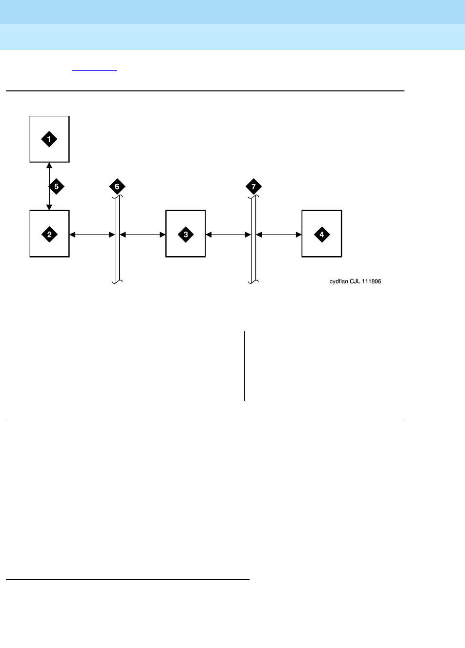
DEFINITY Enterprise Communications Server Release 6
Administration and Feature Description
555-230-522 Issue 4
May 1998
Basic Features
Page 4-251CallVisor Adjunct-Switch Application Interface
4
See Figure 4-3 for a simple ASAI configuration example.
Figure Notes
Figure 4-3. ASAI Switch Interface Link — LAN Transport
For detailed information on CallVisor ASAI, see:
■
DEFINITY
Enterprise Communications Server CallVisor ASAI Protocol
Reference
■
DEFINITY
Enterprise Communications Server CallVisor ASAI Technical
Reference
■
DEFINITY
Enterprise Communications Server Installation, Administration,
and Maintenance of CallVisor ASAI Over the DEFINITY LAN Gateway
How to administer ASAI
You must enable Packet Bus Activated on the Maintenance-Related System
Parameters form before administering other CallVisor ASAI forms.
Administer CallVisor ASAI on the DEFINITY ECS.
1. ASAI adjunct
2. TN556 or TN2198 ISDN-BRI line card
3. TN778 packet controller
4. Switch processing element(SPE)
5. ISDN-BRI
6. Packet bus
7. Memory bus

DEFINITY Enterprise Communications Server Release 6
Administration and Feature Description
555-230-522 Issue 4
May 1998
Basic Features
Page 4-252CallVisor Adjunct-Switch Application Interface
4
Required forms
Form Field Page
System Parameters
Customer-Options
■ASAI Interface
■ASAI Proprietary Adjunct Links
■Adjunct Call Control
■Adjunct Routing
■Domain Control
■Event Notification
■Request Feature
■Set Value
■Answering Machine Detection
■Selective Listening
■Switch Classified Outbound Calls
5-277
Hunt Group ■Controlling Adjunct
■ASAI Link Extension
5-158
Feature Related
System Parameters
■Call Classification After Answer
Supervision 5-123
Call Vector ■ASAI Routing 9-207
Class of Restriction ■Direct Agent Calling (optional) 5-72
Tr u n k Gro u p ■CPN/BN (Send Calling Number)
(optional)
■Receive Answer Supervision
■Answer Supervision Timeout
7-115
Continued on next page

DEFINITY Enterprise Communications Server Release 6
Administration and Feature Description
555-230-522 Issue 4
May 1998
Basic Features
Page 4-253CallVisor Adjunct-Switch Application Interface
4
■Station form — A CallVisor ASAI endpoint must be administered with
station type ASAI or ASAI Proprietary Adjunct link. Depending on the
system, you can assign a maximum of 4 to 8 CallVisor ASAI endpoints.
Station ■Extension
■Ty p e
■Port
■XID
■Fixed TEI
■TEI
■MIM Support
■CRV Length
■Event Minimization
6-4
SIT Treatment for Call
Classification
■All (optional) 9-212
System Parameters
Country-Options
■Tone name, frequency and level 5-277
Required forms for ASAI Link
Form Field Page
Station ■Extension
■Typ e (asai)
■XID
■Fixed TEI
■TEI
■MIM Support (no)
■CRV Length
■Event Minimization
6-4
Required forms — Continued
Form Field Page
Continued on next page

DEFINITY Enterprise Communications Server Release 6
Administration and Feature Description
555-230-522 Issue 4
May 1998
Basic Features
Page 4-254CallVisor Adjunct-Switch Application Interface
4
Detailed description
ASAI Capabilities
Table 4-71 shows which capabilities are available automatically when CallVisor
ASAI is enabled.
Table 4-71. Automatically Enabled CallVisor ASAI Capabilities
Capability
Call
Control
Group
Adjunct
Routing
Group
Domain
Control
Group
Event
Notif.
Group
Request
Feature
Group
Set
Val ue
Group
Event Reports X X X
— Agent Login1X2
— Agent Logout X2
— Alerting X X X
—Answered X X
— Busy/Unavailable X X X
— Call Ended Event
(FAC message) X
— Call Initiated X
— Call Offered to
Domain X
— Call Originated1X
— Call Redirected X X
— Call Conferenced X X X
— Connected X X X
— Cut-Through X X X
— Denial/Reorder X X X
— Disconnect/Drop X X X
—Hold X X X
— Queued X X X
— Reconnected X X X
— Call Transferred X X X
— Trunk Seized X X X
Continued on next page

DEFINITY Enterprise Communications Server Release 6
Administration and Feature Description
555-230-522 Issue 4
May 1998
Basic Features
Page 4-255CallVisor Adjunct-Switch Application Interface
4
Request Feature X
Notification Request X
Notification Cancel X
Notification Ended X
Route End X
Route Request X
Route Select X
Set Value X
Stop Call Notification X
Third Party Answer X
Third Party Auto Dial X
Third Party Call Ended X
Third Party Clear Call X
Third Party Domain
Control X
Third Party Domain
Control Ended X
Third Party Make Call X
Third Party Merge X X
Third Party Reconnect X X
Third Party Relinquish
Control XX
Third Party Selective
Hold XX
Third Party Selective
Drop XX
Third Party Redirect Call X X
Third Party Send DTMF
Signals XX
Table 4-71. Automatically Enabled CallVisor ASAI Capabilities — Continued
Capability
Call
Control
Group
Adjunct
Routing
Group
Domain
Control
Group
Event
Notif.
Group
Request
Feature
Group
Set
Val ue
Group
Continued on next page

DEFINITY Enterprise Communications Server Release 6
Administration and Feature Description
555-230-522 Issue 4
May 1998
Basic Features
Page 4-256CallVisor Adjunct-Switch Application Interface
4
Considerations
■If your system has an expansion cabinet (with or without duplication),
ASAI resources should reside on the system’s Processor Cabinet.
Interactions
Unless noted, you can use system features with ASAI.
■Abbreviated Dialing
An agent logged into an adjunct-controlled ACD split cannot use
Abbreviated Dialing buttons or feature access codes (FACs). Abbreviated
Dialing cannot be used through ASAI.
■Add/Remove Skills
You cannot add or remove skills through ASAI.
■Announcements
Split forced first or second announcements and vector announcements do
not generate event reports for the ASAI adjunct. However, nonsplit
announcements send event reports to the adjunct.
Extensions assigned to integrated announcements cannot be
domain-controlled.
1. Available with Link Version 2 and above.
2. Login and logout are provided only for domain control of ACD split; all other event reports are
provided for domain control of stations.
Third Party Take Control X
Third Party Selective
Disconnect X
Third Party Selective
Reconnect X
Table 4-71. Automatically Enabled CallVisor ASAI Capabilities — Continued
Capability
Call
Control
Group
Adjunct
Routing
Group
Domain
Control
Group
Event
Notif.
Group
Request
Feature
Group
Set
Val ue
Group
Continued on next page

DEFINITY Enterprise Communications Server Release 6
Administration and Feature Description
555-230-522 Issue 4
May 1998
Basic Features
Page 4-257CallVisor Adjunct-Switch Application Interface
4
■Answer Detection
CallVisor ASAI switch-classified calls, Answer Detection, and Answering
Machine Detection share the same set of call-classifier ports.
■Attendant and attendant groups
Individual attendants can be parties on adjunct-monitored calls and are
handled like voice-terminal users. Do not use attendant group 0 in
CallVisor ASAI call control requests. Event reports are not provided for the
attendant group.
Trunks seized for switch-classified calls cannot have Attendant Control
activated.
■Authorization Codes
These are not supported for switch-classified calls.
■Automatic Call Distribution (ACD)
ACD agents and terminals can be domain-controlled. Vector-controlled or
adjunct-controlled splits/skills cannot be monitored via Event Notification.
■Automatic Callback on Busy/Does Not Answer
You cannot activate Automatic Callback on Busy/Does Not Answer over
CallVisor ASAI. A callback call appears as an incoming call to the domain
controllers for a station.
■Automatic Route Selection (ARS) and Automatic Alternate Routing (AAR)
ASAI adjuncts can access ARS and AAR via Third Party Make Call,
Auto_dial and Route requests.
With ARS/AAR, the system does not inform the adjunct which trunk group
was selected for a given call.
■Bridging
Direct agent calls (DACs) to an agent do not alert bridged users of the
agent’s extension. Monitored or controlled calls delivered to terminals with
bridged call appearances send an Alerting Event Report for the principal
and for every alerted bridged call appearance. A Connected Event Report
is sent every time the principal or a bridged user connects to the call.
Unless the complete bridge is dropped from the call, no event reports are
provided when the principal or a bridged user disconnects from the call.
The switch provides a Drop Event Report when the complete bridge
disconnects.
Third-Party Make Calls delivered as non-ACD calls can alert bridging
users, with appropriate events sent for each bridging user and principal.
However, Third-Party Selective Hold, Third-Party Merge, Third-Party
Reconnect, and Third-Party Selective Drop are not permitted on parties in
the bridged state.

DEFINITY Enterprise Communications Server Release 6
Administration and Feature Description
555-230-522 Issue 4
May 1998
Basic Features
Page 4-258CallVisor Adjunct-Switch Application Interface
4
■Call Coverage
— Switch-classified calls to a destination on the system cannot go to
coverage and remain alerting on the principal destination, even if
coverage criteria are met. Switch-classified calls to the call
originator can go to coverage (for the split or the voice terminal) if
the coverage criteria are met.
— Direct agent calls placed through ASAI follow the agent’s, not the
split’s, coverage path, like manually-dialed DACs.
— Calls redirected via ASAI Redirect Call Service continue on the
coverage path if not answered.
■Call Forwarding
— Switch-classified calls to destinations with Call Forwarding remain
at the destination. Switch-classified calls to originators with Call
Forwarding are forwarded.
— You can activate Call Forwarding through ASAI for a physical
extension or an Expert Agent Selection (EAS) agent.
■Call Park
When a call parks at a terminal that uses transfer, the system generates a
Call Transferred Event Report. If the call parks using conference, the
system generates a Call Conferenced Event Report.
■Call Pickup
You must use Call Pickup via the ASAI.
■Call Prompting
— Up to 24 digits collected from the last collect-digit vector command
passes to the adjunct in the Call Offered to Domain Event Report
and Route capability.
— ASAI switch-classified calls and Call Prompting contend for the
same call-classifier ports.
— You can use a version of call prompting that does not require Call
Vectoring through ASAI.
■Call Vectoring
— An adjunct can directly monitor vector directory numbers (VDNs),
but not call vectors.
— While a converse step is being processed, you cannot use ASAI
Send DTMF.
■CDR
Calls that the adjunct originates via Third Party Auto Dial or Third Party
Make Call are marked with condition code B. Calls originated manually
from a domain-controlled station are not marked with condition code B.

DEFINITY Enterprise Communications Server Release 6
Administration and Feature Description
555-230-522 Issue 4
May 1998
Basic Features
Page 4-259CallVisor Adjunct-Switch Application Interface
4
■Class of Restriction
— Third Party Make Calls use the originator’s voice terminal or split
COR. The COR associated with the adjunct’s link is not used.
— For switch-classified calls, only the destination’s COR is checked.
— With adjunct routing, the COR of the associated VDN is checked for
calling-party restriction.
■Conference/Transfer
When an agent is logged into an adjunct-controlled split, the agent must
use his or her data terminal to conference and transfer calls because the
voice terminal is locked.
■Coverage
— Coverage timer. When Redirect Call redirects a call, the coverage
timer for the principal is restarted. Redirect Call can be used while
the coverage point is alerted.
— Don’t Answer Coverage timer. If an agent receiving a Direct Agent
Call has this timer assigned and the call is redirected, the timer is
cancelled.
— Caller Response Interval (CRI). If a call is redirected from the
principal via Redirect Call during the CRI, the CRI timer cancels.
— Redirection Tone. Redirection tone is not given with Redirect Call.
■Data Call Setup
Data calls may not be set up through ASAI, unless they originate from a
voice terminal.
■Directed Call Pickup
This feature cannot be activated through ASAI.
■Display Change Advice Information
This feature can be used through ASAI.
■Distributed Communication Systems (DCS)
Before using DCS with ASAI, it is recommended that you consult a Lucent
Technologies representative.
■Do Not Disturb
Direct agent and switch-classified calls placed by ASAI are delivered to
ACD agents even if this feature is activated.
■Drop Button Operation
You cannot use Drop Button through ASAI.

DEFINITY Enterprise Communications Server Release 6
Administration and Feature Description
555-230-522 Issue 4
May 1998
Basic Features
Page 4-260CallVisor Adjunct-Switch Application Interface
4
■Expansion Port Network (EPN)
The Expansion Interface (EI) board allows CallVisor ASAIs to terminate on
an EPN as well as the Primary Port Network (PPN).
■Forced Entry of Account Codes
You cannot make switch-classified calls to trunk groups with Forced Entry
of Account Codes. Agents logged into adjunct-controlled splits cannot
enter account codes from their voice terminals.
■Hold
Agents logged into an adjunct-controlled split can invoke Hold only via
ASAI.
■Hot Line
Do not use a Third-Party Make Call request for a voice terminal that has
Hot Line.
■Hunt Groups
Event-notification requests are not allowed for hunt groups (other than
ACD splits).
■Interflow
When a call monitored or controlled by an adjunct interflows to another
system, the system stops notifying the adjunct of events, except trunk
events (for example, Trunk Seized or Drop).
■ISDN
Third Party Auto Dial calls follow ISDN rules for the originator’s name and
number. The Call Initiated Event Report is not sent for
en-bloc
BRI sets.
■ISDN Facilities
— An incoming call over an ISDN facility can provide caller and
called-party information, as well as other call-related information
(UUI, CINFO, II-Digits) that is passed to the adjunct in event reports
and Route Request capabilities.
— An outgoing call over an ISDN facility provides call feedback
events from the network (Cut-through, User Busy, Alerting, and/or
Connected). A Trunk Seized Event Report is not sent for outgoing
calls using ISDN facilities. Cause values for some SIT responses
received will be interpreted.
— Switch-classified calls use a call classifier on ISDN facilities and
use both to classify the disposition of the outgoing call, whether or
not the call is interworked, unless Call Classification After Answer
system option is activated.
■Last Number Dialed
Do not invoke this feature through ASAI. Third-Party Make Call and Auto
Dial save the dialed number in system memory.

DEFINITY Enterprise Communications Server Release 6
Administration and Feature Description
555-230-522 Issue 4
May 1998
Basic Features
Page 4-261CallVisor Adjunct-Switch Application Interface
4
■Leave Word Calling
The Message Waiting Lamp can be turned on and off through ASAI.
■Lookahead Interflow
For the receiving PBX, Lookahead Interflow information element passed in
the ISDN message is included in all subsequent call-offered event report
and Route capabilities for the call if the information exists. This information
element includes ANI information and the originally-called VDN, but does
not include digits collected at the original system.
■MultiMedia Endpoints
These cannot be monitored or controlled through ASAI.
■Multiple Split Queuing
When a call is queued in multiple split or skill hunt groups, a queued event
is provided for each split/skill. When the call is removed from queue, the
Alerting Event Report provides the split/skill hunt-group extension of the
alerting agent.
■Music on Hold
These ports cannot be disconnected using listen_disconnect — callers
still hear Music on Hold. Do use ASAI Send DTMF signals on a call with
Music on Hold.
■Priority Calling
You can place Third-Party Make Call, Third-Party Auto Dial, and Route
Select calls as priority calls. Priority Call Coverage and alerting rules
apply.
■Privacy-Manual Exclusion
The system does not send event reports to the adjunct when a user
activates Privacy-Manual Exclusion and causes other bridged users to be
dropped from the call. You cannot use Third-Party Control capabilities (like
Third-Party Answer or Third-Party Reconnect) to bridge users that are not
allowed to bridge into an existing call as a result of Privacy-Manual
Exclusion.
■QSIG
QSIG capabilities cannot be activated through ASAI.
■R2-MFC Signaling
ANI that is available from an R2-MFC trunk is passed on to ASAI adjuncts.
■Redirection on No Answer
When Redirect Call redirects a call from an agent with RONA active, the
RONA timer is cancelled.

DEFINITY Enterprise Communications Server Release 6
Administration and Feature Description
555-230-522 Issue 4
May 1998
Basic Features
Page 4-262CallVisor Adjunct-Switch Application Interface
4
■Ringback Queuing
Calls originated via Third-Party Make Call or Third-Party Auto Dial to a
trunk supporting Ringback Queuing or routing cannot queue.
■Russian Signaling — Intrusion on Incoming Toll Calls
Do not use this feature with ASAI.
■Send All Calls
You can activate Send All Calls via ASAI Request.
■Service Observing
You cannot initiate Service Observing through ASAI.
■Single-Line Voice Terminals
Through ASAI, you can conference up to 6 parties from a single-line voice
terminal.
■Supervisor assistance
If an agent’s voice terminal is locked under adjunct control, ASAI must be
used to access supervisor assistance.
■Temporary bridged call appearances
These are not maintained after Redirect Call redirects a call.
■Terminating Extension Group (TEG)
A TEG is similar to bridging for purposes of CallVisor ASAI event reporting.
All TEG members can be individually domain-controlled.
■Timed ACW/Agent Pause Between Calls
You cannot activate this feature through ASAI.
■Timed reminder
If an attendant makes calls that are monitored and controlled by an
adjunct (including calls originated and routed with CallVisor ASAI), calls
that are not answered are redirected to the attendant when the timed
reminder interval expires.
■Tr u n k Gro u p s
CallVisor ASAI event reporting with Personal Central Office Line (PCOL) is
like bridging. Each PCOL member can be individually domain-controlled.
Each member receives events as applicable to the controlled terminal.
■Voice message retrieval
An adjunct can activate the message-waiting indicator using Set Value.
The voice terminal displays: “You have adjunct messages.”
■Voice Terminal Display
Twenty-seven-character names are made available to ASAI.
■Wait-Answer Supervision Timer (WAST)

DEFINITY Enterprise Communications Server Release 6
Administration and Feature Description
555-230-522 Issue 4
May 1998
Basic Features
Page 4-263CallVisor Adjunct-Switch Application Interface
4
If Redirect Call redirects an alerting call, the WAST is cancelled.
■World Class BRI
ASAI does not support these sets.

DEFINITY Enterprise Communications Server Release 6
Administration and Feature Description
555-230-522 Issue 4
May 1998
Basic Features
Page 4-264Class of Restriction
4
Class of Restriction
Class of Restriction (COR) defines many different classes of call origination and
termination privileges. Systems may have only a single COR, a COR with no
restrictions, or as many CORs as necessary to effect the desired restrictions.
Many different types of CORs can be assigned to many types of facility on the
switch. For example, you can use a calling-party COR to prevent callers from
accessing the public network.
How to administer COR
Detailed description
You must define a unique COR for each combination of Facility Restriction Levels
(FRL), called-party restrictions, calling-party restrictions, miscellaneous
restrictions, and CCSA/EPSCS off-network restrictions.
Required forms
Form Field Page
Class of Restriction ■All 5-72
Agent LoginID ■COR 9-193
Access Endpoint ■COR 7-72
Announcements/Audio Sources ■COR 5-26
Attendant Console ■COR 5-35
Authorization Code — COR Mapping ■COR 5-54
Console-Parameters ■COR 5-86
Hunt Groups ■COR 5-158
Loudspeaker Paging ■COR (1–9, All) 5-209
Data Modules ■COR 6-226
Remote Access ■COR (Barrier Code) 5-258
Station ■COR 6-28
Terminating Extension Group ■COR 5-295
Trunk Groups ■COR 7-115
Vector Directory Number ■COR 9-214

DEFINITY Enterprise Communications Server Release 6
Administration and Feature Description
555-230-522 Issue 4
May 1998
Basic Features
Page 4-265Class of Restriction
4
Called-party and calling-party restrictions
Called-party and calling-party restrictions are the basis for all CORs. When no
restrictions are needed, assign a single COR with called-party and calling-party
restrictions set to none. This type of COR can be used for unrestricted voice
terminals, trunk groups, terminating extension groups, Uniform Call Distribution
(UCD) groups, Direct Department Calling (DDC) groups, data modules,
attendant groups, and individual attendant extensions.
The called-party restriction is checked only at the called terminal, module,
attendant console, zone, or group, even if a call redirects from one voice terminal
to another. For example, if a called terminal (with no terminal restrictions) has Call
Forwarding active to a restricted terminal, the call still completes.
You can administer the following called-party and calling-party restrictions:
■All-Toll
■Inward
■Manual terminating line
■Origination
■Outward
■Public
■TA C - To l l
■Termination
Inward restrictions
You can use inward restrictions to permit users at specific voice terminals to
receive only internal calls. Inward restrictions prohibit users at assigned voice
terminals from receiving public-network, attendant-originated, and
attendant-extended calls.
The COR of the originally-called extension is the only one checked unless you
administer 3-way COR check on conference and transfer calls. Denied calls are
routed to intercept tone, a recorded announcement, or the attendant for Direct
Inward Dialing (DID) calls.
Manual terminating line restrictions
You can use manual terminating line restrictions to allow users at specific voice
terminals to receive calls only from an attendant or that were extended by an
attendant. Calls can redirect to a manual terminating line-restricted voice
terminal. The COR of the originally-called extension is the only one checked.
Local CO, foreign exchange (FX), and Wide Area Telecommunications Service
(WATS) calls are routed to the attendant. DID calls are routed to an
announcement or the attendant. Voice-terminal calls are routed to intercept
treatment.

DEFINITY Enterprise Communications Server Release 6
Administration and Feature Description
555-230-522 Issue 4
May 1998
Basic Features
Page 4-266Class of Restriction
4
Origination restrictions
You can use origination restrictions to prohibit specific voice-terminal users from
originating calls. These users can still receive calls.
Outward restrictions
You can use outward restrictions to prevent specific voice-terminal users from
placing calls to the public network. These users can still place calls to other
voice-terminal users, to the attendant, and over tie trunks. If necessary, an
attendant or an unrestricted voice-terminal user can extend a call to an outside
number for an outward-restricted voice-terminal user.
When outward restriction is applied to the Calling Party Restriction field
on the Class of Restriction form, calls coming into a trunk with that COR will be
denied if they make use of the AAR/ARS feature.
Public restrictions
Public restrictions prohibit specific voice-terminal users from receiving
public-network calls. Denied calls are routed to an intercept tone, a recorded
announcement, or the attendant. Public restrictions still allow users to receive
internal calls from other voice terminals or calls that were extended from the
attendant.
Termination restrictions
You can use termination restrictions to prohibit specific voice-terminal users from
receiving any calls. These users can still originate calls. DID or Advanced
Private-Line Termination calls route to a recorded announcement or the
attendant.
Fully restricted service restrictions
Fully restricted service restrictions prevent specific stations from accessing
public-network calls. Fully-restricted station users cannot use authorization
codes to deactivate this feature.
Calls from the public network to a fully-restricted station redirect to intercept
treatment or to the attendant. If the call redirects to the attendant, the attendant’s
display indicates the call was redirected because of fully restricted service
(FULL).
There are circumstances where a station with fully restricted service can access
or be accessed by the public network. See ‘‘Interactions’’ on page 4-274 for
specific details.

DEFINITY Enterprise Communications Server Release 6
Administration and Feature Description
555-230-522 Issue 4
May 1998
Basic Features
Page 4-267Class of Restriction
4
Miscellaneous terminal restrictions
You can use miscellaneous terminal restrictions to prohibit specific voice-terminal
users from accessing other specific terminals. Restricted calls are routed to
intercept tone.
Miscellaneous trunk restrictions
You can use miscellaneous trunk restrictions to prohibit specific voice-terminal
users from accessing specific trunk groups, such as WATS or CO trunk groups.
Any or all trunk groups can be in a miscellaneous-trunk-restriction group.
Restricted calls are routed to intercept tone.
Toll and TAC-Toll restrictions
Toll restrictions prevent specific voice-terminal users from placing public-network
calls to certain toll-call numbers. Toll restriction is
not
a COR; you assign Toll
restrictions to outgoing trunk groups on the Trunk Group form. You disable
TAC-toll restrictions for specific outgoing trunk groups on the Trunk Group form.
For toll restriction settings, see “Toll Restricted” on page 7-131.
Considerations
■Any number of CORs can have Fully Restricted Service set to y
.
Then, if a user attempts to call the public network, the call routes to
intercept treatment.
■Miscellaneous restrictions are checked on initial call termination and on
redirection.
■Miscellaneous restriction groups apply on a per-COR basis. However, you
can assign the same COR to more than one facility. Facilities with the
same COR may be like facilities (such as two voice terminals) or different
facilities (such as a voice terminal and a trunk group).
■When a call is directed to a VDN extension, the COR of the caller and the
VDN are compared to determine if the caller can access the associated
call vector.
■You can enhance system security by assigning a separate COR to
incoming and to outgoing trunk groups, then restricting calling between
the two groups.
■A COR can be overridden by Class of Service (COS).
Examples of Class of Restriction
The following examples illustrate some of the practical aspects of CORs.

DEFINITY Enterprise Communications Server Release 6
Administration and Feature Description
555-230-522 Issue 4
May 1998
Basic Features
Page 4-268Class of Restriction
4
Example using calling-party and called-party
restrictions and miscellaneous restrictions
To illustrate the use of calling-party and called-party restrictions and
miscellaneous restrictions, assume that your system installation provides the
following:
■Central-office trunks (outgoing)
■WATS
■FX trunks (outgoing)
■Voice terminals
■Data modules
■Terminating extension groups
■Loudspeaker Paging
Suppose you are given the following requirements:
■Only the attendant can access loudspeaker paging.
■Terminating Extension Groups can accept calls only from internal voice
terminals.
■There are six classes of voice terminals:
— Those that are toll restricted
— Those that cannot call outside to a public network (outward
restricted)
— Those that can receive calls only from an attendant
— Those that can call anywhere, any time
— Those that cannot place FX or WATS calls
— Those that cannot place WATS calls
Method 1
Assign a COR to each facility or group of facilities. For simplicity, give each a
unique COR:
■COR 40 — Local CO trunks
■COR 41 — WATS trunks
■COR 42 — FX trunks
■COR 43 — Attendant group
■COR 44 — Data modules
■COR 45 — Terminating extension groups
■COR 46 — Loudspeaker Paging access zones

DEFINITY Enterprise Communications Server Release 6
Administration and Feature Description
555-230-522 Issue 4
May 1998
Basic Features
Page 4-269Class of Restriction
4
■COR 47 — Unrestricted voice terminals
■COR 48 — Toll-restricted voice terminals
■COR 49 — Outward-restricted voice terminals
■COR 50 — Voice terminals that can receive calls only from an attendant
■COR 51 — Voice terminals that cannot place FX or WATS calls
■COR 52 — Voice terminals that cannot place WATS calls
Now determine which CORs cannot call which other CORs:
■COR 40 (local CO trunks) — No restrictions
■COR 41 (WATS) — No restrictions as described above
■COR 42 (FX) — No restrictions
■COR 43 (attendant group) — No restrictions
■COR 44 (data modules) — No restrictions were stated
■COR 45 (TEG) — This COR can receive internal voice-terminal-originated
calls only. Since no tie trunks are specified, use Inward Restriction to
provide the desired restriction. Set Called Party Restriction to
inward. If dial-repeating tie trunks are provided, Miscellaneous
Restrictions could be used to deny trunk access to the group.
■COR 46 (Loudspeaker Paging Access zones) — Since this COR can be
accessed only by an attendant, use Manual Terminating Line to provide
the restriction. Set Called Party Restriction to manual.
■COR 47 (unrestricted voice terminals) — No restrictions
■COR 48 (toll restricted voice terminals) — Set Calling Party
Restriction to tac-toll.
■COR 49 (outward restricted voice terminals) — Set Calling Party
Restriction to outward.
■COR 50 (voice terminals that can receive calls only from an attendant) —
Set Called Party Restriction to manual.
■COR 51 (voice terminals that cannot place WATS or FX calls) — None of
the Calling Party Restrictions uniquely prohibit WATS and FX calls, so
Miscellaneous Restrictions. Set COR 41 (WATS) and COR 42 (FX) in
CALLING PERMISSION to n. Set Calling Party Restriction to
none.
■COR 52 (voice terminals that cannot place WATS calls) — Set the COR 41
(WATS) in CALLING PERMISSION to n. Set Calling Party
Restriction to none.

DEFINITY Enterprise Communications Server Release 6
Administration and Feature Description
555-230-522 Issue 4
May 1998
Basic Features
Page 4-270Class of Restriction
4
Method 2
Alternatively, consider the restrictions to be assigned. This method is probably
more difficult to use, but it minimizes the number of CORs established. This
method requires 9 CORs to effect the same restrictions as 13 CORs with the
previous method.
Assign the following:
■COR 20 — Manual terminating line restriction
NOTE:
A new Manual Terminating-Line Restriction for voice terminals was
not established. COR 20 can be assigned.
■COR 21 — Inward restriction
■COR 22 — Toll restriction
■COR 23 — Outward restriction
■COR 24 — Unrestricted
■COR 25 — COR for WATS
■COR 26 — COR for FX
■COR 27 — Provides Miscellaneous Restrictions for WATS and FX. Set COR
25 and COR 26 for COR 27 to n.
■COR 28 — Provides Miscellaneous Restriction for WATS. Set COR 25 for
COR 28 to n.
Now assign the appropriate COR to each physical or screening facility:
■Central-office trunks — COR 24 (unrestricted)
■WATS — COR 25 (WATS COR)
■FX — COR 26 (FX COR)
■Attendant group — COR 24 (unrestricted)
■Voice terminals — COR 22 (toll), COR 23 (outward), COR 20 (manual),
COR 24 (unrestricted), COR 27 (WATS and FX miscellaneous), or COR 28
(WATS miscellaneous)
■Data modules — COR 24 (unrestricted)
■Terminating Extension Group — COR 21 (inward)
■Loudspeaker Paging trunks — COR 20 (manual)

DEFINITY Enterprise Communications Server Release 6
Administration and Feature Description
555-230-522 Issue 4
May 1998
Basic Features
Page 4-271Class of Restriction
4
Example using Automatic Alternate Routing r
Automatic Route Selection (AAR/ARS) FRL for
control of call routing
Assume that your system provides ARS and authorization codes. You are asked
to establish a group of users who must dial an authorization code to make
outside calls.
Complete the following forms:
1. Feature-Related System Parameter Features form
a. Set Authorization Codes Enabled to y.
b. Set Authorization Code Length to 7.
c. Set Authorization Code Cancellation Symbol to #.
d. Set Attendant Timeout Flag to n.
2. Station form
For unrestricted users, set COR to 1. For restricted users who must dial an
authorization code to make outside calls, set COR to 49.
3. Authorization Codes form
For restricted users, set replacement COR to 1. Set an authorization code
to their 7-digit phone number.
4. Class of Restriction form
Set originating FRLs for restricted and unrestricted users. For users with a
COR of 1, set originating FRL to 7. For users with a COR of 49, set
originating FRL to 0.
5. AAR/ARS Route Pattern form
For route pattern 1 and trunk group 40 (CO)set FRL to 1, NPA to 201, and
Prefix Mark to 1. Assign first-choice, second-choice, and third-choice
routes as follows:
For this example, trunk group 40 is a CO trunk, trunk group 2 is WATS, and
trunk group 32 is a tie trunk to a System 85.
When a caller dials the ARS access code to call out, the FRL of the originating
facility is compared with the FRL of the outgoing trunk group. If the FRL of the
originating facility is less than the FRL of the trunk group, the restricted user is
prompted (via recall dial tone) to enter an authorization code. After the
Trunk
Grp FRL NPA
Prefix
Mark
Toll
List
Deleted
Digits
Inserted
Digits
40 1 201 1
2 3 201 1
32 3 201 1 9

DEFINITY Enterprise Communications Server Release 6
Administration and Feature Description
555-230-522 Issue 4
May 1998
Basic Features
Page 4-272Class of Restriction
4
authorization code is entered, the call is routed to the CO for completion. If the
FRL is insufficient to seize any trunk group in the route pattern, the user hears
intercept tone.
Restricted callers are prompted for an authorization code. Unrestricted users
simply dial the ARS code followed by the desired number.
Examples using Miscellaneous Restrictions
Assume that your system installation provides the following:
■Central-office trunks
■WATS
■FX trunks
■Data modules
■Attendant service
■Voice terminals
■DID trunks
■Remote Access
In an unrestricted environment, each these could have the same COR. However,
suppose the following requirements exist:
■Attendants cannot make data calls.
■Remote Access can be used only for data calls.
■DID cannot be used for data calls except through Remote Access.
(A dedicated Remote Access trunk group is not required, although one or
more could be provided. This example assumes that all Remote Access is
via DID.)
■There are three classes of voice terminals:
— Those that can call anywhere, any time
— Those that can place local CO and in-house calls only
— Those that can place local CO, FX, and in-house calls only
Assign a COR to each facility or group of facilities. For simplicity, give each a
unique COR:
■COR 30 — Local CO trunks
■COR 31 — WATS trunks
■COR 32 — FX trunks
■COR 33 — Data modules
■COR 34 — Attendant group

DEFINITY Enterprise Communications Server Release 6
Administration and Feature Description
555-230-522 Issue 4
May 1998
Basic Features
Page 4-273Class of Restriction
4
■COR 35 — Unrestricted voice terminals
■COR 36 — Voice terminals that can place in-house and local CO calls only
(no FX or WATS calls)
■COR 37 — Voice terminals that can place in-house, local CO, and FX calls
only (no WATS calls)
■COR 38 — DID trunk group
■COR 39 — One of the remote-access barrier codes (can be up to 10)
Now determine which CORs cannot call which other CORs:
■COR 30 (local CO trunks) — No restrictions
■COR 31 (WATS) — CORs that cannot use WATS are specified as they are
encountered. WATS itself is an outgoing service without any calling
capabilities. Thus, Miscellaneous Restrictions are not specified on this
form. Set Calling Party Restriction to none (although this
restriction has no meaning for an outgoing facility). Similarly, the Called
Party Restriction applies to facilities capable of answering a call. Since
this is not the case with WATS, set Calling Party Restriction to
none.
■COR 32 (FX) — No restrictions for reasons cited above for WATS.
■COR 33 (data modules) — No restrictions for reasons cited above for
WATS.
■COR 34 (attendant group) — The attendant group cannot call COR 33
(data modules). Set the COR 33 in CALLING PERMISSION to n.
■COR 35 (unrestricted voice terminals) — No restrictions
■COR 36 (no FX or WATS calls) — This COR cannot call COR 32 (FX) or
COR 31 (WATS). For CORs 32 and 31, set CALLING PERMISSION to n.
■COR 37 (no WATS calls) — This COR cannot call COR 31 (WATS). For
COR 31, set CALLING PERMISSION to n.
■COR 38 (DID) — This COR cannot call COR 33 (data modules). For COR
33, set CALLING PERMISSION to n.
■COR 39 (Remote Access barrier code) — This COR can be used for data
calls only. Thus, this COR can call COR 33, but not CORs 30 (local CO),
31 (WATS), 32 (FX), 34 (attendant group), 35, 36, or 37 (voice terminals).
For CORs 30, 31, 32, 34, 35, 36, and 37, set CALLING PERMISSION to n.
(The CORs listed in the CALLING PERMISSION field can be viewed as
terminating or screening CORs that can or cannot be called by the
originating COR.) Since COR 38 [DID] is neither a terminating nor a
screening COR, you do not need to consider it when you assign the
barrier-code COR.

DEFINITY Enterprise Communications Server Release 6
Administration and Feature Description
555-230-522 Issue 4
May 1998
Basic Features
Page 4-274Class of Restriction
4
Interactions
■AAR/ARS
Originating FRLs are assigned via a COR. Termination and Miscellaneous
Restrictions do not apply to ARS/AAR calls.
■AAR/ARS Partitioning
Partition Group Numbers are assigned via a COR.
■Bridged Call Appearance
The COR assigned to a voice terminal’s primary extension also applies to
calls originated from a bridged call appearance of that extension on
another terminal.
■Call Coverage
Users who normally are restricted from calls can still receive calls directed
to them via Call Coverage. When a call goes to coverage, the called
party’s (not the covering party’s) restrictions are used.
■Call Forwarding All Calls
If a call is restricted between the forwarding and forwarded-to extensions,
Call Forwarding is denied. Restrictions are always checked when Call
Forwarding is activated, but not when a call is forwarded.
■Controlled Restriction
Restrictions assigned via Controlled Restriction override COR restriction.
■Emergency Access to Attendant
Emergency Access to Attendant calls are not restricted by COR.
■Forced Entry of Account Code
This feature is assigned via a COR.
■Loudspeaker Paging
The station number represents a loudspeaker paging zone. Each
Loudspeaker Paging Access zone and each Code Calling Access zone is
assigned a COR.
■Private Network Access
Access to the public network via a private network is allowed or denied via
a COR (assuming that the private network provides the capability to
access the public network).
Interactions for called-party and calling-party restrictions
■Controlled Restriction
Controlled Restrictions are checked when the system authorizes a call.

DEFINITY Enterprise Communications Server Release 6
Administration and Feature Description
555-230-522 Issue 4
May 1998
Basic Features
Page 4-275Class of Restriction
4
■Night Service
Night Station Service overrides Inward, Manual Terminating Line, and
Public Restrictions.
Night Station — Trunk Answer From Any Station overrides Inward, Manual
Terminating Line and Public Restrictions.
■Tie-Trunk Access
Incoming dial-repeating tie-trunk calls can be completed directly to an
inward-restricted or public-restricted extension but cannot be extended by
an attendant to an inward-restricted voice terminal.
■Transfer
Incoming trunk calls cannot be transferred to an inward-restricted
extension when a 3-way COR check is made.
Incoming trunk calls can be transferred from an unrestricted extension to
an inward-restricted or public-restricted extension if the 3-way COR check
on Conference is overridden.
Interactions for fully restricted service restrictions
■Centralized Attendant Service
Since COR information is not passed over Release Link Trunks (RLT), fully
restricted service allows all CAS calls. Therefore, CAS allows a public
network call to complete to a fully-restricted station.
■Distributed Communication System
Fully Restricted Service allows all DCS calls because COR information is
not transparent for DCS. DCS can allow a public network call to be
completed to a Fully Restricted station.
■Emergency Transfer
All authorization features are bypassed when an Emergency Transfer
station is connected to an Emergency Transfer trunk in the Emergency
Transfer Mode.
■Hunt Group
Stations with Fully Restricted Service should not be assigned to Hunt
Groups without Fully Restricted Service.
The COR assigned to the Hunt Group is checked on calls redirected by
the DDC or UCD of the hunt group. Extensions in the hunt group that have
Fully Restricted Service can receive calls from the public network (via the
hunt group) if the COR of the Hunt Group does not have Fully Restricted
Service.
■Personal Central Office Line
Stations with Fully Restricted Service should not be assigned PCOL.

DEFINITY Enterprise Communications Server Release 6
Administration and Feature Description
555-230-522 Issue 4
May 1998
Basic Features
Page 4-276Class of Restriction
4
■Remote Access
If a barrier code is entered during connection to remote access, the
code’s associated COR is used for authorization checks. If remote access
does not require a barrier code, then the default barrier code’s COR is
used. Remote Access can require an authorization code instead of or in
addition to the barrier code. If an authorization code is required, the
authorization code’s associated COR overrides the barrier code’s COR.
Fully restricted service should not be assigned to a station with the following
features or conditions:
■Abbreviated Dialing
■Bridged Call Appearance
■Attendant stations
■Night Service stations
■Stations that are Call Coverage or Send All Calls points
■Stations that are Call Forward destinations
■Stations that are Call Pickup points
Interactions for miscellaneous terminal and trunk restrictions
■AAR/ARS
AAR and ARS access to a trunk group override miscellaneous trunk
restrictions.
■Abbreviated Dialing Privileged Group Number List
A voice-terminal user with authorization to access an Abbreviated Dialing
Privileged Group Number List can place calls to any number on that list.
COR assignments are not checked.
■Privileged System Number List
A voice-terminal user with authorization to access a Privileged System
Number List can place calls to any number on that list. COR assignments
are not checked.

DEFINITY Enterprise Communications Server Release 6
Administration and Feature Description
555-230-522 Issue 4
May 1998
Basic Features
Page 4-277Class of Service
4
Class of Service
Class of Service (COS) determines whether or not voice-terminal users can
access the following features and functions.
■Features
— Automatic Callback
— Call Forwarding
— Data Privacy
— Priority Calling
— Restrict Call Forwarding Off-Net
— Call Forward Busy/Don’t Answer
— Personal Station Access
— Extended Forwarding All
— Extended Forwarding Busy/Don’t Answer
— Trunk-to-Trunk Transfer Restriction Override
■Functions
— Console permission
— Off-hook alert
— Client room

DEFINITY Enterprise Communications Server Release 6
Administration and Feature Description
555-230-522 Issue 4
May 1998
Basic Features
Page 4-278Class of Service
4
How to administer COS
Detailed description
Restriction groups and call origination/reception privileges are defined and
assigned by a COR, not a COS.
There are 16 possible COS. Administer each desired allowed/denied
combination of features and functions to a COS, and indicate that COS number
when administering voice terminals.
Console Permission
Console Permission allows multiappearance voice-terminal users to control the
same features that the attendant controls. Console permission is usually
provided to front-desk personnel in a hotel or motel. With console permission,
you can:
■Activate Automatic Wakeup for another extension
■Activate and deactivate controlled restrictions for another extension or
group of extensions
■Activate and deactivate Do Not Disturb for another extension or group of
extensions
■Activate Call Forwarding for another extension
■Add and remove agent skills
Off-Hook Alert
You can administer Off-Hook Alert only if Emergency Access to the Attendant is
provided. Off-Hook Alert allows you to administer yes or no to each of the 16
COS parameters.
Required forms
Form Field Page
Class of Service All 5-81
Attendant Console COS 5-35
Console-Parameters COS 5-86
Data Modules COS 6-226
Station COS 6-28
Remote Access COS (Barrier Code) 5-258
Packet Gateway Board COS 5-246

DEFINITY Enterprise Communications Server Release 6
Administration and Feature Description
555-230-522 Issue 4
May 1998
Basic Features
Page 4-279Class of Service
4
Client Room
You can administer Client Room only when Hospitality Services are provided and
you have a Property Management system interface. Client Room allows users to
access Check-In, Check-Out, Room Change/Swap, and Maid status. In addition,
Client Room is required at consoles or terminals that are to receive
message-waiting notification.
Interactions
■Hunt Groups
Because hunt groups have an implied COS of 1, be cautious when you
assign restrictions to COS 1.

DEFINITY Enterprise Communications Server Release 6
Administration and Feature Description
555-230-522 Issue 4
May 1998
Basic Features
Page 4-280Code Calling Access
4
Code Calling Access
Code Calling Access allows attendants, voice-terminal users, and tie-trunk users
to page with coded chime signals.
How to administer Code Calling Access
Detailed description
A paging party dials the Code Calling Access code and the extension of the
person to be paged. The paging party is automatically parked (through Call
Park) on the paged party’s extension. The system translates the number to a
chime code and then plays the code over loudspeakers. The paged party,
recognizing the chime code, can answer the call from any system voice terminal
by dialing the Call Park Answer Back access code and his or her own extension.
You can provide up to 9 individual paging zones, such as conference rooms and
warehouses. In addition, one zone can activate all zones simultaneously. Each
paging zone requires a separate Code Calling Access code.
Considerations
■With Code Calling Access, users do not have to be at their own voice
terminal to answer calls. Users who are frequently away from their voice
terminal or at a location where a ringing voice terminal might be disturbing
can be assigned a chime code. Users can answer parked calls from any
system voice terminal.
■You can provide as many as 125 3-digit chime codes. Only one extension
can be assigned to a chime code. You can administer chime codes to
play up to 3 times.
Required forms
Form Field Page
Loudspeaker Paging ■Code Calling Playing Cycles (1–3)
■Port
■Code Calling TACs
■Code Calling CORs
5-209
Code Calling IDs ■All 5-84

DEFINITY Enterprise Communications Server Release 6
Administration and Feature Description
555-230-522 Issue 4
May 1998
Basic Features
Page 4-281Code Calling Access
4
Interactions
■Abbreviated Dialing
If Abbreviated Dialing is used for Code Calling Access, do not use special
characters. Otherwise, the call is denied.
■Call Park
This feature is automatically provided with Code Calling Access.
■Conference — Attendant
A call cannot be conferenced while the attendant is accessing paging
equipment. The attendant can, however, release the call after paging the
called party.
■Conference — Te rm i n a l
A call cannot be conferenced while the attendant is accessing paging
equipment.
■Controlled Restriction
Controlled Restriction prohibits use of Code Calling Access.
■Loudspeaker Paging Access (PagePac Paging)
It is not possible to use a PagePac paging system for Code Calling
Access when multizone paging is desired. The PagePac paging systems
expect a 2-digit code to access a particular zone. The system, however,
immediately plays the chime code once a connection is established.
■Miscellaneous Trunk Restriction
Voice terminals and tie trunks with this restriction cannot use Code Calling
Access.
■Origination Restriction
This restriction prohibits use of Code Calling Access.
■Transfer
A call cannot be transferred while the attendant is accessing paging
equipment.

DEFINITY Enterprise Communications Server Release 6
Administration and Feature Description
555-230-522 Issue 4
May 1998
Basic Features
Page 4-282Conference — Attendant
4
Conference — Attendant
Conference — Attendant allows the attendant to set up a conference call for as
many as six conferees, including the attendant.
How to administer Conference — Attendant
Detailed description
To set up a conference, the attendant dials the number of a conferee and
presses the split key to add each party.
Considerations
■Use this feature whenever an attendant needs to talk with more than one
party at the same time, or to establish a conference call for parties outside
the system.
■The attendant can set up only one conference call at a time. The attendant
can hold a conference call on the console or release from it.
■The attendant cannot handle other calls while setting up a conference call.
■Only the attendant can add another party to the call, once the attendant is
one of the conferees, no matter who established the call.
Interactions
■Bridged Call Appearance
A user can press the Bridged Appearance button and join a conference
call if the call never had 6 parties.
■Call Vectoring
A VDN can be included as a party in a conference call only after vector
processing terminates for that call (for example, after a successful route-to
command).
Required forms
Form Field Page
Feature-Related
System-Parameters
■Public Network Trunks on Conference Call
■Conference Parties with Public Network
Trunks
■Conference Parties without Public Network
Trunks
5-123

DEFINITY Enterprise Communications Server Release 6
Administration and Feature Description
555-230-522 Issue 4
May 1998
Basic Features
Page 4-283Conference — Attendant
4
■Trunk-to-Trunk Transfer
If Trunk-to-Trunk Transfer is disabled and the attendant releases from a
conference call involving only trunk conferees, the trunks disconnect.
When a multifunction station (BRI/Digital/Hybrid) user dials enough digits
to route a call, but could route differently by dialing additional digits, the
station does not recognize the Conference or Transfer buttons. The user
delays dialing for 3-seconds or dials # to indicate the call route based on
the digits already dialed. The Conference or Transfer buttons are then
recognized and the switch completes the operation.
Attendant conferencing may not operate properly if the CO does not
provide answer supervision. In this case, the Answer Supervision
Timeout and Outgoing End of Dial fields are set to the same
nonzero number, and the Receive Answer Supervision field is set to
n.
If the CO
does
provide answer supervision, you can set Answer
Supervision Timeout to 0 and Receive Answer Supervision to y.

DEFINITY Enterprise Communications Server Release 6
Administration and Feature Description
555-230-522 Issue 4
May 1998
Basic Features
Page 4-284Conference — Terminal
4
Conference — Terminal
Conference — Terminal allows multiappearance voice-terminal users to make
6-party conference calls without attendant assistance. This feature also allows
single-line voice-terminal users to make 3-party conference calls without
attendant assistance.
How to administer Conference — Terminal
Considerations
■A single-line voice terminal can have up to 6 parties on a conference call,
if each conferee adds another conferee. For example, one user can add a
party, who then adds a third party, and so on.
■If you do not allow trunk-to-trunk connections and a voice terminal
releases from a conference call (where all of the other parties were
connected to the conference via trunks), then all parties are disconnected.
■If an analog single-line set has Call Wait active and creates a conference
call, Call Wait is rendered inactive as long as the single-line set in on the
call. For example, caller A on an analog set talks to caller B, flashes to talk
to caller C, and flashes to conference B and C. Then, if caller D calls caller
A, Call Wait is denied.
Interactions
■Bridged Call Appearance
A Bridged Appearance button can be used to make conference calls. A
Bridged Appearance can bridge onto a conference call only if there were
never 6 parties on the conference.
Required forms
Form Field Page
Feature-Related System
Parameters
■Public Network Trunks on
Conference Call
■Conference Parties With Public
Network Trunks
■Conference Parties Without Public
Network Trunks
■Conference Tone
5-123

DEFINITY Enterprise Communications Server Release 6
Administration and Feature Description
555-230-522 Issue 4
May 1998
Basic Features
Page 4-285Conference — Terminal
4
■Call Vectoring
A call to a VDN can be included as a party in a conference call only after
vector processing terminates for that call (for example, after a successful
route-to command).
■Class of Restriction
If Restriction Override is set to all, the COR of the party being
added is always checked against the COR of the party controlling the
add-on, but the new party’s COR is not checked against any other
conferee’s CORs.
■Trunk-to-Trunk Transfer
When a multifunction station (BRI/Digital/Hybrid) dials sufficient digits to
route a call, but could route differently if additional digits were dialed, the
station does not recognize the Conference or Transfer buttons. The user
must delay dialing for 3 seconds or dial # to indicate that the call can be
routed based on the digits already dialed. The Conference or Transfer
buttons are then recognized and the switch completes the call.

DEFINITY Enterprise Communications Server Release 6
Administration and Feature Description
555-230-522 Issue 4
May 1998
Basic Features
Page 4-286Consult
4
Consult
Consult allows a covering user, after answering a coverage call, to call the
principal (called party) for private consultation.
Activating Consult places the caller on hold and establishes a private connection
between the principal and the covering user. The covering user can then add the
caller to the conversation, transfer the call to the principal, or return to the caller.
How to administer Consult
Considerations
■Using Consult allows a covering user to confer with the principal, and
determine whether he or she wishes to speak with the called party.
Interactions
■Bridged Call Appearance
Bridged Call Appearances of the principal’s extension are not alerted on a
Consult call to the principal extension.
■Call Coverage
Consult is used only in conjunction with Call Coverage. See ‘‘Call
Coverage’’ on page 4-146 for details.
■Call Waiting Termination
A Consult call acts as a priority call and waits at a single-line voice
terminal, even if the terminal does not have Call Waiting Termination
assigned.
■Temporary Bridged Appearance
Consult calls use the Temporary Bridged Appearance maintained on the
call. At the end of a Consult call, the bridged appearance is no longer
maintained.
Required forms
Form Field Page
Station (multiappearance) ■Button/Feature Button Assignments
— consult 6-28

DEFINITY Enterprise Communications Server Release 6
Administration and Feature Description
555-230-522 Issue 4
May 1998
Basic Features
Page 4-287Coverage Callback
4
Coverage Callback
Coverage Callback allows a covering user to leave a message for the principal
(the called party) that a call has been received from a certain party.
How to administer Coverage Callback
Interactions
■Call Coverage
Coverage Callback is used only in conjunction with Call Coverage.
Required forms
Form Field Page
Station (multiappearance) ■Button/Feature Button Assignments
— cov-cback 6-28

DEFINITY Enterprise Communications Server Release 6
Administration and Feature Description
555-230-522 Issue 4
May 1998
Basic Features
Page 4-288Coverage Incoming Call Identification
4
Coverage Incoming Call Identification
Coverage Incoming Call Identification (ICI) allows a member of a Coverage
Answer Group to identify an incoming call to that group even though the member
does not have a display terminal.
When an incoming call is directed to a Coverage Answer Group, the Coverage
Answer Group status lamp button lights. A second coverage call takes control of
the Coverage ICI lamp. When the call is released it does not return control to the
previous call.
The user presses the Incoming Call Identification (in-call-id) button to identify the
hunt or coverage answer group associated with the current, incoming call.
How to administer Coverage ICI
Interactions
■Call Coverage
Coverage ICI is used only in conjunction with Call Coverage.
Required forms
Form Field Page
Station (multiappearance) ■Button Assignment
— in-call-id (Type:__ Grp:__) 6-28

DEFINITY Enterprise Communications Server Release 6
Administration and Feature Description
555-230-522 Issue 4
May 1998
Basic Features
Page 4-289Customer-Provided-Equipment Alarm
4
Customer-Provided-Equipment Alarm
The Customer-Provided-Equipment (CPE) Alarm is a customer-provided device,
such as a lamp or a bell, that indicates an alarm situation. This device lets you
know that a system alarm has occurred and that the system has attempted to
contact the appropriate service organization about the problem.
DEFINITY ECS activates the CPE Alarm when an event occurs that corresponds
to, or is more severe than, the administered alarm level. You can administer the
CPE Alarm for only one of the following levels.
■Major Alarm — A vital system hardware component has failed. An alarm of
this level may seriously affect overall service.
■Minor Alarm — A hardware component that may affect service on a limited
scale has failed.
■Warning Alarm — A problem may exist with a hardware component, but
the problem does not affect service.
DEFINITY ECS automatically deactivates the CPE Alarm when the problem that
caused the alarm is resolved. If there are multiple problems, the CPE Alarm
remains active until all problems at or above the administered alarm-activation
level are resolved.
For more information, see
DEFINITY Enterprise Communications Server
Installation for Single-Carrier Cabinets
or
DEFINITY Enterprise Communications
Server Installation for Multiple-Carrier Cabinets
manuals.
How to administer CPE Alarm
Interactions
■Power Failure Transfer
The CPE Alarm is always activated during a Power Failure Transfer
regardless of the administered alarm-activation level. This is true even if
the alarm is not administered at any level.
Required forms
Form Field Page
Maintenance-Related System
Parameters
■CPE Alarm Activation Level 5-212

DEFINITY Enterprise Communications Server Release 6
Administration and Feature Description
555-230-522 Issue 4
May 1998
Basic Features
Page 4-290Data Call Setup
4
4
Data Call Setup
Data Call Setup provides multiple methods to set up a data call:
■Data-terminal (keyboard) dialing
■Voice-terminal dialing
■Hayes AT command dialing
■Permanent-switched connections
■Administered connections
■Automatic-calling unit interface (MPD and HSC)
■Hotline dialing
How to administer Data Call Setup
Assign ADU-type hunt groups that connect to terminal servers on a host
computer as no keyboard dialing.
Use voice-terminal dialing to connect the data terminal to an analog modem or
when a data terminal is not accessible for dialing.
Required forms for data-terminal dialing
Form Field Page
Data Module
— PDM/TDM
— Data Line
— 7500
■All
■All
■All
6-243
6-234
6-252
Modem Pool Group ■Circuit Pack Assignments 5-223
Required forms for voice-terminal dialing
Form Field Page
Feature Access Codes Data Origination Access Code 5-113
Station
(multi-appearance)
Feature Button Assignments
— data-ext (Ext:)
6-28
Data Module
— PDM/TDM
— Data Line Data
Module
■All
■All
6-243
6-234
Modem Pool Group ■Circuit Pack Assignments 5-223

DEFINITY Enterprise Communications Server Release 6
Administration and Feature Description
555-230-522 Issue 4
May 1998
Basic Features
Page 4-291Data Call Setup
4
Depending on the hardware used, assign ports to the following:
■Data modules
■BCTs/510Ds
■7400D-series or CALLMASTER digital voice terminals
■7500D-series voice terminals with ADM
■Analog modems (port is assigned using 2500 voice-terminal form)
Detailed description
In addition to data-terminal and voice-terminal dialing, the system accepts calls
from other devices, such as a modular-processor data modules (MPDM)
equipped with an automatic-calling unit (ACU) interface module. Use this device
to dial from a host computer.
Data Call Setup for DCP and ISDN-BRI modules
In addition to the numeral, #, and * characters found on a touch-tone pad, the
following special characters can be dialed.
Each line of dialing information can contain up to 42 characters (the + and %
characters count as two each).
Examples of dialing are:
■DIAL: 3478
■DIAL: 9+(201) 555-1212
Special characters
Character Use
SPACE, -, (, and) improves legibility. The switch ignores these
characters during dialing.
+ character (wait) interrupts or suspends dialing until the user
receives dial tone
, (pause) inserts a 1.5-second pause
% (mark) indicates digits for end-to-end signaling
(touch-tone). This is required when the trunk is
rotary. It is not required when the trunk is
touch-tone.
UNDERLINE or BACKSPACE corrects previously typed characters on the same
line
@ deletes the entire line and starts over with a new
DIAL: prompt

DEFINITY Enterprise Communications Server Release 6
Administration and Feature Description
555-230-522 Issue 4
May 1998
Basic Features
Page 4-292Data Call Setup
4
■DIAL: 8, 555-2368
■DIAL: 9+555-2368+%9999+123 (remote access)
Alphanumeric dialing allows a data-terminal user to make a data call by entering
an alphanumeric name.
Basic-digit dialing is provided through an ADM or 7500B data module. The user
can enter digits from 0 to 9, *, and # from a 7500 series voice-terminal keypad or
an EIA-terminal interface.
Call Forwarding All Calls allows incoming data calls to redirect to a
user-designated extension. The attendant or a forwarding party activates the
feature by dialing a FAC.
Default Dialing allows a data-terminal user to call a preadministered destination
by pressing Enter. The user can call other destinations by entering the complete
address.
Data Hotline is a security feature. The switch terminates calls to a
preadministered hotline. The system discards any address string and routes the
call as if the hotline-destination address were entered. This feature does not
affect incoming calls. This feature is mutually exclusive with Default Dialing.
An AC is an end-to-end connection between two endpoints that is automatically
established whenever the system restarts or when you administer the connection
to be active.
After you administer the ADM as one endpoint of a connection, the switch
establishes the connection at the scheduled time and maintains it for the
specified length of time. After the call is accepted, the data set enters into
continuous mode for the specified length of time. If the switch reboots during the
connection, the connection reinitiates. If the connection drops, the switch
reinitiates the connection.
The system handles all presently defined BRI bearer data-call requests. Some
capabilities that are not supported by Lucent terminals are provided by
non-Lucent terminals. If the switch does not support a capability, a proper cause
value returns to the terminal.
BRI terminals receive a cause or reason code that identifies why a call is being
cleared. The BRI data module converts certain cause values to text messages
for display. In a passive-bus multipoint configuration, the system supports two
BRI endpoints per port, thus doubling the capacity of the BRI circuit pack. When
you change the configuration of a BRI from point-to-point to multipoint, the
original endpoint does not need to reinitialize. Only endpoints that support SPID
initialization can be administered in a multipoint configuration.
The following call-progress messages and their meanings are provided for DCP
and ISDN-BRI modules.

DEFINITY Enterprise Communications Server Release 6
Administration and Feature Description
555-230-522 Issue 4
May 1998
Basic Features
Page 4-293Data Call Setup
4
Call-progress messages
Message Application Meaning
DIAL: DCP Equivalent to dial tone. Enter the desired
number or FAC followed by Enter.
CMD BRI Equivalent to dial tone. Enter the desired
number or FAC followed by Enter.
RINGING DCP, BRI Equivalent to ringing tone. Called
terminal is ringing.
BUSY DCP, BRI Equivalent to busy tone. Called number is
busy or out of service.
ANSWERED DCP, BRI Call is answered .
ANSWERED -
NOT DATA DCP Call is answered and a modem answer
tone is not detected.
TRY AGAIN DCP, BRI Equivalent to reorder tone. System
facilities are currently not available.
DENIED DCP, BRI Equivalent to intercept tone. Call cannot
be placed as dialed.
ABANDONED DCP, BRI Calling user has abandoned the call.
NO TONE DCP, BRI Tone is not detected.
CHECK
OPTIONS DCP, BRI Data-module options are incompatible.
XX IN QUEUE DCP, BRI Current position in queue.
PROCESSING DCP, BRI Out of queue. Facility is available.
TIMEOUT DCP, BRI Time is exceeded. Call terminates.
FORWARDED DCP, BRI Equivalent to redirection-notification
signal. Called terminal activates Call
Forwarding and receives a call, and call
is forwarded.
INCOMING CALL DCP, BRI Equivalent to ringing.
INVALID
ADDRESS DCP Entered name is not in
alphanumeric-dialing table.
WRONG
ADDRESS BRI Entered name is not in
alphanumeric-dialing table.
Continued on next page

DEFINITY Enterprise Communications Server Release 6
Administration and Feature Description
555-230-522 Issue 4
May 1998
Basic Features
Page 4-294Data Call Setup
4
Data Call Setup for DCP modules
Data-terminal dialing
DCP data-terminal dialing allows a user to set up and disconnect data calls
directly from a data terminal as follows.
1. At the DIAL: prompt, the user types the data number. The message
RINGING displays.
2. If the call is queued, the message WAIT, XX IN QUEUE displays. The
queue position XX updates as the call moves up in queue.
3. To originate and disconnect a call, the user presses BREAK. If the terminal
does not generate a 2-second continuous break signal, the user can press
originate/disconnect on the data module.
4. The user can enter digits at the DIAL: prompt.
Voice-terminal dialing
DCP voice-terminal dialing allows voice-terminal users to originate and control
data calls from a voice terminal. Use DCP voice-terminal dialing when a data
terminal is not available.
Users can set up a call using any unrestricted voice terminal and then transfer
the call to a data endpoint.
PLEASE ANS- DCP, BRI Originating voice-terminal user
transferred call to data module using
One-Button Transfer to Data.
TRANSFER DCP Data Call Return-to-Voice is occurring.
CONFIRMED DCP, BRI Equivalent to confirmation tone. Feature
request is accepted, or call has gone to a
local coverage point.
OTHER END DCP, BRI Endpoint has terminated call.
DISCONNECTED DCP, BRI Call is disconnected.
WAIT DCP, BRI Normal processing continues.
WAIT, XX IN
QUEUE DCP Call is in a local hunt-group queue.
Call-progress messages — Continued
Message Application Meaning
Continued on next page

DEFINITY Enterprise Communications Server Release 6
Administration and Feature Description
555-230-522 Issue 4
May 1998
Basic Features
Page 4-295Data Call Setup
4
The primary way to make data calls is with multiappearance voice-terminal
data-extension buttons. Assign any administrable feature button as a
data-extension button. The data-extension button provides one-touch access to
a data module.
The following options, either alone or combined, permit flexibility in making data
calls from a voice terminal.
■One-Button Transfer to Data
A user can transfer a call to the associated data module by pressing the
data-extension button after the endpoint answers.
■Return-to-Voice
A user can change the connection from data to voice. The user presses
the data-extension button associated with the busy data module. If the
user hangs up, the call disconnects. Return of a data call to the voice
terminal implies that the same data call is continued in the voice mode, or
transferred to another data endpoint.
■Data Call Preindication
A user, before dialing a data endpoint, can reserve the associated data
module by pressing the data-extension button. This ensures that a
conversion resource, if needed, and the data module are reserved for the
call. Use of Data Call Preindication before 1-button transfer to data is
recommended for data calls that use toll-network facilities. Data Call
Preindication is in effect until the associated data-extension button is
pressed again for a 1-button transfer; there is no time-out.
Data Call Setup for ISDN-BRI modules
Data-terminal dialing
A user can set up and disconnect data calls directly from a data terminal without
using a voice terminal as follows:
1. The user presses Enter a few times. If the CMD: prompt does not appear,
the user presses Break A + T at the same time, and then presses Enter.
2. At the CMD: prompt, the user types and presses Enter.
3. To disconnect, the user enters +++. At the CMD: prompt, the user types
end and presses Enter.
Voice-terminal dialing
ISDN-BRI voice-terminal dialing allows ISDN-BRI voice-terminal users to
originate a data call. The user presses the data button on the terminal, enters the
number on the dial pad, and then presses the data button again.

DEFINITY Enterprise Communications Server Release 6
Administration and Feature Description
555-230-522 Issue 4
May 1998
Basic Features
Page 4-296Data Call Setup
4
The following data functions are not available on ISDN-BRI voice terminals:
■One-Button Transfer to Data
■Return-to-Voice
■Data Call Preindication
■Voice-Call Transfer to Data and Data-Call Transfer to Voice
Considerations
■BRI has a voice-to-data restriction. A voice terminal cannot call a data
terminal, and a data terminal cannot call a voice terminal.
■BRI voice terminals cannot have data-extension buttons. DCP sets have
these buttons, but cannot have data-extension buttons for BRI.
■When a voice-terminal user places a data call with a modem, the user
dials the data-origination access code assigned in the system before
dialing the endpoint.
■The number of assigned data-extension buttons per voice terminal is not
limited. Assign voice-terminal buttons that access the data module.
■Voice-terminal dialing is not available in ISDN-BRI applications because
ISDN-BRI terminals do not support voice-call transfer to data or data-call
transfer to voice.
Interactions
■Abbreviated Dialing
Only 22 of the 24 (maximum) digits in an abbreviated-dialing number are
available for keyboard dialing. The remaining two digits must contain the
wait indicator for tone detection.
■Call Coverage
A hunt group made up of data endpoints cannot be assigned a coverage
path.
■Call Detail Recording
CDR records the use of modem pools on trunk calls.
■Call Forwarding All Calls
Calls received by a data module can be forwarded. Activate Call
Forwarding All Calls with data-terminal (keyboard) dialing. If the
forwarded-to endpoint is an analog endpoint and the caller is a digital
endpoint, modem pooling is activated automatically.
■Internal Automatic Answer
Data calls are not eligible for IAA.

DEFINITY Enterprise Communications Server Release 6
Administration and Feature Description
555-230-522 Issue 4
May 1998
Basic Features
Page 4-297Data Call Setup
4
■Modem Pooling
Modem Pooling is available on data calls. The system automatically
inserts a modem if one is needed. Data Call Preindication or Data
Origination can be used to indicate the need for a modem.
■UCD
UCD can provide a group of data modules or analog modems for
answering calls to connected facilities (for example, computer ports).
■World-Class Tone Detection
Multiple-line data-terminal dialing is supported if the administered level of
tone detection is precise. You can administer tone-detection options. The
message that Data Call Setup sends to users varies according to the
option.
If the option is not set to precise, and a data call is set up over an analog
trunk, messages describing the status of the called endpoint (for example,
RINGING, BUSY, TRY AGAIN) change according to which tone-detection
option is selected.

DEFINITY Enterprise Communications Server Release 6
Administration and Feature Description
555-230-522 Issue 4
May 1998
Basic Features
Page 4-298Data Hotline
4
Data Hotline
Data Hotline provides for automatic-nondial placement of a data call
preassigned to an endpoint when the originating switch goes off-hook. Use for
security purposes.
How to administer Data Hotline
Required forms
Form Field Page
Abbreviated Dialing
— Enhanced List
— Group List
— System List
— Personal
— 7103A
■All
■All
■All
■All
■All
5-2
5-5
5-11
5-8
5-14
Station ■Abbreviated Dialing List
■Special Dialing Option
— hot-line
— default
— blank
■Hotline Destination AD dial code
6-28
Data Modules ■AD List1 (on all data forms) 6-28
Data Line ■Special Dialing Option
— hot-line
— default
— blank
■AD Dial Code
6-230
Processor
Interface
■Special Dialing Option
— hot-line
— default
— blank
■AD Dial Code
6-246
Continued on next page

DEFINITY Enterprise Communications Server Release 6
Administration and Feature Description
555-230-522 Issue 4
May 1998
Basic Features
Page 4-299Data Hotline
4
Detailed description
The system automatically places Data Hotline calls to preassigned extensions or
off-premises numbers. Calling terminals are connected to the system by a data
module. Users should store the destination number in the abbreviated dialing list
for future reference.
Considerations
■Data Hotline offers fast and accurate call placement to data endpoints.
Users who frequently call the same endpoint can automatically place the
call by going off-hook.
PDM, TDM ■Special Dialing Option
— hot-line
— default
— blank
■AD dial code
6-243
Netcon Data
Module
■Special Dialing Option
— hot-line
— default
— blank
■AD dial code
6-245
X.25 ■Special Dialing Option
— hot-line
— default
— blank
■AD dial code
6-249
7500 ■Special Dialing Option
— hot-line
— default
— blank
■AD dial code
6-252
Required forms — Continued
Form Field Page
Continued on next page

DEFINITY Enterprise Communications Server Release 6
Administration and Feature Description
555-230-522 Issue 4
May 1998
Basic Features
Page 4-300Data Hotline
4
Interactions
■Call Forwarding — All Calls
A Data Hotline caller cannot activate both Call Forwarding and Data
Hotline. Dialing the Call Forwarding feature access code (FAC) causes
activation of the Data Hotline instead.
■Data Terminal (Keyboard) Dialing
Normal terminal-dialing text displays for Data Hotline calls except the
initial-dial prompt normally given on off-hook for origination.

DEFINITY Enterprise Communications Server Release 6
Administration and Feature Description
555-230-522 Issue 4
May 1998
Basic Features
Page 4-301Data Privacy
4
Data Privacy
Data Privacy protects analog data calls from being disturbed by any of the
system’s overriding or ringing features.
How to administer Data Privacy
Detailed description
To activate this feature, the user dials the activation code at the beginning of the
call.
Considerations
■Connections involving one or more digital data endpoints (data module)
are protected from receiving system-generated tones.
■Data Privacy applies to both voice and data calls. You can activate Data
Privacy on Remote Access calls, but not on other incoming trunk calls.
Data Privacy is canceled if a user transfers a call, is added to a
conference call, is bridged onto a call, or disconnects from a call. You can
activate Data Privacy on calls originated from attendant consoles.
Interactions
■Attendant Call Waiting and Call Waiting Termination
If Data Privacy is active, Call Waiting is denied.
■Bridged Call Appearance — Single-Line Voice Terminal
If you activate Data Privacy or assign Data Restriction to a station involved
in a bridged call and the primary terminal or bridging user attempts to
bridge onto the call, this action overrides Data Privacy and Data
Restriction.
■Busy Verification
Busy Verification cannot be active when Data Privacy is active.
Required forms
Form Field Page
Feature Access Code (FAC) ■Data Privacy Access Code 5-113
Class of Service ■Data Privacy (0–15) 5-81
Station ■COS (0–15) 6-28

DEFINITY Enterprise Communications Server Release 6
Administration and Feature Description
555-230-522 Issue 4
May 1998
Basic Features
Page 4-302Data Privacy
4
■Intercom — Automatic and Dial
An extension with Data Privacy or Data Restriction active cannot originate
an intercom call. The user receives an intercept tone.
■Music-on-Hold Access
If a user places a call with Data Privacy on hold, The user must withhold
Music-on-Hold to prevent the transmission of tones that a connected data
service might falsely interpret as a data transmission.
■Priority Calls
If a user activates Data Privacy, Priority Calls are denied on analog voice
terminals. However, Priority Calls appear on the next available line
appearance on multiappearance voice terminals.

DEFINITY Enterprise Communications Server Release 6
Administration and Feature Description
555-230-522 Issue 4
May 1998
Basic Features
Page 4-303Data Restriction
4
Data Restriction
Data Restriction protects analog-data calls from being disturbed by any of the
system’s overriding or ringing features.
How to administer Data Restriction
Detailed description
When you administer Data Restriction to an extension or trunk group, the system
cannot gain access to, or superimpose tones onto, the protected call.
Once you administer Data Restriction for an analog or multiappearance voice
terminal or trunk group, the feature is active on all calls to or from the terminal or
trunk group.
Considerations
■Connections involving one or more digital-data endpoints (data modules)
are already protected from receiving system-generated tones. Data
Restriction is not needed for these connections.
Required forms
Form Field Page
Station ■Data Restriction
— prevent tones = y 6-28
Trunk Groups
— Access
—APLT
—CO
—CPE
—DID
—FX
— ISDN-PRI
—RLT
— Tandem
—Tie
—WATS
■Data Restriction (all)
— prevent tones = y
7-150
7-156
7-168
7-174
7-178
7-193
7-219
7-252
7-257
7-262
7-268

DEFINITY Enterprise Communications Server Release 6
Administration and Feature Description
555-230-522 Issue 4
May 1998
Basic Features
Page 4-304Data Restriction
4
■Data Restriction applies to both voice and data calls.
■Do not assign Data Restriction to attendant consoles.
Interactions
■Attendant Call Waiting and Call Waiting Termination
If Data Restriction is active, Call Waiting is denied.
■Busy Verification
Busy Verification cannot be active when Data Restriction is active.
■Call Vectoring
Music plays on calls from data-restricted extensions when the calls
receive music as the result of a wait-time vector step.
■Intercom — Automatic and Dial
An extension with Data Privacy or Data Restriction activated cannot
originate an intercom call. The user receives an Intercept tone.
■Music-on-Hold Access
If a user places a call with Data Restriction on hold, The user must
withhold Music-on-Hold to prevent the transmission of tones that a
connected data service might falsely interpret as a data transmission.
■Priority Calls
Priority Calls are allowed if the analog station is idle. Call Waiting
(including Priority Call Waiting) is denied if the station is busy. However,
Priority Calls appear on the next available line appearance on
multiappearance voice terminals.
■Service Observing
A data-restricted call cannot be service observed.

DEFINITY Enterprise Communications Server Release 6
Administration and Feature Description
555-230-522 Issue 4
May 1998
Basic Features
Page 4-305Data-Only Off-Premises Extensions
4
Data-Only Off-Premises Extensions
Data-Only Off-Premises Extensions allows users to establish data calls involving
data communications equipment (DCE) or digital terminal equipment (DTE)
located remotely from the system site using DATAPHONE digital service or other
private-line data facilities.
How to administer Data-Only Off-Premises
Extensions
Detailed description
A Data-Only Off-Premises Extension uses an on-premises modular trunk data
module (MTDM). The system communicates with remote data equipment through
the private-line facility linking the on-premises MTDM and the remote data
equipment.
The TDM and DCE or DTE constitute a digital-data endpoint. Place data calls to
this type of data endpoint using Voice Terminal Dialing or Data Terminal
(Keyboard) Dialing. Since there is no voice terminal at the remote site, originate
data calls from the remote data terminal using Keyboard Dialing only. If you use
computer-generated dialing, you must follow Keyboard Dialing protocol.
Considerations
■Data-Only Off-Premises Extensions provides digital-data endpoints
located off-premises through a TDM located on-premises.
Communications to or from TDM (and off-premises equipment) must be
through an on-premises Processor Data Module or Digital Terminal Data
Module. The system does not support communications between two
TDMs. Modem Pooling is similar to a TDM, it cannot be used on calls to or
from a Data-Only Off-Premises Extension.
Required forms
Form Field Page
Data Module
Processor/Trunk
■All 6-243

DEFINITY Enterprise Communications Server Release 6
Administration and Feature Description
555-230-522 Issue 4
May 1998
Basic Features
Page 4-306Data-Only Off-Premises Extensions
4
Interactions
■Voice Terminal Dialing
An on-premises multiappearance voice terminal may have a Data
Extension button associated with the TDM used for a Data-Only
Off-Premises Extension. The voice-terminal user and the remote user
share control of the data module. Actions of the user at the voice terminal
may affect the remote user.
— 1-Button Transfer to Data
The voice-terminal user can transfer a call to the Data-Only
Off-Premises Extension. The Data Extension button lamp on the
voice terminal lights and the Call in Progress lamp on the data
module lights during a data call.
— Data Call Preindication
The multiappearance voice-terminal user presses the idle
associated Data Extension button to reserve a data module. The
data module is busy to all other users. When the user reserves a
data module, the lamp associated with the Data Extension button
winks and lights at any other associated voice terminals. A remote
user receives the BUSY message when attempting to originate a
call.
— Return-to-Voice
To establish a data call, the voice-terminal user presses the
associated busy Data Extension button to transfer the call to the
voice terminal. The data module associated with the Data Extension
button is disconnected from the call. The Call in Progress lamp on
the data module goes dark.

DEFINITY Enterprise Communications Server Release 6
Administration and Feature Description
555-230-522 Issue 4
May 1998
Basic Features
Page 4-307Default Dialing
4
Default Dialing
Default Dialing provides data-terminal users who dial a specific number the
majority of the time a very simple method of dialing that number. Normal data
terminal dialing and alphanumeric dialing are unaffected.
How to Administer Default Dialing
Detailed description
Default Dialing enhances data terminal (keyboard) dialing by allowing a
data-terminal user to place a data call to a preadministered destination by either
pressing a Return at the DIAL: prompt (for data terminals using DCP data
modules) or typing d and pressing Return at the CMD: prompt (for data terminals
using ISDN-BRI data modules). The data-terminal user with a DCP data module
can place calls to other destinations by entering the complete address after the
DIAL: prompt (normal data terminal dialing or alphanumeric dialing). The
data-terminal user with an ISDN-BRI data module can place calls to other
destinations by typing d, a space, the complete address, and Return after the
CMD: prompt.
NOTE:
DU-type hunt groups connecting the system to a terminal server on a host
computer have hunt-group extensions set to no keyboard dialing.
For the AT command interface supported by the 7400A/7400B/8400B data
module, to dial the default destination, enter the ATD command (rather than
press return).
Required forms
Form Field Page
Abbreviated Dialing
— Enhanced
— Group
—System
— Personal
— 7103A
■All
■All
■All
■All
■All
5-2
5-5
5-11
5-8
5-14
Data Modules (all forms) ■Special Dialing Option
■Abbreviated Dialing List
■AD Dial Code
6-226

DEFINITY Enterprise Communications Server Release 6
Administration and Feature Description
555-230-522 Issue 4
May 1998
Basic Features
Page 4-308Default Dialing
4
Interactions
■Data Call Setup
Default Dialing enhances data terminal (keyboard) dialing by allowing
data-terminal users to place data calls to a preadministered destination.
Users either press Return at the DIAL: prompt (for DCP) or type d and press
Return at the CMD: prompt (for ISDN-BRI).

DEFINITY Enterprise Communications Server Release 6
Administration and Feature Description
555-230-522 Issue 4
May 1998
Basic Features
Page 4-309Demand Print
4
Demand Print
Demand Print allows voice-terminal users to print their own undelivered
messages without calling the message center.
How to administer Demand Print
Interactions
None
Required forms
Form Field Page
Station (multiappearance) ■Button/Feature Button Assignments
— print-msgs
■Security Code
6-14
Feature Access Code (FAC) ■Print Messages Access Codes 5-113

DEFINITY Enterprise Communications Server Release 6
Administration and Feature Description
555-230-522 Issue 4
May 1998
Basic Features
Page 4-310Dial Access to Attendant
4
Dial Access to Attendant
Dial Access to Attendant allows voice-terminal users to reach an attendant by
dialing an attendant-access code. Attendants can then extend the call to a trunk
or to another voice terminal.
How to administer Dial Access to Attendant
Detailed description
The attendant-access code length is administrable and may be any 1 or 2 digit
number; the default is 0. To assign a digit other than 0, enter attd in the
appropriate row of the First Digit Table, in the Length=1 column. To assign a
2-digit code, enter misc in the appropriate row of the First Digit Table on the Dial
Plan form. Then complete the Second Digit form for this number. See ‘‘Dial Plan’’
on page 4-311 for more information.
Interactions
■Class of Restriction
If a voice terminal’s COR restricts the user from originating calls, this
prohibits the placement of any calls, including Dial Access to Attendant.
■Conference
If a voice-terminal user calls the attendant by dial access, the attendant
cannot add that user to an existing conference.
Required forms
Form Field Page
Dial Plan Record ■First Digit Table 5-99

DEFINITY Enterprise Communications Server Release 6
Administration and Feature Description
555-230-522 Issue 4
May 1998
Basic Features
Page 4-311Dial Plan
4
Dial Plan
This is the system’s guide to digit translation. When the system receives dialed
digits, it must know what to expect next based on the digits received so far. For
example, if a voice-terminal user dials 4, the system must know how many more
digits to expect before the call is processed.
A feature access code (FAC) extension or trunk access code (TAC) cannot be
assigned to a feature if it is not consistent with the dial plan.
How to administer Dial Plan
Detailed description
The dial plan provides information to the switch on what to do with dialed digits.
Tables define the intended use of a code beginning with a specific first digit or
pair of digits. These digits tell the system how many digits to collect before
processing the full digit string.
For example, a digit string beginning with 8 may tell the system to wait for 4 more
digits because this is the first digit of a 5-digit internal extension. The choices of a
first digit are 0–9, *, and #. Permissible codes and the allowable number of digits
are listed below.
Required forms
Form Field Page
Dial Plan Record ■All 5-99
Second Digit Table ■All 5-264
Uniform Dialing Plan ■Plan Number
■Extension Codes
12-121
Extension Number Portability ■All 12-70
Extended Trunk Access ■Call Screening Entry 12-67
Route Pattern ■All 8-67
Trunk Group ■Digit Treatment
■Digits
7-115
Feature Access Code (FAC) ■As required 5-113
Attendant Console ■As required 5-35

DEFINITY Enterprise Communications Server Release 6
Administration and Feature Description
555-230-522 Issue 4
May 1998
Basic Features
Page 4-312Dial Plan
4
■Attendant (ATTD)
■Users can access the attendant group by dialing the single digit 0. Or you
can set the Dial Plan Record form so that some other digit is used to
access the attendant (for example, 9 is common in Italy). Dial-access
numbers to the attendant can range from 0 to 9 with a length of one or
more digits. In addition, the system provides for Individual Attendant
Access by assigning each attendant an individual extension.
■Dial Access Codes (DAC) — TAC or FAC
TACs or FACs can be from 1 to 4 digits and any number from 1 to 9. For
example, 9 could be used for local trunks, 8 for WATS trunks, and 7 for tie
trunks. The * and # can be used as the first digit for TACs. TACs for DCS
trunk groups and trunk groups controlled by DCS can be a maximum of 3
digits.
■Extensions (EXT)
Flexible numbering allows 1-, 2-, 3-, 4-, or 5-digit extensions.
■Feature Access Codes (FAC) only
You can use 1 to 4 digits for FACs. If you use * or # as part of a FAC, they
must be the first digit. For example, * 2 could be used to activate Call
Forwarding All Calls and # 2 could be used to deactivate Call Forwarding
All Calls. However, you cannot use 2* or 2#.
■Miscellaneous Code (MISC)
The 1-digit Miscellaneous Code indicates that any dialed digit string
starting with the first digit uses the second digit table for interpretation.
The associated entry on the second digit table can be a FAC, trunk
access code, attendant access code, or extension.
■Prefixed Extensions (PEXT)
The dial plan does not route on the first digit prefix (0 to 9), but routes on
the rest of the digits.
You can also administer a Uniform Dial Plan (UDP) as part of the dial plan to be
shared among a group of switches. If you establish a UDP, make all extensions
the same length (4 or 5 digits). So that calls route to the desired switch, a UDP
requires the following information:
■A PBX code, which represents the first 1 to 5 digits of a 4-digit or 5-digit
extension and can range from 0 to 9xxxx with a maximum of 50,000 PBX
codes on R5r and later or 20,000 PBX codes on R5si/csi and later.
■An RNX, which is associated with the PBX code and is used to select an
AAR pattern for the call. This information is required for each PBX code.
The 3-digit RNX can be an AAR location code or, for ENP calls, an ENP
code.
■A PBX ID (1 to 63), which represents a specific switch (optional).
■Whether or not the PBX code is local to this system (optional).

DEFINITY Enterprise Communications Server Release 6
Administration and Feature Description
555-230-522 Issue 4
May 1998
Basic Features
Page 4-313Dial Plan
4
Interactions
All dial-access features and services provided by the system require the dial
plan.
■ISDN-BRI
When an ISDN-BRI station dials sufficient digits to route a call, but the call
could route differently if additional digits were dialed, the station does not
recognize the Conference or Transfer buttons. The user must delay dialing
for 3 seconds or dial # to indicate that the call can be routed based on the
digits already dialed. The Conference or Transfer buttons then are
recognized and the switch completes the operation.
■MF Signaling
Flexible numbering is supported in countries using R2-MFC trunk
signaling without Group II tones. Different-length extensions can exist as
long as the extensions have different first digits.

DEFINITY Enterprise Communications Server Release 6
Administration and Feature Description
555-230-522 Issue 4
May 1998
Basic Features
Page 4-314Distinctive Ringing
4
Distinctive Ringing
Distinctive Ringing provides several ringing cycles to help voice terminal users
and attendants distinguish between incoming call types.
How to administer Distinctive Ringing
Detailed description
You can administer system-wide distinctive-ringing cycles for the three basic call
types. Most installations use 1-burst for internal calls, 2-burst for external calls,
and 3-burst for priority calls. There are also non-administrable ringing signals for
Automatic and Dial Intercom calls, Manual Signaling, and Redirect Notification.
Required forms
Form Field Page
Feature-Related
System Parameters
■Internal
■External
■Priority
■Attendant Originating Calls
■Update Transferred Ring Pattern
5-123
Station (single-line) ■Distinctive Audible Alert 6-4
Table 4-72. Distinctive Ringing Defaults for
Country Code 1
Default Ringing Cycle Call Type User
1-burst ringing (1.2 on,
4.0 off repetitive) Internal voice terminal,
internal tie trunk, and Remote
Access
All voice terminals
Intercom Single-line voice
terminals
Continued on next page

DEFINITY Enterprise Communications Server Release 6
Administration and Feature Description
555-230-522 Issue 4
May 1998
Basic Features
Page 4-315Distinctive Ringing
4
2-burst ringing (0.2 on,
0.4 off; 0.6 on, 4.0off
repetitive)
Attendant-extended,
attendant-originated, and
incoming trunk, including
external tie trunk
All voice terminals
3-burst ringing (0.2 on,
0.1 off; 0.2 on, 0.1 off;
0.6 on, 4.0 off repetitive)
Automatic Callback, Priority
Calling, and Ringback
Queuing callback
Single-line voice
terminals
3-burst ringing (0.1 on,
0.1 off; 0.1 on, 0.3 off;
0.6 on, 4.0 off repetitive)
Automatic Callback, Priority
Calling, and Ringback
Queuing callback
Multiappearance
voice terminals
Table 4-73. Non-Administrable Signals
Default Ringing Cycle Call Type User
Unmodulated tone (0.6 on,
4.6 off repetitive) Intercom Multiappearance voice
terminals
Single unmodulated tone
(0.2 on non-repetitive) Manual Signaling Multiappearance voice
terminals
Single ring (0.2 on
non-repetitive) Redirect
Notification All voice terminals
Table 4-74. Non-Administrable Cycles at an Attendant Console for Country
Code 1
Default Ringing Cycle: Call Type
Low-pitched tone (0.4 on, 1.2 off
repetitive) Incoming call
High-pitched tone (0.4 on, 1.2 off
repetitive) Attendant recall and anytime a call
associated with a timed reminder
interval returns to the console
Low-pitched tone (0.25 on, 0.8 off
repetitive) Waiting in queue
Table 4-72. Distinctive Ringing Defaults for
Country Code 1 — Continued
Default Ringing Cycle Call Type User
Continued on next page

DEFINITY Enterprise Communications Server Release 6
Administration and Feature Description
555-230-522 Issue 4
May 1998
Basic Features
Page 4-316Distinctive Ringing
4
Considerations
■The 2- and 3-burst ringing is optional only on single-line voice terminals. If
Distinctive Ringing is disabled, the system generates a 1-burst repetitive
tone for all incoming calls. This is useful for equipment interfaced by
analog lines, especially if you use off-premises station.
■A single distinctive ring cycle is used for each new incoming call to an
off-hook voice terminal or headset. The system alerts a CALLMASTER
terminal with a single ring cycle whenever either the headset or the
handset is plugged into the headset jack.
Interactions
■Personalized Ringing
The called party hears the user-selected ringing pattern for the distinctive
ring cycles.

DEFINITY Enterprise Communications Server Release 6
Administration and Feature Description
555-230-522 Issue 4
May 1998
Basic Features
Page 4-317Dual DCP I-Channels
4
Dual DCP I-Channels
Dual Digital Communications Protocol (DCP) I-channels support the use of dual
DCP I-channels for AUDIX networking. In this case, networking refers to the
ability to send data files between AUDIX systems, not to communications with the
switch.
How to administer Dual DCP I-Channels
Detailed description
Each AUDIX has 2 DCP connections and 2 external (EIA 232C) connections that
can be used for networking. Each external connection is capable of running one
communications session. Data support for both I-channels increases the
simultaneous AUDIX networking capacity from 4 ports to 6 ports.
You administer Dual DCP I-Channel data modules as processor data modules
(PDMs) with both the primary and secondary data module having the same port
location but different extensions.
If the primary data module is a TTI port, the secondary data module cannot be
administered because TTI cannot be used on a secondary data module.
Similarly, if you already administered the secondary data module, TTI cannot be
administered on the primary data module.
Interactions
None
Required forms
Form Field Page
Data Module (PDM) ■All 6-243

DEFINITY Enterprise Communications Server Release 6
Administration and Feature Description
555-230-522 Issue 4
May 1998
Basic Features
Page 4-318Emergency Access to the Attendant
4
Emergency Access to the Attendant
Emergency Access to the Attendant alerts an attendant if a station remains
off-hook for more than the administered period of time. It also enables a user to
place an emergency call to an attendant.
How to administer Emergency Access to the
Attendant
Detailed description
Emergency calls can be placed automatically by the system or dialed by system
users. Such calls can receive priority handling by the attendant.
Place emergency calls to the attendant in the following ways:
■Automatically by the system
Assign a voice terminal the Off-Hook Alert option via COS. If the terminal is
left off-hook until intercept timeout, the (administrable) off-hook alerting
timer starts. If the terminal is still off-hook when the timer expires, an
emergency call is automatically placed to the attendant.
Required forms
Form Field Page
Class of Service ■Off-Hook Alert 5-81
Console Parameters ■Queue Priorities 5-86
Feature-Related System
Parameters
■Reserved Slots for Attendant Priority
Queue
■Time before Off-Hook Alert
■Emergency Access Redirection
Extension
5-123
Hospitality ■Extension of Journal/Schedule Printer
■Time of Scheduled Emergency
Access Summary Report
10-30
Attendant Console Feature Button Assignments
■— em-acc-att
5-35
Feature Access Code
(FAC)
■Emergency Access To Attendant
Access Code 5-113

DEFINITY Enterprise Communications Server Release 6
Administration and Feature Description
555-230-522 Issue 4
May 1998
Basic Features
Page 4-319Emergency Access to the Attendant
4
■Dial access by a system user
A user can place an emergency call to the attendant by dialing the
Emergency Access to the Attendant feature-access code.
When an emergency call is placed, one of the available attendants receives
visual and audible notification of the call. If all attendants are busy, the call enters
a queue for emergency calls. Calls can be administered to redirect to another
extension if the queue is full.
An emergency call causes the following to occur:
1. The system selects the first available attendant to receive the call.
2. The attendant hears the emergency tone and sees the lamp associated
with the Emergency button, if assigned, light. If the console does not have
emergency-tone capability, the attendant hears normal ringing and sees
the display flash.
3. The attendant display shows:
— Calling-party identification
— Calling-party extension
— How many emergency calls remain in queue
An attendant can place a normal call on hold to handle an emergency call.
An audit record is created for each emergency call. This record includes:
■Extension where the call originated
■The attendant or attendant group that answered the call
■Time of the call
■The following known call results:
— Call Completed — Call answered at attendant or LDN night
extension.
— Queue Full — Emergency-access queue is full; tries to redirect the
call to an emergency-access redirection extension.
— No Attd — No active attendants are available to receive the call;
tries to redirect the call to an emergency-access redirection
extension.
— Redirected Answered — Call is answered by the
emergency-access redirection extension.
— No Redirection Ext. — Could not redirect the call to the
emergency-access redirection extension because none are
administered.
— Attd Night Service — System is in night service. Will try to redirect
the call to attendant night service.

DEFINITY Enterprise Communications Server Release 6
Administration and Feature Description
555-230-522 Issue 4
May 1998
Basic Features
Page 4-320Emergency Access to the Attendant
4
— Failed — Caller drops the call before it can be answered. Call was
either waiting in the attendant emergency queue, ringing at an
attendant console, or ringing at the LDN night extension.
— Redirected Abandoned — Caller drops the call before it can be
answered. Call had been redirected to the emergency-access
redirection extension.
You can generate an Emergency Access Summary Report of the emergency
audit records. Schedule the report for printing once a day at a designated printer.
If the switch has a journal printer Emergency Access to the Attendant audit
records print as the calls occur.
You can monitor emergency-access calls by displaying them at the
administration terminal. The command for listing emergency call events is list
emergency. You can use a from and to time option with the command. For
example, if the command list emergency 8:00am 12:00pm was entered, those
emergency call events display on the management terminal.
Considerations
■The Emergency tone cannot be silenced except by answering the
emergency call.
■The system should have at least one day and one night attendant (or night
service station) for this feature to be useful at all times.
Interactions
■Centralized Attendant Service
For a branch with CAS in effect, an emergency call reroutes to the branch
attendant group. If the branch does not have an attendant or if the branch
is not in CAS Backup Service, the call is denied.
If the branch PBX is in CAS Backup Service, an emergency call routes to
the backup position and is handled as any other nonemergency call.
■COR
An Emergency Access to the Attendant call overrides all restrictions on
the COR.
■Individual Attendant Access
An emergency call cannot be placed to an individual attendant.
Emergency calls have priority over other calls to an individual attendant,
only if they are assigned a higher priority on the Console Parameters form.
■Intercept Treatment
Intercept With Off-Hook Alert automatically activates Emergency Access
to the Attendant.

DEFINITY Enterprise Communications Server Release 6
Administration and Feature Description
555-230-522 Issue 4
May 1998
Basic Features
Page 4-321Emergency Access to the Attendant
4
■Inter-PBX Attendant Service
For branches with Inter-PBX Attendant Service in effect, an emergency
call reroutes to the local attendant group. If the branch does not have an
attendant or if the attendant is not on duty, the call is denied.
■Night Service
When Night Service is in effect, emergency calls route to the night
destination. Such calls are included on the Emergency Audit Record, and
the call is designated as Emergency Night in the audit trail.
When an attendant is in night service, you must assign either a night
station or a redirect extension. Otherwise emergency calls to the night
attendant hear a busy tone.
■Priority Queue
You can change the priority of emergency calls to equal or lower than that
of other types of calls.
■Remote Access
An emergency call cannot be placed through Remote Access.
■Restriction — Controlled
An emergency call overrides any controlled restriction.

DEFINITY Enterprise Communications Server Release 6
Administration and Feature Description
555-230-522 Issue 4
May 1998
Basic Features
Page 4-322Enhanced Voice Terminal Display
4
Enhanced Voice Terminal Display
The Enhanced Voice Terminal Display feature allows you to choose the character
set that you want to see in DEFINITY ECS softkeys and display terminals. In
addition to the standard Roman character set, you can choose either Katakana
or European characters.
The feature supports two groups of enhanced character display sets. The set
that you use is determined by the terminal type, and not by administration.
■Group1 (default) contains the Roman alphabet, numerals, and special
characters found on the standard US English keyboard.
■Group2 contains one of two alternate character sets:
— Group2a contains Katakana characters as well as some European
characters and other symbols.
— Group2b contains characters required to display many European
languages.
How to administer Enhanced Voice Terminal
Display
You activate this feature on a system-wide basis as described below.
Tas k 1
To administer voice terminal displays in Group 2 characters, A Lucent
Technologies employee must enter y in the following field.
Tas k 2
You can now enter the Roman characters that produce the corresponding
Group2 characters on the terminal display.
The system accepts entries as Roman characters preceded by a tilde (~), and
maps them to corresponding Katakana or European characters. (You can still
enter Roman characters after you have activated this feature, just as you
normally would.)
Required forms
Form Field Page
System Parameters
Country-Options
■Enhanced 84xx Terminal Display? 5-271

DEFINITY Enterprise Communications Server Release 6
Administration and Feature Description
555-230-522 Issue 4
May 1998
Basic Features
Page 4-323Enhanced Voice Terminal Display
4
Once you have activated the feature, add or update the fields that you want to
display using the Group 2 character set.
1. Retrieve the appropriate form.
2. Move to the display field that you want to add or change.
3. Enter a tilde (~) where you want to start the display in Group2 characters.
See Table 4-75, Table 4-76, and Table 4-77 for Group1 to Group2
character-map information. Use the character map on the following pages
to determine the Roman characters that correspond to the Group2
characters you want.
4. Type the Roman characters in the display field.
5. If you want to end the display of Group2 characters and continue with
Roman characters, type another tilde, then continue using the Roman set.
If you want the entire field to display in Group2 characters, you can omit
the tilde from the end of the field.
6. Submit the form.
How to combine Katakana characters
The Katakana characters that combine symbols do not appear as single
characters in the terminal-display set. To display these characters, you must use
a combination of characters.
Table 4-75 shows a few examples of what you enter to display these characters.
Characters appear on the display terminal in the order in which you enter them. If
you want the display to read right to left, enter the characters in reverse order on
the form.
Considerations
If you turn the feature off at the system level after Group2 display has been
administered, you must change the display field values back to the appropriate
Group1 characters.
Table 4-75. Examples of how to combine characters
When you enter these characters This displays on the voice terminal
~2<@^ ÒÃàÞ
~2<@^~, Max ÒÃàÞ, Max
~N_ îß
Pe~ n~ a Peña
Fr~a~ulein Fräulein

DEFINITY Enterprise Communications Server Release 6
Administration and Feature Description
555-230-522 Issue 4
May 1998
Basic Features
Page 4-324Enhanced Voice Terminal Display
4
What terminal types can you use?
Whether your system displays Group2a or Group2b depends on the terminal
types attached to the ECS. Each character set for Enhanced Voice Terminal
Display requires specific firmware in the terminal, based on the Group2
character set that you want to display.
NOTE:
It is very important to use terminals with the same firmware type across your
entire system. That is, use only Group2a
or
Group2b terminals. Otherwise,
the displays will not appear as expected. Your Lucent Technologies
representative can ensure that you have the firmware types appropriate for
your system.
Trouble Shooting
Symptom Cause and Solution
Characters that display are
not what you thought you
entered.
This feature is case sensitive. Check the table
to make sure that you entered the right case.
You entered “~c”, and “*”
appears on the display
instead.
Lower-case “c” has a specific meaning in the
DEFINITY system, and therefore cannot be
mapped to any other character. An asterisk “*”
appears in its place.
You entered “~->” or “~<-”
and nothing appears on the
display.
These characters do not exist as single keys on
the standard US-English keyboard. Therefore
the system is not programmed to handle them.
Enhanced display
characters appear in fields
that you did not update.
If an existing display field contains a tilde (~)
followed by Roman characters, and you
update and submit that form after this feature is
activated, that field will display the enhanced
character set.
Nothing displays on the
terminal at all. Some unsupported terminals do not display
anything if a special character is presented.
Check the model of display terminal that you
are using.
You entered a character
with a descender and part
of it appears cut off in the
display.
Some of the unused characters in Group2a
have descenders that do not appear entirely
within the display area. These characters are
not included in the character map. For these
characters (g,j,p,q,y), use Group1 equivalents.

DEFINITY Enterprise Communications Server Release 6
Administration and Feature Description
555-230-522 Issue 4
May 1998
Basic Features
Page 4-325Enhanced Voice Terminal Display
4
Interactions
Internal feature interactions
■Data Call Setup
Not supported.
■Directory
The Enhanced Voice Terminal Display feature interacts with the Directory
feature to include names administered with enhanced display characters
in the directory. Terminal users can select directory entries displayed in
the Group2 character set by using the Directory and Next buttons on their
display terminals, and can use the “*” to indicate special characters in a
directory search. However, they cannot input directory entries using the
voice terminal because of the special characters used.
■ISDN
The system supports enhanced display characters for ISDN calls. These
characters display correctly for calls between properly administered
DEFINITY switches with the same terminal types at both ends.
■Leave Word Calling — Adjunct
Not supported
■Message Retrieval — Print Messages (Demand Print)
Not supported
■OSSI
OSSI displays the literal value of the display field, not the Group2
characters.
■Voice Terminal Display
If the terminal hardware is compatible, all features that display
administered data are supported for enhanced display.
External feature interactions
■Adjunct Switch Applications Interface (ASAI)
Information sent from the DEFINITY ECS to any adjunct is the literal value
of the field as administered, not the enhanced display format. Because the
adjunct has no way to interpret this into special fonts, the resulting display
appears as a string of random characters — for example, as “2<@^ .”
The ASAI-Query Names Database and ASAI-Accessed BCMS Data
features also receive names as described above.

DEFINITY Enterprise Communications Server Release 6
Administration and Feature Description
555-230-522 Issue 4
May 1998
Basic Features
Page 4-326Enhanced Voice Terminal Display
4
■AUDIX
The following AUDIX products operate normally with Enhanced Voice
Terminal Display enabled:
— Basic R1 AUDIX
— Embedded DCIU AUDIX
— Embedded DCP AUDIX (requires R3.2 or greater)
■AUDIX Voice Power/AUDIX Voice Power Lodging
Not supported
■DCS
This feature is supported in a DCS environment. All switches in the
network must have the enhanced character set enabled
and must have
the same software load installed on each server and terminals with the
same firmware type.
■ECMA and QSIG Networking
If two DEFINITY servers are administered for enhanced display for
terminals using the same character group, this feature is supported. It is
not supported between a DEFINITY ECS and a non-DEFINITY switch.
■Look Ahead Interflow
This feature can use the enhanced character set, but terminal firmware
must match the administered display group.
■Monitor 1 and OneVision
Monitor 1 and OneVision receives ASCII characters as administered.
■Novell Telephony Services
Not supported
■Passageway Direct Connect
Not supported
■VuStats
If this feature is used with unsupported terminals, the enhanced character
set may cause screens to be cleared or may display false information.

DEFINITY Enterprise Communications Server Release 6
Administration and Feature Description
555-230-522 Issue 4
May 1998
Basic Features
Page 4-327Enhanced Voice Terminal Display
4
Group1 to Group2a character map
Table 4-76. Group 1 to Group 2a
Group 2a Roman Group 2a Roman
space space Ø8
û!Ù9
ý“Ú:
þ#Á;
ü$Ã<
À%Å=
Æ&Â>
Ç‘Ä?
È(à@
É)áA
Ê*âB
Ë+ãC
Ì,äD
Í-åE
Î.æF
Ï/çG
Ð0èH
Ñ1éI
Ò2êJ
Ó3ëK
Ô4ìL
Õ5íM
Continued on next page

DEFINITY Enterprise Communications Server Release 6
Administration and Feature Description
555-230-522 Issue 4
May 1998
Basic Features
Page 4-328Enhanced Voice Terminal Display
4
For Group2a, the z, { and | characters map to Kanji characters as follows:
z — symbol for 1,000
Ö6îN
×7ïO
ðPρf
ñQgg
òR√h
óS-1 i
ôTjj
õU∗k
öV¢l
÷W£m
øXñn
ùYöo
úZpp
Û[qq
Ü\θr
Ý]∞s
Þ^Ωt
ß_üu
α‘Σv
äaπw
βbxx
µdyy
Table 4-76. Group 1 to Group 2a — Continued
Continued on next page

DEFINITY Enterprise Communications Server Release 6
Administration and Feature Description
555-230-522 Issue 4
May 1998
Basic Features
Page 4-329Enhanced Voice Terminal Display
4
{ — symbol for 10,000
| — symbol for Yen
Group1 to Group2b character map
NOTE:
Some of the characters in the following map appear in only upper- or
lower-case — for example, i, Ê, ø, and others. These display the same for
both upper- and lower-case.
Table 4-77. Group1 to Group2b
Group 2b Roman Group 2b Roman
Ì space »8
Ô !Ë9
„“£:
·#š;
‡$›<
%¯=
&Ê>
È‘”?
Ë(Ó@
Ê)ÂA
Š*¼B
œ+‚C
″,°D
z° -E
i.ÍF
Ú/³G
Õ0ÍH
œ 1«I
Continued on next page

DEFINITY Enterprise Communications Server Release 6
Administration and Feature Description
555-230-522 Issue 4
May 1998
Basic Features
Page 4-330Enhanced Voice Terminal Display
4
Ð2¯J
¡3–K
¿4ÿL
⁄5ÒM
Ÿ6ýN
…7iO
ŒPšh
ÝQäi
ÐR_j
¬Søk
¤Tz¥ l
ŸUÚm
þVÒn
ðWˆo
þXÃp
åYƒq
ÿZ„r
¥[Ðs
Ÿ\¤t
—]¸u
—^Ãv
‘_Àw
Ï‘–x
‰a½y
_bçz
°d{
Table 4-77. Group1 to Group2b — Continued
Group 2b Roman Group 2b Roman
Continued on next page

DEFINITY Enterprise Communications Server Release 6
Administration and Feature Description
555-230-522 Issue 4
May 1998
Basic Features
Page 4-331Enhanced Voice Terminal Display
4
Forms that accept enhanced display characters
■Access-endpoint
■Agent-loginID
■Announcements
■Attendant
■BCMS-VuStats loginIDs
■Console-parameters
■Data-module
■Display-messages
■Display-messages auto-wakeup-dn-dst
■Display-messages call-identifiers
■Display-messages date-time
■Display-messages leave-word-calling
■Display-messages malicious-call-trace
■Display-messages miscellaneous-features
■Display-messages property-management
■Display-messages softkey-labels
■Display-messages time-of-day-routing
■Display-messages vustats
■Hunt-Group
■Listed-directory-numbers
■Paging loudspeaker
■Personal-CO-line
■Pri-endpoint
‹eø|
Ïf“}
Îg
Table 4-77. Group1 to Group2b — Continued
Group 2b Roman Group 2b Roman
Continued on next page

DEFINITY Enterprise Communications Server Release 6
Administration and Feature Description
555-230-522 Issue 4
May 1998
Basic Features
Page 4-332Enhanced Voice Terminal Display
4
■Station
■System-parameters-hospitality
■Term-ext-group
■Trunk-group
■VDN
■VuStats-display-format

DEFINITY Enterprise Communications Server Release 6
Administration and Feature Description
555-230-522 Issue 4
May 1998
Basic Features
Page 4-333Extended User Administration of Redirected Calls
4
Extended User Administration of
Redirected Calls
Extended User Administration of Redirected Calls allows system users to change
their lead-coverage path or their call forwarding from any local (on-site) or remote
(off-site) location.
How to administer Extended User Administration
of Redirected Calls
Detailed description
This feature does not change Call Coverage, nor does it change Call Forwarding
All Calls or the Call Forwarding Busy/Don’t Answer. It merely allows users to
select between one of two previously administered coverage paths or to change
their forwarding from any on-site or off-site location.
Required forms for allowing a change to Call Forwarding
Form Field Page
Feature Access Code
(FAC)
■Extended Call Fwd Activate Busy D/A
■Extended Call Fwd Activate All
■Extended Call Fwd Deactivation
5-113
Class of Service ■Extended Forwarding All
■Extended Forwarding B/DA
5-81
Station ■Station Security Code 6-4
Telecommuting Access ■Telecommuting Access Extension 5-291
Required forms for allowing a choice between two lead-coverage paths
Form Field Page
Feature Access Code
(FAC)
■Change Coverage 5-113
Class of Restriction
(COR)
■Can Change Coverage 5-72
Station ■Station Security Code
■Coverage Path 1
■Coverage Path 2
6-4
Telecommuting Access ■Telecommuting Access Extension 5-291

DEFINITY Enterprise Communications Server Release 6
Administration and Feature Description
555-230-522 Issue 4
May 1998
Basic Features
Page 4-334Extended User Administration of Redirected Calls
4
Telecommuting access extension
The telecommuting access extension allows users to use Extended User
Administration of Redirected Calls from off-site. If you want to quickly disable the
feature for
all
users, change the Telecommuting Access Extension to blank.
If you are operating in a DCS environment, you need to assign a different
telecommuting-access extension to each switch and tell your users which
extension they should use. Users can use Extended User Administration of
Redirected Calls from any of the DCS nodes, but they need to dial the
telecommuting-access extension of the node on which their station is defined
before using the feature access code.
Extended User Administration of Redirected
Calls and COS and COR
Table 4-78 shows the relationship between COS and a user’s ability to use call
forwarding at the user’s station without a security code or from any on-site or
off-site location with a security code.
COR
COR controls the use of the change coverage option of Extended User
Administration of Redirected Calls. This means that, if the Can Change
Coverage field on the COR form is set to y, users with that COR can use the
Change Coverage FAC to change their coverage option. If the field is set to n,
the user cannot use the Change Coverage FAC.
End-user procedures
These user procedures describe both on- and off-site use of the feature.
Table 4-78. COS and Extended User Administration of Redirected Calls of Call
Forwarding
If the user’s COS are set to these values Then the user’s call forwarding capability is
Call
Fwd
All
COS
Call
Fwd
B/DA
COS
Extended
Call Fwd
Activate
All COS
Extended
Call Fwd
Activate Busy
D/A COS
Users can
forward calls from
their station
without a security
code
Users can forward
calls from their
station or from
another location with
a security code
Yes Yes Yes Yes Yes Yes
No No Yes Yes No Yes
Yes Yes No No Yes No

DEFINITY Enterprise Communications Server Release 6
Administration and Feature Description
555-230-522 Issue 4
May 1998
Basic Features
Page 4-335Extended User Administration of Redirected Calls
4
Table 4-79. How to use Extended User Administration of Redirected Calls to change Call
Coverage or activate Call Forwarding from an on-site location
User entry System response Explanation
1. Change Coverage
FAC, Extended Call
Fwd Activate Busy
D/A FAC, or
Extended Call Fwd
Activate All FAC
■Dial tone
■Intercept tone
The system is prompting for the
extension.
The user entered an FAC not defined
in the system or not allowed for this
user.
2. Extension followed
by #, or only a #
■No response The single # refers to the extension at
which the user is entering data.
3. SSC for the
extension entered in
step 2, followed by #
■Dial tone
■Intercept tone
(Note: If the user
has a display voice
terminal, it does
display the SSC or
the #.)
The system is prompting for more
information.
■The user requested an extension
that does not allow extended
forwarding or does not allow
change coverage in its COS.
■The user has entered an invalid or
untranslated extension. This is
logged as an invalid attempt.
■The user entered an extension
that has an inaccessible tenant
partition number for the tenant
partition number of the dialing
station.
■SSC is invalid for the extension.
This is logged as an invalid
attempt.
■Interdigit timeout has occurred.
4. The forwarded-to
extension
■Confirmation
tone
■Intercept tone
Forwarding is successful.
The extension is not valid.
5. The digit 1 or 2 for
the first or second
coverage option
■Confirmation
tone
■Intercept tone
The request is successful — the
coverage option changed.
The user did not enter 1 or 2.

DEFINITY Enterprise Communications Server Release 6
Administration and Feature Description
555-230-522 Issue 4
May 1998
Basic Features
Page 4-336Extended User Administration of Redirected Calls
4
Using this feature from an attendant or
console-permissions station
This operation is the same as that described for a user,
except
that
console-permissions stations and attendants do not need to enter a station
security code, nor do they need to press the pound key (#).
Table 4-80. How to use Extended User Administration of Redirected Calls to deactivate
Call Forwarding from an on-site location
User entry System response Explanation
1. The Extended
Call Fwd
Deactivation FAC
■Dial tone
■Intercept tone
The system is prompting for the
extension.
The user entered an FAC not defined in
the system or not allowed for this user.
2. Extension
followed by #, or
only a #
■No response The single # refers to the extension at
which the user is entering information.
If the user is at a voice terminal with a
display, the # is the last character that
the user sees until the command
sequence is complete, unless the
station is a BRI station. If it is a BRI
station, all characters are visible.
3. SSC for the
extension entered
in step 2,
followed by #
■Dial tone
■Intercept tone
Call Forwarding is cancelled.
■The user has requested an
extension that does not allow
extended forwarding in its COS.
■The user has entered an invalid or
untranslated extension. This is
logged as an invalid attempt.
■The user entered an extension that
has an inaccessible tenant partition
number for the tenant partition
number of the dialing station.
■SSC is invalid for the extension.
This is logged as an invalid
attempt.
■Interdigit timeout has occurred.

DEFINITY Enterprise Communications Server Release 6
Administration and Feature Description
555-230-522 Issue 4
May 1998
Basic Features
Page 4-337Extended User Administration of Redirected Calls
4
How to use Extended User Administration of
Redirected Calls FAC from an off-site location
To use Extended User Administration of Redirected Calls from off-site, a user
must first access the telecommuting-access extension. If the user is making the
request via DID, the user must precede the extension with the correct
public-network prefix. If the user is making the request via a trunk group
dedicated to remote access of this feature, the user must dial the public-network
number for the trunk group.
The system provides dial tone after the user accesses the telecommuting access
extension. At that point the user can enter only one of the four FACs associated
with this feature. The four FACs associated with Extended User Administration of
Redirected Calls are:
■Extended Call Fwd All Activate
■Extended Call Fwd Busy D/A Activate
■Extended Call Fwd Deactivation
■Change Coverage
When the system provides dial tone, the user can proceed with the steps outlined
for on-site use of the feature in Table 4-335.
How to interrupt the command sequence
To interrupt the command sequence and begin again, the user can enter an
asterisk (*) at any point before the second pound sign. The system provides dial
tone, and the user can begin the command sequence at the point of entering the
user’s extension. (The user should not enter the FAC again.) The interrupted
command sequence is not recorded as an invalid attempt.
Security
!SECURITY ALERT:
Invalid extensions and invalid station security codes are logged as security
violations. The extension or incoming trunk from which the command
sequence was dialed, the FAC, and the dialed command string appear on
the Monitor Security-Violations Station Security Codes screen or report if
Security Violation Notification is enabled.
To track security violations, see ‘‘Security Violation Notification’’ on page 4-531
for administration information.

DEFINITY Enterprise Communications Server Release 6
Administration and Feature Description
555-230-522 Issue 4
May 1998
Basic Features
Page 4-338Extended User Administration of Redirected Calls
4
Considerations
■The Station Status screen shows the station’s active lead-coverage
path (1 or 2).
Interactions
■Administered without Hardware
Extended User Administration of Redirected Calls is allowed for AWOH
extensions.
■Bridged Appearance
When the pound key (#) is pressed from a bridged appearance
immediately following any of this feature’s four FACs, the system assumes
that the currently active bridged extension will be administered. The
station security code of the currently active bridged extension must be
entered after the initial # to successfully complete the command
sequence.
If the station has only bridged appearances, the station’s extension must
be dialed after the FAC to successfully complete the command sequence,
since the station’s extension is not associated with any appearances.
■Call Coverage
Extended User Administration of Redirected Calls interacts with this
feature only in that system users can change their lead-coverage path.
An attempt to activate Send All Calls is denied if the currently active
coverage path does not allow Send All Calls in its coverage criteria.
However, if users activate Send All Calls when it is allowed, and then
change their coverage path to one that does not allow Send All Calls, the
Send All Calls button remains lit and Send All Calls automatically resumes
if the user changes back to the coverage path that allows it.
■Call Forwarding
When Call Forwarding is active, the status lamps for the active features for
that extension are lit. When Call Forwarding is deactivated, the status
lamps for both Call Forward All and Call Forward Busy/DA buttons for that
extension are extinguished. Off-net forward destinations are not allowed.
■Distributed Communications System
Assign a different telecommuting access extension for each switch.
System users can use Extended User Administration of Redirected Calls
from any of the DCS nodes, but they dial the extension of the node on
which their station is defined before dialing the FAC.

DEFINITY Enterprise Communications Server Release 6
Administration and Feature Description
555-230-522 Issue 4
May 1998
Basic Features
Page 4-339Extended User Administration of Redirected Calls
4
■Security Violation Notification
Extended User Administration of Redirected Calls security violations are
tracked and reported by SVN for station security codes, if it is enabled.
■Tenant Partitioning
The telecommuting access extension is always automatically assigned to
Tenant Partition 1, so that it can be accessed by all tenants.
The tenant number of the extension being administered must be
accessible by the tenant number from which the Extended User
Administration of Redirected Calls FAC is being dialed or the request is
denied. If the FAC is being dialed on site, the tenant number of the station
or attendant must have access to the tenant number of the extension
being administered. If the FAC is being dialed off site, the tenant number
of the incoming trunk must have access to the tenant number of the
extension being administered.

DEFINITY Enterprise Communications Server Release 6
Administration and Feature Description
555-230-522 Issue 4
May 1998
Basic Features
Page 4-340External Device Alarming
4
External Device Alarming
External Device Alarming allows you to assign analog ports to alarm interfaces
for external devices. You can specify a port location, information to identify the
external device, and the alarm level to report when a contact closure occurs.
You can designate the alarm condition for an external device as major, minor, or
warning. External Device Alarming is supported on all analog-line circuit packs
that are supported by DEFINITY ECS.
For more information, see
DEFINITY Enterprise Communications Server Release
6 Maintenance for R6r
or
DEFINITY Enterprise Communications Server Release 6
Maintenance for R6vs/si
or
DEFINITY Enterprise Communications Server Release
6 Maintenance for R6csi
for
your system type.
How to administer EDA
Interactions
None
Required forms
Form Field Page
System Parameters
Customer- Options
■External Device Alarm Admin 5-277
External-Device-Alarm ■All 5-108

DEFINITY Enterprise Communications Server Release 6
Administration and Feature Description
555-230-522 Issue 4
May 1998
Basic Features
Page 4-341Facility Busy Indication
4
Facility Busy Indication
Facility Busy Indication provides multiappearance voice-terminal users with a
visual indication of the busy or idle status of one of the following system
resources:
■An extension number
■A trunk group
■A terminating extension group
■A hunt group (either DDC or UCD)
■Any loudspeaker paging zone, including all zones
The Facility Busy Indication button provides the attendant or user with direct
access to the extension number, trunk group, or paging zone.
You can store extension numbers, trunk group access codes, and Loudspeaker
Paging access codes in a Facility Busy Indication button.
How to administer Facility Busy Indication
Detailed description
An attendant or a voice-terminal user can have one or more Facility Busy
Indication buttons. The Facility Busy Indication buttons can be used in two ways:
■When users need to know the status of a resource, they press the
appropriate Facility Busy Indication button. The system then automatically
selects an idle call appearance and places a call to the resource. If the
resource is idle, the lamp remains lit until you disconnect from the
resource.
■If a user has not pressed the Facility Busy Indication button and the lamp
lights, the resource is busy. If the lamp flashes, the resource is placing a
call to the attendant or voice terminal who is tracking the resource. The
attendant, and more than one voice terminal, can track the same resource.
An attendant can store extension numbers, trunk group access codes, and
Loudspeaker Paging Access codes in a Facility Busy Indication button.
Required forms
Form Field Page
Station (multiappearance) ■Button/Feature Button Assignments
— busy-ind (TAC/Ext) 6-14
Attendant Console ■Feature Button Assignments
— busy-ind (TAC/Ext) 5-35

DEFINITY Enterprise Communications Server Release 6
Administration and Feature Description
555-230-522 Issue 4
May 1998
Basic Features
Page 4-342Facility Busy Indication
4
The system updates the status of the tracked resource within five seconds of
detecting the change.
The Facility Busy lamp indication for a VDN does not light when the VDN is being
used. The associated button may be used to place a call to a VDN.
Considerations
■It is possible that an incoming call that causes the lamp to flash may go
unanswered. Here is the situation in which that can occur. If the lamp
represents the status of a trunk group, and all trunks in the trunk group
become busy before the flashing call is answered, the system lights the
lamp steadily to indicate that all trunks are busy. When a trunk in that trunk
group becomes idle, the system turns off the busy indication and the lamp
goes dark. In this situation, the call has not been answered or dropped,
even though the lamp flashed, lit steadily, and went out.
■A voice terminal user cannot use this feature to monitor the status of the
attendant console.
Interactions
None

DEFINITY Enterprise Communications Server Release 6
Administration and Feature Description
555-230-522 Issue 4
May 1998
Basic Features
Page 4-343Facility Test Calls
4
Facility Test Calls
You can place Facility Test Calls from a voice terminal to test specific trunks,
DTMF receivers, time slots, and system tones. Lucent Technologies remote
maintenance personnel can make test calls from remote locations. Four types of
Facility Test Calls are available:
■Trunk — To test specific tie or CO trunks. You cannot test DID trunks with
this feature. Your Class of Restriction (COR) must allow you to use the
Facility Access Trunk Test option.
■DTMF receiver — To test the DTMF receivers located on a tone detector or
call classifier/tone detection circuit pack.
■Time slot — To test a specific time slot on the time division multiplex buses
or out-of-service time slots.
■System tone — To test a specific system tone.
DEFINITY Enterprise Communications Server Release 5 Maintenance for R5vs/si
,
DEFINITY Enterprise Communications Server Release 5 Maintenance for R5r
,
and
DEFINITY Enterprise Communications Server Console Operations
contain
more information.
How to administer Facility Test Calls
Security
Proper administration of Facility Test Calls minimizes the ability of unauthorized
persons to gain access to the network. However, it is your responsibility to
properly implement the feature, evaluate and administer the various restriction
levels, protect access codes, and distribute the codes only to individuals who
have been advised of the sensitive nature of the access information. Each
authorized user should be instructed in the proper use and handling of access
codes.
In rare instances, unauthorized individuals use Facility Test Calls to connect to
the public switched network. Applicable tariffs require that the customer pay all
network charges for such calls. Lucent Technologies, Inc., cannot be responsible
Required forms
Form Field Page
Feature Access Code (FAC) ■Facility Test Calls Access Code 5-113
Class of Restriction ■Facility Access Trunk Test 5-72
Station (multiappearance) ■Feature Button Assignments
— trk-ac-alm 6-14

DEFINITY Enterprise Communications Server Release 6
Administration and Feature Description
555-230-522 Issue 4
May 1998
Basic Features
Page 4-344Facility Test Calls
4
for charges incurred by such calls, and will not make any allowance or give any
credit for charges that result from unauthorized access.
To help secure this feature from unauthorized use, take the following steps:
■Remove the access code when not in use.
■Change the access code from the factory default.
■Secure records of the access code.
■Use COR to restrict which users can use the access code.
You can set Logoff Notification to notify you at logoff if Facility Test Calls is still
enabled. This notification guards against inadvertently leaving Facility Test Calls
active. It can also alert the you to unauthorized feature activation.
Consult the
BCS Products Security Handbook
for additional steps to secure your
system.
Considerations
You must use a touch-tone phone that resides on the local switch to make test
calls.
Interactions
■Service Observing
You cannot use Facility Test Calls for Service Observing.

DEFINITY Enterprise Communications Server Release 6
Administration and Feature Description
555-230-522 Issue 4
May 1998
Basic Features
Page 4-345Flexible Billing
4
Flexible Billing
Flexible Billing allows DEFINITY ECS or an adjunct to communicate with the
public network using ISDN PRI messages to change the billing rate for an
incoming 900-type call. Rate-change requests to specify a new billing rate can
be made anytime after a call is answered and before it disconnects.
Flexible Billing is available in the U.S. for use with AT&T MultiQuest® 900
Vari-A-BillTM Service. Flexible billing requires a CallVisor Adjunct-Switch
Application Interface (ASAI) and customer-supplied application software.
How to administer Flexible Billing
Display the System-Parameters Customer-Options form and ensure that
Flexible Billing and ISDN-PRI are set to y.
Detailed description
All change requests are initiated by an adjunct processor (CPE host or VRU)
connected to the DEFINITY ECS. The customer-provided application on the
adjunct processor tells the adjunct when to request a rate change. The billing
rate can be changed to any of the following:
■New rate
■Flat rate (not dependent on length of call)
■Premium charge (a flat charge in addition to the existing rate)
■Premium credit (a flat negative charge in addition to the existing rate)
■Free call
There is never a negative charge for calls. During provisioning process, a
maximum rate is set for each 900 number.
You might want to change the billing rate for a call in progress when you want:
■A new rate for valuable services such as requests for limited-access
information, conversion of text mail to speech, or technical support.
■A flat rate for consultant support, warranty registration, maintenance
contracts, or recovery of a fixed-cost service or product.
■A premium charge for callers who need specialized delivery of information
such as overnight mail or FAX, or to recover the cost of a sample product,
account summary, or transcript.
■A premium credit applied for promotional discounts, first-time callers,
contest winners, or those who use low-overhead resources such as
electronic media rather than human agents.

DEFINITY Enterprise Communications Server Release 6
Administration and Feature Description
555-230-522 Issue 4
May 1998
Basic Features
Page 4-346Flexible Billing
4
Flexible Billing operates as follows:
■An incoming PRI call from the network contains a message that a call can
or cannot use the AT&T MultiQuest 900 Vari-A-Bill Service.
■This information is passed to the adjunct processor using ASAI messaging
or to the PRI VRU adjunct.
■The adjunct is informed of the Flexible Billing capability of a call only if the
called VDN, split, or agent is included in a monitored domain for which
notification has been requested by that adjunct processor.
■Success and failure results from the request are returned to the adjunct.
Subsequent change requests can be made for a call that has already had a rate
change. In this case:
■If the original and subsequent requests were flat charge or new rate, the
previous change is overwritten.
■If the original request was premium charge or premium credit, the
subsequent request must be either premium charge or premium credit.
In any case, the new rate is effective from the time the original change
took effect.
The system can handle a limited number of change requests. See the
DEFINITY
Enterprise Communications Server System Description Pocket Reference
for
capacities information.
Considerations
Cellular end offices and some other end offices (NPA-NXX) do not have the
necessary billing software to accept rate changes. If you receive a large
percentage of calls from specific exchanges, geographical areas, or cellular
callers, do a careful analysis before using Flexible Billing.
Before changing the caller rate, you must inform callers of the new rate and get
their agreement.
Interactions
■Call Detail Recording
If the User Data item is being recorded, the count for this item increases
when you use Flexible Billing.
■Call Vectoring
Incoming Flexible Billing calls can use Call Vectoring for routing.
If a VDN Return Destination is assigned and Flexible Billing is active for a
call, the return destination is ignored and the call disconnects.

DEFINITY Enterprise Communications Server Release 6
Administration and Feature Description
555-230-522 Issue 4
May 1998
Basic Features
Page 4-347Flexible Billing
4
■Conference
If a call arriving on a trunk that supports Flexible Billing is conferenced
with a call from a trunk that does not support Flexible Billing, the switch
sends billing change requests to the trunk that supports Flexible Billing. If
calls are conferenced from trunks that both support Flexible Billing, only
one trunk is sent billing change requests.
NOTE:
Do not conference calls from two or more incoming Flexible Billing
trunks.
■Transfer
If a call is answered by a party on the local switch and is transferred to a
second switch, the second switch does not receive an indication that the
call has Flexible Billing. However, Flexible Billing is available when a call is
transferred to another monitored domain on the same switch.

DEFINITY Enterprise Communications Server Release 6
Administration and Feature Description
555-230-522 Issue 4
May 1998
Basic Features
Page 4-348Go to Cover
4
Go to Cover
Go to Cover allows users who call another internal extension to send the call
directly to coverage.
NOTE:
Go to Cover cannot be activated for calls placed to a Vector Directory
Number extension. Go to Cover can be used to force a call to cover to a
VDN if the called principal has a VDN as a coverage point.
Go to Cover can be used only if the called party is assigned a call-coverage
path. The called party must have alternate answering positions assigned.
To activate Go to Cover, press the Go to Cover button after the call is ringing.
Intercom — Automatic, Intercom — Dial, and Priority Calling redirect to coverage
when the caller presses the Go to Cover button.
How to administer Go To Cover
Required forms
Form Field Page
Station (multi-appearance) ■Button/Feature Button
Assignments -goto-cover 6-14

DEFINITY Enterprise Communications Server Release 6
Administration and Feature Description
555-230-522 Issue 4
May 1998
Basic Features
Page 4-349Group Listen
4
Group Listen
Group Listen allows voice terminal users to talk and listen to another party with
the handset or headset while the 2-way speakerphone is in the listen-only mode.
Others in the room can listen, but cannot speak to the other party via the
speakerphone. The person talking on the handset acts as the spokesperson for
the group. Group Listen provides reduced background noise and improves
clarity during a conference call when a group needs to discuss what is being
communicated to another party.
How to administer Group Listen
1. On the first page of the 6400 Station form, enter grp listen in the
Speakerphone field.
2. Submit the change.
Detailed description
Group Listen works with 6408+, 6408D+, 6216D+, and 6424D+ voice terminals.
To activate Group Listen, the user picks up the handset, places the call, and
while actively talking/listening, presses the speaker button. Users with a headset
plugged into their terminal (and a handset on-hook) activate Group Listen the
same way. The headset is then in the talk/listen mode and the speakerphone is in
the listen-only mode.
Table 4-81. User interactions with Group Listen
Action while in Group Listen Result
Press speaker button while using
a headset or handset only Speakerphone is turned off and handset
or headset remains in talk/listen mode
Hang up handset before 10
seconds pass Call remains active and speakerphone
goes into talk/listen mode
Hang up handset after 10
seconds Call terminates and speakerphone is
turned off
Press Drop button anytime Call terminates, handset and
speakerphone hear dialtone
Plug in headset when handset is
active Ignored
Continued on next page

DEFINITY Enterprise Communications Server Release 6
Administration and Feature Description
555-230-522 Issue 4
May 1998
Basic Features
Page 4-350Group Listen
4
See
6400-Series Single-Line Telephone User’s Guide
(555-230-738) and
6400-Series Multi-Line Telephone User’s Guide
(555-230-739) for more
information about user interactions.
To transition from Group Listen to 2-way
speakerphone
■For Handset
If users are active on a call in Group Listen with the handset off-hook, and,
after 10 seconds want to use the speakerphone for 2-way communication
without dropping the call, they:
1. Press the speaker button, causing the handset to be in talk/listen
mode and the speakerphone disabled
2. Press the Speaker button, causing Group Listen to activate
3. Within 10 seconds, hang up the handset, causing the handset to
deactivate and the speakerphone to be 2-way
■For Headset
If users are active on a call in Group Listen with the handset on-hook, and,
after 10 seconds want to use the speakerphone for 2-way communication
without dropping the call, they:
1. Press the Speaker button, causing the headset to be in talk/listen
mode and the speakerphone disabled
2. Press the Speaker button, causing Group Listen to activate
3. Within 10 seconds, press the Headset button, causing the headset
to deactivate and the speakerphone to be 2-way
Unplug headset while handset is
active Ignored
Unplug headset while handset is
on-hook Group Listen is deactivated and
speakerphone goes into talk/listen mode
Off-hook alerting messages Ignored
Table 4-81. User interactions with Group Listen — Continued
Action while in Group Listen Result
Continued on next page

DEFINITY Enterprise Communications Server Release 6
Administration and Feature Description
555-230-522 Issue 4
May 1998
Basic Features
Page 4-351Group Listen
4
Considerations
!SECURITY ALERT:
To avoid legal issues in some states or countries, Group Listen users should
alert the other party when others are listening to a conversation.
Interactions
■Conference/ Transfer/Hold
If the user pushes the Conference, Transfer or Hold button while in Group
Listen mode, the group that is listening hears what the handset user is
hearing.

DEFINITY Enterprise Communications Server Release 6
Administration and Feature Description
555-230-522 Issue 4
May 1998
Basic Features
Page 4-352Group Paging
4
Group Paging
Group Paging allows a user to make announcements to groups of stations. The
announcements are broadcast and they automatically turn on a station’s
speakerphone. This feature is especially useful when real-time announcements
need to be made to several members of a group. A user dials a paging extension
and the speakerphones of all idle members of a group are activated with a
listen-only capability. The user delivers a message to the group and the group
members hear the message. Group members cannot respond to the user during
a page.
How to administer Group Paging
1. At the system administration terminal (SAT), enter add group-page x
(where x is the number of the page group to be added).
You receive the form, Group Paging Using Speakerphone.
2. In the Group Extension field, enter the extension to be dialed when
using the page group.
3. In the Group Name field, enter the name that the display will show when
calling the page group.
4. In the COR field, enter the class of restriction.
5. Submit your changes.
Paging can now be used. If you wish to view all or some of the page
groups, at the SAT, enter list group-page.
The maximum number of paging groups in a system is 32 and the
maximum number of members allowed in a paging group is 32.
NOTE:
You can administer a group paging button to any DCP terminal. The
Number field represents the extension of the page group, not the
group paging number (1 - 32). You can enter the entire group paging
extension or assign a range of extensions that relate to a group
paging extension. For example, extensions 4001 - 4032 are group
page extensions for groups 1 - 32. You can enter 40 in the Number:
field so that you only need to recall the last two representative digits
of the page group (01, 02, 03, etc.).

DEFINITY Enterprise Communications Server Release 6
Administration and Feature Description
555-230-522 Issue 4
May 1998
Basic Features
Page 4-353Group Paging
4
Detailed description
You use a new form, Group Paging Using Speakerphone, to administer a paging
group. You can add a station to multiple paging groups.
An extension in a paging group does not hear the announcement if the paging
group member:
■Is active on an appearance and using the speakerphone
■Is active on an appearance and using the handset
■Has a ringing call appearance
■Is using Send All Calls
■Is using Do Not Disturb
■Is off-hook
NOTE:
When a group member does not hear the announcement for any of these
reasons, the caller is not notified. Therefore, if it is important for everyone to
hear your announcement, you should check with the people in the group to
make sure that they received it. If none of the group members hear the
announcement for any of these reasons, the caller receives a busy signal.
The people being paged can only listen to the page over the speakerphone or
handset and cannot respond to the person making the page. A paging group
member can drop the call by disconnecting.
The ability to initiate a group page is restricted on a per-station basis via the COR
feature. All DEFINITY features that use the COR are subject to this restriction.
This includes, but is not limited to: trunks, digital stations, analog stations, and
BRI stations. Any station that wishes to initiate a page group must have
permission to call the COR of the page group. Otherwise, the ability to page that
group is denied.
Pages can be made to the following phones with speaker capability: 6400-series,
7406D, 7406+, 7407D, 7407+, 7410+, 7444, 8403B, 8405B/B+, 8405D/D+,
8410B, 8410D, 8411B, 8411D,and 8434D.
NOTE:
See
6400-Series Single-Line Telephone User’s Guide
(555-230-738) and
6400-Series Multi-Line Telephone User’s Guide
(555-230-739) for more
information about user interactions.

DEFINITY Enterprise Communications Server Release 6
Administration and Feature Description
555-230-522 Issue 4
May 1998
Basic Features
Page 4-354Group Paging
4
Considerations
Security Considerations
Because of the nature of this feature, use caution when disseminating sensitive
information. The page initiator is responsible for the range of people who could
inadvertently listen to the page on a neighboring phone.
Enter class of restrictions (CORs) on the VDN and Trunk Group forms as needed
for your protection.This enables/disables VDNs and trunk groups from making
page calls.
Interactions
■Attendant Intrusion
The attendant cannot intrude onto an ongoing group page call. If the
attendant attempts to intrude onto a page group, the attendant receives
intercept tone. If the attendant tries to intrude onto the paging originator,
the intrusion attempt succeeds. However, all group page members are
able to hear both the paging originator and the attendant.
■Auto Exclusion and Manual Exclusion
Bridged appearances are not allowed on the page. Therefore, the Auto
Exclusion and Manual Exclusion features are disabled. If the manual
exclusion button is pressed, it is ignored. Auto Exclusion does not activate
because there are no bridged appearances alerted when the page
terminates.
■Auto Hold
Auto Hold does not put a group page call on hold.The group page call is
dropped and the incoming call is answered.
■Automatic Callback
Automatic Callback is disabled when calling an active page group. Auto
Callback functions normally when calling a single member of the page
group or the page originator. Automatic Callback functions normally when
a page member activates Auto Callback and subsequently receives a
group page call. The origination of a page results in either a successful
page or a busy signal. If the page originator presses the automatic
callback button when calling a busy page group, reorder tone is received.
Automatic Callback functions normally if the target extension is a single
member of the page group or the page originator. If the target extension is
a member of the page group, when the page is disconnected from that
particular station, the callback works normally.

DEFINITY Enterprise Communications Server Release 6
Administration and Feature Description
555-230-522 Issue 4
May 1998
Basic Features
Page 4-355Group Paging
4
■Bridging
Bridging is disabled on this feature. A bridged appearance of a group
member does not receive any indication of a call when the page arrives.
The bridged appearance cannot bridge onto the page. If the bridged
appearance attempts to bridge onto the page, intercept tone is received.
■Call Coverage
A page call does not follow a coverage path on a paged member. A page
group cannot be a coverage point. The group page does not go to
coverage if the group member is not there. For that group member, the
page either terminates at the station or does not terminate at all.
■Call Park
Group members who receive a page cannot park the call. If the call park
button is pressed by a page group member while listening to a page, the
button press is ignored and the page continues normally.
■Call Pickup/Direct Call Pickup
Group pages cannot be picked up by other extensions. Another extension
cannot pick up a group page. The group page either terminates at the
target extension or does not terminate at all. Any other station does not
have the opportunity to perform Call Pickup.
■Call Forwarding
The group page cannot be call forwarded. A page call does not follow a
page group member’s call forward path. No station including the attendant
can set the group page to be forwarded to another number. If a page call
terminates to a station with call forwarding active, the page does not follow
the call forwarding path. The page terminates at the station as in the
normal page case.
■Conference
Group members who receive the page and the originator of the page
cannot conference the page to other extensions. Group members are
prevented from putting the page on hold.
■Distributed Communications System (DCS)
Page groups cannot be administered across DCS switches. DCS is not
supported.
■Direct Inward Dialing
Direct Inward Dialing works normally, but can be restricted from
originating group pages by changing the COR.
■Go to Cover
The Go to Cover feature is disabled. Page originators cannot send a page
call to cover. The page call does not have a coverage path to follow. If the
page originator presses the go to cover button, the button press is
ignored.

DEFINITY Enterprise Communications Server Release 6
Administration and Feature Description
555-230-522 Issue 4
May 1998
Basic Features
Page 4-356Group Paging
4
■Hold
Group members cannot put a group page on hold. The originator can put
the group page on hold. If a page group member attempts to put the page
on hold, the button press is ignored and the page continues normally. The
group member pressing the button receives broken flutter on the call
appearance lights.
■Leave Word Calling
The Leave Word Calling (LWC) feature is disabled. A page group cannot
receive messages. If the LWC calling button is pressed when calling a
busy page group, intercept tone is received.
■Manual Signaling
The Manual Signaling feature cannot be assigned to a page group.
■Send All Calls
If a page group member activates Send All Calls (SAC), that member
does not receive pages.
■Service Observing
A group page member or originator cannot be service observed while
active on a page. If a service observer tries to activate Service Observing
on a party involved on an ongoing page, intercept tone is received.
■Tenant Partitioning
Tenant Partitioning is unaffected. The page group extension is forced into
tenant partition 1. Regardless of the partition in which the page group
members are located, the COR restrictions always apply.
■Transfer
Group members cannot transfer the page. A station can transfer another
extension to a group page number. Once a group page originator is active
on a page call, they can’t transfer the page group to another extension.
■Tr u n k s
Trunks cannot be a page group member. If the user attempts to add a
trunk to a page group, they are denied access with the standard error
message. Trunks may initiate pages if COR permissions allow for this.
Trunk access can be restricted by the COR.

DEFINITY Enterprise Communications Server Release 6
Administration and Feature Description
555-230-522 Issue 4
May 1998
Basic Features
Page 4-357Group Paging
4
■Vec torin g
Paging groups cannot be explicitly added to a vector path. If a user
attempts to add a page group to a vector path, they are denied access
and receive the error message “Cannot route to a group page group.”
NOTE:
If a vector has a collect digits step and a route-to digits step, a
person who uses the vector can enter a page group extension.
Ensure that the COR of the vector restricts the vector from calling the
page group if this action is not desired.

DEFINITY Enterprise Communications Server Release 6
Administration and Feature Description
555-230-522 Issue 4
May 1998
Basic Features
Page 4-358Hold
4
Hold
Hold allows voice-terminal users to disconnect from a call temporarily, use the
voice-terminal for other call purposes, and then return to the original call.
How to administer Hold
Detailed description
Multiappearance Voice-terminal Hold
Multiappearance voice-terminals have a Hold button for activating Hold.
To hold an active call, press the Hold button. The call is held at the call
appearance used for the call. Multiappearance voice-terminal users can hold a
call on each call appearance.
Single-Line Voice-terminal Hold
Two types of Hold (Soft Hold and Hard Hold) are provided for single-line
voice-terminal users.
Soft Hold
Soft Hold is used to conference or transfer a call that includes the held call. The
user can hold the current call, consult with another party, activate or deactivate a
feature, and return to the soft-held call.
■To activate Soft Hold:
1. Press the Recall button or flash the switchhook while on an active
call.
■To conference a call:
1. Activate Soft Hold.
2. Dial another party.
3. Press the Recall button or flash the switchhook a second time.
The held call is conferenced with the user and the other party.
Required Forms
Form Field Page
Feature Access Code (FAC) ■Answer Hold-Unhold 5-113
Station ■Button/Feature Button Assignments
— hold 6-28

DEFINITY Enterprise Communications Server Release 6
Administration and Feature Description
555-230-522 Issue 4
May 1998
Basic Features
Page 4-359Hold
4
■To transfer a call:
1. Complete a conference call.
2. Hang up.
The held call is conferenced with the other party. The system ignores any
subsequent presses of the Recall button or flashing of the switchhook.
■To drop the last party added to a conference call:
1. Complete a conference call.
2. Press the Recall button or flash the switchhook.
This function can be performed only by the controller of the conference
call.
Hard Hold
Hard Hold is used to perform operations that do not include the held call. The
user can hold the current call, then call another party, answer a waiting call and
transfer or conference that call, activate or deactivate features, and so on.
■To activate Hard Hold
1. Press the Recall button or flash the switchhook while on an active
call.
2. Dial the Answer Hold-Unhold access code.
The user can then perform any operation that does not involve the held
call.
■To return to the hard-held call:
1. Hang up.
The held call rings the voice-terminal and can then be answered.
or
1. Press the Recall button or flash the switchhook.
2. Dial the Answer Hold-Unhold access code.
The active call is held while the hard-held call becomes active.
NOTE:
When a user has a call waiting and activates Hard Hold on a
current call, an incoming call is answered automatically.

DEFINITY Enterprise Communications Server Release 6
Administration and Feature Description
555-230-522 Issue 4
May 1998
Basic Features
Page 4-360Hold
4
Considerations
■Use Hold to temporarily disconnect from one call and handle another call.
For example, a user can place one call on hold and either answer another
call or make another call to obtain information for the calling party.
■To drop a call dialed by a single-line voice-terminal within the first 10
seconds (after dialing is completed), flash the switchhook.
■A single-line voice-terminal user cannot hold a call involving an attendant.
A multiappearance voice-terminal user can hold a call involving an
attendant, unless the user attempts to conference or transfer the call.
Interactions
■Automatic Callback
A single-line voice-terminal user cannot receive an Automatic Callback
call while a call is on hold.
■Bridged Call Appearance
Any user who is active on a bridged call, can place the call on hold. If no
other users with a bridged call appearance of the same extension are
connected to the call, the status lamp at the Bridged Appearance button
indicates that the call is on hold. If the primary extension or another
bridged appearance is connected to the call, the status lamp at all
bridged appearances indicates an active status for the call.
■Leave Word Calling (LWC)
A held multiappearance voice-terminal user can activate LWC toward the
holding user.
A single-line voice-terminal user cannot activate LWC toward another user
while a call is on Soft Hold.
■Music-on-Hold
One party on hold can hear music.
■Personal Central-Office Line (PCOL)
When a user who is active on a PCOL call puts the call on Hold, the lamp
flutters or winks. The status lamp associated with the PCOL button lamp
does not track the busy/idle status of the PCOL.
■Priority Calling
It is possible to receive priority ringing and have a call on soft hold.

DEFINITY Enterprise Communications Server Release 6
Administration and Feature Description
555-230-522 Issue 4
May 1998
Basic Features
Page 4-361Hold — Automatic
4
Hold — Automatic
Automatic Hold allows attendants and multifunction voice-terminal users to
alternate between multiple calls.
How to administer Automatic Hold
Detailed description
To put an active call on hold (without pressing the HOLD button), press a second
call-appearance button. The second call appearance becomes active.
Automatic Hold is the equivalent of pressing the HOLD button. A call placed in
Automatic Hold is in Hard Hold.
If Automatic Hold is disabled (the default), the active call appearance drops
when a second call-appearance button is pushed. Default (n) in the Auto Hold
field enables Automatic Drop.
Automatic Hold is enabled and disabled on a system-wide basis. The user of a
multibutton voice-terminal may place on Automatic Hold as many calls as the
number of call-appearances minus one.
The controlling station can have only one soft auto-held call at a time. A soft hold
is the state of a line after the conference or transfer button has been pressed but
before either process is completed. The controlling station is guaranteed the
ability to reenter any auto-held call later unless the auto-held party or parties
disconnect or the auto-held tone times out.
Considerations
■Automatic Hold prevents dropping of active calls.
■When Automatic Hold is enabled and there is a call on active-call
appearance, if the user selects an inactive call-appearance the active call
is put on hard hold. This is the same as when the multifunction
voice-terminal user presses the HOLD button and selects a call
appearance. When Automatic Hold is disabled and there is an active call,
if the user selects an inactive call appearance, the active call is dropped.
■When only Automatic Hold is involved and the attendant on an active loop
presses a second loop, the active call is placed in Hard-Hold.
Required forms
Form Field Page
Feature-Related System Parameters ■Auto Hold 5-123

DEFINITY Enterprise Communications Server Release 6
Administration and Feature Description
555-230-522 Issue 4
May 1998
Basic Features
Page 4-362Hold — Automatic
4
■Held Call Timed Reminder does not apply to conference calls and is not
initiated when a conference is placed on hold.
■Automatic Hold operates in conjunction with the START key or Automatic
Start feature of an attendant console. The START key and the Automatic
Start operation have precedence over Automatic Hold and place active
loop call on Soft Hold.
Interactions
■Centralized Attendant Service
Automatic Hold operates transparently with CAS.
■Distributed Communications System
Automatic Hold operates transparently with DCS and is administered
separately for each node in a DCS network.
■Hold
Automatic Hold operates identically to the Hold feature and its
interactions. See ‘‘Hold’’ on page 4-358 for details.

DEFINITY Enterprise Communications Server Release 6
Administration and Feature Description
555-230-522 Issue 4
May 1998
Basic Features
Page 4-363Hot Line Service
4
Hot Line Service
Hot Line Service allows single-line voice terminal users, by simply lifting the
handset, to automatically place a call to a preassigned destination (extension,
public or private network telephone number, or feature access code).
How to administer Hot Line Service
Detailed description
The Hot Line Service destination number is stored in an Abbreviated Dialing List.
When the Hot Line Service user lifts the handset, the system automatically routes
the call to the stored number and the call completes as if it had been manually
dialed. If the appropriate feature access code is prefixed to the stored number,
Required forms
Form Field Page
Station (single-line) ■Hot Line Destination Number and Dial
Code 6-28
Abbreviated Dialing
— 7103A List
— System List
— Group List
— Personal List
— Enhanced List
■Dial Code (hot line destination)
5-14
5-11
5-5
5-8
5-2
Data Modules
— Data Line Data
Module
■Special Dialing Option
■Hot Line Destination AD List
6-226
6-234
MPDM/MTDM 6-243
Netcon Data Module 6-245
Processor Interface
Data Module
— System Port Data
Module (SAP)
— Packet Gateway
(PGATE)
— Netcon Data
Module
6-246
6-248
5-246
6-245

DEFINITY Enterprise Communications Server Release 6
Administration and Feature Description
555-230-522 Issue 4
May 1998
Basic Features
Page 4-364Hot Line Service
4
AAR, ARS, Data Privacy, or Priority Calling can be used on the call. If the Public
or Private Network Access code is the stored number, the voice-terminal user is
connected to an outgoing trunk and can dial the outside number.
Call reception is not affected by Hot Line Service. A Hot Line Service voice
terminal receives calls allowed by its Class of Restriction (COR). The Hot Line
Service destination is not affected by Hot Line Service.
A Direct Department Calling (DDC), a Uniform Call Distribution (UCD), a
Terminating Extension Group (TEG) extension, or any individual extension within
a group can be a Hot Line Service destination. Also, any extension within a DDC
group, UDC group, or TEG can have Hot Line Service assigned.
Considerations
■Use Hot Line Service when very fast service is required and when you use
a voice terminal only for accessing a certain facility.
■Any number of voice terminals can be assigned Hot Line Service with the
same or different destinations. The limitation is the number of entries that
can be stored in the Abbreviated Dialing lists.
■A Hot Line Service user cannot activate any feature unless the access
code is the destination number or is part of the destination number.
Interactions
■Bridged Call Appearance — Single-Line Voice Terminal
If a single-line voice terminal is administered for Hot Line Service, a
bridged appearance extension also places a hot line call automatically
when a user goes off-hook on that bridged appearance.
■Loudspeaker Paging Access
Loudspeaker Paging Access can be used with Hot Line Service to provide
automatic access to paging equipment.
■Ringback Queuing
If a Hot Line Service call accesses a trunk group with Ringback Queuing,
the call can queue unless the voice terminal is Termination Restricted by
its COR. Queuing, when applicable, is automatic on single-line voice
terminals. Dialing is not required.

DEFINITY Enterprise Communications Server Release 6
Administration and Feature Description
555-230-522 Issue 4
May 1998
Basic Features
Page 4-365Hunt Groups
4
Hunt Groups
A hunt group is a group of extensions that can handle multiple calls
simultaneously to a single phone number. For each call to the phone number, the
system hunts for an available extension in the group and connects the call to that
extension.
A hunt group is especially useful when you expect a high number of calls to a
particular phone number. A hunt group might consist of people trained to
handle calls on specific topics. For example, the group might be:
■A benefits department within your company
■A service department for products you sell
■A travel reservations service
■A pool of attendants
In addition, a hunt group might consist of a group of shared telecommunications
facilities. For example, the group might be:
■A modem pool
■A group of data-line circuit ports
■A group of data modules
NOTE:
You may also assign Automatic Call Distribution (ACD) to a hunt
group. In this case, the hunt group is known as an ACD split. See
‘‘Automatic Call Distribution’’ on page 9-25 for more details about
ACD splits.
How to administer Hunt Groups
Required forms
Form Field Page
Announcements/
Audio Sources
■As required 5-26
Announcement Data
Module
■All 6-233
Coverage Paths ■All 5-94
Hunt Group ■All 5-158
Trunk Groups (All) ■Incoming Destination Night Service 7-115

DEFINITY Enterprise Communications Server Release 6
Administration and Feature Description
555-230-522 Issue 4
May 1998
Basic Features
Page 4-366Hunt Groups
4
Detailed description
The following sections describe how a hunt group works.
Hunting methods
The system uses one of two types of hunting method to distribute calls:
NOTE:
With Expert Agent Selection, the hunting method is different. See ‘‘Expert
Agent Selection’’ on page 9-72.
Hunt group queues
You can set up a queue for a hunt group. When all extensions in the group are
busy, calls wait in queue for the next available extension. You determine how
many calls can wait in queue by setting the queue length.
If all hunt-group members are unavailable or the queue is full, the system treats
the call as follows:
■If the call is internal or is carried on a DID, DS1, or tie trunk, the caller
hears busy tone.
■If the call is on a central office trunk, the caller hears ringing, but gets no
answer.
■If the hunt group has call coverage, the system sends the call to a
coverage point.
See ‘‘How hunt group extensions become unavailable’’ on page 4-368.
Direct
department
calling
The system hunts for an available extension in the hunt
group, always starting with the first extension in the
group. If the first extension is busy, the system checks the
second extension. If the second extension is busy, the
system checks the third, and so on. When an extension is
available, the system rings that extension to connect the
call.
Uniform
call
distribution
The system hunts for the extension that has been available
for the longest time. The system then rings that extension to
connect the call. This type of hunting provides the most
equitable distribution of calls.
Also, this type of hunting is
required for a modem pool, data-line circuit ports, and data
modules
.

DEFINITY Enterprise Communications Server Release 6
Administration and Feature Description
555-230-522 Issue 4
May 1998
Basic Features
Page 4-367Hunt Groups
4
Queue warning level
You can set up a queue warning level and an associated queue warning
indicator lamp. When the queue reaches this level, the lamp lights and remains
lit until the queue drops below this level. You can have one lamp for each
hunt-group queue. Install the lamp the hunt group can see it.
Call coverage
You can set up call coverage for a hunt group. Then, if a hunt-group queue is full,
the system sends new calls to the coverage point.
If a call goes into a hunt group queue, it stays in queue for the Coverage Don’t
Answer interval, then redirects to the coverage point. A call coverage point can
be another hunt group.
Announcements
You can record and assign one delay announcement to each hunt-group queue.
An announcement can be shared among hunt groups. Normally, the
announcement should tell the caller to wait and say that the call will be answered
in the order in which it was received.
A call that connects to a delay announcement remains in queue while the
announcement plays. If the call has not been answered by the time the
announcement completes, the caller hears music (if provided) or silence. When
the call begins ringing a member of the hunt group, the caller hears ringing.
Delay announcement interval. You also define for each hunt group a delay
announcement interval. When a call enters the queue, the interval starts. This
interval (0 to 99 seconds) indicates how long a call remains in queue before the
call connects to a recorded announcement. If Call Coverage is provided, the
Don’t Answer interval (one to 99 ringing cycles) may also begin when the call
enters the queue. After these intervals begin, one of the following occurs:
■If the Don’t Answer interval expires before the delay announcement
interval expires, the call redirects to coverage.
■If no coverage point is available to handle the call, the call remains in
queue and may connect to the delay announcement.
■If the delay announcement interval expires before the Don’t Answer
interval, the call connects to a delay announcement. If the announcement
is already in use, the delay announcement interval is reset.
This process continues until the call is answered, goes to coverage, connects to
an announcement, or ends because the caller hangs up.
If you set the delay announcement interval to 0 seconds, a call automatically
connects to the announcement. The result is a “forced first announcement.” In
this case, the call does not connect to a hunt-group member until after the
announcement. The caller does not hear music.

DEFINITY Enterprise Communications Server Release 6
Administration and Feature Description
555-230-522 Issue 4
May 1998
Basic Features
Page 4-368Hunt Groups
4
If a call redirects to another hunt group via Call Coverage, the caller does not
hear either hunt group’s forced first announcement. However, the caller may hear
the first or second announcement of the covering hunt group.
Analog, aux-trunk, or integrated announcements. Delay announcements may
be analog, aux-trunk, or integrated (digital). For an analog or aux-trunk
announcement, callers who enter the queue hear the associated announcement
the next time the system plays it. Callers who enter the queue after the
announcement begins do not hear it until it starts again. For an integrated
announcement, multiple callers can be connected to the same announcement at
different times, depending on the availability of ports. See ‘‘Recorded
Announcement’’ on page 4-500 for more information.
Example
Assume that a hunt group has the following parameters.
■Queue length is 10 calls.
■Queue warning level is 5 calls.
■Recorded announcement delay is 20 seconds.
All hunt-group members are busy. A call enters the queue as the fifth call, which
causes the queue warning level lamp to light. Hunt-group members see the lamp
and try to quickly complete their present calls. Meanwhile, the call waits in the
queue for 20 seconds and hears the recorded announcement. When a
hunt-group member becomes available, the first call in queue connects to that
group member. The queue warning-level lamp turns off because the number of
calls in queue fell to four.
How hunt group extensions become unavailable
An extension in a hunt group becomes unavailable to receive calls if the hunt
group member is already handling a call. This rule is true even if the call is not a
hunt-group call and even if the extension’s voice terminal is a multiappearance
terminal.
An extension also becomes unavailable if the member presses one of the
following buttons:
■Hunt Group Busy
■Send All Calls
■Call Forwarding All Calls
NOTE:
If a member is also an ACD agent, pressing the AUX work button
also makes the member unavailable. On the other hand, if an agent
presses the ACW (after call work) button, the system considers the
agent be available and will still queue calls.

DEFINITY Enterprise Communications Server Release 6
Administration and Feature Description
555-230-522 Issue 4
May 1998
Basic Features
Page 4-369Hunt Groups
4
Hunt Group Busy
If you turn on the Hunt Group Busy option, a hunt group member can dial the
Hunt Group Busy code followed by the hunt group number. The extension is
unavailable for calls until the group member dials the Hunt Group Busy
cancellation code or presses the button again.
If the last available member of a hunt group tries to activate the Hunt Group Busy
option, the following occurs:
■New calls to the hunt group receive busy tone or go to coverage.
■Calls already in the queue continue to route to the last available extension.
■When the queue is empty, Hunt Group Busy is activated. At the last
available extension, the status lamp associated with the Auxiliary Work
button, if provided, flashes until the queue is empty. When no more calls
remain in the queue, Hunt Group Busy is activated and the status lamp, if
provided, lights steadily.
NOTE:
If an extension is an ACD split agent as well as a hunt-group
member, the split agent normally has an AUX-work button that also
activates/deactivates Hunt Group Busy. If an agent is the last
available member and he/she pushes AUX-work, the button’s light
flashes until the queue is empty. This means that the agent is still
available. When the queue finally empties, the button lights steadily
and Hunt Group Busy takes effect.
Send All Calls
Normally, if a hunt-group member presses the Send All Calls button, the system
still sends calls to that member, but the calls go to coverage. Therefore,
members should not normally use Send All Calls to become unavailable.
NOTE:
If an extension is an ACD split agent as well as a hunt-group member, the
split agent normally has an AUX-work button that also activates/deactivates
Hunt Group Busy. If an agent presses the Send All Calls button, the agent
becomes unavailable for hunt-group calls. The agent can then become
available for calls again by pressing the Send All Calls button again.
Call Forwarding All Calls
With Call Forwarding All Calls active, an extension within a hunt group is
unavailable for hunt-group calls. Callers hear the hunt group’s forced first
announcement, if administered, before the system forwards the call.

DEFINITY Enterprise Communications Server Release 6
Administration and Feature Description
555-230-522 Issue 4
May 1998
Basic Features
Page 4-370Hunt Groups
4
Considerations
■Members assigned to multiple hunt groups
An extension can be a member of more than one hunt-group. However, a
voice terminal, even a multiappearance terminal, can receive only one
hunt group call at a time. On a multiappearance terminal, all appearances
must be idle to receive a hunt-group call.
You can assign a Coverage Incoming Call Indicator (ICI) button to a
multiappearance voice terminal or attendant console. When a member
receives a call for the hunt group associated with the ICI button, the
button’s status lamp lights.
■ACD agents as hunt group members
Do not include ACD split agents in non-ACD hunt groups if they also
receive ACD split calls. The system distributes all ACD calls to split agents
before it distributes hunt-group calls.
When you change an ACD split to a non-ACD hunt group, each split agent
must enter the Hunt Group Busy deactivation code in order to receive calls
in that hunt group. If the agent has an AUX-work button, the button lamp
lights when you make the change. The agent can then press the button to
become available for hunt-group calls.
■Hunt group for communications devices
Members of a hunt group used for shared data communications must be
of the same type. Thus, you can put data modules or analog modems in a
hunt group, but not both. Option settings must be the same for all group
members.
A caller can still use the Data Extension button to access the associated
data module, even if the module is in a hunt group. Individual data
modules or modems can originate and receive calls.
■Access restrictions
You can restrict, via the Class of Restrictions, any extension in a hunt
group from receiving calls other than those to its assigned hunt group. You
can also restrict extensions on your switch from calling the hunt group’s
extension.
■System limits
The size of your system determines how many hunt groups you can set up
and how many extensions you can assign to each group.
■Trunk signaling
A hunt group always has its own extension. Therefore, a caller with a
phone on the switch can call the hunt group by dialing only that extension.
If a trunk group has the ability to pass digits from the CO to the switch (for

DEFINITY Enterprise Communications Server Release 6
Administration and Feature Description
555-230-522 Issue 4
May 1998
Basic Features
Page 4-371Hunt Groups
4
example, a DS1 trunk group with immediate signaling), a caller can also
call the hunt group by dialing a 7-digit phone number that consists of a
specified prefix and the hunt group’s extension.
If a trunk group cannot pass digits from the CO to the switch, incoming
calls on that trunk group can connect to a hunt group only if the trunk
group has the hunt-group extension as its primary destination. This
includes trunk groups for incoming LDN calls, international exchange
calls, 800 service calls, and automatic tie-trunk calls. The hunt group’s
phone number can be completely different from the hunt group’s
extension.
■Answer supervision
The switch sends answer supervision to the central office when a call
connects to an extension in the hunt group or an announcement. Charging
for the call, if applicable, then begins.
Interactions
■Attendant Call Waiting
Attendant Call Waiting does not work for calls that the attendant sends to a
hunt group. It does work for calls to individual hunt-group members.
■Attendant Return Call
Attendant Return Call does not work for calls that the attendant sends to a
hunt group.
■Automatic Callback
Automatic Callback does not work on calls to a hunt group.
■Call Detail Recording
For each call, the system can record the associated hunt-group extension
or member extension that answered.
■Internal Automatic Answer
Internal calls to a hunt-group member are eligible for IAA.
■Leave Word Calling
A hunt group can receive and store LWC messages. The following people
can retrieve LWC messages:
— One member of the hunt group
— A covering user of the group
— A system-wide message retriever
The message retriever must have a voice-terminal display and proper
authorization. If the message retriever is a member of the hunt group, you
can assign to that member a remote Automatic Message Waiting lamp to
indicate when the hunt group has an LWC message.

DEFINITY Enterprise Communications Server Release 6
Administration and Feature Description
555-230-522 Issue 4
May 1998
Basic Features
Page 4-372Hunt Groups
4
■Night Service — Hunt Group
When Night Service is active for a hunt group and the night service
destination is another hunt group, the caller hears the forced
announcement of the first hunt group, if administered. The system then
redirects the call to the night-service hunt group.
■Priority Calling
The system treats a priority call to a hunt group the same as a nonpriority
call, except that the extension receives a distinctive 3-burst ring.
■Terminating Extension Group
A Terminating Extension Group cannot be a member of a hunt group.

DEFINITY Enterprise Communications Server Release 6
Administration and Feature Description
555-230-522 Issue 4
May 1998
Basic Features
Page 4-373Incoming Call Line Identification on Analog Trunks
4
Incoming Call Line Identification on
Analog Trunks
Incoming Call Line Identification (ICLID) provides you with the calling party name
and number received from the central office (CO). This occurs on a CO loop-start
trunk in the U.S. and on a CO loop-start, DID, or DIOD trunk in Japan.
How to administer ICLID
On System-Parameters Customer-Options form, set
■G3 Version field to V6 or greater.
■Analog Trunk Incoming Call ID field to y.
On Trunk Group form, set
■Group Type field to co, did, or diod.
■Receive Analog Incoming Call ID field to Bellcore (for U.S.) or
NTT (for Japan).
■Direction field is incoming or two-way.
On Administrable Timer form, set
■Incoming Seizure (msec) to 120.
To turn off ICLID, set
■Receive Analog Incomiing Call ID field on System-Parameters
Customer-Options form to disable.
■Analog Trunk Incoming Call ID on Trunk Group form to n.
Required forms
Form Field Page
System-Parameters
Customer-Options
■G3 Version
■Analog Trunk Incoming Call ID
5-277
Trunk Group ■Country
■Group Type
■Answer Supervision Timeout
■Receive Analog Incoming Call ID
7-115
Administrable Timer ■Incoming Seizure (msec) 7-115

DEFINITY Enterprise Communications Server Release 6
Administration and Feature Description
555-230-522 Issue 4
May 1998
Basic Features
Page 4-374Incoming Call Line Identification on Analog Trunks
4
Hardware requirement
TN429D CO Trunk circuit pack or later configuration
Detailed description
In the US, the CO sends both calling party name and number, if they are
available; in Japan, the CO sends only the calling party number.
Display of calling party information works with all DEFINITY ECS digital voice
terminals (DCP and BRI) equipped with a 40-character or 32-character
alphanumeric display. The analog voice terminals supported are the 7315H and
7317H series (System 25/MERLIN sets supported by DEFINITY).
For the ICLID on analog trunks, DEFINITY ECS stores and displays 15 characters
of name and number information. If a name/number is longer than 15 characters,
the name/number truncates to 15 characters.
In the absence of caller ID information, or in the case of a CO transmission error,
the trunk group name and trunk access code display.
Interactions
■Attendant Display Features
A redirected call to either the attendant or attendant queue causes the
display on the attendant’s station to read similar to that of the connected
party station display.
■Automatic Display of Incoming Call Identification
If a new call comes in while the station user is off-hook and connected to a
call, the display automatically shows the new incoming call identity for 30
seconds. After 30 seconds, the display returns to the selected call. If the
call redirects after a few rings, the display returns to the selected call. If an
incoming call drops and that call currently displays, the display returns to
the selected call.
■Bridged Call
Incoming call identity displays on both the primary station and the bridged
station.
■Call Forwarding
Forwarded-From Station Display — no information displays on the called
principal’s station.
Forwarded-To Station Display — shows the identity of the calling and
called party and the reason (R) code. If the forwarded-to station is on a
different switch, the called party information does not forward.

DEFINITY Enterprise Communications Server Release 6
Administration and Feature Description
555-230-522 Issue 4
May 1998
Basic Features
Page 4-375Incoming Call Line Identification on Analog Trunks
4
■Call Pickup
Called Party Station Display — shows the calling party’s identity.
Answering Party Station Display — If Call Pick-Up answers an ICLID call,
the display shows both the calling party and the called principal’s
identities.
■Call Coverage
Called Principal’s Display — The called principal’s display shows the
calling party’s identity until the coverage party answers the call. If the
coverage party answers the call, the principal’s station display becomes
blank. If the called principal temporarily bridges in after the coverage
party answers the call, then the coverage party and the called principal’s
displays change to indicate a conference call.
Coverage User Station Display — The coverage user’s station display
shows the same display as the connected party station display.
■Call Vector Routing
When an ICLID call coming from analog trunks transfers to a Vector
Directory Number (VDN), the incoming calling number is directed to VDN
so call vector routing can be based on the ICLID information.
The ANI received for the incoming call (via inband or ISDN) forwards with
a route-to step over a trunk that supports ANI delivery (inband or ISDN).
■DCS Feature Interaction
If the DEFINITY ECS has both DCS and ISDN display features, the ICLID
information displays in DCS formats.
■Hold
When activated, the display becomes blank. The party activating the Hold
reads the newly connected party’s identity. The held station’s display
remains unchanged. When the party unholds, the display refreshes to
indicate the call’s current state.
■Malicious Call Trace
When activated for a particular call, MCT displays incoming calling
numbers to controller stations.
■Tandem Operations
The calling party name/number passes to the terminating switch over
ISDN trunks with DCS+.
■Transfer
When an ICLID call transfers, the display of the transferred-from station
becomes blank. The transferred-to station displays the identity of the
transferred-from party if the transfer is not yet completed. Once the
transfer completes, the transferred-to station displays the identity of the
calling party.

DEFINITY Enterprise Communications Server Release 6
Administration and Feature Description
555-230-522 Issue 4
May 1998
Basic Features
Page 4-376Individual Attendant Access
4
Individual Attendant Access
Individual Attendant Access allows you to access a specific attendant console
and assign each attendant console an individual extension.
How to administer Individual Attendant Access
Detailed description
A user can access an individual attendant by dialing the extension assigned to
the attendant. You can also assign an individual attendant extension to a users’
abbreviated-dialing button for fast access to the attendant.
An individual attendant, when called, can extend the call to another trunk or
extension.
Each attendant has a queue for incoming calls.
Whenever a call is in an attendant’s queue, the top lamp of the Forced Release
button (basic console) or the Personal lamp (enhanced console) light. Console
Call Waiting tones are provided only on calls to the attendant group, not on calls
to individual attendants.
An attendant can be a part of a hunt group. The hunt group can be a DDC group
or a UCD group. Calls to individual attendants and calls to the attendant group
have priority over hunt-group calls to individual attendants.
Any call made from an attendant console that is assigned an individual extension
is considered to be made from the individual attendant, not the attendant group.
Required forms
Form Field Page
Dial Plan Record ■First Digit Table 5-99
Attendant Console ■Extension
■Name
■COR
■COS
5-35
Console Parameters ■All 5-86

DEFINITY Enterprise Communications Server Release 6
Administration and Feature Description
555-230-522 Issue 4
May 1998
Basic Features
Page 4-377Individual Attendant Access
4
Considerations
■Individual attendant extensions allow attendants to use features that an
attendant group cannot use — for example, extensions can be members
of a DDC or UCD group. An individual attendant extension can have its
own Class of Restriction and Class of Service.
■The Position Available lamp on the attendant console indicates whether or
not attendant-group calls can be accepted. The lamp does not indicate
whether or not individual attendant calls can be accepted.
■Each attendant console has one position-busy button. When the button
lamp lights, the attendant does not receive attendant group calls but can
still receive individual attendant calls.
■Because hunt groups offer queuing and make-busy features, you may
wish to assign an individual attendant as the only member of a hunt group.
Interactions
■Abbreviated Dialing
Individual attendant extensions can be in Abbreviated Dialing lists.
Individual attendants, however, cannot have their own Abbreviated Dialing
lists.
■Attendant Display
For calls to or from individual attendants, attendant names (when
specified) display instead of their extensions.
■Attendant Priority Queue
Calls queue according to the priority assigned in Attendant Priority
Queuing.
■Bridged Call Appearance
Do not assign individual attendant extensions to a bridged call
appearance.
■Busy Verification of Terminals and Trunks
An individual attendant extension cannot be busy-verified.
■Call Coverage
Individual attendant extensions can be points in a coverage path but
cannot be members of a coverage answer group.
■Call Park
Individual attendants can park calls on their own extensions or other
individual attendant extensions.
■Call Pickup
Individual attendant extensions cannot be in Call Pickup groups.

DEFINITY Enterprise Communications Server Release 6
Administration and Feature Description
555-230-522 Issue 4
May 1998
Basic Features
Page 4-378Individual Attendant Access
4
■Centralized Attendant Service
Access individual attendants when CAS is in effect.
■COR and COS
Each individual attendant extension has its own COR and COS. Assign an
individual attendant and the group with which the attendant is associated
to the same COR.
■Hunt Groups
Assign individual attendant extensions to DDC and UCD groups. Unlike
voice-terminal users, individual attendants can answer DDC and UCD
calls as long as there is an idle call appearance and no other DDC or UCD
call is on the console.
■Facility Busy Indication
Store an individual attendant extension in a Facility Busy Indication button.
■Integrated Directory
Store the names and extensions of individual attendants in the Integrated
Directory.
■Leave Word Calling
A message from an attendant indicates whether it is from the attendant
group or an attendant with an individual extension.
■Night Service — Night Console Service
This feature affects only calls to the attendant group. Allow calls to
individual attendant extensions when night service is active. A night-only
attendant console with an individual extension can receive individual
attendant calls when night service is active.
■Privacy — Attendant Lockout
This feature applies only to attendant-group calls. It does not affect
individual attendant calls.
■Voice Terminal Display
For calls from individual attendants, attendant names (when specified)
display instead of their extensions.

DEFINITY Enterprise Communications Server Release 6
Administration and Feature Description
555-230-522 Issue 4
May 1998
Basic Features
Page 4-379Integrated Directory
4
Integrated Directory
Integrated Directory allows users with display-equipped terminals to access the
system directory, use the touch-tone buttons to key in a name, and retrieve an
extension from the directory. The directory contains the names and extensions
assigned to all voice terminals administered in the system.
The use of Vector Directory Number names and extensions is not supported for
this feature.
How to administer Integrated Directory
Detailed description
Administer the names in the directory on the Individual Voice Terminal forms.
Names cannot exceed 27 characters (including spaces and commas). Enter
names in one of the following formats:
■Last name, comma, first name, space, middle name or initial (if desired).
For example:
— Jones, Betty Ann
— Smith, A E
— Thomas, John J
— Abbott, Lynn
Required forms
Form Field Page
Station ■Feature/Display Button Assignments
— directory
— next
— call-disp
6-14
Attendant Console ■Feature/Display Button Assignments
— directory
— next
— call-disp
5-35
Station — 7404D
(Data Module page)
■All 6-90

DEFINITY Enterprise Communications Server Release 6
Administration and Feature Description
555-230-522 Issue 4
May 1998
Basic Features
Page 4-380Integrated Directory
4
■First name, space, second name or initial, space, and last name. For
example:
— Betty Ann Jones
— A E Smith
— John J Thomas
— Lynn Abbott
■A single entry is also acceptable. For example:
— Cafeteria
— 1J409
—2F816
— Purchasing
Characters allowed in the directory database are the alphanumeric characters
(A–Z, a–z) and digits (0–9) as well as space ( ) and comma (,) for delimiters. In
addition, the following special characters are allowed: hyphen (-), apostrophe (‘),
period (.), slash (/), and ampersand (&).
Use touch-tone buttons to key in the numbers and letters labeled on them. The
following exceptions apply:
■7 (PRS) is also used for a Q.
■9 (WXY) is also used for a Z.
■* is used for a space or comma.
■# is not used.
To activate the directory, the user presses the Integrated Directory button. This
puts the voice terminal in Integrated Directory mode and turns off the tones that
are normally generated when touch-tone buttons are pressed. The touch-tone
buttons now are used exclusively for keying in names and not for dialing.
After the Integrated Directory button is pressed, the alphanumeric display shows
DIRECTORY — PLEASE ENTER NAME. Names are always keyed in the following
order: last name, comma, first name or initial. If a character outside the allowed
set is entered as the name of a station or data module, the directory search for
that name fails.
When a button is pressed, the display shows the first name that matches the first
letter on the button. The user can continue to enter letters to narrow the search.
When the desired name and extension are displayed, the user can automatically
place a call to that person by pressing the Call Display button.
If the user enters a name that cannot be found in the directory, the display shows
NO MATCH — TRY AGAIN.

DEFINITY Enterprise Communications Server Release 6
Administration and Feature Description
555-230-522 Issue 4
May 1998
Basic Features
Page 4-381Integrated Directory
4
To exit Integrated Directory mode, the user presses another mode button, such
as the Normal mode button.
Considerations
■Integrated Directory saves users time looking up names and extensions.
Instead of searching through lists or directories, a user simply keys in the
desired name and the display shows the name and extension.
■If more than the maximum number of users try to activate the feature at the
same time, the Integrated Directory button lights and the display shows
Directory unavailable — Try Later.
■The entire directory cannot be searched by pressing just one key, such as
2. Pressing 2 and then continually pressing Next Message displays, one
by one, all entries beginning with A, B, C, and 2. If all entries have been
displayed and Next Message is pressed again, the display repeats from
the first entry in the listing associated with 2.
■When the voice terminal is in Integrated Directory mode, it cannot be used
to make calls or access features by dial code. It can, however, still be
used to activate other features or to place calls for which dialing is not
required. Also, a user can enter Integrated Directory mode while active on
a call, and can receive calls while Integrated Directory mode is active.
Interactions
■Attendant Display and Voice Terminal Display
If prefixed extensions are used in the system’s dial plan, the prefix is not
displayed when the extension is displayed. The Call Display button can be
used to dial prefixed extensions because the system dials the prefix, even
though it is not displayed.
■Distributed Communications Systems
This is not a DCS feature. Integrated Directory does not work between
DCS nodes.
■Merlin®/System 25 Voice Terminal Support — 731xH Series Support
The Merlin/System 25 7309H, 7313H, 7314H, 7315H, 7316H, and 7317H
voice terminals do not support Integrated Directory displays.
■Touch-Tone Dialing
Call origination and feature access by dial code are not allowed when
Integrated Directory is active.

DEFINITY Enterprise Communications Server Release 6
Administration and Feature Description
555-230-522 Issue 4
May 1998
Basic Features
Page 4-382Integrated Services Digital Network — Basic Rate Interface Endpoints
4
Integrated Services Digital Network —
Basic Rate Interface Endpoints
The Integrated Services Digital Network (ISDN) eliminates the need for multiple,
separate access arrangements for voice, data, facsimile, and video services and
networks. Using the same pair of wires that now carry simple telephone calls,
ISDN delivers voice, data, and video services in a digital format.
ISDN is a global access standard established by the Consultative Committee for
International Telephone and Telegraph (CCITT). ISDN uses a layered protocol
that conforms to layers one (physical), two (link), and three (network) of the
7-layer Open Systems Interconnect (OSI) Reference Model of the International
Standards Organization (ISO).
DEFINITY ECS supports the two major interfaces specified in the ISDN
standards: Primary Rate Interface (PRI) and Basic Rate Interface (BRI).
■ISDN-PRI connects premises equipment such as switches to the network,
and acts as a powerful interface between intelligent equipment such as
switches and computers.
■ISDN-BRI connects telephones, personal computers, and other desktop
devices to higher-order equipment, such as a switch. It can also connect
ISDN-BRI trunks. (See ‘‘ISDN-BRI trunk group’’ on page 7-198.)
Both PRI and BRI are based on the same common building blocks — the use of
a common interface to a transmission path that is divided into channels. Both PRI
and BRI use 2 types of channels for communication:
■Bearer channels (B-channels) are the communications links in ISDN. They
provide 64-Kpbs digital communications service for voice, data, video,
and other information transmission.
■Data channels (D-channels) are the signaling links in ISDN. They carry
call-control and call-related information, such as caller ID, between ISDN
endpoints. An endpoint may be a BRI voice terminal, BRI data module, or
integrated BRI voice and data terminal.
ISDN-BRI is a 192-Kpbs interface that carries two 64-Kpbs B-channels and one
16-Kpbs D-channel. Although ISDN-BRI supports data transmission on the
D-channel, DEFINITY ECS does not support this capability, and provides only
signaling on this channel. ISDN-BRI provides much of the same functionality
provided with the Digital Communications Protocol (DCP).

DEFINITY Enterprise Communications Server Release 6
Administration and Feature Description
555-230-522 Issue 4
May 1998
Basic Features
Page 4-383Integrated Services Digital Network — Basic Rate Interface Endpoints
4
How to administer ISDN-BRI
Detailed description
DEFINITY ECS supports the following transmissions across ISDN-BRI to an
endpoint:
■A single voice call
■A single data call
■A voice call and a data call simultaneously
■Two simultaneous data calls
ISDN-BRI offers two possible configurations: multipoint and point-to-point.
Multipoint configuration
In this configuration, the system supports two ISDN-BRI endpoints per port.
Endpoints can be:
■Both voice-only
■Both data-only
■One voice-only and one data-only
Both endpoints on a port connect to the switch by the same wire. One endpoint
uses the B1-channel and the other uses the B2-channel. Each endpoint has its
own ISDN-BRI and its own extension. The system distinguishes between the 2
endpoints by means of each endpoint’s unique Service Order Profile Identifier
(SPID).
If two endpoints can each support only one call, then you can administer both
endpoints on the same BRI port so as to provide a multipoint configuration. In this
case, 2 calls potentially can use the two B-channels simultaneously.
Required forms
Form Field Page
Station (7500 series) ■All 6-130
Station (8500 series) ■All 6-130
7500 Data Module ■All 6-252

DEFINITY Enterprise Communications Server Release 6
Administration and Feature Description
555-230-522 Issue 4
May 1998
Basic Features
Page 4-384Integrated Services Digital Network — Basic Rate Interface Endpoints
4
Point-to-point configurations
In the this configuration, the system supports one ISDN-BRI endpoint per port.
The endpoint can be:
■Voice-only
■Data-only
■Integrated voice and data
When one endpoint can support two simultaneous B-channel calls, you must
configure the endpoint as point-to-point. This is because the two services
potentially can use both B-channels simultaneously.
Even though an integrated voice and data endpoint supports both voice and
data calls, the integrated endpoint does not use a multipoint configuration
because it uses only one endpoint.
Service Profile Identifier
When more than one endpoint is connected to a BRI port (for example, a
multipoint configuration), the switch uses the SPID to associate endpoints with
the administered station or data-module extensions. The SPID enables the switch
to differentiate between the endpoints connected to the same BRI port.
You first must administer the SPID on the Station or Data Module forms. Then you
can program the SPID in the BRI endpoint using the procedure in the endpoint’s
user manual. During initialization, the endpoint sends the SPID to the switch. The
SPID you administered on the Station or Data Module forms must match the SPID
programmed into the endpoint. Otherwise, the system restricts service to that
endpoint.
A multipoint configuration requires SPID administration and programming.
However, SPID administration is optional in a point-to-point configuration
because only one endpoint is connected to the BRI port. If you administer the
SPID in a point-to-point configuration, the SPID must match the SPID
programmed into the endpoint. If you do not administer the SPID, the switch uses
the port to associate the endpoint to the administered station or data module
extension.
Terminal Equipment Identifier
The terminal equipment identifier (TEI) initiates communication between the
switch and an endpoint. DEFINITY ECS supports two types of TEIs: fixed and
automatic.
A fixed TEI endpoint supports one fixed TEI value (0 to 63), which is encoded into
the terminal equipment and the fixed TEI initialization procedure. When you
administer a fixed TEI endpoint, you must assign the endpoint’s fixed TEI value to
the Station form or Data Module form for that endpoint. If the endpoint’s fixed TEI

DEFINITY Enterprise Communications Server Release 6
Administration and Feature Description
555-230-522 Issue 4
May 1998
Basic Features
Page 4-385Integrated Services Digital Network — Basic Rate Interface Endpoints
4
value differs from the TEI that is assigned to the Station form or Data Module form
for that endpoint, communication is not established between the switch and the
endpoint. As a result, the endpoint is incapable of providing services. Normally,
the manufacturer specifies the fixed TEI value that is encoded into the terminal or
provides procedures for modifying the fixed TEI value.
An automatic TEI endpoint supports automatic TEI initialization procedures. It
receives a TEI from the system during initialization. With automatic TEI endpoints,
you do not enter any TEI values to the Station form or Data Module form. In
multipoint configurations, you can use only the automatic TEI endpoints.
Currently, all supported BRI endpoints are automatic TEI endpoints.
ISDN-BRI voice/data terminal equipment
Voice transmission on ISDN-BRI is provided by the 7505, 7506, 7507, 8503T,
8510, and 8520 voice terminals. All tests and services available to DCP (Digital
Communications Protocol) users are also available to BRI users.
Data transmission on ISDN-BRI is provided by the 7500 Data Module (or a
compatible stand-alone data module) and the Asynchronous Data Module
(ADM). The 7500 Data Module is a stand-alone unit that supports asynchronous
or synchronous Data Communications Equipment (DCE) and asynchronous Data
Terminal Equipment (DTE):
■In asynchronous mode, the 7500 supports packet-switched or
circuit-switched data communications. You control the 7500 via the front
panel or the keyboard of a connected terminal.
■In synchronous mode, the 7500 supports circuit-switched or nailed-up
data communications. In this mode, the 7500 requires either the
Multipurpose Enhancement Board or the High-Speed Synchronous
Enhancement Board. You control the 7500 via the front panel only.
The Asynchronous Data Module (ADM) may be used with asynchronous DTE as
a data stand for 7500-series ISDN-BRI voice terminals. The ADM consists of a
board located inside the ISDN-BRI voice terminal. It allows the transmission of
integrated voice and data through one voice terminal. (Separate extensions are
used for the voice and data calls.) The ADM supports the Hayes command set
for compatibility with PC communications packages.
The PC/ISDN Platform provides both voice and data transmission and is part of
the AT&T PC Interface package, Group 3. You can use the PC/ISDN Platform in a
stand-alone (no associated voice terminal) configuration. When used in a
stand-alone configuration or with a handset or headset, rather than with one of
the 7500 series voice terminals, PC/ISDN Platform does not support
Management Information Messages (MIMs). Therefore, these stations do not
perform an initialization procedure with the switch. They also do not require a
SPID and do not initiate or respond to MIMs. Even when the platform is used with

DEFINITY Enterprise Communications Server Release 6
Administration and Feature Description
555-230-522 Issue 4
May 1998
Basic Features
Page 4-386Integrated Services Digital Network — Basic Rate Interface Endpoints
4
a 7500 series voice terminal, you should still administer the endpoint (combined
PC and phone) as a noninitializing terminal that does not support MIMs.
NOTE:
When more than one PC/ISDN interface card is used on the same PC, each
card provides a separate interface and is translated on the switch with its
own Equipment Line Location (ELL) as a separate station.
Endpoint initialization
To be fully operative, BRI endpoints must successfully complete endpoint
initialization. Initialization usually occurs at installation time or as part of
reconfiguration.
Multipoint configurations on BRI ports
Passive-bus multipoint configuration, supports two BRI endpoints per port. When
you change from point-to-point to multipoint configuration, you need not
reinitialize the original endpoint. However, in a multipoint configuration, you can
administer only endpoints that support SPID initialization.
Exchange of user information
The BRI protocol allows users to exchange up to 128 octets of user information
end-to-end. The information is passed in user-to-user information elements (IE)
without being interpreted by the switch.
ISDN-BRI data service
Basic digit dialing
Regular digit dialing is provided through the ADM. System users enter digits 0 to
9, *, and #. They can dial from either the set keypad or the EIA (Electronic
Industries Association) terminal interface.
Default Dialing
Default Dialing is an enhancement to Data Call Setup. If you administer Default
Dialing and users either type d or press the data button twice, the switch
terminates the call to the default address. If you do not administer Default
Dialing, the call disconnects. Default Dialing and Data Hotline are mutually
exclusive.
Data Hotline
Data Hotline is a security feature that allows a user to enter a Dial command,
with no address specified. The switch terminates the call to a pre-administered
hotline destination. If a user enters an address, either intentionally or
unintentionally, the system routes the call as if the user had entered the hotline
destination address. This service does not impose any restriction on incoming
calls received at the endpoint. Data Hotline and Default Dialing are mutually
exclusive.

DEFINITY Enterprise Communications Server Release 6
Administration and Feature Description
555-230-522 Issue 4
May 1998
Basic Features
Page 4-387Integrated Services Digital Network — Basic Rate Interface Endpoints
4
Administered Connections
Administered Connection (AC) causes the system to establish an end-to-end
connection between two access endpoints or data endpoints automatically when
the system is restarted or AC is administered and active. You define the attributes
of these connections on the Administered Connection form via the G3-MT.
Once you have administered the ADM as one endpoint of an AC, the system
waits for the scheduled time to initiate the connection. At the scheduled time, the
system establishes the connection and maintains it for the specified length of
time. Once the call is accepted, the set enters into the continuous mode for the
specified length of time. If the switch is rebooted during the continuous
connection, the connection re-initiates call setup. If the connection drops, the
switch re-initiates call setup.
Call request
DEFINITY ECS handles all currently defined BRI bearer data-call requests.
Capabilities that Lucent terminals do not support may be supported by
non-Lucent terminals. For those capabilities the switch does not support, a
proper cause value is returned to the terminal.
Cause values identify why a call is cleared. The BRI data modules convert
certain cause values to text messages for display.
Considerations
■The system supports up to 60 simultaneous voice calls on a BRI. You can
administer two 7507 terminals on a BRI port, each of which supports up to
30 call appearances/bridged appearances.
■DEFINITY ECS supports BRI data endpoints that perform layer 2
disconnect. Administer these endpoints as non-MIM-supporting data-only
endpoints.
■DEFINITY ECS supports BRI voice and data terminals that perform enbloc
sending with any one of the following formats:
— A SETUP message with all the digits in the Keypad IE and a
Sending Complete IE
— A SETUP message with all the digits in the Called Party Number IE
and a Sending Complete IE
— A SETUP message with all the digits in the Called Party Number IE
and no Sending Complete IE
■The following features are
not
provided to BRI users:
— Because the ISDN-BRI protocol requires that the bearer capability
must be specified when sending the SETUP message and cannot
be changed during the call, some functions cannot be provided to

DEFINITY Enterprise Communications Server Release 6
Administration and Feature Description
555-230-522 Issue 4
May 1998
Basic Features
Page 4-388Integrated Services Digital Network — Basic Rate Interface Endpoints
4
BRI voice users. The following functions require a change in the
bearer capability after a call is established and so are not available
to BRI voice users:
■One-button voice-call setup transfer to data
■One-button data-call setup transfer to voice
■Pre-indication of a data call
■Voice-call transfer to data and data-call transfer to voice
— Features using the switchhook and Recall button (for example, Call
Waiting and Analog Conference/Transfer/Hold/Drop) are available
on analog voice terminals only.
■If users with 7506D or 7507D terminals make calls that require additional
digits, the terminal inserts a comma in the displayed dial sequence to
separate the called number from subsequent information.
■Separate extensions numbers are used for voice and data calls to the
same endpoint.
■Two simultaneous data calls to a single endpoint use the same extension
number.
Interactions
■Busy Tone Forward Disconnect
BRI terminals require that Busy Tone Forward Disconnect (BTFD) be
turned off. With BTFD off, an agent with Malicious Call Trace is able to
change states after a call.
■Data button
Besides the call appearance and feature buttons, BRI voice/data
terminals have a fixed, dedicated data button (button 7 on the 7505D and
7506D voice terminals, and button 31 on the 7507D voice terminal) that is
used for data-call setup. In general, feature buttons such as Call
Forwarding or Send All Calls buttons are always associated with voice
features, and cannot be used in conjunction with the data button. For
example, the user cannot activate Call Forwarding for the associated data
endpoint by using the data button followed by the Call Forwarding button
and the designated extension.
■Interworking
The same off-premises call types are permitted as for DCP, with the
exception of voice-to-data and data-to-voice transfer.
■Modem Pooling
Modem Pooling provides the necessary protocol conversion between
Mode 2 digital data endpoints and analog data facilities. A modem pool
resource needs to be inserted during call setup for both call origination

DEFINITY Enterprise Communications Server Release 6
Administration and Feature Description
555-230-522 Issue 4
May 1998
Basic Features
Page 4-389Integrated Services Digital Network — Basic Rate Interface Endpoints
4
and call answering. This resource translates data between Digital
Multiplexed Interface (DMI) Mode 2 protocol used by BRI data endpoints
and the modulated signal used by the modem.
■Preselection
When the user of an ISDN-BRI station assigned with the Select Last
Used Appearance field set to y completes a transfer while off-hook using
the handset, the user hears a dial tone on the last-used appearance,
rather than silence.
■Voice Terminal Display
BRI terminals control their displays. For example, when a user dials state
(BRI terminal is in the Overlap Sending state), any display information sent
to the terminal from the switch is buffered. When the state changes, the
information displays.
The 7506 BRI voice terminal, which has a 2-line, 24-character display,
splits a message when it recognizes a blank closest to the 24th character.
This is left to the discretion of the terminal. As a result, the switch has no
control over it.

DEFINITY Enterprise Communications Server Release 6
Administration and Feature Description
555-230-522 Issue 4
May 1998
Basic Features
Page 4-390Intercept Treatment
4
Intercept Treatment
Intercept Treatment provides an intercept tone or a recorded announcement or
routes the call to an attendant for assistance when calls cannot be completed or
when use of a feature is denied.
A Vector Directory Number (VDN) extension cannot be administered to receive
intercept treatment.
How to administer Intercept Treatment
Detailed description
Intercept Treatment — Tone
Intercept Treatment — Tone provides a siren-type tone to internal calls that
cannot be completed as dialed.
Users hear the tone when they lift the handset and do not dial within 10 seconds,
pause longer than 10 seconds between digits during the dialing process, or
remain connected to Loudspeaker Paging Access for longer than an
administered interval.
If a voice terminal is assigned a Class of Service (COS) with Off-hook Alert, and
the user of that voice terminal receives a tone for a specified period of time and
does not hang up, an emergency call is placed to the attendant.
On Direct Inward Dialing (DID) calls, if Multifrequency Compelled Signaling
(MFC) Intercept Treatment is set to provide a tone, this tone is sent to the central
office (CO) to indicate that the called number is not valid.
On DOD calls using MFC signaling, if the PBX receives MFC intercept tone from
the CO indicating that the dialed number called is not valid, the PBX sends an
intercept signal to the calling station.
Required forms
Form Field Page
Feature-Related System
Parameters
■DID/Tie/ISDN Intercept Treatment
■Controlled Restrictions
5-123
Announcements/Audio
Sources
■Port 5-26

DEFINITY Enterprise Communications Server Release 6
Administration and Feature Description
555-230-522 Issue 4
May 1998
Basic Features
Page 4-391Intercept Treatment
4
Intercept Treatment — Recorded Announcement
Intercept Treatment — Recorded Announcement provides a recorded
announcement to DID and incoming Private Network Access calls that cannot be
completed as dialed or that are transferred to incomplete or restricted stations.
You select and record the message.
Toll charges do not apply to DID and Private Network Access calls routed to
Intercept Treatment — Recorded Announcement.
Intercept Treatment — Attendant
Intercept Treatment — Attendant allows attendants to provide information and
assistance to callers on all DID or incoming Private Network Access calls that
cannot be completed as dialed or that are transferred to incomplete or restricted
stations. Normal toll charges apply to these calls.
Intercept Treatment — Station
Intercept Treatment — Station allows a voice terminal to receive certain calls that
cannot be completed because of a controlled restriction or because the called
party has activated Do Not Disturb. Controlled restrictions that can be
administered to send calls to station intercept are Outward, Termination, and
Station-to-Station.
The calling party receives no indication that the call is receiving Intercept
Treatment.
Considerations
■Only one person can be connected to an analog or auxiliary trunk
announcements at any given time. The caller is always connected to the
beginning of the announcement.
■Integrated announcement boards have16 channels and each channel can
play the same announcement from the beginning. Therefore, up to 16 calls
can be listening to the intercept announcement.

DEFINITY Enterprise Communications Server Release 6
Administration and Feature Description
555-230-522 Issue 4
May 1998
Basic Features
Page 4-392Intercept Treatment
4
Interactions
■MF Signaling
For DID MF signaling calls, whether the corresponding B.x signal or the
intercept tone should be sent to the CO is administrable. The default is to
send the standard DID/TIE/ISDN Intercept Treatment described in this
section. If the option to send the B.x signal is set, then:
— For Group II calls, the B.x signal for the intercept is sent to the CO.
— For non-Group II calls, if the CO dials an invalid number, the trunk is
locked (regardless of this option). If the CO dials a number that is
valid but not assigned, intercept tone is sent to the CO.
■Recorded Announcement
Attendant Intercept and Recorded Announcement Intercept (both
optional) cannot be used together. DID calls and private-network calls
cannot be assigned Intercept Treatment — Tone.

DEFINITY Enterprise Communications Server Release 6
Administration and Feature Description
555-230-522 Issue 4
May 1998
Basic Features
Page 4-393Intercom — Automatic
4
Intercom — Automatic
Intercom Automatic provides a talking path between two voice-terminal users.
Calling users press the Automatic Intercom button and lift the handset, or vice
versa. Called users receive a unique intercom alerting signal, and the status
lamp associated with the Automatic Intercom button, if provided, flashes.
How to administer Intercom — Automatic
Considerations
■Users who frequently call each other can do so by pressing one button
instead of dialing an extension number.
■Single-line voice-terminal users can receive Automatic Intercom calls, but
cannot originate them.
■A combination of Intercom — Automatic and Intercom — Dial can be used
between terminals so that Intercom—Automatic applies in one direction
and Intercom — Dial applies in the other.
■Two terminals with Intercom — Automatic to and from each other, or
terminals with combined Intercom — Automatic and Intercom — Dial to
each other, must be in the same Intercom group.
Interactions
■Call Appearance
A station with Intercom — Automatic must have at least one Call
Appearance translated. Intercom calls terminate to this call appearance
and cause the appropriate feature button (auto-icom) to flash. Intercom
calls cannot terminate to a bridged appearance.
■Call Coverage
Intercom calls are redirected only if the caller activates Go to Cover.
■Call Pickup/Directed Call Pickup
If on the Feature-Related System Parameters form, Call Pickup on
Intercom Calls is set to y, Call Pickup and Directed Call Pickup can be
used to answer an Automatic Intercom call. If the field is set to n,
Required forms
Form Field Page
Intercom Group ■All 5-175
Station (multiappearance) ■Button/Feature Button Assignments
— auto-icom (Grp:__ DC:__) 6-14

DEFINITY Enterprise Communications Server Release 6
Administration and Feature Description
555-230-522 Issue 4
May 1998
Basic Features
Page 4-394Intercom — Automatic
4
Automatic Intercom calls cannot be picked up using Call Pickup or
Directed Call Pickup. The calls are not included in the call-pickup alerting
count.
■Class of Restrictions (COR)
You can administer COR so that station A cannot call Station B. In this
case, Station A receives intercept tone when attempting a call. However,
the same Station A can have Intercom — Automatic capability to Station B.
In this case, A could call B via automatic intercom. Therefore, you need to
use both station restrictions and Intercom groups to restrict a station from
calling other stations.
■Data Privacy and Data Restriction
An extension with Data Privacy or Data Restriction activated cannot
originate an intercom call. Intercept tone is received when the ICOM
button is pressed under this condition.
■Intercom Dial
This feature must be provided. Users assigned an Automatic Intercom
button must be a member of the same Dial Intercom group as the
destination extension.
■Single-Digit Dialing and Mixed Station Numbering
Prefixed extensions longer than five digits (including prefix) cannot be
assigned to intercom lists.

DEFINITY Enterprise Communications Server Release 6
Administration and Feature Description
555-230-522 Issue 4
May 1998
Basic Features
Page 4-395Intercom — Dial
4
Intercom — Dial
Intercom Dial allows multiappearance voice-terminal users to gain rapid
access to other voice-terminal users within an administered group. Calling
voice-terminal users lift the handset, press the Dial Intercom button, and dial the
1-digit or 2-digit code assigned to the desired party. The called user receives
alerting tone, and the status lamp associated with the Intercom button, if
provided, flashes.
How to administer Intercom — Dial
Considerations
■A group of users who frequently call each other can do so by pressing a
Dial Intercom button and dialing a code instead of an extension.
■Single-line voice terminals can receive Intercom — Dial calls, but cannot
originate them.
■A combination of Intercom — Dial and Intercom — Automatic can be used
between terminals so that Intercom — Dial applies in one direction and
Intercom — Automatic applies in the other.
■A Intercom — Dial user can place an intercom call to all members in the
group, including Intercom — Automatic members.
■Two terminals with Intercom — Dial to and from each other, or two
terminals with combined Intercom — Dial and Intercom — Automatic to
and from each other, must be in the same Intercom group.
Interactions
■Call Appearance
A station with Intercom — Dial must have at least one Call Appearance
translated. Intercom calls terminate to this call appearance and cause the
appropriate feature button (dial-icom) to flash. Intercom calls cannot
terminate to a bridged appearance.
Required forms
Form Field Page
Intercom Groups ■All 5-175
Station (multiappearance) ■Button/Feature Button Assignments
— dial-icom (Grp:__) 6-14

DEFINITY Enterprise Communications Server Release 6
Administration and Feature Description
555-230-522 Issue 4
May 1998
Basic Features
Page 4-396Intercom — Dial
4
■Call Coverage
Intercom calls are redirected to Call Coverage only if the caller activates
Go to Cover.
■Call Pickup and Directed Call Pickup
If on the Feature-Related System Parameters form, Call Pickup on
Intercom Calls is set to y, Call Pickup and Directed Call Pickup can be
used to answer an Automatic Intercom call. If the field is set to n,
Automatic Intercom calls cannot be picked up using Call Pickup or
Directed Call Pickup The calls are not included in the call-pickup alerting
count.
■Data Privacy and Data Restriction
An extension with Data Privacy or Data Restriction activated cannot
originate an intercom call. Intercept tone is received when the ICOM
button is pressed under this condition.
■Intercom Automatic
Users who are assigned this feature must be a member of a Dial Intercom
group.
■Single-Digit Dialing and Mixed Station Numbering
Prefixed extensions longer than five digits (including prefix) cannot be
assigned to intercom lists.

DEFINITY Enterprise Communications Server Release 6
Administration and Feature Description
555-230-522 Issue 4
May 1998
Basic Features
Page 4-397Internal Automatic Answer
4
Internal Automatic Answer
Internal Automatic Answer (IAA) provides convenient hands-free answering of
internal calls to some voice-terminal users on most multifunction stations with a
speakerphone or a headphone.
How to administer IAA
Detailed description
An eligible call can be answered automatically via IAA if the user activates IAA at
the answering voice terminal and the terminal is not active (on-hook and able to
accept an incoming call). A voice terminal is active if it is off-hook, is in the
process of dialing digits, or has a call on hold.
The following internal calls are eligible for IAA:
■Station-to-station voice calls, with both voice terminals on the same switch
(includes redirected intraswitch calls)
■Internal call from another switch node in a DCS configuration when the
origin of the call is known to be an internal, non-attendant voice terminal
on that switch (includes redirected inter-DCS calls)
■Attendant-extended external calls if you enable Internal Automatic
Answer for Attendant Extended Calls
The following calls are
not
eligible for IAA:
■Calls from public-network trunks (including PCOL)
■Calls from non-DCS tie trunks
■Automatic Callback calls
■Automatic Circuit Assurance calls
■Data calls
■Attendant-extended external calls if Internal Automatic Answer
for Attendant Extended Calls is disabled
Required forms
Form Field Page
Feature-Related System
Parameters
■Internal Automatic Answer for
Attendant Extended Calls 5-123
Station (multi-appearance) ■All 6-28

DEFINITY Enterprise Communications Server Release 6
Administration and Feature Description
555-230-522 Issue 4
May 1998
Basic Features
Page 4-398Internal Automatic Answer
4
■Calls that the system redirects because of a queue overflow of Emergency
Access to the Attendant calls
■Calls when the receiving station’s Active Station Ringing is set to
continuous
IAA Feature Operations
With IAA, you can assign a single programmable feature button (IAA) to voice
terminals. When the user presses the IAA feature button, the button lamp lights
and the system activates IAA. Pressing the same button again deactivates IAA
and turns off the status lamp. (Pressing the feature button has no effect on a
currently-active call or a ringing call.) The IAA button may be toggled on or off at
any time, regardless of the state of the voice terminal. Using the speakerphone to
place calls does not affect the state of IAA.
The calling voice terminal receives a tone when its call is answered automatically
by a voice terminal with IAA. The called voice terminal receives a tone (a ring
ping) and then goes off-hook when automatically answering an IAA-eligible call.
The answering voice-terminal’s speaker and microphone are both turned on.
If a voice-terminal user has IAA active and is currently busy on a call or is in the
process of dialing digits, subsequent incoming calls are treated as if IAA were
not activated.
Considerations
■Voice-terminal users should always deactivate IAA when leaving the work
area. Otherwise, incoming calls are unintentionally answered by the
unattended station, and do not go to coverage.
■A 602A terminal is off-hook when the headset or speakerphone is
connected. Therefore IAA answers a call if all other call appearances are
idle.
Interactions
■Attendant Console
IAA is not available with Attendant Console.
■Automatic Answer
You cannot administer both IAA and Automatic Answer simultaneously on
the same voice terminal.
■Automatic Call Distribution
IAA applies internal calls as an ACD agent extension in call.

DEFINITY Enterprise Communications Server Release 6
Administration and Feature Description
555-230-522 Issue 4
May 1998
Basic Features
Page 4-399Internal Automatic Answer
4
■Automatic Callback
Callback calls via Automatic Callback are not answered automatically
by IAA.
■Automatic Circuit Assurance
Calls generated by ACA are not eligible for IAA.
■Bridged Call Appearance — Multiappearance Voice Terminal
Calls terminating on a bridged call appearance are not eligible for IAA at
the bridged station, even if the bridged station has IAA active. (IAA can be
used by the principal station to answer the call.)
■Bridged Call Appearance — Single-Line Voice Terminal
Calls terminating to a bridged call appearance are not eligible for IAA at
the bridged station, even if the bridged station has IAA active.
■Call Coverage
If an internal call is redirected to another voice terminal by Call Coverage
redirection criteria, then that call is eligible for IAA at the redirected voice
terminal.
IAA does not apply to calls to the original called extension when:
— The called voice terminal has activated Send All Calls
— The calling voice terminal has selected Go to Cover before placing
the call
Calls directed to a coverage answering group are not eligible for IAA.
NOTE:
If you set the coverage path for a station to All Calls and that station
activates IAA, the first coverage point hears a ring, the principal
station automatically answers, and the coverage-simulated bridge is
dropped. The coverage station rings, but is not able to answer the
call because the coverage-simulated bridge has been dropped.
■Call Forwarding
Calls to a station with IAA and Call Forwarding active are forwarded and
are not answered by the station dialed.
NOTE:
If the forwarded-to station is internal and has IAA active, it
automatically answers the redirected call.
■Call Park
If you are using Deluxe Paging and Call Park times out, the call returns to
the originating station that parked the call and is eligible for IAA.

DEFINITY Enterprise Communications Server Release 6
Administration and Feature Description
555-230-522 Issue 4
May 1998
Basic Features
Page 4-400Internal Automatic Answer
4
■Call Pickup
Internal calls to a voice terminal in a Call Pickup group are eligible for IAA.
If the called extension in a Call Pickup group has IAA-active, the call is
automatically answered. A voice terminal with IAA active is not able to
automatically answer calls to other voice terminals in its Call Pickup group.
■Conference
Internal conference calls can be answered automatically via IAA. If more
than one party has joined a conference call through automatic answer, the
parties remain connected until they disconnect or the controlling party
drops the call.
■Data Call Setup
Data calls are not eligible for IAA.
■Direct Department Calling and Uniform Call Distribution
Internal calls to a DDC or UCD group member are eligible for IAA.
■Distributed Communications System
If a call is from an internal voice terminal on another switch in a DCS
configuration, then that call is considered internal and is eligible for
automatic answer.
■Do Not Disturb
Do Not Disturb preempts IAA at the called voice terminal.
■Go to Cover
IAA does not apply to calls to the original called extension when the
calling voice terminal has selected Go to Cover before placing a call.
■ISDN-BRI
IAA is not available with ISDN-BRI terminals.
■Loudspeaker Paging — Deluxe Paging
When you are using Deluxe Paging and Call Park times out, the call
returns to the originating station that parked the call and is eligible for IAA.
■Ringback Queuing
Automatic calls generated by Ringback Queuing are not eligible for IAA.
■Send All Calls
IAA does not apply to calls to extensions with Send All Calls is active.
■Terminating Extension Group
Calls to a Terminating Extension Group extension are not eligible for IAA.
However, calls placed to an individual extension are eligible.
■Transfer
Transferred calls are eligible to be automatically answered via IAA.

DEFINITY Enterprise Communications Server Release 6
Administration and Feature Description
555-230-522 Issue 4
May 1998
Basic Features
Page 4-401International Operator Access
4
International Operator Access
International Operator Access allows DEFINITY ECS users in Mexico to make
international calls to a central office (CO) operator directory assistance operator
using administrable feature buttons on any digital communications system (DCP)
telephone and attendant console using R2 multifrequency-compelled (MFC)
signaling. This capability is also available in Hong Kong using dual-tone
multifrequency (DTMF) signaling. It is possible for users in other countries to use
this feature if their DEFINITY ECS is using R2 MFC or DTMF signaling. On R2
MFC signaling, pressing the mf-op-intl and mf-da-intl button causes I.11 and I.12
signals, respectively, to be sent out. On DTMF signaling, pressing the mf-op-intl
and mf-da-intl button causes B and C signals, respectively, to be sent out.
How to administer International Operator Access
1. On the third page of the station form, add mf-op-intl or mf-da-intl to the
Feature Button Assignments field.
These are shown when you press the help button to view the administrable
feature button choices.
2. Submit the change.
NOTE:
On the ARS Digit Analysis form, the pressing of one of these feature
buttons is counted as one digit and the Mn and Mx fields should
reflect this pressing of the feature button.
Detailed description
■International calls to CO operators
A DEFINITY ECS user:
1. Dials the ARS access code
2. Dials the international access code
Required forms
Form Field Page
Station ■ Feature Button Assignments
— mf-op-intl
— mf-da-intl
5-123
ARS Digit Analysis ■Mn
■Mx

DEFINITY Enterprise Communications Server Release 6
Administration and Feature Description
555-230-522 Issue 4
May 1998
Basic Features
Page 4-402International Operator Access
4
3. Dials the country code
4. Presses the mf-op-intl button
Ringback, busy, or congestion tone is returned.
■International calls to directory assistance operators
A DEFINITY ECS user:
1. Dials the ARS access code
2. Dials the international access code
3. Dials the country code
4. Presses the mf-da-intl button
Ringback, busy, or congestion tone is returned
Considerations
No more digits can be dialed after pressing the mf-op-intl or mf-da-intl feature
buttons.
Interactions
■Abbreviated Dialing
The mf-op-intl and mf-da-intl feature buttons cannot be programmed and
embedded in abbreviated dialing strings.
■Authorization Code
The Authorization Code feature can be used with this feature.

DEFINITY Enterprise Communications Server Release 6
Administration and Feature Description
555-230-522 Issue 4
May 1998
Basic Features
Page 4-403Last Number Dialed
4
Last Number Dialed
Last Number Dialed allows a user to automatically redial the last number dialed.
The system saves the first 24 digits of the last number dialed, whether the call
was dialed manually or with Abbreviated Dialing. When users press the Last
Number Dialed button or dial the Last Number Dialed feature-access code, the
system places the call again.
How to administer Last Number Dialed
Considerations
■Any special characters (Pause, Wait, Mark, or Suppress) that are stored in
an Abbreviated Dialing button are outpulsed when the number is redialed.
■Any delays in manual dialing are not reflected when the number is
redialed.
■The system does not save Last Number Dialed information to disk, tape,
or flash card. The system never saves manually-dialed end-to-end,
signaling digits.
■A user can enter a partial number, hang up, and use Last Number Dialed,
and manually enter the remaining digits. If the user calls from a display
terminal, the manually-entered digits do not display during the dialing
sequence, but the system successfully completes the call.
Interactions
■Abbreviated Dialing
If the previously-called number was in an Abbreviated Dialing privileged
list and the user’s COR normally prevents the user from dialing the
number, the system uses Intercept Treatment when the user presses Last
Number Dialed. To redial the number, the user must again use the
Abbreviated Dialing privileged list.
Required forms
Form Field Page
Feature Access Code (FAC) ■Last Number Dialed Access Code 5-113
Station (multiappearance) ■Button/Feature Button Assignments
— last-numb 6-14
Attendant Console ■Feature Button Assignments
— last-numb 5-35

DEFINITY Enterprise Communications Server Release 6
Administration and Feature Description
555-230-522 Issue 4
May 1998
Basic Features
Page 4-404Last Number Dialed
4
■Automatic Callback
Users can use Automatic Callback after they use Last Number Dialed on a
call to an internal voice terminal.
■Bridged Call Appearance
Last Number Dialed causes the last number dialed from the voice terminal
to be redialed, regardless of which extension number is used (primary or
bridged call appearance).
■Centralized Attendant Service
Last Number Dialed does not work with CAS. Therefore, if a CAS attendant
attempts to extend a call via Last Number Dialed, the call does not
complete.

DEFINITY Enterprise Communications Server Release 6
Administration and Feature Description
555-230-522 Issue 4
May 1998
Basic Features
Page 4-405Leave Word Calling
4
Leave Word Calling
Leave Word Calling (LWC) allows internal system users to leave a short
preprogrammed message for other internal users. When the message is stored,
the Automatic Message Waiting lamp on the called voice terminal lights. Users
can retrieve LWC messages using a telephone display, Voice Messaging
Retrieval, or AUDIX. Messages may be retrieved in English, French, Italian,
Spanish, or a user-defined language.
DEFINITY ECS also provides voice synthesis (either English or Italian) for LWC,
depending on which voice-synthesis circuit pack is installed in the system.
How to administer LWC
Required forms
Form Field Page
Feature-Related
System Parameters
■Max. Number Of Messages Per Station
■Message Waiting Lamp Indicates
Status For
■Stations With System-Wide Message
Retrieval Permission
5-123
Station ■LWC Reception
■LWC Activation
■Button/Feature Button Assignments
— lwc-store
— lwc-cancel
— aut-msg-wt (Ext:__)
— call-disp
— msg-retr
— next
— delete-msg
— lwc-lock
— cov-msg-rt
6-14
Attendant Console ■Feature Button Assignments
— lwc-store
— lwc-cancel
— delete-msg
— next
— call-disp
— aut-msg-wt (Ext:__)
5-35
Continued on next page

DEFINITY Enterprise Communications Server Release 6
Administration and Feature Description
555-230-522 Issue 4
May 1998
Basic Features
Page 4-406Leave Word Calling
4
Detailed description
LWC electronically stores a standard message — for example, CARTER, ANN
2/7 10:45a 2 CALL 3124. This message means that Ann Carter called two times,
the last time on the morning of February 7, and wants a return call to
extension 3124.
When the system receives identical messages, only the date, time, and number
of messages are updated. If nine or more identical messages accumulate, the
count remains at nine, and only the date and time are updated.
Messages can be stored by calling users, called users, and covering users as
follows:
■Calling user
— Before dialing the desired extension number, press the LWC button
or dial the LWC access code. Then dial the desired number.
— Before the call is answered, if you are a multiappearance
voice-terminal user, press LWC. If you are a single-line
voice-terminal user, press Recall and dial the access code.
— After the call is answered, press LWC or Recall and dial the access
code.
■Called user
— After answering the call, the called user presses LWC to leave a
message for the calling user to return their call. (A called user can
store an LWC message by dialing the LWC access code only if the
called user has an analog voice terminal.)
Feature Access
Code (FAC)
■LWC Message Retrieval Lock
■LWC Message Retrieval Unlock
■LWC Send A Message
■LWC Cancel A Message
5-113
Required forms — Continued
Form Field Page
Continued on next page

DEFINITY Enterprise Communications Server Release 6
Administration and Feature Description
555-230-522 Issue 4
May 1998
Basic Features
Page 4-407Leave Word Calling
4
■Covering user
— A covering user can be through Call Coverage, Call Pickup, or Call
Forwarding All Calls.
— After answering the call, the covering user presses Coverage
Callback to store a message for the called user that tells them to
return a call the calling user.
— After answering the call, the covering user presses LWC to leave a
call-me message for the originally called user.
In addition, a user that was placed on hold can activate LWC and leave a
message for the holding user to place a return call.
A caller who leaves an LWC message can cancel that message, if it has not
already been retrieved. To cancel the message, the calling user lifts the handset,
presses LWC Cancel or dials the access code, and then dials the extension of
the called party.
The system can indicate that one voice terminal received a LWC message on a
second voice terminal. The system lights a remote Automatic Message Waiting
lamp at the remote voice terminal and the Automatic Message Waiting lamp
lights at the called voice terminal. The Remote Automatic Message Waiting lamp
is a status lamp associated with a button assigned for this purpose. Thus, an
assistant’s voice terminal could light when an executive receives a LWC
message. If the executive calls to retrieve messages, the assistant knows at a
glance if any messages have been left.
Users without Voice Terminal Display can have their messages retrieved by a
system-wide message retriever or by covering users in their Call Coverage path.
They can also use Voice Message Retrieval.
The system restricts unauthorized users from displaying, canceling, or deleting
messages. The Lock function restricts a voice terminal and the Unlock function
releases the restriction. Users activate Lock by dialing a system-wide access
code. They cancel Lock by first dialing a system-wide access code and then an
Unlock security code unique to the voice terminal. These functions apply only to
the voice terminal where the function is active. You can assign a status lamp to
show the lock status of the voice terminal.
Considerations
■You can administer up to 10 terminals (or nine terminals and the attendant
console group) as system-wide message retrievers.
■If the stored-message level reaches 95 percent of capacity, the status
lamps associated with all Coverage Message Retrieval buttons in the
system flash. These lamps continue to flash until the stored-message level

DEFINITY Enterprise Communications Server Release 6
Administration and Feature Description
555-230-522 Issue 4
May 1998
Basic Features
Page 4-408Leave Word Calling
4
falls below 85 percent. Authorized retrievers can selectively delete
messages to gain storage space. Old messages are not purged
automatically by the system.
■LWC messages cannot be stored, canceled, or retrieved for Vector
Directory Number extensions.
Interactions
■AUDIX Interface
LWC Cancel cannot be used to cancel an AUDIX message.
■Bridged Call Appearance
A LWC message left by a user on a bridged call appearance leaves a
message for the called party to call the primary extension for the bridged
call appearance. When a user calls a primary extension and activates
LWC, the message is left for the primary extension, even if the call was
answered at a bridged call appearance.
■Call Coverage
You can use LWC with or without Call Coverage. However, the two features
complement each other. The Coverage Callback option of Call Coverage
is provided by LWC. Also, a caller can activate LWC for the called party
even if the call has been answered by a covering user.
■Centralized Attendant Service
LWC Message Retrieval does not work with CAS.
■Conference
A member of a conference call cannot activate LWC because the user
cannot be uniquely identified. After LWC has been activated for a party on
a conference or transfer, the conference or transfer originator cannot
press Conference/Transfer a second time to return to the original call. The
originator must select the call appearance button to return to the
previously-held call.
■Expert Agent Selection
With EAS, the Message lamp defaults to tracking the status of messages
waiting for the logged-in EAS agent rather than for the physical terminal.
You can assign the Message lamp to track the status of messages waiting
for the physical terminal.
■MERLIN/System 25 Voice Terminal — 731xH Series Support
MERLIN/System 25 7309H, 7313H, 7314H, 7315H, 7316H, and 7317H
voice terminals support LWC but do not support Message Retrieval via the
display.
■Vector Directory Number
LWC messages cannot be stored, cancelled, or retrieved through VDN.

DEFINITY Enterprise Communications Server Release 6
Administration and Feature Description
555-230-522 Issue 4
May 1998
Basic Features
Page 4-409Line Lockout
4
Line Lockout
Line Lockout removes single-line voice-terminal extensions from service when
users do not hang up after receiving dial tone for 10 seconds or intercept tone for
30 seconds (default).
How to administer Line Lockout
Detailed description
Line Lockout occurs when:
■A user does not hang up after the other party on a call is disconnected.
The user receives the dial tone for 10 seconds and then receives the
intercept tone for 30 seconds. If the handset remains lifted, the
voice-terminal is taken out of service.
■A user pauses for 10 seconds between digits while dialing.
The user receives intercept tone for 30 seconds. If the handset remains
lifted, the voice-terminal is taken out of service.
The out-of-service condition remains in effect until the user hangs up.
Considerations
■The out-of-service condition provided by Line Lockout does not tie up
switching facilities.
■Line Lockout does not apply to multiappearance voice-terminals.
Interactions
■Intercept Treatment
Call intercept is provided by Intercept Treatment.
Required forms
Form Field Page
Feature-Related System parameters ■Time before Off-hook Alert
■Line Intercept Tone Timer
5-123

DEFINITY Enterprise Communications Server Release 6
Administration and Feature Description
555-230-522 Issue 4
May 1998
Basic Features
Page 4-410Listed Directory Numbers
4
Listed Directory Numbers
Listed Directory Numbers (LDN) has two capabilities that allow outside callers to
access your attendant group, depending on the type of trunk used for the
incoming call. You use one capability to allow attendant group access via
incoming direct inward dial (DID) trunks. You use another capability to allow
attendant group access via incoming central office (CO) and foreign exchange
(FX) trunks.
How to administer LDN
■Listed Directory Numbers Form
— Assign listed directory numbers.
— Assign an optional, associated night-service destination.
Detailed description
The system routes both incoming DID calls and incoming FX and CO calls to an
attendant group, depending on how you administer the trunks.
How the system routes incoming DID trunk calls
to the attendant group
Incoming DID calls route only to an extension. The LDN feature allows you to
assign one or more extensions to an attendant group. The system uses the LDN
extension, or extensions, to route calls to an attendant group.
Required forms for incoming DID calls
Form Field Page
Listed Directory Numbers All 5-207
Required forms for incoming CO or FX trunk calls
Form Field Page
Trunk Group
—CO
—FX
■Incoming Destination 7-115
7-168
7-193

DEFINITY Enterprise Communications Server Release 6
Administration and Feature Description
555-230-522 Issue 4
May 1998
Basic Features
Page 4-411Listed Directory Numbers
4
How the system routes incoming FX and CO
trunk calls to the attendant group
Incoming FX and CO trunks can terminate at an attendant group, although you
administer your system to terminate the calls elsewhere. You can administer the
system to terminate an incoming FX or CO trunk to one of the following:
■Attendant group
■Extension (This could be a VDN, an ACD split, a DDC group, a UCD
group, a remote access extension, or any system extension.)
If you decide to terminate the call at the attendant group,
the system treats the
call as an LDN call
.
Considerations
The number of listed directory numbers that you can assign depends on your
system’s configuration. See
DEFINITY Enterprise Communications Server System
Description Pocket Reference
for capacity information.
Interactions
■Night Service
If you activate night-service capability and a night console is not assigned
or is not operational, incoming LDN calls route as follows:
— DID LDN calls route to a designated DID LDN night extension. If no
DID LDN night extension is designated, DID LDN calls route to the
attendant.
— Incoming CO or FX trunk calls route to the night destination
specified for the trunk group. If no night destination is specified for
the trunk group, the calls route to the normal incoming destination
for that trunk group.
— Internal calls and coverage calls to the attendant route to the DID
LDN night extension during night service.

DEFINITY Enterprise Communications Server Release 6
Administration and Feature Description
555-230-522 Issue 4
May 1998
Basic Features
Page 4-412Loudspeaker Paging Access
4
Loudspeaker Paging Access
Customers can have either normal Loudspeaker Paging Access or Deluxe
Loudspeaker Paging Access (called Deluxe Paging). Deluxe Paging provides
attendants and voice-terminal users with integrated access to voice-paging
equipment and Call Park capabilities. When a user activates Deluxe Paging, the
call is automatically parked. The parked call returns to the parking user with
distinctive alerting when the Call Park Time-out interval expires.
Loudspeaker Paging Access provides attendants and voice-terminal users dial
access to voice-paging equipment. The system can provide as many as 9
individual paging zones. In addition, 1 zone can be provided by the system to
activate all zones simultaneously. (A zone is the location of the loudspeakers —
for example, conference rooms, warehouses, or storerooms.)
How to administer Loudspeaker Paging Access
and Deluxe Paging
Detailed description
The system assigns an individual trunk-access code for each of 10 paging
zones. Users activate Loudspeaker Paging Access by dialing the trunk access
code (TAC) of the desired zone. Users then speak into the handset to make an
announcement.
Required forms
Form Field Page
Station (multiappearance) ■Button/Feature Button Assignments 6-14
Attendant Console ■DTGS Select or Feature Button
Assignments 5-35
Loudspeaker Paging
Access
■All 5-209
Code Calling IDs ■All 5-84
Feature-Related System
Parameters
■Call Park Timeout Interval
■Deluxe Paging and Call Park
Timeout to Originator
5-123
Dial Plan Record ■All 5-99
Second Digit Table ■All 5-264
Console Parameters ■Common Shared Extensions 5-86
Class of Service ■Console Permission 5-81

DEFINITY Enterprise Communications Server Release 6
Administration and Feature Description
555-230-522 Issue 4
May 1998
Basic Features
Page 4-413Loudspeaker Paging Access
4
You can store trunk-access codes in Abbreviated Dialing lists. Multiappearance
voice-terminal users can then activate paging by pressing Abbreviated Dialing
buttons. Attendants can also activate paging by pressing a Direct Trunk Group
select button if the desired zone’s trunk-access code is assigned to one of the
buttons.
In addition to the system loudspeaker paging equipment, you can use a
PagePac paging system. The switch paging system requires a separate port for
each paging zone, and provides only 9 zones. A PagePac system requires only
one port on one circuit pack to provide as many as 39 paging zones.
Loudspeaker Paging Access is particularly useful when used with Call Park.
When one user is away from their desk and receives a call, another user can
answer the call, park it, and page the called party to tell them that extension to
call to retrieve the call. The called party dials the Answer-Back access code and
the extension to retrieve the parked call. Note that without Deluxe Paging, paging
and parking are two separate operations.
Detailed description of Deluxe Paging
Deluxe paging is similar to Loudspeaker Paging Access, but Deluxe Paging
adds the convenience of automatically parking a call. When one user is away
from their desk and receives a call, another user can answer the call, and then
automatically park the call. The user dials the Loudspeaker Paging TAC (which
automatically parks the call) and pages the called party to tell them they have a
call. The called party dials the Answer-Back TAC to retrieve the call.
Deluxe Paging also provides Meet-Me Paging and Meet-Me Conferencing
functions. With Meet-Me Paging, a user activates Deluxe Paging, makes the
announcement for someone to call them back, and hang up. The paged party
then calls the paging party. With Meet-Me Conferencing, a user pages another
party and adds the party onto a conference call when they call the paging party.

DEFINITY Enterprise Communications Server Release 6
Administration and Feature Description
555-230-522 Issue 4
May 1998
Basic Features
Page 4-414Loudspeaker Paging Access
4
How to administer PagePac Paging
To use a PagePac paging system, assign a trunk-access code or extension
(PagePac 50/100/200 only) to the paging system.
If you want users to access the PagePac system through a CO or analog station,
do not administer the paging system on the Loudspeaker Paging Access form.
The system accesses the line as a standard trunk (trunk access code of a CO) or
a standard extension (dialed extension that connects to PagePac).
Detailed description of PagePac Paging
A user simply dials the trunk-access code for the PagePac system to connect to
the PagePac equipment. If there is only one paging zone, the user then pages
from their handset. If there are multiple zones, the user waits for a steady tone,
dials a 1-digit or 2-digit code to access the desired zone, then pages.
Three PagePac paging systems are available:
■PagePac 20
Provides 1 paging zone. Has an input source for music over the paging
system. The music can also serve as the music for the Music-on-Hold
Access feature. Additional hardware is available to provide multizone
paging for 3, 9, or 39 paging zones.
■PagePac VS
Provides 1 to 3 paging zones. Permits paging to all zones simultaneously.
Additional hardware is available to provide music or talkback.
■PagePac 50/100/200
Provides up to 24 paging zones. Additional hardware is available to
provide music or talkback.
Required forms
Form Field Page
CPE trunk group ■All 7-174
Feature-Related System
Parameters
■Call Park Timeout Interval 5-123
Dial Plan Record ■All 5-99
Second Digit Table ■All 5-264
Console Parameters ■Common Shared Extensions 5-86
Class of Service ■Console Permission 5-81

DEFINITY Enterprise Communications Server Release 6
Administration and Feature Description
555-230-522 Issue 4
May 1998
Basic Features
Page 4-415Loudspeaker Paging Access
4
End user procedures for Deluxe Paging
How users activate Deluxe Paging varies depending on the type of voice
terminal they have and whether they are attendants. The following sections
explain how users activate Deluxe Paging in various environments.
Activating Deluxe Paging: single-line voice-terminal users
1. Go off-hook to get dial tone.
If already on a call with another party, press the Recall button or flash the
switchhook. The other party is placed on hold and you hear recall dial
tone.
2. Dial the trunk-access code for the desired paging zone.
You hear dial tone.
3. Dial the extension where the call is to be parked.
You hear a confirmation tone. To park the call on your own extension, dial #
instead of the extension.
4. Make the announcement.
The loudspeaker paging timer starts.
5. Press the Recall button and go on-hook.
The paging equipment is released, the parked call waits to be answered,
and the timer for the Call Park Time-out interval starts.
If another party was placed on hold in Step 1 and did not go on-hook, that
party and you are in conference, parked on the call, and connected to the
paged party when he or she answers the call. (This is known as Meet-Me
Conferencing.)
If the loudspeaker paging time-out interval expires before you press the
Recall button, you receive a confirmation tone, the paging equipment is
released, the call is automatically parked on your extension, and the
calling party hears music (if provided). When the paged party answers the
call, he or she is connected to you. You can then transfer the call to the
calling party.
If the Call Park Time-out interval expires, the call returns to you with the
proper distinctive alerting (such as, 1 burst for internal calls and
conference calls with both internal and external parties; 2 bursts for
external calls). If unanswered, the call follows your coverage path.
If no answer-back is required on the call, hang up instead of pressing the
Recall button. The parked call is dropped and the paging equipment is
released.

DEFINITY Enterprise Communications Server Release 6
Administration and Feature Description
555-230-522 Issue 4
May 1998
Basic Features
Page 4-416Loudspeaker Paging Access
4
Activating Deluxe Paging: multiappearance, voice-terminal users
1. Go off-hook to get dial tone.
If already on a call with another party, press the Transfer button. The other
party is placed on hold and you hear dial tone.
2. Dial the trunk-access code for the desired paging zone.
You hear dial tone.
3. Dial the extension where the call is to be parked.
You hear confirmation tone. To park the call on your own extension, dial #
instead of the extension.
4. Make the announcement.
The loudspeaker paging timer starts.
5. Press the Transfer button and go on-hook.
The paging equipment is released, the call is parked and is now waiting to
be answered, and the timer for the Call Park Time-out interval starts.
If another party was placed on hold in Step 1 and you did not hang-up,
that party is parked on the call and you are connected in conference when
they answer the call. You can press the Conference button instead of the
Transfer button to allow all the parties to connect to you on answer-back.
If the loudspeaker paging time-out interval expires before you press the
Recall button, you receive a confirmation tone, the paging equipment is
released, the call is automatically parked on your extension, and the
calling party hears music (if provided). When the paged party answers the
call, he or she is connected to you. You can then transfer the call to the
calling party.
If the Call Park Time-out interval expires, the call returns to you with the
proper distinctive alerting (such as, 1 burst for internal calls and
conference calls with both internal and external parties; 2 bursts for
external calls). If unanswered, the call follows your coverage path.
If no answer-back is required on the call, hang up instead of pressing the
Transfer or Conference button. The parked call is dropped and the paging
equipment is released.
Activating Deluxe Paging: attendant for another party
1. Press the Start button.
The other party is placed on hold and you hear dial tone.
2. Dial the trunk-access code for the desired paging zone.
You hear dial tone.
3. Dial the extension where the call is to be parked.
You hear confirmation tone. To park the call on your own extension (if
assigned), you dial # instead of the extension.

DEFINITY Enterprise Communications Server Release 6
Administration and Feature Description
555-230-522 Issue 4
May 1998
Basic Features
Page 4-417Loudspeaker Paging Access
4
4. Make the announcement.
The loudspeaker paging timer starts.
5. Press the Release button.
The paging equipment is released, the parked call waits to be answered,
and the timer for the Call Park Time-out interval starts. If the you press the
Split button, the timer for the Call Park Time-out interval starts, and both
the held party and you are parked and connected to the call upon
answer-back.
If the loudspeaker paging time-out interval expires before you press the
Release button, you receive confirmation tone, the paging equipment is
released, the call is automatically parked on the console, and the calling
party hears music (if provided). When the paged party answers the call,
they are connected to you. You can then transfer the call to the calling
party.
Activating Deluxe Paging: answer-back by the paged party
1. Go off-hook to get dial tone.
2. Dial the answer-back feature access code.
You hear dial tone.
3. Dial the extension number where the call is parked, or dial # if the call is
parked on the extension you are using.
Music-on-Hold, if provided, is removed from the parked call, all parties
associated with the parked call receive confirmation tone, and the
answer-back and parked parties are connected.
Unparking a Loudspeaker Paging Call
1. Press the lighted Call Park button.
Considerations
Considerations for Loudspeaker Paging
■An LDN or DID call cannot be connected to the paging facility. However,
the attendant can page and park an incoming call.
■Normally, a user who is busy on a single-line voice terminal hears a
call-waiting tone. If that user is in the process of paging, a call-waiting
tone is not heard.
■You cannot use a PagePac paging system for Code Calling Access with
multizone paging. PagePac systems expect a 2-digit code to access a
particular zone. The system, however, immediately plays the chime code
once a connection is established.

DEFINITY Enterprise Communications Server Release 6
Administration and Feature Description
555-230-522 Issue 4
May 1998
Basic Features
Page 4-418Loudspeaker Paging Access
4
Considerations for Deluxe Paging
■An LDN or DID call cannot be connected to the paging facility. However,
the attendant can page a user and park an incoming call.
■Remote users (such as Remote Access users and tie-trunk users) cannot
use # to park calls on their own extensions.
Interactions
Interactions with Loudspeaker Paging
The following features cannot be used with Loudspeaker Paging:
■Attendant Conference
■Terminal Conference
■Data Call Setup
■Hold
■Ringback Queuing
■Transfer
Interactions with Deluxe Paging
■Bridged Call Appearance
If a parked call includes a shared Terminating Extension Group, a shared
PCOL, or a redirected call with a Temporary Bridged Appearance, the
maximum number of off-hook parties on the call is five, instead of six. The
sixth position is reserved for the answer-back call.
■Call Coverage
If a coverage call is parked by Deluxe Paging, the Temporary Bridged
Appearance at the principal extension is maintained as long as the
covering user remains off-hook or places the call on hold.
■Call Park
A call cannot be parked on more than one extension at a time.
More than one call cannot be parked at the same extension at a time.
Call Park provides common shared extensions for use by attendants or by
voice-terminal users with console permissions. These extensions are not
assigned to a voice terminal, but are stored in system translations and
used to park a call. These extensions are useful when one party is paged
at the request of another party. The calling party is parked by Deluxe
Paging and the extension is announced. Common shared extensions
should be assigned to the optional selector console in any hundreds
group that the attendant can easily identify. The extension lamp identifies
call parked or no call parked (instead of active or idle status).

DEFINITY Enterprise Communications Server Release 6
Administration and Feature Description
555-230-522 Issue 4
May 1998
Basic Features
Page 4-419Loudspeaker Paging Access
4
If the Call Park Time-out interval expires during Deluxe Paging, the call
normally returns to the paging user. However, with Remote Access and Tie
Trunk Access, the call returns to the attendant. If unanswered, the call
follows the coverage path of the paging user.
■Call Pickup
If a Call Pickup call is parked by Deluxe Paging, the Temporary Bridged
Appearance at the principal extension is maintained as long as the
answering pickup-group member remains off-hook or places the call on
hold.
■Call Waiting Termination
Normally, a user who is busy on a single-line voice terminal hears
call-waiting tone when a new call arrives. If that user is in the process of
paging, call-waiting tone is not heard.
■Code Calling Access
You cannot use a PagePac paging system for Code Calling Access with
multizone paging. PagePac systems expect a 2-digit code to access a
particular zone. The system, however, immediately plays the chime code
once a connection is established.
■Conference — Attendant
The maximum number of conferees on a parked Deluxe Paging call is five.
The sixth conferee position is reserved for the answer-back call.
A Deluxe paging call cannot be conferenced unless a party was placed
on hold and parked with the call. This is because paging equipment
cannot be placed on hold.
■Conference — Terminal
Multiappearance voice terminals can have up to 5 conferees on a parked
Deluxe Paging call. The sixth conferee position is reserved for the
answer-back call.
Single-line voice terminals can have up to 2 conferees on a parked Deluxe
Paging call.
A Deluxe paging call cannot be conferenced unless a party was placed
on hold and parked with the call. This is because paging equipment
cannot be placed on hold.
■Data Call Setup
If the Data button has been pressed for modem pooling, access to Deluxe
paging is denied.
■Data Privacy
If a call, with Data Privacy activated, is parked by Deluxe Paging, Data
Privacy for that call is automatically deactivated.

DEFINITY Enterprise Communications Server Release 6
Administration and Feature Description
555-230-522 Issue 4
May 1998
Basic Features
Page 4-420Loudspeaker Paging Access
4
■Hold
Deluxe Paging facilities cannot be placed on hold.
■Hunt Groups
If a hunt-group member parks a call using Deluxe Paging, the call is
parked on the member’s own extension, not the hunt-group extension.
■Leave Word Calling
If a user parks a call for his or her extension with the Conference button,
any parking or parked parties cannot activate LWC because that party
cannot be uniquely identified.
■Manual Originating Line Service
Users assigned Manual Originating Line Service cannot access Deluxe
Paging.
■Music-on-Hold Access
Music-on-Hold, if provided, is connected to the parked party when only
one conferee is left on the parked call. Music-on-Hold is not connected to
a parked call with more than one conferee.
■Multiple LDNs
An LDN call cannot be connected to a Deluxe Paging facility.
■Night Service
If a night-station user parks a Night Service call with Deluxe Paging, the
call is parked on the night station’s primary extension.
■Personal Central Office Line
If a PCOL call is parked by Deluxe Paging, the Temporary Bridged
Appearance of the call is maintained at the PCOL extension until the call is
disconnected.
■Remote Access
Remote Access users can access Deluxe Paging unless they are
restricted by COR from doing so.
■Ringback Queuing
Ringback Queuing is not provided for Deluxe Paging.
■Terminating Extension Group
If a TEG member parks a call using Deluxe Paging, the call is parked on
the member’s own individual extension not the TEG extension. You cannot
park calls on a TEG extension by dialing the extension as a call-park
destination.

DEFINITY Enterprise Communications Server Release 6
Administration and Feature Description
555-230-522 Issue 4
May 1998
Basic Features
Page 4-421Loudspeaker Paging Access
4
■Transfer
A Deluxe paging call cannot be transferred unless a party was placed on
hold and parked with the call. The reason for this is that paging equipment
cannot be placed on hold.

DEFINITY Enterprise Communications Server Release 6
Administration and Feature Description
555-230-522 Issue 4
May 1998
Basic Features
Page 4-422Malicious Call Trace
4
4
Malicious Call Trace
Malicious Call Trace (MCT) allows you to trace malicious calls. MCT allows you to
define a group of terminal users who can notify others in the group when they
receive a malicious call. These users then can retrieve information related to the
call. Using this information, you can identify the malicious call source or provide
information to personnel at an adjacent switch to complete the trace. MCT also
allows you to record the malicious call.
You allow users in the group to activate MCT and/or to control malicious call
trace. The controlling terminal user, or controller, receives the information that
MCT collects on the call.
How to administer MCT
Required forms
Form Field Page
Class of Restriction ■Access to MCT 5-72
Station ■Feature Button Assignments
— mct-act (activate)
— mct-contr (control)
6-14
Feature-Related System
Parameters
■Apply MCT Warning Tone
■MCT Voice Recorder Trunk
Group
5-123
Feature Access Code (FAC) ■Malicious Call Trace Activation
■Malicious Call Trace Deactivation
5-113
Attendant Console ■Feature Button Assignments 5-35
Extensions Administered to
have an MCT-Control Button
■Extensions 5-108
Trunk Group ■MCT Voice Recorder fields:
— Group Type (CPE)
— TAC
— Group Member Assignments
7-175
7-175
7-177

DEFINITY Enterprise Communications Server Release 6
Administration and Feature Description
555-230-522 Issue 4
May 1998
Basic Features
Page 4-423Malicious Call Trace
4
ISDN MCT Notification
The following describes how to administer the ISDN MCT notification for an ISDN
trunk group (public-ntwrk, tandem, tie, or access).
Display the System-Parameter Customer-Options form and ensure that ISDN is
enabled. One of the following must be set on the DS1 form:
■If the DS1 is connected to the public network in Australia, set Country
Protocol field to 2.
■For a private network of DEFINITY systems, set Country Protocol to 1
and Protocol Version to a. This is recommended if DCS features are
used in the private network.
■For a private network of DEFINITY systems, set Peer Protocol to q-sig.
(Peer Protocol appears on the DS1 form when Signaling Mode field
is isdn-pri, Connect field is pbx, and Interface field is peer-master
or peer-slave.)
Display the System-Parameter Customer-Options form and ensure that ISDN is
enabled. One of the following must be set on the ISDN-BRI Trunk Circuit Pack
form:
■If the ISDN-BRI is connected to the public network in Australia, set
Country Protocol field to 2.
■For a private network of DEFINITY systems, set Interface to
peer-master or peer-slave.
Required Forms for ISDN-PRI
Form Field Page
System-Parameter Customer-Options ■ISDN-PRI 5-277
DS1 Circuit Pack ■Country Protocol
■Protocol Version
■Peer Protocol
7-79
Required Forms for ISDN-BRI
Form Field Page
System-Parameter Customer-Options ■ISDN-BRI Trunks 5-277
ISDN-BRI Trunk Circuit Pack ■Interface 7-79

DEFINITY Enterprise Communications Server Release 6
Administration and Feature Description
555-230-522 Issue 4
May 1998
Basic Features
Page 4-424Malicious Call Trace
4
Detailed description
MCT Voice Recorder
The MCT Voice Recorder is any type of audio recorder (for example, a standard
audio cassette player) that you can control via the DEFINITY TN763 Auxiliary
Trunk board. To record the call, manually place the MCT Voice Recorder in
“Record“ mode. The station user then activates the MCT feature which applies
power to the recorder (via the connected Auxiliary Trunk’s control signal
interface).
Activating MCT
To activate MCT while on an active malicious call, perform one of the following:
■Push an MCT-Activate feature button
■Place the call on hold, get a second call appearance, and dial an
MCT-Activate Feature Access Code (FAC). After the dial tone, the user
then dials their own extension, presses #, or waits for a 10-second timeout.
■Signal another user in the defined group to activate MCT. The co-worker
activates MCT, waits for the dial tone, and dials the call recipient’s
extension.
■Inform a controller, who can request that another switch continue tracing
the call.
The switches must be tandemed. The controller on the first switch
supplies the trunk member port id to be traced. The controller on the
second switch activates MCT and presses *, followed by the trunk port id.
The letters A through E of a port id are entered as 1 through 5 on the
station keypad. For example, trunk port id 01C0401 would be entered as
0130401.
Once MCT is activated, information on the call is collected and alerts users in the
group. The alert is not a call, so it is not affected by queues at the user’s terminal.
If an MCT Voice Recorder is connected, it begins recording the conversation.
NOTE:
Any Bridging, Conference, or Intrusion tone connected to parties on the
connection are temporarily removed while the MCT Voice Recorder
connects.
Controlling MCT
The first controlling terminal to respond to an MCT alert becomes the controller
for the call. Alerting on any other controlling terminals stops.

DEFINITY Enterprise Communications Server Release 6
Administration and Feature Description
555-230-522 Issue 4
May 1998
Basic Features
Page 4-425Malicious Call Trace
4
During alerting, the controller’s display shows the message “MALICIOUS CALL
TRACE REQUEST.” While this message displays, no information on incoming
calls displays.
When the controller pushes the MCT-Control button, information displays identifying
the called party. When the controller pushes the button again the remaining MCT
information displays, as the following example shows:
Page 1 “MALICIOUS CALL TRACE REQUEST”
Page 2 “MCT activated by: 1002 for: 51001"
Page 3 “original call redirected from: 52001"
Page 4 “voice recorder port: 01C0104:
Page 5 “party2: 01C1505 <PORT ID>” or “party2: 01C1505 <ISDN PORT ID>”
Page 6 “party3: 52001 <EXTENSION>:” or “party3: 52001 <ISDN PORT ID>”
Page 7 “END OF TRACE INFORMATION”
MCT collects and displays three types of information, calling information as
follows:
■If the call originated inside the system or on the same node within a DCS
network, the calling number displays.
■If the call originates outside the system and an ISDN calling number
identification is available on the incoming trunk, then the calling number
displays. Otherwise, the incoming trunk-equipment location displays. In
this case, the user must call the connecting switch.
For all calls, the system displays the called number, the activating number,
whether the call is active, and identification of any other parties on the call.
Deactivating MCT
The controller deactivates MCT by dialing the MCT-Deactivate FAC. Deactivation
frees resources involved in the trace that were blocked. When all parties hang
up, the MCT Voice Recorder disconnects.
Considerations
■Trunks involved in MCT are blocked from dropping to facilitate tracing.
Terminals involved in a malicious call are not blocked from dropping.
■Except for Emergency Access to the Attendant, features that normally
display information do not do so on a controlling terminal. Otherwise,
these features function normally until MCT deactivates.

DEFINITY Enterprise Communications Server Release 6
Administration and Feature Description
555-230-522 Issue 4
May 1998
Basic Features
Page 4-426Malicious Call Trace
4
■Do not use FACs to activate MCT because the process takes users too
long.
■Visually Impaired Attendant Service (VIAS) voices-out display information
for MCT activation, but not for MCT control.
■MCT information on an active malicious call is lost during a switch failure.
■When directing a trace to an adjacent switch, consider the following:
— The malicious caller may hear a warning tone as a result of the
intrusion.
— You may lose continuity on the trace because the person activating
MCT on the second switch may not be the MCT controller.
■If a malicious call comes in on a non-ISDN trunk, the controller needs the
telephone number for the connecting switch and a cross-reference of
system-trunk port numbers (including DS1 channel number, if
appropriate) not the trunk equipment locations at the connecting switch.
Be sure that they have this information.
■The following are the system initiated operations for MCT:
— Conversation Recording — After the user activates MCT, the
system attaches a MCT Voice Recorder, if available, to record the
conversation, if available.
— Historical Recording — After the user activates MCT, the system
records the MCT-information that you can subsequently retrieve via
the MCT History Administration form.
Interactions
■Bridged Appearance — Temporary
If a controller activates a trace, the original called party can bridge on to
the call.
■Bridged Call Appearance
If a user at a primary extension receives an indication call, then a station
with a bridged call appearance of this extension can bridge on to the call.
For an MCT-Activate button push, if the currently active extension is a
bridged appearance, the system records the primary extension as the
MCT recipient.
For an MCT-Activate FAC, the user dials the number of the terminal with
the bridged call appearance that is actually on the call, instead of the
bridged number. However, the system logs the primary extension as the
recipient. Likewise, for self-originated MCT activations via FAC, the system
logs the primary extension as the MCT recipient provided that the recently
held appearance is a bridged call appearance. When you activate MCT
for yourself, dial # or wait for interdigit timeout.

DEFINITY Enterprise Communications Server Release 6
Administration and Feature Description
555-230-522 Issue 4
May 1998
Basic Features
Page 4-427Malicious Call Trace
4
■Call Waiting
A call cannot wait on the line of a malicious call recipient when MCT is
activated. Instead, the MCT recipient’s line appears busy.
■Conference
A user can use conferencing to place a malicious caller on hold. The user
can initiate conferencing and enter the MCT-Activate FAC, then stop
conferencing and return to the malicious caller’s appearance.
MCT-Activate can be generated for a member of a conference and is not
affected by the number of parties on the conference.
■Centralized Attendant Service
MCT-Activate, MCT-Control, and MCT-Deactivate must be performed by
terminals within the same PBX.
■DCS
If a voice terminal in a DCS network is involved in a malicious call, the
extension is recorded and displayed with the MCT information. MCT
notification passes over ISDN-PRI DCS trunks but MCT-Activate,
MCT-Control, and MCT-Deactivate must be performed by terminals within
the same DCS node.
■Emergency Access to the Attendant
Ordinarily, during MCT-Control no other feature can access the controlling
terminal’s display. However, MCT gives up control of the display until the
Emergency Access call has completed.
■Individual Attendant Access
An attendant can receive an MCT alert to their individual attendant access
extension, if the console is not busy. However, information is not
displayed.
■ISDN
ISDN notification of an MCT activation takes place if either the originator of
the call is an ISDN trunk group with Country Protocol 2 or any trunk on the
call is an ISDN private network trunk with Country Protocol 1 and Protocol
Version “a” or Peer Protocol q-sig. When the ISDN trunk group is Country
Protocol 2, notification is sent only to the public network.
■Make-Busy/Position-Busy/Send All Calls
The switch attempts to activate Make-Busy or Position-Busy for stations or
consoles that activate MCT-Control. If a user has a Send All Calls (SAC)
button administered, then SAC activates when the user activates
MCT-Control. When MCT is deactivated, the station resets to its original
state.
■Music-On-Hold

DEFINITY Enterprise Communications Server Release 6
Administration and Feature Description
555-230-522 Issue 4
May 1998
Basic Features
Page 4-428Malicious Call Trace
4
If an agent places a malicious call on hold that is being recorded and the
call goes to music-on-hold, the music-on-hold port and the MCT Voice
Recorder port can lock. In this case, the MCT Voice Recorder continues to
record the music-on-hold and is unavailable for recording subsequent
malicious calls. You must perform a busy-out/release on the MCT Voice
Recorder port to drop the connection.
■Priority Calling
A priority call to an MCT recipient is denied.
■QSIG Global Networking
MCT notification passes over the following ISDN QSIG trunk groups:
tandem, tie, access, and DMI-BOS. QSIG supplementary services name
and number ID provide a malicious caller’s name and telephone number.
■R2 Multi-Frequency Code
MCT does not use R2 Multi-Frequency Code (MFC) signaling.
■Transfer
If a user transfers a malicious call, the MCT information displayed on the
controlling terminal identifies the transferring party as the MCT recipient.
A user transfers a malicious caller to hold. The user initiates a Transfer,
receives the second dial tone, enters the MCT-Activate FAC, then halts the
remainder of the Transfer operation and returns to the malicious caller’s
appearance.
■Trunk Access Code
To activate MCT for a Trunk Access Code (TAC), a user must have an
MCT-Control button administered. The user hears a dial tone and enters
the trunk-member number for the trunk group that the TAC identified. The
user then becomes the MCT controller for a call involving the identified
trunk member. This TAC operation is useful when users need to trace a
call that has tandemed through their switch to terminate on another switch.
■Tr u n k Gro u p s
If a Personal Central Office Line (PCOL) is involved in an MCT, then the
switch may hold up the trunk until the MCT deactivates.

DEFINITY Enterprise Communications Server Release 6
Administration and Feature Description
555-230-522 Issue 4
May 1998
Basic Features
Page 4-429Manual Message Waiting
4
Manual Message Waiting
Manual Message Waiting enables multiappearance voice-terminal users to press
a designated button on their own terminals and light the Manual Message
Waiting button lamp at another multiappearance voice terminal.
How to administer Manual Message Waiting
Detailed description
Press the Manual Message Waiting button to light the lamp on both the
originating and receiving voice-terminals. Either terminal user can cause the
lamp to go dark by pressing the button.
Considerations
This feature can be administered only to pairs of voice terminals such as a
secretary and an executive. The secretary might press the designated button to
signal the executive that a call needs answering. The executive might press the
button to indicate Do Not Disturb or Not Available to the secretary. (The
button can be marked to reflect the intended use.)
Interactions
None.
Required Forms
Form Field Page
Station (multiappearance) ■Button/Feature Button Assignments
— man-msg-wt 6-14

DEFINITY Enterprise Communications Server Release 6
Administration and Feature Description
555-230-522 Issue 4
May 1998
Basic Features
Page 4-430Manual Originating Line Service
4
Manual Originating Line Service
Manual Originating Line Service connects single-line voice-terminal users to the
attendant automatically when a user lifts the handset.
How to administer Manual Originating Line
Service
Detailed description
When a voice-terminal user lifts the handset, the system automatically routes the
call to the attendant using Hot Line Service. The attendant code is stored in an
Abbreviated Dialing List.
Considerations
■Use Manual Originating Line Service when all call originations are
screened by the attendant. The user lifts the handset and is connected to
the attendant.
■Call reception is not affected. A user can receive calls allowed by the
assigned Class of Restriction (COR).
■Assign Manual Originating Line Service to any number of single-line voice
terminals.
Required Forms
Form Field Page
Abbreviated Dialing List
— System List
— Group List
— Personal List
■Dial Code (attendant)
5-11
5-5
5-8
Station (single-line) ■Abbreviated Dialing List 1, 2, or 3
■Hot Line Destination AD List
6-28

DEFINITY Enterprise Communications Server Release 6
Administration and Feature Description
555-230-522 Issue 4
May 1998
Basic Features
Page 4-431Manual Originating Line Service
4
Interactions
■Hotline Service
A Manual Originating Line Service call is a hotline service call to the
attendant. A voice-terminal user cannot activate features that require
dialing.
■Night Service
When Night Service is activated, the Manual Originating Line Service call
is redirected.

DEFINITY Enterprise Communications Server Release 6
Administration and Feature Description
555-230-522 Issue 4
May 1998
Basic Features
Page 4-432Manual Signaling
4
Manual Signaling
Manual Signaling allows voice-terminal users to signal other voice-terminal users.
When a voice-terminal user presses the Manual Signaling button:
■The status lamp at the originating voice terminal lights for 2 seconds.
■The receiving voice-terminal user hears a 2-second burst of tone.
Manual Signaling is denied if the receiving voice terminal is already being alerted
with an incoming call. The Manual Signaling button lamp at the originating voice
terminal flutters briefly to indicate the denial.
NOTE:
A Manual Signaling button cannot point to a Vector Directory Number.
How to administer Manual Signaling
Considerations
■The sender and the receiver should agree on the meaning of the signal.
Interactions
■Data Modules
If you administer a Manual Signaling button with a data module’s
extension, attempts to activate the button result in denial.
Required forms
Form Field Page
Station (multiappearance) ■Button/Feature Button Assignments
— signal (Ext: ___) 6-14

DEFINITY Enterprise Communications Server Release 6
Administration and Feature Description
555-230-522 Issue 4
May 1998
Basic Features
Page 4-433Messaging Server Interface
4
Messaging Server Interface
This product is not supported as part of Lucent’s service support agreements for
DEFINITY ECS R6 and later.
Messaging Server (MS) interface provides
MS-based features to the system such as Directory Service, Message Center
Service, and Unified Messaging Services such as Electronic Documentation
Communications, UNIX system mail, Office Telesystem, and DCS Centralized
Messaging.
The MS interface consists of a control link between the DEFINITY and the MS and
includes a hunt group of MS agents that takes messages. The control link
transmits extra information relevant to each MS agent-handled call for the
following services:
■Message Center Service — When agents receive (or drop) calls to leave
or retrieve messages.
■Leave Word Calling — When users leave simple messages to call back or
retrieves these call-back messages without MS agent intervention.
■Automatic Message Waiting lamp — When users manipulate message
waiting lamps on stations.
■Clock Synchronization — Used to ensure that the MS clock is
synchronized with the DEFINITYECS clock.
How to administer MS interface
How you administer the MS interface depends on which type of DEFINITY you
have.
Table 4-82. Required forms for R5r only
Form Field Page
Packet Gateway circuit pack ■All 5-246
Data Module
—X.25
— PDM/TDM
■All
■All
6-226
6-249
6-243
Interface Links ■All (for one MS link) 5-179
Continued on next page

DEFINITY Enterprise Communications Server Release 6
Administration and Feature Description
555-230-522 Issue 4
May 1998
Basic Features
Page 4-434Messaging Server Interface
4
Processor Channel Assignments
for the following applications
—msamsc
— msahlwc
— msallwc
— msaamwl
—msaclk
■All 5-248
(R5r)
5-252
(R5si)
Feature-Related System
Parameters
■Messaging Server
Adjunct (MSA) Connected 5-123
Required forms for R5si
Form Field Page
Data Module
— Processor Interface Data
Module
— Netcon Data Module
— PDM/TDM
■All
■All
■All
6-226
6-246
6-245
6-243
Processor Channel Assignments for
the following applications
—msamsc
— msahlwc
— msallwc
— msaamwl
—msaclk
■All 5-248 (R5r)
5-252 (R5si)
Interface Links ■All (for one MS link) 5-179
Feature-Related System Parameters ■Messaging Server
Adjunct (MSA)
Connected
5-123
Table 4-82. Required forms for R5r only — Continued
Form Field Page
Continued on next page

DEFINITY Enterprise Communications Server Release 6
Administration and Feature Description
555-230-522 Issue 4
May 1998
Basic Features
Page 4-435Messaging Server Interface
4
Detailed description
Figure 4-4 shows an MS interface to the system. You can provide SCI link
connectivity (control path) via either an MPDM (distance between the system and
Messaging Server less than 5000 feet or 1500 meters) or LADs and an
associated MTDM (distance greater than 5000 feet or 1500 meters). The EIA
connectivity (data path) can be implemented via one of the three options shown.
Required forms for MS agent hunt group
Form Field Page
Hunt Group ■All 5-158
Required forms to give MS service to a station
Form Field Page
Station ■Messaging Server
Name
■LWC Reception
■Coverage Path
6-4
Coverage Path ■Coverage Point 5-94
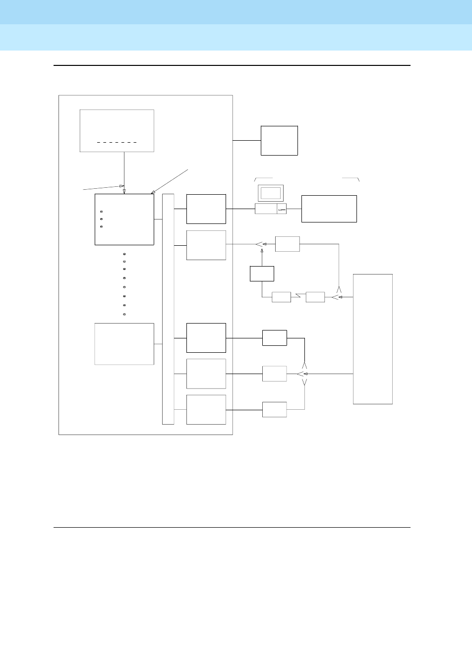
DEFINITY Enterprise Communications Server Release 6
Administration and Feature Description
555-230-522 Issue 4
May 1998
Basic Features
Page 4-436Messaging Server Interface
4
Figure 4-4. Typical Messaging Server Interface Connections
PC
DCP
TN754
LINE CP
DIGITAL
TN754
LINE CP
DIGITAL
ADU
RS232C
DCP
TN726
MESSAGE
SERVER
LINE CP
DIGITAL MPDM
MODEM
DCP
T/R
TN742
TN754
SERIES
VOICE TERMINAL
3B2/310
EQUIPPED
WITH
DATA LINE
CP
ANALOG
7400D
MPDM
3B2/400
3B2/600
SYSTEM V,
R3.0
MTDM
LADS LADS
AGENTS WORKSTATIONS*
1
64
ASSIGN LINKS
USING PROCESSOR
INTERFACE DATA
MODULE AND
INTERFACE LINKS
FORMS
LINE CP
USER
VOICE
TERMINALS
IMPLEMENTATION INSTRUCTIONS
SEE PC/PBX CONNECTIONS FOR ASSOCIATED
SWITCH
RS232C
‡
RS449
†
OR
UNIX
T
D
M
B
U
S
SWITCH
PROCESSING
ELEMENT
PROCESSOR CHANNEL
0 63
INTERFACE
LINK 1
INTERFACE
LINK 8
AND 3B2MS
SERVER
SOFTWARE
FOR DISTANCES GREATER THAN 5000 FEET,
USE LADS AND MTDM CONNECTION.
* PC EQUIPPED WITH 3B2 MS STATION SOFTWARE.
† SCI LINK CONNECTIVITY (CONTROL PATH)
‡ EIA CONNECTIVITY (DATA PATHS)
ASSIGN INTERFACE
USING PROCESSOR
CHANNEL
ASSIGNMENTS
FORM

DEFINITY Enterprise Communications Server Release 6
Administration and Feature Description
555-230-522 Issue 4
May 1998
Basic Features
Page 4-437Messaging Server Interface
4
Considerations
■You must set a coverage point on the Coverage Path form to include the
hunt group number of the MS agent hunt group.
Interactions
None.

DEFINITY Enterprise Communications Server Release 6
Administration and Feature Description
555-230-522 Issue 4
May 1998
Basic Features
Page 4-438Multifrequency Signaling
4
Multifrequency Signaling
Multifrequency (MF) signaling is a form of address signaling used between
switches and the central office (CO). It is similar to dual-tone multifrequency
(DTMF) signaling in that tones convey the dialed number.
With MF signaling, the signal is typically a combination of two frequencies from a
group of 5 or 6 frequencies (2/5 or 2/6). The origination switch and destination
switch exchange tones that have specific meanings according to the MF
protocol.
How to administer MF Signaling
To receive Russian incoming ANI:
■On the DID or DIOD trunk group form, set Country to 15 and Protocol
Type to inloc.
■On AAR and ARS Digit Analysis Table, set ANI Rq field to y
or
on AAR
and ARS Digit Conversion Table, set ANI Req field to y.
Required forms
Form Field Page
Multifrequency-Signaling-Related
System-Parameters
■All 5-228
Trunk Group
—CO
—DID
—DIOD
—Tie
■Outgoing Dial Type
■Incoming Dial Type
■Outgoing Dial Type
■Incoming Dial Type
■Outgoing Dial Type
7-115
7-168
7-178
7-183
7-262
AAR and ARS Digit Analysis Table ■ANI 8-55
AAR and ARS Digit Conversion Table ■ANI 8-63
Class of Restriction ■Category for MFC ANI 5-72
System-Parameters
Customer-Options
■G3 Version
■Multifrequency
Signaling
5-228

DEFINITY Enterprise Communications Server Release 6
Administration and Feature Description
555-230-522 Issue 4
May 1998
Basic Features
Page 4-439Multifrequency Signaling
4
Detailed description
DEFINITY ECS supports two frequency groups:
■R2-multifrequency compelled signaling (R2-MFC) frequency
■R1 frequency (for Spain and Russia)
R2-MFC is a version of MFC recommended by the Consultative Committee for
International Telephone and Telegraph (CCITT). It provides signaling between a
CO and a switch over analog or digital CO, DID, or DIOD trunks. It also provides
signaling between 2 DEFINITY switches.
DEFINITY ECS provides MF signaling that complies with CCITT regulations and
national regulations for specific countries. It provides these types of MF
signaling: Multifrequency Espana (MFE), MF Shuttle, and multifrequency
compelled (R2-MFC). These protocols signal the called number, the calling
party’s number (automatic number identification (ANI)), and information about
the type of call or type of caller (category).
DEFINITY ECS allows prefix digits for ANI sent on outgoing calls to be defined
per PBX or per the originator’s class of restriction.
If a call is a tandem call and the incoming and outgoing trunk use different
protocols, the switch makes no attempt to convert between the various protocol’s
meanings for category. Instead,
■the PBX uses the incoming trunk’s COR assigned category if the outgoing
trunk is Russian or R2-MFC, and
■the PBX uses ARS call types if the outgoing trunk is MFE.
DEFINITY ECS provides the incoming ANI to all features on the switch that need
to identify the calling party.
MFE
MFE, for Country code 11 (Spain), uses R1 frequency and compelled signaling. It
is available on CO and DID trunk groups. There are four kinds of MFE signaling:
■Public 2/5
■Public 2/6
■Ibercom 2/5
■Ibercom 2/6
MF Shuttle
MF shuttle signaling, for country code 15 (Russia), uses R1 frequency and
noncompelled signaling. With MF shuttle signaling, it is possible to change to
decadic rotary pulse in the middle of address signal exchange. MF shuttle
signaling is available on CO, DID, and DIOD trunk groups.

DEFINITY Enterprise Communications Server Release 6
Administration and Feature Description
555-230-522 Issue 4
May 1998
Basic Features
Page 4-440Multifrequency Signaling
4
Also, automatic number identification (ANI) transmission, for Country code 15,
uses a gapless R1 MF signal and is completed within 800ms. This is available on
an outgoing CO trunk group.
R2-MFC
R2-MFC, with DEFINITY ECS, permits each country to define the meanings of the
R2 frequency combinations. Specific frequency combinations for different
countries are described in the
DEFINITY ECS Application Notes for Type
Approval
.
R2-MFC Considerations
■Both non-group II signaling and group II signaling are supported on
incoming MF signaling calls. The group II signaling protocol has an extra
signal that provides caller-category information. Only group II signaling is
supported on outgoing MF signaling calls.
■MF signaling also can be used in tandem trunk groups. After address
signals are collected from an incoming group II MF signaling call, the call
can route to a group II MF signaling trunk.
■Both incoming and outgoing MF signaling calls support ANI. The terminal
displays ANI information and the Call Detail Recording (CDR) record
records it.
■When DEFINITY ECS uses an open numbering plan, the end-of-dial signal
must be defined in the incoming Group I signal administration. After
sending all address digits, the CO sends the end-of-dial signal to
DEFINITY ECS.
■If DEFINITY ECS makes an outgoing call to the CO that uses an open
numbering plan, the CO should send the signal A.1 to DEFINITY ECS after
sending the last address digit to the CO. Then, the CO should timeout and
send a pulsed signal A.3 to DEFINITY ECS requesting the Group II signal.
Guidelines for administering MF signaling
To administer MF signaling, first you identify the origination switch and the
destination switch. (The switch making the call is the origination switch; the
switch answering the call is the destination switch.)
■The origination switch creates
forward
signals, classified as group I and
group II signals.
■The destination switch creates
backward
signals, classified as group A
and group B signals.
Group I and group A signals comprise the basic signaling for the dialed number.
More elaborate signaling requires Group II and group B signals. Signal meanings
and timer values can be administered.

DEFINITY Enterprise Communications Server Release 6
Administration and Feature Description
555-230-522 Issue 4
May 1998
Basic Features
Page 4-441Multifrequency Signaling
4
The sequence below shows a typical interaction between the origination (forward
group I and group II signals) and destination switch (backward group A and
group B signals).
Second, you assign the correlation between signal codes and their meanings.
1. Assign a code to every message. The code consists of a group category,
like group II or A, and a number.
■For example, you might assign code A.1 to the message
“next-digit.”
2. Assign a signal to each identifying code.
■In every country, the frequencies (levels may differ by country)
assigned to the identifying codes are the same. However, the
messages assigned to the identifying codes may be different.
For example, in Switzerland the B.6 code and its associated signal
convey the
free
message, while in Thailand,
free
is conveyed by the
B.1 code and its associated signal. But in both Switzerland and
Thailand, the frequency associated with the B.1 code is the same.
As another example, you might assign the signal “busy” to the B.1
code.
Interactions
■ASAI
ANI collected from incoming R2-MFC signaling can be used with ASAI.
Forward Backward
Group I digit -->
<-- A.1 Group A
digit -->
<-- A.1
digit -->
<-- A.1
digit -->
<-- A.1
digit -->
<-- A.3 End of dial
Group II II.2 -->
<-- B.x Group B

DEFINITY Enterprise Communications Server Release 6
Administration and Feature Description
555-230-522 Issue 4
May 1998
Basic Features
Page 4-442Multifrequency Signaling
4
■Abbreviated Dialing
Although calls dialed automatically from an abbreviated dialing privileged
list complete without class of restriction (COR) checking, ANI prefix and
ANI truncation still apply.
■Attendant Console
If the attendant assists or extends a call for a station via Straightforward
Outward Completion and Through Dialing, and if the attendant has not yet
released the call when the request for ANI comes in from the far end, the
attendant’s COR is used to select the ANI for the call. If the attendant has
already released the call when the request for ANI comes in from the far
end, the attendant’s COR is used to select the ANI for the call.
■Authorization Codes
The COR of the authorization code as administered on the
authorization-code form is not used for ANI prefix determination, even if
the originating endpoint enters an authorization code before call
processing for an outgoing call seizes an outgoing trunk. If the originating
endpoint is an extension, the extension’s ANI is used. If the originating
endpoint is an incoming trunk, the ANI for PBX is used.
■Bridging
The ANI of a voice terminal’s primary extension also applies to calls
originated from a bridged call appearance of that extension on another
terminal. ANI prefix and ANI truncation will still apply to the primary
extension number of bridged call appearances.
■Call Detail Recording
CDR records ANI collected from incoming MF signaling.
For India MFC, on incoming calls, ANI digits may be appended with
zeroes if the actual ANI digits are less than the administered ANI-length; in
those cases, the zero-digits appear on CDR.
■Call Redirection
A call is redirected if any of the following are active: Call Forwarding, Call
Coverage, Send All Calls, or Night Service.
■Call Vectoring
Call Vectoring can now use ANI collected from incoming MFC signaling.
The ANI of a call vector is not used when a call vectoring route-to
command routes a call over an outgoing trunk. Instead, the ANI of the
originating party is sent.
■DID No Answer Timer
DID No Answer Timer is applied to MF signaling DID calls.
■Distributed Communications System (DCS)
In a DCS arrangement, as shown below,

DEFINITY Enterprise Communications Server Release 6
Administration and Feature Description
555-230-522 Issue 4
May 1998
Basic Features
Page 4-443Multifrequency Signaling
4
set -------- PBX_A --------------------PBX_B ------------------------------------- CO
DCS trunk MF trunk
the ANI sent to the CO is determined by the ANI for PBX on PBX_B, but
the category sent to the CO is determined by the Category for MF
ANI field on the Class of Restriction form for the incoming DCS trunk or by
the type of call.
■Expert Agent Select (EAS)
For ANI, the EAS agent’s login extension number and COR overrides the
extension number and COR of the physical terminal where the agent is
logged in. ANI prefix and ANI truncation apply to logged in EAS agents.
■Hunt Groups and Automatic Call Distribution (ACD) Splits
For ANI, a physical terminal’s extension number and COR overrides the
extension number and COR of the hunt group or ACD split that the
terminal is a member of or logged into. ANI prefix and ANI truncation
apply to terminals that are members of hunt groups or logged into ACD
splits.
■Multimedia Call Handling (MMCH)
For call orgination, multimedia complexes use the COR assigned to their
voice terminals. ANI prefix and ANI truncation will apply to the voice
terminals assigned to multimedia complexes.
■Off-Net Call Coverage or Call Forwarding
If the originating endpoint is an extension, the extension’s ANI is used. If
the originating endpoint is an incoming trunk that can supply ANI, the ANI
received from the incoming trunk is used. If the originating endpoint is
neither of the above, the ANI for PBX is used.
■Personal Station Access (PSA)
For ANI, the PSA extension number and COR overrides the extension
number and COR of the physical terminal where the PSA extension
number is associated. ANI prefix and ANI truncation will apply to
associated PSA extension numbers.
■Remote Access
The COR of a remote access barrier code is not used for ANI prefix
determination when the originating end point dials a remote access
extension and then places a call. If the originating endpoint is an
extension, the extension’s ANI is used. If the originating endpoint is an
incoming trunk, the ANI for PBX is used.

DEFINITY Enterprise Communications Server Release 6
Administration and Feature Description
555-230-522 Issue 4
May 1998
Basic Features
Page 4-444Multifrequency Signaling
4
■Station Set Displays
When no ANI is possible, if station sets are equipped with display option,
they do not display the ANI digits. Instead, the trunk group name displays.
When ANI is possible, ANI displays on the station set.
For India Only. If ANI digits are padded with “zero,” then zeroes also are
displayed along with ANI digits.
■Tandem / Offnet Calls
If ANI digits are received on incoming MFC calls, the ANI digits are sent to
outgoing tandem/off-net calls.
For Russia Only. The ANI is requested on incoming trunks only when all
the address digits have been collected. When the incoming trunk on a
tandem call is a Russian incoming local trunk administered to collect ANI,
the PBX collects all ANI digits before seizing the outgoing tandem trunk.
This happens even if ARS is administerd with a “min” value low enough
that it would be possible to determine an outgoing route through digit
analysis.
For India Only. On an outgoing tandem-call, the default operation is to
send the ANI-Not-Available forward signal if ANI is not available from the
incoming trunk. However, in order to support this operation, leave the ANI
for PBX field blank, and define the ANI-Not-Available signal.

DEFINITY Enterprise Communications Server Release 6
Administration and Feature Description
555-230-522 Issue 4
May 1998
Basic Features
Page 4-445Misoperation Handling
4
Misoperation Handling
Misoperation Handling, used only in France and Italy, defines how calls are
handled when a misoperation occurs. A misoperation can occur either:
■When a user with a call on hold goes on-hook before an operation
completes. In some cases, going on-hook completes the operation, as in
call transfer.
■When the system enters Night Service while attendant consoles have calls
on hold.
You can alter standard Misoperation Handling to ensure that callers are not left
on hold indefinitely with no way to reach someone for assistance or that callers
are not dropped by the system.
How to administer Misoperation Handling
Contact a Lucent representative for instructions on administering Misoperation
Handling for use in France.
Detailed description
Misoperation handling varies considerably, depending on how it is administered
and what conditions are in effect when a call is placed on hold.
Standard operation
Standard misoperation handling is in effect when you set the Intercept
Treatment on Failed Trunk Transfers field to y and set Misoperation
Alerting to n.
The type of voice terminal that is in use when the misoperation occurs (analog
single-line or digital multiappearance) affects standard misoperation handling.
The following scenario describes a typical misoperation on an analog terminal.
1. While connected to an incoming external call, an analog-terminal user
flashes with the intent of transferring the call to another terminal.
2. The user hears dial tone, dials an invalid extension, and hangs up.
Required forms
Form Field Page
Feature-Related
System Parameters
■Misoperation Alerting
■Intercept Treatment on Failed Trunk
Transfers
5-123

DEFINITY Enterprise Communications Server Release 6
Administration and Feature Description
555-230-522 Issue 4
May 1998
Basic Features
Page 4-446Misoperation Handling
4
3. A misoperation occurs. The analog-terminal user receives priority
ringback indefinitely.
The following scenario describes a typical misoperation on a digital terminal.
1. While connected to an incoming external call, a digital-terminal user with a
call on hold goes on-hook during another feature operation before
completing the operation.
2. The user hears dial tone, dials an invalid extension, and hangs up.
3. A misoperation occurs unless going on-hook completes the operation (for
example, call transfer). The held call remains on hold indefinitely with a
flashing call-appearance lamp.
Enhanced operation
Once you enable Misoperation Alerting, calls are handled depending upon the
type of call placed on hold and the type of voice terminal (digital
multiappearance, analog single-line, or attendant console) in use when the
misoperation occurs. The following list describes the 3 call types that determine
misoperation handling.
■Call Type 1 — An outgoing public-network call is classified as Type 1
when answer supervision is received or when the trunk group’s Answer
Supervision Timer expires, even if the trunk is still ringing. An incoming call
is classified as Type 1 when it is answered.
■Call Type 2 — An incoming external-public-network call is classified as
Type 2 before it is answered. A misoperation cannot occur with a Type 2
call because an unanswered incoming call cannot be placed on hold
without first being answered.
■Call Type 3 — All internal calls, conference calls, and tie-trunk calls are
classified as Type 3.
Analog terminal misoperation
The following 2 scenarios describe typical misoperations on an analog terminal.
Scenario 1.
1. While connected to an incoming external call (Type 1), an analog-terminal
user flashes to transfer the call to another terminal.
2. The user hears dial tone, dials an invalid extension, then hears intercept
tone.
3. When the user hangs up, the call re-alerts the user for 15 seconds and
eventually routes to the attendant.

DEFINITY Enterprise Communications Server Release 6
Administration and Feature Description
555-230-522 Issue 4
May 1998
Basic Features
Page 4-447Misoperation Handling
4
Scenario 2.
1. While connected to an incoming external call (Type 1), an analog station
user flashes to place the call on hold while calling another extension.
2. The user hears dial tone and dials the CAS Remote Hold/Answer
Hold/unhold access code.
3. The user dials an extension and talks with the user at the extension and
hangs up.
4. A misoperation occurs because the first call is still left on hold.
5. The terminal is alerted for 15 seconds and the call routes to an attendant.
6. If the first call is not answered before the timer expires, the call drops.
Digital terminal misoperation
The following scenario describes a typical misoperation on a digital terminal.
1. While connected to an incoming external call (Type 1), a digital-terminal
user places the call on hold to transfer the call to another terminal.
2. The user hears dial tone, dials an invalid extension, and hangs up.
3. A misoperation occurs. The call on hold rerings the terminal (not priority
ringing) for the number of rings administered for call coverage.
4. The call then routes to the terminal’s coverage path, which directs the call
to an announcement and/or disconnects.
Attendant console misoperation
A misoperation occurs on an attendant console with calls on hold only when the
system enters Night Service.
1. The system enters Night Service with calls on hold at an attendant
console.
2. All calls on hold re-alert (as if the Held-Call Timed-Reminder had expired).
3. When the calls start re-alerting, a timer starts. The timer is set to the value
assigned in the Alerting (sec) field on the Console-Parameters form.
4. If the attendant does not answer the calls before the timer expires, calls
route to the system Night Service destination. Calls that are not answered
at the night service destination before the night-service-disconnect timer
expires are dropped.

DEFINITY Enterprise Communications Server Release 6
Administration and Feature Description
555-230-522 Issue 4
May 1998
Basic Features
Page 4-448Misoperation Handling
4
Interactions
■Attendant Lockout
Attendant Lockout is temporarily disabled on calls that re-alert the
attendant console following a misoperation. This allows an attendant to
answer the calls.
■Bridged Appearances
Misoperation Alerting calls do not re-alert on bridged call appearances.
■Voice Response Integration
Do not use Misoperations Handling with this feature if you are using
analog boards with Conversant.

DEFINITY Enterprise Communications Server Release 6
Administration and Feature Description
555-230-522 Issue 4
May 1998
Basic Features
Page 4-449Modem Pooling
4
Modem Pooling
Modem Pooling allows switched connections between digital-data endpoints
(data modules) and analog-data endpoints via pods of acoustic-coupled
modems. The analog-data endpoint is either a trunk or a line circuit.
How to administer Modem Pooling
Detailed description
Data transmission between a digital data endpoint and an analog endpoint
requires conversion via a modem, because the DCP format used by the data
module is not compatible with the modulated signals of an analog modem. A
modem translates DCP format into modulated signals and vice versa.
Modem Pooling feature provides pools of integrated-conversion modems and
combined-conversion modems.
Integrated-conversion modem pools have functionality integrated on the TN758
Pooled Modem circuit pack, providing two modems. Each one emulates a TDM
cabled to a 212 modem. Integrated are modem pools not available in countries
that use A-law companding.
Combined-conversion modem pools are TDMs cabled to any TDM-compatible
modem. Combined-conversion modem pools can be used with all systems.
When the system needs a modem, it queries the digital-data module associated
with the call to determine if the module’s options are compatible with those
supported by the modem pools. If the options are not compatible, the originating
user receives intercept treatment. If the options are compatible, the system
Required forms for Integrated Modem Pooling
Form Field Page
Modem Pool Group ■All 5-223
Feature Access Code (FAC) ■Data Origination Access Code 5-113
Data Module (all) ■All 6-226
Required forms for Combined Modem Pooling
Form Field Page
Modem Pool Group ■All 5-223
Feature Access Code (FAC) ■Data Origination Access Code 5-113

DEFINITY Enterprise Communications Server Release 6
Administration and Feature Description
555-230-522 Issue 4
May 1998
Basic Features
Page 4-450Modem Pooling
4
obtains a modem from the appropriate pool. If a modem is not available, the user
receives reorder treatment.
The system can detect the needs for a modem. Data calls from an analog-data
endpoint require that the user indicate the need for a modem, because the
system considers such calls to be voice calls. Users indicate this need by dialing
the data-origination access code before dialing the digital-data endpoint.
The system provides a Hold Time parameter to specify the maximum time any
modem can be held but not used (while a data call is in queue).
The integrated-conversion modems support the following options:
■Receiver responds to remote loop
■Loss of carrier disconnect
■Send space disconnect
■Receive space disconnect
■CF-CB common
■Speed, duplex, and synch (administered)
Combined-conversion modems support the following:
■IBM bisynchronous protocols typically used in 3270 and 2780/3780
applications. Both require 2400 or 4800 bps, half-duplex, synchronous
transmission.
■Interactive IBM-TSO applications using 1200 bps, half-duplex,
asynchronous transmissions
■DATAPHONE II switched-network modems supporting asynchronous and
synchronous communications, and autobaud at 300, 1200, or 2400 bps
■The DEFINITY ECS operating at up to 19.2 kbps
■Different pools with different data-transmission characteristics
Considerations
■On data calls between a data module and an analog-data endpoint,
Return-to-Voice releases the modem and returns it to the pool. The
voice-terminal user connects to the analog-data endpoint.
■For traffic purposes, the system accumulates data on modem-pooling
calls separate from voice calls. Measurements on the pools also
accumulate.
■When a voice-terminal user places a data call to a digital-data endpoint,
does not transfer the call to another digital-data endpoint, and uses a
modem or acoustically-coupled modem, the user dials the
data-origination access code before dialing the distant endpoint.

DEFINITY Enterprise Communications Server Release 6
Administration and Feature Description
555-230-522 Issue 4
May 1998
Basic Features
Page 4-451Modem Pooling
4
■Modem Pooling is not restricted. Queuing for modems is not provided,
although calls queued on a hunt group retain reserved modems.
■Avoid mixing modems from different vendors within a combined pool
because such modems may differ in transmission characteristics.
■When you administer data-transmission characteristics (speed, duplex,
and synchronization mode), they must be identical to the TDM and
optional modem selections made by the customer.
■Each data call that uses Modem Pooling uses four time slots (not just two).
As a result, heavy usage of Modem Pooling could affect TDM
bus-blocking characteristics.
■Tandem switches do not insert a pooled modem. The originating switch
inserts a pooled modem.
Interactions
■Call Detail Recording
Data call CDR records the use of modem pools on trunk calls.
■Data Call Setup
Data calls to or from a TDM cannot use Modem Pooling.
■Data Privacy and Data Restriction
The insertion of a modem pool does not turn off Data Privacy or Data
Restriction.
■Data-Only Off-Premises Extensions
Calls to or from a Data-Only Off-Premises Extension cannot use Modem
Pooling, when this type of digital-data endpoint uses a TDM.
■DMI Trunks
If you place a data call from a local analog-data endpoint to a DMI trunk,
you must dial the data-origination access code to obtain a modem. Data
calls on DMI trunks to local analog-data endpoints automatically obtain
modems.
■DS1 Tie Trunk Service
Connect modems used for Modem Pooling to AVD DS1 tie trunks via Data
Terminal Dialing or by dialing the feature-access code for data origination.

DEFINITY Enterprise Communications Server Release 6
Administration and Feature Description
555-230-522 Issue 4
May 1998
Basic Features
Page 4-452Multiappearance Preselection and Preference
4
Multiappearance Preselection and
Preference
Multiappearance Preselection and Preference selects the call appearances you
use to connect to when you lift the handset.
How to administer Multiappearance Preselection
and Preference
You do not have to administer Preselection.
Detailed description
Multiappearance Preselection and Preference provides multiappearance
voice-terminal users with the following options for placing or answering calls on
selected call appearances.
■Ringing Appearance Preference
When a user lifts the handset to answer a call, the system automatically
connects them to the ringing call appearance. If there is more than one
call, the user automatically connects to the oldest (first-in) ringing call
appearance. The in-use (red) lamp tracks the ringing appearance and the
answered appearance.
■Idle Appearance Preference
When a user lifts the handset to place a call, the system automatically
connects them to an idle appearance even if an incoming call is ringing at
another appearance. The in-use (red) lamp tracks an idle appearance
when the user lifts the handset.
■Last Appearance Preference
When a user lifts the handset, they connect to the call appearance or
bridged appearance last used for a call, unless an audibly ringing call on
a different appearance caused the line selection to move. If the line
selection moves, a call may be originated, answered, or unheld,
depending on the state of that appearance.
Required forms
Form Field Page
Station (multiappearance) ■Idle Appearance Preference
■Select Last Used Appearance
6-14

DEFINITY Enterprise Communications Server Release 6
Administration and Feature Description
555-230-522 Issue 4
May 1998
Basic Features
Page 4-453Multiappearance Preselection and Preference
4
■Preselection
Before lifting the handset to place or answer a call, the user can press a
call appearance button or a feature button to select an appearance when
the in-use lamp is dark. Preselection reenters a held call or activates a
feature or the speakerphone if the voice terminal is so equipped.
Preselection overrides both Preference options. If the user does not lift the
handset within 5 seconds after using Preselection, the selected
appearance returns to idle.
You can assign a preselection feature button. For example, if a user
presses an Abbreviated Dialing button, a call appearance is automatically
selected. If the user lifts the handset within 5 seconds, the system
automatically places the call.
Preference dictates whether a user connects to the ringing call
appearance or to an idle call appearance. If there is no call, users
automatically connect to an idle call appearance when they lift the
handset, regardless of which Preference option is assigned.
Considerations
■Multiappearance voice terminals can have from 2 to 10 call appearances.
One of these call appearances is reserved for placing calls or for
receiving a Priority Calling call. If a voice terminal has 2 call appearances
and one of them is active, a nonpriority call cannot access the other call
appearance, even if the call appearance is idle. The default number of call
appearances is 3.
■The reserved call appearance is not a fixed-position button; it is just the
last-idle call appearance. For example, if a voice terminal has 10 call
appearances, any 9 can be in use, but the tenth (last) is reserved.
■All incoming and outgoing calls require a call appearance. There are no
hidden or free call appearances. For example, when a call rings a
call-pickup group member, another member normally presses the Call
Pickup button to answer the call. However, pressing the button only
selects a call appearance for the call, if available. If a call appearance is
not available, the call cannot be picked up.
■Similarly, calls placed by using Facility Busy Indication also require a call
appearance. In this case, the call cannot complete unless an idle call
appearance is available. A Facility Busy Indication button on the called
voice terminal provides a visual indication of the busy or idle status of
another facility, but it does not provide a talking path.

DEFINITY Enterprise Communications Server Release 6
Administration and Feature Description
555-230-522 Issue 4
May 1998
Basic Features
Page 4-454Multiappearance Preselection and Preference
4
Interactions
■Automatic Incoming Call Display
Incoming calls are not displayed if Idle Appearance Preference is
activated.
■Call Coverage
If you administer Cover All Calls as the redirection criterion for a voice
terminal, administer Idle Appearance Preference for the terminal. The
called party can then lift the handset without accidentally connecting to a
call that should be screened.
■Integrated Services Digital Network — Basic Rate Interface
When an ISDN-BRI terminal (with Select Last Used Appearance enabled)
transfers a call while off-hook by using the handset, the user hears dial
tone on the last-used call appearance. Users of other voice-terminal types
hear silence in this case.

DEFINITY Enterprise Communications Server Release 6
Administration and Feature Description
555-230-522 Issue 4
May 1998
Basic Features
Page 4-455Music-on-Hold Access
4
Music-on-Hold Access
Music-on-Hold Access automatically provides music, silence, or tone to a caller.
Providing music lets the caller know that the connection is still active. The
following table shows what happens when you administer one of the options.
NOTE:
If you use equipment that rebroadcasts music or other copyrighted
materials, you may be required to obtain a copyright license from or pay
fees to a third party such as the American Society of Composers, Artists,
and Producers (ASCAP) or Broadcast Music Incorporated (BMI).
How to administer Music-on-Hold Access
Consideration
■If the Tenant Partitioning field on the System-Parameters
Customer-Options form is set to y, you
cannot
administer
Music/Tone
on Hold on the Feature-Related System Parameters form; you must use
the Music Sources form.
■Any number of calls can simultaneously connect to music.
■The system does not provide music to callers in a multiple-party
connection who are in queue, on hold, or parked.
Caller Status Music Silence Tone
On hold yes no yes
On a trunk call that is being transferred yes yes no
Parked yes no yes
Waiting in queue yes no yes
Required forms
Form Field Page
Feature-Related System
Parameters
■Music/Tone On Hold
■Music Port
■Music (or Silence) on
Transferred Trunk Calls
5-123
Music Sources ■All 5-243
CPE trunk group ■All 7-174
Class of Restriction ■Hear System Music on Hold 5-72

DEFINITY Enterprise Communications Server Release 6
Administration and Feature Description
555-230-522 Issue 4
May 1998
Basic Features
Page 4-456Music-on-Hold Access
4
Interactions
■Automatic Call Distribution
If you administer Music/Tone on Hold to provide music, the system
provides the music after the ACD split delayed announcement.
■Data Privacy and Data Restriction
If a call with either Data Privacy or Data Restriction activated is placed on
hold, Music/Tone on Hold access is withheld to prevent transmission
of a musical tone that a connected data service might falsely interpret as a
data transmission.
■Hunting
If you administer Music/Tone on Hold to provide music, the system
provides the music after the DDC group or UCD group delayed
announcement.

DEFINITY Enterprise Communications Server Release 6
Administration and Feature Description
555-230-522 Issue 4
May 1998
Basic Features
Page 4-457Night Service
4
Night Service
DEFINITY ECS provides the following Night Service features:
■Hunt Group Night Service
■Night Console Service
■Night Station Service
■Trunk Answer from Any Station
■Tr u n k Gro u p N i g h t Se rv i c e
Hunt Group Night Service
Hunt Group Night Service allows an attendant or a split supervisor to assign a
hunt group or split to Night Service mode. All calls for the hunt group then are
redirected to the hunt group’s designated Night Service extension (NSE). When a
user activates Hunt Group Night Service, the associated button lamp lights.
How to administer Hunt Group Night Service
Night Console Service
Night Console Service directs all calls for primary and daytime attendant
consoles to a night console. When a user activates Night Console Service, the
Night Service button for each attendant lights and all attendant-seeking calls
(and calls waiting) in the queue are directed to the night console.
To activate and deactivate this feature, the attendant typically presses the Night
button on the principal attendant console or designated console.
Required forms
Form Field Page
Station
(multiappearance)
■Button/Feature Button Assignments
— hunt-ns 6-14
Attendant Console ■Feature Button Assignments
— hunt-ns 5-35
Hunt Group ■Night Service Destination 5-158

DEFINITY Enterprise Communications Server Release 6
Administration and Feature Description
555-230-522 Issue 4
May 1998
Basic Features
Page 4-458Night Service
4
How to administer Night Console Service
Night Station Service
Night Station Service directs incoming calls for the attendant to designated
extensions. Attendants can activate Night Station Service by pressing the Night
button on the principle console if there is not an active night console. If the night
station is busy, calls (including emergency attendant calls) receive busy tone.
They do not queue for the attendant.
When Night Station Service is active, incoming calls to the attendant route as
follows:
■DID Listed Directory Number (LDN) calls route to a designated DID-LDN
night extension.
■Internal calls route to the DID-LDN night extension (unless you administer
the system so only DID-LDN calls can route to the LDN night extension).
■Non-DID calls route to the night destination that you specify for the trunk
group or for the individual trunk. If you do not specify a night destination,
the calls route to the DID-LDN night extension.
You can assign a unique extension as the night destination for each incoming
central-office, foreign-exchange, or 800-Service trunk group. Both the extension
assigned as a trunk group’s night destination and the DID-LDN night extension
can be voice terminals or answering groups (such as DDC group, UCD group, or
TEG).
How to administer Night Station Service
Required forms
Form Field Page
Attendant Console ■Console Type 5-35
Required forms
Form Field Page
Listed Directory Numbers ■Night Destination 5-207
Trunk Groups (All) ■Night Service 7-115
Hunt Group ■Night Service Destination 5-158
Continued on next page

DEFINITY Enterprise Communications Server Release 6
Administration and Feature Description
555-230-522 Issue 4
May 1998
Basic Features
Page 4-459Night Service
4
Trunk Answer from Any Station
Trunk Answer from Any Station (TAAS) allows voice-terminal users to answer all
incoming calls to the attendant when the attendant is not on duty and when other
voice terminals have not been designated to answer the calls. The incoming call
activates a gong, bell, or chime and a voice-terminal user dials an access code
to answer the call.
Users can activate TAAS if each of the following conditions is met:
■The attendant has pressed the Night button on the primary console or a
user (if the switch has no attendant) pressed the Night Service button on
the designated Night Service voice terminal.
■A night console is not assigned or is not operational.
■Night Station Service is not active.
How to administer TAAS
Attendant Console ■Feature Button Assignments
— hunt-ns
— night-ser
— trunk-ns
5-35
Station (multiappearance) ■Button/Feature Button Assignments
— night-ser
— hunt-ns
— trunk-ns
6-14
Required forms
Form Field Page
Trunk Groups (All) ■Night Service (blank) 7-115
Feature Access Code (FAC) ■Trunk Answer Any Station
Access Code 5-113
Console-Parameters ■Ext Alert Port (TAAS) 5-86
Required forms — Continued
Form Field Page
Continued on next page

DEFINITY Enterprise Communications Server Release 6
Administration and Feature Description
555-230-522 Issue 4
May 1998
Basic Features
Page 4-460Night Service
4
Trunk Group Night Service
Trunk Group Night Service allows an attendant or a designated Night Service
voice-terminal user to assign one or all trunk groups to Night Service mode.
When a user activates Night Service, trunk groups that are assigned a Trunk
Group Night Service termination change to Individual Trunk Night Service mode
so that calls coming into the trunk group are redirected to the group’s designated
Night Service extension (NSE). Incoming calls on trunk groups that are not
assigned to Trunk Group Night Service are queued in the attendant queue. If the
call remains unanswered during the Night Service Disconnect Timer interval, the
incoming trunk disconnects.
In addition, a user can assign all the trunk groups to the night service mode at
the same time. Then all the trunk groups are in the System Night Service mode.
Any incoming calls made on the trunk groups are redirected to their designated
NSE. To assign all the trunk groups to System Night Service, the user presses the
System Night Service button on the principal attendant console or the Night
Service button on a designated voice terminal. You can assign a Night Service
button to only one voice terminal.
You can activate Night Service for specific trunk groups (Trunk Group Night
Service) by pressing the individual Trunk Night Service buttons on the attendant
console or on a voice terminal. You can assign Trunk Night Service buttons on
more than one voice terminal.
How to administer Trunk Group Night Service
Considerations
Considerations for Hunt Group Night Service
■Both Hunt Group Night Service and Trunk Group Night Service can be
active at the same time. An incoming trunk call is redirected to the trunk
group’s designated NSE. If this NSE is a hunt group or split that is in Hunt
Group Night Service mode, the call is redirected to the Hunt Group NSE.
Required forms
Form Field Page
Station (multi-appearance) ■Button/Feature Button Assignments
— trunk-ns 6-14
Attendant Console ■Feature Button Assignments
— trunk-ns 5-35
Listed Directory Numbers ■Night Destination 5-207

DEFINITY Enterprise Communications Server Release 6
Administration and Feature Description
555-230-522 Issue 4
May 1998
Basic Features
Page 4-461Night Service
4
■Calls in progress (such as talking, on hold, or waiting in queue) on the
hunt group or split are not affected when the hunt group or split is put in
Hunt Group Night Service mode.
■When a hunt-group queue becomes empty, all idle members are placed in
a busy condition.
■If Night Service is activated for a hunt group or split and a power failure
occurs, the hunt group or split automatically returns to the Night Service
mode.
Considerations for Night Console Service
■The night console must be identical to and have the same features as the
primary console. A daytime console can double as the night console.
■Night Console Service calls to the attendant group are still handled by an
attendant, even though the primary and daytime attendant consoles are
out of service.
■Only one night console is allowed in the system. The night console can be
activated only when the primary and daytime consoles have been
deactivated.
■If Night Console Service is active and a power failure occurs, the system
automatically returns to Night Console Service mode when it is
powered up.
Considerations for Night Station Service
■When Night Station Service is active but you have not established Night
Station extensions, a user can activate Trunk Answer from Any Station
(TAAS).
■You can assign a Night-Serv button to either an attendant extension or a
voice-terminal extension. An individual trunk group or hunt group can be
put into night service by either an attendant extension or a voice-terminal
extension with the necessary button. When a user presses this button to
activate Night Station Service, all calls to that particular trunk group or
hunt group are routed to the Night Service extension assigned to that
group.
■If a trunk without disconnect supervision goes to Night Service, the system
drops the trunk after a period of time to avoid locking up the trunk. The call
is not routed to the DID-LDN night extension.
Considerations for TAAS
■If Night Service is active and a power failure occurs, the system, when
brought back up, automatically returns to Night Service mode.

DEFINITY Enterprise Communications Server Release 6
Administration and Feature Description
555-230-522 Issue 4
May 1998
Basic Features
Page 4-462Night Service
4
Considerations for Trunk Group Night Service
■All incoming calls on Night Service trunk groups go to the trunk group’s
NSE unless the trunk group member has its own Trunk Group Member
Night Destination, in which case the calls are redirected to that destination
instead of the trunk group’s NSE.
■Calls already in progress on a trunk group (such as talking, on hold, or
waiting in queue), are not affected when the individual Trunk Group Night
Service or System Night Service is activated.
■Trunk Group Night Service and System Night Service work independently
of one another.
— When a user activates System Night Service, any trunks that are
controlled by individual Trunk Group Night Service buttons remain
in day service. Trunk groups that are not currently assigned to Trunk
Group Night Service are assigned to System Night Service.
— Trunks with individual Trunk Group Night Service can be removed
from Night Service even though the rest of the system remains in
Night Service.
— When a user deactivates System Night Service, any trunks that
have individual Trunk Group Night Service still active remain in
night service.
— Trunks with individual Trunk Group Night Service can be placed into
Night Service even though the rest of the system remains in day
service.
■If a trunk is added to a trunk group while that trunk group is in Trunk Group
Night Service, the trunk is brought up in night service.
■Individual Trunk Group Night Service does not apply to DID trunk groups.
■If Night Service is activated for a trunk group, and a power failure occurs,
the trunk group automatically returns to the Night Service mode.
■If for some reason, a voice terminal with a trunk-ns button remains
out-of-service after a system reboot and later comes back in service, the
trunk-ns lamp shows the trunk status within 10 seconds of coming back in
service. For example, a voice terminal with a trunk-ns button may be
unplugged when the system is rebooted. If the voice terminal is later
plugged back in, the trunk status is shown on the trunk-ns button within
10 seconds.

DEFINITY Enterprise Communications Server Release 6
Administration and Feature Description
555-230-522 Issue 4
May 1998
Basic Features
Page 4-463Night Service
4
Interactions
Interactions for Hunt Group Night Service
■ACD
When Hunt Group Night Service is active for a split and the night-service
destination is a hunt group, the caller hears the first forced announcement
for the original split. The system then redirects the call to the Night Service
destination hunt group. When an agent in the Night Service hunt group
becomes available, the call goes to that agent. If all agents in the hunt
group are busy, the caller hears the following: forced or delayed first
announcement, ringback, music-on-hold or silence, and a second
announcement.
■Call Coverage
When Hunt Group Night Service is active, the NSE’s normal coverage
criteria and path apply. If the coverage path destination is AUDIX, AUDIX
answers with the mail of the original hunt group. If the NSE is a hunt group
or split of any type, the hunt group or split’s call coverage criteria and
coverage path apply. The coverage criteria and path can be different from
that assigned to the voice terminals that are members of that hunt group
or split.
If a coverage point is a hunt group or split in Night Service, the system
considers the point to be unavailable and does not forward the call to the
coverage point’s NSE.
■Call Forwarding All Calls
If a hunt group or split is in Hunt Group Night Service mode and the hunt
group or split’s NSE has Call Forwarding — All Calls active, the system
forwards night-service calls terminating to that NSE to its designated
call-forward extension.
If the forwarded-to destination is a hunt group or split in Night Service
mode, the system terminates the call at the forwarding extension.
Interactions for Night Console Service
■Tr u n k Gro u p N i g h t Se rv i c e
Activation of Night Console Service for the attendant consoles also puts
trunk groups into night service, except those trunk groups for which you
administered a Trunk Group Night Service button.

DEFINITY Enterprise Communications Server Release 6
Administration and Feature Description
555-230-522 Issue 4
May 1998
Basic Features
Page 4-464Night Service
4
Interactions for Night Station Service
■Call Coverage
Calls routed to the night extension via Night Station Service follow the
coverage path of the night extension under all coverage criteria except
Send All Calls.
If a night extension has a coverage path in which Cover All Calls is
administered, all attendant-seeking calls redirect to coverage. Changes to
the protocol for handling DID-LDN calls (that is, forwarding
attendant-seeking calls on or off premise from the night extension) do not
work.
■Call Forwarding All Calls
Calls redirected to the attendant via Call Forwarding All Calls do not route
to the DID-LDN extension.
■Inward Restriction
Inward-restricted voice terminals can be administered for Night Station
Service. Night Service features override Inward Restriction.
■Night Console Service
Do not provide Night Console Service with this feature.
■Remote Access
A Remote Access extension can be specified as the Night Station
extension on an incoming, non-DID, trunk group.
■Tenant Partitioning
Each tenant may have a designated night-service station. The system
directs calls to an attendant group in night service to the night-service
station of the appropriate tenant (when a night attendant is not available).
When someone places an attendant group into night service, all trunk
groups and hunt groups that belong to tenants served by that attendant
group go into night service. In this case, the system routes incoming calls
to the night-service destination of the appropriate tenant.
Each tenant can have its own listed directory number (LDN) night
destination, trunk answer on any station (TAAS) port, or night attendant.
■Timed Reminder
Timed Reminder calls returning to a console that has been placed in Night
Service and has an assigned DID-LDN night extension are not redirected
to the DID-LDN night extension. Rather, they are dropped.
■Trunk Answer from Any Station
TAAS and Night Station Service can both be assigned within the same
system, but cannot be assigned to the same trunk group.

DEFINITY Enterprise Communications Server Release 6
Administration and Feature Description
555-230-522 Issue 4
May 1998
Basic Features
Page 4-465Night Service
4
Interactions for TAAS
■Call Coverage
If Night Station Service is active, calls that are redirected to the attendant
via Call Coverage can be answered via TAAS.
■Call Forwarding All Calls
If Night Station Service is active, calls that are redirected to the attendant
via Call Forwarding All Calls can be answered via TAAS.
■Inward Restriction
Inward-restricted voice terminals can activate TAAS for incoming trunk
calls. Night Service features override Inward Restriction.
■Night Console Service
Do not provide a Night Console Service with TAAS.
■Night Station Service
TAAS and Night Station Service can both be assigned within the same
system, but cannot be assigned to the same trunk group. Activating Night
Station Service also activates Night Service — Trunk Group for any trunk
group without an individual trunk-group Night Service button.
■Tenant Partitioning
Each tenant can have its own listed directory number (LDN) night
destination, trunk answer on any station (TAAS) port, or night attendant.
Interactions for Trunk Group Night Service
■Call Forwarding All Calls
If the individual Trunk Group Night Service mode and the trunk group’s
NSE have Call Forwarding All Calls activated, the night service calls
terminating to that NSE are forwarded to the designated extension.
■Forced First Announcements
An interaction occurs with System Night Service and Forced First
Announcement. For example, if hunt group A has a forced first
announcement, assign the incoming CO trunk to terminate at hunt group
A. Assign the incoming trunk’s night-service destination to be another hunt
group (hunt group B). Assign a Night Service button to the attendant.
With night service active on the attendant, the incoming CO call routes to
the night-service destination hunt group B and does not play the Forced
First Announcement of the incoming destination’s hunt group A.

DEFINITY Enterprise Communications Server Release 6
Administration and Feature Description
555-230-522 Issue 4
May 1998
Basic Features
Page 4-466Night Service
4
■Listed Directory Number
In System Night Service mode, all incoming LDN calls (except those using
DID trunks) which have activated night service are redirected to their
corresponding trunk group’s NSE. Incoming LDN calls using DID trunks
are directed to the Night Console Service, Night Station Service, or Trunk
Answer From Any Station, respectively, whichever applies first. Non-LDN
DID trunk calls terminate at the dialed extension.

DEFINITY Enterprise Communications Server Release 6
Administration and Feature Description
555-230-522 Issue 4
May 1998
Basic Features
Page 4-467Off-Premises Station
4
Off-Premises Station
Off-Premises Station allows a voice terminal located outside the building where
the switch is located to be connected to the system. If central office (CO) trunk
circuits are used, the voice terminal must be analog and must be FCC-registered
or, outside the US, registered by the appropriate governmental agency. See
DEFINITY Enterprise Communications Server Release 6 System Description
Pocket Reference
for cabling distance information for the various voice terminal
types.
Digital protocol communications (DPC) sets can be used as off-premises
terminals with the addition of the DEFINITY extender.
How to administer Off-Premises Station
You administer off-premises stations in the same way as on-premises voice
terminals, with the following exceptions. For voice terminals used as off-premises
stations:
■Off-Premises Station field must be administered as yes.
■R Balance Network field must be completed.
Detailed description
Off-Premises Station requires cross-connecting capabilities and one port on a
TN742, TN746B, or TN769 analog line or TN767 or TN464 DS1 tie trunk circuit
pack for each interface to be provided. The TN746B, which is a 16-port, 48-volt
circuit pack, can support an off-premises station. The TN746, which is a 16-port,
24-volt circuit pack cannot support an off-premises station.
NOTE:
The use of a message waiting indicator lamp on an off-premises station is
not supported.
Considerations
■Off-premises stations are useful when it is necessary to have a voice
terminal located away from the main location.
■The maximum loop distance for off-premises stations is 20,000 feet
(6093.34 meters) without repeaters.
Required forms
Form Field Page
Station (Analog) ■Off Premise Station
■R Balance Network
6-28

DEFINITY Enterprise Communications Server Release 6
Administration and Feature Description
555-230-522 Issue 4
May 1998
Basic Features
Page 4-468Off-Premises Station
4
Interactions
The Distinctive Ringing feature might function improperly at an off-premises
station due to the distance. However, the Distinctive Ringing feature can be
disabled when Off-Premises Station is administered. If the Distinctive
Ringing feature is not used with an off-premises station, the terminal receives
1-burst ringing for all calls.

DEFINITY Enterprise Communications Server Release 6
Administration and Feature Description
555-230-522 Issue 4
May 1998
Basic Features
Page 4-469On-Hook Dialing
4
On-Hook Dialing
On-Hook Dialing allows 6400- and 8400-series voice terminal users to use
keypad dialing without first going off-hook.
How to administer On-Hook Dialing
Detailed description
On-Hook Dialing activates the built-in 1-way or 2-way speakerphone on 6400-
and 8400-series voice terminals. Administer the speakerphone on the Station
form.
Considerations
When you first activate On-Hook Dialing, to make sure that the phone is in the
S-channel signaling mode, you must go on-hook and then off-hook.
Interactions
None.
Required forms
Form Field Page
Feature Related System
Parameters
Station
■On-hook Dialing on 6400/8400
Te r m i n a l s
■Speakerphone
5-113

DEFINITY Enterprise Communications Server Release 6
Administration and Feature Description
555-230-522 Issue 4
May 1998
Basic Features
Page 4-470PC Console
4
PC Console
PC Console is a telephone application that provides all of the functionality of the
attendant console on any Windows-based PC. It is used as a call-handling
station to answer incoming calls and place outgoing calls, and to manage and
monitor some system operations.
PC Console supports the following languages: English, Parisian French, Latin
American Spanish, and German. You can customize any of these languages, or
input your own language.
How to administer PC Console
Interactions
None.
Required forms
Form Field Page
Console-Parameters ■All 5-86
Attendant Console ■All 5-35

DEFINITY Enterprise Communications Server Release 6
Administration and Feature Description
555-230-522 Issue 4
May 1998
Basic Features
Page 4-471PC/PBX Connection
4
PC/PBX Connection
PC/PBX Connection provides an integrated-voice and data-workstation interface
from DEFINITY ECS to a 6300 or other compatible personal computer (PC). The
connection provides access to a variety of host computers, allowing the PC to
act as a terminal for the host.
How to administer PC/PBX Connection
Detailed description
PC/PBX Connection is a PC application that runs on the PC/PBX platform. This
feature brings the voice terminal and PC together into an integrated voice and
data workstation. The PC can be any IBM-compatible PC.
Lucent Technologies provides the hardware for this connection. The hardware
consists of a PC expansion card and a 7-foot 4-pair modular cord. The software
includes a variety of packages available from different vendors. Contact your
Lucent Technologies representative for more information.
Security measures
There are two areas where unauthorized use may develop with this feature. The
first involves unauthorized users with a PC attempting to make calls from it. The
software in the PC has a security setting. A user can place the PC in security
mode when it is left unattended. Automatic security is an option on the
administration program. With Automatic security enabled, executing the software
brings up the program in security mode. This mode is password-protected on the
PC. Change the password often, and secure records of it.
The second area involves remote access to the PC over its data extension.
Deleted or copied files store in the PC with this feature. This can be
password-protected. Change the password frequently and secure. Consult the
BCS Product Security Handbook
, for additional steps to secure your system and
to find out about obtaining information regularly about security developments.
Required forms
Form Field Page
Personal Computer ■All 6-153

DEFINITY Enterprise Communications Server Release 6
Administration and Feature Description
555-230-522 Issue 4
May 1998
Basic Features
Page 4-472PC/PBX Connection
4
Considerations
■PC users with PC/PBX Connection are linked for easy access to other PCs,
modem pooling, and on- and off-site computers.
Interactions
■Call Log
When a station is optioned for PC/PBX Connection on the station form, and
if using a display set, the call display is slightly altered. Omit the
appearance identifier (a=, b=, c=, d=). If enabling the Call Log feature in
the PC/PBX Connection software, the display information is captured to
disk. You can search the log. Search criteria begins at the left of the
displayed information. By omitting the appearance designator, a user can
enter a search string without contending with the appearance identifiers in
the displayed information.
Software requirements
Install one of the following PC/PBX software packages on the PC:
■PC/PBX Connection Package 1
Provides features such as keyboard dialing, personal phone directory,
directory dialing, and message retrieval. Hardware requirements include
PC, 7404D voice terminal equipped with a message cartridge.
■PC/PBX Connection Package 3
Provides Package 1 services plus additional features (call log, higher file
transfer rates, and the ability to take notes on a call). Hardware
requirements include PC equipped with a DCP card and a 7400D series
voice terminal. Package 3 provides an integrated voice and data
workstation that supports:
— Dialing calls from the PC
— Use of customized phone features from the PC keyboard
— Creating a personal phone directory in the PC, searching the
directory, and dialing voice and data calls from the directory
— Reading phone messages on the PC screen and having the PC
automatically dial calls to users that have left messages
— Logging all incoming and outgoing calls (voice and data) and the
ability to automatically recall them
— Using an associated speakerphone to make hands-free calls
— Use of a security feature to keep directory and message
information private

DEFINITY Enterprise Communications Server Release 6
Administration and Feature Description
555-230-522 Issue 4
May 1998
Basic Features
Page 4-473PC/PBX Connection
4
— Use of the PC as a terminal connected to a variety of host
computers
— Transferring files between the PC and another PC or host computer
— Setting up script programs to have the system perform selected
data functions automatically
— Using voice and data functions simultaneously. Perform PC
application while running the PC/PBX Connection software
application in the background
■PC/PBX Connection Package 5
Package 5 allows the PC to emulate a 3278/3279 terminal. This is a
software enhancement to Package 3 and works with Package 3 hardware
and software.

DEFINITY Enterprise Communications Server Release 6
Administration and Feature Description
555-230-522 Issue 4
May 1998
Basic Features
Page 4-474Personal Station Access
4
Personal Station Access
Personal Station Access (PSA) allows a user whose station is translated to his or
her own preferences and permissions to associate those preferences and
permissions with any other compatible terminal. Preferences and permissions
include the definition of terminal buttons, abbreviated dial lists, and COS and
COR permissions assigned to the user’s station. PSA requires the user to enter a
security code. PSA can be used on-site or off-site.
How to administer PSA
Detailed description
PSA makes it convenient for different users to use the same bank of phones at
different times. For example, several telecommuting employees can use the
same office on different days of the week. The employees use PSA to “associate”
with the office voice terminal — that is, make the terminal “theirs” for the day.
Calls that an employee originates from the station are recognized and displayed
as the employee’s calls, and the calls routed to the employee’s extension route to
the voice terminal “associated” with that extension.
Many types of DCP terminals exist, and these terminals have different types and
numbers of buttons. If you attempt to associate DCP stations with DCP terminals
that have incompatible buttons, button mapping is unpredictable. This is also
true of hybrid terminals. If you want a user to be able to use the terminal buttons
and to have consistent displays, associate stations with terminals of the same
type.
When the employee no longer needs to use the office, he or she “dissociates”
from the terminal.
A telecommuting employee can also use PSA when working at home. For
example, the employee installs a DCP terminal and a DEFINITY Extender at
home, calls into the system, and uses PSA to associate the remote voice terminal
Required forms
Form Field Page
Feature-Related
System Parameters
■TTI State
■Record PSA/TTI Transactions in History
Log (optional)
5-123
Class of Service ■Personal Station Access 5-81
Station ■Security Code 6-28
Feature Access Code
(FAC)
■Personal Station Access (PSA)
Associate Code and Dissociate Code 5-113

DEFINITY Enterprise Communications Server Release 6
Administration and Feature Description
555-230-522 Issue 4
May 1998
Basic Features
Page 4-475Personal Station Access
4
with their extension. The system associates the home terminal — that is,
recognizes the home terminal as having the employee’s preferences and
permission. When someone calls the employee’s extension, the call rings at the
employee’s home.
The dissociate function within PSA allows a user to restrict the features available
to a voice terminal. When a terminal has been dissociated using PSA, it can be
used only to call an attendant or to accept a TTI or PSA request.
NOTE:
Once a station has been associated with a terminal, anyone using the
terminal has the capabilities of the associated station. Be sure to execute a
dissociate request if the terminal can be accessed by unauthorized users.
This is particularly important if you use PSA and DCP extenders to permit
remote DCP access.
End-user procedures
The user executes the following steps to make a station his or hers. If a user
enters more than 15 digits before entering the second #, the system generates
intercept tone.
Table 4-83. Personal Station Access procedures
User Action System Response Result
1. Enter the PSA
associate FAC.
■Dial tone
■Intercept tone
The request is successful.
The request is not successful because it
was not made at an analog, hybrid, or DCP
terminal.
The request is not successful because the
terminal is associated with or assigned to a
station that does not have PSA permission
in its COS.
2. Enter user
extension,
followed by #.
■No response If the user is working at a terminal with
display capabilities, this pound sign is the
last character the system displays until the
PSA sequence is completed.
Continued on next page

DEFINITY Enterprise Communications Server Release 6
Administration and Feature Description
555-230-522 Issue 4
May 1998
Basic Features
Page 4-476Personal Station Access
4
3. Enter the Station
Sec urity Code
(SSC) defined
for the user’s
extension,
followed by the
second #.
■Confirmation
tone The command sequence is complete and
error free; the system queues the request.
Under the following conditions, the user
receives intercept tone
immediately
following the confirmation tone. If the user
receives intercept tone, the user needs to
execute the PSA request again.
— TTI is not enabled for voice.
— Either the dialed extension or the
originating extension has an add,
change, or remove action in progress.
■Intercept tone The request is not successful because the
user entered incompatible extension and
SSC information — that is, the extension is
invalid, the SSC is invalid for the extension,
or both. This will be logged as an invalid
attempt by the Security Violation
Notification (SVN) feature.
The request is not successful because the
user has requested association with a
station that does not have PSA permission
in its COS.
The request is not successful because the
user is attempting to associate a station in
one tenant partition to a station in another
partition.
■Reorder tone The request is not successful because the
dialed extension is in use.
The request is not successful because an
agent is logged in at the dialed extension.
The request is not successful because the
system load is too heavy to allow the
requested action to occur. The user can try
again later.
Table 4-83. Personal Station Access procedures — Continued
User Action System Response Result
Continued on next page

DEFINITY Enterprise Communications Server Release 6
Administration and Feature Description
555-230-522 Issue 4
May 1998
Basic Features
Page 4-477Personal Station Access
4
How to interrupt the associate command
sequence
If the user realizes that he or she has entered incorrect information following the
FAC and wishes to interrupt the command sequence and begin again, the user
can enter an asterisk (*) at any point before the second pound sign. When the
user enters an asterisk, the system provides dial tone, and the user can begin the
command sequence at the point of entering the user’s extension. (The user
should not enter the FAC again). The interrupted command sequence will not be
recorded as an invalid attempt by the SVN feature.
How to use PSA dissociate
The user enters the PSA dissociate FAC to dissociate his or her station from a
terminal. The possible system responses to this request are described below.
■Confirmation tone
The request is successful. The system provides confirmation tone if the
system successfully dissociated the terminal and also if the terminal was
not previously associated. In either case, the terminal is in the state
requested by the user.
■Intercept tone
The station does not have PSA permission in its COS.
Considerations
■A user request for a PSA associate will automatically dissociate another
station from the terminal.
■Extensions that do not have a COS, such as EAS agents or hunt groups,
cannot use PSA.
■PSA-invalid attempts generate referral calls and are recorded by Security
Violation Notification software, if that feature is enabled.
■If a user interrupts the PSA dialing sequence by pressing the release
button or by hanging up, the system does not log the action as an invalid
attempt.

DEFINITY Enterprise Communications Server Release 6
Administration and Feature Description
555-230-522 Issue 4
May 1998
Basic Features
Page 4-478Personal Station Access
4
■PSA functions only on analog, hybrid, and DCP terminals. In addition, the
terminal at which the PSA request is made must be compatible with the
terminal to which it is to be associated. The following table provides a list
of permissible associations.
■The system does not limit the number of stations that can use PSA.
However, heavy use of the associate and dissociate functions may
temporarily impact system performance.
■PSA allows a dissociate request from a bridged appearance. However,
when a user executes a dissociate command from Terminal B, even if the
user is on a bridged appearance of an extension belonging to Terminal A,
the user dissociates the station belonging to Terminal B.
■Stations and ports on different switches cannot be PSA associated. This
includes stations on different switches (or nodes) within DCS
environments.
■PSA commands cannot be successfully executed during a save
translations.
■When a reset 3 or greater (reset 4, reset 5, and so on) occurs on the
system, all associations revert to their state as of the last save translations.
Interactions
■Adjunct/Switch Application Interface
An ASAI link cannot use this feature because ASAI uses a BRI port. Do not
assign an ASAI link to a COS that allows PSA.
■Bridged Appearance
When a user executes a PSA dissociate request for the principal station,
its bridged appearances remain active if the stations on which they
appear have not been dissociated. When a call is made to the principal
extension, any of its bridged appearances that can be alerted are alerted.
Otherwise, the call follows the principal extension’s coverage path.
PSA dissociate requests executed at a bridged appearance dissociates
the station that the bridged appearance is on.
Type of terminal at which PSA
request is made
Type of Station to be associated
BRI Analog Hybrid DCP
BRI No No No No
Analog No Yes No No
Hybrid No No Yes No
DCP No No No Yes

DEFINITY Enterprise Communications Server Release 6
Administration and Feature Description
555-230-522 Issue 4
May 1998
Basic Features
Page 4-479Personal Station Access
4
■Call Management
PSA dissociate automatically logs out an ACD agent.
■Coverage
PSA does not change coverage path operations. If a station is
dissociated, its calls still go to coverage unless they are forwarded.
■Property Management System
A station that is assigned to a room, rather than to a person who needs to
work in multiple locations should not use PSA. Such a station should not
have PSA in its COS.
■Security Violation Notification
PSA security violations are tracked and reported by SVN, if it is active.
■Tenant Partitioning
If a terminal is already associated, a user attempting a PSA associate
request at that terminal must specify a station in the same partition as the
station already associated with the terminal.
However, anyone, in any partition, can execute a PSA dissociate request
at the terminal (if the associated station has PSA in its COS) and then
execute a PSA associate request for a station in any tenant partition.

DEFINITY Enterprise Communications Server Release 6
Administration and Feature Description
555-230-522 Issue 4
May 1998
Basic Features
Page 4-480Personalized Ringing
4
Personalized Ringing
Personalized Ringing allows users of some voice terminals to have one of 8
ringing patterns for incoming calls. Users working closely in the same area can
each specify a different ringing pattern. This enables the users to distinguish
their own ringing voice terminal from other voice terminals in the same area.
How to administer Personalized Ringing
You can administer Personalized Ringing for each voice terminal. Either you or
the end-user can administer Personalized Ringing for a 7404D, 7406D, 7406D+,
7407D, or 7407D+programmable voice terminal.
Detailed description
The eight administrable ringing patterns are different combinations of three
tones:
■750 Hz, 750 Hz, 750 Hz (normal ringing)
■1060 Hz, 1060 Hz, 1060 Hz
■530 Hz, 530 Hz, 530 Hz
■530 Hz, 1060 Hz, 1060 Hz
■1060 Hz, 1060 Hz, 530 Hz
■1060 Hz, 530 Hz, 530 Hz
■1060 Hz, 530 Hz, 1060 Hz
■530 Hz, 1060 Hz, 530 Hz
Required forms
Form Field Page
Station
— 7303S, 7305S
— 7404D
— 7406D, 7406D+, 7407D, 7407D+
— 7434D
— 8403B, 8405B, 8405B+, 8410B
— 8405D, 8405D+, 8410D, 8434
— 8411B, 8411D
— CALLMASTER II and III
■Personalized Ringing
Pattern 6-73
6-90
6-111
6-121
6-172
6-180
6-189
6-141

DEFINITY Enterprise Communications Server Release 6
Administration and Feature Description
555-230-522 Issue 4
May 1998
Basic Features
Page 4-481Personalized Ringing
4
End-user procedures
The 7404D user can select the desired ringing pattern via the voice-terminal’s
menu options. The 7406D or 7407D user can select the desired ringing pattern
by pressing the Shift key and the Select Ring button. The 7103A programmable
voice-terminal user can select one of four ringing patterns via a slide switch on
the voice terminal.
Power failures
The user-specified ringing pattern for a 7404D, 7406D, 7407D, or CALLMASTER
digital voice terminal is lost when the power fails. The user-specified ringing
pattern is retained for ISDN-BRI voice terminals when the power fails.
Interactions
■Distinctive Ringing
With Distinctive Ringing, you can administer the relationship between the
number of ring bursts and the call type. The Personal Ringing Pattern
selected is the same ringing pattern used in the Distinctive Ringing
cycles.

DEFINITY Enterprise Communications Server Release 6
Administration and Feature Description
555-230-522 Issue 4
May 1998
Basic Features
Page 4-482Power Failure Transfer
4
Power Failure Transfer
Power Failure Transfer provides service to and from the local telephone company
central office (CO) during a power failure or when service is impaired.
Power Failure Transfer is also call Emergency Transfer; the terms are
synonymous.
How to administer Power Failure Transfer
None required
Detailed description
Power Failure Transfer allows specific types of voice terminals to access the local
CO and to answer incoming calls during a power failure.
Each DEFINITY ECS cabinet supports Power Failure Transfer panels via the AUX
connectors on the rear panel. The Power Failure feature activates when:
■A transfer panel or associated cabinet loses power
■Manually activating the Emergency Transfer switch on the associated
cabinet maintenance circuit pack
■Under software control when it is determined that service for that cabinet
is severely impaired
You cannot activate any other system features during a complete system power
failure.
Power Failure Transfer panels are available in multiples of five terminals.
Voice Terminals must be 500-type (rotary dial) or 2500-type (touch-tone or
DTMF). You must use rotary dialing if the CO accepts dial pulses only. When a
DEFINITY ECS system is not in Power Failure Transfer mode, power-failure
transfer terminals can be used as regular extensions. Each voice terminal can be
connected to a separate CO.
Interactions
■Night Service
If a power failure occurs when the system is in night service, the system
automatically returns to night service when power returns.

DEFINITY Enterprise Communications Server Release 6
Administration and Feature Description
555-230-522 Issue 4
May 1998
Basic Features
Page 4-483Priority Calling
4
Priority Calling
Priority Calling provides a special form of call alerting between internal
voice-terminal users, including the attendant. The called party receives a
distinctive ring when the calling party uses Priority Calling.
How to administer Priority Calling
Detailed description
You administer the priority-calling ringing-pattern system wide. Default is a
3-burst alerting signal. You allow feature use for each voice-terminal user by
administering the user’s class of service.
The following types of calls are always priority-calling calls:
■Call coverage consult
■Automatic callback
■Ringback queuing
■Attendant intrusion
■Security violation notification
The system generates the call waiting ringback tone that a single-line
voice-terminal user hears even if the user is active on a call. In contrast, the
system
does not
generate the pattern for a multiappearance voice-terminal if
there are no idle call appearances. In this case the caller hears busy tone.
However, the system does generate the pattern if the terminal has an idle call
appearance, including the one reserved for call origination.
Required forms
Form Field Page
Feature Access Code
(FAC)
■Priority Calling Access Code 5-113
Class of Service ■Priority Calling 5-81
Attendant Console ■Feature Button Assignments
— priority 5-35
Station (multiappearance) ■Button/Feature Button Assignments
— priority 6-14
Feature-Related System
Parameters
■Distinctive Audible Alerting 5-123

DEFINITY Enterprise Communications Server Release 6
Administration and Feature Description
555-230-522 Issue 4
May 1998
Basic Features
Page 4-484Priority Calling
4
A user activates priority calling by dialing a priority-calling access code or
pressing a priority button, followed by the desired extension. A user can change
a normal call to a priority call even after it begins ringing at the called extension.
The user does this by pressing the priority button.
Interactions
■Abbreviated Dialing
If a priority call is to be made to a number in an abbreviated dial list, an
Abbreviated Dial button must be used. If a user attempts to use
Abbreviated Dialing (either by button or FAC) after dialing the Priority
Access Code, the system denies the call.
■Bridged Call Appearance
A Bridged Call Appearance receives ringing on a priority call if its
Bridged Call Alerting field on the Station form is y.
■Call Coverage
Priority Calling calls do not redirect to coverage unless the caller activates
Go to Cover. If the call redirects, it remains a priority call, and the covering
user receives a distinctive (default is three-burst) ringing signal.
■Call Forwarding All Calls
Priority Calling calls (except callback calls) are forwarded, and the
forwarded call remains a priority call.
■Call Vectoring
The system generates intercept tone when someone attempts to activate
Priority Calling toward a Vector Directory Number (VDN).
■Call Waiting Termination
A Priority Calling call waits on an active single-line voice terminal even if
Call Waiting Termination is not assigned to the voice terminal. The active,
single-line voice-terminal user receiving the call hears a distinctive
(default is three-burst) priority Call Waiting tone.
■Consult
A Consult call acts as a priority call and waits at a single-line voice
terminal, even if the terminal does not have Call Waiting Indication
assigned.
■Dial Access to Attendant
A Priority Calling call to an attendant alerts the attendant as a non-priority
call. The attendant can originate Priority Calling calls.

DEFINITY Enterprise Communications Server Release 6
Administration and Feature Description
555-230-522 Issue 4
May 1998
Basic Features
Page 4-485Priority Calling
4
■Distributed Communications System
On a DCS tandem call to a single-line voice terminal, the called party does
not receive priority ringing if the caller activates Priority Calling by
pressing the priority button
after making a call
.
■Last Number Dialed
If a priority call is to be made to the last number dialed, the Last Number
Dialed button must be used. The Last Number Dialed feature access code
is not valid after Priority Calling has been activated.
Single-line voice terminals (2500 series) can be administered so that
distinctive signals are not provided. In this case, 1-burst ringing is
provided for priority calls.
■Security Violation Notification
Security Violation Notification calls are priority calls.

DEFINITY Enterprise Communications Server Release 6
Administration and Feature Description
555-230-522 Issue 4
May 1998
Basic Features
Page 4-486Privacy — Attendant Lockout
4
Privacy — Attendant Lockout
Privacy — Attendant Lockout prevents an attendant from reentering a
multiple-party connection held on the console unless recalled by a voice-terminal
user.
How to administer Privacy — Attendant Lockoutt
Considerations
■Privacy — Attendant Lockout provides privacy for parties on a
multiple-party call held on the console. The held parties can hold a private
conversation without interruption by the attendant.
Interactions
■Attendant Recall
Use Attendant Recall to recall the attendant to a call that is originally
conferenced or held by the attendant.
■Individual Attendant Access
Privacy — Attendant Lockout applies only to attendant-group calls. It does
not affect individual attendant calls.
■Trunk-to-Trunk Transfer
Privacy — Attendant Lockout does not function when a call using
Trunk-to-Trunk Transfer is held on the console.
Required forms
Form Field Page
Console-Parameters ■Attendant Lockout 5-86

DEFINITY Enterprise Communications Server Release 6
Administration and Feature Description
555-230-522 Issue 4
May 1998
Basic Features
Page 4-487Privacy — Manual Exclusion
4
Privacy — Manual Exclusion
Privacy — Manual Exclusion allows multiappearance voice-terminal users to
keep other users with appearances of the same extension from bridging onto an
existing call.
How to administer Privacy — Manual Exclusion.
Detailed description
To activate Privacy — Manual Exclusion for a call, press the Exclusion button.
If you press the Exclusion button while other users are bridged onto the call, the
other users are dropped from the call.
Privacy — Manual Exclusion is automatically deactivated when the Exclusion
button is pressed a second time or when the party who activated Privacy —
Manual Exclusion is dropped from the call.
Considerations
Privacy — Manual Exclusion prevents users who have an appearance of another
terminal’s extension from bridging onto that extension.
Interactions
■Bridged Call Appearance
When Privacy — Manual Exclusion is activated, all other users are
prevented from bridging onto the active call.
■Call Coverage
When the principal user bridges onto a call that has gone to coverage and
been answered at the coverage point, the principal user is not dropped
when Privacy — Manual Exclusion is activated.
Required forms
Form Field Page
Station (multiappearance) ■Button/Feature Button Assignments
— exclusion 6-14

DEFINITY Enterprise Communications Server Release 6
Administration and Feature Description
555-230-522 Issue 4
May 1998
Basic Features
Page 4-488Privacy — Manual Exclusion
4
■Call Pickup
The called party is not dropped in the following scenario when Privacy —
Manual Exclusion is activated: a call is made to a Station A and is picked
up, using Call Pickup, by Station B. Station A then bridges onto the call by
going off-hook on its call appearance. Station B activates Privacy —
Manual Exclusion.

DEFINITY Enterprise Communications Server Release 6
Administration and Feature Description
555-230-522 Issue 4
May 1998
Basic Features
Page 4-489Public Network Call Priority
4
Public Network Call Priority
Public Network Call Priority provides Call Retention, Forced Disconnect,
Intrusion, Mode-of-Release Control, and Rering to switches on public networks.
Different countries frequently refer to these capabilities by different names. Not
all features are available in every country.
How to administer Public Network Call Priority
Required forms for China
Form Field Page
Multifrequency-Signaling-
Related System-Parameters
■Incoming Forward Signal Types
for group I and group II
■Incoming Backward signal Types
for group A and group B
5-228
Trunk Group ■Country (set to 18)
■Outgoing Dial Type (set to mf)
■Incoming Dial Type (set to mf)
7-115
Required forms for Russia
Form Field Page
Trunk Group (DID) ■Country (set to 15)
■Protocol Type (set to Intol)
7-178
Trunk Group (DIOD) ■Country (set to 15)
■Protocol Type (set to Intol)
7-183
Required forms for Spain
Form Field Page
Trunk Group ■Country (set to 11) 7-115

DEFINITY Enterprise Communications Server Release 6
Administration and Feature Description
555-230-522 Issue 4
May 1998
Basic Features
Page 4-490Public Network Call Priority
4
Detailed description for China
Forced Disconnect
Forced Disconnect allows a network operator to disconnect a called party from a
local call and connect the called party to an incoming toll call. Parties on the
local call hear a warning tone before disconnect. Forced Disconnect is allowed
only for callers on local single-station calls. It is ignored by DEFINITY ECS on
conference, transferred, and forwarded calls. It is also ignored for calls to group
users and tandem calls.
Mode-of-Release Control
Mode-of -Release Control inhibits release of a trunk circuit when a caller goes
on-hook, based on call type and direction. Instead of releasing the trunk circuit,
DEFINITY ECS keeps the circuit active and reconnects the call if the caller goes
back off-hook. Call types for which this applies are toll, local, or service. Direction
is incoming or outgoing. There are three types of control.
Calling-Party Control
When Calling-Party Control is active, the trunk is not released until the caller goes
on-hook. Several situations may occur.
■If the caller goes on-hook, the trunk is released immediately. The called
party receives busy tone.
■If the called party goes on-hook, the trunk is not released until the caller
goes on-hook or the re-answer timer for outgoing calls expires. The called
party can re-answer the call and talk to the calling party. See ‘‘Rering’’ on
page 4-491.
■If the re-answer timer is activated and expired, the trunk is released on
outgoing calls with Calling-Party Control.
Called-Party Control
When Called-Party Control is active, the trunk is not released until the called
party goes on-hook. Several situations may occur.
■If the called party goes on-hook, the trunk is released immediately. The
caller receives busy tone.
■If the caller goes on-hook, the trunk is not released until the called party
goes on-hook. The caller can go off-hook again to reconnect. There is no
timer involved with Called-Party Control.
First-Party Control
When First-Party Control is active, the trunk is released immediately regardless of
whether the caller or called party goes on-hook first. The party that is still
connected receives busy tone. The default or normal Mode-of-Release Control
for DEFINITY ECS is First-Party Control.

DEFINITY Enterprise Communications Server Release 6
Administration and Feature Description
555-230-522 Issue 4
May 1998
Basic Features
Page 4-491Public Network Call Priority
4
Rering
Rering occurs for incoming calls to DEFINITY ECS with Calling-Party Control.
Basically, when the called party goes on-hook, the trunk is not released and
Rering allows the CO operator to rering the called party and reconnect the call.
Detailed description for Russia
Intrusion
Intrusion allows a network operator to break into a local call and announce an
incoming toll call. Intrusion is allowed on local, single- and multiple-line station
calls. It is ignored by DEFINITY ECS on conference calls, calls on hold, and other
toll calls.
Rering
Rering occurs when a call is interrupted by an operator-assisted incoming call
and kept on hold so that it can be reconnected to a voice terminal. When the
called party goes on-hook, the network toll operator can rering the called party
and reconnect the call.
Detailed description for Spain
Call Retention
When a caller makes an emergency call and then hangs up, the call is not
disconnected, but put on hold. When the caller goes back off-hook, the caller’s
voice terminal reconnects to the emergency call. This feature works on both
analog and digital voice terminals.
Rering
Rering occurs when a call is interrupted by an operator-assisted incoming call
and kept on hold so that it can be reconnected to a voice terminal. When the
called party goes on-hook, the network toll operator can rering the called party
and reconnect the call.
Interactions
China Forced Disconnect Interactions
■Conference
If the network toll call terminates at a voice terminal involved in a
conference, the Forced Disconnect signal is not sent by the network.

DEFINITY Enterprise Communications Server Release 6
Administration and Feature Description
555-230-522 Issue 4
May 1998
Basic Features
Page 4-492Public Network Call Priority
4
■Call Forwarding
For calls forwarded on-premises, on-net, or off-net, the Forced Disconnect
signal is not forwarded.
■Group Users
If a network toll call terminates to a group user, the Forced Disconnect
signal is not sent by the network.
■Non-Station Users
If a network toll call terminates to a non-station user, the Forced
Disconnect signal is not sent by the network.
■Tandem Trunks
DEFINITY ECS does not tandem a Forced Disconnect signal.
■Transfer
If a network toll call is transferred, the Forced Disconnect signal is not sent
by the network.
China Mode-of-Release Control Interactions
■Conference
A call involved in a conference is changed to First-Party Control as the
mode-of-release control.
■Forward
A forwarded call on-premises, on-net, or off-net is changed to First-Party
Control as the mode-of-release control.
■Group Users (Hunt, Trunk, TEG, AUDIX, VDN)
Calls terminating to group users are changed to First-Party Control as the
mode-of-release control.
■Non-Station Users (Personal Attendant, Data-module, Announcement,
Voice Synthesis)
Calls terminating to non-station users are changed to First-Party Control as
the mode-of-release control.
■Tandem Trunks
DEFINITY ECS terminates tandem calls, but the mode-of-release control is
changed to First-Party Control.
■Transfer
A transferred call is changed to First-Party Control as the mode-of-release
control.

DEFINITY Enterprise Communications Server Release 6
Administration and Feature Description
555-230-522 Issue 4
May 1998
Basic Features
Page 4-493Public Network Call Priority
4
China Rering Interactions
■Conference
A call involved in a conference is changed to First-Party Control as its
mode-of-release control. First-Party Control calls do not rering.
■Call Forwarding
For calls forwarded on-premises, on-net, or off-net, Rering signals are not
forwarded.
■Group Users (Hunt, Trunk, TEG, AUDIX, and VDN, etc.)
Rering signals sent to group users are ignored by DEFINITY ECS.
■Non-Station Users (Personal Attendant, Data-module, Announcement,
Voice Synthesis)
Rering signals sent to non-station users are ignored by DEFINITY ECS.
■Tandem Trunks
DEFINITY ECS does not tandem rering signals.
■Transfer
A transferred call is changed to First-Party Control as its mode-of-release
control. First-Party Control calls do not rering.
Russia Intrusion and Rering Interactions
■Announcements
DEFINITY ECS ignores Intrusion and rering when directed toward an
announcement port.
■Abbreviated Ringing and Delayed Ringing
Abbreviated Ringing and Delayed Ringing characteristics assigned using
this feature do not apply to Rering. Rering has its own priority ringing.
■Administered Connections
Intrusion and rering do not apply to Administered Connections.
■Attendant Console
Intrusion and rering do not apply to attendant consoles. They do not apply
to any call involving an attendant console.
■Attendant Serial Call
DEFINITY ECS ignores Intrusion and rering when directed toward an
attendant serial call.
■Automatic Callback
Rering takes precedence over automatic callback on busy or no-answer
calls.

DEFINITY Enterprise Communications Server Release 6
Administration and Feature Description
555-230-522 Issue 4
May 1998
Basic Features
Page 4-494Public Network Call Priority
4
■Busy Verification and Attendant Intrusion
While Intrusion or rering occurs, Busy Verification and Attendant Intrusion
are denied. While Busy Verification or Attendant Intrusion occurs, Intrusion
and rering are denied.
■Call Coverage
Rering overrides Call Coverage. However, if a station is busy and a
coverage destination is free, an incoming toll call rings at the coverage
destination instead of intruding on the busy call.
■Call Forwarding
Intrusion can be used with Call Forwarding. If a station is busy, an
incoming toll call is forwarded instead of intruding on the busy call.
reringering, however, overrides all administered redirection.
■Call Waiting
If Call Waiting is active, calls are not intruded upon. Call Waiting takes
precedence.
■Conference
Intrusion is not permitted to a call involved in a conference.
■Data Calls
Intrusion is not permitted to voice terminals that have data privacy, data
restriction, or data protection active.
■Distinctive Ringing
Ringing characteristics assigned using this feature do not apply to rering.
Rering has its own priority ringing.
■Do Not Disturb
Intrusion is not permitted while Do Not Disturb is active.
■Emergency Access to the Attendant
Intrusion is not permitted to an emergency call.
■Hunt Group and Automatic Call Distribution
If a hunt group queue is not busy, incoming toll calls are placed in the
queue. Busy calls are not intruded upon.
■Intercom (Automatic and Dial)
Intrusion is permitted on Intercom (automatic and dial) calls.
■Malicious Call Trace
Intrusion is not permitted to a station that has Malicious Call Trace active.
■Personal Station Access
Intrusion is not permitted while Personal Station Access is used.

DEFINITY Enterprise Communications Server Release 6
Administration and Feature Description
555-230-522 Issue 4
May 1998
Basic Features
Page 4-495Public Network Call Priority
4
■Pull Transfer
Intrusion is not permitted while Pull Transfer is used.
■Restriction
Intrusion is permitted regardless of COR.
■Ringback Queuing
Intrusion is permitted with Ringback Queuing.
■Station Hunting
Intrusion is permitted while Station Hunting is used.
■Tandem Trunks
Intrusion is not permitted over trunk groups used as tandem trunks.

DEFINITY Enterprise Communications Server Release 6
Administration and Feature Description
555-230-522 Issue 4
May 1998
Basic Features
Page 4-496Pull Transfer
4
Pull Transfer
Pull Transfer allows either the transferring or transferred-to party to press the
TRANSFER button to complete the transfer operation.
How to administer Pull Transfer
Considerations
When attendants control calls, called parties cannot use Pull Transfer. Attendants
who are called parties cannot use Pull Transfer. When attendants have parties on
hold they are transferred with the standard transfer process.
To use Pull Transfer, calling parties and called parties must be on the same
switch, or called parties must be reached via Italian TGU/TGE tie trunks.
Called parties using analog telephones flash the switchhook or press the flash
key or recall button to transfer calls. Called parties using digital phones press the
transfer key to complete transfers.
Interactions
■Analog Station Recall Operation and Feature Activation
When called parties initiate either analog-station recall or feature
activation, callers are not put on hold for transfer, they are transferred via
Pull Transfer.
■AUDIX
AUDIX does not work properly if Pull transfer is enabled.
■BRI stations
Callers using BRI Stations reach desired parties through an intermediate
step by calling a party who calls a final destination. Intermediate parties
activate pull transfer to complete transfers. Final called parties go off hook
as if a new transfers was originated.
■Call Detail Recording
The switch checks to ensure that calls are correctly recorded with CDR
when Pull Transfer is completed.
Required forms for Pull Transfer
Form Field Page
Feature-Related System Parameters ■Pull Transfer 5-123
Station ■All (including a Flash or
Transfer feature button) 6-28

DEFINITY Enterprise Communications Server Release 6
Administration and Feature Description
555-230-522 Issue 4
May 1998
Basic Features
Page 4-497Pull Transfer
4
■Digital Station Transfer Operation
When called parties initiate transfer operations, callers are not put on hold
for transfer; they are transferred via Pull Transfer.
■Non-BRI stations:
Callers using Non-BRI stations reach desired parties through an
intermediate step by calling a party who calls a final destination. Each
called party activates pull transfer.

DEFINITY Enterprise Communications Server Release 6
Administration and Feature Description
555-230-522 Issue 4
May 1998
Basic Features
Page 4-498Recall Signaling
4
Recall Signaling
Recall Signaling allows the user of an analog station to place a call on hold, use
the voice terminal for other call purposes, and then return to the original call.
How to administer Recall Signaling
Detailed description
To activate Recall Signaling:
■Press the flashhook
■Press the ground key on a rotary station
■Press the ground key or the Recall Button on a DTMF station
Recall Signaling allows the user of an analog station to place a call on hold and
consult with another party or activate a feature. The user can then:
■Conference the third party with the original party by another recall signal
■Return to the original party by pressing the Recall button twice or by
flashing the switchhook twice
Use Hold and Conference buttons on digital stations to perform these functions.
Considerations
■You can disable Recall signaling for particular analog stations.
■You can administer how long the system recognizes the press of the
flashhook as Recall Signaling or you may choose not to administer Recall
Signaling at all.
■Using flashhook for Recall Signaling at times places a call on hold when
the analog station user wanted to drop the previous call before dialing
another party.
Required forms
Form Field Page
Feature-Related System Parameters ■Flashhook Interval
■Upper Bound
■Lower Bound
5-123
Station (Analog) ■Switchhook Flash 6-14

DEFINITY Enterprise Communications Server Release 6
Administration and Feature Description
555-230-522 Issue 4
May 1998
Basic Features
Page 4-499Recall Signaling
4
Interactions
None.

DEFINITY Enterprise Communications Server Release 6
Administration and Feature Description
555-230-522 Issue 4
May 1998
Basic Features
Page 4-500Recorded Announcement
4
Recorded Announcement
The Recorded Announcement feature provides an announcement to callers
under a variety of circumstances. For example, announcements let callers know
that their call cannot be completed as dialed, that their call is in queue, or that all
the lines are busy.
How to administer Recorded Announcement
Required forms
Form Field Page
Announcements/Audio Sources
(incl. Integrated Announcement
Translations)
■All 5-26
Feature Access Code (FAC) ■Announcement Access Code 5-113
Station ■COS 6-4
Data Modules
(for Save/Restore/Copy)
— Netcon Data Module
— System Port Data Module (SAP)
— Announcement Data module
■All 6-226
6-245
6-248
6-233
Circuit Packs1■All 5-69
Feature-Related System Parameters2■DID/Tie/ISDN Intercept Treatment
■Controlled Outward Restriction
Intercept Treatment
■Controlled Termination
Restriction (DoNot Disturb)
■Controlled Station-to-Station
Restriction
5-123
Hospitality2■Announcement Type
■Length of Time to Remain
Connected to Announcement
10-30
Trunk Groups (All)2■Incoming Destination 7-115
Continued on next page

DEFINITY Enterprise Communications Server Release 6
Administration and Feature Description
555-230-522 Issue 4
May 1998
Basic Features
Page 4-501Recorded Announcement
4
Detailed description
The system supports several recorded announcement types.
Analog line
Requires an external announcement machine connected by way of an analog
line port.
■Analog — Provides an analog voice-terminal interface via an analog line
port for use with an announcement/audio sources devices that emulate
analog voice terminals. DEFINITY ECS starts playback by applying
ringing; the device indicates playback has stopped by going on-hook
(opening the loop). DEFINITY ECS does not indicate to the device to stop
playback. Use the analog type for announcements that play for a specific
period and then go on-hook at the end. When the device goes on-hook to
indicate that the playback ended, the caller listening to the announcement
hears a click. (See ds1, aux-trk or integrated types for alternative types).
■Analog-m — Like the analog type, analog-m provides an analog line
interface. However, ringing is not applied to start playback. Use this type
for continuous playing music or audio sources. The device stays in an
off-hook state when active and goes on-hook when the device is not
playing, is turned off, or is disconnected.
1. You only need to complete the Circuit Pack form if you administer the Board Location on the
Announcements/Audio Sources form or Data Module form and do not have the circuit pack
plugged in.
2. You only need to complete this form if you plan to use Recorded Announcements with the form’s
associated feature. (For example, if you want to use announcements with the Hospitality features,
you need to complete the Hospitality form.)
Coverage Path2■Coverage Points 5-94
Hunt Group2■First Announcement Extension
■Second Announcement Extension
5-158
Call Vector2■All fields that require
announcements 9-207
Required forms — Continued
Form Field Page
Continued on next page

DEFINITY Enterprise Communications Server Release 6
Administration and Feature Description
555-230-522 Issue 4
May 1998
Basic Features
Page 4-502Recorded Announcement
4
■Analog-fd — Like the analog type, analog-fd provides an analog line
interface and ringing starts the playback. However, a forward disconnect
signal (open loop for about one-half second) is sent to the device to stop
playback when there are no callers left to hear it. This type would be used
for a barge-in repeating announcement.
DS1
The DS1 types provide analog-like interfaces via DS1 line ports — called Line
Side DS1 or Line Side T1. Each of these types indicate to the announcement,
music, or audio-source device to start playback via the Line Side T1 equivalent of
ringing. The DS1 types also expect off-hook from the device to indicate that the
playback is active and on-hook to indicate that the playback is not active.
The ds1-fd and ds1-sa types provide a forward disconnect via transitions of the
“A” signaling bit to the device which indicates when playback should be
stopped. Callers listening to announcements do not hear clicks when the device
disconnects (goes on-hook).
■ds1-fd — Provides an EIA/TIA foreign-exchange (FX) type DS1 interface.
The forward disconnect signal is a toggle of the “A” bit from 0 to 1 and
then back to 0 after 600 msecs. This type is used for CONVERSANT Line
Side T1 ports when used as an analog-like announcement device and is
the recommended method for interfacing.
■ds1-sa — Provides an EIA/TIA special-access type DS1 interface. The
forward disconnect signal is a toggle of the “A” bit from 1 to 0 and then
back to 1 after 600 msecs.
■ds1-ops — Provides an EIA/TIA off-premises-station type DS1 interface
used where the device does not support forward disconnect.
Auxiliary trunk
Requires an external announcement machine connected via a 4-wire auxiliary
trunk interface, such as a 15A announcement system. DEFINITY ECS indicates to
the device to start or stop the playback on the S lead; the device indicates that
the playback is active on the S1 lead.
Integrated
Is stored internally on the switch on an Integrated Announcement circuit pack
(TN750). Each circuit pack has 16 ports available for playing announcements.
This is the recommended source for VDN of Origin Announcements as well as
other general announcement needs.

DEFINITY Enterprise Communications Server Release 6
Administration and Feature Description
555-230-522 Issue 4
May 1998
Basic Features
Page 4-503Recorded Announcement
4
When to use the feature
This is a list of some useful applications for Recorded Announcements.
■DID calls cannot be completed as dialed.
■Incoming private-network-access calls cannot be completed as dialed.
■Calls enter a split or skill (first announcement).
■DDC, UCD, or direct-agent calls have been in queue for an assigned
interval.
■ACD and Call Vectoring calls have been in queue for an assigned interval.
■A call’s destination is a recorded-announcement extension.
■A call routes to a vector that contains an announcement step.
■An announcement extension is specified as a coverage point.
■An announcement is the incoming destination of a trunk group.
■VDN of origin announcement
■Security violation notification
■The Hospitality Automatic Wakeup feature is in use.
About barge-in
Normally, the system connects multiple callers to the beginning of an
announcement, regardless of announcement type. However, you can also
administer auxiliary trunk announcements, DS1 announcements, and integrated
announcements to allow callers to begin listening to an announcement after the
system has begun playing its message. This capability is called “barge-in.”
What happens when you use barge-in
When you administer “barge-in”, only one port plays the announcement at any
one time. When the system routes a call to that announcement, the call
immediately connects to the port and the caller hears the announcement as it is
playing. Most administrators administer “barge-in” announcements to repeat
continually while callers are connected to the port. In this way, the caller listens
until the system plays the entire announcement.
What happens when you do not use barge-in
If an announcement port is available when a call arrives, the system connects the
call to the announcement.
If an announcement port is not available and the announcement is administered
with “no” as the queue option, the caller hears busy or other feedback
depending upon how the announcement was accessed.
If an announcement port is not available and the announcement is administered
with “yes” as the queue option, the call enters the announcement queue. When a

DEFINITY Enterprise Communications Server Release 6
Administration and Feature Description
555-230-522 Issue 4
May 1998
Basic Features
Page 4-504Recorded Announcement
4
port becomes available, the switch connects the calls waiting in the queue to the
beginning of the announcement. The system first connects the call that has been
waiting in queue the longest and then connects as many calls as it can.
Integrated announcements and announcements
recorded on external devices
Recorded Announcement allows you to administer either integrated
announcements or announcements recorded on external devices. The external
devices connect to the switch via analog-line circuit packs or auxiliary trunk
interfaces, such as a TN2183 or a TN763.
The system stores an integrated announcement on a TN750
integrated-announcement circuit pack. The system can store multiple
announcements on each circuit pack up to the system capacity. See
DEFINITY
Enterprise Communications Server Release 5 System Description Pocket
Reference
for capacity information.
Each Integrated Announcement circuit pack has 16 ports, and can play up to 16
simultaneous announcements. The system can connect multiple users to each of
these announcements.
Any announcement stored on a circuit pack can play through any port on the
circuit pack. Any announcement (not administered for “barge-in”) can play
simultaneously through multiple ports. All 16 ports could play the same
announcement at the same time.
You must set the Q field to y (on the Announcements/Audio Sources form) for
each extension that you want to queue for integrated announcements. Calls to
hear integrated announcements at extensions that have queue assigned only
queue when all 16 ports (on the circuit pack that contains the announcement) are
busy. The same queuing pool is used over all boards. The system controls the
announcement queue length for integrated announcements, but you must set the
queue length for analog or aux-trunk announcements.
Single integrated announcement boards
When your switch has only one integrated announcement circuit pack, the circuit
pack can be either a TN750, a TN750B, or a TN750C.
You need to back up a TN750 or TN750B circuit pack
You need to back up a TN750 or TN750B in the following situations:
■Before someone removes a TN750 or TN750B from the switch
■Before someone shuts down power to the switch
In both situations, the system loses any announcements stored on the circuit
pack. Therefore, you need to backup announcements stored on the TN750 or
TN750B circuit packs to the Mass Storage System (MSS). When someone inserts

DEFINITY Enterprise Communications Server Release 6
Administration and Feature Description
555-230-522 Issue 4
May 1998
Basic Features
Page 4-505Recorded Announcement
4
or resets a circuit pack, or when someone powers up the system, the system
checks the circuit pack for announcements. If the system determines that there
are no announcements on the circuit pack, it automatically restores the
announcements from the MSS.
!CAUTION:
The announcements from MSS that are automatically restored are the last
announcement saved to MSS. If multiple circuit packs are used, MSS might
not contain the announcement for the B or A circuit pack.
You do not need to back up a TN750C circuit pack
The TN750C circuit pack has on-board FLASH memory backup, which
substantially reduces the time required for power-up restore and eliminates the
need for a manual save of the circuit pack contents.
The system retains announcements on the TN750C circuit packs, even when
someone removes the circuit pack or when the system loses power. Therefore,
the TN750C does not require the save and restore procedure. However, you can
still use the save and restore procedure to copy the contents of a TN750C to
another circuit pack.
Multiple integrated announcement circuit packs
Multiple Integrated Announcement circuit packs can be installed in G3si and G3r
switches. However, only one of these circuits can be a TN750 or TN750B. Any
additional circuit packs must be TN750C circuit packs.
!CAUTION:
Do not copy announcements from a TN750C to a TN750 or TN750B. This
action may corrupt the announcement data.
Compression rates
The system stores integrated announcements on a TN750A at a compression
rate of 32 Kbps. The system can store integrated announcements at one of three
compression rates on the TN750B and TN750C circuit packs.You administer the
compression rate separately for each announcement extension. In this way, the
system can store announcements with different compression rates on the same
circuit pack. During playback, the switch sets the port to the correct compression
rate for the announcement that it is playing.
■A 64-Kbps compression rate allows for 128 seconds of recorded
announcement per circuit pack.
■A 32-Kbps compression rate allows for 256 seconds of recorded
announcement per circuit pack. This is the default compression rate.

DEFINITY Enterprise Communications Server Release 6
Administration and Feature Description
555-230-522 Issue 4
May 1998
Basic Features
Page 4-506Recorded Announcement
4
■A 16-Kbps compression rate allows for 512 seconds of recorded
announcement per circuit pack. The 16-Kbps rate does not provide a
high-quality recording. It is not recommended for customer
announcements, but is adequate for VDN of Origin announcements.
End-user procedures
End users record, play back, or delete integrated announcements by initiating an
announcement session. However, these end users must have console
permissions assigned to their Class of Service (COS) for the internal station or
Remote Access barrier code in order to initiate an announcement session.
Announcement sessions always use port 0 on the integrated announcement
circuit pack. To begin an announcement session, the user must dial the
administered feature access code (FAC) followed by the announcement
extension. If an announcement session is already in progress, or if a save or
restore command is in progress, the user hears reorder tone (fast busy) and the
system drops the call.
If port 0 is in use, the user hears reorder tone followed by silence. This indicates
that the port will be reserved for an announcement session. The user should
redial the FAC and extension every 45 seconds to gain access to the port.
Once an end user accesses an announcement session, the user can dial “1” to
record an announcement, “2” to play an announcement, or “3” to delete an
announcement. If the circuit pack memory is more than 90% full, the system
gives stutter dial tone when the user gains access to an announcement session.
Even if the user hears stutter tone, the user should begin speaking to record the
announcement.
Begin the recording
If the system user dials a “1”, the switch attempts to start a recording session. If
an announcement already exits and is protected (designated as protect=y), the
user hears intercept tone. If the announcement is currently being played to
callers, the user hears reorder tone. If the system is starting the recording
session, the user hears record tone and can begin recording.
End the recording
When the recording is complete, dial “#” from a hybrid or digital telephone or
hang up from an analog telephone. If you are using an analog telephone, ending
with a “#” puts a tone in the message. If you are using an analog telephone that is
not connected via lineside T1 (DS1 type), the system records a click when you
hang up. After hanging up, you can record another announcement for this
extension or rerecord the same announcement before 15 seconds but you must
wait 15 seconds to record a different announcement. If the circuit pack memory
becomes full during recording, you will hear a reorder tone and the system drops
you. The announcement is not retained.

DEFINITY Enterprise Communications Server Release 6
Administration and Feature Description
555-230-522 Issue 4
May 1998
Basic Features
Page 4-507Recorded Announcement
4
After you have completed a recording and hung up, do not immediately dial the
extension. The announcement just recorded remains busy for approximately 15
seconds. The announcement just recorded can be played back by dialing the
announcement feature access code, then the announcement extension, then “2”
before the 15 second timer expires.
Play back the recording
Upon completion of the recording session (drop), the system sets a 15-second
timer. During this interval, the system restricts the user to one of two tasks: to
listen to the announcement just recorded or to record another announcement.
If the user wants to listen to the announcement before it is available to others, the
user dials the FAC, the extension, and “2.” The system plays the announcement
and then generates dial tone. The user can then perform another operation, such
as record a message.
Delete the recording
If the user dials “3”, the system deletes the announcement and the user hears
confirmation tone. If the announcement is protected or is currently being played,
the system does not delete the announcement and the user hears reorder tone.
Interactions
■Automatic Call Distribution (ACD)
Recorded announcements are used extensively for ACD, Call Vectoring,
Call Prompting, Expert Agent Selection, VDN of Origin Announcement,
Direct Department Calling, and UCD features. See the individual features
for interaction details.
■Automatic Wakeup
Recorded Announcement allows Automatic Wakeup to use the built-in
TN750B or later-suffix announcement circuit pack, in place of the
Audichron adjunct.
If you use an integrated, multiple-integrated, or external type of
announcement for Automatic Wakeup, you can also administer the
announcement to repeat and to allow “barge-in” as a queue type. The
benefit of repeating announcements and “barge-in” queues is that you do
not need a separate port for each wakeup announcement. When guests
go off-hook to receive an announcement at a particular time, they use only
one port and the message repeats on the port until the last guest goes
off-hook and the message ends.

DEFINITY Enterprise Communications Server Release 6
Administration and Feature Description
555-230-522 Issue 4
May 1998
Basic Features
Page 4-508Recorded Telephone Dictation Access
4
Recorded Telephone Dictation Access
Recorded Telephone Dictation Access permits voice-terminal users, including
Remote Access and incoming tie-trunk users, to access dictation equipment.
Users start by dialing an access code or extension. Start/stop is controlled by
voice or dialing. Initial activation and playback are controlled by dial codes.
How to administer Recorded Telephone Dictation
Access
Interactions
Recorded Telephone Dictation Access cannot be used with the following
features:
■Automatic Route Selection
■Conference — Attendant
■Conference — Terminal
Required forms
Form Field Page
CPE trunk group ■All 7-174
2500 Voice Terminal ■All 6-47

DEFINITY Enterprise Communications Server Release 6
Administration and Feature Description
555-230-522 Issue 4
May 1998
Basic Features
Page 4-509Remote Access
4
Remote Access
Remote Access permits authorized callers from remote locations to access the
system via the public network and then use its features and services.
Read the security information on 4-510 before administering this feature.
!SECURITY ALERT:
Lucent Technologies has designed the Remote Access feature
incorporated in this product that, when properly administered by the
customer, enables the customer to minimize the ability of unauthorized
persons to gain access to the network. It is the customer’s responsibility to
take the appropriate steps to properly implement the features, evaluate and
administer the various restriction levels, protect access codes, and
distribute them only to individuals who have been advised of the sensitive
nature of the access information. Each authorized user should be instructed
on the proper use and handling of access codes.
In rare instances, unauthorized individuals make connections to the
telecommunications network through use of remote-access features. In
such an event, applicable tariffs require that the customer pay all network
charges for traffic. Lucent Technologies cannot be responsible for such
charges, and does not make any allowance or give any credit for charges
that result from unauthorized access.
How to administer Remote Access
Required forms
Form Field Page
Remote Access ■All
or
■Permanently Disable?
5-258
Trunk Groups
—CO
—FX
— ISDN-BRI
— ISDN-PRI
—WATS
—DID
■Incoming Destination
■Night Service
7-115
7-168
7-193
7-198
7-219
7-268
7-178
Authorization Code — COR Mapping ■All 5-54

DEFINITY Enterprise Communications Server Release 6
Administration and Feature Description
555-230-522 Issue 4
May 1998
Basic Features
Page 4-510Remote Access
4
Detailed description
Remote Access provides a caller with access to the system and its features from
the public network. This allows an employee to make business calls from home
or use Recorded Telephone Dictation Access to dictate a letter. Authorized users
can also access system features from any on-site extension.
You can administer up to 10 barrier codes, each with a different COR and COS.
Barrier codes can be from 4 to 7 digits,
but all codes must be the same length
.
Barrier codes provide your system security and define calling privileges through
the administered COR. You can also require that users enter an authorization
code to use this feature. Both barrier codes and authorization codes are
described under Security on 4-510.
Remote Access users can dial into the system using DID, CO, FX, or 800 Service
trunks. When a call comes in on a trunk group dedicated to Remote Access, the
system routes the call to the Remote Access extension that you have assigned. If
DID is provided and the Remote Access extension is within the range of numbers
that can be accessed by DID, Remote Access is accessed through DID.
Upon access to the feature, the user hears system dial tone. If you have
administered your system to require a barrier code or authorization code, the
system requires the user to enter it now. If the user enters the required codes, the
system generates dial tone. The user can now place local or long-distance calls
as allowed.
The destination of incoming non-DID trunk calls can be an attendant or an
extension. The destination is specified on each individual trunk group. When the
trunk group is dedicated to Remote Access, the Remote Access extension is
specified. In this case, the user does all dialing. If an attendant is needed on a
call, the user dials the public network telephone number assigned, the barrier
code, and the attendant access code.
You can administer your system to provide attendant-assisted calling during the
day but Remote Access after normal business hours. You do this by setting the
trunk group Incoming Destination field to attd (the attendant), and
specifying the Remote Access extension as the Night Service extension.
Security
The system provides the ability to check the status of the remote access feature
and barrier codes. The status remote-access command displays information
that can help in determining why and when use of Remote Access or a particular
barrier code was denied. The display indicates if Remote Access is:
■Not administered
■Enabled

DEFINITY Enterprise Communications Server Release 6
Administration and Feature Description
555-230-522 Issue 4
May 1998
Basic Features
Page 4-511Remote Access
4
■Disabled
■Disabled following detection of a security violation
It also gives the date and time that Remote Access was last modified.
For each barrier code, the command displays:
■Date the code was administered, reactivated, or modified
■Expiration date
■Number of calls that can be placed with the code
■Number of calls that have been placed using the code
■Whether the code is active or expired
■Date and reason a code expired
For a detailed description of the status remote-access command and display,
see the
BCS Products Security Handbook
.
Barrier Codes
Remote Access has inherent risks; it can lead to large-scale unauthorized
long-distance use. To increase your system’s security, use a 7-digit barrier code
with Remote Access Barrier Code Aging. You can administer the Remote Access
Barrier Code Aging feature to:
■Limit the length of time an access code remains valid
■Limit the number of times an access code can be used
■Both of the above
A barrier code automatically expires if an expiration date or number of accesses
has exceeded the limits you set. If both a time interval and access limits are
administered for a barrier code, the barrier code expires when one of the
conditions is satisfied.
You must administer expiration dates and access limits for each of the possible
10 barrier codes. If your system has more than 10 Remote Access users, they
must share codes.
When you no longer need a barrier code, remove it from the system. Barrier
codes should be safeguarded both by you and their users.
If barrier codes are administered, a special answer-back tone causes a calling
modem to leave dial mode. A modem’s dialer is sometimes used to gain access
(this tone also cancels echo suppressors in the network, preventing DTMF tones
from breaking dial tone from a switch). Barrier codes can be used alone or with
authorization codes.

DEFINITY Enterprise Communications Server Release 6
Administration and Feature Description
555-230-522 Issue 4
May 1998
Basic Features
Page 4-512Remote Access
4
Use the status remote-access command to view the status of a Remote Access
barrier code.
NOTE:
Barrier codes are
not
tracked by Call Detail Recording (CDR). Barrier
codes are incoming access codes, whereas, authorization codes are
primarily outgoing access codes.
Authorization Codes
You can also administer authorization codes to manage access to your system.
You can then use CDR to track code use. Use these guidelines to manage your
system’s authorization codes.
■Assigning codes — Create random codes; do not allow them to follow a
predictable pattern. Use the maximum code length allowed and assign a
unique code to each person responsible for protecting the code.
■Changing codes — Change codes often.
■Deleting codes — Delete codes when they are no longer needed.
■Monitoring use — Use CDR reports to analyze code use.
Alternate Facility Restriction Levels
Consider changing FRLs with AFRL after normal business hours to restrict where
calls can be made over your facilities. Take care, however, not to restrict callers
from summoning emergency services after hours.
Class of Restriction
The COR of an authorization code supersedes that of a barrier code.
■Time of Day Routing — Controlled by the time-of-day entries in COR or by
the partition.
■Toll Restriction and Analysis — Controlled by COR.
■Trunk Access Code — Interacts with toll restriction. You can translate your
switch so that users can make toll calls via Alternate Route Selection
(ARS) without using a trunk access code.
■Trunk Administration — Remote Access trunks can be restricted.
See the
BCS Products Security Handbook
for additional steps to secure your
system and to find out about obtaining security information on a regular basis.

DEFINITY Enterprise Communications Server Release 6
Administration and Feature Description
555-230-522 Issue 4
May 1998
Basic Features
Page 4-513Remote Access
4
Logoff Notification
Use Logoff Notification when Remote Access is enabled, but not actively used.
Logoff Notification notifies you at logoff that Remote Access is enabled. It guards
against inadvertently leaving Remote Access active and can also alert you to
unauthorized feature activation. Logoff Notification is administered by login ID.
End-user procedures
Users can access the system, group, and enhanced Abbreviated Dialing lists via
the remote-access trunk. To set up an Abbreviated Dialing list on a
remote-access trunk, complete the following steps:
1. Set up the Abbreviated Dialing list on the Console form.
2. Administer the Abbreviated Dialing list entries.
3. Dial into the system over the remote-access trunk.
4. If a barrier code and authorization code are administered, dial them.
5. Dial the feature access code followed by the dial code of the list entry.
Considerations
■Ringback Queuing and Automatic Callback cannot be used on a Remote
Access call since the system does not have access to the calling (outside)
number.
■Any feature requiring recall dial tone (for example, Hold and Transfer)
cannot be accessed remotely.
■The Remote Access caller must use a touch-tone voice terminal, or
equivalent.
■After a DTDM’s baud rate is changed from 9600 to 1200, the DTDM cannot
be accessed by Remote Access until an internal call is made to the
DTDM.
Interactions
■Authorization Codes
When a Remote Access caller dials the assigned Remote Access
extension and connects to the system, the system may request the caller
to dial an authorization code in addition to a barrier code. Dial Tone
between the barrier code and authorization code is optional. Calling
privileges associated with the COR assigned to the authorization code
supersede those assigned to the barrier code.
■Class of Restriction
COR restrictions do not block access to the Remote Access feature.

DEFINITY Enterprise Communications Server Release 6
Administration and Feature Description
555-230-522 Issue 4
May 1998
Basic Features
Page 4-514Remote Access
4
■Integrated Services Digital Network Primary Rate Interface
A problem may exist when attempting to make a Remote Access call via a
public and private trunk. For example, a caller dials 957-5730. The caller
receives the beep-beep tones for Remote Access, and dials the barrier
code. At this point, the caller may still hear the system dial tone, indicating
that the digits are
not
being received by PBX#1. To correct the problem,
change the UDP table on PBX#2 to give the extension its own RNX of 555.
■Night Service
The Remote Access extension can be specified as the Night Service
extension on an incoming, non-DID, trunk group.

DEFINITY Enterprise Communications Server Release 6
Administration and Feature Description
555-230-522 Issue 4
May 1998
Basic Features
Page 4-515Restricted/Unrestricted Call Lists
4
Restricted/Unrestricted Call Lists
Restricted/Unrestricted Call Lists controls outgoing call access.
How to administer Restricted/Unrestricted
Call Lists
Detailed description
DEFINITY ECS uses call lists to complete or deny outgoing calls. There can be
one restricted call list (RCL) and up to 10 unrestricted call lists (UCL). The Class
of Restriction (COR) is assigned to the calling facility. It is checked against the
RCL and UCLs.
UCLs are checked when:
■COR is “all-toll” or “tac-toll”
■COR UCL field references one or more UCLs
The call completes if the COR is associated with a UCL whose dialed string
matches the dialed number and the COR is not associated with the RCL.
The call is denied if the COR is associated with the RCL and the dialed string
matches a RCL dialed string. The caller receives intercept treatment. The RCL
takes precedence over the UCL.
The following Authorization Check Flowchart depicts the order of call-processing
functions that occur as a result of user dialed numbers and associated entries on
the Toll Analysis form and the caller’s COR form.
Required forms
Form Field Page
Toll Analysis ■Dialed String
■Min/Max
■RCL
■UCL (1-10)
5-299
Class of Restriction ■RCL
■UCL (1-10)
5-72

DEFINITY Enterprise Communications Server Release 6
Administration and Feature Description
555-230-522 Issue 4
May 1998
Basic Features
Page 4-516Restricted/Unrestricted Call Lists
4
Checks are made as follows:
1. The first check determines if the dialed string is associated with the RCL
(Restricted Call List) on the Toll Analysis form. If it is, the RCL field on the
COR form associated with the caller’s station is checked. If the field is y,
the call is denied; otherwise, checking continues.
2. The next check determines if the Calling Party Restriction field
on the COR form is all-toll or tac-toll. If it is, checking continues;
otherwise the call is allowed.
3. The next check determines if the dialed string is associated with the Toll
List on the Toll Analysis form. If it is, checking continues; otherwise, the
call is allowed.
4. The next check determines if the dialed string is associated with a
Unrestricted Call List number on the Toll Analysis form. If it is, the COR
form is checked to determine if the UCL number is entered on the
Unrestricted Call List field on the form. If it is, the call is allowed;
otherwise, the call is denied.
In summary, calls from facilities are processed based on the COR assigned the
facility, the COR’s association with the System’s RCL, UCL, and Toll List, and the
specific digits dialed.
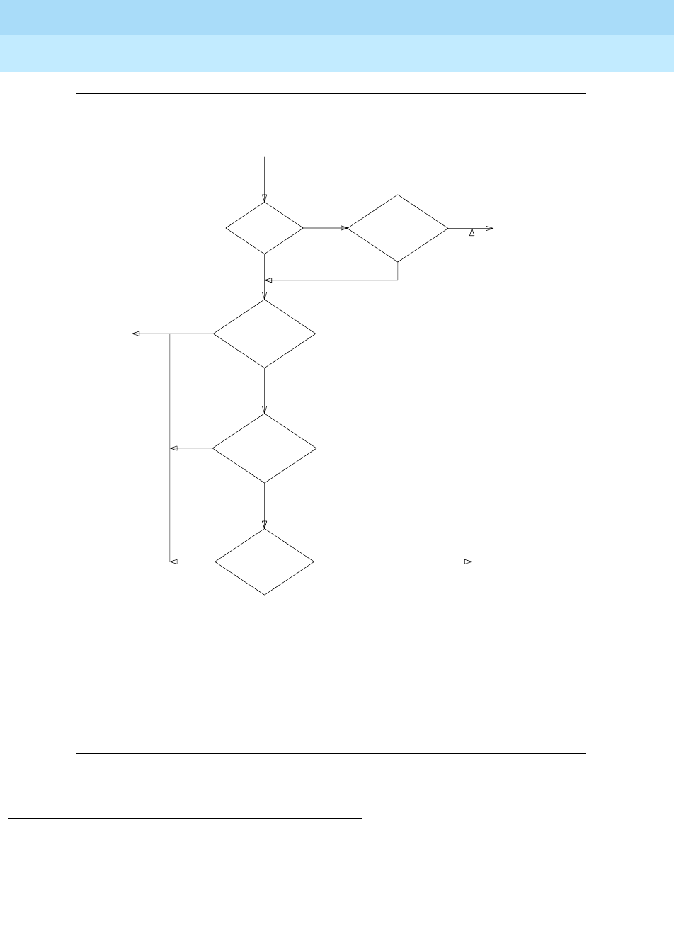
DEFINITY Enterprise Communications Server Release 6
Administration and Feature Description
555-230-522 Issue 4
May 1998
Basic Features
Page 4-517Restricted/Unrestricted Call Lists
4
Figure 4-5. Authorization Check Flowchart
Interactions
None
DIALED NUMBER
# ON
RCL
USER
TOLL
RESTR
# ON
TOLL
LIST
IS
# ON
USERS
UCL
IS
USERS
COR
RCL ON
IS
IS
IS DENY
THE
CALL
YES
YES
NO NO
ALLOW
CALL
THE NO
NO
NO
YES
YES
YES
ANY FEATURE INTERACTIONS THAT
MIGHT TAKE PLACE, SUCH AS WITH
AUTHORIZATION CODES
THIS FLOWCHART DOES NOT REFLECT

DEFINITY Enterprise Communications Server Release 6
Administration and Feature Description
555-230-522 Issue 4
May 1998
Basic Features
Page 4-518Restriction — Controlled
4
Restriction — Controlled
Controlled Restrictions allow a voice-terminal user with console permission to
activate or deactivate specific restrictions.
How to administer Controlled Restrictions
Detailed description
Use Controlled Restriction to administer the following restrictions:
■Outward — The voice terminal cannot place calls to the public network.
■Total — The voice terminal cannot place or receive calls. (Allowed calls
include calls to a remote-access extension, terminating-trunk transmission
tests, and Emergency Access to Attendant calls.)
Direct Inward Dialing (DID) calls are routed to the attendant or a recorded
announcement. All other calls receive intercept tone.
■Termination — The voice terminal cannot receive any calls. Incoming calls
are routed to the attendant, are redirected via Call Coverage, or receive
intercept treatment.
■Station-to-Station — The voice terminal cannot place or receive
station-to-station calls.
To activate Controlled Restriction:
1. Dial the group or extension feature access code.
Required forms
Form Field Page
Feature Access
Code (FAC)
■User Control Restrict Activation and
Deactivation
■Group Control Restrict Activation and
Deactivation
5-113
Feature-Related
System Parameters
■Controlled Outward Restriction
Intercept Treatment
■Controlled Termination Restriction (Do
Not Disturb)
■Controlled Station-to-Station Restriction
5-123

DEFINITY Enterprise Communications Server Release 6
Administration and Feature Description
555-230-522 Issue 4
May 1998
Basic Features
Page 4-519Restriction — Controlled
4
2. Dial the number for the type of restriction desired:
— 1 for outward
— 2 for total
— 3 for termination
— 4 for station-to-station
3. Dial the voice-terminal extension (Attendant Control — Extension) or the
Class of Restriction (COR) for a group of voice terminals (Attendant
Control — COR).
Considerations
■All voice terminals with the same COR are affected by a group restriction.
When a call is placed, both individual and group restrictions are checked.
Interactions
■Call Coverage
Controlled Restrictions are not checked for covering users.
■Call Forwarding
Controlled Restrictions for the forwarded-to extension are checked when
Call Forwarding All Calls is active.
■Class of Restriction
COR is checked when a call is authorized.
■Priority Call
If a a station user or a Station-to-Station Restricted user activates priority
calling before they dial another station, they receive intercept tone. They
receive this tone whether you set Controlled Station to Station
Restriction on the Feature-Related System Parameters form to y or to
n.
■Uniform Call Distribution
Calls dialed through the UDP are not restricted by Outward Restriction.

DEFINITY Enterprise Communications Server Release 6
Administration and Feature Description
555-230-522 Issue 4
May 1998
Basic Features
Page 4-520Ringback Queuing
4
Ringback Queuing
Ringback Queuing places outgoing calls in an ordered queue (first-in, first-out)
when all trunks are busy. The voice-terminal user is automatically called back
when a trunk becomes available.
How to administer Ringback Queuing
NOTE:
Automatic Callback and Ringback Queuing share the same intervals,
codes, and buttons.
Detailed description
If a multiappearance voice-terminal user has an idle Automatic Callback button
and tries to access an all-trunks-busy trunk group, Ringback Queuing is
activated automatically. The lamp associated with the Automatic Callback button
lights and confirmation tone is heard.
Ringback Queuing is automatic for a single-line voice terminal. After dialing is
complete, the user hears confirmation tone if the queue is available. No action is
required.
The callback call is automatically placed to the terminal when a trunk becomes
available. When the user answers the callback call (designated by a 3-burst
alerting signal), the original call automatically continues. Redialing is not
required.
Queuing can be specified for any non-DCS outgoing-only trunk group, or for the
outward direction of a non-DCS 2-way trunk group.
Required forms
Form Field Page
Trunk Groups ■Queue Length 7-115
Feature-Related System Parameters ■Automatic Callback-No
Answer Timeout Interval 5-123
Feature Access Code (FAC) ■Automatic Callback
Activation/ Deactivation 5-113
Station (multiappearance) ■Buttons/Feature Button
Assignments
— auto-cback
6-14

DEFINITY Enterprise Communications Server Release 6
Administration and Feature Description
555-230-522 Issue 4
May 1998
Basic Features
Page 4-521Ringback Queuing
4
Considerations
■Queuing can reduce the number of trunks required.
■A multiappearance voice terminal can have one callback call associated
with each Automatic Callback button assigned to the terminal.
■A single-line voice terminal can have only one automatic-callback call
waiting at a time.
■Queue requests are canceled when:
— A trunk is not available within 30 minutes.
— The user does not answer the callback call within the administered
interval.
— The voice terminal is busy when the callback call is attempted.
— The user dials the Ringback Queuing cancellation code or presses
the Automatic Callback button associated with the queued call.
■Incoming tie-trunk calls cannot queue on an outgoing trunk group. The
system does not know the calling number and cannot originate the
callback call.
■The system checks the busy/idle status of the trunk group just once. If all
trunks are busy, the call queues, even if a trunk has become available by
the time the caller has completed dialing. This occasionally results in the
caller being called back immediately after receiving confirmation tone and
going on-hook.
■A trunk may appear to be available, yet outgoing calls are queued. The
trunk is not free, because it is reserved for a previous Automatic Callback
request.
Interactions
■Automatic Callback
If you provide Ringback Queuing, you must also provide Automatic
Callback.
■Automatic Route Selection
If a multiappearance voice-terminal user has an Automatic Callback
button, makes an ARS call, and all trunks are busy, Ringback Queuing is
activated automatically.
■Bridged Call Appearance
Ringback Queuing is not provided on calls placed from a bridged call
appearance.
■Call Coverage
Callback calls do not redirect, even if Send All Calls is active.

DEFINITY Enterprise Communications Server Release 6
Administration and Feature Description
555-230-522 Issue 4
May 1998
Basic Features
Page 4-522Ringback Queuing
4
■Call Forwarding All Calls
Callback calls are not forwarded.
■Call Pickup
Callback calls cannot be picked up.
■Conference or Transfer
A single-line voice terminal cannot receive a callback call while it has a
call on hold. It can have only one active call at a time.
■Internal Automatic Answer
Automatic calls generated by Ringback Queuing are not eligible for IAA.
■Remote Access
Callback calls cannot be made to Remote Access users because the
system does not know the calling number.

DEFINITY Enterprise Communications Server Release 6
Administration and Feature Description
555-230-522 Issue 4
May 1998
Basic Features
Page 4-523Ringer Cutoff
4
Ringer Cutoff
Ringer Cutoff allows multiappearance voice-terminal users to turn audible ringing
signals on and off. This feature does not affect visual alerting.
When this feature is enabled, only Priority ring (by default 3-burst), Redirect
Notification, Intercom ring, and manual signaling ring at the voice terminal.
Internal and external calls do not ring.
How to administer Ringer Cutoff
Detailed description
The following table summarizes which calls are affected by Ringer Cutoff.
NOTE:
If Call Coverage is set to Cover All and Ringer Cutoff and Redirect
Notification are both active, then Redirect Notification is received. If
Redirect Notification is not active, no audible alerting is received.
Required forms
Form Field Page
Station (multiappearance) ■Redirect Notification
■Button/Feature Button Assignments
— ringer-off
6-14
Redirect notification is
Call Type Inactive Active
Voice terminal to voice terminal no ring ping
Attendant to voice terminal no ring ping
Internal tie to voice terminal no ring ping
APLT trunk to voice terminal no ring ping
Trunk to voice terminal no ring ping
Priority call to voice terminal yes yes
Intercom call to voice terminal yes yes
Manual signaling yes yes

DEFINITY Enterprise Communications Server Release 6
Administration and Feature Description
555-230-522 Issue 4
May 1998
Basic Features
Page 4-524Ringer Cutoff
4
A user may not wish to be disturbed by the arrival of incoming calls, yet not want
calls to be redirected immediately to coverage. For example, an executive may
want a secretary to answer calls before they redirect to coverage. The bridging
user (the secretary) is not affected by the executive’s activation of Ringer Cutoff.
To activate Ringer Cutoff, the user presses the voice-terminal Ringer-Cutoff
button. The associated status lamp lights. Ringing is silenced. If Ringer Cutoff is
activated while the voice terminal is ringing with an internal or external call, the
ringer is silenced.
To deactivate Ringer Cutoff, the user presses the Ringer-Cutoff button again.
Ringing returns to audible. If the selected call is active, other incoming calls do
not start ringing. If the selected call is in the ringing state, the ringer becomes
audible.
Considerations
■A multiappearance voice terminal may have just one Ringer Cutoff button.
■If a primary extension and all other users with bridged appearances of the
primary extension activate Ringer Cutoff, an incoming call silently alerts all
of the terminals and then redirects to coverage.
Interactions
■Automatic Callback
If Ringer Cutoff is active, an Automatic Callback call returns to the user’s
voice terminal with the normal 3-burst ring.
■Bridging
A bridging user is not affected by a primary extension’s activation of
Ringer Cutoff. Nor is the primary extension affected by the bridging user’s
activation of Ringer Cutoff.
■Call Forwarding All Calls
If Ringer Cutoff and Call Forwarding All Calls are active, the user receives
redirect notification, if you set Redirection Notification to y for the
extension.
■Distinctive Ringing
Ringer Cutoff turns off only the distinctive ringing of internal and external
calls. Intercom ringing, priority ringing, redirect notification, and manual
signaling are not turned off.
■Intercom (Automatic and Dial)
If Ringer Cutoff is active, intercom calls still ring the user’s voice terminal.

DEFINITY Enterprise Communications Server Release 6
Administration and Feature Description
555-230-522 Issue 4
May 1998
Basic Features
Page 4-525Ringer Cutoff
4
■Manual Signaling
If Ringer Cutoff is active, Manual Signaling still rings the user’s voice
terminal.
■Ringback Queuing
If Ringer Cutoff is active, the return call for Ringback Queuing still rings the
user’s voice terminal with a 3-burst alerting signal.
■Priority Calling
If Ringer Cutoff is active, priority calls still ring at the user’s voice terminal.
■Send All Calls
When Ringer Cutoff and Send All Calls are both active, the user receives
redirect notification, when Redirection Notification is set to y for
that extension.

DEFINITY Enterprise Communications Server Release 6
Administration and Feature Description
555-230-522 Issue 4
May 1998
Basic Features
Page 4-526Ringing — Abbreviated and Delayed
4
Ringing — Abbreviated and Delayed
Ringing — Abbreviated and Delayed allows you to assign one of four ring types
to each call appearance on a voice terminal. Whatever treatment is assigned to a
call appearance is automatically assigned to each of its bridged call
appearances.
How to administer Ringing — Abbreviated and
Delayed
Detailed description
Ring types fall into two categories:
■Those that alert consistently and don’t change:
— Ringing, in which the lamp flashes and audible ringing occurs
— Silent ringing, in which the lamp flashes and audible ringing does
not occur
■Those that transition from one ringing state to another:
— Abbreviated ringing, in which ringing continues for as many cycles
as specified by the automatic abbreviated/delayed transition
interval and then changes to silent alerting
— Delayed ringing, in which visual alerting continues for as many
cycles as specified by the automatic abbreviated/delayed
transition interval and then changes to ringing
For a station with call appearances that have either abbreviated or delayed
ringing, an abbreviated-ring button associated with that station’s extension can
be assigned on a different station. When one of those call appearances is being
alerted, pressing the button forces immediate transition of the alerting — that is,
from ringing to silence or from silence to ringing.
Required forms
Form Field Page
Feature-Related System
Parameters
■Auto Abbreviated/Delayed Transition
Interval (rings) 5-123
Station ■Per Button Ring Control
■Feature Buttons
6-14

DEFINITY Enterprise Communications Server Release 6
Administration and Feature Description
555-230-522 Issue 4
May 1998
Basic Features
Page 4-527Ringing — Abbreviated and Delayed
4
This feature is most useful in bridging situations in which some users want to be:
■Audibly alerted to a call immediately upon its arrival
■Audibly notified if the call has not been answered within a specified
number of rings or if they have indicated.
■Able to stop the audible alerting if the call is not being answered by the
principal and the user is not able to answer the call.
Because ring type can be specified on a per-station basis, mixing ring-type
specifications within a station’s access to a particular extension is possible.
For Ringing — Abbreviated and Delayed, each call appearance must be:
■Assigned a ring type
■Administered to transition when the:
— Abbreviated/delayed transition interval is reached or when the
voice-terminal user presses the abbreviated ring button
— Voice-terminal user presses the abbreviated ring button, regardless
of the abbreviated/delayed transition interval
Ring options
You assign one of the following ring types to each line button.
■Abbreviated Ring
A call rings the terminal until the automatic or manual abbreviated/delayed
transition occurs. Then the call silently alerts the terminal.
■Delayed Ring
A call silently alerts the terminal until the automatic or manual
abbreviated/delayed transition occurs. Then the call rings the terminal.
■No Ring
A call silently alerts the terminal and does not transition.
■Ring
A call rings the terminal and does not transition.
End user operation
■You can administer Ringing — Abbreviated and Delayed to transition
automatically and manually for each call appearance. Automatic transition
does not require any user action. The transition occurs based on the
administered abbreviated/delayed transition interval.
■Manual transition does require user action. Users press the
abbreviated-ring button on their terminal. This action forces the
abbreviated/delayed transition to occur for all calls at the administered
extension. Calls to other extensions that alert the terminal are not affected.

DEFINITY Enterprise Communications Server Release 6
Administration and Feature Description
555-230-522 Issue 4
May 1998
Basic Features
Page 4-528Ringing — Abbreviated and Delayed
4
Considerations
■You cannot assign Ringing — Abbreviated and Delayed to a system
console.
■At any one time, a voice terminal can have separate calls visually alerting
and audibly alerting.
■If you administer a call appearance for delayed or abbreviated ringing
and do not administer the call appearance for automatic
abbreviated/delayed transition, assign an abbreviated-ring button to the
call appearance extension on that terminal for that call appearance’s
extension.
■You can assign Ringing — Abbreviated and Delayed to analog stations,
whether they are administered as a primary call appearance or a bridged
call appearance set. However, because analog stations cannot visually
alert, a user may unexpectedly answer an incoming call while intending to
originate a call.
Interactions
When one of the following features attempts to alert a station, the ringing
presented to the user is influenced by the ring-type translations specified for
Ringing — Abbreviated and Delayed. Undesirable feature operation may result if
these translations are set inappropriately. For example, a ring type of no ringing
results in the station not being alerted audibly.
■Automatic Callback
■Automatic Call Distribution (ACD)/Hunting
■Automatic Circuit Assurance (ACA)
■Busy Verification of Terminals
■Consult
■Night Service (Unattended Console Service)
■Personal Central Office Line (PCOL)
■Priority Calling
■Ringback Queuing
■Security Violation Notification (SVN)
■Terminating Extension Group (TEG)
■Active Station Ringing
This feature determines when a station is audibly alerted. Active Station
Ringing determines if the ring is to be permitted, shortened to a single ring
cycle, or suppressed. Single ring timing begins when the call rings at
each station that has access to the appearance. In this way, even though

DEFINITY Enterprise Communications Server Release 6
Administration and Feature Description
555-230-522 Issue 4
May 1998
Basic Features
Page 4-529Ringing — Abbreviated and Delayed
4
a call has been alerting other ringing or abbreviated-ringing stations for
more than one ring cycle, the delayed-ringing stations have a full cycle of
ring beginning at the abbreviated/delayed transition.
■Administration Without Hardware
It is possible to assign Ringing — Abbreviated and Delayed to stations
administered without a specified port. When stations are associated with
ports, these assignments become effective.
■Attendant Console
Ringing — Abbreviated and Delayed cannot be assigned to an attendant
console.
■Call Coverage
If the number-of-rings interval for coverage is shorter than the automatic
transition interval, a call redirects to coverage before audibly alerting a call
appearance that has delayed ringing. However, timing continues for the
automatic transition interval in case no coverage point is available and the
call continues to alert at the station.
When a call is immediately redirected to coverage (because of Cover
Active, Cover All, Cover Busy, or Send All Calls), the Ringing —
Abbreviated and Delayed feature has no effect.
■Call Forwarding — Busy/Don’t Answer
When a call is forwarded because it is not answered in the specified time,
the call stops alerting the station and is not affected by the Ringing —
Abbreviated and Delayed feature. However, timing continues for the
automatic transition interval in case forwarding fails and the call continues
to alert at the station.
If the call forward don’t answer interval is shorter than the automatic
transition interval, the call redirects to the forwarded-to extension before
ringing a station with a ring type of delayed ringing.
■Call Vectoring — Expert Agent Selection — Logical Agents
Calls routed to a logical agent use the translations for the Ringing —
Abbreviated and Delayed feature of the station being used by the agent.
■Data Extension Calls
Data Extension calls are not affected by the ring values, but continue to be
directed by the bridged call alerting administration.
■Distinctive Alerting (Ringing)
The Ringing — Abbreviated and Delayed feature affects all audible
alerting using the 1-, 2-, or 3-burst pattern.
■Hospitality Features — Do Not Disturb
The Do Not Disturb feature takes precedence over the Ringing —
Abbreviated and Delayed feature in blocking ringing to the station.

DEFINITY Enterprise Communications Server Release 6
Administration and Feature Description
555-230-522 Issue 4
May 1998
Basic Features
Page 4-530Ringing — Abbreviated and Delayed
4
■Integrated Services Digital Network — World Class Basic Rate Interface
Several of the protocol variations supported by the World Class BRI
feature do not permit the messaging required for control of the station’s
ringer by Ringing — Abbreviated and Delayed. In this case, ring type is
forced to a value of ring.
■Multiappearance Preselection and Preference
The system automatically selects any alerting call on a station whether or
not it is ringing if the Per Button Ring Control field is set to n. If the
field is set to y, it selects only audibly ringing calls.
■Off-Premises Station and Off-Premises Extension Lines
The ring type assigned to OPS and OPX lines are forced to a value of ring.
■PCOL Calls
PCOL calls are not affected by the ring values, but continue to be directed
by the bridged call alerting administration.
■Redirection Notification
If Redirection Notification is enabled, terminals only receive redirection
notification if the alerting button or the first call appearance has an
assigned ring value of ring or abbreviated ring. Bridged terminals only
receive redirection notification for a forwarded call if the Per Button
Ring Control field is set to y and the call appearance has an assigned
ring value of ring or abbreviated ring.
■Ringer Cutoff
Ringer Cutoff takes precedence over Ringing — Abbreviated and
Delayed. Pressing the ringer cutoff button turns off audible alerting at all
call appearances and bridged appearances on the terminal.
■Temporary Bridged Appearances
Temporary Bridged Appearances are not affected by the Ringing —
Abbreviated and Delayed feature. They always silently alert a station.
■Terminating Extension Group Calls
TEG calls are not affected by the ring values, but continue to be directed
by the bridged call alerting administration.
■Voice Mail Systems
Voice mail systems may look for ringing applied to a port to trigger call
answer. Undesirable adjunct operation may result if ring-type translations
are inappropriately set for ports serving these adjuncts.

DEFINITY Enterprise Communications Server Release 6
Administration and Feature Description
555-230-522 Issue 4
May 1998
Basic Features
Page 4-531Security Violation Notification
4
4
Security Violation Notification
Security Violation Notification (SVN) allows you to set security-related parameters
and to receive notification when the limits that you have established are
exceeded. You can run reports related to invalid access attempts. You can also
disable a login ID or remote access authorization that is associated with a
security violation.
When a security violation occurs, SVN notifies a designated referral point. This
can be an attendant console, a display-equipped voice terminal, or a voice
terminal without display for SVN referral calls with announcements.
The system monitors and reports on the following types of security violations:
■Login violations
■Remote access barrier code violations
■Authorization code violations
■Station security code violations
DEFINITY ECS provides the option to log a major alarm if a security violation
occurs involving a Lucent Technologies services login ID. Lucent Technologies is
responsible for retiring the alarm.
DEFINITY ECS Release 6 System Monitoring and Reporting
provides more
information on how to run reports, and respond to security violations.
How to administer SVN
Table 4-84. Required forms
Form Field Page
Security-Related System Parameters ■All 5-266
Station (multi-appearance) ■ Button Assignments (if
needed)
— asvn-halt
— lsvn-halt
— rsvn-halt
— ssvn-halt
6-14
Continued on next page

DEFINITY Enterprise Communications Server Release 6
Administration and Feature Description
555-230-522 Issue 4
May 1998
Basic Features
Page 4-532Security Violation Notification
4
Detailed description
To effectively monitor the security of your system, you need to know how often
both valid and invalid attempts at system entry are normally made. Then you will
know if the number of invalid attempts is unusually high. A significant increase in
such attempts can mean the system is being compromised.
NOTE:
It is recommended that you print and clear the security-violation
measurement reports at least once a month. In a busy system, once a week
is not too frequent.
Security violation thresholds and notification
As an example, you may determine that during a forty-hour week, it’s normal for
users to submit about 1,000 valid barrier codes and 150 invalid barrier codes;
that is, about 3.75 invalid barrier codes are submitted per hour.
With this information, you may decide to declare that a security violation occurs
during any hour in which 8 invalid barrier codes are submitted. If you know that
during an 8-hour period, about 30 invalid codes are submitted, you might set the
threshold to count a security violation when 40 invalid codes are submitted within
eight hours.
You can administer SVN to place a referral call to the location of your choice
whenever the established thresholds are reached.
Invalid attempts accumulate at different rates in the various security arenas
(login, authorization code, remote access, and station security code), depending
on feature usage and the number of users on a server. For this reason, you
administer thresholds separately for each type of violation.
Remote Access ■Disable Following A
Security Violation? 5-258
Login Administration ■Disable Following A
Security Violation? 2-7
Recorded Announcements
(optional)
■All — one
announcement for each
type of referral call
5-26
Table 4-84. Required forms — Continued
Form Field Page
Continued on next page

DEFINITY Enterprise Communications Server Release 6
Administration and Feature Description
555-230-522 Issue 4
May 1998
Basic Features
Page 4-533Security Violation Notification
4
Sequence of events
The following is the sequence of events that occur when a SVN is enabled and a
security violation is detected:
1. SVN parameters are exceeded (the number of invalid attempts permitted
in a specified time interval is exceeded).
2. A SVN referral call (with announcements, if assigned) is placed to a
designated point, and SVN provides an audit trail containing information
about each attempt to access the switch.
3. SVN disables a login ID or Remote Access following the security violation.
4. The login ID or Remote Access remains disabled until re-enabled by an
authorized login ID, with the correct permissions.
Reporting
The system reports information about security violations in the following ways:
■In real time — you can use the monitor security-violations command to
monitor security violations as they may be occurring. Enter this command,
followed by the type of security violation you want to monitor (logins,
remote-access, authorization-codes, or station-security-codes).
■On an immediate basis — when a security violation occurs, the system
sends a priority call to a designated referral point (attendant console or
voice terminal). Thus, there is some chance of apprehending the violator
during the attempted violation.
Upon notification, you can request the Security Violations Status Reports,
which show details of the last sixteen security violations of each type. The
Barrier Code and Authorization Code reports also include the calling party
number from which the attempt was made, where available.
■On a historical basis — the number of security violations of each type, as
well as other security measurements, are collected and displayed in the
Security Violations Summary and Detail reports. These reports show
summary information since the counters were reset by the clear
measurements security-violations command or since system
initialization. They do not show all aspects of the individual security
violations.
SVN- halt buttons
You can administer buttons for the notification extension to stop notification calls.
However, this may pose a security risk. Do not use these buttons if you do not
really need them.
To find out what svn-halt buttons exist in the system, enter the command:
display svn-button-location

DEFINITY Enterprise Communications Server Release 6
Administration and Feature Description
555-230-522 Issue 4
May 1998
Basic Features
Page 4-534Security Violation Notification
4
The SVN Button Locations screen appears.
Screen 4-5. SVN Button Locations
SVN Referral Call With Announcement
The SVN Referral Call with Announcement option has the capacity to provide a
recorded message identifying the type of violation accompanying the SVN
referral call. Using Call Forwarding, Call Coverage, or Call Vector Time-of-Day
Routing (to route to an extension or a number off the switch), SVN referral calls
with announcements can terminate to a point on or off the switch.
Use of other means to route SVN referral calls to alternate destinations are not
supported at this time. An attempt to use an alternate method to route SVN
referral calls may result in a failure to receive the call or to hear the
announcement.
Dealing with security violations
When a security violation has occurred, there are steps that you can take to
ensure that this same attempt is not successful in the future.
--------------------------------------------------------------------------
--------------------------------------------------------------------------
SVN BUTTON LOCATIONS
LOGIN SECURITY VIOLATIONS
Name: Administrator______________
Extension: 81234____
REMOTE ACCESS SECURITY VIOLATIONS
Name: Administrator______________
Extension: 81234____
AUTHORIZATION CODE SECURITY VIOLATIONS
Name: Administrator II___________
Extension: 81235____
STATION SECURITY CODE VIOLATIONS
Name: Administrator II___________
Extension: 81235____
----------------------------------------------------------------------------
--------------------------------------------------------------------------

DEFINITY Enterprise Communications Server Release 6
Administration and Feature Description
555-230-522 Issue 4
May 1998
Basic Features
Page 4-535Security Violation Notification
4
Enable/disable a login ID
The Login Administration form Disable Following a Security
Violation field is used to set the SVN parameters for a single login. When set
to y, SVN disables the specified login ID if it is involved in a security violation. The
Disable a Login ID Following a Security Violation field is
dynamic and only appears when the login component of SVN is enabled.
To enable a login ID that has been disabled by a security violation, or disabled
manually with the command disable login:
1. Log in to the switch using a login ID with the correct permissions.
2. Enter the command enable login <login ID>.
To disable a login ID:
1. Log in to the switch using a login ID with the correct permissions.
2. Enter the command disable login <login ID>.
List the status of a login ID
To list the status of a login ID:
1. Log in to the switch using a login ID with the correct permissions.
2. Enter the command list login.
You see a display indicating the status of the specified login ID. A login ID status
can be listed as:
■Disabled — The login ID was disabled manually using the disable login
command.
■Svn-disabled — A security violation was detected for that login ID and the
login was disabled by the SVN feature.
■Active — The login ID is currently logged in.
■Inactive — The login ID is not logged in.
Enable/disable Remote Access
The Remote Access form Disable Following a Security Violation
field is used to set the SVN parameters for Remote Access on a system-wide
basis. When set to y, SVN disables Remote Access for the entire system if a
remote access security violation occurs. The Disable Following a
Security Violation field is dynamic and only appears when the remote
access component of SVN is enabled.

DEFINITY Enterprise Communications Server Release 6
Administration and Feature Description
555-230-522 Issue 4
May 1998
Basic Features
Page 4-536Security Violation Notification
4
To enable remote access that has been disabled following a security violation, or
disabled manually with the command disable remote access:
1. Log in to the switch using a login ID with the correct permissions.
2. Enter the command enable remote-access.
To disable Remote Access:
1. Log in to the switch using a login ID with the correct permissions.
2. Enter the command disable remote-access.
View the status of Remote Access
You can check the status of remote access and barrier codes.
To list the status of a login ID:
1. Log in to the switch using a login ID with the correct permissions.
2. Enter the command status remote-access[print].
This command shows whether remote access is enabled or disabled, the
existing barrier codes, their expiration dates, and their status. See ‘‘Remote
Access’’ on page 5-258 for more information.
Considerations
■You may only administer one referral destination per system for each type
of violation.
■Exercise caution when administering bridged appearances for stations
that are used as SVN referral destinations. SVN referral calls terminating to
bridged appearances
must
be accompanied by an announcement
message or
must
route to bridge appearances equipped with a display
module. SVN referral calls that do not have an announcement and
terminate to a bridged appearance not having a display will not provide an
indication of the nature of the call.
■An authorization code violation with remote access generates two SVNs --
one displaying “authorization code violation” and one displaying “barrier
code violation,” even though the correct barrier code was input. These two
displays help you determine that the violation took place in the context of a
remote access attempt, not an attempt to place an outgoing call to an ARS
trunk.

DEFINITY Enterprise Communications Server Release 6
Administration and Feature Description
555-230-522 Issue 4
May 1998
Basic Features
Page 4-537Security Violation Notification
4
Interactions
■Call Coverage, Call Forwarding, and Call Pickup
These features are supported for SVN only if you use recorded
announcements.
■Centralized Attendant Services
CAS attendants cannot receive referral calls from branch locations.
■DCS
SVN does not support referral calls across a DCS network.
■Priority Calling
All SVN referral calls are priority calls.

DEFINITY Enterprise Communications Server Release 6
Administration and Feature Description
555-230-522 Issue 4
May 1998
Basic Features
Page 4-538Send All Calls
4
Send All Calls
Send All Calls allows users to temporarily direct all incoming calls to coverage
regardless of the assigned call-coverage redirection criteria. Covering users can
temporarily remove their voice terminals from the coverage path.
How to administer Send All Calls
Interactions
■Automatic Call Distribution
With Send All Calls active, an ACD agent is still available for ACD calls.
■Automatic Callback
Send All Calls does not work with Automatic Callback calls.
■Call Coverage
Refer to Call Coverage in this document to learn about that feature and its
impact on Send All Calls.
■Direct Department Calling/Uniform Call Distribution
With Send All Calls active, a member of a DDC/UCD hunt group is not
available for calls.
■Internal Automatic Answer
IAA does not apply to calls to the original called extension when that
extension has Send All Calls active.
■Night Service
With the console in Night Service and Send All Calls active, a call covers
after the “no answer” ring interval.
Required forms
Form Field Page
Feature Access Code (FAC) ■Send All Calls Activation and
Deactivation 5-113
Station (multiappearance) ■Button/Feature Button Assignments
— send-calls 6-14
Coverage Path ■DND/SAC/Goto Cover 5-94

DEFINITY Enterprise Communications Server Release 6
Administration and Feature Description
555-230-522 Issue 4
May 1998
Basic Features
Page 4-539Service Observing
4
Service Observing
Service Observing allows a specified user, such as a supervisor, to observe or
monitor another user’s calls. In this section, “observer” refers to the supervisor
who is observing calls. “Agent” refers to the terminal, attendant, or logical agent
being observed. A vector directory number (VDN) call can also be observed.
Observers can observe in listen-only or listen-and-talk mode.
Note that you set up Service Observing to observe a particular extension, not all
calls to all extensions at a terminal.
NOTE:
Service Observing may be subject to federal, state, or local laws, rules, or
regulations or require the consent of one or both of the call parties.
Familiarize yourself and comply with all applicable laws, rules, and
regulations before using this feature.
How to administer Service Observing
Required forms
Form Field Page
System Parameters
Customer-Options
■Service Observing (Basic) — for basic
or Logical Agent ID observing
■Service Observing (Basic) and Service
Observing (Remote/By FAC) — for
remote observing or observing via
feature access code
■Service Observing (Basic) and the
Service Observing (VDNs) — for VDN
observing
■Vectoring (Prompting) — for
vector-initiated observing
5-277
Class of Restriction ■Can Be Service Observed
■Can Be Service Observer
■Service Observing COR Table
5-72
Continued on next page

DEFINITY Enterprise Communications Server Release 6
Administration and Feature Description
555-230-522 Issue 4
May 1998
Basic Features
Page 4-540Service Observing
4
■Class of Restriction form
— On the agent’s COR form, set Can Be Service Observed to yes
to allow the extension to be observed.
— On the observer’s COR form, set Can Be Service Observer to
yes to allow the extension owner to observe others’ extensions.
— On the observer’s COR form, grant permission to observe specific
CORs. On the Service Observing COR table, enter y next to the
CORs to be observed.
Detailed description
To begin observing, the observer presses the Service Observing button plus the
agent’s extension number. Initially, the observer is in listen-only mode. The
observer presses the Service Observing button to toggle between listen-only and
listen/talk mode. The lamp indicates which mode the observer is in.
To deactivate Service Observing, the observer hangs up, selects another call
appearance, or presses the disconnect or release button.
An observer can observe an agent who is not active on a call. The observer is in
the wait state until the agent receives a call, then the observer is bridged onto the
call.
Feature-Related
System Parameters
■Service Observing Warning Tone
■Expert Agent Selection (Logical Agent
ID)
5-123
Station
(multiappearance)
■Button/Feature Button Assignment
(basic, VDN, Logical Agent ID)
— serv-obsrv
6-28
Feature Access Code
(FAC)
■Service Observing Listen Only Access
Code (remote/by FAC, VDN, Logical
Agent ID)
■Service Observing Listen/Talk Access
Code (remote/by FAC, VDN, Logical
Agent ID)
5-113
Required forms — Continued
Form Field Page
Continued on next page

DEFINITY Enterprise Communications Server Release 6
Administration and Feature Description
555-230-522 Issue 4
May 1998
Basic Features
Page 4-541Service Observing
4
You can administer a warning tone on each system to let agents and callers know
when someone is observing a call. Before connection, the conference tone may
add 2-3 seconds delay if enabled. The parties hear a 2-second, 440-Hz warning
tone before an observer connects to a call, followed by a half-second burst of
this tone every 12 seconds during observation.
Observing logical-agent IDs
With EAS, an observer can observe agents based on their logical-agent ID rather
than their physical voice terminal. The observer enters the logical-agent ID
extension number of an agent, who must be logged in to a voice terminal. The
observer can monitor every ACD, personal, and Direct Agent call delivered to or
placed by the agent, including calls placed to the physical extension.
Only one observer can observe a physical terminal at one time. An observer
cannot observe a logical agent ID extension at a physical terminal that is already
being observed. Likewise, an observer cannot observe a physical extension that
is being observed as a logical-agent ID extension.
Observing VDNs
To observe a VDN, the observer enters a specific VDN extension and bridges
onto calls (one call at a time) that have started vector processing for that VDN.
The observer hears all tones, call prompting, caller dialing, announcements,
music, and speech that the agent and caller hear. If an observer is in a COR
administered to hear VDN of Origin announcements and has a VOA Repeat
button, he or she can hear and replay VDN of Origin announcements.
The observer sees the name of the VDN, agent, or trunk as each is accessed in
sequence by the VDN. For example, during vector processing the VDN name is
displayed, but when the call connects to an agent, the agent name is displayed.
When the observer connects to a call in vector processing, the system maintains
the connection until the call is disconnected or the observer hangs up, even if the
call is routed or transferred externally. If the observer does not disconnect after
one observed call is disconnected, the observer is connected to another call on
the same VDN. Observing is listen-only as long as the call is in vector
processing. Once the call is out of vector processing, an observer with listen/talk
capability can talk as well as listen.
Observing remotely or by FAC
Observers can observe calls from a remote location or local terminal using
Service Observing FACs. When observing remotely, observers must use FACs.
Different FACs are required for listen-only and listen/talk modes. When observing
locally or remotely by FAC, the observer cannot toggle between modes. Physical
extensions, logical-agent ID extensions, and VDNs can be observed remotely.
Remote observing is initiated through Remote Access or Call Vectoring.

DEFINITY Enterprise Communications Server Release 6
Administration and Feature Description
555-230-522 Issue 4
May 1998
Basic Features
Page 4-542Service Observing
4
■With Remote Access, an observer accesses a switch via a trunk group
dedicated to Remote Access or via a DID to the Remote Access
extension. Remote observing works with all types of DID trunks, including
ISDN-PRI and tie trunks, and DCS over analog, T1, or PRI.
■With Call Vectoring, an observer accesses a switch by dialing a VDN
extension or a central office (CO) trunk that has a VDN extension as its
incoming destination. Using route-to commands, you can design a
Service Observing vector to allow a VDN call to directly access a specific
extension to be observed or a Service Observing dial tone. At the dial
tone, observers can enter any extension that they are authorized to
observe. The following is a simple example of a Service Observing vector.
1.wait-time 0 seconds hearing ringing
2.collect 5 digits announcement 2300
(“please dial your 5- digit security code”)
3.goto step 5 if digits = 12345
4.disconnect after announcement 2000
5.collect 1 digits announcement 2310
(“enter 1 to observe sales, 2 to observe billing”)
6.route-to number 113001 with cov n if digit = 1
(11=listen-only observe, 3001=”Sales” VDN)
7.route-to number 113002 with cov n if digit = 2
(11=listen-only observe, 3002=”Billing” VDN)
8.goto step 5 if unconditionally
You can combine Call Prompting and Call Vectoring to provide security and to
limit observation. See
DEFINITY Enterprise Communications Server Call
Vec toring/EAS Guide
for information about creating a Service Observing vector.
Service Observing indicators
Table 4-85 shows general Service Observing indicators that observers receive.
Table 4-85. General Indications to Observer
Condition Button Lamp Tone
Not active Dark None
Denied activation Broken flutter Intercept/busy/reorder
Activated Steady/Winking Confirmation tone followed by
silence or connection to call.
Observing (listen only) Steady Hear call
Observing (listen/talk) Winking Hear/talk on call
In wait state Flash None
Denied observing Flash (wait state) Silence/ineligible tone followed by
silence

DEFINITY Enterprise Communications Server Release 6
Administration and Feature Description
555-230-522 Issue 4
May 1998
Basic Features
Page 4-543Service Observing
4
Table 4-86 through Table 4-88 show the indicators that observers receive when
they activate and use Service Observing. In these tables:
■Wait state means that the observer has activated Service Observing but
there are no calls or a call cannot be observed. A call appearance is not
reserved. The observer must have an idle call appearance available to be
used by Service Observing when an observable call comes in.
■Ineligible tone is heard when an observed call becomes ineligible for
observation. See ‘‘Considerations’’ on page 4-547 for conditions that make
a call ineligible. This tone is the “hold confirmation tone”— a rapid series
of 5 short 440-Hz beeps. The observer does not hear this tone if the agent
receiving the ineligible call hears zip tone.
1. Extension COR cannot be observed or COR for observer calling permission does not
allow observing the COR of extension to be observed.
Table 4-86. Feedback When Activation Denied
Condition State Lamp Tone
No such extension denied broken flutter intercept
Extension not observable denied broken flutter intercept
Not allowed COR1denied broken flutter intercept
Extension has Data Restriction denied broken flutter intercept
Extension has Exclusion Active denied broken flutter busy
Extension has Data Privacy Active on
call denied broken flutter busy
Extension already observed denied broken flutter busy
Extension is an observer denied broken flutter busy
Extension being busy-verified denied broken flutter reorder
Extension has a 6-party conference denied broken flutter reorder
COR doesn’t allow SO activation denied broken flutter intercept
Observe VDN not optioned denied broken flutter intercept
Logical ID not logged In denied broken flutter busy
Activation to logical with physical
observed denied broken flutter busy
Activation to physical with logical ID
observed denied broken flutter busy
Maximum VDNs being observed denied broken flutter reorder

DEFINITY Enterprise Communications Server Release 6
Administration and Feature Description
555-230-522 Issue 4
May 1998
Basic Features
Page 4-544Service Observing
4
Table 4-87. Feedback When Activation Allowed — At Time of Activation
Condition State Lamp Tone
Active-eligible call observing steady/
winking confirmation tone followed by
connection to call
No active call wait state flash confirmation tone followed by
silence
Call ineligible wait state flash confirmation tone followed by
silence
Call has “No
Observe” COR
wait state flash confirmation tone followed by
silence
VDN call already
being observed wait state flash silence
Table 4-88. Feedback When Activation Allowed — After Observe
Activated
Condition State Lamp Tone
No active/eligible Call wait state flash silence
Call in 6-party conference wait state flash silence
Call already being observed wait state flash silence
Call is being busy-verified wait state flash silence
Call has Data Privacy active wait state flash silence
Call has Data Restriction wait state flash silence
Call has Exclusion Active wait state flash silence
Active-eligible call (in
listen-only mode) SO listen steady hear call
Active-eligible call (in
listen/talk mode) SO
listen/talk winking hear/talk on
call
Press button while observing
in listen-only mode SO
listen/talk winking hear/talk on
call
Observer presses Release not
observing dark none
Call has “No Observe” COR wait state flash silence
Continued on next page

DEFINITY Enterprise Communications Server Release 6
Administration and Feature Description
555-230-522 Issue 4
May 1998
Basic Features
Page 4-545Service Observing
4
While observing, the observer should press only the following buttons:
■Call Appearance
■Service Observing
■Position Busy
■Auto-ckt Assure
■Release (ACD)
(This will end Service Observing)
■Bridged Appearance
■Auxiliary Work
VDN call already being
observed wait state flash silence
No active eligible call wait state flash silence
Eligible VDN call observing steady/
winking hear call
Eligible VDN call (in vector
processing) SO listen steady hear call
Eligible VDN call (out of vector
processing in listen-only) SO listen steady hear call
Eligible VDN call (out of vector
processing in listen/ talk) SO
listen/talk winking hear/talk on
call
Press button while observing
in vector processing SO listen steady no change to
mode
Press button while not in
vector and in listen-only SO
listen/talk winking hear/talk on
call
Call being observed becomes
ineligible wait state flash ineligible
tone followed
by silence
Active call disconnects wait state flash silence
Logical agent logs out denied broken flutter busy, then
silence
Observer (without button)
hangs up deactivates
observing n/a n/a
Table 4-88. Feedback When Activation Allowed — After Observe Activated
— Continued
Condition State Lamp Tone
Continued on next page

DEFINITY Enterprise Communications Server Release 6
Administration and Feature Description
555-230-522 Issue 4
May 1998
Basic Features
Page 4-546Service Observing
4
■Queue Status (NQC, OQT, AQC, and AQT)
■System Night Service
■Hold (ignored)
!SECURITY ALERT:
General security
Use the following COR restrictions to prevent unauthorized observing.
■For the observer, set Can Be An Observer on the COR form to y.
■For the agent to be observed, set Can Be Observed on the COR form to
y.
■For the observer, grant permissions to all CORs to be observed on the
Service Observing Permissions COR table.
VDN-call security
Use the following COR restrictions for VDN-call observing.
■For the VDN extension to be observed, set Can Be Observed on the
COR form to y.
■For the VDN destination, set Can Be Observed on the COR form to y.
■Enter the VDN extensions to be observed in the observer’s Service
Observing Permissions COR table.
Vector-initiated security
Use the following guidelines for vector-initiated observing.
■Use Call prompting commands in Service Observing vectors to provide
passcode protection and limit access to specific destinations or
vector-verified, caller-entered digits.
■Use Time of Day/Day of Week checks in Service Observing vectors.
■Create a vector used exclusively for Service Observing.
■If you use route-to commands to observe a VDN extension, ensure the
extension has an observable COR.
■If the observer is observing locally, grant calling permission to the
observer on the VDN’s COR.
In vector-initiated Service Observing, the COR assigned to the VDN used to
initiate Service Observing, the COR assigned to the internal caller extension, and
the COR assigned to agent to be observed are used to determine if Service
Observing will be allowed. If the agent’s COR is not observable, observation fails

DEFINITY Enterprise Communications Server Release 6
Administration and Feature Description
555-230-522 Issue 4
May 1998
Basic Features
Page 4-547Service Observing
4
regardless of the VDN or caller COR. When a call routes through multiple VDNs,
the COR of the last VDN is used for calling/observing permissions regardless of
VDN Override settings.
If you have administered the optional warning tone, the caller and the observer
hear the tone only when the system connects the call to the answering or
routed-to destination after vector processing is finished. The periodic tone is
heard during the call even if the call is transferred off-switch. Use a warning
announcement at the beginning of vector processing to inform the caller of
observation since the system cannot give a warning tone until the call is out of
vector processing.
Remote-access security
Use the following guidelines for remote observing.
■Use Barrier Codes and Authorization Codes to limit the use of Remote
Access to authorized users. See ‘‘Remote Access’’ on page 4-509 for
information about these codes and other Remote Access security
measures.
■Use different Authorization Codes for different Service Observing
permissions.
■Use Facility Restriction Levels (FRLs) and restrictions such as the
Authorization Code COR to restrict Remote Access service observer
access to other destinations (for example, stations or trunks).
■Use Call Prompting to create additional access security.
Assign the VDN, Barrier Code, and Authorization Code calling and Service
Observing permissions and set Can Be Observer to yes on the associated COR
form. The last COR encountered is used to determine observer permissions.
Considerations
Observability
Although an agent can be a member of multiple splits or skills, an agent can be
observed by only one observer at a time. If two agents with different supervisors
are observed and one agent calls the other, the originator’s supervisor observes
the call, and the other supervisor is placed in the wait state.
An attendant can be observed but
cannot
be an observer.

DEFINITY Enterprise Communications Server Release 6
Administration and Feature Description
555-230-522 Issue 4
May 1998
Basic Features
Page 4-548Service Observing
4
Ineligibility
A call to an agent extension or VDN is ineligible for observing when the call:
■Is already being observed
■Is being busy-verified
■Has Data Privacy active
■Has Data Restriction active, is conferenced with an extension that has
Data Restriction active, or is a VDN call that reached an extension that has
Data Restriction active
■Has Privacy — Manual Exclusion active, is conferenced with an extension
that has Privacy — Manual Exclusion active, or is a VDN call that reached
an extension that has Privacy — Manual Exclusion active
■Is in a conference where adding the observer results in more than 6
parties (see ‘‘Conferenced calls’’ on page 4-548 for more detail on
conferences)
■Is a VDN-observed call that reaches an unobservable extension or VDN.
(Note that the COR of the hunt group, split, or skill used to distribute the
call to the station/agent is not checked. The CORs of stations/agents
conferenced with the call are not checked.)
Trunk calls
If an agent being observed makes an trunk-call, observation starts after the
agent finishes dialing. For central office (CO) trunks, dialing is considered
complete when answer supervision is returned or when answer supervision
timeout occurs.
Multiple observers
Multiple observers can observe a single VDN simultaneously, but only one
observer is observing a given call to the VDN. There is no limit to the number of
observers observing a single VDN as long as the total number of observers
actively observing VDNs does not exceed 50.
Conferenced calls
An observer cannot initiate a conference while observing.
If an observed agent conferences a call and the number of conferenced parties
is less than 6, the observer is placed in the wait state until the call is connected.
Then the observer observes the conference. In addition, the observer is bridged
onto any call on which the agent becomes active before the conference is
complete. When the conference is complete, the observer is again bridged onto
that call.

DEFINITY Enterprise Communications Server Release 6
Administration and Feature Description
555-230-522 Issue 4
May 1998
Basic Features
Page 4-549Service Observing
4
If an observed agent conferences a call and the number of conferenced parties
(including the observer) is 6, the conference is denied.
A call to an observed VDN cannot be monitored if the observer, caller, and other
parties bridged onto the call constitutes more than 6 parties.
If a conference is being observed because an observed agent entered the
conference, when the agent hangs up, the conference is no longer observed. If a
conference is being observed because an observed VDN call entered the
conference, observing continues until the call is routed to an unobservable
destination.
Conference members are observed during a conference regardless of their COR
setting.
If a VDN call being observed is conferenced to an agent call being observed, the
VDN observer continues to observe and the agent observer goes into wait state.
If two observers (of either VDN or agent calls) are conferenced to a call, the first
observer conferenced-in continues to observe and the second observer goes
into the wait state. VDN or agent call observers hear the ineligible tone before
going into wait state.
The same rules apply when multiple observers monitor transferred calls.
Transferred calls
Observers cannot initiate a transfer while observing.
If an agent being observed transfers a call, the observer is placed in wait state.
The observer is bridged on after the transfer is complete.
A VDN observer continues to monitor the transferred call until it is transferred or
routed to a unobservable destination.
Interactions
■ASAI
A call to an observed VDN continues to be observed after it routes to an
adjunct. A call can be routed to a Service Observing FAC by the adjunct
routing command in the same way that it can be with the route-to
command.
■Assist
A VDN observer continues to observe a call during an assist operation.
The observer observes the caller on hold and the conference, when the
agent conferences the assist call with the VDN call.

DEFINITY Enterprise Communications Server Release 6
Administration and Feature Description
555-230-522 Issue 4
May 1998
Basic Features
Page 4-550Service Observing
4
■BCMS
BCMS does not report on Service Observing. BCMS reports show normal
measured-call and agent activity related to Service Observing calls. When
a physical agent (non-EAS) is observed, the BCMS Report By Login ID
shows the physical extension along with the login ID.
■Bridged appearances
If an observer observes agent extension 3082, the observer is bridged
onto calls only to 3082. If the agent with extension 3082 has a bridged
appearance for extension 3282, calls to extension 3282 are not observed.
Although extensions 3082 and 3282 have a call appearance on the same
terminal, the observer cannot observe both extensions at the same time.
■Busy-verification
An observer cannot observe an agent call that is bridged onto by
busy-verification. Also, an agent’s call that is being bridged onto by an
observer cannot be busy-verified.
■Call Coverage/Call Pickup
An observer cannot observe a call answered by a covering agent or
member of a pickup group until the called agent bridges onto the call. The
observer continues observing a call to an observed VDN call if the call is
routed to a destination that forwards the call (via Call Coverage, Call
Forwarding, or Call Pickup).
■Call Park
An observer cannot park a call while observing the call. An observer
observing a VDN continues observing after a call is parked.
■Call Waiting
A call cannot wait on a single-line voice terminal that is being observed.
■Call Work Codes/Integrated Directory
The observer does not hear agent dialing with these features because the
digits are passed to the switch in S-channel messages.
■CMS
When an observer is bridged onto a VDN call, CMS is notified.
■Converse command
Converse-split extension ports can be observed as physical extensions. A
call to an observed VDN continues to be observed if the call is answered
by a VRU through the converse command.
■DCS
To observe stations on another node (a DCS station extension), you must
set up remote-access service observing. A DCS station can only observe
another node using remote service observing. Service observing displays
are not supported across DCS.

DEFINITY Enterprise Communications Server Release 6
Administration and Feature Description
555-230-522 Issue 4
May 1998
Basic Features
Page 4-551Service Observing
4
■Dialed Number Identification Service
Observing by VDN provides monitoring by DNIS since the VDNs represent
the DNIS of the service dialed.
■Direct Agent Calling
A Direct Agent call to a logical-agent ID is monitored by observing the
Logical Agent not by monitoring the physical extension.
■Hold
Observers cannot place calls on hold while observing.
If an observed agent places a call on hold, the observer is put in wait
state. A VDN observer continues to monitor the caller placed on hold.
■Leave Word Calling
Parties on an observed call cannot use LWC.
■Look Ahead Interflow
If an observed VDN call routes to another location via Look Ahead
Interflow, the call continues to be observed. The observer hears a warning
tone, if administered at the sending switch, when the call arrives at the
receiving switch. The observer continues to hear the periodic tone while
observing the VDN call.
■Move Agent/Change Skills
Moves or changes of physical of logical agents being observed occur
according to the move or change rules. Observing continues.
■Multiple Call Handling
While an agent extension or logical ID is observed, only the active call is
monitored. If all calls are put on hold, the observer hears silence.
■Music-on-Delay/Music-on-Hold
If an observer is in listen/talk mode, neither caller nor observer hears
music-on-hold. If an observer is in listen-only mode, the caller hears
music-on-hold, but the observer does not. A VDN observer hears music
provided to the caller.
■Night Service
A VDN observer continues to observe when a call routes to night service.
■Recorded Announcement
A VDN observer continues to monitor a call connected to an
announcement. A Verify Announcement call placed by an observed
physical or logical agent can also be observed.
■Redirection on No Answer
A VDN observer continues observing a call after it is redirected or rings “in
limbo”.

DEFINITY Enterprise Communications Server Release 6
Administration and Feature Description
555-230-522 Issue 4
May 1998
Basic Features
Page 4-552Service Observing
4
■Trunks without disconnect supervision
Service observing cannot be activated over no-disconnect-supervision
trunks. The caller hears denial indication.
■VDN in a Coverage Path
Observers can observe calls that route to a VDN that is being observed or
VDN calls that route to another VDN.
■VDN Return Destination
You can create a prompting VDN with a return destination assigned so
that, if you activate observing and it fails or the denial indication times out,
the prompting VDN allows you to retry activation. This is true only if the
denial and disconnection occur after the call leaves vector processing.
If a vector step fails, the system proceeds to the next vector step.
Disconnect or busy commands cause calls to be dropped and do not
trigger return destination.
When return destination is triggered, the call is monitored through each
return destination operation until the caller disconnects.
■Voice-terminal displays
Non-remote observers’ voice-terminal displays mirror exactly what is
displayed on the observed physical or logical agent’s display. For
example:
a=”3035001234 to Sales SO”
While observing a VDN, an observer sees displayed the name of the VDN
being observed while in vector processing. After the call leaves vector
processing, the name of the agent or trunk group that the call is
connected to is displayed.
■VuStats
Nonremote observers using 2-line displays can activate VuStats for an
agent. An observer must activate VuStats before using Service Observing.
The agent’s statistics appear on the second line of the observer’s display.
■Zip tone
VDN observers do not hear the zip tone that the answering agent hears.

DEFINITY Enterprise Communications Server Release 6
Administration and Feature Description
555-230-522 Issue 4
May 1998
Basic Features
Page 4-553Single-Digit Dialing and Mixed Station Numbering
4
Single-Digit Dialing and Mixed
Station Numbering
Single-Digit Dialing and Mixed Station Numbering allows easy guest access to
internal hotel/motel services and provides the capability to associate room
numbers with guest-room voice terminals.
How to administer Single-Digit Dialing and
Mixed Station Numbering
Detailed description
You must create a dial plan for hotel/motel services and room numbers. Some
suggestions follow.
■Assign a single-digit extension to internal hotel/motel services such as
room service. Assign single-digit extensions to individual-voice terminals
or to a group of voice terminals (for example, to service the front desk).
■Assign a prefixed extension to guest rooms.
A prefixed extension is made up of a prefix and an extension up to five
digits. The prefix identifies the call type. The switch collects dialed digits,
removes the prefix digit, and uses the extension for further processing.
■Mixed station numbering extensions can have from one to five digits and
can begin with any digit from 0 to 9.
The first digit, in combination with the number of digits dialed, defines the
call type. To differentiate between two numbers with the same leading digit
but different lengths, the system monitors the interval after a digit is dialed
and before the next digit is dialed. If the interval extends past the
administered interdigit timeout, the system assumes that dialing is
complete and calculates the number of digits dialed up to that point.
Required forms
Form Field Page
Dial Plan Record ■All 5-99
Feature-Related System Parameters ■Short Interdigit Timeout 5-123

DEFINITY Enterprise Communications Server Release 6
Administration and Feature Description
555-230-522 Issue 4
May 1998
Basic Features
Page 4-554Single-Digit Dialing and Mixed Station Numbering
4
Examples
Dial plan 1 allows the following dial access:
■Single-digit access to three hotel/motel services (2, 3,and 4)
■Nonprefixed access to as many as 100 hotel/motel staff extensions
(500 through 599)
■Ten dial-access codes (DACs) beginning with the digit 1 (10 through 19)
■Toll-call access via DAC 8
■Toll-call access via DAC 9
■Single-digit access to the hotel/motel attendant (0)
■2-digit feature-access codes (FACs) [* or # plus another digit]
■Guest room extensions for as many as 100 floors
— Access to floors 1 through 9 (prefix digit 6 + [100 through 999])
— Access to floors 10 through 99 (prefix digit 7 + [1000 through
9999])
Table 4-89. Sample Hotel/Motel Dial Plan 1
Length
First Digit 1 2 3 4 5 6
1DAC
2 EXT
3 EXT
4 EXT
5EXT
6PEXT
7PEXT
8DAC
9DAC
0ATTD
*FAC
#FAC

DEFINITY Enterprise Communications Server Release 6
Administration and Feature Description
555-230-522 Issue 4
May 1998
Basic Features
Page 4-555Single-Digit Dialing and Mixed Station Numbering
4
Dial plan 2 allows the following dial access:
■Single-digit access to the hotel/motel attendant (0)
■Single-digit access to seven hotel/motel services (1 through 7)
■Toll-calling access via DAC 8
■Toll-calling access via DAC 9
■2-digit access to 60 hotel/motel services (10 through 70)
■2-digit FACs (* or # plus another digit)
■Guest-room extensions for floors 1 through 7 (100 through 799)
Cancel timeout intervals if the user dials # after dialing all required digits.
Considerations
■Mixed Station Numbering allows guest room numbers and room
extensions to be the same.
■You cannot assign prefixed extensions longer than five digits (including
prefix) to intercom lists.
Table 4-90. Sample Hotel/Motel Dial Plan 2
Length
First Digit123456
1 EXT EXT EXT
2 EXT EXT EXT
3 EXT EXT EXT
4 EXT EXT EXT
5 EXT EXT EXT
6 EXT EXT EXT
7 EXT EXT EXT
8DAC
9DAC
0 ATTD
*FAC
#FAC

DEFINITY Enterprise Communications Server Release 6
Administration and Feature Description
555-230-522 Issue 4
May 1998
Basic Features
Page 4-556Single-Digit Dialing and Mixed Station Numbering
4
■A trunk access code (TAC) and an extension can share a first digit only if
the extension is shorter than the TAC.
■Although extensions with the same first digit can have different lengths,
data-channel extensions must have the maximum number of digits to
avoid timeout problems for data calls that the switch automatically sets up,
for example, via the Call Detail Recording (CDR) link.
■An extension and a FAC can share the same first digit only if the extension
is longer as long as they are not used for Automatic Alternate
Routing/Automatic Route Selection (AAR/ARS) faxes. These extensions
work only within the switch; they do not work as remote uniform dialing
plan (UDP) extensions.
Interactions
■Attendant Display and Voice Terminal Display
Prefixed extensions display without the prefix. The return call button
causes the prefix to dial, even though it does not display.
■Property Management System (PMS)
Remove prefixes before messages containing the extension are sent to
the PMS.
Five-digit extensions do not exchange with PMS until modifications are
made to the PMS interface.
■Uniform Dial Plan
The following limitations apply to a distributed communications system
(DCS) environment:
— Extensions that differ in length from the UDP do not distribute to
other switches.
— If the first two digits of an extension correspond to the floor number,
floors cannot be serviced by more than one switch.

DEFINITY Enterprise Communications Server Release 6
Administration and Feature Description
555-230-522 Issue 4
May 1998
Basic Features
Page 4-557Station Hunting
4
Station Hunting
Station Hunting routes calls made to a busy station down a chain of stations until
one is found that is not active.
How to administer Station Hunting
Detailed description
To use Station Hunting, you create a station hunting chain that governs the order
in which a call routes from one station to the next when the called station is busy.
Each station in the chain links to only one subsequent station. However, any
number of stations may link to one station.
The system updates the calling party’s display with “h” when the system begins
checking the station-hunting chain. Likewise, the system updates the display of
the station that is hunted-to (the station that takes the call) with an “h.”
Calls route through the chain as follows.
There is no limit to the number of extensions that can be in a station-hunting
chain.
Required forms
Form Field Page
Coverage Path ■Hunt After Coverage 5-94
Station ■Hunt-to Station 6-14
Table 4-91. Station Hunting Characteristics
Condition Response
Encounters an idle extension Rings extension
Encounters an active extension Routes to next
extension in chain
Encounters an extension with a blank hunt-to station
field Returns busy tone if no
station was idle
Encounters any station a second time Returns busy tone
Has checked 30 stations in the chain, without
finding an idle one Returns busy tone

DEFINITY Enterprise Communications Server Release 6
Administration and Feature Description
555-230-522 Issue 4
May 1998
Basic Features
Page 4-558Station Hunting
4
Station Hunting examples
In this example (Table 4-92), extension 2 is the called extension. Because
extension 2 is busy, the system follows the station-hunting chain to find an idle
extension. The system cannot find an idle extension so it returns busy tone to the
caller. Note that the chain terminates with extension 5. This means that the
system cannot route the call to extension 1 even though it is an idle extension in
the chain.
In this example (Table 4-93), extension 2 is the called extension. Because
extension 2 is busy, the system follows the station-hunting chain to find an idle
extension. The call is answered at extension 1.
In this example (Table 4-94), extension 2 is the called extension. Because
extension 2 is busy, the system follows the station-hunting chain to find an idle
extension. The system encounters extension 3 a second time without finding an
idle station. The system stops checking the station-hunting chain and returns
busy tone to the caller. Notice that both extensions 5 and 2 link to extension 3.
Table 4-92. Station-Hunting Chain — Example 1
Extension State Rings on extension
1Idle2
2Busy3
3Active4
4Active5
5Busy
Table 4-93. Station-Hunting Chain — Example 2
Extension State Rings on extension
1Idle2
2Busy3
3Busy4
4Active5
5Active1

DEFINITY Enterprise Communications Server Release 6
Administration and Feature Description
555-230-522 Issue 4
May 1998
Basic Features
Page 4-559Station Hunting
4
Administration commands
When you remove a station, the system attempts to maintain a station-hunting
chain. Consider the following examples:
■Station 1 links to 2 and 2 links to 3. If you remove station 2, the system
links 1 to 3.
■Station 1 links to 2. Station 2 does not link to another extension. If you
remove station 2, 1 no longer links to another extension.
When you duplicate a station, the extension in the hunt-to station field is not
copied into the duplicated station.
When you execute “list usage extension xxxxx,” the system displays all stations
that contain the station’s extension as their hunt-to station.
Interactions
Remember that the system checks the station-hunting chain only for idle and
available extensions.
■Adjunct Switch Applications Interface
The system attempts Station Hunting when ASAI routes to an extension
with a hunt-to station.
■Administration without Hardware
You can assign a hunt-to station to a station administered without
hardware. It is treated as unavailable and skipped.
■Automatic Call Distribution
An agent extension can be part of a station-hunting chain. The system
hunts the agent’s chain only when the call is made directly to the agent’s
extension. Calls distributed through hunt groups to an ACD agent do not
hunt the agent’s station-hunting chain. Calls made to an extension for
logical agents do not hunt the agent’s station-hunting chain.
Table 4-94. Station-Hunting Chain — Example 3
Extension State Rings on extension
1Idle2
2Busy3
3Busy4
4Busy5
5Busy3

DEFINITY Enterprise Communications Server Release 6
Administration and Feature Description
555-230-522 Issue 4
May 1998
Basic Features
Page 4-560Station Hunting
4
■Automatic Callback
The system does not hunt the chain of the called extension when the call is
a callback-return call.
■Bridged Appearance
The system hunts the extension’s station-hunting chain if the principal
station has no call appearance at which the call can terminate, even
though it may have available bridged appearances on other stations.
■Busy Verification
The system does not attempt Station Hunting for busy-verify calls.
■Call Coverage
Call Coverage has precedence over Station Hunting.
Station Hunting is applied to the final coverage point when the following
conditions occur:
— The Call Coverage form’s Hunt After Coverage field is y.
— The last coverage point is unavailable (busy or no answer).
— The last coverage point is an station with an assigned hunt-to
station.
— No one in the coverage path answered the call.
Coverage — Don’t Answer will cover the call after hunt if the call can
terminate, but no one answers.
■Call Detail Recording
CDR records the called extension, not the answering extension.
■Call Forwarding
Call Forwarding has precedence over Station Hunting.
If an idle station has Call Forwarding active, the system forwards the call. If
a busy station has Call Forwarding active, a call to the station forwards. If
the forwarded-to station is busy, the call follows that forwarded-to station’s
hunting chain.
If the system finds Call Forwarding active at one of the stations in a
station-hunting chain, it considers the station busy and bypasses it. The
call goes to the next station in the chain.
■Call Park
The system does not attempt Station Hunting on callpark-return calls.
■Call Pickup
Call Pickup functions the same for calls terminating at a point in a
station-hunting chain as it does for a regular calls.

DEFINITY Enterprise Communications Server Release 6
Administration and Feature Description
555-230-522 Issue 4
May 1998
Basic Features
Page 4-561Station Hunting
4
■Call Vectoring
You cannot assign a Vector Directory Number as a hunt-to station.
If coverage is set to yes, calls to a vector with a route-to step that routes to
a busy station follow the hunt-to chain of the busy station. If coverage is
set to no, vector processing continues.
■Call Waiting/Attendant Call Waiting
Station Hunting has precedence over Call Waiting.
If a called extension has Call Waiting active, and the extension is already
busy on a call, the system hunts the station-hunting chain. If the system
cannot terminate the call to a member of the chain, then the call waits at
the called extension.
If the system finds Call Waiting active at an extension in a station-hunting
chain, it considers the extension busy and bypasses it.
■Class of Restriction
The system checks the COR of the called extension; it does not check the
COR of the hunt-to stations in the chain.
■Distributed Communications System
Station Hunting is not a DCS feature. All members of a station-hunting
chain must be on the same switch.
■Extension Number Portability
You cannot assign a remote ENP extension as a hunt-to station.
■Hunting/Hunting Group
You cannot assign a direct departmental calling or Uniform Call
Distribution extension as a hunt-to station.
■Intercom Call
The system denies Station Hunting for intercom calls to a busy extension.
■Leave Word Calling
If a caller initiates Leave Word Calling (LWC), the LWC message is left at
the called extension even if the system uses Station Hunting in an attempt
to complete the call.
■Multimedia
Calls to multimedia endpoints must convert to voice before station
hunting.
■Night Service
The system denies Station Hunting when a night service call is made to a
busy night-console extension.

DEFINITY Enterprise Communications Server Release 6
Administration and Feature Description
555-230-522 Issue 4
May 1998
Basic Features
Page 4-562Station Hunting
4
■Outgoing Trunk Queueing
The system does not attempt Station Hunting for an OTQ callback-return
call.
■Personal Central Office Line
The system does not attempt Station Hunting for a PCOL call.
■Personal Station Access
The system considers a station with PSA dissociated as busy and
bypasses it in the station-hunting chain.
■Priority Call
The system denies Station Hunting for priority calls.
■Send All Calls
Station Hunting is blocked for an extension with Send All Calls active.
■Tenant Partitioning
The system applies normal tenant restrictions to a call to the called
extension. However, the system does not check tenant restrictions on
hunt-to stations.
■Terminal Translation Initialization
The system considers a station with TTI separation as busy and bypasses
it in the station-hunting chain.
■Terminating Extension Group
You cannot assign a TEG as a hunt-to station.
■Uniform Dial Plan
You cannot assign a remote UDP extension as a hunt-to station.
■Voice Terminal Restriction
The system applies proper intercept treatment to a restricted, called
extension. However, the system does not check restrictions on hunt-to
stations.

DEFINITY Enterprise Communications Server Release 6
Administration and Feature Description
555-230-522 Issue 4
May 1998
Basic Features
Page 4-563Station Security Codes
4
Station Security Codes
Station Security Codes (SSC) provide security to station users by preventing
other users from accessing functions associated with the user’s station. Each
station user can change their own SSC if they know the station’s current settings.
You must create a system-wide SSC change feature access code (FAC) before
users can change their SSC. You must also provide users with their individual
SSCs. A user cannot change a blank SSC.
How to administer SSC
End-user procedures
Required forms
Form Field Page
Feature Access Code (FAC) ■Station Security Change 5-113
Security-Related System
Parameters
■Minimum Station Security
Code Length 5-266
Station ■Station Security Code 6-4
Table 4-95. How to change an existing station security code
Information the user enters System response Explanation
1. Station security code (SSC)
FAC
■Dial tone System is prompting for the
extension, #, SSC, and #.
■Intercept tone The user entered an FAC not
defined in the system or not
allowed for this user.
2. Extension, followed by #, or
only #
■No response The single # indicates that the
user is referring to the
extension associated with the
terminal at which the user is
entering the information.
If the user is using a voice
terminal with a display, the # is
the last character that the user
sees until the command
sequence is complete.
Continued on next page

DEFINITY Enterprise Communications Server Release 6
Administration and Feature Description
555-230-522 Issue 4
May 1998
Basic Features
Page 4-564Station Security Codes
4
Interrupting the command sequence and logging
invalid attempts
If the user hears intercept tone after step 3, the system logs an invalid attempt via
the Security Violation Notification (SVN) feature. This is true even if the user
attempts to interrupt the change sequence with an asterisk.
If the user stops the change sequence by hanging up or pressing the disconnect
or recall button before hearing intercept tone in step 3, the system does not log
an invalid attempt.
If a user wishes to interrupt the change sequence after the FAC has been entered
and before the final #, the user can enter * to begin again. The system responds
with dial tone.
If the user enters * before the second # in step 3, the user must begin the change
sequence at the point of entering the user’s extension in step 2. (The user should
not enter the FAC again.)
3. SSC for the extension
entered in step 2, followed
by #
■Dial tone
■Intercept tone
The system is prompting for the
new SSC.
The extension is not in the
numbering plan. Or the
combination of the extension
entered in step 2 and the SSC
entered in step 3 is not valid.
4. New SSC, followed by # ■Dial tone
■Intercept tone
The system is prompting for the
new SSC again.
The SSC is shorter than the
system-wide minimum station
security code length or is
longer than 8 digits.
5. New SSC again, followed
by #
■Confirmation
tone
■Intercept tone
■Reorder tone
The request is successful —
the code is changed.
The user did not enter the
same SSC in steps 4 and 5.
The station is being
administered.
Table 4-95. How to change an existing station security code — Continued
Information the user enters System response Explanation
Continued on next page

DEFINITY Enterprise Communications Server Release 6
Administration and Feature Description
555-230-522 Issue 4
May 1998
Basic Features
Page 4-565Station Security Codes
4
If the user enters * in steps 4 or 5, the user must begin the change sequence at
the point of entering the new SSC in step 4.
If the user hears intercept tone in any step, the command sequence has been
invalidated for some reason and they must restart the process at step 1.
Interactions
A user needs an SSC to use the following system capabilities:
■Demand printing
■Extended User Administration of Redirected Calls
■Leave Word Calling
■Personal Station Access
■Voice Message Retrieval

DEFINITY Enterprise Communications Server Release 6
Administration and Feature Description
555-230-522 Issue 4
May 1998
Basic Features
Page 4-566Temporary Bridged Appearance
4
Temporary Bridged Appearance
Temporary Bridged Appearance allows multiappearance voice terminal users in
a terminating extension group (TEG) or personal central office line (PCOL) group
to bridge onto an existing group call. If a call has been answered using the Call
Pickup feature, the originally called party can bridge onto the call. This feature
also allows a called party to bridge onto a call that redirects to coverage before
the called party can answer it.
How to administer Temporary Bridged
Appearance
Detailed description
An incoming call to a TEG or PCOL group is not a call to an individual, although
one particular member of the group can be the most qualified person to handle
the given call. If this individual did not answer the call originally, this individual
can bridge onto the call; the call does not have to be transferred.
A call to an individual can be answered by a call pickup group member. If the
called party returns while the call is still connected, the called party bridges onto
the call and the answering party hangs up.
Call Coverage provides redirection of calls to alternate answering positions
(covering users). A temporary bridged appearance is maintained at the called
voice terminal.
The called party can answer the call at any time, even if it is already answered by
a covering user. If the called party does not bridge onto the call, the covering
user can use the Consult function of Call Coverage to determine if the called
party wants to accept the call. The Consult function uses the temporary bridged
appearance maintained on the call. When the consult call is finished, the
temporary bridged appearance is removed.
Stations that normally have a temporary bridged appearance with their coverage
point do not have a temporary bridged appearance if the coverage point is
AUDIX.
Required forms
Form Field Page
Feature-Related System Parameters ■Keep Held SBA at
Coverage Point 5-123

DEFINITY Enterprise Communications Server Release 6
Administration and Feature Description
555-230-522 Issue 4
May 1998
Basic Features
Page 4-567Temporary Bridged Appearance
4
Considerations
■Temporary Bridged Appearance allows the desired party to bridge onto a
call without manually transferring the call, providing convenience of
operation and saving time.
■Temporary Bridged Appearance does not provide any call originating
capability or the capability to answer another party’s calls. These
capabilities are provided by the Bridged Call Appearance feature.
■If two parties are bridged together on an active call with a third party, and
if the Conference Tone feature is enabled, conference tone is heard.
■The Bridged Call Appearance feature enhances Temporary Bridged
Appearance by allowing more than one call to an extension to be bridged
and by allowing calls to be originated from bridged appearances.
Interactions
■Call Coverage
Calls redirected to Call Coverage maintain a temporary bridged
appearance on the called voice terminal if a call appearance is available
to handle the call. The called party can bridge onto the call at any time.
The system can be administered to allow a temporary bridged
appearance of the call to either remain at or be removed from the covering
voice terminal after the principal bridges onto the call. If two parties are
bridged together on an active call with a third party, and the bridging tone
is administered to yes, all three parties hear the bridging tone.
■Consult
Consult calls use the temporary bridged appearance maintained on the
call. At the conclusion of a consult call, the bridged appearance is no
longer maintained. If the principal chooses not to talk with the calling
party, the principal cannot bridge onto the call later.
■Conference and Transfer
If a call has, or has had, a temporary bridged appearance; is conferenced
or transferred; and redirects to coverage again; a temporary bridged
appearance is not maintained at the conferenced-to or transferred-to
extension.
■Privacy — Manual Exclusion
When Privacy — Manual Exclusion is activated, other users are prevented
from bridging onto a call. A user who attempts to bridge onto a call when
this feature is active is dropped.

DEFINITY Enterprise Communications Server Release 6
Administration and Feature Description
555-230-522 Issue 4
May 1998
Basic Features
Page 4-568Tenant Partitioning
4
Tenant Partitioning
Tenant Partitioning provides telecommunications services to multiple
independent groups of users through a single DEFINITY ECS. Most commonly,
Tenant Partitioning provides these services from a single provider to multiple
tenants of an office complex. This eliminates the need for each tenant to
purchase services separately, while still giving each tenant the appearance of a
dedicated DEFINITY ECS. You can also use this feature to provide group
services, such as departmental attendants, on a single-customer DEFINITY ECS.
Tenant Partitioning also allows you to assign a unique music source for each
tenant partition for callers who are put on hold.
NOTE:
If you use equipment that rebroadcasts music or other copyrighted
materials, you may be required to obtain a copyright license from, or pay
fees to, a third party such as the American Society of Composers, Artists,
and Producers (ASCAP) or Broadcast Music Incorporated (BMI). You can
purchase a Magic-on-Hold® system from AT&T, which does not require
such a license.
How to administer Tenant Partitioning
Required forms
Form Field Page
Tenant ■All 5-292
Attendant Console ■Group Number
■TN
5-35
Access Endpoint ■TN 7-72
Agent LoginID ■TN 9-193
Announcements/Audio Sources ■TN 5-26
Console-Parameters ■TN 5-86
Data Modules ■TN 6-230
Hunt Groups ■TN 5-158
Loudspeaker Paging ■TN (1–9, All) 5-209
Remote Access ■TN 5-258
Station ■TN 6-28
Continued on next page

DEFINITY Enterprise Communications Server Release 6
Administration and Feature Description
555-230-522 Issue 4
May 1998
Basic Features
Page 4-569Tenant Partitioning
4
How to administer Multiple Music-on-Hold
Detailed description of Tenant Partitioning
Tenants are defined and assigned by you, the system administrator. You must
have the same authorization as that required for COR administration.
Because some features are not partitioned, you must take care to administer
these features to prevent inter-tenant access. See ‘‘Interactions’’ on page 4-574
for a list of these features.
You must ensure that:
■All tenants can call and be called by partition 1. This is the system default.
If you change this default some call types fail. For example,
dial 0 fails
, as
do SVN calls, ACA calls, etc.
■All stations in a call-pickup group are under control of the same tenant
■All stations with bridged appearances are under control of the same
tenant
■Stations in different departments (for the purposes of attendant services)
can call each other
See
DEFINITY Enterprise Communications Server Release 6 System Description
Pocket Reference
to determine the number of tenants that your system allows.
You must assign a tenant partition number to each object (endpoint, virtual
endpoint, or other entity) that has an assigned COR. The exceptions are
authorization codes and fixed-assignment virtual endpoints.
Terminating Extension Group ■TN 5-295
Trunk Groups ■TN 7-115
Vector Directory Number ■TN 9-214
Required forms
Form Field Page
Music Sources ■All 5-243
Tenant ■Music source 5-292
Required forms — Continued
Form Field Page
Continued on next page

DEFINITY Enterprise Communications Server Release 6
Administration and Feature Description
555-230-522 Issue 4
May 1998
Basic Features
Page 4-570Tenant Partitioning
4
You administer Tenant Partitioning via the Tenant Partitioning form; you need to
administer one form for each tenant partition. Begin the initial administration of
the Tenant Partitioning feature by completing the tenant partitioning form. Keep in
mind that you must specify an attendant group for each tenant that you define,
even if there are no consoles assigned to the attendant group. You must also
assign an attendant console to a tenant partition and you must assign a group
number to the Attendant Console form.
Tenant Partitioning capabilities
Tenant Partitioning can provide the following services to tenants: telephone
equipment, building wiring, public and private network access, and attendant
services. In addition, the feature can provide a full range of DEFINITY ECS
capabilities to even the smallest tenant office, including Call Coverage, Remote
Access, Night Service Routing, and others. Tenants can also purchase DEFINITY
ECS adjuncts available on the switch, such as CMS activity reporting.
Tenant Partitioning provides advantages to both the telecommunications service
provider and individual tenants:
■Shared resources offer enhanced services at lower cost to the tenant, with
increased profit for the service provider.
■The tenant has the appearance of a dedicated DEFINITY ECS without the
expense.
■All tenants can have attendant services.
■A trained, full-time system administrator can install, administer, and
maintain the switch.
With proper administration, tenant resources, including trunking facilities, and all
other switch endpoints can be protected from access by other tenants.
Partitioning tenants
The default for Tenant Partitioning is one universal tenant for the system. This
tenant, partition 1, is usually reserved for the service provider. By default it has
access to all facilities and any other tenant can access it.
The service provider creates additional partitions based on tenant requirements.
When deciding which tenant partitions to create, remember:
■You can assign each switch endpoint to one and only one tenant partition.
And, you must pass each switch endpoint to a partition. For example, you
must assign each voice terminal, attendant console, trunk, and virtual
endpoint, such as an LDN or VDN, to a tenant partition.
■Most tenant partitions are discrete, separate units. By default, the system
prevents all tenants, except partition 1, from accessing stations or trunking
facilities belonging to other tenants. However, you can change this default.
You can give explicit permission for one tenant to access another. For
example, you can allow tenant 6 to call tenants 9 and 16 only.

DEFINITY Enterprise Communications Server Release 6
Administration and Feature Description
555-230-522 Issue 4
May 1998
Basic Features
Page 4-571Tenant Partitioning
4
NOTE:
If a tenant has permission to call another tenant, it has access to
every endpoint belonging to that tenant. For example, if tenant 6 has
permission to call tenant 9, tenant 6 can also use any trunking
facilities present in tenant partition 9.
■Even if two extensions are blocked from calling each other by Tenant
Partitioning restrictions, either extension can still reach the other by dialing
the extension’s Direct Inward Dialing (DID) number via the public network.
■If any facilities are to be shared among tenants who do not want complete
access to each other’s facilities, you must group the shared facilities in a
separate partition. For example, if two tenants share a trunk, but do not
have direct access to each other’s voice terminals, that trunk will need to
be placed in its own partition so that both tenants can access it.
It is also important to consider the following constraints and requirements of
access control, attendant services, music sources on hold, and network route
selection when you establish or assign partitions.
Access control
Features such as call coverage are limited by tenant-to-tenant access
restrictions. For example, suppose tenant 1 includes a voice terminal from tenant
2 in its coverage path. If tenant 3 has permission to call tenant 1 but not tenant 2,
a call from tenant 3 to tenant 1 skips the tenant 2 coverage point.
You may also want to set up tenants with special access privileges. For example,
you might give a restaurant in an office complex permission to be called by any
other tenant. Likewise, permission to call or be called by other tenants is helpful
for building security or DEFINITY ECS administration or troubleshooting.
You can also assign all CO trunks to one tenant partition that can then be
accessed by all other tenants.
Attendant services
Tenant Partitioning allows you to provide personalized attendant services to each
tenant.
The system provides one principal and one night or day/night attendant per
attendant group. You assign each tenant an attendant group for service. Each
attendant group has a separate queue. Queue warning lamps remain dark when
Tenant Partitioning is active. However, information displayed when someone
presses a queue-status button reflects the status of the attendant-group queue.
The total number of calls queued for all tenants cannot exceed the system limit.
Attendant groups may serve more than one tenant. In this case, the attendant
group cannot extend a call from one tenant via facilities belonging to another
tenant, unless the former tenant has permission to access the other’s facilities.

DEFINITY Enterprise Communications Server Release 6
Administration and Feature Description
555-230-522 Issue 4
May 1998
Basic Features
Page 4-572Tenant Partitioning
4
Each tenant may have a designated night-service station. The system directs
calls to an attendant group in night service to the night-service station of the
appropriate tenant (when a night attendant is not available). When someone
places an attendant group into night service, all trunk groups and hunt groups
that belong to tenants served by that attendant group go into night service. In this
case, the system routes incoming calls to the night-service destination of the
appropriate tenant. Each tenant can have its own listed directory number (LDN)
night destination, trunk answer on any station (TAAS) port, or night attendant.
An attendant can specify that access to a trunk group is under attendant control
if the trunk group is assigned to a tenant served by that attendant’s group. The
system directs any valid user attempt to access the trunk group to the attendant
group serving the tenant.
Network route selection
You can place trunk groups belonging to different tenants in the same route
pattern. Calls routing to that pattern select the first trunk group in the pattern with
access permission by the calling tenant (subject to normal constraints).
Tenant partitioning examples
The following is a simple example of how you might administer Tenant
Partitioning in an office complex.
You assign tenant partition 1, the universal tenant, as the service provider. All
other tenants can call and be called by the service provider.
You assign tenant partitions 2–15 to individual businesses in the complex. You
maintain the system-default restrictions for these tenants. That is, tenants cannot
access voice terminals, trunking facilities, or other switch endpoints belonging to
other tenants.
You assign tenant partition 16 to the restaurant in the building complex. You give
all tenants permission to call this tenant. However, to prevent the restaurant from
accessing trunks and other facilities belonging to tenants, you do not permit the
restaurant to call any other tenants.
You assign tenant partition 17 to all CO trunk groups. You give all tenants
permission to call this tenant.
You assign tenant partition 18 to a trunk group that tenants 3 and 7 want to share.
You give Tenants 3 and 7 access to this partition; you deny all other tenants
access. To prevent toll fraud, you do not allow tenant 18 to call itself.
The ARS route pattern can be the same for all tenants. In this example, the trunk
for tenant partition 18 (the private trunk shared by tenants 3 and 7) is first in the
route pattern. Tenant partition 17 is second. Tenants 3 and 7 route first to partition
18 and then as a second choice to partition 17. You deny all other tenants access
to partition 18 and so the system routes them directly to partition 17.

DEFINITY Enterprise Communications Server Release 6
Administration and Feature Description
555-230-522 Issue 4
May 1998
Basic Features
Page 4-573Tenant Partitioning
4
All facilities that are not shared, including trunk groups, VDNs, voice terminals,
attendant consoles, and other endpoints, are assigned to the tenant partition that
they serve.
Table 4-96 summarizes the calling permissions for the different partitions. Yes
indicates that the partitions have permission to call and be called by each other;
no indicates that partitions cannot call or be called by each other.
Detailed description of Multiple Music-on-Hold
Tenant Partitioning allows you to assign each tenant a music source, unique to
each tenant partition, to be heard when a call is placed on hold. This capability
allows you to tailor the music or messages for the business needs of each tenant
partition. However, keep in mind that the caller on hold hears the music source
assigned to the partition at which the call initially terminates. For example, if calls
coming into the DEFINITY ECS route first to an INTUITY automated attendant that
then routes the call to the appropriate tenant partition, the caller on hold hears
the music source of the INTUITY automated attendant, not the tenant partition to
which it is routed. Likewise, if a caller in tenant partition 2 makes an out-going call
using tenant partition 1’s trunk groups, the caller will hear the music source
assigned to tenant partition 1.
The maximum number of music sources allowed is the same as the maximum
number of tenant partitions allowed; each music source can be used by one or
more tenant partitions.
Table 4-96. Calling permissions for partitions
Calling
tenant
partition
number
Called tenant partition number
12, 4—6, 8—15 3,7 16 17 18
1yes yes yes yes yes yes
2, 4-6,
8-15
yes Each partition
can call itself
but not the
others
no yes yes no
3,7 yes no Each partition
can call itself but
not the others
yes yes yes
16 yes no no yes yes no
17 yes yes yes yes yes no
18 yes no yes no no no
Continued on next page

DEFINITY Enterprise Communications Server Release 6
Administration and Feature Description
555-230-522 Issue 4
May 1998
Basic Features
Page 4-574Tenant Partitioning
4
You can assign one of the following music-on-hold types to each tenant partition.
Interactions
Tenant-partition identification is not passed between switches. A network of
DEFINITY ECS systems does not enforce Tenant Partitioning restrictions without
special administration. For example, Tenant Partitioning on a network of
DEFINITY ECS systems does not enforce tenant-specific tie trunks.
Administration of the following features requires special care to avoid undesired
intertenant access.
■Bridging
■Call Pickup
■Controlled Restriction
■Facility Busy Indication
■Facility Test Calls
■Integrated Directory
■Inter-PBX Attendant Calls
■Main/Satellite/Tributary
■Malicious Call Trace
■Personal CO line
■Private Networking (AAR)
■Uniform Dial Plan
Table 4-97. Music-on-Hold Types
Type System Response for a caller placed on hold
none silence
tone system-wide administered tone
music the music associated with the administered port. The number of
possible music sources equals the number of possible tenant
partitions. Each partition can have its own music source.

DEFINITY Enterprise Communications Server Release 6
Administration and Feature Description
555-230-522 Issue 4
May 1998
Basic Features
Page 4-575Tenant Partitioning
4
The function of any feature that specifies a tenant partition is affected by
tenant-to-tenant restrictions, as follows.
■AAR/ARS
Do not confuse tenant partitions with Time-of-Day Plan Numbers and
Partition Groups in AAR/ARS. You can still use Time-of-Day Plan Numbers
and Partition Groups can still be used to select one of eight route patterns
for AAR/ARS routing when Tenant Partitioning is in effect.
■Attendant and Attendant Group Features
Tenant Partitioning creates multiple attendant groups. Attendant
operations such as direct-station or trunk-group select (DCS/DTGS) are
subject to tenant-to-tenant restrictions, both at selection time and at split
time.
All calls put on hold by an attendant from the attendant group hear the
music source from the attendant group.
■Attendant Control of Trunk-Group Access
An attendant group controls access only to trunk groups that belong to
tenants that are served by that attendant group.
■AUDIX, DEFINITY AUDIX, and AUDIX Voice Power
AUDIX voice and data ports are subject to the same tenant-to-tenant
restrictions as any other endpoint.
AUDIX can restrict one group of subscribers from sending voice mail to
another group. The tenant-partitioning provider can create up to 10
different communities within each AUDIX that either have or do not have
permission to send voice messages across community boundaries.
■Automatic Wakeup
Wakeup music will be the music source assigned to the wakeup station’s
tenant partition.
■Bridged Call Appearance
All stations with bridged call appearances should be administered to be
under control of the same tenant.
■Call Coverage
Tenant-to-Tenant access restrictions apply to coverage paths. If a tenant
cannot access a particular tenant, it cannot access that tenant as part of
another tenant’s coverage point.
When an attendant is specified as part of a coverage path, the attendant
group of the called tenant, not the calling tenant, is accessed.
When a call goes to coverage, is answered, and is put on hold, the music
on hold is the music source assigned to the tenant partition of the terminal
that was originally called.

DEFINITY Enterprise Communications Server Release 6
Administration and Feature Description
555-230-522 Issue 4
May 1998
Basic Features
Page 4-576Tenant Partitioning
4
■Call Detail Record (CDR)
CDR does not report the tenant partition number of the extension or trunk
group used. You must infer the tenant partition number from the extension
or trunk-group number.
■Call Pickup
Administer all stations in a call-pickup group to be under control of the
same tenant. The system supports Call Pickup only if the caller and the
called party can both call the pickup user. The caller and the called party
do not need to be in the same pickup group.
■Call Vectoring/VDN
A caller routed to a new destination by a vector step hears the music
assigned to the new destination.
■CMS
You can administer CMS to provide CMS reports to each tenant. You can
restrict each CMS login to control, on a permission basis, only those
entities that are assigned to a particular tenant. Outputs to separate
printers allow any tenant to print their own CMS reports. The
tenant-partitioning provider must administer CMS to provide this
separation of tenant permissions.
■Dial Access to Attendant
When a tenant dials an attendant, it accesses its own assigned attendant
group.
■Emergency Access to the Attendant
When a tenant dials emergency access, it accesses its own assigned
attendant group.
■Intercept Treatment
When access to the attendant is designated as intercept treatment, the
caller accesses their assigned attendant group.
■Malicious Call Trace
By default, Malicious Call Trace extensions are assigned to tenant partition
1. Therefore, if Malicious Call Trace is enabled, any voice terminal with
permission to call tenant partition 1 can use it.
■Multiple Listed Directory Numbers
Each Listed Directory Number is assigned to a tenant partition.
■Multiple Audio/Music Sources for Vector Delay
When music is administered on the wait-time vector step, the music
played is the music source of the VDN’s tenant number.

DEFINITY Enterprise Communications Server Release 6
Administration and Feature Description
555-230-522 Issue 4
May 1998
Basic Features
Page 4-577Tenant Partitioning
4
■Music-on-Hold Access
When Tenant Partitioning is enabled, you can assign a unique
source for music to each tenant. If Tenant Partitioning on the
System-Parameters Customer-Options form is set to y, you must use the
Music Sources form to administer music-on-hold.
■Night Service
Each tenant can have its own Listed Directory Number (LDN) night
destination, Trunk Answer on Any Station (TAAS) port, or night attendant.
■PC Interfaces
You must assign each PC interface to a tenant partition.
■PC/PBX Connections
You must assign each PC/PBX Connection to a tenant partition.
■PC/ISDN
You must assign each PC/ISDN to a tenant partition.
■Remote Access
You must assign each Remote Access barrier code to a tenant.
■Traffic Studies
Traffic studies do not report the tenant partition number of the extension or
trunk group used. You must infer the tenant partition number must be
inferred from the extension or trunk-group number.
■Uniform Dial Plan
If a Uniform Dial Plan is in place between switches, tenant partition
identification is not passed between the switches, and so tenant-partition
restrictions are not enforced between the switches without special
administration.
NOTE:
Tenant Partitioning restrictions do not override COR restrictions.
COR restrictions are independent of tenant partitions.

DEFINITY Enterprise Communications Server Release 6
Administration and Feature Description
555-230-522 Issue 4
May 1998
Basic Features
Page 4-578Terminal Self Administration
4
Terminal Self Administration
Terminal Self-Administration (TSA) allows users to administer some of their own
feature buttons from their own terminal. Users are prompted, via the terminal’s
display, to choose features to assign to buttons on their voice terminals. TSA can
be administered on 6400-series display voice terminals or display voice
terminals that have a firmware upgrade to support the Admin mode, provide at
least four softkeys, and have 2 X 24 displays.
How to administer TSA
Before administering TSA, make sure that:
■The voice terminal is plugged into its jack.
■The voice terminal is defined with an extension and an assigned port
location.
To administer the Admin button
On the 6400 Station form, administer the Admin button as “admin.” You can
assign this button to a feature button or a softkey.
To administer whether a security code is needed
to enter TSA
On page 2 of the Change System-Parameters Security form:
■Typ e y in the Security Code for Terminal
Self-Administration Required? field if the user will have to
enter a security code after they press the Admin button.
■Ty p e n if the user will not have to enter a security code.
NOTE:
If you type y in this field, assign the user a security code on the first
page of the 6400 Station form.
To administer user-defined language for
displayed messages
If the displayed language is set to “user-defined” for any user in the system,
change the translation for each “user-defined” message to the language that the
user requests.
1. Use the change display-messages self-administration command to
access the 3-page Change Display-Messages Self-Administration form.
2. Change the translation for each “user-defined” message to the language
that the user requests.

DEFINITY Enterprise Communications Server Release 6
Administration and Feature Description
555-230-522 Issue 4
May 1998
Basic Features
Page 4-579Terminal Self Administration
4
Detailed description
Before a user can enter the TSA Admin mode, their terminal must be completely
idle. If the terminal is not idle, the user receives a beep tone and the button press
is ignored.
After a user presses the Admin button and enters a security code (if necessary),
they are prompted, via the terminal’s display, to choose features to administer to
buttons on their voice terminal. The user can add, replace, or delete any of the
following feature-button types from their voice terminal. Also, the user can
change some, but not all, auxiliary data associated with these buttons.
■CDR Account Code
■Automatic Dial
■Blank
■Call Forwarding
■Call Park
■Call Pickup
■Directed Call Pickup
■Group Page
■Send All Calls
■Activate Whisper Page
■Answerback for Whisper Page
■Whisper Page Off
End-user button changes are recorded in the system history log and security
code attempts and successes are recorded in the Security Violations Notification
(SVN) log so that remote services can know what translations are changed.
See
6400-Series Single-Line Telephone User’s Guide
(555-230-738) and
6400-Series Multi-Line Telephone User’s Guide
(555-230-739) for more
information about user interactions.
Considerations
Security
To prevent people from either accidently or maliciously changing other people’s
phone administration, TSA provides a system-wide option of requiring a security
code before the user can enter the Admin mode to administer their buttons. The
security code used by this feature is the same as the Personal Station Access
(PSA) code, which is also used by the telecommuting feature, Call Coverage —
Off-Net.

DEFINITY Enterprise Communications Server Release 6
Administration and Feature Description
555-230-522 Issue 4
May 1998
Basic Features
Page 4-580Terminal Self Administration
4
If this administrable option is turned on, after pressing the Admin button on 6400
terminals, the user is prompted for their PSA security code. They must enter it,
followed by either pressing the pound sign (#) button or the Done softkey. If the
user enters the wrong security code, they see an appropriate error message on
the display. All of the security violation thresholds, reports, and measurements
that currently apply to the entry of PSA security codes during PSA feature
activation also apply to the entry of PSA security codes during TSA.
To prevent voice terminals from accidentally being left in the Admin mode, the
switch returns a voice terminal from the Admin mode to the Normal mode five
minutes after the voice terminal enters the Admin mode or successfully programs
a button, whichever is later.
Interactions
NOTE:
When a terminal is in the Admin mode, the terminal cannot accept any calls
— the terminal is treated as if it were busy. Also, a user cannot make calls
while in the Admin mode.
Any button state a voice terminal is in when the voice terminal enters the Admin
mode stays active while the voice terminal is in the Admin mode.
■ACD Agents
ACD agents who wish access to the Admin mode of TSA must be logged
off before pressing the Admin button. If they are not logged off when they
attempt to enter the Admin mode, they receive a denial (single-beep)
tone.
■Administered Connections
A voice terminal that is an endpoint of an administered connection is
always active on a call, therefore TSA cannot be used.
■Attendant Direct Extension Selection with Busy Lamp
The attendant console’s voice terminal status module shows voice
terminals in the Admin mode as busy.
■Attendant Intrusion
Attendant intrusion is not possible on a voice terminal that is in the Admin
mode.
■Automatic Callback
Automatic Callback stays active if a switch-generated automatic callback
call comes in while a voice terminal is in the Admin mode. The call-back
call is redirected to coverage.
■Automatic Wakeup
Automatic Wakeup treats a voice terminal in the Admin mode as busy.

DEFINITY Enterprise Communications Server Release 6
Administration and Feature Description
555-230-522 Issue 4
May 1998
Basic Features
Page 4-581Terminal Self Administration
4
■Busy Verification
Busy Verification shows a voice terminal in the Admin mode as busy.
■Call Coverage
A Call Coverage path is followed when the terminal is in the Admin mode
because the switch treats the phone as being busy.
■Call Forwarding
Call Forwarding can be active and works correctly in the Admin mode. An
active Call Forwarding button cannot be removed when the terminal is in
the Admin mode.
■Call Forwarding — Busy/Don’t Answer
A Call Forwarding — Busy/Don’t Answer can be active and works
correctly in the Admin mode.
■Call Park
Call Park can be active and works correctly in the Admin mode.
If a parked call times out while the parking extension is in the Admin
mode, the call is treated the same as if all appearances on the parking set
had been busy. The call routes to the attendant, a night service extension,
or the coverage path; or is dropped.
■CAS Backup
CAS Backup can be active and works correctly in the Admin mode.
■Class of Service
All classes of service can access this feature.
■Facility Busy Indication
A facility busy indication button for a voice terminal in the Admin mode
appears as busy.
■Headset
Since the terminal must be on-hook to go into the Admin mode, the
Headset On/Off button must be in the OFF position.
■Intrusion and Rering
This feature blocks Russian and Chinese intrusion. A voice terminal
cannot enter the Admin mode while it has a call appearance on hold
awaiting Russian or Spanish rering because it is not considered
completely idle.
■Personal Station Access (PSA)
A voice terminal that is in the Admin mode of TSA cannot be remotely
unmerged by the PSA feature.

DEFINITY Enterprise Communications Server Release 6
Administration and Feature Description
555-230-522 Issue 4
May 1998
Basic Features
Page 4-582Terminal Self Administration
4
■Ringing — Abbreviated and Delayed
If this feature is active, a call can be silently ringing at a voice terminal and
the user may not realize it. This prevents the user from entering the Admin
mode of TSA.
■Send All Calls (SAC)
Send All Calls can be active for a terminal in the Admin mode. The SAC
state is unaffected by the terminal being in the Admin mode.

DEFINITY Enterprise Communications Server Release 6
Administration and Feature Description
555-230-522 Issue 4
May 1998
Basic Features
Page 4-583Terminal Translation Initialization
4
Terminal Translation Initialization
Terminal Translation Initialization (TTI) allows you to merge an Administered
Without Hardware (AWOH) station to a valid port by dialing a system-wide TTI
security code and the extension from a terminal connected to that port. TTI also
allows you to separate a station from its port by dialing a similar separate digit
sequence. This action causes the station to be administered without hardware.
How to administer TTI
Detailed description
If TTI is active, and you want to disassociate a station, set Port to X (Station,
Attendant, and Data Module forms). If TTI is not active, then a port that is
separated from its station or data module becomes an unadministered port.
When TTI is enabled for voice, all voice ports (except BRI ports) become TTI
ports or ports from which a TTI merge sequence can occur.
TTI can be used for implementing station and data module moves from office to
office. That is, the user separates the station from its port with TTI, unplugs the
station from the jack, plugs the station in a jack in a different office, and merges
the station to its new port with TTI. To activate a station, dial the FAC, TTI Security
Code, and the extension at the new location.
Required forms
Form Field Page
Feature-Related
System Parameters
■TTI Enabled
■TTI State
■TTI Security Code
5-123
Feature Access
Code (FAC)
■Terminal Translation Initialization Merge
Code
■Terminal Translation Initialization
Separation Code
5-113
Station ■All 6-28
Attendant Console ■All 5-35
Data Module ■All 6-230

DEFINITY Enterprise Communications Server Release 6
Administration and Feature Description
555-230-522 Issue 4
May 1998
Basic Features
Page 4-584Terminal Translation Initialization
4
TTI merge from a voice TTI port
Before you can merge a voice station, you must set TTI State to voice on the
Feature-Related System-Parameters form. You also must set the station to match
the port type of the TTI port making the merge request. For example, a digital
terminal type can merge only to a port on a digital board.
!CAUTION:
You can destroy your hardware if you attempt to connect an analog station
to a digital port.
To merge a station and a terminal with TTI, complete the following steps from the
terminal to which the station is to be merged:
1. Dial the TTI merge FAC.
— If the code is correct, you receive dial tone.
— If the code is not correct, you receive intercept tone.
2. Dial the TTI security code from the terminal to which the station is to be
merged.
— If the code is correct, you receive dial tone.
— If the code is not correct, you receive intercept tone.
3. Dial the extension of the station to be merged.
— If the extension is valid, you receive confirmation tone, which may
be followed by dial tone. (It is possible to receive intercept tone
immediately following the confirmation tone. If this happens, you
need to attempt the merge again.)
— If the extension is valid, but the extension is being administered,
you receive reorder tone. Try the merge again later.
— If the extension is invalid, you receive intercept tone.
— If the system is busy and cannot complete the merge, you receive
reorder tone. Try the merge again later.
— If the station has a download status of pending, you receive reorder
tone. You need to change the download status to complete to
successfully complete the TTI merge.

DEFINITY Enterprise Communications Server Release 6
Administration and Feature Description
555-230-522 Issue 4
May 1998
Basic Features
Page 4-585Terminal Translation Initialization
4
TTI separation from a voice station
To complete a TTI separation, complete the following steps from the terminal that
needs to be separated:
1. Dial the TTI separate FAC.
2. Dial the TTI security code.
— If the code is correct, you receive dial tone.
— If the code is not correct, you receive intercept tone.
3. Dial the extension of the station to be separated.
— If you have dialed the extension of the station currently merged with
this terminal, you receive confirmation tone.
— If you have dialed the extension of the station currently merged with
this terminal, but the extension is being administered, you receive
reorder tone. Try the separation again later.
— If you have not dialed the extension of the station currently merged
with this terminal, you receive intercept tone.
— If the system is busy and cannot complete the separation, you
receive reorder tone. Try the separation again later.
Terminal separation from other terminals
The previous examples are for voice terminals. TTI also supports attendants,
data modules, voice/data terminals, and ISDN-BRI terminals.
Attendants
In order for attendants to use TTI, you must assign an extension to the attendant
console. TTI port translations are the same for digital voice terminals and
attendant consoles. To merge a digital TTI voice port and an attendant, you must
first administer the attendant as AWOH. Then a digital voice station must be
plugged into the jack assigned to the attendant console, and the TTI merge digit
sequence must be entered on the digital voice station. Once the TTI merge has
been completed for the attendant console, the digital station must be unplugged
and the attendant plugged into the jack.
An attendant console can be separated from its port only through administration.
A TTI separate request from an attendant console gives the user intercept
treatment.
Data modules
Data modules have different tones and digit sequences.
In the merge and separate control flow, different tones are given to the voice
terminal user to give the current status of the TTI operation. Instead of audible
tones, status messages are displayed on a terminal connected to a data module

DEFINITY Enterprise Communications Server Release 6
Administration and Feature Description
555-230-522 Issue 4
May 1998
Basic Features
Page 4-586Terminal Translation Initialization
4
when activating the TTI sequence through keyboard dialing. If TTI State is set
to data, you see the data display messages. If TTI State is set to voice, you
hear the tones.
For a stand alone data module, the TTI merge/separate digit sequence is entered
in one line at a dial prompt:
■DIAL: <TTI feature access code><TTI security code><AWOH ext>
Separate prompts are not given for the TTI security code and extension.
Voice/data terminals
A station with a data terminal (DTDM) is treated as a voice terminal in the TTI
merge and separation sequence. The DTDM is merged with and separated from
its hardware translation at the same time the station is merged or separated. The
TTI merge and separate sequence can only be initiated through the voice station
for DTDMs; it cannot be initiated through the data port.
ISDN BRI terminals
The TTI separation sequence for Automatic-TEI SPID-initializing BRI terminals is
identical to the sequence used for voice terminals. However, the merge
sequence is different.
■Separation sequence
1. Feature Access Code
2. Security Code
3. Extension
■Merge sequence
1. Connect the station to any port to get power.
2. Program the SPID to the extension with which it will be merged.
3. Unplug the station (this is necessary even if the station is
connected to its intended port).
4. Connect the station to its intended port (this port should indicate
Equipment Type: TTI Port).
5. Receive dial tone.
— If there is dial tone, the merge is complete.
— If there is no dial tone, the terminal’s SPID is not an available
extension.
You can dial the TTI merge sequence for BRI sets only if a user separates a BRI
extension from its set and then wants to undo the process by reassociating the
set to the same extension. Note that you cannot use the SAT to put an X in the
port field of a BRI set that is still connected to the switch. You must use the TTI
separation sequence from the set.

DEFINITY Enterprise Communications Server Release 6
Administration and Feature Description
555-230-522 Issue 4
May 1998
Basic Features
Page 4-587Terminal Translation Initialization
4
Analog Queue Warning Ports and
External Alert Ports
The analog queue warning port (used for hunt groups) and the external alert port
may be AWOH. These extensions can be merged to an analog port via TTI. The
merge must be done by an analog set, and then the analog set is unplugged
from the port. These extensions cannot be separated from their port location with
the TTI feature. A TTI separate request from one of these ports gives you
intercept treatment.
Security measures
!SECURITY ALERT:
If you do not manage this feature carefully, its unauthorized use may cause
you security problems. For example, someone who knows the TTI security
code could disrupt normal business functions by separating voice or data
terminals. You can help protect against this action by frequently changing
the TTI security code. You can further enhance system security by removing
the FAC from the system when it does not need to be used (for example,
there are no moves going on at present). Consult the BCS Systems Security
Handbook for additional steps to secure your system and find out about
obtaining information regularly about security developments.
Considerations
■The TTI Ports field on the System Capacity form shows the number of
TTI ports used in a switch. This field shows only the number of TTI ports
being administered. This is a required field. If a TTI exceeds the maximum
number of ports, the port is not administered and cannot be added. In that
case, a station cannot be added.
BRI endpoints are only counted as one TTI port. For example, for every
two BRI endpoints, one TTI port is counted. As such, you can have two
stations assigned to one port. If either endpoint is administered, the TTI
port count is decremented by 1. You can verify this by using the list
configuration station command.
■The total number of translated voice terminals and Voice TTI ports in a
system is limited to the maximum number of administered stations
supported in the system. The total number of translated data terminals
and Data TTI ports in a system is limited to the maximum number of
administered data modules allowed in the system.
■Set TTI State to voice and then set TTI State to data. When you use
this order, voice and then data, you reduce the chance of a user trying to
use TTI on a data-only terminal that does not have TTI port translation.
This can happen when the number of voice terminals allowed by the
system is twice the number of data terminals. For example, if the system

DEFINITY Enterprise Communications Server Release 6
Administration and Feature Description
555-230-522 Issue 4
May 1998
Basic Features
Page 4-588Terminal Translation Initialization
4
limit for voice terminals is 15,000 and 7,500 for data, then when TTI was
turned on for data first, only the first 7,500 unadministered ports would get
TTI port translations.
■When TTI is activated for the system, the following actions take place:
—If TTI State was previously activated but in a different state (such
as, a voice to data state), the old TTI translations are removed and
the new ones added on a board by board basis.
—If TTI State is set to voice, then default TTI translations are
generated for every unadministered port on all digital, hybrid, and
analog boards.
—If TTI State is set to data, then default TTI translations are
generated for every unadministered port on all digital and data line
boards in the system.
— Whenever a new digital board is inserted when the system is in TTI
Data mode, or when a digital, hybrid, or analog board is inserted
when the system is in TTI Voice mode, the unadministered ports on
the board become TTI ports.
— When TTI is deactivated, all translation for the TTI ports are
removed in the system; the ports return to an unadministered state.
■When a set is successfully merged or separated through the use of TTI,
the transaction appears in the system transaction log.
Interactions
■Attendant
Because the attendant is a central focus for incoming calls, you should
have the attendant in Position Busy mode. This routes incoming calls away
from an attendant attempting to separate. It is possible to have the
attendant in Position Available Mode and still separate. Any calls queued,
held, or seen as active for the attendant prevent separation.
■Attendant Night Service
The night service station cannot be separated while in night service.
■Attendant Release Loop Operation
All calls held with the release loop operation by the attendant are
reclassified as attendant group calls if the attendant separates before the
attendant-timed reminder-interval expires.
■Automatic Callback
If a station has Automatic Callback active for another station, executing
TTI separate for either station breaks the automatic callback sequence.

DEFINITY Enterprise Communications Server Release 6
Administration and Feature Description
555-230-522 Issue 4
May 1998
Basic Features
Page 4-589Terminal Translation Initialization
4
■Bridged Call Appearance
If a station has a bridged call appearance of an off-hook station, the
station with the bridged call appearance can separate at any time and not
disrupt a call in progress. Likewise, the principal can separate without
disrupting an active call on its bridged appearance.
If a station with a bridged call appearance merges itself while the
extension for the bridged appearance is active on a call, that station can
join the call after it has completed the merge sequence.
■Call Coverage
If a station separates while Send All Calls or Goto Coverage is active,
these features remain active while the station has no hardware translation.
You can separate a station that is the target of Send All Calls or Goto
Coverage; the features function as if the station were busy.
■Call Coverage Answer Group
If a station was AWOH, then rejoins the group as a result of a TTI merge, a
PSA associate, or administrative port assignment, that station is excluded
from all transactions already active in the call coverage answer group.
■Call Forwarding
A station can separate while Call Forwarding is active. If a destination
extension for call forwarding separates, Call Forwarding to that extension
remains active. Calls forwarded while the station is separated hear a busy
signal.
■Call Pickup
If a line appearance is available, a member of a call pickup group may
separate at any time. If a call is attempting to terminate, and a member of
a group associates, that member does not join the group for the call that is
currently in progress, but is available for all subsequent calls to that group.
■Customer Provided Equipment Alarm
A station administered with a CPE alarm will retain that alarm indication
when it is merged.
■Expert Agent Selection
Station user records cannot be shared between TTI ports and EAS login
ID extensions. This reduces the number of possible TTI ports your system
provides, depending on the number of administered EAS login IDs. For
example, if you administer 2,000 EAS login IDs, the maximum number of
TTI ports that the system can provide is reduced by 2,000.
■Hunt Group Uniform Call Distribution/Direct Department Calling
The system excludes stations previously AWOH as a result of a TTI
separate, a PSA dissociate, or administration from all transactions already
active in the hunt group when the station is merged.

DEFINITY Enterprise Communications Server Release 6
Administration and Feature Description
555-230-522 Issue 4
May 1998
Basic Features
Page 4-590Terminal Translation Initialization
4
■Message Light
Messages need not be deleted prior to separation. If a station receives
messages while it is in the untranslated state, the message lamp is
updated when the terminal receives hardware translation.
■Personal Station Access
TTI must be enabled for the system to use PSA to allow an individual user
to have TTI-like capabilities for a single station.
■Save translations
All port translations made using TTI are saved when you save translations.
■Send All Calls
Send All Calls remains active when a station becomes separated.
■Terminating Extension Group
If any member of the TEG previously AWOH as a result of TTI, PSA or
station administration is merged, that member is excluded from all
transactions already taking place in the TEG when that member is
merged. This means that a member that merges does not have access to
a call already active in the TEG. The member is able to join in all
subsequent calls to the group.
■Transfer
After a connection has been established from the first to the third party, the
second party, the one who performed the transfer, can be separated.

DEFINITY Enterprise Communications Server Release 6
Administration and Feature Description
555-230-522 Issue 4
May 1998
Basic Features
Page 4-591Terminating Extension Group
4
Terminating Extension Group
Terminating Extension Group (TEG) allows an incoming call to ring as many as 4
voice terminals at one time. Any user in the group can answer the call.
How to administer TEG
Detailed description
You can administer any voice terminal as a TEG member; however, only a
multiappearance voice terminal can be assigned a TEG button with
merged-status lamp. The TEG button allows the user to select a TEG call
appearance for answering or bridging onto an existing call but not for call
origination.
When an incoming call is answered by a TEG member, a temporary bridged
appearance is maintained at the multiappearance voice terminals in the group.
However, this appearance is not visible. Any TEG members can bridge onto the
call by pressing the TEG button.
Considerations
■A voice-terminal user can be a member of more than one TEG, but can
have only one TEG button for each group.
■A TEG can handle only one TEG call at a time. Additional calls do not
reach the TEG. If a coverage path is assigned to the TEG, the additional
calls route accordingly.
Required forms
Form Field Page
Terminating Extension
Group
■All 5-295
Station
(multiappearance)
■Button/Feature Button Assignments
— term-x-gr (Grp:___)
— exclusion
— send-term (Grp:___)
— aut-msg-wt (Ext:___)
■Bridged Call Alerting
6-14

DEFINITY Enterprise Communications Server Release 6
Administration and Feature Description
555-230-522 Issue 4
May 1998
Basic Features
Page 4-592Terminating Extension Group
4
Interactions
■Automatic Callback
This feature cannot be active for a TEG.
■Bridged Call Appearance
Calls to a TEG cannot be bridged, except via a Temporary Bridged
Appearance.
■Call Coverage
A TEG can have a Call Coverage path assigned, but cannot be a point in
a Call Coverage path.
A Send Term button for the TEG can be assigned to group members who
have multiappearance voice terminals. When a user presses Send Term,
calls to the TEG redirect to coverage. The merged status lamp lights on all
voice terminals with a Send Term button. Any member with a Send Term
button can deactivate Send Term by pressing the button. Incoming calls
are again directed to the group.
■Call Park
A TEG call cannot be parked on the group extension. However, a group
member answering a call can park a TEG call on their own extension.
■Direct Department Calling and Uniform Call Distribution
A TEG cannot be a member of a DDC or UCD group.
■Internal Automatic Answer
TEG calls are not eligible for IAA; however, calls placed to an individual
extension are eligible.
■Leave Word Calling
LWC messages can be stored for a TEG and can be retrieved by a
member of the group, a covering user of the group, or a system-wide
message retriever. Voice Terminal Display and proper authorization can be
assigned to the message retriever. Also, a remote Automatic Message
Waiting lamp can be assigned to a group member to provide a visual
indication that a message has been stored for the group. One indicator is
allowed per TEG.
■Privacy — Manual Exclusion
Privacy — Manual Exclusion can be assigned to any of the voice terminals
in a TEG to prohibit bridging by other group members. A TEG member
who attempts to bridge onto a call with Privacy — Manual Exclusion active
is dropped.

DEFINITY Enterprise Communications Server Release 6
Administration and Feature Description
555-230-522 Issue 4
May 1998
Basic Features
Page 4-593Terminating Extension Group
4
■Temporary Bridged Appearance
At multiappearance voice terminals in the TEG, a temporary bridged
appearance is maintained after a call is answered. Other members of the
group can thus bridge onto the call.

DEFINITY Enterprise Communications Server Release 6
Administration and Feature Description
555-230-522 Issue 4
May 1998
Basic Features
Page 4-594Timed Reminder and Attendant Timers
4
Timed Reminder and Attendant
Timers
Timed Reminder automatically alerts the attendant after an administered time
interval. The attendant can reenter the call and decide whether to terminate the
call or permit the waiting to continue.
How to administer Timed Reminder and
Attendant Timers
Detailed description
Use this feature for the following types of calls:
■Extended calls waiting to be answered or waiting to be connected to a
busy single-line voice terminal
■One-party calls placed on hold by an attendant
■Incoming calls that are answered by a voice-terminal user, transferred and
unanswered.
Attendant Timers include:
■Unanswered DID Call Timer — Specifies how long a DID call can go
unanswered before it routes to the administered DID/TIE/ISDN Intercept
Treatment.
■Attendant Return Call Timer — For unanswered calls that were extended
by the attendant, they are returned to the same attendant who released
them if the attendant is available. Otherwise they return to the
attendant-group queue. The Attendant Return Call Timer is not set for calls
extended from one attendant to another individual attendant.
Required forms
Form Field Page
Console-Parameters ■No Answer Timeout
■Alerting
■Timed Reminder on Hold
■Return Call Timeout
5-86

DEFINITY Enterprise Communications Server Release 6
Administration and Feature Description
555-230-522 Issue 4
May 1998
Basic Features
Page 4-595Timed Reminder and Attendant Timers
4
■Attendant Timed Reminder of Held Call Timer — Specifies how long a call
is held. When the timer expires, the held call alerts the attendant. The
message hc appears on the attendant display. You can administer either a
high-pitched ring or a primary alert.
Attendant No-Answer Timer — Specifies how long a call that terminates at
an attendant console can ring with primary alerting. When the call reaches
this interval setting, it rings with a secondary, higher-pitch ring. A disabled
Attendant No Answer Timer’s ringing pattern does not change over from
the primary to the secondary pattern. If the call remains unanswered
during this interval, it routes to the attendant group and console where the
call was placed in a Position Busy state. This feature does not apply to
calls placed to the attendant’s personal number or to calls originated by
the attendant.
■Attendant Alerting Interval (Timed Reminder) — Specifies how long a call
that terminates at an attendant console can ring with secondary alerting.
When the call reaches this interval, the attendant console is placed into
position busy mode and the call forwards to the attendant group. If the
console where the alerting interval is reached is the last active day
console, then the system goes into night service if night service is
enabled. This feature does not apply to calls placed to the attendant’s
personal number or to calls originated by the attendant.
You can disable the alerting interval. In this case, a call continues to ring at
the original attendant’s extension until the caller hangs up or another
feature disconnects the call (for example, reaching the timeout limit for
unanswered DID calls during night service.)
■Line Intercept Tone Timer — Specifies how long line intercept can be. For
example: LITT:10 seconds means that line intercept stops after 10
seconds.
The attendant no answer and alerting timers do not apply to calls placed to the
attendant’s extension. And they do not apply to calls originated by the attendant.
Considerations
■Timed Reminder informs the attendant that a call requires additional
attention. After the attendant reconnects to the call, the attendant explains
that the user can either try another extension, hang up, or continue to wait.
This personal attention can help establish rapport with clients and
customers.
■Assign the Timed Reminder intervals separately for calls waiting for
connection and for calls placed on hold. Each interval can be from 10
seconds to 17 minutes.
■If a call routes to each attendant and remains unanswered, the system
goes into night service. If this happens too frequently, you can lengthen
the timer intervals.

DEFINITY Enterprise Communications Server Release 6
Administration and Feature Description
555-230-522 Issue 4
May 1998
Basic Features
Page 4-596Timed Reminder and Attendant Timers
4
Interactions
■Attendant Call Waiting
An attendant-extended call to a busy single-line voice terminal returns to
an attendant if the Timed Reminder Interval expires before the call
answers or redirects to coverage.
■Call Coverage
If a voice-terminal user transfers a call to an on-premises voice terminal
and the call remains unanswered at the expiration of the Timed Reminder
Interval, the call redirects to an attendant. Redirection occurs even if the
call redirects via Call Coverage or Call Forwarding from the transferred-to
voice terminal.
An attendant-extended call redirects to coverage instead of returning to
an attendant if the coverage criteria are met before the Timed Reminder
Interval expires. However, unanswered calls return to an attendant at the
expiration of the interval.
If a call alerts an attendant as a coverage call (unanswered
station-to-station call with the “attd” (attendant) in the called station’s
coverage path form), the secondary alerting tone does not sound.
■Centralized Attendant Service
If an attendant at the main location transfers a call from a branch location
to an extension at the main location, the timed reminder does not apply
and the call does not return to the attendant if unanswered.
■Transfer
A transferred call that times out redirects to an attendant after an interval
equal to the Attendant Return Call timer.

DEFINITY Enterprise Communications Server Release 6
Administration and Feature Description
555-230-522 Issue 4
May 1998
Basic Features
Page 4-597Transfer
4
Transfer
Transfer allows voice-terminal users to transfer trunk or internal calls to other
voice terminals or trunks without attendant assistance.
How to administer Transfer
Considerations
■You can administer transferred-trunk calls to receive either music or
silence if the first part of the transfer places the call on hold.
■Multiappearance voice terminals must have an idle appearance to transfer
a call.
■Single-line voice-terminal users momentarily flash the switchhook or press
Recall, dial the desired extension, and hang up. Multiappearance
voice-terminal users press Transfer, dial the desired extension, and press
Transfer again.
Interactions
■Attendant Conference
This may not operate properly if the CO does not provide answer
supervision. In that case, Answer Supervision Timeout and
Outgoing End of Dial (on the CO Trunk Group form) must be set to
the same non-zero number. Receive Answer Supervision must be
set to n.
If the CO does provide answer supervision, Answer Supervision
Timeout and Outgoing End of Dial must be set to 0 and Receive
Answer Supervision must be set to y.
■Integrated Services Digital Network Basic Rate Interface (ISDN-BRI)
When an ISDN-BRI station, assigned with Select Last Used
Appearance set to y, completes a transfer while off-hook using the
handset, the user is left listening to dial tone on the last-used appearance.
■Internal Automatic Answer
Transferred calls can be answered automatically via IAA.
Required forms
Form Field Page
Feature-Related
System Parameters
■Music on Transferred Trunk Calls
■Intercept Treatment on Failed Trunk
Transfers
5-123

DEFINITY Enterprise Communications Server Release 6
Administration and Feature Description
555-230-522 Issue 4
May 1998
Basic Features
Page 4-598Transfer
4
■QSIG Networking
If calls over an ISDN-PRI trunk are administered for Supplementary QSIG,
then additional call information may display.
■Station
When a multifunction station (BRI/digital/hybrid) dials enough digits to
route a call, but the call could route differently if additional digits were
dialed, the station does not recognize the Conference or Transfer buttons. The
user must delay dialing for 3 seconds or dial # to indicate that the call can
be routed based on the digits already dialed. The Conference or Tr a n sfe r
buttons then are recognized and the switch completes the operation.
Station users cannot transfer the attendant.

DEFINITY Enterprise Communications Server Release 6
Administration and Feature Description
555-230-522 Issue 4
May 1998
Basic Features
Page 4-599Transfer — Outgoing Trunk to Outgoing Trunk
4
Transfer — Outgoing Trunk to
Outgoing Trunk
Outgoing Trunk to Outgoing Trunk Transfer (OTTOTT) permits a controlling party
(such as a station user or attendant) to initiate two or more outgoing trunk calls
and then connect the trunks. This operation removes the controlling party from
the connection and conferences the outgoing trunks. Alternatively, the controlling
party can establish a conference call with the outgoing trunks and then drop out
of the conference, leaving only the outgoing trunks on the conference.
NOTE:
This is an optional enhancement to Trunk-to-Trunk Transfer and requires
careful administration and use. Distributed Communication System (DCS)
Trunk Turnaround may be an acceptable and safer alternative to this
feature.
OTTOTT allows calls to be established in which the only parties involved are
external to the switch and are on outgoing trunks. This type of call can result in
locked-up trunks, such as trunks that cannot be disconnected except by
busying-out and releasing the affected trunk circuit. To clear the lockup, a service
technician must reseat the trunk board, or busy-out and release the affected
trunk.
How to administer OTTOTT
Required forms
Form Field Page
Trunk Group
— Access Endpoint
—APLT
— CO (Central office)
—DIOD
—DMI-BOS
— FX (Foreign exchange)
— ISDN-PRI
— Tandem
—Tie
—WATS
■Disconnect Supervision-Out
■Disconnect Supervision-Out
■Disconnect Supervision-Out
■Disconnect Supervision-Out
■Disconnect Supervision-Out
■Disconnect Supervision-Out
■Disconnect Supervision-Out
■Disconnect Supervision-Out
■Disconnect Supervision-Out
■Disconnect Supervision-Out
7-115
7-72
7-156
7-168
7-183
7-188
7-193
7-219
7-257
7-262
7-268
Feature-Related System
Parameters
■Trunk-to-Trunk Transfer 5-123

DEFINITY Enterprise Communications Server Release 6
Administration and Feature Description
555-230-522 Issue 4
May 1998
Basic Features
Page 4-600Transfer — Outgoing Trunk to Outgoing Trunk
4
Detailed Description
You must administer at least one outgoing trunk to support OTTOTT and the
network must provide network-answer supervision. The answer supervision test
increases the probability, but does not guarantee, that a disconnect signal is
received from the remote end of the trunk. To mitigate problems associated with
its accidental use, this feature is administrable only on trunk groups on the Trunk
Group form. It is not a system option.
DCS networks provide a similar but more restrictive version of this feature, called
DCS Trunk Turn Around, which permits two outgoing trunks to be connected
when the switch at the remote end of one of the trunks agrees to turn around the
logical direction of the trunk. DCS trunk turnaround is permitted, when some
other party involved in the call (at the remote switch) can provide disconnect
supervision.
Without OTTOTT or DCS, a conference involving two or more outgoing trunks is
permitted only when at least one remaining conference party is an attendant,
incoming trunk, or station.
Considerations
■OTTOTT is not intended for use in DCS networks, since DCS Trunk
Turnaround provides comparable capabilities much more safely. However,
use of OTTOTT with DCS is not prohibited, and may be useful when one or
more of the trunks goes off the DCS network.
Security Measures
!SECURITY ALERT:
You are cautioned that this feature can be used to transfer an outside party
to a trunk over which toll calls might be made. Since trunks have to be
specifically administered for OTTOTT, you should examine the Class of
Restriction (COR) and Facility Restriction Level (FRL) of that trunk group to
determine if they are appropriate.
!SECURITY ALERT:
OTTOTT is not a system-wide parameter. It is administered on a trunk-group
basis. You must enable Trunk-to-Trunk Transfer on the Feature-Related
System Parameters form for this feature to work. If you deem that the feature
is not relevant to your business practices, do not enable it. Alternately, if a
temporary need presents itself, you can temporarily enable this feature and
then turn it off.

DEFINITY Enterprise Communications Server Release 6
Administration and Feature Description
555-230-522 Issue 4
May 1998
Basic Features
Page 4-601Transfer — Outgoing Trunk to Outgoing Trunk
4
Interactions
■DCS Trunk Turnaround
OTTOTT increases the set of cases in which DCS Trunk Turnaround may
be accepted. However, use of OTTOTT in combination with a DCS network
is strongly discouraged. The following algorithm describes the DCS Trunk
Turnaround request process.
a. If any party on the call receives a local-dial, busy, intercept, or
reorder tone, deny turnaround.
b. If any remaining party is an answered station or attendant, accept
turnaround.
c. If any remaining party is on an incoming trunk, accept turnaround.
For the purposes of this check, an outgoing DCS trunk that has
been turned around an odd number of times via a DCS trunk
turnaround is considered an incoming trunk with disconnect
supervision. Similarly, an incoming DCS trunk that has been turned
around an odd number of times is considered an outgoing trunk.
d. If any remaining party is an outgoing trunk administered for
OTTOTT that has received answer supervision, accept turnaround.
e. If any remaining party is an outgoing DCS trunk, forward the
turnaround request.
f. Otherwise, deny turnaround.
■Incoming Disconnect Supervision
Outside of the U.S., incoming disconnect supervision is a switch capability
that restricts transfers or conferences for certain incoming trunks. In the
U.S., all incoming trunks are assumed to provide disconnect supervision.
In some countries this assumption is not valid, so administer whether or
not an incoming trunk provides disconnect supervision for each trunk
group.
■Personal Central Office Lines
Transfer of personal CO lines (PCOLs) is not subject to the normal
restrictions applied to transfer of other trunks. These transfers are allowed
since the PCOL appearance remains on one or more stations as a feature
button. System users must be aware that the DROP button cannot be used
to disconnect the transferred-to party from the call. Hence, if an outgoing
PCOL is transferred to an outgoing trunk and neither of the trunks can
supply a disconnect signal, the two trunks lock up.
■QSIG Global Networking
If either call is over an ISDN-PRI trunk administered with Supplementary
Service Protocol b (QSIG), additional call information may display.

DEFINITY Enterprise Communications Server Release 6
Administration and Feature Description
555-230-522 Issue 4
May 1998
Basic Features
Page 4-602Transfer — Outgoing Trunk to Outgoing Trunk
4
■Release Link Trunks
RLTs are used by Centralized Attendant Service (CAS). An outgoing RLT at
a remote branch is used to access an attendant at the main. The attendant
at the main can transfer the incoming caller to a station or trunk at the
branch. The RLT is typically used only for a short period of time and is
usually idled after the transfer is established.
A station at a branch can transfer an outgoing trunk to the attendant at the
main. This transfer could be viewed as an OTTOTT (the attendant is
accessed via an outgoing RLT). Since administering outgoing disconnect
supervision for RLT trunks provides no additional capability, this
administration is not provided for RLT trunks.
■Restriction
Restrictions on the transferring party may block a transfer or drop
operation even when Outgoing Disconnect Supervision is provided.
■Trunk-to-Trunk Transfer
If this feature-related system parameter is set to restricted, all
trunk-to-trunk transfer/release/drop operations for public trunks (CO, CPE,
CAS, DID, DIOD, FX, and WATS) have calls terminated or receive denial. If
the parameter is set to none, all trunk-to-trunk transfers (except CAS and
DCS) have calls terminated or receive denial.
Hence, this option must be set to all to enable OTTOTT operation for these
types of trunks. The number of public-network trunks allowed on a
conference call is administrable. This number defaults to 1, so if OTTOTT
is being used to connect two or more public network trunks, you must
increase this limit on the Feature-Related System Parameters form.
■Trunks (CO, FX, and WATS)
You cannot have two CO, FX, or WATS trunks in a OTTOTT connection,
even if Disconnect Supervision - Out is set to y.

DEFINITY Enterprise Communications Server Release 6
Administration and Feature Description
555-230-522 Issue 4
May 1998
Basic Features
Page 4-603Trunk Flash
4
Trunk Flash
Trunk Flash allows a feature or function button on a multifunction voice terminal or
attendant console to be assigned as a Flash button. Pressing this button while
connected to a trunk (which must have been administered to allow trunk flash)
causes the System to send a flash signal out over the connected trunk.
Trunk Flash enables multifunction voice terminals to access central office
customized services that are provided by the far-end or Central Office (CO)
located directly behind the DEFINITY System. These central office customized
services are electronic features, such as conference and transfer, that are
accessed by a sequence of flash signal and dial signals from the DEFINITY
System station on an active trunk call. The Trunk Flash feature can help to reduce
the number of trunk lines connected to the DEFINITY switch by:
■Performing trunk-to-trunk call transfers at the far-end or CO, which
eliminates the use of a second trunk line for the duration of the call and
frees the original trunk line for the duration of the call.
■Performing a conference call with a second outside call party, which
eliminates the need for a second trunk line for the duration of the call.
NOTE:
Some analog Dual-Tone Multi-Frequency (DTMF) telephone sets
used in Italy and the United Kingdom are equipped with a FLASH
button that, when pressed, generates a rotary digit 1. When an
analog station which is administered as a DTMF station (for example,
as a 2500 or 71nn-type station) transmits a rotary digit 1, the system
treats the signal as a recall signal from the station set to the
DEFINITY ECS.
How to administer Trunk Flash
Required forms
Form Field Page
Attendant Console ■All 5-35
Feature Access Code (FAC) ■Flash Access Code 5-113
Station (10-MET, 20-MET, 30-MET) ■All 6-14
Continued on next page

DEFINITY Enterprise Communications Server Release 6
Administration and Feature Description
555-230-522 Issue 4
May 1998
Basic Features
Page 4-604Trunk Flash
4
Detailed description
When used by a Centralized Attendant Service (CAS) attendant connected to an
Release Link Trunk (RLT), the flash controls certain CAS features at the branch.
When used by a multifunction voice terminal or non-CAS attendant connected to
a CO, FX, or WATS trunk, the flash controls certain features (such as add-on) at
the connected CO.
Trunk Flash is not available on Personal Central Office Line (PCOL) groups.
The system supports the Trunk Flash signal for incoming, outgoing, or 2-way call
directions on selected 2-wire analog (ground-start or loop-start) or digital (DS1)
trunks or Tie trunks on DS1.
If the trunk group is a DS1 trunk in Italy, the Trunk Flash feature applies only to
outgoing calls.
Station (multiappearance)
— 7303S, 7305D, 7309H
— 7401D, 7403D, 7404D
— 7405D
— 7406D, 7404D
— 7434D
— 8403B, 8405B, 8405B+ 8410B
— 8405D, 8405D+, 8410D, 8434
— 8411B, 8411D
— 603 CALLMASTER Terminal
— 515 BCT
■All
6-73
6-90
6-99
6-111
6-121
6-172
6-180
6-189
6-141
6-55
Trunk Group
—CO
—FX
—WATS
— Tie (for digital TN464 & TnN767)
■All
7-168
7-193
7-268
7-262
Required forms — Continued
Form Field Page
Continued on next page

DEFINITY Enterprise Communications Server Release 6
Administration and Feature Description
555-230-522 Issue 4
May 1998
Basic Features
Page 4-605Trunk Flash
4
This feature may also be activated by dialing the Trunk Flash FAC as
administered on the Feature Access Codes form.
When a system user presses the Trunk Flash (Flash) button, the call can involve
only one trunk line. This trunk must have been administered with Trunk Flash.
If the trunk is not directly connected to the far end or CO providing the
customized services, use of the Trunk Flash signal may cause the call to be
disconnected by the far end or CO.
Calls made after the Flash are not recorded in Call Detail Recording (CDR)
records.
Considerations
NOTE:
The Trunk Flash feature allows the station user to receive central office dial tone, and
place a call that is not monitored by the DEFINITY system, and is not subject to
restrictions (toll, FRL, COR, etc.). Therefore you should enable this feature with
caution.
■A Trunk Flash button can be assigned on CAS attendant consoles,
non-CAS attendant consoles, and multifunction stations. For CAS
attendants, use of this button is limited to certain CAS features via RLT
trunks. For multifunction and non-CAS attendant consoles, this button is
used for the Trunk Flash feature.
■FAC activation of the trunk flash feature is allowed.
■The Flash button is used by the Trunk Flash and CAS features.
■System features (such as internal conference call, transfer, and call park)
may be combined with custom services (that is, CO-based features that
are activated/controlled by sending a flash signal over the trunk to the
CO). However, mixing DEFINITY ECS features with custom services
causes complications for the user when tracking a call. DEFINITY Systems
cannot give the local station user status information on the custom
services.
■The Trunk Flash feature may only be accessed if the call has only one
trunk, the trunk must be outgoing from the PBX’s perspective, and the
trunk group of that trunk has Trunk Flash enabled. The Trunk Flash feature
is disabled when the call involves more than one trunk, even if all the
trunks have Trunk Flash enabled.
■Any DEFINITY ECS station can flash and dial a FAC to access the Trunk
Flash feature; any DEFINITY ECS station with a flash button can access
the Trunk Flash feature by hitting the flash button. The system allows as
many as five stations to participate in a conference call with the trunk line
party. However, to access the Trunk Flash feature, at least one of the
stations must have a Flash button.

DEFINITY Enterprise Communications Server Release 6
Administration and Feature Description
555-230-522 Issue 4
May 1998
Basic Features
Page 4-606Trunk Flash
4
■In a call involving more than one station, one of the stations may press the
Flash button, and another station may dial the phone number. The station
that dials the phone number is not required to have a Flash button.
■If the far-end/CO does not support custom services, the call may be
dropped by the far-end/CO on sending the flash signal or the signal may
be ignored and a click-click sound is heard.
Interactions
None.

DEFINITY Enterprise Communications Server Release 6
Administration and Feature Description
555-230-522 Issue 4
May 1998
Basic Features
Page 4-607Trunk Group Busy/Warning Indicators to Attendant
4
Trunk Group Busy/Warning Indicators
to Attendant
Trunk Group Busy/Warning Indicators to Attendant provides the attendant with a
visual indication that the number of busy trunks in a group is reaching an
administered level.
How to administer Trunk Group Busy/Warning
Indicators to Attendant
Detailed description
The feature also provides a visual indication when all trunks in a group are busy.
The two lamps that provide the visual indications are:
■Warn Lamp
Located on Trunk Hundreds Select buttons that have three lamps. The
lamp lights when a preset number (warning threshold) of trunks in the
associated trunk group are busy.
Required forms
Form Field Page
Attendant Console ■Direct Trunk Group
Select Buttons 5-35
Trunk Groups:
— Access
—APLT
—CO
—CPE
—DMI-BOS
—FX
— ISDN-PRI
—RLT
— Tandem
—Tie
—WATS
■Busy Threshold 7-115
7-150
7-156
7-168
7-174
7-188
7-193
7-219
7-252
7-257
7-262
7-268

DEFINITY Enterprise Communications Server Release 6
Administration and Feature Description
555-230-522 Issue 4
May 1998
Basic Features
Page 4-608Trunk Group Busy/Warning Indicators to Attendant
4
■Busy Lamp
Located at each of the 12 Fixed Trunk Hundreds Select buttons and on
each feature button administered as a Trunk Hundreds Select button. The
lamp lights when all trunks in the associated trunk group are busy.
■The indicators are particularly useful when you are providing Attendant
Control of Trunk Group Access.
Interactions
■Loudspeaker Paging Access
Trunk Group Busy Indicators allow attendants to see whether paging
zones are busy or idle.

DEFINITY Enterprise Communications Server Release 6
Administration and Feature Description
555-230-522 Issue 4
May 1998
Basic Features
Page 4-609Trunk Identification by Attendant
4
Trunk Identification by Attendant
Trunk Identification by Attendant allows an attendant or display-equipped
voice-terminal user to identify the trunk used on a call.
How to administer Trunk Identification by
Attendant
Detailed description
Use this feature when a user is on one of the following established trunk calls:
■An incoming trunk call
■An outgoing trunk call
■A transferred or conferenced call involving a trunk
■A trunk-to-trunk call
Use the Trunk ID button during an established call, while seizing a trunk, while
outpulsing digits on a trunk, or during intervals between digit outpulsing.
When you connect a user to a trunk, and press the Trunk ID button, the trunk
displays. The trunk ID consists of the 1–4 digit trunk-access code for that trunk
group and the 3-digit trunk-group member number.
The trunk ID that is displayed depends on the type of call in process. If the call is
incoming, the incoming trunk ID displays. If the call is outgoing, the outgoing
trunk ID displays. If the call is trunk-to-trunk, the last trunk added to the call
displays.
Required forms
Form Field Page
Attendant Console ■Feature Button Assignments
— trk-id
■Display Language
5-35
Station (7400D Series) ■Feature Button Assignments
— trk-id
■Display Language
6-90

DEFINITY Enterprise Communications Server Release 6
Administration and Feature Description
555-230-522 Issue 4
May 1998
Basic Features
Page 4-610Trunk Identification by Attendant
4
Considerations
■This feature is particularly useful for identification of a faulty trunk. That
trunk can be removed from service and the problem quickly corrected.
■Allow a maximum of one Trunk ID button per attendant and voice-terminal
with a display.
■The feature is denied if there are more than two trunks on the call or if there
are exactly two trunks on the call and the station pressing the Trunk ID
button is not the controlling party.
■When a conference results from an incoming call followed by an outgoing
call, the last trunk added to the conference is the incoming one.
Interactions
■Attendant Display and Voice Terminal Display
Any action by the user or the system that changes the display removes the
trunk ID currently displayed. The Trunk ID button lamp remains lighted as
long as the call is active. When the lamp lights, the user can use the
associated button to redisplay the trunk ID.
If the Trunk ID button is pressed during a call origination (before all digits
are dialed), the trunk ID appears. On a voice terminal-display, any
subsequently dialed digits do not display. On an attendant display, the
subsequently dialed digits overwrite other digits on the display.
■Busy Verification
A trunk being busy-verified can be identified.
■Hold
A trunk held by a user cannot be identified.

DEFINITY Enterprise Communications Server Release 6
Administration and Feature Description
555-230-522 Issue 4
May 1998
Basic Features
Page 4-611Trunk-to-Trunk Transfer
4
Trunk-to-Trunk Transfer
Trunk-to-Trunk Transfer allows the attendant or voice-terminal user to connect an
incoming trunk call to an outgoing trunk.
!SECURITY ALERT:
Trunk-to-trunk transfer poses a significant security risk. Use this feature only
with extreme caution.
How to administer Trunk-to-Trunk Transfer
The system provides three levels of administration for this feature: system-wide,
COR-to-COR, and COS.
To administer Trunk-to-Trunk Transfer system-wide, complete the Feature-Related
System Parameters form. To restrict Trunk-to-Trunk Transfer on a trunk-group
basis, assign COR-to-COR calling-party restrictions on the Class of Restriction
(COR) form. To allow individual users to control Trunk-to-Trunk Transfers, assign
capabilities on the Class of Service (COS) form.
Considerations
■Trunk-to-Trunk Transfer is particularly useful when a caller outside the
system calls a user or attendant and requests a transfer to another outside
number. For example, a worker, away on business, can call in and have
the call transferred elsewhere.
■Transferred trunk calls can be administered to receive either music or
silence.
■Some central office (CO) trunks do not signal the PBX when the CO user
disconnects from a call. The system ensures that incoming CO trunks
without Disconnect Supervision are not transferred to outgoing trunks or to
other incoming CO trunks without Disconnect Supervision.
■An attendant-assisted call connecting an outgoing trunk or incoming trunk
without Disconnect Supervision to an outgoing trunk must be held on the
console. The system does not allow the attendant to release the call. The
attendant can, however, use the Forced Release button and disconnect all
parties associated with the call.
Required forms
Form Field Page
Feature-Related System Parameters Trunk-to-Trunk Transfer 5-123

DEFINITY Enterprise Communications Server Release 6
Administration and Feature Description
555-230-522 Issue 4
May 1998
Basic Features
Page 4-612Trunk-to-Trunk Transfer
4
■If a voice-terminal user has connected two outgoing trunks or an outgoing
call and an incoming call without Disconnect Supervision, the user must
remain on the call. Otherwise, the call is dropped. An incoming trunk with
Disconnect Supervision can be connected to an outgoing trunk without
the user remaining on the call. An incoming trunk can also be connected
to another incoming trunk without the user remaining on the call if one of
the incoming trunks has Disconnect Supervision.
Interactions
■Attendant Lockout
Attendant Lockout does not function on Trunk-to-Trunk Transfer.
■Call Vectoring
Station control of Trunk-to-Trunk Transfer does not affect routing of
incoming trunks to a VDN that ultimately routes to a destination off-net.
A route to a number off the switch does
not
require you to enable
trunk-to-trunk transfer.
■Tenant Partitioning
Station control of Trunk-to-Trunk Transfer is prohibited between trunks in
different tenant partitions if those partitions are restricted.

DEFINITY Enterprise Communications Server Release 6
Administration and Feature Description
555-230-522 Issue 4
May 1998
Basic Features
Page 4-613Visually Impaired Attendant Service
4
Visually Impaired Attendant Service
Visually Impaired Attendant Service (VIAS) allows a visually-impaired attendant
to listen to voiced information about each button in Inspect mode.
How to administer VIAS
Detailed description
VIAS provides voice feedback to a visually-impaired attendant in either Italian or
British English.
The six VIAS attendant buttons are:
■Visually Impaired Service Activation/Deactivation button: activates or
deactivates the feature. All ringers previously disabled (for example, recall
and incoming calls) become reenabled.
■Console Status button: voices whether the console is in Position Available
or Position Busy state, whether the console is a night console, the status of
the attendant queue, and the status of system alarms.
■Display Status button: voices what is shown on the console display. VIAS
support is not available for all display features (for example,
class-of-restriction information, personal names, and some call purposes).
■Last Operation button: voices the last operation performed.
■Last Voiced Message button: repeats the last voiced message.
■Direct Trunk Group Selection Status button: voices the status of an
attendant-monitored trunk group.
The attendant presses the Inspect mode to locate each button and then presses
a feature button to determine the feature assigned to the button without actually
executing the feature. To end Inspect mode, the attendant presses the Normal
button.
Required forms
Form Field Page
Attendant
Console
■Feature Button Assignments VIAS Act/Deact
— console
— display
— dtgs-stat
— last-mess
— last-op
5-35

DEFINITY Enterprise Communications Server Release 6
Administration and Feature Description
555-230-522 Issue 4
May 1998
Basic Features
Page 4-614Visually Impaired Attendant Service
4
Considerations
■Some changes on the attendant console automatically voiced (for
example, alarms reported, night service activated, and call thresholds
reached).
■VIAS does not automatically activate after system initialization. After a
warm restart operation, VIAS remains activated if already activated. After
recovery and cold restart operations, VIAS does not automatically activate
even if already activated. Finally, whenever the attendant console goes to
a busyout state and VIAS activates, VIAS automatically deactivates.
Interactions
■Auto Start — Is always enabled when VIAS activates.
■Don’t Split — The attendant can activate Don’t Split as usual. The Don’t
Split automatically deactivates when the attendant deactivates VIAS.

DEFINITY Enterprise Communications Server Release 6
Administration and Feature Description
555-230-522 Issue 4
May 1998
Basic Features
Page 4-615Voice Message Retrieval
4
Voice Message Retrieval
Voice Message Retrieval allows attendants, voice-terminal users, and
remote-access users to retrieve Leave Word Calling (LWC) and Call Coverage
messages.
How to administer Voice Message Retrieval
Detailed description
Voice Message Retrieval is used only for the retrieval of messages. It can be
used to retrieve a user’s own messages or messages for another user. However,
a different user’s messages can be retrieved only by a user at a voice terminal or
attendant console in the coverage path, by an administered system-wide
message retriever, or by a remote-access user when the extension and
associated security code are known.
The system restricts unauthorized users from retrieving messages. The Lock
function restricts a voice terminal and the Unlock function releases the restriction.
Users activate Lock by dialing a system-wide access code. They cancel Lock by
dialing a system-wide access code and then an Unlock security code unique to
the voice terminal. These functions apply only to the voice terminal where the
function is active. The system-wide access codes and security code used for the
Lock and Unlock functions are the same as those used for LWC message
retrieval by display. You can assign a status lamp to show the lock status of the
voice terminal.
Required forms
Form Field Page
Feature Access Code
(FAC)
■LWC Message Retrieval Lock
■LWC Message Retrieval Unlock
■Voice Coverage Message Retrieval
Access Code
■Voice Principal Message Retrieval
Access Code
5-113
Feature-Related System
Parameters
■Stations With System-Wide Retrieval
Permission
■Message Waiting Lamp Indicates
Status For
5-123
Station ■Security Code 6-28

DEFINITY Enterprise Communications Server Release 6
Administration and Feature Description
555-230-522 Issue 4
May 1998
Basic Features
Page 4-616Voice Message Retrieval
4
End-user procedures
Voice Message Retrieval is activated as follows:
■To retrieve your own messages:
Dial the access code for Voice Message Retrieval of LWC messages.
Then dial # to indicate the dialing extension, or enter a specific extension
and corresponding password (same as the security code used for the
Lock and Unlock functions).
■To retrieve someone else’s messages:
Dial the access code for Voice Message Retrieval of Call Coverage
messages, then dial the extension of the user (within the same coverage
path) whose messages are to be retrieved.
Users can get out of Voice Message Retrieval mode by:
■Hanging up
■Pressing the Drop or Disconnect button
■Activating CALL
Considerations
■When a terminal is in Voice Message Retrieval mode, it cannot be used to
make calls or access other features.
■Voice Message Retrieval cannot be accessed from rotary voice terminals.
■Certain voice terminals and attendants can be designated for
system-wide message retrieval. These system-wide retrievers are the
same as those used for Display Message Retrieval and have the same
privileges.
■The number of simultaneous Voice Message Retrieval users possible
depends on the number of speech-synthesizer circuit packs used in the
system.
Interactions
■AUDIX Interface
Retrieval of LWC messages via Voice Message Retrieval is separate and
distinct from retrieval of messages via INTUITY. LWC messages left for a
principal on AUDIX may not be accessed via Voice Message Retrieval;
however, the caller of Voice Message Retrieval is told if there are any new
messages for the principal on AUDIX:
— Voice Message Retrieval voices that there are AUDIX messages.
— The Display Message Retrieval displays “Message Center AUDIX
Call.”

DEFINITY Enterprise Communications Server Release 6
Administration and Feature Description
555-230-522 Issue 4
May 1998
Basic Features
Page 4-617Voice Message Retrieval
4
If your system has a voice-synthesizer circuit pack and LWC Activation is
active, users can retrieve messages from two locations:
— Users can retrieve LWC messages with Voice Message Retrieval.
— Users can retrieve all other messages with AUDIX.
If you do not have a TN725B speech-synthesizer board, then non-display
voice-terminal users cannot retrieve LWC messages that were sent via the
LWC button on a voice terminal.
■Bridged Call Appearance
Voice Message Retrieval on a Bridged Call Appearance functions the
same as if it were activated by the primary extension associated with the
bridged call appearance.
■Leave Word Calling
Voice Message Retrieval enhances LWC by allowing any authorized
touch-tone voice-terminal user to retrieve messages.

DEFINITY Enterprise Communications Server Release 6
Administration and Feature Description
555-230-522 Issue 4
May 1998
Basic Features
Page 4-618Voice Messaging Systems
4
Voice Messaging Systems
DEFINITY ECS supports several Lucent voice or multimedia messaging systems.
These systems let users send, get, store, and forward messages, as well as
perform many other tasks associated with messages. The systems DEFINITY
ECS supports are:
Other non-Lucent messaging systems may also use mode codes to work with
DEFINITY ECS.
IINTUITY AUDIX INTUITY AUDIX runs on a separate MAP/5, MAP/40, or
MAP/100 PC. The switch communicates with INTUITY
AUDIX over analog voice ports and a data link. The
switch can also communicate with INTUITY AUDIX
without the data link. In this case, the switch and INTUITY
AUDIX communicate by sending and receiving special
strings of touch-tone codes (dual tone multifrequency
tones) over the analog voice ports. These touch-tone
codes are called
mode codes
and carry data such as
calling party ID, called party ID, and type of call.
NOTE:
If your system is a DEFINITY ECS R6csi (compact
modular cabinet) or later, you must use the mode
code integration with Intuity AUDIX.
INTUITY AUDIX allows up to 64 ports. This means up to
64 people can be simultaneously getting or leaving
messages. INTUITY AUDIX also supports fax and e-mail
messaging.
For more information, see
I
NTUITY
AUDIX System
Description
or
I
NTUITY
AUDIX Administration
DEFINITY AUDIX DEFINITY AUDIX runs on a TN 566 or TN567 circuit
pack assembly. This assembly, called a multifunction
board, fits into 5 contiguous slots in the DEFINITY
switch. DEFINITY AUDIX communicates with the switch
over analog voice ports with a data link. DEFINITY
AUDIX can also communicate exclusively over analog
voice ports when set up to emulate a digital phone set.
DEFINITY AUDIX allows up to 16 ports.
For more information, see
DEFINITY AUDIX System
Feature Descriptions, DEFINITY AUDIX System
Administration,
or
D
EFINITY AUDIX System Forms
Reference

DEFINITY Enterprise Communications Server Release 6
Administration and Feature Description
555-230-522 Issue 4
May 1998
Basic Features
Page 4-619Voice Messaging Systems
4
How to administer the switch for voice messaging
A service technician typically completes the initial installation and set up of your
messaging system. However, the procedures on how to administer the switch for
voice messaging are fully described in one of the following documents:
Related Forms
For INTUITY
AUDIX
I
NTUITY
Integration with System 75 and DEFINITY
Communications System Generic 1 and Generic 3
,
585-310-214, Issue 6
For DEFINITY
AUDIX
Switch Administration for the DEFINITY AUDIX System
,
585-300-509, Issue 6
For AUDIX R1
Switch Administration for AUDIX Voice Messaging
,
585-305-505
Related forms
Form Field Page
Circuit Packs ■All on Pages 4 and 5 of the form 5-69
Data Modules ■All (for one AUDIX link) 6-226
Packet Gateway Board
(PGATE)
■All 5-246
User Defined Adjunct
Names
■All 5-303
Interface Links ■All (for one AUDIX link) 5-179
Processor Channel
Assignment
■All (for one AUDIX link) 5-248
or
5-252
Mode Code Related
System Parameters
■All 5-220
Station ■All (for messaging system voice
ports) 6-28
Feature Access Code
(FAC)
■Transfer Into AUDIX 5-113
Hunt Group ■All (as required) 5-158
Continued on next page

DEFINITY Enterprise Communications Server Release 6
Administration and Feature Description
555-230-522 Issue 4
May 1998
Basic Features
Page 4-620Voice Messaging Systems
4
How to administer voice messaging for a DCS
configuration
See ‘‘Distributed Communications System’’ on page 12-11 for a listing of required
forms.
Security Measures
!SECURITY ALERT:
Fraudulent long-distance calls can be placed through I
NTUITY
AUDIX,
DEFINITY AUDIX, and AUDIX R1 if proper security precautions are not
implemented.
Station
(User stations as
required)
■COS
■LWC Reception
■LWC Activation
■Data Restriction
■Redirect Notification
■Coverage Path
■Call Waiting Indication
■Button/Feature Button Assignments
— call-fwd
— goto-cover
— lwc-store
— send-calls
6-28
Class of Service Call Fwd-All Calls 5-81
Coverage Path All 5-94
Related forms — Continued
Form Field Page
Continued on next page

DEFINITY Enterprise Communications Server Release 6
Administration and Feature Description
555-230-522 Issue 4
May 1998
Basic Features
Page 4-621Voice Messaging Systems
4
The following actions help secure your system from unauthorized use.
■For INTUITY AUDIX, DEFINITY AUDIX, and AUDIX R1
— To help prevent exchange of information through unassigned Voice
Mail, remove any unused or unassigned mail.
— Secure system lines that serve AUDIX and control where calls can
be placed. Pay special attention to assigning restrictive COR, COS,
and FRL to the station lines and trunks serving AUDIX. Use switch
CDR reports to determine if the lines are being used for calls that
are normally not within your sphere of business.
— Change default passwords on voice mailboxes immediately after
installation and use random numbers for passwords.
— Require passwords with at least 5 digits.
— Change system administration passwords to alphanumeric codes.
—I
NTUITY AUDIX, AUDIX R1, and DEFINITY AUDIX provide a
maintenance/administration port. A remote port security device
provides an added layer of security to prevent unauthorized access
to this port.
■For INTUITY AUDIX and DEFINITY AUDIX
— Determine whether to allow transfers only to other AUDIX
subscribers or to any extension of the correct length. The most
secure approach is to allow transfers only to other AUDIX
subscribers. If you decide to allow transfers to any extension,
administer the COR on the AUDIX ports to prevent calls outside the
PBX or immediate DCS site network.
■For AUDIX only
— To help prevent having billable calls placed from unauthorized
transfers outside of the system, activate Enhanced Call Transfer
(ECT). ECT performs call transfer over the data link between AUDIX
and the DEFINITY ECS. (The destination extensions must be
administered on the switch dial plan.)
Considerations
■In addition to supporting multiple AUDIX systems, DEFINITY can have
multiple hunt groups associated with a single AUDIX system. This allows
partitioning of the voice ports into different hunt groups and different
coverage paths to cover different voice ports. Thus voice ports can be
reserved for particular users or groups of users (for example, those that
use particular coverage path).

DEFINITY Enterprise Communications Server Release 6
Administration and Feature Description
555-230-522 Issue 4
May 1998
Basic Features
Page 4-622Voice Messaging Systems
4
■The following features do not use coverage paths:
— Transfer into AUDIX with the feature access code or the GOTO
COVER button
— Last Call
■If a local AUDIX and a remote AUDIX use the same hunt-group numbers,
calls route to the local hunt group.
Interactions
■Attendant Conference
An attendant who has split a call can conference the call with AUDIX by
dialing the Transfer Into AUDIX access code. The attendant presses
Release to drop out of the conference call.
■Automatic Call Distribution (external AUDIX only)
You can administer a hunt group as an AUDIX ACD split. You can then
obtain AUDIX traffic measurements with the ACD Call Management
System. Login occurs when AUDIX signals the switch to make a voice port
available for AUDIX service. Logout occurs when AUDIX signals the
switch to disable the port.
AUDIX and ACD CMS must be connected to the same switch. If AUDIX in
the DCS feature is active, a CMS located on a switch other than the host
switch (AUDIX location) does not provide measurements for the AUDIX
ports.
Because AUDIX frequently takes voice ports in and out of service for
maintenance testing, high login activity may be seen for the AUDIX split in
the measurement reports.
On CMS reports that display an agent’s login ID, AUDIX voice ports
always show a login ID that is the same as the extension, even if you have
not administered login IDs on the switch.
■Call Coverage
When a coverage call successfully completes to AUDIX or routes from a
remote switch to the host switch because of coverage, the principal is
dropped from the call (no temporary bridge appearance is maintained).
Coverage calls from a remote switch that fail to reach AUDIX as a
coverage point cannot be returned to the original coverage path on the
remote switch.
■Call Forwarding
An AUDIX user can forward calls to a remote AUDIX hunt group or to the
host AUDIX hunt group. You must correctly administer the AUDIX
destination for the remote AUDIX hunt group.

DEFINITY Enterprise Communications Server Release 6
Administration and Feature Description
555-230-522 Issue 4
May 1998
Basic Features
Page 4-623Voice Messaging Systems
4
■Call Monitoring
Call Monitoring allows users to pick up the handset after the call goes to
AUDIX to listen to the message being left by the caller. This allows the user
to determine whether they want to talk to the caller or let them complete
their message.
■Call Transfer
A call transfer out of AUDIX can be to a UDP extension. If the UDP
extension is on a remote switch, the call is treated as a direct call.
Additional trunks are used for calls transferred between DCS nodes.
Calls may be transferred into AUDIX by users handling redirected calls for
principals who are AUDIX subscribers.
■Class of Restriction
A high FRL assigned in the COR allows callers to transfer to long-distance
numbers.
To prevent toll fraud, assign a low FRL to the AUDIX system ports.
■DCS — Leave Word Calling (external only)
In a DCS network, the called party may be on a different switch than the
calling party. If the DCS link is down, attempts to store Leave Word Cancel
messages are denied and intercept tone is returned. LWC requests are
always denied for principals with AUDIX LWC; in some instances, the
request to cancel LWC may appear to be active when it actually is not
(see ‘‘Leave Word Calling’’ on page 4-405).
When the local switch communicates with INTUITY AUDIX via mode codes,
INTUITY AUDIX cannot support remote DCS switches.
■Facility Test Call
Unauthorized calls can be placed using the facility test-call access code.
To prevent toll fraud, remove the facility test call access code.
■Leave Word Calling
You can have a principal’s LWC messages kept by AUDIX. The principal
can retrieve a message by calling AUDIX. The principal cannot retrieve
the message using other retrieval methods, but is notified of its existence
by AUDIX.
For other messaging services, you can have AUDIX report the existence
of waiting LWC messages for the principal, but not the message content.
The principal can retrieve the message using other retrieval methods, but
is still notified of the existence of AUDIX messages.
If the data link between the system and AUDIX is down, attempts to
activate LWC for an AUDIX-covered principal are denied and reorder tone
is returned.

DEFINITY Enterprise Communications Server Release 6
Administration and Feature Description
555-230-522 Issue 4
May 1998
Basic Features
Page 4-624Voice Messaging Systems
4
If a caller attempts to cancel a LWC message sent to AUDIX, the caller
receives intercept tone if the called party is on the same switch. The caller
receives confirmation tone if the called party is on another switch in the
DCS network as long as the DCS data link to the called party’s switch is
operational, even though the message is not actually canceled.
When the local switch communicates with INTUITY AUDIX via mode codes,
INTUITY AUDIX does not accept or store LWC messages in user mailboxes.
■Ringback Queueing
Ringback Queueing does not apply to AUDIX calls. On direct calls to a
remote AUDIX, if all trunks to the host AUDIX are busy, busy tone is
returned. On coverage calls, if all trunks are busy, AUDIX is treated as a
busy coverage point. If there are coverage points after AUDIX, then the
call terminates at those points.
■Single-Digit Dialing and Mixed-Station Numbering
AUDIX is designed for use with a Uniform Dial Plan. It supports only one
extension length (3-, 4-, or 5-digit) that is used by AUDIX subscribers.
Single-Digit and Mixed Station Numbering cannot be used. However,
nothing prohibits connecting a switch to AUDIX that provides these
features, as long as all AUDIX subscribers have the same extension
length.
■Temporary Bridged Appearance
Stations that normally have a temporary bridged appearance with their
coverage point do not have that appearance if the coverage point is
AUDIX.

DEFINITY Enterprise Communications Server Release 6
Administration and Feature Description
555-230-522 Issue 4
May 1998
Basic Features
Page 4-625Voice Terminal Alerting Options
4
Voice Terminal Alerting Options
Voice Terminal Alerting Options provide a range of audible ringing treatments for
digital and hybrid multiappearance voice-terminals calls to off-hook and
active/idle CALLMASTER voice terminals.
How to administer Voice Terminal Alerting
Options
Considerations
■Voice Terminal Alerting Options do not affect ringing to on-hook terminals.
These terminals always ring audibly until the call is answered, redirected,
or abandoned.
■This option is not available with analog voice terminals, multibutton
electronic telephones (MET), and ISDN-BRI voice terminals.
Interactions
■Bridged Call Alerting
Bridged call appearances ring audibly when a call is directed to that
station. The audible alerting applied to the station is determined by the
Voice Terminal Alerting Option that you administered on the station that is
ringing.
■Distinctive Ringing
A system can still be administered for Distinctive Ringing.
■Priority Calling
When the Voice Terminal Alerting Option is set to audible ringing, priority
calls still receive distinctive audible alerting.
■Ringing — Abbreviated and Delayed
When you enable per-button ring control, this feature is disabled.
Required forms
Form Field Page
Station
(Digital, Hybrid, and CALLMASTER)
■Active Station Ringing 6-28

DEFINITY Enterprise Communications Server Release 6
Administration and Feature Description
555-230-522 Issue 4
May 1998
Basic Features
Page 4-626Voice Terminal Display
4
Voice Terminal Display
Voice-terminal displays provide multiappearance voice-terminal users with
updated call and message information. The information displayed depends upon
the display mode selected by the user. Users may also select any of the following
as the display language: English (default), French, Italian, Spanish, or
user-defined.
This feature provides an instant display of information associated with certain
system features, functions, and services. Information that allows personalized
call answering is available on many calls. Retrieving stored information, such as
messages and directory information, is easy as well as convenient.
How to administer voice terminal displays
Detailed description
You can assign several modes to buttons. Users access these modes by
pressing the assigned button on the display module or voice terminal. All buttons
are administrable.
■Normal mode
Displays call-related information for the active call appearance. This
display includes information identifying the call appearance, calling- or
called-party name, and calling or called number, depending on the type of
call.
Elapsed Time is a display feature that can be invoked anytime the display
is in Normal mode. It displays elapsed time in hours, minutes, and
seconds. Timing starts or stops when the button is pressed.
■Inspect mode
Displays call-related information for an incoming call when the user is
active on a different call appearance.
Required forms
Form Field Page
Station (7400D and 8400D voice terminals)
— Station page
— Data Module page
— Display Module page
■Data Module
■Display Module
■Display Language
■All
■All
6-90

DEFINITY Enterprise Communications Server Release 6
Administration and Feature Description
555-230-522 Issue 4
May 1998
Basic Features
Page 4-627Voice Terminal Display
4
■Stored Number mode
Displays one of the following numbers:
— The last number that the user dialed (Last Number Dialed)
— The number stored in an Abbreviated Dialing button administered
to the voice terminal
— A number stored in an Abbreviated Dialing list
— A number assigned to a button that was administered via Facility
Busy Indication
■Date and Time mode
Displays the current date and time of day.
■Integrated Directory mode
Turns off the touch-tone signals and allows the user to use the touch-tone
buttons to enter the name of a system user. After a name is entered, the
display shows the name and extension.
Integrated Directory can use 1 additional button:
—Call-Disp
Automatically returns the call requested by the currently-displayed
message or the currently-displayed name and extension.
■Message Retrieval mode
Retrieves messages for voice-terminal users. If no messages are stored,
display shows NO MESSAGES. Messages can be retrieved even if the
retriever is active on a call.
Message Retrieval can use 3 additional related buttons:
— Next Message
Retrieves the next message or displays END OF FILE, PUSH
Next TO REPEAT when in Retrieval mode.
— Delete
Deletes the currently displayed message.
—Call-Disp
Automatically returns the call requested by the currently-displayed
message or the currently-displayed name and extension.
■Coverage Message Retrieval Mode
Retrieves messages for voice-terminal users who do not have a display
module assigned to their voice terminal. You must administer retrieval
permission for a user to be able to retrieve another user’s messages. The
retriever does not need to lift the handset to retrieve messages. Messages
can be retrieved even if the retriever is active on a call.

DEFINITY Enterprise Communications Server Release 6
Administration and Feature Description
555-230-522 Issue 4
May 1998
Basic Features
Page 4-628Voice Terminal Display
4
Coverage Message Retrieval can use 3 additional related buttons:
— Next Message
Retrieves the next message or displays END OF FILE, PUSH
Next TO REPEAT when in Retrieval mode.
— Delete
Deletes the currently displayed message.
—Call-Disp
Automatically returns the call requested by the currently-displayed
message or the currently-displayed name and extension.
DEFINITY ECS provides the following call-related information:
■Call Appearance Identification
The call appearance buttons are designated on the display by a
lowercase letter. The display shows a= for a call incoming on the first
button, b= for a call incoming on the second button, and so on.
■Calling Party Identification
When a call is from inside the system, the display shows the caller’s name
or a unique identification administered for the voice terminal being used,
along with the calling party’s extension. When the call is from outside the
system, the display shows the trunk group name (such as CHICAGO) and
the trunk access code assigned to the trunk group used for the call. If a
user is active on a call, and receives a subsequent call the display
automatically shows the identification of the subsequent caller for a few
seconds, then automatically restores the display associated with the
active call appearance.
■Called Party Identification
On calls to a system user, the display shows the digits as they are dialed.
After the dialing is complete, the display shows the called party’s name
and extension. If no name is accessed, the dialed digits are displayed.
On outgoing calls, the display shows the digits as they are dialed. After
dialing is complete, the display shows the name and trunk access code
assigned to the trunk group being called. Optionally on a trunk-group
basis, the display can show only the dialed digits, not the trunk group
name and trunk access code.

DEFINITY Enterprise Communications Server Release 6
Administration and Feature Description
555-230-522 Issue 4
May 1998
Basic Features
Page 4-629Voice Terminal Display
4
■Call Purpose
This identifies the reason for an incoming call or a redirected call. (A
normal incoming call is not identified by a call purpose.) The following
identifiers may be displayed:
— b — Busy — The called voice-terminal user is active on a call, and
has a temporary bridged appearance of the call.
— B — Busy — The called voice-terminal user is active on a call, and
does not have a temporary bridged appearance of the call.
— c — Cover All — The called user has Cover All criteria assigned.
— callback — The call is an Automatic Callback call from the system.
— d — Coverage on Don’t Answer — The call was redirected because
the called voice terminal was not answered. Also indicates that the
called voice-terminal user has a temporary bridged appearance of
the call.
— f — Call Forwarding — Another user has forwarded calls to this
voice terminal.
— h — Station hunt — The called voice-terminal user is active on a
call and station hunt was used to route the call.
— ICOM — The call is an Intercom call.
— p — Pickup — The user answered a Call Pickup group member’s
call.
— park — The user parked a call.
— priority — The call has priority status.
— s — Send All Calls — The called user is temporarily sending all
calls to coverage and the call has been redirected to this voice
terminal.
Considerations
■Certain voice terminals and the attendant group can be designated for
systemwide message retrieval. Users of these voice terminals or consoles
can retrieve Leave Word Calling (LWC) and Call Coverage messages for
other voice-terminal users, including Direct Department Calling (DDC)
groups, Uniform Call Distribution (UCD) groups, and Terminating
Extension Groups (TEG). You can assign systemwide retrieving voice
terminals or consoles on the Feature-Related System Parameters form.
■If the following conditions are met, messages for a voice-terminal user can
be retrieved at selected terminals or any attendant console:
— The retriever is in the user’s Call Coverage path.
— Permission to retrieve messages is assigned for the user’s voice
terminal.

DEFINITY Enterprise Communications Server Release 6
Administration and Feature Description
555-230-522 Issue 4
May 1998
Basic Features
Page 4-630Voice Terminal Display
4
■When all messages have been displayed and deleted for an extension,
the Message lamp on the voice terminal and any associated Remote
Message Waiting indicator, if assigned, go dark.
■Due to space limitations, some name displays are truncated to 15
characters. These include displays for transferred or covered calls,
non-DCS ISDN-PRI call displays, VDN service observing displays, and
when accessing Leave Word Calling messages or checking the queue
status of an agent.
Examples of Voice Terminal Displays
The following figures provide examples of typical voice terminal displays:
■Internal call
dialed digits
then
or, if no name is available
■Outgoing trunk call
Where 8 is the trunk access code and 784-3541 is the number dialed
then
or
■Incoming trunk call
Where 102 is the trunk access code of the incoming trunk group
a=3602
a=TOM BROWN 3062
a=EXT 3602 3062
b=87843541
b=OUTSIDE CALL 8
b=WATS 101
a=OUTSIDE CALL 102

DEFINITY Enterprise Communications Server Release 6
Administration and Feature Description
555-230-522 Issue 4
May 1998
Basic Features
Page 4-631Voice Terminal Display
4
■Conference call
Where 4 is the number of conferees, not including the conference-call
originator
■Internal call redirected to coverage
or
Where d indicates that Go To Cover is active for the calling user
■Incoming trunk call redirected to coverage
Where s indicates that Send All Calls is active for the called user
■Message Retrieval
then
then
Joe Jones called Betty Sims at 11:40 a.m. on October 16. Joe wants Betty
to call his extension, 3124.
■Integrated Directory mode
This display shows the name and extension. The 3 indicates that three
buttons were pressed to reach this display.
b= CONFERENCE 4
b=EXT 3174 to EXT 3077 d
b=BOB SMITH to JOYCE THOMAS d
b=OUTSIDE CALL to DON SMITH s
IN PROGRESS
MESSAGES FOR BETTY R. SIMS
JOE JONES 10/16 11:40a 2 CALL 3124
CARTER, ANN 3408 3

DEFINITY Enterprise Communications Server Release 6
Administration and Feature Description
555-230-522 Issue 4
May 1998
Basic Features
Page 4-632Voice Terminal Display
4
Interactions
■Bridged Call Appearance
A call from the primary extension or a bridged call appearance of the
primary extension is displayed as a call from the primary extension.
■Last Number Dialed
If the Last Number Dialed feature access code is dialed after the stored
number button is pressed, the last number dialed is not displayed.
However, if the Last Number Dialed button is pressed after the stored
number button is pressed, the last number dialed is displayed.
■Single-Digit Dialing and Mixed-Station Numbering
If prefixed extensions are used in the system’s dial plan, the prefix is not
displayed when the extension is displayed. The Return Call button can be
used to dial prefixed extensions, because the system dials the prefix, even
though it is not displayed.

DEFINITY Enterprise Communications Server Release 6
Administration and Feature Description
555-230-522 Issue 4
May 1998
Basic Features
Page 4-633Whisper Page
4
Whisper Page
Whisper Page allows station users to make and receive barge-in announcements
to and from other station users without anyone else on the calls being aware of
the announcements. The TN2182, TN768, or TN780 circuit pack must be
administered. These station users must have an administered class of restriction
(COR) that provides for intraswitch calling.
How to administer Whisper Page
To administer a COR that provides for intraswitch
calling
On the Station form, assign a COR that provides for intraswitch calling.
To administer an FAC for users who do not have
feature buttons
On page 3 of the Feature Access Code form, assign a FAC in the Whisper
Page Activation Access Code field.
Make sure the code conforms to the system-wide dial plan.
To administer a barge-in tone that is different
from the default tone
NOTE:
You can only use a barge-in tone that is different from the default tone if you
have the TN2182 or TN780 circuit pack administered. If you have the
TN768 circuit pack administered, you must use the default tone. If you have
a mixture of different tone/clock circuit packs in your system, you should not
administer a barge-in tone that is different from the default tone.
1. On the first page of the System-Parameters form that has no tone
assigned, enter whisper page in the Tone Name field.
2. Enter a tone frequency and level in the Tone Frequency/Level field.
You can press help to see available options.
To administer buttons
On the Station form, administer the new buttons.

DEFINITY Enterprise Communications Server Release 6
Administration and Feature Description
555-230-522 Issue 4
May 1998
Basic Features
Page 4-634Whisper Page
4
To administer user-defined language for
displayed messages
If the displayed language is set to “user-defined” for any user in the system,
change the translation for each “user-defined” message to the language that the
user requests.
1. Enter change display-messages self-administration command to
access the 3-page change display-messages self-administration form.
2. Change the translation for each “user-defined” message to the language
that the user requests.
Detailed description
You administer Whisper Page by assigning a FAC or programming a feature
button with a lamp to the terminal. To activate Whisper Page, a user dials the FAC
or presses the feature button, and then dials the extension of the user they are
trying to reach.
■If the paged party is not busy, this Whisper Page activation is converted to
a nondivertable priority station-to-station call. This priority call is labeled
as nondivertable because all switch diversion features are overridden by
this call. For example, if the station user has Call Forwarding — All Calls
enabled, this nondivertable priority call still rings the dialed station in
which “normal” priority calls follow the forwarding treatment of the station.
■If the paged party is busy, the paging party, the paged party, and all
parties on the call hear a tone being played to announce the intrusion.
After the tone is complete, the paging party is able to speak to the paged
party only. The paging party is not heard by any other party, and the
paging party is not able to hear any portion of the existing call. The paged
party can ignore the page or choose to answer it.
The station forms for all the supported multifunction terminals need to include the
new button types that are administrable on station buttons.
These new feature buttons are:
■Answerback -> “whisp -anbk”
■Whisper Page Activation -> “whisp -act”
■Whisper Page Off -> “whisp -off”
Any station user who anticipates receiving Whisper Pages may wish to be
administered with a whisp-anbk button. Attendant consoles are only permitted to
have the whisp-act feature button administered on the console, because they
can never be recipients of Whisper Page.
An error message displays when administering whisp-off on a soft key. This
button cannot be allowed to be administered on a softkey, because there is no
simple means to remind the station user that the feature is active on the terminal.

DEFINITY Enterprise Communications Server Release 6
Administration and Feature Description
555-230-522 Issue 4
May 1998
Basic Features
Page 4-635Whisper Page
4
An error message displays when someone attempts to administer any of these
buttons on an unsupported terminal type or on any terminal where the G3 version
is not set to V6 or greater.
A new tone type, Whisper Page Announce, allows customers to customize the
tones to whatever they desire. This tone plays during the activation of the
Whisper Page feature. It plays to all parties on the call, including the originator, to
indicate that a page is occurring. The default tone is 440-Hz for a duration of 600
msec. There is a new keyword for the set of keywords for the Tone Name field.
This keyword is “whisper-page.”
Any station user who wishes to answer Whisper Pages can have an answerback
feature button administered on their terminal. By pressing this button on the
terminal, the paged party places the original caller on hold on the active call
appearance, and automatically establishes a 2-way communication path with the
paging party on another call appearance. The paged party can treat the paging
party and the original call as two separate calls through standard call
processing.
A station user can turn the Whisper Page feature off by pressing a Whisper Page
Off button before call setup or during the call duration. You cannot administer this
feature button on a softkey, and you program it on a feature button associated
with a lamp. The lamp with this feature button indicates to the user when they are
and are not available for “Whisper Pages” from other users.
The 6400-, 7400-, 8400-, and 9400-series DCP terminals support the use of the
Whisper Page feature.
See
6400-Series Single-Line Telephone User’s Guide
(555-230-738) and
6400-Series Multi-Line Telephone User’s Guide
(555-230-739) for more
information about user interactions.
Interactions
■Attendant Auto-Manual Splitting
If this feature is active against a specified station, any Whisper Page
activation towards that station is denied.
■Attendant Display — 8 Character
The display shows the extension number of the station that the attendant is
paging.
■Attendant Display — 40 Character
The display shows “Whisper to” and the name and extension of the station
that the attendant is paging.

DEFINITY Enterprise Communications Server Release 6
Administration and Feature Description
555-230-522 Issue 4
May 1998
Basic Features
Page 4-636Whisper Page
4
■Attendant Intrusion
If this feature is active against a specified station, any Whisper Page
activation toward that station is denied. Also, when a Whisper Page is
active on a station, Attendant Intrusion activation against that extension is
denied. The attendant receives reorder tone and a lamp flutter when the
feature is activated from a feature button.
■Attendant Override of Diversion Features
Whisper Page provides override capability for the following system-level
diversion features:
— Call Forward All Calls
— Call Forward Busy
— Call Forward Don’t Answer
— Send All Calls
—Go To Cover
—Call Coverage
In cases in which these features are active and the station user is not busy,
the station rings with priority ringing. This is done to alert the primary
extension owner to an important call.
In the case in which these features are active and the user is busy,
Whisper Page operates normally.
■Automatic Incoming Call Display
The automatic incoming call display shows “Whisper to” and the name
and extension of the station that the attendant is paging.
The following items indicate the required interactions with the incoming
display when other display affecting features are enabled on the paged
party’s terminal:
— Bridged Call Appearance
Only the terminal designated as the principal extension owner is
given the “Whisper from…” message.
— Conference Call
Only the member of the conference call that is paged receives the
update to the display with the “Whisper from…” message. All other
members of the conference call do not experience a screen
update.
— Date/Time Display
For terminals that support 1- x40-character and 2- x24-character
displays, the incoming string displays for a short period of time and
then is rewritten with the date/time information. For terminals

DEFINITY Enterprise Communications Server Release 6
Administration and Feature Description
555-230-522 Issue 4
May 1998
Basic Features
Page 4-637Whisper Page
4
supporting 2x40-character displays, the date/time information is
relocated to the bottom right-hand portion of the screen, leaving the
top line for incoming messages.
An incoming Whisper Page to an idle terminal is converted to a
nondivertable priority call. The normal display information for
priority calls prevails when providing display updates to the paged
party.
—Elapsed Timers
On receipt of the “Whisper from …” message, the timer is relocated
to the lower right hand portion of the screen on the 2-line displays.
Displays with only a single line keep the timer resident toward the
end of the line and only allow the beginning characters of the
display to present incoming messages.
— Integrated Directory, Stored Number Display, and Message
Retrieval
The standard operation for normal incoming calls prevails in these
cases. No new operation is defined. Stations with Auto-Inspect
enabled allow the screen update to occur temporarily, and the
switch returns the user to the previous function.
■Bridged Call Appearance
The Whisper Page feature is intended to reach a specific station user
associated with a given extension number. In the case of bridged call
appearances, the owner of the extension also known as the primary
extension owner is the intended recipient of the Whisper Page. Whisper
Page activation causes tone to be played to all parties on the call and then
the announcement to only the primary station if the primary station is
already online. This case is similar to a simple 2-party or multiparty
conference call.
In cases in which a station other than the one associated with the primary
extension is using the bridged appearance, the Whisper Page rings the
primary station user’s terminal with priority ringing. This is done to alert the
primary extension owner to an important call.
In cases in which all stations associated with a bridged call appearance
are idle, the primary extension owner’s extension rings with priority ringing
and the display is that of a normal incoming priority call.
The display for an incoming Whisper Page at the primary extension
owner’s terminal is the only terminal with that call appearance that
receives the incoming display message. All other terminals with the
bridged call appearance do not receive a screen update.

DEFINITY Enterprise Communications Server Release 6
Administration and Feature Description
555-230-522 Issue 4
May 1998
Basic Features
Page 4-638Whisper Page
4
■Busy Verification of Terminals and Trunks
When Busy Verification of Terminals is in use against a specific extension,
Whisper Page is blocked from usage by any other station user in the
system. The opposite is true when Whisper Page is in use and another
station user attempts to perform a busy verification of the same station
extension.
■Calling Number Display
Calling number display is provided in the incoming Whisper Page display
message.
■Call Pick-Up Groups
If a Whisper Page activation turns into a priority call at a station that is a
member of a Call Pick-Up group, that call is able to be picked up by any
member of that group.
■Character Voice Terminal Display
See ‘‘Automatic Incoming Call Display’’ on page 4-636.
■Class of Restriction (COR)
A station user must have a COR that allows for station-to-station calling in
order to perform Whisper Paging to a member outside of their own COR.
Inbound/Outbound calling restrictions also determine which station users
can make and receive Whisper Pages. The appropriate COR must also be
in place to allow attendants and other users to perform interpartition
Whisper Paging within a Tenant Partition environment.
■Conference
Whisper Page activation plays the barge-in tone to all parties on the
conference call while only playing the subsequent announcement from the
page initiator to the owner of the station that is being paged. Whisper
Page origination is denied if the page is initiated towards a station with a
conference that already has the maximum number of parties and trunks.
This activation is denied to prevent degradation in voice quality within the
conference call.
Additional parties cannot be added to a conference call if an active
Whisper Page is on the call.
■Data Privacy — Permanent
Any station that has Data Privacy enabled at the time of activation is not
available for a Whisper Page activation.
■Data Privacy — Temporary
Any station that has Data Privacy enabled at the time of activations is not
available for a Whisper Page activation.
■Data/Time Terminal Display
See ‘‘Automatic Incoming Call Display’’ on page 4-636.

DEFINITY Enterprise Communications Server Release 6
Administration and Feature Description
555-230-522 Issue 4
May 1998
Basic Features
Page 4-639Whisper Page
4
■Direct Agent Calling Via Logical Agent ID
Whisper Page is not permitted to an Automatic Call Distribution (ACD)
agent when the originator of the page uses the Whisper Page activate
button followed by Direct Agent calling via Logical Agent ID. Whisper
Page may only be permitted to ACD agents if the originator knows the
physical extension.
■Direct Department Calling (DDC)
A Whisper Page attempt to an extension defined as a DDC extension is
denied, because it is not possible to Whisper Page a group answering
environment.
■Distributed Communication System (DCS)
This feature is not a DCS feature.
■Do Not Disturb
Any station user who has Do Not Disturb active on his or her station set is
not available for Whisper Page terminations.
■Elaspsed Timer
See ‘‘Automatic Incoming Call Display’’ on page 4-636.
■Electronic Tandem Network (ETN)
This feature does not operate in the ETN environment.
■Flexible Language Display
See ‘‘Automatic Incoming Call Display’’ on page 4-636.
■Go to Cover
A Whisper Pager origination is not canceled by pressing the Go to Cover
button. Pressing the Go to Cover button while Whisper Page is being
activated is ignored. The opposite is true as well. If a user has activated
Go to Cover, pressing the Whisper Page activation button does not
override the coverage treatment.
■Group Listen
The Group Listening feature, available on the 6400-series terminals,
allows a user to user his or her handset for full-duplex communication
while having their speakerphone turned on with the microphone muted.
When this feature in active, any incoming Whisper Page is heard over both
the handset and the speaker.
■Group Paging
See ‘‘Group Listen’’ on page 4-639.
■Hunt Groups
A Whisper Page attempt to an extension defined as any type of hunt group
extension is denied, because it is not possible to Whisper Page a group
answering environment.

DEFINITY Enterprise Communications Server Release 6
Administration and Feature Description
555-230-522 Issue 4
May 1998
Basic Features
Page 4-640Whisper Page
4
■Last Number Dialed
Whisper Page activation is tracked as a last number dialed.
■Multilanguage Display
See ‘‘Automatic Incoming Call Display’’ on page 4-636.
■Priority Calling
Whisper Page activation against a station that is not busy becomes a
nondivertable priority call that is not subject to diversion treatment through
any of the Call Forwarding features.
■Privacy — Attendant Lockout
Whisper Page is denied at those stations in which the user has enabled
the Privacy — Attendant Lockout feature.
■QSIG
This feature does not operate in the QSIG environment.
■Send All Calls
Whisper Page overrides a station user’s activation of Send All Calls. A
Whisper Page activation is similar to a priority call, therefore, it ignores
Send All Calls.
■Service Observing — Observe Agents or Non-Agents
Whisper page is allowed if the paging party has paged the service
observer or ACD agent by directly dialing the station extension and not an
ACD number or vector directory number (VDN), the paged party must be
on a supported set, and both the paging and paged parties must be on
the same switch.
■Service Observing — Observe Analog Sets
In this case, only the service observer can receive a Whisper Page if the
observer is on a DCP set. The observed user on the analog set cannot
receive a Whisper Page because the system does not allow Whisper
Paging to analog sets.
■Service Observing — Observe Digital Sets
Whisper Page is permitted if the originator of the page has paged the
service observer or ACD agent by directly dialing the station extension
and not an ACD number or VDN, the paged party is on a supported set,
and the paging and paged parties are on the same switch.
■Service Observing — Observe Logical Agents IDs
A Whisper Page to a Agent Logical ID is denied. A Whisper Page to the
service observer is permitted if the service observer has been dialed
directly, is on a supported terminal, and both the paging and paged
parties are on the same switch.

DEFINITY Enterprise Communications Server Release 6
Administration and Feature Description
555-230-522 Issue 4
May 1998
Basic Features
Page 4-641Whisper Page
4
■Service Observing — Observe Remote By FAC
Whisper Page is permitted if the originator of the page has paged the
service observer or ACD agent by directly dialing the station extension
and not an ACD number, VDN, or Logical Agent ID; and the paged party
must be on a supported set. Both the paging party and the paged party
must be local to the switch or the attempt is denied.
■Tenant Partitioning
Whisper Paging is permitted across tenant partitions if the CORs allow for
intercom calling between members of different partitions. Attendants who
serve multiple partitions make the most use of this feature. It is important
for system administrators to make sure that this capability is managed
appropriately so that tenants aren’t barged-in upon by other tenants that
should not have this functionality.
■Terminating Extension Group
Any Whisper Page activation against an extension associated with a
Terminating Extension Group is denied because Whisper Page cannot be
used in a group answering environment.
■Temporary Bridged Appearances
See ‘‘Bridged Call Appearance’’ on page 4-637.
■Transfer
If a call has an active Whisper Page, the call cannot be transferred.
■Uniform Call Distribution (UCD)
A Whisper Page attempt to an extension defined as a UCD extension is
denied, because it is not possible to Whisper Page a group answering
environment.
■Voice Terminal Restrictions — Origination
This feature does not allow outbound call originations; therefore, Whisper
Page is not allowed.
■Voice Terminal Restrictions — Termination
This feature does not allow inbound calls, therefore Whisper Page is not
allowed.

DEFINITY Enterprise Communications Server Release 6
Administration and Feature Description
555-230-522 Issue 4
May 1998
Basic Features
Page 4-642World-Class Tone Detection
4
World-Class Tone Detection
World-Class Tone Detection allows DEFINITY ECS to identify and handle different
types of call-progress tones. The tone detector and identification is used to
display on Data Terminal Dialing and for deciding when to send digits on trunk
calls through Abbreviated Dialing, ARS, AAR, and Data Terminal Dialing.
How to administer World-Class Tone Detection
NOTE:
The Route Pattern form used with AAR and ARS allows entry of special
characters + and! to indicate when to wait for a dial tone. The Abbreviated
Dialing form allows entry of ~w and ~W for the same purpose. Configure
World-Class Tone Detection to match the characteristics of the dial tone
that is to be detected.
Interactions
■Data Modules
Multiline Data Terminal Dialing is disabled if the Multiple-line Level of
Tone Detection is medium or broadband. It is enabled if the Level
of Tone Detection is precise.
Required forms
Form Field Page
System-Parameters
Country-Options
■Tone Detection Mode
■Dial Tone Validation Timer
■Outpulse Without Tone y/n
■Interdigit Pause
5-271
Feature-Related
System-Parameters
■Level of Tone Detection
■Off Premises Tone Detection Timeout
5-123
DEFINITY Enterprise Communications Server Release 6
Administration and Feature Description
555-230-522 Issue 4
May 1998
Basic Features
Page 4-643World-Class Tone Generation
4
World-Class Tone Generation
World-Class Tone Generation allows you to define call-progress tones. You can
select values for frequency and cadence. If you do not define a call-progress
tone, DEFINITY ECS sends silence.
How to administer World-Class Tone Generation
NOTE:
Brief call-waiting tones are optimal because, while a tone is sounding,
speech cannot be heard.
Required forms
Form Field Page
System-Parameters
Country-Options
■Companding Mode
■Analog Ringing Cadence
■Digital Loss Plan
5-271

DEFINITY Enterprise Communications Server Release 6
Administration and Feature Description
555-230-522 Issue 4
May 1998
Basic Features
Page 4-644World-Class Tone Generation
4

Basic Forms
Page 5-1
5
DEFINITY Enterprise Communications Server Release 6
Administration and Feature Description
555-230-522 Issue 4
May 1998
5
5Basic Forms
This section contains DEFINITY ECS Basic forms.

DEFINITY Enterprise Communications Server Release 6
Administration and Feature Description
555-230-522 Issue 4
May 1998
Basic Forms
Page 5-2Abbreviated Dialing List — Enhanced List
5
Abbreviated Dialing List — Enhanced
List
This form implements an Enhanced Abbreviated Dialing List. The Enhanced List
can consist of ten separate forms numbered from 0 through 9 that allow up to
1000 numbers to be assigned or the Enhanced List can consist of 100 separate
forms numbered 0 through 99 that allow up to 10,000 members to be assigned.
These two options are discussed below. Regardless of the option you select, the
Enhanced List can be accessed by users to place local, long-distance, and
international calls; to activate/deactivate features; or to access remote computer
equipment.
NOTE:
The Abbreviated Dialing Enhanced List field must be enabled on
the System-Parameters Customer-Options form before an Enhanced List
can be administered.
Form 0 assigns dial code list entries 000 to 099, form 1–100 to 199, form 2–200
to 299, form 3–300 to 399, form 4–400 to 499, form 5–500 to 599, form 6–600 to
699, form 7–700 to 799, form 8–800 to 899, and form 9–900 to 999 (the form
number indicates the first digit of the dial code).
Only one Enhanced Abbreviated Dialing List can be assigned in the system. The
list is controlled by the System Administrator.
For attendants with abbreviated dialing, the Console-Parameters form must also
be administered.
Administration commands
Use the following commands to administer the Abbreviated Dialing — Enhanced
List form.
1. If Enhanced Abbreviated Dial Length on the Feature-Related
System-Parameters form is set to 3, enter form number 0 through 9; if the
field is set to 4, enter form number 00 through 99.
Action Object Qualifier1
add abbreviated-dialing enhanced Enter form number
change abbreviated-dialing enhanced Enter form number
display abbreviated-dialing enhanced Enter form number
remove abbreviated-dialing enhanced Enter form number

DEFINITY Enterprise Communications Server Release 6
Administration and Feature Description
555-230-522 Issue 4
May 1998
Basic Forms
Page 5-3Abbreviated Dialing List — Enhanced List
5
Form instructions
Make assignments as required for the following fields on each page of the form.
The example screen form shows only form 0.
Page 1 of the form
Screen 5-1. Abbreviated Dialing Enhanced List — form 1 (page 1 of 4)
■Size (multiple of 5) — Enter the number of dial code list entries that will
be entered on the form. Up to 100 entries per form are allowed. The size
must be entered in multiples of 5 up to 100. Default is 5.
■Privileged — Enter y or n (default). If y is entered, the originating party’s
class of restriction (COR) is never checked and any number in the list will
be dialed. If n is entered, the COR is checked to determine if the number
can be dialed.
Implementation notes
The default value for the Size field is 5. Therefore, only DIAL CODEs 100
through 104 will display initially.
Pages 1 through 4 of the form
■DIAL CODE — Enter the numbers you want to assign to each dial code.
NOTE:
A Vector Directory Number extension may also be assigned.
Up to 24 characters can be used for each entry.
Page 1 of 4
ABBREVIATED DIALING LIST
Enhanced List
Size (multiple of 5): 5 Privileged? n
DIAL CODE
100: ________________________
101: ________________________
102: ________________________
103: ________________________
104: ________________________
105: ________________________

DEFINITY Enterprise Communications Server Release 6
Administration and Feature Description
555-230-522 Issue 4
May 1998
Basic Forms
Page 5-4Abbreviated Dialing List — Enhanced List
5
Valid entries for each dial code are:
— Digits 0–9
— * (star) used for a feature activation or deactivation code
— # (pound) used for a feature activation or deactivation code
— Special characters (count as two characters each):
~p (1.5 second pause between digits)
~w (wait for dial tone)
~m (change to outpulse DTMF digits at the end-to-end rate)
~s (start suppressing display of the digits being outpulsed)
~W (indefinite wait)
NOTE:
If W is used, the switch waits indefinitely for dial tone. This
should be used only where network response time is more
than 30 seconds.
NOTE:
While the system is waiting, a call progress tone receiver is
tied up, and, since there are a limited number of receivers in
the system, outgoing calling capability may be impaired.
See ‘‘Abbreviated Dialing’’ on page 4-1 for a detailed description of the special
characters.

DEFINITY Enterprise Communications Server Release 6
Administration and Feature Description
555-230-522 Issue 4
May 1998
Basic Forms
Page 5-5Abbreviated Dialing List — Group List
5
Abbreviated Dialing List — Group List
This form implements the Abbreviated Dialing Group List. The Group Lists are
controlled by the System Administrator. Up to 100 numbers can be entered per
group list that can be accessed by users to place local, long-distance, and
international calls; to activate/deactivate features; or to access remote computer
equipment.
Administration commands
Use the following commands to administer the Abbreviated Dialing Group List
form.
Form instructions
Make assignments, as required, for the following fields on each page of the form.
1. Brackets [ ] indicate the qualifier is optional. Single quotes (‘ ’) indicate the text
inside the quote must be entered exactly as shown or an abbreviated form of the
word may be entered. MAX is the maximum number available in your system
configuration.
Action Object Qualifier1
add abbreviated-dialing group 1-MAX (or ‘next’)
change abbreviated-dialing group 1-MAX
display abbreviated-dialing group 1-MAX [’print’ or ’schedule’]
list abbreviated-dialing group [xx][’number’ x][’to-number’
x][’count’ n][’print’ or ’schedule’]
remove abbreviated-dialing group 1-MAX

DEFINITY Enterprise Communications Server Release 6
Administration and Feature Description
555-230-522 Issue 4
May 1998
Basic Forms
Page 5-6Abbreviated Dialing List — Group List
5
Page 1 of the form
Screen 5-2. Abbreviated Dialing Group List form (page 1 of X)
■Group List — Enter a group number when completing a paper form. This
is a display-only field when the form is accessed using an administration
command such as add or change.
■Size (multiple of 5) — Enter the number of abbreviated dialing codes you
want to assign. The number must be entered in multiples of five. Default
is 5.
■Program Ext — Enter the extension that has permission to program the
Group List.
■Privileged — Enter y or n (default). If y is entered, the calling voice
terminal’s class of restriction (COR) is never checked and any number in
the group list will be dialed. If n is entered, the calling voice terminal’s
COR is checked to determine if the number can be dialed.
Implementation notes
The default value for the Size field is 5. Therefore, only DIAL CODEs 01 through
05 will be displayed initially. This form becomes two pages for Size field entries
of 31 through 60, three pages for entries of 61 through 90, and four pages for
entries 91 through 00.
Depending on entry setup on System Parameters — Customer Options, A/D
Grp/Sys list dialing start at (01) list items may start at 00 or 01Abbreviated Dialing
List forms:<$startrange>Group List form.
Page 1 of X
ABBREVIATED DIALING LIST
Group List: ____
Size (multiple of 5): 5 Program Ext: _____ Privileged? n
DIAL CODE
01: ________________
02: ________________
03: ________________
04: ________________
05: ________________

DEFINITY Enterprise Communications Server Release 6
Administration and Feature Description
555-230-522 Issue 4
May 1998
Basic Forms
Page 5-7Abbreviated Dialing List — Group List
5
Pages 1 through 3 of the form
■DIAL CODE — Enter the numbers you want to assign to each dial code.
NOTE:
A Vector Directory Number extension may also be assigned.
Up to 24 characters can be used for each entry.
Valid entries for each dial code are:
— Digits 0–9
— * (star) used for a feature activation or deactivation code
— # (pound) used for a feature activation or deactivation code. # can
be the first digit of any FAC.
— Special characters (count as two characters each):
~p (1.5 second pause between digits)
~w (wait for dial tone)
~m (change to outpulse DTMF digits at the end-to-end rate)
~s (start suppressing display of the digits being outpulsed)
~W (indefinite wait)
NOTE:
If ~W is used, the switch waits indefinitely for dial tone. This
should be used only where network response time is more
than 30 seconds.
NOTE:
While the system is waiting, a call progress tone receiver is
tied up, and, since there are a limited number receivers in the
system, outgoing calling capability may be impaired.

DEFINITY Enterprise Communications Server Release 6
Administration and Feature Description
555-230-522 Issue 4
May 1998
Basic Forms
Page 5-8Abbreviated Dialing List — Personal List
5
Abbreviated Dialing List — Personal
List
This form establishes a personal dialing list for voice terminal/data module users.
The personal list must first be assigned to the voice terminal by the System
Administrator before the voice terminal user can add entries in the list. The lists
can be accessed by users to place local, long-distance, and international calls;
to activate/deactivate features; or to access remote computer equipment.
Administration commands
Use the following commands to administer the Abbreviated Dialing — Personal
List form.
1. Brackets [] indicate the qualifier is optional. Single quotes (‘ ’) indicate the text inside
the quote must be entered exactly as shown or an abbreviated form of the word may
be entered. MAX is the maximum number available in your system configuration.
Action Object Qualifier1
change abbreviated-dialing personal xxxx (extension number of
assigned personal list) and List 1-3
display abbreviated-dialing personal xxxx (extension number of
assigned personal list) and List 1-3
[’print’ or ’schedule’]
list abbreviated-dialing personal [xxxx (extension)][’ext’ x][’to-ext’
x][’count’ n] [’print’ or ’schedule’]
DEFINITY Enterprise Communications Server Release 6
Administration and Feature Description
555-230-522 Issue 4
May 1998
Basic Forms
Page 5-9Abbreviated Dialing List — Personal List
5
Form instructions
Screen 5-3. Abbreviated Dialing Personal List form (page 1 of 1)
Make assignments, as required, for the following fields on the form.
■Personal List — Enter the extension number of the voice terminal that will
use this list.
■List Number — Enter a number from 1 to 3. This number identifies each
of the three personal lists that can be assigned to the voice terminal.
■Size (multiple of 5) — Enter the number of abbreviated dialing numbers
to be assigned. This number must be entered in multiples of 5, up to 100.
Default is 5.
■DIAL CODE — Enter the numbers you want to assign to each dial code.
NOTE:
A Vector Directory Number extension may also be assigned.
Up to 24 characters can be used for each entry.
Valid entries for each dial code are:
— Digits 0–9
— * (star) used for a feature activation or deactivation code
— # (pound) used for a feature activation or deactivation code
— Special characters (count as two characters each):
~p (1.5 second pause between digits)
~w (wait for dial tone)
~m (change to outpulse DTMF digits at the end-to-end rate)
Page 1 of 4
ABBREVIATED DIALING LIST
Personal List: _____ List Number: ___
Size (multiple of 5): 5
DIAL CODE
01: ________________
02: ________________
03: ________________
04: ________________
05: ________________
06: ________________
07: ________________
08: ________________
09: ________________
00: ________________

DEFINITY Enterprise Communications Server Release 6
Administration and Feature Description
555-230-522 Issue 4
May 1998
Basic Forms
Page 5-10Abbreviated Dialing List — Personal List
5
~s (start suppressing display of the digits being outpulsed)
~W (indefinite wait)
NOTE:
If ~W is used, the switch waits indefinitely for dial tone. This
should be used only where network response time is more
than 30 seconds.
NOTE:
While the system is waiting, a call progress tone receiver is
tied up, and, since there are a limited number of receivers in
the system, outgoing calling capability may be impaired.
Implementation note
The default value for Size is 5. Therefore, only DIAL CODEs 1 through 5 will be
displayed initially. DIAL CODEs 6 through 0 will also be displayed if the Size field
is “10”. DEFINITY ECS allows up to 100 DIAL CODEs.
Depending on entry setup on System Parameters — Customer Options, A/D
Grp/Sys list dialing start at (01) list items may start at 00 or 01.

DEFINITY Enterprise Communications Server Release 6
Administration and Feature Description
555-230-522 Issue 4
May 1998
Basic Forms
Page 5-11Abbreviated Dialing List — System List
5
Abbreviated Dialing List — System
List
This form implements a system abbreviated dialing list. Only one system list can
be assigned and is administered by the System Administrator. The list can be
accessed by users to place local, long-distance, and international calls; to
activate/deactivate features; or to access remote computer equipment.
Administration commands
Use the following commands to administer the Abbreviated Dialing System List
form.
Form instructions
Make assignments, as required, for the following fields on each page of the form.
1. Brackets [] indicate the qualifier is optional.
Action Object Qualifier1
add abbreviated-dialing system —
change abbreviated-dialing system —
display abbreviated-dialing system [’print’ or ’schedule’]
remove abbreviated-dialing system —

DEFINITY Enterprise Communications Server Release 6
Administration and Feature Description
555-230-522 Issue 4
May 1998
Basic Forms
Page 5-12Abbreviated Dialing List — System List
5
Page 1 of 4 of the form
Screen 5-4. Abbreviated Dialing System List form (page 1 of X)
■Size (multiple of 5) — Enter the number of abbreviated dialing numbers
to be assigned. This number must be entered in multiples of 5, up to 100.
Default is 5.
■Privileged — Enter y if the originating party’s class of restriction (COR) is
never checked and any number in the list can be dialed. Enter n (default)
if the COR is to be checked to determine if the number can be dialed.
Pages 1 through 3 of the form
■DIAL CODE — Enter the numbers you want to assign to each dial code.
NOTE:
A Vector Directory Number extension may also be assigned.
Up to 36 characters can be used for each entry.
Valid entries for each dial code are:
— Digits 0–9
— * (star) used for a feature activation or deactivation code
— # (pound) used for a feature activation or deactivation code
— Special characters (count as two characters each):
~p (1.5 second pause between digits)
~w (wait for dial tone)
Page 1 of X
ABBREVIATED DIALING LIST
System List
Size (multiple of 5): 5 Privileged? n
DIAL CODE
01: ________________
02: ________________
03: ________________
04: ________________
05: ________________
06: ________________
07: ________________
08: ________________
09: ________________
10: ________________
11: ________________
12: ________________
13: ________________
14: ________________
15: ________________

DEFINITY Enterprise Communications Server Release 6
Administration and Feature Description
555-230-522 Issue 4
May 1998
Basic Forms
Page 5-13Abbreviated Dialing List — System List
5
~m (change to outpulse DTMF digits at the end-to-end rate)
~s (start suppressing display of the digits being outpulsed)
~W (indefinite wait)
NOTE:
If ~W is used, the switch waits indefinitely for dial tone. This
should be used only where network response time is more
than 30 seconds.
NOTE:
While the system is waiting, a call progress tone receiver is
tied up, and, since there are a limited number of receivers in
the system, outgoing calling capability may be impaired.
Depending on entry setup on System Parameters — Customer Options, A/D
Grp/Sys list dialing start at (01) list items may start at 00 or 01.
Implementation notes
The default value for the Size field is 5. Therefore, only DIAL CODEs 01 through
05 will be displayed initially. This form becomes two pages for Size field entries of
31 through 60, three pages for entries of 61 through 90, and four pages for
entries 91 through 00.

DEFINITY Enterprise Communications Server Release 6
Administration and Feature Description
555-230-522 Issue 4
May 1998
Basic Forms
Page 5-14Abbreviated Dialing List — 7103A Button List
5
Abbreviated Dialing List — 7103A
Button List
This form assigns abbreviated dialing numbers to the 7103A voice terminal
buttons. The entries can then be accessed by 7103A voice terminal users to
place local, long-distance, and international calls; activate/deactivate features; or
to access remote computer equipment. This form applies only to 7103A fixed
feature voice terminals. Only one 7103A abbreviated dialing list can be
implemented in the system and it applies to all 7103A fixed feature voice
terminals in the system. This list is controlled by the System Administrator.
Administration commands
Use the following commands to administer the Abbreviated Dialing — 7103A
List form.
Form instructions
Make assignments, as required, for the following fields on each page of the form.
(In the following, the dial code numbers 1 through 8 as shown on the form relate
to the buttons on the 7103A voice terminal.)
Action Object Qualifier
add abbreviated-dialing 7103A-buttons —
change abbreviated-dialing 7103A-buttons —
display abbreviated-dialing 7103A-buttons [‘print’ or ‘schedule’]
remove abbreviated-dialing 7103A-buttons —
DEFINITY Enterprise Communications Server Release 6
Administration and Feature Description
555-230-522 Issue 4
May 1998
Basic Forms
Page 5-15Abbreviated Dialing List — 7103A Button List
5
Pages 1 through 4 of the form
Screen 5-5. Abbreviated Dialing List — 7103A Button List
■DIAL CODE FOR THE 7103a STATION BUTTONS — Enter the number
you want to assign to each dial code (button). Any additions or changes
apply to all 7103A fixed feature voice terminals.
NOTE:
A Vector Directory Number extension may also be assigned.
Up to 24 characters can be used for each entry.
Valid entries for each dial code are:
— Digits 0–9
— * (star) used for a feature activation or deactivation code
— # (pound) used for a feature activation or deactivation code
— Special characters (count as two characters each):
~p (pause)
~w (wait)
~m (mark)
~s (suppress)
~W (indefinite wait)
NOTE:
If ˜W is used, the switch waits indefinitely for dial tone. This
should be used only where network response time is more
than 30 seconds.
Page 1 of 1
ABBREVIATED DIALING LIST
7103A Button List
DIAL CODE (FOR THE 7103A STATION BUTTONS)
1: ________________________ 5. ________________________
2: ________________________ 6. ________________________
3: ________________________ 7. ________________________
4: ________________________ 8. ________________________

DEFINITY Enterprise Communications Server Release 6
Administration and Feature Description
555-230-522 Issue 4
May 1998
Basic Forms
Page 5-16Abbreviated Dialing List — 7103A Button List
5
While the system is waiting, a call progress tone receiver is tied up, and, since
there are only two receivers per tone decoder, outgoing calling capability may be
impaired.
Implementation
The default value for the Size field is 5. Therefore, only DIAL CODEs 01 through
05 will be displayed initially. This form becomes two pages for Size field entries of
31 through 60, three pages for entries of 61 through 90, and four pages for
entries 91 through 00.
Depending on entry setup on System Parameters — Customer Options, A/D
Grp/Sys list dialing start at (01) list items may start at 00 or 01.

DEFINITY Enterprise Communications Server Release 6
Administration and Feature Description
555-230-522 Issue 4
May 1998
Basic Forms
Page 5-17Administered Connection
5
Administered Connection
This form assigns an end-to-end Administered Connection (AC) between two
access endpoints or data endpoints. The AC is established automatically by the
system whenever the system restarts or the AC is due to be active. See
‘‘Administered Connections’’ on page 4-13 and ‘‘Access Endpoint’’ on page 7-72
in this book for additional information.
Administration commands
Use the following commands to administer the Administered Connection form.
1. Brackets [ ] indicate the qualifier is optional. Single quotes (‘ ’) indicate the text inside
the quote must be entered exactly as shown or an abbreviated form of the word may
be entered. MAX is the maximum number available in your system configuration.
Action Object Qualifier1
add administered-connection 1-MAX (or ‘next’)
change administered-connection 1-MAX (or ‘next’)
display administered-connection 1-MAX (or ‘next’) [’print’ or ’schedule’]
duplicate administered-connection 1-MAX (or ‘next’)
remove administered-connection 1-MAX (or ‘next’)
list administered-connection 1-MAX [‘count’ 1-MAX] [’print’ or
’schedule’]

DEFINITY Enterprise Communications Server Release 6
Administration and Feature Description
555-230-522 Issue 4
May 1998
Basic Forms
Page 5-18Administered Connection
5
Form instructions
Screen 5-6. Administered Connection form (page 1 of 1)
Make assignments as required for the following fields on the form:
■Connection Number — This is a display-only field when the form is
accessed using an administration command such as change or display.
Enter an unassigned AC number.
■Enable — Enter y (default) to indicate an attempt will be made to
establish the AC when the AC is due to be active.
■Originator — Enter the assigned extension of the originating access
endpoint or data endpoint. The endpoint must be local to the switch on
which the AC is administered. Endpoints may be:
— Nonsignaling DS1 trunk or analog tie trunk
— TN726 data line circuit pack
■Asynchronous EIA 232C compatible equipment
— TN754 digital line circuit pack connections, including:
■MPDM (700D), MTDM (700B, 700C, 700E), 7400D data
module
■7400A, 7400B, 7400C HSL, 8400B data module
■7401D Voice Terminal with 7400B or 8400B data module
■7403D/7405D/7407D/7410D/7434D voice terminal with
DTDM or 7400B or 8400B data module
■7404D or 7406D voice terminal
■510D personal terminal
Page 1 of 1
ADMINISTERED CONNECTION
Connection Number: 1 Enable? y
Originator: ______
Destination: ________________________________________
Name: __________________
AUTHORIZED TIME OF DAY
Continuous? n
Sun? n Mon? n Tue? n Wed? n Thu? n Fri? n Sat? n
Start Time: 00:00
Duration: 000:00
MISENTRYANEOUS PARAMETERS
Alarm Type: warning Alarm Threshold: 5
Retry Interval: 2 Auto Restoration? y
Priority: 5

DEFINITY Enterprise Communications Server Release 6
Administration and Feature Description
555-230-522 Issue 4
May 1998
Basic Forms
Page 5-19Administered Connection
5
■515 BCT, 615 BCT, or 715 BCT terminal
■PC/PBX connection
— TN556 ISDN-BRI line circuit pack connections, including:
■7500 data module
■7505D/7506D/7507D voice terminal with ADM
Default is blank.
■Destination — Used to route the AC to a desired endpoint. Enter the
address of the destination access or data endpoint. This endpoint is the
terminating party of the AC and need not be local to the switch on which
the AC is assigned. Valid entries are the digits 0 through 9, *, #, and
special characters ~m (mark), ~s (suppress), ~p (pause), ~w (wait), ~W
(indefinite wait). The entry must be consistent with the local switch’s dial
plan (that is, the first digits are assigned as an extension, feature access
code, or trunk access code, or DDD Number). If a local extension is
entered, it must be assigned to either an access or data endpoint. Up to
36 characters may be entered. Special characters count as two
characters. Abbreviated Dialing entries may be used in this field. Default
is blank.
NOTE:
If ~W is used, the switch waits indefinitely for dial tone. This should
be used only where network response time is more than 30 seconds.
While the system waits, a call progress tone receiver is tied up, and,
since there are only two receivers per tone decoder, outgoing calling
capability may be impaired.
■Name — Enter a short identification of the AC. This entry is optional. Up to
27 printable alphanumeric characters may be entered. Default is blank.
■Continuous — Enter y (default) to indicate that the AC is continuous (that
is, not scheduled to be active at a certain time). If y is entered, the seven
Start Days and associated Duration fields are not displayed.
■Start Days (Sun through Sat) — Only displays if the Continuous field
is n. Enter y in each of the required days of the week fields to indicate that
an attempt will be made to establish the AC. Default is n.
NOTE:
These fields indicate only the days on which an attempt will be made
to establish the AC and not necessarily the days on which the AC is
active. A scheduled AC may be active over a number of days, and,
in this situation, these fields should be used only to specify the days
on which the AC starts and not other days on which the AC may be
active.

DEFINITY Enterprise Communications Server Release 6
Administration and Feature Description
555-230-522 Issue 4
May 1998
Basic Forms
Page 5-20Administered Connection
5
■Start Time — Only displays if the Continuous field is n. Enter the time of
the day when an attempt should begin to establish a scheduled AC. The
time is specified in two fields separated by a colon. Valid entries are in the
range 00:00 through 23:59 Default is 00:00.
■Duration — Only displays if the Continuous field is n. Enter the period of
time that the scheduled AC should remain active. This period is specified
in two fields separated by a colon. The maximum duration is 167 hours
and 59 minutes (that is, 1 minute less than 1 week). Valid entries are 000
through 167 for the hour field and 00 through 59 for the minute field.
Default is 000:00.
■Alarm Type — Enter the type of alarm to be generated if the AC cannot
be initially established, or fails and cannot be reestablished, and the
number of consecutive failures equals the alarm threshold. The alarm
notification may be disabled for this AC by entering none in this field. Valid
entries are major, minor, warning (default), or none.
NOTE:
All AC alarms and the errors that caused the alarms are recorded in
the system’s alarm and error log. In addition, a status lamp
associated with an attendant console or voice terminal feature
button (ac-alarm) may be used to indicate the AC alarm.
■Alarm Threshold — Only displays if an entry of other than none is
entered in the Alarm Type field. Enter the number of times an attempt to
establish or reestablish an AC must fail consecutively before an AC alarm
generates. An alarm generates on the first failure if 1 is entered in this
field. Valid entries are 1 through 10. Default is 5 (an alarm will be
generated after the fourth retry has failed, thus, with the default retry
interval of 2 minutes, an alarm will be generated approximately 8 minutes
after the first failure occurs).
■Retry Interval — Enter the number of minutes between attempts to
establish or reestablish the AC. Valid entries are 1 through 60. Default is 2.
■Auto Restoration — Enter y to indicate that an attempt is to be made to
reestablish an AC that failed. Auto Restoration is available only for an AC
that is established over an ISDN Software Defined Data Network (SDDN)
trunk group. A y (default) entered in this field is ignored in all other
situations.
■Priority — Enter a number in the range from 1 through 8 that is to be used
to determine the order in which ACs are to be established (1 is the highest
and 8 the lowest priority). Default is 5.

DEFINITY Enterprise Communications Server Release 6
Administration and Feature Description
555-230-522 Issue 4
May 1998
Basic Forms
Page 5-21Alias Station
5
Alias Station
This form administers new voice terminal types not supported by system
software. This form allows the mapping of new terminal types to the supported
terminal types. This mapping does not guarantee compatibility, but allows
nonsupported terminals to be administered and tracked by their own names.
System administration must refer to customer voice terminal documentation for
supported types and associated manuals for non-supported types to avoid type
mismatches between the new terminal and the supported terminal.
NOTE:
Data Communication Protocol (DCP) terminal types must be mapped
(aliased) to DCP terminal types, hybrid types to hybrid types, and analog to
analog types.
See ‘‘Enhanced Voice Terminal Display’’ on page 4-322 in this book for additional
information.
Administration commands
Use the following commands to administer the Alias Station form.
1. Brackets [ ] indicate the qualifier is optional.
Action Object Qualifier1
change alias station —
display alias station [’print’ or ’schedule’]
DEFINITY Enterprise Communications Server Release 6
Administration and Feature Description
555-230-522 Issue 4
May 1998
Basic Forms
Page 5-22Alias Station
5
Form instructions
Screen 5-7. Alias Station form (page 1 of 1)
Make assignments as required for the following fields on the form:
■Alias Set Type — Enter the nonsupported voice terminal type to be
aliased to a similar supported voice terminal type. Up to six characters (all
printable characters except blank characters) are allowed.
NOTE:
A duplicate nonsupported type entry is not allowed on the form (that
is, SET20 and Set20 are considered as duplicates).
■Supported Set Type — Enter the supported voice terminal type to be
mapped or aliased to the nonsupported type entered immediately to the
left in Alias Set Type. Up to five characters (all printable characters
except blank characters) are allowed. Supported voice terminal types are
summarized in ‘‘Voice terminals — general’’ on page 6-4.
Implementation notes
When a system containing an alias set type is upgraded to a new release that
supports the previously aliased set type as a native set type, the last character of
the aliased set type appends a "#.” This indicates that it is no longer necessary to
alias the set type to another supported type. If the set type takes up all six
characters, the “#” replaces the last character.
It is recommended (though not required) that stations using the alias set type be
changed to use the newly supported set type, and the alias set type be removed
from the Alias Station form.
Page 1 of 1
ALIAS STATION
Alias Set Type Supported Set Type
______ ______
______ ______
______ ______
______ ______
______ ______
______ ______
______ ______
______ ______
______ ______
______ ______
’#’ indicates previously aliased set type is now native

DEFINITY Enterprise Communications Server Release 6
Administration and Feature Description
555-230-522 Issue 4
May 1998
Basic Forms
Page 5-23Alphanumeric Dialing Table
5
Alphanumeric Dialing Table
This form associates alpha-names to dialed digit strings. This allows terminal
users to place a
data call
by simply typing the alpha-name. Users need only
remember far-end alpha-names instead of the actual digit strings.
The form consists of paired Alpha-name/Mapped String fields. Entries may be
made in any order on the form. However, before the form is displayed for
changing or reviewing, the entries in the table are sorted alphanumerically by the
alpha-name. All entries will be moved to the beginning of the table, leaving all
blank entries at the end.
Administration commands
Use the following commands to administer the Alphanumeric Dialing Table form.
1. Brackets [ ] indicate the qualifier is optional.
Action Object Qualifier1
change alphanumeric-dial-table —
display alphanumeric-dial-table [print]

DEFINITY Enterprise Communications Server Release 6
Administration and Feature Description
555-230-522 Issue 4
May 1998
Basic Forms
Page 5-24Alphanumeric Dialing Table
5
Form instructions
Screen 5-8. Alphanumeric Dialing form (page 1 of 2)
Make assignments as required for the following fields on the form:
■Alpha-name — Enter from one to eight alphanumeric characters. The
entry must start with an alphabetic character and may not have blank
spaces between characters. All alpha-names in the table must be unique
and cannot be referenced in their own "Mapped String". The alpha-names
can be used in any other "Mapped String" and multiple times in a "Mapped
String". Default is blank.
■Mapped String — Enter from 1 to 24 characters that may contain
alphanumeric, readability, delimiters, and/or special characters. The entry
is used to generate the final dialing string and can include Facility Access
Codes. The following characters are allowed:
Numeric — Digits 0 through 9.
Alpha — A through Z, a through z (note uppercase entries are mapped to
lowercase).
Readability — Character delimiters used for easy reading of the dial
string. The characters are "(", ")", "/", "-", and the space character.
NOTE:
A Mapped String may not contain an Alpha-Name whose Mapped
String also contains an Alpha-Name.
Page 1 of 2
ALPHANUMERIC DIALING TABLE
XXX of XXX administered
Alpha-name Mapped String | Alpha-name Mapped String
|
____________ ______________________ | _____________ ______________________
____________ ______________________ | _____________ ______________________
____________ ______________________ | _____________ ______________________
____________ ______________________ | _____________ ______________________
____________ ______________________ | _____________ ______________________
____________ ______________________ | _____________ ______________________
____________ ______________________ | _____________ ______________________
____________ ______________________ | _____________ ______________________
____________ ______________________ | _____________ ______________________
____________ ______________________ | _____________ ______________________
____________ ______________________ | _____________ ______________________
____________ ______________________ | _____________ ______________________
____________ ______________________ | _____________ ______________________
____________ ______________________ | _____________ ______________________
____________ ______________________ | _____________ ______________________
____________ ______________________ | _____________ ______________________
____________ ______________________ | _____________ ______________________

DEFINITY Enterprise Communications Server Release 6
Administration and Feature Description
555-230-522 Issue 4
May 1998
Basic Forms
Page 5-25Alphanumeric Dialing Table
5
■Special Characters — Used to identify a special operation. The
characters are:
"#" and "*" — Each treated as a numeric.
"^ " — Treated as a readability character.
‘’~w" — Suspend digit outpulsing until a dial tone is detected.
"~p " — Pause 1.5 seconds. (Used only for outgoing trunk calls. If used
internally, the 1.5 second pause is ignored.)
"~m" — Digits following this character are for end-to-end signaling.
Following digits to be outpulsed as tones regardless of type of trunk
signaling, pulse, or tone.
Delimiters can consist of both readability and special characters and are
used to separate tokens of "alpha-names" or numeric sub-strings. For
example, "(205) mt-1234+0000".

DEFINITY Enterprise Communications Server Release 6
Administration and Feature Description
555-230-522 Issue 4
May 1998
Basic Forms
Page 5-26Announcements/Audio Sources
5
Announcements/Audio Sources
This form assigns analog, DS1, auxiliary trunk, or integrated announcements,
audio/music sources, or any desired combination of announcements and audio
sources. Integrated announcements are assigned and recorded on all TN750A,
B, and C announcement circuit packs.
The analog announcements are assigned to analog line circuit packs, such as
TN746 or TN2183, that are connected to external recording or playback
equipment. External announcement equipment can also be connected via an
auxiliary trunk (TN763). DS1 announcements are assigned to DS1 ports on circuit
packs, such as TN767 or TN464.
Each announcement is accessed by dialing an extension number that is
assigned to each announcement.
Integrated announcements on the TN750B and TN750C circuit packs can be
recorded at 16 kbps (for 8 minutes and 32 seconds of total announcement time),
32 kbps (for 4 minutes and 16 seconds of total announcement time), or 64 kbps
(for 2 minutes and 8 seconds of total announcement time) depending on
administration. A different recording speed may be used for each integrated
announcement. These capacities are different if a combination of different
recording speeds is used.
A R5r and later configurations support a maximum of 10 integrated
announcement circuit packs (TN750Cs). At 16 kbps this provides 5120 seconds
(1 hour and 24 minutes) of announcement time. At 32 kbps this provides 2560
seconds (42 minutes) of announcement time.
!CAUTION:
Do not copy, save, or restore announcements from a TN750C to a TN750 or
TN750B, as it may corrupt the announcement data.
Copy Announcements
Copy announcements is used to copy MSS announcement files from disk to tape
or tape to disk.
The TN750C circuit pack contains FLASH memory which provides internal
backup of announcements on the circuit packs. Thus, the TN750C circuit pack
does not need the Save and Restore processes still available for the TN750 and
TN750B circuit packs. However, you can use the save and restore processes to
copy announcements between TN750B/C circuit packs. See Appendix B,
‘‘Administration Commands’’ for information on the save announcement and
restore announcement commands.

DEFINITY Enterprise Communications Server Release 6
Administration and Feature Description
555-230-522 Issue 4
May 1998
Basic Forms
Page 5-27Announcements/Audio Sources
5
Save Announcements
Save Announcements is used to save announcements from the announcement
circuit pack to MSS.
Restore Announcements
Restore Announcements is used to restore announcements from MSS to the
announcement circuit pack.
Erase Announcements
You can erase the existing announcements stored on a TN750C circuit pack’s
FLASH and DRAM memory by executing the erase announcements command.
You must supply the circuit pack location of the circuit pack as part of the
command argument. When you execute a valid erase announcements
command, you will see a warning message:
!WARNING:
This erase announcement command will erase the specified circuit packs
flash and DRAM memory.
If you respond by pressing the enter key, the announcement circuit pack is
erased. If you respond by pressing the cancel key, the announcement circuit
pack is not erased. The erase command outputs the status (busy, success, etc.)
of the flash memory after executing the erase command.
Remove Announcement
Use the change announcements command to remove an existing
announcement. You need only blank out the extension and type fields of the
existing entry. The integrated announcement will be removed from the integrated
announcement circuit pack; it will not be removed from the backup tape or disk.
Use the delete announcement FAC before you change announcements.
Otherwise, the recording time used by the announcement will not be made
available.
Administration commands
Use the following administration commands to administer the recorded
announcements form. In some cases, just the most commonly used commands
are shown. See Appendix B, ‘‘Administration Commands’’, for a complete listing
of all administration commands, the command structure, and the use of
abbreviated command words when entering a command.

DEFINITY Enterprise Communications Server Release 6
Administration and Feature Description
555-230-522 Issue 4
May 1998
Basic Forms
Page 5-28Announcements/Audio Sources
5
Form instructions
Make assignments as required for the following fields on the form:
1. Brackets [ ] indicate the qualifier is optional.
2. See Appendix B, ‘‘Administration Commands’’ in this manual for
more information.
Action Object Qualifier1
change announcements —
change integ-annc-brd-loc
display announcements [’print’ or ’schedule’]
display integrated-annc-boards [’print’ or ’schedule’]
erase announcements board-location
list integrated-annc-boards board-location
[’print’ or ’schedule’]
This qualifier is optional.
copy announcements 2
restore announcements 2
save announcements 2
Continued on next page

DEFINITY Enterprise Communications Server Release 6
Administration and Feature Description
555-230-522 Issue 4
May 1998
Basic Forms
Page 5-29Announcements/Audio Sources
5
Pages 1 through 8 of the form
Screen 5-9. Recorded Announcements form (page 1 of X)
■Ext — Enter a 1- to 5-digit unassigned extension number that agrees with
the dial plan. References to a particular announcement "Ext" may be from
the following forms: Hunt Group, Coverage Path, Trunk Group (Incoming
Destination and Night Destination), Vector, and Feature-Related System
Parameters (DID/Tie/ISDN Intercept Treatment, Controlled
Restriction fields).
■Type — Enter the type of announcement you want to assign to this
extension number. Valid entries are analog-m, analog, analog-fd,
aux-trunk (auxiliary trunk, for using external announcement device with a
4-wire “aux” interface), aux-trk-m, ds1-fd, ds1-ops, ds1-sa, integ-rep
(integrated repeating), and integrated.
If integrated or integ-rep is entered, complete the Protect, Rate, and
Port fields. If analog, ds1-fd, ds1-sa, ds1-ops, or aux-trunk is entered,
complete the QLen (if Q is y) and Port fields.
Integrated announcements have a pre-set queue length (used over all
installed circuit packs) based on the DEFINITY ECS configuration, but the
Q field must be y if you want to enable queueing.
■COR — Enter the desired class of restriction (COR) number from 0
through 95. Default is 1.
■TN— Enter the Tenant Partition number. Default is 1.
■Name — Enter up to 27 alphanumeric characters to describe the
announcement message.
Page 1 of X
ANNOUNCEMENTS/AUDIO SOURCES
Ext. Type COR TN Name Q QLen Pro Rate Port
1: 1701_ analog____ 1_ 1_ busy y 1000 N/A N/A 1B0404
2: 1702_ analog____ 1_ 1_ out of service N/A N/A N/A 1B1701
3: 1703_ integrated 1_ 1_ please dial n N/A n 32 1B18
4: 1704_ aux-trunk_ 1_ 1_ call-back y 20 N/A N/A 2C0902
5: _____ _________ 1_ 1_ ________________________ n
6: _____ _________ 1_ 1_ ________________________ n
7: _____ _________ 1_ 1_ ________________________ n
8: _____ _________ 1_ 1_ ________________________ n
9: _____ _________ 1_ 1_ ________________________ n
10: _____ _________ 1_ 1_ ________________________ n
11: _____ _________ 1_ 1_ ________________________ n
12: _____ _________ 1_ 1_ ________________________ n
13: _____ _________ 1_ 1_ ________________________ n
14: _____ _________ 1_ 1_ ________________________ n
15: _____ _________ 1_ 1_ ________________________ n
16: _____ _________ 1_ 1_ ________________________ n

DEFINITY Enterprise Communications Server Release 6
Administration and Feature Description
555-230-522 Issue 4
May 1998
Basic Forms
Page 5-30Announcements/Audio Sources
5
■Q (Queue) — Enter y in this queue field to queue calls for the
announcement. If the type is either integ-rep or aux-trunk, enter y to
queue calls or b to enable barge-in. Default is n (no queue and no
barge-in). You can enter b only if Type is aux-trunk or integrated. This
field should always be y for ACD and Vectoring delay announcements.
The QLen (Queue Length) field only applies if y is entered in this field with
analog, DS1, and aux types.
■QLen (Queue Length) — Applicable if the Q (Queue) field is y and the
Type field is analog or aux-trunk. Enter the number of calls that can be
queued for this analog announcement. The sum of the queue entries for all
analog announcements cannot exceed the maximum number allowed for
your system configuration. Default is 0. When the Type field entry is
integrated or integ-rep, “N/A” displays in this field.
■Pro — Enter y to protect the integrated announcement from being
deleted or changed by any user. Enter “n”(default) to allow only users with
a console permission COS to change or delete an announcement. When
the Type field is analog, ds1, or aux-trunk, then “N/A” displays in this
field.
■Rate — Used to specify the recording speed (in 1000 bits/second) when
recording announcements on the TN750B or TN750C Integrated circuit
pack. Valid entries are 16, 32 (default), or 64. When the Type field is
analog, ds1, or aux-trunk, then “N/A” displays in this field.
■Port — You can enter an integrated announcement circuit pack location
in this field or an aux trunk, analog line, or DS1 port location (a
station/single line voice terminal form is not to be administered). When a
port location is changed for an integrated announcement, the recording
on the previous circuit pack location is erased. To change the port
locations for all announcement extensions assigned to a circuit pack
location to another circuit pack location without erasing the
announcements on the original circuit pack, change the Integrated
Announcement Translations form.

DEFINITY Enterprise Communications Server Release 6
Administration and Feature Description
555-230-522 Issue 4
May 1998
Basic Forms
Page 5-31Announcements/Audio Sources
5
An integrated announcement circuit pack location breaks down as follows:
An aux or analog location breaks down as follows:
Implementation notes
Announcements 1 and 3 show the fields that are assigned to the analog and
integrated announcement, respectively.
The QLen field only displays when the Type field is analog, ds1, or aux-trunk
and the Queue field is y.
The Prot field only displays when the Type field is integrated.
Only one TN750 or TN750B circuit pack is allowed per system. You can use
TN750C circuit packs exclusively or use one TN750B with multiple TN750C
circuit packs.
Characters Meaning Value
1-2 Cabinet Number 01 through 44
01 through 03
01 (G3s)
3 Carrier A through E
4-5 Slot Number 01 through 20
Characters Meaning Value
1-2 Cabinet Number 01 through 44
01 through 03
01 (G3s)
3 Carrier A through E
4-5 Slot Number 01 through 20
6-7 Circuit Number 01 through 16 (analog)
01 through 04 aux-trunk)

DEFINITY Enterprise Communications Server Release 6
Administration and Feature Description
555-230-522 Issue 4
May 1998
Basic Forms
Page 5-32Announcements/Audio Sources
5
Screen 5-10. Example Display Integrated Announcement Boards
■The number of lines displayed corresponds to the number of
announcement circuit packs plugged in with the maximum dictated by the
system maximum.
■Time Remaining displays the time, in seconds, that can be recorded in
the remaining memory at 32 Kbps. Length in Seconds displays the
amount of time that the recording would take at 32 Kbp. It does not
convert the length to reflect the actual length if the recording was at 16 or
64 Kbps. The sum of the Length in Seconds and Time Remaining
fields is always 256 seconds.
■Number of Recordings is the count of non-zero length recordings on
the circuit pack.
■Checksum ID is a four character hexadecimal value (the first two
characters are always 00) returned from the TN750C circuit pack. The
checksum is calculated from the announcements stored on the circuit
pack. The circuit pack internally updates this value every time an
announcement is recorded or deleted. The checksum is 0000 when
nothing is recorded on the circuit pack. Circuit packs other than the
TN750C do not provide the Checksum ID and will display a blank in the
Checksum ID column.
■The date, time, and location of the announcement circuit pack most
recently saved on MSS displays after the “Last Board Location Saved”
heading. This date is part of the translation data so you must run “save
translations” to retain the date. These fields are set to N/A if a circuit pack
has not been saved using the save announcement command or the save
translations were not run before rebooting. The information here may not
be the same time as displayed on “list config software”. (If the time is not
INTEGRATED ANNOUNCEMENT BOARDS
Last Board Location Saved 02C09 on 07/24/94 0:30 am
Board Time Remaining Number of
Loc. Sfx at 32Kbps Recordings Checksum ID
1: 01B04 B 30 25
2: 01B05 C 256 0 0000
3: 02C09 C 65 15 0015
4: 02C11 C 95 45 00A8
5:
6:
7:
8:
9:
10:

DEFINITY Enterprise Communications Server Release 6
Administration and Feature Description
555-230-522 Issue 4
May 1998
Basic Forms
Page 5-33Announcements/Audio Sources
5
the same, the announcements for a TN750 or TN750B should be saved
again.) “List config software” presents the date of the announcement
saved on MSS.
■The List Config command reports the date on which the save
announcement was last executed successfully. It is the date for MSS
announcements; not translation data.
■The Display Integrated command reports the date on which the save
announcement was last executed successfully. It is translation data and
will be lost if you do not run save translations.
Screen 5-11. Example List Integrated Announcements (page 1 of X)
■The List Integrated Announcements command provides information on
all integrated announcement circuit packs (default) or only a selected
circuit pack. Use this command to verify announcement extension
assignments.
■If a circuit pack does not have announcements on it and does not have
announcements administered on it, then no information about the circuit
pack will be presented with the list command.
■Announcements that are recorded on the circuit pack, but which are not
assigned to an extension, are displayed without an extension and name.
You can see this in the first line of the example.
■An R5r and later configuration can list a maximum of 256 announcements.
An R5si and later can list a maximum of 128.
■Internal Number is the internal announcement number referring to a
specific announcement on the circuit pack that you requested. It does not
correspond to the reference number that is displayed on the
Announcement form.
Page 1 of X
INTEGRATED ANNOUNCEMENTS
Board Location: 01B04 Time Remaining at 32Kbps: 25
Internal Announcement Length in
Number Extension Name Rate Seconds
1 Ext # 16 3
2 16003 sales ad 32 18
3 15003 sales 1st delay 32 210
4 15005 sales 2nd delay 64 0

DEFINITY Enterprise Communications Server Release 6
Administration and Feature Description
555-230-522 Issue 4
May 1998
Basic Forms
Page 5-34Announcements/Audio Sources
5
■Announcement Extension is the extension that was mapped to the
internal number when the extension was administered on the
Announcement form.
■Name is the name administered on the Announcement form.
■Rate is administered on the Announcement form.
■Length in Seconds is the length of the announcement at 32 kbps at the
circuit pack location pointed to by the internal number.
■Time Remaining displays the time, in seconds, that can be recorded in
the remaining memory at 32 kbps. Double this time for recording at 16
kbps or halve the time for recording a 64 kbps.
Screen 5-12. Change Integrated Announcement Translations form
CHANGE INTEGRATED ANNOUNCEMENT TRANSLATIONS
Change all board location translations from board: _____ to: _____
Changing board locations using this command will change
all currently administered “from” board locations on the
“ANNOUNCEMENTS/AUDIO SOURCES” screen to the “to” board
location.

DEFINITY Enterprise Communications Server Release 6
Administration and Feature Description
555-230-522 Issue 4
May 1998
Basic Forms
Page 5-35Attendant Console
5
Attendant Console
This form assigns an Attendant Console to the system.
Administration commands
Use the following commands to administer the Attendant Console form.
Form instructions
Screen 5-13. Attendant Console form (page 1 of X)
1. Brackets [ ] indicate the qualifier is optional. MAX is the
maximum number available in your system configuration.
Action Object Qualifier1
add attendant 1-MAX
change attendant 1-MAX
display attendant 1-MAX [’print’ or ’schedule’]
remove attendant 1-MAX
Page 1 of 3
ATTENDANT CONSOLE 1
Type: console Name: 27 character attd cons name
Extension: 1000 Group: 1 Auto Answer: none
Console Type: principal TN: 1 Data Module? n
Port: 01C1106 COR: 1 Disp Client Redir? n
COS: 1 Display Language: english
DIRECT TRUNK GROUP SELECT BUTTON ASSIGNMENTS (Trunk Access Codes)
Local Remote Local Remote Local Remote
1: 9 5: 9:
2: 82 6: 10:
3: 7: 11:
4: 8: 12:
HUNDREDS SELECT BUTTON ASSIGNMENTS
1: 5: 9: 13: 17:
2: 6: 10: 14: 18:
3: 7: 11: 15: 19:
4: 8: 12: 16: 20:

DEFINITY Enterprise Communications Server Release 6
Administration and Feature Description
555-230-522 Issue 4
May 1998
Basic Forms
Page 5-36Attendant Console
5
Make assignments as required for the following fields on each page of the form:
Page 1 of the form
■Attendant Console x — Enter the console number when completing a
paper form. This is a display-only field when the form is accessed using
an administration command such as add or change.
■Type — Indicates the type of attendant console being administered. Valid
options are console (default) and 302B1.
■Extension (Optional) — Enter the extension for the individual attendant
console. If an extension is not assigned, the attendant can only be
addressed as a member of the attendant group. If the attendant has a
data module, the extension field cannot be blank. Default is blank. Once
administered, the individual attendant extension can also be entered in
any of the following:
— Any coverage point in a call coverage path (Coverage Path form)
— CAS Backup Extension (Console Parameters form)
— Hunt Group Supervisor Extension (Hunt Group form)
— LDN Night Extension (Listed Directory Numbers form)
— Stations with system-wide Message Retrieval Permission
(Feature-Related System Parameters form)
— Member of a Hunt Group (Hunt Group form)
— Incoming Destination for a Trunk Group (Trunk Group forms)
— Night Service Destination for a Hunt Group (Hunt Group form)
■Console Type — Enter this console’s intended use. Valid entries are
principal, day-only, night-only, or day/night. Default is blank. There can
only be one night-only or one day/night console in the system unless
Tenant Partitioning is administered. Night Service is activated from the
principal console or from the one station set per-system that has a
nite-serv button.
■Port — Enter seven characters.
The entry breaks down as follows:
Characters Meaning Value
1-2 Cabinet Number 01 through 44
01 through 03
01

DEFINITY Enterprise Communications Server Release 6
Administration and Feature Description
555-230-522 Issue 4
May 1998
Basic Forms
Page 5-37Attendant Console
5
NOTE:
When using the Administration Without Hardware feature, place an X in this
field to indicate that there is no hardware associated with this port
assignment. An individual attendant extension must be assigned in the
Extension field.
Each attendant console requires a port on a digital line circuit pack. For reliability,
the attendant consoles should not be assigned to ports on the same digital line
circuit pack. For example, if three attendant consoles are to be provided, assign
each console to a port on three different digital line circuit pack, if possible.
However, if required, all attendant consoles can be assigned to ports on the
same digital line circuit pack.
■Name — Enter the name of this console (up to 27 alphanumeric
characters). Any entry is accepted, default is blank.
■Group — Enter the Attendant Group number. Default is 1.
■TN — Enter the Tenant Partition number. Default is 1.
■COS — Enter the class of service (COS) for this attendant console (0
through 15). Default is 1.
■COR — Enter the class of restriction (0 through 95) that reflects the
desired restriction. Default is 1.
■Auto Answer — Entering all in this field indicates an incoming call to an
idle attendant will be answered automatically without any action (no button
presses required) by the attendant. Entering acd for indicates only ACD
split/skill calls and direct agent calls can auto answer. Non-ACD calls
terminated to an attendant console with Auto Answer set to acd ring
audibly. Entering none causes all calls terminated to this attendant
console to receive some sort of audible ringing treatment. Default is none.
■Data Module — Enter y if the console is to be connected to a data
terminal via 7400B or 8400 Data Module. If y is entered, complete the
Data Module form (page 4). Default is n.
■Disp Client Redir — This field is administrable only if the Hospitality
feature has been enabled on the System-Parameters Customer-Options
form. This field affects the station’s display on calls originated from a
station with Client Room Class of Service. When the field is n (default),
then for all calls originating from a Client Room (even redirected calls) that
terminate to this station, this station’s display will not show the redirection
3 Carrier A through E
4-5 Slot Number 01 through 20
6-7 Circuit Number 01 through 08 (digital line circuit pack)
01 through 16 (2-wire digital circuit pack)
01 through 24 (2-wire digital circuit pack
TN2224)
Characters Meaning Value

DEFINITY Enterprise Communications Server Release 6
Administration and Feature Description
555-230-522 Issue 4
May 1998
Basic Forms
Page 5-38Attendant Console
5
information. Only the client name and extension (or room, depending on
what is administered on the Hospitality form) displays. When the field is y,
the redirection information for a call originating from a Client Room and
terminating to this station displays.
NOTE:
For stations with an “audix” station type, AUDIX Voice Power ports,
or ports for any other type of messaging that needs display
information, this field must be y.
■Display Language — Enter the language in which you want console
messages displayed. Valid entries are English, French, Italian, Spanish,
and user-defined. Default is English.
■DIRECT TRUNK GROUP SELECT BUTTON ASSIGNMENTS (Trunk
Access Codes) — Enter the trunk access codes (TACs) for local and
remote PBXs. (There are fields for one local TAC and one remote TAC per
button labeled
Local
and
Remote
.) The local TAC (1 to 4 digits) refers to a
trunk group or Loudspeaker Paging zone on this PBX. Remote TACs are
only useful in a private network (including DCS) network. The remote TAC
(1 to 3 digits) refers to a trunk group on the remote PBX. If a remote TAC is
given, then the local TAC must refer to a trunk group that connects directly
to the remote PBX and is also limited to 1 to 3 digits.
Lucent recommends a DCS trunk be specified as the local TAC between
the local and remote switches. If the TAC specified as local between the
local and remote switches is not a DCS trunk, the remote trunk cannot be
monitored by the local switch.
■HUNDREDS SELECT BUTTON ASSIGNMENTS — Enter in the
appropriate field (1 through 20), the hundreds group to be associated with
a Hundreds Group Select button located on an optional selector console.
Fields 1 through 8 are used when the selector console is a 24A-type
console (See Figure 5-3) and fields 1 through 20 are used when the
console is a 26A-type console (See Figure 5-3). The hundreds group
number entered in the field represents all but the last two digits of an
extension number (for example, the Hundreds Select Button — on the
selector console — for extension 3822 would be “38”; the Hundreds
Select Button for extension 27105 would be “271”). The last two digits of
an extension number are obtained (after pressing a Hundreds Group
Select button) by pressing the appropriate extension button (00 through
99) on the console.
DEFINITY Enterprise Communications Server Release 6
Administration and Feature Description
555-230-522 Issue 4
May 1998
Basic Forms
Page 5-39Attendant Console
5
Page 2 of the form
Screen 5-14. Attendant Console Data Module form (page 2 of 4)
This page displays if the Data Module field on Page 1 is y. Complete the Data
Module form as follows:
■Data Extension — Enter the extension number assigned to the data
module. A data extension can be a 1- to 5-digit number and must agree
with the system’s Dial Plan.
■BCC — Display-only field. Only displays when the ISDN-PRI or
ISDN-BRI Trunks field is enabled on the System-Parameters
Customer-Options form.
NOTE:
The BCC value is used to determine compatibility when non-ISDN
facilities are connected to ISDN facilities (ISDN Interworking feature).
■ITC — Enter restricted or unrestricted.
■Name — Enter the name of the user associated with the data module. The
name is optional, it can be left blank.
■COR — Enter the desired class of restriction (COR) number from
0through 95. Default is 1.
■TN — Enter the Tenant Partitioning number. Default is 1.
■COS — Enter the desired (COS) number from 0 through 15 to designate
allowed features. See ‘‘Class of Service’’ on page 4-277 for additional
information on the allowed features. Default is 1.
■ABBREVIATED DIALING List1: — Enter s (system), g (group), p
(personal), or e (enhanced). If g or p is entered, a group number or
personal list number also is required.
■SPECIAL DIALING OPTION — Enter one of three dialing options that are
available. This identifies the destination of all calls when this data module
originates calls. Valid entries are hot-line, default, or leave blank.
Page 2 of 4
STATION
DATA MODULE
Data Extension: ____ BCC: 2 ITC: restricted
Name: _______________ COR: 1_ COS: 1_
TN: 1_
ABBREVIATED DIALING
List1: ________
SPECIAL DIALING OPTION: default
DEFAULT DIALING
Abbreviated Dialing Dial Code (From above list): _
ASSIGNED MEMBER ( Station with a data extension button for this data module )
Ext Name
1:

DEFINITY Enterprise Communications Server Release 6
Administration and Feature Description
555-230-522 Issue 4
May 1998
Basic Forms
Page 5-40Attendant Console
5
■HOT LINE DESTINATION — Abbreviated Dialing Dial Code — Only
displays when the Special Dialing Option field is hot-line. Enter a
dial code within the range of the abbreviated dialing list type. The
associated AD number is dialed when the user goes off-hook on a Data
Hot Line call.
■DEFAULT DIALING Abbreviated Dialing Dial Code — Only displays
when the Special Dialing Option field is default. Enter a dial code
within the range of the abbreviated dialing list type. The associated AD
number is dialed when the user goes off-hook and enters a carriage return
following the “DIAL” prompt. The data call originator also can perform
data terminal dialing by specifying a dial string that may or may not
contain alphanumeric names.
■Ext — Display-only field. This is the extension number of a previously
administered user who has an associated Data Extension button and who
will share the use of the module.
■Name — Display-only field. Contains the name assigned to the above
extension number.
Page 3 of the form (page 2 if the Data Module
form is not displayed)
Screen 5-15. Attendant Console form (page Y of X)
■FEATURE BUTTON ASSIGNMENTS — Enter the feature buttons from
‘‘Attendant Console Feature Button Characteristics’’ table that you want to
assign to the attendant console. The fixed buttons that cannot be changed
(that is, split and forced release) are shown on the form. The hold,
night-serv, and pos-busy buttons are shown in the system default
locations. These buttons can be administered elsewhere on the form. The
following provides descriptions of feature buttons that are unique to the
Page Y of X
ATTENDANT CONSOLE
FEATURE BUTTON ASSIGNMENTS
1: split_____ 13: __________
2: __________ 14: __________
3: __________ 15: __________
4: __________ 16: __________
5: __________ 17: __________
6: hold _____ * 18: __________
7: __________ 19: forced-rel
8: aux-work RC: Grp: 20: __________
9: __________ 21: __________
10: __________ 22: __________
11: __________ 23: night-serv *
12: __________ 24: pos-busy__ *

DEFINITY Enterprise Communications Server Release 6
Administration and Feature Description
555-230-522 Issue 4
May 1998
Basic Forms
Page 5-41Attendant Console
5
attendant console. See the Button Assignment Tables in this section and
to the ‘‘Voice-terminal feature button descriptions’’ on page 6-14 for a
description of the feature buttons.
— Audible Tones On/Off
■cw-ringoff — Call waiting ringer off; turns on/off the audible
tone for call waiting on attendant console (1 per console).
■in-ringoff — Incoming call ringer off; turns on/off the audible
tone for incoming call ringer (1 per console).
■re-ringoff — Timed reminder ringer off; turns on/off the
audible tone for timer reminder ringer (1 per console).
— Alternate FRL (alt-frl) — Alternate facility restriction level; allows
the attendant to activate or deactivate the AFRL feature. When
activated, this allows the originating device (lines or trunks) to use
an alternate set of the facility restriction levels to originate a call (1
per console).
— Attendant Control of Trunk Group Access
■act-tr-grp — Activate trunk group access; allows the
attendant to control a trunk group. All calls going to the
trunks are routed to the attendant (1 per console).
■deact-tr-g — Deactivate trunk group access; allows the
attendant to release control of a trunk group (1 per console).
— Display Class of Restriction (class-rstr) — Used to display the
COR associated with a call (1 per console).
— Emergency Access to the Attendant (em-acc-att) — The
associated status lamp is flashed when there is one or more calls
on the emergency attendant queue (1 per console).
—Hold (hold) — When the Hold button is pressed while the attendant
is active on a loop, the party on the loop is put on hold and the "call
type" button associated with the loop is lit (1 per console).
— Position Busy (pos-busy) — When this button is pushed, the
attendant is put into position busy mode, the "Pos Avail" light is
turned off, and the light associated with the pos-busy button is lit.
Pushing the pos-busy button a second time takes the console out of
"position busy" mode, turns on the "Pos Avail" light and turns off the
light associated with the pos-busy button.
If the pos-busy button is administered on a 2-LED button, the top
LED flashes when the last attendant goes into "Position Busy"
mode. Otherwise, if the button has only one LED, the single LED
associated with the pos-busy button flashes (1 per console).
— Serial Call (serial-cal) — This button allows the
attendant-extended calls to return to the same attendant if the trunk
remains off-hook (1 per console).

DEFINITY Enterprise Communications Server Release 6
Administration and Feature Description
555-230-522 Issue 4
May 1998
Basic Forms
Page 5-42Attendant Console
5
— Attendant Override (override) — This button enables the attendant
to override diversion features such as, Call Forwarding, Call
Coverage, and so on (1 per console).
— Call Offer (intrusion) — Depression of this button allows the
attendant to extend a call when the called party is active on another
call (1 per console).
— Don’t Split (dont-split) — This button allows the attendant to not
split away a call when dialing (1 per console).
— Visually Impaired Attendant Service (vis) — This button activates
visually impaired service for the attendant. When this service is
activated, the attendant can listen to console status or messages
by pressing buttons that have been translated as follows:
■"con-stat" repeats the console status.
■"display" calls out display contents.
■"dtgs-stat" calls out the DTGS status.
■"last-mess" repeats the last message.
■"last-op" calls out the last operation.
— Trunk Group Select — In addition to the 12 Direct Trunk Group
Selection (DTGS) Button Assignments on Page 1 of the form, up to
12 single lamp DTGS buttons can be administered on this page.
The status lamp associated with the feature button is used to
monitor the busy/idle status of the trunk. Trunk groups administered
on these buttons cannot be controlled using Attendant Control of
Trunk Group Select buttons. The single lamp DTGS buttons can be
administered as follows:
■local-tgs — Local trunk group select; allows the attendant
to access trunk groups on the local PBX (combination of 12
local-tgs/remote-tgs per console).
■remote-tgs — Remote trunk group select; allows the
attendant to access trunk groups on a remote PBX
(combination of 12 local-tgs/remote-tgs per console).
■hundrd-sel — Hundreds group select; in addition to the
fixed HGS buttons on Page 1 of the form, a user can
administer hundreds group select feature buttons on this
page. When a feature button is administered as "hundrd-sel,"
a subfield appears that must then be administered in the
same manner as the fixed HGS button fields (a 1 to 3 digit
hundreds group plus prefix, if needed). Administered
"hundrd-sel" feature buttons operate in the same manner as
fixed HGS buttons.

DEFINITY Enterprise Communications Server Release 6
Administration and Feature Description
555-230-522 Issue 4
May 1998
Basic Forms
Page 5-43Attendant Console
5
The total number of hundreds group select buttons (fixed
and administered) allowed on a console is 20. Thus, if all 20
fixed HGS buttons have been administered, no "hundrd-sel"
feature buttons can be administered.
NOTE:
If no fixed HGS buttons are administered, 19
"hundrd-sel" feature buttons are available. This is
because 5 of the 24 feature buttons must be used for
required feature buttons (hold, pos-busy, night-serv,
forced-rel, and split).
— Group Display (group-disp) — Allows the attendant to see a
display of extensions currently being tracked on the DXS module.
— Group Select (group-sel) — Allows the attendant to select a
specific group of hundreds by dialing the first 2 or 3 digits of the
hundreds group.
— Attendant Room Status
■occ-rooms — Occupied rooms; allows the attendant to see
which rooms are occupied.
■maid-stat — Maid status; allows the attendant to see which
rooms are in one of six specified states.
— VuStats (vu-display) — This button allows users with display
terminals and attendants to turn on the VuStats display. The limit to
the number of VuStats feature buttons you can administer depends
on how many feature buttons are available on the attendant console
you are administering. The system is designed to allow you to set
up a separate VuStats display format for each feature button.
Therefore, agents can change the type of measurements on their
display by selecting a different VuStats feature button.
■If 12 HGS buttons are assigned on page 2 of the form, it is recommended
that the "night," "pos-busy," and "hold" buttons be reassigned to locations
20, 21, and 3, respectively. The HGS buttons should then be assigned to
the right-most three columns, as required.
Implementation note
* These buttons are shown here in their system default locations. However, you
can administer these buttons in other locations on the form.

DEFINITY Enterprise Communications Server Release 6
Administration and Feature Description
555-230-522 Issue 4
May 1998
Basic Forms
Page 5-44Attendant Console
5
Page 4 of the form (page 3 if the Data Module
form is not displayed)
Screen 5-16. Attendant Console form (page Y of X)
■DISPLAY MODULE BUTTON ASSIGNMENTS — Enter the desired
feature or functions from Table 5-1. Display-type buttons obtain display
functions on the associated alphanumeric display. These buttons are
noted as [display button] in the Feature or Function column on the table.
Also, several feature buttons can be administered so that their associated
status lamps can be used to provide visual indications of the associated
feature or function. In some cases, the button itself is not operational.
These buttons are noted as [status lamp]. If a Call Cover Msg Rt
(cov-msg-rt) button is assigned, a Leave Word Calling Delete Msg
(delete-msg) button and a Next (next) button must also be assigned.
Implementation note
Default feature buttons shown above. Other display feature buttons as noted on
Basic Console Feature Button Assignment table can be administered here, as
required.
Page Y of X
ATTENDANT CONSOLE
DISPLAY MODULE BUTTON ASSIGNMENTS
1: normal____ 5: delete-msg
2: inspect___ 6: call-disp_
3: cov-msg-rt 7: date-time_
4: next______ 8: timer_____
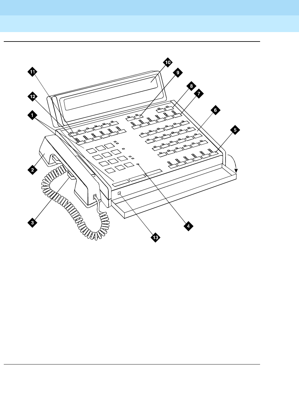
DEFINITY Enterprise Communications Server Release 6
Administration and Feature Description
555-230-522 Issue 4
May 1998
Basic Forms
Page 5-45Attendant Console
5
Figure Notes
Figure 5-1. 302A and 302B Attendant Console
1. Call processing area
2. Handset
3. Handset cradle
4. Warning lamps and call waiting lamps
5. Call appearance buttons
6. Feature area
7. Trunk group select buttons
8. Volume control buttons
9. Display buttons
10. Console display panel
11. Display buttons
12. Trunk group select buttons
13. Lamp Test Switch
302bphn1 KLC 05149
6
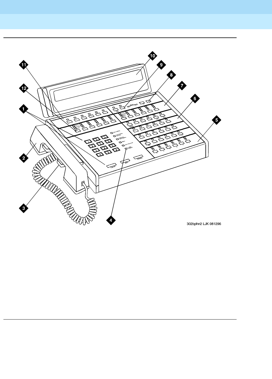
DEFINITY Enterprise Communications Server Release 6
Administration and Feature Description
555-230-522 Issue 4
May 1998
Basic Forms
Page 5-46Attendant Console
5
Figure Notes
Figure 5-2. 302C Attendant Console
1. Call processing area
2. Handset
3. Handset cradle
4. Warning lamps and call waiting lamps
5. Call appearance buttons
6. Feature area
7. Trunk group select buttons
8. Volume control buttons
9. Display buttons
10. Console display panel
11. Display buttons
12. Trunk group select buttons
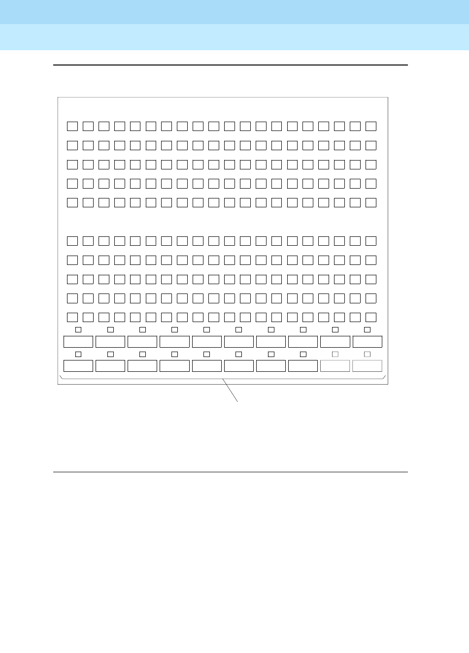
DEFINITY Enterprise Communications Server Release 6
Administration and Feature Description
555-230-522 Issue 4
May 1998
Basic Forms
Page 5-47Attendant Console
5
Figure 5-3. Enhanced Selector Console (26A) Administrable Hundreds Group
Select Buttons
1
ONLY)
2 3 4 5 6 7 8
00 01 02 03 04 05 06 07 08 09
10
20
30
40
50
60
70
80
90 91 92 93 94 95 96 97 98 99
89 88 87 86 85 84 83 82 81
71 72 73 74 75 76 77 78 79
69 68 67 66 65 64 63 62 61
51 52 53 54 55 56 57 58 59
49 48 47 46 45 44 43 42 41
31 32 33 34 35 36 37 38 39
29 28 27 26 25 24 23 22 21
11 12 13 14 15 16 17 18 19
HUNDREDS GROUP
SELECT BUTTONS
FOR IDENTIFICATION
9 10
11 12 13 14 15 16 17 18 19 20
TWENTY ADMINISTRABLE
(NUMBERS 1-20 ARE

DEFINITY Enterprise Communications Server Release 6
Administration and Feature Description
555-230-522 Issue 4
May 1998
Basic Forms
Page 5-48Attendant Console
5
Table 5-1. Attendant Console Feature Button Characteristics
Feature or Function
Recommended
Button Label
Name Entered on
Station form
Maximum
Allowed Notes
Abbreviated Dialing AD abrv-dial (List:___ DC:___) 1 per List/DC 1
Administered
Connection [status
lamp]
AC Alarm ac-alarm 1
Alert Agent of Change
to Split/Skill Hunt
Group
Alert Agent alrt-agchg 1
Automatic Call
Distribution (ACD)
After Call Work after-call (Grp. No.__) N 2
Assist assist (Grp. No:__) 1 per split
group
2
Auto In auto-in (Grp. No.__) 1 per split
group
2
Auxiliary Work aux-work (Grp. No.__) 1 per split
group
2
Manual-In manual-in (Grp. No.__) 1 per split
group
2
Release release 1
Work Code work-code 1
Stroke (0-9) stroke-cnt (Code:_) 1 3
Attendant Console
(Calls Waiting)
CW Aud Off cw-ringoff 1
Attendant Control of
Trunk Group Access
(Activate)
Cont Act act-tr-grp 1
Attendant Control of
Trunk Group Access
(Deactivate)
Cont Deact deact-tr-g 1
Attendant Direct Trunk
Group Select
Local TG
Remote TG
local-tgs
remote-tgs
12 4
Attendant Crisis Alert Crisis Alert crss-alert 1
Attendant Display
[display buttons]
Date/Time date-time 1
Inspect Mode inspect 1
Normal Mode normal 1
Stored Number stored-num 1
Continued on next page

DEFINITY Enterprise Communications Server Release 6
Administration and Feature Description
555-230-522 Issue 4
May 1998
Basic Forms
Page 5-49Attendant Console
5
Attendant Hundreds
Group Select
Group Select _ hundrd-sel (Grp:__) 20 per console 5
Attendant Room
Status Occupied
Rooms Status occ-rooms 1 6
Maid Status maid-stat 1 6
Attendant Override Override override 1
Automatic Circuit
Assurance
ACA aca-halt 1 per system
Automatic Wakeup
(Hospitality)
Auto Wakeup auto-wkup 1
Busy Verification Busy Verify verify 1
Call Coverage Cover Cback cov-cback 1
Consult consult 1
Go To Cover goto-cover 1
Call Coverage
[display button]
Cover Msg Rt cov-msg-rt 1
Call Offer (Intrusion) Intrusion intrusion 1
Call Prompting
[display button]
Caller Info callr-info 1
Call Type Call Type type-disp 1 7
Centralized Attendant
Service
CAS-Backup cas-backup 1
Check In/Out
(Hospitality)
[display buttons]
Check In check-in 1
Check Out check-out 1
Class of Restriction
[display button]
COR class-rstr 1
Demand Print Print Msgs print-msgs 1
Do Not Disturb
(Hospitality)
Do Not Disturb dn-dst 1
Do Not Disturb
(Hospitality) [display
buttons]
Do Not Disturb
Ext
ext-dn-dst 1
Do Not Disturb
Grp
grp-dn-dst 1
Table 5-1. Attendant Console Feature Button Characteristics — Continued
Feature or Function
Recommended
Button Label
Name Entered on
Station form
Maximum
Allowed Notes
Continued on next page

DEFINITY Enterprise Communications Server Release 6
Administration and Feature Description
555-230-522 Issue 4
May 1998
Basic Forms
Page 5-50Attendant Console
5
Don’t Split Don’t Split dont-split 1
Emergency Access
To the Attendant
Emerg. Access
To Attndt
em-acc-att 1
Facility Busy
Indication [status
lamp]
Busy (trunk or
extension#)
busy-ind (TAC/Ext: _) 1 per TAC/Ext. 8
Facility Test Calls
[status lamp]
FTC Alarm trk-ac-alm 1
Group Display Group Display group-disp 1 9
Group Select Group Select group-sel 1
Hardware Failure
[status lamps]
Major Hdwe
Failure
major-alrm 10 per system
Auto Wakeup pr-awu-alm 1
DS1 (facility) ds1-alarm 10 per system
PMS Failure pms-alarm 1
PMS Ptr Alm pr-pms-alm 1
CDR 1 Failure cdr1-alrm 1
CDR 2 Failure cdr2-alrm 1
Sys Ptr Alm pr-sys-alm 1
Hold Hold hold 1
Integrated Directory
[display button]
Integrtd
Directory
directory 1
Incoming Call
Identification
Coverage
(Group number,
type, name, or
ext.#)
in-call-id N
Intrusion (Call Offer) Intrusion intrusion 1
Leave Word Calling Cancel LWC lwc-cancel 1
LWC lwc-store 1
Leave Word Calling
[display buttons]
Delete Msg delete-msg 1
Next next 1
Call Display call-disp 1
Table 5-1. Attendant Console Feature Button Characteristics — Continued
Feature or Function
Recommended
Button Label
Name Entered on
Station form
Maximum
Allowed Notes
Continued on next page

DEFINITY Enterprise Communications Server Release 6
Administration and Feature Description
555-230-522 Issue 4
May 1998
Basic Forms
Page 5-51Attendant Console
5
Leave Word Calling
(Remote Message
Waiting) [status lamp]
Msg (name or
extension #)
aut-msg-wt (Ext:___) N 8
Link Failure Link Failure
(Link No.__)
link-alarm (Link No.__) 1 per Link # 10
Login Security
Violation
lsvn-halt lsvn-halt 1 per system
Night Service Trunk Grp. NS trunk-ns (Grp. No.__) 1 per trunk
group
11
PMS Interface
[display buttons] Message
Waiting Act. mwn-act 1 per system
Message
Waiting Deact.
mwn-deact 1 per system
Priority Calling Prior Call priority N
Position Busy Position Busy pos-busy 1
Queue Status
Indications (ACD)
[display buttons]
AQC atd-qcalls 1
AQT atd-qtime
Queue Status
Indications (ACD)
[status lamps]
NQC q-calls (Grp:_) 1 12
OQT q-time Grp:_) 1 per hunt
group
12
Remote Access
Security Violation
rsvn-halt rsvn-halt 1 per system
Ringing In Aud Off in-ringoff 1
Security Violation
Notification Halt
ssvn-halt ssvn-halt 1 per system 7
Serial Call Serial Call serial-cal 1
System Reset Alert System Reset
Alert [status
lamp]
rs-alert 1
Station Security Code
Notification Halt
ssvn-halt ssvn-halt 1 per system
Night Service (ACD) Hunt Group hunt-ns (Grp. No.__) 3 per hunt
group
12
Table 5-1. Attendant Console Feature Button Characteristics — Continued
Feature or Function
Recommended
Button Label
Name Entered on
Station form
Maximum
Allowed Notes
Continued on next page

DEFINITY Enterprise Communications Server Release 6
Administration and Feature Description
555-230-522 Issue 4
May 1998
Basic Forms
Page 5-52Attendant Console
5
1. List: List number 1 to 3 where the destination number is stored.
DC: Dial codes of destination number.
2. Grp: The split group number for ACD.
3. Code: Enter a stroke code (0 through 9).
4. TAC: local-tgs — TAC of local TG
remote-tgs — (L-TAC) TAC of TG to remote PBX
remote-tgs — (R-TAC) TAC of TG on remote PBX
The combination of local-tgs/remote-tgs per console must not exceed 12 (maximum).
Label associated button appropriately so as to easily identify the trunk group.
5. Grp: Enter a hundreds group number (1 through 20).
6. Enhanced Hospitality must be optioned on the System-Parameters Customer-Options form.
Time of Day Routing
[display buttons]
Immediate
Override
man-ovrid 1
Clocked
Override clk-overid 1
Timed Reminder RC Aud Off re-ringoff 1
Timer Timer timer 1
Trunk Identification
[display button]
Trunk-ID trk-id 1
Trunk Group Name
[display button]
Trunk-Name trunk-name 1
Visually Impaired
Service (VIAS)
VIS vis 1
Console Status con-stat 1
Display display 1
DTGS Status dtgs-stat 1
Last Message last-mess 1
Last Operation last-op 1
VDN of Origin
Announcement
Repeat
VOA Repeat voa-repeat 1 13, 14
VuStats VuStats vu-display 1 13
N = any number of buttons on the voice terminal can be assigned to this feature. Feature
button descriptions are provided in ‘‘Voice-terminal feature button descriptions’’ on page
6-14.
Table 5-1. Attendant Console Feature Button Characteristics — Continued
Feature or Function
Recommended
Button Label
Name Entered on
Station form
Maximum
Allowed Notes
Continued on next page

DEFINITY Enterprise Communications Server Release 6
Administration and Feature Description
555-230-522 Issue 4
May 1998
Basic Forms
Page 5-53Attendant Console
5
7. May be assigned either to a voice terminal or an attendant console.
8. Ext: May be a VDN extension.
9. This button can be administered as either an attendant display button or a feature button.
10. Link: A link number — 1 to 8 for multi-carrier cabinets, 1 to 4 for single-carrier cabinets.
11. Grp: A trunk group number.
12. Grp: Group number of the hunt group.
13. VDN of Origin must be enabled.
14. When this button is pressed, "Call Type 1" (answered public network call), "Call Type 2"
(unanswered public network call), or "Call Type 3" (all other calls) displays for 1 second.

DEFINITY Enterprise Communications Server Release 6
Administration and Feature Description
555-230-522 Issue 4
May 1998
Basic Forms
Page 5-54Authorization Code — COR Mapping
5
Authorization Code — COR Mapping
This form assigns authorization codes and associates them with classes of
restriction (CORs). On an internal originating call, the COR assigned the facility
(such as station) being used to originate the call and its Partition Group Number
(PGN) (when assigned) is used to select a routing pattern. With this, the calling
party can dial a 4- to 7-digit authorization code to override the FRL assigned the
COR (may be associated with voice/data terminals, incoming trunk groups,
remote access trunk groups, or attendant consoles). This allows users within
each PGN to have access to all seven FRLs (when assigned) and still remain
partitioned. On an incoming remote access call, dialing an authorization code as
part of the call dialing sequence selects the COR and the associated PGN to be
used in processing the call.
NOTE:
The use of authorization codes when accessing a Vector Directory Number
extension will be denied.
To maximize the security of the system, the following should be considered:
1. Authorization Codes should be administered to the maximum length
allowed by the system.
2. Authorization Codes should be nonconsecutive (random) and changed at
least quarterly.
3. Authorization Codes should be deactivated immediately if a user leaves
the company or changes assignments.
4. Assign each Authorization Code the minimum level of calling permissions
required.
Administration commands
Use the following commands to administer the Authorization Codes form.
Action Object Qualifier
change authorization-code auth (4-7 digit number)
display authorization-code auth (4-7 digit number)
list authorization-code none
DEFINITY Enterprise Communications Server Release 6
Administration and Feature Description
555-230-522 Issue 4
May 1998
Basic Forms
Page 5-55Authorization Code — COR Mapping
5
Form instructions
Screen 5-17. Authorization Code — COR Mapping form (page 1 of 1)
Make assignments as required for the following fields on the form:
■Number of Codes Administered — This is a display-only field and
contains the sum of the number of Authorization Codes that has been
administered using the Authorization Codes form.
■AC — Enter the 4- to 7-digit authorization code the user must dial. The
number of digits entered must agree with the number assigned to the
Authorization Code Length field on the Feature-Related System
Parameters form.
NOTE:
To enhance system security, choose Authorization Codes of seven
random digits.
■COR — Enter the desired COR number from 0 through 95.
Page 1 of 1
Authorization Code - COR Mapping
Note: XX codes administered. Use “list” to display all codes.
AC COR AC COR AC COR AC COR AC COR AC COR
_______ __ _______ __ _______ __ _______ __ _______ __ _______ __
_______ __ _______ __ _______ __ _______ __ _______ __ _______ __
_______ __ _______ __ _______ __ _______ __ _______ __ _______ __
_______ __ _______ __ _______ __ _______ __ _______ __ _______ __
_______ __ _______ __ _______ __ _______ __ _______ __ _______ __
_______ __ _______ __ _______ __ _______ __ _______ __ _______ __
_______ __ _______ __ _______ __ _______ __ _______ __ _______ __
_______ __ _______ __ _______ __ _______ __ _______ __ _______ __
_______ __ _______ __ _______ __ _______ __ _______ __ _______ __
_______ __ _______ __ _______ __ _______ __ _______ __ _______ __
_______ __ _______ __ _______ __ _______ __ _______ __ _______ __
_______ __ _______ __ _______ __ _______ __ _______ __ _______ __
_______ __ _______ __ _______ __ _______ __ _______ __ _______ __
_______ __ _______ __ _______ __ _______ __ _______ __ _______ __
_______ __ _______ __ _______ __ _______ __ _______ __ _______ __
_______ __ _______ __ _______ __ _______ __ _______ __ _______ __

DEFINITY Enterprise Communications Server Release 6
Administration and Feature Description
555-230-522 Issue 4
May 1998
Basic Forms
Page 5-56Bulletin Board
5
Bulletin Board
The Bulletin Board form allows you to change and display the information in the
bulletin board.
Administration commands
Use the following commands to administer the Bulletin Board..
Form instructions
General Information
Creating Bulletin Board Messages
The message line for all pages and all lines of the form will allow you to enter 40
characters. If you enter a blank line, it will display. If you enter two or more
succeeding blank lines, the system will consolidate them and only store one. The
system will also remove a blank line if it is in line 1 of any of the pages. Blank line
consolidation for the first ten lines of Page 1 is independent of blank line
consolidation performed for lines 11 through 19 of Page 1.
Tabs are not allowed. If you use a tab, it will move the cursor to the next field.
Any of the following characters are valid for all pages and all lines of the form:
■A through Z
■a through z
■Blank
■0 through 9
■!@#$%^&*()_+-=[]{}|\’˜;:’,”<.>/?
Deleting Bulletin Board Messages
You delete a line from the bulletin board by entering a space as the first character
of an existing line. You can, however, add a message line with blank as the first
character.
1. Brackets [ ] indicate the qualifier is optional.
Action Object Qualifier1
change bulletin-board
display bulletin-board [print or schedule]

DEFINITY Enterprise Communications Server Release 6
Administration and Feature Description
555-230-522 Issue 4
May 1998
Basic Forms
Page 5-57Bulletin Board
5
Storing Bulletin Board Messages
You store the information that you have entered just as you do any other SAT
command. That is, you hit the PF3 or <enter> key, depending on your terminal
type.
Page 1 of the Bulletin form
Screen 5-18. Sample Bulletin Board form (page 1 of 3)
Lines 1 through 10 — Lines 1 through 10 of the bulletin board are reserved for
high priority messages. These lines are noted with an asterisk (*) in the first
column on the left. If you have an init or inads login you can enter high-priority
information to trigger the high-priority message at login time.
Lines 11 through 19 — Enter any additional information.
Date — This is a display-only field. The system enters the date that the line of
information was entered or last changed.
Page 2 and 3 of the Bulletin form
Lines 1 through 20 — Enter any additional information.
Date — This is a display-only field. The system enters the date that the line of
information was entered or last changed.
Page 1 of 3
Message (* indicates high-priority) Date
*Lucent is in the process of 03/02/93
*investigating your trunk lockup problem. 03/02/93
*The Bulletin Board will be updated as 03/02/93
*we find information. 03/02/93
* We have identifed the problem. 03/04/93
*The trunk you added does not provide 03/04/93
*disconnect supervision. However, the 03/04/93
*trunk group was administered as such. 03/04/93
*Please call Pat J. for details. 03/04/93
We recently added a new trunk group (14) 03/02/93
and have had many of the members getting 03/02/93
locked up. 03/02/93
We see the error - thanks for checking. 03/05/93

DEFINITY Enterprise Communications Server Release 6
Administration and Feature Description
555-230-522 Issue 4
May 1998
Basic Forms
Page 5-58Cabinet
5
Cabinet
NOTE:
This form is applicable only to R5r and later configurations.
This form describes cabinets and to define mapping between external and
internal circuit pack addresses so that circuit packs and ports can be identified
in a uniform way.
Administration commands
Use the following commands to administer the Cabinet Administration form.
1. "xx" is the cabinet number (01-44 for R5r and later).
Brackets [ ] indicate the qualifier is optional. Single
quotes (’ ’) indicate the text inside the quote must be
entered exactly as shown or an abbreviated form of
the word may be entered.
Action Object Qualifier1
add cabinet xx
remove cabinet xx
change cabinet xx
display cabinet xx [‘print’ or ‘schedule’]
list cabinet [’print’ or ’schedule’]

DEFINITY Enterprise Communications Server Release 6
Administration and Feature Description
555-230-522 Issue 4
May 1998
Basic Forms
Page 5-59Cabinet
5
Form instructions
Screen 5-19. Cabinet Administration form
Make assignments as required for the following fields on the form:
■Cabinet — Display-only field. This field shows the cabinet number as
entered in the command line.
■Cabinet Layout — Enter the type of physical carrier layout. Valid entries
are five-carrier and single-carrier-stack. Default is blank.
■Cabinet Type — Display-only field. This field shows the type of cabinet
being administered. If cabinet "01" is being administered, this field is
"processor." If cabinets "02 through 44" are being administered, this field is
"expansion-portnetwork."
■Number of Port Networks — Enter the number of PNs in the cabinet.
Valid entries are 1 (default), and 2.
■Survivable Remote EPN — Displays only if Cabinet Type is
“expansion-portnetwork.” If set to y, the cabinet has a remote si processor
that provides a backup if the links to this cabinet are inoperative.
■Survivable Remote Processor ID — Displays only if Survivable
Remote EPN is y. Enter the product ID assigned to the remote si. This
allows DEFINITY Fault Management to know which machine is the backup
for this cabinet. The entry in this field cannot be the same as the entry in
the Production Identification field in the Maintenance-Related
System Parameters form.
■Room — Enter up to ten characters identifying the room where the
cabinet is located. Default is blank.
Page 1 of 1
CABINET
CABINET DESCRIPTION
Cabinet: __
Cabinet Layout: ____________________
Cabinet Type: ______________________
Number of Portnetworks: _
Survivable Remote EPN: _ Survivable Remote Processor ID: _____
Room: __________
Floor: __________
Building: __________
CARRIER DESCRIPTION
Carrier Carrier Type Number Duplicate
C _________________ __ __ ___
B _________________ __ __ ___
A Processor
X Fan
D _________________ __ __ ___
E _________________ __ __ ___

DEFINITY Enterprise Communications Server Release 6
Administration and Feature Description
555-230-522 Issue 4
May 1998
Basic Forms
Page 5-60Cabinet
5
■Floor — Enter up to ten characters identifying the floor in the building
where the cabinet is located. Default is blank.
■Building — Enter up to ten characters identifying the building where the
cabinet is located. Default is blank.
■Carrier Type — Enter the type of carrier in the cabinet being
administered. Valid entries are dup-switch-node, expansion-control,
not-used, port, processor, and switch-node.
■Number — Display-only field. Consists of two fields: the Designator
and Number fields. The Designator field contains one of the following
entries:
—PN — If the carrier is a port carrier, processor carrier, or unused
carrier.
—SN — If the carrier is a switch node carrier, or duplicate switch
node carrier.
The Number field contains either the switch node number or port network
number.
■Duplicate — The location for the duplicate of a switch node. Only
displays when administration of PNC Duplication is enabled. If the
Carrier Type is dup-switch-node, the field displays the
three-character carrier address of the duplicate. The first two characters
represent the cabinet number; the third character represents the carrier (A
through E).
This is a display-only field if the Carrier Type is switch-node.
Implementation notes
This form only displays for R5r and later configurations.
This form is for a 5-carrier cabinet layout. The Carrier Description fields
vary for a single-carrier stack and for different configurations of switch nodes and
port networks.
When adding or removing cabinets you can leave gaps in their numbering. For
example, if you are adding a cabinet and want to leave some cabinet numbers
available in the middle of the cabinet range for future expansion, then port
network numbers are assigned by the system which will always use the lowest
available PN.

DEFINITY Enterprise Communications Server Release 6
Administration and Feature Description
555-230-522 Issue 4
May 1998
Basic Forms
Page 5-61CAMA Numbering Format form
5
CAMA Numbering Format form
This form administers the Centralized Automatic Message Accounting (CAMA)
trunks and provides Caller’s Emergency Service Identification (CESID)
information to the local community’s Enhanced 911 system through the local
Tandem Office.
This form provides the CESID format by extension number or number blocks.
This allows for multiple CESID formats to be sent over multiple CAMA trunk
groups allowing for mixed station numbering plans and some limited conversion
from non-DID to DID numbers typically required by the Private Switch/Automatic
Location Interface (PS/ALI) database.
The default CESID defines the CESID for all extension which are not defined in
the Ext Code field.
There are 86 CESID entries over three pages. The first page contains the Default
CESID and 26 extensions to CESID entries. The second and third pages each
contain 30 extensions to CESID entries.
Administration commands
The ability to change and display CAMA numbering is restricted to
Administrators with add/change permission.
Use the following commands to administer the CAMA Numbering Format form.
1. Brackets [] indicate the qualifier is optional. Single quotes (‘ ’) indicate
the text inside the quote must be entered exactly as shown or an
abbreviated form of the word may be entered.
Action Object Qualifier1
change cama-numbering —
display cama-numbering [’print’ or ‘schedule’]

DEFINITY Enterprise Communications Server Release 6
Administration and Feature Description
555-230-522 Issue 4
May 1998
Basic Forms
Page 5-62CAMA Numbering Format form
5
Form instructions
Make assignments as required for the following fields on the form.
Page 1 of the form
Screen 5-20. CAMA Numbering Format form
Field descriptions
■System CESID Default — The default CESID is the CESID sent over the
cama trunk if the Ext Code field is not defined on the cama numbering
form. Enter 1 to 16 digit number or leave blank (default).
■Ext Len — The number of digits in the extension. Valid entries are from 1
to 5 or leave blank (default).
■Ext Code — Contains the leading digits or all the digits in the extension
for the specified CESID. If the extension length is greater than the number
of digits in the extension code, the extension code will be interpreted as a
block of digits. For example, if the extension length is 4 and the extension
code is 11, the CESID will serve extensions 1100 through 1199. The Ext
Code [11] is for a DID block. Ext Code [126] may point a non-DID block to
a nearby DID extension 5241666. Valid entries can be up to 5 digits, or
leave blank (default).
■CESID — The number used to identify the calling terminal within an
emergency service system. This field may represent a prefix to an
extension or the entire CESID. Enter 1 to 16 digits, or leave blank
(default).
■Total Length — The total number of digits to send. Valid entries are from
1 to 16 or leave blank (default).
Page 1 of 3
CAMA NUMBERING - E911 FORMAT
System CESID Default: 5241100______
Ext Ext Total Ext Ext Total
Len Code CESID Length Len Code CESID Length
4_ 11___ 524_________ 7_ __ _____ __________ __
4_ 121__ 524_________ 7_ __ _____ ___________ __
4_ 125__ 5241666_____ 7_ __ _____ ___________ __
4_ 126__ 5241666_____ 7_ __ _____ ___________ __
4_ 127__ 5241666_____ 7_ __ _____ ___________ __
4_ 128__ 5241666_____ 7_ __ _____ ___________ __
4_ 1291_ 5241291_____ 7_ __ _____ ___________ __
4_ 1292_ 5241666_____ 7_ __ ______ ___________ __
__ _____ ____________ __ __ ______ ___________ __
__ _____ ____________ __ __ ______ ___________ __
__ _____ ____________ __ __ ______ ___________ __
__ _____ ____________ __ __ ______ ___________ __
__ _____ ____________ __ __ ______ ___________ __

DEFINITY Enterprise Communications Server Release 6
Administration and Feature Description
555-230-522 Issue 4
May 1998
Basic Forms
Page 5-63CDR System Parameters
5
CDR System Parameters
The Call Detail Recording (CDR) System Parameters form allows the generating
of records that contain information about particular calls controlled by the switch.
This information is useful for call costing, diagnostics, abuse detection, and
network optimization.
Administration commands
Use the following commands to administer the CDR System Parameters form.
Form instructions
Page 1 of the form
Screen 5-21. CDR System Parameters form (page 1 of X)
Make assignments as required for the following fields on each page of the form:
■Node Number (Local PBX ID) — The DCS switch node number in a
network of switches. This field is display only.
Action Object Qualifier
change system-parameters cdr —
display system-parameters cdr —
CDR SYSTEM PARAMETERS
Page 1 of X
Node Number (Local PBX ID): __ CDR Date Format: _________
Primary Output Format: ___________ Primary Output Ext: _____
Secondary Output Format: ___________ Secondary Output Ext: _____
Use ISDN Layouts? _ EIA Device Bit Rate: ____
Use Enhanced Formats? _
Modify Circuit ID Display? _ Remove # from Called Number? _
Record Outgoing Calls Only? _ Intra-switch CDR? _
Suppress CDR for Ineffective Call Attempts? _ Outg Trk Call Splitting? _
Disconnect Information in Place of FRL? _ Outg Attd Call Record? _
Interworking Feat-flag? _
Force Entry of Acct Code for Calls Marked on Toll Analysis Form? _
Calls to Hunt Group - Record: __________
Record Called Vector Directory Number Instead of Group or Member? _
Record Called Agent Login ID Instead of Group or Member? _
Inc Trk Call Splitting? _ Inc Attd Call Record? _
Record Non-Call-Assoc TSC? _ Call Record Handling Option: _________
Record Call-Assoc TSC? _ Digits to Record for Outgoing Calls: _________
Privacy - Digits to Hide: _ CDR Account Code Length: __

DEFINITY Enterprise Communications Server Release 6
Administration and Feature Description
555-230-522 Issue 4
May 1998
Basic Forms
Page 5-64CDR System Parameters
5
■CDR Date Format — Enter month/day or day/month (default) to select
the format for recording CDR date information for timestamp date records
of all formats. If using a customized format, make Date a six-digit field to
ensure the proper output.
■Primary Output Format — Controls data presentation sent to the primary
output device. Entering customized generates the second page of this
form for the customized record administration. Other options are 59-char,
expanded, lsu, lsu-expand, int-direct, int-isdn, int-process, printer,
teleseer, unformatted, or blank (default).
■Primary Output Extension — Appears when the Primary Output
Format field contains a valid value. Enter the extension number assigned
to the primary output device, or eia for R5vs/si and later configurations.
This field is required if a Primary Output Format is specified. Default is
blank.
NOTE:
The first digit of the CDR extension number and the length of that
number must agree with the first digit table of the dial plan.
■Secondary Output Format — Controls data presentation sent to the
secondary output device. Valid entries are lsu, unformatted, int-direct,
int-process or blank (default).
!CAUTION:
This option should only be used by qualified (Lucent Technologies)
service personnel. This option may cause loss of data when the
buffer contains large amounts of data.
■Secondary Output Extension — Appears when the secondary output
format is administered. Enter the extension number assigned to the
secondary output device, or eia for R5vs/si and later configurations.
Default is blank.
NOTE:
The first digit of the CDR extension number and the length of that
number must agree with the first digit table of the dial plan.
■Use ISDN Layouts — Enter y to use ISDN record layouts. This field
applies to both the primary and secondary formats if applicable. The "lsu"
and "printer" output formats will be affected, as well as any format with
ISDN layouts, such as “teleseer.” Default is n. This field and Use
Enhanced Formats cannot both be y.
■EIA Device Bit Rate — Applies to R5vs/si and later configurations only.
Displays if either Primary or Secondary Output Format is eia. Enter
the bit rate of the CDR device connected to the EIA port. Valid entries are
300, 1200, 2400, and 9600.

DEFINITY Enterprise Communications Server Release 6
Administration and Feature Description
555-230-522 Issue 4
May 1998
Basic Forms
Page 5-65CDR System Parameters
5
■Use Enhanced Formats — Enter y to enable the use of the Enhanced
version of the specified primary output format. This field applies to both
the primary and secondary output formats if applicable; however, only the
"expanded", “teleseer”, "lsu", "printer", and "unformatted" output formats
will be affected. This field and Use ISDN Layouts cannot both be y.
■Modified Circuit ID Display — Enter y to modify the format of the
incoming and outgoing circuit ID from the 10’s, units, 100’s format (the
default) to 100’s, 10’s, units. Only the “printer,” “teleseer,” and
“59-character” output formats will be affected.
■Remove # From Called Number — If the value of this field is n (default) a
trailing “#” (or “E”) symbol appears in the Dialed Number field whenever
inter-digit time out or end of dialing occurs. Enter y to have the “#” (or “E”)
symbol removed from the Dialed Number field of the call detail record.
■Record Outgoing Calls Only — Enter y to report outgoing calls; enter n
(default) to report both outgoing and incoming calls.
■Intra-Switch CDR — Enter y to record calls within the switch. Default is n.
■Suppress CDR for Ineffective Call Attempts — Enter y (default) to
ignore reporting of ineffective call attempts. Ineffective call attempts are
calls originated by a voice terminal user that are blocked because the
user did not have sufficient calling privileges or because all outgoing
trunks were busy. This includes the unavailable incoming or outgoing
trunks due to trunk usage allocation for ISDN Call-by-Call Service
Selection trunks and incoming calls rejected by the switch due to NSF
mismatch. Enter n to report ineffective call attempts.
■Outg Trk Call Splitting — Enter y to enable splitting of call records for
outgoing calls that are transferred or conferenced.
■Disconnect Information in Place of FRL — Enter y to record disconnect
information or "n" (default) to record the call’s FRL.
NOTE:
This field changes the Facility Restriction Level (FRL)
field of the CDR record to record the reason for disconnect of a call
rather than the FRL. It is used for isolating problems between the
Generic 3r and the telephone network.
■Outg Attd Call Record — Only appears if Outg Trk Call Splitting
is "y.” Enter "y" to enable separate recording of attendant portions of
outgoing calls that are transferred or conferenced.
■Interworking Feat-flag — Enter n (default) if you want feat-flag operation
to treat interworking as no answer supervision. Enter y if you want feat-flag
operation to show interworked calls with a separate feat-flag value than
timed answer and network answer calls.

DEFINITY Enterprise Communications Server Release 6
Administration and Feature Description
555-230-522 Issue 4
May 1998
Basic Forms
Page 5-66CDR System Parameters
5
■Force Entry of Acct Code for Calls Marked on Toll Analysis Form —
Specifies whether an account code will be required when making a toll
call. This will not necessarily be all chargeable calls and it may even
include some non-chargeable calls. Entering y denies all toll calls without
an account code. Default is n.
■Calls to Hunt Group
—
Record — Enter member-ext (default) to record
the extension of the voice/data terminal where the call terminated; enter
group-ext to record the extension that was dialed. The extension of the
voice/data terminal in the hunt group that answered the call is the
extension assigned to the hunt group.
■Record Called Vector Directory Number Instead of Group or Member
— Enter y to include the Vector Directory Number (VDN) in the Dialed
Number Field of a CDR record. This field and the Record Called
Agent Login ID Instead of Group or Member field cannot both
be y. Default is n.
NOTE:
A VDN overrides group or member information that is otherwise
stored in the Dialed Number Field of the CDR record. If a call is
directed through more than one VDN, the first VDN used for the call
is stored.
■Record Called Agent Login ID Instead of Group or Member — Only
displays if Expert Agent Selection (EAS) is enabled on the
System-Parameters Customer-Options form. Enter y to indicate whether
the EAS agents LoginID is recorded instead of the physical extension in
the Dialed Number. This field and the Record Called Vector
Directory Number Instead of Group or Member field cannot
both be y.
■Inc Trk Call Splitting — Enter y to enable splitting of call records for
incoming calls that are transferred or conferenced.
■Inc Attd Call Record — Only appears if Inc Trk Call Splitting is y.
Enter y to enable separate recording of attendant portions of outgoing
calls that are transferred or conferenced.
■Record Non-Call-Assoc TSC — Enter y to record non-call-associated
TSC information. Default is n.
■Call Record Handling Option — Displays on R5r and later configurations
only. Used to control call routing when new calls come in, the CDR link is
down, and the buffer is filled. Enter reorder to block with an intercept,
warning (default) to stop recording when the buffer is full, or attendant to
route the call to an attendant with options to proceed as a non-CDR call.
NOTE:
Changing this field from the default warning may cause ACD &
vector calls that are measured by CDR to be redirected.

DEFINITY Enterprise Communications Server Release 6
Administration and Feature Description
555-230-522 Issue 4
May 1998
Basic Forms
Page 5-67CDR System Parameters
5
■Record Call-Assoc TSC — Enter y to record call-associated TSC
information. Default is n.
■Digits to Record for Outgoing Calls — Enter dialed or outpulsed to
record the dialed or outpulsed digits in the Dialed Number field of the
CDR.
■Privacy — Digits to Hide — Enter the number of digits (0 to 7) to be
blanked from the back (right to left) of the Dialed Number field on the
CDR record; default is 0.
For example, if "4" is entered in this field and the user dials 555-1234, only
"555" would appear in the Dialed Number field of the CDR record. CDR
Privacy must be enabled on the Station form.
■CDR Account Code Length — Enter the number of digits collected when
the CDR account code is entered. Default is 2.
Page 2 of the form
Screen 5-22. CDR System Parameters form (page 2 of 2)
This page appears only if Primary Record Format is customized.
Data Item — Enter the data items in the order they should appear on the
customized record. The default for all fields is blank, but you must enter at
least one field in order to have a record. A line-feed and return must be
the last two data items in a customized record (see Page 2 sample). See
Tab l e 5 - 2 below for valid entries:
CDR SYSTEM PARAMETERS Page 2 of 2
Data Item - Length Data Item - Length Data Item - Length
1: time____________ - 4_ 17: ________________ - __ 33: ________________ - __
2: space___________ - 1_ 18: ________________ - __ 34: ________________ - __
3: duration________ - 4_ 19: ________________ - __ 35: ________________ - __
4: return__________ - 1_ 20: ________________ - __ 36: ________________ - __
5: line-feed_______ - 1_ 21: ________________ - __ 37: ________________ - __
6: ________________ - __ 22: ________________ - __ 38: ________________ - __
7: ________________ - __ 23: ________________ - __ 39: ________________ - __
8: ________________ - __ 24: ________________ - __ 40: ________________ - __
9: ________________ - __ 25: ________________ - __ 41: ________________ - __
10: ________________ - __ 26: ________________ - __ 42: ________________ - __
11: ________________ - __ 27: ________________ - __ 43: ________________ - __
12: ________________ - __ 28: ________________ - __ 44: ________________ - __
13: ________________ - __ 29: ________________ - __ 45: ________________ - __
14: ________________ - __ 30: ________________ - __ 46: ________________ - __
15: ________________ - __ 31: ________________ - __ 47: ________________ - __
16: ________________ - __ 32: ________________ - __ 48: ________________ - __
Record length = 11

DEFINITY Enterprise Communications Server Release 6
Administration and Feature Description
555-230-522 Issue 4
May 1998
Basic Forms
Page 5-68CDR System Parameters
5
■Length — Enter the length of each data item, if different from the default.
■Record Length — A display-only field that shows the length of the
customized record. This field is updated each time the data item length
field is changed.
Table 5-2. Valid Data Item Entries
Data Item Length Data Item Length
acct-code 15 ins 3
attd-console 2 isdn-cc 11
auth-code 7 ixc-code 4
bandwidth 2 line-feed 1
bcc 1 ma-uui 1
calling-num 10 node-num 2
clg-num-in-tac 10 null 1
code-dial 4 out-crt-id 3
code-used 4 ppm 5
cond-code 1 res-flag 1
date 6 return 1
dialed-num 18 sec-dur 5
duration 4 space 1
feat-flag 1 time 4
frl 1 tsc_ct 4
in-crt-id 3 tsc_flag 1
in-trk-code 4 vdn 5

DEFINITY Enterprise Communications Server Release 6
Administration and Feature Description
555-230-522 Issue 4
May 1998
Basic Forms
Page 5-69Circuit Packs
5
Circuit Packs
This form administers circuit packs to carrier slots before the circuit packs are
actually installed in the carrier or cabinet. This allows the system to be configured
(administered) when the circuit packs have not yet been physically inserted in
their appropriate slots. Before any voice terminals, attendant consoles, or trunks
can be administered in the system, the correct type of circuit pack must be
installed in the appropriate slot, or using the Circuit Pack form, a circuit pack
must be assigned to the slot.
The Circuit Pack Administration forms do not have to be completed if the system
cabinet is equipped with the circuit packs at the time of administration. However,
for switch node carriers, these forms must be administered.
See
DEFINITY Communications System Generic 3 Planning and Configuration
,
555-230-601, for additional information on circuit pack administration and Port
Assignment Records. (The DS1 circuit pack and associated translation coverage
is provided in later in this book).
!WARNING:
For initial installation procedures, circuit packs should only be assigned
slots per the hardware Configuration Layout record (obtained from the
factory or Customer Services Support Organization). Arbitrarily assigning
circuit packs to slots should not be attempted because this eventually
requires (at the time of installation and test) realignment of the circuit packs
and reworking associated wiring to agree with the software translations or
new software translations to agree with the shipped hardware configuration.
Administration commands
Use the following commands to administer the Circuit Pack form.
NOTE:
If no cabinet number is specified, this command defaults to 1.
1. Brackets [ ] indicate the qualifier is optional. Single quotes (’ ’) indicate the
text inside the quote must be entered exactly as shown or an abbreviated
form of the word may be entered. "xx" is the cabinet number.
Action Object Qualifier1
change circuit-packs xx (cabinet number)
display circuit-packs xx (cabinet number) [’print’ or ’schedule’]
DEFINITY Enterprise Communications Server Release 6
Administration and Feature Description
555-230-522 Issue 4
May 1998
Basic Forms
Page 5-70Circuit Packs
5
Form instructions
Make assignments as required for the following fields on each page of the form:
Page 1 of the form
Screen 5-23. Circuit Packs Administration form
NOTE:
Each page of the form represents one carrier within the cabinet specified
on the command line. For R5si and later configurations, all carriers and
slots appear even if they are not included in the actual hardware. This
supports reconfiguration.
■Cabinet — Display-only field. This field shows the cabinet number as
entered on the command line.
■Carrier — Display-only field. This field shows the letter of the carrier (A
through E) circuit packs are being administered on.
■Cabinet Layout — Display-only field. This field is only displayed for R5r
and later configurations. This field describes the physical layout of the
cabinet. Values that may display are five-carrier and
single-carrier-stack.
■Carrier Type — Display-only field. This field shows the type of carrier.
Values that may display are dup-switch-node, expansion-control,
not-used, port, processor, and switch-node.
Page 1 of X
CIRCUIT PACKS
Cabinet: __ Carrier: _
Cabinet Layout: ____________________ Carrier Type: _________________
Slot Code Sfx Name Slot Code Sfx Name
00: ______ _ _ __________________ 11: ______ _ _ __________________
01: ______ _ _ __________________ 12: ______ _ _ __________________
02: ______ _ _ __________________ 13: ______ _ _ __________________
03: ______ _ _ __________________ 14: ______ _ _ __________________
04: ______ _ _ __________________ 15: ______ _ _ __________________
05: ______ _ _ __________________ 16: ______ _ _ __________________
06: ______ _ _ __________________ 17: ______ _ _ __________________
07: ______ _ _ __________________ 18: ______ _ _ __________________
08: ______ _ _ __________________ 19: ______ _ _ __________________
09: ______ _ _ __________________ 20: ______ _ _ __________________
10: ______ _ _ __________________ 21: ______ _ _ __________________
’#’ indicates circuit pack conflict.

DEFINITY Enterprise Communications Server Release 6
Administration and Feature Description
555-230-522 Issue 4
May 1998
Basic Forms
Page 5-71Circuit Packs
5
NOTE:
For R5r and later configurations, if the Carrier Type (as administered
through the Cabinet Administration form) does not match the
physical hardware, the Code fields may display question marks.
■Slot — Display-only field. The slot equates to the physical slot of the given
carrier; the number of slots displayed depends on the system being
configured.
— For R5r and later configurations, the number of slots represent all
administrable slots available for the given carrier type.
— For R5si and later configurations, all slots that could possibly be
administered are displayed, even if they do not apply to the current
configuration of the system. This is to accommodate the situation
when a system is being reconfigured.
■Code — Enter the circuit pack code ("TN" followed by a 3- or 4-digit
number). If there is a physical circuit pack installed in the slot, the entry
must match that of the circuit pack. If there is equipment administered on
a slot, the equipment must be removed from the circuit pack before the
circuit pack can be changed or removed.
■Sfx — Enter the circuit pack suffix, if applicable.
■Name — Display-only field. This field shows the alphanumeric name of
the circuit pack (such as Digital Line).
NOTE:
When the circuit pack physically inserted in the slot differs from what
has been administered on this form, a "#" will display between the
Sfx and Name fields.
Implementation notes
Screen 5-23 shows all fields that may display. The fields that appear on a
particular screen will vary depending upon the system configuration (Cabinet
Layout and Carrier Type) being administered.
The number of Slot fields displayed will vary depending on the system being
configured. For R5r and later configurations, the number of Slot fields displayed
will represent all administrable slots available for the given Carrier Type. For R5si
and later configurations, all possible Slots will display.

DEFINITY Enterprise Communications Server Release 6
Administration and Feature Description
555-230-522 Issue 4
May 1998
Basic Forms
Page 5-72Class of Restriction
5
Class of Restriction
This form implements classes of restriction (COR). Use a COR to control call
origination and termination. A system may have only one COR or as many as
necessary to control calling privileges. Up to 96 different CORs (0 through 95)
can be assigned. CORs can be assigned to any of the following facilities:
■Attendant Console
■Authorization Codes
■Console Parameters
■Data Module
■Hunt Groups
■Loudspeaker Paging/Code Calling Access
■Remote Access
■Station
■Terminating Extension Group
■Tr u n k Gro u p s
NOTE:
When a call is to a vector directory number (VDN) extension, the
COR of the caller and the VDN are compared to determine if the
associated Call Vector can be accessed. After the vector is
accessed, the COR of the VDN is used for further call permission
checking.
Consider the following to enhance your system security:
1. Assign a separate COR to incoming and outgoing trunk groups, then
restrict calling between the two groups.
2. Limit the calling permissions as much as possible by setting appropriate
Calling Party Restrictions and Facility Restriction Levels (FRLs).

DEFINITY Enterprise Communications Server Release 6
Administration and Feature Description
555-230-522 Issue 4
May 1998
Basic Forms
Page 5-73Class of Restriction
5
Administration commands
Use the following commands to administer the Class of Restriction form.
Form instructions
Make assignments as required for the following fields on each page of the form:
Page 1 of the form
Screen 5-24. Class of Restriction form (page 1 of 3)
■COR Number — Enter a number from 0 through 95 when completing a
paper form. This is a display-only field when the form is accessed via an
administration command such as change or display.
1. Brackets [ ] indicate the qualifier is optional.
Action Object Qualifier1
change cor 0-95
display cor 0-95 [’print’ or
’schedule’]
list cor 0-95 [’print’ or
’schedule’]
list partitioned group [’print’ or ’schedule’]
Page 1 of 3
CLASS OF RESTRICTION
COR Number: 10
COR Description: supervisor
FRL: 0 APLT? y
Can Be Service Observed? n Calling Party Restriction: outward
Can Be A Service Observer? n Called Party Restriction: none
Time of Day Chart: 1 Forced Entry of Account Codes? n
Priority Queuing? n Direct Agent Calling? n
Restriction Override: none Facility Access Trunk Test? n
Restricted Call List? n Can Change Coverage? n
Unrestricted Call List? __ __ __ __ __ __ __ __ __ __
Access to MCT? y Fully Restricted Service? n
Category For MFC ANI: 7 Hear VDN of Origin Annc.? n
Send ANI for MFE? n_ Add/Remove Agent Skills? n
MF ANI Prefix: ______ Automatic Charge Display? n
Hear System Music on Hold? y PASTE (Display PBX Data on Phone)? n
Can Be Picked Up By Directed Call Pickup? n
Can Use Directed Call Pickup? n

DEFINITY Enterprise Communications Server Release 6
Administration and Feature Description
555-230-522 Issue 4
May 1998
Basic Forms
Page 5-74Class of Restriction
5
■COR Description — Enter a description of the COR of up to 35
characters.
■FRL — Enter an originating FRL number from 0-7. AAR and/or ARS
features use this entry to determine call access to an outgoing trunk
group. Outgoing call routing is determined by a comparison of the FRLs in
the AAR/ARS Routing Pattern and the FRL associated with the COR of the
call originator (typically, a voice terminal user). An originating FRL of 0 has
the least calling privileges. Default is 0 for all CORs except 10 through 17,
where the default increments by one from 0 through 7, respectively.
NOTE:
To enhance system security, assign the lowest possible FRL.
■APLT — Enter n to allow access to APLT trunk group Enhanced Private
Switched Communications System (EPSCS) or Common Control Switched
Arrangement (CCSA) off-net facilities. Default is y.
NOTE:
If fully restricted service is enabled, set this field to n.
■Can Be Service Observed — Enter y if users with this COR can be
service observed, otherwise enter n (default). Note that this field allows or
denies service observing for not only physical extensions, but also for
logical agent IDs and VDNs. If you want an observer to observe users, set
the users’ CORs to y on the observer’s COR Service Observing
Permission table.
■Can Be a Service Observer — Enter y if users with this COR can service
observe other users, otherwise enter n (default). If you want an observer to
observe users, set the users’ CORs to y on the observer’s COR Service
Observing Permission table.
NOTE:
You cannot enter y in the previous two fields unless Service
Observing (Basic) is enabled on the System-Parameters
Customer-Options form.
!CAUTION:
The use of Service Observing features may be subject to federal,
state, or local laws, rules, or regulations; or require the consent of
one or both of the parties to the conversation. Customers should
familiarize themselves with and comply with all applicable laws,
rules, and regulations before using these features.
■Calling Party Restriction — Enter one of the following commands:
—Origination — Blocks the calling party from originating a call,
except Remote Access calls, from the facility at any time. The party
can only receive calls.

DEFINITY Enterprise Communications Server Release 6
Administration and Feature Description
555-230-522 Issue 4
May 1998
Basic Forms
Page 5-75Class of Restriction
5
—Outward — Blocks the calling party from directly accessing the
exchange network.To enhance security, this is the default.
—All-toll — Blocks the calling party from making ARS and trunk
access calls from a facility assigned the COR to certain toll areas
as defined in the Dialed String field on the Toll Analysis form.
The Dialed String field must be marked as being associated
with the system’s Toll List. The call completes if the facility’s COR
also is associated with an Unrestricted Call List and whose Dialed
String field also matches the dialed number.
—Tac-toll — Blocks the calling party from making trunk access calls
from the facility assigned the COR to certain toll areas as defined in
the Dialed String field on the Toll Analysis form. The Dialed
String field must be marked as being associated with the
system’s Toll List. The call completes if the facility’s COR also is
associated with an Unrestricted Call List and whose Dialed
String field also matches the dialed number. See ‘‘Toll Analysis’’
on page 5-299 for additional information.
—None — No calling party restrictions.
NOTE:
To enhance system security, limit calling permissions as much
as possible.
The COR can be overridden by the COS. See the Trk-to-Trk
Restriction Override field documented with the Class of
Service feature.
■Called Party Restriction — Enter one of the following commands:"
—Inward — Blocks the calling party from receiving incoming
exchange network calls, attendant originated calls, and attendant
completed calls.
—Manual — Blocks the called party from receiving all calls except
for those originated or extended by the attendant.
—Public — Blocks the called party from receiving public network
calls. Attendant calls are allowed to go through to the called party
as well as attendant-assisted calls if the Restriction Override
field in the public restricted station’s COR is attd or all.
—Termination — Blocks the called party from receiving any calls at
any time.
—None — No called party restrictions.
■Partitioned Group Number — This field appears only if AAR/ARS
Partitioning field is enabled on the System Parameters
Customer-Options form and Time of Day Routing field is n. Enter
the AAR/ARS partitioned group number (1 to 8) associated with this COR.

DEFINITY Enterprise Communications Server Release 6
Administration and Feature Description
555-230-522 Issue 4
May 1998
Basic Forms
Page 5-76Class of Restriction
5
■Time of Day Chart — Appears only if Time of Day field is enabled on
the System Parameters Customer-Options form. Enter the AAR/ARS
time-of-day-chart number (1 to 8) associated with this COR.
■Forced Entry of Account Codes — Enter y to indicate that an account
code must be dialed when making outgoing trunk calls. Entering n
(default) indicates that an account code is not required. As a result of
entering a y, any voice terminal assigned the associated COR must dial an
account code before making an outgoing call. Any trunk group assigned
that COR cannot be accessed until an account code is dialed. If a call is
being routed by AAR or ARS, account code checking is not done on the
COR.
NOTE:
To enhance system security, set this field to y.
If the Forced Entry of Account Codes for Toll Calls field on
the System-Parameters Customer-Options form is y, Forced Entry of
Account Codes may also be required for all outgoing calls.
NOTE:
If a COR requiring entry of account codes is assigned a VDN, the
route to commands executed by the associated vector will not be
successful.
■Priority Queuing — Enter y to allow the voice terminal user’s calls to be
placed ahead of non-priority calls in a hunt group queue. Default is n.
NOTE:
If the ACD Option field is not enabled on the System-Parameters
Customer-Options form, this field must be n.
■Direct Agent Calling — Enter y to allow a user to originate or receive
direct agent calls. Use this whenever a user talks directly with a specific
ACD agent, not just anyone in the agent pool. If the system is in Night
Service, the call routes to the Night Service extension. Default is n.
■Restriction Override — Enter the type of user who is allowed to bypass
restriction on the conference/transfer or call forwarding operations. Valid
entries are all, attendant, or none. To enhance security, default is none.
■Facility Access Trunk Test — Enter y to allow Facility Access Trunk Tests
(FAT). Test calls from facilities (for example, voice terminals) will be
allowed to complete if their COR FAT field is y. For calls from facilities
whose COR FAT field is n, intercept treatment will be given. An associated
feature button ("trk-ac-alm") status lamp lights when a successful FAT
access occurs. Pressing one of the alarm buttons (ten maximum) when its
associated status lamp is lit turns off all lamps on all buttons whether the
access is still in progress or has completed. Default is n.

DEFINITY Enterprise Communications Server Release 6
Administration and Feature Description
555-230-522 Issue 4
May 1998
Basic Forms
Page 5-77Class of Restriction
5
■Restricted Call List — Enter y to specify that this COR will have access
to the system’s Restricted Call List (see Toll Analysis on page 5-299). This
list can be used whether the COR is toll restricted. The Restricted Call List
(RCL) has priority over the Toll Analysis Unrestricted Call List (UCL). A call
attempt from a facility assigned a COR (with RCL field set to y), whose
dialed digit string is on the Toll Analysis form and is marked as being
associated with the RCL, will be denied. Default is n.
■Can Change Coverage — Enter y to allow station users with this COR to
select one of two previously administered coverage paths or to activate,
change, or deactivate call forward all calls or call forward busy/don’t
answer from any on-site or off-site location.
■Unrestricted Call List — Displays when Calling Party
Restriction is all-toll or tac-toll. This field allows a user to complete a
toll call with “restricted” dialed digits. This field is associated with the
Dialed String field on the Toll Analysis form. An Unrestricted Call List
number is denoted on that form.
Any entries on the Toll Analysis form with an “X” in the Toll List column is
“restricted.” You cannot complete a restricted call. However, this field
overrides that restriction.
For example, if the Toll Analysis form shows a Dialed String column entry
of 538 and there is an “X” in the Toll List column, the 538 number is
restricted. To override this restriction, in the Toll Analysis form, enter X in
the “5” column under the Unrestricted Call List heading. In the Class of
Restriction form, in this field, enter 5 to complete the restriction override.
■Access to MCT? — This field refers to Malicious Call Trace. Enter y
(default) to allow permissions to activate a request to trace a malicious
call. Entering n does not prevent a station from making entries to the MCT
History report.
■Fully Restricted Service — When y entered for a given COR, stations
assigned that COR will not have access to the public network for either
incoming or outgoing calls.
NOTE:
If this field is enabled, the APLT field must be n.
■Category For MFC ANI — The Calling Party Category digit administered
in this field is included as part of the ANI information sent to the Central
Office on request using R2-MFC signaling. Valid entries are 1 through 10.
Default is 7 (used in other than U.S.).
■Hear VDN of Origin Announcement — Enter y if users with this COR can
receive VDN of Origin messages. Enter n to deny the ability to receive
VDN of Origin messages.

DEFINITY Enterprise Communications Server Release 6
Administration and Feature Description
555-230-522 Issue 4
May 1998
Basic Forms
Page 5-78Class of Restriction
5
■Send ANI for MFE — Only applicable for Spain. Enter y to enable
Automatic Number Identification (ANI). When the value is y, the PBX sends
the calling party’s number to the public or IBERCOM network for line
charging; n indicates block charging. Valid for 2/6 signaling, but not 2/5
signaling.
NOTE:
The following field appears only if Expert Agent Selection
(EAS) is enabled on the Feature-Related System-Parameters form.
■Add/Remove Agent Skills — Enter y to allow users with this COR to add
and remove skills. Enter n to prevent use of this feature.
■MF ANI Prefix — This field defines the prefix to apply to an extension
number when ANI is sent to the CO. This overrides any ANI prefix
administered on the Multifrequency Signaling form. This does not apply
when ANI is tandemed through the PBX on tandem calls or when ANI for
PBX is sent. Valid entry is 1 to 7 digits. Default is blank.
■Automatic Charge Display — Enter y if you use Advice of Charge or
Periodic Pulse Metering and you want call charges to display
automatically on users’ display sets. Default is n (used in other than U.S.).
■Hear System Music on Hold — Enter y (default) to allow the Music on
Hold feature to be activated by a terminal. Enter n to prevent use of the
feature.
■PASTE (Display PBX Data on Phone) — Enter y to download all lists.
Enter n (default) to disallow the PASTE feature.
■Can Be Picked Up By Directed Call Pickup — Enter y to allow this
Station’s or EAS agent’s calls to be picked up by using the Directed Call
Pickup Up feature. Enter n (default) to prevent the use of the feature. Set
Directed Call Pickup on the Feature-Related System Parameters
form to y to set this field to y.
■Can Use Directed Call Pickup — Enter y to allow the station, attendant,
or EAS agent to pick up calls using the Directed Call Pickup feature. Enter
n (default) to prevent them from using the feature. Set Directed Call
Pickup on the Feature-Related System Parameters form to y to set this
field to y.
Implementation note
The Category for MFC ANI field always controls categories for Russian
signaling trunks. It also may control categories for R2-MFC signaling trunks,
depending on what value is in the Use COR for Calling Party Category
field on the system-parameters multi-frequency form.
The Unrestricted Call List field displays only when the Calling Party
Restriction field is All-toll or Tac-toll. Valid entries are 1 through 10 or blank
(default).

DEFINITY Enterprise Communications Server Release 6
Administration and Feature Description
555-230-522 Issue 4
May 1998
Basic Forms
Page 5-79Class of Restriction
5
Page 2 of form
Screen 5-25. Class of Restriction form (page 2 of 3)
■CALLING PERMISSION 0 through 95 — Enter n (default) for each COR
number (0 through 95) that cannot be called by the COR being
implemented. A y means an originating facility assigned this COR can be
used to call facilities assigned this COR.
Page 3 of form
Screen 5-26. Class of Restriction form (page 3 of 3)
Page 2 of 3
CLASS OF RESTRICTION
CALLING PERMISSION (Enter y to grant permission to call specified COR)
0? n 12? n 24? n 36? n 48? n 60? n 72? n 84? n
1? n 13? n 25? n 37? n 49? n 61? n 73? n 85? n
2? n 14? n 26? n 38? n 50? n 62? n 74? n 86? n
3? n 15? n 27? n 39? n 51? n 63? n 75? n 87? n
4? n 16? n 28? n 40? n 52? n 64? n 76? n 88? n
5? n 17? n 29? n 41? n 53? n 65? n 77? n 89? n
6? n 18? n 30? n 42? n 54? n 66? n 78? n 90? n
7? n 19? n 31? n 43? n 55? n 67? n 79? n 91? n
8? n 20? n 32? n 44? n 56? n 68? n 80? n 92? n
9? n 21? n 33? n 45? n 57? n 69? n 81? n 93? n
10? n 22? n 34? n 46? n 58? n 70? n 82? n 94? n
11? n 23? n 35? n 47? n 59? n 71? n 83? n 95? n
Page 3 of 3
CLASS OF RESTRICTION
SERVICE OBSERVING PERMISSIONS
(Enter y to grant permission to service observe specified COR)
0? n 12? n 24? n 36? n 48? n 60? n 72? n 84? n
1? n 13? n 25? n 37? n 49? n 61? n 73? n 85? n
2? n 14? n 26? n 38? n 50? n 62? n 74? n 86? n
3? n 15? n 27? n 39? n 51? n 63? n 75? n 87? n
4? n 16? n 28? n 40? n 52? n 64? n 76? n 88? n
5? n 17? n 29? n 41? n 53? n 65? n 77? n 89? n
6? n 18? n 30? n 42? n 54? n 66? n 78? n 90? n
7? n 19? n 31? n 43? n 55? n 67? n 79? n 91? n
8? n 20? n 32? n 44? n 56? n 68? n 80? n 92? n
9? n 21? n 33? n 45? n 57? n 69? n 81? n 93? n
10? n 22? n 34? n 46? n 58? n 70? n 82? n 94? n
11? n 23? n 35? n 47? n 59? n 71? n 83? n 95? n

DEFINITY Enterprise Communications Server Release 6
Administration and Feature Description
555-230-522 Issue 4
May 1998
Basic Forms
Page 5-80Class of Restriction
5
SERVICE OBSERVING PERMISSION 0 through 95 — Enter n (default) for
each COR number (0 through 95) that cannot be observed by the COR being
implemented. A y grants permission to observe specific CORs.
List COR Information form
Screen 5-27. Class of Restriction Information
This form displays information about a COR or a range of CORs. To access this
form, enter the command list cor 10 to display information for a single COR or
enter list cor cor 10 to-cor 20 to display a range of COR numbers. The print and
schedule options support this list cor command. If the list cor command
executes without arguments, all assigned CORs display.
CLASS OF RESTRICTION INFORMATION
COR Description
0
1
2 Internal station users
3 Remote Access
4 Wideband trunk groups
.
.
.
95

DEFINITY Enterprise Communications Server Release 6
Administration and Feature Description
555-230-522 Issue 4
May 1998
Basic Forms
Page 5-81Class of Service
5
Class of Service
This form administers access permissions for call processing features that
require dial code and/or feature button access permission.
NOTE:
Class of Service (COS) does not apply to trunk groups except for the
Remote Access feature.
A COS assignment defines whether or not a voice terminal user may access or
use the following features and functions. Up to 16 different COS numbers may be
administered (0 through 15).
Administration commands
Use the following commands to access the Class of Service form.
Form instructions
Screen 5-28. Class of Service form (page 1 of 1)
1. Brackets [ ] indicate the qualifier is optional.
Action Object Qualifier1
change cos —
display cos [’print’ or ’schedule’]
Page 1 of 1
CLASS OF SERVICE
0 1 2 3 4 5 6 7 8 9 10 11 12 13 14 15
Auto Callback n y y n y n y n y n y n y n y n
Call Fwd-All Calls n y n y y n n y y n n y y n n y
Data Privacy n y n n n y y y y n n n n y y y
Priority Calling n y n n n n n n n y y y y y y y
Console Permissions n n n n n n n n n n n n n n n n
Off-hook Alert n n n n n n n n n n n n n n n n
Client Room n n n n n n n n n n n n n n n n
Restrict Call Fwd-Off Net n y y y y y y y y y y y y y y y
Call Forward Busy/DA n n n n n n n n n n n n n n n n
Personal Station Access n n n n n n n n n n n n n n n n
Extended Forwarding All n n n n n n n n n n n n n n n n
Extended Forwarding B/DA n n n n n n n n n n n n n n n n
Trk-to-Trk Restriction Override n n n n n n n n n n n n n n n n
QSIG Call Offer Originations n n n n n n n n n n nnnnnn

DEFINITY Enterprise Communications Server Release 6
Administration and Feature Description
555-230-522 Issue 4
May 1998
Basic Forms
Page 5-82Class of Service
5
Make assignments as required on the form:
The form lists the default values for each COS/feature combination. For a
particular combination, y allows access to the feature and n denies access.
Assign entries on the form for each COS to be implemented. Default values are
shown on the form.
NOTE:
To enhance system security, limit calling permissions as much as possible.
■Automatic Callback — (feature)
■Call Forwarding All Calls — (feature)
■Data Privacy — (feature)
■Priority Calling — (feature)
■Restrict Call Fwd-Off Net — (feature)
■Call Forwarding Busy/DA — (feature)
■Personal Station Access — (feature)
■Console Permission — (allows multi-appearance voice terminal users to
control the following features normally controlled by the attendant):
— Automatic Wakeup
— Controlled Restrictions
— Do Not Disturb
— Call Forwarding All Calls
— Integrated Announcement Recording
■Off-Hook Alert — (See ‘‘Emergency Access to the Attendant’’ feature).
Requires that either the Hospitality (Basic) or Emergency Access
to Attendant field (optional features) be enabled on the
System-Parameters Customer-Option form.
■Client Room — (See ‘‘Hospitality Services’’ — allows use of the
Check-In, Check-Out, Room Change/Swap, and Maid Status features).
Requires that the Hospitality field (optional feature) be enabled on the
System-Parameters Customer-Option form. When Client Room is y, a user
must dial a feature access code (FAC) and then the extension when
activating a feature.
■Personal Station Access — You cannot change a COS for this field to y
if Personal Station Access (PSA) on the System Parameters
Customer-Options form is n.
■Extended Forwarding All — You cannot change a COS to y if Extended
Cvg/Fwd Admin on the System Parameters Customer-Options form is n.

DEFINITY Enterprise Communications Server Release 6
Administration and Feature Description
555-230-522 Issue 4
May 1998
Basic Forms
Page 5-83Class of Service
5
■Extended Forwarding B/DA — You cannot change this COS to y if
Extended Cvg/Fwd Admin on the System Parameters
Customer-Options form is n.
■Trk-to-Trk Restriction Override — If set to y, this field supersedes any
system and/or COR-to-COR calling party restrictions that would otherwise
prohibit the trunk-to-trunk transfer operation for users with this COS.
■QSIG Call Offer Originations — For outgoing call offer call originations,
set to y. Default is n.

DEFINITY Enterprise Communications Server Release 6
Administration and Feature Description
555-230-522 Issue 4
May 1998
Basic Forms
Page 5-84Code Calling IDs
5
Code Calling IDs
The Code Calling IDs form assigns extensions to code calling identification
numbers. As many as 125 three-digit chime codes can be provided. Only one
extension can be assigned to each chime code. The system translates the ID
number associated with a code calling extension to a chime code and then plays
the code over a zone loudspeaker as assigned on the Loudspeaker Paging form.
Administration commands
Use the following commands to administer the Code Calling IDs form.
Form instructions
Screen 5-29. Code Calling IDs form (page 1 of 2)
Make assignments as required for the following fields on each page of the form:
1. Brackets [ ] indicate the qualifier is optional. Single quotes (‘ ’)
indicate the text inside the quote must be entered exactly as
shown or an abbreviated form of the word may be entered.
Action Object Qualifier1
change paging code-calling-ids —
display paging code-calling-ids [’print’ or ’schedule’]
Page 1 of 2
CODE CALLING IDs
ID ASSIGNMENTS
Id Ext Id Ext Id Ext Id Ext Id Ext
111: ____ 141: ____ 221: ____ 251: ____ 331: ____
112: ____ 142: ____ 222: ____ 252: ____ 332: ____
113: ____ 143: ____ 223: ____ 253: ____ 333: ____
114: ____ 144: ____ 224: ____ 254: ____ 334: ____
115: ____ 145: ____ 225: ____ 255: ____ 335: ____
121: ____ 151: ____ 231: ____ 311: ____ 341: ____
122: ____ 152: ____ 232: ____ 312: ____ 342: ____
123: ____ 153: ____ 233: ____ 313: ____ 343: ____
124: ____ 154: ____ 234: ____ 314: ____ 344: ____
125: ____ 155: ____ 235: ____ 315: ____ 345: ____
131: ____ 211: ____ 241: ____ 321: ____ 351: ____
132: ____ 212: ____ 242: ____ 322: ____ 352: ____
133: ____ 213: ____ 243: ____ 323: ____ 353: ____
134: ____ 214: ____ 244: ____ 324: ____ 354: ____
135: ____ 215: ____ 245: ____ 325: ____ 355: ____

DEFINITY Enterprise Communications Server Release 6
Administration and Feature Description
555-230-522 Issue 4
May 1998
Basic Forms
Page 5-85Code Calling IDs
5
■Ext — Enter an assigned or unassigned extension (may not be a VDN
extension). The extension, when dialed using Code Calling Access,
causes an associated chime signal to be broadcast over the associated
zone loudspeaker. Leave this field blank if you do not want to assign a
code.

DEFINITY Enterprise Communications Server Release 6
Administration and Feature Description
555-230-522 Issue 4
May 1998
Basic Forms
Page 5-86Console-Parameters
5
Console-Parameters
This form administers attendant console group parameters. This includes basic
parameters for Centralized Attendant Service (CAS) and Inter-PBX Attendant
Service (IAS). A list of the administered attendant consoles also displays on this
form.
Administration commands
Use the following commands to administer the Console-Parameters form.
Form instructions
Make assignments as required for the following fields on each page of the form:
Page 1 of the form
Screen 5-30. Console Parameters — Default Attendant Group form (page 1 of 3)
1. Brackets [ ] indicate the qualifier is optional.
Action Object Qualifier1
change console-parameters —
display console-parameters [’print’ or ’schedule’]
change console-parameters Page 1 of 3
CONSOLE PARAMETERS
Attendant Group Name: 27 character name OPERATOR
COS: 0 COR: 0
Calls in Queue Warning: 5 Attendant Lockout? y
Ext Alert Port (TAAS):
CAS: none
SAC Notification? n Night Service Act. Ext.:
IAS (Branch)? n IAS Tie Trunk Group No.:
IAS Att. Access Code: Alternate FRL Station:
Backup Alerting? n DID-LDN Only to LDN Night Ext? n
TIMING
Time Reminder on Hold (sec): 10 Return Call Timeout (sec): 10
Time in Queue Warning (sec):
INCOMING CALL REMINDERS
No Answer Timeout (sec): 20 Alerting (sec): 40
Secondary Alert on Held Reminder Calls? y
ABBREVIATED DIALING
List1: group 1 List2: List3:
COMMON SHARED EXTENSIONS
Starting Extension: Count:

DEFINITY Enterprise Communications Server Release 6
Administration and Feature Description
555-230-522 Issue 4
May 1998
Basic Forms
Page 5-87Console-Parameters
5
■Attendant Group Name — Enter the name (up to 27 characters) of the
attendant group.
■COS — Enter a class of service (COS) number (0 through 15) that reflects
the desired features for the attendant. Default is 1.
■COR — Enter the class of restriction (COR) number (0 through 95) that
reflects the desired features for the attendant. Default is 1.
■Calls In Queue Warning — Enter the number of incoming calls that can
be in the attendant queue before the console’s second Call Waiting lamp
lights. The console’s first Call Waiting lamp lights when any incoming calls
are waiting to be answered. The second lamp lights when the number of
calls waiting equals the value you entered in the Calls in Queue Warning
field.
■Attendant Lockout — Enter y (default) to activate the Privacy —
Attendant Lockout feature. If y is entered, the attendant is prohibited from
reentering a conference call that has been placed on hold unless recalled
by a voice terminal user on the call.
■Ext Alert Port (TAAS) — Enter the seven-digit port number assigned to
the external alerting device. This supports the Night Service — Trunk
Answer From Any Station feature.
The entry breaks down as follows:
NOTE:
When using the Administration Without Hardware feature, place an
"X" in this field to indicate that there is no hardware associated with
this port assignment.
NOTE:
If an X is used here, you must also fill in the Ext Alert (TAAS)
Extension field.
■Ext Alert (TAAS) Extension — Displays only when an X is entered in the
Ext Alert Port (TAAS) field. This extension is used by the Terminal
Translation Feature (TTI) to assign a port to the Ext Alert Port from a
terminal on the Ext Alert port during system installation or provisioning.
Characters Meaning Value
1-2 Cabinet Number 01 through 22
01 through 03
01 (G3s)
3 Carrier A through E
4-5 Slot Number 01 through 20
6-7 Circuit Number 01 through 08 (Digital Line circuit pack)

DEFINITY Enterprise Communications Server Release 6
Administration and Feature Description
555-230-522 Issue 4
May 1998
Basic Forms
Page 5-88Console-Parameters
5
Once a port is assigned (either via TTI or by changing the Ext Alert
Port field from the G3-MA or other manager terminal) the extension is
automatically removed and treated as unassigned.
■CAS — Enter main, branch, or none (default).
NOTE:
The CAS Main or Branch features must be enabled on the
System-Parameters Customer-Options form for either of these
features to be functional here.
■SAC Notification — Enter y to enable or n (default) to disable Enhanced
Attendant Notification for Send All Calls.
■RLT Trunk Group No. — Appears only when branch is entered in the
CAS field. Enter the trunk group number corresponding to the Release Link
Trunk (RLT) trunk group to the main location when supporting CAS Branch
service.
■CAS Back-Up Ext. — Appears only when "branch" is entered in the CAS
field. This field handles attendant-seeking calls if the RLT trunk group to
the CAS Main PBX is out of service or if CAS Back-Up is activated. This
field must be explicitly defined as an extension in the dial plan. Neither a
prefixed extension nor a VDN extension is allowed. Valid entries are an
extension number for a station, individual attendant console, hunt group,
TEG, or blank.
■Night Service Act. Ext. — A display-only field that contains the extension
of the current night service activation station, if any. Such a station is
administered by assigning it a "night-serv" button.
■IAS (Branch) — Enter y to enable or n (default) to disable the Inter-PBX
Attendant Service (IAS) Branch feature.
NOTE:
CAS and IAS cannot both be active at the same time.
■IAS Tie Trunk Group No. — Enter the number of the tie trunk group to the
main for the IAS (Branch). This entry is required when IAS Branch is y.
■IAS Att. Access Code — Enter the extension number of the attendant
group at the main PBX. This entry is required when IAS Branch is y.
■Alternate FRL Station — Displays the extension of the alternate FRL
activation station.
■Backup Alerting — Enter y to activate this feature. This means that
system users can pick up alerting calls if the attendant queue has reached
its warning state. An n (default) indicates that the feature is not active.
■DID-LDN Only to LDN Night Ext. — Enter y to allow only listed directory
number (LDN) calls to go to the listed directory night service number
extension; otherwise, enter n (all attendant seeking calls will be routed
there). Default is n.

DEFINITY Enterprise Communications Server Release 6
Administration and Feature Description
555-230-522 Issue 4
May 1998
Basic Forms
Page 5-89Console-Parameters
5
■Timed Reminder on Hold (sec) — Enter the time in seconds (10 through
1024) that a call remains on hold at the console before the attendant is
alerted. In a CAS arrangement, the main and the branch consoles (when
administered) should be administered the same. Default is 10.
■Return Call Timeout (sec) — Enter the time in seconds (10 through
1024) before a split away call (call extended and ringing a station or
otherwise split away from the console) returns to the console, or leave
blank. Default is 10.
■Time In Queue Warning (sec) — Enter the number of seconds a call can
remain in the attendant queue before activating an alert. Valid entries are 0
through 999 or blank.
■No Answer Timeout (sec) — Enter the number of seconds (10 through
1024) a call to the attendant can remain unanswered without invoking a
more insistent sounding tone, or leave blank.
■Alerting (sec) — Enter the number of seconds (10 through 1024) after
which a held or unanswered call is disconnected from an attendant loop
and routed to another attendant or night service.
■List1, List2, List3 — Enter system, group, or enhanced for each List #
as required. If group is entered, a subfield for the group number displays.
The subfield’s default is 1. Abbreviated Dialing Personal Lists cannot be
assigned.
■Secondary Alert on Held Reminder Calls? — Enter y to begin attendant
alerting for Held Reminder Calls with secondary alerting. Enter n to have
held reminder calls alert the attendant the same as normal calls. Normal
calls start with primary alerting and switch to secondary alerting when the
No Answer Timeout expires.
COMMON SHARED EXTENSIONS — Provided to the attendant group or
terminals with console permissions for parking calls. Common Shared Extensions
are administered using two fields: a starting extension of the common shared
block and the number of common shared extensions in the block.
■Starting Extension — Enter an unassigned extension number that
conforms to the Dial Plan. These extension numbers can be used by the
attendant to park calls.
■Count — Enter a number to indicate the number of consecutive
extensions, beginning with the Start Extension to be used as common,
shared extensions.
These extension numbers, with no physical voice terminals assigned, are
used by the attendant to park calls. For example, if you enter 4300/3, the
system makes three consecutive extension numbers, 4300, 4301, and
4302, available to the attendant to park calls.

DEFINITY Enterprise Communications Server Release 6
Administration and Feature Description
555-230-522 Issue 4
May 1998
Basic Forms
Page 5-90Console-Parameters
5
The extensions should be assigned to the optional Attendant Selector
Console in the 00 through 09 block (bottom row) in any hundreds group
for easy identification by the attendant. The lamp associated with the
number will identify "call parked" or "no call parked", instead of busy or idle
status.
Page 2 of the form
Screen 5-31. Console Parameters — Default Attendant Group form (page 2 of 3)
■Queue Priorities — Assign a priority level of 1 through 12 to the calls
listed below. You may assign the same priority level to more than one call.
Priority 1 is the highest priority and is the default for Emergency Access.
— Emergency Access
— Assistance Call
—CO Calls
— DID to Attendant
— TIE Call
— Redirected DID Call
— Redirected Call
— Return Call
— Serial Call
— Individual Attendant Access
— Interpositional
— Miscellaneous Call
Page 2 of 3
CONSOLE PARAMETERS
QUEUE PRIORITIES
Emergency Access:1_
Assistance Call:2_
CO Call:2_
DID to Attendant:2_
Tie Call:2_
Redirected DID Call:2_
Redirected Call:2_
Return Call:2_
Serial Call:2_
Individual Attendant Access:2_
Interpositional:2_
Miscellaneous Call:2_
Call-Type Ordering Withn Priority Levels? n

DEFINITY Enterprise Communications Server Release 6
Administration and Feature Description
555-230-522 Issue 4
May 1998
Basic Forms
Page 5-91Console-Parameters
5
■Call-Type Ordering Within Priority Levels? — Enter n if you wish the
calls to be presented in chronological order within the priority levels that
you established above under Queue Priorities.
Enter y if you want to present calls by call type. The three call types are:
— Type 1 — Answered public network
— Type 2 — Unanswered public network
— Type 3 — All others (internal, conference, private network, etc.)
■If you chose this option, calls will first be grouped by the priority level that
you established above under Queue Priorities, then by call type, and,
finally, in the order received.
Page 3 of the form
Screen 5-32. Console Parameters — Default Attendant Group form (page 3 of 3)
■ASSIGNED MEMBERS (Installed attendant console types) —
Display-only field. A list of all attendants in the group will be displayed.
Individual attendant consoles are administered using the Attendant
Console form.
■Grp — This display-only field contains the Attendant Group number.
■TN — This display-only fields contains the Tenant Partition number.
Implementation note
The number of fields will vary based on the maximum number of attendant
consoles allowed for your system configuration.
Page 3 of 3
CONSOLE PARAMETERS
ASSIGNED MEMBERS ( Installed attendant consoles )
Type Grp TN
1: 1 1
2: 1 1
3: 1 1
4: 1 1
5: 1 1
6: 1 1
7: 1 1

DEFINITY Enterprise Communications Server Release 6
Administration and Feature Description
555-230-522 Issue 4
May 1998
Basic Forms
Page 5-92Coverage Answer Group
5
Coverage Answer Group
This form establishes Call Coverage Answer Groups.
An answer group contains up to eight members who act as a coverage point for
another user. For example, if several secretaries are responsible for answering a
department’s redirected calls, all the secretaries could be assigned to an answer
group. The answer group is assigned a group number, and that group number
appears in the department’s coverage path. All terminals in an answer group ring
(alert) simultaneously. Any member of the group can answer the call.
Each coverage answer group is identified by a number from 1 through the
maximum number allowed by your system configuration (see
DEFINITY
Enterprise Communications Server Release 6 System Description Pocket
Reference
). The members of the group are identified by their extension number.
Any installed voice terminal (but not attendants) can be assigned to a coverage
answer group.
Administration commands
Use the following commands to administer the Coverage Answer Group form.
1. Brackets [ ] indicate the qualifier is optional. Single quotes (‘ ’) indicate the text inside
the quote must be entered exactly as shown or an abbreviated form of the word may be
entered. MAX is the maximum number available in your system configuration.
Action Object Qualifier1
add coverage answer-group 1-MAX (or ‘next’)
change coverage answer-group 1-MAX
display coverage answer-group 1-MAX [’print’ or ’schedule’]
list coverage answer-group [1-MAX][’number’ x][’to-number’ x]
[’name’ x]
[’count’ n][’print’ or ’schedule’]
remove coverage answer-group 1-MAX

DEFINITY Enterprise Communications Server Release 6
Administration and Feature Description
555-230-522 Issue 4
May 1998
Basic Forms
Page 5-93Coverage Answer Group
5
Form instructions
Screen 5-33. Coverage Answer Group form (page 1 of 1)
Make assignments as required for the following fields on the form:
■Group Number — Enter a group number when completing a paper form.
This is a display-only field when the form is accessed using an
administration command such as add or change.
■Group Name — Enter the group name you want to use to identify this
group. Up to 27 characters can be used, for example, typing pool, room
12, secy, and so on. Default is COVERAGE GROUP.
NOTE:
Performance Tip — Enter the extension numbers that are group
members. This allows a list coverage answer group command to be
used to list the voice terminals that will be alerted. The list command
can be used in conjunction with the list station, list coverage path,
and list hunt group commands to determine stations involved in call
coverage. This makes it possible to follow call coverage for any
extension, allowing the administrator to easily track call coverage
paths.
■Ext — Enter the extension number (may not be a Vector Directory
Number extension) for each member of this coverage answer group.
■Name — Display-only field. The name is assigned when the member’s
voice terminal is administered.
Page 1 of 1
COVERAGE ANSWER GROUP
Group Number: ____
Group Name: COVERAGE_GROUP_
GROUP MEMBER ASSIGNMENTS
Ext Name Ext Name
1: ____ ___________________________ 5: ____ ___________________________
2: ____ ___________________________ 6: ____ ___________________________
3: ____ ___________________________ 7: ____ ___________________________
4: ____ ___________________________ 8: ____ ___________________________

DEFINITY Enterprise Communications Server Release 6
Administration and Feature Description
555-230-522 Issue 4
May 1998
Basic Forms
Page 5-94Coverage Path
5
Coverage Path
This form implements Call Coverage Paths. The form includes the don’t answer
time interval (number of rings), the call coverage criteria, and the points in the
coverage path used to redirect calls.
Call coverage provides internal system users with automatic redirection of calls
to answering positions. Both internal and outside calls may be redirected to
coverage.
Administration commands
Use the following commands to administer the Coverage Path form.
1. Brackets [ ] indicate the qualifier is optional. Single quotes (‘ ’) indicate the text inside
the quote must be entered exactly as shown or an abbreviated form of the word may
be entered. MAX is the maximum number available in your system configuration.
Action Object Qualifier1
Without Hospitality
Parameter
Reduction Feature
add coverage path 1-MAX (or ‘next’)
change coverage path 1-MAX
display coverage path 1-MAX [’print’ or ’schedule’]
list coverage path [1-MAX][’path’ x]
[’to-path’ x][’count’ n]
[’print’ or ’schedule’]
remove coverage path 1-MAX
With Hospitality
Parameter
Reduction Feature
add coverage path 1-5 (or ‘next’)
change coverage path 1-5
display coverage path 1-5 [’print’ or ’schedule’]
list coverage path [1-5][’path’ x]
[’to-path’ x][’count’ n]
[’print’ or ’schedule’]
remove coverage path 1-5

DEFINITY Enterprise Communications Server Release 6
Administration and Feature Description
555-230-522 Issue 4
May 1998
Basic Forms
Page 5-95Coverage Path
5
Form instructions
Screen 5-34. Coverage Path form (page 1 of 1)
Make assignments as required for the following fields on the form:
■Coverage Path Number — This is a display-only field if the form is
accessed using an administration command such as display, add, or
change. If the Hospitality Parameter Reduction option is enabled
on the System-Parameters Customer-Options form, only five (maximum)
coverage paths can be assigned in the system.
■Hunt After Coverage — Enter y if you want the system to attempt Station
Hunting from the last coverage point, if the coverage point is a busy
station. Default is n.
■Next Path Number — Enter the number of the coverage path to which a
call will be redirected in case of coverage failure (the path’s coverage
criteria does not match the call status) at the current path. If the next
path’s coverage criteria matches the call status, that path is used to
redirect the call and no other path is searched.
■Linkage — A display-only field that shows up to two additional coverage
paths, when assigned, that Next Path Number entry is linked to. A
typical linkage example is provided in this section. Six Coverage Paths (1,
2, 3, 4, 5, 6) are shown.
■COVERAGE CRITERIA are the conditions that, when met, cause the call
to redirect to coverage. Assign one of the following:
— Active — At least one call appearance is busy.
Page 1 of 1
COVERAGE PATH
Coverage Path Number: _
Call Classifier: _ Hunt After Coverage:
Next Path Number: ___ Linkage: ___ ___
COVERAGE CRITERIA
Station/Group Status Inside Call Outside Call
Active? n n
Busy? y y
Don’t Answer? y y Number of Rings: 2
All? n n
DND/SAC/Goto Cover? y y
COVERAGE POINTS
Terminate to Coverage Pts. with Bridged Appearance? n
Point1: ____ Point2: ____ Point3: ____
Point4: ____ Point5: ____ Point6: ____

DEFINITY Enterprise Communications Server Release 6
Administration and Feature Description
555-230-522 Issue 4
May 1998
Basic Forms
Page 5-96Coverage Path
5
— Busy — Only one call appearance is idle. If Restrict Last
Appearance is n on the Station form, then no call appearances are
idle.
— Don’t Answer — The number of rings has exceeded the preset
number.
— All — Users with this path assigned will never answer their own
calls; instead, all calls go immediately to coverage.
— DND/SAC/Goto Cover — DND(Do Not Disturb)/SAC/Goto Cover
allows users to activate Send All Calls and to temporarily direct all
incoming calls to coverage regardless of the assigned Call
Coverage redirection criteria. This feature also allows covering
users to temporarily remove their voice terminals from the coverage
path.
■Active, Busy, Don’t Answer, All and DND/SAC/Goto Cover — Enter a
“y” to activate. This specifies the condition that, when met, causes a call to
redirect to coverage.
■Number of Rings — Enter the number of rings from 1 through 99. Three
rings is the recommended timing. This is the number of rings a user’s
voice terminal rings before the system sees a "no answer" condition and
sends the call to the first coverage point. Default is 3.
■Terminate to Coverage Pts. with Bridged Appearances — Set to y to
allow a call to alert as both a bridged call and a redirected call. Set to n
(default) for the call to skip the coverage point if it has already alerted as a
bridged call.
■COVERAGE POINTS — Allows you to define the Call Coverage Paths.
Coverage points must be assigned sequentially beginning with Point 1 (do
not leave gaps).
Each coverage path can have up to six alternate answering points, any of
which can be
— A voice terminal or individual attendant (an extension number of a
user who will be responsible for answering another user’s
redirected calls
— Any off-net public number (see ‘‘Remote Call Coverage Table’’ on
page 5-263)
— Recorded Announcement
— Audio Information Exchange (AUDIX)
— A Hunt Group Number
— A Coverage Answer Group Number

DEFINITY Enterprise Communications Server Release 6
Administration and Feature Description
555-230-522 Issue 4
May 1998
Basic Forms
Page 5-97Coverage Path
5
— The Attendant Group (“attd”)
— A vector Directory Number (only the last)
NOTE:
A Vector Directory Number may be translated as the last
administered point in a coverage path.
When entering coverage points information, use the following notations:
— The letter "h" to indicate hunt, followed by a hunt group number. For
example, enter "h32" if you want a coverage point routed to hunt
group number 32.
— The letter "c" to indicate coverage answer group followed by the
coverage answer group number. For example, enter "c20" if you
want a coverage point routed to call coverage answer group 20.
— The letter “r” to indicate remote coverage point followed by the
remote coverage point number. For example, enter “r27” if you want
a coverage point routed to remote coverage point 27.
— The letter "v" to indicate VDN followed by the VDN extension
number. For example, enter "v12345" if you want the last
administered coverage point to be the VDN associated with
extension 12345.
—“Attd" if you want a coverage point to be the attendant group.
— The extension number assigned to a voice terminal,
announcement.
■Point1, Point2, Point3, Point4, Point5, Point6, — Enter one of the
following:
— An extension number for the voice terminal or announcement
—"attd" for the attendant group
—h1 through h255 for a hunt group
—c1 through c750 for a coverage point
—r1 through r999 for a remote coverage point
—v+extension (e.g., v12345) for a VDN
If calls redirect to an AUDIX in a DCS network, administer a unique Hunt
Group form. Assign the AUDIX extension in the Group Extension field.
If the AUDIX is connected to the local node, set the Message Center
field to audix; if the AUDIX is connected to another node, set the Message
Center field to rem-audix.
If you set this field to attd and the system has Centralized Attendant
Service (CAS), the call goes to the CAS attendant.

DEFINITY Enterprise Communications Server Release 6
Administration and Feature Description
555-230-522 Issue 4
May 1998
Basic Forms
Page 5-98Coverage Path
5
If calls redirect to Message Center (a special Uniform Call Distribution
hunt group), AUDIX, or to the attendant, do not list any additional
coverage points. These calls will normally queue and never redirect to
another coverage point. Calls to any hunt group will queue if possible.
Calls redirect from a hunt group only if all hunt group members are busy
and either the queue is full or there is no queue.
If the Coverage of Calls Redirected Off-Net feature is not enabled, a
remote coverage point will function as the last point in the coverage path,
because the system will no longer have control of the call once it is
redirected off-net. However, if the Coverage of Calls Redirected Off-Net
feature is enabled, a call redirected off-net can be monitored by the
system and brought back for further call coverage processing.

DEFINITY Enterprise Communications Server Release 6
Administration and Feature Description
555-230-522 Issue 4
May 1998
Basic Forms
Page 5-99Dial Plan Record
5
Dial Plan Record
The Dial Plan is the system’s guide to translating the digits dialed by various
System users. Both the Dial Plan Record and the Second Digit Table forms define
your system’s dial plan. Typical Dial Plan examples are shown for both
Single-Digit and Mixed Station Numbering.
Administration commands
Use the following commands to administer the Dial Plan Record form.
Form instructions
Screen 5-35. Dial Plan Record form (page 1 of 1)
Make assignments as required for the following fields on the form:
1. Brackets [ ] indicate the qualifier is optional.
Action Object Qualifier1
change dialplan —
display dialplan [print or schedule]
DIAL PLAN RECORD Page 1 of 1
North American Area Code: 908 Local Node Number: __
ARS Prefix 1 Required? y ETA Node Number:
Uniform Dialing Plan: 4-digit ETA Routing Pattern:
UDP Extension Search Order: local-extensions-first
FIRST DIGIT TABLE
First Length
Digit -1- -2- -3- -4- -5- -6-
1: __________ __________ __________ __________ __________ __________
2: __________ __________ __________ __________ __________ __________
3: __________ __________ __________ __________ __________ __________
4: __________ __________ __________ __________ __________ __________
5: __________ __________ __________ __________ __________ __________
6: __________ __________ __________ __________ __________ __________
7: __________ __________ __________ __________ __________ __________
8: __________ __________ __________ __________ __________ __________
9: __________ __________ __________ __________ __________ __________
0: __________ __________ __________ __________ __________ __________
*: __________ __________ __________ __________
#: __________ __________ __________ __________

DEFINITY Enterprise Communications Server Release 6
Administration and Feature Description
555-230-522 Issue 4
May 1998
Basic Forms
Page 5-100Dial Plan Record
5
■North American Area Code — Required only in North America. Enter the
area code number where the System is located. Valid entries are any area
code in the form NXX where N is any digit 2 through 9 and X is any digit 0
through 9. Entry must be all digits. Leave blank if not in North America.
■Local Node Number — Enter a number from 1 through 63 to uniquely
identify a node in a PBX network. The Node Number is used by the
automatic restoration capability of Administered Connections. This entry
must match the Distributed Communications System (DCS) switch node
number and the CDR node number if they are specified. The field may be
left blank if automatic restoration, DCS, and CDR are not used.
■ETA Node Number — Enter the number of the destination switch for ETA
calls.
■ETA Routing Pattern — Enter the number of the routing pattern to reach
the destination switch.
■ARS Prefix 1 Required — Only displays if North American Area
Code is not blank. Enter y (default) if dialing a "1" is required to call an area
code. Enter y if the office codes in the HNPA are interchangeable with
NPAs. Requiring a "1" Prefix typically is used within those area codes
where local central office codes resemble area codes (that is, middle digit
is a "0" or a "1"). For example, 201 in New Jersey, or 212 in New York.
■Uniform Dialing Plan — Enter 4-digit or 5-digit to signify the use of a 4-
or 5-digit Dial Plan, or none (default) if no Uniform Dialing Plan (UDP) is to
be administered.
NOTE:
The Uniform Dialing Plan field must be enabled on the
System-Parameters Customer-Option form before any entry other
than none can be entered in this field.
The Uniform Dialing Plan is a separate form that must be
administered if 4-digit or 5-digit is entered in this field. See ‘‘Uniform
Dial Plan Form’’ on page 12-121 for more information.
!CAUTION:
If the entry in the
Uniform Dialing Plan
field is changed from its
previously administered value, all UDP extension codes will be lost.
The UDP provides a common 4- or 5-digit dial plan that can be shared
among a group of switches. Interswitch dialing and intraswitch dialing
both require 4- or 5-digit dialing. The UDP is used with Electronic Tandem
Network (ETN), Main/Satellite/Tributary, and DCS configurations.
Additionally, UDP can be used alone to provide uniform 4- or 5-digit
dialing between two or more private switching systems without ETN, DCS,
or Main/Satellite/Tributary configurations.

DEFINITY Enterprise Communications Server Release 6
Administration and Feature Description
555-230-522 Issue 4
May 1998
Basic Forms
Page 5-101Dial Plan Record
5
NOTE:
Local extensions of fewer digits can still be administered, but cannot
be reached from other switches.
■UDP Extension Search Order — Displays when Uniform Dialing
Plan is 4-digit or 5-digit. Indicates where the system should look for a
dialed extension first. Valid entries are local-extensions-first (default)
and udp-table-first.
When "local-extensions-first" is selected, the dialed extension will be
searched for in local translation first. If found, the call terminates to the
local station. If the extension is not found locally, the UDP tables will be
searched for an off-switch (UDP) conversion.
When "udp-table-first" is selected, the UDP tables will be searched first.
■First Digit table — This table consists of fields for each possible first digit
and dialed number length. The first digit ranges from 0 through 9 plus the
* (star) and # (pound) symbols. The dialed digit length ranges from 1
through 6. Enter one of the following values in each field on the table
(referred to as dial types):
— blank (no object is assigned) — All fields default to blank.
—extension (primary extension) — Can have a first digit of 0 through
9 (* and # not allowed) and can be 1 to 5 digits in length.
For example, if extensions 400 through 499 are required, extension
is entered at the intersection of the "-3-" column and the First Digit
"4" row. If a 4-digit number is administered with a first digit of 6, the
extension numbers 6000 through 6999 will be allowed (extension
is entered at the intersection of the "-4-" column and the First Digit
"6" row). Note the extension cannot have the same first digit as the
ARS or AAR facility access code (FAC).
NOTE:
If the Uniform Dialing Plan is enabled, it is recommended that
no extensions be administered that begin with 0. In the United
States of America, 0 is usually the attendant.
—fac (feature access code) — Can have a first digit of 0 through 9
plus the * (star) and # (pound) symbols. A FAC can be from one to
four digits in length. The * and # symbols each count as a digit
when used and must be the first digit. For example, *2 could be
used to activate a feature and #2 used to deactivate the feature. It
is recommended that a FAC be the last item entered in a row when
mixed numbering is used. Otherwise, problems may be
encountered when 3-digit FACs and 4-digit extension numbers
begin with the same first digit and the FAC is an abbreviated dialing
list access code. If the abbreviated dial list entry that a user wants
to dial in on a station feature button, no problems will be
encountered in dialing. If you manually dial the access code and

DEFINITY Enterprise Communications Server Release 6
Administration and Feature Description
555-230-522 Issue 4
May 1998
Basic Forms
Page 5-102Dial Plan Record
5
the list entry number, you must wait for the inter-digit time-out to
expire after dialing the list access code and before dialing the list
entry number. Otherwise, the call will go to intercept or to an
extension number.
The system requires that FACs for AAR and ARS have the longest
length for a first digit in the First Digit Table.
—dac (dial access code) — Can have a first digit of 0 through 9 (plus
the * and # symbols) and be from one to four digits in length.
The system requires that a DAC have the longest length for a first
digit in the First Digit Table.
You can use the dial access code (DAC) to activate or deactivate a
switch feature or to seize a trunk from a trunk group, or both. In the
first case, the DAC functions as a feature access code, in the
second as a trunk access code.
You can use 4-digit DACs for ordinary trunk access, but they do not
work for attendant control of trunk groups, trunk-ID buttons, or DCS,
and only the last 3 digits of the codes can be recorded in CDR
records. A DAC
must be the last item entered
in a row when mixed
station numbering is used.
—attd — The attendant group number can be administered for
dialed length of 1, and can have a first digit of 0 through 9, or the
two-digit attendant group number whose first digit is defined as
"misc" and whose second digit (0 through 9) is defined on the
Second Digit Table form.
—"misc" — Can have a dialed length of 1, and can have a first digit
of 0 through 9. This call type specifies that the call types for this
digit are actually determined in the Second Digit Table.
—"pextension" — Is made up of a prefix (first digit) that can be a
0through 9 (* and # not allowed) and an extension number of up to
five digits in length. The maximum length of a prefix and extension
combination is six digits. When a prefixed extension is entered in
the dial plan, a TAC cannot be entered before the prefixed
extension on the same row in the table. If a first digit is already
assigned as a TAC, a prefixed digit cannot be entered after the tac
on the same row in the table. The purpose of the prefix is to identify
the dial type as an extension. After digit collection, the prefix digit is
removed from the string of dialed digits. The remaining digits
(extension number) are then processed. A prefixed extension
allows the use of extensions numbers with any first digit (the
extension length must be specified on the table). The "prefixed
extension" cannot have the same first digit as the ARS or AAR
facility access code (FAC).
NOTE:
When a dial plan has mixed station numbering, extensions of
various lengths (all with the same first digit) are mapped on

DEFINITY Enterprise Communications Server Release 6
Administration and Feature Description
555-230-522 Issue 4
May 1998
Basic Forms
Page 5-103Dial Plan Record
5
the First Digit table as shown on Page 1 of the form. The
system then employs an inter-digit time-out to ensure that all
dialed digits are collected. The inter-digit time-out may add
several seconds to the dial time. An alternative to the delay
required in the time-out mechanism at the expense of dialing
an extra digit is to use prefixed extensions in the dial plan.
!WARNING:
Changing from 4 digit to 5 digit (and vice versa) Uniform Dialing Plan will
cause all UDP extension codes to be removed.
DEFINITY Enterprise Communications Server Release 6
Administration and Feature Description
555-230-522 Issue 4
May 1998
Basic Forms
Page 5-104Duplication-Related System Parameters
5
Duplication-Related System
Parameters
NOTE:
This form only applies to R5r and later configurations.
Used to enable or disable operation of Switch Processing Element (SPE) and
Port Network Connectivity (PNC) duplication. The following must be duplicated:
■Each switch node record and every switch node with its duplicate (cabinet
administration is a prerequisite)
■Every fiber link containing either an expansion interface circuit pack as an
endpoint, or a DS1C (fiber link administration is a prerequisite; circuit pack
administration then follows duplication administration)
All nonduplicated switch node interfaces (SNI) to SNI fiber links are automatically
duplicated.
NOTE:
The PNC Duplication field must be enabled with the
system-parameters
customer-options
command before any duplication administration can be
performed.
Administration commands
Use the following commands to administer the Duplication-Related System
Parameters form.
Form instructions
Screen 5-36. Duplication-Related System Parameters form (page 1 of 1)
Action Object Qualifier
change system-parameters duplication
display system-parameters duplication
Page 1 of 1
DUPLICATION-RELATED SYSTEM PARAMETERS
Enable Operation of SPE Duplication? y
Enable Operation of PNC Duplication? y

DEFINITY Enterprise Communications Server Release 6
Administration and Feature Description
555-230-522 Issue 4
May 1998
Basic Forms
Page 5-105Duplication-Related System Parameters
5
Make assignments as required for the following fields on the form:
■Enable Operation of SPE Duplication — Enter y to enable or n (default)
to disable operation of SPE duplication.
■Enable Operation of PNC Duplication — Enter y to enable or n (default)
to disable operation of PNC duplication. This field appears only if PNC
Duplication has been enabled on the System-Parameters
Customer-Options form.
PNC Duplication cannot be enabled until all pnc-a and pnc-b boards are
released from the “busyout” state and duplicate TN2238s have been
administered for every port network.
Once enabled, PNC Duplication cannot be disabled until all pnc-a boards
are made active and all pnc-b boards are in the “busyout” state.

DEFINITY Enterprise Communications Server Release 6
Administration and Feature Description
555-230-522 Issue 4
May 1998
Basic Forms
Page 5-106ETA Call Screening Table
5
ETA Call Screening Table
This form allows a set of digit strings to be identified that should not be routed via
Extended Trunks Access (ETA). This form can also block the routing of certain
FACs or TACs. For example, if the system administrator were to notice a digit
string being mistakenly dialed repeatedly that ended up being routed via ETA to
a remote PBX only to have the remote PBX returning intercept treatment, then
that digit string would be a candidate for the entry into the ETA call screening
table. Entry into this table would have the effect of return intercept treatment to
the caller without first attempting to route the digits to the remote PBX for
interpretation via ETA.
Administration commands
Use the following commands to administer the ETA Call Screening form.
Form instructions
Screen 5-37. ETA Call Screening Table form (page 1 of 1)
1. Brackets [ ] indicate the qualifier is optional.
Action Object Qualifier1
change call-screening
display call-screening
Page 1 of 1
ETA CALL SCREENING TABLE
Entry
No. Call Screening Entry
0: ______
1: ______
2: ______
3: ______
4: ______
5: ______
6: ______
7: ______
8: ______
9: ______

DEFINITY Enterprise Communications Server Release 6
Administration and Feature Description
555-230-522 Issue 4
May 1998
Basic Forms
Page 5-107ETA Call Screening Table
5
Make assignments as required for the following fields on the form:
■Call Screening Entry — Assign those digit strings (up to 10) that should
be blocked for this RNX. Each string can have up to 6 digits and/or special
or wildcard characters. Valid entries are the digits 0 through 9, x, X, *, and
#. The # character may only be used as the first character.

DEFINITY Enterprise Communications Server Release 6
Administration and Feature Description
555-230-522 Issue 4
May 1998
Basic Forms
Page 5-108Extensions Administered to have an MCT-Control Button
5
Extensions Administered
to have an MCT-Control Button
This form assigns the Malicious Call Trace (MCT) feature to specific extensions.
Administration commands
Use following command to access the Malicious Call Trace form.
Form instructions
Screen 5-38. Malicious Call Trace form (page 1 of 1)
Make assignments as required for the following fields on the form:
■1–100 — Assign an extension assigned to an extension or attendant that
will have an MCT-Control Button.
Action Object Qualifier
change mct-group-extensions —
Page 1 of 1
Extensions Administered to have an MCT-Control Button:
1: _____ 16: _____ 31: _____ 46: _____ 61: _____ 76: _____ 91: _____
2: _____ 17: _____ 32: _____ 47: _____ 62: _____ 77: _____ 92: _____
3: _____ 18: _____ 33: _____ 48: _____ 63: _____ 78: _____ 93: _____
4: _____ 19: _____ 34: _____ 49: _____ 64: _____ 79: _____ 94: _____
5: _____ 20: _____ 35: _____ 50: _____ 65: _____ 80: _____ 95: _____
6: _____ 21: _____ 36: _____ 51: _____ 66: _____ 81: _____ 96: _____
7: _____ 22: _____ 37: _____ 52: _____ 67: _____ 82: _____ 97: _____
8: _____ 23: _____ 38: _____ 53: _____ 68: _____ 83: _____ 98: _____
9: _____ 24: _____ 39: _____ 54: _____ 69: _____ 84: _____ 99: _____
10: _____ 25: _____ 40: _____ 55: _____ 70: _____ 85: _____ 100: _____
11: _____ 26: _____ 41: _____ 56: _____ 71: _____ 86: _____
12: _____ 27: _____ 42: _____ 57: _____ 72: _____ 87: _____
13: _____ 28: _____ 43: _____ 58: _____ 73: _____ 88: _____
14: _____ 29: _____ 44: _____ 59: _____ 74: _____ 89: _____
15: _____ 30: _____ 45: _____ 60: _____ 75: _____ 90: _____

DEFINITY Enterprise Communications Server Release 6
Administration and Feature Description
555-230-522 Issue 4
May 1998
Basic Forms
Page 5-109External Device Alarm
5
External Device Alarm
This form administers External Device Alarm. You need to identify the port, the
external device connected to the port (including Product Identifier), and the
alarm level assigned to the external device for each alarm connection. You can
assign an alarm level of major, minor, or warning.
External Device Alarm Admin must be enabled on the System-Parameters
Customer-Options form before External Device Alarm commands can be
administered. This is a right-to-use feature; only INADS can administer
System-Parameters Customer-Options and the add/change/remove
external-device-alarm commands. Execution of the list/display
external-device-alarm commands is controlled by the Command Permission set
up for each login.
Administration commands
Use the following commands to administer the External Device Alarm form.
NOTE:
Port number is the qualifier for add, change, display, and remove
commands. The port number is the “port” location used for the alarm
connection. Since the ‘maintenance circuit pack’ alarm connections
connect to control carrier circuit packs that are in unnumbered slots, the
standard port format cannot be used to designate these alarm
connections. The special locations UUmajor and UUminor are used to
designate the name of the major or minor maintenance circuit pack alarm
connection for cabinet UU. This cabinet number is also assumed for
cabinet 01.
NOTE:
The major/minor designation specifies the pair of wires, on the auxiliary
connector of the Port Network, not the alarm level associated with the
1. Brackets [ ] indicate the qualifier is optional. Single quotes (‘ ’)
indicate the text inside the quote must be entered exactly as shown
or an abbreviated form of the word may be entered.
Action Object Qualifier1
add eda-external-device-alrm port
change eda-external-device-alrm port
display eda-external-device-alrm port
list eda-external-device-alrm [‘print’ or ‘schedule’]
remove eda-external-device-alrm port

DEFINITY Enterprise Communications Server Release 6
Administration and Feature Description
555-230-522 Issue 4
May 1998
Basic Forms
Page 5-110External Device Alarm
5
connection (i.e., the “major” port can be administered as a major, minor, or
warning alarm and the “minor” port can be administered as a major, minor,
or warning alarm.)
Port is made up of the following information.
Display Port Command
External device alarm is a new Equipment Type on the Display Port screen. The
Alt Name, which you enter on the External Device Alarm Port form, will appear on
the Display Port screen in the Identification field.
Form instructions
Make assignments as required for the following fields on each page of the form:
1. Max is the maximum cabinet number for the system.
Characters Meaning Value
1-2 Cabinet Number 1 through Max1
EITHER
3 Carrier A through E
4-5 Slot 01-20
6-7 Circuit Number 01 through 16
OR
3-7 [‘major’ or ‘minor’]

DEFINITY Enterprise Communications Server Release 6
Administration and Feature Description
555-230-522 Issue 4
May 1998
Basic Forms
Page 5-111External Device Alarm
5
Page 1 of the External Device Alarm Port form
Screen 5-39. Example Add External Device Alarm form
Screen 5-40. Example List Eda — External Device Alarm Ports form
■Port — Display only. You entered the port number on the command line.
■Alarm Type — Assign the alarm level for this external device alarm port.
Entries are major, minor (default), or warning.
add external-device-alarm 03minor SPE A
EXTERNAL DEVICE ALARM PORT
Port: 03minor
Alarm Type: major
Alt Name: Audix 2
Description: Audix 2 remote equipment room
Project Identifier: 8123456791
Building: TSC Building 3 Room 25
Address: 8300 E Maplewood Ave Englewood CO 80111
list eda-external-device-alrm Page 1 of 1 SPE
A
EXTERNAL DEVICE ALARM PORTS
Port Alarm Alt Description Product
Type Name Identifier
01c1201 minor UPSI DC battery discharged 7000000001
01c1202 major Audix1 Main Audix main equipment 8123456790
01major minor UPSI DC rectifier alarm 7000000001
01minor minor UPSI DC overvoltage alarm 7000000001
03a2101 warning CC temp Computer Center Temperature
03a2102 major CMS2 Call management adjunct 6222222222
03major major CMS1 Call management adjunct 6111111111
03minor minor Audix2 Audix 2 remote equipment 8123456791

DEFINITY Enterprise Communications Server Release 6
Administration and Feature Description
555-230-522 Issue 4
May 1998
Basic Forms
Page 5-112External Device Alarm
5
■Alt Name — Enter up to a 7 character adjunct short name for this external
device alarm. Entries are a through z, A through Z, 0 through 9, or a space
to create the name. The name will appear in the Alt Name field of several
related List, Display, and Test forms. Default is blank.
■Description — Enter up to a 40 character adjunct description for the
external device alarm. Entries are a through z, A through Z, 0 through 9, or
a space to create the name. Default is blank.
■Product Identifier — Enter the 10 digit product identifier of the external
device alarm. Leading zeroes are significant and retained. If you leave the
field blank, alarms associated with the connected adjunct will use the
switch product identifier administered on the Change System-Parameters
Maintenance screen. Default is blank.
■Building — Enter up to a 40 character description of the external device
alarm’s building location. Entries are a through z, A through Z, 0 through 9,
or a space to create the description. Default is blank.
■Address — Enter up to a 40 character building address. Entries are a
through z, A through Z, 0 through 9, or a space to create the address.
Default is blank.

DEFINITY Enterprise Communications Server Release 6
Administration and Feature Description
555-230-522 Issue 4
May 1998
Basic Forms
Page 5-113Feature Access Code
5
Feature Access Code
This form assigns feature access codes (FACs) that, when dialed, activate or
cancel the system features.
Administration commands
Use the following commands to administer the Feature Access Codes form.
Form instructions
Enter the digits required to access or activate each feature. Feature access
codes must conform to your dial plan.
NOTE:
Analog rotary dial sets cannot use the "*" and "#" symbols.
1. Brackets [ ] indicate the qualifier is optional. Single quotes (‘ ’)
indicate the text inside the quote must be entered exactly as
shown or an abbreviated form of the word may be entered.
Action Object Qualifier1
change feature-access-codes —
display feature-access-codes [’print’ or ’schedule’]

DEFINITY Enterprise Communications Server Release 6
Administration and Feature Description
555-230-522 Issue 4
May 1998
Basic Forms
Page 5-114Feature Access Code
5
Page 1 of the form
Screen 5-41. Feature Access Code (FAC) form (page 1 of x)
■Abbreviated Dialing List1 Access Code — Used to access AD list 1.
1-4 digit number; * and # may be used as first digit.
■Abbreviated Dialing List2 Access Code — Used to access AD list 2.
1-4 digit number; * and # may be used as first digit.
■Abbreviated Dialing List3 Access Code — Used to access AD list 3.
1-4 digit number; * and # may be used as first digit.
■Abbreviated Dial - Prgm Group List Access Code — Used to enter a
group list from a voice terminal.1-4 digit number; * and # may be used as
first digit.
■Announcement Access Code — Used to record announcements.
1-4 digit number; * and # may be used as first digit.
■Answer Back Access Code — Used to retrieve parked calls. 1–4 digit
number; * and # may be used as first digit.
■Auto Alternate Routing (AAR) Access Code — Used to access AAR.
1-4 digit number; * and # may be used as first digit.
■Auto Route Selection (ARS) Access Code1 — Used to access ARS.
1–4 digit number; * and # may be used as first digit.
■(ARS) Access Code 2 — Also used to access ARS. 1–4 digit number; *
and # may be used as first digit.
Page 1 of X
FEATURE ACCESS CODE (FAC)
Abbreviated Dialing List1 Access Code: ____
Abbreviated Dialing List2 Access Code: ____
Abbreviated Dialing List3 Access Code: ____
Abbreviated Dial - Prgm Group List Access Code: ____
Announcement Access Code: ____
Answer Back Access Code: ____
Auto Alternate Routing (AAR) Access Code: ____
Auto Route Selection (ARS) Access Code1: ____ Access Code 2: ____
Automatic Callback Activation: ____ Deactivation: ____
Call Forwarding Activation Busy/DA: ____ All: ____ Deactivation: ____
Call Park Access Code: ____
Call Pickup Access Code: ____
CAS Remote Hold/Answer Hold-Unhold Access Code: ____
CDR Account Code Access Code: ____
Change Coverage: ____
Data Origination Access Code: ____
Data Privacy Access Code: ____
Directed Call Pickup Access Code: ____
Emergency Access To Attendant Access Code: ____
Extended Call Fwd Activate Busy D/A: ____ All: ____ Deactivation: ____

DEFINITY Enterprise Communications Server Release 6
Administration and Feature Description
555-230-522 Issue 4
May 1998
Basic Forms
Page 5-115Feature Access Code
5
■Automatic Callback Activation — Used to activate ACB. 1–4 digit
number; * and # may be used as first digit.
■Deactivation — Used to deactivate ACB. 1-4 digit number; * and #
may be used as first digit.
■Call Forwarding Activation Busy/DA — Used to forward calls to an
administered number if the user is busy or does not answer. 1–4 digit
number; * and # may be used as first digit.
■All — Used to forward calls to an administered number for all calls.
1–4 digit number; * and # may be used as first digit.
■Deactivation — Used to deactivate call forwarding. 1–4 digit
number; * and # may be used as first digit.
■Call Park Access Code — Used to park an active call, which can then be
retrieved from a different station using the answer back access code.
1–4 digit number; * and # may be used as first digit.
■Call Pickup Access Code — Used to answer a call directed to a pickup
group. 1–4 digit number; * and # may be used as first digit.
■CAS Remote Hold/Answer Hold-Unhold Access Code — 1–4 digit
number; * and # may be used as first digit.
■CDR Account Code Access Code — Used prior to entering an account
code for CDR purposes. 1–4 digit number; * and # may be used as first
digit.
■Change Coverage — Used to change a coverage path from a voice
terminal or remote station. 1–4 digit number; * and # may be used as first
digit.
■Data Origination Access Code — Used to originate a data call from a
voice station. 1–4 digit number; * and # may be used as first digit.
■Data Privacy Access Code — Used to isolate a data call from call
waiting or other interruptions. 1–4 digit number; * and # may be used as
first digit.
■Directed Call Pickup Access Code — Used to establish directed call
pickup. 1–4 digit number; * and # may be used as first digit.
■Emergency Access To Attendant Access Code — Used to gain access
to the attendant in an emergency situation. Such calls alert as emergency
calls. 1–4 digit number; * and # may be used as first digit.
This field cannot be used if the Emergency Access to Attendant
field is not enabled on the System-Parameters Customer-Options form.
■Extended Call Fwd Activate Busy D/A — Used to activate call
forwarding from a voice terminal or remote location. 1–4 digit number; *
and # may be used as first digit.
■Extended Call Fwd Activate All — Used to activate call forwarding from
a voice terminal or remote location. 1–4 digit number; * and # may be used
as first digit.

DEFINITY Enterprise Communications Server Release 6
Administration and Feature Description
555-230-522 Issue 4
May 1998
Basic Forms
Page 5-116Feature Access Code
5
■Extended Call Fwd Deactivation — Used to deactivate call forwarding
from a voice terminal or remote location 1–4 digit number; * and # may be
used as first digit.
NOTE:
Users with blank Station Security Codes cannot use the following
FACs:
— Extended Call Forward All Activate
— Extended Call Forward Busy/Don’t Answer Activate
— Extended Call Forward Deactivate
— Change Coverage
Implementation notes
The Emergency Access to Attendant Access Code field displays when
the optional Emergency Access to the Attendant field has been enabled
on the System-Parameters Customer-Options form.
Call Park Access Code — Do not administer to have the same first digit as
another feature access code that is longer in length.
Page 2 of the form
Screen 5-42. Feature Access Code (FAC) form (page 2 of x)
Page 2 of X
FEATURE ACCESS CODE (FAC)
Facility Test Calls Access Code:
Flash Access Code:
Group Control Restrict Activation: Deactivation:
Hunt Group Busy Activation: Deactivation:
ISDN Access Code:
Last Number Dialed Access Code:
Leave Word Callsing Message Retrieval Lock:
Leave Word Calling Message Retrieval Unlock:
Leave Word Calling Send A Message:
Leave Word Calling Cancel A Message:
Malicious Call Trace Activation: Deactivation:
PASTE (Display PBX data on Phone) Access Code:
Per Call CPN Blocking Code Access Code: ____
Per Call CPN Unblocking Code Access Code: ____
Personal Station Access (PSA) Associate Code: Dissociate Code:
Print Messages Access Code:
Priority Calling Access Code:
Program Access Code:
Refresh Terminal Parameters Access Code:
Send All Calls Activation: Deactivation:

DEFINITY Enterprise Communications Server Release 6
Administration and Feature Description
555-230-522 Issue 4
May 1998
Basic Forms
Page 5-117Feature Access Code
5
■Facility Test Calls Access Code — Used to place activate a facility test
call. 1–4 digit number; * and # may be used as first digit.
NOTE:
To ensure the security of your system, leave Facility Test
Calls Access Code blank except when actually testing trunks.
■Flash Access Code — Used to generate trunk flash. 1-4 digit number; *
and # may be used as first digit.
■Group Control Restrict Activation —
■Group Control Restrict Deactivation —
■Hunt Group Busy Activation/Deactivation —
■ISDN Access Code — Used to place an ISDN call without using ARS,
AAR, or UDP. Enter a 1- to 4-digit number; * and # may be used as the first
digit.
■Last Number Dialed Access Code — Used to redial the last number
dialed from this station.
■Leave Word Calling Message Retrieval Lock — Enter the unique code
to be dialed to lock the display module on voice terminals. Valid entries
are a 1- to 4-character string consisting of the characters 0 through 9; *
and # may be used as the first character. (The lock function activates at a
voice terminal by dialing this system-wide lock access code. This
prevents unauthorized users from displaying, canceling, or deleting
messages associated with the voice terminal.) The Lock Messages field
on the Station form also must be enabled.
■Leave Word Calling Message Retrieval Unlock — Enter the unique
code to be dialed to unlock a voice terminal’s display module. Valid entries
are a 1- to 4-character string consisting of the characters 0 through 9; *
and # may be used as the first character. The lock function is canceled at
the voice terminal by dialing this unlock FAC followed by the SCC.
■Leave Word Calling Send A Message — Enter the unique code to be
dialed to send a message. Valid entries are a 1- to 4-character string
consisting of the characters 0 through 9; * and # may be used as the first
character.
■Leave Word Calling Cancel A Message — Enter the unique code to be
dialed to cancel a message. Valid entries are a 1- to 4-character string
consisting of the characters 0 through 9; * and # may be used as the first
character.
■Malicious Call Trace Activation — Used to activate a trace on a
malicious call.
■PASTE (Display PBX data on Phone) Access Code —
■Per Call CPN Blocking Code Access Code— Enter 1 to 4 digit number
and * and # may be used as the first digit. Default is blank.

DEFINITY Enterprise Communications Server Release 6
Administration and Feature Description
555-230-522 Issue 4
May 1998
Basic Forms
Page 5-118Feature Access Code
5
■Per Call CPN Unblocking Code Access Code— Enter 1 to 4 digit
number and * and # may be used as the first digit. Default is blank.
■Personal Station Access (PSA) Associate Code — Enter the unique
code the user will dial to activate the Personal Station Access feature at a
terminal. Valid entries are a 1- to 4-character string consisting of the digits
0 through 9; * and # may be used as the first character.
■Dissociate Code — Enter the code the user will dial to dissociate the PSA
feature at a terminal. Valid entries are a 1- to 4-character string consisting
of the digits 0 through 9; * and # may be used as the first character. You
cannot provide either code until Personal Station Access (PSA) on
the System Parameters Customer-Options form is y.
■Print Messages Access Code —
■Program Access Code —
■Refresh Terminal Parameters Access Code —
■Send All Calls Activation/Deactivation — Used to activate or deactivate
sending all calls to coverage with minimal or no alerting at the station.
Page 3 of the form
Screen 5-43. Feature Access Code (FAC) form (page 3 of x)
■Station Security Code Change Access Code — Enter the code the user
must dial to change their Station Security Code. Valid entries are a 1- to
4-character string consisting of the digits 0 through 9; * and # may be
used as the first character. The SCC must be administered before the user
can change it using this FAC. That is, a user cannot change a blank SCC.
■Terminal Dial-Up Test Access Code —
■Terminal Translation Initialization Merge Code — Enter the digits that
must be dialed to install (merge) a station without losing any of its previous
feature settings. The Terminal Translation Initialization Separation Code
must have been used, or the station made AWOH, when the voice terminal
was removed from its former location in order for the Terminal Translation
Initialization Merge Code to be effective.
Page 3 of X
FEATURE ACCESS CODE (FAC)
Station Security Code Change Access Code: ____
Terminal Dial-up Test Access Code: ____
Terminal Translation Initialization Merge Code: ____ Separation Code: ____
Transfer to AUDIX Access Code: ____
Trunk Answer Any Station Access Code: ____
User Control Restrict Activation: ____ Deactivation: ____
Voice Coverage Message Retrieval Access Code: ____
Voice Principal Message Retrieval Access Code: ____

DEFINITY Enterprise Communications Server Release 6
Administration and Feature Description
555-230-522 Issue 4
May 1998
Basic Forms
Page 5-119Feature Access Code
5
■Terminal Translation Initialization Separation Code — Enter the digits
that must be dialed to remove (separate) a station from a location without
losing any of its feature settings.
■Transfer to AUDIX Access Code — Enter the digits that must be dialed
to allow coverage to transfer the caller to the original call recipient’s AUDIX
mail where the caller can leave a message. Valid entries are a 1- to 4-digit
number consisting of the digits 0 through 9; * and # may be used as the
first digit. Default is blank.
■Trunk Answer Any Station Access Code —
■User Control Restrict Activation/Deactivation —
■Voice Coverage Message Retrieval Access Code — Allows users to
retrieve voice coverage messages via a digital display module.
■Voice Principal Message Retrieval Access Code —
Implementation note
Transfer into AUDIX Access Code — Do not administer to have the same first
digit as another feature access code that is longer in length.
Page 4 of the form
Screen 5-44. Feature Access Code (FAC) form (page 4 of x)
The next eleven fields are only available for administration if the ACD field
(Automatic Call Distribution) has been enabled on the System-Parameters
Customer-Options form.
Page 4 of X
FEATURE ACCESS CODE (FAC)
Automatic Call Distribution Features
After Call Work Access Code: ___
Assist Access Code: ___
Auto-In Access Code: ___
Aux Work Access Code: ___
Login Access Code: ___
Logout Access Code: ___
Manual-In Access Code: ___
Service Observing Listen Only Access Code: ___
Service Observing Listen/Talk Access Code: ___
Add Agent Skill Access Code: ___
Remove Agent Skill Access Code: ___
Call Vectoring/Call Prompting Features
Converse Data Return Code: ___

DEFINITY Enterprise Communications Server Release 6
Administration and Feature Description
555-230-522 Issue 4
May 1998
Basic Forms
Page 5-120Feature Access Code
5
NOTE:
These fields will also display if Vectoring (Basic) and Vectoring
(Prompting) have been enabled on the System-Parameters
Customer-Options form; however, they will only be administrable if ACD has
been enabled.
■After Call Work Access Code — Enter the code the agent must dial
when the agent will be performing work-related ACD activities.
■Assist Access Code — Enter the digit the agent must dial to request
assistance from the split supervisor.
■Auto-In Access Code — Enter the code the agent must dial to become
automatically available to receive another ACD call each time a call is
released.
■Aux Work Access Code — Enter the code the agent must dial when the
agent will be performing non-ACD activities.
■Login Access Code — Enter the code the agent must dial to gain access
to the ACD functions. This is a system-wide code for all ACD agents.
■Logout Access Code — Enter the logout code the agent must enter to
exit ACD. This is a system-wide logout code for all ACD agents.
■Manual-In Access Code — Enter the code the agent must dial to receive
a single, new ACD call upon the completion of an ACD call.
The following two fields appear only if Service Observing (Remote/By
FAC) on the System Parameters Customer-Options form is y.
■Service Observing Listen Only Access Code — Enter the code that
must be dialed to allow a station with Service Observing permission (COR)
to listen to other agent ACD calls without being heard on the ACD call.
■Service Observing Listen/Talk Access Code — Enter the code that must
be dialed to allow a station with Service Observing permission (COR) to
both listen and be heard on an ACD call.
The following two fields appear only if Expert Agent Selection (EAS)
Enabled is optioned on the Feature-Related System-Parameters form.
■Add Agent Skill Access Code — Enter the digits an agent must dial to
be able to add a skill to their current skill set.
■Remove Agent Skill Access Code — Enter the digits an agent must dial
to be able to remove a skill from their current skill set.
The next field is available only if Vectoring (Basic) and Vectoring
(Prompting) have been enabled on the System-Parameters Customer-Options
form.

DEFINITY Enterprise Communications Server Release 6
Administration and Feature Description
555-230-522 Issue 4
May 1998
Basic Forms
Page 5-121Feature Access Code
5
■Converse Data Return Code — Enter the access code the
CONVERSANT must outpulse prior to outpulsing the digits being returned
to the system. This FAC must match the code administered on
CONVERSANT.
Implementation notes
The Call Vectoring/Call Prompting features only display if Vectoring
(Basic) and Vectoring (Prompting) have been enabled on the
System-Parameters Customer-Options form.
Page 5 of the form
Screen 5-45. Feature Access Code (FAC) form (page 5 of xS)
The access codes assigned to the Housekeeping Status (Client Room)
Access Code and Housekeeping Status (Station) Access Code fields
are assigned to reflect the customer requirements. These codes are transmitted
to the Property Management System (PMS) for processing.
The next five fields display only if Hospitality (Basic) has been enabled on
the System-Parameters Customer-Options form.
■Automatic Wakeup Call Access Code — Enter the access code the
user must dial to schedule or cancel a wakeup call.
■Housekeeping Status (Client Room) Access Code — Enter the access
code the housekeeper dials from the client’s room to provide room status.
There are six codes.
Page 5 of X
FEATURE ACCESS CODE (FAC)
Hospitality Features
Automatic Wakeup Call Access Code: ______
Housekeeping Status (Client Room) Access Code: ______
Housekeeping Status (Client Room) Access Code: ______
Housekeeping Status (Client Room) Access Code: ______
Housekeeping Status (Client Room) Access Code: ______
Housekeeping Status (Client Room) Access Code: ______
Housekeeping Status (Client Room) Access Code: ______
Housekeeping Status (Station) Access Code: ______
Housekeeping Status (Station) Access Code: ______
Housekeeping Status (Station) Access Code: ______
Housekeeping Status (Station) Access Code: ______
Verify Wakeup Announcement Access Code: ______
Voice Do Not Disturb Access Code: ______

DEFINITY Enterprise Communications Server Release 6
Administration and Feature Description
555-230-522 Issue 4
May 1998
Basic Forms
Page 5-122Feature Access Code
5
■Housekeeping Status (Station) Access Code — Enter the access code
the housekeeper must dial to provide room status. This access code must
be dialed from designated voice terminals. There are four codes.
■ Verify Wakeup Announcement Access Code — Enter the access code
the user can dial to verify a wakeup announcement.
■ Voice Do Not Disturb Access Code — Enter the access code the user
must dial to enter or cancel a do not disturb request without using a
display — through the use of voice prompting.
Page 6 of the form
Screen 5-46. Feature Access Code (FAC) form (page 5 of 5)
■Multimedia Data Conference Access Code — Enter the access code
the user must dial to initiate a multimedia data collaboration session. This
code only applies if Multimedia Call Handling is enabled.
Page 6 of 6
FEATURE ACCESS CODE (FAC)
Multimedia Features
Multimedia Data Conference Access Code: ______

DEFINITY Enterprise Communications Server Release 6
Administration and Feature Description
555-230-522 Issue 4
May 1998
Basic Forms
Page 5-123Feature-Related System Parameters
5
Feature-Related System Parameters
This form implements system parameters associated with various System
features.
Administration commands
Use the following commands to administer the Feature-Related System
Parameters form.
Form instructions
Make assignments as required for the following fields on each page of the form:
1. Brackets [ ] indicate the qualifier is optional. Single quotes (‘ ’) indicate
the text inside the quote must be entered exactly as shown or an
abbreviated form of the word may be entered.
Action Object Qualifier1
change system-parameters features —
display system-parameters features [’print’ or ’schedule’]
DEFINITY Enterprise Communications Server Release 6
Administration and Feature Description
555-230-522 Issue 4
May 1998
Basic Forms
Page 5-124Feature-Related System Parameters
5
Page 1 of the form
Screen 5-47. Feature-Related System Parameters form (page 1 of 8)
■Trunk-to-Trunk Transfer — Enter all to enable all trunk-to-trunk transfers.
This allows voice terminal users to set up trunk-to-trunk transfer, go
on-hook without disconnecting the call, and forward the call to a remote
location. Enter restricted (restricted public) to restrict all public trunks
(CO, WATS, FX, CPE, DID, and DIOD). Enter none (default) to restrict all
trunks (except CAS and DCS) from being transferred.
NOTE:
Regulations in some countries control the settings for this field. See
your Lucent Technologies representative for assistance.
■Coverage Subsequent Redirection/CFWD No Answer Interval — Enter
the number of times (1 through 99) a voice terminal in a Call Coverage
path rings before the call routes to the next coverage point. A typical
(recommended) interval is 2 to 3 rings. This value also is used by the Call
Forward Busy/Don’t Answer field to control the number of rings
before the call is forwarded. Default is 3.
■Coverage — Caller Response Interval (seconds) — Enter the time in
seconds (0 through 10) the caller (internal caller only) has before the call
redirects to the called party’s first coverage point. The calling party can
either hang up, use Leave Word Calling, or press the Go to Cover button
during this time interval. Default is 4.
Page 1 of 8
FEATURE-RELATED SYSTEM PARAMETERS
Trunk-to-Trunk Transfer? none
Coverage Subsequent Redirection/CFWD No Answer Interval: 3_
Coverage - Caller Response Interval (seconds): 4_
Keep Held SBA at Coverage Point? y_
Automatic Callback - No Answer Timeout Interval (rings): 4_
Call Park Timeout Interval (minutes): 10
Off-Premises Tone Detect Timeout Interval (seconds): 20_
AAR/ARS Dial Tone Required? y
Music/Tone On Hold: music Port: _______
Music (or Silence) On Transferred Trunk Calls: all
DID/Tie/ISDN Intercept Treatment: attd
Messaging Service Adjunct (MSA) Connected? y
Internal Automatic Answer for Attendant Extended Calls? y
Automatic Circuit Assurance (ACA) Enabled? y
ACA Referral Calls: local
ACA Referral Destination: ________
ACA Short Holding Time Originating Extension: ______
ACA Long Holding Time Originating Extension: ______
Abbreviated Dial Programming by Assigned Lists:
Auto Abbreviated/Delayed Transition Interval(rings):

DEFINITY Enterprise Communications Server Release 6
Administration and Feature Description
555-230-522 Issue 4
May 1998
Basic Forms
Page 5-125Feature-Related System Parameters
5
■Keep Held SBA at Coverage Point — Enter y (default) to keep a
simulated bridged appearance on hold at the coverage point when the
principal enters the call; otherwise, enter n. If the bridged appearance is
kept, the covering user then may enter the call along with the principal
and the calling party.
■Automatic Callback — No Answer Timeout Interval (rings) — Enter
the number of times the callback call rings at the calling station before the
callback call is canceled. Valid entries are 2 through 9. Default is 4.
■Call Park Timeout Interval (minutes) — Enter the number of minutes (1
through 90) a call remains parked before it cancels. Default is 10.
■Off-Premises Tone Detect Timeout Interval (seconds) — Enter the
number of seconds (5 through 25) a call progress tone receiver (CPTR)
tries to detect dial tone from a trunk during dialing. Once the time-out
interval occurs, the call either outpulses on the trunk or gets intercept
treatment depending on the setting of the Outpulse Without Tone
field on page 6 of this form. The default is 20.
■AAR/ARS Dial Tone Required — Enter y (default) to indicate a second
dial tone is to be given to the calling party on a incoming tie or DID trunk
call that is to be routed via AAR/ARS. A second dial tone provides
feedback to the user that additional dialing can occur.
■Music/Tone on Hold — Enter music or tone to indicate what a caller
hears while on hold; enter none (default) for silence. This field does not
appear if Tenant Partitioning is y on the System-Parameters
Customer-Options form.
NOTE:
If you use equipment that rebroadcasts music or other copyrighted
materials, you may be required to obtain a copyright license from, or
pay fees to, a third party such as the American Society of
Composers, Artists, and Producers (ASCAP) or Broadcast Music
Incorporated (BMI). You can purchase a Magic OnHold® system,
which does not require such a license, from Lucent Technologies.
■Port — Appears when Music/Tone on Hold is music. Indicates the
port number that provides Music-on-Hold access. This requires a port on
a TN763 Auxiliary Trunk circuit pack or any supported Analog Line circuit
pack. The entry breaks down as follows:
Characters Meaning Value
1-2 Cabinet Number 01 through 22
01 through 03
3 Carrier A through E

DEFINITY Enterprise Communications Server Release 6
Administration and Feature Description
555-230-522 Issue 4
May 1998
Basic Forms
Page 5-126Feature-Related System Parameters
5
■Music (or Silence) On Transferred Trunk Calls — Enter all to allow all
transferred trunk calls to receive music until the call is answered if the
Music-on-Hold feature is available. Enter n (default) if trunk callers are to
hear music (or silence if Music-on-Hold is not administered) while waiting
to be transferred, and then ringback as soon as the transfer is completed
till the call is answered. Enter call-wait if trunk calls transferred to stations
that require the call to wait hear music (if administered); all other
transferred trunk calls receive ringback tone.
■DID/Tie/ISDN Intercept Treatment — Enter a recorded announcement
extension number or attd (default) for the attendant to be used for
intercept of invalid Direct Inward Dialing and/or tie trunk calls.
NOTE:
For system security, Lucent recommends entering "attd" in this field.
This routes intercept calls to the attendant and, if the attendant
receives several of these, they will know a problem exists.
■Messaging Service Adjunct (MSA) Connected — Enter y if AUDIX
Voice Power MSA is connected to the system. Default is n.
■Internal Automatic Answer for Attendant Extended Calls — Enter "y" to
enable IAA for attendant extended calls. This only applies to the 7313H
through 7317H (MERLIN) voice terminals as well as speaker equipped
73XX-series (ATL) hybrid voice terminals and digital voice terminals
(except BRI) with a headphone or speaker capability. Default is n.
■Automatic Circuit Assurance (ACA) Enabled — Must have an "aca-halt"
button administered on the user’s station. Enter y if ACA measurements
will be taken; otherwise, enter n (default). If you enable this feature,
complete the following ACA-related fields.
■ACA Referral Calls — (Only displays when ACA Enabled is y.) Enter
local (default), primary, or remote to indicate where ACA referral calls
generate. Local referral calls generate on and for the local switch. Primary
referral calls generate on the local switch for remote switches as well as
the local switch. Remote referral calls generate at another switch in a DCS
network. In this case, the remote node number must also be entered. The
remote node number is the same node number as defined on the Dial Plan
form. Also, ACA button status transmits to other switches when in a DCS
network.
4-5 Slot Number 01 through 20
6-7 Circuit Number 01 through 04 (Aux Trunk Port)
01 through 16 (Analog Port)
Characters Meaning Value

DEFINITY Enterprise Communications Server Release 6
Administration and Feature Description
555-230-522 Issue 4
May 1998
Basic Forms
Page 5-127Feature-Related System Parameters
5
■ACA Referral Destination — Enter the extension on the local switch that
is to receive the ACA referral call or enter attd for attendant. The specified
extension should be equipped with a display module. This field only
displays if ACA Referral Calls is local or primary.
■ACA Short Holding Time Originating Extension and ACA Long
Holding Time Originating Extension — Enter an unassigned extension
number in each field. Do not use the same extension number for both
fields. The specified extensions are assigned automatically by the system
when the form is submitted. These fields only display if ACA Referral
Calls is local or primary.
■ACA Remote PBX Identification — Enter a number from 1 through 63 to
identify the switch in a DCS network that makes the referral call. This field
only displays if ACA Referral Calls is remote. Do not define the
remote PBX identified in this field as local on the system’s Dial Plan form.
■Auto Abbreviated/Delayed Interval (rings) — Enter the number of rings
(1-16) before an automatic abbreviated delayed transition is triggered for
a call.
■Abbreviated Dial Programming by Assigned Lists — Enter y to allow
programming by station’s assigned list. Enter n (default) if using Program
Access code to indicate which personal list to be programmed.
Implementation notes
If Automatic Circuit Assurance (ACA) Enabled is n, associated ACA
fields will not display.

DEFINITY Enterprise Communications Server Release 6
Administration and Feature Description
555-230-522 Issue 4
May 1998
Basic Forms
Page 5-128Feature-Related System Parameters
5
Page 2 of the form
Screen 5-48. Feature-Related System Parameters form (page 2 of 8)
■Maximum Number of Messages Per Station (when MSA not in
service) — Enter the maximum number of LWC Messages that can be
stored by the system for a voice terminal at a given time. Default is 10.
■Stations With System-wide Retrieval Permission (enter extension) —
Enter up to 10 voice terminal extension numbers that can retrieve LWC
Messages for all other voice terminals. A VDN extension is not allowed. An
entry of attd gives retrieval permission to all attendants.
■Terminal Translation Initialization (TTI) Enabled — Terminal
Translation Initialization (TTI) must be enabled on the
System-Parameters Customer-Options form before the TTI fields can be
administered. Enter y to start a background maintenance task to generate
TTI port translations for unadministered ports on TTI-supported circuit
packs. Enter n to remove existing TTI port translations and make sure no
new TTI port translations will be generated.
!CAUTION:
Changing the
TTI Enable
field from n to y or from y to n triggers a
background maintenance task that either generates (when changed
to y) or removes (when changed to n) TTI port translation for
unadministered ports in the system.
Page 2 of 8
FEATURE-RELATED SYSTEM PARAMETERS
LEAVE WORD CALLING PARAMETERS
Maximum Number of Messages Per Station (when MSA not in service): 10_
Stations with System-wide Retrieval Permission (enter extension)
1: 34430 3: attd_ 5: _____ 7: _____ 9: _____
2: 34412 4: _____ 6: _____ 8: _____ 10: _____
WARNING! SEE USER DOCUMENTATION BEFORE CHANGING TTI STATE
Terminal Translation Initialization (TTI) Enabled? y
TTI State: voice TTI Security Code: _______
Record PSA/TTI Transactions in History Log? _
Prohibit Bridging Onto Calls with Data Privacy? _
Enhanced Abbreviated Dial Length (3 or 4)? _
Call Forward Override? _
External Coverage Treatment for Transferred Incoming Calls? _
Coverage of Calls Redirected Off-Net Enabled? _
Default Multimedia Outgoing Trunk Parameter Selection: 2x64
WIRELESS PARAMETERS
Radio Controllers with Download Server Permission (enter board location)
1: ___ 2: ___ 3: ___ 4: ___ 5: ___

DEFINITY Enterprise Communications Server Release 6
Administration and Feature Description
555-230-522 Issue 4
May 1998
Basic Forms
Page 5-129Feature-Related System Parameters
5
■TTI State — Enter data, resume, suspend, or voice (default). The value
of this field determines what type of TTI default port translation is
generated for unadministered digital ports. Entering suspend allows any
current generation or removal of TTI port translations to be halted and
access to TTI will also be denied. Entering resume allows the TTI state to
return to what it was before TTI was manually suspended. Enter voice for
the Personal Station Access feature. This field displays only when
Terminal Translation Initialization (TTI) Enabled is y.
■TTI Security Code — The TTI security code is a 1- to 7-digit code that TTI
users must enter when accessing TTI from their terminals. (It is also known
as the TTI authorization code but is not the same as system authorization
codes.) This field displays only when Terminal Translation
Initialization (TTI) Enabled is y.
■Record PSA/TTI Transactions in History Log — If y (default), TTI and
PSA transactions record in the history log. You access these transactions
via the List History command. This field appears only if Terminal
Translation Initialization (TTI) Enabled is y.
■Prohibit Bridging Onto Calls with Data Privacy — Enter y to protect
calls from bridge-on by any party, including Service Observing, Intrusion,
Verify, and Bridging. Default is n.
■Enhanced Abbreviated Dial Length (3 or 4) — A value of 3 (default)
makes 1000 Enhanced List entries available to the administrator; a value
of 4 makes 10,000 entries available. The administrator may not be able to
use all entry slots because of system capacity constraints.
■Call Forward Override — This field controls Call Forward Override with
the Call Forwarding — All Calls feature. Set to y to allow the user of the
forwarded-to station to override Call Forward — All Calls. This allows the
user to initiate or transfer a call to the forwarded-from station.
■External Coverage Treatment for Transferred Incoming Calls — If set
to y, then transferred calls have 2 rings (external) when they go to
coverage. If set to n, the calls have 1 ring (internal) when they go to
coverage.
■Coverage of Calls Redirected Off-Net Enabled — Set to y to allow
further processing of calls redirected off-net by call forwarding or call
coverage features. Set Coverage of Calls Redirected Off-Net on
the System Parameters Customer-Options form to y to administer this
field. Default is n.
■Default Multimedia Outgoing Trunk Parameter Selection — Sets
default parameter for bandwidth and bearer for all video calls. Valid
entries are 1x56, 2x56, 1x64, and 2x64 (default).

DEFINITY Enterprise Communications Server Release 6
Administration and Feature Description
555-230-522 Issue 4
May 1998
Basic Forms
Page 5-130Feature-Related System Parameters
5
Page 3 of the form
Screen 5-49. Feature-Related System Parameters form (page 3 of 8)
■Reserved Slots for Attendant Priority Queue — Enter the number of
calls that can go in to the emergency queue. Default is 5.
■Time Before Off-Hook Alert — Enter the time in seconds that a voice
terminal with an Off-Hook Alert Class of Service can remain off-hook (after
intercept tone has started) before an emergency call is sent to the
attendant. Valid entries are 1 to 3000 seconds. Default is 10.
■Emergency Access Redirection Extension — Enter the assigned
extension number (can be a VDN) where emergency queue overflow will
redirect.
■Number of Emergency Calls Allowed in Attendant Queue — Enter the
number of calls allowed in the attendant queue before additional calls are
routed to the backup extension.
■Call Pickup Alerting — Entering y enables the Call Pickup Alerting
feature on a system-wide basis. This provides pickup group members with
a visual indication on the Call Pickup status lamp of calls eligible to be
answered via Call Pickup. Default is n.
■Temporary Bridged Appearance on Call Pickup — Enter y (default) to
allow a temporary bridged appearance for calls answered with the Call
Pickup or Directed Call Pickup features. This field controls this
capability on a system-wide basis. Enter n to prevent the temporary
bridged appearance of calls answered with these features.
Page 3 of 8
FEATURE-RELATED SYSTEM PARAMETERS
Reserved Slots for Attendant Priority Queue: 5_
Time Before Off-Hook Alert: 10__
Emergency Access Redirection Extension: _____
Number of Emergency Calls Allowed in Attendant Queue: __
Call Pickup Alerting? n
Temporary Bridged Appearance on Call Pickup? y
Call Pickup on Intercom Calls? y
Directed Call Pickup? n
Deluxe Paging and Call Park Timeout to Originator? n
Controlled Outward Toll Restriction Intercept Treatment: tone _______
Controlled Termination Restriction (Do Not Disturb): tone _______
Controlled Station to Station Restriction: tone _______
AUTHORIZATION CODE PARAMETERS Authorization Code Enabled? y
Authorization Code Length: 7
Authorization Code Cancellation Symbol? #
Attendant Time Out Flag? n
Display Authorization Code? _
Display Authorization Code? y

DEFINITY Enterprise Communications Server Release 6
Administration and Feature Description
555-230-522 Issue 4
May 1998
Basic Forms
Page 5-131Feature-Related System Parameters
5
■Call Pickup on Intercom Calls — Enter y (default) to allow a user’s or
Agent LoginID’s call, ringing as an intercom call, to be picked up using the
Call Pickup or Directed Call Pickup features. This field controls
the use of this feature throughout the system. Enter n to prevent the use of
these features to pickup an intercom call.
■Directed Call Pickup — Enter y to allow use of the Directed Call Pickup
feature across the system. Enter n (default) to prevent feature use. Feature
use by individual stations, attendants, or EAS agents can be controlled by
COR.
■Deluxe Paging and Call Park Timeout to Originator — Enter y to
enable the Loudspeaker Paging - Deluxe feature that essentially
integrates the Loudspeaker Paging and Call Park features. All
parked calls that time out (not answered by paged party) return to the
parking party. Enter n (default) to enable the Loudspeaker Paging
feature. Paged calls that are to be parked require separate activation of
the Call Park feature. All parked calls that time out return to the attendant.
■Controlled Outward Restriction Intercept Treatment — Enter the type
of intercept treatment the caller receives when the call is outward
restricted. Valid entries are announcement, attendant, coverage,
extension (may not be a VDN extension), or tone (default). If
announcement or extension is entered, enter the extension number for
the announcement or extension in an associated field.
■Controlled Termination Restriction (Do Not Disturb) — Enter the type
of intercept treatment the caller receives when the call is placed to a
termination restricted voice terminal. Valid entries are announcement,
attendant, cover, extension (may not be a VDN extension), or tone
(default). If announcement or extension is entered, complete an
associated extension number field.
■Controlled Station-to-Station Restriction — Enter the type of intercept
treatment the caller receives when the call is placed to a restricted voice
terminal. Valid entries are announcement, attendant, extension (may not
be a VDN extension), or tone (default). If announcement or extension is
entered, an associated extension number field displays. Enter the
extension of the restricted voice terminal in the field.
■Authorization Codes Enabled — Enter y to enable the Authorization
Codes feature on a systemwide basis. This field cannot be administered if
Authorization Codes is not enabled on the System-Parameters
Customer-Options form. Default is n.
NOTE:
To maintain system security, Lucent recommends that Authorization
Codes be used.

DEFINITY Enterprise Communications Server Release 6
Administration and Feature Description
555-230-522 Issue 4
May 1998
Basic Forms
Page 5-132Feature-Related System Parameters
5
■Authorization Code Length — Enter a number from 4 through 7 (default)
that defines the number of digits (length) in the Authorization Code
field. This field only displays and must be completed if Authorization
Codes Enabled is y. This is the number of digits that must be assigned
to the Authorization Code (AC) field on the Authorization Code form.
NOTE:
You enhance your system’s security by using the maximum length for
your authorization code.
■Authorization Code Cancellation Symbol — Enter the symbol a caller
must dial to cancel the 10-second wait period during which the user can
enter an authorization code. Enter the cancellation code # (default) if the
main and tandem switches are both the same type of switch. Enter the
cancellation code 1 if an Lucent Technologies System 85 or DIMENSION
PBX switch is part of the complex/network. This field only displays when
Authorization Code is y.
■Attendant Time Out Flag — Enter y if a call is to be routed to the
attendant if the caller does not dial an authorization code within 10
seconds or dials an invalid authorization code. If this field is not enabled,
the caller receives Intercept tone. This flag affects only remote users or
incoming calls over trunks requiring an authorization code. This field only
displays if Authorization Codes Enabled is y. Default is n.
■Display Authorization Code — Enter “y” to allow authorization code
digits to display on the set during the dialing. Enter “n” if these digits
should not display. This field applies only to DCP, not to BRI or hybrid sets.
NOTE:
To enhance your system’s security, Display Authorization
Code should be set to n.
DEFINITY Enterprise Communications Server Release 6
Administration and Feature Description
555-230-522 Issue 4
May 1998
Basic Forms
Page 5-133Feature-Related System Parameters
5
Page 4 of the form
Screen 5-50. Feature-Related System Parameters form (page 4 of 8)
System Printer Parameters (printer dedicated to support the Report Scheduler
feature):
■System Printer Extension — Enter either the data module extension
number associated with the System printer or enter eia if the DCE jack is
used to interface the printer.
NOTE:
The eia option is not available for R5r and later configurations.
■Lines Per Page — Enter the number of lines per page required for the
report. Valid entries are 24 through 132. Default is 60.
■EIA Device Bit Rate — This field is not displayed for R5r and later
configurations. Enter 1200, 2400, 4800, or 9600 (default) per the required
printer speed setting.
System-Wide Parameters:
■Switch Name — Enter the name of the switch.
Malicious Call Trace Parameters:
■Apply MCT Warning Tone — Enter y to provide an audible tone to the
controlling station when an MCT recorder is actively recording a malicious
call. Default is n.
■MCT Voice Recorder Trunk Group — Assign the trunk group for MCT
voice recorders. Default is blank.
Page 4 of 8
FEATURE-RELATED SYSTEM PARAMETERS
SYSTEM PRINTER PARAMETERS
System Printer Extension: ____ Lines Per Page: 60
EIA Device Bit Rate: 9600
SYSTEM-WIDE PARAMETERS
Switch Name: ________________
MALICIOUS CALL TRACE PARAMETERS
Apply MCT Warning Tone? n MCT Voice Recorder Trunk Group: ___
SEND ALL CALLS OPTIONS
Send All Calls Applies to: station
Auto Inspect on Send All Calls? n
UNIVERSAL CALL ID
Create Universal Call ID (UCID)? n UCID Network Node ID: ___

DEFINITY Enterprise Communications Server Release 6
Administration and Feature Description
555-230-522 Issue 4
May 1998
Basic Forms
Page 5-134Feature-Related System Parameters
5
Send All Calls Options:
■Send All Calls Applies to — If set to station (default), any call to that
station, regardless of the number dialed, causes calls to that station’s own
extension to be sent immediately to Coverage, or causes calls to different
extensions assigned to the station as bridged appearances to become
Ring-Ping notification if Redirect Notification field is y. When set to
extension, only the calls sent to that extension are placed to coverage.
■Auto Inspect on Send All Calls — If set to n (default), you are not
guaranteed a Calling Party display for calls sent directly to Coverage by
the Send-All-Calls feature. If set to y, allows you to be presented
automatically with Calling Party information for calls which are silently
alerting their station because of the Send-All-Calls feature.
Universal Call ID (UCID):
■Create Universal Call ID (UCID) — If set to n (default), the DEFINITY will
not generate a UCID for any call. If set to y, DEFINITY will generate UCID
for each call when necessary.
■UCID Network Node ID — Enter a number unique to the switch in a
network of switches. This number is an important part of the UCID tag and
must be unique to the switch. Valid entries are a number between 1 -
32767 or blank.
Page 5 of the form
Screen 5-51. Feature-Related System Parameters form (page 5 of 8)
Page 5 of 8
FEATURE-RELATED SYSTEM PARAMETERS
Public Network Trunks on Conference Call: 5 Auto Start? n
Conference Parties with Public Network Trunks: 6 Auto Hold? n
Conference Parties without Public Network Trunks: 6 Attendant Tone? y
Night Service Disconnect Timer (seconds): 180 Bridging Tone? n
Short Interdigit Timer (seconds): 3 Conference Tone? n
Unanswered DID Call Timer (seconds): ____ Intrusion Tone? n
Line Intercept Tone Timer (seconds): 30
DID Busy Treatment: tone
Allow AAR/ARS Access from DID/DIOD? _
DISTINCTIVE AUDIBLE ALERTING
Internal: 1 External: 2 Priority: 3
Attendant originated Calls:_ ________
DTMF Tone Feedback Signal to VRU - Connection: _ Disconnection: _

DEFINITY Enterprise Communications Server Release 6
Administration and Feature Description
555-230-522 Issue 4
May 1998
Basic Forms
Page 5-135Feature-Related System Parameters
5
■Public Network Trunks on Conference Call — Enter 0 to 5 (default) to
indicate the number of public network trunks allowed on a conference call.
If this field is 0, the Conference Parties with Public Network
Trunks field will not appear on the form.
■Conference Parties with Public Network Trunks — Enter a number
between 3 and 6 (default) to specify the maximum number of parties
allowed in a conference call involving a public network subscriber. If the
value of the Public Network Trunks on Conference Call field is
0, this field will not appear on the form.
■Conference Parties without Public Network Trunks — Enter a number
between 3 and 6 (default) to specify the maximum number of parties
allowed in a conference call involving no public network trunks.
■Night Service Disconnect Timer (seconds) — Enter a number between
10 and 1024 or blank to indicate how long a trunk call can be unanswered
during night service before being disconnected. The trunk must not have
Disconnect Supervision for this timer to apply. Default is 180.
■Short Interdigit Timer (seconds) — Enter a number between 3 (default)
and 9 to limit the time that digit analysis will wait for the next digit when it
has predicted that all the digits have already been collected.
■Unanswered DID Call Timer (seconds) — Enter number between
10 and 1024 or blank (default) to limit how long a DID call can remain
unanswered before routing to the DID/TIE/ISDN Intercept Treatment
feature. A value of blank disables this timer. This timer interacts with the
nonadministrable 50 second Wait for Answer Supervision Timer (WAST).
The WAST timer overrides this field. Thus if this field is set to a value equal
to or greater than 50 seconds, the caller receives intercept tone instead of
the normal attendant or announcement treatment that is given when the
Unanswered DID Call Timer expires before the WAST. If the Unanswered
DID Call Timer expires while the DID call is being processed by call
vectoring, the timer is ignored. See “Wait Answer Supervision Timer” in
this section.
■Line Intercept Tone Timer (seconds) — Enter a number between 2 and
60 to specify how long an analog station user can wait after hearing
warning tone without going on hook, before the station is placed in the
lockout state. Default is 30.
■Auto Start — Enter y to enable the Automatic Start feature. If this field is
enabled, the Start buttons on all attendant consoles are disabled. Default is
n.
■Auto Hold — Enter y to enable the Automatic Hold feature on a
systemwide basis. Default is n.
■Attendant Tone — Enter y (default) to provide call progress tones to the
attendants.
■Bridging Tone — Enter y to apply a bridging tone when calls are bridged
on primary extensions. Default is n.

DEFINITY Enterprise Communications Server Release 6
Administration and Feature Description
555-230-522 Issue 4
May 1998
Basic Forms
Page 5-136Feature-Related System Parameters
5
■Conference Tone — Enter y to provide conference tone as long as three
or more calls are in a conference call. Default is n.
NOTE:
Bridging and Conference Tones are not supported by all countries. If
these tones are enabled for countries other than Italy, Belgium,
United Kingdom, or Australia, the tones will be equivalent to no tone
(silence) unless the tone is independently administered or
customized on the System-Parameters Country Options form.
■Intrusion Tone — Enter y to apply an intrusion tone (executive override)
when an attendant intrudes on the call. Default is n.
■DID Busy Treatment — Enter attendant or tone (default) to specify how
to handle a DID call to a busy station.
■Allow AAR/ARS Access from DID/DIOD — Enter y to allow calls for DID
and DIOD type trunk groups to complete calls using ARS or AAR. Default
is n.
The next four fields control the Distinctive Audible Alerting feature. This feature
provides an administrable ringing pattern (1-, 2-, or 3-bursts) for internal,
external, and priority calls. An internal call is a station to station call, or a call over
a tie trunk administered as "internal." An external call is from a trunk other than a
tie trunk administered as "internal." A priority call is one so designated by the
calling party. Only sets with correct permissions can make priority calls.
■Internal — Enter a number (1 through 3) to specify the ringing pattern for
internal calls. Default is 1.
■External — Enter a number (1 through 3) to specify the ringing pattern for
external calls. Default is 2.
■Priority — Enter a number (1 through 3) to specify the ringing pattern for
priority calls. Default is 3.
■Attendant Originating Calls — Enter internal, external (default), or
priority to indicate which type of ringing (defined above) to apply to
attendant originated calls.
■DTMF Tone Feedback Signal to VRU - Connection — Enter the type of
DTMF tone feedback signals to be provided to the VRU. Valid entries are
the numbers 0 through 9, the characters *, #, A, B, C, D, or blank. Blank
means that no tone is to be sent to the VRU. This field appears only if
DTMF Feedback Signals for VRU on the Customer-Options System
Parameters form is y.
■DTMF Tone Feedback Signal to VRU - Disconnection — Enter the type
of DTMF tone feedback signals to be provided to the VRU. Valid entries
are the numbers 0 through 9, the characters *, #, A, B, C, D, or blank.
Blank means that no tone is to be sent to the VRU. This field appears only
if DTMF Feedback Signals for VRU on the Customer-Options System
Parameters form is y.

DEFINITY Enterprise Communications Server Release 6
Administration and Feature Description
555-230-522 Issue 4
May 1998
Basic Forms
Page 5-137Feature-Related System Parameters
5
Page 6 of the form
Screen 5-52. Feature-Related System Parameters form (page 6 of 8)
■Pull Transfer — Enter y to enable the Pull Transfer feature on a
systemwide basis. Default is n.
■Update Transferred Ring Pattern — Enter y to change the ringing
pattern from internal to external when an internal station transfers an
external call.
■Outpulse Without Tone — Enter y (default) to indicate the switch will
outpulse digits even when a dial tone has not been received. Enter “n” if
the calling party should receive intercept tone if no dial tone is detected.
■Wait Answer Supervision Timer — Enter y to enable this feature on a
systemwide basis. When y is entered in this field, calls to stations
unanswered after 50 seconds are dropped. When n (default) is entered in
this field, unanswered calls drop only when the calling party goes
on-hook. See “Unanswered DID Call Timer” on 5-135.
■Misoperation Alerting —Enter n for standard misoperation handling
without recall alerting. Enter y for misoperation recall alerting on
multi-appearance stations, analog stations, and attendant consoles.
Misoperation Alerting should not be enabled if Call Prompting is optioned.
■Repetitive Call Waiting Tone — Enter y to indicate a repetitive call
waiting tone is provided to the called party for all forms of call waiting
access. Default is n.
Page 6 of 8
FEATURE-RELATED SYSTEM PARAMETERS
Pull Transfer: n Update Transferred Ring Pattern? n
Outpulse Without Tone? y Wait Answer Supervision Timer? n
Misoperation Alerting? n Repetitive Call Waiting Tone? n
Allow Conference via Flash? y Repetitive Call Waiting Interval (sec): _
Vector Disconnect Timer (min): __ Network Feedback During Tone Detection? y
Hear Zip Tone Following VOA ? y System Updates Time On Station Displays? n
Intercept Treatment On Failed Trunk Transfers? n
Station Tone Forward Disconnect: silence
Level Of Tone Detection: precise
Charge Display Update Frequency (seconds): 30
Date Format on 6400/8400 Terminals: mm/dd/yy
On-hook Dialing on 6400/8400 Terminals? n
RECALL TIMING
Flashhook Interval? y Upper Bound (msec): 1000
Lower Bound (msec): 200
Forward Disconnect Timer (msec): 600
ENHANCED DCS
Enhanced DCS Enabled? n
Apply Intercept Locally? _ Enforce PNT-to-PNT Restrictions? _

DEFINITY Enterprise Communications Server Release 6
Administration and Feature Description
555-230-522 Issue 4
May 1998
Basic Forms
Page 5-138Feature-Related System Parameters
5
■Allow Conference via Flash — Enter y (default) to allow an analog station
to use flash to conference calls together. Enter n to prevent this.
■Repetitive Call Waiting Interval (sec) (This field appears when the
Repetitive Call Waiting Tone is y.) — Enter a number from 1 to 99
in increments of 1 to specify the number of seconds between call waiting
tones.
■Vector Disconnect Timer (min) — Enter the number of minutes, between
1 and 240, that a trunk should remain connected to a vector. The number
of minutes that you enter determines when the trunk will be disconnected
if the Disconnect Supervision-In or Disconnect
Supervision-Out fields on the Trunk form are n. Enter blank if you do
not want DEFINITY ECS to initiate a disconnect.
■Network Feedback During Tone Detection — Enter y (default) to
provide audible feedback to the user while the system attempts to detect
dial tone.
■Hear Zip Tone Following VOA? — Enter y to play zip tone following a
VDN of Origin Announcement (VOA). This tone alerts a voice terminal user
that the announcement has completed and a caller is now connected.
CallMaster voice terminal and attendant console users hear double zip
tone following the announcement. All other voice terminal users hear
single zip tone. Enter n if you do not want zip tone following a VOA. Note
this field does not effect auto-answer zip tone heard prior to the VOA.
■System Updates Time On Station Displays — Enter y to have the
system automatically update the time on display terminals when
background maintenance is run (for example, when the set is plugged in).
This does not apply to terminals (such as BRI voice terminals) where the
user sets the time.
■Intercept Treatment on Failed Trunk Transfers — Enter y to provide
intercept treatment to calls failing trunk transfers. This provides
misoperation handling for such calls. Enter n (default) to drop these calls.
■Station Tone Forward Disconnect — Enter busy, intercept or silence
(default). When a station is the last party remaining off-hook on a call, that
station receives the indicated tone or silence until that station is placed
on-hook, or until the tone has played for 45 seconds and is followed by
silence. The Tone Forward Disconnect applies to any station other than
one administered as a data endpoint, an attendant console, a BRI
terminal, an auto answer, or as an Outgoing Call Management (OCM)
agent.
■Level of Tone Detection — Enter broadband, medium, or precise
(default) to specify the precision level of tone detection to be supported in
the switch.

DEFINITY Enterprise Communications Server Release 6
Administration and Feature Description
555-230-522 Issue 4
May 1998
Basic Forms
Page 5-139Feature-Related System Parameters
5
■Charge Display Update Frequency (seconds) — The amount of time (in
seconds) between charge-display updates. Valid values are 10–60;
default is 30. This applies only if you use Advice of Charge or Periodic
Pulse Metering with display functions. Frequent display updates may have
considerable performance impact.
■Date Format on 6400/8400 Terminals —The format of the date as
displayed on the terminals. Default is mm/dd/yy; the other options are
dd/mm/yy and yy/mm/dd.
■On-hook Dialing on 6400/8400 Terminals — For 6400/8400 terminals
users with speakerphones, allows you to use keypad dialing without first
going off-hook. Enter y to perform Abbreviated Dialing while “on-hook.”
Default is n.
The next four fields control station-to-switch recall signal timing. If a flashhook
interval (recall window) is required, the upper and lower bounds of the interval
can be administered. An on-hook that lasts for a period of time greater than or
equal to the lower bound and less than or equal to the upper bound will be
treated as a recall flash. If an interval is not required, the Disconnect Timing value
must be administered. An on-hook that lasts for a period of time less than this
value will be ignored; greater than or equal to this value will be regarded as a
disconnect. Regardless, an on-hook lasting 50 to 150 ms coming from a
2500-type set will always be treated as a digit pulse unless Ignore Rotary
Digits is y for that station.
■Flashhook Interval — Enter y to indicate that a flashhook interval (recall
window) is required. If a y (default) is entered, Upper Bound and Lower
Bound appear; if n is entered, Disconnect Timing appears.
■Upper Bound (msec) — Appears when Flashhook Interval is y.
Specifies the upper bound of the station-to-switch recall signal timing
interval in milliseconds. Enter 150 through 1250 (in increments of 10) to
specify the upper bound of the flashhook interval. Default is 1000.
■Lower Bound (msec) — Appears when Flashhook Interval is y.
Specifies the lower bound of the station-to-switch recall signal timing
interval in milliseconds. Enter 150 through 1250 (in increments of 10) to
specify the lower bound of the flashhook interval. Default is 200.
■Forward Disconnect Timer (msec) — Specify the duration of a
momentary disconnect sent by the PBX to an analog station user when
that user is the last party still off-hook on a call.

DEFINITY Enterprise Communications Server Release 6
Administration and Feature Description
555-230-522 Issue 4
May 1998
Basic Forms
Page 5-140Feature-Related System Parameters
5
The next three fields control the Enhanced DCS feature.
■Enhanced DCS Enabled? — Enter y to enable the Enhanced DCS
feature on a systemwide basis. Default is n.
■Apply Intercept Locally? — Enter y (default) to indicate that DID/CO
intercept treatment will be applied locally instead of on the originating
switch. This field appears only if Enhanced DCS Enabled is y.
■Enforce PNT-to-PNT Restrictions? — Enter y to indicate that restrictions
and denial of PNT-to-PNT connections will be enforced when the EDCS
message is unavailable. A y in this field means restrictions will be
enforced. This field appears only if Enhanced DCS Enabled is y. Default
is n.
Implementation notes
A flash of 50 msec to 130 msec is always acceptable from a 2500-type set
regardless of the setting of the Upper and Lower bounds and will be treated as
the digit one.
Page 6 of the form
Screen 5-53. Feature-Related System Parameters form (page 6 of 8)
NOTE:
This version of page 6 displays
only
if G3 Version is v5 or greater
on the System Parameters Customer Options form.
Page 6 of 8
FEATURE-RELATED SYSTEM PARAMETERS
ISDN PARAMETERS
Send Non-ISDN Trunk Goup Name as Connected Name? _
Display Connected Name/Number for ISDN DCS Calls? _
Send ISDN Trunk Group Name on Tandem Calls? n
QSIG TSC Extension: ___
Path Replacement with Measurements? n

DEFINITY Enterprise Communications Server Release 6
Administration and Feature Description
555-230-522 Issue 4
May 1998
Basic Forms
Page 5-141Feature-Related System Parameters
5
■Send Non-ISDN Trunk Group Name as Connected Name — Enter y to
send a name of the non-ISDN trunk group as the connected name when a
call routes from ISDN to non-ISDN and the call is answered. Default is n.
■Display Connected Name/Number for ISDN DCS Calls — Enter y to
display the connected name/number (if received) for ISDN DCS calls.
Default is n.
■Send ISDN Trunk Group Name on Tandem Calls — Enter y to provide
consistent display information regardless of trunk type. If set to y, provides
only trunk group name. Default is n.
■QSIG TSC Extension — Displays only if G3 Version is v6 or greater on
the System Parameters Customer Options form. This is the phantom
endpoint extension for QSIG Temporary Signaling Connections (TSCs)
(both incoming and outgoing). Enter any valid, unassigned extension.
Default is blank.
■Path Replacement with Measurements — Displays only if G3 Version
is v6 or greater on the System Parameters Customer Options form. Allows
QSIG path replacement or DCS with Reroute to be attempted on
measured calls. Default is y.
Page 7 of the form
Screen 5-54. Feature-Related System Parameters form (page 7 of 8)
Page 7 of 8
CALL CENTER SYSTEM PARAMETERS
EAS
Expert Agent Selection (EAS) Enabled? n
Minimum Agent-LoginID Password Length:
Direct Agent Announcement Extension: _____ Delay: ___
Message Waiting Lamp Indicates Status For: station
VECTORING
Converse First Data Delay: 0 Second Data Delay: 2
Converse Signaling Tone (msec): 100 Pause (msec): 70_
Prompting Timeout (secs): 10
Interflow-qpos EWT Threshold: 2
SERVICE OBSERVING
Service Observing Warning Tone? n
ASAI
Call Classification After Answer Supervision? n Send UCID to ASAI? n

DEFINITY Enterprise Communications Server Release 6
Administration and Feature Description
555-230-522 Issue 4
May 1998
Basic Forms
Page 5-142Feature-Related System Parameters
5
Call Center System Parameters:
■Expert Agent Selection (EAS) Enabled — Only displays if Expert
Agent Selection (EAS) on the System-Parameters Customer-Options
form is y. Enter y to enable Expert Agent Selection. To enable this field,
either no ACD or vectoring hunt groups may exist or, existing ACD or
vectoring hunt groups must be "skilled." Default is n.
■Minimum Agent-LoginID Password Length — Only displays if Expert
Agent Selection (EAS) on the System-Parameters Customer-Options
form is y. Enter the minimum number of digits that must be administered
as an EAS Agent’s LoginID password. Valid entries are 0 through 9 or
blank. Entering a 0 or blank indicates no password is required. Default is
blank.
■Direct Agent Announcement Extension — Only displays if Expert
Agent Selection (EAS) or ASAI on the System-Parameters
Customer-Options form is y. Enter a valid announcement extension
(consistent with the dial plan).
■Direct Agent Announcement Delay — Only displays if Expert Agent
Selection (EAS) or ASAI on the System-Parameters
Customer-Options form is y. Enter the number of seconds (0 to 99) the
caller will hear ringback before the Direct Agent Announcement is heard
by the calling party.
■Message Waiting Lamp Indicates Status For — Only displays if
Expert Agent Selection (EAS) on the System-Parameters
Customer-Options form is y. If Expert Agent Selection (EAS)
Enabled is y, you can enter either station or loginID, otherwise you can
only enter station.
■Converse First Data Delay/Second Data Delay — Only displays if
Vectoring (Basic) on the System-Parameters Customer-Options form
is y. The First Data Delay prevents data from being outpulsed (as a
result of a converse vector step) from the system to CONVERSANT before
CONVERSANT is ready. The delay commences when the CONVERSANT
port answers the call. Enter the number of seconds (0 to 9) for the delay.
Default is 0. The Second Data Delay is used when two groups of digits
are being outpulsed (as a result of a converse vector step) from the
system to CONVERSANT. The Second Data Delay prevents the second
set from being outpulsed before CONVERSANT is ready. The delay
commences when the first group of digits has been outpulsed. Enter the
number of seconds (0 to 9) for the delay. Default is 2.
■Converse Signaling Tone/Pause — Only displays if Vectoring
(Basic) and DTMF on the System-Parameters Customer-Options form
are y. In the Signaling Tone field, enter the length in milliseconds of the
digit tone for digits being passed to the CONVERSANT. In the Pause field,
enter the length in milliseconds of the delay between digits being passed.
The optimum timers for the CONVERSANT are a 100 msec tone and 70
msec pause.

DEFINITY Enterprise Communications Server Release 6
Administration and Feature Description
555-230-522 Issue 4
May 1998
Basic Forms
Page 5-143Feature-Related System Parameters
5
Values entered in the Tone/Pause fields are rounded up or down
depending upon the type of circuit pack used to outpulse the digits.
■TN742B or later suffix analog board — Tone and pause round up
or down to the nearest 25 msecs. For example a 130 msec tone
rounds down to 125 msecs, a 70 msec pause rounds up to 75
msec for a total of 200 msecs per tone.
■TN464F, TN767E or later suffix DS1 boards — Tone and pause
round up to the nearest 20 msecs. For example a 130 msec tone
rounds up to 140 msecs, a 70 msec pause rounds up to 80 msecs
for a total of 220 msecs per tone.
If a circuit pack has been used for end-to-end signalling to the
CONVERSANT, and has then been used to send digits to a different
destination, the CONVERSANT timers may stay in effect. To reset your
timers to the system default, pull and reseat the circuit pack.
■Prompting Timeout (secs) — Only displays if Vectoring
(Prompting) on the System-Parameters Customer-Options form is y.
Enter the number of seconds, from 4 to 10 (default), before the Collect
Digits command times out for callers using rotary dialing.
■Interflow-qpos EWT Threshold — Part of enhanced Look-Ahead
Interflow. Any calls predicted to be answered before this threshold will not
be interflowed (therefore saving CPU resources). Enter the number of
seconds for this threshold. The default is 2 seconds.
■Service Observing Warning Tone — Service Observing (Basic)
on the System-Parameters Customer-Options form must be y before this
field may be administered. Enter y to assign a warning tone to be given to
voice terminal users and calling parties whenever their calls are being
monitored using the Service Observing feature. Default is n.
NOTE:
The use of Service Observing features may be subject to federal,
state, or local laws, rules or regulations or require the consent of one
or both of the parties to the conversation. Customers should
familiarize themselves and comply with all applicable laws, rules,
and regulations before using these features.
■Call Classification After Answer Supervision? — For use with ASAI
Outbound Call Management (OCM). Enter y to force the switch to rely on
the network to provide answer/busy/drop classification to the switch. After
the call has been answered, a call classifier can be added to perform
answering machine, modem and voice answering detection. Enter n for
standard operation.
■Send UCID to ASAI — Valid entries are n or y. Enter y to enable
transmission of Universal Call ID (UCID) information to ASAI. Enter n
(default) to prevent transmission of UCID information to ASAI.

DEFINITY Enterprise Communications Server Release 6
Administration and Feature Description
555-230-522 Issue 4
May 1998
Basic Forms
Page 5-144Feature-Related System Parameters
5
Page 8 of the form
Screen 5-55. Feature-Related System Parameters form (page 8 of 8)
Agent and Call Selection Parameters:
■MIA Across Splits or Skills? — Enter y to remove an agent from the MIA
queue for all the splits/skills/hunt groups that he or she is available in when
the agent answers a call from any of his or her splits/skills/hunt groups.
The default is n.
■ACW Agents Considered Idle? — Enter y (default) to have agents who
are in After Call Work included in the Most-Idle Agent queue. Enter n to
exclude ACW agents from the queue.
■Call Selection Measurement — Valid entries are current-wait-time
(default) and predicted-wait-time. This field determines how DEFINITY
ECS selects a call for an agent when the agent becomes available and
there are calls in queue. Current Wait Time selects the oldest call waiting
for any of the agent’s skills. Predicted Wait Time is a feature of CentreVu®
Advocate. For more information on CentreVu® Advocate, please contact
your Account Executive.
Reason Codes Parameters:
■Aux Work Reason Code Type — Enter none if you do not want an agent
to enter a Reason Code when entering AUX work. Enter requested if you
want an agent to enter a Reason Code when entering AUX mode but do
not want to force the agent to do so. Enter forced to force an agent to
enter a Reason Code when entering AUX mode. To enter requested or
forced, the Reason Codes and EAS on the System-Parameters
Customer-Option form must be y.
Page 8 of 8
CALL CENTER SYSTEM PARAMETERS
AGENT AND CALL SELECTION
MIA Across Splits or Skills? n
ACW Agents Considered Idle? y
Call Selection Measurement: current-wait-time
REASON CODES
Aux Work Reason Code Type: none
Logout Reason Code Type: none
CALL MANAGEMENT SYSTEM
Adjunct CMS Release:
ACD Login Identification Length: 0
BCMS/VuStats Measurement Interval: hour
BCMS/VuStats Abandon Call Timer (seconds):
Validate BCMS/VuStats Login IDs? n
Clear VuStats Shift Data: on-login

DEFINITY Enterprise Communications Server Release 6
Administration and Feature Description
555-230-522 Issue 4
May 1998
Basic Forms
Page 5-145Feature-Related System Parameters
5
■Logout Reason Code Type — Enter none if you do not want an agent to
enter a Reason Code when logging out. Enter requested if you want an
agent to enter a Reason Code when logging out but do not want to force
the agent to do so. Enter forced to force an agent to enter a Reason Code
when logging out. Enter forced to force an agent to enter a Reason Code
when entering AUX mode. To enter requested or forced, the Reason
Codes and EAS on the System-Parameters Customer-Option form must be
y.
Call Management System Parameters:
■Adjunct CMS Release — Specifies the release of the CMS adjunct used
with the system. For CMS, this field cannot be blank. Default is blank.
■ACD Login Identification Length — Enter the number of digits (0
through 9) for an ACD Agent Login ID if Expert Agent Selection
(EAS) on the System-Parameters Customer-Options form is n. Default is
0. If BCMS/VuStats Login IDs is y, the ACD Login ID length must be
greater than 0. This field identifies an ACD agent to CMS. The number you
enter in this field must equal the number of characters in the agent’s login
ID. For CMS, this field cannot be 0.
■BCMS/VuStats Measurement Interval — You can enter half-hour or
hour (default) for polling and reporting measurement data if the BCMS
(Basic) and/or the VuStats on the System-Parameters
Customer-Options form is y. If neither of these features is optioned, and if
you enter a value in the BCMS Measurement Interval field, the system
displays the following error message:
<value> cannot be used; assign either BCMS or VuStats first
If you receive this message, see your Lucent Technologies representative
to turn on BCMS (Basic) and/or VuStats on the System-Parameters
Customer-Options form.
There are a maximum of 25 time slots available for measurement intervals.
If hour is specified, an entire day of traffic information will be available for
history reports; otherwise, only half a day will be available. This does not
affect daily summaries as they always reflect traffic information for the
entire day. The interval may be changed at any time, but will not go into
effect until the current interval completes.
■BCMS/VuStats Abandon Call Timer (seconds) — Enter none or 1–10 to
specify the number of seconds for calls to be considered abandoned.
Calls with talk time that is less than this number (and that are not held) are
tracked by BCMS and displayed by VuStats as ABAND calls.
■Validate BCMS/VuStats Login IDs — Enter n to allow entry of any ACD
login of the proper length. Enter y to allow entry only of login-IDs that have
been entered on the BCMS Login-ID form.
■Clear VuStats Shift Data — Enter on-login to clear shift data for an agent
when the agent logs in. Enter at-midnight to clear shift data for all agents
at midnight.

DEFINITY Enterprise Communications Server Release 6
Administration and Feature Description
555-230-522 Issue 4
May 1998
Basic Forms
Page 5-146Fiber Link Administration
5
Fiber Link Administration
This form administers fiber links, each of which is identified by a fiber number.
NOTE:
Fiber link administration only applies to R5r and later configurations.
Port networks (PNs) are connected via direct fiber link connections or through a
center stage switch (CSS) to provide the interconnection of port networks
required for voice/data information transfer. The CSS is composed of "switch
nodes" that can be interconnected in one or two levels to provide Port Network
Connectivity (PNC). The CSS provides circuit-switched connectivity for voice and
data communications as well as packet-switched connectivity. Fiber link
administration permits an administration of translation data associated with a
switch connection (such as optical fiber, metallic cable, or DS1CONV circuit
packs and DS1 facility links between two endpoints). The two fiber endpoints can
be:
■An expansion interface (EI) circuit pack
■A switch node interface (SNI) circuit pack
NOTE:
Only one administrative terminal can administer fiber links at a time;
others can display fiber link information.
Administration commands
Use the following commands to administer the Fiber Link Administration form.
1. Brackets [ ] indicate the qualifier is optional.
Single quotes (‘ ’) indicate the text inside the quote
must be entered exactly as shown or an
abbreviated form of the word may be entered.
Action Object Qualifier1
add fiber-link link number or [‘next’]
change fiber-link link number
display fiber-link link number
list fiber-link link number
remove fiber-link link number

DEFINITY Enterprise Communications Server Release 6
Administration and Feature Description
555-230-522 Issue 4
May 1998
Basic Forms
Page 5-147Fiber Link Administration
5
PNCs have three different reliability configurations (one for each system reliability
configuration) as follows:
Simplex PNC
For Simplex PNC, PNC Duplication is disabled on the System-Parameters
Customer-Options form and Operation of Duplication is disabled on the
Duplication-Related System-Parameters form.
Administration of PNC Duplication
The PNC Duplication feature is enabled on the System-Parameters
Customer-Options form and Operation of Duplication is enabled on the
Duplication-Related System-Parameters form. When PNC Duplication is enabled
on the System-Parameters Customer-Options form, the following administration
forms change:
■Cabinet form — Additional fields appear to allow administration of switch
nodes to A-PNC and B-PNC sides of the CSS. The B-PNC is the
duplicated hardware for the A-PNC. Either the A-PNC or the B-PNC can
provide full customized service. B-PNC cannot be used in a simplex PNC
configuration. Pairing of switch nodes is also defined here.
■Fiber Link form — Additional fields appear to allow administration of fiber
links on the B-PNC side of the CSS. If an endpoint on the A-PNC side is
administered as an SNI, its corresponding endpoint on the B-PNC side is
determined (if switch nodes are paired in the cabinet form prior to this
administration) and displayed. However, administration of the duplicate
B-PNC link is not enforced until duplication is in full operation.
■Duplication-Related System-Parameters form — An additional field
appears to enable operation of PNC duplication.
System Configuration PNC
Standard Reliability Simplex Fibers
High Reliability Simplex Fibers to Expansion Port Networks and
Duplicated Fibers between Processor Port
Networks (PPN) and Switch Nodes
Critical Reliability Duplicated Fibers

DEFINITY Enterprise Communications Server Release 6
Administration and Feature Description
555-230-522 Issue 4
May 1998
Basic Forms
Page 5-148Fiber Link Administration
5
Form instructions
Page 1 of the form
Screen 5-56. Fiber Link Administration form
Basic Fiber Link Administration
The following fields appear:
■Fiber Link # — Display-only field. From the command line, enter a 1- to
3-digit number to uniquely identify a switch connection in the system and
its duplicate if appropriate.
■Board Location — Enter the cabinet, carrier, and slot that identifies the
physical location of an SNI or EI board that is the first endpoint of the fiber
link.
■Board Type — Display-only field showing the type of circuit pack in
Endpoint-1.
■Board Location — Enter the cabinet, carrier, and slot that identifies the
physical location of an SNI or EI board that is the second endpoint of the
fiber link.
■Board Type — Display-only field showing the type of circuit pack in
Endpoint-2.
■Is one endpoint remoted via a DS1 Converter Complex? — Enter y to
specify that a DS1 Converter complex is used to remote one endpoint. If a
y is entered, A-PNC DS1 Converter circuit pack Location must be
administered on Page 1. A-PNC DS1 Converter circuit pack Type displays.
A-PNC DS1 Converter (DS1CONV) Attributes must be administered on
Page 2 of this form.
Page 1 of 1
FIBER LINK ADMINISTRATION
Fiber Link #: 1
Is one endpoint remoted via a DS1 Converter Complex? ___
ENDPOINT-1 ENDPOINT-2
(A-PNC) (A-PNC)
Board Location: _____ Board Location: _____
Board Type: xxx Board Type: xxx

DEFINITY Enterprise Communications Server Release 6
Administration and Feature Description
555-230-522 Issue 4
May 1998
Basic Forms
Page 5-149Fiber Link Administration
5
Duplicated Fiber Link Administration
Screen 5-57. Fiber Link Administration form (page 1 of 3)
The following fields appear when Administration of PNC Duplication is
enabled on the System-Parameters Customer-Options form:
■Fiber Link # — Display-only field. From the command line, enter a 1- to
3-digit number to uniquely identify a switch connection in the system and
its duplicate if appropriate.
■Is one endpoint remoted via DS1 Converter Complex? — Enter yes to
specify that a DS1 converter complex is used to remote one endpoint. If
yes is entered, A-PNC and B-PNC DS1 Converter (DS1CONV) Attributes
must be administered on Pages 2 and 3 (respectively) of the form.
■Board Location — Enter the cabinet, carrier, and slot that identifies the
physical location of a circuit pack in the first endpoint of the duplicate fiber
link. Endpoint-1’s duplicate along with Endpoint-2’s duplicate make up the
duplicate fiber link called the B-PNC link.
■Board Type — Display-only field showing the type of circuit pack in
Endpoint-1. The circuit pack type in Endpoint-1 (A-PNC) and Endpoint-1
(B-PNC) must be the same.
■DS1CONV Board Location — Enter the cabinet, carrier, and slot that
identifies the physical location of DS1 Converter circuit pack in the first
endpoint of the duplicate fiber link. Endpoint-1’s duplicate along with
Endpoint-2’s duplicate make up the duplicate fiber link called the B-PNC
link.
add fiber-link next Page 1 of 3
FIBER LINK ADMINISTRATION
Fiber Link #: 1
Is one endpoint remoted via DS1 Converter Complex? yes
ENDPOINT-1 ENDPOINT-2
(A-PNC) (A-PNC)
Board Location: 01E01 Board Location: 02A01
Board Type: ei Board Type: ei
DS1CONV Board Location: 01B01 DS1CONV Board Location: 02B01
DS1CONV Board Type: TN574 DS1CONV Board Type: TN574
ENDPOINT-1 ENDPOINT-2
(B-PNC) (B-PNC)
Board Location: 01D01 Board Location: 02A02
Board Type: ei Board Type: ei
DS1CONV Board Location: 01C01 DS1CONV Board Location: 02C01
DS1CONV Board Type: TN574 DS1CONV Board Type: TN574

DEFINITY Enterprise Communications Server Release 6
Administration and Feature Description
555-230-522 Issue 4
May 1998
Basic Forms
Page 5-150Fiber Link Administration
5
■DS1CONV Board Type — Display-only field showing the type of DS1
Converter circuit pack in Endpoint-1. The circuit pack type in Endpoint-1
(A-PNC) and Endpoint-1 (B-PNC) must be the same. This field is updated
via the Change Circuit-packs command.
■Board Location — Enter the cabinet, carrier, and slot that identifies the
physical location of a circuit pack in the second endpoint of the duplicate
fiber link. Endpoint-2’s duplicate along with Endpoint-1’s duplicate make
up the duplicate fiber link called the B-PNC link.
■Board Type — Display-only field showing the type of circuit pack in
Endpoint-2. The circuit pack type in Endpoint-2 (A-PNC) and Endpoint-2
(B-PNC) must be the same.
■DS1CONV Board Location — Enter the cabinet, carrier, and slot that
identifies the physical location of DS1 Converter circuit pack in the second
endpoint of the duplicate fiber link. Endpoint-2’s duplicate along with
Endpoint-1’s duplicate make up the duplicate fiber link called the B-PNC
link.
■DS1CONV Board Type — Display-only field showing the type of DS1
Converter circuit pack in Endpoint-2. The circuit pack type in Endpoint-2
(A-PNC) and Endpoint-2 (B-PNC) must be the same. This field is updated
via the Change Circuit-packs command.
DS1C Converter Complex Administration for TN574 Circuit Packs
Screen 5-58. Fiber Link Administration form for TN574 Circuit Pack (DS1 Converter
Complex Administration) (page 2 of 3)
add fiber-link next Page 2 of 3
FIBER LINK ADMINISTRATION
A-PNC DS1 CONVERTER (DS1CONV) ATTRIBUTES
DS1CONV Board Location: 01B01 DS1CONV Board Location: 02B01
DS1CONV Board Type: TN574 DS1CONV Board Type: TN574
DS1 CONVERTER FACILITIES
ABC D
Facility Installed? yes no no no
Passes Far-end Clock? yes yes yes yes
Digital Data Compatible? yes yes yes yes
Line Coding: ami-zcs ami-zcs ami-zcs ami-zcs
Framing Mode: esf esf esf esf
DS1CONV-1 Line Compensation: 1 1 1 1
DS1CONV-2 Line Compensation: 1 1 1 1
Facility A Circuit ID: 09876543

DEFINITY Enterprise Communications Server Release 6
Administration and Feature Description
555-230-522 Issue 4
May 1998
Basic Forms
Page 5-151Fiber Link Administration
5
The following DS1 Converter Complex fields appear on Page 2 when the Is one
endpoint remoted via a DS1 Converter Complex field is y.
NOTE:
When you administer DS1 Converter TN1654 circuit packs, different fields
display.
■DS1CONV Board Location — Enter the cabinet, carrier, and slot that
identifies the physical location of the converter circuit pack connected to
the first endpoint of the fiber link. This is entered on Page 1 and displays
on Page 2.
■DS1CONV Board Type — Display-only field showing the type of DS1
Converter circuit pack for the first endpoint.
■DS1CONV Board Location — Enter the cabinet, carrier, and slot that
identifies the physical location of the converter circuit pack connected to
the second endpoint of the fiber link.
■DS1CONV Board Type — Display-only field showing the type of DS1
Converter circuit pack for the second endpoint. This field is updated via
the Change Circuit-packs command.
■Facility Installed — Enter yes in the B, C, and D columns under the DS1
Converter Facilities heading to indicate that this DS1 facility is physically
installed. At least facility A must be installed within the converter complex.
Default is yes for Facility A.
■Passes Far-end Clock — Enter "yes" in the B, C, and D columns under
the DS1 Converter Facilities heading to indicate that this DS1 facility is
suitable to be used as a clock source. If the DS1 signal does not come
directly from the far end converter circuit pack or the network (such as
when the signal is converted from digital to analog and then back to
digital), enter "no.” Default is yes for Facility A.
This field determines whether the DS1 converter circuit pack can use
receive DS1 signal timing to time the transmit fiber signal. This is
necessary for passing timing from a master PN to a slave PN across a
Converter Complex.
■Digital Data Compatible — Enter yes (default) in the B, C, and D
columns under the DS1 Converter Facilities heading to indicate that this
DS1 facility is suitable for transmission of digital data. At least Facility A
must be suitable for transmission of digital data. If Customer Premises
Equipment that alters digital data exists on this facility (such as with a
channel expansion multiplexer), enter no.
■Line Coding — Enter the line coding format, ami-zcs (default), or
ami-basic, b8zs, or hdb3 in the A, B, C, and D columns under the DS1
Converter Facilities heading for each DS1 facility.
When ami-zcs line coding is used, all-zero bytes are prevented from being
transmitted on the DS1 facility because a 1 is arbitrarily written into the
second position of each byte. Thus, if no measures are taken to prevent it,

DEFINITY Enterprise Communications Server Release 6
Administration and Feature Description
555-230-522 Issue 4
May 1998
Basic Forms
Page 5-152Fiber Link Administration
5
ami-zcs line coding results in data corruption. The DS1CONV circuit pack
protects the packet facility (one of up to four facilities dynamically
allocated by the DS1CONV circuit pack) from corruption through a special
escape mechanism.
When b8zs line coding is used, it maintains DS1 facility’s ones-density
requirements by encoding a zero data byte into a specific unique pattern
of bipolar violations on the DS1 line. The opposite end recognizes this
pattern and replaces it with a zero data byte when the data is recovered at
the receiving end.
NOTE:
Note that although the esf framing mode and b8zs line coding are
the preferable modes of operation, you should confirm that the DS1
facilities support them before selecting this line coding.
■Framing Mode — Enter the framing format, esf (default) or d4, in the A,
B, C, and D columns under the DS1 Converter Facilities heading for each
DS1 facility.
NOTE:
The D4 format is supported by the Converter circuit packs, but
because of problems inherent with this format (specifically, inability
to frame on a bit stream that contains data that emulates the D4
framing pattern), its use is discouraged.
■DS1CONV-1 Line Compensation — Enter the line compensation (1 to 5)
in the A, B, C, and D columns under the DS1 Converter Facilities heading
for each DS1 facility connected to ENDPOINT-1 (see Table 5-3).
The DS1 line signal is pre-equalized at the transmitter so that DS1 line
pulses are the correct amplitude and shape when they reach the Network
Interface. The amount of equalization necessary is determined by the
distance to the Network Interface (when the endpoint supplies a DSX-1
interface) and also by the type of wiring used to connect to the Network
Interface. The types of wiring allowed are 22 gauge ABAM (shielded
twisted pair) cable, 24 gauge Premises Distribution System (PDS) wiring,
and 26 gauge PDS wiring.
Table 5-3. Distance to DSX-1 Interface (feet
Equalizer
Setting 22 AWG ABAM & 24 AWG PDS 26 AWG PDS
1 1 to 133 0 to 90
2 133 to 266 90 to 180
Continued on next page

DEFINITY Enterprise Communications Server Release 6
Administration and Feature Description
555-230-522 Issue 4
May 1998
Basic Forms
Page 5-153Fiber Link Administration
5
NOTE:
The line equalization setting defaults to 2 and remains in effect until
changed by administration. Because incorrect equalizer settings
cause a potentially higher error rate on the DS1 facility, it is
necessary to provide the correct settings based on the distance to
the Network interface.
If it is a TN574 circuit pack, the default for all facilities is 1.
■DS1CONV-2 Line Compensation — Enter the line compensation (1 to 5)
in the A, B, C, and D columns under the DS1 Converter Facilities heading
for each DS1 facility connected to ENDPOINT-2 (see Table 5-3). The DS1
line signal is pre-equalized at the transmitter so that DS1 line pulses are
the correct amplitude and shape when they reach the Network Interface.
The amount of equalization necessary is determined by the distance to
the Network Interface (when the endpoint supplies a DSX-1 interface) and
also by the type of wiring used to connect to the Network Interface. The
types of wiring allowed are 22-gauge ABAM (shielded twisted pair) cable,
24-gauge Premises Distribution System (PDS) wiring, and 26-gauge PDS
wiring.
■Facility A Circuit ID — Displays when the value in Facility
Installed for Facility A is yes. Enter up to 40 characters to identify the
cabinet, carrier, and slot of the DS1 Converter circuit pack’s physical
location.
Similarly, Facility B Circuit ID, Facility C Circuit ID, and Facility D Circuit ID
fields display for each of the DS1 Converter Facilities when yes is entered
in the corresponding Facility Installed field.
3 266 to 399 180 to 270
4 399 to 533 270 to 360
5 533 to 655 360 to 450
Table 5-3. Distance to DSX-1 Interface (feet — Continued
Equalizer
Setting 22 AWG ABAM & 24 AWG PDS 26 AWG PDS
Continued on next page

DEFINITY Enterprise Communications Server Release 6
Administration and Feature Description
555-230-522 Issue 4
May 1998
Basic Forms
Page 5-154Fiber Link Administration
5
Duplicated DS1C Converter Complex Administration
for TN574 Circuit Packs
Screen 5-59. Fiber Link Administration form for TN574 Circuit Pack (Duplicated DS1
Converter Complex Administration) (page 3 of 3)
Page 3 appears when the Is one endpoint remoted via a DS1 Converter Complex
field is "yes" and duplication is enabled.
NOTE:
When you administer DS1 Converter TN1654 circuit packs, different fields
display.
For field definitions of the fields displayed on page 3 of the Fiber Link
Administration form, refer back to the previous section.
add fiber-link next Page 3 of 3
FIBER LINK ADMINISTRATION
B-PNC DS1 CONVERTER (DS1CONV) ATTRIBUTES
DS1CONV Board Location: 01C01 DS1CONV Board Location: 02C01
DS1CONV Board Type: TN574 DS1CONV Board Type: TN574
DS1 CONVERTER FACILITIES
ABC D
Facility Installed? yes no no no
Passes Far-end Clock? yes yes yes yes
Digital Data Compatible? yes yes yes yes
Line Coding: ami-zcs ami-zcs ami-zcs ami-zcs
Framing Mode: esf esf esf esf
DS1CONV-1 Line Compensation: 1 1 1 1
DS1CONV-2 Line Compensation: 1 1 1 1
Facility B Circuit ID: 01112343

DEFINITY Enterprise Communications Server Release 6
Administration and Feature Description
555-230-522 Issue 4
May 1998
Basic Forms
Page 5-155Fiber Link Administration
5
DS1 Converter Complex Administration for T1 TN1654 Circuit Packs
Screen 5-60. Fiber Link Administration form for T1 TN1654 Circuit Pack (DS1 Converter
Complex Administration) (page 2 of 3)
The following unique fields display when administering a T1 TN1654 DS1
Converter.
■Bit Rate — Displays when the DS1 Converter circuit pack is TN1654.
Enter either 1.544 for domestic T1 operation or 2.048 for international E1
operation.
NOTE:
Since one bit rate applies for all facilities within the same DS1
Converter complex, the Bit Rate field displays only under
Facility A.
■Facility Startup Idle Code— Displays when the DS1 Converter circuit
pack is TN1654. Enter 8 digits, each digit must be 0 or 1. The second digit
must be 1. Default is 11101000. You can administer this field on a per
circuit pack basis. This is the idle code used when a TN1654 first
establishes a link on a T1/E1 facility. The initial idle code used by the
TN1654 is overwritten by the center stage switch to an “all ones” pattern
once framing is established on that T1/E1 facility.
■Framing Mode — For TN1654 with 1.544 Mbps Bit Rate, this is a
display-only field.
add fiber-link next Page 2 of 3
FIBER LINK ADMINISTRATION
A-PNC DS1 CONVERTER (DS1CONV) ATTRIBUTES
DS1CONV Board Location: 01B01 DS1CONV Board Location: 02B01
DS1CONV Board Type: TN1654 DS1CONV Board Type: TN1654
DS1 CONVERTER FACILITIES
ABC D
Facility Installed? yes yes no no
Bit Rate: 1.544
Facility Startup Idle Code: 11101000
Line Coding: ami-zcs ami-zcs ami-zcs ami-zcs
Framing Mode:
DS1CONV-1 Line Compensation: 1 1 1 1
DS1CONV-2 Line Compensation: 1 1 1 1
Facility A Circuit ID: 09876543
Facility B Circuit ID: 234567889

DEFINITY Enterprise Communications Server Release 6
Administration and Feature Description
555-230-522 Issue 4
May 1998
Basic Forms
Page 5-156Fiber Link Administration
5
Duplicated DS1 Converter Complex Administration for T1 TN1654
Circuit Packs
Screen 5-61. Fiber Link Administration form for E1 TN1654 Circuit Pack (DS1 Converter
Complex Administration) (page 2 of 3)
The following unique fields display when administering a TN1654 DS1 Converter.
■Bit Rate — A display-only field for TN1654 entered on page 3 of the form.
See previous section. 1.544 indicates domestic T1 operation and 2.048
indicates international E1 operation.
DS1 Converter Complex Administration for E1 TN1654 Circuit Packs
The following unique fields display when administering a E1 TN1654 DS1
Converter.
■Bit Rate — Displays when the DS1 Converter circuit pack is TN1654.
Enter either 1.544 for domestic T1 operation or 2.048 for international E1
operation.
NOTE:
Since one bit rate applies for all facilities within the same DS1
Converter complex, Bit Rate displays only under Facility A. To
activate the desired Bit Rate, the toggle switch on the circuit pack
must be set and it must correspond to the Bit Rate.
■Idle Code MSB(1) ... LSB(8) — Displays when the DS1 Converter circuit
pack is TN1654. Enter 8 digits, each digit must be 0 or 1. The second digit
must be 1. Default is 11101000. You can administer this field on a per
circuit pack basis.
add fiber-link next Page 2 of 3
FIBER LINK ADMINISTRATION
A-PNC DS1 CONVERTER (DS1CONV) ATTRIBUTES
DS1CONV Board Location: 01B01 DS1CONV Board Location: 02B01
DS1CONV Board Type: TN1654 DS1CONV Board Type: TN1654
DS1 CONVERTER FACILITIES
ABC D
Facility Installed? yes yes yes no
Bit Rate: 2.048
Facility Startup Idle Code: 11101000
Line Coding: hdb3 hdb3 hdb3 hdb3
CRC? yes
Line Termination:
Facility A Circuit ID: 09876543
Facility B Circuit ID: 234567889
Facility C Circuit ID: 434566335

DEFINITY Enterprise Communications Server Release 6
Administration and Feature Description
555-230-522 Issue 4
May 1998
Basic Forms
Page 5-157Fiber Link Administration
5
■CRC — Displays when the DS1 Converter circuit pack is TN1654 and the
Bit Rate is 2.048 Mbps. Enter yes to receive a “yellow 2” alarm for E1
operation. Default is no. You can administer this field on a per circuit pack
basis.
■Line Termination — A display-only field for DS1 Converter circuit packs
that are TN1654 and have a Bit Rate of 2.048 Mbps. It identifies facility
connections as CEPT 75 ohm coaxial or 120 ohm CEPT twisted pair.
Duplicated DS1 Converter Complex Administration for E1 TN1654
Circuit Packs
See the previous sections for screen layout and field definitions.
Screen 5-62. Fiber Line Administration form for B-PNC DS1 Converter
(DS1CONV) Attributes
add fiber-link next Page 3 of 3
FIBER LINK ADMINISTRATION
B-PNC DS1 CONVERTER (DS1CONV) ATTRIBUTES
DS1CONV Board Location: 01C01 DS1CONV Board Location: 02C01
DS1CONV Board Type: TN1654 DS1CONV Board Type: TN1654
DS1 CONVERTER FACILITIES
ABC D
Facility Installed? yes yes yes no
Bit Rate: 2.048
Facility Startup Idle Code: 11101000
Line Coding: hdb3 hdb3 hdb3 hdb3
CRC? yes
Line Termination:
Facility A Circuit ID: 0AABB01
Facility B Circuit ID: 0CCDD02
Facility C Circuit ID: 0EEFF03

DEFINITY Enterprise Communications Server Release 6
Administration and Feature Description
555-230-522 Issue 4
May 1998
Basic Forms
Page 5-158Hunt Group
5
Hunt Group
Allows calls to be answered by users (agents) at a predefined group of terminals
or devices.
This form creates a hunt group that is identified by a hunt group number. Users
assigned to a hunt group are identified by their extension number.
NOTE:
If Hospitality Parameter Reduction is enabled on the
System-Parameters Customer-Options form, only five hunt groups can be
assigned.
This form can be used to implement a hunt group and its associated features
such as Automatic Call Distribution (ACD) and Hunt Group Queuing. Look at the
various hunt group forms and choose the forms that can be used to implement
your hunt group requirements.
The total number of pages vary depending on your System configuration. See
the
DEFINITY Enterprise Communications Server Release 6 System Description
Pocket Reference
for the maximum number of hunt groups supported by each
configuration.
The System checks for the busy or idle status of extension numbers in the hunt
group when answering calls. A Uniform Call Distribution (UCD) type hunt group
selects the “most idle” extension in the group when answering a new call. A
Direct Department Calling (DDC) type hunt group selects the first available
extension (in the administered sequence) when answering a new call. Expert
Agent Distribution (EAD), used only with Expert Agent Selection (EAS), selects
the “most idle” agent or the “least occupied”1 agent with the highest skill level for
the call’s skill.
NOTE:
Vector controlled splits/skills can be called directly via the split/skill
extension (instead of calling a VDN mapped to a vector that will terminate
the call to a vector controlled split/skill); however, the calls will not receive
any announcements, be forwarded, redirect to coverage, or
intraflow/interflow to another hunt group.
1. CentreVu® Advocate software is required to select agents on the basis of occupancy. For
more information about CentreVu® Advocate, contact your Account Executive.

DEFINITY Enterprise Communications Server Release 6
Administration and Feature Description
555-230-522 Issue 4
May 1998
Basic Forms
Page 5-159Hunt Group
5
Administration commands
Use the following commands to administer the Hunt Group form.
Form instructions
Make assignments as required for the following fields on each page of the form.
Screen 5-63 shows page 1 of the Hunt Group form with all fields displayed.
The two Extension fields display only when Calls Warning Port and Time
Warning Port fields are X.
1. Brackets [ ] indicate the qualifier is optional. Single quotes (‘ ’) indicate the text inside
the quote must be entered exactly as shown or an abbreviated form of the word can
be entered. MAX is the maximum number available in your system configuration.
Action Object Qualifier1
Without Hospitality add hunt-group 1-MAX (or ‘next’)
Parameter Reduction change hunt-group 1-MAX
Feature display hunt-group 1-MAX [’print’ or ’schedule’]
list hunt-group [’print’ or ’schedule’]
remove hunt-group 1-MAX
With Hospitality add hunt-group 1-5 (or ‘next’)
Parameter Reduction change hunt-group 1-5
Feature display hunt-group 1-5 [’print’ or ’schedule’]
list hunt-group [’print’ or ’schedule’]
remove hunt-group 1-5

DEFINITY Enterprise Communications Server Release 6
Administration and Feature Description
555-230-522 Issue 4
May 1998
Basic Forms
Page 5-160Hunt Group
5
Page 1 of the form
Screen 5-63. Hunt Group form (page 1 of X)
Implementation notes
Page 1 when the Queue and Vector fields are n.
Screen 5-64. Hunt Group form (page 1 of X)
Implementation notes
Page 1 when the Queue and Vector fields are y.
The two Extension fields display only when Calls Warning Port and Time
Warning Port fields are X.
Page 1 of X
HUNT GROUP
Group Number: ___ ACD?
Group Name: ____________________________ Queue?
Group Extension: ____ Vector?
Group Type: Coverage Path: ____
TN: Night Service Destination: _____
COR: MM Early Answer?
Security Code: ____
ISDN Caller Disp: ________
Queue Length: ___
Calls Warning Threshold: ___ Port: x Extension: ____
Time Warning Threshold: ___ Port: x Extension: ____
Page 1 of X
HUNT GROUP
Group Number: ___ ACD? n
Group Name: ____________________________ Queue? n
Group Extension: ____ Vector? n
Group Type: Coverage Path: ____
TN: Night Service Destination: _____
COR: MM Early Answer?
Security Code: ____
ISDN Caller Disp: ________

DEFINITY Enterprise Communications Server Release 6
Administration and Feature Description
555-230-522 Issue 4
May 1998
Basic Forms
Page 5-161Hunt Group
5
Screen 5-65. Hunt Group form (page 1 of X)
Implementation notes
Page 1 when the Vector field is n and the Queue field is y.
The two Extension fields display only when Calls Warning Port and Time
Warning Port fields are X.
Screen 5-66. Hunt Group form (page 1 of X)
■Group Number — Enter a hunt group number when completing a paper
form (only five hunt groups can be assigned if the Hospitality
Parameters Reduction is enabled on the System-Parameters
Customer-Options form). This is a display-only field when the form is
accessed using an administration command such as add or change.
Page 1 of X
HUNT GROUP
Group Number: ___ ACD? n
Group Name: ____________________________ Queue? y
Group Extension: ____ Vector? y
Group Type:
TN:
COR: MM Early Answer?
Security Code: ____
ISDN Caller Disp: ________
Queue Length: ___
Calls Warning Threshold: ___ Port: x Extension: ____
Time Warning Threshold: ___ Port: x Extension: ____
Page 1 of X
HUNT GROUP
Group Number: ___ ACD? n
Group Name: ____________________________ Queue? y
Group Extension: ____ Vector? n
Group Type: Coverage Path: ____
TN: Night Service Destination: _____
COR: MM Early Answer?
Security Code: ____
ISDN Caller Disp: ________
Queue Length: ___
Calls Warning Threshold: ___ Port: x Extension: ____
Time Warning Threshold: ___ Port: x Extension: ____

DEFINITY Enterprise Communications Server Release 6
Administration and Feature Description
555-230-522 Issue 4
May 1998
Basic Forms
Page 5-162Hunt Group
5
■Group Name — Enter a 28-character string that uniquely identifies the
group (for example, "parts dept," "purchasing," or "sales dept").
■Group Extension — Enter an unused extension number (1 to 5 digits) to
be assigned to the hunt group.
■Group Type — There are five group types: Uniform Call Distribution
(ucd-mia and ucd-loa), Direct Department Calling (DDC), and Expert
Agent Distribution (ead-mia and ead-loa). Each option uses a different
method to select an agent for a call when two or more agents are
available.
Enter ddc when the call should be routed to the first available agent in the
administered string. Group type ddc is also known as “hot seat”. “ddc”
distribution is not available when the group is administered as a skill.
When ucd-mia or ucd-loa is entered, a call routes to the most-idle agent
(“ucd-mia”) or the least occupied agent (“ucd-loa”), respectively.2 Enter
ucd-mia (default) or ucd-loa if the hunt group has an AUDIX or
Messaging Server Adjunct message. One of these entries is required
when supporting the Outbound Call Management feature and when the
"Controlling Adjunct” field is administered as asai.
When ead-mia or ead-loa is entered, a call routes to the available agent
with the highest skill level for the call. If two or more agents with equal skill
levels are available, DEFINITY ECS routes the call to the most-idle agent
(“ead-mia”) or the least occupied agent (“ead-loa”), respectively. This
allows a call to be distributed to the agent best able to handle the call if
multiple agents are available.
ucd-loa and ead-loa cannot be entered in the Group Type field unless
CentreVu Advocate is set to y on the System Parameters
Customer-Options form. ead-mia and ead-loa cannot be entered in the
Group Type field unless Expert Agent Selection (EAS) is set to y.
■TN — Enter the Tenant Partition number. Default is 1.
■COR — Enter the class of restriction (COR) number from 0 through 95 that
reflects the desired restriction for the hunt group. If this is a hunt group
supporting the AUDIX in a DCS feature, the CORs on the Hunt Group form
on each switch must be the same. Default is 1.
■Security Code — Enter a 4-digit security code (password) used for the
Demand Print feature. Valid entries are a 4-digit security code or leave
blank.
■ISDN Caller Disp — Enter grp-name or mbr-name to specify whether the
hunt group name or member name, respectively, will be sent to the
originating user. This field is required if the ISDN-PRI or ISDN-BRI
Trunks on the System-Parameters Customer-Options form is enabled. If
ISDN-PRI or ISDN-BRI Trunks is not enabled, this field must be blank.
2. Least occupied agent (LOA), is a new agent selection method available on DEFINITY ECS
R3V6 and later switches when you purchase CentreVu® Advocate software. For more
information about CentreVu® Advocate, contact your Lucent Account Executive.

DEFINITY Enterprise Communications Server Release 6
Administration and Feature Description
555-230-522 Issue 4
May 1998
Basic Forms
Page 5-163Hunt Group
5
■ACD — Enter y if the hunt group will function as an ACD split/skill. AUDIX
and MSA hunt groups can function as ACD splits/skills. This field cannot
be set to y if the ACD option is not enabled on the System-Parameters
Customer-Options form. Enter n (default) if this feature is not desired, even
if ACD is enabled on the System-Parameters Customer-Options form.
When the hunt group is assigned as an ACD split/skill, the hunt group
members serve as ACD agents. The agents in this split/skill must log in to
receive ACD split/skill calls. If this hunt group is on a remote switch using
the AUDIX in a DCS feature, enter n.
■Queue — Enter y if the hunt group will be served by a queue. Default is n.
■Vector — Enter y to indicate that this hunt group will be vector controlled.
Vectoring-Basic must be enabled on the System-Parameters
Customer-Option form before y can be entered in the field. Default is n.
(See example screen forms for fields that are displayed when this field is
set to y.)
■Coverage Path — Not displayed if Vector is y. Enter a coverage path
number. This assigns a coverage path for the hunt group. The coverage
path is assigned using the Coverage Path form. Valid entries vary
depending on the system configuration, or leave blank.
■Night Service Destination — Not displayed if Vector is y. Enter the
destination where calls to this split will redirect when the split is in the night
service mode. Valid entries are an assigned extension number (can be a
VDN extension), the attendant group code, or leave blank.
■MM Early Answer — This field applies for systems using Multimedia Call
Handling only. If y, the system begins to answer an H.320 call and
establish an audio channel before offering the conversion call to the hunt
group.
The following fields display if Queue is y:
■Queue Length — Enter the maximum number of calls that can be in the
queue at the same time. This field must have an entry when Queue is y.
■Calls Warning Threshold — Enter the number of calls that can be
queued before the System flashes the queue status (feature buttons
assigned on agents voice terminals) and the optional Auxiliary Queue Call
Warning Threshold lamp assigned to the split/skill. These lamps are
lighted steadily when at least one call is in queue and the threshold has
not yet been reached. Must be less than or equal to the queue length or
leave blank. This field must not be left blank if Calls Warning Port is
assigned a port number.
■(Calls Warning) Port — Enter the seven-character port number assigned
to connect the optional external Auxiliary Queue Call Warning Threshold
lamp that will flash when the number of calls in queue has exceeded the
queue warning threshold (assigned in Calls Warning Threshold).
DEFINITY Enterprise Communications Server Release 6
Administration and Feature Description
555-230-522 Issue 4
May 1998
Basic Forms
Page 5-164Hunt Group
5
The entry breaks down as follows:
NOTE:
This port is assigned to an Analog Line circuit pack or given an "X"
designation if an extension is used.
■(Calls Warning) Extension — An extension is needed when an X is
placed in Calls Warning Port. This extension can be used by the
Terminal Translation Initialization (TTI) feature to assign a port to this
extension from the port itself. Once Calls Warning Port is assigned a
valid port (either via TTI or the change hunt-group command), then the
extension is removed and considered unassigned.
■Time Warning Threshold — Enter the time in seconds (0 through 999, or
blank) that a call can remain in the queue before the System flashes the
Queue status lamps (feature buttons assigned members voice terminals)
and the Auxiliary Queue Time Warning lamp assigned to this split/skill. An
entry of "0" provides a warning whenever a call is queued.
■(Time Warning) Port — Enter the seven-character port number assigned
to the Auxiliary Queue Time Warning lamp that flashes when the time
entered in Time Warning Threshold has been reached by a call in
queue. The entry breaks down as follows:
NOTE:
This port is assigned to an Analog Line circuit pack or given an "X"
designation if an extension is used.
Characters Meaning Value
1-2 Cabinet Number 01 through 44
01 through 03
01
3 Carrier A through E
4-5 Slot Number 01 through 20
6-7 Circuit Number 01 through 16
Characters Meaning Value
1-2 Cabinet Number 01 through 44
01 through 03
01
3 Carrier A through E
4-5 Slot Number 01 through 20
6-7 Circuit Number 01 through 16

DEFINITY Enterprise Communications Server Release 6
Administration and Feature Description
555-230-522 Issue 4
May 1998
Basic Forms
Page 5-165Hunt Group
5
■(Time Warning) Extension — An extension is needed when an X is
placed in Time Warning Port. This extension can be used by the
Terminal Translation Initialization (TTI) feature to assign a port to this
extension from the port itself. Once Time Warning Port is assigned a
valid port (either via TTI or the change hunt-group command), then the
extension is removed and considered unassigned.
Page 2 of the Hunt group form is only displayed when ACD? on page 1 is set to y.
If ACD? is set to n, page 3 becomes page 2 and all subsequent page numbers
are decreased by one.
Screen 5-67 shows page 2 of the form with all fields displayed.
Page 2 of the form
Screen 5-67. Hunt Group form (page 2 of X)
Implementation notes
Page 2 when the Queue and Vector fields are n.
Timed ACW Interval displays only if the Timed ACW option is enabled on
page 3 of the System Parameters Customer-Option form.
Page 2 of X
HUNT GROUP
Skill? _ Acceptable Service Level (sec): ___
AAS? _ Expected Call Handling Time (sec): ___
Measured: ______ VuStats Objective: ____
Supervisor Extension: ____ Timed ACW Interval (sec): ___
Priority on Intraflow? _ Service Level Supervisor? _
Inflow Threshold (sec): ____ Level 1 Threshold (sec): ___
Controlling Adjunct: ____ Level 2 Threshold (sec): ___
Adjunct Link Extension: ____
Multiple Call Handling: ___________ Redirect on No Answer (rings): ___
Redirect to VDN: _____
Forced Entry of Stroke Counts or Call Work Codes? _

DEFINITY Enterprise Communications Server Release 6
Administration and Feature Description
555-230-522 Issue 4
May 1998
Basic Forms
Page 5-166Hunt Group
5
Screen 5-68. Hunt Group form (page 2 of X)
Implementation notes
Page 2 when the Vector field is n and the Queue field is y.
Screen 5-69. Hunt Group form (page 2 of X)
Implementation notes
Page 2 when Queue and Vector are y.
Page 2 of X
HUNT GROUP
Skill? _ Acceptable Service Level (sec): ___
AAS? _ Expected Call Handling Time (sec): ___
Measured: ____
Supervisor Extension: ____ Timed ACW Interval (sec): ___
Priority on Intraflow? _
Controlling Adjunct: ____
Multiple Call Handling: ___________ Redirect on No Answer (rings): ___
Redirect to VDN: _____
Forced Entry of Stroke Counts or Call Work Codes? _
Page 2 of X
HUNT GROUP
Skill? Acceptable Service Level (sec): ___
AAS? _ Expected Call Handling Time (sec): ___
Measured: ______
Supervisor Extension: ____
Priority on Intraflow? _
Inflow Threshold (sec): ____
Controlling Adjunct: ____
Multiple Call Handling: ___________ Redirect on No Answer (rings): ___
Redirect to VDN: _____
Forced Entry of Stroke Counts or Call Work Codes? _
DEFINITY Enterprise Communications Server Release 6
Administration and Feature Description
555-230-522 Issue 4
May 1998
Basic Forms
Page 5-167Hunt Group
5
Screen 5-70. Hunt Group form (page 2 of X)
The Vu Stats Objective field does not appear unless VuStats is enabled on
the System-Parameters Customer-Options form and either internal or both is in
the Measured field on this form.
Service Level Supervisor is displayed because the ACD and Skill fields
are set to y and the CentreVu Advocate field on the System-Parameters
Customer-Options form is set to y. The fields Level 1 Threshold (sec) and
Level 2 Threshold (sec) are only displayed when Service Level
Supervisor is set to y.
■Skill — Only appears if Expert Agent Selection is enabled on the
System-Parameters Customer-Options form. Enter y if this hunt group is an
EAS skill.
NOTE:
If this field is y, then Group Type must be ucd or ead.
■AAS — Displays when the ACD field for this hunt group is y. Enter y when
this hunt group will serve as an Auto-Available Split.
■Measured — Enter internal to have measurement data for the ACD
split/skill collected (internal to the switch) for VuStats or BCMS. This
measurement data is collected for VuStats and BCMS only if they are
optioned on the System-Parameters Customer-Options form. If you enter
internal in the measured field and neither VuStats nor BCMS is optioned
on the System-Parameters Customer-Options form, the system displays
the following message:
<value> cannot be used; assign either BCMS or VuStats first
Contact a Lucent Technologies representative to assist with any changes
you want to make on the System-Parameters Customer-Options form.
Page 2 of X
HUNT GROUP
Skill? Acceptable Service Level (sec): ___
AAS? _ Expected Call Handling Time (sec): ___
Measured: internal VuStats Objective: ____
Supervisor Extension: ____
Service Level Supervisor?
Level 1 Threshold (sec):
Controlling Adjunct: ____ Level 2 Threshold (sec):
Multiple Call Handling: ___________ Redirect on No Answer (rings): ___
Redirect to VDN: _____
Forced Entry of Stroke Counts or Call Work Codes? _

DEFINITY Enterprise Communications Server Release 6
Administration and Feature Description
555-230-522 Issue 4
May 1998
Basic Forms
Page 5-168Hunt Group
5
Enter external to have measurements made by the Call Management
System (external to switch).
Enter both to have measurements collected both internally and externally.
Enter none (default) if measurement reports for this hunt group is not
required.
■Supervisor Extension — Enter the extension number (cannot be a VDN
number) of the ACD split/skill supervisor that agents will reach when using
the Assist feature.
■Priority On Intraflow — Not displayed if Vector is y. Enter y if calls
intraflowing from this split to a covering split will be given priority over
other calls waiting in the covering split queue. Default is n.
■Inflow Threshold — Enter the number of seconds (0 through 999) that a
call can remain in the queue before no more calls will be accepted by the
queue. If 0 is entered, a call is redirected to this split/skill only if there is an
available agent. This field displays only when Vector is n and Queue is y.
■Controlling Adjunct — Enter none to indicate that members of the
split/skill or hunt group are not controlled by an adjunct processor. When
set to asai, all agent logins are controlled by an associated adjunct and
logged-in agents can only use their data terminal keyboards to perform
voice terminal functions (for example, change work state). If the controlling
adjunct is a CONVERSANT voice system (requires an ASAI link), then
enter asai in this field. (The ASAI option must be enabled on the
System-Parameters Customer-Option form for CallVisor ASAI capability.)
■Adjunct Link Extension — Displays when Controlling Adjunct is
asai or adjlk. Enter the appropriate ASAI Link extension (see ‘‘CallVisor
Adjunct-Switch Application Interface’’ on page 4-250). This field cannot be
blank.
■Multiple Call Handling — Displays only if Multiple Call Handling
on the System-Parameters Customer-Options form is set to y. This field
defines whether the hunt group can have multiple call handling
capabilities, and if so, what type. Valid entries are none, on-request,
many-forced, one-forced, or one-per-skill. One-Per-Skill is only valid in
an EAS environment and only when Skills is y. Default is none.
■Acceptable Service Level (sec) — Enter the number of seconds within
which calls to this hunt group should be answered. This allows BCMS
and/or VuStats to report a percentage of calls that were answered within
the specified time. This entry is also used by the CentreVu® Advocate
Service Objective feature. Valid entries are 0 through 9999 seconds.
Default is 30.
■Expected Call Handling Time (sec) — This field appears only if either
Vectoring (Advanced Routing) or CentreVu Advocate on the
System-Parameters Customer-Options form is y. Enter a number from 1 to

DEFINITY Enterprise Communications Server Release 6
Administration and Feature Description
555-230-522 Issue 4
May 1998
Basic Forms
Page 5-169Hunt Group
5
9999 to establish the number of seconds for expected call handling. This
value is used to initialize Expected Wait Time and is also used by the
CentreVu® Advocate Percent Allocation feature.
■VuStats Objective — Enter a numerical user-defined objective. An
objective is a split or skill goal for the call. This could be an agent
objective such as a specific number of calls handled or an average talk
time. The objective could also be a percent within the service level. The
objective appears on the VuStats display and allows agents and
supervisors to compare the current performance against the value of the
objective for the split or skill.
You can use this value in a customized VuStats display format if the value
in the Object Type field on the VuStats display format form is either
agent, agent-extension, or split.
This field appears only if VuStats is enabled on the System-Parameters
Customer-Options form and either internal or both is entered in the
Measured field on this form.
■Timed ACW Interval — When a value is entered in this field, an agent in
auto-in work mode who receives an ACD call from this hunt group is
placed automatically into After Call Work (ACW) when the call drops. Enter
the number of seconds the agent should remain in ACW following the call.
When the administered time is over, the agent automatically becomes
available. Timed ACW cannot be administered if the hunt group is adjunct
controlled, is an AUDIX Message Center, or is an auto-available split.
Timed ACW Interval displays only if the Timed ACW option is enabled
on page 3 of the System Parameters Customer-Option form.
■Service Level Supervisor — This feature is part of CentreVu® Advocate,
an integrated software package for optimizing call center performance,
and only appears if CentreVu Advocate is set to y on the System
Parameters Customer-Options form and Skill is set to y on the Hunt
Group form. For more information on CentreVu® Advocate, contact your
Account Executive.
■Level 1 Threshold (sec) — This field is used with Service Level
Supervisor and only appears if Service Level Supervisor is enabled.
■Level 2 Threshold (sec) — This field is used with Service Level
Supervisor and only appears if Service Level Supervisor is enabled.
■Redirect on No Answer (rings) — Enter the maximum number of rings
(1 to 20, or blank) before a call will redirect back to the split/skill, or to the
administered VDN. Blank deactivates RONA.
■Redirect to VDN — To redirect a RONA call to a VDN instead of to the
split/skill, enter the extension number of the VDN. The administered VDN
must be on-premises and must be administered on the system. The VDN
can specify a vector that will in turn route to an off-premises VDN. You
cannot enter an extension in this field if Redirection on No Answer
(rings) is blank. Direct Agent calls go to the agent’s coverage path if it
is administered. If not, the calls go to a VDN.

DEFINITY Enterprise Communications Server Release 6
Administration and Feature Description
555-230-522 Issue 4
May 1998
Basic Forms
Page 5-170Hunt Group
5
■Forced Entry of Stroke Counts or Call Work Codes — Displays only
when Controlling Adjunct is none. Enter y if either a Stroke Count or
Call Work Code must be entered for each call answered by an agent when
in the Manual-In mode.
Page 3 of the form
Screen 5-71. Hunt Group form (page 3 of X)
■Message Center — Enter the type of messaging adjunct for the hunt
group. Valid entries are msa (Messaging Server Adjunct), rem-audix
(DCS feature allowing AUDIX to be located on another switch), or audix
(for AUDIX located on this switch). Entering none (default) indicates the
hunt group does not serve as a message hunt group. Only one hunt group
in the System can be administered as msa, one as audix, and one as
rem-audix.
■AUDIX Extension — Displays when Message Center is rem-audix.
Enter a valid 4- to 5-digit Uniform Dial Plan (UDP) extension that identifies
the AUDIX hunt group on the host switch used as the Message Center for
this hunt group (supports the AUDIX In DCS arrangement).
■Message Center MSA Name — Only appears on R5r and later
configurations for hunt groups with Message Center set to msa. Enter
the name of the Message Center MSA. (This field is not shown above.
When displayed, it replaces Message Center AUDIX Name.)
■Message Center AUDIX Name — Only appears on R5r and later
configurations for hunt groups with Message Center set to audix or
rem-audix. Enter the name of the Message Center AUDIX.
■Primary — Only appears on R5r and later configurations for hunt groups
with Message Center set to audix, rem-audix, or msa. Enter y to
indicate that the specified AUDIX or Messaging Server is the primary
adjunct.
change hunt-group 1 Page 3 of 39
HUNT GROUP
Message Center: ________
AUDIX Extension: ____
Message Center AUDIX Name: ______
Primary? _
Calling Party Number to INTUITY AUDIX? _
LWC Reception: _______
AUDIX Name: _______
Messaging Server Name: _______
First Announcement Extension: _____ Delay (sec): __
Second Announcement Extension: _____ Delay (sec): __ Recurring? _

DEFINITY Enterprise Communications Server Release 6
Administration and Feature Description
555-230-522 Issue 4
May 1998
Basic Forms
Page 5-171Hunt Group
5
■Calling Party Number to INTUITY AUDIX — Enter y to send the calling
party number to INTUITY AUDIX. Enter n if you do not wish to
communicate the calling party number to INTUITY AUDIX.
■LWC Reception — Defines the destination for Leave Word Calling (LWC)
messages left for the hunt group. Valid entries are audix, msa, spe, or
none.
■AUDIX Name — Only appears on R5r and later configurations. Enter the
name of the AUDIX machine as it appears on the User-Defined Adjunct
Names form.
■Messaging Server Name — Name of the server as it appears in the
User-Defined Adjunct Names form. Only displayed for R5r and later
configurations.
■First Announcement Extension — Displays when Queue is y. Not
displayed if Vector is y. Enter a recorded announcement extension
number or leave blank. This is the announcement the caller receives after
being in the queue for the time interval specified in First
Announcement Delay. If the call hasn’t been answered after the
announcement, the caller hears music (only after the first announcement)
if Music-on-Hold is provided, or ringing for as long as it remains in the
queue. Leaving this field blank indicates there will be no announcement. If
this is the forced first announcement, the caller always hears ringback
after the announcement; otherwise, the caller hears music (if provided).
■First Announcement Delay (sec) — Displays only if Queue is y and
Vector is n. Enter the number of seconds (0 through 99) that a call
remains in queue before the associated first announcement is given the
calling party. The call retains its place in the queue while the caller is
listening to the recorded announcement. If the call hasn’t been answered
after the announcement, the caller hears music (for first announcement
only) if Music-on-Hold is provided or ringing for as long as the call remains
in queue. When 0 is entered, the first announcement is provided
immediately to the caller. This value is set automatically to 0 if there is no
queue. This field must be blank if there is no first announcement.
The following fields display only when ACD and Queue both are y and Vector is
n:
■Second Announcement Extension — Enter the extension number
assigned to a recorded announcement or leave blank. Leaving the field
blank indicates there is no second announcement.
■Second Announcement Delay (sec) — Enter the time in seconds
(1 through 99) before the call in the queue receives a second recorded
announcement or that the second announcement is repeated. It is
recommended that, if this split/skill or hunt group is a coverage point for
another split/skill, this delay should not be more than 15 seconds. Leave
blank if there is no second announcement.
DEFINITY Enterprise Communications Server Release 6
Administration and Feature Description
555-230-522 Issue 4
May 1998
Basic Forms
Page 5-172Hunt Group
5
■Second Announcement Recurring — Enter y if the second
announcement can be repeated. Leave blank if there is no second
announcement.
Pages 4 through X of the form
Screen 5-72. Hunt Group form (page 4 of X)
NOTE:
Only Pages 1, 2, and 3 display if the hunt group is skilled.
■Group Number — Display-only field
■Group Extension — Display-only field
■Group Type — Display-only field
■Member Range Allowed — The range of allowed members displays on
all member pages. These values vary depending on the particular system
and/or configuration.
■Administered Members (min/max) — Displays on all member pages.
Indicates the minimum and maximum member number administered for
this hunt group.
■Total Administered Members — Displays on all member pages.
Indicates the total number of members administered for this hunt group.
■More Members Exist — Display-only field showing there are more
members than currently displayed (the current page is not the last page).
change hunt-group 1 Page 4 of 39
HUNT GROUP
Group Number: 1 Group Extension: 3001 Group Type: ucd
Member Range Allowed: 1 - 999 Administered Members (min/max): 1 /9
Total Administered Members: 9
GROUP MEMBER ASSIGNMENTS
Ext Name Ext Name
1: 1022 station 1022 14: 1023 station 1023
2: 1010 bri 1010 15:
3: 1095 Station 1095 16:
4: 1002 station 1002 17:
5: 1001 Station 1001 18:
6: 1053 stat x1053 19:
7: 1094 Station 1094 20:
8: 311 stat x311 21:
9: 22:
10: 23:
11: 24:
12: 25:
13: 26:
27:
At End of Member List

DEFINITY Enterprise Communications Server Release 6
Administration and Feature Description
555-230-522 Issue 4
May 1998
Basic Forms
Page 5-173Hunt Group
5
■At End of Member List — Display-only field showing the current page is
also the last page.
■Ext — Display-only field if Controlling Adjunct is asai. Controlled
Agent extensions must be entered on the Adjunct Controlled Agent Table
form. If Controlling Adjunct is "none," enter the extension number
associated with a member in the hunt group or with an associated data
module. The extension cannot be a VDN. The data module cannot be a
member of an ACD split/skill.
■Name — Make no entry. This is a display-only field. The name is assigned
to the above extension number when it is administered in the System.
List Hunt Group form
Screen 5-73. List Hunt Group form (page 1 of X)
■Grp No. — The number of a hunt group.
■Grp Ext. — The extension of the hunt group.
■Name — The name administered for the hunt group.
■Grp Typ — The type of the hunt group. See the Group Type field
description for page 1 of the Hunt Group form.
■ACD/MEAS — Indicates whether the hunt group will function as an ACD
split/skill (y or n) and how it is measured (I, B, or N). See the ACD and
Measured field descriptions for Page 1 of the Hunt Group form.
■Vec — An indicator (y or n) of whether the hunt group is controlled by a
vector. See the Vector field description for page 1 of the Hunt Group
form.
■MCH — The MCH type assigned to the hunt group. Values are:
— none
—req for on-request
—one for one-forced
HUNT GROUPS
Grp Grp Grp
No. Name/ Grp ACD/ Que No. Cov Notif/ Dom Message
Ext. Typ MEAS Vec MCH Siz Mem Psth Ctg Adj Ctrl Center
1 hu 1 meas vec
3001 ucd-mia y/R y many 5 4 n n
2 hu 2 meas vec
3002 ucd-mia n/- y none 5 11 n n
33 hu 33 non acd
3003 ucd-mia n/- n none S 5 1 n n

DEFINITY Enterprise Communications Server Release 6
Administration and Feature Description
555-230-522 Issue 4
May 1998
Basic Forms
Page 5-174Hunt Group
5
—per for one-per-skill
—many for many-forced
■Que Siz — The maximum number of calls that can be in queue for the
hunt group.
■No. Mem — The actual number of hunt group members.
■Cov Path — The number of the coverage path for the hunt group.
■Notif/Ctg Adj (Notifying/Controlling Adjunct) — An indicator of notification
(N) or controlling adjunct (C), or none (n). If the Notification field
displays N, it also contains the extension of the ASAI application link that
has the notification. You can have up to three ASAI applications monitoring
a single hunt group. If the field contains C, it also displays the extension of
the controlling adjunct. You can have one controlling adjunct for each hunt
group.
■Dom Ctrl (Domain Control) — Displays the extension of the ASAI link
over which the domain split is set up.
■Message Center — An indicator of the type of message (if any) used.
See the Messaging Center field description for page 2 of the Hunt
Group form.

DEFINITY Enterprise Communications Server Release 6
Administration and Feature Description
555-230-522 Issue 4
May 1998
Basic Forms
Page 5-175Intercom Group
5
Intercom Group
The Automatic and Dial Intercom features are available to users whose voice
terminals have intercom feature button assignments. Members of an intercom
group may have Dial Intercom, Automatic Intercom, both, or neither with respect
to placing an Intercom call. Single-line voice terminals, if a member of the group,
can receive an Intercom call, but cannot place an Intercom call.
This form specifies the group members, not the type of Intercom. (The intercom
type and associated feature buttons are assigned to multi-appearance voice
terminals using the multi-appearance voice terminal forms.)
Administration commands
Use the following commands to administer the Intercom Group form.
Form instructions
Make assignments as required for the following fields on each page of the form:
1. Brackets [ ] indicate the qualifier is optional. Single quotes (‘ ’) indicate the text inside
the quote must be entered exactly as shown or an abbreviated form of the word may
be entered. MAX is the number available in your system configuration.
Action Object Qualifier1
add intercom
-group 1-MAX (or ‘next’)
change intercom
-group 1-MAX
display intercom
-group 1-MAX [’print’ or ’schedule’]
list intercom
-group [1-MAX][’number’ x][’to-number’ x][’count’ n][’print’ or
’schedule’]
remove intercom
-group 1-MAX

DEFINITY Enterprise Communications Server Release 6
Administration and Feature Description
555-230-522 Issue 4
May 1998
Basic Forms
Page 5-176Intercom Group
5
Pages 1 and 2 of the form
Screen 5-74. Intercom Group form (page 1 of 2)
■Group Number — Enter a Group number (1 to 3 digits) when completing
a paper form. This is a display-only field when the form is accessed using
an administration command such as add or change.
■Length of Dial Code — On Page 1, enter 1 or 2. This is the number of
digits that must be dialed to access someone in the group. Enter 1
(default) if group members are fewer than ten or "2" if group members are
ten or more. (On Page 2, this is a display-only field.)
■Ext — Enter the extension number of each member of the group. VDN
extensions are not allowed.
■DC — Enter a 1- or 2-digit code. The number of digits entered depends
on the number assigned in Length of Dial Code. This field cannot be
left blank. This is the code that must be dialed to access that group
member.
NOTE:
If "2" was entered in Length of Dial Code, a 2-digit code must
always be dialed. For example, to access member number 8 with a
2-digit dial code specified, "08" must be dialed.
■Name — Make no entry. The name is assigned when the member’s
associated extension was administered.
change intercom-group 1 Page 1 of 2 SPE B
INTERCOM GROUP
Group Number: 1
Length of Dial Code: 1
GROUP MEMBER ASSIGNMENTS
Ext DC Name
1: 1010 1 27 Character BRIsation1010
2:
3:
4:
5:
6:
7:
8:
9:
10:
11:
12:
13:
14: 1002 3 27 Character Station ex1002
15:
16:

DEFINITY Enterprise Communications Server Release 6
Administration and Feature Description
555-230-522 Issue 4
May 1998
Basic Forms
Page 5-177Inter-Exchange Carrier (IXC) Codes
5
Inter-Exchange Carrier (IXC) Codes
This form allows identification of the IXC in the CDR record.
Administration commands
Use the following commands to administer the Inter-Exchange Carrier Codes
form.
Form instructions
Make assignments as required for the following fields on each page of the form:
Page 1 of the form
Screen 5-75. Inter-Exchange Carrier Codes form (page 1 of 2)
1. Brackets [ ] indicate the qualifier is optional. Single
quotes (‘ ’) indicate the text inside the quote must be
entered exactly as shown or an abbreviated form of
the word may be entered.
Action Object Qualifier1
change ixc-codes —
display ixc-codes [’print’ or ’schedule’]
Page 1 of 2
INTER-EXCHANGE CARRIER CODES
IXC Codes Assignments (Enter up to 15)
CDR IXC CDR IXC
IXC Access IXC Access
Code Number IXC Name Code Number IXC Name
1: _______ _______________ 9: _______ _______________
2: _______ _______________ 10: _______ _______________
3: _______ _______________ 11: _______ _______________
4: _______ _______________ 12: _______ _______________
5: _______ _______________ 13: _______ _______________
6: _______ _______________ 14: _______ _______________
7: _______ _______________ 15: _______ _______________
8: _______ _______________

DEFINITY Enterprise Communications Server Release 6
Administration and Feature Description
555-230-522 Issue 4
May 1998
Basic Forms
Page 5-178Inter-Exchange Carrier (IXC) Codes
5
■IXC Access Number — Enter the digits dialed or inserted by AAR/ARS
into the outpulsed digit string to gain access to the interexchange carrier.
No duplicate access numbers are allowed in the table.
■IXC Name — Enter 0 to 15 characters to identify the IXC. This description
is for information purposes only.
Page 2 of the form
Screen 5-76. Inter-Exchange Carrier Codes form (page 2 of 2)
■IXC Prefix — Enter a valid 1 to 3 digit prefix.
■IXC Code Format — Enter a valid 2 to 4 digit code format, or enter xor X.
Page 2 of 2
IXC Prefix IXC Code Format
1. ___ ____
2. ___ ____
3. ___ ____
4. ___ ____
5. ___ ____

DEFINITY Enterprise Communications Server Release 6
Administration and Feature Description
555-230-522 Issue 4
May 1998
Basic Forms
Page 5-179Interface Links
5
Interface Links
This form identifies, describes, and enables Interface Links. There is one
Interface Link form per System. Interface Links provide a physical interface
between the system and the other nodes in a DCS, ISDN, a Message Server
Adjunct, a CMS, an ISDN Gateway adjunct (supports CPN/BN), or AUDIX.
Administration commands
Use the following commands to access the Interface Links form.
Form instructions
Screen 5-77. Interface Links form (R5si and later configurations) — Example Only
1. Brackets [ ] indicate the qualifier is optional. Single quotes (‘ ’) indicate
the text inside the quote must be entered exactly as shown or an
abbreviated form of the word may be entered.
Action Object Qualifier1
change communication-interface links
display communication-interface links [’print’ or ’schedule’]
Page 1 of 1
INTERFACE LINKS
Est PI Destination DTE/
Link Enable Conn Ext Port Digits Brd DCE Identification
1: _ _ _____ ____ __________ _____ ___ _______________
2: _ _ _____ ____ __________ _____ ___ _______________
3: _ _ _____ ____ __________ _____ ___ _______________
4: _ _ _____ ____ __________ _____ ___ _______________
5: _ _ _____ ____ __________ _____ ___ _______________
6: _ _ _____ ____ __________ _____ ___ _______________
7: _ _ _____ ____ __________ _____ ___ _______________
8: _ _ _____ ____ __________ _____ ___ _______________
Link 1 [eia] - Connected to : ___ Clocking : ________

DEFINITY Enterprise Communications Server Release 6
Administration and Feature Description
555-230-522 Issue 4
May 1998
Basic Forms
Page 5-180Interface Links
5
Screen 5-78. Interface Links form (R5r and later configurations) — Example Only
Make assignments as required for the following fields on the form:
■Link — A display-only field. Indicates the interface link number that
connects to another node in a DCS network, a Message Server, CMS,
ISDN Gateway, or AUDIX. Interface Links always terminate on a port in a
PGATE circuit pack for R5r and later configurations or on the PI circuit
pack for R5si configurations.
■Enable — Enter y to enable the link. Enter n (default) to suppress any
message flow over the link.
■Est Conn — Displays for R5si and later configurations only. Enter y if the
System is responsible for any part of the call setup required for the link
between the System and the far-end data module.
If the physical link is through a pair of MPDMs or MTDMs, then each
switch terminating the link must set up a connection between its Processor
Interface Data Module and MPDM/MTDM.
If the physical link is over a DS1 interface, it is possible (except for ISDN
signaling links) for one switch to set up the entire connection (see
Destination below). In this case, the other switch will not initiate any part of
the connection between the two endpoints. Typically when using a DS1
interface, the Enable field is y on both the originating and terminating
switches but only one link between the two switches will have Est Conn
set to y. The originating switch is defined as having Est Conn set to y.
If the link is to be used for ISDN signaling, enter y.
Page 1 of 1
INTERFACE LINKS
X.25 Destination Establish Connected
Link Enabled Extension Number Connection Data Module Identification
1: _ _____ __________ _ _____ _______________
2: _ _____ __________ _ _____ _______________
3: _ _____ __________ _ _____ _______________
4: _ _____ __________ _ _____ _______________
5: _ _____ __________ _ _____ _______________
6: _ _____ __________ _ _____ _______________
7: _ _____ __________ _ _____ _______________
8: _ _____ __________ _ _____ _______________
9: _ _____ __________ _ _____ _______________
10: _ _____ __________ _ _____ _______________
11: _ _____ __________ _ _____ _______________
12: _ _____ __________ _ _____ _______________
13: _ _____ __________ _ _____ _______________
14: _ _____ __________ _ _____ _______________
15: _ _____ __________ _ _____ _______________
16: _ _____ __________ _ _____ _______________

DEFINITY Enterprise Communications Server Release 6
Administration and Feature Description
555-230-522 Issue 4
May 1998
Basic Forms
Page 5-181Interface Links
5
■X.25 Extension — Displays for R5r and later configurations only.
Automatically displays the extension of a previously administered X.25
data module connected to the Adjunct.
■PI Ext — Displays for R5si and later configurations only. This is the data
extension assigned on the Processor Interface Data Module form. This is a
display-only field. If the data module has not been administered, this field
will be blank.
■Destination Number — Displays for R5r and later configurations only. To
connect the Adjunct via the cable on the back of the PGATE circuit pack,
enter external.
NOTE:
If a value other than external is used, the associated X.25 data
module must have a baud rate of switched.
This field can be left blank assuming the other side will call it; however, it is
equivalent and preferable to put in the actual digits of the other side and
set Establish Connection to n. This allows you to identify which X.25
data module on the remote switch is expected to call this data module.
■Prot — Displays for R5si and later configurations only. Enter the protocol
type that is to be established on the link. Valid entries are bx.25 (default),
and isdn.
■Establish Connection — Displays for R5r and later configurations only.
This field displays when a string of digits is entered in Destination
Number. Enter y if the System is responsible for any part of the call setup
required for the link between the System and the far-end data module.
■Destination — Displays for R5si and later configurations only. Leave
blank if the System is not involved in establishing any part of the
connection (may not be a VDN extension).
For BX.25 links [allowable entries are extension number, TAC (for DS1
data link), or eia (link 1 only)]:
NOTE:
An eia entry is valid only for Simplex systems.
— Enter the extension number in the Digits field that is used to set up
a connection or part of a connection between the local and far-end
data modules for the link.
— If the BX.25 link is through a pair of PDMs or TDMs, then use the
extension of the PDM/TDM as the destination address.
— If the BX.25 link is through a DS1 interface and the local switch is
establishing the connection, enter the TAC if the far-end trunk group
is administered with an incoming destination (for example, the
far-end data module extension). Otherwise, enter the TAC followed
by the far-end data module extension.

DEFINITY Enterprise Communications Server Release 6
Administration and Feature Description
555-230-522 Issue 4
May 1998
Basic Forms
Page 5-182Interface Links
5
For ISDN links:
— Enter the DS1 circuit pack address previously administered as
using ISDN signaling in the Brd field.
If the last channel on the DS1 circuit pack is used for Facility
Associated Signaling, it cannot be administered as a member of
the trunk group. A DS1 circuit pack address can only appear once
as a destination address on the form. Allowable entries are the
5-character DS1 circuit pack location. The first character identifies
the network (1 through 3, default is 1 if no entry); the second
character identifies the carrier (A through E); the third and fourth
characters identify the slot number in the carrier (01 through 20 for
multi-carrier cabinets depending on carrier type or 01 through 18
for single-carrier cabinets depending on cabinet type).
■Connected Data Module — Displays for R5r and later configurations
only.
■DTE/DCE — Displays for R5si and later configurations only. Enter DTE
(default) or DCE to define the type of interface. This field is only
administrable if Prot is bx.25. If one endpoint of a link is DTE, then the
other must be DCE, and vice versa. The assignments must be
coordinated on a network-wide level. Endpoint Switch Links are generally
DTE and Tandem links are generally DCE. If both endpoints are of the
same type (that is, endpoints or tandem), then the assignment of which is
DTE and which is DCE is arbitrary. Typically, when using a DS1 interface,
the originating switch should be administered as DTE and the terminating
switch as DCE.
■Identification — Enter a 15-character name for the link. Used for
identification purposes only. It may be used to identify the destination
machine or left blank.
■Link 1 [eia] — Connected to — Displays only when eia is entered in
Destination and applies only to Link 1. This field defines the physical
characteristics of the device connected to the eia port and only refers to
the physical layer of the protocol (which lines send and receive data, and
so on) and not to the link layer which is controlled by the DTE/DCE field.
Valid entries are dte and dce (default).
■Clocking — Displays only when eia is entered in Destination and
applies only to Link 1. This field sets the clocking for the physical layer of
the protocol. Entering internal states the clocking is provided by the eia
port, and external (default) states that clocking is provided by the other
end of the link. One end of the link should be set to internal and the other
end should be set to external.

DEFINITY Enterprise Communications Server Release 6
Administration and Feature Description
555-230-522 Issue 4
May 1998
Basic Forms
Page 5-183Intra-Switch CDR
5
Intra-Switch CDR
This form administers extensions for which Intra-Switch CDR is to be enabled.
NOTE:
Attendants are not allowed to be optioned for the Intra-Switch CDR feature.
Administration commands
Use the following commands to administer the Intra-Switch CDR form.
If your system can record more than 100 stations (see ‘‘Capacities’’ below), the
system only displays two pages of extensions (112 per page) at one time. When
you enter the add command to add extensions, the system automatically begins
after the last administered extensions. If you enter the change command, the
system display begins with the first extension. If you enter the change command
with an extension number, the system begins the display with that extension.
When you enter the command list intra-switch-cdr <extension> count x, the
system lists "x" switch extensions administered for Intra-Switch CDR beginning
with the extension specified by <extension>. For example, if you enter "list
intra-switch-cdr 81000 count 500," the system displays extension 81000 (if it is
administered for Intra-Switch CDR) and the next 500 extensions that are
administered for Intra-Switch CDR. The display command functions similarly to
the change command.
Capacities
The Intra-Switch CDR extension capacities vary from switch to switch. See the
DEFINITY Enterprise Communications Server Release 6 System Description
Pocket Reference
.
Form instructions
Make assignments as required for the following fields on each page of the form:
1. Brackets [ ] indicate the qualifier is optional. Single quotes (‘ ’)
indicate the text inside the quote must be entered exactly as
shown or an abbreviated form of the word can be entered.
Action Object Qualifier1
add intra-switch-cdr
change intra-switch-cdr [extension]
display intra-switch-cdr [extension][’print’ or ’schedule’]
list intra-switch-cdr [extension][count x]

DEFINITY Enterprise Communications Server Release 6
Administration and Feature Description
555-230-522 Issue 4
May 1998
Basic Forms
Page 5-184Intra-Switch CDR
5
Page 1 of X of the Add/Change/Display form
■Assigned Members — The number of extensions administered out of the
switch version maximum. To add the Intra-Switch CDR feature to
additional extensions, enter the extension number(s) on this form.
Screen 5-79. Intra-Switch CDR form for R5vs and later and R5si and later
Screen 5-80. Intra-Switch CDR form for R5r and later
Page 1 of 1
INTRA-SWITCH CDR
Assigned Members: 2 of 100 administered
1: 72447 17: _____ 33: _____ 49: _____ 65: _____ 81: _____ 97: _____
2: 72448 18: _____ 34: _____ 50: _____ 66: _____ 82: _____ 98: _____
3: _____ 19: _____ 35: _____ 51: _____ 67: _____ 83: _____ 99: _____
4: _____ 20: _____ 36: _____ 52: _____ 68: _____ 84: _____ 100: _____
5: _____ 21: _____ 37: _____ 53: _____ 69: _____ 85: _____
6: _____ 22: _____ 38: _____ 54: _____ 70: _____ 86: _____
7: _____ 23: _____ 39: _____ 55: _____ 71: _____ 87: _____
8: _____ 24: _____ 40: _____ 56: _____ 72: _____ 88: _____
9: _____ 25: _____ 41: _____ 57: _____ 73: _____ 89: _____
10: _____ 26: _____ 42: _____ 58: _____ 74: _____ 90: _____
11: _____ 27: _____ 43: _____ 59: _____ 75: _____ 91: _____
12: _____ 28: _____ 44: _____ 60: _____ 76: _____ 92: _____
13: _____ 29: _____ 45: _____ 61: _____ 77: _____ 93: _____
14: _____ 30: _____ 46: _____ 62: _____ 78: _____ 94: _____
15: _____ 31: _____ 47: _____ 63: _____ 79: _____ 95: _____
16: _____ 32: _____ 48: _____ 64: _____ 80: _____ 96: _____
Page 1 of 2
INTRA-SWITCH CDR
Assigned Members: 2 of 1000 administered
1: 72447 17: _____ 33: _____ 49: _____ 65: _____ 81: _____ 97: _____
2: 72448 18: _____ 34: _____ 50: _____ 66: _____ 82: _____ 98: _____
3: _____ 19: _____ 35: _____ 51: _____ 67: _____ 83: _____ 99: _____
4: _____ 20: _____ 36: _____ 52: _____ 68: _____ 84: _____ 100: _____
5: _____ 21: _____ 37: _____ 53: _____ 69: _____ 85: _____ 101: _____
6: _____ 22: _____ 38: _____ 54: _____ 70: _____ 86: _____ 102: _____
7: _____ 23: _____ 39: _____ 55: _____ 71: _____ 87: _____ 103: _____
8: _____ 24: _____ 40: _____ 56: _____ 72: _____ 88: _____ 104: _____
9: _____ 25: _____ 41: _____ 57: _____ 73: _____ 89: _____ 105: _____
10: _____ 26: _____ 42: _____ 58: _____ 74: _____ 90: _____ 106: _____
11: _____ 27: _____ 43: _____ 59: _____ 75: _____ 91: _____ 107: _____
12: _____ 28: _____ 44: _____ 60: _____ 76: _____ 92: _____ 108: _____
13: _____ 29: _____ 45: _____ 61: _____ 77: _____ 93: _____ 109: _____
14: _____ 30: _____ 46: _____ 62: _____ 78: _____ 94: _____ 110: _____
15: _____ 31: _____ 47: _____ 63: _____ 79: _____ 95: _____ 111: _____
16: _____ 32: _____ 48: _____ 64: _____ 80: _____ 96: _____ 112: _____

DEFINITY Enterprise Communications Server Release 6
Administration and Feature Description
555-230-522 Issue 4
May 1998
Basic Forms
Page 5-185Intra-Switch CDR
5
Implementation notes
If your configuration allows more than 112 trackable extensions, this will be a
multipage form.
Page 1 of X of the List form
Screen 5-81. Intra-Switch CDR form
■Extension — The extensions administered for Intra-Switch CDR
■Type — A user-defined description of the extension
■Name — A user-defined name associated with the extension
INTRA-SWITCH CDR
Extension Type Name
--------- ----- -----
56001 station-user 27 character dr06-1c1101
56002 station-user dr06-1c1102
56098 terminating-extension-group TEG 1
56311 station-user dr6-1c0702

DEFINITY Enterprise Communications Server Release 6
Administration and Feature Description
555-230-522 Issue 4
May 1998
Basic Forms
Page 5-186ISDN-BRI Trunk Circuit Pack
5
ISDN-BRI Trunk Circuit Pack
This form administers an ISDN-BRI circuit pack. See
DEFINITY ECS System
Description Pocket Reference
for information on the maximum number of
ISDN-BRI circuit packs that you can administer.
Administration commands
Use the following commands to administer the BRI Trunk Circuit Pack form.
Form instructions
Make assignments, as required, for the following fields on each page of the form.
1. Brackets [ ] indicate the qualifier is optional. Single quotes (’ ’) indicate
the text inside the quote must be entered exactly as shown or an
abbreviated form of the word may be entered.
2. PP — representing two-digit port network number, C — representing
one-digit carrier identification, SS — representing two-digit slot
number.
Action Object Qualifier1
add bri-trunk-board PPCSS2
change bri-trunk-board PPCSS
display bri-trunk-board [’print’ or ’schedule’]
remove bri-trunk-board PPCSS

DEFINITY Enterprise Communications Server Release 6
Administration and Feature Description
555-230-522 Issue 4
May 1998
Basic Forms
Page 5-187ISDN-BRI Trunk Circuit Pack
5
Page 1 of the form
Screen 5-82. BRI Trunk Form (using a TN2185 circuit pack)
■Location — A display-only field showing the TN2185 circuit pack location
(PPCSS)
■Name — A 15-character alpha-numeric identification that may be used to
identify the circuit pack. Default is blank.
■Interface Companding — Indicates the companding algorithm expected
by the system at the far end. Valid entries are a-law (default) or mu-law.
Blank is not a valid entry.
■DCP/Analog Bearer Capability — Indicates how to encode the Bearer
Capability IE for an outgoing call originated by a DCP or analog endpoint.
Valid entries are 3.1kHz (default) or speech. Blank is not a valid entry.
■T3 Timer Length (sec) — Tells the TE side how long to wait for an inactive
Layer 1 to become active. Valid entries are 1 through 127 seconds in
increments of 1 second. Default is 15. Blank is not a valid entry.
■Port — A display-only field showing the port number to which parameters
administered on the row apply.
■Interface — Tells call processing software whether a particular port is
connected to a user/network or a peer interface. Valid entries for TN2185
are network, user, peer-master, peer-slave (can enter only if the QSIG
Basic Call Setup feature is enabled), or blank (default).
■Side — Determines how glare conditions are handled when Interface field
is peer-slave. Valid entries are a and b. Blank is not a valid entry.
Page 1 of 1
ISDN-BRI TRUNK CIRCUIT PACK
Location: 01A09 Name: ______________
Interface Companding: a-law_ DCP/Analog Bearer Capability: 3.1kHz
T3 Timer Length (sec): 15_
Port Interface Side Cntry/Peer TEI Time Invert Synch Layer 1 Detect
Protocol Fill Bits? Source? Stable? Slips?
1: user_______ 12__ 0__ flags n n n n
2: network____ etsi 0__ ones_ y y y y
3: user_______ 2___ auto flags y n y n
4: peer-slave_ b QSIG 0__ flags n y y n
5: peer-master a QSIG auto ones_ n n n n
6: ___________ ____ 0__ ones_ n n y n
7. ___________ ____ 0__ ones_ n n y n
8: ___________ ____ 0__ ones_ n n y n

DEFINITY Enterprise Communications Server Release 6
Administration and Feature Description
555-230-522 Issue 4
May 1998
Basic Forms
Page 5-188ISDN-BRI Trunk Circuit Pack
5
■Cntry/Peer Protocol — Tells call processing software which ISDN
protocol standard is applied. Valid entries are 1 through 23, etsi, QSIG, or
blank (default - however, you cannot leave this field blank if the
Interface field is set to a valid, non-blank value). When the Interface
field is peer-slave or peer-master, this field must be QSIG. When this field
is 10, 12, 13, or etsi, the Protocol Version field is equivalent to b on
the DS1 circuit pack form.
The choice QSIG is valid only when Interface is peer-slave. When
Cntry/Peer Protocol is set to 10, 12, 13, or etsi, set Provol Version to
b. For all other administered values, the Protocol Version sets to
a
.
■TEI — Valid entries are auto and 0 (default).
■Time Fill — The bit pattern sent on the D-channel between valid LAPD
packets. Valid entries are flags and ones (default). Blank is not a valid
entry.
■Invert Bits — Valid entries are y and n (default). Blank is not a valid entry.
■Synch Source — Valid entries are y and n (default). Blank is not a valid
entry.
■Layer 1 Stable — Tells call processing and maintenance software
whether to expect the network to drop Layer 1 when the BRI port is idle.
Valid entries are n and y (default). Blank is not a valid entry. Only the
TN2185 may be set to n.
■Detect Slips — Tells maintenance software whether slips reported by the
BRI port should be logged. Valid entries are y and n (default). Blank is not
a valid entry.

DEFINITY Enterprise Communications Server Release 6
Administration and Feature Description
555-230-522 Issue 4
May 1998
Basic Forms
Page 5-189ISDN-BRI Trunk Circuit Pack
5
Page 1 of the form
Screen 5-83. BRI Trunk form (with a TN556B or TN2198 circuit pack)
Fields unique to this form
The following fields do not display with a TN556B or TN2198 circuit pack:
■T3 Timer Length (sec)
■Synch Source
■Layer 1 Stable
■Detect Slips
The following field descriptions are unique to the ISDN-BRI Circuit Pack form with
a TN556B or TN2198 circuit pack:
■Interface — Tells call processing software whether a particular port is
connected to a user/network or a peer interface. Valid entries for TN556B
are network, peer-master (can enter only if the QSIG Basic Call Setup
feature is enabled), or blank (default).
■Side — Determines how glare conditions are handled when Interface field
is peer-slave. Valid entries are a (default) and b. Blank is not a valid entry.
This field is not administrable when Interface is network.
■Cntry/Peer Protocol — Tells call processing software which ISDN
protocol standard is applied. Valid entries are 1 through 23, etsi, QSIG, or
blank (default - however, you cannot leave this field blank if the
Interface field is set to a valid, non-blank value). When the Interface
Page 1 of 1
ISDN-BRI TRUNK CIRCUIT PACK
Location: 01A09 Name: ______________
Interface Companding: a-law_ DCP/Analog Bearer Capability: 3.1kHz
Port Interface Side Cntry/Peer TEI Time Invert
Protocol Fill Bits?
1: network__ 12__ 0__ flags n
2: network__ etsi 0__ ones_ y
3: network__ 2___ auto flags y
4: peer-master b QSIG 0__ flags n
5: peer-master a QSIG auto ones_ n
6: __________ ____ 0__ ones_ n
7. __________ ____ 0__ ones_ n
8: __________ ____ 0__ ones_ n
9: __________ ____ 0__ ones_ n
10: __________ ____ 0__ ones_ n
11: __________ ____ 0__ ones_ n
12: __________ ____ 0__ ones_ n
DEFINITY Enterprise Communications Server Release 6
Administration and Feature Description
555-230-522 Issue 4
May 1998
Basic Forms
Page 5-190ISDN-BRI Trunk Circuit Pack
5
field is peer-master, this field must be QSIG. When this field is 10, 12, 13,
or etsi, the Protocol Version field is equivalent to b on the DS1 circuit
pack form.
Page 2 of the form
NOTE:
If administering a TN2185 circuit pack, 8 ports appear; otherwise, 12
ports appear.
Screen 5-84. BRI Trunk Form - Page 2 (using a TN2185 circuit pack)
NOTE:
You cannot change the Endpt Init and SPID port parameters unless
that port is busied out or unadministered. It is possible to change all
other fields on this page even if the corresponding port is active.
NOTE:
If Interface on page 1 contains a valid value when the form is
submitted, the contents of the fields on page 2 for that port are
validated. If Interface is blank when the form is submitted, the
fields on this page for that port reset to their default values.
■Port — A display-only field showing the port number to which parameters
administered on the row apply.
■XID Test — Indicates whether the far end supports the Layer 2 XID test.
Valid entries are y and n (default). Blank is not a valid entry.
Page 2 of 2
ISDN-BRI TRUNK CIRCUIT PACK
Port XID Endpt SPID Endpt Max
Test? Init? ID NCA TSC
1: y n __________ __ ___
2: y y 9089572000 __ ___
3: y y 0001______ __ ___
4: n n __________ __ ___
5: n y 625761449_ 01 ___
6: n n __________ __ ___
7. n n __________ __ ___
8: n n __________ __ ___
9: n n __________ __ ___
10: n n __________ __ ___
11: n n __________ __ ___
12: n n __________ __ ___

DEFINITY Enterprise Communications Server Release 6
Administration and Feature Description
555-230-522 Issue 4
May 1998
Basic Forms
Page 5-191ISDN-BRI Trunk Circuit Pack
5
■Endpt Init — Indicates whether the far end supports endpoint
initialization. Valid entries are y and n (default). Blank is not a valid entry.
If set to n, SPID and Endpt ID must be blank. If set to y, SPID must be
blank. DEFINITY ECS blocks you from changing this field and the SPID
field unless that port is busied out or unadministered.
■SPID — A 12-digit field containing the SPID expected by the far end.
Valid entries are any string of 1 to 12 digits with leading zeroes considered
significant and not ignored, or blank (default). DEFINITY ECS blocks you
from changing this field and the Endpt Init field unless that port is
busied out or unadministered. The only protocol supported for SPID
initialization is Bellcore (Country Code 1). Trunks will not be put in service
if SPID installation is not successful.
■Endpt ID — A 2-digit field containing the Endpoint Identifier expected by
the far end. Valid entries are from 00 to 62 with leading zeroes considered
significant and not ignored, or blank (default).
■Max NCA TSC — A 2-digit field giving the maximum number of
Non-Call-Associated Temporary Signaling Connections allowed on this
BRI D-channel. (This field’s function is the same as the like-name field
onthe Signaling Group form.) Valid entries are 0 through 63. Default is 0.
Blank is not a valid entry.
Trunk Member Administration
Administer BRI trunk members using the following scheme to address the
individual B-channels:
■B-channel 1 uses the port address of the BRI Trunk Port.
■B-channel 2 uses the port address of B-channel 1 incremented by 16.
When adding a BRI trunk to an isdn trunk-group, DEFINITY ECS blocks you from
administering a Signaling Group for that trunk member.
DEFINITY ECS blocks you from administering a BRI trunk member if the port has
not yet been administered on the BRI Trunk form.
For example, administer the B-channels on a TN2185 circuit pack inserted in slot
01A10 as follows:
Port B-channel 1 B-channel 2
1 01A1001 01A1017
2 01A1002 01A1018
3 01A1003 01A1019
4 01A1004 01A1020

DEFINITY Enterprise Communications Server Release 6
Administration and Feature Description
555-230-522 Issue 4
May 1998
Basic Forms
Page 5-192ISDN-BRI Trunk Circuit Pack
5
Interactions
The add bri-trunk board PPCSS command is rejected if PPCSS identifies a
TN556B circuit pack, and a port on that circuit pack has already been assigned
to a station or data-module. If a TN556B circuit pack has been administered as a
BRI trunk circuit pack, any port on that circuit pack is prevented from being
assigned to a station or data-module.
5 01A1005 01A1021
6 01A1006 01A1022
7 01A1007 01A1023
8 01A1008 01A1024

DEFINITY Enterprise Communications Server Release 6
Administration and Feature Description
555-230-522 Issue 4
May 1998
Basic Forms
Page 5-193Language Translations
5
Language Translations
These forms administer a "user-defined" language for display messages. This
allows a user-customized language to be added to the four languages (English,
French, Italian, and Spanish) provided with the System.
Only Roman letters, punctuation, and digits are accepted (blanks are also
acceptable). Diacritical marks are not supported.
NOTE:
If "user-defined" is selected for the display language and no translations
have been made on these forms, all display messages will appear as a
string of asterisks.
Administration commands
Use the following commands to administer the Language Translations forms.
1. Brackets [ ] indicate the qualifier is optional. Single quotes (‘ ’) indicate the text inside
the quote must be entered exactly as shown or an abbreviated form of the word can
be entered.
Action Object Qualifier1
change display-messages auto-wakeup-dn-dst —
display display-messages auto-wakeup-dn-dst [’print’ or ’schedule’]
change display-messages call-identifiers —
display display-messages call-identifiers [’print’ or ’schedule’]
change display-messages date-time —
display display-messages date-time [’print’ or ’schedule’]
change display-messages leave-word-calling —
display display-messages leave-word-calling [’print’ or ’schedule’]
change display-messages malicious-call-trace —
display display-messages malicious-call-trace [’print’ or ’schedule’]
change display-messages miscellaneous-features —
display display-messages miscellaneous-features [’print’ or ’schedule’]
change display-messages property-management —
display display-messages property-management [’print’ or ’schedule’]
change display-messages softkey-labels —
display display-messages softkey-labels [’print’ or ’schedule’]
change display-messages time-of-day-routing —
display display-messages time-of-day-routing [’print’ or ’schedule’]

DEFINITY Enterprise Communications Server Release 6
Administration and Feature Description
555-230-522 Issue 4
May 1998
Basic Forms
Page 5-194Language Translations
5
Form instructions
Make assignments as required for the following fields on the form:
■English — Display-only field. This field contains the English term to be
translated.
■Meaning of English term — Display-only field. Only appears on certain
forms. This field contains a short explanation of the English message if
that message is an abbreviation.
■Translation — Enter the desired translation for the corresponding English
term.
Screen 5-85. Language Translations — Auto-Wakeup-Dn-Dst form (page 1 of 3)
Page 1 of 3
LANGUAGE TRANSLATIONS
1. English: AUTO WAKEUP - Ext:
Translation: ********************:
2. English: WAKEUP ENTRY DENIED
Translation: ************************
3. English: WAKEUP REQUEST CANCELED
Translation: ****************************************
4. English: WAKEUP REQUEST CONFIRMED
Translation: ****************************************
5. English: Wakeup Call
Translation: **************************************
6. English: Time:
Translation: *****:

DEFINITY Enterprise Communications Server Release 6
Administration and Feature Description
555-230-522 Issue 4
May 1998
Basic Forms
Page 5-195Language Translations
5
Screen 5-86. Language Translations — Auto-Wakeup-Dn-Dst form (page 2 of 3)
Screen 5-87. Language Translations — Auto-Wakeup-Dn-Dst form (page 3 of 3)
Page 2 of 3
LANGUAGE TRANSLATIONS
7. English: DO NOT DIST - Ext:
Translation: ********************:
8. English: DO NOT DIST - Group:
Translation: ***********************:
9. English: DO NOT DIST ENTRY DENIED
Translation: ************************
10. English: THANK YOU - DO NOT DIST ENTRY CONFIRMED
Translation: ****************************************
11. English: THANK YOU - DO NOT DIST REQUEST CANCELED
Translation: ****************************************
Page 3 of 3
LANGUAGE TRANSLATIONS
12. English: INTERVAL FULL
Translation: *************
13. English: NO PERMISSION
Translation: *************
14. English: SYSTEM FULL
Translation: *************
15. English: TOO SOON
Translation: *************
16. English: INVALID EXTENSION - TRY AGAIN
Translation: ****************************************
17. English: INVALID GROUP - TRY AGAIN
Translation: ****************************************

DEFINITY Enterprise Communications Server Release 6
Administration and Feature Description
555-230-522 Issue 4
May 1998
Basic Forms
Page 5-196Language Translations
5
Screen 5-88. Language Translations — Call-Identifiers form (page 1 of 4)
Screen 5-89. Language Translations — Call-Identifiers form (page 2 of 4)
Page 1 of 4
LANGUAGE TRANSLATIONS
English Meaning of English term Translated
Term Term
1. sa ACD Supervisor Assistance 1: **
2. ac Attendant Assistance Call 2: **
3. tc Attendant Control Of A Trunk Group 3: **
4. an Attendant No Answer 4: **
5. pc Attendant Personal Call 5: **
6. rc Attendant Recall Call 6: **
7. rt Attendant Return Call 7: **
8. sc Attendant Serial Call 8: **
9. co Controlled Outward Restriction 9: **
10. cs Controlled Station To Station Restriction 10: **
11. ct Controlled Termination Restriction 11: **
12. db DID Find Busy Station With CO Tones 12: **
13. da DID Recall Go To Attendant 13: **
14. qf Emergency Queue Full Redirection 14: **
15. hc Held Call Timed Reminder 15: **
Page 2 of 4
LANGUAGE TRANSLATIONS
English Meaning of English term Translated
Term Term
16. ic Intercept 16: **
17. ip Interposition Call 17: **
18. ld LDN Calls On DID Trunks 18: **
19. so Service Observing 19: **
20. na Unanswered Or Incomplete DID Call 20: **
21. ACB Automatic Callback 21: ********
22. callback Callback Call 22: ********
23. park Call Park 23: ********
24. control Control 24: ********
25. ICOM Intercom Call 25: ********
26. OTQ Outgoing Trunk Queuing 26: ********
27. priority Priority Call 27: ********
28. recall Recall Call 28: ********
29. return Return Call 29: ********
30. ARS Automatic Route Selection 30: ********

DEFINITY Enterprise Communications Server Release 6
Administration and Feature Description
555-230-522 Issue 4
May 1998
Basic Forms
Page 5-197Language Translations
5
Screen 5-90. Language Translations — Call-Identifiers form (page 3 of 4)
Screen 5-91. Language Translations — Call-Identifiers form (page 4 of 4)
Page 3 of 4
LANGUAGE TRANSLATIONS
English Meaning of English term Translated
Term Term
31. forward Call Forwarding 31: ********
32. cover Cover 32: ********
33. DND Do Not Disturb 33: ********
34. p Call Pickup 34: *
35. c Cover All Calls 35: *
36. n Night Station Service, Including No Answer 36: *
37. B All Calls Busy 37: *
38. f Call Forwarding 38: *
39. b Cover Busy 39: *
40. d Cover Don’t Answer 40: *
41. s Send All Calls 41: *
42. to <calling party> to <called party> 42: **
43. VDN Vector Directory Number 43: ***
44. hunt Station Hunting, Origination 44: ********
45. h Station Hunting, Termination 45: *
Page 4 of 4
LANGUAGE TRANSLATIONS
English Meaning of English term Translated
Term Term
46. OPERATOR Operator 46: ***************
47. EXT Extension 47: ***************
48. OUTSIDE CALL Outside Call 48: ***************
49. UNKNOWN NAME Unknown Name 49: ***************
50. CONFERENCE Conference 50: ************
51. ringing Ringing 51: ********
52. busy Busy 52: ********
53. busy(I) Busy With Intrusion Allowed 53: ********
54. wait Wait 54: *****
55. (I) Intrusion 55: ***
56. Sta Station 56: *********
57. Trk Trunk 57: *********
58: offered QSIG call offered to remote endpoint 58: ********

DEFINITY Enterprise Communications Server Release 6
Administration and Feature Description
555-230-522 Issue 4
May 1998
Basic Forms
Page 5-198Language Translations
5
Screen 5-92. Language Translations — Date-Time form (page 1 of 1)
Screen 5-93. Language Translations — Leave-Word-Calling form (page 1 of 2)
Page 1 of 1
LANGUAGE TRANSLATIONS
English Translation English Translation
1. SUNDAY 1: *********** 11. APRIL 11: ***********
2. MONDAY 2: *********** 12. MAY 12: ***********
3. TUESDAY 3: *********** 13. JUNE 13: ***********
4. WEDNESDAY 4: *********** 14. JULY 14: ***********
5. THURSDAY 5: *********** 15. AUGUST 15: ***********
6. FRIDAY 6: *********** 16. SEPTEMBER 16: ***********
7. SATURDAY 7: *********** 17. OCTOBER 17: ***********
8. JANUARY 8: *********** 18. NOVEMBER 18: ***********
9. FEBRUARY 9: *********** 19. DECEMBER 19: ***********
10. MARCH 10: ***********
20. English: SORRY, TIME UNAVAILABLE NOW
Translation: ****************************************
Page 1 of 2
LANGUAGE TRANSLATIONS
1. English: MESSAGES FOR
Translation: ************************
2. English: WHOSE MESSAGES? (DIAL EXTENSION NUMBER)
Translation: ****************************************
3. English: END OF MESSAGES (NEXT TO REPEAT)
Translation: ****************************************
4. English: MESSAGES UNAVAILABLE - TRY LATER
Translation: ****************************************
5. English: MESSAGE RETRIEVAL DENIED
Translation: ****************************************
6. English: MESSAGE RETRIEVAL LOCKED
Translation: ****************************************

DEFINITY Enterprise Communications Server Release 6
Administration and Feature Description
555-230-522 Issue 4
May 1998
Basic Forms
Page 5-199Language Translations
5
Screen 5-94. Language Translations — Leave-Word-Calling form (page 2 of 2)
Screen 5-95. Language Translations — Malicious-Call-Trace form (page 1 of 2)
Page 2 of 2
LANGUAGE TRANSLATIONS
7. English: NO MESSAGES
Translation: ****************************************
8. English: IN PROGRESS
Translation: ****************************************
9. English: DELETED
Translation: ****************************************
10. English: GET DIAL TONE, PUSH Cover Msg Retrieval
Translation: ****************************************
11. English: Message Center (AUDIX) CALL
Translation: ****************************************
12. English: CANNOT BE DELETED - CALL MESSAGE CENTER
Translation: ****************************************
Page 1 of 2
LANGUAGE TRANSLATIONS
1. English: MALICIOUS CALL TRACE REQUEST
Translation: ****************************************
2. English: END OF TRACE INFORMATION
Translation: ****************************************
3. English: original call redirected from:
Translation: *****************************:
4. English: voice recorder port:
Translation: *****************************:
5. English: MCT activated by: for:
Translation: *****************: ****:

DEFINITY Enterprise Communications Server Release 6
Administration and Feature Description
555-230-522 Issue 4
May 1998
Basic Forms
Page 5-200Language Translations
5
Screen 5-96. Language Translations — Malicious-Call-Trace form (page 2 of 2)
Screen 5-97. Language Translations — Miscellaneous-Features form (page 1 of 6)
Page 2 of 2
LANGUAGE TRANSLATIONS
6. English: party : (EXTENSION)
Translation: ******** : ***********************
7. English: party : (ISDN SID/CNI)
Translation: ******** : ****************
8. English: party : (PORT ID)
Translation: ******** : *******************
9. English: party : (ISDN PORT ID)
Translation: ******** : *******************
Page 1 of 6
LANGUAGE TRANSLATIONS
English Translation
1. ALL MADE BUSY 1: ***************
2. BRIDGED 2: ***************
3. DENIED 3: ***************
4. INVALID 4: ***************
5. NO MEMBER 5: ***************
6. OUT OF SERVICE 6: ***************
7. RESTRICTED 7: ***************
8. TERMINATED 8: ***************
9. TRUNK SEIZED 9: ***************
10. VERIFIED 10: ***************
11. CDR OVERLOAD 11: ***************
12. ANSWERED BY 12: ***************
13. CALL FROM 13: ***************
14. Skills 14: ***************

DEFINITY Enterprise Communications Server Release 6
Administration and Feature Description
555-230-522 Issue 4
May 1998
Basic Forms
Page 5-201Language Translations
5
Screen 5-98. Language Translations — Miscellaneous Features form (page 2 of 6)
Screen 5-99. Language Translations — Miscellaneous-Features form (page 3 of 6)
Page 2 of 6
LANGUAGE TRANSLATIONS
English Meaning of English term Translated
Term Term
15. TOLL Toll 15: ****
16. FULL Full 16: ****
17. NONE None 17: ****
18. ORIG Origination 18: ****
19. OTWD Outward 19: ****
20. CALL <call> This Number 20: ****
21. INTL International 21: ****
22. Info Information 22: *****
23. p Primary 23: *
24. s Secondary 24: *
25. m Mark 25: *
26. p Pause 26: *
27. s Suppress 27: *
28. w Wait For A Specified Time 28: *
29. W Wait For Off-Premise Dial Tone 29: *
Page 3 of 6
LANGUAGE TRANSLATIONS
30. English: You have adjunct messages
Translation: ****************************************
31. English: Login Violation
Translation: ****************************************
32. English: Barrier Code Violation
Translation: ****************************************
33. English: Authorization Code Violation
Translation: ****************************************
34. English: DIRECTORY - PLEASE ENTER NAME
Translation: ****************************************
35. English: DIRECTORY UNAVAILABLE - TRY LATER
Translation: ****************************************

DEFINITY Enterprise Communications Server Release 6
Administration and Feature Description
555-230-522 Issue 4
May 1998
Basic Forms
Page 5-202Language Translations
5
Screen 5-100. Language Translations — Miscellaneous-Features form (page 4 of 6)
Screen 5-101. Language Translations — Miscellaneous-Features form (page 5 of 6)
Page 4 of 6
LANGUAGE TRANSLATIONS
36. English: NO MATCH - TRY AGAIN
Translation: ****************************************
37. English: NO NUMBER STORED
Translation: ****************************************
38. English: TRY AGAIN
Translation: ****************************************
39. English: Ext in EMRG Q
Translation: *** **********
40. English: HUNT GROUP NOT ADMINISTERED
Translation: **************** *********************
41. English: Q-time calls
Translation: ****** *****
Page 5 of 6
LANGUAGE TRANSLATIONS
42. English: Add Skill: Enter number, then # sign
Translation: ****************************************
43. English: Remove Skill: Enter number, then # sign
Translation: ****************************************
44. English: Enter Skill Level, then # sign
Translation: ****************************************
45. English: Enter Agent LoginID
Translation: ****************************************
46. English: Call Type
Translation: ***************
47. English: Call Charge
Translation: ********************

DEFINITY Enterprise Communications Server Release 6
Administration and Feature Description
555-230-522 Issue 4
May 1998
Basic Forms
Page 5-203Language Translations
5
Screen 5-102. Language Translations — Miscellaneous-Features form (page 6 of 6)
Screen 5-103. Language Translations — Property-Management form (page 1 of 5)
Page 6 of 6
LANGUAGE TRANSLATIONS
48. English: Station Security Code Violation
Translation: ***************************************
49. English: ENTER REASON CODE
Translation: ***************************************
Page 1 of 5
LANGUAGE TRANSLATIONS
1. English: CHECK IN - Ext:
Translation: *********************************:
2. English: CHECK IN: ROOM ALREADY OCCUPIED
Translation: ****************************************
3. English: CHECK IN COMPLETE
Translation: ****************************************
4. English: CHECK IN FAILED
Translation: ****************************************

DEFINITY Enterprise Communications Server Release 6
Administration and Feature Description
555-230-522 Issue 4
May 1998
Basic Forms
Page 5-204Language Translations
5
Screen 5-104. Language Translations — Property-Management form (page 2 of 5)
Screen 5-105. Language Translations — Property-Management form (page 3 of 5)
Page 2 of 5
LANGUAGE TRANSLATIONS
5. English: CHECK OUT - Ext:
Translation: *********************************:
6. English: CHECK OUT: ROOM ALREADY VACANT
Translation: ****************************************
7. English: CHECK OUT FAILED
Translation: ****************************************
8. English: MESSAGE NOTIFICATION FAILED
Translation: ****************************************
9. English: MESSAGE NOTIFICATION ON - Ext:
Translation: ********************************:
10. English: MESSAGE NOTIFICATION OFF - Ext:
Translation: ********************************:
Page 3 of 5
LANGUAGE TRANSLATIONS
11. English: CHECK OUT COMPLETE: MESSAGE LAMP OFF
Translation: ****************************************
12. English: CHECK OUT COMPLETE: MESSAGE LAMP ON
Translation: ****************************************
13. English: MESSAGE LAMP ON
Translation: ****************************************
14. English: MESSAGE LAMP OFF
Translation: ****************************************
DEFINITY Enterprise Communications Server Release 6
Administration and Feature Description
555-230-522 Issue 4
May 1998
Basic Forms
Page 5-205Language Translations
5
Screen 5-106. Language Translations — Property-Management form (page 4 of 5)
Screen 5-107. Language Translations — Property-Management form (page 5 of 5)
NOTE:
In order to provide unique labeling for AD button types as shown in
Screen 5-108, the switch will replace the last two characters with
digits for the 12-key 8400 and 15-key 8434D voice terminals.
The digits following the “AD” are derived from the button position. If the first
button is an AD button, then it is AD1 and the fifteenth button is AD15. All the AD
buttons between 1 and 15 have the position number appended to “AD.”
Page 4 of 5
LANGUAGE TRANSLATIONS
15. English: Occupied Rooms
Translation: ****************************************
16. English: Enter Room Status
Translation: ****************************************
17. English: Invalid Maid State
Translation: ****************************************
Page 5 of 5
LANGUAGE TRANSLATIONS
18. English: WAKEUP MESSAGE:
Translation: ****************************************
19. English: INVALID NUMBER - TRY AGAIN
Translation: ****************************************

DEFINITY Enterprise Communications Server Release 6
Administration and Feature Description
555-230-522 Issue 4
May 1998
Basic Forms
Page 5-206Language Translations
5
Screen 5-108. Language Translations — Softkey-Labels form (page 1 of 1)
Screen 5-109. Language Translations — Time-Of-Day-Routing form (page 1 of 1)
change display-messages softkey-labels Page 1 of 1
LANGUAGE TRANSLATIONS
English Translation English Translation English Translation
1. AD 1. ***** 17. LWC 17. ***** 33. Acct 33. *****
2. AutCB 2. ***** 18. Mark 18. ***** 34. Drop 34. *****
3. CFrwd 3. ***** 19. Pause 19. ***** 35. GrpPg 35. *****
4. CnLWC 4. ***** 20. PCall 20. ***** 36. WspPg 36. *****
5. Cnslt 5. ***** 21. Prog 21. ***** 37. WspAn 37. *****
6. Count 6. ***** 22. RngOf 22. *****
7. CPark 7. ***** 23. SAC 23. *****
8. CPkUp 8. ***** 24. SFunc 24. *****
9. Dir 9. ***** 25. Spres 25. *****
10. DPkUp 10. ***** 26. Stats 26. *****
11. Excl 11. ***** 27. Stop 27. *****
12. HFAns 12. ***** 28. Timer 28. *****
13. IAuto 13. ***** 29. TmDay 29. *****
14. IDial 14. ***** 30. View 30. *****
15. Inspt 15. ***** 31. Wait 31. *****
16. Last 16. ***** 32. Admin 32. *****
Page 1 of 1
LANGUAGE TRANSLATIONS
1. English: ENTER ACTIVATION ROUTE PLAN, DAY & TIME
Translation: ****************************************
2. English: ENTER DEACTIVATION DAY AND TIME
Translation: ****************************************
3. English: OLD ROUTE PLAN: ENTER NEW PLAN:
Translation: *****************: *****************:
4. English: OLD ROUTE PLAN: NEW PLAN:
Translation: *****************: **************:
5. English: ROUTE PLAN: FOR ACT-TIME:
Translation: **********: **** **********:
6. English: ROUTE PLAN: FOR DEACT-TIME:
Translation: **********: **** **********:

DEFINITY Enterprise Communications Server Release 6
Administration and Feature Description
555-230-522 Issue 4
May 1998
Basic Forms
Page 5-207Listed Directory Numbers
5
Listed Directory Numbers
Allows Direct Inward Dialing (DID) numbers to be treated as public Listed
Directory Numbers (LDNs). When one of these numbers is direct inward dialed,
the calling party is routed to the attendant. The attendant display indicates a
Listed Directory Number call and the name associated with the dialed extension.
Administration commands
Use the following commands to administer the Listed Directory Numbers form.
Form instructions
Screen 5-110. Listed Directory Numbers form (page 1 of 2)
1. Brackets [ ] indicate the qualifier is optional. Single quotes (‘ ’)
indicate the text inside the quote must be entered exactly as
shown or an abbreviated form of the word can be entered.
Action Object Qualifier1
change listed-directory-numbers —
display listed-directory-numbers [’print’ or ’schedule’]
Page 1 of 2
LISTED DIRECTORY NUMBERS
Ext Name TN
1: 51001 27 character station 51001 1
2: 1
3: 1
4: 1
5: 1
6: 1
7: 1
8: 1
9: 1
10: 1
Night Destination: 51002

DEFINITY Enterprise Communications Server Release 6
Administration and Feature Description
555-230-522 Issue 4
May 1998
Basic Forms
Page 5-208Listed Directory Numbers
5
Screen 5-111. Listed Directory Numbers form (page 2 of 2)
Make assignments as required for the following fields on the form:
■Ext — Enter a valid unassigned extension number (1 to 5 digits).
■Name — Enter a name used to identify the Listed Directory Number. Up to
27 alphanumeric characters may be used.
■TN — Enter the Tenant Partition number. Default is 1.
■Night Destination — Enter the valid assigned extension number (may be
a night service extension, a recorded announcement extension, a Vector
Directory Number, an individual attendant extension, or a hunt group
extension) that will receive calls to these listed numbers when the System
is in the Night Service mode. Enter 1 to 5 digits.
Implementation note:
The number of Listed Directory Numbers that can be assigned varies depending
on System configuration. See the
DEFINITY Enterprise Communications Server
Release 6 System Description Pocket Reference
for maximum values.
change listed-directory-numbers Page 2 of 2
LISTED DIRECTORY NUMBERS
Ext Name TN
11: 51003 27 character station 51003 1
12: 1
13: 1
14: 1
15: 1
16: 1
17: 1
18: 1
19: 1
20: 1

DEFINITY Enterprise Communications Server Release 6
Administration and Feature Description
555-230-522 Issue 4
May 1998
Basic Forms
Page 5-209Loudspeaker Paging
5
Loudspeaker Paging
The Loudspeaker Paging form contains the fields required to assign zone
(speaker location) information for Loudspeaker Paging, Loudspeaker Paging —
Deluxe, and Code Calling Access.
Administration commands
Use the following commands to administer the Loudspeaker Paging form.
Form instructions
Make assignments as required for the following fields on each page of the form:
1. Brackets [ ] indicate the qualifier is optional. Single quotes (‘ ’)
indicate the text inside the quote must be entered exactly as
shown or an abbreviated form of the word may be entered.
Action Object Qualifier1
change paging loudspeaker —
display paging loudspeaker [’print’ or ’schedule’]

DEFINITY Enterprise Communications Server Release 6
Administration and Feature Description
555-230-522 Issue 4
May 1998
Basic Forms
Page 5-210Loudspeaker Paging
5
Page 1 of the Loudspeaker Paging form
Screen 5-112. Loudspeaker Paging form (page 1 of 1)
■CDR — Enter y (default) to indicate if you want CDR data collection on the
paging ports.
■ Voice Paging Timeout (sec) — Enter from 10 to 600 seconds. This is the
length of time the user can be connected to the paging equipment. After
the time has elapsed, the call is disconnected. Analyze the typical
messages you expect to broadcast; time them; then add another 4 to 5
seconds.
■Code Calling Playing Cycles — Enter a number from 1 to 3 to indicate
the number of times the code calling identification will play. Analyze who
your code calling users are and whether they are likely to hear the code
chime the first time.
■Port — Enter seven characters.
The entry breaks down as follows:
Characters Meaning Value
1-2 Cabinet Number 01 through 22
01 through 03
01 (G3s)
change paging loudspeaker Page 1 of 1
LOUDSPEAKER PAGING
CDR? y
Voice Paging Timeout (sec):
Code Calling Playing Cycles:
PAGING PORT ASSIGNMENTS
Voice Paging Code Calling
Zone Port TAC COR TN TAC COR TN Location:
1: 1 1 27 character LOUDSPK PAGING
2: 1 1 PAGING
3: 1 1 PAGING
4: 1 1 PAGING
5: 1 1 PAGING
6: 1 1 PAGING
7: 1 1 PAGING
8: 1 1 PAGING
9: 1 1 PAGING
ALL: 1 1

DEFINITY Enterprise Communications Server Release 6
Administration and Feature Description
555-230-522 Issue 4
May 1998
Basic Forms
Page 5-211Loudspeaker Paging
5
NOTE:
When using Administration Without Hardware, place an "X" in this
field to indicate that there is no hardware associated with this port
assignment.
Each assigned paging zone requires a port on a TN763 Auxiliary Line
circuit pack.
If a port is not assigned to a zone, then the CDR, Voice Paging Timeout,
and Code Calling Playing Cycles will be set to the System default values
when the System is administered.
■ Voice Paging — TAC — Enter a 1- to 4-digit Trunk Access Code (TAC)
that corresponds with the Dial Plan Record. One TAC must be assigned
for each zone. This is the code you will dial to access the zone (the
physical location of the loudspeakers). The TAC for the field labeled ALL
activates all speakers in the nine zones when that access code is dialed.
These codes can be assigned to Abbreviated Dialing feature buttons on
user stations or to the DTGS buttons on the attendant consoles for easy
activation by attendants. A different TAC must be assigned for each
paging zone.
■Voice Paging — COR — Enter the desired number from 0 through 95.
Each TAC must be assigned a class of restriction (COR) that reflects the
desired restriction for Loudspeaker Paging.
■Voice Paging — TN— Enter the Tenant Partition number. Default is 1.
■Code Calling — TAC — Enter a 1- to 4-digit TAC that corresponds with
the Dial Plan Record. These codes can be assigned to Abbreviated
Dialing feature buttons on user stations or to the DTGS buttons on the
attendant console for direct access to the zone by the attendant. A
different TAC must be assigned for each paging zone.
■Code Calling — COR — Enter the desired number from 0 through 95.
Each TAC must be assigned a class of restriction (COR) that reflects the
desired restriction for Code Calling.
■Code Calling — TN — Enter the Tenant Partition number. Default is 1.
■Location — Enter the location where the loudspeakers are installed (such
as conference room A, warehouse, storeroom). Default is PAGING.
3 Carrier A through E
4-5 Slot Number 01 through 20
6-7 Circuit Number 01 through 32
Characters Meaning Value

DEFINITY Enterprise Communications Server Release 6
Administration and Feature Description
555-230-522 Issue 4
May 1998
Basic Forms
Page 5-212Maintenance-Related System Parameters
5
Maintenance-Related System
Parameters
This form establishes parameters associated with system maintenance.
Administration commands
Use the following commands to administer this form. In some cases, just the
most commonly used commands are shown. See Appendix B, ‘‘Administration
Commands’’, for a complete listing of all administration commands, the
command structure, and the use of abbreviated command words when entering
a command.
Form instructions
Use this form to specify and display scheduled maintenance operations and
maintenance support functions. This form can also be used to activate and
deactivate INADS alarm origination when performing repairs.
The following pages describe the fields on this form. For more information on any
of the maintenance parameters, see the Maintenance manual for your DEFINITY
ECS.
1. Brackets [ ] indicate the qualifier is optional. Single quotes (‘ ’) indicate the
text inside the quote must be entered exactly as shown or an abbreviated
form of the word can be entered.
Action Object Qualifier1
change system-parameters maintenance —
display system-parameters maintenance [’print’ or ’schedule’]

DEFINITY Enterprise Communications Server Release 6
Administration and Feature Description
555-230-522 Issue 4
May 1998
Basic Forms
Page 5-213Maintenance-Related System Parameters
5
Page 1 of the form
.
Screen 5-113. Maintenance-Related System Parameters form (page 1 of 2)
Operations Support Parameters
■Product Identification — A 10-digit number starting with 1 that identifies
the switch to an Operations Support System (OSS), for example, INADS.
■First OSS Telephone Number — The first telephone number the switch
uses to report alarms to, for example, INADS or Trouble Tracker. The
number must be obtained from the National Customer Support Center
(NCSC) or the TSC. # and * are not allowed in the telephone number.
■Abbrev Alarm Report — Enables the Abbreviated Alarm Report feature
for the first OSS. Default is y.
■Second OSS Telephone Number — The second telephone number that
the switch uses to report alarms to, for example, INADS or Definity SNMP.
The number must be obtained from the National Customer Support Center
(NCSC) or the TSC. # and * are not allowed in the telephone number.
■Abbrev Alarm Report — Enables the Abbreviated Alarm Report feature
for the second OSS. Default is n.
Page 1 of X
MAINTENANCE-RELATED SYSTEM PARAMETERS
OPERATIONS SUPPORT PARAMETERS
Product Identification: 1000000000
First OSS Telephone Number: 5551212 Abbrev Alarm Report? y
Second OSS Telephone Number: 5551213 Abbrev Alarm Report? n
Alarm Origination to OSS Numbers: both
Cleared Alarm Notification? y
Restart Notification? y
Test Remote Access Port? n
CPE Alarm Activation Level: none
Packet Bus Activated? y
Customer Access to INADS Port? n
Repeat Dial Interval (mins): 7
SCHEDULED MAINTENANCE
Start Time: 22: 00 Stop Time: 04: 00
Daily Maintenance: daily Save Translation: daily
Control Channel Interchange: no System Clocks Interchange: no
SPE Interchange: no

DEFINITY Enterprise Communications Server Release 6
Administration and Feature Description
555-230-522 Issue 4
May 1998
Basic Forms
Page 5-214Maintenance-Related System Parameters
5
■Alarm Origination to OSS Numbers — Indicates one of four options for
alarm origination. If this field is set to anything other than neither (default),
the craft login has a 30-minute inactivity timeout.
—If both, all Major and Minor alarms result in an automatic call to
both OSS telephone numbers. Both OSS telephone numbers must
be administered.
—If first-only, all Major and Minor alarms result in an automatic call to
the first OSS number only. The switch does not call the second OSS
telephone number even if the number is administered. The first OSS
telephone number must be administered.
—If neither, alarm origination does not take place. Warning alarms
are not reported to either numbers.
—If second-as-backup, all Major and Minor alarms result in an
automatic call to the first OSS telephone number. If calling the first
OSS telephone number fails four attempts, the switch starts to call
the second OSS telephone number as a backup until calling the
first OSS telephone number becomes successful. Both OSS
telephone numbers must be administered.
■Cleared Alarm Notification — Enables the switch to originate a call to the
OSS and send an alarm resolution message whenever all previously
reported Major and Minor alarms are resolved. Alarm Origination must be
activated in order for Cleared Alarm Notification to work. Default
is n.
■Restart Notification — Enables the switch to originate a call to the OSS
and report any system restarts caused by problems with the switch.
■Test Remote Access Port — Specifies whether testing of the remote
access port on the SYSAM circuit pack is enabled. This field should be set
to y whenever there is an INADS line connected to the switch and there is
a maintenance contract in effect so that alarm origination capability is
maintained.
If no equipment is connected to the remote access port, or if a trunk for
remote access and alarm origination is not provided, running tests on the
remote access port on the SYSAM results in test failures. This causes
unnecessary maintenance alarms and allows potentially destructive tests
to be run. Setting this field to n (default) prevents this.
■CPE Alarm Activation Level — Indicates the minimum level (Major, Minor
or Warning) at which the Customer-Provided Equipment (CPE) alarm is
activated. If the level is none, 1.
The CPE does is not activated for any alarm. Default is none.
NOTE:
The CPE alarm is always activated when the switch goes into
Emergency Transfer, regardless of the CPE Alarm Activation
Level setting.

DEFINITY Enterprise Communications Server Release 6
Administration and Feature Description
555-230-522 Issue 4
May 1998
Basic Forms
Page 5-215Maintenance-Related System Parameters
5
■Packet Bus Activated — This field appears only for R5vs/si and later
configurations. This field must be y for ISDN over PACCON to work.
■Customer Access to INADS Port — Provides the capability to prohibit
access to system administration and maintenance interface, via the
INADS port when using customer login ID’s. This field can only be
activated by Lucent Technologies services through system-parameters
maintenance administration. Default is n.
Scheduled Maintenance
A series of maintenance tests and operations runs automatically every day
according to the schedule and settings specified in the following fields:
■Start Time — The hour and minute in 24-hour notation at which daily
scheduled maintenance will begin running. Default is 22:00.
■Stop Time — The hour and minute when scheduled daily maintenance
will stop running. If any daily maintenance operations are not completed
by this time, the system will note where in the sequence it stopped and
perform those operations during the next scheduled daily maintenance.
■Daily Maintenance — This display-only field simply represents the series
of tests that are always run by maintenance software as part of daily
maintenance.
■Save Translation — Indicates on which days translation data in memory
will be saved automatically to the Mass Storage System disk and/or tape
devices during scheduled maintenance. The save operation is first made
to disk, followed by a disk backup to tape. On systems with duplicated
SPEs, translation data is saved on both SPEs. Valid entries are daily
(default), days of the week, or n. N specifies that no automatic saves are
to be executed.
■Control Channel Interchange — Each port network has a pair of TDM
busses called A and B, each of which has a set of time slots dedicated to
use by the control channel. At any one time, the control channel in each
PN is carried on only one of the two busses. This field indicates which
days the control channel in each port network will be switched from one of
the paired TDM busses to the other. Valid entries are daily, days of the
week, or n (default). N specifies that no interchange be executed.
■System Clocks Interchange — On High and Critical Reliability systems,
this option causes a Tone-Clock interchange in each port network with
duplicated Tone-Clock circuit packs. Each port network interchanges into
the standby Tone-Clock for 20 seconds and then back to the Tone-Clock
that was originally active. This field indicates on which days the
interchanges are to take place. Valid entries are daily, days of the week, or
n (default). N specifies that interchanges be executed.

DEFINITY Enterprise Communications Server Release 6
Administration and Feature Description
555-230-522 Issue 4
May 1998
Basic Forms
Page 5-216Maintenance-Related System Parameters
5
The system performs a Tone-Clock interchange, making the stand by
Tone-Clock active. The newly active Tone-Clock circuit pack is tested and,
while active, provides system clocks for the port network in which it
resides. The system then interchanges back to the originally active
Tone-Clock circuit pack.
■SPE Interchange — On systems with duplicated SPEs, this field indicates
on which days an SPE interchange will be executed during scheduled
maintenance. Valid entries are daily, days of the week, or n (default). N
specifies no scheduled interchanges.
Page 2 of the form
Screen 5-114. Maintenance-Related System Parameters form (page 2 of 2)
■TTRs — When the number of touch tone receivers (TTRs) in service falls
below this number (4 to 200), a WARNING alarm is raised against
TTR-LEV. These are also known as dual-tone multifrequency receivers
(DTMRs). There are 4 TTRs on each TN748 Tone Detector circuit pack,
and up to 50 TN748s in a system. To alarm the first occurrence of a TTR
being taken out of service, set to 4 times the number of TN748s. If this
number is set to more than three less than the total number of TTRs, a port
network with only one TN748 could lose all of its TTRs before this alarm is
raised.
■CPTRs — When the number of call progress tone receivers in service falls
below this number (2 to 100), a WARNING alarm is raised against
TTR-LEV. These are also known as general purpose tone detectors
(GPTDs). There are 2 CPTRs on each TN748 Tone Detector circuit pack,
Page 2 of X
MAINTENANCE-RELATED SYSTEM PARAMETERS
MINIMUM MAINTENANCE THRESHOLDS ( Before Notification )
TTRs: 4 CPTRs: 1 Call Classifier Ports: _
MMIs: 0 VCs:
TERMINATING TRUNK TRANSMISSION TEST (Extension)
Test Type 100: Test Type 102: Test Type 105:
ISDN MAINTENANCE
ISDN-PRI TEST CALL Extension: _____ ISDN BRI Service SPID: _____
DS1 MAINTENANCE
DSO Loop-Around Test Call Extension: _____
LOSS PLAN (Leave Blank if no Extra Loss is Required)
Minimum Number of Parties in a Conference Before Adding Extra Loss: _____
SPE OPTIONAL BOARDS
Disk? y Packet Intf1? y Packet Intf2? n Packet Intf3? n

DEFINITY Enterprise Communications Server Release 6
Administration and Feature Description
555-230-522 Issue 4
May 1998
Basic Forms
Page 5-217Maintenance-Related System Parameters
5
and up to 50 TN748s in a system. To alarm the first occurrence of a CPTR
being taken out of service, set to 2 times the number of TN748s. If this
number is set to more than one less than the total number of TTRs, a port
network with only one TN748 could lose all of its CPTRs before this alarm
is raised.
■Call Classifier Ports — When the number of call classifier ports
(CLSFY-PTs) in service falls below this number, a WARNING alarm is
raised against TTR-LEV. Valid entries are 1 to 200. There are 8 ports on
each TN744 Call Classifier circuit pack, and up to 25 TN744s in a system.
To alarm the first occurrence of a CLSFY-PT being taken out of service, set
this field to 8 times the number of TN744s. If this number is more than 7
less than the total number of CSLFY-PTs in the system, a port network with
only one TN744 could lose all of its CLSFY-PTS before the alarm is raised.
If there are no TN744s in the system, leave this field blank.
■MMIs — The minimum number of ports on Multimedia Interface circuit
packs. Only valid if MMCH is enabled. Valid values are 1–128.
■VCs — The minimum number of ports on Voice Conditioner circuit packs.
Only valid if MMCH is enabled. Valid values are 1–126.
■Test Type 100, Test Type 102, Test Type 105 — An extension assigned to
receive tie-trunk calls from other switches with test line origination
capability. The system responds by sending a sequence of test tones.
— Test Type 100 tests far end to near end loss and C-message.
— Test Type 102 tests far end to near end loss.
— Test Type 105 tests 2-way loss, gain slope, and C-message and
C-notch noise.
■ISDN-PRI Test Call Extension — The extension used by a far-end ISDN
node to place a call to the system to test the ISDN-PRI trunks between the
far-end and the system.
■ISDN-BRI Service SPID — Shows whether the link is associated with the
Service SPID. If the link is associated with the Service SPID, the field
contains a number from 0 to 99999. This number is the test SPID —
otherwise, this field is blank. Service SPID is a feature used by the system
technician to check building wiring between the switch and the BRI
endpoint.
■DSO Loop-Around Test Call Extension — The extension used by the
network service provider to set up a DSO loop around connection for
testing non ISDN DS1 trunks.
This feature is used primarily for testing DSO channels associated with
non ISDN-PRI trunks. The loop-around is activated by dialing the test
extension number. Multiple DSO Loop-Around connections can be set up
by placing multiple calls to the loop-around extension.
For more information see the information about Facility Test Calls in the
maintenance manual for your system.

DEFINITY Enterprise Communications Server Release 6
Administration and Feature Description
555-230-522 Issue 4
May 1998
Basic Forms
Page 5-218Maintenance-Related System Parameters
5
■Loss Plan — Use only when extra loss is required to maintain quality of
transmission on conference calls. Leave this field blank if no extra loss is
required. If extra loss is required, enter digits as shown below.
■SPE Optional Boards — These fields indicate whether a Disk circuit pack
is present in the system, and which Packet Interface slots are
administered. If a Packet Interface circuit pack is physically present, the
corresponding Packet Interface field is set to y when the system
boots, and no change to that field is allowed. If the system is equipped
with duplicated SPEs, a Packet Interface field is set to y when either
SPE carrier contains a Packet Interface circuit pack in the corresponding
position. If a Packet Interface circuit pack is not present, then the value for
the Packet Interface field is read from translation data stored on disk
or tape. If the field is n, a Packet Interface circuit pack may be
administered by changing the corresponding Packet Interface field
to y.
No. Of Parties To
Be Conferenced Enter Digit
32
43
54
65
76

DEFINITY Enterprise Communications Server Release 6
Administration and Feature Description
555-230-522 Issue 4
May 1998
Basic Forms
Page 5-219Maintenance-Related System Parameters
5
Page 3 of the form (vs/si/csi only)
Screen 5-115. Maintenance-Related System Parameters form (page 3 of 3)
■Modem Connection — Indicates the type of modem connection. Values
for vs/si are internal, external or none. Values for csi are external or
none. This value cannot be “none” if Alarm Origination to OSS
Numbers is enabled.
■Data Bits — The number of data bits, either 7 or 8.
■Parity — A display only field. Value is none.
change system-parameters maintenance Page 3 of 3
MAINTENANCE-RELATED SYSTEM PARAMETERS
Modem Connection: none
Data Bits: 8
Parity: None
external none

DEFINITY Enterprise Communications Server Release 6
Administration and Feature Description
555-230-522 Issue 4
May 1998
Basic Forms
Page 5-220Mode Code Related System Parameters
5
Mode Code Related System
Parameters
This form establishes parameters associated with the Mode Code Voice Mail
System Interface.
Administration commands
Use the following commands to administer the Mode Code Related System
Parameters form. In some cases, just the most commonly used commands are
shown. See Appendix B, ‘‘Administration Commands’’ for a complete listing of all
administration commands, the command structure, and the use of abbreviated
command words when entering a command.
Form instructions
Use the Mode Code Related System Parameters form to specify and display
mode codes and administer the duration and interval of touch tones sent from
the switch to the voice mail system (VMS). Mode codes are the touch tones that
the switch sends to the VMS to indicate the type of call (for example, internal
caller, external caller, call coming from coverage) that is accessing the voice mail
system.
The following pages describe the fields on the Mode Code Related System
Parameters form.
NOTE:
You should first check Mode Code Interface on the System Parameters
Customer Options form. This field must be set to y.
1. Brackets [ ] indicate the qualifier is optional. Single quotes (‘ ’) indicate the
text inside the quote must be entered exactly as shown or an abbreviated
form of the word can be entered.
Action Object Qualifier1
change system-parameters mode-code —
display system-parameters mode-code [’print’ ]

DEFINITY Enterprise Communications Server Release 6
Administration and Feature Description
555-230-522 Issue 4
May 1998
Basic Forms
Page 5-221Mode Code Related System Parameters
5
Page 1 of the form
.
Screen 5-116. Mode Code Related System Parameters form
Mode Code Parameters
■Direct Inside Access — This is a value of up to six digits that may include
#, *, or 0 to 9. A blank field is valid and the default is #00. This value
defines a mode code that the switch sends when a caller at an internal
extension dials the VMS access number.
■Direct Dial Access - Trunk — This is a value of up to six digits that may
include #, *, or 0 to 9. A blank field is valid and the default is #01. This
value defines a mode code that the switch sends when an external caller
dials the VMS access number.
■Internal Coverage — This is a value of up to six digits that may include #,
*, or 0 to 9. A blank field is valid and the default is #02. This value defines
a mode code that the switch sends when an internal caller tries to reach a
user at another extension and the call goes to the user’s voice mail
coverage.
■External Coverage — This is a value of up to six digits that may include #,
*, or 0 to 9. A blank field is valid and the default is #03. This value defines
a mode code that the switch sends when an external caller tries to reach a
user at another extension and the call goes to the user’s voice mail
coverage.
Page 1
MODE CODE RELATED SYSTEM PARAMETERS
MODE CODES (FROM SWITCH TO VMS)
Direct Inside Access: #00__
Direct Dial Access - Trunk: #01__
Internal Coverage: #02__
External Coverage: #03__
System In Day Service: #11
System In Night Service: #12
OTHER RELATED PARAMETERS
DTMF Duration On (msec): 100 Off (msec): 100 Sending Delay (msec): 100
VMS Hunt Group Extension : ______

DEFINITY Enterprise Communications Server Release 6
Administration and Feature Description
555-230-522 Issue 4
May 1998
Basic Forms
Page 5-222Mode Code Related System Parameters
5
■System In Day Service — This is a value of up to six digits that may
include #, *, or 0 to 9. A blank field is allowed and the default is #11. This
value indicates to the VMS that the DEFINITY ECS has changed from
Night to Day Service.
■System In Night Service — This is a value of up to six digits that may
include #, *, or 0 to 9. A blank field is allowed and the default is #12. This
value indicates to the VMS that the DEFINITY ECS has changed from Day
to Night Service.
Other Related Parameters
■DTMF DURATION ON — This value must be a multiple of 25 and can be
between 75 and 500 milliseconds. This field cannot be blank. Default is
100 milliseconds. This value defines the length, in milliseconds, of mode
code digits sent to the VMS.
■OFF — This value must be a multiple of 25 and can be between 75 and
200 milliseconds. This field cannot be blank. Default is 100 milliseconds.
This value defines the interdigit interval, or pause, between mode code
digits as they are sent to the VMS.
■Sending Delay — This value must be a multiple of 25 and can be
between 75 and 1000 milliseconds. This field cannot be blank. Default is
100 milliseconds. This value defines the delay between the time the switch
receives answer supervision from the VMS and the time the first mode
code digit is sent.
■VMS Hunt Group Extension — This field should contain the extension of
a hunt group containing VMI extensions. A check is made to verify that a
valid hunt group extension is entered, but a check is not made to verify
that the hunt group members are VMI extensions. A blank field is allowed
or the field can be administered to any assigned hunt group extension
within the switch.

DEFINITY Enterprise Communications Server Release 6
Administration and Feature Description
555-230-522 Issue 4
May 1998
Basic Forms
Page 5-223Modem Pool Group
5
Modem Pool Group
There are two types of conversion resources for Modem Pooling. The first type,
an
integrated conversion resource
, is a circuit pack that emulates a Trunk Data
Module connected to a 212A-type modem. Two conversion resources are on
each circuit pack.
The second type, a
combined conversion resource
, is a separate Trunk Data
Module and modem administered as a unit. The Trunk Data Module component
of the conversion resource may be either a Modular Trunk Data Module (MTDM)
or 7400A Data Module and connects to a digital port using Digital
Communications Protocol (DCP); the modem connects to an analog port.
Administration commands
Use the following commands to administer the Modem Pool Group form.
1. Brackets [ ] indicate the qualifier is optional. Single quotes (‘ ’)
indicate the text inside the quote must be entered exactly as shown
or an abbreviated form of the word may be entered. MAX is the
maximum number available in your system configuration.
Action Object Qualifier1
add modem-pool num [1-MAX]
change modem-pool num [1-MAX]
display modem-pool num [1-MAX] [’print’ or ’schedule’]
list modem-pool num [’print’ or ’remove’]
remove modem-pool num [1-MAX]

DEFINITY Enterprise Communications Server Release 6
Administration and Feature Description
555-230-522 Issue 4
May 1998
Basic Forms
Page 5-224Modem Pool Group
5
Form instructions
Screen 5-117. Modem Pool Group — Integrated form (page 1 of 1)
Implementation note
Page 1 when Group Type is integrated.
Screen 5-118. Modem Pool Group — Combined form (page 1 of 1)
Page 1 of 1
MODEM POOL GROUP
Group Number: 1 Group Type: integrated
Receiver Responds to Remote Loop? n Hold Time (min): 5
Send Space Disconnect? y Receive Space Disconnect? y
CF-CB Common? y Loss of Carrier Disconnect? y
Speed: LOW/300/1200 Duplex: full Synchronization: a/sync
CIRCUIT PACK ASSIGNMENTS
Circuit Pack Circuit Pack
Location Location
1: ___ 9: ___
2: ___ 10: ___
3: ___ 11: ___
4: ___ 12: ___
5: ___ 13: ___
6: ___ 14: ___
7: ___ 15: ___
8: ___ 16: ___
Page 1 of 1
MODEM POOL GROUP
Group Number: _ Group Type: combined
Modem Name: ______ Hold Time (min): 5_
Time Delay: 0_____ Direction: two-way
Speed: LOW/300/1200___ Duplex: full Synchronization: async
PORT PAIR ASSIGNMENTS
Analog Digital Analog Digital Analog Digital Analog Digital
1: _____ _____ 9: _____ _____ 17: _____ ______ 25: _____ _____
2: _____ _____ 10: _____ _____ 18: _____ ______ 26: _____ _____
3: _____ _____ 11: _____ _____ 19: _____ ______ 27: _____ _____
4: _____ _____ 12: _____ _____ 20: _____ ______ 28: _____ _____
5: _____ _____ 13: _____ _____ 21: _____ ______ 29: _____ _____
6: _____ _____ 14: _____ _____ 22: _____ ______ 30: _____ _____
7: _____ _____ 15: _____ _____ 23: _____ ______ 31: _____ _____
8: _____ _____ 16: _____ _____ 24: _____ ______ 32: _____ _____

DEFINITY Enterprise Communications Server Release 6
Administration and Feature Description
555-230-522 Issue 4
May 1998
Basic Forms
Page 5-225Modem Pool Group
5
Implementation note
Page 1 when Group Type is combined.
Make assignments as required for the following fields on the form:
■Group Number — Enter a group number when completing a paper form.
This is a display-only field when the form is accessed using an
administration command such as add or change.
■Group Type — Enter integrated or combined.
■Receiver Responds to Remote Loop — Enter y to allow far-end modem
to put conversion resource into loop back mode. Default is n. (This field
displays only when Group Type is integrated.)
■Hold Time (min) — Enter the maximum number of minutes (1 through 99)
that a conversion resource in the group may be held while a call waits in a
queue or reserved after Data Call Preindication. Default is 5.
■Send Space Disconnect — Enter y (default) to allow the conversion
resource to send 4 seconds of space before disconnecting. (This field
displays only when Group Type is integrated.)
■Receive Space Disconnect — Enter y (default) to allow the conversion
resource to disconnect after receiving 1.6 seconds of space. (This field
displays only when Group Type is integrated.)
■CF-CB Common — Enter y (default) to indicate that the CF and CB leads
on the conversion resource are logically connected. (This field is displays
only when Group Type is integrated.)
■Loss of Carrier Disconnect — Enter y (default) to permit conversion
resource to disconnect if it detects a dropped carrier. (This field is
displays only when Group Type is integrated.)
■Modem Name — Enter a 1- to 6-alphanumeric character string to indicate
the name of the modem pool. (This field displays only when Group Type
is combined.)
■Time Delay — Enter the time delay in seconds (0 through 255) to insert
between sending the ringing to the modem and the off-hook alert to the
data module. Default is 0. (This field displays only when Group Type is
combined.)
■Direction — Enter the direction (incoming, outgoing or two-way) of the
call for which modem pool will operate. Default is two-way. (This field
displays only when Group Type is combined.)
The following fields (Speed, Duplex, and Synchronization) cannot be filled
out for the "integrated" pooled modem forms but can be assigned on the
"combined" pooled modem form. The integrated conversion resource will
automatically adjust its speed and synchronization to the endpoint it is
connected to. In synchronous mode, the integrated modem pool can operate at

DEFINITY Enterprise Communications Server Release 6
Administration and Feature Description
555-230-522 Issue 4
May 1998
Basic Forms
Page 5-226Modem Pool Group
5
1200 baud. In asynchronous mode, it can operate at 300 or 1200 baud.
Full-duplex operation is always used.
■Speed — Enter the communication speed in bits per second (LOW —
0 to 300 blind sampled, 300, 1200, 2400, 4800, 9600, or 19200) of the
conversion resources in the group. Enter one to three speeds separated
by slashes (for example, 300/1200/2400) to indicate a maximum of three
running speeds. Default is LOW/300/1200.
■Duplex — Enter full (default) or half to indicate the duplex mode of the
conversion resources in the group.
■Synchronization — Enter sync or async (default) to indicate the
synchronization mode of the conversion resources in the group.
CIRCUIT PACK ASSIGNMENTS are optional on "integrated" conversion
resource forms only.
■Circuit Pack Location — Enter the port associated with the conversion
resource on the integrated modem pool circuit pack. Enter seven
characters.
The entry breaks down as follows:
PORT PAIR ASSIGNMENTS are optional on "combined" pooled modem forms
only.
■Analog Digital — Enter the port numbers of the modem/TDM pair in a
conversion resource. Enter seven characters.
The entry breaks down as follows:
Characters Meaning Value
1-2 Cabinet Number 01 through 22
01 through 03
01 (G3s)
3 Carrier A through E
4-5 Slot Number 01 through 20
6-7 Circuit Number 01 through 32
Characters Meaning Value
1-2 Cabinet Number 01 through 22
01 through 03
01 (G3s)

DEFINITY Enterprise Communications Server Release 6
Administration and Feature Description
555-230-522 Issue 4
May 1998
Basic Forms
Page 5-227Modem Pool Group
5
NOTE:
Two port entries are required.
3 Carrier A through E
4-5 Slot Number 01 through 20
6-7 Circuit Number 01 through 32
Characters Meaning Value

DEFINITY Enterprise Communications Server Release 6
Administration and Feature Description
555-230-522 Issue 4
May 1998
Basic Forms
Page 5-228Multifrequency-Signaling-Related System Parameters
5
Multifrequency-Signaling-Related
System Parameters
This form sets the system parameters associated with multifrequency signaling.
Administration commands
Use the following commands to administer the Multifrequency-Signaling-Related
System Parameters form.
Form instructions
Page 1 of the form
Screen 5-119. Multifrequency-Signaling-Related System Parameters form (page 1 of 2)
1. Brackets [ ] indicate the qualifier is optional. Single quotes (‘ ’) indicate the text inside
the quote must be entered exactly as shown or an abbreviated form of the word may
be entered.
Action Object Qualifier1
change system-parameters multifrequency-signaling
display system-parameters multifrequency-signaling [’print’ or ’schedule’]
Page 1 of 2
MULTIFREQUENCY-SIGNALING-RELATED SYSTEM PARAMETERS
Incoming Call Type: group-ii-mfc
Outgoing Call Type: none
Maintenance Call Type: none NEXT ANI DIGIT
Test Call Extension: Incoming: send-ani
Interdigit Timer (sec): 10
Maximum Resend Requests: _
Received Signal Gain (dB): 0
Transmitted Signal Gain (dB): -3
Request Incoming ANI (non-AAR/ARS)? n
Multifrequency Signaling Incoming Intercept Treatment? n
Overlap Sending on Link-to-Link Tandem Calls? n
Private Group II Permissions and Public Interworking? y

DEFINITY Enterprise Communications Server Release 6
Administration and Feature Description
555-230-522 Issue 4
May 1998
Basic Forms
Page 5-229Multifrequency-Signaling-Related System Parameters
5
Implementation
Screen 5-119 appears when Incoming Call Type is group-ii-mfc and
Outgoing Call Type is none.
Screen 5-120. Multifrequency-Signaling-Related System Parameters form (page 1 of 4)
Implementation notes
Screen 5-120 appears when both Incoming Call Type and Outgoing Call
Type are group-ii-mfc.
The ANI Prefix, ANI for PBX, and Collect All Digits Before
Seizure fields appear only when the value of the Outgoing Call Type field
is group-ii-mfc or mfe.
If Collect All Digits Before Seizure is y, Overlap Sending on
Link-to-Link Tandem Calls and Convert First Digit End-of-ANI
are not displayed.
■Incoming Call Type — Enter group-ii-mfc (default), non-group-ii-mfc,
or mfe (multi-frequency Espanol, used only in Spain). This field defines the
signal type that a CO uses to place an incoming call to the PBX.
Page 1 of 4
MULTIFREQUENCY-SIGNALING-RELATED SYSTEM PARAMETERS
Incoming Call Type: group-ii-mfc ANI Prefix:
Outgoing Call Type: group-ii-mfc ANI for PBX:
Maintenance Call Type: none NEXT ANI DIGIT
Test Call Extension: Incoming: send-ani
Interdigit Timer (sec): 10 Outgoing: send-ani
Maximum Resend Requests: _
Received Signal Gain (dB): 0
Transmitted Signal Gain (dB): -3
Request Incoming ANI (non-AAR/ARS)? n
Outgoing Forward Signal Present Timer (sec): 15
Outgoing Forward Signal Absent Timer (sec): 30
Multifrequency Signaling Incoming Intercept Treatment? n
Collect All Digits Before Seizure? n
Overlap Sending on Link-to-Link Tandem Calls? n
Private Group II Permissions and Public Interworking? y
Convert First Digit End-of-ANI To: _
Group II Called Party Category: user-type
Use COR for Calling Party Category? n

DEFINITY Enterprise Communications Server Release 6
Administration and Feature Description
555-230-522 Issue 4
May 1998
Basic Forms
Page 5-230Multifrequency-Signaling-Related System Parameters
5
If the value of this field is group-ii-mfc, the second page of the form will
display entries for all group-I, group-II, group-A, and group-B signal types
with a set of default values (see page 2 of form). If the value is
non-group-ii-mfc, the second page displays only group-I and group-A
signal types.
■Outgoing Call Type — Enter group-ii-mfc, none (default), or mfe
(multi-frequency Espanol, used only in Spain). This field defines the signal
type that the PBX uses to place an outgoing call into a CO.
If the content of this field is group-ii-mfc, the system displays the third
page of the form. The third page displays entries for all group-I, group-II
group-A, and group-B signal types with a set of default values. If the
content of this field is none, the system does not display the third page. In
addition, Outgoing Forward Signal Present Timer, Outgoing
Forward Signal Absent Timer, ANI Prefix, ANI for PBX, Next
ANI Digits, and Collect All Digits Before Seizure will not
display on page 1 of the form.
■MFE Type — Enter 2/5 (default) or 2/6 to determine which public
signaling the switch will use. The field only appears when Incoming
Call Type is mfe and the Outgoing Call Type is mfe or none.
■Maintenance Call Type — Enter 1, 2, or none (default) to indicate which
maintenance test is indicated when the CO sends an MFC maintenance
tone. Currently, 1 indicates the Belgium maintenance sequence, and 2
indicates the Saudi Arabian sequence.
■Test Call Extension — Enter an unassigned extension to specify the
destination of a call between the CO and the PBX that tests R2-MFC
signaling. A test call extension is used when the call type is 1. Default is
blank.
■Interdigit Timer (sec) — Enter a number between 1 and 255 to specify
the maximum number of seconds the switch will wait for the first forward
signal (digit) to arrive, and for subsequent expected digits to arrive.
Intercept returns to the calling party if this timer expires. Default is 10.
NOTE:
Make sure the number of seconds entered in this field is less than
the number of seconds entered in the short interdigit timer.
■Maximum Resend Requests — Enter 1–99 (or blank) to indicate the
threshold number of resend type MFC signals DEFINITY ECS will accept
during an outgoing call or blank. 1 means the call is dropped if one resend
signal is received and blank means there is an unlimited number of resend
requests allowed. Default is blank.
■Outgoing Forward Signal Present Timer (sec) — Enter a number
between 1 and 255 to specify the maximum number of seconds to elapse
between signals on a call. This timer runs when MFC tones are being sent
or received on an outgoing call. The timer starts (and restarts) timing when

DEFINITY Enterprise Communications Server Release 6
Administration and Feature Description
555-230-522 Issue 4
May 1998
Basic Forms
Page 5-231Multifrequency-Signaling-Related System Parameters
5
the PBX begins sending a forward signal, and stops timing when the PBX
receives the corresponding backward signal. This field displays only when
the value of Outgoing Call Type is group-ii-mfc. Default is 15.
■Outgoing Forward Signal Absent Timer (sec) — Enter a number
between 11 and 255 to indicate the maximum number of seconds to
elapse between forward signals on outgoing calls. The timer starts (and
restarts) when a forward tone is taken off the link and it stops when the
next forward tone is applied to the link. This field displays only when the
content of Outgoing Call Type is group-ii-mfc. Default is 30.
■Multifrequency Signaling Incoming Intercept Treatment — Enter y
(default) or n to indicate whether a group B "intercept" message is sent to
the CO. If the value of this field is n, then the normal DID/TIE/ISDN
intercept treatment is applied. If the value is y, then the group B signal for
the intercept is sent to the CO, and the intercept tone plays on the trunk.
■Overlap Sending on Link-to-Link Tandem Calls — Enter y or n (default)
to enable overlap sending on link-to-link tandem calls. If y, DEFINITY ECS
sends and receives digits one digit at a time instead of enbloc. (With
enbloc, digits are not sent until the entire group of digits is received).
NOTE:
A DEFINITY ECS with this field set to y when tandeming calls
between switches will send ANI for PBX to the terminating switch if
that switch requests ANI before the DEFINITY ECS receives it from
the originating switch. The terminating switch may request ANI
before the receipt of the last address digit if it is not a DEFINITY ECS
or it is a DEFINITY ECS with the Request Call Category at
Start of Call field set to y.
■Private Group II Permissions and Public Interworking? y/n — Enter y
or n (default). If y, DEFINITY ECS:
— Sends the Category for MFC ANI for the COR of the originating
party for non-private-MFC-trunk to MFC-private-trunk calls
— Sends the Group II category received over the incoming private
trunk as the outgoing Group II category on tandem private MFC
calls
— Applies MFC group II-CPC termination restrictions on incoming
MFC private trunk calls.
— Checks station permissions if you call forward off-net.
■Convert First Digit End-of-ANI To — Enter any digit 0–9 or blank
(default) to specify to what the digit an incoming initial end-of-ani or
end-of-dial MF signal should be converted. Administer on a per-switch
basis.

DEFINITY Enterprise Communications Server Release 6
Administration and Feature Description
555-230-522 Issue 4
May 1998
Basic Forms
Page 5-232Multifrequency-Signaling-Related System Parameters
5
■Received Signal Gain (-Loss) (dB) — Enter a number between -15 and
3 to specify the loss/gain when the MFC port listens to the trunk port.
Default is 0. Currently listens with a range of -5 to -35; this value moves the
range (for example, a value of -5 provides a range of -10 to -40).
■Transmitted Signal Gain (-Loss) (dB) — Enter a number between -15
and 3 to specify the loss/gain when the trunk port listens to the MFC port.
Default is -3. The MFC port currently generates at -5 for MFC and -8 for
MFE; this field adds gain or loss to the starting value of -5.
■ANI Prefix — Enter between one and six digits to define the prefix to
apply to an extension number when ANI is sent to the CO. This field
appears only when Outgoing Call Type is group-ii-mfc or mfe.
Default is blank.
■ANI for PBX — Enter a number from 2 to 15 to define the PBX
identification number that is sent to the CO when ANI is requested (by the
CO) on a particular call but is not available, such as tandem tie trunk calls.
This field appears only when Outgoing Call Type is group-ii-mfc.
Default is blank.
■Next ANI Digit — This field appears when Outgoing Call Type is
group-ii-mfc. Valid input is next-digit, next_ani_digit, and send-ani
(default). This field determines whether the Next ANI Digit signal will be
the same as the "send-ani" signal or the "next-digit" signal or another signal
defines as “next_ani_digit.”
■Collect All Digits Before Seizure — Enter y or n (default) to determine
whether the system collects all the digits before seizing the trunk. This
field appears only when Outgoing Call Type is group-ii-mfc or mfe.
NOTE:
If the following field is y, the ANI Req field on the AAR and ARS Digit
Conversion Table does not apply. To control ANI collection via the
ARS forms, set to n.
■Request Incoming ANI (non-AAR/ARS) — Enter y or n (default) to
determine whether ANI should be requested on incoming R2-MFC calls.
This field only applies if the incoming call via the R2-MFC trunk is
terminating to a local station on this PBX.
NOTE:
The following three fields appear only if Incoming Call Type is
mfe and Outgoing Call Type is mfe or none.
■Forward Cycle Timer (sec) — Enter a number from 1 to 255 to determine
how many seconds to wait to receive the check frequency after sending
an MFE signal. Default is 5.
■Backward Cycle Timer (sec) — Enter a number from 1 to 255 to
determine how many seconds to wait to send the check frequency after
receiving an MFE signal. Default is 5.

DEFINITY Enterprise Communications Server Release 6
Administration and Feature Description
555-230-522 Issue 4
May 1998
Basic Forms
Page 5-233Multifrequency-Signaling-Related System Parameters
5
■Income Dial Timer (sec) — Enter a number between 45 - 255 to
determine how long to wait from the start of a call until the end of the
check frequency of the last signal. Default is 90.
■Outgoing Start Timer (sec) — Enter a number from 1 to 255 to indicate
how long to time from seizure until the beginning of the first Group A signal
from the receiving end, and from the end of the check frequency until the
beginning receipt of the first digit following the Group II signal. The field
appears only if Incoming Call Type and Outgoing Call Types s are
both "mfe".
■Called Party Category — Enter “user-type” (default) or “call-type” to
determine which type of group II signals should be used on the outgoing
R2-MFC call.
■Use COR for Calling Party Category — Enter y or n (default) to indicate
what category should be sent with ANI if requested on an outgoing
R2-MFC call. If you enter y, the category translated for the calling facility’s
COR is used. If you enter n, the category is determined based on the
calling party’s user-type.
Page 2 of the form
Screen 5-121. Multifrequency-Signaling-Related Parameters form (page 2 of 4)
Implementation notes
Previously, the user administered ANI Available and ANI-Not-Available as Group I
forward signals in the range of 11-15. Now these signals range from 1 to 15. If
ANI Available or ANI-Not-Available is administered in both places, the following
error messages should be generated when the user submits the data:
■Error: ANI available signal must be administered only once.
Page 2 of 4
MULTIFREQUENCY-SIGNALING-RELATED SYSTEM PARAMETERS
Request Call Category at Start of Call: n
Restart ANI from Caller Category? y
Number of Incoming ANI Digits: 0
Number of Outgoing ANI Digits: 0__
Truncate station number in ANI _______
INCOMING OUTGOING
ANI Available: ___ ___
ANI Not Available: ___ ___

DEFINITY Enterprise Communications Server Release 6
Administration and Feature Description
555-230-522 Issue 4
May 1998
Basic Forms
Page 5-234Multifrequency-Signaling-Related System Parameters
5
■Error: ANI not available signal must be administered only once.
Either ANI for PBX for ANI-Not-Available signal must be set. If the ANI for PBX
field is blank (used for the tandeming cases), then the ANI-Not-Available signal
field must be set. If one of these conditions is not set, the following error message
generates:
■Error: ANI for PBX or outgoing ANI Not Available signal must be defined.
Currently end-of-ani or end-of-digits must be set. Now, either one of them or
Number of Outgoing ANI Digits must be defined or the user receives the
following error message:
■End-of-ani, end-of-digits or Number of Outgoing ANI Digits must be
defined.
The values for ANI available and ANI-Not-Available must be different or the user
receives the following message:
ANI-Available and ANI-Not-Available signal values must be different.
The fields shown on Page 2 define call category and ANI information.
■Request Call Category at Start of Call— Enter y or n (default) to
indicate that the Send-ANI backward signal requesting for the
caller-category information will be sequenced differently in the MFC
signaling flow.
The Caller-category Request backward signal is disjointed from the ANI
request. If this field is y, the Send-ANI backward signal corresponds
exclusively to the caller-category request. In response to this signal,
DEFINITY ECS sends a forward signal containing the caller-category
information on outgoing calls. On incoming calls, DEFINITY ECS sends
the Send-ANI backward signal upon receipt of the first address signal.
■Restart ANI from Caller Category? — Enter y (default) or n to enable
DEFINITY ECS to send the caller-category signal later again when the
signals for Caller-Category and ANI requests are the same and this signal
is received after the Next-Digit forward signals have been received.
■Number of Incoming ANI Digits — Enter a number from 0 to 15 to
administer the number of ANI digits for incoming MFC calls. Default is 0.
■Number of Outgoing ANI Digits — Enter a number from 0 to 15 to
administer the number of ANI digits for outgoing MFC calls. Default is 0.
DEFINITY ECS appends ANI-Not-Available digits to ANI digits if the actual
ANI length is less than the value administered in this field.
Truncate station number in ANI — This field defines the side of the
extension number to truncate from when station ANI is sent to the CO.
The
ANI prefix (either MFC or COR) is not truncated. There is no effect if ANI
for PBX
is sent. Valid entries are beginning, ending, and no (default).

DEFINITY Enterprise Communications Server Release 6
Administration and Feature Description
555-230-522 Issue 4
May 1998
Basic Forms
Page 5-235Multifrequency-Signaling-Related System Parameters
5
■ANI Available — Enter a number from 1 to 15 to define the incoming and
outgoing ANI-Available signals. Default is blank.
■ANI Not Available — Enter a number from 1 to 15 to define the incoming
and outgoing ANI-Not-Available signals. Default is blank.
NOTE:
On incoming calls, when the ANI-Not-Available forward signal is
received, DEFINITY ECS responds with the End-of-Dial backward
signal. If the ANI-Available forward signal is received, the
subsequent backward signal to collect the remaining ANI digits is
Next ANI.
On outgoing calls, whenever ANI is possible, DEFINITY ECS
outpulses the ANI-Available forward signal to the CO confirming that
ANI is available. Conversely, if ANI is not possible, DEFINITY ECS
outpulses the ANI-Not-Available forward signal to the CO.
Page 3 of the form
Screen 5-122. Multifrequency-Signaling-Related System Parameters form (page 3 of 4)
Page 3 of 4
MULTIFREQUENCY-SIGNALING-RELATED SYSTEM PARAMETERS
INCOMING FORWARD SIGNAL TYPES INCOMING BACKWARD SIGNAL TYPES
(Tones from CO) (Tones to CO)
Group-I Group-II Group-A Group-B
11: ignored 1: normal 1: next-digit 1: free
12: ignored 2: normal 3: end-of-dial 2: busy
13: ignored 3. normal __: 4: congestion
14: ignored 4: normal __: ________________ 7: intercept
15: ignored 5: normal __: ________________ __: __________
6: normal __: ________________ __: __________
7: normal __: ________________ __: __________
8: normal __: ________________ __: __________
9: normal __: ________________ __: __________
10: normal __: ________________ __: __________
11: normal __: ________________ __: __________
12: normal __: ________________ __: __________
13: normal __: ________________ __: __________
14: normal __: ________________ __: __________
15: normal __: ________________ __: __________

DEFINITY Enterprise Communications Server Release 6
Administration and Feature Description
555-230-522 Issue 4
May 1998
Basic Forms
Page 5-236Multifrequency-Signaling-Related System Parameters
5
Implementation note
Screen 5-122 shows the defaults when the Incoming Call Type field is
group-ii-mfc. A variation of the above appears if Incoming Call Type is
equal to non-group-ii-mfc. In addition, when Incoming Call Type is
non-group-ii-mfc, group II and group B columns are not displayed.
The fields shown on Page 3 define the meaning of MFC tones for calls originated
at the CO. See ‘‘Definitions of Group I, II, A, and B signals’’ on page 5-237.
When the form initially appears, either of two sets of default values is possible.
One set is for the group II call type; the other set is for non-group II call type. In
each set, the default value for each field is set to the most common value.
■Tones from CO on Incoming Forward Calls — Group I — Message
codes 11 to 15 display. (Numbers 1 through 10 are assigned to the digits
of the destination telephone number.) Assign a meaning to each code. If
Incoming Call Type is group-ii-mfc, acceptable meanings are drop,
ani-avail, end-of-ani, end-of-dial, ignored, maint-call, ani-not-avail,
and send-congest. If the Incoming Call Type is non-group-ii-mfc,
acceptable meanings are drop and ignored.
Page 4 of the form
Screen 5-123. Multifrequency-Signaling-Related System Parameters form (page 4 of 4)
Page 4 of 4
MULTIFREQUENCY-SIGNALING-RELATED SYSTEM PARAMETERS
OUTGOING FORWARD SIGNAL TYPES OUTGOING BACKWARD SIGNAL TYPES
(Tones to CO) (Tones from CO)
Group-I Group-II Group-A Group-B
__: ______________ 2: normal 1: next-digit 1: free
__: ______________ 5: attendant 2: congestion 2: busy
__: ______________ 6: data-call 3: end-of-dial 3: congestion
__: ______________ __: ______________ 4: congestion 4: congestion
__: ______________ __: ______________ 5: call-info-ani 5: congestion
__: ______________ 6: congestion 6: free
__: ______________ 7: last-2-digits 7: intercept
__: ______________ 8: last-3-digits 8: congestion
__: ______________ 9: congestion 9: congestion
__: ______________ 10: congestion 10: congestion
__: ______________ 11: congestion 11: congestion
__: ______________ 12: congestion 12: congestion
__: ______________ 13: congestion 13: congestion
__: ______________ 14: congestion 14: congestion
__: ______________ 15: congestion 15: congestion

DEFINITY Enterprise Communications Server Release 6
Administration and Feature Description
555-230-522 Issue 4
May 1998
Basic Forms
Page 5-237Multifrequency-Signaling-Related System Parameters
5
This page only appears if Outgoing Call Type is group-ii-mfc or mfe. The
fields shown on this page define the meaning of MFC tones for calls originated at
the PBX. See “Definitions of Group I, II, A, and B signals” on page 5-237.
■Tones to CO on Outgoing Forward Calls — Group I — Enter numbers
between 11 and 15 to identify the message codes. (Numbers 1 through 10
are assigned to the digits of the destination telephone number.) Then
assign a meaning to each code. Acceptable meanings are end-of-digits,
ani-avail, end-of-ani, and ani-not-avail.
■Tones to CO on Outgoing Forward Calls — Group II — Enter numbers
between 1 and 15 to identify the message codes. Then assign a meaning
to each code. Acceptable meanings are attendant, data-call, toll-auto,
and normal. Each or these can only appear once in the group II column.
■Tones from CO on Outgoing Backward Calls — Group A — Message
codes between 1 and 15 display. Assign a meaning to each code.
Acceptable meanings are send-ani, congestion, drop, end-of-dial,
last-2-digits, last-3-digits, last-digit, next-digit, restart, intercept,
resend-digit, and setup-sppath.
■Tones from CO on Outgoing Backward Calls — Group B — Message
codes between 1 and 15 display. Then assign a meaning to each code.
Acceptable meanings are busy, congestion, free, tie-free, and
intercept.
Definitions of Group I, II, A, and B signals
Group I signals
Group I signals are a basic set of forward signals generated by the originating
switch, as follows:
ani-avail
If this signal is defined and ANI is requested on outgoing R2-MFC calls, ANI is
sent to the CO before ANI caller digits are sent. Note that this signal is sent after
the ANI caller category signal. It is used in Hungary.
ani-not-avail
This signal is sent to the CO when the caller’s number is not available in response
to the ANI request. It is used on DOD calls in Brazil and Columbia.
digits 1 to 10
The signals from group I.1 to I.10 are reserved for address digits 0 to 9.
drop
If this signal is received from the CO, the disconnect sequence is initiated by
switch and the call drops.

DEFINITY Enterprise Communications Server Release 6
Administration and Feature Description
555-230-522 Issue 4
May 1998
Basic Forms
Page 5-238Multifrequency-Signaling-Related System Parameters
5
end-of-ani
If ANI digits are sent to the CO, a signal is sent to indicate the end-of-ANI digits.
When incoming ANI is received, this signal indicates the end-of-ani digits. This
signal is used on both DOD and DID calls.
end-of-dial
The CO sends this signal to indicate the end-of-dial digits. The switch responds
with a request for a group II signal. This signal is used when open numbering is
used on DID calls.
end-of-digits
This signal is sent by the origination switch when making outgoing calls, sending
digits, and receiving a next-digit group A signal from the destination switch when
there are no more digits to be sent.
This signal also may be sent when the switch does not have end-of-ani assigned,
is making an outgoing call, is sending ANI, and is receiving a call-info-ani group
A signal from the destination switch when there are no more ANI digits to be sent.
If both end-of-digits and end-of-ani are assigned, the switch uses end-of-an after
sending the last ANI digit and end-of-digits after sending the last called-number
digit.
ignored
If this signal is received from the CO, it is acknowledged by a corresponding
signal (that is, A.1, and so on) from the switch but no action is taken in the
response and it is not counted as a digit. When this signal is received in countries
other than Belgium, it is acknowledged. In Belgium, it is not acknowledged.
maint-call
The CO sends a signal to indicate that a call is a maintenance call. This signal
may be used on DID calls in Saudi Arabia. If the switch receives this tone, it
prepares the special maintenance call sequences for the CO depending on the
type of maintenance call.
send-congestion
If the switch receives this signal from the CO on a DID call, it returns a congestion
signal (group A) to the CO. The congestion signal is sent in compel mode rather
than in pulse mode.
Group II signals
Group II signals are a more elaborate set of forward signals generated by the
originating switch, as follows:

DEFINITY Enterprise Communications Server Release 6
Administration and Feature Description
555-230-522 Issue 4
May 1998
Basic Forms
Page 5-239Multifrequency-Signaling-Related System Parameters
5
attendant
If the switch receives this signal on DID calls, the call terminates at an attendant
regardless of the extension dialed. On DOD calls, this signal is sent to the CO if
the CO requests calling-category information and the originating extension is an
attendant. This signal is used on both DID and DOD calls.
busy-rt-attd
If the switch receives this signal on DID calls, the call terminates at an attendant if
the called extension is busy or at the called extension if it is not busy. This signal
is used on DID calls.
data-call
If the switch receives this signal on DID calls and the terminating extension is not
a data extension, intercept treatment is given. On DOD calls, this signal is sent to
the CO if the CO requests calling-category information and the originating
extension is a data extension. This signal is used on both DID and DOD calls.
drop
If this signal is received from the CO, the disconnect sequence is initiated by
switch and the call drops.
maint-call
If the CO sends this signal to the switch on a DID call, the call is a maintenance
call. When the switch receives this signal, it prepares a special maintenance
sequence for the call. The sequence depends upon the type of maintenance call
expected.
normal
This signal is used to indicate that the caller is a normal subscriber. If it is
received on a DID call, the call is terminated at the called extension. For an
outgoing MF signaling call that uses group II signaling, this signal is sent to the
CO when the CO requests calling-category information and the originating
extension is a station. This signal is used in both DID and DOD calls.
send-intercept
If the switch receives this signal from the CO on a DID call, it returns group B
intercept signal to the CO.
toll-auto
This signal indicates that a call is an automatic toll call. When the call terminates
at a busy station and a special busy signal is defined, the busy signal is sent to
the CO. You can define the special busy signal by choosing the option toll-busy
on the incoming group B signals. This signal is used in China.

DEFINITY Enterprise Communications Server Release 6
Administration and Feature Description
555-230-522 Issue 4
May 1998
Basic Forms
Page 5-240Multifrequency-Signaling-Related System Parameters
5
toll-operator
This signal, used in China, is treated as a normal subscriber signal. See the
normal definition.
Group A signals
Group A signals are basic backward signals generated by the destination switch,
as follows:
send-ani
The CO sends this signal to request calling-party category and sends additional
signals to request ANI digits. This signal is sent to the CO when DEFINITY ECS
requests ANI digits on DID calls. This signal is used on both DOD and DID calls.
congestion
The CO sends this signal to indicate that it is experiencing network congestion.
When the switch receives this signal on DOD calls, the switch drops the trunk
and plays reorder tone to the calling party. This signal is used on DOD calls.
drop
When this signal is sent, the receiving switch initiates disconnect sequence.
end-of-dial
This signal is sent to indicate the end of the address digit string. For MF group II
calls, this signal requests a group II signal and switches the sender over to the
group B signaling mode. This signal is used on both DID and DOD calls.
resend-digit
The switch sends this signal to adjust the outpulsing pointer so that the last digit
can be resent again. This signal is used on DOD calls.
last-digit
The switch sends this signal to adjust the outpulsing pointer so that the last 2
digits can be resent. This signal is used on DOD calls.
last-2-digits
The switch sends this signal to adjust the outpulsing pointer so that the last 3
digits can be resent. This signal is used on DOD calls.
last-3-digits
The switch sends this signal to adjust the outpulsing pointer so that the last 4
digits can be resent. This signal is used on DOD calls.

DEFINITY Enterprise Communications Server Release 6
Administration and Feature Description
555-230-522 Issue 4
May 1998
Basic Forms
Page 5-241Multifrequency-Signaling-Related System Parameters
5
next-digit
The switch sends this signal to request the next digit. This signal is used on both
DID and DOD calls.
next-ani-digit
The switch sends this signal to request the next ANI digit. This signal is used on
DID and DOD calls.
restart
The switch sends this signal to request the whole digit string again. This signal is
used on DOD calls.
setup-sppath
The CO sends this signal to the switch to set up a speech path. This signal is
used on DOD calls and on DID calls in Belgium.
Group B signals
Group B signals enhance group A signals for backward signaling from the
destination switch by providing the status of the called party. In addition, if the
originating switch uses group II signals, the destination switch answers with
group B signals. Group B signals are as follows:
busy
This signal is sent to indicate that the called party is busy. On DID calls, the
signal is sent to the CO if there is no coverage point to terminate the call. If the
switch receives this signal on DOD calls, it plays busy tone to the calling party
and drops the trunk.
congestion
This signal is sent to indicate that the system is congested and the call cannot be
terminated successfully. On DID calls, the signal is sent to the CO to indicate that
a resource is not available. On DOD calls, if the switch receives this signal,
reorder tone is played to the calling party and the trunk is dropped.
free
This signal is sent to indicate that the called party is idle. On DID calls, the signal
is sent to the CO to indicate that the called party is idle and the call is terminated
successfully. If the switch receives this signal on DOD calls, it connects the trunk
to the calling party.

DEFINITY Enterprise Communications Server Release 6
Administration and Feature Description
555-230-522 Issue 4
May 1998
Basic Forms
Page 5-242Multifrequency-Signaling-Related System Parameters
5
intercept
This signal is sent to indicate that the called party number is not in service or is
not correct. On DID calls, if intercept treatment is set to provide a tone, tone is
sent to the CO to indicate that the called number is not valid. If the switch
receives the signal on DOD calls, the switch plays intercept tone to the calling
party and drops the trunk.
toll-busy
This signal, used in China, is sent to indicate that the called party is busy if the
call is an automatic toll call.

DEFINITY Enterprise Communications Server Release 6
Administration and Feature Description
555-230-522 Issue 4
May 1998
Basic Forms
Page 5-243Music Sources
5
Music Sources
This form defines music sources for Tenant Partitions. Each music source defined
on the form can be used by one or more Tenant Partitions. However, a partition
may have only one music source.
NOTE:
If you use equipment that rebroadcasts music or other copyrighted
materials, you may be required to obtain a copyright license from, or pay
fees to, a third party such as the American Society of Composers, Artists,
and Producers (ASCAP) or Broadcast Music Incorporated (BMI). You can
purchase a Magic Hold® system, which does not require such a license,
from Lucent Technologies.
Administration commands
This form is accessible only if Tenant Partitioning is enabled on the
System-Parameters Customer-Options form.
You can use the change and display commands to administer the Tenant
Partitions. The syntax for executing these commands is provided below.
NOTE:
The maximum number of music sources is 20 for GAZ and 100 for MIPS.
1. Brackets indicate that the qualifier is optional.
Action Object Qualifier1
change music-sources
display music-sources [print or schedule]

DEFINITY Enterprise Communications Server Release 6
Administration and Feature Description
555-230-522 Issue 4
May 1998
Basic Forms
Page 5-244Music Sources
5
Form instructions
Page 1 of the Music Sources form
Screen 5-124. Music Sources form sample (page 1)
■Source — This is a display only field.
■Type — Enter the type of treatment to be provided by the music source.
The options are music, tone, or none. If you entered a value in
Music/Tone on Hold on the Feature-Related System Parameters form,
that value will appear in this field. Only one music source is allowed to use
tone-on-hold.
■Port — This field appears only if you entered music in Type. Enter the
auxiliary trunk or analog port address of the music source. Duplicates are
not allowed.
■Description — This field appears only if you entered music or tone in
Type. Enter a 20 character (maximum) description of the administered
music source.
NOTE:
When Tenant Partitioning is enabled, Music/Tone on Hold on the
Feature-Related System Parameters form disappears. However, the
value in that field (tone, music, or none) will appear as the first entry
on the Music Sources form. If the value was music, the port number
will also appear on the Music Sources form. When Tenant
partitioning is disabled, Music/Tone on Hold reappears on the
Feature-Related System Parameters form, along with and the values
from the Music Sources form.
Music Sources Page 1 of X
Source Type Port Description
1 music 01A1003 Easy listening
2 tone Tone-on-Hold
3 music 01A1004 Rock
4 none
5 none
6 none
7 music 12B1301 Oldies
8 none
9 none
10 none
11 music 04C2003 Classical
12 none
13 none
14 none
15 none

DEFINITY Enterprise Communications Server Release 6
Administration and Feature Description
555-230-522 Issue 4
May 1998
Basic Forms
Page 5-245Music Sources
5
Implementation notes
Page 2, for R5vs/si and later configurations, and pages 2 through 4, for G3r,
contain the same information as Page 1, and do not display here to conserve
space. Remember that the maximum number of music sources for R5vs/si and
later configurations is 20 and the maximum for G3r is 100.
DEFINITY Enterprise Communications Server Release 6
Administration and Feature Description
555-230-522 Issue 4
May 1998
Basic Forms
Page 5-246Packet Gateway Board
5
Packet Gateway Board
This form administers the Packet Gateway (PGATE) circuit pack.
NOTE:
The PGATE form only displays for R5r and later configurations.
Administration commands
Use the following commands to access the PGATE form.
Form instructions
Make assignments as required for the following fields on the form:
Page 1 of the form
Screen 5-125. Packet Gateway Board form
■Board Location — Enter five characters. The first two represent the
cabinet (01 to 22). The third represents the carrier (A through E). The
fourth and fifth are the slot numbers within the carrier (01 to 20 for medium
cabinets, 01 to 18 for XE cabinets).
■Name — Enter up to 15 alphanumeric characters as the name of the
adjunct with which the PGATE circuit pack communicates.
Action Object Qualifier
add pgate Enter the circuit pack cabinet, carrier, and
slot
change pgate Enter the circuit pack cabinet, carrier, and
slot
display pgate Enter the circuit pack cabinet, carrier, and
slot
remove pgate Enter the circuit pack cabinet, carrier, and
slot
PACKET GATEWAY BOARD Page 1 of 1
Board Location: _____ Name: _______________
Application: X.25
External cable type: rs232
Port configuration: 1) rs232 2)rs232 3)rs232 4)rs232

DEFINITY Enterprise Communications Server Release 6
Administration and Feature Description
555-230-522 Issue 4
May 1998
Basic Forms
Page 5-247Packet Gateway Board
5
■Application — A display-only field indicating that the communications
protocol used to transmit messages over the PGATE is "X.25".
■External Cable Type — A display-only field indicating that "rs232" is the
type of physical interface being used between the PGATE port and the
adjunct.
■Port Configuration — A display-only field indicating that the port is
configured for "rs232" communication.

DEFINITY Enterprise Communications Server Release 6
Administration and Feature Description
555-230-522 Issue 4
May 1998
Basic Forms
Page 5-248Processor Channel Assignment for R5r and later Installations
5
Processor Channel Assignment for
R5r and later Installations
This form assigns Processor Channels to the System’s interface links and hop
channels for R5r and later configurations.
Administration commands
Use the following commands to administer the Processor Channel Assignment
form.
Form instructions
Make assignments as required for the following fields on each page of the form:
Pages 1 through 8 of the form
Screen 5-126. Processor Channel Assignment — R5r and later form (page 1 of 8)
1. Brackets [ ] indicate the qualifier is optional. Single quotes (‘ ’) indicate the text inside
the quote must be entered exactly as shown or an abbreviated form of the word may be
entered.
Action Object Qualifier1
change communication-interface processor channels
display communication-interface processor channels [‘print’ or ‘schedule’]
PROCESSOR CHANNEL ASSIGNMENT Page 1 of 8
Proc Interface Local Remote Adjunct
Chan Application Link Chan Port Port Name Machine-ID
1: _______ __ __ __ __ _______ __
2: _______ __ __ __ __ _______ __
3: _______ __ __ __ __ _______ __
4: _______ __ __ __ __ _______ __
5: _______ __ __ __ __ _______ __
6: _______ __ __ __ __ _______ __
7: _______ __ __ __ __ _______ __
8: _______ __ __ __ __ _______ __
9: _______ __ __ __ __ _______ __
10: _______ __ __ __ __ _______ __
11: _______ __ __ __ __ _______ __
12: _______ __ __ __ __ _______ __
13: _______ __ __ __ __ _______ __
14: _______ __ __ __ __ _______ __
15: _______ __ __ __ __ _______ __
16: _______ __ __ __ __ _______ __

DEFINITY Enterprise Communications Server Release 6
Administration and Feature Description
555-230-522 Issue 4
May 1998
Basic Forms
Page 5-249Processor Channel Assignment for R5r and later Installations
5
■Proc Chan — This field is display-only and indicates each of the
processor channels.
■Application — Enter the type of application that connects to this
processor channel. Valid entries are noted in the Application Entry column
in Tab le 5- 4 .
■Interface Link — Enter the interface link (1 to 16) to connect the
processor channel to.
■Interface Chan — This field, together with Interface Link, identifies
the link/channel pair that is associated with the local processor channel.
Enter a number from 1 to 64 to identify the interface channel that is
associated with the local processor channel. The Interface Link/Channel
association establishes a network channel to the remote machine. (This
field and Interface Chan must be assigned as a pair or both left blank).
NOTE:
Once a Link/Channel Pair is assigned on the Processor Channel
Assignments form, the pair cannot be assigned on the Hop Channel
Assignments form (for more information, see ‘‘Hop Channel
Assignments Form’’ on page 12-116).
■Local Port — The port (1 to 64) on which this PBX expects the connection
to be established.
■Remote Port — The port (1 to 64) on which the far end expects the
connection to be established.
Table 5-4. Applications
Application Entry Processor Description
audix AUDIX
cpn/bn CPN/BN (ISDN Gateway)
dcs DCS
gateway ISDN Over PRI D-channel Gateway
mis CMS
msaamwl MSA Automatic Message Waiting Lamp
msaclk Switch/MSA Clock Synchronization
msahlwc MSA High Priority Leave Word Calling
msallwc MSA Low Priority Leave Word Calling
msamcs MSA Message Center Service

DEFINITY Enterprise Communications Server Release 6
Administration and Feature Description
555-230-522 Issue 4
May 1998
Basic Forms
Page 5-250Processor Channel Assignment for R5r and later Installations
5
For a far end, this Remote Port entry should match the far end’s Local Port
entry. Generally, the local and remote port values are administrable on
both ends of the connection, and it is required that the local port
(administered on one end) match the remote port (administered on the
other). The terms "local port" and "remote port" are called different things
on different switches and adjuncts, so care must be taken to make sure
the correct numbers match. In addition, the "logical channel" (sometimes
called the "interface channel") must be the same at both ends of the
connection.
For each application, the following table shows the expected "Application
Field" value, and what values on the far end must be matched with the
values on the local machine for remote port, local port, and logical
channel. The specifications in the table are those used on the far end
adjunct or switch. For example:
— On other switches and the AUDIX adjunct the logical channel and
local and remote port values are administrable, so whatever values
are administered on the far-end must be matched appropriately
(see table) on the local switch.
— For CMS and the ISDN Gateway (CPN/BN) adjuncts, the logical
channel is administrable through the X.25 package administration.
The local port and remote port can be administered via the
application (for example, CMS or ISDN Gateway) package.
— On the 3B2 messaging server adjunct (MSA) five processor
channels (for each of the five different "msa" application types)
must be administered. The logical channel and remote port are
dictated by the application field. Only the message server number
is administrable (to indicate which of the 7 possible message
servers this is) on the MSA itself. The local port depends upon the
MSA number (to indicate the port the MSA will direct the connection
to). The values shown in the next table are for MSAs numbered
1 through 7, respectively.
Application
Application
Held Value
Logical
Channel Value Local Port Value
Remote Port
Valu e
System 75 dcs IF chan. no. remote proc. chan. no. proc. chan. no.
Definity G1 dcs IF chan. no. remote proc. chan. no. proc. chan. no.
Definity G3i dcs IF chan. no. remote proc. chan. no. proc. chan. no.
System 85 dcs IF chan. no. remote port no. local port no.
Definity G2 dcs IF chan. no. remote port no. local port no.
Definity G3r dcs IF chan. no. remote port no. local port no.
Continued on next page

DEFINITY Enterprise Communications Server Release 6
Administration and Feature Description
555-230-522 Issue 4
May 1998
Basic Forms
Page 5-251Processor Channel Assignment for R5r and later Installations
5
■Adjunct Name — The AUDIX or MSA Application chooses which Adjunct
this processor channel is communicating with (names are from the
Adjunct Names form).
■Machine-ID — Enter the Machine ID number (1 to 99, or blank)
associated with the port if Application is dcs, audix, or cpn/bn. When
supporting AUDIX, the Machine ID must agree with the AUDIX field entry
on the AUDIX System Translations — Switch-Connection form (part of
AUDIX translations). Typically, with just one AUDIX, this entry is 1.
AUDIX audix logical chan.
no. switch port no. audix port no.
CMS mis logical chan.
no. remote port no. local port no.
ISDN
Gateway cpn/bn logical chan.
no. remote port no. local port no.
MSA msamcs 1 1,10,15,30,38,46,54 1
MSA msahlwc 2 2,11,16,31,39,47,55 2
MSA msallwc 3 3,12,17,32,40,48,56 3
MSA msaamwl 4 4,13,18,33,41,49,57 4
MSA msaclk 8 8,9,14,19,37,45,53 8
Application
Application
Held Value
Logical
Channel Value Local Port Value
Remote Port
Valu e
Continued on next page

DEFINITY Enterprise Communications Server Release 6
Administration and Feature Description
555-230-522 Issue 4
May 1998
Basic Forms
Page 5-252Processor Channel Assignment for R5si and later Installations
5
Processor Channel Assignment for
R5si and later Installations
Used to assign Processor Channels to the System’s interface links for R5si and
later configurations.
Administration commands
Use the following commands to administer the Processor Channel Assignment
form.
Form instructions
Make assignments as required for the following fields on each page of the form:
1. Brackets [ ] indicate the qualifier is optional. Single quotes (‘ ’) indicate the text inside
the quote must be entered exactly as shown or an abbreviated form of the word may be
entered.
Action Object Qualifier1
change communication-interface processor channels
display communication-interface processor channels [‘print’ or ‘schedule’]
DEFINITY Enterprise Communications Server Release 6
Administration and Feature Description
555-230-522 Issue 4
May 1998
Basic Forms
Page 5-253Processor Channel Assignment for R5si and later Installations
5
Pages 1 through 4 of the form
Screen 5-127. Processor Channel Assignment — R5si and later form (page 1 of 4)
■Proc Chan — This field is display-only and indicates each of the 64
processor channels.
■Appl. — Enter the type of application that connects to this processor
channel. Valid entries are noted in the Entry column in the "Processor
Channel Applications" table that follows.
NOTE:
MSA applications, if administered, must be assigned to fixed
processor and remote processor (MSA) channels (1, 2, 3, 4, and 8,
respectively) as shown on the table. Therefore, it is recommended
that channels 1, 2, 3, 4, and 8 be reserved for Messaging Server
Adjunct (MSA) connectivity since the MSA uses fixed channel
numbers.
NOTE:
Channel 10 should be reserved for MIS and Channel 59 for AUDIX.
When the Management Information System (MIS) adjunct processor is a
Messaging Server Adjunct, the Appl field must be msamis. For MIS 3B
adjunct processors, Appl is set to mis.
If Appl is administered as isdn, then no other channels may use the
interface link specified for this processor channel. A link used for
ISDN-PRI cannot be multiplexed to provide other applications.
Page 1 of 4
PROCESSOR CHANNEL ASSIGNMENT
Proc Interface Remote
Chan Appl. Link Chan Priority Proc Chan Machine-ID
1: ______ _ __ ____ __ __
2: ______ _ __ ____ __ __
3: ______ _ __ ____ __ __
4: ______ _ __ ____ __ __
5: ______ _ __ ____ __ __
6: ______ _ __ ____ __ __
7: ______ _ __ ____ __ __
8: ______ _ __ ____ __ __
9: ______ _ __ ____ __ __
10: ______ _ __ ____ __ __
11: ______ _ __ ____ __ __
12: ______ _ __ ____ __ __
13: ______ _ __ ____ __ __
14: ______ _ __ ____ __ __
15: ______ _ __ ____ __ __
16: ______ _ __ ____ __ __

DEFINITY Enterprise Communications Server Release 6
Administration and Feature Description
555-230-522 Issue 4
May 1998
Basic Forms
Page 5-254Processor Channel Assignment for R5si and later Installations
5
When "OCM" is used, the associated interface link may be used to
interface either an Outbound Call Management (OCM) adjunct or and
ISDN Gateway adjunct (supports CPN/BN applications) but not both.
If a processor channel is not assigned, leave this field blank.
■Interface Link — Enter a number from 1 to 8 for multi-carrier cabinets
(1to 4 for single-carrier cabinets) to identify the interface link/channel pair
used to establish a connection to the remote machine. (This field and
Interface Chan must be assigned as a pair or both left blank except
when Appl is isdn.) This is the link number assigned on the Processor
Interface Data Module form.
■Interface Chan — This field, together with Interface Link, identifies
the link/channel pair that is associated with the local processor channel.
Enter a number from 1 through 64 to identify the interface channel that is
associated with the local processor channel. The Interface Link/Channel
association establishes a network channel to the remote machine. (This
field and Interface Chan must be assigned as a pair or both left blank
except when Appl is isdn.)
Once a Link/Channel Pair is assigned on the Processor Channel
Assignments form, the pair cannot be assigned on the Hop Channel
Assignments form (for more information, see ‘‘Hop Channel Assignments
Form’’ on page 12-116).
Appl.
Entry Processor Description Channel Priority
audix AUDIX 59 high (h)
dcs DCS - high (h)
isdn ISDN-PRI - high
mis MIS 10 low (l)
msaamwl MSA Automatic Message Waiting Lamp 4 low (l)
msaclk Switch/MSA Clock Synchronization 8 high (h)
msahlwc MSA High Priority Leave Word Calling 2 high (h)
msallwc MSA Low Priority Leave Word Calling 3 low (l)
msamcs MSA Message Center Service 1 high (h)
msamis MSA/MIS - low (l)
OCM Outbound Call Management - high

DEFINITY Enterprise Communications Server Release 6
Administration and Feature Description
555-230-522 Issue 4
May 1998
Basic Forms
Page 5-255Processor Channel Assignment for R5si and later Installations
5
■Priority — Enter h (high) or l (low) to indicate the priority of this processor
channel. High-priority channels have precedence over the low-priority
channels. Assignments should be made based on the operational speed
of the links and the number of hops in the network channel. Enter the
appropriate priority (as per the "Processor Channel Applications" table).
■Remote Proc Chan — Cannot be assigned when Appl is isdn. Enter the
processor channel number (1 through 64) of the remote switch that
connects to the local processor channel.
■Machine-ID — Enter the Machine ID number associated with the port if
Appl is dcs, audix, or ocm; otherwise, leave this field blank. Machine-IDs
are administered as part of the Uniform Dial Plan (UDP). Valid entries are 1
through 99 or leave blank. When supporting AUDIX, the Machine ID must
agree with the AUDIX field entry on the AUDIX Data Link form (part of
AUDIX translations). Typically, with just one AUDIX, this entry is 1.

DEFINITY Enterprise Communications Server Release 6
Administration and Feature Description
555-230-522 Issue 4
May 1998
Basic Forms
Page 5-256Pickup Group
5
Pickup Group
This form implements call pickup groups with up to 50 extensions per group. A
pickup group is a group of users authorized to answer calls to a voice terminal
extension within that group of users. A voice terminal extension number can only
belong to one pickup group.
Administration commands
Use the following commands to administer the Pickup Group form.
1. Brackets [ ] indicate the qualifier is optional. Single quotes (‘ ’) indicate the text inside the quote
must be entered exactly as shown or an abbreviated form of the word may be entered. MAX is the
maximum number available in your system configuration.
Action Object Qualifier1
Without
Hospitality add pickup-group 1-MAX (or ‘next’)
Parameter
Reduction change pickup-group 1-MAX
Feature display pickup-group 1-MAX [’print’ or ’schedule’]
list intercom-group [1-MAX][’number’ x][’to-number’ x][’count’ n]
[’print’ or ’schedule’]
remove pickup-group 1-MAX
With
Hospitality add pickup-group 1-5 (or ‘next’)
Parameter
Reduction change pickup-group 1-5
Feature display pickup-group 1-5 [’print’ or ’schedule’]
list intercom-group [1-5][’number’ x][’to-number’ x][’count’ n]
[’print’ or ’schedule’]
remove pickup-group 1-5

DEFINITY Enterprise Communications Server Release 6
Administration and Feature Description
555-230-522 Issue 4
May 1998
Basic Forms
Page 5-257Pickup Group
5
Form instructions
Make assignments as required for the following fields on each page of the form:
Pages 1 and 2 of the form
Screen 5-128. Pickup Group form (page 1 of 2)
■Group Number — Enter a Pickup Group number when completing a
paper form. This is a display-only field when the form is accessed using
an administration command such as add or change. If Hospitality
Parameters Reduction is enabled on the System-Parameters
Customer-Options form, only five (maximum) group numbers may be
assigned.
■Ext — Enter the extension number of each user in the group. A VDN
cannot be assigned to a Call Pickup group.
■Name — Make no entry. The name is assigned to the above extension
number when the users and their associated extensions were
administered.
Page 1 of 2
PICKUP GROUP
Group Number: 1
GROUP MEMBER ASSIGNMENTS
Ext Name Ext Name
1: 51001 27 character station 51001 14: 51002 27 character station 51002
2: 15:
3: 16:
4: 17:
5: 18:
6: 19:
7: 20:
8: 21:
9: 22:
10: 23:
11: 24:
12: 25:
13:

DEFINITY Enterprise Communications Server Release 6
Administration and Feature Description
555-230-522 Issue 4
May 1998
Basic Forms
Page 5-258Remote Access
5
Remote Access
!SECURITY ALERT:
Lucent Technologies has designed the Remote Access feature incorporated in this
product that, when properly administered by the customer, will enable the customer to
minimize the ability of unauthorized persons to gain access to the network. It is the
customer’s responsibility to take the appropriate steps to properly implement the
features, evaluate and administer the various restriction levels, protect access codes
and distribute them only to individuals who have been advised of the sensitive nature
of the access information. Each authorized user should be instructed concerning the
proper use and handling of access codes.
In rare instances, unauthorized individuals make connections to the
telecommunications network through use of remote access features. In such an event,
applicable tariffs require that the customer pay all network charges for traffic. Lucent
Technologies cannot be responsible for such charges, and will not make any
allowance or give any credit for charges that result from unauthorized access.
To assist you in maintaining the security of your system, DEFINITY ECS provides
the Status Remote Access command, which provides information and status on
each remote access barrier code and on the remote access feature. A sample
Status Remote Access screen follows the Remote Access form.
The Remote Access form is used to implement the Remote Access feature.
Remote Access permits a caller located outside the System to access the
System through the public or private network and then use the features and
services of the System.
Remote Access users can dial into the System using Central Office, Foreign
Exchange, WATS, and ISDN-PRI trunks. In addition, a dedicated Remote Access
Direct Inward Dialing number can be provided.
To ensure the security of your system, consider the following:
1. All remote access facilities should be unlisted directory telephone
numbers.
2. Users should be required to enter a Barrier Code of seven random digits
AND an Authorization Code of at least seven random digits to make
network calls.
3. Authorization Codes should be nonconsecutive (random) and changed at
least quarterly.
4. Deactivate Authorization Codes immediately if the user leaves the
company or changes assignments.
5. Each Authorization Code should have assigned the minimum level of
calling permissions required.

DEFINITY Enterprise Communications Server Release 6
Administration and Feature Description
555-230-522 Issue 4
May 1998
Basic Forms
Page 5-259Remote Access
5
6. When possible, block off-hours and weekend remote access calling. Use
Alternative Facility Restriction Levels, if available.
7. Use a voice recording, warble tone, or no tone and avoid use of a dial tone
as a prompt when the remote access unit answers.
8. Assign the lowest possible FRL to only allow internal PBX calls.
As an additional step to ensure System security, you can permanently disable the
Remote Access feature if you do not intend to use it now or in the future. If you do
decide to permanently disable the feature, it will require Services intervention to
activate the feature again.
!CAUTION:
Your attempt to disable the Remote Access feature will be lost if the switch
is rebooted without saving translations. Therefore, execute a "save
translation" command after permanently disabling the Remote Access
feature.
Administration commands
Use the following commands to administer the Remote Access form. In some
cases, just the most commonly used commands are shown. See Appendix B,
‘‘Administration Commands’’, for a complete listing of all administration
commands, the command structure, and the use of abbreviated command words
when entering a command.
1. Brackets [ ] indicate the qualifier is optional. Single
quotes (‘ ’) indicate the text inside the quote must be
entered exactly as shown or an abbreviated form of
the word may be entered.
Action Object Qualifier1
change remote-access —
display remote-access [’print’ or ’schedule’]
list remote-access
status remote-access [’print’]

DEFINITY Enterprise Communications Server Release 6
Administration and Feature Description
555-230-522 Issue 4
May 1998
Basic Forms
Page 5-260Remote Access
5
Form instructions
Screen 5-129. Remote Access form (page 1 of 1)
Screen 5-130. Remote Access Status form
Make assignments as required for the following fields on the form:
■Remote Access Extension — Enter an extension number (cannot be a
VDN extension) for Remote Access. This extension is associated with
each trunk that supports the Remote Access feature. This field can be left
blank if no barrier code is assigned and the Remote Access feature is not
accessible. The default for this field is blank. The remote access extension
REMOTE ACCESS
Remote Access Extension________ Barrier Code Length____
Authorization Code Required? y Remote Access Dial Tone: n
Barrier Code COR TN COS Expiration Date No. of Calls Calls Used
1:________ 1__ 1_ 1__ __/__/__ ______ ______
2:________ 1__ 1_ 1__ __/__/__ ______ ______
3:________ 1__ 1_ 1__ __/__/__ ______ ______
4:________ 1__ 1_ 1__ __/__/__ ______ ______
5:________ 1__ 1_ 1__ __/__/__ ______ ______
6:________ 1__ 1_ 1__ __/__/__ ______ ______
7:________ 1__ 1_ 1__ __/__/__ ______ ______
8:________ 1__ 1_ 1__ __/__/__ ______ ______
9:________ 1__ 1_ 1__ __/__/__ ______ ______
10:_______ 1__ 1_ 1__ __/__/__ ______ ______
Permanently Disable? __ Disable Following A Security Violation? y
(NOTE: You must logoff to effect permanent disabling of Remote Access)
REMOTE ACCESS STATUS
Remote Access Status: enabled
Date/Time Modified: 01/30/95 17:00
Barrier Date Expiration No. of Calls Status Date/Time Expired Cause
Code Modified Date Calls Used
1:2374745 01/30/95 03/31/95 50 50 expired 02/15/95 20:43 calls
2:3374837 01/30/95 / / 20 4 active / /
3:3285038 01/30/95 01/31/96 13 expired 02/10/95 09:32 date
4:5738557 01/30/95 07/31/95 20 20 expired 02/03/95 10:14 calls
5:7764884 01/30/95 05/20/95 0 active / / :
6: // // // :
7: // // // :
8: // // // :
9: // // // :
10: // // // :

DEFINITY Enterprise Communications Server Release 6
Administration and Feature Description
555-230-522 Issue 4
May 1998
Basic Forms
Page 5-261Remote Access
5
is used as if it was a DID extension. Only one DID extension can be
assigned as the remote access extension. Calls to that number are treated
the same as calls on the remote access trunk.
When a trunk group is dedicated to Remote Access, the remote access
extension number is administered on the trunk group’s incoming
destination field.
■Barrier Code Length — Enter the desired barrier code length (4 to 7
digits), or leave this field blank indicating that a barrier is not required.
Assigning a barrier code length of 7 provides maximum security.
■Authorization Code Required — Enter y if an authorization code must
be dialed by Remote Access users to access the system’s Remote
Access facilities. Default is n. Use of an authorization code in conjunction
with barrier codes increases the security of the Remote Access feature.
■Remote Access Dial Tone — This field appears on the form if
Authorization Code Required is y. Enter y in this field if Remote
Access Dial Tone is required, as a prompt to the user, to enter an
authorization code to access Remote Access. Enter n if Remote Access
Dial Tone is not required as a prompt.
■Barrier Code — Assign a barrier code that conforms to the number
entered in Barrier Code Length. All codes must be a 4- to 7-digit number.
The code can be any combination of the digits 0 through 9. If Barrier Code
Length is blank, the first Barrier Code field must be specified as none.
Duplicate entries are not allowed. The system default for this field is a
blank. Assign a 7-digit number in this field for maximum security.
■COR — Enter the class of restriction (COR) number (0 through 95)
associated with the barrier code that defines the call restriction features.
Default is 1. Assigning the most restrictive COR that provides only the
level of service required, will provide the maximum security.
■TN — Enter the Tenant Partition number. Default is 1.
■COS — Enter a class of service (COS) number (0 through 15) associated
with the barrier code that defines access permissions for Call Processing
features. Default is 1. Assigning the most restrictive COS that provides
only the level of service required provides the maximum security.
■Expiration Date — Assign an expiration date based on the expected
length of time the barrier code will be needed. Enter the date the remote
access barrier code will expire. Valid entries are a date greater than the
current date or a blank. Default is tomorrow’s date. If it is expected that the
barrier code will be used for a 2-week period, assign a date two weeks
from the current date. If the Expiration Date is assigned, a warning
message is displayed on the system copyright screen seven days prior to
the expiration date. The system administer can modify the expiration date
to extend the time interval if needed.
■No. of Calls — This field specifies the number of Remote Access calls
that can be placed using the associated barrier code. Valid entries are
any number from 1 to 9999 or a blank. The default is one call. The

DEFINITY Enterprise Communications Server Release 6
Administration and Feature Description
555-230-522 Issue 4
May 1998
Basic Forms
Page 5-262Remote Access
5
Expiration Date and No. of Calls fields can be used
independently or in conjunction to provide the maximum security. If both
the Expiration Date and No. of Calls fields are assigned, the
corresponding barrier code expires when the first of these criteria is
satisfied.
■Calls Used — This is a display-only field that specifies the number of
calls that have been placed using the corresponding barrier code. This
field is incremented each time a barrier code is successfully used to
access the Remote Access feature. A usage that exceeds the expected
rate can indicate improper use.
■Permanently Disable — A y in this field permanently disables the
Remote Access feature. Once you have set this field to y, you permanently
block access to the administration interface. Reactivation of access to the
interface requires Lucent Services intervention.
■Disable Following a Security Violation — A y in this field disables the
remote access feature following detection of a remote access security
violation. This field appears on the form if the remote access component of
the SVN feature is enabled. The system administrator can re-enable
Remote Access with the “enable remote access” command. This field
appears on the form if the remote access component of the SVN feature is
enabled.

DEFINITY Enterprise Communications Server Release 6
Administration and Feature Description
555-230-522 Issue 4
May 1998
Basic Forms
Page 5-263Remote Call Coverage Table
5
Remote Call Coverage Table
The Remote Call Coverage Table allows you to provide automatic redirection of
certain calls to alternate off-net answering positions in a Coverage path for any
valid dialed number up to 16 digits that begins with an Automatic Alternate
Routing (AAR) or Automatic Route Selection (ARS) feature access code (FAC),
outgoing trunk dial access code (TAC), or UDP/DCS extension.
Administration commands
Use the following commands to administer the Remote Call Coverage form.
Form instructions
Make assignments as required for the following fields on the form:
Enter coverage points into the numbered fields on the form. Valid coverage
points are valid dialed numbers up to 16 digits that begin with an AAR or ARS
FAC, outgoing trunk TAC, or UDP/DCS extension. Up to 999 remote call coverage
points can be entered on the 23 pages of this form.
Screen 5-131. Remote Call Coverage Table form (page 1 of 23)
Action Object Qualifier
change coverage remote
display coverage remote
REMOTE CALL COVERAGE TABLE
01: ________________ 16: ________________ 31: ________________
02: ________________ 17: ________________ 32: ________________
03: ________________ 18: ________________ 33: ________________
04: ________________ 19: ________________ 34: ________________
05: ________________ 20: ________________ 35: ________________
06: ________________ 21: ________________ 36: ________________
07: ________________ 22: ________________ 37: ________________
08: ________________ 23: ________________ 38: ________________
09: ________________ 24: ________________ 39: ________________
10: ________________ 25: ________________ 40: ________________
11: ________________ 26: ________________ 41: ________________
12: ________________ 27: ________________ 42: ________________
13: ________________ 28: ________________ 43: ________________
14: ________________ 29: ________________ 44: ________________
15:________________ 30: ________________ 45: ________________

DEFINITY Enterprise Communications Server Release 6
Administration and Feature Description
555-230-522 Issue 4
May 1998
Basic Forms
Page 5-264Second Digit Table
5
Second Digit Table
You must complete the Second Digit Table each time you enter misc in the digit
length of 1 column on the Dial Plan Record form. The second digit table is named
for the row where the "misc" appears. In addition, a second digit table can exist
for every first digit value.
Administration commands
Use the following commands to administer the Second Digit Table form.
Form instructions
Screen 5-132. Second Digit Table form (page 1 of 1)
Make assignments as required for the following fields on the form:
■Digit — A display-only field that marks the value of the second digit.
■Identification — Enter an abbreviation to identify the dialed number if a
particular second digit is dialed. Valid entries are attd, extension, tac,
and fac. See the first digit table information, in ‘‘Dial Plan Record’’ above,
for explanations of these.
1. Brackets [ ] indicate the qualifier is optional.
Action Object Qualifier1
add second-digit 0-9
change second-digit 0-9
display second-digit [print or schedule]
Page 1 of 1
SECOND DIGIT TABLE FOR DIGIT _
SECOND DIGIT TABLE
Digit Identification Number of Digit Identification Number of
Digits Digits
0: __________ 0 5: __________ 0
1: __________ 0 6: __________ 0
2: __________ 0 7: __________ 0
3: __________ 0 8: __________ 0
4: __________ 0 9: __________ 0

DEFINITY Enterprise Communications Server Release 6
Administration and Feature Description
555-230-522 Issue 4
May 1998
Basic Forms
Page 5-265Second Digit Table
5
■Number of Digits — Enter the length of the dialed number. Valid entries
are 2 for attd, 2 through 5 for extension, 2 through 4 for tac (2 through 3
with DCS), and 2 through 4 for fac.

DEFINITY Enterprise Communications Server Release 6
Administration and Feature Description
555-230-522 Issue 4
May 1998
Basic Forms
Page 5-266Security-Related System Parameters
5
Security-Related System Parameters
This form supports the Security Violation Notification feature.
Administration commands
You can use the change and display commands to administer the
Security-Related System Parameters form. The syntax for executing these
commands is provided below.
Form instructions
Make assignments as required for the desired fields on the form:
Page 1 of the form
Screen 5-133. Security-Related System Parameters form (page 1 of 2)
1. Brackets [ ] indicate the qualifier is optional.
Action Object Qualifier1
change system-parameters security —
display system-parameters security [‘print; or ‘schedule’]
Page 1 of 2
SECURITY-RELATED SYSTEM PARAMETERS
SECURITY VIOLATION NOTIFICATION PARAMETERS
SVN Login Violation Notification Enabled? y
Originating Extension: _____ Referral Destination: _____
Login Threshold: 5_ Time Interval: 0:03
Announcement Extension: _____
SVN Remote Access Violation Notification Enabled? y
Originating Extension: _____ Referral Destination: _____
Barrier Code Threshold: 10 Time Interval: 0:03
Announcement Extension: _____
SVN Authorization Code Violation Notification Enabled? y
Originating Extension: _____ Referral Destination: _____
Authorization Code Threshold: 10 Time Interval: 0:03
Announcement Extension: _____

DEFINITY Enterprise Communications Server Release 6
Administration and Feature Description
555-230-522 Issue 4
May 1998
Basic Forms
Page 5-267Security-Related System Parameters
5
SVN Login Violation Notification Enabled — Set to y if you want SVN login
violation notification. Default is n. If this field is “y,” the following fields appear:
■Originating Extension — This field requires the entry of an unassigned
extension that is local to the switch and conforms to the dial plan for the
purpose of originating and identifying SVN referral calls for login security
violations. The originating extension initiates the referral call in the event of
a login security violation. It also sends the appropriate alerting message or
display to the referral destination.
■Referral Destination — This field requires an entry of an extension,
assigned to a station, attendant console, or vector directory number (VDN)
that receives the referral call when a security violation occurs. If a VDN is
assigned, the Call Vectoring Time-of-Day routing capability may be used
to route the referral call to different destinations based on the time of day
or the day of the week. The referral destination must be equipped with a
display module unless the Announcement Extension is assigned.
Administration of the Announcement Extension is also required if the
referral destination is a VDN.
■Login Threshold — This field requires an entry of the minimum number of
login attempts that are permitted before a referral call is made. The value
assigned to this field, in conjunction with Time Interval, determines
whether a security violation has occurred. Default is 5.
■Time Interval — This field requires the entry of the time interval in which a
login security violation must occur. The range for the time interval is one
minute to eight hours (0:01 to 7:59), and is entered in the form "x:xx." For
example, if you want the time interval to be one minute, you enter 0:01. If
you want the time interval to be seven and one-half hours, you enter 7:30.
Default is 0:03.
■Announcement Extension — This field permits entry of a previously
administered extension that is assigned to an SVN login violation
announcement. Default is blank.
SVN Remote Access Violation Notification Enabled— Set to y to activate SVN
remote access violation notification. Default is n. If this field is “y,” the following
fields appear:
■Originating Extension — This field requires the entry of an unassigned
extension that is local to the switch and conforms to the dial plan for the
purpose of originating and identifying SVN referral calls for remote access
barrier code violations. The originating extension initiates the referral call
in the event of a Remote Access security violation. It also sends the
appropriate alerting message or display to the referral destination.
■Referral Destination — This field requires an entry of an extension,
assigned to a station, attendant console, or vector directory number (VDN)
that receives the referral call when a security violation occurs. If a VDN is
assigned, the Call Vectoring Time-of-Day routing capability may be used
to route the referral call to different destinations based on the time of day
or the day of the week. The referral destination must be equipped with a

DEFINITY Enterprise Communications Server Release 6
Administration and Feature Description
555-230-522 Issue 4
May 1998
Basic Forms
Page 5-268Security-Related System Parameters
5
display module unless the Announcement Extension is assigned.
Administration of the Announcement Extension is also required if the
referral destination is a VDN.
■Barrier Code Threshold — This field requires an entry of the minimum
number of remote access barrier code attempts that are permitted before
a referral call is made. The value assigned to this field, in conjunction with
Time Interval, determine whether a security violation has occurred. Default
is 10.
■Time Interval — This field requires the entry of the time interval in which
the remote access barrier code attempts must occur. The range for the
time interval is one minute to eight hours (0:01 to 7:59), and is entered in
the form "x:xx." For example, if you want the time interval to be one minute,
you enter "0:01." If you want the time interval to be seven and one-half
hours, you enter "7:30." The system default is 0:03.
■Announcement Extension — This field permits entry of a previously
administered extension that is assigned to an SVN remote access barrier
code violation announcement. The default is blank.
SVN Authorization Code Violation Notification Enabled — Enter y to activate
SVN authorization code violation notification. Default is n. If this field is y, the
following fields appear:
■Originating Extension — This field requires the entry of an unassigned
extension that is local to the switch and conforms to the dial plan for the
purpose of originating and identifying SVN referral calls for authorization
code security violations. The originating extension initiates the referral call
in the event of a authorization code security violation. It also sends the
appropriate alerting message or display to the referral destination.
■Referral Destination — This field requires an entry of an extension,
assigned to a station, attendant console, or vector directory number (VDN)
that receives the referral call when a security violation occurs. If a VDN is
assigned, the Call Vectoring Time-of-Day routing capability may be used
to route the referral call to different destinations based on the time of day
or the day of the week. The referral destination must be equipped with a
display module unless the Announcement Extension is assigned.
Administration of the Announcement Extension is also required if the
referral destination is a VDN.
■Authorization Code Threshold — This field requires an entry of the
minimum number of invalid authorization code security violations attempts
that are permitted before a referral call is made. The value assigned to this
field in conjunction with Time Interval, determines whether a security
violation has occurred. Default is 10.
■Time Interval — This field requires the entry of the time interval in which
the authorization code security violations must occur. The range for the
time interval is one minute to eight hours (0:01 to 7:59), and is entered in

DEFINITY Enterprise Communications Server Release 6
Administration and Feature Description
555-230-522 Issue 4
May 1998
Basic Forms
Page 5-269Security-Related System Parameters
5
the form "x:xx." For example, if you want the time interval to be one minute,
you enter "0:01." If you want the time interval to be seven and one-half
hours, you enter "7:30." Default is 0:03.
■Announcement Extension — This field permits entry of a previously
administered extension that is assigned to an SVN authorization code
violation announcement. Default is blank.
Page 2 of the form
Screen 5-134. Security-Related System Parameters form (page 2 of 2)
SVN Station Security Code Violation Notification Enabled — Set to y to
activate security violation notification for station security codes. Default is n. If
this field is “y,” the following fields appear:
■Originating Extension — This field requires the entry of an unassigned
extension that is local to the switch and conforms to the dial plan for the
purpose of originating and identifying SVN referral calls for station security
code violations. The originating extension initiates the referral call in the
event of a station security code violation. It also sends the appropriate
alerting message or display to the referral destination. The originating
extension cannot be used for any other purpose.
■Referral Destination — This field requires an extension, assigned to a
station, attendant console, or vector directory number (VDN), that receives
the referral call when a station security code violation occurs. If a VDN is
assigned, the Call Vectoring Time-of-Day routing capability may be used
to route the referral call to different destinations based on the time of day
or the day of the week. The referral destination must be equipped with a
Page 2 of 2
SECURITY-RELATED SYSTEM PARAMETERS
SECURITY VIOLATION NOTIFICATION PARAMETERS
SVN Station Security Code Violation Notification Enabled? y
Originating Extension: _____ Referral Destination: _____
Station Security Code Threshold: 10 Time Interval: 0:03
Announcement Extension: _____
STATION SECURITY CODE VERIFICATION PARAMETERS
Minimum Station Security Code Length: 4
Security Code for Terminal Self Administration Required?
ACCESS SECURITY GATEWAY PARAMETERS
SYSAM-LCL? n SYSAM-RMT? n
MAINT? n SYS-PORT? n

DEFINITY Enterprise Communications Server Release 6
Administration and Feature Description
555-230-522 Issue 4
May 1998
Basic Forms
Page 5-270Security-Related System Parameters
5
display module unless the Announcement Extension is assigned.
Administration of the Announcement Extension is also required if the
referral destination is a VDN.
■Station Security Code Threshold — This field requires an entry of the
minimum number of invalid station security code attempts that are
permitted before a referral call is made. The value assigned to this field, in
conjunction with Time Interval, determines whether a security violation has
occurred. You can enter a value of 1 to 255; the system default is 10.
■Time Interval — Enter the time interval in which a predetermined number
(see Station Security Code Threshold, above) of SCC security
violations must occur before an SCC security violation notification is sent.
The range for the time interval is one minute to eight hours (0:00 to 7:59),
and is entered in the form "x:yy," with x representing hours and y
representing minutes. For example, if you want the time interval to be one
minute, you enter 0:01. If you want the time interval to be seven and
one-half hours, you enter 7:30. The system default is 0:03.
■Announcement Extension — This field permits entry of a previously
administered extension that is assigned to an SVN station security code
violation announcement. The default is blank.
Minimum Station Security Code Length — Enter a value of 3–8. This
determines the minimum required length of the Station Security Codes that you
enter on the Station form. Longer codes are more secure. If station security
codes are used for external access to telecommuting features, the minimum
length should be 7 or 8. The default is 4.
Security Code for Terminal Self Administration Required? — Enter y (default)
to indicate that a security code is required or n if a security code is not required.
Access Security Gateway Parameters — These fields are operational for
Lucent technicians only. The Default is n.

DEFINITY Enterprise Communications Server Release 6
Administration and Feature Description
555-230-522 Issue 4
May 1998
Basic Forms
Page 5-271System Parameters Country-Options
5
System Parameters Country-Options
This form implements parameters associated with certain international (including
North American) call characteristics.
Administration commands
Use the following commands to administer the Country Options System
Parameters form. In some cases, just the most commonly used commands are
shown. See Appendix B, ‘‘Administration Commands’’, for a complete listing of all
administration commands, the command structure, and the use of abbreviated
command words when entering a command.
Form instructions
Make assignments as required for the following fields on each page of the form:
Page 1 of the form
Screen 5-135. System Parameters Country-Options form (page 1 of 7)
1. Brackets [ ] indicate the qualifier is optional. Single quotes (‘ ’) indicate the
text inside the quote must be entered exactly as shown or an abbreviated
form of the word can be entered.
Action Object Qualifier1
change system-parameters country-options —
display system-parameters country-options [’print’ or ’schedule’]
Page 1 of 7
SYSTEM PARAMETERS COUNTRY-OPTIONS
Companding Mode: Mu Law Base Tone Generation Set: 1
440Hz PBX-dial Tone? n 440Hz Secondary-dial Tone? n
Digital Loss Plan: 10 Version of Digital Loss Plan: B
Analog Ringing Cadence: 1 Set Layer 1 timer T1 to 30 seconds? n
Analog Line Transmission: 1 Enhanced 84xx Display Character Set? n
TONE DETECTION PARAMETERS
Tone Detection Mode: 6 Dial Tone Validation Timer:
Interdigit Pause: short

DEFINITY Enterprise Communications Server Release 6
Administration and Feature Description
555-230-522 Issue 4
May 1998
Basic Forms
Page 5-272System Parameters Country-Options
5
■Companding Mode — Enter A-law or Mu-law (default) to identify the
companding algorithm to be used by system hardware.
■Base Tone Generation Set — Enter a country code (
1
through 19) to
identify the base tone generation set to be used. This field is meaningful
only if the system tone detector is a TN780, vintage 4 or a TN2182. Default
is 1 (U.S.).
NOTE:
A TN780 vintage 5 or greater or a TN2182 is required if Belgian
Tones (Country code 8) are specified.
■440Hz PBX-dial Tone — Enter y or n (default) to specify whether the PBX
(primary) dial tone will be changed to a continuous 440Hz/-17 tone.
Entering n implies the tone will either be administered on a later page of
this form or, if no individual definition is administered, as defined in Base
Tone Generation Set.
■440Hz Secondary-dial Tone — Enter y or n (default) to specify whether
the Secondary (CO) dial tone will be changed to a continuous 440Hz/-17
tone. Entering n implies the tone will either be administered on a later
page of this form or, if no individual definition is administered, as defined
in Base Tone Generation Set.
■Digital Loss Plan — Enter a country code (1 through 17) to identify the
digital loss plan to be used by the system. Default is 1 (U.S.).
■Version of Digital Loss Plan — Appears when Digital Loss Plan is
10 (country code for UK). Enter A or B (default) to identify the
digital-loss-plan version to be used.
■Analog Ringing Cadence — Enter a country code to identify the ringing
cadence to be used by analog phones in the system. Default is 1 (U.S.).
■Set Layer 1 timer T1 to 30 seconds — Enter y or n (default) to specify
whether the Layer 1 timer is set to 30 seconds.
■Analog Line Transmission — Enter the country code the corresponds to
the transmission and signaling parameters you desire. Valid values are
1–18. Default is 1.
■Enhanced 64xx/84xx Display Character Set — Enter y to use enhanced
font sets for display terminals. Default is n.
The next three fields control tone detection on the system:
■Tone Detection Mode — Enter a code (1 through 5) to specify the type of
tone detection used on a TN420B (or later) tone-detection circuit pack.
Default is 1.
The codes have the following connotations:
1. Precise Italian tone detection algorithm
2. Precise Australian tone detection algorithm

DEFINITY Enterprise Communications Server Release 6
Administration and Feature Description
555-230-522 Issue 4
May 1998
Basic Forms
Page 5-273System Parameters Country-Options
5
3. Precise UK tone detection algorithm
4. Imprecise normal broadband filter algorithm (valid with TN420C or
later Tone Detector circuit pack)
5. Imprecise wideband filter algorithm (valid with TN420C or later
Tone Detector circuit pack)
■Dial Tone Validation Timer — Enter the number of milliseconds
(0through 6375 in increments of 25) that the dial tone validation routine
will use to sample transmissions. This field appears only when Tone
Detection Mode is equal to 4 or 5. (Valid with TN420C or later Tone
Detector circuit pack.) Default is 600.
■Interdigit Pause — Enter short (5 to 30ms) or long (20 to 40ms) to
specify the maximum length of the inter-digit pause. Breaks lasting less
than this range will be bridged or ignored. (Valid with TN420C or later Tone
Detector circuit pack.) Default is short.
Pages 2 through 7 of the form
Screen 5-136. System Parameters Country-Options form (page 2 of 7)
■Tone Name — Enter one of the keywords below to indicate which of the
individually administrable tones this screen modifies. This field (with its
associated Tone (Frequency/Level), Duration, and Step fields) is
meaningful only if the system tone detector is a TN780, vintage 4 or a
TN2182. If this field is blank, all entries in the corresponding Frequency
and Duration fields are ignored. Default is blank.
Page 2 of 7
SYSTEM PARAMETERS COUNTRY-OPTIONS
Tone Name Cadence Tone
Step (Frequency/Level)
busy____________ 1: 440/-17.25___ Duration (msec): 200__
2: silence______ Duration (msec): 200__
3: 440/-17.25___ Duration (msec): 200__
4: silence______ Duration (msec): 200__
5: 440/-17.25___ Duration (msec): 200__
6: goto_________ step: 3_
7: _____________
8: _____________
9: _____________
10: _____________
11: _____________
12: _____________
13: _____________
14: _____________
15: _____________

DEFINITY Enterprise Communications Server Release 6
Administration and Feature Description
555-230-522 Issue 4
May 1998
Basic Forms
Page 5-274System Parameters Country-Options
5
Acceptable keywords are:
— 1-call-wait
— 2-call-wait
— 3-call-wait
—busy
— call-wait-ringback
— conference
— confirmation
— disable-dial
— hold
— intercept
— intrusion
—PBX-dial
— recall-dial
— reorder
— rep-confirmation
—ringback
— secondary-dial
■Cadence Step — This is a display-only field that identifies the number
(1 through 15) of each tone cadence step.
■Tone (Frequency/Level) — Enter silence, goto, or a set of values to
specify the frequency and level of the tone. An entry of silence means no
tone; an entry of goto means to repeat all or part of the sequence,
beginning at the specified cadence step. A final step of silence with an
infinite duration will be added internally to any tone sequence that does
not end in a goto. Default is blank.
In addition to silence and goto, the following is a list of acceptable
numeric value sets for the tone field:
— 350/-17.25
— 350+425/-4.0
— 350+440/-13.75
— 375+425/-15.0
— 404/-11.0
— 404/-16.0
— 404+425/-11.0
— 404+450/-11.0

DEFINITY Enterprise Communications Server Release 6
Administration and Feature Description
555-230-522 Issue 4
May 1998
Basic Forms
Page 5-275System Parameters Country-Options
5
— 425/-4.0
— 425/-11.0
— 425/-17.25
— 440/-17.25
— 440+480/-19.0
— 480/-17.25
— 480+620/-24.0
— 525/-11.0
— 620/-17.25
— 697/-8.5
— 770/-8.5
— 852/-8.5
— 941/-8.5
— 1000/0.0
— 1000/+3.0
— 1004/0.0
— 1004/-16.0
— 1209/-7.5
— 1336/-7.5
— 1400/-11.0
— 1477/-7.5
— 1633/-7.5
— 2025/-12.1
— 2100/-12.1
— 2225/-12.1
— 2804/-16.0
—goto
— silence
■Duration (msec) — Enter blanks or a value between 50 through 12750, in
increments of 50, to describe the duration of each administered tone.
There is one dynamic Duration field associated with each of the 15 Tone
(Frequency/Level) fields on each screen page. Initially, when Tone is
blank, this field does not appear. However, when a non-blank value other
than goto is entered in a Tone field, the associated Duration field
appears, and must be used to specify the duration (in milliseconds) of the
specified tone. Default is blank.

DEFINITY Enterprise Communications Server Release 6
Administration and Feature Description
555-230-522 Issue 4
May 1998
Basic Forms
Page 5-276System Parameters Country-Options
5
■Step — Enter blanks or a Cadence Step (1 through 14) beginning the
repeated sequence for a "goto" entry. There is one dynamic Step field
associated with each of the 15 Tone (Frequency/Level) fields shown
on a screen page. Initially, when Tone is blank, this field does not appear.
However, when "goto" is entered in a Tone field, the associated Step field
appears, and must be used to specify the cadence step to begin
repeating from. Default is blank.

DEFINITY Enterprise Communications Server Release 6
Administration and Feature Description
555-230-522 Issue 4
May 1998
Basic Forms
Page 5-277System Parameters Customer-Options
5
System Parameters Customer-Options
This form sets optional, system-wide parameters. An authorized Lucent
Technologies representative sets these parameters for you. ISDN trunks support
QSIG Multivendor Connectivity, while ISDN-BRI supports QSIG.
Administration commands
Use the following commands to administer this form.
Form instructions
Page 1 of the form
Screen 5-137. System Parameters, Customer Options form (page 1 of 5)
1. Brackets [ ] indicate the qualifier is optional. Single quotes (‘ ’) indicate the text
inside the quote must be entered exactly as shown or an abbreviated form of the
word can be entered.
Action Object Qualifier1
change system-parameters customer-options —
display system-parameters customer-options [’print’ or ’schedule’]
Page 1 of 5
OPTIONAL FEATURES
G3 Version: V6 Maximum Ports: 300
Abbreviated Dialing Enhanced List? n CAS Main? n
Access Security Gateway? n Cvg Of Calls Redirected Off-net? n
Analog Trunk Incoming Call ID? n DCS (Basic)? n
A/D Grp/Sys List Dialing Start at 01? n DCS Call Coverage? n
Answer Supervision by Call Classifier? n DCS with Rerouting? n
ARS? y DEFINITY Network Admin? n
ARS/AAR Partitioning? y DS1 MSP? n
ASAI Interface? n
ASAI Proprietary Adjunct Links? n Emergency Access to Attendant? y
Async. Transfer Mode (ATM) PNC? n Extended Cvg/Fwd Admin? n
Async. Transfer Mode (ATM) Trunking? n External Device Alarm Admin? n
ATMS? n Flexible Billing? n
Audible Message Waiting? n Forced Entry of Account Codes? n
Authorization Codes? n Global Call Classification? n
CAS Branch? n Hospitality (Basic)? y
Hospitality (G3V3 Enhancements)? n
Page 1 of 5
OPTIONAL FEATURES
G3 Version: V6 Maximum Ports: 300
Abbreviated Dialing Enhanced List? n CAS Main? n
Access Security Gateway? n Cvg Of Calls Redirected Off-net? n
Analog Trunk Incoming Call ID? n DCS (Basic)? n
A/D Grp/Sys List Dialing Start at 01? n DCS Call Coverage? n
Answer Supervision by Call Classifier? n DCS with Rerouting? n
ARS? y DEFINITY Network Admin? n
ARS/AAR Partitioning? y DS1 MSP? n
ASAI Interface? n Emergency Access to Attendant? y
ASAI Proprietary Adjunct Links? n Extended Cvg/Fwd Admin? n
Async. Transfer Mode (ATM) PNC? n External Device Alarm Admin? n
Async. Transfer Mode (ATM) Trunking? n Flexible Billing? n
ATMS? n Forced Entry of Account Codes? n
Audible Message Waiting? n Global Call Classification? n
Authorization Codes? n Hospitality (Basic)? y
CAS Branch? n Hospitality (G3V3 Enhancements)? n

DEFINITY Enterprise Communications Server Release 6
Administration and Feature Description
555-230-522 Issue 4
May 1998
Basic Forms
Page 5-278System Parameters Customer-Options
5
■G3 Version — Identifies the version of DEFINITY ECS being used. (V1.1,
V2, V3, V4, V5, V6 per contract)
■Maximum Ports — Number of ports active, per contract.
■Abbreviated Dialing Enhanced List — Provides the capability to store
and retrieve dialing lists that simplify or eliminate dialing. You dial an
abbreviated code or depress an assigned button. The stored entries are
organized in number lists. There are three types of number lists: personal,
group, and enhanced.
■Access Security Gateway — Provides an additional level of security for
remote access.
■A/D Grp/Sys List Dialing Start at 01 — Allows you to number
Abbreviated Dialing group or system lists like the DEFINITY G2 system.
■Analog Trunk Incoming Call ID — Displays only if G3 Version is V6 or
later. This field displays the name and number of an incoming call. Valid
entries are y and n (default).
■Answer Supervision by Call Classifier — Set this field to y if the system
contains a call-classifier circuit pack. This circuit pack detects tones and
voice-frequency signals on the line and determines whether a call has
been answered.
■ARS — Provides access to public and private communications networks.
Long-distance calls can be routed over the best available and most
economical routes. Provides partitioning of ARS routing patterns.
■ARS/AAR Partitioning — Provides the ability to partition AAR and ARS
into 8 user groups within a single DEFINITY ECS. Can establish individual
routing treatment for each group.
■ASAI Interface — Provides linkage between DEFINITY ECS and
adjuncts. CallVisor ASAI improves the call handling efficiency of ACD
agents and other system users by allowing an adjunct to monitor, initiate,
control, and terminate calls on the switch.
■ASAI Proprietary Adjunct Links — Provides linkage between DEFINITY
ECS and adjuncts.
■Asynch. Transfer Mode (ATM) PNC — Set this field to y to enable port
network connectivity (PNC). With this configuration, the processor port
network (PPN) is to be connected to expansion port networks (EPNs) via
an ATM switch.
ATM PNC can be enabled (this field accepts a y) only if:
— the G3 Version field is set to V6
— all prior fiber-link administration has been removed
— all “switch-node” and “dup-switch-node” carrier types have been
removed
Once ATM PNC is enabled, it can be disabled (this field accepts an n)
only if all atm pnc connections have been removed.

DEFINITY Enterprise Communications Server Release 6
Administration and Feature Description
555-230-522 Issue 4
May 1998
Basic Forms
Page 5-279System Parameters Customer-Options
5
■Asynch. Transfer Mode (ATM) Trunking — Set this field to y to enable
circuit emulation service (CES). With this configuration, multiple ISDN-PRI
T1 or E1 trunks can be emulated on one ATM pipe. A y is accepted only if
the G3 Version field is set to V6 and the ISDN-PRI field is set to y.
■ATMS — Provides for voice and data trunk facilities to be measured for
satisfactory transmission performance.
■Audible Message Waiting — Provides audible message waiting.
■Authorization Codes — Permits you to selectively specify levels of
calling privileges that override in-place restrictions. In addition to facilities
access, authorization codes are used for unique identification for billing
security purposes. Authorization codes can be 4-to-7 digits.
■CAS Branch — Provides Centralized Attendant Service - Branch. See
CAS Main for more information.
■CAS Main — Provides multi-location switch customers served by
separate switching vehicles to concentrate attendant positions at a single
main DEFINITY ECS location. The main DEFINITY ECS is served by an
attendant queue that collects calls from all locations (main and branch).
Each branch location switches all of its incoming calls to the centralized
attendant positions over release link trunks (RLTs). The calls are then
extended back to the requested extension at the branch PBX over the
same RLT. When the call is answered, the trunks to the main switch are
dropped and can be used for another call.
■Cvg Of Calls Redirected Off-net — Provides basic telecommuting
capability for Coverage of Calls Redirected Off-Net.
■DCS (Basic) — Provides transparent operation of selected features
across a Distributed Communications System (DCS). Users on one switch
can use features located on another switch. Includes 4- and 5-digit
uniform dialing and 1–4 digit steering. To invoke DCS with Rerouting, enter
y.
■DCS Call Coverage — Provides DCS-based transparency of the call
coverage feature across a DCS network of switches.
■DCS with Rerouting — Provides for rerouting calls transferred among
DCS nodes, enabling rerouting of the call for more effective use of
facilities. Valid entries are y and n (default). To set value to y, enable
ISDN-PRI (on page 2) and DCS (Basic).
■DEFINITY G3 Network Admin — Indicates the switch is accessible by
DEFINITY Network Administration. Valid entries are y and n (default).
■DS1 MSP — Provides the ability to change fields on DS1 circuit pack form
without removing the related translations of all trunks from the trunk group.
■Emergency Access to Attendant — Provides for emergency calls to be
placed to an attendant. These calls can be placed automatically by
DEFINITY ECS or dialed by users.

DEFINITY Enterprise Communications Server Release 6
Administration and Feature Description
555-230-522 Issue 4
May 1998
Basic Forms
Page 5-280System Parameters Customer-Options
5
■Extended Cvg/Fwd Admin — Provides basic telecommuting package
capability for Extended User Administration of Redirected Calls.
■External Device Alarm Admin — Provides for analog line ports to be
used for external alarm interfaces. Allows identification of port location,
adjunct associated with port location, and the alarm level to report.
■Flexible Billing — Provides an internationally accepted standard
interface for end-to-end digital connectivity. Used with a T1 interface and
supports twenty-three 64-KBPS voice or data B-Channels and one
64-Kbps signaling D Channel for total bandwidth of 1.544 Mbps.
■Forced Entry of Account Codes — Allows system administration to
force account users to enter account codes based on user or trunk class
of restriction, or by an option on the Toll Analysis table. FEAC provides an
easy method of allocating the costs of specific calls to the correct project,
department, etc. Enter account code length up to 15 digits that appears
on the CDR report for applicable calls.
■Global Call Classification — Provides call classification outside of North
America. Listens for tones and classifies tones detected. Required for Call
Coverage Off Net and Outgoing Call Management.
■Hospitality (Basic) — Provides access to basic features including:
Attendant Crisis Alert, Attendant Room Status, Automatic
Wakeup, Do Not Disturb, Names Registration, Single-Digit
Dialing, and Mixed Station Numbering.
■Hospitality (G3R5 Enhancements) — Software required for Property
Management System and Automatic Wakeup. Property
Management System Interface activates Forward PMS Messages to
INTUITY Lodging and PMS Protocol Mode (transmit in ASCII mode). Usage
Note: standard hospitality features are included in basic system software.

DEFINITY Enterprise Communications Server Release 6
Administration and Feature Description
555-230-522 Issue 4
May 1998
Basic Forms
Page 5-281System Parameters Customer-Options
5
Page 2 of the form
Screen 5-138. System Parameters, Customer Options form (page 2 of 5)
■ISDN-BRI Trunks — Provides the capability to add ISDN-BRI trunks to
the switch. The ISDN-BRI Trunk circuit pack form is accessible only if this
option is y. If n, the ISDN-BRI Trunk circuit pack form is not accessible
even if ISDN-PRI is y. If enabled, can add isdn trunk groups and the
following forms are accessible:
— network-facilities
— private-numbering
— public-unknown-numbering
■ISDN-PRI — Provides Integrated Services Digital Network (ISDN-PRI)
software for either a switch-hardware platform migration only or a
switch-hardware platform migration in combination with a software version
upgrade.
■ISDN-PRI over PACCON — Same as ISDN-PRI.
■Malicious Call Trace — Provides ability to retrieve certain information
related to a malicious call.
■Mode Code Interface — Allows you to use the Mode Code Voice Mail
System Interface to connect the switch over a DTMF interface to INTUITY
AUDIX or other vendors’ voice mail systems.
■Multifrequency Signaling — Provides for a form of number signaling
used between the switch and the central office. Default is y.
Page 2 of 5
OPTIONAL FEATURES
ISDN-BRI Trunks? n Restrict Call Forward Off Net? n
ISDN-PRI? n Secondary Data Module? y
ISDN-PRI over PACCON? n Station and Trunk MSP? n
Malicious Call Trace? n Tenant Partitioning? n
Mode Code Interface? n Terminal Trans. Init. (TTI)? n
Multifrequency Signaling? y Time of Day Routing? n
Multimedia Appl. Server Interface (MASI)? n Uniform Dialing Plan? n
Multimedia Call Handling (Basic)? n Usage Allocation Enhancements? n
Multimedia Call Handling (Enhanced)? n
Personal Station Access (PSA)? n Wideband Switching? n
PNC Duplicaton? n Wireless? n
Processor and System MSP? n
Private Networking?n

DEFINITY Enterprise Communications Server Release 6
Administration and Feature Description
555-230-522 Issue 4
May 1998
Basic Forms
Page 5-282System Parameters Customer-Options
5
■Multimedia Appl. Server Interface (MASI) — Allows users of the
Multimedia Communications Exchange (MMCX) to take advantage of
certain DEFINITY ECS telephony features.
■Multimedia Call Handling (Basic) — Allows administration of desktop
video-conferencing systems as data modules associated with DEFINITY
ECS voice stations in a multimedia complex. Users can dial one number to
reach either endpoint (voice or data) in the complex.
■Multimedia Call Handling (Enhanced) — Allows a multifunction voice
terminal to control a multimedia call like a standard voice call.
■Personal Station Access (PSA) — Provides basic telecommuting
package capability for Personal Station Access.
■PNC Duplication — Enter y to enable PNC duplication for the critical
reliability configuration with port network connectivity. When upgrading
from high to critical reliability, one of the two duplicated PNC connections
(PPN-to-ATM or PPN-to-CSS) must be removed before PNC duplication
can be enabled.
■Processor and System MSP — Provides for maintaining processor and
system circuit packs.
■Private Networking — Upgrades PNA or ETN software RTU purchased
with earlier systems.
■Restrict Call Forward Off Net — The system can monitor the disposition
of an off-call and, if it detects busy, bring the call back for further
processing, including call coverage.
■Secondary Data Module — Provides ability to use any data module as a
secondary data module.
■Station and Trunk MSP — Provides for maintaining station and trunk
circuit packs.
■Tenant Partitioning — Provides for partitioning of attendant groups
and/or stations and trunk groups. Typically this is used for multiple tenants
in a building or multiple departments within a company or organization.
■Terminal Trans. Init. (TTI) — Allows administrators of Terminal
Translation Initialization (TTI) to merge an Administered Without Hardware
(AWOH) station to a valid port by dialing a system-wide TTI security code
and the extension from a terminal connected to that port.
■Time of Day Routing — Provides AAR and ARS routing of calls based on
the time of day and day of the week. You can take advantage of lower
calling rates during specific times.
■Uniform Dialing Plan — Provides 4– or 5–digit Uniform Dial Plan (UDP)
and 1–4 digit steering. Also allows you to use Extended Trunk Access and
Extension Number Portability features.
■Usage Allocation Enhancements — Provides for assigning ISDN-PRI or
ISDN-BRI Services/Features for Usage Allocation Plans. ISDN-PRI or
ISDN-BRI Trunks must be enabled before using this enhancement.

DEFINITY Enterprise Communications Server Release 6
Administration and Feature Description
555-230-522 Issue 4
May 1998
Basic Forms
Page 5-283System Parameters Customer-Options
5
■Wideband Switching — Provides wideband data software for switching
video or high-speed data. You can aggregate DSO channels up to the
capacity of the span. Wideband supports H0, H11, and H12 standards,
where applicable, as well as customer-defined data rates.
■Wireless — Provides right to use for wireless applications in certain
Network Systems sales. You may purchase it from Lucent Technologies
Network Wireless Systems.
Page 3 of the form
Screen 5-139. Call Center Optional Features form (page 3 of 5)
■Logged-In ACD Agents — Number of ACD Agents contracted for. Use
this field to limit the number of logged-in ACD agents to a number no more
than the maximum supported by the system hunt-group-member capacity
of the hardware configuration.
The limit applies to ACD agents on ACD and EAS calls. Auto-Available
Split (AAS) agent ports are counted when they are assigned. AAS split or
skill members are also counted. If the port for an AAS split/skill member is
logged out, (for example, when a ringing call is redirected) the logged-in
agent count is not updated. These counts are updated only during
administration.
■ACD — Provides the software required for the Call Center Basic, Plus,
Deluxe, and Elite features by all call center features for up to the number
of agents specified. Automatic Call Distribution (ACD) automatically
distributes incoming calls to specified splits or skills.
Page 3 of 5
CALL CENTER OPTIONAL FEATURES
Logged-In ACD Agents: 150
ACD? n Service Observing (Basic)? y
BCMS (Basic)? n Service Observing (Remote/By FAC)? n
BCMS/VuStats LoginIDs? n Service Observing (VDNs)? n
BCMS/VuStats Service Level? n Timed ACW? n
Call Work Codes? n Vectoring (Basic)? n
CentreVu Advocate? n Vectoring (Prompting)? n
DTMF Feedback Signals For VRU? n Vectoring (G3V4 Enhanced)? n
Expert Agent Selection (EAS)? n Vectoring (ANI/II-Digits Routing)? n
EAS-PHD? n Vectoring (G3V4 Advanced Routing)? n
Forced ACD Calls? n Vectoring (CINFO)? n
Lookahead Interflow (LAI)? n Vectoring (Best Service Routing)? n
Multiple Call Handling (On Request)? n VDN of Origin Announcement? n
Multiple Call Handling (Forced)? n VDN Return Destination? n
PASTE (Display PBX Data on Phone)? n VuStats? n
Reason Codes? n VuStats (G3V4 Enhanced)? n

DEFINITY Enterprise Communications Server Release 6
Administration and Feature Description
555-230-522 Issue 4
May 1998
Basic Forms
Page 5-284System Parameters Customer-Options
5
■BCMS (Basic) — Provides real-time and historical reports about agent,
ACD split, Vector Directory Number (VDN) and trunk group activity.
■BCMS/VuStats LoginIDs — Allows you to administer valid agent login
IDs to monitor call activity by agent. This feature can be used when EAS is
not optioned, or in addition to EAS login IDs. When this field is y, both
BCMS and CMS use the same login ID for an agent.
■BCMS/VuStats Service Level — Allows you to set up hunt groups or
Vector Directory Numbers (VDNs) with an acceptable service level. An
acceptable service level defines the number of seconds within which a
call must be answered to be considered acceptable.
■Call Work Codes — Allows agents to enter digits for an ACD call to
record customer-defined events such as account codes or social security
numbers.
■CentreVu® Advocate— Software that provides an integrated set of
advanced features to optimize call center performance. For information on
CentreVu® Advocate, contact your Account Executive.
■DTMF Feedback Signals For VRU — Provides support for the use of
C and D Tones to VRUs.
■EAS-PHD — Increases the number of skills an agent can log in to from
four to 20. Increases the number of agent skill preference levels from two
to 16.
■Expert Agent Selection (EAS) — Provides skills-based routing of calls to
the best-qualified agent.
■Forced ACD Calls — See Multiple Call Handling.
■Lookahead Interflow (LAI) — Provides Look-Ahead Interflow to balance
the load of ACD calls across multiple locations.
■Multiple Call Handling (On Request) — Allows agents to request
additional calls when active on a call.
■Multiple Call Handling (Forced) — Forces an agent to be interrupted
with an additional ACD call while active on an ACD call. Splits or skills can
be one forced, one per skill, or many forced.
■PASTE (Display PBX Data on Phone) — Provides an interface between
the display of a DCP telephone set and PC-based applications.
■Reason Codes — Allows agents to enter a numeric code that describes
their reason for entering the AUX work state or for logging out of the
system.
■Service Observing (Basic) — Allows a specified user to observe an
in-progress call on a listen-only or listen-and-talk basis.
■Service Observing (Remote/By FAC) — Allows users to service observe
calls from a remote location or a local station using this feature’s access
codes.

DEFINITY Enterprise Communications Server Release 6
Administration and Feature Description
555-230-522 Issue 4
May 1998
Basic Forms
Page 5-285System Parameters Customer-Options
5
■Service Observing (VDNs) — Provides the option of observing and/or
monitoring another user’s calls.
■Timed ACW — Places an auto-in agent in ACW for an administered
length of time after completion of the currently active ACD call.
■Vectoring (Basic) — Provides basic call vectoring capability.
■Vectoring (Prompting) — Allows flexible handling of incoming calls
based on information collected from the calling party or from an ISDN-PRI
message.
■Vectoring (G3V4 Enhanced) — Allows for the use of enhanced
comparators, wildcards in digit strings for matching on collected digits
and ANI or II-digits, use of Vector Routing Tables, multiple audio/music
sources for use with wait-time command and priority level with the
oldest-call-wait conditional.
■Vectoring (ANI/II-Digits Routing) — Provides for ANI and II-Digits vector
routing.
■Vectoring (G3V4 Advanced Routing) — Provides for Rolling Average
Speed of Answer Routing, Expected Wait Time Routing, and VDN Calls
Routing.
■Vectoring (CINFO) — Provides the ability to collect ced and cdpd from
the network for vector routing. Requires ISDN trunks.
■Vectoring (Best Service Routing) — Enables the Best Service Routing™
feature. Through special vector commands, Best Service Routing allows
you to compare splits or skills at local and remote locations and queue a
call to the resource that will give the caller the best service.
■VDN of Origin Announcement — Provides a short voice message to an
agent indicating the city of origin of the caller or the service requested by
the caller based on the VDN used to process the call.
■VDN Return Destination — Allows an incoming trunk call to be placed
back in vector processing after all parties, except the originator, drop.
■VuStats — Allows you to present BCMS statistics on voice terminal
displays.
■VuStats (G3V4 Enhanced) —Allows you to use the G3V4 VuStats
enhancements including historical data and thresholds.

DEFINITY Enterprise Communications Server Release 6
Administration and Feature Description
555-230-522 Issue 4
May 1998
Basic Forms
Page 5-286System Parameters Customer-Options
5
Page 4 of the form
Screen 5-140. QSIG Optional Features form (page 4 of 5)
■Basic Call Setup — Provides basic QSIG services: basic connectivity
and calling line ID number.
■Basic Supplementary Services — Provides QSIG Supplementary
Services:
— Name ID.
— Transit Capabilities; that is, the ability to tandem QSIG information
elements.
— Support of Notification Information Elements for interworking
between QSIG and non-QSIG tandemed connections.
— Call Forwarding (Diversion) by forward switching. No reroute
capabilities are provided.
— Call Transfer by join. No path replacement capabilities are
provided.
■Interworking with DCS — This field is reserved for future functionality.
■Supplementary Services with Rerouting — Provides QSIG
Supplementary Services:
— Name ID.
— Transit Capabilities; that is, the ability to tandem QSIG information
elements.
— Support of Notification Information Elements for interworking
between QSIG and non-QSIG tandemed connections.
— Call Forwarding (Diversion) by forward switching. In addition,
reroute capabilities are provided.
— Call Transfer by join. In addition, path replacement capabilities are
provided.
Page 4 of 5
QSIG OPTIONAL FEATURES
Basic Call Setup? n
Basic Supplementary Services? n
Interworking with DCS? n
Supplementary Services with Rerouting? n

DEFINITY Enterprise Communications Server Release 6
Administration and Feature Description
555-230-522 Issue 4
May 1998
Basic Forms
Page 5-287System Parameters Customer-Options
5
Page 5 of the form
Screen 5-141. ASAI Capability Groups form (page 5 of 5)
■Adjunct Routing — Allows the associated adjunct to provide adjunct
routing information to the switch for incoming calls.
■Domain Control — Allows an adjunct to control calls and receive event
reports for station sets and to receive login and logout event reports for
adjuncts in a given ACD split.
■Event Notification — Allows the associated adjunct to request incoming
call notification and enables the switch to send event reports about such
calls.
■Request Feature — Allows the associated adjunct to request features
such as change work modes, login, logout, sac, and fwd.
■Set Value — Allows the adjunct to request status changes for Message
Waiting lamps (that is, control of the on/off state of the lamps) and billing
changes for 900-type call within Flexible Billing.
NOTE:
To request status changes to flexible billing, set Flexible
Billing to y on page 1 of the System-Parameters
Customer-Options form.
For CallVisor ASAI adjuncts, you can assign an alarm severity option to each of
the following categories via the set options command:
■Major on-board ASAI adjunct alarms
■Major off-board ASAI adjunct alarms
■Minor on-board ASAI adjunct alarms
■Minor off-board ASAI adjunct alarms
Page 5 of 5
ASAI CAPABILITY GROUPS
Adjunct Call Control? y
Adjunct Routing? y
Domain Control? y
Event Notification? y
Request Feature? y
Set Value? y
ASAI OPTIONAL FEATURES
Answering Machine Detection? y
Selective Listening? n
Switch Classified Outbound Calls? y

DEFINITY Enterprise Communications Server Release 6
Administration and Feature Description
555-230-522 Issue 4
May 1998
Basic Forms
Page 5-288System Parameters Customer-Options
5
See
DEFINITY Enterprise Communications Server Release 6 Maintenance for R6
and later
or
DEFINITY Enterprise Communications Server Release 6
Maintenance for R6vs/si and later
or
DEFINITY Enterprise Communications
Server Release 6 Maintenance for R6/csi/si and later
for information on using the
set options
command.
For international Outbound Call Management applications, you may need to
complete the System Parameters OCM Call Classification form.
CallVisor ASAI Optional Features
In addition to ASAI capability groups on the System-Parameters
Customer-Options form there are ASAI optional features, which are described
below. Except for Switch Classified Outbound Calls, all options default
to n.
■Answering Machine Detection — Used by the adjunct for predictive
Outbound Call Management.
■Selective Listening — Consists of two capabilities, Third Party Listen
Disconnect and Third Party Listen Reconnect. Listen Disconnect allows
the adjunct to disconnect selected listening paths on an active call. Listen
Reconnect allows the adjunct to reconnect disconnected listening paths.
■Switch Classified Outbound Calls — Enter either y or n to enable or
disable predictive dialing in the switch.
When you enable the CallVisor ASAI option(s), the following capabilities are
automatically enabled, regardless of the groups selected: Value Query (includes
Response Continued Capability), Abort, Heart Beat, Restart Procedure,
Suspend/Resume Alarm.
NOTE:
You must logoff and login to effect the permission changes.

DEFINITY Enterprise Communications Server Release 6
Administration and Feature Description
555-230-522 Issue 4
May 1998
Basic Forms
Page 5-289System Parameters OCM Call Classification
5
System Parameters OCM Call
Classification
This form enters the tone characteristics for your country for Outbound Call
Management (OCM) applications. It is not required for United States OCM
applications. If you cannot access this form, contact your Lucent Technologies
representative.
Page 1 of the form
Screen 5-142. System Parameters OCM Call Classification form (page 1 of 2)
Screen 5-143. System Parameters OCM Call Classification form (page 2 of 9)
Global Classifier Adjustment (dB): — Enter a number in the range 0 – 15 to
specify the dB loss adjustment. Default is 0.
USA Default Algorithm? — Enter y to use the default United States tone
detection set. If you enter n, the USA SIT Algorithm? field appears.
Page 1 of 2
SYSTEM PARAMETERS OCM CALL CLASSIFICATION
TONE DETECTION PARAMETERS
Global Classifier Adjustment (dB): ___
USA Default Algorithm? _n_
USA SIT Algorithm? ___
Page 2 of 9
SYSTEM PARAMETERS OCM CALL CLASSIFICATION
Tone Name Instance Tone Cadence Duration Duration
Continuous Step Minimum Maximum
_________ _____ ___ 1. on _____ _____
2. off _____ _____
3. on _____ _____
4. off _____ _____
5. on _____ _____
6. off _____ _____
7. on _____ _____
8. off _____ _____

DEFINITY Enterprise Communications Server Release 6
Administration and Feature Description
555-230-522 Issue 4
May 1998
Basic Forms
Page 5-290System Parameters OCM Call Classification
5
USA SIT Algorithm? — Enter y to use the United States Special Information
Tones (SIT) tone characteristics for SIT tone detection.
If you enter n, the system treats tones with the administered tone name
“intercept” as if they were SIT VACANT, and treats tones with the administered
tone name “information” as if they were SIT UNKNOWN.
Tone Name — Enter the name of the tone that you are adding or modifying.
Possible values are: busy, information, intercept, reorder, and ringback. This
field is required for tone definition outside of the US and Canada.
Instance — Enter the instance number of the tone. The instance number
distinguishes tones that have the same use but more than one definition of
silence and tone-on characteristics. If the system identifies a tone that matches
the characteristics defined on more than one page of this form the system
applies the tone definition from the earlier page.
Tone Continuous — Enter y to indicate a continuous tone or n to indicate a
non-continuous tones. If you enter y to indicate a continuous tone, you will not be
able to enter data in the duration fields.
Cadence Step — The display-only field identifies the number of each tone
cadence step, and indicates whether the tone is on or off during this cadence
step.
Duration Minimum — Specify the lower limit in milliseconds of the tone duration.
Enter a value between 75 and 6375 milliseconds in increments of 25.
Duration Maximum — Specify the upper limit in milliseconds of the tone
duration. Enter a value between 75 and 6375 milliseconds in increments of 25.
NOTE:
Set Feature-Related System Parameters Off-Premises Tone Detect Timeout
Interval to its maximum value.

DEFINITY Enterprise Communications Server Release 6
Administration and Feature Description
555-230-522 Issue 4
May 1998
Basic Forms
Page 5-291Telecommuting Access
5
Telecommuting Access
This form allows the System Administrator to administer the extension which
allows remote users to use the feature.
Administration commands
The table below provides the commands and command syntax for administering
the Telecommuting Access form.
The List Extension-Type command will show you the extension assigned to the
Telecommuting Access feature.
Form instructions
Make assignments as required for the following fields on the form:
Page 1 of the Telecommuting Access form
Screen 5-144. Telecommuting Access — Default form (page 1)
Telecommuting Access Extension — The default for this field is blank. That
means that no extension is assigned and that no one can use the Telecommuting
Access feature. To allow remote access to the Telecommuting Access feature
only, enter an extension that conforms to your system’s dial plan and which is not
assigned to any other system object. If you need to restrict feature use, enter
blanks.
1. Brackets [ ] indicate the qualifier is optional.
Action Object Qualifier1
add telecommuting-access
change telecommuting-access
display telecommuting-access x[print or schedule]
remove telecommuting-access
TELECOMMUTING ACCESS
Telecommuting Access Extension: ____

DEFINITY Enterprise Communications Server Release 6
Administration and Feature Description
555-230-522 Issue 4
May 1998
Basic Forms
Page 5-292Tenant
5
Tenant
This form defines tenants to the system. Page one of this form requires that you
provide tenant group information and allows you to provide TAAS alert and night
destination information. Page 2 of this form lets you establish calling permission
from this tenant to all other tenants; this tenant can also call itself.
Administration commands
You can use the change and display commands to administer the Tenant
Partitioning form. The syntax for executing these commands is provided below:
Form instructions
Make assignments as required for the following fields on each page of the form:
Page 1 of the Tenant form
Screen 5-145. Tenant — Default form (Tenant 18) (page 1)
Tenant — This is a display only field. It contains the tenant number that you
entered on the command line.
1. Brackets [ ] indicate the qualifier is optional.
Action Object Qualifier1
change tenant x
display tenant x[print or schedule]
Tenant 18
Tenant Description: ________________________________________
Attendant Group: 1
Ext Alert Port (TAAS): _______ Ext Alert (TAAS) Extension: ____*
Night Destination: _____
Music Source: 1

DEFINITY Enterprise Communications Server Release 6
Administration and Feature Description
555-230-522 Issue 4
May 1998
Basic Forms
Page 5-293Tenant
5
Tenant Description — You can provide a description of up to 40 characters of
alpha-numeric information. You may leave the description field blank, but future
administration will be easier if you provide descriptive information.
Attendant Group — You must enter this information which relates a tenant to an
attendant group. See
DEFINITY Enterprise Communications Server Release 6
System Description Pocket Reference
, for your system’s range of allowable
attendant group numbers. Default is 1.
NOTE:
The default for the system is that all attendant groups exist. However, the
attendant group will be empty if no consoles are assigned to it.
Ext Alert Port (TAAS) — Enter TAAS alert port information, if any. Enter the port
number or X. The circuit pack must be installed and defined to the system before
you can refer to it here. The port type and the object type must be consistent,
and the port can be assigned to only one tenant. The port information for this 7
character field is constructed as follows:
Ext Alert (TAAS) Extension —This field appears only if you have entered an X in
Ext Alert Port (TAAS). You must enter a valid, numeric extension number
that has not been previously assigned. If you have specified an X in Ext Alert
Port (TAAS), you must enter extension information in this field.
Night Destination — Enter the night service station extension, if you want night
service for this tenant. Enter a valid, numeric station extension number. The
extension number must have already been defined to the system.
Music Source — Enter the music/tone source for the partition. Default is 1.
Characters Meaning Value
1-2 Cabinet Number 01 through 03
3 Carrier A through E
4-5 Slot Number 00 through 20
6-7 Circuit Number 01 through 31

DEFINITY Enterprise Communications Server Release 6
Administration and Feature Description
555-230-522 Issue 4
May 1998
Basic Forms
Page 5-294Tenant
5
Page 2 of the Tenant form
Screen 5-146. Tenant — Default Partition form (Tenant 18 - R5r and later) (page 2)
Screen 5-147. Tenant — Default form (Tenant 18 - R5vs/si and later) (page 2)
Tenant — This is a display only field. It contains the tenant number that you
entered on the command line.
Enter y to establish calling permission between the tenant number that you
entered on the command line and any other tenant. Enter n to turn off calling
permission. System default allows each tenant to call only itself and Tenant 1;
default for all other tenants is n.
Tenant 18
CALLING PERMISSION (Enter y to grant permission to call specified Tenant)
1? y 11? n 21? n 31? n 41? n 51? n 61? n 71? n 81? n 91? n
2? n 12? n 22? n 32? n 42? n 52? n 62? n 72? n 82? n 92? n
3? n 13? n 23? n 33? n 43? n 53? n 63? n 73? n 83? n 93? n
4? n 14? n 24? n 34? n 44? n 54? n 64? n 74? n 84? n 94? n
5? n 15? n 25? n 35? n 45? n 55? n 65? n 75? n 85? n 95? n
6? n 16? n 26? n 36? n 46? n 56? n 66? n 76? n 86? n 96? n
7? n 17? n 27? n 37? n 47? n 57? n 67? n 77? n 87? n 97? n
8? n 18? y 28? n 38? n 48? n 58? n 68? n 78? n 88? n 98? n
9? n 19? n 29? n 39? n 49? n 59? n 69? n 79? n 89? n 99? n
10? n 20? n 30? n 40? n 50? n 60? n 70? n 80? n 90? n 100? n
Tenant 18
CALLING PERMISSION (Enter y to grant permission to call specified Tenant)
1? y 11? n
2? n 12? n
3? n 13? n
4? n 14? n
5? n 15? n
6? n 16? n
7? n 17? n
8? n 18? y
9? n 19? n
10? n 20? n

DEFINITY Enterprise Communications Server Release 6
Administration and Feature Description
555-230-522 Issue 4
May 1998
Basic Forms
Page 5-295Terminating Extension Group
5
Terminating Extension Group
This form defines Terminating Extension Groups (TEGs). Any voice terminal can
be assigned as a TEG member; however, only a multi-appearance voice terminal
can be assigned a TEG button with associated status lamp. The TEG button
allows the terminal user to select a TEG call appearance for answering or for
bridging onto an existing call.
The TEG members are assigned on an extension number basis. Call reception
restrictions applicable to the group are specified by the group class of restriction
(COR). The group COR takes precedence over an individual member’s COR. The
members could all be termination restricted but still receive calls if the group is
not restricted.
The system allows for as many as 32 TEGs with up to 4 members each. An
extension number can be assigned to more than one TEG but can have only one
appearance of each group.
Administration commands
Use the following commands to administer this form. In some cases, just the
most commonly used commands are shown. See Appendix B, ‘‘Administration
Commands’’, for a complete listing of all administration commands, the
command structure, and the use of abbreviated command words when entering
a command.
1. Brackets [ ] indicate the qualifier is optional. Single quotes (‘ ’) indicate the text inside
the quote must be entered exactly as shown or an abbreviated form of the word can
be entered.
Action Object Qualifier1
add term-ext-group 1-32 (or ‘next’)
change term-ext-group 1-32
display term-ext-group 1-32 [’print’ or’ schedule’]
list term-ext-group [1-32][’number’ x][’to-number’ x][’name’ x][’ext’ x]
[’to-ext’ x][’count’ n][’print’ or ’schedule’]
remove term-ext-group 1-32

DEFINITY Enterprise Communications Server Release 6
Administration and Feature Description
555-230-522 Issue 4
May 1998
Basic Forms
Page 5-296Terminating Extension Group
5
Form instructions
Screen 5-148. Terminating Extension Group form (page 1 of 1)
Make assignments as required for the following fields on the form:
■Group Number — Enter a group number from 1 through 32 when
completing a paper form. This is a display-only field when the form is
accessed using an administration command such as add or change.
■Group Extension — Enter an unused extension number (may not be a
VDN extension) consisting of two to five digits (do not leave blank).
■Group Name — Enter up to 27 characters to identify the group.
■Coverage Path — Enter a number for the call coverage path for this
group. (A TEG cannot serve as a coverage point; however, calls to a TEG
can redirect to coverage).
■Security Code — Enter a 4-digit security code or leave blank. This code
is used for the Demand Print feature.
■COR — Enter the desired class of restriction (COR) number (0 through
95) that reflects the desired restrictions. Default is 1.
■TN — Enter the Tenant Partition number. Default is 1.
■ISDN Caller Display — Enter grp-name or mbr-name to specify whether
the TEG group name or member name (member of TEG where call
terminated) will be sent to the originating user. This field is required if
ISDN-PRI or ISDN-BRI Trunks is enabled on the System-Parameters
Customer-Options form. If ISDN-PRI or ISDN-BRI Trunks is not
enabled, leave blank.
■LWC Reception — Defines the source for Leave Word Calling (LWC)
messages. Enter audix, msa-spe, or none.
■AUDIX Name — Only displays for an R5r and later configuration. Name of
the AUDIX machine as it appears in the Adjunct Names form.
Page 1 of 1
TERMINATING EXTENSION GROUP
Group Number: 1 Group Extension:
Group Name: 27 character Coverage Path:
Security Code: COR: 1
TN: 1
ISDN Caller Disp: LWC Reception: none
AUDIX Name: Messaging Server Name:
GROUP MEMBER ASSIGNMENTS
Ext Name Ext Name
1: 51001 27 character name sta 51001 3:
2: 4: 51002 27 character name sta 51002

DEFINITY Enterprise Communications Server Release 6
Administration and Feature Description
555-230-522 Issue 4
May 1998
Basic Forms
Page 5-297Terminating Extension Group
5
■Messaging Server Name — Only displays for an R5r and later
configuration. Name of the server as it appears in the Adjunct Names
form.
■Group Member Assignments — Ext — Enter the extension number
(may not be a VDN extension) for the members of this group.
■Group Member Assignments — Name — Make no entry. The name is
assigned to the preceding extension number when the TEG member’s
voice terminal is administered.

DEFINITY Enterprise Communications Server Release 6
Administration and Feature Description
555-230-522 Issue 4
May 1998
Basic Forms
Page 5-298Time of Day Coverage Table
5
Time of Day Coverage Table
This form allows a user to specify the coverage path to be in effect for a five time
and day of the week. The user can specify up to five different lead coverage
paths, associated with five different time ranges, for each day of the week. Only
one lead coverage path can be in effect at any one time.
Administration commands
Use the following commands to administer the Time of Day Call Coverage Table.
Form instructions
Screen 5-149. Time of Day Coverage Table (page 1 of 1)
Make assignments as required for the following fields on the form:
■Act Time — Specify the activation time of the lead coverage path
administered in the next CVG PATH field. Enter the information in 24-hour
time format; valid entries are 00:01 to 23:59 or blank. If there are time
gaps in the table, there will be no coverage path in effect during those
periods. The first activation time for a day is set to 00:00 and cannot be
changed. Activation times for a day must be in ascending order from left
to right.
■CVG Path — Enter the coverage path number. Valid entries are 1 through
9999 for the R5r and later configurations and 1 through 999 for the R5vs/si
and later configurations.
Action Object Qualifier
add coverage time-of-day 1 to 999
change coverage time-of-day 1 to 999
display coverage time-of-day 1 to 999
remove coverage time-of-day 1 to 999
TIME OF DAY COVERAGE TABLE ___
Act CVG Act CVG Act CVG Act CVG Act CVG
Time PATH Time PATH Time PATH Time PATH Time PATH
Sun 00:00 ____ __:__ ____ __:__ ____ __:__ ____ __:__ ____
Mon 00:00 ____ __:__ ____ __:__ ____ __:__ ____ __:__ ____
Tue 00:00 ____ __:__ ____ __:__ ____ __:__ ____ __:__ ____
Wed 00:00 ____ __:__ ____ __:__ ____ __:__ ____ __:__ ____
Thu 00:00 ____ __:__ ____ __:__ ____ __:__ ____ __:__ ____
Fri 00:00 ____ __:__ ____ __:__ ____ __:__ ____ __:__ ____
Sat 00:00 ____ __:__ ____ __:__ ____ __:__ ____ __:__ ____

DEFINITY Enterprise Communications Server Release 6
Administration and Feature Description
555-230-522 Issue 4
May 1998
Basic Forms
Page 5-299Toll Analysis
5
Toll Analysis
NOTE:
The Toll List associated with this form has neither relationship or interaction with the
‘‘ARS Toll Table’’ on page 8-75.
This form associates dialed strings to the System’s Restricted Call List (RCL),
Unrestricted Call List (UCL), and Toll List. In addition, dialed strings can be
associated with the CDR Forced Entry of Account Codes feature (calls from
facilities whose COR is administered to include Forced Entry of Account Codes
will be required to include an account code).
NOTE:
To maximize System security, it is recommended that toll calling areas be
restricted as much as possible through the use of the RCL (Restricted Call
List) and Toll List fields on this form.
Administration commands
Use the following commands to administer the Toll Analysis form.
1. Brackets [ ] indicate the qualifier is optional. Single quotes (‘ ’) indicate the text inside the quote
must be entered exactly as shown or an abbreviated form of the word may be entered.
Action Object Qualifier1
change toll Enter digits between 0-9, ‘x’, or ‘X’ [‘min’ 1-23]
display toll Enter digits between 0-9, ‘x’, or ‘X’ [‘min’ 1-23] [’print’
or ’schedule’]
list toll toll-list [‘start’ dialed-string] [‘count’ (1-1000)] [‘print’ or
‘schedule’]
list toll all [‘start’ dialed-string] [‘count’ (1-1000)] [‘print’ or
‘schedule’]
list toll restricted-call [‘start’ dialed-string] [‘count’ (1-1000)] [‘print’ or
‘schedule’]
list toll unrestricted-call
[1-10] [‘start’ dialed-string] [‘count’ (1-1000)] [‘print’ or
‘schedule’]

DEFINITY Enterprise Communications Server Release 6
Administration and Feature Description
555-230-522 Issue 4
May 1998
Basic Forms
Page 5-300Toll Analysis
5
Form instructions
Screen 5-150. Toll Analysis form
Make assignments as required for the following fields on the form:
■Percent Full — This is a 3-character display-only field. The field displays
the percentage of the system memory resources being used. A common
pool of memory resources is shared between the ARS/AAR Digit
Conversion, ARS/AAR Digit Analysis, and Toll Analysis Tables. If the
Percent Full display indicates that the common pool of memory resources
is in jeopardy of becoming full (100%), perform any of the following to
"free-up" resources:
— Delete unnecessary entries from any of the shared resources
tables.
— Utilize the RHNPA table for 6-digit ARS routing.
— Reduce dialed string field entries to the shortest possible length
that accomplishes the desired function.
■Dialed String — Enter up to an 18-character dialed digit string. Valid
entries include the digits 0 through 9 and the wildcard character x or X.
The wildcard letter x or X may be used to substitute for any digit in the
string. A Dialed String, when entered, must be associated with at least one
RCL, UCL, CDR Forced Entry Account Code (CDR FEAC), or Toll List.
■Min — Enter the minimum number of digits to collect (1 to 18). The user
can actually dial up to 23 digits (match is on first 18). Default is blank.
■Max — Enter the maximum digits to collect. The value must be greater
than or equal to the Min value. Default is blank.
Page 1 of 1
TOLL ANALYSIS Percent Full:_
Total Toll CDR <--Unrestricted Call List-->
Dialed String Min Max RCL List FEAC 1 2 3 4 5 6 7 8 9 10
_____________________ ___ ___ _ _ _ _ _ _ _ _ _ _ _ _ _
_____________________ ___ ___ _ _ _ _ _ _ _ _ _ _ _ _ _
_____________________ ___ ___ _ _ _ _ _ _ _ _ _ _ _ _ _
_____________________ ___ ___ _ _ _ _ _ _ _ _ _ _ _ _ _
_____________________ ___ ___ _ _ _ _ _ _ _ _ _ _ _ _ _
_____________________ ___ ___ _ _ _ _ _ _ _ _ _ _ _ _ _
_____________________ ___ ___ _ _ _ _ _ _ _ _ _ _ _ _ _
_____________________ ___ ___ _ _ _ _ _ _ _ _ _ _ _ _ _
_____________________ ___ ___ _ _ _ _ _ _ _ _ _ _ _ _ _
_____________________ ___ ___ _ _ _ _ _ _ _ _ _ _ _ _ _
_____________________ ___ ___ _ _ _ _ _ _ _ _ _ _ _ _ _
_____________________ ___ ___ _ _ _ _ _ _ _ _ _ _ _ _ _
_____________________ ___ ___ _ _ _ _ _ _ _ _ _ _ _ _ _
_____________________ ___ ___ _ _ _ _ _ _ _ _ _ _ _ _ _
_____________________ ___ ___ _ _ _ _ _ _ _ _ _ _ _ _ _
_____________________ ___ ___ _ _ _ _ _ _ _ _ _ _ _ _ _

DEFINITY Enterprise Communications Server Release 6
Administration and Feature Description
555-230-522 Issue 4
May 1998
Basic Forms
Page 5-301Toll Analysis
5
■RCL — Enter x to assign the Dialed String to the RCL. Default is blank. All
entries of x and their associated dialed strings are referred to as the
System’s Restricted Call List. The RCL can be assigned to any COR. A call
attempt from a facility whose COR is marked as being associated with the
RCL and whose dialed string matches a RCL dialed string field will be
denied. The caller receives intercept treatment.
■Toll List — Enter x to assign the Dialed String to the Toll List. Default is
blank. All entries of x and their associated dialed strings are referred to as
the System’s Toll List. The Toll List is a list of dialed strings used for toll
restriction analysis.
When a user calls from a facility whose COR has a Calling Party
Restriction of all-toll or tac-toll, the System checks the Toll Analysis form
for the user’s dialed string. If a match occurs and Toll List is x, the call
will be denied unless the string also is associated with an Unrestricted Call
List that is also assigned the facility’s COR. See ‘‘Class of Restriction’’ on
page 5-72 for definitions of the Calling Party Restrictions. Also see the
"Unrestricted Call List" field description for additional information about
UCLs.
NOTE:
Toll analysis can ignore IXC codes and/or the toll prefix to find a
match.

DEFINITY Enterprise Communications Server Release 6
Administration and Feature Description
555-230-522 Issue 4
May 1998
Basic Forms
Page 5-302Toll Analysis
5
Tab l e 5 - 5 shows the System’s default toll list assignments.
■CDR FEAC — Enter x to assign the dialed string to the CDR Forced Entry
of Account Code feature. Default is blank. Users who place calls from
facilities whose COR is marked as being associated with Forced Entry of
Account Codes and whose dialed string matches an CDR FEAC dialed
string field will be required to enter an account code before the call will
complete.
■Unrestricted Call List — Enter x in the appropriate field to assign the
dialed string to one of the System’s Unrestricted Call Lists (UCL). Default
is blank for all fields.
Implementation note
Entries on the form do not have to be input in a sorted order. Subsequent
displays of the form show all entries in a sorted increasing order.
Table 5-5. Default Toll List Assignments
Dialed String Min Max Toll List
0123x
1423x
20 10 10 x
21 10 10 x
30 10 10 x
31 10 10 x
40 10 10 x
41 10 10 x
50 10 10 x
51 10 10 x
60 10 10 x
61 10 10 x
70 10 10 x
71 10 10 x
80 10 10 x
81 10 10 x
90 10 10 x
91 10 10 x

DEFINITY Enterprise Communications Server Release 6
Administration and Feature Description
555-230-522 Issue 4
May 1998
Basic Forms
Page 5-303User Defined Adjunct Names
5
User Defined Adjunct Names
This form names the AUDIX and Message Server adjuncts.
NOTE:
This form applies to R5r and later configurations only.
Administration commands
Use the following commands to administer the User Defined Adjunct Names
form.
Form instructions
Screen 5-151. User Defined Adjunct Names form
Make assignments as required in the following fields.
■AUDIX Names — Enter the names of the AUDIX adjuncts here. Entries
can be alphanumeric and up to 7 characters long.
■Messaging Server Names — Enter the names of the Messaging Server
adjuncts here. Entries can be alphanumeric and up to 7 characters long.
Action Object
change adjunct-names
display adjunct-names
Page 1 of 1
USER DEFINED ADJUNCT NAMES
AUDIX NAMES MESSAGING SERVER NAMES
1: _______ 1: _______
2: _______ 2: _______
3: _______ 3: _______
4: _______ 4: _______
5: _______ 5: _______
6: _______ 6: _______
7: _______ 7: _______
8: _______

DEFINITY Enterprise Communications Server Release 6
Administration and Feature Description
555-230-522 Issue 4
May 1998
Basic Forms
Page 5-304User Defined Adjunct Names
5

Voice Terminal, PC Interface, and Data Module Administration
Page 6-1
6
DEFINITY Enterprise Communications Server Release 6
Administration and Feature Description
555-230-522 Issue 4
May 1998
6
6Voice Terminal, PC Interface, and
Data Module Administration
This section describes how to administer voice terminals, PC interfaces, and
data modules.
‘‘Voice terminals — general’’ and ‘‘Data Modules — general’’ begin with general
administration details and descriptions of fields that are common to many of the
Station or Data Module forms. If a field is unique to only one or two Station or
Data Module forms, the field is described with the appropriate terminal or data
module. You can also find a description of the Terminal Parameters form at the
beginning of the voice terminals section. This form allows you to adjust the
system-level parameters for specific voice terminals.
‘‘PC Interface’’ describes the DEFINITY EIA interface and the PC interface.
The voice terminal section includes descriptions of the following terminals:
Table 6-1. Voice terminal descriptions
Terminal type Page
10-MET, 20-MET, and 30-MET voice terminals 6-41
500, 2500, K2500, 7101A, 7102A, 7103A, 7104A, 8110,
DS1FD, DS1SA, and VRU voice terminals 6-47
510D personal terminal and 515 business
communications terminal 6-55
6402, 6402D, 6408, 6408+, 6408D, 6408D+, 6416D+,
6424D+ voice terminals 6-60
7302H, 7303H, and 7305H MERLIN voice terminals 6-72
Continued on next page

DEFINITY Enterprise Communications Server Release 6
Administration and Feature Description
555-230-522 Issue 4
May 1998
Voice Terminal, PC Interface, and Data Module Administration
Page 6-2
6
7303S, 7305S, and 7309H voice terminals 6-73
7313H, 7314H, 7315H, 7316H, and 7317H voice
terminals 6-80
7401D, 7401+, 7403D, 7404D, 7410D, and 7410+ voice
terminals 6-90
7405D voice terminals 6-99
7406D, 7406+, 7407D, and 7407+ voice terminals 6-111
7434D and 7444D voice terminals 6-121
7505D, 7506D, 7507D, 8503D, 8510T, and 8520T
ISDN-BRI voice terminals 6-130
CALLMASTER II and III voice terminals 6-141
CALLMASTER VI voice terminals 6-147
Personal Computer 6-153
Constellation voice/data terminals 6-158
MDC9000 and MDW9000 cordless voice terminals 6-163
CP9530 cordless voice terminals 6-168
8403B, 8405B, 8405B+, and 8410B voice terminals 6-172
8405D, 8405D+, 8410D, and 8434D voice terminals 6-180
8411B and 8411D voice terminals 6-189
World Class Basic Rate Interface terminal 6-194
Table 6-1. Voice terminal descriptions — Continued
Terminal type Page
Continued on next page

DEFINITY Enterprise Communications Server Release 6
Administration and Feature Description
555-230-522 Issue 4
May 1998
Voice Terminal, PC Interface, and Data Module Administration
Page 6-3
6
The data module section includes descriptions of the following data modules:
Table 6-2. Data module descriptions
Data module type Page
Announcement data module 6-233
Data line data module 6-234
Processor/trunk data module 6-243
Netcon data module 6-245
Processor interface data module 6-246
System port data module 6-248
X.25 data module 6-249
7500 data module 6-252
World Class BRI data module 6-255

DEFINITY Enterprise Communications Server Release 6
Administration and Feature Description
555-230-522 Issue 4
May 1998
Voice Terminal, PC Interface, and Data Module Administration
Page 6-4Voice terminals — general
6
Voice terminals — general
Voice terminals combine the capabilities of both a telephone and computer and
have a variety of controlling and monitoring capabilities. Voice terminals provide
end-users basic telephone service — placing and answering calls — and the
ability to activate or deactivate the advanced features of the system. DEFINITY
ECS supports both single-line and multiappearance voice terminals.
A single-line voice terminal can have only one incoming call and one virtual call
appearing at the terminal at a time. Multiappearance voice terminals can have up
to ten call appearances appearing at the terminal at the same time.
(Multiappearance voice terminals can have more call appearances with bridging
and adjuncts.) Several of the terminals supported by DEFINITY ECS can display
call progress and status information.
How to administer voice terminals
You assign each voice terminal to your system by administering a Station form.
Each Station form requires that you specify the type of voice terminal in the Type
field; this is how you distinguish between the many different types of voice
terminals. Use the following administration commands to access the appropriate
Station form.
NOTE:
When administering a system that is comprised of a large number of digital
voice terminals, 20- and 30-MET terminals, or hybrid terminals equipped
with feature buttons, administer the voice terminals in the following order:
1. Digital voice terminals
2. 20-MET and 30-MET terminals
Table 6-3. Administration commands
Action Object Qualifier
add station xxxxx (extension) or (‘next’)
change station xxxxx (extension)
display station xxxxx (extension) [’print’]
duplicate station xxxxx (extension) [‘start’ (start extension)] [‘board’
(board addr) or ‘x’] [‘count’ (1-16)] [‘one-ep’]
list station [x (extension)][’ext’ x][’to-ext’ x][’port’ x][’type’ x]
[’count’ n][’print’ or ‘schedule’]
remove station xxxxx (extension)

DEFINITY Enterprise Communications Server Release 6
Administration and Feature Description
555-230-522 Issue 4
May 1998
Voice Terminal, PC Interface, and Data Module Administration
Page 6-5Voice terminals — general
6
3. Hybrid terminals equipped with feature buttons
4. All others (such as, analog, hybrids, 10-MET, and so on)
Tab l e 6 - 4 lists the voice terminals and personal computers that you can
administer. See the voice terminal descriptions later in this section for complete
instructions on administering each terminal type.
To administer terminals that are not in Ta b l e 6 - 4 , use Enhanced Terminal
Administration (ETA) and its associated Alias Station form.
Table 6-4. Voice terminals
Terminal type Model Administer as
Multibutton electronic
telephone (MET) terminals 10-button (5 administrable)
with or without speakerphone 10MET
20-button (15 administrable) 20MET
30-button (25 administrable) 30MET
Single-line analog 500 500
2500 2500
2500 w/ Message Waiting
Adjunct 2500
7101A 7101A
7102A 7101A
7103A Programmable and
Original 7103A
7104A 7104A
8110 8110
DS1FD DS1FD
7302H 7303S
7303H 7303S
Terminals 510D 510
515BCT 515
Continued on next page

DEFINITY Enterprise Communications Server Release 6
Administration and Feature Description
555-230-522 Issue 4
May 1998
Voice Terminal, PC Interface, and Data Module Administration
Page 6-6Voice terminals — general
6
Multiappearance hybrid 7303S 7303S, 7313H
7305H01B or 7305H02B 7305S
7305H03B 7305S
7305H04B 7305S
7305S17305S, 7316H, 7317H
(with opt display)
7309H 7309H, 7313H
7313H 7313H
7314H 7314H
7315H 7315H
7316H 7316H
7317H 7317H
Multiappearance digital 6402 6402
6402D 6402D
6408 6408
6408+ 6408+
6408D 6408D
6408D+ 6408D+
6416D+ 6416D+
6424D+ 6424D+
XM24 (Expansion module) XM24 (Expansion module)
Table 6-4. Voice terminals — Continued
Terminal type Model Administer as
Continued on next page

DEFINITY Enterprise Communications Server Release 6
Administration and Feature Description
555-230-522 Issue 4
May 1998
Voice Terminal, PC Interface, and Data Module Administration
Page 6-7Voice terminals — general
6
7401D 7401D
7401+ 7401+
7403D 7403D
7404D 7404D
7405D 7405D
7406D 7406D
7406+ 7406+
7407D 7407D
7407+ 7407+
7410D 7410D
7410+ 7410+
7434D 7434D
7444D 7444D
8403B 8403B
8405B 8405B
8405B+ 8405B+
8405D 8405D
8405D+ 8405D+
8410B 8410B
8410D 8410D
8411B 8411B
8411D 8411D
8434D 8434D
CALLMASTER I 602A1
CALLMASTER II,
CALLMASTER III 603A1, 603D1, 603E1
CALLMASTER VI 606A1
IDT1 7403D
IDT2 7406D
Table 6-4. Voice terminals — Continued
Terminal type Model Administer as
Continued on next page

DEFINITY Enterprise Communications Server Release 6
Administration and Feature Description
555-230-522 Issue 4
May 1998
Voice Terminal, PC Interface, and Data Module Administration
Page 6-8Voice terminals — general
6
1. If administered as 7316H, then Internal Automatic Answer (IAA) works.
2. “asai” is administered as the ISDN-BRI set type in support of an Adjunct Switch Applications
Interface (ASAI) link. This interface supports use of CallVisor ASAI and an associated adjunct (such
as CONVERSANT speech processor) used with Inbound Call Management.
3. Available without the Automatic Transmission and Measurement System (ATMS) package.
4. K2500 uses the same administration form as the 2500, except it supports rotary or DTMF terminals.
ISDN-BRI station —asai
2
ISDN-BRI station 7505D 7505D
7506D 7506D
7507D 7507D
8503D 8503D
8510T 8510T
8520T 8520T
Personal computer 6300/7300 PC
(voice/data) 6538/9 Constellation
Test Line ATMS 105TL3
Key phone system
interface — K25004
ASAI ASAI
ISDN-BRI data module 7500 7500
Table 6-4. Voice terminals — Continued
Terminal type Model Administer as
Continued on next page

DEFINITY Enterprise Communications Server Release 6
Administration and Feature Description
555-230-522 Issue 4
May 1998
Voice Terminal, PC Interface, and Data Module Administration
Page 6-9Terminal Parameters form
6
Terminal Parameters form
This form administers system-level parameters and audio levels for the 603
CALLMASTER voice terminals and the 6400-series, 8403, 8405B, 8405B+,
8405D, 8405D+, 8410B, 8410D, 8411B, 8411D, and 8434D terminals.
NOTE:
Only authorized Lucent Technologies personnel can administer this form.
Administration commands
You can use the following commands to display the Terminal Parameters form.
Use the 603/606/302B1 command for the CALLMASTER II/III (603) and
CALLMASTER VI (606) voice terminals as well as the 302B1 Attendant Console.
Use the 8400 command for the 8400-series voice terminals.
Making a change to this form affects all 603 voice terminals, 606 voice terminals,
and 302B1 attendant consoles or all 8400-series voice terminals, depending on
whether you are administering the 603/606/302B1 or the 8400-series voice
terminals.
A terminal that has not been programmed with the correct parameters may
experience incorrect volume levels while a user is on a call or incorrect touchtone
levels while the user is placing a call. If you suspect the parameters are incorrect,
use the busyout station/release station commands to force the currently
administered parameters to be sent to the terminal. Use the status station
command to verify that the download status field indicates the parameters were
successfully downloaded.
The switch checks all the 603-, 6400-, and 8400-series terminals each day
(during scheduled maintenance) to ensure they are operating with the
currently-administered transmission parameters. If the switch detects an
1. Brackets [ ] indicate the qualifier is optional. Single quotes (‘ ’) indicate the text inside
the quote must be entered exactly as shown or an abbreviated form of the word can
be entered.
Action Object Qualifier1
display terminal-parameters 603/606/302B1 ‘[print’ or ’schedule’]
display terminal-parameters 8400 [‘print’ or ’schedule’]
display terminal-parameters 6400 [‘print’ or ’schedule’]
DEFINITY Enterprise Communications Server Release 6
Administration and Feature Description
555-230-522 Issue 4
May 1998
Voice Terminal, PC Interface, and Data Module Administration
Page 6-10Terminal Parameters form
6
incorrectly-programmed terminal, it automatically attempts to send the correct
parameters to the terminal.
NOTE:
Terminals that are off-hook cannot be programmed, and therefore, cannot
be corrected until they are on-hook the next time the switch attempts to
correct the parameters.
Form instructions
Screen 6-1. 8400-Series Terminal Parameters form
* This field appears only if Customize Parameters is y.
Screen 6-2. 603/302B1 Terminal Parameters form
8400-TYPE TERMINAL PARAMETERS
Default Parameter Set: __ Customize Parameters? _
OPTIONS*
Display Mode: _* DLI Voltage Level: _________*
Handset Expander Enabled? _*
PRIMARY LEVELS*
Voice Transmit (dB): _____* Voice Sidetone (dB): _____*
Voice Receive (dB): _____* Touch Tone Sidetone (dB): _____*
Touch Tone Transmit (dB): _____*
ADJUNCT LEVELS*+
Voice Transmit (dB): _____* Voice Receive (dB): _____*
Voice Sidetone (dB): _____* Touch Tone Sidetone (dB): _____*
603/302B1 TERMINAL PARAMETERS
Default Parameter Set: __ Customize Parameters? _
OPTIONS*
Display Mode: _* DLI Voltage Level: _________*
PRIMARY LEVELS*
Voice Transmit (dB): _____* Voice Sidetone (dB): _____*
Voice Receive (dB): _____* Touch Tone Sidetone (dB): _____*
Touch Tone Transmit (dB): _____*

DEFINITY Enterprise Communications Server Release 6
Administration and Feature Description
555-230-522 Issue 4
May 1998
Voice Terminal, PC Interface, and Data Module Administration
Page 6-11Terminal Parameters form
6
Screen 6-3. 6400 Type Terminal Parameters form
* This field appears only if Customize Parameters is y.
■Default Parameter Set — Determines which default set of terminal
options and levels will be used. Currently, five default parameter sets (for
the USA, Australia, Italy, Netherlands, and the UK) have been defined. All
other country codes will automatically map to one of these sets. Enter the
correct country code (1 to 19) for your country.
Country codes are shown in Table 6-5.
Table 6-5. Country Codes
Country Code Country Name
1 United States, Canada
2 Australia
3Japan
4Italy
5 Netherlands
6 Singapore
7Mexico
Continued on next page
Page 1 of 1
6400-TYPE TERMINAL PARAMETERS
Default Parameter Set:1 Customize Parameters?y
OPTIONS
Display Mode:
Handset Expander Enabled?
Volume:
PRIMARY LEVELS
Voice Transmit (dB): Voice Sidetone (dB):
Voice Receive (dB): Touch Tone Sidetone (dB):
Touch Tone Transmit (dB):
BUILT-IN SPEAKER LEVELS
Voice Transmit (dB): Voice Receive (dB):
Touch Tone Sidetone (dB):
6402 BUILT-IN SPEAKER LEVELS
Voice Receive (dB): Touch Tone Sidetone (dB):

DEFINITY Enterprise Communications Server Release 6
Administration and Feature Description
555-230-522 Issue 4
May 1998
Voice Terminal, PC Interface, and Data Module Administration
Page 6-12Terminal Parameters form
6
■Customize Parameters — Indicates whether the administrator wishes to
change one or more of the default parameters. If this field is n (no), the
system uses all default parameters associated with the Default Parameter
Set. If this field is y (yes), the OPTION and LEVEL fields appear.
■Display Mode — Determines how the #) and ~ characters appear on the
603 terminal’s display. If this field is set to 1, the # and ~ do not change. If
this field is set to 2, the 603 terminal displays a # as a British pound
sterling symbol and a ~ as a straight overbar. This field only appears if
Customize Parameters is y.
■DLI Voltage Level — Determines whether DCP Line Voltage used by the
terminals is forced high, for
■ced low, or allowed to automatically adjust. This field only appears if
Customize Parameters is y.
8 Belgium, Luxembourg
9 Saudi Arabia
10 United Kingdom
11 Spain
12 France
13 Germany, South Africa
14 Czech Republic, Slovakia
15 Russia (CIS)
16 Argentina
17 Greece
18 China
19 Hong Kong
20 Thailand
21 Macedonia
22 Poland
23 Brazil
etsi Europe, New Zealand, etc.
Table 6-5. Country Codes — Continued
Country Code Country Name
Continued on next page

DEFINITY Enterprise Communications Server Release 6
Administration and Feature Description
555-230-522 Issue 4
May 1998
Voice Terminal, PC Interface, and Data Module Administration
Page 6-13Terminal Parameters form
6
■Handset Expander Enabled — Determines whether the terminal will
reduce noise on the handset. If the field is y, the terminal reduces
background noise. This field appears only if Customize Parameters is
y.
Primary levels
The following fields only appear if Customize Parameters is set to y. In each
case, if the field is blank, the system uses the default setting from the Default
Parameter Set. Also, these fields all require the same input; valid entries are from
-44.0 db through +14.0 db in 0.5 increments (for example, -44.0, -43.5, -43.0 and
son on).
■Voice Transmit (dB) — Determines the volume of voice outbound from
the terminal.
■Voice Receive (dB) — Determines the volume of voice inbound to the
terminal.
■Voice Sidetone (dB) — Determines the volume of voice fed back from
the handset voice microphone to the user’s ear.
■Touch Tone Sidetone (dB) — Determines the touchtone volume fed
back from the terminal when a users presses a button.
■Touch Tone Transmit (dB) — Determines the touchtone volume fed
outbound from the terminal.
NOTE:
You cannot administer all five of the Primary Level fields to +14.0 dB. If
you attempt to submit the Terminal Parameters form with all Primary Levels
set to +14.0 dB, you receive an error message.
Adjunct levels
The following fields appear only if you are administering 8400-series terminals
and if Customize Parameters is y. In each case, if the field is blank, the
system uses the default setting from the Default Parameter Set. Also, these fields
all require the same input; valid input is listed in “Primary levels” above.
Voice Transmit (dB) — Determines the volume of voice outbound from the
adjunct.
Voice Receive (dB) — Determines the volume of voice inbound to the adjunct.
Voice Sidetone (dB) — Determines the volume of voice fed back from the
handset voice microphone to the user’s ear.
Touch Tone Sidetone (dB) — Determines the touchtone volume fed back from
the terminal when a users presses a button.

DEFINITY Enterprise Communications Server Release 6
Administration and Feature Description
555-230-522 Issue 4
May 1998
Voice Terminal, PC Interface, and Data Module Administration
Page 6-14Voice-terminal feature button descriptions
6
Voice-terminal feature button
descriptions
Tab l e 6 - 6 provides descriptions of the feature buttons that you can administer on
multiappearance voice terminals. It also lists the administrable software names
and recommended button label names. Display buttons support voice terminals
equipped with alphanumeric displays.
Depending on the voice terminal type, you may not be able to administer some
feature buttons. The voice terminal type descriptions later in this book include
listings of the feature buttons that you can administer for each terminal.
Table 6-6. Voice-terminal feature button descriptions
Button name
Button
label Description Maximum
abr-prog AbrvDial
Program Abbreviated Dialing Program Mode:
allows users to program abbreviated
dialing buttons or to store or change
numbers in a personal list or group list
associated with the station.
1 per
station
abr-spchar AbrvDial
(char) Abbreviated Dialing Special Character:
allows users to enter an associated
special character [~, ~m (mark), ~p
(pause), ~s (suppress), ~w (wait for dial
tone), or ~W (wait forever)] when
programming an abbreviated dialing list
entry.
1 each per
station
abrdg-appr1
(Ext: ____) (extension) Bridged Call Appearance of an Analog
Station: allows the user to have an
appearance of a single-line voice-terminal
extension.
Depends
on station
type
abrv-dial2
(List: __
DC: __)
AD Abbreviated Dialing: accesses an
associated abbreviated dialing list entry
and causes the associated stored
number to be dialed.
1 per AD
list per dial
code
abrv-ring AR Manually triggers an Abbreviated or
Delayed Transition for calls alerting at an
extension
Continued on next page

DEFINITY Enterprise Communications Server Release 6
Administration and Feature Description
555-230-522 Issue 4
May 1998
Voice Terminal, PC Interface, and Data Module Administration
Page 6-15Voice-terminal feature button descriptions
6
ac-alarm AC Alarm Administered Connection Alarm
Notification: associated status lamp lights
when the number of failures for at least
one administered connection has
equaled the specified threshold.
1 per
station
aca-halt Auto-Ckt
Assure Automatic Circuit Assurance (
display
button
): allows users of display voice
terminals to identify trunk malfunctions.
The system automatically initiates a
referral call to the terminal when a
possible failure occurs. The button is
used to activate/deactivate referral calls.
1 per
system
account Acct Used to enter Call Detail Recording
(CDR) account codes. CDR account
codes allow you to associate and track
calls according to a particular project or
account number.
admin Admin Allows users to administer specific
features on their own stations.
after-call3After Call
Work After Call Work Mode: used to remove an
agent from ACD call distribution in order
for the agent to complete ACD-related
activities such as forms completion.
1 per split
group
alrt-agchg Alert Agent When an agent has had his split/skill hunt
group changed while active on a call, this
button blinks to notify the agent of the
change.
1 per
station
alt-frl Alt FRL Alternate FRL: activates or deactivates
Alternate Facility Restriction Level (AFRL). 1 per
system
assist3
(Group: __) Assist Supervisory Assistance: used by an ACD
agent to place a call to a split supervisor. 1 per split
group
asvn-halt asvn-halt Authorization Code Security Violation
Notification Call: activates or deactivates
call referral when a authorization code
security violation is detected.
1 per
system
Table 6-6. Voice-terminal feature button descriptions — Continued
Button name
Button
label Description Maximum
Continued on next page

DEFINITY Enterprise Communications Server Release 6
Administration and Feature Description
555-230-522 Issue 4
May 1998
Voice Terminal, PC Interface, and Data Module Administration
Page 6-16Voice-terminal feature button descriptions
6
atd-qcalls4AQC Attendant Queue Calls (
display button
):
tracks the number of calls in the attendant
group’s queue and obtains a display of
the queue status.
1 per
station
atd-qtime4AQT Attendant Queue Time (
display button
):
tracks the calls in the attendant group’s
queue according to the oldest time a call
has been queued, and obtains a display
of the queue status.
1 per
station
aut-msg-wt5
(Ext: ___) Message
(name or
ext #)
Automatic Message Waiting: associated
status lamp automatically lights when an
LWC message has been stored in the
system for the associated extension (can
be a VDN).
1 per
aut-mst-ext
auto-cback Auto
CallBack Automatic Call Back: when activated,
allows inside user who placed a call to a
busy or unanswered voice terminal to be
called back automatically when the called
voice terminal becomes available to
receive a call.
1 per
station
auto-icom6
(Group: __) Auto (name
or ext #) Automatic Intercom: places a call to the
station associated with the button. The
called user receives a unique alerting
signal, and a status lamp associated with
a Intercom button flashes.
1 per group
per dial
code
auto-in3
(Group: __) Auto In Auto-In Mode: allows the user to become
automatically available for new ACD calls
upon completion of an ACD call.
1 per split
group
auto-wkup Auto
Wakeup Automatic Wakeup (
display button
):
allows attendants, front-desk users, and
guests to request a wakeup call to be
placed automatically to a certain
extension (may not be a VDN extension)
at a later time.
1 per
station
autodial Autodial Allows a user to dial a number that is not
part of a stored list.
Table 6-6. Voice-terminal feature button descriptions — Continued
Button name
Button
label Description Maximum
Continued on next page

DEFINITY Enterprise Communications Server Release 6
Administration and Feature Description
555-230-522 Issue 4
May 1998
Voice Terminal, PC Interface, and Data Module Administration
Page 6-17Voice-terminal feature button descriptions
6
aux-work3
(Group: __) Auxiliary
Work Auxiliary Work Mode: removes agent from
ACD call distribution in order to complete
non-ACD-related activities.
1 per split
group
brdg-appr1
(Ext: __
button: 1,
(extension) Bridged Call Appearance of a
Multiappearance Station: provides an
appearance of a voice terminal primary
extension at the terminal assigned the
brdg-appr button. The button tracks and
may be used like a call appearance on
the tracked station.
Depends
on station
type
btn-view Button View Button View: allows users to view, on the
terminal’s display, the contents of any
feature button.
busy-ind7
(TAC or Ext) Busy Station Busy Indication: provides an
end-user with a visual indication of the
busy or idle status of an extension, trunk
group, TEG, hunt group, or loudspeaker
paging zone.
1 per
TAC/Ext
call-appr1(extension) Call Appearance: originates or receives
calls. Depends
on station
type
call-disp Return Call Call Displayed Number (
display button
):
automatically initiates a call to the
currently displayed number, which may
be a part of a leave word calling message
or a number retrieved using Integrated
Directory.
1 per
station
call-fwd Call
Forwarding Activates or deactivates Call Forwarding
All Calls.
call-park Call Park Places a current call in the call park state
and later used to retrieve the call. 1 per
station
call-pkup Call Pickup Picks up a call that is ringing in the users
pickup group. 1 per
station
callr-info Caller Info (
display button
) Used with Call Prompting
to allow users to display information
collected from the originator.
1 per
station
Table 6-6. Voice-terminal feature button descriptions — Continued
Button name
Button
label Description Maximum
Continued on next page

DEFINITY Enterprise Communications Server Release 6
Administration and Feature Description
555-230-522 Issue 4
May 1998
Voice Terminal, PC Interface, and Data Module Administration
Page 6-18Voice-terminal feature button descriptions
6
cas-backup CAS
Backup Centralized Attendant Service Backup
Mode: used to redirect all CAS calls to a
backup extension in the local branch if all
RLTs are out-of-service or maintenance
busy. The associated status lamp
indicates if CAS is in the backup mode.
1 per
station
cdr1-alrm CDR 1
Failure CDR Alarm: associated status lamp is
used to indicate that a failure in the
interface to the primary CDR output
device has occurred.
1 per
station
cdr2-alrm CDR 2
Failure CDR Alarm: associated status lamp is
used to indicate that a failure in the
interface to the secondary CDR output
device has occurred.
1 per
station
cfwd-bsyda Call
Forwarding
bsyda (Ext)
Activates Call Forward Busy/Don’t
Answer.
check-in Check In (
display button
) Changes the state of the
associated guest room to occupied and
turn off the outward calling restriction for
the guest room’s station.
1 per
station
check-out Check Out (
display button
) Changes the state of the
associated guest room to vacant and
turns on the outward calling restriction for
the guest room’s station. Also clears
(removes) any wake-up request for the
station.
1 per
station
clk-overid Clocked
Override Clocked Manual Override (
display
button
): used in association with Time of
Day Routing to override the routing plan in
effect for the activating user. The routing
plan is overridden for a specified period
of time.
1 per
station
consult Consult Used by a covering party, after answering
a coverage call, to call the principal
(called party) for private consultation.
1 per
station
Table 6-6. Voice-terminal feature button descriptions — Continued
Button name
Button
label Description Maximum
Continued on next page

DEFINITY Enterprise Communications Server Release 6
Administration and Feature Description
555-230-522 Issue 4
May 1998
Voice Terminal, PC Interface, and Data Module Administration
Page 6-19Voice-terminal feature button descriptions
6
cov-cback Coverage
Callback Used by a covering party to leave a
message for the principal (called Party) to
call the calling party
1 per
station
cov-msg-rt Covr Msg
Retrieve Coverage Message Retrieval (
display
button
): used to place a covering station
into the message retrieval mode for the
purposes of retrieving messages for the
group
1 per
station
cpn-blk CPN Block Blocks the sending of the calling party
number for a call. 1 per
station
cpn-unblk CPN
Unblock Deactives the blocking for sending the
calling party number for a call 1 per
station
data-ext Data (data
ext #) Data Extension; used to set up a data call.
May be used to pre-indicate a data call or
to disconnect a data call. May not be a
VDN or ISDN-BRI extension. Not allowed
on an ISDN-BRI station.
1 per data-
extension
group
date-time Date Time (
display button
) Displays the current date
and time 1 per
station
delete-msg Delete
Message (
display button
) Deletes a stored
message that is currently on the display. 1 per
station
dial-icom8
(Grp: ___) Dial Icom Dial Intercom: Accesses the intercom
group assigned to the button. 1 per group
dir-pkup dir-pkup Directed call pickup
directory Integrtd
Directory Directory (
display button
): used to place
the station’s display in the integrated
directory mode.
1 per
station
disp-chrg Display
Charge Provides your display terminal with a
visual display of accumulated charges on
your current telephone call. Used
exclusively outside the U.S. and Canada.
1 per
station
disp-norm Local/
Normal (
display button
): Toggles between
LOCAL display mode (displays time and
date) and NORMAL mode (displays
call-related data). LED off = LOCAL mode
and LED on = NORMAL.
1 per
station
Table 6-6. Voice-terminal feature button descriptions — Continued
Button name
Button
label Description Maximum
Continued on next page

DEFINITY Enterprise Communications Server Release 6
Administration and Feature Description
555-230-522 Issue 4
May 1998
Voice Terminal, PC Interface, and Data Module Administration
Page 6-20Voice-terminal feature button descriptions
6
dn-dst Do Not
Disturb Places the user in the do not disturb
mode 1 per
station
drop Drop Allows users to drop calls
ds1-alarm DS1
(facility) DS1 Alarm: associated status lamp lights
if an off-circuit pack major, minor, or
warning alarm is active on a DS1 circuit
pack. Off-board alarms (e.g., loss of
signal, slips, misframes) relate to
problems on the facility side of the DS1
interface.
exclusion Exclusion Prevents other users from bridging onto
the current call 1 per
station
ext-dn-dst Do Not
Disturb Ext Extension — Do Not Disturb (
display
button
): used by the attendant console or
hotel front desk display terminal to
activate do not disturb and assign a
corresponding deactivate time to an
extension.
1 per
station
flash9Flash 1) Allows a station on a trunk call with
Trunk Flash to send a Trunk Flash signal
to the far end (e.g., Central Office); 2)
allows a station on a CAS main call to
send a Trunk Flash signal over the
connected RLT trunk back to the branch
to conference or transfer the call.
1 per
station
goto-cover Go To
Cover Go To Coverage: sends a call directly to
coverage instead of waiting for the called
inside-user to answer.
1 per
station
grp-page GrpPg Allows users to make announcements to
groups of stations by automatically
turning on their speakerphones.
grp-dn-dst Do Not
Disturb Grp Group Do Not Disturb (
display button
):
removes a group of users from the do not
disturb mode.
1 per
station
Table 6-6. Voice-terminal feature button descriptions — Continued
Button name
Button
label Description Maximum
Continued on next page

DEFINITY Enterprise Communications Server Release 6
Administration and Feature Description
555-230-522 Issue 4
May 1998
Voice Terminal, PC Interface, and Data Module Administration
Page 6-21Voice-terminal feature button descriptions
6
headset Headset Signals onhook/offhook state changes to
the switch. The green LED is on for
offhook state and off (dark) for onhook
state.
hunt-ns10
(Grp: ___) Hunt Group Hunt-Group Night Service: places a
hunt-group into night service. 3 per hunt
group
in-call-id11
(Type: __
Grp: ___)
Coverage
(group #,
type, name,
or ext #)
Coverage Incoming Call Identification:
identifies the hunt or coverage answer
group associated with the current
incoming call.
1 per
group-type
per group
inspect Inspect
Mode (
display button
) Displays the extension of
the current ringing call or behind a
subsequently-pressed call appearance.
1 per
station
int-aut-an IntAutoAns Internal Auto Answer: conditions any
hybrid or digital station to automatically
answer incoming internal calls.
1 per
station
last-numb LastNumb
Dialed Last Number Dialed: originates a call to
the number last dialed by the station. 1 per
station
link-alarm12
(link# ___) Link Failure
(link #) Link Alarm: associated status lamp
indicates that a failure has occurred on
one of the Processor Interface circuit
pack data links.
8 per
station
lsvn-halt Login SVN Login Security Violation Notification:
activates or deactivates referral call when
a login security violation is detected.
1 per
system
lwc-cancel Cancel LWC Leave Word Calling Cancel: cancels the
last leave word calling message
originated by the user.
1 per
station
lwc-lock Lock LWC Leave Word Calling Lock: locks the
message retrieval capability of the display
module on the station.
1 per
station
lwc-store LWC Leave Word Calling Store: leaves a
message for the user associated with the
last number dialed to return the call to the
originator.
1 per
station
Table 6-6. Voice-terminal feature button descriptions — Continued
Button name
Button
label Description Maximum
Continued on next page

DEFINITY Enterprise Communications Server Release 6
Administration and Feature Description
555-230-522 Issue 4
May 1998
Voice Terminal, PC Interface, and Data Module Administration
Page 6-22Voice-terminal feature button descriptions
6
major-alrm Major
Hdwe
Failure
Major Alarm: associated status lamp
indicates that a vital system hardware
component failed. This type of alarm
represents a disruption of overall system
performance.
1 per
station
man-msg-wt13
(Ext: ___) Msg Wait
(name or
ext #)
Manual Message Waiting: lights a
message waiting lamp on the station
associated with the button.
None
man-overid Immediate
Override Immediate Manual Override (
display
button
): used in association with Time of
Day Routing to temporarily override the
routing plan in effect for the activating
user’s partitioned group number.
1 per
station
manual-in3
(Group: __) Manual In Manual-In Mode: prevents the user from
becoming available for new ACD calls
upon completion of an ACD call by
automatically placing the agent in the
after call work mode.
1 per split
group
mct-act MCT
Activation Malicious Call Trace Activation: sends a
message to MCT controller consoles to
indicate that a user wants to trace a
malicious call.
mct-contr MCT Control Malicious Call Trace Control: allows the
console to take control of malicious call
trace requests. (Must be administered
with change-mct-group-extensions)
mf-da-intl Directory
Assistance Multifrequency Operator International:
allows users to call Directory Assistance. 1 per
station
mf-op-intl CO
attendant Multifrequency Operator International:
allows users to make international calls to
the CO attendant.
1 per
station
mj/mn-alrm Major/Minor
Hdwe
Failure
Minor Alarm: associated status lamp
indicates that a system hardware
component failed and disrupts service on
a limited scale.
1 per
station
Table 6-6. Voice-terminal feature button descriptions — Continued
Button name
Button
label Description Maximum
Continued on next page

DEFINITY Enterprise Communications Server Release 6
Administration and Feature Description
555-230-522 Issue 4
May 1998
Voice Terminal, PC Interface, and Data Module Administration
Page 6-23Voice-terminal feature button descriptions
6
mm-datacnf MM Datacnf Multimedia Data Conference: used to
initiate a data collaboration session
between multimedia endpoints; requires a
button with a lamp.
1 per
station
msg-retr Message
Retrieve Message Retrieval (
display button
):
places the station’s display into the
message retrieval mode.
1 per
station
mwn-act Message
Waiting Act. Message Waiting Activation: lights a
message waiting lamp on an associated
station.
1 per
station
mwn-deact Message
Waiting
Deact
Message Waiting Deactivation: dims a
message waiting lamp on an associated
station.
1 per
station
next Next Next Message (
display button
): steps to
the next message when the station’s
display is in message retrieval mode.
1 per
station
night-serv Night Serv Night Service Activation: toggles the
system in or out of Night Service mode. 1 per
station
noans-alrt RONA Redirection on No Answer Alert: indicates
a Redirection on No Answer timeout has
occurred for the split.
1 per split
normal Normal
Mode Normal (
display button
): places the
station’s display into normal call
identification mode.
1 per
station
per-COline14
(Grp: ___) CO Line
(line #) Personal CO Line: allows the user to
receive calls directly via a specific trunk. 1 per group
pms-alarm PMS Failure PMS Alarm: associated status lamp
indicates that a failure in the PMS
occurred. A major or minor alarm
condition raises the alarm.
1 per
station
pr-awu-alm Auto
Wakeup
Alm
Automatic Wakeup Printer Alarm:
associated status lamp indicates that an
automatic wakeup printer interface failure
occurred.
1 per
station
Table 6-6. Voice-terminal feature button descriptions — Continued
Button name
Button
label Description Maximum
Continued on next page

DEFINITY Enterprise Communications Server Release 6
Administration and Feature Description
555-230-522 Issue 4
May 1998
Voice Terminal, PC Interface, and Data Module Administration
Page 6-24Voice-terminal feature button descriptions
6
pr-pms-alm PMS Ptr
Alarm PMS Printer Alarm: associated status
lamp indicates that a PMS printer
interface failure occurred.
1 per
station
pr-sys-alm Sys Ptr
Alarm System Printer Alarm: associated status
lamp indicates that a system printer
(dedicated to Report Scheduler) interface
failure occurred.
1 per
station
print-msgs Print Msgs Print Messages: allows users to print
messages for any extension by pressing
the button and entering the extension and
a security code.
1 per
station
priority Priority Call Priority Calling: allows a user to place
priority calls or change an existing call to
a priority call.
1 per
station
q-calls15
(Grp: ___) NQC Queue Calls: associated status lamp
flashes if a call warning threshold has
been reached.
1 per hunt
group per
station
q-time15
(Grp: ___) OQT Queue Time: associated status lamp
flashes if a time warning threshold has
been reached.
1 per hunt
group per
station
release3Release Releases an agent from an ACD call. 1 per
station
ringer-off Ringer
Cutoff Ringer-Off: silences the alerting ringer on
the station. 1 per
station
rs-alert System
Reset Alert The associated status lamp lights if a
problem escalates beyond a warm start. 1 per
station
rsvn-halt rsvn-halt Remote Access Barrier Code Security
Violation Notification Call: activates or
deactivates call referral.
1 per
system
scroll Scroll (
display button
) Selects one of two lines
(alternates with each press) of the
16-character LCD display. Only one line
displays at a time.
1 per
station
send-calls Send All
Calls Send All Calls: sends all calls to coverage
as soon as they terminate at the station.
Table 6-6. Voice-terminal feature button descriptions — Continued
Button name
Button
label Description Maximum
Continued on next page

DEFINITY Enterprise Communications Server Release 6
Administration and Feature Description
555-230-522 Issue 4
May 1998
Voice Terminal, PC Interface, and Data Module Administration
Page 6-25Voice-terminal feature button descriptions
6
send-term Send All
Calls-TEG Send All Calls For Terminating Extension
Group: allows the user to forward all calls
directed to a terminating extension group.
1 per TEG
serv-obsrv Service
Observing Service Observing: activates Service
Observing. Used to toggle between a
listen-only and a listen-talk mode.
1 per
station
signal16
(Ext: ___) Signal
(name or
ext #)
Signal: allows the user to manually signal
(via ringing) a station associated with the
button.
1 per signal
extension
ssvn-halt ssvn-halt Toggle whether or not station security
code violation referrals are made to the
referral destination.
1 per
station
stored-num Stored
Number (
display button
) Places the station’s
display into the stored number mode. 1 per
station
stroke-cnt ACD SD
Stroke
Count
Automatic Call Distribution Single Digit
Stroke Count: sends a message to CMS
to increment a stroke count number.
1 per
station
term-x-gr17
(Grp: ___) Term Grp
(name or
ext #)
Terminating Extension Group: provides
one or more extensions. Calls may be
received but not originated with this
button.
1 per TEG
timer Timer (
display button
) Starts a clock on the
station to display elapsed time. 1 per
station
trk-ac-alm FTC Alarm Facility Test Call Alarm: associated status
lamp lights when a successful Facility
Test Call (FTC) occurs.
trk-id Trunk ID Trunk Identification (
display button
):
identifies the tac (trunk access code) and
trunk member number associated with a
call.
1 per
station
trunk-name Trunk Name (
display button
) Displays the name of the
trunk as administered on the CAS Main or
on a switch without CAS.
1 per
station
trunk-ns18
(Grp: ___) Trunk Grp Trunk-Group Night Service: places a
trunk-group into night service. 1 per trunk
group
Table 6-6. Voice-terminal feature button descriptions — Continued
Button name
Button
label Description Maximum
Continued on next page

DEFINITY Enterprise Communications Server Release 6
Administration and Feature Description
555-230-522 Issue 4
May 1998
Voice Terminal, PC Interface, and Data Module Administration
Page 6-26Voice-terminal feature button descriptions
6
1. Must be assigned to a dual-lamped line-appearance button.
2. List: List number 1 to 3 where the destination number is stored. DC: dial code number.
3. Grp: The split group number for ACD.
4. atd-qcalls: Zero-seeking attendant calls reported.
5. Ext: Extension of principal. (May be a VDN extension).
6. Grp: Intercom — Auto-Icom group number. This extension and destination extension must be in the
same group.
7. TAC/Ext: Trunk or extension of voice terminal to be monitored.
8. Grp: Intercom — Dial (Dial Icom) group number.
9. Flash: Not administrable on attendant consoles.
10. Grp: Hunt group number.
verify Verify Busy Verification: allows users to make
test calls and verify a station or a trunk. 1 per
station
voa-repeat19 VOA repeat VDN of Origin Announcement. 1 per
station
vu-display20
(format: __
ID: __)
VuStats # Enables VuStats and specifies a display
format. It is recommended that, on the
button label, you add some form of ID for
the Display format (#).
Depends
on station
type
whisp-anbk Answerback Whisper Page: allows station users to
make and receive barge-in
announcements to and from other station
users without anyone else on the calls
being aware of the announcements.
These station users must have an
administered COR that provides for
intraswitch calling.
whisp-act Whisper
Page
Activation
See the description of Whisper page
above.
whisp-off Whisper
Page Off See the description of Whisper Page
above.
work-code3Work Code Call Work Code: allows an ACD agent
after pressing “work-code” to send up to
16 digits (using the dial pad) to CMS.
1 per
station
Table 6-6. Voice-terminal feature button descriptions — Continued
Button name
Button
label Description Maximum
Continued on next page

DEFINITY Enterprise Communications Server Release 6
Administration and Feature Description
555-230-522 Issue 4
May 1998
Voice Terminal, PC Interface, and Data Module Administration
Page 6-27Voice-terminal feature button descriptions
6
11. Type: A “c” for coverage answer group, “h” for a uniform call distribution or direct department
calling group.
12. Link: Link number — 1 to 8 for multi-carrier cabinets or 1 to 4 for single-carrier cabinets.
13. Ext: The destination extension. (May be a VDN extension)
14. Grp: CO line group number.
15. Grp: Group number of hunt group.
16. Ext: The extension may not be a VDN extension.
17. Grp: TEG number.
18. Grp: Trunk group number.
19. VDN of Origin Announcement must be enabled.
20. Requires voice terminal with display. You can administer as many VuStats buttons as there are
feature buttons available on the voice terminal. With a different VuStats display format assigned to
each button, agents can use different buttons to access different statistics.
format: the number (from 1 to 25) of the format you want the button to display.
ID: a split number, trunk group number, agent extension, or VDN extension. The ID defines the
agent, split, trunk group, or VDN that the display describes. ID is optional.

DEFINITY Enterprise Communications Server Release 6
Administration and Feature Description
555-230-522 Issue 4
May 1998
Voice Terminal, PC Interface, and Data Module Administration
Page 6-28Station form field descriptions
6
Station form field descriptions
This section provides descriptions of standard fields on Station forms. Some of
the fields are used for specific voice terminal types; others are used for all
terminals. Unique fields and fields that require special consideration are listed
with the appropriate voice terminal descriptions later in this book.
Form Instructions
Screen 6-4. Station form (Page 1 of X)
Screen 6-5. Station form (Page 2 of X)
Page 1 of X
STATION
Extension: 1014 Lock Messages? n BCC: 0
Type: 406D Security Code: ______ TN: 1
Port: _____ Coverage Path 1: ___ COR: 1
Name: __________________________ Coverage Path 2: ___ COS: 1
Hunt-to-Station: ____
STATION OPTIONS
Data Module? n Personalized Ringing Pattern: 1
Display Module? n Message Lamp Ext: 1014
MM Complex Data Ext: ____
Page 2 of X
STATION
FEATURE OPTIONS
LWC Reception? msa-spe Auto Select Any Idle Appearance? n
LWC Activation? y Coverage Msg Retrieval? y
CDR Privacy? n Auto Answer: none
Redirect Notification? y Data Restriction? n
Per Button Ring Control? n Idle Appearance Preference? n
PCOL/TEG Call Alerting? n
Active Station Ringing: single Restrict Last Appearance? y
Per Station CPN - Send Calling Number? _
H.320 Conversion? n
AUDIX Name: ______
Messaging Server Name: ______ Audible Message Waiting? n
Display Client Redirection? n
Select Last Used Appearance? n

DEFINITY Enterprise Communications Server Release 6
Administration and Feature Description
555-230-522 Issue 4
May 1998
Voice Terminal, PC Interface, and Data Module Administration
Page 6-29Station form field descriptions
6
Screen 6-6. Station form (Page 3 of X)
Field descriptions
The standard fields are organized alphabetically for easy access.
■1-Step Clearing — If you administer 1-step clearing to n, a call does not
terminate again at the WCBRI terminal when the user drops from the call.
If set to y, the call terminates again at the WCBRI terminal.
■Abbreviated Dialing List1, List2, List3 — Enter p (personal), s(system),
g (group), or e (enhanced). Up to 3 AD lists can be accessed by the voice
terminal. If you enter p or g, you also must enter a personal list number or
a group number, respectively.
■Active Station Ringing — Defines how a call rings at an off-hook station.
Default is single.
— Enter continuous to cause all calls terminated to this station to ring
continuously.
— Enter single to cause a call terminated to an off-hook (active or
idle) station to receive one ring cycle and then ring silently.
— Enter if-busy-single to cause a call terminated to an off-hook and
idle station to ring continuously and a call terminated to an off-hook
and active station to receive one ring cycle and then ring silently.
— Enter silent to cause a call terminated to an off-hook (active or idle)
station to just ring silently.
■Adjunct Supervision — Enter y if an analog disconnect signal is sent
automatically to the port after a call terminates. Analog devices (such as
answering machines and speakerphones) use this signal to turn the
Page 3 of X
STATION
SITE DATA
Room: _______ Headset? n
Jack: ___ Speaker? n
Cable: ___ Mounting: d
Floor: _______ Cord Length: 0_
Building: _______ Set Color: _____
ABBREVIATED DIALING
List1: ________ List2: _________ List3: _________
BUTTON ASSIGNMENTS
1: call-appr 4: cpn-blk
2: call-appr 5: cpn-unblk
3: call-appr

DEFINITY Enterprise Communications Server Release 6
Administration and Feature Description
555-230-522 Issue 4
May 1998
Voice Terminal, PC Interface, and Data Module Administration
Page 6-30Station form field descriptions
6
devices off after a call terminates. In a hunt group environment, however,
the disconnect signal blocks the reception of zip tone and incoming call
notification by an auto-answer station when a call is queued for the station.
For these environments, set this field to n so hunt group agents are alerted
to incoming calls. Adjunct Supervision displays only when Type is
500, 2500, k2500, 8110, ops, ds1fd, ds1sa, VRU, VRUFD, or VRUSA.
■Assigned Member — Ext — The extension is assigned automatically
when the system is administered. This is the extension of the user who has
an associated Data Extension button and shares the module.
■Assigned Member — Name — Display-only field that contains the name
defined for the Assigned Member - Ext.
■Att. Call Waiting Indication — Enter y to assign Attendant Call Waiting to
the voice terminal. This allows attendant-originated and
attendant-extended calls to a busy single-line terminal to wait and sends
distinctive call-waiting tone to the single-line user. Use of this feature is
denied if Data Restriction is y or Switchhook Flash is n, or if Data
Privacy is active via the voice terminal COS assignment.
■Audible Message Waiting — Enter y to have the voice-terminal user
receive stutter dial tone when initiating a call. The tone indicates that the
user has a waiting message. This field only appears if Audible
Message Waiting is active on the System-Parameters
Customer-Options form. This field does not control the Message Waiting
Lamp.
■AUDIX Name — Displays the name of the AUDIX machine as it appears
in the User-Defined Adjunct Names form. This field displays only for the
R5r or later configuration.
■Auto Answer — Enter all to allow all calls (ACD and non-ACD)
terminated to an idle station to be cut through immediately. Enter acd to
allow only ACD split /skill calls and direct agent calls to auto answer. If this
field is acd, Non-ACD calls terminated to a station ring audibly. Enter none
(default) to cause all calls terminated to this station to receive an audible
ringing treatment. In EAS environments, the auto answer setting on the
Agent LoginID form may override a station’s setting when an agent logs in
there.
NOTE:
For analog stations, if Auto Answer is acd and the station is
off-hook and idle, only the ACD split/skill calls and direct agent calls
auto answer; non-ACD calls receive busy treatment. If the station is
active on an ACD call and a non-ACD call arrives, the Agent
receives call-waiting tone.
■Auto Select Any Idle Appearance — Enter y to allow automatic selection
of any idle appearance for transferred or conferenced calls. The system
first attempts to find an idle appearance of the call being transferred or
conferenced. If that attempt fails, the system selects the first idle
appearance. Default is n.

DEFINITY Enterprise Communications Server Release 6
Administration and Feature Description
555-230-522 Issue 4
May 1998
Voice Terminal, PC Interface, and Data Module Administration
Page 6-31Station form field descriptions
6
■BCC — Displays when ISDN-PRI or ISDN-BRI Trunks is enabled on
the System-Parameters Customer-Options form. Display-only field set to 0
for stations (that is, indicates voice or voice-grade data).
See “Generalized Route Selection” in this book for a detailed description
of Bearer Capability Classes (BCC) and their ability to provide specialized
routing for various types of voice and data calls. The BCC value is used to
determine compatibility when non-ISDN facilities are connected to ISDN
facilities (ISDN Interworking).
■Bridged Call Alerting — Enter y to enable audible ringing for TEG,
PCOL, bridged appearances, or Data Extension calls. If Bridged Call
Alerting is n and Per Button Ring Control is n, audible ringing is
suppressed for incoming calls on bridged appearances of another
terminal’s primary extension.
■Building — Enter up to 7 characters to identify the voice-terminal building
location. Valid entries are listed in the site table.
■Button Assignments — Enter the abbreviated software name to assign a
feature button. The feature buttons you can assign to voice terminals are
listed with each terminal description.
NOTE:
If Terminal Translation Initialization (TTI) is activated, insert no button
other than call-appr in the first button position. TTI needs the button
on the first call appearance to get dial tone.
■Cable — Enter up to 5 characters to identify the cable connecting the
voice-terminal jack to the system. This field may be left blank. You also
can enter this information in the Blank column on the Port Assignment
Record.
■Call Waiting Indication — Enter y to activate Call Waiting Termination for
the voice terminal. This allows voice-terminal, attendant-originated, and
outside calls to busy single-line terminals to wait and sends a distinctive
call-waiting tone to the single-line user. This feature is denied if Data
Restriction is y or Switchhook Flash is n, or if Data Privacy is
active via the voice terminal COS assignment.
■CDR Privacy —Enter y to enable Call Privacy for each station. This option
allows digits in the called number field of an outgoing call record to be
blanked, on a per-station basis. The number of blocked digits is
administered system-wide in Privacy - Digits to Hide on the CDR
System Parameters form. Default is n.
■Circuit Switched Data Attributes — The following fields only appear on
the ISDN-BRI Data Module form:
—Default Duplex — Enter full (default) or half to identify the duplex
mode.
—Default Mode — Enter sync or async (default) to identify the data
mode.

DEFINITY Enterprise Communications Server Release 6
Administration and Feature Description
555-230-522 Issue 4
May 1998
Voice Terminal, PC Interface, and Data Module Administration
Page 6-32Station form field descriptions
6
—Default Speed — Enter 1200 (default), 2400, 4800, or 19200 to
identify the data rate.
■COR — Enter a Class of Restriction (COR) number (0 through 95) to
select the desired restriction; default is 1.
■Cord Length — Enter a number from 0 to 99 to specify the length (in feet)
of the cord attached to the receiver. Default is 0.
■COS — Enter the desired Class of Service (COS) number (0 through 15)
to select allowed features. Default is 1.
■Country Protocol — Enter the protocol that corresponds to your
supported initialization and codesets. The Country Protocol must match
any previously-administered endpoint on the same port. The following
table lists the valid protocol entries. Default is 1 (US Bellcore).
.
■Coverage Msg Retrieval — Applies if the voice terminal is marked for
LWC Reception. Enter y (default) to allow users in the voice terminal
Coverage Path to retrieve Leave Word Calling (LWC) messages for this
voice terminal.
■Coverage Module — Enter y to indicate that a coverage module is
connected to the station. Entering y displays an additional page that
contains the button assignment configurations for the module.
■Coverage Path 1 or Coverage Path 2— Enter a coverage-path number
or time-of-day table number from a previously-administered Call Coverage
Path form or Time of Day Coverage Table form. Enter a coverage path
number from 1 to 9999 for R5r and later configurations or from 1 to 999 for
R5vs/si and later configurations. Enter a time-of-day coverage table
number from t1 to t999. Leave blank if no coverage is desired.
NOTE:
If Modified Misoperation is active (Misoperation Alerting is y on the
Feature-Related System Parameters form), you must assign a
Coverage Path to all stations on the switch.
■CRV Length — Displays only for ASAI stations. Enter 1(default) or 2 to
indicate the length of CRV for each interface.
Country/Area Protocol
Australia 2
ETSI (Europe) etsi
Japan 3
Singapore 6
United States (Bellcore National ISDN) 1

DEFINITY Enterprise Communications Server Release 6
Administration and Feature Description
555-230-522 Issue 4
May 1998
Voice Terminal, PC Interface, and Data Module Administration
Page 6-33Station form field descriptions
6
■Data Extension — Enter the extension assigned to the data module. A
data extension can be a 1- to 5-digit number and must agree with the Dial
Plan.
■Data Module — Enter y to indicates that a data module will be
administered with the voice terminal. Entering y displays the Data Module
form.
■Data Module Capabilities — The following field displays only on the
ISDN-BRI Data Module form:
—Origination Default Data Applications — Identifies the mode for
originating data calls if the mode is not specified with the calling
parameters. This mode is also used for terminating trunk calls that
do not have specified bearer capability or administered
connections. Possible mode values are M0 (mode 0), M1 (mode 1),
M2 (mode 2), and M3/2 (mode 3/2 adaptable), or blank. Valid
entries are M0, M1, M2_A (default), M2_S, or M3/2.
■Data Restriction — Enter y to prevent tones, such as call-waiting tones,
from interrupting user calls. Data restriction provides permanent
protection and cannot be changed by the voice-terminal user. Default is n.
Do not assign a Data Restriction if Auto Answer is all or acd.
■Default Dialing Abbreviated Dialing Dial Code — Displays only when
the Special Dialing Option is set to default. Enter a list number (0
through 999) associated with the AD list. When the user goes off-hook and
enters a carriage return following the DIAL prompt, the system dials the
AD number. The data call originator also can perform data-terminal dialing
by specifying a dial string that may or may not contain alphanumeric
names.
■Display Cartridge — Enter y to indicate there is a display cartridge
associated with the station (7404D voice terminals only). Entering y
displays an additional page that contains the button assignment
configurations for display buttons. Default is n.
■Display Client Redirection — Only administrable if Hospitality is
enabled on the System-Parameters Customer-Options form. This field
affects the station’s display on calls that originated from a station with
Client Room Class of Service. When set to n, this station’s display does not
show the redirection information for all calls originating from a Client Room
(even redirected calls) that terminate to this station. Only the client name
and extension (or room, depending on what is administered on the
System-Parameters Hospitality form) display. When set to y, the redirection
information for a call originating from a Client Room and terminating to this
station displays.
NOTE:
For stations with an audix station type, AUDIX Voice Power ports, or
ports for any other type of messaging that needs display information,
Display Client Redirection must be set to y.

DEFINITY Enterprise Communications Server Release 6
Administration and Feature Description
555-230-522 Issue 4
May 1998
Voice Terminal, PC Interface, and Data Module Administration
Page 6-34Station form field descriptions
6
■Display Language — Displays only when Display Module is y. Enter
english (default), french, italian, spanish, or user-defined to specify the
display language.
■Distinctive Audible Alert — Enter y (default) so the voice terminal can
receive the 3 different types of ringing patterns which identify the type of
incoming calls. Features providing distinctive ringing may not work
properly toward off-premises voice terminals
■Endpt ID — Displays only if Endpt Init is y. Enter a 2-digit number
(00–62). Each Endpt ID field must have a unique value for each endpoint
on the same port.
This field provides for multipoint configuration conformance to the Bellcore
Terminal Initialization procedures. In these procedures, a multipoint
configuration requires the last 2 digits of the Service Profile Identifier
(SPID) be between 00 and 63 and be binary unique for each endpoint.
This field, combined with the SPID, gives the effective SPID administered
into the terminal. Bellcore ISDN-1 requires the SPID programmed into the
endpoint contain at least 9 digits. (For example, if the SPID is 1234, and
Endpt ID is 01, then the SPID administered on the terminal is
000123401. The three leading zeros are necessary to create a 9-digit
SPID.)
■Endpt Init — Displays only if MIM Support is y and indicates the
terminal’s endpoint initialization capability. Enter y (default) if the terminal
supports Bellcore ISDN-1 terminal initialization procedures. Enter n for all
other country protocols.
Endpoint initialization is a procedure, required for multipoint operation, by
which User Service Order Profile (USOP) is associated with an endpoint
on the ISDN-BRI. This association is made via the SPID, administered into
the system, and entered into the ISDN-BRI terminal. For an ISDN-BRI
terminal to be operational in a multipoint configuration, both the
administered SPID and the SPID programmed into the ISDN-BRI terminal
must be the same. Therefore, the SPID of new or reused terminals must be
programmed to match the administered SPID value.
■Event Minimization — Allows you to minimize events sent on a link. It
displays only if you set Type to asai. Enter y when an application or library
does not want to receive identical event reports over different
associations. When minimization is enabled, the switch sends a single
event report on only one association and discards any remaining reports.
It is up to the library or application to report this event to other interested
parties or applications. Default is n.
■Extension — Displays the extension you specified when you accessed
this form. When administering the form, enter a valid extension (1 to 5
digits) to access the form.
■Feature Module — Enter y to indicate the station is connected to a
feature module. Default is n. Entering y displays an additional page that
contains the button assignment configurations for the module.

DEFINITY Enterprise Communications Server Release 6
Administration and Feature Description
555-230-522 Issue 4
May 1998
Voice Terminal, PC Interface, and Data Module Administration
Page 6-35Station form field descriptions
6
■Fixed TEI — For ASAI, enter y. This field displays only for ISDN-BRI data
modules and ASAI links. It indicates that the endpoint has a fixed Terminal
Endpoint Identifier (TEI). The TEI identifies a unique access point within a
service. You must administer TEIs for fixed TEI terminals. However, for
terminals with the automatic TEI capability, the system dynamically
assigns the TEI. Entering y displays the TEI field.
■Floor — Enter up to 7 characters to identify the voice-terminal floor
location.
■H.320 Conversion — Allows H.320 compliant calls made to this voice
terminal to be converted to voice-only. Because the system can only
handle a limited number of conversion calls, you may need to limit the
number of terminals with H.320 conversion.
■Headset — Enter y if the terminal has a headset.
■HOT LINE DESTINATION — Abbreviated Dialing Dial Code —
Displays only when Special Dialing Option is hot-line. Enter a list
number (associated with the AD List) from 0 to 999. When the user goes
off-hook on a Data Hot Line call, the system dials the AD number.
■HOT LINE DESTINATION — Abbreviated Dialing List Number — Enter
1, 2, 3, or leave blank (default) to identify the abbreviated dialing list to
access when originating a call.
■HOT LINE DESTINATION — Dial Code — Enter a number from 0 to 999
or leave blank (default). This field is the index for the Abbreviated Dialing
List that contains the digits to be dialed when originating a call.
■Hunt-to Station — Enter the extension the system should hunt to for this
station when the station is busy. This entry functions as one entry in a
station hunting chain. You must specify an extension defined as a local
voice station in your dial plan. A station cannot be its own hunt-to station.
This field displays only when Type is 500, 2500, k2500, 7101A, 7103A,
7104A, or 8110.
■Idle Appearance Preference — Enter y or n (default) to indicate which
call appearance is selected when the user lifts the handset and there is an
incoming call. If you enter y, the user connects to an idle call appearance
instead of the ringing call. If you enter n, the Alerting Appearance
Preference is set and the user connects to the ringing call appearance.
■Ignore Rotary Digits— Enter y to indicate that rotary digits from the set
should be ignored. Enter n (default) to make sure they are not ignored. If
this field is y, the short switch hook flash (50 -150) from a 2500-type set is
ignored.
■ITC — (Information Transfer Capability) Enter restricted (default) or
unrestricted to indicate the type of transmission facilities to be used for
ISDN calls originated from this endpoint. The field does not display for
voice-only or BRI stations.

DEFINITY Enterprise Communications Server Release 6
Administration and Feature Description
555-230-522 Issue 4
May 1998
Voice Terminal, PC Interface, and Data Module Administration
Page 6-36Station form field descriptions
6
— If you set to restricted, either restricted or unrestricted transmission
facilities are used to complete the call. A restricted facility is a
transmission facility that enforces 1’s density digital transmission
(that is, a sequence of 8 digital zeros are converted to a sequence
of 7 zeros and a digital 1).
— If you set to unrestricted, only unrestricted transmission facilities
are used to complete the call. An unrestricted facility is a
transmission facility that does not enforce 1’s density digital
transmission (that is, digital information is sent exactly as is).
■Jack — Enter up to 5 characters to identify the jack location for the voice
terminal connection. This field may be left blank.
■Lock Messages — Enter y to restrict other users from reading or
canceling the voice-terminal messages or retrieving messages via Voice
Message Retrieval. Default is n.
■LWC Activation— Enter y (default) to allow internal voice-terminal users
to leave short LWC messages for this terminal. If the system has
hospitality, enter y for guest-room voice terminals if the terminal
designated to receive failed wakeup messages should receive LWC
messages that indicate the wakeup calls failed. Enter y if LWC
Reception is audix.
■LWC Reception — Enter msa-spe (default) if LWC messages are stored
in the system or on the Messaging Server Adjunct - Switch Processor.
Enter audix if the messages are stored on the Audio Information
Exchange System. Default is none.
■Message Lamp Ext — Enter the extension of the station to be tracked.
Default is the station’s extension. This field displays only when Type is
7101A, 7103A, 8110, or VRU.
■Message Waiting Indicator — Enter led if the message waiting indicator
is a light-emitting diode (LED). Enter neon if the indicator is a neon
indicator. This field displays only for ISDN-BRI data modules and for 500,
2500, K2500, 7104A, 8110, and VRU voice terminals.
■Messaging Server Name — Displays the name of the server as it
appears in the User-Defined Adjunct Names form. This field displays only
for the R5r and later configuration.
■MIM Mtce/Mgt — Displays only if MIM Support is y. It indicates if the
terminal supports MIM Maintenance and Management capabilities other
then endpoint initialization. Default is n.
■MIM Support — (Management Information Message Support) This field
displays only for ISDN-BRI data modules and ASAI. This field supports
MIM endpoint initialization (SPID support) and other Maintenance or
Management capabilities. Enter n for ASAI. Enter y to display Endpt
Init and MIM Mtce/Mgt.

DEFINITY Enterprise Communications Server Release 6
Administration and Feature Description
555-230-522 Issue 4
May 1998
Voice Terminal, PC Interface, and Data Module Administration
Page 6-37Station form field descriptions
6
■MM Complex Data Ext — The extension assigned to the data module of
the multimedia complex. User can dial this extension to place either a
voice or a data call, and voice conversion, coverage, and forwarding
apply as if the call were made to the 1-number. Valid values conform with
your dial plan.
■Multimedia Early Answer — Allows you to establish multimedia early
answer on a station-by-station basis. If this station will receive coverage
calls for multimedia complexes, but is not multimedia-capable, enter y to
ensure that calls are converted and talk path is established before ringing
at this station.
■Name — Enter up to a 27-character name for the person associated with
this voice terminal or data module. This field can be shared with a Room
number. The name assigned to a voice terminal remains with that voice
terminal until it is changed. The Integrated Directory lists the names as
they should be entered on the forms.
■Off Premise Station — (analog terminals only) Enter y if this voice
terminal is not located in the same building with the system. Enter n
(default) if the voice terminal is located in the same building with the
system. If you enter y, you must complete R Balance Network.
■PCOL/TEG Call Alerting — Displays only for 510 voice terminals. Enter y
to alert the station for Personal CO Line/Terminating Extension Group
calls. Default is n.
■Per Button Ring Control — Enter y to allow users to select ring behavior
individually for each call-appr, brdg-appr, or abrdg-appr on the station
and to enable Automatic Abbreviated and Delayed ring transition for each
call-appr on the station. Also, enter y if you do not want the system to
automatically move the line selection to a silently alerting call unless that
call was audibly ringing earlier. Enter n (default) if you want calls on
call-appr buttons to always ring the station and calls on brdg-appr or
abrdg-appr buttons to always ring or not ring based on the Bridged
Call Alerting field value. Also, enter n if you want the system to move
line selection to a silently alerting call if there is no call audibly ringing the
station.
■Personalized Ringing Pattern — Enter a Personalized Ringing Pattern
(1 through 8) according to the following table. (L = 530 Hz, M = 750 Hz,
and H = 1060 Hz) Default is 1.
Ring pattern Tone sequence
1 MMM (standard ringing)
2 HHH
3 LLL
4LHH
5 HHL

DEFINITY Enterprise Communications Server Release 6
Administration and Feature Description
555-230-522 Issue 4
May 1998
Voice Terminal, PC Interface, and Data Module Administration
Page 6-38Station form field descriptions
6
■Per Station CPN - Send Calling Number — Valid entries are:
■y — all outgoing calls from the station will deliver the Calling Party
Number (CPN) information as “Presentation Allowed.”
■n — no CPN information is sent for the call.
■r — outgoing non-DCS network calls from the station will deliver the
Calling Party Number information as “Presentation Restricted.”
■blank (unadministered) — the sending of CPN information for calls
is controlled by any administration on the outgoing trunk group the
calls are carried on. This is the default.
■Port — Enter 7 characters to specify a port as follows:
NOTE:
You can enter X in Port to indicate that there is no hardware
associated with the port assignment (Administration Without
Hardware). These stations are referred to as phantom or AWOH
stations.
For DCP sets, the port can only be assigned once. ISDN-BRI provides a
multipoint configuration capability that allows a previously assigned port
to be specified more than once as follows: 2 stand-alone voice endpoints,
2 stand-alone data endpoints, or 1 integrated voice and data endpoint.
However, for the following cases, the port is assumed to be fully assigned:
— Maximum number of users (currently 2) are assigned on the port.
— One of the users on the port is a fixed TEI station.
— One of the users on the port has B-channel voice and B-channel
data capability.
6HLL
7HLH
8LHL
Characters Meaning Value
1-2 Cabinet Number 01 through 44 (R5r)
01 through 03 (R5si)
01 (R5vs)
3 Carrier A through E
4-5 Slot Number 01 through 20
6-7 Circuit Number 01 through 32
Ring pattern Tone sequence

DEFINITY Enterprise Communications Server Release 6
Administration and Feature Description
555-230-522 Issue 4
May 1998
Voice Terminal, PC Interface, and Data Module Administration
Page 6-39Station form field descriptions
6
— One of the users on the port has no SPID assigned, which includes
terminals that have no SPID initialization capability.
■R Balance Network — Enter y to select the R Balance Capacitor network.
Enter n (default) to select the standard resistor capacitor network. You
must complete this field if Off-Premise Station is y. Enter n when the
station port circuit is connected to terminal equipment (such as SLC
carriers or impedance compensators) optioned for 600-ohm input
impedance and the distance to the terminal equipment from the system is
less than 3,000 feet. Enter y in all other cases.
■Redirect Notification — Enter y (default) to give a half ring at this voice
terminal when calls to this terminal are redirected (via Call Forwarding or
Call Coverage). Enter y if LWC Reception is audix.
■Restrict Last Appearance — Enter y (default) to restrict the last idle call
appearance for incoming priority calls and outgoing call originations only.
■Room — Enter up to 10 characters to identify the voice terminal location.
Enter up to 5 characters to identify the guest room number, if this station is
one of several to be assigned a guest room and the Display Room
Information in Call Display is y on the Hospitality-Related System
Parameters form. This field may be blank.
■Security Code — Enter the 3- to 8-digit security code required by users
for specific system features and functions, including Personal Station
Access, Redirection of Calls Coverage Off-Net, Leave Word Calling,
Message Retrieval, and Demand Printing. The required security code
length is determined by Minimum Security Code Length on the
Feature-Related System Parameters form.
■Select Last Used Appearance — Enter y to indicate a station’s line
selection is not to be moved from the currently selected line button to a
different, non-alerting line button. If you enter y, the line selection on an
on-hook station only moves from the last used line button to a line button
with an audibly alerting call. If there are no alerting calls, the line selection
remains on the button last used for a call. Enter n so the line selection on
an on-hook station with no alerting calls can be moved to a different line
button, which may be serving a different extension.
■Set Color — Enter up to 6 characters to describe the set color.
■Speakerphone — Enter y to indicate a speakerphone is attached to the
voice terminal. Default is n.
■Special Dialing Option — Enter hot-line, default, or leave blank for
regular (normal) keyboard dialing. This field identifies the type of dialing
for calls when this data module originates calls.
■SPID — (Service Profile Identifier) This field displays only if Endpt Init
is y. Enter a variable length parameter (up to 10 digits). SPID is a numeric
string, which means that the value of 00 is different from 000. The SPID
must be different for all terminals on the BRI and from the Service SPID.
The SPID should always be assigned. If the SPID is not assigned for the

DEFINITY Enterprise Communications Server Release 6
Administration and Feature Description
555-230-522 Issue 4
May 1998
Voice Terminal, PC Interface, and Data Module Administration
Page 6-40Station form field descriptions
6
first BRI on a port, any other BRI assignment to that port are blocked. Valid
entries are numeric strings in the range of 0 through 9999999999. Default
is the station extension.
NOTE:
If using Administration Without Hardware for an ISDN-BRI extension
(Port set to X) and Terminal Translation Initialization (TTI) is
intended to be used to assign the port, then the SPID number must
equal the station number.
■Switchhook Flash — Enter y (default) to allow users to use the
switchhook flash function to activate Conference/Transfer/Hold and Call
Waiting. Enter n to disable the flash function so that when the switchhook
is pressed while active on a call, the call drops. If this field is n, you must
set Call Waiting Indication to n.
■TEI — Displays only when Fixed TEI is y. Enter a 1- or 2-digit number
from 0 through 63. Default is blank.
■Tests — Enter y (default) to enable port maintenance tests. If the terminal
equipment (dictaphone) connected to the port does not support these
tests, you must enter n.
■TN — Enter the Tenant Partition number. Default is 1.
■Type — Enter the voice-terminal type. See Table 6-4 for a list of voice
terminals.
■XID — Displays only for an ISDN-BRI data module or an ASAI link. Used
to identify layer 2 XID testing capability. Valid entries are y (default) or n.

DEFINITY Enterprise Communications Server Release 6
Administration and Feature Description
555-230-522 Issue 4
May 1998
Voice Terminal, PC Interface, and Data Module Administration
Page 6-4110-MET, 20-MET, and 30-MET voice terminals
6
10-MET, 20-MET, and 30-MET voice
terminals
The 10-, 20-, and 30-multielectronic telephone (MET) voice terminals contain 10,
20, and 30 feature buttons, respectively.
Form instructions
To administer a 10-MET, 20-MET, or 30-MET voice terminal, complete the
standard as well as the following unique Station form fields.
Page 1 of the form
Screen 6-7. 10-MET, 20-MET, and 30-MET form (Page 1 of X)
■Type — Enter 10MET, 20MET, or 30MET as appropriate.
Page 1 of X
STATION
Extension: 1003 Lock Messages? n BCC: 0
Type: 10MET__ Security Code: ________ TN: 1__
Port: _______ Coverage Path 1: ____ COR: 1_
Name: _________________________ Coverage Path 2: ____ COS: 1_
Hunt-to Station: ____
STATION OPTIONS
Message Lamp Ext: 1000_
MM Complex Data Ext: ____

DEFINITY Enterprise Communications Server Release 6
Administration and Feature Description
555-230-522 Issue 4
May 1998
Voice Terminal, PC Interface, and Data Module Administration
Page 6-4210-MET, 20-MET, and 30-MET voice terminals
6
Screen 6-8. 10-MET, 20-MET, and 30-MET form (Page 2 of X)
Page 3 of the form
■BUTTON ASSIGNMENTS
The feature buttons that you can assign to the MET voice terminals are
listed below. The first 3 buttons are defaulted as call appearance.
abr-prog abr-spchar abrdg-appr abrv-dial
abrv-ring ac-alarm aca-halt after-call
alrt-agchg alt-frl assist asvn-halt
atd-qcalls atd-qtime aut-msg-wt auto-cback
auto-icom auto-in autodial aux-work
brdg-appr busy-ind call-appr call-fwd
call-park call-pkup cas-backup cdr1-alrm
cdr2-alrm cfwd-bsyda consult cov-cback
data-ext dial-icom dir-pkup dn-dst
ds1-alarm exclusion flash goto-cover
hunt-ns in-call-id int-aut-an last-numb
link-alarm lsvn-halt lwc-cancel lwc-store
major-alrm man-msg-wt manual-in mct-act
Continued on next page
Page 2 of X
STATION
FEATURE OPTIONS
LWC Reception: msa-spe Auto Select Any Idle Appearance? n
LWC Activation? y Coverage Msg Retrieval? y
CDR Privacy? n Auto Answer: none
Redirect Notification? y Data Restriction? n
Per Button Ring Control? n Idle Appearance Preference? n
Bridged Call Alerting? n
Restrict Last Appearance? y
H.320 Conversion? n
AUDIX Name: _______ Multimedia Early Answer? n
Messaging Server Name: _______ Audible Message Waiting? n
Select Last Used Appearance? n

DEFINITY Enterprise Communications Server Release 6
Administration and Feature Description
555-230-522 Issue 4
May 1998
Voice Terminal, PC Interface, and Data Module Administration
Page 6-4310-MET, 20-MET, and 30-MET voice terminals
6
Page 4 of the form (20-MET and 30-MET only)
Screen 6-9. 20-MET and 30-MET form (Page 4 of 4)
■FEATURE BUTTON ASSIGNMENTS
The feature buttons that you can assign to the 20/30 MET terminals are the
same as those listed for BUTTON ASSIGNMENTS above. Feature Buttons
1-10 only display for 20-MET terminals. Feature Buttons 11-20 only display
for 30-MET terminals.
1. Stations administered with displays only.
mct-contr mj/mn alrm night-serv noans-alrt
per-COline pms-alarm pr-awu-alm pr-pms-alm
pr-sys-alm print-msgs priority q-calls
q-time release ringer-off rs-alert
rsvn-halt send-calls send-term serv-obsrv
signal ssvn-halt stroke-cnt term-x-gr
trk-ac-alm trunk-ns verify voa-repeat
work-code1
Continued on next page
Page 4 of 4
STATION
FEATURE BUTTON ASSIGNMENTS
1: __________ 11: __________
2: __________ 12: __________
3: __________ 13: __________
4: __________ 14: __________
5: __________ 15: __________
6: __________ 16: __________
7: __________ 17: __________
8: __________ 18: __________
9: __________ 19: __________
10: __________ 20: __________

DEFINITY Enterprise Communications Server Release 6
Administration and Feature Description
555-230-522 Issue 4
May 1998
Voice Terminal, PC Interface, and Data Module Administration
Page 6-4410-MET, 20-MET, and 30-MET voice terminals
6
Figure Notes
Figure 6-1. 10-MET voice terminal
1. Handset 2. Dial pad
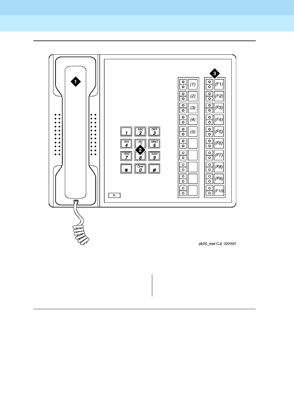
DEFINITY Enterprise Communications Server Release 6
Administration and Feature Description
555-230-522 Issue 4
May 1998
Voice Terminal, PC Interface, and Data Module Administration
Page 6-4510-MET, 20-MET, and 30-MET voice terminals
6
Figure Notes
Figure 6-2. 20-MET voice terminal
1. Handset
2. Dial pad
3. 10 administrable buttons
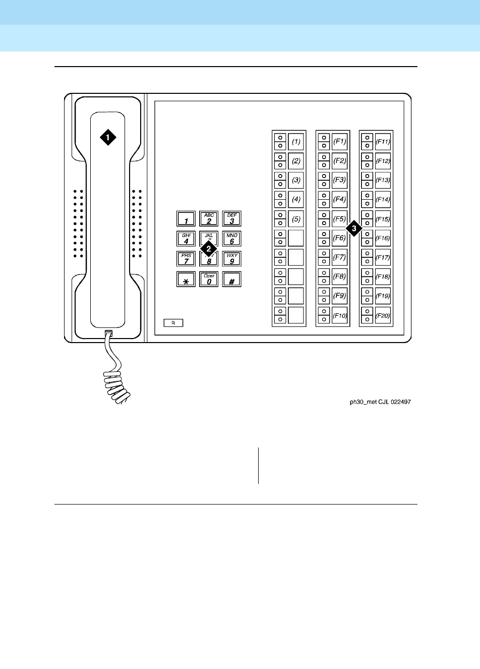
DEFINITY Enterprise Communications Server Release 6
Administration and Feature Description
555-230-522 Issue 4
May 1998
Voice Terminal, PC Interface, and Data Module Administration
Page 6-4610-MET, 20-MET, and 30-MET voice terminals
6
Figure Notes
Figure 6-3. 30-MET voice terminal
1. Handset
2. Dial pad
3. 20 administrable buttons
DEFINITY Enterprise Communications Server Release 6
Administration and Feature Description
555-230-522 Issue 4
May 1998
Voice Terminal, PC Interface, and Data Module Administration
Page 6-47500, 2500, K2500, 7101A, 7102A, 7103A, 7104A, 8110, DS1FD, DS1SA, and VRU
6
500, 2500, K2500, 7101A, 7102A, 7103A,
7104A, 8110, DS1FD, DS1SA, and VRU
voice terminals
DEFINITY allows you to administer the following single-line voice terminals: 500,
2500, K2500, 7101A, 7102A, 7103A, 7104A, 8110, DS1FD, DS1SA, or VRU voice
terminals.
Form instructions
To administer a single-line voice terminal, complete the standard as well as the
following unique Station form fields.
NOTE:
You administer a K2500 Key Phone System Interface the same as you
would a 2500 voice terminal, but the K2500 has the ability to accept either
rotary or DTMF digits. You cannot administer the K2500 to ports on a
TN2135 Analog Line circuit pack
Page 1 of the form
Screen 6-10. Single-line Station form (Page 1 of 3)
■Type — Enter 500, 2500, k2500 (see note), 7101A, 7103A, 7104A, 8110,
ops, ds1fd, ds1sa, VRU, VRUFD, or VRUSA.
— For a 7102A voice terminal, enter 7101A.
— For a 2500 DMGC voice terminal, enter 7101A. This enables the
Recall button and switchhook flash functions.
Page 1 of 3
STATION
Extension: 1003 Lock Messages? n BCC: 0
Type: 500____ Security Code: ________ TN: 1__
Port: _______ Coverage Path 1: ____ COR: 1_
Name: ___________________________ Coverage Path 2: ____ COS: 1_
Hunt-to Station: _____ Tests? y
STATION OPTIONS
Off Premise Station? y Message Waiting Indicator: ____
R Balance Network? n Message Lamp Ext: 1000_

DEFINITY Enterprise Communications Server Release 6
Administration and Feature Description
555-230-522 Issue 4
May 1998
Voice Terminal, PC Interface, and Data Module Administration
Page 6-48500, 2500, K2500, 7101A, 7102A, 7103A, 7104A, 8110, DS1FD, DS1SA, and VRU
6
— When the forward disconnect message is needed for DS-1 ports
(Lineside DS1), enter ds1fd, ds1sa, VRUFD, VRUSA, and a DS-1
circuit pack, either TN767E (or later) or TN464F (or later) circuit
pack.
— The ds1sa or vrusa support special access signaling; the ds1fd or
vrufd support exchange signaling. The forward disconnect signal
for both of these station types is a transition of the a signaling bit for
600ms. The call endpoint (typically a VRU) must have the ability to
respond to the disconnect message. If a DS1 port is translated with
a 500 or 2500 voice terminal, the DS1 protocol does not provide a
means of sending forward disconnect.
— The ops is a DS1 type without a forward disconnect signal.
— Enter ops, ds1fd, ds1sa, VRUFD, or VRUSA to allow a voice
response unit such as Conversant to interface with a DS1 board on
the switch. At the far end, the voice response unit typically uses a
DS0 on a channel bank. At the PBX, the DS0 enters the switch on
the DS1 trunk to which the channel bank is connected.
— The ds1sa is the same as the ds1fd, but also includes messages to
support the special access signaling required by the VRUs. The
ds1sa supports all the fields that the ds1sa does and uses the
same TN767C or greater circuit pack.
— VRU, VRUFD, and VRUSA are valid types only if DTMF Feedback
Signals for VRU is enabled on the Customer-Options System
Parameters form. The VRU type is used for an analog port while
VRUFD or VRUSA are used for DS1 ports.
Screen 6-11. Single-line Station form (Page 2 of 3)
Page 2 of 3
STATION
FEATURE OPTIONS
LWC Reception: msa-spe
LWC Activation? y Coverage Msg Retrieval? y
CDR Privacy? n Auto Answer: none
Redirect Notification? y Data Restriction? n
Per Button Ring Control? n Call Waiting Indication? y
Bridged Call Alerting? n Att. Call Waiting Indication? y
Switchhook Flash? y Distinctive Audible Alert? y
Ignore Rotary Digits? n Adjunct Supervision? y
H.320 Conversion? n
AUDIX Name: _______ Multimedia Early Answer? n
Audible Message Waiting? n
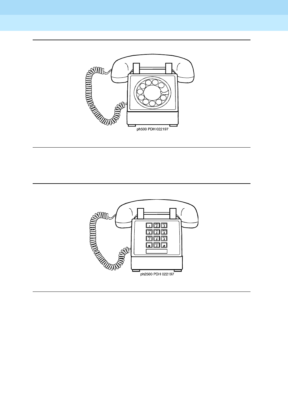
DEFINITY Enterprise Communications Server Release 6
Administration and Feature Description
555-230-522 Issue 4
May 1998
Voice Terminal, PC Interface, and Data Module Administration
Page 6-49500, 2500, K2500, 7101A, 7102A, 7103A, 7104A, 8110, DS1FD, DS1SA, and VRU
6
Figure 6-4. 500 voice terminal
Figure 6-5. 2500 voice terminal
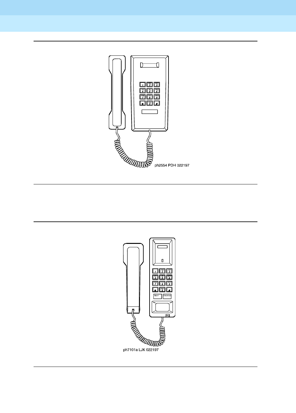
DEFINITY Enterprise Communications Server Release 6
Administration and Feature Description
555-230-522 Issue 4
May 1998
Voice Terminal, PC Interface, and Data Module Administration
Page 6-50500, 2500, K2500, 7101A, 7102A, 7103A, 7104A, 8110, DS1FD, DS1SA, and VRU
6
Figure 6-6. 2554 voice terminal
Figure 6-7. 7101A voice terminal
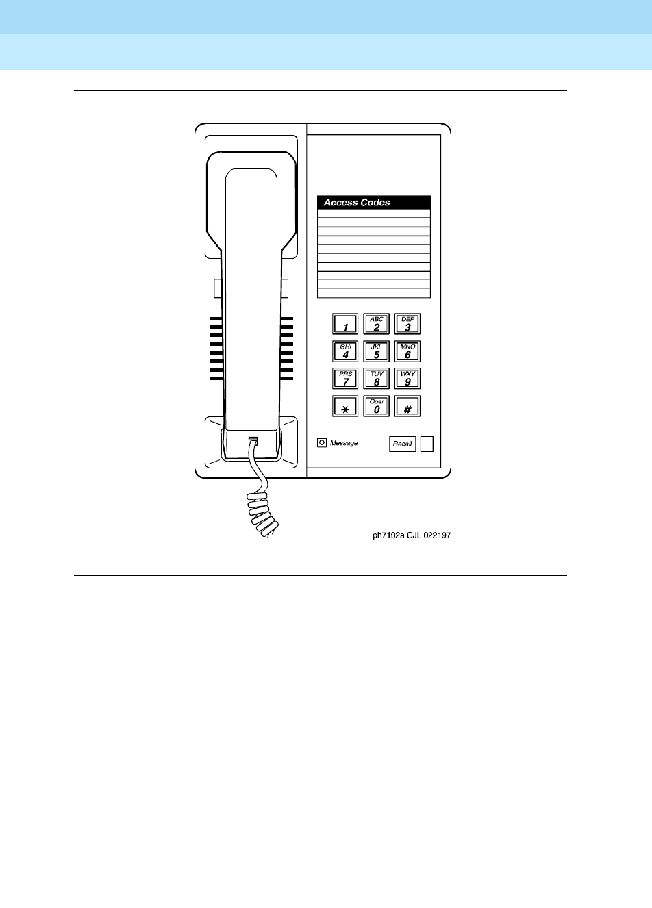
DEFINITY Enterprise Communications Server Release 6
Administration and Feature Description
555-230-522 Issue 4
May 1998
Voice Terminal, PC Interface, and Data Module Administration
Page 6-51500, 2500, K2500, 7101A, 7102A, 7103A, 7104A, 8110, DS1FD, DS1SA, and VRU
6
Figure 6-8. 7102A voice terminal
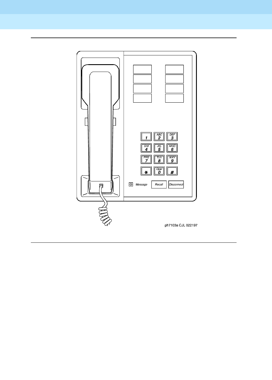
DEFINITY Enterprise Communications Server Release 6
Administration and Feature Description
555-230-522 Issue 4
May 1998
Voice Terminal, PC Interface, and Data Module Administration
Page 6-52500, 2500, K2500, 7101A, 7102A, 7103A, 7104A, 8110, DS1FD, DS1SA, and VRU
6
Figure 6-9. 7103A voice terminal
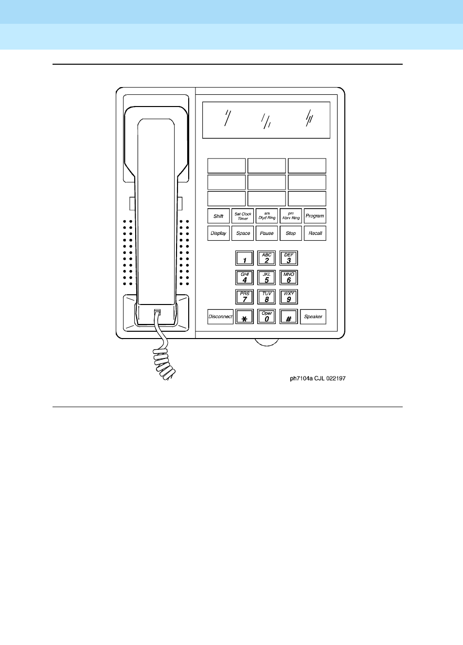
DEFINITY Enterprise Communications Server Release 6
Administration and Feature Description
555-230-522 Issue 4
May 1998
Voice Terminal, PC Interface, and Data Module Administration
Page 6-53500, 2500, K2500, 7101A, 7102A, 7103A, 7104A, 8110, DS1FD, DS1SA, and VRU
6
Figure 6-10. 7104A voice terminal
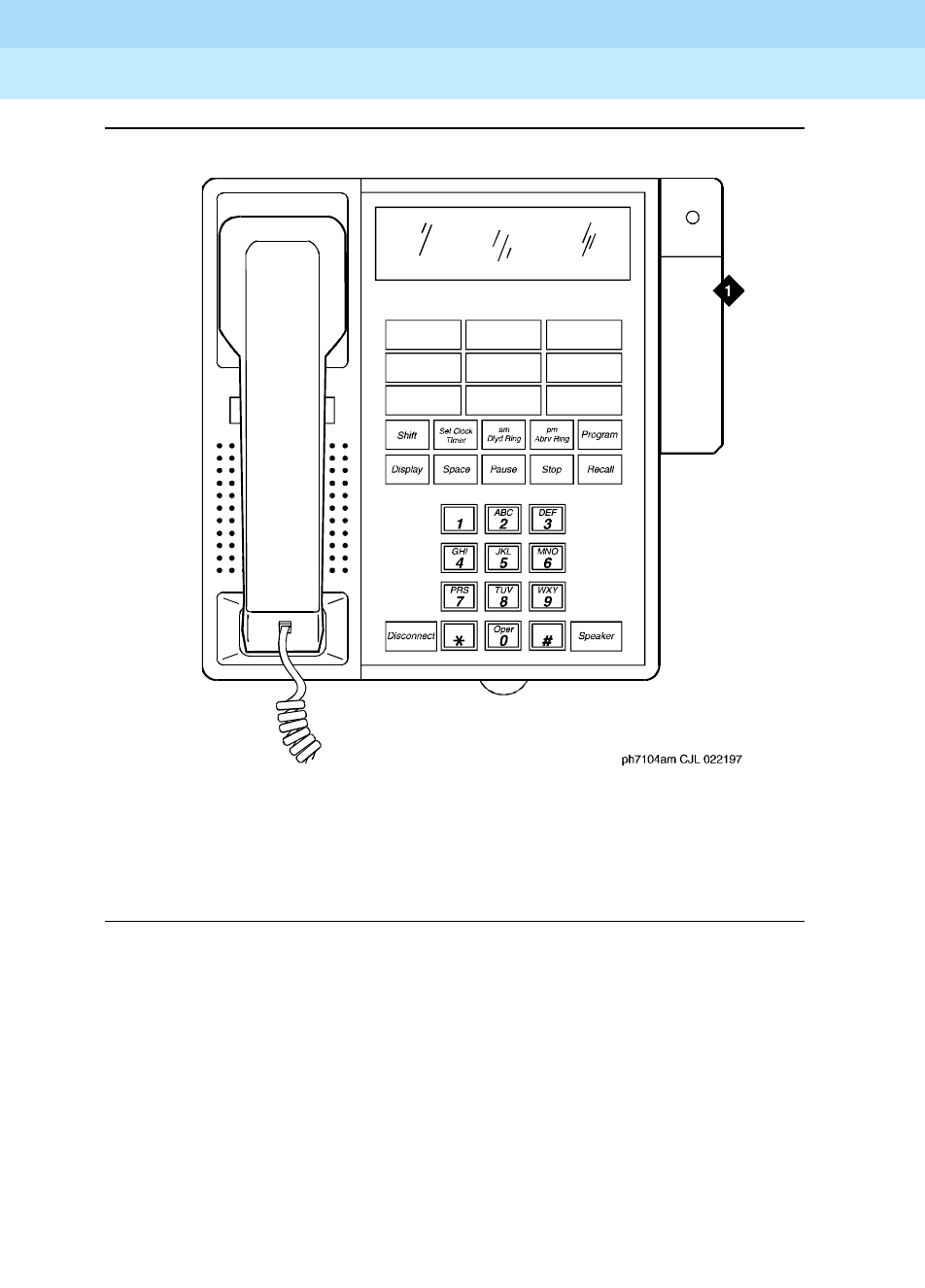
DEFINITY Enterprise Communications Server Release 6
Administration and Feature Description
555-230-522 Issue 4
May 1998
Voice Terminal, PC Interface, and Data Module Administration
Page 6-54500, 2500, K2500, 7101A, 7102A, 7103A, 7104A, 8110, DS1FD, DS1SA, and VRU
6
Figure Notes
Figure 6-11. 7104A voice terminal w/Message Waiting
1. Message waiting adjunct

DEFINITY Enterprise Communications Server Release 6
Administration and Feature Description
555-230-522 Issue 4
May 1998
Voice Terminal, PC Interface, and Data Module Administration
Page 6-55510D personal terminal and 515 business communications terminal
6
510D personal terminal and 515
business communications terminal
Form Instructions
To administer a 510D personal terminal (PT) or 515 business communications
terminal (BCT), complete the standard as well as the following unique Station
form fields.
Page 1 of the form
Screen 6-12. 510D and 515 BCT form (Page 1 of X)
■Type — Enter 510 or 515 as appropriate.
■Data Module — Display-only field. Restricted to y.
■Display Module — Display-only field. Restricted to y.
Page 2 of the form
Screen 6-13. 510D and 515 BCT form (Page 2 of X)
Page 1 of X
STATION
Extension: 1003 Lock Messages? n BCC: 0
Type: 510____ Security Code: ________ TN: 1__
Port: _______ Coverage Path 1: ____ COR: 1_
Name: ___________________________ Coverage Path 2: ____ COS: 1_
Hunt-to Station: _____
STATION OPTIONS
Data Module? y
Display Module? y Message Lamp Ext: 1000_
Display Language: english
Page 2 of X
STATION
FEATURE OPTIONS
LWC Reception? msa-spe Auto Select Any Idle Appearance? n
LWC Activation? y Coverage Msg Retrieval? y
CDR Privacy? n Auto Answer: none
Redirect Notification? y Data Restriction? n
Per Button Ring Control? n Idle Appearance Preference? n
PCOL/TEG Call Alerting? n
Active Station Ringing: single Restrict Last Appearance? y
H.320 Conversion? n
AUDIX Name: ______ Multimedia Early Answer? n
Messaging Server Name: ______ Audible Message Waiting? n
Display Client Redirection? n
Select Last Used Appearance? n

DEFINITY Enterprise Communications Server Release 6
Administration and Feature Description
555-230-522 Issue 4
May 1998
Voice Terminal, PC Interface, and Data Module Administration
Page 6-56510D personal terminal and 515 business communications terminal
6
■Bridged Call Alerting — (515 BCT only) Enter y to allow incoming calls
on bridged appearances of another terminals primary extension or TEG or
PCOL calls to alert at this terminal. Default is n.
Page 3 of the form
Screen 6-14. 510D and 515 BCT form (Page 3 of X)
■Button Assignments
The feature buttons that you can assign to the 510PT and 515 BCT are
listed below. The first 3 button assignments default to call appearance for
both terminals. Button Assignments 5 through 10 display only on the 515
BCT form.
abr-prog abr-spchar abrdg-appr abrv-dial
abrv-ring ac-alarm aca-halt after-call
alrt-agchg alt-frl assist asvn-halt
atd-qcalls1atd-qtime1aut-msg-wt auto-cback
auto-icom auto-in auto-wkup1autodial
aux-work brdg-appr busy-ind call-appr
call-disp1call-fwd call-park call-pkup
callr-info1cas-backup cdr1-alrm cdr2-alrm
cfwd-bsyda check-in1check-out1clk-overid1
consult cov-cback cov-msg-rt1data-ext
date-time1delete-msg1dial-icom directory1
dir-pkup disp-chrg disp-norm dn-dst
Page 3 of X
STATION
SITE DATA
Room: _______ Headset? n
Jack: ___ Speaker? n
Cable: ___ Mounting: d
Floor: _______ Cord Length: 0_
Building: _______ Set Color: _____
ABBREVIATED DIALING
List1: ________ List2: _________ List3: _________
BUTTON ASSIGNMENTS
1: call-appr 6: __________
2: call-appr 7: __________
3: call-appr 8: __________
4: __________ 9: __________
5: __________ 10: __________

DEFINITY Enterprise Communications Server Release 6
Administration and Feature Description
555-230-522 Issue 4
May 1998
Voice Terminal, PC Interface, and Data Module Administration
Page 6-57510D personal terminal and 515 business communications terminal
6
Page 4 of the form (510D Only)
Screen 6-15. 510D Station form (Page 4 of X)
1. Display-type buttons
2. Stations administered with displays only
ds1-alarm exclusion ext-dn-dst1flash
goto-cover grp-dn-dst1hunt-ns in-call-id
inspect1int-aut-an last-numb link-alarm
lsvn-halt lwc-cancel lwc-lock lwc-store
major-alrm man-msg-wt man-overid1manual-in
mct-act mct-contr mj/mn-alrm msg-retr1
mwn-act1mwn-deact1next1night-serv
noans-alrt normal1per-COline pms-alarm
pr-awu-alm pr-pms-alm pr-sys-alm print-msgs
priority q-calls q-time release
ringer-off rs-alert rsvn-halt scroll
send-calls send-term serv-obsrv signal
ssvn-halt stored-num1stroke-cnt term-x-gr
timer1trk-ac-alm trk-id trunk-name1
trunk-ns verify voa-repeat vu-display
work-code2
Page 4 of X
STATION
FEATURE BUTTON ASSIGNMENTS
Column 1: 1: __________
2: __________
3: __________
Column 2: 4: __________
5: __________
6: __________
Column 3: 7: __________
8: __________
9: __________

DEFINITY Enterprise Communications Server Release 6
Administration and Feature Description
555-230-522 Issue 4
May 1998
Voice Terminal, PC Interface, and Data Module Administration
Page 6-58510D personal terminal and 515 business communications terminal
6
■Feature Button Assignments
The features and functions that you can assign to Page 4 of X are the
same as those listed for BUTTON ASSIGNMENTS above.
Page X of the form
■(Display Button Assignments)
The features and functions that you can assign are the same as those
above and are noted as display buttons.
Screen 6-16. 510D and 515 BCT Station form (Page Y of X)
Screen 6-17. 510D and 515 BCT Data Module form (Page Y of X)
Page Y of X
STATION
DISPLAY BUTTON ASSIGNMENTS
1: __________
2: __________
3: __________
4: __________
5: __________
6: __________
7: __________
Page Y of X
STATION
DATA MODULE
Data Extension: ____ Name: ____________________ BCC: 2
COS: 1_
COR: 1_
TN: 1_
ITC: restricted
ABBREVIATED DIALING
List1: ________
SPECIAL DIALING OPTION: _________
HOT LINE DESTINATION
DEFAULT DIALING
Abbreviated Dialing Dial Code (From above list): ____
ASSIGNED MEMBER (Station with a data extension button for this data module)
Ext Name
1:
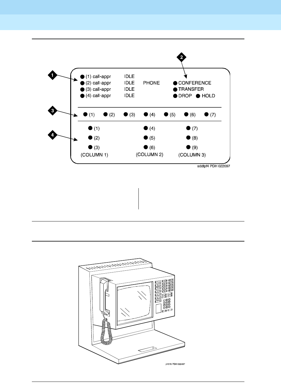
DEFINITY Enterprise Communications Server Release 6
Administration and Feature Description
555-230-522 Issue 4
May 1998
Voice Terminal, PC Interface, and Data Module Administration
Page 6-59510D personal terminal and 515 business communications terminal
6
Figure Notes
Figure 6-12. 510D personal terminal administrable screen button assignments
Figure 6-13. 515 business communications terminal (BCT)
1. 4 programmable buttons
2. 4 fixed feature buttons
3. 7 display buttons
4. 9 feature buttons

DEFINITY Enterprise Communications Server Release 6
Administration and Feature Description
555-230-522 Issue 4
May 1998
Voice Terminal, PC Interface, and Data Module Administration
Page 6-606402, 6402D, 6408, 6408+, 6408D, 6408D+, 6416D+, 6424D+ voice terminals
6
6402, 6402D, 6408, 6408+, 6408D,
6408D+,
6416D+, 6424D+ voice terminals
The 6400-series voice terminals are DCP 2-wire voice terminals that work with
DEFINITY Release 6 and future releases. 6400-series voice terminals operate
similar to the 8400- and 9400-series voice terminals, although there are some
enhancements, feature, and physical differences. The 6400-series voice
terminals have:
■XM24 expansion module
■Different number of call appearances and feature buttons
■New defaults and features for softkeys
■Last number dialed (LND) button instead of a drop button (the drop
function can be administered on any button)
The number of call appearances on a terminal is identified by the last two digits
in the terminal name. The series includes two single-line sets (6402 and 6402D),
8-button sets, a 16-button set, a 24-button set, and a 24-button expansion
module (on the 6416D+ and 6424D+ voice terminals).
To administer a 6400-series terminal
To administer a 6400-series voice terminal, complete the standard as well as the
following unique Station form fields.
For information about adjusting the system-level parameters and audio levels for
the 6400-series voice terminals, see ‘‘Terminal Parameters form’’ on page 6-9.

DEFINITY Enterprise Communications Server Release 6
Administration and Feature Description
555-230-522 Issue 4
May 1998
Voice Terminal, PC Interface, and Data Module Administration
Page 6-616402, 6402D, 6408, 6408+, 6408D, 6408D+, 6416D+, 6424D+ voice terminals
6
On page 1 of the Station form
Screen 6-18. 6400 Station form (Page 1 of X)
Screen 6-19. 6400 Terminal Parameters form (Page 1 of 1)
1. Enter one of the following in the Type field:
■6402 (2-line terminal that supports 1-way speakerphone)
■6402D (2-line display terminal that supports 1-way speakerphone)
■6408 (8-line terminal that supports 1-way speakerphone)
■6408+ (8-line terminal that supports 2-way speakerphone)
Page 1 of X
STATION
Extension: 1003 Lock Messages? n BCC: 0
Type: 6424D+_ Security Code: ________ TN: 1_
Port: _______ Coverage Path 1: ____ COR: 1_
Name: ___________________________ Coverage Path 2: ____ COS: 1_
Hunt-to Station: _____
STATION OPTIONS
Data Module? n Personalized Ringing Pattern: 1
Speakerphone: 2-way Message Lamp Ext: 1000
Display Language: english Mute Button Enabled? y
Expansion Module? n
MM Complex Data Ext: n
Page 1 of 1
6400-TYPE TERMINAL PARAMETERS
Default Parameter Set:1 Customize Parameters?y
OPTIONS
Display Mode: Handset Expander Enabled?
Volume:
PRIMARY LEVELS
Voice Transmit (dB): Voice Sidetone (dB):
Voice Receive (dB): Touch Tone Sidetone (dB):
Touch Tone Transmit (dB):
BUILT-IN SPEAKER LEVELS
Voice Transmit (dB): Voice Receive (dB):
Touch Tone Sidetone (dB):
6402 BUILT-IN SPEAKER LEVELS
Voice Receive (dB): Touch Tone Sidetone (dB):

DEFINITY Enterprise Communications Server Release 6
Administration and Feature Description
555-230-522 Issue 4
May 1998
Voice Terminal, PC Interface, and Data Module Administration
Page 6-626402, 6402D, 6408, 6408+, 6408D, 6408D+, 6416D+, 6424D+ voice terminals
6
■6408D (8-line display terminal that supports 1-way speakerphone)
■6408D+ (8-line display terminal that supports 2-way speakerphone)
■6416D+ (16-line display terminal that supports 2-way
speakerphone)
■6424D+ (24-line display terminal that supports 2-way
speakerphone)
2. Enter y in Data Module if this terminal is to be connected to a data
terminal via a 6400 data module. If you enter y, you must complete the
Data Module form. Default is n.
3. Accept the default of y in Mute Button Enabled? if this terminal should
have the mute button available. Enter n if you want to disable the mute
button.
4. Enter y in Expansion Module (for 6416D+ and 6424D+ terminals only) if
a XM24 expansion module is attached to the terminal. If you enter y, an
optional page of the form appears to allow you to administer the
Expansion Module buttons. Default is n.
Page 2 of the form
Screen 6-20. 6400 Station form (Page 2 of X)
Page 2 of X
STATION
FEATURE OPTIONS
LWC Reception? msa-spe Auto Select Any Idle Appearance? n
LWC Activation? y Coverage Msg Retrieval? y
CDR Privacy? n Auto Answer: none
Redirect Notification? y Data Restriction? n
Per Button Ring Control? n Idle Appearance Preference? n
Bridged Call Alerting? n
Active Station Ringing: single Restrict Last Appearance? y
H.320 Conversion? n
AUDIX Name: ______ Multimedia Early Answer? n
Messaging Server Name: ______ Audible Message Waiting? y
Display Client Redirection? n
Select Last Used Appearance? n

DEFINITY Enterprise Communications Server Release 6
Administration and Feature Description
555-230-522 Issue 4
May 1998
Voice Terminal, PC Interface, and Data Module Administration
Page 6-636402, 6402D, 6408, 6408+, 6408D, 6408D+, 6416D+, 6424D+ voice terminals
6
On page 3 of the form (except 6402)
Screen 6-21. 6400 (except 6402) Station form (Page 3 of X)
■BUTTON ASSIGNMENTS
The feature buttons that you can assign to these voice terminals are
shown in Tab l e 6 - 7, Button Assignments for Page 3 of the Station Form,
and in the following text:
On page 3 of the 6402 form
Screen 6-22. 6402 Station form (Page 3 of X)
account admin btn-view call-timer group-page
Page 3 of X
STATION
SITE DATA
Room: _______ Headset? n
Jack: _____ Speaker? n
Cable: _____ Mounting: d
Floor: _______ Cord Length: 0
Building: _______ Set Color: ______
ABBREVIATED DIALING
List1: ________ List2: ________ List3: ________
BUTTON ASSIGNMENTS
1: __________ 5: __________
2: __________ 6: __________
3: __________ 7: __________
4: __________ 8: __________
Page 3 of X
STATION
SITE DATA
Room: _______ Headset? n
Jack: _____ Speaker? n
Cable: _____ Mounting: d
Floor: _______ Cord Length: 0
Building: _______ Set Color: ______
ABBREVIATED DIALING
List1: ________ List2: ________ List3: ________
BUTTON ASSIGNMENTS
1: call-appr
2: call-appr

DEFINITY Enterprise Communications Server Release 6
Administration and Feature Description
555-230-522 Issue 4
May 1998
Voice Terminal, PC Interface, and Data Module Administration
Page 6-646402, 6402D, 6408, 6408+, 6408D, 6408D+, 6416D+, 6424D+ voice terminals
6
■BUTTON ASSIGNMENTS
The first two buttons on the 6402 voice terminals default as call
appearance buttons and cannot be changed.
On page 4 of the form
■FEATURE BUTTON ASSIGNMENTS
The features and functions that you can assign to the terminal’s
administrable buttons are the same as those for BUTTON ASSIGNMENTS
above.
On page 4 of the 6402 form
Screen 6-23. 6402 Station form (Page 4 of X)
■FEATURE BUTTON ASSIGNMENTS
The user can assign these buttons via the dial pad, or you can assign
them using this form.
Page 4 of X
STATION
FEATURE BUTTON ASSIGNMENTS
1: __________
2: __________
3: __________
4: __________
5: __________
6: __________
7: __________
8: __________
9: __________
*: __________
0: __________
#: __________

DEFINITY Enterprise Communications Server Release 6
Administration and Feature Description
555-230-522 Issue 4
May 1998
Voice Terminal, PC Interface, and Data Module Administration
Page 6-656402, 6402D, 6408, 6408+, 6408D, 6408D+, 6416D+, 6424D+ voice terminals
6
On page 4 of the 6416D+ form
Screen 6-24. 6416D+ Station form (Page 4 of X)
■FEATURE BUTTON ASSIGNMENTS
These are for buttons 9 through 16.
On page 4 of the 6424D+ form
Screen 6-25. 6424D+ Station form (Page 4 of X)
■FEATURE BUTTON ASSIGNMENTS
These are for buttons 9 through 24.
Page 4 of X
STATION
FEATURE BUTTON ASSIGNMENTS
9: __________
10: __________
11: __________
12: __________
13: __________
14: __________
15: __________
16: __________
Page 4 of X
STATION
FEATURE BUTTON ASSIGNMENTS
9: __________
10:__________
11:__________
12:__________
13:__________
14:__________
15:__________
16:__________
17:__________
18:__________
19:__________
20:__________
21:__________
22:__________
23:__________
24:__________

DEFINITY Enterprise Communications Server Release 6
Administration and Feature Description
555-230-522 Issue 4
May 1998
Voice Terminal, PC Interface, and Data Module Administration
Page 6-666402, 6402D, 6408, 6408+, 6408D, 6408D+, 6416D+, 6424D+ voice terminals
6
On page 4 of the 6408D and 6408D+ forms and page 5 of the 6416D+ and
6424D+ forms
Screen 6-26. 6400 Display Station form (Page 5 of X)
■SOFTKEY BUTTON ASSIGNMENTS
The 6408D, 6408D+, 6416D+, and 6424D+ terminals support 12 display
softkeys. These are the default softkeys that the system administers:
You can assign features to these softkeys, making them “virtual” buttons.
When you assign a feature to a softkey, the system automatically
downloads the appropriate information to the terminal for operating the
feature.
You may also customize the softkey displays for English, French, Italian, or
Spanish. These are displayed in the Display Languages field on page 1 of
the Station form. To customize the labels, use the Language Translation
form, set Display Languages to user-defined, and type the command
change display-messages softkey-labels. You may enter a
five-character label for each of the softkeys.
Dir Drop HFAns Timer
PCall AutCB Prog Pause
LWC RingOf BtnVu Admin
Page 5 of X
STATION
SOFTKEY BUTTON ASSIGNMENTS
1: Dir
2: Drop
3: HFAns
4: Timer
5: PCall
6: AutCB
7: Prog
8: Pause
9: LWC
10: RngOf
11: BtnVu
12: Admin

DEFINITY Enterprise Communications Server Release 6
Administration and Feature Description
555-230-522 Issue 4
May 1998
Voice Terminal, PC Interface, and Data Module Administration
Page 6-676402, 6402D, 6408, 6408+, 6408D, 6408D+, 6416D+, 6424D+ voice terminals
6
Page 6 of the 6416D+ or 6424D+ form
Screen 6-27. 6416D+ and 6424D+ with XM24 Expansion Module form (Page 6 of Y)
EXPANSION MODULE
This page appears only if Expansion Module is set to y. Use these
pages to administer buttons on the XM24 expansion module if one is
attached to the terminal.
Fields 1 through 9 on the form correspond to the 24 dual-LED feature
buttons on the expansion module. You can assign to these buttons any of
the features or functions that you can assign to the feature buttons referred
to in the previous section, On page 3 of the form (except 6402).
Page 6 of Y
STATION
EXPANSION MODULE BUTTON ASSIGNMENT
1: __________ 13: __________
2: __________ 14: __________
3: __________ 15: __________
4: __________ 16: __________
5: __________ 17: __________
6: __________ 18: __________
7: __________ 19: __________
8: __________ 20: __________
9: __________ 21: __________
10: __________ 22: __________
11: __________ 23: __________
12: __________ 24: __________

DEFINITY Enterprise Communications Server Release 6
Administration and Feature Description
555-230-522 Issue 4
May 1998
Voice Terminal, PC Interface, and Data Module Administration
Page 6-686402, 6402D, 6408, 6408+, 6408D, 6408D+, 6416D+, 6424D+ voice terminals
6
Page X of Y of the form (DATA MODULE)
Screen 6-28. 6400 Data Module form (Page X of Y)
This page displays only if Data Module is y.
Page X of Y
STATION
DATA MODULE
Data Extension: _______________ Name: _____________ BCC: ____
COS: 1_
COR: 1_
ITC: restricted TN: 1_
ABBREVIATED DIALING
List1: ________
SPECIAL DIALING OPTION: hot-line
HOT LINE DESTINATION
DEFAULT DIALING
Abbreviated Dialing Dial Code (From above list): ___
ASSIGNED MEMBER (Station with a data extension button for this data module)
Ext Name
1. _____ ___________________________
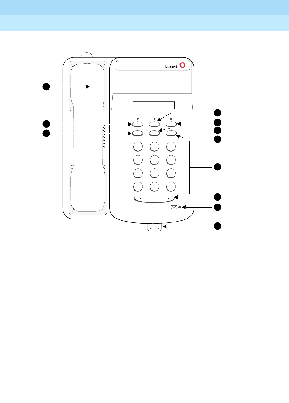
DEFINITY Enterprise Communications Server Release 6
Administration and Feature Description
555-230-522 Issue 4
May 1998
Voice Terminal, PC Interface, and Data Module Administration
Page 6-696402, 6402D, 6408, 6408+, 6408D, 6408D+, 6416D+, 6424D+ voice terminals
6
Figure Notes
Figure 6-14. 6402 Single-Line Voice Terminal
1. Feature button
2. Hold button
3. Transfer/Test button
4. Conf/Ring button
5. Dial pad
6. Volume control button
7. Message light
8. Tray handle (five cards are
provided in the tray located under
the base of every 6400-series
telephone for reference purposes)
9. Redial button
10. Speaker button
11. Handset
7
PQRS
3
DEF
Speaker Feature Hold
Redial Transfer Conf
Test Ring
2
ABC
1
4
GHI
*
56
89
MNOJKL
TUV WXYZ
O#
Volume
5
1
2
3
4
6
7
8
11
10
9
Tel #
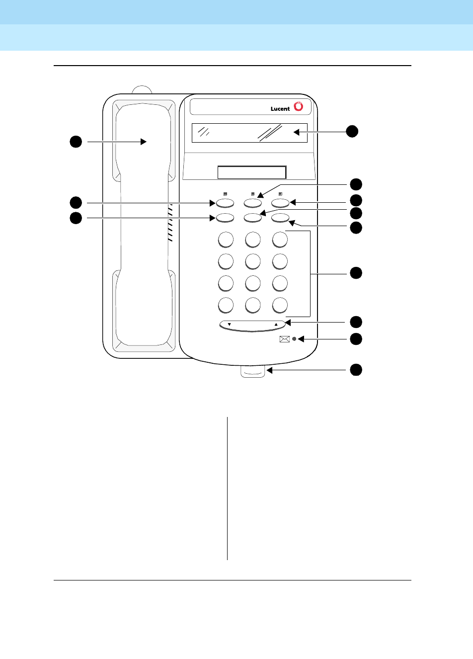
DEFINITY Enterprise Communications Server Release 6
Administration and Feature Description
555-230-522 Issue 4
May 1998
Voice Terminal, PC Interface, and Data Module Administration
Page 6-706402, 6402D, 6408, 6408+, 6408D, 6408D+, 6416D+, 6424D+ voice terminals
6
Figure Notes
Figure 6-15. 6402D Single-Line Voice Terminal
1. Display
2. Feature button
3. Hold button
4. Transfer/Test button
5. Conf/Ring button
6. Dial pad
7. Volume control button
8. Message light
9. Tray handle (five cards are
provided in the tray located under
the base of every 6400-series
telephone for reference purposes)
10. Redial button
11. Speaker button
12. Handset
7
PQRS
3
DEF
Speaker Feature Hold
Redial Transfer Conf
Test Ring
2
ABC
1
4
GHI
*
56
89
MNOJKL
TUV WXYZ
O#
Volume
6
2
3
4
5
7
8
9
12
11
10
Tel #
1
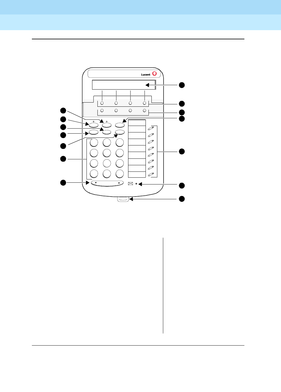
DEFINITY Enterprise Communications Server Release 6
Administration and Feature Description
555-230-522 Issue 4
May 1998
Voice Terminal, PC Interface, and Data Module Administration
Page 6-716402, 6402D, 6408, 6408+, 6408D, 6408D+, 6416D+, 6424D+ voice terminals
6
Figure Notes
Figure 6-16. 6408D Multi-Line Telephone
1. Display
2. Softkeys
3. Display control buttons
4. Hold
5. Call appearance/feature buttons
6. Message light
7. Tray handle (five cards are provided in the
tray located under the base of every
6400-series telephone for reference
purposes)
8. Volume control button
9. Dial pad
10. Conf/Ring button
11. Redial button
12. Transfer/Test button
13. Speaker button
14. Mute button
Handset (not shown here)
7
PQRS
3
DEF
Spkr Mute Hold
Redial Trnsfr Conf
Test Ring
2
ABC
1
4
GHI
*
56
89
MNOJKL
TUV WXYZ
O#
Volume
1
5
4
6
7
13
11
Tel #
Menu Exit Prev Next
9
10
8
3
2
14
12

DEFINITY Enterprise Communications Server Release 6
Administration and Feature Description
555-230-522 Issue 4
May 1998
Voice Terminal, PC Interface, and Data Module Administration
Page 6-727302H, 7303H, and 7305H MERLIN voice terminals
6
7302H, 7303H, and 7305H MERLIN
voice terminals
Administer 7302H voice terminals (5-Button) with the 7303S Station form.
Administer 7303H voice terminals (10-Button) with the 7305S Station form. Only
the first 12 feature function buttons apply. Of these 12 buttons, 8 have two lamps
and 4 have no lamps. However, the system treats the 8 double-lamp buttons as
though they have a single (green) lamp. Administer the 4 buttons (with no lamps)
with features that do not require status indications.
Administer 7305H voice terminals (34-Button) with the 7305S Station form. The
system treats the terminal’s 24 feature function buttons (two lamps each) as
single (green) lamp function buttons.

DEFINITY Enterprise Communications Server Release 6
Administration and Feature Description
555-230-522 Issue 4
May 1998
Voice Terminal, PC Interface, and Data Module Administration
Page 6-737303S, 7305S, and 7309H voice terminals
6
7303S, 7305S, and 7309H voice
terminals
Form instructions
To administer a 7303S, 7305S, 7309S voice terminal, complete the standard as
well as the following unique Station form fields.
Page 1 of the form
Screen 6-29. 7303S, 7305S, and 7309H Station form (Page 1 of X)
■Type — Enter 7303S, 7305S, or 7309H as appropriate.
Page 1 of X
STATION
Extension: ______ BCC: 0
Type: 7303S_ Lock Messages? n TN: 1
Port: _______________ Security Code: ________ COR: 1
Name: _______________ Coverage Path 1: ____ COS: 1
Coverage Path 2: ____
Hunt-to Station: ____
STATION OPTIONS
Personalized Ringing Pattern: 1
Message Lamp Ext: ____
MM Complex Data Ext: ____

DEFINITY Enterprise Communications Server Release 6
Administration and Feature Description
555-230-522 Issue 4
May 1998
Voice Terminal, PC Interface, and Data Module Administration
Page 6-747303S, 7305S, and 7309H voice terminals
6
Page 2 of the form
Screen 6-30. 7303S, 7305S, and 7309H Station form (Page 2 of X)
Page 3 of the form
Screen 6-31. 7303S, 7305S, and 7309H Station form (Page 3 of X)
Page 2 of X
STATION
FEATURE OPTIONS
LWC Reception? msa-spe Auto Select Any Idle Appearance? n
LWC Activation? y Coverage Msg Retrieval? y
CDR Privacy? n Auto Answer: none
Redirect Notification? y Data Restriction? n
Per Button Ring Control? n Idle Appearance Preference? n
Bridged Call Alerting? n
Active Station Ringing: single Restrict Last Appearance? y
H.320 Conversion? n
AUDIX Name: ______ Multimedia Early Answer? n
Messaging Server Name: ______ Audible Message Waiting? y
Select Last Used Appearance? n
Page 3 of X
STATION
SITE DATA
Room: _______ Headset? n
Jack: ___ Speaker? n
Cable: ___ Mounting: d
Floor: _______ Cord Length: 0_
Building: _______ Set Color: _____
ABBREVIATED DIALING
List1: ________ List2: _________ List3: _________
BUTTON ASSIGNMENTS
1: call-appr_ 6: __________
2: call-appr_ 7: __________
3: call-appr_ 8: __________
4: __________ 9: __________
5: __________ 10: __________

DEFINITY Enterprise Communications Server Release 6
Administration and Feature Description
555-230-522 Issue 4
May 1998
Voice Terminal, PC Interface, and Data Module Administration
Page 6-757303S, 7305S, and 7309H voice terminals
6
■BUTTON ASSIGNMENTS
The feature buttons that you can assign to the 7303S, 7305S, and 7309H
voice terminals are listed below. The first 3 buttons default as call
appearances.
1. Stations administered with displays only.
abr-prog abr-spchar abrdg-appr abrv-dial
abrv-ring ac-alarm aca-halt after-call
alrt-agchg alt-frl assist asvn-halt
atd-qcalls atd-qtime aut-msg-wt auto-cback
auto-icom auto-in autodial aux-work
brdg-appr busy-ind call-appr call-fwd
call-park call-pkup cas-backup cdr1-alrm
cdr2-alrm cfwd-bsyda consult cov-cback
data-ext dial-icom dir-pkup dn-dst
ds1-alarm exclusion flash goto-cover
hunt-ns in-call-id int-aut-an last-numb
link-alarm lsvn-halt lwc-cancel lwc-store
major-alrm man-msg-wt manual-in mct-act
mct-contr mj/mn alrm ringer-off night-serv
noans-alrt per-COline pms-alarm pr-awu-alm
pr-pms-alm pr-sys-alm print-msgs priority
q-calls q-time release rs-alert
rsvn-halt send-calls send-term serv-obsrv
signal ssvn-halt stroke-cnt term-x-gr
trk-ac-alm trunk-ns verify voa-repeat
work-code1

DEFINITY Enterprise Communications Server Release 6
Administration and Feature Description
555-230-522 Issue 4
May 1998
Voice Terminal, PC Interface, and Data Module Administration
Page 6-767303S, 7305S, and 7309H voice terminals
6
Page 4 of the form (7305S only)
Screen 6-32. 7305S Voice-terminal form (Page 4 of 4)
■FEATURE BUTTON ASSIGNMENTS
The features and functions that you can assign on Page 4 of X are the
same as those listed for BUTTON ASSIGNMENTS above.
Page 4 of 4
STATION
FEATURE BUTTON ASSIGNMENTS
1: __________ 13: __________
2: __________ 14: __________
3: __________ 15: __________
4: __________ 16: __________
5: __________ 17: __________
6: __________ 18: __________
7: __________ 19: __________
8: __________ 20: __________
9: __________ 21: __________
10: __________ 22: __________
11: __________ 23: __________
12: __________ 24: __________
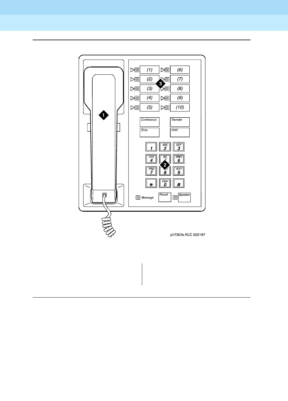
DEFINITY Enterprise Communications Server Release 6
Administration and Feature Description
555-230-522 Issue 4
May 1998
Voice Terminal, PC Interface, and Data Module Administration
Page 6-777303S, 7305S, and 7309H voice terminals
6
Figure Notes
Figure 6-17. 7303S voice terminal
1. Handset
2. Dial pad
3. 10 programmable buttons
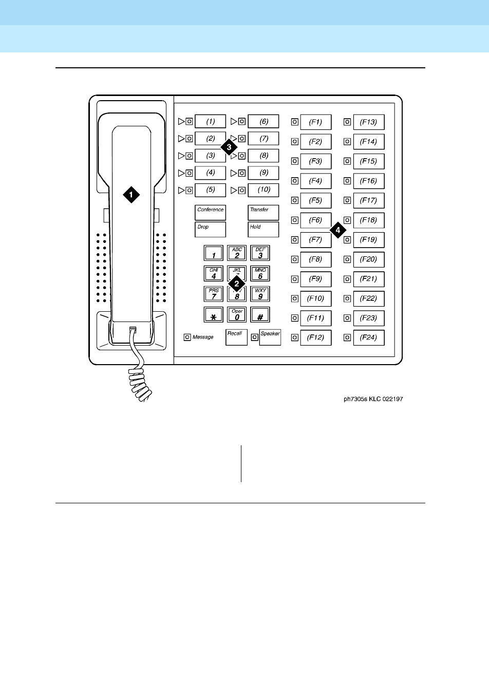
DEFINITY Enterprise Communications Server Release 6
Administration and Feature Description
555-230-522 Issue 4
May 1998
Voice Terminal, PC Interface, and Data Module Administration
Page 6-787303S, 7305S, and 7309H voice terminals
6
Figure Notes
Figure 6-18. 7305S voice terminal
1. Handset
2. Dial pad
3. 10 programmable buttons
4. 24 feature buttons

DEFINITY Enterprise Communications Server Release 6
Administration and Feature Description
555-230-522 Issue 4
May 1998
Voice Terminal, PC Interface, and Data Module Administration
Page 6-797303S, 7305S, and 7309H voice terminals
6
Figure Notes
Figure 6-19. 7309H voice terminal
1. Handset
2. Dial pad
3. 10 programmable buttons with
in-use and status LEDs
DEFINITY Enterprise Communications Server Release 6
Administration and Feature Description
555-230-522 Issue 4
May 1998
Voice Terminal, PC Interface, and Data Module Administration
Page 6-807313H, 7314H, 7315H, 7316H, and 7317H voice terminals
6
7313H, 7314H, 7315H, 7316H, and
7317H voice terminals
The following feature differences and restrictions exist for hybrid voice terminals
in the system:
■Hybrid voice terminals equipped with displays cannot be used as ACD
agents.
■The following feature buttons do not operate on Hybrid terminals: STOP,
PAUSE, RECALL, MESSAGE, HFAI, and HFAI/MIC. The replacement for
Hands Free Automatic Answer on Intercom (HFAI) is Internal Automatic
Answer (IAA).
■When administering IAA on a 731xH series voice terminal, you should
assign a feature button with a lamp so the lamp status of IAA can be
observed.
NOTE:
When placing a call to pager equipment, do not immediately hang
up when finished dialing until receipt of confirmation. Failure to wait
for confirmation may result in an incomplete signal being sent to the
pager resulting in an incomplete call message.
Form instructions
To administer a 7313H (BIS-10), 7314H (BIS-22), 7315H (BIS-22D), 7316H
(BIS-34), or 7317H (BIS-34D) voice terminal, complete the standard as well as
the following unique Station form fields.
Page 1 of the form
Screen 6-33. 7313H, 7314H, 7315H, 7316H, and 7317H Station form (Page 1 of X)
■Type — Enter 7313H, 7314H, 7315H, 7316H, or 7317H as appropriate.
Page 1 of X
STATION
Extension: 1003 Lock Messages? n BCC: 0
Type: 7315H__ Security Code: ________ TN: 1_
Port: _______ Coverage Path 1: ____ COR: 1_
Name: ________________________ Coverage Path 2: ____ COS: 1_
Hunt-to Station: _____
STATION OPTIONS
Personalized Ringing Pattern: 1
Display Module? y Message Lamp Ext: 1000_
MM Complex Data Ext: _____

DEFINITY Enterprise Communications Server Release 6
Administration and Feature Description
555-230-522 Issue 4
May 1998
Voice Terminal, PC Interface, and Data Module Administration
Page 6-817313H, 7314H, 7315H, 7316H, and 7317H voice terminals
6
Page 2 of the form
Screen 6-34. 7313H, 7314H, 7315H, 7316H, and 7317H Station form (Page 2 of X)
Page 3 of the form
■BUTTON ASSIGNMENTS
The feature buttons that you can assign to the 7313H, 7314H, 7315H,
7316H, and 7317H voice terminals are listed below. The first three button
assignments may only be call appearance. The abrdg-appr, brdg-appr
and call-appr buttons can only be assigned to button numbers 1 through
10 on this page of the form. Button assignments 1 through 10 correspond
to the first and second columns of buttons on the voice terminal.
Page 2 of X
STATION
FEATURE OPTIONS
LWC Reception? msa-spe Auto Select Any Idle Appearance? n
LWC Activation? y Coverage Msg Retrieval? y
CDR Privacy? n Auto Answer: none
Redirect Notification? y Data Restriction? n
Per Button Ring Control? n Idle Appearance Preference? n
Bridged Call Alerting? n
Active Station Ringing: single Restrict Last Appearance? y
H.320 Conversion? n
AUDIX Name: ______ Multimedia Early Answer? n
Messaging Server Name: ______ Audible Message Waiting? y
Display Client Redirection? n
Select Last Used Appearance? n

DEFINITY Enterprise Communications Server Release 6
Administration and Feature Description
555-230-522 Issue 4
May 1998
Voice Terminal, PC Interface, and Data Module Administration
Page 6-827313H, 7314H, 7315H, 7316H, and 7317H voice terminals
6
1. Administrable on 731xH and 730xH stations administered as
731xH stations.
2. Administrable on 7315H and 7317H stations only.
3. Stations administered with displays only.
abr-prog abr-spchar abrdg-appr abrv-dial
abrv-ring ac-alarm aca-halt after-call
alrt-agchg alt-frl assist asvn-halt
atd-qcalls atd-qtime aut-msg-wt auto-cback
auto-icom auto-in auto-wkup2autodial
aux-work brdg-appr busy-ind call-appr
call-disp2call-fwd call-park call-pkup
callr-info2cas-backup cdr1-alrm cdr2-alrm
cfwd-bsyda check-in2check-out2clk-overid2
consult cov-cback cov-msg-rt2data-ext
date-time2delete-msg2dial-icom directory2
disp-chrg2disp-norm2dn-dst ds1-alarm
exclusion ext-dn-dst2flash goto-cover
grp-dn-dst2hunt-ns in-call-id inspect2
int-aut-an1last-numb link-alarm lsvn-halt
lwc-cancel lwc-lock2lwc-store major-alrm
man-msg-wt man-overid2manual-in mct-act
mct-contr mj/mn alrm msg-retr2mwn-act2
mwn-deact2next2night-serv noans-alrt
normal2per-COline pms-alarm pr-awu-alm
pr-pms-alm pr-sys-alm print-msgs priority
q-calls q-time release ringer-off
rs-alert rsvn-halt scroll2send-calls
send-term serv-obsrv signal ssvn-halt
stored-num2stroke-cnt term-x-gr timer2
trk-ac-alm trk-id2trunk-name2trunk-ns
verify voa-repeat vu-display2work-code3

DEFINITY Enterprise Communications Server Release 6
Administration and Feature Description
555-230-522 Issue 4
May 1998
Voice Terminal, PC Interface, and Data Module Administration
Page 6-837313H, 7314H, 7315H, 7316H, and 7317H voice terminals
6
Page 3 of the form
(7314H, 7315H, 7316H, and 7317H only)
Screen 6-35. 7313H, 7314H, 7315H, 7316H, and 7317H Station form (Page 3 of X)
■FEATURE BUTTON ASSIGNMENTS
The features and functions that you can assign to the 7314H, 7315H,
7316H, and 7317H on Page 3 of the form are the same as those listed for
BUTTON ASSIGNMENTS above. For the 7314H and 7315H, only buttons 1
through 12 display and correspond to the third column of buttons on the
voice terminal. For the 7316H and 7317H, buttons 1 through 24
correspond to the third and fourth columns of buttons.
Page 3 of X
STATION
SITE DATA
Room: _______ Headset? n
Jack: ___ Speaker? n
Cable: ___ Mounting: d
Floor: _______ Cord Length: 0_
Building: _______ Set Color: _____
ABBREVIATED DIALING
List1: ________ List2: _________ List3: _________
BUTTON ASSIGNMENTS
1: call-appr_ 6: __________
2: call-appr_ 7: __________
3: call-appr_ 8: __________
4: __________ 9: __________
5: __________ 10: __________

DEFINITY Enterprise Communications Server Release 6
Administration and Feature Description
555-230-522 Issue 4
May 1998
Voice Terminal, PC Interface, and Data Module Administration
Page 6-847313H, 7314H, 7315H, 7316H, and 7317H voice terminals
6
Page 4 of the form
Screen 6-36. 7314H, 7315H, 7316H, and 7317H Station form (Page 4 of 4)
Page 4 of 4
STATION
FEATURE BUTTON ASSIGNMENTS
1: __________ 13: __________
2: __________ 14: __________
3: __________ 15: __________
4: __________ 16: __________
5: __________ 17: __________
6: __________ 18: __________
7: __________ 19: __________
8: __________ 20: __________
9: __________ 21: __________
10: __________ 22: __________
11: __________ 23: __________
12: __________ 24: __________
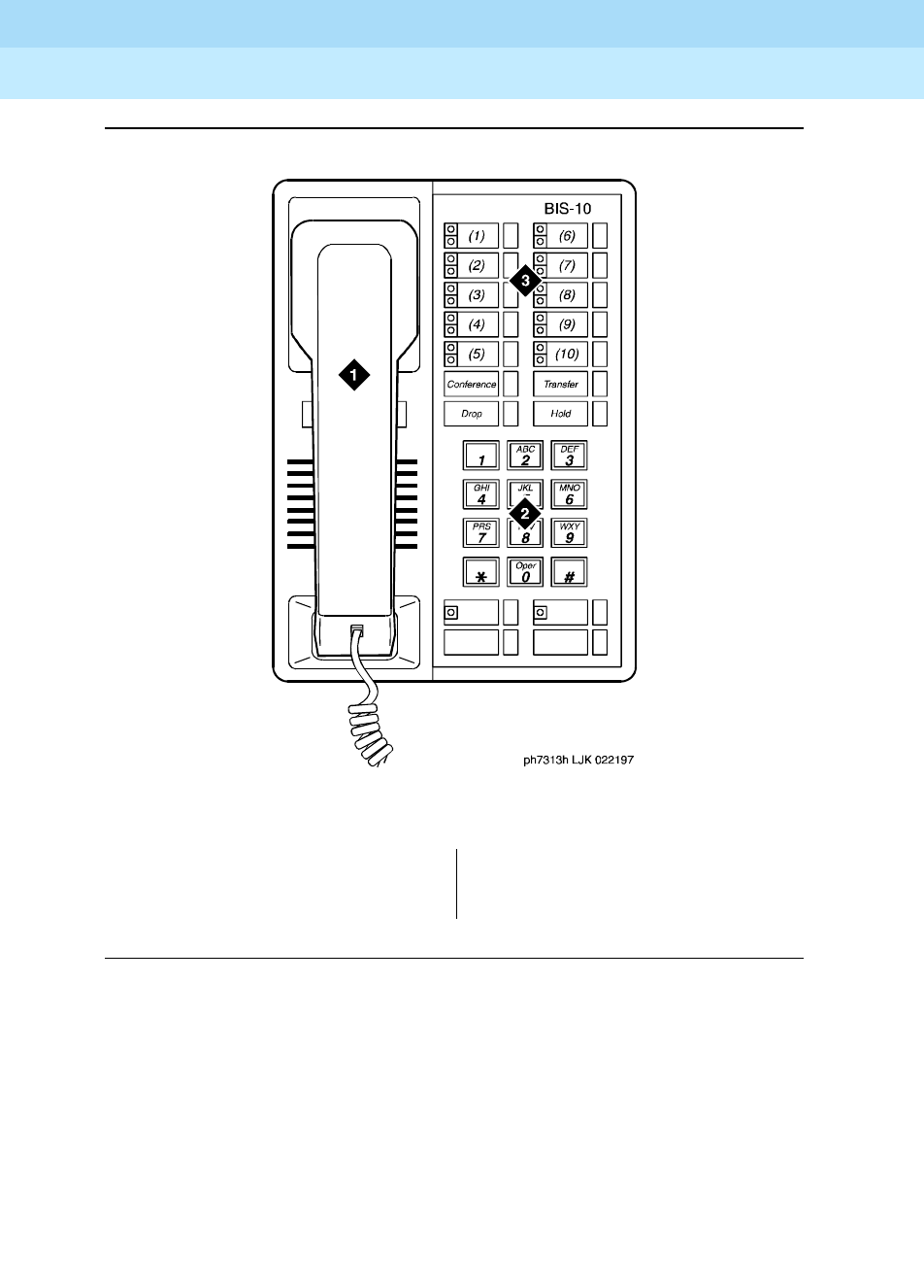
DEFINITY Enterprise Communications Server Release 6
Administration and Feature Description
555-230-522 Issue 4
May 1998
Voice Terminal, PC Interface, and Data Module Administration
Page 6-857313H, 7314H, 7315H, 7316H, and 7317H voice terminals
6
Figure Notes
Figure 6-20. 7313H voice terminal (BIS 10)
1. Handset
2. Dial pad
3. 10 programmable buttons
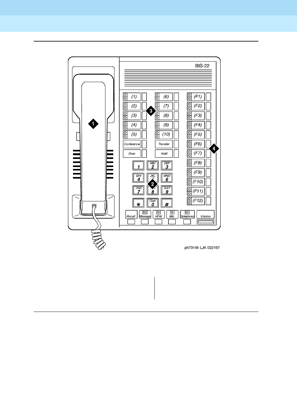
DEFINITY Enterprise Communications Server Release 6
Administration and Feature Description
555-230-522 Issue 4
May 1998
Voice Terminal, PC Interface, and Data Module Administration
Page 6-867313H, 7314H, 7315H, 7316H, and 7317H voice terminals
6
Figure Notes
Figure 6-21. 7314H voice terminal (BIS 22)
1. Handset
2. Dial pad
3. 10 programmable buttons
4. 12 feature buttons
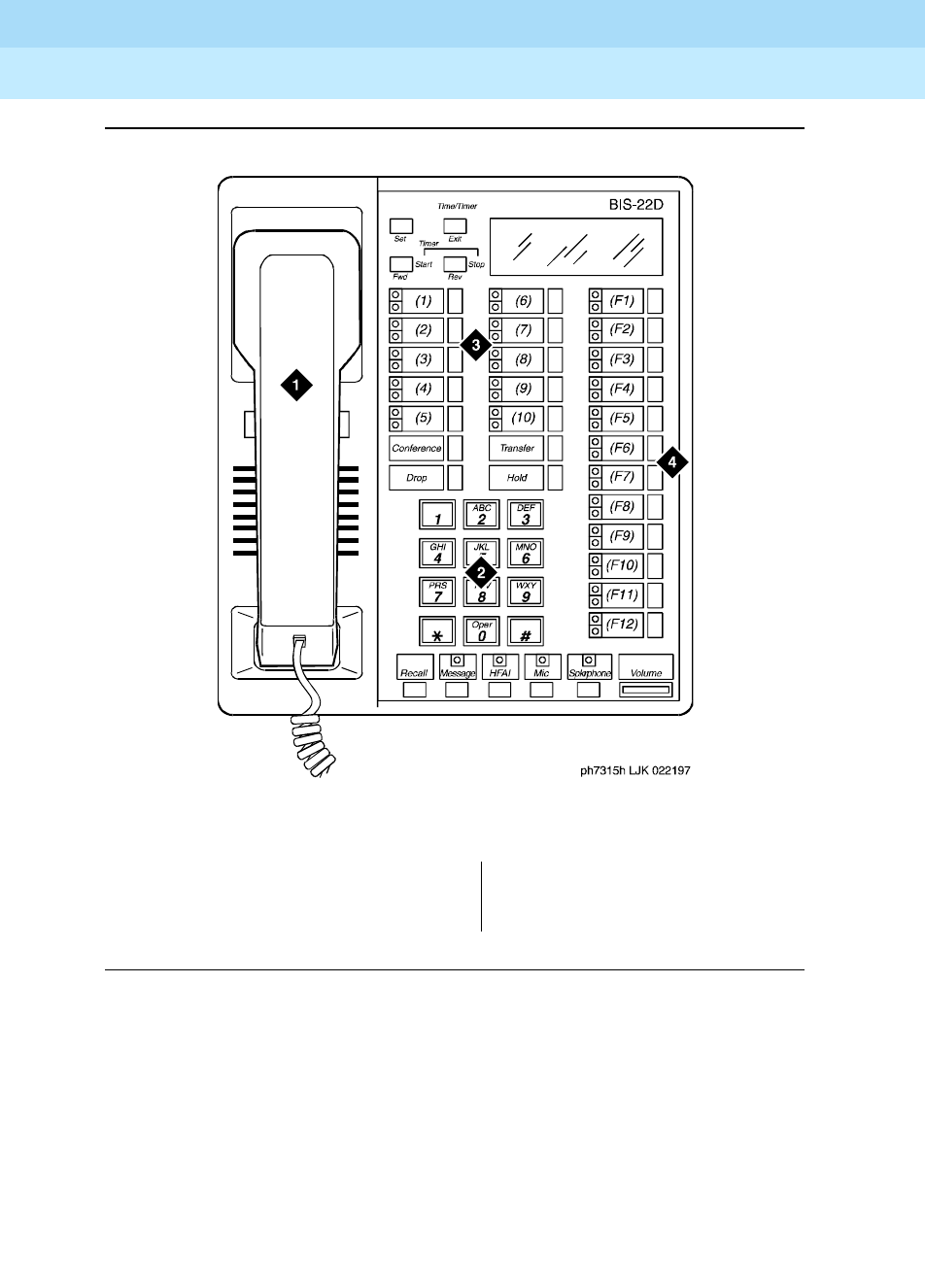
DEFINITY Enterprise Communications Server Release 6
Administration and Feature Description
555-230-522 Issue 4
May 1998
Voice Terminal, PC Interface, and Data Module Administration
Page 6-877313H, 7314H, 7315H, 7316H, and 7317H voice terminals
6
Figure Notes
Figure 6-22. 7315H voice terminal (BIS 22D)
1. Handset
2. Dial pad
3. 10 programmable buttons
4. 12 feature buttons
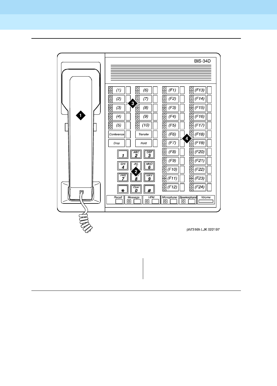
DEFINITY Enterprise Communications Server Release 6
Administration and Feature Description
555-230-522 Issue 4
May 1998
Voice Terminal, PC Interface, and Data Module Administration
Page 6-887313H, 7314H, 7315H, 7316H, and 7317H voice terminals
6
Figure Notes
Figure 6-23. 7316H voice terminal (BIS 34)
1. Handset
2. Dial pad
3. 10 programmable buttons
4. 24 feature buttons

DEFINITY Enterprise Communications Server Release 6
Administration and Feature Description
555-230-522 Issue 4
May 1998
Voice Terminal, PC Interface, and Data Module Administration
Page 6-897313H, 7314H, 7315H, 7316H, and 7317H voice terminals
6
FIgure Notes
Figure 6-24. 7317H voice terminal (BIS 34D)
1. Handset
2. Dial pad
3. 10 programmable buttons
4. 24 feature buttons

DEFINITY Enterprise Communications Server Release 6
Administration and Feature Description
555-230-522 Issue 4
May 1998
Voice Terminal, PC Interface, and Data Module Administration
Page 6-907401D, 7401+, 7403D, 7404D, 7410D, and 7410+ voice terminals
6
7401D, 7401+, 7403D, 7404D, 7410D,
and 7410+ voice terminals
Form instructions
To administer a 7401D, 7401+, 7403D, 7404D, 7410D, or 7410+ voice terminal,
complete the standard as well as the following unique Station form fields.
Page 1 of the form
Screen 6-37. 7401D and 7401+ Station form (Page 1 of X)
Screen 6-38. 7403D, 7410D, and 7401+ Station form (Page 1 of X)
Page 1 of X
STATION
Extension: 1003 Lock Messages? n BCC: 0
Type: 7401D__ Security Code: ________ TN: 1_
Port: _______ Coverage Path 1: ____ COR: 1_
Name: ___________________________ Coverage Path 2: ____ COS: 1_
Hunt-to Station: _____
STATION OPTIONS
Data Module? n Personalized Ringing Pattern: 1
Message Lamp Ext: 1000
MM Complex Data Ext: ____
Page 1 of X
STATION
Extension: 1003 Lock Messages? n BCC: 0
Type: 7403D__ Security Code: ________ TN: 1_
Port: _______ Coverage Path 1: ____ COR: 1_
Name: ______________________ Coverage Path 2: ____ COS: 1_
Hunt-to Station: _____
STATION OPTIONS
Data Module? n
Message Lamp Ext: 1000
MM Complex Data Ext: ____

DEFINITY Enterprise Communications Server Release 6
Administration and Feature Description
555-230-522 Issue 4
May 1998
Voice Terminal, PC Interface, and Data Module Administration
Page 6-917401D, 7401+, 7403D, 7404D, 7410D, and 7410+ voice terminals
6
Screen 6-39. 7404D Station form (Page 1 of X)
■Type — Enter 7401D, 7401+, 7403D, 7404D, 7410D, or 7410+ as
appropriate.
■Data Module — For the 7401D, 7401+, 7410D, and 7410+, enter y if this
terminal is to connect to a data terminal via a 7400B or 8400B Data
Module. For the 7403D, enter y if this terminal is to connect to a data
terminal via optional digital terminal data module (DTDM), 7400B, or
8400B Data Module. For the 7404D, this is a display-only field set to y. If y
is entered, you must complete the Data Module form. Default is n.
Page 2 of the form
Screen 6-40. 7401D and 7401+ Station form (Page 2 of X)
Page 1 of X
STATION
Extension: 1003 Lock Messages? n BCC: 0
Type: 7404D__ Security Code: ________ TN: 1_
Port: _______ Coverage Path 1: ____ COR: 1_
Name: _______________________ Coverage Path 2: ____ COS: 1_
Hunt-to Station: _____
STATION OPTIONS
Data Module? y Personalized Ringing Pattern: 1
Display Module? y Message Lamp Ext: 1000
Display Language: english Display Cartridge? n
MM Complex Data Ext: ____
Page 2 of X
STATION
FEATURE OPTIONS
LWC Reception? msa-spe Auto Select Any Idle Appearance? n
LWC Activation? y Coverage Msg Retrieval? y
CDR Privacy? n Auto Answer: none
Redirect Notification? y Data Restriction? n
Per Button Ring Control? n Idle Appearance Preference? n
PCOL/TEG Call Alerting? n
Active Station Ringing: single Restrict Last Appearance? y
H.320 Conversion? n
AUDIX Name: ______ Multimedia Early Answer? n
Messaging Server Name: ______ Audible Message Waiting? y
Select Last Used Appearance? n

DEFINITY Enterprise Communications Server Release 6
Administration and Feature Description
555-230-522 Issue 4
May 1998
Voice Terminal, PC Interface, and Data Module Administration
Page 6-927401D, 7401+, 7403D, 7404D, 7410D, and 7410+ voice terminals
6
Screen 6-41. 7403D, 7410D, and 7401+ Station form (Page 2 of X)
Screen 6-42. 7404D Station form (Page 2 of X)
■Display Module — Enter y if the 7404D voice terminal is to have a display
via a 7400B or 8400B Data Module and associated data terminal or an
optional Messaging Cartridge (7404D only) and an associated data
terminal. If you enter y, you must complete Display Language and the
Display Button Assignments form. Default is n.
Page 2 of X
STATION
FEATURE OPTIONS
LWC Reception? msa-spe Auto Select Any Idle Appearance? n
LWC Activation? y Coverage Msg Retrieval? y
CDR Privacy? n Auto Answer: none
Redirect Notification? y Data Restriction? n
Per Button Ring Control? n Idle Appearance Preference? n
Bridged Call Alerting? n
Active Station Ringing: single Restrict Last Appearance? y
H.320 Conversion? n
AUDIX Name: ______ Multimedia Early Answer? n
Messaging Server Name: ______ Audible Message Waiting? y
Select Last Used Appearance? n
Page 2 of X
STATION
FEATURE OPTIONS
LWC Reception? msa-spe Auto Select Any Idle Appearance? n
LWC Activation? y Coverage Msg Retrieval? y
CDR Privacy? n Auto Answer: none
Redirect Notification? y Data Restriction? n
Per Button Ring Control? n Idle Appearance Preference? n
Bridged Call Alerting? n
Active Station Ringing: single Restrict Last Appearance? y
H.320 Conversion? n
AUDIX Name: ______ Multimedia Early Answer? n
Messaging Server Name: ______ Audible Message Waiting? y
Display Client Redirection? n
Select Last Used Appearance? n

DEFINITY Enterprise Communications Server Release 6
Administration and Feature Description
555-230-522 Issue 4
May 1998
Voice Terminal, PC Interface, and Data Module Administration
Page 6-937401D, 7401+, 7403D, 7404D, 7410D, and 7410+ voice terminals
6
Page 3 of the form
Screen 6-43. 7401D and 7401+ Station form (Page 3 of X)
Screen 6-44. 7403D, 7410D, and 7410+ Station form (Page 3 of X)
Page 3 of X
STATION
SITE DATA
Room: _______ Headset? n
Jack: _____ Speaker? n
Cable: _____ Mounting: d
Floor: _______ Cord Length: 0
Building: _______ Set Color: ______
ABBREVIATED DIALING
List1: ________ List2: ________ List3: ________
BUTTON ASSIGNMENTS
1: call-appr_ 6: __________
2: call-appr_ 7: __________
3: __________ 8: __________
4: __________ 9: __________
5: __________
Page 3 of X
STATION
SITE DATA
Room: _______ Headset? n
Jack: _____ Speaker? n
Cable: _____ Mounting: d
Floor: _______ Cord Length: 0
Building: _______ Set Color: ______
ABBREVIATED DIALING
List1: ________ List2: ________ List3: ________
BUTTON ASSIGNMENTS
1: call-appr_ 6: __________
2: call-appr_ 7: __________
3: call-appr_ 8: __________
4: __________ 9: __________
5: __________ 10: __________

DEFINITY Enterprise Communications Server Release 6
Administration and Feature Description
555-230-522 Issue 4
May 1998
Voice Terminal, PC Interface, and Data Module Administration
Page 6-947401D, 7401+, 7403D, 7404D, 7410D, and 7410+ voice terminals
6
Screen 6-45. 7404D Station form (Page 3 of X)
■Headset — For a 7401D or 7404D, enter n, these terminals cannot have a
headset. For a 7403D, enter y if the terminal is to have a headset. Default
is n.
■BUTTON ASSIGNMENTS
The feature buttons that you can assign to the 7401D, 7401+, 7403D,
7404D, 7410D, or 7410+ voice terminals are listed below. For 7401D and
7401+, only buttons 1 through 9 display. Buttons 1 and 2 are assigned as
call-appr. Buttons 3 through 9 are used to assign features to dial pad keys
1 through 7. For 7403D, 7404D, 7410D, and 7410+ voice terminals, the 3
three buttons default as call appearance buttons.
Page 3 of X
STATION
SITE DATA
Room: _______ Headset? n
Jack: _____ Speaker? n
Cable: _____ Mounting: d
Floor: _______ Cord Length: 0_
Building: _______ Set Color: ______
ABBREVIATED DIALING
List1: ________ List2: ________ List3: ________
BUTTON ASSIGNMENTS
1: call-appr_ 4: __________
2: call-appr_ 5: __________
3: call-appr_ 6: __________

DEFINITY Enterprise Communications Server Release 6
Administration and Feature Description
555-230-522 Issue 4
May 1998
Voice Terminal, PC Interface, and Data Module Administration
Page 6-957401D, 7401+, 7403D, 7404D, 7410D, and 7410+ voice terminals
6
1. Not administrable on the 7401D or 7401+ voice terminal.
2. Available only on 7403D, 7404D, 7410D, and 7410+.
abr-prog abr-spchar abrdg-appr1abrv-dial
abrv-ring ac-alarm aca-halt after-call
alrt-agchg alt-frl assist asvn-halt
atd-qcalls atd-qtime aut-msg-wt auto-cback
auto-icom auto-in autodial aux-work
brdg-appr1busy-ind call-appr1call-fwd
call-park call-pkup cas-backup cdr1-alrm
cdr2-alrm cfwd-bsyda consult cov-cback
data-ext dial-icom dir-pkup dn-dst
ds1-alarm exclusion flash goto-cover
hunt-ns in-call-id int-aut-an2last-numb
link-alarm lsvn-halt lwc-cancel lwc-store
major-alrm man-msg-wt manual-in mct-act
mct-contr mf-da-intl mf-op-intl mj/mn alrm
night-serv noans-alrt per-COline pms-alarm
pr-awu-alm pr-pms-alm pr-sys-alm print-msgs
priority q-calls q-time release
ringer-off rs-alert rsvn-halt send-calls
send-term serv-obsrv signal ssvn-halt
stroke-cnt term-x-gr trk-ac-alm trunk-ns
verify voa-repeat work-code2

DEFINITY Enterprise Communications Server Release 6
Administration and Feature Description
555-230-522 Issue 4
May 1998
Voice Terminal, PC Interface, and Data Module Administration
Page 6-967401D, 7401+, 7403D, 7404D, 7410D, and 7410+ voice terminals
6
Page 4 of the form
7404D Display Button Assignments form (Page 4 of X)
Page X of the form DISPLAY BUTTON
ASSIGNMENTS)
This page displays only if Display is set to y (7404D only). The display function
is obtained via an optional Messaging Cartridge and an associated data terminal
(also requires administering the Data Module form).
When you administer buttons 1 through 7, they relate to function buttons (F1-F7)
on the associated data terminal.
Page X of the form (DATA MODULE)
This page displays only if Data Module is y.
Screen 6-46. 7401D, 7401+, 7403D, 7404D, 7410+ Data Module form (Page Y of X)
DISPLAY BUTTON ASSIGNMENTS Page 4 of X
1: __________
2: __________
3: __________
4: __________
5: __________
6: __________
7: __________
STATION Page Y of X
DATA MODULE
Data Extension: _______________ Name: ______________________ BCC: 2
COS: 1_
COR: 1_
ITC: restricted TN: 1_
ABBREVIATED DIALING
List1: ________
SPECIAL DIALING OPTION: hot-line
HOT LINE DESTINATION
DEFAULT DIALING
Abbreviated Dialing Dial Code (From above list): ___
ASSIGNED MEMBER (Station with a data extension button for this data module)
Ext Name
1. _____ ___________________________
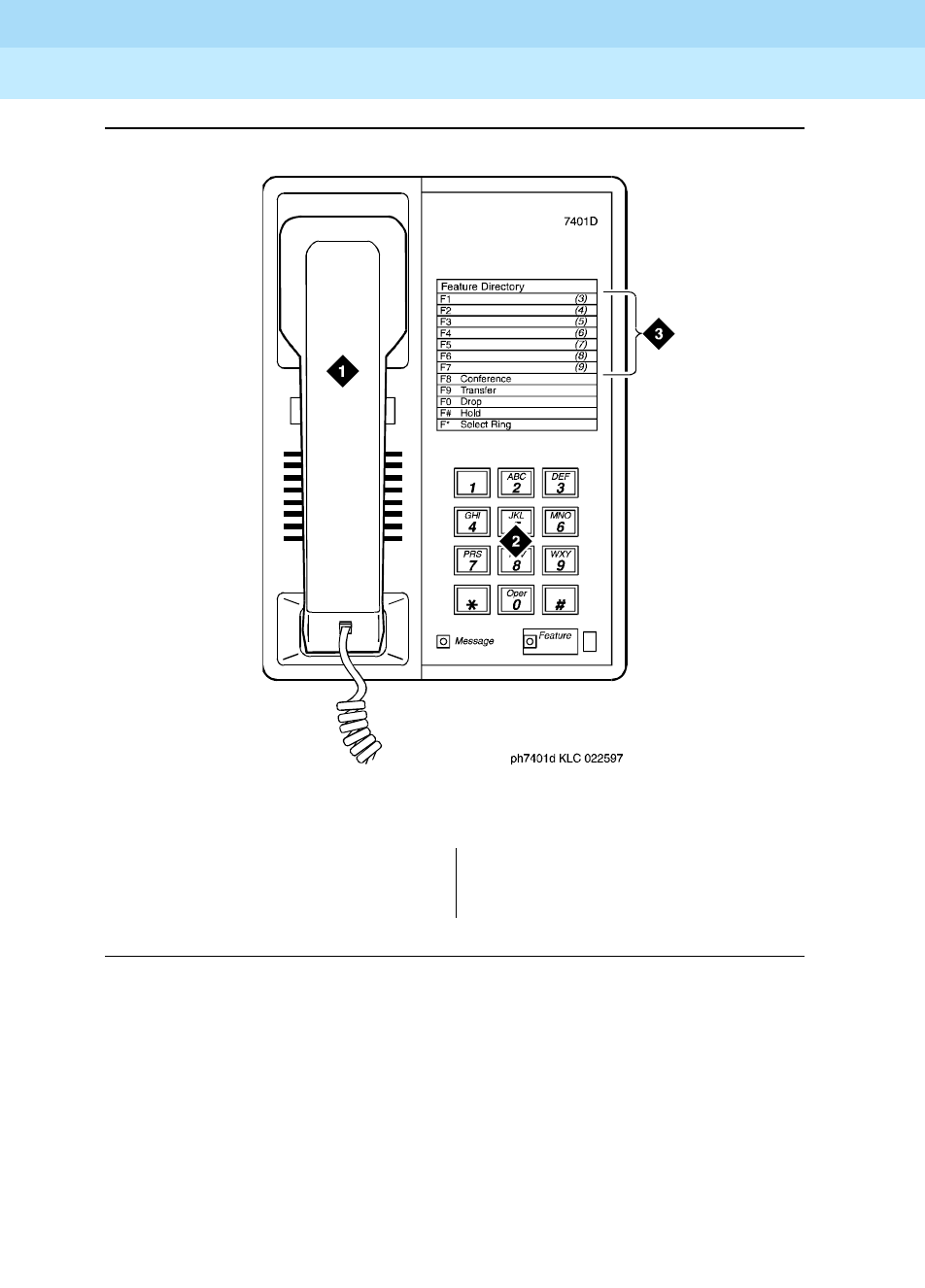
DEFINITY Enterprise Communications Server Release 6
Administration and Feature Description
555-230-522 Issue 4
May 1998
Voice Terminal, PC Interface, and Data Module Administration
Page 6-977401D, 7401+, 7403D, 7404D, 7410D, and 7410+ voice terminals
6
Figure Notes
Figure 6-25. 7401D voice terminal
1. Handset
2. Dial pad
3. Access codes card
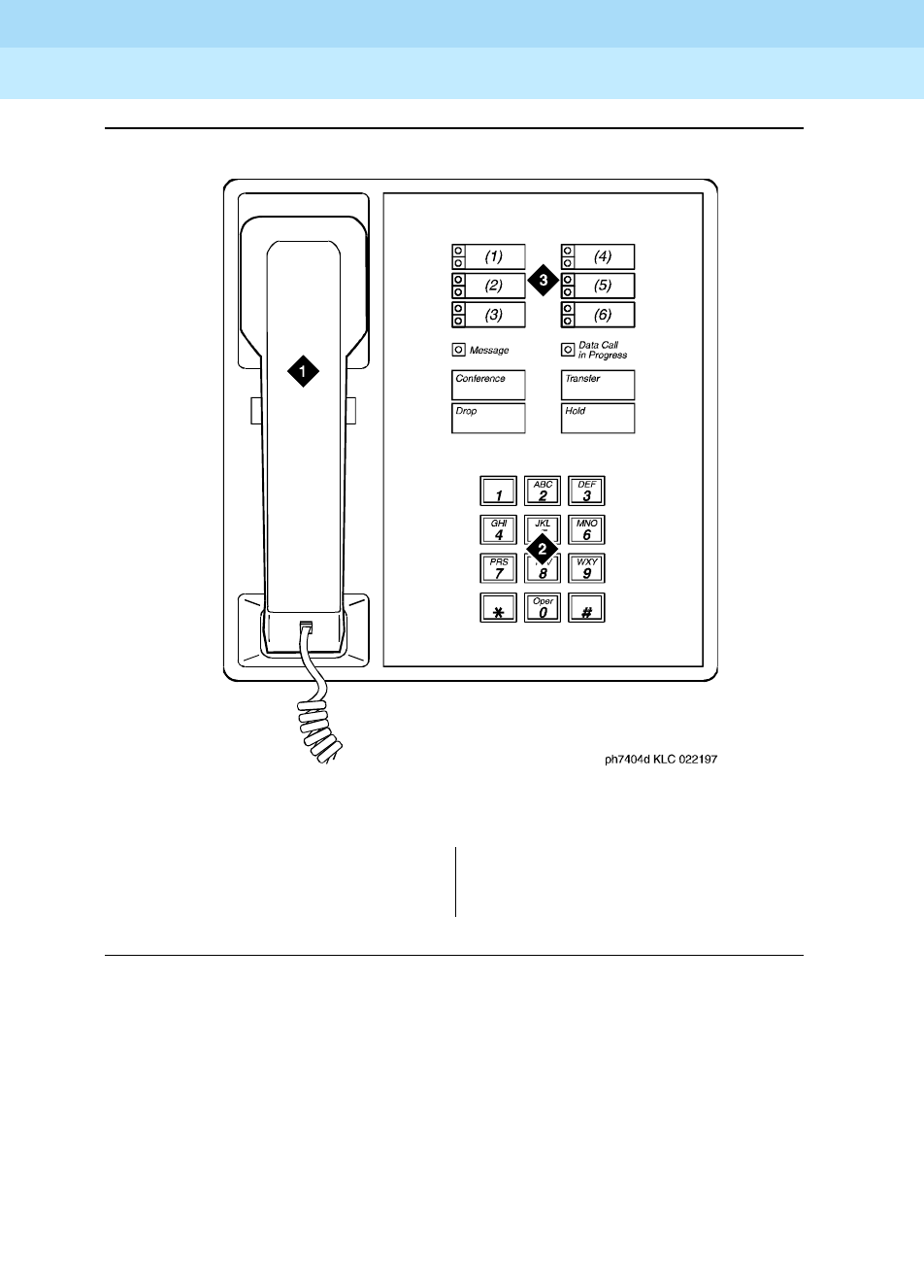
DEFINITY Enterprise Communications Server Release 6
Administration and Feature Description
555-230-522 Issue 4
May 1998
Voice Terminal, PC Interface, and Data Module Administration
Page 6-987401D, 7401+, 7403D, 7404D, 7410D, and 7410+ voice terminals
6
Figure Notes
Figure 6-26. 7404D voice terminal
1. Handset
2. Dial pad
3. 6 progammable buttons

DEFINITY Enterprise Communications Server Release 6
Administration and Feature Description
555-230-522 Issue 4
May 1998
Voice Terminal, PC Interface, and Data Module Administration
Page 6-997405D voice terminal
6
7405D voice terminal
Form instructions
To administer a 7405D voice terminal, complete the standard as well as the
following unique Station form fields.
Page 1 of the form
Screen 6-47. 7405D Station form (Page 1 of X)
■Type — Enter 7405D.
■Data Module — Enter y if this terminal is connected to an optional digital
terminal data module (DTDM). If you enter y, you must complete the Data
Module form. Default is n.
■Feature Module — Enter y if the voice terminal is to connecd to an
optional Feature Module. If you enter y, you must complete the Feature
Module form. Default is n.
■Display Module — Enter y if the voice terminal is to have a display by an
optional Digital Display Module. If you enter y, you must complete the
Display Button assignments form. Default is n.
■Coverage Module — Enter y if the voice terminal is to connect to an
optional Call Coverage Module. If you enter y, you must complete the
Coverage Module form. The voice terminal cannot have an optional
Coverage Module and optional Digital Display Module at the same time.
Default is n.
Page 1 of X
STATION
Extension: 1003 Lock Messages? n BCC: 0
Type: 7405D__ Security Code: ________ TN: 1_
Port: _______ Coverage Path 1: ____ COR: 1_
Name: ___________________________ Coverage Path 2: ____ COS: 1_
Hunt-to Station: _____
STATION OPTIONS
Data Module? y Message Lamp Ext: 1000
Display Module? y Feature Module? n
Display Language: english Coverage Module? n
MM Complex Data Ext: ____

DEFINITY Enterprise Communications Server Release 6
Administration and Feature Description
555-230-522 Issue 4
May 1998
Voice Terminal, PC Interface, and Data Module Administration
Page 6-1007405D voice terminal
6
Page 2 of the form
Screen 6-48. 7405D Station form (Page 2 of X)
Page 3 of the form
Screen 6-49. 7405D Station form (Page 3 of X)
Page 2 of X
STATION
FEATURE OPTIONS
LWC Reception? msa-spe Auto Select Any Idle Appearance? n
LWC Activation? y Coverage Msg Retrieval? y
CDR Privacy? n Auto Answer: none
Redirect Notification? y Data Restriction? n
Per Button Ring Control? n Idle Appearance Preference? n
Bridged Call Alerting? n
Active Station Ringing: single Restrict Last Appearance? y
H.320 Conversion? n
AUDIX Name: ______ Multimedia Early Answer? n
Messaging Server Name: ______ Audible Message Waiting? y
Display Client Redirection? n
Select Last Used Appearance? n
Page 3 of X
STATION
SITE DATA
Room: _______ Headset? n
Jack: ___ Speaker? n
Cable: ___ Mounting: d
Floor: _______ Cord Length: 0_
Building: _______ Set Color: _____
ABBREVIATED DIALING
List1: ________ List2: _________ List3: _________
BUTTON ASSIGNMENTS
1: call-appr_ 6: __________
2: call-appr_ 7: __________
3: call-appr_ 8: __________
4: __________ 9: __________
5: __________ 10: __________

DEFINITY Enterprise Communications Server Release 6
Administration and Feature Description
555-230-522 Issue 4
May 1998
Voice Terminal, PC Interface, and Data Module Administration
Page 6-1017405D voice terminal
6
■BUTTON ASSIGNMENTS
The feature buttons that you can assign to the 7405D voice terminal are
listed below. For 7405D voice terminals, the first 3 buttons default as call
appearances. The 7405D voice terminal can have an optional Function
Key Module (administered as a Feature Module), Digital Display Module,
and Coverage Module, respectively.

DEFINITY Enterprise Communications Server Release 6
Administration and Feature Description
555-230-522 Issue 4
May 1998
Voice Terminal, PC Interface, and Data Module Administration
Page 6-1027405D voice terminal
6
1. Display-type button (not administrable on Coverage Module form).
2. Not administrable on Feature Module form.
abr-prog abr-spchar abrdg-appr abrv-dial
abrv-ring ac-alarm aca-halt after-call
alrt-agchg alt-frl assist asvn-halt
atd-qcalls1atd-qtime1aut-msg-wt auto-cback
auto-icom auto-in auto-wkup1autodial
aux-work brdg-appr2busy-ind call-appr2
call-disp1call-fwd call-park call-pkup
callr-info1cas-backup cdr1-alrm cdr2-alrm
cfwd-bsyda check-in1check-out1clk-overid1
consult cov-cback cov-msg-rt1data-ext
date-time1delete-msg1dial-icom directory1
dir-pkup disp-chrg disp-norm dn-dst
ds1-alarm exclusion ext-dn-dst1flash
goto-cover grp-dn-dst1hunt-ns in-call-id
inspect1int-aut-an last-numb link-alarm
lsvn-halt lwc-cancel lwc-lock lwc-store
major-alrm man-msg-wt man-overid1manual-in
mct-act mct-contr mf-da-intl mf-op-intl
mj/mn alrm msg-retr1mwn-act1mwn-deact1
next1night-serv noans-alrt normal1
per-COline pms-alarm pr-awu-alm pr-pms-alm
pr-sys-alm print-msgs priority q-calls
q-time release ringer-off rs-alert
rsvn-halt scroll send-calls send-term
serv-obsrv signal ssvn-halt stored-num1
stroke-cnt term-x-gr timer1trk-ac-alm
trk-id trunk-name1trunk-ns verify
voa-repeat vu-display work-code

DEFINITY Enterprise Communications Server Release 6
Administration and Feature Description
555-230-522 Issue 4
May 1998
Voice Terminal, PC Interface, and Data Module Administration
Page 6-1037405D voice terminal
6
Page 4 of the form
Screen 6-50. 7405D Station form (Page 4 of X)
■FEATURE BUTTON ASSIGNMENTS
The features buttons that you can assign to page 4 of the form are the
same as those listed for BUTTON ASSIGNMENTS. Display-type feature
buttons may only be assigned if Display is y.
Page X of the form (FEATURE MODULE
BUTTON ASSIGNMENTS)
Screen 6-51. 7405D Feature Module form (Page Y of X)
Page 4 of X
STATION
FEATURE BUTTON ASSIGNMENTS
1: ___________ 13: ___________
2: ___________ 14: ___________
3: ___________ 15: ___________
4: ___________ 16: ___________
5: ___________ 17: ___________
6: ___________ 18: ___________
7: ___________ 19: ___________
8: ___________ 20: ___________
9: ___________ 21: ___________
10: ___________ 22: ___________
11: ___________ 23: ___________
12: ___________ 24: ___________
Page Y of X
STATION
FEATURE MODULE BUTTON ASSIGNMENTS
1: __________ 13: __________
2: __________ 14: __________
3: __________ 15: __________
4: __________ 16: __________
5: __________ 17: __________
6: __________ 18: __________
7: __________ 19: __________
8: __________ 20: __________
9: __________ 21: __________
10: __________ 22: __________
11: __________ 23: __________
12: __________ 24: __________

DEFINITY Enterprise Communications Server Release 6
Administration and Feature Description
555-230-522 Issue 4
May 1998
Voice Terminal, PC Interface, and Data Module Administration
Page 6-1047405D voice terminal
6
This page displays only if Feature Module is y. The feature buttons that you
can assign are the same as those listed for BUTTON ASSIGNMENTS above. Call
appearance and bridged call appearance buttons cannot be administered on
this form.
If you want to assign feature buttons to the optional Function Key Module or
Coverage Module, you must assign them on their respective forms.
Page X of the form (COVERAGE MODULE
BUTTON ASSIGNMENTS)
Screen 6-52. 7405D Coverage Module form (Page Y of X)
This page displays only if Coverage Module is y. The features buttons that you
can assign are the same as those listed for the preceding BUTTON
ASSIGNMENTS, except you cannot administer display-type buttons.
Up to 10 call appearance, 10 abrdg-appr, and 10 brdg-appr buttons can be
distributed between a Coverage Module and the associated administrable
buttons on the 7405D voice terminal.
Page Y of X
STATION
COVERAGE MODULE BUTTON ASSIGNMENTS
1: __________ 11: __________
2: __________ 12: __________
3: __________ 13: __________
4: __________ 14: __________
5: __________ 15: __________
6: __________ 16: __________
7: __________ 17: __________
8: __________ 18: __________
9: __________ 19: __________
10: __________ 20: __________

DEFINITY Enterprise Communications Server Release 6
Administration and Feature Description
555-230-522 Issue 4
May 1998
Voice Terminal, PC Interface, and Data Module Administration
Page 6-1057405D voice terminal
6
Page X of the form (DISPLAY BUTTON
ASSIGNMENTS)
Screen 6-53. 7405D Display form (Page Y of X)
This page displays only if Display is y. The display-type buttons that you can
assign are noted on the above list.
Page X of the form (DATA MODULE)
Screen 6-54. 7405D Data Module form (Page Y of X)
This page displays only if Data Module is y. Button locations (1 through 7) are
associated with buttons 1 through 7 on the optional Digital Display Module.
Page Y of X
STATION
DISPLAY BUTTON ASSIGNMENTS
1: __________
2: __________
3: __________
4: __________
5: __________
6: __________
7: __________
Page Y of X
STATION
DATA MODULE
Data Extension: _______________ Name: ______________________ BCC: 2
COS: 1_
COR: 1_
ITC: restricted TN: 1_
ABBREVIATED DIALING
List1: ________
SPECIAL DIALING OPTION: hot-line
HOT LINE DESTINATION
DEFAULT DIALING
Abbreviated Dialing Dial Code (From above list): ___
ASSIGNED MEMBER (Station with a data extension button for this data module)
Ext Name
1. _____ ___________________________
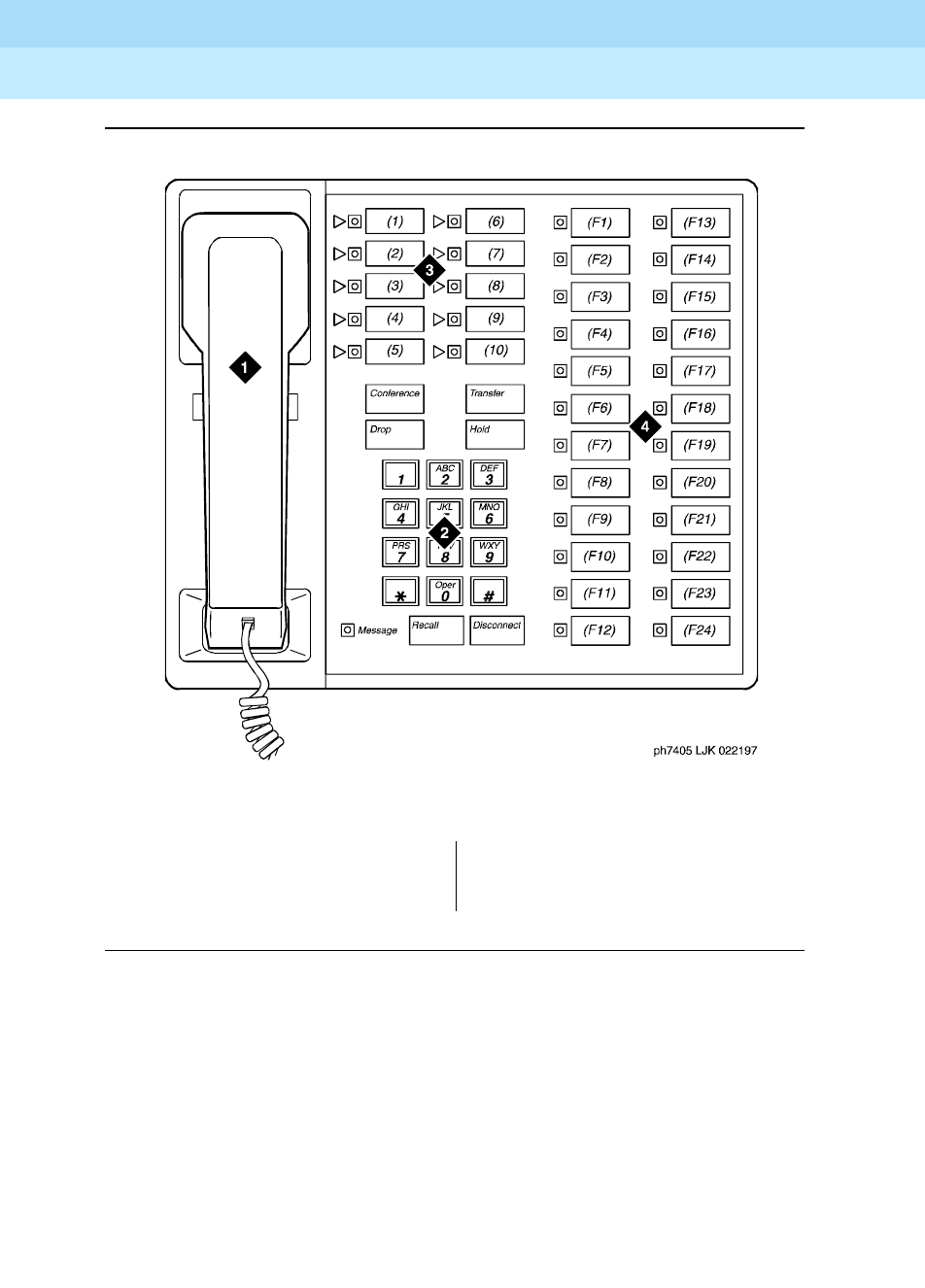
DEFINITY Enterprise Communications Server Release 6
Administration and Feature Description
555-230-522 Issue 4
May 1998
Voice Terminal, PC Interface, and Data Module Administration
Page 6-1067405D voice terminal
6
Figure Notes
Figure 6-27. 7405D voice terminal
1. Handset
2. Dial pad
3. 10 programmable buttons
4. 24 feature buttons
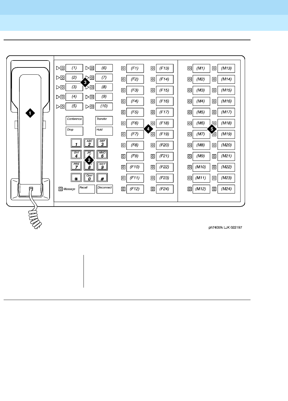
DEFINITY Enterprise Communications Server Release 6
Administration and Feature Description
555-230-522 Issue 4
May 1998
Voice Terminal, PC Interface, and Data Module Administration
Page 6-1077405D voice terminal
6
Figure Notes
Figure 6-28. 7405D voice terminal with optional function key module
1. Handset
2. Dial pad
3. 10 programmable buttons
4. 24 feature buttons
5. Function key module with 24 feature module buttons
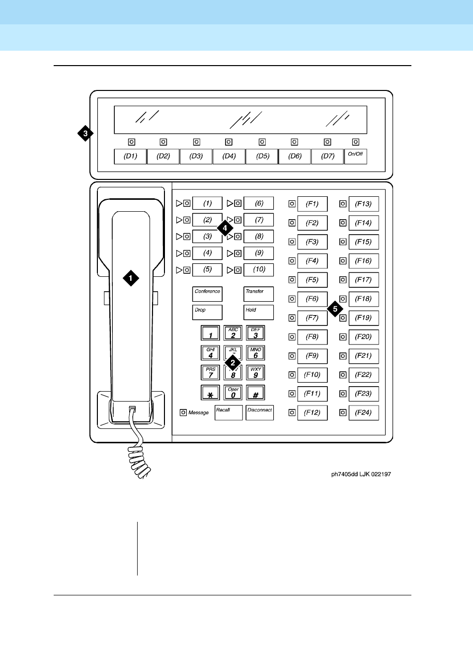
DEFINITY Enterprise Communications Server Release 6
Administration and Feature Description
555-230-522 Issue 4
May 1998
Voice Terminal, PC Interface, and Data Module Administration
Page 6-1087405D voice terminal
6
Figure Notes
Figure 6-29. 7405D voice terminal with optional digital display module
1. Handset
2. Dial pad
3. Digital display module with 7 display buttons
4. 10 programmable buttons
5. 24 feature buttons
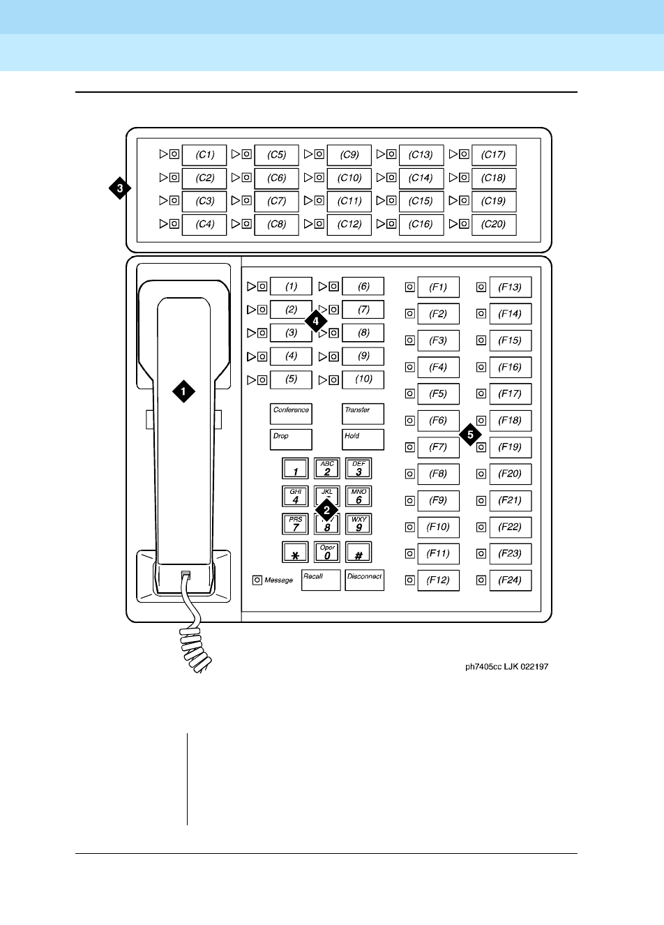
DEFINITY Enterprise Communications Server Release 6
Administration and Feature Description
555-230-522 Issue 4
May 1998
Voice Terminal, PC Interface, and Data Module Administration
Page 6-1097405D voice terminal
6
Figure Notes
Figure 6-30. 7405D voice terminal with optional call coverage module
1. Handset
2. Dial pad
3. Call coverage module with 20 coverage module
buttons and status lamps
4. 10 programmable buttons
5. 24 feature buttons
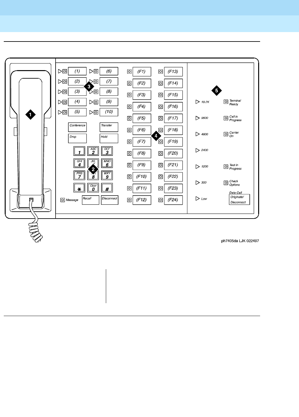
DEFINITY Enterprise Communications Server Release 6
Administration and Feature Description
555-230-522 Issue 4
May 1998
Voice Terminal, PC Interface, and Data Module Administration
Page 6-1107405D voice terminal
6
Figure Notes
Figure 6-31. 7405D voice terminal with optional digital terminal data module
1. Handset
2. Dial pad
3. 10 programmable buttons
4. 24 feature buttons
5. Digital terminal data module

DEFINITY Enterprise Communications Server Release 6
Administration and Feature Description
555-230-522 Issue 4
May 1998
Voice Terminal, PC Interface, and Data Module Administration
Page 6-1117406D, 7406+, 7407D, and 7407+ voice terminals
6
7406D, 7406+, 7407D, and 7407+ voice
terminals
Form instructions
To administer a 7406D, 7406+, 7407D, or 7407+ voice terminal, complete the
standard as well as the following unique Station form fields.
Page 1 of the form
Screen 6-55. 7406D, 7406+, 7407D, 7407+ Station form (Page 1 of X)
■Type — Enter 7406D, 7406+, 7407D, or 7407+ as appropriate.
■Data Module — Enter y (default) if this voice terminal is equipped with an
optional 703A Data Stand (7406D or 7406+), a 702AL1-DSU (7407D or
7407+), 7400B, or 8400B Data Module (7406D, 7406+, 7407D, or 7407+)
and connected to an associated data terminal. If you enter y, you must
complete the Data Module form.
■Display Module — For the 7406D and 7406+, enter y if the voice terminal
is equipped with an optional digital display. Display-only field (set to y) for
the 7407D and 7407+ terminals. If this field is set to y, you must complete
the Display Button Assignments form. Default is n.
Page 1 of X
STATION
Extension: 1003 Lock Messages? n BCC: 0
Type: 7406D__ Security Code: ________ TN: 1_
Port: _______ Coverage Path 1: ____ COR: 1_
Name: ___________________________ Coverage Path 2: ____ COS: 1_
Hunt-to Station: _____
STATION OPTIONS
Data Module? y Personalized Ringing Pattern: 1
Display Module? n Message Lamp Ext: 1000
Display Language: english
MM Complex Data Ext: ____

DEFINITY Enterprise Communications Server Release 6
Administration and Feature Description
555-230-522 Issue 4
May 1998
Voice Terminal, PC Interface, and Data Module Administration
Page 6-1127406D, 7406+, 7407D, and 7407+ voice terminals
6
Page 2 of the form
Screen 6-56. 7406D, 7406+, 7407D, 7407+ Station form (Page 2 of X)
Page 3 of the form
Screen 6-57. 7406D and 7406+ Station form (Page 3 of X)
Page 2 of X
STATION
FEATURE OPTIONS
LWC Reception? msa-spe Auto Select Any Idle Appearance? n
LWC Activation? y Coverage Msg Retrieval? y
CDR Privacy? n Auto Answer: none
Redirect Notification? y Data Restriction? n
Per Button Ring Control? n Idle Appearance Preference? n
Bridged Call Alerting? n
Active Station Ringing: single Restrict Last Appearance? y
H.320 Conversion? n
AUDIX Name: ______ Multimedia Early Answer? n
Messaging Server Name: ______ Audible Message Waiting? y
Display Client Redirection? n
Select Last Used Appearance? n
Page 3 of X
STATION
SITE DATA
Room: _______ Headset? n
Jack: ___ Speaker? n
Cable: ___ Mounting: d
Floor: _______ Cord Length: 0_
Building: _______ Set Color: ______
ABBREVIATED DIALING
List1: ________ List2: _________ List3: _________
BUTTON ASSIGNMENTS
1: call-appr_ 4: _________
2: call-appr_ 5: _________
3: call-appr_

DEFINITY Enterprise Communications Server Release 6
Administration and Feature Description
555-230-522 Issue 4
May 1998
Voice Terminal, PC Interface, and Data Module Administration
Page 6-1137406D, 7406+, 7407D, and 7407+ voice terminals
6
Screen 6-58. 7407D and 7407+ Station form (Page 3 of X)
■Headset — For the 7406D and 7406+, enter y if a headset is to be used.
(7407D and 7407+ terminals cannot have headsets.) Default is n.
■BUTTON ASSIGNMENTS
The feature buttons that you can assign to the 7406D, 7406+, 7407D, or
7407+ voice terminals are listed below. The first 3 buttons default as call
appearance.
Page 3 of X
STATION
SITE DATA
Room: _______ Headset? n
Jack: ___ Speaker? n
Cable: ___ Mounting: d
Floor: _______ Cord Length: 0_
Building: _______ Set Color: ______
ABBREVIATED DIALING
List1: ________ List2: _________ List3: _________
BUTTON ASSIGNMENTS
1: call-appr_ 6: __________
2: call-appr_ 7: __________
3: call-appr_ 8: __________
4: __________ 9: __________
5: __________ 10: __________

DEFINITY Enterprise Communications Server Release 6
Administration and Feature Description
555-230-522 Issue 4
May 1998
Voice Terminal, PC Interface, and Data Module Administration
Page 6-1147406D, 7406+, 7407D, and 7407+ voice terminals
6
1. Display-type button
abr-prog abr-spchar abrdg-appr abrv-dial
abrv-ring ac-alarm aca-halt after-call
alrt-agchg alt-frl assist asvn-halt
atd-qcalls1atd-qtime aut-msg-wt auto-cback
auto-icom auto-in auto-wkup1autodial
aux-work brdg-appr busy-ind call-appr
call-disp1call-fwd call-park call-pkup
callr-info1cas-backup cdr1-alrm cdr2-alrm
cfwd-bsyda check-in1check-out1clk-overid1
consult cov-cback cov-msg-rt1data-ext
date-time1delete-msg1dial-icom directory1
dir-pkup disp-chrg disp-norm dn-dst
ds1-alarm exclusion ext-dn-dst1flash
goto-cover grp-dn-dst1hunt-ns in-call-id
inspect1int-aut-an last-numb link-alarm
lsvn-halt lwc-cancel lwc-lock lwc-store
major-alrm man-msg-wt man-overid1manual-in
mct-act mct-contr mf-da-intl mf-op-intl
mj/mn alrm msg-retr1mwn-act1mwn-deact1
next1night-serv noans-alrt normal1
per-COline pms-alarm pr-awu-alm pr-pms-alm
pr-sys-alm print-msgs priority q-calls
q-time release ringer-off rs-alert
rsvn-halt scroll send-calls send-term
serv-obsrv signal ssvn-halt stored-num1
stroke-cnt term-x-gr timer1trk-ac-alm
trk-id trunk-name1trunk-ns verify
voa-repeat vu-display work-code

DEFINITY Enterprise Communications Server Release 6
Administration and Feature Description
555-230-522 Issue 4
May 1998
Voice Terminal, PC Interface, and Data Module Administration
Page 6-1157406D, 7406+, 7407D, and 7407+ voice terminals
6
Page 4 of the form
Screen 6-59. 7406D Station form (Page 4 of X)
Screen 6-60. 7406+ Station form (Page 4 of X)
Page 4 of X
STATION
FEATURE BUTTON ASSIGNMENTS
2: ___________
3: ___________
1: ___________ 4: ___________
5: ___________ 12: ___________
6: ___________ 13: ___________
7: ___________ 14: ___________
8: ___________ 15: ___________
9: ___________ 16: ___________
10: ___________ 17: ___________
11: ___________ 18: ___________
Page 4 of X
STATION
FEATURE BUTTON ASSIGNMENTS
1: ___________ 2: ___________
3: ___________ 4: ___________
5: ___________ 12: ___________
6: ___________ 13: ___________
7: ___________ 14: ___________
8: ___________ 15: ___________
9: ___________ 16: ___________
10: ___________ 17: ___________
11: ___________ 18: ___________

DEFINITY Enterprise Communications Server Release 6
Administration and Feature Description
555-230-522 Issue 4
May 1998
Voice Terminal, PC Interface, and Data Module Administration
Page 6-1167406D, 7406+, 7407D, and 7407+ voice terminals
6
Screen 6-61. 7407D and 7407+ Voice-terminal form (Page 4 of X)
■FEATURE BUTTON ASSIGNMENTS
The features and functions that you can assign to the 7406D, 7406+,
7407D, or 7407+ voice terminal administrable buttons are the same as
those listed for BUTTON ASSIGNMENTS above.
For 7406D and 7406+ voice terminals, only buttons 1 through 4 have
status lamps. It is recommended that feature button assignments requiring
status lamp indications not be administered to buttons 5 through 18.
Feature buttons 2 and 3 do not work, even if administered, for set versions.
Buttons 5 through 11 are dual function buttons. An associated Shift button
on the voice terminal is used to enable either buttons 5 through 11 or
enable associated buttons 12 through 18.
For 7407D and 7407+ voice terminals, only buttons 1 and 2 have status
lamps. It is recommended that feature button assignments requiring status
lamp indications not be administered to buttons 3 through 24.
Page 4 of X
STATION
FEATURE BUTTON ASSIGNMENTS
1: __________ 2: __________
3: __________ 14: __________
4: __________ 15: __________
5: __________ 16: __________
6: __________ 17: __________
7: __________ 18: __________
8: __________ 19: __________
9: __________ 20: __________
10: __________ 21: __________
11: __________ 22: __________
12: __________ 23: __________
13: __________ 24: __________

DEFINITY Enterprise Communications Server Release 6
Administration and Feature Description
555-230-522 Issue 4
May 1998
Voice Terminal, PC Interface, and Data Module Administration
Page 6-1177406D, 7406+, 7407D, and 7407+ voice terminals
6
Page X of the form (DISPLAY BUTTON
ASSIGNMENTS)
Screen 6-62. 7407D, and 7407+ Station form (Page Y of X)
This page displays only if Type is 7407D or 7407+. The display buttons that can
be administered are noted on the above BUTTON ASSIGNMENTS list. The
abbreviated names as shown on the list must be entered on the form.
Page X of the form (DATA MODULE)
Screen 6-63. 7406D, 7406+, 7407D, and 7407+ Data Module form (Page Y of X)
This page displays only if Data Module is y.
Page Y of X
STATION
DISPLAY BUTTON ASSIGNMENTS
1: __________
2: __________
3: __________
4: __________
5: __________
6: __________
7: __________
Page Y of X
STATION
DATA MODULE
Data Extension: _______________ Name: _______________________ BCC: 2
COS: 1_
COR: 1_
ITC: restricted TN: 1_
ABBREVIATED DIALING
List1: ________
SPECIAL DIALING OPTION: hot-line
HOT LINE DESTINATION
DEFAULT DIALING
Abbreviated Dialing Dial Code (From above list): ___
ASSIGNED MEMBER (Station with a data extension button for this data module)
Ext Name
1. _____ ___________________________
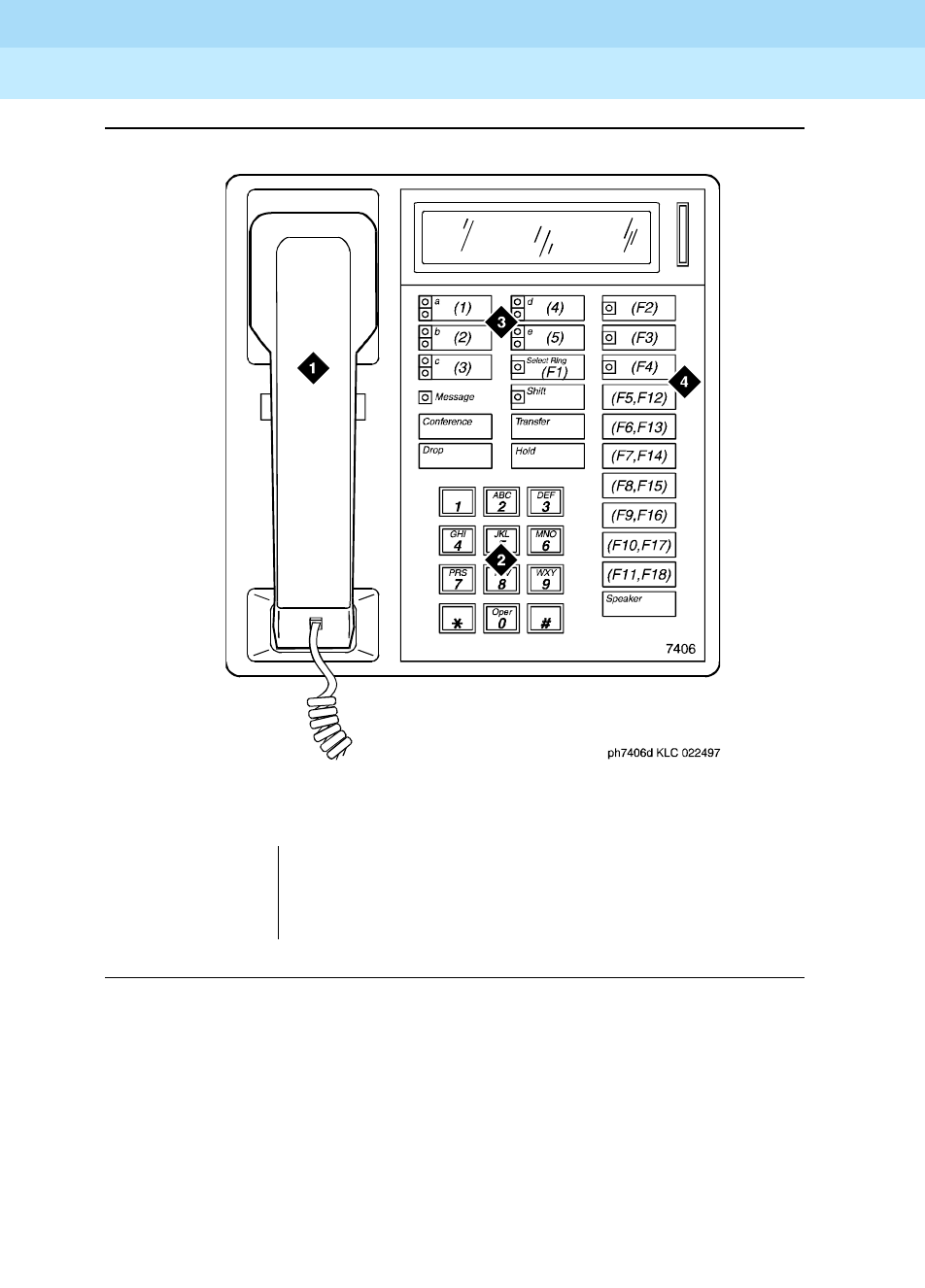
DEFINITY Enterprise Communications Server Release 6
Administration and Feature Description
555-230-522 Issue 4
May 1998
Voice Terminal, PC Interface, and Data Module Administration
Page 6-1187406D, 7406+, 7407D, and 7407+ voice terminals
6
Figure Notes
Figure 6-32. 7406D voice terminal
1. Handset
2. Dial pad
3. 5 programmable buttons
4. 18 feature buttons (feature buttons F12 to F18
are enabled with the Shift key)
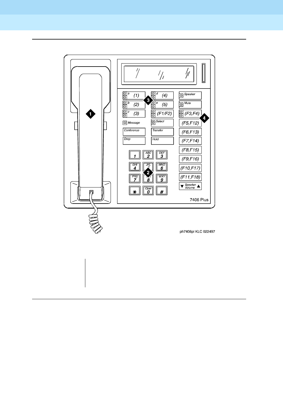
DEFINITY Enterprise Communications Server Release 6
Administration and Feature Description
555-230-522 Issue 4
May 1998
Voice Terminal, PC Interface, and Data Module Administration
Page 6-1197406D, 7406+, 7407D, and 7407+ voice terminals
6
Figure Notes
Figure 6-33. 7406D+ voice terminal
1. Handset
2. Dial pad
3. 5 programmable buttons
4. 18 feature buttons (feature buttons F2, F4, and
F12 to F18 are enabled with the Shift key)
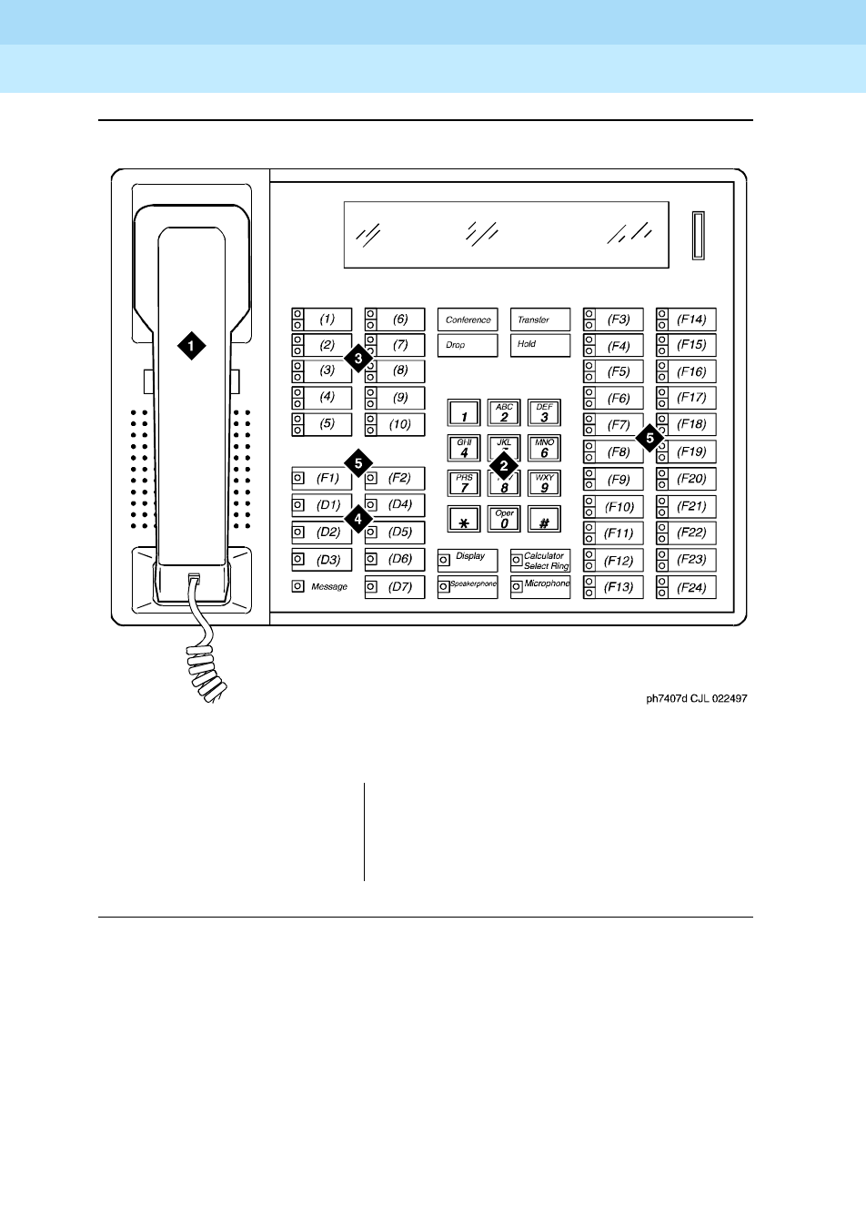
DEFINITY Enterprise Communications Server Release 6
Administration and Feature Description
555-230-522 Issue 4
May 1998
Voice Terminal, PC Interface, and Data Module Administration
Page 6-1207406D, 7406+, 7407D, and 7407+ voice terminals
6
Figure Notes
Figure 6-34. 7407D voice terminal
1. Handset
2. Dial pad
3. 10 programmable buttons
4. 7 display buttons
5. 24 feature buttons

DEFINITY Enterprise Communications Server Release 6
Administration and Feature Description
555-230-522 Issue 4
May 1998
Voice Terminal, PC Interface, and Data Module Administration
Page 6-1217434D and 7444D voice terminal
6
7434D and 7444D voice terminal
Form instructions
To administer a 7434D or 7444D voice terminal, complete the standard as well as
the following unique Station form fields.
Page 1 of the form
Screen 6-64. 7434D and 7444D Station form (Page 1 of X)
■Type — Enter 7434D, or 7444D.
■Data Module — Enter y if this terminal is connected to an optional 7400B
or 8400B Data Module. If you enter y, you must complete the Data Module
form. Default is n.
■Display Module — Enter y if the voice terminal is to have a display by an
optional Digital Display Module. Display only field (set to y) for 7444D
terminals. If this field is set to y, you must complete the Display Button
assignments form. Default is n.
■Coverage Module — This field displays only for 7434D terminals. Enter y
if the voice terminal is to be connected to an optional Call Coverage
Module. If you enter y, you must complete the Coverage Module form. The
voice terminal cannot have an optional Coverage Module and optional
Digital Display Module at the same time. Default is n.
Page 1 of X
STATION
Extension: 1003 Lock Messages? n BCC: 2
Type: 7434D__ Security Code: ________ TN: 1_
Port: _______ Coverage Path 1: ____ COR: 1_
Name: ___________________________ Coverage Path 2: ____ COS: 1_
Hunt-to Station: _____
STATION OPTIONS
Data Module? y Personalized Ringing Pattern: 1
Display Module? y Message Lamp Ext: 1000
Display Language: english
Coverage Module? n
MM Complex Data Ext: ____

DEFINITY Enterprise Communications Server Release 6
Administration and Feature Description
555-230-522 Issue 4
May 1998
Voice Terminal, PC Interface, and Data Module Administration
Page 6-1227434D and 7444D voice terminal
6
Page 2 of the form
Screen 6-65. 7434D and 7444D Station form (Page 2 of X)
Page 3 of the form
Screen 6-66. 7434D and 7444D Station form (Page 3 of X)
■BUTTON ASSIGNMENTS
The feature buttons that you can assign to the 7434D voice terminal are
listed below. The first three buttons are defaulted as call appearance.
Page 2 of X
STATION
FEATURE OPTIONS
LWC Reception? msa-spe Auto Select Any Idle Appearance? n
LWC Activation? y Coverage Msg Retrieval? y
CDR Privacy? n Auto Answer: none
Redirect Notification? y Data Restriction? n
Per Button Ring Control? n Idle Appearance Preference? n
Bridged Call Alerting? n
Active Station Ringing: single Restrict Last Appearance? y
H.320 Conversion? n
AUDIX Name: ______ Multimedia Early Answer? n
Messaging Server Name: ______ Audible Message Waiting? y
Display Client Redirection? n
Select Last Used Appearance? n
Page 3 of X
STATION
SITE DATA
Room: _______ Headset? n
Jack: _____ Speaker? n
Cable: _____ Mounting: d
Floor: _______ Cord Length: 0_
Building: _______ Set Color: ______
ABBREVIATED DIALING
List1: ________ List2: _________ List3: _________
BUTTON ASSIGNMENTS
1: call-appr_ 6: __________
2: call-appr_ 7: __________
3: call-appr_ 8: __________
4: __________ 9: __________
5: __________ 10: __________

DEFINITY Enterprise Communications Server Release 6
Administration and Feature Description
555-230-522 Issue 4
May 1998
Voice Terminal, PC Interface, and Data Module Administration
Page 6-1237434D and 7444D voice terminal
6
1. Display-type button
abr-prog abr-spchar abrdg-appr abrv-dial
abrv-ring ac-alarm aca-halt after-call
alrt-agchg alt-frl assist asvn-halt
atd-qcalls1atd-qtime1aut-msg-wt auto-cback
auto-icom auto-in auto-wkup1autodial
aux-work brdg-appr busy-ind call-appr
call-disp1call-fwd call-park call-pkup
callr-info1cas-backup cdr1-alrm cdr2-alrm
cfwd-bsyda check-in1check-out1clk-overid1
consult cov-cback cov-msg-rt1data-ext
date-time1delete-msg1dial-icom directory1
dir-pkup disp-chrg disp-norm dn-dst
ds1-alarm exclusion ext-dn-dst1flash
goto-cover grp-dn-dst1hunt-ns in-call-id
inspect1int-aut-an last-numb link-alarm
lsvn-halt lwc-cancel lwc-lock lwc-store
major-alrm man-msg-wt man-overid1manual-in
mct-act mct-contr mj/mn alrm msg-retr1
mwn-act1mwn-deact1next1night-serv
noans-alrt normal1per-COline pms-alarm
pr-awu-alm pr-pms-alm pr-sys-alm print-msgs
priority q-calls q-time release
ringer-off rs-alert rsvn-halt scroll
send-calls send-term serv-obsrv signal
ssvn-halt stored-num1stroke-cnt term-x-gr
timer1trk-ac-alm trk-id trunk-name1
trunk-ns verify voa-repeat vu-display
work-code

DEFINITY Enterprise Communications Server Release 6
Administration and Feature Description
555-230-522 Issue 4
May 1998
Voice Terminal, PC Interface, and Data Module Administration
Page 6-1247434D and 7444D voice terminal
6
Page 4 of the form
Screen 6-67. 7434D and 7444D Station form (Page 4 of X)
■BUTTON ASSIGNMENTS
The feature buttons that you can assign are the same as those listed for
BUTTON ASSIGNMENTS above. This form is used to assign features to
the 24 administrable buttons on the 7434D or 7444D voice terminal (may
include call appearance and bridged call appearance buttons). If you
want to assign feature buttons to the optional Coverage Module, assign
them on the Coverage Module page of the form.
Page X of the form (COVERAGE MODULE
BUTTON ASSIGNMENTS)
Screen 6-68. 7434D Coverage Module form (Page Y of X)
Page 4 of X
STATION
BUTTON ASSIGNMENTS
11: __________ 23: __________
12: __________ 24: __________
13: __________ 25: __________
14: __________ 26: __________
15: __________ 27: __________
16: __________ 28: __________
17: __________ 29: __________
18: __________ 30: __________
19: __________ 31: __________
20: __________ 32: __________
21: __________ 33: __________
22: __________ 34: __________
Page Y of X
STATION
COVERAGE MODULE BUTTON ASSIGNMENTS
1: __________ 11: __________
2: __________ 12: __________
3: __________ 13: __________
4: __________ 14: __________
5: __________ 15: __________
6: __________ 16: __________
7: __________ 17: __________
8: __________ 18: __________
9: __________ 19: __________
10: __________ 20: __________

DEFINITY Enterprise Communications Server Release 6
Administration and Feature Description
555-230-522 Issue 4
May 1998
Voice Terminal, PC Interface, and Data Module Administration
Page 6-1257434D and 7444D voice terminal
6
This page displays only if Coverage Module is y. The features buttons that you
can assign are the same as those listed for BUTTON ASSIGNMENTS above
except that you cannot assign display-type buttons. A minimum of 2 or a
maximum of 10 call appearance buttons can be administered. When 2 call
appearance buttons are administered, the maximum number of Bridged
Appearance buttons that can be administered is 52 with a Coverage Module or
32 without a Coverage Module.
Page X of the form (DISPLAY BUTTON
ASSIGNMENTS)
Screen 6-69. 7434D and 7444D Display form (Page Y of X)
This page displays only if Display is y. The display-type buttons that you can
assign are shown on the BUTTON ASSIGNMENTS list. Button locations (1
through 7) are associated with buttons 1 through 7 on the optional Digital Display
Module.
Page Y of X
STATION
DISPLAY BUTTON ASSIGNMENTS
1: __________
2: __________
3: __________
4: __________
5: __________
6: __________
7: __________

DEFINITY Enterprise Communications Server Release 6
Administration and Feature Description
555-230-522 Issue 4
May 1998
Voice Terminal, PC Interface, and Data Module Administration
Page 6-1267434D and 7444D voice terminal
6
Page X of the form (DATA MODULE)
Screen 6-70. 7434D and 7444D Data Module form (Page Y of X)
This page displays only if Data Module is y.
Page Y of X
STATION
DATA MODULE
Data Extension: _______________ Name: ______________________ BCC: 2
COS: 1_
COR: 1_
ITC: restricted TN: 1_
ABBREVIATED DIALING
List1: ________
SPECIAL DIALING OPTION: hot-line
HOT LINE DESTINATION
DEFAULT DIALING
Abbreviated Dialing Dial Code (From above list): ___
ASSIGNED MEMBER (Station with a data extension button for this data module)
Ext Name
1. _____ ___________________________
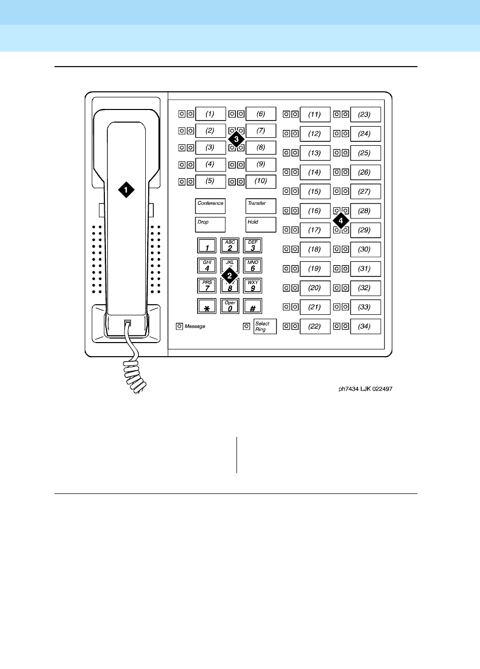
DEFINITY Enterprise Communications Server Release 6
Administration and Feature Description
555-230-522 Issue 4
May 1998
Voice Terminal, PC Interface, and Data Module Administration
Page 6-1277434D and 7444D voice terminal
6
Figure Notes
Figure 6-35. 7434D voice terminal
1. Handset
2. Dial pad
3. 10 programmable buttons
4. 24 feature buttons (11 to 34)
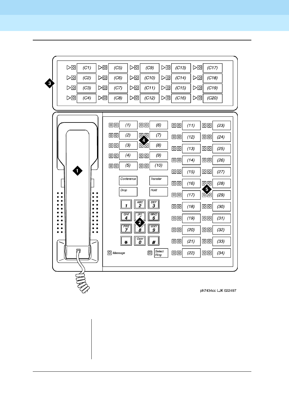
DEFINITY Enterprise Communications Server Release 6
Administration and Feature Description
555-230-522 Issue 4
May 1998
Voice Terminal, PC Interface, and Data Module Administration
Page 6-1287434D and 7444D voice terminal
6
Figure Notes
Figure 6-36. 7434D voice terminal with optional call coverage module
1. Handset
2. Dial pad
3. Call coverage module with 20 coverage module
buttons and status lamps
4. 10 programmable buttons
5. 24 feature buttons (11 to 34)
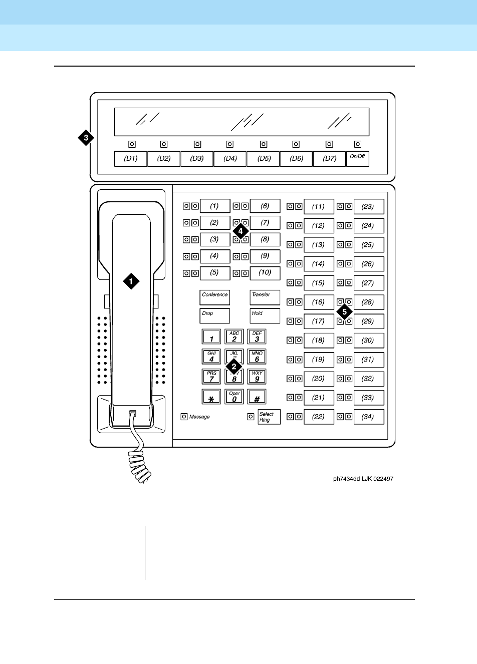
DEFINITY Enterprise Communications Server Release 6
Administration and Feature Description
555-230-522 Issue 4
May 1998
Voice Terminal, PC Interface, and Data Module Administration
Page 6-1297434D and 7444D voice terminal
6
Figure Notes
Figure 6-37. 7434D voice terminal with optional digital display module
1. Handset
2. Dial pad
3. Digital display module with 7 display buttons
4. 10 programmable buttons
5. 24 feature buttons (11 to 34)

DEFINITY Enterprise Communications Server Release 6
Administration and Feature Description
555-230-522 Issue 4
May 1998
Voice Terminal, PC Interface, and Data Module Administration
Page 6-1307505D, 7506D, 7507D, 8503D, 8510T, and 8520T ISDN-BRI voice terminals
6
7505D, 7506D, 7507D, 8503D, 8510T,
and 8520T ISDN-BRI voice terminals
Form instructions
To administer a 7505D, 7506D, 7507D, 8503D, 8510T, or 8520T ISDN-BRI voice
terminal, complete the standard as well as the following unique Station form
fields.
Page 1 of the form
Screen 6-71. 7505D, 7506D, 7507D, 8503D, 8510T, and 8520T Station form (Page 1 of X)
■Type — Enter 7505D, 7506D, 7507D, 8503D, 8510T, or 8520T as
appropriate.
■Data Module displays only for the 7505D, 7506D, 7507D, 8510T, and
8520T ISDN-BRI voice terminals.
■Fixed TEI and TEI do not display for the 8510T and 8520T voice
terminals. When adding an unsupported station using Enhanced Terminal
Administration, if this field is y, TEI displays.
■Display Language displays only for 7506D, 7507D, 8510T, and 8520T
terminals.
Page 1 of X
STATION
Extension: 1003 Lock Messages? n BCC: 0
Type: 7505D__ Security Code: ________ TN: 1_
Port: _______ Coverage Path 1: ____ COR: 1_
Name: ___________________________ Coverage Path 2: ____ COS: 1_
Hunt-to Station: _____
STATION OPTIONS
Data Module? y
Message Lamp Ext: 1000
Display Language: english__
XID? n Fixed TEI? y TEI: __
MIM Support? n Endpt Init? y SPID: 1000______ MIM Mtce/Mgt? n

DEFINITY Enterprise Communications Server Release 6
Administration and Feature Description
555-230-522 Issue 4
May 1998
Voice Terminal, PC Interface, and Data Module Administration
Page 6-1317505D, 7506D, 7507D, 8503D, 8510T, and 8520T ISDN-BRI voice terminals
6
Page 2 of the form
Screen 6-72. 7505D, 7506D, 7507D, 8503D, 8510T, and 8520T Station form (Page 2 of X)
■Display Client Redirection displays only for 7506D, 7507D, 8510T, and
8520T terminals.
Page 3 of the form
Screen 6-73. 7505D, 7506D, 7507D, 8510T, and 8520T Station form (Page 3 of X)
Page 2 of X
STATION
FEATURE OPTIONS
LWC Reception? msa-spe Auto Select Any Idle Appearance? n
LWC Activation? y Coverage Msg Retrieval? y
CDR Privacy? n Auto Answer: none
Redirect Notification? y Data Restriction? n
Per Button Ring Control? n Idle Appearance Preference? n
Bridged Call Alerting? n
Restrict Last Appearance? y
H.320 Conversion? n
AUDIX Name: ______ Multimedia Early Answer? n
Messaging Server Name: ______ Audible Message Waiting? y
Display Client Redirection? n
Select Last Used Appearance? n
Page 3 of X
STATION
SITE DATA
Room: _______ Headset? n
Jack: _____ Speaker? n
Cable: _____ Mounting: d
Floor: _______ Cord Length: 0_
Building: _______ Set Color: ______
ABBREVIATED DIALING
List1: ________ List2: _________ List3: _________
BUTTON ASSIGNMENTS
1: call-appr_ 6: _________
2: call-appr_ 7: _________
3: call-appr_ 8: _________
4: __________ 9: _________
5: __________ 10: _________

DEFINITY Enterprise Communications Server Release 6
Administration and Feature Description
555-230-522 Issue 4
May 1998
Voice Terminal, PC Interface, and Data Module Administration
Page 6-1327505D, 7506D, 7507D, 8503D, 8510T, and 8520T ISDN-BRI voice terminals
6
Implementation note
For a 7505D or 7506D voice terminal, button 7 can be administered as a call
appearance button if an Asynchronous Data Module (ADM) is not attached to the
station. When an ADM is attached, button 7 acts as a DATA button whether or not
the data module has been administered. If the ADM has been administered,
button 7 is set to DATA and access to the field is restricted. If the station is
aliased as a 7505D or 7506D via Enhanced Terminal Administration, button 7 can
be administered as a call appearance button whether or not an ADM is assigned.
There is no Data button on 7507D, 8510T, and 8520T voice terminals.
Screen 6-74. 8503D Station form (Page 3 of X)
■BUTTON ASSIGNMENTS
The feature buttons that you can assign to the 7505D, 7506D, 7507D,
8503D, 8510T, and 8520T voice terminals are listed below. The first 3
buttons default as call appearance.
abr-prog abr-spchar abrdg-appr abrv-dial
abrv-ring ac-alarm aca-halt after-call
alrt-agchg alt-frl assist asvn-halt
atd-qcalls1atd-qtime aut-msg-wt auto-cback
auto-icom auto-in auto-wkup1,2autodial
aux-work brdg-appr busy-ind call-appr
call-disp1,2call-fwd call-park call-pkup
callr-info1,2cas-backup cdr1-alrm cdr2-alrm
cfwd-bsyda check-in1,2check-out1,2clk-overid1,2
Page 3 of X
STATION
SITE DATA
Room: _______ Headset? n
Jack: _____ Speaker? n
Cable: _____ Mounting? d
Floor: _______ Cord Length: 0_
Building: _______ Set Color: ______
ABBREVIATED DIALING
List1: ________ List2: _________ List3: _________
BUTTON ASSIGNMENTS
1: call-appr_
2: call-appr_
3: call-appr_

DEFINITY Enterprise Communications Server Release 6
Administration and Feature Description
555-230-522 Issue 4
May 1998
Voice Terminal, PC Interface, and Data Module Administration
Page 6-1337505D, 7506D, 7507D, 8503D, 8510T, and 8520T ISDN-BRI voice terminals
6
Page 4 of the form
Screen 6-75. 7505D and 7506D Station form (Page 4 of X)
1. Display-type button.
2. Cannot administer on 7505D or 8503D.
consult cov-cback cov-msg-rt1,2data-ext
date-time1,2delete-msg1,2dial-icom directory1,2
dir-pkup2disp-chrg2disp-norm1,2dn-dst
ds1-alarm exclusion ext-dn-dst1,2flash
goto-cover grp-dn-dst1,2hunt-ns in-call-id
inspect1,2int-aut-an last-numb link-alarm
lsvn-halt lwc-cancel lwc-lock1,2lwc-store
major-alrm man-msg-wt man-overid1,2manual-in
mct-act mct-contr mj/mn-alrm msg-retr1,2
mwn-act1,2mwn-deact1,2next1,2night-serv
noans-alrt normal1,2per-COline pms-alarm
pr-awu-alm pr-pms-alm pr-sys-alm print-msgs
priority q-calls q-time release
ringer-off rs-alert rsvn-halt scroll2
send-calls send-term serv-obsrv signal
ssvn-halt stored-num1,2stroke-cnt term-x-gr
timer1,2trk-ac-alm trk-id2trunk-name1,2
trunk-ns verify voa-repeat vu-display2
work-code
Page 4 of X
STATION
FEATURE BUTTON ASSIGNMENTS
1: normal_____ 4: ___________
2: ___________ 5: ___________
3: ___________ 6: ___________
7: ___________
DEFINITY Enterprise Communications Server Release 6
Administration and Feature Description
555-230-522 Issue 4
May 1998
Voice Terminal, PC Interface, and Data Module Administration
Page 6-1347505D, 7506D, 7507D, 8503D, 8510T, and 8520T ISDN-BRI voice terminals
6
Screen 6-76. 7507D Station form (Page 4 of X)
Screen 6-77. 8510T Station form (Page 4 of X)
Screen 6-78. 8520T Station form (Page 4 of X)
Page 4 of X
STATION
BUTTON ASSIGNMENTS
11: normal____ 20: __________
12: __________ 21: normal____
13: __________ 22: __________
14: __________ 23: __________
15: __________ 24: __________
16: __________ 25: __________
17: __________ 26: __________
18: __________ 27: __________
19: __________ 28: __________
29: __________
31: __________ 30: __________
32: __________
33: __________ 37: __________
34: __________ 38: __________
35: __________ 39: __________
36: __________ 40: __________
Page 4 of X
STATION
FEATURE BUTTON ASSIGNMENTS
11: normal
Page 4 of X
STATION
BUTTON ASSIGNMENTS
11: normal____ 16: __________
12: __________ 17: __________
13: __________ 18: __________
14: __________ 19: __________
15: __________ 20: __________

DEFINITY Enterprise Communications Server Release 6
Administration and Feature Description
555-230-522 Issue 4
May 1998
Voice Terminal, PC Interface, and Data Module Administration
Page 6-1357505D, 7506D, 7507D, 8503D, 8510T, and 8520T ISDN-BRI voice terminals
6
■FEATURE BUTTON ASSIGNMENTS
The features and functions that you can assign to the 7505D, 7506D,
7507D, 8503D, 8510T, and 8520T voice-terminal administrable buttons are
the same as those listed for BUTTON ASSIGNMENTS above.
Implementation note
Button 31 can be administered as a feature button if an Asynchronous
Data Module (ADM) is not attached to the station. When an ADM is
attached, button 31 acts as a DATA button whether or not the data module
has been administered. If the ADM has been administered, button 31 is
set to DATA and the field is restricted. If the station is aliased as a 7507D
via Enhanced Terminal Administration, button 31 can be administered as a
feature button whether or not an ADM is assigned.
Page X of the form (DATA MODULE)
Screen 6-79. 7505D, 7506D, 7507D, 8510T, and 8520T ISDN-BRI Data Module form
(Page Y of X)
This page displays only if Data Module is y for 7505D, 7506D, 7507D, 8510T,
and 8520T voice terminals.
Page Y of X
STATION
DATA MODULE
Data Extension: ____ Name: ___________________________
COR: 1_ Multimedia? y
COS: 1_ MM Complex Voice Ext: xxxxx
TN: 1_
ABBREVIATED DIALING
List1: ________
SPECIAL DIALING OPTION: hot-line
HOT LINE DESTINATION
DEFAULT DIALING
Abbreviated Dialing Dial Code (From above list): ___
CIRCUIT SWITCHED DATA ATTRIBUTES
Default Duplex: full Default Mode: async Default Speed: 1200
DATA MODULE CAPABILITIES
Default ITC: restricted Default Data Application? M2_A

DEFINITY Enterprise Communications Server Release 6
Administration and Feature Description
555-230-522 Issue 4
May 1998
Voice Terminal, PC Interface, and Data Module Administration
Page 6-1367505D, 7506D, 7507D, 8503D, 8510T, and 8520T ISDN-BRI voice terminals
6
Screen 6-80. 7505D and 7506D voice-terminal feature button layout
Notes:
1. Buttons F4 through F6 are accessed by shifting buttons F1 through F3.
Button F7 is accessed by shifting the fixed REDIAL button.
2. CA7/DATA button can be administered as a call appearance button.
However, CA7 button should not be administered when ADM is attached
to the terminal. When the ADM is attached, the button acts as a DATA
button, regardless of administration. For 7505D and 7506D terminals, if
ADM is administered, the CA7 button is set to DATA and the field is
restricted. If a terminal is aliased as a 7505D or 7506D voice terminal via
ETA, button CA7 is always administrable as a call appearance button,
whether or not the data module is administered.
____________________________________________________________
| |
| ____ _________________________________ |
| | | | DISPLAY AREA (7506D only) | |
| | | |_________________________________| |
| | | |
| | | |
| | | CA1 (1) CA4 (4) CA8 ( 8) |
| | | CA2 (2) CA5 (5) CA9 ( 9) |
| | | CA3 (3) CA6 (6) CA10(10) |
| | HS | MSG (63) CA7/DATA(7) F1 (1) / F4 (4) |
| | | F2 (2) / F5 (5) |
| | | OTHER FIXED BUTTONS F3 (3) / F6 (6) |
| | | REDIAL / F7 (7) |
| | | ... DIAL PAD ... |
| | | |
| | | |
| |____| |
| |
|___________________________________________________________|
Where: (.) represent the set button number
CA1, CA2, CA3... are call appearance buttons which
appear on page one of the station form.
F1, F2, F3... are the feature buttons.
FIXED BTNS include: conference, Drop, Transfer, and Hold

DEFINITY Enterprise Communications Server Release 6
Administration and Feature Description
555-230-522 Issue 4
May 1998
Voice Terminal, PC Interface, and Data Module Administration
Page 6-1377505D, 7506D, 7507D, 8503D, 8510T, and 8520T ISDN-BRI voice terminals
6
Screen 6-81. 7507D Voice-terminal Feature button Layout
Notes:
1. F1/DATA button can be administered as a feature button. However, F1
should not be administered if ADM is attached to the terminal. If the ADM
is attached, F1 acts as a DATA button regardless of administration. For
7507D terminal, if ADM is administered, F1 is set to DATA and the field is
restricted. If a terminal is aliased as 7507D via ETA, F1 button is always
administrable as a feature button whether or not the data module is
administered.
2. The 7507D terminal supports 31 buttons with two LEDs; however, the
software only supports administration of 30 of these as call appearance
buttons (buttons CA1-CA30). The system maximum of 10 call appearance
buttons still applies. The CA1-CA30 buttons that are not used as call
appearance buttons may be administered as bridged appearance
buttons.
___________________________________________________________________________
| ____ _____________________________ |
| | | | DISPLAY AREA A | |
| | | |_____________________________| |
| | | | DISPLAY AREA B | |
| | | |_____________________________| |
| | | |
| | | CA1 (1) CA6 (6) CA11 (11) CA20 (20) |
| | | CA2 (2) CA7 (7) FIXED CA12 (12) CA21 (21) |
| | | CA3 (3) CA8 (6) BTNS. CA13 (13) CA22 (22) |
| | HS | CA4 (4) CA9 (6) CA14 (14) CA23 (23) |
| | | CA5 (5) CA10 (10) CA15 (15) CA24 (24) |
| | | CA16 (16) CA25 (25) |
| | | F2 (32) F7 (37) CA17 (17) CA26 (26) |
| | | F3 (33) F8 (38) .. KEYPAD .. CA18 (18) CA27 (27) |
| | | F4 (34) F9 (39) CA19 (19) CA28 (28) |
| | | F5 (35) F10 (40) MSG(63) REDIAL CA29 (29) |
| | | F6 (36) F1/DATA (31) CA30 (30) |
| |____| |
|_________________________________________________________________________|
Where: (.) represent the set button number
CA1, CA2, ..., CA30 are call appearance buttons (2 lamp buttons)
F1, F2, F3... are the feature buttons (one LED).
FIXED BTNS include: Conference, Drop, Transfer, and Hold
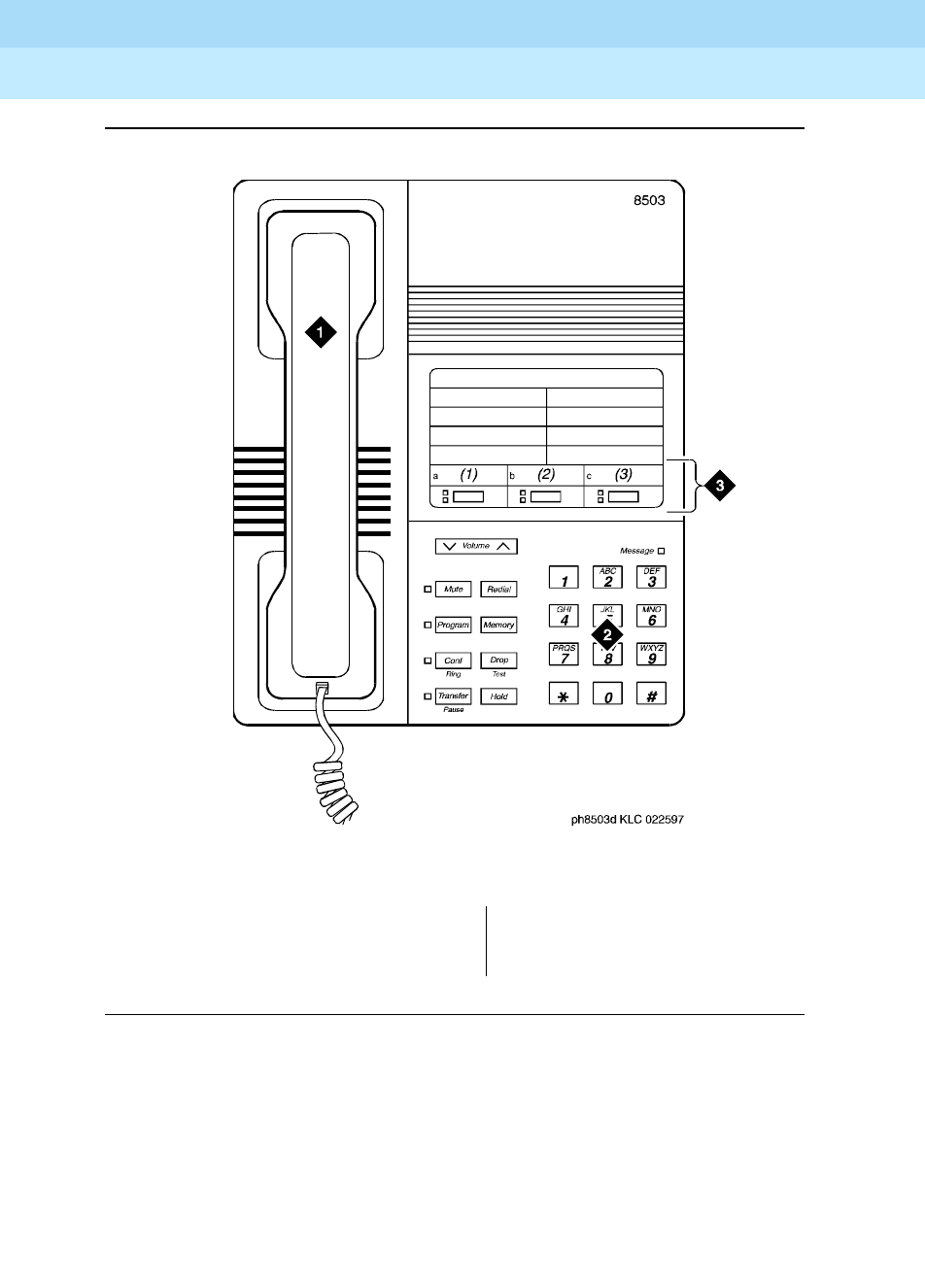
DEFINITY Enterprise Communications Server Release 6
Administration and Feature Description
555-230-522 Issue 4
May 1998
Voice Terminal, PC Interface, and Data Module Administration
Page 6-1387505D, 7506D, 7507D, 8503D, 8510T, and 8520T ISDN-BRI voice terminals
6
Figure Notes
Figure 6-38. 8503D Voice terminal
1. Handset
2. Dial pad
3. 3 programmable buttons
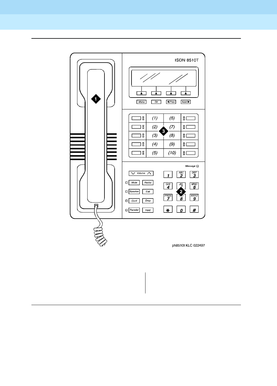
DEFINITY Enterprise Communications Server Release 6
Administration and Feature Description
555-230-522 Issue 4
May 1998
Voice Terminal, PC Interface, and Data Module Administration
Page 6-1397505D, 7506D, 7507D, 8503D, 8510T, and 8520T ISDN-BRI voice terminals
6
Figure Notes
Figure 6-39. 8510T Voice-terminal Feature Button Layout
1. Handset
2. Dial pad
3. 10 programmable buttons
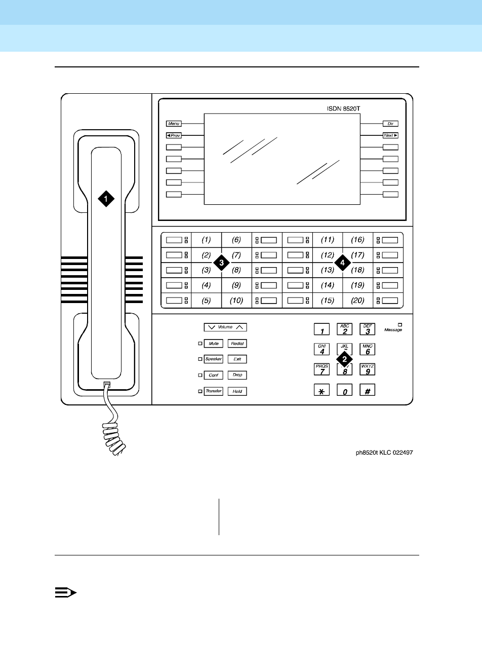
DEFINITY Enterprise Communications Server Release 6
Administration and Feature Description
555-230-522 Issue 4
May 1998
Voice Terminal, PC Interface, and Data Module Administration
Page 6-1407505D, 7506D, 7507D, 8503D, 8510T, and 8520T ISDN-BRI voice terminals
6
Figure Notes
Figure 6-40. 8520T station set layout
NOTE:
The 8520T terminal supports 20 call appearances. The system maximum of
10 call appearance buttons still applies. The (1)–(20) buttons that are not
used as call appearance buttons can be administered as bridged
appearance buttons.
1. Handset
2. Dial pad
3. 10 programmable buttons
4. 10 programmable buttons (11 to 20)

DEFINITY Enterprise Communications Server Release 6
Administration and Feature Description
555-230-522 Issue 4
May 1998
Voice Terminal, PC Interface, and Data Module Administration
Page 6-141CALLMASTER II and III voice terminals
6
CALLMASTER II and III voice
terminals
The CALLMASTER Ii and CALLMASTER III voice terminals provide internal
nonvolatile memory and native support. Native support means the switch stores
a predefined terminal type and automatically downloads the terminal type
information to the terminal.
These enhancements provide several benefits. First, the internal nonvolatile
memory of the terminal stores information even if the terminal loses power.
Second, native support removes from the customer or service technician the
burden of having to alias the terminals, that is — manually map call appearance
and feature buttons onto some other supported terminal type. Also, the
nonvolatile memory can support transmission changes for applications in various
countries.
The 603-type CALLMASTER voice terminal is available in three models: 603A1,
603D1, and 603E1. The only difference among these three is the ability of the
603D1 to tape recording equipment and of the 603E1 to operate on either the
standard 4-wire DCP circuit pack or on a 2-wire circuit pack (16-port,
A-law/Mu-law selectable).
NOTE:
The 603s must have their handset unplugged to receive the downloaded
parameters.
You can check Download Status on the Status Station screen to verify that the
system successfully completes each download. You do not need to download
the information to the terminals, as the switch does it automatically after the
initialization period during the first periodic maintenance cycle.
Form instructions
To administer a 603 CALLMASTER voice terminal, complete the standard as well
as the following unique Station form fields.
NOTE:
If you have one or more 603-type CALLMASTER voice terminals, you must
also have a Lucent technician complete the Terminal Parameters form (see
‘‘Terminal Parameters form’’ on page 6-9). Only Lucent technicians can
complete this form.

DEFINITY Enterprise Communications Server Release 6
Administration and Feature Description
555-230-522 Issue 4
May 1998
Voice Terminal, PC Interface, and Data Module Administration
Page 6-142CALLMASTER II and III voice terminals
6
Page 1 of the form
Screen 6-82. 603A1, 603D1, and 603E1 Station form (Page 1 of X)
■Type — Enter 603A1, 603D1, or 603E1.
■Data Module — Enter y if this terminal is connected to a data terminal via
7400B or 8400B Data Module. If you enter y, you must complete the Data
Module form. Default is n.
■Display Module — Display-only field set to y. You must administer the
display-type buttons on page 3 of the form.
Page 2 of the form
Screen 6-83. 603A1, 603D1, and 603E1 Station form (Page 2 of X)
Page 1 of X
STATION
Extension: 1003 Lock Messages? n BCC: 0
Type: 603A1__ Security Code: ________ TN: 1_
Port: _______ Coverage Path 1: ____ COR: 1_
Name: ___________________________ Coverage Path 2: ____ COS: 1_
Hunt-to Station: _____
STATION OPTIONS
Data Module? n Personalized Ringing Pattern: 1
Display Module? y Message Lamp Ext: 1000
Display Language: english
MM Complex Data Ext: ____
Page 2 of X
STATION
FEATURE OPTIONS
LWC Reception? msa-spe Auto Select Any Idle Appearance? n
LWC Activation? y Coverage Msg Retrieval? y
CDR Privacy? n Auto Answer: none
Redirect Notification? y Data Restriction? n
Per Button Ring Control? n Idle Appearance Preference? n
Bridged Call Alerting? n
Active Station Ringing: single Restrict Last Appearance? y
H.320 Conversion? n
AUDIX Name: ______ Multimedia Early Answer? n
Messaging Server Name: ______ Audible Message Waiting? y
Display Client Redirection? n
Select Last Used Appearance? n

DEFINITY Enterprise Communications Server Release 6
Administration and Feature Description
555-230-522 Issue 4
May 1998
Voice Terminal, PC Interface, and Data Module Administration
Page 6-143CALLMASTER II and III voice terminals
6
Page 3 of the form
Screen 6-84. 603A1, 603D1, and 603E1 Station form (Page 3 of X)
■BUTTON ASSIGNMENTS
The feature buttons that you can assign to the CALLMASTER digital voice
terminal are listed below.
abr-prog abr-spchar abrdg-appr abrv-dial
abrv-ring ac-alarm aca-halt after-call
alrt-agchg alt-frl assist asvn-halt
atd-qcalls1atd-qtime1aut-msg-wt auto-cback
auto-icom auto-in auto-wkup1autodial
aux-work brdg-appr busy-ind call-appr
call-disp call-fwd call-park call-pkup
callr-info1cas-backup cdr1-alrm cdr2-alrm
cfwd-bsyda check-in1check-out1clk-overid1
consult cov-cback cov-msg-rt1data-ext
date-time1delete-msg1dial-icom directory1
dir-pkup disp-chrg disp-norm dn-dst
ds1-alarm exclusion ext-dn-dst1flash
goto-cover grp-dn-dst1hunt-ns in-call-id
Continued on next page
Page 3 of X
STATION
SITE DATA
Room: _______ Headset? n
Jack: _____ Speaker? n
Cable: _____ Mounting: d
Floor: _______ Cord Length: 0_
Building: _______ Set Color: ______
ABBREVIATED DIALING
List1: ________ List2: _________ List3: _________
BUTTON ASSIGNMENTS
1: call-appr_ 4: __________
2: call-appr_ 5: __________
3: call-appr_ 6: __________

DEFINITY Enterprise Communications Server Release 6
Administration and Feature Description
555-230-522 Issue 4
May 1998
Voice Terminal, PC Interface, and Data Module Administration
Page 6-144CALLMASTER II and III voice terminals
6
Page 4 of the form
Screen 6-85. 603A1, 603D1, and 603E1 Station form (Page 4 of X)
1. Requires display.
inspect1int-aut-an last-numb link-alarm
lsvn-halt lwc-cancel lwc-lock lwc-store
major-alrm man-msg-wt man-overid1manual-in
mct-act mct-contr mf-da-intl mf-op-intl
mj/mn-alrm msg-retr1mwn-act1mwn-deact1
next1night-serv noans-alrt normal1
per-COline pms-alarm pr-awu-alm pr-pms-alm
pr-sys-alm print-msgs priority q-calls
q-time release ringer-off rs-alert
rsvn-halt scroll send-calls send-term
serv-obsrv signal ssvn-halt stored-num1
stroke-cnt term-x-gr timer1trk-ac-alm
trk-id trunk-name1trunk-ns verify
voa-repeat vu-display work-code
Continued on next page
Page 4 of X
STATION
FEATURE BUTTON ASSIGNMENTS
1st Column 2nd Column
1: normal____ 7: __________
2: __________ 8: __________
3: __________ 9: __________
4: __________ 10: __________
5: __________ 11: normal____
6: mute 12: __________
3rd Column
13: __________
14: __________
15: __________
16: __________
17: __________
18: Release

DEFINITY Enterprise Communications Server Release 6
Administration and Feature Description
555-230-522 Issue 4
May 1998
Voice Terminal, PC Interface, and Data Module Administration
Page 6-145CALLMASTER II and III voice terminals
6
■FEATURE BUTTON ASSIGNMENTS
The features and functions that you can assign to the terminal’s
administrable buttons are the same as those for BUTTON ASSIGNMENTS
above.
Feature button 6 is preassigned as mute and button 18 is preassigned as
release (they are not administrable). Feature button 12 is already labeled
on the terminal as a login button, but you must still administer it as a login
button.
Page 5 of the form (DATA MODULE)
Screen 6-86. 603A1, 603D1, and 603E1 Data Module form (Page Y of X)
This page displays only if Data Module is y.
Page Y of X
STATION
DATA MODULE
Data Extension: __________ Name: ____________________ BCC: 2
COS: 1_
COR: 1_
ITC: restricted TN: 1_
ABBREVIATED DIALING
List1: ________
SPECIAL DIALING OPTION: hot-line
HOT LINE DESTINATION
DEFAULT DIALING
Abbreviated Dialing Dial Code (From above list): ___
ASSIGNED MEMBER (Station with a data extension button for this data module)
Ext Name
1. _____ ___________________________
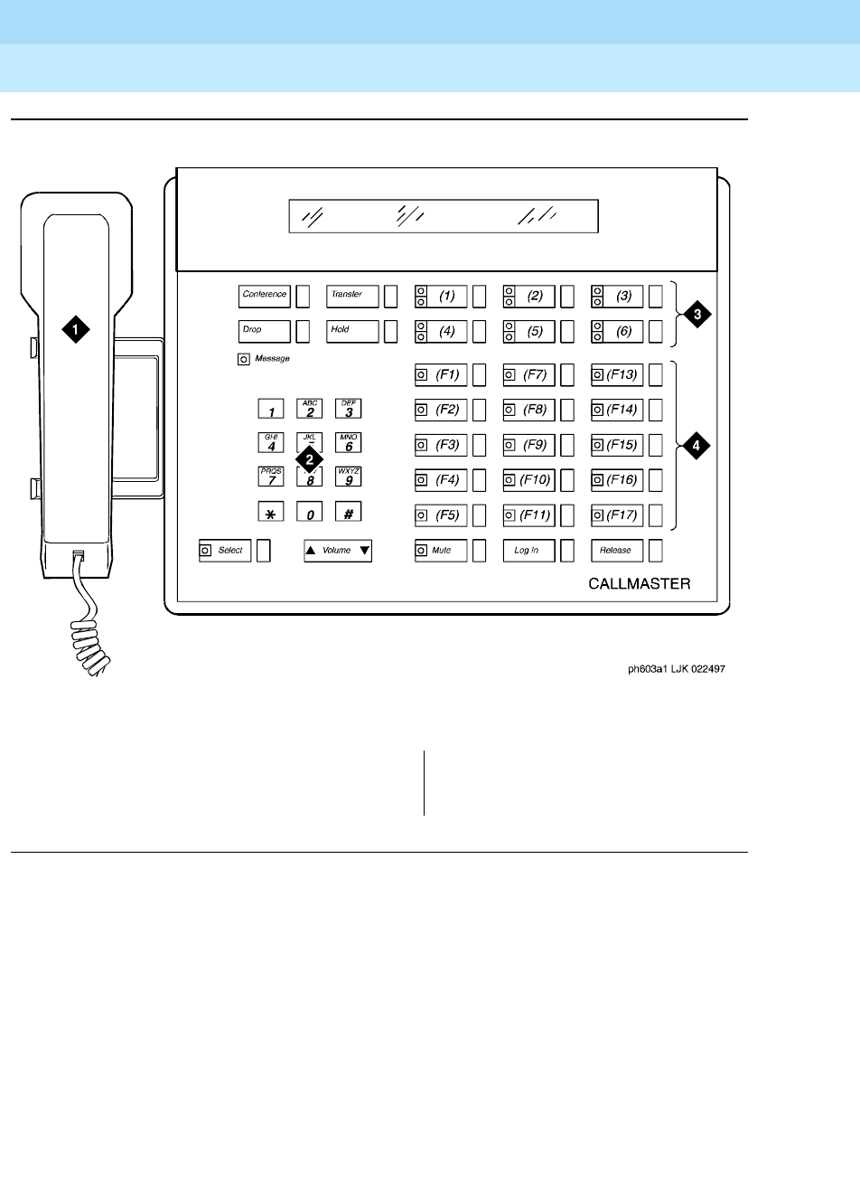
DEFINITY Enterprise Communications Server Release 6
Administration and Feature Description
555-230-522 Issue 4
May 1998
Voice Terminal, PC Interface, and Data Module Administration
Page 6-146CALLMASTER II and III voice terminals
6
Figure Notes
Figure 6-41. 603A1 and 603D1 CALLMASTER II digital voice terminals
1. Handset
2. Dial pad
3. 6 programmable buttons
4. 18 feature buttons

DEFINITY Enterprise Communications Server Release 6
Administration and Feature Description
555-230-522 Issue 4
May 1998
Voice Terminal, PC Interface, and Data Module Administration
Page 6-147CALLMASTER VI voice terminal
6
CALLMASTER VI voice terminal
The CALLMASTER VI (606) terminal is a miniature, 8-button, 2-headset jack,
digital voice terminal that is controlled by the user’s personal computer (PC)
through an RS-232 serial-port connection.
Form instructions
To administer a CALLMASTER VI voice terminal, complete the standard as well
as the following unique Station form fields.
NOTE:
If you have one or more 606-type CALLMASTER voice terminals, you must
also have a Lucent technician complete the ‘‘Terminal Parameters form’’
(see 6-9). Only Lucent technicians can complete this form.
Page 1 of the form
Screen 6-87. 606A1 Station form (Page 1 of X)
■Type — Enter 606A1.
■Data Module — Enter y if this terminal is connected to a data terminal via
a 8400B+ data module. If you enter y, you must complete the Data Module
form. Default is n.
Page 1 of X
STATION
Extension: xxxx x Lock Messages? n BCC: 0
Type: 606A1__ Security Code: ________ TN: 1_
Port: _______ Coverage Path 1: ____ COR: 1_
Name: ___________________________ Coverage Path 2: ____ COS: 1_
Hunt-to Station: _____
STATION OPTIONS
Data Module? n Personalized Ringing Pattern: 1
Message Lamp Ext: 1000
Display Language: english
MM Complex Data Ext: ____

DEFINITY Enterprise Communications Server Release 6
Administration and Feature Description
555-230-522 Issue 4
May 1998
Voice Terminal, PC Interface, and Data Module Administration
Page 6-148CALLMASTER VI voice terminal
6
Page 2 of the form
Screen 6-88. 606A1 Station form (Page 2 of X)
■PHYSICAL ENTITIES
The feature buttons that you can assign to the CALLMASTER VI digital
voice terminal are listed below.
abr-prog abr-spchar abrdg-appr abrv-dial
abrv-ring ac-alarm aca-halt after-call
alrt-agchg alt-frl assist asvn-halt
atd-qcalls atd-qtime aut-msg-wt auto-cback
auto-icom auto-in auto-wkup autodial
aux-work brdg-appr busy-ind call-appr
call-disp call-fwd call-park call-pkup
callr-info cas-backup cdr1-alrm cdr2-alrm
cfwd-bsyda check-in check-out clk-overid
consult cov-cback cov-msg-rt data-ext
date-time delete-msg dial-icom directory
dir-pkup disp-chrg disp-norm dn-dst
ds1-alarm exclusion ext-dn-dst flash
goto-cover grp-dn-dst hunt-ns in-call-id
inspect int-aut-an last-numb link-alarm
Continued on next page
Page 2 of X
STATION
FEATURE OPTIONS
LWC Reception? msa-spe Auto Select Any Idle Appearance? n
LWC Activation? y Coverage Msg Retrieval? y
CDR Privacy? n Auto Answer: none
Redirect Notification? y Data Restriction? n
Per Button Ring Control? n Idle Appearance Preference? n
Bridged Call Alerting? n
Idle/Active Ringing: single Restrict Last Appearance? y
H.320 Conversion? n
Multimedia Early Answer? n
Audible Message Waiting? y
Display Client Redirection? n
Select Last Used Appearance? n

DEFINITY Enterprise Communications Server Release 6
Administration and Feature Description
555-230-522 Issue 4
May 1998
Voice Terminal, PC Interface, and Data Module Administration
Page 6-149CALLMASTER VI voice terminal
6
Page 3 of the form
Screen 6-89. 606A1 Station form (Page 3 of X)
lsvn-halt lwc-cancel lwc-lock lwc-store
major-alrm man-msg-wt man-overid manual-in
mct-act mct-contr mf-da-intl mf-op-intl
mj/mn-alrm msg-retr mwn-act mwn-deact
next night-serv noans-alrt normal
per-COline pms-alarm pr-awu-alm pr-pms-alm
pr-sys-alm print-msgs priority q-calls
q-time release ringer-off rs-alert
rsvn-halt scroll send-calls send-term
serv-obsrv signal ssvn-halt stored-num
stroke-cnt term-x-gr timer trk-ac-alm
trk-id trunk-name trunk-ns uui-info
verify voa-repeat vu-display work-code
Continued on next page
Page 3 of X
STATION
SITE DATA
Room: _______ Headset? n
Jack: _____ Speaker? n
Cable: _____ Mounting: d
Floor: _______ Cord Length: 0_
Building: _______ Set Color: ______
ABBREVIATED DIALING
List1: ________ List2: _________ List3: _________
PHYSICAL ENTITIES
NO LED: abrv-dial List: 0 DC: _____
GREEN LED: call-appr
GREEN LED: call-appr
button: switchhook
RED LED: switchhook/mutelamp
button: mute
RED LED: msg-waiting lamp
DAUL LED: call-appr
DUAL LED: call-appr
RED LED: release

DEFINITY Enterprise Communications Server Release 6
Administration and Feature Description
555-230-522 Issue 4
May 1998
Voice Terminal, PC Interface, and Data Module Administration
Page 6-150CALLMASTER VI voice terminal
6
Page 4, 5, and 6 of the form
Screen 6-90. 606A1 Station form (Page 4 of X)
■VIRTUAL BUTTONS
The features and functions that you can assign to the terminal’s virtual
PHYSICAL ENTITIES above.
Screen 6-91. 606A1 Station form (Page 5 of X)
Page 4 of X
STATION
VIRTUAL BUTTONS with DUAL LED (oo)
oo: _______ oo: _______
oo: _______ oo: _______
oo: _______ oo: _______
oo: _______ oo: _______
oo: _______ oo: _______
oo: _______ oo: _______
oo: _______ oo: _______
oo: _______ oo: _______
oo: _______ oo: _______
oo: _______ oo: _______
oo: _______ oo: _______
oo: _______ oo: _______
oo: _______ oo: _______
oo: _______
Page 5 of X
STATION
VIRTUAL BUTTONS with DUAL LED (oo)
oo: _______ oo: _______
oo: _______ oo: _______
oo: _______ oo: _______
oo: _______ oo: _______
oo: _______ oo: _______
oo: _______ oo: _______
oo: _______ oo: _______
oo: _______ oo: _______
oo: _______ oo: _______

DEFINITY Enterprise Communications Server Release 6
Administration and Feature Description
555-230-522 Issue 4
May 1998
Voice Terminal, PC Interface, and Data Module Administration
Page 6-151CALLMASTER VI voice terminal
6
Screen 6-92. 606A1 Station form (Page 6 of X)
Page 7 of the form (DATA MODULE)
Screen 6-93. 606A1 Data Module form (Page Y of X)
This page displays only if Data Module is y.
Page 6 of X
STATION
VIRTUAL BUTTONS with GREEN LED (o)
o: _______ o: _______
o: _______ o: _______
o: _______ o: _______
o: _______ o: _______
o: _______ o: _______
o: _______ o: _______
o: _______ o: _______
o: _______ o: _______
o: _______ o: inspect
o: _______ o: next
o: _______ o: normal_
Page Y of X
STATION
DATA MODULE
Data Extension: __________ Name: ____________________ BCC: 2
COS: 1_
COR: 1_
ITC: restricted TN: 1_
ABBREVIATED DIALING
List1: ________
SPECIAL DIALING OPTION: hot-line
HOT LINE DESTINATION
DEFAULT DIALING
Abbreviated Dialing Dial Code (From above list): ___
ASSIGNED MEMBER (Station with a data extension button for this data module)
Ext Name
1. _____ ___________________________
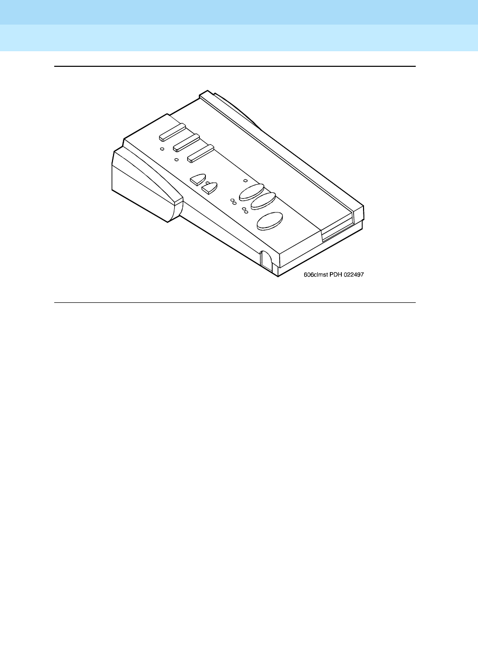
DEFINITY Enterprise Communications Server Release 6
Administration and Feature Description
555-230-522 Issue 4
May 1998
Voice Terminal, PC Interface, and Data Module Administration
Page 6-152CALLMASTER VI voice terminal
6
Figure 6-42. 606A1 CALLMASTER voice terminal

DEFINITY Enterprise Communications Server Release 6
Administration and Feature Description
555-230-522 Issue 4
May 1998
Voice Terminal, PC Interface, and Data Module Administration
Page 6-153Personal Computer
6
Personal Computer
The personal computer (PC) must be an IBM-compatible PC that can be used
with a 7400D series voice terminal to form a workstation arrangement.
Form instructions
To administer a personal computer with a 7400D series terminal, complete the
standard as well as the following unique Station form fields.
Page 1 of the form
.
Screen 6-94. PC Station form (Page 1 of X)
■Type — Enter pc.
■Set — Enter the digital voice terminal type the PC is connected to (7401D,
7401+, 7403D, 7404D, 7405D, 7406D, 7406+, 7407D, 7407+, 7410D,
7410+, 7434D, or 7444D).
■Data Module — Display-only (set to y).
■Display Module — Display-only (set to y).
Page 1 of X
STATION
Extension: 1003 Lock Messages? n BCC: 0
Type: PC____Set: 7401D Security Code: ________ TN: 1_
Port: _______ Coverage Path 1: ____ COR: 1_
Name: _______________________ Coverage Path 2: ____ COS: 1_
Hunt-to Station: _____
STATION OPTIONS
Data Module? y
Display Module? y Message Lamp Ext: 1000
Display Language: english
MM Complex Data Ext: ____

DEFINITY Enterprise Communications Server Release 6
Administration and Feature Description
555-230-522 Issue 4
May 1998
Voice Terminal, PC Interface, and Data Module Administration
Page 6-154Personal Computer
6
Page 2 of the form
Screen 6-95. PC Station form (Page 2 of X)
Page 3 of the form
Screen 6-96. PC Station form (Page 3 of X)
NOTE:
Characters in parenthesis (F1), (F2), and so on represent button locations
on the PC and do not appear on the page 3 of the form.
Page 2 of X
STATION
FEATURE OPTIONS
LWC Reception? msa-spe Auto Select Any Idle Appearance? n
LWC Activation? y Coverage Msg Retrieval? y
CDR Privacy? n Auto Answer: none
Redirect Notification? y Data Restriction? n
Per Button Ring Control? n Idle Appearance Preference? n
PCOL\TEG Call Alerting? n
Active Station Ringing: single Restrict Last Appearance? y
H.320 Conversion? n
AUDIX Name: ______ Multimedia Early Answer? n
Messaging Server Name: ______ Audible Message Waiting? n
Display Client Redirection? n
Select Last Used Appearance? n
Page 3 of X
STATION
SITE DATA
Room: _______ Headset? n
Jack: _____ Speaker? n
Cable: _____ Mounting: d
Floor: _______ Cord Length: 0_
Building: _______ Set Color: ______
ABBREVIATED DIALING
List1: ________ List2: _________ List3: _________
BUTTON ASSIGNMENTS
1: call-appr_ (F1) 6: __________ (AF3)
2: call-appr_ (F3) 7: __________ (AF5)
3: call-appr_ (F5) 8: __________ (AF7)
4: call-appr_ (F7) 9: __________ (AF2)
5: __________ (AF1) 10: __________ (AF4)

DEFINITY Enterprise Communications Server Release 6
Administration and Feature Description
555-230-522 Issue 4
May 1998
Voice Terminal, PC Interface, and Data Module Administration
Page 6-155Personal Computer
6
■BUTTON ASSIGNMENTS
The feature buttons that you can assign to the associated voice terminal
are listed below. Call appearance buttons (call-appr, brdg-appr,
abrdg-appr) should only be administered in BUTTON ASSIGNMENTS
fields 1 through 4.
abr-prog abr-spchar abrdg-appr abrv-dial
abrv-ring ac-alarm aca-halt after-call
alrt-agchg alt-frl assist asvn-halt
atd-qcalls1atd-qtime1aut-msg-wt auto-cback
auto-icom auto-in auto-wkup1autodial
aux-work brdg-appr busy-ind call-appr
call-disp1call-fwd call-park call-pkup
callr-info1cas-backup cdr1-alrm cdr2-alrm
cfwd-bsyda check-in1check-out1clk-overid1
consult cov-cback cov-msg-rt1data-ext
date-time1delete-msg1dial-icom directory1
dir-pkup disp-chrg disp-norm dn-dst
ds1-alarm exclusion ext-dn-dst1flash
goto-cover grp-dn-dst1hunt-ns in-call-id
inspect1int-aut-an last-numb link-alarm
lsvn-halt lwc-cancel lwc-lock lwc-store
major-alrm man-msg-wt man-overid1manual-in
mct-act mct-contr mj/mn-alrm msg-retr1
mwn-act1mwn-deact1next1night-serv
noans-alrt normal1per-COline pms-alarm
pr-awu-alm pr-pms-alm pr-sys-alm print-msgs
priority q-calls q-time release
ringer-off rs-alert rsvn-halt scroll
send-calls send-term serv-obsrv signal
ssvn-halt stored-num1stroke-cnt term-x-gr
Continued on next page

DEFINITY Enterprise Communications Server Release 6
Administration and Feature Description
555-230-522 Issue 4
May 1998
Voice Terminal, PC Interface, and Data Module Administration
Page 6-156Personal Computer
6
Page 4 of the form
Screen 6-97. PC Station form (Page 4 of X)
■FEATURE BUTTON ASSIGNMENTS
The feature buttons that can be administered are the same as those for
BUTTON ASSIGNMENTS above.
1. Display-type buttons
timer1trk-ac-alm trk-id trunk-name1
trunk-ns verify voa-repeat vu-display
work-code
Continued on next page
Page 4 of X
STATION
FEATURE BUTTON ASSIGNMENTS
1: normal____ 13: __________
2: __________ 14: __________
3: __________ 15: __________
4: __________ 16: __________
5: __________ 17: __________
6: __________ 18: release___
7: __________ 19: __________
8: __________ 20: __________
9: __________ 21: __________
10: __________ 22: __________
11: normal____ 23: __________
12: __________ 24: __________

DEFINITY Enterprise Communications Server Release 6
Administration and Feature Description
555-230-522 Issue 4
May 1998
Voice Terminal, PC Interface, and Data Module Administration
Page 6-157Personal Computer
6
Page X of the form (DISPLAY BUTTON
ASSIGNMENTS)
Screen 6-98. PC Station form (Page Y of X)
Administer display-type buttons as required. Display-type buttons are noted on
the above BUTTON ASSIGNMENTS list.
Page X of the form (DATA MODULE)
Screen 6-99. PC Data Module form (Page Y of X)
Complete the Data Module fields as required.
Page Y of X
STATION
DISPLAY BUTTON ASSIGNMENTS
1: __________ (CF1)
2: __________ (CF2)
3: __________ (CF3)
4: __________ (CF4)
5: __________ (CF5)
6: __________ (leave blank)
7: __________ (leave blank)
Page Y of X
STATION
DATA MODULE
Data Extension: _________ Name: ______________________ BCC: 2
COS: 1_
COR: 1_
ITC: restricted TN: 1_
ABBREVIATED DIALING
List1: ________
SPECIAL DIALING OPTION: hot-line
HOT LINE DESTINATION
Abbreviated Dialing Dial Code (From above list): ___
ASSIGNED MEMBER (Station with a data extension button for this data module)
Ext Name
1. _____ ___________________________
DEFINITY Enterprise Communications Server Release 6
Administration and Feature Description
555-230-522 Issue 4
May 1998
Voice Terminal, PC Interface, and Data Module Administration
Page 6-158Constellation voice/data terminals
6
Constellation voice/data terminals
The Constellation voice/ data terminal is a workstation that provides an integrated
environment for applications using digital communications protocol (DCP)
signaling. It operates in conjunction with a voice terminal.
The Constellation terminal provides enhanced capability for a telemarketing
environment. It interacts with the switch and a host computer to provide agents
with information about the calling and called party. The terminal interprets
information about a call, passes the information to a host computer, and receives
information from the host. Information sent by the host appears on the terminal
monitor.
Form instructions
To administer a Constellation voice/data terminal, complete the standard as well
as the following unique Station form fields.
NOTE:
The fields that display depend on what you enter in the Set field, because
each terminal requires different administration. The form included in this
section displays when you set the Set field to 7401D. Please refer to the
individual terminal forms to determine which fields display for each Set
type.
Page 1 of the form
Screen 6-100. Constellation Station form, for default 7401D terminal (Page 1 of X)
■Type — Enter 6538.
■Set — Enter the digital voice terminal type the PC is connected to (7401D,
7406D, 602A1, 603A1, 603D1, or 603E1).
Page 1 of X
STATION
Extension: 1003 Lock Messages? n BCC: 0
Type: PC____Set: 7401D Security Code: ________ TN: 1_
Port: _______ Coverage Path 1: ____ COR: 1_
Name: ___________________________Coverage Path 2: ____ COS: 1_
Hunt-to Station: _____
STATION OPTIONS
Data Module? y
Display Module? y Message Lamp Ext: 1000
Display Language: english

DEFINITY Enterprise Communications Server Release 6
Administration and Feature Description
555-230-522 Issue 4
May 1998
Voice Terminal, PC Interface, and Data Module Administration
Page 6-159Constellation voice/data terminals
6
■Data Module — Display-only (set to y).
■Display Module — Display-only (set to y).
Page 2 of the form
Screen 6-101. Constellation Station form, for default 7401D terminal (Page 2 of X)
Page 3 of the form
Screen 6-102. Constellation voice/terminal Station form (Page 3 of X)
Page 2 of X
STATION
FEATURE OPTIONS
LWC Reception? msa-spe Auto Select Any Idle Appearance? n
LWC Activation? y Coverage Msg Retrieval? y
CDR Privacy? n Auto Answer: none
Redirect Notification? y Data Restriction? n
Per Button Ring Control? n Idle Appearance Preference? n
Bridged Call Alerting? n
Active Station Ringing: single Restrict Last Appearance? y
H.320 Conversion? n
AUDIX Name: ______ Multimedia Early Answer? n
Messaging Server Name: ______ Audible Message Waiting? n
Display Client Redirection? n
Select Last Used Appearance? n
Page 3 of X
STATION
SITE DATA
Room: _______ Headset? n
Jack: _____ Speaker? n
Cable: _____ Mounting? d
Floor: _______ Cord Length: 0_
Building: _______ Set Color: ______
ABBREVIATED DIALING
List1: ________ List2: _________ List3: _________
BUTTON ASSIGNMENTS
1: call-appr_ 6: __________
2: call-appr_ 7: __________
3: call-appr_ 8: __________
4: call-appr_ 9: __________
5: __________ (AF1)

DEFINITY Enterprise Communications Server Release 6
Administration and Feature Description
555-230-522 Issue 4
May 1998
Voice Terminal, PC Interface, and Data Module Administration
Page 6-160Constellation voice/data terminals
6
■BUTTON ASSIGNMENTS
The feature buttons that you can assign to the associated voice terminal
are dependent on the terminal you are administering with the constellation
and are listed below. You should only administer call appearance buttons
(call-appr, brdg-appr, abrdg-appr) in BUTTON ASSIGNMENTS fields 1
through 4.
abr-prog abr-spchar abrdg-appr abrv-dial
abrv-ring ac-alarm aca-halt after-call
alrt-agchg alt-frl assist asvn-halt
atd-qcalls1atd-qtime1aut-msg-wt auto-cback
auto-icom auto-in auto-wkup1autodial
aux-work brdg-appr busy-ind call-appr
call-disp1call-fwd call-park call-pkup
callr-info1cas-backup cdr1-alrm cdr2-alrm
cfwd-bsyda check-in1check-out1clk-overid1
consult cov-cback cov-msg-rt1data-ext
date-time1delete-msg1dial-icom directory1
dir-pkup disp-chrg disp-norm dn-dst
ds1-alarm exclusion ext-dn-dst1flash
goto-cover grp-dn-dst1hunt-ns in-call-id
inspect1int-aut-an last-numb link-alarm
lsvn-halt lwc-cancel lwc-lock lwc-store
major-alrm man-msg-wt man-overid1manual-in
mct-act mct-contr mj/mn-alrm msg-retr1
mwn-act1mwn-deact1next1night-serv
noans-alrt normal1per-COline pms-alarm
pr-awu-alm pr-pms-alm pr-sys-alm print-msgs
priority q-calls q-time release
ringer-off rs-alert rsvn-halt scroll
send-calls send-term serv-obsrv signal
ssvn-halt stored-num1stroke-cnt term-x-gr

DEFINITY Enterprise Communications Server Release 6
Administration and Feature Description
555-230-522 Issue 4
May 1998
Voice Terminal, PC Interface, and Data Module Administration
Page 6-161Constellation voice/data terminals
6
Page 4 of the form
■FEATURE BUTTON ASSIGNMENTS
The feature buttons that can be administered are the same as those for
BUTTON ASSIGNMENTS above.
Page X of the form (DATA MODULE)
Screen 6-103. Constellation Data Module form (Page Y of X)
Complete the Data Module fields as required.
1. Display-type buttons
timer1trk-ac-alm trk-id trunk-name1
trunk-ns verify voa-repeat vu-display
work-code
Page Y of X
STATION
DATA MODULE
Data Extension: ____ Name: ____________________ BCC: 2
COS: 1_
COR: 1_
ITC: restricted TN: 1_
ABBREVIATED DIALING
List1: ________
SPECIAL DIALING OPTION: _____
HOT LINE DESTINATION
DEFAULT DIALING
Abbreviated Dialing Dial Code (From above list): _
ASSIGNED MEMBER ( Station with a data extension button for this data module )
Ext Name
1:
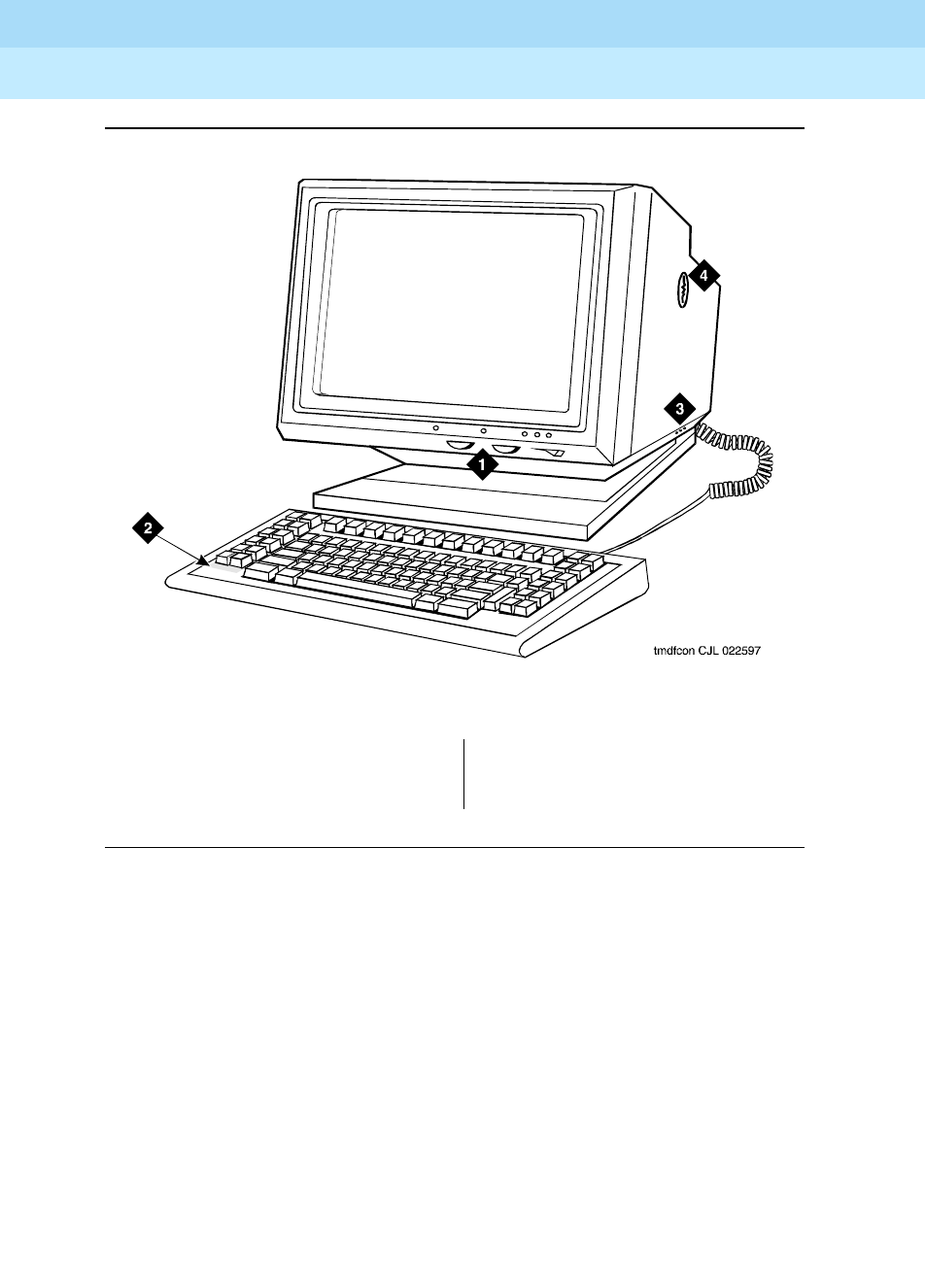
DEFINITY Enterprise Communications Server Release 6
Administration and Feature Description
555-230-522 Issue 4
May 1998
Voice Terminal, PC Interface, and Data Module Administration
Page 6-162Constellation voice/data terminals
6
Figure Notes
Figure 6-43. Constellation data terminal
1. Constellation data terminal
2. Keyboard
3. Monitor
4. Security keylock

DEFINITY Enterprise Communications Server Release 6
Administration and Feature Description
555-230-522 Issue 4
May 1998
Voice Terminal, PC Interface, and Data Module Administration
Page 6-163MDC9000 and MDW9000 cordless voice terminals
6
MDC9000 and MDW9000 cordless
voice terminals
Form instructions
To administer a MDC9000 or MDW9000 cordless voice terminal, complete the
standard as well as the following unique Station form fields.
Page 1 of the form
Screen 6-104. MDC9000 and MDW9000 Station form (Page 1 of X)
■Type — Enter MDC9000 or MDW9000, as appropriate.
Page 1 of X
STATION
Extension: 1003 Lock Messages? n BCC: 0
Type: MDC9000 Security Code: ________ TN: 1_
Port: _______ Coverage Path 1: ____ COR: 1_
Name: ________________________ Coverage Path 2: ____ COS: 1_
Hunt-to Station: _____
STATION OPTIONS
Personalized Ringing Pattern: 1_
Message Lamp Ext: 1000
MM Complex Data Ext: ____

DEFINITY Enterprise Communications Server Release 6
Administration and Feature Description
555-230-522 Issue 4
May 1998
Voice Terminal, PC Interface, and Data Module Administration
Page 6-164MDC9000 and MDW9000 cordless voice terminals
6
Page 2 of the form
Screen 6-105. MDC9000 and MDW9000 Station form (Page 2 of X)
Page 3 of the form
Screen 6-106. MDC9000 and MDW9000 Station form (Page 3 of X)
■BUTTON ASSIGNMENTS
The feature buttons that you can assign to the MDC9000 and MDW9000
cordless voice terminals are listed below. The first 3 button assignments
can only be assigned as call appearances.
Page 2 of X
STATION
FEATURE OPTIONS
LWC Reception? msa-spe Auto Select Any Idle Appearance? n
LWC Activation? y Coverage Msg Retrieval? y
CDR Privacy? n Auto Answer: none
Redirect Notification? y Data Restriction? n
Per Button Ring Control? n Idle Appearance Preference? n
Bridged Call Alerting? n
Active Station Ringing: single__ Restrict Last Appearance? y
H.320 Conversion? n
AUDIX Name: ______ Multimedia Early Answer? n
Messaging Server Name: ______ Audible Message Waiting? n
Select Last Used Appearance? n
Page 3 of X
STATION
SITE DATA
Room: _______ Headset? n
Jack: ___ Speaker? n
Cable: ___ Mounting: d
Floor: _______ Cord Length: 0_
Building: _______ Set Color: _____
ABBREVIATED DIALING
List1: ________ List2: _________ List3: _________
BUTTON ASSIGNMENTS
1: call-appr_ 4: call-appr
2: call-appr_ 5: __________
3: call-appr_ 6: drop

DEFINITY Enterprise Communications Server Release 6
Administration and Feature Description
555-230-522 Issue 4
May 1998
Voice Terminal, PC Interface, and Data Module Administration
Page 6-165MDC9000 and MDW9000 cordless voice terminals
6
abr-prog abr-spchar abrdg-appr abrv-dial
abrv-ring ac-alarm aca-halt after-call
alrt-agchg alt-frl assist asvn-halt
atd-qcalls atd-qtime aut-msg-wt auto-cback
auto-icom auto-in autodial aux-work
brdg-appr busy-ind call-appr call-fwd
call-park call-pkup cas-backup cdr1-alrm
cdr2-alrm cfwd-bsyda consult cov-cback
data-ext dial-icom dir-pkup dn-dst
ds1-alarm exclusion flash goto-cover
hunt-ns in-call-id int-aut-an last-numb
link-alarm lsvn-halt lwc-cancel lwc-store
major-alrm man-msg-wt manual-in mct-act
mct-contr mj/mn-alrm night-serv noans-alrt
per-COline pms-alarm pr-awu-alm pr-pms-alm
pr-sys-alm print-msgs priority q-calls
q-time release ringer-off rs-alert
rsvn-halt send-calls send-term serv-obsrv
signal ssvn-halt stroke-cnt term-x-gr
trk-ac-alm trunk-ns verify voa-repeat
work-code
Continued on next page
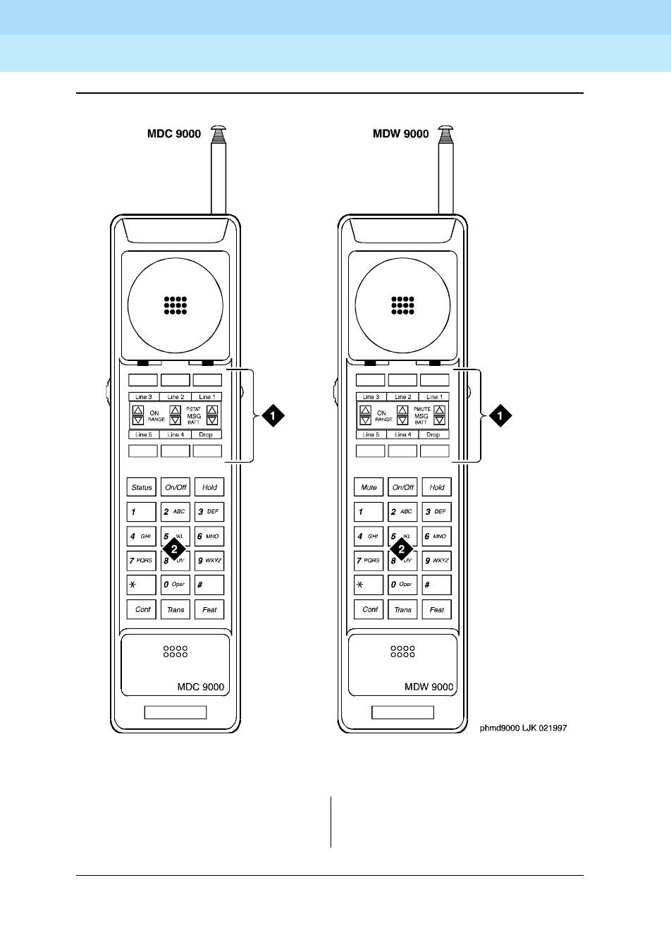
DEFINITY Enterprise Communications Server Release 6
Administration and Feature Description
555-230-522 Issue 4
May 1998
Voice Terminal, PC Interface, and Data Module Administration
Page 6-166MDC9000 and MDW9000 cordless voice terminals
6
Figure Notes
Figure 6-44. MDC9000 and MDW9000 cordless voice terminals
1. 6 programmable buttons
2. Dial pad
1. 6 programmable buttons
2. Dial pad
DEFINITY Enterprise Communications Server Release 6
Administration and Feature Description
555-230-522 Issue 4
May 1998
Voice Terminal, PC Interface, and Data Module Administration
Page 6-167MDC9000 and MDW9000 cordless voice terminals
6
Figure 6-45. MDC9000 and MDW9000 cordless voice terminals and their bases

DEFINITY Enterprise Communications Server Release 6
Administration and Feature Description
555-230-522 Issue 4
May 1998
Voice Terminal, PC Interface, and Data Module Administration
Page 6-168CP9530 cordless voice terminals
6
CP9530 cordless voice terminals
Form instructions
To administer a CP9530 cordless voice terminal, complete the standard as well
as the following unique Station form fields.
Page 1 of the form
Screen 6-107. CP9530 Station form (Page 1 of 3)
■Type — Enter CP9530 as appropriate.
■Tests — Enter y to enable port maintenance tests. Enter n when the voice
terminal is connected through a peripheral unit, such as a dictating
machine, that causes the tests to fail. Default is y.
Page 1 of 3
STATION
BCC: 0
Extension: ____ Lock Messages? n TN: 1
Type: CP9530 Security Code: ________ COR: 1
Port: _______________ Coverage Path 1: ___ COS: 1
Name: ___________________________ Coverage Path 2: ___ Tests? y
Hunt-to Station: ___
STATION OPTIONS
Off Premise Station? y Message Waiting Indicator: ___
R Balance Network? n

DEFINITY Enterprise Communications Server Release 6
Administration and Feature Description
555-230-522 Issue 4
May 1998
Voice Terminal, PC Interface, and Data Module Administration
Page 6-169CP9530 cordless voice terminals
6
Screen 6-108. CP9530 Station form (Page 2 of 3)
Screen 6-109. CP9530 Station form (Page 3 of 3)
Page 2 of 3
STATION
FEATURE OPTIONS
LWC Reception? msa-spe
LWC Activation? y Coverage Msg Retrieval? y
CDR Privacy? y Auto Answer: none
Redirect Notification? y Data Restriction? n
Per Button Ring Control? n Call Waiting Indication? y
Bridged Call Alerting? n Att. Call Waiting Indication? y
Switchhook Flash? y Distinctive Audible Alert? y
Ignore Rotary Digits? _ Adjunct Supervision? n
H.320 Conversion? n
AUDIX Name: _______ Multimedia Early Answer? n
Messaging Server Name: _______ Audible Message Waiting? n
Page 3 of 3
STATION
SITE DATA
Room: _______ Headset? n
Jack: ___ Speaker? n
Cable: ___ Mounting: d
Floor: _______ Cord Length: 0_
Building: _______ Set Color? ______
ABBREVIATED DIALING
List1: ________ List2: _________ List3: _________
HOT LINE DESTINATION
Abbreviated Dialing List Number (From above 1, 2 or 3): _
Dial Code: ____
Line Appearance: call-appr_
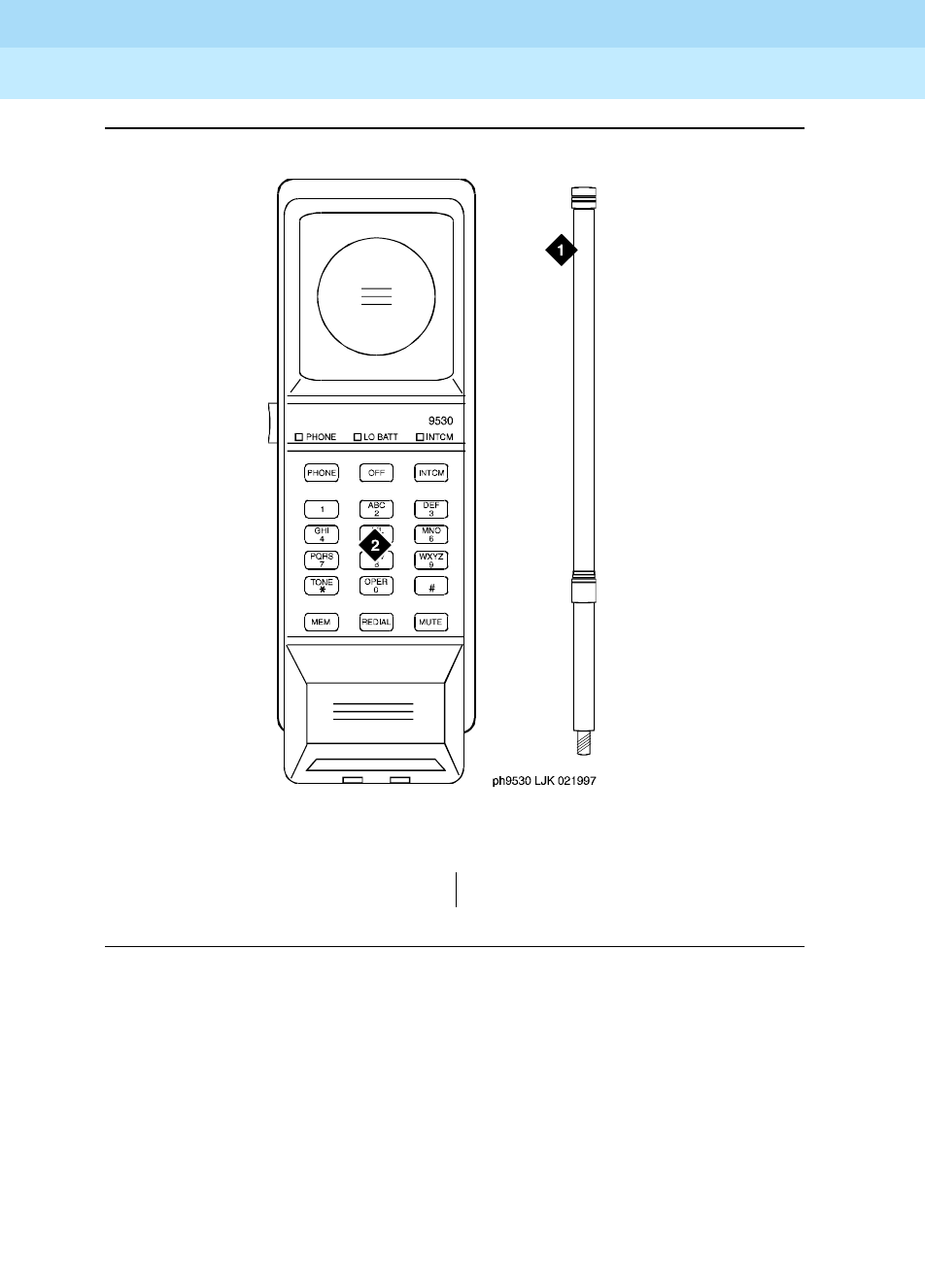
DEFINITY Enterprise Communications Server Release 6
Administration and Feature Description
555-230-522 Issue 4
May 1998
Voice Terminal, PC Interface, and Data Module Administration
Page 6-170CP9530 cordless voice terminals
6
Figure Notes
Figure 6-46. CP9530 cordless voice terminal
1. Antenna 2. Dial pad
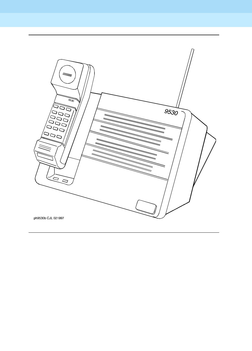
DEFINITY Enterprise Communications Server Release 6
Administration and Feature Description
555-230-522 Issue 4
May 1998
Voice Terminal, PC Interface, and Data Module Administration
Page 6-171CP9530 cordless voice terminals
6
Figure 6-47. CP9530 cordless voice terminal and base

DEFINITY Enterprise Communications Server Release 6
Administration and Feature Description
555-230-522 Issue 4
May 1998
Voice Terminal, PC Interface, and Data Module Administration
Page 6-1728403B, 8405B, 8405B+ and 8410B voice terminals
6
8403B, 8405B, 8405B+ and 8410B voice
terminals
Form instructions
To administer a 8403B, 8405B, 8405+, or 8410B voice terminal, complete the
standard as well as the following unique Station form fields. For information about
adjusting the system-level parameters and audio levels for the 8400-series voice
terminals, see ‘‘Terminal Parameters form’’ on page 6-9.
Page 1 of the form
Screen 6-110. 8403B, 8405B, 8405B+, and 8410B Station form (Page 1 of X)
■Type — Enter one of the following:
—8403B (supports 1-way speakerphone) — default
—8405B (supports 1-way speakerphone)
—8405B+ (supports 2-way speakerphone)
—8410B (supports 2-way speakerphone)
■Data Module — Enter y if this terminal is to connect to a data terminal via
a 7400B or 8400B data module. If you enter y, you must complete the Data
Module form. Default is n.
Page 1 of X
STATION
Extension: 1003 Lock Messages? n BCC: 0
Type: 8403B__ Security Code: ________ TN: 1_
Port: _______ Coverage Path 1: ____ COR: 1_
Name: ___________________________ Coverage Path 2: ____ COS: 1_
Hunt-to Station: _____
STATION OPTIONS
Data Module? n Personalized Ringing Pattern: 1
Speakerphone: 1-way Message Lamp Ext: 1000
Mute Button Enabled? y
MM Complex Data Ext: ____

DEFINITY Enterprise Communications Server Release 6
Administration and Feature Description
555-230-522 Issue 4
May 1998
Voice Terminal, PC Interface, and Data Module Administration
Page 6-1738403B, 8405B, 8405B+ and 8410B voice terminals
6
Page 2 of the form
Screen 6-111. 8403B, 8405B, 8405B+, and 8410B Station form (Page 2 of X)
Page 3 of the 8405 and 8410 form
Screen 6-112. 8403B Station form (Page 3 of X)
Page 2 of X
STATION
FEATURE OPTIONS
LWC Reception? msa-spe Auto Select Any Idle Appearance? n
LWC Activation? y Coverage Msg Retrieval? y
CDR Privacy? n Auto Answer: none
Redirect Notification? y Data Restriction? n
Per Button Ring Control? n Idle Appearance Preference? n
Bridged Call Alerting? n
Active Station Ringing: single Restrict Last Appearance? y
H.320 Conversion? n
AUDIX Name: ______ Multimedia Early Answer? n
Messaging Server Name: ______ Audible Message Waiting? y
Select Last Used Appearance? n
Page 3 of X
STATION
SITE DATA
Room: _______ Headset? n
Jack: _____ Speaker? n
Cable: _____ Mounting: d
Floor: _______ Cord Length: 0
Building: _______ Set Color: ______
ABBREVIATED DIALING
List1: ________ List2: ________ List3: ________
BUTTON ASSIGNMENTS
1: call-appr_
2: call-appr_
3: call-appr_

DEFINITY Enterprise Communications Server Release 6
Administration and Feature Description
555-230-522 Issue 4
May 1998
Voice Terminal, PC Interface, and Data Module Administration
Page 6-1748403B, 8405B, 8405B+ and 8410B voice terminals
6
Screen 6-113. 8405B, 8405B+, and 8410B Station form (Page 3 of X)
■BUTTON ASSIGNMENTS
The feature buttons that you can assign are listed below. The first 3
buttons on the 8403B and the first 3 buttons on the 8405B, 8505B+, and
8410B voice terminals default as call appearance buttons. The 8405B and
the 8405B+ voice terminals have only 5 call appearance buttons. You can
readminister call appearance buttons.
Page 3 of X
STATION
SITE DATA
Room: _______ Headset? n
Jack: _____ Speaker? n
Cable: _____ Mounting: d
Floor: _______ Cord Length: 0
Building: _______ Set Color: ______
ABBREVIATED DIALING
List1: ________ List2: ________ List3: ________
BUTTON ASSIGNMENTS
1: call-appr_ 6: __________
2: call-appr_ 7: __________
3: call-appr_ 8: __________
4: __________ 9: __________
5: __________ 10: __________

DEFINITY Enterprise Communications Server Release 6
Administration and Feature Description
555-230-522 Issue 4
May 1998
Voice Terminal, PC Interface, and Data Module Administration
Page 6-1758403B, 8405B, 8405B+ and 8410B voice terminals
6
,
Page 3 of the 8403B form
■FEATURE BUTTON ASSIGNMENTS
On the form for the 8403B voice terminal, these fields correspond to the 12
feature buttons accessed from the 8403B voice terminal by first pressing
the feature button and then pressing a number on the dial pad. You cannot
administer these buttons as a bridged appearance (brdg-appr or
abrdg-appr).
1. Not allowed for 8403B
abr-prog abr-spchar abrdg-appr1abrv-dial
abrv-ring ac-alarm aca-halt after-call
alrt-agchg alt-frl assist asvn-halt
atd-qcalls atd-qtime aut-msg-wt auto-cback
auto-icom auto-in autodial aux-work
brdg-appr1busy-ind call-appr call-fwd
call-park call-pkup cas-backup cdr1-alrm
cdr2-alrm cfwd-bsyda consult cov-cback
data-ext dial-icom dir-pkup dn-dst
ds1-alarm exclusion flash goto-cover
hunt-ns in-call-id int-aut-an last-numb
link-alarm lsvn-halt lwc-cancel lwc-store
major-alrm man-msg-wt manual-in mct-act
mct-contr mf-da-intl mf-op-intl mj/mn-alrm
night-serv noans-alrt per-COline pms-alarm
pr-awu-alm pr-pms-alm pr-sys-alm print-msgs
priority q-calls q-time release
ringer-off rs-alert rsvn-halt send-calls
send-term serv-obsrv signal ssvn-halt
stroke-cnt term-x-gr trk-ac-alm trunk-ns
verify voa-repeat work-code

DEFINITY Enterprise Communications Server Release 6
Administration and Feature Description
555-230-522 Issue 4
May 1998
Voice Terminal, PC Interface, and Data Module Administration
Page 6-1768403B, 8405B, 8405B+ and 8410B voice terminals
6
Page 4 of the form
Screen 6-114. 8403B Station form (Page 4 of X)
■FEATURE BUTTON ASSIGNMENTS
The features and functions that you can assign to the terminal’s
administrable buttons are the same as those for BUTTON ASSIGNMENTS
above.
Page 4 of X
STATION
FEATURE BUTTON ASSIGNMENTS
1: __________
2: __________
3: __________
4: __________
5: __________
6: __________
7. __________
8: __________
9: __________
*: __________
0: __________
#: __________

DEFINITY Enterprise Communications Server Release 6
Administration and Feature Description
555-230-522 Issue 4
May 1998
Voice Terminal, PC Interface, and Data Module Administration
Page 6-1778403B, 8405B, 8405B+ and 8410B voice terminals
6
Page X of Y of the form (DATA MODULE)
Screen 6-115. 8403B, 8405B, 8405B+, 8410B, and 8434B Data Module form (Page X of Y)
This page displays only if Data Module is y.
Page X of Y
STATION
DATA MODULE
Data Extension: _______________ Name: ____________________ BCC: 2
COS: 1_
COR: 1_
ITC: restricted__ TN: 1_
ABBREVIATED DIALING
List1: ________
SPECIAL DIALING OPTION: hot-line
HOT LINE DESTINATION
DEFAULT DIALING
Abbreviated Dialing Dial Code (From above list): ___
ASSIGNED MEMBER (Station with a data extension button for this data module)
Ext Name
1. _____ ___________________________
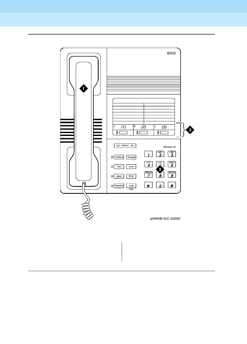
DEFINITY Enterprise Communications Server Release 6
Administration and Feature Description
555-230-522 Issue 4
May 1998
Voice Terminal, PC Interface, and Data Module Administration
Page 6-1788403B, 8405B, 8405B+ and 8410B voice terminals
6
Figure Notes
Figure 6-48. 8403B voice terminal
1. Handset
2. Dial pad
3. 3 programmable buttons
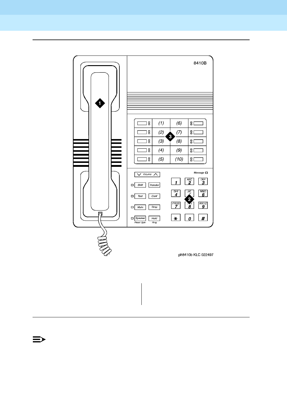
DEFINITY Enterprise Communications Server Release 6
Administration and Feature Description
555-230-522 Issue 4
May 1998
Voice Terminal, PC Interface, and Data Module Administration
Page 6-1798403B, 8405B, 8405B+ and 8410B voice terminals
6
Figure Notes
Figure 6-49. 8410B voice terminal
NOTE:
The 8405B and 8405B+ look like the 8410B with the exception that the
8405 series do not have the second column of line appearances.
1. Handset
2. Dial pad
3. 10 programmable buttons

DEFINITY Enterprise Communications Server Release 6
Administration and Feature Description
555-230-522 Issue 4
May 1998
Voice Terminal, PC Interface, and Data Module Administration
Page 6-1808405D, 8405D+, 8410D, and 8434D voice terminals
6
8405D, 8405D+, 8410D, and 8434D
voice terminals
Form instructions
To administer a 8405D, 8405+, 8410D, or 8434D voice terminal, complete the
standard as well as the following unique Station form fields. For information about
adjusting the system-level parameters and audio levels for the 8400-series voice
terminals, see ‘‘Terminal Parameters form’’ on page 6-9.
Page 1 of the form
Screen 6-116. 8405D, 8405D+, 8410D, and 8434D Station form (Page 1 of X)
■Type — Enter one of the following:
—8405D (supports 1-way speakerphone) — default
—8405D+ (supports 2-way speakerphone)
—8410D (supports 2-way speakerphone)
—8434D (supports 2-way speakerphone)
Page 1 of X
STATION
Extension: 1003 Lock Messages? n BCC: 0
Type: 8434D__ Security Code: ________ TN: 1_
Port: _______ Coverage Path 1: ____ COR: 1_
Name: ___________________________ Coverage Path 2: ____ COS: 1_
Hunt-to Station: _____
STATION OPTIONS
Data Module? n Personalized Ringing Pattern: 1
Speakerphone: 2-way Message Lamp Ext: 1000
Display Language: english Mute Button Enabled? y
Expansion Module? n
MM Complex Data Ext: n

DEFINITY Enterprise Communications Server Release 6
Administration and Feature Description
555-230-522 Issue 4
May 1998
Voice Terminal, PC Interface, and Data Module Administration
Page 6-1818405D, 8405D+, 8410D, and 8434D voice terminals
6
Page 2 of the form
Screen 6-117. 8405D, 8405D+, 8410D, and 8434D Station form (Page 2 of X)
■Data Module — Enter y if this terminal is connected to an optional 7400B
or 8400B data module. If you enter y, you must complete the Data Module
form. Default is n.
■Expansion Module — (8434D only) Identifies whether a ZE801A
expansion module is attached to the station terminal. Enter y or n
(default). If you enter y, an optional page of the form appears to allow you
to administer the Expansion Module buttons.
Page 2 of X
STATION
FEATURE OPTIONS
LWC Reception? msa-spe Auto Select Any Idle Appearance? n
LWC Activation? y Coverage Msg Retrieval? y
CDR Privacy? n Auto Answer: none
Redirect Notification? y Data Restriction? n
Per Button Ring Control? n Idle Appearance Preference? n
Bridged Call Alerting? n
Active Station Ringing: single Restrict Last Appearance? y
H.320 Conversion? n
AUDIX Name: ______ Multimedia Early Answer? n
Messaging Server Name: ______ Audible Message Waiting? y
Display Client Redirection? n
Select Last Used Appearance? n

DEFINITY Enterprise Communications Server Release 6
Administration and Feature Description
555-230-522 Issue 4
May 1998
Voice Terminal, PC Interface, and Data Module Administration
Page 6-1828405D, 8405D+, 8410D, and 8434D voice terminals
6
Page 3 of the form
Screen 6-118. 8405D, 8405D+, 8410D, and 8434D Station form (Page 3 of X)
■BUTTON ASSIGNMENTS
The feature buttons that you can assign to the these voice terminals are
listed below.
Table 6-7. Button Assignments for Page 3 of the Form
abr-prog abr-spchar abrdg-appr abrv-dial
abrv-ring ac-alarm aca-halt after-call
alrt-agchg alt-frl assist asvn-halt
atd-qcalls1atd-qtime1aut-msg-wt auto-cback
auto-icom auto-in auto-wkup1autodial
aux-work brdg-appr busy-ind call-appr
call-disp1call-fwd call-park call-pkup
callr-info1cas-backup cdr1-alrm cdr2-alrm
cfwd-bsyda check-in1check-out1clk-overid1
consult cov-cback cov-msg-rt1data-ext
Continued on next page
Page 3 of X
STATION
SITE DATA
Room: _______ Headset? n
Jack: _____ Speaker? n
Cable: _____ Mounting: d
Floor: _______ Cord Length: 0
Building: _______ Set Color: ______
ABBREVIATED DIALING
List1: ________ List2: ________ List3: ________
BUTTON ASSIGNMENTS
1: call-appr_ 6: __________
2: call-appr_ 7: __________
3: call-appr_ 8: __________
4: __________ 9: __________
5: __________ 10: __________

DEFINITY Enterprise Communications Server Release 6
Administration and Feature Description
555-230-522 Issue 4
May 1998
Voice Terminal, PC Interface, and Data Module Administration
Page 6-1838405D, 8405D+, 8410D, and 8434D voice terminals
6
1. Display-type button
2. All of these voice terminals have an Exit button. This button is mapped to the normal
button function. Therefore, you are not allowed to specify a normal feature button on
any of the button fields on these forms.
date-time1delete-msg1dial-icom directory1
dir-pkup disp-chrg disp-norm dn-dst
ds1-alarm exclusion ext-dn-dst1flash
goto-cover grp-dn-dst1hunt-ns in-call-id
inspect1int-aut-an last-numb link-alarm
lsvn-halt lwc-cancel lwc-lock lwc-store
major-alrm man-msg-wt man-overid1manual-in
mct-act mct-contr mf-da-intl mf-op-intl
mj/mn-alrm msg-retr1mwn-act1mwn-deact1
next1night-serv noans-alrt normal2
per-COline pms-alarm pr-awu-alm pr-pms-alm
pr-sys-alm print-msgs priority q-calls
q-time release ringer-off rs-alert
rsvn-halt scroll send-calls send-term
serv-obsrv signal ssvn-halt stored-num1
stroke-cnt term-x-gr timer1trk-ac-alm
trk-id trunk-name1trunk-ns verify
voa-repeat vu-display work-code
Table 6-7. Button Assignments for Page 3 of the Form — Continued
Continued on next page

DEFINITY Enterprise Communications Server Release 6
Administration and Feature Description
555-230-522 Issue 4
May 1998
Voice Terminal, PC Interface, and Data Module Administration
Page 6-1848405D, 8405D+, 8410D, and 8434D voice terminals
6
Page 4 of the 8434D form
Screen 6-119. 8434D Station form (Page 4 of X)
■FEATURE BUTTON ASSIGNMENTS
The 24 feature buttons correspond to the fixed, dual-LED buttons on the
right side of the 8434D voice terminal. The features that you can assign to
buttons are the same as those listed for BUTTON ASSIGNMENTS above.
Page 4 of X
STATION
FEATURE BUTTON ASSIGNMENTS
1: __________ 13: __________
2: __________ 14: __________
3: __________ 15: __________
4: __________ 16: __________
5: __________ 17: __________
6: __________ 18: __________
7: __________ 19: __________
8: __________ 20: __________
9: __________ 21: __________
10: __________ 22: __________
11: __________ 23: __________
12: __________ 24: __________

DEFINITY Enterprise Communications Server Release 6
Administration and Feature Description
555-230-522 Issue 4
May 1998
Voice Terminal, PC Interface, and Data Module Administration
Page 6-1858405D, 8405D+, 8410D, and 8434D voice terminals
6
Page 4 of the 8405D, 8405D+, and 8410D forms
Page 5 of the 8434 form
Screen 6-120. 8405D, 8405D+, and 8410D Station form (Page 4 of X)
Screen 6-121. 8434D Station form (Page 5 of X)
Page 4 of X
STATION
SOFTKEY BUTTON ASSIGNMENTS
1: lwc-store_
2: lwc-cancel
3: auto-cback
4: timer_____
5: call-fwd__ Ext: ___
6: call-park_
7: date-time_
8: priority__
9: abr-prog__
10: abr-spchar Char: ~p
11: abr-spchar Char: ~m
12: abr-spchar Char: ~w
Page 5 of X
STATION
SOFTKEY BUTTON ASSIGNMENTS
1: lwc-store_
2: lwc-cancel
3: consult___
4: auto-cback
5: timer_____
6: call-fwd__ Ext: ___
7: call-park_
8: exclusion_
9: date-time_
10: priority__
11: abr-prog__
12: abr-spchar Char: ~p
13: abr-spchar Char: ~s
14: abr-spchar Char: ~m
15: abr-spchar Char: ~w

DEFINITY Enterprise Communications Server Release 6
Administration and Feature Description
555-230-522 Issue 4
May 1998
Voice Terminal, PC Interface, and Data Module Administration
Page 6-1868405D, 8405D+, 8410D, and 8434D voice terminals
6
■SOFTKEY BUTTON ASSIGNMENTS
The 8405D, 8405D+, and 8410D voice terminals support 12 display
softkeys and the 8434D voice terminal supports 15 softkeys. You can
assign features to these softkeys, making them “virtual” buttons. When you
assign a feature to a softkey, the system automatically downloads to the
terminal the appropriate information for operating the feature.
You may also customize the softkey displays, for English, French, Italian,
or Spanish. To customize the labels, use the Language Translation form by
issuing the command “change display-messages softkey-labels”. You
may enter a five-character label for each of the softkeys.
Pages 6 or 7 of the 8434D form (EXPANSION MODULE) appear only if
Expansion Module is set to y. Use these pages to administer buttons on
the ZE801A Expansion Module if one is attached to the 8434D terminal.
Fields 1–9 on the form correspond to the 18 dual-LED feature buttons on
the Expansion Module; buttons 10–12 correspond to the 6 single-LED
feature buttons. You can assign to these buttons any of the features or
functions that you can assign to the feature buttons on the 8434D terminal
from the previous list.
Page X of Y of the form (DATA MODULE)
Screen 6-122. 8405D, 8505D+, 8410D, and 8434D Data Module form (Page X of Y)
This page displays only if Data Module is y.
Page X of Y
STATION
DATA MODULE
Data Extension: _______________ Name: ____________________ BCC: 2
COS: 1_
COR: 1_
ITC: restricted TN: 1_
ABBREVIATED DIALING
List1: ________
SPECIAL DIALING OPTION: hot-line
HOT LINE DESTINATION
DEFAULT DIALING
Abbreviated Dialing Dial Code (From above list): ___
ASSIGNED MEMBER (Station with a data extension button for this data module)
Ext Name
1. _____ ___________________________
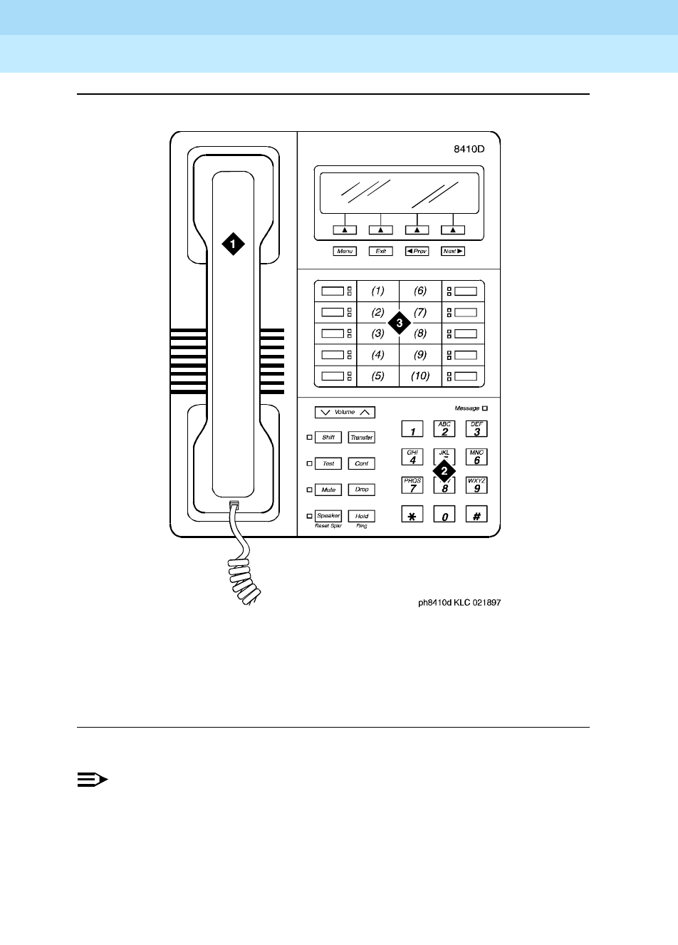
DEFINITY Enterprise Communications Server Release 6
Administration and Feature Description
555-230-522 Issue 4
May 1998
Voice Terminal, PC Interface, and Data Module Administration
Page 6-1878405D, 8405D+, 8410D, and 8434D voice terminals
6
Figure 6-50. 8410D voice terminal
NOTE:
The 8405D and 8405D+ look like the 8410D with the exception that the
8405 series do not have the second column of line appearances.
Figure 6-49 Notes
1. Handset
2. Dial pad
3. 10 programmable buttons
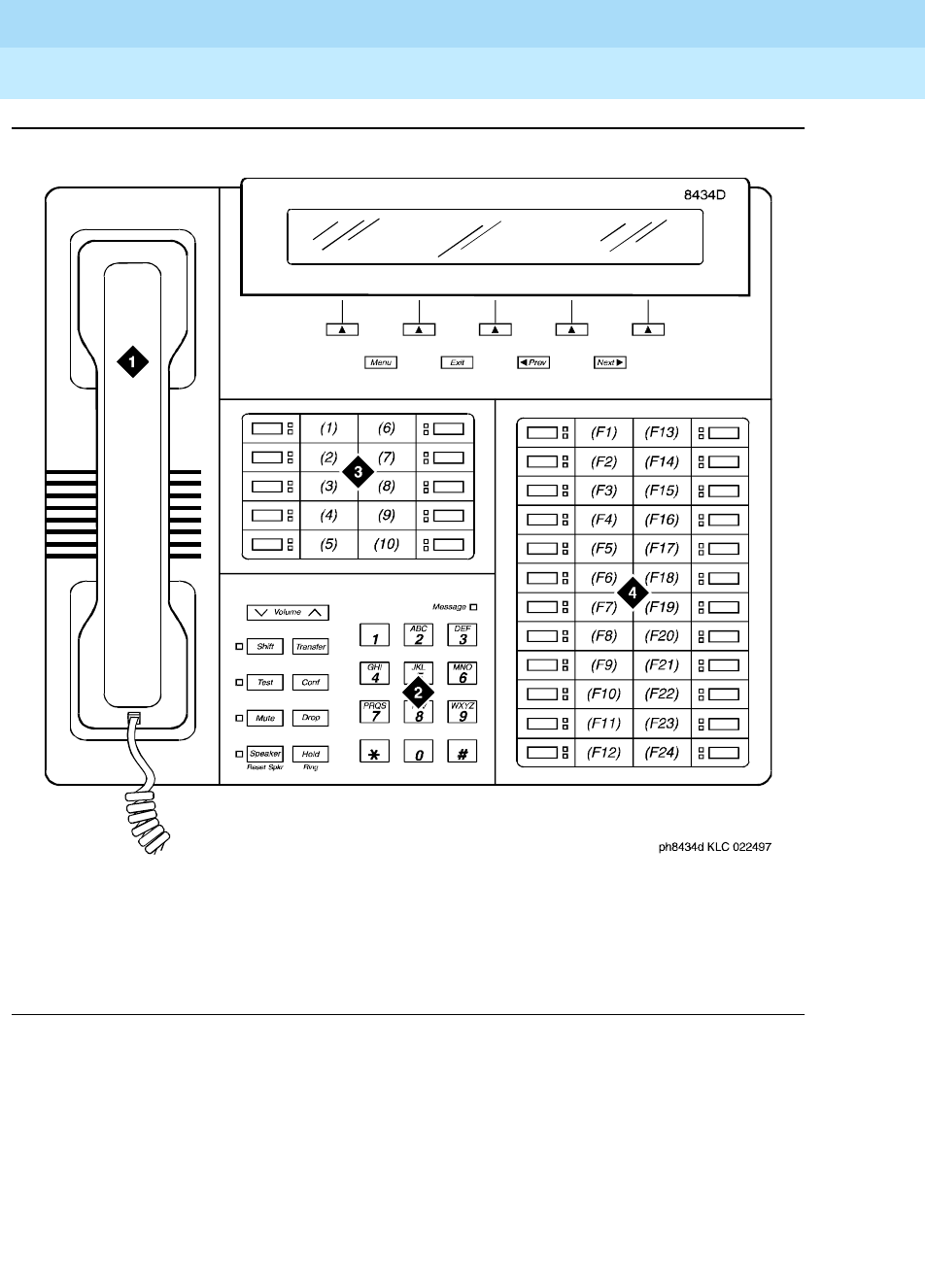
DEFINITY Enterprise Communications Server Release 6
Administration and Feature Description
555-230-522 Issue 4
May 1998
Voice Terminal, PC Interface, and Data Module Administration
Page 6-1888405D, 8405D+, 8410D, and 8434D voice terminals
6
Figure 6-51. 8434D voice terminal
Figure 6-50 Notes
1. Handset
2. Dial pad
3. 10 programmable buttons
4. 24 feature buttons

DEFINITY Enterprise Communications Server Release 6
Administration and Feature Description
555-230-522 Issue 4
May 1998
Voice Terminal, PC Interface, and Data Module Administration
Page 6-1898411B and 8411D voice terminals
6
8411B and 8411D voice terminals
Form instructions
To administer a 8411B or8411D voice terminal, complete the standard as well as
the following unique Station form fields. For information about adjusting the
system-level parameters and audio levels for the 8411-series voice terminals,
see ‘‘Terminal Parameters form’’ on page 6-9.
Page 1 of the form
Screen 6-123. 8411B and 8411D Station form (Page 1 of X)
■Type — Enter 8411B or 8411D as appropriate.
■Data Option — If you are using the administered analog adjunct, enter
analog and complete the Analog Adjunct form. If you are using a 7400B or
8400B data module, enter data-module and complete the Data Module
form.
When an endpoint changes its terminal from a non-8411 terminal to a
8411B/D terminal, the options in the station forms remain the same except
for the Data Option, Data Module and PassageWay.
■PassageWay — Enter y if you are using PassageWay.
!CAUTION:
Do not enable PassageWay unless the user of the PC at this
extension has a valid licensed copy of PassageWay Direct
Connection to DEFINITY ECS running on the PC.
Page 1 of X
STATION
Extension: 1003 Lock Messages? n BCC: 0
Type: 8411D__ Security Code: ________ TN: 1_
Port: _______ Coverage Path 1: ____ COR: 1_
Name: ___________________________ Coverage Path 2: ____ COS: 1_
Hunt-to Station: _____
STATION OPTIONS
Data Option: analog Personalized Ringing Pattern: 1
Speakerphone: 2-way Message Lamp Ext: 1000
Display Language: english Mute Button Enabled? y
PassageWay? n
MM Complex Data Ext: ____

DEFINITY Enterprise Communications Server Release 6
Administration and Feature Description
555-230-522 Issue 4
May 1998
Voice Terminal, PC Interface, and Data Module Administration
Page 6-1908411B and 8411D voice terminals
6
Page 2 of the form
Screen 6-124. 8411B and 8411D Station form (Page 2 of X)
Page 3 of the form
Screen 6-125. 8411B and 8411D Station form (Page 3 of X)
■BUTTON ASSIGNMENTS
The feature buttons that you can assign to the these voice terminals are
listed below.
Page 2 of X
STATION
FEATURE OPTIONS
LWC Reception? msa-spe Auto Select Any Idle Appearance? n
LWC Activation? y Coverage Msg Retrieval? y
CDR Privacy? n Auto Answer: none
Redirect Notification? y Data Restriction? n
Per Button Ring Control? n Idle Appearance Preference? n
Bridged Call Alerting? n
Active Station Ringing: single Restrict Last Appearance? y
H.320 Conversion? n
AUDIX Name: ______ Multimedia Early Answer? n
Messaging Server Name: ______ Audible Message Waiting? n
Display Client Redirection? n
Select Last Used Appearance? n
Page 3 of X
STATION
SITE DATA
Room: _______ Headset? n
Jack: _____ Speaker? n
Cable: _____ Mounting: d
Floor: _______ Cord Length: 0_
Building: _______ Set Color: ______
ABBREVIATED DIALING
List1: ________ List2: _________ List3: _________
BUTTON ASSIGNMENTS
1: call-appr_ 6: _________
2: call-appr_ 7: _________
3: call-appr_ 8: _________
4: __________ 9: _________
5: __________ 10: _________

DEFINITY Enterprise Communications Server Release 6
Administration and Feature Description
555-230-522 Issue 4
May 1998
Voice Terminal, PC Interface, and Data Module Administration
Page 6-1918411B and 8411D voice terminals
6
1. Display-type button, not available on 8411B.
abr-prog abr-spchar abrdg-appr abrv-dial
abrv-ring ac-alarm aca-halt after-call
alrt-agchg alt-frl assist asvn-halt
atd-qcalls1atd-qtime1aut-msg-wt auto-cback
auto-icom auto-in auto-wkup1autodial
aux-work brdg-appr busy-ind call-appr
call-disp1call-fwd call-park call-pkup
callr-info1cas-backup cdr1-alrm cdr2-alrm
cfwd-bsyda check-in1check-out1clk-overid1
consult cov-cback cov-msg-rt1data-ext
date-time1delete-msg1dial-icom directory1
dir-pkup disp-chrg disp-norm dn-dst
ds1-alarm exclusion ext-dn-dst1flash
goto-cover grp-dn-dst1hunt-ns in-call-id
inspect1int-aut-an last-numb link-alarm
lsvn-halt lwc-cancel lwc-lock lwc-store
major-alrm man-msg-wt man-overid1manual-in
mct-act mct-contr mf-da-intl mf-op-intl
mj/mn-alrm msg-retr1mwn-act1mwn-deact1
next1night-serv noans-alrt normal
per-COline pms-alarm pr-awu-alm pr-pms-alm
pr-sys-alm print-msgs priority q-calls
q-time release ringer-off rs-alert
rsvn-halt scroll send-calls send-term
serv-obsrv signal ssvn-halt stored-num1
stroke-cnt term-x-gr timer1trk-ac-alm
trk-id trunk-name1trunk-ns verify
voa-repeat vu-display work-code
DEFINITY Enterprise Communications Server Release 6
Administration and Feature Description
555-230-522 Issue 4
May 1998
Voice Terminal, PC Interface, and Data Module Administration
Page 6-1928411B and 8411D voice terminals
6
Page 4 of the 8411B and 8411D forms
Screen 6-126. 8411D Station form (Page 4 of X)
■SOFTKEY BUTTON ASSIGNMENTS
The 8411B and 8411D voice terminals support 12 display softkeys. You
can assign features to these softkeys, making them “virtual” buttons.
When you assign a feature to a softkey, the system automatically
downloads to the terminal the appropriate information for operating the
feature.
NOTE:
On the 8411, do not administer buttons 9 and 10 if you set Data
Option to analog and set PassageWay to yes.
Page 4 of X
STATION
SOFTKEY BUTTON ASSIGNMENTS
1. lwc-store_
2. lwc-cancel
3. auto-cback
4. timer_____
5. call-fwd__ ext: ______
6. call-park_
7. date-time_
8. priority__
9. abr-prog__
10. apr-spchar Char: ~p
11. abr-spchar Char: ~m
12. abr-spchar Char: ~w

DEFINITY Enterprise Communications Server Release 6
Administration and Feature Description
555-230-522 Issue 4
May 1998
Voice Terminal, PC Interface, and Data Module Administration
Page 6-1938411B and 8411D voice terminals
6
Page X of Y of the form (DATA MODULE)
Screen 6-127. 8411B and 8411D Data Module form (Page Y of X)
This page displays only if Data Option is data-module.
Page X of Y of the form (ANALOG ADJUNCT)
Screen 6-128. 8411B and 8411D Analog Adjunct form (Page Y of X)
This page displays only if Data Option is analog. You cannot assign default
dialing options with the administered analog adjunct.
Page Y of X
STATION
DATA MODULE
Data Extension: _______________ Name: ______________________ BCC: 2
COS: 1_
COR: 1_
ITC: restricted_ TN: 1_
ABBREVIATED DIALING
List1: ________
SPECIAL DIALING OPTION: hot-line
HOT LINE DESTINATION
Abbreviated Dialing Dial Code (From above list): ___
ASSIGNED MEMBER (Station with a data extension button for this data module)
Ext Name
1.
Page Y of X
STATION
ANALOG ADJUNCT
Data Extension: _____ Name: ___________________________
COS: 1_
COR: 1_
ITC: restricted_ TN: 1_
ABBREVIATED DIALING
List1: ________
SPECIAL DIALING OPTION: ______
HOT LINE DESTINATION
Abbreviated Dialing Dial Code (From above list): ___
ASSIGNED MEMBER (Station with a data extension button for this analog adjunct)
Ext Name
1.

DEFINITY Enterprise Communications Server Release 6
Administration and Feature Description
555-230-522 Issue 4
May 1998
Voice Terminal, PC Interface, and Data Module Administration
Page 6-194World Class Basic Rate Interface terminal
6
World Class Basic Rate Interface
terminal
World Class Basic Rate Interface (WCBRI) terminal provides an international BRI
platform that offers multiple protocol options to meet specific country and
application requirements.
WCBRI supports the following country protocols:
■Bellcore National ISDN-1 protocol in the United States (TR268)
■Australia (AUSTEL TS013 and Telecom Australia TPH 1962)
■Japan (NTT BRI)
■Singapore (FETEX 150 TIF 218)
■ETSI NET 3 protocol (ETS 300 102) for use in most of Europe
WCBRI supports multipoint (up to 2 devices per port) for Bellcore National
ISDN-1 Country Protocol.
DEFINITY ECS does not support the following for WCBRI terminals:
■Transfer, hold, drop, or conference
■Administrable feature buttons
■Multiple call appearances and features requiring multiple call
appearances
DEFINITY ECS does not control the display information or ring type at a WCBRI
terminal.
When DEFINITY ECS delivers a call to a WCBRI station the called number IE in
the SETUP message contains the dialed principal’s extension. The extension can
be different from the WCBRI station extension if the call is a hunt group call, TEG
call, a redirected call from coverage, or a call routed by call vectoring.
WCBRI should not be designated as coverage points for many different
principals.
Form instructions
To administer a World Class BRI terminal, complete the standard as well as the
following unique Station form fields.
Some WCBRI endpoints must be programmed with their assigned extension
before they will accept an incoming call. Furthermore, many WCBRI endpoints
can be programmed with multiple directory numbers, one of which must be their
assigned extension. In this case, the WCBRI endpoint will accept calls delivered

DEFINITY Enterprise Communications Server Release 6
Administration and Feature Description
555-230-522 Issue 4
May 1998
Voice Terminal, PC Interface, and Data Module Administration
Page 6-195World Class Basic Rate Interface terminal
6
to the endpoint with any of the programmed numbers. See also ‘‘Multiple
Subscriber Number (MSN) - Limited’’ on page 6-214.
Page 1 of the form
Screen 6-129. World Class BRI terminal Station form (Page 1 of X)
■Type — Enter wcbri.
Page 1 of X
STATION
Extension: 8003_ BCC: 2
Type: WCBRI TN: 1
Port: _______________ Coverage Path 1: ____ COR: 1
Name: _______________________ Coverage Path 2: ____ COS: 1
Hunt-to Station: ____
Data Restriction? n
STATION OPTIONS
Data Module? n
BRI OPTIONS
XID? n Fixed TEI? y TEI: __ 1-Step Clearing? y
Country Protocol: 1___ Endpt Init? y SPID: ________ Endpt ID: __

DEFINITY Enterprise Communications Server Release 6
Administration and Feature Description
555-230-522 Issue 4
May 1998
Voice Terminal, PC Interface, and Data Module Administration
Page 6-196World Class Basic Rate Interface terminal
6
Page X of Y of the form (DATA MODULE)
Screen 6-130. World Class BRI Station form — Data Module (Page X of Y)
This page displays only if Data Module is y.
Screen 6-131. World Class BRI Terminal Station form (Page 3 of X)
Interactions
The unique capabilities of WCBRI terminals impact the way many DEFINITY ECS
features work, as shown in the following table.
Page X of X
STATION
DATA MODULE
Data Extension: Name: ______________
Type: wcbri_________ COS: 1_ Multimedia? y
Port: _______________ COR: 1_ MM Complex Voice Ext: xxxxx
TN: 1__
ABBREVIATED DIALING
List1:
SPECIAL DIALING OPTION:
CIRCUIT SWITCHED DATA ATTRIBUTES
Default Duplex: full Default Mode: async Default Speed: 1200
DATA MODULE CAPABILITIES
Default ITC: restricted Default Data Application: M2_A
Page 3 of X
STATION
SITE DATA
Room: _______ Headset? n
Jack: ___ Speaker? n
Cable: ___ Mounting: d
Floor: _______ Cord Length: 0_
Building: _______ Set Color: ______
ABBREVIATED DIALING
List1: ________ List2: _________ List3: _________
Line Appearance: call-appr

DEFINITY Enterprise Communications Server Release 6
Administration and Feature Description
555-230-522 Issue 4
May 1998
Voice Terminal, PC Interface, and Data Module Administration
Page 6-197World Class Basic Rate Interface terminal
6
Table 6-8. World Class BRI feature interactions
Feature
Support
without
limits
Support
with
limits
No
support
Comments
below
A-law/mu-law companding selection x x
Abbreviated/delayed ringing x x
Abbreviated Dialing x x
ACCUNET x
Adjunct controlled splits x x
Adjunct routing x x
Administered repetitive call waiting tone
interval x
Administrable conference/intrusion tones x x
Administrable country options x
Administrable wait answer supervision
timer xx
Administration without Hardware x x
Agent after hour call work button x x
Agent AUX work/make busy button x
Agent-forced entry of CWC/strokes
counts x
Agent hold with multiple call handling x
Agent hold without multiple call handling x
Agent-home (using CONVERSANT VIS) x x
Agent login/out x x
Agent position x x
Agent work states (unstaffed, AUX, WK,
AVAIL, On-ACD, ACW) x
Agent work modes x x
Agent with multiple splits x x
Alternate Facilities Restriction Levels x
Alerting options x
ASAI x x
Continued on next page

DEFINITY Enterprise Communications Server Release 6
Administration and Feature Description
555-230-522 Issue 4
May 1998
Voice Terminal, PC Interface, and Data Module Administration
Page 6-198World Class Basic Rate Interface terminal
6
Assist x x
Attendant Calling of Inward Restricted
Stations x
Attendant call coverage point x x
AUDIX x x
AUDIX-embedded x
AUDIX-leave message for callback
without caller choice x
AUDIX-leave message for callback with
caller choice (via prompting) x
AUDIX - TN2181 emulation native support x x
AUDIX - transfer (switch and/or DCIU) -
transfer into AUDIX x
AUDIX - transfer (switch and/or DCIU) -
transfer out of AUDIX x
Automatic answering with zip tone x x
Automatic Call Distribution x x
Automatic Callback on busy x
Automatic Callback on don’t answer x
Automatic Circuit Assurance (includes
referrals) xx
Automatic Incoming Call Display x
Authorization Code x
Barrier Codes for Remote Access x
Bridged Call Appearance x x
Busy Verification of Terminals and Trunks x
Call Coverage-answer group x
Call Coverage-attendant as coverage
point xx
Call Coverage-callback x
Table 6-8. World Class BRI feature interactions — Continued
Feature
Support
without
limits
Support
with
limits
No
support
Comments
below
Continued on next page

DEFINITY Enterprise Communications Server Release 6
Administration and Feature Description
555-230-522 Issue 4
May 1998
Voice Terminal, PC Interface, and Data Module Administration
Page 6-199World Class Basic Rate Interface terminal
6
Call Coverage-caller response interval x x
Call Coverage-consult x x
Call Coverage-cover active redirection x
Call Coverage-cover for PCOL calls x x
Call Coverage-covering point don’t
answer timing x
Call Coverage-go to cover x
Call Coverage-hunt group as coverage
point x
Call Coverage-incoming call identification x
Call Coverage-multiple coverage paths x
Call Coverage paths x
Call Coverage-point don’t answer timing x
Call Coverage-redirect notification signal x
Call Coverage-send all calls x x
Call Coverage-temporary bridged
appearance x
Call Coverage tone x
Call Coverage-VDN in a coverage point x
Call Forwarding-All Calls x x
Call Forwarding-Busy and Don’t Answer x x
Call Forwarding-Busy Don’t Answer with
override x
Call Forwarding off-net x
Call hold x
Call master ACD agent terminal x
Call Park x x
Call Pickup x x
Call response interval x x
Table 6-8. World Class BRI feature interactions — Continued
Feature
Support
without
limits
Support
with
limits
No
support
Comments
below
Continued on next page

DEFINITY Enterprise Communications Server Release 6
Administration and Feature Description
555-230-522 Issue 4
May 1998
Voice Terminal, PC Interface, and Data Module Administration
Page 6-200World Class Basic Rate Interface terminal
6
Call Vectoring x
Call Vectoring-ANI/II digits routing x
Call Vectoring-call prompting/DIVA x
Call Vectoring-route to number
with/without coverage x
Call Vectoring-VDN in coverage path x
Call Vectoring-VDN of origin
announcements x
Call Vectoring-VDN of origin display x
Call Vectoring-VDN return destination x x
Call Vectoring-without call choice x
Call Vectoring-with caller choice (via
prompting) x
Call Waiting Termination x
Call work codes x
Calling number display x x
Calling number display (SID/ANI/Extn ID) x x
CDR account codes x
CDR for inter-switch calls x
CDR Privacy x
CDR-periodic pulse metering x x
CDR-splitting of records x
Code Call Access/chime paging x
Common second delay announcement for
all splits x
Conference-terminal x
Controlled Restriction x
COR x
Table 6-8. World Class BRI feature interactions — Continued
Feature
Support
without
limits
Support
with
limits
No
support
Comments
below
Continued on next page

DEFINITY Enterprise Communications Server Release 6
Administration and Feature Description
555-230-522 Issue 4
May 1998
Voice Terminal, PC Interface, and Data Module Administration
Page 6-201World Class Basic Rate Interface terminal
6
COR-Three way checking for
conferences, transfers & call redirections x
COS x
Consult x x
Cut-through operation x
Data Call Setup x x
Data Call Setup dialing-alphanumeric x x
Data Call Setup dialing-default x x
Data Call Setup dialing-hot line x
Data Call Setup dialing-single line x
Data Call Setup dialing-multiple line x
Data Privacy x
Data Restriction x
DCS Alphanumeric Display for Terminals x
Display-voice terminal x
DCS Automatic Circuit Assurance x x
DCS Automatic Callback x x
DCS Busy Verification of Terminals and
Trunks x
DCS Call Coverage off premises x
DCS Call Forwarding All Calls x
DCS Call Waiting & priority calling x
DCS Distinctive Ringing x x
DCS-Enhanced x
DCS Leave Word Calling x x
DCS Multiappearance
Conference/Transfer x
DID x
Table 6-8. World Class BRI feature interactions — Continued
Feature
Support
without
limits
Support
with
limits
No
support
Comments
below
Continued on next page

DEFINITY Enterprise Communications Server Release 6
Administration and Feature Description
555-230-522 Issue 4
May 1998
Voice Terminal, PC Interface, and Data Module Administration
Page 6-202World Class Basic Rate Interface terminal
6
DID busy back x
DID recall x
Dial Access to Attendant x
Dialed Number Identification Service x x
DIOD Trunks x
Direct Agent Calling - via adjunct x x
Direct Department Calling Distribution x x
Direct Department Calling (DDC) x
Direct Inward Dialing x
Direct Outward Dialing x
Display-agent terminal x
Display-called number x
Display-calling number x
Display-city of origin x
Display-connected party x
Display message translation x
Display-queue of origin x
Display-queue status x
Display-VuStats x
Distinctive Alerting (ringing) x x
Distinctive Alerting-administrable x
DNIS display x x
Drop (button operation) x x
DS1-CO/FX/WATS Trunk Service x
DS1 robbed bit AVD tie trunk x
DS1 tie trunk service x
DS1 OPS lines x
Table 6-8. World Class BRI feature interactions — Continued
Feature
Support
without
limits
Support
with
limits
No
support
Comments
below
Continued on next page

DEFINITY Enterprise Communications Server Release 6
Administration and Feature Description
555-230-522 Issue 4
May 1998
Voice Terminal, PC Interface, and Data Module Administration
Page 6-203World Class Basic Rate Interface terminal
6
DS1 - 32-channel interface x
EAS-agents in multiple skills x
EAS-direct agent calling via logical agent
ID x
EAS-expert agent distribution x
EAS-logical agent login x
EAS-VDN skills x
Electronic Tandem Network x
Enhanced terminal administration x
Extended Trunk Access x
Extension steering x
Facility Busy Indication x
Facility Restriction Level and Traveling
Class Marks x
Facility Test Calls x
Flexible Dial Plan x
Forced entry of account codes x
Foreign Exchange (FX) Access x
Hold-single line multiappearance x
Hold-Automatic x
Hospitality-Automatic Wakeup x x
Hospitality-check in/check out
Hospitality-Do Not Disturb x x
Hospitality-Emergency Access to the
Attendant x
Hospitality-housekeeping status x
Hospitality-message waiting notification x x
Hospitality-Single-Digit Dialing and
Mixed Numbering x
Table 6-8. World Class BRI feature interactions — Continued
Feature
Support
without
limits
Support
with
limits
No
support
Comments
below
Continued on next page

DEFINITY Enterprise Communications Server Release 6
Administration and Feature Description
555-230-522 Issue 4
May 1998
Voice Terminal, PC Interface, and Data Module Administration
Page 6-204World Class Basic Rate Interface terminal
6
Host computer access (via DCP/EIA
ports) x
Hot Line Service x
Hunting/Hunt Groups (DDCS & UCD
Only) X
Hunting-Trunk Group x
Inbound Call Management (ICM) with
host via ASAI
Incoming ANI on R2-MFC x
Intercept Treatment x
Intercom Automatic x
Intercom Dial x
Inter PBX Attendant Calls x
International trunks x
Integrated Directory x
ISDN-bearer capability class x
ISDN-codeset conversion x
ISDN-connected party display x
ISDN-QSIG call diversion x x
ISDN-QSIG call transfer x
ISDN-QSIG name and number x
Last Number Dialed x
Leave Word Calling (switch) x
Line Lockout with warning x
Line/feature status indication x
List call forwarding x
Loudspeaker Paging Access with
answerback xx
Table 6-8. World Class BRI feature interactions — Continued
Feature
Support
without
limits
Support
with
limits
No
support
Comments
below
Continued on next page

DEFINITY Enterprise Communications Server Release 6
Administration and Feature Description
555-230-522 Issue 4
May 1998
Voice Terminal, PC Interface, and Data Module Administration
Page 6-205World Class Basic Rate Interface terminal
6
Loudspeaker Paging Access Deluxe with
answerback xx
Malicious Call Trace x x
Manual answering with ringing x
Manual Message Waiting x
Manual Originating Line Service x
Manual Signaling x
Message Retrieval-from display set x
Message Retrieval-message scrolling x
Message Retrieval-password x
Message Retrieval-print messages
(demand print) x
Message Retrieval-voice message
retrieval (synthesized) x
Message Sequence Tracer (PRI, DCIU) x
Message waiting indication-audible x
Message waiting indication-AUDIX
outcalling x
Message waiting indication-automatic x
Messaging Server x
Modem Pooling x
Modified Misoperations x
Multiappearance Preselection and
Preference x
Multiple Call Handling x
Music-on-Hold Access-held calls x x
Music-on-Hold-conference/terminal calls x x
Music-on-Hold Access transferred trunk
calls xx
Table 6-8. World Class BRI feature interactions — Continued
Feature
Support
without
limits
Support
with
limits
No
support
Comments
below
Continued on next page

DEFINITY Enterprise Communications Server Release 6
Administration and Feature Description
555-230-522 Issue 4
May 1998
Voice Terminal, PC Interface, and Data Module Administration
Page 6-206World Class Basic Rate Interface terminal
6
Network Access-public (LEC/AT&T/other
carriers) x
Network Access-Private premises based x
New reason for redirection x
Night Service disconnect timer x
Night Service-Night Console x
Night Service-Night Station Service x x
Night Service-Trunk Answer from any
Station xx
Night Service-Trunk Group x x
No disconnect supervision trunk
operation x
Off-Premises Station x
PC Interface (DCP Port/Data Module, EIA
Port/ADU) x
PC/ISDN x
Personal Central Office Line x
Personalized Ringing x x
Power Failure Transfer x
Public CO register recall x
Priority Calling x x
Privacy-Manual Exclusion x x
Pull Transfer x
Queue Status Indications x
Radio paging access x
Recall Signaling x
Recorded Announcement x
Recorded Telephone Dictation Access x
Redirect alerting call service x
Table 6-8. World Class BRI feature interactions — Continued
Feature
Support
without
limits
Support
with
limits
No
support
Comments
below
Continued on next page

DEFINITY Enterprise Communications Server Release 6
Administration and Feature Description
555-230-522 Issue 4
May 1998
Voice Terminal, PC Interface, and Data Module Administration
Page 6-207World Class Basic Rate Interface terminal
6
■A-law/mu-law companding selection
Companding selections for the WCBRI stations must be compatible with
the switch companding on the System-Parameters Customer-Options
form.
Return call (call display) x
Ringback Queuing x x
Ringer Cutoff x
RONA x
Security-Authorization Code Violation x
Security Violation Notification x
Service Observing x x
Set Value x
Split Sup ervisor x x
Stroke Counts x
Switch Based Enhancements x
Terminal Translation Initialization (TTI) x x
Terminating Extension Group x
Third-Party Call Control x x
Third-Party Domain x x
Third-Party Domain (station/split) x x
Tone Forward Disconnect x
Touch-Tone Dialing x
Transfer x
VDN of Origin Announcements x
VDN of Origin Display x
VDN Return Destination x x
VuStats x
Table 6-8. World Class BRI feature interactions — Continued
Feature
Support
without
limits
Support
with
limits
No
support
Comments
below
Continued on next page

DEFINITY Enterprise Communications Server Release 6
Administration and Feature Description
555-230-522 Issue 4
May 1998
Voice Terminal, PC Interface, and Data Module Administration
Page 6-208World Class Basic Rate Interface terminal
6
■Abbreviated/delayed ringing
You cannot select Alternate-ring values of no-ring, abbreviated-ring, and
delayed-ring. You can enable automatic A/D transition for calls to a WCBRI
station. This allows another user, bridged to a WCBRI station, to use the
feature.
■Abbreviated Dialing
Feature buttons are not supported. Use FAC codes.
■Adjunct controlled splits
Extra phone functions such as hold or transfer are unavailable to an agent
in an adjunct-controlled split.
■Adjunct routing
An adjunct provides priority ringing to a call routed by the adjunct. A
WCBRI station or country protocol may not fully support priority ringing.
■Administered repetitive call-waiting tone interval
Call-waiting tones are not available on WCBRI stations.
■Administrable conference/intrusion tones
Conference and intrusion tones are heard at the WCBRI terminal. You
cannot administer a verify button on the terminal.
■Administrable wait answer supervision timer
A call made from or to a WCBRI station rings for the allotted time. If the
feature is active, the caller hears intercept tone and the call stops ringing
at the terminal.
■Administration without Hardware
You can administer WCBRI stations without port information.
■Agent after-hour call work button
Because WCBRI stations do not support feature buttons, use FACs.
■Agent login/logout
Agents use a FAC to log in or log out. If an agent receives a call while
on-hook (to enter an FAC), the agent can miss the call. The agent may be
unable to hear dial tone (in order to enter the FAC) after going on-hook if
the split is continuously busy with calls.
■Agent-home (using CONVERSANT VIS)
WCBRI stations are not suitable for home-agent stations because of
feature limitations.
■Agent position, Agent work modes
Because WCBRI stations do not support feature buttons, an agent uses a
FAC to establish or change work modes.

DEFINITY Enterprise Communications Server Release 6
Administration and Feature Description
555-230-522 Issue 4
May 1998
Voice Terminal, PC Interface, and Data Module Administration
Page 6-209World Class Basic Rate Interface terminal
6
■Agent with multiple splits
The WCBRI station can accept calls delivered with each logged-in split
extension.
■ASAI
WCBRI stations are not suitable as ASAI agent-voice terminals because
WCBRI stations do not have administrable buttons, lamp control, and
display control. Use the stations for ASAI with these limitations:
— WCBRI stations do not support the message-waiting lamp, but
audible-message waiting indication is available.
— The system considers the WCBRI station as a single-line analog
station with no display, no special-alerting pattern, and no system
control of off-hook/on-hook status.
WCBRI stations can answer switch-classified calls that ASAI uses for
outgoing call management. WCBRI stations do impose some limitations
for user-classified calls. For example, when an ASAI adjunct initiates a
user-classified call and the originator is on-hook, the system selects an
originator’s call appearance and forces it off-hook. WCBRI stations do not
support this processing. Instead, the system treats a WCBRI terminal as
an analog terminal and waits 5 seconds for the WCBRI-originating station
to go off-hook. If the originating station is off-hook with a dial tone, the
system completes dialing to the destination.
■Assist
An agent at a WCBRI station can use only a FAC to request supervisor
assistance. Since an active call is the reason for needing assistance,
Assist is not available to WCBRI users. A WCBRI station does not provide
the agent with a hold button.
■Attendant call-coverage point
A WCBRI station can use an attendant as a coverage point. Because a
WCBRI terminal is treated by the system as an analog terminal, it cannot
have a simulated bridged appearance.
■AUDIX
WCBRI stations can call AUDIX for messages and can use AUDIX as a
coverage point. Although WCBRI stations do not support message lamps,
they do support audible message waiting. Because WCBRI stations do
not support Conference, they also do not support Call Conference into
AUDIX.
■Automatic answering with zip tone
Automatic answering with zip tone is dependent upon the selected call
appearance, which is not supported for WCBRI stations.

DEFINITY Enterprise Communications Server Release 6
Administration and Feature Description
555-230-522 Issue 4
May 1998
Voice Terminal, PC Interface, and Data Module Administration
Page 6-210World Class Basic Rate Interface terminal
6
■Automatic Call Distribution
WCBRI stations do not support release or drop buttons for ACD call
disconnecting. Agents can drop a call by going on-hook. If the WCBRI
station has a drop button that sends either a DISCONNECT or RELEASE
COMPLETE message during an active call, then the call is dropped.
WCBRI stations do not support either stroke counts or call work codes.
Administer these features via feature buttons. WCBRI stations do not
support feature buttons.
ACD calls delivered to a WCBRI station send the hunt-group extension,
not the station extension, as the called number in the SETUP message. For
the WCBRI station to accept such calls, it must either:
— Not check the delivered called number
— Administer with additional directory numbers (hunt-group
extensions) that can be delivered in SETUP messages as called
numbers
The system allows one active call per hunt-group extension. You can avoid
this limitation by using Call Vectoring to route two calls to a single
data-module extension.
■Automatic circuit assurance (includes referrals)
Use a WCBRI station as a remote-referral destination for ACA calls. Use
speech-synthesis boards to voice the ACA to the user. If the WCBRI
station is an A-law terminal, use a British or Italian speech-synthesis
board; if Mu-law, use a North American speech-synthesis board.
■Bridged Call Appearance (single-line, multiappearance)
WCBRI stations support bridging features in only one direction. Administer
a WCBRI station as a bridged appearance on a multiappearance station.
WCBRI stations cannot support bridged appearances for other
extensions.
■Call Coverage-consult
WCBRI stations do not support feature buttons, therefore WCBRI stations
support Call Coverage-consult when the WCBRI terminal is the covered
user, but not when it is the covering user.
■Call Coverage-cover for PCOL calls
Call Coverage-cover for PCOL calls is supported for WCBRI when the
WCBRI terminal is used as a covering user.
■Call Coverage-caller response interval
WCBRI stations do not support feature buttons. The only thing a user can
do during the interval is hang up.
■Call Coverage-send all calls
Activate via the FAC.

DEFINITY Enterprise Communications Server Release 6
Administration and Feature Description
555-230-522 Issue 4
May 1998
Voice Terminal, PC Interface, and Data Module Administration
Page 6-211World Class Basic Rate Interface terminal
6
■Call Forwarding All Calls
A WCBRI user can activate Call Forwarding All Calls by using a FAC, but
there is no visual indication that the feature is active. When a call is
forwarded, the system applies a burst ring to the forwarding terminal.
The system does not send a signal IE in the INFO message to a WCBRI
terminal administered for country protocols 2 (Australia), etsi, or
6 (Singapore).
■Call Forward-Busy and Don’t Answer
A WCBRI user can access Call Forward-Busy and Don’t Answer with a
FAC.
■Call Park
A user cannot park a call from a WCBRI terminal. A WCBRI user can pick
up a parked call using a FAC.
■Call Pickup
A WCBRI terminal can be part of a pickup group and can answer calls
directed to other members of the group by using a FAC.
■Caller response interval
WCBRI stations do not support feature buttons. The only thing a user can
do during the interval is hang up.
■Call Vectoring-distinctive alerting (ringing)
The switch controls a WCBRI ringer via a signal IE. The country protocol
assigned to a WCBRI station impacts signal IE. Specifically, the signal IE
is not permitted for country protocol 2 (Australia) or etsi, and station
ringing is controlled solely by the WCBRI station. In addition, the signal IE
is supported only in a SETUP message for country protocol 6. (Singapore)
For all other situations, the ringer response to the different signal IE values
depends upon station characteristics and local station options that modify
station ringing.
■Calling number display
The system sends a calling number IE message to a WCBRI terminal or, if
the call is an incoming PRI-trunk call, the system tandems the received
calling-number IE to the terminal. Some WCBRI terminals cannot display
the information.
■Calling number display (SID/ANI/Extn ID)
The system delivers the calling party number IE received in a PRI setup
message to a WCBRI station. The station can display the number.
■Consult
WCBRI stations support Consult for the covered user, but not for the
covering user.

DEFINITY Enterprise Communications Server Release 6
Administration and Feature Description
555-230-522 Issue 4
May 1998
Voice Terminal, PC Interface, and Data Module Administration
Page 6-212World Class Basic Rate Interface terminal
6
■Data Call Setup-dialing
Basic-terminal dialing is supported for WCBRI terminals. The WCBRI
terminal controls the digits sent to the system.
■Data Call Setup-alphanumeric
Data Call Setup-alphanumeric is supported for WCBRI terminals that
provide alphanumeric characters in keypad IEs during call setup.
■Data Call Setup-default
Data Call Setup-default is supported if the terminal sends either a sending
complete IE (0xa1) or a called-party number IE with no digits specified in
the SETUP message or subsequent information message.
■DCS Attendant Call Coverage Point
A WCBRI station can use an attendant as a coverage point. Because a
WCBRI terminal is treated by the system as an analog terminal, it cannot
have a simulated bridged appearance.
■DCS Automatic Circuit Assurance
Use a WCBRI station as a remote-referral destination for ACA calls. You
must use speech-synthesis boards to voice the ACA to the user. If the
WCBRI station is an A-law terminal, use a British or Italian
speech-synthesis board; if Mu-law, use a North American
speech-synthesis board.
■DCS Automatic Callback
A WCBRI terminal cannot activate DCS Automatic Callback. A user cannot
key the FAC and the extension to activate DCS Automatic Callback
because the switch allows this procedure for held calls. Call hold is not
available to WCBRI users.
A remote-caller can activate DCS Automatic Callback for a WCBRI
terminal when the terminal is busy or does not answer. When the terminal
is on-hook, the system alerts the caller. When the caller is off-hook, the
system generates a new call and alerts the WCBRI terminal.
■DCS Distinctive Alerting (Ringing)
The switch controls a WCBRI ringer via a signal IE. The country protocol
assigned to a WCBRI station impacts signal IE. Specifically, signal IE is
not permitted for country protocol 2 (Australia) or etsi, and station ringing
is controlled solely by the WCBRI station. In addition, the signal IE is
supported in a SETUP message for country protocol 6. (Singapore)
For all other situations, the ringer response to different signal IE values
depends upon station characteristics and local station options that modify
station ringing.

DEFINITY Enterprise Communications Server Release 6
Administration and Feature Description
555-230-522 Issue 4
May 1998
Voice Terminal, PC Interface, and Data Module Administration
Page 6-213World Class Basic Rate Interface terminal
6
■DCS Leave Word Calling
It is possible to leave a DCS Leave Word Calling message for a WCBRI
terminal user. The user can retrieve the message using the voice-retrieval
message FAC.
A WCBRI terminal can leave a message for a user on a different DCS node
by dialing the LWC send a message FAC and the remote extension.
■Dialed number identification service
WCBRI stations do not support DNIS. Calls delivered to WCBRI stations
have the dialed-principal’s extension as the called-party number.
■Direct Agent Calling - via adjunct
The special-alert pattern (ring ping) used to deliver direct agent calls may
not be supported in all WCBRI stations or country protocols.
■Direct department calling distribution.
Calls delivered to WCBRI stations have the DDC-group extension as the
called-party number.
■Distinctive Alerting (Ringing)
The switch controls a WCBRI ringer via a signal IE. The country protocol
assigned to a WCBRI station impacts signal IE. Specifically, signal IE is
not permitted for country protocol 2 (Australia) or etsi, and station ringing
is controlled solely by the WCBRI station. In addition, the signal IE is
supported in a SETUP message for country protocol 6. (Singapore)
For all other situations, the ringer response to different signal IE values
depends upon station characteristics and local station options that modify
station ringing.
■DNIS display
WCBRI stations do not support DNIS Display. WCBRI stations can display
information in the called-party number IE, but this information is different
from called-number information received over PRI.
■Drop
The switch provides limited support for Drop on WCBRI stations. If a
WCBRI station has a Drop button that sends a DISCONNECT or RELEASE
COMPLETE message to DEFINITY 5.4 during an active call, the call drops.
Do not use the Drop button on the WCBRI station to selectively drop the
last party added to a conference call.
■Hospitality-Automatic Wakeup
Hospitality-Automatic Wakeup is supported with the TN725B
speech-synthesis board and by using voice prompting and the automatic
wakeup FAC. The display is under the control of the WCBRI terminal.

DEFINITY Enterprise Communications Server Release 6
Administration and Feature Description
555-230-522 Issue 4
May 1998
Voice Terminal, PC Interface, and Data Module Administration
Page 6-214World Class Basic Rate Interface terminal
6
■Hospitality-controlled restriction
Hospitality-controlled restriction allows an operator on the Property
Management System to change a room’s restrictions. WCBRI does not
interact with this function.
A WCBRI terminal cannot be a front-desk station and cannot be used to
change restrictions from the front desk.
■Hospitality-Do Not Disturb
Hospitality-Do Not Disturb is supported by voice prompting and the Do
Not Disturb FAC.
■Hospitality-Message Waiting Notification
WCBRI terminals do not have buttons and cannot notify other extensions.
A WCBRI terminal can be notified of waiting messages by setting the
audible message waiting field on the Station form to yes.
■ISDN-QSIG call diversion
A WCBRI user can activate ISDN-QSIG call diversion by using a FAC, but
there is no visual indication that the feature is active. When a call is
forwarded, the system applies a burst ring to the forwarding terminal.
The system does not send a signal IE in the INFO message to a WCBRI
terminal administered for country protocols 2 (Australia), etsi, or
6 (Singapore).
Display updates of QSIG call diversion are not supported for WCBRI
terminals.
■Loudspeaker Paging Access w/answerback
A WCBRI user can activate this feature via an FAC.
■Loudspeaker Paging Access Deluxe w/answerback
A WCBRI user can activate this feature via an FAC.
■Malicious Call Trace
A WCBRI user can activate this feature for another station from a WCBRI
station by entering a FAC. When the WCBRI user hangs up, the trunk is not
released.
■Multiple Subscriber Number (MSN) - Limited
The ISDN standard MSN feature lets you assign multiple extensions to a
single BRI endpoint. The DEFINITY ECS MSN feature works with BRI
endpoints that allow the Channel ID IE to be encoded as “preferred.” The
endpoint must be administered as the far end of an NT-side ISDN-BRI
trunk group. Also, the customer must use the Uniform Dial Plan (UDP)
feature to assign the desired extensions to the “node” at the far end of the
trunk group.

DEFINITY Enterprise Communications Server Release 6
Administration and Feature Description
555-230-522 Issue 4
May 1998
Voice Terminal, PC Interface, and Data Module Administration
Page 6-215World Class Basic Rate Interface terminal
6
■Music-on-Hold-Access held calls
WCBRI stations cannot place a call on hold. If a WCBRI station is placed
on hold by another station, the WCBRI user hears the music provided by
Music-on-Hold-Access held calls.
■Music-on-Hold conference/terminal calls
WCBRI stations cannot initiate a conference. If a WCBRI station is placed
on hold for conference by another station, the WCBRI user hears the
music provided by Music-on-Hold conference/terminal calls.
■Music-on-Hold Access transferred trunk calls
WCBRI stations cannot place a call on hold for transfer. If a WCBRI station
is placed on hold for transfer by another station, the WCBRI user hears the
music provided by Music-on-Hold-Access transferred-trunk calls.
■Night Service (Night Station Service)
WCBRI stations can serve as night stations, but can handle only one call
at a time.
■Night Service (Trunk Answer from any Station)
A WCBRI station can answer a TAAS call by dialing the FAC.
■Night Service (Trunk Group)
Because WCBRI stations do not support feature buttons, do not assign a
WCBRI station the feature button required to activate Night Service-Trunk
Group. A WCBRI station can serve as a night-service destination once this
feature is activated by another station.
■Personalized Ringing
Personalized Ringing is controlled by the WCBRI terminal.
■Priority Calling
WCBRI station users can access Priority Calling with the FAC.
■Privacy-Manual Exclusion
WCBRI stations lack the feature buttons necessary to access
Privacy-Manual Exclusion. A WCBRI station can bridge to another
multiappearance station that has the necessary feature button. When the
WCBRI station is bridged onto a call where another station activates
exclusion, the WCBRI station is removed from the call. If exclusion is
activated before the WCBRI station attempts to bridge onto the call, the
call is blocked.
■Ringback Queuing
Ringback Queuing is blocked for multiappearance stations. WCBRI
stations are considered multiappearance by the software.

DEFINITY Enterprise Communications Server Release 6
Administration and Feature Description
555-230-522 Issue 4
May 1998
Voice Terminal, PC Interface, and Data Module Administration
Page 6-216World Class Basic Rate Interface terminal
6
■Service Observing
WCBRI cannot support Service Observing because it uses feature
buttons. Another station can use Service Observing to observe an active
call at a WCBRI station.
■Split Supervisor
WCBRI stations are not suitable to be split supervisors because the
stations have limited functions — for example, no displays and the inability
to activate Service Observing.
■Terminal Translation Initialization
Terminal Translation Initialization is supported for terminals that provide
SPID initialization, including Nation ISDN BRI terminals, but not other
WCBRI terminals.
■Third-Party Call Control
Third-party selective hold and third-party merge are not supported if the
third-party controlled call is on a WCBRI station. Third-party selective drop
is supported.
■Third-Party Domain (station)
The system treats a WCBRI station as an analog station. It waits 5 seconds
for the station to go off-hook before delivering a call to the station or
originating a call for a station.
■Third-Party Domain (station/split)
The system treats a WCBRI station as an analog station. It waits 5 seconds
for the station to go off-hook before delivering a call to the station or
originating a call.
■VDN Return Destination
Always administer 1-step clearing to yes. If you administer 1-step clearing
to no, a call does not terminate again at the WCBRI terminal when the user
drops from the call. If 1-step clearing is set to yes, the call terminates
again at the WCBRI terminal.

DEFINITY Enterprise Communications Server Release 6
Administration and Feature Description
555-230-522 Issue 4
May 1998
PC Interface Administration
Page 6-217
6
6
6PC Interface Administration

DEFINITY Enterprise Communications Server Release 6
Administration and Feature Description
555-230-522 Issue 4
May 1998
PC Interface Administration
Page 6-218EIA Interface
6
EIA Interface
EIA Interface provides an alternative to digital terminal data modules and
modular processor data modules within the system for interconnection between
EIA 232-compatible digital terminal equipment and the system. The EIA Interface
consists of a data-line circuit-pack port and an asynchronous data unit (ADU).
Administration Commands
Use the following commands to access the EIA Interface.
Detailed description
EIA Interface supports speeds of LOW, 300, 1200, 2400, 9600, and 19200 bps.
A data-line port differs from a data module when functions (options) are set in the
system rather than at the hardware. Users do not have access to the data-line
port, but can access all data-module-related functions. Users can examine and
change such items as speed and parity via a menu-driven selection mode at the
DTE. You can use the management terminal to examine and change functions.
Use a data-line port in conjunction with an ADU to connect the system to:
■Administrative terminals
■The outside world via an integrated modem pool card or
external modem pool resource
■A PMS interface
■Asynchronous data terminals
■Journal printers
Available ADUs are the Z3A1, Z3A2, and Z3A4.
Connect the DCE to a data-line port using a null modem.
Required forms
Form Field Page
Station (multiappearance) ■Feature Button Assignments
— data-ext (Ext:__) 6-28
Data Module (all forms) ■All 7-115

DEFINITY Enterprise Communications Server Release 6
Administration and Feature Description
555-230-522 Issue 4
May 1998
PC Interface Administration
Page 6-219EIA Interface
6
Considerations
■There is no limit to the number of data-line circuit packs the system can
support, subject to slot availability and the system limit of digital-data
endpoints.
■The system does not provide flow-control signaling.
Interactions
■Data Terminal Dialing
Grant Data Terminal (Keyboard) Dialing permission before you use
keyboard dialing.

DEFINITY Enterprise Communications Server Release 6
Administration and Feature Description
555-230-522 Issue 4
May 1998
PC Interface Administration
Page 6-220PC Interface
6
PC Interface
The personal computer (PC) Interface consists of the PC/PBX Connection, the
PC/PBX platforms, and PC/ISDN Platform product family. These products are
used with DEFINITY ECS to provide users of IBM-compatible PCs fully-integrated
voice and data workstation capabilities. (PC/PBX Connection is a voice and data
call-management application.)
Administration Commands
Use the following commands to access the PC Interface.
Detailed description
Two groups of different configurations are available for PC Interface: group 1
uses Digital Communications Protocol (DCP) and group 2 uses the ISDN-BRI
(Basic Rate Interface) protocol.
The group 1 configurations consist of DCP configurations that use a PC/PBX
Interface card (formerly DCP expansion card) in the PC to link to the switch.
Group 1 (shown in Figure 6-1) uses the following connections:
■The PC Interface card plugs into an expansion slot on the PC. The card
has 2 standard 8-pin modular jacks (line and phone).
■The digital phone plugs into the phone jack on the PC Interface card.
■The line jack on the card provides a digital port connection to DEFINITY
ECS.
■The distance between the PC Interface card and the PBX should be no
more than 1524m for 24-gauge wire or 1219m for 26-gauge wire.
Required forms
Form Field Page
Station (personal computer) ■All 6-153
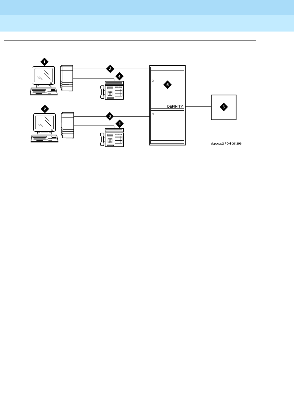
DEFINITY Enterprise Communications Server Release 6
Administration and Feature Description
555-230-522 Issue 4
May 1998
PC Interface Administration
Page 6-221PC Interface
6
Figure 6-1. DCP PC interface configuration (Group 1)
The group 2 configurations link to the switch using a PC/ISDN Interface card
installed in the PC. This group can include a stand-alone PC terminal, or up to
four voice terminals, handsets, or headsets. Group 2 (shown in Figure 6-2) uses
PC/ISDN Interface cards (up to four cards) which plug into expansion slots on
the PC. These cards each provide 2 standard 8-pin modular-jack connections for
both line connections (to the switch) and phone connections. A standard 4-pin
modular jack is also available for use with a handset or headset.
Figure Notes
1. IBM-compatible PC with DCP
Interface card
2. IBM-compatible PC with DCP
Interface card
3. DCP
4. DCP voice terminal
5. DEFINITY ECS (TN754B, TN2181,
or TN2224 digital-line circuit pack)
6. Host
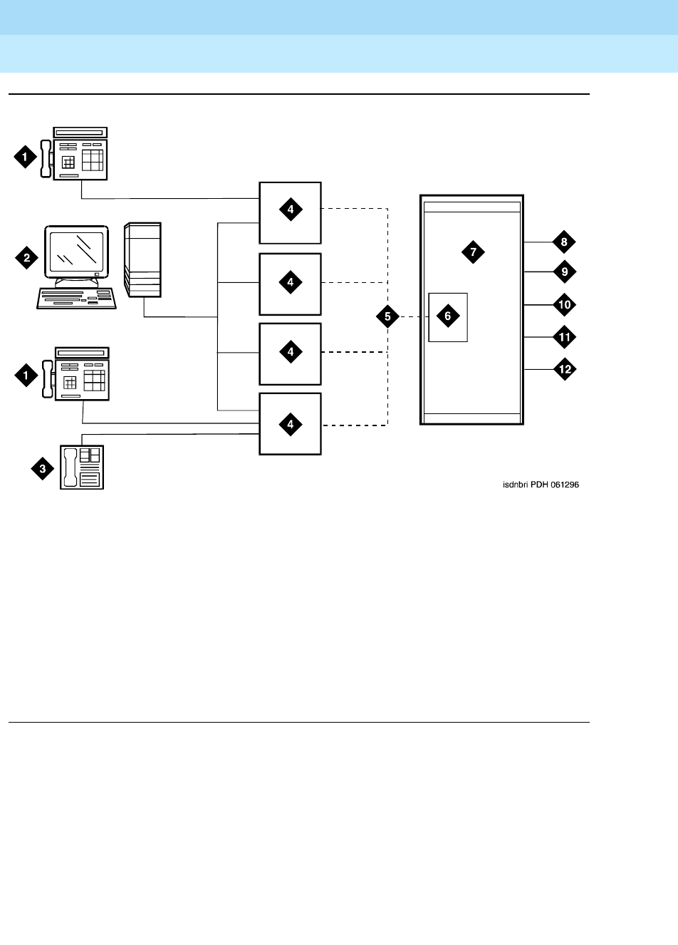
DEFINITY Enterprise Communications Server Release 6
Administration and Feature Description
555-230-522 Issue 4
May 1998
PC Interface Administration
Page 6-222PC Interface
6
Figure 6-2. ISDN—BRI PC interface configuration (Group 2)
PC Interface users have multiple appearances (depending on the software
application used) for their assigned extension. Designate one or more of these
appearances for use with data calls. With the ISDN-BRI version, you can use up
to 4 separate PC/ISDN Interface cards on the same PC. Assign each card a
separate extension, and assign each extension one or more appearances. The
availability of specific features depends on the COS of the extension and the
COS for the switch. Modem Pooling is provided to ensure general availability of
off-net data-calling services.
Figure Notes
1. ISDN voice terminal
2. PC with application
3. Handset or Headset
4. BRI Interface card
5. 2B + D
6. TN556 (ISDN-BRI Line, 4-wire
S/T-NT, interface circuit pack)
7. DEFINITY ECS
8. PRI trunks
9. BRI stations
10. Interworking
11. DMI
12. Switch features

DEFINITY Enterprise Communications Server Release 6
Administration and Feature Description
555-230-522 Issue 4
May 1998
PC Interface Administration
Page 6-223PC Interface
6
Security
There are two areas where unauthorized use may occur with this feature:
unauthorized local use and remote access.
!SECURITY ALERT:
Unauthorized local use involves unauthorized users who attempt to make
calls from a PC. The PC software has a security setting so users can place
the PC in Security Mode when it is unattended. You can also assign
Automatic Security so that the administration program on the PC is always
active and runs in Security Mode. This mode is password-protected.
!SECURITY ALERT:
Remote access involves remote access to the PC over a data extension.
Remote users can delete or copy PC files with this feature. You can
password-protect this feature. Consult the
BCS Product Security Handbook
for additional steps to secure your system and to find out about obtaining
information regularly about security developments.
Considerations
■Use the Function Key Module of the 7405D with PC Interface.
■BRI terminals normally are initializing terminals and require you to assign
an SPID. The PC/ISDN Platform (Group 2), in a stand-alone configuration,
is a noninitializing BRI terminal and does not require you to assign a SPID.
— Set a locally-defined terminal type with General Terminal
Administration
— Define the terminal type as a noninitializing terminal that does not
support Management Information Messages (MIM).
— Assign the PC/ISDN Platform with an associated (initializing)
ISDN-BRI voice terminal (such as an ISDN 7505) using a SPID.
— Assign the station (using a locally-defined terminal type) to take full
advantage of the capabilities of the PC Interface. This terminal type
is also noninitializing with no support of MIMs.
■Do not use voice terminals with data modules with the PC Interface. (You
can still use 3270 Data Modules if you also use 3270 emulation). If you
attach a DCP data module or ISDN data module to a voice terminal that is
connected to a PC Interface card, the data module is bypassed (not
used). All the interface functions are performed by the interface card even
if a data module is present.
■The 7404D voice terminal with messaging cartridge cannot be used with
PC Interface. However, the 7404D with PC cartridge can be used, but only
with Group 1 configurations.

DEFINITY Enterprise Communications Server Release 6
Administration and Feature Description
555-230-522 Issue 4
May 1998
PC Interface Administration
Page 6-224PC Interface
6
Interactions
■Data Communications Access
PC Interface uses a digital interface and is not directly compatible with
Data Communications Access, which uses an analog interface. Apply
Modem Pooling conversion if you use these features together.
■Data Protection
Assign Data Protection—Permanent for use with PC Interface for data
communications.
■Host Computer Access
Both PC Interface and Host Computer Access use digital interfaces.
These features are compatible and Modem Pooling conversion is
unnecessary.
■ISDN-BRI
Each card can have its own separate voice terminal or voice-calling
device. A voice terminal does not require special application software on
the PC. However, a handset or headset alone requires special application
software.
■Modem Pooling
Use Modem Pooling if you use PC Interface to place calls to, or receive
calls from, off-premises stations over analog trunks.

DEFINITY Enterprise Communications Server Release 6
Administration and Feature Description
555-230-522 Issue 4
May 1998
Data Module Administration
Page 6-225
6
6
6Data Module Administration

DEFINITY Enterprise Communications Server Release 6
Administration and Feature Description
555-230-522 Issue 4
May 1998
Data Module Administration
Page 6-226Data Modules — general
6
Data Modules — general
A Data Module is a connection device between a basic-rate interface (BRI) or
digital-communications protocol (DCP) interface of the switch and data-terminal
equipment (DTE) or data-communications equipment (DCE).
The following types of data modules can be used with the system:
■Announcement data module
■Data line data module
■Processor/trunk data module (P/TDM)
■Netcon data module (R5vs and R5si and later configurations only)
■Processor interface data module (R5vs and R5si and later configurations
only)
■System port data module (R5r and later configurations only)
■X.25 data module (R5r and later configurations only)
■7500 data module
■World Class BRI data module
Administration Commands
You assign each data module to your system by administering a Data Module
form. Each Data Module form requires you to specify the type of data module in
the Type field; this is how you distinguish between the many different types of
data modules. Use the following commands to access the appropriate Data
Module form.
1. Brackets [ ] indicate the qualifier is optional.
Table 6-1. Administration commands
Action Object Qualifier1
add data-module xxxx (extension or ‘next’)
change data-module xxxx (extension number)
display data-module xxxx (extension number) [print or schedule]
duplicate data-module xxxx (extension number to be duplicated)
list data-module (starting ext number) xxxx (‘count’) [print or
schedule]
remove data-module xxxx (extension number)
DEFINITY Enterprise Communications Server Release 6
Administration and Feature Description
555-230-522 Issue 4
May 1998
Data Module Administration
Page 6-227Data Modules — general
6
NOTE:
The 51X series Business Communications Terminals (BCTs) are not
administered on the Data Module form. The 510 BCT (equivalent to a
7405D with a display and built-in DTDM), 515 BCT (equivalent to a 7403D
integrated with 7405D display module function, data terminal and built-in
DTDM), and the 7505D, 7506D, and 7507D have a DCP interface but have
built-in data module functionality. Both are administered through the Station
form.
NOTE:
To administer a data module with a 7400D-series voice terminal, refer to the
7400D voice terminal information provided earlier in this book.
Detailed description of data modules
TTI allows data modules without hardware translation to merge with an
appropriate data module connected to an unadministered port. The
unadministered port is given TTI default translation sufficient to allow a terminal
connected to the data module (connected to the port) to request a TTI merge
with the extension of a data module administered without hardware translation.
NOTE:
TTI is not useful for Announcement and X.25 hardware.
Administration Without Hardware Translation supports PDM, TDM, Data-Line,
Announcement, and X.25 data modules.
NOTE:
The 513 BCT has an EIA interface rather than a DCP interface (no built in
data module, attachable telephone, or telephone features). The 513 BCT is
not administered; only the data module to which the 513 BCT is connected
is administered.
7400A/7400B+7400B+ Data Module
Use the 7400A data module instead of an MTDM when you support combined
Modem Pooling. The 7400A data module supports asynchronous operation at
speeds up to 19200-bps, and provides a DCP interface to the switch and an EIA
232C interface to the associated modem. The 7400A operates in stand-alone
mode as a data module.
7400B+ and 8400B+ data modules support asynchronous-data communications
and operate in stand-alone mode for data-only service or in linked mode, which
provides simultaneous voice and data service. The 7400B+ and 8400B+ provide
voice and data communications to 7400D series voice terminals and 602A1
CALLMASTER voice terminals that have a connection to a data terminal or
personal computer. The data modules integrate data and voice into the DCP
protocol required to interface with the switch via a port on a digital-line circuit

DEFINITY Enterprise Communications Server Release 6
Administration and Feature Description
555-230-522 Issue 4
May 1998
Data Module Administration
Page 6-228Data Modules — general
6
pack. Use the 7400B+ or 8400B+ instead of an MPDM when you need
asynchronous operation at speeds up to 19.2-kbps to provide a DCP interface to
the switch for data terminals and printers. The 7400B+ and 8400B+ do not
support synchronous operation and keyboard dialing.
7400D
This data module supports synchronous operation with AUDIX, CMS, and DCS. It
provides synchronous data transmissions at speeds of 19.2-Kbps full duplex.
7400C High Speed Link
The 7400C high-speed link (HSL) is a data-service unit that allows access to
DCP data services. It provides synchronous data transmission at speeds of
56- and 64-Kbps and provides a link to high-speed data networks. Used for
Group 4 fax applications that include electronic mail and messaging, and
electronic storage of printed documents and graphics. Use the 7400C for video
teleconferencing and LAN interconnect applications.
7500 Data Modules
The 7500 Data Module connects data-terminal equipment (DTE) or
data-communications equipment (DCE) to the ISDN network. The 7500 Data
Module supports EIA 232C and V.35 interfaces and RS-366 automatic-calling
unit interface (for the EIA 232C interface only).
The 7500 has no voice functions. Configure in the following ways:
■Asynchronous DCE
300, 1200, 2400, 4800, 9600, 19200-bps
■Synchronous DCE
1200, 2400, 4800, 9600, 19200, 56000, 64000-bps
■Asynchronous DTE (used for modem pooling)
up to 19200-bps
The 7500 Data Module is stand-alone or in a multiple-mount housing.

DEFINITY Enterprise Communications Server Release 6
Administration and Feature Description
555-230-522 Issue 4
May 1998
Data Module Administration
Page 6-229Data Modules — general
6
Asynchronous Data Module
NOTE:
The alias station command cannot be used to alias data modules.
Use the Asynchronous Data Module (ADM) with asynchronous DTEs as a data
stand for the 7500 Series of ISDN-BRI voice terminals, thus providing connection
to the ISDN network. The ADM provides integrated voice and data on the same
voice terminal and supports data rates of 300, 1200, 2400, 4800, 9600, and
19200-bps. This module also supports the Hayes command set, providing
compatibility with PC communications packages.

DEFINITY Enterprise Communications Server Release 6
Administration and Feature Description
555-230-522 Issue 4
May 1998
Data Module Administration
Page 6-230Data module form field description
6
Data module form field description
The following section provides descriptions of standard fields on Data Module
forms. Some of the fields are used for specific data module types; others are
used for all data modules. Unique fields and fields requiring special
consideration are listed with the appropriate data module descriptions later in
this book.
The standard fields are organized alphabetically for easy access.
■ABBREVIATED DIALING List1 — Enter p (personal), s (system), g
(group), or e (enhanced). If you enter p or g, you also must enter a
personal list number or a group number, respectively. Entry in this field
supports Data Hot Line. This field can be left blank.
■BCC — (Bearer Capability Class) Displays when ISDN-PRI or ISDN-BRI
Trunks is enabled on the System-Parameters Customer-Options form. It
is a display-only field. The value in the field corresponds to the speed
setting of the data module. A BCC of “1” relates to 56-kbps, BCC values of
2, 3, and 4 relate to 64 kbps. This field may be compared with the BCC
value in an associated routing pattern when attempted calls utilizing the
data module fail to complete. The BCC values must be the same.
See “Generalized Route Selection” in this book for a detailed description
of Bearer Capability Classes (BCC) and their ability to provide specialized
routing for various types of voice and data calls. The BCC value is used to
determine compatibility when non-ISDN-PRI facilities are connected to
ISDN facilities (ISDN-PRI Interworking).
■Board — Enter the five character announcement board number that
identifies the physical board to which the announcement module is
connected. If you are using Administration Without Hardware, enter X in
this field to indicate that there is no hardware associated with this port
assignment. Default is blank.
The five character announcement board number is comprised of:
■COR — Enter a Class of Restriction (COR) number (0 through 95) to
select the desired restriction; default is 1.
Characters Meaning Value
1-2 Cabinet Number 01 through 44 (R5r and
later configurations)
01 through 03 (R5si
and later configurations)
01 (R5vs and later
configurations)
3 Carrier A through E
4-5 Slot Number 01 through 20

DEFINITY Enterprise Communications Server Release 6
Administration and Feature Description
555-230-522 Issue 4
May 1998
Data Module Administration
Page 6-231Data module form field description
6
■COS — Enter the desired Class of Service (COS) number (0 through 15)
to select allowed features; default is 1.
■Data Extension — Enter the extension assigned to the data module. A
data extension can be a 1- to 5-digit number and must agree with the Dial
Plan.
■Default Dialing Abbreviated Dialing Dial Code — Only displays when
the Special Dialing Option is set to default. Enter a list number (0 through
999) associated with the AD list. When the user goes off-hook and enters a
carriage return following the DIAL prompt, the system dials the AD
number. The data call originator can also perform data-terminal dialing by
specifying a dial string that may or may not contain alphanumeric names.
Default is blank.
■Ext and Name — Make no entry. This is the extension number and name
of the user (previously administered) with associated Data Extension
buttons who shares the module.
■HOT LINE DESTINATION — Abbreviated Dialing Dial Code —
Displays only when Special Dialing Option is hot-line. Enter a list
number (associated with the AD List) from 0 to 999. When the user goes
off-hook on a Data Hot Line call, the system dials the AD number. Entry in
this field supports Data Hot Line.
■ITC (Information Transfer Capability) — Only displays when Comm Type
is 56k-data or 64k-data. Enter restricted (default) or unrestricted to
indicate the type of transmission facilities to be used for ISDN calls
originated from this endpoint. The field does not display for voice-only or
BRI stations.
— If you set ITC to restricted, either restricted or unrestricted
transmission facilities are used to complete the call. A restricted
facility is a transmission facility that enforces 1’s density digital
transmission (that is, a sequence of 8 digital zeros are converted to
a sequence of 7 zeros and a digital 1).
— If you set ITC to unrestricted, only unrestricted transmission
facilities are used to complete the call. An unrestricted facility is a
transmission facility that does not enforce 1’s density digital
transmission (that is, digital information is sent exactly as is).
■MM Complex Voice Ext: (display only) — This field contains the number
of the associated voice terminal in the multimedia complex. This field only
displays after you set Multimedia to y. This field is left blank until you
enter the data module extension in MM Complex Data Ext on the Station
form. Once you complete the field on the station form, these two
extensions are associated as two parts of a one-number complex, which
is the extension of the voice terminal. Valid values conform to your dial
plan.
■Multimedia — Enter y to make this data module part of a multimedia
complex. This field only appears if MM on the System-Parameters
Customer Options form is y.

DEFINITY Enterprise Communications Server Release 6
Administration and Feature Description
555-230-522 Issue 4
May 1998
Data Module Administration
Page 6-232Data module form field description
6
■Name — Enter the name of the user associated with the data module. The
name is optional and can be blank.
■Port — Enter 7 characters to specify a port location to which the data
module is connected as follows:
NOTE:
You can enter X in the Port field to indicate that there is no hardware
associated with the port assignment (Administration Without
Hardware). These stations are referred to as “phantom stations.” If
this data module is designated as a secondary data module
(Secondary data module set to y) X cannot be entered into this field.
The Port of a primary data module cannot be changed to X if a
secondary data module is administered.
■SPECIAL DIALING OPTION — Enter hot-line, default, or leave blank for
regular (normal) keyboard dialing. This field identifies the type of dialing
for calls when this data module originates calls.
■TN — Enter the Tenant Partition number. Default is 1.
Characters Meaning Value
1-2 Cabinet Number 01 through 44 (R5r and later
configurations)
01 through 03 (R5si and later
configurations)
01 (R5vs)
3 Carrier A through E
4-5 Slot Number 01 through 20
6-7 Circuit Number 01 through 04 (x.25 circuit pack)
01 through 32 (R5si and later
configurations)
DEFINITY Enterprise Communications Server Release 6
Administration and Feature Description
555-230-522 Issue 4
May 1998
Data Module Administration
Page 6-233Announcement Data Module
6
Announcement Data Module
The TN750 Announcement circuit pack has a built-in data module that is
administered using the Announcement Data Module form. This data module (in
conjunction with an administered Netcon Data Module in R5vs and R5si and later
configurations) allows the system to save the recorded announcements file from
the TN750 announcement circuit pack to the system tape/disk/memory card
(depending on system configuration) and restore from the system
tape/disk/memory card to the announcement circuit pack. Only one TN750A or
TN750B board can be automatically restored during a system reload. TN750C is
not automatically restored during a system reload.
The TN750C board contains flash memory which provides internal backup of
announcements on the boards. Thus, the TN750C board does not need the Save
and Restore processes still available for the TN750 and TN750B boards.
However, you can use the Save and Restore processes to copy announcements
between TN750B/C boards.
NOTE:
Announcements are not saved when a save translations command is
executed. Execute the save announcements command to save
announcements. This operation does not save announcements on external
announcement units connected to AUX or Analog line circuit packs.
Form instructions
To administer an Announcement Data Module, complete the standard as well as
the following unique Data Module form fields.
■Type — Enter “announcement”.
Screen 6-1. Recorded Announcement Data Module form (Page 1 of 1)
add data-module next Page 1 of 1
DATA MODULE
Data Extension: 30 Name: BCC:
Type: announcement COS: 1 Remote Loop-Around Test? n
Port: _______ COR: 1 Secondary data module? n
ITC: restricted__ TN: 1 Connected to: dte
ABBREVIATED DIALING
List1:
SPECIAL DIALING OPTION:
ASSIGNED MEMBER ( Station with a data extension button for this data module )
Ext Name
1: 1002 27 character station name

DEFINITY Enterprise Communications Server Release 6
Administration and Feature Description
555-230-522 Issue 4
May 1998
Data Module Administration
Page 6-234Data Line Data Module
6
Data Line Data Module
The Data Line Data Module (DLDM) form assigns ports on the TN726 Data Line
circuit pack (DLC) that allows EIA 232C devices to connect to the system. The
DLC, with a companion Asynchronous Data Unit (ADU), provides a less
expensive data interface to the system than data modules such as Digital
Terminal Data Modules (DTDMs), Modular Processor Data Modules (MPDMs),
Modular Trunk Data Modules (MTDMs), or other asynchronous DCP data
modules.
The DLC supports asynchronous transmissions at speeds of Low and 300, 1200,
2400, 4800, 9600, and 19200 bps over 2-pair (full-duplex) lines. These lines can
have different lengths, depending on the transmission speed and wire gauge.
The DLC has 8 ports. The connection from the port to the EIA device is
direct
,
meaning that no multiplexing is involved. A single port of the DLC is equivalent in
functionality to a data module and a digital line port. The DLC appears as a data
module to the Digital Terminal Equipment (DTE) and as a digital line port to the
switch.
The DLC connects the following EIA 232C equipment to the system:
■Printers
■Non-Intelligent Data Terminals
■Intelligent Terminals, Personal Computers (PCs)
■Host Computers
■Information Systems Network (ISN), RS-232C Local Area Networks
(LANs), or other data switches.
Form instructions
To administer a Data Line Data Module, complete the standard as well as the
following unique Data Module form fields.

DEFINITY Enterprise Communications Server Release 6
Administration and Feature Description
555-230-522 Issue 4
May 1998
Data Module Administration
Page 6-235Data Line Data Module
6
Screen 6-2. Data Line Data Module form (Page 1 of 2)
Screen 6-3. Data Line Data Module form (Page 2 of 2) — if KYBD Dialing set to y
Page 1 of 2
DATA MODULE
Data Extension: 30 Name: 27 BCC:
Type: data-line___ COS: 1
Port: _______ COR: 1
ITC: restricted__ TN: 1 Connected to: dte
ABBREVIATED DIALING
List1:
SPECIAL DIALING OPTION:
ASSIGNED MEMBER (Station with a data extension button for this data module)
Ext Name
1: 1002 27 character station name
DATA MODULE Page 2 of 2
CAPABILITIES
KYBD Dialing? y Configuration? n
Busy Out? n
SPEEDS
Low? y 1200? y 4800? y 19200? y
300? y 2400? y 9600? y Autoadjust? n
OPTIONS
Permit Mismatch? n Dial Echoing? y
Disconnect Sequence: two-breaks Answer Text? y
Parity: even Connected Indication? y

DEFINITY Enterprise Communications Server Release 6
Administration and Feature Description
555-230-522 Issue 4
May 1998
Data Module Administration
Page 6-236Data Line Data Module
6
Screen 6-4. Data Line Data Module form (Page 2 of 2) — if KYBD Dialing set to n)
■Type — Enter “data-line”.
■Connected To — Enter dte (Data Terminal Equipment) or isn (Information
Systems Network). This field shows to what the ADU (Asynchronous Data
Unit) is connected. Default is dte.
Page 2 of the form
See “DLC Option Settings” following these instructions for additional information
when assigning entries for the remaining fields on the form.
■KYBD Dialing — Enter y to allow keyboard dialing. This enables the data
endpoint to receive and transmit text during call origination or termination.
If you enter y, Low must be set to n.
This option must be enabled to allow data endpoints to originate calls via
the EIA 232C interface and obtain ASCII feedback text. When enabled,
the user gets the dial prompt. This option normally is enabled for
“originate/receive” DTE that has a need to set up data calls. If this option is
disabled, originations cannot be done at the DTE and text feedback does
not occur at the DTE during call setup/take down. Data call answering is
still allowed but without text feedback.
NOTE:
ADU-type hunt groups connecting the system to terminal servers on
a host computer should have these hunt group extensions assigned
as “no” keyboard dialing.
■Configuration — Displays when KYBD Dialing is enabled. Enter y to
allow the viewing and changing of options from the DTE.
This option normally is enabled for “originate/receive” DTE such as
non-intelligent terminals and disabled for intelligent devices such as
computers. Keyboard dialing must be enabled with this option.
DATA MODULE Page 2 of 2
CAPABILITIES
KYBD Dialing? n
Busy Out? n
SPEEDS
Low? y 1200? y 4800? y 19200? y
300? y 2400? y 9600? y
OPTIONS
Permit Mismatch? n

DEFINITY Enterprise Communications Server Release 6
Administration and Feature Description
555-230-522 Issue 4
May 1998
Data Module Administration
Page 6-237Data Line Data Module
6
■Busy Out — Enter y to place the DLC port in a busied-out state once the
DTE control lead to the DLC is dropped. This option should be enabled for
DTEs that are members of a hunt group and to allow “busy out” when DTE
turns power off so that calls do not terminate on that DTE.
■SPEEDS — Enter y to select operating speeds as follows:
—Low — Enter y to instruct the DLC to operate at a low speed from 0
to 1800 bits per second (bps). Enter n if y is entered in the
Keyboard Dialing field.
—300, 1200, 2400, 4800, 9600, or 19200 — Enter y beside the
desired operating speed. Enter n if the speed is not desired. The
DLC can be any one of these speeds. The speed is matched for the
duration of the call, from call setup to call takedown.
When multiple speeds are selected (select three or more, do not
select just two speeds) and autoadjust is disabled, the DTE’s speed
must be the highest selected speed. This is required because all
feedback text is delivered to the DTE at the highest selected
speed.
—Autoadjust — Displays when KYBD Dialing is enabled. Enter y
which tells the DLC port to automatically adjust to the operating
speed and parity of the DTE it is connected to. Enter n if this option
is not desired. Autoadjust can be selected with any of the speeds
selected in the previous step. Autoadjust allows the DLC port to
determine the speed and parity of the DTE and then match itself to
this speed. Autoadjust only applies to calls originated by the user
through Keyboard Dialing.
■Permit Mismatch — Enter y to instruct the DLC to operate at the highest
selected speed, which is a higher rate than the far-end data module. Enter
n if this option is not desired.
This option allows the EIA interface to operate at a rate different than that
agreed to in the data module handshake. (The data module handshake is
always the highest compatible rate as determined by the reported speed
option of each data module.) Permit Mismatch eliminates the need to
change the DTE/DLC speed every time a call is placed to/from an
endpoint operating at a different speed. When this option is enabled, the
DLC reports the highest optioned speed and all the lower speeds (or the
previously selected autoadjust speed) during the handshake process.
!CAUTION:
Caution must be used when using this option to send information
from a DTE/DCE that is transmitting data at higher rates than that of
the far end. Sustained usage of this type transmission results in loss
of data. Whenever this option is enabled, the DTE must match the
highest speed selected for the associated DLC port.

DEFINITY Enterprise Communications Server Release 6
Administration and Feature Description
555-230-522 Issue 4
May 1998
Data Module Administration
Page 6-238Data Line Data Module
6
This option is intended to be used by a DTE device operating locally at a
higher baud rate than that of its far-end connection but transmitting
relatively low amounts of data (for example, a user typing at a terminal).
Also, this option may be selected whether or not Keyboard Dialing is
selected.
NOTE:
The Low speed setting is not reported as an available speed when
Permit Mismatch is enabled.
■Dial Echoing — Displays when KYBD Dialing is enabled. Enter y to
echo characters back to the DTE. Dial echoing should be disabled when
keyboard dialing is done by an intelligent device.
■Disconnect Sequence — Displays when KYBD Dialing is enabled.
Enter long-break or two-breaks to select the sequence for a disconnect.
A long-break is greater than 2 seconds and two-breaks is within 1 second.
■Answer Text — Displays when KYBD Dialing is enabled. Enter y to
allow text messages to be delivered to the DTE when a call is being
answered. Enter n if this option is not desired.
This option enables text feedback that is normally delivered to the DTE
when a call is answered or disconnected. The Answer Text option applies
to DLC-generated text as well as text received from the system. If this
option is disabled, the system still generates the text, but the DLC
prevents it from being sent to the device.
This applies to the following messages:
— INCOMING CALL
—ANSWERED
— DISCONNECTED
— DISCONNECTED OTHER END
This option is usually disabled when the answering DTE is a computer or
an intelligent device.
■Parity — Displays when KYBD Dialing is enabled. Enter even, odd,
mark, or space to select the desired type of parity. The DLC generates the
parities (even, odd, mark, and space) when call setup text is sent to the
DTE. The DLC does not check the parity when receiving dialing
characters. Parity has nothing to do with the far end; it is used by the DLC
to terminal communications during call setup.
■Connected Indication — Displays when KYBD Dialing is enabled.
Enter y to give text feedback to the DTE when a connection has been
established. This option generates a “CONNECTED” message to the DTE
when the connection has been established. If KYBD Dialing is not
selected, the connected indication is provided by the DLC activating its
EIA 232C control lead.

DEFINITY Enterprise Communications Server Release 6
Administration and Feature Description
555-230-522 Issue 4
May 1998
Data Module Administration
Page 6-239Data Line Data Module
6
DLC Option Settings
The following provides additional information on the option settings for DLCs
when used with the following types of devices:
■Printers
■Non-intelligent terminals
■Data terminals and personal computers
■Host computers
■Information Systems Network (ISN)
Printers
A DLC port, attached to a printer, usually terminates a data call. Therefore, in this
connection, the printer is the endpoint device. The originating device may be
attached to a DCP mode 2 data module (such as the MPDM) or the DLC. A Z3A
ADU extends the range of the EIA 232C connection.
When a receive-only printer (or any printer that does not generate the Transmit
Data and DTR leads) is used, the ADU must be powered from a small
plug-mounted transformer (2012D, or equivalent) connected to pins 7 and 8 of
the modular jack. (See
ADU User Manual
for details.)
An ADU cannot be used if the printer has hardware flow control using the Clear
To Send (CTS) lead. An ADU can be used, however, if the printer is using
software flow control.
A printer connected to a DLC is usually assigned as a line. Table 6-2 lists the
option settings for printer connections.
Table 6-2. DLDM form settings for printer connection
Field on form Option Comments
Speed Highest speed at
which the Printer
operates
Subject to distance
limitations; Autoadjust not
used
KYBD Dialing no
Busy Out yes If printer is member of Hunt
Group
Permit Mismatch yes No, if printer is low speed
Parity - Don’t care
Dial Echoing - Don’t care
Continued on next page

DEFINITY Enterprise Communications Server Release 6
Administration and Feature Description
555-230-522 Issue 4
May 1998
Data Module Administration
Page 6-240Data Line Data Module
6
Non-intelligent terminals
A non-intelligent terminal connected to the DLC usually is assigned as a line.
Tab l e 6 - 3 lists the option settings for non-intelligent terminals.
Disconnect
Sequence -Don’t care
Answer Text - Don’t care
Connected
Indication -Don’t care
Configuration no
Table 6-3. DLDM form settings for connection to non-intelligent terminals
Field On form Option Comments
Speed All speeds at which
the terminal can
operate; autoadjust
Subject to distance limitations;
Autoadjust when Keyboard
Dialing is “y” and the Terminal
can generate an ASCII “return”
KYBD Dialing yes
Busy Out no Yes, if terminal is member of a
hunt group
Permit Mismatch yes -
Parity Same as DTE
Dial Echoing yes Only if KYBD Dialing is yes
Disconnect
Sequence 2 <BREAK>s Depends on terminal
Answer Text yes
Connected
Indication -Don’t care
Configuration yes
Table 6-2. DLDM form settings for printer connection — Continued
Field on form Option Comments
Continued on next page

DEFINITY Enterprise Communications Server Release 6
Administration and Feature Description
555-230-522 Issue 4
May 1998
Data Module Administration
Page 6-241Data Line Data Module
6
Data terminals and personal computers
An intelligent data terminal or a personal computer (PC) attached to a DLC can
either originate or terminate a data call. A single ADU at the site of the originating
device extends the distance signals can travel to the switch (the model ADU
depends on the terminal connector). An analog telephone can be attached to
this arrangement whenever an ADU uses the standard building wiring. Ta b le 6 -4
lists the option settings used for data terminal and personal computer
connections.
Host computers
A host computer may originate and terminate a data call. For this application, the
number of DLCs required depends on the number of ports needed. An MADU
can be used (instead of eight ADUs) to complete the connection. Table 6-5 lists
option settings for a port that has a terminating connection to a host computer.
Tab l e 6 - 5 shows the option settings for a port that has an originating connection
from a host computer.
Table 6-4. DLDM form settings for connection to data terminal or personal
computer
Field on form Option Comments
Speed All speeds at which
the Data Terminal
or PC can operate
Subject to distance limitations;
Autoadjust not used
KYBD Dialing yes
Busy Out no Yes, if device is accessed
through a hunt group
Permit Mismatch yes No, if device does not support
XON/XOFF flow control
Parity Same as DTE
Dial Echoing no These devices can dial in the
ASCII stream without human
intervention
Disconnect
Sequence Long <BREAK> -
Answer Text no These devices may not want to
see any text
Connected
Indication -Don’t care
Configuration yes

DEFINITY Enterprise Communications Server Release 6
Administration and Feature Description
555-230-522 Issue 4
May 1998
Data Module Administration
Page 6-242Data Line Data Module
6
NOTE:
If Keyboard Dialing is disabled, the rest of the option settings are
irrelevant.
Table 6-5. DLDM form settings for terminating connection to host computer
Field on form Option Comments
Speed All speeds at which
the computer can
operate
Subject to distance limitations;
Autoadjust not used
KYBD Dialing no
Busy Out - Don’t care
Permit Mismatch - Don’t care
Parity - Don’t care
Dial Echoing - Don’t care
Disconnect
Sequence - Don’t care
Answer Text - Don’t care
Connected
Indication -Don’t care
Configuration - Don’t care

DEFINITY Enterprise Communications Server Release 6
Administration and Feature Description
555-230-522 Issue 4
May 1998
Data Module Administration
Page 6-243Processor/Trunk Data Module
6
Processor/Trunk Data Module
These forms assign Modular Processor Data Modules (MPDMs) and Modular
Trunk Data Modules (MTDMs). One form is required for assigning MPDMs
(700D), 7400B, 7400D or 8400B Data Module, and another form for MTDMs
(700B, 700C, 700E, 7400A). One form must be completed for each MPDM,
7400B, 7400D, 8400B or MTDM.
The MPDM or 7400B Data Module provides a Data Communications Equipment
(DCE) interface for connection to equipment such as data terminals, CDR output
devices, on-premises administration terminal, Message Server, Property
Management System (PMS), AUDIX, and host computers. It also provides a
Digital Communications Protocol (DCP) interface to the digital switch. (DCE is the
equipment on the network side of a communications link that provides all the
functions required to make the binary serial data from the source or transmitter
compatible with the communications channel.)
The MTDM provides an Electronic Industries Association (EIA) Data Terminal
Equipment (DTE) interface for connection to off-premises private line trunk
facilities or a switched telecommunications network and a DCP interface for
connection to the digital switch. (DTE is the equipment comprising the endpoints
in a connection over a data circuit. For example, in a connection between a data
terminal and a host computer, the terminal, the host, and their associated
modems or data modules make up the DTE.) The MTDM or 7400A Data Module
can also serve as part of a conversion resource for Combined Modem Pooling.

DEFINITY Enterprise Communications Server Release 6
Administration and Feature Description
555-230-522 Issue 4
May 1998
Data Module Administration
Page 6-244Processor/Trunk Data Module
6
Form instructions
Screen 6-5. MPDM/MTDM Data Module form (Page 1 of 1)
To administer a MPDM or MTDM, complete the standard as well as the following
unique Data Module form fields.
■Type — Enter pdm (default) when assigning a DCE interface or tdm when
assigning a DTE interface.
■Connected To — Only displays when Type is pdm. Enter dte if the data
module is connected to Data Terminal Equipment (DTE) or enter isn if
connected to an Information Systems Network (ISN).
■Remote Loop-Around Test — Enter y if the data module supports a
loop-back test at the EIA interface. In general, Lucent Technologies
equipment supports this test but it is not required by Level 2 Digital
Communications Protocol.
■Secondary data module — Only displays when Type is pdm. Enter y if
this PDM is the secondary data module used for Dual I-channel AUDIX
networking. Enter n if this is the primary PDM, or if this data module is not
used for AUDIX networking. The primary data module must be
administered before the secondary data module may be added. If Port is
X, Secondary data module cannot be y.
Page 1 of 1
DATA MODULE
Data Extension: 30 Name: 27 BCC:
Type: pdm_________ COS: 1 Remote Loop-Around Test? n
Port: _______ COR: 1 Secondary data module? n
ITC: restricted__ TN: 1 Connected to: dte
ABBREVIATED DIALING
List1:
SPECIAL DIALING OPTION:
ASSIGNED MEMBER (Station with a data extension button for this data module)
Ext Name
1: 1002 27 character station name

DEFINITY Enterprise Communications Server Release 6
Administration and Feature Description
555-230-522 Issue 4
May 1998
Data Module Administration
Page 6-245Netcon Data Module
6
Netcon Data Module
Netcon data modules are the Processor Data Modules (PDMs) that are
integrated into the system’s network control ports that provide asynchronous
circuit switched interfaces to the maintenance and administration terminals,
Hospitality journal printers, and CDR digital output. They are characterized by
their special locations, that is, special port identifications.
NOTE:
The Netcon data module is only applicable to R5vs and R5si and later
configurations. For R5r and later configurations, see ‘‘System Port Data
Module’’ on page 6-248.
Form instructions
Screen 6-6. Netcon Data Module form (Page 1 of 1)
To administer a Netcon Data Module, complete the standard as well as the
following unique Data Module form fields.
■Type — Enter netcon.
■Physical Channel — Enter a netcon data channel number from 01
through 04.
■Maintenance Extension — Enter the extension number required to
perform maintenance functions on the standby netcon physical channel in
a duplicated system. The standby remote loop around tests fails if this
field is not administered.
Page 1 of 1
DATA MODULE
Data Extension: BCC: __
Type: netcon COS: 1 Maintenance Extension: ____
Physical Channel: __ COR: 1
Name: _______________ TN: 1
ITC: restricted
ABBREVIATED DIALING
List1: _______________
SPECIAL DIALING OPTION: _____
HOT LINE DESTINATION
Abbreviated Dialing Dial Code (From above list): _
ASSIGNED MEMBER (Station with a data extension button for this data module)
Ext Name
1:

DEFINITY Enterprise Communications Server Release 6
Administration and Feature Description
555-230-522 Issue 4
May 1998
Data Module Administration
Page 6-246Processor Interface Data Module
6
Processor Interface Data Module
The Processor Interface data modules are the Processor Data Modules (PDMs)
that are integrated into the system’s synchronous/asynchronous Processor
Interface circuit pack ports.
NOTE:
The Processor Interface data module is applicable only to R5vs and R5si
and later configurations.
They are used to provide the following interfaces:
■3B/Call Management System (maximum of one)
■3B/Message Server (maximum of one)
■Distributed Communications System (maximum of eight)
■AUDIX (maximum of one)
■ISDN-PRI (maximum of eight)
NOTE:
Not all maximums can be achieved at the same time
Connections for these interfaces are achieved via a digital line port and MPDM
combination, and/or in the case of DCS or ISDN-PRI, via a DS1 interface. One
direct EIA connection is available (labeled as Processor Interface on the back of
the Control Cabinet) for simplex operation. When used, the physical channel
assignment (see below) must be “01”. Use of the EIA connection eliminates the
need for one digital line port/MPDM combination.

DEFINITY Enterprise Communications Server Release 6
Administration and Feature Description
555-230-522 Issue 4
May 1998
Data Module Administration
Page 6-247Processor Interface Data Module
6
Form instructions
Screen 6-7. Processor Interface Data Module form (Page 1 of 1)
To administer a Processor Interface Data Module, complete the standard as well
as the following unique Data Module form fields.
■Type — Enter procr-infc.
■Maintenance Extension — Enter the extension number required to
perform maintenance functions on the standby physical channel in a
duplicated system. The standby remote loop around tests fail if this field is
not administered.
■Physical Channel — Enter the 2-digit circuit number of the Processor
Interface port. A multi-carrier cabinet system supports the use of two
Processor Interface circuit packs, the first circuit pack (mounted in Control
Carrier A) supports physical channels or links 01 through 04; the second
(mounted in Control Carrier A) supports physical channels or links 05
through 08. A single-carrier cabinet system supports one Processor
Interface circuit pack and physical channels or links 01 through 04 only.
The Physical Channel number is referred to on associated system forms
as the Interface Link number.
Page 1 of 1
DATA MODULE
Data Extension:
Type: procr-infc COS: 1 Maintenance Extension: _____
Physical Channel: ___ COR: 1
Name: _______________ TN: 1
ABBREVIATED DIALING
List1: ____________
SPECIAL DIALING OPTION: _____
HOT LINE DESTINATION
Abbreviated Dialing Dial Code (From above list): _
ASSIGNED MEMBER ( Station with a data extension button for this data module )
Ext Name
1:

DEFINITY Enterprise Communications Server Release 6
Administration and Feature Description
555-230-522 Issue 4
May 1998
Data Module Administration
Page 6-248System Port Data Module
6
System Port Data Module
Screen 6-8. System Port Data Module form (Page 1 of 4)
To administer a System Port Data Module, complete the standard as well as the
following unique Data Module form fields.
■Type — Enter system-port.
■PDATA Port — Used to relate the physical PDATA port to which the mode
3 portion of the system port is connected. Enter a seven
alphanumeric-digit port location to which the data module is connected
where the first two characters identify the cabinet number (01 to 22); the
third character identifies the carrier (A through E); the fourth and fifth
characters identify the slot number in the carrier (01 to 20); the last two
characters identify the circuit number (01 to 12). This entry must be
assigned to a port on a PDATA Line Board.
DATA MODULE Page 1 of 4
Data Extension: ____ BCC: 2
Type: system-port_ COS: 1
Port: __ COR: 1
Name: _______________ TN: 1
PDATA Port: _______
ASSIGNED MEMBER ( Station with a data extension button for this data module )
Ext Name
1: _____ __________

DEFINITY Enterprise Communications Server Release 6
Administration and Feature Description
555-230-522 Issue 4
May 1998
Data Module Administration
Page 6-249X.25 Data Module
6
X.25 Data Module
These forms assign BX.25 Data Modules in R5r and later configurations for
communications to Adjuncts and other nodes in a DCS network. Each one of
these data modules must correspond to an entry in the Interface Link form.
Form instructions
To administer a X.25 Data Module, complete the standard as well as the following
unique Data Module form fields.
Page 1 of the form
Screen 6-9. X.25 Data Module form (Page 1 of 2)
■Type — Enter x.25.
■Endpoint Type — Must be assigned as adjunct. An endpoint type is a
type of packet switched data endpoint that uses X.25 call control
procedures. The X.25 Endpoint connects to external ports on the PGATE
board and to the TDM bus via a DS1 trunk. Ports connected to the adjunct
endpoint can be either DTEs or DCEs. The type of endpoint (DTE or DCE)
is administrable on the “data-mod” form.
■DTE/DCE — Specifies how the above endpoint type acts (DTE or DCE).
Default is dte.
■Baud Rate — The maximum raw data transmission speed (300, 1200,
2400, 4800, 9600, or 19200; may also be switched if Cable Type on the
PGATE form is none). Default is blank.
■Error Logging — To record X.25 protocol errors in the hardware error log,
enter y. See the
DEFINITY Enterprise Communications Server
Maintenance manual
for more information about error logs.
DATA MODULE Page 1 of 2
Data Extension: 20000
Type: x.25________ COS: 1 Remote Lop-Around Test? n
Port: 01C0301 COR: 1 Baud Rate: 9600
Name: G2 DCIU LINK 4 TN: 1
Endpoint Type: adjunct DTE/DTC: dce Error Logging? y
Permanent Virtual Circuit? y Highest PVC Logical Channel: 64
Switched Virtual Circuit? n

DEFINITY Enterprise Communications Server Release 6
Administration and Feature Description
555-230-522 Issue 4
May 1998
Data Module Administration
Page 6-250X.25 Data Module
6
■Remote Loop-Around Test — To allow remote loop-around tests on this
port, enter y. An n aborts a request for this test. See the
DEFINITY
Enterprise Communications Server Maintenance manual
for more
information about remote loop-around tests.
■Permanent Virtual Circuit — Indicates that the logical channels for PVC
are allowed for this port; default is y (cannot be changed).
■Switched Virtual Circuit — Indicates that the Switched Virtual Circuit is
not allowed for this port; default is n (cannot be changed).
■Highest PVC Logical Channel — Indicates that 1 to 64 Logical Channels
are allowed on this port. Default is 64 (cannot be changed).
Page 2 of the form
Screen 6-10. Adjunct Data Module form (Page 2 of 2)
■Number of Outstanding Frames (w) — Specifies layer 2 window size (1
to 7 frames). If the value is 2, up to 2 frames can be sent without
confirmation. Default is 4.
■Retry Attempt Counter (N2) — Specifies the number of times (0 to 7) to
send one frame when this frame is not confirmed for a period of time.
Default is 2.
■Frame Size (N1) — Specifies the number of bytes (135 or 263) in a frame.
Default is 135. If the value is 135, there can be up to 1080 bits within a
frame. This value is suitable for all adjuncts and for DCS.
■Retransmission (T1) Timer (1/10 seconds) — The T1 timer is started at
the beginning or the end of the transmission of a frame. At the end of this
timer (0 to 250), retransmission of a frame is initiated according to the
procedures for link set-up and disconnection or information transfer.
Default is 10.
DATA MODULE Page 2 of 2
LAYER 2 PARAMETERS
Number of Outstanding Frames (w): 4
Retry Attempt Counter (N2): 2
Frame Size (N1): 135
Retransmission (T1) Timer (1/10 seconds): 10
Idle (T4) Timer (1/10 seconds): 30
LAYER 3 PARAMETERS
Number of Outstanding Packets: 2
Restart (T20) Timer (seconds): 8
Reset (T22) Timer (seconds): 10

DEFINITY Enterprise Communications Server Release 6
Administration and Feature Description
555-230-522 Issue 4
May 1998
Data Module Administration
Page 6-251X.25 Data Module
6
■Idle (T4) Timer (1/10 seconds) — The T4 timer is a system parameter
that represents the time a DTE allows without frames being exchanged on
the data link (0 to 250). Default is 30.
■Number of Outstanding Packets — Specifies the number of packets (2
to 7) that can be sent without confirmation. Default is 2.
■Restart (T20) Timer (seconds) — The T20 timer is a DTE time-limit (0 to
500) started when DTE issues a restart indication and terminated when
the restart request is received or confirmed. Default is 8.
■Reset (T22) Timer (seconds) — The T22 timer is a DTE time-limit (0 to
500) started when DTE issues a reset indication and terminated when the
reset request is received or confirmed. Default is 10.

DEFINITY Enterprise Communications Server Release 6
Administration and Feature Description
555-230-522 Issue 4
May 1998
Data Module Administration
Page 6-2527500 Data Module
6
7500 Data Module
The 7500 data module supports automatic TEI, B-channel, maintenance and
management messaging, and SPID initialization capabilities. BRI endpoints, both
voice and/or data, are assigned to either the TN556 ISDN-BRI circuit pack or the
TN2198 ISDN-BRI circuit pack. Each can support up to 12 ports. Since BRI
provides multipoint capability, more than one ISDN endpoint (voice or data) can
be administered on one port. For BRI, multipoint administration allows for
terminals having SPID initialization capabilities, and can only be allowed if no
endpoint administered on the same port is a fixed tie endpoint and no station on
the same port has B-channel data capability. Currently, multipoint is restricted to
2 endpoints per port.
Form instructions
To administer a 7500 Data Module, complete the standard as well as the
following unique Data Module form fields.
Page 1 of the form
Screen 6-11. 7500 Data Module form (Page 1 of 2)
■Type — Enter 7500.
■CIRCUIT SWITCHED DATA ATTRIBUTES
NOTE:
These fields represent defaults needed for modem pooling
conversion resource insertion when the endpoint does not support
data query capability. These fields have no significance for data
Page 1 of 2
DATA MODULE
Data Extension: Name: ______________
Type: 7500___________ COS: 1_ Multimedia? y
Port: _______________ COR: 1_ MM Complex Voice Ext: xxxxx
TN: 1__
ABBREVIATED DIALING
List1: ____________
SPECIAL DIALING OPTION: hot-line
HOT LINE DESTINATION
Abbreviated Dialing Dial Code (From above list): _
CIRCUIT SWITCHED DATA ATTRIBUTES (used for modem pooling)
Default Duplex: full Default Mode: async Default Speed: 1200_
DATA MODULE CAPABILITIES
Default ITC: restricted Default Data Application? M2_A

DEFINITY Enterprise Communications Server Release 6
Administration and Feature Description
555-230-522 Issue 4
May 1998
Data Module Administration
Page 6-2537500 Data Module
6
modules providing data query [all Lucent Technologies-supported
ISDN-BRI data modules (7500 and ADM)]. For Lucent Technologies
ISDN-BRI data modules, use the default settings.
—Default Duplex — Used to identify the duplex mode. Valid entries
are full (default) or half.
—Default Mode — Used to identify the data mode. Valid entries are
sync (synchronous) or async (asynchronous). Default is async.
—Default Speed — Used to identify the data rate. Valid entries are
1200 (default), 2400, 4800, and 19200. When default mode is sync,
valid entries also include speeds of 56000 and 64000.
■DATA MODULE CAPABILITIES
—Origination Default Data Applications — Used to identify mode
to be used for originating data calls when the mode is not specified
with the calling parameters. This mode is also used for terminating
trunk calls that do not have bearer capability specified or
administered connections. Possible mode values are M0 (mode 0),
M1 (mode 1), M2 (mode 2), and M3/2 (mode 3/2 adaptable), or
blank. Valid entries are M0, M1, M2_A (default), M2_S, or M3/2.
Page 2 of the form
Screen 6-12. 7500 Data Module form (Page 2 of 2)
■XID — Used to identify layer 2 XID testing capability. Default is y.
■Fixed TEI — Used to indicate whether or not the endpoint has Fixed
Terminal Equipment Identifier (TEI) capability. TEI identifies a unique
access point within a service. For Fixed TEI stations, the TEI must be
administered. Terminals with automatic TEI capability, the associated TEI
is assigned by the system. Default is n.
■TEI — Only displays if Fixed TEI is y. Enter a 1- to 2-digit number in the
range of 0 through 63.
■MIM Support — (Management Information Message Support) Used to
support two types of capabilities: MIM endpoint initialization capability
(SPID support), and other Maintenance/Management capability. Default is
y.
Page 2 of 2
DATA MODULE
BRI LINK/MAINTENANCE PARAMETERS
XID? y Fixed TEI? n TEI: ___
MIM Support? y Endpt Init? y SPID: 300_____ MIM Mtce/Mgt? y

DEFINITY Enterprise Communications Server Release 6
Administration and Feature Description
555-230-522 Issue 4
May 1998
Data Module Administration
Page 6-2547500 Data Module
6
■Endpt Init — Only displays if MIM Support is y. Used to indicate the
terminal’s endpoint initialization capability. Endpoint initialization is a
procedure, required for multipoint operation, by which User Service Order
Profile (USOP) is associated with an endpoint on the ISDN-BRI. This
association is made via the Service Profile Identifier (SPID), administered
into the system and entered into the ISDN-BRI terminal. For a ISDN-BRI
terminal to become operational in a multipoint configuration, both the
administered SPID and the SPID programmed into the ISDN-BRI terminal
must be the same. This means that the SPID of the new or re-used
terminals must be programmed to match the administered SPID value.
Default is y.
■SPID — Only displays if Endpt Init is y. The Service Profile Identifier
(SPID) is a variable parameter of up to ten digits. The SPID must be
different for all terminals on the ISDN-BRI and from the Service SPID. The
SPID should always be assigned, if the SPID is not assigned for the first
ISDN-BRI on a port, any other ISDN-BRI assignment to that port is
blocked. Valid entries are numeric strings in the range of 0 through
9999999999. Default is the station’s extension number.
■MIM Mtce/Mgt — Only displays if MIM Support is y (default). Used to
indicate if the terminal supports MIM Maintenance and Management
capabilities, other than endpoint initialization

DEFINITY Enterprise Communications Server Release 6
Administration and Feature Description
555-230-522 Issue 4
May 1998
Data Module Administration
Page 6-255World Class BRI Data Module
6
World Class BRI Data Module
Form instructions
To administer a World Class BRI Data Module, complete the standard as well as
the following unique Data Module form fields.
Page 1 of the form
Screen 6-13. World Class BRI Data Module form (Page 1 of 2)
■Type — Enter wcbri.
■CIRCUIT SWITCHED DATA ATTRIBUTES
NOTE:
These fields represent defaults needed for modem pooling
conversion resource insertion when the endpoint does not support
data query capability (typically a DMI Mode2 BRI endpoint). These
fields have no significance for data modules providing data query.
For World Class ISDN-BRI data modules, the default settings should
be used.
—Default Duplex — Used to identify the duplex mode. Valid entries
are full (default) or half.
Page 1 of 2
DATA MODULE
Data Extension: Name: ______________
Type: 7wcbri_________ COS: 1_ Multimedia? y
Port: _______________ COR: 1_ MM Complex Voice Ext: xxxxx
TN: 1__
ABBREVIATED DIALING
List1:
SPECIAL DIALING OPTION:
CIRCUIT SWITCHED DATA ATTRIBUTES
Default Duplex: full Default Mode: async Default Speed: 1200
DATA MODULE CAPABILITIES
Default ITC: restricted Default Data Application: M2_A

DEFINITY Enterprise Communications Server Release 6
Administration and Feature Description
555-230-522 Issue 4
May 1998
Data Module Administration
Page 6-256World Class BRI Data Module
6
—Default Mode — Used to identify the data mode. Valid entries are
sync (synchronous) or async (asynchronous). Default is async.
—Default Speed — Used to identify the data rate. Valid entries are
1200 (default), 2400, 4800, and 19200. When default mode is sync,
valid entries also include speeds of 56000 and 64000.
■DATA MODULE CAPABILITIES — These fields are used when a BRI
endpoint is the originator of an administered connection.
—Default ITC — Should be set to unrestricted for a WCBRI
endpoint used as an administered connection.
—Origination Default Data Applications — Used to identify the
mode to be used for originating data calls when the mode is not
specified with the calling parameters. This mode is also used for
terminating trunk calls that do not have bearer capability specified
or administered connections. Possible mode values are M0 (mode
0), M1 (mode 1), and M3/2 (mode 3/2 adaptable,) or blank. Valid
entries are M0, M2_2, M2_S, or M3/2. Default is M2_A. This field
should be M0 (DMI Mode 0) for a WCBRI endpoint used as an
administered connection.
Page 2 of the form
Screen 6-14. World Class Data Module form (Page 2 of 2)
■XID — Used to identify layer 2 XID testing capability. Default is n.
■Fixed TEI — Used to indicate whether or not the endpoint has Fixed
Terminal Identification (TEI) capability. TEI is used to identify a unique
access point within a service. For Fixed TEI stations, the TEI must be
administered. For terminals with automatic TEI capability, the associated
TEI is assigned by the system. Default is n.
■TEI — Only displays if Fixed TEI is y. Enter a number in the range of 0
through 63.
Page 2 of 2
DATA MODULE
BRI LINK/MAINTENANCE PARAMETERS
XID? n Fixed TEI? n TEI: ___
Country Protocol: 1___ Endpt Init? y SPID: ________ Endpt ID: __

DEFINITY Enterprise Communications Server Release 6
Administration and Feature Description
555-230-522 Issue 4
May 1998
Data Module Administration
Page 6-257World Class BRI Data Module
6
■Country Protocol — Enter the protocol that corresponds to your
supported initialization and codesets. The Country Protocol must match
any previously-administered endpoint on the same port. The following
table lists the valid protocol entries. Default is 1 (US Bellcore).
■Endpt Init — Displays only if MIM Support is y and indicates the
terminal’s endpoint initialization capability. Enter y (default) if the terminal
supports Bellcore ISDN-1 terminal initialization procedures or enter n for
all other country protocols.
Endpoint initialization is a procedure, required for multipoint operation, by
which User Service Order Profile (USOP) is associated with an endpoint
on the ISDN-BRI. This association is made via the SPID, administered into
the system, and entered into the ISDN-BRI terminal. For an ISDN-BRI
terminal to be operational in a multipoint configuration, both the
administered SPID and the SPID programmed into the ISDN-BRI terminal
must be the same. Therefore, the SPID of new or reused terminals must be
programmed to match the administered SPID value.
■SPID — (Service Profile Identifier) This field displays only if Endpt Init
is y. Enter a variable length parameter (up to 10 digits). SPID is a numeric
string, which means that the value of 00 is different from 000. The SPID
must be different for all terminals on the BRI and from the Service SPID.
The SPID should always be assigned. If the SPID is not assigned for the
first BRI on a port, any other BRI assignments to that port are blocked.
Valid entries are numeric strings in the range of 0 through 9999999999.
Default is the station extension.
NOTE:
If using Administration Without Hardware for an ISDN-BRI extension
(Port set to X) and Terminal Translation Initialization (TTI) is intended
to be used to assign the port, then the SPID number must equal the
station number.
Country/Area Protocol
Australia 2
ETSI (Europe) etsi
Japan 3
Singapore 6
United States (Bellcore National ISDN) 1

DEFINITY Enterprise Communications Server Release 6
Administration and Feature Description
555-230-522 Issue 4
May 1998
Data Module Administration
Page 6-258World Class BRI Data Module
6
■Endpt ID — This field displays only if Endpt Init is y. Enter a 2-digit
number (00–62). Each Endpt ID field must have a unique value for each
endpoint on the same port.
This field provides for multipoint configuration conformance to the Bellcore
Terminal Initialization procedures. In these procedures, a multipoint
configuration requires that the last 2 digits of the Service Profile Identifier
(SPID) be between 00 and 63 and be binary unique for each endpoint.
This field, combined with the SPID, gives the effective SPID administered
into the terminal. Bellcore ISDN-1 requires that the SPID programmed into
the endpoint contain at least 9 digits. (For example, if SPID is 1234, and
Endpt ID is set to 01, then the SPID administered on the terminal is
000123401. The three leading zeros are necessary to create a 9-digit
SPID.)

Trunk Group Administration
Page 7-1
7
DEFINITY Enterprise Communications Server Release 6
Administration and Feature Description
555-230-522 Issue 4
May 1998
7
7Trunk Group Administration
This section contains the following DEFINITY ECS Trunk Group Administration
features. Trunk Group Administration Forms are located at the end of this
chapter.
Feature Page
Automatic Transmission Measurement System 7-2
DS1 Trunk Service 7-11
Digital Multiplexed Interface 7-19
Enhanced ICSU 7-21
ISDN Trunks— General 7-25
Call-by-Call Service Selection 7-42
Facility and Non-Facility Associated Signaling 7-49
Wideband Switching 7-56
Form Page
Trunk Group Administration Forms 7-71

DEFINITY Enterprise Communications Server Release 6
Administration and Feature Description
555-230-522 Issue 4
May 1998
Trunk Group Administration
Page 7-2Automatic Transmission Measurement System
7
Automatic Transmission
Measurement System
Automatic Transmission Measurement System (ATMS) measures transmission
performance for voice and data trunk facilities. Performance is evaluated against
user-defined threshold values.
The measurement report contains data on trunk signal loss, noise, signaling
return loss, and echo return loss.
How to administer ATMS
A Lucent Technologies administrator must enable ATMS on the
System-Parameters Customer-Options form before you can administer ATMS.
Detailed description
You can initiate ATMS to perform either demand testing or scheduled testing.
Use the system administration terminal to perform demand testing. Use the
ATMS Trunk Test Schedule form to set the testing schedule.
Trunk-test results are stored in a database. These measurements reflect the state
of the trunk at the time of its last test. If trunks are tested on a regular basis, trunk
measurements should not be more than 3 weeks old.
The entire set of measurements for all test cases is usually polled by an adjunct
for historical reporting and printing.
Measurements can be output to a G3-MT printer, a system printer, or a G3-MA. If
output is to a G3-MA, data is collected by a personal computer for offline
analysis. Approximately 10 measurements are listed per page on a G3-MT
screen; about 50 measurements are listed per page on a printer.
Required forms
Form Field Page
ATMS Trunk Test Schedule ■All 7-76
Station ■Station Type
■Port Number
6-28
Class of Restriction ■Facility Access Trunk Test 5-72
Hunt Group ■All (optional) 5-158
Trunk Groups ■All (ATMS Thresholds) 7-115

DEFINITY Enterprise Communications Server Release 6
Administration and Feature Description
555-230-522 Issue 4
May 1998
Trunk Group Administration
Page 7-3Automatic Transmission Measurement System
7
When a trunk fails a test twice and the administered busyout limit is not
exceeded, then this trunk is busied out. You can administer the busyout limit at
25, 50, 75, or 100 percent, including trunks busied out for any reason. For
example, if the limit is 25 percent and 30 percent of the trunks are busied out
because of hardware problems, then a failing trunk is not busied out.
When a decision to busyout a trunk is made, the trunk is not rechecked when
other events cause the number of busied-out trunks to change. This means that
ATMS could take 25 percent of the trunks out of service, and a later hardware
failure could take an additional 25 percent out of service. If the ATMS busyout
limit is 25 percent, it is not rechecked and the trunks remain out of service.
Setting limits incorrectly can cause trunks to be busied out unnecessarily.
Resetting limits does not immediately affect the busied-out state of a trunk. You
can put the trunk back into service immediately by either changing the limits and
running a demand test or using the release command on the entire trunk group.
Terminating test lines
A terminating test line (TTL) is an extension over a DID or tie trunk that users call
into to generate a random set of far-end measurements about the facility used to
make the call. The originating switch compares the far-end measurements to the
near-end measurements to determine the quality of the facility (per customer-set
thresholds).
ATMS allows the following measurements for TTLs:
■Two-way transmission loss at 404 Hz, 1004 Hz, and 2804 Hz
■Near-end and far-end C-message and C-notched noise
■Near-end and far-end signaling and echo return loss
■Central office 100-type TTLs
■One-way transmission loss at 1004 Hz
■Near-end C-message noise
■Near-end signaling and echo return loss
■Central office 102-type TTLs
■One-way transmission loss at 1004 Hz
■Central office 105-type TTLs
■Two-way transmission loss at 404 Hz, 1004 Hz, and 2804 Hz
■Near-end and far-end C-message and C-notched noise
■Near-end and far-end signaling and echo return loss

DEFINITY Enterprise Communications Server Release 6
Administration and Feature Description
555-230-522 Issue 4
May 1998
Trunk Group Administration
Page 7-4Automatic Transmission Measurement System
7
Test schedules
With R5r and later configurations, you can assign up to 30 test schedules. Each
schedule consists of up to 60 trunk group/member fields. This allows you to
create up to 1,800 different trunk group/member combinations for testing. With
R5si and later configurations, you can assign up to 5 test schedules. Each
schedule consists of up to 10 trunk group/member fields, allowing you to create
up to 50 different trunk/group member combinations for testing. Administering
this feature is a two-step process:
1. Define test times for each schedule
2. Assign trunks to the test times
After you define the test schedules, the system automatically makes the
connections and takes the measurements at the specified time and day without
any additional user intervention. Schedules ready to run are queued and run in a
round-robin (FIFO) manner. Scheduled tests run until all trunk groups/members in
the schedule have been tested or until the scheduled test duration is exceeded.
Test schedules assigned the same run time are selected to run based on the
schedule number (smaller schedule numbers first).
NOTE:
If schedules are assigned at the same time, it is unlikely that all scheduled
tests will complete during the allotted time if other schedules are vying for
the same resources.
Determining schedule times
Trunk test schedules should run during trunk idle times (when resource
consumption is low). The trunk idle times will be the time frames available for
testing each node connected to the switch.
Once the idle times are determined, the next step is to compute the time required
for testing the trunks between each node. Time requirements between each node
are based on the quantity of trunks between nodes and the time needed to test
each trunk to that node. Only outgoing trunks from the originating system need to
be considered. Currently, there is no way to test incoming-only trunks in the
near-end mode.
The characteristics of a trunk along with the test objectives are used to determine
the total test time per trunk. The trunk characteristics might determine the type of
test to run:
■Digital Facilities
For digital facilities that go between switching systems without needing
digital channel banks, a supervision-only test is recommended to detect
an initial tone from a TTL. For digital facilities that go between an analog
CO switch and a digital PBX switch via a channel bank, all tests might be
considered.

DEFINITY Enterprise Communications Server Release 6
Administration and Feature Description
555-230-522 Issue 4
May 1998
Trunk Group Administration
Page 7-5Automatic Transmission Measurement System
7
■2-Wire Facilities
For 2-wire facilities such as local CO trunks, only loss and noise
measurements are recommended since echo is usually not controlled on
these facilities.
■4-Wire Facilities
For 4-wire facilities such as interlocation tie trunks between different
locations, all measurements are appropriate. For 4-wire facilities such as
intralocation tie trunks (only wire conductors between switches), loss
measurements may not be meaningful because of the short distances.
Test objectives might determine the per trunk test time, such as:
■How often you want to test various trunk groups. For example, you may
want to test network trunks daily, but test non-network trunks only weekly.
You may want to test more frequently immediately after installation and
less frequently thereafter.
■You may want to test daily to all TTLs with free access and weekly to those
with cost access.
After these objectives and characteristics have been considered, the test time for
a trunk group is figured using the following formula:
TT = q [dt + nt + ttt]
Where:
TT = the Trunk group test time in seconds
q = the Number of trunks in the trunk group
dt = the Dial time in seconds
For Touch Tone: 0.1 times (# of dialed digits)
For Rotary: 0.7 times (# of dialed digits) + 0.1 times (sum
of dialed digits, with 0 equal to 10)
nt = the Network time (always 2 seconds)
ttt = the Transmission test time (see Table 7-1)

DEFINITY Enterprise Communications Server Release 6
Administration and Feature Description
555-230-522 Issue 4
May 1998
Trunk Group Administration
Page 7-6Automatic Transmission Measurement System
7
Tabl e 7-1. Tr an sm i s si o n Test Lin es
Tes t Type Time (s ec )
All Tests
56A (old) 35
100 20
102 2
105 (ZLC12,SN261) 65
56A (new) 65
All Tests Except Return Loss
56A (old) 30
100 10
LC/SN 30
105 or new 56A 50
All Tests Except Self
56A (old) 20
105 (ZLC12,SN261) 35
56A (new) 35
All Tests Except Self & Return
Loss
56A (old) 15
105 or new 56A 25
Supervision Tests
All types 2
Continued on next page

DEFINITY Enterprise Communications Server Release 6
Administration and Feature Description
555-230-522 Issue 4
May 1998
Trunk Group Administration
Page 7-7Automatic Transmission Measurement System
7
ATMS test schedule example
Assume that the variables have the following values as an example for figuring
the total test time for a trunk group:
The total Originating Test Line (OTL) time required for this trunk group is 6,770
seconds.
Each trunk groups test time is assigned to an idle hour slot. The sum total of all
test times assigned to a particular node should not exceed the idle time available
for testing that node.
If the total test time exceeds the trunk idle hours, the following options are
available:
■Additional TTLs can be added on the far-end nodes.
■The trunk group members can be split across schedules which test
portions of a trunk group on alternate weeks.
NOTE:
When setting up test times, the analog port in the TN771C cannot serve as
an OTL and TTL at the same time.
Managing OTL/TTL resources
Trunk group testing can occur concurrently when multiple boards exists. The
number of available OTL resources determines the number of tests that can
occur concurrently. Some internal limits have been set to control the number of
concurrent tests. For background scheduling, the limit is four concurrent tests
and the foreground demand test is limited to the number of maintenance users
that can be operating simultaneously, which is currently set to three. Altogether,
seven concurrent tests can run at the same time. If the number of OTL resources
are less than the number of schedules being tested, the schedules are queued
and tested sequentially.
OTLs are assigned to test schedule entries (a test entry is an individual trunk
within a trunk group member/range field). Whenever an OTL is requested for test
assignments, it is dedicated to the first available untested schedule entry on the
test queue. An OTL remains dedicated to a schedule until all test entries in the
schedule have been tested. When the last test entry in the schedule has been
q = 100
dt = 0.7 seconds (7 digits * 0.1 seconds/digit)
nt = 2 seconds
ttt = 65 seconds (105 test type)

DEFINITY Enterprise Communications Server Release 6
Administration and Feature Description
555-230-522 Issue 4
May 1998
Trunk Group Administration
Page 7-8Automatic Transmission Measurement System
7
tested, the OTL is assigned to the next untested schedule entry. A throttle
parameter is provided which limits the number of OTLs that can be assigned per
schedule.
When multiple OTL boards exist and the test schedule entries terminate at the
same location, there must be a one-to-one correspondence between every OTL
and TTL. When multiple OTLs terminate at the same TTL, the contention for the
TTL will cause some tests to abort due to the far-end TTL being busy. One way to
avoid this condition is to make sure that the number of far-end TTL resources
equals the number of near-end OTLs used for testing. If this is not possible, limit
the number of OTLs tested within each schedule with the OTL Throttle field to
prevent entries within the same test schedule from originating multiple tests to a
far-end system that can only support a single TTL resource. (This does not
prevent entries from different schedules for competing for the same TTL
resource.) In general, find the group within the schedule that has the fewest TTLs
at the far end, and set the OTL Throttle field to this value.
NOTE:
If the OTL Throttle value is greater than the actual number of system OTLs,
a test may be aborted due to the unavailability of an OTL resource.
If the OTL Throttle value for a schedule is 4, the next queued schedule cannot be
run until all the entries from the current schedule are complete. This is because
OTL resources are assigned to test schedule entries and not to test schedules.
The use of the OTL throttle parameter can limit the number of entries being tested
within the same test schedule and can, therefore, allow trunk group entries from
different schedules to be tested concurrently.
OTL throttle value example
To illustrate the use of the OTL throttle value, assume that the tests take the same
amount of time to run and are administered as follows:
Schedule # Test time OTL throttle Trunk group
Members in
trunk group
11 am4 10 4
11 2
21 am1 12 1
31 am4 13 4

DEFINITY Enterprise Communications Server Release 6
Administration and Feature Description
555-230-522 Issue 4
May 1998
Trunk Group Administration
Page 7-9Automatic Transmission Measurement System
7
All schedules are set to run at the same time. When the schedules are started,
Schedule 1 is assigned 4 OTLs and Schedules 2 and 3 are put into a queue
waiting for an OTL assignment. For the first round of tests the OTLs are assigned
as follows:
For the second round of tests the OTLs are assigned as follows:
For the third round of tests the OTLs are assigned as follows:
After this round of tests, all schedules have been tested and the OTLs are put
back into an inactive state waiting for the next test schedule to start.
OTL # Assigned to schedule # Trunk group/member assignment
1 1 10/1
2 1 10/2
3 1 10/3
4 1 10/4
OTL # Assigned to schedule # Trunk group/member assignment
1 1 11/1
2 1 11/2
3 2 12/1
4 3 13/1
OTL # Assigned to schedule # Trunk group/member assignment
1 3 13/2
2 3 13/3
3 3 13/4
4

DEFINITY Enterprise Communications Server Release 6
Administration and Feature Description
555-230-522 Issue 4
May 1998
Trunk Group Administration
Page 7-10Automatic Transmission Measurement System
7
Considerations
■At least one TN771C circuit pack is required because of the Local Area
Network (LAN) bus maintenance which the board performs. The number
of TN771C circuit packs administrable on the switch is limited by the
number of EPNs and PPNs in a switch network. Each PPN contains one
TN771C and each EPN may contain one TN771C. Each TN771C circuit
pack supports testing of one analog trunk at a time. The number of OTL
and TTL circuit packs required in a System depends on:
1. The frequency that the customer requires their trunks to be tested
2. The number of trunks
3. The number of TTL devices on far-end switches that are available to
test against
4. The time per day that can be used for testing
■The number of concurrent tests that can be run is limited by the number of
OTLs available and is also dependent on the type of test command,
demand or scheduled. Demand test are limited to three concurrent tests,
while scheduled tests are limited to four concurrent tests (such as 4 active
OTLs). If more than four tests are needed simultaneously, the requests are
queued and run on a round-robin basis. The number of TTLs that can be
administered is limited by the number of available ports.
Interactions
Interacts with the trunk threshold values defined on the Trunk Group form. The
marginal values defined on that form are used to highlight measurements on the
G3-MT report that are out of tolerance. The unacceptable values are used to
identify (by blinking) the trunk members on the G3-MT report that are unusable.
You can quickly identify out-of-tolerance or unusable trunks.

DEFINITY Enterprise Communications Server Release 6
Administration and Feature Description
555-230-522 Issue 4
May 1998
Trunk Group Administration
Page 7-11DS1 Trunk Service
7
DS1 Trunk Service
Digital Signal Level 1 (DS1) trunk service is bit-oriented signaling (BOS) that
multiplexes 24 channels into a single 1.544-Mbps stream. DS1 can be used for
voice or voice-grade data and for data-transmission protocols.
E1 trunk service is BOS that multiplexes 32 channels into a single 2.048-Mbps
stream. Both T1 and E1 provide a digital interface for trunk groups.
How to administer DS1 trunk service
NOTE:
Assign the DS1 circuit pack before you administer the members of the
associated trunk groups.
!CAUTION:
If enhanced DS1 administration is not enabled, you cannot not make
changes to the DS1 Circuit Pack form before you remove related member
translations of all trunks from the trunk group.
Required forms
Form Field Page
DS1 Circuit Pack ■All 7-79
Trunk Group
Access
APLT
CO
DID
DIOD
DMI-BOS
FX
ISDN-PRI
RLT
Tandem
Tie
WATS
■All 7-115
7-150
7-168
7-168
7-178
7-183
7-188
7-193
7-219
7-252
7-257
7-262
7-268
Synchronization Plan ■All 7-112

DEFINITY Enterprise Communications Server Release 6
Administration and Feature Description
555-230-522 Issue 4
May 1998
Trunk Group Administration
Page 7-12DS1 Trunk Service
7
For information about how to administer DS1 with enhanced administration, see
‘‘Enhanced DS1 administration’’ on page 7-14.
Detailed description of DS1
DS1 trunk service provides a digital interface for the following trunks.
■Voice-grade DS1 tie trunks
■Alternate voice/data (AVD) DS1 tie trunks
■Robbed-bit AVD (RBAVD) DS1 tie trunks
■Digital Multiplexed Interface (DMI) tie trunks
■ISDN-PRI trunks
■Central Office (CO) trunks
■Foreign Exchange (FX) trunks
■Remote-access trunks
■WATS trunks
■Direct Inward Dialing (DID) trunks
■Main/Satellite tie trunks
■Tie trunks that link Common-Control Switching Arrangement (CCSA) or
Enhanced Private Switched Communications Service (EPSCS) networks
■Release-link trunks for Centralized Attendant Service (CAS)
■Access trunks
■Off-premises stations (also known as station-side DS1)
■Access endpoints (Release 5si and later configurations)
DS1 functions in public and private networks:
■Electronic tandem networks (ETN) or tandem tie-trunk networks (TTTN)
■Direct access to local exchange carriers

DEFINITY Enterprise Communications Server Release 6
Administration and Feature Description
555-230-522 Issue 4
May 1998
Trunk Group Administration
Page 7-13DS1 Trunk Service
7
DS1 operational and signaling parameters
Tab l e 7 - 2 provides the recommended combination of parameters for each DS1
interface.
1. CO is any of the following trunk types: CO, FX, WATS.
Tie is any of the following trunk types: access, tie, tandem, RLT, APLT.
Table 7-2. DS1 Operational and signaling parameters
DS1 Circuit
Packs
# Trunk
Members
Bit Rate
Mbps Companding
Signaling
Mode Trunk Type1
TN722 1-23 1.544 mulaw common-chan Tie, DMI-BOS,
CO2
1-24 robbed-bit Tie
TN722B 1-23 1.544 mulaw common-chan Tie, DMI-BOS,
CO2
1-24 robbed-bit CO/DID/Tie
TN767D, E31-23 1.544 mulaw common-chan Tie, DMI-BOS,
C02
1-24 robbed-bit CO/DID/Tie
1-23 (24th
is D-chan) isdn-pri4ISDN
1-24 isdn-ext4ISDN
TN464B51-30 2.048 alaw/mulaw6CAS CO/DID/Tie
1-31 alaw isdn-pri4ISDN
1-31 isdn-ext4ISDN
1-23 1.544 mulaw common-chan Tie, DMI-BOS,
CO2
TN464C, D,
E, F31-24
1-23 (24th
is D-chan)
1-31 (16th
is D-chan)
1-24
1-31
1-30
1.5444
2.048
1.5444
2.048
2.048
alaw/mulaw
alaw/mulaw
alaw/mulaw
robbed-bit
isdn-pri4
isdn-ext4
CAS
CO/DID/Tie
ISDN
ISDN
ISDN
CO/DID/Tie
Continued on next page

DEFINITY Enterprise Communications Server Release 6
Administration and Feature Description
555-230-522 Issue 4
May 1998
Trunk Group Administration
Page 7-14DS1 Trunk Service
7
Enhanced DS1 administration
You can change some of the fields on the DS1 Circuit Pack form without
removing the related translations of all trunks from the trunk group if on the
System-Parameters Customer-Options form DS1 MSP is enabled and you are
assigned the associated login permissions. The following enhanced DS1
administration login permissions must be assigned on the Command Permission
Categories form:
■Maintain Enhanced DS1 must be y.
■Maintain Trunks must be y.
■Maintain Switch Circuit Packs must be y.
If you busy out the DS1 circuit pack, you can change the following fields: CRC,
Connect, Country Protocol, Framing Mode, Interface, Interconnect,
Line Coding, and Protocol Version. After changing these fields, you may
also have to change and resubmit associated forms.
DS1 field implementation guidelines
The ITC (Information Transfer Capability) field appears on the route-pattern
(Pattern Number) form, Trunk Group form, and Access Endpoint form. The Line
Coding and the Bit Rate appear on the DS1 Circuit Pack form. Set the fields
as shown below.
2. Common-channel DS1 circuit packs used in CO trunk groups must have a trunk type of auto.
3. Integrated CSU functionality is available only with the TN767D and TN464E or later-suffix DS1
circuit packs. Enhanced ICSU functionality only is available with the TN767E and TN464F or
later-suffix DS1 circuit packs.
4. Mixed-mode signaling is allowed. This means that if the signaling mode is isdn-ext or isdn-pri, a
port from that circuit pack may be used in any trunk group that allows robbed-bit signaling.
5. The TN464B’s companding is based upon the system companding that you administer.
6. ISDN-PRI calls are not guaranteed to work for the TN464B if the system’s companding is set to
mu-law.
ITC and corresponding Line Coding for bit rate 1.544-Mbps
ITC field Line Coding field
restricted ami-zcs
unrestricted b8zs

DEFINITY Enterprise Communications Server Release 6
Administration and Feature Description
555-230-522 Issue 4
May 1998
Trunk Group Administration
Page 7-15DS1 Trunk Service
7
The Interconnect field appears on the DS1 Circuit Pack form. The Group
Type field appears on the Trunk Group form. Set the fields as shown below.
DS1 form implementation guidelines
For enhanced DS1 administration, field settings on the DS1 Circuit Pack form
must be consistent with those on other forms. Therefore, if you change values on
the DS1 form, you must change related values on the other forms and resubmit
them.
ITC and corresponding Line Coding for bit rate 2.048-Mbps
ITC field Line Coding field
restricted ami-basic
unrestricted hdb3
Interconnect and corresponding Group Type entries
Interconnect field Group Type field
co co, did, diod, fx, or wats
pbx access, aplt, isdn-pri, tandem, or tie
DS1 fields and corresponding forms (for ISDN)
DS1 Circuit Pack field Affected forms Page
Line Coding ■Route Pattern
■Access Endpoint
■PRI Endpoint
■Signaling Group
■Trunk Group
8-67
7-72
7-102
7-106
7-115
Connect ■Signaling Group 7-106
Protocol Version ■Signaling Group 7-106
Interface ■Signaling Group 7-106
Interconnect ■Trunk Group 7-106
Country Protocol ■Signaling Group
■Trunk Group
7-106
7-115

DEFINITY Enterprise Communications Server Release 6
Administration and Feature Description
555-230-522 Issue 4
May 1998
Trunk Group Administration
Page 7-16DS1 Trunk Service
7
Expanded technical information
Signaling modes
Common-channel signaling (CCS) is an industry-standard technique in which
any one of a group of channels carries the signals for the other channels. Lucent
Technologies uses the 24th channel of a group for signaling. This signaling
technique differs from 24-channel signaling. When the system is configured for
Facility-Associated Signaling, 24-channel signaling uses the 24th channel in a
DS1 facility to carry signals; this technique is also called clear channel,
out-of-band, or alternate voice data (AVD) signaling.
Channel Associated Signaling (CAS) is similar to common-channel signaling,
and is used only when the Bit Rate is 2.048 (the trunk is used with a CEPT1 (E1)
interface). Signaling is carried on the 16th channel.
Robbed-bit signaling is a per-channel signaling technique for transmitting
signaling bits on each channel in a DS1 facility. The least-significant bit in every
6th transmitted information frame is robbed and replaced by a signaling bit. This
technique is also called in-band signaling.
ISDN-PRI signaling requires use of the TN767 or TN464 (C or later) DS1 interface
circuit pack. Signaling is carried on the 24th channel for a 1.544 Mbps
connection and the 16th channel for a 2.048 Mbps connection.
ISDN-ext signaling also requires use of the TN767 or TN464 (C or later) DS1
interface circuit pack. This choice enables the TN767 or TN464 to use ISDN
signaling. Neither the 24th channel for TN767 nor the 16th channel for TN464 can
be used as a D-channel. When the system is configured for
Non-Facility-Associated Signaling, all channels on a DS1 facility may be used for
voice or data. The system may be configured for Facility-Associated Signaling
and Non-Facility-Associated Signaling at the same time.
ISDN signaling requirements
For ISDN capabilities with the R5si and later configurations, the Processor
Interface (PI) or Packet Control (PACCON) board is required. For ISDN
capabilities with the R5r and later configurations, the Packet Interface (PKTINT)
board is required. These boards terminate layer 2 (LAPD) of the PRI protocol.

DEFINITY Enterprise Communications Server Release 6
Administration and Feature Description
555-230-522 Issue 4
May 1998
Trunk Group Administration
Page 7-17DS1 Trunk Service
7
Public network signaling administration
Table 7-3. DEFINITY ECS Public Network Access connections (ISDN-PRI Layer 3)
Admin
value Country Protocol supported
B-channel
mtce msg
Interworking
message
1 - a United States,
Canada AT&T TR 41449/ 41459 (tested
with AT&T network, Canadian
network, and MCI network)
Service Progress
1 - b United States Bellcore TR 1268;
NIUF.302; ANSI T1.607 Restart Progress
1 - c United States NORTEL DMS-250
BCS36/IEC01 Service Progress
2 Australia AUSTEL TS014.1;
Telecom Australia TPH 1856 Restart Progress
3 Japan NTT INS-NET Restart Alerting
4 Italy ETS 300 102 Restart Progress
5 Netherlands ETS 300 102 Restart Progress
6 Singapore ETS 300 102 Restart Progress
7 Mexico ETS 300 102 Restart Progress
8 Belgium ETS 300 102 Restart Alerting
9 Saudi Arabia ETS 300 102 Restart Progress
10 - a United
Kingdom ETS 300 102 (for connection to
DASS II/DPNSS through
external converter)
Restart Progress
10 - b United
Kingdom ETS 300 102 (Mercury);
British Telecom ISDN 30 none Alerting
11 Spain Telefonica ISDN Specification Restart Progress
12 - a France VN4 (French National PRI) None Alerting
12 - b France ETS 300 102 modified
according to P10-20, called
Euronumeris
None Alerting
13 - a Germany FTZ 1 TR 6 (German National
PRI) None Alerting
13 - b Germany ETS 300 102 Restart Alerting
Continued on next page

DEFINITY Enterprise Communications Server Release 6
Administration and Feature Description
555-230-522 Issue 4
May 1998
Trunk Group Administration
Page 7-18DS1 Trunk Service
7
14 Czech
Republic,
Slovakia
ETS 300 102 Restart Progress
15 Russia (CIS) ETS 300 102 Restart Progress
16 Argentina ETS 300 102 Restart Progress
17 Greece ETS 300 102 Restart Progress
18 China ETS 300 102 Restart Progress
19 Hong Kong ETS 300 102 Restart Progress
20 Thailand ETS 300 102 Restart Progress
21 Macedonia ETS 300 102 Restart Progress
22 Poland ETS 300 102 Restart Progress
23 Brazil ETS 300 102 Restart Progress
ETSI - a Europe, New
Zealand, etc. ETS 300 102 Restart Progress
ETSI - b ETS 300 102 None Progress
Table 7-3. DEFINITY ECS Public Network Access connections (ISDN-PRI Layer 3)
— Continued
Admin
value Country Protocol supported
B-channel
mtce msg
Interworking
message
Continued on next page

DEFINITY Enterprise Communications Server Release 6
Administration and Feature Description
555-230-522 Issue 4
May 1998
Trunk Group Administration
Page 7-19Digital Multiplexed Interface
7
Digital Multiplexed Interface
Digital Multiplexed Interface (DMI) supports two signaling techniques:
bit-oriented signaling and message-oriented signaling for direct connection to
host computers.
How to administer DMI
Detailed description
Use message-oriented signaling with ISDN-PRI. You cannot use ISDN-PRI for
bit-oriented signaling.
DMI provides 23 64-kbps data channels, plus one 64-kbps channel for
common-channel signaling. Within the data channel, DMI provides
control-information exchange and data formats supporting data transport at all
standard data rates. Use each data channel in one of the following transfer
modes:
■Mode 0 — 64-kbps channel (raw, unformated)
■Mode 1 — 56-kbps channel
■Mode 2 — 0 — 19.2-kbps synchronous/asynchronous
■Mode 3 — multiple virtual channels (up to 64k)
NOTE:
TN767, TN464C, and later revisions of the DS1 circuit packs provide a
DSX1 interface.
Access DMI trunks the same way as you access tie trunks. DMI trunks connect to
host computers; Tie trunks connect to another switch. Each trunk functions like a
PDM because the DMI protocol is identical to the DCP protocol used by the data
modules.
Required forms
Form Field Page
DS1 Circuit Pack All 7-79
Trunk Group
DMI-BOS
ISDN-PRI
All
All
7-188
7-219
Synchronization Plan All 7-112

DEFINITY Enterprise Communications Server Release 6
Administration and Feature Description
555-230-522 Issue 4
May 1998
Trunk Group Administration
Page 7-20Digital Multiplexed Interface
7
Interactions
■Data Restriction
DMI trunks cannot be data restricted.
■Modem Pooling
Data calls dialed from a local analog data endpoint to a DMI trunk contain
the data-origination access code to obtain a conversion resource. Data
calls on DMI trunks to local analog data endpoints obtain conversion
resources.

DEFINITY Enterprise Communications Server Release 6
Administration and Feature Description
555-230-522 Issue 4
May 1998
Trunk Group Administration
Page 7-21Enhanced ICSU
7
Enhanced ICSU
The Integrated Channel Service Unit (ICSU) is the combination of a 120A CSU
module and a TN464E, TN767D, or later suffix DS1 circuit pack.
NOTE:
The term 120A refers to the 120A1 and later suffix CSU modules. The
TN767 and the TN464C and later revisions of the DS1 circuit packs provide
a DSX1 interface.
The DS1 circuit pack automatically initializes and tests the 120A CSU module,
and detects on-line alarms. The 120A CSU module, in combination with the DS1
circuit pack, provides the essential functions that have historically been provided
by external CSUs. For more information about the ICSU, see
DEFINITY
Communications System Generic 1, Generic 2, and Generic 3 V1 and V2
Integrated CSU Module Installation and Operation
.
The Enhanced ICSU functionality provides for the administration and
maintenance of the ICSU by local and remote personnel. It also provides for
additional performance measurements of a DS1 facility and for new loopback
tests. Enhanced ICSU is only available for use in the US with 1.544 Mbps DS1
service. It requires a 120A CSU module with the TN767E, TN464F or later suffix
DS1 board.
NOTE:
A CSU module is not required for the Enhanced ICSU functionality for
performance measurements or the on-demand long-duration loopback
tests.
How to administer Enhanced Integrated Channel
Service Unit
The ICSU can be administered for connection to any DS1 trunk service.
The Enhanced ICSU is administered on the DS1 Circuit Pack form by entering
the add ds1 or change ds1 command. On this form, when Near-End CSU Type
is identified as integrated, additional CSU module administration options
become available.

DEFINITY Enterprise Communications Server Release 6
Administration and Feature Description
555-230-522 Issue 4
May 1998
Trunk Group Administration
Page 7-22Enhanced ICSU
7
Detailed description
Testing
The following testing and performance measurement functions can be
performed with Enhanced ICSU.
■On-demand short-duration loopback testing of the DS1 board and CSU
module, including board loopback, equipment loopback, and repeater
loopback tests
■On-demand long-duration loopback testing of building wiring to the CPE
loopback jack
■On-demand long-duration loopback testing to the far-end CSU
■On-demand long-duration 1-way span testing to and from remote test
equipment or another DEFINITY ECS
■The ability to inject bit errors in long-duration loopback test patterns
The enhanced feature allows users to view long-duration loopback/span test
results during testing on the DS1 Link Performance Measurements Summary
report. The summary report provides loopback/span test information about the
type of test being run, the pattern being sent, whether the DS1 board is
synchronized to the looped test pattern, the bit-error count, and the test duration.
It also provides performance information, described in the next section. See
DEFINITY Enterprise Communications Server System Monitoring and Reporting
for more detailed information including a sample summary report.
At any time during testing, Loopback/Span Test Bit-Error Count and Test Duration
and ESF Error Events on the summary report can be cleared. Also, at any
time during testing, the loopback test can be terminated.
Required forms
Form Field Page
DS1 Circuit Pack ■Near-End CSU Type
■Transmit LBO
■Receive ALBO
■Upon DTE LOS
■Supply CPE Loopback Jack Power
7-79

DEFINITY Enterprise Communications Server Release 6
Administration and Feature Description
555-230-522 Issue 4
May 1998
Trunk Group Administration
Page 7-23Enhanced ICSU
7
Performance measurements
The following performance measurements are added to the DS-1 Link
Performance Measurements Summary report. An N/A in any of these fields
indicates that enhanced functionality is not activated.
■Controlled slip seconds (CSS)
■Loss of frame count (LOFC)
■The Failed Seconds (FS) field is replaced by Unavailable/Failed Seconds
(UAS/FS)
■ESF error events
The following performance measurements are added to the DS1 Link
Performance Measurements Detailed Log report. An N/A in any of these fields
indicates that enhanced functionality is not activated.
■Controlled slip seconds (CSS)
■Loss of frame count (LOFC)
■The Failed Seconds (FS) field is replaced by “Unavailable/Failed Seconds
(UAS/FS)”
Performance measurement reports can be created for local, carrier-local, and
remote facilities.
■Local reports display user measurements.
These measurements are the user copies of the local (near-end)
performance measurements and can be cleared by the user. They cannot
be cleared by the carrier.
■Carrier-local reports display network measurements.
These measurements are the carrier copies of the local (near-end)
performance measurements. They can only be cleared by the carrier.
■Remote reports display remote CSU measurements.
These measurements are available from the CSU at the far-end of the link.
They can be cleared from the near-end of the link.
See
DEFINITY Enterprise Communications Server System Monitoring and
Reporting
for additional information.

DEFINITY Enterprise Communications Server Release 6
Administration and Feature Description
555-230-522 Issue 4
May 1998
Trunk Group Administration
Page 7-24Enhanced ICSU
7
Considerations
■The DS1 circuit pack must be taken out of service with the busyout board
command before loopback/span tests can be run on-demand.
■Only one loopback/span test can be active at any one time on a DS1
facility.
■If the DS1 circuit pack is currently functioning as part of a network
requested loopback test, loopback/span testing is denied.
■If the DS1 span is being used as the clock reference for the switch, a
different reference must be selected before the DS1 span is looped.
Interactions
None.

DEFINITY Enterprise Communications Server Release 6
Administration and Feature Description
555-230-522 Issue 4
May 1998
Trunk Group Administration
Page 7-25ISDN Trunks— General
7
ISDN Trunks— General
The Integrated Services Digital Network (ISDN) provides a message-oriented
signaling method that allows information to be sent along with a call. ISDN gives
you access to a variety of public and private network services and facilities. The
ISDN standard consists of layers 1, 2, and 3 of the Open System Interconnect
(OSI) model. DEFINITY ECS can be connected to an ISDN using standard frame
formats: Basic Rate Interface (BRI) and the Primary Rate Interface (PRI).
An ISDN provides end-to-end digital connectivity and uses a high-speed
interface which provides service-independent access to switched services.
Through internationally accepted standard interfaces, an ISDN provides circuit or
packet-switched connectivity within a network and can link to other ISDN
supported interfaces to provide national and international digital connectivity.
ISDN supports the following:
■Call-by-Call Service Selection (CBC)
■Distributed Communications System (DCS) connectivity (Only ISDN-PRI
supports DCS+ and DCS with Rerouting)
■Electronic Tandem Network (ETN) connectivity
■Facility Associated Signaling (FAS) and Non-Facility Associated Signaling
(NFAS) (Only ISDN-PRI supports this)
■Generalized Route Selection (GRS)
■Call Identification Display — Calling Party Number (CPN) and Billing
Number (BN)
■Administered Connections and Access Endpoints
■Interworking (a mixture of ISDN and non-ISDN trunking and stations)
■Wideband Switching (H0, H11, H12, and NxDS0) (Only ISDN-PRI
supports this)
■QSIG Multivendor Connectivity
■Lookahead Inteflow
■Lookahead Routing
■Usage Allocation
The following forms (listed in Trunk Group Administration Forms on page 7-71)
are used in implementing ISDN:
■Access Endpoints
■ISDN-BRI and ISDN-PRI Trunk Groups
— Supplementary Service Protocol (supports public network
connection)
— Calling Number (supports CPN)

DEFINITY Enterprise Communications Server Release 6
Administration and Feature Description
555-230-522 Issue 4
May 1998
Trunk Group Administration
Page 7-26ISDN Trunks— General
7
— Incoming Call Handling Treatment Table (supports digit
manipulation, CPN or BN requests, and night service destinations)
— CBC Trunk Group Usage Allocation form (supports Call-by-Call
Service Selection Usage Allocation Plans)
— CBC Trunk Group Allocation Plan Assignment Schedule (supports
Call-by-Call Service Selection Usage Allocation Plans)
— Wideband Support Options (supports Wideband Switching)
■ISDN Numbering — Private
■ISDN Numbering — Public or Unknown
■ISDN TSC Gateway Channel Assignment
■Network-Facilities (supports usage allocation used in Call-by-Call Service
Selection)
■Signaling Group (group of B-channels for which a given D-channel or
D-channel pair carries signaling information)
How to administer ISDN
See ‘‘ISDN-BRI trunk group’’ on page 7-198 or ‘‘ISDN-PRI trunk group’’ on page
7-219 for instructions on how to administer ISDN. See the following features for
information on how to administer each feature.
Feature Page
Administered Connections 4-13
Call-by-Call Service Selection 7-42
Distributed Communications System 12-11
Facility and Non-Facility Associated Signaling 7-49
Generalized Route Selection 8-33
Lookahead Interflow 9-98
Lookahead Routing 8-45
QSIG Call Diversion 12-82
QSIG Call Transfer 12-84
QSIG Name Identification 12-86
QSIG Path Replacement 12-90
Wideband Switching 7-56
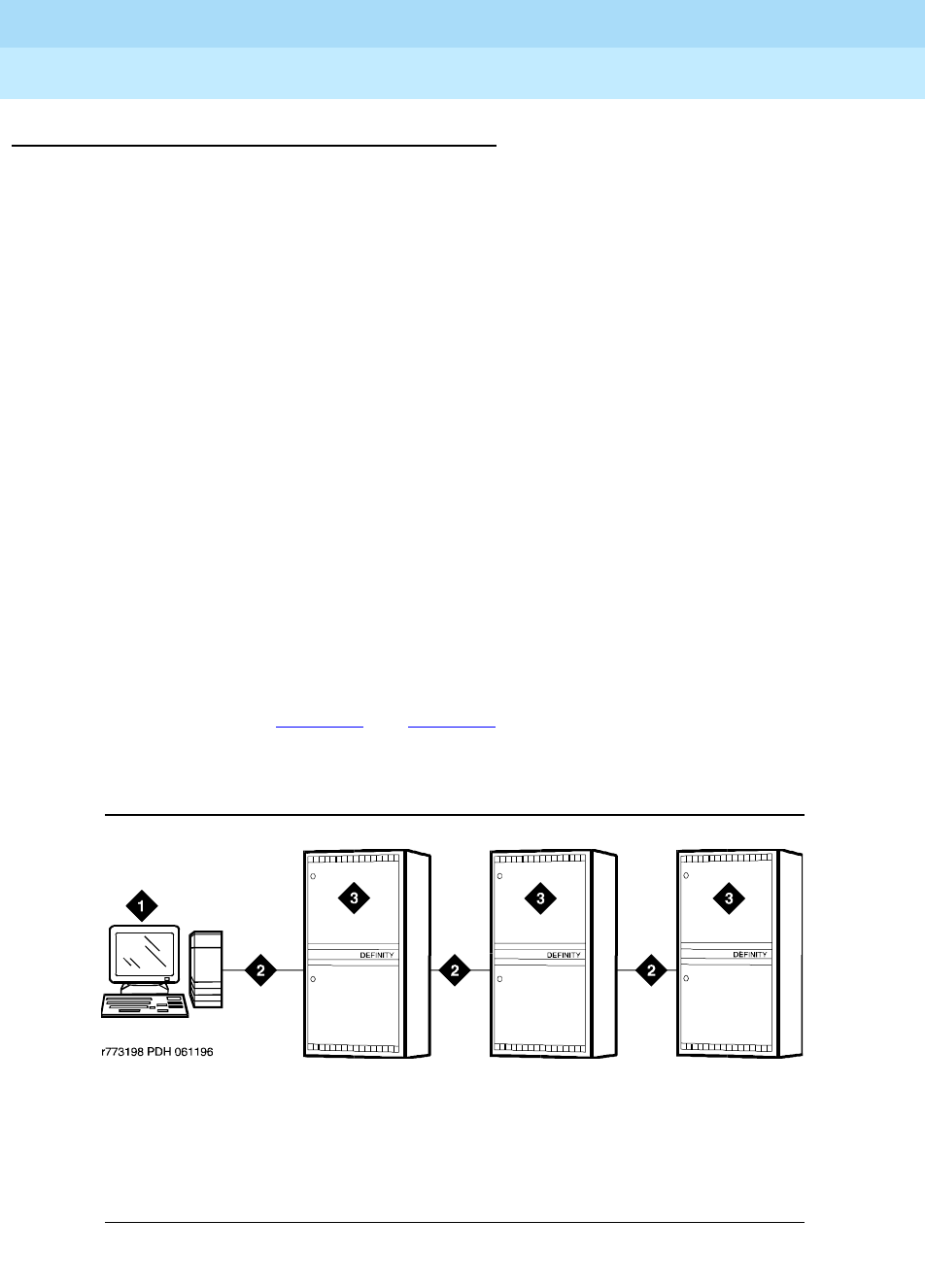
DEFINITY Enterprise Communications Server Release 6
Administration and Feature Description
555-230-522 Issue 4
May 1998
Trunk Group Administration
Page 7-27ISDN Trunks— General
7
Detailed description
In ISDN-PRI, the transmission standard for layer 1 (the physical layer) is either
DS1 T1 or E1. The DS1 T1 (used in North America and Japan) is a
digital-transmission standard that carries traffic at the rate of 1.544 Mbps, and
the E1 (used in Europe) carries traffic at a rate of 2.048 Mbps. The “D” (data)
channel multiplexes signaling messages for the “B” (bearer) channels carrying
voice or data. In a T1, when a D-channel is present, it occupies Channel 24. In an
E1, when a D-channel is present, it occupies channel 16.
DEFINITY ECS offers several administrable protocols, each of which provides a
different set of services that ISDN allows. See “DS1 Trunk Service” for more
information. These protocols are discussed in detail later in this section. The
following combination of services, including but not limited to Basic Call, Basic
Supplementary Services, Supplementary Services with Rerouting, Display, and
QSIG Networking are supported on the ISDN-PRI interface. The services
available with global ISDN are country dependent.
With ISDN, DEFINITY ECS interfaces with a wide range of other products
including switches, network switches, and host computers. These products
include earlier DEFINITY communications systems, public network switches (for
example, 4ESS, 5ESS, and Northern Telecom DMS250), and other products that
adhere to the ISDN signaling protocol.
As an example of how ISDN is used in private- and public-network
configurations, see Figure 7-1 and Figure 7-2. As seen, ISDN can be used to
connect a switch to a public-switched network, a switch to a host computer, or a
switch to another switch.
Figure 7-1. ISDN private network configuration
Figure Notes
1. Host computer
2. ISDN trunk
3. DEFINITY ECS
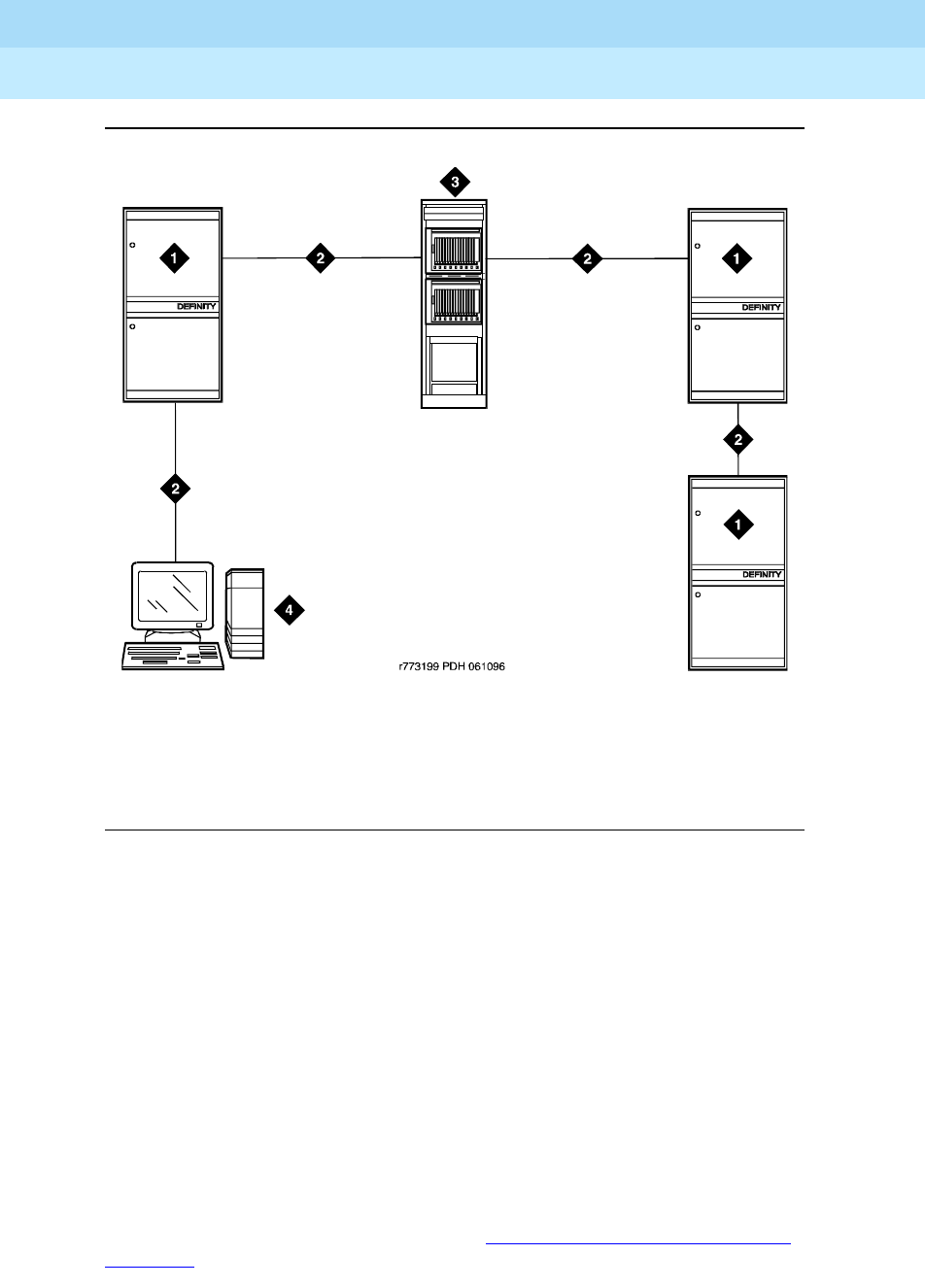
DEFINITY Enterprise Communications Server Release 6
Administration and Feature Description
555-230-522 Issue 4
May 1998
Trunk Group Administration
Page 7-28ISDN Trunks— General
7
Figure 7-2. ISDN public network configuration
AT&T Switched Network Protocol
DEFINITY ECS supports the AT&T Switched Network Protocol described in the
TR41449 (for 4ESS to common carrier) and TR41459 (for 5ESS to CO) ISDN
protocol standards as defined by AT&T. This protocol is used when the DS1
circuit pack is administered for Country Code 1, Protocol Version a. The AT&T
Switched Network provides you with the following services.
Access to AT&T Switched Network Services
ISDN provides access to AT&T Switched Network Services. See Service Type
on the ISDN Trunk Group form for a table that outlines these switched-network
services. An ISDN trunk group may be dedicated to a particular feature.
Alternately, an ISDN call-by-call trunk group may provide access to several
features. For a description of the services accessible via ISDN (either via
dedicated or call-by-call trunk groups), see ‘‘Call-by-Call Service Selection’’ on
page 7-42.
Figure Notes
1. DEFINITY ECS
2. ISDN trunk
3. Public switched network
4. Host computer

DEFINITY Enterprise Communications Server Release 6
Administration and Feature Description
555-230-522 Issue 4
May 1998
Trunk Group Administration
Page 7-29ISDN Trunks— General
7
Call Identification Display
ISDN Call Identification Display provides a transparent name and number
display for all display-equipped voice terminals within an ISDN network. The
feature is transparent in that the same information can be provided at all ISDN
facilities. Voice terminals using this feature should be digital voice terminals with
a 40-character alphanumeric display. The Merlin hybrid sets with 32-character
displays (7315H and 7317H) also support this feature.
ISDN Call Identification Display is provided in addition to the normal Voice
Terminal Display and Attendant Display features when the network supports
end-to-end ISDN connectivity. When both ISDN and DCS display information are
received, the switch can display either the DCS or ISDN call identification
information. If only ISDN display information is received, information displays in
ISDN format. See ‘‘Expanded technical information’’ on page 7-34 for more detail
on CPN and BN.
The display fields that may be used for ISDN are: Name, Number,
Miscellaneous Call Identification, and Reason for Call
Redirection. The display information varies, depending on the type of call,
how the call is handled (for example, whether it is redirected or not), and the
information is available on the call. The display information for basic calls (those
with just a caller and called party) and for redirected calls is provided in
‘‘Expanded technical information’’ on page 7-34.
CPN/BN to Host Call Identification
The CPN/BN to Host Call Identification enables CPN and BN information to be
passed from the switch to the ISDN Gateway, so that the ISDN Gateway can
forward the information to a host for data-screen delivery to agents in an ACD
split.
By delivering call-identification information such as CPN/BN and switch
information such as the answering-agent’s extension to an adjunct network (ISDN
Gateway), the adjunct automatically delivers data screens to agents for new call
arrivals and call transfers.
Figure 7-3 shows a simplified diagram of a CPN- and BN-to-host arrangement.
The ISDN Gateway is a UNIX or MSDOS computer connected to the switch on
one side and to a host computer on the other side. The connection to the switch
is over a synchronous interface with BX.25 protocol.
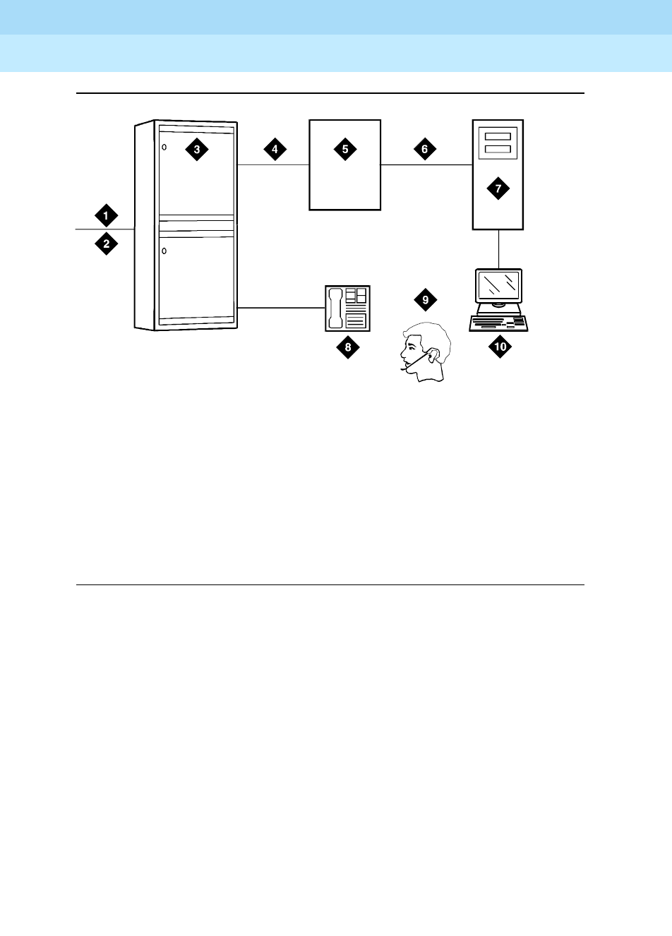
DEFINITY Enterprise Communications Server Release 6
Administration and Feature Description
555-230-522 Issue 4
May 1998
Trunk Group Administration
Page 7-30ISDN Trunks— General
7
Figure 7-3. CPN- and BN-to-host configuration
Private network services
In addition to providing access to switched-public networks, ISDN provides
private-network services by connecting DEFINITY ECS in an Electronic Tandem
Network (ETN), Distributed Communications System (DCS), or QSIG Network.
This gives you more efficient private networks that support new integrated voice
and data services. ETN, DCS, and QSIG networking services are provided as
follows.
ETN services
DEFINITY ECS that function as tandem nodes in an ETN can be interconnected
using DS1 trunking facilities with ISDN. All signaling between the tandem
switches is done with ISDN D-channel and normal ISDN protocol. The ISDN can
also be used to connect ETN tandem and main switches. In this case, the main
switch collects all of the address digits from local users as well as users at other
satellite and tributary switches, and originates a call over ISDN to the tandem
switch.
Figure Notes
1. ISDN trunk
2. SID/ANI
3. DEFINITY ECS
4. BX.25
5. ISDN Gateway
6. Existing interface
7. Host computer
8. Voice terminal
9. ACD agent position
10. Data terminal
r7
8
1
86
1
CJ
L
060996

DEFINITY Enterprise Communications Server Release 6
Administration and Feature Description
555-230-522 Issue 4
May 1998
Trunk Group Administration
Page 7-31ISDN Trunks— General
7
Automatic Alternate Routing (AAR) and Automatic Route Selection (ARS)
are used with ISDN and DS1 trunking facilities to access ETN facilities.
AAR and ARS are used to collect the dialing information for the call that is
originated from the main switch.
DCS services
ISDN-PRI facilities can be used in a DCS arrangement whenever tie trunks
are used to connect the DCS nodes. Most DCS features are not affected
by ISDN-PRI. However, there is a minor impact on a few of the DCS
features, as far as the functions that the local and remote switches
perform.
QSIG services
QSIG networking provides compliance to the International Organization
for Standardization (ISO) ISDN private-networking specifications. The
QSIG Networking platform is supported over the ISDN Basic Call setup
protocol. DEFINITY ECS supports QSIG Supplementary Services. For
more information, see ‘‘QSIG’’ on page 12-77.
Wideband Switching (ISDN-PRI only)
Wideband Switching provides support for services that require large bandwidth,
such as high-speed video conferencing. Wideband also supports multiple
channel calls end-to-end. These services have traditionally been handled by
dedicated facilities. With Wideband Switching, dedicated facilities are no longer
a requirement for these large bandwidth services.
Call-by-Call Service Selection
Call-by-Call Service Selection allows the same ISDN trunk group to carry calls to
a variety of services or facilities. Embodied in this feature is the ability to allocate
usage. It provides significant flexibility for creating user-defined incoming and
outgoing services and is used on any ISDN trunk group.
Access to Software Defined Data Network
With ISDN, the SDDN service may be accessed. SDDN provides virtual
private-line connectivity via the switched public network. The services provided
by SDDN include voice, data, and video applications. SDDN services
complement the ISDN voice services.
Access to Switched Digital International
Switched Digital International (SDI) provides 64 kbps of unrestricted connectivity
to international locations via the AT&T Switched Network. It is also the backbone
for the AT&T International ISDN network. SDI complements the ACCUNET digital
service already available to United States locations. This service can be
accessed using Call-by-Call Service Selection. SDI provides economical
high-speed data transfer to international locations.

DEFINITY Enterprise Communications Server Release 6
Administration and Feature Description
555-230-522 Issue 4
May 1998
Trunk Group Administration
Page 7-32ISDN Trunks— General
7
National ISDN-2 Services
DEFINITY ECS supports National ISDN-2 (NI-2), which offers many of the same
services as the AT&T Switched Network protocol. The NI-2 protocol is used when
the DS1 circuit pack is administered for Country Code 1, Protocol Version b.
NI-2 provides users with the following services:
■Calling Line Identification
■Non-Facility Associated Signaling (ISDN-PRI only)
■D-Channel Backup (ISDN-PRI only)
■Wideband Switching (ISDN-PRI only)
■Call-by-Call Service Selection
Calling Line Identification
Calling Line Identification for NI-2 is essentially Calling Party Number (CPN)
identification, as previously described.
Non-Facility Associated Signaling (ISDN-PRI only)
Non-Facility Associated Signaling (NFAS) allows an ISDN-PRI T1 or E1 Interface
D-channel (signaling channel) to convey signaling information for B-channels
(voice and data) on ISDN-PRI T1 or E1 facilities other than the one containing the
D-channel. See ‘‘Facility and Non-Facility Associated Signaling’’ on page 7-49 for
more information.
D-Channel Backup (ISDN-PRI only)
D-Channel Backup is provided to improve reliability in the event of a
signaling-link failure. See ‘‘Facility and Non-Facility Associated Signaling’’ on
page 7-49 for more information.
Wideband Switching (ISDN-PRI only)
Wideband Switching for NI-2 is essentially the same as that of the AT&T Switched
Network ISDN-PRI protocol.
Call-by-Call Service Selection
Call-by-Call Service Selection for NI-2 is essentially the same as that for the AT&T
Switched Network ISDN-PRI protocol.
ISDN interworking
ISDN interworking is a call that uses a combination of both ISDN trunking and
station facilities and non-ISDN trunking and station facilities. A non-ISDN trunking
facility is any trunk facility supported by the system that does not use the ITU-T
recommended Q.931 message set for signaling. Non-ISDN trunking facilities
include facilities such as analog trunks, AVD DS1 trunks, and DS1 trunks with
bit-oriented signaling (robbed-bit or common channel).
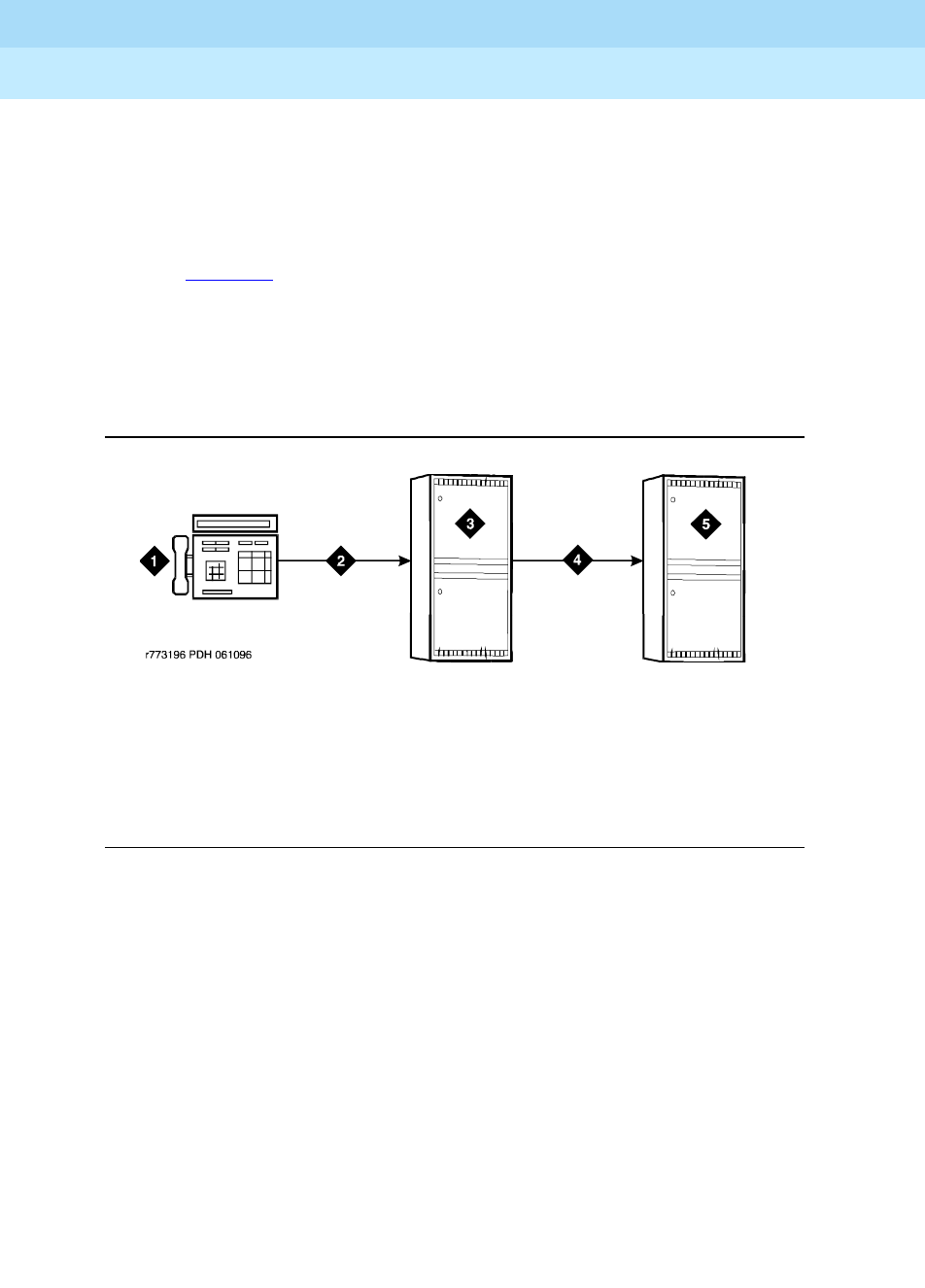
DEFINITY Enterprise Communications Server Release 6
Administration and Feature Description
555-230-522 Issue 4
May 1998
Trunk Group Administration
Page 7-33ISDN Trunks— General
7
DEFINITY ECS supports the conversion of ISDN signaling to non-ISDN in-band
signaling and the conversion of non-ISDN in-band signaling to ISDN signaling for
interworking purposes.
A mixture of ISDN and non-ISDN signaling is required in order to provide
end-to-end signaling when using different types of trunk or station facilities on a
call. See Figure 7-4 for an example of interworking. In this example, a call for
someone at Switch B comes into Switch A. Interworking allows the ISDN
signaling of the call to be converted at Switch A to non-ISDN in-band signaling
before the call forwards to Switch B. Even though the call comes into Switch A on
an ISDN trunk, Switch A can send the call to Switch B over a non-ISDN trunk by
converting the signaling information.
Figure 7-4. Interworking example
The system provides accurate CDR billing information on calls that are not
interworked. Accuracy of CDR billing information on interworked calls is
equivalent to the accuracy provided by the public network.
DEFINITY ECS supports sending a non-ISDN trunk name as the connected
name. Therefore, a non-ISDN trunk name can be sent as the connected name
even when a call starts out as an ISDN call but is interworked over non-ISDN
trunks.
Figure Notes
1. Call from network to Switch B
2. ISDN trunk
3. Switch A
4. Non-ISDN trunk
5. Switch B

DEFINITY Enterprise Communications Server Release 6
Administration and Feature Description
555-230-522 Issue 4
May 1998
Trunk Group Administration
Page 7-34ISDN Trunks— General
7
Expanded technical information
ISDN-related hardware
ISDN-PRI is supported by the TN767 circuit pack (for assignment of a T1
signaling link and up to 24 ISDN-PRI trunk group members), or the TN464C or
later circuit pack (for assignment of a T1 or E1 signaling link and up to 24 or 31
ISDN-PRI trunk group members, respectively). The TN2185 ISDN Trunk-side BRI
circuit pack supports the ISDN-BRI trunk group.
■For R6si and later configurations, the D-channel is switched through either
the TN765 Processor Interface (PI) circuit pack or the TN778 Packet
Control (PACCON) circuit pack.
■For R6r and later configurations, the D-channel is switched through the
TN1655 Packet Interface (PKTINT) circuit pack.
NOTE:
The TN767 cannot be used to carry the D-channel if either the TN778
(PACCON) or TN1655 (PKTINT) circuit pack is used to switch the
D-channel; however, the TN767, in these circumstances, can be used for
NFAS interfaces carrying only B-channels.
ISDN-BRI is supported by the TN2185 Trunk-side BRI circuit pack (for
implementing the user side on the BRI interface) and the TN556B (or TN556C)
and TN2198 ISDN BRI Line circuit packs.
■For R6si and R6vs and later configurations, the D-channel switches
through the TN7778 Packet Control circuit pack.
■For R6r and later configurations, the D-channel switches through the
TN1655 Packet Interface circuit pack.
A TN780 or TN2182 Tone Clock circuit pack provides synchronization for the
ISDN-BRI Trunk circuit pack.
Call Identification Display
Two types of identification numbers are provided with ISDN. These identification
numbers may be used in the various types of displays used with ISDN. The two
types of identification numbers are as follows:
■Calling Party Number (CPN): A 0–15 digit DDD number associated with a
specific station. When a system user makes a call that uses ISDN, that
user’s CPN is provided by the system for ISDN. ISDN public-unknown
numbering or ISDN private numbering forms are administered to create a
0–15 digit CPN from a local station number.
■Billing Number (BN): The calling party’s billing number, which is provided
to an inter-exchange network via Equal Access or Centralized Automatic
Message Accounting (CAMA). This number is stored at either a local or
network switch. If a customer is connected directly to the AT&T Switched

DEFINITY Enterprise Communications Server Release 6
Administration and Feature Description
555-230-522 Issue 4
May 1998
Trunk Group Administration
Page 7-35ISDN Trunks— General
7
Network, the BN is the customer’s billing number stored in that network. If
the CPN is not provided on an incoming ISDN call, the network uses the
BN for the station identification number.
The following types of display information are provided with ISDN.
■Calling Party’s Number
The calling party’s number appears on the called party’s display. This
number is provided only if the outgoing ISDN trunk group is administered
to send the CPN, and if ISDN public-unknown numbering or ISDN private
numbering forms are administered to create a CPN. On calls incoming to
a system, the network may provide either the CPN or BN as the calling
party’s number. Extensions and 12-digit international numbers display
without dashes. Dashes are only used for 7-digit and 10-digit numbers
when North American Area Code is enabled on the Dial Plan form.
■Calling Party’s Name
The calling party’s name appears on the called party’s display. On calls
generated from a DEFINITY ECS, the calling party’s name is provided if
the ISDN trunk group is administered to send the name to the network. On
calls incoming to a DEFINITY ECS, the (public or private) network may
provide the calling party’s name. If the calling party’s name is not
available, the called party’s display shows “CALL FROM” instead,
followed by the calling party’s number (if available).
■Connected Party’s Number
The connected party’s number appears on the calling party’s display. On
calls generated from a DEFINITY ECS, the called party’s number appears
on the calling party’s display as the calling party dials the number. If the
(public or private) ISDN network provides the connected party’s number,
the calling party’s display is updated to show the connected party’s
number. The format of the connected party’s number is the same as that of
the calling party’s number described previously on calls incoming to a
DEFINITY ECS. The 0–15 digit number of the party who answers the call is
provided to the ISDN network only if the incoming ISDN trunk group is
administered to send connected number to the network and ISDN
public-unknown numbering or ISDN private numbering forms are
administered to create a CPN.
NOTE:
The connected party may be the party actually called, in the event
the call is transferred before the connected party answers the call.
■Connected Party’s Name
The connected party’s name appears on the calling party’s display. On
calls generated from a DEFINITY ECS, the (public or private) ISDN
network may provide the connected party’s name to the DEFINITY ECS,

DEFINITY Enterprise Communications Server Release 6
Administration and Feature Description
555-230-522 Issue 4
May 1998
Trunk Group Administration
Page 7-36ISDN Trunks— General
7
when the call is answered. If the connected party’s name is not available,
the calling party’s display shows
ANSWERED BY
, followed by the
connected party’s number (if available).
On calls incoming to a DEFINITY ECS, the connected party’s name is
provided if the incoming ISDN trunk group is administered to send the
name to the network.
ISDN basic call
A basic ISDN call has both a caller and a called party, and the called party
answers the call. When the caller goes off-hook, a= appears on the display. The
digits then appear as they are dialed. These digits may be overwritten by the
trunk group name if Outgoing Display of the Trunk Group Administration form
is y. Once the called party (or a user with a bridged appearance for the called
party) answers the call, the displays for the caller and called parties are
described below.
■If
both the name and number information are available
, the displays are as
follows. The MISCID (Miscellaneous Identification) field may
be blank if that information is not available.
— Caller Display
a= CALLED NAME CALLED NUMBER MISCID
— Called Party Display
a= CALLER NAME CALLER NUMBER MISCID
■If
only the name information is available,
the displays are as follows:
— Caller Display
a= CALLED NAME MISCID
— Called Party Display
a= CALLER NAME MISCID
■If
only the number information is available,
the displays are as follows:
— Caller Display
a= ANSWERED BY CALLED NUMBER MISCID
— Called Party Display
a= CALL FROM CALLER NUMBER MISCID

DEFINITY Enterprise Communications Server Release 6
Administration and Feature Description
555-230-522 Issue 4
May 1998
Trunk Group Administration
Page 7-37ISDN Trunks— General
7
■If
neither the name nor the number information is available,
the displays
are as follows:
— Caller Display (shows one of the following, depending on
administration)
a= DIALED NUMBER MISCID
a= TRUNK NAME MISCID
— Called Party Display
a= TRUNK NAME MISCID
Redirected ISDN call
This is a call that has been redirected from the called party’s extension by a
feature such as Call Coverage, Call Forwarding All Calls, Bridged Call
Appearance, or Call Pickup. Once the call is connected, the displays for the
calling, called, and connected parties are as follows.
— Calling Party Display
a= CONNECTED NAME CONNECTED NUM MISCID
— Called Party Display
The following information appears on the display if the called party
bridges onto the redirected call after it has been answered. In this
situation, the connected party’s display (given later) shows the same
information. The calling party’s display is also updated if the calling and
called parties are on the same switch.
a= CONFERENCE 2
— Connected Party Display
The connected party is who answers the redirected call. The “R” indicates
the reason for redirection.
a= CALLING ID to CALLED ID R
The CALLING ID and the CALLED ID may be the name or the number,
depending on what has been received from the far end.

DEFINITY Enterprise Communications Server Release 6
Administration and Feature Description
555-230-522 Issue 4
May 1998
Trunk Group Administration
Page 7-38ISDN Trunks— General
7
Interactions
■Attendant Display
The information provided by ISDN Call Identification Display is in addition
to the display features already provided.
When an ISDN call is redirected to the attendant, and both name and
number display information is available, the name displays on the console
for the caller and called party identification. When a call is transferred or
conferenced, DEFINITY ECS can redisplay DCS and ISDN
caller/called/connected party information.
■Bridged Call Appearance
ISDN Call Identification Display information is provided at both the primary
extension and the extension with the bridged call appearance. Both
displays show the same called-party information, whether the call is made
from the primary extension or the bridged call appearance. On a call to a
primary extension, the caller’s display shows the identification of the called
primary extension, even if the call is answered by the bridged call
appearance.
■Call Forwarding
When an ISDN call is forwarded, no ISDN Call Identification Display
information is shown on the display of the forwarding extension.
The forwarded-to extension’s display shows information on the caller,
called party (if the forwarded-to station is on the same switch), and the
reason for redirection.
■Call Pickup
When an ISDN call is answered via Call Pickup, the caller’s display
identifies the answering party, the called party’s display identifies the
caller, and the answering party’s display identifies both the caller and
called parties.
■Caller Information Forwarding
With CINFO you can use a vector
collect digits
step to retrieve caller
entered digits (ced) and customer database-provided digits (cdpd)
supplied by the network in an incoming call’s ISDN SET UP message.
ISDN is required if the CINFO comes from the network.
■Conference — Attendant
A conference call is identified as a call with “n” number of conferees. This
display information generates locally and does not change the display on
another switch. If the conference call eventually drops back to a two-party
call, the original display information is restored.

DEFINITY Enterprise Communications Server Release 6
Administration and Feature Description
555-230-522 Issue 4
May 1998
Trunk Group Administration
Page 7-39ISDN Trunks— General
7
■Conference — Terminal
A conference call is identified as a call with “n” number of conferees. This
display information generates locally and does not change the display on
another switch. If the conference call eventually drops back to a two-party
call, the original display information is restored. However, when two DCS
and/or ISDN calls (or any possible combination of each) are conferenced
and revert to a two-party call, the trunk group of the remaining call
displays.
■DCS
If both DCS and ISDN features are provided over the same facility with a
DEFINITY ECS, DCS displays generally override ISDN displays. However,
with DEFINITY ECS, the ISDN connected name and number can override
the DCS called name and number if Display Connected
Name/Number for ISDN DCS Calls is y on the Feature-Related
System Parameters form
When two DCS and/or ISDN calls (or any possible combination of each)
are conferenced and revert to a two-party call, the trunk group of the
remaining call displays.
■Facility Restriction Level and Traveling Class Mark
The TCM used to pass on the originating facility’s FRL is sent by ISDN
facilities in the SETUP message only if the trunk services type is tandem.
■Hold
When an ISDN call is placed on Hold, the display of the party who
activates Hold goes blank, and then identifies the new caller or connected
party, if there is one. The held party’s display remains unchanged. When
the held party is reconnected to the holding party, the holding party’s
display is updated to indicate the current status of the call.
■Hunting
On ISDN calls to a hunt group extension, the caller’s display identifies
either the hunt group name or the group member who answers the call,
depending on hunt group administration.
■Information Indicator Digits (II-digits)
With II-digits you can make vector-routing decisions based on the type of
the originating line. II-digits are provided for an incoming call by ISDN-PRI.
It is a generally available ISDN AT&T Network service.
■LookAhead Interflow
LookAhead Interflow requires ISDN connectivity end-to-end over a private
network.

DEFINITY Enterprise Communications Server Release 6
Administration and Feature Description
555-230-522 Issue 4
May 1998
Trunk Group Administration
Page 7-40ISDN Trunks— General
7
■Look Ahead Routing
Look Ahead Routing allows you to continue to try to reroute an outgoing
ISDN call when initial attempts fail because you receive certain cause
values which indicate a congestion situation. You can indicate the next
route-pattern preference or indicate that the current route pattern should
be attempted again.
■Malicious Call Trace
ISDN calling number identification is sent when MCT notification is
activated on an ISDN trunk.
■Multiple Subscriber Number (MSN) - Limited
The ISDN standard MSN feature lets you assign multiple extensions to a
single BRI endpoint. A side effect of supporting the NT interface is the
MSN feature works with BRI endpoints allowing the Channel ID IE to be
encoded as “preferred.” The endpoint must be administered as the far
end of an NT-side ISDN-BRI trunk group. Also, you must use the Uniform
Dial Plan (UDP) feature to assign the desired extensions to the “node” at
the far end of the trunk group.
■Overlap Sending
You can administer overlap sending on AAR and ARS calls routed over
ISDN trunk groups. This allows you to send and receive digits one digit at
a time instead of enbloc. (With enbloc, digits are not sent until the entire
group of digits is received).
■Terminating Extension Group
On ISDN calls to a TEG, the caller’s display identifies either the group or
the group member who answers the call, depending on administration.
■Transfer
When a call is transferred across an ISDN trunk, the display of the party
who transfers the call goes blank. The transferred party’s display does not
change. The display of the transferred-to party identifies the party
transferred.
When an ISDN call is transferred to a party on the same switch as the
party who transfers the call, the information on the display of the party who
transfers the call shows on the transferred-to party’s display.
When QSIG Call Transfer is enabled for a non-DCS ISDN call, the
transferred-to party’s name and number displays for the party that was not
transferred.
■Voice Terminal
The information provided by ISDN Call Identification Display is in addition
to the display features already provided.
When an ISDN call is redirected to a voice terminal, and both name and
number display information are available, the name displays on the
terminal for the calling and called party identification. When a call is

DEFINITY Enterprise Communications Server Release 6
Administration and Feature Description
555-230-522 Issue 4
May 1998
Trunk Group Administration
Page 7-41ISDN Trunks— General
7
transferred or conferenced, DEFINITY ECS can redisplay DCS and ISDN
calling/called/connected party information. However, when two DCS
and/or ISDN calls (or any possible combination of each) are conferenced
and revert to a two-party call, the trunk group of the remaining call
displays.

DEFINITY Enterprise Communications Server Release 6
Administration and Feature Description
555-230-522 Issue 4
May 1998
Trunk Group Administration
Page 7-42Call-by-Call Service Selection
7
Call-by-Call Service Selection
Call-by-Call Service Selection enables a single ISDN trunk group to carry calls to
a variety of services. It does not require that each trunk group be dedicated to a
specific service. It allows you to set up various voice and data services and
features for a particular call.
How to administer Call-by-Call Service Selection
You administer Call-by-Call Service Selection on a per trunk group basis.
You can administer trunk Usage Allocation for multiple called numbers within a
given Service/Feature, or you can administer trunk Usage Allocation for incoming
or outgoing calls independent of Service/Feature.
Required forms
Form Field Page
System-Parameters
Customer-Options
■Version
■ISDN-PRI
■ISDN-BRI Trunks
■Usage Allocation Enhancements
5-277
ISDN-PRI Trunk Group
— Incoming Call Handling
Treatment (ICHT) Table
■Service Type
■Usage Alloc
■All
7-219
ISDN-BRI Trunk Group
— Incoming Call Handling
Treatment (ICHT) Table
■Service Type
■Usage Alloc
■All
7-198
Route Pattern ■IXC
■Service/Feature
■Band
8-67

DEFINITY Enterprise Communications Server Release 6
Administration and Feature Description
555-230-522 Issue 4
May 1998
Trunk Group Administration
Page 7-43Call-by-Call Service Selection
7
Detailed description
Call-by-Call Service Selection uses the same route patterns and route
preferences that are used by Automatic Alternate Routing (AAR), Automatic
Route Selection (ARS), and Generalize Route Selection (GRS). The service or
facility used on an outgoing Call-by-Call Service Selection call is determined by
information assigned in the AAR/ARS/GRS route patterns.
You can allow a variety of services to use a single trunk group. The system
obtains trunking efficiency by distributing traffic over all the available trunks.
Then you can assign services that are used on incoming and outgoing
Call-by-Call Service Selection calls.
Using Country Protocol 1, you integrate services and features such as
MEGACOM, ACCUNET, and INWATS onto a single transmission facility
(ISDN-PRI trunk group) with flexible assignment of trunks to each service or
feature. Calls such as an incoming 800 Service call that requires
through-switching as an Outgoing WATS call can be routed via the same facility.
See the ISDN-PRI trunk group form on page ‘‘ISDN-PRI trunk group’’ on page
7-219 for a listing of available services.
NOTE:
When the DEFINITY ECS is connected to 5ESS, all of the services
supported under the Lucent Technologies and NI-2 country options
are available.
A Call-by-Call Service Selection example is shown in Figure 7-5.
Required forms
Form Field Page
System-Parameters
Customer-Options
■Version
■ISDN-PRI Trunks
■ISDN-BRI Trunks
■Usage Allocation Enhancements
5-277
Network-Facilities ■All 7-100
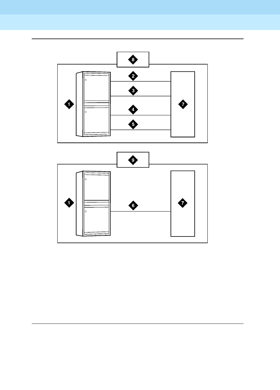
DEFINITY Enterprise Communications Server Release 6
Administration and Feature Description
555-230-522 Issue 4
May 1998
Trunk Group Administration
Page 7-44Call-by-Call Service Selection
7
Figure Notes
Figure 7-5. Call-by-Call Service Selection example
1. DEFINITY ECS
2. Megacom trunk group
3. Megacom 800 trunk group
4. SDN trunk group
5. OUTWATS trunk group
6. Call-by-Call Service Selection trunk group
7. Public-switched network
8. Without Call-by-Call Service Selection
9. With Call-by-Call Service Selection
r77
3
1
9
7
CJ
L
060396

DEFINITY Enterprise Communications Server Release 6
Administration and Feature Description
555-230-522 Issue 4
May 1998
Trunk Group Administration
Page 7-45Call-by-Call Service Selection
7
ISDN messages and information elements for Usage Allocation
Understanding the technical details of ISDN messages and information elements
may help you implement ISDN.
Call-by-Call Service Selection allows the system to specify one of the preceding
service types on a call-by-call basis. You can specify service types by classifying
incoming calls to an ISDN Call-By-Call trunk group using the called-party’s
number.
You can also specify service types with a SETUP message that indicates the
intent of the originating system to initiate a call using the specified service or
facility. The SETUP message may contain units called information elements (IE)
that specify call-related information. The IE used with Call-by-Call Service
Selection are:
■Network-Specific Facility (NSF) — Indicates which facilities or services are
to be used to complete the call (typically not used outside the US and
Canada).
The system also checks all incoming ISDN trunk calls for the presence of
an NSF IE. If an NSF IE is present, the system makes sure that the
requested service is compatible with the trunk administration before it
accepts a call.
For an outgoing call on a Call-By-Call trunk group, the NSF IE is
constructed using the Service/Feature specified on the routing-pattern
preference selected for the call.
If the Service/Feature specified does not have an associated NSF, an NSF
IE is not sent. For example, SETUP messages for incoming and outgoing
calls classified only by a called-party number do not contain an NSF IE.
■Transit Network Selection — Indicates which interexchange carrier is to be
used on an inter-LATA call.
If a call requires both the Service/Feature and the interexchange carrier to
be specified, the interexchange carrier information is sent in the NSF IE
rather than the Transit Network Selection IE.
Usage Allocation Plans
Optional Usage Allocation Plans (UAP) may be assigned to provide more control
over a Call-by-Call Service Selection trunk group. You can allocate a minimum
and maximum number of channels for incoming and outgoing called numbers,
privileged users, and voice and data calls.
A UAP allows the customer to set the following options:
■Maximum number of trunks that each service can use at any given
time.The sum for all services may exceed the total number of trunk-group
members. For example, for a15-member trunk group, you could
administer a maximum of seven MEGACOM service calls, six MEGACOM

DEFINITY Enterprise Communications Server Release 6
Administration and Feature Description
555-230-522 Issue 4
May 1998
Trunk Group Administration
Page 7-46Call-by-Call Service Selection
7
800 service calls, and eight SDN calls. This ensures that all trunk-group
members are not dominated by a specific service, yet allows for
fluctuations in demand.
■Minimum number of trunks that always must be available for each service.
The sum for all services may not exceed the total number of trunk-group
members. For example, for a 10-member trunk group that provides
access to MEGACOM service, MEGACOM 800 service, and SDN, the
minimum number of trunks to be used for each of these services cannot
add up to more than 10.
When these UAP limits are exceeded, the system rejects the call, even if a trunk
is available. On outgoing calls, the calling party receives a reorder tone unless
other preferences are available.
You can assign either fixed or scheduled UAP for each Call-by-Call Service
Selection trunk group.
■With a fixed UAP, one plan applies at all times.
■With a scheduled UAP, different plans can be administered to apply at
different times of day and days of week. As many as 6 activation times and
associated plans can be assigned for each day of the week.
You can have anything from a simple fixed UAP to a very flexible UAP with many
scheduling options. You can even start out with no UAP and build one as the
need arises.
Incoming Call-Handling Treatment
Call-by-Call Service Selection provides special Incoming Call-Handling
Treatment for ISDN trunk groups. An incoming call on an ISDN trunk is handled
according to a treatment table administered for the trunk group. Depending on
the platform you use, the table allows for a different number of combinations of
call treatments.
The treatment for an incoming call is selected based on the first 3 columns in the
ICHT table on the ISDN Trunk Group form. When the attributes of an incoming
call match these specifications, the call is treated according to the
corresponding following 4 columns. If an incoming call matches more than one
set of specifications, the most restrictive case applies. Table 7-4 lists the possible
cases from most restrictive to least restrictive.

DEFINITY Enterprise Communications Server Release 6
Administration and Feature Description
555-230-522 Issue 4
May 1998
Trunk Group Administration
Page 7-47Call-by-Call Service Selection
7
Considerations
Call-by-Call Service Selection provides the following benefits:
■Cost reduction — Since many services share the same trunks, the total
number of trunks can be reduced.
■Improved service — Features and services are less likely to be blocked.
■Simplified Networking — Network engineering is simplified because
analysis of trunking needs can be done based on total traffic instead of on
a per-service basis.
■Timely response to changes — With UAPs, the network does not have to
be consulted.
■Measurement of Call-by-Call Service Selection calls
Interactions
■Automatic Alternate Routing and Automatic Route Selection
Call-by-Call Service Selection uses the same routing tables and routing
preferences that are used by AAR and ARS.
Table 7-4. Call-by-Call Service Selection specifications
Service / Feature Called Len Called Number
Most restrictive Specified Specified x leading digits
specified
Specified Specified y leading digits
specified, where y < x
Specified Specified not specified
Specified Not specified not specified
“other” Specified x leading digits
specified
“other” Specified y leading digits
specified, where y < x
“other” Specified Not specified
Least restrictive “other” Not specified Not specified

DEFINITY Enterprise Communications Server Release 6
Administration and Feature Description
555-230-522 Issue 4
May 1998
Trunk Group Administration
Page 7-48Call-by-Call Service Selection
7
■Call Detail Recording
On successful call attempts using ISDN Call-By-Call trunk groups, CDR
records the NSF specified by the call’s NSF IE. CDR refers to this
information as the ISDN Network Service (INS). The value passed to CDR
is the 3-digit equivalent of NSF IE. NSF information for Facility Type 2 calls
(used with ISDN-Pri Call-by-Call trunk groups) also is recorded if the NSF
is available in the incoming SETUP message.
If an outgoing Call-by-Call Service Selection call uses an interexchange
carrier other than the presubscribed common carrier, CDR records the
3-digit or 4-digit Interexchange Carrier Code (IXC). CDR may not record
the IXC properly if the dialed-code format differs from the US IXC formats.
When a Call-by-Call Service Selection call is rejected because of a UAP,
CDR records the cause as an ineffective call attempt. The NSF recording
takes place also for the user-defined Facility Type 2. However, the NSF
recording takes place only if the NSF is available in the incoming SETUP
message.
■Generalized Route Selection
Call-by-Call Service Selection uses the same routing tables and routing
preferences used by GRS.
■Multiquest Flexible Billing
Do not use a Service/Facility with Facility Type set to 2 or 3. NSF
processing is not performed for Facility Type 2. An NSF is not included in
the outgoing SETUP message for Facility Type 3.
■Time-of-Day Routing
Any Time-of-Day Routing administration that affects routing preference
also affects Call-by-Call Service Selection. Use Time-of-Day Routing to
vary the IXC based on the time of day and day of week.
■Traffic Measurements
The system provides traffic measurements for each individual service
administered for a ISDN Call-by-Call Service Selection trunk group.

DEFINITY Enterprise Communications Server Release 6
Administration and Feature Description
555-230-522 Issue 4
May 1998
Trunk Group Administration
Page 7-49Facility and Non-Facility Associated Signaling
7
Facility and Non-Facility Associated
Signaling
Facility Associated Signaling (FAS) allows an ISDN-PRI T1/E1 interface
D-channel to carry signaling information for the 23 bearer (B) channels on its
associated span.
Non-Facility Associated Signaling (NFAS) allows an ISDN-PRI T1/E1 interface
D-channel to carry signaling information for the 23 bearer (B) channels on its
associated spans. With NFAS, one D-channel can carry signaling for up to 300
B-channels.
How to administer FAS and NFAS.
Detailed description
A D-channel can carry signaling information for numerous B-channels located on
different DS1/E1 circuit packs.
NOTE:
NFAS is only valid for DS1/E1 Country Protocol 1.
D-Channel Backup with NFAS
When NFAS is used, a backup D-channel can be administered to improve
reliability. The system switches to the backup D-channel if a signaling link failure
occurs on the primary D-channel span.
One D-channel is administered as the Primary D-channel and another D-channel
is administered as the Secondary D-channel. These assignments ensure that
both D-channels are in the same state at the same time and neither can be used
to carry B-channel traffic at any time. The Primary D-channel is given
precedence over the Secondary D-channel.
When D-Channel Backup is activated, all calls that have been answered are
preserved. However, some call-related information may be lost. Calls that are not
answered when D-channels are switched also may lose call-related information.
Required forms
Form Field Page
Signaling Group ■All 7-106
ISDN-PRI Trunk Group ■Port
■Sig Grp
7-219
DS1 Circuit Pack ■Signaling Mode 7-79
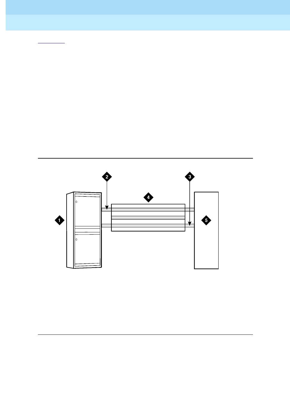
DEFINITY Enterprise Communications Server Release 6
Administration and Feature Description
555-230-522 Issue 4
May 1998
Trunk Group Administration
Page 7-50Facility and Non-Facility Associated Signaling
7
Figure 7-6 shows a possible configuration involving 3 ISDN-PRIs between a
DEFINITY ECS and another DEFINITY ECS or the public network. With DS1 (24
channel) interfaces, 2 of the ISDN-PRIs contain a D-channel and 23 B-channels,
while the other ISDN-PRI contains 24 B-channels. One of the D-channels is the
Primary D-channel, and the other is the Secondary D-channel. Together, this pair
of D-channels signals for all 70 (23+24+23) of the B-channels that are part of the
3 PRIs.
Since the D-channels are signaling for more than one DS1/E1 facility, D-Channel
Backup requires the use of NFAS. At any given time, one of the two D-channels is
carrying Layer 3 signaling messages, while the other D-channel is active at layer
2, but in a standby mode only. Any layer 3 messages received over the standby
D-channel are ignored. Since only one of the D-channels can be active at a time,
load sharing between the two D-channels is not possible. The two D-channels
can provide signaling for only a predefined set of B-channels and cannot
dynamically backup other D-channels on other interfaces.
Figure 7-6. Example D-Channel Backup with 3 ISDN-PRIs
Figure Notes
1. DEFINITY ECS
2. Secondary D-Channel
3. Primary D-Channel
4. ISDN-PRI controlled by D-Channel
5. Network Far-End Switch DEFINITY ECS
r7
8
17
99 CJ
L
060996

DEFINITY Enterprise Communications Server Release 6
Administration and Feature Description
555-230-522 Issue 4
May 1998
Trunk Group Administration
Page 7-51Facility and Non-Facility Associated Signaling
7
D-Channel Backup activation
■D-Channel Failure
If the signaling link fails on the active D-channel (D1) or the hardware
carrying D1 fails, the system sends a message over the standby
D-channel (D2). D2 then becomes the active D-channel and carries all
subsequent signaling messages. When the signaling link or hardware on
D1 recovers from the failure, D1 becomes the standby D-channel.
■System Technician Commands
If a system technician commands that a D-channel switchover take place,
the first action taken by the system is to tear down the signaling link on D1.
After this is completed, a message is sent on D2 to request that D2
become the active D-channel. D2 then becomes the active D-channel and
the switchover is complete.
Guidelines for administering FAS and NFAS
Coordinate the following when implementing FAS and NFAS:
■Decide which DS1/E1 facilities will use FAS.
■Decide which of the remaining DS1/E1 facilities carries D-channel
signaling information on the 16th (E1) or 24th (DS1) channel. For those
channels that have a D-Channel Backup, D-channel pairs must be
allocated.
■Define Signaling Groups. A Signaling Group is a group of B-channels for
which a given D-channel (or D-channel pair) carries the signaling
information. Each Signaling Group must be designated as either a FAS or
NFAS Signaling Group.
— A FAS Signaling Group must contain all the ISDN B-Channels on
the DS1/E1 interface associated with the group’s D-channel, and
cannot contain B-channels from any other DS1/E1 circuit pack. For
24-channel DS1 boards, some of the DS1 ports may use in-band
(robbed-bit) signaling and be members in a tie trunk group rather
than an ISDN trunk group. These tie trunks cannot be members of a
Signaling Group.
— There is no restriction on which DS1/E1 ports can belong to an
NFAS Signaling Group. Normally, an NFAS Signaling Group
consists of one or two D-channels and several complete DS1/E1
interfaces.
If a Signaling Group contains only a subset of a DS1/E1’s
B-channels (ports 1–12, for example), it is considered an NFAS
Signaling Group, not a FAS Signaling Group. The remaining
B-channels on the DS1/E1 are then assigned as members of
another NFAS Signaling Group.

DEFINITY Enterprise Communications Server Release 6
Administration and Feature Description
555-230-522 Issue 4
May 1998
Trunk Group Administration
Page 7-52Facility and Non-Facility Associated Signaling
7
■An Interface ID must be assigned to each DS1/E1 facility in an NFAS
Signaling Group. For example, if the B-channels in a Signaling Group
span 3 DS1/E1 facilities, a unique Interface ID must be assigned to each
of the 3 DS1/E1 facilities. This designation is required to uniquely identify
the same B-channel (port) number on each of the DS1/E1 facilities in the
Signaling Group. Therefore, this interface must be agreed upon by both
sides of the interface and administered prior to initialization.
■Primary and Secondary D-Channel Backup must be agreed upon by both
sides of the interface and administered prior to initialization. If the IDs do
not match, the signaling group will come up but calls will fail.
The following forms show the DS1 interface configuration for NFAS. When
implementing FAS and NFAS, the DS1 form must be submitted first, followed by
the Interface Link and associated forms, followed by the ISDN-PRI trunk group,
Signaling Group, and Trunk Group Members forms.
The Interface Link and associated forms may be administered at any time after
the DS1 forms have been administered, with the following restrictions:
■A D-channel cannot be assigned on a Signaling Group form unless the
associated link is disabled.
■A trunk member cannot be assigned unless its associated Signaling
Group has been administered.
The Signaling Mode must be specified for each DS1 circuit pack. Because
this circuit pack has Signaling Mode set to isdn-ext, all trunks on this circuit
pack are signaled using either inband robbed-bit signaling, or by a D-channel on
another DS1 circuit pack.
Screen 7-1. DS1 Circuit Pack form (Signaling Mode = isdn-ext)
Next, Signaling Groups are administered using Signaling Group forms.
Page 1 of 1
DS1 CIRCUIT PACK
Location: 1B17 Name: _______________
Bit Rate: 2.048 Line Coding: hdb3
Signaling Mode: isdn-ext
Interface Companding: 5law
Idle Code: 11111111
MAINTENANCE PARAMETERS
Slip Detection? n Remote Loop-Around Test? n

DEFINITY Enterprise Communications Server Release 6
Administration and Feature Description
555-230-522 Issue 4
May 1998
Trunk Group Administration
Page 7-53Facility and Non-Facility Associated Signaling
7
Screen 7-2. Signaling Group form (Group 1) — D-channel Backup, Three DS1
Interfaces
Screen 7-3. Signaling Group form (Group 2) — No D-channel Backup, Two
DS1 Interfaces
Screen 7-4. Signaling Group form (Group 3) — Facility Associated Signaling
Page 1 of 1
SIGNALING GROUP
Group Number : 1 Associated Signaling? n Max number of NCA TSC: 0
Primary D-Channel: 1B1524 Max number of CA TSC: 0
Secondary D-Channel: 1B1624 Trunk Group for NCA TSC: __
Trunk Group for Channel Selection: _____
Trunk Brd Interface ID Trunk Brd Interface ID
1: 1B15 0 11: ____ __
2: 1B16 1 12: ____ __
3: 1B17 2 13: ____ __
4: ____ __ 14: ____ __
5: ____ __ 15: ____ __
Page 1 of 1
SIGNALING GROUP
Group Number : 2 Associated Signaling? n Max number of NCA TSC: 0
Primary D-Channel: 1B1824 Max number of CA TSC: 0
Secondary D-Channel: ______ Trunk Group for NCA TSC: __
Trunk Group for Channel Selection: _____
Trunk Brd Interface ID Trunk Brd Interface ID
1: 1B17 0 11: ____ __
2: 1B18 1 12: ____ __
3: ____ __ 13: ____ __
4: ____ __ 14: ____ __
5: ____ __ 15: ____ __
Page 1 of 1
SIGNALING GROUP
Group Number : 3 Associated Signaling? y Max number of NCA TSC: 0
Primary D-Channel: 1B1924 Max number of CA TSC: 0
Trunk Group for NCA TSC: __
Trunk Group for Channel Selection: _____

DEFINITY Enterprise Communications Server Release 6
Administration and Feature Description
555-230-522 Issue 4
May 1998
Trunk Group Administration
Page 7-54Facility and Non-Facility Associated Signaling
7
Note that in Screen 7-2, Screen 7-3 and Screen 7-4:
■Signaling Group 1 B-channels on DS1 circuit packs (boards) B0 and B1
are signaled by D-channel pair B1524 (see Primary D-channel field)
and B1624 (see Secondary D-channel field).
■Signaling Group 2 B-channels on board B1 are signaled by D-channel
B1824.
■Board B0 has no D-channel. The B-channels on board B0 can be signaled
by either D-channel pair B1524/B1624 (Signaling Group 1) or D-channel
B1824 (Signaling Group 2).
■The DS1 interface on board B19 (Signaling Group 3) is a Facility
Associated Signaling case. Note that Secondary D-channel and
Trunk Board/Interface ID are not displayed when Associated
Signaling is y.
The following 2 communications-interface forms must be completed for the
ISDN-PRI interface on R5vs/si and later configurations if the D-channel is
switched through the TN765 Processor Interface (PI) circuit pack:
■Interface Links form — Used to create an association between the
D-channel on a DSI circuit pack and the port on a TN765 Processor
Interface circuit pack used for this link.
■Processor Channels form — Used to assign processor channels to the link
administered on the Interface Links form.
Finally, trunk ports are added to the ISDN-PRI trunk group and to Signaling
Groups.
.
Screen 7-5. ISDN-PRI Trunk Group form — Trunk Members with Required
Signaling Group
Page Y of X
TRUNK GROUP
Administered Members (min/max): xxx/yyy
Total Administered Members: xxx
GROUP MEMBER ASSIGNMENTS
Port Code Sfx Name Night Sig Grp
1: 1B1501___ ___________ _________ _
2: 1B1523___ ___________ _________ _
3: 1B1601___ ___________ _________ _
4: 1B1623___ ___________ _________ _
5: 1B1701___ ___________ _________ 1
6: 1B1709___ ___________ _________ 1
7: 1B1716___ ___________ _________ 2
8: 1B1724___ ___________ _________ 2
9: 1B1801___ ___________ _________ _
10: 1B1823___ ___________ _________ _
11: 1B1901___ ___________ _________ _
12: 1B1923___ ___________ _________ _
13: _________ ___________ _________ _
14: _________ ___________ _________ _
15: _________ ___________ _________ _

DEFINITY Enterprise Communications Server Release 6
Administration and Feature Description
555-230-522 Issue 4
May 1998
Trunk Group Administration
Page 7-55Facility and Non-Facility Associated Signaling
7
The Sig Grp column on the above trunk group form is completed as follows:
■If a DS1 interface appears in one and only one Signaling Group, then Sig
Grp may be left blank because the system automatically populates the
field with the correct Signaling Group.
■If a DS1 circuit pack appears in more than one Signaling Group, then the
Signaling Group numbers must be entered in the appropriate fields before
submitting the form.
Interactions
Non-Facility Associated Signaling is not supported with ISDN-BRI trunks.

DEFINITY Enterprise Communications Server Release 6
Administration and Feature Description
555-230-522 Issue 4
May 1998
Trunk Group Administration
Page 7-56Wideband Switching
7
Wideband Switching
Wideband Switching provides the ability to dedicate 2 or more ISDN-PRI
B-channels or DS0 endpoints for applications that require large bandwidth. It
provides high-speed end-to-end connectivity between endpoints where
dedicated facilities are not economic or appropriate.
How to administer Wideband Switching
Detailed description
ISDN-PRI divides a T1 or E1 trunk into 24 (31 for E1) information channels and
one signaling channel for standard narrowband communication. Certain
applications, like video conferencing, require greater bandwidth. You can
combine several narrowband channels into one wideband channel to
accommodate the extra bandwidth requirement. DEFINITY ECS serves as a
gateway to many types of high-bandwidth traffic. In addition, DS1 converters
(TN1654) are used for wideband switching at remote locations.
Wideband Switching supports:
■High-speed video conferencing
■WAN disaster recovery
■Scheduled batch processing (for example, nightly file transfers)
■LAN interconnections and imaging
■Other applications involving high-speed data transmission, video
transmission, or high bandwidth
Required forms
Form Field Page
Access Endpoint ■All 7-72
PRI Endpoint ■All 7-102
ISDN-PRI Trunk Group ■All 7-219
Route Pattern ■All 8-67
Fiber Link Administration (optional) ■All 5-146

DEFINITY Enterprise Communications Server Release 6
Administration and Feature Description
555-230-522 Issue 4
May 1998
Trunk Group Administration
Page 7-57Wideband Switching
7
Tab l e 7 - 5 provides information on Wideband Switching channel types.
Channel allocation
Perform wideband-channel allocation using one of three allocation algorithms:
fixed, flexible, or floating.
■Fixed allocation — Provides contiguous-channel aggregation. The starting
channel is constrained to a predetermined starting point. (Used only for
H0, H11, and H12 calls.)
■Flexible allocation — Allows a wideband call to occupy noncontiguous
positions within a single T1 or E1 facility.
■Floating allocation — Enforces contiguous-channel aggregation. The
starting channel is not constrained to a predetermined starting point.
Typical uses
A typical video application uses an ISDN-PRI interface to DS0 1 through 6 of the
line-side facility. See to Figure 7-7.
Table 7-5. Wideband switching channel types
Channel Type Number of Channels Data Rate
H0 6 384 Kbps
H11 24 1536 Kbps
H12 30 1920 Kbps
NXDS0 (T1) 2-24 128–1536 Kbps
NXDS0 (E1) 2-31 128–1984 Kbps
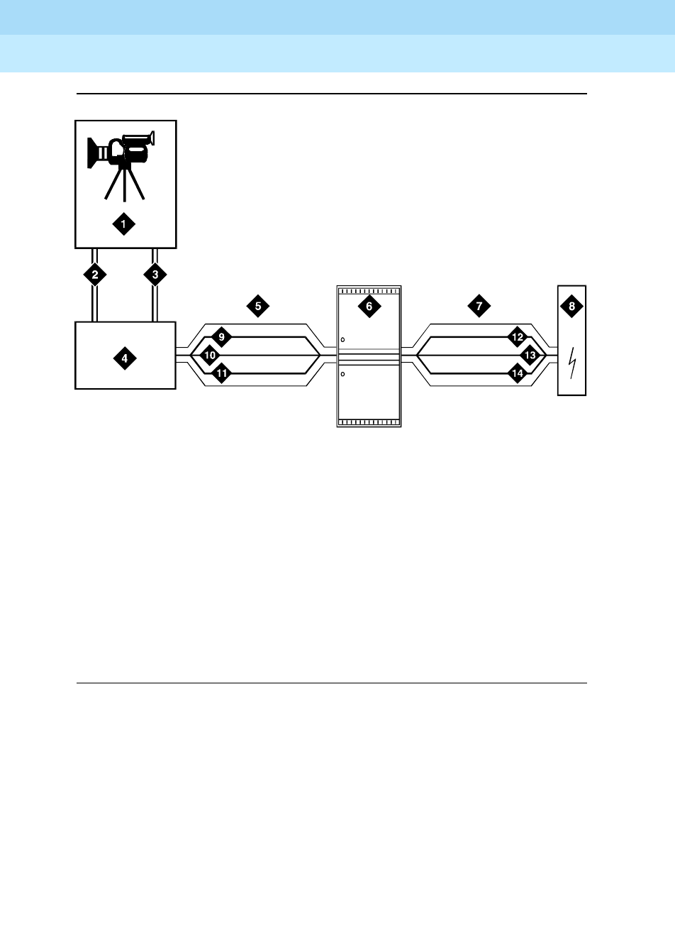
DEFINITY Enterprise Communications Server Release 6
Administration and Feature Description
555-230-522 Issue 4
May 1998
Trunk Group Administration
Page 7-58Wideband Switching
7
Figure Notes
Figure 7-7. Wideband Switching Video Application
Endpoint applications
An endpoint application is the origination or destination point of a wideband call.
Endpoint applications can be any number of data applications based on the
customer’s particular needs.
ISDN-PRI terminal adapters
ISDN-PRI terminal adapters translate standard ISDN signaling into a form that
can be used by the endpoint application and vice versa. The terminal adapter
also must adhere to the PRI-endpoint boundaries as administered on the
DEFINITY ECS switch when handling both incoming (to the endpoint)
applications and outgoing calls.
1. Video application
2. Port 1
3. Port 2
4. ISDN terminal adaptor
5. Line-side ISDN-PRI
6. DEFINITY ECS
7. ISDN trunk
8. Network
9. DS0 24 D-channel
10. DS0 23 unused
11. DS0 1–6 wideband
12. DS0 24 D-channel
13. DS0 7–23 narrow bands
14. DS0 1–6 wideband
wdbndex CJL 061996

DEFINITY Enterprise Communications Server Release 6
Administration and Feature Description
555-230-522 Issue 4
May 1998
Trunk Group Administration
Page 7-59Wideband Switching
7
The terminal adapter passes calls to and receives calls from the line-side
ISDN-SETUP messages indicating the data rate and specific B-channels (DS0)
to be used and communicates all other call status information via standard ISDN
messages. See the
DEFINITY Line-Side ISDN Primary Rate Interface Technical
Reference
for more information.
Line-side (T1 or E1) ISDN-PRI facility
A line-side ISDN-PRI (T1 or E1) facility is comprised of a group DS0s (24 for a T1
facility and 32 for an E1 facility). In this context, these DS0s are also called
channels. There are 23 B-channels and a single D-channel for a T1 facility and
30 B-channels and a single D-channel for an E1 facility. Data flows
bi-directionally across the facility between the switch and the ISDN-PRI terminal
adapter.
PRI-endpoints
A PRI-endpoint (PE) is a combination of DS0 B-channels on a line-side T1 or E1
ISDN-PRI facility that has been assigned an extension.
A PRI-endpoint can support calls of lower bandwidth. In other words, a PE
having a width 6 (six DS0s) can handle a call of one channel (64 Kbps) up to and
including six channels (384 Kbps). Also, a PE can support calls on non-adjacent
channels. For example, an endpoint application connected to a PE defined as
using B-channels 1 through 6 of an ISDN-PRI facility could originate a call using
B-channels 1, 3, and 5 successfully. If the PE has been administered to use
flexible channel allocation, the algorithm for offering a call to the PE starts from
the first DS0 administered to the PE. Since only one active call is permitted on a
PE, contiguous B-channels are always selected unless one or more B-channels
are not in service.
A PE remains in service unless all of its B-channels are out of service. In other
words, if B-channel 1 is out of service and the PE is five B-channels wide, a
wideband call of up to four B-channels in width could still be handled by the PE.
A PE can only be active on a single call at any given time, that is, it is either
considered idle, active (busy), or out of service.
One facility can support multiple separate and distinct PRI-endpoints (several
extensions) within a single facility. Non-overlapping contiguous sets of DS0s
(B-channels) are associated with each PE.
Universal digital signal level 1 board
The UDS1 board is the interface for line-side and network facilities carrying
wideband calls. The board is a TN464C or later circuit pack.
Non-signaling configuration
Wideband can also support configurations using non-signaling (non-ISDN-PRI)
line-side T1 or E1 facilities. The endpoint applications are the same as those
defined for configurations with signaling.

DEFINITY Enterprise Communications Server Release 6
Administration and Feature Description
555-230-522 Issue 4
May 1998
Trunk Group Administration
Page 7-60Wideband Switching
7
Data service unit/channel service unit
This unit simply passes the call to the endpoint application. Unlike terminal
adapters, the DSU/CSU does not have a signaling capability.
NOTE:
No DSU/CSU is needed if the endpoint application has a fractional T1
interface.
Line-side (T1 or E1) facility
This facility, like the ISDN-PRI facility, is composed of a group of DS0s (24 for a
T1 facility and 31 for an E1 facility). Line-side facilities are controlled solely from
the switch. Through the access-endpoint command, a specific DS0 or group of
DS0s is assigned an extension. This individual DS0 or group, along with the
extension, is known as a wideband access endpoint (WAE).
Wideband access endpoint
WAEs have no signaling interface to the switch. These endpoints simply transmit
and receive wideband data when the connection is active.
NOTE:
The switch can determine if the connection is active, but this does not
necessarily mean that data is actually coming across the connection.
A WAE is treated as a single endpoint and can support only one call. If all DS0s
comprising a wideband access endpoint are in service, then the wideband
access endpoint is considered in service. Otherwise, the wideband access
endpoint is considered out of service. If an in-service wideband access endpoint
has no active calls on its DS0s, it is considered idle. Otherwise, the wideband
access endpoint is considered busy.
Multiple WAEs are separate and distinct within the facility and endpoint
applications must be administered to send and receive the correct data rate over
the correct DS0s. An incoming call at the incorrect data rate is blocked.
Guidelines and examples
This section examines wideband and its components in relation to the following
specific customer usage scenarios:
■High-speed video conferencing
■Data backup connection
■Scheduled batch processing
■Primary data connectivity
■Networking

DEFINITY Enterprise Communications Server Release 6
Administration and Feature Description
555-230-522 Issue 4
May 1998
Trunk Group Administration
Page 7-61Wideband Switching
7
High-speed video conferencing
All data rates are multiples of 64 Kbps; from 128 Kbps to 1,536 Kbps (T1) and
1,984 Kbps (E1) are supported. Key customer data rates are listed in Table 7-5.
Data backup connection
Using wideband for data transmission backup provides customers with alternate
transmission paths for critical data in the event of primary transmission path
failure.
Scheduled batch processing
Scheduled batch processing applications are used for periodic database
updates (for example, retail inventory) or distributions (for example, airline fare
schedules). These updates are primarily done after business hours and are often
referred to as nightly file transfers. Wideband meets the high bandwidth
requirements at low cost for scheduled batch processing. In addition, wideband
allows the dedicated-access bandwidth for busy-hour switch traffic to be used
for these applications after business hours; no additional bandwidth costs are
incurred.
The non-ISDN backup data connection is also appropriate for scheduled batch
processing applications. Administered Connections are used to schedule daily
or weekly sessions originating from this application.
Primary data connectivity
Permanent data connections (those always active during business hours), such
as interconnections between LANs, are well suited for DEFINITY ECS when
ISDN-PRI endpoints are used. The ISDN end-to-end monitoring and the
endpoint’s ability to react to failures provide for critical data availability needs.
With ISDN, endpoints can detect network failures and initiate backup
connections through the switch; ISDN endpoints can also establish additional
calls when extra bandwidth is needed.
Any failures not automatically restored by DEFINITY ECS are signaled to the
endpoint application, which can initiate backup data connections over the same
PRI endpoint. DEFINITY ECS routes the backup data connections over alternate
facilities if necessary.
Networking
All of the wideband networking is over ISDN-PRI facilities but may connect to a
variety of networks, other domestic interexchange carriers’ services, private line,
RBOC services, and services in other countries.

DEFINITY Enterprise Communications Server Release 6
Administration and Feature Description
555-230-522 Issue 4
May 1998
Trunk Group Administration
Page 7-62Wideband Switching
7
ISDN-PRI trunk groups and channel
allocation
Only ISDN-PRI trunks support wideband calls to the network. Wideband’s
bandwidth requirements have necessitated modification of the algorithms by
which trunks look for clear channels. The following section describes the search
methods and their relationship to the available wideband data services.
Facility lists
A wideband call accessing the network must reside on a single ISDN-PRI facility.
Trunks within a trunk group must be organized based on the facility on which they
reside. This is accomplished by compiling a facility list as trunks are
administered to a trunk group; if a trunk is added to a trunk group from a facility
not already on that trunk group’s list, that facility is added to the list in an order
based on the facility’s signaling group number and interface identifier. In other
words, the facility list is compiled in an ascending order based first on signaling
group number and second on the interface identifier assigned to the facility
within the signaling group. For example, if three facilities having signaling
group/interface identifier combinations of 1/1, 1/2, and 2/1 were associated with
a trunk group, then a call offered to that trunk group would search those facilities
in the order as they were just listed. Also note that since trunks within a given
facility can span several trunk groups, a single facility can be associated with
several different trunk groups.
Given this facility list concept, the algorithms have the ability to search for trunks,
by facility, in an attempt to satisfy the bandwidth requirements of a given
wideband call. If one facility does not have enough available bandwidth to
support a given call, or it is not used for a given call due to the constraints
presented in the following section, then the algorithm searches the next facility in
the trunk group for the required bandwidth (if there is more than one facility in the
trunk group).
In addition to searching for channels based on facilities and required bandwidth,
Port Network (PN) preferential trunk routing is also employed. This PN routing
applies within each algorithm at a higher priority than the constraints put on the
algorithm by the parameters listed later in this section. In short, all facilities that
reside on the same PN as the originating endpoint are searched in an attempt to
satisfy the bandwidth of a given call, prior to searching any facilities on another
PN.
Direction of trunk/hunting within facilities
The algorithms have the ability to select trunks from low B-channel to high
B-channel or from high B-channel to low B-channel with an ISDN facility. This is a
per ISDN trunk group option, but infers the direction of search within all ISDN
facilities (or portions of those facilities) administered within that trunk group. This
is necessary so the selection of trunks are not prone to as much glare as they
otherwise would be if trunks were chosen in the same direction by both user and

DEFINITY Enterprise Communications Server Release 6
Administration and Feature Description
555-230-522 Issue 4
May 1998
Trunk Group Administration
Page 7-63Wideband Switching
7
network sides of the ISDN interface. Note that in previous DEFINITY ECS
releases, the order in which trunks were selected, whether through linear or
circular hunting, would always be with respect to the order in which trunks were
administered within the trunk group. Now, with the support of wideband services,
all trunks within an ISDN trunk group optioned for wideband are ordered based
on this new “direction of trunk/hunt with facilities” parameter, and without regard
to the order in which trunks are administered within the trunk group. If an ISDN
trunk group is not optioned for wideband, then a cyclical trunk hunt based on the
administration of trunks within the trunk group is still available.
H11
When a trunk group is administered to support H11, the algorithm to satisfy a call
requiring 1,536 Kbps of bandwidth uses a fixed allocation scheme. That is, the
algorithm searches for an available facility using the following facility-specific
channel definitions.
■T1: H11 can only be carried on a facility without a D-channel being
signaled in an NFAS arrangement (B-channels 1-24 are used).
■E1: Although the 1,536-kbps bandwidth could be satisfied using a number
of fixed starting points (for example, 1, 2, 3, etc.) the only fixed starting
point being supported is 1. Hence, B-channels 1–15 and 17–25 are
always used to carry an H11 call on an E1 facility.
If the algorithm cannot find an available facility within the trunk group that meets
these constraints, then the call is blocked from using this trunk group. In this
case, the call may be routed to a different trunk group preference via
Generalized Route Selection (GRS), at which time, based on the wideband
options administered on that trunk group, the call would be subject to another
hunt algorithm (that is, either the same H11 algorithm or perhaps an N x DS0
algorithm described in a later paragraph).
This same hunt algorithm, when offered any other call (other than a 1,920-kbps
call) attempts to preserve idle facilities by selecting trunk(s) in a partially
contaminated facility if one exists. If the bandwidth required by this call cannot
be satisfied by any partially contaminated facility, then the call is placed on
available trunk(s) within an idle facility, thus contaminating the facility. Again,
facilities are selected via the trunk group’s facility list and with PN preference,
and trunk(s) within a facility are selected based on the direction of channel
search administered. Note that on a T1 facility, a D-channel is not considered a
busy trunk and results in a facility with a D-channel always being partially
contaminated. On an E1 facility, however, a D-channel is not considered a busy
trunk because H11 and H12 calls may still be placed on that facility; an E1 facility
with a D-channel and idle B-channels is considered an idle facility.

DEFINITY Enterprise Communications Server Release 6
Administration and Feature Description
555-230-522 Issue 4
May 1998
Trunk Group Administration
Page 7-64Wideband Switching
7
H12
Since H12 is 1,920 Kbps which is comprised of 30 B-channels, a 1,920-kbps call
can only be carried on an E1 facility. As with H11, the hunt algorithm uses a fixed
allocation scheme with channel 1 being the fixed starting point. Hence, an H12
call always is carried on B-channels 1 to 15 and 17 to 31 on an E1 facility (as
illustrated in the following table). When offered any other call (other than a
1,536-kbps call), the algorithm behaves as it does when H11 is optioned.
H0
When a trunk group is administered to support H0, the algorithm to satisfy a call
requiring 384 Kbps of bandwidth also uses a fixed allocation scheme. Unlike the
H11 fixed scheme which only supports a single fixed starting point, the H0 fixed
scheme supports four (T1) or five (E1) fixed starting points. The H0 algorithm
searches for an available quadrant within a facility based on the direction of trunk
or hunt administered. If the algorithm cannot find an available quadrant within
any facility allocated to this trunk group, then the call is blocked from using this
trunk group. Again, based on GRS administration, the call may route to a different
trunk group preference and be subject to another algorithm based on the
wideband options administered.
This same trunk or hunt algorithm, when offered any narrowband or N x DS0 call,
attempts to preserve idle quadrants by choosing a trunk(s) in a partially
contaminated quadrant if one exists. If a partially contaminated quadrant
capable of carrying the call does not exist, then the call is placed on available
trunk(s) within an idle quadrant, thus contaminating the quadrant. Again, facilities
are selected via the trunk group’s facility list and with PN preference, and a
trunk(s) within a facility is selected based on the direction administered. Note that
a D-channel is considered a busy trunk and results in the top most quadrant of a
T1, B-channels 19 to 24, always being partially contaminated. This is
not true
for
NFAS.
If this H0 optioned trunk group is also administered to support H11, H12, or N x
DS0, then this algorithm also attempts to preserve idle facilities. In other words,
when offered a narrowband, H0, or N x DS0 call, the algorithm searches
partially-contaminated facilities before it searches to idle facilities.
DS0s Comprising Each Channel
Facility
ISDN
Interface H11 H12
T1
T1
23B + D
24B (NFAS)
-
1-24
-
-
E1
E1
30B + D
31B (NFAS)
1-15, 17-25
1-15, 17-25
1-15, 17-31
1-15, 17-31

DEFINITY Enterprise Communications Server Release 6
Administration and Feature Description
555-230-522 Issue 4
May 1998
Trunk Group Administration
Page 7-65Wideband Switching
7
N x DS0
For the N x DS0 multi-rate service, a trunk group parameter determines whether
a floating or a flexible trunk allocation scheme is to be used. The algorithm to
satisfy an N x DS0 call is either floating or flexible.
■Floating (Contiguous) — In the floating scheme, an N x DS0 call is placed
on a contiguous group of B-channels large enough to satisfy the
requested bandwidth without any constraint being put on the starting
channel (that is, no fixed starting point trunk).
■Flexible — In the flexible scheme, an N x DS0 call is placed on any set of
B-channels as long as the requested bandwidth is satisfied. There is
absolutely no constraint such as contiguity of B-channels or fixed starting
points. Of course, as with all wideband calls, all the B-channels
comprising the wideband call must reside on the same ISDN facility.
Regardless of the allocation scheme employed, the N x DS0 algorithm,
like the H11 and H12 algorithms, attempts to preserve idle facilities when
offered B, H0, and N x DS0 calls. This is important so that N x DS0 calls,
for large values of N, have a better chance of being satisfied by a given
trunk group. However, if one of these calls cannot be satisfied by a
partially-contaminated facility and an idle facility exists, a trunk on that idle
facility is selected, thus contaminating that facility.
There are additional factors to note regarding specific values of N and the
NxDS0 service:
— N = 1 — this is considered a narrowband call and is treated as any
other voice or narrowband-data (B-channel) call.
— N = 6 — if a trunk group is optioned for both H0 and N x DS0
service, a 384-kbps call offered to that trunk group is treated as an
H0 call and the H0 constraints apply. If the H0 constraints cannot
be met, then the call is blocked.
— N = 24 — if a trunk group is optioned for both H11 and N x DS0
service, a 384-kbps call offered to that trunk group is treated as an
H0 call and the H0 constraints apply. If the H0 constraints cannot
be met, then the call is blocked.
— N = 24 — if a trunk group is optioned for both H11 and N x DS0
service, a 1,536-kbps call offered to that trunk group is treated as
an H11 call and the H11 trunk allocation constraints apply.
— N = 30 — if a trunk group is optioned for both H12 and N x DS0
service, a 1,920-kbps call offered to that trunk group is treated as
an H12 call and the H12 trunk allocation constraints apply.

DEFINITY Enterprise Communications Server Release 6
Administration and Feature Description
555-230-522 Issue 4
May 1998
Trunk Group Administration
Page 7-66Wideband Switching
7
Glare and blocking
Glare prevention
Glare occurs when both sides of an ISDN interface select the same B-channel for
call initiation. For example, a user side of an interface selects the B-channel for
an outgoing call and, before the switch receives and processes the SETUP
message, the switch selects the same B-channel for call origination. Since
wideband uses more channels, the chances of glare are greater. Glare
conditions can be limited with proper channel administration but may never be
eliminated and some calls might still be dropped.
Some glare situations might not be resolvable. In one case, the network and the
user side may send SETUP messages simultaneously or nearly simultaneously.
Another glare scenario can occur in the brief window after the SETUP message
has been sent but before the first response is received from the switch at the
other side of the interface. If an incoming SETUP arrive during this window, the
incoming SETUP message is allowed to proceed and the outgoing call is
dropped. Various glare situations and their resolution are described in Ta b l e 7 -6 .
DEFINITY ECS does not negotiate channels for wideband calls.
Table 7-6. Handling Glare
GLARE RESOLUTION
Outgoing
Call Type
Incoming
Call Type
Switch-Supporting
User Protocol
Switch-Supporting
Network Protocol
B-channel B-channel No negotiation
Incoming call (from
network) wins
Negotiation is attempted
Incoming call (from user)
dropped if negotiation is
unsuccessful
Outgoing call (to network)
retried on another trunk Outgoing call (to user) stays
up
B-channel(s) Wide No negotiation No negotiation
Incoming call (from
network) dropped Incoming call (from user)
dropped
Outgoing calls (to network)
stay up but likely are
dropped by network
because channels are in
use, although there is a
possibility some switches
might negotiate these calls.
Outgoing calls (to user) stay
up and possibly stay up if
other side lets the network
call win.
Continued on next page

DEFINITY Enterprise Communications Server Release 6
Administration and Feature Description
555-230-522 Issue 4
May 1998
Trunk Group Administration
Page 7-67Wideband Switching
7
To reduce glare probability, the network needs to be administered so both sides
of the interface select channels from opposite ends of facilities. For example, on
a 23B+D trunk group, the user side could be administered to select B-channels
starting at channel 23 while the network side would be administered to start
selecting at channel 1. Using the same example, if channel 22 is active but
channel 23 is idle, the user side should select channel 23 for re-use. This is
known as linear trunk hunt and is the hunt option used by DEFINITY ECS for
wideband.
Blocking prevention
Blocking occurs when insufficient B-channels required to make a call are
available. Narrowband calls require only one channel so blocking is less likely
than with wideband calls which require multiple B-channels. Blocking also
occurs for wideband calls when bandwidth is not available in the appropriate
format (that is, fixed, floating, or flexible).
DEFINITY ECS selects trunks for both wideband and narrowband calls to
maximize availability of idle fixed channels for H0, H11, and H12 calls and idle
floating channels for N x DS0 calls that require a contiguous bandwidth. The
strategy for preserving idle channels to minimize blocking depends on the
channel type.
Wide B-channel(s) No negotiation Negotiation is attempted
Incoming call (from
network) wins Incoming call (from user)
dropped if negotiation is
unsuccessful
Outgoing call (to network)
retried on another trunk Outgoing call (to user) stays
up
Wide Wide No negotiation No negotiation
Incoming call (from
network) dropped Incoming call (from user)
dropped
Outgoing call (to network)
stays up but likely are
dropped by network
because channels are in
use.
Outgoing call (to user) stays
up and may not be dropped
by other side because other
side, if it is not a DEFINITY
ECS, may let the network
call win.
Table 7-6. Handling Glare — Continued
GLARE RESOLUTION
Outgoing
Call Type
Incoming
Call Type
Switch-Supporting
User Protocol
Switch-Supporting
Network Protocol
Continued on next page

DEFINITY Enterprise Communications Server Release 6
Administration and Feature Description
555-230-522 Issue 4
May 1998
Trunk Group Administration
Page 7-68Wideband Switching
7
Considerations
■Glare arises when both sides of an ISDN-PRI interface simultaneously
select the same B-channel for call initiation. Because Wideband Switching
uses multiple B-channels, the possibility of glare is greater than it is with
other calls.
■To reduce glare, administer the system so that each side of the ISDN-PRI
interface selects channels from opposite ends of the interface.
■For wideband switching with non-ISDN-PRI equipment, you can use an
ISDN-PRI terminal adapter.
■For example, if the user side is provisioned to start at the high side (DS0
23) and DS0 22 is idle but DS0 23 is active, reselect DS0 22 for the next
call. This is known as linear trunk hunting. Only the direction of hunt is
administrable.
■Blocking occurs when not enough bandwidth is available for a call.
■To reduce blocking, the switch selects trunks to maximize availability of
idle fixed channels for H0, H11, and H12 calls and idle floating channels
for NxDS0 calls. The strategy depends on the channel type. The chances
for blocking are reduced if you use a flexible algorithm, assuming it is
supported on the other end.
Interactions
■Administered Connections
Provides call initiation for WAEs. All Administered Connections that
originate from WAEs use the entire bandwidth administered for WAE. The
destination of an Administered Connection can be a PRI endpoint.
■Automatic Circuit Assurance
Treats wideband calls as single-trunk calls so that a single ACA-referral
call is made if an ACA-referral call is required. The call is on the lowest
B-channel associated with the wideband call.
Channel Type Blocking Minimization Strategy
H0 Preserve idle quadrants
H11 Preserve idle facilities
H12 Preserve idle facilities
Flexible NxDS0 Preserve idle facilities
Floating NxDS0 Preserve idle facilities as first priority

DEFINITY Enterprise Communications Server Release 6
Administration and Feature Description
555-230-522 Issue 4
May 1998
Trunk Group Administration
Page 7-69Wideband Switching
7
■Call Coverage
A wideband endpoint extension cannot be administered as a coverage
point in a call-coverage path.
■Call Detail Recording
When CDR is active for the trunk group, all wideband calls generate CDR
records. The feature flag indicates a data call and CDR records contain
bandwidth and Bearer Capability Class (BCC).
■Call Forwarding
You must block Call Forwarding through Class of Service.
■Call Management System and Basic Call Management System
Wideband calls can be carried over trunks that are measured by CMS and
BCMS. Wideband endpoints are not measured by CMS and BCMS.
■Call Vectoring
PRI endpoints use a vector-directory number when dialing. For example,
PRI endpoint 1001 dials VDN 500. VDN 500 points to Vector 1. Vector 1
can point to other PRI endpoints such as route-to 1002, or route-to 1003,
or busy.
Call Vectoring is used by certain applications. When an incoming
wideband call hunts for an available wideband endpoint, the call can
route to a VDN, that sends the call to the first available PRI endpoint.
■Class of Restriction
COR identifies caller and called-party privileges for PRI endpoints.
Administer the COR so that account codes are not required. Forced entry
of account codes is turned off for wideband endpoints.
■Class of Service
COS determines the class of features that a wideband endpoint can
activate.
■Facility and Non-Facility Associated Signaling
FAS and NFAS with or without D-Channel Backup requires administration
via signaling groups for trunk-side wideband interfaces.
■Facility Busy Indication
You can administer a busy-indicator button for a wideband-endpoint
extension, but the button does not accurately track endpoint status.
■Facility Test Calls
Use Facility Test Calls to perform loop-back testing of the wideband call
facility.
■Fiber Link Administration
Use Fiber Link Administration for adding remote locations.

DEFINITY Enterprise Communications Server Release 6
Administration and Feature Description
555-230-522 Issue 4
May 1998
Trunk Group Administration
Page 7-70Wideband Switching
7
■Generalized Route Selection
GRS supports wideband BCC to identify wideband calls. GRS searches a
route pattern for a preference that has wideband BCC. Route preferences
that support wideband BCC also support other BCCs to allow different call
types to share the same trunk group.
■Subnet Trunking
Accomplish Subnet Trunking via GRS and routing pattern administration.
■Wideband Switching
Not supported with ISDN-BRI trunks.

DEFINITY Enterprise Communications Server Release 6
Administration and Feature Description
555-230-522 Issue 4
May 1998
Trunk Group Administration
Page 7-71Trunk Group Administration Forms
7
7
Trunk Group Administration Forms
This section contains the following Trunk Group Administration forms.
■Access Endpoint
■ATMS Trunk Test Schedule
■DS1 Circuit Pack
■Digit Absorption
■ISDN Numbering — Private
■ISDN Numbering — Public/Unknown
■ISDN TSC Gateway Channel Assignments
■Network-Facilities
■PRI Endpoint
■Signaling Group
■Synchronization Plan
■Trunk Groups — General
■Access trunk group
■APLT trunk group
■CAMA - E911 trunk group
■CO trunk group
■CPE trunk group
■DID trunk group
■DIOD trunk group
■DMI-BOS trunk group
■FX trunk group
■ISDN-BRI trunk group
■ISDN-PRI trunk group
■PCOL trunk group
■RLT trunk group
■Tandem trunk group
■Tie trunk group
■WATS trunk group

DEFINITY Enterprise Communications Server Release 6
Administration and Feature Description
555-230-522 Issue 4
May 1998
Trunk Group Administration
Page 7-72Access Endpoint
7
Access Endpoint
This form administers Access Endpoints and Wideband Access endpoints.
NOTE:
You can administer Wideband Access Endpoints only if Wideband
Switching is enabled on the System-Parameters Customer-Options form.
An Access Endpoint is a nonsignaling trunk that neither responds to signaling
nor generates signaling. Access Endpoints eliminate the need to dedicate an
entire trunk group for the access of a single trunk by providing the capability to
assign an extension number to a single trunk. An Access Endpoint can be
specified as the Originator or Destination endpoint of an administered
connection.
A Wideband Access Endpoint (WAE) is an endpoint application connected to
line-side non-ISDN T1 or E1 facilities and, like Access Endpoints, have no
signaling interface with the system. For information on endpoint applications
connected to line-side ISDN-PRI facilities, see ‘‘PRI Endpoint’’ on page 7-102.
The WAE is defined by a starting port (DS0) and a width specifying the number of
adjacent nonsignaling DS0s (positioned within a DS1 facility) that make up the
endpoint. This width may be between 2 and 31 adjacent DS0s.
NOTE:
Access Endpoints and Wideband Access Endpoints consume the same
resources that trunks use. Thus, the sum of Access Endpoints and trunks
cannot exceed the maximum number of trunks available in your system
configuration.
Administration commands
Use the following commands to administer the Access Endpoint form
1. Brackets [ ] indicate the qualifier is optional. Single quotes (‘ ’) indicate the text inside
the quote must be entered exactly as shown or an abbreviated form of the word may
be entered. MAX is the maximum number available in your system configuration.
Action Object Qualifier1
add access-endpoint xxxx (ext. or ‘next’)
change access-endpoint xxxx (ext. or ‘next’)
display access-endpoint xxxx (ext. or ‘next’) [’print’ or ’schedule’]
duplicate access-endpoint xxxx (ext. or ‘next’)
remove access-endpoint xxxx (ext. or ‘next’)
list access-endpoint xxxx [‘count’ 1-MAX] [’print’ or ’schedule’]
DEFINITY Enterprise Communications Server Release 6
Administration and Feature Description
555-230-522 Issue 4
May 1998
Trunk Group Administration
Page 7-73Access Endpoint
7
Form instructions
Screen 7-1. Access Endpoint form
■Extension — Display-only field. Shows the extension number as
specified in the command line, or shows the next available extension
number if "next" was entered on the command line. This is the extension
number assigned to the nonsignaling trunk and used to access the trunk
endpoint.
■(Starting) Port — Enter seven characters.
The entry breaks down as follows:
NOTE:
For Wideband Access Endpoints, analog tie trunks cannot be used
and the TN464C (or greater) DS1 circuit pack must be used.
The DS1 circuit number corresponds to the channel that will carry the data
traffic. Channels 1 through 31 (TN464 only) or channels 1 through 24
(TN722, TN767, or TN464) may be used when the DS1 Signaling Type is
Characters Meaning Value
1-2 Cabinet
Number 01 through 44 (R5r and later
configurations)
01 through 03 (R5si and later
configurations)
01 (R5vs and later configurations)
3 Carrier A through E
4-5 Slot Number 01 through 20
6-7 Circuit
Number 01 through 04 (Analog TIE trunks)
01 through 31 (DS1 Interface ports)
add access-endpoint next Page 1 of 1
ACCESS ENDPOINT
Extension: 30001 (Starting) Port:
Communication Type: voice-grade-data Name: 27 character name ext 30001
COR: 1 COS: 1
TN: 1 ITC: restricted

DEFINITY Enterprise Communications Server Release 6
Administration and Feature Description
555-230-522 Issue 4
May 1998
Trunk Group Administration
Page 7-74Access Endpoint
7
"robbed-bit" or "isdn-ext". For Common Channel or ISDN-PRI signaling,
channel use is limited to channels 1 through 30 (TN464 only) or channels
1 through 23 (TN464 or TN767). A channel can be administered as an
access endpoint regardless of the DS1 signaling type.
■Communication Type — For an analog tie trunk access endpoint, enter
voice-grade-data. For a DS1 access endpoint, enter either 56k-data,
64k-data, or voice-grade-data (default) as appropriate (64k-data is not
allowed for robbed-bit trunks). For a Wideband access endpoint, enter
wideband.
■Name — Enter up to 27 alphanumeric characters to identify the endpoint.
Default is blank.
■Width — Only displays if Communication Type is wideband. Enter the
number of adjacent DS0 ports (2 to 31), beginning with the specified
Starting Port, that make up the WAE. A width of 6 (default) defines a 384
Kbps WAE. This field cannot be blank.
■COR — Enter the appropriate class of restriction (COR) number from
0–95. The COR is administered so that only an administered connection
(AC) endpoint can be connected to another AC endpoint. Default is 1.
■COS — Enter the appropriate COS number from 0–15. The COS is
administered (see COS form instructions) so that the use of the Call
Forwarding All Calls feature for access endpoints is prohibited. Default is
1.
■TN — Enter the Tenant Partition number. Default is 1.
■ITC — (Information Transfer Capability) Displays when Communication
Type is 56k-data, 64k-data, or Wideband. Valid entries are restricted
(default) or unrestricted. This field is used to determine the type of
transmission facilities to be used for ISDN calls originating from this
endpoint.
When unrestricted, only unrestricted transmission facilities (b8zs) will be
used to complete the call. An unrestricted facility is a transmission facility
that does not enforce 1’s density digital transmission (that is, digital
information is sent exactly as is).
When restricted, either restricted (zcs-ami) or unrestricted transmission
facilities is used to complete the call. A restricted facility is a transmission
facility that enforces 1’s density digital transmission (that is, a sequence of
eight digital zeros is converted to a sequence of seven zeros and a digital
one) via zcs coding on DS1 circuit pack.
NOTE:
For Wideband Access Endpoints, enter unrestricted.
When adding an access endpoint with the ITC administered as
unrestricted, its associated port has to be a channel of a DS1 circuit pack
with Zero Code Suppression administered as B8ZS. If the port is not a

DEFINITY Enterprise Communications Server Release 6
Administration and Feature Description
555-230-522 Issue 4
May 1998
Trunk Group Administration
Page 7-75Access Endpoint
7
channel of a DS1 circuit pack with its Zero Code Suppression
administered as B8ZS, the end validation fails and the form submission is
rejected. The cursor is moved to ITC with the following error message:
An unrestricted access endpoint can only be from B8ZS
DS1 circuit pack
When adding an access endpoint with the ITC administered as restricted,
its associated port can be a channel from a DS1 circuit pack with Zero
Code Suppression administered as ZCS or B8ZS.
For an existing access endpoint, ITC can only be changed from restricted
to unrestricted if its associated port is a channel of a DS1 circuit pack with
its Zero Code Suppression field administered as B8ZS. If the port is
not a channel of a DS1 circuit pack with its Zero Code Suppression
field administered as B8ZS, the end validation fails and the form
submission is rejected. The cursor is moved to ITC with the following error
message:
An unrestricted access endpoint can use only B8ZS DS1
circuit pack
Without this end validation, a user could administer an access endpoint as
unrestricted when in fact it is restricted, that is its associated port is a
member of a DS1 circuit pack that uses ZCS data transmission.

DEFINITY Enterprise Communications Server Release 6
Administration and Feature Description
555-230-522 Issue 4
May 1998
Trunk Group Administration
Page 7-76ATMS Trunk Test Schedule
7
ATMS Trunk Test Schedule
Automatic Transmission Measurement System (ATMS) provides advanced
maintenance procedures for monitoring system trunk facilities. This system
performs transmission tests on system trunks to determine if trunks are
performing satisfactorily. These tests can be initiated in two different manners:
demand and/or scheduled. The
demand
test command can be entered by the
system user directly from the System Administration Terminal (SAT) to initiate a
test immediately. The
schedule
test command schedules tests, via a schedule
form, to automatically initiate tests at a predetermined time.
Administration Commands
Use the following commands to access the ATMS Trunk Test Schedule form.
1. Brackets [ ] indicate the qualifier is optional. Single quotes (‘ ’) indicate the text
inside the quote must be entered exactly as shown or an abbreviated form of
the word may be entered.
Action Object Qualifier1
add test-schedule [‘schedule_number’] [next]
change test-schedule [‘schedule_number’]
display test-schedule [‘schedule_number’]
list test-schedule
remove test-schedule [‘schedule_number’]

DEFINITY Enterprise Communications Server Release 6
Administration and Feature Description
555-230-522 Issue 4
May 1998
Trunk Group Administration
Page 7-77ATMS Trunk Test Schedule
7
Form Instructions
Screen 7-2. ATMS Trunk Test Schedule Form (Page 1 of 1)
Make assignments as required for the following fields on the form.
■Schedule — Display-only field shows the current schedule number.
■Schedule Time — Enter the hour and minute that test are to begin in
24-hour time conventions. A time of "00:00" represents midnight. This time
must be greater than the current time.
■Schedule Date — Enter the month (1 to 12), day (1 to 31), and year on
which testing will begin; default is the system date. This date must be
equal to or greater than the current date.
■Schedule Test Days (SU:, MO:, TU:, WE:, TH:, FR:, SA:) — Enter a y
next to the days of the week on which this schedule will run.
■Interval — Enter the length of this schedule in weeks. If this field is 0
(default), the schedule runs on the specified days only once.
■OTL Throttle — Enter the number of concurrent tests run within a
schedule. This guarantees that all trunk members within a schedule are
tested serially or if multiple trunk members are tested from the same
schedule.
■Test Type — Enter one of the following types of test to be performed on
the trunk group/members in this schedule:
—full
(Default) Runs the most comprehensive test and collects all
associated measurements for each TTL type.
Page 1 of 1
ATMS TRUNK TEST SCHEDULE
Schedule No: __
Schedule Time: __:__ Schedule Test Days Interval: __
Schedule Date: __/__/__ SU: _ TU: _ TH: _ SA: _ Duration: __
OTL Throttle: _ MO: _ WE: _ FR: _ Test Type: ______
Trk Bgn End Trk Bgn End Trk Bgn End Trk Bgn End Trk Bgn End
Grp Mem Mem Grp Mem Mem Grp Mem Mem Grp Mem Mem Grp Mem Mem
___ ___ ___ ___ ___ ___ ___ ___ ___ ___ ___ ___ ___ ___ ___
___ ___ ___ ___ ___ ___ ___ ___ ___ ___ ___ ___ ___ ___ ___
___ ___ ___ ___ ___ ___ ___ ___ ___ ___ ___ ___ ___ ___ ___
___ ___ ___ ___ ___ ___ ___ ___ ___ ___ ___ ___ ___ ___ ___
___ ___ ___ ___ ___ ___ ___ ___ ___ ___ ___ ___ ___ ___ ___
___ ___ ___ ___ ___ ___ ___ ___ ___ ___ ___ ___ ___ ___ ___
___ ___ ___ ___ ___ ___ ___ ___ ___ ___ ___ ___ ___ ___ ___
___ ___ ___ ___ ___ ___ ___ ___ ___ ___ ___ ___ ___ ___ ___
___ ___ ___ ___ ___ ___ ___ ___ ___ ___ ___ ___ ___ ___ ___
___ ___ ___ ___ ___ ___ ___ ___ ___ ___ ___ ___ ___ ___ ___
___ ___ ___ ___ ___ ___ ___ ___ ___ ___ ___ ___ ___ ___ ___
___ ___ ___ ___ ___ ___ ___ ___ ___ ___ ___ ___ ___ ___ ___

DEFINITY Enterprise Communications Server Release 6
Administration and Feature Description
555-230-522 Issue 4
May 1998
Trunk Group Administration
Page 7-78ATMS Trunk Test Schedule
7
—supv
Performs a supervision test and will only confirm the presence of
the test set at the far end. No measurements will be taken for this
test.
—no-st
Runs the "full" test, but skips any self-test sequences. This saves
about 20 seconds on the type 105 test and will not have any effect
on type 100 or 102 tests.
—no-rl
Runs the "full" test, but skips any return loss sequences. This saves
about 20 seconds on the type 105 test and will not have any effect
on type 100 or 102 tests.
—no-st/rl
Runs the "full" test, but skips all self-test and return loss sequences.
This saves about 40 seconds on the type 105 test and will not have
any effect on type 100 or 102 tests.
■Duration — Enter the maximum number of hours (1 to 24) a schedule can
remain active. Schedules continue to run until all trunk group/members for
that particular schedule are tested or until the schedule duration is
reached. If the duration is reached before all trunk groups/members can
be tested, the schedule will stop.
■Trk Grp — Enter the trunk group numbers to be tested when this
schedule runs. There is no limit to the number of times that a trunk group
can appear on any particular schedule, or to the number of different
schedules in which a trunk group can appear. Default is blank.
■Bgn Mbr — Enter the beginning member number of the trunk group to be
tested; default is 1.
■End Mbr — Enter the ending member number of the trunk group to be
tested. This value must be greater than or equal to the value of the
beginning member field.
Implementation Note
The number of fields displayed will vary depending on system configuration. The
form shown above is for R5r and later configurations.

DEFINITY Enterprise Communications Server Release 6
Administration and Feature Description
555-230-522 Issue 4
May 1998
Trunk Group Administration
Page 7-79DS1 Circuit Pack form
7
DS1 Circuit Pack form
See the
DEFINITY ECS System Description Pocket Reference
for information on
the maximum number of DS1 circuit packs that you can administer.
Administration commands
Use the following commands to administer the DS1 circuit pack form
Field descriptions
Screen 7-3. DS1 Circuit Pack form (page 1 of 1)
1. Brackets [ ] indicate the qualifier is optional.
2. [P] — representing port network number, C — representing
carrier (A-F), and ss — representing slot number.
Action Object Qualifier1
add ds1 [P]Css2
change ds1 [P]Css(board)
display ds1 [P]Css
list measurements ds1 summary location
list measurements ds1 log location
remove ds1 [P]Css
DS1 CIRCUIT PACK
Location: _____ Name: _______________
Bit Rate: _____ Line Coding: ____
Line Compensation: _ Framing Mode: ___
Signaling Mode: ___________
Connect: _________ Interface: ___________
Interconnect: ___ Country Protocol: ________
Side: _
Interface Companding: _____ CRC? _
Idle Code: ________
DMI-BOS? _
MAINTENANCE PARAMETERS
Slip Detection? _ Near-end CSU Type: ________

DEFINITY Enterprise Communications Server Release 6
Administration and Feature Description
555-230-522 Issue 4
May 1998
Trunk Group Administration
Page 7-80DS1 Circuit Pack form
7
Screen 7-4. DS1 Circuit Pack form (page 1 of 1)
Screen 7-5. DS1 Circuit Pack form (page 1 of 2)
DS1 CIRCUIT PACK
Location: _____ Name: _______________
Bit Rate: _____ Line Coding: ____
Line Compensation: _ Framing Mode: ___
Signaling Mode: ___________
Connect: _________ Interface: ___________
Interconnect: ___ Peer Protocol: ________
Country Protocol: ____
Protocol Version: _
Interface Companding: _____ CRC? _
Idle Code: ________
DCP/Analog Bearer Capability: ________
MMI Cabling Board: _____ MMI Interface: ESM
MAINTENANCE PARAMETERS
Slip Detection? _ Near-end CSU Type: ________
DS1 CIRCUIT PACK
Location: 01A07 Name:
Bit Rate: 1.544 Line Coding: ami-zcs
Line Compensation: 1 Framing Mode: esf
Signaling Mode: robbed-bit
Idle Code: 11111111
MAINTENANCE PARAMETERS
Slip Detection? n Near-end CSU Type: integrated

DEFINITY Enterprise Communications Server Release 6
Administration and Feature Description
555-230-522 Issue 4
May 1998
Trunk Group Administration
Page 7-81DS1 Circuit Pack form
7
Screen 7-6. DS1 Circuit Pack form for Croatia and South Africa (page 1 of 1)
■Location — This is a 7–character display-only field when the form is
accessed using an administration command such as add or change.
The entry breaks down as follows:
The location also should be identified for record purposes on the Port
Assignment Record and the Circuit Pack Administration form.
■Name — Enter the name of the DS1 link (limit 15–characters). Typically,
this is the destination of the link.
■Bit Rate — Enter 1.544 for the 24-channel DS1 rate. Enter 2.048 for the
32-channel E1 rate (TN464 only). Integrated CSU requires that you enter
the Bit Rate of 1.544.
Characters Meaning Value
1-2 Cabinet Number 01 through 44 (R5r and
later configurations)
01 through 03 (R5si and
later configurations)
01 (R5vs and later
configurations)
3 Carrier A through E
4-5 Slot Number 01 through 20
DS1 CIRCUIT PACK
Location: ______ Name: ____________
Bit Rate: ______ Line Coding: ____
Signaling Mode: __________
Interconnect: ____ Country Protocol: ______
Interface Companding: ____
Idle Code: ____
Received Digital Metering Pulse Minimum (ms):
Received Digital Metering Pulse Maximum (ms):
Received Digital Metering Pulse Value:
Slip Detection: __ Near-end CSU Type: ______

DEFINITY Enterprise Communications Server Release 6
Administration and Feature Description
555-230-522 Issue 4
May 1998
Trunk Group Administration
Page 7-82DS1 Circuit Pack form
7
NOTE:
Once an add ds1 operation is complete (that is, the DS1 form has
been submitted) Bit Rate can not be changed. To change Bit
Rate, execute a remove ds1 command followed by an add ds1
command, then reenter the DS1 form.
NOTE:
The TN464C (and later release) and TN767D (and later release)
circuit packs must have an option switch or plug on the circuit board
set to match the Bit Rate selection.
■Line Coding — Enter b8zs (bipolar eight zero substitution), ami-basic
(alternate mark inversion basic), ami-zcs (alternate mark inversion with
zero code suppression), or hdb3 (high density bipolar 3). The line coding
method must match the method used on the other end of the link. Or, it
must be converted by an intervening CSU. If line coding does not match,
voice calls will work, but a single data call will bring down the DS1. The
line coding entry indicates which line coding format should be used to
ensure that the data meets T1 or E1 carrier requirements. When the DS1
circuit pack is used for ISDN, the ISDN D-channel data is inverted when
ami-basic or ami-zcs is entered and not inverted when b8zs or hdb3 is
entered.
Hdb3 or ami-basic is allowed when Bit Rate is 2.048. B8zs, ami-basic
or ami-zcs is allowed when Bit Rate is 1.544.
Zero code suppression (zcs) is a technique for ensuring adequate ones
density. It checks for all zeros in an 8-bit time slot. If all zeros exist, bit 2 is
changed from a 0 to a 1. When zcs is invoked on an all zeros octet; data is
lost permanently.
!CAUTION:
If you make a change in this field, you must busyout the DS1 circuit
pack. You must also change the following forms: Route-Pattern,
Access Endpoint, PRI Endpoint, Signaling-Group, and Trunk-Group.
NOTE:
ZCS line coding is not recommended for digital-data applications.

DEFINITY Enterprise Communications Server Release 6
Administration and Feature Description
555-230-522 Issue 4
May 1998
Trunk Group Administration
Page 7-83DS1 Circuit Pack form
7
■Line Compensation — Enter a number from 1 to 5 as follows:
— For 22-gauge ABAM cable terminated on a DSX-1 cross-connect:
— For 22-gauge ABAM cable directly connecting to DS1 interfaces:
■Framing Mode — Enter d4 or esf (default). This mode must match the
method used on the other end of the link. D4 is a framing format of 12
frames for analog representation on T1 carriers using DS1 signals.
To get enhanced performance measurements, the framing mode must be
esf on the DS1 Circuit Pack form. When esf is entered for a TN464F or
TN767E or later suffix DS1 circuit pack, a second page of the DS1 Circuit
Pack form becomes available to administer ESF Data Link options.
■Signaling Mode — Enter CAS (Channel Associated Signaling),
robbed-bit, isdn-pri, isdn-ext, or common-chan (default). This mode
must match the method used on the other end of the link.
■Connect — Only displays when Signaling Mode is isdn-pri. Specify
what is on the far end of the PBX to control Layer 3 protocol properly. If
pbx is entered, Interface displays. When line-side is entered, this
implies that the switch is acting as the network side of the isdn-pri
interface. This is used to support the Roll About Video capability. Valid
entries are network (system default), host, line-side, and pbx.
■Interface — Only displays when Connect is pbx. Valid entries are
network, peer-master, peer-slave, or user (system default). Specify
whether the PBX corresponds to the network or user side of the interface,
which is needed for the ISDN-PRI Layer 2 protocol, and is also used at
Compensation Length (feet) Length (m)
1 (default) 000–133 000–40.5
2 133–266 40.5–81.0
3 266–399 81.0–122
4 399–533 122–163
5 533–655 163–200
Compensation Length (feet) Length (m)
1 (default) 0000–0266 000–081
2 0266–0532 081–162
3 0532–0798 162–243
4 0798–1066 243–325
5 1066–1310 325–400

DEFINITY Enterprise Communications Server Release 6
Administration and Feature Description
555-230-522 Issue 4
May 1998
Trunk Group Administration
Page 7-84DS1 Circuit Pack form
7
Layer 3 to handle glare conditions. If you are connecting to a network,
your side should be user. If you are connecting to a host, your side should
be network.
NOTE:
When the far end is a DEFINITY ECS, the Interface field on one
end of the connection must be user and the other end must be
translated as network.
For PRI private network protocol layer 2 operations, two other values are
possible: peer-master and peer-slave. Entering either of these values
causes two additional fields to appear: Peer Protocol and Side.
■Interconnect — Enter pbx or CO. If pbx is selected, the trunk operates as
a tie trunk. If CO is selected, the trunk operates as a CO or DID trunk.
■Country Protocol — Enter a country code or etsi to indicate the type of
Primary Rate Interface (PRI) protocol that you want to use on this line. Your
choice is determined by the country where the trunk terminates. For more
information on country protocols, see Table 7-3 on 7-17.
■Interworking Message — Appears if Signaling Mode is isdn-pri.
Enter PROGress (default) or ALERTing to indicate whether a PROGress
message or ALERTing message should be sent when interworking a call.
■Peer Protocol — Displays if Interface is peer-master or peer-slave.
This allows you to administer the peer level protocol that will operate in the
private network. The value Q-SIG is necessary for implementing QSIG
Network Basic Call.
NOTE:
To enter Q-SIG, you must have QSIG Optional Features Basic
Call Setup enabled on the System-Related Customer-Options
form.
■Side — Appears if Interface is peer-master or peer-slave. This value
is used for call collision (glare) resolution at layer 3. The default value of
the field changes depending upon which value Peer Protocol
contains. The default a is paired with peer-master, and the default b is
paired with peer-slave. The reason for these defaults is that logically, side
a is the master at layer 3, in that side a wins the contested trunk in call
collision situations. However, it is critical that this administration correctly
pairs with the far-end administration. If the far-end is administered as the b
side, this field should be set to a regardless of whether layer 2 designation
is peer-master or peer-slave, and vice versa.
■Interface Companding — Enter alaw or mulaw. This field displays only if
the circuit pack is a TN464C or later.
■CRC — Enter y to indicate that a cyclic redundancy check is to be
performed on transmissions that the board receives.

DEFINITY Enterprise Communications Server Release 6
Administration and Feature Description
555-230-522 Issue 4
May 1998
Trunk Group Administration
Page 7-85DS1 Circuit Pack form
7
■Protocol Version — Appears under the following conditions:
—Country on the trunk group form is 1 (USA), 10 (UK), 12 (France),
13 (Germany), or etsi.
NOTE:
Use protocol version c only when the country protocol is 1 (USA).
—Signaling Mode is isdn-pri
—Connect is pbx or network
—Interface is user or network
!WARNING:
The AT&T Switched Network Protocol does not support restricted
displays of connected numbers. Therefore, if you administer the 1a
country-protocol/protocol-version combination on the DS1 form, you
cannot administer
Send Connected Number
to r (restricted) on the
ISDN-PRI Trunk Group form, as this causes display problems.
■Idle Code — Enter the 8-digit string to be sent out on idle DS0 channels.
The string to be entered must be compatible with the protocol of the
country where the trunk terminates.
■DMI-BOS — Only displays when Signaling Mode is common-chan.
Enter y (default) to activate the Digital Multiplexed Interface Bit Oriented
Signaling (DMI BOS) mode.
DMI/BOS is a 24th channel signaling scheme using a DS1 facility that
uses 23 message channels and 1 signaling channel (24th). DMI/BOS has
greater capacity than the 24th-channel Robbed-Bit Signaling scheme.
Entering n indicates that the DS1 provides the Lucent Technologies
proprietary format; y indicates that the DS1/DMI interface provides the
DMI format.
■DCP/ANALOG Bearer Capability — Displays when Signaling Mode is
isdn-pri. It is used to determine bearer capability encoding. Enter 3.1kHz
(default) or speech.
■MMI Cabling Board — Enter the slot location (cabinet, carrier, slot) of the
multimedia interface circuit pack that is connected to the Expansion
Services Module (ESM). This field appears only if MMCH is enabled on the
System-Parameters Customer-Options form.
■MMI Interface — A display only field that appears only if MMCH is enabled
and there is a value in the MMI Cabling Board field.

DEFINITY Enterprise Communications Server Release 6
Administration and Feature Description
555-230-522 Issue 4
May 1998
Trunk Group Administration
Page 7-86DS1 Circuit Pack form
7
■Received Digital Metering Pulse Minimum (ms) — Only displays when
Signal Mode is CAS (Channel Associated Signaling), Country
Protocol is 21 or 7, and Interconnect is co or tie. This field is
administerable from 20 ms to 1000 ms in increments of 10ms. Visible only
for countries that use periodic pulse metering (PPM) as defined in Ta b le
7-7. The default is a value which depends on Country Protocol’s
entry. The entry for this field must be less than Received Digital
Metering Pulse Maximum. Tab l e 7 - 7 shows the default values for this
field.
■Received Digital Metering Pulse Maximum (ms) — Only displays when
Signal Mode is CAS (Channel Associated Signaling), Country
Protocol is 21 or 7, and Interconnect is co or tie. This field is
administerable from 20 ms to 1000 ms in increments of 10ms. Visible only
for countries that use periodic pulse metering (PPM) as defined in Ta b le
7-7. The default is a value which depends on Country Protocol’s
entry. The entry for this field must be higher than Received Digital
Metering Pulse Maximum. Tab l e 7 - 7 shows the default values for this
field.
■Received Digital Metering Pulse Value — (Country Code 21 only) Only
displays when Signal Mode is CAS (Channel Associated Signaling),
Country Protocol is 21 or 7, and Interconnect is co or tie. Valid
entries are 0 and 1. It defaults to a value which depends on the Country
Protocol field’s entry. Table 7-7 shows the default values for this field.
NOTE:
If Country Protocol has a value whose corresponding row in
Table 7-7 has only entries of “NA”, then the Incoming Digital PPM
fields will be blank when Country Protocol is set to that country
code.
Table 7-7. Incoming Digital PPM Signaling Default (per Country Protocol
code)
Code Country PPM Min (ms) PPM Max (ms) PPM Value
0null NANANA
1U.S. NANANA
2 Australia 80 180 0
3 Japan NA NA NA
4 Italy 120 150 1
5 Netherlands 90 160 0
6 Singapore NA NA NA
Continued on next page

DEFINITY Enterprise Communications Server Release 6
Administration and Feature Description
555-230-522 Issue 4
May 1998
Trunk Group Administration
Page 7-87DS1 Circuit Pack form
7
■Slip Detection — Enter y to enable the slip-rate status of this circuit pack
to be used by maintenance software to determine whether an excessive
frame slip rate exists. Enter n (default) when DMI is used or when testing is
not required.
NOTE:
Those DS1 facilities that are used to provide the primary and
secondary synchronization references should be administered for
slip detection y. Typically, those other DS1/T1 spans that are used for
data applications and which are used as a synchronization service
should also be administered for slip detection. This excludes all
T1-spans connecting channel banks, unless the channel bank is
externally timed. Normally, those DS1/T1 spans that are used
exclusively for voice and that are not designed as the primary or
secondary synchronization source, should be administered for slip
detection n.
7 Mexico 20 180 1
8 Belgium 20 180 1
9 Saudia Arabia NA NA NA
10 UK NA NA NA
11 Spain 50 220 0
12 France NA NA NA
13 Germany NA NA NA
14 Czech Republic 40 340 1
15Russia CISNANANA
16 Argentina 10 180 1
17 Greece 100 180 1
18ChinaNANANA
19 Hong Kong NA NA NA
20 Thailand 20 180 1
21 Macedonia 120 150 1
22 Poland 100 150 0
23 Brazil NA NA NA
Table 7-7. Incoming Digital PPM Signaling Default (per Country Protocol
code) — Continued
Code Country PPM Min (ms) PPM Max (ms) PPM Value
Continued on next page

DEFINITY Enterprise Communications Server Release 6
Administration and Feature Description
555-230-522 Issue 4
May 1998
Trunk Group Administration
Page 7-88DS1 Circuit Pack form
7
The digital switch maintains a slip count record for each DS1 interface.
The slip count is used to determine if the T1-span is experiencing errors
and, if so, the severity of the errors (type alarm). Option y enables
switching between the primary, secondary, or internal high-accuracy
clock.
NOTE:
If as many as 50 percent of those spans that are administered for
slip detection are experiencing slips (with respect to the primary),
then a decision is made to switch to the secondary.
■Near-end CSU Type — Appears only when the DS1 circuit pack is a
TN767E or TN464F or later suffix model, Bit Rate is 1.544 and Country
Protocol is 1 (U.S.). Enter other or integrated.
—The value other indicates that no CSU is attached to the DS1
facility, or that the CSU is an external unit. No options are available
for administering the CSU.
—The value integrated indicates that a 120A CSU module is
attached to the DS1 board. This integrated CSU (ICSU) can accept
software administrable option downlinks and perform the enhanced
ICSU functionality if the following conditions are met. The correct
suffix of DS1 circuit pack (TN767E or TN464F or later) must be
administered via a circuit pack form or must be installed in the PBX.
When you enter a value of integrated, a second page of the DS1
Circuit Pack form is available to administer CSU module options.
Alarm When PRI Endpoint Detached — Displays only when Connect is
line-side. Enter y if the UDS1 circuit pack is connected to Roll About
Video equipment. (Normally if the video equipment is disconnected,
off-board alarms are raised to indicate the loss of connectivity from the
system). Valid entries are y (default), and n.
If you enter n in this field, when the UDS1 circuit pack detects a loss of
signal, it assumes that the equipment is disconnected and no alarms are
raised.
DEFINITY Enterprise Communications Server Release 6
Administration and Feature Description
555-230-522 Issue 4
May 1998
Trunk Group Administration
Page 7-89DS1 Circuit Pack form
7
Page 2 of the form
Screen 7-7. DS1 Circuit Pack form (page 2 of 2)
Page 2 of the form appears only when: the version is V3 or greater; the DS1
circuit pack is TN767E, TN464F, or later release; and Framing Mode is esf or
Near-end CSU Type is integrated.
NOTE:
The following three fields appear only if Framing Mode is esf.
■Network Management Protocol — Enter tabs (default).
■Send ANSI-T1.403 One-Second Performance Reports —
Appears only when the Network Management Protocol is
tabs. Enter y or n (default).
■Far-end CSU Address — Appears only when the Network
Management Protocol is tabs. This field administers the transmit
direction address used for the
ESF data link
command. Enter a or
b (default).
NOTE:
The following four fields appear only if Near-end CSU Type is integrated:
■Transmit LBO — (Transmit Line Build-Out) The amount of fixed
loss inserted in the transmit direction. Enter 0db (default), -7.5db,
-15db, or -22.5db.
■Receive ALBO — (Receive Automatic Line Build-Out) The gain is
inserted automatically in the receive direction to compensate for
line losses. Enter 26db (default) or 36db.
DS1 CIRCUIT PACK
ESF DATA LINK OPTIONS
Network Management Protocol: tabs
Send ANSI-T1.403 One-Second Performance Reports? n
Far-end CSU Address: b
INTEGRATED CSU OPTIONS
Transmit LBO: 0db
Receive ALBO: -26db
Upon DTE LOS: loopback
CPE LOOPBACK JACK OPTIONS
Supply CPE Loopback Jack Power? n

DEFINITY Enterprise Communications Server Release 6
Administration and Feature Description
555-230-522 Issue 4
May 1998
Trunk Group Administration
Page 7-90DS1 Circuit Pack form
7
■Upon DTE LOS — Identifies how the signal should be handled if
the signal is lost (LOS) from the DTE (DS1 circuit pack) towards the
network. Enter loopback (default) for returning the network signal
to the network, or enter ais to send an unframed all-ones signal to
the network (the AIS or Blue Alarm).
■Supply CPE Loopback Jack Power — Enter y if the DS1 board
should supply power to the CPE Loopback Jack equipment during
loopback testing. Otherwise, enter n (default).
Implementation note
The fields that appear on a particular screen vary depending upon the type of
circuit pack being administered, the speed, signaling mode, and so on.

DEFINITY Enterprise Communications Server Release 6
Administration and Feature Description
555-230-522 Issue 4
May 1998
Trunk Group Administration
Page 7-91Digit Absorption
7
Digit Absorption
This form implements up to 5 digit absorption lists. The form may be required for
each CO and FX trunk group connected to a step-by-step CO. Each outgoing
digit string from the switch to the step-by-step CO is treated per entries in the
“Absorption Treatment Assignment” section of the form.
Administration commands
Use the following commands to administer the Digit Absorption form
Form instructions
NOTE:
If Expected Digits on the Trunk Group form is blank, you cannot
administer Digit Absorption.
1. Brackets [ ] indicate the qualifier is optional.
Action Object Qualifier1
change digit-absorption 0-4
display digit-absorption 0-4 [print or schedule]

DEFINITY Enterprise Communications Server Release 6
Administration and Feature Description
555-230-522 Issue 4
May 1998
Trunk Group Administration
Page 7-92Digit Absorption
7
Pages 1–8 of the form
Screen 7-8. Digit Absorption form (page 1 of 1)
■List Number — A display-only field when accessed during administration
using a command such as change or display. When completing a paper
form, enter a list number 0, 1, 2, 3, or 4. The list number is referenced via
field entry on the associated trunk group. Up to five different Digit
Absorption forms may be administered.
■ABSORPTION TREATMENT ASSIGNMENT — Enter a desired treatment
letter (A through F); default is A. All choices for the digits 0 through 9 must
be taken from the same group (Group I or Group II).
Page 1 of 1
DIGIT ABSORPTION
List Number: __
ABSORPTION TREATMENT INFORMATION (All selections must be from same group)
Choice Meaning
Group I. A Digit not absorbed.
B Digit absorbed repeatedly.
C Digit absorbed once with no further absorption.
Group II. A Digit not absorbed.
D Digit absorbed only if it is the first digit.
E Digit absorbed only if it is the second digit and
the first digit was already absorbed.
F Digit asorbed only if it is the first or second digit.
ABSORPTION TREATMENT ASSIGNMENT (select treatment (A-F) for each digit below)
0: A 2: A 4: A 6: A 8: A
1: A 3: A 5: A 7: A 9: A

DEFINITY Enterprise Communications Server Release 6
Administration and Feature Description
555-230-522 Issue 4
May 1998
Trunk Group Administration
Page 7-93ISDN Numbering — Private
7
ISDN Numbering — Private
This form supports Private Numbering Plans (PNP). It allows you to specify the
digits to be put in the Calling Number IE, Connected Number Information
Element (IE), and the QSIG Party Number for extensions in the Private
Numbering Plan.
Administration commands
Use the following commands to administer the ISDN Numbering - Private form
Form instructions
Screen 7-9. ISDN Number — Private Format form (page 1 of 1)
■Network Level — Enter the value of the highest regional level employed
by the PNP network. Valid entries are 0, 1, 2, or blank (default). Use the
following table to find the relationship between the network level and the
Numbering Plan Identification/Type of Number (NPI/TON) encoding used
in the Calling Number and/or Connected Number IEs in addition to the
QSIG Party Number.
Action Object Qualifier
change isdn private-numbering
display isdn private-numbering
Network Level NPI TON
0PNPlocal
1 PNP Regional Level 1
2 PNP Regional Level 2
Page 1 of 1
ISDN NUMBERING - PRIVATE FORMAT
Network Level: _ PBX Identifier: ____
Level 2 code: _____ Deleted Digits: _
Level 1 code: _____

DEFINITY Enterprise Communications Server Release 6
Administration and Feature Description
555-230-522 Issue 4
May 1998
Trunk Group Administration
Page 7-94ISDN Numbering — Private
7
NOTE:
If Network Level is left blank and Send Calling Number and/or
Send Connected Number is y or r with private specified for
Numbering Format on the ISDN Trunk Group form, the Calling
Number and/or Connected Number IEs will not be sent. If the field is
left blank but private has been specified in Numbering Format on
the ISDN Trunk Group form, the Identification Number (PartyNumber
data type) is sent for QSIG PartyNumbers encoded in ASN.1-defined
APDUs. In this case, the ASN.1 data type containing the
PartyNumber (PresentedAddressScreened,
PresentedAddressUnscreened, PresentedNumberScreened, or
PresentedNumberUnscreened) is sent marked as
“PresentationRestricted” with “NULL” for the associated digits.
■Level 2 Code — Enter the switch’s second level regional code in the
network. You can enter up to 5 numbers (0 - 9), or you can enter a blank
(default). You can enter numbers only if Network Level is 2. Administer
this field carefully. The system will not check to ensure that you have
entered a Level 2 Code that supports the network level you entered in
Network Level. You will be restricted from administering a non-blank
entry if the Network Level specified above is less than 2 or blank.
However, because blank regional codes are valid, an entry is not required
if Network Level is 2.
■Level 1 Code — Enter the switch’s first level regional code in the network.
You can enter up to 5 numbers (0 - 9) or you can enter a blank (default).
You can enter a non-blank value only if Network Level is 1 or 2.
Administer this field carefully. The system will not check to ensure that you
have entered a Level 1 Code that supports the network level you entered
in Network Level. You will be restricted from administering a non-blank
entry if the Network Level specified above is less than 1 or blank.
However, because blank regional codes are valid, an entry is not required
if Network Level is 1 or 2.
■PBX Identifier — Similar to a Listed Directory Number in the public
network, this field prepended with the regional codes administered above
allows the PBX to be uniquely identified in the network. Enter up to 5
numbers (0 - 9), or you can enter a blank (default).
■Deleted Digits — Enter the number of digits to be deleted from the most
significant digits of local extensions prior to sending in the Calling and/or
Connected Number IEs as well as the QSIG PartyNumber. This allows
UDP network numbers to be converted to PNP Complete Numbers. Valid
entries are 0 (default), 1, or 2.

DEFINITY Enterprise Communications Server Release 6
Administration and Feature Description
555-230-522 Issue 4
May 1998
Trunk Group Administration
Page 7-95ISDN Numbering — Public/ Unknown
7
ISDN Numbering — Public/ Unknown
This form supports the ISDN Call Identification Display feature. The feature
provides a name/number display for display-equipped stations within an ISDN
network. The system uses the caller’s name and number and displays it on the
called party’s display. Likewise, the called party’s name and number can be
displayed on the caller’s display.
The form allows you to specify the desired digits for the Calling Number IE and
the Connected Number IE (in addition to the QSIG Party Number) for any
extension in the Public and/or Unknown Number Plans.
Administer these forms if either Send Calling Number, Send Connected
Number is specified, or Supplementary Service Protocol is b on the trunk
group form.
NOTE:
If the table is not properly administered and Send Calling Number or
Send Connected Number is y or r and Numbering Format on the ISDN
Trunk Group form is public or unknown, the Calling Number and
Connected Number IE are not sent. If the table is not administered, but
Send Calling Number or Send Connected Number is public or
unknown, the Identification Number (PartyNumber data type) is not sent
for QSIG PartyNumbers. In this case, the ASN.1 data type containing the
PartyNumber (PresentedAddressScreened,
PresentedAddressUnscreened, PresentedNumberScreened, or
PresentedNumberUnscreened) will be sent marked as
“PresentationRestricted” with “NULL” for the associated digits.
Administration commands
Use the following commands to administer the ISDN Numbering - Public
Unknown form
Action Object Qualifier
change isdn public-unknown-numbering
display isdn public-unknown-numbering

DEFINITY Enterprise Communications Server Release 6
Administration and Feature Description
555-230-522 Issue 4
May 1998
Trunk Group Administration
Page 7-96ISDN Numbering — Public/ Unknown
7
Form instructions
Pages 1 of the form
Screen 7-10. ISDN Numbering Public/Unknown form (page 1 of 8)
■Ext Len — Specifies the number of digits the extension can have. Enter a
number from 0–5 that corresponds to the extension lengths allowed by the
dial plan, or leave blank.
■Ext Code — Allows for groups of extensions to be administered. The Ext
Code can be up to 5-digits long depending on the Ext Len field entry.
The entry cannot be greater than the Ext Len field entry. For example, in
the case of a 4-digit Ext Len field entry, an Ext Code of 12 is the equivalent
of all extensions of the form 12xx, excluding any explicitly listed longer
codes. If a code of 123 is also listed, the 12 code is equivalent of all
extensions of the form 12xx except extensions of the form 123x. The
coding precludes having to list all the applicable 12xx extensions. Valid
entries are digits 0–9, attd for attendant, or blank.
NOTE:
When "0" alone is entered, the Ext Len field must be 1 and the DDD
number must be 10-digits.
■CPN Prefix — Specifies the number that is added to the beginning of the
extension to form a 10-digit CPN number. The CPN Prefix can be a 6- to
10-digit number, or can be blank. If it is a 10-digit number, the extension
number is not used to formulate the 10-digit CPN number. Only digits are
allowed in the CPN Prefix column. Leading spaces, or spaces in between
the digits, are not allowed.
Page 1 of 8
ISDN NUMBERING - PUBLIC/UNKNOWN FORMAT
Ext Ext CPN Total CPN Ext Ext CPN Total CPN
Len Code Prefix Length Len Code Prefix Length
_ _____ _______________ __ _ _____ _______________ __
_ _____ _______________ __ _ _____ _______________ __
_ _____ _______________ __ _ _____ _______________ __
_ _____ _______________ __ _ _____ _______________ __
_ _____ _______________ __ _ _____ _______________ __
_ _____ _______________ __ _ _____ _______________ __
_ _____ _______________ __ _ _____ _______________ __
_ _____ _______________ __ _ _____ _______________ __
_ _____ _______________ __ _ _____ _______________ __
_ _____ _______________ __ _ _____ _______________ __
_ _____ _______________ __ _ _____ _______________ __
_ _____ _______________ __ _ _____ _______________ __
_ _____ _______________ __ _ _____ _______________ __
_ _____ _______________ __ _ _____ _______________ __
_ _____ _______________ __ _ _____ _______________ __

DEFINITY Enterprise Communications Server Release 6
Administration and Feature Description
555-230-522 Issue 4
May 1998
Trunk Group Administration
Page 7-97ISDN Numbering — Public/ Unknown
7
If the number of digits in the CPN Prefix plus the extension length exceeds
10, excess leading digits of the extension are deleted when formulating
the 10-digit CPN number. If the number of CPN Prefix digits plus the
extension length is less than 10, the entry is disallowed except for a blank
entry. If the CPN Prefix entry is left blank, no calling party number
information is provided to the called party and no connected party
number information is provided to the calling party.
■Total CPN Length — Enter the total number of digits to send. Valid
entries are 0–15, or blank.

DEFINITY Enterprise Communications Server Release 6
Administration and Feature Description
555-230-522 Issue 4
May 1998
Trunk Group Administration
Page 7-98ISDN TSC Gateway Channel Assignments
7
ISDN TSC Gateway Channel
Assignments
This form is required when the switch is to act as a gateway between a switch
that supports the Temporary Signaling Connections (TSC) feature and a
non-TSC-compatible switch. The gateway provides interface protocols
necessary for communications to exist between a switch administered with
Non-Call Associated TSCs in a Signaling Group on the ISDN side and a
processor channel (BX.25) on the non-ISDN side. A NCA-TSC is a type of virtual
connection established for exchanging user information messages on ISDN-PRI
D-channels. There is no B-channel related to the connection.
Administration commands
Use the following commands to administer the ISDN TSC Gateway Channel
Assignments form
1. Brackets [ ] indicate the qualifier is optional. Single quotes (‘ ’)
indicate the text inside the quote must be entered exactly as
shown or an abbreviated form of the word may be entered.
Action Object Qualifier1
change isdn tsc-gateway
display isdn tsc-gateway [’print’]

DEFINITY Enterprise Communications Server Release 6
Administration and Feature Description
555-230-522 Issue 4
May 1998
Trunk Group Administration
Page 7-99ISDN TSC Gateway Channel Assignments
7
Form instructions
Screen 7-11. ISDN TSC Gateway Channel Assignment form
■Sig Group — Used to indicate the Signaling Group to which the
NCA-TSC belongs. Default is blank.
■Adm’d NCA TSC Index — Used to indicate the administered NCA-TSC
that acts as one endpoint of the gateway. Default is blank.
■Processor Channel — Used to indicate the processor channel to which
the administered NCA-TSC index will be mapped. This processor channel
is used as another endpoint of the connection in this gateway assignment.
The default is blank.
■Application — Used to indicate the feature this gateway is used for.
Gateway channels can be used for DCS+ or ISDN-PRI DCS AUDIX
feature. Valid entries are audix or dcs; default is blank.
Page 1 of 2
ISDN TSC GATEWAY CHANNEL ASSIGNMENT
Sig Adm’d NCA Processor Appli- Sig Adm’d NCA Processor Appli-
Group TSC Index Channel cation Group TSC Index Channel cation
1: _ __ ___ ______ 17: __ __ ___ ______
2: _ __ ___ ______ 18: __ __ ___ ______
3: _ __ ___ ______ 19: __ __ ___ ______
4: _ __ ___ ______ 20: __ __ ___ ______
5: _ __ ___ ______ 21: __ __ ___ ______
6: _ __ ___ ______ 22: __ __ ___ ______
7: _ __ ___ ______ 23: __ __ ___ ______
8: _ __ ___ ______ 24: __ __ ___ ______
9: _ __ ___ ______ 25: __ __ ___ ______
10: _ __ ___ ______ 26: __ __ ___ ______
11: _ __ ___ ______ 27: __ __ ___ ______
12: _ __ ___ ______ 28: __ __ ___ ______
13: _ __ ___ ______ 29: __ __ ___ ______
14: _ __ ___ ______ 30: __ __ ___ ______
15: _ __ ___ ______ 31: __ __ ___ ______
16: _ __ ___ ______ 32: __ __ ___ ______

DEFINITY Enterprise Communications Server Release 6
Administration and Feature Description
555-230-522 Issue 4
May 1998
Trunk Group Administration
Page 7-100Network-Facilities
7
Network-Facilities
This form supports the Call-by-Call Service Selection feature for ISDN trunks. The
Predefined Services/Features are administered by Lucent Technologies
personnel. If Usage Allocation Enhancement is enabled, you can administer the
Additional Services/Features fields.
Administration commands
Use the following commands to administer the Network-Facilities form
Form instructions
Screen 7-12. Network Facilities form
1. Brackets [ ] indicate the qualifier is optional. Single quotes (‘ ’)
indicate the text inside the quote must be entered exactly as
shown or an abbreviated form of the word may be entered.
Action Object Qualifier1
change isdn network-facilities
display isdn network-facilities [‘print’ or ‘schedule’]
change isdn network-facilities Page 1 of X
NETWORK-FACILITIES
Facility Facility
Name Type Coding Name Type Coding
sub-operator 0 00110 mega800 1 00010
operator 0 00101 megacom 1 00011
outwats-bnd 1 00001 inwats 1 00100
sdn 1 00001 wats-max-bnd 1 00101
accunet 1 00110 lds 1 00111
i800 1 01000 multiquest 1 10000
_____________ _ ______ _____________ _ _____
_____________ _ ______ _____________ _ _____
_____________ _ ______ _____________ _ _____
_____________ _ ______ _____________ _ _____
_____________ _ ______ _____________ _ _____
_____________ _ ______ _____________ _ _____
_____________ _ ______ _____________ _ _____
_____________ _ ______ _____________ _ _____
_____________ _ ______ _____________ _ _____
_____________ _ ______ _____________ _ _____
_____________ _ ______ _____________ _ _____
_____________ _ ______ _____________ _ _____

DEFINITY Enterprise Communications Server Release 6
Administration and Feature Description
555-230-522 Issue 4
May 1998
Trunk Group Administration
Page 7-101Network-Facilities
7
The Network-Facilities form displays the AT&T Switched Network Services in
Predefined Services/Features. See ‘‘ISDN-BRI trunk group’’ on page 7-198 or
‘‘ISDN-PRI trunk group’’ on page 7-219 for a list of predefined Services Types.
■Name — Contains up to 15 alphanumeric characters to specify the name
of the indicated Service/Feature.
■Facility Type — A 0 indicates that the associated entry is a feature, and a
1 indicates the associated entry is a service. A 2 indicates that the
associated entry is of type incoming. A 3 indicates that the associated
entry is of type outgoing.
NOTE:
Types 2 and 3 can be administered if Usage Allocation
Enhancements on the System-Parameters Customer-Options form
is enabled.
■Facility Coding — Contains five binary values that specify the ISDN
encoding value of the associated Service/Feature.
NOTE:
This field does not display if Facility Type is either 2 or 3.
The additional Services/Features area on the form is available for new services
and features. The number of entries available depends on system memory and
configuration.

DEFINITY Enterprise Communications Server Release 6
Administration and Feature Description
555-230-522 Issue 4
May 1998
Trunk Group Administration
Page 7-102PRI Endpoint
7
PRI Endpoint
This form administers PRI Endpoints for the Wideband Switching feature.
NOTE:
A PRI Endpoint with a width greater than 1 may be administered only if the
Wideband Switching feature has been enabled on the System-Parameters
Customer-Options form.
A PRI Endpoint is an endpoint application connected to line-side ISDN-PRI
facilities and has standard ISDN-PRI signaling interfaces to the system. For
information on endpoint applications connected to line-side non-ISDN T1 or E1
facilities, see ‘‘Access Endpoint’’ on page 7-72 in this module.
A PRI Endpoint is defined as 1–31 adjacent DS0s/B-channels, addressable via a
single extension, and signaled via a D-channel (Signaling Group) over a
standard T1 or E1 ISDN-PRI interface.
Administration commands
Use the following commands to administer the PRI Endpoint form.
1. Brackets [ ] indicate the qualifier is optional. Single quotes (’ ’) indicate the
text inside the quote must be entered exactly as shown or an abbreviated
form of the word may be entered.
Action Object Qualifier1
add pri-endpoint extension or ’next’
change pri-endpoint extension
display pri-endpoint extension [’print’ or ’schedule’]
list pri-endpoint extension [’count’ X][’print’ or ’schedule’]
remove pri-endpoint extension

DEFINITY Enterprise Communications Server Release 6
Administration and Feature Description
555-230-522 Issue 4
May 1998
Trunk Group Administration
Page 7-103PRI Endpoint
7
Form instructions
Screen 7-13. PRI Endpoint form
■Extension — Display-only field when the form is accessed using an
administration command such as change or display. This is the extension
number used to access the PRI endpoint. Enter a valid unassigned
extension number when completing a paper form. Default is blank.
■Name — Enter up to 27 alphanumeric characters to identify the endpoint.
Default is blank.
■(Starting) Port — Enter the seven-character starting port of the PRI
Endpoint.
The entry breaks down as follows:
■Width — Enter the number of adjacent DS0 ports (1 to 31), beginning
with the specified Starting Port, that make up the PRI Endpoint. A width of
6 defines a PRI Endpoint that can support data rates up to 384 Kbps. This
field cannot be blank.
Characters Meaning Value
1-2 Cabinet Number 01 through 22 (R5r and later
configurations)
01 through 03 (R5si and later
configurations)
01 through 02 (G3s)
3 Carrier A through E
4-5 Slot Number 01 through 20
6-7 Circuit Number 01 through 31 (DS1 Interface ports)
add pri-endpoint next Page 1 of 1
PRI ENDPOINT
Extension: 300
Name: 27 character PRI Endpoint 1
(Starting) Port: Width: 1
Originating Auto Restoration? n Signaling Group:
COR: 1 COS: 1
TN: 1 Simultaneous Calls? n
Maintenance Tests? y
WIDEBAND SUPPORT OPTIONS
H0? n
H11? n
H12? n
NXDS0? y Contiguous? n

DEFINITY Enterprise Communications Server Release 6
Administration and Feature Description
555-230-522 Issue 4
May 1998
Trunk Group Administration
Page 7-104PRI Endpoint
7
■Originating Auto Restoration — Enter y to automatically restore calls
originating from this PRI Endpoint (while maintaining endpoint call status)
in the case of network failure if the call is over SDDN network facilities.
Default is n.
■Signaling Group — Enter the D-channel or D-channel pair that will
provide the signaling information for the set of B-channels that make up
the PRI Endpoint.
Valid entries are: 1 to 166 (R5r and later configurations), 1 to 8 (R5si and
later configurations), and 1 to 4 (G3s). Default is blank.
■COR — Enter the appropriate class of restriction (COR) number from
0–95, to determine calling and called party privileges. Default is 1.
■COS — Enter the appropriate COS number from 0–15. The COS is
administered (see COS form instructions) to determine a certain class of
features that can be activated by, or on behalf of, the endpoint. Default is
1.
■Maintenance Tests — Enter y (default) to run hourly maintenance tests
on this PRI Endpoint Entering n disables the hourly maintenance tests for
this PRI Endpoint.
■Simultaneous Calls — Enter y to specify that multiple simultaneous calls
can be placed to/from the PRI Endpoint. Default is n.
■H0 — Enter y to specify the ISDN information transfer rate for 384 Kbps of
data, which is comprised of six B-channels. When a PRI Endpoint is
administered to support H0, the hunt algorithm to satisfy a call requiring
384 Kbps of bandwidth uses a fixed allocation scheme. Default is n.
■H11 — Enter y to specify the ISDN information transfer rate for 1536 Kbps
of data, which is comprised of 24 B-channels. When a PRI Endpoint is
administered to support H11, the hunt algorithm to satisfy a call requiring
1536 Kbps of bandwidth uses a fixed allocation scheme. Default is n.
■H12 — Enter y to specify the ISDN information transfer rate for 1920 Kbps
data, which includes 30 B-channels. When a PE is administered to
support H12, the hunt algorithm to satisfy a call requiring 1920 Kbps of
bandwidth uses a fixed allocation scheme. Default is n.
■NXDS0 — Enter y to specify the NXDS0 multi-rate service. Default is n.

DEFINITY Enterprise Communications Server Release 6
Administration and Feature Description
555-230-522 Issue 4
May 1998
Trunk Group Administration
Page 7-105PRI Endpoint
7
■Contiguous? — Specifies whether to hunt contiguous NXDS0 channels.
This field only appears if y is entered in NXDS0.
The hunt algorithm to satisfy an NXDS0 call is as follows:
— Enter y to specify the "floating" scheme. NXDS0 calls are placed on
a contiguous group of B-channels large enough to satisfy the
requested bandwidth without constraint on the starting channel (no
fixed starting point trunk).
NOTE:
H0 and NXDS0 "floating" scheme cannot both be y.
— Enter n to specify the "flexible" scheme. NXDS0 calls are placed on
any set of B-channels on the same facility as long as the requested
bandwidth is satisfied. There are no constraints, such as contiguity
of B-channels or fixed starting points.

DEFINITY Enterprise Communications Server Release 6
Administration and Feature Description
555-230-522 Issue 4
May 1998
Trunk Group Administration
Page 7-106Signaling Group
7
Signaling Group
This form identifies groups of ISDN-PRI DS1 interface B-channels for which a
given D-channel or D-channel pair carries associated signaling information. The
Non-Facility Associated Signaling (NFAS) feature allows a D-channel to convey
signaling information for B-channels that are located on DS1 facilities other than
the one containing the D-channel. With NFAS, a signaling group does not
necessarily correspond to a single DS1 interface. The Signaling Group form is
administered to show how B-channels and D-channels are related.
The Signaling Group form also supports Facility Associated Signaling (FAS). The
form establishes the fact that a D-channel carries signaling information for all
B-channels on its associated DS1 interface, and for no others.
In addition, the form administers Temporary Signaling Connections (TSC) used in
support of DCS Over ISDN-PRI D-channel (includes ISDN-PRI D-channel DCS
AUDIX).
Administration commands
Use the following commands to administer the Signaling Group form
1. Brackets [ ] indicate the qualifier is optional. Single quotes (‘ ’) indicate the text
inside the quote must be entered exactly as shown or an abbreviated form of the
word may be entered. MAX is the maximum number available in your system
configuration.
Action Object Qualifier1
add signaling-group 1-MAX or ’next’
change signaling-group 1-MAX
display signaling-group 1-MAX [’print’ or ’schedule’]
list signaling-group 1-MAX [’print’ or ’schedule’]
remove signaling-group 1-MAX

DEFINITY Enterprise Communications Server Release 6
Administration and Feature Description
555-230-522 Issue 4
May 1998
Trunk Group Administration
Page 7-107Signaling Group
7
Form instructions
Screen 7-14. Signaling Group form (page 1 of 5)
■Group Number — Display-only field when the form is accessed using an
administration command such as display or change.
■Associated Signaling — Enter y (default) to indicate Facility Associated
Signaling or n to indicate Non-Facility Associated Signaling. (As stated
earlier, for FAS the D-channel can only carry signaling information for
B-channels located on the same DS1 circuit pack.)
■Primary D-channel — Enter a 6- to 7-character port number associated
with the DS1 Interface circuit pack port:
The entry breaks down as follows:
Characters Meaning Value
1-2 Cabinet Number 01 through 44 (R5r and later
configurations)
01 through 03 (R5si and later
configurations)
01 (R5vs and later
configurations)
3 Carrier A through E
4-5 Slot Number 01 through 20
6-7 Port 16 or 24
Page 1 of 5
SIGNALING GROUP
Group Number : _
Associated Signaling? n Max number of NCA TSC: __
Primary D-Channel: ______ Max number of CA TSC: __
Secondary D-Channel: ______ Trunk Group for NCA TSC: __
Trunk Group for Channel Selection: ___
Supplementary Service Protocol: a
Trunk Brd Interface ID Trunk Brd Interface ID
1: ____ __ 11: ____ __
2: ____ __ 12: ____ __
3: ____ __ 13: ____ __
4: ____ __ 14: ____ __
5: ____ __ 15: ____ __
6: ____ __ 16: ____ __
7: ____ __ 17: ____ __
8: ____ __ 18: ____ __
9: ____ __ 19: ____ __
10: ____ __ 20: ____ __

DEFINITY Enterprise Communications Server Release 6
Administration and Feature Description
555-230-522 Issue 4
May 1998
Trunk Group Administration
Page 7-108Signaling Group
7
The port number assigns the primary D-channel in the Signaling Group.
For 24-channel facilities, the 24th port is assigned as the D-channel. For
32-channel facilities, the 16th port is assigned as the D-channel. Default is
blank.
■Secondary D-channel — Displays when Associated Signaling is n
(indicates NFAS). Enter a 6- to 7-character port number associated with
the DS1 Interface circuit pack port used for secondary D-channel
signaling:
The entry breaks down as follows:
The port number assigns the secondary D-channel in the Signaling
Group. For 24-channel facilities, the 24th port is assigned as the
D-channel. For 32-channel facilities, the 16th port is assigned as the
D-channel. Default is blank.
■Max Number of NCA TSC — The maximum number of simultaneous
Non-Call Associated Temporary Signaling Connections (NCA-TSCs) that
can exist in the Signaling Group. This number includes all NCA-TSCs that
are administered on this form and those NCA-TSCs that tandem through
the switch in-route to another switch in the network. Default is 0.
■Max number of CA TSC — The maximum number of simultaneous Call
Associated Temporary Signaling Connections (CA-TSCs) that can exist in
the Signaling Group. Typically, the number of ISDN-PRI trunk group
members controlled by the Signaling Group. Default is 0.
■Trunk Group For NCA TSC — The ISDN-PRI trunk group number whose
incoming call handling table will be used to handle incoming NCA-TSCs
through the Signaling Group. Enter the assigned ISDN-PRI trunk group
number whose call handling table will be used to route the incoming NCA
TSCs. (An ISDN-BRI trunk group may not be used.) Default is blank.
■Trunk Group for Channel Selection — Enter the assigned trunk group
number. (An ISDN-BRI trunk group may not be used.) Default is blank.
■Supplementary Service Protocol — Determines whether AT&T NCA
TSCs or QSIG NCA TSCs are sent over the interface. Valid entries are a
(AT&T protocol) or b (QSIG protocol). Blank is not a valid entry. Default is
Characters Meaning Value
1-2 Cabinet Number 01 through 44 (R5r and later
configurations)
01 through 03 (R5si and later
configurations)
01 (R5vs and later configurations)
3 Carrier A through E
4-5 Slot Number 01 through 20
6-7 Port 16 or 24

DEFINITY Enterprise Communications Server Release 6
Administration and Feature Description
555-230-522 Issue 4
May 1998
Trunk Group Administration
Page 7-109Signaling Group
7
a. This field may be set to b only if Basic Supplementary Services
on the System-Parameters Customer-Options form is y. If this field is b,
pages 2 through 5 do not appear.
To change this field from a to b, first check the Adm’d NCA TSC Index
field on the ‘‘ISDN TSC Gateway Channel Assignments’’ on page 7-98.
Make sure no NCA TSC on the Signaling Group form is administered as a
Gateway Channel. If they are, you must remove the NCA TSC Gateway
assignment first before this field can be changed to b.
■Trunk Brd — Displays when Associated Signaling is "n" (indicates
NFAS). Default is blank. Enter a 5-character DS1 Interface circuit pack
number that has trunk members belonging to this Signaling Group.
The entry breaks down as follows:
■Interface ID — Displays when Associated Signaling is "n" (indicates
NFAS). Enter an interface ID for the corresponding DS1 Interface circuit
pack. In an NFAS Signaling Group, an Interface ID must be assigned to
each DS1 facility so that it can be referenced by both interfacing switches.
When a call is established between switches, the Interface ID at each end
is used to determine which B-channel is to be used to establish the call.
The Interface ID numbers on both ends must be the same.
Characters Meaning Value
1-2 Cabinet Number 01 through 44 (R5r and later
configurations)
01 through 03 (R5si and later
configurations)
01 (R5vs and later configurations)
3 Carrier A through E
4-5 Slot Number 01 through 20

DEFINITY Enterprise Communications Server Release 6
Administration and Feature Description
555-230-522 Issue 4
May 1998
Trunk Group Administration
Page 7-110Signaling Group
7
Pages 2 through 5 of the form
Screen 7-15. Signaling Group form Administered NCA TSC Assignment (page 2 of 5)
■Service/Feature — The service type for all administered NCA-TSCs
assigned in this Signaling Group. Valid entries are: accunet, i800, inwats,
lds, mega800, megacom, multiquest, nca-tsc, operator, sdn,
sub-operator, wats-max-bnd, and Facility Type 0 and 1 user-defined
services. Default is blank.
■As-needed Inactivity Time-out (min) — The inactivity time-out for
as-needed NCA-TSCs assigned in the Signaling Group. An as-needed
administered NCA-TSC staying inactive in this time period will be removed
from service. Default is blank.
■TSC Index — Display-only field. Specifies the administered NCA-TSCs
assigned. The administered NCA TSC index represents one DCS or DCS
AUDIX logical channel connecting any two switches. The Index number
ranges from 1–64.
■Local Ext — Used to assign an extension on the switch to the
administered NCA-TSC. Enter an unassigned extension number.
NOTE:
The extension cannot be previously assigned to another
administered NCA-TSC, station, or data module, and so on.
■Enabled — Enter "y" to enable the administered NCA-TSC.
■Establish — Used to indicate the strategy for establishing this
administered NCA-TSC. Valid entries are permanent and as-needed. An
entry of permanent means that the administered NCA-TSC can be
established by either the near end or the far end. An entry of as-needed
ADMINISTERED NCA TSC ASSIGNMENT Page 2 of 5
Service/Feature: __________ As-needed Inactivity Time-out (min): __
TSC Local Adj. Mach.
Index Ext. Enabled Established Dest. Digits Appl. Name ID
1: _____ _ _________ _______________ _______ _______ __
2: _____ _ _________ _______________ _______ _______ __
3: _____ _ _________ _______________ _______ _______ __
4: _____ _ _________ _______________ _______ _______ __
5: _____ _ _________ _______________ _______ _______ __
6: _____ _ _________ _______________ _______ _______ __
7: _____ _ _________ _______________ _______ _______ __
8: _____ _ _________ _______________ _______ _______ __
9: _____ _ _________ _______________ _______ _______ __
10: _____ _ _________ _______________ _______ _______ __
11: _____ _ _________ _______________ _______ _______ __
12: _____ _ _________ _______________ _______ _______ __
13: _____ _ _________ _______________ _______ _______ __
14: _____ _ _________ _______________ _______ _______ __
15: _____ _ _________ _______________ _______ _______ __
16: _____ _ _________ _______________ _______ _______ __

DEFINITY Enterprise Communications Server Release 6
Administration and Feature Description
555-230-522 Issue 4
May 1998
Trunk Group Administration
Page 7-111Signaling Group
7
means the administered NCA-TSC will be established the first time the
administered NCA-TSC is needed. It can be set up either by the near end
or far end switch. Default is blank.
■Dest. Digits — Used to route the administered NCA-TSC to the far end
switch. Valid entries are digits 0 through 9 and the +, *, and # special
characters, and can include up to 15 digits. Default is blank.
NOTE:
These digits are sent as entered to the destination switch; no routing
or other digit manipulation is performed.
■Appl. — Specifies the application this administered NCA-TSC is going to
be used for. Valid entries are audix, dcs, and gateway. The audix entry is
used for ISDN-PRI D-channel DCS AUDIX feature. The dcs entry is used
for the DCS Over ISDN-PRI D-channel feature. The "gateway" entry is used
when the administered NCA-TSC will be used as one end in the gateway
channel connecting to a BX.25 link. If gateway is entered, then the ISDN
TSC Gateway Channel Assignments form must be completed. Default is
blank.
■Adjunct Name — Only displays for R6r and later configurations. Displays
when Appl is audix. Enter the name of the AUDIX as it appears on the
"Adjunct Names" form.
■Machine ID — Used to indicate the far-end PBX or the AUDIX machine to
which this administered NCA-TSC will be connected. Default is blank.

DEFINITY Enterprise Communications Server Release 6
Administration and Feature Description
555-230-522 Issue 4
May 1998
Trunk Group Administration
Page 7-112Synchronization Plan
7
Synchronization Plan
This form assigns primary and secondary external synchronization sources. This
provides synchronization between the switch and digital facilities that the switch
is connected to. When the switch is connected to digital facilities, the switch
(both Processor Cabinets and Expansion Cabinets) must be synchronized to the
incoming data rate of 8,000 frames-per-second. This timing information reference
may be derived from DS1 facilities or from a Stratum 3 external clock. Loss of the
reference signal, excessive phase changes, and variation in timing frequency
can cause loss of data or dropped data connections. When no external digital
facilities, including Stratum 3 external clocks, are present or when a switch is the
"master" node of a network providing timing to the rest of the network, the timing
can come from an oscillator on the switch’s tone/clock circuit pack.
NOTE:
The Synchronization Plan may not be required for some digital connections.
The switch’s internal clock may suffice.
Administration commands
Use the following commands to administer the Synchronization Plan form.
1. Brackets [ ] indicate the qualifier is optional. Single quotes (‘ ’) indicate the text
inside the quote must be entered exactly as shown or an abbreviated form of the
word may be entered.
Action Object Qualifier1
change synchronization —
display synchronization [’print’ or ’schedule’]

DEFINITY Enterprise Communications Server Release 6
Administration and Feature Description
555-230-522 Issue 4
May 1998
Trunk Group Administration
Page 7-113Synchronization Plan
7
Form instructions
Page 1 of the form
Screen 7-16. Synchronization Plan form (page 1 of X)
■Stratum — Enter the stratum level to be used for synchronization. Valid
entries are 3 or 4 (default).
NOTE:
Stratum 3 capability is only possible when using a TN780 Tone Clock
circuit pack.
■Port Network — Only displays when Stratum is 3. This is a display-only
field.
■Primary — Only displays when Stratum is 4. Note that the Primary and
Secondary synchronization sources (DS1 or BRI trunk facilities) must be
on the same Port Cabinet (that is, PPN, EPN1, or EPN3). Enter a 4- or
5-character circuit pack location number for the circuit pack that will
function as the primary synchronization source.
The entry breaks down as follows:
Characters Meaning Value
1-2 Cabinet
Number 01 through 44 (R5r and later configurations)
01 through 03 (R5si and later configurations)
01 (R5vs and later configurations)
3 Carrier A through E
4-5 Slot Number 01 through 20
Page 1 of X
SYNCHRONIZATION PLAN
SYNCHRONIZATION SOURCE (circuit pack location)
Stratum: _
Port Network: _
Primary: ___ Secondary: ___
Location Name Slip Type Location Name Slip Type
01C17 ______________ D UDS1-BD _____ _______________ _ ___
01C18 ______________ Y TBRI-BD _____ _______________ _ ___
_____ _______________ _ _____ _______________ _ ___
_____ _______________ _ _____ _______________ _ ___
_____ _______________ _ _____ _______________ _ ___
_____ _______________ _ _____ _______________ _ ___
_____ _______________ _ _____ _______________ _ ___
_____ _______________ _ _____ _______________ _ ___
NOTE: TN722B & TN464B DS1 sources result in stratum 4, type II synchronization

DEFINITY Enterprise Communications Server Release 6
Administration and Feature Description
555-230-522 Issue 4
May 1998
Trunk Group Administration
Page 7-114Synchronization Plan
7
A blank entry means no external source. The clock circuit pack’s internal
source is the implicit last choice. Only one switch in the network can
function as the primary synchronization source.
■Secondary — Only displays when Stratum is 4. Note that the Primary
and Secondary synchronization sources (DS1 or BRI trunk facilities) must
be on the same Port Cabinet (that is, PPN, EPN1, or EPN3). Enter a 4- or
5-character circuit pack location number for the circuit pack that will
function as a secondary synchronization source.
The entry breaks down as follows:
The system will select automatically the secondary circuit pack if the
primary circuit has a failure.
Pages 1–X of the form
■Location/Name — Only displays if Stratum is 4. Identifies the location
and name for each DS1 or BRI trunk circuit pack administered via the DS1
or BRI Trunk Circuit Pack form. These fields are display only.
■Slip — Displays as y if Slip Detection has been enabled for any of
the 8 ports on the DS1 Circuit Pack form.
■Type — Contains a value for each displayed circuit pack that indicates
the circuit pack’s maintenance name. For example, UDS1-BD appears for
a TN464 circuit pack, and TBR1-BD appears for a TN2185 circuit pack.
Instructions for administering a DS1/DMI interface are provided in
AT&T Generic
1 and System 75 and System 85 DS1/DMI/ISDN-PRI Interface Service Manual
,
555-025-101.
Implementation notes
This is a 6-page form for R6r and later configurations and a 2-page form for R6si
and later configurations.
Characters Meaning Value
1-2 Cabinet
Number 01 through 44 (R5r and later
configurations)
01 through 03 (R5si and later
configurations)
01 (R5vs and later configurations)
3 Carrier A through E
4-5 Slot Number 01 through 20

DEFINITY Enterprise Communications Server Release 6
Administration and Feature Description
555-230-522 Issue 4
May 1998
Trunk Group Administration
Page 7-115Trunk Groups — General
7
7
Trunk Groups — General
This section contains the forms and instructions required to administer trunk
groups in DEFINITY ECS. See the
DEFINITY ECS System Description
Poc ket
Reference
for capacity information on the maximum number of trunks and trunk
groups for each system configuration.
What are trunks?
Communication links called trunks connect two switching systems. These trunks
are grouped together through trunk group administration when trunks of the
same type are used for the same application.
Trunk group administration allows the system administrator to assign service
characteristics to a group of trunks rather than to each trunk individually.
Changes can be made and characteristics can be removed on a group basis.
Trunks and access endpoints consume the same resource. Therefore, the sum of
trunks and access endpoints cannot exceed the total number of trunks allowed
for a particular DEFINITY ECS configuration.
Trunk group types
This section addresses forms for the following trunk group types:
■Access trunk group
■Advanced Private Line Termination (APLT) trunk group
■Centralized Automatic Message Accounting (CAMA) trunk group
■Central Office (CO) trunk group
■Customer Provided Equipment (CPE) trunk group
■Digital Multiplex Interface Bit-Oriented Signaling (DMI-BOS) trunk group
■Direct Inward Dialing (DID) trunk group
■Direct Inward/Outward Dialing (DIOD) trunk group
■Foreign Exchange (FX) trunk group
■Integrated Services Digital Network-Basic Rate Interface (ISDN-BRI) trunk
group. (The ISDN-BRI has the same group type as the ISDN-PRI. The
difference is in the trunk member ports. The ISDN-BRI ports belong to the
ISDN-BRI circuit packs (TN2185). The ISDN-PRI ports belong to the DS1
circuit packs (TN464).)
■Integrated Services Digital Network-Primary Rate Interface (ISDN-PRI)
trunk group
■Personal Central Office Line (PCOL) trunk group
■Release Link Trunk (RLT) group

DEFINITY Enterprise Communications Server Release 6
Administration and Feature Description
555-230-522 Issue 4
May 1998
Trunk Group Administration
Page 7-116Trunk Groups — General
7
■Tandem trunk group
■Tie trunk group
■Wide Area Telecommunications Service (WATS) trunk group
Introduction to trunk groups
This section contains three types of material.
■An overview of various trunk-related terms and concepts
■Descriptions of fields displayed on many of the various trunk group forms,
organized alphabetically, by the form on which they appear
■Trunk group forms and fields unique to a particular trunk group
For specific technical information about trunk groups, see the
DEFINITY
Communications System Generic 1 and System 75 and System 85
DS1/DMI/ISDN-PRI Reference
.
Trunk characteristics
A trunk is named for its transmission characteristics and can be analog or digital
depending on the type of signals it carries. One transmission characteristic is
signaling, which is the transmission of supervision, address, alerting, or other
switching information.
A trunk is further classified as one of the following:
■One-way incoming trunk — A local trunk that can be selected (seized) by
the far-end connected switch.
■One-way outgoing trunk — A trunk that can be seized by the local switch
to call the far-end switch.
■Two-way trunk — A trunk that can be seized at either end of the
connected switches.
Supervisory signaling
Supervisory signaling establishes or sets up the connection of the local switch to
the distant switch. In general, supervisory signaling can be thought of in two
phases:
■Seizure signal — The originating office’s signal for a request for service
from the distant office.
■Start dial signal — The distant office’s acknowledgment that it is ready to
accept dialing from the originating office.

DEFINITY Enterprise Communications Server Release 6
Administration and Feature Description
555-230-522 Issue 4
May 1998
Trunk Group Administration
Page 7-117Trunk Groups — General
7
Types of supervisory signaling
The following types of supervision signaling are used in trunks.
■Ear & Mouth (E&M) supervision — A symmetric signaling scheme used
on private network trunks in which dc voltage levels are sent over E&M
leads. The E&M leads are separate from the transmission path. E & M
signals indicate on-hook/off-hook states of each end of the connection
path.
■Ground Start (GS) supervision — A supervisory signaling scheme used
on public network trunks in which ground is applied on the tip (T) lead by
the CO and on the ring (R) lead by the switch. For example, the calling
switch on a call to a CO using an outgoing trunk interface seizes the
outgoing trunk by placing a ground on the trunk interface R lead. The CO
recognizes the trunk seizure as a request for service and grounds the
trunk T lead to indicate to the calling switch that the CO is ready to receive
digits. Ground Start trunks are preferred over trunks using Loop Start
signaling (description follows) for the following reasons:
— The tip ground seizure that the distant switch sends minimizes the
interval during which a two-way trunk can be seized from both ends
(called glare) since the switch can make trunks busy to outgoing
calls almost immediately.
— Ground Start trunks provide a positive indication of a distant
switch’s disconnect. The removal of the tip ground can be acted on:
■To prevent a station line from being connected to CO dial
tone by remaining off-hook after completing a call. This
prevents a restricted station from making an unauthorized
call after placing an authorized call via the attendant.
■To hold the trunk busy until the CO disconnects so that
another switch cannot seize the trunk and be connected to
the CO party of the previous call.
■Loop Start (LS) supervision — A supervisory signaling scheme used
between a telephone and a switch in which the telephone or far-end office
completes the loop current path formed by the trunk leads (wires). The
circuit provides one signaling state when it is open and another when it is
closed. A third signaling state is achieved by changing the direction or
magnitude of current in the loop. The most preferred method of loop start
signaling is reverse battery signaling. Disconnect times when using loop
start signaling can result in delays of up to 10–20 seconds. In addition,
glare, as described in ground start, is possible.
■Reverse Battery (RB) supervision — A supervisory technique on
one-way trunks that uses open and closure signals from the originating
end and reversals of battery and ground from the terminating end
(normally used on direct inward dialing trunks).

DEFINITY Enterprise Communications Server Release 6
Administration and Feature Description
555-230-522 Issue 4
May 1998
Trunk Group Administration
Page 7-118Trunk Groups — General
7
Transmission of address
With signaling there are three types of transmission of address. Transmission of
address is the method of signaling used to represent digits and/or characters for
called numbers, calling numbers, and so on. The methods of addressing are dial
pulse (DP), dual tone multifrequency (DTMF), and multifrequency (MF)
addressing.
■DP addressing — A means of signaling that consists of regular
momentary interruptions of a direct or alternating current at the sending
end. The number of interruptions corresponds to the value of a digit or
character (alternating current is not used by switches). The interruptions
usually are produced by a rotary telephone dial, or may be produced by a
sender in a switching system.
■DTMF addressing — Signaling arrangements (commonly known as
touch-tone) that consist of two, simultaneous, dialing signals. One tone is
from a low group of four frequencies. The other tone is from a high group
of four frequencies. Both tones correspond to digits, letters, or characters
(0–9, A–Y, or * and #). One of the tones (1,633 Hz) from the high group is a
spare.
■MF addressing — Signaling arrangements that make use of only 2
frequencies out of 6 to represent 10 decimal digits (0– 9) and 5 auxiliary
signals. MF signals are used for called number addressing, calling
number identification. They also report whether the far end is ringing or
busy.
Transmission of alerting
Network trunks operate as automatic, immediate start, dial tone, wink start, or
delay dial according to the type of start dial signal (alerting) the switch sends out
or expects to receive. The different transmissions of alerting are as follows:
■Automatic — The originating switch sends no digits or start dial signal
and expects the terminating switch to complete the call. The call usually is
completed by the attendant or other service such as Centralized
Attendant Service (CAS).
■Immediate start — The originating switch sends digits immediately
without waiting for a start dial signal from the terminating switch.
■Dial tone — The terminating switch sends precise dial tone to the
originating switch. This indicates the terminating switch is ready to receive
digits.
■Wink start — The terminating switch sends a wink start (momentary
off-hook) signal to the originating switch. This indicates the terminating
switch is ready to receive digits.
■Delay dial — The terminating switch sends a delay dial signal (an
off-hook signal followed by an on-hook signal) to the originating switch.
This indicates the terminating switch is ready to receive digits.

DEFINITY Enterprise Communications Server Release 6
Administration and Feature Description
555-230-522 Issue 4
May 1998
Trunk Group Administration
Page 7-119Trunk Groups — General
7
With digital trunks, signaling schemes are basically the same as for analog trunks
when establishing a call. Supervisory, addressing, and alerting have been
carried over to the digital trunks. These schemes are handled in a variety of ways
to indicate particular calling states, such as on-hook, off-hook, ringing, not
ringing, and so on, by using A and B bit-timed signaling. A and B bits carry a 0 or
1 depending on the type of trunk, the near-end channel unit type, far-end channel
type, trunk condition (open loop, loop closure, reverse battery, and so on), and
whether it is transmit or receive signaling. In addition to the above, see ‘‘DS1
Circuit Pack form’’ on page 7-79 for trunk-related terms associated with DS1
trunk interfaces.
Private network trunks
Tie trunks and tandem trunks are private network trunks. The tie trunks that
interconnect the switches of a private network are universal. This means the
trunks can be administered with a variety of translation encodes. The originating
switch can recognize any start dial signal (precise dial tone, wink start, or delay
dial) that the terminating switch sends. If the originating switch does not receive
one of these start dial signals, it can be administered to send digits after an
administered time-out interval. The time-out interval is the amount of time the
originating switch waits before sending digits.
Tie trunks are further classified according to the type of signal (analog or digital)
they carry.
Analog tie trunks
Analog tie trunks are communications paths that carry voice and voiceband data
communication. The term voice implies that sound is transferred into electrical
form and transmitted within an approximate voiceband of 300 Hz to 3,400 Hz.
Voiceband data implies that data is transmitted within the voiceband and
requires a conversion resource (modem) at both ends of the connection. The
data-transmission rate for analog tie trunks depends on the data-handling
capability of the modems in the connection.
Other factors that affect the data rate are the number of tie trunks in the
connection and the technology of any multiplex systems used in the facilities.
Generally, for data rates up to 300 bps, a connection can have five tie trunks in
tandem. For data rates greater than 300 bps up to 2,400 bps, a connection can
have up to three tie trunks in tandem. For data rates greater than 2,400 bps up to
4,800 bps, a connection can have up to two tie trunks in tandem.
Analog tie trunks, used in unswitched connections, can support up to 9,600 bps.
Release Link trunk
A special type of private network tie trunk is a Release Link Trunk (RLT). RLTs are
used between a central or main location and a branch location to provide
Centralized Attendant Service. It functions as a one-way outgoing circuit from the

DEFINITY Enterprise Communications Server Release 6
Administration and Feature Description
555-230-522 Issue 4
May 1998
Trunk Group Administration
Page 7-120Trunk Groups — General
7
branch locations and a one-way incoming to the main location. RLTs participate
in the redirection of incoming calls originally directed to the branch location to
attendants at the main location, and handle call completion back to the branch
location.
Advanced Private Line Termination trunk
Another special type of trunk is the Advanced Private Line Termination (APLT)
trunk. APLT provides access to and termination from CO-based private networks;
namely, Common Control Switching Arrangements (CCSA) and Enhanced
Private Switched Communications Service (EPSCS). APLT trunks are physically
the same as those used for analog tie trunks, where the trunk signaling is
compatible with EPSCS and CCSA network switches. The outgoing APLT trunk
repeats any number of digits to the private network as dialed. APLT trunks can
tandem through the PBX from EPSCS network only; CCSA networks require an
attendant to complete the call.
Digital Tie trunk
The digital tie trunk is a high-speed and a high-volume trunk interface to a T1 or
E1 carrier. It uses a digital signal (DS1). By multiplexing 24 64-kbps digital
channels onto a single 1.544-Mbps T1 carrier, or 32 64-kbps digital channels
onto a single 2.048-Mbps E1 carrier, DS1 offers an economical alternative to the
analog tie trunk as well as a high-speed fully digital (without modems) connection
between the switches.
The maximum per-channel data rate for DS1 is 64 Kbps, and it can carry voice,
voiceband data, or high-speed data communications.
Digital Multiplex interface
The DS1 tie trunk is also used for Digital Multiplex Interface Bit-Oriented
Signaling (DMI-BOS). DMI-BOS provides high-speed communications over
digital transmission facilities between a host computer and a DEFINITY ECS. The
DMI-BOS trunk uses the A bit for signaling to provide wink-start dial-repeating
into the switch and automatic out or two-way wink start.
Public network trunks
Public network trunks are used to connect a private network switch to a public
network switch (central office). They can be analog or digital trunks.
In reference to a central office, the term local applies to a switch within the local
exchange area. An exchange area has a single-uniform set of charges for
telephone service and may be served by more than one CO. Within an exchange
area, a call between any two points is a local call.
Public network trunks also function as special access to AT&T Communications
(AT&T-C) toll network. AT&T-C provides such services as MEGACOM,
MEGACOM 800, and ACCUNET.

DEFINITY Enterprise Communications Server Release 6
Administration and Feature Description
555-230-522 Issue 4
May 1998
Trunk Group Administration
Page 7-121Trunk Groups — General
7
Public network trunks
The following are public network trunks:
■Central Office (CO) Trunk — A one-way outgoing, one-way incoming, or
two-way trunk. It connects the switch to a CO within the local exchange
area. A direct outward dialing (DOD) trunk connects the switch to a CO.
These trunks allow terminal (station) users to place calls to a public
network central office directly (without attendant assistance).
■Foreign Exchange (FX) Trunk — A one-way outgoing, one-way
incoming, or two-way trunk. It connects the switch to a CO outside the
local exchange area. These trunks give a caller direct access to a central
office outside the local exchange area without having to use the public
network.
■Wide Area Telecommunications Service (WATS) Trunk — A one-way
outgoing or one-way incoming trunk. It connects the switch to a CO
equipped to handle WATS calls. The outgoing trunks allow a customer, for
a monthly charge, to place outgoing station-to-station calls to telephones
in a defined service area. The service area has one or more geographic
areas known as WATS bands. Incoming trunk calls are completed by the
attendant or other service.
A one-way incoming trunk connecting the switch to a CO equipped to
handle 1-800 service calls is an inward WATS. For a monthly charge,
customers can receive incoming station-to-station calls from telephones in
a defined service area without charge to the caller.
■Direct Inward Dialing (DID) Trunk — A one-way incoming trunk. It
connects the switch to a local CO. These trunks allow calls from the public
network to complete to terminals (stations) assigned to a private network
switch without attendant assistance.
■Direct Inward/Outward Dialing (DIOD) Trunk —A trunk that allows both
DID and CO functionality on a single trunk port. On outgoing calls, it is a
CO call. On incoming and two -way calls, it is either a DID or CO call. See
the appropriate category in this list for further definition.
Digital public network trunks
The digital public network trunk provides a DS1 interface to the central office
over T1 or E1 carrier. The DS1 public network trunk provides an interface to CO,
FX, WATS, and DID. The DS1 interface supports incoming and outgoing dial
types of ground start, loop start, auto/auto, auto/delay, auto/immed, and
auto/wink. Signaling may be robbed-bit or common-channel depending on the
trunk type and whether the dial-type is incoming or outgoing. The interface may
be used to connect the switch to a toll office directly using wink-start tie trunks for
two-way access to the toll network.

DEFINITY Enterprise Communications Server Release 6
Administration and Feature Description
555-230-522 Issue 4
May 1998
Trunk Group Administration
Page 7-122Trunk Groups — General
7
Field descriptions — trunk group forms
See the following for descriptions of fields displayed on many of the various trunk
group forms. Descriptions are organized by the form they appear on and are
listed alphabetically within each form. Fields unique to a particular form are
presented under that form.
Page 1 of the form
■Analog Gain — Displays if Country is 15 and Trunk Type (in/out)
is 2-wire-ac, 2-wire-dc, or 3-wire. This field allows you to specify a boost
in analog gain for the TN2199 port in the direction toward the switch. Enter
a (-3dB gain boost), b (-6dB gain boost), c (-8dB gain boost), or none
(default). This applies
only
to the TN2199 port.
■Answer Supervision Timeout — Used for all trunk types, except DID, to
indicate the amount of time in seconds the system allows for a call to be
answered before beginning a CDR record of a call. This interval begins as
soon as the outgoing trunk is seized. Valid entries are 0 to 250; default is
10. For OCM applications, set Answer Supervision for trunks supporting
network answer supervision to y. For trunks that do not receive a real
answer, this field determines when the CallVisor Adjunct-Switch
Application Interface (ASAI) connect event is sent.
NOTE:
This timeout does not override answer supervision sent from the
network or other firmware (DS1 port circuit timers). DS1 firmware
sent answer supervision is administered in Outgoing End of
Dial (sec) on the Administrable Timers page of the trunk group
form.
■Auth Code — Only displays if Direction is incoming or two-way. Enter
y if an authorization code must be dialed to complete incoming calls on
the trunk group. This field can only be y if Authorization Codes is
enabled on the System-Parameters Customer-Options form. Default is n.
■Auto Guard — Enter y to prevent repeated seizures of a defective trunk.
This field is effective only for TN438B, TN465B, and TN2147 ports.
TN438B ports have hardware support for detecting a defective trunk.
TN465B and TN2147 ports consider a trunk defective if no dial tone is
detected on an outgoing call, and Outpulse Without Tone is n on the
Feature-Related System Parameters form. Default is n.
■BCC (Bearer Capability Class) — Displays when Comm Type is data,
avd, or rbavd. Used by the Generalized Route Selection feature and
identifies the type of traffic on trunks in the group. The BCC entry is used
by far-end tandem switches to select outgoing routing facilities with
equivalent BCC classes. Valid entries are 0, 1, 2, 3, and 4. Default is 0 for
avd or rbavd, and 2 for data.

DEFINITY Enterprise Communications Server Release 6
Administration and Feature Description
555-230-522 Issue 4
May 1998
Trunk Group Administration
Page 7-123Trunk Groups — General
7
■Bit Rate — Displays when Comm Type is avd or rbavd. It also appears if
the Comm Type is data, but only if ISDN-PRI is enabled on the
System-Parameters Customer-Options form. Specifies the baud rate to be
used by pooled modems. Valid entries are 300, 1200 (default), 2400,
4800, 9600, and 19200.
■Busy Threshold — Enter the number of trunk group members that must
be busy before the attendant is alerted by the Warning lamp on the
Attendant Console. For a TN790, the default is 99. For a UN331B, the
default is 255.
■Call Still Held — Enter y to prevent call collisions by not allowing an
outgoing seizure for a period of not less than 140 seconds. This field is
used only at the end of an incoming call where the disconnect is initiated
by the switch. It effectively will extend the Incoming Glare Guard timer by
140 seconds. This field is effective only for TN438B, TN465B, and TN2147
ports and is used primarily when Country Code is 2. Default is n.
■CDR Reports — Valid entries are:
—y (default) — CDR records will be generated by completed
outgoing calls terminated on this trunk group. If incoming calls are
being recorded (Record Outgoing Calls Only on the CDR
System Parameters form is n), then a single CDR record will be
generated for answered calls with the call duration.
—n — no CDR records will be generated by calls originated by or
terminated on this trunk group.
—r (ring-intvl) — CDR records will be generated for both incoming
and outgoing calls. In addition, the following ringing interval CDR
records are generated:
■Abandoned calls — A condition code of “H” is generated
indicating the time until the call was abandoned.
■Answered calls — A condition code of “G” is generated for
the interval of start of ring to answer.
■Calls to busy stations — A condition code of “I” is generated
with a recorded interval of 0.
NOTE:
For ISDN trunk groups, the Charge Advice field
affects CDR information. For CO, DIOD, FX, and WATS
trunk groups, the Analog PPM field affects CDR
information.
■CO Type — Displays when Country is 14 and is applicable only if the
trunk group members are administered on a TN464D vintage 2 or greater.
This field specifies the type of CO the trunk group is attached to. Valid
entries are analog (default) and digital.

DEFINITY Enterprise Communications Server Release 6
Administration and Feature Description
555-230-522 Issue 4
May 1998
Trunk Group Administration
Page 7-124Trunk Groups — General
7
■Comm Type — Indicates if the trunk is to be used for voice, data,
alternate voice-data (avd), or alternate voice/voice grade data and
56-kbps digital data (rbavd) calls. Valid entries are avd, rbavd, voice
(default), or data. Type rbavd supports access to voice/data SDN service
on robbed-bit transmission facilities.
NOTE:
Comm Types of avd and rbavd require trunk member ports on a
DS1 circuit pack. An rbavd type requires that the DS1 circuit pack
be administered for robbed-bit, or (if mixed mode signaling is
allowed on the DS1 circuit pack) ISDN-EXT, or ISDN-PRI. An avd
type requires that the DS1 circuit pack be administered for either
common-chan or CAS signaling.
■Connected to Toll — Indicates a loss plan. Enter y if connected to a CO
toll office. This field displays when Trunk Type contains an entry of
auto/..., delay/..., wink/..., or immed/.... If n, STT Loss displays.
■COR — Enter a class of restriction (COR) number (0–95) that reflects the
desired restriction; default is 1.
■Country — This field specifies the Country Code for each subscriber line.
Valid values are any number between 1–23, inclusive. The value of this
field, in conjunction with the values of Trunk Termination and Trunk
Gain, determines the input and trans-hybrid balance impedance
requirements for TN465B, TN2146, and TN2147 ports.
—If Country is 18, DEFINITY ECS can be administered for Public
Network Call Priority (Mode of Release Control, Forced Disconnect,
and Rering).
—If Country is 11, DEFINITY ECS is administered for Public Network
Call Priority (Call Retention and Rering).
—If Country is 15, DEFINITY ECS is administered for Public Network
Call Priority (Intrusion and Rering). Also, Protocol Type appears
for Group Type DID or DIOD.
—If Country is 23 and Group Type is either CO or DID, DEFINITY
ECS is administered for Block Collect Calls.
—If Country is 14, CO Type appears for Group Type DID or DIOD.
■Cut-Through — Displays when Outgoing Dial Type is either rotary
or tone. Enter y to allow “cut-through” to the CO trunk.
If the dialed digits are restricted:
— The connection to the CO trunk is dropped.
— Intercept treatment is applied.
Enter n (default) and the user will receive switch dial tone. Instead of digits
being sent to the CO as they are dialed, they are collected, checked for
restrictions, and, if there are no restrictions, the digits are sent to the CO.

DEFINITY Enterprise Communications Server Release 6
Administration and Feature Description
555-230-522 Issue 4
May 1998
Trunk Group Administration
Page 7-125Trunk Groups — General
7
■Cyclical Hunt — Displays when Direction is two-way and Trunk
Type is loop-start. Enter y (default) if a preferential hunting algorithm is to
be used. Otherwise, a linear hunting algorithm will be used.
■Dial Access — Enter y to allow the trunk group to be accessed via a TAC.
Access via the ARS feature is allowed regardless of this entry. Default is n.
■Dial Detection — Applies only to TN2199 ports. Enter A-wire (default) or
B-wire, as appropriate. The Country field must be 15.
■Digit Absorption List — Enter a digit list absorption number, if required,
when this trunk group terminates at a step-by-step office. This field
specifies the type of absorption as specified on the System Digit
Absorption form. Up to five different forms (lists 0 to 4) may be
administered. Default is blank.
■Digit Treatment — Indicates if digits are to be absorbed or inserted. A
blank indicates no digit absorption or insertion. Valid entries are
absorption or insertion, or leave blank. If you enter absorption or
insertion, then you must enter a value in Digits.
NOTE:
DCS features that use the remote-tgs button (on the remote switch)
do not work when the local trunk group deletes or inserts digits on
the incoming call. These buttons try to dial a local TAC. Adding or
deleting digits defeats this operation and renders the remote feature
inoperable. If digit manipulation is needed, use it on the outgoing
side, based on the routing pattern. One reason for digit manipulation
is insertion of the AAR feature access code (FAC).
■Digits — Indicates the digits to be inserted or number of digits to be
absorbed. This field is used with Digit Treatment; if Digit
Treatment is not blank, then this field cannot be blank. No entry
indicates that no digit absorption or insertion is done. Valid entries are the
number of digits to be absorbed (1–5) or the actual digits to be inserted
(up to 4 digits including the characters * and #).
■Direction — Enter whether the trunk group is incoming, outgoing, or
two-way (default). Note Direction administered affects which timers
appear on the Administrable Timer page.
■Disconnect Supervision-In — Displays when Direction is either
incoming or two-way. Default is y. Internally, the field is set to n if
Direction is outgoing. Enter y to indicate that the far-end has the ability
to release a trunk when the calling party releases from a call and the
system is able to recognize the release signal.
■Disconnect Supervision-Out — Displays when Direction is either
outgoing or two-way. Default is n. Internally, the field is set to n if
Direction is incoming. If the field is set to y, a warning message
appears to alert the user of possible trunk lockups. This field specifies
whether trunks in this trunk group provide disconnect supervision when
seized outgoing (that is, whether these trunks should be allowed to

DEFINITY Enterprise Communications Server Release 6
Administration and Feature Description
555-230-522 Issue 4
May 1998
Trunk Group Administration
Page 7-126Trunk Groups — General
7
participate in outgoing trunk to outgoing trunk calls). This field is set
independently of the trunk-to-trunk transfer system parameter, although
both options must be set appropriately if outgoing trunk to outgoing trunk
transfers are desired.
■Disconnect Timing (msec) — Specifies the minimum time period in ms
that is required for recognition of disconnect by the serving central office
or far-end switch. The time interval must be in increments of 10 (from
140–2550 ms); default is 500. This timer is not used for ports on a circuit
pack that can receive the administrable Incoming Disconnect and
Outgoing Disconnect timers. These latter two timers replace the former.
■Disconnect Type — Displays only if Country is 15 and Trunk Type is
2-wire-ac, 2-wire-dc, or 3-wire. This field indicates which side or user
controls the disconnect, where A refers to the
calling
party and B refers to
the
called
party. Enter AandB or AorB (default). This applies
only
to the
TN2199 port.
■Drop Treatment — Setting to intercept indicates that intercept tone is
applied on the talk path of DID calls dropped by the terminating party
when the originating party is still on the call. Entering busy indicates busy
tone will be applied, and silence (default) indicates no tone will be
applied.
NOTE:
In Italy, Drop Treatment must be administered as intercept for all
DID trunk groups.
■DTT to DCO Loss (Digital Tie to Digital CO Trunk Loss) — Specifies the
loss plan used for the trunk group that connects a DIU-CO (Digital
Interface Unit at a Central Office) to a DIU-DTT (Digital Interface Unit for a
Digital Tie Trunk Interface). Displays when Trunk Type is auto/...,
delay/..., wink/..., or immed/...
This option affects the transmission performance of public network access
via a private switch network. Enter low if private network users complain
about too much loss on calls to the public network, otherwise, normal
should be used. Valid entries are normal (default) and low. The entry is
based on the following:
—normal — Corresponds to a (0, -6) dB gain pair and is used as the
default option. (This corresponds to the DTT/EIA DCO port to port
configuration as described in
DEFINITY Communications System
Generic 1 and System 75 and System 85 DS1/DMI/ISDN-PRI
Reference
.)
—low — Corresponds to (+3, -3) dB gain pair. Low is used for
internetwork applications in which no significant configuration will
encounter echo, stability, or overload problems because of
reduced loss. With the low gain pair, subscriber station DTMF
signals transmitted through the digital class 5 office into the
customer network may experience non-recoverable digit mutilation
in secondary signaling applications (that is, DTMF signaling after

DEFINITY Enterprise Communications Server Release 6
Administration and Feature Description
555-230-522 Issue 4
May 1998
Trunk Group Administration
Page 7-127Trunk Groups — General
7
the connection has been established). (This corresponds to the
DTT/ISL DCO port to port configuration as described in
DEFINITY
Communications System Generic 1 and System 75 and System 85
DS1/DMI/ISDN-PRI Reference
.)
■Duplex — Displays when Comm Type is avd or rbavd. It also appears if
Comm Type is data, but only if ISDN-PRI is enabled on the
System-Parameters Customer-Options form. Specifies either full or half
duplex for the trunk group. Valid entries are full (default) or half.
■Expected Digits — Only displays if Trunk Signaling Type is left
blank, Direction is incoming or two-way, and Incoming Dial Type
is mf. This field specifies the number of digits that the far-end sends for an
incoming connection. If Digit Treatment is absorption, this field must
have a value greater than that in Expected Digits. Valid values are
between 1 and 18 inclusive.
NOTE:
When you leave Expected Digits blank, you cannot administer
digit absorbtion
■Group Name — Enter a unique name that identifies the trunk group. Up to
27 characters can be used; default is OUTSIDE CALL.
■Group Number — Enter a group number when completing a paper form.
This is a display-only field when the form is accessed using an
administration command such as add or change.
NOTE:
When supporting DCS, it is required that the far-end node trunk
group be assigned the same group number.
■Group Type — Enter the trunk group type.
NOTE:
A Group Type of isdn-pri can be entered only if ISDN-PRI or
ISDN-BRI Trunks on the System-Parameters Customer-Options
form has been enabled.
■Incoming Destination — Displays when Direction is incoming or
two-way. Indicates where incoming calls will terminate. Valid entries are
an extension number, the attendant group access code (attd), VDN, or
leave blank if Trunk Type (in/out) is not auto/... If attd is entered, a
call is treated as a Listed Directory Number (LDN) call.
■Incoming Dial Tone — Indicates whether or not the trunk group will pass
on incoming dial tone to the calling party. Valid entries are y (default) or n.
■Incoming Dial Type — Indicates the type of pulses required on an
incoming trunk group. If using Inband ANI feature, enter tone. Valid
entries are tone (default), rotary, or (if Trunk Signaling Type is
blank), mf.

DEFINITY Enterprise Communications Server Release 6
Administration and Feature Description
555-230-522 Issue 4
May 1998
Trunk Group Administration
Page 7-128Trunk Groups — General
7
NOTE:
The Multifrequency Signaling field must be enabled on the
System-Parameters Customer-Options form before a value of mf
may be administered.
The Incoming Dial Type field may not be mf if Used for DCS
(Page 2 of the form) is y.
The value in this field impacts the appearance of Incoming Partial
Dial (sec) on the Administrable Timer Page.
■Incoming Rotary Timeout (sec) — The timing interval required by the
far-end to which the system is connected. If the system is connected to a
Step-by-Step office, 18 seconds or more must be used; if the system is not
connected to a Step-by-Step office, 5 seconds or more may be used.
Valid entries are 5 through 99, or blank; default is 5.
■ITC (Information Transfer Capability) — Displays when Comm Type is
data, avd, or rbavd and BCC is not 0. Used by the GRS feature and
enables the system to route calls to restricted (default) or unrestricted
facilities according to the endpoint’s information transfer capability. A trunk
member is said to be restricted if the circuit pack it belongs to is
administered as ami-bsic or ami-zcs in Line Coding of the DS1 form. A
trunk member is said to be unrestricted if the circuit pack it belongs to is
administered as b8zs or hdb3 in Line Coding of the DS1 form. A
restricted trunk member can carry only restricted calls. An unrestricted
trunk member may carry restricted or unrestricted calls. A trunk group with
a transfer capability of unrestricted may have only unrestricted trunk
members.
■Night Service — Enter the extension number assigned to Night Service.
The extension number entered receives all incoming calls when Night
Service is activated and the individual trunk member Night field is not
administered to override this group extension. Valid entries are an
extension number (can be a VDN extension), the attendant group access
code (attd), or leave blank (default) if Trunk Type (in/out) is not
auto/...
NOTE:
The following trunk groups do not support night service: CPE, DID,
and DIOD.
■Outgoing Dial Type — Identifies the type of pulsing required on an
outgoing call. Valid entries are tone (default), rotary, or (if Trunk
Signaling Type is blank) mf.
NOTE:
Multifrequency Signaling must be enabled on the
System-Parameters Customer-Options form before a value of mf
may be administered.

DEFINITY Enterprise Communications Server Release 6
Administration and Feature Description
555-230-522 Issue 4
May 1998
Trunk Group Administration
Page 7-129Trunk Groups — General
7
Outgoing Dial Type may not be set to mf if Used for DCS
(Page 2 of the form) is y.
■Outgoing Display — Specifies whether the trunk group name displays on
a terminal placing an outgoing call. It controls what displays before the
call is connected. Valid entries are y or n (default). When n, the dialed
number displays. When y, the trunk group name and number replace the
dialed number.
■Prefix-1 — Indicates if the prefix 1 is required for NXX FNPA calls (where
N is 2 through 9, and X is 0 through 9). Valid entries are y (default) and n.
■Protocol Type — For DID and DIOD trunk groups. Only displays when
Country is 15 and is applicable only if the trunk group members are
administered on a TN2199 or TN464D vintage 3 or greater. This field
specifies the type of line signaling protocol (Incoming Local or Incoming
Toll) to be used. Valid entries are inloc (default) and intol. Only the inloc
protocol provides ANI.
■Queue Length — Only displays when Direction is outgoing or
two-way. Enter the number of outgoing calls that can be held waiting. A 0
(default) indicates that no calls are held in queue. Enter 0 for DCS trunks.
Valid values are 0-100. This field turns off if Direction is incoming.
■RA Trunk Loss (Remote Access Trunk Loss) — Displays when
Terminal Balanced is n. Specifies the type of dB loss to be applied to
non-terminally balanced trunks. If experiencing unsatisfactory echo
performance (hollowness), enter 2dB. Valid entries are 0db (default) and
2db.
■Receive Answer Supervision — Specifies whether the network provides
answer supervision for the trunks. Answer supervision refers to notification
from the far-end that the called party has gone off-hook to answer the call.
When answer supervision is not provided, the originating switch can
classify a call as answered using the Answer Supervision Timeout
field entry (for domestic circuit packs) or, for circuit packs that take
administrable timers, by using Outgoing End of Dial (sec). For
trunks over which answer supervision is provided by the network, set this
field to y (default) and Answer Supervision Timeout to 0 to disable
the firmware timeout. The firmware timeout is set automatically to 0 on
circuit packs that take the administrable Outgoing End of Dial
(sec) field. Receive Answer Supervision must be n if Direction
is incoming.
■Receive Release Ack — Displays only when Trunk Signaling Type
is either cont or dis. (Thus, this field only applies to TN2140 ports.) Enter y
(default) if the switch should expect to receive a release acknowledgment
in response to a forward or backward release signal.
■Send Answer Supervision — Displays when Trunk Signaling Type
is cont or
dis
and only applies to TN2140 ports. Enter y (default) if the
switch should signal that the destination party has answered.

DEFINITY Enterprise Communications Server Release 6
Administration and Feature Description
555-230-522 Issue 4
May 1998
Trunk Group Administration
Page 7-130Trunk Groups — General
7
■Send Release Ack — Displays when Trunk Signaling Type is cont
or dis and only applies to TN2140 ports. Enter y (default) if the switch
must send a release acknowledgment in response to a forward or
backward release signal.
■Sig Bit Inversion — This field allows the user to administer the signaling
bit inversion (the A-bit and B-bit inversion) on a per-port basis and applies
only to TN464B or later circuit packs. The CCITT standards define on-hook
to be “1” in the A-bit and off-hook to be “0.” This definition is the opposite
of the EIA definition. The default in the TN464 firmware for signaling bit
inversion is to use the CCITT standard for 32-channel mode and to use the
EIA standard for 24-channel mode. Valid entries are A, B, A&B and none
(default).
■STT Loss (Satellite Switch Tie Trunk Loss) — Displays when Connected
to Toll is n. Specifies the loss plan to be used for the trunk group. Valid
entries are normal (default) or low. This option affects the transmission
performance of a private network.
Although the use of this option has wider applications, only for the
simplest network arrangements (such as co-located DCS) should this field
be administered without Network Engineering advice. The low option
(described as the ISL digital low loss plan in
DEFINITY Communications
System Generic 1 and System 75 and System 85 DS1/DMI/ISDN-PRI
Reference
) should be used when:
1. Stations on the satellite switch complain of too much loss on calls to
the public network.
2. The network consists of no more than three switches: one main
and one or two satellite switches.
3. All switches have the low option available.
4. The total DS1 trunk connection length is less than 100 miles.
If the preceding conditions are not met, obtain Network Engineering
assistance. The field entry is based on the following:
—normal — Applies to AIU-TT (Analog Interface Unit at Customer
Switching System for Tie Trunk — 4-wire E&M interface), and
DIU-TT (Digital Interface Unit at Customer Switching System for Tie
Tr u n k — voice or AVD DS1 interface) loss plans.
—low — Applies to AIU-TTS (same as AIU-TT, but suitable for private
network connections that can be connected in tandem with public
network connections) and DIU-TTS (same as DIU-TT, but suitable
for private network connections that can be connected in tandem
with public network connections). These interfaces were formerly
referred to as DIU DTT ISL.
■Synchronization — Enter whether the trunk group will use synchronous
or asynchronous communications. Valid entries are async (default) and
sync.
— Displays when Group Type is dmi-bos or isdn-pri.

DEFINITY Enterprise Communications Server Release 6
Administration and Feature Description
555-230-522 Issue 4
May 1998
Trunk Group Administration
Page 7-131Trunk Groups — General
7
— Displays when Group Type is access, co, fx, tandem, tie, or wats
and Comm Type is avd or rbavd.
— Displays when Group Type is access, co, fx, tandem, tie, or
wats, Comm Type is data, and ISDN-PRI or ISDN-BRI Trunks is
enabled on the System-Parameters Customer-Options form.
■TAC — Enter the trunk access code (TAC) that must be dialed to access
the trunk group. CDR also uses the TAC to identify the trunk group on
associated CDR reports. A different TAC must be assigned to each trunk
group. Valid entries are TACs that are compatible with the System Dial
Plan (1–4 digits; 1–3 digits for DCS or to remotely control it).
■Terminal Balanced — Displays when Trunk Type is ground-start,
loop-start, immed-start, or wink-start. Enter y for terminally balanced
trunks or n (default) for unbalanced trunks. Typically, a Trunk
Termination field of 600ohm signifies a balanced trunk group and a
field of rc signifies a non-balanced trunk group. If the trunks in this group
pass the Low Frequency Return Loss test requirements, then they are
terminally balanced, and this field should be y.
■TN — Enter the Tenant Partition number. For TN790 (Release 6si and later
configurations), valid values are 1–20. For UN331B (Release 6r and later
configurations), valid values are 1–100. Default is 1.
■Toll Restricted — Enter y (default) if this trunk group is to be toll
restricted. This field only applies for outgoing TAC calls if the originating
party is toll restricted. Trunks with an Outgoing Dial Type field of
automatic should have this field set to n.
■Trunk Flash — Enter y or n (default) to indicate if access to customized
services provided by a far-end (such as Central Office) is permitted for
this trunk group. The switch must be directly connected to a far-end that
provides such services via an analog or digital trunk.
■Trunk Gain — This value specifies the gain of the trunk, and can be high
(default) or low, in conjunction with the values of Trunk Termination
and Country, determine the input and trans-hybrid balance impedance
for TN465B, TN2146, TN2147, and TN2184 ports. All other CO and DID
circuit packs are set automatically to high.
■Trunk Signaling Type — Specifies the kind of signaling to use for
members in the trunk group, and if administered to a non-blank value,
severely restricts the ports that can be administered in the trunk group.
Valid values are cont (continuous), dis (discontinuous), or blank (default).
Entering one of these values indicates that only ports from a TN2140
Italian tie trunk may be administered as trunk group members. Entering
one of these values causes Send Release Ack, Receive Release
Ack, and Send Answer Supervision to appear. If the field is blank,
ports from any other Tie trunk circuit pack may be added as trunk group
members.

DEFINITY Enterprise Communications Server Release 6
Administration and Feature Description
555-230-522 Issue 4
May 1998
Trunk Group Administration
Page 7-132Trunk Groups — General
7
If Group Type is tie, valid values include tge, tgi, and tgu. Entering one
of these three values indicates that only ports from a TN497 Italian Tie
trunk can be administered as trunk group members.
NOTE:
The value in this field also affects which timers will appear on the
Administrable Timer Page.
■Trunk Termination — Specifies how the trunk group is terminated. Valid
entries are 600ohm or rc (default). Enter 600ohm when the switch trunk
port is connected to terminal equipment (for example, SLC carrier or
compensators optioned for 600 ohms input impedance) and the distance
to the terminal equipment from the switch is less than 3000 feet.
■Trunk Type — Identifies the physical type of trunk. It may differ for
incoming and outgoing types. Valid entries are ground-start, loop-start,
auto/auto, auto/delay, auto/immed, and auto/wink. If Country is 15,
additional valid entries are 2-wire-ac, 2-wire-dc, and 3-wire. These three
trunk types must be on a TN2199 circuit board.
■Trunk Type (in/out) — Identifies the physical type of incoming and
outgoing trunks. The trunks may be automatic, immed-start, wink-start or
delay-dial; additionally, they may be cont (continuous-seize-ack) if Trunk
Signaling Type is cont; if Trunk Signaling Type is dis, only disc
(discontinuous-seize-ack is used instead of wink) and immed are
allowed. It may differ for incoming and outgoing directions.
■When the Trunk Signaling Type is dis, the valid values are immed
and disc”:
When the Trunk Signaling Type is “cont,” the valid values are:
Otherwise, the valid values are:
disc/disc disc/immed immed/disc immed/immed
auto/auto auto/cont auto/delay auto/immed auto/wink
cont/auto cont/cont cont/delay cont/immed cont/wink
delay/auto delay/cont delay/delay delay/immed delay/wink
immed/auto immed/cont immed/delay immed/immed immed/wink
wink/auto wink/cont wink/delay wink/immed wink/wink
auto/auto auto/delay auto/immed auto/wink
delay/auto delay/delay delay/immed delay/wink
immed/auto immed/delay immed/immed immed/wink
wink/auto wink/delay wink/immed wink/wink

DEFINITY Enterprise Communications Server Release 6
Administration and Feature Description
555-230-522 Issue 4
May 1998
Trunk Group Administration
Page 7-133Trunk Groups — General
7
NOTE:
For immed/immed trunks (on incoming trunks), the far-end switch
seizes the trunk and then sends digits without waiting for
acknowledgment from the receiving switch. When heavily loaded,
the receiving switch may incur a short delay in attaching a Touch
Tone Receiver to this call and, therefore, cause it to lose digits. Using
wink-start trunks or increasing the dial-guard timer value on the
far-end switch avoids this problem.
■Version — Displays only if Country is 5. The Version indicates the type
of signaling to be used and applies only to TN2147 ports. Enter a (default)
if Country 5 signaling is to be used. Enter b if Country 1 signaling is to
be used. The value b is appropriate if connected to an Ericcson AXE-10
switch.
■Wink Timer (msec) — Displays when the trunk type for the “outgoing”
side of the in/out field is wink or delay. Enter a number from 300 (default)
to 5000 in increments of 50. This timer is sent only to TN760C (vintage 4 or
later), TN767, and TN464C (or later) circuit packs.
NOTE:
This value is the same for each member of the trunk group where the
timing is administered. That is, if members from TN760B ports are
mixed with members from TN760C V4 ports, only the TN760C V4
ports are set to this value. (The TN760B ports use a default value on
the circuit pack itself.)
United States domestic requirements state that for a “wink” start
trunk, the wink must begin within five seconds (the
“wait-for-wink-to-start” time) and must end within 290 ms (the
“wait-for-wink-to-end” time). For a “delay” dial trunk, the wink must
begin within 140 ms (the “wait-for-wink-to-start” time) and end when
the switch is ready to receive digits.
For trunk types with an outgoing type Wink, the call is rejected if the
wink starts more than 5 seconds after the seize, and if the wink lasts
longer than the wink timer setting.
For trunk types with an outgoing type Delay, the Delay Dial signal is
ignored if it starts after the wink timer setting after the seize, and if it
lasts longer than 5 seconds.
Page 2 of the form
■Abandoned Call Search — Administered when Trunk Type is
ground-start. Enter y if this trunk group will conduct an Abandoned Call
Search to identify a ghost call.

DEFINITY Enterprise Communications Server Release 6
Administration and Feature Description
555-230-522 Issue 4
May 1998
Trunk Group Administration
Page 7-134Trunk Groups — General
7
NOTE:
Abandoned Call Search is designed to work with CO trunks (ground
start - analog) that
do not
provide disconnect supervision. Central
offices that provide disconnect supervision do not require use of the
Abandoned Call Search feature. The CO must support Abandoned
Call Search for the feature to work properly.
■ACA Assignment — Specifies whether Automatic Circuit Assurance
(ACA) measurements will be taken for this trunk group. Valid entries are y
or n (default). If y is entered, complete the Long Holding Time, Short
Holding Time, and Short Holding Threshold fields.
■Charge Conversion — Displays when Direction is outgoing or
two-way. For ISDN trunk groups, it displays when Charge Advice is
not
none. Used to set the value of a charge unit in terms of currency.
DEFINITY ECS multiplies the number of charge units by the value of this
field and displays it as a currency amount. If there is no value in this field,
DEFINITY ECS displays the number of charge units without conversion to
currency. Valid entries are from 1–64,500. Default is 1.
■Charge Type — Displays when Direction is outgoing or two-way. For
ISDN trunk groups, it displays when Charge Advice is
not
none. Entry in
this field displays on the end-user voice-terminal display. It is a text string
you use to describe charges related to a phone call. Default is units.
■Connected to CO — Displays when the software is R6 or later
configurations and Group Type is tie. Permits overlap sending to a
Central Office. Valid entries are y and n (default).
■Currency Symbol — Displays when Direction is outgoing or
two-way. For ISDN trunk groups, it displays when Charge Advice is
not
none. Entry in this field displays on the end-user voice-terminal display. It
is a symbol you want to display in front of the charge amount. Valid values
are any character (to a maximum of 3) that you can enter from your
keyboard. The default is blank.
■Data Restriction — Used to prevent features from generating tones on a
data call that would cause erroneous data transmission. Valid entries are y
or n (default).
■Decimal Point — Displays when Direction is outgoing or two-way.
For ISDN trunk groups, it displays when Charge Advice is
not
none.
Entry in this field displays on the end-user voice-terminal display. You use
it to set a decimal point indicator. Valid values are comma, period, or
none (default).
■Glare Handling — Only displays when Direction is two-way and the
outgoing side of Trunk Type is either wink or delay. This field
determines how glare situations should be treated. Valid entries are
control, backoff, or none (default).

DEFINITY Enterprise Communications Server Release 6
Administration and Feature Description
555-230-522 Issue 4
May 1998
Trunk Group Administration
Page 7-135Trunk Groups — General
7
Warnings are generated if the field is changed to either control or backoff
and ports for the trunk group are not capable of detecting glare. The
following circuit packs can detect glare situations: TN767 (all releases),
TN760C (or later releases), and TN464C (or later releases).
■Incoming Tone (DTMF) ANI — Displays only when Incoming Dial
Type on page 1 is tone. Valid entries are *ANI*DNIS*, ANI*DNIS*, or no
(default).
With the *ANI*DNIS* option, the far end must provide a leading “ * .” With
the ANI*DNIS* option, the far end does not provide a leading “ * .”
These ANI digits are printed on a CDR record, passed to the Audix Intuity
and ASAI interface, and displayed on the station set (and on tandem calls
if the outgoing trunk requires ANI). Then this received ANI is sent to the
outgoing trunk.
■Internal Alert — Specifies if internal ringing and coverage will be used for
incoming calls. Valid entries are y or n (default).
■Long Holding Time (hours) — Displays only when ACA Assignment is
y. This field is the length (in hours) that the system will consider as being a
long holding time. If 0 is entered, the system will not consider long holding
calls. Valid entries are 0 to 10; default is 1.
■Maintenance Tests — Indicates whether hourly maintenance tests will be
made on this trunk group. Valid entries are y (default) or n.
NOTE:
The value administered is not saved when the form is submitted
unless one or more trunk members are administered.
■Measured — Indicates if the system will transmit data for this trunk group
to the Call Management System (CMS). Valid entries are internal,
external, both, or none (default). Enter internal if the data can be sent to
the Basic Call Management System (BCMS) [which is internal to the
switch] the VuStats data display, or both. Enter external to send the data
to the CMS adjunct. Enter both to collect data internally and to send the
data to the CMS adjunct reports. Enter none if trunk group measurement
reports are not required. Note that you cannot use internal and both
unless either BCMS (Basic) or VuStats is enabled on the
System-Parameters Customer-Options form.
■PBX ID — Displays when Used for DCS is y. Enter the ID of the switch
at the other end of this trunk. Identifies the remote switch within the
network with which the trunk will communicate on a DCS signaling link.
Valid entries are 1 to 63; default is blank.
■Per Call CPN Blocking Code — (For Access, APLT, CO, DIOD, FX,
Tandem, Tie, and WATS trunk groups only.) Enter 1 to 4 digit number and *
and # may be used as the first digit.

DEFINITY Enterprise Communications Server Release 6
Administration and Feature Description
555-230-522 Issue 4
May 1998
Trunk Group Administration
Page 7-136Trunk Groups — General
7
■Per Call CPN Unblocking Code — (For Access, APLT, CO, DIOD, FX,
Tandem, Tie, and WATS trunk groups only.) Enter 1 to 4 digit number and *
and # may be used as the first digit.
■Receive Analog Incoming Call ID — Delays ringing on the trunks to
collect Incoming Call Line Identification (ICLID) information. This field
displays when the Analog Trunk Incoming Call ID field on the
System-Parameters Customer-Options form is y, Group Type field on the
Trunk Group form is co, did, or diod, and the Direction field is
incoming or two-way (the Direction field on DID trunks does not
display because all calls are incoming; on DIOD trunks, it defaults to
two-way). Valid entries are Bellcore (used for U.S.), NTT (used for
Japan), and disabled (default).
■Request Category — Displays when Country is 15 and Shuttle is y.
Enter y when the switch should request a call category from the CO.
Default is n.
■Seize When Maintenance Busy — This field is effective only for ports on
TN760C (or later release), TN767, and TN464C (or later release) circuit
packs. It indicates whether an outgoing seize is generated when a trunk is
maintenance busied, and whether the far-end switch is administered to do
likewise. This supports the Electronic Tandem Network Busyout feature.
The intended use of this feature is to prevent the far-end switch from
reporting problems concerning a trunk that has been removed from
service at the near end. The setting of this field has no effect on the
behavior of the far-end machine; it controls the behavior of the near end
switch and the
expected
far-end behavior.
If the administered value of this field is either near-end or both-ends, an
outgoing seize will be initiated whenever a trunk in this trunk group is
maintenance busied. The seize is maintained until the maintenance
busyout is released. This action will likely cause alarms at the far-end
switch, perhaps leading to a far-end maintenance busy out, unless the
far-end switch is administered to expect this behavior.
If the administered value of this field is either far-end or both-ends, any
abnormally long incoming seize (including failure to drop from a
completed call) is
assumed to be the result of a far-end maintenance busy
condition
.
Note that this assumption may be incorrect, since the abnormally long
seize may actually be due to a transient or permanent failure of the trunk
circuit. Regardless of the cause of the abnormally long seize, the near end
response is to:
1. Generate a warning alarm indicating that the trunk is assumed to
be maintenance busy at the far-end,
2. Remove the trunk from service, and
3. Keep the trunk out of service until a far-end disconnect is received.
The values allowed depend on Direction. When Direction is
incoming, the valid values are far-end and neither-end.

DEFINITY Enterprise Communications Server Release 6
Administration and Feature Description
555-230-522 Issue 4
May 1998
Trunk Group Administration
Page 7-137Trunk Groups — General
7
When Direction is outgoing, the valid values are near-end and
neither-end.
When Direction is two-way, the valid values are both-ends, far-end,
near-end, and neither-end.
■Short Holding Threshold — Displays when ACA Assignment is y.
Number of times the system records a short holding call before an
attendant is alerted to the possibility of a faulty trunk. Valid entries are 0 to
30; default is 15.
■Short Holding Time (seconds) — Displays when ACA Assignment is y.
Specifies the length (in seconds) that the system considers as being a
short holding time. If 0 is entered, the system will not consider short
holding calls. Valid entries are 0 to 160; default is 10.
■Shuttle — Displays when Country is 15 and Outgoing Dial Type is
rotary. Enter y to enable MF shuttle signaling. Default is n. Can be
administered on TN 464D (or later release) or TN2199 circuit packs.
■Start B Signal — Displays when Country is 15 and the Shuttle field is
y. Enter 1 - 3 to indicate which B signal should be used to start a call.
Default is 1. Each of the three entries are described below:
—1 = Start calls with signal B1 (first digit)
—2 = Start calls with signal B2 (next digit)
—3 = Start calls with signal B3 (previous digit)
The value administered in this field must be coordinated with the
CO-equivalents of Start Position.
■Start Position — Displays when Country is 15 and Shuttle is y. Enter
1 - 9 to indicate which digit in the digit string is considered to be the
“previously sent” digit. Values and their meanings must be agreed upon
by the system administrator and the CO. Default is 1.
■Suppress # Outpulsing — Indicates end-to-end signaling begins with
(and includes) the “#” when y is entered here. The final “#” is suppressed
in cases where the system would normally outpulse it. This field should be
y when the Central Office (for example, rotary) or any other facility treats
“#” as an error; default is n.
■Used for DCS — Specifies whether the trunk group will send and receive
messages on a DCS signaling link. Valid entries are y or n (default). If this
field is y, you can administer ISDN-BRI trunk groups unless DCS
Signaling is d-chan. In that case, remove the BRI trunks or set DCS
Signaling to bx.25 before submitting the form.
NOTE:
This field cannot be activated if the trunk group number is greater
than 255 or if the Trunk Access code is more than 3-digits long.

DEFINITY Enterprise Communications Server Release 6
Administration and Feature Description
555-230-522 Issue 4
May 1998
Trunk Group Administration
Page 7-138Trunk Groups — General
7
Administrable Timers form
■Answer Send (msec) — Enter the duration (in msec) of the answer signal
pulse. This field appears only if Trunk Signaling Type is dis and the
trunk group Direction is incoming or two-way. Valid entries are 10 to
2550 in increments of 10. Default is 80. Only TN2140 and TN2199 ports
receive this timer.
■Break (msec) — Enter the duration of the break interval (the pulse
duration) while the system is outpulsing digits using dial pulse signaling.
If PPS is 10, the sum of Make (msec) and Break (msec) must equal
100. Valid entries are 20 to 80 in increments of 5. The field cannot be
blank. The default is 60.
If PPS is 20, the sum of Make (msec) and Break (msec) must equal
50. Valid entries are 10 to 40 in increments of 5. The field cannot be blank.
The default is 30.
■Disconnect Signal Error (sec) — Enter the time (in sec) within which a
disconnect signal from the far-end is expected after the internal party (a
station or a tie trunk) goes on-hook. If the timer expires, the system can
assume a disconnect failure and take an appropriate action (such as an
error message). This field appears for ground-start trunk groups. Valid
entries are 1 to 255 in increments of 1; default is 240.
■Flash Length (msec) — Specifies the length of the flash signal to be
generated toward the Central Office. Valid entries are 10 to 2550 in
increments of 10; default is 540. This timer is sent to TN436B, TN459B,
TN464C (or later), TN465B (or later), (TN753 if Country is 23), TN2146,
TN2147, TN2184, and TN2199 circuit boards.
■Frequency — Displays if Direction is outgoing or two-way and PPM is
y. Identifies the PPM pulse frequency(ies). Circuit packs can listen for up
to three different frequencies, (12kHz, 16kHz, and 50Hz), plus two
frequency combinations, (50Hz/12kHz and 50Hz/16kHz). Valid entries are
12k, 16k, 50, 50/12k (default), and 50/16k. This field is sent to the
TN465B, TN2138, and TN2184 circuit packs.
NOTE:
The TN465B (or later) and TN2184 can only detect 12k and 16kHz
PPM. Therefore, if 50/12k or 12k is administered, the circuit pack will
be set to detect 12kHz. If 16k, 50, or 50/16k is administered, the
circuit pack will be set to detect 16kHz.
■Glare — Enter the minimum time (in msec) between sending an outgoing
seizure and receiving a seizure acknowledgment. If seizure
acknowledgment is received before expiration of the timer, a glare
condition is assumed. It is only administrable if Trunk Signaling Type
is cont and the trunk group Direction is two-way or outgoing. Valid
entries are 40 to 100 in increments of 10. Default is 40. Only TN2140 ports
receive this timer.

DEFINITY Enterprise Communications Server Release 6
Administration and Feature Description
555-230-522 Issue 4
May 1998
Trunk Group Administration
Page 7-139Trunk Groups — General
7
■Incoming Dial Guard (msec) — Enter the interval between the detection
of an incoming seizure and the acceptance of the first digit. The switch will
not accept digits before this timer expires. Valid entries are 10–2550 in
increments of 10; default is 70.
NOTE:
This timer is never sent to TN429 ports.
■Incoming Disconnect (msec) — A disconnect signal on an incoming call
is considered valid only if it continues at least for the time specified by this
timer. Valid entries are 50–2550 in increments of 10. The field cannot be
blank; default is 500. The field appears only for an incoming or two-way
trunk group when Trunk Signaling Type is either blank or cont.
■Incoming Disconnect Send (msec) — Calls may be cleared by either
the calling switch (forward release) or the called switch (backward
release). Backward release is signaled by the called switch by grounding
the M-lead for the duration specified by this timer. It is only administrable if
Trunk Signaling Type is dis and the trunk group Direction is
incoming or two-way. Valid entries are 500–1200 in increments of 100.
Default is 800. Only TN2140 ports receive this timer.
■Incoming Glare Guard (msec) — Enter the minimum time (in msec)
between the time an incoming trunk is released and the same trunk can
be seized for an outgoing call. This guard time ensures the far-end has
released all equipment after the incoming trunk is released. Valid entries
are 100 to 25500 in increments of 100. The field cannot be blank. Default
is 1500. This field only appears when the trunk group Direction is
two-way.
■Incoming Incomplete Dial Alarm (sec) — Enter the maximum time (in
sec) allowed between incoming seizure and receipt of all digits. Intervals
greater than this generate an inline error. Valid entries are 1 to 255
(default) in increments of 1. Only the TN436 (all), TN459 (all), TN464C (or
later), TN760Dv15 (or later), TN767, TN2140, TN2146, TN2184, and
TN2199 circuit packs.
■Incoming Partial Dial (sec) — Enter the time (in sec) allowed between
digits. Valid entries are 5 to 255 in increments of 1; default is 18. This timer
appears only if Incoming Dial Type is rotary.
NOTE:
This timer is never sent to TN429 ports.
■Incoming Seizure (msec) — Enter the minimum time (in msec) required
for recognition of incoming ringing signal from the far-end. Valid entries
are 20 to 2550 in increments of 10. The field cannot be blank. Default is
500. This field appears when Trunk Signaling Type is cont and
Direction is incoming or two-way. Only TN429, TN438 (any release),
TN 447, TN464C (or later), TN465 (any release), TN767, TN2138, TN2140,
TN2147, TN2184, and TN2199 ports receive this timer.

DEFINITY Enterprise Communications Server Release 6
Administration and Feature Description
555-230-522 Issue 4
May 1998
Trunk Group Administration
Page 7-140Trunk Groups — General
7
■Make (msec) — Enter the duration of the make interval (the pause
between pulses) while the system is outpulsing digits using dial pulse
signaling.
If PPS is 10, the sum of Make (msec) and Break (msec) must equal
100. Valid entries are 20 to 80 in increments of 5. The field cannot be
blank. The default is 40.
If PPS is 20, the sum of Make (msec) and Break (msec) must equal
50. Valid entries are 10 to 40 in increments of 5. The field cannot be blank.
The default is 20.
■Normal Outgoing Seize Send (msec) — Outgoing seizure is signaled by
the calling switch momentarily grounding the M-lead for the duration
specified by this timer. This field appears only if Trunk Signaling
Type is dis and the trunk group Direction is two-way or outgoing.
Valid entries are 10 to 990 in increments of 10. Default is 70. Only TN2140
ports receive this timer.
■Outgoing Dial Guard (msec) — This timer specifies the minimum time
between seizure acknowledgment of a trunk and the outpulsing of digits.
For trunks that do not provide seizure acknowledgment, the timer
specifies the minimum time between seizure and the outpulsing of digits.
Any digit dialed by the station user after they lift the receiver, but before
the timer times out, is not outpulsed until the timer expires. Valid entries
are 100–25500 in increments of 100. The field cannot be blank. Default is
1600.
■Outgoing Disconnect (msec) — A disconnect signal on an outgoing call
is considered valid only if it continues at least for the time specified by this
timer. This timer begins timing when a disconnect signal has been
detected on an outgoing call over the trunk, and resets when the signal is
no longer detected. If the timer times out, the trunk drops. Valid entries are
50 to 2550 in increments of 10. The field cannot be blank. Default is 500.
■Outgoing Disconnect Send (msec) — Forward release is signaled by
the calling switch by grounding the M-lead for the duration specified by
this timer. It is administrable only if Trunk Signaling Type is “dis” and
the trunk group Direction is two-way or outgoing. Valid entries are 100
to 9900 in increments of 100. Default is 800. Only TN2140 ports receive
this timer.
■Outgoing End of Dial (sec) — Enter the maximum time (in sec) a trunk
may wait for answer supervision after dialing an outgoing call. During a
cut-through operation, timing begins after each outgoing digit is sent by
the switch and timing ceases after the far-end sends answer supervision.
If the timer expires, the switch acts as if it had received answer
supervision. On senderized operation, the timer begins after the last digit
collected is sent by the switch. The timer ceases when the far-end sends
answer supervision. If the timer expires, the switch acts as if it has
received answer supervision. This field appears when Direction is
outgoing or two-way and Receive Answer Supervision is n. This

DEFINITY Enterprise Communications Server Release 6
Administration and Feature Description
555-230-522 Issue 4
May 1998
Trunk Group Administration
Page 7-141Trunk Groups — General
7
field will not appear if Receive Answer Supervision is y, but a zero
(0) value will be sent down to the firmware to disable the timer. Valid
entries are 1 to 254 in increments of 1. Default is 10.
NOTE:
This field controls the firmware answer-supervision timer on ports
that take the administrable timers; Answer Supervision
Timeout on Page 1 of the Trunk Group form controls answer
supervision for ports that do not take administrable timers. This field
and the value administered in Answer Supervision Timeout on
the Trunk Group form should be the same value.
■Outgoing Glare Guard (msec) — Enter the minimum time (in msec)
between the time an outgoing trunk is released and the same trunk can be
seized for another outgoing call. This guard time will ensure that the
far-end has released all equipment after the outgoing trunk is released.
Valid entries are 100 to 25500 in increments of 100. The field cannot be
blank. Default is 1500. This field only appears for outgoing and two-way
trunk groups.
■Outgoing Last Digit (sec) — Enter the maximum time (in seconds) to
wait for the next digit dialed. After the timer expires, no more digits are
accepted by the circuit pack. It will only be administrable if Trunk
Signaling Type is dis or cont and the trunk group Direction is
two-way or outgoing. Valid entries are 1 to 40; default is 10. Only TN497
and TN2140 ports receive this timer.
■Outgoing Rotary Dial Interdigit (msec) — Enter the interval (in msec)
between rotary dial digits being outpulsed by the switch. Valid entries are
150 to 2550 in increments of 10. The field cannot be blank. Default is 800.
This field only appears when Outgoing Dial Type is rotary.
■Outgoing Seizure (msec) — Displays when Country is 15, Direction
is outgoing or two-way, and Trunk Type is 2-wire-ac, 2-wire-dc, or
3-wire. This timer specifies the duration (in milliseconds) of the outgoing
seizure signal. Enter a number between 20 and 2550 in increments of 10;
default is 200. This timer is sent only to the TN2199 circuit pack.
■Outgoing Seizure Response (sec) — Enter a maximum time (in sec) by
which the switch should receive the proceed-to-dial indication from the
far-end after sending the seize signal. If the indication is not received in
this time, a seizure failure response is uplinked. Valid entries are 1 to 255
in increments of 1. Default is 5. This timer is sent to the TN438B, TN439,
TN447, TN458, TN464B (or later), TN465B (or later), TN760Dv15 (or later),
TN767, TN2140, TN2147, TN2184, and TN2199 circuit packs.
■Pause (msec) — Enter the minimum length of a pause between tones
being sent in response to button depressions at a hybrid station set. It is
administrable only if the Trunk Signaling Type is blank. Valid entries are 20
to 2550 in increments of 10; default is 150. All CO, DIOD, and Tie circuit
packs that accept administrable timers accept this timer. However, this

DEFINITY Enterprise Communications Server Release 6
Administration and Feature Description
555-230-522 Issue 4
May 1998
Trunk Group Administration
Page 7-142Trunk Groups — General
7
timer is sent only to the following DID circuit packs: TN464B (or later),
TN767, TN436B, TN459B, TN2146, TN2199, and TN429 and TN2184 ports
in a DID trunk group.
■PPM — (For CO, DIOD, FX, PCOL, and WATS trunks.) Appears for
outgoing and two-way CO trunks. Enter y if Periodical Pulse Metering
(PPM) pulses should be collected from the public network to determine
call cost. If this field is y, Frequency displays.
■PPS — Enter either 10 or 20 to specify the PPS (pulses per second)
assigned to rotary dial pulse trunk groups. Valid entries are 10 (default) or
20.
NOTE:
The TN439, TN458, TN497, TN747Bv12 (or later), and TN767 circuit
packs can do only 10pps.
■Programmed Dial Pause (msec) — Enter the length (in msec) of a pause
during abbreviated dialing, ARS outpulsing, and terminal dialing
operations. This timer is administrable for all outgoing and two-way trunk
groups. Valid entries are 100 to 25500 in increments of 100. Default is
1500. This timer is sent to the TN464B (or later), TN760Dv15 (or later),
TN767, TN458, and TN2140 tie circuit packs. All CO circuit packs that
accept administrable timers accept this timer.
■Release Ack Send (msec) — Enter the duration (in msec) of the forward
release acknowledgment signal. After receiving a forward release signal,
the called switch must send the forward release acknowledgment signal.
This signal is sent by grounding the M-lead for the duration specified by
this timer. This field appears only if Trunk Signaling Type is dis and
the trunk group Direction is incoming or two-way. Valid entries are 500
to 1200 in increments of 100. Default is 600. Only TN2140 ports receive
this timer.
■Ringing Monitor (msec) — Enter the minimum time required to
determine if the trunk disconnects. If the ringing signal disappears for a
duration longer than the time specified in this field, the call will be
assumed to be disconnected. Valid entries are 200 to 51000 in increments
of 200. The field cannot be blank; default is 5200. This timer is sent to
TN464C (or later), TN767, TN438 (all), TN447, TN465 (all), TN2138,
TN2147, TN2184, and TN2199 CO circuit packs.
■Seize Ack Delay (msec) — Enter the maximum time (in msec) between
receiving a seizure and the sending of seizure acknowledgment by the
called switch. This field appears only if Trunk Signaling Type is dis
and the trunk group Direction is incoming or two-way. Valid entries are
40 to 120 in increments of 10. Default is 100. Only TN2140 ports receive
this timer.

DEFINITY Enterprise Communications Server Release 6
Administration and Feature Description
555-230-522 Issue 4
May 1998
Trunk Group Administration
Page 7-143Trunk Groups — General
7
■Seize Ack Send (msec) — Enter the duration (in msec) of the seize
acknowledge pulse. This field appears only if Trunk Signaling Type
is dis and the trunk group Direction is incoming or two-way. Valid
entries are 10 to 990 in increments of 10. Default is 80. Only TN2140 ports
receive this timer.
■Tone (msec) — Enter the length of a DTMF tone sent in response to a
button depression at a hybrid station set. Valid entries are 20–2550 in
increments of 10; the default is 350. This field appears only if Trunk
Signaling Type is blank. This timer is sent only to the TN2184 circuit
boards. All CO, DIOD, and Tie circuit packs that accept administrable
timers accept this timer. However, this timer is only sent to the following
DID circuit packs: TN464B (or later), TN767, TN436B, TN459B, TN2146,
TN2199, and TN429 and TN2184 ports in a DID trunk group.
ATMS Thresholds form
NOTE:
This form appears when Direction on Page 1 is outgoing or two-way
and ATMS is enabled on the Feature-Related System Parameters form.
■Allow ATMS Busyout, Error Logging and Alarming — Enter y to allow
ATMS error logging and alarming (subject to filtering depending on the
service organization used to deal with alarms); default is n.
■Far-End Test No. — Enter the access number (1 to 20 digits) dialed to
reach the TTL.
■Marginal and Unacceptable Thresholds
—Marginal Threshold - Max - 1004 Hz Loss — Enter the maximum
signal loss (0 to 21) for a 1004 Hz test tone (in dB) allowed before
reporting a trunk as out of tolerance; default is 21. A smaller dB
value is more restrictive.
—Marginal Threshold - Min -1004 Hz Loss — Enter -2 (default), -1,
or 0 to 21 to indicate the minimum signal loss for a 1004 Hz test
tone (in dB) allowed before reporting a trunk as out of tolerance. A
larger dB value is more restrictive.
—Unacceptable Threshold - Max - 1004 Hz Loss — Enter the
maximum signal loss (0 to 21) for a 1004 Hz test tone (in dB)
allowed before reporting a trunk as unacceptable; default is 21. A
smaller dB value is more restrictive.
—Unacceptable Threshold - Min - 1004 Hz Loss — Enter -2
(default), -1, or 0 to 21 to indicate the minimum signal loss for a
1004 Hz test tone (in dB) allowed before reporting a trunk as
unacceptable. A larger dB value is more restrictive.

DEFINITY Enterprise Communications Server Release 6
Administration and Feature Description
555-230-522 Issue 4
May 1998
Trunk Group Administration
Page 7-144Trunk Groups — General
7
—Marginal Threshold - -Dev - 404 Hz Loss — Enter the maximum
negative deviation of measured loss (0 to 9) at 404 Hz from the
1004 Hz test tone noise level (in dB) allowed before reporting a
trunk as out of tolerance; default is 9. Smaller dB values are more
restrictive.
—Marginal Threshold - +Dev - 404 Hz Loss — Enter the maximum
positive deviation of measured loss (0 to 9) at 404 Hz from the 1004
Hz test tone loss level (in dB) allowed before reporting a trunk as
out of tolerance; default is 9. Smaller dB values are more restrictive.
—Unacceptable Threshold - -Dev - 404 Hz — Enter the maximum
negative deviation of measured loss (0 to 9) at 404 Hz from the
1004 Hz test tone loss level (in dB) allowed before reporting a trunk
as unacceptable; default is 9. Smaller dB values are more
restrictive.
—Unacceptable Threshold - +Dev - 404 Hz — Enter the maximum
positive deviation of measured loss (0 to 9) at 404 Hz from the 1004
Hz test tone loss level (in dB) allowed before reporting a trunk as
unacceptable; default is 9. Smaller dB values are more restrictive.
—Marginal Threshold - -Dev - 2804 Hz — Enter the maximum
negative deviation of measured loss (0 to 9) at 2804 Hz from the
1004 Hz test tone loss level (in dB) allowed before reporting a trunk
as out of tolerance; default is 9. Smaller dB values are more
restrictive.
—Marginal Threshold - +Dev - 2804 Hz — Enter the maximum
positive deviation of measured loss (0 to 9) at 2804 Hz from the
1004 Hz test tone loss level (in dB) allowed before reporting a trunk
as out of tolerance; default is 9. Smaller dB values are more
restrictive.
—Unacceptable Threshold - -Dev - 2804 Hz — Enter the maximum
negative deviation of measured loss (0 to 9) at 2804 Hz from the
1004 Hz test tone loss level (in dB) allowed before reporting a trunk
as unacceptable; default is 9. Smaller dB values are more
restrictive.
—Unacceptable Threshold - +Dev - 2804 Hz — Enter the maximum
positive deviation of measured loss (0 to 9) at 2804 Hz from the
1004 Hz test tone loss level (in dB) allowed before reporting a trunk
as unacceptable; default is 9. Smaller dB values are more
restrictive.
—Marginal Threshold - Maximum C Message Noise — Enter the
maximum C-message noise interference (15 to 55) in dBmC above
reference noise terminating on a voice terminal as measured within
the voice band frequency range (500 to 2500 Hz) allowed before
reporting a trunk as out of tolerance. The default is 55. Smaller
values are more restrictive.

DEFINITY Enterprise Communications Server Release 6
Administration and Feature Description
555-230-522 Issue 4
May 1998
Trunk Group Administration
Page 7-145Trunk Groups — General
7
—Unacceptable Threshold - Maximum C Message Noise — Enter
the maximum C-message noise interference (15 to 55) in dBmC
above reference noise terminating on a voice terminal as measured
within the voice band frequency range (500 to 2500 Hz) allowed
before reporting a trunk as unacceptable. The default is 55. Smaller
values are more restrictive.
—Marginal Threshold - Maximum C Notched Noise — Enter the
maximum C-notched signal dependent noise interference (34 to
74) in dBmC allowed before reporting a trunk as out of tolerance.
The default is 74. Smaller values are more restrictive.
—Unacceptable Threshold - Maximum C Notched Noise — Enter
the maximum C-notched signal dependent noise interference (34 to
74) in dBmC allowed before reporting a trunk as unacceptable. The
default is 74. Smaller values are more restrictive.
—Marginal Threshold - Minimum SRL-HI — Enter the minimum
high-frequency signaling return loss (0 to 40) in dB allowed before
reporting a trunk as out of tolerance. The default is 0. Larger values
are more restrictive.
—Unacceptable Threshold - Minimum SRL-HI — Enter the
minimum high-frequency signaling return loss (0 to 40) in dB
allowed before reporting a trunk as unacceptable. The default is 0.
Larger values are more restrictive.
—Marginal Threshold - Minimum SRL-LO — Enter the minimum
low-frequency signaling return loss (0 to 40) in dB allowed before
reporting a trunk as out of tolerance. The default is 0. Larger values
are more restrictive.
—Unacceptable Threshold - Minimum SRL-LO — Enter the
minimum low-frequency signaling return loss (0 to 40) in dB allowed
before reporting a trunk as unacceptable. The default is 0. Larger
values are more restrictive.
—Marginal Threshold - Minimum ERL — Enter the minimum
low-frequency echo return loss (0 to 40) in dB allowed before
reporting a trunk as out of tolerance. The default is 0. Larger values
are more restrictive.
—Unacceptable Threshold - Minimum ERL — Enter the minimum
low-frequency echo return loss (0 to 40) in dB allowed before
reporting a trunk as unacceptable. The default is 0. Larger values
are more restrictive.
■Maximum Percentage of Trunks Which Can Be Removed From
Service by ATMS — Enter the highest percentage of trunks from the trunk
group (0 to 100) that can be removed from service at one time because of
unacceptable transmission measurement results; default is 0.

DEFINITY Enterprise Communications Server Release 6
Administration and Feature Description
555-230-522 Issue 4
May 1998
Trunk Group Administration
Page 7-146Trunk Groups — General
7
■Trunk Contact — Enter up to 25 alphanumeric character name and/or
number of the trunk vendor contact (the name and/or telephone number of
someone from the trunk vendor who can be contacted in the event of
problems with the trunks); default is blank.
■Trunk Length — Enter 0–4 digits followed by k (for kilometers) or m (for
miles) showing the length of the trunk. This field is not required. It can be
used to assist with threshold establishment, since noise on a trunk
increases with the length of the trunk. The default is 0m.
■Trunk Vendor — Enter up to 22 alphanumeric character name of the
trunk vendor name (who to notify in the event of problems with the trunks);
default is blank.
■TTL Contact — Enter the 0 to 25 alphanumeric character TTL vendor
contact (the name and/or telephone number of someone from the TTL
vendor who can be contacted in the event of problems with the TTL);
default is blank.
■TTL Type — Specifies the type of TTL selected for testing trunks. The TTL
type determines what ATMS tests can be completed and thus which
threshold values need to be administered. The different TTLs supported
are 105 with return loss (105-w-rl) (default), 105 without return loss
(105-wo-rl), high-level tone source (high-lts), low-level tone source
(low-lts), 100 type (100), and 102 type (102).
The following table explains the differences between TTL Types:
The far-end switch containing the TTL may be any of the following:
Type TTL Description Example
105-w-rl
Full range of 18
measurements or some
defaults for return loss used
(56A)
TN771B, ZLC12 and
SN261B circuit packs
and new 56A
mini-responder
105-wo-rl
Cannot return default
values for far-end return
loss
Older 56A
mini-responder
high-level-tone
Sends a fixed sequence of
tones at 0 dBm ZLC12 and SN261B
circuit packs
low-level-tone
Sends a fixed sequence of
tones at -16dBm SN261B circuit pack
100
Up to 5 measurements that
sends a 1004 Hz tone then
a quiet termination
102
One measurement that
sends a 1004 Hz tone

DEFINITY Enterprise Communications Server Release 6
Administration and Feature Description
555-230-522 Issue 4
May 1998
Trunk Group Administration
Page 7-147Trunk Groups — General
7
■System 85 R2 switch, equipped with the Maintenance/Test Board
(TN771B)
■System 75 R1V2 and beyond, all of which contain the circuitry
required to perform the TTL function
■System 85 R2 switch, equipped with the Analog/Digital Facility Test
Circuit (ADFTC, SN261)
■DIMENSION FP8, equipped with the Analog Facility Test Circuit
(AFTC, ZLC-12)
■Central Office switches, equipped with various TTL equipment that
provide 100, 102, or 105 test line capabilities (56A)
Other vendor switches
may
be supported if compatible test lines are
provided by these switches.
Four different versions of the ATMS Threshold Administration page can
occur depending upon the measurements allowed by the TTL type
selected. The four possibilities are:
1. 105-w-rl and 105-wo-rl — All thresholds appear.
2. high-lts and low-lts — All thresholds (except maximum C-notched
noise) appear.
3. 100 — All thresholds (except maximum c-notched noise, 404Hz
loss, and 2804 Hz loss) appear.
4. 102 — Only 1004 Hz loss threshold appears.
■TTL Vendor — Enter the 0 to 22 alphanumeric character TTL vendor
name (the name of the vendor supplying the terminating test line); default
is blank.
■Unacceptable Thresholds — See Marginal and Unacceptable
Thresholds on page 7-143.
Group Member Assignments form
NOTE:
The total number of pages, and the first page of the Group Member
Assignments, vary depending on whether the Administrable Timers and
ATMS Thresholds pages display.
■Administered Members (min/max) — Indicates the minimum and
maximum member numbers that have been administered for the particular
trunk group. This field displays on all member pages.

DEFINITY Enterprise Communications Server Release 6
Administration and Feature Description
555-230-522 Issue 4
May 1998
Trunk Group Administration
Page 7-148Trunk Groups — General
7
■Ans Delay — Specifies the length of the wait for answer supervision delay
(in ms) for trunks using the TN722A or later, TN760 (B, C, or D), TN767,
TN464 (any suffix), TN437, TN439, TN458, or TN2140 circuit packs. Valid
entries are 20 to 5100 in increments of 20; default is blank and internally
treated as a zero. This delay serves two purposes:
— Used to ensure that the answer supervision signal is valid and not a
secondary delay-dial or wink-start signal.
— Used to bridge over momentary off-hook signals resulting from
connections made off-network through certain No. 5 Crossbar
CCSA switches as the connection is being established.
■Code — Display-only field. Displays the type of circuit pack physically
installed or logically administered at the location to which this member has
been assigned. If a circuit pack is neither installed nor administered at the
member’s location, the field is blank.
■Mode — Specifies the signaling mode used on Tie Trunks with TN722A or
later release, TN760B or later release, TN767, TN464 (any suffix), TN437,
TN439, TN458, or TN2140 circuit packs. Valid entries are e&m (interface),
simplex (phantomed), or protected. This entry must correspond to
associated dip switch settings on the circuit pack.
■Name — Enter up to ten characters to identify the member of the trunk
group. The name can be a 7-digit telephone number or a 10-digit Trunk
Circuit Identification number (provided by the trunk supplier).
■Night — Enter the extension of the night destination for the trunk. This
individual night destination overrides the group night service destination
on the first page of the trunk group form. Incoming calls are routed to this
destination when the system is placed in night service mode. (If attd is
entered, night service will be to the attendant.)
■Port — Enter seven characters. The first two characters identify the
cabinet (01 to 44 [R6r], 01 to 03 [R6si]); the third character identifies the
carrier (A through E); the fourth and fifth identify the slot number in the
carrier (01 to 20 for multi-carrier cabinets or 01 to 18 for single-carrier
cabinets); the last two characters identify the circuit number (01 to 31).
NOTE:
When supporting DCS, it is required that the trunk be the same
member number on both nodes. The member number of the trunk is
the display-only field at the far left of the screen, just before the Port
field.
■Sfx — (Display-only field) Displays the type of circuit pack (suffix only)
physically installed at the location to which this member has been
assigned. Field is blank if a circuit pack has not been physically installed.
■Total Administered Members (Display-only field) — Indicates the total
number of members administered in the trunk group. This field appears on
all trunk group member pages.

DEFINITY Enterprise Communications Server Release 6
Administration and Feature Description
555-230-522 Issue 4
May 1998
Trunk Group Administration
Page 7-149Trunk Groups — General
7
■Type — Specifies the signaling type to be used. This field should be used
only with TN760B (or later release), TN722 (with any suffix), TN767,
TN2140 (when Trunk Signaling Type is cont), TN437, TN439, TN464
with any suffix, or TN458 circuit packs.
The Type column displays when Trunk Signaling Type is blank or
cont. The Type column does not display if Trunk Signaling Type is
dis.
The value of t5 rev is allowed only for the TN760D vintage 10 or later.
When Type is t5 rev, Mode must be e&m.
Valid entries are t1 stan, t1 comp, t5rev, or type 5. Default is blank.

DEFINITY Enterprise Communications Server Release 6
Administration and Feature Description
555-230-522 Issue 4
May 1998
Trunk Group Administration
Page 7-150Access trunk group
7
Access trunk group
This form provides the ability to communicate with another switch as either a
main or tandem switch in an Electronic Tandem Network (ETN). However, this
trunk group does not send or receive Traveling Class Marks.
An ISDN trunk group whose Service Type is access can also function as an
access trunk group.
Administration commands
Use the following commands to administer the Access trunk group form.
Hardware requirements
A port is required on a TN464D, TN722B, TN760C, or TN767 circuit pack for
each trunk assigned in the Access trunk group. A TN464D provides 24 or 32
ports, a TN722B or TN767 provides 24 ports, and a TN760C provides 4 ports.
Field descriptions
The fields on the following forms are described in ‘‘Trunk Groups — General’’ on
page 7-115.
1. Brackets [ ] indicate the qualifier is optional. Single quotes (‘ ’) indicate the text
inside the quote must be entered exactly as shown or an abbreviated form of the
word may be entered. MAX is the maximum number available in your system
configuration.
Action Object Qualifier1
add trunk-group 1–MAX (or ‘next’)
change trunk-group 1–MAX or TAC X...
display trunk-group 1–MAX [’number’ X][’to-number’ X][’count’ N]
[’tac’ assigned TAC][’print’ or ’schedule’]
list trunk-group [’print’ or ’schedule’]
remove trunk-group 1–MAX or TAC X...

DEFINITY Enterprise Communications Server Release 6
Administration and Feature Description
555-230-522 Issue 4
May 1998
Trunk Group Administration
Page 7-151Access trunk group
7
Access trunk group form page 1
Screen 7-17. Access Trunk Group form (page 1)
Page 1 of X
TRUNK GROUP
Group Number: xxx Group Type: access CDR Reports: y
Group Name: Did - Incoming DTMF ANI COR: 1_ TN: 1__ TAC: ____
Direction: two-way_ Outgoing Display? n Trunk Signaling Type: ____
Dial Access? n Busy Threshold: 99_ Night Service: _____
Queue Length: 0__ Incoming Destination: _____
Comm Type: voice Auth Code? n
TRUNK PARAMETERS
Trunk Type (in/out): ____________ Incoming Rotary Timeout(sec): 5_
Outgoing Dial Type: tone_____ Incoming Dial Type: tone____
Disconnect Timing(msec): 500_
Digit Treatment: __________ Digits: ____
Sig Bit Inversion: none
Terminal Balanced? n RA Trunk Loss: 0db
Incoming Dial Tone? y
Disconnect Supervision - In? y Out? n
Answer Supervision Timeout: 0__ Receive Answer Supervision? y

DEFINITY Enterprise Communications Server Release 6
Administration and Feature Description
555-230-522 Issue 4
May 1998
Trunk Group Administration
Page 7-152Access trunk group
7
Access trunk group form page 1
Screen 7-18. Access Trunk Group form (page 1)
Implementation notes
Answer Supervision Timeout defaults to 0.
BCC displays when Comm Type is avd or when ISDN-PRI or ISDN-BRI
Trunks is optioned on the System-Parameters Customer-Options form and
Comm Type is avd, data, or rbavd.
Queue Length displays when Direction is outgoing or two-way.
Night Service displays when Destination is incoming or two-way.
Synchronization displays when Comm Type is avd or rbavd.
Page 1 of X
TRUNK GROUP
Group Number: xxx Group Type: access CDR Reports: y
Group Name: Did - Incoming DTMF ANI COR: 1_ TN: 1__ TAC: ____
Direction: two-way_ Outgoing Display? n Trunk Signaling Type: ____
Dial Access? n Busy Threshold: 99_ Night Service: _____
Queue Length: 0__ Incoming Destination: _____
Comm Type: voice Auth Code? n
TRUNK PARAMETERS
Trunk Type (in/out): ____________ Incoming Rotary Timeout(sec): 5_
Outgoing Dial Type: tone_____ Incoming Dial Type: tone____
Disconnect Timing(msec): 500_
Digit Treatment: __________ Digits: ____
Sig Bit Inversion: none
Terminal Balanced? n RA Trunk Loss: 0db
Incoming Dial Tone? y
Bit Rate: 1200 Synchronization: _____ Duplex: ____
Disconnect Supervision - In? y Out? n
Answer Supervision Timeout: 0__ Receive Answer Supervision? y

DEFINITY Enterprise Communications Server Release 6
Administration and Feature Description
555-230-522 Issue 4
May 1998
Trunk Group Administration
Page 7-153Access trunk group
7
Access trunk group form page 2
Screen 7-19. Access Trunk Group form (page 2)
Implementation notes
In Incoming Tone (DTMF) ANI, enter y to activate the Inband ANI/DNIS
feature. Default is n.
Administrable Timers form
Screen 7-20. Access Trunk Group Administrable Timers form
change trunk-group 1 Page 2 of X
TRUNK FEATURES
ACA Assignment? n Measured: none
Maintenance Tests? y
Data Restriction? n
Used for DCS? n
Suppress # Outpulsing? n
Seize When Maintenance Busy: _________
Incoming Tone (DTMF) ANI? y Per Call CPN Blocking Code: ___
Per Call CPN Unblocking Code: ___
Page Y of X
TRUNK GROUP
ADMINISTRABLE TIMERS
Incoming Disconnect(msec): 500 Outgoing Disconnect(msec): 500
Incoming Dial Guard(msec): 70 Outgoing Dial Guard(msec): 1600
Incoming Glare Guard(msec): 1500 Outgoing Glare Guard(msec): 1500
Incoming Partial Dial(sec): 18
Outgoing Rotary Dial Interdigit(msec): 800_
Outgoing End of Dial(sec): 10 Outgoing Seizure Response(sec): 5
Programmed Dial Pause(msec): 1500 Disconnect Signal Error(sec): 240
Incoming Incomplete Dial Alarm(sec): 255
END TO END SIGNALING
Tone (msec): 350 Pause (msec): 150
OUTPULSING TIMING
PPS: 10 Make (msec): 40 Break (msec): 60

DEFINITY Enterprise Communications Server Release 6
Administration and Feature Description
555-230-522 Issue 4
May 1998
Trunk Group Administration
Page 7-154Access trunk group
7
Implementation notes
Outgoing End of Dial displays if Receive Answer Supervision from
Page 1 is n.
Incoming Dial Guard is administrable when Trunk Signaling Type is
blank.
Outgoing Disconnect displays if Trunk Signaling Type is blank or cont
and Direction is outgoing or two-way.
ATMS Thresholds form
Screen 7-21. Access Trunk Group ATMS Thresholds form
Page Y of X
ATMS THRESHOLDS
TTL Type: 105-w-rl______ Far End Test No: _______________
TTL Vendor: _____________________ TTL Contact: ________________________
Trunk Vendor: ____________ Trunk Contact: ________________________
Trunk Length: ____
MARGINAL UNACCEPTABLE
Min Max Min Max
1004 Hz Loss: -2 21 -2 21
-Dev +Dev -Dev +Dev
404 Hz Loss: 9 9 9 9
2804 Hz Loss: 9 9 9 9
Maximum C Message Noise: 55 55
Maximum C Notched Noise: 74 74
Minimum SRL-HI: 0_ 0_
Minimum SRL-LO: 0_ 0_
Minimum ERL: 0_ 0_
Allow ATMS Busyout, Error Logging and Alarming? y
Maximum Percentage of Trunks Which Can Be Removed from Service by ATMS: 0_

DEFINITY Enterprise Communications Server Release 6
Administration and Feature Description
555-230-522 Issue 4
May 1998
Trunk Group Administration
Page 7-155Access trunk group
7
Group Member Assignments form
Screen 7-22. Access Group Member Assignments form
TRUNK GROUP Page Y of X
Administered Members(min/max): 0/0
Total Administered Members: 0
GROUP MEMBER ASSIGNMENTS
Port Code Sfx Name Night Mode Type Ans Delay
1: _______ _____ _ ___________ _____ ________ _______ ____
2: _______ _____ _ ___________ _____ ________ _______ ____
3: _______ _____ _ ___________ _____ ________ _______ ____
4: _______ _____ _ ___________ _____ ________ _______ ____
5: _______ _____ _ ___________ _____ ________ _______ ____
6: _______ _____ _ ___________ _____ ________ _______ ____
7: _______ _____ _ ___________ _____ ________ _______ ____
8: _______ _____ _ ___________ _____ ________ _______ ____
9: _______ _____ _ ___________ _____ ________ _______ ____
10: _______ _____ _ ___________ _____ ________ _______ ____
11: _______ _____ _ ___________ _____ ________ _______ ____
12: _______ _____ _ ___________ _____ ________ _______ ____
13: _______ _____ _ ___________ _____ ________ _______ ____
14: _______ _____ _ ___________ _____ ________ _______ ____
15: _______ _____ _ ___________ _____ ________ _______ ____

DEFINITY Enterprise Communications Server Release 6
Administration and Feature Description
555-230-522 Issue 4
May 1998
Trunk Group Administration
Page 7-156APLT trunk group
7
APLT trunk group
This form provides access to and termination from advanced private line
termination (APLT) networks. APLT trunks are used with a Common Control
Switching Arrangement (CCSA) or Enhanced Private Switched Communications
Service (EPSCS) network. If the trunk group is assigned as external, incoming
calls have a 2-burst distinctive-ringing signal.
NOTE:
On the Class of Restriction form, you must enter n in APLT to allow access
to APLT trunk group CCSA and EPSCS networks.
Administration commands
Use the following commands to administer the APLT trunk group form.
Hardware requirements
A port on a TN760C circuit pack or TN464D, TN722B, or TN767 DS1 circuit pack
is required for each trunk assigned in the APLT trunk group. A TN760C provides
4 ports for 4-wire E&M lead signaling. A TN722B or TN767 provides 24 ports, and
the TN464D provides either 24 or 32 ports, for Tie trunk groups, RLT groups, and
APLT trunk groups.
Field descriptions
The fields on the following forms are described in ‘‘Trunk Groups — General’’.
1. Brackets [ ] indicate the qualifier is optional. Single quotes (‘ ’) indicate the text
inside the quote must be entered exactly as shown or an abbreviated form of the
word may be entered. MAX is the maximum number available in your system
configuration.
Action Object Qualifier1
add trunk-group 1–MAX (or ‘next’)
change trunk-group 1–MAX or TAC X...
display trunk-group 1–MAX [’number’ X][’to-number’ X][’count’ N]
[’tac’ assigned TAC][’print’ or ’schedule’]
list trunk-group [’print’ or ’schedule’]
remove trunk-group 1–MAX or TAC X...

DEFINITY Enterprise Communications Server Release 6
Administration and Feature Description
555-230-522 Issue 4
May 1998
Trunk Group Administration
Page 7-157APLT trunk group
7
APLT trunk group form page 1
Screen 7-23. APLT Trunk Group form (page 1)
Implementation notes
Answer Supervision Timeout defaults to 0.
BCC displays when Comm Type is avd or when ISDN-PRI or ISDN-BRI
Trunks is optioned on the System-Parameters Customer-Options form and Comm
Type is avd, data, or rbavd.
Queue Length displays when Direction is outgoing or two-way.
Night Service displays when Direction is incoming or two-way.
Synchronization displays when Comm Type is avd or rbavd.
TRUNK GROUP Page 1 of X
Group Number: 1 Group Type: aplt CDR Reports: y
Group Name: Did - Incoming DTMF ANI COR: 1 TN: 1__ TAC: ____
Direction: two-way Outgoing Display? n Trunk Signaling Type: ____
Dial Access? y Busy Threshold: 99 Night Service: _____
Queue Length: 0 Incoming Destination: _____
Auth Code? n
TRUNK PARAMETERS
Trunk Type(in/out): ____________ Incoming Rotary Timeout: 5
Outgoing Dial Type: tone Incoming Dial Type: tone
Disconnect Timing(msec): 500
Digits:
Sig Bit Inversion: none
Terminal Balanced? n RA Trunk Loss: 0db
Incoming Dial Tone? y
Disconnect Supervision - In? y Out? n
Answer Supervision Timeout: 0 Receive Answer Supervision? y

DEFINITY Enterprise Communications Server Release 6
Administration and Feature Description
555-230-522 Issue 4
May 1998
Trunk Group Administration
Page 7-158APLT trunk group
7
APLT trunk group form page 2
Screen 7-24. APLT Trunk Group form (Page 2)
Implementation notes
In Incoming Tone (DTMF) ANI, enter y to activate the Inband ANI/DNIS
feature. Default is n.
Administrable Timers form
Screen 7-25. APLT Trunk Group Administrable Timers form
change trunk-group 1 Page 2 of X
TRUNK GROUP
TRUNK FEATURES
ACA Assignment? n Measured: none
Maintenance Tests? y
Data Restriction? n
Suppress # Outpulsing? n
Seize When Maintenance Busy: _________
Incoming Tone (DTMF) ANI? y Per Call CPN Blocking Code: ___
Per Call CPN Unblocking Code: ___
Page Y of X
TRUNK GROUP
ADMINISTRABLE TIMERS
Incoming Disconnect(msec): 500 Outgoing Disconnect(msec): 500
Incoming Dial Guard(msec): 70 Outgoing Dial Guard(msec): 1600
Incoming Glare Guard(msec): 1500 Outgoing Glare Guard(msec): 1500
Outgoing Rotary Dial Interdigit(msec): 800_
Outgoing End of Dial(sec): 10 Outgoing Seizure Response(sec): 5
Programmed Dial Pause(msec): 1500 Disconnect Signal Error(sec): 240
Incoming Incomplete Dial Alarm(sec): 255
END TO END SIGNALING
Tone (msec): 350 Pause (msec): 150
OUTPULSING TIMING
PPS: 10 Make (msec): 40 Break (msec): 60

DEFINITY Enterprise Communications Server Release 6
Administration and Feature Description
555-230-522 Issue 4
May 1998
Trunk Group Administration
Page 7-159APLT trunk group
7
Implementation notes
Incoming Dial Guard is administrable when Trunk Signaling Type is
blank.
Outgoing Disconnect displays if Trunk Signaling Type is blank or cont
and Direction is outgoing or two-way.
ATMS Thresholds form
Screen 7-26. APLT Trunk Group ATMS Thresholds form
ATMS THRESHOLDS Page Y of X
TTL Type: 105-w-rl______ Far End Test No: _______________
TTL Vendor: _____________________ TTL Contact: ________________________
Trunk Vendor: ____________ Trunk Contact: ________________________
Trunk Length: ____
MARGINAL UNACCEPTABLE
Min Max Min Max
1004 Hz Loss: -2 21 -2 21
-Dev +Dev -Dev +Dev
404 Hz Loss: 9 9 9 9
2804 Hz Loss: 9 9 9 9
Maximum C Message Noise: 55 55
Maximum C Notched Noise: 74 74
Minimum SRL-HI: 0_ 0_
Minimum SRL-LO: 0_ 0_
Minimum ERL: 0_ 0_
Allow ATMS Busyout, Error Logging and Alarming? y
Maximum Percentage of Trunks Which Can Be Removed from Service by ATMS: 0_

DEFINITY Enterprise Communications Server Release 6
Administration and Feature Description
555-230-522 Issue 4
May 1998
Trunk Group Administration
Page 7-160APLT trunk group
7
Group Member Assignments form
Screen 7-27. APLT Group Member Assignments form
TRUNK GROUP Page Y of X
Administered Members(min/max): xxx/yyy
Total Administered Members: xxx
GROUP MEMBER ASSIGNMENTS
Port Code Sfx Name Night Mode Type Ans Delay
1: _______ _____ _ ___________ _____ ________ _______ ____
2: _______ _____ _ ___________ _____ ________ _______ ____
3: _______ _____ _ ___________ _____ ________ _______ ____
4: _______ _____ _ ___________ _____ ________ _______ ____
5: _______ _____ _ ___________ _____ ________ _______ ____
6: _______ _____ _ ___________ _____ ________ _______ ____
7: _______ _____ _ ___________ _____ ________ _______ ____
8: _______ _____ _ ___________ _____ ________ _______ ____
9: _______ _____ _ ___________ _____ ________ _______ ____
10: _______ _____ _ ___________ _____ ________ _______ ____
11: _______ _____ _ ___________ _____ ________ _______ ____
12: _______ _____ _ ___________ _____ ________ _______ ____
13: _______ _____ _ ___________ _____ ________ _______ ____
14: _______ _____ _ ___________ _____ ________ _______ ____
15: _______ _____ _ ___________ _____ ________ _______ ____

DEFINITY Enterprise Communications Server Release 6
Administration and Feature Description
555-230-522 Issue 4
May 1998
Trunk Group Administration
Page 7-161CAMA - E911 trunk group
7
CAMA - E911 trunk group
This form administers the Centralized Automatic Message Accounting (CAMA)
trunks and provides Caller’s Emergency Service Identification (CESID)
information to the local community’s Enhanced 911 system through the local
Tandem Office.
When the CAMA feature is administered and a 911 call is placed from a
DEFINITY ECS station, DEFINITY software searches for the proper CAMA
Touch-Tone Receiver (TTR) resource in the port network (PN) where the CAMA
trunk group is located.
If the proper CAMA TTR resource is not available in that PN, the software checks
any other available PNs for the proper CAMA TTR resource. If this resource is not
found in the entire system, a busy tone is returned to the calling party. However, if
another trunk group is in the same routing pattern as the CAMA trunk group, the
call routes to the next available trunk group in the pattern. For example, if a CO
trunk group is used, then any available TTR resource can be used and the call
routes as a normal call over the CO trunk and the public switched telephone
network (PSTN).
Administration commands
The ability to change and display CAMA numbering is restricted to
Administrators with add/change permission.
Use the following commands to administer the CAMA - E911 trunk group form.
1. Brackets [ ] indicate the qualifier is optional. Single quotes (‘ ’) indicate the text
inside the quote must be entered exactly as shown or an abbreviated form of the
word may be entered. MAX is the maximum number available in your system
configuration.
Action Object Qualifier1
add trunk-group 1–MAX (or ‘next’)
change trunk-group 1–MAX or TAC X...
display trunk-group 1–MAX [’number’ X][’to-number’ X][’count’ N]
[’tac’ assigned TAC][’print’ or ’schedule’]
list trunk-group [’print’ or ’schedule’]
remove trunk-group 1–MAX or TAC X...

DEFINITY Enterprise Communications Server Release 6
Administration and Feature Description
555-230-522 Issue 4
May 1998
Trunk Group Administration
Page 7-162CAMA - E911 trunk group
7
Hardware requirements
■TN429C CO circuit pack
NOTE:
CAMA requires at least one of the following two circuit packs in the port
network’s supporting CAMA trunk groups.
■TN2182BV1 or TN2182BV2 Tone Clock/Call Classifier - Detector circuit
pack or later configuration.
■TN744DV1 or TN744DV2 Call Classifier - Detector circuit pack or later
configuration.
The following touch-tone receivers (TTRs) are not compatible:
■TN748 any vintage
■TN756
Lucent recommends all TTR-equipped circuit packs in the PN with CAMA trunk
groups be either TN2182BV1/TN2182BV2 or TN7744DV1/TN744DV2 or later
configurations.
How to administer CAMA - E911 trunk groups
■Trunk Group (CAMA) — Complete all fields as required.
■Group Type — Enter cama.
Required forms
Form Field Page
ARS Digit Analysis Table ■All
CAMA Numbering Format ■All
Class of Restriction ■Calling Party Restriction
Feature Access Code ■ARS Access Code1
■ARS Access Code2
Route Pattern ■All
Trunk Group (CAMA) ■All

DEFINITY Enterprise Communications Server Release 6
Administration and Feature Description
555-230-522 Issue 4
May 1998
Trunk Group Administration
Page 7-163CAMA - E911 trunk group
7
Field Descriptions
Many of the fields on the following forms are described in ‘‘Trunk Groups —
General’’. If a field on this form is unique, it is listed and defined in the following
paragraphs.
Form instructions
Make assignments as required for the following fields on the form.
Page 1 of the form
Screen 7-28. CAMA Trunk Group form
Fields unique to this form
The following fields are unique to the CAMA - E911 trunk group form:
■CESID I Digits Sent — The CESID Information (I) digits sent by the PBX
to tell the Central Office or E911 tandem switch how to interpret the
received ANI or CESID digits and is part of the E911 signaling protocol.
Valid entries are from 1 to 3 digits, or leave blank (default).
■Outgoing Dial Type — Enter r1mf (default).
Page 1 of 10
TRUNK GROUP
Group Number: xxx Group Type: cama CDR Reports: y
Group Name: Emergency 911 COR: 1 TN: 1 TAC: 602
Direction: outgoing Outgoing Display? y CESID I Digits Sent: 0
Busy Threshold: 99
TRUNK PARAMETERS
Trunk Type: wink-start
Outgoing Dial Type: r1mf
Trunk Termination: rc
Trunk Gain: high

DEFINITY Enterprise Communications Server Release 6
Administration and Feature Description
555-230-522 Issue 4
May 1998
Trunk Group Administration
Page 7-164CAMA - E911 trunk group
7
Trunk Features form
Screen 7-29. Trunk Features form
Administrable Timers form
Screen 7-30. Administrable Timers form
Implementation notes
■Outgoing Disconnect (msec) — Used to disconnect signal for an
outgoing trunk call. It begins when the disconnect signal is detected and
reset when the signal is no longer detected. The disconnect signal is
considered valid if it lasts at least for the time specified by this timer. The
trunk is dropped when the timer is expired. Enter a number between 50
and 2550 in increments of 10 or enter 400 (default). Blank is not a valid
entry.
Page 2 of 10
TRUNK FEATURES
ACA Assignment? n
Maintenance Tests? y
Page 3 of 10
TRUNK GROUP
ADMINISTRABLE TIMERS
Outgoing Disconnect (msec): 400
Cama Outgoing Dial Guard (msec): 75
Outgoing Glare Guard (msec): 1000
Cama Wink Start Time (msec): 5000
Outgoing End of Dial (sec): 1 Outgoing Seizure Response (sec): 4
Disconnect Signal Error (sec): 30

DEFINITY Enterprise Communications Server Release 6
Administration and Feature Description
555-230-522 Issue 4
May 1998
Trunk Group Administration
Page 7-165CAMA - E911 trunk group
7
■Cama Outgoing Dial Guard (msec) — Specifies the minimum time
between seizure acknowledgment of a trunk and the outpulsing of digits.
Enter a number between 25 and 6375 in increments of 25 or enter 75
(default). Blank is not a valid entry.
■Outgoing Glare Guard (msec) — Specifies the minimum time between
release of a trunk after an outgoing call and seizure of the same trunk for
an outgoing call. Enter a number between 100 and 25500 in increments of
100 or enter 1000 (default). Blank is not a valid entry.
■Outgoing End of Dial (sec) — Specifies how long the PBX has to wait
before an answer supervision can be assumed for those CO trunks which
do not provide call answer supervision. Enter a number between 1 and
254 in increments of 1 or enter 1 (default).
■Outgoing Seizure Response (sec) — Specifies the time by which the
switch should receive the proceed to dial indication from the far end after
sending the seize signal. If the indication is not received in this time, the
seizure failure response message is uplinked. A different value is required
for the Cama trunk type. Enter a number between 1 and 255 in increments
of 1 or enter 4 (default).
■Cama Wink Start Time (msec) — Specifies the wait-for-wink-to-end time
for the wink start Cama trunk. The wink must begin within the value of the
Outgoing Seizure Response timer. Enter a number between 20 and 5100
in increments of 20 or enter 5000 (default).
■Disconnect Signal Error (sec) — Specifies how long to wait for the far
end to release a call after the PBX sends a disconnect signal, before
logging error of lacking release from the far end. Enter a number between
1 and 255 in increments of 1 or enter 30 (default).

DEFINITY Enterprise Communications Server Release 6
Administration and Feature Description
555-230-522 Issue 4
May 1998
Trunk Group Administration
Page 7-166CAMA - E911 trunk group
7
Group Members Assignments form
Screen 7-31. Group Member Assignments form (page 4)
List Trunk Groups form
Screen 7-32. List Trunk Groups form
Interactions
■When an Expert Agent Selection (EAS) agent dials 911, the CESID
outpulsed will be of the physical station, not the logical agent.
Page 4 of 10
TRUNK GROUP
Administered Members (min/max): 1/2
GROUP MEMBER ASSIGNMENTS Total Administered Members: 2
Port Code Sfx Name
1: 01C0401 TN429 C
2: 01C0402 TN429 C
3:
4:
5:
6:
7:
8:
9.
10:
11:
12:
13:
Page 1 of 3
TRUNK GROUPS
Grp No. Out Que
No. TAC Group Type Group Name Mem TN COR CDR Meas Disp Len
1 601 isdn-pri dcs pri dr3:dr6 8 1 1 y none n 0
2 602 cama emergency 911 2 1 1 y none n 0
3 603 tie dcs ds1 dr3:dr6 4 1 1 y none n 0
4 604 tie dcs data 1 1 1 y none n 0
5 88 tie dr2/ds1-data 1 1 1 y none n 0
6 86 tie dr2/ds1-tie 4 1 1 y none n 0
7 87 tie dr22/dr3-ds1 4 1 1 y none n 0
8 608 isdn-pri dr22/pri 4 1 1 y none n 0
9 609 tie DCS/dr22/data 1 1 1 y none n 0
10 610 isdn-pri PRI/DR22 4 1 1 y none n 0
11 611 isdn-pri PRI/dr06 9 1 1 y none y 0
12 612 isdn-pri DTGS-DCS 4 1 1 y none n 0
13 613 tie DTGS-DCS 4 1 1 y none n 0
14 614 tie DCS dr3:dr6 alg 1 1 1 y none n 0

DEFINITY Enterprise Communications Server Release 6
Administration and Feature Description
555-230-522 Issue 4
May 1998
Trunk Group Administration
Page 7-167CAMA - E911 trunk group
7
■CAMA/E911 will only work on DEFINITY ECS if TN429C and
TN2182BV1/TN2182BV2 (or TN744DV1/TN744DV2) or later configuration
TTR-equipped circuit packs are used. This feature will not always work
properly if other circuit packs providing Touch-Tone Receiver (TTR) or
General-Purpose Tone Receiver (GPTR) are in the same port network as
the TN429C circuit packs used to interface with CAMA trunks.
■Lucent does not recommend the tandeming of 911 calls.
■911 calls from a bridged extension will report the CESID of the principle
station.
■The CAMA/E911 Interface feature is compatible with the Attendant Crisis
Alert feature.
■The CAMA/E911 feature does not impact the functionality of the XTEND,
Telident, and Proctor adjuncts.
■Class of Restriction (COR), Tenant Partitioning, and Facilities Restriction
Level (FRL) restrictions apply to CAMA trunks and 911 calls.
■When a Personal Station Access/Terminal Translation Initialization
(PAS/TTI) station is associated with a physical station, the CESID
outpulsed when dialing 911 is that of the PSA/TTI station, not of the
physical station.

DEFINITY Enterprise Communications Server Release 6
Administration and Feature Description
555-230-522 Issue 4
May 1998
Trunk Group Administration
Page 7-168CO trunk group
7
CO trunk group
This form connects the system to the public telecommunications network via a
local central office (CO).
If the CO is a step-by-step office, complete the Digit Absorption form. Digit
Absorption List on this form must reference the Digit Absorption List
Number.
Administration commands
Use the following commands to administer the CO trunk group form.
Hardware requirements
A port on an analog CO or digital DS1 circuit pack is required for each CO trunk
assigned. For example, a TN747B provides 8 analog ports, a TN767 provides 24
digital ports, and a TN464D provides either 24 or 32 digital ports. Other circuit
packs may also be used. See
System Description Pocket Reference
for the
complete list of trunk circuit packs and their capabilities.
For Republic of China: This feature utilizes the TN2147C Analog CO Trunk circuit
pack. Customers wishing to receive Periodic Pulse Metering (PPM) will continue
to use the TN465C LS CO Trunk circuit pack because the TN21477C does not
detect Chinese PPM.
1. Brackets [ ] indicate the qualifier is optional. Single quotes (‘ ’) indicate the text
inside the quote must be entered exactly as shown or an abbreviated form of the
word may be entered. MAX is the maximum number available in your system
configuration.
Action Object Qualifier1
add trunk-group 1–MAX (or ‘next’)
change trunk-group 1–MAX or TAC X...
display trunk-group 1–MAX [’number’ X][’to-number’ X][’count’ N]
[’tac’ assigned TAC][’print’ or ’schedule’]
list trunk-group [’print’ or ’schedule’]
remove trunk-group 1–MAX or TAC X...

DEFINITY Enterprise Communications Server Release 6
Administration and Feature Description
555-230-522 Issue 4
May 1998
Trunk Group Administration
Page 7-169CO trunk group
7
How to administer CO trunk groups
■Tr u n k Gro u p ( C O ) — Complete all fields as required.
■Digit Absorption — If required, complete this form when the central office
is a step-by-step office. Digit Absorption List on the Central Office
trunk group form must reference the Digit Absorption List Number entered
on the form.
■DS1 Circuit Pack form — Complete all fields as required if the DS1 circuit
pack is used.
■ARS Analysis Table form — Complete all fields as required. The table
controls the dialing patters that can be used with Central Office Trunk
Groups.
Interactions
For Republic of China: When Country is set to 18, the TN2147C provides the
same signaling characteristics of the TN465C including:
■Dual Tone Multi-frequency (DTMF) tone-on timing
■DTMF tone-off timing
■Signaling protocol
For Republic of China: When Country is set to 18, the TN2147C provides the
same transmission characteristics of the TN465C including:
■DTMF high frequency gain
■DTMF low frequency gain
■Ring detector impedance
■Transmission gain or loss
Required forms
Form Field Page
Trunk Group (CO) ■All 7-168
Digit Absorption ■All 7-91
DS1 Circuit Pack ■All 7-79
ARS and ARS Digit Analysis Table ■All 8-54

DEFINITY Enterprise Communications Server Release 6
Administration and Feature Description
555-230-522 Issue 4
May 1998
Trunk Group Administration
Page 7-170CO trunk group
7
Field descriptions
The fields on the following forms are described in ‘‘Trunk Groups — General’’.
CO trunk group form page 1
Screen 7-33. CO Trunk Group form (page 1)
Implementation notes
BCC displays when ISDN-PRI is optioned for on the System-Parameters
Customer-Options form and Comm Type is avd, data, or rbavd.
Synchronization displays when Comm Type is avd or rbavd.
Dial Detection displays when Country Code is 15 and Trunk Type is
2-wire-ac, 2-wire-dc or 3-wire.
Page 1 of
X
TRUNK GROUP
Group Number: xxx Group Type: co CDR Reports: y
Group Name: OUTSIDE_CALL_______________ COR: 1_ TN: 1__ TAC: ____
Direction: two-way_ Outgoing Display? n
Dial Access? n Busy Threshold: 99_ Night Service: _____
Queue Length: 0__ Country: 1_ Incoming Destination: _____
Comm Type: rbavd Auth Code? n Digit Absorption List: _
Prefix-1? y Trunk Flash? n Toll Restricted? y
BCC: _
TRUNK PARAMETERS
Trunk Type: ____________
Outgoing Dial Type: tone_____ Cut-Through? n
Trunk Termination: rc____ Disconnect Timing(msec): 500_
Auto Guard? n Call Still Held? n Sig Bit Inversion: none
Trunk Gain: high
Bit Rate: 1200 Synchronization: _____ Duplex: ____
Disconnect Supervision - In? y Out? n
Answer Supervision Timeout: 10_ Receive Answer Supervision? n

DEFINITY Enterprise Communications Server Release 6
Administration and Feature Description
555-230-522 Issue 4
May 1998
Trunk Group Administration
Page 7-171CO trunk group
7
CO trunk group form page 2
Screen 7-34. CO Trunk Group form (Page 2)
Implementation notes
Shuttle displays when Country Code is 15 and Outgoing Dial Type is
rotary.
Administrable Timers form
Screen 7-35. Administrable Timers for Ground Start CO Trunk Group
(two-way) with PPM
Page 2 of X
TRUNK FEATURES
ACA Assignment? n Measured: none
Maintenance Tests? y
Data Restriction? n
Abandoned Call Search? n
Suppress # Outpulsing? n
Shuttle? n
Charge Conversion: 1____
Decimal Point: none__
Currency Symbol: ___
Charge Type: units__ Receive Analog Incoming Call ID: disabled
Per Call CPN Blocking Code: ___
Per Call CPN Unblocking Code: ___
Page Y of X
TRUNK GROUP
ADMINISTRABLE TIMERS
Incoming Disconnect(msec): 500 Outgoing Disconnect(msec): 500
Outgoing Dial Guard(msec): 1600
Incoming Glare Guard(msec): 1500 Outgoing Glare Guard(msec): 1500
Outgoing Rotary Dial Interdigit(msec): 800
Ringing Monitor(msec): 5200 Incoming Seizure(msec): 500
Outgoing End of Dial(sec): 10 Outgoing Seizure Response(sec): 5
Programmed Dial Pause(msec): 1500 Disconnect Signal Error(sec): 240
Flash Length(msec): 540
END TO END SIGNALING
Tone (msec): 350 Pause (msec): 150
OUTPULSING INFORMATION
PPS: 10 Make(msec): 40 Break(msec): 60 PPM? y Frequency: 50/12k

DEFINITY Enterprise Communications Server Release 6
Administration and Feature Description
555-230-522 Issue 4
May 1998
Trunk Group Administration
Page 7-172CO trunk group
7
Implementation note
Outgoing Disconnect displays if Direction is outgoing or two-way and
Trunk Type is ground-start.
Outgoing End of Dial does not display if Receive Answer Supervision
is y.
Screen 7-36. Administrable Timers for Loop Start CO Trunk Group (two-way)
Implementation notes
Outgoing Disconnect displays if Direction is outgoing or two-way and
Trunk Type is loop-start.
Outgoing Disconnect also displays if Direction is outgoing or two-way,
Country Code is 15, and Trunk Type is 2-wire-ac, 2-wire-dc, or 3-wire.
Page Y of X
TRUNK GROUP
ADMINISTRABLE TIMERS
Incoming Disconnect(msec): 500 Outgoing Disconnect(msec): 500
Outgoing Dial Guard(msec): 1600
Incoming Glare Guard(msec): 1500 Outgoing Glare Guard(msec): 1500
Outgoing Rotary Dial Interdigit(msec): 800
Ringing Monitor(sec): 5200 Incoming Seizure(msec): 500
Outgoing End of Dial(sec): 10 Outgoing Seizure Response(sec): 5
Programmed Dial Pause(msec): 1500
Flash Length(msec): 540
END TO END SIGNALING
Tone (msec): 350 Pause (msec): 150
OUTPULSING INFORMATION
PPS: 10 Make(msec): 40 Break(msec): 60 Analog PPM? y

DEFINITY Enterprise Communications Server Release 6
Administration and Feature Description
555-230-522 Issue 4
May 1998
Trunk Group Administration
Page 7-173CO trunk group
7
ATMS Thresholds form
Screen 7-37. CO Trunk Group ATMS Thresholds form
Group Member Assignments form
Screen 7-38. CO Group Member Assignments form
Page Y of X
ATMS THRESHOLDS
TTL Type: 105-w-rl________ Far End Test No:__________________
TTL Vendor: ______________ TTL Contact:______________________
Trunk Vendor: ____________ Trunk Contact: ___________________
Trunk Length: ___________
MARGINAL UNACCEPTABLE
Min Max Min Max
1004 Hz Loss: -2 21 -2 21
-Dev +Dev -Dev +Dev
404 Hz Loss: 9 9 9 9
2804 Hz Loss: 9 9 9 9
Maximum C Message Noise: 55 55
Maximum C Notched Noise: 74 74
Minimum SRL-HI: 0_ 0_
Minimum SRL-LO: 0_ 0_
Minimum ERL: 0_ 0_
Allow ATMS Busyout, Error Logging and Alarming? y
Maximum Percentage of Trunks Which Can Be Removed from Service by ATMS: 0_
TRUNK GROUP Page Y of X
Administered Members(min/max): xxx/yyy
Total Administered Members: xxx
GROUP MEMBER ASSIGNMENTS
Port Code Sfx Name Night Mode Type Ans Delay
1: _______ _____ _ ___________ _____ ________ _______ ____
2: _______ _____ _ ___________ _____ ________ _______ ____
3: _______ _____ _ ___________ _____ ________ _______ ____
4: _______ _____ _ ___________ _____ ________ _______ ____
5: _______ _____ _ ___________ _____ ________ _______ ____
6: _______ _____ _ ___________ _____ ________ _______ ____
7: _______ _____ _ ___________ _____ ________ _______ ____
8: _______ _____ _ ___________ _____ ________ _______ ____
9: _______ _____ _ ___________ _____ ________ _______ ____
10: _______ _____ _ ___________ _____ ________ _______ ____
11: _______ _____ _ ___________ _____ ________ _______ ____
12: _______ _____ _ ___________ _____ ________ _______ ____
13: _______ _____ _ ___________ _____ ________ _______ ____
14: _______ _____ _ ___________ _____ ________ _______ ____
15: _______ _____ _ ___________ _____ ________ _______ ____

DEFINITY Enterprise Communications Server Release 6
Administration and Feature Description
555-230-522 Issue 4
May 1998
Trunk Group Administration
Page 7-174CPE trunk group
7
CPE trunk group
This form provides access between DEFINITY ECS and customer-provided
equipment (CPE).
The auxiliary trunk ports that are used to connect CPE to the switch are
administered as CPE trunk group members. Some features can be assigned to
the system using other system forms. For example, trunk port interfaces can be
assigned on system forms for such features as Music-on-Hold Access
(Feature-Related System Parameters form) and Loudspeaker Paging and Code
Calling Access (Loudspeaker Paging and Code Calling Access form).
Administration commands
Use the following commands to administer the CPE trunk group form.
Hardware requirements
A port on a TN763C auxiliary trunk circuit pack is required for each trunk
assigned to the CPE trunk group. A TN763C provides 4 ports.
Field descriptions
The fields on the following forms are described in ‘‘Trunk Groups — General’’.
1. Brackets [ ] indicate the qualifier is optional. Single quotes (‘ ’) indicate the text
inside the quote must be entered exactly as shown or an abbreviated form of the
word may be entered. MAX is the maximum number available in your system
configuration.
Action Object Qualifier1
add trunk-group 1–MAX (or ‘next’)
change trunk-group 1–MAX or TAC X...
display trunk-group 1–MAX [’number’ X][’to-number’ X][’count’ N]
[’tac’ assigned TAC][’print’ or ’schedule’]
list trunk-group [’print’ or ’schedule’]
remove trunk-group 1–MAX or TAC X...

DEFINITY Enterprise Communications Server Release 6
Administration and Feature Description
555-230-522 Issue 4
May 1998
Trunk Group Administration
Page 7-175CPE trunk group
7
CPE Trunk Group form page 1
Screen 7-39. CPE Trunk Group form (Page 1)
Fields unique to this form
The following field is unique to the CPE Trunk Group form.
■End-to-End Signaling — Specifies the duration (in ms) of touch-tone
signal tone that is sent to the far-end for interpretation by devices at that
location. Valid entries are 60 to 360 in increments of 10, or leave blank;
default is 60.
NOTE:
For trunks that do not receive real answer supervision, a “connect”
Event report is sent when the Answer Supervision Timeout occurs.
Page 1 of X
TRUNK GROUP
Group Number: xxx Group Type: cpe CDR Reports: y
Group Name: OUTSIDE_CALL____________ COR: 1_ TN: 1__ TAC:____
Outgoing Display? n
Dial Access? n Busy Threshold: 99
Queue Length: 0__
TRUNK PARAMETERS
Disconnect Timing(msec): 500_
End-to-End Signaling: 60_
Answer Supervision Timeout: _10

DEFINITY Enterprise Communications Server Release 6
Administration and Feature Description
555-230-522 Issue 4
May 1998
Trunk Group Administration
Page 7-176CPE trunk group
7
CPE Trunk Group form page 2
Screen 7-40. CPE Trunk Group form (page 2)
Administrable Timers form
Screen 7-41. CPE Trunk Group Administrable Timers form
Page 2 of X
TRUNK GROUP
TRUNK FEATURES
ACA Assignment? n Measured: none
Maintenance Tests? y
Data Restriction? n
Suppress # Outpulsing? n
Page Y of X
TRUNK GROUP
ADMINISTRABLE TIMERS
Incoming Disconnect(msec): 500 Outgoing Disconnect(msec): 500
Incoming Dial Guard(msec): 70 Outgoing Dial Guard(msec): 1600
Incoming Glare Guard(msec): 1500 Outgoing Glare Guard(msec): 1500
Outgoing Rotary Dial Interdigit(msec): 800_
Outgoing End of Dial(sec): 10 Outgoing Seizure Response(sec): 5
Programmed Dial Pause(msec): 1500 Disconnect Signal Error(sec): 240
Incoming Incomplete Dial Alarm(sec): 255
END TO END SIGNALING
Tone (msec): 350 Pause (msec): 150
OUTPULSING TIMING
PPS: 10 Make (msec): 40 Break (msec): 60

DEFINITY Enterprise Communications Server Release 6
Administration and Feature Description
555-230-522 Issue 4
May 1998
Trunk Group Administration
Page 7-177CPE trunk group
7
ATMS Thresholds form
)
Screen 7-42. CPE Trunk Group ATMS Thresholds form
Group Member Assignments form
Screen 7-43. CPE Group Member Assignments form
Page Y of X
ATMS THRESHOLDS
TTL Type: 105-w-rl______ Far End Test No: _______________
TTL Vendor: _____________________ TTL Contact: ________________________
Trunk Vendor: ____________ Trunk Contact: ________________________
Trunk Length: ____
MARGINAL UNACCEPTABLE
Min Max Min Max
1004 Hz Loss: -2 21 -2 21
-Dev +Dev -Dev +Dev
404 Hz Loss: 9 9 9 9
2804 Hz Loss: 9 9 9 9
Maximum C Message Noise: 55 55
Maximum C Notched Noise: 74 74
Minimum SRL-HI: 0_ 0_
Minimum SRL-LO: 0_ 0_
Minimum ERL: 0_ 0_
Allow ATMS Busyout, Error Logging and Alarming? y
Maximum Percentage of Trunks Which Can Be Removed from Service by ATMS: 0_
Page Y of X
TRUNK GROUP
Administered Members(min/max): xxx/yyy
GROUP MEMBER ASSIGNMENTS Total Administered Members: xxx
Port Code Sfx Name
1: _______ _____ _ __________
2: _______ _____ _ __________
3: _______ _____ _ __________
4: _______ _____ _ __________
5: _______ _____ _ __________
6: _______ _____ _ __________
7: _______ _____ _ __________
8: _______ _____ _ __________
9: _______ _____ _ __________
10: _______ _____ _ __________
11: _______ _____ _ __________
12: _______ _____ _ __________
13: _______ _____ _ __________
14: _______ _____ _ __________
15: _______ _____ _ __________

DEFINITY Enterprise Communications Server Release 6
Administration and Feature Description
555-230-522 Issue 4
May 1998
Trunk Group Administration
Page 7-178DID trunk group
7
DID trunk group
The Direct Inward Dialing (DID) trunk group form allows an incoming call from the
exchange network to reach a specific extension number directly without
attendant intervention. DID features are also supported over Main/Satellite
TGU/TGE trunks.
On the Feature-Related System Parameters form, you can set DID/Tie/ISDN
Intercept Treatment to handle calls that do not complete.
Administration commands
Use the following commands to administer the DID trunk group form.
Hardware requirements
The following 8-port circuit packs are available:
■TN753 (used with Country code 1 and 23)
■TN436 (used with Country code 2)
■TN459 (used with Country code 10)
■TN2139 (used with Country code 4)
■TN2146 (used with Country code 5 and 8)
■TN2184 (used with Country code 13)
■TN464 DS1 and TN767 DS1
■TN2199
1. Brackets [ ] indicate the qualifier is optional. Single quotes (‘ ’) indicate the text
inside the quote must be entered exactly as shown or an abbreviated form of the
word may be entered. MAX is the maximum number available in your system
configuration.
Action Object Qualifier1
add trunk-group 1—MAX (or ‘next’)
change trunk-group 1—MAX or TAC X...
display trunk-group 1—MAX [’number’ X][’to-number’
X][’count’ N] [’tac’ assigned
TAC][’print’ or ’schedule’]
list trunk-group [’print’ or ’schedule’]
remove trunk-group 1—MAX or TAC X...

DEFINITY Enterprise Communications Server Release 6
Administration and Feature Description
555-230-522 Issue 4
May 1998
Trunk Group Administration
Page 7-179DID trunk group
7
How to administer DID trunk groups
■Tr u n k Gro u p ( D I D ) — Verify or complete all fields.
■Feature-Related System Parameters — Complete DID/Tie/ISDN
Intercept Treatment and DID Busy Treatment to specify call
handling for invalid DID calls or DID calls that terminate to a busy station.
Field descriptions
The fields on the following forms are described in ‘‘Trunk Groups — General’’.
DID trunk group form page 1
Screen 7-44. DID Trunk Group form (page 1)
Required forms
Form Field Page
Trunk Group (DID) ■All 7-178
Feature-Related System
Parameters
■DID/Tie/ISDN Intercept Treatment
DID Busy Treatment 5-123
Page 1 of X
TRUNK GROUP
Group Number: xxx Group Type: did CDR Reports: y
Group Name: Did - Incoming DTMF ANI COR: 1_ TN: 1__ TAC: ____
Country: 14
Auth Code? n
TRUNK PARAMETERS
Trunk Type: ____________ Incoming Rotary Timeout(sec): 5_
Incoming Dial Type: tone_
Trunk Termination: rc____ Disconnect Timing(msec): 500_
Digit Treatment: __________ Digits: ____
Expected Digits: __ Sig Bit Inversion: none
Terminal Balanced? n RA Trunk Loss: 0db
Extended Loop Range? n Trunk Gain: high Drop Treatment: silence
Disconnect Supervision - In? y

DEFINITY Enterprise Communications Server Release 6
Administration and Feature Description
555-230-522 Issue 4
May 1998
Trunk Group Administration
Page 7-180DID trunk group
7
Fields unique to this form
The following field is unique to the DID trunk group form.
■Extended Loop Range — This field appears only on a DID trunk group
and only for the TN459A circuit pack. Enter y or n (default) depending on
the distance between the central office and the switch. If greater than the
required distance, then the field should be y.
Implementation notes
Dial Detection displays when Country Code is 15 and Trunk Type is
2-wire-ac, 2-wire-dc, or 3-wire.
DID trunk group form page 2
Screen 7-45. DID Trunk Group form (Page 2)
Implementation notes
Shuttle displays when Country Code is 15 and Incoming Dial Type is
rotary. When Shuttle is y, Request Category and Start B Signal also
display.
In Incoming Tone (DTMF) ANI, enter y to activate the Inband ANI/DNIS
feature. Default is n.
change trunk-group 1 Page 2 of X
TRUNK FEATURES
ACA Assignment? n Measured: none
Maintenance Tests? y
Data Restriction? n
Suppress # Outpulsing? n
Charge Conversion: 1 Shuttle? y
Decimal Point: none Start B Signal: 1
Currency Symbol: ____ Request Category? n
Charge Type: ____ Receive Analog Incoming Call ID? disabled
Incoming Tone (DTMF) ANI: no Per Call CPN Blocking Code: ___
Per Call CPN Unblocking Code: ___

DEFINITY Enterprise Communications Server Release 6
Administration and Feature Description
555-230-522 Issue 4
May 1998
Trunk Group Administration
Page 7-181DID trunk group
7
Administrable Timers form
Screen 7-46. DID Trunk Group Administrable Timers form
Implementation notes
Incoming Seizure displays when Country Code is “15” and Trunk Type is
2-wire-ac, 2-wire-dc, or 3-wire. These three trunk types must be on a TN2199
circuit board.
Disconnect Signal Error also displays when Country Code is 15 and
Trunk Type is 2-wire-ac, 2-wire-dc, or 3-wire.
Answer Send displays when Country Code is 15 and Trunk Type is
2-wire-ac, 2-wire-dc, or 3-wire.
Page Y of X
TRUNK GROUP
ADMINISTRABLE TIMERS
Incoming Disconnect(msec): 500
Incoming Dial Guard(msec): 70
Incoming Partial Dial(sec): 18
Flash Length(msec): 540 Incoming Incomplete Dial Alarm(sec): 255
END TO END SIGNALING
Tone(msec): 350 Pause(msec): 150
OUTPULSING INFORMATION
PPS: 10 Make (msec): 40 Break (msec): 60

DEFINITY Enterprise Communications Server Release 6
Administration and Feature Description
555-230-522 Issue 4
May 1998
Trunk Group Administration
Page 7-182DID trunk group
7
Group Member Assignments form
Screen 7-47. DID Group Member Assignments form
Page Y of X
TRUNK GROUP
Administered Members(min/max): xxx/yyy
GROUP MEMBER ASSIGNMENTS Total Administered Members: xxx
Port Code Sfx Name
226: _______ _____ _ __________
227: _______ _____ _ __________
228: _______ _____ _ __________
229: _______ _____ _ __________
230: _______ _____ _ __________
231: _______ _____ _ __________
232: _______ _____ _ __________
233: _______ _____ _ __________
234: _______ _____ _ __________
235: _______ _____ _ __________
236: _______ _____ _ __________
237: _______ _____ _ __________
238: _______ _____ _ __________
239: _______ _____ _ __________
240: _______ _____ _ __________

DEFINITY Enterprise Communications Server Release 6
Administration and Feature Description
555-230-522 Issue 4
May 1998
Trunk Group Administration
Page 7-183DIOD trunk group
7
DIOD trunk group
This form assigns a Direct Inward and Outward Dialing (DIOD) trunk group and
associated trunk ports. It allows non-attendant-assisted incoming and outgoing
calls from a local exchange. DIOD trunk groups support both voice and data
transmissions. To use data transmissions over digital DIOD trunk groups, set the
Comm Type field to data or avd.
On the Feature-Related System Parameters form, you can set DID/Tie/ISDN
Intercept Treatment to handle calls that do not complete.
Administration commands
Use the following commands to administer the DIOD trunk group form.
Hardware requirements
■TN429 analog (with Country code 3)
■TN2184 analog with PPM detection (with Country code 13)
■TN464D digital with a bit rate of at least 2.048 Mbps
1. Brackets [ ] indicate the qualifier is optional. Single quotes (‘ ’) indicate the text inside
the quote must be entered exactly as shown or an abbreviated form of the word may
be entered. MAX is the maximum number available in your system configuration.
Action Object Qualifier1
add trunk-group 1—MAX (or ‘next’)
change trunk-group 1—MAX or TAC X...
display trunk-group 1—MAX [’number’ X][’to-number’ X][’count’ N]
[’tac’ assigned TAC][’print’ or ’schedule’]
list trunk-group [’print’ or ’schedule’]
remove trunk-group 1—MAX or TAC X...

DEFINITY Enterprise Communications Server Release 6
Administration and Feature Description
555-230-522 Issue 4
May 1998
Trunk Group Administration
Page 7-184DIOD trunk group
7
How to administer DIOD trunk groups
■Tr u n k Gro u p ( D I O D ) — Verify or complete all fields. The group type field
must contain “diod.”
■Feature-Related System Parameters — Complete DID/Tie/ISDN
Intercept Treatment and DID Busy Treatment to specify call
handling for invalid DID calls or DID calls that terminate to a busy station.
Field Descriptions
The fields on the following forms are described in ‘‘Trunk Groups — General’’.
DIOD trunk group form page 1
Screen 7-48. DIOD Trunk Group form (page 1)
Required forms
Form Field Page
Trunk Group (DIOD) ■All 7-183
Feature-Related System
Parameters
■DID/Tie/ISDN Intercept Treatment
■DOD Busy Treatment
5-123
Page 1 of X
TRUNK GROUP
Group Number: xxx Group Type: diod CDR Reports: y
Group Name: Did - Incoming DTMF ANU COR: 1_ TN: 1__ TAC: ____
Direction: two-way_ Outgoing Display? n
Dial Access? n Busy Threshold: 99_
Queue Length: 0__ Country: 1_
Comm Type: ___ Auth Code? n Digit Absorption List: _
Prefix-1? y Trunk Flash? n Toll Restricted? y
BCC: 0
TRUNK PARAMETERS
Trunk Type: ____________
Outgoing Dial Type: tone_____ Incoming Dial Type: tone_
Trunk Termination: rc____
Digit Treatment: __________ Digits: ____
Expected Digits: __ Sig Bit Inversion: none
Terminal Balanced? n RA Trunk Loss: 0db
Trunk Gain: high Drop Treatment: silence
Bit Rate: 1200 Synchronization: _____ Duplex: ____
Disconnect Supervision - In? y Out? n Cyclical Hunt? n
Answer Supervision Timeout: 10_ Receive Answer Supervision? n

DEFINITY Enterprise Communications Server Release 6
Administration and Feature Description
555-230-522 Issue 4
May 1998
Trunk Group Administration
Page 7-185DIOD trunk group
7
Implementation notes
Terminal Balanced and Cyclical Hunt only display when Trunk Type is
loop-start.
Enter loop-start in Trunk Type for analog DIOD trunk ports. All analog
members of this group must be on TN429 (Japan) or TN2184 (Germany) circuit
packs. All digital members of this group must be TN464Dv2 or later.
Enter immed-start or wink-start in Trunk Type for digital DIOD trunk ports.
DIOD trunk group form page 2
Screen 7-49. DID Trunk Group form (Page 2)
Implementation note
Shuttle displays when Country Code is 15, Incoming Dial Type is rotary,
and Outgoing Dial Type is rotary. When Shuttle is y, Request Category
and Start B Signal also display.
In Incoming Tone (DTMF) ANI, enter y to activate the Inband ANI/DNIS
feature. Default is n.
change trunk-group 1 Page 2 of X
TRUNK GROUP
TRUNK FEATURES
ACA Assignment? n Measured: none
Maintenance Tests? y
Data Restriction? n
Suppress # Outpulsing? n
Charge Conversion: 1 Shuttle? y
Decimal Point: none Start B Signal: 1
Currency Symbol: ____ Request Category? n
Charge Type: ____ Receive Analog Incoming Call ID? disabled
Incoming Tone (DTMF) ANI: no Per Call CPN Blocking Code: ___
Per Call CPN Unblocking Code: ___

DEFINITY Enterprise Communications Server Release 6
Administration and Feature Description
555-230-522 Issue 4
May 1998
Trunk Group Administration
Page 7-186DIOD trunk group
7
Administrable Timers form
Screen 7-50. DIOD Trunk Group Administrable Timers form
ATMS Thresholds form
Screen 7-51. DIOD Trunk Group ATMS Thresholds form
Page Y of X
ADMINISTRABLE TIMERS
Incoming Disconnect(msec): 500 Outgoing Disconnect(msec): 500
Incoming Dial Guard (msec): ___ Outgoing Dial Guard(msec): 1600
Incoming Glare Guard(msec): 1500 Outgoing Glare Guard(msec): 1500
Outgoing Rotary Dial Interdigit(msec): 800
Ringing Monitor(msec): 5200 Incoming Seizure(msec): 500
Outgoing End of Dial(sec): 10 Outgoing Seizure Response(sec): 5
Programmed Dial Pause(msec): 1500
Flash Length (msec): ___ Incomiing Incomplete Dial Alarm (sec): ___
END TO END SIGNALING
Tone(msec): 350 Pause(msec): 150
OUTPULSING INFORMATION
PPS: 10 Make(msec): 40 Break(msec): 60 PPM? y
ATMS THRESHOLDS Page Y of X
TTL Type: 105-w-rl______ Far End Test No: _______________
TTL Vendor: _____________________ TTL Contact: ________________________
Trunk Vendor: ____________ Trunk Contact: ________________________
Trunk Length: ____
MARGINAL UNACCEPTABLE
Min Max Min Max
1004 Hz Loss: -2 21 -2 21
-Dev +Dev -Dev +Dev
404 Hz Loss: 9 9 9 9
2804 Hz Loss: 9 9 9 9
Maximum C Message Noise: 55 55
Maximum C Notched Noise: 74 74
Minimum SRL-HI: 0_ 0_
Minimum SRL-LO: 0_ 0_
Minimum ERL: 0_ 0_
Allow ATMS Busyout, Error Logging and Alarming? y
Maximum Percentage of Trunks Which Can Be Removed from Service by ATMS: 0_

DEFINITY Enterprise Communications Server Release 6
Administration and Feature Description
555-230-522 Issue 4
May 1998
Trunk Group Administration
Page 7-187DIOD trunk group
7
Group Member Assignments form
Screen 7-52. DIOD Group Member Assignments form
Implementation note
All DIOD analog trunk group members must be on TN429 (Japan) or TN2184
(Germany) circuit packs. All digital members of this group must be TN464Dv2 or
later.
Page Y of X
TRUNK GROUP
Administered Members(min/max): xxx/yyy
Total Administered Members: xxx
GROUP MEMBER ASSIGNMENTS
Port Code Sfx Name Mode Type Ans Delay
1: _______ ___________ ________ _______ ____
2: _______ ___________ ________ _______ ____
3: _______ ___________ ________ _______ ____
4: _______ ___________ ________ _______ ____
5: _______ ___________ ________ _______ ____
6: _______ ___________ ________ _______ ____
7: _______ ___________ ________ _______ ____
8: _______ ___________ ________ _______ ____
9: _______ ___________ ________ _______ ____
10: _______ ___________ ________ _______ ____
11: _______ ___________ ________ _______ ____
12: _______ ___________ ________ _______ ____
13: _______ ___________ ________ _______ ____
14: _______ ___________ ________ _______ ____
15: _______ ___________ ________ _______ ____

DEFINITY Enterprise Communications Server Release 6
Administration and Feature Description
555-230-522 Issue 4
May 1998
Trunk Group Administration
Page 7-188DMI-BOS trunk group
7
DMI-BOS trunk group
The Digital Multiplexed Interface Bit-Oriented Signaling (DMI-BOS) trunk group
form allows communications to/from the system using DMI-BOS protocol.
Administration commands
Use the following commands to administer the DMI-BOS trunk group form.
Field descriptions
The fields on the following forms are described in ‘‘Trunk Groups — General’’.
1. Brackets [ ] indicate the qualifier is optional. Single quotes (’ ’) indicate the text
inside the quote must be entered exactly as shown or an abbreviated form of the
word may be entered. MAX is the maximum number available in your system
configuration.
Action Object Qualifier1
add trunk-group 1–MAX (or ‘next’)
change trunk-group 1–MAX or TAC X...
display trunk-group 1–MAX [’number’ X][’to-number’ X][’count’ N]
[’tac’ assigned TAC][’print’ or ’schedule’]
list trunk-group [’print’ or ’schedule’]
remove trunk-group 1–MAX or TAC X...

DEFINITY Enterprise Communications Server Release 6
Administration and Feature Description
555-230-522 Issue 4
May 1998
Trunk Group Administration
Page 7-189DMI-BOS trunk group
7
DMI-BOS trunk group form page 1
Screen 7-53. DMI-BOS Trunk Group form (page 1)
Implementation notes
Answer Supervision Timeout defaults to 0.
Expected Digits only displays when Direction is incoming or two-way
and Incoming Dial Type is mf.
For trunks that do not receive real answer supervision, a “connect” Event report is
sent when the Answer Supervision Timeout occurs.
Trunk Type (in/out) for incoming and outgoing trunks can be automatic,
immed-start, wink-start or delay-dial. Valid values are:
NOTE:
For “immed/immed” trunks (on incoming trunks), the far-end switch
seizes the trunk and then sends digits without waiting for
acknowledgment from the receiving switch. When heavily loaded,
the receiving switch may incur a short delay in attaching a Touch
Tone Receiver to this call and, therefore, cause it to lose digits. Using
auto/auto auto/delay auto/immed auto/wink
delay/auto delay/delay delay/immed delay/wink
immed/auto immed/delay immed/immed immed/wink
wink/auto wink/delay wink/immed wink/wink
Page 1 of X
TRUNK GROUP
Group Number: xxx Group Type: dmi-bos CDR Reports: y
Group Name: Did - Incoming DTMF ANI COR: 1_ TN: 1__ TAC: ___
Direction: two-way_ Outgoing Display? n
Dial Access? n Busy Threshold: 99_ Night Service: _____
Incoming Destination: _____
Auth Code? n
TRUNK PARAMETERS
Trunk Type (in/out): ____________ Incoming Rotary Timeout(sec): 5_
Outgoing Dial Type: tone_____ Incoming Dial Type: tone__
Disconnect Timing(msec): 500_
Digit Treatment: __________ Digits: ____
Sig Bit Inversion: none
Terminal Balanced? n RA Trunk Loss: 0db
Incoming Dial Tone? y
Bit Rate: 1200_ Synchronization: async Duplex: full
Answer Supervision Timeout: 0__ Receive Answer Supervision? y

DEFINITY Enterprise Communications Server Release 6
Administration and Feature Description
555-230-522 Issue 4
May 1998
Trunk Group Administration
Page 7-190DMI-BOS trunk group
7
wink-start trunks or increasing the dial-guard timer value on the
far-end switch avoids this problem.
DMI-BOS trunk group form page 2
Screen 7-54. DMI-BOS Trunk Group form (Page 2)
Implementation notes
In Incoming Tone (DTMF) ANI, enter y to activate the Inband ANI/DNIS
feature. Default is n.
Administrable Timers form
Screen 7-55. DMI-BOS Trunk Group Administrable Timers form
change trunk-group 1 Page 2 of X
TRUNK GROUP
TRUNK FEATURES
ACA Assignment? n Measured: none
Maintenance Tests? y
Data Restriction? n
Suppress # Outpulsing? n
Charge Conversion: 1 Shuttle? y
Decimal Point: none Start B Signal: 1
Currency Symbol: ____ Request Category? n
Charge Type: ____ Receive Analog Incoming Call ID? disabled
Incoming Tone (DTMF) ANI: no Per Call CPN Blocking Code: ___
Per Call CPN Unblocking Code: ___
Page Y of X
TRUNK GROUP
ADMINISTRABLE TIMERS
Incoming Disconnect(msec): 500 Outgoing Dial Guard (msec): 500
Incoming Dial Guard(msec): 70 Outgoing Dial Guard(msec): 1600
Incoming Glare Guard(msec): 1500 Outgoing Glare Guard(msec): 1500
Incoming Partial Dial(sec): 18
Outgoing Rotary Dial Interdigit (msec): 800
Outgoing End of Dial (sec): 10 Outgoing Seizure Response (sec): 5
Programmed Dial Pause (msec): 1500 Disconnect Signal Error(sec): 240
Incoming Incomplete Dial Alarm(sec): 255
END TO END SIGNALING
Tone (msec): 350 Pause (msec): 150
OUTPULSING TIMING
PPS: 10 Make (msec): 40 Break (msec): 60

DEFINITY Enterprise Communications Server Release 6
Administration and Feature Description
555-230-522 Issue 4
May 1998
Trunk Group Administration
Page 7-191DMI-BOS trunk group
7
Implementation notes
Outgoing End of Dial only appears if Receive Answer Supervision is
y.
Outgoing Disconnect displays only if Direction is outgoing or two-way.
ATMS Thresholds form
Screen 7-56. DMI-BOS Trunk Group ATMS Thresholds form
ATMS THRESHOLDS
TTL Type: 105-w-rl______ Far End Test No: _______________
TTL Vendor: _____________________ TTL Contact: ________________________
Trunk Vendor: ____________ Trunk Contact: ________________________
Trunk Length: ____
MARGINAL UNACCEPTABLE
Min Max Min Max
1004 Hz Loss: -2 21 -2 21
-Dev +Dev -Dev +Dev
404 Hz Loss: 9 9 9 9
2804 Hz Loss: 9 9 9 9
Maximum C Message Noise: 55 55
Maximum C Notched Noise: 74 74
Minimum SRL-HI: 0_ 0_
Minimum SRL-LO: 0_ 0_
Minimum ERL: 0_ 0_
Allow ATMS Busyout, Error Logging and Alarming? y
Maximum Percentage of Trunks Which Can Be Removed from Service by ATMS: 0_

DEFINITY Enterprise Communications Server Release 6
Administration and Feature Description
555-230-522 Issue 4
May 1998
Trunk Group Administration
Page 7-192DMI-BOS trunk group
7
Group Member Assignments form
Screen 7-57. DMI-BOS Group Member Assignments form
Page Y of X
TRUNK GROUP
Administered Members(min/max): xxx/yyy
Total Administered Members: xxx
GROUP MEMBER ASSIGNMENTS
Port Code Sfx Name Night Mode Type Ans Delay
1: _______ _____ _ ___________ _____ ________ _______ ____
2: _______ _____ _ ___________ _____ ________ _______ ____
3: _______ _____ _ ___________ _____ ________ _______ ____
4: _______ _____ _ ___________ _____ ________ _______ ____
5: _______ _____ _ ___________ _____ ________ _______ ____
6: _______ _____ _ ___________ _____ ________ _______ ____
7: _______ _____ _ ___________ _____ ________ _______ ____
8: _______ _____ _ ___________ _____ ________ _______ ____
9: _______ _____ _ ___________ _____ ________ _______ ____
10: _______ _____ _ ___________ _____ ________ _______ ____
11: _______ _____ _ ___________ _____ ________ _______ ____
12: _______ _____ _ ___________ _____ ________ _______ ____
13: _______ _____ _ ___________ _____ ________ _______ ____
14: _______ _____ _ ___________ _____ ________ _______ ____
15: _______ _____ _ ___________ _____ ________ _______ ____

DEFINITY Enterprise Communications Server Release 6
Administration and Feature Description
555-230-522 Issue 4
May 1998
Trunk Group Administration
Page 7-193FX trunk group
7
FX trunk group
The Foreign Exchange (FX) trunk group allows a connection between a distant
central office and DEFINITY ECS.
If the CO is a step-by-step office, complete the Digit Absorption form. The Digit
Absorption List field on the Central Office trunk group form must reference the
Digit Absorption List Number.
Administration commands
Use the following commands to administer the FX trunk group form.
Hardware requirements
A port is required on a TN747B CO trunk, or TN464D or TN767 DS1 circuit pack
for each trunk assigned to a FX trunk group. A TN747B provides 8 ports, a TN767
provides 24 ports, and a TN464D provides either 24 or 32 ports.
How to administer FX trunk groups
1. Brackets [ ] indicate the qualifier is optional. Single quotes (‘ ’) indicate the text
inside the quote must be entered exactly as shown or an abbreviated form of the
word may be entered. MAX is the maximum number available in your system
configuration.
Action Object Qualifier1
add trunk-group 1–MAX (or ‘next’)
change trunk-group 1–MAX or TAC X...
display trunk-group 1–MAX [’number’ X][’to-number’ X][’count’ N]
[’tac’ assigned TAC][’print’ or ’schedule’]
list trunk-group [’print’ or ’schedule’]
remove trunk-group 1–MAX or TAC X...
Required forms
Form Field Page
Trunk Group (FX) ■All 7-193
Digit Absorption ■All 7-91

DEFINITY Enterprise Communications Server Release 6
Administration and Feature Description
555-230-522 Issue 4
May 1998
Trunk Group Administration
Page 7-194FX trunk group
7
■Tr u n k Gro u p ( FX) — Complete all fields.
■Digit Absorption — If required, complete this form when the far-end
central office is a step-by-step office. Digit Absorption List on the
Foreign Exchange trunk group must reference the Digit Absorption List
number entered on the form.
Field descriptions
The fields on the following forms are described in ‘‘Trunk Groups — General’’.
FX trunk group form page 1
Screen 7-58. FX Trunk Group form (page 1)
Implementation notes
BCC only displays when Comm Type is “avd”, or “rbavd”, or ISDN-PRI is
optioned for on the System-Parameters Customer-Options form and Comm Type
is “avd”, “data”, or “rbavd.”
Synchronization only displays if Comm Type is avd or rbavd.
Terminal Balanced and Cyclical Hunt only display if Trunk Type is
loop-start.
Page 1 of X
TRUNK GROUP
Group Number: xxx Group Type: fx CDR Reports: y
Group Name: OUTSIDE_CALL_______________ COR: 1_ TN: 1__ TAC: ____
Direction: two-way_ Outgoing Display? n
Dial Access? n Busy Threshold: 99_ Night Service: _____
Queue Length: 0__ Country: 5_ Version: a Incoming Destination: _____
Comm Type: voice Auth Code? n Digit Absorption List: _
Prefix-1? y Trunk Flash? n Toll Restricted? y
BCC: _
TRUNK PARAMETERS
Trunk Type: ____________
Outgoing Dial Type: tone_____ Cut-Through? n
Trunk Termination: rc____ Disconnect Timing(msec): 500_
Auto Guard? n Call Still Held? n Sig Bit Inversion: none
Terminal Balanced? n
Trunk Gain: high
Bit Rate: 1200_ Synchronization: async Duplex: full
Disconnect Supervision - In? y Out? n
Answer Supervision Timeout: 10_ Receive Answer Supervision? n

DEFINITY Enterprise Communications Server Release 6
Administration and Feature Description
555-230-522 Issue 4
May 1998
Trunk Group Administration
Page 7-195FX trunk group
7
Dial Detection displays when Country Code is 15 and Trunk Type is
2-wire-ac, 2-wire-dc or 3-wire.
FX trunk group form page 2
Screen 7-59. FX Trunk Group form (page 2)
Implementation note
Shuttle displays when Country Code is 15 and Outgoing Dial Type is
rotary.
Start Position displays when Shuttle is y.
Page 2 of X
TRUNK FEATURES
ACA Assignment? n Measured: none
Maintenance Tests? y
Data Restriction? n
Abandoned Call Search? n
Suppress # Outpulsing? n
Charge Conversion: 1 Shuttle? y
Decimal Point: none
Currency Symbol: ____ Start Position: 1
Charge Type: ____
Per Call CPN Blocking Code: ___
Per Call CPN Unblocking Code: ___

DEFINITY Enterprise Communications Server Release 6
Administration and Feature Description
555-230-522 Issue 4
May 1998
Trunk Group Administration
Page 7-196FX trunk group
7
Administrable Timers form
Screen 7-60. FX Trunk Group Administrable Timers form
Implementation notes
PPM only displays when Direction is outgoing or two-way.
Frequency only displays when PPM is y.
Outgoing Disconnect displays if Direction is outgoing or two-way and
Trunk Type is ground-start or loop-start.
Outgoing Disconnect also displays if Direction is outgoing or two-way,
Country Code is 15, and Trunk Type is 2-wire-ac, 2-wire-dc, or 3-wire.
TRUNK GROUP Page Y of X
ADMINISTRABLE TIMERS
Incoming Disconnect(msec): 500 Outgoing Disconnect(msec): 500
Outgoing Dial Guard(msec): 1600
Incoming Glare Guard(msec): 1500 Outgoing Glare Guard(msec): 1500
Outgoing Rotary Dial Interdigit(msec): 800
Ringing Monitor(msec): 5200 Incoming Seizure(msec): 500
Outgoing End of Dial(sec): 10 Outgoing Seizure Response(sec): 5
Programmed Dial Pause(msec): 1500 Disconnect Signal Error(sec): 240
Flash Length(msec): 540
END TO END SIGNALING
Tone (msec): 350 Pause (msec): 150
OUTPULSING INFORMATION
PPS: 10 Make(msec): 40 Break(msec): 60 PPM? y

DEFINITY Enterprise Communications Server Release 6
Administration and Feature Description
555-230-522 Issue 4
May 1998
Trunk Group Administration
Page 7-197FX trunk group
7
ATMS Thresholds form
Screen 7-61. FX Trunk Group ATMS Thresholds form
Group Member Assignments form
Screen 7-62. FX Group Member Assignments form
Page Y of X
ATMS THRESHOLDS
TTL Type: 105-w-rl______ Far End Test No: _______________
TTL Vendor: _____________________ TTL Contact: ________________________
Trunk Vendor: ____________ Trunk Contact: ________________________
Trunk Length: ____
MARGINAL UNACCEPTABLE
Min Max Min Max
1004 Hz Loss: -2 21 -2 21
-Dev +Dev -Dev +Dev
404 Hz Loss: 9 9 9 9
2804 Hz Loss: 9 9 9 9
Maximum C Message Noise: 55 55
Maximum C Notched Noise: 74 74
Minimum SRL-HI: 0_ 0_
Minimum SRL-LO: 0_ 0_
Minimum ERL: 0_ 0_
Allow ATMS Busyout, Error Logging and Alarming? y
Maximum Percentage of Trunks Which Can Be Removed from Service by ATMS: 0_
TRUNK GROUP Page Y of X
Administered Members(min/max): xxx/yyy
GROUP MEMBER ASSIGNMENTS Total Administered Members: xxx
Port Code Sfx Name Night Mode Type Ans Delay
1: _______ _____ _ ___________ _____ ________ _______ ____
2: _______ _____ _ ___________ _____ ________ _______ ____
3: _______ _____ _ ___________ _____ ________ _______ ____
4: _______ _____ _ ___________ _____ ________ _______ ____
5: _______ _____ _ ___________ _____ ________ _______ ____
6: _______ _____ _ ___________ _____ ________ _______ ____
7: _______ _____ _ ___________ _____ ________ _______ ____
8: _______ _____ _ ___________ _____ ________ _______ ____
9: _______ _____ _ ___________ _____ ________ _______ ____
10: _______ _____ _ ___________ _____ ________ _______ ____
11: _______ _____ _ ___________ _____ ________ _______ ____
12: _______ _____ _ ___________ _____ ________ _______ ____
13: _______ _____ _ ___________ _____ ________ _______ ____
14: _______ _____ _ ___________ _____ ________ _______ ____
15: _______ _____ _ ___________ _____ ________ _______ ____

DEFINITY Enterprise Communications Server Release 6
Administration and Feature Description
555-230-522 Issue 4
May 1998
Trunk Group Administration
Page 7-198ISDN-BRI trunk group
7
ISDN-BRI trunk group
This form assigns an Integrated Services Digital Network-Basic Rate Interface
(ISDN-BRI) trunk group that supports the ISDN-BRI and Call-by-Call Service
Selection features. The trunk group provides end-to-end digital connectivity and
supports a wide range of services including voice and non-voice services, to
which users have access by a limited set of CCITT-defined, standard
multipurpose interfaces.
Calls can be processed to a variety of switched nodal services such as
MEGACOM telecommunications service, WATS, and ACCUNET digital service
and calls destined for different interexchange carriers.
Administration commands
When an ISDN-BRI trunk connects two switches, the trunk options should be set
identically at both ends of the administer connection. Use the following
commands to administer the ISDN-BRI trunk group form connection.
Hardware requirements
ISDN-BRI is supported by the TN2185 Trunk-side BRI circuit pack (for
implementing the user side of the BRI interface) and by the TN556B or TN556C
ISDN-BRI Line circuit pack or the TN2198 ISDN BRI (U-LT) Line circuit pack (for
the network side of the BRI interface).
■For R6si and later configurations and R6vs and later configurations, the
D-channel switches through the TN778 Packet Control (PACCON) circuit
pack. See Table 7-8.
■For R6r and later configurations, the D-channel switches through the
TN1655 Packet Interface (PKTINT) circuit pack. See Table 7-9.
■A TN780 or TN2182 Tone Clock circuit pack provides synchronization for
the ISDN-BRI Trunk circuit pack.
Action Object Qualifier
add trunk-group 1–MAX (or ‘next’)
change trunk-group 1–MAX or tac X...
display trunk-group 1–MAX [’number’ X][’to-number’ X][’count’ N]
[’tac’ assigned TAC][’print’ or ’schedule’]
list trunk-group [’print’ or ’schedule’]
remove trunk-group 1–MAX or tac X...

DEFINITY Enterprise Communications Server Release 6
Administration and Feature Description
555-230-522 Issue 4
May 1998
Trunk Group Administration
Page 7-199ISDN-BRI trunk group
7
How to administer ISDN-BRI trunk groups
Table 7-8. Required forms for the TN778 Packet Control (PACCON) for an
R6si and later configurations
Form Field Page
Feature-Related System
Parameters
■Send Non-ISDN Trunk Group Name
as Connected Name?
■Display Connected Name/Number
for ISDN DCS Calls?
5-123
System-Parameters
Customer-Options
■Version
■ISDN-BRI Trunks
■QSIG Optional Features
5-277
Maintenance-Related
System Parameters
■Packet Bus Maint 5-212
Synchronization Plan ■All 7-112
Trunk Group (ISDN-BRI) ■All 7-198
ISDN Numbering -
Public/Unknown
■All 7-95
ISDN Numbering - Private ■All 7-93
ISDN-BRI Circuit Pack
Form
■All 5-186
Route Pattern ■All 8-67
Hunt Groups ■ISDN Caller Display 5-158
Terminating Extension
Group
■ISDN Caller Display 5-295
Continued on next page

DEFINITY Enterprise Communications Server Release 6
Administration and Feature Description
555-230-522 Issue 4
May 1998
Trunk Group Administration
Page 7-200ISDN-BRI trunk group
7
Notes for Above Tables
■System-Parameters Customer-Options — ISDN-BRI Trunks should be
enabled. The QSIG Optional Features fields may be enabled to allow
appropriate administration for the Supplementary Service Protocol.
■Feature-Related System-Parameters Features — Set Send Non-ISDN
Trunk Group Name as Connected Name and Display Connected
Name/Number for ISDN DCS Calls. Default is n.
■ISDN-BRI Trunk Circuit Pack — Assign all fields as required.
■Maintenance-Related System-Parameters — Use this form only for a
TN778. Set Packet Bus Maint to y.
■ISDN-BRI Trunk Group — Enter information in all the fields except the
trunk group members. Enter the members after you establish the signaling
links.
Table 7-9. Required forms for a R6r and later configurations
Form Field Page
Feature-Related System
Parameters
■Send Non-ISDN Trunk Group Name
as Connected Name?
■Display Connected Name/Number
for ISDN DCS Calls?
5-123
System-Parameters
Customer-Options
■Version
■ISDN-BRI Trunks
■QSIG Optional Features
5-277
Synchronization Plan ■All 7-112
Trunk Group (ISDN-BRI) ■All 7-198
ISDN Numbering -
Public/Unknown
■All 7-95
ISDN-BRI Circuit Pack
Form
■All 5-186
ISDN Numbering - Private ■All 7-93
Route Pattern ■All 8-67
Hunt Groups ■ISDN Caller Display 5-158
Terminating Extension
Group
■ISDN Caller Display 5-295

DEFINITY Enterprise Communications Server Release 6
Administration and Feature Description
555-230-522 Issue 4
May 1998
Trunk Group Administration
Page 7-201ISDN-BRI trunk group
7
■ISDN Numbering - Public/Unknown — Complete all fields. This form
supports the ISDN Call Identification Display.
■ISDN Numbering - Private — Complete all fields. This form supports the
ISDN Call Identification Display.
■Routing Pattern — Complete all fields including the Supplemental ISDN
Routing Information fields as required.
■Hunt Group — Complete ISDN Caller Display by entering either
grp-name or mbr-name to specify whether the hunt group name or
member name, respectively, is sent to the originating user (supports the
ISDN Call Identification Display feature).
■Terminating Extension Group — Complete ISDN Caller Display by
entering either grp-name or mbr-name to specify whether the group
name or member name, respectively, is sent to the originating user
(supports the ISDN Call Identification Display feature).
■Synchronization Plan — Assigns primary and secondary external
synchronization sources for the ISDN-BRI Trunk circuit pack. Complete all
form fields as required.
Design Considerations
ISDN-BRI and ISDN-PRI trunks cannot be mixed in the same trunk group.
Therefore, consider the following:
■The earliest trunk member (the lowest numbered one) administered will be
considered correct.
■If an offending member is subsequently found (meaning the first member
was BRI and a later member was PRI, or vice versa), the cursor positions
on the offending member, and the following error message appears:
Cannot mix BRI and PRI ports in the same trunk group.
Field descriptions
Many of the fields on the following forms are described in ‘‘Trunk Groups —
General’’. If a field on this form is unique, it is listed and defined.

DEFINITY Enterprise Communications Server Release 6
Administration and Feature Description
555-230-522 Issue 4
May 1998
Trunk Group Administration
Page 7-202ISDN-BRI trunk group
7
ISDN-BRI trunk group form
Screen 7-63. ISDN-BRI Trunk Group form (page 1)
Fields unique to this form
These fields are unique to the ISDN-BRI trunk group form.
■Calling Number — These three fields comprise the administrable fields
for the Calling Line Identification Prefix feature. They display when
Direction is incoming or two-way.
— Delete — The number of digits to delete from the calling party
number for all incoming calls on this trunk group. Valid values are
any number from 1-15, all or blank.
— Insert — The specific digits prefixed to incoming calls when the
calling party is a member of this trunk group. Valid values are any
string of 1-15 digits or blank.
— Numbering Format — Indicates TON/NPI encoding applied to CPN
information modified by the CLI Prefix feature. This encoding does
not apply to calls originating locally. Numbering Format on page
two of this form applies to calls originated from this switch.
If this field is blank, DEFINITY ECS passes on the encoding
received in the incoming setup message. If the incoming setup
message did not contain CPN information, and digits are added,
the outgoing message will contain these digits. If Numbering
Format is blank in this case, the value defaults to pub-unk.
Page 1 of X
TRUNK GROUP
Group Number: xxx Group Type: isdn CDR Reports: y
Group Name: OUTSIDE_CALL_______________ COR: 1_ TN: 1__ TAC: ____
Direction: two-way_ Outgoing Display? n
Dial Access? n Busy Threshold: 99_ Night Service: ____
Queue Length: 0__
Service Type: ________________ Auth Code? n TestCall ITC: rest
Usage Alloc:_________________________Far End Test Line No: _______________
TestCall BCC: 4
TRUNK PARAMETERS
Codeset to Send Display: 6 Codeset to Send TCM,Lookahead: 6
Max Message Size to Send: 260 Charge Advice: none_____________
Supplementary Service Protocol: a Digit Handling(in/out):overlap/overlap
Digit Treatment: insertion Digits: 1234
Trunk Hunt: cyclical
Connected to Toll? n STT Loss: normal DTT to DCO Loss: normal
Calling Number - Delete: ___ Insert: _______________ Numbering Format: _______
Bit Rate: 1200_ Synchronization: async Duplex: full
Disconnect Supervision - In? y Out? n
Answer Supervision Timeout: 0__

DEFINITY Enterprise Communications Server Release 6
Administration and Feature Description
555-230-522 Issue 4
May 1998
Trunk Group Administration
Page 7-203ISDN-BRI trunk group
7
If Numbering Format on page two of this form is also
administered as unknown, the trunk group is modified to “unk-unk”
encoding of the TON/NPI. Therefore, this field also must contain a
value other than “unknown.”
NOTE:
The values for this field map to the Type of Numbering (TON)
and Numbering Plan Identifier (NPI) values shown in Ta b l e
7-10.
■Charge Advice — Allows you to accumulate and access charge
information about a call. You must have already set CDR Report to y or r
(ring-intvl) before changing this field from its default of none. You may
specify one of the following options.
■none — No Advice of Charge information is collected by the
system.
■automatic — Advice of Charge is enabled automatically for all
outgoing calls over this trunk group.
■end-on-request — DEFINITY ECS will request information at the
end of the call for each outgoing call over this trunk group.
■during-on-request — DEFINITY ECS will request information during
and at the end of the call for each outgoing call over this trunk
group.
Table 7-10. Numbering Format Valid Values
Numbering format
valid values
Type of numbering
(TON)
Numbering plan identifier
(NPI)
blank incoming TON
unmodified incoming NPI unmodified
natl-pub national(2) E.164(1)
intl-pub international(1) E.164(1)
locl-pub local/subscriber(4) E.164(1)
pub-unk unknown(0) E.164(1)
lev0-pvt local(4) Private Numbering Plan - PNP(9)
lev1-pvt Regional Level 1(2) Private Numbering Plan - PNP(9)
lev2-pvt Regional Level 2(1) Private Numbering Plan - PNP(9)
unk-unk unknown(0) unknown(0)

DEFINITY Enterprise Communications Server Release 6
Administration and Feature Description
555-230-522 Issue 4
May 1998
Trunk Group Administration
Page 7-204ISDN-BRI trunk group
7
Remember that receiving Advice of Charge during the call (administered
as “automatic” or “during-on-request”) affects system performance
because of the increased ISDN message activity on the signaling channel,
which may reduce the maximum call capacity.
■Codeset to Send Display — This field defines the codeset for sending
the information element for Display. The value depends on the type of
switch the user is connected to as follows.
■0 — CCITT
■6 — Any other than CCITT or System 85 R2V4, 4E11 (default)
■7 — System 85 R2V4, 4E11
■Codeset to Send TCM, Lookahead — This field defines the codeset for
sending the information element for Traveling Class Marks and Lookahead
Interflow. The value depends on the type of switch the user is connected
to. Valid entries are 7 for System 85 R2V4, 4E11, or newer switch types, or
6 (default) for other types.
NOTE:
A Traveling Class Mark (that is, the user’s FRL or the user’s trunk
group FRL) is passed between tandem nodes in an ETN in the setup
message only when the Service Type is tandem. It then is used
by the distant tandem switch to permit access to facilities consistent
with the originating user’s privileges.
■Digit Handling (in/out) — This field defines whether overlap receiving
and overlap sending features are enabled. Set the field to overlap when
you want overlap receiving or overlap sending. Set to enbloc when you do
not want these features enabled. The first field value indicates digit
receiving and the second value indicates digit sending. There are 4
possible combinations: enbloc/enbloc (default), enbloc/overlap,
overlap/enbloc, and overlap/overlap.
Without overlap receiving or sending enabled, the digits on incoming and
outgoing calls are sent enbloc. If Digit Handling is overlap/enbloc or
overlap/overlap, the following results:
— Incoming Call Handling Treatment table does not appear
—Digit Treatment and Digits appear
— Warning message indicates that all Incoming Call Handling entries
are removed when form is submitted
— When form is submitted with these values, all Incoming Call
Handling entries are removed
■Far End Test Line No. — Specifies the number sent to the far-end’s ISDN
test line extension. When the test trunk long command is issued, this
exact number is sent to the far-end to establish a call that tests the
integrity of the trunk member under test. The number does not pass
through routing or undergo digit manipulation. The digits entered must be

DEFINITY Enterprise Communications Server Release 6
Administration and Feature Description
555-230-522 Issue 4
May 1998
Trunk Group Administration
Page 7-205ISDN-BRI trunk group
7
what the far-end expects. For example, for an ISDN tandem trunk, the
far-end test number should be a 7-digit ETN (Electronic Tandem Network)
number. Up to 15 digits may be entered in this field.
■Max Message Size to Send — Defines the maximum size of ISDN
messages sent by the switch. Currently, the system can receive 260 byte
messages. Valid entries are 128, 244, 256, and 260 (default).
■Service Type — Indicates the service for which this trunk group is
dedicated. Table 7-11 provides a listing of predefined entries. In addition
to the Services/Features listed in this table, any user-defined Facility
Type of 0 (feature) or 1 (service) on the Network Facilities form is allowed.
An entry of cbc is also allowed, which indicates this trunk group is used by
the Call-By-Call Service Selection feature.
Up to 10 (R6si, R6vs) or 200 (R6r) ISDN-BRI and/or ISDN-PRI trunk groups
can have this field administered as cbc.
Table 7-11. Predefined Services/Features — ISDN
Administration
mnemonic Description
access A tie trunk giving access to an Electronic Tandem Network — See
‘‘Access trunk group’’
accunet ACCUNET Switched Digital Service — part of ACI (AT&T
Communications ISDN) phase 2.
cbc Call-by-Call service — provides different dial plans for different
services on an ISDN-BRI trunk group.
dmi-mos Digital multiplexed interface — message oriented signaling — See
‘‘DMI-BOS trunk group’’. Do not use for DCS with Rerouting.
i800 International 800 Service — allows a subscriber to receive
international calls without a charge to the call originating party.
inwats INWATS — provides OUTWATS-like pricing and service for
incoming calls.
lds Long-Distance Service — part of ACI (AT&T Communications ISDN)
phase 2.
megacom MEGACOM Service — an AT&T communications service that
provides unbanded long-distance services using special access
(switch to 4ESS switch) from an AT&T communications node.
mega800 MEGACOM 800 Service — an AT&T communications service that
provides unbanded 800 service using special access (4ESS switch
to switch) from an AT&T communications node.
Continued on next page

DEFINITY Enterprise Communications Server Release 6
Administration and Feature Description
555-230-522 Issue 4
May 1998
Trunk Group Administration
Page 7-206ISDN-BRI trunk group
7
multiquest AT&T MULTIQUEST Telecommunications Service — dial 700
service. A terminating-user’s service that supports interactive voice
service between callers at switched-access locations and service
provides directly connected to the AT&T Switched Network (ASN).
operator Network Operator — provides access to the network operator.
outwats-bnd OUTWATS Band — WATS is a voice-grade service providing both
voice and low speed data transmission capabilities from the user
location to defined service areas referred to as bands; the widest
band is 5.
public-ntwrk Public network calls — It is the equivalent of CO (outgoing), DID, or
DIOD trunk groups. If Service Type is public-ntwrk, Dial Access can
be set to
y
.
sddn Software Defined Data Network — provides a virtual private line
connectivity via the AT&T switched network (4ESS switch). Services
include voice, data, and video applications. These services
complement the SDN service. Do not use for DCS with Rerouting.
sdn Software Defined Network (SDN) — an AT&T communications
offering that provides a virtual private network using the public
switched network. SDN can carry voice and data between customer
locations as well as off-net locations.
sub-operator Presubscribed Common Carrier Operator — provides access to the
presubscribed common carrier operator.
tandem Tandem tie trunks integral to an ETN — See ‘‘Tandem trunk group’’.
tie Tie trunks — general purpose — See ‘‘Tie trunk group’’.
wats-max-bnd Maximum Banded Wats — a WATS-like offering for which a user’s
calls are billed at the highest WATS band subscribed to by users.
Table 7-11. Predefined Services/Features — ISDN — Continued
Administration
mnemonic Description
Continued on next page

DEFINITY Enterprise Communications Server Release 6
Administration and Feature Description
555-230-522 Issue 4
May 1998
Trunk Group Administration
Page 7-207ISDN-BRI trunk group
7
■Supplementary Service Protocol — Indicates which supplementary
service protocol to use for services over this trunk group.
Supplementary
Service protocols are mutually exclusive
. Enter one of the following.
Default is a.
■Test Call BCC — Indicates the Bearer Capability Code (BCC) used for the
ISDN test call. Valid entries and their definitions are as follows:
■0 — Voice
■1 — Mode 1
■2 — Mode 2 Asynchronous
■3 — Mode 3 Circuit
■4 — Mode 0 (default)
■Testcall ITC — Controls the encoding of the Information Transfer
Capability (ITC) codepoint of the bearer capability IE in the SETUP
message when generating an ISDN test call. Allowed values are rest
(restricted) and unr (unrestricted). Default is rest.
NOTE:
ISDN Testcall feature has no routing, so a testcall is never blocked
due to an incompatible ITC.
■Testcall Service — Specifies the call-by-call selection for an ISDN-BRI
test call. Only appears if Service Type is cbc. Valid entries are all of the
services listed in Table 7-13 excluding sddn or any new Facility Type
of 0 (feature), 1 (service), or 3 (outgoing) that is defined by users on the
Network Specific Facility Encoding form.
■Trunk Hunt — The switch performs a trunk hunt when searching for
available channels within a facility in an ISDN-BRI trunk group.
Enter cyclical to enable a circular trunk hunt based on the sequence the
trunks were administered within the trunk group.
a National public network/Shared UUI
b ISO/ETSI QSIG Private Network
c ETSI public network
d European Computer Manufacturer’s Association (ECMA)
QSIG private network (supports only Name Identification
and Additional Network Feature Transit Counter (ANF-TC))
e DCS with Rerouting
— Do not use Service Type of dmi-mos or sddn with
this option.
—Set Used for DCS (on page 2) to y.

DEFINITY Enterprise Communications Server Release 6
Administration and Feature Description
555-230-522 Issue 4
May 1998
Trunk Group Administration
Page 7-208ISDN-BRI trunk group
7
■Usage Alloc — Displays when Service Type is cbc. Specifies whether
users want to allocate the services provided by the trunk group. Valid
entries are y and n (default). If y is entered, two additional CBC-related
forms display. They are the CBC Trunk Group Usage Allocation Plans form
and the CBC Trunk Group Usage Allocation Plan Assignment Schedule.
Implementation notes
Answer Supervision Timeout defaults to 0.
Queue Length displays when Direction is outgoing or two-way.
Screen 7-64. ISDN-BRI Trunk Group form (page 2)
Fields unique to this form
These fields are unique to the ISDN-BRI trunk group form.
■DCS Signaling — Specifies the means used to send the DCS message.
This field only displays if Used for DCS entry is y and Service Type is
anything except dmi-mos or sddn. Valid entries are bx.25 for the
traditional DCS feature or d-chan for the DCS over ISDN-PRI D-channel
feature. Allows you to administer an ISDN trunk group with BRI trunk
members unless the DCS Signaling field is d-chan.
■Hop Dgt — The Tandem Hop Limitation and QSIG Additional Network
Feature Transit Counter (ANF-TC) features provide a counter that reflects
the number of switches (that is, the number of hops) that a call has gone
through. The counter increments as a call leaves DEFINITY ECS using
tandem facilities. Valid values are y and n (default). One or both of the
features can be applied to the trunk group depending on the following:
— If you enter y and Group Type is tandem or Group Type is isdn
and Service Type is tandem, the Tandem Hop Limitation feature
is applied to the trunk group.
Page 2 of X
TRUNK FEATURES
ACA Assignment? n Measured: none____ Wideband Support? n
Long Holding Time(hours: _ Internal Alert? _ Maintenance Tests? y
Short Holding Time (sec): _ Data Restriction? n NCA-TSC Trunk Member: 7
Short Holding Threshold: __ Send Name: n Send Calling Number: n
Used for DCS? n Hop Dgt: _ Send Connected Number: n
Suppress # Outpulsing? n Numbering Format: ______ DCS Signaling: ____
Outgoing Channel ID Encoding: _________
Charge Conversion: 1____ UUI IE Treatment: shared
Decimal Point: none__ Maximum Size of UUI IE Contents: 128
Currency Symbol: ___
Charge Type: units__
Send UCID? n
Send Codeset 6/7 LAI IE? y

DEFINITY Enterprise Communications Server Release 6
Administration and Feature Description
555-230-522 Issue 4
May 1998
Trunk Group Administration
Page 7-209ISDN-BRI trunk group
7
— If you enter y and you set Group Type to isdn, set Service Type
to access, dmi-mos, public-ntwrk, tandem, tie, or any of the
craft-defined services allowed in the field. Set Supplementary
Service Protocol to b or d, then the ANF-TC feature is applied
to calls on the trunk group.
NOTE:
The above conditions overlap. If Group Type is isdn,
Service Type is tandem, and Supplementary Service
Protocol is b or d, then both the Tandem Hop Limitation and
ANF-TC features are applied to calls on the trunk group.
— If both features are applied to calls on the trunk group, ANF-TC
takes precedence. In situations where DEFINITY ECS is an
Incoming or Outgoing Gateway, either feature uses the hop count
and transit information provided by the other.
■Maximum Size of UUI IE Contents—This field appears when the UUI
Treatment field is set to shared. Enter the maximum number of bytes of
user information that the network supports. The default is 128.
■NCA-TSC Trunk Member — Identifies the trunk member whose
D-channel will be used to route tandem NCA-TSCs. Value range for this
field is from 1 to the maximum number of members per trunk group
supported on the switch. Default is blank.
■Numbering Format — This field appears if Send Calling Number is y
or r or Send Connected Number is y or r. This specifies the encoding of
the Numbering Plan Indicator field for identification purposes in the
Calling Number and/or Connected Number IEs, and in the QSIG Party
Number. Valid entries are public (default), unknown, and private. Public
indicates that the number plan according to CCITT Recommendation
E.164 is used and that the Type of Number is national. Unknown
indicates the Numbering Plan Indicator is unknown and the Type of
Number is unknown. Private indicates the Numbering Plan Indicator is
PNP and the Type of Number is determined from the ISDN
Private-Numbering form.
■Outgoing Channel ID Encoding — Displays only if Group Type is isdn,
Used for DCS is y, and Service Type is anything except dmi-mos or
sddn. Determines whether to encode the Channel ID IE as preferred or
exclusive. Blank is not a valid entry. Defaults are determined as follows:
If Group Type is isdn and Used for DCS is y, default is exclusive.
If Group Type is isdn and Used for DCS is n, default is preferred.
If Group Type is not isdn or it is isdn, but Used for DCS does not
appear, default is preferred.
■Send Calling Number — Specifies whether the calling party’s number is
sent on outgoing or tandemed ISDN calls. Valid entries are y, n (default),
or r (restricted). If y is entered, the ISDN Numbering - Public/Unknown

DEFINITY Enterprise Communications Server Release 6
Administration and Feature Description
555-230-522 Issue 4
May 1998
Trunk Group Administration
Page 7-210ISDN-BRI trunk group
7
Format form is accessed to construct the actual number to be sent, or the
ISDN Numbering-Private form (based on Numbering Format) is used. If
r is entered, the calling number is sent “presentation restricted.”
NOTE:
The ISDN Numbering - Public/Unknown Format form can override
Send Calling Number entry for any administrable block of
extensions.
■Send Codeset 6/7 LAI IE?—Specifies whether the ISDN trunk should
transmit information in Codeset 6/7. If the UUI IE Treatment field is
shared, then this field should be n. Otherwise, the same information will
be sent twice and may exceed the message size. Default is y for
pre-DEFINITY 6.3 compatibility.
■Send Connected Number — Specifies if the connected party’s number is
sent on incoming or tandemmed ISDN calls. Valid entries are y, n (default),
or r (restricted). If y is entered, the ISDN Numbering - Public/Unknown
Format form is accessed to construct the actual number sent, or the ISDN
Numbering-Private form (based on Numbering Format) is used. If the
value is r, the connected number is sent “presentation restricted.”
NOTE:
The ISDN Numbering - Public/Unknown Format form overrides Send
Connected Number entry for any administrable block of
extensions.
■Send Name — Specifies whether the calling/connected/called/busy
party’s administered name is sent to the network on outgoing/incoming
calls. Valid entries are y, n (default), or r (restricted). The value r indicates
that the calling/connected name will be sent by the switch but will be
marked “presentation restricted.” The value r is only valid if
Supplementary Services Protocol is b (for called/busy only) or d
for the QSIG Global Networking Supplementary Services Protocol. When
Supplementary Service Protocol is e (DCS with Rerouting), only
values of y and n permitted.
NOTE:
If name information is not administered for the calling station or the
connected/called/busy station, the system sends the extension
number in place of the name.
■Send UCID—Specifies whether or not the trunk should transmit Universal
Call IDs. The valid entries are y and n (default).
■UUI IE Treatment—Specifies whether the user information is shared.
Enter shared if the trunk is connected to a DEFINITY 6.3 (or later) switch.
Enter service-provider (default) if the trunk is connected to a
pre-DEFINITY 6.3 switch or service provider functionality is desired.

DEFINITY Enterprise Communications Server Release 6
Administration and Feature Description
555-230-522 Issue 4
May 1998
Trunk Group Administration
Page 7-211ISDN-BRI trunk group
7
■Wideband Support — Specifies whether or not Wideband Switching is
supported by this trunk group. The only valid entry for ISDN-BRI trunk
groups is n (default).
Implementation notes
Internal Alert only displays if Service Type is tie.
DCS Signaling and PBX ID display when Used for DCS is y.
The Used for DCS is not displayed if Service Type is dmi-mos or sddn.
Hop Dgt displays if the Service Type is tandem. It also displays when the
Supplementary Service Protocol is b and the Service Type is access,
dmi-mos, public-ntwrk, tandem, tie, or any Type 0 or Type 1 craft defined
service.
Numbering Format displays if Send Calling Number and/or Send
Connected Number are y or r.
Shared UUI Feature Priorities Page
This page appears on the trunk group form
only
when the UUI IE Treatment
field is shared. The fields in this page show the priorities for each type of
information to be forwarded in the Shared UUI.
Screen 7-65. Shared UUI Feature Priorities Page
Fields unique to this form
Changing the priorities in this form may affect whether or not certain information
will be sent. For more information about setting priorities, see Information
Forwarding.
SHARED UUI FEATURE PRIORITIES
ASAI: 1
Universal Call ID: 2
MULTI SITE ROUTING (MSR)
In-VDN Time: 3
VDN Name: 4
Collected Digits: 5
Other LAI Information: 6

DEFINITY Enterprise Communications Server Release 6
Administration and Feature Description
555-230-522 Issue 4
May 1998
Trunk Group Administration
Page 7-212ISDN-BRI trunk group
7
■ASAI — User information from ASAI. Valid entries are 1 to 6 and blank. If
blank, that field’s information is not forwarded.
■Universal Call ID — Unique tag to identify each call. Valid entries are 1 to
6 and blank. If blank, that field’s information is not forwarded.
■In-VDN TIme — Number of seconds the call has spent in vector
processing. Valid entries are 1 to 6 and blank. If blank, that field’s
information is not forwarded.
■VDN Name — Name of the active VDN (also called LAI DNIS). Valid
entries are 1 to 6 and blank. If blank, that field’s information is not
forwarded.
■Collected Digits — Digits collected from caller (not including dial-ahead
digits). Valid entries are 1 to 6 and blank. If blank, that field’s information is
not forwarded.
■Other LAI Information — Includes the time stamp of when the call
entered the current queue, the call’s priority level in its current queue, and
the type of interflow. Valid entries are 1 to 6 and blank. If blank, that field’s
information is not forwarded.
Incoming Call Handling Treatment Table
Screen 7-66. Incoming Call Handling Treatment Table form
NOTE:
This table does not appear if Digit Handling (in/out) is overlap on
the “in” side or if Direction is outgoing.
Page y of x
INCOMING CALL HANDLING TREATMENT
Service/ Called Called Del Insert Per Call Night
Feature Len Number CPN/BN Serv
_____________ ___ _______________ ___ ______________ __________ _______
_____________ ___ _______________ ___ ______________ __________ _______
_____________ ___ _______________ ___ ______________ __________ _______
_____________ ___ _______________ ___ ______________ __________ _______
_____________ ___ _______________ ___ ______________ __________ _______
_____________ ___ _______________ ___ ______________ __________ _______
_____________ ___ _______________ ___ ______________ __________ _______
_____________ ___ _______________ ___ ______________ __________ _______
_____________ ___ _______________ ___ ______________ __________ _______
_____________ ___ _______________ ___ ______________ __________ _______
_____________ ___ _______________ ___ ______________ __________ _______
_____________ ___ _______________ ___ ______________ __________ _______
_____________ ___ _______________ ___ ______________ __________ _______
_____________ ___ _______________ ___ ______________ __________ _______
_____________ ___ _______________ ___ ______________ __________ _______
_____________ ___ _______________ ___ ______________ __________ _______
_____________ ___ _______________ ___ ______________ __________ _______

DEFINITY Enterprise Communications Server Release 6
Administration and Feature Description
555-230-522 Issue 4
May 1998
Trunk Group Administration
Page 7-213ISDN-BRI trunk group
7
The Incoming Call Handling Treatment Table can (optionally) provide unique call
treatment for different incoming calls on any ISDN-BRI trunk group. The number
of unique treatments that can be specified in this table and the number of pages
vary depending on whether the Usage Allocation Enhancements feature is
enabled and on the amount of available system memory.
Unique digit manipulation capabilities, CPN/BN requests, and night service
destinations are possible for different types of incoming calls. The unique digit
manipulation capabilities can be particularly useful to accommodate different
dial plans for different services on an ISDN-BRI trunk type with a Service Type
(field entry) of cbc (Call-by-Call). The table can also be used for ISDN-BRI trunk
groups that are not Call-by-Call. For example, an ISDN-BRI group with Service
Type set to mega800 could use the Incoming Call Handling Treatment table to
distinguish treatment of calls to different 800 numbers based on the Dialed
Number Identification Service (DNIS) number that is incoming to the switch.
Each row in the table consists of seven columns. The first three columns
(Service/Feature, Called Len, and Called Number) constitute a key that together
select which row or unique treatment should apply for an incoming call on the
group. The remaining four columns (Del, Insert, and so on) specify the treatment
to be provided for a call that matches the key.
If an incoming call is for a service listed in a row on the table, then that row may
specify the treatment for the call, depending on the other two columns of the key.
Called Len is used to continue the row determination. If the number of digits
received with the incoming call matches the number of digits in Called Len for
calls to the matched service, then this row may apply. If no other row also
contains a matching service and called length, then this row does apply. If
another row does exist with the same service and number length, then Called
Number will be used to continue the row determination.
If the leading digits received with the incoming call match the digits specified in
Called Number, then this row applies to the call. Therefore, with this table, a
unique treatment can be given to any incoming call, even if these calls are to the
same service or have the same length of digits. The remaining four fields specify
the unique treatment for the call once the row has been determined. Together, the
Del and Insert fields can be used to manipulate the incoming number that will be
used to route the call. Per Call CPN/BN can be used to request CPN/BN for
specific calls incoming on the group. The Night Serv field is used to have calls of
different types routed to different night destinations when night service is in
effect.
NOTE:
DCS features that use the remote-tgs button (on the remote switch) do not
work when the local trunk group deletes or inserts digits on the incoming
call. These buttons try to dial a local TAC. Adding or deleting digits defeats
this operation and renders the remote feature inoperable. If digit
manipulation is needed, use it on the outgoing side, based on the routing
pattern. One reason for digit manipulation is insertion of the AAR feature
access code (FAC).

DEFINITY Enterprise Communications Server Release 6
Administration and Feature Description
555-230-522 Issue 4
May 1998
Trunk Group Administration
Page 7-214ISDN-BRI trunk group
7
Fields unique to this form
These fields are located on the Incoming Call Handling Treatment Table form.
■Service/Feature — Specifies the ISDN Services/Features for an incoming
call type. See Service Type description for a list of predefined
Services/Features that can be received. Or, use Type 0, Type 1, and Type
2 user defined services. The identifier “other” can be used for any
Services/Features not explicitly specified.
■Called Len — Specifies the number of digits received for an incoming
call. A blank entry is used as a “wild card” entry and, when used, means
that any length of digits associated with the specified Service/Feature can
match in this field. Valid entries are 0 to 21, or leave blank.
■Called Number — Specifies the leading digits received for an incoming
call. A blank entry is used as a “wild card” entry and, when used, means
that any number associated with the specified Service/Feature can match
in this field. Valid entries are 1 to 16 digits, or leave blank.
■Del — Specifies the number of leading digits to be deleted from the
incoming Called Party Number. Calls of a particular type may be
administered to be routed to a single destination by deleting all incoming
digits and then administering Insert with the desired extension. Valid
entries are 1 to 21, all, or leave blank.
■Insert — Specifies the digits to be prepended to the front of the remaining
digits after any (optional) digit deletion has been performed. The resultant
number formed from digit deletion/insertion is used to route the call,
provided night service is not in effect. Valid entries are up to 16 characters
consisting of a combination from the following: 0 through 9, *, #, or leave
blank.
■Per Call CPN/BN — Specifies when and how to request Calling Party
Number (CPN) or Billing Number (BN) for calls of this type. Leave blank
when connected to another switch, or when connected to a public network
outside North America. Within North America, leave blank when
connected to a public network that does not permit customer equipment
to request CPN or BN for individual incoming calls. The AT&T Switched
Network offers this service under the titles “CPN/BN to Terminating End on
a Per-Call Basis” and “ANI (BN) on Request.” An entry of none indicates
the switch will not request either CPN or BN for any incoming calls of this
type. Valid entries are cpn-only, bn-only, bn-pref (prefer BN, but accepts
CPN), cpn-pref (prefer CPN, but accepts BN), none, or leave blank
(default). Leave blank when connected to another switch or to a network
other than the AT&T Switched Network.
NOTE:
A 4-second delay occurs in terminating the call to the far-end station
if the connecting switch does not respond to the request.

DEFINITY Enterprise Communications Server Release 6
Administration and Feature Description
555-230-522 Issue 4
May 1998
Trunk Group Administration
Page 7-215ISDN-BRI trunk group
7
■Night Serv — Specifies a night service extension (can be a VDN
extension) per Service/Feature. An entry other than blank overrides Night
Service entry on page 1 of the form. This entry can be overridden by the
Trunk/Member Night Service entry when provided. Valid entries are an
assigned extension, the attendant group access code (attd), or leave
blank.
Implementation notes
When Service Type is cbc, incoming call handling and digit manipulation are
handled on a per Service/Feature basis.
For ISDN trunk groups with cbc entered in Service Type, Service/Feature
cannot be any of the following: access, dmi-mos, public-ntwrk, sddn, tandem,
or tie.
When Service Type is not cbc, Service/Feature must match Service
Type entered.
CBC Trunk Group Usage Allocation form
Screen 7-67. CBC Trunk Group Usage Allocation form
CBC TRUNK GROUP USAGE ALLOCATION Page y of X
Usage Allocation Plan 1 Usage Allocation Plan 2 Usage Allocation Plan 3
Min# Max# Min# Max# Min# Max#
Service/Feature Chan Chan Service/Feature Chan Chan Service/Feature Chan Chan
_______________ __ __ _______________ __ __ _______________ __ __
_______________ __ __ _______________ __ __ _______________ __ __
_______________ __ __ _______________ __ __ _______________ __ __
_______________ __ __ _______________ __ __ _______________ __ __
_______________ __ __ _______________ __ __ _______________ __ __
_______________ __ __ _______________ __ __ _______________ __ __
_______________ __ __ _______________ __ __ _______________ __ __
_______________ __ __ _______________ __ __ _______________ __ __
_______________ __ __ _______________ __ __ _______________ __ __
_______________ __ __ _______________ __ __ _______________ __ __
_______________ __ __ _______________ __ __ _______________ __ __
_______________ __ __ _______________ __ __ _______________ __ __
_______________ __ __ _______________ __ __ _______________ __ __
_______________ __ __ _______________ __ __ _______________ __ __
_______________ __ __ _______________ __ __ _______________ __ __

DEFINITY Enterprise Communications Server Release 6
Administration and Feature Description
555-230-522 Issue 4
May 1998
Trunk Group Administration
Page 7-216ISDN-BRI trunk group
7
Fields unique to this form
The CBC Trunk Group Usage Allocation form sets a minimum and maximum
number of members for up to ten different Services/Features for up to three
different Usage Allocation Plans (1–3).
NOTE:
See ‘‘Call-by-Call Service Selection’’ for a detailed description of Usage
Allocation Plans.
■Service/Feature — Specifies the ISDN Services/Features that can be
requested at call setup time when using this trunk group. See Service
Type description for a list of predefined Services/Features that can be
received on a call by call basis. In addition, the user defined service types
can also be used. The identifier “other” is used for all Services/Features
not explicitly specified.
■Min# Chan — Indicates the minimum number of members of an ISDN-BRI
trunk group with a Service Type of cbc that a particular Service/Feature
can use at any given time. The sum of the minimum number of members
for all Service/Features must not exceed the total number of members of
the trunk group. Valid values are 0-99 or blank (default).
■Max# Chan — Indicates the maximum number of members of a ISDN-BRI
trunk group with a Service Type of cbc that a particular Service/Feature
can use at any given time. This field must be completed if a
Service/Feature has been entered in the Incoming Call Handling
Treatment Table form. Valid values are 0-99 or blank (default).
Implementation note
This form displays when Service Type is cbc and Usage Alloc is y.

DEFINITY Enterprise Communications Server Release 6
Administration and Feature Description
555-230-522 Issue 4
May 1998
Trunk Group Administration
Page 7-217ISDN-BRI trunk group
7
CBC Service Trunk Group Allocation Plan
Assignment Schedule form
Screen 7-68. CBC Service Trunk Group Allocation Plan Assignment Schedule form
Fields unique to this form
The CBC Service Trunk Group Allocation Plan Assignment Schedule form
provides for administering a fixed schedule or administering a schedule that can
change up to six times a day for each day of the week. This form determines
which CBC Service Trunk Group Allocation Plan will be in use at any given time.
■Fixed — Indicates whether the allocation plan will be fixed. If y is entered,
the plan number entered in Allocation Plan Number will be enabled.
Default is n.
■Allocation Plan Number — Specifies the CBC Trunk Allocation Plan (1
through 3) that is in effect if a fixed usage method has been selected. This
field must be assigned if Fixed is y. Valid entries are 1 through 3 or blank
(default).
■Scheduled — Indicates whether or not the allocation plans will be in effect
according to the schedule found on this page. If y is entered in this field
then there must be at least one entry in the schedule.
■Act Time — Indicates the time the usage allocation plan administered in
the next field (Plan #) will become effective. Enter the time in military time.
There must be at least one entry per day. Valid entries are 00:00 through
23:59.
■Plan # — Specifies the number of the usage allocation plan that will be in
effect from the activation time until the activation time of the next
scheduled plan change. Valid entries are 1 to 3 or blank (default).
Page Yof X
CBC SERVICE TRUNK GROUP ALLOCATION PLAN ASSIGNMENT SCHEDULE
Usage Method:
Fixed? y Allocation Plan Number: 1
Scheduled? n
Usage Allocation Plan Activation Schedule:
Act Plan Act Plan Act Plan Act Plan Act Plan Act Plan
Time # Time # Time # Time # Time # Time #
Sun __:__ __ __:__ __ __:__ __ __:__ __ __:__ __ __:__ __
Mon __:__ __ __:__ __ __:__ __ __:__ __ __:__ __ __:__ __
Tue __:__ __ __:__ __ __:__ __ __:__ __ __:__ __ __:__ __
Wed __:__ __ __:__ __ __:__ __ __:__ __ __:__ __ __:__ __
Thu __:__ __ __:__ __ __:__ __ __:__ __ __:__ __ __:__ __
Fri __:__ __ __:__ __ __:__ __ __:__ __ __:__ __ __:__ __
Sat __:__ __ __:__ __ __:__ __ __:__ __ __:__ __ __:__ __
DEFINITY Enterprise Communications Server Release 6
Administration and Feature Description
555-230-522 Issue 4
May 1998
Trunk Group Administration
Page 7-218ISDN-BRI trunk group
7
Implementation notes
This form displays when Service Type is cbc and the Usage Alloc is y.
Allocation Plan Number only displays if Fixed is y.
Group Member Assignments form
Screen 7-69. ISDN-BRI Group Member Assignment form
Fields unique to this form
These fields are unique to the ISDN-BRI Trunk Group Member Assignment form.
NOTE:
The total number of pages, and the first page of Group Member
Assignments, will vary depending on whether the CBC and Wideband
Support pages display.
■Port — Specifies the B-channel port numbers with B-channel 2 being the
port number plus 16. For example, if B-channel 1’s port number is
01A1002, then B-channel 2’s port number would be 01A1018.
■Sig Grp — When an ISDN-BRI trunk port is administered, this field
becomes unadministrable.
TRUNK GROUP Page Y of X
Administered Members(min/max): xxx/yyy
GROUP MEMBER ASSIGNMENTS Total Administered Members: xxx
Port Code Sfx Name Night Sig Grp
1: _______ _____ _ __________ _____ ___
2: _______ _____ _ __________ _____ ___
3: _______ _____ _ __________ _____ ___
4: _______ _____ _ __________ _____ ___
5: _______ _____ _ __________ _____ ___
6: _______ _____ _ __________ _____ ___
7: _______ _____ _ __________ _____ ___
8: _______ _____ _ __________ _____ ___
9: _______ _____ _ __________ _____ ___
10: _______ _____ _ __________ _____ ___
11: _______ _____ _ __________ _____ ___
12: _______ _____ _ __________ _____ ___
13: _______ _____ _ __________ _____ ___
14: _______ _____ _ __________ _____ ___
15: _______ _____ _ __________ _____ ___

DEFINITY Enterprise Communications Server Release 6
Administration and Feature Description
555-230-522 Issue 4
May 1998
Trunk Group Administration
Page 7-219ISDN-PRI trunk group
7
ISDN-PRI trunk group
This form assigns an Integrated Services Digital Network-Primary Rate Interface
(ISDN-PRI) trunk group that supports the ISDN-PRI and Call-by-Call Service
Selection features. The trunk group provides end-to-end digital connectivity and
supports a wide range of services including voice and non-voice services, to
which users have access by a limited set of CCITT-defined, standard
multipurpose interfaces. Calls can be processed to a variety of switched nodal
services such as MEGACOM telecommunications service, WATS, and ACCUNET
digital service and calls destined for different interexchange carriers.
The ISDN-PRI trunk group may also be used to support the Wideband Switching
feature. This is intended to work with the H0 (384 Kbps), H11 (1536 Kbps), H12
(1920 Kbps), and NXDS0 (128 to 1984 Kbps) data services, and to support
high-speed video conferencing and data applications.
Administration commands
When an ISDN-PRI trunk connects two switches, set the trunk options identically
at both ends of the connection, with the exception of Trunk Hunt. It is acceptable
for both ends to have Trunk Hunt administered as cyclical, but if one end is
administered as ascend, the other end must be administered as descend. This
helps avoid the possibility of glare conditions.
Use the following commands to administer the ISDN-PRI trunk group form.
Hardware requirements
ISDN-PRI is supported by the TN767 circuit pack (for assignment of a T1
signaling link and up to 24 ISDN-PRI trunk group members), or the TN464C or
later circuit pack (for assignment of a T1 or E1 signaling link and up to 24 or 31
ISDN-PRI trunk group members, respectively). The TN2207 circuit pack can also
be used with ISDN-PRI.
■For R6si and later configurations and R6vs and later configurations, the
D-channel switches through either the TN765 Processor Interface (PI)
circuit pack or the TN778 Packet Control (PACCON) circuit pack.
Action Object Qualifier
add trunk-group 1–MAX (or ‘next’)
change trunk-group 1–MAX or tac X...
display trunk-group 1–MAX [’number’ X][’to-number’ X][’count’ N]
[’tac’ assigned TAC][’print’ or ’schedule’]
list trunk-group [’print’ or ’schedule’]
remove trunk-group 1–MAX or tac X...

DEFINITY Enterprise Communications Server Release 6
Administration and Feature Description
555-230-522 Issue 4
May 1998
Trunk Group Administration
Page 7-220ISDN-PRI trunk group
7
■For R6r and later configurations, the D-channel switches through the
TN1655 Packet Interface (PKTINT) circuit pack.
■A TN780 or TN2182 Tone Clock circuit pack is required to provide
synchronization for the DS1 circuit pack.
NOTE:
The TN767 cannot be used to carry the D-channel if either the
TN778 (PACCON) or TN1655 (PKTINT) circuit packs are used to
switch the D-channel. However, in these circumstances, the TN767
can be used for NFAS interfaces carrying only B-channels.
How to administer ISDN-PRI trunk groups
Required forms for the TN765 Processor Interface (PI) for R6si and later
configurations
Form Field Page
System-Parameters
Customer-Options
■Version
■ISDN-PR
■QSIG Optional Features
5-277
Feature-Related System
Parameters
■Send Non-ISDN Trunk Group Name
as Connected Name
■Display Connected Name/Number
for ISDN DCS Calls
5-123
DS1 Circuit Pack ■All 7-79
Signaling Group ■All 7-106
Synchronization Plan ■All 7-112
Data Module ■All 6-230
Processor Channel
Assignment for R5si and
later configuration
Installation
■All 5-252
Interface Links ■All 5-179
Trunk Group (ISDN-PRI) ■All 7-219
ISDN Numbering -
Public/Unknown
■All 7-95
ISDN Numbering - Private ■All 7-93
Continued on next page

DEFINITY Enterprise Communications Server Release 6
Administration and Feature Description
555-230-522 Issue 4
May 1998
Trunk Group Administration
Page 7-221ISDN-PRI trunk group
7
Route Pattern ■All 8-67
Hunt Groups ■ISDN Caller Display 5-158
Terminating Extension
Group
■ISDN Caller Display 5-295
Required forms for the TN778 Packet Control (PACCON) for R6si and later
configurations
Form Field Page
Feature-Related System
Parameters
■Send Non-ISDN Trunk Group Name
as Connected Name?
■Display Connected Name/Number
for ISDN DCS Calls?
5-123
DS1 Circuit Pack ■All 7-79
System-Parameters
Customer-Options
■Version
■ISDN-PRI
■ISDN-BRI Trunks
■PRI Over PACCON
■QSIG Optional Features
5-277
Maintenance-Related
System Parameters
■Packet Bus Maint 5-212
Signaling Group ■All 7-106
Synchronization Plan ■All 7-112
Trunk Group (ISDN-PRI) ■All 7-219
ISDN Numbering -
Public/Unknown
■All 7-95
ISDN Numbering - Private ■All 7-93
Continued on next page
Required forms for the TN765 Processor Interface (PI) for R6si and later
configurations — Continued
Form Field Page
Continued on next page

DEFINITY Enterprise Communications Server Release 6
Administration and Feature Description
555-230-522 Issue 4
May 1998
Trunk Group Administration
Page 7-222ISDN-PRI trunk group
7
Route Pattern ■All 8-67
Hunt Groups ■ISDN Caller Display 5-158
Terminating Extension
Group
■ISDN Caller Display 5-295
Required forms for R6r and later configurations
Form Field Page
Feature-Related System
Parameters
■Send Non-ISDN Trunk Group Name
as Connected Name?
■Display Connected Name/Number
for ISDN DCS Calls?
5-123
System-Parameters
Customer-Options
■Version
■ISDN-PRI
■ISDN-BrI Trunks
■QSIG Optional Features
5-277
DS1 Circuit Pack ■All 7-79
Signaling Group ■All 7-106
Synchronization Plan ■All 7-112
Trunk Group (ISDN-PRI) ■All 7-219
ISDN Numbering -
Public/Unknown
■All 7-95
ISDN Numbering - Private ■All 7-93
Route Pattern ■All 8-67
Hunt Groups ■ISDN Caller Display 5-158
Terminating Extension
Group
■ISDN Caller Display 5-295
Required forms for the TN778 Packet Control (PACCON) for R6si and later
configurations — Continued
Form Field Page
Continued on next page

DEFINITY Enterprise Communications Server Release 6
Administration and Feature Description
555-230-522 Issue 4
May 1998
Trunk Group Administration
Page 7-223ISDN-PRI trunk group
7
Notes for the Above Tables
■System-Parameters Customer-Options — ISDN-PRI should be enabled.
For a TN778, set PRI Over PACCON to y. The QSIG Optional Features
fields may be enabled to allow appropriate administration for the
Supplementary Service Protocol.
■System-Parameters Features — Set Send Non-ISDN Trunk Group
Name as Connected Name and Display Connected Name/Number
for ISDN DCS Calls. (Default is n.)
■DS1 Circuit Pack —
— DS1 (T1) Circuit Pack
Assign all fields as required. For Facility Associated Signaling, up
to 23 ports are available for administration as trunk members in an
associated ISDN-PRI trunk group. The 24th port is used as a
signaling channel. For Non-Facility Associated Signaling, all 24
ports may be used on certain DS1 circuit packs. The D-channel
signaling function for these packs must be provided by a
designated DS1 pack on its 24th channel.
— E1 Circuit Pack
Assign all fields as required. For Facility Associated Signaling, up
to 30 ports are available for administration as trunk members in an
associated ISDN-PRI trunk group. Port number 16 is used as a
signaling channel.
■System-Parameters Maintenance-Options — Use this form only for a
TN778. Set Packet Bus Maint to y.
■ISDN-PRI Trunk Group — Enter information in all the fields except the trunk
group members. Enter the members after you establish the signaling links.
■Signaling Group — Complete all fields. This form identifies groups of
ISDN-PRI DS1 interface B-channels for which a given D-channel (or
D-channel pair) will carry the associated signaling information (supports
the Facility and Non-Facility Associated Signaling feature). Each DS1
board that is required to have a D-channel must be in a different signaling
group by itself (unless D-channel backup is needed, in which case a
second DS1 is administered as a backup D-channel). You are not required
to select a channel for a trunk group, but if you do, you must have already
defined the trunk group as type ISDN.
NOTE:
The following three forms, Processor Interface Data Module,
Communication Interface Links, and Communication Processor
Channel Assignment are used only to implement the ISDN-PRI
feature using PI TN765.

DEFINITY Enterprise Communications Server Release 6
Administration and Feature Description
555-230-522 Issue 4
May 1998
Trunk Group Administration
Page 7-224ISDN-PRI trunk group
7
■Processor Interface Data Module — Use this form only for a TN765.
Assign up to 8 interface links using 8 Processor Interface Data Module
forms for multi-carrier cabinet systems, and up to 4 links for single-carrier
cabinet systems. One Processor Interface Data Module form must be
completed for each interface link to be assigned.
■Communication Interface Links — Use this form only for a TN765. Assign
link numbers 01 to 08 for a multi-carrier cabinet system or links 01 to 04 for
a single-carrier cabinet system as required. When first administering this
form in DEFINITY ECS for ISDN, do not administer the Enable field.
■Communication Processor Channel Assignment — Use this form only for a
TN765. Enter assigned link numbers and assign associated channel
numbers to each link. Complete all fields of the form as required. When
first administering this form in DEFINITY ECS for ISDN, you need to:
— First, administer the Interface Links form, except the Enable field.
— Second, administer the ISDN fields on the Processor Channel form.
— Last, go back to the Interface Links form and administer the Enable
field.
■ISDN Numbering - Public/Unknown — Complete all fields. This form
supports the ISDN-PRI Call Identification Display.
■ISDN Numbering - Private — Complete all fields. This form supports the
ISDN-PRI Call Identification Display.
■Routing Pattern — Complete all fields including the Supplemental ISDN
Routing Information fields as required.
■Hunt Group — Complete ISDN Caller Display by entering either
grp-name or mbr-name to specify whether the hunt group name or
member name, respectively, is sent to the originating user (supports the
ISDN-PRI Call Identification Display feature).
■Terminating Extension Group — Complete ISDN Caller Display by
entering either grp-name or mbr-name to specify whether the group
name or member name, respectively, is sent to the originating user
(supports the ISDN-PRI Call Identification Display feature).
■Synchronization Plan — Assigns primary and secondary external
synchronization sources for the DS1 circuit pack. Complete all form fields
as required.

DEFINITY Enterprise Communications Server Release 6
Administration and Feature Description
555-230-522 Issue 4
May 1998
Trunk Group Administration
Page 7-225ISDN-PRI trunk group
7
Design Considerations
ISDN-BRI and ISDN-PRI trunks cannot be mixed in the same trunk group.
Therefore, consider the following:
■The earliest trunk member (the lowest numbered one) administered is
considered correct.
■If an offending member is subsequently found (meaning the first member
was BRI and a later member was PRI, or vice versa), the cursor positions
on the offending member, and the following error message appears:
Cannot mix BRI and PRI ports in the same trunk group.
Field descriptions
Many of the fields on the following forms are described in ‘‘Trunk Groups —
General’’ on page 7-115. If a field on this form is unique, it is listed and defined.
ISDN-PRI trunk group form page 1
Screen 7-70. ISDN-PRI Trunk Group form (page 1)
Page 1 of X
TRUNK GROUP
Group Number: xxx Group Type: isdn CDR Reports: y
Group Name: OUTSIDE_CALL_______________ COR: 1_ TN: 1__ TAC: ____
Direction: two-way_ Outgoing Display? n
Dial Access? n Busy Threshold: 99_ Night Service: ____
Queue Length: 0__
Service Type: ________________ Auth Code? n TestCall ITC: rest
Usage Alloc:_________________________Far End Test Line No: _______________
TestCall BCC: 4 TestCall Service: ______________
TRUNK PARAMETERS
Codeset to Send Display: 6 Codeset to Send TCM,Lookahead: 6
Max Message Size to Send: 260 Charge Advice: none_____________
Supplementary Service Protocol: a Digit Handling(in/out):overlap/overlap
Digit Treatment: insertion Digits: 1234
Trunk Hunt: cyclical
Connected to Toll? n STT Loss: normal DTT to DCO Loss: normal
Calling Number - Delete: ___ Insert: _______________ Numbering Format: _______
Bit Rate: 1200_ Synchronization: async Duplex: full
Disconnect Supervision - In? y Out? n
Answer Supervision Timeout: 0__

DEFINITY Enterprise Communications Server Release 6
Administration and Feature Description
555-230-522 Issue 4
May 1998
Trunk Group Administration
Page 7-226ISDN-PRI trunk group
7
Fields unique to this form
These fields are unique to the ISDN-PRI trunk group form.
■Calling Number — These three fields comprise the administrable fields
for the Calling Line Identification Prefix feature. They display when
Direction is incoming or two-way.
— Delete — The number of digits to delete from the calling party
number for all incoming calls on this trunk group. Valid values: any
number from 1-15, all or blank.
— Insert — The specific digits prefixed to incoming calls when the
calling party is a member of this trunk group. Valid values: any
string of 1-15 digits or blank.
— Numbering Format — Indicates TON/NPI encoding applied to CPN
information modified by the CLI Prefix feature. This encoding does
not apply to calls originating locally. Numbering Format on page
two of this form applies to calls originated from this switch.
If this field is blank, DEFINITY ECS passes on the encoding
received in the incoming setup message. If the incoming setup
message did not contain CPN information, and digits are added,
the outgoing message will contain these digits. If Numbering
Format is blank in this case, the value defaults to pub-unk.
If Numbering Format on page two of this form is also
administered as unknown, the trunk group is modified to “unk-unk”
encoding of the TON/NPI. Therefore this field also must contain a
value other than unknown.
NOTE:
The values for this field map to the Type of Numbering (TON)
and Numbering Plan Identifier (NPI) values shown in Ta b l e
7-12.
Table 7-12. Numbering Format Valid Values
Numbering format
valid values
Type o f numbering
(TON)
Numbering plan identifier
(NPI)
blank incoming TON
unmodified incoming NPI unmodified
natl-pub national(2) E.164(1)
intl-pub international(1) E.164(1)
locl-pub local/subscriber(4) E.164(1)
Continued on next page

DEFINITY Enterprise Communications Server Release 6
Administration and Feature Description
555-230-522 Issue 4
May 1998
Trunk Group Administration
Page 7-227ISDN-PRI trunk group
7
■Charge Advice — Allows you to accumulate and access charge
information about a call. You must have already set CDR Report to y or r
(ring-intvl) before changing this field from its default of none. You may
specify one of the following options:
■none — No Advice of Charge information is collected by the
system.
■automatic — Advice of Charge is enabled automatically for all
outgoing calls over this trunk group.
■end-on-request — DEFINITY ECS will request information at the
end of the call for each outgoing call over this trunk group.
■during-on-request — DEFINITY ECS will request information during
and at the end of the call for each outgoing call over this trunk
group.
Remember that requesting “during-on-request” affects system
performance because the option increases message activity on the
signaling channel which may reduce the maximum call capacity.
■Codeset to Send Display — This field defines the codeset for sending
the information element for Display. The value depends on the type of
switch the user is connected to.
■0 — CCITT
■6 — Any other than CCITT or System 85 R2V4, 4E11 (default)
■7 — System 85 R2V4, 4E11
pub-unk unknown(0) E.164(1)
lev0-pvt local(4) Private Numbering Plan -
PNP(9)
lev1-pvt Regional Level 1(2) Private Numbering Plan -
PNP(9)
lev2-pvt Regional Level 2(1) Private Numbering Plan -
PNP(9)
unk-unk unknown(0) unknown(0)
Table 7-12. Numbering Format Valid Values — Continued
Numbering format
valid values
Type o f numbering
(TON)
Numbering plan identifier
(NPI)
Continued on next page

DEFINITY Enterprise Communications Server Release 6
Administration and Feature Description
555-230-522 Issue 4
May 1998
Trunk Group Administration
Page 7-228ISDN-PRI trunk group
7
■Codeset to Send TCM, Lookahead — This field defines the codeset for
sending the information element for Traveling Class Marks and Lookahead
Interflow. The value depends on the type of switch the user is connected
to. Valid entries are 7 for System 85 R2V4, 4E11, or newer switch types, or
6 (default) for other types.
NOTE:
A Traveling Class Mark (that is, the user’s FRL or the user’s trunk
group FRL) is passed between tandem nodes in an ETN in the setup
message only when the Service Type is tandem. It is then used
by the distant tandem switch to permit access to facilities consistent
with the originating user’s privileges.
■Digit Handling (in/out) — This field defines whether overlap receiving
and overlap sending features are enabled. Set the field to overlap when
you want overlap receiving or overlap sending. Set the field to enbloc
when you do not want these features enabled. The first field value
indicates digit receiving and the second value indicates digit sending.
There are 4 possible combinations: enbloc/enbloc (default),
enbloc/overlap, overlap/enbloc, and overlap/overlap.
Without overlap receiving or sending enabled, the digits on incoming and
outgoing calls are sent enbloc. If Digit Handling is overlap/enbloc or
overlap/overlap, the following results:
— Incoming Call Handling Treatment table does not appear.
—Digit Treatment and Digits appear.
— Warning message indicates that all Incoming Call Handling entries
are removed when form is submitted.
— When form is submitted with these values, all Incoming Call
Handling entries are removed.
■Far End Test Line No. — Specifies the number sent to the far-end’s ISDN
test line extension. When the test trunk long command is issued, this
exact number is sent to the far-end to establish a call that tests the
integrity of the trunk member under test. The number does not pass
through routing or undergo digit manipulation. The digits entered must be
what the far-end expects. For example, for an ISDN tandem trunk, the
far-end test number should be a 7-digit ETN (Electronic Tandem Network)
number. Up to 15 digits may be entered in this field.

DEFINITY Enterprise Communications Server Release 6
Administration and Feature Description
555-230-522 Issue 4
May 1998
Trunk Group Administration
Page 7-229ISDN-PRI trunk group
7
■Max Message Size to Send — Defines the maximum size of ISDN-PRI
messages sent by the switch. Currently, the system can receive 260 byte
messages. Valid entries are 128, 244, 256, and 260 (default). The
following table indicates the expected message size from several Lucent
Technologies products.
■Service Type — Indicates the service for which this trunk group is
dedicated. Table 7-13 provides a listing of predefined entries. In addition
to the Services/Features listed in this table, any user-defined Facility Type
of Type 0 (feature) or Type 1 (service) on the Network Facilities form is
allowed. An entry of cbc is also allowed, which indicates this trunk group
is used by the Call-By-Call Service Selection feature.
Up to 10 (R6si, R6vs) or 200 (R6r) ISDN-BRI and/or ISDN-PRI trunk groups
can have this field administered as cbc.
Products Message Length (octets) Received
4ESS (4E11) 256
4ESS (4E13) 256
4ESS (4E14) 256
5ESS (5E4) 244
5ESS (5E5) 244
5ESS (5E6) 244
System 75 (all) 260
System 85 (R2V4) 128
System 85 (R2V5) 260
System 85 (R2V6) 260
Table 7-13. Predefined Services/Features — ISDN
Administratio
n mnemonic Description
access A tie trunk giving access to an Electronic Tandem Network — See
‘‘Access trunk group’’ on page 7-150
accunet ACCUNET Switched Digital Service — part of ACI (AT&T
Communications ISDN) phase 2.
cbc Call-by-Call service — provides different dial plans for different
services on an ISDN-PRI trunk group.
Continued on next page

DEFINITY Enterprise Communications Server Release 6
Administration and Feature Description
555-230-522 Issue 4
May 1998
Trunk Group Administration
Page 7-230ISDN-PRI trunk group
7
dmi-mos Digital multiplexed interface — message oriented signaling — See
‘‘DMI-BOS trunk group’’ on page 7-188. Do not use with DCS with
Rerouting.
i800 International 800 Service — allows a subscriber to receive international
calls without a charge to the call originating party.
inwats INWATS — provides OUTWATS-like pricing and service for incoming
calls.
lds Long-Distance Service — part of ACI (AT&T Communications ISDN)
phase 2.
megacom MEGACOM Service — an AT&T communications service that provides
unbanded long-distance services using special access (switch to
4ESS switch) from an AT&T communications node.
mega800 MEGACOM 800 Service — an AT&T communications service that
provides unbanded 800 service using special access (4ESS switch to
switch) from an AT&T communications node.
multiquest AT&T MULTIQUEST Telecommunications Service — dial 700 service.
A terminating-user’s service that supports interactive voice service
between callers at switched-access locations and service provides
directly connected to the AT&T Switched Network (ASN).
operator Network Operator — provides access to the network operator.
outwats-bnd OUTWATS Band — WATS is a voice-grade service providing both
voice and low speed data transmission capabilities from the user’s
location to defined service areas referred to as bands; the widest band
is 5.
public-ntwrk Public network calls — It is the equivalent of CO (outgoing), DID, or
DIOD trunk groups. If Service Type is public-ntwrk, Dial Access can be
set to
y
.
sddn Software Defined Data Network — provides a virtual private line
connectivity via the AT&T switched network (4ESS switch). Services
include voice, data, and video applications. These services
complement the SDN service. Do not use for DCS with Rerouting.
sdn Software Defined Network (SDN) — an AT&T communications offering
that provides a virtual private network using the public switched
network. SDN can carry voice and data between customer locations as
well as off-net locations.
Table 7-13. Predefined Services/Features — ISDN — Continued
Administratio
n mnemonic Description
Continued on next page

DEFINITY Enterprise Communications Server Release 6
Administration and Feature Description
555-230-522 Issue 4
May 1998
Trunk Group Administration
Page 7-231ISDN-PRI trunk group
7
■Supplementary Service Protocol — Indicates which supplementary
service protocol should be used for services over this trunk group.
Supplementary Service protocols are mutually exclusive
. Enter one of the
following Supplementary Service Protocols. Default is a.
■Test Call BCC — Indicates the Bearer Capability Code (BCC) used for the
ISDN-PRI test call. Valid entries and their definitions are as follows:
■0 — Voice
■1 — Mode 1
■2 — Mode 2 Asynchronous
■3 — Mode 3 Circuit
■4 — Mode 0 (default)
sub-operator Presubscribed Common Carrier Operator — provides access to the
presubscribed common carrier operator.
tandem Tandem tie trunks integral to an ETN — See ‘‘Tandem trunk group’’.
tie Tie trunks — general purpose — See ‘‘Tie trunk group’’.
wats-max-bnd Maximum Banded Wats — a WATS-like offering for which a user’s calls
are billed at the highest WATS band subscribed to by users.
a national public network
b ISO/ETSI QSIG Private Network
c ETSI public network
d European Computer Manufacturer’s Association (ECMA) QSIG
private network (supports only Name Identification and
Additional Network Feature Transit Counter (ANF-TC))
e DCS with Rerouting
— Do not use Service Type of dmi-mos or sddn with
this option.
—Set Used for DCS (on page 2) to y.
Table 7-13. Predefined Services/Features — ISDN — Continued
Administratio
n mnemonic Description
Continued on next page

DEFINITY Enterprise Communications Server Release 6
Administration and Feature Description
555-230-522 Issue 4
May 1998
Trunk Group Administration
Page 7-232ISDN-PRI trunk group
7
■Testcall ITC — Controls the encoding of the Information Transfer
Capability (ITC) codepoint of the bearer capability IE in the SETUP
message when generating an ISDN test call. Allowed values are rest
(restricted) and unre (unrestricted); default is rest.
NOTE:
ISDN Testcall feature has no routing, so a testcall is never blocked
due to an incompatible ITC.
■Testcall Service — Specifies the call-by-call selection for an ISDN-PRI
test call. Only appears if Service Type is cbc. Valid entries are all of the
services listed in Table 7-13 excluding sddn or any new Facility Type of
Type 0 (feature), Type 1 (service), or Type 3 (outgoing) that is defined by
users on the Network Specific Facility Encoding form.
■Trunk Hunt — The switch performs a trunk hunt when searching for
available channels within a facility in an ISDN-PRI trunk group. Enter
ascend to enable a linear trunk hunt search from the lowest to highest
numbered channels, or descend for a linear trunk hunt search from the
highest to lowest numbered channels. With both ascend and descend, all
trunks within an ISDN-PRI trunk group are selected based on this field and
without regard to the order in which trunks are administered within the
trunk group.
Enter cyclical (default) to enable a circular trunk hunt based on the
sequence the trunks were administered within the trunk group.
NOTE:
The cyclical option cannot be set if the trunk group is to be used for
Wideband operations (Wideband Support set to y).
The search can be administered per ISDN-PRI trunk group, but it infers the
direction of search within all ISDN-PRI facilities (or portions of those
facilities) administered within the trunk group.
■Usage Alloc — Displays when Service Type is cbc. Specifies whether
the users want to allocate the services provided by the trunk group. Valid
entries are y and n (default). If y is entered, two additional CBC-related
forms display. They are the CBC Trunk Group Usage Allocation Plans form
and the CBC Trunk Group Usage Allocation Plan Assignment Schedule.
Implementation notes
Answer Supervision Timeout defaults to 0.
Digit Treatment and Digits display when Digit Handling (in/out) is
overlap on the “in” side.

DEFINITY Enterprise Communications Server Release 6
Administration and Feature Description
555-230-522 Issue 4
May 1998
Trunk Group Administration
Page 7-233ISDN-PRI trunk group
7
Queue Length displays when Direction is outgoing or two-way.
Usage Alloc and Testcall Service display when Service Type is cbc.
ISDN-PRI trunk group form page 2
Screen 7-71. ISDN-PRI Trunk Group form (page 2)
Fields unique to this form
These fields are unique to the ISDN-PRI trunk group form.
■DCS Signaling — Specifies the means used to send the DCS message.
This field only displays if Used for DCS entry is y and Service Type is
anything except dmi-mos or sddn. Valid entries are bx.25 for the
traditional DCS feature or d-chan for the DCS over ISDN-PRI D-channel
feature.
■Hop Dgt — The Tandem Hop Limitation and QSIG Additional Network
Feature Transit Counter (ANF-TC) features provide a counter that reflects
the number of switches (that is, the number of hops) that a call has gone
through. The counter increments as a call leaves DEFINITY ECS using
tandem facilities. Valid values are y and n (default). One or both of the
features can be applied to the trunk group depending on the following:
— If you enter y and Group Type is tandem or Group Type is isdn
and Service Type is tandem, the Tandem Hop Limitation feature
is applied to the trunk group.
— If you enter y and you set Group Type to isdn, set Service Type
to access, dmi-mos, public-ntwrk, tandem, tie, or any of the
craft-defined services allowed in the field. Set Supplementary
Service Protocol to b or d, then the ANF-TC feature is applied
to calls on the trunk group.
Page 2 of X
TRUNK FEATURES
ACA Assignment? n Measured: none____ Wideband Support? n
Long Holding Time(hours: _ Internal Alert? _ Maintenance Tests? y
Short Holding Time (sec): _ Data Restriction? n NCA-TSC Trunk Member: 7
Short Holding Threshold: __ Send Name: n Send Calling Number: n
Used for DCS? n Hop Dgt: _ Send Connected Number: n
Suppress # Outpulsing? n Numbering Format: ______ DCS Signaling: ____
Outgoing Channel ID Encoding: _________
Charge Conversion: 1____ UUI IE Treatment: shared
Decimal Point: none__ Maximum Size of UUI IE Contents: 128
Currency Symbol: ___
Charge Type: units__
Send UCID? n
Send Codeset 6/7 LAI IE? y

DEFINITY Enterprise Communications Server Release 6
Administration and Feature Description
555-230-522 Issue 4
May 1998
Trunk Group Administration
Page 7-234ISDN-PRI trunk group
7
NOTE:
The above conditions overlap. If Group Type is isdn,
Service Type is tandem, and Supplementary Service
Protocol is b or d, then both the Tandem Hop Limitation and
ANF-TC features are applied to calls on the trunk group.
— If both features are applied to calls on the trunk group, ANF-TC
takes precedence. In situations where DEFINITY ECS is an
Incoming or Outgoing Gateway, either feature uses the hop count
and transit information provided by the other.
■Maximum Size of UUI IE Contents—Appears when UUI Treatment is
shared.
■NCA-TSC Trunk Member — Identifies the trunk member whose
D-channel will be used to route tandem NCA-TSCs. Value range for this
field is from 1 to the maximum number of members per trunk group
supported on the switch. Default is blank.
■Numbering Format — This field appears if Send Calling Number is y
or r or Send Connected Number is y or r. This specifies the encoding of
the “Numbering Plan Indicator” field for identification purposes in the
Calling Number and/or Connected Number IEs, and in the QSIG Party
Number. Valid entries are public (default), unknown, and private. Public
indicates that the number plan according to CCITT Recommendation
E.164 is used and that the Type of Number will be national. Unknown
indicates the Numbering Plan Indicator is unknown and that the
Type of Number is unknown. Private indicates the Numbering Plan
Indicator is PNP and the Type of Number is determined from the
ISDN Private-Numbering form.
■Outgoing Channel ID Encoding — Displays only if Group Type is isdn,
Used for DCS is y, and Service Type is anything except dmi-mos or
sddn. Blank is not a valid entry. Defaults are determined as follows:
If Group Type is isdn and Used for DCS is y, default is exclusive.
If Group Type is isdn and Used for DCS is n, default is preferred.
If Group Type is not isdn or it is isdn, but Used for DCS does not
appear, default is preferred.
■Send Calling Number — Specifies whether the calling party’s number is
sent on outgoing or tandemed ISDN calls. Valid entries are y, n (default),
or r (restricted). If y is entered, the ISDN Numbering - Public/Unknown
Format form is accessed to construct the actual number to be sent, or the
ISDN Numbering-Private form (based on Numbering Format) is used. If
the value is r, the calling number is sent “presentation restricted.”
NOTE:
The ISDN Numbering - Public/Unknown Format form can override
the Send Calling Number entry for any administrable block of
extensions.

DEFINITY Enterprise Communications Server Release 6
Administration and Feature Description
555-230-522 Issue 4
May 1998
Trunk Group Administration
Page 7-235ISDN-PRI trunk group
7
■Send Codeset 6/7 LAI IE?—Specifies whether the ISDN trunk should
transmit information in Codeset 6/7. If the UUI IE Treatment field is
shared, then this field should be n. Otherwise, the same information will
be sent twice and may exceed the message size. Default is y for
pre-DEFINITY 6.3 compatibility.
■Send Connected Number — Specifies if the connected party’s number is
sent on incoming or tandemmed ISDN calls. Valid entries are y, n (default),
or r (restricted). If y is entered, the ISDN Numbering - Public/Unknown
Format form is accessed to construct the actual number sent, or the ISDN
Numbering-Private form (based on Numbering Format) is used. If the
value is r, the connected number is sent “presentation restricted.”
!WARNING:
The AT&T Switched Network Protocol does not support restricted
displays of connected numbers. Therefore, if you administer the 1a
country-protocol/protocol-version combination on the DS1 form, you
should not administer Send Connected Number to “r” (restricted) on
the ISDN-PRI Trunk Group form, as this causes display problems.
NOTE:
The ISDN Numbering - Public/Unknown Format form overrides the
Send Connected Number entry for any administrable block of
extensions.
■Send Name — Specifies whether the calling/connected/called/busy
party’s administered name is sent to the network on outgoing/incoming
calls. Valid entries are y, n (default), or r (restricted). The value r indicates
that the calling/connected name will be sent by the switch but will be
marked “presentation restricted.” The value r is only valid if the
Supplementary Services Protocol is b (for called/busy only) or d
for the QSIG Global Networking Supplementary Services Protocol. When
Supplementary Service Protocol is e (DCS with Rerouting), only
values of y and n permitted.
NOTE:
If name information is not administered for the calling station or the
connected/called/busy station, the system sends the extension
number in place of the name.
■Send UCID—Specifies whether or not the trunk should transmit Universal
Call IDs. The valid entries are y and n (default).
■UUI IE Treatment—Specifies whether the Information Element (IE) is
shared. Enter shared if the trunk is connected to a DEFINITY 6.3 (or later)
switch. Enter service-provider (default) if the trunk is connected to a
pre-DEFINITY 6.3 switch or service provider functionality is desired.

DEFINITY Enterprise Communications Server Release 6
Administration and Feature Description
555-230-522 Issue 4
May 1998
Trunk Group Administration
Page 7-236ISDN-PRI trunk group
7
■Wideband Support — Specifies whether or not Wideband Switching is
supported by this trunk group. Valid entries are y or n (default). You can
administer this field only if Wideband Switching is enabled on the
System-Parameters Customer-Options form. If set to y, the Wideband
Support Options page displays. All trunk members must be from TN464C
(or later) circuit packs.
NOTE:
Wideband trunk calls are treated as a single trunk call when
Automatic Circuit Assurance (ACA) measurements are taken. This
way, if an ACA referral call is generated (for short or long holding
time), the wideband call only triggers a single referral call using the
lowest B-channel trunk member associated with the wideband
channel.
Implementation notes
Internal Alert only displays if Service Type is tie.
DCS Signaling and PBX ID display when Used for DCS is y.
Used for DCS does not display if Service Type is dmi-mos or sddn. Set
value to y to use with DCS with Rerouting
Hop Dgt displays if Service Type is tandem. It also displays when
Supplementary Service Protocol is b and Service Type is access,
dmi-mos, public-ntwrk, tandem, tie, or any Type 0 or Type 1 craft defined
service.
Shared UUI Feature Priorities Page
This page appears on the trunk group form
only
when the UUI IE Treatment
field is shared. The fields in this page show the priorities for each type of
information to be forwarded in the Shared UUI.

DEFINITY Enterprise Communications Server Release 6
Administration and Feature Description
555-230-522 Issue 4
May 1998
Trunk Group Administration
Page 7-237ISDN-PRI trunk group
7
Screen 7-72. Shared UUI Feature Priorities Page
Fields unique to this form
Changing the priorities in this form may affect whether or not certain information
will be sent. For more information about setting priorities, see Information
Forwarding.
■ASAI — User information from ASAI. Valid entries are 1 to 6 and blank. If
blank, that field’s information is not forwarded.
■Universal Call ID — Unique tag to identify each call. Valid entries are 1 to
6 and blank. If blank, that field’s information is not forwarded.
■In-VDN TIme — Number of seconds the call has spent in vector
processing. Valid entries are 1 to 6 and blank. If blank, that field’s
information is not forwarded.
■VDN Name — Name of the active VDN (also called LAI DNIS). Valid
entries are 1 to 6 and blank. If blank, that field’s information is not
forwarded.
■Collected Digits — Digits collected from caller (not including dial-ahead
digits). Valid entries are 1 to 6 and blank. If blank, that field’s information is
not forwarded.
■Other LAI Information — Includes the time stamp of when the call
entered the current queue, the call’s priority level in its current queue, and
the type of interflow. Valid entries are 1 to 6 and blank. If blank, that field’s
information is not forwarded.
SHARED UUI FEATURE PRIORITIES
ASAI: 1
Universal Call ID: 2
MULTI SITE ROUTING (MSR)
In-VDN Time: 3
VDN Name: 4
Collected Digits: 5
Other LAI Information: 6

DEFINITY Enterprise Communications Server Release 6
Administration and Feature Description
555-230-522 Issue 4
May 1998
Trunk Group Administration
Page 7-238ISDN-PRI trunk group
7
Incoming Call Handling Treatment Table
Screen 7-73. Incoming Call Handling Treatment Table form
NOTE:
This table does not appear if Digit Handling (in/out) is overlap on
the “in” side or if Direction is outgoing.
The Incoming Call Handling Treatment Table can (optionally) provide unique call
treatment for different incoming calls on any ISDN-PRI trunk group. The number
of unique treatments that can be specified in this table and the number of pages
vary depending on whether the Usage Allocation Enhancements feature is
enabled and on the amount of available system memory.
Unique digit manipulation capabilities, CPN/BN requests, and night service
destinations are possible for different types of incoming calls. The unique digit
manipulation capabilities can be particularly useful to accommodate different
dial plans for different services on an ISDN-PRI trunk type with a Service Type
(field entry) of cbc (Call-by-Call). The table can also be used for ISDN-PRI trunk
groups that are not Call-by-Call. For example, an ISDN-PRI group with Service
Type set to mega800 could use the Incoming Call Handling Treatment table to
distinguish treatment of calls to different 800 numbers based on the Dialed
Number Identification Service (DNIS) number that is incoming to the switch.
Each row in the table consists of seven columns. The first three columns
(Service/Feature, Called Len, and Called Number) constitute a key that together
select which row or unique treatment should apply for an incoming call on the
group. The remaining four columns (Del, Insert, and so on) specify the treatment
to be provided for a call that matches the key.
Page y of x
INCOMING CALL HANDLING TREATMENT
Service/ Called Called Del Insert Per Call Night
Feature Len Number CPN/BN Serv
_____________ ___ _______________ ___ ______________ __________ _______
_____________ ___ _______________ ___ ______________ __________ _______
_____________ ___ _______________ ___ ______________ __________ _______
_____________ ___ _______________ ___ ______________ __________ _______
_____________ ___ _______________ ___ ______________ __________ _______
_____________ ___ _______________ ___ ______________ __________ _______
_____________ ___ _______________ ___ ______________ __________ _______
_____________ ___ _______________ ___ ______________ __________ _______
_____________ ___ _______________ ___ ______________ __________ _______
_____________ ___ _______________ ___ ______________ __________ _______
_____________ ___ _______________ ___ ______________ __________ _______
_____________ ___ _______________ ___ ______________ __________ _______
_____________ ___ _______________ ___ ______________ __________ _______
_____________ ___ _______________ ___ ______________ __________ _______
_____________ ___ _______________ ___ ______________ __________ _______
_____________ ___ _______________ ___ ______________ __________ _______
_____________ ___ _______________ ___ ______________ __________ _______

DEFINITY Enterprise Communications Server Release 6
Administration and Feature Description
555-230-522 Issue 4
May 1998
Trunk Group Administration
Page 7-239ISDN-PRI trunk group
7
If an incoming call is for a service listed in a row on the table, then that row may
specify the treatment for the call, depending on the other two columns of the key.
Called Len is used to continue the row determination. If the number of digits
received with the incoming call matches the number of digits in Called Len for
calls to the matched service, then this row may apply. If no other row also
contains a matching service and called length, then this row does apply. If
another row does exist with the same service and number length, then Called
Number will be used to continue the row determination.
If the leading digits received with the incoming call match the digits specified in
Called Number, then this row applies to the call. Therefore, with this table, a
unique treatment can be given to any incoming call, even if these calls are to the
same service or have the same length of digits. The remaining four fields specify
the unique treatment for the call once the row has been determined. Together, the
Del and Insert fields can be used to manipulate the incoming number that will
be used to route the call. Per Call CPN/BN can be used to request CPN/BN for
specific calls incoming on the group. Night Serv is used to have calls of
different types routed to different night destinations when night service is in
effect.
NOTE:
DCS features that use the remote-tgs button (on the remote switch) do not
work when the local trunk group deletes or inserts digits on the incoming
call. These buttons try to dial a local TAC. Adding or deleting digits defeats
this operation and renders the remote feature inoperable. If digit
manipulation is needed, use it on the outgoing side, based on the routing
pattern. One reason for digit manipulation is insertion of the AAR feature
access code (FAC).
Fields unique to this form
These fields are located on the Incoming Call Handling Treatment Table form.
■Service/Feature — Specifies the ISDN Services/Features for an incoming
call type. See the Service Type field description for a list of predefined
Services/Features that can be received. Or, use Type 0, Type 1, and Type
2 user defined services. The identifier “other” can be used for any
Services/Features not explicitly specified.
■Called Len — Specifies the number of digits received for an incoming
call. A blank entry is used as a “wild card” entry and, when used, means
that any length of digits associated with the specified Service/Feature can
match in this field. Valid entries are 0 to 21, or leave blank.
■Called Number — Specifies the leading digits received for an incoming
call. A blank entry is used as a “wild card” entry and, when used, means
that any number associated with the specified Service/Feature can match
in this field. Valid entries are 1 to 16 digits, or leave blank.

DEFINITY Enterprise Communications Server Release 6
Administration and Feature Description
555-230-522 Issue 4
May 1998
Trunk Group Administration
Page 7-240ISDN-PRI trunk group
7
■Del — Specifies the number of leading digits to be deleted from the
incoming Called Party Number. Calls of a particular type may be
administered to be routed to a single destination by deleting all incoming
digits and then administering the Insert field with the desired extension.
Valid entries are 1 to 21, all, or leave blank.
■Insert — Specifies the digits to be prepended to the front of the remaining
digits after any (optional) digit deletion has been performed. The resultant
number formed from digit deletion/insertion is used to route the call,
provided night service is not in effect. Valid entries are up to 16 characters
consisting of a combination from the following: 0 through 9, *, #, or leave
blank.
■Per Call CPN/BN — Specifies when and how to request Calling Party
Number (CPN) or Billing Number (BN) for calls of this type. Leave blank
when connected to another switch, or when connected to a public network
outside North America. Within North America, leave blank when
connected to a public network that does not permit customer equipment
to request CPN or BN for individual incoming calls. The AT&T Switched
Network offers this service under the titles “CPN/BN to Terminating End on
a Per-Call Basis” and “ANI (BN) on Request.” An entry of none indicates
the switch will not request either CPN or BN for any incoming calls of this
type. Valid entries are cpn-only, bn-only, bn-pref (prefer BN, but accepts
CPN), cpn-pref (prefer CPN, but accepts BN), none, or leave blank
(default). Leave blank when connected to another switch or to a network
other than the AT&T Switched Network.
NOTE:
A 4-second delay occurs in terminating the call to the far-end station
if the connecting switch does not respond to the request.
■Night Serv — Specifies a night service extension (can be a VDN
extension) per Service/Feature. An entry other than blank overrides the
Night Service entry on page 1 of the form. This entry can be
overridden by the Trunk/Member Night Service entry when provided. Valid
entries are an assigned extension, the attendant group access code
(attd), or leave blank.
Implementation notes
When Service Type is cbc, incoming call handling and digit manipulation are
handled on a per Service/Feature basis.
For ISDN trunk groups with cbc entered in Service Type, Service/Feature
cannot be any of the following: access, dmi-mos, public-ntwrk, sddn, tandem,
or tie.
When Service Type is not cbc, Service/Feature must match the Service
Type field entered.
DEFINITY Enterprise Communications Server Release 6
Administration and Feature Description
555-230-522 Issue 4
May 1998
Trunk Group Administration
Page 7-241ISDN-PRI trunk group
7
CBC Trunk Group Usage Allocation form
Screen 7-74. CBC Trunk Group Usage Allocation form
Fields unique to this form
The CBC Trunk Group Usage Allocation form sets a minimum and maximum
number of members for up to ten different Services/Features for up to three
different Usage Allocation Plans (1–3).
NOTE:
See ‘‘Call-by-Call Service Selection’’ for a detailed description of Usage
Allocation Plans.
■Service/Feature — Specifies the ISDN Services/Features that can be
requested at call setup time when using this trunk group. See the
Service Type field description for a list of predefined Services/Features
that can be received on a call by call basis. In addition, the user defined
service types can also be used. The identifier “other” is used for all
Services/Features not explicitly specified.
■Min# Chan — Indicates the minimum number of members of an ISDN-PRI
trunk group with a Service Type of cbc that a particular Service/Feature
can use at any given time. The sum of the minimum number of members
for all Service/Features must not exceed the total number of members of
the trunk group. Valid values are 0-99 or blank (default).
■Max# Chan — Indicates the maximum number of members of a ISDN-PRI
trunk group with a Service Type of cbc that a particular Service/Feature
can use at any given time. This field must be completed if a
Service/Feature has been entered in the Incoming Call Handling
Treatment Table form. Valid values are 0-99 or blank (default).
CBC TRUNK GROUP USAGE ALLOCATION Page y of X
Usage Allocation Plan 1 Usage Allocation Plan 2 Usage Allocation Plan 3
Min# Max# Min# Max# Min# Max#
Service/Feature Chan Chan Service/Feature Chan Chan Service/Feature Chan Chan
_______________ __ __ _______________ __ __ _______________ __ __
_______________ __ __ _______________ __ __ _______________ __ __
_______________ __ __ _______________ __ __ _______________ __ __
_______________ __ __ _______________ __ __ _______________ __ __
_______________ __ __ _______________ __ __ _______________ __ __
_______________ __ __ _______________ __ __ _______________ __ __
_______________ __ __ _______________ __ __ _______________ __ __
_______________ __ __ _______________ __ __ _______________ __ __
_______________ __ __ _______________ __ __ _______________ __ __
_______________ __ __ _______________ __ __ _______________ __ __
_______________ __ __ _______________ __ __ _______________ __ __
_______________ __ __ _______________ __ __ _______________ __ __
_______________ __ __ _______________ __ __ _______________ __ __
_______________ __ __ _______________ __ __ _______________ __ __
_______________ __ __ _______________ __ __ _______________ __ __

DEFINITY Enterprise Communications Server Release 6
Administration and Feature Description
555-230-522 Issue 4
May 1998
Trunk Group Administration
Page 7-242ISDN-PRI trunk group
7
Implementation note
This form displays when Service Type is cbc and Usage Alloc is y.
CBC Service Trunk Group Allocation Plan
Assignment Schedule form
Screen 7-75. CBC Service Trunk Group Allocation Plan Assignment Schedule form
Fields unique to this form
The CBC Service Trunk Group Allocation Plan Assignment Schedule form
provides for administering a fixed schedule or administering a schedule that can
change up to six times a day for each day of the week. This form determines
which CBC Service Trunk Group Allocation Plan will be in use at any given time.
■Fixed — Indicates whether the allocation plan will be fixed. If y is entered
in this field, the plan number entered in Allocation Plan Number will
be enabled. Default is n.
■Allocation Plan Number — Specifies the CBC Trunk Allocation Plan (1
through 3) that is in effect if a fixed usage method has been selected. This
field must be assigned if Fixed is y. Valid entries are 1 through 3 or blank
(default).
■Scheduled — Indicates whether or not the allocation plans will be in effect
according to the schedule found on this page. If y is entered in this field
then there must be at least one entry in the schedule.
Page Yof X
CBC SERVICE TRUNK GROUP ALLOCATION PLAN ASSIGNMENT SCHEDULE
Usage Method:
Fixed? y Allocation Plan Number: 1
Scheduled? n
Usage Allocation Plan Activation Schedule:
Act Plan Act Plan Act Plan Act Plan Act Plan Act Plan
Time # Time # Time # Time # Time # Time #
Sun __:__ __ __:__ __ __:__ __ __:__ __ __:__ __ __:__ __
Mon __:__ __ __:__ __ __:__ __ __:__ __ __:__ __ __:__ __
Tue __:__ __ __:__ __ __:__ __ __:__ __ __:__ __ __:__ __
Wed __:__ __ __:__ __ __:__ __ __:__ __ __:__ __ __:__ __
Thu __:__ __ __:__ __ __:__ __ __:__ __ __:__ __ __:__ __
Fri __:__ __ __:__ __ __:__ __ __:__ __ __:__ __ __:__ __
Sat __:__ __ __:__ __ __:__ __ __:__ __ __:__ __ __:__ __
DEFINITY Enterprise Communications Server Release 6
Administration and Feature Description
555-230-522 Issue 4
May 1998
Trunk Group Administration
Page 7-243ISDN-PRI trunk group
7
■Act Time — Indicates the time the usage allocation plan administered in
the next field (Plan #) will become effective. Enter the time in military time.
There must be at least one entry per day. Valid entries are 00:00 through
23:59.
■Plan # — Specifies the number of the usage allocation plan that will be in
effect from the activation time until the activation time of the next
scheduled plan change. Valid entries are 1 to 3 or blank (default).
Implementation notes
This form displays when Service Type is cbc and the Usage Alloc is y.
Allocation Plan Number only displays if Fixed is y.
Wideband Support Options form
Screen 7-76. Wideband Support Options form
Fields unique to this form
The Wideband Support Options form appears immediately before the trunk
group member pages. The actual page number will vary.
NOTE:
All B-channels that comprise the wideband call must reside on the same
ISDN-PRI facility. Also, all trunk members in an ISDN-PRI trunk group with
Wideband Support set to y must be from a TN464C (or later) circuit pack.
■H0 — Enter y to specify the ISDN information transfer rate for 384-kbps of
data, which is comprised of six B-channels. When a trunk group is
administered to support H0, the trunk/hunt algorithm to satisfy a call
requiring 384-kbps of bandwidth uses a fixed allocation scheme. Default
is n.
Page Y of X
Wideband Support Options
H0? n
H11? n
H12? n
NxDS0? y Contiguous? n

DEFINITY Enterprise Communications Server Release 6
Administration and Feature Description
555-230-522 Issue 4
May 1998
Trunk Group Administration
Page 7-244ISDN-PRI trunk group
7
■H11 — Enter y to specify the ISDN information transfer rate for 1536-kbps
of data, which is comprised of 24 B-channels. When a trunk group is
administered to support H11, the trunk/hunt algorithm to satisfy a call
requiring 1536-kbps bandwidth uses a fixed allocation scheme. Default
is n.
■H12 — Enter y to specify the ISDN information transfer rate for 1920-kbps
of data, which is comprised of 30 B-channels. When a trunk group is
administered to support H12, the trunk/hunt algorithm to satisfy a call
requiring 1920-kbps bandwidth uses a fixed allocation scheme. Default
is n.
■NxDS0 — Enter y to specify the “N by DS-zero” multi-rate service. Default
is n.
■Contiguous? — Specifies whether or not to hunt contiguous NXDS0
channels. This field only appears if NXDS0 is y.
The trunk/hunt algorithm to satisfy an NXDS0 call is as follows:
— Enter y to specify the “floating” scheme. NXDS0 calls are placed on
a contiguous group of B-channels large enough to satisfy the
requested bandwidth without constraint on the starting channel (no
fixed starting point trunk).
NOTE:
H0 and NXDS0 “floating” scheme cannot both be y.
— Enter n to specify the “flexible” scheme. NXDS0 calls are placed on
any set of B-channels on the same facility as long as the requested
bandwidth is satisfied. There are no constraints such as contiguity
of B-channels or fixed starting points.
Implementation notes
This form displays when the Wideband Support is y.
Contiguous only displays if NXDS0 is y.
DEFINITY Enterprise Communications Server Release 6
Administration and Feature Description
555-230-522 Issue 4
May 1998
Trunk Group Administration
Page 7-245ISDN-PRI trunk group
7
Group Member Assignments form
Screen 7-77. ISDN-PRI Group Member Assignment form
Fields unique to this form
This field is unique to the ISDN-PRI Trunk Group Member Assignment form.
NOTE:
When supporting DCS, Member Number Assignments must be the same
between nodes (Member #1 must be Member #1 at the far-end trunk
group).
For BX.25 signaling, Trunk Group numbers must be the same between
nodes (trunk group 1 must be trunk group 1 at the far-end).
The trunk access code (TAC) must be less than four digits.
The total number of pages, and the first page of Group Member
Assignments, will vary depending on whether the CBC and Wideband
Support pages display.
■Sig Grp — Enter the appropriate signaling group number. If a DS1
interface appears in one signaling group, then the number of that
signaling group appears as a default in the Sig Grp column for any trunk
on that interface after the form is submitted. This value cannot be altered
without adding a DS1 interface to another signaling group. If a DS1 circuit
pack appears in more than one signaling group, then Sig Grp cannot be
left blank. One of the signaling group members must be entered. Valid
values are 1–0 or 1–166 depending on the amount of system memory.
Default is blank.
TRUNK GROUP Page Y of X
Administered Members(min/max): xxx/yyy
GROUP MEMBER ASSIGNMENTS Total Administered Members: xxx
Port Code Sfx Name Night Sig Grp
1: _______ _____ _ __________ _____ ___
2: _______ _____ _ __________ _____ ___
3: _______ _____ _ __________ _____ ___
4: _______ _____ _ __________ _____ ___
5: _______ _____ _ __________ _____ ___
6: _______ _____ _ __________ _____ ___
7: _______ _____ _ __________ _____ ___
8: _______ _____ _ __________ _____ ___
9: _______ _____ _ __________ _____ ___
10: _______ _____ _ __________ _____ ___
11: _______ _____ _ __________ _____ ___
12: _______ _____ _ __________ _____ ___
13: _______ _____ _ __________ _____ ___
14: _______ _____ _ __________ _____ ___
15: _______ _____ _ __________ _____ ___

DEFINITY Enterprise Communications Server Release 6
Administration and Feature Description
555-230-522 Issue 4
May 1998
Trunk Group Administration
Page 7-246PCOL trunk group
7
PCOL trunk group
The Personal Central Office Line (PCOL) Trunk Group form provides a dedicated
trunk circuit between multiappearance voice terminals and a CO or other switch
via the network.
Each PCOL can have an appearance at multiple multiappearance voice
terminals. Users assigned this feature press the PCOL feature button to answer
and place calls — dial access is not provided. The status lamp associated with
the PCOL button indicates the busy or idle status of the trunk. PCOLs are not
assigned a COR.
An incoming PCOL call rings all voice terminals assigned the feature (ringing can
be either audible or silent, depending on administration). The PCOL button status
lamp flashes even if all call appearances at the voice terminal are active. If a call
appearance is idle, the status lamp associated with that appearance also
flashes.
CO, FX, and WATS trunks can be assigned as PCOLs.
Administration commands
Use the following commands to administer the PCOL trunk group form.
Hardware requirements
Requires a port on a TN747B Central Office Trunk circuit pack for each CO, FX,
or WATS trunk assigned as a PCOL.
1. Brackets [ ] indicate the qualifier is optional. Single quotes (‘ ’) indicate the text inside
the quote must be entered exactly as shown or an abbreviated form of the word may
be entered. MAX is the maximum number available in your system configuration.
Action Object Qualifier1
add personal-co-line 1—MAX (or ’next’)
change personal-co-line 1—MAX
display personal-co-line 1—MAX [’number’ X][’to-number’ X][’count’ N]
[’tac’ assigned TAC][’print’ or ’schedule’] 1—
MAX (or ’next’)
list personal-co-line [’print’ or ’schedule’]
remove personal-co-line 1—MAX

DEFINITY Enterprise Communications Server Release 6
Administration and Feature Description
555-230-522 Issue 4
May 1998
Trunk Group Administration
Page 7-247PCOL trunk group
7
How to administer PCOL trunk groups
■Personal Central Office Line Group (PCOLG) — Verify or complete all
fields.
■Station — Assign (per CO line) buttons to voice terminals in group. If
Leave Word Calling (LWC) messages are to be stored for the PCOLG,
assign a LWC Remote Message Waiting (aut-msg-wt) feature button with
status lamp to one of the voice terminals in the group.
Field descriptions
The fields on the following forms are described in ‘‘Trunk Groups — General’’ on
page 7-115.
PCOL trunk group form page 1
Screen 7-78. PCOL Trunk Group form (page 1)
Required forms
Form Field Page
Personal Central Office
Line Group
■All 7-168
Station (multiappearance) ■Button/Feature Button Assignments
— per-COline (Grp:__)
— aut-msg-wt (Ext:____)
6-14
Page 1 of X
PERSONAL CO LINE GROUP
Group Number: 1 Group Type: co CDR Reports: y
Group Name: OUTSIDE CALL Coverage Path: ____ TAC: ___
Security Code: ____ Outgoing Display? n Data Restriction? n
TRUNK PARAMETERS
Trunk Type: ____________ Trunk Direction: two-way
Trunk Port: _______ Disconnect Timing(msec): 500
Trunk Name: __________ Trunk Termination: ______
Outgoing Dial Type: tone Terminal Balanced? n
Prefix-1? y RA Trunk Loss: 0dB
Disconnect Supervision - In? y Call Still Held? n
Answer Supervision Timeout: ___ Receive Answer Supervision? _
Trunk Gain: high Country: 1
Charge Conversion: 1____
Decimal Point: none__
Currency Symbol: ___
Charge Type: units__

DEFINITY Enterprise Communications Server Release 6
Administration and Feature Description
555-230-522 Issue 4
May 1998
Trunk Group Administration
Page 7-248PCOL trunk group
7
Fields unique to this form
The following field is unique to the PCOL trunk group form.
■Coverage Path — Enter the number of the Call Coverage Path used to
redirect the incoming calls on this PCOL Group. This field may be blank.
■Security Code — Enter a 4-digit code (or leave blank) that users must dial
to retrieve voice messages and to use the Demand Print Message feature.
■Data Restriction — Is used to restrict DEFINITY ECS features from
causing overriding tones on a PCOL. This provides permanent protection.
Valid entries are y or n (default).
■Trunk Direction — Identifies the direction of the trunks in the PCOL
Group. Valid entries are incoming, outgoing, or two-way (default) for CO
and FX group types. For WATS Group Types, only incoming or outgoing
may be entered.
■Trunk Port — Enter seven characters. The first two characters identify the
cabinet (01 to 44 [R5r and later configurations], 1 to 3 [R5si and later
configurations]); the third character identifies the carrier (A through E); the
fourth and fifth identify the slot number in the carrier (01 to 20); the last two
characters identify the circuit number (01 to 31).
■Trunk Name — A 10-character name that identifies the PCOL group.
Implementation notes
Call Still Held displays when Group Type is co, fx, or wats.
RA Trunk Loss only displays when Terminal Balanced is n.
Disconnect Supervision In only displays when Direction is incoming,
outgoing, or two-way.
Outgoing Disconnect and Incoming Disconnect display when
Trunk Type is loop-start or ground-start and Direction is two-way
or outgoing.
Prefix-1 and Call Still Held only display when Group Type is co or fx.

DEFINITY Enterprise Communications Server Release 6
Administration and Feature Description
555-230-522 Issue 4
May 1998
Trunk Group Administration
Page 7-249PCOL trunk group
7
PCOL trunk group form page 2
Screen 7-79. PCOL Trunk Group form (page 2)
Implementation note
This is a display-only form. The PCOL trunk groups are assigned on the Station
form. The number of fields displayed varies depending on the DEFINITY ECS
configuration and the amount of system memory available.
Administrable Timers form
Screen 7-80. PCOL Trunk Group Administrable Timers form
Page 2 of X
PERSONAL CO LINE GROUP
ASSIGNED MEMBERS (Stations with a button for this PCOL Group)
Ext Name Ext Name
1: 9:
2: 10:
3: 11:
4: 12:
5: 13:
6: 14:
7: 15:
8: 16:
Page Y of X
ADMINISTRABLE TIMERS
Outgoing Dial Guard(msec): 160
Incoming Glare Guard(msec): 1500 Outgoing Glare Guard(msec): 1500
Outgoing Rotary Dial Interdigit(msec): 800
Ringing Monitor(msec): 5200 Incoming Seizure(msec): 500
Outgoing End of Dial(sec): 10 Outgoing Seizure Response(sec): 5
Programmed Dial Pause(msec): 1500
Flash Length(msec): 540
END TO END SIGNALING
Tone(msec): 350 Pause(msec): 150
OUTPULSING INFORMATION
PPS: 10 Make(msec): 40 Break(msec): 60 PPM?: y Frequency: 50/12k

DEFINITY Enterprise Communications Server Release 6
Administration and Feature Description
555-230-522 Issue 4
May 1998
Trunk Group Administration
Page 7-250PCOL trunk group
7
Implementation notes
PPM only displays when CDR Reports is y.
Incoming Disconnect only displays when Trunk Type is ground-start or
loop-start and Direction is incoming or two-way.
Outgoing Disconnect only displays when Trunk Type is ground-start or
loop-start and Direction is outgoing or two-way.
Outgoing Glare Guard and Outgoing End of Dial only display when
Direction is outgoing or two-way.
Considerations
The following features cannot be used with the PCOL feature: ARS, Call
Forwarding All Calls, and Ringback Queuing.
Interactions
■Abbreviated Dialing
Abbreviated Dialing can be used with the PCOL feature. However, the
accessed lists are associated with the individual voice terminals.
■Auto Hold
Auto Hold does not work between PCOL calls.
■Bridged Call Appearance
If a user is active on his or her primary extension number on a PCOL call,
bridged call appearances of that extension number cannot be used to
bridge onto the call. The call can only be bridged onto if another voice
terminal is a member of the same PCOL group and has a PCOL button.
■Call Coverage
AUDIX cannot be in the coverage path of a PCOL group.
■Hold
When a user, active on a PCOL call, puts the call on Hold, the status lamp
associated with the PCOL button does not track the busy/idle status of the
PCOL.
■LWC
LWC cannot be used with a PCOL call.

DEFINITY Enterprise Communications Server Release 6
Administration and Feature Description
555-230-522 Issue 4
May 1998
Trunk Group Administration
Page 7-251PCOL trunk group
7
■Call Detail Recording
CDR can be activated for PCOL calls, but the CDR record does not
specifically identify the call as PCOL. A PCOL call can, however, be
identified by the trunk access code used on the call. The call is recorded
to the extension number assigned to the voice terminal where the call was
originated or answered.
■Send All Calls
Send All Calls cannot be activated for a PCOL group.
■Temporary Bridged Appearance
When a PCOL is shared (assigned to a group), any group member can
bridge onto a PCOL call through the Temporary Bridged Appearance
feature. The Privacy — Manual Exclusion feature can be activated on such
a call if the voice terminal is assigned an Exclusion button.
■Transfer
A PCOL can be transferred to an extension that does not have a button for
that PCOL.

DEFINITY Enterprise Communications Server Release 6
Administration and Feature Description
555-230-522 Issue 4
May 1998
Trunk Group Administration
Page 7-252RLT trunk group
7
RLT trunk group
The Release Link Trunk (RLT) Group form implements the Centralized Attendant
Service (CAS) feature, and connects attendant-seeking calls from a branch
location to a main location.
Administration commands
Use the following commands to administer the RLT trunk group form.
Hardware requirements
A port is required on a TN722B, TN767, or TN464D circuit pack for each trunk to
be assigned in the Trunk Group. A TN722B or TN767 provides 24 ports, and a
TN464D provides 24 or 32 ports.
Field descriptions
The fields on the following forms are described in ‘‘Trunk Groups — General’’.
1. Brackets [ ] indicate the qualifier is optional. Single quotes (‘ ’) indicate the text inside
the quote must be entered exactly as shown or an abbreviated form of the word may
be entered. MAX is the maximum number available in your system configuration.
Action Object Qualifier1
add trunk-group 1–MAX (or ’next’)
change trunk-group 1–MAX or TAC X...
display trunk-group 1–MAX [’number’ X][’to-number’ X][’count’ N] [’tac’
assigned TAC][’print’ or ’schedule’]
list trunk-group [’print’ or ’schedule’]
remove trunk-group 1–MAX or TAC X...

DEFINITY Enterprise Communications Server Release 6
Administration and Feature Description
555-230-522 Issue 4
May 1998
Trunk Group Administration
Page 7-253RLT trunk group
7
RLT group form page 1
Screen 7-81. RLT Group form (page 1)
Implementation notes
Answer Supervision Timeout defaults to 0.
Queue Length displays if Direction is outgoing.
When the Trunk Signaling Type is dis, the valid values are immed and
disc:
When the Trunk Signaling Type is cont, the valid values are:
disc/disc disc/immed immed/disc immed/immed
auto/cont auto/delay auto/immed auto/wink cont/auto
cont/delay cont/immed cont/wink delay/auto delay/cont
delay/immed delay/wink immed/auto immed/cont immed/delay
immed/wink wink/auto wink/cont /wink/delay wink/immed
Page 1 of X
TRUNK GROUP
Group Number: xxx Group Type: rlt CDR Reports: y
Group Name: OUTSIDE_CALL_______________ COR: 1_ TN: 1__ TAC: ____
Direction: incoming Outgoing Display? n Trunk Signaling Type: ____
Busy Threshold: 99_ Night Service: _____
Queue Length: 0__ Incoming Destination: _____
Auth Code? n
TRUNK PARAMETERS
Trunk Type (in/out): ____________ Incoming Rotary Timeout(sec): 5_
Outgoing Dial Type: tone_____ Incoming Dial Type: tone_____
Sig Bit Inversion: none
Incoming Dial Tone? y
Disconnect Supervision - In? y
Answer Supervision Timeout: 0__ Receive Answer Supervision? y
DEFINITY Enterprise Communications Server Release 6
Administration and Feature Description
555-230-522 Issue 4
May 1998
Trunk Group Administration
Page 7-254RLT trunk group
7
Otherwise, the valid values are:
NOTE:
For “immed/immed” trunks (on incoming trunks), the far-end switch
seizes the trunk and then sends digits without waiting for
acknowledgment from the receiving switch. When heavily loaded,
the receiving switch may incur a short delay in attaching a
Touch-Tone Receiver to this call and, therefore, cause it to lose
digits. Using wink-start trunks or increasing the dial-guard timer
value on the far-end switch avoids this problem.
RLT group form page 2
Screen 7-82. RLT Group form (page 2)
auto/delay auto/immed auto/wink delay/wink
delay/auto delay/delay delay/immed immed/wink
immed/auto immed/delay immed/immed wink/wink
wink/auto wink/delay wink/immed
Page 2 of X
TRUNK FEATURES
ACA Assignment? n Measured: none
Maintenance Tests? y
Data Restriction? n
Used for DCS? n
Suppress # Outpulsing? n

DEFINITY Enterprise Communications Server Release 6
Administration and Feature Description
555-230-522 Issue 4
May 1998
Trunk Group Administration
Page 7-255RLT trunk group
7
Administrable Timers form
Screen 7-83. RLT Trunk Group Administrable Timers form
Implementation notes
Incoming Dial Guard is administrable when Trunk Signaling Type is
blank.
Incoming Seizure displays when Trunk Signaling Type is cont and
Direction is incoming.
Outgoing End of Dial only displays when Direction is outgoing and
Receive Answer Supervision is n.
Incoming Disconnect only displays when Direction is incoming and
Trunk Signaling Type is blank or cont.
Outgoing Disconnect displays if Trunk Signaling Type is blank or cont
and Direction is outgoing.
NOTE:
TN760Dv15 (or later) ports used in a Release Link Trunk group will have
their incoming and outgoing disconnect timer value internally forced to 280
ms. All other ports in the group that take administrable timers will receive
the value administered in this field. All other ports in the group that do not
take administrable timers will have their disconnect timing forced to 280
ms.
Page Y of X
TRUNK GROUP
ADMINISTRABLE TIMERS
Incoming Disconnect(msec): 500 Outgoing Disconnect(msec): 500
Incoming Dial Guard(msec): 70 Outgoing Dial Guard(msec): 1600
Incoming Glare Guard(msec): 1500 Outgoing Glare Guard(msec): 1500
Incoming Partial Dial (sec): 18
Outgoing Rotary Dial Interdigit(msec): 800_
Outgoing End of Dial(sec): 10 Outgoing Seizure Response(sec): 5
Programmed Dial Pause(msec): 1500 Disconnect Signal Error(sec): 240
Incoming Incomplete Dial Alarm(sec): 255
END TO END SIGNALING
Tone (msec): 350 Pause (msec): 150
OUTPULSING TIMING
PPS: 10 Make (msec): 40 Break (msec): 60

DEFINITY Enterprise Communications Server Release 6
Administration and Feature Description
555-230-522 Issue 4
May 1998
Trunk Group Administration
Page 7-256RLT trunk group
7
ATMS Thresholds form
Screen 7-84. RLT Group ATMS Thresholds form
Group Member Assignments form
Screen 7-85. RLT Group Member Assignments form
Page Y of X
ATMS THRESHOLDS
TTL Type: 105-w-rl______ Far End Test No: _______________
TTL Vendor: _____________________ TTL Contact: ________________________
Trunk Vendor: ____________ Trunk Contact: ________________________
Trunk Length: ____
MARGINAL UNACCEPTABLE
Min Max Min Max
1004 Hz Loss: -2 21 -2 21
-Dev +Dev -Dev +Dev
404 Hz Loss: 9 9 9 9
2804 Hz Loss: 9 9 9 9
Maximum C Message Noise: 55 55
Maximum C Notched Noise: 74 74
Minimum SRL-HI: 0_ 0_
Minimum SRL-LO: 0_ 0_
Minimum ERL: 0_ 0_
Allow ATMS Busyout, Error Logging and Alarming? y
Maximum Percentage of Trunks Which Can Be Removed from Service by ATMS: 0_
TRUNK GROUP Page Y of X
Administered Members(min/max): xxx/yyy
Total Administered Members: xxx
GROUP MEMBER ASSIGNMENTS
Port Code Sfx Name Night Mode Type Ans Delay
1: _______ _____ _ ___________ _____ ________ _______ ____
2: _______ _____ _ ___________ _____ ________ _______ ____
3: _______ _____ _ ___________ _____ ________ _______ ____
4: _______ _____ _ ___________ _____ ________ _______ ____
5: _______ _____ _ ___________ _____ ________ _______ ____
6: _______ _____ _ ___________ _____ ________ _______ ____
7: _______ _____ _ ___________ _____ ________ _______ ____
8: _______ _____ _ ___________ _____ ________ _______ ____
9: _______ _____ _ ___________ _____ ________ _______ ____
10: _______ _____ _ ___________ _____ ________ _______ ____
11: _______ _____ _ ___________ _____ ________ _______ ____
12: _______ _____ _ ___________ _____ ________ _______ ____
13: _______ _____ _ ___________ _____ ________ _______ ____
14: _______ _____ _ ___________ _____ ________ _______ ____
15: _______ _____ _ ___________ _____ ________ _______ ____

DEFINITY Enterprise Communications Server Release 6
Administration and Feature Description
555-230-522 Issue 4
May 1998
Trunk Group Administration
Page 7-257Tandem trunk group
7
Tandem trunk group
This form interconnects tandem nodes in an ETN network. The trunk group
provides the system with the ability to act as an intermediate switch (through
switch) in a private network and is capable of transmitting and receiving
Traveling Class Marks as well as outpulsing 7-digit RNX-XXXX dialed numbers. A
Traveling Class Mark represents a user’s Facility Restriction Level (FRL) or the
FRL of the user’s trunk group.
Administration commands
Use the following commands to administer the Tandem trunk group form.
Hardware requirements
A port is required on a TN722B, TN760D, TN767, or TN464D circuit pack for
each trunk to be assigned in the Access Trunk Group. A TN760D provides four
ports, a TN722B or TN767 provides 24 or 32 ports, and a TN464D provides 32
ports.
Field descriptions
The fields on the following forms are described in ‘‘Trunk Groups — General’’ on
page 7-115.
1. Brackets [ ] indicate the qualifier is optional. Single quotes (’ ’) indicate the text inside
the quote must be entered exactly as shown or an abbreviated form of the word may
be entered. MAX is the maximum number available in your system configuration.
Action Object Qualifier1
add trunk-group 1—MAX (or ’next’)
change trunk-group 1—MAX or TAC X...
display trunk-group 1—MAX [’number’ X][’to-number’ X][’count’ N] [’tac’
assigned TAC][’print’ or ’schedule’]
list trunk-group [’print’ or ’schedule’]
remove trunk-group 1—MAX or TAC X...

DEFINITY Enterprise Communications Server Release 6
Administration and Feature Description
555-230-522 Issue 4
May 1998
Trunk Group Administration
Page 7-258Tandem trunk group
7
Tandem trunk group form page 1
Screen 7-86. Tandem Trunk Group form (page 1)
Implementation notes
BCC displays when Comm Type is avd, or when ISDN-PRI is optioned for on the
System-Parameters Customer-Options form and Comm Type is avd, rbavd, or
data.
Page 1 of X
TRUNK GROUP
Group Number: xxx Group Type: tandem CDR Reports: y
Group Name: Did - Incoming DTMF ANI COR: 1_ TN: 1__ TAC: ____
Direction: two-way_ Outgoing Display? n Trunk Signaling Type: ____
Dial Access? n Busy Threshold: 99_ Night Service: _____
Queue Length: 0_ Incoming Destination: _____
Comm Type: voice
BCC: _
TRUNK PARAMETERS
Trunk Type (in/out): ____________ Incoming Rotary Timeout(sec): 5_
Outgoing Dial Type: tone_____ Incoming Dial Type: tone_____
Disconnect Timing(msec): 500_
Digit Treatment: __________ Digits: ____
Sig Bit Inversion: none
Terminal Balanced? n RA Trunk Loss: 0db
Incoming Dial Tone? y Sig Bit Inversion: none
Bit Rate: 1200 Synchronization: _____ Duplex: full
Disconnect Supervision - In? y Out? n
Answer Supervision Timeout: 0__ Receive Answer Supervision? y
DEFINITY Enterprise Communications Server Release 6
Administration and Feature Description
555-230-522 Issue 4
May 1998
Trunk Group Administration
Page 7-259Tandem trunk group
7
Tandem trunk group form page 2
Screen 7-87. Tandem Trunk Group form (Page 2)
Fields unique to this form
The definition of the following field is unique to the Tandem trunk group form.
■Hop Dgt — The Tandem Hop Limitation feature provides a counter that
reflects the number of switches (i.e., the number of hops) that a call has
gone through; the counter is incremented as a call leaves DEFINITY ECS
using tandem facilities. Enter y if you want the Tandem Hop Limitation
feature applied to this trunk group; enter n (default) if you do not.
NOTE:
Never use Tandem-tie trunks to transport UDP numbers (the Hop
count will not be recognized as such following the extension
received at the receiving switch).
change trunk-group 1 Page 2 of X
TRUNK GROUP
TRUNK FEATURES
ACA Assignment? n Measured: none
Maintenance Tests? y
Data Restriction? n
Used for DCS? n Hop Digit? n
Suppress # Outpulsing? n
Seize When Maintenance Busy: _________
Incoming Tone (DTMF) ANI? y Per Call CPN Blocking Code: ___
Per Call CPN Unblocking Code: ___

DEFINITY Enterprise Communications Server Release 6
Administration and Feature Description
555-230-522 Issue 4
May 1998
Trunk Group Administration
Page 7-260Tandem trunk group
7
Administrable Timers form
Screen 7-88. Tandem Trunk Group Administrable Timers form
Implementation notes
Incoming Dial Guard is administrable when Trunk Signaling Type is
blank.
Incoming Disconnect only displays when Trunk Signaling Type is blank
or cont and Direction is incoming or two-way.
Outgoing Disconnect only displays when Trunk Signaling Type is blank or
cont and Direction is outgoing or two-way.
Page Y of X
TRUNK GROUP
ADMINISTRABLE TIMERS
Incoming Disconnect(msec): 500 Outgoing Disconnect(msec): 500
Incoming Dial Guard(msec): 70 Outgoing Dial Guard(msec): 1600
Incoming Glare Guard(msec): 1500 Outgoing Glare Guard(msec): 1500
Outgoing Rotary Dial Interdigit(msec): 800_
Outgoing End of Dial(sec): 10 Outgoing Seizure Response(sec): 5
Programmed Dial Pause(msec): 1500 Disconnect Signal Error(sec): 240
Incoming Incomplete Dial Alarm(sec): 255
END TO END SIGNALING
Tone (msec): 350 Pause (msec): 150
OUTPULSING TIMING
PPS: 10 Make (msec): 40 Break (msec): 60

DEFINITY Enterprise Communications Server Release 6
Administration and Feature Description
555-230-522 Issue 4
May 1998
Trunk Group Administration
Page 7-261Tandem trunk group
7
ATMS Thresholds form
Screen 7-89. Tandem Trunk Group ATMS Thresholds form
Group Member Assignments form
Screen 7-90. Tandem Group Member Assignments form
Page Y of X
ATMS THRESHOLDS
TTL Type: 105-w-rl______ Far End Test No: _______________
TTL Vendor: _____________________ TTL Contact: ________________________
Trunk Vendor: ____________ Trunk Contact: ________________________
Trunk Length: ____
MARGINAL UNACCEPTABLE
Min Max Min Max
1004 Hz Loss: -2 21 -2 21
-Dev +Dev -Dev +Dev
404 Hz Loss: 9 9 9 9
2804 Hz Loss: 9 9 9 9
Maximum C Message Noise: 55 55
Maximum C Notched Noise: 74 74
Minimum SRL-HI: 0_ 0_
Minimum SRL-LO: 0_ 0_
Minimum ERL: 0_ 0_
Allow ATMS Busyout, Error Logging and Alarming? y
Maximum Percentage of Trunks Which Can Be Removed from Service by ATMS: 0_
Page Y of X
TRUNK GROUP
Administered Members(min/max): xxx/yyy
Total Administered Members: xxx
GROUP MEMBER ASSIGNMENTS
Port Code Sfx Name Night Mode Type Ans Delay
1: _______ _____ _ ___________ _____ ________ _______ ____
2: _______ _____ _ ___________ _____ ________ _______ ____
3: _______ _____ _ ___________ _____ ________ _______ ____
4: _______ _____ _ ___________ _____ ________ _______ ____
5: _______ _____ _ ___________ _____ ________ _______ ____
6: _______ _____ _ ___________ _____ ________ _______ ____
7: _______ _____ _ ___________ _____ ________ _______ ____
8: _______ _____ _ ___________ _____ ________ _______ ____
9: _______ _____ _ ___________ _____ ________ _______ ____
10: _______ _____ _ ___________ _____ ________ _______ ____
11: _______ _____ _ ___________ _____ ________ _______ ____
12: _______ _____ _ ___________ _____ ________ _______ ____
13: _______ _____ _ ___________ _____ ________ _______ ____
14: _______ _____ _ ___________ _____ ________ _______ ____
15: _______ _____ _ ___________ _____ ________ _______ ____

DEFINITY Enterprise Communications Server Release 6
Administration and Feature Description
555-230-522 Issue 4
May 1998
Trunk Group Administration
Page 7-262Tie trunk group
7
Tie trunk group
This form provides private access between DEFINITY ECS and another switch or
network. The trunks are used to interconnect a satellite, tributary, and a main
switch in an ETN. The trunk group can also be used to interface a 4ESS switch in
support of MEGACOM, MEGACOM 800, and MEGACOM 800 DNIS.
Administration commands
Use the following commands to administer the Tie trunk group form.
Hardware requirements
A port is required on a TN722B, TN760D, TN767, or TN464D circuit pack for
each trunk to be assigned in the Trunk Group. A TN760D provides four ports, a
TN722B or TN767 provides 24 or 32 ports, and a TN464D provides 32 ports.
Field descriptions
The fields on the following forms are described in ‘‘Trunk Groups — General’’.
1. Brackets [ ] indicate the qualifier is optional. Single quotes (‘ ’) indicate the text inside
the quote must be entered exactly as shown or an abbreviated form of the word may
be entered. MAX is the maximum number available in your system configuration.
Action Object Qualifier1
add trunk-group 1—MAX (or ‘next’)
change trunk-group 1—MAX or TAC X...
display trunk-group 1—MAX [’number’ X][’to-number’ X][’count’ N] [’tac’
assigned TAC][’print’ or ’schedule’]
list trunk-group [’print’ or ’schedule’]
remove trunk-group 1—MAX or TAC X...

DEFINITY Enterprise Communications Server Release 6
Administration and Feature Description
555-230-522 Issue 4
May 1998
Trunk Group Administration
Page 7-263Tie trunk group
7
Tie trunk group form page 1
Screen 7-91. Tie Trunk Group form (page 1)
Fields unique to this form
The following field is unique to the Tie trunk group form.
■Line Length — This field appears only when Trunk Signaling Type
has a value of tge, tgi, or tgu. (Thus, this field only applies to TN497
ports.)
NOTE:
The value administered is not saved when the form is submitted
unless one or more trunk members are administered.
Implementation notes
Answer Supervision Timeout defaults to 0.
BCC displays when the Comm Type is avd or when ISDN-PRI is optioned on the
System-Parameters Customer-Options form and Comm Type is avd, rbavd, or
data.
Synchronization displays when Comm Type is avd or rbavd.
Page 1 of X
TRUNK GROUP
Group Number: xxx Group Type: tie CDR Reports: y
Group Name: Did - Incoming DTMF ANU COR: 1_ TN: 1__ TAC: ____
Direction: two-way_ Outgoing Display? n Trunk Signaling Type: ____
Dial Access? n Busy Threshold: 99_ Night Service: _____
Queue Length: 0__ Incoming Destination: _____
Comm Type: voice Auth Code? n
Trunk Flash? n
BCC: 0
TRUNK PARAMETERS
Trunk Type (in/out): ____________ Incoming Rotary Timeout(sec): 5_
Outgoing Dial Type: tone_____ Incoming Dial Type: tone_____
Disconnect Timing(msec): 500_
Digit Treatment: __________ Digits: ____
Sig Bit Inversion: none
Terminal Balanced? n RA Trunk Loss: 0db
Incoming Dial Tone? y
Bit Rate: 1200 Synchronization: _____ Duplex: full
Disconnect Supervision - In? y Out? n
Answer Supervision Timeout: 0__ Receive Answer Supervision? y

DEFINITY Enterprise Communications Server Release 6
Administration and Feature Description
555-230-522 Issue 4
May 1998
Trunk Group Administration
Page 7-264Tie trunk group
7
Outgoing Disconnect displays if Trunk Signaling Type is blank or cont
and Direction is outgoing or two-way.
Trunk Type, Outgoing Dial Type, Incoming Dial Type, and Receive
Answer Supervision do not display if Trunk Signaling Type is tge, tgi or
tgu.
Line Length only displays if Trunk Signaling Type is tge, tgi or tgu.
When Trunk Signaling Type is dis, the valid values are:
When Trunk Signaling Type is “cont,” the valid values are:
Otherwise, the valid values are:
NOTE:
For “immed/immed” trunks (on incoming trunks), the far-end switch seizes
the trunk and then sends digits without waiting for acknowledgment from
the receiving switch. When heavily loaded, the receiving switch may incur a
short delay in attaching a Touch Tone Receiver to this call and, therefore,
cause it to lose digits. Using wink-start trunks or increasing the dial-guard
timer value on the far-end switch avoids this problem.
disc/disc disc/immed immed/disc immed/immed
auto/auto auto/cont auto/delay auto/immed auto/wink
cont/auto cont/cont cont/delay cont/immed cont/wink
delay/auto delay/cont delay/delay delay/immed delay/wink
immed/auto immed/cont immed/delay immed/immed immed/wink
wink/auto wink/cont wink/delay wink/immed wink/wink
auto/auto auto/delay auto/immed auto/wink
delay/auto delay/delay delay/immed delay/wink
immed/auto immed/delay immed/immed immed/wink
wink/auto wink/delay wink/immed wink/wink

DEFINITY Enterprise Communications Server Release 6
Administration and Feature Description
555-230-522 Issue 4
May 1998
Trunk Group Administration
Page 7-265Tie trunk group
7
Tie trunk group form page 2
Screen 7-92. Tie Trunk Group form (Page 2)
Administrable Timers form
Screen 7-93. Tie Trunk Group Administrable Timers form
change trunk-group 1 Page 2 of X
TRUNK GROUP
TRUNK FEATURES
ACA Assignment? n Measured: none
Internal Alert: n Maintenance Tests? y
Data Restriction? n
Used for DCS? n
Suppress # Outpulsing? n
Seizure When Maintenance Busy: neither-end
Incoming Tone (DTMF) ANI? y Per Call CPN Blocking Code: ___
Connected to CO? n Per Call CPN Unblocking Code: ___
Page Y of X
ADMINISTRABLE TIMERS
Incoming Disconnect(msec): 500 Outgoing Disconnect(msec): 500
Incoming Dial Guard(msec): 70 Outgoing Dial Guard(msec): 1600
Incoming Glare Guard(msec): 1500 Outgoing Glare Guard(msec): 1500
Incoming Partial Dial(sec): 18
Outgoing Rotary Dial Interdigit(msec): 800_
Outgoing End of Dial (sec): 10 Outgoing Seizure Response (sec): 5
Programmed Dial Pause (msec): 1500 Disconnect Signal Error(sec): 240
Incoming Incomplete Dial Alarm(sec): 255
END TO END SIGNALING
Tone (msec): 350 Pause: (msec): 150
OUTPULSING TIMING
PPS: 10 Make (msec): 40 Break (msec): 60

DEFINITY Enterprise Communications Server Release 6
Administration and Feature Description
555-230-522 Issue 4
May 1998
Trunk Group Administration
Page 7-266Tie trunk group
7
Screen 7-94. Administrable Timer for TGE/TGI Type Trunk Group (two-way)
Implementation notes
Incoming Dial Guard is administrable when Trunk Signaling Type is
blank.
ATMS Thresholds form
Screen 7-95. Tie Trunk Group ATMS Thresholds form
Page Y of X
ADMINISTRABLE TIMERS
Incoming Glare Guard(msec): 1500_ Outgoing Glare Guard(msec): 1500_
Incoming Partial Dial(sec): 18_
Outgoing Rotary Dial Interdigit(msec): 800_
Outgoing End of Dial(sec): 10_
OUTPULSING INFORMATION
PPS: 10 Make (msec): 40 Break (msec): 60
Page Y of X
ATMS THRESHOLDS
TTL Type: 105-w-rl______ Far End Test No: _______________
TTL Vendor: _____________________ TTL Contact: ________________________
Trunk Vendor: ____________ Trunk Contact: ________________________
Trunk Length: ____
MARGINAL UNACCEPTABLE
Min Max Min Max
1004 Hz Loss: -2 21 -2 21
-Dev +Dev -Dev +Dev
404 Hz Loss: 9 9 9 9
2804 Hz Loss: 9 9 9 9
Maximum C Message Noise: 55 55
Maximum C Notched Noise: 74 74
Minimum SRL-HI: 0_ 0_
Minimum SRL-LO: 0_ 0_
Minimum ERL: 0_ 0_
Allow ATMS Busyout, Error Logging and Alarming? y
Maximum Percentage of Trunks Which Can Be Removed from Service by ATMS: 0_

DEFINITY Enterprise Communications Server Release 6
Administration and Feature Description
555-230-522 Issue 4
May 1998
Trunk Group Administration
Page 7-267Tie trunk group
7
Group Member Assignments form
Screen 7-96. Tie Group Member Assignments form
Implementation notes
The Type column displays when Trunk Signaling Type is blank or cont. The
Type column does not display if Trunk Signaling Type is dis.
The Ans Delay column displays when Trunk Signaling Type is blank, cont,
or dis.
Mode, Type, and Ans Delay do not display if Trunk Signaling Type is tge,
tgi, or tgu.
Page Y of X
TRUNK GROUP
Administered Members(min/max): xxx/yyy
Total Administered Members: xxx
GROUP MEMBER ASSIGNMENTS
Port Code Sfx Name Night Mode Type Ans Delay
1: _______ _____ _ ___________ _____ ________ _______ ____
2: _______ _____ _ ___________ _____ ________ _______ ____
3: _______ _____ _ ___________ _____ ________ _______ ____
4: _______ _____ _ ___________ _____ ________ _______ ____
5: _______ _____ _ ___________ _____ ________ _______ ____
6: _______ _____ _ ___________ _____ ________ _______ ____
7: _______ _____ _ ___________ _____ ________ _______ ____
8: _______ _____ _ ___________ _____ ________ _______ ____
9: _______ _____ _ ___________ _____ ________ _______ ____
10: _______ _____ _ ___________ _____ ________ _______ ____
11: _______ _____ _ ___________ _____ ________ _______ ____
12: _______ _____ _ ___________ _____ ________ _______ ____
13: _______ _____ _ ___________ _____ ________ _______ ____
14: _______ _____ _ ___________ _____ ________ _______ ____
15: _______ _____ _ ___________ _____ ________ _______ ____

DEFINITY Enterprise Communications Server Release 6
Administration and Feature Description
555-230-522 Issue 4
May 1998
Trunk Group Administration
Page 7-268WATS trunk group
7
WATS trunk group
This form provides access to and/or from a portion of the DDD network via
dedicated trunks to and/or from a wide area telecommunications service (WATS)
serving office.
Administration commands
Use the following commands to administer the WATS trunk group form.
Hardware requirements
A port on a TN747B CO Trunk, or TN767 or TN464 DS1 Interface circuit pack is
required for each WATS trunk to be assigned. A TN747 provides eight ports, a
TN767 provides 24 ports, and a TN464D can provide either 24 or 32 ports.
Field descriptions
The fields on the following forms are described in ‘‘Trunk Groups — General’’ on
page 7-115.
1. Brackets [ ] indicate the qualifier is optional. Single quotes (‘ ’) indicate the text inside
the quote must be entered exactly as shown or an abbreviated form of the word may
be entered. MAX is the maximum number available in your system configuration.
Action Object Qualifier1
add trunk-group 1—MAX (or ’next’)
change trunk-group 1—MAX or TAC X...
display trunk-group 1—MAX [’number’ X][’to-number’ X][’count’ N]
’tac’ assigned TAC][’print’ or ’schedule’]
list trunk-group [’print’ or ’schedule’]
remove trunk-group 1—MAX or TAC X...

DEFINITY Enterprise Communications Server Release 6
Administration and Feature Description
555-230-522 Issue 4
May 1998
Trunk Group Administration
Page 7-269WATS trunk group
7
WATS trunk group form page 1
Screen 7-97. WATS Trunk Group form (page 1)
Implementation notes
Bit Rate, Synchronization, and Duplex s display when Comm Type is
avd.
Dial Detection displays when Country Code is 15 and Trunk Type is
2-wire-ac, 2-wire-dc or 3-wire.
Page 1 of
TRUNK GROUP
Group Number: xxx Group Type: wats CDR Reports: y
Group Name: OUTSIDE_CALL_______________ COR: 1_ TN: 1__ TAC: ____
Direction: two-way_ Outgoing Display? n
Dial Access? n Busy Threshold: 99_ Night Service: ____
Queue Length: 0__ Country: 1_ Incoming Destination: ____
Comm Type: avd Auth Code? n
Trunk Flash? n
BCC: 0
TRUNK PARAMETERS
Trunk Type: ____________
Outgoing Dial Type: tone_____ Incoming Dial Type: tone___
Trunk Termination: rc____ Disconnect Timing(msec): 500_
Sig Bit Inversion: none
Terminal Balanced: n
Trunk Gain: high
Bit Rate: 1200 Synchronization: _____ Duplex: full
Disconnect Supervision - In? y Out? n
Answer Supervision Timeout: 10_ Receive Answer Supervision? n

DEFINITY Enterprise Communications Server Release 6
Administration and Feature Description
555-230-522 Issue 4
May 1998
Trunk Group Administration
Page 7-270WATS trunk group
7
WATS trunk group form page 2
Screen 7-98. WATS Trunk Group form (page 2)
Implementation notes
Shuttle displays when Country Code is 15 and Outgoing Dial Type is
rotary.
Start Position displays when Shuttle is y.
Administrable Timers form
Screen 7-99. Administrable Timers for Ground Start WATS Trunk Group (two-way)
with PPM
Page 2 of X
TRUNK FEATURES
ACA Assignment? n Measured: none
Maintenance Tests? y
Data Restriction? n
Abandoned Call Search? n
Suppress # Outpulsing? n
Charge Conversion: 1____ Shuttle? y
Decimal Point: none__
Currency Symbol: ___ Start Position: 1
Charge Type: units__
Per Call CPN Blocking Code: ___
Per Call CPN Unblocking Code: ___
TRUNK GROUP Page Y of X
ADMINISTRABLE TIMERS
Incoming Disconnect(msec): 500 Outgoing Disconnect (msec): 500
Outgoing Dial Guard(msec): 1600
Incoming Glare Guard(msec): 1500 Outgoing Glare Guard(msec): 1500
Outgoing Rotary Dial Interdigit(msec): 800
Ringing Monitor(msec): 5200 Incoming Seizure(msec): 500
Outgoing End of Dial(sec): 10 Outgoing Seizure Response(sec): 5
Programmed Dial Pause(msec): 1500 Disconnect Signal Error(sec): 240
Flash Length(msec): 540
END TO END SIGNALING
Tone (msec): 350 Pause (msec): 150
OUTPULSING INFORMATION
PPS: 10 Make(msec): 40 Break(msec): 60 PPM? y Frequency: 50/12k

DEFINITY Enterprise Communications Server Release 6
Administration and Feature Description
555-230-522 Issue 4
May 1998
Trunk Group Administration
Page 7-271WATS trunk group
7
Implementation note
Frequency only displays when PPM is y.
Screen 7-100. Administrable Timers for Loop Start WATS Trunk Group (two-way)
Implementation notes
Outgoing End of Dial only displays if Receive Answer Supervision is
n.
Outgoing Disconnect displays if Direction is outgoing or two-way and
Trunk Type is ground-start or loop-start.
Outgoing Disconnect also displays if Direction is outgoing or two-way,
Country Code is 15, and Trunk Type is 2-wire-ac, 2-wire-dc, or 3-wire.
TRUNK GROUP Page Y of X
ADMINISTRABLE TIMERS
Incoming Disconnect(msec): 500 Outgoing Disconnect(msec): 500
Outgoing Dial Guard(msec): 1600
Incoming Glare Guard(msec): 1500 Outgoing Glare Guard(msec): 1500
Outgoing Rotary Dial Interdigit(msec): 800
Ringing Monitor(msec): 5200 Incoming Seizure(msec): 500
Outgoing End of Dial(sec): 10 Outgoing Seizure Response(sec): 5
Programmed Dial Pause(msec): 1500
Flash Length(msec): 540
END TO END SIGNALING
Tone (msec): 350 Pause: (msec): 150
OUTPULSING INFORMATION
PPS: 10 Make(msec): 40 Break(msec): 60 Analog PPM? y

DEFINITY Enterprise Communications Server Release 6
Administration and Feature Description
555-230-522 Issue 4
May 1998
Trunk Group Administration
Page 7-272WATS trunk group
7
ATMS Thresholds form
Screen 7-101. WATS Trunk Group ATMS Thresholds form
Group Member Assignments form
Screen 7-102. WATS Group Member Assignments form
Page Y of X
ATMS THRESHOLDS
TTL Type: 105-w-rl______ Far End Test No: _______________
TTL Vendor: _____________________ TTL Contact: ________________________
Trunk Vendor: ____________ Trunk Contact: ________________________
Trunk Length: ____
MARGINAL UNACCEPTABLE
Min Max Min Max
1004 Hz Loss: -2 21 -2 21
-Dev +Dev -Dev +Dev
404 Hz Loss: 9 9 9 9
2804 Hz Loss: 9 9 9 9
Maximum C Message Noise: 55 55
Maximum C Notched Noise: 74 74
Minimum SRL-HI: 0_ 0_
Minimum SRL-LO: 0_ 0_
Minimum ERL: 0_ 0_
Allow ATMS Busyout, Error Logging and Alarming? y
Maximum Percentage of Trunks Which Can Be Removed from Service by ATMS: 0_
TRUNK GROUP Page Y of X
Administered Members(min/max): xxx/yyy
Total Administered Members: xxx
GROUP MEMBER ASSIGNMENTS
Port Code Sfx Name Night Mode Type Ans Delay
1: _______ _____ _ ___________ _____ ________ _______ ____
2: _______ _____ _ ___________ _____ ________ _______ ____
3: _______ _____ _ ___________ _____ ________ _______ ____
4: _______ _____ _ ___________ _____ ________ _______ ____
5: _______ _____ _ ___________ _____ ________ _______ ____
6: _______ _____ _ ___________ _____ ________ _______ ____
7: _______ _____ _ ___________ _____ ________ _______ ____
8: _______ _____ _ ___________ _____ ________ _______ ____
9: _______ _____ _ ___________ _____ ________ _______ ____
10: _______ _____ _ ___________ _____ ________ _______ ____
11: _______ _____ _ ___________ _____ ________ _______ ____
12: _______ _____ _ ___________ _____ ________ _______ ____
13: _______ _____ _ ___________ _____ ________ _______ ____
14: _______ _____ _ ___________ _____ ________ _______ ____
15: _______ _____ _ ___________ _____ ________ _______ ____

Automatic Routing
Page 8-1
8
DEFINITY Enterprise Communications Server Release 6
Administration and Feature Description
555-230-522 Issue 4
May 1998
8
8Automatic Routing
This section contains the following DEFINITY ECS Automatic Routing features.
Automatic Routing forms are located at the end of this chapter.
Feature Page
AAR and ARS 8-3
AAR and ARS Overlap Sending 8-20
AAR and ARS Partitioning 8-21
Facility Restriction Levels and Traveling Class Marks 8-24
Alternate Facility Restriction Levels 8-29
Generalized Route Selection 8-33
Look-Ahead Routing 8-45
Subnet Trunking 8-48
Time of Day Routing 8-50
Form Page
Automatic Routing Forms 8-54

DEFINITY Enterprise Communications Server Release 6
Administration and Feature Description
555-230-522 Issue 4
May 1998
Automatic Routing
Page 8-2Automatic Routing — General
8
Automatic Routing — General
DEFINITY ECS provides a variety of automatic-routing features for public and
private networks. Automatic Alternate Routing (AAR) and Automatic Route
Selection (ARS) are the foundation for these automatic-routing features. They
route calls based on the preferred (normally the least expensive) route available
at the time the call is placed. Generally, AAR routes calls over a private network
and ARS routes calls using the public network numbering plan. However, both
AAR and ARS support public and private networks.
When you use AAR and ARS, you can also use the following additional features:
■AAR/ARS Overlap Sending
■AAR/ARS Partitioning
■Facility Restriction Levels (FRL) and Traveling Class Marks (TCM)
■Alternate Facility Restriction Levels (AFRL)
■Generalized Route Selection (GRS)
■Look Ahead Routing (LAR)
■Subnet Trunking
■Time of Day (TOD) Routing

DEFINITY Enterprise Communications Server Release 6
Administration and Feature Description
555-230-522 Issue 4
May 1998
Automatic Routing
Page 8-3AAR and ARS
8
AAR and ARS
AAR
AAR supports private networks. Private network calls originate and terminate at
one or many customer locations without accessing the public network. When you
dial an access code and phone number, AAR selects the most desirable route for
the call and performs any necessary digit conversion. If the first choice is
unavailable, another trunk group, if administered, is chosen automatically.
The numbers you call using AAR are normally private-network numbers.
However, you can call a public-network number, a service code, an international
number, operator access code, or an operator-assisted dialing number. With
AAR and Subnet Trunking, you have a convenient way to place international calls
to frequently-called foreign cities. Such calls route as far as possible over the
private network, and then access the public network. This saves toll charges and
allows you to use your private network as much as possible.
Certain domestic calls may reach a point on a private network where they can
route no further because tie trunks to the next switch are unavailable. In this
case, subnet trunking can delete the location code and insert the appropriate
public-network code. Calls of this type route off of the private network to a central
office (CO). The CO may be connected to either a private-network tandem or
main switch. Toll charges, if any, are from the final ETN switch to the destination.
ARS
ARS selects carriers automatically and routes calls inexpensively over the public
network. When there are one or more long-distance carriers or services,
DEFINITY ECS selects the most preferred route for the call. Long-distance
carrier-code dialing may not be required on routes selected by the system. You
assign long-distance carrier-codes and DEFINITY ECS translates them. The
system can insert codes as needed to guarantee automatic carrier selection.
ARS can route calls to a variety of types-of-numbers (TON):
ARS can access a variety of types of public-network and private-network trunk
groups including CO, FX, ISDN, tie, and WATS. See each trunk group type in
other sections of this manual for additional information.
■Local dialing ■National dialing
■International dialing ■Operator-assisted dialing
■Service codes ■Inter-exchange carrier (IXC)

DEFINITY Enterprise Communications Server Release 6
Administration and Feature Description
555-230-522 Issue 4
May 1998
Automatic Routing
Page 8-4AAR and ARS
8
How to administer AAR and ARS
■Private Networking must be enabled on the System-Parameters
Customer-Options form before you can use an AAR Feature Access Code.
■ARS networking must be enabled on the System-Parameters
Customer-Options form before you can use an ARS Feature Access Code.
Required forms for AAR
Form Field Page
Dial Plan Record ■Feature Access Code 5-99
Class of Restriction ■FRL
■Calling Party Restriction
■Partitioned Group
Number
or
■Time of Day Plan
Number
5-72
Feature Access Codes ■AAR Access Code
■ARS Access Code
5-113
5-113
AAR and ARS Digit Analysis Table ■All 8-54
AAR and ARS Digit Conversion Table ■All 8-63
Node Number Routing (optional) ■All 12-119
Route Pattern ■All 8-67
Remote Home Number Plan Area
(optional)
■All 8-76
Time of Day Routing Plan (optional) ■All 8-78
Feature-Related System Parameters ■AAR/ARS Dial Tone
Required 5-123

DEFINITY Enterprise Communications Server Release 6
Administration and Feature Description
555-230-522 Issue 4
May 1998
Automatic Routing
Page 8-5AAR and ARS
8
Required forms for ARS
Form Field Page
Class of Restriction ■FRL
■Calling Party Restriction
■Restricted Call List
■Partitioned Group
Number
OR
■Time of Day Chart
5-72
Dial Plan Record ■Area Code
■ARS Prefix 1 Required
5-99
Feature Access Codes ■ARS Access Code
■AAR Access Code
5-113
5-113
Toll Analysis ■Dialed String
■Min/Max
■RCL
■UCL (1–10)
■Toll Li s t
5-299
AAR and ARS Digit Analysis Table ■All 8-54
AAR and ARS Digit Conversion Table ■All 8-63
Route Pattern ■All 8-67
Remote Home Numbering
Plan Area (RHNPA) (optional)
■All 8-76
ARS Toll Table (optional) ■All 8-75
Time of Day Routing Plan (optional) ■All 8-78
Feature-Related System Parameters ■AAR/ARS Dial Tone
Required 5-123

DEFINITY Enterprise Communications Server Release 6
Administration and Feature Description
555-230-522 Issue 4
May 1998
Automatic Routing
Page 8-6AAR and ARS
8
Detailed description
A detailed description of AAR and ARS follows. Included is information on
dialing, digit analysis, digit conversion, and route pattern. Considerations and
interactions that involve implementation are addressed.
More detailed information is provided in Expanded Technical Information.
Included is an explanation of AAR dialing, ARS dialing, call processing, and
electronic tandem networks (ETN). Finally, the following additional related
features are addressed: AAR/ARS Partitioning, Facility Restriction Levels and
Traveling Class Marks, Alternate Facility Restriction Levels, Generalized Route
Selection, Look Ahead Routing, Overlap Sending, Subnet Trunking, and Time of
Day Routing.
Review Figure 8-1 for an overview of the automatic routing.
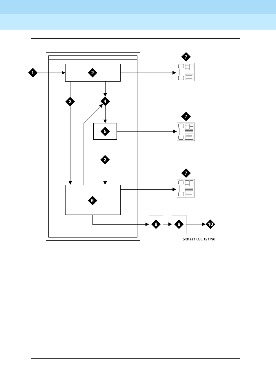
DEFINITY Enterprise Communications Server Release 6
Administration and Feature Description
555-230-522 Issue 4
May 1998
Automatic Routing
Page 8-7AAR and ARS
8
Figure 8-1. Automatic Routing
Figure Notes
1. Input from voice terminal, public
network trunk, or private network trunk
2. Analyze digits to determine address
type (First Digit Table)
3. Direct to AAR/ARS
4. Direct to Uniform Dial Plan (UDP)
5. Analyze digits using UDP to determine
route
6. Delete and insert digits (AAR and ARS
Digit Conversion Tables)
7. Terminate call at voice terminal
8. Analyze digits (AAR and ARS
Digit Analysis Tables) and
determine route pattern (Route
Pattern, Node Number Routing,
Extended Trunk Access forms)
9. Select outgoing trunk group and
delete and insert digits
10. Output to public network trunk
or private network trunk

DEFINITY Enterprise Communications Server Release 6
Administration and Feature Description
555-230-522 Issue 4
May 1998
Automatic Routing
Page 8-8AAR and ARS
8
Dialing
Automatic routing starts when you dial a feature access code followed by the
number to be called. For AAR, this access code is usually the digit 8. For ARS,
this access code is usually the digit 9 in the US and 0 outside of the US.
As soon as you dial the AAR or ARS access code, the system checks to see if
your voice-terminal extension has been origination restricted or outward
restricted by its assigned Class of Restriction (COR). The system also checks to
see if you have a controlled restriction of either outward or total. If any of these
restrictions exist, intercept treatment is applied to the call. Otherwise, the AAR or
ARS call continues and you can enter the number to be called.
A second dial tone may or may not be heard after the AAR or ARS access code
is dialed, depending on system administration. For more detailed information,
see Expanded Technical Information.
Interdigit timeout
DEFINITY ECS uses a long interdigit timer and a short interdigit timer during the
dialing process. Normally, a long,10-second interdigit timer is used between
each digit. This timer waits for another digit when the digits dialed are not a valid
destination. If this timer runs out, you receive timeout and an intercept tone.
If the digits dialed point to a valid destination, but there is a similar string of digits
that is of different length, the short, 3-second interdigit timer is started.
If dialing does not continue before the timers expire, the system assumes that no
more digits are to follow, and appends # to indicate end of dialing. You also may
override the timer by dialing #. This results in faster call processing.
When no length ambiguity exists and all digits are collected, the call is routed,
and no timer or # is required.
Digit analysis
Digit analysis compares the dialed number (or incoming digit string) with entries
in the AAR or ARS Digit Analysis Table depending on which Dial Access Code
was utilized. When DEFINITY ECS finds a dialed-string entry in the table that
matches the incoming digit string, the AAR or ARS Digit Analysis Table maps the
incoming digit string to a specific route pattern and call type. The selected route
pattern and call type are used to route the call. The AAR or ARS Digit Analysis
Table also shows the minimum and maximum number of digits required for the
analysis of each incoming digit string. Node-number routing can also be
specified on this form.
A dialing pattern can be mapped directly to a specific route pattern and call
type. Or, it can be changed in the AAR or ARS Digit Conversion Table. During
digit conversion, digits may be inserted or deleted from the digit string. For
instance, private network numbers may be converted to other private network

DEFINITY Enterprise Communications Server Release 6
Administration and Feature Description
555-230-522 Issue 4
May 1998
Automatic Routing
Page 8-9AAR and ARS
8
numbers or public network numbers or extensions. This new dialed string is
analyzed again in the appropriate analysis table for routing. Matching criteria are
(most important first):
■Number of digits (between min and max)
■Most number of matching digits
■Exact match over wildcard match (from left to right)
Digit conversion
When an access code and number are dialed, the dialed string is compared to
entries in the Matching Pattern field of the ARS or AAR Digit Conversion
Table. If all or part of the dialed string matches one of the Matching Patterns, the
matching part of the dialed string is replaced by a new number from the
Replacement String field. This new number then is used to route the call. The
new number is analyzed using the AAR or ARS Digit Analysis Table or is routed
directly to an extension. An intercept tone is supplied if a match is not found or if
the call fails to route.
Review the following examples. These conditions are assumed for the examples:
ARS Access Code = 9, AAR Access Code = 8, Home RNX (Private Network
Office Code) = 222, Prefix 1 is required on all long-distance DDD calls, Dashes
(-) shown in Table 8-1 are for readability only. The dialed digits are mapped to the
matching pattern that most closely matches the dialed number.
Example:
If the dialed string is 957-1234 and matching patterns 957-1 and 957-123 are in
the table, the match is on pattern 957-123. The call is routed as dialed.

DEFINITY Enterprise Communications Server Release 6
Administration and Feature Description
555-230-522 Issue 4
May 1998
Automatic Routing
Page 8-10AAR and ARS
8
Route pattern
DEFINITY ECS selects a route pattern for a call as a result of the digit analysis
performed on the number dialed. The AAR or ARS Digit Analysis Table analyzes
up to 28 digits. An RHNPA Table is used to screen 3 additional digits after an
area code. A route pattern is a sequence of trunk groups that are used to route
the call. (More than one combination of dialed digits can point to the same route
pattern.)
1. This method may also be used to block unauthorized IDDD calls.
2. This can be done via subnet trunking
Table 8-1. ARS Digit Conversion Examples
Operation
Actual Digits
Dialed
Matching
Pattern
Replacement
String
Modified
Address Notes
DDD call to
ETN
9-1-303-538-1345 1-303-538 362 362-1345 Call routes via AAR for
RNX 362
Long-distance
call to
presubscribed
carrier
9-10222+DDD 10222 (blank) (blank) Call routes as dialed
with DDD # over
private network
Terminating a
local DDD call
to an internal
station
9-1-201-957-5567
or 9-957-5567
1-201-957-5
or
957-5
222-5 222-5567. Call goes to home RNX
222, ext. 5567
Unauthorized
call to intercept
treatment
9-1-212-976-1616 1-XXX-976 # (blank) "#" means end of
dialing. ARS ignores
digits dialed after 976.
User gets intercept
treatment.
International
calls to an
attendant
9-011-91-672530 011-91 222-0111# 222-0111 Call routes to local
switch (RNX 222), then
to attendant
(222-0111). Call can
route to an
announcement by
replacing 0111 with an
announcement
extension.1
International
call from
certain
European
countries
needing dial
tone detection
0-00-XXXXXXXX 00 + 00+200+XXXX The first 0 denotes
ARS, the second pair
of 0s denotes an
international call, the
pluses denote "wait" for
dial tone detection.

DEFINITY Enterprise Communications Server Release 6
Administration and Feature Description
555-230-522 Issue 4
May 1998
Automatic Routing
Page 8-11AAR and ARS
8
You relate a Dialed String (number dialed) to a Rte Pat (route pattern) on the AAR
or ARS Digit Analysis Table. You set up the Rte Pat on the Route Pattern form.
Usually, you arrange the trunk groups in a route pattern by preference. The least
expensive route pattern is generally the preferred route. To select a route pattern,
DEFINITY ECS considers preference order and FRL compatibility.
You also assign an FRL to a routing-pattern preference. FRLs are assigned to
both trunk groups and voice terminals via the COR. The caller’s FRL must be
greater than or equal to the preference FRL. See the section on Facility
Restriction Levels and Traveling Class Marks for additional information.
When AAR and ARS route calls over ISDN trunk groups, overlap sending can be
administered. This allows you to send and receive digits one digit at a time
instead of enbloc (digits are not sent until the entire group of digits is received).
In countries with complex public-network numbering plans, this decreases call
setup time significantly. When overlap receiving is enabled, this is especially
significant for tandemed calls.
If AAR routes the call to another switch over a trunk with ISDN overlap sending,
the system seizes the outgoing ISDN trunk and starts sending digits while
DEFINITY ECS continues to collect (receive) the remaining incoming digits. After
receiving the number of digits administered in the Max. digit field of the AAR Digit
Conversion Table (or a timeout), the system sends an end-of-dial signal
backward to the originating switch. With overlap sending, it also is no longer
necessary to enter # to indicate end of dialing. Additional information is provided
in the section on Overlap Sending.
Look-Ahead Routing allows you to maximize your route-pattern preferences. It
allows you to continue to try to reroute an outgoing ISDN call when initial attempts
fail because of congested trunks. You can indicate the next route-pattern
preference or indicate that the current route-pattern preference should be
attempted a second time before going to the next preference. Additional
information is provided in the section on Look-Ahead Routing.
Expanded technical information
The following paragraphs contain further information about AAR dialing and
translations, ARS dialing and translations, and trunking facilities.
AAR dialing
Typically, AAR simplifies dialing. You dial the AAR access code (normally 8)
followed by a private network or public network number. AAR selects the route
and performs whatever digit manipulation is necessary. In addition, AAR selects
the most cost-effective public-network or private-network route. If the first-choice
preference is not available, another preference is chosen automatically. For
outgoing ISDN calls, route selection is dependent on Bearer Capability Class
(BCC), Facility Restriction Level (FRL), and type of facility.

DEFINITY Enterprise Communications Server Release 6
Administration and Feature Description
555-230-522 Issue 4
May 1998
Automatic Routing
Page 8-12AAR and ARS
8
AAR allows you to dial a private network number to reach a specific public
network. The call can be routed via a private network to an appropriate exit point,
where digit insertion is used for conversion to the appropriate access code,
country code, city code, and exchange.
You can administer DEFINITY ECS to include RN, RNX, and RXX dial plans,
where R = 2 to 9, N = 2 to 9, and X = 0 to 9 (and any other forms). See the
following table for default translations associated with AAR Digit Analysis.
ARS dialing
You can administer DEFINITY ECS to recognize different types of dialing patterns
on outgoing calls and route the call accordingly. The following dialing patterns
are supported.
■Operator Assistance Calls — The first digit following the ARS access
code is a 0. If a 0 is dialed by itself to access an operator, a special
interdigit timeout occurs, the route for dial 0 calls is selected and a 0# is
outpulsed. If the user dials another 0, the route for 00 is selected, and a
00# is outpulsed. The call is routed to the toll operator (if one exists)
instead of the local operator in this case.
■DDD Calls with Prefix Digit 1 Required — The Pfx Mrk (Prefix Mark)
field (on the Route Pattern form) is administered as follows for each of the
6 possible routing choices on the form:
The digit 1 may or may not be required at the public network office to
which the call is routing. (If 1 is dialed on 7-digit calls at a stand-alone
system (non-ETN), the 1 is outpulsed by the system.) In the other cases,
the 1 outpulsing requirements are indicated in the system. Since any given
call may have a choice of routes, some of which may require a 1 and some
of which may not, this indication is associated with each route. Five
Table 8-2. AAR Digit Analysis Default Translations
Total Digits
Dialed String Min. Max. Call Type
2 7 7 aar
3 7 7 aar
4 7 7 aar
5 7 7 aar
6 7 7 aar
7 7 7 aar
8 7 7 aar
9 7 7 aar

DEFINITY Enterprise Communications Server Release 6
Administration and Feature Description
555-230-522 Issue 4
May 1998
Automatic Routing
Page 8-13AAR and ARS
8
choices are available and are identified in translations by a Prefix Mark.
Digit 1 outpulsing only applies to calls administered as “fnpa” or “hnpa" in
the ARS Digit Analysis table. The values and meanings of the Prefix Marks
are as follows:
— Prefix Mark 0 — Suppress a user-dialed Prefix digit 1 for 10-digit
FNPA calls, but leave a user-dialed Prefix digit 1 for the following
types of calls:
■10-digit calls that are not administered as FNPA or HNPA
types in the ARS Routing Table.
■7-digit HNPA calls
— Prefix Mark 1 — Send a 1 on 10-digit calls, but not on 7-digit calls.
— Prefix Mark 2 — Send a 1 on all toll calls (for example, all 10-digit
calls and 7-digit toll calls).
—Prefix Mark 3 — Send a 1 on all toll calls and keep or insert the NPA
to ensure that all toll calls are 10-digit calls. Note that a user-dialed
Prefix digit 1 for a 7-digit call makes it a toll call and, hence, NPA is
also inserted in this case.
— Prefix Mark 4 — Always suppress a user-dialed Prefix digit 1.
NOTE:
This capability is required, for example, when routing ISDN calls to
an Lucent Technologies 4ESS. If the prefix digit 1 were not
suppressed, then the 4ESS would reach calls.
Which of the five possible treatments of the 1 prefix digit should be
administered on a given route is based on the characteristics of the
distant office. Prefix Mark 0 prevents the system from sending a 1 prefix
digit for 10-digit FNPA calls. However, the system leaves a user-dialed
prefix digit 1 for 7-digit HNPA calls and 10-digit calls that are not
administered as FNPA or HNPA types in the ARS Routing Table. In some
areas, all toll calls must be dialed as 1+10 digits. Check with your local
network provider.
Prefix Mark 1 causes the system to send a 1 prefix on all 10-digit FNPA
calls.
With Prefix Marks 2 and 3, the decision is based on whether the call is a
toll call. Toll Lists are provided in the system to furnish this information. A
Toll List simply indicates if the office code associated with the call
constitutes a toll call from the interconnecting office (not from the local
system). Up to 32 Toll Lists are provided. The applicable list number, if
any, for the call is assigned in the Routing Pattern.
Prefix Marks are only applicable on 7- or 10-digit DDD public network
calls. Requirements for outpulsing a 1 are specified via Prefix Marks and
go into effect when the call accesses is outpulsed. Digit 1 outpulsing only
applies to calls administered as “fnpa" or “hnpa” in the ARS Digit Analysis
table.

DEFINITY Enterprise Communications Server Release 6
Administration and Feature Description
555-230-522 Issue 4
May 1998
Automatic Routing
Page 8-14AAR and ARS
8
■DDD Calls with Prefix Digit 1 Not Required — The first digit of a
long-distance call following the ARS access code may or may not be a 1
(dialing the 1 prefix before a 10-digit call is optional). In systems where the
1 prefix is dialed (even though not required), the prefix is ignored if no
match is found with the “1” included. The default ARS translations include
entries starting with “1.”
■Operator Assisted and International Calls — The first digits following
the ARS access code are a 0 (operator), 00 (toll operator), and optionally
followed by a 10-digit DDD number, or by 01 or 010 (international
operator) for international dialing and optionally followed by international
destination address digits. Because of the variable number of digits
required for these calls, an interdigit timeout is used to recognize end of
dialing.
■International Direct Distance Dialing — An international telephone
number consists of a country code (CC) plus the national number (NN).
The NN is simply the number used when calling within the country. In the
North American Numbering Plan (NANP), NN is a 10-digit address. In the
NANP, special prefix codes alert DEFINITY ECS that an international
number is being dialed. These codes are outlined as follows:
— 011 — Indicates that the caller is making a station paid direct
international call and CC plus NN digits follow. The term IDDD
(International Direct Distance Dialing) is normally associated with
011 plus (011+) station calls.
— 01 — Indicates that the caller desires operator assistance in an
international call, such as person-to-person, credit card, collect
call, and so on, and CC and NN digits follow. The term ICDOS
(International Customer-Dialed and Operator-Serviced) reflects the
nature of 01+ dialing options.
A 01+ (ICDOS) call is similar to 0+ or 00+ (operator-assisted North
American Network) call, whereas a 011+ (IDDD) call is similar to a
1+ call.
■Special Service Codes — The first digit following the ARS Access Code
is a special system or service code. In North America, such codes consist
of only three digits in the form N11 (where N = 2 to 9) with or without
dialing the “1” prefix digit. These are recognized as complete addresses,
and even if no further digits are dialed, are routed to the appropriate
facility. The interdigit timeout determines whether the call is a 3- or 7-digit
call. For example, if the user dials 911, the call routes to the police or
emergency operator, and if the user dials 811-XXXX, the call is translated
as a 7-digit call for the repair bureau corresponding to the last 4 digits
(811 is a service code for repair).
■Call Dialed with Inter-Exchange Carrier (IXC) Access — The IXC Code,
if dialed, is comprised of the first digits following the ARS Access Code,
usually a 5- or 7-digit IXC code. IXC codes are defined in the
Inter-Exchange Carrier Codes form on page 5-177. DEFINITY ECS
decides the number of digits to collect based on the digits following the

DEFINITY Enterprise Communications Server Release 6
Administration and Feature Description
555-230-522 Issue 4
May 1998
Automatic Routing
Page 8-15AAR and ARS
8
code. The IXC code may be followed by a DDD or IDDD number. This
gives you control over which carriers or which facilities are used for routing
the call. The call may be routed based on administration of the IXC code in
the ARS Digit Analysis Table.
DEFINITY ECS supports three general IXC access arrangements that are
commonly referred to as Feature Group A, B, and D (FG A, FG B, FG D).
From a caller’s perspective, the major differences between use of the
various groups are:
— To select an IXC, FG A and FG B require the dialing of 7 digits
(NXX-XXXX or 950-0/1XXX, respectively) but FG D requires just 5
digits (10XXX).
— Single-stage dialing is supported for FG D, but FG A and FG B
require 2-stage dialing. (Two-stage dialing means that there is a
pause for dial tone between the 2 groups of dialed digits.) FG A
and FG B calls are analyzed and routed just like normal calls.
— No customer identification digits are required for FG D.
— A touch-tone telephone is required to enter a Personal Identification
Number code when using FG A or FG B. (These digits are not
collected or analyzed by the switch.) A dial pulse or touch-tone
telephone may be used with FG D.
See Ta b le 8 - 3 for default translations associated with ARS digit analysis.
Table 8-3. ARS Digit Analysis Default Translations
Dialed String
Total Digits
Min. Max.
Route
Pattern Call Type
0 1 1 den op
0 8 8 den op
0 11 11 den op
00 2 2 den op
01 9 17 den iop
011 10 18 den intl
10XXX0 6 6 den op
10XXX0 16 16 den op
10XXX1 16 16 den fnpa
10XXX01 14 22 den iop
10XXX011 15 23 den intl
Continued on next page

DEFINITY Enterprise Communications Server Release 6
Administration and Feature Description
555-230-522 Issue 4
May 1998
Automatic Routing
Page 8-16AAR and ARS
8
Trunking facilities
Automatic routing uses a combination of public and private trunking facilities.
Off-net facilities include trunks such as CO, FX, and WATS. These trunks carry
public network calls. On-net facilities include trunks such as tie, tandem, and
private ISDN trunks. These trunks are dedicated to your private network.
1XXX555 11 11 den fnpa
1XXX976 11 11 den fnpa
18000555 11 11 den fnpa
1809 11 11 den fnpa
1900555 11 11 den fnpa
411 3 3 den svct
555 7 7 den hnpa
611 3 3 1 svcl
811 3 3 1 svcl
911 3 3 1 svcl
976 7 7 den hnpa
N772hnpa
1N00 11 11 den fnpa
1NX 11 11 den fnpa
Legend:
N - 2 through 9
X - any digit (0 - 9)
den - deny
fnpa - foreign number plan area (10-digit call)
hnpa - home number plan area (7-digit call)
intl - international
iop - international operator
op - operator
svcl - service (local)
svct - service (toll)
Table 8-3. ARS Digit Analysis Default Translations — Continued
Dialed String
Total Digits
Min. Max.
Route
Pattern Call Type
Continued on next page

DEFINITY Enterprise Communications Server Release 6
Administration and Feature Description
555-230-522 Issue 4
May 1998
Automatic Routing
Page 8-17AAR and ARS
8
DEFINITY ECS can serve as an electronic tandem network (ETN). An ETN is a
hierarchical network of privately-owned trunk and switching facilities that provide
a cost-effective alternative to toll calling between locations. Tandem trunks are
used to interconnect two tandem nodes in an ETN.
An ETN consists of tandem switches, the intertandem tie trunks that interconnect
them, the access- or bypass-tie trunks from a tandem switch to a main switch,
and the capability to control call routing over these facilities. Within an ETN, each
switching facility is identified by a unique private-network office code.
Private-network office codes may be 1–8 digits.
Traveling Class Marks (TCM) are appended to AAR and ARS numbers outpulsed
on ETNs. Remember, TCMs represent the caller’s FRL or the FRL of the caller’s
access trunk group. Access trunks are used to connect a subtending main
switch to a tandem node. Tie trunks are used to interconnect a satellite or
tributary and the homing main switch. An ETN tandem node can, however,
directly access main and tributary switches that are homed on another tandem
node using bypass-access trunks.
Considerations
■ARS and AAR can access the same trunk groups and share the same
route patterns, toll lists, and RHNPA tables. ARS calls can be converted to
AAR calls and vice-versa.
■Internal memory resources used for digit analysis are shared by ARS and
AAR Digit Conversion and Toll Analysis. The Percent Full field on the ARS
Digit Analysis and AAR Digit Analysis screens indicates how many of
these resources are used for both AAR and ARS.
Interactions
■Abbreviated Dialing
FRL checking is bypassed on ARS and AAR calls made via a privileged
Abbreviated Dialing Group List.
■Attendant Control of Trunk Group Access
Attendant control of a trunk group, in effect, removes the trunk group from
the route pattern. ARS and AAR do not access controlled trunk groups.
■CAS
A CAS Attendant can extend a call out of a branch switch using ARS and
AAR. When you dial the feature access code and number, the call is
routed according to the AAR and ARS administration at the branch switch.

DEFINITY Enterprise Communications Server Release 6
Administration and Feature Description
555-230-522 Issue 4
May 1998
Automatic Routing
Page 8-18AAR and ARS
8
■CDR
— A CDR account code may be required for an AAR call if it crosses
over and becomes an ARS call.
— An ARS or AAR call using a trunk group marked for CDR is
indicated by the dialed access code and by a condition code. It is
possible to record either the dialed number or the outpulsed
number. If the dialed number is recorded, subnet trunking does not
affect CDR.
— Outpulsed digits can be recorded.
— If CDR generation is administered for a trunk group assigned to a
route pattern, data is collected for all calls routed through the trunk
group.
— If a CDR account code is to be dialed with an ARS or AAR call, it
must be dialed before the ARS or AAR access code is dialed.
■Controlled Restriction, Origination Restriction, and Outward Restriction
These features prohibit access to ARS and AAR.
■Forced Entry of Account Codes
Prefix marks and other digits inserted from route patterns are not used to
determine whether a call is a toll call. See Forced Entry of Account Codes
below for more information.
■ISDN-BRI Stations
An ISDN-BRI station does not recognize the conference or transfer
buttons until a call is ready to be routed. For calls that require an interdigit
timeout, you must delay dialing for 3 seconds or dial a # to indicate that
the call is ready to be routed. The routing operation is completed by the
switch and then the ISDN-BRI station recognizes the conference or
transfer buttons.
■Miscellaneous Trunk Restrictions
Miscellaneous Restrictions are not checked on ARS and AAR calls.
■Personal Central Office Line (PCOL) Trunk
A PCOL trunk group cannot be assigned to a route pattern.
■Ringback Queuing
— Ringback Queuing can be used on ARS and AAR calls when they
originate at a switch that provides the queuing. Incoming tie trunk
calls do not queue on an outgoing trunk group.
— Ringback Queuing is activated automatically when you have an
Automatic Callback button, make an ARS or AAR call, and all trunks
are busy.

DEFINITY Enterprise Communications Server Release 6
Administration and Feature Description
555-230-522 Issue 4
May 1998
Automatic Routing
Page 8-19AAR and ARS
8
■Toll Restriction
Toll Restriction is checked if calls are dialed as ARS calls; it is not checked
on AAR calls even if they digit convert to ARS calls.
■Voice Terminal Display
— The voice terminal display shows the dialed digits (not outpulsed
digits) on AAR and ARS calls and then may change to the name of
the trunk group.
— On ARS calls, the called party shown on the display is that of the
trunk group actually used. The Miscellaneous Call Identification
field on the display shows ARS. By administering trunk groups, you
can replace the dialed digits with the name of the trunk group and
trunk access code (TAC).
— Outgoing AAR calls display the trunk name and TAC.
— An ISDN-BRI station may format these display fields differently, and
the timing of display updates may be different.

DEFINITY Enterprise Communications Server Release 6
Administration and Feature Description
555-230-522 Issue 4
May 1998
Automatic Routing
Page 8-20AAR and ARS Overlap Sending
8
AAR and ARS Overlap Sending
DEFINITY ECS supports overlap sending for AAR and ARS calls that are routed
over ISDN trunk groups. ISDN call-address information is sent one digit at a time
instead of enbloc — in other words, all address information in one block. In
countries with complex public-network numbering plans, this allows for a
significant decrease in call setup time. When overlap receiving is enabled, this is
especially significant for tandemed calls.
If AAR or ARS determines that the call is to be routed to another switch over a
trunk with ISDN overlap sending, the system seizes the outgoing ISDN trunk and
starts sending digits while DEFINITY ECS continues to collect (receive) the
remaining incoming digits. After receiving the number of digits administered in
the Max field of the AAR or ARS Digit Analysis form (or a timeout), the system
sends an end-of-dial signal backward to the originating switch. It is no longer
necessary to enter # to indicate end of dialing.
How to administer AAR and ARS Overlap
Sending
Required forms
Form Field Page
ISDN-PRI Trunk Group ■Digit Handling (in/out) 7-219
ISDN-BRI Trunk Group ■Digit Handling (in/out) 7-198

DEFINITY Enterprise Communications Server Release 6
Administration and Feature Description
555-230-522 Issue 4
May 1998
Automatic Routing
Page 8-21AAR and ARS Partitioning
8
AAR and ARS Partitioning
AAR and ARS can be partitioned into 8 user groups within a single DEFINITY
ECS. AAR and ARS Partitioning provides individual routing treatment for each of
these user groups.
User groups share the same Partition Group Number (PGN). The PGN is not a
restriction; it indicates the choice of routing tables used on a particular call. Each
Class of Restriction (COR) is assigned a specific PGN or Time of Day
specification. Different CORs may be assigned the same PGN.
How to administer AAR and ARS Partitioning
■Different Digit Analysis tables must be administered for each partitioned
user group.
■A PGN must be assigned to each COR table. A Time of Day Plan Number
is assigned to the COR instead of the PGN if Time of Day Routing is used.
Detailed description
This feature allows you to divide users into groups and restrict or allow different
access to facilities depending upon the group. In motels, for instance, AAR and
ARS Partitioning allows you to group employees and guests and give them
different access to facilities. When a guest places an interstate call, the guest
user-group’s ARS tables can route the call to a telephone-billing information
system that bills back or allocates long-distance charges. A similar call placed
by an employee can route over a direct-distance dialing (DDD) trunk.
All partitioned user groups share the same pool of route patterns. The translation
tables that specify the route-pattern number are unique for each partitioned user
group. Route patterns may be shared among the user groups or may be
dedicated to a particular user group. Once you activate AAR or ARS and dial
enough digits for the system to search for the route pattern, the PGN of the
caller’s COR is used to select the table to look up the route pattern.
Required forms
Form Field Page
Class of Restriction ■Partitioned Group Number 5-72
Time of Day Routing Plan (optional) ■All 8-78
AAR and ARS Digit Analysis Table ■Partitioned Group Number 8-54

DEFINITY Enterprise Communications Server Release 6
Administration and Feature Description
555-230-522 Issue 4
May 1998
Automatic Routing
Page 8-22AAR and ARS Partitioning
8
The following can use AAR and ARS Partitioning:
■Voice terminals
■Attendant consoles
■Remote-access users
■Data endpoints
■Incoming trunks
Considerations
■The following situations may require AAR and ARS Partitioning:
— User groups with different routing preferences for calls to a given
area due to special billing needs
— User groups that have dedicated use of a particular network facility
— User groups in different businesses in one or more buildings
serviced by a single system
— Data users who require special facility types on outgoing calls
■Partition user groups are only used with AAR, and ARS, and UDP. There is
no capability to access the partitioned user groups directly. Operation is
transparent to the user.
Interactions
■Bridged Call Appearance
If a Bridged Call Appearance is used for an AAR or ARS call, the system
uses the bridged extension’s PGN instead of the caller’s PGN.
■Call Detail Recording (CDR)
The PGN used to route the call is not recorded in CDR.
■Call Forwarding All Calls
If a call terminates at a voice terminal that has Call Forwarding activate
and the forwarded-to number uses AAR or ARS, the caller’s COR is used
to look up the PGN for the call.
■DCS
When a call routes over DCS, PGN information is not sent to the far-end
switch. The far-end switch is only capable of using the incoming trunk’s
PGN to route the call.
■Remote Access
If a remote-access user activates ARS, the COR assigned to the barrier
code dialed (or the Authorization Code, if required) is used to select the
PGN for the call.

DEFINITY Enterprise Communications Server Release 6
Administration and Feature Description
555-230-522 Issue 4
May 1998
Automatic Routing
Page 8-23AAR and ARS Partitioning
8
■Straightforward Outward Completion and Through Dialing
If the attendant assists or extends a call and activates ARS, the attendant’s
COR is used to select the PGN for the call if the individual extension
number is assigned, otherwise it refers to the COR set on the console
parameter.
■Time of Day Routing
TOD Routing allows different AAR and ARS Partitions to be used at
different times of the day and different days of the week. If you wish to
assign certain users to a particular partition at all times, you must use a
default Time-Of-Day Routing Plan that points to the same PGN # at all
times.
■Uniform Dial Plan
Since UDP calls expand the dialed digits into 7-digit numbers and then
use AAR to route the call, these calls use partitioning. Once the call is
handled by AAR, the caller’s COR is used to select the PGN for the call.

DEFINITY Enterprise Communications Server Release 6
Administration and Feature Description
555-230-522 Issue 4
May 1998
Automatic Routing
Page 8-24Facility Restriction Levels and Traveling Class Marks
8
Facility Restriction Levels and
Traveling Class Marks
Facility Restriction Levels (FRL) and Traveling Class Marks (TCM) allow certain
calls to specific users, while denying the same calls to other users. For example,
certain users may be allowed to use central office (CO) trunks to other corporate
locations while other users may be restricted to less expensive private-network
lines.
FRLs and TCMs provide up to 8 levels of restriction for users of AAR and ARS.
How to administer FRLs and TCMs
NOTE:
FRLs are important to system security. Assign the most restrictive (7) FRL
consistent with the FRLs to be used on the COR form and the least
restrictive (0) FRL on the Route Pattern form in order to help prevent
unauthorized use of system features.
Detailed description
FRLs and TCMs are transparent to the user. The appropriate values are
predetermined and programmed into the system. Dialing procedures are
unaffected.
Call routing for each call is determined by the dialed area code or office code
(either public or private network) or by the administered dial string. Analysis of
the called number yields a route pattern. More than one dialed string can point to
the same pattern. Each route preference includes:
■Trunk group number
■Minimum FRL required to access the trunk group
Each facility, such as a trunk or voice terminal, that is capable of originating a call
also has an associated FRL. Whether a call is allowed or not depends on 2
things: compatibility between FRLs and availability of an idle trunk.
Required forms
Form Field Page
Class of Restriction ■FRL 5-72
Route Pattern ■FRL (0–7) 8-67

DEFINITY Enterprise Communications Server Release 6
Administration and Feature Description
555-230-522 Issue 4
May 1998
Automatic Routing
Page 8-25Facility Restriction Levels and Traveling Class Marks
8
Compatibility is determined by a comparison of the minimum FRL associated
with the route preference and the originating-side FRL. Either can have a value of
0–7. Access to the associated trunk group is permitted if the originating-side FRL
is greater than or equal to the minimum FRL of the preference. Note that lower
originating-side FRLs can access to fewer routing preferences, whereas lower
minimum FRLs on the Route Pattern permit greater access. Stated another way, a
0 originating-side FRL is the most restricted and a 7 is the least restricted. A 0
minimum FRL is the least restrictive, and a 7 is the most restrictive (when applied
to the route pattern’s FRL). Compatibility checking begins with the first-choice
route (the first one in the pattern). Assuming that access is permitted, availability
is checked; that is, is there an idle trunk in the group? If so, the call continues. If
not, compatibility is checked on the next-choice route. The intercept treatment is
not received unless all possible routes are inaccessible.
If the compatibility check fails on the next-choice or subsequent route, or if all
accessible trunk groups are busy, the call may queue on the first routing
preference or first compatible trunk group if trunk queueing is provided.
If the trunk group selected for a call is an intertandem tie-trunk group, then a
TCM is outpulsed as the last digit. A TCM is equivalent to the originating-side
FRL. At the next tandem switch, compatibility and availability checking are done,
as before. In this case, the FRL assigned to the incoming intertandem tie-trunk
group is used as the originating-side FRL (to compare with the minimum FRL). If
it is sufficient, then the call continues and no comparison between the TCM and
minimum FRL is made. If it is not sufficient, then the TCM is compared with the
minimum FRL to see if the call is allowed to continue. If this fails to yield a route
and if the TCM is higher than the tie-trunk FRL, then the TCM is used in another
attempt to complete the call.
Call-originating facilities
At a switch serving as the call-origination point, any of the following can be the
originator of an ARS or AAR call:
■Voice terminal
■Remote Access user
■Attendant
■Incoming tie-trunk group from a subtending location
■Data terminal capable of keyboard dialing
At a tandem switch, either of the following can be the originator of an ARS or AAR
call:
■Incoming intertandem tie-trunk group
■Incoming access tie-trunk group — links a remote main switch to a
tandem switch

DEFINITY Enterprise Communications Server Release 6
Administration and Feature Description
555-230-522 Issue 4
May 1998
Automatic Routing
Page 8-26Facility Restriction Levels and Traveling Class Marks
8
Each of these facilities is assigned an FRL via an associated COR, either directly
or indirectly.
Voice terminals and all incoming tie-trunk groups use the FRL within the assigned
COR. Attendants use the FRL within the COR assigned to the attendant group for
extended calls. If Individual Attendant Access is assigned, the individual
attendant’s COR FRL is used. Data terminals use the FRL within the COR
assigned to the associated data module.
Remote Access can be accessed via the following trunk groups: DID, ISDN, tie,
dedicated CO, 800-service, or dedicated FX. The applicable originating FRL is
contained in the COR assigned to the dialed barrier code. If a barrier code is not
required on remote access calls, the applicable FRL is the default (none).
Call terminating facilities
Any of the following trunk types can serve as the termination point for an ARS or
AAR call:
■Tie trunk — excluding Release Link Trunks (RLT), but including Common
Control Switching Arrangement (CCSA) and Enhanced Private Switched
Communications Services (EPSCS) access trunks
■Wide Area Telecommunications Service (WATS)
■CO
■Foreign exchange (FX)
■Integrated Services Digital Network - Primary Rate Interface (ISDN-PRI)
Each of these outgoing trunk groups has an assigned COR that contains an FRL.
However, this FRL is never used. Terminating-side FRLs are assigned in the route
pattern, not to the outgoing trunk group.
Considerations
■FRLs restrict certain users from placing selected calls while allowing other
users to place the same calls.
■A COR is assigned to each trunk group. If the COR specifies an FRL, the
FRL is ignored. The minimum FRL specified in the route pattern is the only
FRL used on the terminating side of the call.
■On attendant-extended calls, the attendant-group FRL is used rather than
the FRL of the calling party.

DEFINITY Enterprise Communications Server Release 6
Administration and Feature Description
555-230-522 Issue 4
May 1998
Automatic Routing
Page 8-27Facility Restriction Levels and Traveling Class Marks
8
Guidelines and examples
The following guidelines and examples illustrate some practical aspects of FRLs.
FRLs on the terminating end of a call are not checked unless the terminating
facility is a trunk group in a route pattern. This simplifies assignments. At each
switch, the trunk groups available to handle a given AAR or ARS call can be
listed in any order within the route pattern. Access to each listed trunk group
must be determined via an FRL. On a scale of 0–7, the relative value is
determined and assigned. Decisions are normally based on the cost, or
appropriateness, of using the facility. The same FRL value can be assigned to
more than one trunk group if there is no reason to prefer one trunk group over
another.
If some users within the system are not allowed to make outside calls, use some
value other than 0 for the first-choice route. Then assign these users an FRL of 0
to deny access to any trunk group, because all trunk-group FRLs are greater
than 0.
Each route pattern must be individually constructed. The same trunk group can
be used in more than one pattern. The associated FRL is assigned within the
pattern and is not associated with the trunk group itself. The same trunk group
can have a different FRL in a different pattern.
Be consistent in FRL assignments. Do not use a range of 0–5 in one pattern and
2–7 in another pattern if all users can access the first-choice route. Admittedly,
the trunk group with an FRL of 2 may be more expensive than the trunk group
with an FRL of 0, but there is no reason to assign 2 to a trunk group that everyone
can access. For ease of assignments, always use 0 for such a trunk group.
Establish COR for each FRL in a route pattern. Assign the appropriate COR to
users who can access the routes restricted by the FRL. For example, a middle
executive might be able to access all routes with an FRL of 5 or lower, whereas
the president can access all routes. In this case, the executive is assigned a
COR with an FRL of 5 and the president is assigned a COR with an FRL of 7.
Remote access users can access system features and services the same as an
on-premises user. FRL assignment is via remote-access barrier codes. Up to 10
barrier codes, each with its own COR (and FRL), can be assigned. Although the
COR defines other restrictions, 10 barrier codes are enough to provide a range of
FRL assignments. Assign barrier code FRLs as if the user were on-premises. The
simplest way to assign these FRLs is to duplicate the on-premises FRLs, then
relate the appropriate barrier code to users who need remote access.

DEFINITY Enterprise Communications Server Release 6
Administration and Feature Description
555-230-522 Issue 4
May 1998
Automatic Routing
Page 8-28Facility Restriction Levels and Traveling Class Marks
8
The following is an example of how FRLs can be assigned in a COR:
■FRL0 — 911 access only
■FRL1 — Local calls only
■FRL2 — FRL1 plus home area-code calls using WATS
■FRL3 — FRL2 plus use of local lines for all calls in the home area code
■FRL4 — FRL3 plus calls to all the USA, using WATS only
■FRL5 — FRL4 plus calls to all the USA, using local lines
■FRL6 — FRL5 plus international calls
■FRL7 — Reserved
Interactions
■AAR and ARS
FRLs apply only on ARS and AAR calls (including Uniform Dial Plan).
■Authorization Codes
Authorizations Codes can be used to raise a user’s FRL.
■Call Detail Recording
If 15-digit CDR account codes are used, the FRL field in the CDR record is
overwritten.
■Intercept Treatment
The TCM containing the originating facility’s FRL is sent over ISDN
facilities in the SETUP message.

DEFINITY Enterprise Communications Server Release 6
Administration and Feature Description
555-230-522 Issue 4
May 1998
Automatic Routing
Page 8-29Alternate Facility Restriction Levels
8
Alternate Facility Restriction Levels
Alternate Facility Restriction Levels (AFRL) allows DEFINITY ECS to adjust facility
restriction levels or authorization codes for lines or trunks. Each line or trunk is
normally assigned an FRL. With this feature, alternate FRLs are also assigned.
Attendants or System Administrators can change to the alternates, thus
changing access to lines and trunks. For example, a company might want to use
this feature to disable most long-distance calling at night to prevent unauthorized
staff from making long-distance calls.
!CAUTION:
AFRL impacts AAR and ARS call routing because it may change the routing
preferences. Using AFRL on tandem and tie-trunk applications affects
entire networks. Calls that may be part of a cross-country private network
may be blocked.
How to administer AFRL
Detailed description
AFRLs affect two types of users: the attendant or System Administrator (who
enables and disables the AFRL feature) and a voice-terminal user (who places
outgoing trunk calls).
Attendant perspective
You can administer an ALT-FRL button to any attendant console or any station.
Pressing the ALT-FRL button activates or deactivates AFRL. Pressing the ALT-FRL
button on any console or station may affect the status of other buttons.
When AFRL is activate, the user may notice a sudden change in calling
privileges. For example, the user may have been able to make long-distance
calls but AFRL (which have been administered to add restrictions to the calling
Required forms
Form Field Page
Alternate Facility Restriction
Level
■Current Status
■Alternate FRL
8-29
Station ■Feature Button Assignments 6-28
Attendant Console ■Feature Button Assignments 5-35

DEFINITY Enterprise Communications Server Release 6
Administration and Feature Description
555-230-522 Issue 4
May 1998
Automatic Routing
Page 8-30Alternate Facility Restriction Levels
8
parties) can no longer do so. When AFRL is active, you can be any one of 3 types
of alterable FRL entities:
■An originating line
■An originating trunk (for example, an incoming trunk call)
■A dialed authorization code
Terminal-user perspective
If you use AFRL to restrict calling at certain hours, make sure that users know
about those restrictions.
Trunk originator case
In this case, the originator is in reality an incoming trunk. Incoming trunk calls can
be direct inward dialing (DID) calls to a station, incoming calls on access
tie-trunks, or possibly intertandem tie-trunk calls. The FRL of the device is first
used to determine if it is at a high enough level to select the outgoing device. If it
is not, then the FRL associated with this signaling entity, called a Traveling Class
Mark (TCM), is used. Tandem trunk groups are administered to pass along the
FRL level associated with the other switch as part of the interoffice signaling
protocol. This can be done inband as part of the addressing information which is
sent between two switches using tone sending on the trunk itself, or can be done
using special ISDN Q.931 messaging. In either case, the seizure of the outgoing
trunk is not done until either the TCM is received or (in the case of inband
signaling) an interdigit timeout occurs while waiting for the TCM digit.
If AFRLs are active, the FRL associated with the incoming trunk group is set to a
new FRL. If after doing so, the originator is blocked from the trunk facility due to
insufficient FRL, the TCM, if any, is used. The TCM, which is in reality just another
FRL, is also set to a new FRL value. Therefore, the TCM information recorded in
the billing data (CDR) is the AFRL value, not the original TCM.
Due to the application of AFRL on tandem and tie trunk applications, entire
networks can be affected by the application of the AFRL feature. Use caution to
engineer AFRLs as
now calls
that may be part of a cross-country switch network
and that may be blocked from completion due to the engineering of a restrictive
AFRL arrangement.
Considerations
■Consider the impact on your operations when there are sudden changes
in the calling privileges of your system users. Consider announcing
changes and preparing your telecommunications department to handle
inquiries.

DEFINITY Enterprise Communications Server Release 6
Administration and Feature Description
555-230-522 Issue 4
May 1998
Automatic Routing
Page 8-31Alternate Facility Restriction Levels
8
Guidelines and examples
The following examples should help you understand AFRLs and should illustrate
some of their practical aspects.
AFRL mapping
FRLs are used to determine the privileges that an originating party can have
when making an outgoing trunk call. This party can be either a line or a trunk. An
FRL is assigned to each device and/or device group through its associate COR.
When a device originates an outgoing trunk call, its FRL is compared to the FRL
of either the terminating trunk group or (for AAR or ARS) the preference. If the
FRL of the originator is greater than or equal to the terminating FRL, the call
proceeds. Otherwise, the call is blocked. FRLs restrict outgoing calls by
destination, by time of day, or by facility problem (such as trunk outages).
For example, a technician could remap FRLs less than 3 to 3 and FRLs greater
than 3 to 7. Any attendant or station with an AFRL button can control whether the
original FRL or the AFRL is used.
Authorization codes
Authorization codes prevent unauthorized access to various facilities. You can
use them, for example, to restrict access to certain trunk groups or to remote
access trunk groups. When a user dials an authorization code, it is validated by
the system. If it is not valid, the call routes to an assignable intercept. If the code
is valid, the system determines an associated COR. This COR has an FRL
associated with it. If AFRL is activated, it is the AFRL level and not the FRL that is
used in mapping the AFRL.
For example, a user whose FRL is 1 attempts a toll call. AFRL is active and maps
as shown in Figure 8-2 (that is, FRL =1 maps to AFRL=3). The desired trunk has
an FRL of 7, and so the user is blocked. If Authorization Codes are enabled, the
user is prompted to dial an authorization code to obtain greater calling privileges.
As shown in Figure 8-2, an Auth Code set to1234567 has a COR set to 3 and,
therefore, an FRL set to 5. This is still not high enough to permit access to the
desired trunk except when the user presses the active AFRL button. Then the
AFRL feature is active and maps the FRL of 5 to 7, thus allowing the call to
complete.

DEFINITY Enterprise Communications Server Release 6
Administration and Feature Description
555-230-522 Issue 4
May 1998
Automatic Routing
Page 8-32Alternate Facility Restriction Levels
8
Figure 8-2. Example of authorization codes with AFRLs
Interactions
■AAR/ARS
ARFL can change route preferences and affect the cost of usage-sensitive
calls.
■Facility Restriction Levels and Traveling Class Marks
AFRL sets up alternate levels to those normally provided by FRL.
3
0
3
7
6
5
4
3
2
1
AFRL FRL
COR to FRL Table Authorization code to COR Table
7
5
FRL to AFRL Table
3
1
4
3
2
1
FRL COR
3
3
2
3
COR
2222222
1234569
1234568
1234567
Authorization Code
Trunk Desired COR is 4
Originator COR is 1
7
7
7
7
3
3

DEFINITY Enterprise Communications Server Release 6
Administration and Feature Description
555-230-522 Issue 4
May 1998
Automatic Routing
Page 8-33Generalized Route Selection
8
Generalized Route Selection
Generalized Route Selection (GRS) provides voice and data call-routing
capabilities. You use it to select not only the least-cost routing, but also the most
optimal routing over the appropriate facilities.
GRS is a capability built onto the AAR and ARS features. In AAR or ARS, routing
is based on the dialed number, the FRL of the caller, the partition group number,
and the time of day. GRS provides additional parameters in the routing decision.
It enhances AAR and ARS and maximizes the chance of using the right facility to
route the call. Also, if an endpoint incompatibility exists, it provides a conversion
resource (such as a modem from a modem pool) to attempt to match the right
facility with the right endpoint.
How to administer GRS
Detailed description
GRS allows customers to use separate routes for voice and data calls. For data
calls, DEFINITY ECS distinguishes between restricted and unrestricted digital
transmissions. This allows the switch to route data calls onto the appropriate
facilities. With GRS, you can integrate voice and data on the same trunk group.
Required forms
Form Field Page
Route Pattern ■IXC
■BCC
■ITC
■BCIE
■Service/Feature
■Band
8-67
Trunk Group ■BCC
Access 7-150
CO 7-168
FX 7-193
Tandem 7-257
Tie 7-262

DEFINITY Enterprise Communications Server Release 6
Administration and Feature Description
555-230-522 Issue 4
May 1998
Automatic Routing
Page 8-34Generalized Route Selection
8
GRS allows the system to use the ISDN Call-by-Call Service Selection feature to
access public network services. It also provides interworking between ISDN and
non-ISDN entities.
ISDN interworking is the mixture of ISDN trunks and non-ISDN trunks in a call. A
mixture of these signaling procedures is required to provide end-to-end
connectivity when different type trunking facilities are used.
ISDN services add 5 routing parameters that are specified on each trunk group
preference of the route pattern. These parameters are:
■Bearer Capability Class (BCC) — Identifies the type of call, such as voice
calls and different types of data calls. For all trunk groups, the BCC is
checked to see if the route selected is compatible.
■Information Transfer Capability (ITC) — Identifies the type of data
transmission (restricted, unrestricted, or both). For all trunk groups, the
ITC is checked to see if the route selected is compatible.
■Network Specific Facility — Identifies the services and features to be used
to complete a call.
■Band — Identifies the OUTWATS band (US only). WATS is a voice-grade
service providing both voice and low-speed data transmission calls to
defined areas (bands) for a flat rate charge.
■Inter-Exchange Carrier (IXC) — Identifies the specific common carrier,
such as AT&T, to be used for a call.
In GRS, there are 5 BCCs. Customers may specify routing for each BCC
according to their particular transmission needs. See the Expanded Technical
Information portion of this section for more information on BCCs and ISDN BCC
Parameters.
Expanded technical information on BCC
BCCs
BCCs are the mechanisms by which specialized routing is provided for the
various type data calls and voice calls. Each trunk group preference in the AAR
or ARS route patterns contains a BCC parameter. When a call is originated, a
route is selected based on the BCC of the originating facility. BCCs are used to
classify the type of traffic permitted on this trunk in the outgoing direction. Details
on how a trunk group preference is determined are given in Guidelines and
examples.
A set of ISDN bearer capability and low-layer compatibility parameters are
defined by a BCC.

DEFINITY Enterprise Communications Server Release 6
Administration and Feature Description
555-230-522 Issue 4
May 1998
Automatic Routing
Page 8-35Generalized Route Selection
8
The system will determine the originating endpoint’s BCC from one of the
following:
■For an ISDN-BRI set, the switch determines the BCC by using information
from the Bearer Capability Information Element (IE) and Low-Layer
Compatibility IE in the ISDN SETUP message.
■For a non-BRI terminal, the switch creates a BCC by using information
about the station administration for the terminal and information obtained
by performing a terminal query.
■From the administered value of the incoming trunk. For a non-ISDN trunk
group, the switch uses the administered BCC value.
■From the ISDN bearer capability and low-layer compatibility parameters, if
the call is an ISDN trunk-originated call.
The BCC associated with the routing preference in the route pattern is
administered by the system administrator. More than one BCC can be associated
with each preference and the same facility can appear multiple times in a route
pattern and in multiple route patterns.
The BCC of the originating endpoint (trunk or terminal) is matched with the BCCs
of the routing preferences. An exact match is not always required. The system
determines when conversion/insertion resources must be used to successfully
complete a call via a compatible, but not identical, BCC.
GRS recognizes one or more of 5 BCCs for each trunk group preference in the
route pattern (DCP/DMI mode is explained later). See Table 8-4.
Table 8-4. BCC Assignment
Endpoint
Voice/
Data Mode BCC Comments
Voice Terminal Voice 0
Data Line Circuit Pack 2 2
Voice Data Set 2 2
Modular Processor Data Module 0,1,2 1,2,4 See Note
Modular Processor Data
Module-M1 1 1 For ACCUNET
Switched 56
kbps Service
Modular Trunk
Data Module 22
Digital Terminal
Data Module 22
Continued on next page

DEFINITY Enterprise Communications Server Release 6
Administration and Feature Description
555-230-522 Issue 4
May 1998
Automatic Routing
Page 8-36Generalized Route Selection
8
:
NOTE:
For all endpoints, the switch automatically determines its current operating
mode when the data module originates. Before any call is originated, the
default is Mode 2.
Since call origination from a data module determines the mode used on the
call, you should press the Originate/Disconnect button once after changing
data options. This way, the right mode is sure to be assigned to the next
call.
510D Personal Terminal 2 2
Digital Communications Protocol
Interface 0,2,3 2,3,4 See Note
7400A Data Module 2 2
3270T Data Module 3 3
3270C Data Module 3 3
3270A Data Module 2,3 2,3 See Note
Legend
BCC Type
DCP/DMI
Mode
0 Voice-Grade Data and Voice None
1 56 kbps Data (Mode 1) 1
2 64 kbps Data (Mode 2) 2
3 64 kbps Data (Mode 3) 3
4 64 kbps Data (Mode 0) 0
Table 8-4. BCC Assignment — Continued
Endpoint
Vo ice /
Data Mode BCC Comments
Continued on next page

DEFINITY Enterprise Communications Server Release 6
Administration and Feature Description
555-230-522 Issue 4
May 1998
Automatic Routing
Page 8-37Generalized Route Selection
8
ISDN BCC parameters
The ISDN BCC Parameters are:
■Information Transfer Capability
■Low-Layer Compatibility
■DCP/DMI Mode
Information Transfer Capability
The information to be transferred (or type of call) requires different transmission
facilities. For example, transmission needs for voice calls and data calls are
generally different. Voice and voice-grade data calls can be sent over analog
trunks, while high speed data calls require digital trunks.
The Information Transfer Capability parameter in the Bearer Capability
Information Element (BC IE) and Low-Layer Compatibility Information Element
(LLC IE) have the following 4 values:
■Voice (speech)
■Voice-grade data (3.1 kHz transmission)
■Unrestricted digital transmission
■Restricted digital transmission.
With data calls, the switch distinguishes the information transfer capability
(restricted or unrestricted) of the originating data endpoint (trunk or terminal). It
uses the information transfer capability of the data endpoint to route the call to
the appropriate facility. For BRI and PRI originating data endpoints, the
information transfer capability is contained in the ISDN SETUP message. For
non-ISDN data endpoints, the switch uses the information transfer capability
specified by the system administrator. The default for the information transfer
capability of an endpoint is
restricted
. This can be changed to restricted or
unrestricted for each non-ISDN originating endpoint.
More than one Information Transfer Capability can be supported by one BCC.
See Ta b le 8 - 5 .

DEFINITY Enterprise Communications Server Release 6
Administration and Feature Description
555-230-522 Issue 4
May 1998
Automatic Routing
Page 8-38Generalized Route Selection
8
Low-Layer Compatibility
The low-layer compatibility information element provides remote compatibility
checking. This element is used with the bearer capability element and
determines the mode of the originating caller. The low-layer compatibility
information element is optional and sent only in case of data calls.
NOTE:
DCP Mode 0 does not send an LLC IE.
DCP/DMI Mode
The Digital Communications Protocol (DCP) and the Digital Mulitplexed Interface
(DMI) modes are data parameters of the originating data facility. These modes
are not applicable to voice.
The mode values (0, 1, 2, and 3) are administered for data and Alternate
Voice/Date (AVD) non-ISDN trunk groups. These mode values determine the
BCC of the trunk groups.
Determination of BCC at tandeming or
terminating system
The BCC parameters received on the signaling channel (D-channel) determine
the BCC for an incoming call from an ISDN trunk to a tandem or terminating
switch. This includes the ITC (restricted or unrestricted) if the call is a data call.
1. Typically not used outside of North America.
2. Use BCC 4 for an unknown data mode that requires a 64-KBPS channel.
Table 8-5. Assignment of BCC Based on Information Transfer Capability
DCP/DMI
MODE
Information
Transfer Capability BCC Comments
— Speech, 3.1 kHz 0 Used for Voice/ Voice Grade Data.
M1 Unrestricted/
Restricted Digital 1 Used for Mode 1 Data (56 kbps).
M21Unrestricted/
Restricted Digital 2 Used for Mode 2 Data (async data
speed up to 19.2 kbps).
M31Unrestricted/
Restricted Digital 3 Used for Mode 3 Data (64 kbps).
M0 Unrestricted/
Restricted Digital 4 Used for Mode 0 Data2 (64 kbps
clear channel).

DEFINITY Enterprise Communications Server Release 6
Administration and Feature Description
555-230-522 Issue 4
May 1998
Automatic Routing
Page 8-39Generalized Route Selection
8
The BCC for an incoming call from a non-ISDN trunk is determined as follows:
■If the incoming trunk is a voice trunk, then the BCC is defaulted to 0.
■If the incoming trunk is a data, AVD, or RBAVD (robbed-bit AVD) trunk,
then the BCC and ITC are administrable.
Guidelines and examples
The AAR/ARS route pattern contains an indication for each trunk group
preference showing which BCC or BCCs can use that trunk group. A trunk group
preference may have more than one BCC.
GRS uses a
look-ahead
algorithm when determining which preference in a route
pattern to choose. GRS first attempts to find an exact match between the
originator’s BCC and the corresponding allowed BCC for any of the preferences
in the route pattern. Therefore, if preference 1 does not have an exact match
(even though there are available compatible members in preference 1), it is
skipped over if a subsequent preference in the same pattern has an allowed
BCC that exactly matches the originator’s BCC.
After matching the BCCs, DEFINITY ECS matches the ITCs. The originator’s ITC
is matched to the route preference ITC.
■Unrestricted (unre) matches on “unr” or “both”
■Restricted (rest) matches on “rest” or “both”
NOTE:
ITC matching only applies to data calls (BCC 1 through 4).
As an example of how GRS chooses a trunk group preference, assume
preference 1 in a pattern has BCC 0 and BCC 2 set to yes, while preference 2
has BCC 1, BCC 3, and BCC 4 set to yes. A voice or Mode 2 data call accessing
this pattern uses the first preference, while a Mode 1, Mode 3, or Mode 0 data
call uses the second. (This is independent of the availability of trunks in the first
preference.)
When an exact match is not found in any of the route-pattern preferences, calls
are treated as follows:
■Calls With an Originating BCC of 0
A BCC 0-originated call (such as voice or analog modem) is not denied
routing by GRS, even if the route pattern lacks a preference with BCC 0
set to yes. This allows you to use voice transfer to data when making a
data call, without the need for data preindication.
— If a BCC 0-originated call accesses a route pattern for which there
is no preference for BCC 0 set to yes, then GRS chooses a
preference with BCC 2 set to yes (if one exists).

DEFINITY Enterprise Communications Server Release 6
Administration and Feature Description
555-230-522 Issue 4
May 1998
Automatic Routing
Page 8-40Generalized Route Selection
8
— If none exists, the next preferred order would be a preference with
BCC 1 set to yes, followed by BCC 3, and finally, BCC 4.
Since each preference must allow at least one BCC to be passed, a BCC
0 (voice) originated call is never blocked by GRS. The call is of course still
subject to other restrictions, such as FRL restrictions. The ITC does not
help select a preference.
Since BCC 0 (voice) has no ITC, the switch selects an ITC from the route
pattern when a BCC 0 call is being routed as a data call. Ta b le 8 - 6 shows
how the ITC codepoint in the Bearer Capability IE is determined.
■Calls With an Originating BCC of 2
— If a BCC 2 originated call accesses a route pattern for which no
preference has BCC 2 set to yes, then GRS chooses a preference
with BCC 0 set to yes (if one exists).
— If none exists, the call is blocked with intercept treatment.
■Calls With an Originating BCC of 1, 3, or 4
A DCP/DMI Mode 0 (BCC 4), Mode 1 (BCC 1), or Mode 3 (BCC 3)
originated call requires an exact match on at least one preference in a
route pattern in order for GRS to allow the call to complete.
For example, a Mode 1 originated call completes only if the accessed
route pattern has a preference with BCC 1 set to yes. The ITCs must also
match.
When an ISDN trunk group preference is accessed, the BCC information is
encoded and sent in the outgoing ISDN SETUP message to the distant-end as
shown below. The BCC information sent to the far-end is important. The BCC
information that the far-end receives in the SETUP message becomes the
originating BCC for the far-end’s incoming trunk call.
Table 8-6. Determination of ITC Codepoint
Originating
Endpoint’s
ITC
Routing Preference’s ITC
ITC codepoint
in BC IErestricted unrestricted
both
endpoint
both
unrestricted
voice x restricted
voice x unrestricted
voice x unrestricted
voice x unrestricted

DEFINITY Enterprise Communications Server Release 6
Administration and Feature Description
555-230-522 Issue 4
May 1998
Automatic Routing
Page 8-41Generalized Route Selection
8
■If an exact match of the originator’s BCC and ITC is found, then that
Bearer Capability is encoded and sent in the ISDN SETUP message to the
far-end. If the call is a data call, the system uses the ITC of the route
pattern to encode the SETUP message as shown in Ta b l e 8 -7 .
■If an exact match is not found, but the call is allowed to proceed, then the
BCC encoded in the SETUP message sent to the far-end is that of the
route pattern.
For example, if a BCC 2 (for example, DTDM) endpoint originates a call
and accesses a pattern that has one preference with only BCC 0 set to
yes, then the switch automatically inserts a modem pool for this call. In
effect, the modem pool is converting BCC 2 to BCC 0. The far-end cannot
distinguish this call from a BCC 0-originated call that has no modem pool
inserted. Therefore, BCC 0 is sent in the SETUP message. This may in turn
determine routing decisions by the far-end. Additional routing decisions
are made as shown in Table 8-8 through Table 8-12.
1. A voice originated call without data preindication that is routed to a route pattern with data
preferences only.
Table 8-7. Encoding of Setup message
Originating
Endpoint’s
ITC
Routing Preference’s ITC ITC
codepoint in
BC IErestricted unrestricted
both
endpoint
both
unrestricted
restricted x restricted
restricted x restricted
restricted x unrestricted
unrestricted x unrestricted
unrestricted x unrestricted
unrestricted x unrestricted
voice1x restricted
voice x unrestricted
voice x unrestricted
voice x unrestricted

DEFINITY Enterprise Communications Server Release 6
Administration and Feature Description
555-230-522 Issue 4
May 1998
Automatic Routing
Page 8-42Generalized Route Selection
8
BCC and ITC Determination on Calls from Endpoints to ISDN Trunks
If BCC 1, 2, 3, or 4 is chosen from Table 8-8, Table 8-9 is used to determine the
appropriate ITC.
Table 8-8. Calls from Endpoint to ISDN Trunks
Originating BCC
Chosen BCC from the Route Pattern
BCC 0 BCC 1 BCC 2 BCC 3 BCC 4
BCC 0 P PT PT PT PT
BCC 1 B P B B B
BCC 2 PM B P B B
BCC 3 B B B P B
BCC 4 B B B B P
Legend
B Block the call with intercept treatment
PAllow the call and send the originating endpoint’s BCC in the
SETUP message. Use the ITC as shown in Table 8-9
PT Allow the call and send the BCC and ITC chosen from the
route pattern in the SETUP message
PM Insert a pooled modem for the call and send the BCC and
ITC chosen from the route pattern in the SETUP message
Table 8-9. Calls from Endpoints to ISDN Trunks
Originating
ITC
Chosen ITC from the Route Pattern
unr rest both endpt both unr
unr P B P PU
rest B P P PU
Legend
B Block the call with intercept treatment
P Allow the call and send the originating endpoint’s ITC in the
SETUP message
PU Allow the call and send unrestricted in the SETUP message

DEFINITY Enterprise Communications Server Release 6
Administration and Feature Description
555-230-522 Issue 4
May 1998
Automatic Routing
Page 8-43Generalized Route Selection
8
BCC and ITC Determination on Calls from Trunks to ISDN
If BCC 1, 2, 3, or 4 is chosen from Table 8-10, Table 8-11 is used to determine the
appropriate ITC.
Table 8-10. Calls from Trunks to ISDN Trunks
Chosen BCC from the Route Pattern
Originating BCC BCC 0 BCC 1 BCC 2 BCC 3 BCC 4
BCC 0 P PT PT PT PT
BCC 1 B P B B B
BCC 2 PT B P B B
BCC 3 B B B P B
BCC 4 B B B B P
Legend
B Block the call with intercept treatment
PAllow the call and send the incoming trunk’s BCC in the
SETUP message. Use the ITC as shown in Table 8-11
PT Allow the call and send the BCC and ITC chosen from the
route pattern in the SETUP message
Table 8-11. Calls from Trunks to ISDN Trunks
Originating Chosen ITC from the Route Pattern
Originating ITC unr rest both endpt both unr
unr P B P PU
rest BPPPU
Legend
B Block the call with intercept treatment
P Allow the call and send the incoming trunk’s ITC in the
SETUP message
PU Allow the call and send unrestricted in the SETUP message

DEFINITY Enterprise Communications Server Release 6
Administration and Feature Description
555-230-522 Issue 4
May 1998
Automatic Routing
Page 8-44Generalized Route Selection
8
The system does not insert pooled modem for any interworking trunk-to-ISDN
trunk calls. The BCC and ITC of an incoming trunk are determined as follows:
■ISDN Trunk BCC and ITC are in the received SETUP message
■AVD Trunk BCC and ITC are the BCC and ITC values administered on the
trunk group form
■RBAVD Trunk BCC and ITC are the BCC and ITC values administered on
the trunk group form
■Data Trunk BCC and ITC are the BCC and ITC values administered on the
trunk group form
■Voice Trunk BCC is 0.
BCC and ITC Determination on Calls from ISDN Trunks to Endpoints
(GRS not Involved)
NOTE:
The system does not use ITCs when terminating to an endpoint.
Table 8-12. Calls from ISDN Trunks to Endpoints
Originating
BCC
Terminating Endpoint BCC
BCC 0 BCC 1 BCC 2 BCC 3 BCC 4
BCC 0 P P PM P P
BCC 1 PPPPP
BCC 2 PPPPP
BCC 3 PPPPP
BCC 4 PPPPP
Legend
P Allow the call, and (1) if it is a voice originated call, let the
calling user decide whether the terminating endpoint is the
correct endpoint or not based on audible feedback (for
example, data tone), or (2) if it is a data call, the data
handshake procedure will establish or drop the call based
on the compatibility of the endpoints.
PM Insert a pooled modem and terminate the call to the
endpoint. The ITC defaults to restricted in this case.

DEFINITY Enterprise Communications Server Release 6
Administration and Feature Description
555-230-522 Issue 4
May 1998
Automatic Routing
Page 8-45Look-Ahead Routing
8
Look-Ahead Routing
Look-Ahead Routing (LAR) provides an efficient way to use trunking facilities. It
allows you to continue to try to reroute an outgoing ISDN call that is not
completing. When DEFINITY ECS receives a cause value that indicates
congestion, LAR tells the system what to do next. For each routing preference,
you can indicate if the next routing preference should be attempted or if the
current routing preference should be attempted a second time. If the second
attempt fails, the next routing preference is attempted.
LAR can be administered at either an origination switch or a tandem switch.
However, it also can be turned off at different points in the network to reduce
network load. You use LAR with AAR and ARS, GRS, UDP. You can also use it
with the Feature Access Code ISDN Access Code. A LAR field is administered on
the Route Pattern form.
How to administer LAR
NOTE:
When LAR is used in a mixed network of DEFINITY ECS and pre-DEFINITY
ECS switches, LAR ends at the pre-DEFINITY ECS switch and calls are
rejected the normal way. However, if a LAR-triggering cause value is
passed back in the network to a DEFINITY ECS that is enabled for LAR,
LAR is attempted from that switch again.
Detailed description
LAR can be administered for each ISDN route preference per Pattern Number.
The maximum number of LAR attempts per call per switch is 2 times the number
of route preferences in the route pattern. LAR can be administered at each
intermediate node that the call may be tandemed through to allow all possible
routes to be attempted. You can control LAR by:
■Administering it on a per route-preference basis
■Partitioning trunks
■Limiting the number of hop counts
Required forms
Form Field Page
Route Pattern ■LAR 8-67

DEFINITY Enterprise Communications Server Release 6
Administration and Feature Description
555-230-522 Issue 4
May 1998
Automatic Routing
Page 8-46Look-Ahead Routing
8
LAR activation
LAR is active when a call is rejected with a cause value in the range of #34–#47
and #3 (no route to destination). The range of #34–#47 indicates congestion and
that resources are unavailable. The following cause values activate LAR:
NOTE:
When country code 13, protocol version a, is administered on the DS1
Circuit Pack form, only the cause values #10 and #89 activate LAR.
LAR termination
LAR terminates when:
■Call is successfully routed
■Call is rejected with a non-LAR-triggering cause value
■No further route preference can be used to route the call
LAR measurement
You can measure the number of LAR reroutes that are attempted and successful.
A new form, Measurements LAR Route Pattern, displays LAR measurements for
a particular route pattern. A route pattern must be selected for measurement
before data collection. See
DEFINITY Enterprise Communications Server
Release 6 System Monitoring and Reporting
for more information.
Considerations
■LAR cannot be activated by dialing an ISDN TAC or via Extended Trunk
Access (ETA).
■If LAR is enabled for an ISDN-PRI route preference and AAR, ARS, GRS,
or ISDN Access Code is used, LAR can be active on all outgoing calls
using that route preference. This includes: Abbreviated Dialing, ACCUNET
Cause Value Cause Description
3■No route to destination
34 ■No circuit/channel available
38 ■Network out of order
41 ■Temporary failure
42 ■Switching equipment congestion
43 ■Access information discarded
44 ■Requested circuit or channel not available
47 ■Resources unavailable

DEFINITY Enterprise Communications Server Release 6
Administration and Feature Description
555-230-522 Issue 4
May 1998
Automatic Routing
Page 8-47Look-Ahead Routing
8
Service, Administered Connections, Call-by-Call Service Selection, Call
Forwarding, Call Vectoring, Electronic Tandem Networks, Multimedia,
Outgoing Call Management, and QSIG Networks.
Interactions
■Automatic Circuit Assurance
LAR rerouting attempts are recorded as short holding time calls.
■Distributed Communications Systems
If a non-DCS trunk preference is selected for rerouting a DCS call, DCS
feature transparency is lost. If LAR for a DCS call is done within the same
DCS trunk group, feature transparency is not lost.
■Generalized Route Selection
LAR on a route preference does not change or impact GRS feature
operation.
■QSIG Networks
If a non-Supplementary Services B (SS B) trunk preference is selected for
rerouting a SS B call, QSIG feature transparency is lost. If LAR for a QSIG
call is done through either the same or another SS B trunk group, feature
transparency is not lost.
■Ringback Queuing
When a call originates and queues at the trunk group queue, the call can
be placed in queue multiple times if LAR is active. The call originator can
be called back each time the call is continued automatically.
■Satellite Hop Limit
Satellite Hop Limit always takes precedence over LAR. When the
maximum hop limit is reached for a route preference, the last call routing
attempt is denied and the call is rejected with a cause value of #28 —
invalid number format. (This value does not activate LAR.)
■System Measurements
System resource use during LAR attempts are included in existing system
measurements and performance reports. They include the following
measurements: route pattern, call rate, call summary, performance
summary, processor occupancy, trunk group, and call-by-call
measurements. For more information about LAR system measurements,
refer to
DEFINITY Enterprise Communications Server Release 6 System
Monitoring and Reporting
.

DEFINITY Enterprise Communications Server Release 6
Administration and Feature Description
555-230-522 Issue 4
May 1998
Automatic Routing
Page 8-48Subnet Trunking
8
Subnet Trunking
Subnet Trunking modifies the number you dial so an AAR or ARS call can route
over different trunk groups. These trunk groups frequently terminate in switches
with different dial plans.
Subnet Trunking inserts digits, deletes digits, pauses, and/or waits for dial tone in
digit outpulsing, as required, so calls route:
■To or through a remote switch
■Over Tie trunks to a private network switch
■Over CO trunks to the serving CO
Subnet Trunking is not required on calls terminating directly to a party at the local
switch. AAR handles these calls.
Subnet Trunking is required on calls routing to or through a remote switch,
regardless of the call’s destination.
How to administer Subnet Trunking
Detailed description of Subnet Trunking
An AAR or ARS call may ultimately reach a point where it can no longer route on
a private network. That is, the call reaches a point where another on-network
switch is not available for the call. Assuming the call is not denied at this point, it
routes to one of the following:
■Directly to a party at the local switch
■Directly to a WATS serving office
■Directly to a local CO or a FX CO
Calls accessing a local CO or FX CO directly from the terminating switch
normally require Subnet Trunking only if access to a long-distance carrier is other
than the carrier automatically provided by the CO. In this case, DEFINITY ECS
inserts the appropriate dial access code into the digit string. Subnet Trunking is
Required forms
Form Field Page
Route Pattern ■No. Del. Digits
■Inserted Digits
8-67
Feature-Related System
Parameters
■Off Premises Tone Detect Timeout
■Interval
5-123

DEFINITY Enterprise Communications Server Release 6
Administration and Feature Description
555-230-522 Issue 4
May 1998
Automatic Routing
Page 8-49Subnet Trunking
8
needed only if the number is modified or if the call passes through some
intermediate switch.
Subnet Trunking is used to provide added functionality to the system. For
example, it can convert an AAR number into an international number. Also, it can
modify a digit string so that a remote access trunk group can be used on calls.
ARS does not use Subnet Trunking to add or delete an area code; it handles it via
code conversion.
AAR uses Subnet Trunking to convert an on-network number to a public network
number. In this case, the conversion may include an Area Code insertion via
Subnet Trunking.
Any of several special characters may be used with Subnet Trunking:
■Pause — Delays outpulsing of subsequent digits for 1.5 seconds
■Wait — Can be administered in one of two ways
— In the first way, delays outpulsing of subsequent digits for a
preprogrammed interval (from 5 to 25 seconds) or, if tone detectors
are provided, until dial tone is received from the distant switch or
the interval expires, whichever occurs first.
— In the second way, dial tone must be received before any
outpulsing is done.
■Convert-to-tone — Causes all remaining digits to be outpulsed using tone
signaling.

DEFINITY Enterprise Communications Server Release 6
Administration and Feature Description
555-230-522 Issue 4
May 1998
Automatic Routing
Page 8-50Time of Day Routing
8
Time of Day Routing
Time of Day (TOD) Routing provides the most economical routing of ARS and
AAR calls. This routing is based on the time of day and day of the week that each
call is made. Up to 8 TOD routing plans may be administered, each scheduled to
change up to 6 times a day for each day in the week.
With TOD Routing, you can take advantage of lower calling rates during specific
times of the day and week. In addition, companies with locations in different time
zones can use different locations that have lower rates at different times of the
day or week. This feature is also used to change patterns during the times an
office is closed in order to reduce or eliminate unauthorized calls.
How to administer Time of Day Routing
■Time of Day Routing can only be used if AAR and ARS Partitioning and
AAR or ARS are used. Also, it needs to be enabled on the
System-Parameters Customer-Options form.
Detailed description
TOD Routing uses the Time of Day Plan Number assigned by the COR feature. A
Time of Day Routing Plan can be administered for each of the 8 Time of Day Plan
Numbers. When you make an AAR or ARS call, the call is routed according to the
Time of Day Routing Plan associated with your Time of Day Plan Number.
After a call passes through AAR or ARS Digit Conversion (with no matching
pattern found) and toll analysis allows the call, the Time of Day Plan Number of
the calling party is used to make the choice of an associated Time of Day
Required forms
Form Field Page
Time of Day Routing Plan ■All 8-78
AAR and ARS Digit Analysis
Table
■All 8-54
Node Number Routing (optional) ■All 12-119
Class of Restriction ■Time of Day Plan Number 5-72
Station (multi-appearance)
(optional)
■Button/Feature Button
Assignments
— man-overid
— clk-overid
6-28
Attendant Console (optional) ■Feature Button Assignments
— man-overid
— clk-overid
5-35

DEFINITY Enterprise Communications Server Release 6
Administration and Feature Description
555-230-522 Issue 4
May 1998
Automatic Routing
Page 8-51Time of Day Routing
8
Routing form. A PGN is identified and AAR or ARS Partitioning selects the
specific partition of the AAR or ARS Digit Analysis form and determines how the
call is routed.
When TOD Routing is enabled, it applies to all AAR or ARS outgoing calls: voice
terminals, attendants, data terminals, remote access users, incoming tie trunks,
ISDN-PRI trunks, and trunks used for call forwarding to external numbers.
Overriding the Time of Day Routing Plan
An attendant or a voice terminal user with console permission and a display can
temporarily override the activating user’s current routing plan. This can be
accomplished by either of two methods:
■Immediate Manual Override
■Clocked Manual Override
Both types of override cannot be activated simultaneously. If either type is
activated while the other is still in effect, the newly activated override goes into
effect and the other override is automatically deactivated.
There is no indication via the management terminal that either type of override is
activate. Also, since these overrides are temporary, they are not saved to
translations.
Guidelines and examples
Assume the following:
■Jim is the user at extension 1234.
■Extension 1234 is assigned a COR of 2.
■COR 2 is assigned a Time of Day Plan Number of 3.
■The Time of Day Routing Plan table for Time of Day Plan Number 3 is
administered as shown in Screen 8-1.
When Jim comes into work on Monday morning at 8:30 and at that time makes an
ARS call (dials the ARS access code followed by the number of the person he is
calling), the system looks at the Time of Day Plan Number assigned to Jim’s COR
to determine which Time of Day Routing Plan table is used.
Since Jim has a COR of 2 and COR 2 has a Time of Day Plan Number of 3, the
system uses Time of Day Routing Plan 3 to route the call.
According to Time of Day Routing Plan 3, all calls made between 8:00 a.m. and
12:00 p.m. route according to the ARS Digit Analysis Table associated with PGN
2. Therefore, these tables are used to find a route pattern for the call.

DEFINITY Enterprise Communications Server Release 6
Administration and Feature Description
555-230-522 Issue 4
May 1998
Automatic Routing
Page 8-52Time of Day Routing
8
If Jim makes a call between 12:00 p.m. and 1:00 p.m. on Monday, the same Time
of Day Routing Plan table (number 3) is used and the call is routed according to
PGN 1. See Screen 8-1.
Screen 8-1. Time of Day Routing Plan
Interactions
■Abbreviated Dialing
For TOD Routing purposes, a user’s own COR Time of Day Plan Number is
used when accessing an Abbreviated Dialing privileged list. The call is
processed the same as if the call had been dialed directly using AAR or
ARS.
■Attendant Extended Calls
When an attendant extends a call and that call uses AAR or ARS to
process the call, the call is routed according to the Time of Day Plan
Number of the attendant’s COR.
■Authorization Codes
If a user’s FRL is changed using an Authorization Code, the COR FRL
associated with the entered Authorization Code is used in route pattern
selection.
■AAR and ARS
When Time of Day Routing is assigned, all AAR and ARS calls use the
Time of Day Routing Plans for routing calls.
■Bridged Call Appearance
The COR Time of Day Plan Number of the primary extension applies to
calls originated from a bridged call appearance of the primary extension.
■Call Detail Recording
Normal CDR records are generated. Information about the Time of Day
Plan Number used to route the call is not provided.
Page 1 of 1
TIME OF DAY ROUTING PLAN 3
Act PGN Act PGN Act PGN Act PGN Act PGN Act
Time # Time # Time # Time # Time # Time
Sun 00:01 1 __:__ _ __:__ _ __:__ _ __:__ _ __:__ _
Mon 00:01 1 __08:__00 _2 __12:__00 _1 __13:__00 _2 __17:__00 _1 __:__ _
Tue 00:01 1 __08:__00 _2 __12:__00 _1 __13:__00 _2 __17:__00 _1 __:__ _
Wed 00:01 1 __08:__00 _2 __12:__00 _1 __13:__00 _2 __17:__00 _1 __:__ _
Thu 00:01 1 __08:__00 _2 __12:__00 _1 __13:__00 _2 __17:__00 _1 __:__ _
Fri 00:01 1 __08:__00 _2 __12:__00 _1 __13:__00 _2 __17:__00 _1 __:__ _
Sat 00:01 1 __:__ _ __:__ _ __:__ _ __:__ _ __:__ _

DEFINITY Enterprise Communications Server Release 6
Administration and Feature Description
555-230-522 Issue 4
May 1998
Automatic Routing
Page 8-53Time of Day Routing
8
■Call Forwarding
If you enable call forwarding and AAR or ARS routes an incoming call to
the forwarded-to number, the COR Time of Day Plan Number of the caller
is used to route the call.
■DCS
Care should be taken when making Time of Day Routing assignments in a
DCS environment. Depending on a user’s Time of Day Plan Number, a
user may or may not be routed to a DCS trunk group. If a user is not routed
to a DCS trunk group, feature transparency is lost.
When a call routes over a DCS trunk, the switch at the far end routes the
call according to the COR Time of Day Plan Number of the incoming trunk.
■Individual Attendant Access
When an individual attendant access call is made, the individual
attendant’s COR Time of Day Plan Number is used for routing the call.
■Remote Access
When an AAR or ARS call is made via remote access, the COR Time of
Day Plan Number of the barrier code and/or authorization code that was
entered is used for routing the call.
■UDP
The caller’s COR Time of Day Plan Number is used to route UDP calls.
This section contains the forms and associated instructions for implementing
automatic routing. Included are:
■AAR and ARS Digit Analysis Table
■AAR and ARS Digit Conversion Table
■AAR and ARS Route Pattern form
■ARS Toll Table
■Remote Home Numbering Plan Area (RHNPA) Table
■Time of Day Routing Plan
AAR and ARS are implemented using similar forms. When fields and their
definitions are the same, they are not repeated. When they are different, the
difference is noted. Examples of both forms are provided.
NOTE:
For AAR administration, on the System-Parameters Customer-Options form,
either the Private Networking or Uniform Dialing Plan option must be
enabled.
For ARS administration, on the System-Parameters Customer-Options form,
the Automatic Route Selection must be enabled as well as Time of Day
Routing.

DEFINITY Enterprise Communications Server Release 6
Administration and Feature Description
555-230-522 Issue 4
May 1998
Automatic Routing Forms
Page 8-54Time of Day Routing
8
8Automatic Routing Forms

DEFINITY Enterprise Communications Server Release 6
Administration and Feature Description
555-230-522 Issue 4
May 1998
Automatic Routing Forms
Page 8-55AAR and ARS Digit Analysis Table
8
AAR and ARS Digit Analysis Table
This form maps customer dialed strings to route patterns. When there is a
Remote Home Numbering Plan Area (RHNPA) entry in Rte Pat, the RHNPA
Table translates the next 3 digits.
If RHNPA translations are required for certain dialed strings, enter r1–r32 in the
appropriate Rte Pat field on the AAR or ARS Digit Analysis Table. The RHNPA
Table is used for translating 3-digit codes in the range 000–999. The RHNPA
Table is used typically for the DDD of CO codes in a non-local NPA. For
additional information, see ‘‘RHNPA Table’’ on page 8-76.
Administration commands
Use the following commands to administer the AAR and ARS Digit Analysis Table
form.
1. Some qualifiers are available with R5si and later configurations only.
Brackets [] indicate the qualifier is optional. Single quotes (‘ ‘) indicate the
text inside the quote must be entered exactly as shown or an abbreviated
form of the word may be entered. MAX is the maximum number available
in your system configuration.
Action Object Qualifier1
change aar analysis
ars analysis Enter digits between 0 to 9, ‘x’ or ‘X’ (dialed
string) [‘part’ 1-8] [‘min’(1-MAX)]
display aar analysis
ars analysis Enter digits between 0 to 9, ‘x’ or ‘X’ (dialed
string) [‘part’ 1-8] [‘min’ (1-MAX)] [’print’ or
’schedule’]
list aar analysis
ars analysis [‘start’ string] [‘count’ 1-MAX] [‘route’(1-MAX
or r1-r32)], [‘part’ (1-8)], [‘node’ (1-MAX)],
[‘to-node’ (1-MAX), [‘print’ or ’schedule’]
list aar route-chosen
ars route-chosen Enter dialed number, [‘partition’ (1-8)], [’print’
or ’schedule’]

DEFINITY Enterprise Communications Server Release 6
Administration and Feature Description
555-230-522 Issue 4
May 1998
Automatic Routing Forms
Page 8-56AAR and ARS Digit Analysis Table
8
Form Instructions
Screen 8-1. AAR Digit Analysis Table
Screen 8-2. ARS Digit Analysis Table
AAR DIGIT ANALYSIS TABLE
Partitioned Group Number: _ Percent Full: ___
Dialed Total Rte Call Nd ANI Dialed Total Rte Call Nd ANI
String Mn Mx Pat Type Num Rq String Mn Mx Pat Type Num Rq
_________________ __ __ ___ ____ ___ _ __________________ __ __ ___ ____ ___ _
_________________ __ __ ___ ____ ___ _ __________________ __ __ ___ ____ ___ _
_________________ __ __ ___ ____ ___ _ __________________ __ __ ___ ____ ___ _
_________________ __ __ ___ ____ ___ _ __________________ __ __ ___ ____ ___ _
_________________ __ __ ___ ____ ___ _ __________________ __ __ ___ ____ ___ _
_________________ __ __ ___ ____ ___ _ __________________ __ __ ___ ____ ___ _
_________________ __ __ ___ ____ ___ _ __________________ __ __ ___ ____ ___ _
_________________ __ __ ___ ____ ___ _ __________________ __ __ ___ ____ ___ _
_________________ __ __ ___ ____ ___ _ __________________ __ __ ___ ____ ___ _
_________________ __ __ ___ ____ ___ _ __________________ __ __ ___ ____ ___ _
_________________ __ __ ___ ____ ___ _ __________________ __ __ ___ ____ ___ _
_________________ __ __ ___ ____ ___ _ __________________ __ __ ___ ____ ___ _
_________________ __ __ ___ ____ ___ _ __________________ __ __ ___ ____ ___ _
_________________ __ __ ___ ____ ___ _ __________________ __ __ ___ ____ ___ _
_________________ __ __ ___ ____ ___ _ __________________ __ __ ___ ____ ___ _
Page 1 of 1
ARS DIGIT ANALYSIS TABLE
Partitioned Group Number: _ Percent Full: ___
Dialed Total Rte Call Nd ANI Dialed Total Rte Call Nd ANI
String Mn Mx Pat Type Num Rq String Mn Mx Pat Type Num Rq
_________________ __ __ ___ ____ ___ _ __________________ __ __ ___ ____ ___ _
_________________ __ __ ___ ____ ___ _ __________________ __ __ ___ ____ ___ _
_________________ __ __ ___ ____ ___ _ __________________ __ __ ___ ____ ___ _
_________________ __ __ ___ ____ ___ _ __________________ __ __ ___ ____ ___ _
_________________ __ __ ___ ____ ___ _ __________________ __ __ ___ ____ ___ _
_________________ __ __ ___ ____ ___ _ __________________ __ __ ___ ____ ___ _
_________________ __ __ ___ ____ ___ _ __________________ __ __ ___ ____ ___ _
_________________ __ __ ___ ____ ___ _ __________________ __ __ ___ ____ ___ _
_________________ __ __ ___ ____ ___ _ __________________ __ __ ___ ____ ___ _
_________________ __ __ ___ ____ ___ _ __________________ __ __ ___ ____ ___ _
_________________ __ __ ___ ____ ___ _ __________________ __ __ ___ ____ ___ _
_________________ __ __ ___ ____ ___ _ __________________ __ __ ___ ____ ___ _
_________________ __ __ ___ ____ ___ _ __________________ __ __ ___ ____ ___ _
_________________ __ __ ___ ____ ___ _ __________________ __ __ ___ ____ ___ _
_________________ __ __ ___ ____ ___ _ __________________ __ __ ___ ____ ___ _

DEFINITY Enterprise Communications Server Release 6
Administration and Feature Description
555-230-522 Issue 4
May 1998
Automatic Routing Forms
Page 8-57AAR and ARS Digit Analysis Table
8
■Percent Full — 3-character display-only field. Displays the percentage of
the System’s memory resources that have been used. A common pool of
memory resources is shared between the ARS and AAR Analysis tables.
If this field display indicates that the System memory resources are in
jeopardy of becoming full (100%), perform any of the following to free-up
memory resources:
— Delete unnecessary entries from any of the shared resources tables
— Use RHNPA Tables for 6-digit screening. Use ARS analysis to
screen on the area code. Then use the RHNPA Table to finish the
6-digit screening in the office code.
— Reduce Dialed String field entries to shortest possible length
that accomplishes the desired function.
■Partitioned Group Number — Enter the PGN to be associated with this
table. Valid entries are 1 (default) to 8.
■Dialed String — Enter the dialed string of significant digits. Up to 18 ARS
characters consisting of the digits 0 through 9 or * are allowed. Use a
wildcard letter (x or X) to substitute for any digit occurring in the dialed
string at the character position where used.
NOTE:
The user-dialed digits are matched to the Dialed String entry
that most closely matches the dialed number (referred to as the
longest match). For example, if a user dials 297-1234 and the AAR
or ARS Analysis Table has dialed string entries of 297-1 and
297-123, the match is on the 297-123 entry. In addition, an exact
match is made on dialed string entries of the same number of digits
in cases where wildcard characters are used. For example, if 424 is
dialed and the table has dialed string entries of 424 and X24, the
match is on the 424 entry.
An example of dialed string entries and associated Min and Max entries is
provided in the following table. RNXs 200 through 299 can be assigned on
the AAR Analysis Table in the following ways:
Dialed String Min. # of Digits Max. # of Digits
277
or
20 7 7
21 7 7
22 7 7
... ... ...
29 7 7

DEFINITY Enterprise Communications Server Release 6
Administration and Feature Description
555-230-522 Issue 4
May 1998
Automatic Routing Forms
Page 8-58AAR and ARS Digit Analysis Table
8
■Min — Enter the minimum number of digits needed to validate and route
the call. Default is blank.
■Max — Enter the maximum number of digits to collect, between Min and
28. Default is blank.
■Rte Pat (Route Pattern) — Enter the route pattern number or a pointer to
an associated Remote Home Number Plan Area (RHNPA) form (r1 to r32)
to be used to route the call once all identifying digits have been received,
nod to use node number routing, n/a to indicate that routing is not
applicable to this PGN, den to block the call, or blank (default).
■Call Type (for AAR only) — Enter aar for regular AAR calls. Enter intl, or
pubu if the administered route pattern contains preferences which are
public network ISDN trunks requiring Type of Number (TON) encodings
"international" or unknown respectively. Enter lev0, lev1, or lev2 or leave
blank (default) to specify Private Numbering Plan (PNP) number formats.
See the ISDN Protocol Table below for the Numbering Plan Identifier (NPI)
and Type of Numbering based on Call Type.
■Call Type (for ARS only) — Valid call types are:
Call Type
Numbering
Plan Identifier
Type of
Numbering
aar E.164(1) national(2)
intl E.164(1) international(1)
pubu E.164(1) unknown(0)
lev0 PNP(9) local(4)
lev1 PNP(9) Regional Level 1(2)
lev2 PNP(9) Regional Level 2(1)
Call Type Description
China # 1
Call Type
alrt alerts attendant console for emergency normal
emer emergency call normal
fnpa 10-digit North American Numbering Plan
(NANP) call (11 digits with Prefix Digit "1") attendant
hnpa 7-digit NANP call normal
intl public-network international number toll-auto
Continued on next page

DEFINITY Enterprise Communications Server Release 6
Administration and Feature Description
555-230-522 Issue 4
May 1998
Automatic Routing Forms
Page 8-59AAR and ARS Digit Analysis Table
8
■Node Number — The number of the destination node if node number
routing or DCS are used.
■ANI Rq — Enter y if ANI is required on incoming R2-MFC or Russian MF
ANI calls. Default is n. This field only applies if the Request Incoming
ANI (non-AAR/ARS) field on the Multifrequency-Signaling-Related
System Parameters form is n.
AAR and ARS Digit Analysis Default
Translations
Tab l e 8 - 1 lists the AAR and ARS Digit Analysis Default Translations.
Tab l e 8 - 2 lists the ARS Digit Analysis Default Translations.
iop international operator attendant
locl public-network local number normal
lpvt local private normal
natl non-NANP normal
npvt national private normal
nsvc national service normal
op operator attendant
pubu public-network number (E.164)-unknown normal
svcl national(2) toll-auto
svct national(2) normal
Call Type Description
China # 1
Call Type
Continued on next page
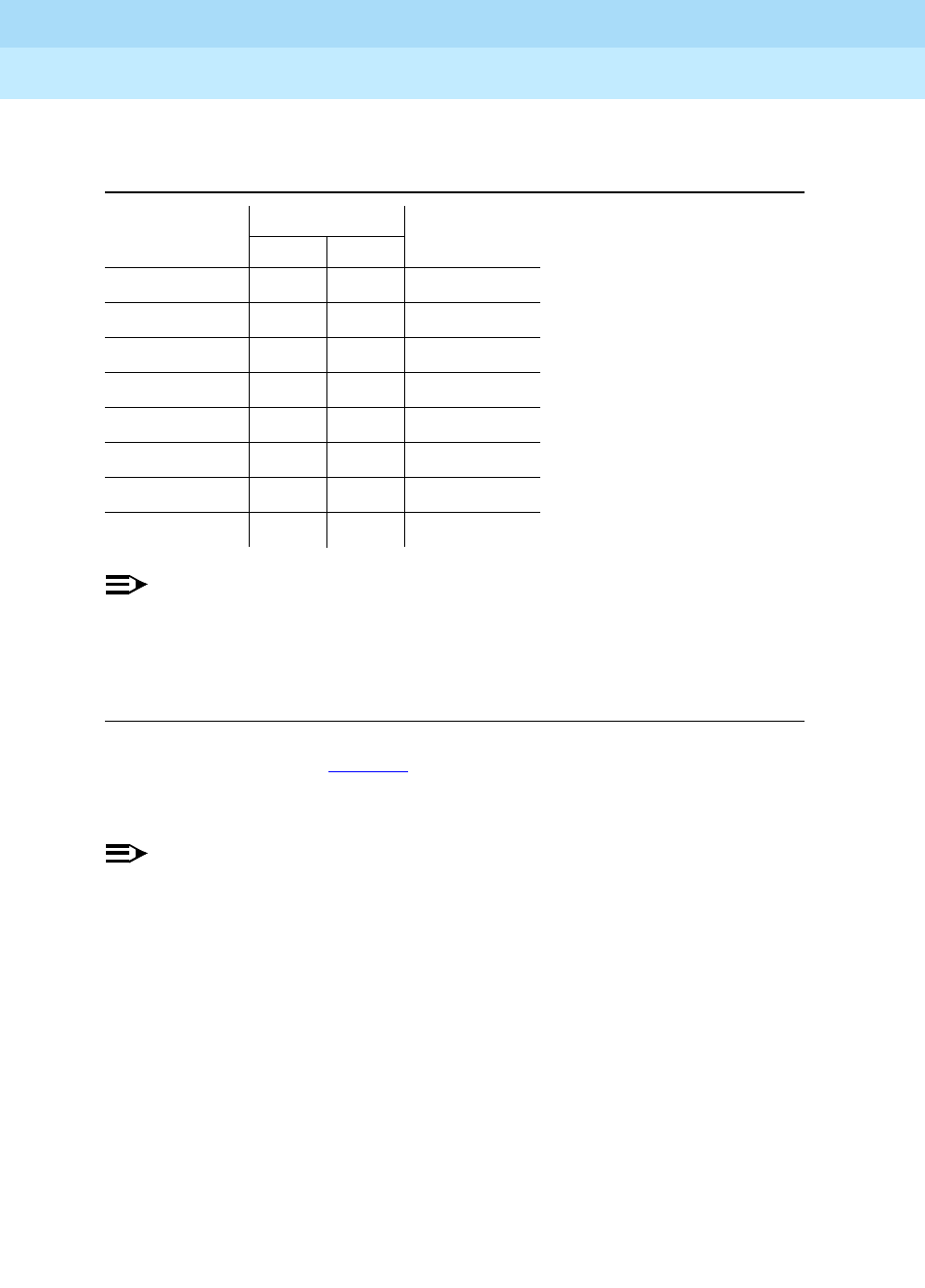
DEFINITY Enterprise Communications Server Release 6
Administration and Feature Description
555-230-522 Issue 4
May 1998
Automatic Routing Forms
Page 8-60AAR and ARS Digit Analysis Table
8
NOTE:
Any dialed digit-string not accounted for on the table is considered invalid
and the call is routed to intercept. These default translations are used for
call processing regardless of whether or not AAR or ARS has been
optioned for on the switch.
The translations shown in Table 8-2 appear only once in the switch’s memory but
are displayed in sorted order (including additions) on each of the 8 possible ARS
Digit Analysis Tables.
NOTE:
For service outside of North America, these defaults should be deleted. You
can delete the defaults by entering change ARS analysis 0. Then blank
out all of the Dialed Strings with spaces.
Table 8-1. AAR Digit Analysis Default Translations
Total Digits
Dialed String Min. Max. Call Type
2 7 7 aar
3 7 7 aar
4 7 7 aar
5 7 7 aar
6 7 7 aar
7 7 7 aar
8 7 7 aar
9 7 7 aar

DEFINITY Enterprise Communications Server Release 6
Administration and Feature Description
555-230-522 Issue 4
May 1998
Automatic Routing Forms
Page 8-61AAR and ARS Digit Analysis Table
8
Table 8-2. ARS Digit Analysis Default Translations
Total Digits
Dialed
String Min. Max.
Route
Pattern Call Type
0 1 1 den op
0 8 8 den op
0 11 11 den op
00 2 2 den op
01 9 17 den iop
011 10 18 den intl
10XXX0 6 6 den op
10XXX0 16 16 den op
10XXX01 14 22 den iop
10XXX011 15 23 den intl
1XXX555 11 11 den fnpa
1XXX976 11 11 den fnpa
18000555 11 11 den fnpa
1809 11 11 den fnpa
1900555 11 11 den fnpa
411 3 3 den svc
555 7 7 den hnpa
611 3 3 1 svc
811 3 3 1 svc
911 3 3 1 svc
976 7 7 den hnpa
N 7 7 2 hnpa
1N00 11 11 den fnpa
Continued on next page

DEFINITY Enterprise Communications Server Release 6
Administration and Feature Description
555-230-522 Issue 4
May 1998
Automatic Routing Forms
Page 8-62AAR and ARS Digit Analysis Table
8
1NX 11 11 den fnpa
Legend:
N - 2 through 9
X - any digit (0 - 9)
den - deny
fnpa - foreign number plan area (10-digit call)
hnpa - home number plan area (7-digit call)
intl - international
iop - international operator
op - operator
svc - service
Table 8-2. ARS Digit Analysis Default Translations
— Continued
Total Digits
Dialed
String Min. Max.
Route
Pattern Call Type
Continued on next page

DEFINITY Enterprise Communications Server Release 6
Administration and Feature Description
555-230-522 Issue 4
May 1998
Automatic Routing Forms
Page 8-63AAR and ARS Digit Conversion Table
8
AAR and ARS Digit Conversion Table
This form converts private-network numbers to other private-network or to
public-network ARS numbers. It is essential for converting home AAR numbers
into extension numbers. Using this table, you can:
■Steer some AAR calls to other switches in the private network
■Change the dialed string to a public-network number and route the call via
the ARS feature
■Block or intercept certain private-network calls to the attendant group
■Route unauthorized public-network calls to an attendant or give them
intercept tone
The form allows for the replacement of all or part of a dialed string with a
modified string and/or change of analysis type. The modified string represents an
alternative equivalent address and results in call analysis according to the
network type. This table is accessed during call-processing.
Digit conversion enhances the capabilities of the AAR and ARS features so that
outgoing public-network calls and private-network calls can be changed to local,
private, or public network destinations. The calls are then analyzed by the UDP,
AAR, or ARS features and routed according to the associated route patterns.
Administration commands
Use the following commands to administer the AAR and ARS Digit Conversion
Tab l e f or m.
1. Brackets [ ] indicate the qualifier is optional. Single quotes (‘ ’) indicate the text inside
the quote must be entered exactly as shown or an abbreviated form of the word may
be entered. MAX is the maximum number available in your system configuration.
Action Object Qualifier1
change aar digit-conversion
ars digit-conversion Enter digits between 0 to 9 ‘x’ or ‘X’
display aar digit-conversion
ars digit-conversion Enter digits between 0 to 9 ‘x’ or ‘X’
[’print’ or ’schedule’]
list aar digit-conversion
ars digit-conversion Enter [‘start’ matching pattern][‘count’
(1-MAX)] [’print’ or ’schedule’]

DEFINITY Enterprise Communications Server Release 6
Administration and Feature Description
555-230-522 Issue 4
May 1998
Automatic Routing Forms
Page 8-64AAR and ARS Digit Conversion Table
8
Form Instructions
Screen 8-3. AAR Digit Conversion Table
Screen 8-4. ARS Digit Conversion Table Form
Page 1 of 2
AAR DIGIT CONVERSION TABLE
Percent Full: ___
Matching Pattern Min Max Del Replacement String Net Conv ANI Req
__________________ __ __ __ __________________ ___ _ _
__________________ __ __ __ __________________ ___ _ _
__________________ __ __ __ __________________ ___ _ _
__________________ __ __ __ __________________ ___ _ _
__________________ __ __ __ __________________ ___ _ _
__________________ __ __ __ __________________ ___ _ _
__________________ __ __ __ __________________ ___ _ _
__________________ __ __ __ __________________ ___ _ _
__________________ __ __ __ __________________ ___ _ _
__________________ __ __ __ __________________ ___ _ _
__________________ __ __ __ __________________ ___ _ _
__________________ __ __ __ __________________ ___ _ _
__________________ __ __ __ __________________ ___ _ _
__________________ __ __ __ __________________ ___ _ _
__________________ __ __ __ __________________ ___ _ _
__________________ __ __ __ __________________ ___ _ _
Page 1 of 2
ARS DIGIT CONVERSION TABLE
Percent Full: ___
Matching Pattern Min Max Del Replacement String Net Conv ANI Req
__________________ __ __ __ __________________ ___ _ _
__________________ __ __ __ __________________ ___ _ _
__________________ __ __ __ __________________ ___ _ _
__________________ __ __ __ __________________ ___ _ _
__________________ __ __ __ __________________ ___ _ _
__________________ __ __ __ __________________ ___ _ _
__________________ __ __ __ __________________ ___ _ _
__________________ __ __ __ __________________ ___ _ _
__________________ __ __ __ __________________ ___ _ _
__________________ __ __ __ __________________ ___ _ _
__________________ __ __ __ __________________ ___ _ _
__________________ __ __ __ __________________ ___ _ _
__________________ __ __ __ __________________ ___ _ _
__________________ __ __ __ __________________ ___ _ _
__________________ __ __ __ __________________ ___ _ _
__________________ __ __ __ __________________ ___ _ _

DEFINITY Enterprise Communications Server Release 6
Administration and Feature Description
555-230-522 Issue 4
May 1998
Automatic Routing Forms
Page 8-65AAR and ARS Digit Conversion Table
8
NOTE:
When the form is accessed via a display or change command, the entries
are sorted separately in the order of the matching pattern. Specific digits
are sorted before the characters “*,” “x,” or “X.”
■Percent Full — 3-character display-only field. Displays the percentage of
the used system’s memory resources. A common pool of memory
resources is shared between the ARS and AAR Digit Conversion tables.
If this field indicates that the system memory resources are in jeopardy of
becoming full (100%), perform any of the following to free-up memory
resources:
— Delete unnecessary entries from any of the shared resources tables
— Use RHNPA Tables for 6-digit screening
— Reduce Dialed String entries to shortest possible length that
accomplishes the desired function
■Matching Pattern — Enter a 1–18-digit string to be matched against a
dialed number. Matching Pattern entries must be unique within the table.
The string may contain the digits 0–9 or a * and wildcard characters “x” or
“X.” These are used to match any digit in the range of 0–9 or *. If a Prefix
Digit is required for 10-digit DDD numbers, then the Prefix Digit "1" must
be present in the Matching Pattern string for the match to succeed.
If the associated Replacement String has an entry, Matching
Pattern must also have an entry.
■Min — The minimum number of digits in the dialed string
■Max — Enter the maximum number of digits to collect, between Min and
28.
■Del — The number of digits to delete from the beginning of the dialed
string
■Replacement String — Enter a 0–18-digit dialed string that replaces the
deleted portion of the dialed number. The dialed string may contain the
digits 0–9 or *, a "#" character, or be blank. The "#" character, when used,
must be at the end of the digit-string and is used to indicate
end-of-dialing.
NOTE:
A blank Replacement String has the effect of just deleting the
leading digits from the dialed string. Because the "#" character in the
Replacement String indicates the end-of-dialing, any digits
dialed after the inserted portion of the string are ignored. Deletion of
digits and blank replacements are used to crossover from ARS to
AAR.

DEFINITY Enterprise Communications Server Release 6
Administration and Feature Description
555-230-522 Issue 4
May 1998
Automatic Routing Forms
Page 8-66AAR and ARS Digit Conversion Table
8
■Net — The network in which to analyze the resulting number. Enter ext,
aar, or ars. The resulting digit-string is then analyzed as an extension
number, an AAR address, or an ARS address respectively.
■Conv — Enter y or n. To allow further conversion enter y.
■ANI Req — Enter y if ANI is required on incoming R2-MFC or Russian MF
ANI calls. Default is n. This field only applies if the Request Incoming
ANI (non-AAR/ARS) field on the Multifrequency-Signaling-Related
System Parameters form is n.

DEFINITY Enterprise Communications Server Release 6
Administration and Feature Description
555-230-522 Issue 4
May 1998
Automatic Routing Forms
Page 8-67Route Pattern form
8
Route Pattern form
The digit translations performed by the AAR and ARS Digit Analysis and RHNPA
Tables cause a specific route pattern to be selected for routing the call. The route
pattern contains a sequence of trunk groups on which an attempt is made to
route the call.
The Route Pattern form implements one route pattern. Each route pattern can
contain alternate trunk groups. The maximum number of route patterns and
alternate trunk groups allowed depends on the configuration and memory
available in your system.
The route patterns specified on the Route Pattern form are used by the following
features: AAR, ARS, GRS, and Call-by-Call Service Selection.
Before a call is routed, DEFINITY ECS checks the Facility Restriction Level (FRL)
compatibility to ensure:
■Calling party’s FRL is greater than or equal to the routing preference’s FRL
■Calling party’s BCC matches the BCC specified for the routing preference
(ISDN calls only)
■Facility type is okay for the call type
■There is an unused circuit (trunk port) available in the selected trunk group
When all checks are complete and compatibility is ensured, digits are outpulsed
over the selected trunk group member.
Administration commands
Use the following commands to administer the Route Pattern form
1. Brackets [ ] indicate the qualifier is optional. Single quotes (‘ ’) indicate the text inside
the quote must be entered exactly as shown or an abbreviated form of the word may
be entered. MAX is the maximum number available in your system configuration.
Action Object Qualifier1
change route-pattern 1-MAX
display route-pattern 1-MAX [print]
list route-pattern Enter [‘trunk’ (1-MAX)] [‘service’/feature name
string] [‘print‘ or ‘schedule’]

DEFINITY Enterprise Communications Server Release 6
Administration and Feature Description
555-230-522 Issue 4
May 1998
Automatic Routing Forms
Page 8-68Route Pattern form
8
Form Instructions
Screen 8-5. Route Pattern form (Page 1 of X)
Make assignments as required for the following fields on the form:
■Pattern Number — This is a display-only field when the form is accessed
using an administration command such as change or display.
■Grp No. — Enter the desired trunk-group number to specify which
trunk-group will be associated with the entries on this line of the form.
■FRL — Enter the FRL 0– 7 to be assigned this routing preference (this line
of parameters on the form). 0 is the least restrictive and 7 is the most
restrictive. Trunk-group FRLs are changeable from pattern to pattern. The
calling party’s FRL must be greater than or equal to this FRL to access the
associated trunk-group.
Valid entries are 0 to 7.
NOTE:
For system security reasons, Lucent recommends using the most
restrictive FRL possible.
■NPA— This entry is not required for AAR. For ARS, enter the NPA of the
distant-end (terminating endpoint). For WATS trunks, the NPA is the same
as the home NPA unless the LEC wants 10 digits for local NPA calls. For tie
trunks, the NPA field is left blank. Valid entries are 3-digits in the form: first
digit (2–9), second digit (0–9), third digit (0– 9). Default is blank.
■Prefix Mark — Not required for AAR. For ARS, enter a number from 0–4 or
blank (default) as indicated below. This specifies whether the prefix digit 1
is outpulsed.
change route-pattern 1 Page 1 of X
Pattern Number: 1_
Grp. FRL NPA Pfx Hop Toll No. Del Inserted IXC
No. Mrk Lmt List Digits Digits
1: ___ _ ___ _ __ __ __ ____________________________________ user
2: ___ _ ___ _ __ __ __ ____________________________________ user
3: ___ _ ___ _ __ __ __ ____________________________________ user
4: ___ _ ___ _ __ __ __ ____________________________________ user
5: ___ _ ___ _ __ __ __ ____________________________________ user
6: ___ _ ___ _ __ __ __ ____________________________________ user
BCC VALUE TSC CA-TSC ITC BCIE Service/Feature Numbering
0 1 2 3 4 W Request Format
1: y y y y y n y none_____ both ept outwats-bnd____ BAND: ___ ________
2: y y y y y n n rest _______________ ________
3: y y y y y n n rest _______________ ________
4: y y y y y n n rest _______________ ________
5: y y y y y n n rest _______________ ________
6: y y y y y n n rest _______________ ________

DEFINITY Enterprise Communications Server Release 6
Administration and Feature Description
555-230-522 Issue 4
May 1998
Automatic Routing Forms
Page 8-69Route Pattern form
8
For a WAT -trunk, the Prefix Mark is the same as the local CO trunk. Prefix
Mark operations only apply to FNPA or HNPA call types (ARS). For tie
trunks, leave field this blank.
■Hop Lmt — Controls the number of hops for each preference. A blank in
this field indicates that there is no limit to the number of hops for this
preference. Enter a number from 1–9 to limit the number of hops if using
the tandem hop feature. Enter a number from 1–32 if using the transit
feature. DEFINITY ECS blocks a hop equal to or greater than the number
you enter.
■Toll List — Not required for AAR. For ARS, enter a number that
references the ARS Toll Table associated with the terminating NPA of the
trunk group. This field must be completed if Prefix Mark is 2 or 3.
Default is blank.
■No. Del. Digits — Enter the total number of digits to be deleted from the
dialed string when selecting this trunk-group for call-routing. Default is
blank.
Any nonblank entry in this field (including 0) causes any user-dialed IXC
code to be deleted in addition to the number of digits specified.
0 Indicates that the Prefix digit 1 is never outpulsed for 10-digit
user-dialed FNPA calls, but leaves a user-dialed Prefix digit 1 for
7-digit HNPA calls. Prefix Mark 0 also leaves 1s on 10-digit calls
that are not administered as FNPA- or HNPA-types.
NOTE:
FNPA and HNPA are North American Numbering Plan terms.
1 Indicates that the Prefix digit 1 is outpulsed if and only if the call is
a 10-digit call. Select Prefix Mark 1 for those HNPAs that require
users to dial 1 to indicate a toll-call.
2 Indicates that the Prefix digit 1 is outpulsed for all toll calls, 7- and
10-digit. Prefix Mark 2 must refer to a Toll Table. See Toll List
definition.
3 Indicates that the Prefix digit 1 is outpulsed for all toll-calls. These
calls are always outpulsed as 10-digit numbers, even if they are
within the HNPA. Prefix Mark 3 must refer to a Toll Table. See Toll
List definition.
4 Indicates that the user-dialed Prefix digit 1 is always suppressed.
NOTE:
This capability is required, for example, when routing ISDN
calls to an Lucent Technologies 4ESS. If the prefix digit 1
were not suppressed, then the 4ESS would reject such calls.

DEFINITY Enterprise Communications Server Release 6
Administration and Feature Description
555-230-522 Issue 4
May 1998
Automatic Routing Forms
Page 8-70Route Pattern form
8
NOTE:
Use 0 (zero) in this field to suppress user-dialed IXC codes. This
capability is useful when the call is routed via ISDN trunks to a 4ESS
office. The 4ESS will reject a call if the IXC code is sent along with
the address digits.
■Inserted Digits — Enter the actual digits to be inserted. Up to 52 digits
may be outpulsed. This includes 36 digits which you enter here plus up to
18-digits originally dialed. When they are used, special symbols count as
two digits each. The special characters used in route patterns are
described below.
NOTE:
Do not use a comma "," (1.5 second pause) as the first character in
the string unless absolutely necessary. Misuse of the character can
result in calls, such as Abbreviated Dialing or Last Number Dialed,
not completing to the far end.
1. If the outgoing trunk is signaling type “mf,” the signal administered as the
“end-of-digit” in the Outgoing Group column of the System-Parameters
Multifrequency-Signaling form is inserted, and not the “*” or the “#.”
Special
Character Description
* digit * (See note below1.)
# digit # (See note below1.)
, 1.5 second pause
+ Wait for dial tone up to the Off Premises Tone Detection
Timer and then either outpulse or intercept tone based on
Out Pulse Without Tone y/n (Feature-Related System
Parameters form). Outpulsed DTMF digits are sent at the
rate specified by the End-to-End Signaling Tone and Pause
parameters (Trunk Group Administrable Timers form).
% Start End-to-End Signaling. Send digits as DTMF inband
tones at the rate specified by the End-to-End Signaling tone
and Pause parameters (Trunk Group Administrable Timers
form).
! Wait for dial tone without timeout and then outpulse DTMF
digits at the rate specified by the End-to-End Signaling Tone
and Pause parameters (Trunk Group Administrable Timers
form).
& Wait for ANI (used for Russian pulse trunks to indicate where
to wait for ANI prompt and send in-band ANI)

DEFINITY Enterprise Communications Server Release 6
Administration and Feature Description
555-230-522 Issue 4
May 1998
Automatic Routing Forms
Page 8-71Route Pattern form
8
When an asterisk “*” is translated in the route pattern and the signal
“end-of-dial” is translated on the Multifrequency-Signaling form, the
MFC tone for the “end-of-digits” is sent out to the CO in place of the
asterisk “*.”
■IXC — Displays when ISDN-PRI or ISDN-BRI Trunks are enabled on
the System-Parameters Customer-Options form. For ISDN Preference
trunks, enter the last two-to-four digits to represent an equal access
inter-exchange carrier (IXC) code number (such as 10XX or 10XXX).
NOTE:
This length should match the format established on the IXC Codes
form.
This field is used by all calls that route via an IXC, and is used also for Call
Detail Recording (CDR). If an IXC is not specified, a call is transmitted by
the presubscribed common carrier.
NOTE:
The IXC field must be none for non-ISDN trunk groups and for
Bellcore NI-2 Operator Service Access. If you need to send an IXC
code for a non-ISDN trunk group, then enter this IXC value in
Inserted Digits.
■BCC Value (required by GRS feature) — Displays when ISDN-PRI or
ISDN-BRI Trunks are enabled on the System-Parameters
Customer-Options form. Enter y (default) or n in the appropriate BCC
column (0, 1, 2, 3, 4, or W) to specify whether the BCC is valid for the
associated route. The following defines the BCC values:
■TSC — Enter y to allow incoming Non-Call-Associated TSC requests to
be tandemed out and to allow the establishment of Call-Associated TSCs
associated with B-channel connections of that preference. To achieve
feature transparency, DCS+ calls should be routed via a route pattern that
has an ISDN-PRI Used for DCS trunk-group as a first preference.
BCC Value Description
0 Voice-Grade Data and Voice
1 56-kbps Data (Mode 1)
2 64-kbps Data (Mode 2)
3 64-kbps Data (Mode 3)
4 64-kbps Data (Mode 0)
W 128 to 1984-kbps Data (Wideband)

DEFINITY Enterprise Communications Server Release 6
Administration and Feature Description
555-230-522 Issue 4
May 1998
Automatic Routing Forms
Page 8-72Route Pattern form
8
■CA-TSC Request — Appears when TSC is y. A CA-TSC uses the call
reference value of the call control data packets to exchange
user-information messages associated with an ISDN B-channel
connection. CA-TSCs are a finite system and trunk group resource. There
is a trade-off between the two possible entries — a small time-lag with the
first and usage generated by the second. Valid entries are:
■ITC (Information Transfer Capability) — Used to administer the type of
traffic (restricted, unrestricted, or both) that is allowed to be carried by this
routing preference. If entering rest (restricted), then only calls originating
from restricted endpoints may access this route pattern. If entering unre
(unrestricted), then only calls originating from unrestricted endpoints may
access this route pattern. If entering both, then calls originating from both
restricted and unrestricted endpoints may access the route pattern.
This field must be unre or both if BCC W is y.
■BCIE (Bearer Capability Information Element) — Used to determine how
to create the ITC codepoint in the BCIE of the setup message. This field
only applies to ISDN trunks and is displayed and administrable only if ITC
is both. Valid entries are ept (endpoint) and“unr (unrestricted). Default is
ept.
as-needed (Recommended for most situations.) CA-TSC is not
established along with the B-channel call. If a CA-TSC is
needed due to feature activation somewhere in the
lifetime of this B-channel call, then the CA-TSC is
established at that time and remains active for the
duration of the call.
at-setup Causes a CA-TSC to be established at the same time as
the initial B-channel connection is established. In other
words, a CA-TSC is set up for each and every B-channel
call whether CA-TSC is ever needed.
none Disallows the establishment of CA-TSCs associated with
B-channel connections of the current preference
(tandeming of NCA-TSC setup requests, however, are
still permitted).
NOTE:
With as-needed, the need to establish the CA-TSC
causes a slight delay in the invocation of the
Call-Associated feature. This delay is not present
with at-setup because the CA-TSC is established
already at call-setup and is ready to be used
immediately upon feature invocation.

DEFINITY Enterprise Communications Server Release 6
Administration and Feature Description
555-230-522 Issue 4
May 1998
Automatic Routing Forms
Page 8-73Route Pattern form
8
■Service/Feature (required by the Call-by-Call Service Selection feature)
— Displays when ISDN-PRI or ISDN-BRI Trunks is enabled on the
System-Parameters Customer-Options form. Enter up to 15 characters
that represent the Service/Feature carried by a call in this route pattern.
Default is blank. Valid entries are:
— accunet
—i800
— inwats
—lds
— mega800
— megacom
— multiquest
—operator
— outwats-bnd
—sdn
— sub-operator
— wats-max-bnd
■Band (required by the Call-by-Call Service Selection feature) — Displays
when ISDN-PRI or ISDN-BRI Trunks is enabled on the
System-Parameters Customer-Options form. Enter a number that
represents the OUTWATS band number. This field displays when
Services/Features is outwats-bnd. The default is blank.
■Numbering Format — Displays when ISDN-PRI or ISDN-BRI Trunks
is enabled on the System-Parameters Customer-Options form. This field
specifies the format of the routing-number used for the trunk group
administered for the preference. You can leave the field blank (default) or
you can enter one of the following values from Table 8-3 if the trunk group
specified for preference is ISDN:
Table 8-3. Numbering Format Values
Route Pattern
Format Numbering Plan Identifier Type of Numbering
blank E.164(1) 1-MAX
natl-pub E.164(1) national(2)
intl-pub E.164(1) international(1)
locl-pub E.164(1) local/subscriber(4)
Continued on next page
DEFINITY Enterprise Communications Server Release 6
Administration and Feature Description
555-230-522 Issue 4
May 1998
Automatic Routing Forms
Page 8-74Route Pattern form
8
NOTE:
To access Bellcore NI-2 Operator Service Access, Inserted
Digits must be unk-unk.
■LAR — Enter the routing-preference for Look Ahead Routing. The choices
are described below.
Implementation Notes
The number of pages displayed depends upon the amount of system memory.
Also, many of the fields only display under certain conditions. See field
definitions for those conditions.
pub-unk E.164(1) unknown(0)
lev0-pvt Private Numbering Plan - PNP(9) local(4)
lev1-pvt Private Numbering Plan - PNP(9) Regional Level 1(2)
lev2-pvt Private Numbering Plan - PNP(9) Regional Level 2(1)
unk-unk unknown(0) unknown(0)
LAR Value DEFINITY ECS Actions
next Go to the next routing-preference and attempt the call
again
rehu Rehunt within the current routing-preference for another
trunk to attempt the call again
none Look Ahead Routing is not enabled for the preference
Table 8-3. Numbering Format Values — Continued
Route Pattern
Format Numbering Plan Identifier Type of Numbering
Continued on next page

DEFINITY Enterprise Communications Server Release 6
Administration and Feature Description
555-230-522 Issue 4
May 1998
Automatic Routing Forms
Page 8-75ARS Toll Table
8
AR S Tol l Ta bl e
This form assigns ARS Toll Tables used by Subnet Trunking. Use it to specify
whether calls to CO codes listed on the table are toll or non-toll calls. You specify
non-toll calls based on the last 2 digits of the distant-end of the trunk group.
Administration commands
Use the following commands to administer the ARS Toll Table form.
Form Instructions
Screen 8-6. ARS Toll Table
■ARS TOLL TABLE — Enter the ARS Toll Table number. Up to 8 forms may
be required for each table, one for each 100-block, 2 to 9.
■OFFICE CODES — Enter a 100-block — 200–299 through 900–999. A
separate form is required for each 100-block.
■00: through 99: — Enter n beside each CO code to be designated as
non-toll. These fields represent the last 2 digits of the codes within the
100-block. If no changes are made, the codes are implemented as
toll-type codes (default).
1. Brackets [ ] indicate the qualifier is optional. Single quotes (‘ ’) indicate the text inside
the quote must be entered exactly as shown or an abbreviated form of the word may
be entered. MAX is the maximum number available in your system configuration.
Action Object Qualifier1
change ars toll n:xxx (1–MAX:office code) n:xyy: n(1-MAX); ‘:’ ;x(2-MAX;
display ars toll n:xxx (1–MAX:office code) [’print’ or ’schedule’]
ARS TOLL TABLE: __ Page 1 of 1
OFFICE CODES: x00-x99
00: y 10: y 20: y 30: y 40: y 50: y 60: y 70: y 80: y 90: y
01: y 11: y 21: y 31: y 41: y 51: y 61: y 71: y 81: y 91: y
02: y 12: y 22: y 32: y 42: y 52: y 62: y 72: y 82: y 92: y
03: y 13: y 23: y 33: y 43: y 53: y 63: y 73: y 83: y 93: y
04: y 14: y 24: y 34: y 44: y 54: y 64: y 74: y 84: y 94: y
05: y 15: y 25: y 35: y 45: y 55: y 65: y 75: y 85: y 95: y
06: y 16: y 26: y 36: y 46: y 56: y 66: y 76: y 86: y 96: y
07: y 17: y 27: y 37: y 47: y 57: y 67: y 77: y 87: y 97: y
08: y 18: y 28: y 38: y 48: y 58: y 68: y 78: y 88: y 98: y
09: y 19: y 29: y 39: y 49: y 59: y 69: y 79: y 89: y 99: y

DEFINITY Enterprise Communications Server Release 6
Administration and Feature Description
555-230-522 Issue 4
May 1998
Automatic Routing Forms
Page 8-76RHNPA Table
8
RHNPA Table
The Remote Home Numbering Plan Area (RHNPA) Table assigns additional
3-digit screenings (for instance, on the prefix or nxx numbers) and associated
route pattern numbers for up to 32 RHNPA Tables (r1–r32). One form is required
for each 100-block of codes in the range 000–999. RHNPA Tables can be used
with any call-type and a choice of up to 12 route patterns is provided for each
100-block of codes.
RHNPA Tables typically are used for the DDD prefixes.
The ARS Digit Analysis Table performs translations on the first 3 digits of the
dialed string. The RHNPA Table performs translations on the next 3-digit dialed
string.
Example
The Rte Pat fields on the ARS Digit Analysis Table are set to r1, r10 and r32.
These point to the respective RHNPA Tables 1, 10, or 32. Therefore, the next 3
digits dialed represent a CO code in the FNPA. These digits are translated by the
RHNPA Table and routed via the assigned route pattern to the CO.
The RHNPA Table can also be used for AAR analysis.
Administration commands
Use the following commands to administer the RHNPA Table form.
1. Brackets [ ] indicate the qualifier is optional. Single quotes (‘ ’) indicate the text inside the
quote must be entered exactly as shown or an abbreviated form of the word may be entered.
MAX is the maximum number available in your system configuration.
Action Object Qualifier1
change rhnpa Enter RHNPA and office code n:xyy n(1-MAX) x(0-MAX)
y(0-MAX) y(0-MAX)
display rhnpa Enter RHNPA and office code n:xyy n(1-MAX) x(0-MAX)
y(0-MAX) y(0-9) [’print’ or ’schedule’]

DEFINITY Enterprise Communications Server Release 6
Administration and Feature Description
555-230-522 Issue 4
May 1998
Automatic Routing Forms
Page 8-77RHNPA Table
8
Form Instructions
Screen 8-7. RHNPA Table (Page 1 of 1)
■RHNPA TABLE — Enter the applicable table number from 1–32. Up to 8
forms may be required for each table, one for each 100-block, 2 to 9.
■CODE — Enter the desired 100-block; that is, 000 through 099, 100
through 199, 200 through 299,...800 through 899, 900 through 999. A
separate form is required for each 100-block.
■Pattern Choices — Enter a pattern number representing the route
patterns that can be accessed by the RHNPAs identified on this form.
Each form on each RHNPA Table may have 12 different route patterns
(Pattern Choices). A Pattern choice listed on one form automatically
defaults to the other forms of the same RHNPA Table. If one pattern is
used most often (that is, accessed by the greatest number of CO codes in
this block), assign that as Pattern Choice 1. Otherwise, the correlation
between Pattern Choice Numbers and route patterns is completely
arbitrary.
■Code-Pattern Choice Assignments (from 1-12 above) — Enter a
Pattern Choice number from the list above in the field associated with
each CO Code. The Code fields represent the last 2-digits of the codes
within the 100-block. This field points to the Pattern Choice above, which
contains the route pattern to be used.
RHNPA TABLE: __ Page 1 of 1
CODE: x00 - x99
Pattern Choices
1: ___ 3: ___ 5: ___ 7: ___ 9: ___ 11: ___
2: ___ 4: ___ 6: ___ 8: ___ 10: ___ 12: ___
Code-Pattern Choice Assignments (from 1(en12 above)
00: 1__ 10: 1__ 20: 1__ 30: 1__ 40: 1__ 50: 1__ 60: 1__ 70: 1__ 80: 1__ 90: 1__
01: 1__ 11: 1__ 21: 1__ 31: 1__ 41: 1__ 51: 1__ 61: 1__ 71: 1__ 81: 1__ 91: 1__
02: 1__ 12: 1__ 22: 1__ 32: 1__ 42: 1__ 52: 1__ 62: 1__ 72: 1__ 82: 1__ 92: 1__
03: 1__ 13: 1__ 23: 1__ 33: 1__ 43: 1__ 53: 1__ 63: 1__ 73: 1__ 83: 1__ 93: 1__
04: 1__ 14: 1__ 24: 1__ 34: 1__ 44: 1__ 54: 1__ 64: 1__ 74: 1__ 84: 1__ 94: 1__
05: 1__ 15: 1__ 25: 1__ 35: 1__ 45: 1__ 55: 1__ 65: 1__ 75: 1__ 85: 1__ 95: 1__
06: 1__ 16: 1__ 26: 1__ 36: 1__ 46: 1__ 56: 1__ 66: 1__ 76: 1__ 86: 1__ 96: 1__
07: 1__ 17: 1__ 27: 1__ 37: 1__ 47: 1__ 57: 1__ 67: 1__ 77: 1__ 87: 1__ 97: 1__
08: 1__ 18: 1__ 28: 1__ 38: 1__ 48: 1__ 58: 1__ 68: 1__ 78: 1__ 88: 1__ 98: 1__
09: 1__ 19: 1__ 29: 1__ 39: 1__ 49: 1__ 59: 1__ 69: 1__ 79: 1__ 89: 1__ 99: 1__

DEFINITY Enterprise Communications Server Release 6
Administration and Feature Description
555-230-522 Issue 4
May 1998
Automatic Routing Forms
Page 8-78Time of Day Routing Plan
8
Time of Day Routing Plan
Use this form to assign Time of Day Routing Plans. Using this form, you can route
AAR and ARS calls based on the time of day each call is made. Up to 8 Time of
Day Routing Plans can be administered, each scheduled to change up to 6 times
a day, for each day in the week.
The calling party’s FRL must be greater than or equal to the FRL assigned in the
route pattern. The route pattern is selected by matching on the Time of Day
Routing Plan the PGN# with the Partitioned Group Number field on the AAR or
ARS Digit Analysis Table. Then, the AAR or ARS Digit Analysis Table selects the
route pattern.
NOTE:
The following optional features must be enabled on the System-Parameters
Customer-Options form before this form can be administered: Automatic
Route Selection (ARS) or Private Networking, AAR/ARS Partitioning, and
Time of Day Routing.
Administration commands
Use the following commands to administer the Time of Day Routing Plan form.
1. Brackets [ ] indicate the qualifier is optional. Single quotes (‘ ’) indicate
the text inside the quote must be entered exactly as shown or an
abbreviated form of the word may be entered. MAX is the maximum
number available in your system configuration.
Action Object Qualifier1
display time-of-day [‘print’ or ‘schedule’]
display time-of-day 1-MAX (plan number) [’print’ or ’schedule’]
change time-of-day [time of day routing plan (1-MAX)]

DEFINITY Enterprise Communications Server Release 6
Administration and Feature Description
555-230-522 Issue 4
May 1998
Automatic Routing Forms
Page 8-79Time of Day Routing Plan
8
Form Instructions
Screen 8-8. Time Of Day Routing Form (Page 1 of 1)
■Time of Day Routing Plan — Specifies the TOD routing plan number. Up
to 8 of these plans can be administered. This is a display-only field when
the form is accessed using an administration command such as add or
change.
■Act Time — Specifies the time of day the route pattern (identified by PGN
#) is effective. The time is represented in military time (24:00 hours per
day). List times for the same day in increasing order. Valid entries are
00:00–23:59; default is 00:00. There must be at least one entry for each
day.
■PGN # — Enter a PGN that points to the appropriate AAR or ARS Digit
Analysis Tables. The AAR or ARS Digit Analysis Tables should have the
same PGN #. This is how you point to the route pattern that should be
active for the activation time. There must be at least one entry for each
day.
The AAR or ARS Digit Analysis Table selected and the route pattern used
is based on the dialed string. Default is 1.
NOTE:
It is possible to point to an AAR or ARS Digit Analysis Table
associated with a PGN that has a different FRL than the FRL
assigned to the caller’s facility. Proceed with caution when making
these assignments.
Before a call is routed, DEFINITY ECS checks to see that the Calling
party’s FRL is greater than or equal to the routing preference’s FRL.
TIME OF DAY ROUTING PLAN x Page 1 of 1
Act PGN Act PGN Act PGN Act PGN Act PGN Act PGN
Time # Time # Time # Time # Time # Time #
Sun 00:00 1 __:__ _ __:__ _ __:__ _ __:__ _ __:__ _
Mon 00:00 1 __:__ _ __:__ _ __:__ _ __:__ _ __:__ _
Tue 00:00 1 __:__ _ __:__ _ __:__ _ __:__ _ __:__ _
Wed 00:00 1 __:__ _ __:__ _ __:__ _ __:__ _ __:__ _
Thu 00:00 1 __:__ _ __:__ _ __:__ _ __:__ _ __:__ _
Fri 00:00 1 __:__ _ __:__ _ __:__ _ __:__ _ __:__ _
Sat 00:00 1 __:__ _ __:__ _ __:__ _ __:__ _ __:__ _

DEFINITY Enterprise Communications Server Release 6
Administration and Feature Description
555-230-522 Issue 4
May 1998
Automatic Routing Forms
Page 8-80Time of Day Routing Plan
8

Call Center
Page 9-1
9
DEFINITY Enterprise Communications Server Release 6
Administration and Feature Description
555-230-522 Issue 4
May 1998
9
9Call Center
This section contains the following DEFINITY ECS Call Center features. Call
Center forms are located at the end of this chapter.
Table 9-1. Call Center features
Feature Page
Abandoned Call Search 9-3
Add/Remove Skills 9-5
Agent Call Handling 9-7
Auto-Available Split 9-22
Automatic Call Distribution 9-25
Basic Call Management System 9-40
Best Service Routing™ 9-44
Call Management System 9-58
Call Prompting 9-60
Call Vectoring 9-63
Expert Agent Selection 9-72
Inbound Call Management 9-81
Information Forwarding 9-89
Look-Ahead Interflow 9-98
Continued on next page

DEFINITY Enterprise Communications Server Release 6
Administration and Feature Description
555-230-522 Issue 4
May 1998
Call Center
Page 9-2
9
Multiple Call Handling 9-104
Queue Status Indications 9-110
Reason Codes 9-112
Redirection on No Answer 9-116
Universal Call ID 9-130
VDN of Origin Announcement 9-146
Voice Response Integration 9-152
VuStats 9-161
Forms Page
Call Center Forms 9-192
Related feature or form Page
‘‘Announcements/Audio Sources’’ 5-26
Calling Party/Billing Number 4-246
‘‘CallVisor Adjunct-Switch Application Interface’’ 4-250
‘‘Class of Restriction’’ 4-264
‘‘Hunt Groups’’ 4-365
‘‘Malicious Call Trace’’ 4-422
Recorded Announcement 4-500
‘‘Service Observing’’ 4-539
CALLMASTER II and III voice terminals 6-141
500, 2500, K2500, 7101A, 7102A, 7103A, 7104A,
8110, DS1FD, DS1SA, and VRU voice terminals 6-47
Table 9-1. Call Center features — Continued
Feature Page
Continued on next page

DEFINITY Enterprise Communications Server Release 6
Administration and Feature Description
555-230-522 Issue 4
May 1998
Call Center
Page 9-3Abandoned Call Search
9
Abandoned Call Search
Abandoned Call Search allows the switch to identify abandoned calls if the
central office (CO) does not provide timely disconnect supervision. An
abandoned call is one in which the calling party hangs up before the call is
answered. Note that Abandoned Call Search is suitable only for older COs that
do not provide timely disconnect supervision. Most COs provide timely
disconnect supervision and do not require Abandoned Call Search.
Before an incoming Automatic Call Distribution (ACD) split rings a hunt group
member or agent, the system checks to make sure that the calling party has not
abandoned the call. If the calling party has abandoned the call, the call does not
ring the hunt group member or agent.
If a call has been abandoned, the system determines if the calling party is still
connected to the ground-start trunk at the CO. To do this, the system flashes (that
is, opens the tip-ring loop for 150 to 200 ms) the CO end of the trunk. If the calling
party is still connected, the CO does not respond. If the calling party has
abandoned the call, the CO sends the system a disconnect signal within 800 ms.
The system interprets this as an abandoned call, releases the trunk, and the call
does not ring the hunt group member or agent.
Outside of the U.S., a flash of this duration may be handled differently. See
‘‘Trunk Flash’’ on page 4-603 for more information.
How to administer Abandoned Call Search
You administer Abandoned Call Search on a per-trunk-group basis. Administer
each ground-start CO, FX, and WATS trunk group either having Abandoned Call
Search or not having it. Abandoned Call Search is not supported for tie trunks.
Required forms
Form Field Page
Trunk Group
—CO
FX
WATS
■Abandoned Call Search 7-115
7-168
7-193
7-268

DEFINITY Enterprise Communications Server Release 6
Administration and Feature Description
555-230-522 Issue 4
May 1998
Call Center
Page 9-4Abandoned Call Search
9
Considerations
NOTE:
Abandoned Call Search works with ground-start analog trunks that
do not
provide disconnect supervision and that
do
react to a 500-ms break.
Some older COs can take as long as two minutes to notify the switch of a
disconnect. Thus, the switch must determine within one second whether the call
has been abandoned, before extending the call. Even with Abandoned Call
Search or disconnect supervision, there is a small probability that a call will be
extended to the destination hunt group after the caller has hung up. Abandoned
Call Search and disconnect supervision significantly reduce that probability.
Abandoned Call Search allows agents and hunt group members to answer more
calls because time is not wasted on abandoned calls. In addition, call-handling
statistics that the Call Management System (CMS) generates are more accurate
because it is clear when a call is abandoned.
However, be aware that Abandoned Call Search adds an overhead of up to one
second to each call delivered to an agent.
Interactions
None.

DEFINITY Enterprise Communications Server Release 6
Administration and Feature Description
555-230-522 Issue 4
May 1998
Call Center
Page 9-5Add/Remove Skills
9
Add/Remove Skills
Add/Remove Skills allows an agent using Expert Agent Selection (EAS) to add or
remove skills. A skill is a numeric identifier in the switch that refers to an agent’s
specific ability. For example, an agent who is able to speak English and Spanish
could be assigned a Spanish-speaking skill with an identifier of 20. The agent
then adds skill 20 to his or her set of working skills. If a customer needs a
Spanish-speaking agent, the system routes the call to an agent with that skill.
Each agent can have up to 20 skills active at any one time. Agents can dial
feature access codes (FACs) to add or remove a skill. Or a supervisor with
console permission can enter an agent’s login ID and add or remove an agent’s
skill. If a supervisor adds or removes a skill for an agent, the agent receives a
change notification.
To determine if they need to add or remove a skill, agents and supervisors can
use queue-status indications, VuStats, or Call Management System (CMS) or
Basic Call Management System (BCMS) information. When adding a skill, the
agent must specify the skill priority level (1 — 16).
On voice terminals with displays, the system prompts the agent through the
process of adding or removing a skill and displays the updated set of skills.
How to administer Add/Remove Skills
Considerations
■A skill cannot be removed from an agent’s skill set if the agent is on a call
for that skill or in the After-Call-Work (ACW) state for that skill.
■With EAS, agents cannot remove their Direct Agent Skill.
Required forms
Form Field Page
Class of Restriction (COR) ■Add/Remove Agent Skills 5-72
Feature Access Code (FAC) ■Add Agent Skills
■Remove Agent Skills
5-113
Language Translations ■41-44 on Page 5 5-193
Hunt Group ■Skill 5-158
Class of Service ■Administer console permissions
for supervisors 5-81

DEFINITY Enterprise Communications Server Release 6
Administration and Feature Description
555-230-522 Issue 4
May 1998
Call Center
Page 9-6Add/Remove Skills
9
Interactions
■Auto-Available Splits (AAS)
If an agent adds a skill that is administered as Auto-Available, on the
Agent Login ID form, you must set the AAS field to y for that agent’s login
ID.
■BCMS
BCMS begins tracking a new skill as soon as it is added. When an agent
removes a skill, the real-time agent information specific to that skill is
removed from the real-time reports, but it still appears on the historical
reports.
■EAS-PHD
When EAS-PHD is set as an option, agents cannot remove their Direct
Agent Skill. In an EAS environment, agents must have at least one skill
assigned to them during a login session. With EAS-PHD, agents can
specify up to 20 skills.
If EAS-PHD is not enabled, agents can specify only 4 skills.
■VuStats
Because VuStats displays information gathered by BCMS whether BCMS
is enabled or not, the BCMS interaction above applies to VuStats.

DEFINITY Enterprise Communications Server Release 6
Administration and Feature Description
555-230-522 Issue 4
May 1998
Call Center
Page 9-7Agent Call Handling
9
Agent Call Handling
Agent Call Handling allows you to administer functions that Automatic Call
Distribution (ACD) agents use to answer and process ACD calls.
You define the following agent capabilities:
■Agent login and logout
■Agent answering options: Automatic Answer (zip tone) or Manual Answer
■ACD work modes: Auxiliary Work (AUX Work), Auto-In, Manual-In, or After
Call Work (ACW)
■Timed ACW
■Agent request for supervisor assistance
■ACD call disconnect (Release button)
■Stroke counts
■Call work codes
■Forced entry of stroke counts and call work codes
‘‘Agent capacity and related limits’’ on page 9-15 describes agent-capacity
planning.
NOTE:
All of these agent capabilities are also supported through the CallVisor
Adjunct/Switch Applications Interface (ASAI). For information, see
‘‘CallVisor Adjunct-Switch Application Interface’’ on page 4-250.
How to administer Agent Call Handling
Required forms
Form Field Page
Feature Access Code
(FAC)
■Feature Access Codes for ACD
features 5-113
Hunt Group ■Forced Stroke Count or Call Work Code
■Timed ACW Interval
5-158
Vector Directory Number ■VDN Timed ACW Interval 9-214
Continued on next page

DEFINITY Enterprise Communications Server Release 6
Administration and Feature Description
555-230-522 Issue 4
May 1998
Call Center
Page 9-8Agent Call Handling
9
Station
(multi-appearance)
■Button/Feature Button Assignments
— manual-in
— auto-in
— aux-work
— after-call
—assist
— release
—work-code
— stroke-cnt
■Active Station Ringing (DCP, Hybrid)
■Idle/Active Ringing (CALLMASTER)
■VuStats
6-28
Stations (all) ■Auto Answer 6-28
Attendant Console ■Feature Button Assignments
— after-call
—assist
— auto-in
— aux-work
— manual-in
— release
—work-code
— stroke-cnt
■Auto Answer
5-35
Agent LoginID
(EAS only)
■All 9-193
Required forms — Continued
Form Field Page
Continued on next page

DEFINITY Enterprise Communications Server Release 6
Administration and Feature Description
555-230-522 Issue 4
May 1998
Call Center
Page 9-9Agent Call Handling
9
Detailed description
This section describes agents capabilities. For details on procedures that agents
follow when using these capabilities, see
DEFINITY Enterprise Communications
Server Generic 1, Generic 3, and System 75 Automatic Call Distribution (ACD)
Agent Instructions
.
NOTE:
This information applies generally to ACD; see ‘‘Expert Agent Selection’’ on
page 9-72 for additional EAS procedures.
Agent login and logout
To receive ACD calls, an agent must log into the system. An agent can be logged
into multiple splits. If a hunt group is measured by Call Management System
(CMS) or Basic Call Management System (BCMS) or is a skill, an agent must
enter a login ID; otherwise, the login ID is optional.
Login
To log in, an agent goes off-hook and dials the login feature access code (FAC),
followed by the split number and the log-in ID, if required. If login is successful,
the agent automatically enters Auxiliary Work mode for that split. The Auxiliary
Work button lamp for that split, lights steadily and the agent hears the
confirmation tone.
If the split is measured, the system sends messages to CMS or BCMS that the
agent (identified by login ID) has logged in and has entered Auxiliary Work
mode.
Login is canceled and the agent receives intercept tone if any of the following
occur during login:
■The agent dials an invalid login FAC or split number (that is, the number of
a split that does not exist or to which the agent is not assigned).
■The agent is already logged into the maximum number of splits.
■The agent dials a split number for a split that he or she is already logged
into.
Logout
The agent should log out when he or she leaves for an extended period of time
and is unavailable for ACD calls. If the split is measured by CMS or BCMS and an
agent logs out, a message is sent to the CMS or BCMS so that the agent’s status
is no longer measured. If an agent is logged into multiple splits, he or she should
log out of each split.
When temporarily unavailable for calls, an agent should use Auxiliary work mode,
rather than logging out. CMS or BCMS can continue tracking the agent’s auxiliary
work time.

DEFINITY Enterprise Communications Server Release 6
Administration and Feature Description
555-230-522 Issue 4
May 1998
Call Center
Page 9-10Agent Call Handling
9
To log out of a split, an agent goes off-hook and dials the logout FAC followed by
the split number. If logout is successful, the agent hears confirmation tone and
work-mode button lamps darken. The logout is canceled and the agent receives
an intercept if any of the following occur during logout:
■The agent dials an invalid logout FAC or split number.
■The agent dials a split number for a split that he or she is not logged into.
If an agent is using a handset in Automatic Answer mode, the agent can log out
simply by hanging up or turning off the headset. (This does not mean pressing
the release button on a CALLMASTER voice terminal.) This does not apply to
quick-disconnect. If the agent pulls the handset to log out, the agent is
automatically logged out of all splits that he or she has logged into.
Agent answering options
An agent can answer ACD calls by using either a headset, handset, or
speakerphone. You can assign an agent as either Automatic Answer or Manual
Answer.
NOTE:
Use Automatic Answer with a headset. See ‘‘Considerations’’ on page 9-17
for more information.
Automatic Answer
The information in this section applies to ACD and EAS environments.
An agent assigned to Automatic Answer hears zip tone and connects directly to
incoming calls without ringing.
NOTE:
You can administer Automatic Answer to apply only to ACD calls or to apply
to all calls terminating to the agent’s set. If all calls are Automatic Answer
and the agent receives direct-extension calls, he or she should always
activate Call Forwarding, or Send All Calls when leaving temporarily or for
an extended period, so that calls do not terminate to an unstaffed station.
Manual Answer
An agent assigned to Manual Answer hears ringing, and then goes off-hook to
answer the incoming call.
ACD work modes
At any given time, an agent can be in one of four work modes:
■Auxiliary Work (AUX)
■Auto-In
■Manual-In

DEFINITY Enterprise Communications Server Release 6
Administration and Feature Description
555-230-522 Issue 4
May 1998
Call Center
Page 9-11Agent Call Handling
9
■After Call Work (ACW)
An agent can change work modes at any time.
To enter any work mode, an agent presses the button or dials the FAC for that
mode, depending on what you have administered. If the agent has no active or
held calls, the work-mode button lamp lights steadily and CMS or BCMS is
informed of the agent’s mode change. If the agent has active or held calls, the
lamp flashes until all calls are dropped, then the new work mode’s lamp lights
steadily and CMS or BCMS is informed of the agent’s mode change.
The attempt is canceled and the agent receives an intercept if the agent:
■Tries to enter a work mode for an invalid split
■Tries to enter the work mode for a split of which he or she is not a member
■Dials an invalid FAC
Auxiliary work mode
An agent should enter Auxiliary Work mode for a split whenever taking a
temporary break. This makes the agent unavailable for ACD calls to that split and
removes them from the most-idle-agent queue. CMS and BCMS can continue to
track the agent.
The agent is no longer available to answer other ACD calls to that split. However,
the agent may be available for ACD calls to other splits that the agent is logged
into, depending on the agent’s state in those splits. The agent is still available for
non-ACD calls. CMS or BCMS are notified whenever an agent in Auxiliary Work
mode receives an incoming non-ACD call or makes an outgoing call. When an
agent logs into a split, he or she automatically enters Auxiliary Work mode for that
split.
NOTE:
Agents in vector-controlled splits can go into Auxiliary Work mode even if
they are the last agent and calls are queued to that split.
Auto-In mode
In Auto-In mode, the agent automatically becomes available for answering new
ACD calls upon disconnecting from an ACD call.
Manual-In mode
In Manual-In mode, the agent automatically enters ACW mode for that split upon
disconnecting from an ACD call and is not available for any ACD calls. To
become available for ACD calls, the agent must manually reenter either Auto-In
mode or Manual-In mode.

DEFINITY Enterprise Communications Server Release 6
Administration and Feature Description
555-230-522 Issue 4
May 1998
Call Center
Page 9-12Agent Call Handling
9
After Call Work mode
An agent should enter ACW mode when he or she needs to perform ACD-related
activities, such as filling out a form as a result of an ACD call. The agent is
unavailable for ACD calls to all splits while in ACW mode. Switch administration
determines whether the agent remains in the Most Idle Agent queue while in
ACW.
When an agent is in the Manual-In mode and disconnects from an ACD call, he
or she automatically enters ACW mode. Although no longer available for ACD
calls, the agent is still available for non-ACD calls. CMS or BCMS is notified
whenever an agent in ACW mode receives an incoming non-ACD call or makes
an outgoing call.
Timed After Call Work
With Timed ACW administered, an Auto-In agent is immediately placed in ACW
mode for a specific length of time after completing the currently-active ACD call.
When the Timed ACW interval expires, the agent automatically returns to the
Auto-In work mode. If the agent activates ACW while not on a call, the agent is
placed in ACW (not timed) mode regardless of whether the agent is in Auto-In or
Manual-In mode.
Use Timed ACW to allow agents to rest between incoming ACD calls, or to pace
agents when they have to complete work from the previous call within an allotted
time. In addition, if you have Home Agent, use Timed ACW to allow agents
additional time to dial a FAC to place themselves in a different work mode after
the current ACD call is completed.
Timed ACW and VDN
You can administer Timed ACW for all calls to a split/skill and/or to a VDN. Any
completed calls to the split/skill or to the VDN, including direct agent calls, are
followed by a timed ACW when the answering agent is in Auto-In work mode. If a
VDN call routes to a split/skill, the Timed ACW interval for the VDN overrides the
Timed ACW interval for the hunt group. VDN override applies to VDN-Timed
ACW.
Cancelling Timed ACW
When an agent activates Auto-In or Manual-In mode during Timed ACW, the
agent becomes available and timed ACW is cancelled. An agent can change to
Manual-In mode before or during a call. The system cancels Timed ACW and
applies ACW (not timed) mode when the call is released. The agent remains in
ACW until he or she requests another mode. When the agent releases an ACD
call, the ACW lamp (if provided) lights. At the end of the administered Timed
ACW interval, the ACW lamp goes dark and the Auto-In lamp lights.
Timed ACW also is canceled when an agent presses the ACW button or dials the
ACW FAC.

DEFINITY Enterprise Communications Server Release 6
Administration and Feature Description
555-230-522 Issue 4
May 1998
Call Center
Page 9-13Agent Call Handling
9
If an agent activates Auxiliary Work mode during Timed ACW, the agent is
placed in that mode and Timed ACW is cancelled.
Agent request for supervisor assistance
To request assistance from the split supervisor, an agent, with or without an
active ACD call, presses the Assist button or puts the call on hold and dials the
Assist FAC plus the split number. The agent must be logged into the split. Assist
generates 3-burst ringing at the supervisor’s station. If a split supervisor is not
assigned, the agent receives intercept tone.
Attendants should press the Start button before pressing the Assist button. This
allows them to later transfer the call. This rings like a priority call at the
supervisor’s set.
When the agent presses the Assist button, the following happens:
1. If the agent is active on an ACD call, the ACD call is automatically placed
on hold and a call is placed to the split supervisor. If the agent is not active
on an ACD call, a call is automatically placed to the supervisor.
2. CMS or BCMS is notified of the request and the supervisor’s display shows
that the call is a request for assistance. This rings like a priority call at the
supervisor’s set.
3. The caller hears silence or music on hold.
4. After the agent has talked to the supervisor, the agent can drop the assist
call and return to the ACD call, set up a conference call with the
supervisor and the calling party, or transfer the call to the supervisor.
When the agent puts the call on hold and dials the Assist FAC plus the split
number, the system handles the request as if the agent pressed the Assist
button, except that the Assist call does not follow the supervisor’s coverage path.
Stroke counts
Stroke counts allow you to record in CMS the number of times that a particular
customer-related event occurs. For example, agents could press a button each
time a customer requests information on a certain item.
Stroke counts are reported to CMS in real time. The system does not store stroke
counts. Use stroke counts only when CMS is connected and you have defined
ACD splits to be measured by CMS.
Stroke counts allow agents to record up to nine administrator-defined events on a
per-call basis. You can assign 10 Stroke Count button types. Stroke Count 0 is
reserved for tracking Audio Difficulty or poor transmission quality.
For troubleshooting purposes, CMS records the equipment location of the trunk
that the agent was using when he or she pressed the Audio Difficulty button.

DEFINITY Enterprise Communications Server Release 6
Administration and Feature Description
555-230-522 Issue 4
May 1998
Call Center
Page 9-14Agent Call Handling
9
Make sure that agents are aware that pressing this does not improve audio
transmission quality.
To enter a stroke count, an ACD agent presses a Stroke Count button while
off-hook. The system validates that the agent is either active on an ACD call or in
the ACW mode for an ACD split. If yes, the feature lamp lights steadily for two
seconds to indicate activation and the stroke count is sent to CMS. If not, the
feature lamp flutters and no message is sent.
Call work codes
Call work codes are up to 16-digit sequences that ACD agents enter to record
such customer-related information as account codes, social security numbers, or
phone numbers. You define the codes for your site. Codes that agents enter are
sent to CMS for storage for splits measured by CMS and only when the link to the
CMS is up. Agents must have multiappearance voice terminals (for example,
CALLMASTER) to enter call work codes.
To enter call work codes, the agent must be off-hook and either:
■On an ACD call
■In ACW mode after disconnecting from a call while in Manual-In mode
■In Timed ACW after disconnecting from a call while in Auto-In mode
■In Auto-In mode and pending for ACW mode
The sequence of event is as follows:
1. The agent select Call Work Code (CWC) button.
2. The CWC lamp lights steadily and a C: prompt appears on the agent’s
display. The agent must wait for the ready indication before entering the
call work code or the caller hears the touch-tone digits being dialed.
3. Agent enters up to 16 digits on the dial pad. The agent can press * to
erase digits.
4. The agent presses # to send the code entry to CMS.
5. The Call Work Code lamp goes dark and the display returns to normal.
6. If the agent presses any feature button or hangs up during digit collection,
the code entry is cancelled and data is sent to CMS. The CWC lamp goes
dark and the display is cleared.
Call work codes may be used by as many as 100 agents simultaneously. If 100
agents are simultaneously using this function, and another agent attempts to
enter a call work code, the agent receives a display message to try again later.
Forced entry of stroke counts and call work codes
You can administer a split so that agents must enter a stroke count and/or a call
work code before becoming available for another call using Manual-In mode.

DEFINITY Enterprise Communications Server Release 6
Administration and Feature Description
555-230-522 Issue 4
May 1998
Call Center
Page 9-15Agent Call Handling
9
NOTE:
Multiappearance voice terminals or an attendant console are required for
agents to enter stroke counts or call work codes.
To enter a stroke count and/or call work code, the agent must be on a call, or in
ACW mode after releasing a call in Manual-In mode.
After releasing a call, the agent automatically enters ACW mode and cannot
return to Manual-In mode until entering a stroke count or call work code. If the
agent presses the Manual-In button or FAC before entering a stroke count or a
call work code, the Manual-In lamp flutters or intercept tone is given.
Once the agent enters a stroke count or call work code and presses the
Manual-In button or FAC, he or she returns to Manual-In mode and the Manual-In
lamp lights.
Any of the agent’s splits can have Forced Entry assigned. If the agent goes into
Auxiliary Work mode in any split, the Forced Entry requirement for all other splits
is removed.
Expanded technical information
Agent capacity and related limits
Agent Sizing adds an overriding capacity limit to the number of logged-in ACD
agents. It can be used to limit the number of logged-in ACD agents to a number
less than (or equal to) the maximum supported by the system configuration.
The logged-in ACD agents limit applies to ACD agents in traditional (or non-EAS)
ACD splits or in Expert Agent Selection (EAS) skills. Auto-Available Split/Skill
(AAS) agent ports are logged in and counted when they are first assigned, while
the non-AAS agents are counted when they actually log in. Each logged-in agent
is counted as a single agent independent of the number of splits or skills logged
in to for the Logged-in ACD agents limit. AAS and non-AAS agents are counted
towards this limit whether they are BCMS/CMS measured or not.
The agent sizing limit is administered by authorized Lucent Technologies
personnel via the Logged-in ACD Agents option on the System-Parameters
Customer-Options form. The maximum number of allowed logged-in ACD agents
is set to correspond to the configuration you purchase.
For agent sizing, if you have agents working in shifts, you should purchase
enough agent capacity to allow for a smooth shift change. If agents on a
subsequent shift are logging in before agents in the previous shift have logged
out, agents could be denied login because too many agents are currently logged
in. Additionally, the non-ACD and/or non-agent (AAS/VRU) use of Hunt Group
resources must be considered. Call Center managers need to be aware of their
logged-in ACD agent and other related limits when adding agents to handle a

DEFINITY Enterprise Communications Server Release 6
Administration and Feature Description
555-230-522 Issue 4
May 1998
Call Center
Page 9-16Agent Call Handling
9
traffic peak or when planning a special campaign. Some of the resource
utilization is displayed dynamically on the Display Capacities form.
Note that under certain configurations, the limit set in the Logged-In Agents field
cannot be reached due to some other system limit being reached. In particular,
note that the ECS R5r and later configurations with EAS only supports up to 500
agents logged in if each has the maximum 20 skills assigned due to the 10,000
Hunt Group member limit.
In addition to the logged-in ACD agents limit, the number of agents supported is
dependent on the upper limits that the system platform supports. The following
limits must also be considered.
■Maximum Hunt Group members
— Non-ACD members include hunting groups with or without queues,
Message Center Service groups, INTUITY/AUDIX groups and
Remote AUDIX groups (see ‘‘Hunt Group’’ on page 5-158). Each
line or port in a group is counted once when assigned.
— ACD members (also called agent-split pairs or agent-skill pairs with
EAS). For agents in multiple splits/skills, each combination (pair) is
counted as a member (e.g., an EAS agent logged into 4 skills or a
non-EAS agent assigned to 4 splits counts as 4 members).
Non-EAS ACD members are counted when assigned (note that
many more splits can be assigned to an agent than can be logged
into but each agent-split pair is still counted towards the limit). EAS
ACD members are counted when they log in.
■Hunt Group members per group — Count of non-ACD or ACD members
within a group/split/skill. Counting is done as above for maximum Hunt
Group members.
■Additional traditional ACD (non-EAS) agents limits:
— Maximum logged-in agents system limit
— Maximum splits an agent can log into
■Additional EAS limits:
— ACD members (skill pairs) administered — Limits skill assignments
to agents (each AAS port is counted as one skill pair)
— Agent Login IDs Administered — Limits number of AAS ports and
EAS agents that can be pre-assigned
— Agent Login IDs Logged-In (staffed) system limit — Upper limit on
the number of EAS agents (and AAS ports) that can be logged-in
simultaneously
— Skills per Agent — The maximum number of skills a particular agent
can be assigned

DEFINITY Enterprise Communications Server Release 6
Administration and Feature Description
555-230-522 Issue 4
May 1998
Call Center
Page 9-17Agent Call Handling
9
■Call Management System (CMS) logged in ACD members (agent-split/skill
pairs) limits assigned. Both a Lucent Technologies setup and
customer-administered limit is assigned in CMS. These limits are related to
the CMS memory/hardware configuration equipped and are passed over
the link to the DEFINITY switch to reduce/set the externally measured
logged-in ACD member component of the Hunt Group member limit to
that supported by CMS.
■BCMS internally measured ACD agents system limit. Non-EAS ACD
agents counted when assigned while EAS agents are counted when
logged in.
When the maximum number of ACD agents are logged in or any of the other
above limits are reached, an agent who attempts to log in hears reorder tone or is
otherwise denied log in. Also with EAS, an agent logging in may not have all the
assigned skills logged in if the ACD member limit is reached.
The administrator of a non-EAS system also can be blocked from adding agents
to splits via the Hunt Group form or the administrator of an EAS system can be
blocked from assigning additional Login IDs or skills to an agent via the Login ID
form if the relevant system limits are reached.
Considerations
Release button
Agents using Automatic Answer are logged out of all splits when they disconnect
from an ACD call by hanging up. Therefore, agents should use the Release
button, if provided. This button is in addition to the fixed Release button on the
attendant console.
Timed ACW
To prevent agents from canceling Timed ACW by pressing the Manual-In or ACW
buttons, do not assign these buttons to the agents’ voice terminals. Timed ACW
cannot be assigned to AAS, adjunct-controlled, AUDIX, Remote AUDIX, or
Message Center splits. In addition, VDN-Timed ACW does not apply to calls
routed to a converse split by way of the
converse-on
vector command. Timed
ACW assigned to a converse split hunt group applies.
BCMS and CentreVu CMS track Timed ACW as standard ACW work states. Time
spent in Timed ACW is not specifically identified.
Nonvector-controlled splits
For nonvector-controlled splits, the last available agent in a split cannot enter
Auxiliary Work mode if any calls remain in the split queue. (However, the agent
can log out.)

DEFINITY Enterprise Communications Server Release 6
Administration and Feature Description
555-230-522 Issue 4
May 1998
Call Center
Page 9-18Agent Call Handling
9
When the last available agent tries to enter Auxiliary Work mode, the following
occurs:
■The Auxiliary Work button flashes indicating the change is pending.
■New calls on the ACD split either receive busy tone or redirect to
coverage. Calls in the queue continue to route to the last available agent
until the queue is empty.
■At the last available voice terminal or console, the Auxiliary Work button
lamp flashes until the queue is empty. The terminal then enters Auxiliary
Work mode and the associated lamp lights steadily.
Agents logged into multiple splits
If an agent is logged into multiple splits, the agent may become unavailable for
calls to one split because of activity at another split. For example, if an agent
enters After Call Work mode for one split, the agent becomes unavailable for
calls to other splits.
An agent should not log into a split while a call is on hold at his or her extension.
Agents with Automatic Answer
Agents who use Automatic Answer should use a headset. The agent hears zip
tone through the headset and automatically connects to a call.
If either the incoming trunk group or the agent’s extension is data-restricted, the
agent does not hear zip tone. Therefore, do not assign data-restriction to a
headset user’s extension.
It is not recommended that you use Automatic Answer with a handset or
speakerphone. The handset or speakerphone must be off-hook (handset lifted or
speakerphone turned on) all the time for the agent to hear zip tone.
If automatic answer is assigned for all calls, when a non-ACD call arrives,
non-ACD Auto-Answer agents hear Incoming Call ID tone, not ringing.
CALLMASTER terminals
Calls for CALLMASTER digital voice terminals and attendant stations are
announced by double tones.The tones that are doubled are zip (Auto-Answer
ACD agent calls) and Incoming Call ID (for End of VDN of Origin announcements
and all other Auto-Answer calls). The user hears part of the first tone and all of
the second tone.

DEFINITY Enterprise Communications Server Release 6
Administration and Feature Description
555-230-522 Issue 4
May 1998
Call Center
Page 9-19Agent Call Handling
9
Agents assigned to hunt-group and ACD calls
Do not use agents for hunt-group calls and ACD split calls simultaneously.
Otherwise, all of the calls from one split (either ACD or hunt-group) are answered
first.
The oldest call-waiting termination is supported only for agents who are servicing
ACD calls only.
Interactions
■Abbreviated Dialing
Assign Abbreviated Dialing buttons to make agent login easier. You can
program an Abbreviated Dialing button to dial access code, split number,
and/or agent login ID. With DEFINITY switches (R4 or later) you can use
Autodial feature buttons to assign log and logout feature buttons.
■Auto-Available Split (AAS)
An AAS cannot be administered for Timed ACW.
■Bridging
ACD split/skill calls are not bridged.
Station calls are bridged and agents are able to bridge onto them. If an
agent bridges onto a call, the call is considered a non-ACD extension-in
call. The agent is not available for an ACD call unless the agent is a
member of a many-forced, one-forced, or one-per-skill MCH split/skill. The
agent can put the call on hold and become available to receive ACD calls
even in non-MCH splits/skills if only bridged appearances are active.
■Call Coverage
If an ACD call routes to an agent as a result of covering to a VDN (where
the VDN is the last coverage point in the coverage path), Timed ACW
applies as administered for the VDN or split/skill.
■Call Forwarding
If an ACD call routes to an agent after being call-forwarded to a VDN,
Timed ACW applies as administered for the VDN or split/skill.
■Call Pickup
When an ACD agent answers a call via Call Pickup, the call is treated as
an incoming non-ACD call. The agent can put the call on hold and
become available for additional calls.
■Call Work Codes
The call work code 100-agent limit is shared with Reason Codes.
Therefore, no more than 100 agents can simultaneously enter either a call
work code or reason code.

DEFINITY Enterprise Communications Server Release 6
Administration and Feature Description
555-230-522 Issue 4
May 1998
Call Center
Page 9-20Agent Call Handling
9
■CallVisor ASAI Adjunct
If a split/skill hunt group has CallVisor ASAI as the controlling adjunct, you
cannot administer Timed ACW for the split/skill. Additionally, if an ACD call
is routed to an agent in an adjunct-controlled split/skill, the agent is not
placed in Timed ACW when the call ends.
■CentreVu CMS
Timed ACW is reported on CMS reports in the same way as any other
ACW. CMS gives exception notification only on ACW intervals that are
longer than the defined threshold.
■Conference
If an agent receives an ACD call through a VDN and then conferences in
other agents, the agents added to the call use the Timed ACW interval
associated with the number dialed to conference them.
An ACD agent on conference with more than three parties may cause
inaccurate CMS measurements.
■Expert Agent Selection
When EAS is active, all ACD hunt groups are assigned as
vector-controlled skills. Agents log in using Logical Agent IDs. Skills can
be preassigned to login IDs, however, assignment on the Login ID form
does not actually assign a non-AAS login ID to the skills until the ID is
logged in. When the login ID is logged in, each skill is counted as a
hunt-group member towards the system hunt-group member limit, the
per-group member limit, and each agent is counted as a logged-in ACD
agent.
■Multiple Call Handling
If MCH calls are on hold at an agent’s terminal and the agent completes a
call that normally is followed by Timed ACW, the agent is not placed in
ACW. If no MCH calls are on hold, but one is alerting at the station when
the Timed ACW call completes, the agent is placed in ACW.
MCH affects when agents can enter different work modes and when calls
are delivered to agents in Manual-In or Auto-In work modes. See ‘‘Multiple
Call Handling’’ on page 9-104 for detailed information.
■Transfer
If an agent receives an ACD call through a VDN and then transfers the call
to another agent, the second agent uses the Timed ACW interval assigned
to the number that was dialed to transfer the call.
For an EAS agent, this is the Timed ACW interval associated with his or her
Direct Agent skill. For an agent receiving a call transferred to a second
VDN, this is the VDN Timed ACW interval of the second VDN. The agent
who originally transferred the call uses the ACW associated with the VDN
or split/skill that first received the call.

DEFINITY Enterprise Communications Server Release 6
Administration and Feature Description
555-230-522 Issue 4
May 1998
Call Center
Page 9-21Agent Call Handling
9
■VDN Override
If a VDN has VDN Override set to no and the vector routes a call to a
second VDN, the first VDN’s Timed ACW interval is used for Timed ACW. If
VDN Override is set to yes, the second VDN’s Timed ACW interval is used.
If no interval is set for the second VDN, no Timed ACW is associated with
the call.
■Voice Response Integration
If an ACD call routes on a
converse
vector command, any VDN-Timed
ACW associated with the call is ignored for agents in the converse
split/skill. However, if the converse split/skill has an administered Timed
ACW interval, the answering agent associated with the split/skill is placed
in Timed ACW when
converse
vector command processing completes.

DEFINITY Enterprise Communications Server Release 6
Administration and Feature Description
555-230-522 Issue 4
May 1998
Call Center
Page 9-22Auto-Available Split
9
Auto-Available Split
Auto-Available Split (AAS) allows members of an ACD split to be in Auto-In work
mode continuously. An agent in Auto-In work mode becomes available for
another ACD call immediately after disconnecting from an ACD call.
Use AAS to bring ACD-split members back into Auto-In work mode after a
system restart. Although not restricted to such, this feature is intended to be used
for splits containing only nonhuman members — for example, recorders or
voice-response units (VRUs).
How to administer AAS
ACD must be set as a system option and the ACD field on the Hunt Group form
must be set to y.
Detailed description
■Agent login with AAS
With AAS, ACD splits generally operate as usual. The major difference is
in how work modes are handled.
For ACD splits with AAS, agents are automatically logged in under the
following circumstances:
— Call Management System (CMS) completes an Agent Move request
into an Auto-Available split.
— A maintenance-busied-out port, which is defined as an agent in an
Auto-Available split, is released.
— The system reinitializes and requires agents to log in again.
— You administer a split on the Hunt Group form as AAS = y.
— You administer an agent into an existing AAS split.
Once an agent is logged into an Auto-Available split, it is immediately
moved to the Auto-In work mode and subsequent requests to change out
of that mode are denied.
Required forms
Form Field Page
Hunt Group ■AAS 5-158
Agent LoginID (EAS only) ■AAS 9-193

DEFINITY Enterprise Communications Server Release 6
Administration and Feature Description
555-230-522 Issue 4
May 1998
Call Center
Page 9-23Auto-Available Split
9
■Agent logout with AAS
For ACD splits with AAS, agents are automatically logged out under the
following circumstances:
— CMS completes an Agent Move request out of an Auto-Available
split.
— The Auto-Available agent’s port is unavailable because
maintenance is being performed.
— You administer a split as AAS = n.
— You remove an agent from an existing AAS split.
— Redirection on No Answer (RONA) redirects a call that the agent
has not answered after an administered number of rings.
Considerations
■AAS is intended primarily for non-BX.25 and non-ASAI PBX adjuncts such
as Conversant VIS, that require extra help in getting PBX ports back online
after a restart. AUDIX is incompatible with AAS because it uses BX.25
messages to automatically activate its ACD agent ports after a PBX
restart.
■Because AAS is intended for nonhuman agents, do not administer an
Auto-Answer terminal as a member of an AAS.
■AAS is not intended for any agent port hardware that can change its work
mode state since a request to move to any state other than AUTO-IN is
denied; however, administration of such terminals is not blocked.
Interactions
■Auto-Answer
Do not administer an Auto-Answer terminal as a member of an AAS.
Auto-Answer was originally implemented for human agents. Currently, if a
nonanalog terminal is administered as Auto-Answer and that terminal is
logged into a split, when the terminal goes on-hook, the terminal is logged
out.
Agents at analog terminals defined as Auto-Answer who are logged into a
split must dial a log-out FAC to log out. If a terminal is a member of an
AAS, a log-out FAC is denied. To log the agent out, you must either remove
the terminal from the split when it is not active on a call or busy-out the
terminal.
If an agent in an AAS with an Auto-Answer terminal goes off-hook, his or
her terminal is logged into any Auto-Available splits of which it is a
member. To log out of the AAS splits, the agent goes on-hook, is placed in
AUX work mode, and then presses the RELEASE button on nonanalog

DEFINITY Enterprise Communications Server Release 6
Administration and Feature Description
555-230-522 Issue 4
May 1998
Call Center
Page 9-24Auto-Available Split
9
sets or disconnects on analog sets. Because agents are not placed
immediately in Auto-In work mode, they may place personal or emergency
calls rather than answering ACD calls that may be in queue.
■CMS
For each agent, AAS notifies CMS of any login, logout, or change into the
Auto-In work mode. In a non-EAS environment, an AAS agent is identified
to CMS with a login ID equivalent to the agent’s administered extension.
With EAS, the AAS login ID and port are assigned on the Login ID form.
With CMS Move Agent, you can move a member from one AAS split to
another while that member is logged in.

DEFINITY Enterprise Communications Server Release 6
Administration and Feature Description
555-230-522 Issue 4
May 1998
Call Center
Page 9-25Automatic Call Distribution
9
Automatic Call Distribution
Automatic Call Distribution (ACD) allows incoming calls to connect automatically
to specific splits. An ACD split is simply a hunt group that is designed to receive
a high volume of similar calls. Calls to a specific split are automatically
distributed among the agents, or hunt group members, assigned to that split.
Calls queue to the split until an agent is available.
An ACD agent can be a voice-terminal extension, individual attendant extension,
or, in an Expert Agent Selection (EAS) environment, an agent login ID. An agent
can be logged into multiple splits. However, in a non-EAS environment, agents
can be logged into only one split if that split is administered for Multiple Call
Handling (MCH).
You can assign a supervisor to each split. The split supervisor can listen in on
agent calls, monitor the split queue status, and assist agents on ACD calls.
Although split supervisors can assist agents on ACD calls, the supervisors do not
normally receive ACD calls unless they are also members of the split.
If you have Call Management System (CMS) or Basic Call Management System
(BCMS), you can measure and create reports on the status of ACD agents, splits,
and trunks. See ‘‘Agent Call Handling’’ on page 9-7 and ‘‘Call Management
System’’ on page 9-58 or ‘‘Basic Call Management System’’ on page 9-40 before
setting up your ACD splits. See ‘‘Agent Call Handling’’ on page 9-7 for detail on
administering agent functions and operations.
Figure 9-26 shows an a typical ACD arrangement.

DEFINITY Enterprise Communications Server Release 6
Administration and Feature Description
555-230-522 Issue 4
May 1998
Call Center
Page 9-26Automatic Call Distribution
9
Figure 9-1. Typical ACD Arrangement
Figure Notes
1. Incoming calls
2. ACD switch
3. Trunk group 1
4. Trunk group 2
5. Trunk group 3
6. Trunk group 4
7. Split 1 Business Travel (10 agents)
8. Split 2 Personal Travel (8 agents)
9. Split 3 Group Travel (5 agents)
10. Split 4 General Information (15 agents)
11. Queues
12. Announcement 1
13. Announcement 2
14. Intraflow (Call Coverage)
15. Split 2 Personal Travel (3rd choice)
16. Split 3 Group Travel (2nd choice)
17. Split 4 General Information (1st choice)
18. Supervisor (with Service Observing)
19. Announcement
20. Disconnect
21. Call Management System (CMS)
22. Terminal
23. Printer

DEFINITY Enterprise Communications Server Release 6
Administration and Feature Description
555-230-522 Issue 4
May 1998
Call Center
Page 9-27Automatic Call Distribution
9
How to administer ACD
Required forms
Form Field Page
Trunk Groups
CO
FX
Tie
WATS
■Incoming Destination 7-115
Class of Restriction ■Can Be Service Observer? (optional)
■Can Be Service Observed? (optional)
5-72
Attendant Console ■Headset, Auto Answer 5-35
Station ■Headset, Auto Answer
■Button Assignments - Work-Mode, Queue
Status, Call Info
6-28
Hunt Group ■All 5-158
Feature-Related
System-Parameters
■Service Observing (optional)
— Service Observing Warning Tone
— Service Observing by FAC
■Most Idle Agent
— MIA Across Splits or Skills
— ACW Agents on MIA List
■Call Management System
— ACD Login Identification Length
5-123
Feature Access
Code (FAC)
■Automatic Call Distribution page
■Announcement Access Code
■Service Observing Listen Only or
Listen/Talk Access Code (optional)
5-113
Announcements/
Audio Sources
■All 5-26

DEFINITY Enterprise Communications Server Release 6
Administration and Feature Description
555-230-522 Issue 4
May 1998
Call Center
Page 9-28Automatic Call Distribution
9
■Tr u n k Gro u p fo r m s — In the Group Number field, assign consecutive
Group Numbers to trunk groups when you are using two or more trunk
groups to support ACD applications.
■Hunt Group form — When the ACD field is set to y, complete the fields that
apply. In the AAS field, enter y to enable Auto-Available Split. See
‘‘Auto-Available Split’’ on page 9-22 for more information.
Detailed description
You can administer an ACD split to use one of three methods to select an
available agent:
■Direct Department Calling
■Uniform Call Distribution
■Expert Agent Distribution
Direct Department Calling
If you administer a split for Direct Department Calling (DDC), an incoming call is
routed to the first available agent extension in the administered sequence. If the
agent is not available, the call routes to the next available agent, and so on.
Incoming calls are always routed to the first agent in the sequence, so calls are
not evenly distributed among agents. DDC is not available with EAS.
Uniform Call Distribution
Uniform Call Distribution (UCD) uses the Most-Idle Agent (MIA) algorithm to route
calls. The MIA algorithm creates a queue of agents who are available to receive
calls. An incoming call is routed to the agent who has waited the longest time in
the queue. When an agent receives a call, the agent is removed from the queue
for the split/skill to which the call was delivered. If MIA Across Splits/Skills is
active, the agent is also removed from all other agent queues. Otherwise, the
agent remains in the MIA queue for any other splits/skills that he or she is logged
into.
The agent is returned to the agent queue (or queues if MIA Across Splits/Skills is
active), based on how you administer the following:
■If forced Multiple Call Handling applies, the agent is placed in the queue
when the call stops alerting.
■If ACW Agents on MIA List is enabled, the agent is queued when the call
completes.
■If ACW Agents on MIA List is disabled, the agent is queued when ACW
completes.
UCD distributes calls evenly among agents logged in to a particular split/skill.
UCD with MIA Across Splits/Skills distributes calls evenly among agents logged
into the same splits/skills.

DEFINITY Enterprise Communications Server Release 6
Administration and Feature Description
555-230-522 Issue 4
May 1998
Call Center
Page 9-29Automatic Call Distribution
9
Expert Agent Distribution
Expert Agent Distribution (EAD) is available only with Expert Agent Selection
(EAS). EAD also uses the MIA algorithm to route calls but maintains a queue of
idle agents by agent skill level.
When you are using EAS Preference Handling Distribution (EAS-PHD), the agent
can enter the MIA queue at one of 16 levels. The lower the level, the higher the
level of expertise; so an agent with skill level 1 is the most qualified to answer a
call to that skill. Without EAS-PHD, agents enter the MIA queue as either level 1
or level 2 agents.
When agents with a lower skill level become idle, they enter the MIA queue in
front of agents with a higher skill level. See ‘‘Expert Agent Selection’’ on page
9-72 for more information about EAS Call Distribution.
Queuing and announcements
You create a queue for an ACD split by setting Queue to y on the Hunt Group
form. When all agents are active on calls or in After-Call Work mode, the queue
allows incoming calls to wait for an idle agent. The next available agent is
automatically connected to the call in the split queue.
For non-vector-controlled splits, calls do not queue to splits in these cases:
■No agents are logged in
■All logged-in agents are in Auxiliary Work mode
■No queue slots are available
The caller gets a busy signal (or busy coverage, if administered) unless a call
comes in via an automatic-in central office (CO) facility. In this case, the caller
hears ringback from the CO and the system continues trying to place the call in
the queue.
You can assign two announcements to each split and administer a second
announcement to repeat. When an incoming call is directed to an ACD split, the
call is either directed to an agent or is automatically connected to the first
announcement. See ‘‘Announcement rules’’ on page 9-32 in this section for
information on how announcements are affected by call forwarding and call
coverage.
First announcement
After a call enters a split queue, the caller hears ringing and the first
announcement delay interval begins. If an agent becomes available during the
first announcement delay interval, the call is connected to the agent. Otherwise,
the interval expires and the system tries to connect the incoming call to the first
announcement, with one of the following results:

DEFINITY Enterprise Communications Server Release 6
Administration and Feature Description
555-230-522 Issue 4
May 1998
Call Center
Page 9-30Automatic Call Distribution
9
■If the first announcement is available, the caller hears ringing, then the first
announcement.
■If the announcement is busy and has no queue, the caller hears ringing
and the first announcement delay interval is reset. The system tries to
access the announcement again when the interval expires.
■If the announcement is busy and has a queue, then:
— If the queue is full, the caller hears ringing and the first
announcement delay interval is reset. The system tries to access
the announcement again when the interval expires.
— If the queue is not full, the call enters the announcement queue and
the caller hears ringing, then the first announcement. The system
then tries to connect the call to an agent.
■If the announcement is not busy, but is still unavailable, the
second-announcement delay interval begins and the system attempts to
connect the call to the second announcement.
If there is no first or second announcement, the call remains in queue until
answered or removed from the queue.
Forced first announcement
The first-announcement delay interval defines how long a call remains in queue
before the call is connected to the first announcement. If this interval is 0
seconds, the incoming call is automatically connected to the first announcement.
This is a forced first announcement — the call is not routed to an agent until after
the caller hears the first announcement.
With a forced first announcement, the following occurs:
■If a first announcement is available, the caller hears ringing and then the
first announcement. The system then tries to connect the call to an agent.
■If the announcement is busy and has no queue, the system waits 10
seconds and then tries to access the announcement.
■If the announcement is busy and has a queue, then:
— If the queue is full, the system waits 10 seconds, then tries to
access the announcement.
— If the queue is not full, the call enters the announcement queue and
the caller hears ringing, then the first announcement. The system
then tries to connect the call to an agent.
■If the announcement is not busy but is still unavailable (for example, it may
have been deleted), then the system tries to connect the call to an agent.
After a forced first announcement, the caller always hears ringback (or
music-on-hold, if administered) until the call is answered or is connected to a
second delay announcement. After a first or second delay announcement, the
caller hears music-on-hold, if administered.

DEFINITY Enterprise Communications Server Release 6
Administration and Feature Description
555-230-522 Issue 4
May 1998
Call Center
Page 9-31Automatic Call Distribution
9
Second announcement
After the first announcement, the second-announcement delay interval begins
and the caller hears ringing (if there is no forced first announcement), or music, if
provided. If an agent becomes available during the interval, the call is
connected. Otherwise, the interval expires and the system tries to connect the
incoming call to the second announcement, resulting in one of the following:
■If the second announcement is available, the caller hears ringing or music,
then the second announcement.
■If the announcement is busy and has no queue, the caller hears ringing
and the second-announcement delay interval is reset. The system tries to
access the announcement again when the interval expires.
■If the announcement is busy and has a queue, then:
— If the queue is full, the caller hears ringing (only if the first
announcement has not been heard) and the
second-announcement delay interval is reset. The system tries to
access the announcement again when the interval expires.
— If the queue is not full, the call enters the announcement queue and
the caller hears ringing (only if the first announcement has not been
heard), then the second announcement. The system then connects
the call to an agent.
■If the announcement is not busy but is still unavailable, the call remains in
queue until answered or removed from the queue.
After the second announcement, the caller hears music, if provided, or silence
and then:
■If you administered the split to repeat the second announcement, the
system tries to connect the call to the second announcement after the
delay expires.
■If you administered the split not to repeat the second announcement, the
call remains in the queue until answered or removed from the queue.
Forced disconnect
You can connect an incoming call directly to an announcement and then
disconnect the call after the announcement has completed in one of two ways:
■Administer an announcement extension as the incoming destination. The
caller is directed to the announcement and is disconnected, without being
queued for a split.
■Administer an announcement extension as a point in a split’s coverage
path. Calls that have been in the queue for a long time are forced to go
directly to the announcement and are disconnected.

DEFINITY Enterprise Communications Server Release 6
Administration and Feature Description
555-230-522 Issue 4
May 1998
Call Center
Page 9-32Automatic Call Distribution
9
Announcement rules
The following rules govern announcements a caller hears:
■Calls that reach a split directly always hear a forced first announcement, if
assigned, regardless of subsequent call coverage, call forwarding, night
service, or busy signal processing. If these calls queue long enough, they
hear first and second announcements.
■Calls that reach a split via call coverage receive a second announcement
only, if administered. The assumption is that a caller has likely heard a first
announcement at the original split or station before being redirected.
■Calls that reach a split via call forwarding receive first and second
announcements at the destination split, if administered. These calls can
receive a forced first announcement at the original split, if administered,
but not at the split they are forwarded to.
Entering the queue
When a forced first announcement is not assigned, the system tries to connect
an incoming call to an available agent. If an agent is available, the call is
connected to the agent. If all agents are active (either on an ACD call or in ACW
mode), the call enters the split queue.
If no queue is assigned, or if no queue slots are available and the incoming
facility is a CO trunk, the caller hears ringing. The system continues trying to
queue the call until a queue slot becomes available, or until the call is
abandoned or an agent becomes available. When you have administered
Intraflow and Interflow with Call Coverage and Call Forwarding All Calls, the
caller hears a busy tone or the call is redirected in any of these cases:
■No split queue is assigned.
■The queue is full.
■No agents are logged in.
■All logged-in agents are in AUX work mode, and the incoming facility is a
digit-oriented facility (digits are sent to the PBX as in DID, incoming wink,
or immediate tie trunks)
NOTE:
Central office trunk (non-DID) calls receive ringback from the CO, so the
PBX cannot give these callers a busy signal. The system tries to put such
calls into queue until successful or until the call is abandoned.

DEFINITY Enterprise Communications Server Release 6
Administration and Feature Description
555-230-522 Issue 4
May 1998
Call Center
Page 9-33Automatic Call Distribution
9
Priority queuing
Priority queuing allows priority calls to be queued ahead of calls with normal
priority. You can implement priority queuing in two ways:
■Assign Priority Queuing to a calling party’s Class of Restriction (COR).
■Assign Priority on Intraflow to an ACD split. This allows calls from the split,
when intraflowed into another split, to be queued ahead of nonpriority
calls. For more information, see ‘‘Information Forwarding’’ on page 9-89.
Queue status indications
You can assign queue status indications on agents’ or supervisors’ terminals or
consoles for ACD calls in queue. For more information, see ‘‘Queue Status
Indications’’ on page 9-110.
Direct Agent Calling
NOTE:
Direct Agent Calling requires CallVisor Adjunct-Switch Application Interface
(ASAI) or EAS. Both originating and called party Class of Restrictions
(CORs) must be set to allow Direct Agent Dialing. See ‘‘Expert Agent
Selection’’ on page 9-72 for information on Direct Agent Announcements.
Direct Agent Calling (DAC) causes a call to a particular ACD agent to be treated
as an ACD call. Agents can enter After Call Work mode for direct agent calls and
CMS and BCMS correctly measure these calls as ACD calls.
If an agent is available to answer an ACD call, the direct agent call is delivered to
the agent. An agent in Automatic Answer mode hears a zip tone.
An agent with a multifunction voice terminal or who is on-hook and not available
to answer an ACD call hears a ring-ping. An agent with a single-line voice
terminal and who is off-hook and not available hears the call-waiting tone, even
when Call Waiting Termination is not assigned. The ring-ping or call waiting tone
is given only once per call when the direct-agent call is queued. The lit work
mode button lamp for the split on the agent’s voice terminal flashes, indicating
that a direct agent call is waiting. Flashing starts when the call queues and stops
when all direct agent calls are removed from the queue (that is, they are
answered, abandoned, or sent to coverage).
While on a direct-agent call, the agent becomes unavailable for subsequent ACD
calls. If the agent logs off by unplugging the headset, he or she can still answer a
direct-agent call in the queue by logging back in and becoming available.
Agents who have direct-agent calls waiting are not allowed to log off using a
FAC. If the agent is in Manual In mode or pushes the After Call Work (ACW)
button while on a direct-agent call, the agent goes to ACW mode.

DEFINITY Enterprise Communications Server Release 6
Administration and Feature Description
555-230-522 Issue 4
May 1998
Call Center
Page 9-34Automatic Call Distribution
9
Generally, direct-agent calls are queued and served in first-in, first-out order
before other calls, including priority calls. However, if you administer a skill level
for Call Handling Preference, direct-agent calls must be assigned the highest
priority for them to be delivered before other ACD calls. Otherwise, calls with a
higher skill level are distributed before direct-agent calls.
Note that you can use Multiple Call Handling (MCH) to allow agents to answer a
direct agent call with another ACD call active.
Direct-agent calls follow the receiving agent’s coverage and call forwarding
paths, if these features are administered. Once a call goes to coverage or is
forwarded, the call is no longer treated as a direct-agent call, and CMS is
informed that the call has been forwarded.
Considerations
Maximum Number of Agents
If an agent is assigned to more than one split, each assignment applies to the
maximum number of agents. When computing the number of agents measured
by BCMS, count one agent as one agent regardless of the number of splits that
the agent will be logged into. For CMS sizing, count one agent for each agent in
each split measured by CMS; one agent logged into three splits counts as three
agents.
Using the Number of Agents System Capacity screen, you can view the Used,
Available, and System Limit counts.
MIA Across Splits/Skills
MIA Across Splits/Skills distributes calls more equally to agents with multiple
splits or skills. When agents handle a call for one split or skill, they go to the back
of all their idle agent lists.
With MIA Across Splits/Skills, agents may not receive calls from all of their
splits/skills. If, for example, split 20 has a very short average agent idle time and
split 22 has a very long average agent idle time, agents with both of these skills
may never become the most-idle for skill 22 because they continuously take calls
for split 20.
Announcements
Announcements can be analog, aux trunk, DS1, or integrated. Integrated
announcements use the 16-channel announcement board and queuing is based
on whether one of the 16 channels is available. When a channel becomes
available, any announcements on the board can be accessed, including the
announcement already being played. A caller may be in queue for an
announcement because a channel is not available, even though that

DEFINITY Enterprise Communications Server Release 6
Administration and Feature Description
555-230-522 Issue 4
May 1998
Call Center
Page 9-35Automatic Call Distribution
9
announcement is not being used. The maximum queue length for all digital
announcements is shown in the Capacities Table in the
DEFINITY Enterprise
Communications Server Release 6 System Description Pocket Reference
.
Queues for analog and aux trunk announcements are on a per-announcement
basis. You can also install multiple Integrated Announcement boards to allow for
more announcements.
If a delay announcement is used, answer supervision is sent to the distant office
when the caller is connected to the announcement. Charging for the call, if
applicable, begins when answer supervision is returned.
Storing and retrieving messages
Leave Word Calling messages can be stored for an ACD split and retrieved by a
split member, a covering user of the split, or a system-wide message retriever.
The message retriever must have a voice terminal display and proper
authorization. You can also assign a remote Automatic Message Waiting lamp to
a split agent’s terminal to indicate when a message has been stored for the split.
Class of Restriction
Each ACD split and each individual agent is assigned a COR. You can use
Miscellaneous Restrictions to prohibit selected users from accessing certain
splits. You can use Miscellaneous Restrictions or restrictions assigned through
the COR to prevent agents from being accessed individually. Unless you
administer such restrictions, each agent can be accessed individually as well as
through the split.
An agent with origination and termination restriction can receive ACD calls and
use the assist function. A terminal in a COR with termination restriction can
receive ACD calls.
If you are using Service Observing, administer a COR for observers and agents
being observed.
Trunk groups and ACD splits
■If you assign an ACD split extension as the incoming destination of a trunk
group and that split’s extension is later changed, you must also change
the trunk group’s incoming destination to a valid extension.
■Calls incoming on a non-DID trunk group can route to an ACD split instead
of to an attendant. Calls incoming on any non-DID trunk group can have
only one primary destination; therefore, the trunk group must be dedicated
to the ACD split or a VDN.

DEFINITY Enterprise Communications Server Release 6
Administration and Feature Description
555-230-522 Issue 4
May 1998
Call Center
Page 9-36Automatic Call Distribution
9
■For MEGACOM 800 Service with DNIS over a wink/wink-tie trunk, if all
agents are logged out or in AUX work mode, incoming MEGACOM calls
receive a busy signal if no coverage path is provided (unlike other
automatic-in trunk groups, which receive ringback from the central office).
■CO switches usually drop calls that remain unanswered after two to three
minutes. Therefore, if an incoming CO call queues to a split without
hearing an announcement or music, and the caller hears CO ringback for
two to three minutes, the CO drops the call.
Agent considerations
■Agents should not be used for hunt group calls and ACD split calls
simultaneously. Otherwise, all calls from one split (either ACD or hunt
group) are answered first. For example, if ACD calls are answered first,
none of the hunt-group calls are answered until all of the ACD calls are
answered.
■Agents with multiappearance voice terminals can receive only one ACD
call at a time unless Multiple Call Handling is active. Without MCH, a voice
terminal is available for an ACD call only if all call appearances are idle.
The agent may, however, receive non-ACD calls while active on an ACD
call.
Vector-controlled splits
■You can enhance ACD by using Call Prompting, Call Vectoring and Expert
Agent Selection. For detailed information on vector-controlled splits, see
the
DEFINITY Enterprise Communications Server Call Vectoring/EAS
Guide
. Vector-controlled splits/skills should not be called directly via the
split/skill extension (instead of via a VDN mapped to a vector that
terminates the call to a vector controlled split/skill). However, if split/skill
extensions are called, the calls do not receive any announcements, are
not forwarded or redirected to coverage, and do no intraflow/interflow to
another hunt group.
■The oldest-call-waiting termination, which is available with Call Vectoring,
is supported for agents who are servicing ACD calls only.
Changing hunt groups from ACD to non-ACD
Before you change a hunt group from ACD to non-ACD, all agents in that hunt
group must be logged out. When you change a hunt group from ACD to
non-ACD, the system places all agents in that hunt group in busy state. If any
voice terminals in the hunt group have an Auxiliary Work button, the button lamp
lights. To become available for calls, the agent presses the Auxiliary Work button
or dials the Hunt Group Busy Deactivation FAC followed by the hunt-group
number.

DEFINITY Enterprise Communications Server Release 6
Administration and Feature Description
555-230-522 Issue 4
May 1998
Call Center
Page 9-37Automatic Call Distribution
9
Interactions
■Attendant Call Waiting
An attendant can originate or extend a call to an ACD split. Attendant Call
Waiting cannot be used on such calls. However, such calls can enter the
split queue.
■Attendant Intrusion
Attendant Intrusion does not work with ACD split extensions because an
ACD extension has many agent extensions. It is not possible to determine
which agent extension to intrude upon.
■Automatic Callback
Automatic Callback calls cannot be activated toward an ACD split.
■Call Coverage
Calls can redirect to or from an ACD split. A vector-controlled split cannot
be assigned a coverage path.
For a call to an ACD split to be redirected to call coverage on the Busy
coverage criterion, one of the following conditions must exist:
— All agents in the split are active on at least one call appearance and
the queue, if there is one, is full.
— No agents are logged in.
— All agents are in Auxiliary Work mode.
If the queue is not full, a call enters the queue when at least one agent is
on an ACD call or in ACW mode. Queued calls remain in queue until the
Coverage Don’t Answer Interval expires before redirecting to coverage. If
any split agent becomes available, the call is directed to the agent.
Calls that redirect on the Don’t Answer coverage criterion are reported to
BCMS/CMS as intraflowed calls.
If a call is queued for an ACD split and redirects via Call Coverage directly
to an announcement, the call is dropped after the announcement.
Calls to a split that are directed to an agent’s voice terminal do not follow
the agent’s call coverage path. If an agent activates Send All Calls it does
not affect the distribution of ACD calls. An ACD split call directed to an
agent’s station follows the split’s call coverage path, once the agent’s
Don’t Answer interval is met.
■Call Forwarding All Calls
Call Forwarding All Calls activated for an individual extension does not
affect the extension’s ACD functions.
When activated for the split extension, calls directed to the split are
forwarded from the split. Calls receive no announcements associated with
that split (other than a forced first announcement, if administered). The

DEFINITY Enterprise Communications Server Release 6
Administration and Feature Description
555-230-522 Issue 4
May 1998
Call Center
Page 9-38Automatic Call Distribution
9
system reports to BCMS or CMS that calls are queued on the split. The
system reports to CMS when the call is removed from the queue and
forwarded.
Calls can be forwarded to an off-premises destination to activate Intraflow
and Interflow. See ‘‘Information Forwarding’’ on page 9-89 in this book for
more information.
■Data Call Setup
Voice-terminal or data-terminal dialing can be used on calls to or from a
member of an ACD split.
■Data Restriction
If the trunk group used for an ACD call has data restriction activated,
agents with Automatic Answer activated do not hear the usual zip tone.
■DCS
CMS cannot measure ACD splits on a DCS network as if they were one
switch. Agents for a split must be all on the same switch. If a call to an
ACD split is forwarded to a split at another DCS node, the caller does not
hear the forced first announcement at the second split.
If an ACD split is in night service, with a split at second DCS node as the
night service destination, a call to the first split is connected to the second
split’s first forced announcement.
■Dial Intercom
An agent with origination and termination restriction can receive ACD calls
and can make and receive dial intercom calls.
■Hold
If an agent puts an ACD call on hold, information is reported to the CMS
via Personal Call Tracking. CMS records the amount of time the agent
actually talks on the call.
■Individual Attendant Access
Individual attendant extensions can be assigned to ACD splits. Unlike
voice-terminal users, individual attendants can answer ACD calls as long
as there is an idle call appearance and no other ACD call is on the
console.
■Internal Automatic Answer (IAA)
Internal calls directed to an ACD split are eligible for IAA. You cannot
administer IAA and ACD Automatic Answer simultaneously on the same
station.
■Intraflow and Interflow
Intraflow and Interflow, when used with Call Forwarding All Calls or Call
Coverage, allows splits to be redirected to other destinations on and
outside the system. For more information, see ‘‘Information Forwarding’’ on
page 9-89.

DEFINITY Enterprise Communications Server Release 6
Administration and Feature Description
555-230-522 Issue 4
May 1998
Call Center
Page 9-39Automatic Call Distribution
9
■Multiappearance Preselection and Preference
All assigned call appearances must be idle before an ACD call is directed
to a voice terminal.
■Night Service – Hunt Group
When Hunt Group Night Service is activated for a split and the
night-service destination is a hunt group, a caller hears the first forced
announcement at the original split. The call is redirected to the
night-service destination hunt group. If all agents in the hunt group are
busy, the caller hears whatever you have assigned.
■Terminating Extension Group
A TEG cannot be a member of an ACD split.
■Transfer
Calls cannot be transferred to a busy split. The transfer fails and the agent
transferring the call is re-connected to the call. If an agent presses the
Transfer button, dials the hunt-group extension number, and then
disconnects while the split is busy, the call is disconnected.
■Voice Terminal Display
For calls dialed directly to an ACD split extension, the identity of both the
calling party and ACD split are shown on the voice terminal display.

DEFINITY Enterprise Communications Server Release 6
Administration and Feature Description
555-230-522 Issue 4
May 1998
Call Center
Page 9-40Basic Call Management System
9
Basic Call Management System
Basic Call Management System (BCMS) provides real-time and historical reports
to assist you in managing agents, ACD splits (hunt groups), VDNs, and trunk
groups. You can display BCMS reports on the Management Terminal or print
them on the printer associated with the Management Terminal. In addition, you
can schedule historical reports to print on the system printer.
BCMS provides the following reports:
■Real Time Reports
— Split Status
— System Status
— VDN Status
■Historical Reports
—Agent
— Agent Summary
— Split
— Split Summary
— Trunk Group
— Trunk Group Summary
—VDN
— VDN Summary
For a detailed description of BCMS and the reports it provides, see
DEFINITY
Enterprise Communications Server Release 6 Basic Call Management System
(BCMS) Operations
.

DEFINITY Enterprise Communications Server Release 6
Administration and Feature Description
555-230-522 Issue 4
May 1998
Call Center
Page 9-41Basic Call Management System
9
How to administer BCMS
All agents should log off before any changes are made to the BCMS/VuStats
Login ID form.
Measurements can be turned off for a split while agents are logged in, but agents
must be logged off to start measurements for a split.
Required forms
Form Field Page
System Parameters
Customer-Options
■BCMS
■BCMS Service Level
■ACD
■BCMS/VuStats Login ID
5-277
Agent LoginID ■ When BCMS is being used with EAS,
complete all fields for each agent 9-193
BCMS/VuStats Login ID ■When BCMS is being used without
EAS, enter a Login ID and Name for
each agent.
9-200
Feature-Related
System Parameters
■BCMS Parameters
■BCMS/VuStats Measurement Interval
■ACD Login Identification Length
■BCMS/VuStats Abandoned Call Timer
■System Printer Extension
■Lines Per Page
5-123
Hunt Groups ■Measured
■Acceptable Service Level
5-158
Trunk Groups ■Measured 7-115
Vector Directory
Number (VDN)
■Measured
■Acceptable Service Level
9-214

DEFINITY Enterprise Communications Server Release 6
Administration and Feature Description
555-230-522 Issue 4
May 1998
Call Center
Page 9-42Basic Call Management System
9
Interactions
For information about how BCMS records redirected and conferenced calls, see
DEFINITY Enterprise Communications Server Basic Call Management System
(BCMS) Operations
.
■Move Agents From CMS
If agents are moved from one split to another split by the CMS adjunct,
measurements are stopped for the agent’s “from” split and started for the
agent’s “to” split.
If the adjunct CMS attempts to move an agent that is not being measured
by BCMS into a split that is being measured by BCMS, and the move
would exceed the maximum number of measured agents, the switch
rejects the move. Otherwise, internal BCMS measurements are started for
the agent. If the adjunct CMS moves an agent from a split that is
measured by BCMS to a split that is not BCMS-measured, internal
measurements for the agent stop.
■Night Service
When night service is activated for a split, new calls go to the alternate
destination. BCMS does not record these calls as OUTFLOW. If the
destination is a measured split, BCMS treats the calls as new incoming
calls (that is, BCMS does not record them as INFLOW).
■System Measurements
The system can produce BCMS reports, adjunct CMS reports, and switch
traffic measurements simultaneously.
BCMS measurements are not determined in the same way as trunk group
and hunt group measurements although some of the information is similar.
Therefore, the two reports may represent data differently.
1. The Monitor Split command will only display status for the first 100 agents logged into the split
regardless of how many additional agents log in to the split.
Table 9-2. System Capacity
R6vs/csi/si R6r
Maximum agents displays by Monitor BCMS Split command 10011001
Maximum BCMS terminals 3 4
Maximum active maintenance commands for system 1 5
Maximum BCMS terminals in monitor mode at same time213
Continued on next page

DEFINITY Enterprise Communications Server Release 6
Administration and Feature Description
555-230-522 Issue 4
May 1998
Call Center
Page 9-43Basic Call Management System
9
2. BCMS monitoring, being a maintenance command, is limited by the active maintenance
commands limit, reduced by 2 in the “r” system configuration (since 2 active command slots are
reserved for the INADs and SAT logins respectively).

DEFINITY Enterprise Communications Server Release 6
Administration and Feature Description
555-230-522 Issue 4
May 1998
Call Center
Page 9-44Best Service Routing™
9
Best Service Routing™
Best Service Routing™ (BSR) allows DEFINITY® ECS to compare specified splits
or skills, identify the split or skill that will provide the best service to a call, and
deliver the call to that resource. If no agents are currently available in that split or
skill, the call is queued. To respond to changing conditions and operate more
efficiently, BSR monitors the status of the specified resources and adjusts call
processing and routing as appropriate.
BSR is available in single and multi-site versions. Single-site BSR compares splits
or skills on the DEFINITY ECS where it resides to find the best resource to service
a call. Multi-site BSR extends this capability across a network of DEFINITY
switches, comparing local splits or skills, remote splits or skills, or both, and
routing calls to the resource that will provide the best service.
Best Service Routing is summarized in this chapter. For complete information on
how to get the most from BSR, see Chapter 9, “Best Service Routing” in the
DEFINITY® ECS Release 6 Call Vectoring/Expert Agent Selection (EAS)
manual.
Benefits of Best Service Routing
Both single- and multi-site BSR intelligently compare specific resources to find
the one that can best service a call. In addition, multi-site BSR allows you to
integrate a network of call centers for better load balancing and optimal agent
utilization. Depending on your specific application, BSR can yield a variety of
other benefits as shown below.
Table 9-3. Best Service Routing benefits
You can benefit by… As a result of…
Improved customer
satisfaction
■Lower average speed of answer (ASA),
thus more calls handled1
■Greater probability that expert agents will
be available for a specific call type (for
centers with Expert Agent Selection)
■Lower abandonment rate
By balancing the load between locations
in a network, BSR reduces extremes in
wait times between the locations.
Continued on next page

DEFINITY Enterprise Communications Server Release 6
Administration and Feature Description
555-230-522 Issue 4
May 1998
Call Center
Page 9-45Best Service Routing™
9
1. A location’s ASA may be low because the location is underutilized and agents
are frequently sitting idle. When BSR is implemented at such a location, ASA
may rise because of the rise in incoming call volume.
Increased revenue ■Lower average speed of answer (ASA),
thus more calls handled
■Lower abandonment rate
■Lower network cost
■Greater probability that high-revenue
generating agents will be available for a
specific call type (for centers with Expert
Agent Selection)
Improved productivity ■Increased agent occupancy rates
Improve your service without adding
staff, or reduce staff while maintaining
your current level of service.
■Faster delivery of interflowed calls
Agents at one location in a network are
less likely to sit idle while calls wait in
queue at another location.
Increased operating
flexibility, easier
staffing and
scheduling
■Larger pool of agents available to take
calls in a split or skill
Spikes in call volume at a single call
center can be distributed across all
centers. Temporarily understaffed centers
can be supported by the other centers in
the network.
Improved service
levels
■Lower average speed of answer (ASA),
thus more calls handled
Increased
performance
■Less messaging and processing required
per call
Operating separate
sites as an integrated
“virtual call center”
■DEFINITY ECS’s ability to compare
resources and queue a call to the best
one
■DEFINITY ECS’s enhanced information
forwarding capabilities
Table 9-3. Best Service Routing benefits — Continued
You can benefit by… As a result of…

DEFINITY Enterprise Communications Server Release 6
Administration and Feature Description
555-230-522 Issue 4
May 1998
Call Center
Page 9-46Best Service Routing™
9
Before you Start
For single-site BSR applications, your switch must meet the requirements shown
below (except for LAI). To use multi-site BSR applications, both the switches
involved and the network connecting them must meet all the requirements
described in this section.
!CAUTION:
To ensure your network meets the requirements for BSR support presented
below, contact your Account Executive about BSR network certification.
Switch requirements
Your switch has to meet
all
of the requirements shown below to support Best
Service Routing. Check the settings shown below before you try to use BSR.
1. ISDN connectivity is only necessary if you want to use multi-site BSR. One or both of
these fields must be set to “Y.” Multi-site BSR operates over both BRI and PRI trunks.
2. Lookahead Interflow is only necessary if you want to use multi-site BSR. For status poll
and interflow calls used in multi-site BSR applications, set up trunks as you would for
LAI. See Chapter 9, ‘‘Look-Ahead Interflow’’, for more information. Information
Forwarding is not required for polling calls
.
Table 9-4. Requirements to use Best Service Routing
Form Page Field Must be set to…
Software Version 1 Memory Resident G3V6i.03 or
G3V6r.03
System-
Parameters
Customer-
Options1
1 G3 Version V6 or higher
2 ISDN-BRI Trunks? Y
ISDN-PRI Trunks? Y
3 Vectoring (G3V4
Advanced Routing) Y
Vectoring (Best
Service Routing) Y
Lookahead Interflow
(LAI)2Y
Feature-Related
System Parameters 8 Adjunct CMS Release R3V6 or higher,
or left blank

DEFINITY Enterprise Communications Server Release 6
Administration and Feature Description
555-230-522 Issue 4
May 1998
Call Center
Page 9-47Best Service Routing™
9
NOTE:
If you begin using BSR and then decide to turn it off, you will not be able to
set Vectoring (Best Service Routing) to “N” until you remove all BSR
commands from vectors.
Network requirements
To support BSR, networks must meet both the criteria for LAI call control
operation over switched networks (see ‘‘Look-Ahead Interflow’’ on page 9-98)
and the following criteria:
■The network must support end-to-end transport of codeset 0 user data,
either as a User-to-User Information Element (UUI IE) or by QSIG
Manufacturer Specific Information (MSI IE), in the ISDN SETUP and
DISCONNECT messages. (For more information, see ‘‘Information
Forwarding’’ on page 9-89.)
Private networks can be configured for either QSIG (transport via MSI
packaged in a codeset 0 Facility IE) or non-QSIG (transport via a codeset
0 UUI IE). Currently, public networks do not support QSIG and user data
can only be transported via the UUI IE when supported by the network.
Future public network offerings may support QSIG, possibly by Virtual
Private Network.
■DEFINITY ECS must support the ISDN country protocol.
■The network byte limit for user information contents (the user data portion)
must be large enough to carry the data needed for the customer
application.
NOTE:
Some public network providers may require service activation and/or
fees for user information transport.
■Response time for ISDN signaling should be fast enough that an entire
consider series can execute within a single ring cycle.
Enhanced information forwarding has been tested with several major carriers. To
find out if these capabilities work with your carrier, check with your account team
for the most current information.
If testing has not been done to verify operation over the public networks involved
with the preferred specific configuration, use of private ISDN trunking between
the nodes should be assumed until successful testing has been completed.
How to administer Best Service Routing
BSR administration varies, depending on whether your switch is configured for
single- or multi-site BSR.

DEFINITY Enterprise Communications Server Release 6
Administration and Feature Description
555-230-522 Issue 4
May 1998
Call Center
Page 9-48Best Service Routing™
9
Single-site BSR
Multi-site BSR
Required forms for administering single-site BSR
Form Field Page
System Parameters
Customer-Options
■G3 Version
■Vectoring (G3V4 Advanced Routing)
■Vectoring (Best Service Routing)
5-277
Feature-Related
System Parameters
■Adjunct CMS Release 5-123
VDN ■BSR Available Agent Strategy 9-214
Call Vector ■Complete a form for each vector that
uses BSR commands 9-207
Required forms for administering multi-site BSR
Form Field Page
System Parameters
Customer-Options
■G3 Version
■Vectoring (Best Service Routing)
■Vectoring (G3V4 Advanced Routing)
■Lookahead Interflow (LAI)
5-277
Feature-Related
System Parameters
■Adjunct CMS Release 5-123
Trunk Group
(ISDN-BRI)1■Outgoing Display
■Supplementary Service Protocol
■UUI Treatment
7-198
Trunk Group
(ISDN-PRI)
■Outgoing Display
■Supplementary Service Protocol
■UUI Treatment
7-219
Best Service Routing
Application Plan
■Complete one form for each BSR
application 9-197
VDN ■BSR Application
■BSR Available Agent Strategy
9-214
Call Vector ■Complete a form for each vector
(primary, status poll and interflow
vectors) in a BSR application
9-207

DEFINITY Enterprise Communications Server Release 6
Administration and Feature Description
555-230-522 Issue 4
May 1998
Call Center
Page 9-49Best Service Routing™
9
Multi-site BSR requires that Look-Ahead Interflow (LAI) be enabled. See ‘‘How to
administer Look-Ahead Interflow’’ on page 9-99 for a list of required forms and
fields. Since BSR can forward information such as VDN name, in-VDN time, and
collected digits with interflowed calls, also see ‘‘Administering User-to-User
Information Transport’’ on page 9-90 for instructions.
Detailed description
To use Best Service Routing on a single switch, you simply use special
commands and command elements that are part of the DEFINITY ECS call
vectoring language. As a result, BSR for a single location can be easily added to
existing vectors without modifying other parts of DEFINITY ECS.
Multi-site applications work similarly, but additional administration is required.
Since steps in a multi-site BSR vector will contact one or more remote locations,
you need to define these locations, tell DEFINITY ECS how to contact each one,
and set up VDNs and vectors to handle communications between the sending
switch and each remote switch.
Three VDN/vector pairs must be used in every multi-site BSR application. The
Primary VDN/vector pair, on the sending switch, contacts the specified remote
switches, collects information, compares the information, and delivers or queues
the call to the resource that is likely to provide the best service. Two VDN/vector
pairs are needed on each remote switch. A Status Poll VDN/vector pair provides
information about the best resource at its location in response to inquiries from
BSR applications on other switches. Finally, an Interflow VDN/vector pair is
needed to receive and process the calls interflowed from BSR applications on
other switches.
Call surplus situations
Every BSR application compares a set of predetermined resources (splits or
skills) and selects the “best” resource to service the call. In a call surplus
situation (no agents available), the best resource is the split or skill with the
lowest Expected Wait Time (EWT). For purposes of calculating the best resource
in a call surplus situation, BSR allows you to adjust the EWT figure for any split or
skill. The actual EWT for calls in queue isn’t changed, of course; only the figure
used in the calculations performed by the BSR feature is changed. You don’t
have to enter adjustments, but the ability to adjust the EWT for splits or skills
allows you to program preferences in vectors. Because of agent expertise, for
example, or the availability or cost of tie trunks, you might prefer that some
resources
not
service a call unless doing so significantly decreases the call’s
time in queue.
1. Settings in the fields Codeset to Send TCM, Lookahead and Send Codeset 6/7 LAI IE?
on the ISDN trunk forms do not affect BSR.

DEFINITY Enterprise Communications Server Release 6
Administration and Feature Description
555-230-522 Issue 4
May 1998
Call Center
Page 9-50Best Service Routing™
9
Agent surplus situations
In an agent surplus situation (one or more agents available to take incoming
calls), BSR will deliver a new call according to the BSR Available Agent Strategy
specified on the VDN form. The “best” resource will be the split or skill that meets
the criteria defined by the strategy you’ve chosen for that VDN. BSR can use any
of the five strategies shown in the table below to select an agent when agents are
available.
When agents are available in one or more of the specified resources, BSR does
not consider EWT adjustments in selecting an agent for a call.
NOTE:
The BSR Available Agent Strategy assigned to a VDN should match the
agent selection method used in the splits or skills considered by a BSR
application.
1. LOA is a new agent selection method available as an option on DEFINITY
ECS R6.3 and later switches. For more information, please see the
CentreVu
®
Advocate User Guide
(585-215-855).
Table 9-5. BSR Available Agent Strategies
If BSR Available
Agent Strategy is set
to… The call will be delivered to…
1st-found the first available agent. BSR will not consider any
other resources as soon as it finds an available
agent.
ucd-mia the agent who has been idle the longest. BSR will
compare all the splits or skills specified in the vector
before delivering the call.
ead-mia the agent with the highest skill level relevant to the
call who has been idle the longest. BSR will compare
all the splits or skills specified in the vector before
delivering the call.
ucd-loa the least-occupied agent.1 BSR will compare all the
splits or skills specified in the vector before
delivering the call.
ead-loa the agent with the highest skill level relevant to the
call who is the least occupied. BSR will compare all
the splits or skills specified in the vector before
delivering the call.

DEFINITY Enterprise Communications Server Release 6
Administration and Feature Description
555-230-522 Issue 4
May 1998
Call Center
Page 9-51Best Service Routing™
9
Vector commands for single-site BSR
The following table shows the vector commands and command elements used in
single-site BSR applications.
Table 9-6. Vector commands and command elements
for single-site BSR
Commands and command
elements Use this …
Commands
consider
split/skill
to obtain the Expected Wait Time or
agent data needed to identify the best
local resource. One
consider
step must
be written for each split or skill you want
to check.1
queue-to
with the
best
keyword to queue calls to
the best resource identified by the
consider sequence.
check
with the
best
keyword to queue calls to
the best resource identified by the
consider sequence if the resource
meets certain conditions.
Continued on next page

DEFINITY Enterprise Communications Server Release 6
Administration and Feature Description
555-230-522 Issue 4
May 1998
Call Center
Page 9-52Best Service Routing™
9
1. Since the
consider
command is designed to compare two or more resources,
consider
commands are typically written in sequences of two or more with the sequence
terminating in a
queue-to best
step. This set of
consider
commands and a
queue-to
best
step is called a consider series.
2. Of course, DEFINITY ECS doesn’t increase the actual wait time in a split or skill. It only
adjusts EWT in the calculations used to identify the “best” split or skill to which to queue
a call.
Key word
best
in
queue-to, check,
and
goto
commands
that refer to the resource identified as
best by a series of consider steps
Conditional
wait-improved
to prevent calls from being queued to an
additional split or skill when the
reduction in Expected Wait Time isn’t
enough to be useful. “Wait improved”
means that a call’s EWT must be
improved by a specific amount (a figure
you specify in seconds) over its current
EWT or DEFINITY ECS won’t queue it to
the additional split or skill.
User adjustment
adjust-by
to specify your preferences for the splits
or skills that might handle calls in a
particular vector. Any time a
consider
step returns EWT for a local split or skill,
you can increase this value.2 As a result,
this split or skill is less likely to service a
call unless its EWT is significantly
shorter than that of any other available
split or skill.
For example, you may prefer that the
main split or skill in a vector handle as
many calls as possible but want to use
another split or skill as a backup. You
can write the
consider
step that checks
the backup split or skill to increase the
returned EWT by a set amount.
Table 9-6. Vector commands and command elements
for single-site BSR — Continued
Commands and command
elements Use this …
Continued on next page

DEFINITY Enterprise Communications Server Release 6
Administration and Feature Description
555-230-522 Issue 4
May 1998
Call Center
Page 9-53Best Service Routing™
9
Vector commands for multi-site BSR
The following table summarizes the vector commands and command elements
that support multi-site BSR applications.
Table 9-7. Vector commands and command elements
for multi-site BSR
Commands and command
elements Use this…
Commands
consider
split/skill
to obtain the Expected Wait Time or
agent data needed to identify the best
local resource. One
consider
step must
be written for each split or skill you want
to check.1
consider
location
to obtain the Expected Wait Time or
agent data needed to identify the best
resource at a remote switch. One
consider
step must be written for each
location you want to check. Routing
information is obtained from the BSR
Application plan for the active VDN.
reply-best
to return data to another switch in
response to a status poll
queue-to
with the
best
keyword to queue calls to
the best resource identified by the
consider sequence.
check
with the
best
keyword to queue calls to
the best resource identified by the
consider sequence if the resource
meets certain conditions.
Continued on next page

DEFINITY Enterprise Communications Server Release 6
Administration and Feature Description
555-230-522 Issue 4
May 1998
Call Center
Page 9-54Best Service Routing™
9
1. Since the
consider
command is designed to compare two or more resources,
consider
commands are typically written in sequences of two or more with the sequence
terminating in a
queue-to best
step. This set of
consider
commands and a
queue-to
best
step is called a consider series.
2. Of course, DEFINITY ECS doesn’t increase the actual wait time in a split or skill. It only
adjusts EWT in the calculations used to identify the “best” split or skill to which to
queue a call.
Key word
best
in
queue-to, check,
and
goto
commands that refer to the resource
identified as best by a series of
consider steps
Conditional
wait-improved
to prevent calls from being queued to
an additional split or skill—local or
remote—when the reduction in
Expected Wait Time isn’t enough to be
useful. “Wait improved” means that a
call’s EWT must be improved by a
specific amount (a figure you specify in
seconds) over its current EWT or
DEFINITY ECS won’t queue it to the
additional split or skill.
User adjustment
adjust-by
control long-distance costs and limit
trunk usage. Any time a vector polls a
local or remote resource, you can
increase the EWT returned by that
resource by a preset amount.2 You
might want to set this adjustment to
reflect factors such as the availability of
tie trunks or agent expertise at remote
locations.
Table 9-7. Vector commands and command elements
for multi-site BSR — Continued
Commands and command
elements Use this…
Continued on next page

DEFINITY Enterprise Communications Server Release 6
Administration and Feature Description
555-230-522 Issue 4
May 1998
Call Center
Page 9-55Best Service Routing™
9
Interactions
■Agent Terminal Display
If collected digits are forwarded with an interflowed call, the forwarded
digits are displayed to the answering agent (unless they’re overridden with
newly collected digits).
■Best Service Routing (BSR)/LAI
Restrictions and interactions that apply to LAI also apply to BSR status poll and
interflow calls. See the
DEFINITY
®
ECS Release 6 Call Vectoring/Expert Agent
Selection (EAS) Guide
(555-230-521) or the ‘‘Look-Ahead Interflow’’ chapter in
this manual for more information.
■BCMS
BCMS does not report accumulated in-VDN time.
BCMS does not log LAI attempts and therefore will not log BSR status
polls, which are treated as LAI attempts.
■Call Vectoring
The following considerations apply to ALL vectors when BSR is enabled
on your switch.
route-to
VDN: If a call is routed to a new VDN, any “best” resource data
defined by a series of consider steps in the previous VDN will be initialized
(cleared)
goto vector
: If a
goto vector
command is executed, any “best” resource
data produced by a series of consider steps in the original VDN will remain
with the call and can be used in the subsequent vector.
best
keyword: The
best
keyword cannot be used as a replacement for
split/skill in the following vector commands:
— converse-on split/skill
— messaging split/skill
The
best
keyword can be used in the following commands, but only with
the conditionals listed:
—
goto
step
or
goto vector
commands using the
expected-wait
or
wait-improved
conditionals
—
check
commands using the using the
unconditional
,
expected-wait
, or
wait-improved
conditionals
Consider
command: Don’t use other commands within a series of
consider
steps, since these may delay the execution of the series.
Splits or skills used in
consider
commands must be vector controlled.
Converse command: Collected digits forwarded with the call will be
passed to VRU via the "digits" data passing type.

DEFINITY Enterprise Communications Server Release 6
Administration and Feature Description
555-230-522 Issue 4
May 1998
Call Center
Page 9-56Best Service Routing™
9
■Direct Department Calling
BSR will function when the considered splits use DDC call distribution.
Once the best resource is determined, the actual call distribution will
follow the split’s DDC setting regardless of the BSR Available Agent
Strategy. DDC may not be used as a BSR Available Agent Strategy.
■Expert Agent Selection
EAS is required to use the EAD-MIA or EAD-LOA Available Agent Strategy.
EAS VDN skills (1st, 2nd, 3rd) can be used in
consider skill
commands.
■Facility Restriction Levels
The FRL applies to status poll and interflow calls in the same way it works
with the "route-to number" command.
■ISDN
Best Service Routing and globally supported information transport are
fully functional over ISDN PRI or ISDN BRI trunking facilities.
■Lucent Distributed Networking via QSIG - Manufacturers Specific
Information (MSI)
BSR will not function with systems from other vendors (unless that vendor
develops a corresponding capability that works with DEFINITY ECS).
■Multi-Split/Skill Queuing
A call may be queued up to 3 times by
queue-to
or
check
commands in
the same vector. One vector may therefore contain up to 3 series of
consider
steps. Each series must be followed by a
queue-to best
step.
Each consider series will select the best remote resource from the options
you specify and queue the call to that resource.
■Network Access
BSR operates over public, private, or virtual private (for example, SDN)
ISDN-BRI and -PRI networks that meet the criteria explained in ‘‘Network
requirements’’ on page 9-47. Best Service Routing requires that the
network support transport of user-to-user data via MSI or UUI as a codeset
0 Information Element. The numbers administered on the BSR Application
Plan form are expected to access VDNs via ISDN trunks.
Administration or call processing will not prevent access to other types of
routing numbers, but BSR is only intended to support the types of
applications described in this section. Attempts to use the BSR feature for
any other purposes may not work.
■Operating Support System Interface (OSSI)
The new administration commands, conditionals, keywords and forms are
available via OSSI.

DEFINITY Enterprise Communications Server Release 6
Administration and Feature Description
555-230-522 Issue 4
May 1998
Call Center
Page 9-57Best Service Routing™
9
■QSIG
LAI, BSR, and information forwarding function over QSIG trunk facilities if
the remote locations are DEFINITY systems. BSR and information
forwarding require R3V6.3 or later switch software.
■Redirection on No Answer (RONA)
Calls redirected to a VDN by RONA can be subsequently processed and
BSR or LAI applications. When the RONA feature redirects a call to a VDN,
any best resource data defined in a previous vector will be initialized
(cleared).
■Service Observing
You can observe a call in BSR or LAI processing as long as the call is still
connected through the local DEFINITY ECS. All current restrictions on
Service Observing still apply.
■Transfer
If a call is transferred to a VDN, any best resource data defined in previous
vector processing will be initialized (cleared). In fact, transferred calls do
not forward any of the information that is forwarded with interflows
(previously collected digits, In-VDN time, etc.).
■Trunk Access Code (TAC)
Use of routing numbers (status poll or interflow) that utilize TACs is not
recommended since the required in-band outpulsing slows the setup
operation significantly.
■VDN Override
VDN Override applies to the BSR Application Number and the Available
Agent Strategy option assigned on the VDN form. It also applies to the
VDN name forwarded via Information Forwarding. When a
consider
step is
executed, the application number and available agent strategy assigned
to the active VDN for the call will be used.
■VDN Return Destination
The best resource data for a call is initialized when the call first leaves
vector processing and therefore will not be available should the call return
to vector processing.
■VuStats
No enhancements have been added for BSR.

DEFINITY Enterprise Communications Server Release 6
Administration and Feature Description
555-230-522 Issue 4
May 1998
Call Center
Page 9-58Call Management System
9
Call Management System
Call Management System (CMS) allows you to collect and monitor ACD facilities
and personnel. You can create reports on the status of agents, splits, trunks,
vectors, and vector directory numbers. You can store historical CMS reports or
display real-time reports at a terminal.
Unlike Basic Call Management System (BCMS), the CMS resides on an adjunct
computer that connects to the switch via a data link. See Figure 9-1 for a typical
ACD CMS configuration.
This section describes how to administer the interface between DEFINITY and
CMS. See
CentreVu Call Management System Release 3 Version 5
Administration
for more information on CMS.
How to administer the DEFINITY/CMS Interface
Required forms
Form Field Page
Feature-Related System Parameters ■Adjunct CMS Release
■Automatic Call Distribution
■ACD Log-in Identification
Length
■Minimum Agent Login ID
■Password Length
5-123
Processor Interface Data Module
(R5si and later configurations only)
■All (for one CMS link) 6-246
Processor/Trunk Data Module (PDM) ■All (for one CMS link) 6-243
X.25 Data Module (R5r and later
configurations only)
■All (for one CMS link) 6-249
Processor Channel Assignment ■All (for one CMS link) 5-248
Interface Links ■All (for one CMS link) 5-179
Hunt Group ■Measured 5-158
Trunk Group (All) ■Measured 7-115
Vector Directory Number (VDN) ■Measured 9-214
Packet Gateway Board (PGATE) (R5r
and later configurations only)
■All 5-246

DEFINITY Enterprise Communications Server Release 6
Administration and Feature Description
555-230-522 Issue 4
May 1998
Call Center
Page 9-59Call Management System
9
■Feature-Related System Parameters form — In ACD Log-in Identification
Length, enter the number of digits the agent must dial to log into the ACD
split. Enter the appropriate Adjunct CMS Release number.
■Processor Interface Data Module form — Assign a physical channel and
maintenance extension. For the PDM data module, assign a digital line
port. For the X.25 data module, assign DTE/DCE as dte and Baud Rate as
9600.
■Processor Channel Assignment form — Enter the CMS link number from
the Interface Links Form. Enter the appropriate Interface Channel and
Remote Proc Chan. Leave the Machine ID field blank.
■Communication Interface Link form — Enter in Destination Digits the
extension assigned to the PDM data module. Set the Prot field bx25. Set
the DTE/DCE field to dte.
■Complete the form that applies (Hunt Group, Trunk Group, and VDN
Forms) when the Measured field is set to either external or both. See the
DEFINITY Enterprise Communications Server Release 6 System
Description Pocket Reference
for the maximum number of hunt groups,
trunk groups, agents, and VDNs that can be measured.
■Packet Gateway (PGATE) form — Enter the board location.
Considerations
CMS measurements may be inaccurate on calls to splits that intraflow to the
attendant group.
Interactions
None.

DEFINITY Enterprise Communications Server Release 6
Administration and Feature Description
555-230-522 Issue 4
May 1998
Call Center
Page 9-60Call Prompting
9
Call Prompting
See the
DEFINITY Enterprise Communications Server Release 6 Call
Vec toring/EAS Guide
for a detailed description of Call Prompting and its uses.
The guide contains information that is critical to the effective and efficient use of
this feature.
Call Prompting uses specialized vector commands to process incoming calls
based on information collected from the caller or from an ISDN-PRI message. It
can be used in various applications to better handle incoming calls. The
following list gives a brief description of some Call Prompting applications.
■Automated Attendant — Allows the caller to enter the extension of the
party that he or she would like to reach. The call is routed to that
extension.
■Data In/Voice Answer (DIVA) Capability — Allows the caller to hear an
announcement based on the digits that he or she enters, or to be directed
to a hunt group or another system extension.
■Data Collection — Allows the caller to enter data that can be used by a
host/adjunct to assist in call handling. This data, for example, may be the
caller’s account number.
■CINFO (Caller Information Forwarding) Routing — Allows a call to be
routed based on digits supplied by the network in an ISDN-PRI message.
■Message Collection — Gives the caller the option of leaving a message or
waiting in queue for an agent.
How to administer Call Prompting
Required forms
Form Field Page
System Parameters
Customer-Options
■Vectoring (Prompting)
■Vec toring (CINFO)
■ISDN-PRI — for CINFO only
■This form describes other vectoring
options that may be required
depending upon the application.
5-277
Feature-Related System
Parameters
■Prompting Timeout 5-123
Vector Directory Number ■All 9-214
Continued on next page

DEFINITY Enterprise Communications Server Release 6
Administration and Feature Description
555-230-522 Issue 4
May 1998
Call Center
Page 9-61Call Prompting
9
If Vectoring (Basic) is not enabled on the System-Parameters Customer-Options
form, the Call Prompting feature cannot queue calls or make conditional checks
based on queue or agent status, time of day, or day of week.
CINFO requires the AT&T Intelligent Call Processing (ICP) service, ISDN-PRI, and
Vectoring (Prompting).
You can administer any display-equipped voice terminal or attendant console
with a Caller Information CALLR-INFO button. The button displays digits
collected for the last
collect digits
command.
You must have Call Vectoring software for CMS to use Call Prompting (with or
without Call Vectoring) with CMS.
Considerations
Call prompting, with the exception of CINFO, competes with several features for
ports on the call classifier - detector circuit pack or equivalent.
Interactions
The following interactions apply specifically to Call Prompting. For general Call
Vectoring interactions that may affect Call Prompting applications see ‘‘Call
Vectoring’’ on page 9-63.
Announcements/Audio
Sources
■Complete all fields for each
extension that provides a Call
Prompting announcement
5-26
Hunt Group ■Vector 5-158
Call Vector ■Complete a form for each Call
Prompting vector 9-207
Station
(multi-appearance)
■Button/Feature Button Assignments
- callr-info 6-14
Attendant Console ■Feature Button Assignments
-callr-info 5-35
Required forms
Form Field Page
Continued on next page

DEFINITY Enterprise Communications Server Release 6
Administration and Feature Description
555-230-522 Issue 4
May 1998
Call Center
Page 9-62Call Prompting
9
■Authorization Codes
If authorization codes are enabled, and a
route-to
command in a
prompting vector accesses AAR or ARS, if the VDN’s FRL does not have
the permission to use the chosen routing preference, then the system
does not prompt for an authorization code and the
route-to
command fails.
■CallVisor ASAI
ASAI-provided digits can be collected by the Call Vectoring feature via the
collect
vector command as dial-ahead digits. CINFO is passed to
CallVisor ASAI.
■Hold
With the exception of CINFO, if a call is put on hold during the processing
of a
collect
command, the command restarts, beginning with the
announcement prompt, when the call is taken off hold. All dialed-ahead
digits are lost. Similarly, if a call to a vector is put on hold, vector
processing is suspended when a
collect
command is encountered. When
the call becomes active, the
collect
command resumes.
■Inbound Call Management (ICM)
You can use Call Prompting to collect information that may later be used
by an adjunct to handle a call.
■Transfer
If a call to a VDN is transferred during a
collect
command, the
collect
command restarts when the transfer is complete, and all dialed-ahead
digits are lost. Similarly, if a call to a vector is transferred, vector
processing is suspended when a
collect
command is encountered. When
the transfer is complete, the
collect
command resumes. This is not true
when a
collect
command collects CINFO digits. In this case vector
processing is not suspended. Attendant extended calls do suspend
vector processing in the same way as transferred calls.

DEFINITY Enterprise Communications Server Release 6
Administration and Feature Description
555-230-522 Issue 4
May 1998
Call Center
Page 9-63Call Vectoring
9
Call Vectoring
Call Vectoring processes incoming and internal calls according to a
programmed set of commands. These commands, called vector commands,
determine the type of processing that calls receive. For example, vector
commands can direct calls to on-premise or off-premise destinations, to any hunt
group, split, or skill, or to a specific call treatment such as an announcement,
forced disconnect, forced busy, or delay. Vectors can queue or route calls based
on a variety of different conditions.
There are many different applications for Call Vectoring. However, it primarily is
used to handle the call activity of ACD splits/skills.
For more information about administering call vectoring, see ‘‘Best Service
Routing™’’ on page 9-44 and ‘‘Look-Ahead Interflow’’ on page 9-98.
See the
DEFINITY Enterprise Communications Server Call Vectoring/EAS Guide
for a detailed description of Call Vectoring and its uses. The guide contains
information that is critical to the effective and efficient use of this feature.
How to administer Call Vectoring
Required forms
Form Field Page
System Parameters
Customer-Options
■Vectoring (Basic)
■Vectoring (G3V4 Enhanced)
■Vectoring (G3V4 Advanced Routing)
■Vectoring (ANI/II-Digits Routing)
5-277
Vector Directory Number ■All 9-214
Announcements/Audio
Sources
■Complete all fields for each
extension that provides a vectoring
announcement
5-26
Hunt Group ■Vec tor
■ACD
5-158

DEFINITY Enterprise Communications Server Release 6
Administration and Feature Description
555-230-522 Issue 4
May 1998
Call Center
Page 9-64Call Vectoring
9
Do not change a vector while it is processing calls since calls already in the
vector could experience problems. Instead, add a new vector and change the
VDN to point to the new vector.
You cannot enter a VDN extension in the fields listed in Tab l e 9 -8 .
Call Vector ■Complete a form for each vector 9-207
Feature-Related System
Parameters
■Vector Disconnect Timer
■Music/Tone on Hold
■Port
■Music (or Silence) on Transferred
Trunk Calls
5-123
Vector Routing Table ■All 9-219
Table 9-8. VDN extension cannot be entered
in these fields.
Form Field
Announcements/Audio
Sources
■Extension Number
Call Coverage Answer
Group
■Group Member Assignments
Call Coverage Paths ■Coverage Point Assignments, other than the
last coverage point
Console Parameters ■CAS Back-up Extension
Continued on next page
Required forms
Form Field Page

DEFINITY Enterprise Communications Server Release 6
Administration and Feature Description
555-230-522 Issue 4
May 1998
Call Center
Page 9-65Call Vectoring
9
Feature-Related System
Parameters
■ACA Long Holding Time Originating
Extension
■ACA Short Holding Time Originating
Extension
■Extensions With System wide Retrieval
Permission
■Controlled Outward Restriction Intercept
Treatment
■Controlled Termination Restriction (Do Not
Disturb)
■Controlled Station-to-Station Restriction
Hospitality ■Extension of PMS Log Printer
■Extension of Journal/Schedule Printer
■Extension of PMS
■Extension to Receive Failed Wakeup LWC
Messages
Hunt Group and Agent
LoginID with EAS
■Supervisor Extension
■Member Extensions
Intercom Group ■Member Extensions
Listed Directory Numbers ■LDN Extensions
Loudspeaker Paging and
Code Calling Access
■Extension Numbers Assigned to Codes
Pickup Groups ■Member Extensions
Remote Access ■Remote Access Extension
Station Forms ■Hunt to Station
Terminating Extension
Group
■Member Extensions
Table 9-8. VDN extension cannot be entered
in these fields. — Continued
Form Field
Continued on next page

DEFINITY Enterprise Communications Server Release 6
Administration and Feature Description
555-230-522 Issue 4
May 1998
Call Center
Page 9-66Call Vectoring
9
You can enter a VDN extension in the following fields.
You cannot enter a VDN extension as auxiliary data for the following buttons:
■Bridged Appearance (brdg-app)
■Data Call Setup (data-ext)
You can enter a VDN extension as auxiliary data for the following buttons:
■Remote Message Waiting Indicator (aut-msg-wt)
■Facility Busy Indication (busy-ind)
■Manual Message Waiting (man-msg-wt)
■Manual Signaling (signal)
Interactions
■AP Demand Print
A VDN cannot be used as an argument to the feature access code for AP
Demand Print.
■Attendant Control of Trunk Group Access
If a
route-to
step in a vector dials a controlled trunk group, vector
processing continues at the next step.
■Attendant Recall
Attendant Recall to a VDN is blocked.
■AUDIX Interface
A
route-to
step in a vector may call the AUDIX extension. If a voice port
can be seized to that adjunct, vector processing is terminated. The
system sends a message to AUDIX requesting retrieval of messages for
the originating extension (not the VDN).
AUDIX may also be accessed by the
queue-to main split
and
check-backup split
commands. Also, the messaging step may use an
AUDIX hunt group in its operation.
Form Field
Abbreviated Dialing Lists
Call Coverage Paths ■allow it as the last coverage point only
Hunt Group ■Night Destination
Listed Directory Numbers ■Night Destination
Tr u n k Gro u p s ■Night Destination
■Incoming Destination

DEFINITY Enterprise Communications Server Release 6
Administration and Feature Description
555-230-522 Issue 4
May 1998
Call Center
Page 9-67Call Vectoring
9
■Authorization Codes
If authorization codes are enabled, and if a
route-to
command in a
prompting vector accesses AAR or ARS and the VDN’s FRL does not have
the permission to utilize the chosen routing preference, then no
authorization code is prompted for and the
route-to
command fails.
■Automatic Alternate Routing (AAR)/Automatic Route Selection (ARS)
Any
route-to
command in a vector can dial an AAR/ARS FAC followed by
other digits. It cannot dial only the FAC.
■Automatic Callback
Automatic Callback cannot be used for calls placed to a VDN.
■Bridged Call Appearance
VDN extensions cannot be assigned to bridged appearance buttons. A
route-to
command to an extension with bridged appearances updates
bridged appearance button lamps.
■Busy Verification of Terminals and Trunks
Busy verification of VDNs is denied and intercept tone is returned.
■Call Coverage
A VDN may be administered as the last point in a coverage path.
■Call Forwarding
Calls can be forwarded to a VDN. Calls placed by a
route-to
command to
an extension that has call forwarding activated are forwarded.
An attendant or voice terminal with console permission cannot
activation/deactivation call forwarding for a VDN.
An attendant or voice terminal with console permission cannot
activation/deactivation call forwarding for a vector-controlled hunt group.
■Call Detail Recording
You can administer the Feature Related System Parameters form so that
the VDN extension is used in place of the Hunt Group or Agent extension.
This overrides the “Call to Hunt Group - Record” option of CDR for Call
Vectoring calls.
If a vector interacts with an extension or group that has Call Forwarding All
Calls active, normal Call Forwarding/CDR interactions apply.
For incoming calls to a VDN, the duration of the call is recorded from the
time answer supervision is returned.
— If answer supervision is returned by the vector, and the call never
goes to another extension, then the VDN extension is recorded as
the called number in the CDR record.

DEFINITY Enterprise Communications Server Release 6
Administration and Feature Description
555-230-522 Issue 4
May 1998
Call Center
Page 9-68Call Vectoring
9
— If the call terminates to a hunt group, then the VDN, hunt group, or
agent extension is recorded as the called number as per the
administration described above.
— If the call terminates to a trunk, then the following two CDR records
are generated:
■An incoming record with the VDN as the called number and
the duration from the time answer supervision was provided
to the incoming trunk.
■An outgoing record containing the incoming trunk
information as the calling number and the dialed digits and
the outgoing trunk information as the called number.
Outgoing vector calls generate ordinary outgoing CDR records with the
originating extension as the calling number.
No Ineffective Call Attempt records are generated for Call Vectoring
route-to
commands that are unsuccessful.
■Call Detail Recording — Account Code Dialing
If a
route-to number
command in a vector specifies an CDR account code,
vector processing continues at the next step.
■Call Park
Calls cannot be parked on a VDN.
■Call Waiting Termination
If an extension is busy and has call waiting termination administered, the
route-to with cov n
operation is considered unsuccessful and vector
processing continues at the next step.
Route-to with cov y
is successful
(call will wait) and vector processing terminates.
■Class of Restriction
Each VDN in the system has a COR associated with it. This VDN COR is
used to determine the calling permissions/restrictions, the AAR/ARS PGN,
and the priority queuing associated with a vector.
■Code Calling Access
A VDN cannot be used as the argument to the code calling access feature
access code.
If a
route-to number
command in a vector specifies the code calling
feature access code, vector processing continues at the next step.
■Conference
A call to a VDN can be included as a party in a conference call only after
vector processing terminates for that call.
■Data Restriction
Music will play on calls from data restricted extensions when the call
receives music as the result of a wait-time vector step.

DEFINITY Enterprise Communications Server Release 6
Administration and Feature Description
555-230-522 Issue 4
May 1998
Call Center
Page 9-69Call Vectoring
9
■Facilities Restriction Level
If a
route-to
command dials an external number via AAR/ARS, the FRL
associated with the VDN COR is used to determine the accessibility of a
routing preference in an AAR/ARS pattern.
■Facility Busy Indication
The facility busy lamp indication for a VDN is always off. A facility busy
button may be used to call a VDN.
■Facility Test Calls
If a
route-to number
command in a vector specifies a Facility Test Call,
vector processing continues at the next step.
■Forced Entry of Account Codes
If a COR requiring entry of account codes is assigned to a VDN, the
route-to number
commands executed by the associated vector are
unsuccessful and vector processing continues at the next step.
■Individual Attendant Access
A call sent to an attendant by a
route-to number
command can wait in the
attendant priority queue. The call is removed from vector processing.
■Integrated Directory
VDN names and extensions are not available in the Integrated Directory
feature.
■Intercept Treatment
A VDN cannot be used for Intercept Treatment.
■Inter-PBX Attendant Calls
A
route-to number
command in a vector can dial the Inter-PBX Attendant.
If the call attempts to access a controlled trunk group, vector processing
continues at the next step.
■Intraflow and Interflow
The functionality of intraflow and interflow may be obtained using the
check-backup split
and
goto
Call Vectoring commands.
Calls may intraflow from an ACD split which is not vector-controlled into
one that is vector-controlled.
■Leave Word Calling
LWC messages cannot be stored, canceled, or retrieved for a VDN.
■Night Service
A VDN can be administered as a night service destination.
Route-to
commands that route to destinations with night service activated
redirect to the night service destinations.
■Priority Calling

DEFINITY Enterprise Communications Server Release 6
Administration and Feature Description
555-230-522 Issue 4
May 1998
Call Center
Page 9-70Call Vectoring
9
A VDN cannot be used with the priority calling access code. Intercept
tone is supplied to the user. If a
route-to number
in a vector specifies the
priority calling access code, vector processing continues at the next step.
■Property Management System Interface
VDNs cannot be used with the following features and functions: Message
Waiting Notification, Check-In, Check-Out, Room Status, and Automatic
Wakeup.
■Recorded Announcement
The first announcement extension, second announcement extension, first
announcement delay, second announcement delay, and recurring second
announcement do not exist for a vector-controlled hunt group.
■Redirection on No Answer
If an ACD split/skill or Direct Agent call is not answered after an
administered number of rings, RONA can redirect that call to a VDN for
alternate treatment.
■Ringback Queuing
External call attempts made via
route-to
commands with coverage no are
not queue via Ringback Queuing when all trunks are busy. External call
attempts made via
route-to
commands with coverage yes are.
■Send All Calls
If the destination of a
route-to with coverage no
command has the Send All
Calls feature active, calls are not redirected. If there is an idle appearance,
the call terminates and vector processing stops. If not, vector processing
continues at the next step.
If the Send All Calls button is pressed after a vector call is terminated,
button activation is denied.
■Time of Day Routing
Since a
route-to number
command in a vector can specify the AAR or ARS
access codes, the TOD routing algorithm can be used to route the call.
■Timed After Call Work (ACW)
A Timed ACW interval can be assigned to a VDN.
■Timed Reminder
The attendant Timed Reminder is not available for calls placed,
transferred, or extended to a VDN. Vectoring causes all other timers to be
ignored.
■Transfer
Calls can be transferred to a VDN.
■Traveling Class Mark

DEFINITY Enterprise Communications Server Release 6
Administration and Feature Description
555-230-522 Issue 4
May 1998
Call Center
Page 9-71Call Vectoring
9
A TCM is sent when a
route-to
command dials a seven-digit ETN or
10-digit DDD number via AAR/ARS. This TCM is the FRL associated with
the VDN COR.

DEFINITY Enterprise Communications Server Release 6
Administration and Feature Description
555-230-522 Issue 4
May 1998
Call Center
Page 9-72Expert Agent Selection
9
Expert Agent Selection
See the
DEFINITY Enterprise Communications Server Release 6 Call
Vec toring/EAS Guide
for a detailed description of Expert Agent Selection. The
guide contains information that is critical to the effective and efficient use of this
feature.
Use Expert Agent Selection (EAS) to route incoming Automatic Call Distribution
(ACD) calls to the agent who is best qualified to handle the call, that is, the agent
with the specialized skills or experience required to best meet the caller’s needs.
In addition, EAS provides the following capabilities:
■You assign all agent functions to the agent login ID and not to a physical
voice terminal. Therefore, EAS agents can login to and work at any voice
terminal in the system.
■Using the agent login ID, a caller places a call directly to a specific agent.
These calls can be treated and reported as ACD calls.
EAS ensures the best possible service to the caller.
How to administer EAS
Required forms
Form Field Page
System Parameters
Customer-Options
■ACD
■Expert Agent Selection (EAS)
■EAS-PHD
■Vectoring (Basic)
5-277
Agent LoginID ■All 9-193
Hunt Group ■Skill
■ACD
■Vector
Set all three fields to y.1
■Group Type (ucd/ead)
5-158
Vector Directory Number ■1st/2nd/3rd Skill (optional) 9-214
Class of Restriction ■Direct Agent Calling 5-72
Continued on next page

DEFINITY Enterprise Communications Server Release 6
Administration and Feature Description
555-230-522 Issue 4
May 1998
Call Center
Page 9-73Expert Agent Selection
9
EAS must be both optioned on the System Parameters Customer-Options form,
and enabled on the Feature-Related System Parameters form. Once EAS is
optioned, you can complete most of the EAS-related administration prior to
enabling the feature.
When EAS is optioned on the System-Parameters Customer-Options form, Skill
Hunt Groups replace splits. In addition, help messages, error messages and
field titles change from “Split” to “Skill” on various forms.
Any EAS agent Login ID must be part of the station numbering plan.
Physical aspects of the voice terminal, such as the set type and button layout,
are associated with the voice terminal and not the Login ID. On the Station form
with the EAS featured optioned, when a work-mode button is selected, no “Gp”
information can be entered. The assist and queue status buttons require that
“Group” be entered.
How to administer Direct Agent Announcement
Direct Agent Announcement (DAA) enhances Direct Agent Calling capabilities
for CallVisor Adjunct-Switch Application Interface (ASAI) and Expert Agent
Selection (EAS). It plays an announcement to Direct Agent callers waiting in a
queue. The following forms should be administered for DAA.
1. If the Message Center field is set to AUDIX on the Hunt Group form, the Skill and ACD
fields must be set to y, but the Vector field can be set to either y or n.
CDR System Parameters ■Record Called Agent Login ID Instead
of Group or Member 5-63
Call Vector ■All 9-207
Feature-Related System
Parameters
■Expert Agent Selection (EAS) Enabled
■Minimum Agent-LoginId Password
Length
■Direct Agent Announcement
Extension/Delay
■Message Waiting Lamp Indicates
Status For
5-123
Required forms — Continued
Form Field Page
Continued on next page

DEFINITY Enterprise Communications Server Release 6
Administration and Feature Description
555-230-522 Issue 4
May 1998
Call Center
Page 9-74Expert Agent Selection
9
You must also have enabled either Expert Agent Selection (EAS) or ASAI Adjunct
Routing (or both).
Detailed administration for EAS
In general, EAS uses vectors to route calls to agents with the required skills. To
administer EAS you must:
■Assign skills to VDNs on the Vector Directory Number form.
■Create vectors that will route a call to the correct skill.
■Assign skills with priority levels to agents on the Agent Login ID form.
VDN administration
You can administer up to three VDN skill preferences on the Vector Directory
Number form in the 1st Skill, 2nd Skill and 3rd Skill fields. These fields indicate
the skills that are required to handle calls to this VDN. All of the VDN skills on the
VDN form are optional. For example, only the first and third, or only the second
and third VDN skills might be assigned. Vector steps can then refer back to these
fields to route calls. For example,
queue-to main skill 1st
routes calls the skill
administered as 1st on the VDN form.
Vector administration
When a call routes to a VDN, the VDN directs the call to the vector that is
specified on the Vector Directory number form. The vector then queues the call to
the skill specified in a vector step. You can write vectors that route calls either to
specific skill numbers or to the skill preferences administered on the Vector
Directory Number form.
Required forms
Form Field Page
System-Parameters
Customer-Options
■ACD
■Vectoring (Basic )
■Expert Agent Selection (EAS)
OR
■ASAI Adjunct Routing
5-277
Feature-Related
System Parameters
■Direct Agent Announcement Delay
■Direct Agent Announcement Extension
5-123
Announcements/Audio
Sources
■All 5-26

DEFINITY Enterprise Communications Server Release 6
Administration and Feature Description
555-230-522 Issue 4
May 1998
Call Center
Page 9-75Expert Agent Selection
9
Agent administration
Assign skills to each agent. In addition, assign a skill level to each skill for the
agent. When a vector routes incoming calls to a skill, the call is delivered to an
available agent with the skill assigned. If no agents are available, the call is
queued until it can be answered by an agent who has the skill required to handle
the call.
Detailed description
Call distribution
The call distribution method and Call Handling Preference administration
determine which agent will receive an incoming call.
Call Distribution Method
EAS can use either Uniform Call Distribution (UCD) or Expert Agent Distribution
(EAD) routing as the call distribution method. Both methods use the Most-Idle
Agent (MIA) algorithm to route calls. The MIA algorithm creates a queue of
agents who are available to receive calls. With UCD routing, the queue is a single
list of all available agents. When an agent becomes available, he or she is added
to the bottom of the list. With EAD routing, the MIA queue is maintained by agent
skill level. When an agent becomes available he or she is added to the bottom of
the list of agents who have this skill assigned at the same level. Thus when a new
call arrives, it is delivered to an available agent at the highest level (most expert).
Call Handling Preference administration
Call Handling Preference administration on the Agent Login ID form can route
calls based either on greatest need or on agent skill level.
Tab l e 9 - 9 summarizes how a call is routed based on greatest need or agent skill
level administration with either UCD or EAD distribution.

DEFINITY Enterprise Communications Server Release 6
Administration and Feature Description
555-230-522 Issue 4
May 1998
Call Center
Page 9-76Expert Agent Selection
9
MIA Across Splits/Skills
In addition, both UCD and EAD can be used in conjunction the MIA Across
Splits/Skills option. With MIA Across Splits/Skills, when an agent answers a call
from any skill, the agent is removed from the MIA queue for all the skills he or she
is logged into.
See, ‘‘Automatic Call Distribution’’ on page 9-25 for more information about UCD,
EAD, and MIA Across Splits/Skills.
Additional Agent Login ID Capabilities
The following capabilities are also associated with agents’ login IDs.
■Auto-Answer — When EAS is optioned, auto answer settings can be
assigned to agents on the Agent LoginID form. An agent’s auto answer
setting will apply to the station where the agent logs in. If the auto answer
setting for that station is different, the agent’s setting overrides the
station’s.
■Calls — to call an EAS Agent, the caller dials the Login ID extension. The
call is extended to the physical extension where the agent with that Login
ID is logged in. Calls to the Login ID reach the agent independent of the
voice terminal the agent is currently using. For example, when agents use
multiple phones because they have multiple offices or rotate desks, login
IDs allow these agents to be reached independent of their current
location.
Table 9-9. Call Handling Preference Call Distribution
EAD with Skill
Level
EAD with
Greatest Need
UCD with
Skill Level
UCD with
Greatest Need
Agents are
available. When a
new call arrives it
is delivered to:
Most-idle
agent with the
highest skill
level for the
calls’ skill.
Most-idle
agent with the
highest skill
level for the
call’s skill.
Most-idle
agent with
the call’s
skill.
Most-idle
agent with the
call’s skill.
Agents are not
available, calls
are in queue.
When an agent
becomes
available, he or
she receives:
Highest priority
oldest call
waiting for
agent’s
highest level
skill with calls in
queue.
Highest priority
oldest call
waiting for any
of the agent’s
skills.
Highest
priority
oldest call
waiting for
the agent’s
highest level
skill with calls
in queue.
Highest
priority oldest
call waiting
for any of the
agent’s skills.

DEFINITY Enterprise Communications Server Release 6
Administration and Feature Description
555-230-522 Issue 4
May 1998
Call Center
Page 9-77Expert Agent Selection
9
■Name — calls to the Login ID display the name associated with the Login
ID and not the name associated with the voice terminal. This is also true
for calls made from a voice terminal with an agent logged in.
■Coverage — when the agent is logged out, or when calls go to coverage
because the agent is busy, or does not answer, calls to the Login ID go to
the coverage path associated with the agent and not the voice terminal.
When an agent is logged out, calls go to the agent’s busy coverage
destination.
■Restrictions — calls to the Login ID or from the agent use the restrictions
associated with the agent and not the voice terminal.
Voice terminals are fully functional when an agent is not logged in. The
restrictions, coverage, and name revert to the voice terminal administration when
the agent logs out.
Direct Agent Calling
Calls to an agent’s Login ID are treated as Direct Agent calls if the caller and the
agent have the “Direct Agent Calling” class of restriction. Direct Agent calls can
be originated by stations or trunks. If the caller or agent does not have the proper
COR, the call is treated as a normal non-ACD (personal) call.
Direct Agent Calls are treated as ACD calls. For example they receive zip tone
answer, queuing, after call work and are measured by BCMS and CMS.
Any of the agent’s skills can be his or her Direct Agent skill. When greatest need
is optioned as the Call Handling Preference, the agent will always get Direct
Agent calls before any skill calls. This is because Direct Agent calls have a
higher priority than skills calls. However, when skill level is optioned as the Call
Handling Preference, the agent will get direct agent calls first only if the direct
agent skill has the agent’s highest skill level. Otherwise calls from a skill with a
higher level will be distributed before Direct Agent calls. If the Direct Agent skill
and another skill are the same skill level, the agent will always receive Direct
Agent calls before the other skill calls because Direct Agent calls have a higher
priority.
A
route-to
vector command with an EAS Login ID as the destination is treated as
a Direct Agent call if the VDN and agent have the COR and the Direct Agent field
is set to “y”.
Considerations
Station User records cannot be shared between TTI ports and EAS LoginID
extensions. This causes a reduction in the number of possible EAS LoginID
extensions allowed by the System depending on the number of administered TTI
ports. For example, if 2,000 TTI ports are administered, the maximum number of
allowable EAS LoginIDs is reduced by 2,000.

DEFINITY Enterprise Communications Server Release 6
Administration and Feature Description
555-230-522 Issue 4
May 1998
Call Center
Page 9-78Expert Agent Selection
9
EAS agent Login IDs are also tracked for personal calls. CMS uses the first skill
an EAS Agent is logged into to track personal calls. If the first logged-into skill is
unmeasured, CMS credits the agent Login ID with the personal call, but no skill
hunt group is credited with the personal call.
The system can have either splits or skill hunt groups but not both
simultaneously. Non-ACD hunt groups can exist with either splits or skill hunt
groups. Skill hunt groups are required when using EAS.
Interactions
Unless otherwise specified, the feature interactions for skill hunt groups are the
same as for vector-controlled splits.
■Abbreviated Dialing
Abbreviated dialing can be used to log in/out EAS agents. Abbreviated
dialing lists/buttons can only be administered for stations.
■Add/Remove Skills
In the EAS environment, agents have the ability to add and remove skills
during a login session by dialing a FAC. Other voice terminal users with
console permissions can add or remove an agent’s skill on behalf of the
agent. (Note that the ability to add and remove skills depends on whether
a user has a class of restriction (COR) that allows adding and removing
skills.)
■Administration Without Hardware
EAS Login ID extensions are extensions without hardware. Login ID
extensions require space in the dial plan.
■Agent Work Mode States
With EAS, agents can only be in a single work mode at any one time for all
their skills.
■Assist
The Assist feature can be used with a skill hunt group (for example, where
there is one supervisor per skill hunt group). When assist is selected, a call
is placed to the supervisor associated with the skill for the active call.
■AUDIX
Calls to the EAS agent Login ID can cover to AUDIX.
■Auto-Available Splits
If a skill hunt group is administered as an Auto-Available Skill (AAS) the
EAS Login IDs assigned to this skill must also be administered as
Auto-Available. When the switch reinitializes, these Login IDs are
automatically logged in with the Auto-In work-mode. If any switch features
attempt to change the work-mode to anything except to Auto-In, this
attempt is denied. This feature is not intended for human agents.

DEFINITY Enterprise Communications Server Release 6
Administration and Feature Description
555-230-522 Issue 4
May 1998
Call Center
Page 9-79Expert Agent Selection
9
■Automatic Answering with Zip Tone
The Automatic Answer option can only be administered for a physical
extension.
■Call Forwarding
Skill hunt groups (since they are vector-controlled) cannot be call
forwarded. EAS agent Login IDs cannot be forwarded, but the physical
extension where the EAS agent is logged in can be forwarded.
■Call Park
Calls cannot be parked on the skill hunt group extension.
■Call Pickup
Skill hunt group extensions and EAS Login ID extensions cannot be
members of a call pickup group.
■Class of Restriction (COR)
Skill hunt groups do have a class of restriction. This is used if the skill hunt
group extension is called directly.
The COR for an EAS agent Login ID overrides the physical extension’s
COR of the voice terminal an EAS agent logs into.
■Class of Service (COS)
EAS agents do not have a COS associated with their Login ID. Therefore,
the COS of the voice terminal is not affected when an EAS agent logs into
that terminal.
■Directed Call Pickup
An EAS agent can use the Directed Call Pickup feature to pick up a call
and/or have his or her calls picked up by another terminal user. The Class
of Restriction of the agent will override the Class of Restriction of the
station where the agent is logged in.
If both the station’s COR and the logged-in agent’s COR allow the call to
be picked up using Directed Call Pickup, the user picking up the call can
use either the station’s extension or the agent’s loginID.
■Displays - Voice Terminal
When an EAS agent logs in, the display for originators who call the Login
ID shows the Login ID and agent name (as administered via the Agent
Login ID form). Calls that the agent originates show the Agent Login ID
and agent name at the receiving terminal’s display. However, the user can
display the name of the physical terminal where the EAS agent is logged
in. To do this, the user must be active on a call with the agent, and must
have a terminal with an alphanumeric display and an inspect button.
When the inspect button is pressed during a call to or from the EAS agent,
the physical terminal name of the agent is displayed.
Calls to the physical extension show the physical extension’s number and
name on the originator’s display.

DEFINITY Enterprise Communications Server Release 6
Administration and Feature Description
555-230-522 Issue 4
May 1998
Call Center
Page 9-80Expert Agent Selection
9
■Leave Word Calling
EAS agents can retrieve LWC messages left for the Login ID of the agent
using the message retrieval button.
■Look Ahead Interflow
VDN skills are not sent to another ACD/PBX when a call interflows using
Look Ahead Interflow. If skills have the same meaning on both ACDs, then
a Look Ahead Interflow command to a VDN with the same skills assigned
can provide a mapping of the skills.
■Message Waiting Lamp
The Message Waiting Lamp by default tracks the status of messages
waiting for the logged in EAS agent LoginID rather than messages for the
physical terminal. The operation of the Message Waiting Lamp can be
changed so that it tracks the status of messages waiting for the physical
terminal where the agent is logged in. See ‘‘Feature-Related System
Parameters’’ on page 5-123 for more information.
■Queue Status Indications
Physical extensions can be administered with Queue Status Indicator
buttons and lamps for skill hunt groups. Queue Status Indicators can be
administered for all skills needed by agents using that physical extension,
given that enough buttons are available.
■Service Observing
The Service Observing feature is activated in the EAS environment by
dialing either the physical extension of the terminal where an EAS agent is
logged in or the Login ID of the agent.
■VuStats
VuStats displays can show an agent’s skill assignments and can show
some measurements by skill.

DEFINITY Enterprise Communications Server Release 6
Administration and Feature Description
555-230-522 Issue 4
May 1998
Call Center
Page 9-81Inbound Call Management
9
Inbound Call Management
Inbound Call Management (ICM) allows you to integrate DEFINITY features with
host-application processing and routing, and automate delivery of caller
information to agents’ displays. You can create a sophisticated system to handle
inbound calls for applications such as telemarketing and claims processing.
To implement ICM, you integrate DEFINITY features such as Automatic Call
Distribution (ACD), Expert Agent Selection (EAS) Call Vectoring, Direct Agent
Calling, and Call Prompting with an application on a host processor. The host
application, or adjunct, can be a CallVisor/PC, CONVERSANT voice system,
Telephony Services Server serving a local-area network, or a vendor application
using the CallVisor Adjunct/Switch Applications Interface (ASAI). A CallVisor
ASAI link between the switch and adjunct allows the adjunct to control incoming
call processing and routing.
In addition, you can automate ACD agent terminal displays and associate them
with new and transferred calls, and assist calls to a supervisor. You can display
incoming call information such as Calling Party Number (CPN), Billing Number
(BN), and Dialed Number Identification Service (DNIS). Or, you can set up the
adjunct to retrieve caller information from a database and display it on a
particular agent’s screen, based on the service dialed.
See ‘‘Detailed description’’ on page 9-83 for more information on applications.
See
DEFINITY Communications System Generic 3 CallVisor ASAI Planning
for
information on vendor application partners.
How to administer ICM
Display the System-Parameters Customer-Options and ensure that the ACD
option is enabled. If you are using CallVisor ASAI or Call Vectoring, ensure
appropriate ASAI Capability Groups options or the Vectoring (Basic) and/or
Vectoring (Prompting) options are enabled.

DEFINITY Enterprise Communications Server Release 6
Administration and Feature Description
555-230-522 Issue 4
May 1998
Call Center
Page 9-82Inbound Call Management
9
■Trunk Group form — Administer the Per Call CPN/BN field for the
appropriate ISDN-PRI trunk group. The corresponding information is sent
with a call-offered event report to the adjunct.
■Hunt Group form — Complete a Hunt Group form for each split that the
ICM adjunct will monitor.
Required forms
Form Field Page
System-Parameters
Customer-Options
■ACD
■Vectoring (Basic)
■Vectoring (Prompting)
■ASAI Capability Groups
5-277
Trunk Group (ISDN-PRI) ■Per Call CPN/BN 7-219
Hunt Groups ■Group Type
■ACD
■Queue
■Vector
■Measured
■Supervisor Extension
■Controlling Adjunct
■Queue Length
■Calls Warning Threshold
■Calls Warning Port
■Time Warning Threshold
■Time Warning Port
5-158
Class of Restriction ■Direct Agent Calling (optional) 5-72
Call Vector ■All 9-207
Station (agent stations) ■All 6-28
Agent LoginID (EAS only) ■All 9-193

DEFINITY Enterprise Communications Server Release 6
Administration and Feature Description
555-230-522 Issue 4
May 1998
Call Center
Page 9-83Inbound Call Management
9
■Call Vector form — If you are using Call Vectoring, an ASAI link interface
extension number is required for adjunct routing vector commands. This
extension is the same as the one you enter on the Station form.
See ‘‘Automatic Call Distribution’’ on page 9-25, ‘‘Call Vectoring’’ on page 9-63,
‘‘Call Prompting’’ on page 9-60 and ‘‘CallVisor Adjunct-Switch Application
Interface’’ on page 4-250 and any other features you are implementing for ICM
for additional administration requirements.
Detailed description
Applications
The following are some typical ICM applications:
■The system passes calling party/billing number (CPN/BN) information and
the call is routed to an adjunct application for screen pop and supervisory
transfers, with screen duplication.
■The system sends to the adjunct application both caller and prompter
information about all incoming calls to a particular number. According to
caller information in a database, the application directs the switch to route
the call. For example, the call could be routed to a preferred agent, to best
customer treatment, or to accounts receivable.
■The system uses Call Prompting to obtain a customer account number
and then passes this information to the adjunct for call routing or screen
pop.
■The system connects the caller to a voice response unit (VRU), along with
caller CPN/BN and DNIS information.The caller then interacts with the
VRU to direct how the call is handled. The system can verify a caller’s
identity and provide access to database information such as claims status
or account balance.
■With Direct Agent Calling, an adjunct application can transfer a call to a
specific ACD agent and have the call treated as an ACD call and tracked
on Call Management System (CMS).
■An adjunct application can attach information used by another application
to an ICM call using User-to-User Information fields. The adjunct transfers
the call, along with the application-specific information, over primary rate
interface (PRI) trunk to a CallVisor ASAI application at another switch. For
example, an application at one switch can determine a caller’s account or
claim number and pass this information to a special list on another switch,
where an application will transfer the call.
See
DEFINITY Communications System Generic 3 CallVisor ASAI Technical
Reference
for additional application scenarios.

DEFINITY Enterprise Communications Server Release 6
Administration and Feature Description
555-230-522 Issue 4
May 1998
Call Center
Page 9-84Inbound Call Management
9
Agent data screen delivery applications
You can use the CONVERSANT voice system to deliver appropriate display data
about callers to agents. You can pass information such as CPN/BN, DNIS, and
Lookahead Interflow information, digits collected from Call Prompting, and which
agent is selected to a CONVERSANT voice system. CONVERSANT delivers the
appropriate data screen to the agent who takes the voice call. CONVERSANT
can transfer or duplicate data screens for transferred or conferenced calls. A
simplified configuration of this type of application is shown in Figure 9-2.
CONVERSANT VIS is used as an example — other adjunct processors have
similar capabilities but should be verified for a particular application. If the host
supports ASAI, CONVERSANT is not needed.
Figure 9-2. Simplified ICM Configuration for Data Screen Delivery
Figure Notes
1. Voice terminal
2. ISDN-PRI
3. DEFINITY ECS
4. ASAI
5. CONVERSANT
6. Host
7. Agent data terminal
8. Agent voice terminal

DEFINITY Enterprise Communications Server Release 6
Administration and Feature Description
555-230-522 Issue 4
May 1998
Call Center
Page 9-85Inbound Call Management
9
General processing for this type of application occurs as follows.
1. The CONVERSANT voice system or host requests notification for events
such as call offered, call ended, call connected, call dropped, call
transfer, and alerting.
2. The switch notifies CONVERSANT with event reports when the call arrives,
when the agent answers, when the call drops, and so on.
3. CONVERSANT sends information to the host application so that it can
send a data screen to the agent’s data terminal.
CONVERSANT can determine when a call drops before being answered and can
track abandoned calls or use CPN/BN information for callbacks.
Integration with speech processing adjuncts
ICM can be used to provide integration with VRUs. The advantages of using ICM
with CallVisor ASAI in addition to tip/ring interfaces are as follows:
■Data-screen integration is provided on transferred calls.
■Answer notification is provided on internal calls (CallVisor ASAI
capabilities let you know what happens with the call).
■ISDN network information such as CPN/BN and DNIS is delivered to
agents (call prompting for this information is not necessary).
A simplified configuration of this application is shown in Figure 9-3.

DEFINITY Enterprise Communications Server Release 6
Administration and Feature Description
555-230-522 Issue 4
May 1998
Call Center
Page 9-86Inbound Call Management
9
Figure 9-3. Simplified ICM Configuration for Speech Processor Integration
General processing for this type of application occurs as follows
1. The switch uses CallVisor ASAI link to pass incoming call information to
the CONVERSANT voice system.
2. The ACD split or EAS skill on the switch distributes the call to an available
voice line.
3. After digits are collected via a DTMF keypad, CONVERSANT transfers the
call back to an ACD split or specific agent on the switch via CallVisor
ASAI.
4. If the call is transferred to a split agent, the switch uses CallVisor ASAI link
to pass an event report on which agent receives the call.
5. CONVERSANT forwards the agent ID to the host application, which
delivers a data screen to the agent.
Figure Notes
1. Voice terminal
2. ISDN-PRI
3. DEFINITY ECS
4. ASAI
5. Speech processor
6. Tip/ring lines
7. Agent voice terminal
8. Agent data terminal
9. Host

DEFINITY Enterprise Communications Server Release 6
Administration and Feature Description
555-230-522 Issue 4
May 1998
Call Center
Page 9-87Inbound Call Management
9
6. Agents can display collected digits on their data terminals. Except for the
dialed number, information from a CONVERSANT voice system cannot be
carried with the call and displayed on a voice terminal. For example, digits
collected in a CONVERSANT voice system adjunct cannot be passed to
the switch for display.
7. If the collected digits are the extension where the call is being routed,
these routing digits are passed to the switch as the destination in the
CallVisor ASAI third-party make-call request. CONVERSANT uses the
request to set up various types of calls.
Host/adjunct call routing
The host or CONVERSANT adjunct uses incoming call information to route the
call to a split, vector, particular agent, or location off the switch. CONVERSANT
can also direct the system to handle the call as a priority call. Routing can be
based on the caller’s area code or country code, digits collected via Call
Prompting, dialed number or service, agent availability, or information in a
customer database.
To implement this type of call routing, make sure that calls come into a vector that
contains an
adjunct routing
vector command. This command causes the switch
to initiate the route CallVisor ASAI capability. Vector processing occurs while the
caller waits. A default split or answering position can also be specified in the
vector, in case CONVERSANT does not respond in the administered amount of
time (determined by the announcement/wait steps). Announcement and wait
steps are needed to give the host time to respond.
For adjunct routing, if the call queues to a split or leaves vector processing, a
route-end request is sent to CONVERSANT.
Considerations
Administrators and planners must consider:
■ICM traffic
■Rated switch capacity
■CallVisor ASAI interface traffic
■Rated capacity of the adjunct application processor
Lucent Technologies Technical Design Center can provide planning assistance.
In addition, you must consider the following:
■CallVisor ASAI and BX.25 CPN/BN-ANI are not supported simultaneously.
■Direct Agent Calls (DACs) are allowed only if the caller and the receiving
agent have a Class of Restriction (COR) that allows Direct Agent Calling.

DEFINITY Enterprise Communications Server Release 6
Administration and Feature Description
555-230-522 Issue 4
May 1998
Call Center
Page 9-88Inbound Call Management
9
■DACs cannot go through vectors.
■DACs cannot be made over a DCS link. If the receiving agent is not an
internal extension, the call is denied.
Interactions
■Call Prompting
Digits collected by Call Prompting are passed with current call information
to a CONVERSANT adjunct.
■Direct Agent Calling
Direct Agent Calling allows an adjunct to direct a call to a particular ACD
agent and have the call treated as an ACD call. Calls that enter the switch
as ACD calls and are routed to a particular agent via adjunct routing, or
are transferred via a third-party make-call request, are treated as ACD
calls for the duration of the call. See ‘‘Automatic Call Distribution’’ on page
9-25 for more information on Direct Agent Calls.
■Priority Calling
CallVisor ASAI allows both Priority Calling and Direct Agent Calling for the
same call.

DEFINITY Enterprise Communications Server Release 6
Administration and Feature Description
555-230-522 Issue 4
May 1998
Call Center
Page 9-89Information Forwarding
9
Information Forwarding
Whenever DEFINITY ECS interflows a call over ISDN trunk facilities (for example,
PRI or BRI) by means of a
route-to
(with Lookahead Interflow active),
queue-to
best
, or
check best
command, the following information is sent with the call via
user-to-user information transport (via UUI IE or QSIG MSI) and can be used by
adjuncts or displayed at the receiving switch:
■ASAI user information
■the name of the active VDN (LAI DNIS)
■other LAI information (a time stamp showing when the call entered the
current queue, the call’s priority level in its current queue, and the type of
interflow)
■any collected digits (this does not include dial-ahead digits). These digits
are available for processing at remote vectors and/or displaying to the
agent.
■the number of seconds that the call has already spent in vector
processing (called “in-VDN time”)
■Universal Call ID (UCID)
NOTE:
Sending of information depends on priority settings and activated features.
Forwarding of the last three items, collected digits, in-VDN time, and UCID is new
in DEFINITY ECS G3V6.3.
Interactions
■Best Service Routing
Best Service Routing-related data is sent in addition to the associated
ASAI user data and UCID. For more information, see
Call Vectoring/Expert
Agent Selection
(555-230-521).
User-to-User Information Transport
In the past, lookahead interflow transported the LAI Information Element (IE) in
codeset 6 or 7, which functioned over non-QSIG private networks, but only over
certain public networks.
Now, call centers can transport application information (including the LAI
information) over many more public ISDN networks because of using User to
User Signaling (UUS) Supplementary Services that incorporate user-to-user
information (codeset 0 UUI). Information passes over QSIG private networks
using manufacturer specific information (MSI—codeset 0 Facility IE) in various
messages.

DEFINITY Enterprise Communications Server Release 6
Administration and Feature Description
555-230-522 Issue 4
May 1998
Call Center
Page 9-90Information Forwarding
9
This feature
■enables multiple DEFINITY applications to share the contents of the UUI IE
or MSI
■allows for backwards compatibility with pre-R6.3 DEFINITY software.
For more information about how to administer user-to-user information transport,
see the Information Forwarding chapter in the
Call Vectoring/Expert Agent
Selection (EAS)
guide, 555-230-521.
Support of new features
Information transport supports these call center features:
■Enhanced Look-Ahead Interflow—routes calls from busy call centers to
centers that are less busy.
NOTE:
Look-Ahead Interflow information can be forwarded using
information transport or the traditional codeset 6/7 LAI IE.
■Best Service Routing—routes calls to the best available agents wherever
they are.
■Universal Call ID—provides a means to collect and trace call data from
multiple call centers.
For information about enhanced lookahead interflow, see Look-Ahead Interflow
on 9-98. For information about Best Service Routing, see Best Service Routing™
on 9-44. For information about Universal Call ID, see Universal Call ID on 9-130.
Administering User-to-User Information
Tr a nsp o r t
This section outlines the procedure to administer your incoming and outgoing
trunk groups to send user data over your network. Before administering the trunk
group, review these guidelines:
■If you are using shared UUI (any Supplementary Service other than b),
then you must administer the UUI Treatment for the trunk groups (both
outgoing and incoming at the remote end) as shared. Use this option
when you want to forward information to R6.3 or later DEFINITY switches in
non-QSIG networks.
■With QSIG (Supplementary Service b), you need to administer Shared UUI
to include ASAI user information with MSI transport. If UUI Treatment is
the default service-provider, DEFINITY forwards the ASAI user data (if
provided) in a non-shared codeset 0 UUI IE while forwarding the other
data as MSI.

DEFINITY Enterprise Communications Server Release 6
Administration and Feature Description
555-230-522 Issue 4
May 1998
Call Center
Page 9-91Information Forwarding
9
NOTE:
You do not need to complete this procedure if you do not intend to send
user data over the network.
Table 9-10 lists the form and fields needed to administer information transport on
trunk groups.
To administer Shared UUI information transport:
1. In the command line, enter change trunk-group n and press RETURN.
The Trunk Group administration form comes up.
n
is the number of the
trunk group you want to administer.
2. Go to page 2 of the form.
3. In the UUI Treatment field, enter shared and press RETURN.
!CAUTION:
If the trunk group is connected to a pre-DEFINITY 6.3 switch or if you
want service provider functionality, do not enter shared. Instead,
leave the default service-provider in this field. You cannot use
Table 9-10. Forms needed to administer information transport
Form
needed Fields needed Why is this field needed?
Is field
optional? Page
ISDN
Trunk
Group
(BRI or
PRI)
UUI IE
Treatment Set field to either
■shared (for trunk groups
connected to DEFINITY
R6.3 or later if you want
shared data).
■service-provider (for
trunk groups connected
to pre-DEFINITY R6.3
switches or if you want
service provider
functionality).
Y
However,
this field
cannot
be blank.
for
BRI
7-208
for
PRI
7-233
Maximum
Size of UUI IE
Contents
Set according to what the
network supports. 128
(default) is recommended for
private networking.
Y7-208
7-233
Shared UUI
Feature
Priority fields
Set the priority for each type
of user data (such as UCID,
ASAI, and other application
information). Only needed
for non-QSIG trunk groups.
Y
If blank,
info not
sent.
7-211
7-236

DEFINITY Enterprise Communications Server Release 6
Administration and Feature Description
555-230-522 Issue 4
May 1998
Call Center
Page 9-92Information Forwarding
9
Shared UUI unless the trunk group is connected to a DEFINITY 6.3
(or later) switch.
The Maximum Size of UUI IE Contents field appears.
If you enter shared and the Send Codeset 6/7 LAI trunk group option
is on, you send the LAI information twice (unless the LAI Name and Other
LAI data items’ priorities are blank with non-QSIG—with QSIG, both are
always sent), and you may exceed the maximum ISDN message size.
4. If you want to change the default size of 128 in the Maximum Size of
UUI IE Contents field, then enter the number for the maximum UUI
size. If you want to keep the default size, go to Step 5.
You must administer the trunk groups to send the appropriate amount of
user information over the connected network. For example, if the public
network only supports 32 bytes of user information, and you enter a
number larger than 32, the network may reject the entire UUI IE.
DEFINITY accepts a range from 32 to 128.
5. Go to page 4 (the Shared UUI Feature Priorities page which comes up
only when the UUI Treatment field is set to shared).
Notice that all feature names (whether enabled or not) appear on this
page. The default values were assigned when Shared UUI was enabled.
6. Either leave the default settings, or reassign numbers from 1 to 6 (1 is the
highest priority) to each feature. For more information about user needs,
see Determining User Information Needs in the next section.
NOTE:
If you leave a feature field blank, that feature will not transport in the
UUI IE. If the public network supports less than 82 bytes, you need
to choose what feature information you want to send, and give that
feature field a higher priority.
7. Press to save your changes.
Determining User Information Needs
The network byte limit on user information contents (the user data part of the UUI
IE) must be large enough to carry the data needed for the customer application.
If you want to forward information over a network that does not support at least 82
bytes of user data, you must determine the space required for the application
and adjust priorities accordingly. For more information, see “Determining User
Information Needs” in the Information Forwarding chapter of the
Call
Vectoring/Expert Agent Selection (EAS)
guide, 555-230-521.
ENTER

DEFINITY Enterprise Communications Server Release 6
Administration and Feature Description
555-230-522 Issue 4
May 1998
Call Center
Page 9-93Information Forwarding
9
Considerations
— Enhanced information forwarding has been tested with several major
carriers. To find out if these capabilities work with your carrier, check with
your account team for the most current information. If testing has not been
done to verify operation over the public networks involved with the
preferred specific configuration, use of private ISDN trunking between the
nodes should be assumed until successful testing has been completed.
— Any switch that acts as tandem node
must
have priorities assigned to the
Shared UUI features for non-QSIG trunk groups. Even if this switch does
not create anything, the priorities must be set correctly to pass the
information along. For more information, see the Troubleshooting section.
—The Send codeset 6/7 LAI trunk group option operates independently
of the UUI IE Treatment trunk group option. However, if you turn both
of these options on, you’ll send the same information twice and possibly
exceed the maximum ISDN message size. DEFINITY provides a warning
message when both options are administered. There are two ways to
correct when the user data exceeds the maximum message size, either:
■put a blank in the priority fields for VDN Name and Other LAI
Information on the Shared UUI Feature Priorities form, or
■disable the Send codeset 6/7 LAI option.
— For non-QSIG or QSIG trunk groups to DEFINITY R6.3 (or later) switches
that require information forwarding, the UUI IE Treatment should be
shared and the Send Codeset 6/7 LAI IE should be n. For more
information, see the
DEFINITY ECS Call Vectoring/Expert Agent Selection
(EAS)
guide, 555-230-521.
— Information transported via the Shared UUI is DEFINITY-proprietary; the
information will not work with non-DEFINITY switches unless these
switches adhere to the proprietary encoding.
Troubleshooting
The following troubleshooting hints should be reviewed when information is not
forwarded, even though you received no error messages while administering the
Shared UUI feature, and all software and connections meet the minimum
requirements:
— If DCS is used, make sure
all
ISDN trunks between DEFINITY switches
used for DCS or remote AUDIX are configured in the D-channel mode.
— For each ISDN trunk administered with the Shared UUI option, make sure
the UUI size does not exceed the UUI IE size that the network can
support.
— For all non-QSIG ISDN trunks, make sure the UUI IE Treatment field is
set to shared.

DEFINITY Enterprise Communications Server Release 6
Administration and Feature Description
555-230-522 Issue 4
May 1998
Call Center
Page 9-94Information Forwarding
9
— Make sure trunk group options are set correctly for the application and
configuration.
— Applications may fail on networks supporting limited UUI transport.
Administration determines which application’s UUI will be transported in
these cases. If a given application is failing, first check the administration
to determine if the application in question has the highest priority. This
applies to tandem nodes as well as originating nodes.
Applications that originate UUI on tandem nodes can request that
assigned priorities at the tandem node be applied to the resulting UUI.
Therefore, it is possible for a tandem node to erase UUI information
received from the originator.
In other words, passing UUI through a tandem node transparently as
required for UUS Service 1, does not apply to DEFINITY’s proprietary
shared UUI procedures.

DEFINITY Enterprise Communications Server Release 6
Administration and Feature Description
555-230-522 Issue 4
May 1998
Call Center
Page 9-95Intraflow and Interflow
9
Intraflow and Interflow
Intraflow and Interflow allow you to redirect ACD calls from one split to another
split when the splits are not vector-controlled. Intraflow redirects calls to other
splits within the system using Call Coverage or Call Forwarding All Calls.
Interflow redirects calls to an external split or location using Call Forwarding All
Calls.
Intraflow
Use Call Coverage with Intraflow to redirect ACD calls from one split to another
conditionally
, according to the coverage path’s redirection criteria. For example,
you can define a split’s coverage path to automatically redirect incoming ACD
calls to another split when a terminal is busy or unanswered. You can redirect
calls to less busy splits, for more efficient call handling.
Use Call Forwarding with Intraflow to
unconditionally
forward a split’s calls.
Interflow
Interflow allows you to redirect ACD calls from a split on one switch to a split on
another switch or external location. Use Call Forwarding All Calls with Interflow to
unconditionally
forward calls directed to a split extension to an off-premises
location. Calls can be forwarded to destinations off the PBX (that is, phone
numbers on the public telephone network). You cannot use Call Coverage with
Interflow. If a coverage point station or split is forwarded/interflowed, it is taken
out of the coverage path.
For details on how to forward calls to an external extension, see ‘‘Call
Forwarding’’ on page 4-224. See ‘‘Call Vectoring’’ on page 9-63 and
‘‘Look-Ahead Interflow’’ on page 9-98 for information on advanced Interflow
capabilities. See ‘‘Call Coverage’’ on page 4-146 for information on Call
Coverage redirection criteria.

DEFINITY Enterprise Communications Server Release 6
Administration and Feature Description
555-230-522 Issue 4
May 1998
Call Center
Page 9-96Intraflow and Interflow
9
How to administer Intraflow and Interflow
Detailed description
Assign an inflow threshold for each split receiving Intraflow and Interflow calls.
This threshold prevents a split from receiving new ACD calls if the oldest call in
the queue has been there longer than the threshold. If an ACD call is forwarded
or redirected through Call Coverage, but cannot be routed to another split or
coverage path point, it remains in queue at the original split even though
coverage tone may be heard.
For a split with Intraflow and Call Coverage assigned, you can also assign Priority
on Intraflow. When an ACD call intraflowing from a split with Priority on Intraflow to
a covering split enters the split’s queue, that call is placed ahead of nonpriority
calls but behind other priority calls already in the queue. All priority calls are
answered before any nonpriority calls.
Calls intraflowed via Call Coverage to a covering split are never connected to the
first delay announcement at the covering split. Calls redirected via Call
Forwarding receive the delay first announcement at the forwarded-to split, but
never receive a forced first announcement.
As an illustration of how Intraflow works, assume the following:
■A call is intraflowed from split 1 to split 2 via Call Coverage.
■Split 1 is assigned priority on intraflow.
■Split 2 has a queue with three priority calls and four nonpriority calls.
■Split 2 has an inflow threshold of 90 seconds and the oldest call in queue
at split 2 has been in queue for 60 seconds.
Required forms
Form Field Page
Feature-Related
System Parameters
■Coverage — Don’t Answer Interval for
Subsequent Redirection 5-123
Feature Access Code
(FAC)
■Call Forwarding Activation
■Call Forwarding Deactivation
5-113
Hunt Group ■Inflow Threshold
■Priority on Intraflow
5-158
Coverage Paths ■Don’t Answer
■Busy
■Number of Rings
5-94

DEFINITY Enterprise Communications Server Release 6
Administration and Feature Description
555-230-522 Issue 4
May 1998
Call Center
Page 9-97Intraflow and Interflow
9
■Split 2 has been assigned a second delay announcement and has a
second delay announcement interval of 45 seconds.
■Music-on-Hold is provided.
When the call is intraflowed from split 1 to split 2, the call is placed in the split 2
queue as the fourth priority call, ahead of the four nonpriority calls. The call stays
in the queue for 45 seconds and is still not answered. Then the call is connected
to the second delay announcement for split 2. After the announcement, the caller
hears music until an agent answers the call.
You can assign a Coverage ICI button to an agent’s multiappearance voice
terminal. The agents use the button to identify a call that is intraflowed from
another split. When an agent receives such a call, the button lamp lights.
Considerations
The same coverage path can be used for as many splits as desired. You should
administer redirection criteria for a split’s coverage path so that calls are
redirected under Busy or Don’t Answer conditions. Do not use All or Send All
Calls as redirection criteria.
Interactions
■Call Coverage
All splits with the same coverage path are automatically assigned the
same Don’t Answer Interval. The default Don’t Answer Interval is 2.
If Intraflow via Coverage is active, the Coverage Don’t Answer Interval
associated with Call Coverage begins when a call enters the split queue.
If the Coverage Don’t Answer interval expires before either of the two
delay-announcement intervals expires, a call is redirected to coverage. If
either of the delay-announcement intervals expires before the Coverage
Don’t Answer interval, the call is connected to a delay announcement, if
available.
If no coverage point is available to handle a call, a call remains in queue
and may then be connected to a delay announcement.
■Temporary Bridged Appearance
If an ACD call is routed to a split agent but is intraflowed to another split
before being answered, the Temporary Bridged Appearance at the
agent’s terminal or console is no longer maintained.

DEFINITY Enterprise Communications Server Release 6
Administration and Feature Description
555-230-522 Issue 4
May 1998
Call Center
Page 9-98Look-Ahead Interflow
9
Look-Ahead Interflow
Use Look-Ahead Interflow to balance the load of ACD calls across multiple
locations. With Look-Ahead Interflow, you can optionally route a call to a backup
location based on your system’s ability to handle the call within parameters
defined in a vector. In turn, the backup system can accept or deny the call also
based on parameters defined in a vector.
DEFINITY 6.3 release includes an enhanced Look-Ahead Interflow that
■results in First in First Out (FIFO) or near FIFO call routing via a new
conditional
■uses less computer processing resources during Look-Ahead Interflow
than pre-DEFINITY 6.3 software.
■provides enhanced, globally-supported information forwarding over
public or private ISDN (for example, PRI and BRI) networks using
non-QSIG or QSIG protocols. For more information, see Information
Forwarding on 9-89.
NOTE:
The rest of this section assumes you will read the
DEFINITY Enterprise
Communications Server Call Vectoring/EAS Guide
(555-230-521) for a
detailed description of Look-Ahead Interflow and its uses. The guide
contains information that is critical to the effective and efficient use of this
feature.

DEFINITY Enterprise Communications Server Release 6
Administration and Feature Description
555-230-522 Issue 4
May 1998
Call Center
Page 9-99Look-Ahead Interflow
9
How to administer Look-Ahead Interflow
See ‘‘Call Vectoring’’ on page 9-63 for associated Call Vectoring administration.
■System-Parameters Customer-Options — For full functionality, options
must be enabled at both the sending and receiving switches. If
Look-Ahead Interflow is not optioned on the receiving switch, interflow still
results on a look-ahead basis. However, the forwarded Dialed Number
Identification Service (DNIS) (sending switch VDN name) information is
ignored and tandem Look-Ahead Interflow is not provided.
■Trunk Group Form (ISDN) — If you do not want the call originator’s display
to update on each Look-Ahead Interflow call attempt, look-ahead calls
should be routed over trunk groups with the Outgoing Display field set
to n.
■Feature-Related System Parameters Form — Administer the
Interflow-Qpos EWT Threshold field when working with enhanced
Look-Ahead Interflow. Any calls that will be answered before this threshold
will not be interflowed (therefore saving CPU resources).
■ISDN Numbering - Public/Unknown Form — Administer a CPN Prefix for
each Vector Directory Number (VDN) that maps to a vector used to place
Look-Ahead Interflow calls. If you do not, a Look-Ahead Interflow DNIS of
all blanks displays on the answering agent’s voice terminal.
Required forms
Form Field Page
System Parameters
Customer-Options
■Vectoring (Basic)
■ISDN-PRI
■Lookahead Interflow
5-277
Trunk Group (ISDN) ■ Outgoing Display
■Codeset to Send TCM, Lookahead
■Supplementary Service Protocol
■UUI Treatment
7-219
Feature-Related
System Parameters
■Interflow-Qpos EWT Threshold 5-141
ISDN Numbering -
Public/Unknown
■Ext Len
■Ext Code
■CPN Prefix
7-95
Call Vector ■Complete a form for each Look-Ahead
Interflow vector 9-207

DEFINITY Enterprise Communications Server Release 6
Administration and Feature Description
555-230-522 Issue 4
May 1998
Call Center
Page 9-100Look-Ahead Interflow
9
For private network non-QSIG connectivity with direct facilities between
DEFINITY systems, administer Look-Ahead Interflow DS1/E1 circuit packs with
Country Protocol Option 1 independent of the country where the system is
located.
Considerations
■LAI has been tested with several major carriers. To find out if these
capabilities work with your carrier, check with your account team for the
most current information. If testing has not been done to verify operation
over the public networks involved with the preferred specific configuration,
use of private ISDN trunking between the nodes should be assumed until
successful testing has been completed.
■All calls routed over ISDN facilities by a route-to number with cov n
or
route-to digits with cov n
vector command on a switch where
Look-Ahead Interflow is enabled are treated as Look-Ahead Interflow call
attempts.
A vector may route a call over an ISDN facility to a destination that is not a
VDN. The sending switch processes this call as a Look-Ahead Interflow
call even though it is not. ISDN processing at the receiving switch causes
the call to always be accepted. However, the DNIS and any other
information in the Look-Ahead Interflow information forwarded with the call
are ignored.
■Until the lookahead attempt is accepted by the receiving switch, the caller
continues to hear any feedback applied by the sending switch vector and
will remain in any split/skill queues.
■Route-to number with coverage y or route-to digits with coverage y
commands never result in a Look-Ahead Interflow call attempt. The
sending end assumes the call is always going to be accepted. This
command always completes the call. Moreover, the command should not
be used if the vector at the receiving switch might deny the call, since the
caller in this case would be given a busy signal or would be disconnected.
Use this command with coverage y only when you want unconditional
interflow (with Look-Ahead Interflow active) and the terminating switch is
set up accordingly.
■Audible feedback may be provided to the caller before interflow is
attempted. Therefore, another audible feedback from the receiving switch
may confuse the caller. For example, a caller hearing ringback on the
sending switch may be confused if music is applied suddenly when the
call interflows to the receiving switch.
Interactions
■AAR/ARS

DEFINITY Enterprise Communications Server Release 6
Administration and Feature Description
555-230-522 Issue 4
May 1998
Call Center
Page 9-101Look-Ahead Interflow
9
ISDN facilities used to provide Look-Ahead Interflow to a VDN on another
switch in a private network can use the AAR feature if private facilities are
to be used for call routing.
■Agent Terminal Display
If collected digits are forwarded with an interflowed call, the forwarded
digits are displayed to the answering agent (unless they’re overridden with
newly collected digits).
■Attendant Control of Trunk Group Access
Calls will not route over a trunk with Attendant Control of Trunk Group
Access set.
■Authorization Codes
Authorization Codes must not be required for interflow routing. Assign a
high enough FRL to the VDN so that the route desired for routing interflow
calls can be used without requiring an Authorization Code entry. If a route
choice is encountered that requires a higher FRL, the interflow is
considered an invalid destination (rejected for Look-Ahead Interflow or not
available for standard interflow) without the application of recall dial tone.
■BCMS
BCMS does not log LAI attempts, nor does it report accumulated in-VDN
time.
■Call Detail Recording — Sending Switch
No Ineffective Call Attempt or Outgoing Call CDR records are generated
for vector
route-to
commands that are unsuccessful including denied
Look-Ahead Interflow attempts.
If a local (on-switch) call to a VDN generates a Look-Ahead Interflow call
attempt that is accepted, and answer supervision is returned from the
receiving switch, then one Outgoing Call CDR record is generated with the
originating extension as the calling number.
If an incoming (off-switch) call to a VDN generates a Look-Ahead Interflow
call attempt that is accepted, and no answer supervision is returned from
the receiving switch, then one incoming CDR record is generated. The
VDN is the called number, and the duration is from the time answer
supervision was provided to the incoming trunk.
If an incoming (off-switch) call to a VDN generates a Look-Ahead Interflow
call attempt that is accepted, and answer supervision is returned from the
receiving switch, then two incoming CDR records are generated:
— An incoming record with the VDN as the called number and the
duration as the time since answer supervision was provided to the
incoming trunk. This is generated if the call is initially answered in
the sending switch before interflow takes place.

DEFINITY Enterprise Communications Server Release 6
Administration and Feature Description
555-230-522 Issue 4
May 1998
Call Center
Page 9-102Look-Ahead Interflow
9
— An outgoing record containing the incoming trunk information as
the calling number and the dialed digits and the outgoing trunk
information as the called number.
■Call Detail Recording — Receiving Switch
On the receiving switch, an incoming Look-Ahead Interflow call is treated
like any other incoming vector call.
If answer supervision is returned by the vector, and the call is never
terminated to another destination, then the VDN extension is recorded as
the called number in the CDR record.
If the call terminates to a hunt group, then the VDN, hunt group, or agent
extension is recorded as the called number. If the Record VDN in
Record field of the Feature Related System Parameters is y, then the VDN
extension overrides the Call to Hunt Group - Record administration
option for vector calls.
■Call Prompting
Digits collected at the sending switch, no matter how they are collected
(caller-entered, ASAI provided, CINFO provided, etc.) are forwarded with
interflowed calls and available at the remote switch via information
forwarding. For more information, see Information Forwarding.
NOTE:
Dial-ahead digits are not forwarded with the call. There is a
maximum of 16 forwarded digits.
■Centralized Attendant Service
A centralized attendant can be a Look-Ahead Interflow destination.
■Display - 27 Character
The VDN name (part of the LAI information forwarded with calls) can be up
to 15 characters long. Any characters over this limit will be dropped.
■Facilities Restriction Level and Traveling Class Marks
The FRL for interflow over ARS/AAR route choices is assigned to the
original VDN used for the incoming call.
■Incoming Call Management
The adjunct routing capabilities of vectoring can be used at the sending
switch to determine if a call should be interflowed. Adjunct routing at the
receiving switch can be used to tandem the call to a far-end switch.
If the call terminates to a trunk (tandem), then two CDR records are
generated:
— An incoming record with the VDN as the called number and the
duration as the time since answer supervision was provided to the
incoming trunk.

DEFINITY Enterprise Communications Server Release 6
Administration and Feature Description
555-230-522 Issue 4
May 1998
Call Center
Page 9-103Look-Ahead Interflow
9
— An outgoing record containing the incoming trunk information as
the calling number and the dialed digits and the outgoing trunk
information as the called number.
■Lucent Distributed Networking - Manufacturers Specific Information (MSI)
LAI (whether enhanced or not) may not function with systems from other
vendors (unless that vendor develops a corresponding capability that
works with DEFINITY ECS).
■Network Access
LAI operates over public, private, or virtual private (for example, SDN)
ISDN-BRI and -PRI networks that meet minimum network requirements.
The sending of a Look-Ahead Interflow codeset 6/7 information element is
counted toward Message Associated User-to-User Information (MA-UUI)
counts.
■QSIG
LAI and information forwarding function over QSIG trunk facilities if the
remote locations are DEFINITY systems. You may get LAI call control
functionality with other vendors if DEFINITY is the starting point.
■Redirect on No Answer (RONA)
Calls redirected to a VDN by RONA can be subsequently processed and
routed by LAI applications.
■Service Observing
You can observe a call in LAI processing via VDN observing throughout
the life of the call (as long as the call is still connected through the local
DEFINITY ECS). All current restrictions on Service Observing still apply.
Incoming calls can be service observed at the remote switch.
■Trunk-to-Trunk Transfer
Interflowed calls may be transferred by a receiving switch to another trunk
connection.
■VDN Override
The name of the active VDN for a call is displayed at the remote answering
agent.

DEFINITY Enterprise Communications Server Release 6
Administration and Feature Description
555-230-522 Issue 4
May 1998
Call Center
Page 9-104Multiple Call Handling
9
Multiple Call Handling
Multiple Call Handling (MCH) allows agents to receive an ACD call while other
types of calls are alerting, active, or on hold.
How to administer MCH
The MCH column on the List Hunt Group form contains the value that you enter in
Multiple Call Handling.
Detailed description
Applications
Use Multiple Call Handling in applications where you want agents to take
additional calls without dropping the active call. Examples of applications
include:
■An agent and a caller may need to wait on a call for information. MCH
allows the agent to put the call on hold and handle other ACD calls until
information is available.
■ACD calls may be more important to your business than non-ACD calls.
Use MCH to interrupt agents on non-ACD calls with an ACD call.
■In an EAS environment, calls from one skill may be more important than
calls from another skill. Use MCH to interrupt an agent who has a call from
the less-important skill with a call from the more-important skill.
You can use MCH in an Expert Agent Selection (EAS) or non-EAS environment.
■With EAS, you can administer any combination of MCH and non-MCH
skills for an agent. If an EAS agent is a member of both MCH and
non-MCH skills, he or she can handle multiple simultaneous ACD or Direct
Agent Calls only in the MCH skills.
■Without EAS, agents can be logged into only one split if it is an MCH split.
Similarly, a non-EAS agent logged in to a non-MCH split cannot log into an
MCH split.
Required forms
Form Field Page
Hunt Group ■ACD
■Multiple Call Handling
5-158

DEFINITY Enterprise Communications Server Release 6
Administration and Feature Description
555-230-522 Issue 4
May 1998
Call Center
Page 9-105Multiple Call Handling
9
MCH example
In this example, an agent is logged into 4 skills, each with a different MCH option.
Table 9-11 shows how calls are delivered when an unrestricted-line appearance
is available and the agent is in Auto-In or Manual-In work mode (AUX work mode
is not pending).
Agents and supervisors in on-request MCH splits or skills can use Queue Status,
VuStats, and BCMS/CMS reports to determine if a call is waiting that must be
answered immediately.
MCH settings
On request
In on-request splits or skills, the following is true.
■If an agent goes into Auto-In or Manual-In work mode, but there are no
calls in the queue, the agent is placed at the bottom of the MIA queue or at
the bottom of their skill level in the EAD queue, or is made available in the
DDC queue.
Table 9-11. MCH Call Delivery Example
Calls Delivered?
Condition
Skill 1
(MCH=
on-request)
Skill 2
(MCH=
one-forced)
Skill 3
(MCH=one
- per-skill)
Skill 4
(MCH=
many-
forced)
No calls on set yes yes yes yes
One active extn call no yes yes yes
Skill 1 call active no yes yes yes
Skill 2 or 4 call active no no yes yes
Skill 3 call active no no no yes
Extn call held, no other action no yes yes yes
Skill 1, 2, or 4 call held, no other
action no no yes yes
Skill 3 call held, no other action no no no yes
Extn call held, then AI/MI selected yes yes yes yes
Skill 1,2,3, or 4 call held, then
AI/MI selected yes yes yes yes

DEFINITY Enterprise Communications Server Release 6
Administration and Feature Description
555-230-522 Issue 4
May 1998
Call Center
Page 9-106Multiple Call Handling
9
■Agents must select Auto-In or Manual-In work mode for each new ACD
call they take while a call is on hold.
■The agent can take additional ACD calls as long as there is an available
line appearance.
Use on-request MCH in conjunction with a feature such as VuStats, which agents
can use to see when the split queue is getting full and take additional calls.
One forced
An agent who is idle or active on a non-ACD call is automatically interrupted with
an ACD call from this split or skill when no other ACD call for any of the agent’s
splits or skills are alerting, active, or held. In addition, the following must also be
true:
■The agent is in Manual-In or Auto-In work mode.
■The agent is the most idle or next available.
■An unrestricted line appearance is available.
■AUX work or Move from CMS are not pending.
As long as an ACD call is active or held, the agent does not automatically receive
an additional call from the one-forced split or skill. An agent in a one-forced
split/skill in Auto-In or Manual-In work mode is unavailable for that split/skill from
the time that an ACD call rings until all ACD calls are abandoned, redirected, or
dropped. However, the agent can request another ACD call from a one-forced
split or skill by placing the active call on hold and selecting Manual-In or Auto-In
work mode.
If an agent with multiple skills is active on an ACD call for a group with one-forced
MCH, the agent could be forced to take an ACD call for one of his or her other
skills, depending on that skill’s MCH settings.
Because one-forced MCH forces an ACD call to alert an agent who is not on an
ACD call, use it when you want ACD calls to take precedence over other calls.
One per skill
You must have EAS to use one-per-skill MCH. An agent with no ACD calls for this
skill is automatically interrupted with a single ACD call from this skill under the
same conditions listed for one-forced.
If a one-per-skill call is active or held, the agent does not automatically receive
additional calls from that skill. However, the agent can request another ACD call
from a one-per-skill in the usual way.
If an agent with multiple skills is active on an ACD call for a one-per-skill group,
the agent could be forced an ACD call for one of his or her other skills if those
skills are many-forced or one-per-skill MCH.

DEFINITY Enterprise Communications Server Release 6
Administration and Feature Description
555-230-522 Issue 4
May 1998
Call Center
Page 9-107Multiple Call Handling
9
Use one-per-skill MCH when calls from one skill are of higher priority than other
ACD calls.
Many forced
Agents are automatically interrupted with an ACD call under the same conditions
listed for one-forced. As soon as an agent answers an alerting ACD call, the
agent immediately becomes available to receive another ACD call from a
many-forced split or skill.
Agents in many-forced groups in Auto-In or Manual-In work mode are
unavailable only when an ACD call is ringing.
Use many-forced MCH when agents must answer important or urgent calls, even
when they must put equally important calls on hold. It can also be used to force
Direct Agent calls to an agent.
Considerations
■Agents can receive multiple calls only when in Auto-In or Manual-In work
mode. All forced MCH calls are delivered with ringing at the agent’s
station, not with zip tone. Requested MCH calls are delivered with ringing
or zip tone.
■Agents can toggle between Auto-In and Manual-In work mode.
■If an agent selects ACW or AUX work mode with calls on hold, the work
mode is pending until all calls complete or until an Manual-In call
completes. New ACD calls are not delivered when AUX work is pending.
When an ACD or Direct Agent call with pending ACW completes, the
agent enters ACW. When an agent is active on a non-ACD call with ACW
pending, the agent can receive forced MCH calls.
■If an agent is either in Auto-In work mode and active on an ACD or Direct
Agent call, or in Auto-In or Manual-In work mode and active on a non-ACD
call and a Manual-In ACD or Direct Agent call abandons from hold, the
agent is pending for ACW work mode and the after-call button lamp
flashes.
■If an agent reconnects to an ACD or Direct Agent call on hold, his or her
work mode changes to the call’s work mode (Auto-In or Manual-In).
■Do not use forced MCH with DDC distribution because the first agent
continues to receive calls until all line appearances are busy.

DEFINITY Enterprise Communications Server Release 6
Administration and Feature Description
555-230-522 Issue 4
May 1998
Call Center
Page 9-108Multiple Call Handling
9
Interactions
■Automatic Hold
To answer a ringing ACD call, an agent in a many-forced, one-forced, or
one-per-skill split/skill pushes the line-appearance button. If automatic
hold is administered, the active call is automatically placed on hold.
Otherwise, the agent must first push hold.
■Call Work Codes and Stroke Counts
Agents handle multiple ACD calls simultaneously with MCH can enter
CWCs and Stroke Counts. When an agent does so with multiple calls on
the station, the code/count is associated with the last call the agent
handled. If an agent enters a code/count during an active call with calls on
hold, the code/count is associated with the active call.
If an agent with on-request MCH is active on a call that requires forced
entry of CWC or stroke counts and places the call on hold without entering
a code/count, he or she cannot request another call.
If agents with many-forced MCH are in a split/skill with forced entry of
CWC or stroke counts, they are forced to handle an ACD call even if they
have not entered a code/count.
■Direct Agent Calling
Agents can handle multiple Direct Agent calls if their direct agent skills
have MCH. The queue-status indicator is not lit when a Direct Agent call
queues to a split/skill. Agents are notified that calls are waiting with a ring
ping and a flashing current-work-mode lamp.
■Move Agent While Staffed
An agent with a move pending can place a call on hold and request
another ACD call. All calls and ACW must complete before the pending
move occurs.
■Non-ACD calls
If an agent activates Auto-In or Manual-In work mode with calls on hold, he
or she can answer or originate a non-ACD call. With on-request MCH, the
agent is temporarily unavailable for ACD or Direct Agent calls. With forced
MCH, a call can be delivered. If an agent in ACW reconnects to an
AUXIN/AUXOUT call, the agent remains in ACW.
■Queueing
When an agent is available, the agent is placed at the end of the queue for
Uniform Call Distribution (UCD) hunt groups or at the bottom of the skill
type for Expert Agent Distribution (EAD) hunt groups, or is made available
for Direct Department Calling (DDC) hunt groups. When the agent
becomes the most available according to group type (UCD, EAD, or
DDC), he or she receives a queued ACD or Direct Agent call.

DEFINITY Enterprise Communications Server Release 6
Administration and Feature Description
555-230-522 Issue 4
May 1998
Call Center
Page 9-109Multiple Call Handling
9
If the last agent on a forced MCH split is pending for AUX work mode in a
nonvector-controlled split, the agent must empty the queue before going
to AUX work mode. The agent continues receiving ACD calls until the
queue is emptied.
■Redirection on No Answer
If an agent has a call active or on hold and the RONA timer expires for
another ringing ACD call, RONA redirects the alerting call back to the
split/skill or administered VDN. The agent is not taken out of service when
the call redirects, but is placed at the bottom of the Most Idle Agent (MIA)
or Expert Agent Distribution (EAD) queue.
■Restricted line appearance
If you administer last-available line appearance as Restricted Last
Appearance for an agent’s terminal, the agent does not receive additional
ACD calls because the appearance is reserved for making conference or
transfer calls.

DEFINITY Enterprise Communications Server Release 6
Administration and Feature Description
555-230-522 Issue 4
May 1998
Call Center
Page 9-110Queue Status Indications
9
Queue Status Indications
Queue Status Indications allows you to assign queue-status indicators for
Automatic Call Distribution (ACD) calls based on the number of calls queued and
time in queue. You can assign these indications to lamps on agent, supervisor, or
attendant terminals or consoles to help users monitor queue activity.
In addition, you can define auxiliary queue warning lamps to track queue status.
On voice terminals and consoles with displays, you can display the number of
calls queued and time in queue of a split’s oldest call.
How to administer Queue Status Indications
Required forms
Form Field Page
Hunt Groups ■Queue Length
■Calls Warning Threshold (per split or
attendant group)
■Time Warning Threshold (per split or
attendant group)
■Time Warning Port (per split)
■Calls Warning Port (per split)
5-158
Station
(multi-appearance)
■Button/Feature Button Assignments
— q-calls
—q-time
6-14
Attendant Console ■Feature Button Assignments
— atd-qcalls
— atd-qtime
— q-calls
—q-time
5-35
System Capacity ■Queue Status Buttons

DEFINITY Enterprise Communications Server Release 6
Administration and Feature Description
555-230-522 Issue 4
May 1998
Call Center
Page 9-111Queue Status Indications
9
Detailed description
There are two types of Queue Status Indications:
■Number of queued calls (NQC)
The system report the total number of calls, excluding direct agent calls
(DACs), in queue at a hunt group.
■Oldest queued time (OQT)
The system reports the time in queue of the oldest call in a split queue.
You can also use auxiliary queue warning lamps to provide both types of
indications. Install the lamps at any location convenient to split agents.
If a queue status threshold is reached, the lamp next to the associated button
flashes. If calls are queued but the threshold is not reached, the lamp lights
steadily. If no calls are queued, the lamp goes dark.
If agents at voice terminals and consoles with displays press either the OQT or
NQC button, the following information is briefly displayed:
■Split name (or extension, if name is not assigned)
■Oldest queued time
■Number of queued calls
You can use Queue Status Indications to provide status information for attendant
groups or other hunt group types (DDC and UCD). With attendant groups, the
button names (AQT and AQC) are different than for split queues, the display
shows OPERATOR instead of split name or extension, and all status information
applies to the attendant group queue.
If you need to know how many queue status buttons you’ve administered, or how
many your system will allow you to administer, check page 5 of the System
Capacity form.
Interactions
■Attendant and Voice Terminal Displays Timer
The timer and the queue status information can be displayed at the same
time. On 1-line displays, the timer is displayed in the last eight display
positions and the number of queued calls is not displayed. On 2-line
displays, the timer is displayed on the first line and the queue status
information is displayed on the second line.
■CMS
When you use CMS to move an agent from one split to another, all buttons
associated with the first split, including NQC and OQT buttons, become
associated with the second split.

DEFINITY Enterprise Communications Server Release 6
Administration and Feature Description
555-230-522 Issue 4
May 1998
Call Center
Page 9-112Reason Codes
9
Reason Codes
Reason Codes allows agents to enter a numeric code that describes their reason
for entering Auxiliary (AUX) work mode or for logging out of the system. Reason
codes give call center managers detailed information about how agents spend
their time. Use this data to develop more precise staffing forecasting models or
use it with schedule-adherence packages to ensure that agents are performing
scheduled activities at the scheduled time.
You can administer the codes so that entry is forced or optional. Ten reason
codes are available, including a default code. You can assign two system-wide
names to each code — one for entering AUX work mode and one for logging out.
You can use VuStats to display the reason code name or number. Use VuStats or
CMS to gather historical and real-time reason-codes statistics.
You must have Expert Agent Selection (EAS) enabled to use reason codes.
How to administer Reason Codes
Required forms
Form Field Page
System Parameters
Customer-Options
■ACD
■EAS
■Reason Codes
5-277
Attendant Console ■RC 5-35
Feature-Related
System Parameters
■EAS
■Aux Work Reason Code Type
■Logout Reason Code Type
■CMS Release (Release 5 and later
configurations, or none)
5-123
Feature Access Code
(FAC) (optional)
■Aux Work Reason Code Type
■Logout Reason Code Type
5-113
Language Translations ■Line 49 5-193
Reason Code Names ■All 5-193
Station ■RC 6-28

DEFINITY Enterprise Communications Server Release 6
Administration and Feature Description
555-230-522 Issue 4
May 1998
Call Center
Page 9-113Reason Codes
9
Detailed description
Forced reason codes
If you have administered forced reason codes, agents cannot enter AUX work
mode or log out until they enter a code. Agents can enter codes 1 — 9, but not
default code 0.
If an agent enters an invalid code or fails to enter a code within the administered
timeout interval, the change is denied and the agent remains in the current work
mode. If the agent dialed a FAC, the agent hears an intercept tone. If the agent
pressed the AUX button, the AUX lamp flutters and then goes dark (or lights
steadily if the agent was already in AUX with a different reason code).
Requested reason codes
If you have administered requested reason codes, agents need not enter a code
to enter AUX work mode or log out. Agents can enter the codes 0 — 9. If an
agent enters an invalid code or fails to enter a code within the timeout interval,
the agent enters AUX work mode or logs out with default code 0.
Entering AUX work mode
An agent can enter an AUX reason code in one of three ways:
■Pressing an AUX work button with an assigned code
■Pressing an AUX work button with no assigned code and responding to
the prompt for a reason code
■Dialing an AUX work FAC and responding to the dialtone prompt for a
reason code
If there are no calls ringing, active, or held at the voice terminal, agents enter
AUX work mode immediately and the AUX lamp lights steadily. Otherwise, the
AUX lamp blinks until the agent completes all calls at the terminal.
If a button for AUX work is associated with the reason code that the agent
entered, the button lamp lights. If no such AUX button exists, the system lights
the first AUX button lamp with no administered reason code.
You can assign an AUX button without a reason code to an agent’s voice
terminal. This allows agents with a limited number of buttons to use all 10 reason
codes.
Logging out
To log out with a reason code, the agent dials the logout FAC, hears a second
dial tone and enters a reason code. The agent hears confirmation tone and is
logged out.

DEFINITY Enterprise Communications Server Release 6
Administration and Feature Description
555-230-522 Issue 4
May 1998
Call Center
Page 9-114Reason Codes
9
Default code
Default code 0 is used when the system puts an agent into AUX work mode or
logs the agent out without the involvement of the agent. For example:
■When an agent logs in and is put into AUX mode
■When an agent makes or receives a non-ACD call from the available state
■When a call is redirected as a result of Redirection on No Answer (RONA)
and the agent is logged out or put into AUX mode
■When agent skill assignments are changed while an agent is staffed (the
system automatically logs the agent out and back in)
■When an agent forces a logout without entering a code (for example, by
pulling the headset)
■When an agent who is requested to enter a reason code fails to enter a
valid code within the 10-second timeout period
■When an agent with requested reason codes enters # or *
Considerations
■If an agent in Auto-In or Manual-In work mode dials the logout FAC but
fails to enter a reason code and logout reason codes are forced, the agent
is returned to the available state. ACD calls are delivered even if the agent
has left the voice terminal. To prevent this, be certain that agents enter
AUX or ACW work mode before logging out.
■When an agent changes to AUX work mode and the AUX Work Reason
Code Type is set to none, the agent is put into AUX work mode with the
default reason code even if you have administered a different reason code
for the AUX button. Setting AUX Work Reason Code in this way allows you
to complete button administration before activating the feature.
■Do not administer AUX buttons without a reason code for hybrid station
sets.
■When an agent in AUX work mode is active on a non-ACD call, the agent
cannot immediately change the reason code. A change is pending until
the call drops.
■There is a limit to the number of agents who can simultaneously be
entering either a reason code or a Call Work Code. See the
DEFINITY
Enterprise Communications Server Release 6 System Description Pocket
Reference
for this limit.

DEFINITY Enterprise Communications Server Release 6
Administration and Feature Description
555-230-522 Issue 4
May 1998
Call Center
Page 9-115Reason Codes
9
Interactions
■Abbreviated Dialing
You can program FACs for AUX work mode or logout with or without an
associated Reason Code on automatic-dial buttons or in abbreviated-dial
lists. At the reason code prompt, when an agent selects an
abbreviated-dial or automatic-dial button, the first digit of the button is
taken as the reason code.
■Agents in Multiple Skills
When an agent who is assigned to multiple skills enters AUX work mode
with a reason code, the agent enters AUX work for all of his or her skills
with the same reason code.
■ASAI
ASAI allows a host to log an agent out and place an agent in AUX work
mode with a reason code. The host can query the agent’s current work
mode and receive the reason code associated with the AUX work mode.
■Auto-Available Split
The system logs AAS agents out for Redirection on No Answer with the
default reason code.
■Basic Call Management System
Statistics about AUX work mode by reason code are not available in
BCMS reports.
■CMS
CMS tracks time in AUX work mode by reason code and displays reason
codes for agents currently in that mode. When an agent is moved from
CMS while the agent is staffed, the system logs the agent out using the
default code, and then logs the agent back in again. If an agent is in AUX
work mode when moved, the agent is returned to AUX work mode with the
same reason code when the move is completed.
■Direct Agent Calling
When a Direct Agent call is queued for an agent in AUX work mode with a
reason code, the appropriate AUX button lamp flutters to alert the agent to
the queued call. If there is no AUX button lamp, agents receive an audible
alert (ring-ping or call-waiting tone). If there is an AUX button with no
assigned reason code administered, then that lamp flutters.
■Redirection on No Answer
When a call is redirected via RONA, an agent is placed into AUX work
mode with the default code or is logged out with the default code if the
agent is in an auto-available skill.

DEFINITY Enterprise Communications Server Release 6
Administration and Feature Description
555-230-522 Issue 4
May 1998
Call Center
Page 9-116Redirection on No Answer
9
Redirection on No Answer
Redirection on No Answer (RONA) redirects a ringing ACD split or skill call or
Direct Agent Call after an administered number of rings. RONA prevents an
unanswered call from ringing indefinitely. The call can redirect either to the split
or skill to be answered by another agent or to a VDN for alternative call handling.
Direct Agent Calls route to the agent’s coverage path, or to a VDN if no coverage
path is administered.
You must have ACD enabled to use RONA. Administer RONA for each ACD split
hunt group as required. RONA can be used in Auto-Available Splits (AAS), or in
splits and skills with agents operating in Manual-In work mode. You can
administer RONA for vector-controlled or nonvector-controlled splits or skills.
Do not administer RONA for splits controlled by adjuncts or AUDIX or for
auto-answer agents assigned splits or skills because calls must ring at a terminal
to be redirected.
How to administer RONA
You must set Controlling Adjunct to none.
Detailed description
When RONA is invoked for a call, the system:
■Places an agent in AUX work mode, and thus unavailable to receive calls
from other splits or skills. In an AAS, the agent is logged out.
Required forms
Form Field Page
Hunt Group ■ACD
■AAS
■Vec tor
■Controlling Adjunct
■Message Center
■Redirect On No Answer (Rings)
■Redirect to VDN
5-158
Station (multifunction) ■Button Assignments
— noans-alrt 6-14

DEFINITY Enterprise Communications Server Release 6
Administration and Feature Description
555-230-522 Issue 4
May 1998
Call Center
Page 9-117Redirection on No Answer
9
■Redirects split or skill calls back to the split or skill or administered VDN.
Redirected calls are requeued at the highest priority so that they are
distributed before any other split or skill calls. See ‘‘RONA Routing
Sequences’’ on page 9-118 for more information about call redirection.
■Sends a message to CMS.
When a RONA timeout occurs, the Noans-alrt lamp for the split/skill lights
steadily. The supervisor presses the Noans-alrt button to display the login
ID or the extension and name of the last agent timed out with RONA.
■Records the redirection in BCMS or CMS. See ‘‘Using BCMS/CMS reports
with RONA’’ on page 9-119 for additional information.
Application examples
VRU applications
Typically, RONA is used with VRU applications in AAS configurations. RONA
detects VRU failures and provides alternate operation. For example, an adjunct
port failure is not detected by ACD call processing. RONA detects the failure,
takes the port out of service, and provides notification of the failure.
Use Call Vectoring for flexible call handling in case of a VRU failure. Assign
RONA a converse split connected to the Conversant or to equivalent VRU ports.
Whenever RONA times out on a ringing call delivered via the
converse-on
command to a VRU port, the agent is logged out and the call is redirected back
to the converse split.1 With a complete VRU failure, all VRU ports are eventually
logged out and vector processing for the
converse-on
command bypasses that
step for new calls.
The Screen 9-1 vector shows how to provide automatic backup for a complete
VRU failure.
Screen 9-1. Call Vector
1. RONA can’t redirect a call to an administered VDN from a
converse
step.
CALL VECTOR
01 wait-time 0 secs hearing ringback
02 converse-on split... (VRU returns the digit “1” as a return code
followed by additional digits for the application)
03 collect 1 digits after announcement none
04 goto step 6 if digits = "1"
05 goto vector xxx (for backup when the VRU fails)
06 collect 2 digits after announcement none
07 ...

DEFINITY Enterprise Communications Server Release 6
Administration and Feature Description
555-230-522 Issue 4
May 1998
Call Center
Page 9-118Redirection on No Answer
9
In Screen 9-1, the application works as expected as long as the VRU returns the
digit string, which includes a return code of 1. In this case, the condition in Step 4
is satisfied and the program branches to Step 6, which provides normal
application processing.
On the other hand, if all VRU ports in an AAS split are logged out by a RONA
timeout, the
converse-on
command step (Step 2) is skipped, and no digits are
collected by Step 3 (after the 10-second timeout). The condition in Step 4 is not
satisfied and vector processing proceeds to Step 5, which branches to vector
xxx to connect the call to an agent.
Other applications
You can use RONA for applications that involve human agents with manual
answering and other adjunct applications, such as Home Agent. For example, a
call may not be answered because an agent left without entering AUX work
mode or logging out. You can use RONA to make the nonanswering agent
unavailable and redirect calls to another agent or to the RONA VDN.
RONA Routing Sequences
Table 9-12 and Table 9-13 describe how RONA redirects split or skill calls and
Direct Agent calls.
Table 9-12. RONA Routing Sequence for Direct Agent Calls
Redirection Destination Explanation
Coverage path Direct Agent calls redirect to a coverage path, if
one exists. Priority calls do not route to coverage.
RONA VDN If no coverage path exists but a VDN is
administered for RONA, Direct Agent calls
redirect to the VDN.
VDN return destination For external calls, if neither a coverage path nor a
RONA VDN are administered, then Direct Agent
calls redirect to the VDN Return Destination
extension.
None Calls continue ringing.

DEFINITY Enterprise Communications Server Release 6
Administration and Feature Description
555-230-522 Issue 4
May 1998
Call Center
Page 9-119Redirection on No Answer
9
Using BCMS/CMS reports with RONA
You can use BCMS and CMS reports to determine which agents had RONA
timeouts and how calls were redirected.
With R3V2 and later releases of CMS, the exception report lists agents who were
timed out and made unavailable. With BCMS and earlier releases of CMS, you
can determine which agents were in AUX work mode or logged-out with AAS.
With R3 CMS, you can use the real-time “Split Status” report to see which agents
are in AUX work mode, but you need a custom report to see logged-out agents.
With BCMS, use SAT to create a list of unstaffed agents for the split to see which
agents are logged out (for AAS applications). With EAS, list agent-loginid
specifying unstaffed and AAS = yes.
With BCMS, agents’ changes to AUX work mode appears in the BCMS Split
(AGENT) Status report. In an AAS split, agents log out, so they do not appear in
the Split Status report. When the call is requeued, the System Status report
shows only the AVG ANSW SPEED time and AVG ABAND TIME time for the
requeued call. The Historical Split and System reports show both a FLOWOUT
(primary split) and FLOWIN (redirected split) for requeued calls, while the VDN
report shows only a FLOWOUT.
Direct Agent calls are recorded as ACD split calls but the flowout is recorded
only if an agent’s coverage path requeues the call to a split.
Since BCMS does not report exceptions, RONA events are not reported. If you
have BCMS, use the RONA split lamp indicator for RONA event indication.
Table 9-13. RONA Routing Sequence for Split/Skill Calls
Redirection Destination Explanation
RONA VDN If a RONA VDN is administered, calls redirect to
the VDN.
Requeue to split/skill If a RONA VDN is not administered, calls redirect
to the split or skill.
Coverage path In nonvector-controlled splits, if calls cannot
requeue to the split, they redirect to the split’s
coverage path if one is administered.
VDN return destination For external calls, if a split coverage path or a
RONA VDN is not administered and calls can not
requeue, they redirect to the VDN Return
Destination extension.

DEFINITY Enterprise Communications Server Release 6
Administration and Feature Description
555-230-522 Issue 4
May 1998
Call Center
Page 9-120Redirection on No Answer
9
Returning AAS agents to service
When RONA redirects a call that was directed to an AAS, the agent is logged out.
To return an AAS agent to service, readminister the agent as a member of the
AAS split to be logged in again in one of the following ways:
■For ACD splits, remove the agent from the split and then resubmit the split
Hunt Group form with the agent added to it. Alternatively, administer the
agent in a different location in the split members list on the Hunt Group
form. Use the
list unstaffed-agents
command to get a list of all AAS agents
that have been logged out, not just AAS agents that were logged out
because of a RONA timeout.
■For EAS skills, readminister the Agent LoginID form so that the AAS agent
is automatically logged in. To determine which EAS agents are logged out,
use the
list agent-loginid
command.
■For ACD splits and for EAS skills, you can busy-out the AAS agent station
with the
G3-MT busyout station
command and release it with the
release
station
command. Releasing the AAS agent station automatically logs the
agent in. If all AAS agent ports on the circuit pack had a RONA timeout,
busy-out and release the entire circuit pack.
■Use CMS Move Agents to move up to 32 agents at a time into a dedicated
unused split/skill and then move the agents back into the AAS split/skill.
You can set this up using the timetable on a manual-scheduled basis to
activate when the VRU has been restored to service after a failure.
■Use ASAI to log the logged-out agents back in via ASAI login request
messages.
Considerations
■RONA can timeout while an agent is actually at the terminal if the agent
does not answer soon enough or has selected another work mode while a
call is ringing. RONA handles the call as usual, making the agent
unavailable. With ACD splits, agents at multifunction terminals know that
they have been made unavailable when they see the AUX-Work lamp lit.
They press the Auto-In or Manual-In button to become available.
■Specify a coverage path or VDN for redirection for nonvector-controlled
splits or for Logical Agent IDs with EAS Direct Agent Calls to ensure that
calls are always redirected.

DEFINITY Enterprise Communications Server Release 6
Administration and Feature Description
555-230-522 Issue 4
May 1998
Call Center
Page 9-121Redirection on No Answer
9
Interactions
■AAS
Use AAS with RONA for VRU ACD non-ASAI adjunct-controlled split
applications. Assign AAS only to ACD hunt groups. When all lines in a
vector-controlled AAS split are logged out, the split is considered
unavailable, and vector processing skips the step in the vector for new
calls.
If RONA occurs on the last VRU port in an AAS split, the call is not
requeued to the converse split, but is processed by the next vector step.
Any calls queued to a split that has been taken out of service may be left
at this split. When the system reinitializes, all busied-out ports are
automatically logged back into the AAS splits. New calls cause a RONA
timeout if the adjunct or agent still does not answer after the system
reinitializes.
■Abandoned Call Search
Abandoned Call Search, if defined for a trunk, is reapplied to call on that
trunk that RONA requeued whenever the calls are routed to another agent.
■Agents in multiple splits
When a RONA timeout occurs, an ACD split agent is placed in AUX work
mode with notification to CMS for all splits that the agent is logged into.
The agent is responsible for becoming available in each split. In an AAS,
agents are logged out of all splits that they are logged into. You must log
agents back into the AAS splits.
■Agent logout
An agent can log out from a multifunction set while an ACD call subject to
RONA is ringing the set. However, if the agent logs out before RONA times
out, RONA timing is canceled, and RONA redirection and notification
occur immediately.
■Agent work modes
If an agent presses the ACW button with an ACD call ringing, the change
request is pending. If the agent has a pending change to ACW before a
RONA timeout occurs on a ringing ACD call, RONA timing continues. At
timeout, the call is redirected, CMS is notified, and the agent is placed in
AUX work (overriding the pending ACW request).
If an agent presses the AUX-Work button with an ACD call ringing, the
change request is pending. With ACD splits, since the RONA time-out
changes the state to AUX-Work, there is no conflict with the pending
AUX-Work change request. With AAS splits, an agent-initiated AUX-Work
change is denied per existing operation.

DEFINITY Enterprise Communications Server Release 6
Administration and Feature Description
555-230-522 Issue 4
May 1998
Call Center
Page 9-122Redirection on No Answer
9
■ASAI
RONA applies to vector-processed calls that are routed by an adjunct to
an ACD split or agent as a Direct Agent Call.
You can assign RONA to ASAI adjunct-monitored splits and
adjunct-monitored calls. An event report is not sent to the ASAI adjunct
when a RONA timeout puts an agent into AUX work mode.
The adjunct makes an agent query (as part of the value query capability
group) to determine the agent’s state. Once the call is requeued to the
split, the adjunct receives a call-queued event report if event reporting is
active for the domain (VDN or nonvector-controlled split).
An adjunct-monitored split can be assigned as an auto-available split. The
logout event for an AAS split is sent to the adjunct when RONA timeout
logs an agent out.
You cannot assign RONA to an adjunct-controlled split. An
adjunct-controlled split cannot be an AAS.
ASAI CONVERSANT VRU applications are configured with
nonvector-controlled splits using manual-answer operation on analog lines
to CONVERSANT ports. The ASAI link provides event notification for the
ACD split for enhanced services. In addition, you can log in and log out
the ports as required. (AAS splits are not used for this application because
the ASAI link controls the login or logout).
You can assign RONA to these splits to detect failure conditions in the
same manner as non-ASAI VRU applications. RONA does not notify
CONVERSANT of AUX work mode changes. ASAI CONVERSANT cannot
query to determine the states of its ports. You must restore ports manually
after a failure via CONVERSANT management screens. Complete failure is
automatically restored when CONVERSANT reinitializes. Table 9-14
describes ASAI events that the switch sends the adjunct for various
stages of the RONA call. Also included are the ASAI associations
(assuming that they are active) for which the events are provided. For the
split to have Notification association active, the split must not be
vector-controlled or adjunct-controlled.

DEFINITY Enterprise Communications Server Release 6
Administration and Feature Description
555-230-522 Issue 4
May 1998
Call Center
Page 9-123Redirection on No Answer
9
When a call is redirected via ASAI Redirect Call, the RONA timer is
canceled.
■Attendant return call
If an attendant extends a call to an ACD split or VDN for which the return
call timer is not activated, the call does not interact with RONA. The
Attendant Return Call Timer is not set if an attendant extends the call to
another attendant.
Table 9-14. RONA/ASAI Events
Stage of Call ASAI Event ASAI Associations
1. RONA timeout Logout (for AAS) Domain (agent) control
2. Call redirected to
split Call redirected Domain (station) control (for agent
ext call is leaving)
Call queued (only if the
call queues) Domain (station) control, (for new
agent & for internal originator) call
control, notification
3. Call redirected to
VDN processing Call redirected Domain (station) control (for agent
ext that call is leaving)
Call redirected (only if call
is redirected to a VDN
with Notification active)
Notification
Call offered to Domain Notification (VDN)
4. Call delivered to
agent Alerting Domain (station) control, (for new
agent & for internal originator) call
control, notification
5. Call routed to
split’s coverage
path
Call redirected followed
by existing operation of
ASAI Events
Domain (station) control (for agent
ext that call is leaving)
6. Infinite feedback
to caller Call redirected Domain (station) control (for agent
ext that call is leaving)
7. Continue vector
processing Call redirected followed
by existing ASAI events Domain (station) control (for agent
ext that call is leaving redirecting to
VDN)
8. Call routed to
direct agent’s
coverage path
Call redirected followed
by existing operation of
ASAI events
Domain (station) control (for agent
ext that call is leaving)

DEFINITY Enterprise Communications Server Release 6
Administration and Feature Description
555-230-522 Issue 4
May 1998
Call Center
Page 9-124Redirection on No Answer
9
■AUDIX Transfer
RONA applies to a call transferred by AUDIX to an ACD split.
A redirected call to AUDIX does not go to split or agent coverage after it is
transferred out of AUDIX. If RONA times out on this type of call, the call
cannot be redirected.
■Automatic answering
If an agent with automatic answering receives a call with zip tone instead
of ringing, RONA timing is canceled.
■Call Coverage
Direct Agent calls are redirected to the agent’s coverage path if a path is
administered. A temporary bridged call appearance is not maintained for
a call directed to an ACD hunt group or VDN, or for a Direct Agent call.
When a call is redirected to an ACD split or direct agent logical ID as a
point in the coverage path via Expert Agent Selection (EAS), the Coverage
Subsequent Redirection/CFWD No Answer timer is started on the call.
Covered calls go to the next point in the split’s coverage path.
If no other point is available to accept the call, the call remains queued or
continues to ring the current coverage point. When RONA times out at the
coverage point, the following occurs:
— RONA does not reset the Subsequent Redirection/CFWD No
Answer timer. The timer that expires first controls the call.
— If the coverage point for a covered call is a direct agent logical
agent ID whose split has RONA, and if RONA times out first, the call
is sent to the next point in the split’s coverage path, not to the
agent’s coverage path. The Subsequent Redirection/CFWD No
Answer timer is reset when the call is redirected to the next
coverage point.
— If RONA was applied to an ACD call that was a previously
redirected coverage call (that is, the RONA split was a point in the
coverage path), RONA is used to requeue the call as specified for a
noncovered call. However, the call is not designed to go to split
coverage or forwarding. The Subsequent Redirection/CFWD No
Answer timer is reset if RONA requeues the call to the RONA split.
Both the RONA timer and Subsequent Redirection/CFWD No
Answer timer are reapplied.
— If RONA applies to an ACD call that was a previously-redirected
coverage call (for example, the RONA split was the second point in
the coverage path), the call is redirected to the next coverage point
in the principal’s coverage path if the call cannot be requeued to
the RONA split. The Subsequent Redirection/CFWD No Answer
timer is reset.

DEFINITY Enterprise Communications Server Release 6
Administration and Feature Description
555-230-522 Issue 4
May 1998
Call Center
Page 9-125Redirection on No Answer
9
— If no other point in the coverage path exists or other points are
unavailable, the split-covered call that cannot be requeued or the
direct-agent-covered call receives call-cannot-be-redirected
handling.
■Call Detail Recording (CDR)
When an agent is assigned to be recorded on the CDR record as the
called number, the RONA redirected-to answering destination is recorded
as the final called number. You can administer CDR to record the VDN, the
hunt group, or the answering agent as the called number.
■Call Forwarding All
If an adjunct Direct Agent call is made to an agent’s extension that has
Call Forwarding All assigned and it is redirected by RONA, the call follows
the agent’s coverage path.
A call forwarded via Call Forwarding to a split or logical agent ID with
RONA is sent to the principal’s coverage path instead of going to the
split’s coverage path (if the call cannot be requeued) or to the agent’s
coverage path (for a Direct Agent call) on RONA redirection.
■Call Pickup
A member of an agent’s pickup group can pick up an ACD call that is
being timed for RONA. RONA is cancelled.
■Call Vectoring
RONA applies to vector-controlled ACD splits when calls are queued via
the
queue-to main split
, or
converse-on split
, or
check-backup split
commands. Also, RONA applies to nonvector-controlled and
vector-controlled ACD splits when calls are routed to the split via a
route-to
or a
messaging split
command. Basic Call Vectoring handles an AAS with
all agents logged out as unavailable and skips the relevant step, just as it
does for a split with all queue slots busy. With an
adjunct routing
or
route-to with coverage
step that routes to a vector-controlled split with all
agents logged out, the call is given a busy tone just as when the call
cannot queue to a nonvector controlled split according to the existing
operation.
Vector events are generated for a RONA timeout when
converse-on
processes a call or results in a RONA redirection failure, and when a
vector step is skipped because all AAS agents are logged out.
Do not assign vector-controlled splits coverage, forwarding, or night
service, because Call Vectoring provides these functions. These functions
do not apply to RONA-redirected calls involving vector-controlled splits.
■Calling/Called Number Display
A call to a split that RONA redirects is similar to a direct call to the split. If
the call goes to coverage, the destination display looks like it does for a
normal covered call.

DEFINITY Enterprise Communications Server Release 6
Administration and Feature Description
555-230-522 Issue 4
May 1998
Call Center
Page 9-126Redirection on No Answer
9
An internal or DCS caller to an ACD hunt group or VDN sees displayed the
hunt-group or VDN name and extension. This display remains when the
call rings an agent. A Direct Agent call (with EAS) initiated at a voice
terminal displays the agent name and logical ID when the call rings the
agent’s terminal. If the ACD-split or Direct Agent call goes to coverage, the
name remains, but the extension or logical ID portion changes to “cover.”
This also happens when RONA redirects a call.
■Delay announcements
Delay announcements assigned to non-vector-controlled splits are
applied to requeued RONA calls as usual for redirected calls.
■Direct Agent Calling
RONA applies to Direct Agent calls from splits with RONA assigned.
RONA timing applies when a Direct Agent call (from an adjunct or voice
terminal) is delivered to and rings an agent with manual answering.
Agents are placed in AUX work mode or logged out even if they are the
last agent in the split and ACD split calls are queued. Direct agent calls
that are queued for an agent remain queued and are not delivered
because the agent is unavailable. Don’t-answer (DA) coverage continues
for the queued calls.
If an agent with a coverage path is made unavailable by a RONA time-out
on a non-covered Direct Agent call, the call follows the agent’s coverage
path. With EAS, the agent’s logical extension coverage path for Direct
Agent calls is used. If the agent has no coverage path or if the path is
unavailable, the call cannot be redirected and the caller hears
previously-provided feedback.
If Direct Agent call comes from a split that has forwarding or night service,
the call is forwarded, precluding RONA timing. If the agent has forwarding
or Send-All-Calls, the Direct Agent call is forwarded (ACD calls only) or
goes to coverage, precluding RONA timing.
■Direct Department Calling
RONA applies to DDC-type hunt-group ACD calls.
■Home Agent
RONA applies to Home Agent lines that terminate on the CONVERSANT
Home Agent system as a means to detect port failures. Home Agent lines
use Manual Answer and are not present in AAS. Once RONA notification is
made, you can correct the failure and restore service manually on
CONVERSANT.
■Inbound Call Management (ICM)
RONA applies to ICM-managed calls that ring an agent in an ACD split
with RONA assigned.
■Message Center/Server Service
You can assign RONA to Message Center/Server ACD splits.

DEFINITY Enterprise Communications Server Release 6
Administration and Feature Description
555-230-522 Issue 4
May 1998
Call Center
Page 9-127Redirection on No Answer
9
■Multiple Call Handling (MCH)
If an MCH agent has a call active or on hold and the Redirection on No
Answer timer expires for another ringing ACD call, the ringing call is
redirected to the split/skill or administered VDN. When the call redirects,
the agent is not made unavailable, but is placed in the Most Idle Agent
(MIA) queue.
■Music-on-Hold access — Music on Transferred trunk call
Trunk callers who are transferred to another destination continue to hear
administered music (or silence), not ringback, while the call rings. This
applies while the transferred call queues to a split.
If the trunk call (an ACD call or Direct Agent call) is transferred to a split
with RONA, timeout applies to the call, but the caller continues to hear the
previous feedback instead of ringback.
■Night Service
When Night Service is activated, calls (including RONA calls) for the hunt
group redirect to the night station extension. If the night service split has
RONA assigned, RONA timing is reapplied to the redirected call.
■Queue status indications
Calls that RONA requeues are counted in the queued calls total. When a
RONA call is queued, the call’s call-wait time is reset, so RONA does not
affect the oldest call waiting (OCW) time.
■Queuing
When redirected to a split, RONA timed-out ACD calls in a
nonvector-controlled split are queued at the highest priority. These calls
are distributed before any other calls, except Direct Agent calls.
■Stations
RONA applies to ACD split or direct agent ACD calls that ring at
multifunction or hybrid stations with Manual Answering in an ACD hunt
group.
RONA applies to Off-Premises Station (OPS) lines in an ACD split.
■Voice Response Integration (VRI)
You can assign RONA to converse splits. RONA timing applies to calls
that a
converse-on
command queues and delivers. RONA timing is
canceled if a call is delivered to an agent in another split to whom the
system previously tried to queue a call.
RONA interacts with a converse split that is an AAS like any other AAS.
If RONA must redirect a call to an agent port in a converse split and the
queue is full or all AAS agents are logged out, the call is processed by the
next vector step while the caller continues to hear the previous vector
feedback.

DEFINITY Enterprise Communications Server Release 6
Administration and Feature Description
555-230-522 Issue 4
May 1998
Call Center
Page 9-128Redirection on No Answer
9
Interactions with other ringing call timers
Several features time the ringing when an ACD call is delivered to an agent. You
can use RONA’s timer in conjunction with other timers.
NOTE:
The timer that expires first applies to the call. RONA is canceled if any of
the other timers expires first, except in the case of coverage timers.
When a coverage timer expires, RONA timing is canceled only when the call
goes to coverage. If RONA times out first, the other timers continue timing or are
stopped and may later be reset. The timers that may interact with RONA are
listed in Table 9-15 and Table 9-16. Table 9-16 indicates what happens to the
timer if RONA times out first
If you want RONA notification and redirection, set the number of rings (or
equivalent time) for a RONA timeout to shorter than other timeout periods. DA
timers start when a call is placed in queue and continue when the call rings the
Table 9-15. Timer Description
Timer Description
Split DA Split Call Coverage Don’t Answer (nonvector-controlled)
Covering
DA Covering Point DA - Subsequent Redirection No Answer
Agent DA Agent DA Coverage (Direct Agent Calls)
NATO DID/CO Trk No Answer Timeout
WAST Wait Answer Supervision Timer
Table 9-16. RONA/Timer Interaction
Timer
RONA
Timeout Restarted After Redirection?
Split DA Stopped If requeued or delivered to another agent
Covering DA Stopped If redirects to covering point
Agent DA Stopped If covers to Direct Agent with coverage
NATO Continues N/A
WAST Stopped If ringing destination or RONA redirection
fails

DEFINITY Enterprise Communications Server Release 6
Administration and Feature Description
555-230-522 Issue 4
May 1998
Call Center
Page 9-129Redirection on No Answer
9
station. Since RONA starts only when the call is ringing, the RONA interval is
usually set to two or three rings, while the DA interval is set to 10 or more rings.
Since queue time is variable, assign a coverage timeout period that is greater
than the longest expected queue time plus three or four rings (the time the call
could ring the agent).
The NATO timer starts when the call seizes the incoming trunk. The timer could
thus be timing before the call is queued by vector processing. Therefore, set the
NATO timer to greater than the longest expected time before the call rings the
agent (including time before and after being queued) plus three or four rings.
The WAST timer starts when the call rings the agent. Set the RONA timer to a
slightly shorter interval (fewer than 10 rings) than the WAST 50-second interval.

DEFINITY Enterprise Communications Server Release 6
Administration and Feature Description
555-230-522 Issue 4
May 1998
Call Center
Page 9-130Universal Call ID
9
Universal Call ID
Universal Call ID (UCID) is a unique tag assigned to a call.
In simple call scenarios, the tag stays with that call within a DEFINITY-based
network connected by ISDN lines. In complex call scenarios, the tag often
merges with other tags.
NOTE:
The UCID data element is “universal” because it does not just identify a call
on one particular DEFINITY switch; a UCID uniquely identifies a call across
a network of DEFINITY switches.
What is UCID’s purpose?
The purpose of UCID is to tag a call with a unique identifier.
UCID provides a way to track calls across multiple DEFINITY switches and Voice
Response Units (INTUITY CONVERSANT for DEFINITY R6.3).
Call centers can use UCID to track call history. Because UCID can uniquely
identify every call in a network of any size, it possible to track call-related data
from multiple sources (DEFINITY and INTUITY CONVERSANT) and multiple sites.
For example, you can combine data from many locations and print reports that
enable you to track a call throughout its lifecycle. For information about such
reports, refer to the CentreVu® Call Management System R3V6 Reports manual
585-215-851.
NOTE:
Although UCID is intended for call centers, a DEFINITY ECS configured to
create UCIDs will assign one to
every
call—not just to Automatic Call
Distribution (ACD) calls.
In the near future, a client tool will use UCIDs to present a unified call record.
What does UCID look like?
The Universal Call ID is an 8-byte data element that displays as a 20-character
number. It looks something like this:
01035051001071518260
How Does UCID Work?
For every new call that comes into or is originated by a DEFINITY or
CONVERSANT product, the product creates a UCID. Depending on the call
scenario, the UCID will either remain unique to that call or merge with other
UCIDs.

DEFINITY Enterprise Communications Server Release 6
Administration and Feature Description
555-230-522 Issue 4
May 1998
Call Center
Page 9-131Universal Call ID
9
What creates UCIDs?
Both DEFINITY ECS and CONVERSANT can create UCIDs once the capability
has been enabled. In other words, neither product automatically creates UCIDs
until the feature is enabled.
When are UCIDs created?
Once DEFINITY ECS or CONVERSANT is administered to create UCIDs, these
products assign a UCID to each call. For incoming calls over ISDN trunks,
DEFINITY ECS determines whether or not the call already has a UCID. If so, the
switch preserves the existing UCID and does not create a new one. If the call
does not have a UCID, the switch creates one when call processing begins. For
incoming calls over non-ISDN trunks, DEFINITY ECS creates a UCID for the call
because non-ISDN trunks do not support the transmission of UCID.
For outgoing calls, DEFINITY ECS creates a UCID when the caller goes off-hook.
How are UCIDs transmitted?
How DEFINITY ECS transmits UCIDs depends on the sending and receiving
equipment. See Table 9-17 for an overview.
1. Refer to Information Forwarding section.
Table 9-17. UCID Transmission
Sender Receiver Connection UCID contained in
DEFINITY ECS DEFINITY ECS ISDN (BRI or PRI)
trunks using QSIG
service protocol
codeset 0 Facility IE as
manufacturer specific
information (MSI) IE1
DEFINITY ECS DEFINITY ECS ISDN (BRI or PRI)
trunks using
Shared UUI service
protocol
codeset 0 shared
user-to-user
information (UUI) IE1
DEFINITY ECS INTUITY
CONVERSANT ASAI various ASAI messages
INTUITY
CONVERSANT DEFINITY ECS ISDN-PRI codeset 0 shared UUI
IE1
DEFINITY ECS
CentreVu
CMS BX.25 SETUP5 CMS message
DEFINITY ECS CTI adjunct ASAI various ASAI messages
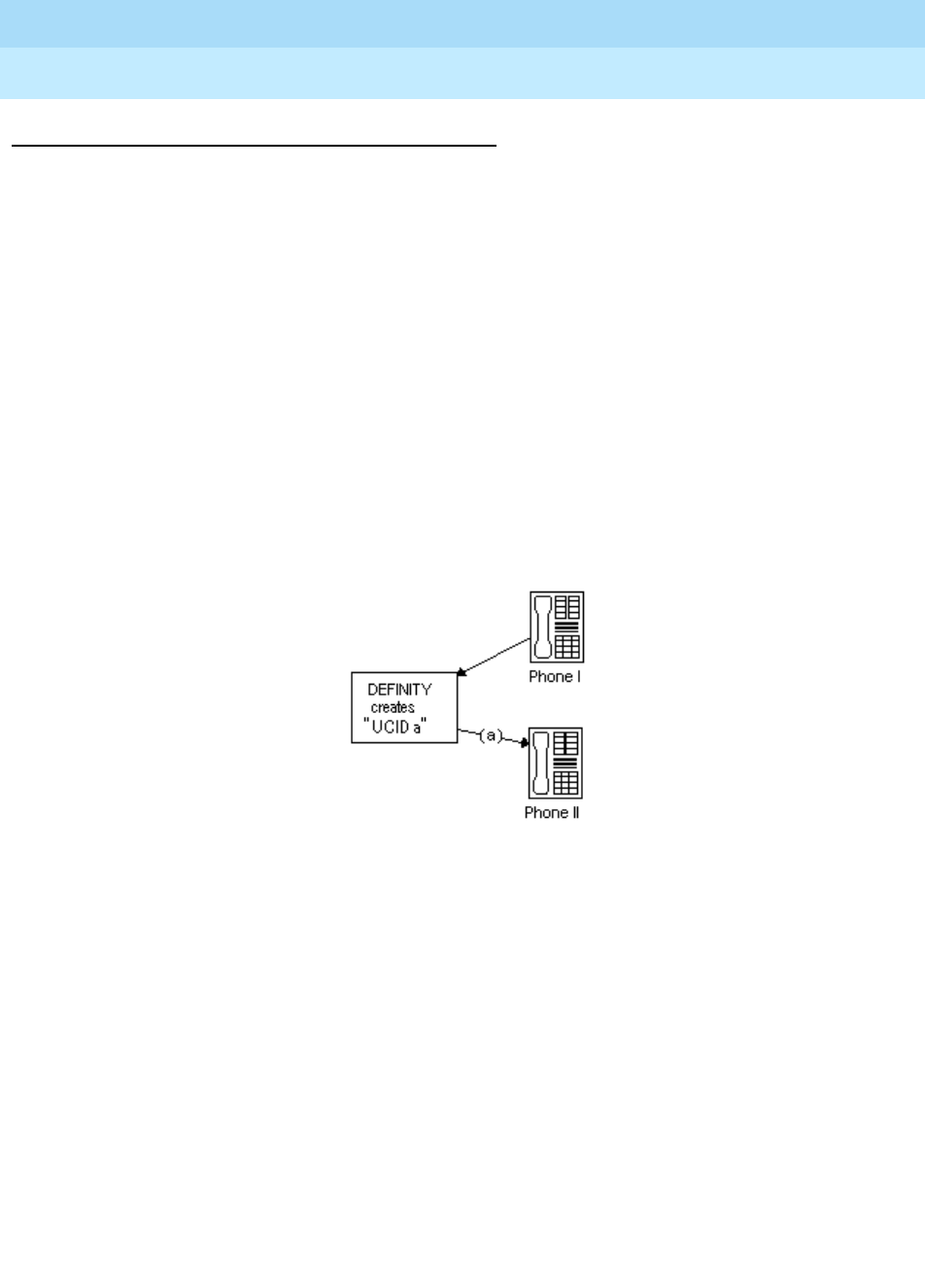
DEFINITY Enterprise Communications Server Release 6
Administration and Feature Description
555-230-522 Issue 4
May 1998
Call Center
Page 9-132Universal Call ID
9
How are UCIDs tracked?
The way a network maintains and tracks a UCID depends on the call path. To
illustrate UCID transport throughout a call’s life cycle, this section describes
several call scenarios:
■Station-to-station Calls
■Incoming Trunk Calls
■Outgoing Trunk Calls
■Simple Transfer or Conference
■Complex Transfer
and
Conference
Station-to-Station Calls
This scenario describes what happens when Phone I calls Phone II (both phones
are on the same switch).
DEFINITY creates a new UCID (such as UCID “a”) for any call originated by an
internal station user.
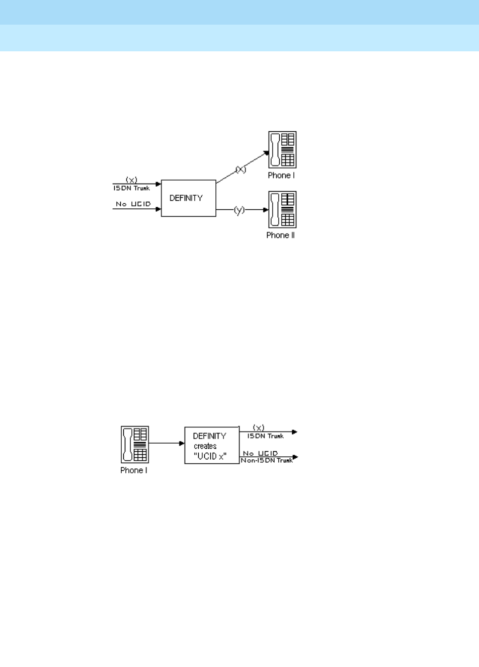
DEFINITY Enterprise Communications Server Release 6
Administration and Feature Description
555-230-522 Issue 4
May 1998
Call Center
Page 9-133Universal Call ID
9
Incoming Trunk Calls
UCID is assigned to an incoming call.
DEFINITY either
■receives UCID “x” information from an incoming call over an ISDN trunk.
■creates UCID “y” for incoming calls that do not already have a UCID.
There is one CMS call history record for each incoming call.
Outgoing Trunk Calls
UCID is associated with the outgoing trunk call from Phone I.
DEFINITY creates a UCID (such as UCID “x”) for an outgoing trunk call and then
sends it over an outgoing shared UUI or QSIG ISDN trunk.
DEFINITY creates a UCID (such as UCID “x”) for an outgoing trunk call even if
the trunk (such as a non-ISDN trunk) does not support the transmission of a
UCID.
Simple Transfer or Conference
This scenario describes a simple transfer or conference call scenario.
When an incoming trunk or station call is received by the station user at Phone I
and transferred to or conferenced with another station user or outside party:
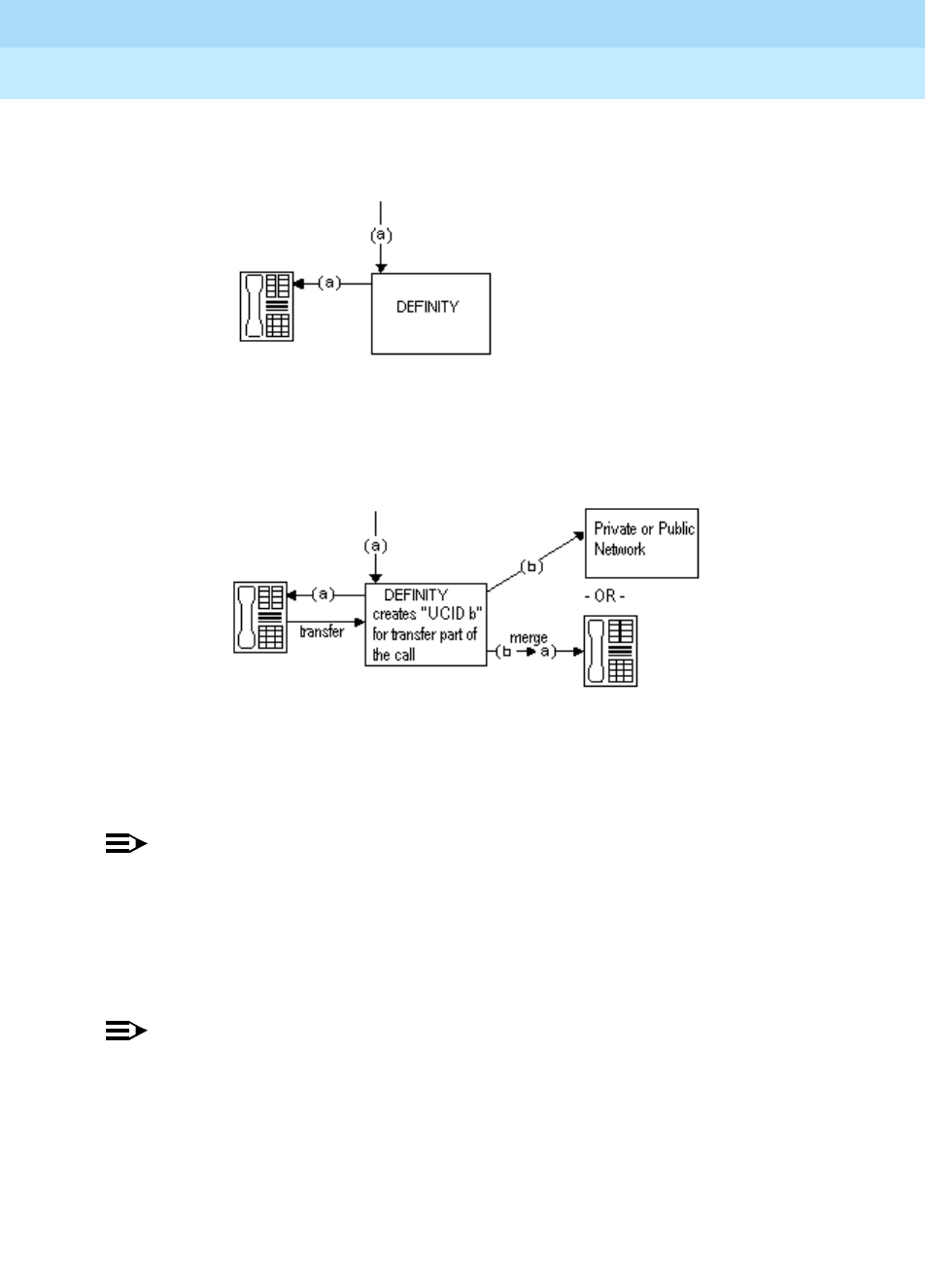
DEFINITY Enterprise Communications Server Release 6
Administration and Feature Description
555-230-522 Issue 4
May 1998
Call Center
Page 9-134Universal Call ID
9
1. DEFINITY creates a UCID for the incoming call if it needs one.
2. DEFINITY creates a new UCID for the temporary conference or transfer
portion of the call.
3. DEFINITY merges the temporary portion of the call with the original call
when the conference or transfer is completed within the DEFINITY switch.
This is when the overriding UCID (such as UCID “a”), becomes the UCID
for all parties within the DEFINITY.
NOTE:
If the outgoing trunk does not support the sending of UCIDs, then the UCID
of the outgoing call at the receiving switch will be “null”.
If the call is transferred to another switch, only the UCID for the transfer (UCID
“b”) gets passed on. This is because the DEFINITY cannot merge UCIDs if the
call is not completed within the switch.
NOTE:
If, during the conference or transfer, the incoming call drops before the
operation is complete, the two UCIDs will not appear to be associated
because no merge of the two parts of the call was done.
Complex Conference
The following complex call scenario illustrates when a station user adds an
incoming call to an existing conference.
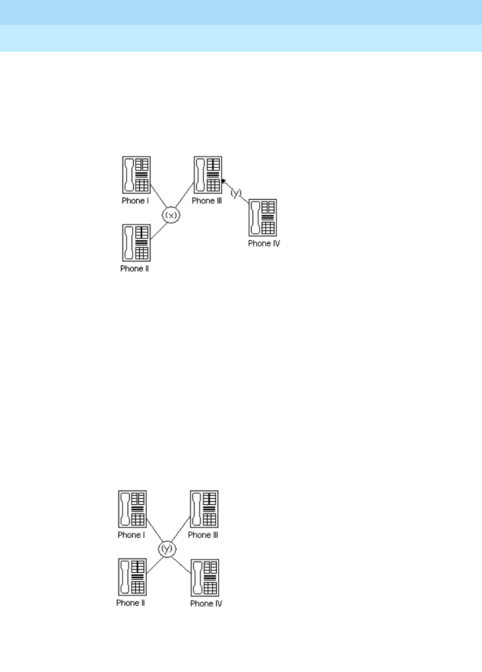
DEFINITY Enterprise Communications Server Release 6
Administration and Feature Description
555-230-522 Issue 4
May 1998
Call Center
Page 9-135Universal Call ID
9
In this scenario,
1. Phones I, II, and III are in the same conference call with UCID “x”.
2. The person at Phone III receives an incoming call from Phone IV (this call
has UCID “y” associated with it).
3. The person at Phone III puts the conference call on hold and answers the
incoming call from Phone IV.
4. The person at Phone III decides to add Phone IV into the conference call.
5. The person at Phone III
a. presses the Conference button
b. presses the call appearance button to return to the conference call
c. presses the Conference button again.
This brings the conference call into the call between Phones III and IV.
6. UCID “y” overrides UCID “x” because the DEFINITY views Phone IV as the
primary party in the conference initiated by step 5.
7. The UCIDs associated with each segment of the complex conference are
sent to CMS if the parties in the call are measured (for this example, if the
parties are ACD agents in a measured split/skill).
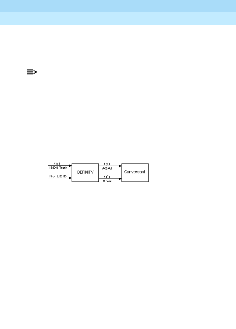
DEFINITY Enterprise Communications Server Release 6
Administration and Feature Description
555-230-522 Issue 4
May 1998
Call Center
Page 9-136Universal Call ID
9
DEFINITY before INTUITY CONVERSANT
The following scenarios describe what happens to UCID information when a call
comes in to DEFINITY before it goes to INTUITY CONVERSANT. In this
configuration, the INTUITY CONVERSANT serves as a Voice-Response Unit (VRU)
that controls the routing of incoming ACD calls.
NOTE:
This configuration is more common than a call coming in to INTUITY
CONVERSANT before reaching DEFINITY.
This section describes two scenarios:
■Simple call tracking
■CONVERSANT transfers a call
Simple call tracking
The following call scenario describes when a call comes in to DEFINITY before
INTUITY CONVERSANT.
When DEFINITY is before INTUITY CONVERSANT:
1. DEFINITY ECS receives an incoming call over an ISDN trunk.
2. DEFINITY does one of two things:
■If the incoming call has a UCID (such as UCID “x”), then DEFINITY
passes it along.
■If the incoming call does not have an associated UCID, DEFINITY
creates a new one (such as UCID “y”).
3. DEFINITY passes the UCID to INTUITY CONVERSANT through an ASAI
connection (via the activation of split/skill or VDN “event notification” by
the INTUITY CONVERSANT).
4. UCID information is sent to CMS if trunk, VDN(s), and/or split/skill(s)
involved in the call are measured.
INTUITY CONVERSANT Transfers a Call
The following call scenario involves a CONVERSANT behind DEFINITY
configuration when CONVERSANT initiates a call transfer after the call is
answered by a port on the INTUITY CONVERSANT that serves as an ACD agent.
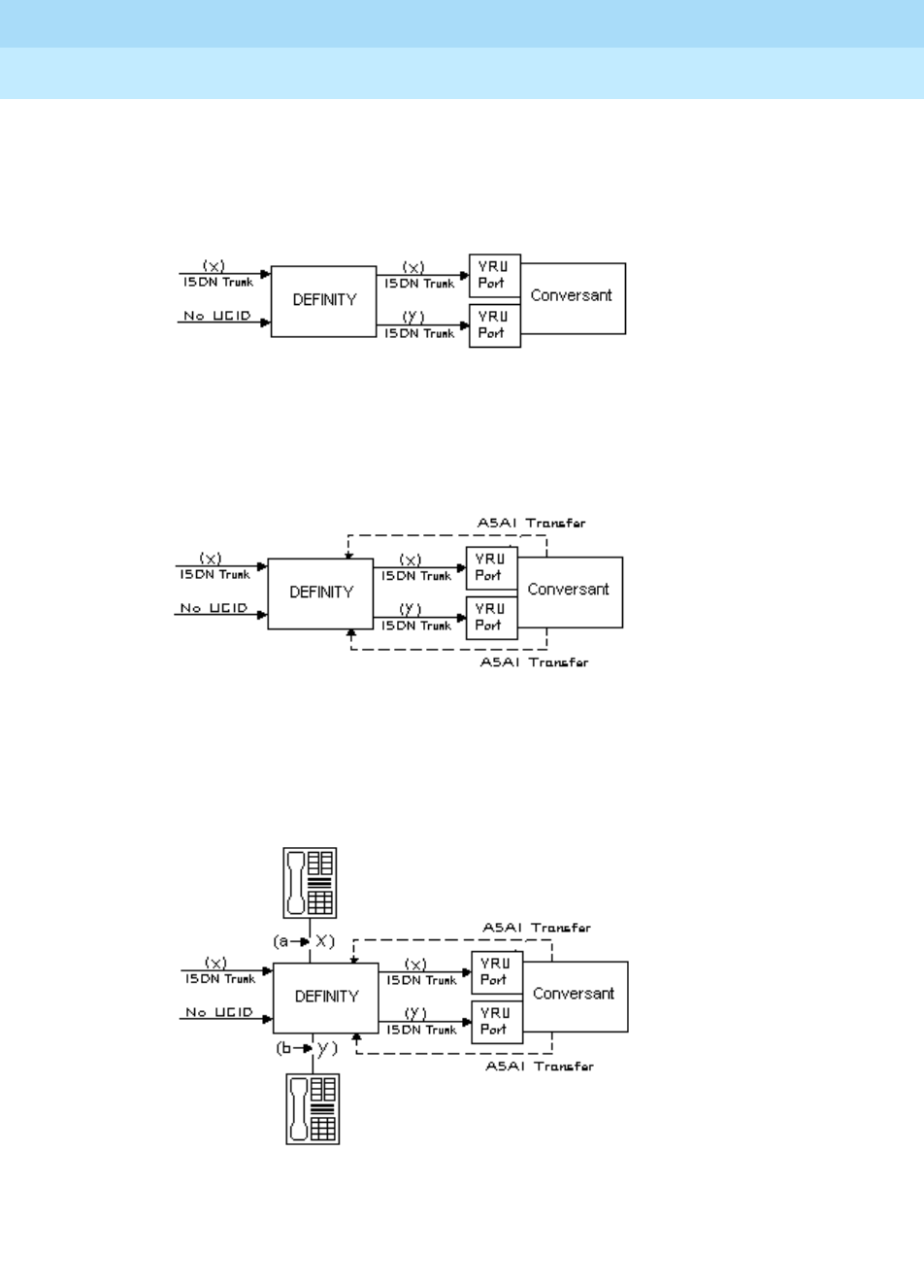
DEFINITY Enterprise Communications Server Release 6
Administration and Feature Description
555-230-522 Issue 4
May 1998
Call Center
Page 9-137Universal Call ID
9
1. Call is directed to INTUITY CONVERSANT VRU port (typically by call
vectoring) with UCID information (UCID “x” or UCID “y”).
2. INTUITY CONVERSANT determines the call’s destination and transfers the
call (via an ASAI “third-party transfer” operation).
3. DEFINITY ECS temporarily creates a new UCID (such as UCID “a” or
UCID “b”) for the transfer portion of the call (the original UCID is quickly
merged into the call).
4. The UCIDs of the transfer segment and merged call are returned to INTUITY
CONVERSANT in ASAI acknowledgment messages.
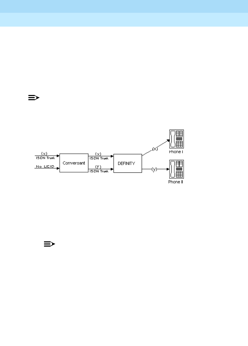
DEFINITY Enterprise Communications Server Release 6
Administration and Feature Description
555-230-522 Issue 4
May 1998
Call Center
Page 9-138Universal Call ID
9
5. DEFINITY sends UCID information to CMS if trunk, VDN(s), and/or
split/skill(s) involved in the call are measured.
INTUITY CONVERSANT before DEFINITY
This scenario illustrates a system configuration where a call comes in to INTUITY
CONVERSANT before reaching DEFINITY. In this configuration, INTUITY
CONVERSANT provides voice response services and/or call screening so that
the number of incoming calls to the DEFINITY ECS is reduced.
NOTE:
This configuration is less common than the DEFINITY before INTUITY
CONVERSANT configuration.
When INTUITY CONVERSANT is before DEFINITY
1. INTUITY CONVERSANT receives an incoming call with UCID “x”.
or
INTUITY CONVERSANT creates a new UCID “y” and associates it with the
incoming call (if the call has no UCID already associated with it).
NOTE:
For INTUITY CONVERSANT to recognize an incoming UCID (such as
UCID “x”) from an ISDN trunk, special INTUITY CONVERSANT
scripting is required. When INTUITY CONVERSANT receives a call
from the public network, it automatically creates a new UCID
because it cannot recognize whether or not the call already has a
UCID.
2. INTUITY CONVERSANT sends UCID to DEFINITY ECS over an ISDN-PRI
trunk.
3. DEFINITY receives UCID and reuses it for the incoming call.
4. DEFINITY reports UCID to CMS if the trunks, VDNs, and/or splits/skills
associated with the call are measured.

DEFINITY Enterprise Communications Server Release 6
Administration and Feature Description
555-230-522 Issue 4
May 1998
Call Center
Page 9-139Universal Call ID
9
Interactions
■Distributed Communications System (DCS)
If DCS is used in a network of DEFINITY switches where UCIDs are
tracked, the DCS feature must be configured with ISDN trunks having the
Shared UUI service protocol. Otherwise, calls that are handled through
one of the many DCS features (such as DCS Coverage) will not retain the
UCID initially assigned to the call.
■Remote AUDIX
For remote AUDIX over DCS, the DCS trunk(s) used to accomplish the
remote AUDIX operation must be configured (as described previously in
“Distributed Communications System”) to retain the UCID associated with
a call.
■Tandem Calls
When a call is tandemed through a DEFINITY ECS switch, the UCID
information may be blocked or passed through the tandem switch. To
pass a UCID through a tandem switch, both the incoming and outgoing
trunks at the tandem switch must be configured to handle UCIDs. See
‘‘Information Forwarding’’ on page 9-89 for proper private and public
network information forwarding administration.
Before You Start
Before you start to administer the UCID feature, be aware that UCIDs are
successfully transmitted
only
when all DEFINITY network components meet the
requirements (software and connections) specified below.
Some requirements vary, depending on how you want to use UCID. Table 9-18
shows the requirements for different applications of UCID.
Table 9-18. Requirements for UCID Applications
What do you want to do?
Your system must
meet the following
software
requirements…
Your system must
have the following
connections
…
Have DEFINITY create
UCIDs DEFINITY R6.3 or later
Have DEFINITY send
UCID to another
DEFINITY
DEFINITY R6.3 or later ISDN (BRI/PRI) trunks
with Shared UUI or
QSIG service protocol
Have DEFINITY send
UCID to CONVERSANT DEFINITY R6.3 or later
CONVERSANT 7.0 or
later
ASAI link to
CONVERSANT

DEFINITY Enterprise Communications Server Release 6
Administration and Feature Description
555-230-522 Issue 4
May 1998
Call Center
Page 9-140Universal Call ID
9
NOTE:
You can check your software version numbers by typing list config
software at the SAT terminal. Because “V6” (version 6) includes 6.1
through 6.3, you may have to check that your network has the separate 6.3
upgrade (this is the earliest DEFINITY version to support UCID).
To maximize the benefits of UCID, it is recommended that all switches be
configured with DEFINITY R6.3 (or later) software. However, because upgrading
a network is often a gradual process, there may be a switch that cannot yet
support UCIDs. In this environment, disallow the UCID transmission for any trunk
group connected to a pre-DEFINITY R6.3 switch. For information about enabling
or disabling UCID transmission on a trunk group, see “How to Administer
Universal Call ID” later in this chapter.
In the case of a DEFINITY network component that cannot support UCIDs, it is
recommended that the component (ISDN trunk group, ASAI connection, or CMS
software) be administered to disallow the sending or receiving of UCID. For
example, if a DEFINITY R6.3 is connected to a non-Lucent Technologies PBX,
then the connecting ISDN trunk must be administered to not send UCID over that
trunk for outgoing calls.
How to Administer Universal Call ID
These instructions assume you’re using the SAT (Subscriber Access Terminal)
screen or a terminal emulator to access the DEFINITY software.
Have DEFINITY receive
UCID from
CONVERSANT
DEFINITY R6.3 or later
CONVERSANT 7.0 or
later
ISDN-PRI connection
(with shared UUI)
between switch and
CONVERSANT
Have DEFINITY send
UCIDs to CMS
DEFINITY R6.3 or later
CMS R3V6 or later
BX.25 connection from
switch to CMS
Have DEFINITY send
UCIDs to a CTI
Application
DEFINITY R6.3 or later
T-Server R3.1.0 or later
DEFINITY PBX Driver
(G3PD)- R3.1.0 or later
CallVisor PC V6 or later
ASAI link to adjunct
Table 9-18. Requirements for UCID Applications
What do you want to do?
Your system must
meet the following
software
requirements…
Your system must
have the following
connections
…

DEFINITY Enterprise Communications Server Release 6
Administration and Feature Description
555-230-522 Issue 4
May 1998
Call Center
Page 9-141Universal Call ID
9
There are three tasks involved in administering UCID on DEFINITY ECS.
Complete these tasks in the following order:
Task a. Check ASAI Interface before enabling UCID
Task b. Set DEFINITY ECS to create and send UCIDs
Task c. Enable UCID Transmission on Trunk Groups
Task a: Check ASAI Interface before enabling
UCID
If this procedure is not performed, you may encounter the “ASAI Interface feature
not assigned” error message in later steps.
To check the ASAI interface:
1. In the command line, enter change system-parameters
customer-options and press RETURN.
2. On page 1, enter y in the ASAI Interface field.
3. Log out and log back in if this and any other fields in this form have
changed.
Table 9-19. Form Needed to Check ASAI Interface
Form needed Field needed?
Why is this field
needed?
Is field
optional? Page
Optional
Features ASAI Interface Global setting to send
UCIDs to ASAI Y5-277

DEFINITY Enterprise Communications Server Release 6
Administration and Feature Description
555-230-522 Issue 4
May 1998
Call Center
Page 9-142Universal Call ID
9
Task b: Set DEFINITY ECS to create and send
UCIDs
You must administer each DEFINITY switch that you want to create UCIDs. If you
do not administer a switch, it will pass along an already-created UCID, but it
won’t create one if a call comes to it first.
For DEFINITY to create and send UCIDs:
1. If your network includes CMS and you want CMS to track UCIDs, then
enter busyout mis in the command line. If not, go to step 2.
2. In the command line, enter change system-parameters feature and
press RETURN.
The Feature-Related System Parameters form comes up.
3. Go to page 4 of the form.
4. In the Create Universal Call ID (UCID)? field, enter y.
5. In the UCID Network Node ID field, enter the node ID number.
Valid numbers are from 1 to 32,767.
!CAUTION:
The UCID Network Node ID must be unique for every DEFINITY and
CONVERSANT in the system. If it is not unique, the integrity of the
UCID is compromised.
6. If your network includes ASAI, go to page 7 of the form. If not, go to step 8.
7. In the Send UCID to ASAI? field, enter y.
Table 9-20. Forms Needed for DEFINITY to Create and Send UCID
Form
needed Fields needed
Why is this field
needed?
Is field
optional? Page
Feature-
Related
System
Parameters
Create Universal
Call ID (UCID)? To generate a
UCID for each call
when necessary.
N5-133
UCID Network
Node ID Important
component of the
UCID tag.
N5-133
Send UCID to
ASAI? So that ASAI
receives UCIDs. Y5-141
Adjunct CMS
Release So that CMS
receives UCIDs. Y5-145

DEFINITY Enterprise Communications Server Release 6
Administration and Feature Description
555-230-522 Issue 4
May 1998
Call Center
Page 9-143Universal Call ID
9
8. If you have performed the busyout mis command, go to step 9. If not, you
are done with this task (Task b), so press to save your work and go
to Task c.
9. Go to page 8 of the form.
10. In the Adjunct CMS Release field, enter R3V6.
11. Press to save your work.
12. In the command line, enter release mis.
Task c: Enable UCID Transmission on Trunk
Groups
When you send UCIDs over ISDN trunks, it is administered on a trunk group
basis. Table 9-21 provides the form and field information that you need to
perform this task.
To enable UCID transmission on a trunk group:
1. In the command line, enter change trunk-group n and press RETURN.
The Trunk Group administration form comes up.
n
is the number of the
trunk group you want to administer.
2. On page 1, enter ISDN in the Group Type field.
3. In the Supplementary Service Protocol field, enter the letter of the
service protocol you want for this trunk group.
b is for QSIG, other protocols are for UUI.
4. Go to page 2 of the form.
5. In the Send UCID? field, enter y.
6. Press to save your changes.
Table 9-21. Enabling UCID transmission on trunk groups
Form
needed Fields needed Why is this field needed?
Is field
optional? Page
Trunk
Group Group Type To specify correct trunk
type: ISDN is the only type
that supports UCID.
N7-202
Sup plementary
Service Protocol Specify correct service
type. b is for QSIG, others
are for UUI.
N7-202
Send UCID? Allows or blocks UCID
transmission. N7-208
ENTER
ENTER
ENTER

DEFINITY Enterprise Communications Server Release 6
Administration and Feature Description
555-230-522 Issue 4
May 1998
Call Center
Page 9-144Universal Call ID
9
You also need to administer your trunk groups to send user data over your private
and public networks. To administer the trunk groups, see ‘‘Information
Forwarding’’ on page 9-89.
Considerations
— UCID has been tested with several major carriers. To find out if these
capabilities work with your carrier, check with your account team for the
most current information. If testing has not been done to verify operation
over the public networks involved with the preferred specific configuration,
use of private ISDN trunking between the nodes should be assumed until
successful testing has been completed.
Troubleshooting
The following troubleshooting hints should be reviewed when UCIDs are not
transmitted, even though you received no error messages while administering
the UCID feature, and all software and connections meet the minimum
requirements:
— A tandem switch has the Send UCID? option set to y for all trunk groups
that AAR/ARS or station users may use to tandem an incoming call.
— If DCS is used, make sure
all
ISDN trunks between DEFINITY switches
used for DCS or remote AUDIX are configured in the D-channel mode.
— For CMS tracking purposes, make sure all trunks, VDN, and split/skills that
handle calls for which UCIDs are tracked are administered as “measured”
(either “both” or “external”).

DEFINITY Enterprise Communications Server Release 6
Administration and Feature Description
555-230-522 Issue 4
May 1998
Call Center
Page 9-145VDN in a Coverage Path
9
VDN in a Coverage Path
VDN in a Coverage Path (VICP) enhances Call Coverage and Call Vectoring to
allow you to assign Vector Directory Numbers (VDNs) as the last point in
coverage paths. Calls that go to coverage can be processed by
vectoring/prompting to extend Call Coverage treatments.
How to administer VICP
■Call Coverage Path form — Set one of the following to the extension of the
VDN to be used as a coverage point: Point 1, Point 2, Point 3, Point 4,
Point 5, Point 6.
Considerations
A VDN is not allowed as a member of a coverage answer group. A vector cannot
route a covered call to a coverage answer group — a coverage answer group
can only be a point in a coverage path.
Removing a VDN from the system with the
remove vdn <extension>
command
automatically removes the VDN from any coverage paths.
Interactions
None
Required Forms
Form Field Page
Coverage Paths ■All 5-94
Call Vector ■All 9-207
Vector Directory Number ■All 9-214

DEFINITY Enterprise Communications Server Release 6
Administration and Feature Description
555-230-522 Issue 4
May 1998
Call Center
Page 9-146VDN of Origin Announcement
9
VDN of Origin Announcement
VDN of Origin Announcement (VOA) provides agents with a short message
about a caller’s city of origin or requested service based on the VDN used to
process the call.
Use VOA messages to help agents to respond appropriately to callers. For
example, if you have two 800 numbers, one for placing orders and one for
technical support, you can administer two VDNs to route calls to the same set of
agents. When an incoming call is routed to a VDN with a VOA assigned (for
example, “new order” or “tech help”), the VDN routes the call to a vector, which
can place the call in an agent queue. When an agent answers the call, he or she
hears the VOA message and can respond appropriately to the caller’s request.
How to administer VOA
■Announcements/Audio Sources — Assign each VOA you want to use. You
can administer aux-trunk types with queue, without queue, and with
barge-in. You can administer integrated types with queue and without
queue. Do not administer analog and integrated repeating announcement
types as VOAs.
The VDN for which you are administering a VOA must be in a vector command
line.
Detailed description
The agent cannot hear the caller while the VOA message is playing. The caller is
not connected to the agent until after the message completes and cannot hear
the message or the agent during the message. The caller hears ringback while
the agent is listening to the VOA.
Required forms
Form Field Page
Attendant Console ■Feature Button Assignments
— VOA Repeat 5-35
Class of Restriction (COR) ■VDN of Origin Announcements 5-72
Feature-Related System
Parameters
■Hear Zip Tone Following VOA? 5-123
Announcements/Audio
Sources
■All 5-26
Vector Directory Number ■VDN of Origin Annc. Extension 9-214
Voice Terminals ■Feature Button Assignments
— VOA Repeat 6-4

DEFINITY Enterprise Communications Server Release 6
Administration and Feature Description
555-230-522 Issue 4
May 1998
Call Center
Page 9-147VDN of Origin Announcement
9
Agents logged in at multiline terminals see the call-appearance button for an
incoming call flash until after the VOA completes. An agent can press the
flashing call-appearance button to stop the VOA.
To repeat the VOA, an agent presses the VOA Repeat button. The VOA Repeat
button lamp lights during the VOA. The VOA Repeat button lamp remains lit if the
repeat request is queued. If an agent presses the VOA Repeat button while the
lamp is lit, the VOA is stopped. If an agent presses the VOA Repeat button but
there is no VOA or the system cannot play the VOA within three seconds, the
lamp flutters.
You assign VOAs for each VDN. However, the VOA applies to a COR, so you
must administer a COR for agents who will receive VOAs.
You can set up VOAs in four ways:
■Agents can hear a unique announcement based on the dialed number
identification service (DNIS) received from the service office or carrier
switch. Assign each DNIS as the VDN of a vector. Set up the VOA to
announce the services associated with the DNIS.
NOTE:
The announcement associated with the current VDN only plays if the
VDN Override for the previous VDN is set to y. If VDN Override for the
previous VDN is set to n, the VOA associated with that VDN plays.
■Use vector steps, an integrated prompting, or
converse-on
step to route
calls to a VDN. Set up the VOA to announce the service the caller
requested or to announce a condition that caused the call to
route-to
the
VDN.
■You can route calls to a voice response system, directly or through a
vector. Use voice prompting to direct the caller to enter a touchtone
response, and route the call to a specific VDN based on the caller’s
response. Set up the VOA to indicate the service the caller selected.
■If agents require a caller’s city of origin, assign the trunk group to a
particular VDN. Set up the VOA to provide the location of the origin of the
trunk group. Subsequent VDNs can be used to handle the call, or multiple
VDNs can be assigned to a single vector.
NOTE:
VDN Override applies to VOA in the same way that VDN Override
applies to display information. If a VDN with a VOA has VDN
Override enabled, the system overrides the original VOA with VOAs
in subsequent VDNs to which the call is routed.

DEFINITY Enterprise Communications Server Release 6
Administration and Feature Description
555-230-522 Issue 4
May 1998
Call Center
Page 9-148VDN of Origin Announcement
9
Considerations
■Because callers are kept waiting while a VOA plays, messages should be
kept very brief — no more than 1.5 seconds in length. Agents should use
a speakerphone or headset, so they do not miss the VOA while they are
picking up the handset. If agents cannot use a speakerphone or headset,
administer voice terminals with a VOA Repeat button.
■If you have multiple announcement boards, you should place shorter
VOAs on one board and longer recorded announcements on the other to
avoid delaying delivery of VOAs. If you have only one announcement
board, place VOAs on the integrated board and consider installing an
auxiliary announcement device for longer announcements.
■Agents must be on the same switch as the VOA.
■A VOA can be assigned to multiple VDNs, but a VDN can have only one
VOA.
■If you use the TN750 circuit board for integrated announcements, the
system maintains a separate logical queue for VOAs. If the VOA cannot be
delivered to the agent within 1 second because of traffic or inoperative
equipment, the system does not provide the announcement. VOAs are
higher priority than other announcements on the TN750. A burst of VOAs
can delay other announcements. Therefore, record non-VDN of Origin
Announcements as auxiliary or analog.
■Auxiliary announcements are connected for a duration of 1 to 2 seconds
on a barge-in basis, immediately after the agent answers (or is assigned
the call for auto-answer) and the incoming call is extended to the agent.
Integrated and non-barge-in auxiliary announcements are connected for
the duration of the announcement. The switch does not ensure that the
integrated announcement is shorter than the allowed playback time.
■VOA supports Auxiliary Trunks (aux-trunk) with barge-in, queue, or without
queue. For aux-trunk with or without queue, when the trunk is idle, a VDN
call seizes the trunk to start the VOA and the system plays the entire
announcement (not just 1 to 2 seconds). However, if the announcement is
busy and if aux-trunk has barge-in, the call does not queue but bridges
onto the announcement for 1 to 2 seconds. When the VOA completes, the
trunk is released along with the listeners, and the next call requiring the
VOA starts the process over again. For this reason, your aux-trunk
announcements should consist of one short announcement that repeats
during the full announcement time. For example, you might want to record
“New Order” as many times as possible, so that when a call bridges to the
announcement, the agent hears “New Order” no matter where the agent
bridges into the announcement.
■If you use aux-trunk or integrated announcement without queue and a port
is busy when a VDN call comes in, the system cannot play an
announcement. If you use aux-trunk or integrated announcement with
queue, the system plays the current announcement for an agent and then
connects the next agent in the queue.

DEFINITY Enterprise Communications Server Release 6
Administration and Feature Description
555-230-522 Issue 4
May 1998
Call Center
Page 9-149VDN of Origin Announcement
9
Interactions
■Agent Call Handling (Answering Options)
— Automatic Answer
ACD agents at voice terminals in Auto Answer mode hear a zip
tone, then the VOA. You can also administer a zip tone after the
VOA completes, to alert agents that an announcement is complete
and a caller is connected.
Non-ACD agents can receive a VOA if a call is routed to them via
vector processing. When non-ACD agents at voice terminals in
Automatic Answer mode receive calls, they hear a call ID tone then
the VOA. Agents hear a second zip tone after the VOA indicating
connection to the caller.
— Manual Answer
When non-ACD agents at voice terminals in Manual Answer mode
receive calls they hear ringing, answer the call, and hear the VOA.
■ASAI Adjunct Routing
If a vector step includes Adjunct Routing, the VOA is played for the agent
to whom the call is routed.
■Auto-Available Split (AAS)
AAS is intended to be used for splits containing only nonhuman adjuncts
such as AUDIX or Conversant; however, VOAs can be directed to
Auto-Available splits.
■Call Forwarding
VOAs apply to forwarded calls, including those forwarded to a hunt group.
The answering station must be on the same switch. If a VOA is forwarded,
the message is played only if the destination extension is administered
with a COR that allows VOA.
■Call Pickup
Call Pickup allows an agent to pick up a ringing call on another extension.
If the pick-up extension has COR permissions for VOA, the agent can
receive a VOA.
■Conference
If an agent receives a call and then conferences in additional stations, any
station on the connection can use VOA Repeat button to replay the VOA.
Only the person using the button can hear the VOA unless the call is being
service observed.

DEFINITY Enterprise Communications Server Release 6
Administration and Feature Description
555-230-522 Issue 4
May 1998
Call Center
Page 9-150VDN of Origin Announcement
9
■Converse-on split
A converse-on split is one used in a
converse-on
vector step. When a
converse-on
vector step is executed, a VOA is not applied. After returning
to the vector, the call can be routed to
a station or VDN where the
answering agent receives the VOA (as if the
converse-on
step had not
been processed).
■Coverage
VOA applies to coverage paths.
■Data Restriction
Data Restriction prevents tones from being applied to line or trunk circuits
during a data call. VOAs are not played for data-restricted calls.
■Direct Agent Calling
Direct Agent Calling allows a vector to
route a call to particular ACD agent
and have the call treated as an ACD call. The VOA only applies to direct
agent calls if the calls reach an agent through vector processing. Direct
agent calls from a voice terminal on a switch are not vector-processed and
cannot cause a VOA to be played.
■Enhanced Automatic Wake-up
If you are using enhancements to Automatic Wake-up with integrated
announcements, there can be contention for integrated announcement
ports. VOAs have priority over Automatic Wake-Up announcements.
■Expert Agent Selection (EAS)
When you are using EAS, the logical agent COR definition determines the
assignment of VOAs for each extension. EAS uses the COR of the logical
agent instead of the COR for the terminal being used by the agent.
■Hold
Agents cannot use the VOA Repeat button if their calls are all on hold. The
VOA Repeat button only applies to active calls.
■Home Agent
You can assign an initial VOA to a home-agent port on the switch.
However, home agents cannot use a VOA Repeat button because home
agents need a dial access code (DAC) to reach features and VOA replay
does not use a DAC.
■Hunt Groups
VOAs apply to calls routed to a hunt group. The COR for the answering
station’s extension determines whether the station can receive a VOA.

DEFINITY Enterprise Communications Server Release 6
Administration and Feature Description
555-230-522 Issue 4
May 1998
Call Center
Page 9-151VDN of Origin Announcement
9
■Lookahead Interflow
VOAs apply only to the switch where the VDN is defined. If a call interflows
to another switch, the VOA is lost. You can have the interflow to another
switch access a VDN with the same VOA message as on the original
switch.
■Redirection on No Answer (RONA)
If a call re-queues to a split or skill because the RONA timer expired, the
VOA applies to the call when an agent answers the call.
■Service Observing
The system handles Service Observing calls as conference connections.
If the observer presses the VOA Repeat button only he or she hears the
announcement. However, if another party on the call presses the VOA
Repeat button, the user and the observer hear the VOA.
■Supervisor Assist
If an agent requests supervisor assistance and conferences the
supervisor into a call, either the agent or the supervisor can use their VOA
Repeat button to replay the VOA, but only the person who presses the
button hears the VOA.
■Transfers
If an agent receives a VDN call and transfers the call, the answering party
can use the VOA Repeat button to replay the message.
■VOA distribution
If you use long VOAs or multiple VOAs, there may be a delay between the
zip tone and the announcement. The system provides multiple
announcement circuit packs to help prevent announcement delays.
Contact your Lucent representative for more information.

DEFINITY Enterprise Communications Server Release 6
Administration and Feature Description
555-230-522 Issue 4
May 1998
Call Center
Page 9-152Voice Response Integration
9
Voice Response Integration
Voice Response Integration (VRI) integrates Call Vectoring with the capabilities of
voice response units (VRUs) such as the Lucent Technologies CONVERSANT
Voice Information System (CVIS). With VRI, you can:
■Run a VRU script while retaining control of a call in vector processing
■Run a VRU script while a call is queued, retaining its position in the queue
■Pool CONVERSANT ports for multiple applications
■Use a VRU as a flexible external-announcement device
■Pass data between the system and a VRU
■Tandem VRU data through a switch to an ASAI host
The
converse-on
command, which is part of Basic Call Vectoring, provides these
capabilities. Use a
converse-on
call-vector step to integrate a VRU with
Automatic Call Distribution (ACD). VRI allows you to use VRU capabilities while
controlling a call in ACD.
Include VRUs with vector processing to take advantage of the following:
■Access to local and host databases
■Validation of caller information
■Text-to-speech capabilities
■Speech recognition
■Increased recorded announcement capacity
■Audiotex applications
■Interactive voice-response (IVR) applications
■Transaction-processing applications
VRI allows users to make productive use of queuing time. For example, while a
call is queued, a caller can listen to product information via an audiotex
application or can complete an interactive voice-response transaction. It may be
possible to resolve the caller’s questions while the call is queued, which helps
reduce queuing time for other callers during peak times.
For more information on VRI and the
converse-on
command, see the
DEFINITY
Enterprise Communications Server Release 6 Call Vectoring/Expert Agent
Selection (EAS)
.

DEFINITY Enterprise Communications Server Release 6
Administration and Feature Description
555-230-522 Issue 4
May 1998
Call Center
Page 9-153Voice Response Integration
9
How to administer VRI
Enable Call Prompting to allow the system to collect digits from the caller and
CONVERSANT to return data. You must have Call Prompting to administer the
Converse Data Return Code and use the digits keyword for the <data_1> or
<data_2> fields on the
converse-on
command.
Detailed description
A call queued to an ACD split retains position in the queue while a VRU script is
being run. When an agent becomes available, the line to the VRU is dropped and
the caller connects to the agent.
The
converse-on
command delivers a call to a predetermined converse split
(skill). A converse split is administered and operates exactly like other splits.
Nonconverse splits are ACD splits accessed by
queue-to main
and
check-backup
vector steps.
Members of a converse split are the ports connected to the VRU. If all VRU ports
are busy, a call queues to the converse split with the administered priority. After
the VRU answers the call, the
converse-on
command may pass up to 2 data
items to the VRU, depending on command parameters specified. You can pass
data required by a VRU script or data that selects the VRU script to be run.
Whether or not you pass data, a caller is connected to the VRU, which runs the
VRU script. Audible feedback provided by the vector is not heard and no further
vector steps are run until the VRU script completes. The VRU may return data to
the system and then drops the line to the system. Vector processing continues at
the step following the
converse-on
command.
Required forms
Form Field Page
System Parameters
Customer-Options
■Call Prompting 5-277
Feature Access Code (FAC) ■Converse Data Return Code 5-113
Feature-Related System
Parameters
■Converse Delay Data1/Data2
■Converse Signaling Tone/Pause
5-123
Call Vector ■All 9-207

DEFINITY Enterprise Communications Server Release 6
Administration and Feature Description
555-230-522 Issue 4
May 1998
Call Center
Page 9-154Voice Response Integration
9
If the call was queued to a nonconverse split before the
converse-on
command
was run, the call retains its queue position. If an agent becomes available while
the VRU script runs, the system drops the line to the VRU and connects the caller
to the agent. The VRU detects the disconnect and terminates the VRU script. For
converse-on
command syntax, see
DEFINITY
Enterprise Communications Server
Release 6 Call Vectoring/Expert Agent Selection (EAS)
.
Call Prompting allows you to collect and use digits that the VRU returns. These
digits are handled as dial-ahead digits. Rules for collecting and processing VRU
digits are the same as for Call Prompting.
You can use digits returned from the VRU in the following ways:
■To display for the answering agent’s (automatically for 2-line displays or
with the CALLR-INFO button for other displays)
■As an extension in a
route-to digits
vector step. For example:
converse-on split. . . . (VRU returns 4 digits)
collect 4 digits after announcement none
route-to digits coverage y
■For vector-conditional branching in an
if digits equals
vector step. For
example:
converse-on split . . . (VRU returns 1 digit)
collect 1 digit after announcement none
goto vector 101 if digits = 1
goto vector 102 if digits = 2
goto vector 103 if unconditionally
■Tandemed to an ASAI host
Collected digits are passed to ASAI hosts in Call Offered to Domain Event
reports and in
route request
messages, thus caller digits or database
information returned from the VRU can be tandemed through the system
to ASAI hosts. For example:
converse-on split ... (VRU returns 9 digits)
collect 9 digits after announcement none
adjunct route link Y
In this vector, the digits returned from the VRU are forwarded to the ASAI host in
the adjunct routing
route request
message.
!SECURITY ALERT:
When you use a VRU application that returns data for a collect-digits step,
the opportunity for toll fraud exists when the VRU application does not
return any data. Take the following precautions:
■If the collected digits are used to route calls internally, ensure that
the Class of Restriction (COR) for the vector directory number
(VDN) does not allow calls to route externally.

DEFINITY Enterprise Communications Server Release 6
Administration and Feature Description
555-230-522 Issue 4
May 1998
Call Center
Page 9-155Voice Response Integration
9
■If the collected digits are used to route calls externally, use a
password to verify that the collected digits have been passed by
the VRU application. For example, in the following vector, the VRU
application returns a 3-digit password followed by the 8-digit
external number. The vector routes calls without the correct
password to a vector 23.
converse-on split 10 pri m passing none and none (VRU returns
11 digits)
collect 3 digits after announcement none
goto vector 23 if digits <> 234
collect 8 digits after announcement none
route-to digits with coverage n
Interactions
Converse splits interact like other vector-controlled splits unless noted here.
■Adjunct Switch Applications Interface (ASAI)
When a
converse-on
vector step places a call to an ASAI-monitored
domain, ASAI event messages are sent over the ASAI link. When a
converse-on
step places an ASAI-monitored call, the ALERT message
sent to the ASAI adjunct includes a cause IE, Coding Standard 3 value 23
(CS3/23), which informs the adjunct that the call has not been dequeued
from any nonconverse splits.
If a
converse-on
step is run while an adjunct routing request is
outstanding, the request is canceled.
ASAI cannot transfer or conference calls, but can direct the system to do
this.
■Agents
Although not recommended, you can use a
converse-on
step to deliver a
call to a group of human agents. To agents, the call looks like an ACD call,
except they cannot use certain features, such as Transfer, Conference,
and Supervisor Assist.
The agent can return data to vector processing by pushing the transfer
button (or flash hook on analog) and dialing the converse-on data return
code and required digits.
■Answer supervision
Answer supervision is returned only once during a call. If a call is
answered because of a
converse-on
step, answer supervision is sent if it
hasn’t previously been sent. If digits are passed to the VRU, answer
supervision is sent after digits are sent.

DEFINITY Enterprise Communications Server Release 6
Administration and Feature Description
555-230-522 Issue 4
May 1998
Call Center
Page 9-156Voice Response Integration
9
■INTUITY AUDIX
If a
converse-on
step calls AUDIX, the call is handled as a direct call to
AUDIX. The caller hears the AUDIX welcome message and can retrieve
messages as usual.
If a call is forwarded to a VDN and then delivered to an AUDIX hunt group
by a
converse-on
step, the call to AUDIX is treated as a redirected call,
and the caller may leave a message.
■Auto-Available Split (AAS)
A
converse-on
vector step can place a call to an AAS. Use auto-available
converse splits for VRI except when ASAI controls the converse split.
■Automatic answering
When you administer CONVERSANT ports as agents of a converse split,
do not administer agents as automatic answer. The system-provided zip
tone may interfere with the interaction between CONVERSANT and the
calling party.
■BCMS/CMS
BCMS tracks calls that a
converse-on
step places to a BCMS-measured
hunt group. CMS tracks calls that a
converse-on
step places to a
CMS-measured hunt group, split, or skill.
The VDN tracks such calls as waiting in the vector. A call is considered
answered when answered by a nonconverse split agent, not when
answered by a
converse split agent. The
converse split tracks this as a
separate “answered” call when the VRU answers. Though trunk and split
totals may no longer match, VDN and trunk totals match.
■Call Detail Recording
The duration of a call to a VDN is recorded from when answer supervision
is returned after a successful
converse-on
step. Unsuccessful
converse-on
steps do not generate ineffective call-attempt records.
Converse-on
steps cannot place calls; these steps simply direct a call to a
hunt group.
■Call Park
Calls that a
converse-on
step placed cannot be parked.
■Call Pickup
Do not use Call Pickup with
converse-on
steps.
■Class of Restriction
The system does not check CORs when a
converse-on
vector step routes
a call to a split.
■Conference
You cannot conference a call routed by a
converse-on
step.

DEFINITY Enterprise Communications Server Release 6
Administration and Feature Description
555-230-522 Issue 4
May 1998
Call Center
Page 9-157Voice Response Integration
9
■Direct Department Calling
You can administer a
converse split as a DDC split.
■Distributed Communications System
If an incoming DCS call is placed to a vector with a
converse-on split x pri
m passing ani...
step, the caller’s DCS extension is sent to the VRU.
■Expert Agent Selection
C
onverse-on
steps can place calls to a skill hunt group.
■Hold
An agent answering a converse call can put the call on hold, but the caller
does not hear music on hold. If a call is queued to a backup split before it
was sent to the VRU and a nonconverse split agent answers the call on
hold, the agent who placed the call on hold is dropped, and the caller
connects to the answering agent.
■Hold — Automatic
Automatic hold applies to converse-on calls.
■Hunt Groups
A
converse-on
step can deliver a call to a vector-controlled or AUDIX hunt
group, ACD split, agent skill, or message center.
■ISDN
You can administer a
converse-on
step to send a caller’s calling party/
billing number (CPN/BN) to CONVERSANT using the caller keyword.
■Intraswitch CDR
If a converse-on call is answered and either the caller or the VDN
associated with the call is administered for intraswitch recording, timing
for the call is started and the CDR record shows “calling party to VDN” as
the originating and answering parties.
■Line-side T1 connectivity
T1 connectivity between the DEFINITY ECS and CONVERSANT is
supported for VRI. The DS1 board must be a TN767E (or later) or TN464F
(or later). Administer all converse agents as DS1FD-type stations.
Operation of the converse step using Line-side T1 is identical to that over
a tip/ring line. In particular, delay-timing and outpulsing speed is the same
as for analog lines. T1 connectivity to CONVERSANT is supported only in
the United States and Canada.
■Look-Ahead Interflow
If an incoming call or a call routed by a
converse-on
vector step is
answered by a VRU, or is queued to the converse split while a
Look-Ahead Interflow call attempt is outstanding, the attempt is accepted.

DEFINITY Enterprise Communications Server Release 6
Administration and Feature Description
555-230-522 Issue 4
May 1998
Call Center
Page 9-158Voice Response Integration
9
■Message Center
Converse-on
steps can deliver calls to message hunt groups. Such calls
are handled as direct calls to the message hunt group.
If a call is forwarded to a VDN and a
converse-on
step delivers it to a
message split, it is handled as a redirected call.
A
converse-on
step can queue a call to three different skills and then to a
converse skill group or split.
■Music-on-Hold
During the data return phase of a
converse-on
step, the caller is placed on
hold, but does not hear music.
■Nonvector-controlled splits
A
converse-on
step cannot route a call to a nonvector-controlled split.
■Queuing
Converse-on calls queue when they are delivered to busy hunt groups.
Call Vectoring audible feedback is not disconnected while a converse-on
call is queued.
If a
converse-on
step is run while a call is queued to a non-converse split,
the call remains in queue, even after being answered by the VRU.
C
onverse-on
steps can queue calls at one of four priority levels: low,
medium, high or top. You administer the queue priority of a call on the
converse-on
step.
■R2-MFC Signaling
R2-MFC signaling trunks can send ANI to VRUs via the ani data item on
the
converse-on
step.
■Recorded announcement
Use VRI to increase the system’s recorded announcement capacity by
offloading some recorded announcements to a VRU, such as
CONVERSANT. Using the
converse-on
step, redirect callers to a group of
VRU ports by passing the number of the announcement to be played.
CONVERSANT can play any announcement on any port.
Although only one caller can be connected to each port, up to 48 callers
can be connected simultaneously to CONVERSANT. The maximum
number of callers that can be connected to a VRU simultaneously varies
with each VRU.
■Redirection on No Answer (RONA)
If a
converse-on
step calls a hunt group with “no answer timeout”
administered, and the call rings an agent/port for longer than the timeout
interval, the call redirects and the agent/port is put into AUX work mode
(or logged out if the agent is an AAS member).

DEFINITY Enterprise Communications Server Release 6
Administration and Feature Description
555-230-522 Issue 4
May 1998
Call Center
Page 9-159Voice Response Integration
9
With RONA, the call is requeued to the split. The call cannot requeue to
the split if it is an AAS with all agents logged out or if the queue is full. If the
call cannot be requeued, the
converse-on
step fails, a vector event is
logged, and processing restarts at the next vector step.
■Service Observing
Calls delivered by a
converse-on
step can be observed. To prevent the
observer from hearing tones associated with data being sent to the VRU,
the observer is not connected to the call until after data is passed. If the
VRU returns data, the observer is put in service-observing-pending mode
and the caller is put on hold while the data is sent. When the converse-on
session ends and the VRU drops the line, the observer remains in
service-observing-pending mode and waits for the next call.
In addition, the observer observing a VDN does not hear data being sent.
After data is sent, the observer rejoins the call.
Do not administer a service observing warning tone because the warning
tone may interfere with the interaction between CONVERSANT and the
caller.
■System measurements
System measurements track converse-on calls to hunt groups.
■Touch-tone dialing
A caller can use touch-tone dialing while digits are passed in a
converse-on session. The data is not corrupted. The system does not
collect the dialed numbers as dial-ahead digits.
After the system sends digits to CONVERSANT, a caller can enter
touch-tone digits at a CONVERSANT prompt. After CONVERSANT has
returned data to the system and an additional
collect <#> digits
vector
step is run, a caller can enter a touch-tone response to a system prompt.
■Transfer
A call delivered by a
converse-on
step cannot be transferred.
If an attempt to transfer a converse-on call is made, a vector event is
logged, the line to CONVERSANT is dropped, and processing restarts at
the next vector step.
If a human agent tries to transfer a call, the transfer fails and the agent
reconnects to the call.
■Transfer out of AUDIX
If a
converse-on
step delivers a call to an AUDIX hunt group and the caller
tries to transfer out of AUDIX, the transfer fails and processing continues
at the next vector step.
■Uniform Call Distribution (UCD)
You can administer a converse split as a UCD split.
■VDN display override

DEFINITY Enterprise Communications Server Release 6
Administration and Feature Description
555-230-522 Issue 4
May 1998
Call Center
Page 9-160Voice Response Integration
9
If a call that accesses multiple VDNs encounters a
converse-on
step that
passes vdn, normal display override rules determine which VDN number
is sent to the VRU.
■Vector-controlled splits
Converse-on
steps can deliver calls only to skills or vector-controlled
splits.

DEFINITY Enterprise Communications Server Release 6
Administration and Feature Description
555-230-522 Issue 4
May 1998
Call Center
Page 9-161VuStats
9
VuStats
VuStats presents Basic Call Management System (BCMS) statistics on voice
terminal displays. Agents, supervisors, call center managers, and other users
can press a button and view statistics for agents, splits or skills, VDNs, and trunk
groups.
These statistics reflect information collected during the current BCMS interval,
information collected since the agent logged in or since the day began, or
historical data accumulated over an administered number of intervals. The
information is limited to 40 characters displayed at a time. VuStats can display on
demand or update periodically.
With VuStats, any digital-display voice-terminal user can view BCMS statistics
otherwise available only on BCMS reports or management terminals. These
statistics can help agents monitor their own performance or can be used to
manage splits or small call centers.
NOTE:
Although VuStats can run with either BCMS or CMS enabled, neither is
required.

DEFINITY Enterprise Communications Server Release 6
Administration and Feature Description
555-230-522 Issue 4
May 1998
Call Center
Page 9-162VuStats
9
Figure 9-4 illustrates a CallMaster terminal with a VuStats display.
Figure 9-4. CallMaster Terminal with VuStats Display
1
4
7
2
5
8
0
3
6
9
#
ABC DEF
GHI JKL MNO
PRS TUV WXY
Oper
VUS
STAFF = 4 AV = 0 AUX = 2 WAIT = 4 ASL = 87
callmstr CJL 061896

DEFINITY Enterprise Communications Server Release 6
Administration and Feature Description
555-230-522 Issue 4
May 1998
Call Center
Page 9-163VuStats
9
How to administer VuStats
Display the System-Parameter Customer-Options form and ensure that ACD,
BCMS/VuStats Login IDs, BCMS/VuStats Service Level, and VuStats or VuStats
(G3V4 Enhanced) are set to yes.
Table 9-22. System-Parameter Customer-Options form
Form Field Page
System Parameter
Customer-Options
■ACD
■BCMS/VuStats Login ID
■BCMS/VuStats Service Level
■VuStats or VuStats (G3V4 Enhanced)
5-277
Required forms
Form Field Page
Feature-Related System
Parameters
■ACD Login Identification Length
■BCMS/VuStats Measurement Interval
■BCMS/VuStats Abandoned Call Timer
■Validate BCMS/VuStats Login IDs
■Clear VuStats Shift Data
5-123
Trunk Group ■Measured 7-115
Attendant Console ■Feature Buttons 5-35
BCMS/VuStats Login ID ■Login ID, Name 9-200
Hunt Group ■ACD
■Acceptable Service Level
■Measured
■Objective
5-158
Voice Terminals (Station) ■Feature Buttons 6-14
Vector Directory Number ■Acceptable Service Level
■Measured
9-214
VuStats ■All 9-161

DEFINITY Enterprise Communications Server Release 6
Administration and Feature Description
555-230-522 Issue 4
May 1998
Call Center
Page 9-164VuStats
9
■Feature-Related System-Parameters form
—ACD Login Identification Length — If you are not using EAS,
enter a number (1–9) that identifies the length of Agent Login IDs
used by BCMS/VuStats. If you are not using BCMS/VuStats Login
IDs, accept the default 0. This field defines the ACD login ID length
and the BCMS login ID length, so you must coordinate with the
BCMS administrator before changing this field.
—BCMS/VuStats Measurement Interval — This interval determines
how frequently BCMS polls and records data for BCMS reports and
VuStats displays. Set this field to half-hour or hour.
If you specify hour, an entire day of traffic information is available
for BCMS history reports. Otherwise, only half a day is
available.There is a maximum of 25 measurement intervals,
including the current interval.
—BCMS/VuStats Abandon Call Timer — Set this field to 1–10, or
leave blank. This value is the number of seconds a call can last and
still be recorded as an abandoned call. For example, if you set this
field to 5, a call could last up to 5 seconds and be recorded as
abandoned. Thus, very short calls are not included as ACD calls in
BCMS and VuStats statistics. Abandoned time is measured from
the time the call is answered until the agent hangs up. Any time an
agent is on a call that is within the abandon call timer value is
recorded as total AUX time with the default reason code. Use this
timer if your central office does not provide disconnect supervision.
—Validate BCMS/VuStats Login IDs — Set to n to allow entry of any
ACD login of the proper length. Set to y to allow entry only of
login-IDs that have been entered on the BCMS/VuStats Login-ID
form.
—Clear VuStats Shift Data. Set to on-login or at-midnight to specify
when shift data for an agent is cleared.
■Agent Login ID form — Administer Agent Login IDs for EAS. With EAS,
VuStats accesses agent and agent-extension object type information
based on agent login ID. Agents logging in agent IDs (administered on
this form or BCMS/VuStats Login ID form) can view their own statistics on
any VuStats voice terminal they are using. If agent IDs are not
administered, VuStats displays only statistics collected for the agent’s
extension.
■Trunk Group form — For each trunk group that will have VuStat display
statistics, set Measured to internal or both. Specify internal to record
statistics for BCMS/VuStats. Specify both to record statistics for
BCMS/VuStats and CMS.

DEFINITY Enterprise Communications Server Release 6
Administration and Feature Description
555-230-522 Issue 4
May 1998
Call Center
Page 9-165VuStats
9
■Attendant Console form — Administer a VuStats feature button
(vu-display) to allow an attendant to display VuStats statistics. There is no
limit to the number of VuStats buttons that can be administered.
—Fmt — When you assign VuStats feature buttons, an Fmt field
appears. You can associate a VuStats feature button with a
particular display format. The Fmt value identifies the VuStats
format used to display the information. Specify 1 — 50 in the Fmt (1
is the default format). See "Format Number” in this section for
additional information.
—ID number — Optionally administer an ID number for each
vu-display button. Use the ID number to define the agent, split,
trunk group, or VDN that the VuStats display will describe. The ID
can be an agent login ID or extension number, a split or trunk group
number, or a VDN extension. For example, a vu-display button
administered with split ID 6 is used to view statistics for split
number 6.
Do not administer IDs for VuStats displays with the agent object
type. Agent object type displays are limited to statistics for the
logged-in agent.
IDs allow supervisors and agents to bypass entering an agent
extension, split, or VDN number when viewing statistics. IDs can
also be used to limit access to certain statistics to designated voice
terminals.
■BCMS/VuStats Login ID form — Administer Agent Login IDs if you do not
have EAS. BCMS/VuStats Login IDs can be used to track statistics by
specific agent rather than extension number. Specify any character,
except a space, to be used as a placeholder for data in Format
Description text. $ is the default. Each character holds a place for one
character of data. See “Data Field Character” in this section for more
information.
■Hunt Group form
—ACD — Set this field to y.
—Acceptable Service Level — Specify the number of seconds
within which calls to this hunt group are answered. Calls answered
within this time are considered acceptable. BCMS and VuStats use
this value to determine the percentage of calls that meet the
acceptable service level.
—Measured — Set this field to internal or both. Specify internal to
record statistics for BCMS/VuStats. Specify both to record statistics
for BCMS/VuStats and CMS.
—Objective — Specify an objective, or goal, for the split. Examples
include an agent objective of a number of ACD calls to be handled,
an average talk time, or a percent of calls to be answered within the
acceptable service level.

DEFINITY Enterprise Communications Server Release 6
Administration and Feature Description
555-230-522 Issue 4
May 1998
Call Center
Page 9-166VuStats
9
■Voice Terminal (Station) form — Administer a VuStats feature button
(vu-display) to allow agents to display VuStats statistics. See “Attendant
Console form” above for more information.
■Vector Directory Number form
For each VDN that has statistics displayed by VuStats, administer the
following fields:
—Acceptable Service Level — Specify the number of seconds
within which calls to this VDN are answered. Calls answered within
this time are considered acceptable. BCMS and VuStats use this
value to determine the percentage of calls that meet the acceptable
service level.
—Measured — Set this field to internal or both. Specify internal to
record statistics for BCMS/VuStats. Specify both to record statistics
for BCMS/VuStats and CMS.
■VuStats Display Format form
—Format Number — The system generates a format number
automatically when it creates a VuStats display. You cannot change
this number. You can create 50 different display formats. Format
Number 1 is a predefined sample format that you can modify. See
“Attendant Console form” in this section for more information.
—Next Format Number — Specify the number of the display to be
shown after the current display when a user presses the “next”
button. To link displays, administer a next button Attendant Console
or Station form. In general, you only link displays with the same
object type.
—Number of Intervals — Specify the number of BCMS intervals
used to collect data when you have specified interval as the period
for a historical Data Type. For example, if the BCMS interval is
1 hour and you specify 8 in this field, historical data with a period of
interval is based on the previous 8 hours. See “Period” in this
section for more information.
■Object Type — Set this field to one of five object types: agent,
agent-extension, split, trunk-group, and VDN. Each object type
displays specific types of data.
—Agent — Provides agents with their own statistics, or statistics
about the splits/skills they log into.
—Agent-extension — Provides supervisors with statistics about
agents or the splits/skills the agents log into. VuStats can
automatically display statistics for a specific agent (if you
administer agent login ID or BCMS/Vustats Login ID). Or,
supervisors can enter the ID of any agent they want to review.
—Split — Displays statistics about a specific split/skill. You must
administer the split as Measured (internal or both) on the Hunt
Group form.

DEFINITY Enterprise Communications Server Release 6
Administration and Feature Description
555-230-522 Issue 4
May 1998
Call Center
Page 9-167VuStats
9
—Trunk-group — Displays statistics about a specific trunk group.
You must administer the trunk group as Measured (internal or both)
on the Trunk Group form.
—VDN — Displays statistics about a specific VDN. You must
administer the VDN as Measured (internal or both) on the Vector
Directory Number form.
See ‘‘What information is displayed’’ on page 9-170 in this section for a
description of data that is displayed for each object type.
—Data Type — Specify data types to define what data is displayed
for each object type. You can specify up to 10 data types for each
display. See Table 9-173 for a description of data types associated
with each object type.
—Period — Set the amount of time to be used to collect the historical
data for display. Set this field to day, interval, or leave blank. Day
displays all data collected for a Data Type since midnight. Interval
displays all data collected for a Data Type during the number of
intervals specified in Number of Intervals ending with the current
interval. Leaving the field blank displays only the data collected for
the current interval.
—Threshold — Specify the conditions under which the VuStats
button lamp flashes, alerting agents when there is a problem. Set
both a comparator and a threshold value. For example, if you want
to alert agents when the percent of calls within acceptable service
level drops below 90%, specify the split-percent-in-service-level
data type with a Threshold comparator of <= and a threshold value
of 90.
—Split Reference — Some data types associated with agent and
agent-extension object types display statistics about the split/skill
an agent is logged into. These data types usually begin with the
word split. For example, the data type “split-agents-available”
displays how many agents are available on a specific split or all
splits the agent is logged into.
— Specify a reference number with the data type to define which split
the displayed data is for. The reference number also describes the
order in which an agent logged into the split. For example,
specifying reference number 1 for the data type
“split-agents-available” displays the number of agents available on
the first split the agent is logged into.
Specify Top to display the first-administered highest-level skill for
EAS agents, or the first split logged into for non-EAS agents.
Specifying All displays data for all splits the agent is logged into
and is valid only for acd-calls, average-acd-talk-time,
shift-acd-calls, and shift-average-acd-talk-time data types.

DEFINITY Enterprise Communications Server Release 6
Administration and Feature Description
555-230-522 Issue 4
May 1998
Call Center
Page 9-168VuStats
9
—Data Field Character — Specify any character, except a space, to
be used as a placeholder for data in the Format Description. $ is
the default. For example, in the entry “AUX=$$” the dollar signs
each hold a place for one character of data.
—Format Description — Specify the text to be displayed with a data
type, followed by Data Field Characters needed as placeholders
for data-type data. List data types in the Data Type fields in the
same order that the data type text appears in Format Description.
For example, in Screen 9-2, STAFF, AV, AUX, WAIT, and ASL are all
text labels for data types. STAFF is associated with the first data
type, split-agents-staffed, AV is associated with the second data
type, split-agents-available, and so on.
Screen 9-2. Format Description Example
If the data for a field is too large for the number of data field
characters entered, VuStats displays asterisks. If name database
items are too large for the number of data field characters, VuStats
truncates the data. VuStats also displays Split Objective (assigned
on the Hunt Group form) as asterisks if the information exceeds the
data field size.
—Format — Specify the format of data that has a time value. Format
is required for time-value data types such as
“split-oldest-call-waiting”. Specify one of the following:
■ccs -- Hundred-call seconds (CCS) rounded to the nearest
CCS
■h -- Hours rounded to the nearest hour
■h:mm -- Hours and minutes rounded to the nearest minute
■h:mm:ss -- Hours, minutes, and seconds
VUSTATS DISPLAY FORMAT
Format Number: 1 Object Type: agent
Next Format Number: 2 Update Interval: 30 On Change? n
Data Field Character: $
Number of Intervals:
Format Description: STAFF=$$ AV=$$ AUX=$$ WAIT=$$$$$ ASL=$$$
Data Type Format Period Threshold Ref
1: split-agents-staffed 1
2: split-agents-available 1
3: split-agents-in-aux-all 1
4: split-oldest-call-waiting m:ss 1
5: split-acceptable-service-level m:ss 1
.
.
.

DEFINITY Enterprise Communications Server Release 6
Administration and Feature Description
555-230-522 Issue 4
May 1998
Call Center
Page 9-169VuStats
9
■m -- Minutes rounded to the nearest minute
■m:ss -- Minutes and seconds
■s -- Seconds
—Update Interval — Set the interval at which the VuStats display
data is updated to one of the following:
■no-update — The display does not update and appears
only for the interval specified in the Display Interval field.
■polled — The display updates every hour or half-hour
depending upon the value in BCMS/ VuStats Measurement
Interval on the Feature-Related System-Parameters form.
Specifying polled may impact system performance at the
time of the measurement interval.
■10, 20, 30, 60, 120 — The display updates every 10, 20, 30,
60, or 120 seconds.
—On Change — Specify whether the display will update whenever
the agent changes work state. Set this field to y or n. If set to y, the
display updates when the agent changes state and updates
according to the Update Interval.
—Display Interval — Administer only if you specified a no update
Update Interval. Specify one of the following:
■not-cleared — The display does not clear. The display
remains until it is overwritten by another feature or the user
presses the normal button.
■5, 10, 15, 30 — The display clears after 5, 10, 15, or 30
seconds.

DEFINITY Enterprise Communications Server Release 6
Administration and Feature Description
555-230-522 Issue 4
May 1998
Call Center
Page 9-170VuStats
9
Detailed description
What information is displayed
The following forms and fields determine information that VuStats displays.
Figure 9-5. Forms that Determine What Information Appears on the VuStats Display
Data Type
Data type defines what data is displayed for an object type. For example, for an
agent object type, VuStats can display information agents are interested in, such
as the total number of calls the agent has answered since login, the average time
the agent has spent on ACD calls, the number of agents available to receive calls
for a split, and the percent of calls within the acceptable service level.
What
Hunt Group form
Vector Directory Number form
Acceptable Service Level
Measured
Objective
Acceptable Service Level
Measured
Access Trunk Group
Measured
Agent LoginID form
All Fields
Attendant Console form
Feature Buttons
ID
BCMS/VuStats Login ID form
All Fields
Station (Voice Terminal) forms
Feature Buttons
ID
VuStats Display Format form
Format Number
Next Format Number
Number of Intervals
Object Type
Data Type
Period
Threshold
Ref

DEFINITY Enterprise Communications Server Release 6
Administration and Feature Description
555-230-522 Issue 4
May 1998
Call Center
Page 9-171VuStats
9
For split object types, VuStats can display split description and performance
information, such as average speed of answer, number of calls waiting, and
agent work states. VuStats can also display an objective, acceptable service
level, or percent of calls answered within the acceptable service level for a split.
See Table 9-182 and Table 9-186 for more information on data types.
Period
VuStats can show statistics that have accumulated for the day, or for an
administered number of intervals. For example, if you administer VuStats to
display the number of ACD calls for the past 4 completed intervals, it displays the
number of ACD calls received in the past 2 hours (1/2-hour intervals) or 4 hours
(1-hour intervals) plus those completed during the current interval. Using
historical data can affect processor occupancy, depending upon the number of
active users, their update rates, and the number of historical data types.
With agent or agent-extension object types, shift data is available for the number
of ACD calls answered, the average ACD talk time, and AUX work mode time by
Reason Code for an agent. You can clear shift data at midnight or the next time
an agent logs in.
Threshold
Many data types can be administered with a threshold comparator and value.
When the condition defined by the threshold is true, and the data type is shown
on the display, the VuStats button lamp flashes. For example, suppose a format is
created in which the oldest call waiting data type is administered with a threshold
of >= (greater than or equal to) five minutes. Whenever that VuStats format is
displayed, if the oldest call in queue has been waiting for five minutes or longer,
the VuStats lamp flashes on the voice terminal. Each time the display updates,
the threshold is checked for each data type being displayed.
Format description
Use Format Description to create labels on the display to identify data. For
example, in Figure 9-4 “AUX=” identifies the data type “split-agents-in-aux-all”
(that is, the number of agents currently in AUX work mode for a specified split).
Text appears on the display exactly as you enter it in the field. Text is optional.
Because of the 40-character limit, use abbreviations when possible. For
example, use “S=” to indicate “split number”.
Display linking
Link display formats to increase the amount of information users can view. For
example, link a display of information for an agent’s first split to a display of
information for the agent’s second split. Or, link a display of information about the
work states of all agents on a split linked to another display of information about
calls waiting, number of calls abandoned, or oldest call waiting for the split.
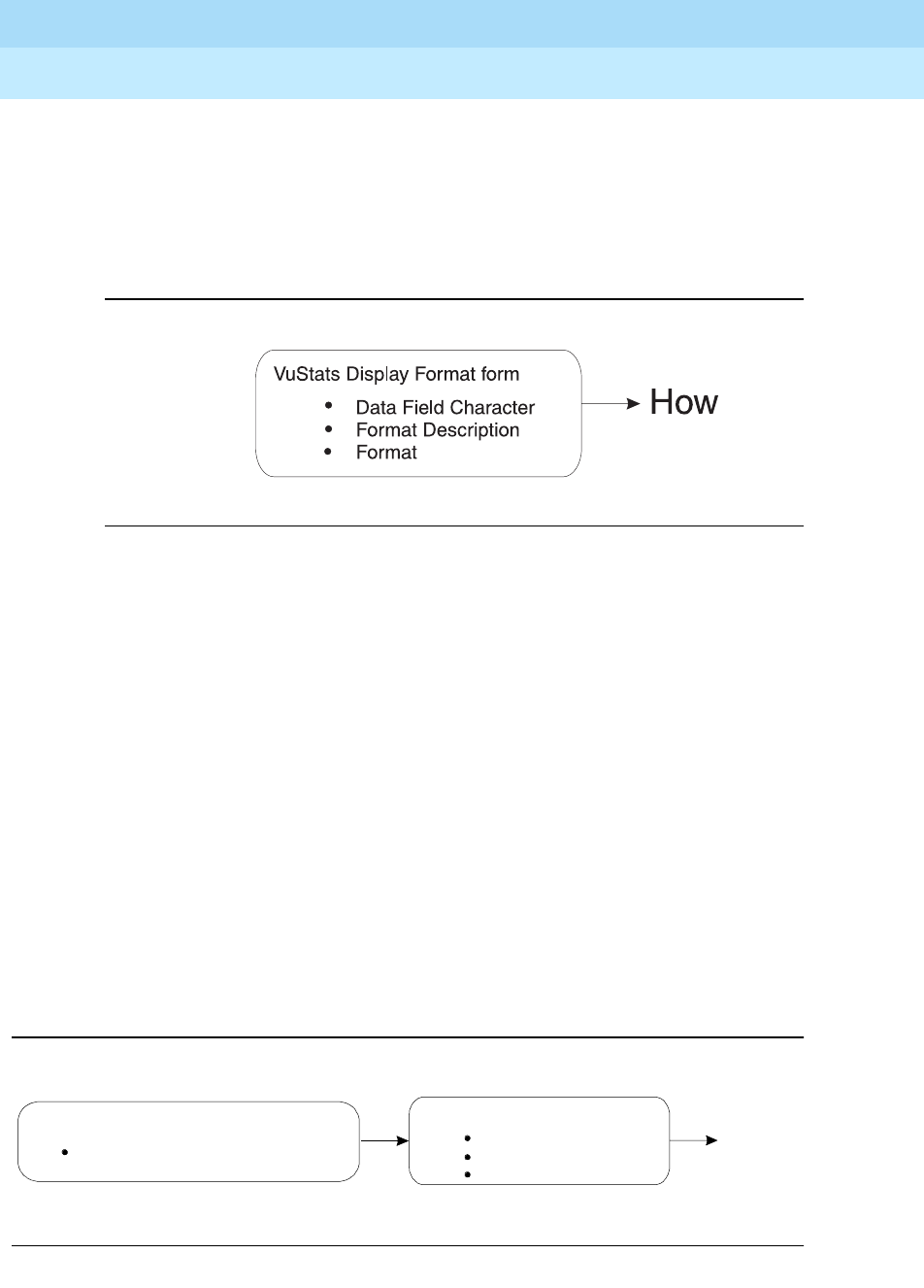
DEFINITY Enterprise Communications Server Release 6
Administration and Feature Description
555-230-522 Issue 4
May 1998
Call Center
Page 9-172VuStats
9
If you use display linking, assign a Next button on agent terminals.
How the information looks
The following fields on the VuStats Display form determine how information looks
on the VuStats display.
Figure 9-6. Fields that Determine What Information Appears on the VuStats
Display
VuStats statistics appear on the second line of 2-line DCP terminal displays or on
the first line of 1-line DCP terminals and all BRI terminals. On voice terminals with
2 x 24 displays, the display automatically wraps to the second line of the display.
When VuStats is activated, it overwrites and cancels any display feature on the
second line of a 2-line display and on the first line of a 1-line display.
You define the following format information on the VuStats Display Format form:
■Labels for data types and the amount of space reserved for data
■Order in which data types appear on the display
■Format for time-related data types
■Display links
When the information updates
The following forms and fields determine when VuStats displays update.
Figure 9-7. Fields that Determine When Information Updates on the VuStats Display
When
Feature-Related System-Parameters form
BCMS/Vustats Measurement Interval
VuStats Display Format form
Update Interval
On change
Display Interval

DEFINITY Enterprise Communications Server Release 6
Administration and Feature Description
555-230-522 Issue 4
May 1998
Call Center
Page 9-173VuStats
9
Most display features that use the second line of a 2-line display or the first line of
a 1-line display overwrite and cancel VuStats. Reason Codes and Call Work
Codes only suspend VuStats; when the prompt is removed, the VuStats display
reappears.
User press the normal button to clear the VuStats display.
Administer VuStats to display information until agents press the normal button or
another operation overwrites the VuStats display. Or, administer VuStats to
display for an interval of 5, 10, 15, or 30 seconds.
You can also administer VuStats to update displayed statistics every 10, 20, 30,
60 or 120 seconds or every time an agent changes work mode or a BCMS
Measurement Interval is completed, or not update at all.
Tables of Data Types
Table 9-23, Table 9-24, Table 9-25 and Table 9-26 describe the data types you
can define for each object type.
Table 9-23. Agent and Agent-Extension Data Types
VuStats Data Type Description
BCMS Report: Field
Name/Column
Heading
acd-calls Split/skill calls and direct agent calls
answered by an agent Split status/VDN
Status/Agent Report:
ACD CALLS
agent-extension The extension for a specific agent; if
either BCMS/VuStats Login IDs or EAS
is optioned, then this shows the agent’s
login ID.
Split Status: Login ID
or EXT
agent-name The administered name for a specific
agent. Split Status/Agent
Report/Agent
Summary Report:
Agent
agent-state The agent’s current work state Split Status: STATE
average-acd-call-
time The average of hold-time plus talk-time. None
Continued on next page

DEFINITY Enterprise Communications Server Release 6
Administration and Feature Description
555-230-522 Issue 4
May 1998
Call Center
Page 9-174VuStats
9
average-acd-talk-
time The average time a specific agent has
spent talking on completed ACD calls
during a specified time period for all
internally-measured splits/skills that the
agent was logged into. This does not
include the time a call was ringing or
was on hold at an agent’s terminal.
Agent Report/Agent
Summary Report:
AVG TALK TIME
average-extension-
time The average amount of time an agent
spent on non-ACD calls while logged
into at least one split/skill during the
reported interval. This average does not
include time when the agent was
holding the EXTN call.
Agent Report/Agent
Summary Report:
AVG EXTN TIME
call-rate The current rate of ACD calls handled
per agent per hour for all split/skills. None
current-reason-code The number of the Reason Code
associated with the agent’s current
AUX work mode, or with the agent’s
logout.
None
current-reason-code-
name The name of the Reason Code
associated with the agent’s current
AUX work mode or with the agent’s
logout.
None
elapsed-time-in-state The amount of time an agent has been
in the current state. None
extension-calls The number of incoming and outgoing
non-ACD calls that an agent completed
while logged into at least one split/skill.
Agent Report: EXTN
CALLS
extension-incoming-
calls The number of non-ACD calls that an
agent receives while logged into at
least one split/skill.
Split Report: EXT IN
CALLS
extension-outgoing-
calls The number of non-ACD calls that an
agent places while logged into at least
one split/skill.
Split Report: EXT
OUT CALLS
Table 9-23. Agent and Agent-Extension Data Types — Continued
VuStats Data Type Description
BCMS Report: Field
Name/Column
Heading
Continued on next page

DEFINITY Enterprise Communications Server Release 6
Administration and Feature Description
555-230-522 Issue 4
May 1998
Call Center
Page 9-175VuStats
9
shift-acd-calls The number of ACD calls answered by
an agent during the administered
period.
None
shift-aux-time-1 The amount of time an agent has spent
in AUX work mode for Reason Code 1
during the administered period.
None
shift-aux-time-2 The amount of time an agent has spent
in AUX work mode for Reason Code 2
during the administered period.
None
shift-aux-time-3 The amount of time an agent has spent
in AUX work mode for Reason Code 3
during the administered period.
None
shift-aux-time-4 The amount of time an agent has spent
in AUX work mode for Reason Code 4
during the administered period.
None
shift-aux-time-5 The amount of time an agent has spent
in AUX work mode for Reason Code 5
during the administered period.
None
shift-aux-time-6 The amount of time an agent has spent
in AUX work mode for Reason Code 6
during the administered period.
None
shift-aux-time-7 The amount of time an agent has spent
in AUX work mode for Reason Code 7
during the administered period.
None
shift-aux-time-8 The amount of time an agent has spent
in AUX work mode for Reason Code 8
during the administered period.
None
shift-aux-time-9 The amount of time an agent has spent
in AUX work mode for Reason Code 9
during the administered period.
None
shift-aux-time-all The amount of time an agent has spent
in AUX work mode for all Reason Codes
during the administered period.
None
Table 9-23. Agent and Agent-Extension Data Types — Continued
VuStats Data Type Description
BCMS Report: Field
Name/Column
Heading
Continued on next page

DEFINITY Enterprise Communications Server Release 6
Administration and Feature Description
555-230-522 Issue 4
May 1998
Call Center
Page 9-176VuStats
9
shift-aux-time-default The amount of time an agent has spent
in AUX work mode for the default
Reason Code (code 0) during the
administered period.
None
shift-aux-time-non-
default The amount of time an agent has spent
in AUX work mode for Reason Codes 1
through 9 during the administered
period.
None
shift-aux-time-reason-
code The amount of time an agent has spent
in AUX work mode for the agent’s
current Reason Code during the
administered period.
None
shift-average-acd-
talk-time The average talk time for ACD calls for
a specific agent during the
administered period.
None
skill-level The skill level at which the skill was
assigned to the agent. None
split-acceptable-
service-level The number of seconds within which
calls must be answered to be
considered acceptable. Identified on a
per-hunt group basis. Timing begins
when the call enters the hunt group
queue.
Split Status:
Acceptable Service
Level
split-acd-calls Split/skill calls and direct agent calls
answered by an agent. System Status/Split
Report/Split Summary
Report: ACD CALLS
split-after-call-
sessions The number of times all agents have
entered After Call Work (ACW) for a
specific split/skill.
None
split-agents-available The number of agents currently
available to receive ACD calls for a
specific split. This includes agents in
Auto-In or Manual-In work mode.
Split Status: Avail
split-agents-in-after-
call For a specific split, the number of
agents currently in ACW. Split Status: ACW
Table 9-23. Agent and Agent-Extension Data Types — Continued
VuStats Data Type Description
BCMS Report: Field
Name/Column
Heading
Continued on next page

DEFINITY Enterprise Communications Server Release 6
Administration and Feature Description
555-230-522 Issue 4
May 1998
Call Center
Page 9-177VuStats
9
split-agents-in-aux-1 For a specific skill, the number of
agents currently in Aux work mode with
Reason Code 1.
None
split-agents-in-aux-2 For a specific skill, the number of
agents currently in Aux work mode with
Reason Code 2.
None
split-agents-in-aux-3 For a specific skill, the number of
agents currently in Aux work mode with
Reason Code 3.
None
split-agents-in-aux-4 For a specific skill, the number of
agents currently in Aux work mode with
Reason Code 4.
None
split-agents-in-aux-5 For a specific skill, the number of
agents currently in Aux work mode with
Reason Code 5.
None
split-agents-in-aux-6 For a specific skill, the number of
agents currently in Aux work mode with
Reason Code 6.
None
split-agents-in-aux-7 For a specific skill, the number of
agents currently in Aux work mode with
Reason Code 7.
None
split-agents-in-aux-8 For a specific skill, the number of
agents currently in Aux work mode with
Reason Code 8.
None
split-agents-in-aux-9 For a specific skill, the number of
agents currently in Aux work mode with
Reason Code 9.
None
split-agents-in-aux- all For a specific split/skill, the total
number of agents currently in Aux work
mode for all Reason Codes.
Split Status: AUX
split-agents-in-aux-
default For a specific split/skill, the number of
agents currently in Aux work mode with
the default Reason Code (code 0).
None
Table 9-23. Agent and Agent-Extension Data Types — Continued
VuStats Data Type Description
BCMS Report: Field
Name/Column
Heading
Continued on next page

DEFINITY Enterprise Communications Server Release 6
Administration and Feature Description
555-230-522 Issue 4
May 1998
Call Center
Page 9-178VuStats
9
split-agents-in-aux-
non-default For a specific skill, the number of
agents currently in Aux work mode with
Reason Codes 1 through 9.
None
split-agents-in-other The number of agents currently who:
are on a call for another split, are in
ACW work mode for another split, have
a call on hold but are not in another
state, or have a call ringing at their
terminals, or are dialing a number while
in AI/MI.
Split Status: Other
split-agents-on-acd-
calls The number of agents currently on
split/skill or direct agent ACD calls for a
specific split.
Split Status: ACD
split-agents-on-
extension-calls The number of agents in a specific split
who are currently on non-ACD calls. Split Status: Extn
split-agents-staffed The number of agents currently logged
into a split. Split Status: Staffed
split-average-acd-
talk-time The average talk time for ACD calls
during a specific period/day for a
specified split.
System Status/Split
Report/Split Summary
Report: AVG TALK
TIME
split-average-after-
call-time The average time for call-related ACW
completed by agents for this split (the
same as average-after-call-time, but
only available for agent and
agent-extension object types).
Call-related ACW time is recorded
when an agent leaves the ACW state. If
an agent is in call-related ACW when an
interval completes, all of the ACW time
will be recorded for the interval in which
the agent leaves ACW.
System Status: AVG
AFTER CALL
split-average-speed-
of-answer The average speed for answering split
and direct agent ACD calls that have
completed for a specified split/skill.
System Status/Split
Report/Split Summary
Report: AVG SPEED
ANS
Table 9-23. Agent and Agent-Extension Data Types — Continued
VuStats Data Type Description
BCMS Report: Field
Name/Column
Heading
Continued on next page

DEFINITY Enterprise Communications Server Release 6
Administration and Feature Description
555-230-522 Issue 4
May 1998
Call Center
Page 9-179VuStats
9
split-average-time-to-
abandon The average time calls waited in queue
and ringing before abandoning. System Status/Split
Report/Split Summary
Report: AVG ABAND
TIME
split-call-rate The current rate of ACD calls handled
per agent per hour for a specific split or
skill.
None
split-calls-
abandoned The number of calls that abandoned
from queue (provided this is the first
split/skill queued to) or abandoned from
ringing.
System Status/Split
Report/Split Summary
Report: ABAND
CALLS
split-calls-flowed-in The total number of calls for a specific
split/skill that were received as a
coverage point (intraflowed) from
another internally-measured split/skill,
or were call-forwarded (interflowed) to
the split/skill.
Split Report/Split
Summary Report:
FLOW IN
split-calls-flowed-out The total number of calls for a specific
split/skill that successfully extended to
the split/skill’s coverage point, were
call-forwarded out, or were answered
via call pick-up.
Split Report/Split
Summary Report:
FLOW OUT
split-calls-waiting The number of calls that have
encountered a split but have not been
answered, abandoned, or outflowed.
System Status:
CALLS WAIT
split-extension The administered extension for a split. None
split-name The administered name for a split/skill. Split Report/Split
Status: Split Name
System Status: SPLIT
split-number The administered number for a
split/skill. Split Report/Split
Status: Split Name
System Status: SPLIT
split-objective The administered objective for a
split/skill. None
Table 9-23. Agent and Agent-Extension Data Types — Continued
VuStats Data Type Description
BCMS Report: Field
Name/Column
Heading
Continued on next page

DEFINITY Enterprise Communications Server Release 6
Administration and Feature Description
555-230-522 Issue 4
May 1998
Call Center
Page 9-180VuStats
9
split-oldest-call-
waiting The time the oldest call has been
waiting for a specific split/skill. System Status:
OLDEST CALL
split-percent-in-
service-level For a specific split/skill, the percentage
of calls answered within the
administered service level on the hunt
group form.
System Status/Split
Report/Split Summary
Report: % WITHIN
SERVICE LEVEL
split-total-acd-talk-
time For a specified split/skill, the total time
agents spent talking on split/skill calls
and direct agent calls for this split.
None
split-total-after-call-
time The total time an agent spent in
call-related ACW for this split/skill and
non-call-related ACW for any split/skill
during a specific time period, excluding
time spent on incoming or outgoing
extension calls while in ACW.
Split Report/Split
Summary Report:
TOTAL AFTER CALL
split-total-aux-time The total time an agent spent in AUX
mode for this split/skill. Split Report/Split
Summary Report:
TOTAL AUX/OTHER
total-acd-call-time The total talk time plus the total hold
time for split/skill and Direct Agent ACD
calls.
None
total-acd-talk-time The total time agents spent talking on
split/skill calls and direct agent calls. None
total-after-call-time The total time an agent spent in
call-related or non-call-related ACW for
any split during a specific time period,
excluding time spent on incoming or
outgoing extension calls while in ACW.
(With EAS, all non-call related ACW
time is associated with the first skill
logged into.)
Agent Report/Agent
Summary Report:
TOTAL AFTER CALL
Table 9-23. Agent and Agent-Extension Data Types — Continued
VuStats Data Type Description
BCMS Report: Field
Name/Column
Heading
Continued on next page

DEFINITY Enterprise Communications Server Release 6
Administration and Feature Description
555-230-522 Issue 4
May 1998
Call Center
Page 9-181VuStats
9
total-aux-time The total time an agent spent in AUX
work for all splits/skills (simultaneously)
that the agent was logged into. If an
agent entered AUX in one interval, but
ended AUX in another, each of the
intervals will reflect the appropriate
amount of time spent in the interval
(agent reports also include OTHER
time).
Agent Report/Agent
Summary Report:
TOTAL AUX/OTHER
total-available-time The time an agent was available in at
least one split/skill. Agent Report:
TOTAL AVAIL TIME
total-hold-time The total amount of time ACD calls were
on hold at a specific agent’s voice
terminal. This time is the “caller’s hold
time” and is independent of the agent’s
state. This time does not include hold
time for non-ACD calls on hold.
Agent Report:
TOTAL HOLD TIME
total-staffed-time The total amount of time an agent was
logged into one or more splits/skills
during a specific period/day. An agent
is clocked for staff time as long as he or
she is logged into any split.
Agent Report:
TOTAL TIME
STAFFED
Table 9-23. Agent and Agent-Extension Data Types — Continued
VuStats Data Type Description
BCMS Report: Field
Name/Column
Heading
Continued on next page

DEFINITY Enterprise Communications Server Release 6
Administration and Feature Description
555-230-522 Issue 4
May 1998
Call Center
Page 9-182VuStats
9
Table 9-24. Split Data Types
VuStats Data Type Description
BCMS Report: Field
Name/Column
Heading
acceptable-service-level The number of seconds within which
calls must be answered to be
considered acceptable. Identified on
a per-hunt group basis. Timing
begins when the call enters the hunt
group queue.
Split Status/Split
Report: Acceptable
Service Level
acd-calls Split calls and direct agent calls
answered by an agent Split status/VDN
Status/Agent
Report: ACD CALLS
after-call sessions The number of times all agents have
entered After Call Work (ACW). None
agents-available The number of agents currently
available to receive ACD calls. This
includes agents in Auto-In or
Manual-In work mode.
Split Status: Avail
agents-in-after-call The number of agents currently in
ACW mode. Split Status: ACW
agents-in-aux-1 The number of agents currently in Aux
work mode for Reason Code 1 for the
referenced skill.
None
agents-in-aux-2 The number of agents currently in Aux
work mode for Reason Code 2 for the
referenced skill.
None
agents-in-aux-3 The number of agents currently in Aux
work mode for Reason Code 3 for the
referenced skill.
None
agents-in-aux-4 The number of agents currently in Aux
work mode for Reason Code 4 for the
referenced skill.
None
agents-in-aux-5 The number of agents currently in Aux
work mode for Reason Code 5 for the
referenced skill.
None
agents-in-aux-6 The number of agents currently in Aux
work mode for Reason Code 6 for the
referenced skill.
None
Continued on next page

DEFINITY Enterprise Communications Server Release 6
Administration and Feature Description
555-230-522 Issue 4
May 1998
Call Center
Page 9-183VuStats
9
agents-in-aux-7 The number of agents currently in Aux
work mode for Reason Code 7 for the
referenced skill.
None
agents-in-aux-8 The number of agents currently in Aux
work mode for Reason Code 8 for the
referenced skill.
None
agents-in-aux-9 The number of agents currently in Aux
work mode for Reason Code 9 for the
referenced skill.
None
agents-in-aux-all The number of agents currently in Aux
work mode for all Reason Codes for
the referenced split/skill.
Split Status: AUX
agents-in-aux-default The number of agents currently in Aux
work mode for the default Reason
Code (code 0) for the referenced
split/skill.
None
agents-in-aux-non-
default The number of agents currently in Aux
work mode for Reason Codes 1
through 9 for the referenced skill.
None
agents-in-other The number of agents who currently:
are on a call for another split, are in
ACW work mode for another split,
have a call on hold but are not in
another state, or have a call ringing at
their terminal, or are dialing a number
from AI/MI mode.
Split Status: Other
agents-on-acd-calls The number of agents currently on
split/skill or direct agent ACD calls for
a specific split.
Split Status: ACD
agents-on-extension-
calls The number of agents in a specific
split who are currently on non-ACD
calls.
Split Status: Extn
agents-staffed The number of agents currently
logged into the specified split. Split Status: Staffed
Table 9-24. Split Data Types — Continued
VuStats Data Type Description
BCMS Report: Field
Name/Column
Heading
Continued on next page

DEFINITY Enterprise Communications Server Release 6
Administration and Feature Description
555-230-522 Issue 4
May 1998
Call Center
Page 9-184VuStats
9
average-acd-talk-time The average talk time for ACD calls
during a specific period/day for a
specified split.
System Status/Split
Report: AVG TALK
TIME
average-after-call- time The average time for call-related
ACW completed by agents in this
split. Call-related ACW time is
recorded when an agent leaves the
ACW state. If an agent is in
call-related ACW when an interval
completes, all of the ACW time will be
recorded for the interval in which the
agent leaves ACW.
System Status: AVG
AFTER CALL
average-speed-of-
answer The average speed for answering
split/skill and direct agent ACD calls
that have completed for a specified
split/skill during a specified time. This
includes queue time and ringing time
for this split.
System Status/Split
Report: AVG
SPEED ANS
average-time-to-
abandon The average time calls waited before
abandoning. System Status/Split
Report: AVG
ABAND TIME
call-rate The current rate of ACD calls handled
per agent per hour for all split/skills. none
calls-abandoned The number of calls that abandoned. System Status/Split
Report: ABAND
CALLS
calls-flowed-in The total number of calls for a specific
split that were received as a coverage
point (intraflowed) from another
internally-measured split, or were
call-forwarded (interflowed) to the
split. This does not include calls that
were interflowed from a remote switch
by the Look Ahead Interflow feature.
Split Report/Split
Summary Report:
FLOW IN
Table 9-24. Split Data Types — Continued
VuStats Data Type Description
BCMS Report: Field
Name/Column
Heading
Continued on next page

DEFINITY Enterprise Communications Server Release 6
Administration and Feature Description
555-230-522 Issue 4
May 1998
Call Center
Page 9-185VuStats
9
calls-flowed-out The number of calls the split
extended to its coverage point, calls
that call-forward out or are answered
by call pickup, calls that queued to
this split as a primary split and were
answered or abandoned from ringing
in another split.
Split Report/Split
Summary Report:
FLOW OUT
calls-waiting The number of calls that have
encountered a split/skill but have not
been answered, abandoned, or
outflowed.
System Status:
CALLS WAIT
oldest-call-waiting The time the oldest call has been
waiting in the split/skill. Timing begins
when the call enters the split/skill.
System Status:
OLDEST CALL
percent-in-service- level The percentage of calls offered to the
split that were answered within the
service level administered on the hunt
group form.
System Status/Split
Report/Split
Summary Report: %
IN SERV LEVL
split-extension The administered extension for a split. None
split-name The administered name for a split. Split Report/Split
Status: Split Name
System Status:
SPLIT
split-number The administered number for a split. Split Report/Split
Status: Split Name
System Status:
SPLIT
split-objective The administered objective for a split. None
total-acd-talk-time The total time agents spent talking on
split/skill calls and direct agent calls
for this split.
None
Table 9-24. Split Data Types — Continued
VuStats Data Type Description
BCMS Report: Field
Name/Column
Heading
Continued on next page

DEFINITY Enterprise Communications Server Release 6
Administration and Feature Description
555-230-522 Issue 4
May 1998
Call Center
Page 9-186VuStats
9
total-after-call-time The total time agents spent in
call-related or non-call-related ACW
for any split during a specific time
period.
Split Report/Split
Summary Report:
TOTAL AFTER CALL
total-aux-time The total time agents spent in AUX
work mode for all Reason Codes for
the referenced split/skill during the
administered period.
Split Report/Split
Summary Report:
TOTAL AUX/OTHER
Table 9-25. VDN Data Types
VuStats Data Type Description
BCMS Report: Field
Name/Column
Heading
acceptable-service-
level The number of seconds within which
calls must be answered to be
considered acceptable. Identified on a
per-VDN basis. Timing begins when the
call enters the vector.
VDN Status/VDN
Report: Acceptable
Service Level
acd-calls Split calls and direct agent calls
answered by an agent VDN Status: ACD
CALLS
average-acd-talk-time The average talk time for ACD calls
during a specific period/day for a
specified VDN.
VDN Status/Split
Report: AVG TALK
HOLD
average-speed-of-
answer The average speed for answering ACD
and CONNect calls that have
completed for a specified VDN during a
specified time. This includes time in
vector processing.
VDN Status/VDN
Report/VDN
Summary Report:
AVG SPEED ANS
average-time-to-
abandon The average time calls waited before
abandoning. VDN Status/VDN
Report: AVG
ABAND TIME
Continued on next page
Table 9-24. Split Data Types — Continued
VuStats Data Type Description
BCMS Report: Field
Name/Column
Heading
Continued on next page

DEFINITY Enterprise Communications Server Release 6
Administration and Feature Description
555-230-522 Issue 4
May 1998
Call Center
Page 9-187VuStats
9
calls-abandoned The number of calls that abandoned. VDN Status/VDN
Report/VDN
Summary Report:
ABAND CALLS
calls-flowed-out The total number of calls for a specific
VDN that successfully routed to another
VDN or off the switch.
VDN Status/VDN
Report/VDN
Summary Report:
FLOW OUT
calls-forced-busy-or-
disc The number of calls given forced busy
or forced disconnect. VDN Status/VDN
Report/VDN
Summary Report:
CALLS BUSY/DISC
calls-offered All calls offered to a VDN, including
ACD calls, connected calls, abandoned
calls, busy calls (calls that received a
busy signal), disconnected calls (calls
disconnected by the switch), and
outflow calls (calls directed to another
VDN or off-switch destination).
VDN Status/VDN
Report/VDN
Summary Report:
CALLS OFFERED
calls-waiting The number of calls that have
encountered a VDN, but have not been
answered, abandoned, or outflowed.
VDN Status: CALLS
WAIT
non-acd-connected-c
alls The number of non-ACD calls routed
from a specific VDN that were
connected to an extension.
VDN Status/VDN
Report/VDN
Summary Report:
CONN CALLS
oldest-calling-waiting The time the oldest call has been
waiting in the VDN. Timing begins when
the call enters the vector.
VDN Status: OLDEST
CALL
percent-in-service-
level The percentage of calls offered to the
VDN that were answered within the
service level administered for the VDN.
VDN Status/VDN
Report/VDN
Summary Report: %
IN SERV LEVL
total-acd-talk-time The total time agents spent talking on
split/skill calls and direct agent calls. None
Table 9-25. VDN Data Types — Continued
VuStats Data Type Description
BCMS Report: Field
Name/Column
Heading
Continued on next page

DEFINITY Enterprise Communications Server Release 6
Administration and Feature Description
555-230-522 Issue 4
May 1998
Call Center
Page 9-188VuStats
9
vdn-extension The extension of a vector directory
number (VDN). VDN Status/VDN
Report: VDN EXT
vdn-name The name of a vector directory number
(VDN). VDN Status/VDN
Summary Report:
VDN NAME
Table 9-26. Trunk Group Data Types
VuStats Data Type Description
BCMS Report: Field
Name/Column
Heading
average-incoming-
call-time Average holding time for incoming
trunk calls. Trunk Group:
INCOMING TIME
average-outgoing-call
-time Average holding time for outgoing trunk
calls. Trunk Group:
OUTGOING TIME
incoming-abandoned
-calls Incoming calls abandoned during a
specified time period for a specified
trunk group.
Trunk Group:
INCOMING ABAND
incoming-calls Incoming calls carried by a specified
trunk group. Trunk Group:
INCOMING CALLS
incoming-usage The total trunk holding time for
incoming calls in hundred call seconds. Trunk Group:
INCOMING CCS
number-of-trunks The number of trunks in a specified
trunk group. Trunk Group:
Number of Trunks
outgoing-calls The number of outgoing calls carried
by a specified trunk group. Trunk Group:
OUTGOING CALLS
outgoing-completed-
calls The number of outgoing calls that
received answer supervision or answer
timeout.
Trunk Group:
OUTGOING COMP
outgoing-usage The total trunk holding time for outgoing
calls in hundred call seconds. Trunk Group:
OUTGOING CCS
Continued on next page
Table 9-25. VDN Data Types — Continued
VuStats Data Type Description
BCMS Report: Field
Name/Column
Heading
Continued on next page

DEFINITY Enterprise Communications Server Release 6
Administration and Feature Description
555-230-522 Issue 4
May 1998
Call Center
Page 9-189VuStats
9
Considerations
Some VuStats data is accumulated for an agent’s login session. This shift data
clears either at midnight or the next time the agent logs in depending upon how
the system is administered. If the data clears at login and agents log out to go to
lunch, the system clears their accumulated data when they log back in after
lunch.
To accumulate a full day’s statistics, you can require agents and supervisors to
keep a running total of all their login sessions, or, to avoid this, use historical data,
require agents to use AUX work mode when temporarily unavailable, or
administer the system to clear shift data at midnight.
percent-all-trunks-
busy The percent of time all the trunks in a
specified trunk group were busy during
a specified period/day. Timing for a call
begins when the last trunk is seized.
Trunk Group: % ALL
BUSY
percent-trunks-maint-
busy The percent of time trunks were busied
out for maintenance during a specified
period/day.
Trunk Group: %
TIME MAINT
trunk-group-name The name administered for a specific
trunk group. Trunk Group: Trunk
Group Name
trunk-group-number The number administered for a specific
trunk group. Trunk Group: Trunk
Group Number
trunks-in-use The number of trunks currently in use
(not idle). None
trunks-maint-busy The number of trunks currently busied
out for maintenance. None
Table 9-26. Trunk Group Data Types — Continued
VuStats Data Type Description
BCMS Report: Field
Name/Column
Heading
Continued on next page

DEFINITY Enterprise Communications Server Release 6
Administration and Feature Description
555-230-522 Issue 4
May 1998
Call Center
Page 9-190VuStats
9
Interactions
■BCMS
You must have BCMS activated to receive BCMS reports. VuStats displays
data collected by BCMS, but BCMS need not be enabled for you to use
VuStats.
■Call Prompting
When Call Prompting digits are displayed, VuStats is canceled. When an
agent reactivates VuStats, the VuStats display overwrites the Call
Prompting display.
■Call Work Codes (CWC)
The CWC-display prompt suspends VuStats, so when the CWC prompt is
removed, the VuStats display reappears.
If VuStats is activated while a CWC is being entered (that is, the pound (#)
sign is not yet dialed), the CWC display is overwritten. The CWC must be
reentered.
■Change skills
An agent changing skills automatically cancels VuStats. Display of the
new skills overwrites the VuStats display. When the agent reactivates
VuStats, the VuStats display overwrites the new skills display.
■CMS
Moving an agent from one split or skill to another does not affect the ID
assigned to the vu-display button.
If an agent is moved from one split or skill to another, the system does not
associate VuStat buttons from the agent’s previous split or skill to the new
split or skill. Therefore if you must frequently move agents between splits
or skills, do not associate agents’ VuStats buttons with a specific split or
skill. Instead, associate the VuStats button with the agent format (without
an ID) on each agent’s voice terminal and use a split reference to view the
agent’s split/skill.
■EAS-PHD
When you have EAS-PHD enabled, VuStats can provide statistical data for
all twenty skills. However, agent statistics by skill (agent or
agent-extension object types) are available only for the current interval or
for the “shift-acd-calls” and “shift-average-acd-talk-time” data types.
■Integrated Directory
If an agent activates Integrated Directory, VuStats is automatically
cancelled. The Integrated Directory display overwrites the VuStats display
and the VuStats button extinguishes. When VuStats is reactivated, the
VuStats display overwrites the Integrated Directory display.

DEFINITY Enterprise Communications Server Release 6
Administration and Feature Description
555-230-522 Issue 4
May 1998
Call Center
Page 9-191VuStats
9
■Queue-Status Indications
The queue-status button display automatically cancels VuStats. When
VuStats is reactivated, the VuStats display overwrites the queue-status
display.
■Reason Codes
Using certain VuStats data types, you can report real-time and historical
AUX work mode time by Reason Code or AUX work mode time summed
for each Reason Code.
The Reason Codes display prompt suspends VuStats; when the Reason
Codes prompt is removed, the VuStats display reappears.
■Service Observing
On terminals with a 1-line display, the Service Observing button display
automatically cancels VuStats. When VuStats is reactivated, the VuStats
display overwrites the Service Observing display.

DEFINITY Enterprise Communications Server Release 6
Administration and Feature Description
555-230-522 Issue 4
May 1998
Call Center Forms
Page 9-192
9
9
9Call Center Forms

DEFINITY Enterprise Communications Server Release 6
Administration and Feature Description
555-230-522 Issue 4
May 1998
Call Center Forms
Page 9-193Agent LoginID
9
Agent LoginID
This form is used to administer Agent LoginIDs for the Expert Agent Selection
feature.
Administration Commands
Use the following administration commands to administer the Agent LoginID
form.
Form Instructions
Make assignments as required for the following fields on the form:
■Login ID — Display-only field. Contains the identifier for the Logical Agent
as entered on the command line.
■Name — Enter up to a 27-character string naming the agent. Any
alpha-numeric character is valid. Default is blank.
■TN — Enter the Tenant Partition number. Default is “1.”
■COR — Enter the Class of Restriction (from 0 to 95) for the agent. Default
is 1.
■Coverage Path — Enter the number of the Coverage Path used by calls
to the LoginID or leave blank (default). This is used when the agent is
logged out, busy, or does not answer.
■Security Code — Enter the 4-digit security code (password) for the
Demand Print messages feature. This field may be blank (default).
■Direct Agent Skill — Enter the number of the skill that is used to handle
Direct Agent calls.
■Call Handling Preference — Choices are skill-level, greatest-need, and
percent-allocation. When calls are in queue and an agent becomes
available, “skill-level” delivers the oldest, highest priority call waiting for
1. Brackets [ ] indicate the qualifier is optional. Single quotes (’ ’) indicate the text
inside the quote must be entered exactly as shown or an abbreviated form of
the word may be entered.
Action Object Qualifier1
add agent-loginid xxxxx (extension) or "next’
change agent-loginid xxxxx (extension)
display agent-loginid xxxxx (extension) [’print’ or ’schedule’]
remove agent-loginid xxxxx (extension)
list agent-loginid [’staffed’ |’unstaffed’ [’name’ x][’aas’ y/n]]

DEFINITY Enterprise Communications Server Release 6
Administration and Feature Description
555-230-522 Issue 4
May 1998
Call Center Forms
Page 9-194Agent LoginID
9
the agent’s highest level skill. “Greatest-need” delivers the oldest, highest
priority call waiting for any of the agent’s skills. “Percent-allocation” is a
new call selection method available only with Lucent’s CentreVu®
Advocate software. For more information, please see the
CentreVu
®
Advocate User Guide
(585-215-855).
■Service Objective —This field is displayed only when the call handling
preference is greatest-need or skill-level. Service Objective is a new
feature that is part of Lucent’s CentreVu® Advocate software. For more
information, please see the
CentreVu
®
Advocate User Guide
(585-215-855).
■Direct Agent Calls First (not shown) — This field replaces the Service
Objective field when percent-allocation is entered in the Call
Handling Preference field. Percent allocation is only available with
Lucent’s CentreVu® Advocate software. For more information, please see
the
CentreVu
®
Advocate User Guide
(585-215-855).
■AAS — Enter “y” if this extension will be used as a port for an Auto
Available Split/Skill. Default is “n.”
!WARNING:
Entering “y” in the AAS field clears the password and requires
execution of the “remove agent-loginid” command. To set AAS to “n”,
this logical agent must be removed then re-added.
!WARNING:
This option is intended for switch adjunct equipment ports only, not
human agents.
■AUDIX — Enter “y” if this extension will be used as a port for an AUDIX.
Default is “n.”
NOTE:
The AAS and AUDIX fields cannot both be “y”.
■LWC Reception — Enter where LWC messages will be stored for this
Agent LoginID. For R5r configurations, valid entries are “audix”, “msa”
“spe” (default), and “none”. For R5si configurations, valid entries are
“audix”, “msa-spe” (default), and “none.”
■Port Extension (not shown) — Only displayed if either the AAS or AUDIX
field is “y”. Enter the assigned extension for the AAS or AUDIX port. This
extension cannot be a VDN or an Agent LoginID.
■AUDIX Name for Messaging — Only applicable to R5r configurations.
Enter the name of the AUDIX used for LWC Reception and/or the name of
the AUDIX that provides coverage for this Agent LoginID or leave blank
(default).

DEFINITY Enterprise Communications Server Release 6
Administration and Feature Description
555-230-522 Issue 4
May 1998
Call Center Forms
Page 9-195Agent LoginID
9
■Messaging Server Name for Messaging — Only applicable to R5r
configurations. Enter the name of the Messaging Server used for LWC
Reception and/or the name of the Messaging Server that provides
coverage for this Agent LoginID or leave blank (default).
■LoginID for ISDN Display — Enter “y” if the Agent LoginID CPN and
Name field is to be included in ISDN messaging over network facilities. In
this case, the physical station extension CPN and Name is sent. Default
is “n.”
■Password — Only displayed if both the AAS and AUDIX fields are “n”.
Enter up to nine digits as the password the Agent must enter upon login.
Valid entries are the digits 0 through 9. The minimum number of digits that
must be entered in this field is specified in the Minimum Agent-LoginID
Password Length field on the Feature-Related System Parameters form.
NOTE:
Values entered into this field will not be echoed to the screen.
■Password (enter again) — Only displayed if both the AAS and AUDIX
fields are “n.” Reenter the same password exactly as it was entered in the
Password field.
NOTE:
Values entered into this field will not be echoed to the screen.
■Auto Answer — Valid entries are all, acd, none, and station. When
Expert Agent Selection is optioned, the agent’s auto answer setting will
apply to the station where the agent logs in. If the auto answer setting for
that station is different, the agent’s setting will override the station’s.
The entries all, acd, and none have the same effect as the corresponding
entries on the Station form. Enter all to allow all calls (ACD and non-ACD)
terminated to the agent to be cut through immediately. Enter acd to allow
only ACD split /skill calls and direct agent calls to auto answer. If this field
is acd, Non-ACD calls terminated to the agent ring audibly. Enter none
(default) to cause all calls terminated to this agent to receive an audible
ringing treatment. Enter station if you want auto answer for the agent to be
controlled by the auto answer field on the Station form.
■SN (Skill Number) — Enter the Skill Hunt Group(s) that this agent
handles. The same skill may not be entered twice. If EAS-PHD is not
optioned, up to 4 skills can be entered. If EAS-PHD is optioned, up to 20
skills can be entered.
■RL (Reserve Level) — Enter the reserve level (if any) assigned to this
agent with the Service Level Supervisor feature. Service Level Supervisor
is available as part of Lucent’s CentreVu® Advocate software. For more
information, please see the
CentreVu
®
Advocate User Guide
(585-215-855).

DEFINITY Enterprise Communications Server Release 6
Administration and Feature Description
555-230-522 Issue 4
May 1998
Call Center Forms
Page 9-196Agent LoginID
9
■SL (Skill Level) — Enter the priority level that each skill has for this
particular agent. If EAS-PHD is not optioned, 2 priority levels are available.
If EAS-PHD is optioned, 16 priority levels are available. In releases prior to
R3V5, level 1 was the primary skill and level 2 was the secondary skill.
■PA (Percent Allocation) — This field is displayed only when the call
handling preference is percent-allocation. Percent Allocation is available
as part of Lucent’s CentreVu® Advocate software. For more information,
please see the
CentreVu
®
Advocate User Guide
(585-215-855).
Screen 9-1. Agent LoginID Form
Implementation Notes
The Port Extension field is only displayed if either the AAS or AUDIX field is “y”.
The AUDIX Name for Messaging and Messaging Server Name for Messaging
fields are only displayed for R5r configurations.
The Password and Password (enter again) fields are only displayed when both
the AAS and AUDIX fields are “n”.
add agent-loginID 9011 Page 1 of 1
AGENT LOGINID
Login ID: 9011_ AAS? _
Name: _________________________ AUDIX? _
TN: 1__ LWC Reception: msa-spe
COR: 1 AUDIX Name for Messaging: _______
Coverage Path: ____ Messaging Server Name for Messaging: _______
Security Code: ____ LoginID for ISDN Display? n
Direct Agent Skill: ___ Password: _________
Call Handling Preference: skill-level Password (enter again): _________
Service Objective? _ Auto Answer: ______
SN RL SL PA SN RL SL PA SN RL SL PA SN RL SL PA
1: __ _ __ ___ 6: __ _ __ ___ 11: __ _ __ ___ 16: __ _ __ ___
2: __ _ __ ___ 7: __ _ __ ___ 12: __ _ __ ___ 17: __ _ __ ___
3: __ _ __ ___ 8: __ _ __ ___ 13: __ _ __ ___ 18: __ _ __ ___
4: __ _ __ ___ 9: __ _ __ ___ 14: __ _ __ ___ 19: __ _ __ ___
5. __ _ __ ___ 10: __ _ __ ___ 15: __ _ __ ___ 20: __ _ __ ___
WARNING: Agent must log in again before skill changes take effect

DEFINITY Enterprise Communications Server Release 6
Administration and Feature Description
555-230-522 Issue 4
May 1998
Call Center Forms
Page 9-197Best Service Routing (BSR) Application Plan
9
Best Service Routing (BSR)
Application Plan
Use this form to identify the remote locations used in each BSR application.
NOTE:
For an explanation of BSR application plans see ‘‘Best Service
Routing™’’ on page 9-44.
Administration Commands
Use the following administration commands to administer the BCMS/VuStats
Login ID form. Valid application numbers are 1–255.
Form Instructions
Make assignments as required for the following fields on the form:
■Application Number—This display-only field shows the identifying
number of the plan you’re working with. Numbered from 1 to 255.
■Application Name—Give the application plan a name with up to 15
characters.
■Location Number—One plan may have 1–255 locations. Location
numbers are identifiers, and therefore need not be in sequential order. For
example, you could assign locations with the identifiers 1, 3, 14 and 89 to
one application plan.
1. Brackets [ ] indicate the qualifier is optional. Single quotes (’ ’)
indicate the text inside the quote must be entered exactly as
shown or an abbreviated form of the word may be entered.
2. The command “list best-service-routing” displays the List Best
Services Routing Applications form. This is a display-only form
and is shown below.
Action Object Qualifier1
add best-service-routing xxx (application
number) or ‘next’
change best-service-routing xxx (application
number)
display best-service-routing xxx (application
number)
remove best-service-routing xxx (application
number)
list2best-service-routing

DEFINITY Enterprise Communications Server Release 6
Administration and Feature Description
555-230-522 Issue 4
May 1998
Call Center Forms
Page 9-198Best Service Routing (BSR) Application Plan
9
■Location Name—Give each location a name with up to 15 characters.
■Switch Node—This is an optional field. If you’re using Universal Call ID,
enter the UCID Network Node ID for each switch in this field. Valid
Network Node IDs range from 1–32,767.
■Status Poll VDN—In this field, enter the routing number (including the dial
access code) your switch will use to access the Status Poll VDN at the
remote location. Valid entries may be up to 16 characters long and contain
the digits 0–9, * or #, p (pause), w/W (wait), m (mark), and s (suppress)
characters.
■Interflow VDN—In this field, enter the routing number (including the dial
access code) your switch will use to access the Interflow VDN at the
remote location. Valid entries may be up to 16 characters long and contain
the digits 0–9, * or #, p (pause), w/W (wait), m (mark), and s (suppress)
characters.
Screen 9-2. Best Service Routing Application Plan Form
add best-service-routing Page 1 of 16
BEST SERVICE ROUTING APPLICATION PLAN
Application Number: 15 Name: International Lock? y
Num Location Name Switch Node Status Poll VDN Interflow VDN
1 New Jersey 320 919081234015 919081234115
3 Denver 18 913031234015 913031234115
4 New York 12345 912121234015 2121234115
___ ______________ _____ _______________ _____________
___ ______________ _____ _______________ _____________
___ ______________ _____ _______________ _____________
___ ______________ _____ _______________ _____________
___ ______________ _____ _______________ _____________
___ ______________ _____ _______________ _____________
___ ______________ _____ _______________ _____________
___ ______________ _____ _______________ _____________
___ ______________ _____ _______________ _____________
___ ______________ _____ _______________ _____________
___ ______________ _____ _______________ _____________
___ ______________ _____ _______________ _____________
___ ______________ _____ _______________ _____________
___ ______________ _____ _______________ _____________
___ ______________ _____ _______________ _____________
___ ______________ _____ _______________ _____________
___ ______________ _____ _______________ _____________

DEFINITY Enterprise Communications Server Release 6
Administration and Feature Description
555-230-522 Issue 4
May 1998
Call Center Forms
Page 9-199Best Service Routing (BSR) Application Plan
9
Screen 9-3. List Best Service Routing Applications Form
list best-service-routing
BEST SERVICE ROUTING APPLICATIONS
Number Name
xxx International
xxx Tech Support
xxx Sales

DEFINITY Enterprise Communications Server Release 6
Administration and Feature Description
555-230-522 Issue 4
May 1998
Call Center Forms
Page 9-200BCMS/VuStats Login ID
9
BCMS/VuStats Login ID
If you want to monitor call activity by agent login IDs, and if the "BCMS/VuStats
Login ID" field on the System-Parameters Customer-Options form is set to "y" but
the EAS feature is not optioned, the administrator uses this form to administer
valid logins.
You do not have to enter names. If you do not use names with the login IDs, the
data you receive from BCMS and/or VuStats defaults to "ID xxxxxxxxx" where
"xxxxxxxxx" is the login ID.
NOTE:
Only agents using one of the administered login IDs can successfully log in
to a split measured by BCMS.
Administration Commands
Use the following administration commands to administer the BCMS/VuStats
Login ID form.
Form Instructions
Make assignments as required for the following fields on the form:
■Login ID — A number up to nine digits that an agent must enter to be
measured in a split by BCMS. The login IDS are restricted to up to five
digits if you are using EAS. The system validates each login ID. If you
enter a duplicate login ID, the system displays an error message and
places the cursor at the duplicate field. Also, the login ID must be the
same length as the number in the "ACD Login Identification Length" field
on the Feature-Related System-Parameters form. If the login ID you enter
does not match the length specified in the "ACD Login Identification
Length" field, the system displays an error message and places the cursor
at the field that is incorrect.
1. Brackets [ ] indicate the qualifier is optional.
Action Object Qualifier1
add bcms/vustats login IDs
change bcms/vustats login IDs [login ID]
display bcms/vustats login IDs [login ID]
list bcms/vustats login IDs [login ID] count X

DEFINITY Enterprise Communications Server Release 6
Administration and Feature Description
555-230-522 Issue 4
May 1998
Call Center Forms
Page 9-201BCMS/VuStats Login ID
9
NOTE:
The administered login length may change to another value, but
doing so changes the allowed length for all IDs entered on this form.
Before agents with logins that do not match the administered login
length can log on, you must readminister either the ACD login
identification length to fit the existing logins or change the logins to
match the ACD login identification length.
■Name — A name associated with the login ID (optional).
Screen 9-4. BCMS/VuStats Login IDs Form
Implementation Notes
The form appears only two pages (64 IDs) at a time. If you are adding login IDs,
you can fill two pages and then reissue the command to fill an additional two
pages, and so on. If you are changing or displaying login IDs, the system
displays two pages of login IDs beginning with the ID you specified; if you did not
specify a login ID when you issued the command, the display begins with the first
login ID. The list command lists all login IDs and may run to 63 pages.
change bcms/vu-stats login IDs
Page 1 of x
BCMS/VU-STATS LOGIN IDS
Assigned Numbers: 300 of 400
Login Id Name Login Id Name
1: _________ _______________ 17: _________ _______________
2: _________ _______________ 18: _________ _______________
3: _________ _______________ 19: _________ _______________
4: _________ _______________ 20: _________ _______________
5: _________ _______________ 21: _________ _______________
6: _________ _______________ 22: _________ _______________
7: _________ _______________ 23: _________ _______________
8: _________ _______________ 24: _________ _______________
9: _________ _______________ 25: _________ _______________
10: _________ _______________ 26: _________ _______________
11: _________ _______________ 27: _________ _______________
12: _________ _______________ 28: _________ _______________
13: _________ _______________ 29: _________ _______________
14: _________ _______________ 30: _________ _______________
15: _________ _______________ 31: _________ _______________
16: _________ _______________ 32: _________ _______________

DEFINITY Enterprise Communications Server Release 6
Administration and Feature Description
555-230-522 Issue 4
May 1998
Call Center Forms
Page 9-202Call Center System Parameters
9
Call Center System Parameters
Call Center System Parameters are listed on pages 7 and 8 of the
Feature-Related System Parameters form. They are duplicated here for your
convenience.
Page 7 of the form
Screen 9-5. Feature-Related System Parameters form (page 7 of 8)
EAS parameters:
■Expert Agent Selection (EAS) Enabled — Only displays if Expert
Agent Selection (EAS) on the System-Parameters Customer-Options
form is y. Enter y to enable Expert Agent Selection. To enable this field,
either no ACD or vectoring hunt groups may exist or, existing ACD or
vectoring hunt groups must be "skilled." Default is n.
■Minimum Agent-LoginID Password Length — Only displays if Expert
Agent Selection (EAS) on the System-Parameters Customer-Options
form is y. Enter the minimum number of digits that must be administered
as an EAS Agent’s LoginID password. Valid entries are 0 through 9 or
blank. Entering a 0 or blank indicates no password is required. Default is
blank.
■Direct Agent Announcement Extension — Only displays if Expert
Agent Selection (EAS) or ASAI on the System-Parameters
Customer-Options form is y. Enter a valid announcement extension
(consistent with the dial plan).
Page 7 of 8
CALL CENTER SYSTEM PARAMETERS
EAS
Expert Agent Selection (EAS) Enabled? n
Minimum Agent-LoginID Password Length:
Direct Agent Announcement Extension: _____ Delay: ___
Message Waiting Lamp Indicates Status For: station
VECTORING
Converse First Data Delay: 0 Second Data Delay: 2
Converse Signaling Tone (msec): 100 Pause (msec): 70_
Prompting Timeout (secs): 10
Interflow-qpos EWT Threshold: 2
SERVICE OBSERVING
Service Observing Warning Tone? n
ASAI
Call Classification After Answer Supervision? n Send UCID to ASAI? n

DEFINITY Enterprise Communications Server Release 6
Administration and Feature Description
555-230-522 Issue 4
May 1998
Call Center Forms
Page 9-203Call Center System Parameters
9
■Direct Agent Announcement Delay — Only displays if Expert Agent
Selection (EAS) or ASAI on the System-Parameters
Customer-Options form is y. Enter the number of seconds (0 to 99) the
caller will hear ringback before the Direct Agent Announcement is heard
by the calling party.
■Message Waiting Lamp Indicates Status For — Only displays if
Expert Agent Selection (EAS) on the System-Parameters
Customer-Options form is y. If Expert Agent Selection (EAS)
Enabled is y, you can enter either station or loginID, otherwise you can
only enter station.
Vectoring parameters:
■Converse First Data Delay/Second Data Delay — Only displays if
Vectoring (Basic) on the System-Parameters Customer-Options form
is y. The First Data Delay prevents data from being outpulsed (as a
result of a converse vector step) from the system to a voice response unit
(VRU) before the unit is ready. The delay commences when the VRU port
answers the call. Enter the number of seconds (0 to 9) for the delay.
Default is 0. The Second Data Delay is used when two groups of digits
are being outpulsed (as a result of a converse vector step) from the
system to the VRU. The Second Data Delay prevents the second set
from being outpulsed before the VRU is ready. The delay commences
when the first group of digits has been outpulsed. Enter the number of
seconds (0 to 9) for the delay. Default is 2.
■Converse Signaling Tone/Pause — Only displays if Vectoring
(Basic) and DTMF on the System-Parameters Customer-Options form
are y. In the Signaling Tone field, enter the length in milliseconds of the
digit tone for digits being passed to a voice response unit (VRU). In the
Pause field, enter the length in milliseconds of the delay between digits
being passed. The optimum timers for the VRU are a 100 msec tone and
70 msec pause.
Values entered in the Tone/Pause fields are rounded up or down
depending upon the type of circuit pack used to outpulse the digits.
■TN742B or later suffix analog board — Tone and pause round up
or down to the nearest 25 msecs. For example a 130 msec tone
rounds down to 125 msecs, a 70 msec pause rounds up to 75
msec for a total of 200 msecs per tone.
■TN464F, TN767E or later suffix DS1 boards — Tone and pause
round up to the nearest 20 msecs. For example a 130 msec tone
rounds up to 140 msecs, a 70 msec pause rounds up to 80 msecs
for a total of 220 msecs per tone.
If a circuit pack has been used for end-to-end signalling to the VRU, and
has then been used to send digits to a different destination, the VRU
timers may stay in effect. To reset your timers to the system default, pull
and reseat the circuit pack.

DEFINITY Enterprise Communications Server Release 6
Administration and Feature Description
555-230-522 Issue 4
May 1998
Call Center Forms
Page 9-204Call Center System Parameters
9
■Prompting Timeout (secs) — Only displays if Vectoring
(Prompting) on the System-Parameters Customer-Options form is y.
Enter the number of seconds, from 4 to 10 (default), before the Collect
Digits command times out for callers using rotary dialing.
■Interflow-qpos EWT Threshold — Part of enhanced Look-Ahead
Interflow. Any calls predicted to be answered before this threshold will not
be interflowed (therefore saving CPU resources). Enter the number of
seconds for this threshold. The default is 2 seconds.
Service Observing parameters:
■Service Observing Warning Tone — Service Observing (Basic)
on the System-Parameters Customer-Options form must be y before this
field may be administered. Enter y to assign a warning tone to be given to
voice terminal users and calling parties whenever their calls are being
monitored using the Service Observing feature. Default is n.
NOTE:
The use of Service Observing features may be subject to federal,
state, or local laws, rules or regulations or require the consent of one
or both of the parties to the conversation. Customers should
familiarize themselves and comply with all applicable laws, rules,
and regulations before using these features.
ASAI parameters
■Call Classification After Answer Supervision? — For use with ASAI
Outbound Call Management (OCM). Enter y to force the switch to rely on
the network to provide answer/busy/drop classification to the switch. After
the call has been answered, a call classifier can be added to perform
answering machine, modem and voice answering detection. Enter n for
standard operation.
■Send UCID to ASAI? — Enter y to enables transmission of Universal Call
ID (UCID) information to ASAI. Enter n (default) to prevent transmission of
UCID information to ASAI.

DEFINITY Enterprise Communications Server Release 6
Administration and Feature Description
555-230-522 Issue 4
May 1998
Call Center Forms
Page 9-205Call Center System Parameters
9
Page 8 of the form
Screen 9-6. Feature-Related System Parameters form (page 8 of 8)
Agent and Call Selection Parameters:
■MIA Across Splits or Skills? — Enter y to remove an agent from the MIA
queue for all the splits/skills/hunt groups that he or she is available in when
the agent answers a call from any of his or her splits/skills/hunt groups.
The default is n.
■ACW Agents Considered Idle? — Enter y (default) to have agents who
are in After Call Work included in the Most-Idle Agent queue. Enter n to
exclude ACW agents from the queue.
■Call Selection Measurement — Valid entries are current-wait-time
(default) and predicted-wait-time. This field determines how DEFINITY
ECS selects a call for an agent when the agent becomes available and
there are calls in queue. Current Wait Time selects the oldest call waiting
for any of the agent’s skills. Predicted Wait Time is a feature of CentreVu®
Advocate. For more information, please see the
CentreVu
®
Advocate User
Guide
(585-215-855).
Reason Codes Parameters:
■Aux Work Reason Code Type — Enter none if you do not want an agent
to enter a Reason Code when entering AUX work. Enter requested if you
want an agent to enter a Reason Code when entering AUX mode but do
not want to force the agent to do so. Enter forced to force an agent to
enter a Reason Code when entering AUX mode. To enter requested or
forced, the Reason Codes and EAS on the System-Parameters
Customer-Option form must be y.
Page 8 of 8
CALL CENTER SYSTEM PARAMETERS
AGENT AND CALL SELECTION
MIA Across Splits or Skills? n
ACW Agents Considered Idle? y
Call Selection Measurement: current-wait-time
REASON CODES
Aux Work Reason Code Type: none
Logout Reason Code Type: none
CALL MANAGEMENT SYSTEM
Adjunct CMS Release:
ACD Login Identification Length: 0
BCMS/VuStats Measurement Interval: hour
BCMS/VuStats Abandon Call Timer (seconds):
Validate BCMS/VuStats Login IDs? n
Clear VuStats Shift Data: on-login

DEFINITY Enterprise Communications Server Release 6
Administration and Feature Description
555-230-522 Issue 4
May 1998
Call Center Forms
Page 9-206Call Center System Parameters
9
■Logout Reason Code Type — Enter none if you do not want an agent to
enter a Reason Code when logging out. Enter requested if you want an
agent to enter a Reason Code when logging out but do not want to force
the agent to do so. Enter forced to force an agent to enter a Reason Code
when logging out. Enter forced to force an agent to enter a Reason Code
when entering AUX mode. To enter requested or forced, the Reason
Codes and EAS on the System-Parameters Customer-Option form must
be y.
Call Management System Parameters:
■Adjunct CMS Release — Specifies the release of the CMS adjunct used
with the system. For CMS, this field cannot be blank. Default is blank.
■ACD Login Identification Length — Enter the number of digits (0
through 9) for an ACD Agent Login ID if Expert Agent Selection
(EAS) on the System-Parameters Customer-Options form is n. Default is
0. If BCMS/VuStats Login IDs is y, the ACD Login ID length must be
greater than 0. This field identifies an ACD agent to CMS. The number you
enter in this field must equal the number of characters in the agent’s login
ID. For CMS, this field cannot be 0.
■BCMS/VuStats Measurement Interval — You can enter half-hour or
hour (default) for polling and reporting measurement data if the BCMS
(Basic) and/or the VuStats on the System-Parameters
Customer-Options form is y. If neither of these features is optioned, and if
you enter a value in the BCMS Measurement Interval field, the system
displays the following error message:
<value> cannot be used; assign either BCMS or VuStats first
If you receive this message, see your Lucent Technologies representative
to turn on BCMS (Basic) and/or VuStats on the System-Parameters
Customer-Options form.
There are a maximum of 25 time slots available for measurement intervals.
If hour is specified, an entire day of traffic information will be available for
history reports; otherwise, only half a day will be available. This does not
affect daily summaries as they always reflect traffic information for the
entire day. The interval may be changed at any time, but will not go into
effect until the current interval completes.
■BCMS/VuStats Abandon Call Timer (seconds) — Enter none or 1–10 to
specify the number of seconds for calls to be considered abandoned.
Calls with talk time that is less than this number (and that are not held) are
tracked by BCMS and displayed by VuStats as ABAND calls.
■Validate BCMS/VuStats Login IDs — Enter n to allow entry of any ACD
login of the proper length. Enter y to allow entry only of login-IDs that have
been entered on the BCMS Login-ID form.
■Clear VuStats Shift Data — Enter on-login to clear shift data for an agent
when the agent logs in. Enter at-midnight to clear shift data for all agents
at midnight.

DEFINITY Enterprise Communications Server Release 6
Administration and Feature Description
555-230-522 Issue 4
May 1998
Call Center Forms
Page 9-207Call Vector
9
Call Vector
This form programs a series of commands that specify how to handle calls
directed to a Vector Directory Number (VDN). Refer to
DEFINITY Enterprise
Communications Server Release 5 Call Vectoring/EAS Guide
for additional
information.
Administration Commands
Use the following commands to administer the Call Vector form.
Form Instructions
Screen 9-7. Call Vector Form (Page 1 of X)
1. Brackets [ ] indicate the qualifier is optional. Single quotes (‘ ’) indicate
the text inside the quote must be entered exactly as shown or an
abbreviated form of the word may be entered. MAX is the maximum
number available in your system configuration.
2. Do not change a call vector while it is processing a call. It is
recommended to add a new vector with the Call Vector form, and then
use the Vector Directory Number form to point an existing VDN to the new
vector.
Action Object Qualifier1
change2vector 1-MAX
display vector 1-MAX [’print’ or ’schedule’]
list vector 1-MAX [‘count’ 1-MAX] [’print’ or ’schedule’]
Page 1 of 3
CALL VECTOR
Number: Name: _______________ Multimedia? n Lock? n
Basic? y EAS? n G3V4 Enhanced? y ANI/II-Digits? y ASAI Routing? n
Prompting? y LAI? n G3V4 Adv Route? y CINFO? y BSR? n
01 ____________
02 ____________
03 ____________
04 ____________
05 ____________
06 ____________
07 ____________
08 ____________
09 ____________
10 ____________
11 ____________
DEFINITY Enterprise Communications Server Release 6
Administration and Feature Description
555-230-522 Issue 4
May 1998
Call Center Forms
Page 9-208Call Vector
9
Form Instructions
Screen 9-8. Call Vector Form (Page 2 of X)
Screen 9-9. Call Vector Form (Page 3 of X)
Make assignments as required for the following fields on the form:
■Number — Display-only field when the form is accessed using a change
or display administration command. Enter a vector number when
completing a paper form.
■Name — Enter up to 27 alphanumeric characters to represent the vector
name. This is an optional field. Default is blank.
■Multimedia — Indicates whether the vector should receive early answer
treatment for multimedia calls. This only applies if Multimedia Call
Handling is enabled. If you expect this vector to recieve multimedia calls,
set this field to y. Valid values are y or n. If this value is y, the call is
considered to be anwered at the start of vector processing, and billing for
the call starts at that time. See ‘‘Multimedia Call Handling’’ on page 11-30
for more information.
Page 2 of 3
CALL VECTOR
12 ____________
13 ____________
14 ____________
15 ____________
16 ____________
17 ____________
18 ____________
19 ____________
20 ____________
21 ____________
22 ____________
Page 3 of 3
CALL VECTOR
23 ____________
24 ____________
25 ____________
26 ____________
27 ____________
28 ____________
29 ____________
30 ____________
31 ____________
32 ____________

DEFINITY Enterprise Communications Server Release 6
Administration and Feature Description
555-230-522 Issue 4
May 1998
Call Center Forms
Page 9-209Call Vector
9
■Lock—This field controls access to the vector from Lucent CentreVu®
products. Enter n to give CentreVu® CMS and CentreVu® Control Center
users the ability to administer this vector from these client programs. Enter
y if you do not want this vector to be accessible to these client programs.
Locked vectors can only be displayed and administered through the SAT
or a terminal emulator.
NOTE:
Always lock vectors that contain secure information (for example,
access codes).
■Basic — Display-only field. Indicates whether the Vectoring (Basic)
option is enabled on the System-Parameters Customer-Options form. Valid
values are y or n.
■EAS — Display-only field. Indicates whether the Expert Agent
Selection (EAS) option is enabled on the System-Parameters
Customer-Options form. Valid values are y or n.
NOTE:
When Expert Agent Selection (EAS) is enabled, the help
messages and error messages associated with this form will reflect a
terminology change from "Split" to "Skill". In addition, the vector
commands entered also will be affected by this terminology change
(for example,
check backup split
becomes
check backup skill
when
EAS is enabled).
■G3V4 Enhanced — Display-only field. Indicates whether you can use
G3V4 Enhanced Vector Routing commands and features.
■ANI/II-Digits — Display-only field. Indicates whether you can use ANI and
II-Digits Vector Routing Commands. ANI/II-Digits Routing requires that
G3V4 Enhanced be set to y.
■ASAI Routing — Display-only field. Indicates whether or not the
CallVisor Adjunct/Switch Applications Interface (ASAI)
Routing option is enabled on the System-Parameters Customer-Options
form. Valid values are y or n.
■Prompting — Display-only field. Indicates whether the Vectoring
(Prompting) option is enabled on the System-Parameters
Customer-Options form. Valid values are y or n.
■LAI — Display-only field. Indicates whether Look-Ahead Interflow is
enabled.
■G3V4 Adv Route — Display-only field. Indicates whether you can use the
G3V4 Advanced Vector Routing commands.
■CINFO — Display-only field. Indicates whether the Vectoring (CINFO)
option is enabled on the System-Parameters Customer-Options form. Valid
values are y or n.

DEFINITY Enterprise Communications Server Release 6
Administration and Feature Description
555-230-522 Issue 4
May 1998
Call Center Forms
Page 9-210Call Vector
9
■BSR—A y in this display-only field indicates that the Vectoring (Best
Service Routing) option is enabled on the System-Parameters
Customer-Options form. Thus, you can use BSR commands and
command elements in your vectors. An n indicates that the BSR option is
not enabled.
■01 through XX — Enter vector commands as required (up to the
maximum allowed in your configuration).

DEFINITY Enterprise Communications Server Release 6
Administration and Feature Description
555-230-522 Issue 4
May 1998
Call Center Forms
Page 9-211Reason Code Names
9
Reason Code Names
Use the Reason Code Names form to assign names to Reason Codes. You can
assign a different name to each Reason Code for Aux Work and for Logout.
Administration Commands
Use the following administration commands to access the Reason Code Names
form.
Form Instructions
Make assignments as required for the following fields on the form.
■Aux Work — For each Reason Code enter the name to be associated with
this Reason Code when the agent uses this Reason Code to enter Aux
Work mode. Names can be up to ten characters long.
■Logout — For each Reason Code enter the name to be associated with
this Reason Code when the agent uses this Reason Code to log out.
Names can be up to ten characters long.
Screen 9-10. Reason Code Names form (Page 1 of 1)
Action Object
display reason-code-names
change reason-code-names
REASON CODE NAMES
Aux Work Logout
Reason Code 1: __________ __________
Reason Code 2: __________ __________
Reason Code 3: __________ __________
Reason Code 4: __________ __________
Reason Code 5: __________ __________
Reason Code 6: __________ __________
Reason Code 7: __________ __________
Reason Code 8: __________ __________
Reason Code 9: __________ __________
Default Reason Code: __________ __________

DEFINITY Enterprise Communications Server Release 6
Administration and Feature Description
555-230-522 Issue 4
May 1998
Call Center Forms
Page 9-212SIT Treatment for Call Classification
9
SIT Treatment for Call Classification
This form is used to provide the capability of specifying the treatment of Special
Information Tones (SITs) used for Outbound Call Management type calls with
USA tone characteristics. The TN744 Call Classifier circuit pack ports are used to
detect SITs. The TN744 is capable of detecting the following six SITs:
■SIT Ineffective Other
■SIT Intercept
■SIT No Circuit
■SIT Reorder
■SIT Vacant Code
■SIT Unknown
■AMD Treatment
Administration Commands
Use the following administration commands to administer the SIT Treatment For
Call Classification form. In some cases, just the most commonly used commands
are shown. Refer to Appendix B, ‘‘Administration Commands’’, for a complete
listing of all administration commands, the command structure, and the use of
abbreviated command words when entering a command.
.
Form Instructions
Make assignments as required for the following fields on the form:
In the field following each type of SIT, enter “answered” to specify that the call is
classified as answered, and is therefore sent to an agent; or enter “dropped” to
specify that the call is classified as not answered, and is therefore not sent to an
agent.
■SIT Ineffective Other — Sample announcement following this SIT —
“You are not required to dial a “1” when calling this number.” Valid entries
are “answered” and “dropped.” Default is “dropped.”
1. Brackets [ ] indicate the qualifier is optional. Single quotes (‘ ’)
indicate the text inside the quote must be entered exactly as
shown or an abbreviated form of the word can be entered.
Action Object Qualifier1
change sit-treatment —
display sit-treatment [’print’ or ’schedule’]

DEFINITY Enterprise Communications Server Release 6
Administration and Feature Description
555-230-522 Issue 4
May 1998
Call Center Forms
Page 9-213SIT Treatment for Call Classification
9
■SIT Intercept — Sample announcement following this SIT — “XXX-XXXX
has been changed to YYY-YYYY, please make a note of it.” Valid entries
are “answered” and “dropped.” Default is “answered.”
■SIT No Circuit — Sample announcement following this SIT — “All circuits
are busy, please try to call again later.” Valid entries are “answered” and
“dropped.” Default is “dropped.”
■SIT Reorder — Sample announcement following this SIT — “Your call did
not go through, please hang up and dial again.” Valid entries are
“answered” and “dropped.” Default is “dropped.”
■SIT Vacant Code — Sample announcement following this SIT — “Your
call cannot be completed as dialed, please check the number and dial
again.” Valid entries are “answered” and “dropped.” Default is “dropped.”
■SIT Unknown — A situation or condition that is unknown to the network is
encountered. Valid entries are “answered” and “dropped.” Default is
“dropped.”
■AMD (Answering Machine Detected) — An ASAI adjunct can request
AMD for a switch-classified call. If Answering Machine is detected, one of
two treatments is specified. Valid entries are “dropped” and “connected.”
Default is “dropped.”
AMD Treatment has two separately administrable subfields. Talk Duration
is for full seconds and Pause Duration is for fractions of a second,
separated by a display-only decimal point. Talk Duration defaults to
2.0 seconds and allows a range from 0.1 seconds to 5.0 seconds in
increments of 0.1 seconds. Pause duration defaults to 0.5 seconds and
allows a range from 0.1 seconds to 2.0 seconds in increments of
0.1 seconds.
Screen 9-11. SIT Treatment For Call Classification Form
SIT TREATMENT FOR CALL CLASSIFICATION
SIT Ineffective Other: dropped
SIT Intercept: answered
SIT No Circuit: dropped
SIT Reorder: dropped
SIT Vacant Code: dropped
SIT Unknown: dropped
AMD Treatment: dropped
Pause Duration (seconds): 0.5
Talk Duration (seconds): 2.0

DEFINITY Enterprise Communications Server Release 6
Administration and Feature Description
555-230-522 Issue 4
May 1998
Call Center Forms
Page 9-214Vector Directory Number
9
Vector Directory Number
This form is used to define vector directory numbers (VDNs) for the Call
Vectoring feature. A VDN is an extension number used to access a call vector.
Each VDN is mapped to one call vector.
VDNs are software extension numbers (that is, not assigned to physical
equipment). A VDN is accessed via direct dial CO trunks mapped to the VDN
(incoming destination or night service extension), DID trunks, and LDN calls. The
VDN may be Night Destination for LDN.
For more information, refer to the
DEFINITY Enterprise Communications Server
Release 5 Call Vectoring/EAS Guide
.
Administration Commands
Use the following administration commands to administer the Vector Directory
Number form
Form Instructions
Make assignment as required for the following fields on the form:
■Extension — Enter the extension associated with the VDN when
completing a paper form. The extension is a 1- to 5-digit number that
starts with a valid first digit and length as defined by the System’s dial
plan. This is a display-only field when using an administration command
such as add or change to access the form.
1. Brackets [ ] indicate the qualifier is optional. Single quotes (‘ ’) indicate the text inside
the quote must be entered exactly as shown or an abbreviated form of the word can
be entered. MAX is the maximum number available in your system configuration.
Refer to
DEFINITY ECS Release 5 — System Description Pocket Reference
.
Action Object Qualifier1
add vdn xxxxx (extension number of VDN to be added) or ’next’
change vdn xxxxx (extension number of VDN to be changed)
display vdn xxxxx (extension number of VDN to be displayed) [’print’
or ’schedule’]
list vdn xxxxx (extension number of VDN to be listed) (‘count’
1-MAX) [’print’ or ’schedule’]
vdn bsr xxx (number of a BSR application plan)
remove vdn xxxxx (extension number of VDN to be removed)

DEFINITY Enterprise Communications Server Release 6
Administration and Feature Description
555-230-522 Issue 4
May 1998
Call Center Forms
Page 9-215Vector Directory Number
9
■Name — Enter up to a 27-character alphanumeric name that identifies the
VDN. This is an optional field that need not contain any data. The name
may be truncated on agents’ displays depending on the application.
When information is forwarded with an interflowed call, only the first 15
characters are sent.
■Allow VDN Override? — This entry affects the operation of an agent’s
display and certain options/data assigned to the VDN when a call is
routed through several VDNs. If it is set to n, the name of this VDN appears
on the agent’s display and the VDN’s AUDIX mail is accessed. If any
subsequent VDNs are used to process this call, their names will not
appear on the terminating display and the AUDIX mail for the original VDN
is accessed. If the field is set to y, the name of the VDN appearing on the
terminating display will depend on the administration and chaining of the
subsequent VDNs and the AUDIX mail for the last VDN is accessed.
Default is “n.”
For Expert Agent Selection (EAS), if this field is y on the original VDN, the
Skills of the new VDN will be used. If this field is n on the original VDN, the
Skills of the original VDN will be used.
For Best Service Routing (BSR), if this field is y on the original VDN, the
BSR Application and Available Agent Strategy of the new VDN will be
used. If this field is n on the original VDN, the BSR Application and
Available Agent Strategy of the original VDN will be used.
■COR — Enter a 1- to 2-digit number that specifies the class of restriction
(COR) to be assigned the VDN. The default value is “1.” The field cannot
be blank and must have an entry in the range from 0 through 95.
■TN — Enter the Tenant Partition number. The default value is “1”.
■Vector Number — Enter a 1- to 3-digit vector number that specifies a
particular call vector that is accessed through the VDN. Valid entries are in
the range from 1 through the maximum number allowed in your system
configuration. The field cannot be blank.
■AUDIX Name — Only displayed for R5r and later configurations. If this
VDN is associated with the AUDIX vector, enter the name of the AUDIX
machine as it appears in the Adjunct Names form.
■Messaging Server Name — Only displayed for R5r configurations. If this
VDN is associated with MSA, enter the name of the server as it appears in
the Adjunct names form.
■Measured — Used to collect measurement data for this VDN. Valid
entries are “internal,” “external,” “both,” or “none.” Data may be collected
for reporting by BCMS or CMS. Default is “none.”
NOTE:
The BCMS feature must be enabled on the System-Parameters
Customer-Options form for the Measured field to be set to “internal”
or “both.” In addition, the appropriate CMS release must be

DEFINITY Enterprise Communications Server Release 6
Administration and Feature Description
555-230-522 Issue 4
May 1998
Call Center Forms
Page 9-216Vector Directory Number
9
administered on the Feature-Related System Parameters form if the
field is being changed to “external” or “both.”
■Acceptable Service Level (sec) — Only displayed when the
BCMS/VuStats Service Level option is enabled on the System-Parameters
Customer-Options form and the Measured field is “internal” or “both.”
Enter the number of seconds within which calls to this VDN should be
answered. This will allow BCMS to print out a percentage of calls that were
answered within the specified time. Valid entries are 0 through 9999
seconds. Default is blank.
The following field appears only if VDN of Origin Announcements is
enabled on the System-Parameters Customer-Options form.
■VDN of Origin Annc. Extension — Enter the extension number of the
VDN of Origin announcement. Default is none.
■1st/2nd/3rd Skill — Only displayed when Expert Agent Selection is
enabled on the System-Parameters Customer-Options form. Enter the
desired Skill numbers (or leave blank) in each field.
■Return Destination — The VDN extension number to which an incoming
trunk call will be routed if it returns to vector processing after the agent
drops the call.
■VDN Timed ACW Interval — When a value is entered in this field, an
agent in auto-in work mode who receives a call from this VDN is
automatically placed into After Call Work (ACW) when the call drops. Enter
the number of seconds the agent should remain in ACW following the call.
When the administered time is over, the agent automatically becomes
available. This field has priority over the “Timed ACW Interval” field on the
Hunt Group form.
■BSR Application — To use multi-site Best Service Routing with this VDN,
enter a 1- to 3-digit number to specify an application plan for the VDN.
This field only appears if Lookahead Interflow (LAI) and Vectoring (Best
Service Routing) are enabled on the System Parameters
Customer-Options form.
■BSR Available Agent Strategy — The available agent strategy
determines how Best Service Routing identifies the “best” split or skill to
service a call in an agent surplus situation. To use Best Service Routing
with this VDN, enter an agent selection strategy in this field. Acceptable
entries are 1st-found, UCD-LOA, UCD-MIA, EAD-LOA, and EAD-MIA.
This field only appears if Vectoring (Best Service Routing) is enabled on
the System Parameters Customer-Options form.

DEFINITY Enterprise Communications Server Release 6
Administration and Feature Description
555-230-522 Issue 4
May 1998
Call Center Forms
Page 9-217Vector Directory Number
9
Screen 9-12. Vector Directory Number — Add/Change Form
Screen 9-13. Vector Directory Numbers — List Form
Implementation Notes
AUDIX Name and Messaging Server Name are only displayed for a R5r
configuration.
The BCMS feature must have been optioned if the Measured field is set to
“internal” or “both.” In addition, the appropriate CMS release must be
administered on the Feature-Related System Parameters form if the field is being
changed to “external” or “both.”
Page 1 of 1
VECTOR DIRECTORY NUMBER
Extension: 50000
Name:
Allow VDN Override? n
COR: 59
TN: 1
Vector Number: 234
AUDIX Name:
Messaging Server Name:
Measured: none
Acceptable Service Level (sec):
VDN of Origin Annc. Extension: 301
1st Skill:
2nd Skill:
3rd Skill:
Return Destination:
VDN Timed ACW Interval:
BSR Application:
BSR Available Agent Strategy: 1st-found
VECTOR DIRECTORY NUMBERS
Event
VDN Vec Orig Notif Skills
Name Ext Ovrd COR TN Num Meas Annc Adj 1st 2nd 3rd
Tech Support 50000 y 59 1 234 none 301
Customer Serv. 50001 n 1 1 1 none 302
New Orders 50002 y 23 1 5 none 303
Denver 50003 y 23 1 123 int 304
San Francisco 50004 y 39 1 123 ext 305
Chicago 50005 y 12 1 123 both 306

DEFINITY Enterprise Communications Server Release 6
Administration and Feature Description
555-230-522 Issue 4
May 1998
Call Center Forms
Page 9-218Vector Directory Number
9
The 1st/2nd/3rd Skill fields are only displayed when Expert Agent Selection is
enabled on the System-Parameters Customer-Options form.
The BCMS Acceptable Service Level (sec) field is only displayed if the BCMS
Acceptable Service Level option is enabled on the System-Parameters
Customer-Options form and the Measured field is “internal” or “both.”
Data for the Orig Annc column appears only when VDN of Origin Announcement
is enabled on the System-Parameters Customer-Options form.
To list all VDNs using the same BSR Application Plan, type the administration
command list VDN BSR
xxx
(xxx is the number of the BSR Application Plan
used by one or more VDNs).

DEFINITY Enterprise Communications Server Release 6
Administration and Feature Description
555-230-522 Issue 4
May 1998
Call Center Forms
Page 9-219Vector Routing Table
9
Vector Routing Table
This form is used to store “ani” or “digits” that you refer to in your “goto” vector
steps. It is available to you only if the Vectoring (G3V4 Enhanced) field on the
System-Parameters Customer-Options form is set to yes.
For more information, refer to ‘‘Call Vectoring’’ on page 9-63 or to
DEFINITY
Enterprise Communications Server Release 5 Call Vectoring /EAS Guide
.
Administration Commands
You can use the commands listed in the table below to administer Vector Routing
Tables. In addition, you can use the “List Usage” command to see the vectors
and digit fields used by a Vector Routing Table.
Form Instructions
Make assignment as required for the following fields on the form:
■Number — This is the table number that you entered on the command
line. It is a display only field.
■Name — Enter a 1 to 15-character alphanumeric table name. You may
leave this field blank.
■Sort? — Enter “y” if you want the digit fields to be sorted. Default is “n.” If
you elect not to sort the numbers, they will remain in the order that you
entered them. If you elect to sort the number fields, they will be sorted as
described below. Remember that leading zeros are significant. That
means that 02 will sort ahead of a 2 followed by a space.
— Any Plus signs (+) will sort first.
— Any question marks (?) will sort second.
— All numbers (0–9) will sort last.
Action Object Qualifier
add vrt 1 through x, or next
change vrt 1 through x, or next
display vrt 1 through x, or next
remove vrt 1 through x, or next
list vrt none - all Routing Tables will display

DEFINITY Enterprise Communications Server Release 6
Administration and Feature Description
555-230-522 Issue 4
May 1998
Call Center Forms
Page 9-220Vector Routing Table
9
■Number (1-32) — Enter a number. Entries in this field also can include the
“+” and/or “?” wildcard. The “+” represents a group of digits. The “?”
represents a single digit. The field is limited to 16 characters and these
characters are restricted as follows:
— You may enter only a plus sign (+), a question mark (?), or the
numbers 0 through 9. No other entries are valid.
— You may enter one plus sign (+) as either the first or last character
in the number field. However, you cannot use this character as the
sixteenth character of the number field.
— You may use as many question marks (?) as you wish, anywhere in
the number field.
— You may not embed blanks in the number field.
— You may leave the field entirely blank. If you leave the field blank
DEFINITY ECS will store the entry as a null value.
Screen 9-14. Vector Routing Table Form (1 of 3)
Page 1 of 3
VECTOR ROUTING TABLE
Number: ___ Name: _______________ Sort? n
1:________________ 17: ________________
2:________________ 18: ________________
3:________________ 19: ________________
4:________________ 20: ________________
5:________________ 21: ________________
6:________________ 22: ________________
7:________________ 23: ________________
8:________________ 24: ________________
9:________________ 25: ________________
10:________________ 26: ________________
11:________________ 27: ________________
12:________________ 28: ________________
13:________________ 29: ________________
14:________________ 30: ________________
15:________________ 31: ________________
16:________________ 32: ________________

DEFINITY Enterprise Communications Server Release 6
Administration and Feature Description
555-230-522 Issue 4
May 1998
Call Center Forms
Page 9-221VuStats Display Format
9
VuStats Display Format
Use the VuStats Display Format form to define the content and layout of
information on VuStats voice terminal displays. The system has 50 different
display formats; the first display is a predefined example format, which can be
changed; displays 2 through 50 are blank. Each display format can contain up to
ten data items. However, the amount of data to be displayed is limited to 40
characters, due to the physical limitations on display voice terminals.
Administration Commands
Use the following administration commands to access the VuStats Display
Format form.
Form Instructions
Enter the data as required for the following fields on the form:
■Format Number — This is the display format number you entered on the
command line. It is a display only field and cannot be modified.
■Next Format Number — To link this display to another display, enter the
number of the display format that should appear when a VuStats user
presses the next button, or enter “none.”
■Data Field Character — The character that will be used in the Format
Description field to identify the position and length of each data field (see
the Format Description field description below). The default is “$.” Enter
another character if the “$” is needed for fixed text in the Format
Description field. Any character is valid except a space.
■Number of Intervals — If you intend to display interval-based historical
data, specify the number of measurement intervals in this field. You can
enter a number between 1 and 24. If you enter 24, and the BCMS
measurement interval on the Feature-Related System Parameters form is
set to 1 hour, you will receive information on the previous 24 hours. If the
1. Specify a number from 1 to 50 to indicate the number of the display
format to be to changed or displayed. “Count ##” is the number of
display formats to list.
Action Object Qualifier1
change vustats-display-format 1-50
display vustats-display-format 1-50
list vustats-display-format 1-50 count ##

DEFINITY Enterprise Communications Server Release 6
Administration and Feature Description
555-230-522 Issue 4
May 1998
Call Center Forms
Page 9-222VuStats Display Format
9
BCMS measurement interval is set to half-hour, you will receive information
on the previous 12 hours. You can also leave this field blank. If you do, you
will receive information on the current interval.
■Object Type — The type of object for which data will be displayed. Enter
one of the following values: “agent” (for staffed agents to view their own
statistics), “agent-extension” (for other users to view agent statistics),
“split” (default), “trunk-group,” or “vdn.”
■Update Interval — The interval, in seconds, between display updates.
Enter one of the following values:
■On Change — Enter “y” to update the display whenever the agent’s state
changes. The update on agent state change is in addition to the update
as a result of the value entered in the Update Interval field. If “n” is
entered, an update will only occur based on the Update Interval and not
on the agent state change.
■Display Interval — The interval, in seconds, for which data is displayed if
“no update” is entered in the Update Interval field. Enter one of the
following values:
Valid Input Description
no-update The display is not updated, and appears only
for the interval specified in the Display Interval
field
polled Updates the display hourly or half-hourly,
based on the value in "BCMS Measurement
Interval" (System-Parameters Features form)
10 Updates every 10 seconds
20 Updates every 20 seconds
30 Updates every 30 seconds, default value
60 Updates every 1 minute
120 Updates every 2 minutes
Valid Input Description
Body
5 Display clears after 5 seconds
10 Display clears after 10 seconds, default value
15 Display clears after 15 seconds
30 Display clears after 30 seconds
not-cleared The display does not clear, and the data appears
until the display is used for another operation or
until you press the Normal button.

DEFINITY Enterprise Communications Server Release 6
Administration and Feature Description
555-230-522 Issue 4
May 1998
Call Center Forms
Page 9-223VuStats Display Format
9
■Format Description — The definition of the layout for the 40-character
display. Specify the starting position and the length of the data items by
entering, for each data field, an optional label for the field followed the
appropriate number of data field characters (such as $s). Each “$”
represents one character in the display. For example, if the data will be a
maximum of five characters long (for example, to display 5-digit agent
extensions), enter “$$$$$.”
NOTE:
Some data types have preset maximum field length limits based on
switch administration. For example, the data type
“acceptable-service-level” is taken from the BCMS Acceptable
Service Level field on the Hunt Group and Vector Directory Number
forms; on this form, the field allows a maximum number of four
characters. Therefore, for the acceptable-service-level, you should
not create a VuStats display field that consists of more than four
characters (that is, “$$$$”). Other data types have similar limits.
Field lengths for data items that appear as time must match the value in
the Format field, which is discussed below. Remember to account for
possible colons when the display will be in a time format.
Format descriptions can be all text (such as a message of the day) or they
can be all data fields, in which case users will have to memorize the labels
or use customer-provided overlays above or below the display.
NOTE:
If the numeric data for a field is too large for the number of data field
characters entered, the VuStats display will show asterisks instead of
data. If name database items are too large for the number of data
field characters, the VuStats display will truncate the data to fit the
data field size. The split objective, as entered on the Hunt Group
form, will display as asterisks if the information exceeds the data
field size.
Data Item Fields
On lines 1 through 10, beneath the Data Type field label enter data items for the
display format. These data items are associated with the sets of data field
characters in the Format Description field. Each data item is defined by one or
more of the following fields: Data Type, Format, Period, Threshold, and Split
Reference. Input for these fields is described in more detail below.
Enter each data item in the same order as data fields are defined in the Format
Description field. For example, Line 1 of the Data Type field must contain the data
item for the first data field (that is, the first set of $s).
■Data Type — The data item to be included in the current display format.
For a complete list of data types available for each object type, see
“Tables of Data Types” on page 3-540.

DEFINITY Enterprise Communications Server Release 6
Administration and Feature Description
555-230-522 Issue 4
May 1998
Call Center Forms
Page 9-224VuStats Display Format
9
■Format — The format for displaying the data type. The format is required
only for a data type with a time value. Enter one of the following Format
values.
■Period — Enter the measurement period for the data type. If the data type
is historical data, you cannot leave this field blank. Valid entries are “day”
(midnight to the current time), “interval” (the time specified in the “Number
of Intervals” field), or blank. Refer to ‘‘Tables of Required and Allowed
Fields’’ on page 9-227 to determine if a measurement period is required
for a particular Data Type.
■Threshold — The threshold field is always an optional field. It contains
two subfields, the threshold comparator and the threshold value. The
threshold value is used with the threshold comparator to determine if a
threshold warning should be generated. A threshold warning is generated
if the specified condition is met for one or more of the data items. If the
specified condition is not met for any of the data items, then no threshold
warning is generated. The threshold value can be any numeric value from
0 to 999. Valid threshold comparators are:
— = (equal to)
— <> (not equal to)
— < (less than)
— <= (less than or equal to)
— > (greater than)
— >= (greater than or equal to)
Val id
Input Description
Minimum
Input
Length
ccs Hundred call seconds (CCS) rounded to the
nearest CCS 1
h Hours rounded to the nearest hour 1
h:mm Hours and minutes rounded to the nearest
minute 4
h:mm:ss Hours, minutes, and seconds 7
m Minutes rounded to the nearest minute 1
m:ss Minutes and seconds 4
s Seconds 1

DEFINITY Enterprise Communications Server Release 6
Administration and Feature Description
555-230-522 Issue 4
May 1998
Call Center Forms
Page 9-225VuStats Display Format
9
■Ref — A reference to a split/skill; this field does not appear unless the
Object Type is either “agent” or “agent-extension.” This field is required
only if the data type is an agent-related data type collected on a per-split
basis or a split-related data type for one of the agent’s logged-in splits.
Enter one of the following values:
— “Top” references the first-administered, highest-level skill for EAS
agents, or the first split logged into for non-EAS agents.
NOTE:
With EAS, the “top” skill for VuStats is the first administered,
highest level skill measured “internally” or “both.” For CMS it
is the first-administered, highest-level skill measured
“externally” or “both.” Therefore, it is possible for the top skill
to be a different number skill for CMS than it is for VuStats. To
avoid this, measure all skills as “both.”
— “All” displays the combined data for all splits the agent is logged
into.
— Any number from 1-20. The number represents a split to which the
agent has logged in. For example, if the Ref field contains “1,”
VuStats displays the data for the first split the agent logged into, if
the Ref field contains “2,” VuStats displays the data for the second
split the agent logged into, and so on.
Screen 9-15. VuStats Display Format — Blank Change/Display Form
VUSTATS DISPLAY FORMAT
Format Number: ___ Object Type: _______________
Next Format Number: _____ Update Interval: ___________ On Change? _
Data Field Character: _ Display Interval: ______________
Number of Intervals:__
Format Description: ________________________________________
Data Type Format Period Threshold Ref
1: ________________________________________ _______ ________ __ ___ ___
2: ________________________________________ _______ ________ __ ___ ___
3: ________________________________________ _______ ________ __ ___ ___
4: ________________________________________ _______ ________ __ ___ ___
5: ________________________________________ _______ ________ __ ___ ___
6: ________________________________________ _______ ________ __ ___ ___
7: ________________________________________ _______ ________ __ ___ ___
8: ________________________________________ _______ ________ __ ___ ___
9: ________________________________________ _______ ________ __ ___ ___
10: ________________________________________ _______ ________ __ ___ ___

DEFINITY Enterprise Communications Server Release 6
Administration and Feature Description
555-230-522 Issue 4
May 1998
Call Center Forms
Page 9-226VuStats Display Format
9
Screen 9-16 shows an example of a completed VuStats Display Format screen.
Screen 9-16. VuStats Display Format — Example Change/Display Form
List VuStats Display Format Screen
A second VuStats Display Format screen is available with the list command. The
purpose of this screen is to present the format of all, or a selected number, of
VuStats displays. The List VuStats Display Format screen displays the Format
Number, Next Format Number, Number of Intervals, Object Type, Update
Interval, and Format Description fields, and all designated data items, including
the Data Type, Format, Threshold, and Ref (split reference).
Use this screen to compare VuStats displays to each other. This “list”
presentation is most helpful when trying to see how displays are linked to each
other. The screen includes the Next field, which contains the number of the next
display (if any) to which a display is linked.
Screen 9-17 shows an example of the List VuStats Display Format screen. The
fields for this screen are described below. Refer to the previous field descriptions
in this section for more information.
No — Number. The unique identifying number of each display format.
Next — The number of the next display if the current display is linked to
(followed by) another display format, or “none” if the current display format is not
linked to another display format.
Int — Number of Intervals. The number of measurement intervals.
Object Type — The type of object for which data will be displayed.
change display-format 11 Page 1 of 1
VUSTATS DISPLAY FORMAT
Format Number: 11 Object Type: agent
Next Format Number: 12 Update Interval: 30 On Change? n
Data Field Character: $
Number of Intervals: 16
Format Description: SPLIT=$$ ASL=$$ ASA=$$ PSL=$$$
Data Type Format Period Threshold Ref
1: split-number 1
2: split-acceptable-service-level s 1
3: split-average-speed-of-answer s interval 1
4: split-percent-in-service-level interval 1
5:
6:
7:
8:
9:
10:

DEFINITY Enterprise Communications Server Release 6
Administration and Feature Description
555-230-522 Issue 4
May 1998
Call Center Forms
Page 9-227VuStats Display Format
9
Update — Update Interval. The time between display updates.
Format Description — The definition of the display’s layout. The first line of the
Format Description contains the text that precedes the data on a display plus the
length of each data field (indicated by $s). The succeeding lines of the Format
Description identify the data items, in the order they are to appear. The data
items are the actual measurements and other information that tell how agents,
splits, vector directory numbers (VDNs), trunk groups, and the call center are
performing. The data items are followed by the format (if any), which identifies
how the data is to appear in the display, the period and threshold (if any), and the
split reference (if any).
Screen 9-17. VuStats Display Formats — List Form
Tables of Required and Allowed Fields
Table 9-1. Required and Allowed Fields — Agent and
Agent-Extension Data Types
VuStats Data Type Format Period Threshold Reference
acd-calls required allowed required
agent-extension
agent-name
agent-state required
average-acd-call-time required required allowed
average-acd-talk-time required required allowed required
Continued on next page
Page 1
VUSTATS DISPLAY FORMATS
No Next Int Object Type Update Format Description
1 none split 30 SPLIT=$$ WAITING=$$$ OLDEST=$$$$$
split-number
calls-waiting
oldest-call-waiting m:ss
2 none agent-extension on-change AGENT=$$$$ STATE=$$$$$$$$$ TIME=$$$$$$$$
agent extension
agent state 1
time-agent-entered-state 1
press CANCEL to quit -- press NEXT PAGE to continue

DEFINITY Enterprise Communications Server Release 6
Administration and Feature Description
555-230-522 Issue 4
May 1998
Call Center Forms
Page 9-228VuStats Display Format
9
average-extension-time required required allowed
call-rate required allowed
current-reason-code allowed
current-reason-code-name allowed
elapsed-time-in-state
extension-calls required allowed
extension-incoming-calls allowed
extension-outgoing-calls allowed
shift-acd-calls allowed required
shift-aux-time-1 required allowed
shift-aux-time-2 required allowed
shift-aux-time-3 required allowed
shift-aux-time-4 required allowed
shift-aux-time-5 required allowed
shift-aux-time-6 required allowed
shift-aux-time-7 required allowed
shift-aux-time-8 required allowed
shift-aux-time-9 required allowed
shift-aux-time-all required allowed
shift-aux-time-default required allowed
shift-aux-time-non-default required allowed
shift-aux-time-reason-code required allowed
shift-average-acd-talk-time required allowed required
skill-level required
split-acceptable-service-level required required
split-acd-calls required allowed required
split-after-call-sessions allowed required
split-agents-available allowed required
Table 9-1. Required and Allowed Fields — Agent and
Agent-Extension Data Types — Continued
VuStats Data Type Format Period Threshold Reference
Continued on next page

DEFINITY Enterprise Communications Server Release 6
Administration and Feature Description
555-230-522 Issue 4
May 1998
Call Center Forms
Page 9-229VuStats Display Format
9
split-agents-in-after-call allowed required
split-agents-in-aux-1 allowed required
split-agents-in-aux-2 allowed required
split-agents-in-aux-3 allowed required
split-agents-in-aux-4 allowed required
split-agents-in-aux-5 allowed required
split-agents-in-aux-6 allowed required
split-agents-in-aux-7 allowed required
split-agents-in-aux-8 allowed required
split-agents-in-aux-9 allowed required
split-agents-in-aux-all allowed required
split-agents-in-aux-default allowed required
split-agents-in-aux-non-default allowed required
split-agents-in-other allowed required
split-agents-on-acd-calls allowed required
split-agents-on-extension-calls allowed required
split-agents-staffed allowed required
split-average-acd-talk-time required required allowed required
split-average-after-call-time required allowed required
split-average-speed-of-answer required required allowed required
split-average-time-to-abandon required required allowed required
split-call-rate allowed required
split-calls-abandoned required allowed required
split-calls-flowed-in required allowed required
split-calls-flowed-out required allowed required
split-calls-waiting allowed required
split-extension required
split-name required
Table 9-1. Required and Allowed Fields — Agent and
Agent-Extension Data Types — Continued
VuStats Data Type Format Period Threshold Reference
Continued on next page

DEFINITY Enterprise Communications Server Release 6
Administration and Feature Description
555-230-522 Issue 4
May 1998
Call Center Forms
Page 9-230VuStats Display Format
9
split-number required
split-objective required
split-oldest-calling-waiting required allowed required
split-percent-in-service-level required allowed required
split-total-acd-talk-time required required allowed required
split-total-after-call-time required required allowed required
split-total-aux-time required required allowed required
time-agent-entered-state required
total-acd-call-time required required allowed
total-acd-talk-time required required allowed
total-after-call-time required required allowed
total-aux-time required required allowed
total-available-time required required allowed
total-hold-time required required allowed
total-staffed-time required required allowed
Table 9-1. Required and Allowed Fields — Agent and
Agent-Extension Data Types — Continued
VuStats Data Type Format Period Threshold Reference
Continued on next page

DEFINITY Enterprise Communications Server Release 6
Administration and Feature Description
555-230-522 Issue 4
May 1998
Call Center Forms
Page 9-231VuStats Display Format
9
Table 9-2. Required and Allowed Fields —
Split Data Types
VuStats Data Type Format Period Threshold
acceptable-service-level required
acd-calls required allowed
after-call sessions allowed
agents-available allowed
agents-in-after-call allowed
agents-in-aux-1 allowed
agents-in-aux-2 allowed
agents-in-aux-3 allowed
agents-in-aux-4 allowed
agents-in-aux-5 allowed
agents-in-aux-6 allowed
agents-in-aux-7 allowed
agents-in-aux-8 allowed
agents-in-aux-9 allowed
agents-in-aux-all allowed
agents-in-aux-default allowed
agents-in-aux-non-default allowed
agents-in-other allowed
agents-on-acd-calls allowed
agents-on-extension-calls allowed
agents-staffed allowed
average-acd-talk-time required required allowed
average-after-call-time required allowed
average-speed-of-answer required required allowed
average-time-to-abandon required required allowed
call-rate allowed
calls-abandoned required allowed
Continued on next page

DEFINITY Enterprise Communications Server Release 6
Administration and Feature Description
555-230-522 Issue 4
May 1998
Call Center Forms
Page 9-232VuStats Display Format
9
calls-flowed-in required allowed
calls-flowed-out required allowed
calls-waiting allowed
oldest-calling-waiting required allowed
percent-in-service-level required allowed
split-extension
split-name
split-number
split-objective
total-acd-talk-time required required allowed
total-after-call-time required required allowed
total-aux-time required required allowed
Table 9-2. Required and Allowed Fields —
Split Data Types — Continued
VuStats Data Type Format Period Threshold
Continued on next page

DEFINITY Enterprise Communications Server Release 6
Administration and Feature Description
555-230-522 Issue 4
May 1998
Call Center Forms
Page 9-233VuStats Display Format
9
Table 9-3. Required and Allowed Fields — VDN Data Types
VuStats Data Type Format Period Threshold
acceptable-service-level required
acd-calls required allowed
average-acd-talk-time required required allowed
average-speed-of-answer required required allowed
average-time-to-abandon required required allowed
calls-abandoned required allowed
calls-flowed-out required allowed
calls-forced-busy-or-disc required allowed
calls-offered required allowed
calls-waiting allowed
non-acd-connected-calls required allowed
oldest-calling-waiting required allowed
percent-in-service-level required allowed
total-acd-talk-time required required allowed
vdn-extension
vdn-name

DEFINITY Enterprise Communications Server Release 6
Administration and Feature Description
555-230-522 Issue 4
May 1998
Call Center Forms
Page 9-234VuStats Display Format
9
Table 9-4. Required and Allowed Fields — Trunk Group
Data Types
VuStats Data Type Format Period Threshold
average-incoming-call-time required required allowed
average-outgoing-call-time required required allowed
incoming-abandoned-calls required allowed
incoming-calls required allowed
incoming-usage required required allowed
number-of-trunks
outgoing-calls required allowed
outgoing-completed-calls required allowed
outgoing-usage required required allowed
percent-all-trunks-busy required allowed
percent-trunks-maint-busy required allowed
trunk-group-name
trunk-group-number
trunks-in-use allowed
trunks-maint-busy required allowed

Hospitality
Page 10-1
10
DEFINITY Enterprise Communications Server Release 6
Administration and Feature Description
555-230-522 Issue 4
May 1998
10
10 Hospitality
This section contains the following DEFINITY ECS Hospitality features. Hospitality
forms are located at the end of this chapter. Note that in this section, the term
“guest” refers to a guest or a patient.
.
Feature Page
Attendant Room Status 10-2
Automatic Wakeup 10-4
Do Not Disturb 10-11
Hospitality Services 10-15
Names Registration 10-17
Property Management System Interface 10-21
Form Page
Hospitality Forms 10-29

DEFINITY Enterprise Communications Server Release 6
Administration and Feature Description
555-230-522 Issue 4
May 1998
Hospitality
Page 10-2Attendant Room Status
10
Attendant Room Status
Attendant Room Status allows the attendant to see whether a room is vacant or
occupied and each room’s housekeeping status.
NOTE:
This feature is available only if you have Enhanced Hospitality enabled on
the System-Parameters Customer-Options form. (See your Lucent
Technologies support representative for assistance with this form.)
How to administer Attendant Room Status
Detailed description
Check In/Check Out Status
The attendant determines check in/check out status by pressing the OCC-ROOMS
(occupied rooms) button on the attendant console.
This activates check in/checkout mode. The DXS lamps light for all occupied
rooms. The console displays a message indicating that it is in check in/check out
mode.
Occupancy status normally updates as guests check in and out.
Maid Status
The attendant determines maid status by pressing the MAID-STAT button on the
attendant console. This activates Maid-Status mode. The attendant is prompted
to enter a status number (1 through 6). The display shows the state
corresponding to that number and lights the DXS lamps for all rooms currently in
that state.
Required forms
Form Field Page
Attendant Console ■Feature Button Assignment
— occ-rooms
— maid-stat
5-35
Hospitality ■All of page 3 10-30
Language Translations Page 4
■fields 15 through 17
5-193
Feature Access Code (FAC) Page 5 5-113

DEFINITY Enterprise Communications Server Release 6
Administration and Feature Description
555-230-522 Issue 4
May 1998
Hospitality
Page 10-3Attendant Room Status
10
While the console is in Maid-Status mode, the attendant can enter another status
number. The console display shows the new status and lights the DXS lamps for
all rooms in that state.
The status of a room updates when a maid or inspector dials from the room and
changes the status.
The messages that appear on the console identify each of six states and are
user-defined. (For example, you could define state 1 as clean, ready to use and
state 2 as occupied, needs cleaning). As with other display messages,
administer the prompts and status messages for a specific language.
Considerations
■The feature is not available for attendants connected to the switch by a
distributed communications system (DCS). Attendant consoles are the
only terminals that can access this feature
Interactions
■Outgoing Calls
When Check in/Check out mode is active, the attendant can make
outgoing calls via the keypad. The attendant can return to normal mode or
any other mode by pressing the appropriate button on the console.
Check in/Check out mode does not affect other attendant operations.
When Maid Status mode is active, the attendant cannot make outgoing
calls via the keypad. However, the attendant can make calls via the DXS
module or the feature buttons. Attendant can return to normal mode or any
other mode by pressing the appropriate button on the console.

DEFINITY Enterprise Communications Server Release 6
Administration and Feature Description
555-230-522 Issue 4
May 1998
Hospitality
Page 10-4Automatic Wakeup
10
Automatic Wakeup
Automatic Wakeup allows attendants, front desk users, and guests to place an
automatic wakeup call to a certain extension at a later time.
If the Dual Wakeup enhancement is activated, each extension is allowed two
wakeup call requests within one 24-hour time period. If the Room Activated
Wakeup with Tones enhancement is activated, wakeup calls can be activated via
tones that prompt users for the time they wish to waken. These enhancements
are activated on the change system-parameters hospitality form by entering y in
the Dual Wakeup and Room Activated Wakeup with Tones fields. These options
default to y and can only be changed by Lucent Technologies personnel.
How to administer Automatic Wakeup
Required forms
Form Field Page
Station
(multi-appearance)
■Feature Button Assignment
— auto-wkup
— aut-msg-wt for the extension that is the
“Extension to Receive Failed Wakeup
LWC Messages”
■Display Language
6-28
Attendant Console ■Feature Button Assignments
— auto-wkup
— aut-msg-wt for the extension that is the
“Extension to Receive Failed Wakeup
LWC Messages”
■Display Language
■Default Announcement Extension (if the
Announcement Type is multiple-integrated)
5-35
Announcements/
Audio Sources
■All
—integrated
— integ-rep
5-26
Continued on next page

DEFINITY Enterprise Communications Server Release 6
Administration and Feature Description
555-230-522 Issue 4
May 1998
Hospitality
Page 10-5Automatic Wakeup
10
Detailed description
Wakeup requests may be placed from 5 minutes to 23 hours and 55 minutes in
advance of a wakeup call.
When a user answers a wakeup call, the system can provide a recorded
announcement, a speech-synthesis announcement, music, or silence depending
on the administration of Automatic Wakeup.
All wakeup times entered into the system round to the nearest five minutes. For
example, a requested time of 6:58 am stores in the system as 7:00 am. The
switch bases time-validity checks on the rounded figure.
Wakeup calls are placed within two and one-half minutes of the requested time,
and never reroute, forward, or go to coverage. Before placing the wakeup call,
the system overrides Do Not Disturb for the extension.
Class of Service ■Console Permission 5-81
Feature Access
Code (FAC)
■Announcement Access Code
■Automatic Wakeup Call Access Code
■Verify Wakeup Announcement Code
5-113
Hospitality ■Announcement Type
■Length of Time to Remain Connected to an
Announcement
■Announcement Ports
■Auxiliary Board for Announcement
■Extension of Journal/Schedule Printer
■Extension of PMS Log Printer
■Extension to Receive Failed Wakeup LWC
Messages
■Routing Extension on Unavailable Voice
Synthesis
■Time of Scheduled Wakeup Activity Report
■Time of Scheduled Wakeup Summary
Report
10-30
Required forms — Continued
Form Field Page
Continued on next page

DEFINITY Enterprise Communications Server Release 6
Administration and Feature Description
555-230-522 Issue 4
May 1998
Hospitality
Page 10-6Automatic Wakeup
10
If a wakeup-call attempt is not answered or if the extension is busy, the system
tries two more times at 5-minute intervals. If the call does not complete after three
attempts, the switch leaves a LWC message for a designated extension (usually
assigned to a button on the attendant console or backup voice terminal). The
system maintains a complete record of all wakeup-call activity for the past 24
hours.
Users with touch-tone dialing can enter a wakeup request (if they have a speech
synthesizer board and no display set) or can have the attendant set a wakeup
time. Users with rotary-dial terminals call the attendant to request a wakeup call.
Activate Automatic Wakeup either by dialing the FAC or by pressing the
automatic wakeup entry button. If the system has a speech synthesizer board,
the system provides voice prompting. If the user has a display set, the system
provides display prompting.
■Voice Prompting with Room Activated with Tones Off
A guest enters his or her own wakeup-call request. The request is entered
only for the extension where the call originates.
After the user dials the Automatic Wakeup FAC, the system generates
voice prompts (the system must have a voice synthesizer). These prompts
tell the user when to enter information and what information is needed.
Use touch-tone buttons to enter the information. The system accepts
military or standard time. The user dials the automatic wakeup FAC again
to change or delete a wakeup request.
If the user makes invalid entries, a standard message generates that
notifies the user of the error. The system then repeats the original prompt
for input. If invalid entries occur on the second try, the system informs the
user to dial the attendant for assistance.
■Voice Prompting with Room Activated with Tones On
A guest enters his or her own wakeup-call request. The request is entered
only for the extension where the call originates.
After the user dials the Automatic Wakeup FAC, the system generates
recall dial tone (the system does not need a voice synthesizer). This dial
tone prompts the user to enter the time in a 24-hour, 4-digit format.
Confirmation tone means that the wakeup request is successful.
■Display Prompting with Dual Wakeup Off
Display prompting is provided to attendants, front-desk users, and to other
users with display-equipped voice terminals. Administer front-desk users
(or any other voice terminals you want to grant permissions to) with a
console permission class of service (COS) to perform the same actions as
the attendant. Other users can enter a wakeup request only for the
extension where the call originates.
The attendant presses the automatic wakeup entry button to activate the
feature. If the attendant is on an active call with a system user, the user’s
extension displays as the default extension after pressing the pound sign

DEFINITY Enterprise Communications Server Release 6
Administration and Feature Description
555-230-522 Issue 4
May 1998
Hospitality
Page 10-7Automatic Wakeup
10
(#). If the displayed extension is not the extension of the user requesting
the wakeup call, the attendant can change it. Display prompting continues
until the attendant enters all necessary information and the request for the
wakeup call is confirmed.
If a condition exists that does not allow the system to accept the wakeup
request, the system displays the reason for denial. Wakeup requests are
denied for one of the following reasons:
— Too Soon — Indicates that the requested wakeup time is within the
current five-minute wakeup interval
— System Full — Indicates that the maximum number of wakeup calls
is reached
— Interval Full — Indicates that the maximum number of wakeup calls
in any 15-minute interval is reached
The attendant can change or cancel a wakeup call request at any time.
■Display Prompting with Dual Wakeup On
Display prompting with Dual Wakeup works the same as Display
Prompting with Dual Wakeup off (described in the previous text), except
that after the first wakeup request is entered, the user is prompted for the
second wakeup request.
When the system places a wakeup call, one of the following occurs:
— Extension Is Busy — The wakeup call is placed again later.
— No Answer — The extension rings for 30 seconds. If the call is not
answered, the system tries again later.
— Ringing Blockage — If four or more ports on the same
analog-circuit pack are already ringing, the system waits 16
seconds and tries again. If the second attempt is blocked, the call
has failed and the system waits five minutes before trying again.
— Call Is Answered — The guest answers the wakeup call and hears
either music, a recorded announcement, the speech-synthesizer
announcement, or silence.
— System Reset — indicates that a system reset level 1 or system
reset level 2 occurred while the system attempted to place the
wakeup call. Calls affected by these conditions are treated as other
wakeup attempts.
If a wakeup call is incomplete because of a busy, no answer, ringing blockage, or
system reset, the system attempts to place the call two more times at five-minute
intervals. If the call is not completed after three attempts, the system leaves an
LWC message.
A special extension, called the Wakeup Messages Extension, is administered
exclusively for receiving failed wakeup-call LWC messages. When a failed

DEFINITY Enterprise Communications Server Release 6
Administration and Feature Description
555-230-522 Issue 4
May 1998
Hospitality
Page 10-8Automatic Wakeup
10
message is retrieved, the display shows the date, time, and extension for the
failed wakeup-call attempt.
Assign an automatic-message waiting (AMW) button and associated lamp to
attendant consoles or front-desk terminals. The number associated with the
button can be the wakeup-messages extension. The AMW lamp lights when a
failed wakeup message is waiting. The user retrieves the message by invoking
coverage-message retrieval on the wakeup-message extension. The user
presses the AMW button to place the console or terminal in coverage-retrieval
mode. The user then retrieves the failed wakeup-call attempt messages. Only
attendants and specified voice-terminal users can retrieve and delete failed
wakeup messages.
The system maintains an audit-trail record of wakeup-call activity for the past 24
hours. The wakeup-call buffer can only hold a number of records equal to the
maximum number of stations administrable on the switch. For example, if a
maximum of 200 stations is administrable, only 200 automatic-wakeup records
are stored.
You can display wakeup events at the management terminal, or print to a
designated printer. If the system has a journal printer, wakeup events print as
they occur.
The audit trail record contains the following information:
■Type of event:
—Request
— A new wakeup-call request is made.
— Change — The time is changed on an existing wakeup-call
request.
— Cancel — A wakeup request is canceled.
— Move To — The wakeup request for this room moves to another
room.
— Move From — The wakeup request for another room moves from
the old room to the new room.
— Move-Cancel — A wakeup request from another room replaces the
request for this room.
—Swap
— A room swap occurs and at least one of the rooms has a
wakeup request. Wakeup calls swap when a room swap is
performed. A journal entry is made for each room. If the room
receives a wakeup call as the result of the swap, the time of the call
is provided in the entry. If the room loses a wakeup call as the result
of the swap (and has not received another), the time is not present
in the entry.
— Completed — The wakeup call completes successfully.
—Not Completed — The wakeup call failed.

DEFINITY Enterprise Communications Server Release 6
Administration and Feature Description
555-230-522 Issue 4
May 1998
Hospitality
Page 10-9Automatic Wakeup
10
—Skip — The wakeup call is skipped. This event occurs if the system
time advances past the requested time of a wakeup call.
■Time of the event
■Extension number receiving the call
■Time of the wakeup request
■Extension (or 0 for the attendant) where the event took place
■Number of call attempts that were placed
■An indication of why a wakeup-call attempt failed
In addition, all wakeup-time changes are recorded. This record shows the
original time requested and the changed time. The audit-trail record is not
backed up and all wakeup data is lost if a system failure occurs.
Schedule the following reports for printing on a daily basis:
■Wakeup Activity report – summarizes wakeup activity for each extension
that had any wakeup activity over the past 24 hours.
■Wakeup Summary report — gives an hour-by-hour summary of the
number of scheduled wakeup calls, the number of wakeup calls
completed, and a list of extensions. The report covers all
automatic-wakeup events for each hour over a 24-hour period.
With VDNs and multiple announcements, you can choose as the announcement
extension a VDN that reaches one announcement if the system clock is less than
12:00 and another if the system clock is greater than 12:00. The hotel guest
hears “good morning” before noon and “good evening” after noon. Or, a
business customer can choose as the announcement extension a VDN that
points to an extension assigned to a quorum bridge, with the wakeup time as a
scheduled teleconference time. When the wakeup call is completed, the
customer automatically connects to the teleconference bridge.
You can administer a multiple announcement to repeat. To enable repeating
announcements, enter announcement type
integ-rep
on the Recorded
Announcement form. With repeating integrated-message functionality, the
announcement keeps repeating from when the first guest (of a group of guests
receiving the same wakeup announcement at the same time) goes off-hook until
the last guest goes on-hook.
If the announcement type is either an externally-recorded announcement or is
integrated-repeating, you can administer the wakeup-call queue for barge-in.
Barge-in means that the guest receiving the wakeup call hears the
announcement as soon as he or she is off-hook, even if the announcement is not
at the beginning. This provides the capability of many users being bridged onto
the same announcement port, eliminating the need for a separate port for each
wakeup call. For additional information, see Recorded Announcement.

DEFINITY Enterprise Communications Server Release 6
Administration and Feature Description
555-230-522 Issue 4
May 1998
Hospitality
Page 10-10Automatic Wakeup
10
Considerations
■Up to 10 attendant consoles and/or front desk terminals may be in the
wakeup display mode at any one time.
■Wakeup call attempts are not rerouted, forwarded, or sent to coverage.
Interactions
■Attendant or Voice Terminal Display
If the console or terminal is in automatic-wakeup mode and the user
presses another display-mode button, wakeup mode aborts and the
wakeup request is not entered, changed, or deleted.
■Do Not Disturb
If Do Not Disturb is active at a voice terminal, Automatic Wakeup
deactivates Do Not Disturb for that terminal, and the system places the
wakeup call.
■PMS Interface
A Check-Out request cancels an active-wakeup call request for the guest
room. Room Change/Room Swap requests through PMS cause a wakeup
request to change or swap.
■Voice Synthesis Board
Auto Wakeup competes with the following features for use of the
speech-synthesizer board.
— Do Not Disturb
— Leave Word Calling Message Retrieval
— Visually Impaired Attendant Service

DEFINITY Enterprise Communications Server Release 6
Administration and Feature Description
555-230-522 Issue 4
May 1998
Hospitality
Page 10-11Do Not Disturb
10
Do Not Disturb
Do Not Disturb allows guests, attendants, and authorized front-desk
voice-terminal users (those with console permission) to request that no calls,
other than priority calls, terminate at a particular extension until a specified time.
At the specified time, the system automatically deactivates the feature and allows
calls to terminate normally at the extension.
How to administer Do Not Disturb
Detailed description
Do Not Disturb is a form of termination restriction associated with an automatic
deactivate time. When Do Not Disturb is active, the user receives only those calls
associated with Automatic Callback, Automatic Wakeup, and Priority Calling, and
those calls that are redirected to that extension via the Call Coverage and Call
Forwarding All Calls. All other calls redirect to a recorded announcement, an
attendant, or intercept tone.
Voice-terminal users with touch-tone dialing can activate this feature themselves
or ask the front desk to do it for them. Users with rotary-dial terminals must call
the attendant or front-desk user to request Do Not Disturb.
Required forms
Form Field Page
Attendant Console ■Feature Button Assignments
—dn-dst
— grp-dndst
5-35
Station
(multiappearance)
■Feature Button Assignments
—dn-dst
—ext-dn-dst
— grp-dn-dst
6-28
Feature Access Code
(FAC)
■Group Control Restrict Activation or
Deactivation 5-113
Feature-Related System
Parameters
■Controlled Termination Restriction
(Do Not Disturb)
— tone
5-123

DEFINITY Enterprise Communications Server Release 6
Administration and Feature Description
555-230-522 Issue 4
May 1998
Hospitality
Page 10-12Do Not Disturb
10
Activation by Voice Terminal Users
Voice-terminal users can activate Do Not Disturb by dial access or by button
access. If users have a speech-synthesizer board, they can activate Do Not
Disturb themselves, without attendant assistance.
■Dial Access
When a user dials a Do Not Disturb feature access code (FAC), the
system prompts the user to enter a deactivate time. The user may later
change or delete the request by dialing the Do Not Disturb FAC again and
entering the required information.
If the user makes invalid entries or if system conditions prevent entry of the
request, the system informs the user to dial the attendant or front desk for
assistance, if the user has a speech-synthesizer board.
■Button Access
If a voice terminal has a Do Not Disturb button, the user can press the
button to activate the feature. The handset may be on-hook or off-hook.
The user presses the button a second time to deactivate the feature.
The lamp associated with the Do Not Disturb button lights until the feature
is deactivated with the button. An automatic-deactivate time is not
provided.
Activation by Attendant
The attendant can activate the feature for a user or a group of users. (The
assigned COR determines which users are in the group.) The attendant presses
the Do Not Disturb — Extension button followed by the extension, or the Do Not
Disturb — Group button. The extension followed by the appropriate COR
number.
The attendant can cancel a Do Not Disturb request by activating the feature,
entering the desired extension or group COR number, and pressing the delete
button.
Activation via a PMS
The system provides an interface to a Property Management System (PMS). This
interface allows activation and deactivation of controlled restrictions. Activation
of Do Not Disturb through a PMS is similar to activation of termination restriction.
A scheduled deactivate time cannot be specified.

DEFINITY Enterprise Communications Server Release 6
Administration and Feature Description
555-230-522 Issue 4
May 1998
Hospitality
Page 10-13Do Not Disturb
10
Audit Trail Reports
The system keeps a record of all voice terminals that are in Do Not Disturb mode.
You can display or print this information.
Administer the following reports for printing on a daily basis:
■Do Not Disturb Status Report — This report lists all extensions with Do Not
Disturb active and the specified deactivate time for each.
■Do Not Disturb Plus COR Status Report — This report lists all extensions,
plus those whose controlled-restriction level is termination restriction. (The
attendant activates termination restriction for a specific extension or COR.
A deactivate time is not associated with termination restriction.)
Records do not include Do Not Disturb information for extensions that are both
termination and outward restricted.
Considerations
■Do Not Disturb lessens the attendant’s workload when voice-terminal
users with speech-synthesizer boards activate the feature themselves.
■A front-desk user must have a console-permission COS to activate this
feature.
■The number of available speech-synthesis ports is the only limit on the
number of users receiving voice prompting.
Interactions
■Automatic Callback
Do Not Disturb does not block an Automatic Callback call. Return calls
terminate at a voice terminal in the normal way.
■Automatic Wakeup
An Automatic Wakeup call deactivates Do Not Disturb and alerts the guest
at the specified time.
■Call Coverage
If a point in a coverage path has Do Not Disturb active, calls covering to
that extension alert the extension unless the extension has
controlled-restriction termination active. When Do Not Disturb is active
and a terminal does not have a coverage path, calls are routed to the
attendant.
■Call Forwarding All Calls
If Do Not Disturb is active at the forwarding extension, the caller receives
intercept treatment. If Do Not Disturb is active at the forwarded-to
extension, the call alerts the forwarded-to extension.

DEFINITY Enterprise Communications Server Release 6
Administration and Feature Description
555-230-522 Issue 4
May 1998
Hospitality
Page 10-14Do Not Disturb
10
■Controlled Restriction
When a terminal has total-controlled restriction, it cannot receive or place
any calls. However, it can receive a call if another station has an auto-icom
button pointing to the controlled-restriction station.
■Internal Automatic Answer (IAA)
Activation of Do Not Disturb at the called voice terminal preempts IAA.
■PC Console
You cannot implement Do Not Disturb at a PC Console.
■PMS Interface
Checkout from either a PMS or the switch automatically deactivates Do Not
Disturb for the specified extension.

DEFINITY Enterprise Communications Server Release 6
Administration and Feature Description
555-230-522 Issue 4
May 1998
Hospitality
Page 10-15Hospitality Services
10
Hospitality Services
A system with Hospitality enabled and Hospitality Parameter Reduction disabled
provides all system capabilities and supports all types of customers. A system
with both Hospitality and Hospitality Parameter Reduction enabled provides
reduced system parameters that have a major impact on essential system
features used by non-lodging customers. The Hospitality features set (Auto
Wakeup, Do Not Disturb, PMS) is the same on both packages.
How to administer Hospitality Services
Detailed description
Parameters reduced when Hospitality Parameter Reduction is enabled are listed
in
DEFINITY Enterprise Communication System Release 6 System Description
Pocket Reference
.
The following parameters are affected:
■Tr u n k s
■Hunt groups
■Pickup groups
■Call coverage paths
Required forms
Form Field Page
Hospitality ■All 10-30
COS ■Client room 5-81
Attendant Console ■Hospitality Button Assignments
— auto-wkup
— check-in
— check-out
—dn-dst
—ext-dn-dst
—mwn-act
— mwn-deact
— crss-alert
5-35

DEFINITY Enterprise Communications Server Release 6
Administration and Feature Description
555-230-522 Issue 4
May 1998
Hospitality
Page 10-16Hospitality Services
10
Interactions
None

DEFINITY Enterprise Communications Server Release 6
Administration and Feature Description
555-230-522 Issue 4
May 1998
Hospitality
Page 10-17Names Registration
10
Names Registration
Names Registration automatically sends a guest’s name and room extension
from the PMS to the switch at checkin, and automatically removes this
information at checkout.
How to administer Names Registration
Refer to ‘‘Property Management System Interface’’ on page 10-21 for information
on the PMS interface and associated administration guidelines.
Detailed description
The information provided by Names Registration displays on any attendant
console or display-equipped voice terminal (as might be used for example, by
Room Service, Security, and others). The information allows hotel personnel to
provide personalized greetings to calling guests. For example, if John Smith calls
room service, personnel with a display-equipped voice terminal, see John’s
name and room extension and can answer with a personalized greeting.
The name of the calling or called party can display on display-equipped voice
terminals. To maintain necessary guest security, hotels do not divulge guests’
room numbers to other guests or callers. For this reason, do not assign
display-equipped voice terminals to guest rooms.
Check In
The switch performs the following procedures at check in:
1. Information about the guest is obtained and stored in the hotel’s PMS.
2. The PMS sends a checkin message to the switch.
3. The switch stores the guest’s name and coverage path.
Required forms
Form Field Page
Hospitality ■PMS Protocol Mode
— transparent or ASCII
■Default Coverage Path for Client Rooms
— default
■Milliseconds Before PMS Link Acknowledgment
Timeout
10-30

DEFINITY Enterprise Communications Server Release 6
Administration and Feature Description
555-230-522 Issue 4
May 1998
Hospitality
Page 10-18Names Registration
10
4. The switch removes the outward restriction on the telephone in the guest
room. The switch removes all LWC messages.
5. The switch changes the status of the room from unoccupied to occupied.
At checkin, update the PBX names internal table and the call-coverage
path for the guest phone. Name Registration automatically sends a guest’s
name, extension (room), and preferred call-coverage path to the switch.
Check Out
1. The switch clears any previous wakeup calls.
2. The switch clears message-waiting lamp indications.
3. The switch activates controlled outward restriction, removes the guest’s
name, and identifies any unopened messages.
At checkout, Name Registration automatically changes the call-coverage path to
the administered Default Coverage Path for Client Rooms.
Guest Information Input/Change
Use Guest Information Input/Change to change the guest name associated with
an extension, input a guest name after checkin, or change a call-coverage path.
For example, hotel may checkin airline personnel before their arrival to guarantee
their reservation. However, hotel personnel may be unaware of the guests’ names
and so wait until their arrival to update the names.
Name Registration Information Format
For both Name Registration and Guest Information Input/Change, a guest name
may consist of as many as 15 characters, including spaces and commas. Do not
use periods. See ‘‘Interactions’’ on page 10-19 for more information.
The name may be in all upper case letters, all lower case letters, or a mixture of
upper case and lower case letters. To use Integrated Directory, enter the name
using one of the following methods.
■Last name, comma, first name (for example, Jones, Fred)
■Last name, comma, first name, space, title/middle initial/name (for
example, Jones, Fred Mr)
■Last name only (for example, Jones)
■First name, space, middle name, space, last name (for example, Fred A
Jones)

DEFINITY Enterprise Communications Server Release 6
Administration and Feature Description
555-230-522 Issue 4
May 1998
Hospitality
Page 10-19Names Registration
10
Call Coverage
Both Names Registration and Guest Information Input/Change messages contain
call-coverage path numbers. These numbers do not display but are used to
configure the appropriate call-coverage arrangements for guest extensions.
Arrangements can be for voice mail, text messages, any available coverage
point, or no coverage at all.
Administer call-coverage paths on the switch, and use the associated path
numbers to establish coverage arrangements at checkin. For suites, administer
paths to allow one room in the suite to be the coverage point for the other. To
make customized arrangements at time of checkin (such as coverage from one
guest room to another), manually administer the path attributes at the switch.
Considerations
■Call-coverage path numbers sent by PMS to the switch for automatic
reconfiguration are limited to those administered in the switch and stored
in PMS.
■A guest room extension can have a maximum of five digits.
■An input in PMS of the name displayed on display-equipped voice
terminals updates the switch.
Interactions
■Call Coverage
Call-coverage arrangements are not limited to automatic update during
checkin messages sent from PMS. Hotel personnel require coverage
points other than those designated for guests. Call-coverage paths can be
manually administered at the switch via the management terminal.
■COS
If an extension has a client room COS, the save translation operation
clears the station name and sets the coverage path to the default
coverage path for client room when stored on tape. This does not affect
the existing information in memory. However, if the translations are read in,
it affects existing extensions until a database swap synchronizes the
switch and PMS.
■Interface
During a Room Change/Room Swap, the name originally associated with
the first terminal is changed or swapped to the second terminal along with
call-coverage path, automatic wake-up entries, message-waiting status,
and controlled restrictions.

DEFINITY Enterprise Communications Server Release 6
Administration and Feature Description
555-230-522 Issue 4
May 1998
Hospitality
Page 10-20Names Registration
10
■Name Character Length
The switch supports 27-character names, but the PMS interface supports
only 15-character names.

DEFINITY Enterprise Communications Server Release 6
Administration and Feature Description
555-230-522 Issue 4
May 1998
Hospitality
Page 10-21Property Management System Interface
10
Property Management System
Interface
Property Management System (PMS) Interface provides a communications link
between the switch and a customer-owned PMS. The PMS allows a customer to
control certain features in a hospital and hotel/motel environments. Refer to
DEFINITY ECS GuestWorks Server and System 75 Property Management
Interface Specifications
.
How to administer PMS Interface
Required forms
Form Field Page
Class of Service ■Client Room (y)
■Console Permission (y for attendant
and front desk)
5-81
Hospitality ■All 10-30
Attendant Console Feature Button Assignments
■All Hospitality-related
5-35
Feature Access Code
(FAC)
■All Hospitality Features 5-113
Station (multi-appearance)
(front desk terminal)
Button/Feature Button Assignments
■All Hospitality-related
6-28
Data Modules
Netcon (R5si and later
configurations only)
MPDM
Data Line
7400 A, 7400 B
■All
■All (one for PMS link and one for
each printer, log, and journal)
■All
■All
6-245
6-243
6-234
6-90

DEFINITY Enterprise Communications Server Release 6
Administration and Feature Description
555-230-522 Issue 4
May 1998
Hospitality
Page 10-22Property Management System Interface
10
Detailed description
The following table summarizes how the hospitality features are activated when
you use only the switch and when you use the PMS.
PMS/Switch links
Feature Switch Only With PMS
Automatic Wakeup Activated via console
button N/A
Call Coverage Activated via
administration with
TERRANOVA ECS
Administration
Activated via PMS terminal
— Transparent or ASCII
mode
Check-In/Check-out Activated via console
button Activated via PMS terminal
— Normal, Transparent, or
ASCII mode
Controlled
Restriction Activated via console
button Activated via PMS terminal
— Normal, Transparent, or
ASCII mode
Do Not Disturb Activated via console
button Activated via PMS terminal
— Normal, Transparent, or
ASCII mode
Emergency Access
to Attendant Activated by guest
action N/A
Housekeeping
Status Activated via console
button Activated via PMS terminal
— Normal, Transparent, or
ASCII mode
Message Waiting
Notification Activated via console
button Activated via PMS terminal
— Normal, Transparent, or
ASCII mode
Names Registration Activated via
administration with
TERRANOVA ECS
Administration
Activated via PMS terminal
— Transparent or ASCII
mode
Room
Change/Swap and
Guest Information
Input/Change
Activated via
administration with
TERRANOVA ECS
Administration
Activated via PMS terminal
— Normal, Transparent, or
ASCII mode
Room Occupancy Activated via console
button Activated via PMS terminal
— Normal, Transparent, or
ASCII mode

DEFINITY Enterprise Communications Server Release 6
Administration and Feature Description
555-230-522 Issue 4
May 1998
Hospitality
Page 10-23Property Management System Interface
10
The PMS Interface provides the following:
■A communications protocol for controlling message exchange between
the switch and a PMS
■An application module for controlling the operation of PMS features
■Status data on all guest/patient rooms for selected features
The protocol is full-duplex asynchronous and provides the mechanisms for
setting up a data session with PMS, message-exchange control, error
identification, and recovery. The interface supports standard data rates.
Two protocol modes are provided: the normal-protocol mode as described
above, and transparent-protocol mode. Transparent-protocol mode supports
ASCII-character transmission.
The application module of the PMS Interface implements requested features and
provides backup if the PMS link is down. Whether or not the link is down, the
switch always maintains the following data for each room:
■Whether the room is vacant or occupied
■Whether the voice terminal’s message lamp is on or off
■Whether a controlled restriction is active at the voice terminal and, if so,
which one
■The guest’s name and coverage path
When the PMS link is down, the switch automatically activates
Check-In/Check-Out for the attendant console and front-desk terminal with
display capability, and continues to support PMS features activated from
guest/patient-room voice terminals.
When the PMS link is up again, the switch sends one of the following messages
to PMS:
■No room-status changes occurred during loss of communications.
■Room-status changes did occur during loss of communications; therefore,
a data exchange is needed to synchronize the switch and the PMS
databases.
■The system failed momentarily, destroying its record of room status;
therefore, a data exchange is needed to synchronize the switch and the
PMS databases.
When the PMS link is down or not used, the switch maintains an audit-trail report
of all events that are normally sent to the PMS. The audit-trail report (accessed
via the management terminal) is a sequential listing of all PMS transactions
executed by the switch when the PMS link is down. Included are error events that
occur when the link is up or down.

DEFINITY Enterprise Communications Server Release 6
Administration and Feature Description
555-230-522 Issue 4
May 1998
Hospitality
Page 10-24Property Management System Interface
10
If you have a PMS printer and the PMS link is down, the following status changes
print as changes occur:
■Room number
■FAC d ialed
■Any additional information digits that were dialed
■Reason for the entry (error message)
■Time that the error occurred
Additional reports print to the PMS Journal/Schedule printer. These include
Automatic Wakeup activity, Emergency Access to the Attendant activity, and
scheduled reports.
A supporting function called Room Data Image synchronizes the switch and PMS
databases after a PMS link goes down and comes back up. Information
exchanged includes:
■Room extension
■Whether the room is occupied or vacant
■Message Waiting lamp status
■Controlled Restriction status
■Guest’s name
■Call Coverage path
Message Waiting Notification
Message Waiting Notification requests originate from attendant consoles,
front-desk terminals, or PMS terminals. When a request is entered, PMS sends a
message to the switch to change the state of the Message Waiting lamp. If the
lamp is activated by AUDIX, INTUITY Lodging, or Leave Word Calling (LWC), the
PMS cannot deactivate the lamp. PMS cannot turn LWC or AUDIC messages on
or off; these are controlled by the switch.
Assign a console permissions COS to any console or terminal as part of the
“System Wide Retrieval Stations” to retrieve requests for another station. Assign a
client room COS to the extensions for which Message Notification is to be made.
Controlled Restriction
When Controlled Restriction is activated through the PMS, the PMS sends a
message to the switch to assign one of the following restrictions to the voice
terminal in a guest/patient room:
■No restriction
■Outward restriction
■Total re st ric t i o n

DEFINITY Enterprise Communications Server Release 6
Administration and Feature Description
555-230-522 Issue 4
May 1998
Hospitality
Page 10-25Property Management System Interface
10
■Station-to-station restriction
■Termination restriction
■Combined outward and termination restriction
■Combined outward and station-to-station restriction
■Combined termination and station-to-station restriction
The attendant can still set Controlled Restriction for a voice terminal whether the
PMS link is up or down.
PMS-Down Log
The pms-down log records only those User Controller Restriction events that are
for stations having a Class of Service (COS) where:
■the Client Room is y
■the Controlled Restriction Configuration is act-pms
■the pms link is not up
■the pms log extension is valid
Housekeeping Status
Your housekeeping staff enters status information from voice terminals in
guest/patient rooms or from designated terminals. You can assign up to 10
Housekeeping Status access codes within two different types:
■Room Voice-Terminal access code type
Staff members dial up to six access codes that represent room status plus
up to six additional digits for items such as maid identification.
■Designated Voice-Terminal access code type
Staff members dial up to four access codes that represent room status
plus the room extension and then up to six additional digits for items such
as maid identification.
The switch notifies PMS when Housekeeping Status information is entered. If the
PMS is unavailable, the switch writes this information to a log. The log is
accessible at the switch terminal, and is sent to the log printer, if administered.
Check In/Check Out
A Check-In request deactivates the outward-controlled restriction on the terminal
in a guest/patient room. A Check-Out request deactivates any controlled
restrictions and changes the controlled-restriction level to outward restriction,
checks for any messages, clears the wakeup request, and deactivates Do Not
Disturb.

DEFINITY Enterprise Communications Server Release 6
Administration and Feature Description
555-230-522 Issue 4
May 1998
Hospitality
Page 10-26Property Management System Interface
10
If you do not use PMS or if the PMS link is down, the attendant can activate
Check-In and Check-Out from an attendant console or a front-desk terminal with
display capability and console permission. This requires two buttons, Check-In
and Check-Out. Pressing either button places the display in the respective mode
and allows use of the touch-tone or DTMF buttons for entering data (rather than
for placing calls).
The attendant exits Check-In or Check-Out mode by pressing any other button
associated with the display (for example, the Normal Mode button). This restores
the display and the touch-tone or DTMF buttons to normal operation.
A Check-In/Check-Out request sends information for Names Registration to the
switch. This information includes the guest’s name, room extension, and
call-coverage path. If the PMS link is down and checkin is done from an
attendant console or display-equipped front-desk terminal, the guest’s name and
coverage-path information is not automatically updated.
If a guest/patient room has both a voice and a data extension, the checkout
request applies only to the voice extension. See ‘‘Names Registration’’ on page
10-17 for more information on Check-In and Check-Out.
Room Change/Room Swap
Room Change/Room Swap is provided only through PMS and activated from a
PMS terminal. With Room Change, data pertaining to the old room — including a
pending wakeup request, the guest’s name (transparent/ASCII mode), and the
guest’s call-coverage path (transparent/ASCII mode) — moves to the new room.
With Room Swap, data pertaining to the two rooms swap. With either feature, if
the occupancy status is inconsistent, the system sends an error message to
PMS.
Names Registration
Names Registration automatically sends a guest’s name and room extension
from PMS to the switch at checkin, and removes this information at checkout. The
guest’s call-coverage path is sent to the switch during checkin and set to the
administered Default Call Coverage Path for Client Rooms at checkout.
Guest Information Input/Change
Guest Information Input/Change allows the attendant to enter or alter guest
information (name or coverage path). Information changed at the PMS is
automatically sent to the switch.

DEFINITY Enterprise Communications Server Release 6
Administration and Feature Description
555-230-522 Issue 4
May 1998
Hospitality
Page 10-27Property Management System Interface
10
PMS/INTUITY Message Tandeming
PMS/INTUITY Message Tandeming allows the following PMS administrative
messages to tandem through the switch to an INTUITY Lodging adjunct. This
eliminates the need for the INTUITY-to-PMS voice messaging link. This does not
remove the need for the INTUITY-to-PMS call accounting link.
■Check-in
■Check-out
■Room-data-image
■Guest-information
■Message-waiting status
■Room-swap
When the Data Communication Interface Unit (DCIU) (DEFINITY/INTUITY
interface) link is down and the PMS/DEFINITY link is up, The switch buffer holds
up to 100 PMS messages. The switch updates the INTUITY Lodging adjunct once
the DCIU link is up. If the buffer overflows before the link is up, the database
resync among PMS/DEFINITY/INTUITY initiates by demand or by a routine
database update from PMS.
Note that in GuestWorks, this feature is called “Server/INTUITY/PMS Link
Integration”.
Considerations
■You can use LWC or Integrated Message Center Service for the hospital or
hotel/motel staff and Message Waiting Notification for guests/patients.
However, if you do not use Message Waiting Notification, Integrated
Message Center Service is used for both.
■Do not remove an extension while the PMS link is active.
■Normal-protocol mode allows extensions of up to four digits.
Transparent/ASCII-protocol mode allows extensions of up to five digits.
■When save translations is done when transparent/ASCII-protocol mode is
active, station names with client-room COS save as blank and coverage
paths save as the default coverage path for client rooms.
■The PMS link may not work correctly when multiple p-extensions have the
same leading digit and adjacent lengths. For example, 3 and 4
p-extensions with the same leading digit may cause problems. The same
applies to 4 and 5, and 5 and 6.
■A room extension may begin with 0 only if the PMS sends a prefix digit or a
fixed number of digits.

DEFINITY Enterprise Communications Server Release 6
Administration and Feature Description
555-230-522 Issue 4
May 1998
Hospitality
Page 10-28Property Management System Interface
10
Interactions
■Attendant Console or Front Desk Terminal
Activate Controlled Restriction, Check-In/Check-Out, and Message
Waiting Notification at an attendant console or a front-desk terminal with
console permission. The attendant console receives visual notification of
the status of the PMS link between the system and the PMS.
■AUDIX Interface
Message lamps activated by this feature cannot deactivate with feature
buttons or with feature messages from the PMS.
■Automatic Wakeup
Set or cancel an Automatic Wakeup request for a guest room as a result of
Room Change/Room Swap or Check-Out.
■Do Not Disturb
Set or cancel a Do Not Disturb request for a guest room as a result of a
different Controlled Restriction, Room Change/Room Swap, or Check-Out.
■Leave Word Calling (LWC)
Message lamps activated by this feature cannot deactivate with Manual
Message Waiting feature buttons.
If Room Change is active, LWC messages for the old room do not move to
the new room. If Room Swap is active, LWC messages for the two rooms
do not swap. Therefore, do not encourage use of LWC in guest rooms.
■Restriction — Controlled
Controlled Restriction for a group of user extensions, when activated from
the switch, is not conveyed to the PMS. The PMS is not able to add or
remove such restrictions by sending feature messages.

DEFINITY Enterprise Communications Server Release 6
Administration and Feature Description
555-230-522 Issue 4
May 1998
Hospitality Forms
Page 10-29
10
10
10 Hospitality Forms

DEFINITY Enterprise Communications Server Release 6
Administration and Feature Description
555-230-522 Issue 4
May 1998
Hospitality Forms
Page 10-30Hospitality
10
Hospitality
This form is used to implement the system parameters associated with the
hospitality features. To use and administer the Hospitality-related features,
Hospitality must be enabled on the System-Parameters Customer-Options form.
Contact your Lucent Technologies support representative for assistance.
Administration Commands
Use the following administration commands to administer the Hospitality form.
Form Instructions
Make assignments as required for the following fields on each page of the form:
Page 1 of the Form
■Message Waiting Configuration — This indicates whether message
waiting notification requests and changes are being exchanged between
the server and the PMS. Allowable entries are act-nopms1 or act-pms.
The option act-nopms indicates that message waiting is operational on
the server but message waiting information is not being transmitted
between the PMS and server. The option act-pms indicates that message
waiting is active on the server and information between the PMS and
server is being transmitted. The default is act-nopms.
■Controlled Restrictions Configuration — This indicates whether
controlled restriction information is being exchanged between the server
and the PMS. If active (act-pms), the server and the PMS exchange and
accept controlled restriction information. Allowable entries are
act-nopms1 and act-pms. The default is act-nopms.
1. Brackets [ ] indicate the qualifier is optional. Single quotes (‘ ’) indicate
the text inside the quote must be entered exactly as shown or an
abbreviated form of the word can be entered.
1. If act-nopms, the message is acknowledged (MESSAGE ACK), but no action is taken.
Action Object Qualifier1
change system-parameters hospitality —
display system-parameters hospitality [’print’ or ’schedule’]

DEFINITY Enterprise Communications Server Release 6
Administration and Feature Description
555-230-522 Issue 4
May 1998
Hospitality Forms
Page 10-31Hospitality
10
■Housekeeper Information Configuration — This indicates whether
housekeeper information is being exchanged between the server and the
PMS. If active (act-pms), the server and PMS exchange and accept
housekeeper information. Allowable entries are act-nopms1 or act-pms.
The default is act-nopms.
■Number of Housekeeper ID Digits — This is the number of digits (0 to 6)
that the housekeeper must dial for identification. The default is 0.
■Extension of PMS Log Printer — This is a valid data extension number
(cannot be a VDN extension) that is assigned to the data module
connected to the PMS/Log printer. This extension is dialed by the server to
send housekeeping and PMS events to the printer.
■Extension of Journal/Schedule Printer — This is a valid data extension
number (cannot be a VDN extension) that is assigned to the data module
connected to the Journal/Schedule printer. This extension can be the
same as the PMS/Log printer and both sets of reports may be printed on
the same printer. This extension is dialed by the server to send journal
information or schedule reports to the printer.
■Client Room Coverage Path Configuration — This indicates whether the
server and the PMS exchange coverage path information for guest
stations. If active (act-pms), the server and PMS exchange and accept
coverage path information. Allowable entries are act-nopms2 or act-pms.
This field does not apply to normal mode. When upgrading from a release
that does not support this feature, the field is set to act-pms if the PMS
protocol mode is administered for transparent or ASCII mode. The default
is act-nopms.
■Default Coverage Path for Client Rooms — This indicates the coverage
path assigned when the server receives a check-out message for a valid
extension or a new check-in. This applies only to stations with a “client
room” class of service in the “occupied” mode. This field does not apply to
normal mode; it is used only for transparent or ASCII mode. The value in
this field is also used during a translation save as the coverage path for
each station with “client room” class of service.
■Forward PMS Message to INTUITY Lodging — This indicates whether
the PMS-to-INTUITY messages will be sent through the server (y) or
directly to the Lucent INTUITY Lodging system (n). This field does not
apply to normal mode; it is used only in ASCII mode.
■Extension of PMS — This indicates the data extension number (cannot
be a VDN extension) the server must dial to access PMS. When this
extension is entered and PMS is ready, the server brings up the link.
■PMS Protocol Mode — This indicates the message protocol mode used
between the server and PMS. Allowable entries are normal and
transparent. The default is normal.
2. If act-nopms, the message is acknowledged (MESSAGE ACK), but no action is taken.

DEFINITY Enterprise Communications Server Release 6
Administration and Feature Description
555-230-522 Issue 4
May 1998
Hospitality Forms
Page 10-32Hospitality
10
■ASCII mode — This indicates whether the ASCII-only mode is being used
for the PMS message set. The PMS Protocol Mode field must be set to
transparent. This field does not apply to normal mode. The default is n.
■Seconds Before PMS Link Idle Timeout — This indicates the idle time in
seconds (5 to 20) that the server waits for an acknowledgment from the
PMS before the server enters link failure mode from the PMS transmission
link. The default is 10.
■Milliseconds Before PMS Link Acknowledgment Timeout — Enter the
time in milliseconds (100 to 1500) the system waits for an
acknowledgment from the PMS indicating it correctly received a message.
Default is 150. The possible values are:
— 100 - 300 ms (normal mode)
— 100 - 1500 ms (transparent or ASCII mode)
■PMS Link Maximum Retransmissions — This indicates the number of
times (1 to 5) that the server will retransmit a message to the PMS in
response to a negative acknowledgment or send an inquiry for
acknowledgment from the PMS before giving up on the message. The
default is 3.
■PMS Link Maximum Retransmission Requests — This indicates the
number of times (1 to 5) that the server will allow the PMS to request
acknowledgment for a message that it sent. The default is 3.
■Take Down Link for Lost Messages — This indicates whether the link will
be taken down if messages are being lost. Enter y to cause the PMS link to
come down; enter n to keep the link operating. Careful monitoring of the
PMS error log is recommended when using this option. The default is y.
Page 2 of the Form
■Dual Wakeup — Enter y if each extension can request two wakeup calls
within one 24-hour time period.
■Room Activated Wakeup with Tones — Enter y if wakeup calls can be
activated via tones that prompt users for the time they wish to waken. (This
allows room activated wakeup calls without the use of a speech
synthesizer or a display telephone.)
■Time of Scheduled Wakeup Activity Report — This indicates the time of
day that the Wakeup Activity Report will be printed on the
Journal/Schedule Printer. This report summarizes the wakeup activity for
each extension that had wakeup activity for the past 24 hours. Enter the
time hh:mm:am/pm where hh=hour, mm=minute, am/pm=A.M. or P.M.
■Time of Scheduled Wakeup Summary Report — This indicates the time
of day that the Wakeup Summary Report will be printed on the
Journal/Schedule printer. This report gives an hour-by-hour summary of
the number of scheduled wakeup calls and a list of extensions to which

DEFINITY Enterprise Communications Server Release 6
Administration and Feature Description
555-230-522 Issue 4
May 1998
Hospitality Forms
Page 10-33Hospitality
10
wakeup calls were attempted but did not complete during the hour. Enter
the time hh:mm:am/pm where hh=hour, mm=minute, am/pm=A.M. or
P.M.
■Time of Scheduled Emergency Access Summary Report — This
indicates the time of day that the Emergency Access Summary Report will
be printed on the Journal/Schedule printer. The time is represented by
hh:mm:am/pm where hh=hour, mm=minute, and am/pm=A.M. or P.M.
■Announcement Type —This indicates the type of automatic wakeup
announcement the hotel guest will receive. Allowable entries are as
follows:
— external (applicable when using an announcement adjunct)
If external is used, complete the Auxiliary Board for
Announcement field.
— integrated (applicable when using the TN750B or TN750C
announcement circuit pack)
If integrated is used, complete the Integrated Announcement
Extension field. The extension you enter must be a valid integrated
announcement extension (administered on the Recorded
Announcements form) or a VDN. If you enter an invalid extension,
the server displays an error message.
— mult-integ (multi-integrated; applicable when using the TN750B or
TN750C announcement circuit pack)
If mult-integ is used, complete the Default Announcement
Extension field. The extension you enter must be a valid integrated
announcement extension (administered on the Recorded
Announcements form) or a VDN. If you enter an invalid extension,
the server displays an error message.
— voice-synthesis
If voice-synthesis is used, complete the Announcement Ports
field.
— music-on-hold
If music-on-hold is used, no other field appears.
— silence (default)
If silence is used, no other field appears.
NOTE:
One of the following four fields appears depending on what data is entered
in the Announcement Type field.
■Auxiliary Board for Announcement — This field displays only when the
external announcement type is used. This indicates the equipment
location of an auxiliary trunk circuit that connects to the external
announcement equipment. Enter a 4- or 5-character circuit pack number.

DEFINITY Enterprise Communications Server Release 6
Administration and Feature Description
555-230-522 Issue 4
May 1998
Hospitality Forms
Page 10-34Hospitality
10
■Integrated Announcement Extension — This field displays only when
the integrated announcement type is used. This indicates the wakeup
announcement extension when using the integrated announcement circuit
pack. Enter the extension (5-digits or less) of the announcement you want
to use for wakeup calls.
■Default Announcement Extension — This field displays only when the
mult-integ announcement type is used. This indicates the default wakeup
announcement extension when using the integrated announcement circuit
pack. Enter the extension (5-digits or less) of the announcement you want
to use for default wakeup calls.
■Announcement Ports — This field displays only when the
voice-synthesis announcement type is used. For the voice-synthesis
announcement type, this indicates the equipment location of two ports on
the voice synthesizer circuit pack (TN725B). Any two of the four ports can
be assigned.
■Length of Time to Remain Connected to Announcement — Enter the
length of time in seconds (0 to 300) that a hotel guest will be connected to
an announcement. This applies only after the guest has heard the
announcement completely one time, but continues to listen for a second
time. The default is 30.
■Extension to Receive Failed Wakeup LWC Messages — This indicates
where unsuccessful wakeup LWC messages will be stored. This is usually
administered to an unassigned extension (cannot be a VDN extension) or
to the attendant (attd). In addition, a LWC lamp for that extension is usually
assigned to the attendant console as an indication of failed wakeup calls.
The default is blank.
■Routing Extension on Unavailable Voice Synthesis — This indicates
where a wakeup call will go to if both wakeup announcements on the
Speech Synthesizer circuit pack are not available. This is usually
administered to an unassigned extension (cannot be a VDN extension) or
to the attendant (attd). The default is blank.
■Display Room Information in Call Display — This indicates the type of
guest room information displayed on voice terminal displays. If this field is
set to n, the voice terminals will display the name and extension number. If
this field is set to y, the voice terminals will display the name and room
number. The extension number and room number are not always the same
number. The default is n.
■Number of Digits from PMS — This indicates the number of digits being
sent from the PMS to the server to identify room numbers. If using mixed
numbering in the server, leave this field blank. When using normal mode,
digits 1 through 4 are valid. When using transparent or ASCII mode, digits
1 through 5 are valid. The default is blank.

DEFINITY Enterprise Communications Server Release 6
Administration and Feature Description
555-230-522 Issue 4
May 1998
Hospitality Forms
Page 10-35Hospitality
10
NOTE:
If the Number of Digits from PMS field is blank and the PMS Sends
Prefix field is set to n, the server will not support an extension that
starts with 0.
■PMS Sends Prefix — This indicates if the PMS sends a prefix digit to the
server as part of the room numbering plan. This field can be set to y or n.
The default is n.
NOTE:
If the PMS Sends Prefix field is set to n and the Number of Digits
from PMS field is blank, the server will not support an extension that
starts with 0.
■Number of Digits in PMS Coverage Path — This indicates whether the
coverage paths are 3 or 4 digits long. In Release 5, there can be up
to 7500 coverage paths.
■Digit to Insert/Delete — Enter the leading digit that may be deleted and
inserted back as described in the following text. The current PMS
message set uses the extension number as the room identifier. In many
customer configurations, the leading digit of the extension number is
dropped to form the room number. In order to accommodate PMS devices
that are based on room number and not extension, this leading digit may
be deleted on messages from the PBX to the PMS, and then inserted back
on messages from the PMS.
NOTE:
The PMS interface supports 3-, 4-, or 5-digit extensions, but prefixed
extensions do not send the entire number across the interface. Only
the assigned extension number is sent. Therefore, you should not
use prefixed extensions for numbers that are also going to use the
Digit to Insert/Delete function.
Page 3 of the Form
■Definition for Rooms in State 1 - 6 — The default is the Rooms in State
number. You can enter up to 30 characters.
Implementation Notes
One of four fields can appear after the Announcement Type field, depending on
the data that is entered in the field. See the Announcement Type field
description under “Page 2 of the Form.”
!CAUTION:
Do not set the time for the following reports to coincide when the server
does its scheduled maintenance tests (usually at 1 a.m.). See the change

DEFINITY Enterprise Communications Server Release 6
Administration and Feature Description
555-230-522 Issue 4
May 1998
Hospitality Forms
Page 10-36Hospitality
10
system-parameters maintenance screen to verify the time and coordinate
this administration so the times do not overlap.
The definitions for room states (page 3 of the form), are for Attendant Room
Status only. If you are not using Attendant Room Status, you do not need to
complete these fields.
Screen 10-1. Hospitality Form (Page 1 of 3)
change system-parameters hospitality Page 1 of 3
HOSPITALITY
Message Waiting Configuration: act-nopms
Controlled Restrictions Configuration: act-nopms
Housekeeper Information Configuration: act-nopms
Number of Housekeeper ID Digits: 0
Extension of PMS Log Printer:
Extension of Journal/Schedule Printer:
Client Room Coverage Path Configuration: act-nopms
Default Coverage Path for Client Rooms:
Forward PMS Messages to Intuity Lodging? n
PMS LINK PARAMETERS
Extension of PMS:
PMS Protocol Mode: transparent ASCII mode? n
Seconds before PMS Link Idle Timeout: 20
Milliseconds before PMS Link Acknowledgment Timeout: 500
PMS Link Maximum Retransmissions: 3
PMS Link Maximum Retransmission Requests: 3
Take Down Link for Lost Messages? y

DEFINITY Enterprise Communications Server Release 6
Administration and Feature Description
555-230-522 Issue 4
May 1998
Hospitality Forms
Page 10-37Hospitality
10
Screen 10-2. Hospitality Form (Page 2 of 3)
Screen 10-3. Hospitality Form — (Page 3 of 3)
Page 2 of 3
HOSPITALITY
Dual Wakeup?
Room Activated Wakeup With Tones?
Time of Scheduled Wakeup Activity Report: ______
Time of Scheduled Wakeup Summary Report: ______
Time of Scheduled Emergency Access Summary Report: ______
Announcement Type:
Length of Time To Remain Connected To Announcement: 30____
Extension To Receive Failed Wakeup LWC Messages: ______
Routing Extension On Unavailable Voice Synthesis: ______
Display Room Information in Call Display? n
Number of Digits from PMS: 1
PMS Sends Prefix? y
Number of Digits in PMS Coverage Path: 3
Digit to Insert/Delete:
Page 3 of 3
Definition for Rooms in State 1: Rooms in State 1
Definition for Rooms in State 2: Rooms in State 2
Definition for Rooms in State 3: Rooms in State 3
Definition for Rooms in State 4: Rooms in State 4
Definition for Rooms in State 5: Rooms in State 5
Definition for Rooms in State 6: Rooms in State 6

DEFINITY Enterprise Communications Server Release 6
Administration and Feature Description
555-230-522 Issue 4
May 1998
Hospitality Forms
Page 10-38Hospitality
10

Multimedia
Page 11-1
11
DEFINITY Enterprise Communications Server Release 6
Administration and Feature Description
555-230-522 Issue 4
May 1998
11
11 Multimedia
This chapter contains multimedia features available on DEFINITY ECS. The
multimedia administration forms are located at the end of each section.
Feature Page
Multimedia Applications Server Interface 11-2
Multimedia Call Handling 11-30
Form Page
Multimedia Forms 11-39

DEFINITY Enterprise Communications Server Release 6
Administration and Feature Description
555-230-522 Issue 4
May 1998
Multimedia
Page 11-2Multimedia Applications Server Interface
11
Multimedia Applications Server
Interface
The Multimedia Applications Server Interface (MASI) defines a protocol and a set
of operations that are used to extend DEFINITY feature functionality to a
Multimedia Communications Exchange (MMCX) system. MASI architecture fits
the client/server model, where the DEFINITY functions as a server for MMCX
clients. Examples of DEFINITY features supported by MASI include Call Detail
Recording (CDR), AUDIX/INTUITY voice mail integration, and AAR/ARS.
MMCX can make use of both MASI features, and MMCX autonomous features.
Autonomous features are those that MMCX provides, even if MASI is not enabled.
This document does not discuss them unless there is a consideration for MASI
administration.
Some autonomous MMCX features:
■Basic Call (Place/Drop)
■Call Coverage
■Conference
■Transfer
DEFINITY/MASI features:
■Basic Call (Place/Drop) — DEFINITY tracks the status of all calls placed to
or from a MASI terminal.
■Call Detail Recording — DEFINITY tracks calls to and from MASI terminals
and can produce call records that indicate if a call uses MASI.
■Call Coverage — DEFINITY tracks MMCX calls that are sent to coverage.
A DEFINITY coverage path can contain both MASI terminals and
DEFINITY stations.
■Conference — DEFINITY tracks conference calls that involve MASI
terminals, if a DEFINITY station originates the conference. Conferences
that involve MASI terminals and DEFINITY stations are voice-only. If the
DEFINITY station originates the call, the caller can use the consultative
form of conference or transfer.
■World Class Routing (AAR or ARS) — Calls from MASI terminals can take
advantage of DEFINITY ECS World Class Routing capabilities.
■Voice messaging access to AUDIX/INTUITY — MMCX users can take
advantage of AUDIX voice messaging, and receive message waiting
indication.
■MMCX trunking — By assigning DEFINITY trunk access codes to
interfaces from the MMCX to other MMCXs or the PSTN, DEFINITY ECS
can monitor traffic over those interfaces.

DEFINITY Enterprise Communications Server Release 6
Administration and Feature Description
555-230-522 Issue 4
May 1998
Multimedia
Page 11-3Multimedia Applications Server Interface
11
Before you start
!CAUTION:
DEFINITY ECS offers a wide range of features, and MMCX users may want
to take advantage of this. In some cases, these features will operate as
expected. However, some features are not supported for use over the MASI
link, and their behavior is unpredictable. You may cause harm to your
system by attempting to use these features. The Interactions section
contains a list of features, and lists those features that are absolutely not
supported for use with MASI. If you administer features on the DO NOT
ADMINISTER list, Lucent Technologies cannot be responsible for the result.
For purposes of administration, there are feature buttons and groups of users that
you must not administer with MASI terminal extensions. There are also features
that you simply cannot administer for a MASI terminal, because the software
does not allow it.
About this document
The following document describes the Multimedia Applications Server Interface,
and provides instructions on how to set it up, including administration and
monitoring. It also includes a section on troubleshooting.
You need to use both the DEFINITY system administration terminal (SAT) and the
MMCX administration terminal to administer MASI. This document describes
what you need to do at the DEFINITY SAT. It also occasionally mentions
administration that you must do at the MMCX administration terminal. For more
detailed MMCX information, see the
MMCX Technical Reference
.
List of terms
This is a list of terms that are specific to MASI, or that have meanings in the
context of MASI that are not standard.
■chgmasi — The command you use to administer MASI at the MMCX
administration terminal.
■Interserver — Connections between MMCX terminals on different MMCX
servers/nodes.
■MASI domain — A MASI domain consists of a DEFINITY and one or more
MASI nodes that share the same dial plan. That is, the extension numbers
on the MMCX are known to the DEFINITY, and fit in the DEFINITY dial plan.
■MASI interworking — MASI interworking refers to the completion of a
voice connection within DEFINITY, involving at least one MASI terminal
and a MASI path.
■MASI link — The connection between the MMCX and the DEFINITY ECS.

DEFINITY Enterprise Communications Server Release 6
Administration and Feature Description
555-230-522 Issue 4
May 1998
Multimedia
Page 11-4Multimedia Applications Server Interface
11
■MASI node — A single MMCX server. You may connect more than one
MASI node to a DEFINITY. Each node has a separate number. This node
number needs to be consistent whenever referring to a specific MMCX
server.
■MASI non-interworking — MASI non-interworking refers to the
completion of a call by MMCX, not involving a MASI path.
■MASI path — The ISDN B-channels between MMCX and DEFINITY in a
MASI environment. Paths are used for voice and data connections
between DEFINITY and MMCX.
■MASI signaling link — ISDN D-channel used to transport a new ISO
protocol called the MASI protocol between the DEFINITY ECS and the
MMCX.
■MASI terminal — The DEFINITY representation of MMCX terminals in a
MASI environment.
■MMCX interface — PRI interface for connecting an MMCX server to other
public, private or WAN switching systems or equipment that is part of the
public network. Similar to a DEFINITY trunk group. These may include
non-MASI trunks connecting the DEFINITY ECS and the MMCX.
■MMCX trunk — The DEFINITY representation of trunk or network facilities
terminating on MMCX. For purposes of MASI, they are called “interfaces.”
Planning for MASI
Before you start to administer MASI, you should make a plan for how to do it.
Among the configurations on the following pages, there is probably one that
matches the configuration of your system fairly closely. You might want to either
write on these pages, or draw up your own configuration. It may help you if you
have already determined trunk group and signaling group numbers, unused
extensions, and so on. The following are things you need to consider:
■Establish the dial plan on the MMCX to agree with that of the DEFINITY
ECS. If you use Universal Dial Plan and MMCX, you may need to make
adjustments for the MMCX dial plan.
■Find unused extensions and trunk group numbers. You need:
— one trunk group number for each ISDN-PRI connection to the
MMCX
— one signaling group number for each MASI node and an unused
DEFINITY extension for the signaling group
— one unused DEFINITY extension for the Near-End Path Termination
number for all MASI Paths to this ECS. You can use the same
number for all MASI nodes in the domain.
— two unused MMCX extensions for the nearpath and tscnum
arguments to the chgmasi command. This is the command you use
to administer MASI on the MMCX.
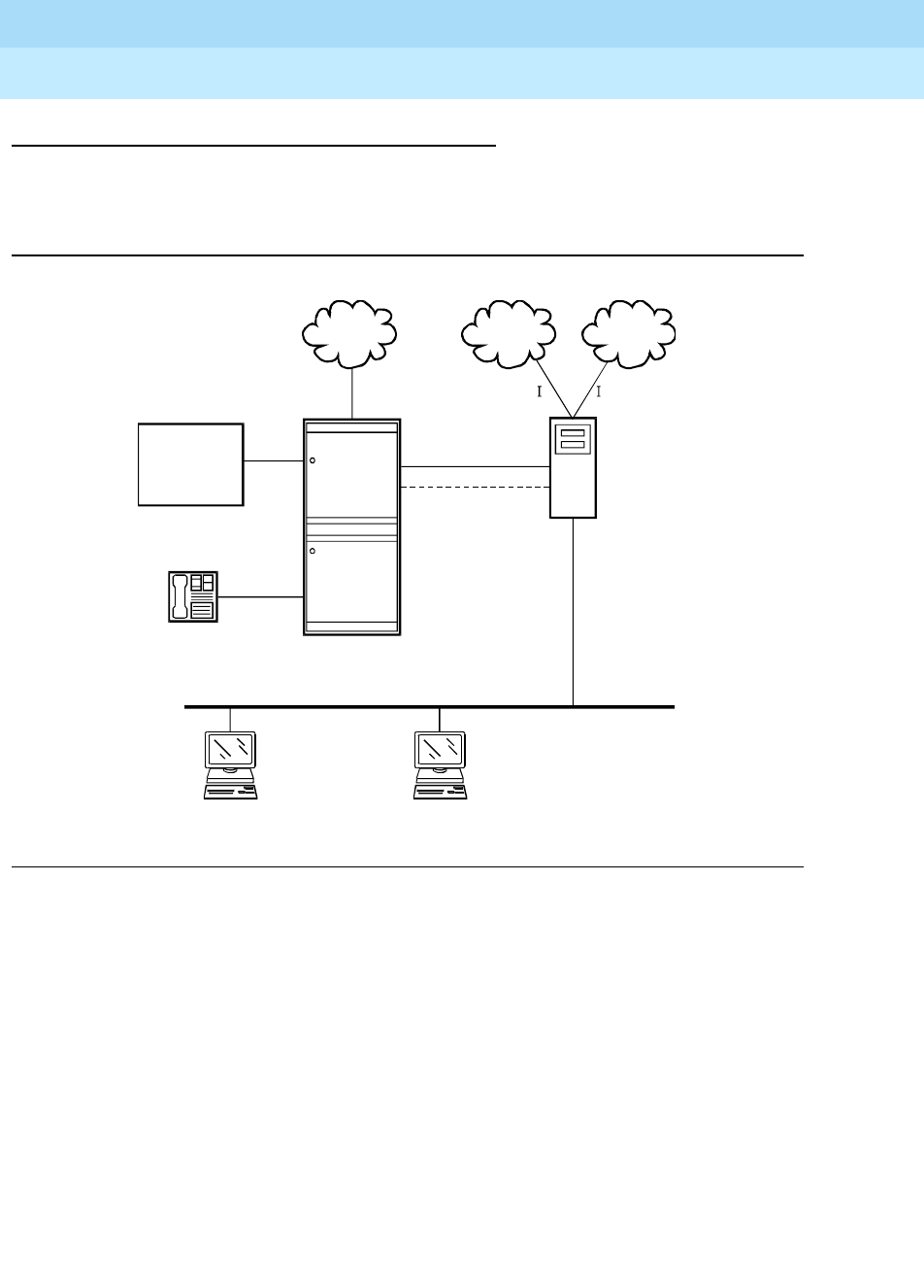
DEFINITY Enterprise Communications Server Release 6
Administration and Feature Description
555-230-522 Issue 4
May 1998
Multimedia
Page 11-5Multimedia Applications Server Interface
11
MASI configurations
There are several ways to set up combinations of MASI nodes and DEFINITY
servers.The following figures depict several possible configurations.
Figure 11-1. MASI domain of one DEFINITY ECS and one MMCX
The parts of this drawing, for MASI, are as follows:
■Trunk 1 — This is any type of trunk connection to the public network.
■Trunk 2 — This is the link between the DEFINITY ECS and the MMCX, and
requires a TN464C or later DS1 circuit pack. You administer this link as an
ISDN-PRI trunk group, a MASI path and an NCA-TSC.
■I1 and I2 — These are MMCX interfaces to destinations other than
DEFINITY. Administer as MASI trunks.
■E1 and E2 — Endpoints (terminals) belonging to the MMCX. Administer as
MASI terminals.
■MMCX — Determine a node number for each MMCX server. This can be
any number from 1–15. Once established, DEFINITY informs the MMCX of
its node number.
DEFINITY
PSTN PSTN WAN
AUDIX
S1
Trunk 2
Trunk 1
MMCX
1
DEFINITY
1
LAN
E1 E2
c
y
dfdda1 LJK 071597
12
SG1
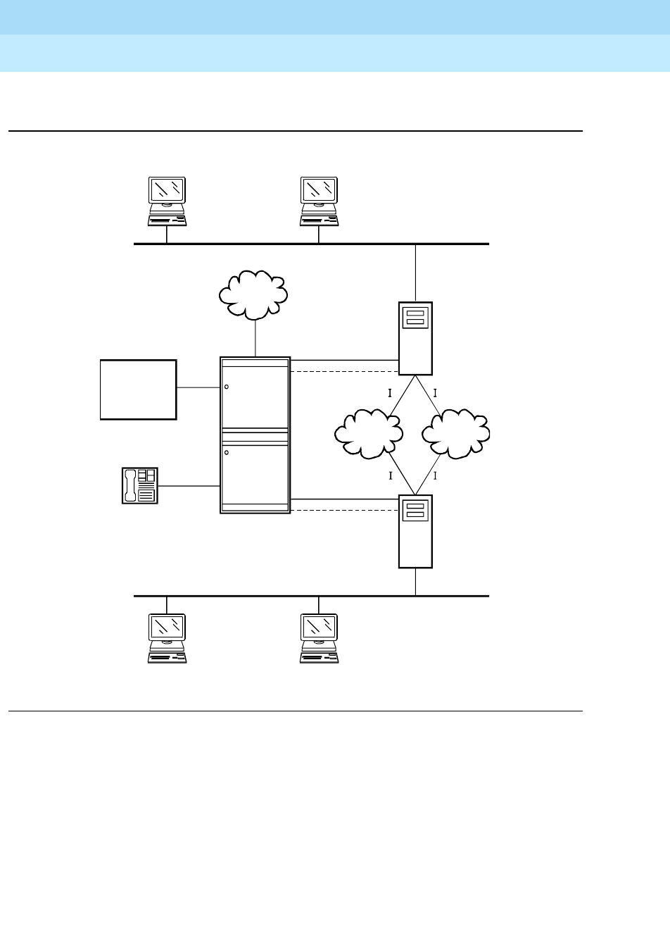
DEFINITY Enterprise Communications Server Release 6
Administration and Feature Description
555-230-522 Issue 4
May 1998
Multimedia
Page 11-6Multimedia Applications Server Interface
11
■S1 — DEFINITY station.
Figure 11-2. MASI domain of one DEFINITY and two (or more) MMCXs
DEFINITY
PSTN
PSTN WAN
AUDIX
S1
Trunk 1
Trunk 3
Trunk 2
SG2
SG1 MMCX
1
MMCX
2
DEFINITY
1
LAN
LAN
E1
E3
E2
E4
c
y
dfdda2 LJK 071597
34
12
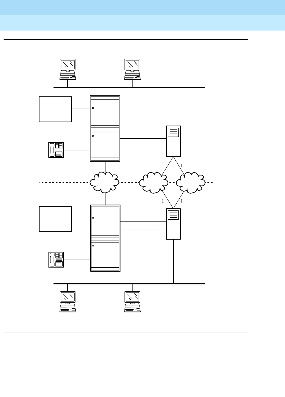
DEFINITY Enterprise Communications Server Release 6
Administration and Feature Description
555-230-522 Issue 4
May 1998
Multimedia
Page 11-7Multimedia Applications Server Interface
11
Figure 11-3. Two separate MASI domains
DEFINITY
PSTN PSTN WAN
AUDIX
S1
Trunk 1
Trunk 4
Trunk 3
Trunk 2
SG2
SG1
MMCX
1
MMCX
2
DEFINITY
1
DEFINITY
AUDIX
S2
DEFINITY
2
LAN
LAN
E1
E3
E2
E4
cydfdda3 LJK 071897
34
12
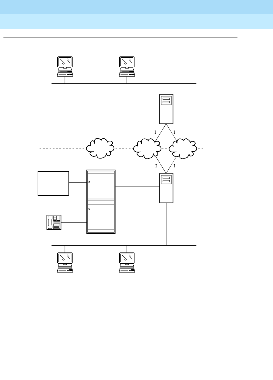
DEFINITY Enterprise Communications Server Release 6
Administration and Feature Description
555-230-522 Issue 4
May 1998
Multimedia
Page 11-8Multimedia Applications Server Interface
11
Figure 11-4. One MASI domain, and one non-MASI MMCX
The MASI node must be directly connected to the DEFINITY ECS for MASI
features to work. In this configuration, terminals that belong to MMCX 2 (E3 and
E4), do not take advantage of MASI capabilities.
DEFINITY
PSTN PSTN WAN
INTUITY
S1
Trunk 1
Trunk 2
SG1
MMCX
1
MMCX
2
DEFINITY
1
LAN
LAN
E1
E3
E2
E4
cydfdda4 LJK 071897
34
12

DEFINITY Enterprise Communications Server Release 6
Administration and Feature Description
555-230-522 Issue 4
May 1998
Multimedia
Page 11-9Multimedia Applications Server Interface
11
How to administer MASI
This section discusses the administration required to make MASI work. You
perform most of this administration from the DEFINITY SAT. However, there are a
few things you must do at the MMCX administration terminal. This section
sometimes refers to the chgmasi command. This is the command you use to
administer MASI parameters on the MMCX. For more information about using the
chgmasi command, refer to your
MMCX Technical Reference
.
Step 1 — Establish customer options (Lucent
Technologies)
A Lucent Technologies representative must activate MASI using the
System-Parameters Customer-Options form. The representative should also
verify that ISDN-PRI (R6r and later configurations) or ISDN-PRI over PACCON
(R6vs/si/csi and later configurations), and AAR/ARS are enabled. The value of
the G3 Version field must be V5 or higher. The actual software load must be R6.1
or higher.
On the MMCX, MASI must be enabled using the chgmasi command.
Step 2 — Establish maintenance parameters and
alarming options (Lucent Technologies)
Ensure that the Maintenance-Related System Parameters form, Packet Bus
Activated field = y.
Using the set options command (Lucent Technologies init or inads logins only),
set MASI alarming options. For more information, see
DEFINITY ECS
Maintenance
for the appropriate model.
Step 3 — Establish the physical connection
Establish the physical connection between the DEFINITY ECS and the MMCX.
For more information about installing the cables, see
Installation for Adjuncts and
Peripherals
.
Step 4 — Administer circuit pack
Using the DS1 Circuit Pack form, verify that the DS1 circuit pack you use to
establish the MASI link is administered as follows:
■Bit Rate = 1.544
■Line Coding = b8zs
■Line Compensation = 1
■Signaling Mode = isdn-pri
■Interface = network

DEFINITY Enterprise Communications Server Release 6
Administration and Feature Description
555-230-522 Issue 4
May 1998
Multimedia
Page 11-10Multimedia Applications Server Interface
11
■Country Protocol = 1
■Protocol Version = a
Step 5 — Administer a signaling group
For each MASI node, you need to establish a unique signaling group. Use the
command add signaling-group xxx to access the Signaling Group form.
Screen 11-1. Signaling Group Form (Page 1 of 5)
For each link, establish a Non-Call Associated Temporary Signaling Connection
(NCA-TSC) with the following attributes:
■Associated Signaling — MASI requires Facility Associated Signaling, so
this field must be set to y.
■Primary D-channel — Enter a 6- to 7-character port number associated
with the DS1 Interface circuit pack port. The port address of the PRI that
carries D-channel signaling.
The entry breaks down as follows:
The port number is used to assign the primary D-channel in the Signaling
Group. For 24-channel facilities, the 24th port is assigned as the
D-channel. For 32-channel facilities, the 16th port is assigned as the
D-channel.
Characters Meaning Value
1-2 Cabinet Number 1 – 44 (R5r and later configurations)
1 – 3 (R5si and later configurationsi)
1 (R5vs and later configurations)
3 Carrier A – E
4-5 Slot Number 01 – 20
6-7 Port 16 or 24
Page 1 of 5
SIGNALING GROUP
Group Number: _ Associated Signaling? y Max number of NCA TSC: __
Primary D-Channel: ______ Max number of CA TSC: __
Trunk Group for NCA TSC: __
Trunk Group for Channel Selection: ___

DEFINITY Enterprise Communications Server Release 6
Administration and Feature Description
555-230-522 Issue 4
May 1998
Multimedia
Page 11-11Multimedia Applications Server Interface
11
■Max Number of NCA TSC — For MASI, this must be 1.
■Max number of CA TSC — Leave the default of 0.
■Trunk Group For NCA TSC — This can be left blank.
■Trunk Group for Channel Selection — This can be left blank.
Screen 11-2. Administered NCA TSC Assignment page of the Signaling Group form
■Service/Feature — Leave blank.
■As-needed Inactivity Time-out (min) — This field only applies to
as-needed NCA-TSCs. Since MASI requires a permanent connection,
leave blank.
■TSC Index — This display-only field specifies the administered
NCA-TSCs assigned.
■Local Ext — Enter a valid, unassigned DEFINITY ECS extension. This
extension does not need a port assignment and does not need to
correspond to any other administration.
■Enabled — Enter y to enable the administered NCA-TSC. You may want
to wait to enable this link until all other administration is in place. If this is y,
DEFINITY ECS attempts to establish the connection as soon as you submit
the form. This may cause your system to alarm, if other administration is
not finished.
■Establish — Used to indicate the strategy for establishing this
administered NCA-TSC. Enter permanent for MASI.
ADMINISTERED NCA TSC ASSIGNMENT Page 2 of 5
Service/Feature: __________ As-needed Inactivity Time-out (min): __
TSC Local Mach.
Index Ext. Enabled Established Dest. Digits Appl. ID
1: _____ _ _________ _______________ _______ __
2: _____ _ _________ _______________ _______ __
3: _____ _ _________ _______________ _______ __
4: _____ _ _________ _______________ _______ __
5: _____ _ _________ _______________ _______ __
6: _____ _ _________ _______________ _______ __
7: _____ _ _________ _______________ _______ __
8: _____ _ _________ _______________ _______ __
9: _____ _ _________ _______________ _______ __
10: _____ _ _________ _______________ _______ __
11: _____ _ _________ _______________ _______ __
12: _____ _ _________ _______________ _______ __
13: _____ _ _________ _______________ _______ __
14: _____ _ _________ _______________ _______ __
15: _____ _ _________ _______________ _______ __
16: _____ _ _________ _______________ _______ __

DEFINITY Enterprise Communications Server Release 6
Administration and Feature Description
555-230-522 Issue 4
May 1998
Multimedia
Page 11-12Multimedia Applications Server Interface
11
■Dest. Digits — A valid MMCX extension. This must correspond to the
value of the
tscnum
argument to the chgmasi command.
NOTE:
These digits are sent as entered to the destination MMCX; no routing
or other digit manipulation is performed.
■Appl. — Specifies the application this administered NCA-TSC is going to
be used for. Enter masi.
■Machine ID — Used to indicate the MASI node to which this administered
NCA-TSC is connected. This number should be the same as the MASI
node number found on other forms.
How to list TSCs or determine status of the TSC
To determine which TSCs are designated for MASI, use the list masi tsc
command.
Screen 11-3. MASI Temporary Signaling Connections (TSC) Display
This command displays the following:
■Sig Grp — The number of the signaling group to which this TSC belongs
■Primary D-Channel — Port location of the Primary D-channel
■TSC Index — The number of the MASI TSC within the signaling group
■Local Ext. — DEFINITY extension associated with the TSC
■Enabled — Indicates the state of the connection - enabled (y/n)
■Established — Value of established flag (as-needed/permanent)
■Dest. Digits — The MMCX extension that indicates the TSC destination
■Mach. ID — MASI node number
Once you establish and enable the signaling group, you need to verify that it is
active. Use the command status signaling-group signaling-group# or status
MASI TEMPORARY SIGNALING CONNECTIONS (TSC)
Sig. Primary TSC Local Mach.
Grp D-Chan Index Ext. Enabled Established Dest. Digits ID
xxx xxxxxxx xxx xxxxx x xxxxxxxx xxxxxxxxxxxxxxx xx
xxx xxxxxxx xxx xxxxx x xxxxxxxx xxxxxxxxxxxxxxx xx
xxx xxxxxxx xxx xxxxx x xxxxxxxx xxxxxxxxxxxxxxx xx

DEFINITY Enterprise Communications Server Release 6
Administration and Feature Description
555-230-522 Issue 4
May 1998
Multimedia
Page 11-13Multimedia Applications Server Interface
11
tsc-administered signaling-group# [/tsc-index] [print] to determine if the link
is active.
Step 6 — Administer ISDN-PRI trunk group
Use the command add trunk-group xxx to access the Trunk Groups form. For a
more detailed description of the ISDN-PRI trunk group, see ‘‘ISDN-PRI trunk
group’’ on page 7-219.
Establish an ISDN-PRI trunk group with the following attributes:
Page 1
■Group Type = isdn-pri
■TAC = valid TAC that conforms to your existing dial plan
■Direction = two-way
■Service Type = tie
■CDR Reports = n
You must also administer the PRI link from the MMCX to the ECS, using the
MMCX administration terminal. See the
MMCX Technical Reference
for
information on the addpri command.
Step 7 — Administer MASI Path Parameters
Use the change masi path-parameters command to access the MASI Path
Parameters form.
Screen 11-4. MASI Path Parameters form
MASI PATH PARAMETERS
Near-End Path Extension: _____
MASI Node Trunk Group Far-End Path Termination Number
1 __ __________________
2 __ __________________
3 __ __________________
4 __ __________________
5 __ __________________
6 __ __________________
7 __ __________________
8 __ __________________
9 __ __________________
10 __ __________________
11 __ __________________
12 __ __________________
13 __ __________________
14 __ __________________
15 __ __________________

DEFINITY Enterprise Communications Server Release 6
Administration and Feature Description
555-230-522 Issue 4
May 1998
Multimedia
Page 11-14Multimedia Applications Server Interface
11
Establish a MASI Path with the following attributes:
■Near-End Path Extension — An unassigned DEFINITY extension. When
using the chgmasi command to administer the MMCX, this is the farpath
extension. See the
MMCX Technical Reference
for more information.
■MASI Node — The node number for the MMCX. For each MMCX/MASI
node, this number must be the same everywhere it occurs (signaling
group, masi trunk group, and masi terminal forms).
■Trunk Group — This is the DEFINITY trunk group number for the
ISDN-PRI trunk that will be used to establish call paths.
■Far-End Path Termination Number — This is an unassigned MMCX
extension. When using the chgmasi command to administer the MMCX,
this is the nearpath extension. See the
MMCX Technical Reference
for
more information.
Step 8 — Administer MASI trunk groups
You use the MASI trunk group form to define MMCX interfaces that interconnect
MASI nodes, or that connect MMCX nodes to another private switch or central
office. Examples of MMCX interfaces include:
■PRI trunks linking MMCX servers
■PRI trunks linking MMCX to the PSTN
■PRI trunks from MMCX to DEFINITY that are used for purposes other than
MASI
■LAN interfaces linking MMCX servers
Use the command add masi trunk-group xxx (or ‘next’) to access the MASI
Trunk Group form. The trunk group number must not be assigned, and you
cannot exceed the maximum total trunks for your system. Valid values for xxx are
unused DEFINITY trunk group numbers between 1–96 for R6vs/si/csi and later
configurations, and 1–120 for R6r and later configurations.

DEFINITY Enterprise Communications Server Release 6
Administration and Feature Description
555-230-522 Issue 4
May 1998
Multimedia
Page 11-15Multimedia Applications Server Interface
11
Screen 11-5. MASI Trunk Group Form
■Group Number — This field displays the MASI trunk group number. This
is the number assigned when executing the add masi trunk-group
command.
■CDR Reports — Valid entries are “y,” “n,” and “r.” Default is “y.”
— If you enter “y,” CDR records will be generated by completed
outgoing calls terminated on this trunk group. If incoming calls are
being recorded (the Record Outgoing Calls Only field on the CDR
System Parameters form is set to “n”), then a single CDR record will
be generated for answered calls with the call duration.
— If you enter “n,” no CDR records will be generated by calls
originated by or terminated on this trunk group.
■Group Name — Enter a unique name that identifies the trunk group. Up to
27 characters can be used; default is “INCOMING CALL.”
■COR — Enter a class of restriction (COR) number (0–95) that reflects the
desired restriction; default is “1.”
■TN — This field displays the Tenant Partition number. For R6 and later
configurations, all MASI trunks are associated with Tenant 1.
■TAC — Enter the trunk access code (TAC) that identifies the trunk group
on CDR reports. You must assign a different TAC to each MMCX interface.
Valid entries conform to the dial plan (1–4 digits, * and # are valid first
digits).
■MASI Node Number — The node number assigned to this MMCX
machine.
■Remote Group Number — This is the number of the remote trunk group.
For ISDN-PRI interfaces, valid values are any number 1–8; for LAN or WAN
calling interfaces, the value must be 9. The combination of MASI Node
Number and Remote Group Number must be unique. Remote group
number corresponds to the group number on the MASI node.
MASI TRUNK GROUP
Group Number: 15 CDR Reports? y
Group Name: INCOMING CALL______________ COR: 1_ TN: 1 TAC: 915_
MASI Node Number: __ Remote Group Number: _

DEFINITY Enterprise Communications Server Release 6
Administration and Feature Description
555-230-522 Issue 4
May 1998
Multimedia
Page 11-16Multimedia Applications Server Interface
11
How to view a list of all MASI trunk groups
To view a list of all the MASI trunks administered on the ECS, use the command
list masi trunk-group.
Screen 11-6. List masi trunk-group output
How to determine the status of MASI trunk groups
To determine the status of a specific MASI trunk, use the command status masi
trunk-group xxx, where xxx is the trunk group number. This command provides
descriptive information about the trunk, and the number of currently active trunk
calls.
Screen 11-7. Status masi trunk-group output
Step 9 — Administer MASI terminals
Use the add masi terminal xxxxx or next command to administer each MASI
terminal as a MASI terminal. You use available extensions on the ECS, so they
need to conform to DEFINITY ECS dial plan. The extension must match the
MASI TRUNK GROUP
Group Node Remote
Number TAC Group Name Number Grp No. CDR COR TN
xxx xxxx xxxxxxxxxxxxxxxxxxxxxxxxxxx xx x x xx xxx
MASI TRUNK GROUP STATUS
Group Number: xxx Number of Active MMCX Trunk Calls: xxx
MASI Node Number: xx
Remote Group Number: xxx

DEFINITY Enterprise Communications Server Release 6
Administration and Feature Description
555-230-522 Issue 4
May 1998
Multimedia
Page 11-17Multimedia Applications Server Interface
11
DEFINITY dial plan, and for the add command, the extension must not already be
in use.The extension of the MASI terminal must match the number of the MASI
terminal.
DEFINITY users dial the MASI Terminal Extension to reach MMCX users.
NOTE:
Anytime you add a terminal or other extension to the MMCX, you must
administer a corresponding MASI terminal on DEFINITY. If you do not, you
will not be able to dial this extension from DEFINITY.
Screen 11-8. MASI Terminal Form — page 1
■Extension — This field displays the extension that you entered on the
command line.
■BCC — This field displays the bearer capability class of the terminal, and
identifies the type of traffic the terminal supports. For MASI, this is always
0, for voice or voice-grade data.
■MASI Node Number — The number of the node on which this terminal
resides.
■TN — The tenant partition in which this terminal resides. At present, all
MASI terminals must reside within tenant 1. This field is display-only, and
always 1.
■COR — The class of restriction associated with this terminal.
■Name — The name associated with the terminal. This can be any
alphanumeric string up to 27 characters.
■Send Display Info — Indicates whether DEFINITY should forward display
information associated with a call. Set to y.
MASI TERMINAL
Extension: 1000 BCC: 0
MASI Node Number: __ TN: 1__
COR: 1_
Name: ___________________________
TERMINAL OPTIONS
Send Display Info? y

DEFINITY Enterprise Communications Server Release 6
Administration and Feature Description
555-230-522 Issue 4
May 1998
Multimedia
Page 11-18Multimedia Applications Server Interface
11
Screen 11-9. MASI Terminal form — page 2
■LWC Reception — This field indicates whether the terminal can receive
Leave Word Calling messages. Valid values are none, audix, and spe (for
R6r and later configurations) or mas-spe (for R6vs/si/csi and later
configurations). SPE-based LWC is not supported for MASI terminals.
However, if DEFINITY AUDIX is used without a Data Control Link, you must
administer MASI terminals to receive SPE-based LWC messages. For
such cases, the LWC feature is used by AUDIX to activate and deactivate
message waiting lamps on MASI terminals.
■CDR Privacy — Indicates whether CDR Privacy is supported for this
terminal. See ‘‘Call Detail Recording’’ on page 4-167 for more information.
■AUDIX Name — This field only appears on R6r and later configurations.
This field contains the name of the AUDIX adjunct for LWC messages. If
LWC reception field is set to audix, this field must contain a name. The
name must match a machine name on the Adjunct Names form.
Screen 11-10. MASI Terminal Form — page 3
MASI TERMINAL
FEATURE OPTIONS
LWC Reception: none___
CDR Privacy? n
AUDIX Name: ________
MASI TERMINAL
SITE DATA
Room: _______
Jack: _____
Cable: _____
Floor: _______
Building: _______
BUTTON ASSIGNMENTS
1: call-appr

DEFINITY Enterprise Communications Server Release 6
Administration and Feature Description
555-230-522 Issue 4
May 1998
Multimedia
Page 11-19Multimedia Applications Server Interface
11
■Room — Enter up to 10 characters to identify the MASI terminal location.
This field may be blank.
■Jack — Enter up to 5 characters to identify the location where the MASI
terminal is connected. This field may be left blank.
■Cable — Enter up to 5 characters to identify the cable that connects the
MASI terminal to the system. This field may be left blank.
■Floor — Enter up to 7 characters to identify the floor where the MASI
terminal is located.
■Building — Enter up to 7 characters to identify the building where the
MASI terminal is located. Valid entries are listed in the site table.
■Button Assignments — This field contains a call appearance button and
is display only.
Duplicate masi terminal
Once you have one MASI terminal administered to your liking, you can use the
duplicate masi terminal command to administer other stations with the same
characteristics.
Screen 11-11. Duplicate MASI Terminal form
How to list and status MASI terminals
To view a list of all the MASI terminals administered on the ECS, use the
command list masi terminals.This command only lists terminals within the
domain of the DEFINITY ECS from whose SAT you issue the command.
MASI TERMINAL
Ext Name Room Jack Cable
77777 ___________________________ _________ _____ _____
77778 ___________________________ _________ _____ _____
77779 ___________________________ _________ _____ _____
77781 ___________________________ _________ _____ _____
77782 ___________________________ _________ _____ _____
77783 ___________________________ _________ _____ _____
_____ ___________________________ _________ _____ _____
_____ ___________________________ _________ _____ _____
_____ ___________________________ _________ _____ _____
_____ ___________________________ _________ _____ _____
_____ ___________________________ _________ _____ _____
_____ ___________________________ _________ _____ _____
_____ ___________________________ _________ _____ _____
_____ ___________________________ _________ _____ _____
_____ ___________________________ _________ _____ _____

DEFINITY Enterprise Communications Server Release 6
Administration and Feature Description
555-230-522 Issue 4
May 1998
Multimedia
Page 11-20Multimedia Applications Server Interface
11
Screen 11-12. List MASI Terminal output
To view the active or idle status of a specific MASI terminal, use the command
status masi terminal (extension).
Screen 11-13. Status masi terminal command
To determine which extension you assigned as the MASI Near-End Path
Termination extension, use the command list extension-type. This command
displays the extension number and type (attendant, masi-terminal, etc.), as well
as other information about the extension.
MASI TERMINALS
Node
Ext Name Number CDR COR TN
xxxxx xxxxxxxxxxxxxxxxxxxxxxxxxxx xx x xx xxx
xxxxx xxxxxxxxxxxxxxxxxxxxxxxxxxx xx x xx xxx
xxxxx xxxxxxxxxxxxxxxxxxxxxxxxxxx xx x xx xxx
xxxxx xxxxxxxxxxxxxxxxxxxxxxxxxxx xx x xx xxx
GENERAL STATUS
TYPE: MASI Service State: active
Extension: 54001
MASI Node Number: 14

DEFINITY Enterprise Communications Server Release 6
Administration and Feature Description
555-230-522 Issue 4
May 1998
Multimedia
Page 11-21Multimedia Applications Server Interface
11
Screen 11-14. List extension type
Step 10 — Administer features
AAR/ARS
1. AAR/ARS is an optional feature on DEFINITY, and you need to purchase
this option to use it with MMCX. To verify that this feature is enabled, use
the command display system-parameters customer-options. If it is not
enabled, call your Lucent Technologies representative.
2. The MMCX dial plan must use the same feature access codes as the
DEFINITY ECS. If this is not already the case, modify the MMCX dial plan
using the chgdp command. See the
MMCX Technical Reference
for more
information.
3. Include this feature access code in the chgmasi command.
CDR
1. To get call detail records for calls over MMCX interfaces, set
CDR Reports = y on the MASI Trunk Group form.
2. To get call records for calls over the ISDN-PRI trunk group, set
CDR Reports = y on the ISDN-PRI Trunk Group form.
3. To track calls between a MASI terminal and other MASI terminals or
DEFINITY stations, enter the MASI terminal extension on the Intraswitch
CDR form.
4. Enter n in the Record Non-Call Assoc TSC field on the CDR System
Parameters form.
NOTE:
If you use the same PRI trunks for MASI and non-MASI calls, it is strongly
recommended that you do not enable CDR for these calls. Establish a
separate trunk group for non-MASI calls and set CDR Reports = n.
EXTENSION TYPE
Cv1/
Ext Type Name COR TN COS Cv2
--- ---- ---- --- -- --- ----
1234 masi-terminal 1 1 1
4077 term-masi-path-call

DEFINITY Enterprise Communications Server Release 6
Administration and Feature Description
555-230-522 Issue 4
May 1998
Multimedia
Page 11-22Multimedia Applications Server Interface
11
Coverage
To establish coverage from a MASI terminal to AUDIX:
1. Use the MMCX user interface to enter the AUDIX hunt group extension as
the coverage point. You cannot use DEFINITY coverage administration for
MASI terminals.
2. If AUDIX ports are not administered on DEFINITY, do so.
3. Set up the MASI terminal as an AUDIX subscriber. Enter the MASI terminal
extension in the extension field on the Subscriber Administration form.
To establish coverage from a MASI terminal to another MMCX terminal or
DEFINITY station:
1. Use the MMCX user interface to enter the desired extension as the
coverage point for the MASI terminal. You cannot use DEFINITY coverage
administration for MASI terminals.
Step 11 — Verify administration
Make test calls from DEFINITY to MMCX, ensure that you can indeed place and
receive calls.
Call an unattended MASI terminal. Verify that the call goes to AUDX. Retrieve the
call from the MASI terminal. Verify that all works as expected.
MASI command permissions
If you are the super-user for your system, you can restrict other administrative
logins from changing MASI administration. To do this, use the change
permissions (login-ID) command. Enter y in the Additional Restrictions field,
then move to the Restricted Object List page of the form.
You may restrict the following MASI-related objects:
■masi-path-parameters
■masi-terminal
■masi-trunk-group
■masi-tsc

DEFINITY Enterprise Communications Server Release 6
Administration and Feature Description
555-230-522 Issue 4
May 1998
Multimedia
Page 11-23Multimedia Applications Server Interface
11
Detailed description of features
AAR/ARS
MMCX can take advantage of advanced routing features for voice-only calls to
the PSTN or a DEFINTY system private network. Users must enter the AAR/ARS
access code before the rest of the dialed digits. MASI will route the call over the
DEFINITY private network (AAR) or the public network (ARS), based on the digits
supplied by the MMCX user.
Routing patterns must contain only trunk groups that actually terminate on the
DEFINITY ECS. Calls from one MMCX to another do not use AAR/ARS.
Authorization codes are not supported.
Call Detail Recording
Using the MASI link, DEFINITY is able to track call detail information for calls
made using MMCX terminals and interfaces. CDR records all calls originating
from or terminating at a MASI terminal. MASI CDR does not record ineffective call
attempts when all MASI paths are busy.
The Resource Flag value of 8 indicates a MASI call. This field appears in
unformatted, int-isdn, expanded and customized CDR formats. For formats other
than these, you can determine that a call involves a MASI terminal or trunk by the
TAC, dialed number or calling number fields.
The following are the CDR capabilities of MASI. Administration information is
under the heading ‘‘How to administer MASI’’ on page 11-9.
■Incoming/Outgoing Trunk Call Splitting
Call splitting does not produce separate records for MMCX calls that are
transferred or conferenced.
■Intraswitch CDR
You can administer intraswitch CDR to monitor MASI terminals. To do this,
simply add the MASI terminal extension on the Intraswitch CDR form.
DEFINITY then monitors calls from MASI terminals to other MASI terminals,
and calls between MASI terminals and DEFINITY stations.
■CDR Privacy
You can administer a MASI terminal for CDR Privacy.
■Account Code Dialing and Forced Entry of Account Codes
This is not supported for MASI terminals. Therefore, make sure the COR
you assign does not force entry of account codes.
■Trunk CDR
You can get call detail records for all incoming and outgoing calls made
over MMCX interfaces.

DEFINITY Enterprise Communications Server Release 6
Administration and Feature Description
555-230-522 Issue 4
May 1998
Multimedia
Page 11-24Multimedia Applications Server Interface
11
Call redirection / Voice-messaging access
MMCX users can enter a DEFINITY extension, including an AUDIX hunt group,
Callmaster agent, attendant console or voice terminal as their coverage point.
If AUDIX is established as the MASI terminal’s coverage point, the MASI terminal
receives message waiting indication, and dials the AUDIX hunt group extension
to retrieve messages. Once connected to AUDIX, operation for the MMCX user is
the same as for a DEFINITY station user, including use of # to identify the
extension, if desired.
NOTE:
It is not possible to determine the call coverage status of a MASI terminal.
DEFINITY tracks calls to MASI terminals that follow the autonomous coverage
path from the MASI terminal. MMCX calls redirected to DEFINITY stations contain
display information.
MASI terminals that dial AUDIX directly, or that place calls to MASI terminals that
cover to AUDIX, do not receive ringback if all AUDIX ports are busy. Instead,
these callers see a message that the called party is busy, and the call drops.
Transfer
MASI terminals cannot transfer calls to DEFINITY stations, and cannot transfer a
call to another MASI terminal if the call involves a DEFINITY station.
Conferencing
Conferences can involve both MASI terminals and DEFINITY stations, and either
one may initiate the conference. DEFINITY stations participate in such
conferences in voice-only mode. If an MMCX user initiates a conference that
involves DEFINITY stations, the conference will drop when the initiator drops from
the call. If a DEFINITY station initiates the conference, that station may drop
without affecting the other conferees.
Status tracking - terminals and trunks
DEFINITY tracks the active/idle status of all MASI terminals, and monitors traffic
over MMCX interfaces.
Trunk groups
For MASI purposes, there are two kinds of trunk groups: the ISDN-PRI trunk
groups that serve as paths for establishing calls between DEFINITY stations or
trunks and MASI terminals or interfaces, and the remote trunks that are interfaces
from the MMCX to other entities. Each MASI remote trunk group appears to
DEFINITY as a single unit, with no concept of members within the group.

DEFINITY Enterprise Communications Server Release 6
Administration and Feature Description
555-230-522 Issue 4
May 1998
Multimedia
Page 11-25Multimedia Applications Server Interface
11
NOTE:
You cannot test, busy out, or release MASI remote trunk groups, since you
cannot dial a MASI remote trunk TAC from DEFINITY. The TAC merely
identifies the trunk to DEFINITY for status and CDR.
You cannot administer MASI trunks as part of DEFINITY route patterns.
Interactions & Unsupported Features
We can generalize feature interactions to some extent. For example, since there
are no buttons available to a MASI terminal, any feature that requires a button is
also not available. MASI cannot support features that require the user to dial a
trunk access code for a MASI remote trunk, or a feature access code other than
AAR/ARS. The MMCX dial plan may contain only those feature access codes that
are supported.
!CAUTION:
DO NOT ADMINISTER the following features! The following features are not supported
for use over the MASI link, and Lucent Technologies cannot responsible for the results
if you attempt to administer them.
Unsupported Call Center features
■ASAI — You must not administer a MASI terminal in an ASAI domain. MASI
terminals and MMCX trunks are not monitored by ASAI. It may be possible
for a MASI terminal to place a call to a DEFINITY station that is part of an
ASAI domain. ASAI will not be blocked from controlling this call, but there
may be unpredictable results. The same is true for calls originating from
an ASAI domain terminating at MASI terminals, and for ASAI-monitored
hunt groups that contain MASI terminals.
■Automatic Call Distribution — You must not include a MASI terminal
extension as part of an ACD hunt group. You must not mix MASI
administration with anything related to ACD, including Outbound Call
Management and PASTE.
■Call Vectoring — You must not include MASI terminal extensions in any
step of a vector.
Unsupported Basic features
■Bridged Call Appearances — You must not administer a bridged
appearance that involves a MASI terminal.
■Call Coverage — You must not administer a MASI terminal in a DEFINITY
station’s coverage path.
■Call Forwarding — You must not forward a DEFINITY station to a MASI
terminal.

DEFINITY Enterprise Communications Server Release 6
Administration and Feature Description
555-230-522 Issue 4
May 1998
Multimedia
Page 11-26Multimedia Applications Server Interface
11
■Call Pickup — You must not administer a MASI terminal as part of a pickup
group.
■Intercom — You must not administer MASI terminals as members of any
type of intercom group.
■Manual Message Waiting — You must not administer a manual message
waiting button (man-msg-wt) with a MASI terminal as the referenced
extension.
■Manual Signaling — You must not administer a manual signaling button
(signal) with a MASI terminal as the referenced extension.
■Night Service — You must not administer a MASI terminal as a night
service destination.
■Pull transfer — MASI terminals cannot perform a pull transfer operation.
You must not administer this feature on an ECS where MASI is active. This
applies only in Italy.
■Station Hunting — You must not administer a MASI terminal as part of a
station hunting path.
■Terminating Extension Groups — You must not administer a MASI terminal
as part of a TEG.
Other interactions
The following section describes feature behaviors that may not be as expected,
but that are not likely to be destructive.
Attendant features
■Dial Access to the Attendant — MASI terminals will be able to dial the
attendant access code, if it is administered in the MMCX dial plan.
■Attendant Direct Extension Selection — Attendants are able to access
MASI terminals via DXS buttons and busy lamp indicates status of the
MASI terminal.
■Emergency Access to the Attendant — MASI terminals have emergency
access using the attendant access code, if it is administered in the MMCX
dial plan. However, off-hook alerting is not administrable.
■Attendant Intrusion — Attendants are able to activate intrusion towards
MASI terminals.
■Attendant Override — Attendants are not able to activate override towards
MASI terminals.
■Attendant Recall — MASI terminals cannot activate attendant recall.
■Attendant Remote Trunk Group Select — Attendants cannot use this
feature to select MASI remote trunks.
■Attendant Return Call — Operates normally if a MASI terminal is the called
party.

DEFINITY Enterprise Communications Server Release 6
Administration and Feature Description
555-230-522 Issue 4
May 1998
Multimedia
Page 11-27Multimedia Applications Server Interface
11
■Attendant Serial Call — Serial calls are denied if the calling party is an
MMCX interface.
■Attendant Straightforward Outward Completion — The attendant is able to
complete calls to DEFINITY trunks for MASI terminals.
■Attendant Through Dialing —The attendant can use Through Dialing to
pass dial tone to MASI terminals.
■Attendant Timers — Attendant timers work the same no matter what kind
of terminal is involved.
■Attendant Trunk Group Busy/Warning Indicators — You cannot administer
Busy/Warning indicators for MASI trunks because they are not standard
DEFINITY trunks. However, you can administer these indicators for the
trunk group administered for MASI paths.
■Attendant Trunk Identification — The attendant is not able to identify the
trunk name via button pushes.
Basic features
■Abbreviated Dialing — A DEFINITY station can enter an MMCX extension
in an AD list. However, MASI terminals cannot use AD.
■Administered Connections — MASI terminals must not be the originator
nor the destination of an administered connection.
■Automatic Callback — Automatic callback does not work towards a MASI
terminal.
■Automatic Circuit Assurance — You must not administer a MASI terminal
as an ACA referral destination. You cannot administer ACA for MASI
remote trunks.
■Busy Verification of Terminals and Trunks — You cannot use Busy
Verification for MASI terminals or remote trunks.
■Call Detail Recording — CDR Account Code Dialing and Forced Entry of
Account Codes are not supported for MASI terminals. See Call Detail
Recording in Detailed Description for more information.
■Call Park — The attendant can park calls at the extension of a MASI
terminal, but users can only retrieve these calls from a DEFINITY station,
since MASI terminals cannot dial the Answer Back FAC.
■Data Call Setup — DEFINITY users cannot place data calls to MASI
terminals.
■Facility Busy Indication — You can use FBI to track the status of MASI
terminals. The FBI button and indicator lamp must be on a DEFINITY
station. You cannot use FBI to track MMCX interfaces.
■Facility Test Calls — DEFINITY users cannot make test calls to MMCX
interfaces.
■Go to Cover — MASI terminals cannot activate this feature.

DEFINITY Enterprise Communications Server Release 6
Administration and Feature Description
555-230-522 Issue 4
May 1998
Multimedia
Page 11-28Multimedia Applications Server Interface
11
■Leave Word Calling — The only valid LWC destination for a MASI terminal
is AUDIX. You cannot administer SPE-based LWC. MASI terminals cannot
send LWC messages to DEFINITY stations or MASI terminals.
■Loudspeaker paging — You can administer a MASI terminal as a code
calling extension.
■Malicious Call Trace — MASI terminals cannot initiate malicious call trace.
■Message Retrieval — MMCX users can only retrieve messages through
AUDIX.
■Music on Hold — Music on hold will only be available if a DEFINITY station
has placed the call on hold.
■Override — Executive override does not work towards MASI terminals.
■Priority Calling — Priority calling is not supported for calls to or from MASI
terminals.
■Ringback Queueing — Ringback Queueing is not supported for MASI
terminals.
■Send All Calls — MMCX has an autonomous SAC function. See Call
Redirection for more information.
■Tenant Partitioning — All MASI terminals exist in tenant 1, and you cannot
change the tenant number.
■Time of Day coverage — As with all coverage, DEFINITY does not control
coverage of the MASI terminal.
■Transfer out of AUDIX — A MASI terminal cannot use *T to transfer from
AUDIX to another MASI terminal.
Hospitality features
■Do Not Disturb — MASI terminals cannot activate Do Not Disturb.
Multimedia features
■Multimedia Call Handling — DEFINITY MMCH users are not able to make
H.320 calls to MASI terminals over the MASI link. Calls between MMCX
terminals and MMCH terminals are voice only.

DEFINITY Enterprise Communications Server Release 6
Administration and Feature Description
555-230-522 Issue 4
May 1998
Multimedia
Page 11-29Multimedia Applications Server Interface
11
Troubleshooting
Verify proper operation using the following commands and follow normal
escalation procedures to resolve any failures detected by the demand test.
1. Verify the DS1 trunk using the test board <board location> long
command.
2. Verify the ISDN Signaling Group using the test signaling-group <group
number> command. Also verify proper administration.
3. Verify the temporary signaling connection using the test
tsc-administered <group number> command. Also verify proper
administration.
Common error conditions
If the cable from the ECS to the MMCX becomes disconnected, you should see
alarms raised against ISDN-SGRP and UDS1-BD. In particular, you should
observe ISDN-SGRP errors such as 769, 1793, and 257. To resolve, reconnect
the cable and follow normal test procedures.
If the far-end path termination number is incorrect, you should observe
MASI-PTH error 513. To resolve, correct administration using the MASI Path
Parameters form.
If the Layer 3 TSC is not administered properly or is out of service, you should
observe errors (but no alarms) raised against TSC-ADM. Verify the signaling
group administration and follow normal escalation procedures for TSC-ADM.
What do these errors look like? Is this meant for anyone other than techs?
If the TSC fails to come up even through Layer 2 Signaling Group and below
pass tests, you may run test tsc-administered <group number> to force a
switch heartbeat test, or simply wait 5–10 minutes for the link to recover. This
situation may happen if the switch is rebooted or if the MASI interface is
administered before the MMCX is properly administered.
You may want to use busy port and release port commands to unlock things if
features are not working.

DEFINITY Enterprise Communications Server Release 6
Administration and Feature Description
555-230-522 Issue 4
May 1998
Multimedia
Page 11-30Multimedia Call Handling
11
Multimedia Call Handling
Functional description of MMCH
Multimedia Call Handling (MMCH) enables you to control voice, video, and data
transmissions using your voice terminal and PC. You can conduct video
conferences and route calls like a standard voice call. You can also share PC
applications so that you and your colleagues can collaborate while working from
remote sites. MMCH enhances your voice terminal’s capabilities to place or
receive multimedia calls by taking advantage of DEFINITY ECS’s powerful
call-handling and routing features.
Operations in Basic or Enhanced modes
There are two distinct levels of functionality: Basic and Enhanced. The Basic
mode of operation treats a standard-protocol H.320 multimedia call as a data
call. If the call is redirected, it is converted to a voice call. As a voice call, certain
features are enabled, such as coverage, voice mail, and multiparty video
conferencing. The Enhanced mode of operation allows a multifunction voice
terminal to control a multimedia call like a standard voice call. Spontaneous
video conferencing, call forwarding, call coverage, hold, transfer and park, along
with many routing features, are available to multimedia calls.
Both modes of
operation allow data collaboration between multiple parties using the T.120
standard protocol.
Definitions: MMCH features and components
Multimedia call
A multimedia call, for MMCH, is one that conforms to the H.320 and T.120 suite of
protocol standards. These standards allow video-conferencing packages from
different vendors to communicate with one another. The capabilities of the
individual multimedia-endpoint package can vary, however.
■An H.320 call can contain voice, video and data.
■The bandwidth for MMCH calls is limited to 2 B-channels.
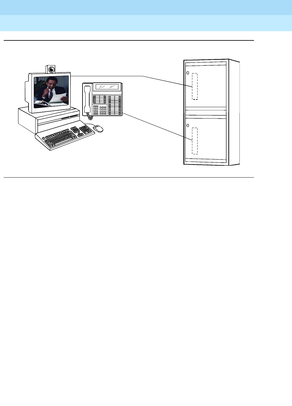
DEFINITY Enterprise Communications Server Release 6
Administration and Feature Description
555-230-522 Issue 4
May 1998
Multimedia
Page 11-31Multimedia Call Handling
11
Figure 11-5. MMCH multimedia complex
Basic multimedia complex
A Basic multimedia complex consists of a BRI-connected multimedia-equipped
PC and a non-BRI-connected multifunction voice terminal administered in Basic
mode. With a Basic multimedia complex, users place voice calls at the
multifunction voice terminal and multimedia calls from the multimedia equipped
PC. Voice calls will be answered at the multifunction voice terminal and
multimedia calls will alert first at the PC and, if unanswered, will next alert at the
voice station. A Basic multimedia complex provides a loose integration of the
voice station and H.320 DVC system.
Enhanced multimedia complex
An Enhanced multimedia complex consists of a BRI-connected
multimedia-equipped PC and a non-BRI-connected multifunction voice terminal
administered in Enhanced mode. The Enhanced multimedia complex acts as
though the PC were directly connected to the multifunction voice terminal. Thus,
voice call control, multimedia call control and call status are enabled at the voice
terminal. An Enhanced multimedia complex provides a tight integration of the
voice station and H.320 DVC system.
Multimedia endpoint
The multimedia endpoint is a user’s PC that has been equipped with an H.320
multimedia package. The PC is physically connected to the DEFINITY ECS with a
BRI line.
BRI
port
circuit
card
DCP
port
circuit
card
DEFINITY
cydfdvc1 LJK 121997
Any vendor’s
H.320 DVC
product
DEFINITY
DCP
multifunction
telephone
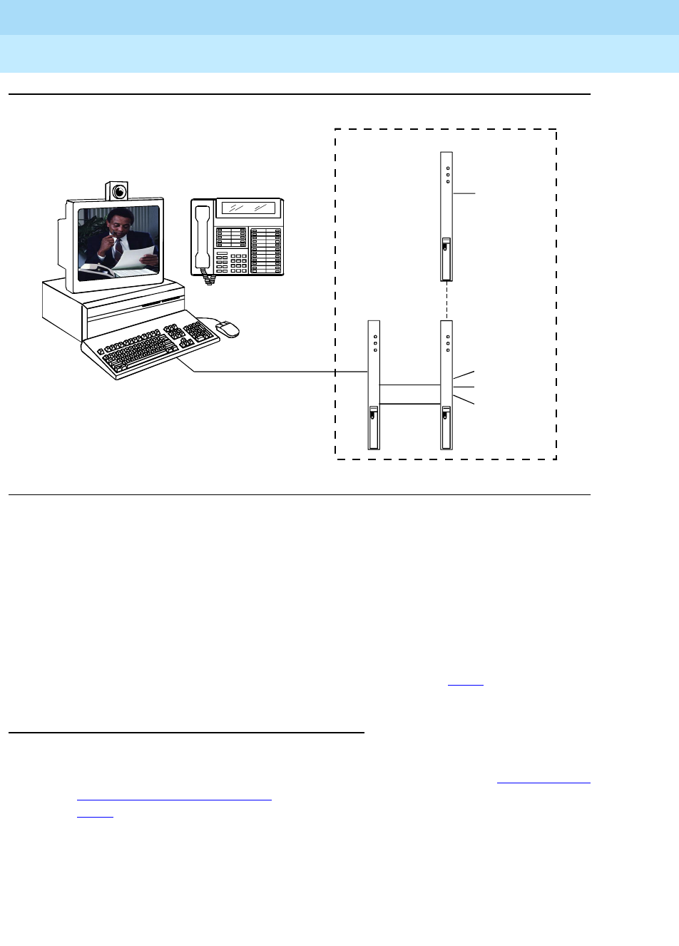
DEFINITY Enterprise Communications Server Release 6
Administration and Feature Description
555-230-522 Issue 4
May 1998
Multimedia
Page 11-32Multimedia Call Handling
11
Figure 11-6. Enhanced MMCH service link
Enhanced mode service link
The service link is the combined hardware and software multimedia connection
between the user’s multimedia endpoint and the DEFINITY ECS which terminates
the H.320 protocol. The service link provides video, data, and, optionally, voice
streams to augment the capabilities of the voice terminal and PC. A service link
only applies to an Enhanced multimedia complex, never to a Basic multimedia
complex. The service link is administered on the station form and can be either
“permanent” or “as-needed.” For detailed information see 11-49.
Feature Description
MMCH’s two levels of functionality for a multimedia complex, Basic and
Enhanced mode, are enabled either by switch administration (see ‘‘System Level
Administration’’ on page 11-41) or by an mm-basic feature button or FAC (see
11-51).
Basic Mode Operation
In Basic Mode:
■All voice-only calls originate at the voice station.
DEFINITY
cydfdvc2 LJK 011498
BRI
H.320
protocols
Audio
conditioning
Audio stream
Video stream
Data stream
VC
MMI

DEFINITY Enterprise Communications Server Release 6
Administration and Feature Description
555-230-522 Issue 4
May 1998
Multimedia
Page 11-33Multimedia Call Handling
11
■All multimedia calls originate with the H.320 DVC system.
■All incoming voice calls attempt to alert at the voice station and receive all
standard voice call treatment.
■All incoming H.320 multimedia calls attempt to alert on the H.320 DVC
system initially. If answered, a 2-way video call will result. The Basic
multimedia complex voice station will not be involved in the call in any
way.
If the H.320 multimedia call is not answered at the H.320 DVC system and
the Basic multimedia complex voice station has the H.320 field
administered to “y”, the call will:
— timeout at the DVC system
— alert at the associated voice station set as a voice-only call
— receive all standard voice call treatment.
■Call control depends on what type of call is being originated.
— Video is received and controlled at the PC.
— Voice is received and controlled at the telephone set.
■The voice station of a Basic multimedia complex must manually add their
multimedia endpoint to a multimedia conference. There is limited support
for multimedia feature interactions. A specific set of voice features work for
multimedia calls.
■Service Links are not used by Basic mode complexes.
■A single number may be used to reach the Basic multimedia complex for
voice or H.320 multimedia calls.
See
‘‘Basic Mode MM complex’’ on page 11-59.
Enhanced Mode Operation
The Enhanced multimedia complex provides a much more tightly coupled
integration of the complex voice station and H.320 DVC system. In Enhanced
Mode:
■Both multimedia and voice calls must originate at the telephone set.
■Voice and multimedia calls can be controlled at the telephone set.
■Conferencing is spontaneous and established just like a voice-only
conference call.
■There is extensive support for multimedia feature interaction. Most voice
features work the same for multimedia calls.
■Service Links can be either “permanent” or “as-needed.”
See
‘‘Enhanced Mode MM complex’’ on page 11-73.

DEFINITY Enterprise Communications Server Release 6
Administration and Feature Description
555-230-522 Issue 4
May 1998
Multimedia
Page 11-34Multimedia Call Handling
11
Physical Installation
The physical components necessary to utilize MMCH capabilities include:
■DEFINITY ECS software (see ‘‘Administration commands’’ on page 11-41).
■H.320 DVC systems that are BRI connected to the DEFINITY ECS.
■Non-BRI multifunction voice terminals.
■DEFINITY TN787 MultiMedia Interface (MMI) and TN788 Voice
Conditioner (VC) boards.
■A T.120 Enhanced Services Module (ESM) server (necessary only if you
plan to do T.210 data collaboration). Connectivity of the ESM requires an
additional TN787 along with a TN2207 DS1 circuit pack.
Dual Port Desktop
Both Basic and Enhanced multimedia complexes are dual-port desktops that
consist of:
■a BRI-connected multimedia-equipped PC that supports the H.320
protocol
■a non-BRI-connected multifunction telephone set.
The PC and the multifunction voice terminal are individually wired to the
DEFINITY ECS. These two pieces of equipment can be administratively
associated to form a Basic or ENHANCED multimedia complex (see ‘‘Planning &
administration for MMCH’’ on page 11-37).
MMCH works with any H.320 system that is fully H.320 compliant and operates at
the 2B or 128K rate.
NOTE:
If you intend to share applications among users or whiteboard capabilities,
the endpoint software you choose must also support the T.120 protocol.
The following endpoint-software packages have been tested:
■PictureTel PCS 50 & PCS 100, Release 1.6T
■Proshare 2.0a, 2.1
■Zydacron Z250 Ver. 2.02, Z350 Ver. 1.2 (With Netmeeting 2.0)
MMI & VC hardware
The MMCH feature requires the use of two additional circuit packs:
■Multi Media Interface (MMI) TN787J.
■Voice Conditioner (VC) TN788B.

DEFINITY Enterprise Communications Server Release 6
Administration and Feature Description
555-230-522 Issue 4
May 1998
Multimedia
Page 11-35Multimedia Call Handling
11
The TN787 and TN788 are service circuit packs. The TN787 supports
simultaneous operation of 16 2B H.320 calls. The TN788 supports the voice
processing for 4 H.320 endpoints.
■These service circuit packs may be located in any Port Network.
■These packs do not require any translations as part of their
implementation.
■The MMI and VC circuit packs are resource circuit packs akin to the Tone
Detector circuit packs.
■These circuit packs require no switch administration and may be located
in multiple port networks.
■Specific provisioning guidelines for the number and placement of these
packs can be found by calling the Lucent Technical Support Center (TSC)
at (303) 850 - 8187.
T.120 Data Collaboration Server
The Expansion Services Module (ESM) provides T.120 data collaboration
capability on a MMCH multipoint H.320 video conference.
■Each person in the conference who wants to participate in the data
collaboration session, must have a personal computer with an H.320 video
application that supports the T.120 protocol.
■The DEFINITY ECS must have an ESM installed.
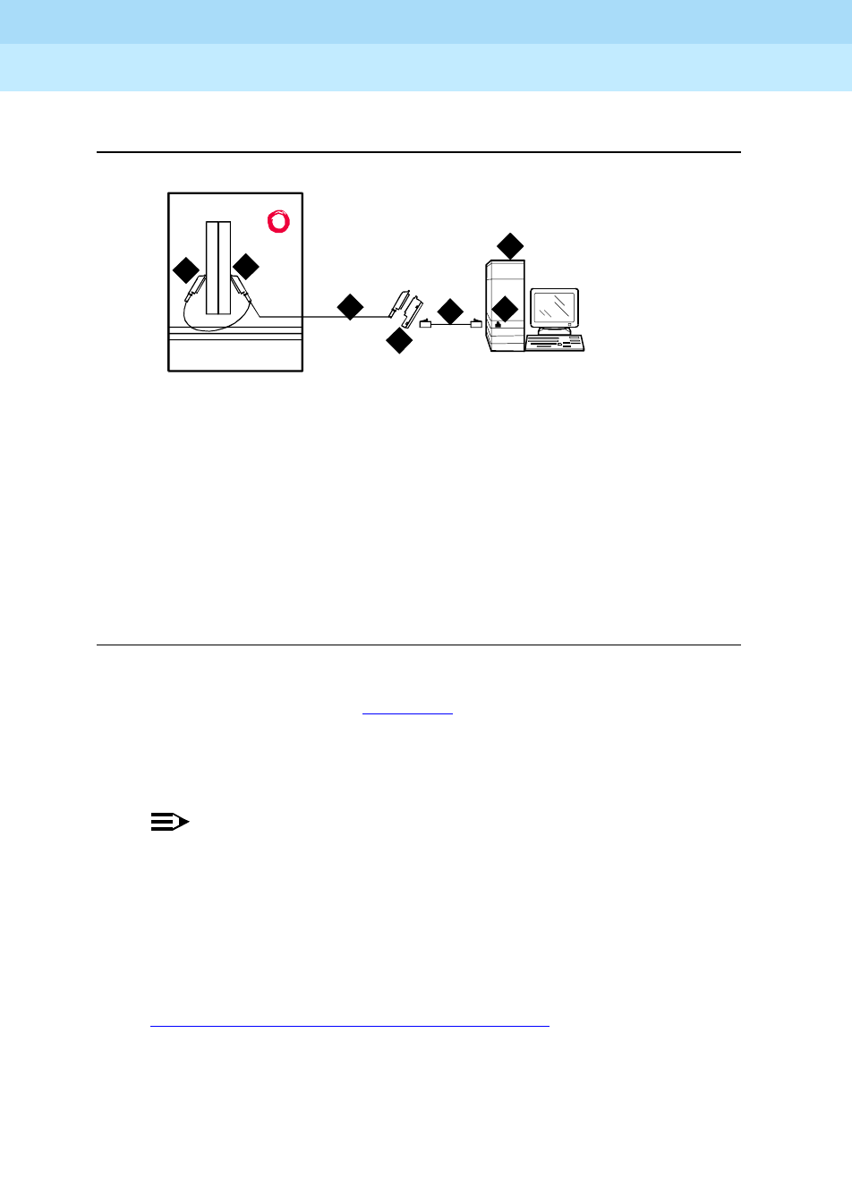
DEFINITY Enterprise Communications Server Release 6
Administration and Feature Description
555-230-522 Issue 4
May 1998
Multimedia
Page 11-36Multimedia Call Handling
11
ESM Installation
Figure Notes
Figure 11-7. Typical Multimedia Call handling ESM Connections
Use the following procedure and Figure 11-7 to connect to the ESM equipment:
1. Install the TN2207 primary rate interface (PRI) circuit pack and the TN787
multimedia interface (MMI) circuit pack in the DEFINITY System port
carrier.
NOTE:
These two circuit packs should be co-located in the cabinet since
they must be connected by a Y-cable on the back plane of the
DEFINITY ECS.
2. Record the circuit pack locations.
3. Connect the ESM Y-cable as shown.
4. Administer the DS1 form and the signaling-group form for the ESM (see
‘‘ESM T.120 Server Administration’’ on page 11-53).
5. Configure the ESM adjunct.
1. Port B Y-cable connector to a TN787
multimedia interface (MMI) circuit pack
2. Port A Y-cable connector to a TN2207
PRI circuit pack
3. 25-pair Y-cable
4. 356A adapter
5. D8W cord connected to 356A
adapter S/B port 8
6. Expansion service module
(ESM)
7. Port B on compatible primary
rate interface (PRI) card
cydf012 RPY 100697
12
4
5
3
6
7

DEFINITY Enterprise Communications Server Release 6
Administration and Feature Description
555-230-522 Issue 4
May 1998
Multimedia
Page 11-37Multimedia Call Handling
11
System Capacities
The following capacity information provides a starting point for understanding the
current MMCH physical system limitations.
Planning & administration for MMCH
The following are some of the tasks you perform in planning and administering
MMCH.
Planning the system
This is a list of questions to help you use DEFINITY ECS for multimedia.
■How many MMCH users are you going to have?
■How many multimedia calls do you expect to have at any given time?
With the information above you can determine how many Voice Conditioner (VC)
and Multimedia Interface (MMI) circuit packs you need.
■Will users need data collaboration capabilities? If so, you need to install
the Expansion Service Module (ESM).
■Which stations, hunt groups or vectors need early answer?
■Do you have ISDN-PRI trunks? It is possible to use separate DS1 trunks for
data, but ISDN-PRI trunks are recommended.
Table 11-1. MMCH System Capacities
R6.3 si R6.3 r
TN787 MMI boards 5 13
TN788 VC boards 20 52
Max Simultaneous 3 MM pty calls 26 69
Max Simultaneous Conversion calls 80 208
Nominal Dual-Port Desktops
■Basic mode office environment 675 2000
■Enhanced mode office
environment 225 675
■Enhanced mode Call Center 32 83

DEFINITY Enterprise Communications Server Release 6
Administration and Feature Description
555-230-522 Issue 4
May 1998
Multimedia
Page 11-38Multimedia Call Handling
11
Installation checklist
1. Purchase MMCH right-to-use.
2. Lucent Technologies — enable MMCH on Customer-Options form.
3. Administer default multimedia outgoing trunk parameter selection on the
System-Parameters Features form.
4. Administer MMCH related feature access code on the Feature Access
Code form.
5. Install and administer hardware:
■Install MMIs, VCs and ESM.
■Administer ESM to ECS connection — DS1 Circuit Pack form,
Signaling Group form.
■Establish maintenance parameters — Maintenance Related System
Parameters form.
6. Administer multimedia complexes:
■Administer data modules — Data Module form
■Administer stations as part of a multimedia complex, assign
associated data module extension, multimedia mode, service link
mode and appropriate multimedia buttons — Station forms
7. Administer early answer and H.320 flag for stations, the early answer flag
for hunt groups, and the multimedia flag for vectors as appropriate.
8. Train end users.
9. Monitor traffic and performance.

DEFINITY Enterprise Communications Server Release 6
Administration and Feature Description
555-230-522 Issue 4
May 1998
Multimedia
Page 11-39Multimedia Forms
11
Multimedia Forms
Table 11-2. Required forms
Form Field Page
System-Parameters
Customer-Options
■Multimedia Call Handling (Basic)
■Multimedia Call Handling (Enhanced)
11-41
System-Parameters
Features
■Default Multimedia Outgoing Trunk
Parameter Selection (p.2) 11-42
Maintenance-Related
System Parameters
■Packet Bus Activated = y
■Minimum Maintenance Thresholds
MMIs, VCs
11-45
Data Module
(type = 7500 or WCBRI)
■Multimedia (p. 1) = y
■XID (p . 2) = n
■MIM Support (p. 2) = n
11-46
Station ■MM Complex Data Ext (p. 1)
■H.320 Conversion (p. 2)
■Multimedia Early Answer (p. 2)
■Multimedia Mode (p.2)
■Service Link Mode (p.2)
■Feature Buttons (p.3) (optional)
11-47
Hunt Group ■MM Early Answer (optional) 11-56
Call Vector ■Multimedia (optional) 11-57
Continued on next page

DEFINITY Enterprise Communications Server Release 6
Administration and Feature Description
555-230-522 Issue 4
May 1998
Multimedia
Page 11-40Multimedia Forms
11
Feature Access Codes ■Basic Mode Activation (p.5)
■Enhanced Mode Activation (p.5)
■Multimedia Call Access Code (p.5)
■Multimedia Data Conference
Activation & Deactivation (p.5)
■Multimedia Multi-Address Access
Code (p.5)
■Multimedia Parameter Access Code
(p.5)
11-43
DS1 Circuit Pack (ESM
Only)
■Bit Rate=2.048
■Line Coding=hdb3
■Signaling Mode=isdn-pri
■Connect=pbx
■Interface=network
■Country Protocol=1
■CRC=y
■MMI Cabling Board
11-53
Signaling group (ESM
Only)
■Primary D-Channel 11-55
Table 11-2. Required forms
Continued on next page

DEFINITY Enterprise Communications Server Release 6
Administration and Feature Description
555-230-522 Issue 4
May 1998
Multimedia
Page 11-41Multimedia Forms
11
Administration commands
System Level Administration
System-Parameters Customer-Options form:
To enable the MMCH release 6.3 feature, you must change the
System-Parameters Customer-Options form. There are two MMCH related fields
on page 2 of this form.
■The “Multimedia Call Handling (Basic)” field must be set to ‘y’ to allow
MMCH Basic mode operation.
■The “Multimedia Call Handling (Enhanced)” field must be set to ‘y’ to allow
MMCH Enhanced mode operations.
Screen 11-15. System-Parameters Customer-Options Form (Page 2of 4)
change system-parameters customer-options Page 2 of 4
OPTIONAL FEATURES
ISDN-BRI Trunks? n Restrict Call Forward Off Net? y
ISDN-PRI? y Secondary Data Module? y
ISDN-PRI over PACCON? y SoftLock? n
Malicious Call Trace? n Station and Trunk MSP? n
Mode Code Interface? n Tenant Partitioning? n
Multifrequency Signaling? y Terminal Trans. Init. (TTI)? n
Multimedia Appl. Server Interface (MASI)? n Time of Day Routing? n
Multimedia Call Handling (Basic)? y Uniform Dialing Plan? y
Multimedia Call Handling (Enhanced)? y Usage Allocation Enhancements? y
Personal Station Access (PSA)? n
Wideband Switching? n
Wireless? n
Processor and System MSP? n
Private Networking? y
(NOTE: You must logoff & login to effect the permission changes.)

DEFINITY Enterprise Communications Server Release 6
Administration and Feature Description
555-230-522 Issue 4
May 1998
Multimedia
Page 11-42Multimedia Forms
11
System-Parameters Features form:
The default bandwidth for MMCH calls is defined on the System-Parameters
Features form shown below.
NOTE:
Originating a multimedia call with the mm-call button will originate a call
according to the Default Multimedia Parameters selected on the System
Parameters Features form.
■This default parameter will be either 2x56 or 2x64.
■The bearer capability of the multimedia calls will either be 56K or
64K and the bandwidth will be 2B channels.
Screen 11-16. System-Parameters Features Form (Page 2 of 8)
change system-parameters features Page 2 of 8
FEATURE-RELATED SYSTEM PARAMETERS
LEAVE WORD CALLING PARAMETERS
Maximum Number of Messages Per Station (when MSA not in service): 10
Stations with System-wide Retrieval Permission (enter extension)
1: 3: 5: 7: 9:
2: 4: 6: 8: 10:
WARNING! SEE USER DOCUMENTATION BEFORE CHANGING TTI STATE
Terminal Translation Initialization (TTI) Enabled? n
Prohibit Bridging Onto Calls With Data Privacy? n
Enhanced Abbreviated Dial Length (3 or 4): 3
Call Forward Override? n
External Coverage Treatment for Transferred Incoming Calls? n
Coverage Of Calls Redirected Off-Net Enabled? n
Default Multimedia Outgoing Trunk Parameter Selection: 2x64
WIRELESS PARAMETERS
Radio Controllers with Download Server Permission (enter board location)
1: 2: 3: 4: 5:

DEFINITY Enterprise Communications Server Release 6
Administration and Feature Description
555-230-522 Issue 4
May 1998
Multimedia
Page 11-43Multimedia Forms
11
MMCH Feature Access Codes (FACs)
The following MMCH specific feature access codes can be administered in the
feature-access-codes form.
NOTE:
These FACs only work if MMCH has been enabled via the
System-Parameters Customer-Options form.
Screen 11-17. Feature-Access-Codes Form (Page 6 of 6)
■Basic Mode Activation: If you enter this FAC when your system is an
Enhanced multimedia complex, it will revert to a Basic multimedia
complex. If you enter this FAC when your system is a Basic mode station it
will do nothing.
■Enhanced Mode Activation: If you enter this FAC when your system is a
Basic multimedia complex, it will become an Enhanced multimedia
complex. If you enter this FAC when your system is an Enhanced mode
station it will do nothing.
■Multimedia Call Access Code: If you enter this FAC from any voice
station, it indicates to the DEFINITY ECS that you are making an Enhanced
multimedia mode call. If you originate a multimedia call with the
multimedia call access code, it will originate a call according to the
Default Multimedia Parameters selected on the System Parameters
Features form.
■Multimedia Data Conference Activation: If you enter this FAC from any
voice station that is participating in a multimedia call, it will alert the
DEFINITY ECS that you want to enable data collaboration with the other
parties on the call. If you enter this FAC a second time, it will give denial
treatment (since a collaboration session is already active). This FAC only
applies to voice stations on a DEFINITY ECS switch equipped with an ESM
adjunct.
change feature-access-codes Page 6 of 6
FEATURE ACCESS CODE (FAC)
Multimedia Features
Basic Mode Activation: *01
Enhanced Mode Activation: *02
Multimedia Call Access Code: *03
Multimedia Data Conference Activation: *04 Deactivation: #04
Multimedia Multi-Address Access Code: *05
Multimedia Parameter Access Code: *06

DEFINITY Enterprise Communications Server Release 6
Administration and Feature Description
555-230-522 Issue 4
May 1998
Multimedia
Page 11-44Multimedia Forms
11
The Multimedia Data Conference Activation FAC must be entered after
your system is active on a multimedia call. To enter the FAC:
1. Select TRANSFER
2. Receive a dialtone
3. Dial the Multimedia Data Conference Activation FAC
4. Receive a confirmation tone
5. Re-select the call appearance for the held-multimedia call.
■Multimedia Data Conference Deactivation: If you enter this FAC from the
voice terminal that enabled data collaboration on a multimedia mode call,
it will deactivate the data session and revert to a voice and video call. If
you enter this deactivation FAC while participating in a data-collaboration
multimedia call that
you
did not
initiate
, you will get denial treatment.
The Multimedia Data Conference Deactivation FAC must be entered after
you are active on a multimedia call. To enter the FAC:
1. Select TRANSFER
2. Receive a dialtone
3. Dial the FAC
4. Receive a confirmation tone
5. Re-select the call appearance for the held multimedia call.
■Multimedia Multi-Address Access Code: The multimedia multi-address
access code is similar to the multimedia call access code. It allows
origination of a multimedia call from a voice station. It is used when the
destination being dialed requires a different address for each of the 2
B-channels. For example, ISDN-BRI provided by a Central Office is
provisioned with separate listed directory numbers for each B-channel. In
order to make a 2B multimedia call to such a device, two sets of
addresses must be entered.
Originating a multimedia call with the multimedia multi-address access
code will originate a call according to the Default Multimedia Parameters
selected on the System Parameters Features form.
■Multimedia Parameter Access Code: This FAC can be entered by any
voice station to indicate to the DEFINITY ECS that you want to initiate a
multimedia mode call with a specific bearer capability. This FAC would be
followed by a 1 or 2 to indicate the following parameter selections
respectively: 2x64 (unrestricted initial system default), 2x56 (restricted).

DEFINITY Enterprise Communications Server Release 6
Administration and Feature Description
555-230-522 Issue 4
May 1998
Multimedia
Page 11-45Multimedia Forms
11
Maintenance-Related System Parameters
Screen 11-18. Maintenance-Related System Parameters Form (Page 2 of 3)
Multimedia Complex/Station
Use the following administration commands to add, change, duplicate, or
remove stations and data modules.
Action Objects Qualifier
add station
data module xxxxx (extension) or ‘next’
xxxxx (extension) or ‘next’
change station
data module xxxxx (extension)
xxxxx (extension)
duplicate station
data module xxxxx (extension)
xxxxx (extension)
remove station
data module xxxxx (extension)
xxxxx (extension)
- -
change system-parameters maintenance Page 2 of 3
MAINTENANCE-RELATED SYSTEM PARAMETERS
MINIMUM MAINTENANCE THRESHOLDS ( Before Notification )
TTRs: 4 CPTRs: 1 Call Classifier Ports: 0
MMIs: 0 VCs: 0
TERMINATING TRUNK TRANSMISSION TEST ( Extension )
Test Type 100: Test Type 102: Test Type 105:
ISDN MAINTENANCE
ISDN-PRI Test Call Extension: ISDN-BRI Service SPID:
DS1 MAINTENANCE
DS0 Loop-Around Test Call Extension:
LOSS PLAN ( Leave Blank if no Extra Loss is Required )
Minimum Number of Parties in a Conference Before Adding Extra Loss:
SPE OPTIONAL BOARDS
Disk? y Packet Intf1? y Packet Intf2? n Packet Intf3? n

DEFINITY Enterprise Communications Server Release 6
Administration and Feature Description
555-230-522 Issue 4
May 1998
Multimedia
Page 11-46Multimedia Forms
11
Data module form
The H.320 DVC system should contain a BRI interface. You must connect this
BRI interface to a port on a TN556 BRI circuit pack and administer it as a BRI
data module.
■You may administer the data endpoint type as 7500 (recommended) or
WCBRI.
■The fields for multimedia are the same on either form.
■The administration for a Basic mode and an Enhanced mode data module
are exactly the same.
Screen 11-19. Data Module Form (Page 1 of 2)
Screen 11-20. Data Module Form (Page 2 of 2)
■Type — Set the data module type to 7500 or WCBRI.
■Multimedia — This field appears on the data module form only if MM is
set to yes on the System-Parameters Customer Options form. Enter Y to
enable this data module to be multimedia compliant.
Page 1 of 2
DATA MODULE
Data Extension: 65001 Name: ___________________________
Type: 7500_______ COS: 1_ Multimedia? y
Port: _____ COR: 1_ MM Complex Voice Ext: 67434
ABBREVIATED DIALING
List1: ____________
SPECIAL DIALING OPTION: hot-line
HOT LINE DESTINATION
Abbreviated Dialing Dial Code (From above list): _
CIRCUIT SWITCHED DATA ATTRIBUTES (used for modem pooling)
Default Duplex: full Default Mode: async Default Speed: 1200_
DATA MODULE CAPABILITIES
Default ITC: restricted Default Data Application? M2_A
Page 2 of 2
DATA MODULE
BRI LINK/MAINTENANCE PARAMETERS
XID? n Fixed TEI? n TEI: ___
MIM Support? n

DEFINITY Enterprise Communications Server Release 6
Administration and Feature Description
555-230-522 Issue 4
May 1998
Multimedia
Page 11-47Multimedia Forms
11
■MM Complex Voice Ext: (display only) — This field contains the number
of the associated telephone in the complex. This is a display-only field,
and is blank until you enter the data module extension in the Station form
MM Complex Data Ext field. Once you have done that, these two
extensions are associated as two parts of a multimedia complex.
■XID and MIM Support — These fields must be set to n.
Station form
After you have administered the BRI data module, use the Station form to
associate it with a voice station to form a multimedia complex. This is a
one-to-one relationship: you can administer only one station and one data
endpoint per multimedia complex. Neither the voice station, nor the data
endpoint can be a member of another multimedia complex.
NOTE:
A BRI station cannot be part of a multimedia complex.
Station form, page 1
Screen 11-21. Station Form (Page 1 of 5)
■MM Complex Data Ext: — This is the extension assigned to the data
module of the multimedia complex. This field must be filled out to create
either a Basic or an Enhanced multimedia complex. Other users can dial
this extension to place either a voice or a multimedia call to this complex.
It is interchangeable with the voice station extension for reaching the
multimedia complex directly.
change station 67434 Page 1 of 5
STATION
Extension: 67434 Lock Messages? n BCC: 0
Type: 7434D Security Code: TN: 1
Port: 01C1103 Coverage Path 1: COR: 1
Name: jud’s phone Coverage Path 2: COS: 1
Hunt-to Station:
STATION OPTIONS
Data Module? n Personalized Ringing Pattern: 1
Display Module? y Message Lamp Ext: 67434
Display Language: english
Coverage Module? n
MM Complex Data Ext: 65001

DEFINITY Enterprise Communications Server Release 6
Administration and Feature Description
555-230-522 Issue 4
May 1998
Multimedia
Page 11-48Multimedia Forms
11
Station form, page 2
Screen 11-22. Station Form (Page 2 of 5)
■H.320 Conversion — This field is optional for non-multimedia complex
voice stations and for Basic multimedia complex voice stations. It is
mandatory for Enhanced multimedia complex voice stations. Because the
system can only handle a limited number of conversion calls, you may
need to limit the number of telephones with H.320 conversion. Enhanced
multimedia complexes must have this flag set to y.
For non-multimedia complex voice stations, setting this field to y allows
H.320 calls to convert to voice and alert at the standalone voice station. If
the call is unanswered at the voice station, the call will follow standard
voice treatment. Any subsequent station that is reached in the routing of
this call, that is, coverage points, forwarded destinations, call pickup
members, and so forth, do not need to have the H.320 field enabled. The
H.320 field is only needed at the
first
station that may receive the H.320
call.
For Basic multimedia complex voice stations, setting this field to y allows
H.320 calls to convert to voice and alert at the Basic multimedia complex
voice station
after
an attempt has been made to offer the call to the H.320
DVC system. If the call is unanswered at the H.320 DVC system, the call
will alert at the voice station after 5 seconds or after the administered
number of rings as specified in the voice station’s coverage path. If the
call is unanswered at the voice station, the call will follow standard voice
treatment. Any subsequent station that is reached in the routing of this call,
that is, coverage points, forwarded destinations, call pickup members,
and so forth, do not need to have the H.320 field enabled. The H.320 field
is only needed at the
first
station that may receive the H.320 call.
change station 67434 Page 2 of 5
STATION
FEATURE OPTIONS
LWC Reception: msa-spe Auto Select Any Idle Appearance? n
LWC Activation? y Coverage Msg Retrieval? y
CDR Privacy? n Auto Answer: none
Redirect Notification? y Data Restriction? n
Per Button Ring Control? n Idle Appearance Preference? n
Bridged Call Alerting? n
Active Station Ringing: single Restrict Last Appearance? y
H.320 Conversion? y
Service Link Mode: as-needed Per Station CPN - Send Calling Number?
Multimedia Mode: enhanced Multimedia Early Answer? n
Display Client Redirection? n
Select Last Used Appearance? n

DEFINITY Enterprise Communications Server Release 6
Administration and Feature Description
555-230-522 Issue 4
May 1998
Multimedia
Page 11-49Multimedia Forms
11
■Service Link Mode — The service link is the combined hardware and
software multimedia connection between an Enhanced mode complex’s
H.320 DVC system and the DEFINITY ECS which terminates the H.320
protocol. A service link is never used by a Basic mode complex H.320
DVC system. Connecting a service link will take several seconds. When
the service link is connected, it uses MMI, VC and system timeslot
resources. When the service link is disconnected it does not tie up any
resources. The Service Link Mode can be administered as either
‘as-needed’ or ‘permanent’ as described below:
— As-Needed - Most non-call center multimedia users will be
administered with this service link mode. The as-needed mode
provides the Enhanced multimedia complex with a connected
service link whenever a multimedia call is answered by the station
and for a period of 10 seconds after the last multimedia call on the
station has been disconnected. Having the service link stay
connected for 10 seconds allows a user to disconnect a multimedia
call and then make another multimedia call without having to wait
for the service link to disconnect and re-establish.
— Permanent - Multimedia call center agents and other users who are
constantly making or receiving multimedia calls may want to be
administered with this service link mode. The permanent mode
service link will be connected during the station’s first multimedia
call and will remain in a connected state until the user disconnects
from their PC’s multimedia application or the DEFINITY ECS switch
restarts. This provides a multimedia user with a much quicker video
cut-through when answering a multimedia call from another
permanent mode station or a multimedia call that has been early
answered.
■Multimedia Mode — There are two multimedia modes, Basic and
Enhanced, as described below:
—Basic
— A Basic multimedia complex consists of a BRI-connected
multimedia-equipped PC and a non-BRI-connected multifunction
telephone set. When in Basic mode, users place voice calls at the
multifunction telephone and multimedia calls from the multimedia
equipped PC. Voice calls will be answered at the multifunction
telephone and multimedia calls will alert first at the PC and if
unanswered will next alert at the voice station if it is administered
with H.320 = y. A Basic mode complex has limited multimedia
feature capability as described in ‘‘Basic Mode Operation’’ on page
11-32).
— Enhanced — An Enhanced multimedia complex consists of a
BRI-connected multimedia-equipped PC and a non-BRI-connected
multifunction telephone. The Enhanced mode station acts as
though the PC were directly connected to the multifunction
telephone; the service link provides the actual connection between
DEFINITY ECS and the PC. Thus, voice and multimedia calls are
originated and received at the telephone set. Voice and multimedia

DEFINITY Enterprise Communications Server Release 6
Administration and Feature Description
555-230-522 Issue 4
May 1998
Multimedia
Page 11-50Multimedia Forms
11
call status are also displayed at the telephone set. An Enhanced
mode station allows multimedia calls to take full advantage of most
call control features as described in ‘‘Enhanced Mode Operation’’
on page 11-33.
■Multimedia Early Answer — This field lets you set this phone for early
answer of multimedia calls. The system will answer the incoming
multimedia call on behalf of the station and proceed to establish the H.320
protocol. After audio path has been established to the caller, the call will
then alert at the voice station. The station may then answer by going
off-hook and will have immediate audio path. No hourglass tone will be
heard by the answering party (see ‘‘Hourglass Tone’’ on page 11-64).
Example: An administrative assistant who does not have a multimedia PC,
but may get multimedia mode calls from forwarding or coverage, may
want to set the H.320 flag to y and the early answer flag to y on their voice
station. This allows any multimedia call to be presented to the station with
immediate voice path rather than hourglass tone. The answered call could
then be transferred as voice to voice mail or transferred as multimedia to a
user equipped with a multimedia endpoint.
Multimedia Buttons
There are six new multimedia specific buttons that may be added to a voice
station. Most of them may be placed on any voice station, whether it is part of a
Basic multimedia complex, an Enhanced multimedia complex or not part of any
multimedia complex. Two feature buttons, mm-basic and mm-pcaudio, may only
be placed on stations which are part of an Enhanced multimedia complex.
All of the multimedia specific feature buttons have a corresponding feature
access code except mm-pcaudio and mm-cfwd.
■The mm-pcaudio feature can only be used with a station form button.
■The mm-cfwd button may be replaced by the standard “
call forward
” FAC
followed by the “
multimedia call
” FAC.

DEFINITY Enterprise Communications Server Release 6
Administration and Feature Description
555-230-522 Issue 4
May 1998
Multimedia
Page 11-51Multimedia Forms
11
Station form, page 3
Screen 11-23. Station Form (Page 3 of 5)
■mm-call — This button may exist on any voice station. Most multimedia
enabled users will want an mm-call button. This button (or it’s
corresponding FAC) must be used to indicate that the user is placing a
multimedia mode call. To place a multimedia mode call the user would go
off-hook, select an idle call appearance, and press the mm-call button
followed by the destination extension digits. If the user has a
speakerphone they can simply press the mm-call button, which preselects
an idle call appearance, followed by the destination extension digits.
The mm-call button lamp lights when you press this button during call
origination. The lamp also lights to indicate that the selected call
appearance is a multimedia mode call.
■mm-basic — This button is only allowed on the voice station of a
multimedia complex. The mm-basic button toggles your station between
Basic and Enhanced modes. If you press the mm-basic button when you
are an Enhanced multimedia complex, you will revert to a Basic
multimedia complex and the button status lamp will be lit. If you press this
button when you are a Basic mode station it will switch you to an
Enhanced mode station and the button status lamp will not be lit. This
button can NOT be used to change the station’s multimedia mode when
the station has an active multimedia call appearance.
change station 67434 Page 3 of 5
STATION
SITE DATA
Room: Headset? n
Jack: Speaker? n
Cable: Mounting: d
Floor: Cord Length: 0
Building: Set Color:
ABBREVIATED DIALING
List1: List2: List3:
BUTTON ASSIGNMENTS
1: call-appr 6: mm-pcaudio
2: call-appr 7: mm-datacnf
3: call-appr 8: mm-cfwd
4: mm-call 9: mm-multnbr
5: mm-basic 10:

DEFINITY Enterprise Communications Server Release 6
Administration and Feature Description
555-230-522 Issue 4
May 1998
Multimedia
Page 11-52Multimedia Forms
11
Toggling between Basic and Enhanced mode changes the station’s
administered Multimedia mode. When in Basic mode this field on the
station form will show basic. When in Enhanced mode this field on the
station form will show enhanced. The current station Multimedia mode will
be saved to translation when a save translation command is executed.
■mm-pcaudio — This button only works for an Enhanced multimedia
complex voice station. When originating or receiving a multimedia call, the
audio path is connected to the voice station’s handset or speakerphone
device. The mm-pcaudio button allows a user to switch the audio portion
of any call to their PC’s audio input/output device (if available). To switch
the audio path to the PC while active on a call, the user presses the
mm-pcaudio button (if off-hook you may now hang up the handset). The
mm-pcaudio button’s status lamp will light up when the button is pushed
to move the audio path to the PC and remain lit while the audio path is at
the PC device.
NOTE:
If you are on a voice only call, the voice path will switch to the PC
device but you will get muted or loopback video depending on the
multimedia endpoint software.
A user may simply go off-hook on their voice station or press the
speakerphone button to move the audio path of a multimedia call from the
PC back to the voice station. Pressing the mm-pcaudio button while the
status lamp is lit and the voice station’s handset is on-hook will disconnect
the user from the active call.
■mm-datacnf — Pressing the mm-datacnf button from any voice station
that is participating in a multimedia call will light the status lamp and alert
the DEFINITY ECS that you want to enable T.120 data collaboration with
the other parties on the call. The button status lamp will also light for other
participants in the multimedia call who have mm-datacnf buttons.
Pressing this button from the voice station that enabled data collaboration
on a multimedia mode call will deactivate the data session and revert to a
voice and video call. If you are participating on a multimedia call with data
collaboration, but did not initiate the data collaboration, and you press this
button, the status lamp led will flash momentarily and the T.120 data
services will not be terminated, (only the station that activated the
collaboration session can deactivate it). This button only works for stations
connected to a DEFINITY ECS equipped with an ESM adjunct.
■mm-cfwd — The mm-cfwd button allows a user to indicate that
multimedia mode calls will be forwarded off of the DEFINITY ECS switch
as multimedia mode calls to a specific forwarded-to destination. If voice
call forwarding is active and multimedia call forwarding is not active then
multimedia calls going off of the DEFINITY ECS switch will be forwarded
as voice only calls.

DEFINITY Enterprise Communications Server Release 6
Administration and Feature Description
555-230-522 Issue 4
May 1998
Multimedia
Page 11-53Multimedia Forms
11
The mm-cfwd button status lamp will be lit to indicate that multimedia call
forwarding is activated. Pressing the mm-cfwd button when the lamp is lit
will deactivate multimedia call forwarding.
Note - pressing the mm-cfwd button is the same as dialing the regular
call-fwd FAC followed by the mm-call button or FAC followed by the
desired forwarded-to extension digits.
■mm-multinbr — The mm-multinbr call button is similar to the mm-call
button. It allows origination of a multimedia call from any voice station. It is
used when the destination being dialed requires a different address for
each of the 2 B-channels. An example of this is Central Office provided
ISDN-BRI. This type of BRI line is provisioned with separate listed
directory numbers for each B-channel. In order to make a 2B multimedia
call to such a device, two sets of address must be entered.
Originating a multimedia call with the mm-multinbr button will originate a
call according to the Default Multimedia Parameters selected on the
System Parameters Features form. This default parameter will be either
2x56 or 2x64. The bearer capability of the multimedia calls will either be
56K or 64K and the bandwidth will be 2B channels.
ESM T.120 Server Administration
DS1 form, page 1
Screen 11-24. DS1 Form (Page 1 of 1)
change ds1 1c09 Page 1 of 1
DS1 CIRCUIT PACK
Location: 01C09 Name:
Bit Rate: 2.048 Line Coding: hdb3
Signaling Mode: isdn-pri
Connect: pbx Interface: network
Country Protocol: 1
CRC? y
Idle Code: 11111111
DCP/Analog Bearer Capability: 3.1kHz
MMI Cabling Board: 01C10 MMI Interface: ESM
Slip Detection? n Near-end CSU Type: other

DEFINITY Enterprise Communications Server Release 6
Administration and Feature Description
555-230-522 Issue 4
May 1998
Multimedia
Page 11-54Multimedia Forms
11
From the system administration terminal:
1. Enter list configuration all, and a list of the installed carriers, circuit
packs, and ports appears.
2. Record the location (board number) of the MMI board cabled to the
Tn2207 slot and verify that all other required circuit packs (refer to ‘‘ESM
Installation’’) are present.
3. Enter add DS1 xxxxx, (where xxxxx is the location of the TN2207 PRI
circuit pack recorded in step 2), and the DS1 circuit pack administration
form appears.
4. Set the Name: field to ESM DS1
5. Set the Bit Rate: field to 2.048
The TN2207 DS1 must have a bit rate of 2.048, even if all other DS1
boards in the system are operating at 1.544. Verify the 24/32 channel
switch on the circuit pack is in the 32 channel position.
6. Set the Line Coding: field to hdb3
7. Set the Signaling Mode: field to isdn-pri
8. Set the Connect: field to pbx
9. Set the Interface: field to network
10. Set the Country Protocol:field to 1
11. Set the CRC?:field to y
12. The Idle Code default is 11111111.
13. The DCP/Analog Bearer Capability default is 3.1 kHz.
14. Set the MMI Cabling Board: field to xxxxx (where xxxxx is the location
of the TN787 MMI circuit pack recorded in step 2). This must be the slot
for port B of the Y-cable.
15. The MMI Interface: field ESM appears.

DEFINITY Enterprise Communications Server Release 6
Administration and Feature Description
555-230-522 Issue 4
May 1998
Multimedia
Page 11-55Multimedia Forms
11
Signaling-Group form, page 1
Screen 11-25. Signaling-Group Form (Page 1 of 5)
1. Enter add signaling-group next and the signaling-group form appears.
2. Change Associated Signaling: field to y.
3. Change Primary D-Channel Port: field to xxxx16 (where xxxx is the
address of the TN2207 PRI circuit pack, for example: 1B0516).
4. The Max Number of NCA TSC: default is 0.
5. The Max Number of GA TSC: default is 0.
6. Trunk Group for NCA TSC: ____ (leave blank)
7. Trunk Group for Channel Selection:____ (leave blank)
8. Logoff the terminal and then log back on the terminal to view your
changes.
Troubleshooting. To determine ESM link status enter the following commands
from the system administration terminal:
1. Status esm
2. Status signaling-group
3. List MMI
NOTE:
When you move ESM circuit packs, you MUST remove the DS1 and
signaling group translations. You cannot use the change circuit pack
command.
change signaling-group 6 Page 1 of 5
SIGNALING GROUP
Group Number: 6
Associated Signaling? y Max number of NCA TSC: 0
Primary D-Channel: 01C0916 Max number of CA TSC: 0
Trunk Group for NCA TSC:
Trunk Group for Channel Selection:
Supplementary Service Protocol: a

DEFINITY Enterprise Communications Server Release 6
Administration and Feature Description
555-230-522 Issue 4
May 1998
Multimedia
Page 11-56Multimedia Forms
11
Hunt Group Form
(See 11-69 for Hunting with Basic Complex or 11-71 for Hunting with Enhanced
Mode Complex.)
Screen 11-26. Hunt Group Form (Page 1)
■MM Early Answer — This field is to be used when the hunt group will
expect to receive H.320 multimedia calls and the members of the hunt
group are voice extensions. The voice members of the hunt group should
all have the H.320 field on each of their station forms set to “y”. The MM
Early Answer field lets you set this hunt group for early answer of
multimedia calls. The system will answer the incoming multimedia call on
behalf of the agent and proceed to establish the H.320 protocol. After
audio path has been established, the call will then alert at the agent’s
voice station. The station may then answer by going off-hook and will have
immediate audio path. No hourglass tone will be heard by the answering
party. This is especially important for AUDIX hunt groups, because
otherwise the caller may miss all or a portion of the AUDIX greeting.
The MM Early Answer field has no effect on voice calls.
The MM Early Answer field has no effect if the hunt group members are
data extensions.
change hunt-group 101 Page 1 of 3
HUNT GROUP
Group Number: 101 ACD? y
Group Name: hu 101 Queue? y
Group Extension: 52001 Vector? y
Group Type: ucd-mia
TN: 1
COR: 1 MM Early Answer? n
Security Code:
ISDN Caller Display:
Queue Length: 5
Calls Warning Threshold: 2 Port:
Time Warning Threshold: 15 Port:
DEFINITY Enterprise Communications Server Release 6
Administration and Feature Description
555-230-522 Issue 4
May 1998
Multimedia
Page 11-57Multimedia Forms
11
Call Vector Form
Screen 11-27. Call Vector Form (Page 1 of 3)
Multimedia — Very often, calls are routed to hunt groups or skills via a vector.
The existing VDNs and vectors which exist for routing voice calls can be used to
route multimedia calls.
In order to use a vector for multimedia calls that will terminate to voice stations,
you must set the Multimedia field on the vector form to y. This field has no effect
on voice calls routing through the vector. This field will cause multimedia calls
routed through the vector to receive early answer treatment prior to processing
the vector steps. This provides a talk path to the caller for announcements or
immediate conversation with an agent.
NOTE:
Vectors which have the Multimedia field set to “y” must eventually
route to hunt groups, skills or numbers which are voice extensions. A
vector with the multimedia field set to “y” should never be set up to
route to a hunt group or number which is a data extension.
When a vector is used to route video (56K/64K) calls to a hunt group comprised
of data extensions, the vector
must
have the multimedia field set to n.
Duplicating multimedia endpoints
Use the duplicate station command to enter groups of multimedia endpoints at
one time. If the original station form had a data module page, the second page of
this form appears.
change vector 10 Page 1 of 3
CALL VECTOR
Number: 10 Name Multimedia? y Lock? n
Basic? y EAS? n G3V4 Enhanced? y ANI/II-Digits? y ASAI Routing? n
Prompting? n LAI? n G3V4 Adv Route? y CINFO? n BSR? n
01 route-to number 69999 with cov n if unconditionally
02
03
04
05
06
07
08
09
10

DEFINITY Enterprise Communications Server Release 6
Administration and Feature Description
555-230-522 Issue 4
May 1998
Multimedia
Page 11-58Multimedia Forms
11
Screen 11-28. Duplicate Station Form (Page 1)
Screen 11-29. Duplicate Station Form (Page 2)
Detailed feature operation descriptions follow.
STATION
Security Endpt
Ext Port Name Code Room Jack Cable ID
_____ _______ ___________________________ ________ _________ _____ _____ __
_____ _______ ___________________________ ________ _________ _____ _____ __
_____ _______ ___________________________ ________ _________ _____ _____ __
_____ _______ ___________________________ ________ _________ _____ _____ __
_____ _______ ___________________________ ________ _________ _____ _____ __
_____ _______ ___________________________ ________ _________ _____ _____ __
_____ _______ ___________________________ ________ _________ _____ _____ __
_____ _______ ___________________________ ________ _________ _____ _____ __
_____ _______ ___________________________ ________ _________ _____ _____ __
_____ _______ ___________________________ ________ _________ _____ _____ __
_____ _______ ___________________________ ________ _________ _____ _____ __
_____ _______ ___________________________ ________ _________ _____ _____ __
_____ _______ ___________________________ ________ _________ _____ _____ __
_____ _______ ___________________________ ________ _________ _____ _____ __
_____ _______ ___________________________ ________ _________ _____ _____ __
_____ _______ ___________________________ ________ _________ _____ _____ __
STATION
Data Data Ext MM Data
Ext Ext Name Ext
xxxxx _____ ___________________________ _____
xxxxx _____ ___________________________ _____
xxxxx _____ ___________________________ _____
xxxxx _____ ___________________________ _____
xxxxx _____ ___________________________ _____
xxxxx _____ ___________________________ _____
xxxxx _____ ___________________________ _____
xxxxx _____ ___________________________ _____
xxxxx _____ ___________________________ _____
xxxxx _____ ___________________________ _____
xxxxx _____ ___________________________ _____
xxxxx _____ ___________________________ _____
xxxxx _____ ___________________________ _____
xxxxx _____ ___________________________ _____
xxxxx _____ ___________________________ _____
xxxxx _____ ___________________________ _____

DEFINITY Enterprise Communications Server Release 6
Administration and Feature Description
555-230-522 Issue 4
May 1998
Multimedia
Page 11-59Basic Mode MM complex
11
Basic Mode MM complex
1-number access. 1-number access permits originating users to make voice or
multimedia calls to a Basic multimedia complex by dialing the same number for
either type of call. The number may be the voice station extension or the data
module extension. If the incoming call is a voice call, DEFINITY ECS directs it to
the telephone. If the incoming call is 56K or 64K data call, DEFINITY ECS
recognizes it as such and sends it to the multimedia endpoint. Likewise, if a voice
call is addressed to the data extension, the system recognizes this and directs
the call to the voice station.
Calls originating on the same switch as the Basic mode complex destination may
always use 1-number access for voice or video. In order to take advantage of
1-number access for calls originating from a remote location, the incoming calls
must arrive over ISDN-PRI trunks. If the system is setup with separate data
non-PRI digital facilities multimedia calls must be made to the data extension.
AVD (Alternate voice/data) trunk groups cannot be used to provide 1-number
access with MMCH. If the AVD trunk group has a BCC of 0, all calls arriving over
the AVD trunk to the Basic mode complex will be assumed to be voice calls. If the
AVD trunk group has a BCC of 1 or 4, all calls arriving over the AVD trunk to the
Basic mode complex will be assumed to be multimedia calls.
Originating voice calls. All voice calls are originated at the voice station.
Originating multimedia calls. For a Basic mode complex, multimedia calls are
normally originated at the user’s multimedia equipped PC. These multimedia
calls use the associated station’s COR/COS.
The voice station of a Basic multimedia complex may also use the “mm-call”
button or FAC, and the “mm-multinbr” button or FAC to originate multimedia calls.
When these methods are used, a multimedia call is originated from the voice
station. In order for the Basic multimedia complex to receive video, the user must
make a call from the H.320 DVC system to the voice station of the complex or
must make a multimedia call from the voice station to the H.320 DVC. This allows
the station to spontaneously add themselves or other parties to a multimedia
conference.
1. H.320 DVC system GUI. The normal way for a Basic multimedia complex
endpoint to originate a multimedia call is through the vendor provided user
interface. Generally, digits to dial are entered, speed is selected and the
call originates from the DVC system. The voice station is not involved in
such as origination.
Any voice station may use the following mechanisms to originate a
multimedia call from the voice station. For stations that are not part of a
multimedia complex, video cannot be provided. For voice stations that are
part of a Basic multimedia complex, video is not provided until a
multimedia call is made from the complex’s H.320 DVC system to the

DEFINITY Enterprise Communications Server Release 6
Administration and Feature Description
555-230-522 Issue 4
May 1998
Multimedia
Page 11-60Basic Mode MM complex
11
voice station or a multimedia call is made from the voice station to the
H.320 DVC system. Video is automatically included for Enhanced
multimedia complexes (see 11-33).
2. mm-call (Multimedia Call) button. If the station has an mm-call button
administered, the user goes off-hook and selects the mm-call button. The
user may select the mm-call button and then go off-hook. If the user has a
speakerphone on the station, the user may originate the call simply by
selecting the mm-call button. The speakerphone will automatically be
placed off-hook and dialtone will be heard. Upon selection of the mm-call
button, the mm-call status lamp (green led) should become solid.
The user now dials the destination address digits. The destination address
may be provided by dialing digits, using abbreviated dial entries, last
number dialed, station busy indicators, etc. Originating a multimedia call
with the mm-call button will originate a call according to the Default
Multimedia Parameters selected on the System Parameters Features form.
This default parameter will be either 2x56 or 2x64. The bearer capability of
the multimedia calls will either be 56K or 64K and the bandwidth will be 2B
channels.
For calls with a bandwidth of 2B, use of the mm-call button to originate will
cause the same destination address to be used for both channels of the
2B call. See the section below on the mm-multinbr button/FAC for
information on originating a 2B call where the destination has a different
address for each B-channel.
NOTE:
The mm-call feature button is generally used by stations that are part
of an Enhanced multimedia complex, but may be used by any
station to originate a multimedia call.
3. Multimedia Call feature Access Code. For stations that do not have an
administered mm-call button, the Multimedia call feature access code
may be used instead. The user goes off-hook on the station, waits for
dialtone, then dials the MM-call FAC, receives dialtone again and then
dials the call normally. The destination address may be provided by
dialing digits, using abbreviated dial entries, last number dialed, station
busy indicators, etc.
Originating a multimedia call with the mm-call button will originate a call
according to the Default Multimedia Parameters selected on the System
Parameters Features form. This default parameter will be either 2x56 or
2x64. The bearer capability of the multimedia calls will either be 56K or
64K and the bandwidth will be 2B channels.
For calls with a bandwidth of 2B, use of the mm-call button to originate will
cause the same destination address to be used for both channels of the
2B call. See the section below on the mm-multinbr button/FAC for
information on originating a 2B call where the destination has a different
address for each B-channel.

DEFINITY Enterprise Communications Server Release 6
Administration and Feature Description
555-230-522 Issue 4
May 1998
Multimedia
Page 11-61Basic Mode MM complex
11
NOTE:
The mm-call feature access code is generally used by stations that
are part of an Enhanced multimedia complex, but may be used by
any station to originate a multimedia call.
4. mm-multinbr (Multimedia Multi-number) button. The mm-multinbr
button is similar to the mm-call button. It allows origination of a multimedia
call from a voice station. It is used when the destination being dialed
requires a different address for each of the 2 B-channels. An example of
this is Central Office provided ISDN-BRI. This type of BRI line is
provisioned with separate listed directory numbers for each B-channel. In
order to make a 2B multimedia call to such a device, two sets of
addresses must be entered.
The user goes off-hook and selects the mm-multinbr button. The user may
select the mm-multinbr button and then go off-hook. If the user has a
speakerphone on the station, the user may originate the call simply by
selecting the mm-multinbr button. The speakerphone will automatically be
placed off-hook and dialtone will be heard. Upon selection of the
mm-multinbr button, the mm-multinbr and mm-call (if present) status lamp
(green led) should light steadily. The user now dials the first destination
address digits. The destination address may be provided by dialing digits,
using abbreviated dial entries, last number dialed, etc. The system will
provide dialtone after the first address has been completed. The user now
dials the second destination address digits. The destination address may
be provided by dialing digits, using abbreviated dial entries, last number
dialed, etc. After the 2nd address has been collected the mm-multinbr
status lamp will go off.
Originating a multimedia call with the mm-multinbr button will originate a
call according to the Default Multimedia Parameters selected on the
System Parameters Features form. This default parameter will be either
2x56 or 2x64. The bearer capability of the multimedia calls will either be
56K or 64K and the bandwidth will be 2B channels.
NOTE:
The mm-multinbr feature button is generally used by stations that are
part of an Enhanced multimedia complex, but may be used by any
station to originate a dual address multimedia call.
5. Multimedia Multi-number Call feature Access Code. For stations that do
not have an administered mm-multinbr button, the Multimedia
Multi-number call feature access code may be used instead. It allows
origination of a multimedia call from a voice station. It is used when the
destination being dialed requires a different address for each of the 2
B-channels. An example of this is Central Office provided ISDN-BRI. This
type of BRI line is provisioned with separate listed directory numbers for
each B-channel. In order to make a 2B multimedia call to such a device,
two sets of addresses must be entered.

DEFINITY Enterprise Communications Server Release 6
Administration and Feature Description
555-230-522 Issue 4
May 1998
Multimedia
Page 11-62Basic Mode MM complex
11
The user goes off-hook and dials the MM-multinbr feature access code.
Upon dialing of the MM-multinbr FAC, the mm-call (if present) status lamp
(green led) should become solid. The user now dials the first destination
address digits. The destination address may be provided by dialing digits,
using abbreviated dial entries, last number dialed, etc. The system will
provide dialtone after the first address has been completed. The user now
dials the second destination address digits. The destination address may
be provided by dialing digits, using abbreviated dial entries, last number
dialed, etc.
Originating a multimedia call with the MM-multinbr FAC will originate a call
according to the Default Multimedia Parameters selected on the System
Parameters Features form. This default parameter will be either 2x56 or
2x64. The bearer capability of the multimedia calls will either be 56K or
64K and the bandwidth will be 2B channels.
NOTE:
The mm-multinbr FAC is generally used by stations that are part of
an Enhanced multimedia complex, but may be used by any station
to originate a dual address multimedia call.
6. Multimedia parameter selection feature access code. This FAC is used
to originate a multimedia call that wishes to use a different bearer and
bandwidth than the system default. For example, if the system has a
default multimedia parameter of 2x64 and the user wishes to make a call
to a destination that is known to only have 56K digital facilities, the MM
parameter selection FAC can be used to select a bearer and bandwidth of
2x56 for this specific call.
The MM parameter selection FAC may be used in conjunction with the
mm-multinbr button or FAC to make a single or dual address multimedia
call at the desired bearer and bandwidth. The user goes off-hook and
dials the MM-parameter selection feature access code. Dialtone is
returned. The user enters a single digit, 1 or 2, where 1 = 2x64, 2 = 2x56.
All other digits will produce reorder. Dialtone is returned. Upon dialing of
the MM-parameter selection FAC, the mm-call (if present) status lamp
(green led) should become solid. The user may indicate a dual-address
call at this point with the mm-multinbr button or FAC. The user now dials
one or two sets of destination address digits. The destination address may
be provided by dialing digits, using abbreviated dial entries, last number
dialed, etc.
NOTE:
The mm-parameter selection FAC is generally used by stations that
are part of an Enhanced multimedia complex, but may be used by
any station to originate a dual address multimedia call.
7. Dialing sequences that include TACs, AAR, ARS, Authorization codes,
CDR account codes, FRLs
1. Single address with TAC

DEFINITY Enterprise Communications Server Release 6
Administration and Feature Description
555-230-522 Issue 4
May 1998
Multimedia
Page 11-63Basic Mode MM complex
11
■Dial mm-call button or FAC, Hear dialtone
■Dial TAC , Dial destination digits
2. Dual address with TAC
■Dial mm-multinbr button or FAC, Hear dialtone
■Dial TAC , Dial 1st dest. digits, Hear dialtone
■Dial TAC , Dial 2nd dest. digits
3. Single address with AAR/ARS
■Dial mm-call button or FAC, Hear dialtone
■Dial AAR/ARS, Dial destination digits
4. Dual address with AAR/ARS
■Dial mm-multinbr button or FAC, Hear dialtone
■Dial AAR/ARS, Dial 1st dest. digits, Hear dialtone
■Dial AAR/ARS, Dial 2nd dest. digits
5. Single address with AAR/ARS and authorization code
■Dial mm-call button or FAC, Hear dialtone
■Dial AAR/ARS FAC, Dial destination digits, Hear stutter
dialtone
■Dial authorization code
6. Dual address with AAR/ARS and authorization code
■Dial mm-multinbr button or FAC, Hear dialtone
■Dial AAR/ARS FAC, Dial 1st dest. digits, Hear dialtone
■Dial AAR/ARS FAC, Dial 2nd dest. digits, Hear stutter
dialtone
■Dial authorization code
7. Single address with TAC or AAR/ARS and CDR account code
■Dial mm-call button or FAC, Hear dialtone
■Dial CDR FAC, Hear dialtone
■Dial CDR account code, Hear dialtone
■Dial TAC or AAR/ARS, Dial destination digits
8. Dual address with TAC or AAR/ARS and CDR account code
■Dial mm-multinbr button or FAC, Hear dialtone
■Dial CDR FAC, Hear dialtone
■Dial CDR account code, Hear dialtone
■Dial TAC or AAR/ARS, Dial 1st dest. digits

DEFINITY Enterprise Communications Server Release 6
Administration and Feature Description
555-230-522 Issue 4
May 1998
Multimedia
Page 11-64Basic Mode MM complex
11
■Dial TAC or AAR/ARS, Dial 2nd dest. digits
Receiving voice calls. Any voice calls directed to the voice or data extension of a
Basic multimedia complex will ring at the voice station.
Receiving multimedia calls. Any data calls directed to the voice or data
extension of a Basic multimedia complex will ring at the multimedia equipped PC
if it is available. You may answer the multimedia call at the PC and voice and
video will connect to the PC. If the data endpoint is unavailable, the system
verifies that the telephone of the complex is administered with the H.320 field set
to y. If so, the system converts the call to voice and sends it to the telephone of
the multimedia complex, where the call then alerts.
Hourglass Tone. When a voice station answers a converted multimedia call, the
answering party may hear different things depending on the nature of the
originator. If the origination is directly from an H.320 DVC system or if the
originator is an Enhanced mode complex on a remote switch, an immediate
audio path will not exist between the two parties. This is because the H.320
protocol must be established after the call is answered. It takes several seconds
for the H.320 protocol to establish an audio path. During this interval the
answering party will hear special ringback. When the audio path exists the
special ringback will be removed and replaced with a short incoming call tone
indicating that audio now exists. The combination of special ringback followed by
incoming call tone is referred to as “hourglass tone.” Hourglass tone is an
indication to the answering party that they should wait for the H.320 call to
establish audio.
Early Answer. The answering party may administer their station to avoid hearing
hourglass tone. With the station form Early Answer field set to y, the system
answers the incoming multimedia call on behalf of the station and establishes the
H.320 protocol. After audio path has been established, the call will then alert at
the voice station of the Basic complex destination. The station may then answer
by going off-hook and will have immediate audio path. No hourglass tone will be
heard by the answering party.
If the H.320 field is not set to y for the telephone of a Basic multimedia complex,
H.320 calls alert at the multimedia endpoint until the caller drops. If an H.320 call
is directed to a telephone with H.320 set to n, the system denies the call.
You can assign H.320 conversion to any voice station.
Authorization. Multimedia complexes require the same types of authorization
(COR/COS) as standard telephones. If a call is addressed to the voice extension,
the system checks the COR/COS of the telephone, whether the call is voice-only
or multimedia. If a call is addressed to the data extension, the system checks the
COR/COS of the data endpoint. If the call is subsequently redirected to the voice
station, the system does a second COR/COS check for the authorization of the
voice station. Calls originated from the PC use the COR/COS of the voice station.

DEFINITY Enterprise Communications Server Release 6
Administration and Feature Description
555-230-522 Issue 4
May 1998
Multimedia
Page 11-65Basic Mode MM complex
11
Adjunct Switch Applications Interface . ASAI is not expected to support
call-association for data calls. Therefore Lucent Technologies does not
recommend that you use ASAI for multimedia.
Administered Connections. Basic Multimedia endpoints may serve as the
origination point or destination of an administered connection.
Administration without Hardware. You cannot use AWOH to administer a data
module or the data endpoint in a multimedia complex. However, you can use
AWOH to administer the telephone.
Authorization and Barrier Codes. Basic Mode multimedia users or off-premises
PC users may not be able to respond to prompts for authorization or barrier
codes. Multimedia endpoints do not recognize the prompts.
An on-premises user might be able to use Remote Access and enter the entire
digit string at once before launching the call, but it would be better to eliminate
the need for such codes for multimedia users who need to call off premises.
Bridged Appearances. Voice users can bridge onto a call if the user has a
bridged appearance of a voice member of the call.
Call redirection. Calls directed to either member of the Basic multimedia
complex are subject to redirection (coverage, forwarding). DEFINITY ECS
converts calls to voice before sending them to coverage. Calls redirected
through call forwarding maintain multimedia status if forwarded from the data
endpoint.
Conferencing . A multimedia conference can consist of multimedia and
voice-only conferees. All multimedia conferees are added to a multimedia
conference by a voice-terminal user on the switch, who acts as the controller of
the multimedia conference. When the controller is a Basic complex voice station,
the controller must remain on the conference until all parties have joined. Once
all endpoints are on the conference, the voice-terminal user may put the call on
hold or drop, if the user wishes.
Video conferees can see only their local video and one other party. If more than
two people are involved in a video conference, the person who is speaking is the
one whose video appears to other conferees. The speaker’s video shows the
previous speaker. This changes dynamically as the speaker changes.
Creating a multi-party video conference
All multimedia conferences must be controlled by a voice phone. Multimedia
conferees may be added by calling the voice phone or by having the voice
phone make a multimedia call to other DVC endpoints. The controller can then
conference together individual parties to create a multimedia conference.
To set up a multimedia conference:
1. Determine who is going to be the conference controller.

DEFINITY Enterprise Communications Server Release 6
Administration and Feature Description
555-230-522 Issue 4
May 1998
Multimedia
Page 11-66Basic Mode MM complex
11
2. At the appointed time, the conference controller calls his or her telephone
from the multimedia endpoint by dialing the 1-number extension. Once
this call is established, the controller conferences in other calls as if this
were a voice conference. The controller continues to add conferees in this
manner until all conferees have joined, or until the number of conferees
reaches the administered limit.
3. The conference controller may also add voice or multimedia parties to the
conference spontaneously. The controller hits CONFERENCE, makes a
voice or multimedia call to a new party. To make a multimedia call, the
controller must originate a call using the mm-call button or FAC or the
mm-multinbr button or FAC. After the new party begins alerting, the
controller may hit CONFERENCE to add the party to the existing
conference on hold.
Coverage. Multimedia calls to a Basic mode complex are subject to the same
coverage criteria as voice calls and follow the coverage path administered for
the voice station of the Basic multimedia mode complex.
If a plain voice station or a Basic mode complex is the covering party, the
answering voice station will receive audio only. If all voice stations in the
coverage path have the station form Early Answer field set to n and the originator
of the multimedia call was not a local Enhanced mode complex, the answering
station will hear hourglass tone.
If an Enhanced mode complex is the covering party, the answering voice station
will receive voice and video. If all voice stations in the coverage path have the
station form Early Answer field set to n and the originator of the multimedia call
was not a local Enhanced mode complex, the answering station will hear
hourglass tone.
Coverage: Multimedia calls and off-net call coverage. If the principal station’s
coverage path include a remote coverage point, the multimedia call will cover
off-switch as voice only. If the call is unanswered off-switch and proceeds to the
next coverage point on-switch, the multimedia nature of the call is preserved.
Coverage: Multimedia calls and coverage to voice mail. Voice mail systems
such as AUDIX are typically the last point in a coverage path and are usually
implemented as a hunt group. In order to guarantee that the originator of an
H.320 multimedia call hears the voice mail greeting, the hunt group that defines
the list of voice mail ports should have the Early Answer field on the hunt group
set to y. This field will have no effect on voice calls to the voice mail system.
Call Detail Recording. Each channel of a 2-channel call generates a separate
CDR record.
Data Collaboration
Once you have established a multi-point video conference, multi-point T.120 data
collaboration may be enabled for that call. This will allow all video parties on the
current conference to collaborate.

DEFINITY Enterprise Communications Server Release 6
Administration and Feature Description
555-230-522 Issue 4
May 1998
Multimedia
Page 11-67Basic Mode MM complex
11
T.120 Data conferencing is made possible through the Expansion Services
Module (ESM) which is an adjunct to the DEFINITY ECS. Up to six parties may
participate in a single data conference, and up to 24 parties may use ESM
facilities for data collaboration at any given time.
Adding data sharing to a video conference
1. Set up a multimedia conference.
2. Once a multimedia call is active, any voice station in the conference, can
initiate data collaboration by pressing the mm-datacnf button. Or, to use
the feature access code to initiate a data conference, press the Transfer
button. A second line-appearance becomes active and you hear dial tone.
Dial the multimedia data conference feature access code. Confirmation
tone is heard and the system automatically reselects the held call
appearance of the multimedia conference. The DEFINITY ECS will select a
data rate which is acceptable to all H.320 DVC systems in the current call.
If the system does not have sufficient ESM resources available for all
parties currently in the call, activation of T.120 data sharing will be denied.
The mm-datacnf status lamp will flash denial or the mm-datacnf FAC will
produce reorder.
3. Each H.320 DVC system in the conference call is joined to the data
conference. On many DVC systems, the provided GUI may prompt the
user with a dialog box, requesting the user to select a specific conference
to join. With DEFINITY MMCH, there should only be one conference
available to select.
4. The user must now use the PC’s GUI to begin application sharing. The
method for beginning application sharing or file transfer is different for
each H.320 multimedia application. One of the H.320 DVC systems
activates data sharing from the H.320 DVC vendor provided GUI. See your
H.320 DVC system documentation for details.
5. The same H.320 DVC system as in step 4, opens an application,
whiteboard, etc. to share and the image of the application is displayed on
all H.320 DVC systems in the conference.
For details on how multiple users may control the shared application, see
the vendor provided documentation for your specific H.320 DVC system.
6. To end the data collaboration session and retain the voice/video
conference, the station that selected the mm-datacnf button or FAC may
press the mm-datacnf button or hit transfer and dial the mm-datacnf
deactivation FAC.
NOTE:
As of this writing, many endpoints do not respond correctly to ending
the data collaboration session and retaining voice/video. Some
H.320 DVC systems drop the entire call. It is recommended that
once T.120 data sharing has been enabled for a conference, that it
remain active for the duration of the conference call. When all

DEFINITY Enterprise Communications Server Release 6
Administration and Feature Description
555-230-522 Issue 4
May 1998
Multimedia
Page 11-68Basic Mode MM complex
11
endpoints have dropped from the call, the T.120 resources will be
released.
Joining a multimedia conference after T.120 data sharing has been enabled.
If a multimedia conference with T.120 data sharing is already active and it is
desired to conference in a new video endpoint, the new video endpoint can be
conferenced into the existing call. The new endpoint will be allowed into the data
conference if there exists sufficient ESM resources for the new endpoint. The new
endpoint will get voice/video and data sharing if the new endpoint supports the
MLP data rate chosen by the system when T.120 data collaboration was
activated. If the endpoint does not support the pre-existing MLP data rate, the
new endpoint will only receive voice and video.
Single switch data collaboration. When all parties involved in data collaboration
conference are located on the same physical DEFINITY ECS, there is no
restriction on the type of user. The parties may be any combination of Enhanced
multimedia complexes, Basic multimedia complexes or stand-alone H.320 DVC
systems.
Multi- switch data collaboration. When all parties involved in data collaboration
conference are not located on the same physical DEFINITY ECS, the parties
located on the DEFINITY ECS hosting the data conference (i.e. the switch that
activated mm-datacnf) may be any combination of Enhanced multimedia
complexes, Basic multimedia complexes or stand-alone H.320 DVC systems. All
parties on remote switches must not be Enhanced multimedia complexes: they
must be Basic multimedia complexes or stand-alone H.320 DVC systems. Prior
to originating or receiving a multimedia mode call, the mm-basic feature button
or feature access code can be used to dynamically change an Enhanced mode
complex into a Basic mode complex and back again.
Forwarding of voice/multimedia calls. In Basic mode you can forward calls from
either the voice terminal or the multimedia endpoint. To forward a call from the
multimedia endpoint:
1. At the PC’s multimedia application, enter the call-forwarding feature
access code (FAC)
2. Enter the forward-to number in the dialed number field on the endpoint
software
3. Click the Dial button (or equivalent)
NOTE:
The PC multimedia software will probably respond with a message that the
call failed, since it does not recognize the FAC. In fact, DEFINITY ECS
does
receive
the message, and forwards all multimedia calls addressed to the
1-number.
If a call is forwarded from the voice terminal, the call converts to voice first. If
using the multimedia endpoint to forward, the calls arrive at the forwarded-to

DEFINITY Enterprise Communications Server Release 6
Administration and Feature Description
555-230-522 Issue 4
May 1998
Multimedia
Page 11-69Basic Mode MM complex
11
extension as a data call. Such calls continue to ring until answered or
abandoned, rather than follow a coverage path.
Users can forward calls from the multimedia endpoint using the call forward FAC.
You can also assign a call-forward button at the voice station to forward calls for
the data endpoint. If a Basic multimedia complex has console permissions, that
user can forward calls for others by dialing the FAC, the data extension, and then
the forwarded-to number.
Call Park. A voice-terminal user can park any active call, voice or multimedia,
and unpark the call from another telephone. Users cannot park or unpark calls
using multimedia endpoints.
Call Pickup. Members of a pickup group can answer an H.320 call using a
telephone after the call has been converted to voice. This is true for standard or
directed call pickup.
Consult. After a call is converted to voice, consult may be used when
transferring or conferencing the call.
COR/COS. The Class of Restriction and Class of Service for H.320 calls
originated from a 1-number complex are the same as those of the telephone in
the complex.
Data Call Setup. Basic complex multimedia endpoints are BRI data endpoints,
and may use data call-setup procedures as provided by the software vendor.
Data Hotline. If endpoint software allows users to select the dial function without
entering a number, the endpoint can be used for hotline dialing.
Dial Access to Attendant. Access to Attendant is blocked for a data call from a
Basic mode multimedia endpoint.
Data Trunk Groups. Data trunk groups may be used to carry H.320 calls of a
fixed (administered) bearer capability.
Hold. The voice station and multimedia endpoint of a Basic complex are each
independent devices with respect to call control. When a Basic multimedia
complex voice station executes hold only the voice station is held. If the user has
conferenced their multimedia endpoint into a multimedia conference, activating
hold will
not
disconnect the multimedia endpoint from the conference, it will only
disconnect the Basic multimedia complex voice station. Executing hold with an
Enhanced mode complex will fully disconnect voice and video from the current
active call.
Hunt Groups using Basic Mode complexes. Since Basic mode complexes may
receive point to point multimedia calls at the DVC system and voice calls to the
station simultaneously, the voice station extension may be placed in any normal
voice hunt group or ACD skill and the data extension may be placed in a simple
hunt group made up of only data extensions.

DEFINITY Enterprise Communications Server Release 6
Administration and Feature Description
555-230-522 Issue 4
May 1998
Multimedia
Page 11-70Basic Mode MM complex
11
Basic mode complex data extensions or stand-alone data extensions may be
used to create simple data hunt groups. Data extensions are not allowed in ACD
hunt groups. It is recommended that you do not mix voice and data stations in a
hunt group.
If you want multimedia calls to hunt to multimedia endpoints (i.e. 2B point to point
data hunting), put the data extension in the hunt group. If you place the voice
extension in a hunt group, only voice calls hunt to that extension. Multimedia calls
to a hunt group with a Basic mode voice station as the hunt group member will
not
be offered to the DVC system of the Basic mode complex. If either the voice
or data extension of a Basic mode complex is busy, the entire complex is
considered busy for hunting purposes.
In order to guarantee that all members of a voice hunt group or skill can receive
voice or multimedia calls, all members should have the H.320 field on the station
form set to “y”. Simple voice stations and Basic complex mode voice stations will
receive voice only. Enhanced mode stations will receive voice and video.
The MM Early Answer field (on the Hunt Group form) tells the system to answer
the incoming multimedia call and establish audio before it reaches the first
member of the hunt group. Thus, when the talk path is established, the caller is
able to speak with an agent immediately. This is not necessary for hunt groups
comprised of data extensions.
Hunting, Other considerations. Agents that are part of a Basic mode complex
may dial a feature access code to remove themselves from availability (and to
indicate that they are available again) from both the multimedia endpoint and the
telephone independently. This allows the voice member or the data member to
be individually made unavailable. To make the data extension unavailable, the
agent must dial the FAC from the DVC system.
CMS measurements may indicate unusually slow ASA, because of the time
required for the system to establish early-answer before offering the call to an
agent.
Hunting Call association (routing). Typically incoming voice calls consist of 2
B-channel calls to the same address, to provide greater bandwidth and better
video resolution. DEFINITY ECS attempts to correctly pair up incoming calls and
offer them as a unit to a single agent. MMCH uses call association to route both
calls to the extension that answered the first call, regardless of how the call was
routed internally.
Two 56K/64K data calls with the same calling party number to the same
destination number are considered to be associated. The system makes every
attempt to route both calls of a 2-channel call to the same answering party. If the
first call terminates at a member of a hunt group, the second call does not have
to hunt, but goes directly to the same member. In order for 2B multimedia calls to
be correctly given to a single agent, incoming calls to the hunt group must have
ANI information. The ANI information may be in the form if ISDN calling party
number or DCS calling party number. Multimedia calls made on the same switch

DEFINITY Enterprise Communications Server Release 6
Administration and Feature Description
555-230-522 Issue 4
May 1998
Multimedia
Page 11-71Basic Mode MM complex
11
as the hunt group are easily associated. If multimedia calls into a hunt group
have incorrect ANI information (i.e. all calls from switch X to switch Y include the
LDN for switch X), then as the volume of calls increases, the number of
mis-associated calls will increase. If multimedia calls into a hunt group have no
ANI information, the switch will never associate pairs of calls and all calls will be
treated independently and routed to separate agents. This is not a
recommended configuration.
Hunting with Multimedia vectors. Very often, calls are routed to hunt groups or
skills via a vector. The existing VDNs and vectors which exist for routing voice
calls can be used to route multimedia calls.
In order to use a vector for multimedia calls that will terminate to voice stations,
you must set the Multimedia field on the vector form to y. This field has no effect
on voice calls routing through the vector. This field will cause multimedia calls
routed through the vector to receive early answer treatment prior to processing
the vector steps. This provides a talk path to the caller for announcements or
immediate conversation with an agent.
NOTE:
Vectors which have the Multimedia field set to y must
eventually route to hunt groups, skills or numbers which are
voice extensions. A vector with the multimedia field set to y
should never be set up to route to a hunt group or number
which is a data extension.
When a vector is used to route video (56K/64K) calls to a hunt group comprised
of data extensions, the vector
must
have the multimedia field set to n.
Intercept Treatment. H.320 calls that receive intercept treatment are treated like
other data calls. H.320 calls cannot be directed to an attendant for service
because the attendant cannot have H.320 conversion service.
ISDN Trunk Groups. Lucent Technologies highly recommends that you use
ISDN trunks for multimedia calls. ISDN PRI trunks allow complete 1-number
access for an Enhanced multimedia complex. ANI provided over PRI trunks
allows correct routing of multiple bearer channels to the correct destination
device. ISDN also provides the bearer capability on a call by call basis which
can be used to distinguish voice calls from multimedia calls.
Malicious Call Trace. If a malicious call terminates at a Basic multimedia
complex endpoint, the user can dial the feature access code from the telephone
to activate malicious call trace, followed by the extension of the multimedia
endpoint. If the user does not dial the multimedia extension, MCT traces any call
held on the telephone.
Message Waiting. Message Waiting indication is handled at the telephone.
Because H.320 calls are converted to voice before going to coverage, all
messages are voice only.

DEFINITY Enterprise Communications Server Release 6
Administration and Feature Description
555-230-522 Issue 4
May 1998
Multimedia
Page 11-72Basic Mode MM complex
11
Night Service. Incoming Basic mode data calls follow established night-service
processing for data calls.
Remote Access. The switch does not prevent Basic multimedia complexes from
attempting to use remote access. However, these Basic mode endpoints will
most likely not be able to dial the necessary codes.
Station Hunting . Basic mode data calls to endpoints that have an extension
administered in the hunt-to-station field hunt based on established hunting
criteria. The call is converted to voice before station hunting.
Tenant Partitioning. Permission to make multimedia calls or add parties of any
type to a conference is subject to standard tenant-partitioning restrictions.
Terminating Extension Groups. Basic mode data calls to a TEG are converted
to voice and can terminate only at a voice endpoint. Effectively, DEFINITY ECS
treats the multimedia-complex extension as a voice-only endpoint.
Telephone Display. Display information for calls to or from a Basic multimedia
complex contains the 1-number.

DEFINITY Enterprise Communications Server Release 6
Administration and Feature Description
555-230-522 Issue 4
May 1998
Multimedia
Page 11-73Enhanced Mode MM complex
11
Enhanced Mode MM complex
The Enhanced multimedia complex provides a much greater unified and
integrated interface for control of voice and multimedia calls. The multifunction
voice station is used to control all calls, whether voice or multimedia. The H.320
desktop video system is used to present the video stream, data stream and
(optionally) audio stream to the user. The H.320 desktop video system is
not
used
for call control. The Enhanced multimedia complex allows the multifunction voice
station to handle voice or multimedia calls in an almost identical manner. Each
call appearance on the voice station may represent a voice or multimedia call,
allowing multiple voice or multimedia calls to be present simultaneously on the
station. The user may manage the separate call appearances without regard to
the voice or multimedia nature of the specific call. The standard
HOLD/TRANSFER/CONFERENCE/DROP actions may be applied to any call
without regard to the voice or multimedia nature of the call.
1-number access
1-number access permits originating users to make voice or multimedia calls to
an Enhanced multimedia complex by dialing the same number for either type of
call. The number may be the voice station extension or the data module
extension. If the incoming call is a voice call, DEFINITY ECS alerts the station of
an incoming voice call. If the incoming call is 56K or 64K data call, DEFINITY
ECS recognizes it as a multimedia call and inserts resources to terminate the
H.320 protocol and then alerts the voice station with a multimedia call.
Calls originating on the same switch as the Enhanced mode complex destination
may always use 1-number access for voice or video. In order to take advantage
of 1-number access for calls originating from a remote location, the incoming
calls must arrive over ISDN-PRI trunks. If the system is setup with separate
non-PRI digital facilities for data, multimedia calls must be made to the data
extension of the Enhanced mode complex.
AVD (Alternate voice/data) trunk groups cannot be used to provide 1-number
access with MMCH. If the AVD trunk group has a BCC of 0, all calls arriving over
the AVD trunk to the Basic mode complex will be assumed to be voice calls. If the
AVD trunk group has a BCC of 1 or 4, all calls arriving over the AVD trunk to the
Basic mode complex will be assumed to be multimedia calls.
ORIGINATION
The basic call sequence from an Enhanced mode complex is to originate a
multimedia call and alert the destination. When the destination answers the call,
the originating station’s H.320 desktop video system will be alerted (that is, called
by the switch to establish the service link). If the H.320 desktop video system is
not configured for auto-answer, the user must answer the H.320 calls via the DVC
GUI. If the H.320 DVC is configured for auto-answer, no action is needed via the
DVC GUI. It is recommended, but not required, that Enhanced mode complexes
place their desktop video system into an auto-answer mode of operation. If the
far-end is providing a video signal, the 2-way video will be observed. If the

DEFINITY Enterprise Communications Server Release 6
Administration and Feature Description
555-230-522 Issue 4
May 1998
Multimedia
Page 11-74Enhanced Mode MM complex
11
destination is not providing a video signal (call was answered by a simple voice
station), then loopback video will be provided at the Enhanced mode complex
originator. The audio signal will exist at the handset of the voice station. The
audio signal may be moved to the H.320 DVC system via activation of a
mm-pcaudio button on the voice station. See the section below on mm-pcaudio.
Hourglass tone. The originating party may hear different things when the
incoming multimedia call is answered depending on the nature of the answering
party. If the call is being answered directly by an H.320 DVC system or if the
answering party is an Enhanced mode complex on a remote switch, an
immediate audio path will not exist between the two parties. This is because the
H.320 protocol must be established after the call is answered. It takes several
seconds for the H.320 protocol to establish an audio path. During this interval the
originating party will hear special ringback. When the audio path exists the
special ringback will be removed and replaced with a short incoming call tone
indicating that audio path now exists. The combination of special ringback
followed by incoming call tone is referred to as “hourglass tone.” Hourglass tone
is an indication to the originating party that they should wait for the H.320 call to
establish audio.
- originating voice calls
Voice calls are originated from the voice station of an Enhanced mode complex
in the normal manner as for any voice station.
- originating multimedia calls
Multimedia calls from an Enhanced multimedia complex are originated from the
VOICE STATION, NOT the H.320 desktop video system. All multimedia
originations require the user to indicate the multimedia nature of the call prior to
providing any address digits. There are several different ways to originate a
multimedia call from the voice station.
1. mm-call (Multimedia Call) button. If the station has an mm-call button
administered, the user goes off-hook and selects the mm-call button. The
user may select the mm-call button and then go off-hook. If the user has a
speakerphone on the station, the user may originate the call simply by
selecting the mm-call button. The speakerphone will automatically be
placed off-hook and dialtone will be heard. Upon selection of the mm-call
button, the mm-call status lamp (green led) will light steadily, indicating a
multimedia call.
The user now dials the destination address digits. The destination address
may be provided by dialing digits, using abbreviated dial entries, last
number dialed, station busy indicators, etc. Originating a multimedia call
with the mm-call button will originate a call according to the Default
Multimedia Parameters selected on the System Parameters Features form.
This default parameter will be either 2x56 or 2x64. The bearer capability of
the multimedia calls will either be 56K or 64K and the bandwidth will be 2B
channels.

DEFINITY Enterprise Communications Server Release 6
Administration and Feature Description
555-230-522 Issue 4
May 1998
Multimedia
Page 11-75Enhanced Mode MM complex
11
For calls with a bandwidth of 2B, use of the mm-call button to originate will
cause the same destination address to be used for both channels of the
2B call. See the section below on the mm-multinbr button/FAC for
information on originating a 2B call where the destination has a different
address for each B-channel.
NOTE:
The mm-call feature button is generally used by stations that are part
of an Enhanced multimedia complex, but may be used by any
station to originate a multimedia call.
2. Multimedia Call feature Access Code. For stations that do not have an
administered mm-call button, the Multimedia call feature access code
may be used instead. The user goes off-hook on the station, waits for
dialtone, then dials the MM-call FAC, receives dialtone again and then
dials the call normally. The destination address may be provided by
dialing digits, using abbreviated dial entries, last number dialed, station
busy indicators, etc.
Originating a multimedia call with the mm-call button will originate a call
according to the Default Multimedia Parameters selected on the System
Parameters Features form. This default parameter will be either 2x56 or
2x64. The bearer capability of the multimedia calls will either be 56K or
64K and the bandwidth will be 2B channels.
For calls with a bandwidth of 2B, use of the mm-call button to originate will
cause the same destination address to be used for both channels of the
2B call. See the section below on the mm-multinbr button/FAC for
information on originating a 2B call where the destination has a different
address for each B-channel.
NOTE:
The mm-call feature access code is generally used by stations that
are part of an Enhanced multimedia complex, but may be used by
any station to originate a multimedia call.
3. mm-multinbr (Multimedia Multi-number) button. The mm-multinbr
button is similar to the mm-call button. It allows origination of a multimedia
call from a voice station. It is used when the destination being dialed
requires a different address for each of the 2 B-channels. An example of
this is Central Office provided ISDN-BRI. This type of BRI line is
provisioned with separate listed directory numbers for each B-channel. In
order to make a 2B multimedia call to such a device, two sets of
addresses must be entered.
The user goes off-hook and selects the mm-multinbr button. The user may
select the mm-multinbr button and then go off-hook. If the user has a
speakerphone on the station, the user may originate the call simply by
selecting the mm-multinbr button. The speakerphone will automatically be
placed off-hook and dialtone will be heard. Upon selection of the
mm-multinbr button, the mm-multinbr and mm-call (if present) status lamp

DEFINITY Enterprise Communications Server Release 6
Administration and Feature Description
555-230-522 Issue 4
May 1998
Multimedia
Page 11-76Enhanced Mode MM complex
11
(green led) should become solid. The user now dials the first destination
address digits. The destination address may be provided by dialing digits,
using abbreviated dial entries, last number dialed, etc. The system will
provide dialtone after the first address has been completed. The user now
dials the second destination address digits. The destination address may
be provided by dialing digits, using abbreviated dial entries, last number
dialed, etc. After the 2nd address has been collected the mm-multinbr
status lamp will go off.
Originating a multimedia call with the mm-multinbr button will originate a
call according to the Default Multimedia Parameters selected on the
System Parameters Features form. This default parameter will be either
2x56 or 2x64. The bearer capability of the multimedia calls will either be
56K or 64K and the bandwidth will be 2B channels.
NOTE:
The mm-multinbr feature button is generally used by stations that are
part of an Enhanced multimedia complex, but may be used by any
station to originate a dual address multimedia call.
4. Multimedia Multi-number Call feature Access Code. For stations that do
not have an administered mm-multinbr button, the Multimedia
Multi-number call feature access code may be used instead. It allows
origination of a multimedia call from a voice station. It is used when the
destination being dialed requires a different address for each of the 2
B-channels. An example of this is Central Office provided ISDN-BRI. This
type of BRI line is provisioned with separate listed directory numbers for
each B-channel. In order to make a 2B multimedia call to such a device,
two sets of addresses must be entered.
The user goes off-hook and dials the MM-multinbr feature access code.
Upon dialing of the MM-multinbr FAC, the mm-call (if present) status lamp
(green led) should become solid. The user now dials the first destination
address digits. The destination address may be provided by dialing digits,
using abbreviated dial entries, last number dialed, etc. The system will
provide dialtone after the first address has been completed. The user now
dials the second destination address digits. The destination address may
be provided by dialing digits, using abbreviated dial entries, last number
dialed, etc.
Originating a multimedia call with the MM-multinbr FAC will originate a call
according to the Default Multimedia Parameters selected on the System
Parameters Features form. This default parameter will be either 2x56 or
2x64. The bearer capability of the multimedia calls will either be 56K or
64K and the bandwidth will be 2B channels.
NOTE:
The mm-multinbr FAC is generally used by stations that are part of
an Enhanced multimedia complex, but may be used by any station
to originate a dual address multimedia call.

DEFINITY Enterprise Communications Server Release 6
Administration and Feature Description
555-230-522 Issue 4
May 1998
Multimedia
Page 11-77Enhanced Mode MM complex
11
5. Multimedia parameter selection feature access code. This FAC is used
to originate a multimedia call that wishes to use a different bearer and
bandwidth than the system default. For example, if the system has a
default multimedia parameter of 2x64 and the user wishes to make a call
to a destination that is known to only have 56K digital facilities, the MM
parameter selection FAC can be used to select a bearer and bandwidth of
2x56 for this specific call.
The MM parameter selection FAC may be used in conjunction with the
mm-multinbr button or FAC to make a single or dual address multimedia
call at the desired bearer and bandwidth. The user goes off-hook and
dials the MM-parameter selection feature access code. Dialtone is
returned. The user enters a single digit, 1 or 2, where 1 = 2x64, 2 = 2x56.
All other digits will produce reorder. Dialtone is returned. Upon dialing of
the MM-parameter selection FAC, the mm-call (if present) status lamp
(green led) should become solid. The user may indicate a dual-address
call at this point with the mm-multinbr button or FAC. The user now dials
one or two sets of destination address digits. The destination address may
be provided by dialing digits, using abbreviated dial entries, last number
dialed, etc.
NOTE:
The mm-parameter selection FAC is generally used by stations that
are part of an Enhanced multimedia complex, but may be used by
any station to originate a dual address multimedia call.
6. Dialing sequences that include TACs, AAR, ARS, Authorization codes,
CDR account codes, FRLS
1. Single address with TAC
■Dial mm-call button or FAC, Hear dialtone
■Dial TAC , Dial destination digits
2. Dual address with TAC
■Dial mm-multinbr button or FAC, Hear dialtone
■Dial TAC , Dial 1st dest. digits, Hear dialtone
■Dial TAC , Dial 2nd dest. digits
3. Single address with AAR/ARS
■Dial mm-call button or FAC, Hear dialtone
■Dial AAR/ARS, Dial destination digits
4. Dual address with AAR/ARS
■Dial mm-multinbr button or FAC, Hear dialtone
■Dial AAR/ARS, Dial 1st dest. digits, Hear dialtone
■Dial AAR/ARS, Dial 2nd dest. digits
5. Single address with AAR/ARS and authorization code

DEFINITY Enterprise Communications Server Release 6
Administration and Feature Description
555-230-522 Issue 4
May 1998
Multimedia
Page 11-78Enhanced Mode MM complex
11
■Dial mm-call button or FAC, Hear dialtone
■Dial AAR/ARS FAC, Dial destination digits, Hear stutter
dialtone
■Dial authorization code
6. Dual address with AAR/ARS and authorization code
■Dial mm-multinbr button or FAC, Hear dialtone
■Dial AAR/ARS, Dial 1st dest. digits, Hear dialtone
■Dial AAR/ARS, Dial 2nd dest. digits, Hear stutter dialtone
■Dial authorization code
7. Single address with TAC or AAR/ARS and CDR account code
■Dial mm-call button or FAC, Hear dialtone
■Dial CDR FAC, Hear dialtone
■Dial CDR account code, Hear dialtone
■Dial TAC or AAR/ARS, Dial destination digits
8. Dual address with TAC or AAR/ARS and CDR account code
■Dial mm-multinbr button or FAC, Hear dialtone
■Dial CDR FAC, Hear dialtone
■Dial CDR account code, Hear dialtone
■Dial TAC or AAR/ARS, Dial 1st dest. digits
■Dial TAC or AAR/ARS, Dial 2nd dest. digits
Answering
The user actions required to answer voice or multimedia calls at an Enhanced
multimedia complex are identical if the H.320 DVC system is configured for
auto-answer. If the H.320 DVC system is not configured for auto-answer an
additional step is required. See answering multimedia calls below. It is
recommended, but not required, that Enhanced mode complexes place their
desktop video system into an auto-answer mode of operation.
Answering voice calls
Incoming voice calls will alert at the voice station of the Enhanced multimedia
complex in the normal manner. Standard alerting and call appearance flashing
will occur. They are answered in the normal manner by selecting the alerting call
appearance and going off-hook on the voice station.
Answering multimedia calls
Incoming multimedia calls will alert at the voice station of the Enhanced
multimedia complex in the same manner as voice calls with one addition. If the
alerting station has an administered mm-call button and the alerting call

DEFINITY Enterprise Communications Server Release 6
Administration and Feature Description
555-230-522 Issue 4
May 1998
Multimedia
Page 11-79Enhanced Mode MM complex
11
appearance is the selected call appearance (i.e. the red led is lit, on the alerting
call appearance), then the mm-call button status lamp will go on indicating that
the call on the selected call appearance is a multimedia call.
The incoming multimedia call is answered in the normal manner by selecting the
alerting call appearance and going off-hook on the voice station. If the H.320
DVC system for the answering party is configured for auto-answer, no other
action is needed to complete the multimedia call. If the H.320 DVC system for the
answering party is not configured for auto-answer, the H.320 DVC system will
alert and must also be answered by the user. It is recommended, but not
required, that Enhanced mode complexes place their desktop video system into
an auto-answer mode of operation.
If the originating party is providing a video signal, then a complete 2-way
multimedia call will exist. If the originating party is not providing a video signal,
the answering party will receive loopback video. The audio signal will exist at the
handset of the voice station. The audio signal may be moved to the H.320 DVC
system via activation of a mm-pcaudio button on the voice station. (See the
section below on mm-pcaudio 11-83. 11-52.)
Hourglass Tone. The answering party may hear different things when the
incoming multimedia call is answered depending on the nature of the originator.
If the origination is directly from an H.320 DVC system or if the originator is an
Enhanced mode complex on a remote switch, an immediate audio path will not
exist between the two parties. This is because the H.320 protocol must be
established after the call is answered. It takes several seconds for the H.320
protocol to establish an audio path. During this interval the answering party will
hear special ringback. When the audio path exists the special ringback will be
removed and replaced with a short “incoming call tone” indicating that audio now
exists. The combination of special ringback followed by incoming call tone is
referred to as “hourglass tone.” Hourglass tone is an indication to the answering
party that they should wait for the H.320 call to establish audio.
Early Answer. The answering party may administer their station in such a way as
to avoid hearing hourglass tone. If the station form has set the Early Answer field
to y, then the system will answer the incoming multimedia call on behalf of the
station and proceed to establish the H.320 protocol. After audio path has been
established, the call will then alert at the voice station of the Enhanced mode
complex destination. The station may then answer by going off-hook and will
have immediate audio path. No hourglass tone will be heard by the answering
party.
- multiple call appearance operation
With an Enhanced mode complex all calls to or from the complex are controlled
via the voice station. Each voice or multimedia call has its own call appearance
which may be selected without regard for the nature of the call using the specific
call appearance. This allows a multifunction station to control multiple voice or
multimedia calls in exactly the same way they would control multiple voice calls.

DEFINITY Enterprise Communications Server Release 6
Administration and Feature Description
555-230-522 Issue 4
May 1998
Multimedia
Page 11-80Enhanced Mode MM complex
11
As an example, a user may originate a simple voice call on the first call
appearance. A multimedia call may then arrive on the second call appearance.
The user activates HOLD on the first call appearance and selects the second call
appearance to answer the multimedia call. The user may then activate HOLD on
the second call appearance and reselect the first call appearance or select a
third call appearance and originate another call.
- creating a multi-party video conference
An Enhanced multimedia complex can create a spontaneous video conference
in the same way that a spontaneous voice conference is created. Given an active
call, the user activates the CONFERENCE button. This puts the current call on
HOLD and activates a new call appearance. The user makes a multimedia call
according to the instructions for originating a multimedia call and then selects
CONFERENCE to combine or merge the two call appearances. This results in a
3-way conference.
If all three parties are video equipped, then a 3-way video conference results.
Conference members see the current speaker on video. The current speaker
sees the last speaker on video. If one of the parties is not video equipped, then a
3-way audio conference exists and the two video equipped parties have 2-way
video. The CONFERENCE action may be repeated until 6 parties have been
conferenced together. The 6 parties may be any mix of voice or video, local or
remote parties.
The following steps create a multi-party voice/video conference:
1. Enhanced mode complex station A originates a multimedia call to, or
receives a multimedia call from, party B. Station A and party B have 2-way
voice and video.
2. Station A, activates CONFERENCE.
3. Station A originates a multimedia call (i.e. uses the mm-call
button/FAC/etc.) and dials the party to be added, Enhanced multimedia
complex C.
4. Party C, answers the call from station A.
5. Station A selects CONFERENCE to complete the 3-way conference.
Parties A,B and C will be in a 3-way voice/video conference.
NOTE:
If party C is another Enhanced mode complex on the same switch as
station A, station A does not need to indicate a multimedia call prior to
dialing the new party in step 3. While A consults with C, the call will be
audio only. When A completes the conference in step 5, party C’s video will
be activated.
A multi-party video conference uses voice activated switching to determine
which parties are seen. The current speaker is seen by all other parties. The
current speaker sees the previous speaker.

DEFINITY Enterprise Communications Server Release 6
Administration and Feature Description
555-230-522 Issue 4
May 1998
Multimedia
Page 11-81Enhanced Mode MM complex
11
Additional voice or video parties may be added by repeating these steps.
Data Collaboration
Once you have established a multi-point video conference, multi-point T.120 data
collaboration may be enabled for that call. This will allow all video parties on the
current conference to collaborate.
T.120 Data conferencing is made possible through the Expansion Services
Module (ESM) which is an adjunct to the DEFINITY ECS. Up to six parties may
participate in a single data conference, and up to 24 parties may use ESM
facilities for data collaboration at any given time.
The following steps add data sharing to a video conference:
1. Set up a multimedia conference.
2. Once a multimedia call is active, any member can initiate data
collaboration by pressing the mm-datacnf button. Or, to use the feature
access code to initiate a data conference, press the Transfer button. A
second line-appearance becomes active and you hear dial tone. Dial the
multimedia data conference feature access code. Confirmation tone is
heard and the system automatically reselects the held call appearance of
the multimedia conference. The DEFINITY ECS will select an MLP data
rate which is acceptable to all H.320 DVC systems in the current call.
If the system does not have sufficient ESM resources available for all
parties currently in the call, activation of T.120 data sharing will be denied.
The mm-datacnf status lamp will flash denial or the mm-datacnf FAC will
produce reorder.
3. Each H.320 DVC system in the conference call is joined to the data
conference. On many DVC systems, the provided GUI may prompt the
user with a dialog box, requesting the user to select a specific conference
to join. With DEFINITY MMCH, there should only be one conference
available to select.
4. The user must now use the PC’s GUI to begin application sharing. The
method for beginning application sharing or file transfer is different for
each H.320 multimedia application. One of the H.320 DVC systems
activates data sharing from the H.320 DVC vendor provided GUI. See your
H.320 DVC system documentation for details.
5. The same H.320 DVC system as in step 4, opens an application,
whiteboard, etc. to share and the image of the application is displayed on
all H.320 DVC systems in the conference.
For details on how multiple users may control the shared application, see
the vendor provided documentation for your specific H.320 DVC system.
6. To end the data collaboration session and retain the voice/video
conference, the station that selected the mm-datacnf button or FAC may
press the mm-datacnf button or hit transfer and dial the mm-datacnf
deactivation FAC.

DEFINITY Enterprise Communications Server Release 6
Administration and Feature Description
555-230-522 Issue 4
May 1998
Multimedia
Page 11-82Enhanced Mode MM complex
11
NOTE:
Currently, many endpoints do not respond correctly to ending the
data collaboration session and retaining voice/video. Some H.320
DVC systems drop the entire call. It is recommended that once T.120
data sharing has been enabled for a conference, that it remain
active for the duration of the conference call. When all endpoints
have dropped from the call, the T.120 resources will be released.
Joining a multimedia conference after T.120 data sharing has been enabled.
If a multimedia conference with T.120 data sharing is already active and it is
desired to conference in a new video endpoint, the new video endpoint can be
conferenced into the existing call. The new endpoint will be allowed into the data
conference if there exists sufficient ESM resources for the new endpoint. The new
endpoint will get voice/video and data sharing if the new endpoint supports the
data rate chosen by the system when T.120 data collaboration was activated. If
the endpoint does not support the pre-existing data rate, the new endpoint will
only receive voice and video.
Activating HOLD while on a T.120 data collaboration conference.
If an Enhanced multimedia complex is active on a multimedia call and the call
has activated T.120 data collaboration, the user should be receiving voice/video
and data. If the station places this existing call on hold, audio and video will be
disconnected for the current call. The data collaboration portion of the call will
remain intact and unaffected. While this T.120 data conference is on hold, the
user will only be allowed to receive audio on all other call appearances. Thus a
user is limited to one call appearance that has T.120 data collaboration active.
Single switch data collaboration. When all parties involved in data collaboration
conference are located on the same physical DEFINITY ECS, there is no
restriction on the type of user. The parties may be any combination of Enhanced
multimedia complexes, Basic multimedia complexes or stand-alone H.320 DVC
systems.
Multi- switch data collaboration. When all parties involved in data collaboration
conference are
not
located on the same physical DEFINITY ECS, the parties
located on the DEFINITY ECS hosting the data conference (i.e. the switch that
activated mm-datacnf) may be any combination of Enhanced multimedia
complexes, Basic multimedia complexes or stand-alone H.320 DVC systems.
NOTE:
All parties on remote switches must not be Enhanced multimedia
complexes. They must be Basic multimedia complexes or stand-alone
H.320 DVC systems.
Prior to originating or receiving a multimedia mode call, the mm-basic feature
button or feature access code can be used to dynamically change an Enhanced
mode complex into a Basic mode complex and back again.

DEFINITY Enterprise Communications Server Release 6
Administration and Feature Description
555-230-522 Issue 4
May 1998
Multimedia
Page 11-83Enhanced Mode MM complex
11
Voice station audio vs. H.320 DVC system audio
When an Enhanced mode complex originates or receives a voice or multimedia
call, the call is originated with the station handset or answered with the station
handset. The audio path will be through the handset. If the user’s H.320 DVC
system has speakers and a microphone, the user may wish to use the H.320
DVC system for audio in much the same manner as a built-in or separate
telephone speakerphone. The user can move the station’s audio to the H.320
DVC system by selecting an mm-pcaudio feature button on the voice station.
There is no feature access code for this function.
The mm-pcaudio feature button works very much like a speakerphone on/off
button. If the station is off-hook and selects mm-pcaudio, audio is directed to the
PC DVC system. The switch-hook may be placed on-hook. If the handset is taken
off-hook, the audio moves back to the handset. If the mm-pcaudio button is
selected while audio is already on the DVC system and the handset is on-hook,
this acts as a speakerphone off action and disconnects the current call.
The mm-pcaudio feature button may be used for voice as well as multimedia
calls. If the mm-pcaudio feature button is selected while on a voice only call, the
DVC system is alerted and brought into the call. No video will be transmitted or
displayed. Audio will be directed through the PC DVC system.
Switching between Basic and Enhanced modes
There may exist occasions when an Enhanced mode complex needs to switch to
Basic mode operation temporarily. One example is when a user wishes to make a
direct point to point multimedia call originated directly from the H.320 DVC. Basic
mode operation allows this functionality at the expense of losing multimedia call
handling capabilities (i.e. hold/xfer/conf). To switch from Enhanced mode to
Basic mode, the station may either select a mm-basic feature button or dial the
mm-basic feature access code. Both of these actions are valid only if the
Enhanced mode station has no multimedia calls active.
When in Basic mode, the status lamp for the mm-basic button, if present, will be
on solid. The mm-basic feature button acts as a toggle. If the status lamp is on,
when the button is selected, the lamp will go off and the station will return to
Enhanced mode. The mm-enhanced feature access code will set the state of the
station back to Enhanced. Switching to Enhanced mode is only valid if the
associated H.320 DVC system is idle.
NOTE:
Toggling between Basic and Enhanced mode changes the station’s
administered Multimedia mode. When in Basic mode this field on the
station form will show basic. When in Enhanced mode this field on the
station form will show enhanced. The current station Multimedia mode will
be saved to translation when a save translation command is executed.

DEFINITY Enterprise Communications Server Release 6
Administration and Feature Description
555-230-522 Issue 4
May 1998
Multimedia
Page 11-84Enhanced Mode MM complex
11
Forwarding of voice and multimedia calls
The Enhanced multimedia mode complex voice station may use the existing
standard call forwarding mechanisms to activate forwarding for voice calls. If the
forwarding destination is on the same switch then this will also forward
multimedia calls as multimedia calls to the destination. If the forwarding
destination is off switch, multimedia calls will forward off switch as voice only
calls. This is appropriate when the user will be at a location that is not able to
receive multimedia calls.
To forward multimedia calls off switch as multimedia calls, the user must activate
multimedia call forwarding. This may be done with an mm-cfwd button or feature
access code. The user may also activate standard voice call forwarding and
select the mm-call button prior to entering the forwarding address.
Coverage
Multimedia calls to an Enhanced mode complex are subject to the same
coverage criteria as voice calls and follow the coverage path administered for
the voice station of the Enhanced multimedia mode complex.
If a plain voice station or a Basic mode complex is the covering party, the
answering voice station will receive audio only. If all voice stations in the
coverage path have the station form Early Answer field set to n and the originator
of the multimedia call was not a local Enhanced mode complex, the answering
station will hear hourglass tone.
If an Enhanced mode complex is the covering party, the answering voice station
will receive voice and video. If all voice stations in the coverage path have the
station form Early Answer field set to n and the originator of the multimedia call
was not a local Enhanced mode complex, the answering station will hear
hourglass tone.
Multimedia calls and off-net call coverage. If the principal station’s coverage
path include a remote coverage point, the multimedia call will cover off-switch as
voice only. If the call is unanswered off-switch and proceeds to the next coverage
point on-switch, the multimedia nature of the call is preserved.
Multimedia calls and coverage to voice mail. Voice mail systems such as
AUDIX are typically the last point in a coverage path and are usually
implemented as a hunt group. In order to guarantee that the originator of an
H.320 multimedia call hears the voice mail greeting, the hunt group that defines
the list of voice mail ports should have the Early Answer field on the hunt group
set to y. This field will have no effect on voice calls to the voice mail system.
Hunt Groups using Enhanced Mode Complexes
When creating hunt groups with Enhanced multimedia mode complexes, only the
station extension should ever be entered as a hunt group member. Any hunt
group or ACD skill can include the voice station of an Enhanced multimedia
complex as a member. The data extension of an Enhanced mode complex

DEFINITY Enterprise Communications Server Release 6
Administration and Feature Description
555-230-522 Issue 4
May 1998
Multimedia
Page 11-85Enhanced Mode MM complex
11
should never be entered as any hunt group member. A hunt group or skill may
have a mix of members that are stand-alone stations and Enhanced mode
complex stations. In order to guarantee that all members of the hunt group or skill
can receive voice or multimedia calls, all members should have the H.320 field
on the station form set to y. Simple voice stations will receive voice only.
Enhanced mode stations will receive voice and video.
The MM Early Answer field (on the Hunt Group form) tells the system to answer
an incoming multimedia call and establish audio before it reaches the first
member of the hunt group. Thus, when the talk path is established, the caller is
able to speak with an agent immediately.
Other considerations. CMS measurements may indicate unusually slow ASA,
because of the time required for the system to establish early-answer before
offering the call to an agent.
Call association (routing). Typically incoming voice calls consist of 2 B-channel
calls to the same address, to provide greater bandwidth and better video
resolution. DEFINITY ECS attempts to correctly pair up incoming calls and offer
them as a unit to a single agent. MMCH uses call association to route both calls
to the extension that answered the first call, regardless of how the call was routed
internally.
Two 56K/64K data calls with the same calling party number to the same
destination number are considered to be associated. The system makes every
attempt to route both calls of a 2-channel call to the same answering party. If the
first call terminates at a member of a hunt group, the second call does not have
to hunt, but goes directly to the same member.
In order for 2B multimedia calls to be correctly given to a single agent, incoming
calls to the hunt group must have ANI information. The ANI information may be in
the form of ISDN calling party number or DCS calling party number. Multimedia
calls made on the same switch as the hunt group are easily associated. If
multimedia calls into a hunt group have insufficient ANI information (i.e. all calls
from switch X to switch Y include the LDN for switch X), then as the volume of
calls increases the number of mis-associated calls will increase. If multimedia
calls into a hunt group have no ANI information, the switch will never associate
pairs of calls and all calls will be treated independently and routed to separate
agents. This is not a recommended configuration.
Multimedia vectors. Very often, calls are routed to hunt groups or skills via a
vector. The existing VDNs and vectors which exist for routing voice calls can be
used to route multimedia calls.
In order to use a vector for multimedia calls, you must set the Multimedia field on
the vector form to y. This field has no effect on voice calls routing through the
vector. This field will cause multimedia calls routed through the vector to receive
early answer treatment prior to processing the vector steps. This provides a talk
path to the caller for announcements or immediate conversation with an agent.

DEFINITY Enterprise Communications Server Release 6
Administration and Feature Description
555-230-522 Issue 4
May 1998
Multimedia
Page 11-86Enhanced Mode MM complex
11
NOTE:
Vectors which have the Multimedia field set must eventually route to
hunt groups, skills or numbers which are voice extensions. A vector
with the multimedia field set to y should never be set up to route to a
hunt group or number which is a data extension.
Interactions
Interactions are listed here only if the operation is different from standard.
■Administered Connections
An Enhanced multimedia complex voice station may serve as the
origination point or destination of an administered connection. If the
Multimedia call feature access code is included in the administration of
the administered connection, this will result in a video AC.
An Enhanced multimedia complex H.320 DVC system may not serve as
the origination point of an administered connection.
■Administration without Hardware
You cannot use AWOH to administer a data module or the data endpoint in
a multimedia complex. However, you can use AWOH to administer the
telephone.
■Bridged Appearances
Enhanced multimedia complex voice station users can bridge onto a call if
the user has a bridged appearance. If the bridged appearance is for a
multimedia call, selecting the bridged appearance will result in a
multimedia call.
■Call Detail Recording
Each channel of a 2-channel multimedia call generates a separate CDR
record that is tagged as data.
■Call Park
Any station can park a multimedia call, and unpark the call from another
telephone. If a multimedia call is unparked by an Enhanced mode
complex station, a multimedia call will result. Users cannot park or unpark
calls using multimedia endpoints.
■Call Pickup
Any member of a pickup group can answer a multimedia call after the call
has begun alerting at a station call appearance. If the station picking up
the call is an Enhanced mode complex station and the call is multimedia,
a multimedia call will result. This is true for standard or directed call
pickup.
■Consult
After a multimedia call has been answered, consult may be used when
transferring or conferencing the call.

DEFINITY Enterprise Communications Server Release 6
Administration and Feature Description
555-230-522 Issue 4
May 1998
Multimedia
Page 11-87Enhanced Mode MM complex
11
■COR/COS
The Class of Restriction and Class of Service for a multimedia call
originated from an Enhanced multimedia complex are those of the voice
station in the complex.
■Data Call Setup
An Enhanced mode multimedia H.320 DVC system may not originate calls
from the DVC system. All calls, both voice or video are originated from the
voice station.
■Data Hotline
An Enhanced multimedia complex H.320 DVC endpoint may not be used
to originate a call for hotline dialing. In order to setup a video hotline
function with an Enhanced mode complex, the hotline number
administered for the voice station should include the Multimedia call
feature access code.
■Data Trunk Groups
Data trunk groups may be used to carry H.320 calls of a fixed
(administered) bearer capability.
■ISDN Trunk Groups
Lucent Technologies highly recommends that you use ISDN trunks for
multimedia calls. ISDN PRI trunks allow complete 1-number access for an
Enhanced multimedia complex. ANI provided over PRI trunks allows
correct routing of multiple bearer channels to the correct destination
device. ISDN also provides the bearer capability on a call by call basis
that can be used to distinguish voice calls from multimedia calls.
■Night Service
Incoming H.320 calls follow established night-service processing for data
calls.
■Remote Access
The switch does not prevent Enhanced multimedia complexes from
attempting to use remote access. However, these endpoints will most
likely not be able to dial the necessary codes.
■Station Hunting
Multimedia calls to Enhanced mode complex voice stations that have an
extension administered in the hunt-to-station field hunt based on
established hunting criteria. If the hunt-to-station is also an Enhanced
mode complex station, a multimedia call will result when the call is
answered.
■Terminating Extension Groups
A multimedia call to a TEG may be answered by any member of the TEG.
If the member answering the call is an Enhanced mode complex station, a
multimedia call will result.

DEFINITY Enterprise Communications Server Release 6
Administration and Feature Description
555-230-522 Issue 4
May 1998
Multimedia
Page 11-88Enhanced Mode MM complex
11
■Telephone Display
Display information for calls to or from an Enhanced multimedia complex
contains the display information associated with the voice station.
Troubleshooting
If one channel of a 2 B-channel call goes down, your choices are to continue with
reduced transmission quality, or to hang up the call and start over. It is not
possible to re-establish the second channel while the call is still active.
If you cannot share data with others, it may be that both parties do not have the
same endpoint software. This is true for some data collaboration, but most
whiteboard and file transfer software implementations are compatible.
Monitoring MMCH
This section briefly discusses some of the commands you can use to monitor
multimedia complexes and conferences.
DEFINITY Enterprise Communications
Server Release 6 — Maintenance for R6vs/si
and
DEFINITY Enterprise
Communications Server Release 6 — Maintenance for R6r
discuss these
commands and their output in detail.
.
Action Objects Qualifier
display station
data module xxxxx (extension)
xxxxx (extension)
list mmi
measurements
multimedia
multimedia-interface
voice-conditioner
esm
endpoints [’print’ or ’schedule’]
h.320-stations [’print’ or ’schedule’]
status attendant
conference
conference
conference
data module
station
trunk
esm
xxxx (console number)
all
xxx (conference ID)
xxx (conference ID) endpoint (endpoint ID)
xxxxx (extension)
xxxxx (extension)
(group number or group number/member
number)

DEFINITY Enterprise Communications Server Release 6
Administration and Feature Description
555-230-522 Issue 4
May 1998
Multimedia
Page 11-89Enhanced Mode MM complex
11
Status commands
The status commands for data module, station, trunk, and attendant provide the
conference ID and endpoint ID for any of these involved in an active multimedia
conference.
Screen 11-30. Status Station 1002 — General Status Form
The following fields specific to multimedia appear on the status station,
attendant, data module and trunk screens.
■MM Conference ID — This field appears only if the station is active on a
multimedia conference. It displays the ID for the conference. Enter this
number with the status conference command to get more information
about this conference.
■MM Endpoint ID — This field appears only if the station is active on a
multimedia conference. It displays the endpoint ID for the station. Enter
this number with the status conference endpoint command to learn more
about this endpoint’s involvement in the conference.
List commands
The list multimedia endpoints command shows you all the multimedia data
modules that exist in your system, and their associated telephones, if any. The
list multimedia H.320-stations command shows you all the stations that are
administered for H.320 conversion.
status station 1002
GENERAL STATUS
Type: 7405D Service State: in-service/on-hook
Extension: 1002 Maintenance Busy? no
Port: 01C0702 SAC Activated? no
Call Parked? no User Cntrl Restr: none
Ring Cut Off Act? no Group Cntrl Restr: none
Active Coverage Option: 1 CF Destination Ext:
MM Conference ID:
MM Endpoint ID:
Message Waiting:
Connected Ports:
ACD STATUS HOSPITALITY STATUS
Agent Logged In Work Mode AWU Call At:
User DND: not activated
Group DND: not activated
Room Status: non-guest room
On ACD Call? no
DEFINITY Enterprise Communications Server Release 6
Administration and Feature Description
555-230-522 Issue 4
May 1998
Multimedia
Page 11-90Enhanced Mode MM complex
11
Screen 11-31. List Multimedia Endpoints Form
Screen 11-32. List Multimedia H.320-Stations Form
List measurements commands
Several reports are available to help you determine the amount of traffic your
switch carries for multimedia conferences and conversion calls. All reports show
traffic over multimedia circuit packs housed within the same switch, although not
necessarily in the same port network. You can use these reports to determine if
you have adequate resources to handle the multimedia traffic on your system.
NOTE:
Point-to-point multimedia calls between Basic mode or standalone
multimedia endpoints do not use MMIs or VCs, and therefore do not count
in these measurements.
The following reports are available:
■MMI Hourly and Summary
■ESM-MMI Hourly and Summary
■VC Hourly and Summary
The Hourly and Summary reports provide the same types of information. The
hourly report shows measurements for the last 24 hours, whereas the summary
reports show measurements for one hour, according to the type of summary you
request.
MULTIMEDIA ENDPOINTS
Data Ext MM Complex Voice Ext H.320 Conversion?
100 87654 y
1321
15683 738 n
MULTIMEDIA H.320-STATIONS
Station Ext MM Data Ext
100 87654
1321
15683 738

DEFINITY Enterprise Communications Server Release 6
Administration and Feature Description
555-230-522 Issue 4
May 1998
Multimedia
Page 11-91Enhanced Mode MM complex
11
MMI reports
Use the following commands to view the MMI reports. You can also print or
schedule any of these reports.
list measurements multimedia-interface hourly
list measurements multimedia-interface summary yesterday-peak,
today-peak, or last-hour
Screen 11-33. MMI Hourly Report
Screen 11-34. MMI Summary Report
list measurements mmi hourly Page 1
Switch Name: Cust_Switch_Name Date: 11:33 am TUE JUL 31, 19xx
MMI HOURLY REPORT
Meas Avail Avail Total Total MMI Out of % %
Hour Ports Usage Usage Alloc Denials Srv-CCS APB Blockage
1900 0 0 0 0 0 0 0 0
1800 0 0 0 0 0 0 0 0
1700 0 0 0 0 0 0 0 0
1600 0 0 0 0 0 0 0 0
1500 0 0 0 0 0 0 0 0
1400 0 0 0 0 0 0 0 0
1300 0 0 0 0 0 0 0 0
1200 0 0 0 0 0 0 0 0
1100 0 0 0 0 0 0 0 0
1000 0 0 0 0 0 0 0 0
0900 0 0 0 0 0 0 0 0
0800 0 0 0 0 0 0 0 0
press CANCEL to quit -- Press NEXT PAGE to continue
list measurements mmi summary today-peak Page 1
Switch Name: Cust_Switch_Name Date: 11:33 am TUE JUL 31, 19xx
MMI SUMMARY REPORT
Peak Hour for all MMIs : 1100
Meas Avail Avail Total Total MMI Out of % %
Hour Ports Usage Usage Alloc Denials Srv-CCS APB Blockage
1100 0 0 0 0 0 0 0 0

DEFINITY Enterprise Communications Server Release 6
Administration and Feature Description
555-230-522 Issue 4
May 1998
Multimedia
Page 11-92Enhanced Mode MM complex
11
Table 11-3. MMI Summary Report
Field Description
Switch
Name
The name of the switch that contains the MMIs.
Date The date and time that you requested the report, or that the
report was run, if scheduled.
Peak Hour
For All
MMIs
If you use the yesterday-peak or today-peak qualifiers, this
field displays the hour of greatest usage for the specified day.
Meas Hour The hour for which these measurements apply, on the
24-hour clock.
Avail
Ports
Total network MMI ports in the system. This does not include
any MMIs that are cabled to an ESM. ESM-MMIs are
measured separately.
Avail
Usage
Total time that is available in the system for network MMI
ports, in CCS units.
Total
Usage
The total time, in CCS units, that MMI ports are in use on a
call. Includes the time that the ports are out of service or
maintenance busy. Usage is measured from the time the port
is allocated until it is released.
Total
Alloc
The total number of times that an MMI port was allocated to a
call. Keep in mind that a 2-channel call occupies 2 ports, so
this number does not necessarily reflect the number of calls
that took place. Also, point-to-point calls do not use MMI
resources, so these allocations are for conversion calls of
multimedia conferences.
MMI
Denials
Total number of times an MMI port was needed but could not
be allocated because all ports were busy. Ideally, this
number should be zero. If you see denials on a regular basis,
you should consider adding MMIs to your system.
Out of
Srv - CCS
The total time, in CCS units, that any MMI ports were out of
service during any part of the measured interval.
% APB Percent All Ports Busy. The percentage of time during the
measured interval that all MMI ports are unavailable to carry a
new call.
% Blockage The percentage of attempted allocations of MMI ports that
are not successful. This value is calculated as % blockage =
(MMI Denials / Total Alloc + MMI Denials) * 100
Continued on next page

DEFINITY Enterprise Communications Server Release 6
Administration and Feature Description
555-230-522 Issue 4
May 1998
Multimedia
Page 11-93Enhanced Mode MM complex
11
ESM Reports
Use the following commands to view the ESM reports. You can also print or
schedule any of these reports. ESM reports show traffic over the MMI that is
cabled to the ESM.
list measurements esm hourly
list measurements esm summary yesterday-peak, today-peak, or last-hour
Screen 11-35. ESM Hourly Report — Page 1
Screen 11-36. ESM Summary Report
list measurements esm hourly Page 1
Switch Name: Cust_Switch_Name Date: 11:33 am TUE JUL 31, 19xx
ESM HOURLY REPORT
Meas Avail Avail Total Total MMI Out of % %
Hour Ports Usage Usage Alloc Denials Srv-CCS APB Blockage
1900 0 0 0 0 0 0 0 0
1800 0 0 0 0 0 0 0 0
1700 0 0 0 0 0 0 0 0
1600 0 0 0 0 0 0 0 0
1500 0 0 0 0 0 0 0 0
1400 0 0 0 0 0 0 0 0
1300 0 0 0 0 0 0 0 0
1200 0 0 0 0 0 0 0 0
1100 0 0 0 0 0 0 0 0
1000 0 0 0 0 0 0 0 0
0900 0 0 0 0 0 0 0 0
0800 0 0 0 0 0 0 0 0
press CANCEL to quit -- Press NEXT PAGE to continue
list measurements esm summary today-peak Page 1
Switch Name: Cust_Switch_Name Date: 11:33 am TUE JUL 31, 19xx
ESM SUMMARY REPORT
Peak Hour for all ESM-MMIs : 1100
Meas Avail Avail Total Total MMI Out of % %
Hour Ports Usage Usage Alloc Denials Srv-CCS APB Blockage
1100 0 0 0 0 0 0 0 0

DEFINITY Enterprise Communications Server Release 6
Administration and Feature Description
555-230-522 Issue 4
May 1998
Multimedia
Page 11-94Enhanced Mode MM complex
11
VC reports
Use the following commands to view the MMI reports. You can also print or
schedule any of these reports.
list measurements voice-conditioners hourly
Table 11-4. ESM Summary Report
Field Description
Switch
Name
The name of the switch that contains the ESM-MMIs.
Date The date and time that you requested the report, or that the
report was run, if scheduled.
Peak Hour
For All
ESM-MMIs
If you use the yesterday-peak or today-peak qualifiers, this
field displays the hour of greatest usage for the specified day.
Meas Hour The hour for which these measurements apply, on the
24-hour clock.
Avail
Ports
Total network ESM-MMIs in the system.
Avail
Usage
Total time, in CCS units, that is available in the system for
ESM-MMI ports.
Total
Usage
The total time, in CCS units, that ESM-MMI ports are in use on
a call. Includes the time that the ports are out of service or
maintenance busy. Usage is measured from the time the port
is allocated until it is released.
Total
Alloc
The total number of times that an ESM-MMI port was
allocated to a call.
MMI
Denials
Total number of times an ESM-MMI port was needed but
could not be allocated because all ports were busy.
Out Srv The total time, in CCS units, that any ESM-MMI ports were out
of service during any part of the measured interval.
%APB (all
ports
busy)
The percentage of time during the measured interval that all
ESM-MMI ports are unavailable to carry a new call.
% Blockage The percentage of attempted allocations of ESM-MMI ports
that are not successful.This value is calculated as %
blockage = (MMI Denials / Total Alloc + MMI Denials) * 100
Continued on next page

DEFINITY Enterprise Communications Server Release 6
Administration and Feature Description
555-230-522 Issue 4
May 1998
Multimedia
Page 11-95Enhanced Mode MM complex
11
list measurements voice-conditioners summary yesterday-peak,
today-peak, or last-hour
Screen 11-37. ESM Hourly Report — Page 1
Screen 11-38. VC Summary Report
list measurements esm hourly Page 1
Switch Name: Cust_Switch_Name Date: 11:33 am TUE JUL 31, 19xx
VC HOURLY REPORT
Meas # ---------USAGE--------- --ALLOCATIONS--- -----DENIALS---- Out % %
Hour Prt Avail H320 Voice Total H320 Voice Total H320 Voice Total Srv APB Blk
1900 0 0 0 0 0 0 0 0 0 0 0 0 0 0
1800 0 0 0 0 0 0 0 0 0 0 0 0 0 0
1700 0 0 0 0 0 0 0 0 0 0 0 0 0 0
1600 0 0 0 0 0 0 0 0 0 0 0 0 0 0
1500 0 0 0 0 0 0 0 0 0 0 0 0 0 0
1400 0 0 0 0 0 0 0 0 0 0 0 0 0 0
1300 0 0 0 0 0 0 0 0 0 0 0 0 0 0
1200 0 0 0 0 0 0 0 0 0 0 0 0 0 0
1100 0 0 0 0 0 0 0 0 0 0 0 0 0 0
1000 0 0 0 0 0 0 0 0 0 0 0 0 0 0
0900 0 0 0 0 0 0 0 0 0 0 0 0 0 0
0800 0 0 0 0 0 0 0 0 0 0 0 0 0 0
press CANCEL to quit -- Press NEXT PAGE to continue
list measurements vc summary today-peak Page 1
Switch Name: Cust_Switch_Name Date: 11:33 am TUE JUL 31, 19xx
VOICE-CONDITIONERS SUMMARY REPORT
Peak Hour for all VC : 1100
Meas # ---------USAGE--------- --ALLOCATIONS--- -----DENIALS---- Out % %
Hour Prt Avail H320 Voice Total H320 Voice Total H320 Voice Total Srv APB Blk
1100 0 0 0 0 0 0 0 0 0 0 0 0 0 0

DEFINITY Enterprise Communications Server Release 6
Administration and Feature Description
555-230-522 Issue 4
May 1998
Multimedia
Page 11-96Enhanced Mode MM complex
11
Table 11-5. VC Summary
Field Description
Switch
Name
The name of the switch that contains the VCs.
Date The date and time that you requested the report, or that the
report was run, if scheduled.
Peak Hour
For All VC
If you use the yesterday-peak or today-peak qualifiers, this
field displays the hour of greatest usage for the specified day.
Meas Hour The hour for which these measurements apply, on the
24-hour clock.
# Prt Total number of VC ports in the system.
Usage -
Avail
Total time, in CCS, that all VC ports are available in the
system. Calculated as #MMI ports x 36.
Usage -
H320
Total time that VC ports are allocated to H320 endpoints.
Usage -
Voice
Total time VC ports are allocated to voice endpoints.
Usage
-Total
Total time, in CCS units, that VC ports are unavailable to carry
a new call. This includes time that the ports are busy on a
call, out of service or maintenance busy. Measured from the
time that the port is allocated until it is released.
Allocation
s - Total
Total number of times a VC port was allocated to a call. Each
B-channel used on a multimedia call counts as one
allocation.
Denials-H3
20
Number of times a port was needed for an H320 call, but was
not available.
Denials
-voice
Number of times a port was needed for a voice call, but was
not available.
Denials-To
tal
Total number of times a VC port was needed for any call, but
was not allocated because all VC ports were busy.
Continued on next page

DEFINITY Enterprise Communications Server Release 6
Administration and Feature Description
555-230-522 Issue 4
May 1998
Multimedia
Page 11-97Enhanced Mode MM complex
11
Considerations
Each channel of a 2-channel BRI call takes one port on an MMI circuit pack. This
alone limits the number of multimedia calls your system can handle. In addition,
each conference takes one port on a voice-conditioner circuit pack.
Also, there is a limit to the number of conversion calls that the system can handle
simultaneously. If you experience traffic problems after installing multimedia, you
may want to lower the number of stations that use H.320 conversion.
Out Srv The total time, in CCS units, that any MMI ports were out of
service during any part of the measured interval.
%APB (all
ports
busy)
The percentage of time during the measured interval that all
MMI ports are unavailable to carry a new call.
% Blockage The percentage of attempted allocations of MMI ports that
are not successful. This value is calculated as % blockage =
(MMI Denials / Total Alloc + MMI Denials) * 100
Table 11-5. VC Summary
Field Description
Continued on next page

DEFINITY Enterprise Communications Server Release 6
Administration and Feature Description
555-230-522 Issue 4
May 1998
Multimedia
Page 11-98References
11
References
Other information about MMCH is available in the following books:
DEFINITY ECS Release 6 — Overview
contains a high-level description of the
MMCH feature.
DEFINITY ECS Release 6 — Installation for Adjuncts and Peripherals
describes
how to install necessary circuit packs, and how to set up endpoint hardware and
software.
DEFINITY ECS Release 6 — Maintenance
DEFINITY ECS Release 6 — System Description Pocket Reference
describes the
hardware components that are required for MMCH.

Private Networking
Page 12-1
12
DEFINITY Enterprise Communications Server Release 6
Administration and Feature Description
555-230-522 Issue 4
May 1998
12
12 Private Networking
This section contains the following DEFINITY ECS Private Networking features
and related forms.
Table 12-1. Private Networking features and related forms
Feature Page
ATM-PNC 12-3
Centralized Attendant Service 12-4
Distributed Communications System 12-11
DCS Alphanumeric Display for Terminals 12-27
DCS Attendant Control of Trunk Group Access 12-28
DCS Attendant Direct Trunk Group Selection 12-29
DCS Attendant Display 12-31
DCS Automatic Callback 12-32
DCS Automatic Circuit Assurance 12-34
DCS Busy Verification of Terminals and Trunks 12-35
DCS Call Coverage 12-36
DCS Call Forwarding 12-41
DCS Call Waiting 12-42
Continued on next page

DEFINITY Enterprise Communications Server Release 6
Administration and Feature Description
555-230-522 Issue 4
May 1998
Private Networking
Page 12-2
12
DCS Distinctive Ringing 12-43
DCS Leave Word Calling 12-44
DCS Multiappearance Conference/Transfer 12-46
DCS Over ISDN-PRI D-channel 12-47
DCS Trunk Group Busy/Warning Indication 12-52
DCS with Rerouting 12-50
Emergency (911) Calls 12-54
Enhanced DCS 12-55
Extended Trunk Access 12-67
Extension Number Portability 12-70
Inter-PBX Attendant Calls 12-72
Node Number Routing 12-74
Private Network Access 12-75
QSIG 12-77
QSIG Call Forwarding (Diversion) 12-82
QSIG Call Transfer 12-84
QSIG Name and Number Identification 12-86
QSIG Path Replacement (ANF-PR) 12-90
QSIG Supplementary Service - Call Completion 12-91
QSIG Supplementary Service - Call Offer 12-96
QSIG Transit Counter (ANF-TC) 12-99
Uniform Dial Plan 12-103
Form Page
Private Networking Forms 12-109
Table 12-1. Private Networking features and related forms
— Continued
Feature Page
Continued on next page
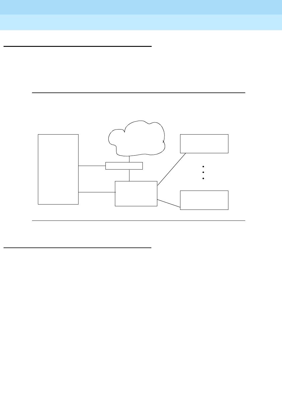
DEFINITY Enterprise Communications Server Release 6
Administration and Feature Description
555-230-522 Issue 4
May 1998
Private Networking
Page 12-3ATM-PNC
12
ATM-PNC
Port network connectivity (PNC) enables you to connect the processor port
network (PPN) to each of the expansion port networks (EPNs). The ATM-PNC
feature uses an ansynchronous transfer mode (ATM) switch to perform the
function of the center-stage switch between the PPN and EPNs.
Figure 12-1. ATM-PNC Hardware Configuration
How to Administer ATM-PNC
The initial administration of an ATM-PNC system is performed by service
technicians at installation. See
Installation for Adjuncts and Peripherals
for
details. For a description of maintenance procedures including troubleshooting
for ATM-PNC, see
Maintenance for R6r
, 555-230-126, Issue 3.
DEFINITY
PPN DS1 Splitter
ATM Switch
PSTN DEFINITY EPN
DEFINITY EPN
OC-3 MM
Fiber
Clock Reference

DEFINITY Enterprise Communications Server Release 6
Administration and Feature Description
555-230-522 Issue 4
May 1998
Private Networking
Page 12-4Centralized Attendant Service
12
Centralized Attendant Service
Centralized Attendant Service (CAS) allows attendants in a private network of
switching systems to be concentrated at a central or main location.
How to administer CAS
Required forms
Form Field Page
System-Parameters
Customer-Options Async. Transfer Mode (ATM)
PNC? 5-277
Synchronization Plan Synchronization Source
Synchronization Reference
Stratum
Duplication-Related System
Parameters Enable Operation of PNC
Duplication 5-104
Fiber Link Administration
ATM-PNC All
Circuit Packs
Cabinet
Required forms
Form Field Page
Attendant Console ■Feature Button Assignments
— cas-backup -trunk-name 5-35
Console-Parameters ■CAS
■RLT Trunk Group Number
■CAS Back-Up Ext
■Timed Reminder on Hold
■Return Call Timeout (sec)
5-86
Station (multi-appearance) ■Feature Button Assignments
— cas-backup
— flash
— trunk name
— night serv
6-28
Trunk Group (RLT) ■All 7-252
Feature Access Code (FAC) ■CAS Remote Hold Access Code 5-113

DEFINITY Enterprise Communications Server Release 6
Administration and Feature Description
555-230-522 Issue 4
May 1998
Private Networking
Page 12-5Centralized Attendant Service
12
Detailed description
Each branch in a CAS has its own LDN or other type of access from the public
network. Incoming trunk calls to the branch, as well as attendant-seeking voice
terminal calls, route to the centralized attendants over release link trunks (RLT).
The CAS attendants are at the main location. The main location can be a
DEFINITY ECS, a DEFINITY System Generic 1 or 3, a DEFINITY System
Generic 2.1, a System 85, a DIMENSION PBX, or a System 75 (V3).
The CAS main switch operates independently of the CAS branch switches.
Operation for CAS main-switch traffic is identical to operation of a stand-alone
switch.
Each branch in a CAS network connects to the main by way of RLTs. These
trunks provide paths for:
■Sending incoming attendant-seeking trunk calls at the branch to the main
for processing and extending them back to the branch (both parts of a call
use the same trunk)
■Returning timed-out waiting and held calls from the branch to the main
■Routing calls from the branch to the main
Two queues are associated with CAS calls: one at the main and one at the
branch. If idle RLTs are available from the branch to the main, RLTs are seized
and CAS calls are queued at the main along with other attendant-seeking calls. If
all RLTs are in use, CAS calls to the attendant are queued at the branch in a RLT
queue. The length of the queue can vary from 1 to 100, as set during
administration of the RLT group.
Backup service provides for all CAS calls can be sent to a backup extension in
the branch if all RLTs are maintenance-busy or out of service, or if the attendant
presses a Backup button that is not lighted.
■To activate the feature and provide notification that backup service is in
effect, assign the backup extension to a Backup button and associated
status lamp.
■The status lamp remains lighted as long as backup service is in effect.
■To deactivate the feature, the attendant presses the Backup button while
the status lamp is lighted. Calls are not sent to the backup extension
unless all RLTs are maintenance-busy or out of service.
The attendant can put a CAS call from a branch on Remote Hold. The branch
holds the call and drops the RLT. After a time-out (same as the timed reminder for
an attendant-held call), the branch automatically attempts to route the call back
to the attendant. The returning call can queue for the RLT. Attendants should use
Remote Hold when they have to put a call on hold to keep RLTs from being tied
up unnecessarily.

DEFINITY Enterprise Communications Server Release 6
Administration and Feature Description
555-230-522 Issue 4
May 1998
Private Networking
Page 12-6Centralized Attendant Service
12
Branch-generated call-identification tones
The branch in a CAS network generates call-identification tones and transmits
them to the CAS attendant by way of the RLT. These tones indicate the type of
call coming from the branch or the status of a call extended to or held at the
branch. The attendant hears these tones in the console handset before being
connected to the caller. The tones may vary by country.
■Incoming trunk call: 480 Hz (100 ms), 440 Hz (100 ms), 480 Hz (100 ms) in
sequence; heard immediately after attendant lifts handset
■Call from branch terminal to attendant or transferred by branch terminal to
attendant: 440 Hz (100 ms), silence (100 ms), 440 Hz (100 ms) in
sequence; heard immediately after attendant lifts handset
■Call extended to idle station or recall on does not answer ringback tone
(300 ms) followed by connection to normal ringing cycle
■Call extended to busy terminal — automatically waiting or recall on
attendant call waiting: 440 Hz (100 ms)
■Call extended to busy terminal — waiting denied or not provided: busy
tone
■Remote hold or remote hold recall: a series of four to six cycles of 440 Hz
(50 ms), silence (50 ms)
■Recall on does not answer: burst of ringback (300 ms), then connection to
normal ringback at any point in its cycle
■Recall from a call on remote hold: a series of four to six cycles of 440 Hz
(50 ms), silence (50 ms)
■Recall from a call waiting at a single-line terminal: burst of 440 Hz (100ms)
The centralized attendant at the main has access, through RLTs, to all outgoing
trunk facilities at the branches in a CAS network. The attendant can extend an
incoming LDN call to an outgoing trunk at a branch by dialing the access code
and allowing the caller to dial the rest of the number or by dialing the complete
outgoing number.
Calls extended to busy single-line voice terminals at the branch wait
automatically. If there is a call in queue, the user hears a busy signal. When
station hunting and send all calls is administered, the call routes along the
administered path. Not answering any waiting extended call within an
administered interval causes the branch switch to return the call to the attendant.
Call Waiting does not apply to multiappearance terminals; if no appearances are
available, busy tone is sent to the attendant, who tells the caller that the line is
busy.
Calls from voice terminals at the branch to an attendant also route over RLTs
seized by the branch switch. A branch caller reaches the attendant by dialing the
attendant-group access code. The access code is administrable; the default is 0.
The conversation between the branch caller and the attendant ties up the seized
RLT, but calls of this type are usually short.

DEFINITY Enterprise Communications Server Release 6
Administration and Feature Description
555-230-522 Issue 4
May 1998
Private Networking
Page 12-7Centralized Attendant Service
12
Considerations
■CAS reduces the number of attendants required at a branch. For example,
a chain of department stores can have a centralized attendant location at
the main store to handle calls for the branch stores.
■In a CAS network, DEFINITY switches can function as branches or as the
main. A branch can connect to only one main.
■A branch can have an attendant. Access to the branch attendant must be
by way of an individual attendant extension. Incoming trunk calls in a CAS
network can bypass branch attendants but can be routed back to them by
the centralized attendant.
■Branch calls terminate on the CAS main switch based on the incoming
RLT trunk-group day-destination or night-service destination. An attendant
console is not always answering or extending incoming CAS calls. If
someone other than an attendant answers a CAS call, that person can
extend the call back to the branch by pressing the FLASH button on a
multiappearance voice terminal or flashing the switchhook on a single-line
voice terminal. The branch reaction to Flash Signals and the branch
application of tones is the same whether an attendant or someone other
than an attendant answers or extends the call.
■If an extended call returns to the main attendant unanswered, the called
party at the branch does not drop but continues to be alerted until the
caller releases. This allows the attendant to talk to the caller, then extend
the call again, if the caller wishes, without redialing the number.
■If an extended CAS call recall times out and goes to coverage but no one
answers, then the branch leaves the extended-to party ringing and drops
coverage.
■When an analog-station call goes to coverage, the station drops from the
call. This is the exception to the branch leaving the extended-to party
ringing. If the main attendant extends a call to an analog station and that
call goes to coverage and later returns to the main attendant, the call is
treated as an incoming LDN call and the attendant must re-extend the call,
if requested by the user.
■On an incoming CAS call to the main attendant, the Name field from the
trunk-group form for that RLT displays to the attendant. Therefore, you
should administer the field to provide meaningful branch identification
information.
■Music-on-Hold feature at branch applies to two stages of LDN calls:
during call extension and Remote Hold.
Interactions
■Abbreviated Dialing

DEFINITY Enterprise Communications Server Release 6
Administration and Feature Description
555-230-522 Issue 4
May 1998
Private Networking
Page 12-8Centralized Attendant Service
12
The main attendant can use an Abbreviated Dialing button to extend CAS
calls after obtaining branch dial tone.
■Attendant Auto-Manual Splitting
The SPLIT lamp and button do not function on CAS main calls extended
via the RLT trunk. Attendant conference does not function on CAS calls.
■Attendant Control of Trunk-Group Access
If a branch attendant has control of an outgoing RLT trunk group, new
attendant-seeking calls route to the branch attendant.
■Attendant Override of Diversion
Use Attendant Override of Diversion with CAS.
■Attendant Serial Calling
Attendant Serial Calling does not work for CAS calls.
■Automatic Alternate Routing and Automatic Route Selection
CAS calls can be routed using AAR and ARS.
■Busy-Indicator Buttons
Busy indicators can identify incoming calls over an RLT. You can also use
Busy indicators to dial after the attendant starts to extend a call.
■Call Coverage
Redirect calls to a centralized attendant by Call Coverage. Do not redirect
calls to a CAS backup extension for backup service via Send All Calls to
the backup extension’s coverage path.
■Call Detail Recording
If the CAS main RLT trunk has the CDR option selected, CDR records
generate for incoming CAS calls.
■Call Forwarding
Do not forward calls to a CAS extension.
■Call Park
If a CAS attendant parks a call and the call returns to the attendant after
the Call Park expiration interval, the attendant hears incoming trunk-call
notification.
■DCS Operation
If an RLT trunk group is administered as a DCS trunk, the following
interaction applies: On an incoming CAS call to the attendant, the DCS
message displays instead of the name of the incoming RLT trunk group.
Upon answering the call, the attendant hears call-identification tones,
indicating that the call is a CAS call. Use a TRUNK-NAME button to obtain
the name of the RLT trunk group.
■DXS and DTGS Buttons

DEFINITY Enterprise Communications Server Release 6
Administration and Feature Description
555-230-522 Issue 4
May 1998
Private Networking
Page 12-9Centralized Attendant Service
12
DXS and DTGS buttons at the main attendant console can be used with
CAS. However, with DXS buttons, it takes a few seconds before the
attendant hears ringback tone.
■Emergency Access to the Attendant
CAS Branch Emergency Access calls generated by a Feature Access
Code route Off-Hook Alert to the branch attendant group. If there is no
attendant in the branch, the call routes to the branch’s administered
Emergency Access Redirection Extension. When the branch switch is in
CAS Backup Service, the calls route to the backup station and the call is
treated as a normal call.
■Hunt Groups
If an incoming CAS call directs to a hunt group, the call does not redirect
to the hunt group’s coverage path. Depending on the circumstances, the
attendant can get a busy tone or ringing.
■Last Number Dialed
An attendant cannot extend calls using Last Number Dialed.
■Leave Word Calling
If a message is left for a branch user and the attendant at the CAS switch
tries to retrieve the message by using LWC message retrieval, permission
is denied.
■Night Service — Night Console Service
When the CAS main enters night service, CAS calls terminate at the CAS
main night-service destination. When the branch enters Night Service,
CAS calls route to the branch night console, the LDN night station, or the
TAAS.
■Night Service — Trunk Answer from Any Station
In a multiswitch DCS environment with CAS, the result of transferring
incoming trunk calls via Night Service Extension or Trunk Answer from Any
Station varies depending on the home switch of the transferred-to station,
the home switch of the connected trunk, and the type of night-service
function chosen (Night Service Extension, Trunk Answer From Any Station,
or both).
■Nonattendant Console Handling of CAS Calls
The CAS branch calls terminate at the CAS main based on the incoming
RLT trunk-group day destination or night-service destination. You can also
answer a CAS call by the Trunk Answer Any Station feature.
Normally, a nonattendant extends a CAS call by pressing the Flash button.
However, if the nonattendant does not have a Flash button, extend the call
as follows:

DEFINITY Enterprise Communications Server Release 6
Administration and Feature Description
555-230-522 Issue 4
May 1998
Private Networking
Page 12-10Centralized Attendant Service
12
— Multiappearance voice-terminal users press the Conference or
Transfer button and then dial the desired extension. To complete
the call, the user drops the call. To drop the extended-to party, the
user presses the Conference or Transfer button again.
— Single-line voice-terminal users flash the switchhook and then dial
the extension. To complete the call, the user drops the call. To drop
the extended-to party, the user flashes the switchhook again.
■Non-Attendant Console Holds Call
A multifunction nonattendant can hold a CAS call by pressing the hold
button.
■Nonattendant Console Releases Call
A nonattendant can drop the RLT by going on-hook, using the
DISCONNECT or DROP button, or selecting another call appearance.
■Nonattendant — Display Trunk Name
If the nonattendant with a display presses the TRUNK-NAME button while
active on a trunk call, the switch displays Name from the trunk-group form.
■Timed Reminder
The timer value for recalling held calls at the attendant console that can be
set on the console form.
If an attendant at the CAS main transfers a call from a branch to an
extension at the main, the timed reminder does not apply and the call
does not return to the attendant if unanswered. If a branch call is
unanswered, the branch timed reminder times out and the call routes to a
new RLT trunk and back to a CAS main attendant.
■Trunk-Name Button
Use the trunk-name button when an outgoing call is made over a trunk
administered to have no outgoing display.

DEFINITY Enterprise Communications Server Release 6
Administration and Feature Description
555-230-522 Issue 4
May 1998
Private Networking
Page 12-11Distributed Communications System
12
Distributed Communications System
Distributed Communications System (DCS) allows you to configure 2 or more
switches as if they were a single, large DEFINITY ECS. DCS provides attendant
and voice-terminal features between these switch locations. DCS simplifies
dialing procedures and allows transparent use of some of the DEFINITY ECS
features. (Feature transparency means that features are available to all users on
DCS regardless of the switch location.)
Configuring a DCS network is a complex process that involves 4 major steps:
■Planning your DCS network
■Connecting the physical equipment in the network
■Administering the physical layer (hardware connections)
■Administering the link layer to create a DCS
How to administer DCS
To administer your DCS, complete the following steps:
1. Connect the switches using the necessary circuit packs, data modules,
and boards, and trunks.
For more information about what hardware you need for your physical
DCS network and how to connect the network, see
DEFINITY Enterprise
Communications Server Release 6 Terminals and Adjuncts Reference.
2. Administer any packet gateway (pgate) boards, processor data modules
(PDM), X.25 data modules, processor interface data modules, and trunks
you have in the DCS network.
NOTE:
Trunk group member numbers and trunk group numbers must match
on both ends of each connection.

DEFINITY Enterprise Communications Server Release 6
Administration and Feature Description
555-230-522 Issue 4
May 1998
Private Networking
Page 12-12Distributed Communications System
12
For information about administering this equipment, see the following
sections in this book.
3. Plan and implement a Dial Plan and Uniform Dial Plan for each switch in
the DCS network.
For more information about administering the dial plans, see ‘‘Dial Plan’’
on page 4-311 and ‘‘Uniform Dial Plan’’ on page 12-103.
Plan your network so you can easily expand and administer the dial plan
table. All nodes within the DCS network must be assigned compatible but
different dial plans. It is recommended that:
■All feature access codes be identical
■Design routing patterns consistently at each node to make outward
dialing transparent
Use the Uniform Dial Plan (UDP) to assign extensions. The UDP design
has to be coordinated among the switches in the DCS network to obtain a
common 4- or 5-digit dial plan. For example, if you have three switches
(nodes) in your DCS network, plan to use unique groups of extensions for
each switch (such as, 4xxxx on one switch, 5xxxx on the second switch,
and 6xxxx on the third switch).
NOTE:
Be sure to record the value in Local PBX ID for each switch. You
need to use this ID to identify the node number on the Route Pattern
form.
The Local PBX ID is the value assigned to the nearest switch (node).
For example, if switch A is connected to B, the Local PBX ID at A
identifies the node number for B. Similarly, you can find the node
number for A, by looking for the Local PBX ID on B (be sure to look at
the connection to A, if it has more than one connection).
Form Page
DS1 Circuit Pack 7-79
Trunk Groups 7-115
Data Modules
X.25 (R5r and later configurations only)
Processor Interface (R5si and later configurations only)
Netcon (R5si and later configurations only)
Processor (if both R5si and R5r in the DCS)
6-226
6-249
6-246
6-245
6-243
Packet Gateway Board (R5r and later configurations only) 5-246
Continued on next page

DEFINITY Enterprise Communications Server Release 6
Administration and Feature Description
555-230-522 Issue 4
May 1998
Private Networking
Page 12-13Distributed Communications System
12
4. Complete a route pattern for each ultimate destination in the network.
For example, if you have four switches in your DCS — switches A, B, C,
and D — you need route patterns for each of the following connections:
5. Administer the following forms to configure the links in the DCS:
NOTE:
Complete the Administered Connections form if you use a PDM and
you set the Destination (or Destination Number for R5r and later
configurations) to external on the Interface Links form.
A to B A to C A to D B to C
B to D C to D B to A C to A
D to A C to B D to B D to C
Required forms
Form Field Page
Interface
Links
■Enable
■X.25 Connection
(R5r and later configurations)
■Destination Number
(R5r and later configurations)
■Establish Connection
(R5r and later configurations)
■Connected Data Module
(R5r and later configurations)
■Est Conn
(R5siand later configurations)
■PI Ext
(R5si and later configurations)
■Prot
(R5si and later configurations)
■Destination
(R5si and later configurations)
■DCE/DTE
(R5si and later configurations)
5-179

DEFINITY Enterprise Communications Server Release 6
Administration and Feature Description
555-230-522 Issue 4
May 1998
Private Networking
Page 12-14Distributed Communications System
12
6. Complete the Processor Channel Assignment form on each switch to
establish dialogs from the switch to other nodes on the network.
This step involves extensive planning as you must map each link, channel,
and remote port throughout the network.
7. Administer the Hop Channels.
For more information, see ‘‘Hop Channel Assignments Form’’ on page
12-116.
8. If you are using ISDN, administer the gateway functions.
For more information, see ‘‘ISDN TSC Gateway Channel Assignments’’ on
page 7-98.
Detailed description of DCS
DCS network configurations can be:
■Traditional DCS network — A DCS network configured with 2 or more
switches using BX.25 signaling for transporting DCS feature transparency
information.
■D-channel DCS network (private network only) — A DCS network that
includes DEFINITY ECS using the ISDN-PRI D-channel DCS transparency
information (D-channel signaling). ISDN-PRI facilities with this type of
network use only private-line facilities.
■D-channel DCS network (public network access/egress) — A DCS
network that includes DEFINITY ECS using D-channel signaling. At least
one of these ISDN-PRI facilities uses a public network ISDN-PRI.
Administered
Connection
■Connection Number
■Originator
■Destination
■Name
■Retry Interval
■Auto Restoration?
5-17
Processor
Channel
Assignment
■All Proc Chan fields that you
want to be assigned DCS 5-248
(R5r and later
configurations)
5-252
(R5si and later
configurations)
Required forms
Form Field Page

DEFINITY Enterprise Communications Server Release 6
Administration and Feature Description
555-230-522 Issue 4
May 1998
Private Networking
Page 12-15Distributed Communications System
12
■Integrated DCS network (private network only) — A DCS network that
contains a variety of switches using BX.25 or D-channel signaling
methods. At least one DEFINITY ECS serves as an ISDN-PRI DCS
Gateway node. This node can interwork DCS transparency information
between a BX.25 connection and one of the ISDN-PRI user-to-user
signaling methods over the D-channel.
An ISDN-PRI DCS Gateway node provides backward compatibility to
existing traditional DCS networks.
■Integrated DCS network (public network access) — The same as
D-channel DCS Network (Private Network Only), but the D-channel of at
least one ISDN- PRI facility uses a public network ISDN-PRI.
Once you have connected and set up your DCS network, you can provide the
following features across the network:
■DCS Alphanumeric Display for Terminals
■DCS Attendant Control of Trunk Group Access
■DCS Attendant Direct Trunk Group Selection
■DCS Attendant Display
■DCS Automatic Callback
■DCS Automatic Circuit Assurance
■DCS Busy Verification of Terminals and Trunks
■DCS Call Coverage
■DCS Call Forwarding
■DCS Call Waiting
■DCS Distinctive Ringing
■DCS Leave Word Calling
■DCS Multiappearance Conference/ Transfer
■DCS Over ISDN-PRI D-channel
■DCS Trunk Group Busy/Warning Indication
■DCS with Rerouting
■Enhanced DCS
DCS/AUDIX gateway
DEFINITY ECS can serve as an interface between PBXs that support the
D-channel signaling feature and those that do not support this feature. The
switch providing this interface is known as the ISDN-DCS Gateway node and
provides backward compatibility to existing traditional DCS networks.

DEFINITY Enterprise Communications Server Release 6
Administration and Feature Description
555-230-522 Issue 4
May 1998
Private Networking
Page 12-16Distributed Communications System
12
It maintains a mapping between processor channels and Administered
NCA-TSCs. When a DCS D-channel message arrives on an Administered
NCA-TSC acting as a gateway, it is converted to a traditional DCS message and
sent out through the processor channel that has been administered to map to this
Administered NCA-TSC. Likewise, when a traditional DCS message arrives at the
gateway node on a processor channel acting as a gateway, it is converted to a
DCS D-channel message and sent out through the Administered NCA-TSC that
has been associated with this processor channel on the ISDN Gateway Channel
form.
In summary, a gateway is required whenever a transition is being made from
BX.25 signaling to D-channel signaling. When the transition takes place at a
switch that sits between that part of the network that supports D-channel DCS
and that part that does not, that switch is an ISDN-DCS Gateway. A DCS network
consisting entirely of switches that support D-channel DCS never requires an
ISDN-DCS Gateway because none of the switches require “translation” to/from
BX.25.
Example DCS configurations
The following two examples provide details for setting up two basic DCS
networks. The first is a two-node network and the second is a three-node
network.
2-Node private network with AUDIX
Figure 12-2 shows a 2-node DCS/AUDIX D-channel network. In this
configuration, DCS feature transparency is achieved exclusively through the
exchange of user-to-user information on the D-channel using one of the three
methods discussed earlier — MA-UUI, CA-TSCs or NCA-TSCs. Although
NCA-TSCs are nothing more than virtual connections on the D-channel, they are
shown as independent entities in the diagram for the purposes of clarity.
Administered TSC 2/1 (that is, the first Administered NCA-TSC of signaling group
2) of Switch A is connected to TSC 4/1 of Switch B. This virtual connection is
used in the exchange of user-to-user information for DCS features not associated
with any current B-channel connection.
Notice that for AUDIX, a BX.25 data link is no longer required between the host
switch and the remote switch(es). AUDIX messages between the AUDIX and the
remote switch will use the AUDIX Gateway functionality of the host switch and will
be transported to the remote switch via an NCA-TSC. Specifically, AUDIX
messages destined for Switch B will arrive at Switch A on Link 1, Channel 2
(processor channel 57), be converted to ISDN-PRI Q.931 format and sent out via
Administered NCA-TSC 2/2.
This is accomplished by administering processor channel 57 as a gateway and
mapping it on the gateway form to Administered NCA-TSC 2 of signaling group 2
that is also administered as a gateway.
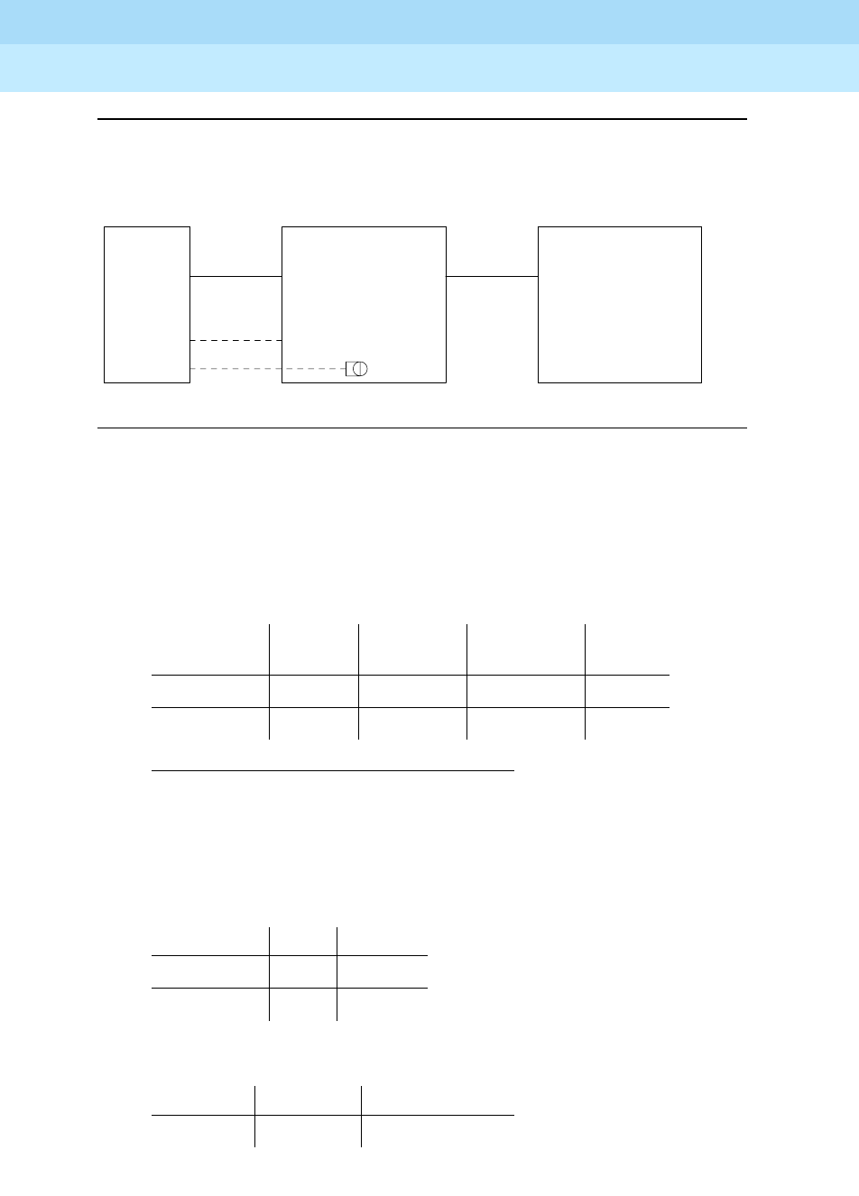
DEFINITY Enterprise Communications Server Release 6
Administration and Feature Description
555-230-522 Issue 4
May 1998
Private Networking
Page 12-17Distributed Communications System
12
Figure 12-2. 2-Node private network
The following tables show you how you would complete each of the necessary
forms.
AUDIX administration
■AUDIX Translations for,
Administration for switch 1
■Dial Plan form
■Uniform Dial Plan form
1. Switch Port refers to the processor channel that is used for AUDIX in
the PBX.
Switch
Number
AUDIX
Port
Switch
Port1Logical
Channel
Data
Link
115911
225721
Start Dig. Len Usage
44ext
54ext
Ext Code Type Location Code
5xxx UDPcode 222
1/1
1 Link Link
TSC TSC
1
SWITCH 2
SWITCH 1
AUDIX
. . . . . . . . . . . . . . . . . .
. . . . . . . . . . . . . . . . . . . . . . . . . . . . . . . .
D-CHANNEL
BX.25
1/2
1/2
1/1
G3i
PBX ID 2
RNX 222
G3i
PBX ID 1
RNX 221
AUDIX 2
DCS 1-2
AUDIX 2
AUDIX 1 4/1
4/2
1
2/2
2/1
2

DEFINITY Enterprise Communications Server Release 6
Administration and Feature Description
555-230-522 Issue 4
May 1998
Private Networking
Page 12-18Distributed Communications System
12
■AAR Digit Conversion form
■AAR Analysis Table
■Signaling Group form (signaling group 2)
■Tr u n k Gro u p fo r m
■Routing Pattern form
■Gateway Channel form
Matching
Pattern Min Max Del
Replacement
String Net Conv
221 7 7 3 - ext n
Dialed String Min Max Rte Pat Call Type Node Num
222 7 7 2 aar 2
TSC Local Enabled Establish Dest. Far-end Appl.
Index Ext. Ext. PBX-ID
1 4900 y permanent 5900 2 dcs
2 4901 y permanent 5901 - gateway
Group # Grp Type
Used for
DCS?
DCS Sig.
Method PBX ID
2 isdn-pri y d-chan 2
Routing
Pattern #
Trunk
Group # FRL Del TSC
CA-TSC
Request
22 03yat-setup
Signaling Group
TSC
Index
Processor
Channel Application
2 2 57 audix

DEFINITY Enterprise Communications Server Release 6
Administration and Feature Description
555-230-522 Issue 4
May 1998
Private Networking
Page 12-19Distributed Communications System
12
■Processor Channel form
Administration for switch 2
■Dial Plan form
■Uniform Dial Plan form
■AAR Digit Conversion form
■AAR Analysis Table
■Signaling Group form (signaling group 4)
Proc
Channel Application
Inter.
Link Channel
Remote Proc.
Channel
PBX
ID
57 gateway 1 2 2 -
59 audix 1 1 1 1
Start Dig. Len Usage
44ext
54ext
Ext Code Type Location Code
4xxx UDPcode 221
Matching
Pattern Min Max Del
Replacement
String Net Conv
222 7 7 3 - ext n
Dialed
String Min Max Rte Pat Call Type
Node
Num
221 7 7 1 aar 1
TSC
Index
Local
Ext. Enabled Establish Dest.
Far-end
Ext.
Appl
PBX-ID
1 5900 y permanent 4900 1 dcs
2 5901 y permanent 4901 - audix

DEFINITY Enterprise Communications Server Release 6
Administration and Feature Description
555-230-522 Issue 4
May 1998
Private Networking
Page 12-20Distributed Communications System
12
■Tr u n k Gro u p fo r m
■Routing Pattern form
3-Node public/private network with AUDIX
The D-channel signaling feature expands the domain of DCS networks by
supporting configurations that include public network ISDN facilities utilizing
network services including Software Defined Network (SDN). By eliminating the
need for dedicated private line facilities, this feature allows geographically
dispersed DCS networks to be cost effective. Figure 12-3 shows a 3-node
network.
Group # Grp Type Used for DCS?
DCS Sig.
Method PBX ID
1 isdn-pri y d-chan 1
Routing
Pattern #
Trunk
Group # FRL Del TSC
CA-TSC
Request
1103yat-setup
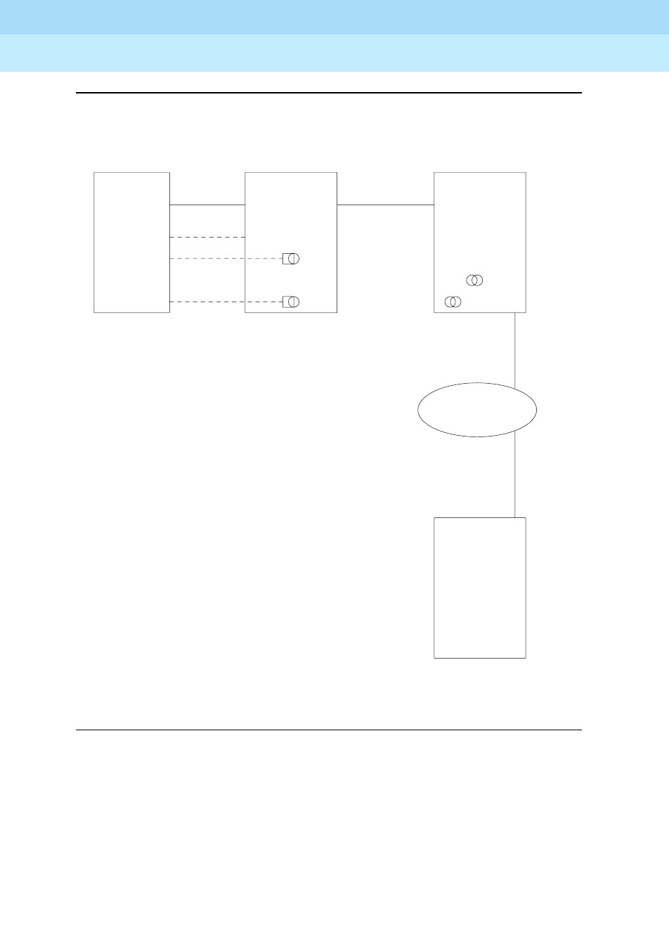
DEFINITY Enterprise Communications Server Release 6
Administration and Feature Description
555-230-522 Issue 4
May 1998
Private Networking
Page 12-21Distributed Communications System
12
Figure 12-3. 3-Node public/private network
AUDIX SWITCH 1 SWITCH 2
SWITCH 3
1/1
1/2
1/3
1/1
1/2
1/3
2/1
2/2
2/3
2/4
4/1
4/2
TSC
TSC
TSC TSC
Link
1/3 1/2 1/1
5/1
AUDIX 1
AUDIX 2
AUDIX 3
DCS 1-2
AUDIX 2
DCS 1-3
AUDIX 3
D
C
S
2
-
3
D
C
S
2
-
3
D
C
S
1
-
3
D
C
S
1
-
3
A
U
D
I
X
3
A
U
D
I
X
3
AT&T
NETWORK
G3i
PBX ID 2
RNX 222
G3i
PBX ID 3
RNX223
G3i
PBX ID 1
RNX 221
. . . . . . . . . . . . . . . . . . . . . . . . . . . . . . . . . . . . . .
.
.
.
.
.
.
.
.
.
.
.
.
.
.
.
.
.
.
.
.
.
.
.
.
.
.
.
.
.
.
.
.
.
.
.
.
.
.
.
.
.
.
.
.
.
.
.
.
.
.
.
.
.
.
.
.
.
.
.
.
.
.
.
.
.
.
.
.
.
.
.
.
.
.
.
.
.
.
.
.
.
.
.
.
.
.
. . . . . . . . . . . . . . . . . . . . . . . . . . . . . . . . .
. . . . . . . . . . . . . . . . . . . . . . . . . . . . . . . . . .
. . . . . . . . . . . . . . . . . . . . . . . . .
.
.
.
.
.
.
.
.
.
.
.
.
.
.
.
.
.
.
.
.
.
.
.
.
.
.
.
.
.
.
.
.
.
.
.
.
.
.
.
BX.25 D CHANNEL
D
-
C
H
A
N
N
E
L
D
-
C
H
A
N
N
E
L
1 1 2 1
2
1

DEFINITY Enterprise Communications Server Release 6
Administration and Feature Description
555-230-522 Issue 4
May 1998
Private Networking
Page 12-22Distributed Communications System
12
The following tables show you how you would complete each of the necessary
forms.
AUDIX administration
■AUDIX Translations form
Administration for switch 1
■Dial Plan form
■Uniform Dial Plan form
■AAR Digit Conversion form
■AAR Analysis Table
1. Switch Port refers to the processor channel that is used for AUDIX in the PBX.
Switch Number AUDIX Port Switch Port1Logical Channel
Data
Link
115911
225721
335831
Start Dig. Len Usage
44ext
54ext
64ext
Ext Code Type Location Code
5xxx UDPcode 222
6xxx UDPcode 223
Matching
Pattern Min Max Del
Replacement
String Net Conv
221 7 7 3 - ext n
Dialed String Min Max Rte Pat Call Type Node Num
222 7 7 2 aar 2
223 7 7 3 aar 3

DEFINITY Enterprise Communications Server Release 6
Administration and Feature Description
555-230-522 Issue 4
May 1998
Private Networking
Page 12-23Distributed Communications System
12
■Signaling Group form (signaling group 2)
■Tr u n k Gro u p fo r m
■Routing Pattern form
■Gateway Channel form
■Processor Channel form
TSC
Index
Local
Ext. Enabled Establish
Dest.
Ext.
Far-end
PBX-ID Appl
1 4900 y permanent 5900 2 dcs
2 4901 y permanent 5901 - gateway
3 4902 y permanent 6902 3 dcs
4 4903 y permanent 6903 - gateway
Group # Grp Type Used for DCS? DCS Sig. Method PBX ID
2 isdn-pri y d-chan 2
3 isdn-pri y d-chan 3
Routing
Pattern #
Trunk
Group # FRL Del TSC CA-TSC Request
2203yat-setup
3303yat-setup
Signaling Group TSC Index Processor Channel Application
2 2 60 audix
2 4 61 audix
Proc
Channel Application
Inter.
Link Channel
Remote Proc.
Channel PBX ID
59 audix 1 1 1 1
57 gateway 1 2 2 -
58 gateway 1 3 3 -

DEFINITY Enterprise Communications Server Release 6
Administration and Feature Description
555-230-522 Issue 4
May 1998
Private Networking
Page 12-24Distributed Communications System
12
Administration for switch 2
■Dial Plan form
■Uniform Dial Plan form
■AAR Digit Conversion form
■AAR Analysis Table
■Signaling Group form
Signaling group 4
Signaling group 5
Start Dig. Len Usage
44ext
54ext
64ext
Ext Code Type Location Code
4xxx UDPcode 221
6xxx UDPcode 223
Matching
Pattern Min Max Del
Replacement
String Net Conv
222 7 7 3 - ext n
Dialed String Min Max Rte Pat Call Type Node Num
221 7 7 1 aar 1
223 7 7 3 aar 3
TSC Local Enabled Establish Dest. Far-end Appl.
Index Ext. Ext. PBX-ID
1 5900 y permanent 4900 1 dcs
2 5901 y permanent 4901 - audix
TSC Local Enabled Establish Dest. Far-end Appl.
Index Ext. Ext. PBX-ID
1 5905 y permanent 6905 3 dcs

DEFINITY Enterprise Communications Server Release 6
Administration and Feature Description
555-230-522 Issue 4
May 1998
Private Networking
Page 12-25Distributed Communications System
12
■Tr u n k Gro u p fo r m
■Routing Pattern form
Administration for switch 3
■Dial Plan form
■Uniform Dial Plan form
■AAR Digit Conversion form
1. This field is only used for tandeming.
Group # Grp Type
Used
for
DCS?
DCS
Sig.
Method PBX ID
NCA-TSC
Sig. Group1
1 isdn-pri y d-chan 1 -
3 isdn-pri y d-chan 5
Routing
Pattern #
Trunk
Group # FRL Del TSC CA-TSC Request
1103yat-setup
3303yat-setup
Start Dig. Len Usage
44ext
54ext
64ext
Ext Code Type Location Code
4xxx UDPcode 221
5xxx UDPcode 222
Matching
Pattern Min Max Del
Replacement
String Net Conv
223 7 7 3 - ext n

DEFINITY Enterprise Communications Server Release 6
Administration and Feature Description
555-230-522 Issue 4
May 1998
Private Networking
Page 12-26Distributed Communications System
12
■AAR Analysis Table
■Signaling Group form (signaling group 4)
■Tr u n k Gro u p fo r m
■Routing Pattern form
Interactions
See the specific DCS features for interactions with each DCS feature.
1. Should be blank if SDN network routing requires 7 digits.
Dialed String Min Max Rte Pat Call Type Node Num
221 7 7 1 aar 1
222 7 7 2 aar 2
TSC
Index
Local
Ext.
Enable
d Establish
Dest.
Ext.
Far-end
PBX-ID Appl.
1 6905 y permanent 5905 2 dcs
2 6902 y permanent 4902 1 dcs
3 6903 y permanent 4903 - audix
Group # Grp Type
Used for
DCS? DCS Sig. Method PBX ID
1 isdn-pri y d-chan
Routing
Pattern #
Trunk
Group # FRL Del TSC CA-TSC Request
1103
1yat-setup

DEFINITY Enterprise Communications Server Release 6
Administration and Feature Description
555-230-522 Issue 4
May 1998
Private Networking
Page 12-27DCS Alphanumeric Display for Terminals
12
DCS Alphanumeric Display for
Terminals
DCS Alphanumeric Display for Terminals allows calls to or from
alphanumeric-display terminals to have transparency for call-related data.
The transparency allows calling-name display, called-name display, and
miscellaneous identifiers to be transferred from a terminal on one node to a
terminal on another node.
The following DCS configurations provide transparency of alphanumeric
displays.
■Networks of 2 or more DEFINITY ECS
■Networks of 2 or more DEFINITY switches: (Generic 1 or Generic 3i) with a
System 75 Version 3 or later, Generic 2, System 85 Release 2 Version 2 or
later, or a Generic 2.1 as an intermediate node
■A DEFINITY system Generic 1 connected to a System 85 Release 2
Version 2 or later, or a Generic 2 or later.
How to administer DCS Alphanumeric Display
for Terminals
Required forms
Form Field Page
Trunk Group - Tie (DCS TG) Outgoing Display 7-262

DEFINITY Enterprise Communications Server Release 6
Administration and Feature Description
555-230-522 Issue 4
May 1998
Private Networking
Page 12-28DCS Attendant Control of Trunk Group Access
12
DCS Attendant Control of Trunk
Group Access
DCS Attendant Control of Trunk Group Access allows an attendant at any node in
the DCS to control an outgoing trunk group at an adjacent node in the cluster.
To use this feature, you must have a DCS Trunk Group between the local and
remote switches, and the trunks in that trunk group cannot insert digits on
incoming calls. If you need digit insertion on these trunks, it should be added on
the outgoing trunk based on the dialed string.
NOTE:
DCS Attendant Control of Trunk Group Access is not available if you are
using D-channel DCS.
How to administer DCS Attendant Control of
Trunk Group Access
Required forms
Form Field Page
Attendant Console ■Feature Button Assignments
— act-tr-grp
— deact-tr-g
— remote-tgs
5-35

DEFINITY Enterprise Communications Server Release 6
Administration and Feature Description
555-230-522 Issue 4
May 1998
Private Networking
Page 12-29DCS Attendant Direct Trunk Group Selection
12
DCS Attendant Direct Trunk Group
Selection
DCS Attendant Direct Trunk Group Selection allows attendants at one node to
have direct access to an idle outgoing trunk at a different node in the DCS. This
feature functions the same as regular Direct Trunk Group Selection, except
attendants can access trunk groups at remote nodes.
NOTE:
DCS Attendant Direct Trunk Group Selection is not available if you are using
D-channel DCS.
To use this feature, you must have a DCS Trunk Group between the local and
remote switches, and the trunks in that trunk group cannot insert digits on
incoming calls. If you need digit insertion on these trunks, it should be added on
the outgoing trunk based on the dialed digits.
You can assign a Trunk Hundreds Select button to access a trunk group at the
local node or a trunk group at a remote node. A Trunk Group Select button
assigned to access a remote node is referred to as a remote Trunk Hundreds
Select button. Pressing a remote Trunk Group Select button is the same as
dialing the tie trunk group access code for the remote node and the trunk access
code of the selected trunk.
Each attendant console has 12 Trunk Hundreds Select buttons for Attendant
Direct Trunk Group selection. Each button allows the attendant to directly access
an outgoing trunk group by pressing the button assigned to that trunk group.
Each button’s Busy lamp lights when all trunks in its associated trunk group are
busy. On a basic console, 6 of these buttons have 2 additional lamps for
Attendant Control of Trunk Group Access. On an enhanced console, all 12
buttons have the additional lamps. The two additional lamps are:
■Warn (warning) lamp
Lights when a preset number of trunks are busy in the associated trunk
group.
■Cont (control) lamp
Lights when the attendant activates Attendant Control of Trunk Group
Access for the associated trunk group.
Users can activate attendant control of a remote trunk group in the DCS network
by pressing the Cont button followed by the desired Remote Trunk Hundreds
Select button. The initiating node sends a message to the remote node where the
trunk group to be controlled resides to indicate that control of that trunk group
was initiated.
When the remote node receives the activation message from the initiating node, it
has 4 seconds to reply back to the initiating node whether control of the remote
trunk group can be activated. If control of the remote trunk group can be

DEFINITY Enterprise Communications Server Release 6
Administration and Feature Description
555-230-522 Issue 4
May 1998
Private Networking
Page 12-30DCS Attendant Direct Trunk Group Selection
12
activated, a confirmation message is sent to the initiating node and the Cont
lamp lights at the remote node. An error message is sent to the attendant at the
initiating node if the trunk access code is invalid or if the trunk group is already
controlled. An error message is also sent if the remote node is a System 85 or
Enhanced DIMENSION PBX and the attendant does not have a Trunk Hundreds
Select button with Cont lamp for that trunk group.
When a trunk group is controlled in a DCS environment, calls to the trunk group
by anyone other than an attendant route to the local attendant at the node where
the trunk group resides. If that node does not have an attendant, the call routes to
a CAS main attendant or an attendant for Inter-PBX Attendant Calls. However, if
CAS or Inter-PBX Attendant Calls is not provided, the party attempting to call on
the controlled trunk receives intercept tone.
How to administer DCS Attendant Direct Trunk
Group Selection
Required forms
Form Field Page
Attendant Console ■Direct Trunk Group Select Button
Assignments
— remote-tgs
5-35

DEFINITY Enterprise Communications Server Release 6
Administration and Feature Description
555-230-522 Issue 4
May 1998
Private Networking
Page 12-31DCS Attendant Display
12
DCS Attendant Display
The DCS Attendant Display provides transparency for displaying call-related
information.
Calls to and from DEFINITY ECS in a DCS environment have calling-party ID and
called-party ID transparency when:
■The other party is at another Generic 1, Generic 3, or System 75, and the
intermediate node is a Generic 1, Generic 2, Generic 3, System 75 Version
3 or later, or a System 85 Release 2 Version 2 or later.
■The other party is at a System 85 Release 2 Version 2 or later, or a
DEFINITY system Generic 2 or later.
■The call is not routed through an intermediate System 85 Release 2
Version 1 or Enhanced DIMENSION PBX node. (These calls display only
the extension of the calling party or called party.)
How to administer DCS Attendant Display
You administer DCS Attendant Display the same as you do Attendant Display.
See ‘‘Attendant Display’’ on page 4-74 for more information.
Required forms
Form Field Page
Attendant Console ■Display Module Button Assignments
■Display Language
5-35

DEFINITY Enterprise Communications Server Release 6
Administration and Feature Description
555-230-522 Issue 4
May 1998
Private Networking
Page 12-32DCS Automatic Callback
12
DCS Automatic Callback
DCS Automatic Callback allows a user at one node to make an automatic
callback call to a user at another node in the DCS.
A DCS Automatic Callback call can be initiated from a terminal at one node to a
terminal at another node in the same way as if at a local node under the following
conditions.
■If the called party is at a System 85, Generic 2, or Enhanced DIMENSION
PBX node, the callback call can only be activated if the called node is
returning busy tone or special audible ringback.
■If the called party is at a Generic 3, Generic 1 or System 75 node, the
callback call can be activated if the called node is returning busy tone,
Call Waiting ringback tone, or ringback tone.
■The calling party must disconnect within 6 seconds after hearing the
confirmation tone for Automatic Callback activation.
Automatic Callback uses the following rules when the callback call is made to a
user at another node:
■When the calling party answers the callback call, and no tie trunk to the
called-party’s node is available, Automatic Callback is reactivated toward
the called party. The calling party hears confirmation tone instead of
ringback when this occurs.
■If the calling party is on a System 85, Generic 2, or Enhanced DIMENSION
PBX node and is unable to receive the callback call (for example, a busy
single-line voice terminal without Call Waiting), Automatic Callback is
reactivated by the calling party’s node. If the calling party is on a Generic
3, Generic 1, or System 75 node and is unable to receive the callback call,
the callback call is canceled.
■If the called party is unable to receive the callback call because they are
busy again (for example, the called party goes on hook and then off hook
immediately to place another call), the calling party hears busy tone again
and can choose to reactivate Auto Callback, if desired.

DEFINITY Enterprise Communications Server Release 6
Administration and Feature Description
555-230-522 Issue 4
May 1998
Private Networking
Page 12-33DCS Automatic Callback
12
How to administer DCS Automatic Callback
You administer DCS Automatic Callback the same as you do Automatic Callback.
See ‘‘Automatic Callback’’ on page 4-100 for more information.
Required forms
Form Field Page
Feature-Related System
Parameters
■Automatic Callback — No Answer
Timeout Interval 5-123
Feature Access Code
(FAC)
■Automatic Callback Activation
■Automatic Callback Deactivation
5-113
Station
(multiappearance)
■Button/Feature Button Assignments
— auto-cback 6-14
Class of Service ■Automatic Callback (0–15) 5-81

DEFINITY Enterprise Communications Server Release 6
Administration and Feature Description
555-230-522 Issue 4
May 1998
Private Networking
Page 12-34DCS Automatic Circuit Assurance
12
DCS Automatic Circuit Assurance
DCS Automatic Circuit Assurance (ACA) allows a voice-terminal user or
attendant at a node to activate and deactivate ACA referral calls for the entire
DCS network. This transparency allows the referral calls to originate at a node
other than the node that detects the problem.
If referral calls are generated at a node for one or more remote nodes, the remote
nodes are notified when ACA referral is activated or deactivated. If referral calls
are generated at a remote node for a DEFINITY ECS node, the DEFINITY ECS
node is notified when ACA referral is activated or deactivated at the remote node.
The lamp associated with the ACA button lights when ACA referral is activated
and goes dark when ACA referral is deactivated. The ACA button serves no other
purpose when a remote node generates the DEFINITY ECS referral calls.
How to administer DCS ACA
Required forms
Form Field Page
Feature-Related System
Parameters
■ACA Referral Calls 5-123
Attendant Console ■Feature Button Assignments
— aca halt 5-35
Station
(multiappearance)
■Button/Feature Button Assignments
— aca halt 6-14
Trunk Group (Tie) ■ACA Assignment
■Long Holding Time
■Short Holding Time
■Short Holding Threshold
7-262

DEFINITY Enterprise Communications Server Release 6
Administration and Feature Description
555-230-522 Issue 4
May 1998
Private Networking
Page 12-35DCS Busy Verification of Terminals and Trunks
12
DCS Busy Verification of Terminals
and Trunks
DCS Busy Verification of Terminals and Trunks allows attendants and
multiappearance voice-terminal users to make test calls to voice terminals and
trunk groups that are located at other nodes in the DCS.
To use this feature, you must have a DCS Trunk Group between the local and
remote switches, and the trunks in that trunk group cannot insert digits on
incoming calls. If you need digit insertion on these trunks, it should be added on
the outgoing trunk based on the dialed digits.
Attendants and voice-terminal users can busy-verify voice terminals at a remote
location by pressing Verify and dialing the UDP extension. Verification continues
as if the voice terminal is on the same node.
Multiappearance voice terminal users can busy-verify an adjunct at a remote
location by pressing Verify and dialing the TAC of the tie trunk group to the
remote node. Then they must press Verify a second time and dial the desired
TAC and the trunk group member number to be verified. Verification of the trunk
then continues as if the trunk is on the same node.
How to administer DCS Busy Verification of
Terminals and Trunks
You administer DCS Busy Verification of Terminals and Trunks the same as you
do Busy Verification of Terminals and Trunks. See ‘‘Busy Verification of Terminals
and Trunks’’ on page 4-130 for more information.
Required forms
Form Field Page
Attendant Console Feature Button Assignments
— verify 5-35
Station
(multi-appearance) Button/Feature Button Assignments
— verify 6-14

DEFINITY Enterprise Communications Server Release 6
Administration and Feature Description
555-230-522 Issue 4
May 1998
Private Networking
Page 12-36DCS Call Coverage
12
DCS Call Coverage
DCS Call Coverage provides DCS messaging required for calls to be covered on
remote systems when there is a DCS signaling link (BX.25 or ISDN-PRI) for the
trunk groups. Calls to an extension on one system are covered by extensions on
remote systems that are administered as coverage points.
How to administer DCS Call Coverage
To administer DCS Call Coverage, you must have DCS software and UDP or PNA
software. DCS Call Coverage must be enabled on all systems having principals
or coverage points and on all intervening systems.
Detailed description of DCS Call Coverage
DCS Call Coverage is similar to Call Coverage, with the following exceptions:
■Coverage Answer Groups across nodes are not supported.
■Under some conditions, a call follows the coverage point’s coverage path.
(See ‘‘Operation Under Error Conditions’’ on page 12-40 for more
information.)
■Under some conditions, Consult does not work properly. (See ‘‘Operation
Under Error Conditions’’ on page 12-40 for more information.)
■Displays differ in some cases. (See ‘‘How to administer DCS
Alphanumeric Display for Terminals’’ on page 12-27 for more details.)
■DCS Call Coverage does not support Coverage Call Back from a remote
node.
■DCS Call Coverage supports Consult.
NOTE:
In releases prior to DEFINITY ECS and G3V4, DCS Call Coverage
was limited to coverage of a single point and that point had to be an
AUDIX, AUDIX DEFINITY, or INTUITY.
Required forms
Form Field Page
All forms required for DCS All 12-11
All forms required for Call Coverage All 4-146
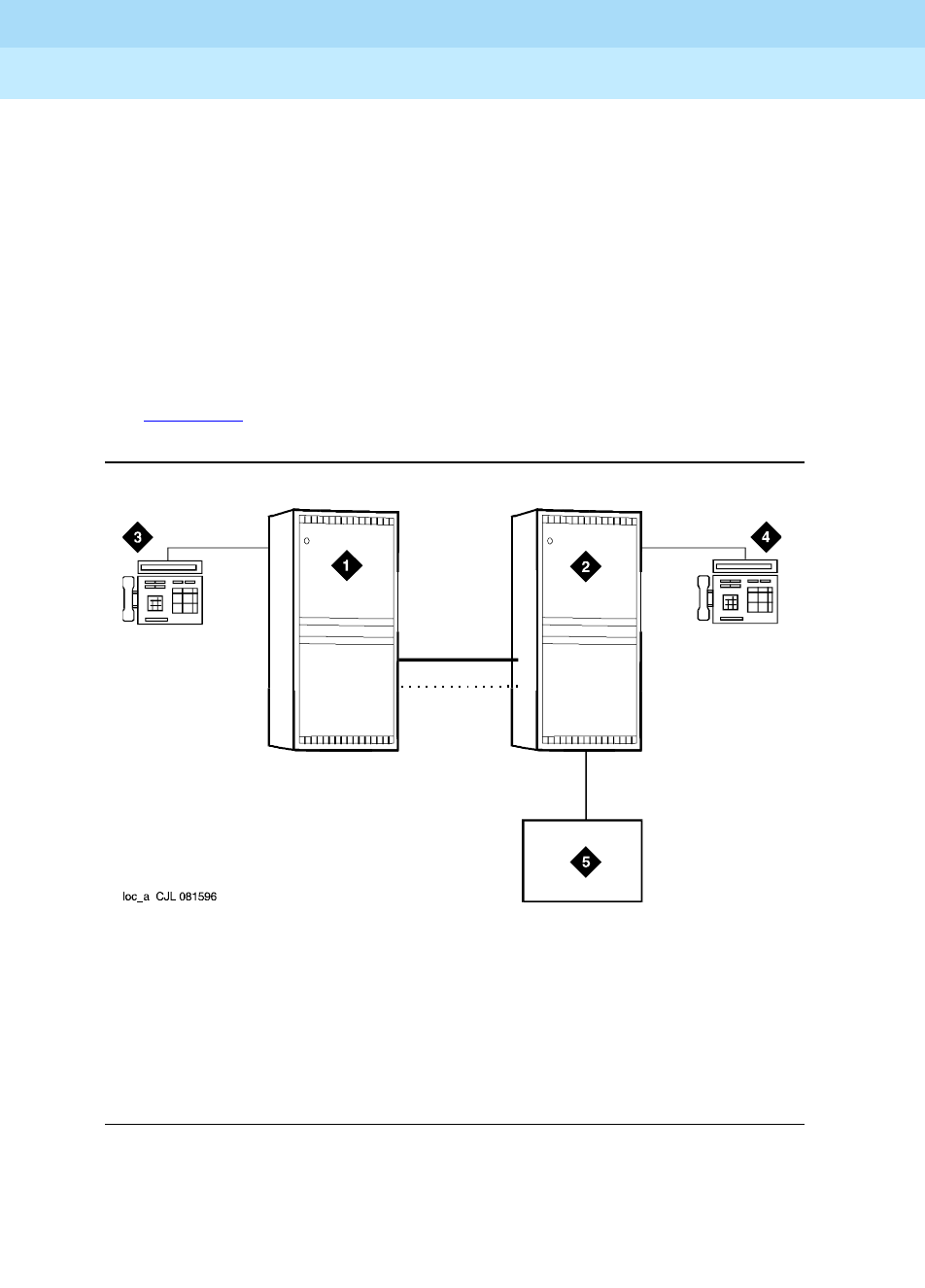
DEFINITY Enterprise Communications Server Release 6
Administration and Feature Description
555-230-522 Issue 4
May 1998
Private Networking
Page 12-37DCS Call Coverage
12
DCS Call Coverage applications
Without DCS Call Coverage, the following coverage cannot be achieved:
■You spend time in multiple locations and want calls to Station B to be
covered first by Station A and then by AUDIX, DEFINITY AUDIX, or INTUITY.
■You move from location A to location B and want calls to Station A to be
covered first at Station B, then at AUDIX.
■You are normally located at Station B, but want calls to first be answered
by an administrative assistant at Station A, and then by the AUDIX at
location B.
See Figure 12-4 for an example of a DCS Call Coverage configuration.
:
Figure Notes
Figure 12-4. Configuration for DCS Call Coverage
1. Location A - DEFINITY ECS
2. Location B - DEFINITY ECS
3. Station A
4. Station B
5. AUDIX, DEFINITY AUDIX or INTUITY
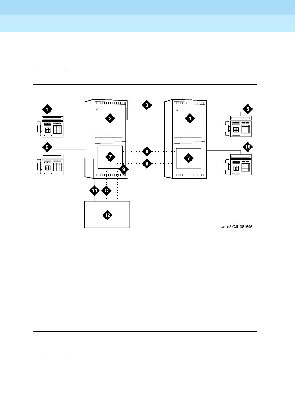
DEFINITY Enterprise Communications Server Release 6
Administration and Feature Description
555-230-522 Issue 4
May 1998
Private Networking
Page 12-38DCS Call Coverage
12
DCS Call Coverage Operation
DCS Call Coverage allows calls to cover to points other than AUDIX on a remote
system. Through DCS messaging, it provides transparency for Call Coverage.
Figure 12-5 shows an example of DCS Call Coverage.
.
Figure Notes
Figure 12-5. DCS Call Coverage
In Figure 12-5, calls to Station A can be covered first by Station B, then by Station
C or D, and finally by the AUDIX on system A. Alternatively, calls could be
covered by Station C, then Station B, then Station D, and so on.
If the called party answers after the call goes to coverage and the coverage point
has answered, then the called party, calling party, and coverage point are all
conferenced together.
1. Station A
2. System A - DEFINITY ECS
3. DCS Tie Trunk Groups
4. System B - DEFINITY ECS
5. Station C
6. Station B
7. PGATE or PI Board
8. X.25 or ISDN PRI DCS Signaling Link
9. Hop or ISDN TSC Gateway
10. Station D
11. AUDIX Voice Lines
12. AUDIX - x34000

DEFINITY Enterprise Communications Server Release 6
Administration and Feature Description
555-230-522 Issue 4
May 1998
Private Networking
Page 12-39DCS Call Coverage
12
If the called party answers and the coverage point has not answered, the call to
the coverage point drops and the called party connects to the calling party.
Operation under Normal Conditions
In a normal DCS Call Coverage configuration where the DCS link is up, the DCS
trunk group is available, and DCS Call Coverage is active on the local and
remote systems, DCS Call Coverage works as follows:
1. A call comes into the principal.
2. The principal does not answer within the administered number of rings or
has Send All Calls active.
3. The call is redirected to the first coverage point, which is on the remote
system. Also, at this time the DCS distinctive ringing message is sent to
the coverage point along with 2 messages conveying the caller’s name
and the principal’s name.
4. The coverage point rings with internal ringing (if the caller is on a DCS
node) or with external ringing.
5. The covering station answers and receives the calling party’s name and
principal’s name on the display.
Other DCS Call Coverage situations can occur which deviate from the normal
operation, including:
■A call to the principal redirects to the remote coverage point, which is
unavailable. The coverage point is considered unavailable when:
— The coverage point is not a valid extension, QDN, or VDN.
— The coverage point is busy with no hunting, forwarded, or has send
all calls activated, or activates send all calls after ringing.
— The coverage point has no staffed agents or an invalid vector.
When the coverage point is unavailable, the local system determines the
availability status from a time-out or from a message from the remote
system. When the local system discovers that the coverage point is
unavailable, it tries the next coverage point. If the last coverage point is
unavailable, the previous coverage point rings until it is answered or until
the caller hangs up. If only one coverage point exists in the path and it is
unavailable, the principal’s station rings until it is answered or until the
caller hangs up.
■A call to the principal is forwarded and the forwarded-to extension is not
available. In this case, the first coverage point in the principal’s path is
tried. Note that the coverage does not follow the forwarded-to extension’s
coverage path.

DEFINITY Enterprise Communications Server Release 6
Administration and Feature Description
555-230-522 Issue 4
May 1998
Private Networking
Page 12-40DCS Call Coverage
12
■A call to the principal redirects to the remote coverage point, which
answers. Subsequently, the principal goes off hook. In this case, the local
system bridges the principal onto the call between the calling party and
coverage point creating a conference among the three. The principal
receives the call on the same call appearance as the original call.
■A call to the principal redirects to the remote coverage point. While the
remote coverage point is ringing, the principal answers the call. In this
case the call is not cut through to the coverage point. Instead, ringing and
ringback is removed from the coverage point and the call is cut through to
the principal.
Operation Under Error Conditions
Table 12-2 describes the DCS Call Coverage under error conditions.
In addition, when the DCS link is down, call consult operates differently. If Station
A calls Station B but the call covers to Station C, then Station C consults back to
Station B and Station B receives the consult call on the next call appearance.
Table 12-2. Error Conditions
Error Condition Action
DCS link not up.
or
DCS trunk is not available.
or
DCS Call Coverage feature is not
activated on the remote system.
The call is routed to the remote
coverage point. If the call is
answered, it is treated as Call
Coverage Off Premises (also called
Remote Call Coverage). If the call is
redirected at the remote coverage
point before the DCS SRI expires,
the remote point’s path is followed. If
the call is not answered within the
DCS SRI time-out period, the next
coverage point is tried with DCS Call
Coverage from the local system.
All trunks to the remote system, DCS
or otherwise, are busy The next coverage point is tried with
DCS Call Coverage from the local
system.

DEFINITY Enterprise Communications Server Release 6
Administration and Feature Description
555-230-522 Issue 4
May 1998
Private Networking
Page 12-41DCS Call Forwarding
12
DCS Call Forwarding
DCS Call Forwarding allows all calls to an extension to be forwarded to a
selected extension in the DCS network or to an external (off-premises) number.
If the Call Forwarding and DCS Call Forwarding are both active, and if a call is
forwarded between extensions on the same node, the Call Forwarding coverage
path is used. If the nodes are different, the DCS Call Forwarding coverage path is
used.
Voice-terminal users in the DCS can activate/deactivate this feature with a dial
access code or with a Call Forwarding button.
NOTE:
Calls can be forwarded to a Vector Directory Number (VDN) anywhere in
the DCS network. An attendant cannot activate/deactivate Call Forwarding
for a VDN.
How to administer DCS Call Forwarding
You administer DCS Call Forwarding the same as you do Call Forwarding. See
‘‘Call Forwarding’’ on page 4-224 for more information.
Required forms
Form Field Page
Feature Access
Code (FAC)
■Call Forwarding Activation
■Call Forwarding Deactivation
5-113
Station ■Redirect Notification
■Button/Feature Button Assignments
— call-fwd
6-28
Class of Service ■Call Fwd-All Calls (0-15) 5-81

DEFINITY Enterprise Communications Server Release 6
Administration and Feature Description
555-230-522 Issue 4
May 1998
Private Networking
Page 12-42DCS Call Waiting
12
DCS Call Waiting
DCS Call Waiting allows calls from one node to busy single-line voice terminals at
another node to wait until the called party is available to accept the call. With
DCS Call Waiting, a single-line voice terminal user, by knowing a call is waiting,
can quickly process calls from locations within the DCS. DCS Call Waiting
functions the same as normal Call Waiting.
DCS Call Waiting includes the following features:
■Attendant Call Waiting
■Call Waiting — Termination
■Priority Calling
DCS priority calling from the attendant station is
not
available.
How to administer DCS Call Waiting
None

DEFINITY Enterprise Communications Server Release 6
Administration and Feature Description
555-230-522 Issue 4
May 1998
Private Networking
Page 12-43DCS Distinctive Ringing
12
DCS Distinctive Ringing
DCS Distinctive Ringing activates the called-terminal alerting or ringing device to
indicate the type of incoming call to the user before they answer it. Distinctive
Alerting functions in a DCS environment the same as it does within a single
system.
By default, internal calls are identified by a 1-burst ringing pattern, external calls
by a 2-burst ringing pattern, and priority calls by a 3-burst ringing pattern.
However, you can administer these patterns.
How to administer DCS Distinctive Ringing
None.

DEFINITY Enterprise Communications Server Release 6
Administration and Feature Description
555-230-522 Issue 4
May 1998
Private Networking
Page 12-44DCS Leave Word Calling
12
DCS Leave Word Calling
DCS Leave Word Calling (LWC) enables users to leave preprogrammed “call me”
messages at other terminals within the DCS network. Messages can be left by
calling, called, or covering users.
LWC transparency in a DCS configuration allows messages from a DEFINITY
switch to another node, depending on the storage capability of the remote node.
How to administer DCS LWC
Required forms
Form Field Page
Feature-Related
System Parameters
■Max. Number Of Messages Per Station
■Stations With System-Wide Message
Retrieval Permission
5-123
Feature Access
Code (FAC)
■LWC Message Retrieval Lock
■LWC Message Retrieval Unlock
■LWC Send A Message
■LWC Cancel A Message
5-113
Station ■LWC Reception
■LWC Activation
■Button/Feature/Button Assignments
— lwc-store
— lwc-cancel
— aut-msg-wt (Ext:__)
— msg-retr
— delete-msg
— lwc-lock
— next
— call-disp
— cov-msg-rt
6-28
Continued on next page

DEFINITY Enterprise Communications Server Release 6
Administration and Feature Description
555-230-522 Issue 4
May 1998
Private Networking
Page 12-45DCS Leave Word Calling
12
You administer DCS LWC the same as you do LWC. See ‘‘Leave Word Calling’’
on page 4-405 for more information.
Attendant Console Feature Button Assignments
— cov-msg-rt
— delete-msg
— next
— lwc-cancel
— call-disp
— lwc-store
— aut-msg-wt (Ext:__)
5-35
Required forms — Continued
Form Field Page
Continued on next page

DEFINITY Enterprise Communications Server Release 6
Administration and Feature Description
555-230-522 Issue 4
May 1998
Private Networking
Page 12-46DCS Multiappearance Conference/ Transfer
12
DCS Multiappearance Conference/
Tr a n s fe r
DCS Multiappearance Conference/Transfer provides transparency for
transferring calls and conferencing calls within a DCS network. A user in the DCS
can initiate conference calls among or transfer calls originated from extensions in
the DCS network to another extension within the DCS by dialing the UDP
extension. (For transferred calls, the destination need not be within the DCS.)
In a DCS, if a party in a conference hangs up or completes a transfer leaving only
outgoing trunks on the call, the system attempts to preserve the connection if any
of the remaining parties on the call is a DCS tie trunk.
The display transparency is not preserved after a conference of transfer across
the DCS network.
How to administer DCS Multiappearance
Conference/Transfer
None.

DEFINITY Enterprise Communications Server Release 6
Administration and Feature Description
555-230-522 Issue 4
May 1998
Private Networking
Page 12-47DCS Over ISDN-PRI D-channel
12
DCS Over ISDN-PRI D-channel
DCS Over ISDN-PRI D-channel (DCS+) enhances DCS by allowing access to the
public network for DCS connectivity between DCS switch nodes. With this
feature, DCS features are no longer restricted to private facilities.
The ISDN-PRI B-channel is used for voice communications, and the ISDN-PRI
D-channel transports DCS control information. The only difference between DCS
networks that do not utilize the DCS Over ISDN-PRI and those that do is in the
method of signaling. The DCS Over ISDN-PRI D-channel uses
Message-Associated User-to-User Information (MA-UUI) and Temporary
Signaling Connections (TSC) to transport certain DCS control information.
MA-UUI allows additional user-specific information to be transported along with
certain ISDN call-control messages.
NOTE:
Use this feature only over DS1/E1 or T1 circuit packs that are administered
to Country Protocol Option 1 (even in a private network environment)
independent of what country the system is in.
How to administer DCS Over ISDN-PRI
D-channel
Required forms
Form Field Page
Signaling Group ■Max number of NCA TSC
■Max number of CA TSC
■Trunk Group for NCA TSC
■Administered NCA TSC Assignment
fields
■Service/Feature
■Inactivity Time-out (min)
7-106
ISDN TSC Gateway
Channel Assignments
■All 7-98
Trunk Group (ISDN-PRI) ■Used for DCS Node Number DCS
Signaling
■NCA TSC Signaling Group
7-219
Continued on next page

DEFINITY Enterprise Communications Server Release 6
Administration and Feature Description
555-230-522 Issue 4
May 1998
Private Networking
Page 12-48DCS Over ISDN-PRI D-channel
12
NOTE:
There are several differences in administration between switches. For
example, PRI is translated a little differently in G3r when traditional DCS
and this feature are used in combination. On systems with AUDIX in a DCS
environment, an additional column has been added to the Signaling Group
form so you can specify which AUDIX and switch to use. When traditional
DCS and DCS over ISDN are used in combination, translations are also
different.
Detailed description
A TSC provides a temporary signaling path through ISDN switches for
exchanging supplementary service information on ISDN-PRI D-channels. There
is no B-channel related to the connection; no data or voice transmissions take
place.
There are two types of temporary signaling connections:
■Call Associated (CA-TSC)
■Non-Call Associated (NCA-TSC)
A CA-TSC refers to a service for exchanging USER INFORMATION messages
associated with an ISDN B-channel connection by the call reference value of the
call control data packets. On DEFINITY ECS, this type of TSC is used only for
DCS features on ISDN-PRI Signaling Groups administered with Supplementary
Service Protocol a.
An NCA-TSC is a connection not related with any ISDN B-channel connections.
DECINITY ECS supports two types of NCA-TSC that conform to two different
protocol standards:
Route Pattern ■TSC
■CA TSC Request
8-67
Processor Channel
Assignment
■Application 5-248
or
5-252
Feature-Related System
Parameters
■Record TSCs for CDR 5-123
Required forms — Continued
Form Field Page
Continued on next page

DEFINITY Enterprise Communications Server Release 6
Administration and Feature Description
555-230-522 Issue 4
May 1998
Private Networking
Page 12-49DCS Over ISDN-PRI D-channel
12
■The AT&T type of NCA-TSC is used for the DCS Over ISDN-PRI D-channel
and DCS AUDIX applications. Only ISDN-PRI Signaling Groups
administered with Supplementary Service Protocol a support AT&T
NCA-TSCs.
■The QSIG type of NCA-TSC is used for certain QSIG features such as Call
Completion (Automatic Call Back). This type of NCA-TSC is referred to in
the QSIG protocol standards as a Call-Independent Signaling Connection
(CISC). Only ISDN-PRI Signaling Groups administered with
Supplementary Service Protocol b support QSIG NCA-TSCs.
For further information, see ‘‘QSIG NCA-TSC’’ on page 12-80.
AT&T NCA-TSC
An AT&T NCA-TSC is an administered virtual connection established for
exchanging USER INFORMATION messages on the ISDN D-channel. Once an
AT&T NCA-TSC has been administered and enabled, it is active for an extended
period of time. There are two types of administered NCA-TSCs depending on
their setup mechanism:
■Permanent (can be established by Near-end or Far-end)
■As-needed
Once enabled, a permanent NCA-TSC remains established while the system is
running. If the permanent NCA-TSC drops for any reason, the system attempts to
reestablish the connection. An as-needed administered NCA-TSC is established
based on user request and the availability of TSC facilities. The connection drops
after an administered period of inactivity.
The system can transport DCS or DCS AUDIX messages over an ISDN-PRI
D-channel and over BX.25 data links when functioning as a gateway between a
switch equipped with DCS Over ISDN-PRI D-channel and a switch equipped with
traditional DCS using BX.25 data links. In this situation, the messages travel from
the gateway through the NCA-TSCs or CA-TSCs to TSC-capable switches and
from the gateway to switches that support only traditional DCS via a BX.25 logical
channel.
At least one switch must be configured as an ISDN DCS Gateway node in a DCS
network that consists of switches that support DCS Over ISDN-PRI D-channel
and PBXs that do not support the feature. Switches directly connected to AUDIX
serve as Gateway nodes.

DEFINITY Enterprise Communications Server Release 6
Administration and Feature Description
555-230-522 Issue 4
May 1998
Private Networking
Page 12-50DCS with Rerouting
12
DCS with Rerouting
Distributed Communications System (DCS) with Rerouting allows a call’s
connection between two DEFINITY systems to be replaced by a new connection.
All of the trunks used in the original path must be DCS and the new path utilizes
only DCS trunks. DCS with Rerouting provides the following capabilities:
■Attempts to obtain a better (generally less expensive) connection.
■May replace the current path of a call with a route that is better in terms of
Automatic Alternate Routing/Automatic Route Selection (AAR/ARS) routing
preferences administered on a DEFINITY ECS.
■Frees up resources being used unnecessarily.
How to administer DCS with Rerouting
Detailed description
DCS with Rerouting primarily provides you with the ability to attempt to be more
effective with the usage of Trunk groups administered for Supplementary
Services Protocol Option E (SSE) during the existence of an active call. This
means using a more preferred route (in terms of UDP/AAR/ARS routing
preferences administered on the PBX) between the PBXs involved.
Your users invoke DCS with Rerouting by Call Transfer, Transfer out of Audix, and
dial 0 out of Audix. DCS with Rerouting must be enabled on a switch-wide basis
and the trunk groups involved must be administered as SSE.
Considerations
■DCS with Rerouting could fail.
■Depending upon administration of routing patterns, the new route could
be worse than the original.
Required forms
Form Field Page
Trunk Group
ISDN-PRI All 7-219

DEFINITY Enterprise Communications Server Release 6
Administration and Feature Description
555-230-522 Issue 4
May 1998
Private Networking
Page 12-51DCS with Rerouting
12
Interactions
■When interworking with non-ISDN trunks or non-Supplementary Service
Option E ISDN trunks, DEFINITY acts as a gateway in the following sense:
■When a call is tandeming through a DEFINITY system from a
non-ISDN trunk to an SSE trunk or from a non-Option E to an SSE
trunk, the system acts as an incoming gateway.
■When a call is tandeming through a DEFINITY system from an SSE
trunk to a non-ISDN trunk or from an SSE trunk to a non-Option E
trunk, the system acts as an outgoing gateway.
As an example, when calls come in from the public network to the
DCS network and then are transferred to another extension within
the private network, DEFINITY functions as an incoming gateway
and rerouting occurs.
■If a conference call is transferred, rerouting will not occur.
■Trunks or endpoints measured by the Call Management System (CMS) will
not have rerouting take place.
■Trunks or endpoints that are involved with vectoring or announcements will
not have rerouting take place.

DEFINITY Enterprise Communications Server Release 6
Administration and Feature Description
555-230-522 Issue 4
May 1998
Private Networking
Page 12-52DCS Trunk Group Busy/Warning Indication
12
DCS Trunk Group Busy/Warning
Indication
DCS Trunk Group Busy/Warning Indication provides attendants with a visual
indication that the number of busy trunks in a remote group reached an
administered level. A visual indication is also provided when all trunks in a trunk
group are busy.
NOTE:
DCS Trunk Group Busy/Warning Indication is not available if you are using
DCS over ISDN-PRI.
To use this feature, you must have a DCS Trunk Group between the local and
remote switches, and the trunks in that trunk group cannot insert digits on
incoming calls. If you need digit insertion on these trunks, it should be added on
the outgoing trunk based on the dialed digits.
You can administer DCS Trunk Group Busy/Warning Indication only for remote
trunk groups that are directly connected to the local switch. Trunk group access
codes for these trunk groups must be 3 digits or less.
If an attendant has a Trunk Hundreds Select button assigned to a remote trunk
group, the button’s Busy lamp lights when all trunks in the trunk group are busy. If
an attendant has a 3-lamp Trunk Hundreds Select button assigned to a remote
trunk group, the button’s Warn lamp lights when the number of busy trunks in the
trunk group reaches the Busy Warning Threshold.
To ensure that the busy, warning, and control status of all Trunk Hundreds Select
buttons in the DCS remain consistent with the status of the corresponding trunk
groups, some nodes in the DCS broadcast the status of a different local trunk
group, every 50 seconds, to all directly connected nodes. (A pair of DCS nodes
are directly-connected if the voice tie trunks between them are not connected
through another switch). For example, a node with 30 trunk groups would take
1,500 (50 x 30) seconds to broadcast the status of all 30 trunk groups. This is
called a lamp audit. When a node receives a lamp audit message, its TGB/TGW
lamps update accordingly.

DEFINITY Enterprise Communications Server Release 6
Administration and Feature Description
555-230-522 Issue 4
May 1998
Private Networking
Page 12-53DCS Trunk Group Busy/Warning Indication
12
How to administer DCS Trunk Group
Busy/Warning Indication
Required forms
Form Field Page
Attendant Console ■Direct Trunk Group Select Button
Assignments
— (1–6) for 301A Basic
or
— (1–12) for the 302A Enhanced Attendant
Console
5-35
Trunk Groups (All) ■Busy Threshold 7-115

DEFINITY Enterprise Communications Server Release 6
Administration and Feature Description
555-230-522 Issue 4
May 1998
Private Networking
Page 12-54Emergency (911) Calls
12
Emergency (911) Calls
The Enhanced 911 (E911) systems installed in many jurisdictions in the U.S. are
equipped so that by dialing a service code (911 in the U.S.) a victim of a fire,
accident, crime, or medical emergency may quickly access a public safety
agency that will dispatch the appropriate response. The public E911 system
maintains a database that stores location and background information to aid
public safety agencies in responding quickly with the appropriate assistance.
Information about the calling party can be triggered by the transmission of a
Caller’s Emergency Service Identification (CESID) number over Centralized
Automatic Message Accounting (CAMA) trunks when the call originates from
behind a PBX. 911 calls from a station on a PBX not equipped with CAMA trunks
(or an adjunct computer system associated with CAMA trunks) will not provide
the E911 system with the information required to identify the location of the
person placing the call. Instead, the E911 system will only be able to identify the
location of the trunk termination at the PBX.
This feature allows transmission of identifying information in the form of the
CESID over CAMA trunks as to the extension number of a DID station associated
with the calling party. The calling party may be at or near a station on a remote
port network, or may be at a remote location served by an off-premises station.
How to administer Emergency (911) Calls
Interactions
None.
Required forms
Form Field Page
ARS Digit Analysis Table ■All 8-55
CAMA Numbering Format ■All 5-61
Class of Restriction ■Calling Party Restriction 5-72
Feature Access Code ■ARS Access Code1
■ARS Access Code2
5-113
Route Pattern ■All 8-67
Trunk Group (CAMA) ■All 7-161

DEFINITY Enterprise Communications Server Release 6
Administration and Feature Description
555-230-522 Issue 4
May 1998
Private Networking
Page 12-55Enhanced DCS
12
Enhanced DCS
Enhanced DCS (EDCS) adds features to the existing DCS capabilities.EDCS is
used primarily in Italy. EDCS adds the following features:
■Exchanging information to provide class of restriction (COR) checking
between switches in the EDCS network
■Providing call-progress information for the attendant
■Allowing attendant intrusion between a main and a satellite
■Allowing a main PBX to provide DID/CO intercept treatment rather than the
satellite PBX.
NOTE:
EDCS is not compatible with DCS Over/Under ISDN-PRI. If used with
ISDN-PRI, configure the switch as a DCS node. Also, DCS-ISDN display
enhancements are not currently available in EDCS.
How to administer Enhanced DCS
Required forms
Form Field Page
Feature-Related
System Parameters
■Enhanced DCS Enabled?
■Apply Intercept Locally?
■Enforce PNT-to-PNT Restrictions?
5-123

DEFINITY Enterprise Communications Server Release 6
Administration and Feature Description
555-230-522 Issue 4
May 1998
Private Networking
Page 12-56DCS feature considerations
12
DCS feature considerations
■The DS1 Circuit Pack form must be completed if DS1 tie trunks are used
for DCS signaling.
■The Synchronization Plan form must be completed if DS1 tie trunks are
used for DCS signaling. You assign a secondary circuit pack that the
system can use if the primary circuit pack fails.
■If you call an attendant on another switch in the DCS network, your display
shows the attendant’s name, but does not show the attendant’s extension,
instead you see a zero where the extension should be.
DCS Alphanumeric Display considerations
■Calls to and from a DEFINITY ECS in a DCS network have Calling/Called
Name Display transparency under the following conditions:
— The other party is at another DEFINITY ECS or a DEFINITY Generic
3 and the tandem node is a System 75 Version 3 or later, DEFINITY
Generic 1, DEFINITY Generic 3, System 85 Release 2 Version 2 or
later, or a DEFINITY Generic 2.1.
— The call is not routed through a tandem System 85 Release 2
Version 1 or Enhanced DIMENSION PBX node. (Such calls display
only the extension number of the calling or called party.)
■On outgoing DCS calls, display of the called name may be delayed for a
few seconds until the required information arrives from the distant node.
The called name display only works between DEFINITY ECS, DEFINITY
Generic 1 and Generic 3 Systems, and System 75s.
■Within the same DEFINITY ECS, DEFINITY Generic 1 or Generic 3 nodes
in a DCS, complete transparency of Calling and Called Name Display
exists.
DCS Attendant Control of Trunk Group Access considerations
■This feature is not available for trunk groups with 4-digit trunk access
codes or for trunk members 100 through 999.
■There must be direct DCS tie trunk connections between the initiating
node and the remote node where the trunk group to be controlled
originates. Otherwise, control of remote trunk groups is denied.
■If the remote node (where the trunk group to be controlled resides) is a
System 75, Generic 1, or Generic 3, it is not necessary for that node to
have an attendant console with corresponding three-lamp Trunk Hundreds
Select button. However, if the remote node is a System 85, Generic 2.1, or
Enhanced DIMENSION PBX, control of the trunk group is not allowed
unless an attendant at that node has a corresponding three-lamp Trunk
Group Select button.

DEFINITY Enterprise Communications Server Release 6
Administration and Feature Description
555-230-522 Issue 4
May 1998
Private Networking
Page 12-57DCS feature considerations
12
■The attendant must use the Remote Trunk Hundreds Select button to
directly access the controlled remote trunk group. If an attendant controls
a remote trunk group, and that attendant dials the trunk access codes of
the DCS tie trunk and the controlled remote trunk group, the call is routed
to the attendant at the node where the trunk group resides.
■If Attendant Control of Trunk Group Access is activated, and no attendant
is assigned, or the attendant is later removed, calls to a controlled trunk
group route to the attendant queue.
DCS Attendant Direct Trunk Group Selection considerations
■This feature is not available for trunk groups with 4-digit trunk access
codes or for trunk members 100 through 999.
■There must be a direct DCS tie trunk connection between the initializing
node and the remote node where the trunk group to be accessed
originates. Otherwise, access to the remote trunk group is denied.
DCS Attendant Display considerations
■CORs for a DEFINITY switch may not correspond to those used by an
Enhanced DIMENSION PBX, System 85, or DEFINITY system Generic 2.1.
Therefore, if the DCS network contains nodes other than Generic 1 or
Generic 3, the display CORs may be misinterpreted. If it is important that
certain CORs between various systems correspond with each other, those
CORs should be administered accordingly.
■On outgoing calls, the display of called party information may be delayed
a few seconds until the required information arrives from the remote node.
The called party information is displayed only if both nodes are Generic 1
or System 75.
■DCS tie trunks between nodes must be administered with the Outgoing
Display enabled. This enables the called party’s name to be displayed at
the calling attendant’s display.
DCS Automatic Callback considerations
■An Automatic Callback request is canceled automatically if the called
party does not become available within 40 minutes, or if the calling party
does not hang up within six seconds after activating Automatic Callback.
■DCS Automatic Callback does not work on the last trunk between nodes.
Thus, if
n
trunks are provided, there can be up to
n - 1
Automatic Callback
calls.
DCS Busy Verification of Terminals and Trunks considerations
■This feature is not available for trunk groups with 4-digit trunk access
codes or for trunk members 100 through 999.

DEFINITY Enterprise Communications Server Release 6
Administration and Feature Description
555-230-522 Issue 4
May 1998
Private Networking
Page 12-58DCS feature considerations
12
DCS Call Coverage considerations
■The following software is required for DCS Call Coverage.
— DCS software
— UDP or PNA software
— DCS Call Coverage must be enabled on all systems having
principals or coverage points and on all intervening systems.
DCS Call Forwarding considerations
■With DCS Call Forwarding, voice terminal users can have their calls follow
them to any location within the DCS network or outside the DCS network.
■Calls to an attendant cannot be forwarded. However, an attendant can
activate or deactivate the feature for other extension numbers within the
DCS.
DCS Distinctive Ringing considerations
■When DCS transparency is lost for any reason, terminal-to-terminal calls
made between nodes produce external ringing instead of the usual
internal ringing. Loss of transparency may occur when the data link
between nodes is down or when data transmission delay exceeds the
trunk signaling time.
DCS LWC considerations
■LWC cannot be successfully activated toward any system that is not
capable of storing the messages, either internally or in an associated
adjunct.
■Messages from one node, through an intermediate node, to a remote node
do not require storage capability at the intermediate node.
■LWC transparency is supported for all DCS configurations except for
cases when either the activating node or the remote node is either an
ENHANCED DIMENSION PBX or a System 85 R2V1.
■Retrieval of LWC messages is permitted only from a terminal at the node
where the messages are stored.
■DCS LWC cannot be activated from an attendant console.
DCS Multiappearance Conference/Transfer considerations
■DCS Multi-Appearance Conference/Transfer is useful when it is necessary
to talk to more than one party at one time within a DCS. Multiappearance
voice terminals must have an idle appearance in order to transfer a call.

DEFINITY Enterprise Communications Server Release 6
Administration and Feature Description
555-230-522 Issue 4
May 1998
Private Networking
Page 12-59DCS feature considerations
12
DCS Over ISDN-PRI D-channel considerations
■Users should not notice any difference between DCS features over
ISDN-PRI and traditional DCS features.
■The gateway node serves as the terminating node to the D-channel DCS
network as well as the terminating node to the traditional DCS network.
A PBX serving as an ISDN DCS Gateway node introduces some
interesting situations when administering processor channels in an
associated traditional DCS PBX. In a traditional DCS network, (BX.25
processor channel links) Remote Port in the “Processor Channel
Assignments” form refers to the processor channel of the destination PBX.
In an Integrated DCS network, Remote Proc Chan in the “Processor
Channel Assignments” form refers to the processor channel of the
Gateway PBX (if the destination PBX is an ISDN DCS PBX),
not
the
destination PBX.
On the contrary, Machine-ID in the “Processor Channel Assignments”
form refers to the destination PBX, either an ISDN DCS PBX or a traditional
DCS PBX. The Gateway PBX number must not be used in this field if the
destination PBX is an ISDN DCS PBX.
DCS Trunk Group Busy/Warning Indication considerations
■This feature is not available for trunk groups with 4-digit trunk access
codes or for trunk members 100 through 999.
■Trunk Group Busy and Trunk Group Warning Indication is particularly
useful with the Attendant Control of Trunk Group Access feature. The
indicators alert the attendant when control of access to local and remote
trunk groups is necessary.
■Except for remote S75 R1V3, S85/G2 and S75 R1V2 switches, this feature
is only transparent if the remote switch is directly connected by voice tie
trunks. For S75 R1V3 and S85/G2 remote switches, Trunk Group Busy and
Trunk Group Warning Indication is provided regardless of whether the
voice tie trunks are directly-connected or in tandem through an
intermediate node; For S75 R1V2 remote switches, no Trunk Group Busy
and Trunk Group Warning Indication transparency is provided.
Enhanced DCS considerations
■If the DCS link fails, the administrator can choose to allow calls to continue
without class of restriction checking or to block all DCS calls to
inward-restricted stations.
■Enhanced DCS is not available with DCS over an ISDN-PRI D-channel.
When EDCS is used, all nodes in the DCS network must use EDCS.
■The DCS Transfer display enhancements and DCS Conference display
enhancements do not apply when EDCS is enabled.

DEFINITY Enterprise Communications Server Release 6
Administration and Feature Description
555-230-522 Issue 4
May 1998
Private Networking
Page 12-60DCS feature considerations
12
DCS Interactions
DCS Alphanumeric Display interactions
The following features allow transparency with respect to Calling or Called Name
Display and miscellaneous ID.
■Automatic Callback
Complete display transparency.
■Call Coverage
At the calling terminal, the miscellaneous id “cover” is not displayed.
■Call Forwarding
When a system user calls a party on a different node in the DCS and the
call is forwarded, the miscellaneous ID “forward” is not displayed. At the
covering (forwarded-to) user’s terminal, only the calling party’s name is
shown; the called party’s name is not displayed.
■Call Park
When a DCS call between a local system user and a user on another node
is parked by the remote user, the miscellaneous ID “park” is not displayed
at the local terminal.
■Call Pickup
When a DCS call from a system user to another node is answered by way
of Call Pickup, the miscellaneous ID “cover” is not displayed at the caller’s
terminal.
■Call Waiting
When a DCS call from a system user to another node is waiting at the
called terminal, the miscellaneous ID “wait” is not displayed at the caller’s
terminal.
■CAS
When a user dials the extension for CAS, a RLT is seized or the caller is
queued for an RLT. The caller’s terminal displays the trunk group identifier,
such as OPERATOR.
■Conference
When two DCS and/or ISDN-PRI calls (or any possible combination of
each) are conferenced and revert to a two-party call, the trunk group of
the remaining call is displayed.
■DDC/UCD
Complete display transparency.
■Internal Terminal-to-Terminal Calling
Complete display transparency.

DEFINITY Enterprise Communications Server Release 6
Administration and Feature Description
555-230-522 Issue 4
May 1998
Private Networking
Page 12-61DCS feature considerations
12
■ISDN-PRI
If both DCS and ISDN-PRI features are provided with a system, the
ISDN-PRI display information displays in DCS format.
DCS Attendant Control of Trunk Group Access interactions
■DCS Attendant Display
When a user attempts to access a controlled trunk group and is routed to
the local attendant, the display shows the reason the call was redirected. If
the call is routed via CAS or the Inter-PBX Attendant Calls feature, the
display does not show the reason the call was redirected.
■UDP
DCS tie trunks should not be attendant controlled. This would result in all
UDP calls on the controlled tie trunk being routed to the controlling
attendant instead of to the desired destination.
DCS Attendant Display interactions
■When both ISDN and DCS display information, or only DCS display
information, is received, the switch displays the DCS display information in
the DCS format. If ISDN display information is received, and no DCS
display information is received, then the ISDN display information displays
in the ISDN formats.
DCS Automatic Callback interactions
■Attendant Control of Trunk Group Access and DCS Attendant Control of
Trunk Group Access
Automatic Callback cannot be activated if the call uses a controlled trunk
group.
■Call Forwarding and DCS Call Forwarding
Automatic Callback calls cannot be activated on a voice terminal at a
DEFINITY switch or System 75 node that has Call Forwarding activated.
■Vector Directory Number
Automatic callback calls do not apply for VDNs.
DCS Automatic Circuit Assurance interactions
■None.
DCS Busy Verification interactions
■If the Trunk Identification by Attendant feature is used during busy
verification of a trunk (Trunk ID button is pressed), the trunk access code
and trunk group member number of the DCS tie trunk being used is
displayed.

DEFINITY Enterprise Communications Server Release 6
Administration and Feature Description
555-230-522 Issue 4
May 1998
Private Networking
Page 12-62DCS feature considerations
12
■DCS Busy Verification of Terminals and Trunks transparency is lost if the
routing pattern is administered to not delete the RNX and the AAR prefix is
inserted on the terminating switch trunk group. The voice terminal display
at the terminating switch displays only a=station name. Extension is left
blank.
DCS Call Coverage interactions
DCS Call Coverage has the same interactions as Call Coverage plus the
following additional interactions.
■Call Coverage Off Premises
If the coverage point is a non-UDP number in the remote call coverage
table, Call Coverage Off Premises is applied to the call rather than DCS
Call Coverage, even if a DCS link exists to the remote system.
■Coverage Answer Groups
DCS Call Coverage to Coverage Answer Groups on remote systems are
not supported by DCS Call Coverage. Coverage answer groups cannot
be administered on a system other than the principal’s system.
■Coverage Call Back
DCS Call Coverage does not support Coverage Call Back from a remote
node. This is because the coverage point’s system has no way of knowing
whether the caller can respond to Leave Word Calling. For example, the
coverage point’s system does not know whether the calling party is a trunk
or a station.
■Displays
The displays on the DCS Call Coverage point’s terminal may be different
than those associated with the Call Coverage feature in the following
situations:
— When the call from the calling party to the principal or the
redirected call to the coverage point travel over ISDN-PRI trunk
groups.
— When the calling party is on a System 85 or Generic 2.
— When the DCS name message is not received by the remote
(coverage point’s) system.
■Go to Cover
Go to Cover is not supported over DCS and therefore is not supported
with DCS Call Coverage.
■Leave Word Calling Back to Principal
With DCS Call Coverage, a covering user on a different node cannot press
their LWC button to leave a message for the principal to call the covering
user.

DEFINITY Enterprise Communications Server Release 6
Administration and Feature Description
555-230-522 Issue 4
May 1998
Private Networking
Page 12-63DCS feature considerations
12
■Queuing
DCS Call Coverage interacts with queuing in the following way. If a call is
queued to a coverage point, such as a queue to a hunt group or an ACD
split, and the queue is not full, the call remains in the queue without
subsequent redirection until answered or until the caller hangs up.
DCS Call Forwarding interactions
■If the forwarding extension and the designated extension are at different
nodes, and the designated extension’s coverage criteria are met on a
forwarded call, the call is redirected to a point in the designated
extension’s coverage path.
■If the forwarding extension and the designated extension are at different
nodes, LWC and Coverage Callback cannot be activated at the
designated extension for a forwarded call.
■There is a 30-second interval during which calls forwarded from the
DEFINITY switch to another DCS node is denied. This prevents forwarded
incoming trunk calls from being forwarded ad infinitum between two
extensions.
DCS Call Waiting interactions
■DCS Call Waiting is denied when the following features are activated at the
single-line voice terminal:
— Automatic Callback (to or from the voice terminal)
— Data Privacy
— Data Restriction
■On incoming trunk calls to the attendant extended over DCS trunks,
Attendant Call Waiting interacts with the EDCS feature.
DCS Distinctive Ringing interactions
■Distinctive Ringing
Distinctive Ringing treats a call from another switch in a DCS arrangement
as external; DCS Distinctive Ringing treats such calls as internal. If both
features are administered, DCS Distinctive Ringing takes precedence. If
EDCS is activated, DID treatment may be different. See ‘‘Enhanced DCS’’
on page 12-55.
■Tie Trunk Access
On DEFINITY ECS, tie trunk groups can be administered as either internal
or external tie trunk groups. Calls from internal tie trunk groups are treated
as terminal-originated calls and receive one-burst ringing. Calls from
external tie trunk groups are treated as externally originated calls and
receive two-burst ringing.

DEFINITY Enterprise Communications Server Release 6
Administration and Feature Description
555-230-522 Issue 4
May 1998
Private Networking
Page 12-64DCS feature considerations
12
■The following distinctive ringing features cannot be provided between
nodes in a DCS:
— Intercom — Automatic
— Intercom — Dial
— Manual Signaling
DCS LWC interactions
■DCS Multi-appearance Conference/Transfer
Activation of LWC is denied after a DCS call has been conferenced or
transferred.
■DCS Call Forwarding
If the forwarding extension and the designated extension are at different
nodes, LWC cannot be activated at the designated extension for a
forwarded call.
DCS Multiappearance Conference/Transfer interactions
■Voice Terminal Display
No display transparency is provided for DCS Multi-Appearance
Conference/Transfer.
■EDCS
On calls to or from Public Network Trunks, calling/called party restrictions
are checked when EDCS is active.
DCS Over ISDN-PRI D-channel interactions
■ASAI
For incoming calls on DCS over ISDN-PRI, ASAI applications receive the
ISDN-PRI Calling Party Information, not the DCS Calling Party Information.
■Attendant DXS with Busy Lamp Field
An attempt by the attendant to directly select an extension that has been
previously administered as belonging to a administered NCA-TSC results
in intercept tone being received.
■CDR
CDR records both the status and the utilization of TSCs. Both CA-TSCs
and NCA-TSCs can be recorded. For more information, consult the CDR
description in this manual or the CDR manual.
■D-channel Backup
In the event of a D-channel switchover (primary to secondary or
secondary back to primary) in a private network, administered NCA-TSCs
that were active are assumed to have remained active. Any
unacknowledged user-user service requests are assumed to be rejected,

DEFINITY Enterprise Communications Server Release 6
Administration and Feature Description
555-230-522 Issue 4
May 1998
Private Networking
Page 12-65DCS feature considerations
12
and administered NCA-TSCs which were in the process of being
established at the time of the switchover are dropped when the switchover
occurs. Those administered NCA-TSCs that were dropped are
reattempted again.
If a D-channel switchover occurs on a D-channel going to the public
network then all TSCs are dropped. A maintenance-provided “heartbeat”
message periodically is sent over each permanent administered
NCA-TSC to ensure that such a situation is detected and recovered from.
■Distributed Communications System AUDIX (DCS AUDIX)
The DCS over ISDN-PRI D-channel feature can be used to support DCS
AUDIX. (The connection between G3si and AUDIX should be BX.25.)
■GRS
GRS selects TSC compatible facilities when routing NCA-TSCs. In other
words, a NCA-TSC request can only select a routing preference that
supports TSCs.
In a tandem node, GRS first selects facilities that support TSCs if the call
falls into any one of the following two conditions:
— It requests a CA-TSC explicitly
— It contains a DCS information element in the SETUP message
Once a trunk group with available members is selected, the call proceeds
even if all the TSCs belonging to the associated signaling group are
active. In other words, the completion of a call is given priority over DCS
transparency.
■ISDN-PRI
This feature uses ISDN-PRI call control protocol and messages.
■SDN
The DCS over ISDN-PRI D-channel feature allows the system to access
public networks such as SDN. SDN supports all DCS features except for
the following:
— DCS Attendant Control of Trunk Group Access
— DCS Attendant Direct Trunk Group Selection
— DCS Busy Verification of Terminals and Trunks
■Voice Terminals
An attempt to dial an extension that has been previously administered as
belonging to an administered NCA-TSC results in intercept tone being
received.

DEFINITY Enterprise Communications Server Release 6
Administration and Feature Description
555-230-522 Issue 4
May 1998
Private Networking
Page 12-66DCS feature considerations
12
DCS Trunk Group Busy/Warning Indication interactions
■Loudspeaker Paging Access
If Trunk Hundreds Select buttons are assigned for Loudspeaker Paging
Access zones, Trunk Group Busy Indicators provide a visual indication of
the busy or idle status of the zones at the remote location as well as at the
local node.
Enhanced DCS interactions
■Class of Restriction
When a call goes to coverage, it is the called party’s (not the covering
party’s) restrictions that are used.

DEFINITY Enterprise Communications Server Release 6
Administration and Feature Description
555-230-522 Issue 4
May 1998
Private Networking
Page 12-67Extended Trunk Access
12
Extended Trunk Access
Use Extended Trunk Access (ETA) in conjunction with Uniform Dial Plan (UDP) to
allow DEFINITY ECS to send any unrecognized number (such as an extension
not administered locally) to another switch for analysis and routing. Such
unrecognized numbers can be Facility Access Codes, Trunk Access Codes, or
extensions that are not in the UDP table. Non-UDP numbers are administered on
either the First Digit Table (on the Dial Plan Record form) or the Second Digit
Table. They also are not administered on the ETA Call Screening Table. ETA helps
you make full use of automatic routing and UDP.
How to administer ETA
!CAUTION:
Switches can be chained together using ETA. However, you must ensure
that switches do not route in a circular ETA call setup. Switch A can route to
switch B, and switch B can route to switch C. But, if switch A routes to
switch B and switch B routes to switch A, you create a circular ETA call
setup.
Detailed description
Historically, ETA has been used by satellite switches to access stations, trunks,
and features at the main switch. ETA frees you from having to enumerate the
entire dial plan for the main or satellite complex. Calls that would get intercept
treatment without ETA are routed to a remote switch to be reprocessed. The
following processing takes place when ETA is administered:
■ETA call is identified because it fails all other routing possibilities.
■The dialed string is not in the ETA Call Screening Table.
■An available route pattern is selected based on the Dial Plan form ETA
Routing Pattern or ETA Node Number entries.
■The dialed string is sent to the remote switch.
Required forms
Form Field Page
Dial Plan Record
(First Digit and Second Digit Tables)
■ETA Routing Pattern
■ETA Node Number
5-99
ETA Call Screening Table ■Call Screening Entry 12-113

DEFINITY Enterprise Communications Server Release 6
Administration and Feature Description
555-230-522 Issue 4
May 1998
Private Networking
Page 12-68Extended Trunk Access
12
Examples of ETA administration
CASE #1
■ETA Route Pattern — Not administered
■ETA Node Number — Not administered
In this case, ETA is not active. It is not used to route undefined dialed strings.
CASE #2
■ETA Route Pattern — Administered
■ETA Node Number — Not administered
In this case, the ETA Route Pattern routes undefined dialed strings. However,
since an ETA Node Number is not specified, non-call-related DCS messages are
not routed.
CASE #3
■ETA Route Pattern — Not administered
■ETA Node Number — Administered
In this case, the ETA Node Number provides the route pattern. Non-call-related
DCS messages also can route since a node number is supplied.
CASE #4
■ETA Route Pattern — Administered
■ETA Node Number — Administered
In this case, the ETA Route Pattern routes undefined dialed strings while the ETA
Node Number routes DCS messages. Nodes themselves do not have to be
administered for ETA. ETA should not be used over tandem-tie trunks.
Interactions
■Abbreviated Dialing
Abbreviated Dialing calls are routed via ETA.
■Attendant
Attendants calls are routed via ETA.
■Data-Call Setup
Analog and digital endpoints can access ETA. The digit string goes to the
remote switch like any other digit string is sent. The remote switch handles
the data-call setup from that point forward.

DEFINITY Enterprise Communications Server Release 6
Administration and Feature Description
555-230-522 Issue 4
May 1998
Private Networking
Page 12-69Extended Trunk Access
12
■Facility Restriction Levels
It is possible to restrict trunks that are being used in conjunction with ETA
by assigning FRLs.
■Last Number Dialed
If a number is routed via ETA to a remote switch and you want to reaccess
that number, then reaccess uses ETA.
■Modem Pooling
Modems in Modem Pools are treated like all other trunks.
■Remote Access
Remote-access trunks are able to access the ETA feature just as any other
trunk or station does.

DEFINITY Enterprise Communications Server Release 6
Administration and Feature Description
555-230-522 Issue 4
May 1998
Private Networking
Page 12-70Extension Number Portability
12
Extension Number Portability
Extension Number Portability (ENP) gives you the ability to assign any extension
to any switch in an ENP subnetwork. Stations can be moved across switches
while retaining the original extension number, as long as the switches are part of
the ENP subnetwork. EPN is used in conjunction with Automatic Alternate
Routing (AAR) and Uniform Dial Plan (UDP).
How to administer ENP
■AAR Digit Conversion form — Assign all 3-digit ENP codes as home, and
if using a 5-digit UDP, associate the ENP codes with the leading, or
10 thousands, digit (that is, the fifth digit of the extension). For example,
for extension number 73446, “7” is the 10 thousands digit.
■ENP Numbering Plan form — Associate the leading one or two digits of
extensions in the ENP subnetwork with a 3-digit ENP code, used to
construct a 7-digit AAR-like ENP number.
■Node Number Routing form — Associate a route pattern with each node in
the ENP subnetwork.
■Uniform Dialing Plan form — Enter the number of digits in the plan (4 or 5)
and the Extension Codes for non-home extensions in the ENP subnetwork
as ENPNode (node number routed).
Detailed description
The ENP Numbering Plan allows you to set 4- or 5-digit extensions in the ENP
subnetwork to a 7-digit AAR-like number that is sent to other nodes in the
network. Only the first 1 or 2 leading digits of the extension are significant.
ENP Codes are distinguished from AAR location codes because ENP Codes are
home on every node within the ENP subnetwork, and ENP Codes are
administered in the ENP Numbering Plan table as well as in the AAR Analysis
table. Since ENP Codes are home on every node, they cannot be used as AAR
location codes.
Required forms
Form Field Page
AAR and ARS Digit Conversion Table ■All 8-63
Extension Number Portability
Numbering Plan
■All 12-115
Node Number Routing ■All 12-119
Uniform Dialing Plan ■Ext Code 12-121

DEFINITY Enterprise Communications Server Release 6
Administration and Feature Description
555-230-522 Issue 4
May 1998
Private Networking
Page 12-71Extension Number Portability
12
UDP extensions are converted to ENP numbers if node number routing is
specified for the extensions in88
the UDP table.
NOTE:
One ENP code is required for a 4-digit ENP subnetwork. A 5-digit UDP
requires one ENP code for each leading digit of extensions used within the
ENP subnetwork.
DCS message signaling links are not required to support ENP. As a result, many
multiple switch configurations are possible with ENP. Typically the ENP network
will be a subnetwork of a UDP or Electronic Tandem Network (ETN).
Interactions
■Distributed Communications System
If you use DCS, the ENP node numbers must correspond to DCS node
numbers.

DEFINITY Enterprise Communications Server Release 6
Administration and Feature Description
555-230-522 Issue 4
May 1998
Private Networking
Page 12-72Inter-PBX Attendant Service
12
Inter-PBX Attendant Service
Inter-PBX Attendant Service (IAS) allows attendants for multiple branches to be
concentrated at a main location. Incoming trunk calls to the branch, as well as
attendant-seeking voice-terminal calls, route over tie trunks to the main location.
How to administer Inter-PBX Attendant Service
Detailed description
Inter-PBX Attendant Service calls are incoming tie-trunk calls from a branch
location to the main-location attendant group. If no attendant in the group is
immediately available, the calls are queued. When an attendant becomes
available, the call routes to that attendant. Extended calls are treated as
incoming calls to the main location.
DEFINITY ECS can be a branch or main location. Users at each branch can
access other branch locations through the main location. A branch can have
local attendants. You access these local attendants using Individual Attendant
Access.
Interactions
■Attendant Control of Trunk-Group Access
If a call at a branch attempts to access a controlled trunk group, the call
routes to a branch attendant, if there is one. If there is no branch
attendant, the call routes to the attendant group at the main location.
■Attendant Display and DCS Attendant Display
In a DCS environment, an incoming call from a branch displays at the
attendant console at the main location as a local call.
In a non-DCS environment, an incoming call displays at the attendant
console at the main location as an incoming tie-trunk call.
Required forms
Form Field Page
Tie Trunk Group (Main) ■Incoming Destination 7-262
Console Parameters (Branch) ■IAS (Branch)
■IAS Tie Trunk Group No.
■IAS Att. Access Code
5-86
Tie trunk group (Branch) ■All 7-262

DEFINITY Enterprise Communications Server Release 6
Administration and Feature Description
555-230-522 Issue 4
May 1998
Private Networking
Page 12-73Inter-PBX Attendant Service
12
■Attendant Recall
If an attendant at the main location holds a call, the calling parties at the
branch cannot recall the attendant.
■Call Coverage
A call redirected to a coverage path with the attendant group as a
coverage point skips that coverage point. It goes to the next coverage
point at the branch, if administered, or continues to ring at the previous
coverage point. If the attendant group 0 is the only coverage point, it
continues to ring at the principal’s extension.
■Centralized Attendant Service
CAS and Inter-PBX attendant calling cannot be used at the same time.
■Dial Access to Attendant
Administer Dial Access to Attendant via the dial platform to the same digit
on both the IAS main switch and the IAS branch switch. On the branch
switch, administer the PBX attendant access code (Console Parameters
form) to match the main PBX attendant-group dial access code.
■Electronic Tandem Network
Inter-PBX Attendant Calls can be used within an ETN. The attendant group
for the network can be located at the main switch and serve other tandem
switches connected by tie trunks.
■Night Service
Inter-PBX Attendant Calls deactivates when a branch goes into night
service, and reactivates when the branch comes out of night service.

DEFINITY Enterprise Communications Server Release 6
Administration and Feature Description
555-230-522 Issue 4
May 1998
Private Networking
Page 12-74Node Number Routing
12
Node Number Routing
Use Node Number Routing (NNR) to specify the route pattern associated with
each node in a private network. NNR is a required capability for Extension
Number Portability (ENP) and is used in conjunction with Automatic Route
Selection (ARS), AAR and ARS Partitioning, Private Networking, and Uniform Dial
Plan (UDP). UDP extensions can be routed to a specified node using its
associated pattern. NNR allows a UDP route pattern based on node numbers or
on location codes. On the AAR and ARS Digit Analysis Tables, you also can
specify a Node Number instead of a Route Pattern.
How to administer NNR
Interactions
None.
Required forms
Form Field Page
Node Number Routing ■All 12-119

DEFINITY Enterprise Communications Server Release 6
Administration and Feature Description
555-230-522 Issue 4
May 1998
Private Networking
Page 12-75Private Network Access
12
Private Network Access
Use Private Network Access to allow calls to other switching systems in a private
network. These calls do not use the public network. They are routed over
customer-dedicated facilities.
How to administer Private Network Access
■Tr u n k Gro u p Fo r m s — Se t Group Type to access, aplt, tandem, tie, or
isdn and Service Type to access, tie, or tandem. Complete COR digit
treatment and common type fields for tie trunk groups associated with a
private network.
Detailed description
Private networks can include:
■Common-control switching arrangement (CCSA)
■Distributed Communications Systems (DCS) and Enhanced DCS (EDCS)
■Electronic tandem network (ETN)
■Enhanced private-switched communications service (EPSCS)
■Tandem-tie-trunk network (TTTN)
■Italian Traslatore Giunzione Uscente/Entrante/Interno (TGU/TGE/TGI)
trunks
Required forms
Form Field Page
Trunk Groups
Access
APLT
ISDN-BRI
ISDN-PRI
Tandem
■All
7-150
7-156
7-198
7-219
7-257
Class of Restriction ■Advanced Private Line
Termination 5-72
Feature Access Code (FAC) ■Automatic Alternate
Routing Access Code 5-113
AAR and ARS Digit Analysis Table ■All 8-54
AAR and ARS Digit Conversion Table ■All 8-63
Node Number Routing ■All 12-119
Station ■COR 6-28

DEFINITY Enterprise Communications Server Release 6
Administration and Feature Description
555-230-522 Issue 4
May 1998
Private Networking
Page 12-76Private Network Access
12
Unless prohibited by the COR, all incoming private network trunks, except CCSA,
can access outgoing trunks without attendant or terminal-user assistance. All
incoming CCSA calls must route to an attendant or a terminal user.
When off-network calling is part of the CCSA and EPSCS, long-distance calls
route as far as possible over these networks before terminating on the public
network. Thus, charges for toll calls are reduced. The COR you administer to
individual system users determines whether access to this capability is allowed
or denied.
In Italy, TGU/TGE/TGI trunks provide private network access between 2 switching
systems. They also provide some feature transparency for COR (Inward
Restriction), DID (when reaching busy stations), and Intrusion.
Interactions
■Attendant Call Waiting
Call Waiting is provided via Italian TGU/TGE (main and satellite) trunks.
Call Waiting also is provided in Italy and all other countries through DCS.
■Attendant Intrusion
Attendant Intrusion is provided on satellite switches via TGU/TGE trunks.
Attendant Intrusion also is provided through DCS.

DEFINITY Enterprise Communications Server Release 6
Administration and Feature Description
555-230-522 Issue 4
May 1998
Private Networking
Page 12-77QSIG
12
QSIG
QSIG provides compliance to the International Organization for Standardization
(ISO) Integrated Services Digital Network private-networking specifications.
QSIG is defined by ISO as the worldwide standard for private networks.
QSIG is the generic name for a family of signaling protocols. The Q-reference
point or interface is the logical point where signaling is passed between two peer
entities in a private network. QSIG signaling provides feature transparency in a
single-vendor or multi-vendor environment.
QSIG provides call-related supplementary services. These are services that
provide features in addition to voice or data connectivity and number transport
and display. Examples of supplementary services include Name Identification,
Call Forwarding (Diversion), and Call Transfer.
DEFINITY ECS provides three levels of QSIG functionality:
■Basic Call Setup — Supports basic call setup and number transport
■Basic Supplementary Services — Supports Name Identification Services,
Call Forwarding (Diversion), and Call Transfer
■Supplementary Services with Rerouting — Supports Call Forwarding
(Diversion) with Reroute (using Path Replacement) and Call Transfer with
Reroute (using Path Replacement)
How to administer QSIG
DEFINITY ECS supports QSIG over both ISDN-PRI trunks (using the DS1 circuit
pack) and ISDN-BRI trunks (using the ISDN-BRI trunk circuit pack).
Required forms for Basic Call Setup
Form Field Page
DS1 Circuit Pack (for
ISDN-PRI only)
■Connect
■Interface
■Peer Protocol
■Signaling Mode
7-79
ISDN-BRI Circuit Pack ■All 5-186
ISDN-BRI Trunk Group ■Group Type 7-198
ISDN-PRI Trunk Group ■Group Type 7-219
System Parameters
Customer-Options
■ISDN
■Basic Call Setup
5-277

DEFINITY Enterprise Communications Server Release 6
Administration and Feature Description
555-230-522 Issue 4
May 1998
Private Networking
Page 12-78QSIG
12
■DS1 Circuit Pack form — Set Connect to pbx, Interface to
peer-master or peer-slave, Peer Protocol to q-sig, and Signaling
Mode to isdn-pri or isdn-ext, as required.
Supplementary Services
■DEFINITY ECS provides QSIG in addition to some national public network
protocols and the European Telecommunications Standards Institute
(ETSI) protocols for supplementary services.
The protocols are mutually
exclusive
. On the Trunk Group form, set the Group Type to isdn and one
of the following Supplementary Service Protocols. For a more
complete list of options, see Supplementary Service Protocol on page
7-207 for ISDN-BRI trunks and page 7-231 for ISDN-PRI trunks.
Required forms for Basic Supplementary Services
Form Field Page
System Parameters
Customer-Options
■ISDN
■Basic Supplementary Services
5-277
ISDN-BRI Trunk Group ■Group Type
■Supplementary Service Protocol
7-198
ISDN-PRI Trunk Group ■Group Type
■Supplementary Service Protocol
7-219
Required forms for Supplementary Services with Rerouting
Form Field Page
System Parameters
Customer-Options
■ISDN
■Basic Supplementary Services
■Supplementary Services with Rerouting
5-277
ISDN-BRI Trunk Group ■Group Type
■Supplementary Service Protocol
7-198
ISDN-PRI Trunk Group ■Group Type
■Supplementary Service Protocol
7-219
ISDN Numbering -
Private
■All 7-93
b ISO/ETSI QSIG Private Network
d European Computer Manufacturer’s Association (ECMA) QSIG
private network (supports only Name Identification and
Additional Network Feature Transit Counter (ANF-TC))

DEFINITY Enterprise Communications Server Release 6
Administration and Feature Description
555-230-522 Issue 4
May 1998
Private Networking
Page 12-79QSIG
12
Additional Network Features
DEFINITY ECS also includes QSIG Additional Network Feature (ANF) capability.
ANFs are used for networking; they operate behind the scene. You are not
always aware that DEFINITY ECS is using them. They provide services in
addition to the basic call. DEFINITY ECS includes the following ANFs: Transit
Counter (ANF-TC) and Path Replacement (ANF-PR). Path Replacement is a
mechanism used for routing.
Detailed description
QSIG signaling protocols are based on ITU-T (formerly CCITT) Q.931 access
protocols across the Q-reference point. QSIG standards are also supported by
the ISDN Private Networking Specification (IPNS) Forum. DEFINITY ECS QSIG
complies with a number of international regulations. For example, QSIG:
■Complies with ISO standard 11572 for layer 3 to support private-network
connectivity.
■Meets requirements for the ISO Private Network Generic Functional
Procedures (ISO standard 11582) for call-related supplementary services.
■Supports call-related supplementary service transport, Abstract Syntax
Notation 1 (ASN.1)/Basic Encoding Rules (BER), and Remote Operation
Service Element (ROSE) services/protocols.
■Provides the Name and Number Identification supplementary service as
defined by ISO Standards 13864, 13868, and 11572.
■Provides Call Forwarding (Diversion) as defined by ISO Standards 13872
and 13873.
■Provides Call Transfer as defined by ISO Standards 13865 and 13869.
A Temporary Signaling Connection (TSC) provides a temporary signaling path
through ISDN switches for exchanging supplementary service information on
ISDN-PRI D-channels. There is no B-channel related to the connection; no data
or voice transmissions take place.
There are two types of temporary signaling connections:
■Call Associated (CA-TSC)
■Non-Call Associated (NCA-TSC)
A CA-TSC refers to a service for exchanging USER INFORMATION messages
associated with an ISDN B-channel connection by the call reference value of the
call control data packets. On DEFINITY ECS, this type of TSC is used only for
DCS features on ISDN-PRI Signaling Groups administered with Supplementary
Service Protocol a.
An NCA-TSC is a connection not related with any ISDN B-channel connections.
DECINITY ECS supports two types of NCA-TSC that conform to two different
protocol standards:

DEFINITY Enterprise Communications Server Release 6
Administration and Feature Description
555-230-522 Issue 4
May 1998
Private Networking
Page 12-80QSIG
12
■The AT&T type of NCA-TSC is used for the DCS over ISDN-PRI D-channel
and DCS AUDIX applications. Only ISDN-PRI Signaling Groups
administered with Supplementary Service Protocol a support AT&T
NCA-TSCs. For further information, see ‘‘AT&T NCA-TSC’’ on page 12-49.
■The QSIG type of NCA-TSC is used for certain QSIG features such as Call
Completion (Automatic Call Back). This type of NCA-TSC is referred to in
the QSIG protocol standards as a Call-Independent Signaling Connection
(CISC). Only ISDN-PRI Signaling Groups administered with
Supplementary Service Protocol b support QSIG NCA-TSCs.
QSIG NCA-TSC
Used to exchange Facility Information Elements in call control messages,
FACILITY messages, or a combination of both. NCA-TSC is not administered
ahead of time, but is invoked dynamically by the QSIG feature that needs it.
Some QSIG features remove the NCA-TSC when it is no longer needed; others
leave the NCA-TSC active for a longer period of time.
DEFINITY ECS does not provide gateway functionality between a QSIG
NCA-TSC and an AT&T NCA-TSC. For example, although a call can be routed
from a DCS network into a QSIG network, it is not possible for the caller in this
case to invoke an automatic callback.
Called Name
Enables the calling party to see the name of the called party while the call is
ringing at the called party’s terminal. Called Name is similar to the display
provided for local on-switch calls, as well as for the DCS calls, with the following
exceptions:
■Names longer than 15 characters are truncated; only the first 15
characters display.
■The number never displays.
Busy Name
Enables the calling party to see the name of the called party while listening to a
busy tone because the called party’s terminal was busy. Busy Name is similar to
the display provided for local on-switch calls, as well as for DCS calls, with the
exceptions noted for Called Name.
QSIG Path Retention
Path Retention is a generic mechanism that can be used by supplementary
services during call establishment.
The Originating PBX invokes path retention for one supplementary service or for
several simultaneous supplementary services. Invocating a particular
supplementary service means retaining the network connection if the Terminating

DEFINITY Enterprise Communications Server Release 6
Administration and Feature Description
555-230-522 Issue 4
May 1998
Private Networking
Page 12-81QSIG
12
PBX encounters the appropriate conditions. The Originating PBX is informed of
the reason for retaining the connection. It then decides (for example, by
consulting the calling user) whether to invoke the supplementary service. Under
some circumstances in which the network connection is retained, more than one
of the supplementary services for which path retention has been invoked may be
applicable.
Successive retentions of the network connection by the Terminating PBX
following a single path-retention invocation by the Originating PBX are possible.
This is a result of different conditions being encountered at the Terminating PBX.
When an attempt is made to invoke a supplementary service for which the
network connection has been retained, a further condition can be encountered
that can cause the network connection to be retained again for the same or a
different supplementary service.
Path retention is specified in terms of a Path Retention entity existing within the
Coordination Function at the Originating PBX and at the Terminating PBX.

DEFINITY Enterprise Communications Server Release 6
Administration and Feature Description
555-230-522 Issue 4
May 1998
Private Networking
Page 12-82QSIG Call Forwarding (Diversion)
12
QSIG Call Forwarding (Diversion)
QSIG Call Forwarding (Diversion) is based on the DEFINITY ECS Call Forwarding
feature. It extends the feature transparency aspects of Call Forwarding over a
QSIG trunk.
■If QSIG Call Forwarding Unconditional is activate, all calls are diverted
immediately.
■If QSIG Call Forwarding with busy/don’t answer is activate and a station is
busy, a call is diverted immediately.
■If QSIG Call Forwarding with busy/don’t answer is activate and a station is
idle but the call is not answered, a call is diverted after a specified number
of rings.
These features are activated either by dialing a feature access code or by
pressing a button. See ‘‘Call Forwarding’’ on page 4-224 for detailed descriptions
of how to use these features.
ANF-PR applies to all QSIG Call Forwarding features. A forwarded call can be
rerouted in a private network to find a more cost-effective or resource-efficient
path.
QSIG Call Forwarding (Diversion) provides additional call information to both the
caller and the diverted-to station above what is provided if the call is forwarded
over a trunk that is not administered for QSIG Supplementary Service Protocol b.
The caller sees “forward” on the display when a call is forwarded. The diverted-to
user receives information that the call has been forwarded with the redirection
symbol “f.” Depending upon QSIG Name and Number Identification Services
administration, the originator can see the connected party’s name or number
followed by “forward.” The diverted-to user can see the originator’s identification
(name or number) and the diverting user’s (called party) identification (name or
number) followed by “f.”
When a call has already been forwarded 3 times over a QSIG trunk, it is not
forwarded again but instead terminates at the final forwarded-to terminal. Remote
activation and deactivation of this feature are not supported.
Because QSIG Call Forwarding (Diversion) is compatible with the ISO QSIG
standards, DEFINITY ECS provides feature transparency for Call Forwarding with
any switch that follows these standards.
If an incoming QSIG call is forwarded to another extension, the Called Name sent
in ALERTING or DISCONNECT is the name of the forwarding extension. If the
original Called Name is not available, the Redirecting Name is available, the
Redirecting Name is sent instead. This applies to Call Forward All Calls and Call
Forward Busy/Don’t Answer.

DEFINITY Enterprise Communications Server Release 6
Administration and Feature Description
555-230-522 Issue 4
May 1998
Private Networking
Page 12-83QSIG Call Forwarding (Diversion)
12
How to administer QSIG Call Forwarding
(Diversion)
NOTE:
The QSIG b and d protocols are not allowed with DCS.
Required forms
Form Field Page
System Parameters
Customer-Options
■QSIG Basic Supplementary Services (for
Call Forwarding without rerouting)
■QSIG Supplementary Services with
Rerouting (for Call Forwarding with
rerouting)
■Restrict Call Forward Off Net
5-277
Class of Service ■Restrict Call Forward Off Net 5-81
ISDN-BRI Trunk
Group
■Group Type
■Supplementary Service Protocol
■Disconnect Supervision
7-198
ISDN-PRI Trunk
Group
■Group Type
■Supplementary Service Protocol
■Disconnect Supervision
7-219

DEFINITY Enterprise Communications Server Release 6
Administration and Feature Description
555-230-522 Issue 4
May 1998
Private Networking
Page 12-84QSIG Call Transfer
12
QSIG Call Transfer
QSIG Call Transfer is based on the current DEFINITY ECS Transfer and
Trunk-to-Trunk Transfer features. QSIG Transfer signaling occurs as long as one
of the calls involves a QSIG trunk between the two switches.
Once a call is transferred, the transferring switch is unnecessary. Additional
Network Feature-Path Replacement (ANF-PR) is invoked automatically to
connect the transferred call more efficiently in the private network. QSIG Call
Transfer attempts to connect the two parties more efficiently and drops the
unnecessary switches.
When you use this feature, you see no difference between QSIG Call Transfer
and the standard DEFINITY ECS Transfer or Trunk-to-Trunk Transfer features. See
the basic features: ‘‘Transfer’’ on page 4-597 and ‘‘Transfer — Outgoing Trunk to
Outgoing Trunk’’ on page 4-599.
QSIG Call Transfer differs from standard DEFINITY ECS Transfer in that additional
call information is available for the connected parties after the transfer
completes.
Depending upon QSIG Identification Services administration, the connected
parties’ displays show each other’s name and/or number. If the name and
number are not available, the display of a connected party updates with the
name of the involved trunk group.

DEFINITY Enterprise Communications Server Release 6
Administration and Feature Description
555-230-522 Issue 4
May 1998
Private Networking
Page 12-85QSIG Call Transfer
12
How to administer QSIG Call Transfer
NOTE:
Unless QSIG Name and Number Identification is also administered, name
and number information do not display when a call is transferred. Also,
DCS does not allow the QSIG b and d protocols.
Required forms
Form Field Page
System Parameters
Customer-Options
■QSIG Basic Supplementary Services
(for Call Transfer without rerouting)
■QSIG Supplementary Services with
Rerouting (for Call Transfer with
rerouting)
5-277
Feature-Related
System Parameters
■Trunk-to-Trunk Transfer 5-123
ISDN-BRI trunk group ■Group Type
■Supplementary Service Protocol
■Disconnect Supervision
7-198
ISDN-PRI trunk group ■Group Type
■Supplementary Service Protocol
■Disconnect Supervision
7-219

DEFINITY Enterprise Communications Server Release 6
Administration and Feature Description
555-230-522 Issue 4
May 1998
Private Networking
Page 12-86QSIG Name and Number Identification
12
QSIG Name and Number
Identification
QSIG Name and Number Identification allows a switch to send and receive the
calling number, calling name, connected number, and connected name.
Additional parameters that control the display of the connected name and
number are administered on the Feature-Related System-Parameters form.
You can administer “yes”, “no”, or “restricted.” Restricted means that DEFINITY
ECS sends the information but sends it “presentation restricted,” which indicates
to the receiving switch that the information should not be displayed. A received
restricted name or number is included on the Call Detail Record (CDR). Due to
current networking limitations, a received Restricted Calling Party Number
displays. However, a received Restricted Connected Party Number or
Calling/Connected Name is
not
displayed.
QSIG Name and Number Identification displays up to 15 characters for the
calling and connected name and up to 15 digits for the calling and connected
number across ISDN interfaces.
Transit switch information
When DEFINITY ECS acts as a transit switch, the QSIG standards require it to
pass on all supplementary service information that is not addressed to it. This
includes name information. (A “transit” switch is a switch that routes an incoming
call administered for Supplementary Services Protocol Bto a trunk also
administered for Supplementary Services Protocol B.) However, Basic Call Setup
and number information is subject to modification by the transit switch. This
means that trunk group administration on a transit switch does not override
incoming name information, but may override incoming number information (as
long as this does not lower the restriction on the information).
Example. If a non-restricted calling name and number are received by a
DEFINITY ECS acting as a transit switch, and if the outgoing trunk is
administered for presentation restricted for both name and number, the number
is passed on as “restricted” and name is passed on as “unrestricted.”
Tandem switch information
However, in the case of tandemed calls (calls involving two ISDN trunks that are
not both administered for Supplementary Service Protocol B), trunk group
administration may override both incoming name and number information, as
long as doing so does not lower the restriction on the information. For example, a
tandemed call that comes in with restricted name information is sent out with
restricted name information even if the outgoing trunk is administered for
presentation unrestricted. However, non-restricted data is sent restricted if the
trunk group administration is set for “presentation restricted.”

DEFINITY Enterprise Communications Server Release 6
Administration and Feature Description
555-230-522 Issue 4
May 1998
Private Networking
Page 12-87QSIG Name and Number Identification
12
ISDN numbering formats
The ability to send calling name, connected number, and calling number, or to
restrict their display, is administered on the ISDN Trunk Group form. The ISDN
system parameters are administered on the Feature-Related System-Parameters
form. Numbering is specified on the ISDN Public-Unknown-Numbering and/or
ISDN Private-Numbering forms. The numbering form you use depends on how
you administer the ISDN trunk group Numbering Format field.
■On the ISDN trunk group form, if you set Numbering Format to one of
the public or unknown numbering formats, use the ISDN
Public-Unknown-Numbering form.
■On the ISDN trunk group form, if you set Numbering Format to one of
the private numbering formats, use the ISDN Private-Numbering form.
However, there is an exception. If the Called Party Number is formatted
with the public numbering format, the Calling/Connected Party Number is
created in the public format even if “private” is specified on the ISDN trunk
group form. This provides the caller or called party a number that can be
used to reach the other party. Since the call routes through the public
network, the public Calling/Connected Party Number is a more accurate
address.
Called/Busy Name Display
A QSIG Called Name or Busy Name displays on the calling party’s display as
soon as the ALERTING or DISCONNECT message has been received. The
display format matches exactly the format used to display a QSIG Connected
Name. If the name received in ALERTING or DISCONNECT is longer than 15
characters, the leftmost 15 characters display.
If a CONNECT message is received while a QSIG Called Name displays, and if
the CONNECT contains a Connected Name and/or Number, DEFINITY ECS
updates the calling station display with the connected information. If no
Connected Name or Number is received, the displays continues to show the
Called Name (and Called Number, if applicable).

DEFINITY Enterprise Communications Server Release 6
Administration and Feature Description
555-230-522 Issue 4
May 1998
Private Networking
Page 12-88QSIG Name and Number Identification
12
How to administer QSIG Name and Number
Identification
Required forms
Form Field Page
System Parameters
Customer-Options
■QSIG Basic Call Setup (for Calling
Number)
■QSIG Basic Supplementary Services (for
Calling Name)
5-277
DS1 Circuit Pack ■All 7-79
Hunt Group ■Group Name
■Ext
■Member Name
■ISDN Caller Disp
5-158
ISDN Numbering —
Public/Unknown
■All 7-95
ISDN Numbering —
Private
■All 7-93
Station Name 6-28
Terminating
Extension Group
■Group Name
■Ext
■ISDN Caller Disp
5-295
Continued on next page

DEFINITY Enterprise Communications Server Release 6
Administration and Feature Description
555-230-522 Issue 4
May 1998
Private Networking
Page 12-89QSIG Name and Number Identification
12
NOTE:
The QSIG b and d protocols are not allowed with DCS.
ISDN-BRI trunk
group
■Outgoing Display
■Send Calling Number
■Send Connected Number Send Name
■Supplementary Service
Protocol
■Numbering Format
7-198
ISDN-PRI trunk
group
■Outgoing Display
■Send Calling Number
■Send Connected Number Send Name
■Supplementary Service
Protocol
■Numbering Format
7-219
Feature-Related
System Parameters
■Trunk-to-Trunk Transfer 5-123
Required forms — Continued
Form Field Page
Continued on next page

DEFINITY Enterprise Communications Server Release 6
Administration and Feature Description
555-230-522 Issue 4
May 1998
Private Networking
Page 12-90QSIG Path Replacement (ANF–PR)
12
QSIG Path Replacement (ANF–PR)
DEFINITY ECS provides QSIG Additional Network Feature Path Replacement
(ANF-PR) as defined in ISO/IEC 13863 and 13874. With this feature, a call’s
connections between switches in a private network can be replaced with new
connections while the call is active.
ANF-PR is invoked when a call is transferred and improvements may be made in
the routes. For example, after a call is transferred, the two parties on the
transferred call can be connected directly and the unnecessary trunks are
dropped off the call. The routing administered at the endpoints allows for a more
efficient route connection. See ‘‘QSIG Call Transfer’’ on page 12-84 for more
information.
ANF-PR selects the best route based on the preference assigned to routes in the
Route Pattern form. Least cost Supplementary Service B (SSB) routes must be
first, followed by more expensive routes.
NOTE:
When routes to SSB trunks are included with routes to non-SSB trunks, SSB
trunks must appear first on the Route Pattern form. This is because as soon
as ANF-PR encounters a non-SSB trunk in the route pattern, it stops
looking.
Class of Restriction (COR) and Facility Restriction Levels (FRL) are adhered to in
routing calls. ANF-PR is not invoked on data calls because there is a period of
time when information can be lost.
How to administer QSIG Path Replacement
Required forms
Form Field Page
System Parameters
Customer-Options
■QSIG Basic Supplementary Services
■Supplementary Services with Rerouting
5-277
ISDN-BRI trunk
group
■Group Type
■Supplementary Service Protocol
7-198
ISDN-PRI trunk
group
■Group Type
■Supplementary Service Protocol
7-219

DEFINITY Enterprise Communications Server Release 6
Administration and Feature Description
555-230-522 Issue 4
May 1998
Private Networking
Page 12-91QSIG Supplementary Service - Call Completion
12
QSIG Supplementary Service - Call
Completion
Use this feature to provide QSIG Supplementary Service - Call Completion
(SS-CC).
How to administer QSIG Supplementary Service
- Call Completion
For voice terminals, administer the following:
■For the Signaling Group form, set Supplementary Service Protocol
to b and Max Number of NCA TSC to greater than 0.
■For the Feature-Related System Parameters form, set QSIG TSC
Extension to the dedicated number for QSIG calls.
■For the Trunk Group form, set Supplementary Service Protocol to
b.
■For the Route Pattern form, set TSC to y (only if the PBX is a transit node
for QSIG CISC).
Required forms
Form Field Page
Signaling Group ■Supplementary Service Protocol
■Max Number of NCA TSC
7-106
Route Pattern ■TSC 8-67
Feature-Related System
Parameters
■QSIG TSC Extension
■Automatic Callback - No Answer
Timeout Interval (rings)
5-123
Feature Access Code ■Automatic Callback Activation
and Deactivation 5-113
Station ■Button/Feature Button
Assignments - Auto-cback 6-28
Class of Service ■Auto Callback 5-81
System-Parameters
Customer-Options
■ISDN-PRI
■Basic Supplementary Services
■Basic Call Setup
5-277
Trunk group ■Supplementary Service Protocol
■NCA-TSC Trunk Member
7-198
7-219

DEFINITY Enterprise Communications Server Release 6
Administration and Feature Description
555-230-522 Issue 4
May 1998
Private Networking
Page 12-92QSIG Supplementary Service - Call Completion
12
For digital voice terminals, you also must use the Station form, and administer for
Automatic Callback button.
Detailed description
The Supplementary Service - Completion of Calls to Busy Subscribers
(SS-CCBS) and Supplementary Service - Completion of Calls on No Reply
(SS-CCNR) are the equivalent QSIG features of Automatic Callback On Busy and
Automatic Callback on No Answer, respectively.
SS-CCBS and SS-CCNR allow any QSIG network voice user who placed a call to
a busy or unanswered voice terminal over the QSIG network to be called back
automatically when the called voice terminal becomes available.
An analog voice terminal user activates SS-CCBS or SS-CCNR by pressing the
Recall button or flashing the switchhook and then dialing the Automatic Callback
(ACB) Activation feature access code. The type of supplementary service being
invoked (CCBS versus CCNR) depends on the busy or unanswered condition of
the call. DEFINITY ECS identifies which supplementary service to invoke as a
consequence of the ACB activation request. An analog user can activate only
one ACB call at any given time.
A multiappearance voice terminal user can activate SS-CCBS or SS-CCNR for
the number of ACB buttons assigned to the terminal. After placing a call to a
voice terminal over the QSIG network that is busy or not answering, the caller can
activate SS-CCBS or SS-CCNR by pressing an idle ACB button. DEFINITY ECS
identifies which supplementary service to invoke as a consequence of the ACB
activation request.
The requested supplementary service remains activated until the Call
Completion performs, or until the Service Duration Timer expires (40 minutes).
When SS-CCBS or SS-CCNR activates towards the busy or not answering station
on the terminating PBX, the terminating PBX monitors the called voice terminal. A
busy voice terminal becomes available when the user hangs up after completing
the current call. An unanswered voice terminal becomes available after being
used for another call and then hung up. When the called voice terminal becomes
available to receive a call, the terminating PBX notifies the originating PBX to
initiate a Call Completion call attempt.
After the called voice terminal at the terminating PBX becomes available and the
initiation of the Call Completion call, the calling party at the originating PBX
receives a priority ringing callback call. If the calling party lifts the handset,
ringing starts at the terminating PBX.
An SS-CCBS or SS-CCNR request cancels at both PBXs for any of the following
user-related reasons:
■A successful Call Completion call.

DEFINITY Enterprise Communications Server Release 6
Administration and Feature Description
555-230-522 Issue 4
May 1998
Private Networking
Page 12-93QSIG Supplementary Service - Call Completion
12
■The called party at the terminating PBX does not become available within
40 minutes.
■The calling party does not answer the priority callback call within the
administered interval (2 to 9 ringing cycles).
■The calling party decides not to wait and presses the same ACB button a
second time (multiappearance voice terminal) or dials the ACB Cancel
feature access code (analog voice terminal).
■The calling party is unable to receive the callback call because it is busy
during the attempted priority callback call.
■After the calling party receives the priority callback call, but before alerting
the called user at the terminating PBX, the called party becomes busy
again.
Interactions
■Adjunct Switch Applications Interface (ASAI)
ASAI cannot invoke/initiate QSIG-CC.
■Attendant Calling Waiting and Call Waiting Termination
If you activate QSIG SS-CC to a single line voice terminal, the Attendant
Call Waiting and Call Waiting Termination features are denied.
■Attendant Console Group
You cannot activate QSIG SS-CC toward the attendant console group or
towards the individual attendant.
■Attendant Control of Trunk Group Access
You cannot activate QSIG SS-CC if the call uses a controlled trunk group.
■AUDIX
You cannot activate QSIG SS-CC towards AUDIX. SS-CC to any
transferred-to station is not allowed.
■Automatic Call Distribution (ACD)
You cannot activate QSIG SS-CC towards a voice terminal after dialing the
ACD group extension. It is possible to invoke SS-CC towards a station
when dialing the individual’s extension number. You can activate SS-CC
from any ACD agent.

DEFINITY Enterprise Communications Server Release 6
Administration and Feature Description
555-230-522 Issue 4
May 1998
Private Networking
Page 12-94QSIG Supplementary Service - Call Completion
12
■Bridged Call Appearance
You cannot activate QSIG SS-CC from a bridged call appearance. When a
call originates from a primary extension number, the return call notification
rings at all bridged call appearances.
■Call Coverage
QSIG SS-CC requests are always activated at the principal user and not
coverage points. Similar to ACB, QSIG SS-CC Call Completion calls to the
called user can redirect to coverage.
■Call Forwarding
You cannot activate SS-CCBS or SS-CCNR towards a called station that
has Call Forwarding enabled.
■Call Pickup
On recall at the originating side, a group member cannot answer a QSIG
SS-CC call for another group member.
■Call Waiting
Call Waiting is denied when QSIG SS-CC is activated to the single-line
voice terminal.
■Conference and Transfer
You cannot activate QSIG SS-CC towards a transferred-to party.
■Hold
A single-line voice terminal cannot receive a QSIG SS-CC call while it has
a call on hold.
■Hotline Service
A hotline service cannot request SS-CC.
■Internal Automatic Answer (IAA)
If the IAA feature is enabled, QSIG SS-CC calls are not answered
automatically.
■Manual Originating Line Service
A manual originating service cannot request QSIG SS-CC.
■Multimedia Endpoints
You cannot activate QSIG-CC towards multimedia data endpoints.
■Outgoing Trunk Queueing
Outgoing Trunk Queueing cannot be invoked after the calling party
answers the priority call back call and no trunks are available. The
SS-CCBS and SS-CCNR request cancels at both PBXs.

DEFINITY Enterprise Communications Server Release 6
Administration and Feature Description
555-230-522 Issue 4
May 1998
Private Networking
Page 12-95QSIG Supplementary Service - Call Completion
12
■Termination Extension Group (TEG)
You cannot activate QSIG SS-CC towards a TEG extension, but QSIG-CC
requests can be activated towards a single member in the group.
■Uniform Call Distribution and Direct Department Calling
You cannot activate QSIG SS-CC towards a uniform call distribution group
or a direct department calling group extension, but you can activate
towards a single member in the group.
■Vector Directory Number (VDN)
You cannot activate SS-CC towards a VDN extension.

DEFINITY Enterprise Communications Server Release 6
Administration and Feature Description
555-230-522 Issue 4
May 1998
Private Networking
Page 12-96QSIG Supplementary Service - Call Offer
12
QSIG Supplementary Service - Call
Offer
This feature, on request from the calling user (or on that user’s behalf), enables a
call to be offered to a busy called user and to wait for that person to accept the
call, after the necessary resources have become available.
The busy called user is given an indication of the offered call. During the time that
the call is offered, the called user may ignore the offered call or may attempt to
make the necessary resources available (for instance, by releasing or placing
another call on hold). When and if the necessary resources become available,
the call completes as a normal incoming call.
There are four ways of invoking QSIG Supplementary Service - Call Offer
(SS-CO). A Private Telecommunication Network (PTN) offers one or more of these
ways. They are:
■Network invocation (immediate) — the PTN automatically invokes SS-CO
whenever the calling user makes a call to a user that is busy, if required by
the service profile of the calling user.
■Consultation — the calling user, on being informed that a call has failed
because it is busy at the destination and that SS-CO may be possible, is
able, within a defined time period (consultation timer), to request
invocation of SS-CO.
■Immediate invocation — the calling user is able to request invocation of
SS-CO as part of the initial call set-up.
■Network invocation (delayed) — the network, having informed the calling
user that a call has failed because it is busy at the destination, invokes
SS-CO automatically unless the calling user initiates call clearing within a
defined time period (automatic call offer invocation timer).
DEFINITY ECS supports immediate invocation on outgoing QSIG originations if
the originator’s Class of Service (COS) is so optioned. DEFINITY ECS supports
all of the above for incoming QSIG calls.
SS-CO is considered completed when any of the following occurs:
■The offered call starts alerting
■The offered call is answered
■The calling user releases the offered call
■The terminating end PBX rejects the offered call
When a QSIG Call Offer service terminates, the service is considered successful
if one of the following occurs:
■The called user is an Analog set, busy, and Call Waiting
Termination on the Station form is enabled

DEFINITY Enterprise Communications Server Release 6
Administration and Feature Description
555-230-522 Issue 4
May 1998
Private Networking
Page 12-97QSIG Supplementary Service - Call Offer
12
■The called user is a Multi Call-appearance set, at least one
call-appearance is busy for an active call, and at least one
call-appearance is available for incoming calls
■If the call cannot be offered to the original called user due to call
deflection (for instance, Send All Calls active, Call Coverage due to “busy”
condition), but it can be offered/terminated to another user within the
same PBX which satisfies either condition (1) or (2)
■If the called number is a group number (for instance, Hunt group
(UCD/DDC), Coverage Answer Group, Attendant group, and so forth) and
the offered call can be queued or terminated to one of the group member
which satisfies either condition (1) or (2)
The effect of QSIG SS-CO on the terminating end is similar to the DCS Call
Waiting feature with the exception that for Call Waiting, the calling side (user or
PBX) does not have to convey any special message to invoke the feature. The
Call Waiting Termination feature is driven based on the terminating user (for
instance, single line analog set user with Call Waiting enabled).
For internal calls (for instance, intra-PBX calls) within DEFINITY for the Call
Waiting feature, if Call Waiting is invoked successfully at the called user, the
calling user’s display (for display equipped terminal) is updated with call
progress message “wait” and a special audible ringback tone is provided. For
DCS Call Waiting, the calling user is provided with special audible ringback tone
but is not provided with a display update. For QSIG Call Offer, DEFINITY takes
advantage of the additional information available from the far end, if QSIG Call
Offer invokes successfully, and provides similar information to the calling user as
the Call Waiting feature provides for on internal calls, with the exception that the
display update will be “offerred” instead of “wait” to reflect invocation of QSIG
Call Offer service.
On successful invocation of the QSIG Call Offer service, the called user receives
an indication of the terminated offered call. Currently, DEFINITY provides an
administrable tone (one, two, or three bursts) to the called busy user when Call
Waiting Termination is invoked. When the QSIG Call Offer service is invoked
successfully, DEFINITY provides the following:
■To the busy analog set user, the same tone as Call Waiting Termination
feature, or
■To the busy Multi call-appearance set (for instance, at least one
call-appearance is busy for an active call and at least one
call-appearance is available for incoming calls) user, a normal incoming
call tone
For incoming QSIG calls, the QSIG Call Offer service may use path retention
which is a generic mechanism to retain the signaling connection so that the
originating party can decide whether to invoke the supplementary service. The
network connection can be retained for more than one of the supplementary
services for which path retention has been invoked.

DEFINITY Enterprise Communications Server Release 6
Administration and Feature Description
555-230-522 Issue 4
May 1998
Private Networking
Page 12-98QSIG Supplementary Service - Call Offer
12
How to administer QSIG SS-CO
Detailed description
— DS1 Circuit Pack form — Set Connect to pbx, Interface to
peer-master or peer-slave, Peer Protocol to q-sig, and Signaling
Mode to isdn-pri or isdn-ext, as required.
— For outgoing call offer call originations:
■System Parameters Customer-Option form — on QSIG OPTIONAL
FEATURES (page 4), set Basic Call Setup to y and Basic
Supplementary Services to y.
■Class of Service form — set QSIG Call Offer Originations
to y.
— For incoming call offer calls to a single line appearance:
■System Parameters Customer-Option form — on QSIG OPTIONAL
FEATURES (page 4), set Basic Supplementary Services to y.
■Station form — set Call Waiting Indication to y.
— For incoming call offer calls to a multiple line appearance:
■System Parameters Customer-Option form — on QSIG OPTIONAL
FEATURES (page 4), set Basic Supplementary Services to y.
Table 12-3. Required forms for Basic Call Setup
Form Field Page
Class of Service ■QSIG Call Offer Originations 5-81
System-Parameters
Customer-Options
■ISDN
■Basic Call Setup
■Basic Supplementary Services
5-277
DS1 Circuit Pack form ■Connect
■Interface
■Peer Protocol
■Signaling Mode
7-79
Station ■Call Waiting Indication 6-28

DEFINITY Enterprise Communications Server Release 6
Administration and Feature Description
555-230-522 Issue 4
May 1998
Private Networking
Page 12-99QSIG Transit Counter (ANF–TC)
12
QSIG Transit Counter (ANF–TC)
DEFINITY ECS provides QSIG ANF-TC as defined in ISO/IEC 6B032 and 6B033.
It prevents indefinite looping, connections giving poor transmission performance,
and inefficient use of network resources.
ANF-TC is invoked automatically for ISDN basic calls and the Route Pattern form
indicates the number of switches through which a call may be routed.
How to administer QSIG Transit Counter
■On ISDN trunk group form, set Group Type to isdn, Hop Dgt to y, and
Supplementary Service to b for QSIG or d for ECMA.
■On Route Pattern form, set Hop Lmt.
QSIG Interactions
QSIG Call Forwarding (Diversion) interactions
The interactions that apply to the standard DEFINITY ECS Call Forwarding
features also apply to Call Forwarding (Diversion) with QSIG. See ‘‘Call
Forwarding’’ on page 4-224 for a description of these interactions. The following
are additional interactions.
■Alternate Facilities Restriction Levels
The AFRL of the original call is the AFRL used for Call Forwarding with
Reroute.
■Authorization Codes
Call Forwarding with Reroute is denied to calls that require an
Authorization Code.
Required forms
Form Field Page
ISDN-BRI Trunk Group ■Group Type
■Hop Dgt
■Supplementary Service Protocol
7-198
ISDN-PRI Trunk Group ■Group Type
■Hop Dgt
■Supplementary Service Protocol
7-219
Route Pattern ■Hop Lmt 8-67

DEFINITY Enterprise Communications Server Release 6
Administration and Feature Description
555-230-522 Issue 4
May 1998
Private Networking
Page 12-100QSIG Transit Counter (ANF–TC)
12
■Automatic Alternate Routing and Automatic Route Selection
Call Forwarding with Reroute uses AAR and ARS to reroute the original
call.
■Call Detail Recording
Call Forwarding with Reroute is denied to calls that require Forced Entry of
Account Codes.
■Call Transfer
When a forwarded call transfers, the forwarding indication displays to the
caller until the call is answered. This display includes the trunk group
name and word “forward.” When the call is answered, the word “forward”
is removed and the name and number of the answering party displays.
■Distributed Communications Systems
Call Forwarding feature transparency does not exist on calls tandemed
between a QSIG (Supplementary Service protocol b) network and a
traditional DCS network. However, the basic call continues.
■Facility Restriction Levels and Traveling Class Marks
The FRL (and TCM) of the original call is the FRL used for Call Forwarding
with Reroute.
■Forwarding and Coverage
If a coverage point is a number that routes over an ISDN (Supplementary
Service protocol b) trunk, QSIG diversion information is not passed to the
coverage switch.
■QSIG Name and Number Identification
Availability of name and/or number display at the originating and
diverted-to users depends upon how QSIG Name and Number
Identification has been administered for the switches involved.
■Terminating Call has Coverage Active
If a call is forwarded off switch, the terminating switch has call coverage
activated, and the criteria are met, the call does not route to the forwarding
party’s coverage path. It routes to the terminating station’s coverage path.
QSIG Call Transfer interactions
■Call Forwarding (Diversion)
When a call is forwarded and transferred or transferred and forwarded, the
forwarding indication displays to the caller until the call is answered. This
display includes the trunk group name and word “forward.” When the call
is answered, the word “forward” is removed and the name and number of
the answering party displays.

DEFINITY Enterprise Communications Server Release 6
Administration and Feature Description
555-230-522 Issue 4
May 1998
Private Networking
Page 12-101QSIG Transit Counter (ANF–TC)
12
■Distributed Communications Systems
The only DCS transparency that exists when a call is transferred in a DCS
network and passed over a QSIG administered trunk is calling name.
■QSIG Path Replacement
ANF-PR is invoked whenever a QSIG transferred call is answered.
■QSIG Name and Number Identification
Availability of name and/or number display at the connected parties
depends upon how QSIG Name and Number Identification has been
administered for the switches involved.
QSIG Name and Number Identification
interactions
■Distributed Communications Systems (DCS)
DEFINITY ECS can display DCS called name/number information or ISDN
connected name/number information in a DCS (ISDN) network.
When an incoming ISDN call is routed back out over a non-ISDN trunk
group, DEFINITY ECS can send the name of the non-ISDN trunk group as
the connected name if the Send Non-ISDN Trunk Group Name as
Connected Name is enabled on the Feature-Related System-Parameters
form.
QSIG Path Replacement interactions
■Basic Call Management System
If the old connection is monitored by a BCMS entity, ANF-PR is blocked
due to BCMS measurements.
■Call Detail Recording
Codes for recording the new connections of ANF-PR calls are code J for
incoming trunk calls and code K for outgoing trunk calls. When a path is
replaced, you also may receive records for short-duration calls that are not
directly linked to the J and K records.
■Call Management System
If the old connection is monitored by a CMS entity, ANF-PR is blocked due
to CMS measurements.
■Call Vectoring
■A transferred call that terminates at a vector and is answered cannot have
its path replaced.
■Data-Call Setup
A data call is denied ANF-PR.

DEFINITY Enterprise Communications Server Release 6
Administration and Feature Description
555-230-522 Issue 4
May 1998
Private Networking
Page 12-102QSIG Transit Counter (ANF–TC)
12
■Data Privacy
If Data Privacy is active, ANF-PR is denied.
■Data Restriction
If Data Restriction is active, ANF-PR is denied.
■Malicious Call Trace
If MCT is active, ANF-PR is denied.
■Recorded Announcement
A call that is receiving a recorded announcement cannot have its path
replaced.
■Trunk Access Code
The paths of outgoing calls made using a TAC are not replaced.
■Voice Terminals
Voice terminal displays that show trunk group name should update with
new trunk group information after ANF-PR occurs. Calling and connected
party displays are not disturbed when ANF-PR takes place if the original
display shows the connected party name, number, or both.
QSIG Transit Counter interactions
■Call Forwarding (Diversion)
When call forwarding (Diversion) occurs and the ANF-TC feature is
enabled, the transit counter is set to zero.
■ISDN Trunk Group Administration
If all of the conditions are satisfied for both the Tandem Hop Limitation and
ANF-TC, ANF-TC takes precedence. In situations where DEFINITY ECS is
an Incoming or Outgoing Gateway, either makes use of the hop
count/transit count information provided by the other.
■Trunk Access Code
ANF-TC does not apply to TAC calls.

DEFINITY Enterprise Communications Server Release 6
Administration and Feature Description
555-230-522 Issue 4
May 1998
Private Networking
Page 12-103Uniform Dial Plan
12
Uniform Dial Plan
Uniform Dial Plan (UDP) provides a common 4- or 5-digit dial plan (specified in
the Dial Plan Record) that can be shared among a group of switches. Interswitch
dialing and intraswitch dialing both require 4- or 5-digit dialing. UDP is used with
an electronic tandem network (ETN); main, satellite, and tributary switches; and
Distributed Communications Systems (DCS). In addition, UDP can provide
uniform 4- or 5-digit dialing between 2 or more private-switching systems without
ETN, main, satellite, and tributary switches, or DCS.
How to administer UDP
NOTE:
On the Uniform Dialing Plan form, if you change Ext Code and Type from
a 4-digit or 5-digit extension number to none, a warning message informs
you that all UDP extension codes will be lost. The same warning message
displays when you change Ext Code and Type extension numbers from
4-digits to 5-digits or from 5-digits to 4-digits.
Required forms
Form Field Page
Dial Plan Record
Second Digit Table
■Uniform Dial Plan
■UDP Extension Search
Order
5-99
5-264
Uniform Dial Plan ■All 12-121
AAR and ARS Digit Analysis Table ■All 8-54
AAR and ARS Digit Conversion Table ■All 8-63
Node Number Routing ■Route Pat 12-119
Extension Number Portability
Numbering Plan
■All 12-115
Route Pattern ■All 8-67

DEFINITY Enterprise Communications Server Release 6
Administration and Feature Description
555-230-522 Issue 4
May 1998
Private Networking
Page 12-104Uniform Dial Plan
12
Detailed description
UDP routes calls off the local switch by converting the extension number into a
private-network number with 7 digits. This number is formed by prepending a
3-digit code (of the form XXX) to the (last) 4 digits of the extension number. 3
types of conversion are supported: UDPCode, AARCode, and ENPNode.
■For UDPCode and AARCode, XXX is a 3-digit private-network location
code, and the result is analyzed and routed via Automatic Alternate
Routing (AAR). UDPCode conversion prohibits digit conversion via AAR;
AARCode conversion permits it, just as if you dialed the AAR number
instead of the extension.
■For ENPCode, XXX is called an Extension Number Portability (ENP) code.
It is not used for routing; node-number routing is used instead. The ENP
code is chosen based on the first 1 or 2 digits of the dialed string.
Because it is not used for routing, the ENPCode can be independent of
location.
UDP conversion is specified for individual extensions or groups of extensions
sharing the same leading digits, via the UDP form and extension codes. An
extension code is the desired leading digits of an extension followed by an “x”
(wildcard). For example, “123xx” “12345”is the extension code for all 100
possible extensions beginning with “123” plus two wild cards. “12345” is an
extension code specifying one extension.
Each extension code can be assigned to 1 of 6 possible treatments.
■UDPCode — Conversion to AAR with given location code, further
conversion suppressed
■AARCode — Conversion to AAR with given location code, further
conversion allowed
■ENPCode — Conversion to private network number (via ENP form), route
to given node number routing
■TempOOS — Temporarily out of service, give reorder
■Local — Local range of extensions
■blank — Similar to local, however, this extension is not chosen when the
system is asked to “add a station”
When a user at a switch that is included in a UDP dials an extension, DEFINITY
ECS first checks to see if the extension is assigned to a local station on that
switch. If so, the call is routed to the station, and UDP is not invoked. If the
extension is not found locally, the system checks to see if the extension matches
an assigned extension code. If the extension matches an assigned extension
code, the system performs the specified conversion into a private network
number and routes the call as specified. If more than one extension code
matches, the “best” match (most explicit digits) is used. For example, 1234x is
chosen over 123xx if 12345 is dialed. However, 123xx is chosen if 12355 is

DEFINITY Enterprise Communications Server Release 6
Administration and Feature Description
555-230-522 Issue 4
May 1998
Private Networking
Page 12-105Uniform Dial Plan
12
dialed. If no matching extension code is found, the user receives intercept
treatment. Or, if Extended Trunk Access (ETA) is enabled, the call routes via ETA.
Example of how UDP works
To administer, assign each UDP code:
■To a private network location code (RNX) or node number. (The RNX is
equivalent to an office code of a central office in a public network. This
RNX determines how a UDP call is routed.)
■Assign each UDP code as either local or remote to the switch.
To understand the function of a UDP, review the following example.
A given station is called using the same 5-digit extension regardless of where in
the ETN the call originates. Three switches are included in Table 12-4. Each has
been assigned a list of RNX and UDP codes. See Table 12-4 and
Figure 12-6.
Table 12-4. Switch/RMX/UDP Codes
SWITCH RNX UDP CODE
A22441
C22351
C22352
B22260
B22261
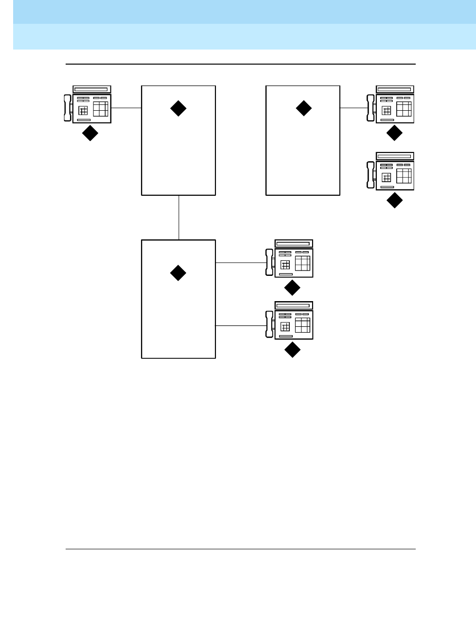
DEFINITY Enterprise Communications Server Release 6
Administration and Feature Description
555-230-522 Issue 4
May 1998
Private Networking
Page 12-106Uniform Dial Plan
12
Figure Notes
Figure 12-6. UDP Example
If a user at extension 41000 wants to call extension 61234, there are two choices:
■Dial 61234
■Dial the AAR access code followed by 222-1234
1. Switch A
Dial Plan for extensions is 41XXX
RNX=224
2. Switch B:
Dial Plan for Extensions is 60XXX and 61XXX
RNX=222
3. Switch C:
Dial Plan for extensions is 51XXX and 52XXX
RNX=223
4. Extension 41000
5. Extension 61234
6. Extension 60123
7. Extension 51234
8. Extension 5200
3
45
1 2
7
6
8
r7
6
4
905 CJ
L
06
22
96

DEFINITY Enterprise Communications Server Release 6
Administration and Feature Description
555-230-522 Issue 4
May 1998
Private Networking
Page 12-107Uniform Dial Plan
12
If 61234 is dialed, the system recognizes 61 as a remote UDP, determines the
associated RNX (222), and uses AAR to route the call to 222-1234.
If the AAR access code and 222-1234 are dialed, the system finds the route
pattern for RNX 222 and routes the call to the switch associated with that RNX.
Whenever UDP is used to route a call to another switch, the correct digit deletion
and insertion must be specified within the route pattern so that the receiving
switch gets digits in the format it expects. DEFINITY ECS can be configured in
several different ways.
■If AAR is available on the receiving switch, Subnet Trunking can be used
to insert the AAR feature access code on the originating switch or digit
insertion may be used to insert it on the receiving switch. The receiving
switch then uses AAR digit conversion to convert 222 with 7 digits to an
extension by deleting 3 digits and inserting a 6.
■If AAR is not available on the receiving switch, Subnet Trunking must be
used on the originating switch to delete the 222 and insert the digit 6 at the
beginning of the extension number so that the receiving switch can
continue to route correctly.
If the user at extension 51234 on Switch C dials extension 61234, the call must
first go through Switch A before proceeding to Switch B. When 61234 is dialed,
the system recognizes 61 as a UDP code, determines the associated RNX (222),
and uses AAR to route the call. The AAR feature access code plus 222-1234 are
outpulsed to Switch A. Switch A then recognizes the RNX 222 as a remote switch
and routes the call to Switch B and extension 61234. This same type of call
routing occurs when an extension at Switch B calls an extension at Switch C.
If extension 61234 on Switch B calls extension 61235, the system recognizes 61
as a local UDP code and routes the call directly to extension 61235.
Considerations
■In North American network environments, extensions beginning with 0
may route to an attendant. You are encouraged to use another number as
the leading digit when assigning extensions.
■When you call an extension on another switch, there may be a slight delay
before call-progress tones are applied. This delay is due to the trunk
signaling necessary to complete the call to the remote switch.
■When you select the option to look at the UDP table first, calls that might
otherwise terminate at a local extension route over the network. This is
easily reversed. When you remove the extensions from the UDP table, the
local extension can be dialed again.

DEFINITY Enterprise Communications Server Release 6
Administration and Feature Description
555-230-522 Issue 4
May 1998
Private Networking
Page 12-108Uniform Dial Plan
12
■If AAR is active, FRLs and Traveling Class Marks (TCMs) can be sent
along with the private network number. UDPCode and AARCode
conversions use the FRL assigned to the caller. ENPNode conversion
always raises the FRL to the maximum (7).
If an FRL is insufficient to access the facility, access is denied. There is no
prompt for an authorization code even if authorization codes are enabled
and administered.
■If AAR is not active, tandem-tie trunks should not be used to transport
UDP numbers. The TCM is not recognized at the terminating switch.
NOTE:
Never use tandem-tie trunks to transport UDP numbers (the TCM
and Hop count will not be recognized as such following the
extension received at the receiving switch).
Interactions
■Automatic Alternate Routing
AAR routes UDP calls. (Included with UDP is the required AAR subset.) If
AAR is enabled in addition to UDP, then the 7-digit AAR number provides
the same routing as UDP.
■Dial Plan
— All of the extension numbers on a switch are not necessarily part of
UDP. Any that do not belong to UDP are handled by a regular,
non-UDP Dial Plan associated with the switch.
— When administering the Dial Plan form and designating a group of
extensions as UDP non-local, you can specify whether you want to
search for local extensions first or last. This allows flexibility to
change extensions from local to non-local and vice-versa.
■DID Trunk Group
DID calls to 5-digit UDP extension numbers require that the DID trunk
group insert enough digits to make a 5-digit extension number.
■Distributed Communications System
UDP is required when DCS is provided. The necessary UDP software is
provided with the DCS software.
■Extension Number Portability
If an extension code is administered to use ENP node routing, ENP routes
the call to the correct switch. If AAR is enabled in addition to UDP, the
7-digit AAR number provides the same routing as UDP (that is, via ENP).

DEFINITY Enterprise Communications Server Release 6
Administration and Feature Description
555-230-522 Issue 4
May 1998
Private Networking Forms
Page 12-109Uniform Dial Plan
12
12 Private Networking Forms
This section describes the following forms related to private networking:
■ATM PNC
■ATM Measurements
■Extented Trunk Access Call Screening Form
■Extension Number Portability Numbering Plan
■Hop Channel Assignments
■Node Number Routing

DEFINITY Enterprise Communications Server Release 6
Administration and Feature Description
555-230-522 Issue 4
May 1998
Private Networking Forms
Page 12-110.ATM-PNC Form
12
.ATM-PNC Form
This form is used to administer the TN2238 circuit pack associated with a port network
connectivity (PNC) configuration using an ATM switch. The ATM PNC form is identical
for processor port network (PPN) and the expansion port network (EPN).
Administration Commands
Use the following commands to administer the ATM PNC form.
NOTE:
These commands are available only if the “Asynch. Transfer Mode (ATM) PNC?”
field on the Customer Options form is set to “y”.
Form Description
Screen 12-1. ATM PNC Form — Standard Reliability
Action Object Qualifier
change atm pnc connection-number
display atm pnc connection-number
add atm pnc connection-number
remove atm pnc connection-number
list atm pnc
Page 1 of 1
ATM PNC
Connection Number:
Location:
Name:
Address Format:
AFI:
E.164:
HO-DSP:
ESI:
SEL:

DEFINITY Enterprise Communications Server Release 6
Administration and Feature Description
555-230-522 Issue 4
May 1998
Private Networking Forms
Page 12-111.ATM-PNC Form
12
Screen 12-2. ATM PNC Form — Critical Reliability
Make assignments as required for the following fields on the form:
■Connection Number — 1–44 entered from the command line. Display only.
■Location — Enter cabinet(1–x); carrier(A–E); slot(01–03. Default is blank.
■Name — Enter 1–15 alphanumeric characters. Default is blank.
■Address Format — Enter E.164 ATM Private, DCC ATM, or ICD ATM.
Default is E.164 ATM Private.
■AFI — Authority and Format Identifier. Valid values are 39, 45, or 47. Default is
45. Display only.
■E.164 — Field name may also be DCC or ICD, depending on the value of the
Address Format field. Enter 1–15 decimal digits. Default is blank.
■DCC — Data Country Code. Enter 1–4 decimal digits. Default is blank.
■ICD — International Code Designator. Enter 1–4 decimal digits. Default is blank.
■HO-DSP — High-Order Domain-Specific Part. Enter 8 hexadecimal digits if
Address Format is E.164: otherwise enter 20 hexadecimal digits. Default is blank.
■ESI — End System Indentifier. Enter 12 hexadecimal digits. Default is blank.
■SEL — Selector. Enter 2 hexadecimal digits. Default is blank.
NOTE:
For critical reliability, the A-PNC field values cannot be changed; the B-PNC field
values can be changed only if A-PNC is active and B-PNC has been busied-out.
Page 1 of 1
ATM PNC
Connection Number:
A - PNC B - PNC
Location: Location:
Name: Name:
Address Format: Address Format:
AFI: AFI:
E.164: E.164:
HO-DSP: HO-DSP:
ESI: ESI:
SEL: SEL:

DEFINITY Enterprise Communications Server Release 6
Administration and Feature Description
555-230-522 Issue 4
May 1998
Private Networking Forms
Page 12-112.ATM-PNC Form
12

DEFINITY Enterprise Communications Server Release 6
Administration and Feature Description
555-230-522 Issue 4
May 1998
Private Networking Forms
Page 12-113Extended Trunk Access Call Screening Form
12
Extended Trunk Access Call Screening
Form
This form allows a set of digit strings to be identified that should not be routed via
ETA. This form can also block the routing of certain FACs or TACs. For example, if
the system administrator were to notice a digit string being mistakenly dialed
repeatedly that ended up being routed via ETA to a remote PBX only to have the
remote PBX return intercept treatment, then that digit string would be a candidate
for the entry into the ETA call screening table. Entry into this table would have the
effect of return intercept treatment to the caller without first attempting to route
the digits to the remote PBX for interpretation via ETA.
Administration Commands
Use the following commands to administer the Extended Trunk Access Call
Screening form.
Form Instructions
Screen 12-3. ETA Call Screening Table Form (Page 1 of 1)
Action Object Qualifier
change call-screening
display call-screening
Page 1 of 1
ETA CALL SCREENING TABLE
Entry
No. Call Screening Entry
0: ______
1: ______
2: ______
3: ______
4: ______
5: ______
6: ______
7: ______
8: ______
9: ______

DEFINITY Enterprise Communications Server Release 6
Administration and Feature Description
555-230-522 Issue 4
May 1998
Private Networking Forms
Page 12-114Extended Trunk Access Call Screening Form
12
Make assignments as required for the following fields on the form:
■Call Screening Entry — Assign those digit strings (up to 10) that should
be blocked for this RNX. Each string can have up to 6 digits and/or special
or wildcard characters. Valid entries are the digits 0 through 9, x, X, *, and
#. The "#" character may only be used as the first character.

DEFINITY Enterprise Communications Server Release 6
Administration and Feature Description
555-230-522 Issue 4
May 1998
Private Networking Forms
Page 12-115Extension Number Portability Numbering Plan Form
12
Extension Number Portability
Numbering Plan Form
Administration Commands
Use the following commands to administer the ENP Numbering Plan form.
Form Instructions
Screen 12-4. Extension Number Portability Numbering Plan Form (Page 1 of 1)
Make assignments as required for the following fields on the form.
■ENP Code — Assign a 3-digit code to translate each 4- or 5-digit UDP
extension that is node number routed to a 7 digit, AAR-like number used
for outpulsing a call within an ENP sub network. This field maps each
leading digit of a UDP extension to an ENP Code or blank.
1. Brackets [ ] indicate the qualifier is optional. Single quotes
(‘ ’) indicate the text inside the quote must be entered
exactly as shown or an abbreviated form of the word may
be entered.
Action Object Qualifier1
change enp-number-plan
display enp-number-plan [‘print’ or ‘schedule’]
Page 1 of 1
EXTENSION NUMBER PORTABILITY
NUMBERING PLAN
ENP ENP ENP ENP ENP ENP ENP ENP ENP ENP
Code Code Code Code Code Code Code Code Code Code
0x: ___ 1x: ___ 2x: ___ 3x: ___ 4x: ___ 5x: ___ 6x: ___ 7x: ___ 8x: ___ 9x: ___
00: ___ 10: ___ 20: ___ 30: ___ 40: ___ 50: ___ 60: ___ 70: ___ 80: ___ 90: ___
01: ___ 11: ___ 21: ___ 31: ___ 41: ___ 51: ___ 61: ___ 71: ___ 81: ___ 91: ___
02: ___ 12: ___ 22: ___ 32: ___ 42: ___ 52: ___ 62: ___ 72: ___ 82: ___ 92: ___
03: ___ 13: ___ 23: ___ 33: ___ 43: ___ 53: ___ 63: ___ 73: ___ 83: ___ 93: ___
04: ___ 14: ___ 24: ___ 34: ___ 44: ___ 54: ___ 64: ___ 74: ___ 84: ___ 94: ___
05: ___ 15: ___ 25: ___ 35: ___ 45: ___ 55: ___ 65: ___ 75: ___ 85: ___ 95: ___
06: ___ 16: ___ 26: ___ 36: ___ 46: ___ 56: ___ 66: ___ 76: ___ 86: ___ 96: ___
07: ___ 17: ___ 27: ___ 37: ___ 47: ___ 57: ___ 67: ___ 77: ___ 87: ___ 97: ___
08: ___ 18: ___ 28: ___ 38: ___ 48: ___ 58: ___ 68: ___ 78: ___ 88: ___ 98: ___
09: ___ 19: ___ 29: ___ 39: ___ 49: ___ 59: ___ 69: ___ 79: ___ 89: ___ 99: ___

DEFINITY Enterprise Communications Server Release 6
Administration and Feature Description
555-230-522 Issue 4
May 1998
Private Networking Forms
Page 12-116Hop Channel Assignments Form
12
Hop Channel Assignments Form
This form assigns Hop Channels. The maximum number of connections that may
be established between channels on the system’s interface links varies
depending on System configuration.
Administration Commands
Use the following commands to administer the Hop Channel Assignment form.
Screen 12-5. Hop Channel Assignment Form (Page 1 of 4)
1. Brackets [ ] indicate the qualifier is optional. Single quotes (‘ ’) indicate the text
inside the quote must be entered exactly as shown or an abbreviated form of the
word may be entered.
Action Object Qualifier1
change communication-interface hop-channels
display communication-interface hop-channels [’print’ or ’schedule’]
HOP CHANNEL ASSIGNMENT Page 1 of 4
Link/Channel A Link/Channel B Link/Channel A Link/Channel B
1: __ __ __ __ 17: __ __ __ __
2: __ __ __ __ 18: __ __ __ __
3: __ __ __ __ 19: __ __ __ __
4: __ __ __ __ 20: __ __ __ __
5: __ __ __ __ 21: __ __ __ __
6: __ __ __ __ 22: __ __ __ __
7: __ __ __ __ 23: __ __ __ __
8: __ __ __ __ 24: __ __ __ __
9: __ __ __ __ 25: __ __ __ __
10: __ __ __ __ 26: __ __ __ __
11: __ __ __ __ 27: __ __ __ __
12: __ __ __ __ 28: __ __ __ __
13: __ __ __ __ 29: __ __ __ __
14: __ __ __ __ 30: __ __ __ __
15: __ __ __ __ 31: __ __ __ __
16: __ __ __ __ 32: __ __ __ __

DEFINITY Enterprise Communications Server Release 6
Administration and Feature Description
555-230-522 Issue 4
May 1998
Private Networking Forms
Page 12-117Hop Channel Assignments Form
12
Form Instructions
Observe the following when assigning hop channels:
■The Link/Chan pair must not be assigned to a local processor channel on
the Processor Channel Assignments form.
■The four associated hop channel fields must be either filled in or left blank.
Make assignments as required for the following fields on each page of the form:
Pages 1 through X of the Form
Screen 12-6. Hop Channel Assignment Form (R5r and later configurations and R5si
and later configurations) (Page 1 of 2)
NOTE:
This is a two-page form for R5si and later configurations and a four-page
form for R5r and later configurations.
■Link — Enter an interface link number in each field.
■Chan(nel) — This field is labeled "Channel" for R5r and later
configurations and "Chan" for R5si and later configurations. Enter a
channel number in each field.
■Priority — Displays for R5si and later configurations only. Enter high or
low to indicate whether the hop channel has high or low priority. Priorities
should be assigned based on the operational speed of the links and the
number of hops in the network channel.
HOP CHANNEL ASSIGNMENT Page 1 of 2
Link/Chan Link/Chan Priority Link/Chan Link/Chan Priority
_ __ _ __ _ _ __ _ __ _
_ __ _ __ _ _ __ _ __ _
_ __ _ __ _ _ __ _ __ _
_ __ _ __ _ _ __ _ __ _
_ __ _ __ _ _ __ _ __ _
_ __ _ __ _ _ __ _ __ _
_ __ _ __ _ _ __ _ __ _
_ __ _ __ _ _ __ _ __ _
_ __ _ __ _ _ __ _ __ _
_ __ _ __ _ _ __ _ __ _
_ __ _ __ _ _ __ _ __ _
_ __ _ __ _ _ __ _ __ _
_ __ _ __ _ _ __ _ __ _
_ __ _ __ _ _ __ _ __ _
_ __ _ __ _ _ __ _ __ _
_ __ _ __ _ _ __ _ __ _
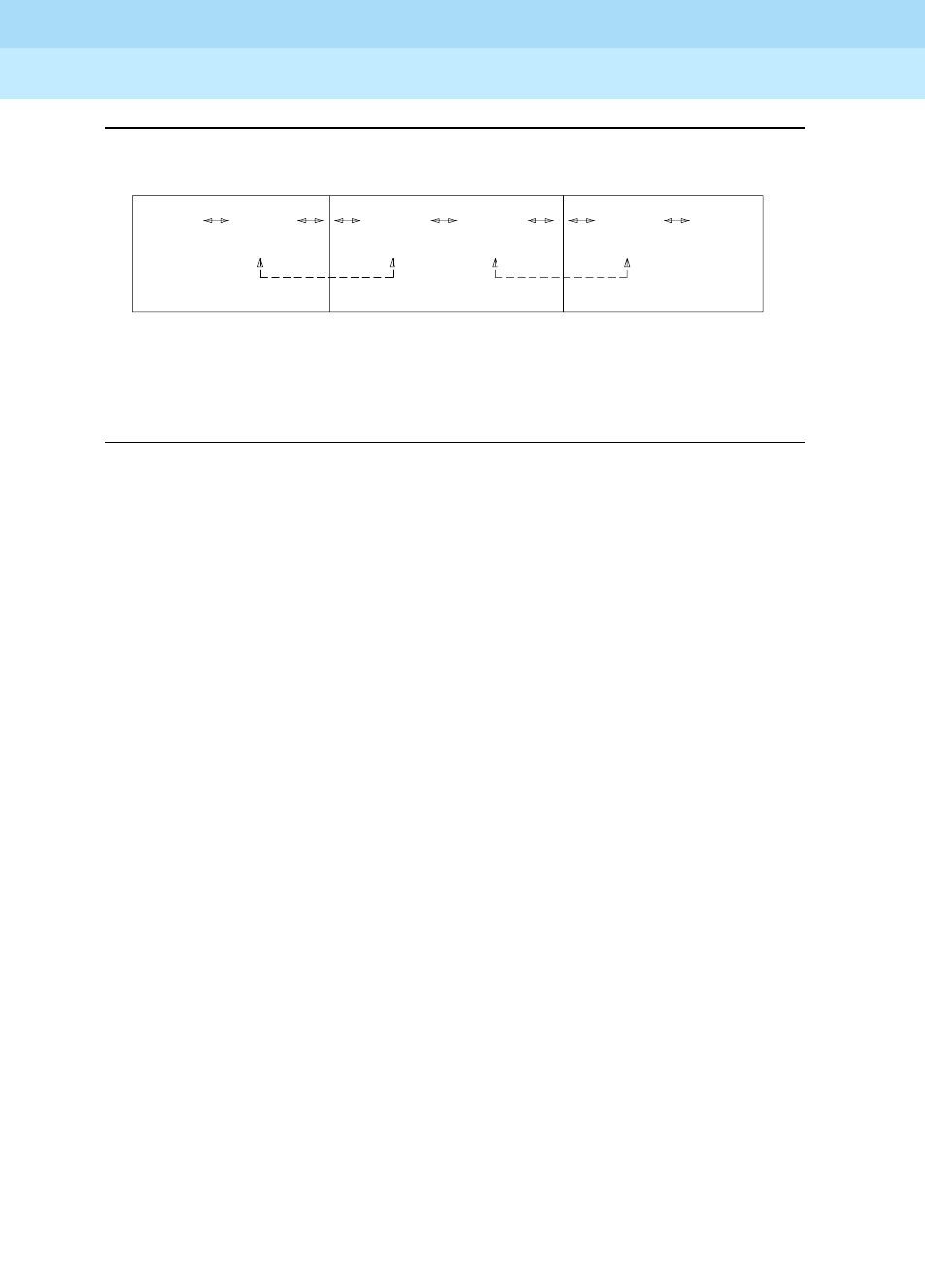
DEFINITY Enterprise Communications Server Release 6
Administration and Feature Description
555-230-522 Issue 4
May 1998
Private Networking Forms
Page 12-118Hop Channel Assignments Form
12
Figure 12-1. Interface Channel Assignments Between Switches
SWITCH A TANDEM SWITCH
THE INTERFACE CHANNELS ON THE TANDEM
SWITCH SHOULD MATCH THE INTERFACE CHANNELS
ON SWITCHES A AND B. THE PROCESSOR CHANNELS
DO NOT HAVE TO MATCH.
INTERFACE INTERFACE
CHANNEL
30
CHANNEL
30
SWITCH B
INTERFACE INTERFACE
CHANNEL
40
CHANNEL
40
PROCESSOR
CHANNEL
9
CHANNEL
1
PROCESSOR

DEFINITY Enterprise Communications Server Release 6
Administration and Feature Description
555-230-522 Issue 4
May 1998
Private Networking Forms
Page 12-119Node Number Routing Form
12
Node Number Routing Form
This form specifies the routing pattern associated with each node in a public or
private network. NNR is a required capability for Extension Number Portability
(ENP) and is associated with the Uniform Dial Plan (UDP).
Administration Commands
Use the following commands to administer the Node Number Routing form.
1. Brackets [ ] indicate the qualifier is optional. Single quotes (‘ ’) indicate the
text inside the quote must be entered exactly as shown or an abbreviated
form of the word may be entered. MAX is the maximum number available in
your system configuration.
Action Object Qualifier1
change node-routing Enter digits between 1-MAX [‘partition’ 1-8]
display node-routing Enter digits between 1-MAX [‘partition’ 1-8]
list node-routing Enter digits between 1-MAX [‘partition’ 1-8]

DEFINITY Enterprise Communications Server Release 6
Administration and Feature Description
555-230-522 Issue 4
May 1998
Private Networking Forms
Page 12-120Node Number Routing Form
12
Form Instructions
Screen 12-7. Node Number Routing Form (Page 1 of 2)
Make assignments as required for the following fields on the form.
■Partitioned Group Number — This read-only field displays the
partitioned group number associated with the node numbers being
administered. The partitioned group number is either specified on the
command line or defaults to partitioned group number 1.
■Node Number — This display-only field lists the node number to be
changed.
NOTE:
Two pages display simultaneously for a total of 200 nodes (100 per
page). For example, entering change node-routing 87 displays
nodes 1 through 199, and entering change node-routing 151
displays nodes 100 through 299. However, entering change
node-routing 999 displays nodes 900 through 999 on one page.
■Route Pat — Enter the routing pattern associated with the corresponding
node number. This field repeats the same number of times as there are
node numbers on the page; default is blank
.
change node-routing 87 partition 2 Page 1 of 2
NODE NUMBER ROUTING
Partitioned Group Number: 2
Route Route Route Route Route Route Route
Pat Pat Pat Pat Pat Pat Pat
15: ___ 30: ___ 45: ___ 60: ___ 75: ___ 90: ___
1: ___ 16: ___ 31: ___ 46: ___ 61: ___ 76: ___ 91: ___
2: ___ 17: ___ 32: ___ 47: ___ 62: ___ 77: ___ 92: ___
3: ___ 18: ___ 33: ___ 48: ___ 63: ___ 78: ___ 93: ___
4: ___ 19: ___ 34: ___ 49: ___ 64: ___ 79: ___ 94: ___
5: ___ 20: ___ 35: ___ 50: ___ 65: ___ 80: ___ 95: ___
6: ___ 21: ___ 36: ___ 51: ___ 66: ___ 81: ___ 96: ___
7: ___ 22: ___ 37: ___ 52: ___ 67: ___ 82: ___ 97: ___
8: ___ 23: ___ 38: ___ 53: ___ 68: ___ 83: ___ 98: ___
9: ___ 24: ___ 39: ___ 54: ___ 69: ___ 84: ___ 99: ___
10: ___ 25: ___ 40: ___ 55: ___ 70: ___ 85: ___
11: ___ 26: ___ 41: ___ 56: ___ 71: ___ 86: ___
12: ___ 27: ___ 42: ___ 57: ___ 72: ___ 87: ___
13: ___ 28: ___ 43: ___ 58: ___ 73: ___ 88: ___
14: ___ 29: ___ 44: ___ 59: ___ 74: ___ 89: ___

DEFINITY Enterprise Communications Server Release 6
Administration and Feature Description
555-230-522 Issue 4
May 1998
Private Networking Forms
Page 12-121Uniform Dial Plan Form
12
Uniform Dial Plan Form
This form administers the Uniform Dial Plan (UDP).
Administration Commands
Use the following commands to administer the Uniform Dial Plan form.
Form Instructions
Screen 12-8. Uniform Dial Plan Form (Page 1 of 2)
1. Brackets [ ] indicate the qualifier is optional. Single quotes (‘ ’) indicate the text
inside the quote must be entered exactly as shown or an abbreviated form of the
word may be entered. MAX is the maximum number available in your system
configuration.
Action Object Qualifier1
change udp Enter 1-MAX digits between 0-9, ‘x’ or ‘X’
display udp Enter 1-MAX digits between 0-9, ‘x’ or ‘X’ [’print’ or
’schedule’]
list udp Enter [’ext’ x][’to-ext’ x][ ’type’ x [[’dest’ x][to-dest’ x]] ]
[’print’ or ’schedule’]
Page 1 of 2
UNIFORM DIALING PLAN
Ext Codes: _____
Ext Code: _____ Type: _______ ___
dd Type dd Type dd Type dd Type dd Type
0x: _______ ___ 1x: _______ ___ 2x: _______ ___ 3x: _______ ___ 4x: _______ ___
00: _______ ___ 10: _______ ___ 20: _______ ___ 30: _______ ___ 40: _______ ___
01: _______ ___ 11: _______ ___ 21: _______ ___ 31: _______ ___ 41: _______ ___
02: _______ ___ 12: _______ ___ 22: _______ ___ 32: _______ ___ 42: _______ ___
03: _______ ___ 13: _______ ___ 23: _______ ___ 33: _______ ___ 43: _______ ___
04: _______ ___ 14: _______ ___ 24: _______ ___ 34: _______ ___ 44: _______ ___
05: _______ ___ 15: _______ ___ 25: _______ ___ 35: _______ ___ 45: _______ ___
06: _______ ___ 16: _______ ___ 26: _______ ___ 36: _______ ___ 46: _______ ___
07: _______ ___ 17: _______ ___ 27: _______ ___ 37: _______ ___ 47: _______ ___
08: _______ ___ 18: _______ ___ 28: _______ ___ 38: _______ ___ 48: _______ ___
09: _______ ___ 19: _______ ___ 29: _______ ___ 39: _______ ___ 49: _______ ___

DEFINITY Enterprise Communications Server Release 6
Administration and Feature Description
555-230-522 Issue 4
May 1998
Private Networking Forms
Page 12-122Uniform Dial Plan Form
12
Screen 12-9. Uniform Dial Plan Form (Page 2 of 2)
Make assignments as required for the following fields on each page of the form:
■Ext Codes — Displays a string of digits, "x", and "dd." The position of the
dd shows which digit positions of the Ext Codes are being administered.
For example, 512dd means that the last two digits of the Ext Codes, for the
leading digits 512, are being administered on the form. The string, 5ddxx,
shows that the second and third digits of the Ext Codes, for the leading
digit 5, are being administered on the form (these entries would all be
wildcard entries).
■Ext Code, Type (and associated data) — Displays what rules apply if the
entries on the form are not administered. For example, shows a form for
Ext Codes starting with 512. If these entries are not administered, the entry
for Ext Code 51xxx applies to these entries, and if Ext Code 51xxx is not
administered, the entry for Ext Code 5xxxx applies to these entries. In a
5-digit UDP, these read-only fields display only if at least 3 digits are
specified in the command-line key, although one set (the set on the left) of
these fields would still display if 2 digits are specified in the command-line
key. If only 1 digit is specified or if ’x’ or ’X’ is specified in the
command-line key, then neither of these sets of fields display, since there
is no Ext Code more general than those listed on the form.
■dd — Displays the two digits (or x’s) representing the extension or group
of extensions to be administered. For this field, "xx:" is repeated on both
pages, since it is the default for all other entries on both pages. Changing
the type associated with this field on one page changes it on both pages.
■Type — Specify the type of treatment for the extension (AARCode,
ENPNode, Local, TempOOS, UDPCode, or blank). That is, specify
whether the extension should receive intercept treatment, be converted to
AAR, or be converted via ENP. The difference between AAR Location
Codes and UDP Location Codes is that 7-digit AAR Numbers created from
Page 2 of 2
UNIFORM DIALING PLAN
Ext Codes: _____
Ext Code: _____ Type: _______ ___
dd Type dd Type dd Type dd Type dd Type
5x: _______ ___ 6x: _______ ___ 7x: _______ ___ 8x: _______ ___ 9x: _______ ___
50: _______ ___ 60: _______ ___ 70: _______ ___ 80: _______ ___ 90: _______ ___
51: _______ ___ 61: _______ ___ 71: _______ ___ 81: _______ ___ 91: _______ ___
52: _______ ___ 62: _______ ___ 72: _______ ___ 82: _______ ___ 92: _______ ___
53: _______ ___ 63: _______ ___ 73: _______ ___ 83: _______ ___ 93: _______ ___
54: _______ ___ 64: _______ ___ 74: _______ ___ 84: _______ ___ 94: _______ ___
55: _______ ___ 65: _______ ___ 75: _______ ___ 85: _______ ___ 95: _______ ___
56: _______ ___ 66: _______ ___ 76: _______ ___ 86: _______ ___ 96: _______ ___
57: _______ ___ 67: _______ ___ 77: _______ ___ 87: _______ ___ 97: _______ ___
58: _______ ___ 68: _______ ___ 78: _______ ___ 88: _______ ___ 98: _______ ___
59: _______ ___ 69: _______ ___ 79: _______ ___ 89: _______ ___ 99: _______ ___

DEFINITY Enterprise Communications Server Release 6
Administration and Feature Description
555-230-522 Issue 4
May 1998
Private Networking Forms
Page 12-123Uniform Dial Plan Form
12
AAR Location Codes may be changed during AAR analysis by AAR digit
conversion before being routed. Seven-digit AAR Numbers created from
UDP Location Codes are not subject to digit conversion before being
routed with AAR digit analysis.
When an extension code that is displayed on the UDP form is not
administrable because it conflicts with the translations in the first and/or
second digit tables, then the type field for that extension code displays
"NotInDP."
The entry TempOOS indicates an extension is temporarily out-of-service.
Calls to these extensions receive reorder.
A blank entry indicates this Ext code is not administered. If no matching
code can be found, then the call receives intercept treatment.
■Location Code — Specify the 3-digit location code for Ext Codes
administered with a type of AARCode or UDPCode. This field displays if
AARCode or UDPCode is entered as the type.
■Node Number — Specify the node number for Ext Codes administered
with a type of ENPNode. This field pops up if ENPNode is entered as the
type.
NOTE:
This node number must not be the same as the local node number
on the dial plan form.

DEFINITY Enterprise Communications Server Release 6
Administration and Feature Description
555-230-522 Issue 4
May 1998
Private Networking Forms
Page 12-124Uniform Dial Plan Form
12

Transition Reference
Page A-1DEFINITY ECS R6.1 to R6.3 Transition Reference
A
DEFINITY Enterprise Communications Server Release 6
Administration and Feature Description
555-230-522 Issue 4
May 1998
A
ATransition Reference
DEFINITY ECS R6.1 to R6.3
Transition Reference
This appendix presents two types of information. First, it lists all DEFINITY ECS
Release 6.3 features, and notes which are new or changed for Release 6.3.
Second, it provides a brief description of feature changes. See the individual
feature descriptions for a detailed explanation of new and changed features.
Release 6.3 Features
Tab l e A -1 lists R6.3 enhancements to existing features.

DEFINITY Enterprise Communications Server Release 6
Administration and Feature Description
555-230-522 Issue 4
May 1998
Transition Reference
Page A-2Release 6.3 Features
A
Table A-1. Release 5.4 to Release 6.3 Transition Reference
Feature Name
New R6.3
Feature
Changed
for R6.3
6400-Series Voice Terminals
7505D, 7506D, 7507D, 8503D, 8510T, and 8520T
ISDN-BRI Voice Terminals
AAR and ARS X
AAR/ARS Overlap Sending
AAR/ARS Partitioning
AAR and ARS Digit Analysis Table X
AAR and ARS Digit Conversion Table X
Abandoned Call Search
Abbreviated Dialing (Enhanced) X
Access Trunk Group
Add/Remove Skills
Additional External Alarming1
Administrable Language Displays
Administrable Logins
Administered Connections
Administration Without Hardware
Agent Call Handling
Agent Sizing
Alphanumeric Dialing
Alternate Facility Restriction Levels
Answer Detection
Alternate OSSA Number
Attendant Auto-Manual Splitting
Attendant Backup Alerting
Attendant Call Waiting
Attendant Control of Trunk Group Access
Attendant Direct Extension Selection With Busy
Lamp Field
Continued on next page

DEFINITY Enterprise Communications Server Release 6
Administration and Feature Description
555-230-522 Issue 4
May 1998
Transition Reference
Page A-3Release 6.3 Features
A
Attendant Direct Trunk Group Selection
Attendant Display
Attendant Intrusion (Call Offer)
Attendant Override of Diversion Features
Attendant Priority Queue
Attendant Recall
Attendant Release Loop Operation
Attendant Room Status
Attendant Serial Calling
Audible Message Waiting
Audio Information Exchange (AUDIX) Interface
Authorization Codes
Auto-Available Split (AAS)
Automatic Alternate Routing (AAR) and Automatic
Route Selection (ARS)
Automatic Callback
Automatic Call Distribution (ACD)
Automatic Circuit Assurance
Automatic Hold
Automatic Incoming Call Display
Automatic Transmission Measurement System
Automatic Wakeup
Auto-Start/Don’t Split
Basic Call Management System (BCMS)
Best Service Routing™ X
Block Collect Call
Bridged Call Appearance
Busy Verification of Terminals and Trunks
Table A-1. Release 5.4 to Release 6.3 Transition Reference — Continued
Feature Name
New R6.3
Feature
Changed
for R6.3
Continued on next page

DEFINITY Enterprise Communications Server Release 6
Administration and Feature Description
555-230-522 Issue 4
May 1998
Transition Reference
Page A-4Release 6.3 Features
A
Button View X?
Call-By-Call Service Selection
Call Charge Information
Call Coverage
Call Detail Recording (CDR)
Call Forwarding
Call Forward Busy/Don’t Answer
Call Park
Call Pickup
Call Prompting
Call Timer X
Call Vectoring X?
Call Waiting Termination
CAMA Trunk Group
CAMA Numbering Format form
Centralized Attendant Service (CAS)
CentreVu® Call Management System2X?
Class of Restriction (COR) X
Class of Service (COS)
Clear Message Waiting Indicators
Code Calling Access
Conference — Attendant
Conference — Terminal
Constellation Voice/Data Terminal Support
Consult
CO Trunk Group X
Coverage Callback
Coverage Incoming Call Identification (ICI)
Table A-1. Release 5.4 to Release 6.3 Transition Reference — Continued
Feature Name
New R6.3
Feature
Changed
for R6.3
Continued on next page

DEFINITY Enterprise Communications Server Release 6
Administration and Feature Description
555-230-522 Issue 4
May 1998
Transition Reference
Page A-5Release 6.3 Features
A
CPN Restriction
Customer-Provided Equipment (CPE) Alarm
Data Call Setup
Data Hot Line
Data-Only Off-Premises Extensions
Data Privacy
Data Restriction
DCS with Rerouting
Distributed Communication System (DCS) X
Default Dialing
DEFINITY LAN Gateway
Dial Access to Attendant
Dial Plan
Digital Multiplexed Interface
Direct Inward Dialing (DID) Trunk Group X
Direct Inward and Outward Dialing (DIOD) —
International
Direct Inward and Outward Dialing (DIOD) Trunk
Group X
Distinctive Ringing
DMI-BOS Trunk Group
Do Not Disturb
DS1 Circuit Pack Form
DS1 Trunk Service (T1 and E1)
EIA Interface
Emergency Access to the Attendant
Enhanced Voice Terminal Display
Expert Agent Selection
Extended User Administration of Redirected Calls
Table A-1. Release 5.4 to Release 6.3 Transition Reference — Continued
Feature Name
New R6.3
Feature
Changed
for R6.3
Continued on next page

DEFINITY Enterprise Communications Server Release 6
Administration and Feature Description
555-230-522 Issue 4
May 1998
Transition Reference
Page A-6Release 6.3 Features
A
Facility and Non-Facility Associated Signaling
Facility Busy Indication
Facility Restriction Levels (FRL) and Traveling Class
Marks (TCM)
Facility Test Calls
Feature Access Code X?
Feature-Related System Parameters X
Fiber Link Administration X
Flexible Billing
Forced Password Aging
Generalized Route Selection (GRS)
Go to Cover
Group Listen
Group Paging
Hold
Hold—Automatic
Hospitality
Hot Line Service
Hunting
Inbound Call Management
Incoming Call Line Identification on Analog Trunk X
Individual Attendant Access
Information Forwarding X
Integrated Directory
Intercept Treatment
Intercom — Automatic
Intercom — Dial
Internal Automatic Answer
Table A-1. Release 5.4 to Release 6.3 Transition Reference — Continued
Feature Name
New R6.3
Feature
Changed
for R6.3
Continued on next page

DEFINITY Enterprise Communications Server Release 6
Administration and Feature Description
555-230-522 Issue 4
May 1998
Transition Reference
Page A-7Release 6.3 Features
A
Inter-PBX Attendant Calls
Intraflow and Interflow
ISDN-BRI Circuit Pack form X
ISDN-BRI Trunk Circuit Pack X
ISDN-BRI Trunk Group X
ISDN-BRI (S/T)
ISDN BRI (U-Zwire)
ISDN - General X
ISDN Numbering - Private
ISDN-PRI Trunk Group X
International Operator Access
Language Translations X?
Last Number Dialed
Leave Word Calling
Line Lockout
Look Ahead Interflow X
Look Ahead Routing
Loudspeaker Paging Access
Malicious Call Trace
Manual Message Waiting
Manual Originating Line Service
Manual Signaling
MERLIN®/System 25 — Voice Terminal Support
(731xH Series)
Misoperations Handling (modified)
Modem Pooling
Multi-Appearance Preselection and Preference
Multifrequency Signaling X
Table A-1. Release 5.4 to Release 6.3 Transition Reference — Continued
Feature Name
New R6.3
Feature
Changed
for R6.3
Continued on next page

DEFINITY Enterprise Communications Server Release 6
Administration and Feature Description
555-230-522 Issue 4
May 1998
Transition Reference
Page A-8Release 6.3 Features
A
Multifrequency-Signaling-Related System
Parameters X
Multimedia Applications Server Interface
Multimedia Call Handling X
Multiple Call Handling
Music-on-Hold Access
Names Registration
Network Access — Private
Night Service X
On-Hook Dialing X
PC Interface
Personal Central Office Line (PCOL)
Personal Station Access
Personalized Ringing
Power Failure Transfer
PRI Endpoint
Priority Calling
Privacy — Attendant Lockout
Privacy — Manual Exclusion
Property Management System Interface X
Public Network Call Priority
Pull Transfer
QSIG X
QSIG Supplementary Service - Call Completion X
Queue Status Indications
Reason Codes
Recall Signaling
Recent Change History
Table A-1. Release 5.4 to Release 6.3 Transition Reference — Continued
Feature Name
New R6.3
Feature
Changed
for R6.3
Continued on next page

DEFINITY Enterprise Communications Server Release 6
Administration and Feature Description
555-230-522 Issue 4
May 1998
Transition Reference
Page A-9Release 6.3 Features
A
Recorded Announcement
Recorded Telephone Dictation Access
Redirection On No Answer (RONA)
Remote Access
Report Scheduler and System Printer
Restriction — Controlled
RHNPA Table
Ringback Queuing
Ringer Cutoff
Ringing — Abbreviated and Delayed
Rotary Dialing
Route Pattern Form
Security Violation Notification (SVN)
Send All Calls
Service Observing
Signaling Group X
Station Form Field Descriptions X
Station Hunting
Station Security Code
Subnet Trunking
Switch Based Bulletin Board
Synchronization Plan X
System-Parameters Customer-Options X
Tandem Trunk Group
Temporary Bridged Appearance
Tenant Partitioning
Terminal Self Administration
Terminal Translation Initiation
Table A-1. Release 5.4 to Release 6.3 Transition Reference — Continued
Feature Name
New R6.3
Feature
Changed
for R6.3
Continued on next page

DEFINITY Enterprise Communications Server Release 6
Administration and Feature Description
555-230-522 Issue 4
May 1998
Transition Reference
Page A-10Release 6.3 Features
A
Terminating Extension Group
Through Dialing
Tie Trunk Group
Time of Day Routing
Time of Day Routing Plan
Timed Reminder and Attendant Timers
Transfer
Transfer Outgoing Trunk to Outgoing Trunk
Trunk Flash
Trunk Group Busy/Warning Indicators to Attendant
Trunk Groups - General X
Trunk Identification By Attendant
Trunk-to-Trunk Transfer
Uniform Dial Plan (UDP)
Universal Call ID (UCID) X
Unrestricted Uniform Dial Plan)
VDN of Origin Announcements
Visually Impaired Attendant Services (VIAS)
Voice Message Retrieval
Voice Messaging Systems
Voice Response Integration
Voice Terminal Alerting Options
Voice Terminal Display
Voice Terminal Feature Button Descriptions X
Voice Terminal, PC Interface, and Data Module
VuStats
Whisper Page X
Wideband Switching
Table A-1. Release 5.4 to Release 6.3 Transition Reference — Continued
Feature Name
New R6.3
Feature
Changed
for R6.3
Continued on next page

DEFINITY Enterprise Communications Server Release 6
Administration and Feature Description
555-230-522 Issue 4
May 1998
Transition Reference
Page A-11Release 6.3 Features
A
1. For information about this feature see
DEFINITY Enterprise Communications Server
Release 6 — Maintenance and Test for R6r
or
DEFINITY Enterprise Communications
Server Release 6 — Maintenance and Test for R6vs/si
.
2. For information about this feature, see
DEFINITY Enterprise Communications Server
Release 5 — Basic Call Management System (BCMS) Operations.
World Class BRI
World Class Tone Detection
World Class Tone Generation
Table A-1. Release 5.4 to Release 6.3 Transition Reference — Continued
Feature Name
New R6.3
Feature
Changed
for R6.3
Continued on next page

DEFINITY Enterprise Communications Server Release 6
Administration and Feature Description
555-230-522 Issue 4
May 1998
Transition Reference
Page A-12Release 6.3 Enhancements
A
Release 6.3 Enhancements
Abbreviated Dialing, Enhanced
■Users of 8400 and 6400 display phones can create menu-display labels
for AD and other buttons. Abbreviated dialing and display messages can
be programmed on these phones with the handset in place.
6402D Voice Terminal
■This is a 2-line display terminal that supports 1-way speakerphone.
Best Service Routing™ (BSR)
■This feature automatically compares splits or skills in ACD environments to
find the one that can provide the best service to each caller. BSR can
operate at a single site, or it can be used with Look-Ahead Interflow to
integrate a network of geographically distributed locations into a virtual
call center.
DIOD Data on Digital Trunk
■Direct Inward and Outward Dialing (DIOD) trunk groups now support both
voice and data transmissions.
Incoming Call Line Identification on Analog Trunks
■ICLID provides the calling party name and number received from the
central office (CO) over the TN429D DIOD Trunk circuit pack.
Information Forwarding
■Whenever DEFINITY ECS interflows a call over ISDN trunk facilities (for
example, PRI or BRI) by means of a
route-to
(with Look-Ahead Interflow
active),
queue-to best
, or
check best
command, user data is sent with the
call via user-to-user information transport (via UUI IE or QSIG MSI) and
can be used by adjuncts or displayed at the receiving switch.
ISDN-BRI Trunk Group
■Now supports DCS over BRI trunks using BX.25 and TCP/IP links, and BRI
trunks over the two-wire U interface using the TN2198 circuit pack.
Country Protocol 1 (Bellcore National ISDN) was added including support
of Service Profile Identifiers (SPIDs) and Endpoint Identifiers, and QSIG
features developed for ISDN-PRI in R6.2 and R6.3 (Call Offer, Call
Completion, and Message Waiting) are supported on BRI trunks.
Look-Ahead Interflow
■Balances the load of ACD calls across multiple locations. Enhanced
Look-Ahead Interflow (with DEFINITY R6.3) results in First in First Out
(FIFO) or near FIFO call routing via a new conditional and uses less
computer processing resources.

DEFINITY Enterprise Communications Server Release 6
Administration and Feature Description
555-230-522 Issue 4
May 1998
Transition Reference
Page A-13Release 6.3 Enhancements
A
Mode Code Related System Parameters Form
■Three new fields are added to this form: System In Day Service, System
In Night Service, and VMS Hunt Group Extension.
Multimedia Call Handling
■The new Enhanced mode of operation allows a multifunction user to
control a multimedia call like a standard voice call.
Multimedia Call Handling — Enhanced Mode
■The Enhanced mode of operation allows a multifunction voice terminal to
control a multimedia call like a standard voice call.
QSIG Call Independent Signaling Connections
■CISCs are functionally equivalent to the Temporary Signaling Connection
supported on DEFINITY ECS. These are used to pass QSIG
Supplementary Service information that is independent of an active call
between two QSIG compliant nodes.
QSIG Supplementary Service - Call Completion
■Completion of Calls to Busy Subscribers and Completion of Calls on No
Reply are the equivalent QSIG features of Automatic Callback on Busy
and Automatic Callback on No Answer, respectively. Both allow any QSIG
network voice user who placed a call to a busy or unanswered voice
terminal over the QSIG network to be called back automatically when the
called voice terminal becomes available.
Russian Incoming ANI
■Provides the switch with the capability to receive the calling party’s
number from incoming Russian trunks.
Russian Multiple ANI
■Allows MF ANI (calling party number, signaled via multifrequency
signaling) prefix digits to be defined on a class of restriction basis. This
allows a PBX servicing multiple COs to provide different ANIs to each.
Universal Call ID
■Tags a call with a unique identifier. In simple call scenarios, the tag stays
with that call within a DEFINITY-based network connected by ISDN lines.
In complex call scenarios, the tag often merges with other tags.

DEFINITY Enterprise Communications Server Release 6
Administration and Feature Description
555-230-522 Issue 4
May 1998
Transition Reference
Page A-14Release 6.3 Enhancements
A

Administration Commands
Page B-1Commands
B
DEFINITY Enterprise Communications Server Release 6
Administration and Feature Description
555-230-522 Issue 4
May 1998
B
BAdministration Commands
Commands
The following pages provide a summary of the available commands and their
associated objects.
You can display a list of the available actions, objects and qualifiers at any time
by pressing the Help key. The list that appears contains only those words that are
appropriate, based on your login permissions and the words already entered on
the command line.
Restrictions
You will not be able to execute a command if:
■You do not have permission to execute the command
■The system configuration does not require a command
■The command is a member of a set of commands that is being used by
another user.

DEFINITY Enterprise Communications Server Release 6
Administration and Feature Description
555-230-522 Issue 4
May 1998
Administration Commands
Page B-2Add
B
Add
The add command allows you to add objects to the system. The object you add
must not already exist in the system. For example, if you enter the command, add
attendant 3, there must not already be an “attendant 3.” If the name you selected
already exists, an error message appears and you will need to rename the
attendant or other object.
The following objects are available for use with the
add
command. You can
display this list by pressing the Help key after entering the action word "add.”
■abbreviated-dialing
■access-endpoint
■administered-connection
■agent-loginID
■attendant
■best-service-routing
■cabinet
■coverage
■data-module
■ds1
■eda-external-
device-alarm
■fiber-link
■hunt-group
■intercom-group
■intra-switch-cdr
■login-ID
■modem-pool
■personal-CO-line
■pri-endpoint
■prec
■pgate
■pickup-group
■second-digit
■signaling-group
■station
■term-ext-group
■test-schedule
■trunk-group
■vdn
■vrt

DEFINITY Enterprise Communications Server Release 6
Administration and Feature Description
555-230-522 Issue 4
May 1998
Administration Commands
Page B-3Change
B
Change
The object you want to change must be currently administered in the system. In
addition to the objects listed below, you can change adjunct information by
entering the command change
adjunct-name
, where adjuct-name is the name
of the administered adjunct.
■aar
■abbreviated-dialing
■access-endpoint
■adjunct-controlled-
agent
■administered-connection
■agent-loginID
■alias
■alphanumeric-dial-table
■alternate-frl
■announcements
■ars
■best-service-routing
■bulletin-board
■attendant
■authorization-code
■cabinet
■call-screening
■circuit-packs
■communication-
interface
■console-parameters
■cor
■cos
■coverage
■data-module
■dialplan
■digit-absorption
■display-messages
■ds1
■enp-number-plan
■eda-external-device-
alarm
■feature-access-code
■fiber-link
■hunt-group
■intercom-group
■integ-annc-brd-loc
■intra-switch-cdr
■isdn
■ixc-codes
■listed-directory-numbers
■login
■mct-group-extensions
■meas-selection
■modem-pool
■mst
■music-source
■node-routing
■paging password
■permissions
■personal-CO-line
■pickup-group
■pri-endpoint
■remote access
■report-scheduler
■rhnpa
■route-pattern
■second-digit
■signaling-group
■sit-treatment
■site-data
■station
■synchronization
■system-parameters
■telecommuting-
access
■tenant
■term-ext-group
■terminal-parameters
■test-schedule
■time-of-day
■toll
■trunk-group
■udp
■vdn
■vector
■vrt
■vustats-display-
format

DEFINITY Enterprise Communications Server Release 6
Administration and Feature Description
555-230-522 Issue 4
May 1998
Administration Commands
Page B-4Clear
B
Clear
The clear command allows you to clear measurements for security violations and
to clear (turn off) message waiting lamps.
■amw
■measurements

DEFINITY Enterprise Communications Server Release 6
Administration and Feature Description
555-230-522 Issue 4
May 1998
Administration Commands
Page B-5Display
B
Display
Allows viewing of parameters associated with a specific object/qualifier. If the
command
display station 4444
is entered, for example, the voice terminal screen
form currently administered for extension 4444 is displayed. If you use the "print"
qualifier, for example,
display station 4444 print
, the form is printed on the printer
associated with the administration terminal.
The following object words are available for use with the
display
command. In
addition to the words listed below, you can display adjunct information by
entering the command display
adjunct-name
, where adjuct-name is the name
of the administered adjunct.
■aar
■abbreviated-dialing
■access-endpoint
■administered-connection
■agent-loginID
■alias
■alphanumeric-dial-table
■alternate-frl
■announcements
■ars
■attendant
■authorization-code
■best-service-routing
■bulletin-board
■buttons-location-aca
■cabinet
■call-screening
■capacity
■circuit-packs
■communication-interface
■console-parameters
■cor
■cos
■coverage
■data-module
■dialplan
■digit-absorption
■disabled-tests
■display-messages
■ds1
■enp-number-plan
■errors
■events
■eda-external-device-
alarm
■feature-access-codes
■fiber-link
■hunt-group
■initcauses
■integrated-annc-boards
■intercom-group
■internal-data
■intra-switch-cdr
■isdn
■ixc-codes
■listed-directory-numbers
■login
■mct-group-extensions
■meas-selection
■memory-configuration
■modem-pool
■mst
■node-routing
■paging
■permissions
■personal-CO-line
■pgate
■pickup-group
■port
■pri-endpoint
■reason-code-names
■remote-access
■rhnpa
■route-pattern
■second-digit
■signaling-group
■sit-treatment

DEFINITY Enterprise Communications Server Release 6
Administration and Feature Description
555-230-522 Issue 4
May 1998
Administration Commands
Page B-6Duplicate
B
Duplicate
Allows duplication of existing objects and must be used with a qualifying
extension to automatically establish service for multiple voice terminals and data
modules. Only one data module can be duplicated at a time. Up to 16 stations
can be duplicated at one time. The objects that can be duplicated are:
■access-endpoint
■administered-connection
■data-modules
■station
■site-data
■software
■station
■svn-button-location
■synchronization
■system-parameters
■telecommuting-access
■term-ext-group
■terminal-parameters
■tenant
■test-schedule
■time
■time-of-day
■toll
■trunk-group
■udp
■vdn
■vector
■vrt
■vustats-display-
format

DEFINITY Enterprise Communications Server Release 6
Administration and Feature Description
555-230-522 Issue 4
May 1998
Administration Commands
Page B-7List
B
List
Displays parameters associated with groups of objects. Use this command to
obtain a list of all, or a range of, voice terminals, trunks, and other features that
have been administered. The list command and its associated qualifiers can be
used to retrieve data for all the ports in the system, or for a specified subset of
ports. The following objects are available for use with the
list
command.
■aar
■abbreviated-dialing
■aca-parameters
■access-endpoint
■administered-
connection
■agent-loginID
■ars
■authorization-code
■bcms
■best-service-routing
■bridged-extensions
■cabinet
■call-forwarding
■configuration
■cor
■coverage
■data-module
■disabled-MOs
■do-not-disturb
■emergency
■eda-external-device-
alarm
■extension-type
■fiber-link
■groups-of-extension
■historyhunt-group
■integtrated-annc-
boards
■intercom-group
■intra-switch-cdr
■isdn-testcall
■logins
■marked-ports
■mct-history
■measurements
■members
■modem-pool
■monitored-station
■mmi
■mst
■music-source
■multimedia
■node-routing
■partitioned-group
■performance
■personal-CO-line
■pgate
■pickup-group
■pri-endpoint
■pms-down
■report scheduler
■route-pattern
■set-data
■signaling-group
■sys-link
■station
■tenant
■term-ext-group
■test-schedule
■testcalls
■toll
■trunk-group
■udp
■usage
■vdn
■vector
■vrt
■vustats-display-
format
■wakeup

DEFINITY Enterprise Communications Server Release 6
Administration and Feature Description
555-230-522 Issue 4
May 1998
Administration Commands
Page B-8Remove
B
Remove
Displays the form for the associated object. For example, if you type the
command
remove station 8000
, the form for station 8000 appears. If you want to
remove this station, press ENTER to delete it from the system. Press CANCEL to
leave the station as it is. The following objects are available for use with the
remove
command.
■abbreviated-dialing
■access-endpoint
■administered-
connection
■agent-loginID
■attendant
■best-service-routing
■cabinet
■coverage
■data-module
■ds1
■eda-external-device-
alarm
■fiber-link
■hunt-group
■intercom-group
■login
■modem-pool
■personal-CO-line
■pgate
■pickup-group
■prec
■pri-endpoint
■report scheduler
■second-digit
■signaling-group
■station
■term-ext-group
■test-schedule
■trunk-group
■vdn
■vrt

DEFINITY Enterprise Communications Server Release 6
Administration and Feature Description
555-230-522 Issue 4
May 1998
Administration Commands
Page B-9Status
B
Status
Displays the operational status of the facility indicated by the object word. A
complete description of all status commands is provided in
DEFINITY Enterprise
Communications Server Maintenance
. The following object words are available
for use with the
status
command. You can display this list by pressing the Help
key after entering the action word "status."
■access-endpoint
■administered-
connection
■attendant
■audits
■bri-port
■cabinet
■card-mem
■cdr-link
■conference
■data-module
■hardware-group
■health
■interface
■isdn-testcall
■journal-link
■link
■logins
■mst
■packet-control
■packet-interface
■periodic-scheduled
■pgate-port
■pms-link
■pnc
■pri-endpoint
■processor-channels
■signaling-group
■spe
■sp-link
■station
■switch-node
■synchronization
■sys-link
■system
■trunk
■tsc-administered
■tti
■radio-controller
■remote-access

DEFINITY Enterprise Communications Server Release 6
Administration and Feature Description
555-230-522 Issue 4
May 1998
Administration Commands
Page B-10Status
B

References
Page C-1Basic DEFINITY ECS Documents
C
DEFINITY Enterprise Communications Server Release 6
Administration and Feature Description
555-230-522 Issue 4
May 1998
C
CReferences
This section contains a list of user documents for the DEFINITY Enterprise
Communications Server (ECS) Release 6. (Most of these documents are
backward compatible with, and can be used with, the DEFINITY ECS Release 5
systems.)
To order these or other DEFINITY documents, contact the Lucent Technologies
Publications Center at the address and phone number on the back of the title
page of this document. A complete catalog of Business Communications
Systems (BCS) documents, including previous issues of the documents listed
here, is available on the World Wide Web. Ask your account team for the web
address.
Basic DEFINITY ECS Documents
These documents are issued for all new and upgrade DEFINITY ECS Release 6
systems.
Administration
DEFINITY ECS Release 6
—
Overview,
Issue 5
, 555-230-024
Provides a detailed overview of the ECS including descriptions of many of the
major features, applications, hardware, system capabilities, and the support
provided with the system. This document is available in the following languages:
English, German (DE), Dutch (NL), Brazilian Portuguese (PTB), European French
(FR), Latin Spanish (SPL), Italian (IT), Russian (RU), and Japanese (JA). To order,
append the language suffix to the document number; for example,
555-230-894DE for German. No suffix is needed for the English version.

DEFINITY Enterprise Communications Server Release 6
Administration and Feature Description
555-230-522 Issue 4
May 1998
References
Page C-2Basic DEFINITY ECS Documents
C
DEFINITY ECS Release 6.2 — Change Description, Issue 1,
555-230-476
Gives a high-level overview of what is new in DEFNITY ECS Release 6. Describes
the hardware and software enhancements and lists the problem corrections for
this release.
DEFINITY ECS Release 6 — System Description Pocket Reference, Issue 2,
555-230-211
Provides hardware descriptions, system parameters, listing of hardware required
to use features, system configurations, and environmental requirements. This
compact reference combines and replaces Release 6
System Description and
Specifications
and Release 6
Pocket Reference
.
DEFINITY ECS Release 6
—
Administration and Feature Description, Issue
3
, 555-230-522
Provides descriptions of system features. Also provides step-by-step procedures
for preparing the screens that are required to implement the features, functions,
and services of the system. Includes the applications and benefits, feature
interactions, administration requirements, hardware requirements, and
procedures for voice terminal, data module, and trunk group administration.
DEFINITY System’s Little Instruction Book, Issue 3,
555-230-727
Provides step-by-step procedures for performing basic switch administration
tasks. Includes managing phones, managing features, generating reports,
enhancing system security, and troubleshooting.
DEFINITY ECS Release 5
—
System Monitoring and Reporting, Issue 4,
555-230-511
Provides detailed descriptions of the measurement, status, security, and recent
change history reports available in the system and is intended for administrators
who validate traffic reports and evaluate system performance. Includes
corrective actions for potential problems. Issue 2 of this document was titled
Tr a f f ic Rep or t s
. The Release 5 version of this document applies to Release 6 as
well.
DEFINITY ECS Release 6
—
Implementation Blank Forms, Issue 3
,
555-230-303
Provides blank paper forms corresponding to the screens that are required to
implement the features, functions, and services of the system. The Release 5
forms apply to Release 6 as well.
BCS Products Security Handbook, Issue 6
, 555-025-600
Provides information about the risks of telecommunications fraud and measures
for addressing those risks and preventing unauthorized use of BCS products.
This document is intended for telecommunications managers, console operators,
and security organizations within companies.

DEFINITY Enterprise Communications Server Release 6
Administration and Feature Description
555-230-522 Issue 4
May 1998
References
Page C-3Basic DEFINITY ECS Documents
C
DEFINITY ECS
Release 6—
Terminals and Adjuncts Reference, Issue 9
,
555-015-201
Provides descriptions of the peripheral equipment that can be used with System
75, System 85, DEFINITY Communications System, and DEFINITY ECS. This
document is intended for customers and Lucent Technologies account teams for
selecting the correct peripherals to accompany an ECS. The Release 5 version of
this document applies to Release 6 as well.
DEFINITY ECS
—
Telephone Guide Builder, Issue 4
, 555-230-755
Provides capability to produce laser-printed documentation for specific
telephones. The software is supported by a comprehensive user’s guide and
on-line help. This product requires a 386 PC, minimum of 6MB disk space,
minimum of 4MB RAM, a printer supported by Microsoft GDI printer drive, and
Microsoft Windows 3.1 or higher. A mouse is recommended. This document
applies to Release 6 as well as earlier DEFINITY systems.
DEFINITY ECS
— International
Telephone Guide Builder, Issue 1
,
555-230-742
Same as 555-230-755 but customized for international locations.
Guide Builder Software for DEFINITY ECS Telephones, Issue 1
, 555-230-755
Guide Builder is software used to produce laser-printed documentation for
specific voice terminals. It is supported by a quick reference guide and online
help.
Installation and Maintenance
DEFINITY ECS Release 6
—
Installation and Test for Single-Carrier Cabinets,
Issue 3
, 555-230-894
Provides procedures and information for hardware installation and initial testing
of single-carrier cabinets.The Release 5 version of this document applies to
Release 6 as well.
This document is available in the following languages: English, German (DE),
Dutch (NL), Brazilian Portuguese (PTB), European French (FR), Castillian
Spanish (SP), Italian (IT), Russian (RU), and Japanese (JA). To order, append the
language suffix to the document number; for example, 555-230-894DE for
German. No suffix is needed for the English version.
DEFINITY ECS Release 6
—
Installation and Upgrades for CSCC, Issue 1
,
555-230-124
Provides procedures and information for hardware installation, upgrades, and
initial testing of compact single-carrier cabinets. The Release 5 version of this
document applies to Release 6 as well.

DEFINITY Enterprise Communications Server Release 6
Administration and Feature Description
555-230-522 Issue 4
May 1998
References
Page C-4Basic DEFINITY ECS Documents
C
DEFINITY ECS Release 6
—
Installation and Test for Multi-Carrier Cabinets,
Issue 4,
555-230-112
Provides procedures and information for hardware installation and initial testing
of multi-carrier cabinets.
DEFINITY ECS Release 6
—
Installation and Test for Compact Modular
Cabinets, Issue 2,
555-230-128
Provides procedures and information for hardware installation and initial testing
of compact modular cabinets.
DEFINITY ECS Release 6
—
Installation for Adjuncts and Peripherals, Issue
3
, 555-230-125
Provides procedures and information for hardware installation and initial testing
of ECS adjunct and peripheral systems and equipment.
DEFINITY ECS Release 6
—
Upgrades and Additions for R6r, Issue 4,
555-230-121
Provides procedures for an installation technician to convert an existing Generic
3 Version 4 DEFINITY Communications System to DEFINITY ECS and from
DEFINITY ECS Release 5 to DEFINITY ECS Release 6.
Included are upgrade considerations, lists of required hardware, and
step-by-step upgrade procedures. Also included are procedures to add control
carriers, switch node carriers, port carriers, circuit packs, auxiliary cabinets, and
other equipment.
DEFINITY ECS Release 6
—
Upgrades and Additions for R6vs/si, Issue 4
,
555-230-120
Provides procedures for an installation technician to convert an existing
DEFINITY Communications System Generic 3 Version 4 to DEFINITY ECS and
from DEFINITY ECS Release 5 to DEFINITY ECS Release 6.
Included are upgrade considerations, lists of required hardware, and
step-by-step upgrade procedures. Also included are procedures to add control
carriers, switch node carriers, port carriers, circuit packs, auxiliary cabinets, and
other equipment.
DEFINITY ECS
Release 6
—
Maintenance for R6r, Issue 2
, 555-230-126
Provides detailed descriptions of the procedures for monitoring, testing,
troubleshooting, and maintaining the R6r ECS. Included are maintenance
commands, step-by-step trouble-clearing procedures, the procedures for using
all tests, and explanations of the system’s error codes.
DEFINITY ECS Release 6
—
Maintenance for R6vs/si, Issue 2
, 555-204-127

DEFINITY Enterprise Communications Server Release 6
Administration and Feature Description
555-230-522 Issue 4
May 1998
References
Page C-5Call Center Documents
C
Provides detailed descriptions of the procedures for monitoring, testing,
troubleshooting, and maintaining the R6vs/si ECS. Included are maintenance
commands, step-by-step trouble-clearing procedures, the procedures for using
all tests, and explanations of the system’s error codes.
DEFINITY ECS Release 6
—
Maintenance for R6csi (Compact Modular
Cabinets), Issue 2
, 555-204-129
Provides detailed descriptions of the procedures for monitoring, testing,
troubleshooting, and maintaining the R6csi ECS. Included are maintenance
commands, step-by-step trouble-clearing procedures, the procedures for using
all tests, and explanations of the system’s error codes.
DEFINITY ECS
—
International Telephone Guide Builder, Issue 1
,
555-230-742
Same as 555-230-755 above but customized for international locations.
Call Center Documents
These documents are issued for DEFINITY ECS Call Center applications.
DEFINITY
DEFINITY ECS Release 6
—
Call Vectoring/EAS Guide, Issue 1
, 585-230-521
Provides information on how to write, use, and troubleshoot vectors, which are
command sequences that process telephone calls in an Automatic Call
Distribution (ACD) environment. This document applies to Release 6 as well as
earlier DEFINITY systems.
It is provided in two parts: tutorial and reference. The tutorial provides
step-by-step procedures for writing and implementing basic vectors. The
reference includes detailed descriptions of the call vectoring features, vector
management, vector administration, adjunct routing, troubleshooting, and
interactions with management information systems (including the Call
Management System).
DEFINITY ECS Release 6
—
Basic Call Management System (BCMS)
Operations, Issue 1
, 555-230-706
Provides detailed instructions on how to generate reports and manage the
system. It is intended for telecommunications managers who wish to use BCMS
(Basic Call Management System) reports and for system managers responsible
for maintaining the system. This documentation applies to Release 6 as well as
earlier DEFINITY systems.

DEFINITY Enterprise Communications Server Release 6
Administration and Feature Description
555-230-522 Issue 4
May 1998
References
Page C-6Application-Specific Documents
C
CentreVu CMS
CentreVu Call Management System Release 3 Version 5 — Administration,
Issue 1,
585-215-820
CentreVu Call Management System Release 3 Version 5 — Reports, Issue 1,
585-215-821
CentreVu Call Management System Release 3 Version 5 —
Custom Reports,
Issue 1,
585-215-822
CentreVu Call Management System Release 3 Version 5 —
Upgrades and
Migrations, Issue 3,
585-215-826
CentreVu Call Management System Release 3 Version 5 —
External Call
History Reference, Issue 1,
585-215-824
CentreVu Call Management System Release 3 Version 5 —
Forecast,
Issue 1,
585-215-825
Application-Specific Documents
These documents support specific DEFINITY applications.
DEFINITY ECS Generic 2 to Release 5 — Transition Reference, Issue 1,
555-230-523
Provides information on the differences in features and administration between
the old and new systems when upgrading from a Generic 2 system to DEFINITY
ECS Release 5.
ASAI
DEFINITY ECS Release 6 — CallVisor ASAI Planning Guide, Issue 4
,
555-230-222
Provides procedures and directions for the account team and customer
personnel for effectively planning and implementing the CallVisor Adjunct/Switch
Application Interface (ASAI) PBX-Host environment. The CallVisor ASAI is a
communications interface that allows adjunct processors to access switch
features and to control switch calls. It is implemented using an Integrated
Services Digital Network (ISDN) Basic Rate Interface (BRI). Hardware and
software requirements are included.
DEFINITY ECS Release 6 — CallVisor ASAI Protocol Reference, Issue 7
,
555-230-221

DEFINITY Enterprise Communications Server Release 6
Administration and Feature Description
555-230-522 Issue 4
May 1998
References
Page C-7Application-Specific Documents
C
Provides detailed layer 3 protocol information regarding the CallVisor
Adjunct/Switch Application Interface (ASAI) for the systems and is intended for
the library or driver programmer of an adjunct processor to create the library of
commands used by the applications programmers. Describes the ISDN
message, facility information elements, and information elements.
DEFINITY ECS Release 6 — CallVisor ASAI Technical Reference, Issue 7,
555-230-220
Provides detailed information regarding the CallVisor Adjunct/Switch Application
Interface (ASAI) for the systems and is intended for the application designer
responsible for building and/or programming custom applications and features.
DEFINITY ECS Release 6 — CallVisor ASAI DEFINITY LAN Gateway over
MAP-D Installation, Administration, and Maintenance of, Issue 1
,
555-230-114
Provides procedures for installation, administration, and maintenance of the
CallVisor Adjunct/Switch Application Interface (ASAI) Ethernet application over
the DEFINITY LAN Gateway and is intended for system administrators,
telecommunications managers, Management Information System (MIS)
managers, LAN managers, and Lucent personnel. The ASAI-Ethernet application
provides ASAI functionality using 10Base-T Ethernet rather than BRI as a
transport media.
DEFINITY ECS Release 6 — CallVisor ASAI PC LAN over MAP-D Installation,
Administration, and Maintenance of, Issue 1
, 555-230-113
Provides procedures for installation, administration, and maintenance of the
CallVisor Adjunct/Switch Application Interface (ASAI) Ethernet application over
the PC LAN and is intended for system administrators, telecommunications
managers, Management Information System (MIS) managers, LAN managers,
and Lucent personnel. The ASAI-Ethernet application provides ASAI functionality
using 10Base-T Ethernet rather than BRI as a transport media.
DEFINITY ECS Release 6 — Call Visor ASAI Overview, Issue 2,
555-230-225
Provides a general description of Call Visor ASAI.
This document is available in the following languages: English, German (DE),
Dutch (NL), Brazilian Portuguese (PTB), European French (FR), Colombian
Spanish (SPL), and Japanese (JA). To order, append the language suffix to the
document number; for example, 555-230-894DE for German. No suffix is needed
for the English version.
DEFINITY ECS Release 6 —
CallVisor PC ASAI Installation and Reference,
Issue 3, 555-230-227
Provides procedural and reference information for installers, Tier 3 support
personnel, and application designers.

DEFINITY Enterprise Communications Server Release 6
Administration and Feature Description
555-230-522 Issue 4
May 1998
References
Page C-8Application-Specific Documents
C
ACD
DEFINITY ECS Release 6 — Automatic Call Distribution (ACD) Agent
Instructions, Issue 5
, 555-230-722
Provides information for use by agents after they have completed ACD training.
Includes descriptions of ACD features and the procedures for using them.
DEFINITY ECS Release 6 — Automatic Call Distribution (ACD) Supervisor
Instructions, Issue 4
, 555-230-724
Provides information for use by supervisors after they have completed ACD
training. Includes descriptions of ACD features and the procedures for using
them.
Call Detail Recording
Call Detail
Acquisition & Processing Reference
, Issue 2, 555-006-202
Provides a general technical description of the ECS call detail recording feature
and of the products that collect, store, poll, and process call records.
Console Operations
DEFINITY ECS Console Operations, Issue 3
, 555-230-700
Provides operating instructions for the attendant console. Included are
descriptions of the console control keys and functions, call-handling procedures,
basic system troubleshooting information, and routine maintenance procedures.
DEFINITY ECS Release 6 — Console Operations Quick Reference, Issue 2
,
555-230-890
Provides operating instructions for the attendant console. Included are
descriptions of the console control keys and functions, call handling, basic
system-troubleshooting information, and routine maintenance procedures.
This document is available in the following languages: English, German (DE),
Dutch (NL), Brazilian Portuguese (PTB), European French (FR), Colombian
Spanish (SPL), and Japanese (JA). To order, append the language suffix to the
document number; for example, 555-230-894DE for German. No suffix is needed
for the English version.
Hospitality
An Introduction to DEFINITY Communications System Generic 3 Hospitality
Services, Issue 1
, 555-230-021
Provides an overview of the features available for use by the lodging and health
industries to improve their property management and to provide assistance to
their employees and clients. Included are brief definitions of many of the system
features, descriptions of the hardware, planning considerations, and list of the
system capabilities. This documentation also applies to Release 6.

DEFINITY Enterprise Communications Server Release 6
Administration and Feature Description
555-230-522 Issue 4
May 1998
References
Page C-9Application-Specific Documents
C
DEFINITY ECS Release 6 — Hospitality Operations, Issue 4
, 555-230-723
Provides step-by-step procedures for using the features available for the lodging
and health industries to improve their property management and to provide
assistance to their employees and clients. Includes detailed descriptions of
reports.

DEFINITY Enterprise Communications Server Release 6
Administration and Feature Description
555-230-522 Issue 4
May 1998
References
Page C-10Documents on CD-ROM
C
Documents on CD-ROM
The following CD-ROMs are available from the Publications Center.
Administration and Call Center CD-ROM, Issue 3
, 555-230-828
Includes the documents listed in the Administration, Call Center, Console
Operations, and Hospitality sections above.
DEFINITY ECS Release 6 Documentation Library CD-ROM, Issue 1
,
555-230-833
A comprehensive set of DEFINITY documentation. Includes the documents in the
Administration and Call Center CD-ROM
and
the documents listed in the
Installation and Maintenance sections above.

DEFINITY Enterprise Communications Server Release 6
Administration and Feature Description
555-230-522 Issue 4
May 1998
Page GL-1
Glossary and Abbreviations
GL
Glossary and Abbreviations
Numerics
800 service
A service in the United States that allows incoming calls from certain areas to an assigned number
for a flat-rate charge based on usage.
A
AA
Archangel. See angel.
AAC
ATM access concentrator
AAR
See Automatic Alternate Routing (AAR).
abandoned call
An incoming call in which the caller hangs up before the call is answered.
Abbreviated Dialing (AD)
A feature that allows callers to place calls by dialing just one or two digits.
AC
1. Alternating current.
2. See Administered Connection (AC).
AAR
Automatic Alternate Routing
ACA
See Automatic Circuit Assurance (ACA).
ACB
See Automatic Callback (ACB).
ACD
See Automatic Call Distribution (ACD).
ACD agent
See agent.
ACU
See Automatic calling unit (ACU)
ACW
See after-call work (ACW) mode.
access code
A 1-, 2-, or 3-digit dial code used to activate or cancel a feature, or access an outgoing trunk.

DEFINITY Enterprise Communications Server Release 6
Administration and Feature Description
555-230-522 Issue 4
May 1998
Glossary and Abbreviations
Page GL-2
access endpoint
Either a nonsignaling channel on a DS1 interface or a nonsignaling port on an analog tie-trunk
circuit pack that is assigned a unique extension.
access tie trunk
A trunk that connects a main communications system with a tandem communications system in an
electronic tandem network (ETN). An access tie trunk can also be used to connect a system or
tandem to a serving office or service node. Also called access trunk.
access trunk
See access tie trunk.
ACCUNET
A trademarked name for a family of digital services offered by AT&T in the United States.
ACD
See
Automatic Call Distribution (ACD). ACD also refers to a work state in which an agent is on an
ACD call.
ACD work mode
See work mode.
active-notification association
A link that is initiated by an adjunct, allowing it to receive event reports for a specific switch entity,
such as an outgoing call.
active-notification call
A call for which event reports are sent over an active-notification association (communication
channel) to the adjunct. Sometimes referred to as a monitored call.
active notification domain
VDN or ACD split extension for which event notification has been requested.
ACU
See Automatic calling unit (ACU).
AD
See Abbreviated Dialing (AD).
ADAP
AUDIX Data Acquisition Package
ADC
See analog-to-digital converter (ADC).
adjunct
A processor that does one or more tasks for another processor and that is optional in the
configuration of the other processor. See also application.
adjunct-control association
A relationship initiated by an application via
Third Party Make Call
, the
Third Party Take Control,
or
Domain (Station) Control
capabilities to set up calls and control calls already in progress.
adjunct-controlled call
Call that can be controlled using an adjunct-control association. Call must have been originated
via
Third Party Make Call
or
Domain (Station) Control
capabilities or must have been taken control
of via
Third Party Take Control
or
Domain (Station) Control
capabilities.

DEFINITY Enterprise Communications Server Release 6
Administration and Feature Description
555-230-522 Issue 4
May 1998
Glossary and Abbreviations
Page GL-3
adjunct-controlled split
An ACD split that is administered to be under adjunct control. Agents logged into such splits must
do all telephony work, ACD login/ logout, and changes of work mode through the adjunct (except
for auto-available adjunct-controlled splits, whose agents may not log in/out or change work
mode).
adjunct-monitored call
An adjunct-controlled call, active-notification call, or call that provides event reporting over a
domain-control association.
Adjunct-Switch Application Interface (ASAI)
A recommendation for interfacing adjuncts and communications systems, based on the CCITT
Q.932 specification for layer 3.
ADM
Asynchronous data module
administer
To access and change parameters associated with the services or features of a system.
Administered Connection (AC)
A feature that allows the switch to automatically establish and maintain end-to-end connections
between access endpoints (trunks) and/or data endpoints (data modules).
administration group
See capability group.
administration terminal
A terminal that is used to administer and maintain a system. See also terminal.
Administration Without Hardware (AWOH)
A feature that allows administration of ports without associated terminals or other hardware.
ADU
See asynchronous data unit (ADU).
AE
See access endpoint.
after-call work (ACW) mode
A mode in which agents are unavailable to receive ACD calls. Agents enter the ACW mode to
perform ACD-related activities such as filling out a form after an ACD call.
AG
ASAI Gateway
agent
A person who receives calls directed to a split. A member of an ACD hunt group or ACD split. Also
called an ACD agent.
agent report
A report that provides historical traffic information for internally measured agents.
AIM
Asynchronous interface module
AIOD
Automatic Identification of Outward Dialing

DEFINITY Enterprise Communications Server Release 6
Administration and Feature Description
555-230-522 Issue 4
May 1998
Glossary and Abbreviations
Page GL-4
ALBO
Automatic Line Build Out
All trunks busy (ATB)
The state in which no trunks are available for call handling.
ALM-ACK
Alarm acknowledge
American Standard Code for Information Interchange
See ASCII (American Standard Code for Information Interchange).
AMW
Automatic Message Waiting
AN
Analog
analog
The representation of information by continuously variable physical quantities such as amplitude,
frequency, and phase. See also digital.
analog data
Data that is transmitted over a digital facility in analog (PCM) form. The data must pass through a
modem either at both ends or at a modem pool at the distant end.
analog telephone
A telephone that receives acoustic voice signals and sends analog electrical signals along the
telephone line. Analog telephones are usually served by a single wire pair (tip and ring). The
model-2500 telephone set is a typical example of an analog telephone.
analog-to-digital converter (ADC)
A device that converts an analog signal to digital form. See also digital-to-analog converter (DAC).
angel
A microprocessor located on each port card in a processor port network (PPN). The angel uses
the control-channel message set (CCMS) to manage communications between the port card and
the archangel on the controlling switch-processing element (SPE). The angel also monitors the
status of other microprocessors on a port card and maintains error counters and thresholds.
ANI
See Automatic Number Identification (ANI).
ANSI
American National Standards Institute. A United States professional/technical association
supporting a variety of standards.
answerback code
A number used to respond to a page from a code-calling or loudspeaker-paging system, or to
retrieve a parked call.
AOL
Attendant-offered load
AP
Applications processor
APLT
Advanced Private-Line Termination

DEFINITY Enterprise Communications Server Release 6
Administration and Feature Description
555-230-522 Issue 4
May 1998
Glossary and Abbreviations
Page GL-5
appearance
A software process that is associated with an extension and whose purpose is to supervise a call.
An extension can have multiple appearances. Also called call appearance, line appearance, and
occurrence. See also call appearance.
application
An adjunct that requests and receives ASAI services or capabilities. One or more applications can
reside on a single adjunct. However, the switch cannot distinguish among several applications
residing on the same adjunct and treats the adjunct, and all resident applications, as a single
application. The terms application and adjunct are used interchangeably throughout this
document.
applications processor
A micro-computer based, program controlled computer providing application services for the
DEFINITY switch. The processor is used with several user-controlled applications such as traffic
analysis and electronic documentation.
application service element
See capability group.
architecture
The organizational structure of a system, including hardware and software.
ARS
See Automatic Route Selection (ARS).
ASAI
See Adjunct-Switch Application Interface (ASAI)
ASCII (American Standard Code for Information Interchange)
The standard code for representing characters in digital form. Each character is represented by an
8-bit code (including parity bit).
association
A communication channel between adjunct and switch for messaging purposes. An active
association is one that applies to an existing call on the switch or to an extension on the call.
asynchronous data transmission
A method of transmitting data in which each character is preceded by a start bit and followed by a
stop bit, thus permitting data characters to be transmitted at irregular intervals. This type
transmission is advantageous when transmission is not regular (characters typed at a keyboard).
Also called asynchronous transmission. See also synchronous data transmission.
asynchronous data unit (ADU)
A device that allows direct connection between RS-232C equipment and a digital switch.
Asynchronous Transfer Mode (ATM)
A packet-like switching technology in which data is transmitted in fixed-size (53-byte) cells. ATM
provides high-speed access for data communication in LAN, campus, and WAN environments.
ATB
See All trunks busy (ATB).
ATD
See Attention dial (ATD).
attendant
A person at a console who provides personalized service for incoming callers and voice-services
users by performing switching and signaling operations. See also attendant console.

DEFINITY Enterprise Communications Server Release 6
Administration and Feature Description
555-230-522 Issue 4
May 1998
Glossary and Abbreviations
Page GL-6
ATM
See Asynchronous Transfer Mode (ATM).
attendant console
The workstation used by an attendant. The attendant console allows the attendant to originate a
call, answer an incoming call, transfer a call to another extension or trunk, put a call on hold, and
remove a call from hold. Attendants using the console can also manage and monitor some system
operations. Also called console. See also attendant.
Attention dial (ATD)
A command in the Hayes modem command set for asynchronous modems.
Audio Information Exchange (AUDIX)
A fully integrated voice-mail system. Can be used with a variety of communications systems to
provide call-history data, such as subscriber identification and reason for redirection.
AUDIX
See Audio Information Exchange (AUDIX).
auto-in trunk group
Trunk group for which the CO processes all of the digits for an incoming call. When a CO seizes a
trunk from an auto-in trunk group, the switch automatically connects the trunk to the destination —
typically an ACD split where, if no agents are available, the call goes into a queue in which callers
are answered in the order in which they arrive.
Auto-In Work mode
One of four agent work modes: the mode in which an agent is ready to process another call as
soon as the current call is completed.
Automatic Alternate Routing (AAR)
A feature that routes calls to other than the first-choice route when facilities are unavailable.***
Automatic Callback (ACB)
A feature that enables internal callers, upon reaching a busy extension, to have the system
automatically connect and ring both parties when the called party becomes available.
Automatic Call Distribution (ACD)
A feature that answers calls, and then, depending on administered instructions, delivers
messages appropriate for the caller and routes the call to an agent when one becomes available.
Automatic Call Distribution (ACD) split
A method of routing calls of a similar type among agents in a call center. Also, a group of
extensions that are staffed by agents trained to handle a certain type of incoming call.
Automatic calling unit (ACU)
A device that places a telephone call.
Automatic Circuit Assurance (ACA)
A feature that tracks calls of unusual duration to facilitate troubleshooting. A high number of very
short calls or a low number of very long calls may signify a faulty trunk.
Automatic Number Identification (ANI)
Representation of the calling number, for display or for further use to access information about the
caller.

DEFINITY Enterprise Communications Server Release 6
Administration and Feature Description
555-230-522 Issue 4
May 1998
Glossary and Abbreviations
Page GL-7
automatic restoration
A service that restores disrupted connections between access endpoints (nonsignaling trunks)
and data endpoints (devices that connect the switch to data terminal and/or communications
equipment). Restoration is done within seconds of a service disruption so that critical data
applications can remain operational.
Automatic Route Selection (ARS)
A feature that allows the system to automatically choose the least-cost way to send a toll call.
automatic trunk
A trunk that does not require addressing information because the destination is predetermined. A
request for service on the trunk, called a seizure, is sufficient to route the call. The normal
destination of an automatic trunk is the communications-system attendant group. Also called
automatic incoming trunk and automatic tie trunk.
AUX
Auxiliary
auxiliary equipment
Equipment used for optional system features, such as Loudspeaker Paging and Music-on-Hold.
auxiliary trunk
A trunk used to connect auxiliary equipment, such as radio-paging equipment, to a
communications system.
Aux-Work mode
A work mode in which agents are unavailable to receive ACD calls. Agents enter Aux-Work mode
when involved in non-ACD activities such as taking a break, going to lunch, or placing an outgoing
call.
AV D
Alternate voice/data
AWOH
See Administration Without Hardware (AWOH).
AWG
American Wire Gauge
AWT
Average work time
B
B8ZS
Bipolar Eight Zero Substitution.
bandwidth
The difference, expressed in hertz, between the defined highest and lowest frequencies in a
range.
barrier code
A security code used with the Remote Access feature to prevent unauthorized access to the
system.

DEFINITY Enterprise Communications Server Release 6
Administration and Feature Description
555-230-522 Issue 4
May 1998
Glossary and Abbreviations
Page GL-8
Basic Rate Interface (BRI)
A standard ISDN frame format that specifies the protocol used between two or more
communications systems. BRI runs at 192 Mbps and provides two 64-kbps B-channels (voice and
data) and one 16-kbps D-channel (signaling). The D-channel connects, monitors, and disconnects
all calls. It also can carry low-speed packet data at 9.6 kbps.
baud
A unit of transmission rate equal to the number of signal events per second. See also bit rate and
bits per second (bps).
BCC
See Bearer capability class (BCC).
BCMS
Basic Call Management System
BCT
See business communications terminal (BCT).
Bearer capability class (BCC)
Code that identifies the type of a call (for example, voice and different types of data).
Determination of BCC is based on the caller’s characteristics for non-ISDN endpoints and on the
Bearer Capability and Low-Layer Compatibility Information Elements of an ISDN endpoint. Current
BCCs are 0 (voice-grade data and voice), 1 (DMI mode 1, 56 kbps data transmission), 2 (DMI
mode 2, synchronous/asynchronous data transmission up to 19.2 kbps) 3 (DMI mode 3, 64 kbps
circuit/packet data transmission), 4 (DMI mode 0, 64 kbps synchronous data), 5 (temporary
signaling connection, and 6 (wideband call, 128–1984 kbps synchronous data).
BER
Bit error rate
BHCC
Busy-hour call completions
bit (binary digit)
One unit of information in binary notation, having two possible values: 0 or 1.
bits per second (bps)
The number of binary units of information that are transmitted or received per second. See also
baud and bit rate.
bit rate
The speed at which bits are transmitted, usually expressed in bits per second. Also called data
rate. See also baud and bits per second (bps).
BLF
Busy Lamp Field
BN
Billing number
BOS
Bit-oriented signaling
BPN
Billed-party number
bpsSee bits per second (bps).

DEFINITY Enterprise Communications Server Release 6
Administration and Feature Description
555-230-522 Issue 4
May 1998
Glossary and Abbreviations
Page GL-9
bridge (bridging)
The appearance of a voice terminal’s extension at one or more other voice terminals.
BRI
The ISDN Basic Rate Interface specification.
bridged appearance
A call appearance on a voice terminal that matches a call appearance on another voice terminal
for the duration of a call.
BTU
British Thermal Unit
buffer
1. In hardware, a circuit or component that isolates one electrical circuit from another. Typically, a
buffer holds data from one circuit or process until another circuit or process is ready to accept the
data.
2. In software, an area of memory that is used for temporary storage.
bus
A multiconductor electrical path used to transfer information over a common connection from any
of several sources to any of several destinations.
business communications terminal (BCT)
A digital data terminal used for business applications. A BCT can function via a data module as a
special-purpose terminal for services provided by a processor or as a terminal for data entry and
retrieval.
BX.25
A version of the CCITT X.25 protocol for data communications. BX.25 adds a fourth level to the
standard X.25 interface. This uppermost level combines levels 4, 5, and 6 of the ISO reference
model.
bypass tie trunks
A 1-way, outgoing tie trunk from a tandem switch to a main switch in an ETN. Bypass tie trunks,
provided in limited quantities, are used as a last-choice route when all trunks to another tandem
switch are busy. Bypass tie trunks are used only if all applicable intertandem trunks are busy.
byte
A sequence of (usually eight) bits processed together.
C
cabinet
Housing for racks, shelves, or carriers that hold electronic equipment.
cable
Physical connection between two pieces of equipment (for example, data terminal and modem) or
between a piece of equipment and a termination field.
cable connector
A jack (female) or plug (male) on the end of a cable. A cable connector connects wires on a cable
to specific leads on telephone or data equipment.
CACR
Cancellation of Authorization Code Request

DEFINITY Enterprise Communications Server Release 6
Administration and Feature Description
555-230-522 Issue 4
May 1998
Glossary and Abbreviations
Page GL-10
CAG
Coverage answer group
call appearance
1. For the attendant console, six buttons, labeled a–f, used to originate, receive, and hold calls.
Two lights next to the button show the status of the call appearance.
2. For the voice terminal, a button labeled with an extension and used to place outgoing calls,
receive incoming calls, or hold calls. Two lights next to the button show the status of the call
appearance.
call-control capabilities
Capabilities (
Third Party Selective Hold, Third Party Reconnect, Third Party Merge
) that can be
used in either of the Third Party Call Control ASE (cluster) subsets (Call Control and Domain
Control).
Call Detail Recording (CDR)
A feature that uses software and hardware to record call data (same as CDRU).
Call Detail Recording utility (CDRU)
Software that collects, stores, optionally filters, and outputs call-detail records.
Call Management System (CMS)
An application, running on an adjunct processor, that collects information from an ACD unit. CMS
enables customers to monitor and manage telemarketing centers by generating reports on the
status of agents, splits, trunks, trunk groups, vectors, and VDNs, and enables customers to
partially administer the ACD feature for a communications system.
call-reference value (CRV)
An identifier present in ISDN messages that associates a related sequence of messages. In ASAI,
CRVs distinguish between associations.
call vector
A set of up to 15 vector commands to be performed for an incoming or internal call.
callback call
A call that automatically returns to a voice-terminal user who activated the Automatic Callback or
Ringback Queuing feature.
call-waiting ringback tone
A low-pitched tone identical to ringback tone except that the tone decreases in the last 0.2
seconds (in the United States). Call-waiting ringback tone notifies the attendant that the Attendant
Call Waiting feature is activated and that the called party is aware of the waiting call. Tones in
international countries may sound different.
call work code
A number, up to 16 digits, entered by ACD agents to record the occurrence of customer-defined
events (such as account codes, social security numbers, or phone numbers) on ACD calls.
CAMA
Centralized Automatic Message Accounting
carrier
An enclosed shelf containing vertical slots that hold circuit packs.
carried load
The amount of traffic served by traffic-sensitive facilities during a given interval.
CARR-POW
Carrier Port and Power Unit for AC Powered Systems

DEFINITY Enterprise Communications Server Release 6
Administration and Feature Description
555-230-522 Issue 4
May 1998
Glossary and Abbreviations
Page GL-11
CAS
Centralized Attendant Service or Call Accounting System
capability
A request or indication of an operation. For example,
Third Party Make Call
is a request for setting
up a call;
event report
is an indication that an event has occurred.
capability group
Set of capabilities, determined by switch administration, that can be requested by an application.
Capability groups denote association types. For example,
Call Control
is a type of association that
allows certain functions (the ones in the capability group) to be performed over this type of
association. Also referred to as administration groups or application service elements (ASEs).
CA-TSC
Call-Associated Temporary Signaling Connection
cause value
A value is returned in response to requests or in event reports when a denial or unexpected
condition occurs. ASAI cause values fall into two coding standards: Coding Standard 0 includes
any cause values that are part of AT&T and CCITT ISDN specifications; Coding standard 3
includes any other ASAI cause values. This document uses a notation for cause value where the
coding standard for the cause is given first, then a slash, then the cause value. Example: CS0/100
is coding standard 0, cause value 100.
CBC
Call-by-call or coupled bonding conductor
CC
Country code
CCIS
Common-Channel Interoffice Signaling
CCITT
CCITT (Comitte Consultatif International Telephonique et Telegraphique), now called
International
Telecommunications Union
(ITU). See International Telecommunications Union (ITU).
CCMS
Control-Channel Message Set
CCS
See capability.
CCS or hundred call seconds
A unit of call traffic. Call traffic for a facility is scanned every 100 seconds. If the facility is busy, it is
assumed to have been busy for the entire scan interval. There are 3600 seconds per hour. The
Roman numeral for 100 is the capital letter C. The abbreviation for call seconds is CS. Therefore,
100 call seconds is abbreviated CCS. If a facility is busy for an entire hour, then it is said to have
been busy for 36 CCS. See also Erlang.
CCSA
Common-Control Switching Arrangement
CDM
Channel-division multiplexing
CDOS
Customer-dialed and operator serviced

DEFINITY Enterprise Communications Server Release 6
Administration and Feature Description
555-230-522 Issue 4
May 1998
Glossary and Abbreviations
Page GL-12
CDPD
Customer database-provided digits
CDR
See Call Detail Recording (CDR).
CDRP
Call Detail Record Poller
CDRR
Call Detail Recording and Reporting
CDRU
See Call Detail Recording utility (CDRU).
CED
Caller entered digits
CEM
Channel-expansion multiplexing
center-stage switch (CSS)
The central interface between the processor port network and expansion port networks in a
CSS-connected system.
central office (CO)
The location housing telephone switching equipment that provides local telephone service and
access to toll facilities for long-distance calling.
central office (CO) codes
The first three digits of a 7-digit public-network telephone number in the United States.
central office (CO) trunk
A telecommunications channel that provides access from the system to the public network through
the local CO.
CEPT1
European Conference of Postal and Telecommunications Rate 1
CESID
Caller’s Emergency Service Identification
channel
1. A circuit-switched call.
2. A communications path for transmitting voice and data.
3. In wideband, all of the time slots (contiguous or noncontiguous) necessary to support a call.
Example: an H0-channel uses six 64-kbps time slots.
4. A DS0 on a T1 or E1 facility not specifically associated with a logical circuit-switched call;
analogous to a single trunk.
channel negotiation
The process by which the channel offered in the Channel Identification Information Element (CIIE)
in the SETUP message is negotiated to be another channel acceptable to the switch that receives
the SETUP message and ultimately to the switch that sent the SETUP. Negotiation is attempted
only if the CIIE is encoded as
Preferred
. Channel negotiation is not attempted for wideband calls.
CI
Clock input

DEFINITY Enterprise Communications Server Release 6
Administration and Feature Description
555-230-522 Issue 4
May 1998
Glossary and Abbreviations
Page GL-13
circuit
1. An arrangement of electrical elements through which electric current flows.
2. A channel or transmission path between two or more points.
circuit pack
A card on which electrical circuits are printed, and IC chips and electrical components are
installed. A circuit pack is installed in a switch carrier.
CISPR
International Special Committee on Radio Interference
Class of Restriction (COR)
A feature that allows up to 96 classes of call-origination and call-termination restrictions for voice
terminals, voice-terminal groups, data modules, and trunk groups. See also Class of Service
(COS).
Class of Service (COS)
A feature that uses a number to specify if voice-terminal users can activate the Automatic
Callback, Call Forwarding All Calls, Data Privacy, or Priority Calling features. See also Class of
Restriction (COR).
cm
Centimeter
CM
Connection Manager
CMC
Compact Modular Cabinet
CMDR
Centralized Message Detail Recording
CMS
Call Management System
CO
See central office (CO).
common-control switching arrangement (CCSA)
A private telecommunications network using dedicated trunks and a shared switching center for
interconnecting company locations.
communications system
The software-controlled processor complex that interprets dialing pulses, tones, and keyboard
characters and makes the proper connections both within the system and external to the system.
The communications system itself consists of a digital computer, software, storage device, and
carriers with special hardware to perform the connections. A communications system provides
voice and data communications services, including access to public and private networks, for
telephones and data terminals on a customer’s premises. See also switch.
confirmation tone
A tone confirming that feature activation, deactivation, or cancellation has been accepted.
connectivity
The connection of disparate devices within a single system.
console
See attendant console.

DEFINITY Enterprise Communications Server Release 6
Administration and Feature Description
555-230-522 Issue 4
May 1998
Glossary and Abbreviations
Page GL-14
contiguous
Adjacent DS0s within one T1 or E1 facility or adjacent TDM or fiber time slots. The first and last
TDM bus, DS0, or fiber time slots are not considered contiguous (no wraparound). For an E1
facility with a D-channel, DS0s 15 and 17 are considered contiguous.
control cabinet
See control carrier.
control carrier
A carrier in a multi-carrier cabinet that contains the SPE circuit packs and, unlike an R5r control
carrier, port circuit packs. Also called control cabinet in a single-carrier cabinet. See also
switch-processing element (SPE).
controlled station
A station that is monitored and controlled via a domain-control association.
COR
See Class of Restriction (COR).
COS
See Class of Service (COS).
coverage answer group
A group of up to eight voice terminals that ring simultaneously when a call is redirected to it by Call
Coverage. Any one of the group can answer the call.
coverage call
A call that is automatically redirected from the called party’s extension to an alternate answering
position when certain coverage criteria are met.
coverage path
The order in which calls are redirected to alternate answering positions.
coverage point
An extension or attendant group, VDN, or ACD split designated as an alternate answering position
in a coverage path.
covering user
A person at a coverage point who answers a redirected call.
CP
Circuit pack
CPE
Customer-premises equipment
CPN
Called-party number
CPN/BN
Calling-party number/billing number
CPTR
Call-progress-tone receiver
CRC
Cyclical Redundancy Checking

DEFINITY Enterprise Communications Server Release 6
Administration and Feature Description
555-230-522 Issue 4
May 1998
Glossary and Abbreviations
Page GL-15
critical-reliability system
A system that has the following duplicated items: control carriers, tone clocks, EI circuit packs,
and cabling between port networks and center-stage switch in a CSS-connected system. See also
duplicated common control, and duplication.
CSA
Canadian Safety Association or Customer Software Administrator
CSCC
Compact single-carrier cabinet
CSCN
Center-stage control network
CSD
Customer-service document
CSM
Centralized System Management
CSS
See center-stage switch (CSS).
CSSO
Customer Services Support Organization
CSU
Channel service unit
CTS
Clear to Send
CWC
See call work code.
D
DAC
1. Dial access code or Direct Agent Calling
2. See digital-to-analog converter (DAC).
data channel
A communications path between two points used to transmit digital signals.
data-communications equipment (DCE)
The equipment (usually a modem, data module, or packet assembler/disassembler) on the
network side of a communications link that makes the binary serial data from the source or
transmitter compatible with the communications channel.
data link
The configuration of physical facilities enabling end terminals to communicate directly with each
other.
data module
An interconnection device between a BRI or DCP interface of the switch and data terminal
equipment or data communications equipment.

DEFINITY Enterprise Communications Server Release 6
Administration and Feature Description
555-230-522 Issue 4
May 1998
Glossary and Abbreviations
Page GL-16
data path
The end-to-end connection used for a data communications link. A data path is the combination of
all elements of an interprocessor communication in a DCS.
data port
A point of access to a computer that uses trunks or lines for transmitting or receiving data.
data rate
See bit rate.
data service unit (DSU)
A device that transmits digital data on transmission facilities.
data terminal
An input/output (I/O) device that has either switched or direct access to a host computer or to a
processor interface.
data terminal equipment (DTE)
Equipment consisting of the endpoints in a connection over a data circuit. In a connection
between a data terminal and host, the terminal, the host, and their associated modems or data
modules make up the DTE.
dB
Decibel
dBA
Decibels in reference to amperes.
dBrnC
Decibels above reference noise with C filter.
DC
Direct current
DCE
Data-communications equipment
D-channel backup
Type of backup used with Non-Facility Associated Signaling (NFAS). A primary D-channel
provides signaling for an NFAS D-channel group (two or more PRI facilities). A second D-channel,
on a separate PRI facility of the NFAS D-channel group, is designated as backup for the
D-channel. Failure of the primary D-channel causes automatic transfer of call-control signaling to
the backup D-channel. The backup becomes the primary D-channel. When the failed channel
returns to service, it becomes the backup D-channel.
DCO
Digital central office
DCP
Digital Communications Protocol
DCS
Distributed Communications System
DDC
Direct Department Calling
DDD
Direct Distance Dialing

DEFINITY Enterprise Communications Server Release 6
Administration and Feature Description
555-230-522 Issue 4
May 1998
Glossary and Abbreviations
Page GL-17
delay-dial trunk
A trunk that allows dialing directly into a communications system (digits are received as they are
dialed).
denying a request
Sending a negative acknowledgement (NAK), done by sending an FIE with a
return error
component (and a cause value). It should not be confused with the denial event report that applies
to calls.
designated voice terminal
The specific voice terminal to which calls, originally directed to a certain extension, are redirected.
Commonly used to mean the forwarded-to terminal when Call Forwarding All Calls is active.
dial-repeating trunks
A PBX tie trunk that is capable of handling PBX station-signaling information without attendant
assistance.
dial-repeating tie trunk
A tie trunk that transmits called-party addressing information between two communications
systems.
DID
Direct Inward Dialing
digit conversion
A process used to convert specific dialed numbers into other dialed numbers.
digital
The representation of information by discrete steps. See also analog.
digital communications protocol (DCP)
■A proprietary protocol used to transmit both digitized voice and digitized data over
the same communications link. A DCP link is made up of two 64-kbps information
(I-) channels and one 8-kbps signaling (S-) channel. The DCP protocol
supports two information-bearing channels, and thus two telephones/data
modules. The I1 channel is the DCP channel assigned on the first page of
the 8411 station form. The I2 channel is the DCP channel assigned on the
analog adjunct page of the 8411 station form or on the data module page.
■Digital Communications Protocol. The DCP protocol supports two
information-bearing channels, and thus two telephones/data modules. The
I1 channel is the DCP channel assigned on the first page of the 8411
station form. The I2 channel is the DCP channel assigned on the analog
adjunct page of the 8411 station form or on the data module page.
digital data endpoints
In DEFINITY ECS, devices such as the 510D terminal or the 515-type business communications
terminal (BCT).
digital multiplexed interface (DMI)
An interface that provides connectivity between a communications system and a host computer or
between two communications systems using DS1 24th-channel signaling. DMI provides 23
64-kbps data channels and 1 common-signaling channel over a twisted-pair connection. DMI is
offered through two capabilities: bit-oriented signaling (DMI-BOS) and message-oriented signaling
(DMI-MOS).

DEFINITY Enterprise Communications Server Release 6
Administration and Feature Description
555-230-522 Issue 4
May 1998
Glossary and Abbreviations
Page GL-18
digital signal level 0 (DS0)
A single 64-kbps voice channel. A DS0 is a single 64-kbps channel in a T1 or E1 facility and
consists of eight bits in a T1 or E1 frame every 125 microseconds.
digital signal level 1 (DS1)
A single 1.544-Mbps (United States) or 2.048-Mbps (outside the United States) digital signal
carried on a T1 transmission facility. A DS1 converter complex consists of a pair, one at each end,
of DS1 converter circuit packs and the associated T1/E1 facilities.
digital terminal data module (DTDM)
An integrated or adjunct data module that shares with a digital telephone the same physical port
for connection to a communications system. The function of a DTDM is similar to that of a PDM and
MPDM in that it converts RS-232C signals to DCP signals.
digital-to-analog converter (DAC)
A device that converts data in digital form to the corresponding analog signals. See also
analog-to-digital converter (ADC).
digital transmission
A mode of transmission in which information to be transmitted is first converted to digital form and
then transmitted as a serial stream of pulses.
digital trunk
A circuit that carries digital voice and/or digital data in a telecommunications channel.
DIOD
Direct Inward and Outward Dialing
direct agent
A feature, accessed only via ASAI, that allows a call to be placed in a split queue but routed only to
a specific agent in that split. The call receives normal ACD call treatment (for example,
announcements) and is measured as an ACD call while ensuring that a particular agent answers.
Direct Extension Selection (DXS)
A feature on an attendant console that allows an attendant direct access to voice terminals by
pressing a group-select button and a DXS button.
Direct Inward Dialing (DID)
A feature that allows an incoming call from the public network (not FX or WATS) to reach a specific
telephone without attendant assistance.
Direct Inward Dialing (DID) trunk
An incoming trunk used for dialing directly from the public network into a communications system
without help from the attendant.
disk drive
An electromechanical device that stores data on and retrieves data from one or more disks.
distributed communications system (DCS)
A network configuration linking two or more communications systems in such a way that selected
features appear to operate as if the network were one system.
DIVA
Data In/Voice Answer
DLC
Data line circuit
DLDM
Data-line data module

DEFINITY Enterprise Communications Server Release 6
Administration and Feature Description
555-230-522 Issue 4
May 1998
Glossary and Abbreviations
Page GL-19
DMI
Digital-multiplexed interface
DND
Do not disturb
DNIS
Dialed-Number Identification Service
DOD
Direct Outward Dialing
domain
VDNs, ACD splits, and stations. The VDN domain is used for active-notification associations. The
ACD-split domain is for active-notification associations and domain-control associations. The
station domain is used for the domain-control associations.
domain-control association
A
Third Party Domain Control Request
capability initiates a unique CRV/link number combination,
which is referred to as a domain-control association.
domain-controlled split
A split for which
Third Party Domain Control
request has been accepted. A domain-controlled split
provides an event report for logout.
domain-controlled station
A station for which a
Third_Party_Domain_Control
request has been accepted. A
domain-controlled station provides event reports for calls that are alerting, connected, or held at
the station.
domain-controlled station on a call
A station that is active on a call, and which provides event reports over one or two domain-control
associations.
DOSS
Delivery Operations Support System
DOT
Duplication Option Terminal
DPM
Dial Plan Manager
DPR
Dual-port RAM
DS1
Digital Signal Level 1
DS1C
Digital Signal Level-1 protocol C
DS1 CONV
Digital Signal Level-1 converter
DSI
Digital signal interface
DSU
Data service unit

DEFINITY Enterprise Communications Server Release 6
Administration and Feature Description
555-230-522 Issue 4
May 1998
Glossary and Abbreviations
Page GL-20
DTDM
Digital-terminal data module
DTE
Data-terminal equipment
DTGS
Direct Trunk Group Select
DTMF
Dual-tone multifrequency
DTS
Disk-tape system
duplicated common control
Two processors ensuring continuous operation of a communications system. While one processor
is online, the other functions as a backup. The backup processor goes online periodically or when
a problem occurs.
duplication
The use of redundant components to improve availability. When a duplicated subsystem fails, its
backup redundant system automatically takes over.
duplication option
A system option that duplicates the following: control carrier containing the SPE, EI circuit packs in
carriers, fiber-optic cabling between port networks, and center-stage switch in a CSS-connected
system.
DWBS
DEFINITY Wireless Business System
DXS
Direct extension selection
E
E1
A digital transmission standard that carries traffic at 2.048 Mbps. The E1 facility is divided into 32
channels (DS0s) of 64 kbps information. Channel 0 is reserved for framing and synchronization
information. A D-channel occupies channel 16.
E & M
Ear and mouth (receive and transmit)
EA
Expansion archangel
EAL
Expansion archangel link
ear and mouth (E & M) signaling
Trunk supervisory signaling, used between two communications systems, whereby signaling
information is transferred through 2-state voltage conditions (on the E and M leads) for analog
applications and through a single bit for digital applications.

DEFINITY Enterprise Communications Server Release 6
Administration and Feature Description
555-230-522 Issue 4
May 1998
Glossary and Abbreviations
Page GL-21
EAS
See ‘‘Expert Agent Selection’’.
ECC
Error Correct Code
ECMA
European Computer Manufacturers Association
EEBCDIC
Extended Binary-Coded Decimal Interexchange Code
EFP
Electronic power feed
EI
Expansion interface
EIA
Electronic Industries Association
EIA-232
A physical interface specified by the EIA. EIA-232 transmits and receives asynchronous data at
speeds of up to 19.2 kbps over cable distances of up to 50 feet. EIA-232 replaces RS-232 protocol
in some DEFINITY applications.
electronic tandem network (ETN)
A tandem tie-trunk network that has automatic call-routing capabilities based on the number
dialed and the most preferred route available. Each switch in the network is assigned a unique
private network office code (RNX), and each voice terminal is assigned a unique extension.
Electronics Industries Association (EIA)
A trade association of the electronics industry that establishes electrical and functional standards.
emergency transfer
If a major system failure occurs, automatic transfer is initiated to a group of telephones capable of
making outgoing calls. The system operates in this mode until the failure is repaired and the
system automatically returns to normal operation. Also called power-failure transfer.
EMI
Electromagnetic interference
end-to-end signaling
The transmission of touch-tone signals generated by dialing from a voice terminal to remote
computer equipment. These digits are sent over the trunk as DTMF digits whether the trunk
signaling type is marked as tone or rotary and whether the originating station is tone or rotary.
Example: a call to a voice-mail machine or automated-attendant service. A connection is first
established over an outgoing trunk. Then additional digits are dialed to transmit information to be
processed by the computer equipment.
enhanced private-switched communications service (EPSCS)
An analog private telecommunications network based on the No. 5 crossbar and 1A ESS that
provides advanced voice and data telecommunications services to companies with many
locations.
EPN
Expansion-port network
EPROM
Erasable programmable read-only memory

DEFINITY Enterprise Communications Server Release 6
Administration and Feature Description
555-230-522 Issue 4
May 1998
Glossary and Abbreviations
Page GL-22
EPSCS
Enhanced Private Switched Communications Services
ERL
Echo return loss
Erlang
A unit of traffic intensity, or load, used to express the amount of traffic needed to keep one facility
busy for one hour. One Erlang is equal to 36 CCS. See also capability.
ESF
Extended superframe format
ESPA
European Standard Paging Access
ETA
Extended Trunk Access; also Enhanced Terminal Administration
ETN
Electronic tandem network
ETSI
European Telecommunications Standards Institute
expansion archangel (EAA)
A network-control microprocessor located on an expansion interface (EI) port circuit pack in an
expansion port network. The EA provides an interface between the EPN and its controlling
switch-processing element.
expansion-archangel link (EAL)
A link-access function on the D-channel (LAPD) logical link that exists between a
switch-processing element and an expansion archangel (EA). The EAL carries control messages
from the SPE to the EA and to port circuit packs in an expansion port network.
expansion control cabinet
See expansion control carrier.
expansion control carrier
A carrier in a multicarrier cabinet that contains extra port circuit packs and a maintenance
interface. Also called expansion control cabinet in a single-carrier cabinet.
expansion interface (EI)
A port circuit pack in a port network that provides the interface between a PN’s TDM bus/ packet
bus and a fiber-optic link. The EI carries circuit-switched data, packet-switched data, network
control, timing control, and DS1 control. In addition, an EI in an expansion port network
communicates with the master maintenance circuit pack to provide the EPN’s environmental and
alarm status to the switch-processing element.
expansion port network (EPN)
A port network (PN) that is connected to the TDM bus and packet bus of a processor port network
(PPN). Control is achieved by indirect connection of the EPN to the PPN via a port-network link
(PNL). See also port network (PN).
Expert Agent Selection
A feature allowing incoming calls to be routed to specialized groups of agents within a larger pool
of agents.

DEFINITY Enterprise Communications Server Release 6
Administration and Feature Description
555-230-522 Issue 4
May 1998
Glossary and Abbreviations
Page GL-23
extension-in
Extension-In (ExtIn) is the work state agents go into when they answer (receive) a non-ACD call. If
the agent is in Manual-In or Auto-In and receives an extension-in call, it is recorded by CMS as an
AUX-In call.
extension-out
The work state that agents go into when they place (originate) a non-ACD call.
external measurements
Those ACD measurements that are made by the External CMS adjunct.
extension
A 1- to 5-digit number by which calls are routed through a communications system or, with a
Uniform Dial Plan (UDP) or main-satellite dialing plan, through a private network.
external call
A connection between a communications system user and a party on the public network or on
another communications system in a private network.
F
FAC
Feature Access Code
facility
A telecommunications transmission pathway and associated equipment.
facility-associated signaling (FAS)
Signaling for which a D-channel carries signaling only for those channels on the same physical
interface.
FAS
Facility-associated signaling
FAT
Facility access trunk
FAX
Facsimile
FCC
Federal Communications Commission
FEAC
Forced Entry of Account Codes
feature
A specifically defined function or service provided by the system.
feature button
A labeled button on a telephone or attendant console used to access a specific feature.
FEP
Front-end processor

DEFINITY Enterprise Communications Server Release 6
Administration and Feature Description
555-230-522 Issue 4
May 1998
Glossary and Abbreviations
Page GL-24
fiber optics
A technology using materials that transmit ultrawideband electromagnetic light-frequency ranges
for high-capacity carrier systems.
FICFacility interface codes
fixed
A trunk allocation term. In the fixed allocation scheme, the time slots necessary to support a
wideband call are contiguous, and the first time slot is constrained to certain starting points.
flexible
A trunk allocation term. In the flexible allocation scheme, the time slots of a wideband call can
occupy noncontiguous positions within a single T1 or E1 facility.
floating
A trunk allocation term. In the floating allocation scheme, the time slots of a wideband call are
contiguous, but the position of the first time slot is not fixed.
FNPA
Foreign Numbering-Plan Area
foreign-exchange (FX)
A CO other than the one providing local access to the public telephone network.
foreign-exchange trunk
A telecommunications channel that directly connects the system to a CO other than its local CO.
foreign numbering-plan area code (FNPAC)
An area code other than the local area code, that must be dialed to call outside the local
geographical area.
FRL
Facilities Restriction Level
FX
Foreign exchange
G
G3-MA
Generic 3 Management Applications
G3-MT
Generic 3 Management Terminal
G3r
Generic 3, RISC (Reduced Instruction Set Computer)
generalized route selection (GRS)
An enhancement to Automatic Alternate Routing/Automatic Route Selection (AAR/ARS) that
performs routing based on call attributes, such as Bearer Capability Classes (BCCs), in addition to
the address and facilities restriction level (FRL), thus facilitating a Uniform Dial Plan (UDP) that is
independent of the type of call being placed.
glare
The simultaneous seizure of a 2-way trunk by two communications systems, resulting in a standoff.

DEFINITY Enterprise Communications Server Release 6
Administration and Feature Description
555-230-522 Issue 4
May 1998
Glossary and Abbreviations
Page GL-25
GM
Group manager
GPTR
General-purpose tone receiver
grade of service
The number of call attempts that fail to receive service immediately. Grade of service is also
expressed as the quantity of all calls that are blocked or delayed.
ground-start trunk
A trunk on which, for outgoing calls, the system transmits a request for services to a distant
switching system by grounding the trunk ring lead. To receive the digits of the called number, that
system grounds the trunk tip lead. When the system detects this ground, the digits are sent.
GRS
Generalized Route Selection
H
H0
An ISDN information transfer rate for 384-kbps data defined by CCITT and ANSI standards.
H11
An ISDN information transfer rate for 1536-kbps data defined by CCITT and ANSI standards.
H12
An ISDN information transfer rate for 1920-kbps data defined by CCITT and ANSI standards.
handshaking logic
A format used to initiate a data connection between two data module devices.
hertz (Hz)
A unit of frequency equal to one cycle per second.
high-reliability system
A system having the following: two control carriers, duplicate expansion interface (EI) circuit packs
in the PPN (in R5r with CSS), and duplicate switch node clock circuit packs in the switch node (SN)
carriers. See also duplicated common control, duplication, duplication option, and
critical-reliability system.
HNPA
See home numbering-plan area code (HNPA).
holding time
The total length of time in minutes and seconds that a facility is used during a call.
home numbering-plan area code (HNPA)
The local area code. The area code does not have to be dialed to call numbers within the local
geographical area.
hop
Nondirect communication between two switch communications interfaces (SCI) where the SCI
message passes automatically without intermediate processing through one or more intermediate
SCIs.

DEFINITY Enterprise Communications Server Release 6
Administration and Feature Description
555-230-522 Issue 4
May 1998
Glossary and Abbreviations
Page GL-26
host computer
A computer, connected to a network, that processes data from data-entry devices.
hunt group
A group of extensions that are assigned the Station Hunting feature so that a call to a busy
extension reroutes to an idle extension in the group. See also ACD work mode.
Hz
See hertz (Hz).
I
I1
The first information channel of DCP.
I2
The second information channel of DCP.
I2 Interface
A proprietary interface used for the DEFINITY Wireless Business System for the radio-controller
circuit packs. Each interface provides communication between the radio-controller circuit pack
and up to two wireless fixed bases.
I3 Interface
A proprietary interface used for the DEFINITY Wireless Business System for the cell antenna units.
Each wireless fixed base can communicate to up to four cell antenna units.
IAS
Inter-PBX Attendant Service
ICC
Intercabinet cable or intercarrier cable
ICD
Inbound Call Director
ICDOS
International Customer-Dialed Operator Service
ICHT
Incoming call-handling table
ICI Incoming call identifier
ICM
Inbound Call Management
IDDD
International Direct Distance Dialing
IDF
Intermediate distribution frame
IE
Information element

DEFINITY Enterprise Communications Server Release 6
Administration and Feature Description
555-230-522 Issue 4
May 1998
Glossary and Abbreviations
Page GL-27
immediate-start tie trunk
A trunk on which, after making a connection with a distant switching system for an outgoing call,
the system waits a nominal 65 ms before sending the digits of the called number. This allows time
for the distant system to prepare to receive digits. On an incoming call, the system has less than
65 ms to prepare to receive the digits.
IMT
Intermachine trunk
in
Inch
INADS
Initialization and Administration System
incoming gateway
A PBX that routes an incoming call on a trunk
not
administered for Supplementary Services
Protocol B to a trunk
not
administered for
Supplementary Services Protocol B.
information exchange
The exchange of data between users of two different systems, such as the switch and a host
computer, over a LAN.
Information Systems Network (ISN)
A WAN and LAN with an open architecture combining host computers, minicomputers, word
processors, storage devices, PCs, high-speed printers, and nonintelligent terminals into a single
packet-switching system.
INS
ISDN Network Service
inside call
A call placed from one telephone to another within the local communications system.
Integrated Services Digital Network (ISDN)
A public or private network that provides end-to-end digital communications for all services to
which users have access by a limited set of standard multipurpose user-network interfaces
defined by the CCITT. Through internationally accepted standard interfaces, ISDN provides digital
circuit-switched or packet-switched communications within the network and links to other ISDNs to
provide national and international digital communications. See also Integrated Services Digital
Network Basic Rate Interface (ISDN-BRI) and Integrated Services Digital Network Primary Rate
Interface (ISDN-PRI).
Integrated Services Digital Network Basic Rate Interface (ISDN-BRI)
The interface between a communications system and terminal that includes two 64-kbps
B-channels for transmitting voice or data and one 16-kbps D-channel for transmitting associated
B-channel call control and out-of-band signaling information. ISDN-BRI also includes 48 kbps for
transmitting framing and D-channel contention information, for a total interface speed of 192 kbps.
ISDN-BRI serves ISDN terminals and digital terminals fitted with ISDN terminal adapters. See also
Integrated Services Digital Network (ISDN) andIntegrated Services Digital Network Primary Rate
Interface (ISDN-PRI).

DEFINITY Enterprise Communications Server Release 6
Administration and Feature Description
555-230-522 Issue 4
May 1998
Glossary and Abbreviations
Page GL-28
Integrated Services Digital Network Primary Rate Interface (ISDN-PRI)
The interface between multiple communications systems that in North America includes 24
64-kbps channels, corresponding to the North American digital signal level-1 (DS1) standard rate
of 1.544 Mbps. The most common arrangement of channels in ISDN-PRI is 23 64-kbps B-channels
for transmitting voice and data and 1 64-kbps D-channel for transmitting associated B-channel call
control and out-of-band signaling information. With nonfacility-associated signaling (NFAS),
ISDN-PRI can include 24 B-channels and no D-channel. See also Integrated Services Digital
Network (ISDN) andIntegrated Services Digital Network Basic Rate Interface (ISDN-BRI).
intercept tone
A tone that indicates a dialing error or denial of the service requested.
interface
A common boundary between two systems or pieces of equipment.
internal call
A connection between two users within a system.
International Telecommunications Union (ITU)
Formerly known as International Telegraph and Telephone Consultative Committee (CCITT), ITU is
an international organization that sets universal standards for data communications, including
ISDN. ITU members are from telecommunications companies and organizations around the world.
See alsoBX.25.
International Telegraph and Telephone Consultative Committee
See International Telecommunications Union (ITU).
interflow
The ability for calls to forward to other splits on the same PBX or a different PBX using the Call
Forward All Calls feature.
intraflow
The ability for calls to redirect to other splits on the same PBX on a conditional or unconditional
basis using call coverage busy, don’t answer, or all criteria.
internal measurements
BCMS measurements that are made by the system. ACD measurements that are made external to
the system (via External CMS) are referred to as external measurements.
in-use lamp
A red light on a multiappearance voice terminal that lights to show which call appearance will be
selected when the handset is lifted or which call appearance is active when a user is off-hook.
INWATS
Inward Wide Area Telephone Service
IO
Information outlet
ISDN
See Integrated Services Digital Network (ISDN).
ISDN Gateway (IG)
A feature allowing integration of the switch and a host-based telemarketing application via a link to
a gateway adjunct. The gateway adjunct is a 3B-based product that notifies the host-based
telemarketing application of call events.
ISDN trunk
A trunk administered for use with ISDN-PRI. Also called ISDN facility.

DEFINITY Enterprise Communications Server Release 6
Administration and Feature Description
555-230-522 Issue 4
May 1998
Glossary and Abbreviations
Page GL-29
ISDN-PRI terminal adapter
An interface between endpoint applications and an ISDN PRI facility. ISDN-PRI terminal adapters
are currently available from other vendors and are primarily designed for video conferencing
applications. Accordingly, currently available terminal adapters adapt the two pairs of video codec
data (V.35) and dialing (RS-366) ports to an ISDN PRI facility.
IS/DTT
Integrated Services/digital tie trunk
ISN
Information Systems Network
ISO
International Standards Organization
ISV
Independent software vendor
ITPInstallation test procedure
ITU
International Telecommunications Union
IXC
Interexchange carrier code
K
kHz
Kilohertz
kbps
Kilobits per second
kbyte
Kilobyte
kg
Kilogram
L
LAN
Local area network
LAP-D
Link Access Procedure on the D-channel
LAPD
Link Access Procedure data
LATA
Local access and transport area

DEFINITY Enterprise Communications Server Release 6
Administration and Feature Description
555-230-522 Issue 4
May 1998
Glossary and Abbreviations
Page GL-30
lb
Pound
LBO
Line buildout
LDN
Listed directory number
LDS
Long-distance service
LEC
Local exchange carrier
LED
See light-emitting diode (LED).
light-emitting diode (LED)
A semiconductor device that produces light when voltage is applied. LEDs provide a visual
indication of the operational status of hardware components, the results of maintenance tests, the
alarm status of circuit packs, and the activation of telephone features.
lightwave transceiver
Hardware that provides an interface to fiber-optic cable from port circuit packs and DS1 converter
circuit packs. Lightwave transceivers convert electrical signals to light signals and vice versa.
line
A transmission path between a communications system or CO switching system and a voice
terminal or other terminal.
line appearance
See appearance.
line buildout
A selectable output attenuation is generally required of DTE equipment because T1 circuits
require the last span to lose 15–22.5 dB.
line port
Hardware that provides the access point to a communications system for each circuit associated
with a telephone or data terminal.
link
A transmitter-receiver channel that connects two systems.
link-access procedure on the D-channel (LAPD)
A link-layer protocol on the ISDN-BRI and ISDN-PRI data-link layer (level 2). LAPD provides data
transfer between two devices, and error and flow control on multiple logical links. LAPD is used for
signaling and low-speed packet data (X.25 and mode 3) on the signaling (D-) channel and for
mode-3 data communications on a bearer (B-) channel.
LINL
Local indirect neighbor link
local area network (LAN)
A networking arrangement designed for a limited geographical area. Generally, a LAN is limited in
range to a maximum of 6.2 miles and provides high-speed carrier service with low error rates.
Common configurations include daisy chain, star (including circuit-switched), ring, and bus.

DEFINITY Enterprise Communications Server Release 6
Administration and Feature Description
555-230-522 Issue 4
May 1998
Glossary and Abbreviations
Page GL-31
logical link
The communications path between a processor and a BRI terminal.
loop-start trunk
A trunk on which, after establishing a connection with a distant switching system for an outgoing
call, the system waits for a signal on the loop formed by the trunk leads before sending the digits
of the called number.
LSU
Local storage unit
LW C
Leave Word Calling
M
MAC
Medium access
MADU
Modular asynchronous data unit
main distribution frame (MDF)
A device that mounts to the wall inside the system equipment room. The MDF provides a
connection point from outside telephone lines to the PBX switch and to the inside telephone
stations.
main-satellite-tributary
A private network configuration that can either stand alone or access an ETN. A main switch
provides interconnection, via tie trunks, with one or more subtending switches, called satellites; all
attendant positions for the main/satellite configuration; and access to and from the public network.
To a user outside the complex, a main/satellite configuration appears as one switch, with one listed
directory number (LDN). A tributary switch is connected to the main switch via tie trunks, but has
its own attendant positions and LDN.
maintenance
Activities involved in keeping a telecommunications system in proper working condition: the
detection and isolation of software and hardware faults, and automatic and manual recovery from
these faults.
management terminal
The terminal that is used by the system administrator to administer the switch. The terminal may
also be used to access the BCMS feature.
major alarm
An indication of a failure that has caused critical degradation of service and requires immediate
attention. Major alarms are automatically displayed on LEDs on the attendant console and
maintenance or alarming circuit pack, logged to the alarm log, and reported to a remote
maintenance facility, if applicable.
Manual-In work mode
One of four agent work modes: the mode in which an agent is ready to process another call
manually.
See
Auto-In Work mode for a contrast.

DEFINITY Enterprise Communications Server Release 6
Administration and Feature Description
555-230-522 Issue 4
May 1998
Glossary and Abbreviations
Page GL-32
MAP
Maintenance action process
MAPD
Multiapplication platform for DEFINITY
MA-UUI
Message-Associated User-to-User Signaling
Mbps
Megabits per second
M-Bus
Memory bus
Mbyte
Megabyte
MCC
Multicarrier cabinet
MCS
Message Center Service
MCT
Malicious Call Trace
MCU
Multipoint control unit
MDF
Main distribution frame
MDM
Modular data module
MDR
Message detail record
MEM
Memory
memory
A device into which information can be copied and held, and from which information can later be
obtained.
memory shadowing link
An operating-system condition that provides a method for memory-resident programs to be more
quickly accessed, allowing a system to reboot faster.
message center
An answering service that supplies agents to and stores messages for later retrieval.
message center agent
A member of a message-center hunt group who takes and retrieves messages for voice-terminal
users.
MET
Multibutton electronic telephone

DEFINITY Enterprise Communications Server Release 6
Administration and Feature Description
555-230-522 Issue 4
May 1998
Glossary and Abbreviations
Page GL-33
MF
Multifrequency
MFB
Multifunction board
MFC
Multifrequency code
MHz
Megahertz
MIM
Management information message
minor alarm
An indication of a failure that could affect customer service. Minor alarms are automatically
displayed on LEDs on the attendant console and maintenance or alarming circuit pack, sent to the
alarm log, and reported to a remote maintenance facility, if applicable.
MIPS
Million instructions per second
MIS
Management information system
MISCID
Miscellaneous identification
MMCS
Multimedia Call Server
MMCH
Multimedia call handling
MMI
Multimedia interface
MMS
Material Management Services
MO
Maintenance object
modem
A device that converts digital data signals to analog signals for transmission over telephone
circuits. The analog signals are converted back to the original digital data signals by another
modem at the other end of the circuit.
modem pooling
A capability that provides shared conversion resources (modems and data modules) for
cost-effective access to analog facilities by data terminals. When needed, modem pooling inserts
a conversion resource into the path of a data call. Modem pooling serves both outgoing and
incoming calls.
modular processor data module (MPDM)
A processor data module (PDM) that can be configured to provide several kinds of interfaces
(RS-232C, RS-449, and V.35) to customer-provided data terminal equipment (DTE). See also
processor data module (PDM).

DEFINITY Enterprise Communications Server Release 6
Administration and Feature Description
555-230-522 Issue 4
May 1998
Glossary and Abbreviations
Page GL-34
modular trunk data module (MTDM)
A trunk data module that can be configured to provide several kinds of interfaces (RS-232,
RS-449, and V.35) to customer-provided data terminal equipment.
modulator-demodulator
See modem.
monitored call
See active-notification call.
MOS
Message-oriented signaling
MPDM
Modular processor data module
MS
Message server
ms
Millisecond
MS/T
Main satellite/tributary
MSA
Message servicing adjunct
MSG
Message service
MSL
Material stocking location
MSM
Modular System Management
MSS
Mass storage system
MSSNET
Mass storage/network control
MTManagement terminal
MTDM
Modular trunk data module
MTP
Maintenance tape processor
MTT
Multitasking terminal
multiappearance voice terminal
A terminal equipped with several call-appearance buttons for the same extension, allowing the
user to handle more than one call on that same extension at the same time.
Multicarrier cabinet
A structure that holds one to five carriers. See also single-carrier cabinet.

DEFINITY Enterprise Communications Server Release 6
Administration and Feature Description
555-230-522 Issue 4
May 1998
Glossary and Abbreviations
Page GL-35
Multifrequency Compelled (MFC) Release 2 (R2) signaling
A signal consisting of two frequency components, such that when a signal is transmitted from a
switch, another signal acknowledging the transmitted signal is received by the switch. R2
designates signaling used in the United States and in countries outside the United States.
multiplexer
A device used to combine a number of individual channels into a single common bit stream for
transmission.
multiplexing
A process whereby a transmission facility is divided into two or more channels, either by splitting
the frequency band into a number of narrower bands or by dividing the transmission channel into
successive time slots. See also time-division multiplexing (TDM).
multirate
The new N x DS0 service (see N x DS0).
MWL
Message-waiting lamp
N
N+1
Method of determining redundant backup requirements. Example: if four rectifier modules are
required for a DC-powered single-carrier cabinet, a fifth rectifier module is installed for backup.
N x DS0
N x DS0, equivalently referred to as N x 64 kbps, is an emerging standard for wideband calls
separate from H0, H11, and H12 ISDN channels. The emerging N x DS0 ISDN multirate circuit
mode bearer service will provide circuit-switched calls with data-rate multiples of 64 kbps up to
1536 kbps on a T1 facility or up to 1920 kbps on an E1 facility. In the switch, N x DS0 channels will
range up to 1984 kbps using NFAS E1 interfaces.
NANP
North American Numbering Plan
narrowband
A circuit-switched call at a data rate up to and including 64 kbps. All nonwideband switch calls are
considered narrowband.
native terminal support
A predefined terminal type exists in switch software, eliminating the need to alias the terminal (that
is, manually map call appearances and feature buttons onto some other natively supported
terminal type).
NAU
Network access unit
NCA/TSC
Noncall-associated/temporary-signaling connection
NCOSS
Network Control Operations Support Center
NCSO
National Customer Support Organization

DEFINITY Enterprise Communications Server Release 6
Administration and Feature Description
555-230-522 Issue 4
May 1998
Glossary and Abbreviations
Page GL-36
NEC
National Engineering Center
NEMA
National Electrical Manufacturer’s Association
NETCON
Network-control circuit pack
network
A series of points, nodes, or stations connected by communications channels.
network-specific facility (NSF)
An information element in an ISDN-PRI message that specifies which public-network service is
used. NSF applies only when Call-by-Call Service Selection is used to access a public-network
service.
network interface
A common boundary between two systems in an interconnected group of systems.
NFAS
See Nonfacility-associated signaling (NFAS).
NI
Network interface
NID
Network Inward Dialing
NM
Network management
NN
National number
node
A switching or control point for a network. Nodes are either tandem (they receive signals and pass
them on) or terminal (they originate or terminate a transmission path).
Nonfacility-associated signaling (NFAS)
A method that allows multiple T1 and/or E1 facilities to share a single D-channel to form an
ISDN-PRI. If D-channel backup is not used, one facility is configured with a D-channel, and the
other facilities that share the D-channel are configured without D-channels. If D-channel backup is
used, two facilities are configured to have D-channels (one D-channel on each facility), and the
other facilities that share the D-channels are configured without D-channels.
NPA
Numbering-plan area
NPE
Network processing element
NQC
Number of queued calls
NSE
Night-service extension
NSU
Network sharing unit

DEFINITY Enterprise Communications Server Release 6
Administration and Feature Description
555-230-522 Issue 4
May 1998
Glossary and Abbreviations
Page GL-37
null modem cable
Special wiring of an RS-232-C cable such that a computer can talk to another computer (or to a
printer) without a modem.
NXX
Public-network office code
O
OAOperator assisted
occurrence
See appearance.
OCM
Outbound Call Management
offered load
The traffic that would be generated by all the requests for service occurring within a monitored
interval, usually one hour.
ONS
On-premises station
OPS
Off-premises station
OPX
Off-premises extension
OQT
Oldest queued time
OSHA
Occupational Safety and Health Act
OSI
Open Systems Interconnect
OSS
Operations Support System
OSSI
Operational Support System Interface
OTDR
Optical time-domain reflectometer
othersplit
The work state that indicates that an agent is currently active on another split’s call, or in ACW for
another split.
OTL
Originating Test Line

DEFINITY Enterprise Communications Server Release 6
Administration and Feature Description
555-230-522 Issue 4
May 1998
Glossary and Abbreviations
Page GL-38
OTQ
Outgoing trunk queuing
outgoing gateway
A PBX that routes an incoming call on a trunk administered for Supplementary Services Protocol B
to a trunk
not
administered for
Supplementary Services Protocol B.
P
PACCON
Packet control
packet
A group of bits (including a message element, which is the data, and a control information element
(IE), which is the header) used in packet switching and transmitted as a discrete unit. In each
packet, the message element and control IE are arranged in a specified format. See also packet
bus and packet switching.
packet bus
A wide-bandwidth bus that transmits packets.
packet switching
A data-transmission technique whereby user information is segmented and routed in discrete data
envelopes called packets, each with its own appended control information, for routing,
sequencing, and error checking. Packet switching allows a channel to be occupied only during
the transmission of a packet. On completion of the transmission, the channel is made available for
the transfer of other packets. See also BX.25and packet.
PAD
Packet assembly/disassembly
paging trunk
A telecommunications channel used to access an amplifier for loudspeaker paging.
party/extension active on call
A party is on the call if he or she is actually connected to the call (in active talk or in held state). An
originator of a call is always a party on the call. Alerting parties, busy parties, and tones are not
parties on the call.
PBX
Private branch exchange
PC
See personal computer (PC).
PCM
See pulse-code modulation (PCM).
PCOL
Personal central-office line
PCOLG
Personal central-office line group
PCS
Permanent switched calls

DEFINITY Enterprise Communications Server Release 6
Administration and Feature Description
555-230-522 Issue 4
May 1998
Glossary and Abbreviations
Page GL-39
PDM
See processor data module (PDM).
PDS
Premises Distribution System
PE Processing element
PEC
Price element code
PEI
Processor element interchange
personal computer (PC)
A personally controllable microcomputer.
PGATE
Packet gateway
PGN
Partitioned group number
PI Processor interface
PIB
Processor interface board
pickup group
A group of individuals authorized to answer any call directed to an extension within the group.
PIDB
Product image database
PKTINT
Packet interface
PL
Private line
PLS
Premises Lightwave System
PMS
Property Management System
PN
Port network
PNA
Private network access
POE
Processor occupancy evaluation
POP
Point of presence

DEFINITY Enterprise Communications Server Release 6
Administration and Feature Description
555-230-522 Issue 4
May 1998
Glossary and Abbreviations
Page GL-40
port
A data- or voice-transmission access point on a device that is used for communicating with other
devices.
port carrier
A carrier in a multicarrier cabinet or a single-carrier cabinet containing port circuit packs, power
units, and service circuits. Also called a port cabinet in a single-carrier cabinet.
port network (PN)
A cabinet containing a TDM bus and packet bus to which the following components are
connected: port circuit packs, one or two tone-clock circuit packs, a maintenance circuit pack,
service circuit packs, and (optionally) up to four expansion interface (EI) circuit packs in DEFINITY
ECS. Each PN is controlled either locally or remotely by a switch processing element (SPE). See
also expansion port network (EPN) and processor port network (PPN).
port-network connectivity
The interconnection of port networks (PNs), regardless of whether the configuration uses direct or
switched connectivity.
PPM
1. Parts per million
2. Periodic pulse metering
PPN
See processor port network (PPN).
PRISee Primary Rate Interface (PRI).
primary extension
The main extension associated with the physical voice or data terminal.
Primary Rate Interface (PRI)
A standard ISDN frame format that specifies the protocol used between two or more
communications systems. PRI runs at 1.544 Mbps and, as used in North America, provides 23
64-kbps B-channels (voice or data) and one 64-kbps D-channel (signaling). The D-channel is the
24th channel of the interface and contains multiplexed signaling information for the other 23
channels.
PRI endpoint (PE)
The wideband switching capability introduces PRI endpoints on switch line-side interfaces. A PRI
endpoint consists of one or more contiguous B-channels on a line-side T1 or E1 ISDN PRI facility
and has an extension. Endpoint applications have call-control capabilities over PRI endpoints.
principal
A terminal that has its primary extension bridged on one or more other terminals.
principal (user)
A person to whom a telephone is assigned and who has message-center coverage.
private network
A network used exclusively for the telecommunications needs of a particular customer.
private network office code (RNX)
The first three digits of a 7-digit private network number.
processor carrier
See control carrier.

DEFINITY Enterprise Communications Server Release 6
Administration and Feature Description
555-230-522 Issue 4
May 1998
Glossary and Abbreviations
Page GL-41
processor data module (PDM)
A device that provides an RS-232C DCE interface for connecting to data terminals, applications
processors (APs), and host computers, and provides a DCP interface for connection to a
communications system. See also modular processor data module (MPDM).
processor port network (PPN)
A port network controlled by a switch-processing element that is directly connected to that PN’s
TDM bus and LAN bus. See also port network (PN).
processor port network (PPN) control carrier
A carrier containing the maintenance circuit pack, tone/clock circuit pack, and SPE circuit packs
for a processor port network (PPN) and, optionally, port circuit packs.
PROCR
Processor
Property Management System (PMS)
A stand-alone computer used by lodging and health-services organizations for services such as
reservations, housekeeping, and billing.
protocol
A set of conventions or rules governing the format and timing of message exchanges to control
data movement and correction of errors.
PSC
Premises service consultant
PSDN
Packet-switch public data network
PT Personal terminal
PTC
Positive temperature coefficient
PTT
Postal Telephone and Telegraph
public network
The network that can be openly accessed by all customers for local and long-distance calling.
pulse-code modulation (PCM)
An extension of pulse-amplitude modulation (PAM) in which carrier-signal pulses modulated by an
analog signal, such as speech, are quantized and encoded to a digital, usually binary, format.
Q
QPPCN
Quality Protection Plan Change Notice
quadrant
A group of six contiguous DS0s in fixed locations on an ISDN-PRI facility. Note that this term
comes from T1 terminology (one-fourth of a T1), but there are five quadrants on an E1 ISDN-PRI
facility (30B + D).

DEFINITY Enterprise Communications Server Release 6
Administration and Feature Description
555-230-522 Issue 4
May 1998
Glossary and Abbreviations
Page GL-42
queue
An ordered sequence of calls waiting to be processed.
queuing
The process of holding calls in order of their arrival to await connection to an attendant, to an
answering group, or to an idle trunk. Calls are automatically connected in first-in, first-out
sequence.
R
RAM
See random-access memory (RAM).
random-access memory (RAM)
A storage arrangement whereby information can be retrieved at a speed independent of the
location of the stored information.
RBS
Robbed-bit signaling
RC
Radio controller
RCL
Restricted call list
read-only memory (ROM)
A storage arrangement primarily for information-retrieval applications.
recall dial tone
Tones signalling that the system has completed a function (such as holding a call) and is ready to
accept dialing.
redirection criteria
Information administered for each voice terminal’s coverage path that determines when an
incoming call is redirected to coverage.
Redirection on No Answer
An optional feature that redirects an unanswered ringing ACD call after an administered number of
rings. The call is then redirected back to the agent.
remote home numbering-plan area code (RHNPA)
A foreign numbering-plan area code that is treated as a home area code by the Automatic Route
Selection (ARS) feature. Calls can be allowed or denied based on the area code and the dialed
CO code rather than just the area code. If the call is allowed, the ARS pattern used for the call is
determined by these six digits.
Remote Operations Service Element (ROSE)
A CCITT and ISO standard that defines a notation and services that support interactions between
the various entities that make up a distributed application.
REN
Ringer equivalency number

DEFINITY Enterprise Communications Server Release 6
Administration and Feature Description
555-230-522 Issue 4
May 1998
Glossary and Abbreviations
Page GL-43
reorder tone
A tone to signal that at least one of the facilities, such as a trunk or a digit transmitter, needed for
the call was not available.
report scheduler
Software that is used in conjunction with the system printer to schedule the days of the week and
time of day that the desired reports are to be printed.
RFP
Request for proposal
RHNPA
See remote home numbering-plan area code (RHNPA).
RINL
Remote indirect neighbor link
RISC
Reduced-instruction-set computer
RLT
Release-link trunk
RMATS
Remote Maintenance, Administration, and Traffic System
RNX
Route-number index (private network office code)
ROM
See read-only memory (ROM).
ROSE
See Remote Operations Service Element (ROSE).
RPN
Routing-plan number
RS-232C
A physical interface specified by the Electronic Industries Association (EIA). RS-232C transmits
and receives asynchronous data at speeds of up to 19.2 kbps over cable distances of up to 50
feet.
RS-449
Recommended Standard 449
RSC
Regional Support Center
S
S1
The first logical signalling channel of DCP. The channel is used to provide signaling information for
DCP’s I1 channel.

DEFINITY Enterprise Communications Server Release 6
Administration and Feature Description
555-230-522 Issue 4
May 1998
Glossary and Abbreviations
Page GL-44
S2
The second logical signaling channel of DCP. The channel is used to provide signaling information
for DCP’s I2 channel.
SABM
Set Asynchronous Balance Mode
SAC
Send All Calls
SAKI
See sanity and control interface (SAKI).
sanity and control interface (SAKI)
A custom VLSI microchip located on each port circuit pack. The SAKI provides address
recognition, buffering, and synchronization between the angel and the five control time slots that
make up the control channel. The SAKI also scans and collects status information for the angel on
its port circuit pack and, when polled, transmits this information to the archangel.
SAT
System access terminal
SCC
1. See single-carrier cabinet.
2. Serial communications controller
SCD
Switch-control driver
SCI
Switch communications interface
SCO
System control office
SCOTCH
Switch Conferencing for TDM Bus in Concentration Highway
SCSI
See small computer system interface (SCSI).
SDDN
Software-Defined Data Network
SDI
Switched Digital International
SDLC
Synchronous data-link control
SDN
Software-defined network
SFRL
Single-frequency return loss
SID
Station-identification number
simplex system
A system that has no redundant hardware.

DEFINITY Enterprise Communications Server Release 6
Administration and Feature Description
555-230-522 Issue 4
May 1998
Glossary and Abbreviations
Page GL-45
simulated bridged appearance
The same as a temporary bridged appearance; allows the terminal user (usually the principal) to
bridge onto a call that had been answered by another party on his or her behalf.
single-carrier cabinet
A combined cabinet and carrier unit that contains one carrier. See also Multicarrier cabinet.
single-line voice terminal
A voice terminal served by a single-line tip and ring circuit (models 500, 2500, 7101A, 7103A).
SIT
Special-information tones
small computer system interface (SCSI)
An ANSI bus standard that provides a high-level command interface between host computers and
peripheral devices.
SMDR
Station Message Detail Recording
SN Switch Node
SNA
Systems Network Architecture
SNC
Switch Node Clock
SNI
Switch Node Interface
SNMP
Simple Network Management Protocol
software
A set of computer programs that perform one or more tasks.
SPE
Switch Processing Element
SPID
Service Profile Identifier
split
See ACD work mode.
split condition
A condition whereby a caller is temporarily separated from a connection with an attendant. A split
condition automatically occurs when the attendant, active on a call, presses the start button.
split number
The split’s identity to the switch and BCMS.
split report
A report that provides historical traffic information for internally measured splits.
split (agent) status report
A report that provides real-time status and measurement data for internally measured agents and
the split to which they are assigned.

DEFINITY Enterprise Communications Server Release 6
Administration and Feature Description
555-230-522 Issue 4
May 1998
Glossary and Abbreviations
Page GL-46
SSI
Standard serial interface
SSM
Single-site management
SSV
Station service
ST3
Stratum 3 clock board
staffed
Indicates that an agent position is logged in. A staffed agent functions in one of four work modes:
Auto-In, Manual-In, ACW, or AUX-Work.
STARLAN
Star-Based Local Area Network
Station Message Detail Recording (SMDR)
An obsolete term now called CDR — a switch feature that uses software and hardware to record
call data. See Call Detail Recording (CDR).
standard serial interface (SSI)
A communications protocol developed for use with 500-type business communications terminals
(BCTs) and 400-series printers.
status lamp
A green light that shows the status of a call appearance or a feature button by the state of the light
(lit, flashing, fluttering, broken flutter, or unlit).
stroke counts
A method used by ACD agents to record up to nine customer-defined events per call when CMS is
active.
SVN
Security-violation notification
switch
Any kind of telephone switching system. See also communications system.
switchhook
The buttons located under the receiver on a voice terminal.
switch-node (SN) carrier
A carrier containing a single switch node, power units, and, optionally, one or two DS1 converter
circuit packs. An SN carrier is located in a center-stage switch.
switch-node (SN) clock
The circuit pack in an SN carrier that provides clock and maintenance alarm functions and
environmental monitors.
switch-node interface (SNI)
The basic building block of a switch node. An SNI circuit pack controls the routing of circuit,
packet, and control messages.

DEFINITY Enterprise Communications Server Release 6
Administration and Feature Description
555-230-522 Issue 4
May 1998
Glossary and Abbreviations
Page GL-47
switch-node link (SNL)
The hardware that provides a bridge between two or more switch nodes. The SNL consists of the
two SNI circuit packs residing on the switch nodes and the hardware connecting the SNIs. This
hardware can include lightwave transceivers that convert the SNI’s electrical signals to light
signals, the copper wire that connects the SNIs to the lightwave transceivers, a full-duplex
fiber-optic cable, DS1 converter circuit cards and DS1 facilities if a company does not have rights
to lay cable, and appropriate connectors.
switch-processing element (SPE)
A complex of circuit packs (processor, memory, disk controller, and bus-interface cards) mounted
in a PPN control carrier. The SPE serves as the control element for that PPN and, optionally, for one
or more EPNs.
SXS
Step-by-step
synchronous data transmission
A method of sending data in which discrete signal elements are sent at a fixed and continuous rate
and specified times. See also association.
SYSAM
System Access and Administration
system administrator
The person who maintains overall customer responsibility for system administration. Generally, all
administration functions are performed from the Management Terminal. The switch requires a
special login, referred to as the system administrator login, to gain access to
system-administration capabilities.
system printer
An optional printer that may be used to print scheduled reports via the report scheduler.
system report
A report that provides historical traffic information for internally measured splits.
system-status report
A report that provides real-time status information for internally measured splits.
system manager
A person responsible for specifying and administering features and services for a system.
system reload
A process that allows stored data to be written from a tape into the system memory (normally after
a power outage).
T
T1
A digital transmission standard that in North America carries traffic at the DS1 rate of 1.544 Mbps.
A T1 facility is divided into 24 channels (DS0s) of 64 kbps. These 24 channels, with an overall
digital rate of 1.536 Mbps, and an 8-kbps framing and synchronization channel make up the
1.544-Mbps transmission. When a D-channel is present, it occupies channel 24. T1 facilities are
also used in Japan and some Middle-Eastern countries.
TAAS
Trunk Answer from Any Station

DEFINITY Enterprise Communications Server Release 6
Administration and Feature Description
555-230-522 Issue 4
May 1998
Glossary and Abbreviations
Page GL-48
TABS
Telemetry asynchronous block serial
TAC
Trunk-access code
tandem switch
A switch within an electronic tandem network (ETN) that provides the logic to determine the best
route for a network call, possibly modifies the digits outpulsed, and allows or denies certain calls
to certain users.
tandem through
The switched connection of an incoming trunk to an outgoing trunk without human intervention.
tandem tie-trunk network (TTTN)
A private network that interconnects several customer switching systems.
TC
Technical consultant
TCM
Traveling class mark
TDM
See time-division multiplexing (TDM).
TDR
Time-of-day routing
TEG
Terminating extension group
terminal
A device that sends and receives data within a system. See also administration terminal.
tie trunk
A telecommunications channel that directly connects two private switching systems.
time-division multiplex (TDM) bus
A bus that is time-shared regularly by preallocating short time slots to each transmitter. In a PBX,
all port circuits are connected to the TDM bus, permitting any port to send a signal to any other
port.
time-division multiplexing (TDM)
Multiplexing that divides a transmission channel into successive time slots. See also multiplexing.
time interval
The period of time, either one hour or one-half hour, that BCMS measurements are collected for a
reports.
time slice
See time interval.
time slot
64 kbps of digital information structured as eight bits every 125 microseconds. In the switch, a
time slot refers to either a DS0 on a T1 or E1 facility or a 64-kbps unit on the TDM bus or fiber
connection between port networks.

DEFINITY Enterprise Communications Server Release 6
Administration and Feature Description
555-230-522 Issue 4
May 1998
Glossary and Abbreviations
Page GL-49
time slot sequence integrity
The situation whereby the N octets of a wideband call that are transmitted in one T1 or E1 frame
arrive at the output in the same order that they were introduced.
to control
An application can invoke
Third Party Call Control
capabilities using either an adjunct-control or
domain-control association.
to monitor
An application can receive
event reports
on an active-notification, adjunct-control, or
domain-control association.
TOD
Time of day
tone ringer
A device with a speaker, used in electronic voice terminals to alert the user.
TOP
Task-oriented protocol
trunk
A dedicated telecommunications channel between two communications systems or COs.
trunk allocation
The manner in which trunks are selected to form wideband channels.
trunk-data module
A device that connects off-premises private-line trunk facilities and DEFINITY ECS. The trunk-data
module converts between the RS-232C and the DCP, and can connect to DDD modems as the
DCP member of a modem pool.
trunk group
Telecommunications channels assigned as a group for certain functions that can be used
interchangeably between two communications systems or COs.
TSC
Technical Service Center
TTI
Terminal translation initialization
TTR
Touch-tone receiver
TTT
Terminating trunk transmission
TTTN
See tandem tie-trunk network (TTTN).
TTY
Teletypewriter

DEFINITY Enterprise Communications Server Release 6
Administration and Feature Description
555-230-522 Issue 4
May 1998
Glossary and Abbreviations
Page GL-50
U
UAP
Usage-allocation plan
UART
Universal asynchronous transmitter
UCD
Uniform call distribution
UCL
Unrestricted call list
UDP
See Uniform Dial Plan (UDP).
UL
Underwriter Laboratories
UM
User manager
Uniform Dial Plan (UDP)
A feature that allows a unique 4- or 5-digit number assignment for each terminal in a multiswitch
configuration such as a DCS or main-satellite-tributary system.
UNMA
Unified Network Management Architecture
UNP
Uniform numbering plan
UPS
Uninterruptible power supply
USOP
User service-order profile
UUCP
UNIX-to-UNIX Communications Protocol
UUI
User-to-user information
V
VA R
Value-added reseller
VDN
See vector directory number (VDN).

DEFINITY Enterprise Communications Server Release 6
Administration and Feature Description
555-230-522 Issue 4
May 1998
Glossary and Abbreviations
Page GL-51
vector directory number (VDN)
An extension that provides access to the Vectoring feature on the switch. Vectoring allows a
customer to specify the treatment of incoming calls based on the dialed number.
vector-controlled split
A hunt group or ACD split administered with the vector field enabled. Access to such a split is
possible only by dialing a VDN extension.
VIS
Voice Information System
VLSI
Very-large-scale integration
VM
Vol tme ter
VNI
Virtual nodepoint identifier
voice terminal
A single-line or multiappearance telephone.
W
WATS
See Wide Area Telecommunications Service (WATS).
WCC
World-Class Core
WCR
World-Class Routing
WCTD
World-Class Tone Detection
WFB
Wireless fixed base
Wide Area Telecommunications Service (WATS)
A service in the United States that allows calls to certain areas for a flat-rate charge based on
expected usage.
wideband
A circuit-switched call at a data rate greater than 64 kbps. A circuit-switched call on a single T1 or
E1 facility with a bandwidth between 128 and 1536 (T1) or 1984 (E1) kbps in multiples of 64 kbps.
H0, H11, H12, and N x DS0 calls are wideband.
wideband access endpoint
Access endpoints, extended with wideband switching to include wideband access endpoints. A
wideband access endpoint consists of one or more contiguous DS0s on a line-side T1 or E1 facility
and has an extension. The Administered Connections feature provides call control for calls
originating from wideband access endpoints.

DEFINITY Enterprise Communications Server Release 6
Administration and Feature Description
555-230-522 Issue 4
May 1998
Glossary and Abbreviations
Page GL-52
wink-start tie trunk
A trunk with which, after making a connection with a distant switching system for an outgoing call,
the system waits for a momentary signal (wink) before sending the digits of the called number.
Similarly, on an incoming call, the system sends the wink signal when ready to receive digits.
work mode
One of four states (Auto-In, Manual-In, ACW, AUX-Work) that an ACD agent can be in. Upon
logging in, an agent enters AUX-Work mode. To become available to receive ACD calls, the agent
enters Auto-In or Manual-In mode. To do work associated with a completed ACD call, an agent
enters ACW mode.
work state
An ACD agent may be a member of up to three different splits. Each ACD agent continuously
exhibits a work state for every split of which it is a member. Valid work states are Avail, Unstaffed,
AUX-Work, ACW, ACD (answering an ACD call), ExtIn, ExtOut, and OtherSpl. An agent’s work
state for a particular split may change for a variety of reasons (example: when a call is answered or
abandoned, or the agent changes work modes). The BCMS feature monitors work states and uses
this information to provide BCMS reports.
write operation
The process of putting information onto a storage medium, such as a hard disk.
WSA
Waiting session accept
WSS
Wireless Subscriber System
Z
ZCS
Zero Code Suppression

Index
Page IN-1
DEFINITY Enterprise Communications Server Release 6
Administration and Feature Description
555-230-522 Issue 4
May 1998
IN
Index
Numerics
1,5-210, 5-298
1-burst ringing,4-468, 12-43
1-button transfers,4-295
2-burst ringing,12-43
3-burst ringing,4-483, 4-520, 9-13, 12-43
7-digit barrier codes,4-511
7-layer Open Systems Interconnect (OSI) Reference Model,4-382
10-MET voice terminals,6-44, 6-41
20-MET voice terminals,6-41, 6-45
26A enhanced selector consoles,5-47
30-MET voice terminals,6-41, 6-46
32-character display stations,4-39
40-character display stations,4-20
302A attendant consoles,5-45
302B attendant consoles,5-45
302C attendant consoles,5-46
500 voice terminals,6-47, 6-49
510D personal terminals,6-55, 6-59
513 system administration terminals (SAT),2-2
515 business communications terminals,6-55, 6-59
603-type CALLMASTER,
see
CALLMASTER voice terminals
610 system administration terminals (SAT),2-2
615 system administration terminals (SAT),2-2
715 system administration terminals (SAT),2-2
911 emergency calls,4-66
365,4-290
2500 voice terminals,6-47, 6-49
2554 voice terminals,6-50
4410 system administration terminals (SAT),2-2
4425 system administration terminals (SAT),2-2
6402 DCP 2-wire single line voice terminals,6-60, 6-69
6402D DCP 2-wire single line display voice terminals,6-60, 6-70
6402D DCP 2-wire single line voice terminals,6-60
6408 DCP 2-wire multiline voice terminals,6-60
6408+ DCP 2-wire multiline voice terminals,6-60
6408D DCP 2-wire multiline voice terminals,6-60, 6-71
6416D+ DCP 2-wire multiline voice terminals,6-60
6424D+ DCP 2-wire multiline voice terminals,6-60
7101A voice terminals,6-47, 6-50
7102A voice terminals,6-47, 6-51
7103A fixed feature voice terminals,4-8, 5-14, 6-47, 6-52
7103A group number lists,4-8
7104A voice terminals,6-47, 6-53
7302H (5-button) MERLIN voice terminals,6-72
7303H (10-button) MERLIN voice terminals,6-72
7303S voice terminals,6-73, 6-77
7305H (34-button) MERLIN voice terminals,6-72
7305S voice terminals,6-73, 6-78
7309H voice terminals,6-73, 6-79
7313H (BIS-10) voice terminals,6-80, 6-85
7314H (BIS-22) voice terminals,6-80, 6-86
7315H (BIS-22D) voice terminals,4-39, 6-80, 6-87
7316H (BIS-34) voice terminals,6-80, 6-88

DEFINITY Enterprise Communications Server Release 6
Administration and Feature Description
555-230-522 Issue 4
May 1998
Index
Page IN-2
7317H (BIS-34D) voice terminals,4-39, 6-80, 6-89
7400A data modules,6-227
7400B data modules,6-91
7400B+ data modules,6-227
7400C high speed links (HSL),6-228
7401+ voice terminals,6-90
7401D voice terminals,6-90, 6-97
7403D voice terminals,6-90
7404D voice terminals,6-90, 6-98
7405D ISDN–BRI voice terminals,6-99, 6-106, 6-130, 6-223
7406+ voice terminals,6-111
7406D ISDN–BRI voice terminals,6-111, 6-118, 6-130
7406D+ ISDN–BRI voice terminals,6-119
7407+ voice terminals,6-111
7407D ISDN–BRI voice terminals,6-111, 6-130
7410+ voice terminals,6-90
7410D voice terminals,6-90
7434D voice terminals,6-121
7444D voice terminals,6-121
7500 data modules,4-385, 6-226, 6-228, 6-252
8110 voice terminals,6-47
8400B data modules,6-91
8403B voice terminals,6-172, 6-178
8405+ voice terminals,6-172, 6-179
8405B voice terminals,6-172, 6-179
8405D voice terminals,6-180, 6-187
8405D+ voice terminals,6-180, 6-187
8410B voice terminals,6-172, 6-179
8410D voice terminals,6-180, 6-187
8411B voice terminals,6-189
8411D voice terminals,6-189
8434D voice terminals,6-180, 6-188
8503D ISDN–BRI voice terminals,6-130, 6-138
8510T ISDN–BRI voice terminals,6-130, 6-139
8520T ISDN–BRI voice terminals,6-130, 6-140
A
AAR and ARS Digit Analysis Table form,8-55 to 8-62
administration commands,8-55
AAR and ARS Digit Conversion Table form,8-63 to 8-64
administration commands,8-63
AAR and ARS features,8-3 to 8-19
AAR analysis tables
dialed string entries,8-57
AAR dialing,8-11
ARS analysis tables
call types,8-58
digit analysis default translations,8-61
ARS dialing,8-12
authorization codes,4-95
considerations,8-17
detailed description,8-6
dialing,8-8
digit analysis,8-8
digit conversion,8-9
forms,5-263, 8-4, 8-55, 8-63, 8-67

DEFINITY Enterprise Communications Server Release 6
Administration and Feature Description
555-230-522 Issue 4
May 1998
Index
Page IN-3
AAR and ARS features, (cont)
interactions,8-17
Abbreviated Dialing (AD),8-17
Administered Connections (AC),4-18
Alternate Facility Restriction Levels (AFRL),8-32
Attendant Control of Trunk Group Access,4-64, 8-17
Authorization Codes,4-96
Call by Call (CBC) Service Selection,7-47
Call Detail Recording (CDR),4-215, 8-18
Call Vectoring,9-67
CallVisor ASAI,4-257
Centralized Attendant Service (CAS),8-17, 12-8
Class of Restriction (COR),4-274, 4-276
Facility Restriction Levels (FRL) and Traveling Class Marks (TCM),8-28
forced entry of account codes (FEAC),8-18
ISDN–BRI,8-18
Look Ahead (LAI) Interflow,9-100
miscellaneous trunk restrictions,8-18
personal central office lines (PCOL),8-18
QSIG Call Forwarding (Diversion),12-100
Recorded Telephone Dictation Access,4-508
Restriction—Controlled,8-18
Ringback Queuing,4-521, 8-18
Tenant Partitioning,4-575
Time of Day (TOD) Routing,8-52
toll restrictions,8-19
Uniform Dial Plan (UDP),12-108
Voice Terminal Display,8-19
interdigit timeouts,8-8
private networks,8-3
public networks,8-3
remote home numbering plan area (RHNPA) entries,8-55
route patterns,8-10
trunking facilities,8-16
AAR and ARS Overlap Sending feature,8-20
interactions
ISDN feature,7-40
AAR and ARS Partitioning feature,8-21 to 8-23
interactions
Bridged Call Appearance,8-22
Call Detail Recording (CDR),8-22
call forwarding—all calls,8-22
Class of Restriction (COR),4-274
Distributed Communications System (DCS),8-22
Remote Access,8-22
straightforward outward completion and through dialing,8-23
Time of Day (TOD) Routing,8-23
Uniform Dial Plan (UDP),8-23
routing patterns,8-21
user situations,8-22
AAR and ARS Toll Table form
administration commands,8-75
AAR dialing,8-11

DEFINITY Enterprise Communications Server Release 6
Administration and Feature Description
555-230-522 Issue 4
May 1998
Index
Page IN-4
Abandoned Call Search feature,9-3 to 9-4
interactions
Call Management System (CMS),9-4
Redirection on No Answer (RONA),9-121
Abbreviated Dialing (AD) feature,4-1 to 4-12
Abbreviated Dialing buttons,4-403, 4-453
AbrvDial (char) buttons,6-14
AbrvDial Program buttons,6-14
AD buttons,4-1, 4-7, 4-8, 6-14
considerations,4-11
designated users,4-9
dial codes,5-3, 5-6, 5-10, 5-13, 5-16
end user operations,4-8
enhanced number lists,4-4, 4-5
forms,4-2, 5-14
group number lists,4-3, 4-5, 4-9
interactions
AAR and ARS,8-17
Administered Connections (AC),4-18
Administration without Hardware (AWOH),4-41
Agent Call Handling,9-19
Attendant Console,4-12
AUDIX,4-12
Bridged Call Appearance,4-12, 4-116
Call Detail Recording (CDR),4-213
Call Park,4-234
Call Pickup,4-238
CallVisor ASAI,4-256
Centralized Attendant Service (CAS),12-7
Class of Restriction (COR),4-276
Code Calling Access,4-281
Data Call Setup,4-296
Expert Agent Selection (EAS),9-78
Extended Trunk Access (ETA),12-68
Hotline Service,4-12
Individual Attendant Access,4-377
Last Number Dialed,4-12, 4-403
MF Signaling,4-442
Priority Calling,4-484
Reason Codes,9-115
Remote Access,4-12
Time of Day (TOD) Routing,8-52
list access options,4-7
list entries,4-4
list types,4-3
personal number lists,4-3, 4-4, 4-8
security alerts,4-12
special characters,4-5, 4-6
system number lists,4-4, 4-5
Abbreviated Dialing List forms
7103A Button List form,5-14 to 5-16
Enhanced List form,5-2 to 5-4
Group List form,5-5 to 5-7
Personal List form,5-8 to 5-10
System List form,5-11 to 5-13
Abbreviated Dialing List—System List form
administration commands,5-61, 7-161

DEFINITY Enterprise Communications Server Release 6
Administration and Feature Description
555-230-522 Issue 4
May 1998
Index
Page IN-5
abbreviated ringing,4-526
abstract syntax notation 1 (ASN-1),12-79
ACA Measurements Report,4-105
Access Endpoint form,7-72 to 7-75, 7-122
access endpoints,4-15
Access Trunk Group form,7-122, 7-150 to 7-155
Acct buttons,6-15
ACCUNET,7-43, 7-120, 7-198, 7-219
acoustic coupled modems,4-449
action commands,B-1
add commands,B-2
add data-module command,1-8
Add/Remove Skills feature,9-5
interactions
Auto Available Split (AAS),9-6
Basic Call Management System (BCMS),9-5, 9-6
Call Management System (CMS),9-5
CallVisor ASAI,4-256
Expert Agent Selection (EAS),9-5, 9-78
Expert Agent Selection–preference handling distribution (EAS–PHD),9-6
Service Observing,4-551
VuStats,9-5, 9-6
forms,9-5
additional network features (ANF),12-79
adjuncts
Audichron,4-507
defined adjunct names,
see
User Defined Adjunct Names form
Inbound Call Management (ICM) applications,9-83
processors,9-84
speech processing,9-85
terminal parameters,6-13
Admin buttons,4-578, 6-15
Administered Connections (AC) feature,4-13 to 4-19
AC Alarm buttons,6-15
access endpoints,4-15
applications,4-15
autorestorations,4-17
dropping administered connections,4-17
errors,4-16
establishing administered connections,4-16
failures,4-16, 4-17
fast retries,4-17
forms,4-13, 5-17
interactions
AAR and ARS,4-18
Abbreviated Dialing (AD),4-18
Administration without Hardware (AWOH),4-44, 4-47
Busy Verification of Terminals and Trunks (Verify),4-18
Call Detail Recording (CDR),4-18
Call Forwarding,4-18
Class of Restriction (COR),4-18
Class of Service (COS),4-18
Data Call Setup,4-18
Data Hotline,4-18
D-channel backup,4-19
Digital Multiplexed Interface (DMI),4-18
Facility and Nonfacility Associated Signaling (FAS and NFAS),4-19
Facility Test Calls,4-19

DEFINITY Enterprise Communications Server Release 6
Administration and Feature Description
555-230-522 Issue 4
May 1998
Index
Page IN-6
Administered Connections (AC) feature, interactions, (cont)
Generalized Route Selection (GRS),4-18
Hunt Groups,4-19
Modem Pooling,4-19
Multimedia Call Handling (MMCH),11-65, 11-86
set time command,4-19
system measurements,4-19
terminal dialing,4-19
Terminal Self Administration (TSA),4-580
trunk groups,4-19
Wideband Switching,7-68
SDDN ISDN–PRI trunk groups,4-13
Administered Connections (AC) form,5-17 to 5-20
Administrable Language Displays feature,4-20 to 4-39
call appearance designations,4-22
considerations,4-39
feature displays,4-20
interactions
Automatic Circuit Assurance (ACA),4-106
administrable ringing patterns,4-480
administration
commands,B-1
sequence,1-5
Administration without Hardware (AWOH) feature,4-40 to 4-48
association and disassociation interactions,4-45
attendant interactions,4-43
AWOH stations,4-40
data module interactions,4-47
data terminal interactions,4-44
interactions
Abbreviated Dialing (AD),4-41
Administered Connections (AC),4-44, 4-47
attendant groups,4-43
Attendant Priority Queue,4-45
Attendant Release Loop Operation,4-45
attendant return calls,4-47
Attendant Serial Calling,4-47
Automatic Call Distribution (ACD),4-41
Automatic Callback (ACB),4-41, 4-45
Bridged Call Appearance,4-41, 4-45
Busy Verification of Terminals and Trunks (Verify),4-41
Call Coverage,4-42, 4-45, 4-162
call coverage answer groups,4-45
Call Forwarding,4-42, 4-46
Call Park,4-42, 4-46
Call Pickup,4-46, 4-238
Call Waiting Termination,4-42
Conference,4-42
Customer Provided Equipment (CPE) Alarm,4-42
Data buttons,4-42
Data Call Setup,4-44
data terminal dialing,4-47
displays,4-42
Emergency Access to Attendant,4-44
Expert Agent Selection (EAS),9-78
Extended User Administration of Redirected Calls,4-338

DEFINITY Enterprise Communications Server Release 6
Administration and Feature Description
555-230-522 Issue 4
May 1998
Index
Page IN-7
Administration without Hardware (AWOH) feature, interactions, (cont)
Facility Busy Indication,4-42
Hold,4-46
Hunt Groups,4-44, 4-46, 4-48
incoming destinations,4-42, 4-44
Intercom—Automatic,4-46
Intercom—Dial,4-46
interposition calling (attendant to attendant),4-44
Leave Word Calling (LWC),4-43
Manual Message Waiting,4-43
Manual Signaling,4-43
message lights,4-46
Multimedia Call Handling (MMCH),11-65, 11-86
night station service,4-44, 4-45
personal central office lines (PCOL),4-43
Priority Calling,4-43
Ringing—Abbreviated and Delayed,4-529
Send All Calls (SAC),4-43, 4-46
Station Hunting,4-43, 4-559
station to station calls,4-43, 4-46
terminal to data module calls,4-44, 4-48
Terminating Extension Group (TEG),4-46
Transfer,4-43, 4-47, 4-48
trunk group night service,4-47
voice terminal dialing,4-47
world class attendants,4-44
ISDN–BRI terminals,4-43
phantom stations,4-41
station disassociations and associations,4-40
voice terminal interactions,4-41
world class attendant interactions,4-47
advanced private line termination (APLT),7-120, 7-156
after call work (ACW)
buttons,6-15, 9-33
modes,9-12
states,9-5
Agent Call Handling feature,9-7 to 9-21
after call work (ACW) modes,9-12
agent sizing,9-15
agents assigned to hunt group and ACD calls,9-19
agents with automatic answer,9-18
answering options,9-10
Assist buttons/feature access codes (FAC),9-13
Audio Difficulty buttons,9-13
auto-in modes,9-11
automatic answer,9-10
Automatic Call Distribution (ACD) work modes,9-10
auxiliary (AUX) work modes,9-9, 9-11
button assignments,9-17
CALLMASTER voice terminals,9-10, 9-14, 9-18
cancelling timed after call work (ACW),9-12
considerations,9-17
detailed description,9-9
expanded technical information,9-15
forms,9-7
headsets,9-18
home agents,9-12

DEFINITY Enterprise Communications Server Release 6
Administration and Feature Description
555-230-522 Issue 4
May 1998
Index
Page IN-8
Agent Call Handling feature, (cont)
hunt group calls,9-19
interactions
Abbreviated Dialing (AD),9-19
Auto Available Split (AAS),9-19
Bridged Call Appearance,9-19
Call Coverage,4-162, 9-19
Call Forwarding,9-19
Call Pickup,9-19
call work codes (CWC),9-14, 9-19
CallVisor ASAI,9-7, 9-20
CenterVu CMS,9-17, 9-20
Conference—Attendant,9-20
Conference—Terminal,9-20
Expert Agent Selection (EAS),9-20
Multiple Call Handling (MCH),9-20
Transfer,9-20
VDN of Origin Announcement (VOA),9-149
vector directory number (VDN) override,9-21
Voice Response Integration (VRI),9-21
logins/logouts,9-9
manual answer,9-10
manual-in modes,9-11
most idle agent (MIA) queues,9-11
Release buttons,9-17
splits,9-11, 9-17, 9-18
stroke counts,9-13, 9-14
supervisory assistance,9-13
timed after call work (ACW),9-12, 9-17
Agent LoginID form,9-193 to 9-196
agents
see also
most idle agents (MIA)
ACD split agents,4-369
ACD work modes,9-10, 9-121
answering options,9-10
automatic message waiting lights,9-35
capacities,
see
sizing
considerations
Automatic Answer,9-18
Automatic Call Distribution (ACD),9-19
data screen delivery applications,9-84
greatest need routing,9-75
home agents
Redirection on No Answer (RONA),9-118, 9-126
timed after call work (ACW),9-12
VDN of Origin Announcement (VOA),9-150
hunt group calls,9-19
logins,
see under
logins
logouts,
see under
logouts
move agent requests,9-24, 9-108
multiple skills,9-115
origination and termination restrictions,9-35
pacing,9-12, 9-17
personal calls,9-78
sizing,9-15, 9-34

DEFINITY Enterprise Communications Server Release 6
Administration and Feature Description
555-230-522 Issue 4
May 1998
Index
Page IN-9
agents, (cont)
skill level routing,9-75
supervisory assistance,9-13
Voice Response Integration (VRI),9-155
VuStats data,9-173
alarms
origination,2-4
security violations,4-531
Alert Agent buttons,6-15
algorithms
call pickup distribution,4-237
look ahead,8-39
MIA,9-28
most idle agents (MIA),9-75
trunk groups,7-63
Alias Station form,5-21 to 5-22
alias stations,6-132, 6-135, 6-136, 6-141
Alphanumeric Dialing feature,4-49
Alphanumeric Dialing Table form,5-23 to 5-25
Alternate Facility Restriction Levels (AFRL) feature,8-29 to 8-32
AFRL mapping,8-31
ALT-FRL buttons,6-15, 8-29
attendant perspective,8-29
authorization codes,8-31
caution,8-29
considerations,8-30
forms,8-29
FRL entities,8-30
guidelines,8-31
interactions
AAR and ARS,8-32
Facility Restriction Levels (FRL) and Traveling Class Marks (TCM),8-32
QSIG Call Forwarding (Diversion),12-99
terminal user perspective,8-30
toll fraud prevention,8-29
trunk originator case,8-30
Alternate Operations Support System Alarm (OSSA) Number feature,4-51
alternate voice data (AVD) signaling,7-16
American Society of Composers, Artists, and Producers (ASCAP),4-455, 4-568
AMW buttons,10-8
analog tie trunks,7-119
announcement data modules,6-233
Announcement Ports,10-34
Announcement Type,10-33
announcements
see also
Recorded Announcement and VDN of Origin Announcement (VOA)
auxiliary boards,10-33
CallVisor ASAI,4-256
default extension,10-34
delay announcements,9-126
first,9-29
forced first,9-30
integrated extension,10-34
rules,9-32
second,9-31
splits,9-29
Voice Response Integration (VRI),9-158
Announcements/Audio Sources form,5-26 to 5-34

DEFINITY Enterprise Communications Server Release 6
Administration and Feature Description
555-230-522 Issue 4
May 1998
Index
Page IN-10
Answer Detection feature,4-52 to 4-53
interactions
Call Detail Recording (CDR),4-53, 4-213
Call Forwarding,4-228
Call Prompting,4-53
CallVisor ASAI,4-53, 4-257
answer supervision
Answer Detection,4-52
Hunt Groups,4-371
tests,4-600
timer detection,4-52
trunk group timers,4-76
Voice Response Integration (VRI),9-155
answering machine messages,4-97
APLT Trunk Group form,7-122, 7-156 to 7-158
application programming interfaces (API),4-250
AQC buttons,6-16
AQT buttons,6-16
AR buttons,6-14
ARS dialing,8-12
ARS Toll Table form,8-75
ASCII mode,10-32
asvn-halt buttons,6-15
asynchronous data modules (ADM),4-385, 6-229
asynchronous data units (ADU),4-290
AT&T Intelligent Call Processing (ICP) service,9-61
AT&T MultiQuest 900 Vari-A-Bill Service,4-345
AT&T Switched Network Protocols,7-28, 7-85
AT&T Switched Network Services,7-28, 7-101
atd-qcall feature buttons,4-55
ATMS Thresholds form,7-143, 7-177
ATMS Trunk Test Schedule form,7-76 to 7-78, 7-122
attendant
access codes,4-310
barge in,10-9
call appearance buttons,4-76
call categories,4-85
interactions
Administration without Hardware (AWOH),4-43
Call Pickup,4-238
CallVisor ASAI,4-257
Redirection on No Answer (RONA),9-123
Terminal Translation Initialization (TTI),4-585
Time of Day (TOD) Routing,8-52
return calls,4-371
Attendant Auto Manual Splitting feature,4-54
interactions
Centralized Attendant Service (CAS),12-8
Whisper Page,4-635
Attendant Backup Alerting feature,4-55 to 4-56
Attendant Call Waiting feature,4-57 to 4-59
call waiting ringback tone,4-483
call waiting tones,4-643, 9-33
interactions
Attendant Direct Extension Selection (DXS) with Busy Light Field,4-69
Attendant Intrusion (Call Offer),4-83
Automatic Call Distribution (ACD),9-37
Automatic Callback (ACB),4-58, 4-101

DEFINITY Enterprise Communications Server Release 6
Administration and Feature Description
555-230-522 Issue 4
May 1998
Index
Page IN-11
Attendant Call Waiting feature, interactions, (cont)
Call Coverage,4-58
Call Waiting Termination,4-245
Data Privacy,4-59, 4-301
Data Restriction,4-59, 4-304
DCS Alphanumeric Display for Terminals,12-60
direct department calling (DDC),4-59
Hunt Groups,4-371
Loudspeaker Paging Access,4-59
Music on Hold Access,4-59
Private Network Access,12-76
QSIG Supplementary Service - Call Completion,12-93, 12-94
Recorded Telephone Dictation Access,4-59
Service Observing,4-550
Station Hunting,4-561
Timed Reminder and Attendant Timers,4-596
uniform call distribution (UCD),4-59
Attendant Calling of Inward Restricted Stations feature,4-60
Attendant Console feature,4-61
adding consoles,1-7
console parameters,1-7
forms,5-35
interactions
Abbreviated Dialing (AD),4-12
Call Detail Recording (CDR),4-213
Internal Automatic Answer (IAA),4-398
MF Signaling,4-442
Property Management System (PMS) Interface,10-28
QSIG Supplementary Service - Call Completion,12-93
Ringing—Abbreviated and Delayed,4-529
Attendant Console form,5-35 to 5-53
302A and 302B attendant consoles,5-45
302C attendant consoles,5-46
administration commands,5-35
enhanced selector consoles (26As),5-47
feature button characteristics,5-48
instructions,5-35
Attendant Control of Trunk Group Access feature,4-62 to 4-65
interactions
AAR and ARS,4-64, 8-17
Attendant Direct Trunk Group Selection,4-64, 4-73
Attendant Display,4-64
Authorization Codes,4-64
Call Vectoring,9-66
Centralized Attendant Service (CAS),12-8
DCS Automatic Callback (ACB),12-61
Inter-PBX Attendant Service (IAS),12-72
Look Ahead Interflow (LAI),9-101
QSIG,4-64
QSIG Supplementary Service - Call Completion,12-93
Tenant Partitioning,4-575
Trunk Group Busy/Warning Indicators to Attendant,4-64
Uniform Dial Plan (UDP),4-65

DEFINITY Enterprise Communications Server Release 6
Administration and Feature Description
555-230-522 Issue 4
May 1998
Index
Page IN-12
Attendant Crisis Alert feature,4-66 to 4-67
crss-alert buttons,4-66
interactions
Tenant Partitioning,4-67
Attendant Direct Extension Selection (DXS) with Busy Light Field feature,4-68 to 4-71
enhanced DXS tracking,4-70
Group Display buttons,4-70
interactions
Attendant Call Waiting,4-69
Attendant Display,4-71
Call Coverage,4-71
Centralized Attendant Service (CAS),4-71
DCS Over ISDN–PRI D-Channel (DCS+),12-64
Terminal Self Administration (TSA),4-580
standard DXS tracking,4-69
Attendant Direct Trunk Group Selection feature,4-72 to 4-73
interactions
Attendant Control of Trunk Group Access,4-64, 4-73
QSIG,4-73
Attendant Display feature,4-74 to 4-82
see also
Administrable Language Displays
answer supervision timers,4-76
button assignments,4-75
call appearance identification displays,4-76
call progress feedback,4-77
call purpose identifiers
Call Coverage,4-79
calls directed, redirected or returned,4-77
call related information,4-76
call types,4-76
called party identification displays,4-76
calling party identification displays,4-76
considerations,4-82
detailed description,4-74
displays modes,4-74
forms,4-74
interactions
Attendant Control of Trunk Group Access,4-64
Attendant Direct Extension Selection (DXS) with Busy Light Field,4-71
Attendant Release Loop Operation,4-89
Automatic Wakeup,10-10
Bridged Call Appearance,4-82, 4-117
Hospitality Services,4-82
Individual Attendant Access,4-377
Integrated Directory,4-381
Inter-PBX Attendant Service (IAS),12-72
ISDN,7-38
Queue Status Indications,9-111
Single Digit Dialing and Mixed Station Numbering,4-556
Trunk Identification by Attendant,4-610
Whisper Page,4-635
internal COR displays,4-77
sample displays,4-80
Attendant features
Attendant Automanual Splitting,4-54
Attendant Backup Alerting,4-55
Attendant Call Waiting,4-57

DEFINITY Enterprise Communications Server Release 6
Administration and Feature Description
555-230-522 Issue 4
May 1998
Index
Page IN-13
Attendant features, (cont)
Attendant Calling of Inward Restricted Stations,4-60
Attendant Console,4-61
Attendant Control of Trunk Group Access,4-62
Attendant Crisis Alert,4-66
Attendant Direct Extension Selection (DXS) with Busy Light Field,4-68
Attendant Direct Trunk Group Selection,4-72
Attendant Display,4-74
Attendant Intrusion (Call Offer),4-83
Attendant Override of Diversion Features,4-84
Attendant Priority Queue,4-85
Attendant Recall,4-88
Attendant Release Loop Operation,4-89
Attendant Serial Calling,4-90
Auto Start and Don’t Split feature,4-97
Automated Attendant,4-98
Dial Access to Attendant,4-310
Emergency Access to Attendant,4-318
Individual Attendant Access,4-376
Privacy—Attendant Lockout,4-486
Timed Reminder and Attendant Timers,4-594
Trunk Group Busy/Warning Indicators to Attendant,4-607
Trunk Identification by Attendant,4-609
Visually Impaired Attendant Service (VIAS),4-613
Attendant Intrusion (Call Offer) feature,4-83
interactions
Automatic Call Distribution (ACD),9-37
Automatic Callback (ACB),4-101
Group Paging,4-354
Private Network Access,12-76
Terminal Self Administration (TSA),4-580
Whisper Page,4-636
Attendant Override of Diversion Features feature,4-84
interactions
Call Forwarding,4-228
Centralized Attendant Service (CAS),12-8
Whisper Page,4-636
Attendant Priority Queue feature,4-85 to 4-87
attendant call categories,4-85
interactions
Administration without Hardware (AWOH),4-45
hunt group night service,4-87
Individual Attendant Access,4-377
multiparty calls,4-87
Off Premises Station,4-87
priorities by call category,4-85
priorities by call types,4-86
Attendant Recall feature,4-88
interactions
Call Vectoring,9-66
Inter-PBX Attendant Service (IAS),12-73
Privacy—Attendant Lockout,4-486
Attendant Release Loop Operation feature,4-89
interactions
Administration without Hardware (AWOH),4-45
Terminal Translation Initialization (TTI),4-588
Attendant Room Status feature,10-2 to 10-3

DEFINITY Enterprise Communications Server Release 6
Administration and Feature Description
555-230-522 Issue 4
May 1998
Index
Page IN-14
Attendant Serial Calling feature,4-90
interactions
Administration without Hardware (AWOH),4-47
Centralized Attendant Service (CAS),4-91, 12-8
Distributed Communications System (DCS),4-91
priority queues,4-91
Serial Call buttons,4-90
audible alerting,4-66
Audible Message Waiting feature,4-92
Audichron adjuncts,4-507
Audio Difficulty buttons,9-13
audio transmission quality,9-13
audiotex applications,9-152
audit trails,4-105
AUDIX
call monitoring,4-623
forms
Interface Links,5-179
User Defined Adjunct Names,5-303
interactions
Abbreviated Dialing (AD),4-12
Auto Available Split (AAS),9-23
Automated Attendant,4-99
Automatic Call Distribution (ACD),4-622
Automatic Circuit Assurance (ACA),4-106
Call Coverage,4-622
Call Detail Recording (CDR),4-214
Call Forwarding,4-622
Call Vectoring,9-66
Class of Restriction (COR),4-623
Conference—Attendant,4-622
DCS Call Coverage,12-38
DCS Leave Word Calling (LWC),4-623
Enhanced Voice Terminal Display,4-326
Expert Agent Selection (EAS),9-78
Leave Word Calling (LWC),4-408, 4-623
Property Management System (PMS) Interface,10-28
Pull Transfer,4-496
QSIG Supplementary Service - Call Completion,12-93
Ringback Queuing,4-624
Single Digit Dialing and Mixed Station Numbering,4-624
Temporary Bridged Appearance,4-624
Tenant Partitioning,4-575
Transfer,4-623
Voice Message Retrieval,4-616
Voice Messaging Systems,4-618
Voice Response Integration (VRI),9-159
Australia
country codes,6-11
Malicious Call Trace (MCT),4-423
World Class Core–BRI,6-194
Authorization Code—COR Mapping form,5-54 to 5-55

DEFINITY Enterprise Communications Server Release 6
Administration and Feature Description
555-230-522 Issue 4
May 1998
Index
Page IN-15
Authorization Codes feature,4-93 to 4-96
AAR and ARS calls,4-95
authorization codes,4-510
considerations,4-95
forms,4-93, 5-54
interactions
AAR and ARS,4-96
Attendant Control of Trunk Group Access,4-64
Automated Attendant,4-99
Call Detail Recording (CDR),4-96, 4-214
Call Prompting,9-62
Call Vectoring,9-67
CallVisor ASAI,4-257
cancellation of authorization code requests (CACR),4-96
Class of Restriction (COR),4-96
Facility Restriction Levels (FRL) and Traveling Class Marks (TCM),4-96, 8-28
forced entry of account codes (FEAC),4-96
Look Ahead Interflow (LAI),9-101
MF Signaling,4-442
Multimedia Call Handling (MMCH),11-65
QSIG Call Forwarding (Diversion),12-99
Remote Access,4-513
Time of Day (TOD) Routing,8-52
auto answer terminals,
see under
voice terminals
Auto Available Split (AAS) feature,9-22 to 9-24
interactions
Add/Remove Skills,9-6
Agent Call Handling,9-19
AUDIX,9-23
auto answer terminals,9-23
Call Management System (CMS),9-24
Expert Agent Selection (EAS),9-78
Reason Codes,9-115
Redirection on No Answer (RONA),9-121
VDN of Origin Announcement (VOA),9-149
Voice Response Integration (VRI),9-156
auto-in work modes,9-11, 9-22
Auto Start and Don’t Split feature,4-97
Don’t Split buttons,4-97
interactions
Call Detail Recording (CDR),4-97
Visually Impaired Attendant Service (VIAS),4-97, 4-614
Autodial buttons,6-16
Auto-In buttons,6-16
Automated Attendant feature,4-98
interactions
AUDIX,4-99
Authorization Codes,4-99
Call Prompting,9-60
CallVisor ASAI,4-99
Hold,4-99
Inbound Call Management (ICM),4-99
Transfer,4-99

DEFINITY Enterprise Communications Server Release 6
Administration and Feature Description
555-230-522 Issue 4
May 1998
Index
Page IN-16
automatic answering
agent answering options,9-10
Expert Agent Selection (EAS),9-79
handsets,9-18
headsets,9-18
Internal Automatic Answer (IAA),4-398
Redirection on No Answer (RONA),9-124
speakerphones,9-18
Voice Response Integration (VRI),9-156
Automatic Call Distribution (ACD) feature,9-25 to 9-39
ACD SD Stroke Count buttons,6-25
ACD splits,
see under
splits
agents
answering options,9-10
considerations,9-36
logins/logouts,9-9, 9-76
sizing,9-34
announcements,9-29, 9-32, 9-34
Auto-In buttons,6-16
call handling preferences,9-34
changing hunt groups,9-36
considerations,9-34
dialed number identification service (DNIS),9-36
direct agent calling (DAC),9-33
direct department calling (DDC),9-28
expert agent distribution (EAD),9-29
first announcements,9-29
forced disconnects,9-31
forced first announcements,9-30
forms,9-27
interactions
Administration without Hardware (AWOH),4-41
Attendant Call Waiting,9-37
Attendant Intrusion (Call Offer),9-37
AUDIX,4-622
Automatic Callback (ACB),9-37
Block Collect Call,4-110
Bridged Call Appearance,4-117
Call Coverage,4-164, 9-37
Call Forwarding,9-37
CallVisor ASAI,4-257
Class of Restriction (COR),9-35
Data Call Setup,9-38
Data Restriction,9-38
Distributed Communications System (DCS),9-38
Hold,9-38
hunt group night service,4-463, 9-39
Individual Attendant Access,9-38
Intercom—Dial,9-38
Internal Automatic Answer (IAA),4-398, 9-38
Intraflow and Interflow,9-38
Multiappearance Preselection and Preference,9-39
Music on Hold Access,4-456
QSIG Supplementary Service - Call Completion,12-93
Ringing—Abbreviated and Delayed,4-528
Send All Calls (SAC),4-538
Service Observing,9-35

DEFINITY Enterprise Communications Server Release 6
Administration and Feature Description
555-230-522 Issue 4
May 1998
Index
Page IN-17
Automatic Call Distribution (ACD) feature, interactions, (cont)
Station Hunting,4-559
Terminal Self Administration (TSA),4-580
Terminating Extension Group (TEG),9-39
Transfer,9-39
Voice Terminal Display,9-39
leave word calling messages,9-35
MIA across splits/skills,9-34
MIA algorithm,9-28
preference handling distribution (EAS—PHD),9-29
queue status indications,9-33
queues,9-29, 9-33
second announcements,9-31
skills,
see
Expert Agent Selection (EAS)
split queues,9-32
split supervisor,9-25
trunk groups,9-35
typical arrangements,9-25
uniform call distribution (UCD),9-28
vector controlled splits,9-36
work modes,9-10
Automatic Callback (ACB) feature,4-100 to 4-103
ACB buttons,4-100
Autocallback buttons,6-16
Automatic Callback buttons,4-520
interactions
Administration without Hardware (AWOH),4-41, 4-45
Attendant Call Waiting,4-58, 4-101
Attendant Intrusion (Call Offer),4-101
Automatic Call Distribution (ACD),9-37
Bridged Call Appearance,4-101, 4-117
Busy Verification of Terminals and Trunks (Verify),4-102, 4-133
Call Coverage,4-102, 4-162
Call Detail Recording (CDR),4-215
Call Forwarding,4-102, 4-228
Call Pickup,4-102, 4-238
Call Vectoring,9-67
Call Waiting Termination,4-101, 4-245
CallVisor ASAI,4-257
Class of Restriction (COR),4-102
Conference—Terminal,4-102
DCS Alphanumeric Display for Terminals,12-60
DCS Call Waiting,12-63
Distributed Communications System (DCS),4-102
Do Not Disturb (DND),10-13
Group Paging,4-354
Hold,4-102, 4-360
Hotline Service,4-102
Hunt Groups,4-371
Intercom—Automatic,4-102
Intercom—Dial,4-102
Internal Automatic Answer (IAA),4-102, 4-399
Last Number Dialed,4-404
Manual Originating Line Service,4-102
Ringback Queuing,4-102, 4-521
Ringer Cutoff,4-524

DEFINITY Enterprise Communications Server Release 6
Administration and Feature Description
555-230-522 Issue 4
May 1998
Index
Page IN-18
Automatic Callback (ACB) feature, interactions, (cont)
Ringing—Abbreviated and Delayed,4-528
Send All Calls (SAC),4-538
Station Hunting,4-560
Terminal Self Administration (TSA),4-580
Terminal Translation Initialization (TTI),4-588
Terminating Extension Group (TEG),4-592
Transfer,4-102
Voice Terminal Display,4-103
automatic calling unit (ACU) interface modules,4-291
Automatic Circuit Assurance (ACA) feature,4-104 to 4-107
ACA buttons,12-34
ACA-halt buttons,4-105
audit trail records,4-105
Auto-Ckt assure buttons,6-15
interactions
Administrable Language Displays,4-106
AUDIX,4-106
Busy Verification of Terminals and Trunks (Verify),4-106
Call Detail Recording (CDR),4-215
Centralized Attendant Service (CAS),4-106
Distributed Communications System (DCS),4-106
Internal Automatic Answer (IAA),4-106, 4-399
Look Ahead Routing (LAR),8-47
night console service,4-106
Ringing—Abbreviated and Delayed,4-528
Visually Impaired Attendant Service (VIAS),4-106
Voice Message Retrieval,4-107
Wideband Switching,4-107, 7-68
message information,4-105
referral calls,4-105
automatic dialing buttons,4-1, 4-8
Automatic Incoming Call Display feature,4-108
interactions
Call Charge Information,4-142
Multiappearance Preselection and Preference,4-454
station type PC/PBXs,4-109
trunk groups,4-109
Voice Terminal Display,4-109
Whisper Page,4-636
automatic message waiting buttons,10-8
automatic number identification (ANI),4-440
Automatic Routing features
AAR and ARS,8-3
AAR and ARS Overlap Sending,8-20
AAR and ARS Partitioning,8-21
Alternate Facility Restriction Levels (AFRL),8-29
Facility Restriction Levels (FRL),8-24
Generalized Route Selection (GRS),8-33
Look Ahead Routing (LAR),8-45
Subnet Trunking,8-48
Time of Day (TOD) Routing,8-50
Traveling Class Marks (TCM),8-24
Automatic Routing forms,8-54

DEFINITY Enterprise Communications Server Release 6
Administration and Feature Description
555-230-522 Issue 4
May 1998
Index
Page IN-19
Automatic Transmission Measurement System (ATMS) feature,7-2 to 7-10
ATMS Trunk Test Schedule form,7-2
busyout limits,7-3
considerations,7-10
detailed description,7-2
determining per trunk test time by test objectives,7-5
determining schedule times,7-4
determining types of tests by trunk characteristics,7-4
forms,7-2
interactions,7-10
managing OTL/TTL resources,7-7
terminating test lines (TTL),7-3
test schedule example,7-7
Automatic Wakeup feature,10-4 to 10-10
audit trail records,10-8
Automatic Wakeup buttons,10-6
Autowakeup-Alm buttons,6-23
Autowakeup buttons,6-16
barge in,10-9
considerations,10-10
daily reports,10-9
detailed description,10-5
display prompting,10-6, 10-7
forms,5-194, 10-4
interactions
Attendant Display,10-10
Call Detail Recording (CDR),4-216
Call Park,4-234
Do Not Disturb (DND),10-10, 10-13
Property Management System (PMS) Interface,10-10, 10-28
Recorded Announcement,4-507
Tenant Partitioning,4-575
Terminal Self Administration (TSA),4-580
VDN of Origin Announcement (VOA),9-150
voice synthesizers,10-10
Voice Terminal Display,10-10
language displays,4-21
LWC messages,10-7
multiple announcements,10-9
request denial,10-7
speech synthesizer boards,10-6
vector directory numbers (VDNs),10-9
voice prompting,10-6
Wakeup Activity reports,10-9
wakeup messages extensions,10-7
Wakeup Summary reports,10-9
autorestorations,4-17
auxiliary (AUX) work modes
Agent Call Handling,9-9
lights,9-11
Reason Codes,9-112, 9-113
Redirection on No Answer (RONA),9-116
skills,9-116
splits,9-11, 9-116
Auxiliary Board for Announcement,10-33
auxiliary queue warning lights,9-111
auxiliary trunks (aux-trunks),9-148
Auxiliary Work buttons,6-17, 9-36

DEFINITY Enterprise Communications Server Release 6
Administration and Feature Description
555-230-522 Issue 4
May 1998
Index
Page IN-20
B
B8ZS DS1 circuit packs,7-75
backup
command operation,2-30, 2-35
completion status screen,2-32
disk command,2-31
memory card related failures,2-21
Backup buttons,12-5
Backup Completion Station screen,2-33
barge in,4-503, 10-9
barrier codes,4-510, 4-511, 11-65
Basic Call Management System (BCMS) feature,9-40 to 9-43
interactions
Add/Remove Skills,9-5, 9-6
Best Service Routing (BSR),9-55
Block Collect Call,4-110
Call Management System (CMS),9-42
Look Ahead Interflow (LAI),9-101
Night Service,9-42
QSIG Additional Network Feature Path Replacement (ANF–PR),12-101
Reason Codes,9-115
Redirection on No Answer (RONA),9-119
Service Observing,4-550
system measurements,9-42
Voice Response Integration (VRI),9-156
VuStats,9-190
Wideband Switching,7-69
reports,9-40
statistics,9-161
basic encoding rules (BER),12-79
basic multimedia complex,11-31
BCMS Split (AGENT) Status report,9-119
BCMS/VuStats Login IDs form,9-200 to 9-201
BCS Products Security Handbook,3-1
bearer capability classes (BCC),4-202, 8-34, 8-42
bearer capability information elements (BCIE),8-37, 8-72
bearer channels (B-channels),4-382
Bellcore National ISDN protocols
ISDN-1 protocol,6-194
ISDN-2 protocol,7-32
Best Service Routing (BSR) feature,9-44 to 9-57
administering multi-site BSR,9-48
administering single-site BSR,9-48
benefits of,9-44
call vectoring,9-49
agent surplus situations,9-50
call surplus situations,9-49
commands for multi-site BSR,9-53
commands for single-site BSR,9-51
interactions
Agent Terminal Display,9-55
Basic Call Management System (BCMS),9-55
BSR/LAI,9-55
Call Vectoring,9-55

DEFINITY Enterprise Communications Server Release 6
Administration and Feature Description
555-230-522 Issue 4
May 1998
Index
Page IN-21
Best Service Routing (BSR) feature, interactions, (cont)
Direct Department Calling,9-56
Expert Agent Selection (EAS),9-56
Facility Restriction Levels,9-56
Information Forwarding,9-89
ISDN,9-56
Manufacturer Specific Information (MSI),9-56
Multi-Split/Skill Queuing,9-56
Network Access,9-56
Operating Support System Interface (OSSI),9-56
QSIG,9-57
Redirection on No Answer (RONA),9-57
Service Observing,9-57
Transfer,9-57
Trunk Code Access (TAC),9-57
VDN Override,9-57
VDN Return Destination,9-57
VuStats,9-57
network requirements,9-47
switch requirements,9-46
types of,9-44
billing rate changes,4-345
bit oriented signaling (BOS),7-11, 7-19, 7-120, 7-188
blank station forms,1-4
Block Collect Call feature,4-110 to 4-111
interactions
Automatic Call Distribution (ACD),4-110
Basic Call Management System (BCMS),4-110
busy tone forward disconnect (BTFD),4-111
Call Coverage,4-111
Call Forwarding,4-111
Call Vectoring,4-111
Distributed Communications System (DCS),4-111
electronic tandem networks (ETN),4-111
Remote Access,4-111
Voice Terminal Display,4-111
blocking,7-67
BRI platform (international),6-194
Bridged Call Appearance feature,4-112 to 4-127
considerations
multiappearance voice terminals,4-116
single line voice terminals,4-115
detailed description,4-113
extension administrable buttons and lights,4-113
forms,4-112
interactions
AAR and ARS Partitioning,8-22
Abbreviated Dialing (AD),4-12, 4-116
Administration without Hardware (AWOH),4-41, 4-45
Agent Call Handling,9-19
Attendant Display,4-82, 4-117
Automatic Call Distribution (ACD),4-117
Automatic Callback (ACB),4-101, 4-117
Call Charge Information,4-142
Call Coverage,4-117, 4-162
Call Detail Recording (CDR),4-118, 4-216

DEFINITY Enterprise Communications Server Release 6
Administration and Feature Description
555-230-522 Issue 4
May 1998
Index
Page IN-22
Bridged Call Appearance feature, interactions, (cont)
Call Forwarding,4-229
call forwarding—all calls,4-118
call forwarding busy/don’t answer,4-118
Call Park,4-118, 4-234
Call Pickup,4-118, 4-239
Call Vectoring,9-67
Call Waiting Termination,4-120
CallVisor ASAI,4-116, 4-257
Class of Restriction (COR),4-120, 4-274
Conference—Attendant,4-120, 4-282
Conference—Terminal,4-120, 4-284
Consult,4-122, 4-286
coverage answer groups,4-122
Data Privacy,4-122, 4-301
Data Restriction,4-122
deluxe paging,4-418
Extended User Administration of Redirected Calls,4-338
Facility Busy Indication,4-122
Group Paging,4-355
Hold,4-360
Hold—Automatic,4-123
Hotline Service,4-123, 4-364
Hunt Groups,4-123
Individual Attendant Access,4-377
Intercom—Automatic,4-124
Intercom—Dial,4-124
Internal Automatic Answer (IAA),4-124, 4-399
ISDN,7-38
Last Number Dialed,4-124, 4-404
Leave Word Calling (LWC),4-124, 4-408
Malicious Call Trace (MCT),4-426
MF Signaling,4-442
Misoperation Handling,4-448
Multiappearance Preselection and Preference,4-124
Multimedia Call Handling (MMCH),11-65, 11-86
personal central office lines (PCOL),4-124
Personal Station Access (PSA),4-478
Priority Calling,4-125, 4-484
Privacy—Manual Exclusion,4-125, 4-487
QSIG Supplementary Service - Call Completion,12-94
redirection notification,4-125
Ringback Queuing,4-125, 4-521
Ringer Cutoff,4-125, 4-524
Ringing—Abbreviated and Delayed,4-125
Service Observing,4-125, 4-550
Station Hunting,4-560
Tenant Partitioning,4-575
Terminal Translation Initialization (TTI),4-589
Terminating Extension Group (TEG),4-126, 4-592
Time of Day (TOD) Routing,8-52
Transfer,4-126
Videophone 2500,4-127
Voice Message Retrieval,4-127, 4-617

DEFINITY Enterprise Communications Server Release 6
Administration and Feature Description
555-230-522 Issue 4
May 1998
Index
Page IN-23
Bridged Call Appearance feature, interactions, (cont)
voice paging,4-127
Voice Terminal Alerting Options,4-625
Voice Terminal Display,4-117, 4-632
Whisper Page,4-637
multiappearance voice terminals,4-113
sample applications,4-114
British English,4-613
Broadcast Music Incorporated (BMI),4-568
btn-view buttons,4-135
built-in speakerphone voice terminals,
see
7313H (BIS-10), 7314H (BIS-22), 7315H (BIS-22D), 7316H
(BIS-34) and 7317H (BIS-34D) voice terminals
Bulletin Board feature,4-128 to 4-129
Bulletin Board form,5-56 to 5-57
Busy Indicator buttons,6-17, 12-8
busy light fields,4-69, 4-72, 4-608, 12-52
Busy name,12-80
busy tone forward disconnect (BTFD),4-111, 4-388
Busy Verification of Terminals and Trunks (Verify) feature,4-130 to 4-133
interactions
Administered Connections (AC),4-18
Administration without Hardware (AWOH),4-41
Automatic Callback (ACB),4-102, 4-133
Automatic Circuit Assurance (ACA),4-106
Call Coverage,4-133
Call Detail Recording (CDR),4-216
Call Forwarding,4-133
Call Vectoring,9-67
Call Waiting Termination,4-133
Conference—Attendant,4-133
Conference—Terminal,4-133
Data Privacy,4-134, 4-301
Data Restriction,4-134, 4-304
Hold,4-134
Individual Attendant Access,4-134, 4-377
Loudspeaker Paging Access,4-134
Ringing—Abbreviated and Delayed,4-528
Service Observing,4-550
Station Hunting,4-560
Terminal Self Administration (TSA),4-581
Transfer,4-134
Trunk Identification by Attendant,4-610
voice terminal origination restrictions,4-134
voice terminal termination restrictions,4-134
Whisper Page,4-638
language displays,4-22
verification
ACD splits,4-132
DDC groups,4-132
trunk groups,4-132
UCD groups,4-132
voice terminals,4-130
Verify buttons,4-130, 6-26, 12-35
busyout limits,7-3

DEFINITY Enterprise Communications Server Release 6
Administration and Feature Description
555-230-522 Issue 4
May 1998
Index
Page IN-24
button assignments
Agent Call Handling,9-17
attendant consoles,5-44, 5-48
VDN extensions,9-66
Voice Terminal Display,4-626
Button View feature,4-135
BX.25 data modules,
see
X.25 data modules
BX.25 protocols,7-29
C
Cabinet form,5-58 to 5-60
call appearance
buttons,4-76, 4-361, 4-628
Intercom—Automatic,4-393
Intercom—Dial,4-395
status buttons,4-237
call associated–temporary signaling connections (CA–TSC),12-48, 12-79
Call by Call (CBC) Service Selection feature,7-42 to 7-47
considerations,7-47
example,7-44
forms,7-42, 8-67
incoming call handling treatment,7-46
information elements (IE),7-45
interactions
AAR and ARS,7-47
Call Detail Recording (CDR),4-216, 7-48
Generalized Route Selection (GRS),7-48
multiquest flexible billing,7-48
Time of Day (TOD) Routing,7-48
traffic measurements,7-48
ISDN–PRI messages and information elements,7-45
usage allocation plans (UAP),7-45
Call Center features
Abandoned Call Search,9-3
Add/Remove Skills,9-5
Agent Call Handling,9-7
Auto Available Split (AAS),9-22
Automatic Call Distribution (ACD),9-25
Basic Call Management System (BCMS),9-40
Best Service Routing (BSR),9-44
Call Management System (CMS),9-58
Call Prompting,9-60
Call Vectoring,9-63
Expert Agent Selection (EAS),9-72
Inbound Call Management (ICM),9-81
Information Forwarding,9-89
Intraflow and Interflow,9-89
Look Ahead Interflow (LAI),9-98
Multiple Call Handling (MCH),9-104
Queue Status Indications,9-110
Reason Codes,9-112
Redirection on No Answer (RONA),9-116
Universal Call ID (UCID),9-130
VDN in a Coverage Path (VICP),9-130
VDN of Origin Announcement (VOA),9-146
Voice Response Integration (VRI),9-152
VuStats,9-161

DEFINITY Enterprise Communications Server Release 6
Administration and Feature Description
555-230-522 Issue 4
May 1998
Index
Page IN-25
Call Center System Parameters form,9-202
Call Charge Information feature,4-136 to 4-142
advice of charge (AOC)
description,4-136
forms,4-137
attendant consoles,4-141
button operations,4-142
Call Detail Recording (CDR)
forms,4-139
reports,4-136
charge displays
description,4-136
forms,4-140
considerations,4-141
detailed description,4-141
interactions,4-142
attendant features,4-142
Automatic Incoming Call Display,4-142
Bridged Call Appearance,4-142
Call Coverage,4-143
Call Forwarding,4-143
Call Park,4-143
call preserving software updates,4-144
CDR Adjuncts,4-143
CDR Call Splitting,4-143
Centralized Attendant Service (CAS),4-144
Conference—Attendant,4-144
Conference—Terminal,4-144
Distributed Communications System (DCS),4-144
electronic tandem networks (ETN),4-144
Enhanced Voice Terminal Display,4-144
Hold,4-144
Last Number Dialed,4-144
QSIG,4-144
system resets,4-144
Transfer,4-143
performance impact,4-141
Periodic Pulse Metering (PPM)
description,4-136
forms,4-138
call classification answer detection,4-52
Call Coverage feature,4-146 to 4-161
call purpose identifier displays,4-79
call redirection examples,4-154
considerations,4-157
coverage answer groups,4-45, 4-153
Coverage buttons,6-21
coverage paths,4-148, 4-160
coverage subsequent redirection intervals,4-148
covering user options,4-152
detailed description,4-147
directed call pickup,4-152
forms,4-146, 5-92, 5-94
guidelines,4-157

DEFINITY Enterprise Communications Server Release 6
Administration and Feature Description
555-230-522 Issue 4
May 1998
Index
Page IN-26
Call Coverage feature, (cont)
interactions
Administration without Hardware (AWOH),4-42, 4-45, 4-162
Agent Call Handling,4-162, 9-19
Attendant Call Waiting,4-58
Attendant Direct Extension Selection (DXS) with Busy Light Field,4-71
AUDIX,4-622
Automatic Call Distribution (ACD),4-164, 9-37
Automatic Callback (ACB),4-102, 4-162
Block Collect Call,4-111
Bridged Call Appearance,4-117, 4-162
Busy Verification of Terminals and Trunks (Verify),4-133
Call Charge Information,4-143
Call Detail Recording (CDR),4-163, 4-216
Call Forwarding,4-163, 4-229
Call Pickup,4-163, 4-239
Call Vectoring,9-67
CallVisor ASAI,4-258, 4-259
Centralized Attendant Service (CAS),4-163, 12-8
Class of Restriction (COR),4-163, 4-274
Conference—Attendant,4-164
Conference—Terminal,4-164
Consult,4-152, 4-286
Coverage Callback,4-153, 4-287
Coverage Incoming Call Identification (ICI),4-153, 4-288
Data Call Setup,4-296
DCS Alphanumeric Display for Terminals,12-60
DCS Call Coverage,12-62
deluxe paging,4-418
direct department calling (DDC),4-164
Do Not Disturb (DND),10-13
Extended User Administration of Redirected Calls,4-157, 4-338
Group Paging,4-355
Hold,4-164
hunt group night service,4-463
Individual Attendant Access,4-377
Intercom—Automatic,4-162, 4-393
Intercom—Dial,4-162, 4-396
Internal Automatic Answer (IAA),4-164, 4-399
Inter-PBX Attendant Service (IAS),12-73
Intraflow and Interflow,9-97
Leave Word Calling (LWC),4-164, 4-408
Multiappearance Preselection and Preference,4-454
Multimedia Call Handling (MMCH),11-66
Names Registration,10-19
Night Service,4-165
night station service,4-464
Personal Station Access (PSA),4-479
Priority Calling,4-162, 4-484
Privacy—Manual Exclusion,4-165, 4-487
QSIG Call Forwarding (Diversion),12-100
QSIG Supplementary Service - Call Completion,12-94
Redirection on No Answer (RONA),9-124
Restriction—Controlled,4-163, 4-519

DEFINITY Enterprise Communications Server Release 6
Administration and Feature Description
555-230-522 Issue 4
May 1998
Index
Page IN-27
Call Coverage feature, interactions, (cont)
Ringback Queuing,4-162, 4-521
Ringing—Abbreviated and Delayed,4-529
Security Violation Notification (SVN),4-537
Send All Calls (SAC),4-538
Service Observing,4-550
Station Hunting,4-560
Temporary Bridged Appearance,4-165, 4-567
Tenant Partitioning,4-165, 4-575
Terminal Self Administration (TSA),4-581
Terminal Translation Initialization (TTI),4-589
Terminating Extension Group (TEG),4-592
Timed Reminder and Attendant Timers,4-596
Transfer,4-165
trunk answer from any station (TAAS),4-465
uniform call distribution (UCD),4-164
VDN of Origin Announcement (VOA),9-150
Wideband Switching,7-69
measurements and reports,4-157
message retrieval display modes,4-75
multiple coverage paths,4-148
overrides
conditions,4-151
system features,4-150
redirection criteria and conditions,4-149
remote off net call coverage,4-155
switch communication interface (SCI) links,4-156
time of day coverage table,4-153
typical coverage arrangements,4-157
VDN in a Coverage Path (VICP),4-156
Call Detail Recording (CDR) feature,4-167 to 4-223
account code dialing
Auto Start and Don’t Split,4-97
description,4-170
forms,4-168
call disconnect data,4-208
call splitting for incoming and outgoing trunks
attendant call recording,4-174
Call Charge Information,4-143
description,4-172
forms,4-169
incoming trunk examples,4-172
outgoing trunk examples,4-174
CDR Failure buttons,6-18
CDR Privacy,4-170, 4-176
considerations,4-213
date and time,4-213
date record formats,4-178
detailed description,4-170
encoding for TSC flags,4-212
forced entry of account codes (FEAC)
AAR and ARS,8-18
Authorization Codes,4-96
Call Forwarding,4-229

DEFINITY Enterprise Communications Server Release 6
Administration and Feature Description
555-230-522 Issue 4
May 1998
Index
Page IN-28
Call Detail Recording (CDR) feature, forced entry of account codes (FEAC), (cont)
Call Vectoring,9-69
Class of Restriction (COR),4-274
description,4-171
forms,4-168
forms,4-167, 5-177, 5-183, 5-299
interactions
AAR and ARS,4-215, 8-18
AAR and ARS Partitioning,8-22
Abbreviated Dialing (AD),4-213
Administered Connections (AC),4-18
Answer Detection,4-53, 4-213
Attendant Console,4-213
AUDIX,4-214
Authorization Codes,4-96, 4-214
Automatic Callback (ACB),4-215
Automatic Circuit Assurance (ACA),4-215
Automatic Wakeup,4-216
Bridged Call Appearance,4-118, 4-216
Busy Verification of Terminals and Trunks (Verify),4-216
Call by Call (CBC) Service Selection,4-216, 7-48
Call Charge Information,4-143
Call Coverage,4-163, 4-216
Call Forwarding,4-229
call forwarding–all calls,4-216
Call Park,4-217
Call Pickup,4-217, 4-239
Call Vectoring,4-217, 9-68
Call Waiting Termination,4-218
CallVisor ASAI,4-258, 4-260
Centralized Attendant Service (CAS),4-218, 12-8
CO trunks,4-218
Conference,4-218
Data Call Setup,4-296
DCS Over ISDN–PRI D-Channel (DCS+),12-64
DID trunks,4-219
Distributed Communications System (DCS),4-219
Emergency Access to Attendant,4-219
Expert Agent Selection (EAS),4-219
Facility Restriction Levels (FRL) and Traveling Class Marks (TCM),8-28
Flexible Billing,4-346
FX trunks,4-219
Hotline Service,4-219
Hunt Groups,4-219, 4-371
Intercept Treatment,4-219
Intercom—Automatic,4-220
Intercom—Dial,4-220
Inter-PBX Attendant Service (IAS),4-220
ISDN,4-220
Last Number Dialed,4-220
Listed Directory Numbers (LDN),4-220
Look Ahead Interflow (LAI),9-101
Manual Originating Line Service,4-220
MF Signaling,4-442
Modem Pooling,4-451

DEFINITY Enterprise Communications Server Release 6
Administration and Feature Description
555-230-522 Issue 4
May 1998
Index
Page IN-29
Call Detail Recording (CDR) feature, interactions, (cont)
Multimedia Call Handling (MMCH),11-66, 11-86
Night Service,4-220
Off Premises Station,4-221
personal central office lines (PCOL),4-221
planned interchange on duplicated Release 5r,4-221
Private Network Access,4-221
Pull Transfer,4-496
QSIG Additional Network Feature Path Replacement (ANF–PR),12-101
QSIG Call Forwarding (Diversion),12-100
Redirection on No Answer (RONA),9-125
Remote Access,4-221
Ringback Queuing,4-221
Security Violation Notification (SVN),4-221
Service Observing,4-221
Station Hunting,4-560
system date and time,2-17
tandem tie trunk switching,4-221
Temporary Bridged Appearance,4-222
temporary signaling connections (TSC),4-222
Tenant Partitioning,4-576
tie trunk access,4-222
Time of Day (TOD) Routing,8-52
Transfer,4-222
Trunk to Trunk Transfer,4-223
Uniform Dial Plan (UDP),4-223
VDN return destination,4-223
Voice Response Integration (VRI),9-156
WATS and 800 Service,4-223
Wideband Switching,7-69
intraswitch CDR,9-157
description,4-175
forms,4-170
language displays,4-22
network specific facility to INS mapping,4-209
output,4-176
record formats
condition code override matrix,4-205
condition codes,4-203
customized formats,4-179
data format—59 character,4-183
data format—enhanced expanded,4-193
data format—enhanced LSU,4-190
data format—enhanced printer,4-186
data format—enhanced TELESEER,4-182
data format—enhanced unformatted,4-196
data format—expanded,4-191
data format—Int process,4-197
data format—Int-direct,4-198
data format—Int-ISDN,4-199
data format—ISDN LSU,4-189
data format—ISDN printer,4-185
data format—ISDN TELESEER,4-181
data format—LSU,4-188
data format—LSU-expand,4-187

DEFINITY Enterprise Communications Server Release 6
Administration and Feature Description
555-230-522 Issue 4
May 1998
Index
Page IN-30
Call Detail Recording (CDR) feature, record formats, (cont)
data format—printer,4-184
data format—TELESEER,4-180
data format—unformatted,4-195
date record formats,4-177
record field descriptions,4-201
security alerts,4-171
security measures,4-213
valid data item entries,5-68
Call Display buttons,4-75, 4-628
Call Forwarding feature,4-224 to 4-228
call forwarding—all calls
AAR and ARS Partitioning,8-22
Automatic Call Distribution (ACD),9-37
Bridged Call Appearance,4-118
buttons,4-226
Call Detail Recording (CDR),4-216
Class of Restriction (COR),4-274
Data Call Setup,4-296
Data Hotline,4-300
description,4-224, 4-225, 4-369
Do Not Disturb (DND),10-13
end user procedures,4-226
Night Service,4-463
night station service,4-464
Priority Calling,4-484
Redirection on No Answer (RONA),9-125
Ringback Queuing,4-522
Ringer Cutoff,4-524
trunk answer from any station (TAAS),4-465
trunk group night service,4-465
call forwarding busy/don’t answer
Bridged Call Appearance,4-118
buttons,4-226
Call Forwarding bsyda buttons,6-18
description,4-224, 4-225
end user procedures,4-226
Ringing—Abbreviated and Delayed,4-529
Terminal Self Administration (TSA),4-581
Call Forwarding buttons,6-17
call forwarding off net
coverage of calls redirected off net,4-224
description,4-224, 4-226, 4-228
call forwarding override,4-224, 4-226
considerations,4-227
forms,4-224
interactions
Administered Connections (AC),4-18
Administration without Hardware (AWOH),4-42, 4-46
Agent Call Handling,9-19
Answer Detection,4-228
Attendant Override of Diversion Features,4-228
AUDIX,4-622
Automatic Callback (ACB),4-102, 4-228
Block Collect Call,4-111
Bridged Call Appearance,4-229

DEFINITY Enterprise Communications Server Release 6
Administration and Feature Description
555-230-522 Issue 4
May 1998
Index
Page IN-31
Call Forwarding feature,interactions, (cont)
Busy Verification of Terminals and Trunks (Verify),4-133
Call Charge Information,4-143
Call Coverage,4-163, 4-229
Call Detail Recording (CDR),4-229
Call Park,4-229
Call Pickup,4-229, 4-239
Call Prompting,4-230
Call Vectoring,9-67
CallVisor ASAI,4-230, 4-258
Centralized Attendant Service (CAS),12-8
Conference—Attendant,4-230
Conference—Terminal,4-230
DCS Alphanumeric Display for Terminals,12-60
DCS Automatic Callback (ACB),12-61
direct inward dialing (DID),4-230
Expert Agent Selection (EAS),4-230, 9-79
Extended User Administration of Redirected Calls,4-338
forced entry of account codes (FEAC),4-229
Group Paging,4-355
Hold,4-230
Hotline Service,4-230
Internal Automatic Answer (IAA),4-399
Intraflow and Interflow,4-230
ISDN,7-38
Leave Word Calling (LWC),4-231
Manual Originating Line Service,4-230
MF Signaling,4-231, 4-443
Multimedia Call Handling (MMCH),11-68
personal central office lines (PCOL),4-231
QSIG,4-231
QSIG Additional Network Feature–Transit Counter (ANF–TC),12-102
QSIG Call Forwarding (Diversion),12-100
QSIG Call Transfer,12-100
QSIG Supplementary Service - Call Completion,12-94
Restriction—Controlled,4-519
Ringback Queuing,4-228
Security Violation Notification (SVN),4-537
Send All Calls (SAC),4-231
Station Hunting,4-560
Temporary Bridged Appearance,4-231
Terminal Self Administration (TSA),4-581
Terminal Translation Initialization (TTI),4-589
Time of Day (TOD) Routing,8-53
Transfer,4-231
VDN of Origin Announcement (VOA),9-149
Wideband Switching,7-69
security alerts,4-227
call handling preferences,9-34, 9-75
call identification displays
called party identification,4-76, 4-628
calling party identification,4-76, 4-628
Incoming Call Identification (in-call-id) buttons,4-288
language identifiers,4-31
Whisper Page,4-638

DEFINITY Enterprise Communications Server Release 6
Administration and Feature Description
555-230-522 Issue 4
May 1998
Index
Page IN-32
call identification tones,12-6
Call Management System (CMS) feature,9-58 to 9-59
CMS stroke counts,9-13
interactions
Abandoned Call Search,9-4
Add/Remove Skills,9-5
Auto Available Split (AAS),9-24
Basic Call Management System (BCMS),9-42
Personal Station Access (PSA),4-479
QSIG Additional Network Feature Path Replacement (ANF–PR),12-101
Queue Status Indications,9-111
Reason Codes,9-115
Redirection on No Answer (RONA),9-119
Service Observing,4-550
Tenant Partitioning,4-576
Voice Response Integration (VRI),9-156
VuStats,9-190
Wideband Switching,7-69
Call Park feature,4-232 to 4-235
Call Park buttons,4-233, 6-17
interactions
Abbreviated Dialing (AD),4-234
Administration without Hardware (AWOH),4-42, 4-46
Automatic Wakeup,4-234
Bridged Call Appearance,4-118, 4-234
Call Charge Information,4-143
Call Detail Recording (CDR),4-217
Call Forwarding,4-229
Call Vectoring,4-234, 9-68
CallVisor ASAI,4-258
Centralized Attendant Service (CAS),12-8
Code Calling Access,4-234, 4-281
Conference—Attendant,4-234
Conference—Terminal,4-234
Data Privacy,4-234
Data Restriction,4-234
DCS Alphanumeric Display for Terminals,12-60
deluxe paging,4-418
Drop buttons,4-234
Expert Agent Selection (EAS),9-79
Group Paging,4-355
Individual Attendant Access,4-377
Internal Automatic Answer (IAA),4-399
Loudspeaker Paging Access,4-234
Multimedia Call Handling (MMCH),11-69, 11-86
Music on Hold Access,4-234
Remote Access,4-235
Service Observing,4-550
Station Hunting,4-560
Terminal Self Administration (TSA),4-581
Terminating Extension Group (TEG),4-592
Voice Response Integration (VRI),9-156

DEFINITY Enterprise Communications Server Release 6
Administration and Feature Description
555-230-522 Issue 4
May 1998
Index
Page IN-33
Call Pickup feature,4-236 to 4-241
call distribution algorithms,4-237
call pickup alerting,4-237, 4-238, 4-239
Call Pickup buttons,4-236, 6-17
call pickup groups,4-236
considerations,4-238
directed call pickup,4-236, 4-237, 4-355, 9-79
forms,4-236, 5-256
interactions
Abbreviated Dialing (AD),4-238
Administration without Hardware (AWOH),4-46, 4-238
Agent Call Handling,9-19
attendants,4-238
Automatic Callback (ACB),4-102, 4-238
Bridged Call Appearance,4-118, 4-239
Call Coverage,4-163, 4-239
Call Detail Recording (CDR),4-217, 4-239
Call Forwarding,4-229, 4-239
Call Waiting Termination,4-239, 4-245
CallVisor ASAI,4-258, 4-259
Conference—Terminal,4-239
Consult,4-240
DCS Alphanumeric Display for Terminals,12-60
deluxe paging,4-419
Expert Agent Selection (EAS),4-240, 9-79
Group Paging,4-355
Hold,4-240
Hotline Service,4-240
Individual Attendant Access,4-377
Intercom—Automatic,4-240, 4-393
Intercom—Dial,4-240, 4-396
Internal Automatic Answer (IAA),4-240, 4-400
ISDN,7-38
Malicious Call Trace (MCT),4-240
Manual Originating Line Service,4-240
Multimedia Call Handling (MMCH),4-241, 11-69, 11-86
Privacy—Manual Exclusion,4-241, 4-488
QSIG Supplementary Service - Call Completion,12-94
Redirection on No Answer (RONA),9-125
Ringback Queuing,4-238, 4-522
Security Violation Notification (SVN),4-537
Service Observing,4-550
Station Hunting,4-560
Tenant Partitioning,4-241, 4-576
Terminal Translation Initialization (TTI),4-589
Terminating Extension Group (TEG),4-241
Transfer,4-241
VDN of Origin Announcement (VOA),9-149
Voice Response Integration (VRI),9-156
Whisper Page,4-638
call progress feedback displays,4-23, 4-77
call progress tones,4-155, 4-642, 4-643

DEFINITY Enterprise Communications Server Release 6
Administration and Feature Description
555-230-522 Issue 4
May 1998
Index
Page IN-34
Call Prompting feature,9-60 to 9-62
applications
Automated Attendant,9-60
caller information forwarding (CINFO) routing,9-60
data collection,9-60
data in/voice answer (DIVA) capability,9-60
Inbound Call Management (ICM),9-83
message collection option,9-60
interactions
Answer Detection,4-53
Authorization Codes,9-62
Call Forwarding,4-230
CallVisor ASAI,4-258, 9-62
Group Paging,4-357
Hold,9-62
Inbound Call Management (ICM),9-62, 9-88
Look Ahead Interflow (LAI),9-102
Transfer,9-62
Voice Response Integration (VRI),9-154
VuStats,9-190
call purpose identifiers,4-77, 4-629
call redirection criteria and conditions,4-149
call screening (form),
see
ETA Call-Screening Table form
Call Timer,4-242
Call Timer feature,4-242
Call Type buttons,4-76
call type priorities,4-86
Call Vector form,9-207 to 9-208
Call Vectoring feature,9-63 to 9-71
see also
Look Ahead Interflow (LAI)
interactions
AAR and ARS,9-67
Attendant Control of Trunk Group Access,9-66
Attendant Recall,9-66
AUDIX,9-66
Authorization Codes,9-67
Automatic Callback (ACB),9-67
Best Service Routing (BSR),9-55
Block Collect Call,4-111
Bridged Call Appearance,9-67
Busy Verification of Terminals and Trunks (Verify),9-67
Call Coverage,9-67
Call Detail Recording (CDR),4-217, 9-68
Call Forwarding,9-67
Call Park,4-234, 9-68
Call Waiting Termination,9-68
CallVisor ASAI,4-258
Class of Restriction (COR),9-68
Code Calling Access,9-68
Conference—Attendant,4-282, 9-68
Conference—Terminal,4-285, 9-68
Data Restriction,4-304, 9-68
Demand Print,9-66
Facility Busy Indication,9-69
Facility Restriction Levels (FRL) and Traveling Class Marks (TCM),9-69, 9-70
Facility Test Calls,9-69

DEFINITY Enterprise Communications Server Release 6
Administration and Feature Description
555-230-522 Issue 4
May 1998
Index
Page IN-35
Call Vectoring feature, interactions, (cont)
Flexible Billing,4-346
forced entry of account codes (FEAC),9-69
Individual Attendant Access,9-69
Integrated Directory,9-69
Intercept Treatment,9-69
Inter-PBX Attendant Service (IAS),9-69
Intraflow and Interflow,9-69
Leave Word Calling (LWC),9-69
MF Signaling,4-442
Night Service,9-69
Priority Calling,4-484, 9-69
Property Management System (PMS) Interface,9-70
QSIG Additional Network Feature Path Replacement (ANF–PR),12-101
Recorded Announcement,9-70
Redirection on No Answer (RONA),9-70, 9-125
Ringback Queuing,9-70
Ringing—Abbreviated and Delayed,4-529
Send All Calls (SAC),9-70
Station Hunting,4-561
Tenant Partitioning,4-576
Time of Day (TOD) Routing,9-70
timed after call work (ACW),9-70
Timed Reminder and Attendant Timers,9-70
Transfer,9-70
Trunk to Trunk Transfer,4-612
Wideband Switching,7-69
Call Waiting Termination feature,4-244 to 4-245
interactions
Administration without Hardware (AWOH),4-42
Attendant Call Waiting,4-245
Automatic Callback (ACB),4-101, 4-245
Bridged Call Appearance,4-120
Busy Verification of Terminals and Trunks (Verify),4-133
Call Detail Recording (CDR),4-218
Call Pickup,4-239, 4-245
Call Vectoring,9-68
Consult,4-286
Data Privacy,4-245, 4-301
Data Restriction,4-245, 4-304
deluxe paging,4-419
Malicious Call Trace (MCT),4-427
Priority Calling,4-484
QSIG Supplementary Service - Call Completion,12-93
call work codes (CWC)
Agent Call Handling,9-14, 9-19
forced entries,9-14
lights,9-14
Multiple Call Handling (MCH),9-108
Service Observing,4-550
VuStats,9-190
Called name,12-80
Caller Info buttons,6-17
caller information forwarding (CINFO) routing
Call Prompting,9-60
ISDN,7-38

DEFINITY Enterprise Communications Server Release 6
Administration and Feature Description
555-230-522 Issue 4
May 1998
Index
Page IN-36
Calling Party Number Restriction
CPN restriction precedence,4-249
forms,4-247
per call CPN restriction,4-248
per line CPN restriction,4-248
Calling Party Number/Billing Number (CPN/BN) feature,4-246, 9-83
Calling Party Numbere Restriction feature,4-247 to 4-249
calling privilege controls,4-77, 4-93, 8-29
CALLMASTER voice terminals
Agent Call Handling,9-10, 9-14, 9-18
alerting options,4-625
Automatic Incoming Call Display,4-108
data communications,6-227
figure,6-146
VuStats display,9-162
CALLR-INFO buttons,9-61, 4-98
CallVisor ASAI feature
capabilities,4-254
considerations,4-256
detailed description,4-254
Flexible Billing,4-346
forms,4-252
interactions
AAR and ARS,4-257
Abbreviated Dialing (AD),4-256
Add/Remove Skills,4-256
Agent Call Handling,9-7, 9-20
announcements,4-256
Answer Detection,4-53, 4-257
ASAI Drop button,4-259
ASAI expansion port networks (EPN),4-260
attendants,4-257
Authorization Codes,4-257
Automated Attendant,4-99
Automatic Call Distribution (ACD),4-257
Automatic Callback (ACB),4-257
Bridged Call Appearance,4-116, 4-257
Call Coverage,4-258, 4-259
Call Detail Recording (CDR),4-258, 4-260
Call Forwarding,4-230, 4-258
Call Park,4-258
Call Pickup,4-258, 4-259
Call Prompting,4-258, 9-62
Call Vectoring,4-258
Class of Restriction (COR),4-259
Conference—Terminal,4-259
Data Call Setup,4-259
DCS Over ISDN–PRI D-Channel (DCS+),12-64
display change advice information,4-259
Distributed Communications System (DCS),4-259
Do Not Disturb (DND),4-259
Enhanced Voice Terminal Display,4-325
Hold,4-260
Hotline Service,4-260
Hunt Groups,4-260
Intraflow and Interflow,4-260

DEFINITY Enterprise Communications Server Release 6
Administration and Feature Description
555-230-522 Issue 4
May 1998
Index
Page IN-37
CallVisor ASAI feature, interactions, (cont)
ISDN,4-260
ISDN–PRI facilities,4-260
Last Number Dialed,4-260
Leave Word Calling (LWC),4-261
Look Ahead Interflow (LAI),4-261
MF Signaling,4-441
Multimedia Call Handling (MMCH),11-65
multimedia endpoints,4-261
multiple split queuing,4-261
Music on Hold Access,4-261
Personal Station Access (PSA),4-478
Priority Calling,4-261
Privacy—Manual Exclusion,4-261
QSIG,4-261
QSIG Supplementary Service - Call Completion,12-93
R2 multifrequency compelled (MFC) signaling,4-261
Reason Codes,9-115
Redirection on No Answer (RONA),4-261, 9-122
Ringback Queuing,4-262
Russian MF shuttle signaling,4-262
Send All Calls (SAC),4-262
Service Observing,4-262, 4-549
single line voice terminals,4-262
Station Hunting,4-559
supervisor assist,4-262
Temporary Bridged Appearance,4-262
Terminating Extension Group (TEG),4-262
timed after call work (ACW) agent pause,4-262
Timed Reminder and Attendant Timers,4-262
Transfer,4-259
VDN of Origin Announcement (VOA),9-149
Voice Message Retrieval,4-262
Voice Response Integration (VRI),9-155
wait answer supervision timers (WAST),4-262
world class–BRI terminals,4-263
language displays,4-21
CallVisor ASAI-BRI,4-250
CallVisor/PC,9-81
CAMA – E911 Trunk Group form,7-161
cancellation of authorization code requests (CACR),4-95, 4-96
CCITT,4-382, 4-439
CDR System Parameters form,5-63 to 5-68
Centers of Excellence,xxxvi
CenterVu CMS,9-17, 9-20
central office (CO)
CO Line buttons,6-23
power failures,4-482
Centralized Attendant Service (CAS) feature,12-4 to 12-10
backup service,12-5
branch generated call identification tones,12-6
CAS Backup buttons,6-18
considerations,12-7
forms,5-86

DEFINITY Enterprise Communications Server Release 6
Administration and Feature Description
555-230-522 Issue 4
May 1998
Index
Page IN-38
Centralized Attendant Service (CAS) feature, (cont)
interactions
AAR and ARS,8-17, 12-8
Abbreviated Dialing (AD),12-7
Attendant Auto Manual Splitting,12-8
Attendant Control of Trunk Group Access,12-8
Attendant Direct Extension Selection (DXS) with Busy Light Field,4-71
Attendant Override of Diversion Features,4-84, 12-8
Attendant Serial Calling,4-91, 12-8
Automatic Circuit Assurance (ACA),4-106
Busy Indicator buttons,12-8
Call Charge Information,4-144
Call Coverage,4-163, 12-8
Call Detail Recording (CDR),4-218, 12-8
Call Forwarding,12-8
Call Park,12-8
Class of Restriction (COR),4-275
DCS Alphanumeric Display for Terminals,12-60
Distributed Communications System (DCS),12-8
DTGS buttons,12-8
DXS buttons,12-8
Emergency Access to Attendant,4-320, 12-9
Hold—Automatic,4-362
Hunt Groups,12-9
Individual Attendant Access,4-378
Inter-PBX Attendant Service (IAS),12-73
Last Number Dialed,4-404, 12-9
Leave Word Calling (LWC),4-408, 12-9
Look Ahead Interflow (LAI),9-102
Malicious Call Trace (MCT),4-427
Night Service,12-9
nonattendant consoles,12-9
Security Violation Notification (SVN),4-537
Terminal Self Administration (TSA),4-581
Timed Reminder and Attendant Timers,4-596, 12-10
Trunk-Name buttons,12-10
queues,12-5
release link trunks (RLT),12-5
remote hold,12-5
Terminal Translation Initialization (TTI),4-588
Trunk-Name buttons,6-25
Centralized Automatic Message Accounting trunk group, see CAMA – E911 Trunk Group form
change commands,B-3
change login command,2-10
channel service units (CSU),7-60
character voice terminal displays,4-638
Check In/Check Out buttons,6-18
check in/check out status,10-2, 10-3
chime codes,4-280
China
#1 signaling,4-490
country codes,6-12
Public Network Call Priority,4-489, 4-490, 4-491

DEFINITY Enterprise Communications Server Release 6
Administration and Feature Description
555-230-522 Issue 4
May 1998
Index
Page IN-39
circuit packs
TN725B,10-34
TN750B,10-33
TN750C,10-33
TN763D,10-33
Circuit Packs form,5-69 to 5-71
administration commands,5-69
implementation notes,5-71
instructions,5-70
screen,5-70
Class of Restriction (COR) feature,4-264 to 4-276
ACD splits,9-35
called party and calling party restrictions
interactions
Night Service,4-275
Restriction—Controlled,4-274
tie trunk access,4-275
Transfer,4-275
inward restrictions,4-265
manual terminating line restrictions,4-265
origination restrictions,4-266
outward restrictions,4-266
public restrictions,4-266
termination restrictions,4-266
considerations,4-267
COR buttons,4-77
detailed description,4-264
display identifiers,4-77
examples
AAR/ARS FRL for control of call routing,4-271
calling party and called party restrictions,4-268
miscellaneous restrictions,4-268, 4-272
forms,4-264
fully restricted service restrictions,4-266
interactions
Centralized Attendant Service (CAS),4-275
Distributed Communications System (DCS),4-275
emergency transfers,4-275
Hunt Groups,4-275
personal central office lines (PCOL),4-275
Remote Access,4-276
interactions
AAR and ARS,4-274
AAR and ARS Partitioning,4-274
Administered Connections (AC),4-18
AUDIX,4-623
Authorization Codes,4-96
Automatic Callback (ACB),4-102
Bridged Call Appearance,4-120, 4-274
Call Coverage,4-163, 4-274
Call Forwarding,4-274
Call Vectoring,9-68
CallVisor ASAI,4-259

DEFINITY Enterprise Communications Server Release 6
Administration and Feature Description
555-230-522 Issue 4
May 1998
Index
Page IN-40
Class of Restriction (COR) feature, interactions, (cont)
Conference—Terminal,4-285
Dial Access to Attendant,4-310
Emergency Access to Attendant,4-274, 4-320
Enhanced DCS (EDCS),12-66
Expert Agent Selection (EAS),9-79
forced entry of account codes (FEAC),4-274
Individual Attendant Access,4-378
Intercom—Automatic,4-394
Loudspeaker Paging Access,4-274
Multimedia Call Handling (MMCH),11-69, 11-87
Private Network Access,4-274
Remote Access,4-513
Restriction—Controlled,4-274, 4-519
Station Hunting,4-561
Voice Response Integration (VRI),9-156
Whisper Page,4-638
Wideband Switching,7-69
language displays,4-23
security measures,4-621
terminal and trunk restrictions,4-267
interactions
AAR and ARS,4-276
Abbreviated Dialing (AD),4-276
privileged system number lists,4-276
toll and TAC toll restrictions,4-267
Class of Restriction form,5-72 to 5-80
administration commands,5-73
facility assignments,5-72
implementation notes,5-78
instructions,5-73
system security,5-72
Class of Service (COS) feature,4-277 to 4-279
interactions,4-279
Administered Connections (AC),4-18
Expert Agent Selection (EAS),9-79
Hunt Groups,4-279
Individual Attendant Access,4-378
Multimedia Call Handling (MMCH),11-69, 11-87
Terminal Self Administration (TSA),4-581
Wideband Switching,7-69
security measures,4-621
Class of Service form,5-81 to 5-83
administration commands,5-81
instructions,5-81
clear commands,B-4
clear measurements commands
security-violations,2-8
client room COS,4-279, 10-19
Client Room Coverage Path Configuration,10-31
Clocked-Override buttons,6-18
CO Trunk Group form,7-122, 7-168 to 7-173

DEFINITY Enterprise Communications Server Release 6
Administration and Feature Description
555-230-522 Issue 4
May 1998
Index
Page IN-41
Code Calling Access feature,4-280 to 4-281
interactions
Abbreviated Dialing (AD),4-281
Call Park,4-234, 4-281
Call Vectoring,9-68
Conference—Attendant,4-281
Conference—Terminal,4-281
deluxe paging,4-419
Loudspeaker Paging Access,4-281
miscellaneous trunk restrictions,4-281
origination restrictions,4-281
Restriction—Controlled,4-281
Transfer,4-281
Code Calling IDs form,5-84 to 5-85
coded chime signals,4-280
collect calls (disallowed in Brazil),4-110
combined conversion modems,4-449, 4-450
Command Completion Status screen,2-30
command line
abbreviations,2-7
case sensitivity,2-7
categories,2-6
formats,B-1
Help key,2-4
keyword entries,2-7
objects
add commands,B-2
change commands,B-3
display commands,B-5
duplicating commands,B-6
list commands,B-7
remove commands,B-8
status commands,B-9
programmable function keys,2-2
qualifiers,B-1
restrictions,B-1
structure,2-7
Command Permission Categories form,2-8, 2-12, 7-14
common channel signaling (CCS),7-16
common control switching arrangements (CCSA),7-120, 7-156, 12-75
communication interface links (form),
see
Interface Links form
communication interface processor channels (form),
see
Processor Channel Assignment forms
communications survey,1-1
Conference buttons,4-88, 4-233, 4-283, 4-285, 4-351
Conference—Attendant feature,4-282
interactions
Administration without Hardware (AWOH),4-42
Agent Call Handling,9-20
Attendant Intrusion (Call Offer),4-83
AUDIX,4-622
Bridged Call Appearance,4-120, 4-282
Busy Verification of Terminals and Trunks (Verify),4-133
Call Charge Information,4-144
Call Coverage,4-164
Call Detail Recording (CDR),4-218
Call Forwarding,4-230
Call Park,4-234

DEFINITY Enterprise Communications Server Release 6
Administration and Feature Description
555-230-522 Issue 4
May 1998
Index
Page IN-42
Conference—Attendant feature, interactions, (cont)
Call Vectoring,4-282, 9-68
Code Calling Access,4-281
DCS Alphanumeric Display for Terminals,12-60
deluxe paging,4-419
Dial Access to Attendant,4-310
Flexible Billing,4-347
Group Paging,4-355
Internal Automatic Answer (IAA),4-400
ISDN,7-38
Leave Word Calling (LWC),4-408
Recorded Telephone Dictation Access,4-508
Ringback Queuing,4-522
Temporary Bridged Appearance,4-567
Transfer,4-597
Trunk to Trunk Transfer,4-283
Whisper Page,4-638
Conference—Terminal feature,4-284
interactions
Administration without Hardware (AWOH),4-42
Agent Call Handling,9-20
Attendant Intrusion (Call Offer),4-83
Automatic Callback (ACB),4-102
Bridged Call Appearance,4-120, 4-284
Busy Verification of Terminals and Trunks (Verify),4-133
Call Charge Information,4-144
Call Coverage,4-164
Call Detail Recording (CDR),4-218
Call Forwarding,4-230
Call Park,4-234
Call Pickup,4-239
Call Vectoring,4-285, 9-68
CallVisor ASAI,4-259
Class of Restriction (COR),4-285
Code Calling Access,4-281
DCS Alphanumeric Display for Terminals,12-60
deluxe paging,4-419
Flexible Billing,4-347
Group Paging,4-355
Internal Automatic Answer (IAA),4-400
ISDN,7-39
Leave Word Calling (LWC),4-408
Malicious Call Trace (MCT),4-427
multifunction stations,4-285
Recorded Telephone Dictation Access,4-508
Ringback Queuing,4-522
Temporary Bridged Appearance,4-567
Trunk to Trunk Transfer,4-285
VDN of Origin Announcement (VOA),9-149
Voice Response Integration (VRI),9-156
Whisper Page,4-638
Console Parameters form,5-86 to 5-91
console permissions,4-278
Console Status buttons,4-613
Constellation voice/data terminals,6-162

DEFINITY Enterprise Communications Server Release 6
Administration and Feature Description
555-230-522 Issue 4
May 1998
Index
Page IN-43
Consult feature,4-286
Consult buttons,4-152, 6-18
interactions
Bridged Call Appearance,4-122, 4-286
Call Coverage,4-152, 4-286
Call Pickup,4-240
Call Waiting Termination,4-286
Multimedia Call Handling (MMCH),11-69, 11-86
Priority Calling,4-484
Ringing—Abbreviated and Delayed,4-528
Temporary Bridged Appearance,4-286, 4-567
Cont buttons,12-29
Control Deactivate buttons,4-63
Controlled Restrictions Configuration,10-30
controlled slip seconds (CSS),7-23
controlled trunk groups,4-62
conventions used,xxviii
CONVERSANT voice information system (CVIS)
host/adjunct call routing,9-87
Inbound Call Management (ICM),9-81, 9-84
Voice Response Integration (VRI),9-152
converse commands,4-550
converse-on vector command,9-17, 9-152
converse splits,
see under
splits
cordless voice terminals,
see
CP9530, MDC9000 and MDW9000.
Corporate Security,xxxvi
country codes
tables,6-11
country protocol options,6-32, 6-194, 7-43, 12-47
coverage (form),
see
Remote Call Coverage Table form
Coverage Answer Group form,5-92 to 5-93
coverage answer groups,4-122, 4-153, 4-288, 12-62
Coverage Callback feature,4-287
Coverage Callback buttons,4-153, 6-19
interactions
Call Coverage,4-153
DCS Call Coverage,12-62
DCS Call Forwarding,12-63
Coverage Incoming Call Identification (ICI) feature,4-288
Coverage ICI buttons,4-153
incoming call ID tones,9-18
Incoming Call Identification (in-call-id) buttons,4-288
interactions
Call Coverage,4-153
coverage message retrieval
Covr Msg Retrieve buttons,4-407, 6-19
modes,4-627
permissions,4-82
Coverage Path for Client Rooms,10-31
Coverage Path form,5-94 to 5-98
coverage paths,10-35
coverage subsequent redirection intervals,4-148
coverage time of day (form),
see
Time of Day Coverage Table form
CP9530 cordless voice terminals,6-168, 6-170
CPE Trunk Group form,7-122, 7-174 to 7-177
CPN restriction precedence,4-249

DEFINITY Enterprise Communications Server Release 6
Administration and Feature Description
555-230-522 Issue 4
May 1998
Index
Page IN-44
Customer Provided Equipment (CPE) Alarm feature,4-289
interactions
Administration without Hardware (AWOH),4-42
Terminal Translation Initialization (TTI),4-589
customer provided equipment (CPE) forms,7-174
D
D-channel backups
Administered Connections (AC),4-19
Facility and Nonfacility Associated Signaling (FAS and NFAS),7-51
DCS Over ISDN–PRI D-Channel (DCS+),12-64
Data buttons,4-42, 4-388, 6-19
Data Call Setup feature,4-290 to 4-297
call progress messages,4-293
considerations,4-296
data call preindications,4-295
data communications protocol (DCP) modules,4-294
data terminal dialing,4-295
DCP and ISDN–BRI modules,4-291
detailed description,4-291
forms,4-290
interactions
Abbreviated Dialing (AD),4-296
Administered Connections (AC),4-18
Administration without Hardware (AWOH),4-44
Automatic Call Distribution (ACD),9-38
Call Coverage,4-296
Call Detail Recording (CDR),4-296
call forwarding—all calls,4-296
CallVisor ASAI,4-259
Default Dialing,4-308
deluxe paging,4-419
Enhanced Voice Terminal Display,4-325
Extended Trunk Access (ETA),12-68
Internal Automatic Answer (IAA),4-296, 4-400
Modem Pooling,4-297, 4-451
Multimedia Call Handling (MMCH),11-69, 11-87
QSIG Additional Network Feature Path Replacement (ANF–PR),12-101
uniform call distribution (UCD),4-297
World Class Tone Detection (WCTD),4-297
ISDN–BRI modules,4-295
methods,4-290
one button transfer to data,4-295
port assignments,4-291
return to voice,4-295
special characters,4-291
voice terminal dialing,4-294, 4-295
data collection ports,B-7
data communications equipment (DCE),4-305, 6-228
data communications protocol (DCP) modules,4-294
data extension buttons,4-295
data extension calls,4-529

DEFINITY Enterprise Communications Server Release 6
Administration and Feature Description
555-230-522 Issue 4
May 1998
Index
Page IN-45
Data Hotline feature,4-298 to 4-300
interactions
Administered Connections (AC),4-18
call forwarding—all calls,4-300
data terminal dialing,4-300
Multimedia Call Handling (MMCH),11-69, 11-87
data in/voice answer (DIVA) capability,9-60
data line circuit (DLC) pack option settings,6-239
Data Line Data Module form,6-234 to 6-242
connections
intelligent data terminals,6-241
non-intelligent terminals,6-240
personal computers (PCs),6-241
DLC option settings,6-239
instructions,6-234
printer settings,6-239
screens,6-235
data line data modules
connection to data terminals or PCs,6-241
forms,6-234
printer connection options,6-239
Data Module forms
administration commands,6-226
field descriptions,6-230
data modules
see also
specific data module types
7500,6-228
administration,6-225
administration commands,6-226
automatic duplication,B-6
data line circuit (DLC) packs,6-234
detailed description,6-227
digital data endpoints,4-449
Manual Signaling,4-432
moves with TTI,4-583
types of,6-226
Data Only Off Premises Extensions feature,4-305
interactions
Modem Pooling,4-451
voice terminal dialing,4-306
data origination access codes,4-450
Data Privacy feature,4-301
interactions
Attendant Call Waiting,4-59, 4-301
Attendant Intrusion (Call Offer),4-83
Bridged Call Appearance,4-122, 4-301
Busy Verification of Terminals and Trunks (Verify),4-134, 4-301
Call Park,4-234
Call Waiting Termination,4-245, 4-301
DCS Call Waiting,12-63
deluxe paging,4-419
Intercom—Automatic,4-302, 4-394
Intercom—Dial,4-302, 4-396
Modem Pooling,4-451
Music on Hold Access,4-302, 4-456
Priority Calling,4-302
QSIG Additional Network Feature Path Replacement (ANF–PR),12-102
Whisper Page,4-638

DEFINITY Enterprise Communications Server Release 6
Administration and Feature Description
555-230-522 Issue 4
May 1998
Index
Page IN-46
data protection,6-224
Data Restriction feature,4-303
interactions
Attendant Call Waiting,4-59, 4-304
Attendant Intrusion (Call Offer),4-83
Automatic Call Distribution (ACD),9-38
Bridged Call Appearance,4-122
Busy Verification of Terminals and Trunks (Verify),4-134, 4-304
Call Park,4-234
Call Vectoring,4-304, 9-68
Call Waiting Termination,4-245, 4-304
DCS Call Waiting,12-63
Digital Multiplexed Interface (DMI),7-19, 7-20
Intercom—Automatic,4-304, 4-394
Intercom—Dial,4-304, 4-396
Modem Pooling,4-451
Music on Hold Access,4-304, 4-456
Priority Calling,4-304
QSIG Additional Network Feature Path Replacement (ANF–PR),12-102
Service Observing,4-304
VDN of Origin Announcement (VOA),9-150
data screen delivery,9-84
data service units (DSU),6-228, 7-60
data terminal dialing,4-294, 4-300, 4-642
Administration without Hardware (AWOH),4-47
Alphanumeric Dialing,4-49
Data Call Setup,4-49, 4-295
Data Only Off Premises Extensions,4-305
Default Dialing,4-307
EIA Interface,6-219
data terminal equipment (DTE),6-228
data terminal speed settings,2-16
DATAPHONE digital service,4-305
DATAPHONE II switched network modems,4-450
date and time
attendant display modes,4-75
Call Detail Recording (CDR),2-17, 4-213
display buttons,6-19
language display modes,4-23
modes,4-627
screens,2-17
settings,2-17
day language displays,4-24
DCS Alphanumeric Display for Terminals feature,12-27, 12-56
interactions
Attendant Call Waiting,12-60
Automatic Callback (ACB),12-60
Call Coverage,12-60
Call Forwarding,12-60
Call Park,12-60
Call Pickup,12-60
Centralized Attendant Service (CAS),12-60
conference,12-60
direct department calling (DDC),12-60
internal terminal to terminal calling,12-60
ISDN–PRI,12-61
uniform call distribution (UCD),12-60

DEFINITY Enterprise Communications Server Release 6
Administration and Feature Description
555-230-522 Issue 4
May 1998
Index
Page IN-47
DCS Attendant Control of Trunk Group Access feature,12-28, 12-56
interactions
DCS Attendant Display,12-61
DCS Automatic Callback (ACB),12-61
Uniform Dial Plan (UDP),12-61
DCS Attendant Direct Trunk Group Selection feature,12-29, 12-57
DCS Attendant Display feature,12-31, 12-57
interactions,12-61
DCS Attendant Control of Trunk Group Access,12-61
Inter-PBX Attendant Service (IAS),12-72
DCS Automatic Callback (ACB) feature,12-32, 12-57
interactions
Attendant Control of Trunk Group Access,12-61
Call Forwarding,12-61
DCS Attendant Control of Trunk Group Access,12-61
DCS Call Forwarding,12-61
vector directory numbers (VDN),12-61
DCS Automatic Circuit Assurance (ACA) feature,12-34
DCS Busy Verification of Terminals and Trunks feature,12-35, 12-57
interactions
routing patterns,12-62
Trunk Identification by Attendant,12-61
DCS Call Coverage feature,12-36 to 12-40, 12-58
applications,12-37
AUDIX,12-38
configuration example,12-37
interactions
Call Coverage off premises,12-62
coverage answer groups,12-62
Coverage Callback,12-62
displays,12-62
Go to Cover,12-62
Leave Word Calling (LWC),12-62
queuing,12-63
operation,12-38
operation under error conditions,12-40
operation under normal conditions,12-39
DCS Call Forwarding feature,12-41, 12-58
interactions
Coverage Callback,12-63
DCS Automatic Callback (ACB),12-61
DCS Leave Word Calling (LWC),12-64
DCS nodes,12-63
Leave Word Calling (LWC),12-63
DCS Call Waiting feature,12-42
interactions
Automatic Callback (ACB),12-63
Data Privacy,12-63
Data Restriction,12-63
Enhanced DCS (EDCS),12-63

DEFINITY Enterprise Communications Server Release 6
Administration and Feature Description
555-230-522 Issue 4
May 1998
Index
Page IN-48
DCS Distinctive Ringing feature,12-43, 12-58
interactions
Distinctive Ringing,12-63
Intercom—Automatic,12-64
Intercom—Dial,12-64
Manual Signaling,12-64
tie trunk access,12-63
ringing patterns,12-43
DCS Leave Word Calling (LWC) feature,12-44, 12-58
interactions
AUDIX,4-623
DCS Call Forwarding,12-64
DCS Multiappearance Conference/Transfer,12-64
DCS Multiappearance Conference/Transfer feature,12-46, 12-58
interactions
DCS Leave Word Calling (LWC),12-64
Enhanced DCS (EDCS),12-64
Voice Terminal Display,12-64
DCS Over ISDN–PRI D-Channel (DCS+) feature,12-47 to 12-49
call associated–temporary signaling connections (CA–TSC),12-48
considerations,12-59
gateway nodes,12-49
interactions
Attendant Direct Extension Selection (DXS) with Busy Light Field,12-64
Call Detail Recording (CDR),12-64
CallVisor ASAI,12-64
D-channel backup,12-64
DCS AUDIX,12-65
Generalized Route Selection (GRS),12-65
ISDN–PRI,12-65
software defined networks (SDN),12-65
voice terminals,12-65
noncall associated–temporary signaling connections (NCA–TSC),12-48
signaling methods,12-47
DCS Trunk Group Busy/Warning Indication feature,12-52, 12-59
interactions
Loudspeaker Paging Access,12-66
DCS trunk turnarounds,4-600, 4-601
DCS with Rerouting feature,12-50
considerations,12-50
description,12-50
forms,12-50
interactions,12-51
DEC VT220,2-2
Default Announcement Extension,10-34
default codes,9-114
Default Coverage Path for Client Rooms,10-31
Default Dialing feature,4-307
default feature buttons,5-44
DEFINITY documentation, list of,C-1
DEFINITY Helpline,xxxvi
DEFINITY LAN Gateway,4-250
delayed ringing,4-526
Delete buttons,4-75, 4-628
Delete-Message buttons,6-19
delta channels (D-channels or data channels),4-382

DEFINITY Enterprise Communications Server Release 6
Administration and Feature Description
555-230-522 Issue 4
May 1998
Index
Page IN-49
Demand Print feature,4-309
interactions
Call Vectoring,9-66
Station Security Codes (SSC),4-565
diacritical marks,5-193
Dial Access to Attendant feature,4-310
interactions
Inter-PBX Attendant Service (IAS),12-73
Multimedia Call Handling (MMCH),11-69
Priority Calling,4-484
Tenant Partitioning,4-576
dial ahead digits,9-154
Dial buttons,11-68
dial codes,5-3, 5-6, 5-10, 5-13, 5-16
Dial Plan feature,4-311 to 4-313
forms,4-311, 5-99
interactions
ISDN–BRI,4-313
MF Signaling,4-313
Uniform Dial Plan (UDP),4-312, 12-108
permissible codes/allowable number digits,4-311
Dial Plan Record form,5-99 to 5-103
dial plans
establishing,1-7
hotel/motel services and room numbers,4-553
dialed number identification service (DNIS),4-41, 4-551, 9-36
dictation equipment,4-508
DID Trunk Group form,7-122, 7-178 to 7-182
Digit Absorption form,7-91 to 7-92, 7-122
digit analysis,8-8
digit conversion,8-9
Digit to Insert/Delete,10-35
digital communications protocol (DCP)
data module formats,4-449
ISDN–BRI,4-382
off premises terminals,4-467
PC Interface configurations,6-220
digital data endpoints,4-301, 4-303, 4-305
digital display voice terminals,
see under
voice terminals
Digital Multiplexed Interface (DMI) feature,7-19
interactions
Administered Connections (AC),4-18
Data Restriction,7-19, 7-20
Modem Pooling,4-451, 7-20
Multimedia Call Handling (MMCH),11-69
digital multiplexed interfaces (DMI)
DMI-BOS protocols,7-188
DS1 tie trunks,7-120
digital public network trunks,7-121
digital terminal data modules (DTDM),6-91, 6-234
digital terminal equipment (DTE),4-305
digital tie trunks,7-120
Digits from PMS,10-34
Digits in PMS Coverage Path,10-35

DEFINITY Enterprise Communications Server Release 6
Administration and Feature Description
555-230-522 Issue 4
May 1998
Index
Page IN-50
DIOD Trunk Group form,7-183 to 7-187
administration,7-184
field descriptions,7-122
hardware requirements,7-183
implementation notes,7-185
screens,7-184
Dir buttons,4-142
direct agent calling (DAC)
Automatic Call Distribution (ACD),9-33
call handling preferences,9-34
CallVisor,4-257
Expert Agent Selection (EAS),9-77
Inbound Call Management (ICM),9-83, 9-87, 9-88
Multiple Call Handling (MCH),9-108
Reason Codes,9-115
Redirection on No Answer (RONA),9-126
RONA routing sequences,9-118
Service Observing,4-551
VDN of Origin Announcement (VOA),9-150
via logical agent ID,4-639
direct department calling (DDC)
Attendant Call Waiting,4-59
Automatic Call Distribution (ACD),9-28
busy verification,4-132
Call Coverage,4-164
DCS Alphanumeric Display for Terminals,12-60
Internal Automatic Answer (IAA),4-400
QSIG Supplementary Service - Call Completion,12-95
Redirection on No Answer (RONA),9-126
Send All Calls (SAC),4-538
Terminal Translation Initialization (TTI),4-589
Terminating Extension Group (TEG),4-592
test calls,4-130
Voice Response Integration (VRI),9-157
Whisper Page,4-639
direct extension selection
DXS buttons,4-54, 4-68, 12-8
DXS tracking,4-68
direct inward dialing (DID)
Call Forwarding,4-230
DID-LDN night extensions,4-461
DID no answer timers,4-442
Group Paging,4-355
Listed Directory Numbers form,5-207
trunk groups,12-108
direct inward dialing, see DIDTrunk Group form,7-178
direct inward/outward dialing, see DIODTrunk Group form,7-183
Direct Trunk Group Selection Status buttons,4-613
disassociated stations,4-40
disconnects, forced,9-31
disp-chrg buttons,4-142
display commands,2-18, B-5
display login command,2-11
display messages (form),
see
Language Translations forms
Display Room Information in Call Display,10-34
Display Status buttons,4-613
displays
change advice information,4-259
modes,4-74
RONA calling/called number displays,9-125

DEFINITY Enterprise Communications Server Release 6
Administration and Feature Description
555-230-522 Issue 4
May 1998
Index
Page IN-51
Distinctive Ringing feature,4-314 to 4-316
default ringing cycles,4-314
defaults for country code 1,4-314
interactions
DCS Distinctive Ringing,12-63
Off Premises Station,4-468
Personalized Ringing,4-316, 4-481
Ringer Cutoff,4-524
Ringing—Abbreviated and Delayed,4-529
Voice Terminal Alerting Options,4-625
nonadministrable cycles at attendant console for country code 1,4-315
nonadministrable signals,4-315
Distributed Communications System (DCS) feature,12-11 to 12-26
see also
specific DCS features
2-Node private network with AUDIX,12-16
3-Node public/private network with AUDIX,12-20
administration for switch 1,12-17, 12-22
administration for switch 2,12-19, 12-24
administration for switch 3,12-25
AUDIX administration,12-17, 12-22
AUDIX configuration examples,12-16
AUDIX/DCS gateway,12-15
configuring DCS networks,12-11
DCS features,12-15
detailed description,12-14
feature considerations,12-56
forms,5-179, 12-12, 12-13
interactions,12-26
AAR and ARS Partitioning,8-22
Attendant Serial Calling,4-91
Automatic Call Distribution (ACD),9-38
Automatic Callback (ACB),4-102
Automatic Circuit Assurance (ACA),4-106
Block Collect Call,4-111
Call Charge Information,4-144
Call Detail Recording (CDR),4-219
CallVisor ASAI,4-259
Centralized Attendant Service (CAS),12-8
Class of Restriction (COR),4-275
Enhanced Voice Terminal Display,4-326
Extended User Administration of Redirected Calls,4-338
Extension Number Portability (ENP),12-71
Group Paging,4-355
Hold—Automatic,4-362
Integrated Directory,4-381
Internal Automatic Answer (IAA),4-400
ISDN,7-39
Look Ahead Routing (LAR),8-47
Malicious Call Trace (MCT),4-427
MF Signaling,4-442
Priority Calling,4-485
QSIG Call Forwarding (Diversion),12-100
QSIG Call Transfer,12-101
QSIG Name and Number Identification,12-101
Security Violation Notification (SVN),4-537
Service Observing,4-550

DEFINITY Enterprise Communications Server Release 6
Administration and Feature Description
555-230-522 Issue 4
May 1998
Index
Page IN-52
Distributed Communications System (DCS) feature, interactions, (cont)
Station Hunting,4-561
Time of Day (TOD) Routing,8-53
Uniform Dial Plan (UDP),12-108
Voice Response Integration (VRI),9-157
Whisper Page,4-639
network configurations,12-14
diversion features
Attendant Override of Diversion Features,4-84
Call Coverage,4-146
Call Forwarding,4-224
Send All Calls (SAC),4-538
DMI-BOS Trunk Group form
field descriptions,7-122
implementation notes,7-189
screens,7-189
Do Not Disturb (DND) feature,10-11 to 10-13
activation by
attendants,10-12
Property Management System (PMS) Interface,10-12
voice terminal users,10-12
audit trail reports,10-13
considerations,10-13
daily reports,10-13
detailed description,10-11
Do Not Disturb buttons,6-20, 10-12
Do Not Disturb Ext buttons,6-20
Do Not Disturb Grp buttons,6-20
Do Not Disturb Plus COR Status report,10-13
Do Not Disturb Status report,10-13
forms,10-11
interactions
Automatic Callback (ACB),10-13
Automatic Wakeup,10-10, 10-13
Call Coverage,10-13
call forwarding—all calls,10-13
CallVisor ASAI,4-259
Internal Automatic Answer (IAA),4-400, 10-14
PC Console,10-14
Property Management System (PMS) Interface,10-14, 10-28
Restriction—Controlled,10-14
Ringing—Abbreviated and Delayed,4-529
Whisper Page,4-639
language displays,4-25
speech synthesizer boards,10-12
Do Not Disturb Plus COR Status report,10-13
Do Not Disturb Status report,10-13
documentation, related,C-1
Drop buttons,4-234, 4-259, 6-20
DS1 alarm buttons,6-20
DS1 Circuit Pack form,7-79 to 7-90
administration commands,5-186, 7-79
field descriptions,7-79
DS1 Trunk Service feature,7-11 to 7-18
alternate voice data (AVD) signaling,7-16
Command Permission Categories form,7-14
common channel signaling (CCS),7-16
detailed description,7-12

DEFINITY Enterprise Communications Server Release 6
Administration and Feature Description
555-230-522 Issue 4
May 1998
Index
Page IN-53
DS1 Trunk Service feature, (cont)
DS1 field implementation guidelines,7-14
DS1 operational and signaling parameters,7-13
enhanced DS1 administration,7-14
forms,7-11
interactions
Modem Pooling,4-451
ISDN signaling requirements,7-16
public network signaling administration,7-17
signaling modes,7-16
DS1FD voice terminals,6-47
DS1SA voice terminals,6-47
DTGS buttons,12-8
Dual DCP I-Channels feature,4-317
dual tone multifrequency (DTMF) receivers,4-343
Dual Wakeup,10-32
duplex system backup,2-33
duplicate command,1-7
duplicate data-module command,1-8
Duplication-Related System Parameters form,5-104 to 5-105
E
EIA 232C data terminal equipment (DTE) interfaces,4-386, 6-218, 6-228, 6-243
EIA Interface feature,6-218 to 6-219
interactions
data terminal dialing,6-219
elapsed time display modes,4-75, 4-639
electronic tandem networks (ETN)
Block Collect Call,4-111
Call Charge Information,4-144
Inter-PBX Attendant Service (IAS),12-73
ISDN,7-30
Private Network Access,12-75
Whisper Page,4-639
Emergency Access Calls report,4-67
Emergency Access to Attendant feature,4-318 to 4-321
considerations,4-425
emergency call audit records,4-319
interactions
Administration without Hardware (AWOH),4-44
Call Detail Recording (CDR),4-219
Centralized Attendant Service (CAS),4-320, 12-9
Class of Restriction (COR),4-274, 4-320
Individual Attendant Access,4-320
Intercept Treatment,4-320
Inter-PBX Attendant Service (IAS),4-321
Malicious Call Trace (MCT),4-427
Night Service,4-321
priority queues,4-321
Remote Access,4-321
Restriction—Controlled,4-321
Tenant Partitioning,4-576
language displays,4-30
off hook alerts,4-278
emergency calls,4-66, 4-84

DEFINITY Enterprise Communications Server Release 6
Administration and Feature Description
555-230-522 Issue 4
May 1998
Index
Page IN-54
emergency transfers,4-275
end user survey,1-4
endpoint software applications,7-58, 11-34
enhanced call transfers (ECT),3-2, 4-621
Enhanced DCS (EDCS) feature,12-55, 12-59
interactions
Class of Restriction (COR),12-66
DCS Call Waiting,12-63
DCS Multiappearance Conference/Transfer,12-64
enhanced direct extension selection (DXS) tracking,4-68, 4-70
enhanced multimedia complex,11-31
enhanced number lists,4-4, 4-5
enhanced private switched communications service (EPSCS),7-120, 7-156, 12-75
enhanced terminal administration (ETA),6-5
Enhanced Voice Terminal Display feature,4-322 to 4-332
activation tasks,4-322
considerations,4-323
directory,4-325
external feature interactions
AUDIX,4-326
AUDIX Voice Power/Audix Voice Power Lodging,4-326
CallVisor ASAI,4-325
Distributed Communications System (DCS),4-326
Look Ahead Interflow (LAI),4-326
Monitor 1 and OneVision,4-326
Novell Telephony Services,4-326
Passageway Direct Connect,4-326
QSIG,4-326
VuStats,4-326
forms,4-322
forms that accept enhanced display characters,4-331
group 1 to group 2a character maps,4-327
group 1 to group 2b character maps,4-329
interactions
AUDIX,4-326
Call Charge Information,4-144
internal feature interactions
Data Call Setup,4-325
ISDN,4-325
Leave Word Calling (LWC),4-325
OSSI,4-325
Voice Message Retrieval,4-325
Voice Terminal Display,4-325
Katakana characters,4-323
trouble shooting,4-324
enhancements (to existing features),A-1
errors
Administered Connections (AC),4-16
codes,2-25
DCS Call Coverage error conditions,12-40
extended superframe format (ESF) CRC-6,7-23
list of codes and descriptions,2-36
memory card related failures,2-21
messages,2-25
Multimedia Applications Server Interface (MASI),11-29
ETA Call Screening Table form,5-106 to 5-107, 12-113

DEFINITY Enterprise Communications Server Release 6
Administration and Feature Description
555-230-522 Issue 4
May 1998
Index
Page IN-55
ETSI protocols
NET 3 protocol,6-194
supplementary service protocols,12-78
European characters,4-322
European WCBRI protocols,6-194
Exclusion buttons,6-20
expansion interface (EI) circuit boards,4-260
expansion port networks (EPN)
CallVisor,4-260
Expert Agent Selection (EAS) feature,9-72 to 9-80
agent administration,9-75
agent login IDs,9-76, 9-77
call distribution,9-75
call distribution methods,9-75
call handling preference,9-75
considerations,9-77
direct agent announcement (DAA)
capabilities,9-73
forms,9-74
direct agent calling (DAC),9-77
expert agent distribution (EAD),9-75
forms,9-72, 9-120
interactions
Abbreviated Dialing (AD),9-78
Add/Remove Skills,9-5, 9-78
Administration without Hardware (AWOH),9-78
Agent Call Handling,9-20
AUDIX,9-78
Auto Available Split (AAS),9-78
automatic answering,9-79
Best Service Routing (BSR),9-56
Call Detail Recording (CDR),4-219
Call Forwarding,4-230, 9-79
Call Park,9-79
Call Pickup,4-240, 9-79
Class of Restriction (COR),9-79
Class of Service (COS),9-79
directed call pickup,9-79
Leave Word Calling (LWC),4-408, 9-80
Look Ahead Interflow (LAI),9-80
message waiting lights,9-80
MF Signaling,4-443
Queue Status Indications,9-80
Ringing—Abbreviated and Delayed,4-529
Service Observing,9-80
supervisor assist,9-78
Terminal Translation Initialization (TTI),4-589
VDN of Origin Announcement (VOA),9-150
Voice Response Integration (VRI),9-157
Voice Terminal Display,9-79
VuStats,9-80
work modes,9-78
Multiple Call Handling (MCH),9-104
personal calls,9-78
routing,9-75
uniform call distribution (UCD),9-75
vector administration,9-74
Vector Directory Number (VDN) administration,9-74

DEFINITY Enterprise Communications Server Release 6
Administration and Feature Description
555-230-522 Issue 4
May 1998
Index
Page IN-56
Expert Agent Selection–preference handling distribution (EAS–PHD)
Add/Remove Skills,9-6
VuStats,9-190
extended superframe format (ESF) CRC-6 errors,7-23
Extended Trunk Access (ETA) feature,12-67 to 12-69
cautions,12-67
forms,5-106, 12-67
interactions
Abbreviated Dialing (AD),12-68
attendant calls,12-68
Data Call Setup,12-68
Facility Restriction Levels (FRL) and Traveling Class Marks (TCM),12-69
Last Number Dialed,12-69
Modem Pooling,12-69
Remote Access,12-69
Extended User Administration of Redirected Calls feature,4-333 to 4-338
changing Call Coverage or activating Call Forwarding from on-site locations,4-335
Class of Restriction (COR),4-334
Class of Service (COS),4-334
considerations,4-338
deactivating Call Forwarding from on-site locations,4-336
detailed description,4-333
end user procedures,4-334
forms,4-333
interactions
Administration without Hardware (AWOH),4-338
Bridged Call Appearance,4-338
Call Coverage,4-157, 4-338
Call Forwarding,4-338
Distributed Communications System (DCS),4-338
Security Violation Notification (SVN),4-339
Station Security Codes (SSC),4-565
Tenant Partitioning,4-339
interrupting the command sequence,4-337
security alerts,4-337
telecommuting access extensions,4-334
using attendants or console-permissions stations,4-336
using FAC from off site locations,4-337
extension buttons,6-14, 6-17
Extension Number Portability (ENP) feature,12-70 to 12-71
ENP codes,12-70
ENP numbering plans,12-70
interactions
Distributed Communications System (DCS),12-71
Station Hunting,4-561
Uniform Dial Plan (UDP),12-108
Extension Number Portability Numbering Plan form,12-115
Extension of Journal/Schedule Printer,10-31
Extension of PMS,10-31
Extension of PMS Log Printer,10-31
Extension to Receive Failed Wakeup LWC Messages,10-34
extensions
status tracking,4-68
Extensions Administered to have an MCT-Control Button form,5-108
External Device Alarm Port form,5-109 to 5-112
External Device Alarming feature,4-340

DEFINITY Enterprise Communications Server Release 6
Administration and Feature Description
555-230-522 Issue 4
May 1998
Index
Page IN-57
F
Facility and Nonfacility Associated Signaling (FAS and NFAS) feature,7-49 to 7-55
D-channel backup activation,7-51
D-channel backup with NFAS,7-49
D-channel failures,7-51
DS1 interface configuration for NFAS,7-52
form,7-49
guidelines for administering FAS and NFAS,7-51
interactions,7-55
Administered Connections (AC),4-19
Wideband Switching,7-69
ISDN–PRI interface on R5vs/si,7-54
system technician commands,7-51
Facility Busy Indication feature,4-341
Facility Busy Indication buttons,4-341
interactions
Administration without Hardware (AWOH),4-42
Bridged Call Appearance,4-122
Call Vectoring,9-69
Individual Attendant Access,4-378
Terminal Self Administration (TSA),4-581
Wideband Switching,7-69
Facility Restriction Levels (FRL) and Traveling Class Marks (TCM) features,8-24 to 8-28
call originating facilities,8-25
call-terminating facilities,8-26
considerations,8-26
forms,8-24
guidelines,8-27
interactions
AAR and ARS,8-28
Alternate Facility Restriction Levels (AFRL),8-32
Authorization Codes,4-96, 8-28
Call Detail Recording (CDR),8-28
Call Vectoring,9-69, 9-70
Extended Trunk Access (ETA),12-69
Intercept Treatment,8-28
ISDN,7-39
Look Ahead Interflow (LAI),9-102
QSIG Call Forwarding (Diversion),12-100
security measures,4-621
Facility Test Calls feature,4-343
interactions
Administered Connections (AC),4-19
Call Vectoring,9-69
Voice Messaging Systems,4-623
Wideband Switching,7-69
test types,4-343
failed seconds (FS),7-23

DEFINITY Enterprise Communications Server Release 6
Administration and Feature Description
555-230-522 Issue 4
May 1998
Index
Page IN-58
failures
Administered Connections (AC),4-16
central office (CO) power,4-482
D-channels,7-51
Multimedia Applications Server Interface (MASI),11-29
network failures,7-61
power,4-461, 4-482
primary transmission paths,7-61
voice response units (VRU),9-117
fast retries,4-17
Feature Access Code (FAC) form,5-113 to 5-122
administration commands,5-113
instructions,5-113
screens and implementation notes,5-114
feature access codes (FAC)
agent login,9-9
changing,1-7
Malicious Call Trace (MCT),4-426
skill changes,9-5
Feature-Related System Parameters form,5-123 to ??
administration commands,5-123
instructions,5-123
feature transparency,12-77
Feature-Related System Parameters form,5-145, 9-206
features
administration,1-3
default buttons.,5-44
feature button characteristics,5-48
feature button displays,4-135
optional,1-3
security precautions,3-3
system,1-7
transition reference,A-1
Fiber Link Administration form,5-146 to 5-157
administration commands,5-146
instructions
basic fiber link administration,5-148
DS1 converter boards,5-155, 5-156, 5-157
DS1C converter boards,5-150, 5-154
duplicated fiber link administration,5-149
PNC duplication,5-147
simplex PNC,5-147
first announcements,9-29
Flash buttons,4-603, 4-605, 6-20
Flexible Billing feature,4-345 to 4-347
interactions
Call Detail Recording (CDR),4-346
Call Vectoring,4-346
Conference—Attendant,4-347
Conference—Terminal,4-347
Transfer,4-347
rates,4-345
flexible language displays,4-639
forced disconnects,9-31
forced first announcements,4-465, 9-30
forced password aging,2-11
Forced Release buttons,4-84, 4-376
foreign exchange (FX) trunk group administration,7-193
Forward PMS Message to INTUITY Lodging,10-31

DEFINITY Enterprise Communications Server Release 6
Administration and Feature Description
555-230-522 Issue 4
May 1998
Index
Page IN-59
France
Administrable Language Displays,4-20
country codes,6-12
Language Translations,5-193
Leave Word Calling (LWC),4-405
Misoperation Handling,4-445
PC Console,4-470
Voice Terminal Display,4-626
FTC Alarm buttons,6-25
function keys
modules,6-101, 6-223
programmable,2-2
system administration terminals (SAT),2-5
FX Trunk Group form,7-193 to 7-196
G
gateway nodes,12-49
Generalized Route Selection (GRS) feature,8-33 to 8-44
BCC and ITC determination on calls from
endpoints to ISDN–PRI trunks,8-42
ISDN trunks to endpoints (GRS not involved),8-44
trunks to ISDN–PRI,8-43
BCC determination at tandeming or terminating system,8-38
BCC examples,8-39
bearer capability classes (BCC),8-34
detailed description,8-33
digital communications protocols (DCP),8-38
digital multiplexed interface (DMI) modes,8-38
forms,8-33, 8-67
information transfer capabilities (ITC),8-37
interactions
Administered Connections (AC),4-18
Call by Call (CBC) Service Selection feature,7-48
DCS Over ISDN–PRI D-Channel (DCS+),12-65
Look Ahead Routing (LAR),8-47
Wideband Switching,7-70
ISDN BCC Parameters,8-37
ISDN–PRI routing parameters,8-34
ITC codepoints,8-40
ITC encoding setup message,8-41
look ahead algorithms,8-39
low layer compatibility information elements (LLC IE),8-38
Germany
country codes,6-12
PC Console,4-470
glare,7-66, 7-219
Go to Cover feature,4-348
Go To Cover buttons,4-348, 4-622, 6-20
interactions
DCS Call Coverage,12-62
Group Paging,4-355
Internal Automatic Answer (IAA),4-400
Whisper Page,4-639
group 4 fax applications,6-228
Group Display buttons,4-69, 4-70

DEFINITY Enterprise Communications Server Release 6
Administration and Feature Description
555-230-522 Issue 4
May 1998
Index
Page IN-60
group forms,1-4
Group Listen feature,4-349 to 4-351
interactions
Whisper Page,4-639
security alert,4-351
Group Member Assignments form,7-147
implementation notes,7-267
screens,7-155, 7-160, 7-173, 7-177, 7-182, 7-187, 7-192, 7-197, 7-218, 7-245, 7-256, 7-261,
7-267, 7-272
group number lists,4-3, 4-5, 4-9
Group Paging feature,4-352 to 4-357
GrpPg buttons,6-20
interactions
Attendant Intrusion (Call Offer),4-354
Automatic Callback (ACB),4-354
Bridged Call Appearance,4-355
Call Coverage,4-355
Call Forwarding,4-355
Call Park,4-355
Call Pickup,4-355
Call Prompting,4-357
Conference—Attendant,4-355
Conference—Terminal,4-355
direct inward dialing (DID),4-355
directed call pickup,4-355
Distributed Communications System (DCS),4-355
Go to Cover,4-355
Hold,4-356
Hold—Automatic,4-354
Leave Word Calling (LWC),4-356
Manual Signaling,4-356
Privacy—Attendant Lockout,4-354
Privacy—Manual Exclusion,4-354
Send All Calls (SAC),4-356
Service Observing,4-356
Tenant Partitioning,4-356
Transfer,4-356
trunk groups,4-356
Whisper Page,4-639
security considerations,4-354
Group Select buttons,4-68
GuestWorks,10-27
H
H.320 calls,11-30
H0 channels,7-64
H11 channels,7-63
H12 channels,7-64
hands free answering,4-397
hardware components
CPE alarms,4-289
Hayes command set,6-229

DEFINITY Enterprise Communications Server Release 6
Administration and Feature Description
555-230-522 Issue 4
May 1998
Index
Page IN-61
headsets,4-581
Agent Call Handling,9-18
automatic answering,9-18
held call timed reminders,4-362
Help key
command line,2-4
status commands,B-9
system administration terminals (SAT),2-4
high priority messages,4-128
high speed links (HSL),6-228
Historical Split report,9-119
History report
system security,3-2
Hold feature,4-358 to 4-360
considerations,4-360
forms,4-358
hard hold,4-359
Hold buttons,4-358
interactions
Administration without Hardware (AWOH),4-46
Automated Attendant,4-99
Automatic Call Distribution (ACD),9-38
Automatic Callback (ACB),4-102, 4-360
Bridged Call Appearance,4-360
Busy Verification of Terminals and Trunks (Verify),4-134
Call Charge Information,4-144
Call Coverage,4-164
Call Forwarding,4-230
Call Pickup,4-240
Call Prompting,9-62
CallVisor ASAI,4-260
deluxe paging,4-420
Group Paging,4-356
Hold—Automatic,4-362
ISDN,7-39
Leave Word Calling (LWC),4-360
Multimedia Call Handling (MMCH),11-69
Music on Hold Access,4-360
personal central office lines (PCOL),4-360
Priority Calling,4-360
QSIG Supplementary Service - Call Completion,12-94
Service Observing,4-551
Trunk Identification by Attendant,4-610
VDN of Origin Announcement (VOA),9-150
Voice Response Integration (VRI),9-157
Hold Time parameters,4-450
Hold—Automatic feature,4-361 to 4-362
interactions
Bridged Call Appearance,4-123
Centralized Attendant Service (CAS),4-362
Distributed Communications System (DCS),4-362
Group Paging,4-354
Hold,4-362
Multiple Call Handling (MCH),9-108
Voice Response Integration (VRI),9-157

DEFINITY Enterprise Communications Server Release 6
Administration and Feature Description
555-230-522 Issue 4
May 1998
Index
Page IN-62
Hop Channel Assignment form
administration commands,12-116
assignments between switches,12-118
instructions,12-117
screen,12-116
Hospitality features
Attendant Room Status,10-2
Automatic Wakeup,10-4
Do Not Disturb (DND),10-11
Hospitality Services,10-15
Names Registration,10-17
Property Management System (PMS) Interface,10-21
Hospitality form,10-30 to 10-37
administration commands,10-30
implementation notes,10-35
instructions,10-30
screens,10-36
Hospitality Services feature,10-15
interactions
Attendant Display,4-82
host computer access,6-224
host routing,9-87
Hotline Service feature,4-363 to 4-364
interactions
Abbreviated Dialing (AD),4-12
Automatic Callback (ACB),4-102
Bridged Call Appearance,4-123, 4-364
Call Detail Recording (CDR),4-219
Call Forwarding,4-230
Call Pickup,4-240
CallVisor ASAI,4-260
Loudspeaker Paging Access,4-364
Manual Originating Line Service,4-431
QSIG Supplementary Service - Call Completion,12-94
Ringback Queuing,4-364
housekeeper
configuration,10-31
Hundreds Select buttons,4-54, 4-68, 5-47
Hunt Group form,5-158 to 5-174
administration commands,5-159
implementation notes,5-160
instructions,5-159
Hunt Groups feature,4-365 to 4-372
ACD splits,9-25
ADU-type hunt groups,4-290
analog announcements,4-368
announcements,4-367
aux-trunk announcements,4-368
call coverage,4-367
considerations,4-370
delay announcement intervals,4-367
detailed description,4-366
example,4-368
forms,4-365
how extensions become unavailable,4-368
hunt group busy options,4-369
Hunt Group buttons,6-21
hunt group queues,4-366

DEFINITY Enterprise Communications Server Release 6
Administration and Feature Description
555-230-522 Issue 4
May 1998
Index
Page IN-63
Hunt Groups feature, (cont)
hunting methods,4-366
integrated announcements,4-368
interactions
Administered Connections (AC),4-19
Administration without Hardware (AWOH),4-44, 4-46, 4-48
Attendant Call Waiting,4-371
attendant return calls,4-371
Automatic Callback (ACB),4-371
Bridged Call Appearance,4-123
Call Detail Recording (CDR),4-219, 4-371
CallVisor ASAI,4-260
Centralized Attendant Service (CAS),12-9
Class of Restriction (COR),4-275
Class of Service (COS),4-279
deluxe paging,4-420
hunt group night service,4-372
Individual Attendant Access,4-378
Internal Automatic Answer (IAA),4-371
ISDN,7-39
Leave Word Calling (LWC),4-371
MF Signaling,4-443
Multimedia Call Handling (MMCH),11-69
Music on Hold Access,4-456
Priority Calling,4-372
Station Hunting,4-561
Terminal Translation Initialization (TTI),4-589
Terminating Extension Group (TEG),4-372
VDN of Origin Announcement (VOA),9-150
Voice Response Integration (VRI),9-157
Whisper Page,4-639
queue warning levels,4-367
Send All Calls,4-369
trunk signaling,4-370
hybrid voice terminals,
see
7313H (BIS-10), 7314H (BIS-22), 7315H (BIS-22D), 7316
I
ICLID,
see
Incoming Call Line Identification on Analog Trunks
idle appearance preferences,4-452
Immediate Override buttons,6-22
Inbound Call Management (ICM) feature,9-81 to 9-88
adjuncts,9-81, 9-87
applications
adjunct applications,9-83
agent data screen delivery,9-84
Call Prompting,9-83
Calling Party Number/Billing Number (CPN/BN),9-83
direct agent calling (DAC),9-83
voice response units (VRU),9-83
configurations,9-84, 9-86
considerations,9-87
CONVERSANT voice information system (CVIS),9-81
displays,9-81

DEFINITY Enterprise Communications Server Release 6
Administration and Feature Description
555-230-522 Issue 4
May 1998
Index
Page IN-64
Inbound Call Management (ICM) feature, (cont)
forms,9-82
host applications,9-81
host routing,9-87
integration with speech delivery,9-85
interactions
Automated Attendant,4-99
Call Prompting,9-62, 9-88
direct agent calling (DAC),9-88
Look Ahead Interflow (LAI),9-102
Priority Calling,9-88
Redirection on No Answer (RONA),9-126
Incoming Call Line Identification on Analog Trunks feature,4-373 to 4-375
detailed description,4-374
forms,4-373
hardware requirement,4-374
interactions
Attendant Display Features,4-374
Automatic Display of Incoming Call Identification,4-374
Bridged Call,4-374
Call Coverage,4-375
Call Forwarding,4-374
Call Pickup,4-375
Call Vector Routing,4-375
DCS Feature Interaction,4-375
Hold,4-375
Malicious Call Trace,4-375
Tandem Operations,4-375
Transfer,4-375
incoming disconnect supervision,4-601
India,4-444
Individual Attendant Access feature,4-376 to 4-378
interactions
Abbreviated Dialing (AD),4-377
Attendant Display,4-377
Attendant Priority Queue,4-377
Attendant Recall,4-88
Automatic Call Distribution (ACD),9-38
Bridged Call Appearance,4-377
Busy Verification of Terminals and Trunks (Verify),4-134, 4-377
Call Coverage,4-377
Call Park,4-377
Call Pickup,4-377
Call Vectoring,9-69
Centralized Attendant Service (CAS),4-378
Class of Restriction (COR),4-378
Class of Service (COS),4-378
Emergency Access to Attendant,4-320
Facility Busy Indication,4-378
Hunt Groups,4-378
Integrated Directory,4-378
Leave Word Calling (LWC),4-378
Malicious Call Trace (MCT),4-427
night console service,4-378
Privacy—Attendant Lockout,4-378, 4-486
Time of Day (TOD) Routing,8-53
Voice Terminal Display,4-378

DEFINITY Enterprise Communications Server Release 6
Administration and Feature Description
555-230-522 Issue 4
May 1998
Index
Page IN-65
information elements (IE),7-45
Information Forwarding feature,9-89 to 9-94
Administering UUI Transport,9-90
Determining User Information Needs,9-92
interactions
Best Service Routing,9-89
Shared UUI Administration,9-91
Support of New Features,9-90
Testing,9-93
Troubleshooting,9-93
UUI Transport,9-89
information indicator digits (II-digits),7-39
information transfer capabilities (ITC),8-34, 8-37, 8-72
Initialization and Administration System (INADS),4-51
inspect display modes,4-75, 4-613, 4-626
Inspect Mode buttons,6-21
integrated announcement board (form),
see
Announcements/Audio Sources form
Integrated Announcement Extension,10-34
Integrated Channel Service Unit (ICSU) feature,7-21 to 7-24
performance measurements,7-23
testing,7-22
integrated conversion modems,4-449, 4-450
Integrated Directory feature,4-379 to 4-381
activating the directory,4-380
display modes,4-75, 4-627
Integrated Directory buttons,4-380
Integrtd Directory buttons,6-19
interactions
Attendant Display,4-381
Call Vectoring,9-69
Distributed Communications System (DCS),4-381
Individual Attendant Access,4-378
Merlin/System 25 voice terminals,4-381
Service Observing,4-550
touch tone dialing,4-381
Voice Terminal Display,4-381
VuStats,9-190
language displays,4-27
Inter-Exchange Carrier Codes form,5-177 to 5-178
Inter-PBX Attendant Service (IAS) feature,12-72
form,5-86
interactions
Attendant Control of Trunk Group Access,12-72
Attendant Display,12-72
Attendant Recall,12-73
Call Coverage,12-73
Call Detail Recording (CDR),4-220
Centralized Attendant Service (CAS),12-73
DCS Attendant Display,12-72
Dial Access to Attendant,12-73
electronic tandem networks (ETN),12-73
Emergency Access to Attendant,4-321
Night Service,12-73
Call Vectoring,9-69
interactions
Call Timer,4-242
intercept tones,10-11

DEFINITY Enterprise Communications Server Release 6
Administration and Feature Description
555-230-522 Issue 4
May 1998
Index
Page IN-66
Intercept Treatment feature,4-390 to 4-392
attendants,4-391
interactions
Call Detail Recording (CDR),4-219
Call Vectoring,9-69
Emergency Access to Attendant,4-320
Facility Restriction Levels (FRL) and Traveling Class Marks (TCM),8-28
Line Lockout,4-409
MF Signaling,4-392
Multimedia Call Handling (MMCH),11-71
Recorded Announcement,4-392
Tenant Partitioning,4-576
multifrequency compelled (MFC) signaling,4-390
recorded announcements,4-391
siren type tones,4-390
stations,4-391
Intercom Group form,5-175 to 5-176
Intercom—Automatic feature,4-393
Auto-(name or ext #) buttons,6-16
Automatic Intercom buttons,4-393
forms,4-393, 5-175
interactions
Administration without Hardware (AWOH),4-46
Automatic Callback (ACB),4-102
Bridged Call Appearance,4-124
call appearances,4-393
Call Coverage,4-162, 4-393
Call Detail Recording (CDR),4-220
Call Pickup,4-240, 4-393
Class of Restriction (COR),4-394
Data Privacy,4-302, 4-394
Data Restriction,4-304, 4-394
DCS Distinctive Ringing,12-64
Intercom—Dial,4-394, 4-396
Ringer Cutoff,4-524
Single Digit Dialing and Mixed Station Numbering,4-394
Station Hunting,4-561
Intercom—Dial feature,4-395
Dial-Icom buttons,6-19
forms,4-395, 5-175
interactions
Administration without Hardware (AWOH),4-46
Automatic Call Distribution (ACD),9-38
Automatic Callback (ACB),4-102
Bridged Call Appearance,4-124
call appearances,4-395
Call Coverage,4-162, 4-396
Call Detail Recording (CDR),4-220
Call Pickup,4-240, 4-396
Data Privacy,4-302, 4-396
Data Restriction,4-304, 4-396
DCS Distinctive Ringing,12-64
Intercom—Automatic,4-394, 4-396
Ringer Cutoff,4-524
Single Digit Dialing and Mixed Station Numbering,4-396
Station Hunting,4-561
Intercom buttons,4-395

DEFINITY Enterprise Communications Server Release 6
Administration and Feature Description
555-230-522 Issue 4
May 1998
Index
Page IN-67
interdigit timeout,8-8
Inter-Exchange Carrier Codes form,5-177
inter exchange carriers (IXC),8-34, 8-71
Interface Links form,5-179 to 5-182
administration commands,5-179
instructions,5-179
Internal Automatic Answer (IAA) feature,4-397 to 4-400
IAA feature buttons,4-398
IntAutoAns buttons,6-21
interactions
Attendant Console,4-398
automatic answering,4-398
Automatic Call Distribution (ACD),4-398, 9-38
Automatic Callback (ACB),4-102, 4-399
Automatic Circuit Assurance (ACA),4-106, 4-399
Bridged Call Appearance,4-124, 4-399
Call Coverage,4-164, 4-399
Call Forwarding,4-399
Call Park,4-399
Call Pickup,4-240, 4-400
Conference,4-400
Data Call Setup,4-296, 4-400
direct department calling (DDC),4-400
Distributed Communications System (DCS),4-400
Do Not Disturb (DND),4-400, 10-14
Go to Cover,4-400
Hunt Groups,4-371
ISDN–BRI,4-400
Loudspeaker Paging Access,4-400
QSIG Supplementary Service - Call Completion,12-94
Ringback Queuing,4-400, 4-522
Send All Calls (SAC),4-400, 4-538
Terminating Extension Group (TEG),4-400, 4-592
Transfer,4-400, 4-597
uniform call distribution (UCD),4-400
international BRI platform,6-194
International Operator Access feature,4-401
International Organization for Standardization (ISO)
7-layer Open Systems Interconnect (OSI) Reference Model,4-382
ISDN–PRI private networking specifications,12-77
QSIG signaling protocols,12-79
Inter-PBX Attendant Service (IAS) feature
interactions
Call Vectoring,9-69
interposition calling (attendant to attendant),4-44
interservers,11-3
interworking,4-388
Intraflow and Interflow features,9-95 to 9-97
ACD call redirection options,9-95
interactions
Automatic Call Distribution (ACD),9-38
Call Coverage,9-97
Call Forwarding,4-230
Call Vectoring,9-69
CallVisor ASAI,4-260
Temporary Bridged Appearance,9-97

DEFINITY Enterprise Communications Server Release 6
Administration and Feature Description
555-230-522 Issue 4
May 1998
Index
Page IN-68
Intra-Switch CDR form,5-183 to 5-185
Intuity AUDIX,4-618
inward restriction,4-464, 4-465
inward wide area telecommunications service (INWATS),7-43
ISDN
interactions
Malicious Call Trace (MCT),4-423
ISDN feature,7-25 to 7-41
administrable protocols,7-27
AT&T Switched Network Protocols,7-28
AT&T Switched Network Services,7-28
Call by Call (CBC) Service Selection,7-31
call identification displays,7-29, 7-34, 7-35
CPN/BN-to-host call identification,7-29
DCS services,7-31
detailed description,7-27
electronic tandem networks (ETN) services,7-30
feature administration,7-26
forms,5-179, 7-25
hardware,7-34
identification numbers,7-34
interactions
AAR and ARS Overlap Sending,7-40
Attendant Display,7-38
Bridged Call Appearance,7-38
Call Detail Recording (CDR),4-220
Call Forwarding,7-38
Call Pickup,7-38
caller information forwarding (CINFO) routing,7-38
CallVisor ASAI,4-260
Conference—Attendant,7-38
Conference—Terminal,7-39
Distributed Communications System (DCS),7-39
Enhanced Voice Terminal Display,4-325
Facility Restriction Levels (FRL) and Traveling Class Marks (TCM),7-39
Hold,7-39
Hunt Groups,7-39
information indicator digits (II-digits),7-39
Look Ahead Interflow (LAI),7-39
Look Ahead Routing (LAR),7-40
Malicious Call Trace (MCT),7-40
Terminating Extension Group (TEG),7-40
Transfer,7-40
Voice Response Integration (VRI),9-157
Voice Terminal Display,7-40
ISDN gateway,7-29
ISDN–PRI
basic calls,7-36
interworking,7-32
redirected calls,7-37
supported interfaces,7-25
language displays,4-27
private network configurations,7-27
private network services,7-30
public network configurations,7-28
QSIG services,7-31
software defined data networks (SDDN),7-31

DEFINITY Enterprise Communications Server Release 6
Administration and Feature Description
555-230-522 Issue 4
May 1998
Index
Page IN-69
ISDN feature, (cont)
Switched Digital International (SDI),7-31
types of information,7-35
Wideband Switching,7-31
ISDN Numbering—Private Format form,7-93
ISDN Numbering—Public/Unknown Format form,7-95 to 7-96, 7-122
ISDN Private Networking Specification (IPNS) forum,12-79
ISDN TELESEER,4-181
ISDN TSC Gateway Channel Assignment form,7-98 to 7-99, 7-122
ISDN-BRI feature
Malicious Call Trace (MCT) notifications,4-423
ISDN–BRI feature,4-382 to 4-389
Administered Connections (AC),4-387
basic digit dialing,4-386
call requests,4-387
considerations,4-387
data hotline,4-386
data service,4-386
default dialing,4-386
detailed description,4-383
endpoint initialization,4-386
equipment line location (ELL),4-386
exchange of user information,4-386
forms,4-383
interactions
AAR and ARS,8-18
busy tone forward disconnect (BTFD),4-388
Data buttons,4-388
Dial Plan,4-313
Internal Automatic Answer (IAA),4-400
interworking,4-388
Modem Pooling,4-388
Multiappearance Preselection and Preference,4-389, 4-454
Personal Computer (PC) Interface,6-224
Pull Transfer,4-496
Transfer,4-597
Voice Terminal Display,4-389
Wideband Switching,7-70
multipoint configurations on BRI ports,4-383, 4-386
point to point configurations,4-384
security measures,4-386
service profile identifiers (SPID),4-384
terminal equipment identifiers (TEI),4-384
voice/data terminal equipment,4-385
ISDN–BRI protocol,6-220
ISDN–BRI Trunk Circuit Pack form,5-186 to 5-192
administration commands,5-186
instructions,5-186
interactions,5-192
trunk member administration,5-191
ISDN–BRI Trunk Group form,7-198, 7-198 to 7-218
administration commands,7-198
field descriptions,7-201, 7-202
hardware requirements,7-198
implementation notes,7-208, 7-211, 7-215
screens,7-202
ISDN–BRI voice terminals,
see
7505D, 7506D, 7507D, 8503D, 8510T and 8520T

DEFINITY Enterprise Communications Server Release 6
Administration and Feature Description
555-230-522 Issue 4
May 1998
Index
Page IN-70
ISDN–PRI
access codes,8-45
interactions
CallVisor ASAI,4-260
DCS Alphanumeric Display for Terminals,12-61
DCS Over ISDN–PRI D-Channel (DCS+),12-65
Malicious Call Trace (MCT),4-427
Multimedia Call Handling (MMCH),11-71, 11-87
QSIG Additional Network Feature–Transit Counter (ANF–TC),12-102
Remote Access,4-514
overlap sending,8-20
ISDN-PRI feature
Malicious Call Trace (MCT) notifications,4-423
ISDN–PRI Trunk Group form,7-219 to 7-245
administration commands,7-150, 7-156, 7-161, 7-168, 7-174, 7-178, 7-183, 7-188, 7-193, 7-198,
7-219, 7-246, 7-257, 7-262, 7-268, 8-67
design considerations,7-225
field descriptions,7-122, 7-208, 7-226, 7-233
forms
R5r system,7-200, 7-222
TN765 processor interface (PI) for R5si,7-220
TN778 packet control (PACCON) for a R5si and R5r,7-221
TN778 packet-control (PACCON) for a R5si and R5r,7-199
hardware requirements,7-198, 7-219
implementation notes,7-232, 7-236
predefined services and features,7-205, 7-229
screens,7-202, 7-208, 7-225, 7-233
Italy
Administrable Language Displays,4-20
Attendant Intrusion (Call Offer),4-83
country codes,6-11
Enhanced DCS (EDCS),12-55
Language Translations,5-193
Leave Word Calling (LWC),4-405
Misoperation Handling,4-445
traslatore giunzione uscente/entrante/interno (TGU/TGE/TGI) trunks,4-83, 7-178, 12-75
Trunk Flash,4-603, 4-604
Visually Impaired Attendant Service (VIAS),4-613
Voice Terminal Display,4-626
ITU-T access protocols,12-79
J
Japan
country codes,6-11
ISDN–PRI DS1-T1 layers,7-27
World Class Core–BRI(WCBRI),6-194
K
K2500 voice terminals,6-47
Katakana characters,4-322, 4-323
keywords,2-4

DEFINITY Enterprise Communications Server Release 6
Administration and Feature Description
555-230-522 Issue 4
May 1998
Index
Page IN-71
L
LAN interconnect applications,6-228
Language Translations form,5-193 to 5-206
languages
displays,6-92, 6-130
flexible language displays,4-639
user customized,5-193
voice terminal messages,4-20
last appearance preferences,4-452
Last Number Dialed feature,4-403
interactions
Abbreviated Dialing (AD),4-12, 4-403
Automatic Callback (ACB),4-404
Bridged Call Appearance,4-124, 4-404
Call Charge Information,4-144
Call Detail Recording (CDR),4-220
CallVisor ASAI,4-260
Centralized Attendant Service (CAS),4-404, 12-9
Extended Trunk Access (ETA),12-69
Priority Calling,4-485
Voice Terminal Display,4-632
Whisper Page,4-640
LastNumb Dialed buttons,6-21
Last Operation buttons,4-613
Last Voiced Message buttons,4-613
Latin American Spanish on PC Console,4-470
Leave Word Calling (LWC) feature,4-405 to 4-408
canceling messages,4-407
considerations,4-407
forms,4-405, 5-198
interactions
Administration without Hardware (AWOH),4-43
AUDIX,4-408, 4-623
Bridged Call Appearance,4-124, 4-408
Call Coverage,4-164, 4-408
Call Forwarding,4-231
Call Vectoring,9-69
CallVisor ASAI,4-261
Centralized Attendant Service (CAS),4-408, 12-9
Conference,4-408
DCS Call Coverage,12-62
DCS Call Forwarding,12-63
deluxe paging,4-420
Enhanced Voice Terminal Display,4-325
Expert Agent Selection (EAS),4-408, 9-80
Group Paging,4-356
Hold,4-360
Hunt Groups,4-371
Individual Attendant Access,4-378
MERLIN/System 25 voice terminals,4-408
Property Management System (PMS) Interface,10-28
Service Observing,4-551
Station Hunting,4-561

DEFINITY Enterprise Communications Server Release 6
Administration and Feature Description
555-230-522 Issue 4
May 1998
Index
Page IN-72
Leave Word Calling (LWC) feature, interactions, (cont)
Station Security Codes (SSC),4-565
Terminating Extension Group (TEG),4-592
vector directory numbers (VDN),4-408
Voice Message Retrieval,4-617
language displays,4-28
Leave Word Calling buttons,4-153
lock functions,4-407
LWC buttons,6-21
message storing,4-406
standard messages,4-406
Length of Time to Remain Connected to Announcement,10-34
light audits,12-52
Line Lockout feature,4-409
line side (T1 or E1) ISDN–PRI facilities,7-59, 7-60
link administration (remote),2-15
Link Failure buttons,6-21
list commands
objects,B-7
printing,2-18
list logins command,2-11
list multimedia endpoints command,11-89
list multimedia H.320-stations command,11-89
Listed Directory Numbers (LDN) feature,4-410 to 4-411
see also
Centralized Attendant Service (CAS)
forms,4-410, 5-207
interactions
Call Detail Recording (CDR),4-220
deluxe paging,4-420
night console service,4-411
Tenant Partitioning,4-576
trunk group night service,4-466
routing incoming FX and CO trunk calls to attendant groups,4-411
routing of incoming DID trunk calls to attendant groups,4-410
Listed Directory Numbers form,5-207 to 5-208
Local/Normal buttons,6-19
lock functions,4-407, 4-615
Lock LWC buttons,6-21
logical agent IDs,4-541
Login Administration form,2-9, 2-10
Login SVN buttons,6-21
logins
adding login names,2-8
administration commands,2-8
administration form,2-9
Agent Call Handling,9-9
Auto Available Split (AAS),9-22
Automatic Call Distribution (ACD),9-9
changing attributes,2-10
displaying login names,2-11
Expert Agent Selection (EAS),9-76
high priority messages,4-128
listing login names,2-11
passwords,1-6
removing login names,2-11
Security Violation Notification (SVN),4-535
setting permissions,2-8
super user login and password combinations,2-7
system administration terminals (SAT),2-2
system security,3-2

DEFINITY Enterprise Communications Server Release 6
Administration and Feature Description
555-230-522 Issue 4
May 1998
Index
Page IN-73
Logoff Notification screen,2-4
logoffs (system)
notifications
Facility Test Calls,4-344
Remote Access,4-513
screens,2-3, 2-4
system administration terminals (SAT),2-3
logouts (agent)
Agent Call Handling,9-9
Auto Available Split (AAS),9-23
Automatic Call Distribution (ACD),9-9
Reason Codes,9-113
Redirection on No Answer (RONA),9-121
look ahead algorithms,8-39
Look Ahead Interflow (LAI) feature,9-98 to 9-103
see also
Call Vectoring
interactions
AAR and ARS,9-100
Agent Terminal Display,9-101
Attendant Control of Trunk Group Access,9-101
Authorization Codes,9-101
Basic Call Management System (BCMS),9-101
Call Detail Recording (CDR),9-101
Call Prompting,9-102
CallVisor ASAI,4-261
Centralized Attendant Service (CAS),9-102
Enhanced Voice Terminal Display,4-326
Expert Agent Selection (EAS),9-80
Facility Restriction Levels (FRL) and Traveling Class Marks (TCM),9-102
Inbound Call Management (ICM),9-102
ISDN,7-39
Service Observing,4-551
Trunk to Trunk Transfer,9-103
VDN of Origin Announcement (VOA),9-151
Voice Response Integration (VRI),9-157
testing,9-100
Look Ahead Routing (LAR) feature,8-45 to 8-47
activation,8-46
cause values,8-46
controls,8-45
interactions
Automatic Circuit Assurance (ACA),8-47
Distributed Communications System (DCS),8-47
Generalized Route Selection (GRS),8-47
ISDN,7-40
QSIG,8-47
Ringback Queuing,8-47
satellite hop limits,8-47
system measurements,8-47
measurements,8-46
termination,8-46
loss of frame counts (LOFC),7-23

DEFINITY Enterprise Communications Server Release 6
Administration and Feature Description
555-230-522 Issue 4
May 1998
Index
Page IN-74
Loudspeaker Paging Access feature,4-412 to 4-418
deluxe paging
answer back by the paged party,4-417
attendant for another party,4-416
considerations,4-418
detailed description,4-413
end user procedures,4-415
interactions,4-418
meet me conferencing,4-413
meet me paging,4-413
multiappearance voice terminals,4-416
single line voice terminals,4-415
detailed description,4-412
forms,5-209
interactions
Attendant Call Waiting,4-59
Busy Verification of Terminals and Trunks (Verify),4-134
Call Park,4-234
Class of Restriction (COR),4-274
Code Calling Access,4-281
DCS Trunk Group Busy/Warning Indication,12-66
Hotline Service,4-364
Internal Automatic Answer (IAA),4-400
Trunk-Group Busy/Warning Indicators to Attendant,4-608
loudspeaker paging
considerations,4-417
forms,4-412
interactions,4-418
unparking a call,4-417
PagePac Paging
detailed description,4-414
forms,4-414
types of systems,4-414
Loudspeaker Paging form,5-209 to 5-211
low layer compatibility information elements (LLC IE),8-37, 8-38
Lucent Technologies
Bulletin Board,4-128
Centers of Excellence,xxxvi
Corporate Security,xxxvi
DEFINITY Helpline,xxxvi
National Customer Care Center Support Line,xxx, 3-1
Technical Design Center,9-87
Technical Service Center,xxxvi, 3-2
M
Magic-on-Hold system,4-568
maid status,10-2, 10-3
Maintenance-Related System Parameters form,5-212 to 5-219
instructions
operations support parameters,5-213
scheduled maintenance,5-215
maintenance test calls from remote locations,4-343
Major Hdwe Failure buttons,6-22
Major/Minor Hdwe Failure buttons,6-22

DEFINITY Enterprise Communications Server Release 6
Administration and Feature Description
555-230-522 Issue 4
May 1998
Index
Page IN-75
make busy activation,4-427
Malicious Call Trace (MCT) feature,4-422 to 4-428
activation,4-424
Australian public network,4-423
considerations,4-425
Emergency Access to Attendant,4-425
feature access codes (FAC),4-426
Visually Impaired Attendant Service (VIAS),4-426
controlling terminals,4-424
deactivation,4-425
forms,4-422, 5-108, 5-199
forms for ISDN-BRI,4-423
forms for ISDN-PRI,4-423
interactions
Bridged Call Appearance,4-426
Call Pickup,4-240
Call Waiting Termination,4-427
Centralized Attendant Service (CAS),4-427
Conference—Terminal,4-427
Distributed Communications System (DCS),4-427
Emergency Access to Attendant,4-427
Individual Attendant Access,4-427
ISDN,7-40
ISDN–PRI,4-427
make busy activation,4-427
Multimedia Call Handling (MMCH),11-71
Music on Hold Access,4-427
personal central office lines (PCOL),4-428
position busy,4-427
Priority Calling,4-428
QSIG,4-428
QSIG Additional Network Feature Path Replacement (ANF–PR),12-102
R2 multifrequency compelled (MFC) signaling,4-428
Send All Calls (SAC),4-427
Tenant Partitioning,4-576
Transfer,4-428
trunk access codes (TAC),4-428
ISDN notifications,4-423
language displays,4-30
MCT-Activate feature buttons,4-424
MCT-Activation buttons,6-22
MCT-Control buttons,4-425, 6-22
MCT Voice Recorder,4-424
manual answer,
see under
agents
Manual-In buttons,6-22
manual-in work modes,9-11
Manual Message Waiting feature,4-429
interactions
Administration without Hardware (AWOH),4-43
Manual Message Waiting buttons,4-429

DEFINITY Enterprise Communications Server Release 6
Administration and Feature Description
555-230-522 Issue 4
May 1998
Index
Page IN-76
Manual Originating Line Service feature,4-430
interactions
Automatic Callback (ACB),4-102
Call Detail Recording (CDR),4-220
Call Forwarding,4-230
Call Pickup,4-240
deluxe paging,4-420
Hotline Service,4-431
Night Service,4-431
QSIG Supplementary Service - Call Completion,12-94
Manual Signaling feature,4-432
interactions
Administration without Hardware (AWOH),4-43
DCS Distinctive Ringing,12-64
Group Paging,4-356
Ringer Cutoff,4-525
Manual Signaling buttons,4-432
MDC9000 cordless voice terminals,6-163, 6-166
MDW9000 cordless voice terminals,6-163, 6-166
meet me conferencing,4-413
meet me paging,4-413
MEGACOM,7-43, 7-120, 7-198, 7-219, 7-262
MEGACOM 800 DNI,7-262
MEGACOM 800 service,7-120, 7-262, 9-36
memory cards
failures,2-21
Release 5 si/vs backup,2-19
write-protect switches,2-22
MERLIN voice terminals,
see
7302H, 7303H and 7305H
message associated–user to user information (MA–UUI),12-47
Message buttons,6-16
message centers
Demand Print,4-309
Redirection on No Answer (RONA),9-126
Voice Response Integration (VRI),9-158
message collection options,9-60
message lights
Administration without Hardware (AWOH),4-46
Terminal Translation Initialization (TTI),4-590
message oriented signaling,7-19
Message Retrieve buttons,6-23
message servicing adjuncts (MSA),4-92
Message Waiting
configuration,10-30
Message-Waiting Act buttons,6-23
Message-Waiting Deact buttons,6-23
message waiting lights
clear commands,B-4
Expert Agent Selection (EAS),9-80
messages
displays,4-92
LWC messages,4-407
personal service information,4-74
standard,4-406
storing,4-406

DEFINITY Enterprise Communications Server Release 6
Administration and Feature Description
555-230-522 Issue 4
May 1998
Index
Page IN-77
Messaging Server (MS) Interface feature,4-433 to 4-437
considerations,4-437
detailed description,4-435
EIA connectivity options,4-435
features supported,4-433
forms,5-179, 5-303
forms for MS agent hunt groups,4-435
forms for MS service to stations,4-435
forms for R5r,4-433
forms for R5si,4-434
MS agent handled call information,4-433
SCI link connectivity,4-435
MF Espana (MFE),4-439
MF shuttle signaling,4-439, 7-137
MF Signaling feature,4-438 to 4-444
administering,4-440
automatic number identification (ANI),4-440
definitions of signals,5-237
detailed description,4-439
forms,4-438
interactions
Abbreviated Dialing,4-442
Attendant Console,4-442
Authorization Codes,4-442
Automatic Call Distribution (ACD) Splits
splits,4-443
Bridging,4-442
Call Detail Recording (CDR),4-442
Call Forwarding,4-231, 4-443
call redirection,4-442
Call Vectoring,4-442
CallVisor ASAI,4-441
Dial Plan,4-313
DID no answer timers,4-442
Distributed Communications System (DCS),4-442
Expert Agent Select (EAS),4-443
Hunt Groups,4-443
Intercept Treatment,4-392
Multimedia Call Handling,4-443
Off-Net Call Coverage,4-443
Personal Station Access (PSA),4-443
Remote Access,4-443
station set displays,4-444
tandem/offnet calls,4-444
MF Espana (MFE),4-439
MF shuttle signaling,4-439
R2 multifrequency compelled (MFC) signaling,4-440
misoperation alerting,4-446
Misoperation Handling feature,4-445 to 4-447
analog terminal misoperations,4-446
attendant console misoperations,4-447
detailed description,4-445
digital terminal misoperations,4-447
enhanced operation,4-446
forms,4-445

DEFINITY Enterprise Communications Server Release 6
Administration and Feature Description
555-230-522 Issue 4
May 1998
Index
Page IN-78
Misoperation Handling feature, (cont)
interactions
Bridged Call Appearance,4-448
Privacy—Attendant Lockout,4-448
Voice Response Integration (VRI),4-448
misoperation alerting,4-446
standard operation,4-445
Mode Code Related System Parameters form,5-220 to 5-222
mode codes,4-618
Mode Related System Parameters form
administration commands,5-220
instructions,5-220
mode code parameters,5-221
other related parameters,5-222
Modem Pool Group form,5-223 to 5-227
Modem Pooling feature,4-449 to 4-451
combined conversion modems,4-449, 4-450
considerations,4-450
detailed description,4-449
forms,4-449, 5-223
integrated conversion modems,4-449, 4-450
interactions
Administered Connections (AC),4-19
Call Detail Recording (CDR),4-451
Data Call Setup,4-297, 4-451
Data Only Off Premises Extensions,4-451
Data Privacy,4-451
Data Restriction,4-451
Digital Multiplexed Interface (DMI),4-451, 7-20
DS1 Trunk Service,4-451
Extended Trunk Access (ETA),12-69
ISDN–BRI,4-388
Personal Computer (PC) Interface,6-224
modular processor data modules (MPDM),4-291, 6-234, 6-244
modular trunk data modules (MTDM),4-305, 6-234, 6-244
month language displays,4-25
most idle agents
MIA algorithm,9-28
most idle agents (MIA)
across splits or skills,9-28
across splits/skills,9-34
MIA algorithm,9-75
queues,9-11
skills,9-76
splits,9-76
move agent requests,4-551
Multiappearance Preselection and Preference feature,4-452 to 4-454
interactions
Automatic Call Distribution (ACD),9-39
Automatic Incoming Call Display,4-454
Bridged Call Appearance,4-124
Call Coverage,4-454
ISDN–BRI,4-389, 4-454
Ringing—Abbreviated and Delayed,4-530

DEFINITY Enterprise Communications Server Release 6
Administration and Feature Description
555-230-522 Issue 4
May 1998
Index
Page IN-79
multiappearance voice terminals
Agent Call Handling,9-14
Bridged Call Appearance,4-116
console permission,4-278
deluxe paging,4-416
Facility Busy Indication,4-341
Intercom—Dial,4-395
Manual Message Waiting,4-429
Privacy—Manual Exclusion,4-487
Ringer Cutoff,4-523
Multifrequency-Signaling-Related System Parameters form,5-228 to 5-242
administration commands,5-228
implementation notes,5-228
instructions,5-228
signal definitions
Group A signals,5-240
Group B signals,5-241
Group I signals,5-237
Group II signals,5-238
multifunction boards (MFB),4-618
multilanguage displays,4-640
Multimedia Applications Server Interface (MASI) feature,11-2 to 11-29
AAR and ARS,11-23
administration terminal requirements,11-3
autonomous MMCX features,11-2
basic features not supported,11-25
Call Center features not supported,11-25
Call Detail Recording (CDR),11-23
call redirection,11-24
caution,11-3
command permissions,11-22
Conferencing,11-24
configurations,11-5
DEFINITY/MASI features,11-2
detailed feature description,11-23
error conditions,11-29
features not supported,11-25
forms,11-9
how to administer,11-9 to 11-22
interactions,11-25
attendant features,11-26
basic features,11-27
Hospitality features,11-28
multimedia features,11-28
planning for MASI,11-4
status tracking, terminals and trunk,11-24
terms,11-3
Transfer,11-24
troubleshooting,11-29
trunk groups,11-24
voice messaging access,11-24
Multimedia Call Handling (MMCH) feature,11-30 to 11-97
1-number access,11-59, 11-73
authorization,11-64
call association (routing),11-70, 11-85
call redirection,11-65
conferencing,11-65
considerations,11-90, 11-97
endpoint software packages,11-34

DEFINITY Enterprise Communications Server Release 6
Administration and Feature Description
555-230-522 Issue 4
May 1998
Index
Page IN-80
Multimedia Call Handling (MMCH) feature, (cont)
forms,11-39
interactions
Administered Connections (AC),11-65, 11-86
Administration without Hardware (AWOH),11-65, 11-86
Authorization Codes,11-65
Bridged Call Appearance,11-65, 11-86
Call Coverage,11-66
Call Detail Recording (CDR),11-66, 11-86
Call Forwarding,11-68
Call Park,11-69, 11-86
Call Pickup,4-241, 11-69, 11-86
CallVisor ASAI,11-65
Class of Restriction (COR),11-69, 11-87
Class of Service (COS),11-69, 11-87
Consult,11-69, 11-86
Data Call Setup,11-69, 11-87
Data Hotline,11-69, 11-87
Dial Access to Attendant,11-69
Digital Multiplexed Interface (DMI),11-69
Hold,11-69
Hunt Groups,11-69
Intercept Treatment,11-71
ISDN–PRI,11-71, 11-87
Malicious Call Trace (MCT),11-71
message waiting,11-71
Night Service,11-72, 11-87
Remote Access,11-72, 11-87
Station Hunting,4-561, 11-72, 11-87
Tenant Partitioning,11-72
Terminating Extension Group (TEG),11-72, 11-87
Voice Terminal Display,11-72, 11-88
list commands,11-89
monitor commands,11-88
multimedia complexes,11-31
status commands,11-89
Multimedia Call Handling feature
interactions
MF Signaling,4-443
multimedia endpoints,4-261, 12-94
Multimedia features
Multimedia Applications Server Interface (MASI),11-2
Multimedia Call Handling (MMCH),11-30
Multimedia forms,11-39
Data Module form
administration commands,11-41
screen,11-46
Hunt Group form,11-56
Station form
administration commands,11-41
duplicating multimedia endpoints,11-45
multiparty calls,4-87
Multiple Call Handling (MCH) feature,9-104 to 9-109
applications,9-104
considerations,9-107
example,9-105

DEFINITY Enterprise Communications Server Release 6
Administration and Feature Description
555-230-522 Issue 4
May 1998
Index
Page IN-81
Multiple Call Handling (MCH) feature, (cont)
forms,9-104
interactions
Agent Call Handling,9-20
call work codes (CWC),9-108
direct agent calling (DAC),9-108
Expert Agent Selection (EAS),9-104
Hold—Automatic,9-108
move agent while staffed,9-108
nonACD calls,9-108
queues,9-108
Redirection on No Answer (RONA),9-109, 9-127
restricted line appearance,9-109
Service Observing,4-551
stroke counts,9-108
settings
many forced,9-107
on request splits/skills,9-105
one forced,9-106
one per skill MCH,9-106
work modes,9-107
Multiple Music-on-Hold,4-573
multiple splits,
see under
splits
multiple voice terminals,
see
voice terminals, duplicate command
multipoint configurations on BRI ports,4-383
multiquest flexible billing,7-48
music on delay,4-551
Music on Hold Access feature,4-455
interactions
Attendant Call Waiting,4-59
Automatic Call Distribution (ACD),4-456
Call Park,4-234
CallVisor ASAI,4-261
Data Privacy,4-302, 4-456
Data Restriction,4-304, 4-456
deluxe paging,4-420
Hold,4-360
Hunt Groups,4-456
Malicious Call Trace (MCT),4-427
Redirection on No Answer (RONA),9-127
Service Observing,4-551
Tenant Partitioning,4-577
Voice Response Integration (VRI),9-158
music sources,4-573
Music Sources form,5-243 to 5-245
administration commands,5-243
implementation notes,5-245
instructions,5-244
N
N x DS0 channels,7-65
N747B CO trunk circuit packs,7-168
N2184 DIOD trunk circuit packs,7-183

DEFINITY Enterprise Communications Server Release 6
Administration and Feature Description
555-230-522 Issue 4
May 1998
Index
Page IN-82
Names Registration feature,10-17 to 10-20
call coverage,10-19
check in,10-17
check out,10-18
client room COS,10-19
considerations,10-19
detailed description,10-17
guest information input/change,10-18
information format,10-18
interactions,10-19
interface,10-19
name character length,10-20
narrowband calls,7-67
National Customer Care Center Support Line,xxxvi, 3-1
National ISDN-1 Services (NI-1),6-194
National ISDN-2 Services (NI-2),7-32
Call by Call (CBC) Service Selection,7-32
calling line identification,7-32
D-Channel Backup,7-32
Nonfacility Associated Signaling (NFAS),7-32
Wideband Switching,7-32
NATO timers,9-129
netcon channels,1-7, 2-15
netcon circuit packs,2-21
netcon data modules,6-245
network answer supervision,4-600
network answer supervision detection,4-52
Network-Facilities form,7-100, 7-122
network specific facilities (NSF),7-45
Next buttons,6-23, 9-172
Next Message buttons,4-75, 4-628
Night Service feature
trunk group night service
Trunk Night Service buttons,4-460
Night Service features
hunt group night service
Attendant Priority Queue,4-87
Automatic Call Distribution (ACD),4-463, 9-39
Call Coverage,4-463
call forwarding—all calls,4-463
considerations,4-460
description,4-457
forms,4-457
Hunt Groups,4-372
interactions
Basic Call Management System (BCMS),9-42
Call Coverage,4-165
Call Detail Recording (CDR),4-220
Call Vectoring,9-69
Emergency Access to Attendant,4-321
Inter-PBX Attendant Service (IAS),12-73
Manual Originating Line Service,4-431
Multimedia Call Handling (MMCH),11-72, 11-87
Power Failure Transfer,4-482
Remote Access,4-514
Service Observing,4-551
Station Hunting,4-561
Night buttons,4-458, 4-459

DEFINITY Enterprise Communications Server Release 6
Administration and Feature Description
555-230-522 Issue 4
May 1998
Index
Page IN-83
Night Service features, (cont)
night console service
Automatic Circuit Assurance (ACA),4-106
Centralized Attendant Service (CAS),12-9
considerations,4-461
description,4-457
form,4-458
Individual Attendant Access,4-378
Listed Directory Numbers (LDN),4-411
night station service,4-464
Ringing—Abbreviated and Delayed,4-528
Send All Calls (SAC),4-538
Tenant Partitioning,4-577
trunk answer from any station (TAAS),4-459, 4-465
trunk group night service,4-463
Night-Serv buttons,6-23, 4-461
Night Service buttons,4-457, 4-459
night service disconnect timers,4-460
night service extensions (NSE),4-457, 4-460, 4-510
night station service
Administration without Hardware (AWOH),4-44, 4-45
Call Coverage,4-464
call forwarding—all calls,4-464
Class of Restriction (COR),4-275
considerations,4-461
deluxe paging,4-420
description,4-458
forms,4-458
incoming call routing,4-458
inward restriction,4-464
night console service,4-464
Redirection on No Answer (RONA),9-127
Remote Access,4-464
Tenant Partitioning,4-464
Terminal Translation Initialization (TTI),4-588
Timed Reminder and Attendant Timers,4-464
trunk answer from any station (TAAS),4-464, 4-465
trunk answer from any station (TAAS)
Attendant Backup Alerting,4-56
Call Coverage,4-465
call forwarding—all calls,4-465
Centralized Attendant Service (CAS),12-9
Class of Restriction (COR),4-275
considerations,4-461
description,4-459
forms,4-459
inward restriction,4-465
night console service,4-465
night station service,4-464, 4-465
Tenant Partitioning,4-465, 4-577
trunk group night service
Administration without Hardware (AWOH),4-47
call forwarding—all calls,4-465
description,4-460
forced first announcements,4-465

DEFINITY Enterprise Communications Server Release 6
Administration and Feature Description
555-230-522 Issue 4
May 1998
Index
Page IN-84
Night Service features, trunk group night service (cont)
forms,4-460
Listed Directory Numbers (LDN),4-466
night console service,4-463
Trunk Night Service buttons,4-460
Trunk-Grp buttons,6-25
trunk-group night service
considerations,4-462
Node Number Routing (NNR) feature,12-74
Node Number Routing form,12-119 to 12-120
nonACD calls,9-108
nonattendant consoles,12-9
noncall associated–temporary signaling connections (NCA–TSC),12-48, 12-79
nonintelligent terminal settings,6-240
nonvector controlled splits,
see under
splits
Normal buttons,4-145, 4-613
normal display modes,4-74, 4-82, 4-626
Normal Mode buttons,4-381, 6-23
Novell Telephony Services,4-326
Number of Digits from PMS,10-34
Number of Digits in PMS Coverage Path,10-35
Number of Housekeeper ID Digits,10-31
number of queued calls (NQC)
hunt groups,9-111
NQC buttons,6-24
numbering plan identifiers (NPI),8-58
O
off hook alerts,4-278
Off Premises Station feature,4-467
interactions
Attendant Priority Queue,4-87
Call Detail Recording (CDR),4-221
Distinctive Ringing,4-468
Ringing—Abbreviated and Delayed,4-530
offnet (tandem) calls,4-444
oldest queued times (OQT),9-111
OQT buttons,6-24
on switch resource status,4-69
OneVision Network Management Solutions,4-51
Onhook Dialing,4-469
open system interconnect (OSI) models,4-382, 7-25
operational status,B-9
optional digital terminal data modules (DTDM),6-91
optional features,1-3
optional messaging cartridges,6-92
origination restrictions,4-281
see also
Class of Restriction (COR)
outbound call management (OCM)
OCM applications,5-289
OCM call classification forms,4-226
outgoing trunk queueing,12-94
outward restrictions,
see
Restriction—Controlled
Override buttons,4-84

DEFINITY Enterprise Communications Server Release 6
Administration and Feature Description
555-230-522 Issue 4
May 1998
Index
Page IN-85
P
packet control (PACCON) boards,7-16
packet gateway (pgate) boards,12-11
Packet Gateway Board form,5-246 to 5-247
packet interface (PKTINT) boards,7-16
PagePac paging
PagePac 20,4-414
PagePac 50/100/200,4-414
PagePac VS,4-414
paging code-calling-ids (form),
see
Code Calling IDs form
paging loudspeaker (form),
see
Loudspeaker Paging form
parameters
attendant consoles,1-7
login names,2-8
system,1-7
Parisian French for PC Console,4-470
partitioned group numbers (PGN),4-96, 8-21
party identifiers,4-34
Passageway Direct Connect,4-326
passwords
aging,2-11
encryption,3-2
how to enter,2-3
logins,1-6
remote port security devices (RPSD),3-2
security measures,4-621
super user login and password combinations,2-7
PC Console feature,4-470
interactions
Do Not Disturb (DND),10-14
PC/PBX Connection feature,4-471 to 4-473
forms,4-471
interactions
call log,4-472
Tenant Partitioning,4-577
security measures,4-471
software requirements,4-472
PCOL Trunk Group form,7-246 to 7-251
field descriptions,7-122, 7-248
implementation notes,7-248
interactions,7-250
permission for coverage message retrievals,4-82
personal central office lines (PCOL)
AAR and ARS,8-18
Administration without Hardware (AWOH),4-43
Bridged Call Appearance,4-124
Call Detail Recording (CDR),4-221
Call Forwarding,4-231
Class of Restriction (COR),4-275
deluxe paging,4-420
Hold,4-360
Malicious Call Trace (MCT),4-428
Ringing—Abbreviated and Delayed,4-528, 4-530
Station Hunting,4-562
Transfer—Outgoing Trunk to Outgoing Trunk Transfer (OTTOTT),4-601
trunk group forms,7-246

DEFINITY Enterprise Communications Server Release 6
Administration and Feature Description
555-230-522 Issue 4
May 1998
Index
Page IN-86
Personal Computer (PC) Interface feature,6-220 to 6-224
considerations,6-223
DCP PC configurations (Group 1),6-221
interactions
data protection,6-224
host computer access,6-224
ISDN–BRI,6-224
Modem Pooling,6-224
Tenant Partitioning,4-577
ISDN-BRI PC configurations (Group 2),6-222
security alerts,6-223
personal computers (PC)
integrated workstations,4-471
system administration terminals (SAT),2-2
personal number lists,4-3, 4-4, 4-8
personal service information,4-74
Personal Station Access (PSA) feature,4-474 to 4-479
button mapping,4-474
considerations,4-477
detailed description,4-474
dissociating from PSA,4-477
end user procedures,4-475
forms,4-474
interactions
Bridged Call Appearance,4-478
Call Coverage,4-479
Call Management System (CMS),4-479
CallVisor ASAI,4-478
MF Signaling,4-443
Property Management System (PMS) Interface,4-479
Security Violation Notification (SVN),4-479
Station Hunting,4-562
Station Security Codes (SSC),4-565
Tenant Partitioning,4-479
Terminal Self Administration (TSA),4-581
Terminal Translation Initialization (TTI),4-590
interrupting the associate command sequence,4-477
permissible associations,4-478
Personalized Ringing feature,4-480 to 4-481
interactions
Distinctive Ringing,4-316, 4-481
power failures,4-481
phantom stations,4-41, 6-38
Pickup Group form,5-256 to 5-257
PictureTel,11-34
PMS Link Maximum Retransmission Requests,10-32
PMS Link Maximum Retransmissions,10-32
PMS Protocol Mode,10-31
PMS Sends Prefix,10-35
port network (PN) preferential trunk routing,7-62
port network connectivity (PNC),5-104
ports
assignment records,1-5
retrieving data,B-7
system access,2-15
position busy,4-427
position-busy buttons,4-66

DEFINITY Enterprise Communications Server Release 6
Administration and Feature Description
555-230-522 Issue 4
May 1998
Index
Page IN-87
Power Failure Transfer feature,4-482
interactions
Customer Provided Equipment (CPE) Alarm,4-289
power failure transfer terminals,4-482
power outages and translations,1-6
pr (print) command,2-18
preprinted labels,1-5
PRI Endpoint form,7-102 to 7-106, 7-122
PRI endpoints (PE),7-59
PRI–VRU adjuncts,4-346
primary level terminal parameters,6-13
primary port networks (PPN),4-260
primary transmission path failures,7-61
print (pr) command,2-18
Print Msgs buttons,6-24
printers
asynchronous data units (ADU),6-239
data line circuit (DLC) packs,6-239
on-demand printing command,2-18
Priority Calling feature,4-483 to 4-485
interactions
Abbreviated Dialing (AD),4-484
Administration without Hardware (AWOH),4-43
Bridged Call Appearance,4-125, 4-484
Call Coverage,4-162, 4-484
call forwarding—all calls,4-484
Call Vectoring,4-484, 9-69
Call Waiting Termination,4-484
CallVisor ASAI,4-261
Consult,4-484
Data Privacy,4-302
Data Restriction,4-304
Dial Access to Attendant,4-484
Distributed Communications System (DCS),4-485
Hold,4-360
Hunt Groups,4-372
Inbound Call Management (ICM),9-88
Last Number Dialed,4-485
Malicious Call Trace (MCT),4-428
Restriction—Controlled,4-519
Ringer Cutoff,4-525
Ringing—Abbreviated and Delayed,4-528
Security Violation Notification (SVN),4-485, 4-537
Station Hunting,4-562
Voice Terminal Alerting Options,4-625
Whisper Page,4-640
Priority Call buttons,4-484, 6-24
priority call waiting tones,4-244
types of priority calling calls,4-483
priority messages,4-128
priority queuing,4-85, 4-321, 9-33

DEFINITY Enterprise Communications Server Release 6
Administration and Feature Description
555-230-522 Issue 4
May 1998
Index
Page IN-88
Privacy—Attendant Lockout feature,4-486
interactions
Attendant Recall,4-486
Group Paging,4-354
Individual Attendant Access,4-378, 4-486
Misoperation Handling,4-448
Trunk to Trunk Transfer,4-486, 4-612
Whisper Page,4-640
Privacy—Manual Exclusion feature,4-487
interactions
Bridged Call Appearance,4-125, 4-487
Call Coverage,4-165, 4-487
Call Pickup,4-241, 4-488
CallVisor ASAI,4-261
Group Paging,4-354
Temporary Bridged Appearance,4-567
Terminating Extension Group (TEG),4-592
manual exclusion buttons,4-354
private line data facilities,4-305
Private Network Access feature,12-75 to 12-76
forms,8-63, 12-75
interactions
Attendant Call Waiting,12-76
Attendant Intrusion (Call Offer),12-76
Call Detail Recording (CDR),4-221
Class of Restriction (COR),4-274
private network nodes,12-74
private network numbering plans,8-63
private network services,7-30
private network trunks,7-119
Private Networking features
Centralized Attendant Service (CAS),12-4
DCS Alphanumeric Display for Terminals,12-27
DCS Attendant Control of Trunk Group Access,12-28
DCS Attendant Direct Trunk Group Selection,12-29
DCS Attendant Display,12-31
DCS Automatic Callback (ACB),12-32
DCS Automatic Circuit Assurance (ACA),12-34
DCS Busy Verification of Terminals and Trunks,12-35
DCS Call Coverage,12-36
DCS Call Forwarding,12-41
DCS Call Waiting,12-42
DCS Distinctive Ringing,12-43
DCS Leave Word Calling (LWC),12-44
DCS Multiappearance Conference/Transfer,12-46
DCS Over ISDN–PRI D-Channel (DCS+),12-47
DCS Trunk Group Busy/Warning Indication,12-52
DCS with Rerouting,12-50
Distributed Communications System (DCS),12-11
Enhanced DCS (EDCS),12-55
Extended Trunk Access (ETA),12-67
Extension Number Portability (ENP),12-70
Inter-PBX Attendant Service (IAS),12-72
Node Number Routing (NNR),12-74
Private Network Access,12-75
QSIG,12-77, 12-96
QSIG Additional Network Feature Path Replacement (ANF-PR),12-90
QSIG Additional Network Feature–Transit Counter (ANF–TC),12-96

DEFINITY Enterprise Communications Server Release 6
Administration and Feature Description
555-230-522 Issue 4
May 1998
Index
Page IN-89
Private Networking features, (cont)
QSIG Call Forwarding (Diversion),12-82
QSIG Call Transfer,12-84
QSIG Name and Number Identification,12-86
Uniform Dial Plan (UDP),12-103
Private Networking forms,12-109
private networks,8-3
private numbering plans (PNP),7-93, 8-58
privileged system number lists,4-276
Processor Channel Assignment (R5i) form,5-248 to 5-251
Processor Channel Assignment (R5si) form,5-252 to 5-255
processor data modules (PDM),6-246, 9-59, 12-11
processor interface (PI) boards,6-226, 6-246, 7-16, 12-11
processor/trunk data modules (P/TDM),6-226
programmable function keys,2-2
Property Management System (PMS) Interface feature,10-21 to 10-28
audit trail reports,10-23
check in-check out,10-25
considerations,10-27
detailed description,10-22
forms,5-204, 10-21
guest information input/change,10-26
housekeeping status,10-25
interactions
Attendant Console,10-28
AUDIX,10-28
Automatic Wakeup,10-10, 10-28
Call Vectoring,9-70
Do Not Disturb (DND),10-14, 10-28
Leave Word Calling (LWC),10-28
Personal Station Access (PSA),4-479
Restriction—Controlled,10-28
Single Digit Dialing and Mixed Station Numbering,4-556
language displays,4-35
message waiting notification,10-24
names registration,10-26
normal protocol modes,10-23
PMS Failure buttons,6-23
PMS/INTUITY message tandeming,10-27
PMS Ptr Alarm buttons,6-24
PMS/switch links table,10-22
protocol modes,10-23
Restriction—Controlled,10-24
room change/room swap,10-26
switch links,10-22
transparent protocol modes,10-23
Proshare,11-34
protocol mode,10-31
PSI (Expert System),4-51
Public Network Call Priority feature,4-489 to 4-495
China
forced disconnect,4-490
forms,4-489
intrusion interactions,4-581
mode of release control interactions,4-492
mode of release control types,4-490
re-ring description,4-491
re-ring interactions,4-493

DEFINITY Enterprise Communications Server Release 6
Administration and Feature Description
555-230-522 Issue 4
May 1998
Index
Page IN-90
Public Network Call Priority feature, (cont)
form,8-63
Russia
forms,4-489
intrusion description,4-491
intrusion interactions,4-493, 4-581
rering description,4-491
rering interactions,4-493, 4-581
Spain
call retention,4-491
forms,4-489
re-ring,4-491
rering interactions,4-581
public networks
access,4-509
ARS,8-3
numbering plans,4-76, 8-11, 8-20, 8-63
signaling administration,7-17
trunks,7-120, 7-121
unauthorized access,4-343
Pull Transfer feature,4-496
interactions
analog station recall operation and feature activation,4-496
AUDIX,4-496
Call Detail Recording (CDR),4-496
digital station transfer operation,4-497
ISDN–BRI stations,4-496
nonISDN–BRI stations,4-497
Q
Q.932 facilities information elements (FIE),4-250
Q-reference points,12-77
QSIG – CO. See QSIG Supplementary Service – Call Offer feature
QSIG Additional Network Feature Path Replacement (ANF–PR) feature,12-90
interactions
Basic Call Management System (BCMS),12-101
Call Detail Recording (CDR),12-101
Call Management System (CMS),12-101
Call Vectoring,12-101
Data Call Setup,12-101
Data Privacy,12-102
Data Restriction,12-102
Malicious Call Trace (MCT),12-102
QSIG Call Transfer,12-101
Recorded Announcement,12-102
trunk access codes (TAC),12-102
Voice Terminal Display,12-102
QSIG Additional Network Feature–Transit Counter (ANF–TC) feature,12-99, 12-102
QSIG busy name display,12-87

DEFINITY Enterprise Communications Server Release 6
Administration and Feature Description
555-230-522 Issue 4
May 1998
Index
Page IN-91
QSIG Call Forwarding (Diversion) feature,12-82, 12-82 to 12-83
forms,12-83
interactions
AAR and ARS,12-100
Alternate Facility Restriction Levels (AFRL),12-99
Authorization Codes,12-99
Call Coverage,12-100
Call Detail Recording (CDR),12-100
Call Forwarding,12-100
Distributed Communications System (DCS),12-100
Facility Restriction Levels (FRL) and Traveling Class Marks (TCM),12-100
QSIG Name and Number Identification,12-100
terminating call has coverage active,12-100
Transfer,12-100
QSIG Call Transfer feature,12-84
forms,12-85
interactions
Call Forwarding,12-100
Distributed Communications System (DCS),12-101
QSIG Additional Network Feature Path Replacement (ANF–PR),12-101
QSIG Name and Number Identification,12-101
QSIG called name display,12-87
QSIG feature
call associated–temporary signaling connections (CA–TSC),12-79
QSIG Features
QSIG NCA-TSC,12-80
QSIG features,12-77 to 12-81
see also
specific QSIG features
additional network features (ANF),12-79
Busy name,12-80
Called name,12-80
detailed description,12-79
forms,12-77
interactions,12-99
Attendant Control of Trunk Group Access,4-64
Attendant Direct Trunk Group Selection,4-73
Call Charge Information,4-144
Call Forwarding,4-231
CallVisor ASAI,4-261
Enhanced Voice Terminal Display,4-326
Look Ahead Routing (LAR),8-47
Malicious Call Trace (MCT),4-428
Transfer,4-598
Transfer—Outgoing Trunk to Outgoing Trunk Transfer (OTTOTT),4-601
Whisper Page,4-640
levels of functionality,12-77
noncall associated–temporary signaling connections (NCA–TSC),12-79
QSIG Path Retention,12-80
QSIG signaling protocols,12-79
supplementary services,12-78
QSIG Name and Number Identification feature,12-86 to 12-89
called/busy name display,12-87
forms,12-88

DEFINITY Enterprise Communications Server Release 6
Administration and Feature Description
555-230-522 Issue 4
May 1998
Index
Page IN-92
QSIG Name and Number Identification feature, (cont)
interactions
Distributed Communications System (DCS),12-101
QSIG Call Forwarding (Diversion),12-100
QSIG Call Transfer,12-101
ISDN numbering formats,12-87
tandem switch information,12-86
transit switch information,12-86
QSIG NCA-TSC,12-80
QSIG Path Replacement (ANF-PR),12-90
QSIG Path Retention,12-80
QSIG Supplementary Service - Call Completion feature,12-91 to 12-95
detailed description,12-92
forms,12-91
interactions
Adjunct Switch Applications Interface (ASAI),12-93
Attendant Call Waiting,12-93
Attendant Console Group,12-93
Attendant Control of Trunk Group Access,12-93
AUDIX,12-93
Automatic Call Distribution (ACD),12-93
Bridged Call Appearance,12-94
Call Coverage,12-94
Call Forwarding,12-94
Call Pickup,12-94
Call Waiting,12-94
Call Waiting Termination,12-93
Direct Department Calling,12-95
Hold,12-94
Hotline Service,12-94
Internal Automatic Answer (IAA),12-94
Manual Originating Line Service,12-94
Multimedia Endpoints,12-94
Outgoing Trunk Queueing,12-94
Termination Extension Group (TEG),12-95
Transfer,12-94
Uniform Call Distribution,12-95
Vector Directory Numbers,12-95
QSIG Supplementary Service – Call Offer feature,12-96 to 12-98
completed,12-96
description,12-98
forms,12-98
invoking,12-96
successful,12-96
Queue Status Indications feature,9-110 to 9-111
interactions
Attendant Display,9-111
Call Management System (CMS),9-111
Expert Agent Selection (EAS),9-80
Redirection on No Answer (RONA),9-127
Voice Terminal Display,9-111
VuStats,9-191
language displays,4-31
oldest queued times (OQT),9-111

DEFINITY Enterprise Communications Server Release 6
Administration and Feature Description
555-230-522 Issue 4
May 1998
Index
Page IN-93
queues
Attendant Serial Calling,4-91
Centralized Attendant Service (CAS),12-5
DCS Call Coverage,12-63
hunt groups,4-366
most idle agents (MIA),9-11
Multiple Call Handling (MCH),9-108
number of queued calls (NQC),9-111
oldest queued times (OQT),9-111
ordered (first in, first out),4-520
outgoing trunks (OTQ),4-562
priority levels,4-85, 9-33
Recorded Announcement,4-500
Redirection on No Answer (RONA),9-127
split,9-32
status indications,9-33
status indicators,9-5, 9-191
Voice Response Integration (VRI),9-152, 9-158
warning levels,4-55
R
R2 multifrequency compelled (MFC) signaling,4-440
CallVisor ASAI,4-261
Malicious Call Trace (MCT),4-428
Voice Response Integration (VRI),9-158
R5.4 to R6.1 transition reference,A-1
Reason Code Names form,9-211
Reason Codes feature,9-112 to 9-115
auxiliary (AUX) work modes,9-113
considerations,9-114
default codes,9-114
forced reason codes,9-113
forms,9-112
interactions
Abbreviated Dialing (AD),9-115
Auto Available Split (AAS),9-115
Basic Call Management System (BCMS),9-115
Call Management System (CMS),9-115
CallVisor ASAI,9-115
direct agent calling (DAC),9-115
multiple skills,9-115
Redirection on No Answer (RONA),9-115
VuStats,9-191
requested reason codes,9-113
Recall buttons,4-88, 4-100, 4-415
Recall Signaling feature,4-498
record keeping,1-5
Recorded Announcement feature,4-500 to 4-507
analog line types,4-501
announcement board backups,4-504
announcements recorded on external devices,4-504
applications,4-503
auxiliary trunk (aux-trunk) types,4-502
barge in capability,4-503
compression rates,4-505
detailed description,4-501

DEFINITY Enterprise Communications Server Release 6
Administration and Feature Description
555-230-522 Issue 4
May 1998
Index
Page IN-94
Recorded Announcement feature, (cont)
DS1 types,4-502
end user procedures,4-506
forms,4-500
integrated announcement board,4-502
integrated announcement boards,4-504
interactions
Automatic Wakeup,4-507
Call Vectoring,9-70
Intercept Treatment,4-392
QSIG Additional Network Feature Path Replacement (ANF–PR),12-102
Service Observing,4-551
multiple integrated announcement boards,4-505
single integrated announcement board,4-504
types of recorded announcements,4-501
Recorded Telephone Dictation Access feature,4-508
interactions
Attendant Call Waiting,4-59
redirection criteria and conditions,4-149
redirection notification,4-125, 4-530
Redirection on No Answer (RONA) feature,9-116 to 9-129
applications,9-117
auxiliary (AUX) work modes,9-116
considerations,9-120
forms,9-116
home agents,9-118
interactions
Abandoned Call Search,9-121
agent logout,9-121
agent work modes,9-121
agents in multiple splits,9-121
attendant return call,9-123
Auto Available Split (AAS),9-121
automatic answering,9-124
Basic Call Management System (BCMS),9-119
Best Service Routing (BSR),9-57
Call Coverage,9-124
Call Detail Recording (CDR),9-125
Call Forwarding,9-125
Call Management System (CMS),9-119
Call Pickup,9-125
Call Vectoring,9-70, 9-125
called number displays,9-125
calling number displays,9-125
CallVisor ASAI,4-261, 9-122
delay announcements,9-126
direct agent calling (DAC),9-126
direct department calling (DDC),9-126
home agents,9-126
Inbound Call Management (ICM),9-126
message center/server service,9-126
Multiple Call Handling (MCH),9-109, 9-127
Music on Hold Access,9-127
Night Service,9-127
Queue Status Indications,9-127
queues,9-127

DEFINITY Enterprise Communications Server Release 6
Administration and Feature Description
555-230-522 Issue 4
May 1998
Index
Page IN-95
Redirection on No Answer (RONA) feature, interactions, (cont)
Reason Codes,9-115
Service Observing,4-551
stations,9-127
VDN of Origin Announcement (VOA),9-151
Voice Messaging Systems,9-124
Voice Response Integration (VRI),9-127, 9-158
NATO timers,9-129
reports,9-119
returning AAS agents to service,9-120
ringing call timers,9-128
RONA buttons,6-23
routing sequences,9-118
split lamp indicators,9-119
timer descriptions,9-128
timer interactions,9-128
vector directory numbers (VDN),9-116
voice response unit (VRU) applications,9-117
wait answer supervision timers (WAST),9-129
references to other DEFINITY documentation,C-1
referral calls,4-105
regulations (for Service Observing),4-539
Release buttons,4-72, 4-84, 4-97, 6-24, 9-17
release link trunks (RLT),4-602, 4-604, 7-119, 7-252, 12-5
remote access extensions,4-510
Remote Access feature,4-509 to 4-514
Alternate Facility Restriction Levels (AFRL),4-512
authorization codes,4-510, 4-512
barrier code aging,4-511
barrier codes,4-510, 4-511
Class of Restriction (COR),4-512
considerations,4-513
detailed description,4-510
end user procedures,4-513
forms,4-509, 5-258
interactions
AAR and ARS Partitioning,8-22
Abbreviated Dialing (AD),4-12
Authorization Codes,4-513
Block Collect Call,4-111
Call Detail Recording (CDR),4-221
Call Park,4-235
Class of Restriction (COR),4-276, 4-513
deluxe paging,4-420
Emergency Access to Attendant,4-321
Extended Trunk Access (ETA),12-69
ISDN–PRI,4-514
MF Signaling,4-443
Multimedia Call Handling (MMCH),11-72, 11-87
Night Service,4-514
night station service,4-464
Ringback Queuing,4-522
Tenant Partitioning,4-577
Time of Day (TOD) Routing,8-53
logoff notifications,4-513
security alerts,4-509, 4-510
Service Observing,4-542

DEFINITY Enterprise Communications Server Release 6
Administration and Feature Description
555-230-522 Issue 4
May 1998
Index
Page IN-96
Remote Access form,5-258 to 5-262
administration commands,5-259
instructions,5-260
security alerts,5-258
remote access numbers (RAN),4-95
remote administration
definitions,2-14
links,2-15
port security,3-2
procedures,2-16
security alerts,2-14
translations,2-15
uniform call distribution (UCD),2-15
Remote Call Coverage Table form,5-263
remote hold,12-5
Remote Home Numbering Plan Area (RHNPA) Table,8-55
Remote Home Numbering Plan Area (RHNPA) Table form,8-76
remote operation service element (ROSE) services/protocols,12-79
remote port security devices (RPSD),3-2, 4-621
remote service observing,4-541
remove commands,B-8
remove login command,2-11
restore announcements command,2-24
restore disk command,2-34
restricted line appearances,9-109
Restricted/Unrestricted Call Lists (RCL/UCL) feature,4-515 to 4-517
authorization check flowchart,4-515
detailed description,4-515
forms,4-515, 5-299
interactions,4-517
Restriction—Controlled feature,4-518 to 4-519
interactions
AAR and ARS,8-18
Call Coverage,4-163, 4-519
Call Forwarding,4-519
Class of Restriction (COR),4-274, 4-519
Code Calling Access,4-281
Do Not Disturb (DND),10-14
Emergency Access to Attendant,4-321
Priority Calling,4-519
Property Management System (PMS) Interface,10-28
Station Hunting,4-562
Transfer—Outgoing Trunk to Outgoing Trunk Transfer (OTTOTT),4-602
uniform call distribution (UCD),4-519
Return Call buttons,6-17
RHNPA table form,8-76 to 8-77
ring ping tones,9-33
Ringback Queuing feature,4-520 to 4-522
interactions
AAR and ARS,4-521, 8-18
AUDIX,4-624
Automatic Callback (ACB),4-102, 4-521
Bridged Call Appearance,4-125, 4-521
Call Coverage,4-162, 4-521
Call Detail Recording (CDR),4-221
Call Forwarding,4-228
call forwarding—all calls,4-522
Call Pickup,4-238, 4-522

DEFINITY Enterprise Communications Server Release 6
Administration and Feature Description
555-230-522 Issue 4
May 1998
Index
Page IN-97
Ringback Queuing feature, interactions, (cont)
Call Vectoring,9-70
CallVisor ASAI,4-262
conference,4-522
deluxe paging,4-420
Hotline Service,4-364
Internal Automatic Answer (IAA),4-400, 4-522
Look Ahead Routing (LAR),8-47
Remote Access,4-522
Ringer Cutoff,4-525
Ringing—Abbreviated and Delayed,4-528
Transfer,4-522
ringback tones,12-6
Ringer Cutoff feature,4-523 to 4-525
interactions
Attendant Backup Alerting,4-56
Automatic Callback (ACB),4-524
Bridged Call Appearance,4-125, 4-524
call forwarding—all calls,4-524
Distinctive Ringing,4-524
Intercom—Automatic,4-524
Intercom—Dial,4-524
Manual Signaling,4-525
Priority Calling,4-525
Ringback Queuing,4-525
Ringing—Abbreviated and Delayed,4-530
Send All Calls (SAC),4-525
Ringer Cutoff buttons,4-524, 6-24
ringing,4-526
ringing appearance preferences,4-452
ringing call timers,9-128
Ringing—Abbreviated and Delayed feature,4-526 to 4-530
call appearances,4-527
considerations,4-528
end user operation,4-527
interactions
active station ringing,4-528
Administration without Hardware (AWOH),4-529
Attendant Console,4-529
Automatic Call Distribution (ACD),4-528
Automatic Callback (ACB),4-528
Automatic Circuit Assurance (ACA),4-528
Bridged Call Appearance,4-125
Busy Verification of Terminals and Trunks (Verify),4-528
Call Coverage,4-529
call forwarding—busy/don’t answer,4-529
Call Vectoring,4-529
Consult,4-528
data extension calls,4-529
Distinctive Ringing,4-529
Do Not Disturb (DND),4-529
Expert Agent Selection (EAS),4-529
Multiappearance Preselection and Preference,4-530
Off Premises Station,4-530
personal central office lines (PCOL),4-528, 4-530

DEFINITY Enterprise Communications Server Release 6
Administration and Feature Description
555-230-522 Issue 4
May 1998
Index
Page IN-98
Ringing—Abbreviated and Delayed feature, interactions, (cont)
Priority Calling,4-528
redirection notification,4-530
Ringback Queuing,4-528
Ringer Cutoff,4-530
Security Violation Notification (SVN),4-528
Temporary Bridged Appearance,4-530
Terminal Self Administration (TSA),4-582
Terminating Extension Group (TEG),4-528, 4-530
voice mail systems,4-530
Voice Terminal Alerting Options,4-625
world class–BRI terminals,4-530
night console service,4-528
ring options,4-527
ring types,4-526
RLT Group form,7-122, 7-252 to 7-256
administration commands,7-252
hardware requirements,7-252
screens,7-253
Room Activated Wakeup with Tones,10-32
route pattern,8-10
Route Pattern form,8-67 to 8-74
route-to vector commands,9-77
routing
economical,8-50
least cost,8-33
Routing Extension On Unavailable Voice Synthesis,10-34
RS-366 automatic-calling units (ACU),6-228
rsvn-halt buttons,6-24
Russia
country codes,6-12
MF shuttle signaling,4-262, 4-439, 7-137
Public Network Call Priority,4-489, 4-491, 4-493
S
satellite hop limits,8-47
satellite switches,12-67
satellite TGU/TGE trunks,7-178
save announcements
command,2-24
screen,2-20
save translations
Command Completion Status screen,2-29
command operation,2-19
command operations,2-29
command syntax,2-28
list of error codes,2-30
screen,2-20
Terminal Translation Initialization (TTI),4-590
Scheduled Emergency Access Summary Report,10-33
scheduled maintenance,2-31
Scheduled Wakeup Activity Report,10-32
Scheduled Wakeup Summary Report,10-32
screens
display formats,2-5

DEFINITY Enterprise Communications Server Release 6
Administration and Feature Description
555-230-522 Issue 4
May 1998
Index
Page IN-99
Scroll buttons,6-24
second announcements,9-31
Second Digit Table form,5-264 to 5-265
Seconds Before PMS Link Idle Timeout,10-32
security alerts
Abbreviated Dialing (AD),4-12
Call Detail Recording (CDR),4-171
Call Forwarding,4-227
Extended User Administration of Redirected Calls,4-337
Group Listen,4-351
Personal Computer (PC) Interface,6-223
Remote Access,4-509, 4-510, 5-258
remote administration,2-14
Service Observing,4-546
Terminal Translation Initialization (TTI),4-587
Transfer—Outgoing Trunk to Outgoing Trunk Transfer (OTTOTT) feature,4-600
Trunk to Trunk Transfer,4-611
Voice Messaging Systems,4-620
Voice Response Integration (VRI),9-154
Security Handbook,3-1
Security-Related System Parameters form,5-266 to 5-270
instructions
SVN authorization code violation notification,5-268
SVN remote access violation notification,5-267
minimum station security code length,5-270
SVN login violation notification,5-267
SVN station security code violation notification,5-269
Security Violation Notification (SVN) feature,4-531 to 4-536
considerations,4-536
dealing with security violations,4-534
detailed description,4-532
enable/disable login IDs,4-535
enable/disable Remote Access,4-535
forms,4-531, 5-266
interactions
Call Coverage,4-537
Call Detail Recording (CDR),4-221
Call Forwarding,4-537
Call Pickup,4-537
Centralized Attendant Service (CAS),4-537
Distributed Communications System (DCS),4-537
Extended User Administration of Redirected Calls,4-339
Personal Station Access (PSA),4-479
Priority Calling,4-485, 4-537
Ringing—Abbreviated and Delayed,4-528
language displays,4-36
list the status of login IDs,4-535
screen,4-534
security violation thresholds and notification,4-532
sequence of events,4-533
SVN-halt buttons,4-533
SVN referral calls with announcements,4-534
system reporting,4-533
system security,3-2
view status of Remote Access,4-536
security violations status reports
loginIds added/removed,2-8
seizure signals,7-116

DEFINITY Enterprise Communications Server Release 6
Administration and Feature Description
555-230-522 Issue 4
May 1998
Index
Page IN-100
Send All Calls (SAC) feature,4-538
interactions
Administration without Hardware (AWOH),4-43, 4-46
Automatic Call Distribution (ACD),4-538
Automatic Callback (ACB),4-538
Call Coverage,4-538
Call Forwarding,4-231
Call Vectoring,9-70
CallVisor ASAI,4-262
direct department calling (DDC),4-538
Group Paging,4-356
Internal Automatic Answer (IAA),4-400, 4-538
Malicious Call Trace (MCT),4-427
night console service,4-538
Ringer Cutoff,4-525
Station Hunting,4-562
Terminal Self Administration (TSA),4-582
Terminal Translation Initialization (TTI),4-590
uniform call distribution (UCD),4-538
Whisper Page,4-640
Send All Calls buttons,4-369, 6-24
Send All Calls-TEG buttons,6-25
Server/INTUITY/PMS Link Integration,10-27
service access points (SAP),1-7
service marks,xxix
Service Observing feature,4-539 to 4-552
activation allowed (after observe activated),4-544
activation allowed (at time of activation),4-544
button light indicators,4-542
button restrictions,4-545
conferenced calls,4-548
considerations,4-547
indicators (to observers),4-542
ineligibility,4-548
interactions
Add/Remove Skills,4-551
assists,4-549
Attendant Call Waiting,4-550
Automatic Call Distribution (ACD),9-35
Basic Call Management System (BCMS),4-550
Bridged Call Appearance,4-125, 4-550
Busy Verification of Terminals and Trunks (Verify),4-550
Call Coverage,4-550
Call Detail Recording (CDR),4-221
Call Management System (CMS),4-550
Call Park,4-550
Call Pickup,4-550
call work codes (CWC),4-550
CallVisor ASAI,4-262, 4-549
converse commands,4-550
Data Restriction,4-304
dialed number identification service (DNIS),4-551
direct agent calling (DAC),4-551
Distributed Communications System (DCS),4-550
Expert Agent Selection (EAS),9-80
Facility Test Calls,4-344

DEFINITY Enterprise Communications Server Release 6
Administration and Feature Description
555-230-522 Issue 4
May 1998
Index
Page IN-101
Service Observing feature, interactions, (cont)
Group Paging,4-356
groups,4-552
Hold,4-551
Integrated Directory,4-550
Leave Word Calling (LWC),4-551
Look Ahead Interflow (LAI),4-551
move agents,4-551
Multiple Call Handling (MCH),4-551
Music on Hold Access,4-551
Night Service,4-551
Recorded Announcement,4-551
Redirection on No Answer (RONA),4-551
VDN in a Coverage Path (VICP),4-552
VDN of Origin Announcement (VOA),4-552, 9-151
Voice Response Integration (VRI),9-159
Voice Terminal Display,4-552
VuStats,4-552, 9-191
Whisper Page,4-640
zip tones,4-552
logical agent IDs,4-541
multiple observers,4-548
observability,4-547
observing remotely,4-541
regulations,4-539
Remote Access,4-542
security alerts
general security,4-546
remote access security,4-547
VDN call security,4-546
vector initiated security,4-546
Service Observing buttons,4-540, 6-25
skills,4-547
splits,4-547
transferred calls,4-549
trunk calls,4-548
vector directory numbers (VDN),4-539, 4-541, 4-542
warning tones,4-541
service profile identifiers (SPID),4-384, 6-39, 6-223, 6-252
set time command,2-17, 4-19
Signal buttons,6-25
Signaling Group form,7-106 to 7-111, 7-122, 11-10
instructions,7-107
silent ringing,4-526
simplex system backup,2-33
Singapore
country codes,6-11
WCBRI terminals,6-194
Single Digit Dialing and Mixed Station Numbering feature,4-553 to 4-556
forms,5-99
interactions
Attendant Display,4-556
AUDIX,4-624
Intercom—Automatic,4-394
Intercom—Dial,4-396
Property Management System (PMS) Interface,4-556
Uniform Dial Plan (UDP),4-556
Voice Terminal Display,4-556, 4-632

DEFINITY Enterprise Communications Server Release 6
Administration and Feature Description
555-230-522 Issue 4
May 1998
Index
Page IN-102
single line voice terminals
Bridged Call Appearance,4-115
CallVisor ASAI,4-262
deluxe paging,4-415
Line Lockout,4-409
Manual Originating Line Service,4-430
Ringback Queuing,4-520
soft hold and hard hold,4-358
SIT Treatment for Call Classification form,9-212 to 9-213
skills
agent skill level routing,9-75
auxiliary (AUX) work modes,9-116
call handling preferences,9-34
converse skills,9-153
multiple skills,9-115
on request MCH settings,9-105
Reason Codes,9-115
Redirection on No Answer (RONA),9-116, 9-118
Service Observing,4-547
settings
many forced MCH,9-107
one forced MCH,9-106
one per skill MCH,9-106
vector controlled skills,9-160
voice response units (VRU),9-153
VuStats,9-190
soft autohold,4-361
soft hold,4-358
software defined data networks (SDDN),4-13, 4-15, 7-31
software defined networks (SDN),12-65
Spain
Administrable Language Displays,4-20
country codes,6-12
Language Translations,5-193
Leave Word Calling (LWC),4-405
MF Espana (MFE),4-439
Public Network Call Priority,4-489, 4-491
Voice Terminal Display,4-626
speakerphones,4-349, 9-18
special code displays,4-36
special information tones (SIT),9-212
special ring tones,4-244
speech processing adjuncts,9-85
speech synthesizer boards,10-6, 10-12
splits
ACD split agents,4-369
ACD split queues,9-29
ACD splits,4-132, 9-19, 9-25, 9-35, 9-116
adjunct controlled,9-122
auxiliary (AUX) work modes,9-116
bridging,9-19
converse splits,9-150, 9-153
login split numbers,9-9
multiple splits
Automatic Call Distribution (ACD),9-18
queuing,4-261
Redirection on No Answer (RONA),9-121

DEFINITY Enterprise Communications Server Release 6
Administration and Feature Description
555-230-522 Issue 4
May 1998
Index
Page IN-103
splits, (cont)
nonvector controlled splits
Agent Call Handling,9-17
Automatic Call Distribution (ACD),9-29
Voice Response Integration (VRI),9-158
on request MCH settings,9-105
queues,9-32
Redirection on No Answer (RONA),9-116, 9-118
Service Observing,4-547
settings
many forced MCH,9-107
one forced MCH,9-106
split keys,4-282
supervisors,9-13, 9-25
vector controlled splits,9-11, 9-36, 9-160
voice response units (VRU),9-153
VuStats,9-161, 9-182
ssvn-halt buttons,6-25
Start buttons,4-54, 4-97
start-dial signals,7-116
Start keys,4-362
Station form,6-5
see also
specific voice terminal types
administration commands,6-4
button labels,6-14
field descriptions,6-28
Station Hunting feature,4-557 to 4-562
characteristics,4-557
examples,4-558
interactions
Administration without Hardware (AWOH),4-43, 4-559
Attendant Call Waiting,4-561
Automatic Call Distribution (ACD),4-559
Automatic Callback (ACB),4-560
Bridged Call Appearance,4-560
Busy Verification of Terminals and Trunks (Verify),4-560
Call Coverage,4-560
Call Detail Recording (CDR),4-560
Call Forwarding,4-560
Call Park,4-560
Call Pickup,4-560
Call Vectoring,4-561
CallVisor ASAI,4-559
Class of Restriction (COR),4-561
Distributed Communications System (DCS),4-561
Extension Number Portability (ENP),4-561
Hunt Groups,4-561
intercom calls,4-561
Leave Word Calling (LWC),4-561
Multimedia Call Handling (MMCH),4-561, 11-72, 11-87
Night Service,4-561
outgoing trunk queueing (OTQ),4-562
personal central office lines (PCOL),4-562
Personal Station Access (PSA),4-562
Priority Calling,4-562
Send All Calls (SAC),4-562
Tenant Partitioning,4-562

DEFINITY Enterprise Communications Server Release 6
Administration and Feature Description
555-230-522 Issue 4
May 1998
Index
Page IN-104
Station Hunting feature, interactions, (cont)
Terminal Translation Initialization (TTI),4-562
Terminating Extension Group (TEG),4-562
Uniform Dial Plan (UDP),4-562
voice terminal restrictions,4-562
language displays,4-37
station hunting chains,4-557
Station Security Codes (SSC) feature,4-563 to 4-565
changing existing station security codes,4-563
interactions
Demand Print,4-565
Extended User Administration of Redirected Calls,4-565
Leave Word Calling (LWC),4-565
Personal Station Access (PSA),4-565
Voice Message Retrieval,4-565
interrupting the command sequence,4-564
logging invalid attempts,4-564
station to station calls,4-43, 4-46
station to station restrictions,
see
Restriction—Controlled
station type PC/PBXs,4-109
stations
active station ringing,4-528
analog station recall operation and feature activation,4-496
moves,4-583
Redirection on No Answer (RONA),9-127
set displays,4-444
tracking,4-71
Transfer,4-598
statistics,
see
VuStats
status commands,B-9
Status remote-access command,4-536
step by step central offices (CO),7-168
stored numbers
buttons,6-25
display modes,4-75, 4-627
language displays,4-36
stroke counts
Call Management System (CMS),9-13
forced entry,9-14
Multiple Call Handling (MCH),9-108
Subnet Trunking feature,8-48 to 8-49
forms,8-48, 8-75
interactions
Wideband Switching,7-70
supervisor
assist
buttons,6-15, 9-13
CallVisor ASAI,4-262
Expert Agent Selection (EAS),9-78
Service Observing,4-549
VDN of Origin Announcement (VOA),9-151
split assignments,9-25
supervisory signaling,7-116
supplementary service B (SSB) routes,12-90
switch communication interface (SCI) links,4-156
switch processing elements (SPE),5-104
switched data access,1-7
Switched Digital International (SDI),7-31

DEFINITY Enterprise Communications Server Release 6
Administration and Feature Description
555-230-522 Issue 4
May 1998
Index
Page IN-105
switchhook flash,4-88
Synchronization Plan form,7-112 to 7-114, 7-122
Sys Ptr Alarm buttons,6-24
system access ports,2-15
system administration passwords,4-621
system administration terminals (SAT)
configurations,2-2
Help key,2-4
labeled function keys,2-5
logins,2-2
remote administration,2-14
system administrators,2-1
system backup for R5r
backup command,2-31
error conditions,2-25
operations,2-24
restoring announcements,2-24
save translation command error codes,2-30
system backup for R5vs/si
errors,2-21
memory cards,2-19
save translations command,2-19
saving and restoring,2-18
system failures,1-6
system features,1-7
system generated tones,4-301
system measurements
Administered Connections (AC),4-19
Basic Call Management System (BCMS),9-42
Look Ahead Routing (LAR),8-47
Voice Response Integration (VRI),9-159
system number lists,4-4, 4-5
system parameters,1-7
system parameters cdr (form),
see
CDR System Parameters form
System Parameters Country-Options form,5-271 to 5-276
administration commands,5-271
instructions,5-271
System Parameters Customer-Options form,5-277 to 5-288
administration commands,5-277
instructions,5-277
CallVisor ASAI optional features,5-288
system parameters duplication (form),
see
Duplication-Related System Parameters form
system parameters features (form),
see
Feature-Related System Parameters form
system parameters maintenance (form),
see
Maintenance-Related System Parameters form
System Parameters Maintenance form,2-19
system parameters multifrequency-signaling (form),
see
Multifrequency-Signaling-Related System
Parameters form
System Parameters OCM Call Classification form,5-289 to 5-290
system parameters security (form),
see
Security-Related System Parameters form
system port data modules,6-226, 6-248
System report,9-119
System Reset Alert buttons,6-24
system resets,4-144
system security
Authorization Codes,4-93
basic security,3-2
BCS Products Security Handbook,3-1
calling permissions,5-72
Class of Restriction form,5-72
Data Call Setup,4-292

DEFINITY Enterprise Communications Server Release 6
Administration and Feature Description
555-230-522 Issue 4
May 1998
Index
Page IN-106
system security, (cont)
disabling Remote Access,5-259
enhanced call transfers (ECT),3-2
Facility Test Calls,4-343
feature related precautions,3-3
History report,3-2
login password aging,2-11
PC/PBX Connection,4-471
permission categories,2-12
physical security,3-2, 3-3
Remote Access,4-509, 4-510
Security-Related System Parameters form,5-266
Security Violation Notification (SVN),4-532
system administration passwords,4-621
Terminal Translation Initialization (TTI),4-587
toll fraud,3-1
Transfer—Outgoing Trunk to Outgoing Trunk Transfer (OTTOTT),4-600
unauthorized use,4-621
System Status report,9-119
system technician commands,7-51
system time and date,4-19
system tone facility test calls,4-343
T
T.120 calls,11-30
T1 connectivity,9-157
Take Down Link for Lost Messages,10-32
tandem/offnet calls,4-444
tandem tie trunk networks (TTTN),4-221, 12-75
Tandem Trunk Group form,7-122, 7-257 to 7-261
Technical Service Center,xxxvi, 3-2
Telecommuting Access form,5-291
telecommuting employees,4-474
telephony services servers,9-81
TELESEER,4-177, 4-180
Temporary Bridged Appearance feature,4-566 to 4-567
detailed description,4-566
interactions
AUDIX,4-624
Call Coverage,4-165, 4-567
Call Detail Recording (CDR),4-222
Call Forwarding,4-231
CallVisor ASAI,4-262
Conference,4-567
Consult,4-286, 4-567
Intraflow and Interflow,9-97
Privacy—Manual Exclusion,4-567
Ringing—Abbreviated and Delayed,4-530
Terminating Extension Group (TEG),4-593
Transfer,4-567
Whisper Page,4-641
temporary signaling connections (TSC),4-222, 7-98, 12-47
Tenant form,5-292 to 5-294

DEFINITY Enterprise Communications Server Release 6
Administration and Feature Description
555-230-522 Issue 4
May 1998
Index
Page IN-107
Tenant Partitioning feature,4-568 to 4-577
access control,4-571
attendant services,4-571
capabilities,4-570
examples,4-572
features to be administered with care to avoid intertenant access,4-574
forms,4-568, 5-243, 5-292
interactions
AAR and ARS,4-575
attendant and attendant group features,4-575
Attendant Backup Alerting,4-56
Attendant Control of Trunk Group Access,4-575
Attendant Crisis Alert,4-67
AUDIX,4-575
Automatic Wakeup,4-575
Bridged Call Appearance,4-575
Call Coverage,4-165, 4-575
Call Detail Recording (CDR),4-576
Call Management System (CMS),4-576
Call Pickup,4-241, 4-576
Call Vectoring,4-576
Dial Access to Attendant,4-576
Emergency Access to Attendant,4-576
Extended User Administration of Redirected Calls,4-339
Group Paging,4-356
Intercept Treatment,4-576
Listed Directory Numbers (LDN),4-576
Malicious Call Trace (MCT),4-576
Multimedia Call Handling (MMCH),11-72
multiple audio/music sources for vector delays,4-576
Music on Hold Access,4-577
night console service,4-577
night station service,4-464
PC/ISDN,4-577
PC/PBX Connection,4-577
Personal Computer (PC) Interface,4-577
Personal Station Access (PSA),4-479
Remote Access,4-577
Station Hunting,4-562
traffic studies,4-577
trunk answer from any station (TAAS),4-465, 4-577
Trunk to Trunk Transfer,4-612
Uniform Dial Plan (UDP),4-577
Whisper Page,4-641
multiple music on hold
detailed description,4-573
forms,4-569
types,4-574
network route selection,4-572
partitioning tenants,4-570
Term Grp buttons,6-25
terminal and trunk restrictions,4-267
terminal dialing,4-19
terminal emulation,2-2
terminal equipment identifiers (TEI),4-384
terminal parameters,6-13

DEFINITY Enterprise Communications Server Release 6
Administration and Feature Description
555-230-522 Issue 4
May 1998
Index
Page IN-108
Terminal Self Administration (TSA) feature,4-578 to 4-582
interactions
Administered Connections (AC),4-580
Attendant Direct Extension Selection (DXS) with Busy Light Field,4-580
Attendant Intrusion (Call Offer),4-580
Automatic Call Distribution (ACD),4-580
Automatic Callback (ACB),4-580
Automatic Wakeup,4-580
Busy Verification of Terminals and Trunks (Verify),4-581
Call Coverage,4-581
Call Forwarding,4-581
call forwarding—busy/don’t answer,4-581
Call Park,4-581
Centralized Attendant Service (CAS),4-581
Class of Service (COS),4-581
Facility Busy Indication,4-581
headsets,4-581
intrusion,4-581
Personal Station Access (PSA),4-581
rering,4-581
Ringing—Abbreviated and Delayed,4-582
Send All Calls (SAC),4-582
security,4-579
Terminal Translation Initialization (TTI) feature,4-583 to 4-590
analog queue warning ports,4-587
attendants,4-585
considerations,4-587
data modules,4-585
detailed description,4-583
external alert ports,4-587
forms,4-583
interactions
Attendant Release Loop Operation,4-588
Automatic Callback (ACB),4-588
Bridged Call Appearance,4-589
Call Coverage,4-589
Call Forwarding,4-589
Call Pickup,4-589
Centralized Attendant Service (CAS),4-588
Customer Provided Equipment (CPE) Alarm,4-589
direct department calling (DDC),4-589
Expert Agent Selection (EAS),4-589
Hunt Groups,4-589
message lights,4-590
night station service,4-588
Personal Station Access (PSA),4-590
save translations,4-590
Send All Calls (SAC),4-590
Station Hunting,4-562
Terminating Extension Group (TEG),4-590
Transfer,4-590
uniform call distribution (UCD),4-589
ISDN–BRI terminals,4-586
merge stations and terminals with TTI ports,4-584
security alerts,4-587

DEFINITY Enterprise Communications Server Release 6
Administration and Feature Description
555-230-522 Issue 4
May 1998
Index
Page IN-109
Terminal Translation Initialization (TTI) feature, (cont)
separation from voice stations,4-585
terminal separation from other terminals,4-585
TTI security codes,4-583
voice/data terminals,4-586
Terminating Extension Group (TEG) feature,4-591 to 4-593, 5-295
interactions
Administration without Hardware (AWOH),4-46
Automatic Call Distribution (ACD),9-39
Automatic Callback (ACB),4-592
Bridged Call Appearance,4-126, 4-592
Call Coverage,4-592
Call Park,4-592
Call Pickup,4-241
CallVisor ASAI,4-262
deluxe paging,4-420
direct department calling (DDC),4-592
Hunt Groups,4-372
Internal Automatic Answer (IAA),4-400, 4-592
ISDN,7-40
Leave Word Calling (LWC),4-592
Multimedia Call Handling (MMCH),11-72, 11-87
Privacy—Manual Exclusion,4-592
Ringing—Abbreviated and Delayed,4-528, 4-530
Station Hunting,4-562
Temporary Bridged Appearance,4-593
Terminal Translation Initialization (TTI),4-590
uniform call distribution (UCD),4-592
Whisper Page,4-641
TEG buttons,4-591
Terminating Extension Group form,5-295 to 5-297
terminating test lines (TTL),7-3
Termination Extension Group (TEG) feature
interactions
QSIG Supplementary Service - Call Completion,12-95
termination restrictions,10-11
see also
Restriction—Controlled
test card-mem command,2-21
test display modes,4-75
tie trunk access,4-222, 4-275, 12-63
Tie Trunk Group form,7-262 to 7-267
field descriptions,7-122, 7-263
hardware requirements,7-262
screens,7-263, 7-269
time division multiplexing (TDM),4-449
Time of Day (TOD) Routing feature,8-50 to 8-53
clocked manual override,8-51
detailed description,8-50
form,8-78
forms,5-206, 8-50
guidelines,8-51
immediate manual override,8-51
interactions
AAR and ARS,8-52
AAR and ARS Partitioning,8-23
Abbreviated Dialing (AD),8-52
attendant extended calls,8-52

DEFINITY Enterprise Communications Server Release 6
Administration and Feature Description
555-230-522 Issue 4
May 1998
Index
Page IN-110
Time of Day (TOD) Routing feature, interactions, (cont)
Authorization Codes,8-52
Bridged Call Appearance,8-52
Call by Call (CBC) Service Selection,7-48
Call Detail Recording (CDR),8-52
Call Forwarding,8-53
Call Vectoring,9-70
Distributed Communications System (DCS),8-53
Individual Attendant Access,8-53
Remote Access,8-53
Uniform Dial Plan (UDP),8-53
language displays,4-38
screen,8-52
temporary overrides,8-51
time of day coverage table,4-153
Time of Day Coverage Table form,5-298
administration commands,5-298
instructions,5-298
Time of Day Routing Plan form,8-78 to 8-79
administration commands,8-78
Time of Scheduled Emergency Access Summary Report,10-33
Time of Scheduled Wakeup Activity Report,10-32
Time of Scheduled Wakeup Summary Report,10-32
time slot facility test calls,4-343
timed after call work (ACW)
Agent Call Handling,9-12, 9-17
Call Vectoring,9-70
CallVisor ASAI,4-262
cancelling,9-12
vector directory numbers (VDN),9-12
Timed Reminder and Attendant Timers feature,4-594 to 4-596
interactions
Attendant Call Waiting,4-596
Attendant Release Loop Operation,4-89
Call Coverage,4-596
Call Vectoring,9-70
CallVisor ASAI,4-262
Centralized Attendant Service (CAS),4-596, 12-10
night station service,4-464
Transfer,4-596
Timer buttons,6-25
timers
attendant alerting interval,4-595
attendant no answer timers,4-595
attendant return call timers,4-594
attendant timed reminder of held calls,4-595
DID no answer,4-442
line intercept tone timers,4-595
unanswered DID call timers,4-594
TN429 DIOD trunk circuit packs,7-183
TN436B DID trunk circuit packs,7-178
TN459B DID trunk circuit packs,7-178
TN464 DS1 interface circuit packs,4-467, 7-178, 7-268
TN464C DS1 interface circuit packs,7-34, 7-73, 7-219
TN464D DS1 interface circuit packs,7-150, 7-156, 7-168, 7-193, 7-252, 7-257, 7-262
TN464F DS1 interface circuit packs,7-183
TN556 ISDN–BRI port board circuit packs,5-19, 6-252
TN556B ISDN–BRI port board circuit packs,7-198

DEFINITY Enterprise Communications Server Release 6
Administration and Feature Description
555-230-522 Issue 4
May 1998
Index
Page IN-111
TN574 DS1 converter circuit packs,5-150, 5-154
TN722B DS1 tie trunk circuit packs,7-73, 7-150, 7-156, 7-252, 7-257, 7-262
TN726 data line circuit packs,5-18, 6-234
TN742 analog line circuit packs,4-467
TN744 call classifier circuit packs,9-212
TN746 analog line circuit packs,5-26
TN746B analog line circuit packs,4-467
TN747B CO trunk circuit packs,7-193, 7-246, 7-268
TN750 announcement board circuit packs,4-502, 4-504, 5-26
TN750A announcement board circuit packs,5-26, 6-233
TN750B announcement board circuit packs,4-504, 5-26, 6-233
TN750C announcement board circuit packs,4-505, 5-26, 6-233, 9-148
TN754 digital line circuit packs,5-18, 5-150
TN758 pooled modem circuit packs,4-449
TN760C tie trunk circuit packs,7-150
TN760D tie trunk circuit packs,7-257, 7-262
TN763 auxiliary trunk circuit packs,4-504, 5-26
TN763C auxiliary trunk circuit packs,7-174
TN765 processor interface (PI) circuit packs,7-34, 7-54
TN767 DS1 interface circuit packs,4-467, 7-34, 7-73, 7-150, 7-156, 7-168, 7-178, 7-219, 7-252,
7-257, 7-262, 7-268
TN769 analog line circuit packs,4-467
TN771D maintenance/test circuit packs,7-10
TN777B netcon circuit packs,2-21
TN778 packet control (PACCON) circuit packs,7-34, 7-198, 7-219
TN780 tone clock circuit packs,7-198, 7-220
TN1654 DS1 converter circuit packs,5-154, 5-155, 5-156, 5-157
TN1655 packet interface circuit packs,7-34, 7-198, 7-220
TN2139 DID trunk circuit packs,7-178
TN2146 DID trunk circuit packs,7-178
TN2182 tone clock circuit packs,7-198, 7-220
TN2183 analog line circuit packs,4-504, 5-26
TN2184 DIOD trunk circuit packs,7-178
TN2198 ISDN–BRI port board circuit packs,6-252
TN2199 trunk circuit packs,7-178
TN753 DID trunk circuit packs,7-178
TN429D CO trunk circuit pack,4-374
TN725B circuit packs,10-34
TN750B circuit packs,10-33
TN750C circuit packs,10-33
TN763D circuit packs,10-33
Toll Analysis form,5-299 to 5-302
administration commands,5-299
default toll list assignments,5-302
implementation notes,5-302
instructions,5-300
toll fraud,3-1, 4-213, 4-620, 8-50
toll restrictions,8-19
tones
administrable ringing patterns,4-480
audible ringback,4-244, 12-6
call identification,12-6
call progress,4-155, 4-642, 4-643
call waiting,4-643, 9-33
call waiting ringback,4-483
incoming call ID,9-18
intercept,10-11
priority call waiting,4-244
quick burst,4-244
ring ping,9-33

DEFINITY Enterprise Communications Server Release 6
Administration and Feature Description
555-230-522 Issue 4
May 1998
Index
Page IN-112
tones, (cont)
siren type,4-390
special information tones (SIT),9-212
special ringing,4-244
system generated,4-301
system tone facility test calls,4-343
warning,4-541
zip,9-18, 9-33, 9-77
total restrictions,
see
Restriction—Controlled
touch tone dialing
Facility Test Calls,4-344
Integrated Directory,4-381
Voice Response Integration (VRI),9-159
trademarks,xxix
traffic measurements,7-48
traffic studies,4-577
Transfer feature,4-597
enhanced call transfers (ECT),3-2
interactions
Administration without Hardware (AWOH),4-43, 4-47, 4-48
Agent Call Handling,9-20
AUDIX,4-623
Automated Attendant,4-99
Automatic Call Distribution (ACD),9-39
Automatic Callback (ACB),4-102
Bridged Call Appearance,4-126
Busy Verification of Terminals and Trunks (Verify),4-134
Call Charge Information,4-143
Call Coverage,4-165
Call Detail Recording (CDR),4-222
Call Forwarding,4-231
Call Pickup,4-241
Call Prompting,9-62
Call Vectoring,9-70
CallVisor ASAI,4-259
Class of Restriction (COR),4-275
Code Calling Access,4-281
Conference—Attendant,4-597
deluxe paging,4-421
Flexible Billing,4-347
Group Paging,4-356
Internal Automatic Answer (IAA),4-400, 4-597
ISDN,7-40
ISDN–BRI,4-597
Malicious Call Trace (MCT),4-428
QSIG,4-598
QSIG Call Forwarding (Diversion),12-100
QSIG Supplementary Service - Call Completion,12-94
Ringback Queuing,4-522
stations,4-598
Temporary Bridged Appearance,4-567
Terminal Translation Initialization (TTI),4-590
Timed Reminder and Attendant Timers,4-596
VDN of Origin Announcement (VOA),9-151
Voice Response Integration (VRI),9-159
Whisper Page,4-641
Transfer buttons,4-88, 4-233, 4-283, 4-285, 4-351, 4-496

DEFINITY Enterprise Communications Server Release 6
Administration and Feature Description
555-230-522 Issue 4
May 1998
Index
Page IN-113
Transfer—Outgoing Trunk to Outgoing Trunk Transfer (OTTOTT) feature,4-599 to 4-602
interactions
DCS trunk turnarounds,4-601
incoming disconnect supervision,4-601
personal central office lines (PCOL),4-601
QSIG,4-601
release link trunks (RLT),4-602
Restriction—Controlled,4-602
Trunk to Trunk Transfer,4-602
trunks groups,4-602
security alerts,4-600
transit network selections,7-45
transition reference,A-1
translations
backing up,2-24
Command Completion Status screen,2-30
entry order,1-6
remote administration,2-15
restoring,2-24
saving,1-6, 2-24
saving data,2-19
Trouble Tracker,4-51
trouble tracking systems,4-51
trunk access codes (TAC)
QSIG Additional Network Feature Path Replacement (ANF–PR),12-102
QSIG Additional Network Feature–Transit Counter (ANF–TC),12-102
Trunk Flash feature,4-603 to 4-606
interactions
Abandoned Call Search,9-3
Trunk Flash buttons,4-605
Trunk Group Administration features
Automatic Transmission Measurement System (ATMS),7-2
Call by Call (CBC) Service Selection,7-42
Digital Multiplexed Interface (DMI),7-19
DS1 Trunk Service,7-11
Facility and Nonfacility Associated Signaling (FAS and NFAS),7-49
Integrated Channel Service Unit (ICSU),7-21
ISDN,7-25
Wideband Switching,7-56
Trunk Group Busy/Warning Indicators to Attendant feature,4-607
interactions
Attendant Control of Trunk Group Access,4-64
Trunk Group Select buttons,4-54, 4-63, 12-29
trunk groups
AAR and ARS restrictions,8-18
Administered Connections (AC),4-19
advanced private line termination (APLT),7-120, 7-156
analog tie trunks,7-119
answer supervision timers,4-76
attendant control,4-62
Automatic Incoming Call Display,4-109
busy trunk indicators,4-607
busy verification,4-132
characteristics,7-116
Code Calling Access restrictions,4-281
controlled access,4-64
digital public network trunks,7-121
digital tie trunks,7-120
Facility Test Calls,4-343

DEFINITY Enterprise Communications Server Release 6
Administration and Feature Description
555-230-522 Issue 4
May 1998
Index
Page IN-114
trunk groups, (cont)
faulty trunk identification,4-610
general information,7-115
Group Paging,4-356
malfunctions,4-104
private network trunks,7-119
public network trunks,7-120, 7-121
release link trunks (RLT),7-119
Service Observing trunk,4-552
supervisory signaling,7-116
test calls,4-130
threshold values,4-105
Transfer—Outgoing Trunk to Outgoing Trunk Transfer (OTTOTT),4-602
transmission of address,7-118
transmission of alerting,7-118
trunk access codes (TAC),4-130, 4-428
types,7-115
VuStats,9-188
warning thresholds,4-607
Trunk Hundreds Select buttons,4-63, 4-72, 4-607, 12-29, 12-52
Trunk Identification by Attendant feature,4-609 to 4-610
interactions
Attendant Display,4-610
Busy Verification of Terminals and Trunks (Verify),4-610
DCS Busy Verification of Terminals and Trunks,12-61
Hold,4-610
Voice Terminal Display,4-610
Trunk ID buttons,4-609, 6-25, 12-61
Trunk to Trunk Transfer feature,4-611
interactions
Call Detail Recording (CDR),4-223
Call Vectoring,4-612
Conference—Attendant,4-283
Conference—Terminal,4-285
Look Ahead Interflow (LAI),9-103
Privacy—Attendant Lockout,4-486, 4-612
Tenant Partitioning,4-612
Transfer—Outgoing Trunk to Outgoing Trunk Transfer (OTTOTT),4-602
security alert,4-611
trunk turnarounds,4-599
trunking facilities,8-16
type of number (TON) encodings,8-58
U
Unanswered DID Call Timer (seconds),5-135
unavailable/failed seconds (UAS/FS),7-23
uniform call distribution (UCD)
Attendant Call Waiting,4-59
Automatic Call Distribution (ACD),9-28
busy verification,4-132
Call Coverage,4-164
Data Call Setup,4-297
DCS Alphanumeric Display for Terminals,12-60
Internal Automatic Answer (IAA),4-400
QSIG Supplementary Service - Call Completion,12-95

DEFINITY Enterprise Communications Server Release 6
Administration and Feature Description
555-230-522 Issue 4
May 1998
Index
Page IN-115
uniform call distribution (UCD), (cont)
remote administration,2-15
Restriction—Controlled,4-519
Send All Calls (SAC),4-538
Terminal Translation Initialization (TTI),4-589
Terminating Extension Group (TEG),4-592
test calls,4-130
Voice Response Integration (VRI),9-159
Whisper Page,4-641
Uniform Dial Plan (UDP) feature,12-103 to 12-108
considerations,12-107
detailed description,12-104
examples,12-106
forms,5-263, 12-103
interactions
AAR and ARS,12-108
AAR and ARS Partitioning,8-23
Attendant Control of Trunk Group Access,4-65
Call Detail Recording (CDR),4-223
DCS Attendant Control of Trunk Group Access,12-61
Dial Plan,12-108
DID trunk groups,12-108
Distributed Communications System (DCS),12-108
Extension Number Portability (ENP),12-108
Single Digit Dialing and Mixed Station Numbering,4-556
Station Hunting,4-562
Tenant Partitioning,4-577
Time of Day (TOD) Routing,8-53
UDP codes,12-105
Uniform Dial Plan form,12-121 to 12-122
United Kingdom
country codes,6-12
Trunk Flash,4-603
Universal Call ID (UCID) feature,9-130
Administering UCID,9-140
Before you administer UCID,9-139
creating,9-131
interactions
Distributed Communications System (DCS),9-139
Remote AUDIX,9-139
purpose,9-130
Tandem Calls,9-139
testing,9-144
tracking
complex conference,9-134
CONVERSANT before DEFINITY,9-138
DEFINITY before CONVERSANT,9-134, 9-136
incoming trunk calls,9-133
outgoing trunk calls,9-133
simple transfer or conference,9-133
station-to-station calls,9-132
transmitting,9-131
Troubleshooting,9-144
universal digital signal level 1 boards (UDS1),7-59
unlock functions,4-615

DEFINITY Enterprise Communications Server Release 6
Administration and Feature Description
555-230-522 Issue 4
May 1998
Index
Page IN-116
usage allocation
enhancements,7-100
ISDN–PRI messages and information elements,7-45
usage allocation plans (UAP),7-45
user customized language translations,5-193
User Defined Adjunct Names form,5-303
user defined language displays,4-20
V
VDN in a Coverage Path (VICP) feature,9-145
interactions
Call Coverage,4-156
Service Observing,4-552
VDN of Origin Announcement (VOA) feature,9-146 to 9-151
auxiliary trunks (aux-trunks),9-148
considerations,9-148
detailed description,9-146
distribution,9-151
forms,9-146
interactions
Agent Call Handling,9-149
Auto Available Split (AAS),9-149
Automatic Wakeup,9-150
Call Coverage,9-150
Call Forwarding,9-149
Call Pickup,9-149
CallVisor ASAI adjunct routing,9-149
Conference—Terminal,9-149
converse splits,9-150
Data Restriction,9-150
direct agent calling (DAC),9-150
Expert Agent Selection (EAS),9-150
Hold,9-150
home agents,9-150
Hunt Groups,9-150
Look Ahead Interflow (LAI),9-151
Redirection on No Answer (RONA),9-151
Service Observing,4-552, 9-151
supervisor assists,9-151
Transfer,9-151
multiple announcement boards,9-148
setting up VOAs,9-147
vector directory number (VDN) override,9-147
VOA Repeat buttons,6-26, 9-147
vector commands
Call Prompting,9-60
Call Vectoring,9-63
Inbound Call Management (ICM),9-87
vector controlled splits,
see under
splits
Vector Directory Number form,9-214 to 9-218
administration commands,9-214
implementation notes–list,9-217
instructions,9-214
screen–add/change,9-217
screen–list,9-217

DEFINITY Enterprise Communications Server Release 6
Administration and Feature Description
555-230-522 Issue 4
May 1998
Index
Page IN-117
vector directory numbers (VDN)
Agent Call Handling override,9-21
DCS Automatic Callback (ACB),12-61
DXS lights,4-68
Leave Word Calling (LWC),4-408
Redirection on No Answer (RONA),9-116
Service Observing,4-539, 4-541, 4-542
timed after call work (ACW),9-12
VDN reports,9-119
VOA override,9-147
Voice Response Integration (VRI),9-159
VuStats data types,9-186
Vector Routing Table form,9-219 to 9-220
vector routing tables,9-219
vectory directory numbers (VDN)
QSIG Supplementary Service - Call Completion,12-95
video conferencing,6-228, 7-61, 11-31
Videophone 2500,4-127
virtual buttons,6-192
visual alerting,4-66
Visually Impaired Attendant Service (VIAS) feature,4-613 to 4-614
interactions
Auto Start and Don’t Split,4-97, 4-614
Automatic Circuit Assurance (ACA),4-106
Malicious Call Trace (MCT),4-426
VIAS Activation/Deactivation buttons,4-613
VIAS attendant buttons,4-613
voice feedback languages,4-613
voice mail security,4-621
voice mail systems,4-530
voice mailbox passwords,4-621
Voice Message Retrieval feature,4-615 to 4-617
interactions
AUDIX,4-616
Automatic Circuit Assurance (ACA),4-107
Bridged Call Appearance,4-127, 4-617
CallVisor ASAI,4-262
Enhanced Voice Terminal Display,4-325
Leave Word Calling (LWC),4-617
Station Security Codes (SSC),4-565
modes,4-627
Voice Messaging Systems feature,4-618 to 4-622
considerations,4-621
DCS configurations,4-620
forms,4-619
interactions,4-622
Redirection on No Answer (RONA),9-124
Voice Response Integration (VRI),9-156
security alerts,4-620
supported systems,4-618
voice paging,4-127
voice prompting
with Room Activated with Tones off,10-6
with Room Activated with Tones on,10-6

DEFINITY Enterprise Communications Server Release 6
Administration and Feature Description
555-230-522 Issue 4
May 1998
Index
Page IN-118
Voice Response Integration (VRI) feature,9-152 to 9-160
audiotex applications,9-152
CONVERSANT voice information system (CVIS),9-152
converse-on vector command,9-152
detailed description,9-153
dial ahead digits,9-154
forms,9-153
interactions
Agent Call Handling,9-21
agents,9-155
answer supervision,9-155
AUDIX,9-159
Auto Available Split (AAS),9-156
automatic answering,9-156
Basic Call Management System (BCMS),9-156
Call Detail Recording (CDR),9-156
Call Management System (CMS),9-156
Call Park,9-156
Call Pickup,9-156
Call Prompting,9-154
CallVisor ASAI,9-155
Class of Restriction (COR),9-156
Conference—Terminal,9-156
direct department calling (DDC),9-157
Distributed Communications System (DCS),9-157
Expert Agent Selection (EAS),9-157
Hold,9-157
Hold—Automatic,9-157
Hunt Groups,9-157
intraswitch CDR,9-157
ISDN,9-157
Look Ahead Interflow (LAI),9-157
message centers,9-158
Misoperation Handling,4-448
Music on Hold Access,9-158
nonvector controlled splits,9-158
queuing,9-158
R2 multifrequency compelled (MFC) signaling,9-158
recorded announcements,9-158
Redirection on No Answer (RONA),9-127, 9-158
Service Observing,9-159
system measurements,9-159
T1 connectivity,9-157
touch tone dialing,9-159
Transfer,9-159
uniform call distribution (UCD),9-159
VDN display override,9-159
vector controlled splits,9-160
Voice Messaging Systems,9-156
queues,9-152
security alerts,9-154
voice response units (VRU),9-152

DEFINITY Enterprise Communications Server Release 6
Administration and Feature Description
555-230-522 Issue 4
May 1998
Index
Page IN-119
voice response units (VRU)
failures,9-117
Inbound Call Management (ICM),9-83
Redirection on No Answer (RONA),9-117
Voice Response Integration (VRI),9-152
voice terminals,6-47
voice synthesis circuit packs,4-405
voice synthesizers,4-92, 10-10
Voice Terminal Alerting Options feature,4-625
voice terminal dialing
Administration without Hardware (AWOH),4-47
Data Call Setup,4-294, 4-295
Data Only Off Premises Extensions,4-305, 4-306
Voice Terminal Display feature,4-626 to 4-632
button assignments,4-626
call related information,4-628
considerations,4-629
detailed description,4-626
display examples,4-630
forms,4-626
interactions
AAR and ARS,8-19
Automatic Call Distribution (ACD),9-39
Automatic Callback (ACB),4-103
Automatic Incoming Call Display,4-109
Automatic Wakeup,10-10
Block Collect Call,4-111
Bridged Call Appearance,4-117, 4-632
DCS Multiappearance Conference/Transfer,12-64
Enhanced Voice Terminal Display,4-325
Expert Agent Selection (EAS),9-79
Individual Attendant Access,4-378
Integrated Directory,4-381
ISDN,7-40
ISDN–BRI,4-389
Last Number Dialed,4-632
Multimedia Call Handling (MMCH),11-72, 11-88
QSIG Additional Network Feature Path Replacement (ANF–PR),12-102
Queue Status Indications,9-111
Service Observing,4-552
Single Digit Dialing and Mixed Station Numbering,4-556, 4-632
Trunk Identification by Attendant,4-610
voice terminals
administration commands,6-4
administration order,6-4
auto answer terminals,9-23
busy verification,4-130
button assignments,9-17
digital display,9-161
duplicate command,1-7, B-6
enhanced terminal administration (ETA),6-5
feature button descriptions,6-14
inward restriction overrides,4-60
ISDN call identification displays,7-29
language display options,4-20
lock functions,4-407, 4-615
multiappearance,4-113
origination restrictions,4-134

DEFINITY Enterprise Communications Server Release 6
Administration and Feature Description
555-230-522 Issue 4
May 1998
Index
Page IN-120
voice terminals, (cont)
power failure transfer terminals,4-482
preprinted labels,1-5
restrictions,4-276, 4-641
termination restrictions,4-134
test calls,4-130
Trunk Flash,4-603
unlock functions,4-615
VuStats Display Format form,9-221 to 9-234
administration commands,9-221
instructions,9-221
required and allowed field tables,9-227
screens,9-225
VuStats feature,9-161 to 9-191
button light flashes,9-171
CALLMASTER display,9-162
considerations,9-189
data types,9-170
agents and agent extensions,9-173
split data,9-182
tables,9-173
trunk groups,9-188
vector directory numbers (VDN),9-186
detailed description,9-170
display formats,9-171
split data types,9-231
trunk group data types,9-233, 9-234
VDN data types,9-233
display intervals,9-169
display linking,9-171
forms,9-163
how information appears,9-172
information displayed,9-170
interactions
Add/Remove Skills,9-5, 9-6
Basic Call Management System (BCMS),9-190
Call Management System (CMS),9-190
Call Prompting,9-190
call work codes (CWC),9-190
changing skills,9-190
Enhanced Voice Terminal Display,4-326
Expert Agent Selection (EAS),9-80
Expert Agent Selection–preference handling distribution (EAS–PHD),9-190
Integrated Directory,9-190
Queue Status Indications,9-191
Reason Codes,9-191
Service Observing,4-552, 9-191
Next buttons,9-172
statistical periods,9-171
text labels,9-171
thresholds,9-171
VuStats # buttons,6-26
VuStats feature buttons,9-165
when information updates,9-172

DEFINITY Enterprise Communications Server Release 6
Administration and Feature Description
555-230-522 Issue 4
May 1998
Index
Page IN-121
W
wait answer supervision timers (WAST),4-262, 5-137, 9-129
Wakeup Activity reports,10-9
wakeup messages extensions,10-7
Wakeup Summary reports,10-9
Warn (warning) lights,4-72, 4-607
WATS Trunk Group form,7-268 to 7-272
field descriptions,7-122
hardware requirements,7-268
implementation notes,7-269
Whisper Page feature,4-633 to 4-641
interactions
Attendant Auto Manual Splitting,4-635
Attendant Display,4-635
Attendant Intrusion (Call Offer),4-636
Attendant Override of Diversion Features,4-636
Automatic Incoming Call Display,4-636
Bridged Call Appearance,4-637
Busy Verification of Terminals and Trunks (Verify),4-638
Call Pickup,4-638
calling number displays,4-638
character voice terminal displays,4-638
Class of Restriction (COR),4-638
Conference—Attendant,4-638
Conference—Terminal,4-638
Data Privacy,4-638
data/time terminal displays,4-638
direct agent calling (DAC) via logical agent ID,4-639
direct department calling (DDC),4-639
Distributed Communications System (DCS),4-639
Do Not Disturb (DND),4-639
elapsed timers,4-639
electronic tandem networks (ETN),4-639
flexible language displays,4-639
Go to Cover,4-639
Group Listen,4-639
Group Paging,4-639
Hunt Groups,4-639
Last Number Dialed,4-640
multilanguage displays,4-640
Priority Calling,4-640
Privacy—Attendant Lockout,4-640
QSIG,4-640
Send All Calls (SAC),4-640
Service Observing,4-640
Temporary Bridged Appearance,4-641
Tenant Partitioning,4-641
Terminating Extension Group (TEG),4-641
Transfer,4-641
uniform call distribution (UCD),4-641
voice terminal restrictions,4-641

DEFINITY Enterprise Communications Server Release 6
Administration and Feature Description
555-230-522 Issue 4
May 1998
Index
Page IN-122
Whisper Page feature, (cont)
station buttons,4-634
whisp-act buttons,4-634
whisp-anbk buttons,4-634
whisp-off buttons,4-634
Whisper Page Off buttons,4-635
wide area telecommunications service (WATS),7-198, 7-219, 7-268
wideband access endpoints (WAE),7-72
Wideband Switching feature,7-56 to 7-70
applications,7-56
blocking prevention,7-67
channel allocation,7-57
channel service units (CSU),7-60
considerations,7-68
data backup connections,7-61
data service units (DSU),7-60
detailed description,7-56
direction of trunk/hunting within facilities,7-62
endpoint applications,7-58
facility lists,7-62
forms,7-56
glare prevention and resolution,7-66
H0 channels,7-64
H11 channels,7-63
H12 channels,7-64
high speed video conferencing,7-61
interactions
Administered Connections (AC),7-68
Automatic Circuit Assurance (ACA),4-107, 7-68
Basic Call Management System (BCMS),7-69
Call Coverage,7-69
Call Detail Recording (CDR),7-69
Call Forwarding,7-69
Call Management System (CMS),7-69
Call Vectoring,7-69
Class of Restriction (COR),7-69
Class of Service (COS),7-69
Facility and Nonfacility Associated Signaling (FAS and NFAS),7-69
Facility Busy Indication,7-69
Facility Test Calls,7-69
Generalized Route Selection (GRS),7-70
ISDN–BRI,7-70
Subnet Trunking,7-70
ISDN–PRI terminal adapters,7-58
ISDN–PRI trunk groups and channel allocations,7-62
line side (T1 or E1) ISDN–PRI facilities,7-59, 7-60
N x DS0 channels,7-65
networking,7-61
nonsignaling configurations,7-59
port network (PN) preferential trunk routing,7-62
PRI endpoints (PE),7-59, 7-102
primary data connectivity,7-61
scheduled batch processing,7-61
typical uses,7-57
universal digital signal level 1 boards (UDS1),7-59
wideband access endpoints (WAE),7-60
wink start dial repeating,7-120
Work Code buttons,6-26

DEFINITY Enterprise Communications Server Release 6
Administration and Feature Description
555-230-522 Issue 4
May 1998
Index
Page IN-123
work modes
buttons,9-73
Expert Agent Selection (EAS),9-78
Multiple Call Handling (MCH),9-107
workstation arrangements
Constellation voice/data terminals,6-158
PC Interface,6-220
PC/PBX Connection,4-471
PC with 7400D series terminals,6-153
world class attendants,4-44
World Class Tone Detection (WCTD) feature,4-642
interactions
Data Call Setup,4-297
World Class Tone Generation feature,4-643
world class–BRI data modules,6-226, 6-255
world class–BRI terminals
CallVisor ASAI,4-263
country requirements,6-194
feature interactions,6-197
Ringing—Abbreviated and Delayed,4-530
screens,6-195
X
X.25 data modules,6-226, 6-249, 9-59, 12-11
Z
zip tones
automatic answer mode,9-33
CALLMASTER voice terminals,9-18
data restricted agent extension,9-18
Expert Agent Selection (EAS),9-77
Service Observing,4-552
VDN of Origin Announcement,9-151
Zydacron,11-34

DEFINITY Enterprise Communications Server Release 6
Administration and Feature Description
555-230-522 Issue 4
May 1998
Index
Page IN-124
